The Bright Pyramid Wavefront Sensor - arXiv
10
The Bright Pyramid Wavefront Sensor Benjamin L. Gerard a,b , Vincent Chambouleyron c,d , Rebecca Jensen-Clem b,a , and Jean-Fran¸ cois Sauvage c,d a University of California Observatories, CA, USA b University of California Santa Cruz, CA, USA c Aix Marseille Univ, CNRS, CNES, LAM, Marseille, France d DOTA, ONERA, Universit´ e Paris Saclay, F-91123 Palaiseau, France ABSTRACT Extreme adaptive optics (AO) is crucial for enabling the contrasts needed for ground-based high contrast imaging instruments to detect exoplanets. Pushing exoplanet imaging detection sensitivities towards lower mass, closer separations, and older planets will require upgrading AO wavefront sensors (WFSs) to be more efficient. In particular, future WFS designs will aim to improve a WFS’s measurement error (i.e., the wavefront level at which photon noise, detector noise, and/or sky background limits a WFS measurement) and linearity (i.e., the wavefront level, in the absence of photon noise, aliasing, and servo lag, at which an AO loop can close and the corresponding closed-loop residual level). We present one such design here called the bright pyramid WFS (bPWFS), which improves both the linearity and measurement errors as compared to the non-modulated pyramid WFS (PWFS). The bPWFS is a unique design that, unlike other WFSs, doesn’t sacrifice measurement error for linearity, potentially enabling this WFS to (a) close the AO loop on open loop turbulence utilising a tip/tilt modulation mirror (i.e., a modulated bPWFS; analogous to the procedure used for the regular modulated PWFS), and (b) reach deeper closed-loop residual wavefront levels (i.e., improving both linearity and measurement error) compared to the regular non-modulated PWFS. The latter approach could be particularly beneficial to enable improved AO performance using the bWFS as a second stage AO WFS. In this paper we will present an AO error budget analysis of the non-modulated bPWFS as well as supporting AO testbed results from the Marseille Astrophysics Laboratory. Keywords: Adaptive Optics, Wavefront Sensing 1. INTRODUCTION Astronomical adaptive optics (AO) systems have evolved in the past three decades from providing barely diffraction-limited wavefronts at near infrared science wavelengths 1 to “extreme” Strehl ratios up to 90%, 2, 3 as a result now enabling new exoplanet imaging science. 4 Because of such progress and developments, this Extreme AO (ExAO) field is now limited by AO error budget components that were previously negligible with past-generation non-ExAO systems, which in turn limits the mass, separations, and ages of self-luminous exoplan- ets that ExAO-based exoplanet imaging instruments can detect and characterize. 5 In particular, the Pyramid wavefront sensor (PWFS) 6 has revolutionized the field of Fourier-based AO wavefront sensing, enabling signifi- cant gains in wavefront measurement errors due to photon noise and aliasing, but at the cost of increased WFS non-linearities. A tip/tilt modulator mirror in the WFS path of an AO system decreases PWFS non-linearities, but this modulation comes with a trade-off of decreased efficiency to other measurement error terms. 7, 8 More recently it has been generalized that non-modulated Fourier-based WFSs—which includes the PWFS, Zernike WFS, 9, 10 iQuad WFS, 11 and more generally any WFS involving a phase mask in the upstream focal plane of a pupil imager—can be designed either (1) to be more linear (i.e., how well a WFS can reconstruct a given input wavefront, which is itself a function of input aberration strength) but at the cost of degrading measurement errors (i.e., the wavefront level at which photon noise, detector noise, and/or sky background limits a WFS measurement) or (2) to enable improved measurement errors but at the cost of degrading linearity. 8 Send correspondence to Benjamin L. Gerard: [email protected] arXiv:2107.13105v1 [astro-ph.EP] 27 Jul 2021
-
Upload
khangminh22 -
Category
Documents
-
view
0 -
download
0
Transcript of The Bright Pyramid Wavefront Sensor - arXiv
The Bright Pyramid Wavefront Sensor
Benjamin L. Gerarda,b, Vincent Chambouleyronc,d, Rebecca Jensen-Clemb,a, and Jean-FrancoisSauvagec,d
aUniversity of California Observatories, CA, USAbUniversity of California Santa Cruz, CA, USA
cAix Marseille Univ, CNRS, CNES, LAM, Marseille, FrancedDOTA, ONERA, Universite Paris Saclay, F-91123 Palaiseau, France
ABSTRACT
Extreme adaptive optics (AO) is crucial for enabling the contrasts needed for ground-based high contrast imaginginstruments to detect exoplanets. Pushing exoplanet imaging detection sensitivities towards lower mass, closerseparations, and older planets will require upgrading AO wavefront sensors (WFSs) to be more efficient. Inparticular, future WFS designs will aim to improve a WFS’s measurement error (i.e., the wavefront level atwhich photon noise, detector noise, and/or sky background limits a WFS measurement) and linearity (i.e., thewavefront level, in the absence of photon noise, aliasing, and servo lag, at which an AO loop can close andthe corresponding closed-loop residual level). We present one such design here called the bright pyramid WFS(bPWFS), which improves both the linearity and measurement errors as compared to the non-modulated pyramidWFS (PWFS). The bPWFS is a unique design that, unlike other WFSs, doesn’t sacrifice measurement errorfor linearity, potentially enabling this WFS to (a) close the AO loop on open loop turbulence utilising a tip/tiltmodulation mirror (i.e., a modulated bPWFS; analogous to the procedure used for the regular modulated PWFS),and (b) reach deeper closed-loop residual wavefront levels (i.e., improving both linearity and measurement error)compared to the regular non-modulated PWFS. The latter approach could be particularly beneficial to enableimproved AO performance using the bWFS as a second stage AO WFS. In this paper we will present an AOerror budget analysis of the non-modulated bPWFS as well as supporting AO testbed results from the MarseilleAstrophysics Laboratory.
Keywords: Adaptive Optics, Wavefront Sensing
1. INTRODUCTION
Astronomical adaptive optics (AO) systems have evolved in the past three decades from providing barelydiffraction-limited wavefronts at near infrared science wavelengths1 to “extreme” Strehl ratios up to 90%,2,3
as a result now enabling new exoplanet imaging science.4 Because of such progress and developments, thisExtreme AO (ExAO) field is now limited by AO error budget components that were previously negligible withpast-generation non-ExAO systems, which in turn limits the mass, separations, and ages of self-luminous exoplan-ets that ExAO-based exoplanet imaging instruments can detect and characterize.5 In particular, the Pyramidwavefront sensor (PWFS)6 has revolutionized the field of Fourier-based AO wavefront sensing, enabling signifi-cant gains in wavefront measurement errors due to photon noise and aliasing, but at the cost of increased WFSnon-linearities. A tip/tilt modulator mirror in the WFS path of an AO system decreases PWFS non-linearities,but this modulation comes with a trade-off of decreased efficiency to other measurement error terms.7,8
More recently it has been generalized that non-modulated Fourier-based WFSs—which includes the PWFS,Zernike WFS,9,10 iQuad WFS,11 and more generally any WFS involving a phase mask in the upstream focalplane of a pupil imager—can be designed either (1) to be more linear (i.e., how well a WFS can reconstructa given input wavefront, which is itself a function of input aberration strength) but at the cost of degradingmeasurement errors (i.e., the wavefront level at which photon noise, detector noise, and/or sky background limitsa WFS measurement) or (2) to enable improved measurement errors but at the cost of degrading linearity.8
Send correspondence to Benjamin L. Gerard: [email protected]
arX
iv:2
107.
1310
5v1
[as
tro-
ph.E
P] 2
7 Ju
l 202
1
However, in this paper we propose two new Fourier-based WFSs called the bright and dark PWFS (bPWFS anddPWFS, respectively), modifying the PWFS design to enable—for the bPWFS—both improved measurementerrors and linearity. In §2 we present simulations of this concept and a corresponding error budget analysiscompared to the regular PWFS. In §3 we present preliminary validation of these bPWFS and dPWFS conceptsfrom the AO testbed at the Marseille Astrophysics Laboratory.12 We discuss further implications of these resultsand future work in §4, and we conclude in §5.
2. SIMULATIONS
2.1 Concept
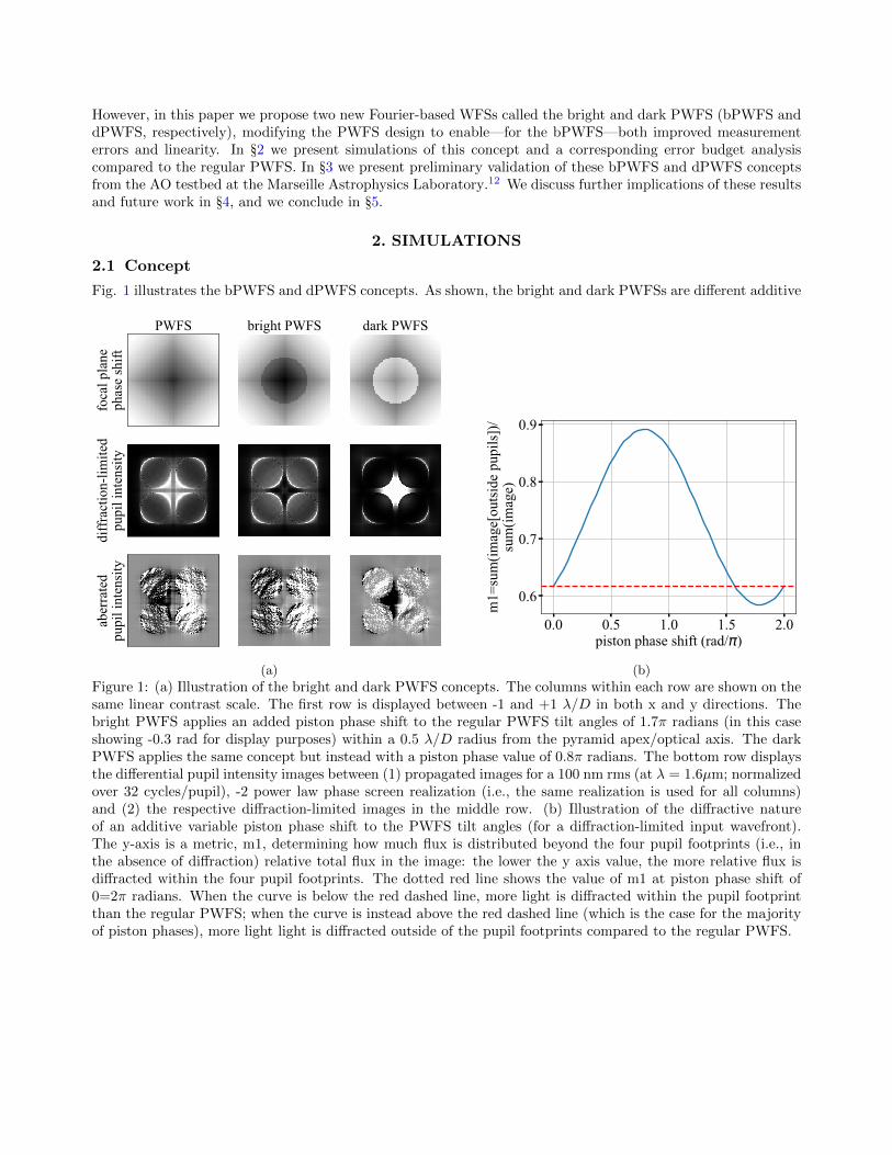
Fig. 1 illustrates the bPWFS and dPWFS concepts. As shown, the bright and dark PWFSs are different additive
foca
l pla
neph
ase
shift
PWFS bright PWFS dark PWFS
diff
ract
ion-
limite
dpu
pil i
nten
sity
aber
rate
dpu
pil i
nten
sity
(a)
0.0 0.5 1.0 1.5 2.0piston phase shift (rad/ )
0.6
0.7
0.8
0.9
m1=
sum
(imag
e[ou
tsid
e pu
pils
])/
sum
(imag
e)
(b)
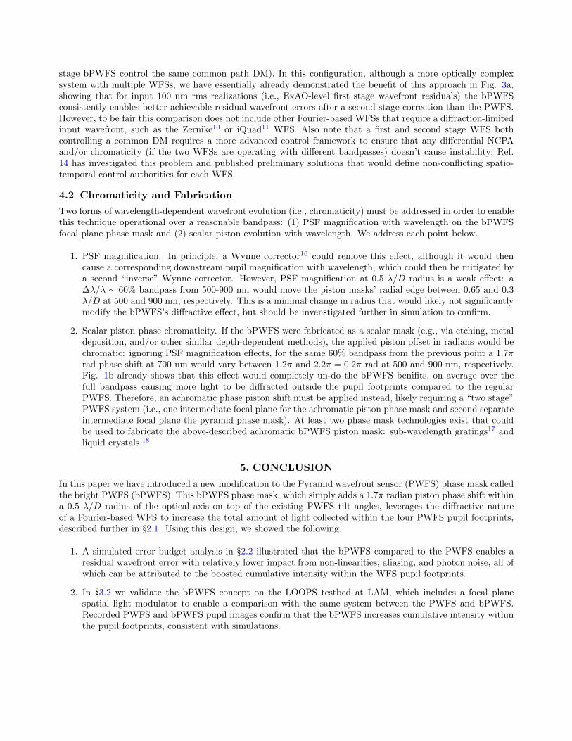
Figure 1: (a) Illustration of the bright and dark PWFS concepts. The columns within each row are shown on thesame linear contrast scale. The first row is displayed between -1 and +1 λ/D in both x and y directions. Thebright PWFS applies an added piston phase shift to the regular PWFS tilt angles of 1.7π radians (in this caseshowing -0.3 rad for display purposes) within a 0.5 λ/D radius from the pyramid apex/optical axis. The darkPWFS applies the same concept but instead with a piston phase value of 0.8π radians. The bottom row displaysthe differential pupil intensity images between (1) propagated images for a 100 nm rms (at λ = 1.6µm; normalizedover 32 cycles/pupil), -2 power law phase screen realization (i.e., the same realization is used for all columns)and (2) the respective diffraction-limited images in the middle row. (b) Illustration of the diffractive natureof an additive variable piston phase shift to the PWFS tilt angles (for a diffraction-limited input wavefront).The y-axis is a metric, m1, determining how much flux is distributed beyond the four pupil footprints (i.e., inthe absence of diffraction) relative total flux in the image: the lower the y axis value, the more relative flux isdiffracted within the four pupil footprints. The dotted red line shows the value of m1 at piston phase shift of0=2π radians. When the curve is below the red dashed line, more light is diffracted within the pupil footprintthan the regular PWFS; when the curve is instead above the red dashed line (which is the case for the majorityof piston phases), more light light is diffracted outside of the pupil footprints compared to the regular PWFS.
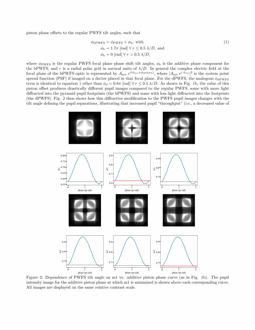
piston phase offsets to the regular PWFS tilt angles, such that
φbPWFS = φPWFS + φb, with (1)
φb = 1.7π [rad] ∀ r ≤ 0.5 λ/D, and
φb = 0 [rad] ∀ r > 0.5 λ/D,
where φPWFS is the regular PWFS focal plane phase shift tilt angles, φb is the additive phase component forthe bPWFS, and r is a radial polar grid in natural units of λ/D. In general the complex electric field at thefocal plane of the bPWFS optic is represented by Asys e
i(φsys+φbPWFS), where |Asys ei φsys |2 is the system point
spread function (PSF) if imaged on a dector placed in that focal plane. For the dPWFS, the analogous φdPWFS
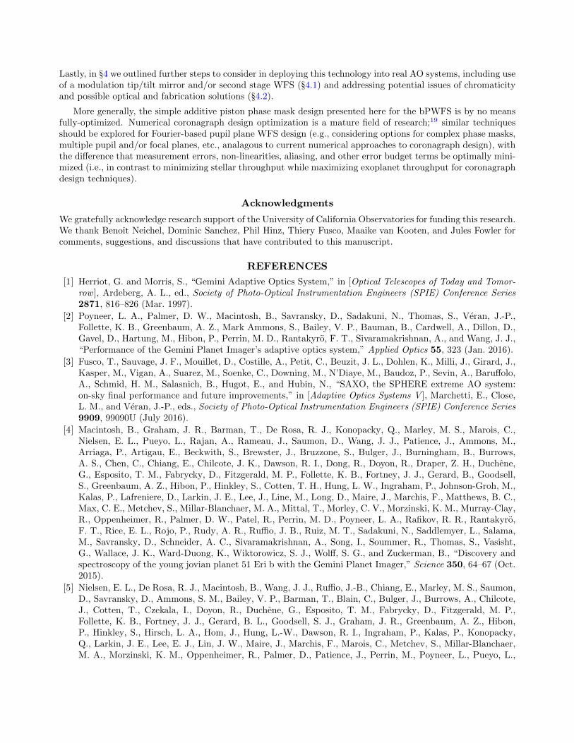
term is identical to equation 1 other than φd = 0.8π [rad] ∀ r ≤ 0.5 λ/D. As shown in Fig. 1b, the value of thispiston offset produces drastically different pupil images compared to the regular PWFS, some with more lightdiffracted into the pyramid pupil footprints (the bPWFS) and some with less light diffracted into the footprints(the dPWFS). Fig. 2 then shows how this diffractive modification to the PWFS pupil images changes with thetilt angle defining the pupil separations, illustrating that increased pupil “throughput” (i.e., a decreased value of
0 1 2phase (pi rad)
0.55
0.60
0.65
0.70
0.75
0.80
m1
0 1 2phase (pi rad)
0.6
0.7
0.8
0.9
m1
0 1 2phase (pi rad)
0.7
0.8
0.9
m1
0 1 2phase (pi rad)
0.7
0.8
0.9
m1
0 1 2phase (pi rad)
0.7
0.8
0.9
m1
0 1 2phase (pi rad)
0.7
0.8
0.9
m1
Figure 2: Dependence of PWFS tilt angle on m1 vs. additive piston phase curve (as in Fig. 1b). The pupilintensity image for the additive piston phase at which m1 is minimized is shown above each corresponding curve.All images are displayed on the same relative contrast scale.
m1) with this bright PWFS concept relative to the regular PWFS is only achieved when the pupil separationsare less than about 1 pupil diameter from one another. This effect is to be expected; effectively, this additivephase shift is acting as a Roddier&Roddier coronagraph13 or a Zernike WFS9 on the four pupils, depending onthe value of additive piston applied to the central λ/D diameter region. When the four pupils are separatedby more than one pupil diameter form one another, the central dark “coronagraphic” pupil from the bPWFSno longer redistributes light from within this central pupil footprint into the four pupils from the PWFS tiltangles. However, a more complex numerical optimization should further investigate the limits of this approach(see §5). Regardless, a separation between the four PWFS pupils is still generally a desired trait, enabling (1)an increased achievable pupil sampling for use with higher order deformable mirrors (DMs) and/or to reducealiasing in WFS measurement errors, and/or (2) decreasing the required sub-array/detector size to readout,enabling higher accessible loop speeds and/or lower detector read noise.
2.2 Error Budget Analysis
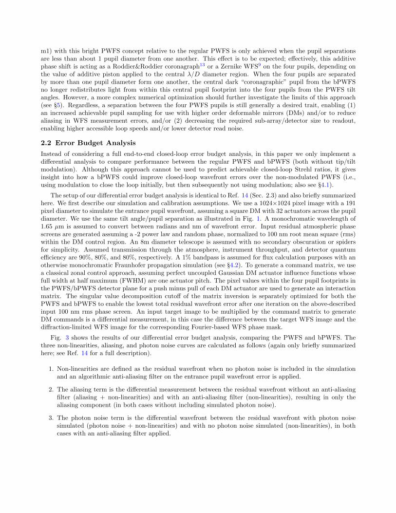
Instead of considering a full end-to-end closed-loop error budget analysis, in this paper we only implement adifferential analysis to compare performance between the regular PWFS and bPWFS (both without tip/tiltmodulation). Although this approach cannot be used to predict achievable closed-loop Strehl ratios, it givesinsight into how a bPWFS could improve closed-loop wavefront errors over the non-modulated PWFS (i.e.,using modulation to close the loop initially, but then subsequently not using modulation; also see §4.1).
The setup of our differential error budget analysis is identical to Ref. 14 (Sec. 2.3) and also briefly summarizedhere. We first describe our simulation and calibration assumptions. We use a 1024×1024 pixel image with a 191pixel diameter to simulate the entrance pupil wavefront, assuming a square DM with 32 actuators across the pupildiameter. We use the same tilt angle/pupil separation as illustrated in Fig. 1. A monochromatic wavelength of1.65 µm is assumed to convert between radians and nm of wavefront error. Input residual atmospheric phasescreens are generated assuming a -2 power law and random phase, normalized to 100 nm root mean square (rms)within the DM control region. An 8m diameter telescope is assumed with no secondary obscuration or spidersfor simplicity. Assumed transmission through the atmosphere, instrument throughput, and detector quantumefficiency are 90%, 80%, and 80%, respectively. A 1% bandpass is assumed for flux calculation purposes with anotherwise monochromatic Fraunhofer propagation simulation (see §4.2). To generate a command matrix, we usea classical zonal control approach, assuming perfect uncoupled Gaussian DM actuator influence functions whosefull width at half maximum (FWHM) are one actuator pitch. The pixel values within the four pupil footprints inthe PWFS/bPWFS detector plane for a push minus pull of each DM actuator are used to generate an interactionmatrix. The singular value decomposition cutoff of the matrix inversion is separately optimized for both thePWFS and bPWFS to enable the lowest total residual wavefront error after one iteration on the above-describedinput 100 nm rms phase screen. An input target image to be multiplied by the command matrix to generateDM commands is a differential measurement, in this case the difference between the target WFS image and thediffraction-limited WFS image for the corresponding Fourier-based WFS phase mask.
Fig. 3 shows the results of our differential error budget analysis, comparing the PWFS and bPWFS. Thethree non-linearities, aliasing, and photon noise curves are calculated as follows (again only briefly summarizedhere; see Ref. 14 for a full description).
1. Non-linearities are defined as the residual wavefront when no photon noise is included in the simulationand an algorithmic anti-aliasing filter on the entrance pupil wavefront error is applied.
2. The aliasing term is the differential measurement between the residual wavefront without an anti-aliasingfilter (aliasing + non-linearities) and with an anti-aliasing filter (non-linearities), resulting in only thealiasing component (in both cases without including simulated photon noise).
3. The photon noise term is the differential wavefront between the residual wavefront with photon noisesimulated (photon noise + non-linearities) and with no photon noise simulated (non-linearities), in bothcases with an anti-aliasing filter applied.
0 5 10 15spatial frequency (cycles/pupil)
100
101
(f) (n
m rm
s)
mI=7, / =0.01, tint=0.5 ms
inputoutputnon-linearitiesaliasingphoton noisePWFSbPWFS
(a)
0 5 10 15spatial frequency (cycles/pupil)
0.2
0.4
0.6
0.8
1.0
1.2
(f) (n
m rm
s)
diffraction-limited measurement error,mI=5, / =0.01, tint=1 ms
(f)PWFS(f)bPWFS(f)PWFS/ (f)bPWFS 0.2
0.4
0.6
0.8
1.0
1.2
(f)PW
FS/
(f)bP
WFS
(b)
Figure 3: AO error budget, comparing the regular PWFS (solid lines) and bright PWFS (dashed lines). In bothpanels the y axis shows wavefront error for a given spatial frequency bin, identical to the definition in equation1 of Ref. 15. (a) A breakdown of output residuals, after 3 iterations using a unity gain integral controller,into components for photon noise, alaising, and non-linearities, comparing the PWFS and bPWFS for eachcomponent. Each curve shown is from a median over 100 different uncorrelated wavefront realizations (wherein each case the input is normalized to 100 nm rms as described in the text). (b) Error budget comparison ofreconstructed photon noise for the PWFS and bPWFS, both for an input diffraction-limited (i.e., zero phase)wavefront. Each curve is medianed over 100 individual photon noise realizations.
Figure 3 clearly shows the gain in all error budget terms from the bPWFS over the PWFS: the overall residualwavefront in panel a is lower, with relatively less contributions from non-linearities, aliasing, and photon noise.Panel b shows that for the same number of input photons, the measurement error due to photon noise for adiffraction-limited wavefront (i.e., no aliasing and minimal non-linearities) is about 20% lower for the bPWFSvs. PWFS. These performance gains can be interpreted as follows.
1. Non-linearities and aliasing. The bPWFS phase mask diffracts more light into the four pupil footprints andenables that increased light to display entrance pupil phase aberations as intensity variations on the WFSdetector, which causes less signal from the input wavefront error to be spatially redistributed beyond suchfootprints. More diffracted light outside the pupil footprints leads to increased non-linearities, particularlyfor larger wavefront errors. More diffracted light/light redistribution also has the potential to opticallyredistribute higher order un-correctable wavefront errors to look like correctable ones and vice versa.
2. Photon noise. More photons within the pupil footprints that show signal from entrance pupil phase aberra-tion as intensity variations increases the signal-to-noise ratio (S/N) of a given wavefront error proportionalto the square root of the number of photons. A higher S/N WFS measurement of a given wavefront errorresults in less noise being propagated onto the DM from the WFS reconstruction and ultimately a lowerachievable residual wavefront error.
Also note that this same error budget analysis for the dPWFS showed the opposite of what we presented herefor the bPWFS: all error terms for the dPWFS perform worse than the PWFS. This is consistent with the aboveinterpretation, illustrating that when more light is diffracted outside the pupil footprints which would otherwisebe entrance pupil phase aberrations converted to intensity variations on the WFS detector, expected performanceis worse.
3. LABORATORY TESTS
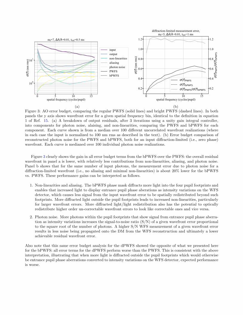
3.1 The LOOPS Testbed
The LOOPS—LAM (Laboratoire d’Astrophysique de Marseille)/ONERA (Office National d’Etudes et de Recherchesen Aerospatiales) On-sky Pyramid Sensor—testbed is a laboratory at LAM developed to test new AO technolo-gies, described in Ref. 12 and references therein. Although many new AO technologies have been deployed andtested on this bench, for the purposes of this paper there are three relevant hardware sources on the LOOPSbench (introduced in the order of light propagation): (1) a λ=635nm laser diode light source conjugated atinfinity, (2) a downstream 1024×1280 pixel Hamamatsu Spatial Light Modulator (SLM; LCOS-SLM X13138)conjugated to a focal plane at f/264∗, and (3) a further downstream a 2048×2048 pixel Hamamatsu ORCA-Flash4.0 v2 pupil imaging detector, sampling around 300 pixels across the pupil diameter.
3.2 Preliminary Results
The LOOPS focal plane SLM described in §3.1 enables applying the phase masks for the PWFS, bPWFS, anddPWFS, with all other testbed parameters unchanged between masks. The results of this are shown in Fig. 4.Consistent with simulations in Fig. 1a, Fig. 4 clearly shows less light between the four pupils for the bPWFSvs. regular PWFS and conversely more light between pupils for the dPWFS.
4. DISCUSSION AND FUTURE WORK
4.1 Modulation and Linearity
Implementing the modulated PWFS is a key next step to validating the benefit of the bPWFS over the PWFS.We expect that for modulation radii greater than about 1 λ/D, the modulated bPWFS performance will beidentical to the modulated PWFS, since the bPWFS piston mask only extents radially to 0.5 λ/D. However,a key question to answer is whether or not switching from a modulated to un-modulated bPWFS in closed-loop will enable improved closed-loop performance. Future simulations and/or laboratory tests should thereforeinvestigate this further.
Alternatively, another approach to considering the benefit of the bPWFS is it’s use as a second stage AOWFS (i.e., both a first stage AO WFS, such as a modulated PWFS or a Shack Hartmann WFS, and a second
∗See Ref. 12 for a detailed description of the steps taken to limit SLM-based systematics (such as polarization-dependent and filling-factor errors), ensuring custom focal plane phase shifts can be applied without interference fromthese effects.
Figure 4: Preliminary Laboratory validation of the bright PWFS concept with the LOOPS testbed at LAM,using an SLM in the focal plane to modulate the added focal plane piston phase shift within the central 0.5 λ/Dof the optical axis. (a) The regular PWFS (i.e., no added piston). (b) the bright PWFS: 1.7 π rad added piston.(c) the dark PWFS: 0.6 π added piston.
stage bPWFS control the same common path DM). In this configuration, although a more optically complexsystem with multiple WFSs, we have essentially already demonstrated the benefit of this approach in Fig. 3a,showing that for input 100 nm rms realizations (i.e., ExAO-level first stage wavefront residuals) the bPWFSconsistently enables better achievable residual wavefront errors after a second stage correction than the PWFS.However, to be fair this comparison does not include other Fourier-based WFSs that require a diffraction-limitedinput wavefront, such as the Zernike10 or iQuad11 WFS. Also note that a first and second stage WFS bothcontrolling a common DM requires a more advanced control framework to ensure that any differential NCPAand/or chromaticity (if the two WFSs are operating with different bandpasses) doesn’t cause instability; Ref.14 has investigated this problem and published preliminary solutions that would define non-conflicting spatio-temporal control authorities for each WFS.
4.2 Chromaticity and Fabrication
Two forms of wavelength-dependent wavefront evolution (i.e., chromaticity) must be addressed in order to enablethis technique operational over a reasonable bandpass: (1) PSF magnification with wavelength on the bPWFSfocal plane phase mask and (2) scalar piston evolution with wavelength. We address each point below.
1. PSF magnification. In principle, a Wynne corrector16 could remove this effect, although it would thencause a corresponding downstream pupil magnification with wavelength, which could then be mitigated bya second “inverse” Wynne corrector. However, PSF magnification at 0.5 λ/D radius is a weak effect: a∆λ/λ ∼ 60% bandpass from 500-900 nm would move the piston masks’ radial edge between 0.65 and 0.3λ/D at 500 and 900 nm, respectively. This is a minimal change in radius that would likely not significantlymodify the bPWFS’s diffractive effect, but should be invenstigated further in simulation to confirm.
2. Scalar piston phase chromaticity. If the bPWFS were fabricated as a scalar mask (e.g., via etching, metaldeposition, and/or other similar depth-dependent methods), the applied piston offset in radians would bechromatic: ignoring PSF magnification effects, for the same 60% bandpass from the previous point a 1.7πrad phase shift at 700 nm would vary between 1.2π and 2.2π = 0.2π rad at 500 and 900 nm, respectively.Fig. 1b already shows that this effect would completely un-do the bPWFS benifits, on average over thefull bandpass causing more light to be diffracted outside the pupil footprints compared to the regularPWFS. Therefore, an achromatic phase piston shift must be applied instead, likely requiring a “two stage”PWFS system (i.e., one intermediate focal plane for the achromatic piston phase mask and second separateintermediate focal plane the pyramid phase mask). At least two phase mask technologies exist that couldbe used to fabricate the above-described achromatic bPWFS piston mask: sub-wavelength gratings17 andliquid crystals.18
5. CONCLUSION
In this paper we have introduced a new modification to the Pyramid wavefront sensor (PWFS) phase mask calledthe bright PWFS (bPWFS). This bPWFS phase mask, which simply adds a 1.7π radian piston phase shift withina 0.5 λ/D radius of the optical axis on top of the existing PWFS tilt angles, leverages the diffractive natureof a Fourier-based WFS to increase the total amount of light collected within the four PWFS pupil footprints,described further in §2.1. Using this design, we showed the following.
1. A simulated error budget analysis in §2.2 illustrated that the bPWFS compared to the PWFS enables aresidual wavefront error with relatively lower impact from non-linearities, aliasing, and photon noise, all ofwhich can be attributed to the boosted cumulative intensity within the WFS pupil footprints.
2. In §3.2 we validate the bPWFS concept on the LOOPS testbed at LAM, which includes a focal planespatial light modulator to enable a comparison with the same system between the PWFS and bPWFS.Recorded PWFS and bPWFS pupil images confirm that the bPWFS increases cumulative intensity withinthe pupil footprints, consistent with simulations.
Lastly, in §4 we outlined further steps to consider in deploying this technology into real AO systems, including useof a modulation tip/tilt mirror and/or second stage WFS (§4.1) and addressing potential issues of chromaticityand possible optical and fabrication solutions (§4.2).
More generally, the simple additive piston phase mask design presented here for the bPWFS is by no meansfully-optimized. Numerical coronagraph design optimization is a mature field of research;19 similar techniquesshould be explored for Fourier-based pupil plane WFS design (e.g., considering options for complex phase masks,multiple pupil and/or focal planes, etc., analagous to current numerical approaches to coronagraph design), withthe difference that measurement errors, non-linearities, aliasing, and other error budget terms be optimally mini-mized (i.e., in contrast to minimizing stellar throughput while maximizing exoplanet throughput for coronagraphdesign techniques).
Acknowledgments
We gratefully acknowledge research support of the University of California Observatories for funding this research.We thank Benoıt Neichel, Dominic Sanchez, Phil Hinz, Thiery Fusco, Maaike van Kooten, and Jules Fowler forcomments, suggestions, and discussions that have contributed to this manuscript.
REFERENCES
[1] Herriot, G. and Morris, S., “Gemini Adaptive Optics System,” in [Optical Telescopes of Today and Tomor-row ], Ardeberg, A. L., ed., Society of Photo-Optical Instrumentation Engineers (SPIE) Conference Series2871, 816–826 (Mar. 1997).
[2] Poyneer, L. A., Palmer, D. W., Macintosh, B., Savransky, D., Sadakuni, N., Thomas, S., Veran, J.-P.,Follette, K. B., Greenbaum, A. Z., Mark Ammons, S., Bailey, V. P., Bauman, B., Cardwell, A., Dillon, D.,Gavel, D., Hartung, M., Hibon, P., Perrin, M. D., Rantakyro, F. T., Sivaramakrishnan, A., and Wang, J. J.,“Performance of the Gemini Planet Imager’s adaptive optics system,” Applied Optics 55, 323 (Jan. 2016).
[3] Fusco, T., Sauvage, J. F., Mouillet, D., Costille, A., Petit, C., Beuzit, J. L., Dohlen, K., Milli, J., Girard, J.,Kasper, M., Vigan, A., Suarez, M., Soenke, C., Downing, M., N’Diaye, M., Baudoz, P., Sevin, A., Baruffolo,A., Schmid, H. M., Salasnich, B., Hugot, E., and Hubin, N., “SAXO, the SPHERE extreme AO system:on-sky final performance and future improvements,” in [Adaptive Optics Systems V ], Marchetti, E., Close,L. M., and Veran, J.-P., eds., Society of Photo-Optical Instrumentation Engineers (SPIE) Conference Series9909, 99090U (July 2016).
[4] Macintosh, B., Graham, J. R., Barman, T., De Rosa, R. J., Konopacky, Q., Marley, M. S., Marois, C.,Nielsen, E. L., Pueyo, L., Rajan, A., Rameau, J., Saumon, D., Wang, J. J., Patience, J., Ammons, M.,Arriaga, P., Artigau, E., Beckwith, S., Brewster, J., Bruzzone, S., Bulger, J., Burningham, B., Burrows,A. S., Chen, C., Chiang, E., Chilcote, J. K., Dawson, R. I., Dong, R., Doyon, R., Draper, Z. H., Duchene,G., Esposito, T. M., Fabrycky, D., Fitzgerald, M. P., Follette, K. B., Fortney, J. J., Gerard, B., Goodsell,S., Greenbaum, A. Z., Hibon, P., Hinkley, S., Cotten, T. H., Hung, L. W., Ingraham, P., Johnson-Groh, M.,Kalas, P., Lafreniere, D., Larkin, J. E., Lee, J., Line, M., Long, D., Maire, J., Marchis, F., Matthews, B. C.,Max, C. E., Metchev, S., Millar-Blanchaer, M. A., Mittal, T., Morley, C. V., Morzinski, K. M., Murray-Clay,R., Oppenheimer, R., Palmer, D. W., Patel, R., Perrin, M. D., Poyneer, L. A., Rafikov, R. R., Rantakyro,F. T., Rice, E. L., Rojo, P., Rudy, A. R., Ruffio, J. B., Ruiz, M. T., Sadakuni, N., Saddlemyer, L., Salama,M., Savransky, D., Schneider, A. C., Sivaramakrishnan, A., Song, I., Soummer, R., Thomas, S., Vasisht,G., Wallace, J. K., Ward-Duong, K., Wiktorowicz, S. J., Wolff, S. G., and Zuckerman, B., “Discovery andspectroscopy of the young jovian planet 51 Eri b with the Gemini Planet Imager,” Science 350, 64–67 (Oct.2015).
[5] Nielsen, E. L., De Rosa, R. J., Macintosh, B., Wang, J. J., Ruffio, J.-B., Chiang, E., Marley, M. S., Saumon,D., Savransky, D., Ammons, S. M., Bailey, V. P., Barman, T., Blain, C., Bulger, J., Burrows, A., Chilcote,J., Cotten, T., Czekala, I., Doyon, R., Duchene, G., Esposito, T. M., Fabrycky, D., Fitzgerald, M. P.,Follette, K. B., Fortney, J. J., Gerard, B. L., Goodsell, S. J., Graham, J. R., Greenbaum, A. Z., Hibon,P., Hinkley, S., Hirsch, L. A., Hom, J., Hung, L.-W., Dawson, R. I., Ingraham, P., Kalas, P., Konopacky,Q., Larkin, J. E., Lee, E. J., Lin, J. W., Maire, J., Marchis, F., Marois, C., Metchev, S., Millar-Blanchaer,M. A., Morzinski, K. M., Oppenheimer, R., Palmer, D., Patience, J., Perrin, M., Poyneer, L., Pueyo, L.,
Rafikov, R. R., Rajan, A., Rameau, J., Rantakyro, F. T., Ren, B., Schneider, A. C., Sivaramakrishnan,A., Song, I., Soummer, R., Tallis, M., Thomas, S., Ward-Duong, K., and Wolff, S., “The Gemini PlanetImager Exoplanet Survey: Giant Planet and Brown Dwarf Demographics from 10 to 100 au,” AstronomicalJournal 158, 13 (July 2019).
[6] Ragazzoni, R., “Pupil plane wavefront sensing with an oscillating prism,” Journal of Modern Optics 43,289–293 (Feb. 1996).
[7] Correia, C. M., Fauvarque, O., Bond, C. Z., Chambouleyron, V., Sauvage, J.-F., and Fusco, T., “Performancelimits of adaptive-optics/high-contrast imagers with pyramid wavefront sensors,” Monthly Notices of theRoyal Astronomical Society 495, 4380–4391 (July 2020).
[8] Fauvarque, O., Neichel, B., Fusco, T., Sauvage, J.-F., and Girault, O., “General formalism for Fourier-basedwave front sensing,” Optica 3, 1440 (Dec. 2016).
[9] Zernike, F., “Diffraction theory of the knife-edge test and its improved form, the phase-contrast method,”Monthly Notices of the Royal Astronomical Society 94, 377–384 (Mar. 1934).
[10] Chambouleyron, V., Fauvarque, O., Sauvage, J. F., Dohlen, K., Levraud, N., Vigan, A., N’Diaye, M.,Neichel, B., and Fusco, T., “Variation on a Zernike wavefront sensor theme: Optimal use of photons,”Astronomy and Astrophysics 650, L8 (June 2021).
[11] Fauvarque, O., Hutterer, V., Janin-Potiron, P., Duboisset, J., Correia, C., Neichel, B., Sauvage, J. F., Fusco,T., Shatokhina, I., Ramlau, R., Chambouleyron, V., and Brule, Y., “The ıQuad sensor: a new Fourier-basedwave front sensor derived from the 4 quadrants coronagraph,” Proc. AO4ELT6 401-Pdyj-81 (2019).
[12] Janin-Potiron, P., Chambouleyron, V., Schatz, L., Fauvarque, O., Bond, C. Z., Abautret, Y., Muslimov, E.,El-Hadi, K., Sauvage, J.-F., Dohlen, K., Neichel, B., Correia, C. M., and Fusco, T., “Adaptive optics withprogrammable Fourier-based wavefront sensors: a spatial light modulator approach to the LAM/ONERAon-sky pyramid sensor testbed,” Journal of Astronomical Telescopes, Instruments, and Systems 5, 039001(July 2019).
[13] Roddier, F. and Roddier, C., “Stellar Coronograph with Phase Mask,” Publications of the AstronomicalSociety of the Pacific 109, 815–820 (July 1997).
[14] Gerard, B. L., Veran, J.-P., Singh, G., Herriot, G., Lardiere, O., and Marois, C., “Fast focal plane wavefrontsensing as a second stage adaptive optics wavefront sensor,” in [Adaptive Optics Systems VII ], Schreiber,L., Schmidt, D., and Vernet, E., eds., 11448, 483 – 499, International Society for Optics and Photonics,SPIE (2021).
[15] Vigan, A., N’Diaye, M., Dohlen, K., Sauvage, J. F., Milli, J., Zins, G., Petit, C., Wahhaj, Z., Cantalloube,F., Caillat, A., Costille, A., Le Merrer, J., Carlotti, A., Beuzit, J. L., and Mouillet, D., “Calibration of quasi-static aberrations in exoplanet direct-imaging instruments with a Zernike phase-mask sensor. III. On-skyvalidation in VLT/SPHERE,” A&A 629, A11 (Sept. 2019).
[16] Wynne, C. G., “Extending the bandwidth of speckle interferometry.,” Optics Communications 28, 21–25(1979).
[17] Konig, L., Absil, O., Delacroix, C., Lobet, M., Karlsson, M., Vargas Catalan, E., Orban de Xivry, G., Loicq,J., and Habraken, S., “Vortex phase masks of topological charge 4 and higher with diamond subwavelengthgratings,” in [Society of Photo-Optical Instrumentation Engineers (SPIE) Conference Series ], Society ofPhoto-Optical Instrumentation Engineers (SPIE) Conference Series 11451, 1145144 (Dec. 2020).
[18] Doelman, D. S., Snik, F., Por, E. H., Bos, S. P., Otten, G. P. P. L., Kenworthy, M., Haffert, S. Y., Wilby,M., Bohn, A. J., Sutlieff, B. J., Miller, K., Ouellet, M., de Boer, J., Keller, C. U., Escuti, M. J., Shi, S.,Warriner, N. Z., Hornburg, K., Birkby, J. L., Males, J., Morzinski, K. M., Close, L. M., Codona, J., Long, J.,Schatz, L., Lumbres, J., Rodack, A., Van Gorkom, K., Hedglen, A., Guyon, O., Lozi, J., Groff, T., Chilcote,J., Jovanovic, N., Thibault, S., de Jonge, C., Allain, G., Vallee, C., Patel, D., Cote, O., Marois, C., Hinz,P., Stone, J., Skemer, A., Briesemeister, Z., Boehle, A., Glauser, A. M., Taylor, W., Baudoz, P., Huby, E.,Absil, O., Carlomagno, B., and Delacroix, C., “Vector-apodizing phase plate coronagraph: design, currentperformance, and future development [Invited],” Applied Optics 60, D52 (July 2021).
[19] Ruane, G., Riggs, A., Mazoyer, J., Por, E. H., N’Diaye, M., Huby, E., Baudoz, P., Galicher, R., Douglas,E., Knight, J., Carlomagno, B., Fogarty, K., Pueyo, L., Zimmerman, N., Absil, O., Beaulieu, M., Cady, E.,Carlotti, A., Doelman, D., Guyon, O., Haffert, S., Jewell, J., Jovanovic, N., Keller, C., Kenworthy, M. A.,

Kuhn, J., Miller, K., Sirbu, D., Snik, F., Wallace, J. K., Wilby, M., and Ygouf, M., “Review of high-contrastimaging systems for current and future ground- and space-based telescopes I: coronagraph design methodsand optical performance metrics,” in [Space Telescopes and Instrumentation 2018: Optical, Infrared, andMillimeter Wave ], Lystrup, M., MacEwen, H. A., Fazio, G. G., Batalha, N., Siegler, N., and Tong, E. C.,eds., Society of Photo-Optical Instrumentation Engineers (SPIE) Conference Series 10698, 106982S (Aug.2018).