Big Video Bright Future - ZTE
151
Big Video Bright Future ZTE Big Video White Paper
-
Upload
khangminh22 -
Category
Documents
-
view
3 -
download
0
Transcript of Big Video Bright Future - ZTE
Big Video Bright Future
ZTE Big Video White Paper

Big Video Bright Future
ZTE Confidential & Proprietary 1
Big Video Bright Future
Version Date Author Reviewer Notes
V1.0 2011/12/06 ZTE Not open to the third party
V2.0 2012/02/14 ZTE Added the document map convenient button
V2.1 2012/06/04 ZTE Modified the footer
V2.2 2015/03/11 ZTE Modified the cover and the header logo
V3.0 2016/07/07 ZTE Integration and general revision
V3.1 2016/07/14 ZTE Modified the abbreviation
V4.0 2016/08/05 ZTE General revision
© 2016 ZTE Corporation. All rights reserved.
ZTE CONFIDENTIAL: This document contains proprietary information of ZTE and is not to be disclosed or used
without the prior written permission of ZTE.
Due to update and improvement of ZTE products and technologies, information in this document is subjected to
change without notice.
Big Video Bright Future
2 ZTE Confidential & Proprietary
TABLE OF CONTENTS
1 Big Video, Big Future ...................................................................................... 10
1.1 The Big Video Era Is Coming ............................................................................. 10
1.2 The Big Video Is a Key Opportunity for Operators’ Transformation .................... 11
1.2.1 Chinese Operators’ Big Video Strategy .............................................................. 12
1.2.2 International Operators’ Big Video Strategy ....................................................... 14
1.3 Challenges Brought by the Big Video to Operators ............................................ 15
1.4 ZTE Big Video Solution Helps Operators Embrace the Big Future ..................... 16
2 Wired Network Solution with Best Video Experience ................................... 18
2.1 Requirements of big video for wired network ...................................................... 18
2.2 Problems of traditional wired network architecture carrying big video services ... 20
2.2.1 Problems in home-area network (HAN) .............................................................. 20
2.2.2 Problems in access network .............................................................................. 21
2.2.3 Problems in metro network and backbone network ............................................ 22
2.3 Target architecture and evolution strategy of wired network of optimal video
experience ......................................................................................................... 23
2.3.1 Target architecture of wired network of optimal video experience ...................... 23
2.3.2 Evolution strategy of wired network of optimal video experience ........................ 25
2.3.3 Home Area Network ........................................................................................... 29
2.3.4 Access network .................................................................................................. 31
2.3.5 Metro & backbone network reconstruction ......................................................... 36
2.4 Conclusion ......................................................................................................... 49
3 Wireless Network Solution with Best Video Experience .............................. 50
3.1 Requirements and Challenges for Wireless Network by Mobile Video Service ... 50
3.2 Elite Wireless Video Network Solution ............................................................... 52
3.2.1 Existing Wireless Video Network Solution .......................................................... 53
3.2.2 Enhanced Pre5G Wireless Video Network Solution ........................................... 64
3.2.3 Future Wireless Network Solution for Big video ................................................. 79
3.2.4 Summary ........................................................................................................... 89
4 Big Video Service Platform Solution .............................................................. 90
4.1 Pain Points and Innovation of the Big Video Service Platform ............................ 90
4.2 Architecture of the Cloudized Video Platform ..................................................... 94
4.2.1 System Architecture ........................................................................................... 95
4.2.2 VNF Deployment................................................................................................ 95
4.2.3 Scalable Dispatching ......................................................................................... 97
4.2.4 Supporting the SDN ........................................................................................... 99
4.3 Smart Video Pipeline ....................................................................................... 100
Big Video Bright Future
ZTE Confidential & Proprietary 3
4.3.1 Significance of Establishing a Smart Video Pipeline ......................................... 100
4.3.2 Integrated CDN as the Core of the Smart Video Pipeline ................................. 102
4.4 Capability Opening Platform ............................................................................ 108
4.4.1 Infrastructure Capability Opening Platform ....................................................... 110
4.4.2 Value-added Application Opening Platform ...................................................... 111
4.4.3 CDN Capability Opening Platform .................................................................... 112
4.4.4 Supporting the Application Store ...................................................................... 113
4.4.5 Terminal Component Capability Opening ......................................................... 114
4.5 User Experience as the King ............................................................................ 115
4.5.1 UHD Experience .............................................................................................. 116
4.5.2 FMC ................................................................................................................. 116
4.5.3 Personalized Services ..................................................................................... 117
4.5.4 User Experience Supported by Big Data .......................................................... 118
4.5.5 Visual Communication Service......................................................................... 121
5 Big Video User Experience Assurance Solution ......................................... 124
5.1 Challenges Brought by Big Video in User Perception and O&M ....................... 124
5.2 Big Video User Experience Evaluation System V-QoE .................................... 126
5.2.1 V-QoE Indicator System Architecture ............................................................... 127
5.2.2 Factors Determining the V-QoE ....................................................................... 127
5.2.3 Meaning of V-QoE ........................................................................................... 128
5.2.4 V-QoE Calculation ........................................................................................... 129
5.3 FMC IPTV End-to-end Smart O&M .................................................................. 133
5.3.1 Overview .......................................................................................................... 133
5.3.2 Customer Video Experience Perceived by Multiple Video Probes .................... 135
5.3.3 O&M Monitoring of the Total Network Video Service ........................................ 136
5.3.4 Smartly Delimiting the Video Fault ................................................................... 137
5.3.5 Rapidly Positioning the Video Service Network Fault ....................................... 138
5.3.6 Rapidly Positioning the Fault of the Bearer Network ........................................ 139
5.3.7 Rapidly Positioning the Fault of the Access Network ........................................ 139
5.3.8 IPTV O&M under the Mobile Scenario ............................................................. 140
5.4 Mobile Network O&M, Planning, and Construction with Video Quality
Experience as the Core.................................................................................... 141
5.4.1 Difference and Root Cause Analysis ................................................................ 141
5.4.2 Mobile Network Planning and Construction with Video Experience as the Core 145
5.4.3 Network Evaluation and Target Setting ............................................................ 146
6 Conclusion ..................................................................................................... 147
7 Abbreviation .................................................................................................. 148
Big Video Bright Future
4 ZTE Confidential & Proprietary
Big Video Bright Future
ZTE Confidential & Proprietary 5
FIGURES
Figure 1-1 Four Stages of Video Service Development ......................................................11
Figure 1-2 Four Connotations of Big Video ........................................................................16
Figure 2-1 Wired network evolution in different development stages of 4K ........................25
Figure 2-2 Rate comparison of 802.11n and 802.11ac .......................................................29
Figure 2-3 HAN seamless coverage solution .....................................................................30
Figure 2-4 Distributed buffer solution of OLT .....................................................................33
Figure 2-5 Comparison of token bucket rate limit and Shaper rate limit..............................33
Figure 2-6 Combo PON solution ........................................................................................34
Figure 2-7 Network architecture in the early stage of 4K ....................................................37
Figure 2-8 Video service dedicated channels .....................................................................38
Figure 2-9 Video service QoS guarantee ...........................................................................39
Figure 2-10 TCP symmetric optimization ...........................................................................40
Figure 2-11 TCP asymmetric optimization .........................................................................40
Figure 2-12 FCC speedup principle ...................................................................................42
Figure 2-13 FCC Cache deployment position.....................................................................43
Figure 2-14 Network architecture evolution: CO reconstruction .........................................45
Figure 2-15 Benefit of edge CO reconstruction – substantial increase of bandwidth utilization
.............................................................................................................................................46
Figure 2-16 Benefit of edge CO reconstruction – reduced device quantity and power
consumption .........................................................................................................................46
Figure 2-17 Benefit of edge CO reconstruction – reduced CR downlink port bandwidth and
increased utilization rate .......................................................................................................47
Figure 2-18 Network architecture evolution : distributed CO ..............................................49
Figure 3-1 Mobile Video Service in 2020 Occupying 75% of the Data Services (Source:
Cisco VNI Mobile, 2016) .......................................................................................................51
Figure 3-2 Average Service Distribution of a City in September 2015 ................................52
Figure 3-3 Three Phases of Enhanced Wireless Video Network Evolution .........................53
Figure 3-4 Enhanced Wireless Network Video Solution .....................................................54
Figure 3-5 Schematic Diagram of Macro-Micro eICIC ........................................................57
Big Video Bright Future
6 ZTE Confidential & Proprietary
Figure 3-6 Enhancement of Video User Perception by New Wireless Functions ................58
Figure 3-7 Existing Architecture of Wireless Bearer Network .............................................60
Figure 3-8 Core Network Architecture ................................................................................61
Figure 3-9 Dedicated Channel for Video Services ..............................................................62
Figure 3-10 TCP Proxy Architecture for Mobile Networks ..................................................63
Figure 3-11 Network Architecture over LAA and LWA ........................................................66
Figure 3-12 Evolution of Enhanced LTE Technologies .......................................................67
Figure 3-13 Application Scenario of Pre5G Massive MIMO Technology ............................68
Figure 3-14 Schematic Diagram of Pre 5G UDN Solution ..................................................69
Figure 3-15 Schematic Diagram of Wireless Network Evolution .........................................71
Figure 3-16 Pre5G Wireless Bearer Network Evolution ......................................................72
Figure 3-17 eMBMS Service Solution for Bearer Network ..................................................72
Figure 3-18 eMBMS Unicast and Multicast Services Carried over Bearer Network ............73
Figure 3-19 MEC-based Wireless Bearer Network .............................................................74
Figure 3-20 SDN Over Bearer Network ..............................................................................75
Figure 3-21 Core Network Architecture Evolution in Pre5G................................................75
Figure 3-22 Separated Control Plane and User Plane of GW ............................................77
Figure 3-23 Schematic Diagram of Service Orchestration ..................................................78
Figure 3-24 Video Optimization and Caching Based on Network State ..............................79
Figure 3-25 5G Development Orientation Diagram ............................................................80
Figure 3-26 Performance Indicators of the Enhanced Broadband Technology ...................81
Figure 3-27 NGMN-Proposed 5G Network Architecture .....................................................82
Figure 3-28 ZTE 5G Technology Design Ideas ..................................................................82
Figure 3-29 ZTE 5G UAI Architecture ................................................................................83
Figure 3-30 CAS-Based 5G Network Architecture .............................................................85
Figure 3-31 CAS Software Architecture Supporting Big Video Services .............................85
Figure 3-32 CPRI over OTN Diagram ................................................................................87
Figure 3-33 NGFI Diagram .................................................................................................87
Figure 3-34 Coordinated Planning of the IP Layer and the Optical Layer ...........................88
Figure 3-35 Wireless Bearer Network Under Network Slicing ............................................89
Big Video Bright Future
ZTE Confidential & Proprietary 7
Figure 4-1 Four Major Evolution Directions of the Big Video Service Platform ......................93
Figure 4-2 Video Platform of the Cloudized Architecture ....................................................94
Figure 4-3 System Architecture of the Cloudized Video Platform .......................................95
Figure 4-4 Logic of Deploying and Compiling the VNF of the Cloudized Video Architecture
.............................................................................................................................................97
Figure 4-5 Figure of Elastically Dispatching the Cloudized Video Architecture ...................97
Figure 4-6 Figure of How the CDN Network Supports Dispatching the SDN Traffic ...........99
Figure 4-7 New Generation Smart Pipeline Model ........................................................... 101
Figure 4-8 Smart Content Pipeline Model ........................................................................ 101
Figure 4-9 Big Video Service Capability Opening Architecture ......................................... 110
Figure 4-10 Basic Service Opening Platform ................................................................... 111
Figure 4-11 Value-added Service Opening Platform ........................................................ 112
Figure 4-12 CDN Capability Opening Platform ................................................................. 113
Figure 4-13 Operation Frame of the TV Store .................................................................. 114
Figure 4-14 Modular Open Architecture of the Terminal ................................................... 115
Figure 4-15 Individualized Page Presence ....................................................................... 118
Figure 4-16 Big Video User Portrait Architecture .............................................................. 119
Figure 4-17 Smart Recommendation Based on Analyzing the Program Information ........ 120
Figure 4-18 Smart Ad System .......................................................................................... 121
Figure 4-19 Architecture Diagram of Rapid Video Communication Construction Solution 123
Figure 4-20 Architecture of the Integrated Construction Solution ..................................... 124
Figure 5-1 Identification of Video Experience Fault Causes ............................................. 126
Figure 5-2 V-QoE Architecture ......................................................................................... 127
Figure 5-3 Factors Determining the V-QoE ...................................................................... 128
Figure 5-4 Meaning of V-QoE Values .............................................................................. 129
Figure 5-5 IPTV End-to-end O&M Solution Architecture .................................................. 135
Figure 5-6 Deploying Probes to Collect Video Streams to Analyze Video Quality ............ 141
Figure 5-7 V-QoE Value Displayed in Geographic Grids .................................................. 142
Figure 5-8 How to Delimit/Locate the Cause for Deteriorated V-QoE Video Performance
Indicators ............................................................................................................................ 143
Big Video Bright Future
8 ZTE Confidential & Proprietary
Figure 5-9 Delimiting/Locating the Cause for Deteriorated V-QoE Video Performance
Indicators Based on the Rule Base..................................................................................... 143
Figure 5-10 Process of Delimiting/Locating the Cause for Deteriorated V-QoE Video
Performance Indicators ...................................................................................................... 144
Figure 5-11 Example of Delimiting/Locating the Cause for Deteriorated V-QoE Video
Performance Indicators ...................................................................................................... 144
Figure 5-12 Comparison Between V-QoE Planning and Deployment Results .................. 145
Figure 5-13 Three Key Steps in Network Planning and Construction ............................... 146
TABLES
Table 1-1 Development of Broadband and Video Users of China’s 3 Telecom Operators ....13
Table 2-1 4K/8K/VR bit rates and bandwidth requirements ................................................18
Table 2-2 Requirement of 4K VOD and Live for delay and packet loss ..............................19
Table 2-3 Typical service models in the early stage of 4K video service ............................26
Table 2-4 Typical service models in the mature stage of 4K video service .........................27
Table 2-5 Typical service models in the developed stage of 4K video service....................28
Table 2-6 Traffic models in the early stage of 4K ...............................................................37
Table 2-7 Comparison of two modes .................................................................................40
Table 2-8 Factors affecting channel switching time ............................................................41
Table 2-9 Channel switching statistical table ......................................................................42
Table 2-10 Equipment capacity requirements in the mature stage of 4K service ................44
Table 2-11 Device distribution and bandwidth distribution after CO reconstruction ............45
Table 2-12 Network equipment capacity requirement in mature stage of 8K and VR .........48
Table 3-1 Recommended QCI Assignment for Mobile Networks ........................................62
Table 4-1 Comparison of Modes of Traditional Video Services and Big Video Services .....90
Table 4-2 Definition of Components of the Cloudized Video Architecture...........................95
Table 5-1 Reference Scores of Resolution and Frame Rate ............................................ 130
Table 5-2 Reference Score of the Freezing/Fuzzy Situation ............................................ 132
Table 5-3 Buffer Overflow Reference Scores ................................................................... 132
Big Video Bright Future
ZTE Confidential & Proprietary 9
Table 5-4 Interaction Quality Reference Scores ............................................................... 133
Table 5-5 Relationship Between Video Resolutions and Network Guaranty Rates (Using the
5-Inch Mobile Terminal as an Example) ............................................................................. 146
Table 5-6 Relationship Between Area Characteristics and Network Planning Policies ..... 147
Big Video Bright Future
10 ZTE Confidential & Proprietary
1 Big Video, Big Future
1.1 The Big Video Era Is Coming
Today, the video service is users’ favorite service relative to text, image, and voice
services. As a media form that has the most extensive audience, the video media can
vividly demonstrate a thing, a process, a dynamic detail and have a greater influence on
the audience than any other media forms. In the past, due to technological limitations,
HD videos cannot be easily transmitted. Now, video filming and production technologies
and telecom network technologies keep developing, and video media production and
communication costs keep reducing, so it becomes possible to transmit clearer videos
online. Meanwhile, people never stop pursuing clearer video. The dramatically growing
demand for ultra HD video services such as 4K, 8K, and VR/AR services calls for a new
era where the video service is booming. In this circumstance, the world is embracing the
big video era.
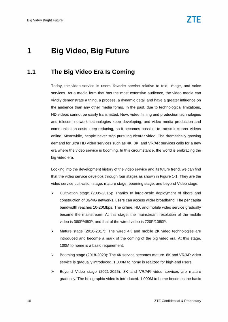
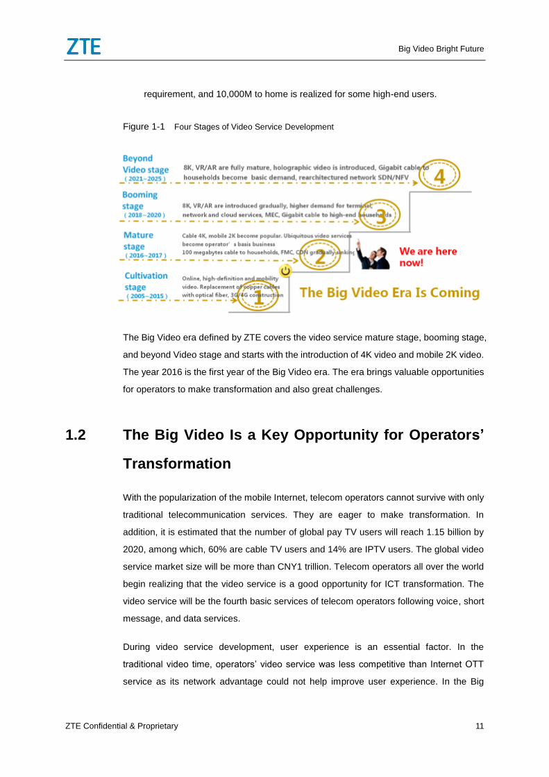
Looking into the development history of the video service and its future trend, we can find
that the video service develops through four stages as shown in Figure 1-1. They are the
video service cultivation stage, mature stage, booming stage, and beyond Video stage.
Cultivation stage (2005-2015): Thanks to large-scale deployment of fibers and
construction of 3G/4G networks, users can access wider broadband. The per capita
bandwidth reaches 10-20Mbps. The online, HD, and mobile video service gradually
become the mainstream. At this stage, the mainstream resolution of the mobile
video is 360P/480P, and that of the wired video is 720P/1080P.
Mature stage (2016-2017): The wired 4K and mobile 2K video technologies are
introduced and become a mark of the coming of the big video era. At this stage,
100M to home is a basic requirement.
Booming stage (2018-2020): The 4K service becomes mature. 8K and VR/AR video
service is gradually introduced. 1,000M to home is realized for high-end users.
Beyond Video stage (2021-2025): 8K and VR/AR video services are mature
gradually. The holographic video is introduced. 1,000M to home becomes the basic
Big Video Bright Future
ZTE Confidential & Proprietary 11
requirement, and 10,000M to home is realized for some high-end users.
Figure 1-1 Four Stages of Video Service Development
The Big Video era defined by ZTE covers the video service mature stage, booming stage,
and beyond Video stage and starts with the introduction of 4K video and mobile 2K video.
The year 2016 is the first year of the Big Video era. The era brings valuable opportunities
for operators to make transformation and also great challenges.
1.2 The Big Video Is a Key Opportunity for Operators’
Transformation
With the popularization of the mobile Internet, telecom operators cannot survive with only
traditional telecommunication services. They are eager to make transformation. In
addition, it is estimated that the number of global pay TV users will reach 1.15 billion by
2020, among which, 60% are cable TV users and 14% are IPTV users. The global video
service market size will be more than CNY1 trillion. Telecom operators all over the world
begin realizing that the video service is a good opportunity for ICT transformation. The
video service will be the fourth basic services of telecom operators following voice, short
message, and data services.
During video service development, user experience is an essential factor. In the
traditional video time, operators’ video service was less competitive than Internet OTT
service as its network advantage could not help improve user experience. In the Big
Big Video Bright Future
12 ZTE Confidential & Proprietary
Video era, however, 4K, 8K, and VR/AR ultra HD video service requires higher-quality
network, which is exactly the advantage of telecom operators. Operators can provide the
video service with higher quality and better experience than the Internet OTT video
service. Therefore, the big video will be critical for operators to establish competitive
strength and achieve business successes.
The big video era is the best time for operators to enter the video realm. Global top
operators have already recognized this opportunity and actively implemented big video
as the beginning of their own strategies.
1.2.1 Chinese Operators’ Big Video Strategy
In recent years, the traditional telecom operators in China have had the video business
as the basic telecommunication business and began to offer their own TV video service
as a basic service. In August 2013, the State Council released the “Broadband China”
optical network strategy. With rapid broadband construction, the video service also
develops fast. Through large-scale network construction during 2013-2015 and driven by
the “three-network convergence promotion scheme” published by the State Council, the
operators’ video service, typically IPTV and OTT, entered the second large-scale
construction period in 2015. By the end of 2015, the total amount of video service users
of China Telecom, China Unicom, and China Mobile reached 55 million. Starting from
2016, the three operators will invest even more resources to develop the video service.
By the end of 2016, as estimated, the total number of users of the three operators will
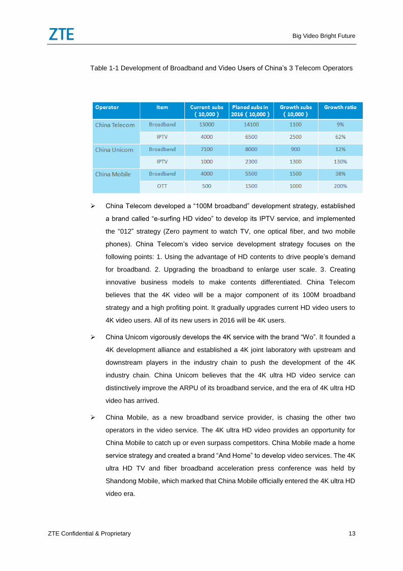
exceed 100 million with an annual growth rate up to 87%. Table 1-1 shows specific
statistics.
Big Video Bright Future
ZTE Confidential & Proprietary 13
Table 1-1 Development of Broadband and Video Users of China’s 3 Telecom Operators
China Telecom developed a “100M broadband” development strategy, established
a brand called “e-surfing HD video” to develop its IPTV service, and implemented
the “012” strategy (Zero payment to watch TV, one optical fiber, and two mobile
phones). China Telecom’s video service development strategy focuses on the
following points: 1. Using the advantage of HD contents to drive people’s demand
for broadband. 2. Upgrading the broadband to enlarge user scale. 3. Creating
innovative business models to make contents differentiated. China Telecom
believes that the 4K video will be a major component of its 100M broadband
strategy and a high profiting point. It gradually upgrades current HD video users to
4K video users. All of its new users in 2016 will be 4K users.
China Unicom vigorously develops the 4K service with the brand “Wo”. It founded a
4K development alliance and established a 4K joint laboratory with upstream and
downstream players in the industry chain to push the development of the 4K
industry chain. China Unicom believes that the 4K ultra HD video service can
distinctively improve the ARPU of its broadband service, and the era of 4K ultra HD
video has arrived.
China Mobile, as a new broadband service provider, is chasing the other two
operators in the video service. The 4K ultra HD video provides an opportunity for
China Mobile to catch up or even surpass competitors. China Mobile made a home
service strategy and created a brand “And Home” to develop video services. The 4K
ultra HD TV and fiber broadband acceleration press conference was held by
Shandong Mobile, which marked that China Mobile officially entered the 4K ultra HD
video era.
Big Video Bright Future
14 ZTE Confidential & Proprietary
China Radio and TV, as a traditional cable TV operator, has more than 200 million
video users. As telecom operators engage in the TV domain through the IPTV
service, China Radio and TV is faced with a big challenge. On one hand, it makes
use of its rich contents and provides more 4K ultra HD contents. On the other hand,
it actively improves network quality to meet 4K requirements. Based on its
traditional TV service, it enters the broadband field and becomes the fourth telecom
operator.
1.2.2 International Operators’ Big Video Strategy
Top telecom operators in Europe and America pay special attention to content expansion
and merge broadband or video service providers to boost video service development.
For example, Vodafone bought ACCOR (DSL 3 million lines), the second largest
broadband operator in Germany in 2009, bought KABEL (10 million lines of TV users),
the largest MSO (Multi-Service Operator) in Germany in 2013, bought ONO (5 million
lines), the largest MSO in Spain in 2014, and deployed FTTH in Portugal. The largest
MSO in France bought SRF to realize multi-screen convergence. AT&T bought
DIRECTV to provide all-round services including broadband, content, and satellite TV.
UPC, the largest MSO in Europe and the second largest MSO in the world bought the
largest MSO in UK, VRIGIN MEDIA. BT believes that the 4K video service is an
opportunity for them to really compete with the pay TV service. It strives to provide the
best experience of big video service such as 4K video by constructing
ultra-high-bandwidth network.
Korea SKT is a telecom operator that entered the video field earlier than others. Back in
2006, it provided the IPTV service. In 2012, it extended the IPTV live TV service to the
mobile network and provided the fixed-mobile video service. After 2014, it further
develops its ultra HD video service and deploys 4K service on the wired network and
mobile network to allow users to watch 4K live TV at any time anywhere. SKT develops
the video service as its basic service and makes coordinative plans to develop both the
video service and the network. It strives to improve competitive strength and attraction of
the video service to enlarge user scale and improve profitability.
Indonesia Telkom, as the largest telecom operator and network service provider in
Indonesia, provides the big video service with the brand IndiHome. It plans to develop 3
Big Video Bright Future
ZTE Confidential & Proprietary 15
million new video users in two years and 8 million users in five years. In the future,
Indonesia Telkom will provide more innovative services and products such as app store,
big data analysis, and next-generation STB to meet users’ all-round requirements facing
leisure, entertainment, and life for improving user experience. Following the topic of
“cooperative innovation, rich experience”, it also optimizes the value-added service
development model, track the latest activities and trend of the industry, and develop and
practice new services to rapidly provide new and attractive services for users and lead
the big video development in Asia Pacific and even the whole world.
1.3 Challenges Brought by the Big Video to Operators
According to Conviva’s user video report, 35% video users regard watching experience
as the primary factor when choosing the video service. 56% users feel unbearable when
the video is freezing and give up. For live programs, the watching duration of users not
encountering caching is 240% longer than the watching duration of users encountering
caching. Obviously, user video experience is a critical factor to the success of the video
service.
The video experience depends on the operator’s network. The big video service
including 4K, 8K, and VR/AR services requires a bandwidth increase by tens of times.
Specifically, the 4K video service requires three improvements. First, the 4K video
resolution is improved to 3840 * 2160, four times of the HD video resolution (1920 *
1080); Second, the video FPS is improved to 50/60 up from the HD video’s 25/30. The
ultimate-experience FPS could reach 100/120. Third, the color accuracy is improved.
The color encoding by each pixel is improved to 10bit or 12bit up from 8bit. It can even
reach 16 times higher than the original level. According to the different combination of
FPS and color levels, the 4K video could be Quasi 4K, Basic 4K, and Ultra 4K. Through
H.265 coding, the bit rate of the 4K video is 2-10 times higher than that of the HD video,
requiring a 22.5M-75M bandwidth. The 8K video requires higher bandwidth, about
90M-300M, four times the 4K video. The VR video requires even higher bandwidth up to
300M-1.2G, 4-16 times the 4K video.
According to Cisco’s forecast of global video traffic development among 2016-2020, the
mobile traffic will increase by 10 times, and the fixed network traffic by 4-5 times. The
video traffic will account for more than 75% of the Internet traffic. Developed regions will
Big Video Bright Future
16 ZTE Confidential & Proprietary
see an even faster video traffic growth. The mobile traffic will increase by 20 times, and
the fixed traffic by at least 10 times. The percentage of video traffic will reach 80%. The
huge demand for bandwidth and traffic brings significant challenges for operators in
terms of network bandwidth increase and capability improvement of network delay,
packet loss rate, QoS, QoE end-to-end monitoring and assurance. Operators need to
transform the traditional network architecture focusing on the HSI service and high
convergence ratio principle to the target network architecture that focuses on video
service and low convergence ratio principle.
1.4 ZTE Big Video Solution Helps Operators Embrace
the Big Future
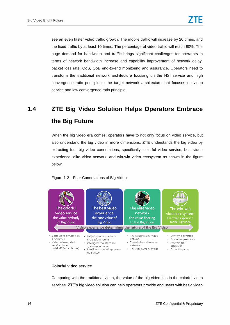
When the big video era comes, operators have to not only focus on video service, but
also understand the big video in more dimensions. ZTE understands the big video by
extracting four big video connotations, specifically, colorful video service, best video
experience, elite video network, and win-win video ecosystem as shown in the figure
below.
Figure 1-2 Four Connotations of Big Video
Colorful video service
Comparing with the traditional video, the value of the big video lies in the colorful video
services. ZTE’s big video solution can help operators provide end users with basic video
Big Video Bright Future
ZTE Confidential & Proprietary 17
service and value-added video services. The basic video service keeps developing to
higher definition, 4K, 8K, VR/AR, and even holographic video. Value-added video
services include video call, FMC, multi-screen interaction, gaming, online education and
smart home etc.
Best video experience
The best video experience is the core requirement of users when choosing the video
service. The best video experience must achieve the best in content experience,
operation experience, and watching experience. The V-QoE video experience evaluation
system proposed by ZTE scientifically evaluates video experience from these three
aspects. In addition, based on the V-QoE evaluation system, ZTE builds up a
fixed-mobile converged video service end-to-end O&M system to monitor users’ video
experience in real time, thorough and accurate way, quickly locate faults, and ensure
high-quality video service for customers as required.
Elite video network
The best video experience cannot be realized without an elite video network. To meet the
big video’s QoS and QoE requirements, the network bearing the big video service must
feature high bandwidth, low delay, low packet loss rate and fixed-mobile convergence,
and can meet the requirements of the future network SDN/NFV architecture and fully
realize flexible resource scheduling within the whole network. ZTE can provide
ultra-high-bandwidth, low-delay, and high-QoS elite wired video network, elite wireless
video network, and elite CDN solution to support the big video service to help operators
meet traffic challenges in the big video era, reconstruct networks and build up big video
networks.
Win-win video ecosystem
We cannot find any enterprise in the world that can satisfy all user requirements. To
provide one-stop services for users and go further in the big video field, operators have to
collaborate with partners in the industry chain, including content, ad, terminal, and
equipment providers to build a big video ecosystem. ZTE, with its rich experience and
position in the industry of the operator video field, maintains good relationships with
industry chain partners so that it can provide operators with one-stop video service
solutions and services and achieve win-win situation through the video ecosystem.
Big Video Bright Future
18 ZTE Confidential & Proprietary
Based on the four connotations of big video, ZTE always strives to help operators build
up best-experience FBB&MBB elite video networks, to build up an open video platform
integrating tremendous contents, colorful services, and third-party apps to form a win-win
big video ecosystem, and to realize smart operation and maintenance of video services
based on the video big data analysis system to improve O&M efficiency and profitability
and help operators to make a bright future.
2 Wired Network Solution with Best Video
Experience
2.1 Requirements of big video for wired network
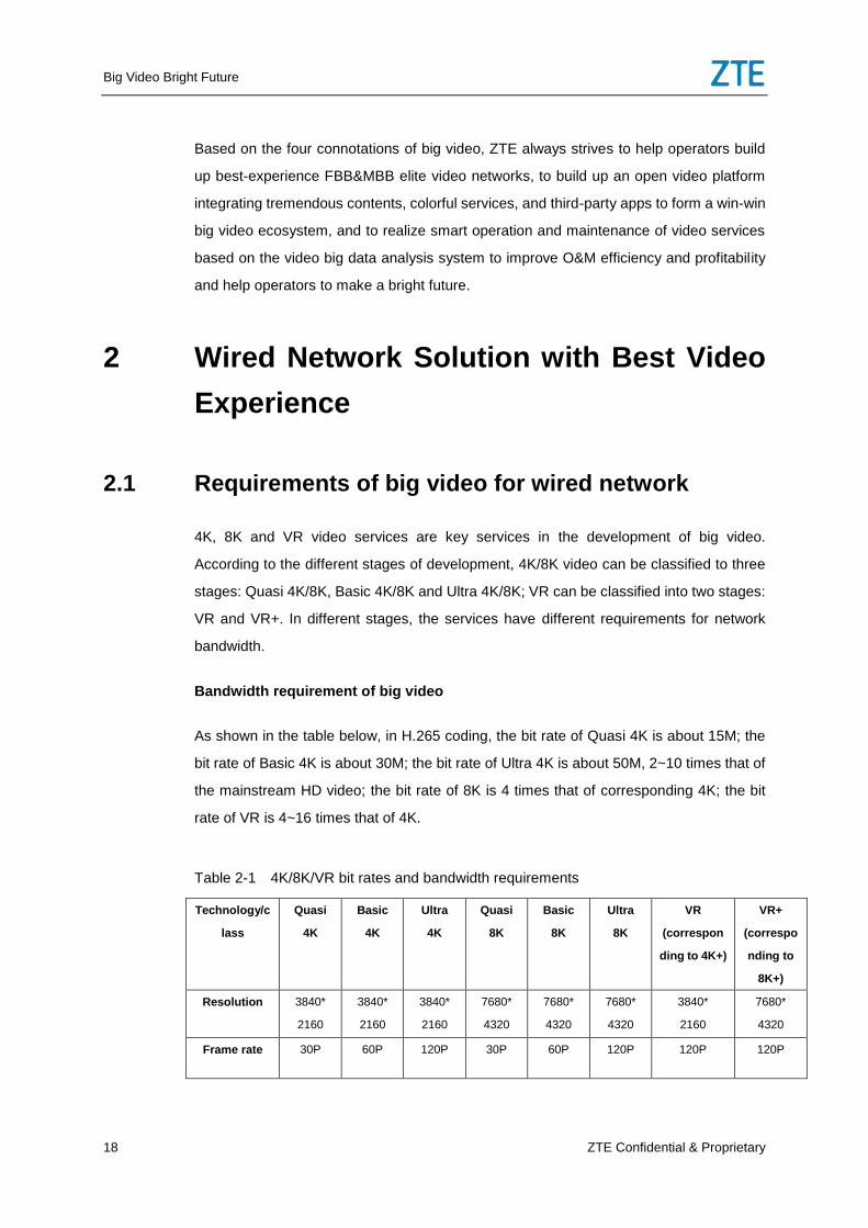
4K, 8K and VR video services are key services in the development of big video.
According to the different stages of development, 4K/8K video can be classified to three
stages: Quasi 4K/8K, Basic 4K/8K and Ultra 4K/8K; VR can be classified into two stages:
VR and VR+. In different stages, the services have different requirements for network
bandwidth.
Bandwidth requirement of big video
As shown in the table below, in H.265 coding, the bit rate of Quasi 4K is about 15M; the
bit rate of Basic 4K is about 30M; the bit rate of Ultra 4K is about 50M, 2~10 times that of
the mainstream HD video; the bit rate of 8K is 4 times that of corresponding 4K; the bit
rate of VR is 4~16 times that of 4K.
Table 2-1 4K/8K/VR bit rates and bandwidth requirements
Technology/c
lass
Quasi
4K
Basic
4K
Ultra
4K
Quasi
8K
Basic
8K
Ultra
8K
VR
(correspon
ding to 4K+)
VR+
(correspo
nding to
8K+)
Resolution 3840*
2160
3840*
2160
3840*
2160
7680*
4320
7680*
4320
7680*
4320
3840*
2160
7680*
4320
Frame rate 30P 60P 120P 30P 60P 120P 120P 120P
Big Video Bright Future
ZTE Confidential & Proprietary 19
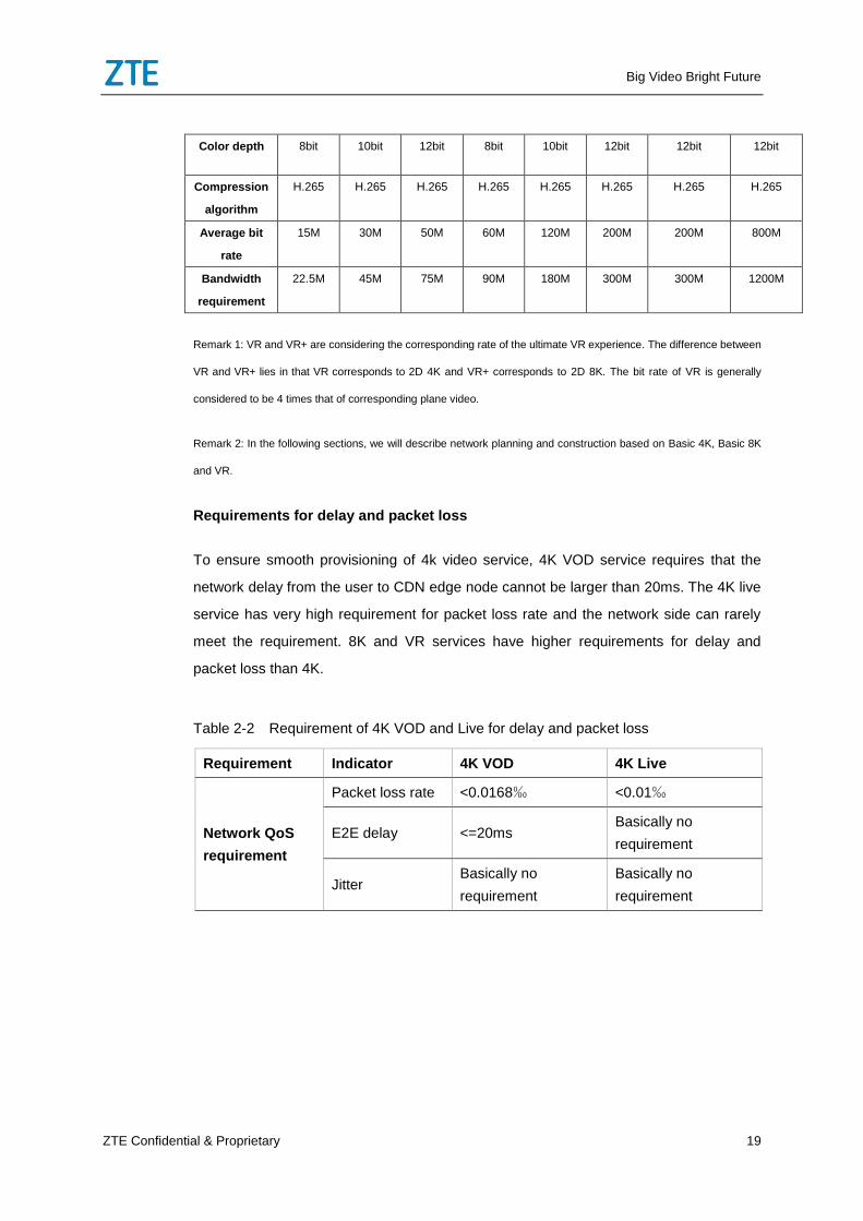
Color depth 8bit 10bit 12bit 8bit 10bit 12bit 12bit 12bit
Compression
algorithm
H.265 H.265 H.265 H.265 H.265 H.265 H.265 H.265
Average bit
rate
15M 30M 50M 60M 120M 200M 200M 800M
Bandwidth
requirement
22.5M 45M 75M 90M 180M 300M 300M 1200M
Remark 1: VR and VR+ are considering the corresponding rate of the ultimate VR experience. The difference between
VR and VR+ lies in that VR corresponds to 2D 4K and VR+ corresponds to 2D 8K. The bit rate of VR is generally
considered to be 4 times that of corresponding plane video.
Remark 2: In the following sections, we will describe network planning and construction based on Basic 4K, Basic 8K
and VR.
Requirements for delay and packet loss
To ensure smooth provisioning of 4k video service, 4K VOD service requires that the
network delay from the user to CDN edge node cannot be larger than 20ms. The 4K live
service has very high requirement for packet loss rate and the network side can rarely
meet the requirement. 8K and VR services have higher requirements for delay and
packet loss than 4K.
Table 2-2 Requirement of 4K VOD and Live for delay and packet loss
Requirement Indicator 4K VOD 4K Live
Network QoS
requirement
Packet loss rate <0.0168‰ <0.01‰
E2E delay <=20ms Basically no
requirement
Jitter Basically no
requirement
Basically no
requirement
Big Video Bright Future
20 ZTE Confidential & Proprietary
2.2 Problems of traditional wired network architecture
carrying big video services
Traditional network architecture supports HSI services featuring large bandwidth, low
concurrency and low requirement for delay. However, the big video service requires the
features of large bandwidth, high concurrency, low packet loss rate and low delay.
Traditional network architecture has the features of multiple network layers, multi-layer
aggregation and high convergence ratio. To meet the requirements of big video service
and offer better user experience, the problems existing in family, access and bearer
networks in traditional network architecture need be solved.
2.2.1 Problems in home-area network (HAN)
To bear big video service well, there are the following problems in HAN:
First, the HAN deployment problem: the Ethernet LAN (GE/10GE) can meet the
bandwidth requirements of big video in every stage. However, many families did not lay
the cat5 cables at the beginning and it is difficult to rewire the house.
With the increase in the use of mobile terminals in the family, the WiFi’s bandwidth will be
a bottleneck, and some other problems of WiFi will be more serious. The 802.11n adopts
2.4G band, which has much interference and so the signal is unstable. In 1*1 MIMO, the
bandwidth is only 60-70Mbps; and it needs to be upgraded to 2*2 MIMO (140M) or 3*3
(200M). Moreover, it is a big problem for WiFi signals to pierce through a wall. Therefore,
to better carry big video services like 4K, it is generally required to upgrade to 802.11ac
and enable 5G band to reduce interference and increase bandwidth. Meanwhile, some
other wired technologies must be used to connect the distributed APs to solve signal
coverage problem.
PLC/PLC (G.hn) is also a common technology used in HAN and the bandwidth can be up
to 400M. But,with the problems including much interference from electric appliances and
neighbors and unstable bandwidth, it cannot carry big video services stably.
Big Video Bright Future
ZTE Confidential & Proprietary 21
Cable G.hn can provide a bandwidth of 1Gbps; there is little interference and the
bandwidth is stable, so it is an ideal big video bearer technology for HAN besides
Ethernet. But it costs high and conflicts with CATV service.
Second, HAN wiring and device installation problem: for example, in the typical network
case of ONU+RG+PLC1+PLC2+AP+PAD/STB, the signals will pass through 5 devices
and 4 different technologies will be used. The wiring and installation are complicated and
will easily go wrong; many device, signal and link problems tend to occur, which will bring
long delay and high packet loss rate. How to simplify HAN wiring and improve its
reliability is a major problem.
Third, delay and jitter problem of HAN device processing: At present, WiFi AP and PLC
generally uses CPU for forwarding and the delay and jitter are about 5ms; the delay of
ONU and RG processing is hundreds of microseconds, less than 1ms. The long delay of
HAN will have much influence on VOD service (such as HLS) using TCP protocol.
Fourth, device processing performance problem: at present, the throughput of some
ONU and RG is only 100M-200Mbps.Obviously this will become a bottleneck with the
development of big video service and needs to be upgraded to Gbps platform.
Fifth, with the popularization of VR and AR services, HAN needs 10G bandwidth, and the
HAN’s delay, jitter, packet loss rate, and CPE’s performance problems will become even
more prominent.
2.2.2 Problems in access network
The access network has the following requirements to support big video service:
First, the access bandwidth to home must be enough for the big video. The deployed
GPON/EPON FTTC+xDSL and GPON/EPON FTTB+LAN networks cannot meet the
requirements of 4K service. The GPON FTTH network cannot meet the requirements of
8K and VR.
Second, OLT uplink bandwidth broadening problem: With the development of video
service, it’s necessary to increase OLT uplink bandwidth. In some operator’s aggregation
network, there are no OTNs. So, there might be the issue of insufficient fiber resource
when increasing OLT uplink bandwidth.
Big Video Bright Future
22 ZTE Confidential & Proprietary
Third, the current FTTX network has long delay problem; especially the
FTTB+xDSL/FTTdp+G.fast networks, which delay can be up to 5ms-10ms. The long
delay may do some harm to big video bearing based on TCP.
Fourth, the existing FTTX network can not monitor the QoS of big video service very well
and can not locate the fault quickly.
Lastly, as the key device in FTTX network, the OLT needs sufficient buffer and QoS
capability for big video. However, some previously deployed OLTs in the existing network
don’t support these features.
2.2.3 Problems in metro network and backbone network
As the aggregation network above the access network, traditional metro networks and
backbone networks are facing a series of challenges brought by surging traffic:
Video service multicast replication points and CDN nodes are placed high; metro
network bandwidth is severely wasted and service experience is poor
The operator’s network still has some PPPoE users. The service edge control point
and replication point are both at BNG. The path from the replication point to the user
access network is too long, and there are N times traffic replications, which
consume much metro network bandwidth.
IPTV and CDN coverage is different in different areas of operators. Most CDN
nodes are highly placed. This high placement design makes users pass several
nodes to get resource and brings metro network bandwidth waste.
Multiple factors cause poor video experience of the existing network
In the high placement network design, there are many network node hops, which
causes E2E service path too long, prolongs E2E service delay and increase the
probability of network congestion. Once congestion occurs, the priority scheduling
of QoS still cannot meet the user’s requirement for delay, which will lower user
experience.
After big video services like the 4K video are introduced, the traffic is increasing
rapidly. Current metro networks are mainly 10G and under 10G. As the service
bearer channel, they are gradually changing from “lightly loaded” to “heavily loaded”
Big Video Bright Future
ZTE Confidential & Proprietary 23
and network congestion risks are increasing.
There is no complete evaluation system for video quality, so the operators cannot
give correct analysis and perform network path protection, which causes poor video
experience.
The expansion cost is huge and maintenance is difficult
With video traffic increase, E2E network devices need expansion. The lower the
convergence ratio is, the larger the E2E device expansion scale is. How to implement flat
networks and convenient maintenance is an important threshold to cross. Simply
canceling the aggregation layer switch network to lower the BNG devices to the
aggregation position will simplify one network layer and reduce some delay, but it will
cause a series of problems: BNG maintenance nodes will increase substantially,
equipment utilization rate will be reduced, human resource and material investment will
rise sharply. For some areas without enough maintenance capability, it will increase the
maintenance difficulty. The SDN/NFV technology can avoid the above problems to
implement convenient service provisioning and management, but how to achieve smooth
evolution in the existing architecture, how to reuse and upgrade existing aggregation
switches and how to provide economical and effective metro & backbone bearer
networks are also urgent problems to be solved.
2.3 Target architecture and evolution strategy of wired
network of optimal video experience
2.3.1 Target architecture of wired network of optimal video experience
As stated above, traditional network architecture can hardly meet the optimal experience
requirement of big video, so the bearer network must be changed. The future bearer
network architecture that can satisfy big video experience should have the following
three characteristics: high throughput, resource pooling and intelligent OAM.
High throughput
Big Video Bright Future
24 ZTE Confidential & Proprietary
High throughput is the basis for optimal experience of big video. High-bandwidth
transmission pipes are to be provided by adjusting network architecture to ease the
network load and avoid network congestion. Meanwhile, dedicated pipes for big video
services are to be constructed and reasonable CDN sites are to be deployed to perform
service distribution nearby and meet the requirement of big video for low delay and low
packet loss rate. The network should meet the following requirements:
E2E bandwidth >=1000M/screen; HAN >=1000M seamless coverage, to meet the
requirement of 4K video in its mature stage.
Meet the delay requirement of RTT≦20ms;
Meet the packet loss rate (PLR 10-5
) requirement.
Resource pooling
The introduction of SDN technology and implementation of NFV can effectively integrate
network resource, optimize network architecture, and provide more convenient service
deployment modes to substantially reduce the operator’s service management
complexity and costs. The future big video network will feature reconstruction and
cloudization. Key network parts are to be virtualized and DC-centered control and
management networks are to be used to provide optimized resource and service.
Key components of virtualization: vBNG, vCDN, vOLT and virtual switches.
Optimize network architecture to make the network flatter.
Build distributed DCs to perform service provisioning and OAM nearby.
Intelligent OAM
Intelligent OAM is the guarantee for optimal experience of big video. Big video network
needs E2E experience guarantee. However, in the early metro network development,
video service as a basic service cannot measure user experience and cannot locate the
problems. The OAM problem has become a prominent obstacle for video service
development. The future target network architecture should support the following OAM
functions:
Terminal user experience can be evaluated. An overall video service evaluation
system is to be constructed to reflect the video service experience of customers and
give real-time feedbacks.
Big Video Bright Future
ZTE Confidential & Proprietary 25
Implement cross-border location and improve OAM capability. The network analysis
system and video quality analysis system cooperate in troubleshooting according to
video service monitoring to implement network fault path sourcing and fast fault
location function.
2.3.2 Evolution strategy of wired network of optimal video experience
The development of big video is a gradual process, which requires not only considering
both the basic situations and subsequent planning of operator networks but also video
user scale development and factors related to the whole big video industrial chain, such
as latest technological standards and terminal support. The networks can be constructed
according to the following three stages.
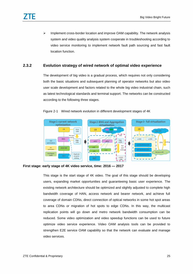
Figure 2-1 Wired network evolution in different development stages of 4K
First stage: early stage of 4K video service, time: 2016 — 2017
This stage is the start stage of 4K video. The goal of this stage should be developing
users, expanding market opportunities and guaranteeing basic user experience. The
existing network architecture should be optimized and slightly adjusted to complete high
bandwidth coverage of HAN, access network and bearer network, and achieve full
coverage of domain CDNs, direct connection of optical networks in some hot spot areas
to area CDNs or migration of hot spots to edge CDNs. In this way, the multicast
replication points will go down and metro network bandwidth consumption can be
reduced. Some video optimization and video speedup functions can be used to future
optimize video service experience. Video OAM analysis tools can be provided to
strengthen E2E service OAM capability so that the network can evaluate and manage
video services.
Big Video Bright Future
26 ZTE Confidential & Proprietary
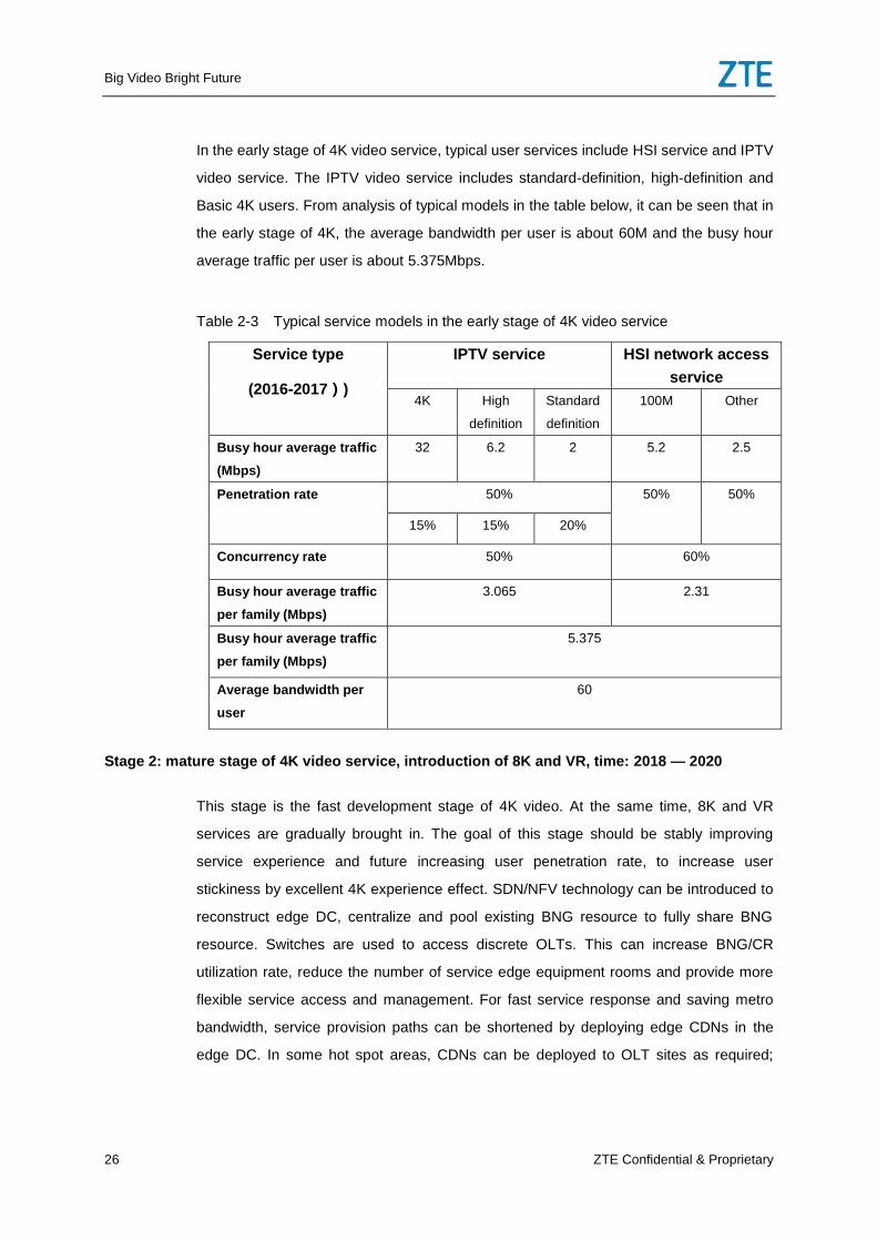
In the early stage of 4K video service, typical user services include HSI service and IPTV
video service. The IPTV video service includes standard-definition, high-definition and
Basic 4K users. From analysis of typical models in the table below, it can be seen that in
the early stage of 4K, the average bandwidth per user is about 60M and the busy hour
average traffic per user is about 5.375Mbps.
Table 2-3 Typical service models in the early stage of 4K video service
Service type
(2016-2017))
IPTV service HSI network access
service
4K High
definition
Standard
definition
100M
Other
Busy hour average traffic
(Mbps)
32 6.2 2 5.2 2.5
Penetration rate 50% 50% 50%
15% 15% 20%
Concurrency rate 50% 60%
Busy hour average traffic
per family (Mbps)
3.065 2.31
Busy hour average traffic
per family (Mbps)
5.375
Average bandwidth per
user
60
Stage 2: mature stage of 4K video service, introduction of 8K and VR, time: 2018 — 2020
This stage is the fast development stage of 4K video. At the same time, 8K and VR
services are gradually brought in. The goal of this stage should be stably improving
service experience and future increasing user penetration rate, to increase user
stickiness by excellent 4K experience effect. SDN/NFV technology can be introduced to
reconstruct edge DC, centralize and pool existing BNG resource to fully share BNG
resource. Switches are used to access discrete OLTs. This can increase BNG/CR
utilization rate, reduce the number of service edge equipment rooms and provide more
flexible service access and management. For fast service response and saving metro
bandwidth, service provision paths can be shortened by deploying edge CDNs in the
edge DC. In some hot spot areas, CDNs can be deployed to OLT sites as required;
Big Video Bright Future
ZTE Confidential & Proprietary 27
independent CDN equipment or OLT integrated with mini CDN is used to complete
hot-spot video head storage to achieve shortest path access.
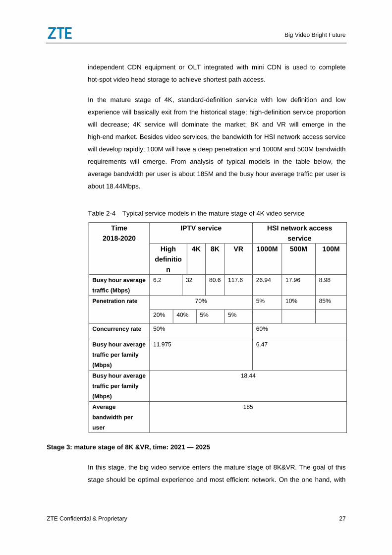
In the mature stage of 4K, standard-definition service with low definition and low
experience will basically exit from the historical stage; high-definition service proportion
will decrease; 4K service will dominate the market; 8K and VR will emerge in the
high-end market. Besides video services, the bandwidth for HSI network access service
will develop rapidly; 100M will have a deep penetration and 1000M and 500M bandwidth
requirements will emerge. From analysis of typical models in the table below, the
average bandwidth per user is about 185M and the busy hour average traffic per user is
about 18.44Mbps.
Table 2-4 Typical service models in the mature stage of 4K video service
Time
2018-2020
IPTV service HSI network access
service
High
definitio
n
4K 8K VR 1000M 500M 100M
Busy hour average
traffic (Mbps)
6.2 32 80.6 117.6 26.94 17.96 8.98
Penetration rate 70% 5% 10% 85%
20% 40% 5% 5%
Concurrency rate 50% 60%
Busy hour average
traffic per family
(Mbps)
11.975 6.47
Busy hour average
traffic per family
(Mbps)
18.44
Average
bandwidth per
user
185
Stage 3: mature stage of 8K &VR, time: 2021 — 2025
In this stage, the big video service enters the mature stage of 8K&VR. The goal of this
stage should be optimal experience and most efficient network. On the one hand, with
Big Video Bright Future
28 ZTE Confidential & Proprietary
constant expansion of user scale and increase of video traffic, network architecture can
be future optimized: converting OLT offices to ADC (Access DC); upgrading OLT to
support IPoE and become the gateway for big video services; transparently transmitting
Non big video services to edge DCs; lowering OTN to ADC, connected to CR and edge
DC via OTN, to reduce network layers, achieve flatter network architecture and reduce
network construction cost. On the other hand, key network parts can be future virtualized,
to achieve vBNG, vOLT and vCDN functions. At the same time, ADC and distributed
cloud (DC) architecture are to be promoted to achieve nearby control and management.
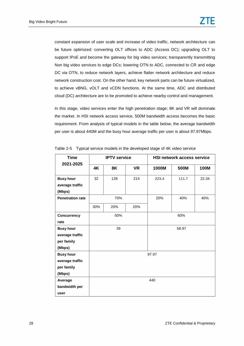
In this stage, video services enter the high penetration stage; 8K and VR will dominate
the market. In HSI network access service, 500M bandwidth access becomes the basic
requirement. From analysis of typical models in the table below, the average bandwidth
per user is about 440M and the busy hour average traffic per user is about 97.97Mbps.
Table 2-5 Typical service models in the developed stage of 4K video service
Time
2021-2025
IPTV service HSI network access service
4K 8K VR 1000M 500M 100M
Busy hour
average traffic
(Mbps)
32 128 214 223.4 111.7 22.34
Penetration rate 70% 20% 40% 40%
30% 20% 20%
Concurrency
rate
50% 60%
Busy hour
average traffic
per family
(Mbps)
39 58.97
Busy hour
average traffic
per family
(Mbps)
97.97
Average
bandwidth per
user
440
Big Video Bright Future
ZTE Confidential & Proprietary 29
It is required that the upgrade and reconstruction of HAN, access network, metro and
backbone network should be performed stage by stage according to the three stages of
big video service development.
2.3.3 Home Area Network
2.3.3.1 Stage 1: Simplifying network and improving WiFi coverage
Facilitating integrated CPE device to simplify HAN
In HAN, it is better to use integrated HGU or HGU with built-in STB as the access
gateway. Compared with the multi-level architecture, integrated equipment can
simplify wiring and installation, reduce delay and packet loss, avoid connection error,
and improve customers’ experience of video service.
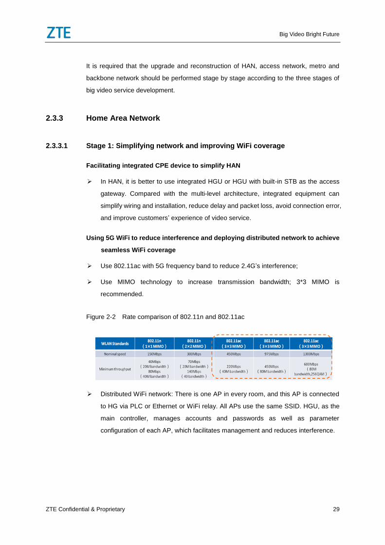
Using 5G WiFi to reduce interference and deploying distributed network to achieve
seamless WiFi coverage
Use 802.11ac with 5G frequency band to reduce 2.4G’s interference;
Use MIMO technology to increase transmission bandwidth; 3*3 MIMO is
recommended.
Figure 2-2 Rate comparison of 802.11n and 802.11ac
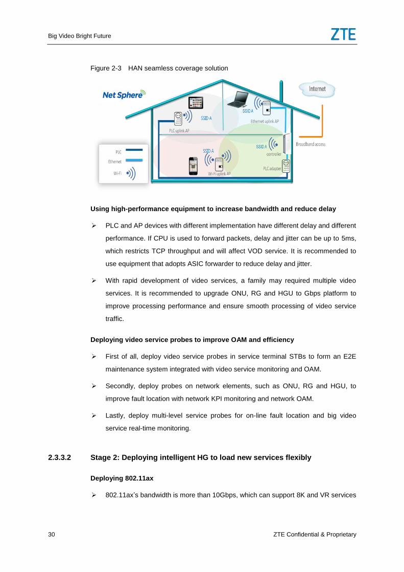
Distributed WiFi network: There is one AP in every room, and this AP is connected
to HG via PLC or Ethernet or WiFi relay. All APs use the same SSID. HGU, as the
main controller, manages accounts and passwords as well as parameter
configuration of each AP, which facilitates management and reduces interference.
Big Video Bright Future
30 ZTE Confidential & Proprietary
Figure 2-3 HAN seamless coverage solution
Using high-performance equipment to increase bandwidth and reduce delay
PLC and AP devices with different implementation have different delay and different
performance. If CPU is used to forward packets, delay and jitter can be up to 5ms,
which restricts TCP throughput and will affect VOD service. It is recommended to
use equipment that adopts ASIC forwarder to reduce delay and jitter.
With rapid development of video services, a family may required multiple video
services. It is recommended to upgrade ONU, RG and HGU to Gbps platform to
improve processing performance and ensure smooth processing of video service
traffic.
Deploying video service probes to improve OAM and efficiency
First of all, deploy video service probes in service terminal STBs to form an E2E
maintenance system integrated with video service monitoring and OAM.
Secondly, deploy probes on network elements, such as ONU, RG and HGU, to
improve fault location with network KPI monitoring and network OAM.
Lastly, deploy multi-level service probes for on-line fault location and big video
service real-time monitoring.
2.3.3.2 Stage 2: Deploying intelligent HG to load new services flexibly
Deploying 802.11ax
802.11ax’s bandwidth is more than 10Gbps, which can support 8K and VR services
Big Video Bright Future
ZTE Confidential & Proprietary 31
easily.
Using intelligent HG to deploy new services flexibly
Use intelligent HG open platform to load new services flexibly;
The HG is integrated with CDN function to implement Home-CDN, which facilitates
family video resource sharing and saves network bandwidth.
2.3.3.3 Stage 3: Deploying NFV RG
NFV RG
After CO reconstruction, the NFV RG--vCPE can be deployed for rapid service
deployment and service scaling.
2.3.4 Access network
To bear big video services well, the access network must be adjusted, reconstructed and
upgraded constantly. The primary goal is to meet the bandwidth requirement of big video
services. The secondary goal is to adjust the function distribution of different devices to
save bandwidth, reduce delay and packet loss and improve service throughput. The
other goals include protecting the previous investment and network smooth evolution.
2.3.4.1 Stage 1: Upgrading and adjusting the network to meet bandwidth
requirement
Reasonably upgrading and adjusting FTTX network to ensure bandwidth
The bandwidths to home are requested to be 100M, 300M and 1000M in different
stages. GPON FTTH 1:64 optical split ratio can basically meet the requirement of
early-stage 100M to home, but cannot meet the requirement of mature-stage 300M
to home. It is recommended to reduce the optical split ratio or upgrade to 10G xPON
FTTH. GPON/EPON FTTB cannot meet the requirement of early-stage 100M to
home, and is recommended to upgrade to XG-PON/10G EPON.
For DSL network, the factors affecting the DSL bandwidth mainly include DSL
technology, quality of copper wire, subscriber loop length and physical environment.
DSL technologies supporting 4K services and their access distance ranges are:
Big Video Bright Future
32 ZTE Confidential & Proprietary
VD2 Vectoring (100M@500m), VD2 35B Vectoring (300M@300m) and G.fast
(1G@50m). As the actual performance of copper is largely affected by environment
factors, it is recommended to configure a DSL line diagnosis system for the copper
network to determine whether it can provide 4K services and optional service suites
according to the performance evaluation result of the subscriber cable. When the
subscriber cable performance is not good enough, consider DSL optimization (for
example, enabling retransmission and block interleave functions), or deploy faster
DSL technology, or evolve from FTTC/FTTB to FTTdp.
Increasing OLT uplink bandwidth to ensure lightly loaded network operation
With the development of big video services, OLT uplink bandwidth is required to be
increased from N*GE to N*10GE, even to N*100GE.When the aggregation network
is deployed with OTN, OTN can be used to increase uplink bandwidth flexibly on
demand. In this case, it is generally suggested that the uplink bandwidth should be
upgraded to 10GE when the uplink traffic is larger than 7Gbps, or 100GE when the
uplink traffic is larger than 70Gbps. When the aggregation network is not deployed
with OTN, the uplink fiber resource is generally limited. In this case, it is generally
suggested that the uplink bandwidth should be upgraded to 10GE when the uplink
traffic is larger than 3Gbps, or 100GE when the uplink traffic is larger than 30Gbps.
Monitor the peak traffic on each uplink port regularly or in real time. When the peak
traffic reaches 70% of the port bandwidth, it is recommended to add new uplink port
to ensure lightly loaded network operation.
Using IPoE access mode and independent channels for operators’ self-operated
video services to guarantee service’s quality
Carry HSI services and video services by different L2/L3 networks to reduce
resource conflicts and ensure video services quality.
Operators’ proprietary big video services are recommended to be accessed using
IPoE, and multicast replication points can be moved to OLT to save network
bandwidth.
Implementing service detection on OLT
Implement video service detection on OLT after STB, RG and ONU for full path
monitoring of video quality and fast fault location.
Big Video Bright Future
ZTE Confidential & Proprietary 33
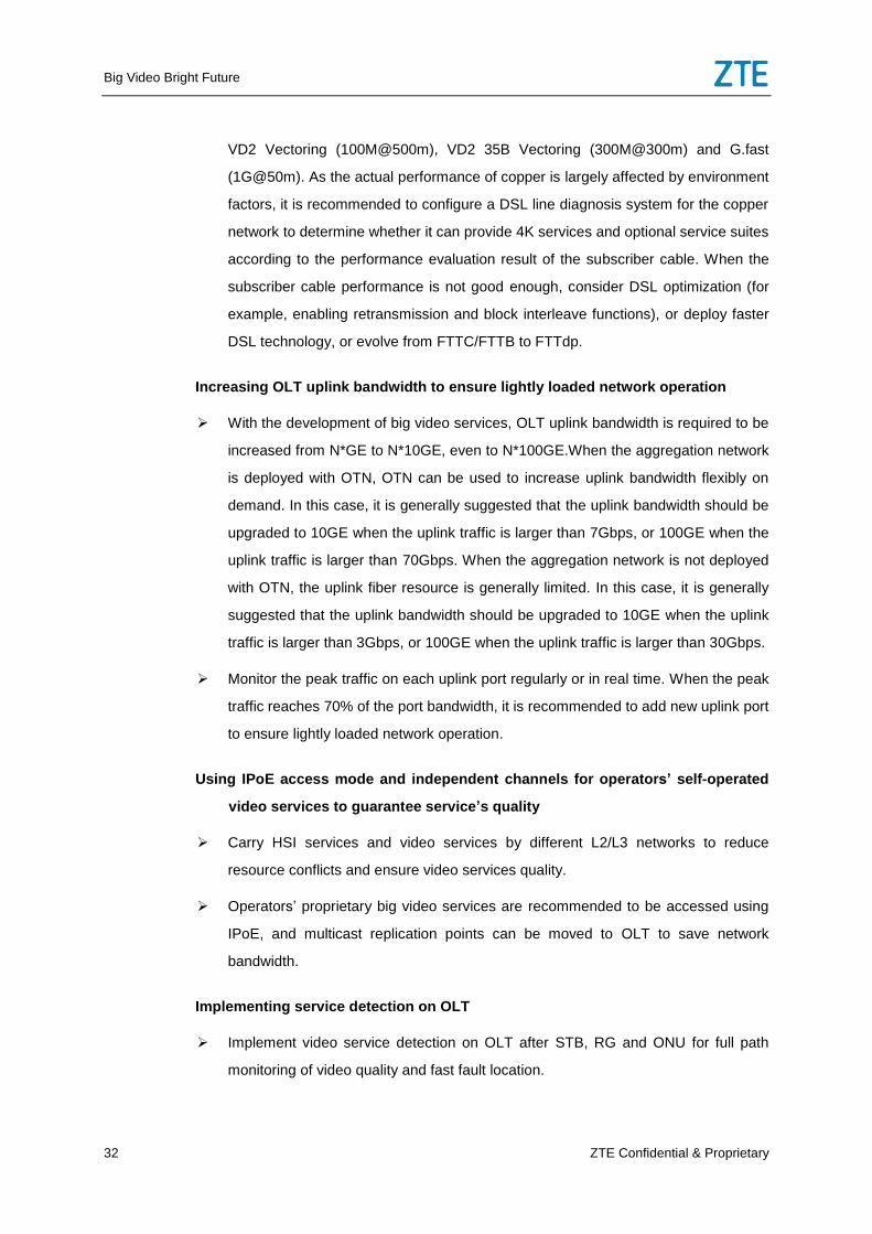
OLT should assign adequate buffer to reduce burst packet loss
The OLT main control card and PON line card should have enough buffers to
reduce packet loss caused by burst traffic of big video services. Distributed buffer
solution enables OLT’s buffer processing capability to increase with user growth.
Figure 2-4 Distributed buffer solution of OLT
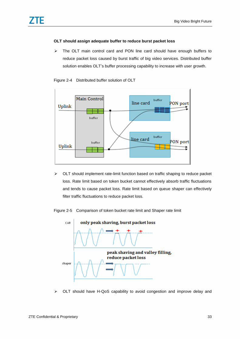
OLT should implement rate-limit function based on traffic shaping to reduce packet
loss. Rate limit based on token bucket cannot effectively absorb traffic fluctuations
and tends to cause packet loss. Rate limit based on queue shaper can effectively
filter traffic fluctuations to reduce packet loss.
Figure 2-5 Comparison of token bucket rate limit and Shaper rate limit
OLT should have H-QoS capability to avoid congestion and improve delay and
Big Video Bright Future
34 ZTE Confidential & Proprietary
packet loss. The downlink pipes of OLT are for per user per service, featuring large
quantity and small bandwidth. The uplink pipes correspond to every service,
featuring small quantity and large bandwidth. When the downlink traffic goes from
wide pipes to thin pipes, congestions may easily occur, which will cause packet loss
and delay and make big video service quality poorer. Therefore, OLT should have
queue scheduling and management capability per user per service to isolate traffic
per user per service to avoid mutual conflicts and influence between users and
services.
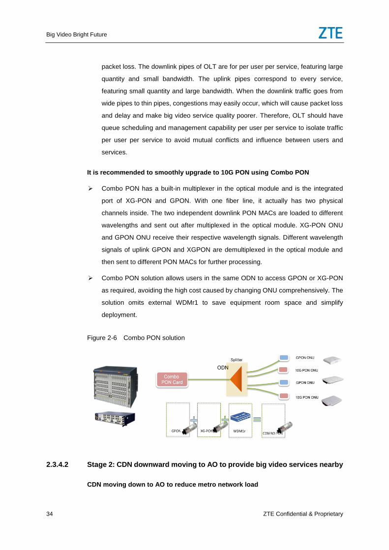
It is recommended to smoothly upgrade to 10G PON using Combo PON
Combo PON has a built-in multiplexer in the optical module and is the integrated
port of XG-PON and GPON. With one fiber line, it actually has two physical
channels inside. The two independent downlink PON MACs are loaded to different
wavelengths and sent out after multiplexed in the optical module. XG-PON ONU
and GPON ONU receive their respective wavelength signals. Different wavelength
signals of uplink GPON and XGPON are demultiplexed in the optical module and
then sent to different PON MACs for further processing.
Combo PON solution allows users in the same ODN to access GPON or XG-PON
as required, avoiding the high cost caused by changing ONU comprehensively. The
solution omits external WDMr1 to save equipment room space and simplify
deployment.
Figure 2-6 Combo PON solution
2.3.4.2 Stage 2: CDN downward moving to AO to provide big video services nearby
CDN moving down to AO to reduce metro network load
Big Video Bright Future
ZTE Confidential & Proprietary 35
When the uplink fiber resource of OLT is insufficient and it is difficult to redeploy it,
CDN can move down from metro edge (BNG) to AO to further reduce aggregation
layer load and BNG load.
CDN in AO can provide services nearby and improve video service experience
quality.
Deploying OTN in aggregation network to meet the continuous growth of access
network uplink traffic
Deploying OTN at the aggregation layer can effectively solve the uplink bandwidth
problem of access network while keeping stable network architecture.
When OTN moves down to AO, OLT can be directly connected with BNG via OTN,
which reduces network layers and improves delay and packet loss.
OLTs in some hot spot areas have L3 and BNG functions
OLT supports L3 function, which makes it easier for CDN to move down.
OLT supports BNG function, which simplify access control and avoids performance
bottlenecks.
Deploying video service optimization features on OLT
OLT supports FCC and ARQ, which improves live video service experience.
OLT supports TCP optimization function, which improves VOD service experience.
2.3.4.3 Stage 3: Deploying 100G PON and reconstructing AO as remote-DC
Deploying 100G PON
With further development of video service, 8K and VR services require
higher-speed access technologies. 25G PON and 100G PON can be deployed in
this stage.
DC-based AO
With the development of DC-based CO, AO can also be restructured as DC. SDN
and NFV technologies are introduced to AO; various big video services can be
flexibly and economically deployed.
Big Video Bright Future
36 ZTE Confidential & Proprietary
2.3.5 Metro & backbone network reconstruction
The three development stages of big video have different requirements for metro &
backbone networks. Metro & backbone network reconstruction can be performed by
stages.
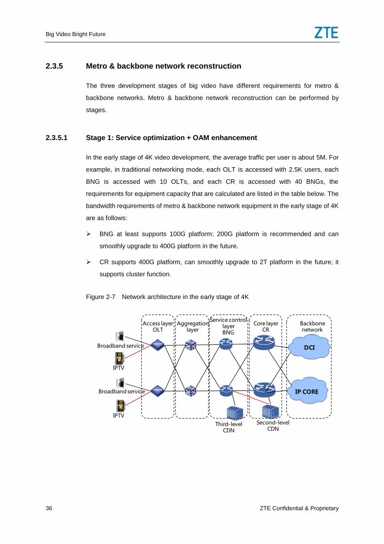
2.3.5.1 Stage 1: Service optimization + OAM enhancement
In the early stage of 4K video development, the average traffic per user is about 5M. For
example, in traditional networking mode, each OLT is accessed with 2.5K users, each
BNG is accessed with 10 OLTs, and each CR is accessed with 40 BNGs, the
requirements for equipment capacity that are calculated are listed in the table below. The
bandwidth requirements of metro & backbone network equipment in the early stage of 4K
are as follows:
BNG at least supports 100G platform; 200G platform is recommended and can
smoothly upgrade to 400G platform in the future.
CR supports 400G platform, can smoothly upgrade to 2T platform in the future; it
supports cluster function.
Figure 2-7 Network architecture in the early stage of 4K
Core layer CR
Service control layerBNG
Aggregation layer
Access layer OLT
Backbone network
Broadband service
IPTV
Broadband service
Second-level CDN
Third-level CDN
IP CORE
DCI
IPTV
Big Video Bright Future
ZTE Confidential & Proprietary 37
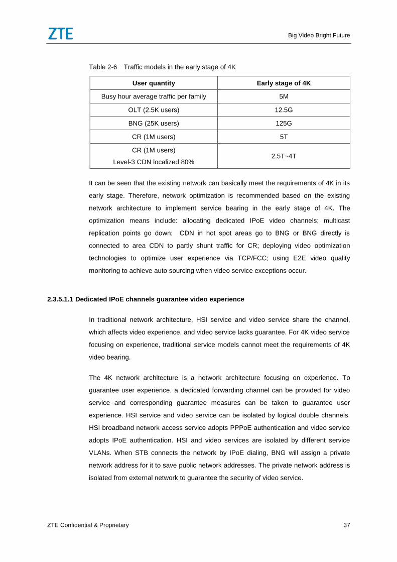
Table 2-6 Traffic models in the early stage of 4K
User quantity Early stage of 4K
Busy hour average traffic per family 5M
OLT (2.5K users) 12.5G
BNG (25K users) 125G
CR (1M users) 5T
CR (1M users)
Level-3 CDN localized 80% 2.5T~4T
It can be seen that the existing network can basically meet the requirements of 4K in its
early stage. Therefore, network optimization is recommended based on the existing
network architecture to implement service bearing in the early stage of 4K. The
optimization means include: allocating dedicated IPoE video channels; multicast
replication points go down; CDN in hot spot areas go to BNG or BNG directly is
connected to area CDN to partly shunt traffic for CR; deploying video optimization
technologies to optimize user experience via TCP/FCC; using E2E video quality
monitoring to achieve auto sourcing when video service exceptions occur.
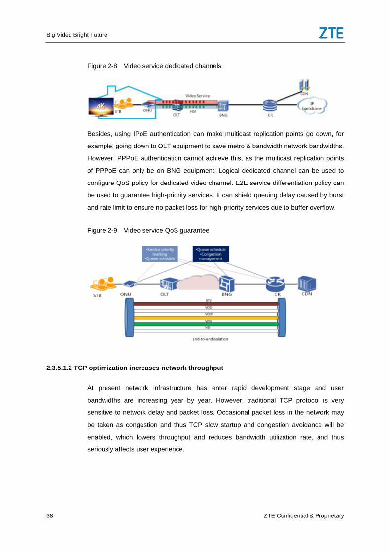
2.3.5.1.1 Dedicated IPoE channels guarantee video experience
In traditional network architecture, HSI service and video service share the channel,
which affects video experience, and video service lacks guarantee. For 4K video service
focusing on experience, traditional service models cannot meet the requirements of 4K
video bearing.
The 4K network architecture is a network architecture focusing on experience. To
guarantee user experience, a dedicated forwarding channel can be provided for video
service and corresponding guarantee measures can be taken to guarantee user
experience. HSI service and video service can be isolated by logical double channels.
HSI broadband network access service adopts PPPoE authentication and video service
adopts IPoE authentication. HSI and video services are isolated by different service
VLANs. When STB connects the network by IPoE dialing, BNG will assign a private
network address for it to save public network addresses. The private network address is
isolated from external network to guarantee the security of video service.
Big Video Bright Future
38 ZTE Confidential & Proprietary
Figure 2-8 Video service dedicated channels
Besides, using IPoE authentication can make multicast replication points go down, for
example, going down to OLT equipment to save metro & bandwidth network bandwidths.
However, PPPoE authentication cannot achieve this, as the multicast replication points
of PPPoE can only be on BNG equipment. Logical dedicated channel can be used to
configure QoS policy for dedicated video channel. E2E service differentiation policy can
be used to guarantee high-priority services. It can shield queuing delay caused by burst
and rate limit to ensure no packet loss for high-priority services due to buffer overflow.
Figure 2-9 Video service QoS guarantee
2.3.5.1.2 TCP optimization increases network throughput
At present network infrastructure has enter rapid development stage and user
bandwidths are increasing year by year. However, traditional TCP protocol is very
sensitive to network delay and packet loss. Occasional packet loss in the network may
be taken as congestion and thus TCP slow startup and congestion avoidance will be
enabled, which lowers throughput and reduces bandwidth utilization rate, and thus
seriously affects user experience.
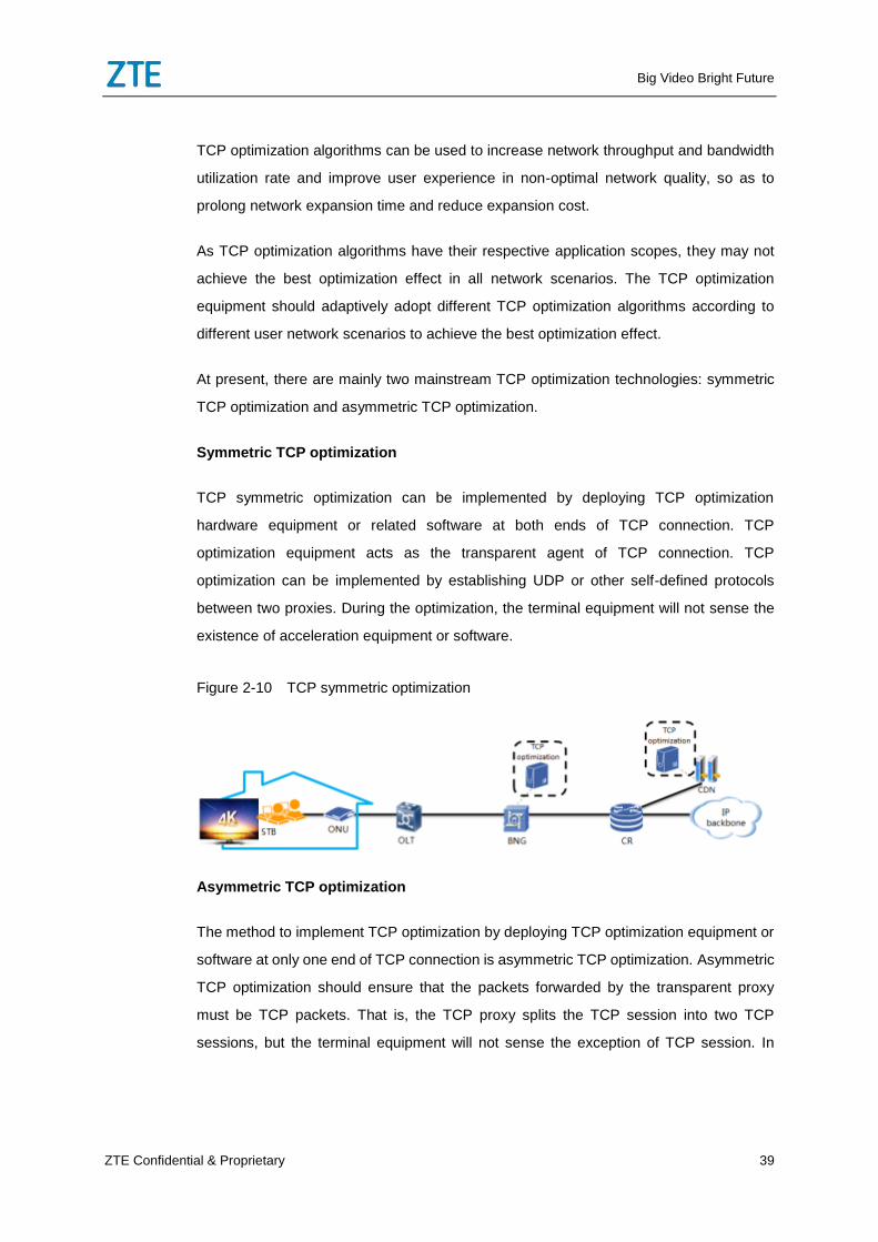
Big Video Bright Future
ZTE Confidential & Proprietary 39
TCP optimization algorithms can be used to increase network throughput and bandwidth
utilization rate and improve user experience in non-optimal network quality, so as to
prolong network expansion time and reduce expansion cost.
As TCP optimization algorithms have their respective application scopes, they may not
achieve the best optimization effect in all network scenarios. The TCP optimization
equipment should adaptively adopt different TCP optimization algorithms according to
different user network scenarios to achieve the best optimization effect.
At present, there are mainly two mainstream TCP optimization technologies: symmetric
TCP optimization and asymmetric TCP optimization.
Symmetric TCP optimization
TCP symmetric optimization can be implemented by deploying TCP optimization
hardware equipment or related software at both ends of TCP connection. TCP
optimization equipment acts as the transparent agent of TCP connection. TCP
optimization can be implemented by establishing UDP or other self-defined protocols
between two proxies. During the optimization, the terminal equipment will not sense the
existence of acceleration equipment or software.
Figure 2-10 TCP symmetric optimization
Asymmetric TCP optimization
The method to implement TCP optimization by deploying TCP optimization equipment or
software at only one end of TCP connection is asymmetric TCP optimization. Asymmetric
TCP optimization should ensure that the packets forwarded by the transparent proxy
must be TCP packets. That is, the TCP proxy splits the TCP session into two TCP
sessions, but the terminal equipment will not sense the exception of TCP session. In
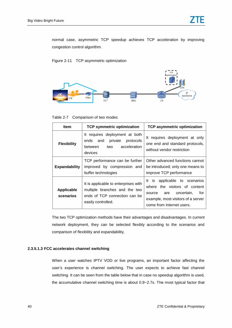
Big Video Bright Future
40 ZTE Confidential & Proprietary
normal case, asymmetric TCP speedup achieves TCP acceleration by improving
congestion control algorithm.
Figure 2-11 TCP asymmetric optimization
Table 2-7 Comparison of two modes
Item TCP symmetric optimization TCP asymmetric optimization
Flexibility
It requires deployment at both
ends and private protocols
between two acceleration
devices
It requires deployment at only
one end and standard protocols,
without vendor restriction
Expandability
TCP performance can be further
improved by compression and
buffer technologies
Other advanced functions cannot
be introduced; only one means to
improve TCP performance
Applicable
scenarios
It is applicable to enterprises with
multiple branches and the two
ends of TCP connection can be
easily controlled.
It is applicable to scenarios
where the visitors of content
source are uncertain, for
example, most visitors of a server
come from Internet users.
The two TCP optimization methods have their advantages and disadvantages. In current
network deployment, they can be selected flexibly according to the scenarios and
comparison of flexibility and expandability.
2.3.5.1.3 FCC accelerates channel switching
When a user watches IPTV VOD or live programs, an important factor affecting the
user’s experience is channel switching. The user expects to achieve fast channel
switching. It can be seen from the table below that in case no speedup algorithm is used,
the accumulative channel switching time is about 0.9~2.7s. The most typical factor that
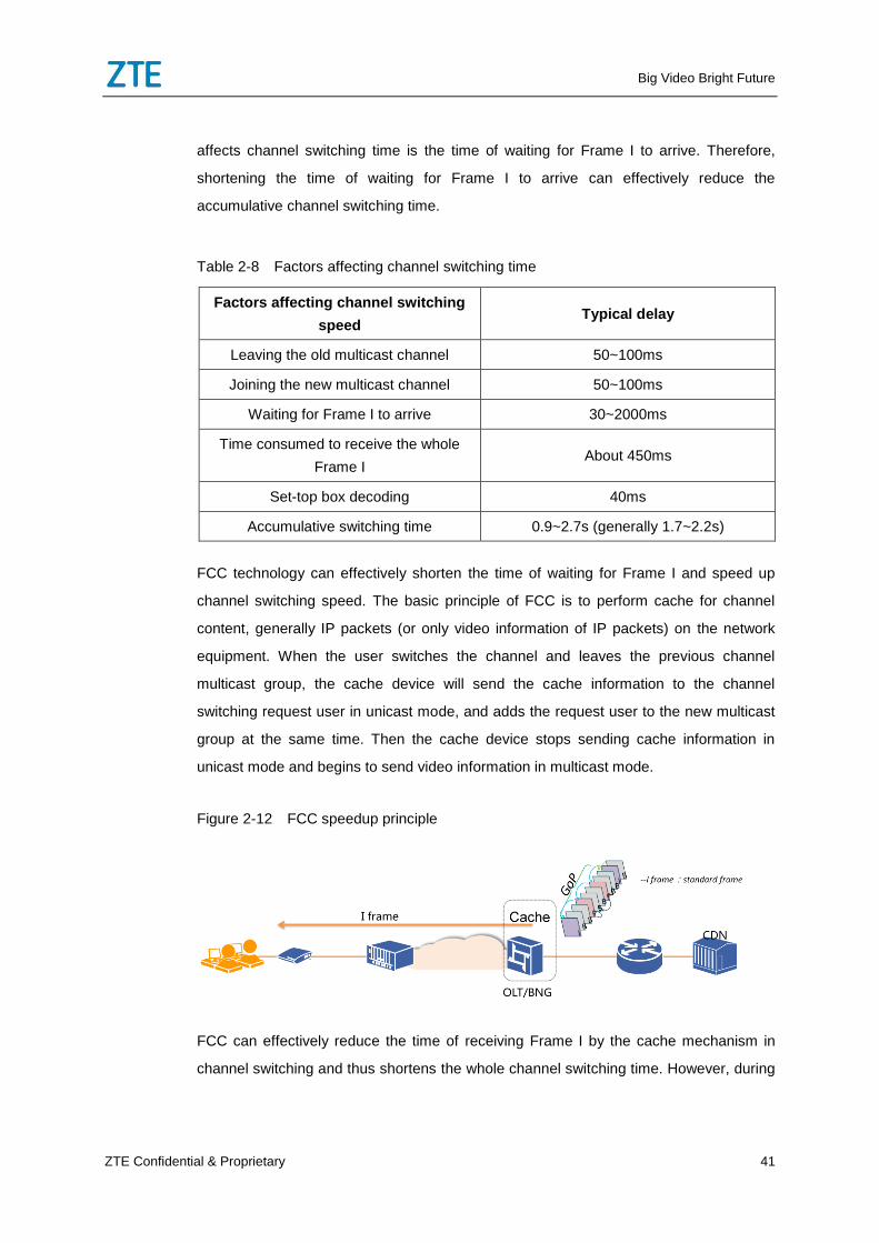
Big Video Bright Future
ZTE Confidential & Proprietary 41
affects channel switching time is the time of waiting for Frame I to arrive. Therefore,
shortening the time of waiting for Frame I to arrive can effectively reduce the
accumulative channel switching time.
Table 2-8 Factors affecting channel switching time
Factors affecting channel switching
speed Typical delay
Leaving the old multicast channel 50~100ms
Joining the new multicast channel 50~100ms
Waiting for Frame I to arrive 30~2000ms
Time consumed to receive the whole
Frame I About 450ms
Set-top box decoding 40ms
Accumulative switching time 0.9~2.7s (generally 1.7~2.2s)
FCC technology can effectively shorten the time of waiting for Frame I and speed up
channel switching speed. The basic principle of FCC is to perform cache for channel
content, generally IP packets (or only video information of IP packets) on the network
equipment. When the user switches the channel and leaves the previous channel
multicast group, the cache device will send the cache information to the channel
switching request user in unicast mode, and adds the request user to the new multicast
group at the same time. Then the cache device stops sending cache information in
unicast mode and begins to send video information in multicast mode.
Figure 2-12 FCC speedup principle
FCC can effectively reduce the time of receiving Frame I by the cache mechanism in
channel switching and thus shortens the whole channel switching time. However, during
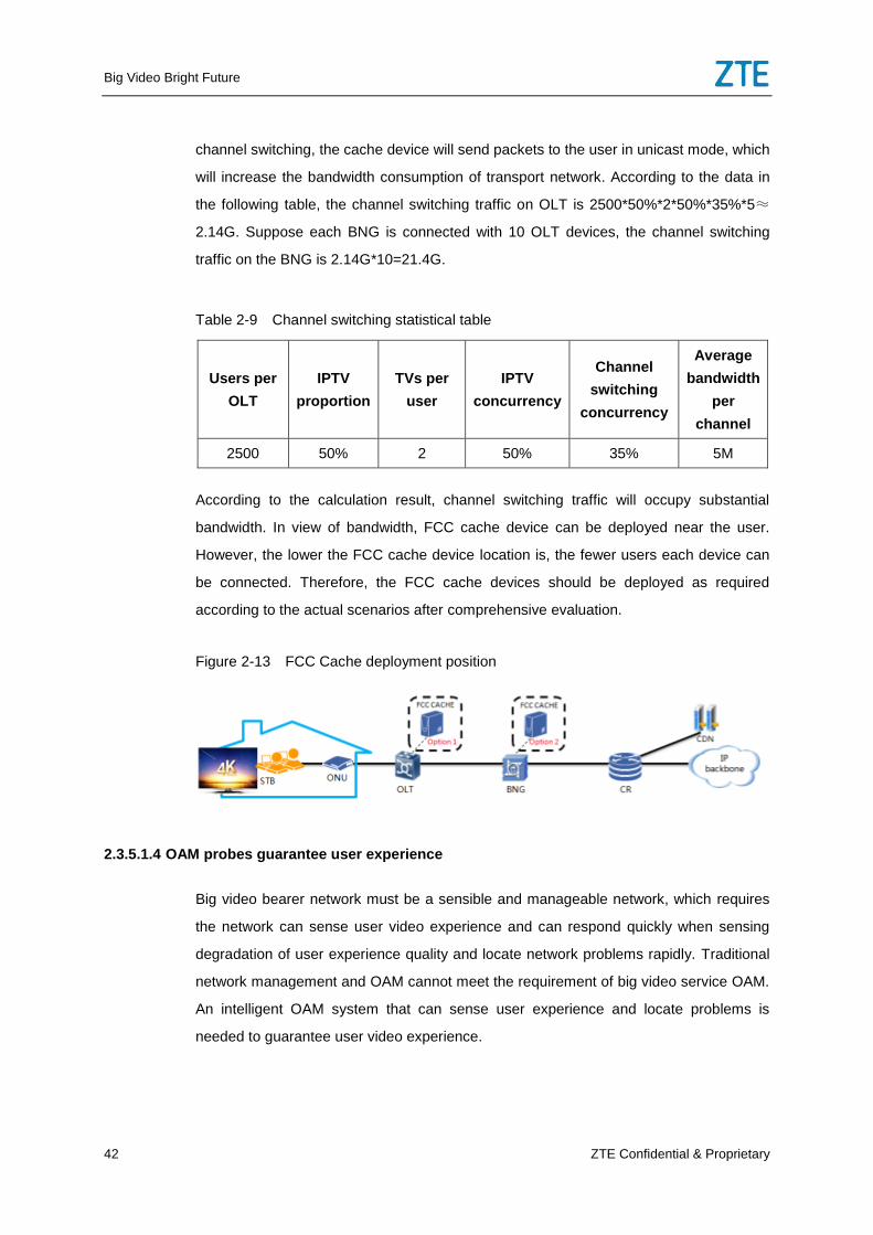
Big Video Bright Future
42 ZTE Confidential & Proprietary
channel switching, the cache device will send packets to the user in unicast mode, which
will increase the bandwidth consumption of transport network. According to the data in
the following table, the channel switching traffic on OLT is 2500*50%*2*50%*35%*5≈
2.14G. Suppose each BNG is connected with 10 OLT devices, the channel switching
traffic on the BNG is 2.14G*10=21.4G.
Table 2-9 Channel switching statistical table
Users per
OLT
IPTV
proportion
TVs per
user
IPTV
concurrency
Channel
switching
concurrency
Average
bandwidth
per
channel
2500 50% 2 50% 35% 5M
According to the calculation result, channel switching traffic will occupy substantial
bandwidth. In view of bandwidth, FCC cache device can be deployed near the user.
However, the lower the FCC cache device location is, the fewer users each device can
be connected. Therefore, the FCC cache devices should be deployed as required
according to the actual scenarios after comprehensive evaluation.
Figure 2-13 FCC Cache deployment position
2.3.5.1.4 OAM probes guarantee user experience
Big video bearer network must be a sensible and manageable network, which requires
the network can sense user video experience and can respond quickly when sensing
degradation of user experience quality and locate network problems rapidly. Traditional
network management and OAM cannot meet the requirement of big video service OAM.
An intelligent OAM system that can sense user experience and locate problems is
needed to guarantee user video experience.
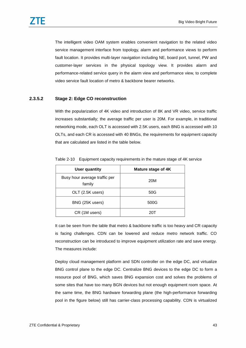
Big Video Bright Future
ZTE Confidential & Proprietary 43
The intelligent video OAM system enables convenient navigation to the related video
service management interface from topology, alarm and performance views to perform
fault location. It provides multi-layer navigation including NE, board port, tunnel, PW and
customer-layer services in the physical topology view. It provides alarm and
performance-related service query in the alarm view and performance view, to complete
video service fault location of metro & backbone bearer networks.
2.3.5.2 Stage 2: Edge CO reconstruction
With the popularization of 4K video and introduction of 8K and VR video, service traffic
increases substantially; the average traffic per user is 20M. For example, in traditional
networking mode, each OLT is accessed with 2.5K users, each BNG is accessed with 10
OLTs, and each CR is accessed with 40 BNGs, the requirements for equipment capacity
that are calculated are listed in the table below.
Table 2-10 Equipment capacity requirements in the mature stage of 4K service
User quantity Mature stage of 4K
Busy hour average traffic per
family 20M
OLT (2.5K users) 50G
BNG (25K users) 500G
CR (1M users) 20T
It can be seen from the table that metro & backbone traffic is too heavy and CR capacity
is facing challenges. CDN can be lowered and reduce metro network traffic. CO
reconstruction can be introduced to improve equipment utilization rate and save energy.
The measures include:
Deploy cloud management platform and SDN controller on the edge DC, and virtualize
BNG control plane to the edge DC. Centralize BNG devices to the edge DC to form a
resource pool of BNG, which saves BNG expansion cost and solves the problems of
some sites that have too many BGN devices but not enough equipment room space. At
the same time, the BNG hardware forwarding plane (the high-performance forwarding
pool in the figure below) still has carrier-class processing capability. CDN is virtualized
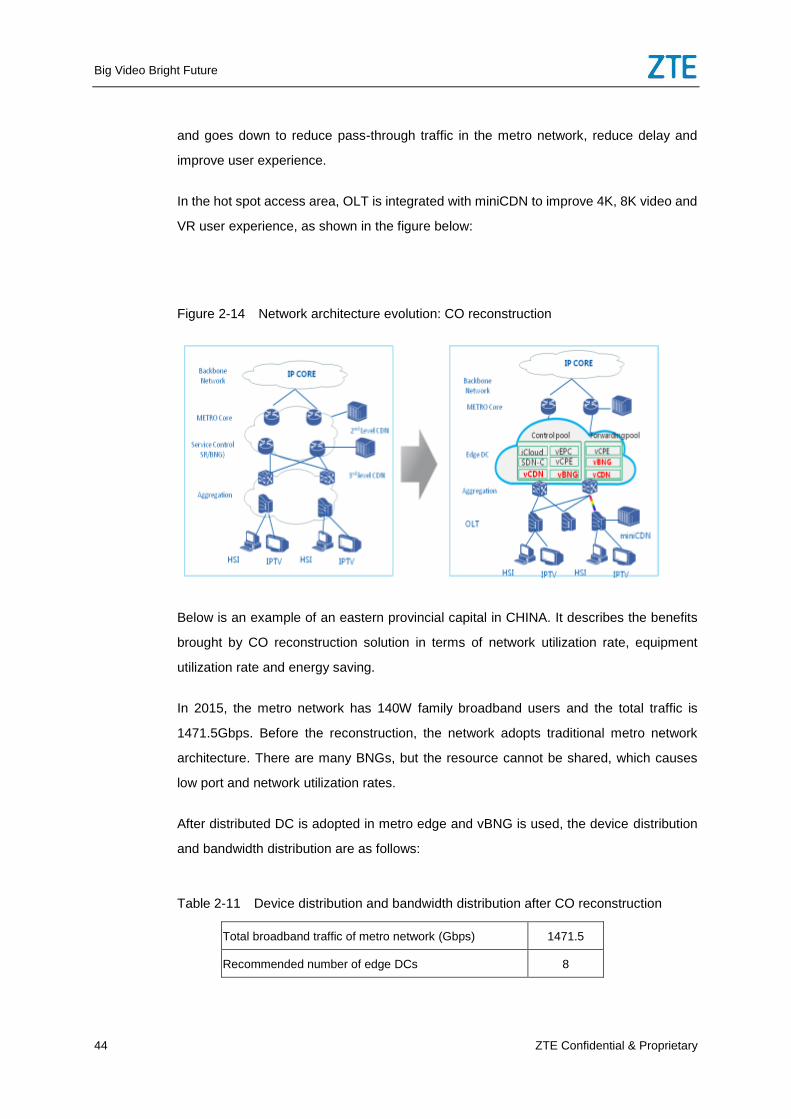
Big Video Bright Future
44 ZTE Confidential & Proprietary
and goes down to reduce pass-through traffic in the metro network, reduce delay and
improve user experience.
In the hot spot access area, OLT is integrated with miniCDN to improve 4K, 8K video and
VR user experience, as shown in the figure below:
Figure 2-14 Network architecture evolution: CO reconstruction
Below is an example of an eastern provincial capital in CHINA. It describes the benefits
brought by CO reconstruction solution in terms of network utilization rate, equipment
utilization rate and energy saving.
In 2015, the metro network has 140W family broadband users and the total traffic is
1471.5Gbps. Before the reconstruction, the network adopts traditional metro network
architecture. There are many BNGs, but the resource cannot be shared, which causes
low port and network utilization rates.
After distributed DC is adopted in metro edge and vBNG is used, the device distribution
and bandwidth distribution are as follows:
Table 2-11 Device distribution and bandwidth distribution after CO reconstruction
Total broadband traffic of metro network (Gbps) 1471.5
Recommended number of edge DCs 8
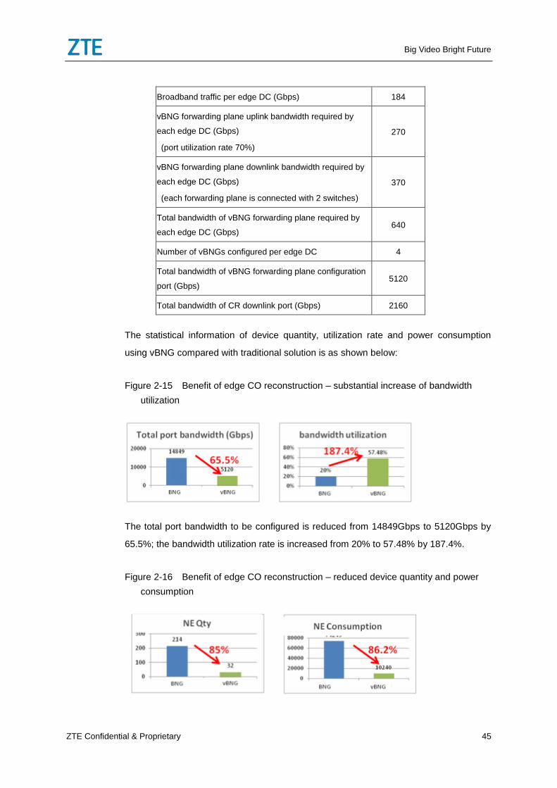
Big Video Bright Future
ZTE Confidential & Proprietary 45
Broadband traffic per edge DC (Gbps) 184
vBNG forwarding plane uplink bandwidth required by
each edge DC (Gbps)
(port utilization rate 70%)
270
vBNG forwarding plane downlink bandwidth required by
each edge DC (Gbps)
(each forwarding plane is connected with 2 switches)
370
Total bandwidth of vBNG forwarding plane required by
each edge DC (Gbps) 640
Number of vBNGs configured per edge DC 4
Total bandwidth of vBNG forwarding plane configuration
port (Gbps) 5120
Total bandwidth of CR downlink port (Gbps) 2160
The statistical information of device quantity, utilization rate and power consumption
using vBNG compared with traditional solution is as shown below:
Figure 2-15 Benefit of edge CO reconstruction – substantial increase of bandwidth
utilization
The total port bandwidth to be configured is reduced from 14849Gbps to 5120Gbps by
65.5%; the bandwidth utilization rate is increased from 20% to 57.48% by 187.4%.
Figure 2-16 Benefit of edge CO reconstruction – reduced device quantity and power
consumption
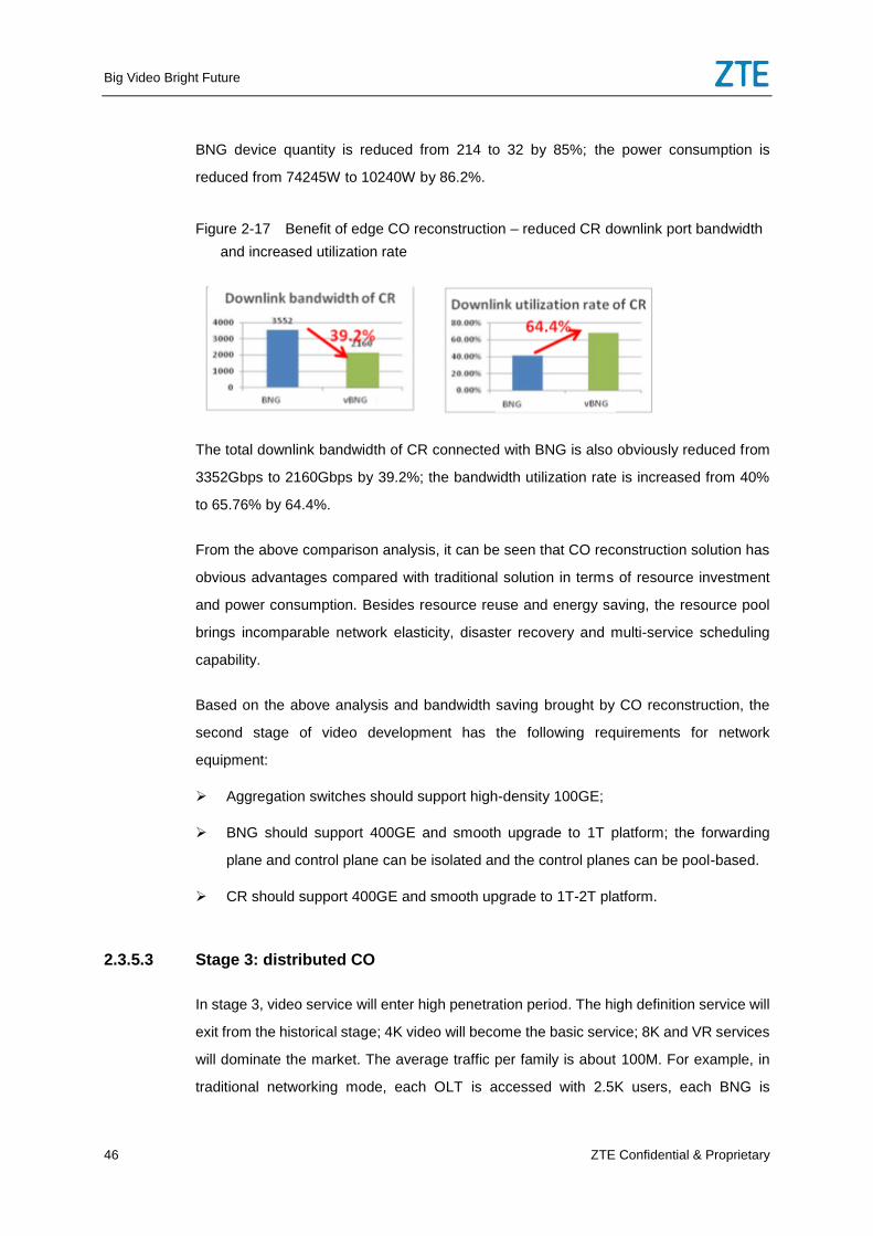
Big Video Bright Future
46 ZTE Confidential & Proprietary
BNG device quantity is reduced from 214 to 32 by 85%; the power consumption is
reduced from 74245W to 10240W by 86.2%.
Figure 2-17 Benefit of edge CO reconstruction – reduced CR downlink port bandwidth
and increased utilization rate
The total downlink bandwidth of CR connected with BNG is also obviously reduced from
3352Gbps to 2160Gbps by 39.2%; the bandwidth utilization rate is increased from 40%
to 65.76% by 64.4%.
From the above comparison analysis, it can be seen that CO reconstruction solution has
obvious advantages compared with traditional solution in terms of resource investment
and power consumption. Besides resource reuse and energy saving, the resource pool
brings incomparable network elasticity, disaster recovery and multi-service scheduling
capability.
Based on the above analysis and bandwidth saving brought by CO reconstruction, the
second stage of video development has the following requirements for network
equipment:
Aggregation switches should support high-density 100GE;
BNG should support 400GE and smooth upgrade to 1T platform; the forwarding
plane and control plane can be isolated and the control planes can be pool-based.
CR should support 400GE and smooth upgrade to 1T-2T platform.
2.3.5.3 Stage 3: distributed CO
In stage 3, video service will enter high penetration period. The high definition service will
exit from the historical stage; 4K video will become the basic service; 8K and VR services
will dominate the market. The average traffic per family is about 100M. For example, in
traditional networking mode, each OLT is accessed with 2.5K users, each BNG is
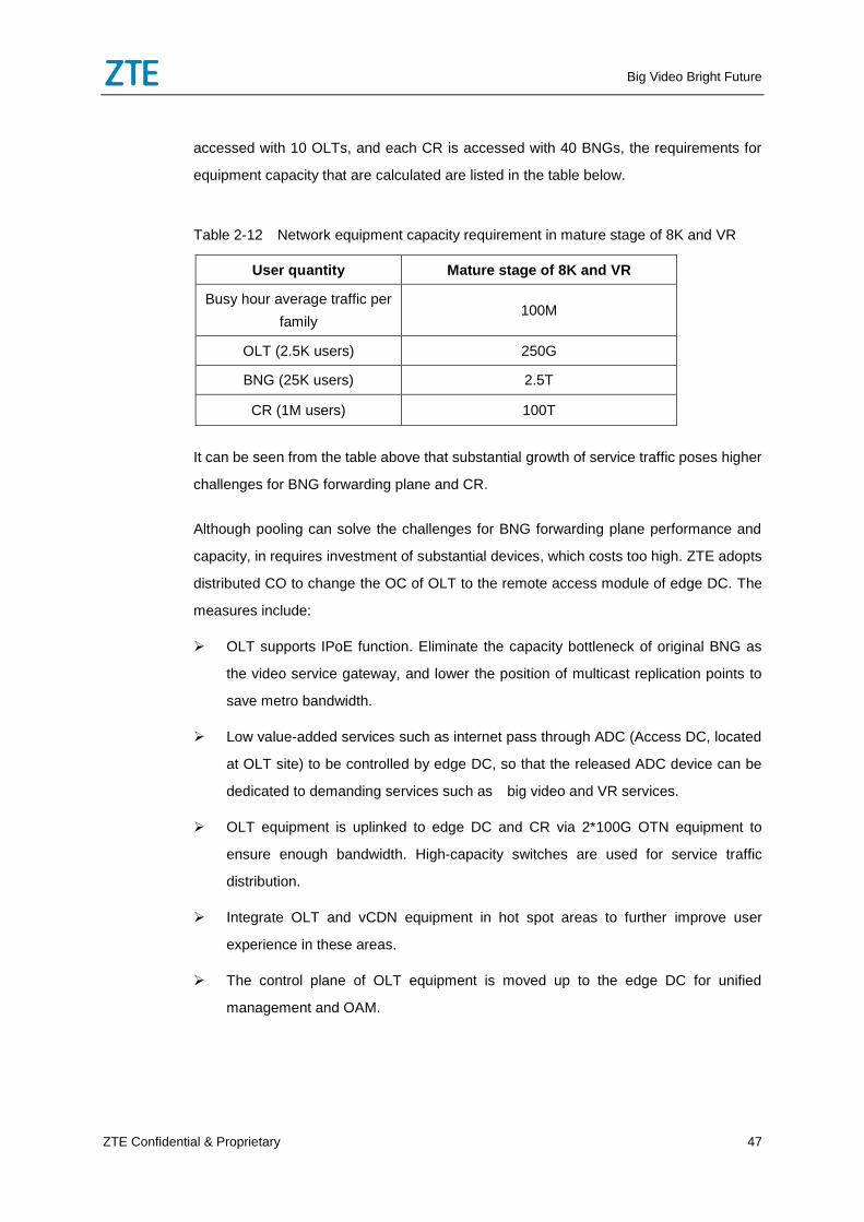
Big Video Bright Future
ZTE Confidential & Proprietary 47
accessed with 10 OLTs, and each CR is accessed with 40 BNGs, the requirements for
equipment capacity that are calculated are listed in the table below.
Table 2-12 Network equipment capacity requirement in mature stage of 8K and VR
User quantity Mature stage of 8K and VR
Busy hour average traffic per
family 100M
OLT (2.5K users) 250G
BNG (25K users) 2.5T
CR (1M users) 100T
It can be seen from the table above that substantial growth of service traffic poses higher
challenges for BNG forwarding plane and CR.
Although pooling can solve the challenges for BNG forwarding plane performance and
capacity, in requires investment of substantial devices, which costs too high. ZTE adopts
distributed CO to change the OC of OLT to the remote access module of edge DC. The
measures include:
OLT supports IPoE function. Eliminate the capacity bottleneck of original BNG as
the video service gateway, and lower the position of multicast replication points to
save metro bandwidth.
Low value-added services such as internet pass through ADC (Access DC, located
at OLT site) to be controlled by edge DC, so that the released ADC device can be
dedicated to demanding services such as big video and VR services.
OLT equipment is uplinked to edge DC and CR via 2*100G OTN equipment to
ensure enough bandwidth. High-capacity switches are used for service traffic
distribution.
Integrate OLT and vCDN equipment in hot spot areas to further improve user
experience in these areas.
The control plane of OLT equipment is moved up to the edge DC for unified
management and OAM.
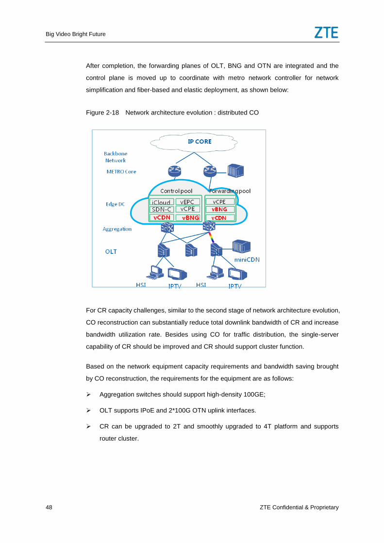
Big Video Bright Future
48 ZTE Confidential & Proprietary
After completion, the forwarding planes of OLT, BNG and OTN are integrated and the
control plane is moved up to coordinate with metro network controller for network
simplification and fiber-based and elastic deployment, as shown below:
Figure 2-18 Network architecture evolution : distributed CO
For CR capacity challenges, similar to the second stage of network architecture evolution,
CO reconstruction can substantially reduce total downlink bandwidth of CR and increase
bandwidth utilization rate. Besides using CO for traffic distribution, the single-server
capability of CR should be improved and CR should support cluster function.
Based on the network equipment capacity requirements and bandwidth saving brought
by CO reconstruction, the requirements for the equipment are as follows:
Aggregation switches should support high-density 100GE;
OLT supports IPoE and 2*100G OTN uplink interfaces.
CR can be upgraded to 2T and smoothly upgraded to 4T platform and supports
router cluster.
Big Video Bright Future
ZTE Confidential & Proprietary 49
2.4 Conclusion
Big video needs stronger transport network. The key characteristics of future transport
network are: DC-centered, high throughput, flat and virtualized. Big video service is the
key driving force for network reconstruction and future evolution. ZTE’s wired network
solution of optimal video experience takes operators’ existing network and future network
development trend into full consideration and supports smooth evolution in the future. It
can adapt to the requirements of big video service in different stages with the optimal
video experience network architecture.
Stage 1: solve the key problem of video service, implement performance optimization
and intelligent OAM based on existing network and establish E2E high-throughput pipes.
Stage 2: Realize BGN forwarding planes pooling and CDN pooling to increase
equipment utilization rate and efficiency.
Stage 3: Build flat networks and lower BNG; key parts including BNG and CDN can be
virtualized as required.
3 Wireless Network Solution with Best
Video Experience
3.1 Requirements and Challenges for Wireless Network
by Mobile Video Service
The video service has gradually become the basic mobile service after voice and data
services. According to a global traffic analysis, most of increasing traffic comes from
video services in recent years. Video service, especially HD video service, has greatly
stimulated traffic consumption and enabled a fast growth of user traffic.
The tariff of data services decreases as mobile data services grow rapidly. A sustainable
growth of total revenue can be guaranteed as long as the data service growth is faster
than the tariff decrease. The video service which comes from data services has taken
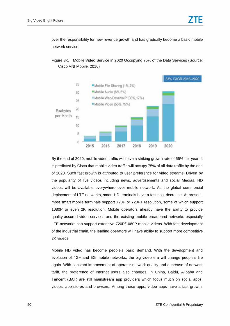
Big Video Bright Future
50 ZTE Confidential & Proprietary
over the responsibility for new revenue growth and has gradually become a basic mobile
network service.
Figure 3-1 Mobile Video Service in 2020 Occupying 75% of the Data Services (Source:
Cisco VNI Mobile, 2016)
By the end of 2020, mobile video traffic will have a striking growth rate of 55% per year. It
is predicted by Cisco that mobile video traffic will occupy 75% of all data traffic by the end
of 2020. Such fast growth is attributed to user preference for video streams. Driven by
the popularity of live videos including news, advertisements and social Medias, HD
videos will be available everywhere over mobile network. As the global commercial
deployment of LTE networks, smart HD terminals have a fast cost decrease. At present,
most smart mobile terminals support 720P or 720P+ resolution, some of which support
1080P or even 2K resolution. Mobile operators already have the ability to provide
quality-assured video services and the existing mobile broadband networks especially
LTE networks can support extensive 720P/1080P mobile videos. With fast development
of the industrial chain, the leading operators will have ability to support more competitive
2K videos.
Mobile HD video has become people's basic demand. With the development and
evolution of 4G+ and 5G mobile networks, the big video era will change people's life
again. With constant improvement of operator network quality and decrease of network
tariff, the preference of Internet users also changes. In China, Baidu, Alibaba and
Tencent (BAT) are still mainstream app providers which focus much on social apps,
videos, app stores and browsers. Among these apps, video apps have a fast growth.
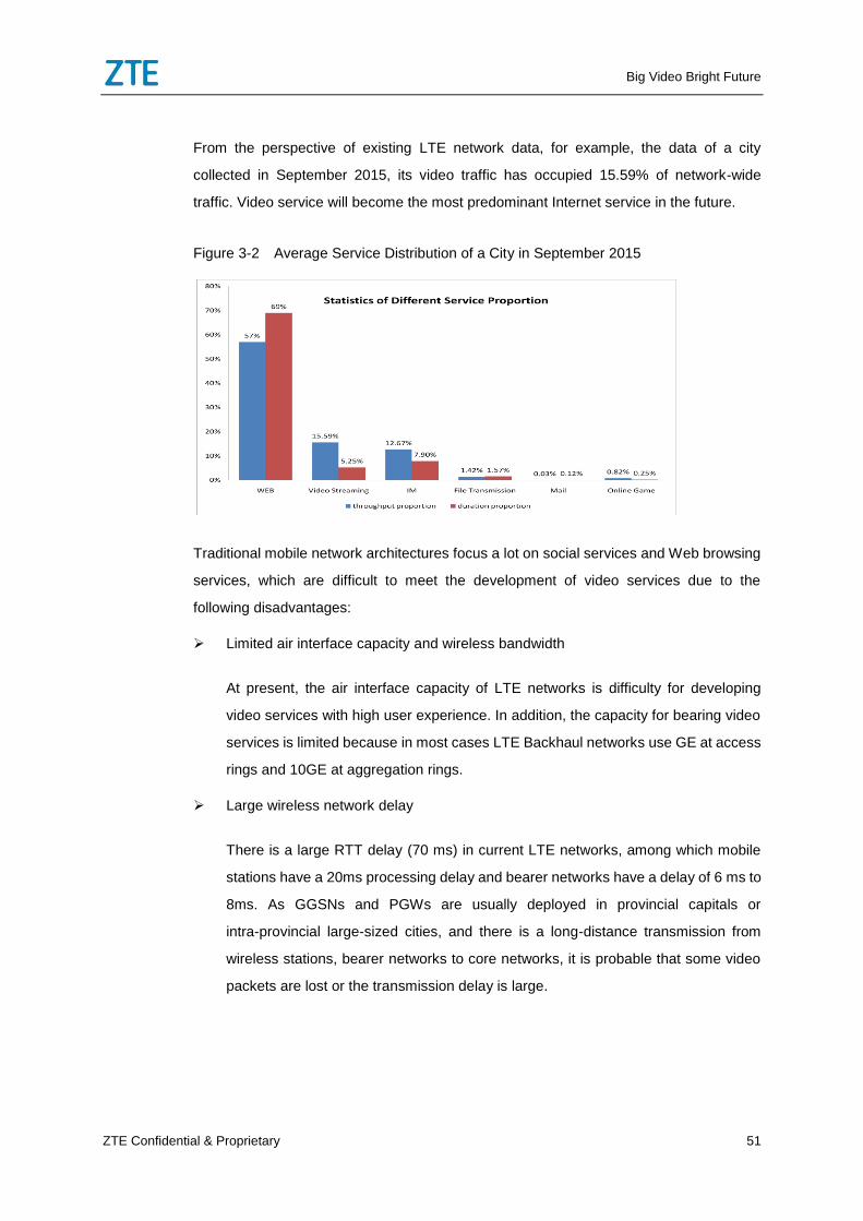
Big Video Bright Future
ZTE Confidential & Proprietary 51
From the perspective of existing LTE network data, for example, the data of a city
collected in September 2015, its video traffic has occupied 15.59% of network-wide
traffic. Video service will become the most predominant Internet service in the future.
Figure 3-2 Average Service Distribution of a City in September 2015
Traditional mobile network architectures focus a lot on social services and Web browsing
services, which are difficult to meet the development of video services due to the
following disadvantages:
Limited air interface capacity and wireless bandwidth
At present, the air interface capacity of LTE networks is difficulty for developing
video services with high user experience. In addition, the capacity for bearing video
services is limited because in most cases LTE Backhaul networks use GE at access
rings and 10GE at aggregation rings.
Large wireless network delay
There is a large RTT delay (70 ms) in current LTE networks, among which mobile
stations have a 20ms processing delay and bearer networks have a delay of 6 ms to
8ms. As GGSNs and PGWs are usually deployed in provincial capitals or
intra-provincial large-sized cities, and there is a long-distance transmission from
wireless stations, bearer networks to core networks, it is probable that some video
packets are lost or the transmission delay is large.
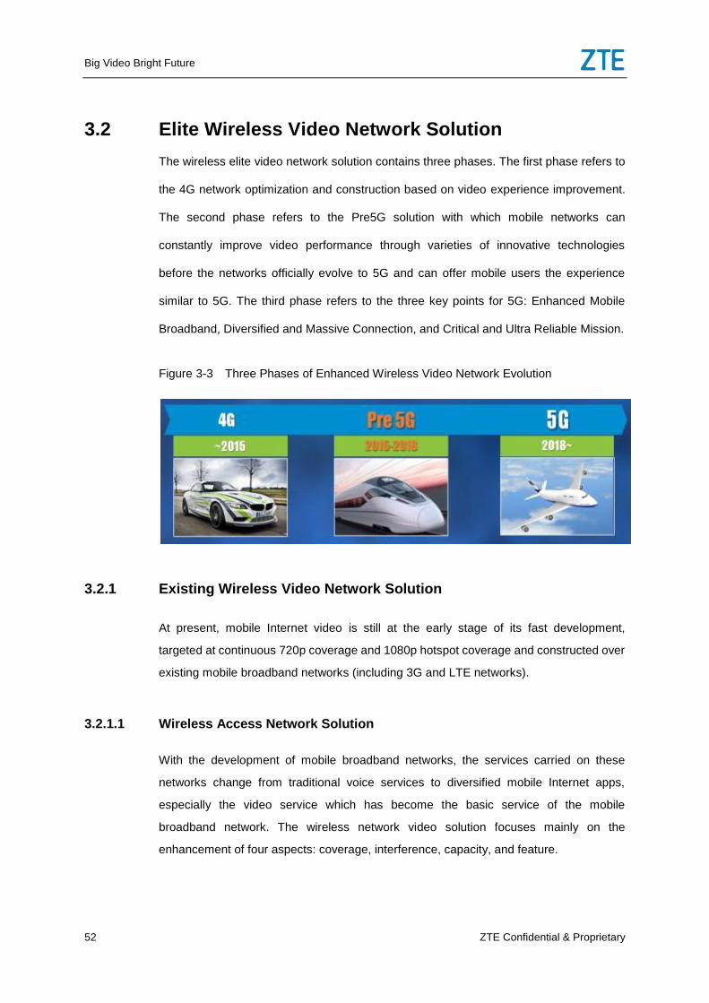
Big Video Bright Future
52 ZTE Confidential & Proprietary
3.2 Elite Wireless Video Network Solution
The wireless elite video network solution contains three phases. The first phase refers to
the 4G network optimization and construction based on video experience improvement.
The second phase refers to the Pre5G solution with which mobile networks can
constantly improve video performance through varieties of innovative technologies
before the networks officially evolve to 5G and can offer mobile users the experience
similar to 5G. The third phase refers to the three key points for 5G: Enhanced Mobile
Broadband, Diversified and Massive Connection, and Critical and Ultra Reliable Mission.
Figure 3-3 Three Phases of Enhanced Wireless Video Network Evolution
3.2.1 Existing Wireless Video Network Solution
At present, mobile Internet video is still at the early stage of its fast development,
targeted at continuous 720p coverage and 1080p hotspot coverage and constructed over
existing mobile broadband networks (including 3G and LTE networks).
3.2.1.1 Wireless Access Network Solution
With the development of mobile broadband networks, the services carried on these
networks change from traditional voice services to diversified mobile Internet apps,
especially the video service which has become the basic service of the mobile
broadband network. The wireless network video solution focuses mainly on the
enhancement of four aspects: coverage, interference, capacity, and feature.
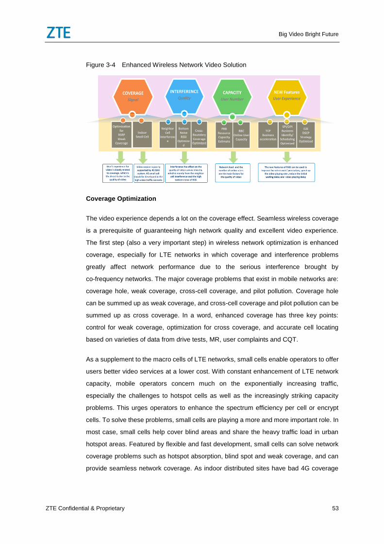
Big Video Bright Future
ZTE Confidential & Proprietary 53
Figure 3-4 Enhanced Wireless Network Video Solution
Coverage Optimization
The video experience depends a lot on the coverage effect. Seamless wireless coverage
is a prerequisite of guaranteeing high network quality and excellent video experience.
The first step (also a very important step) in wireless network optimization is enhanced
coverage, especially for LTE networks in which coverage and interference problems
greatly affect network performance due to the serious interference brought by
co-frequency networks. The major coverage problems that exist in mobile networks are:
coverage hole, weak coverage, cross-cell coverage, and pilot pollution. Coverage hole
can be summed up as weak coverage, and cross-cell coverage and pilot pollution can be
summed up as cross coverage. In a word, enhanced coverage has three key points:
control for weak coverage, optimization for cross coverage, and accurate cell locating
based on varieties of data from drive tests, MR, user complaints and CQT.
As a supplement to the macro cells of LTE networks, small cells enable operators to offer
users better video services at a lower cost. With constant enhancement of LTE network
capacity, mobile operators concern much on the exponentially increasing traffic,
especially the challenges to hotspot cells as well as the increasingly striking capacity
problems. This urges operators to enhance the spectrum efficiency per cell or encrypt
cells. To solve these problems, small cells are playing a more and more important role. In
most case, small cells help cover blind areas and share the heavy traffic load in urban
hotspot areas. Featured by flexible and fast development, small cells can solve network
coverage problems such as hotspot absorption, blind spot and weak coverage, and can
provide seamless network coverage. As indoor distributed sites have bad 4G coverage
Big Video Bright Future
54 ZTE Confidential & Proprietary
for video services, it is preferred to deploy LTE small cells in critical high traffic areas. For
current hotspots, the enhanced outdoor blind-area and hotspot solution includes:
Outdoor Macro-Micro Co-Frequency Networking for Blind Area Coverage of Main
Urban Roads
At present, the primary cause of weak coverage for roads is the long-time negotiation
with property management companies regarding the places where sites are deployed.
Compared to macro stations, small stations mounted on lamp poles or walls are easier to
cover blind areas.
Outdoor Macro-Micro Networking for In-Depth Blind Area Coverage of Main Urban
Areas
If the sectors of macro stations cannot seamlessly cover all target buildings, for example,
both sides of a building are covered by the antenna's side lobe, it is difficult to well absorb
indoor traffic. In this case, small stations mounted on lamp poles nearby can be a
supplement to weak coverage.
Outdoor Macro-Micro Networking for In-Depth Hotspot Coverage of Main Urban
Areas
An indoor area is a real hotspot. From the perspective of network evolution, the in-depth
areas covered by micro stations as a way of supplement are in fact the hotspots covered
by macro stations. Therefore, if there are adequate frequency points, a pilot network with
micro stations simplifies network architecture and balances the capacity load between
macro stations and micro stations.
Interference Optimization
The LTE system has no co-frequency interference within its affiliated cell. In most cases,
interference comes from adjacent cells that use the same frequency. The intra-system
interference usually refers to inter-user interference and other interference caused by
improper PCI planning. The inter-system interference usually refers to the interference
caused by radars and some civil facilities. All the above interference can seriously affect
LTE network performance. For the inter-system interference, multiple parties need
coordination in order to optimize it. For the intra-system interference, it is advisable to
control the cell coverage by adjusting engineering parameters and then try to avoid any
PCI conflict between adjacent cells during PCI planning. For LTE co-frequency networks,
Big Video Bright Future
ZTE Confidential & Proprietary 55
it is more convenient that there are only signals from the source cell and the target cell at
the handover area. For the signals that cannot be directly handed over, make a proper
control and if necessary use a frequency sweeper to locate interference. In most cases,
interference can be solved through:
PCI planning and self-optimizing to avoid PCI conflict
Adjustment of engineering parameters
Enhancement of primary cell signals to reduce the strength of interference signals
Location of external interference sources
In a macro-micro Hetnet network, interference can be solved through:
Macro-Micro Supercell: refers to the SuperCell that consists of a single macro cell
and several micro cells. They share the same cell resources, including cell ID,
PBCH, PSS/SSS, Paging, SIB1, CRS, and PCFICH. Compared to the macro-micro
co-frequency network, Supercell can better solve the mutual interference among
public channels such as C-RS, PBCH and Paging over Hetnet. In addition, it judges
problems by converting the cell handovers over Hetnet into the inter-CP active sets
over SuperCell, which efficiently reduces the number of cell handovers.
Macro-Micro eICIC: refers to the enhanced inter-cell interference coordination over
an instant domain. It is applicable only to the single-frequency scenario in a
co-frequency network. One or more subframes are configured to Almost Blank
Subframe (ABS) over macro cells and micro cells serve user terminals (UEs) over
ABS. This avoids main interference from macro cells and enhances the service rate
of UEs, as shown in Figure 3-5.
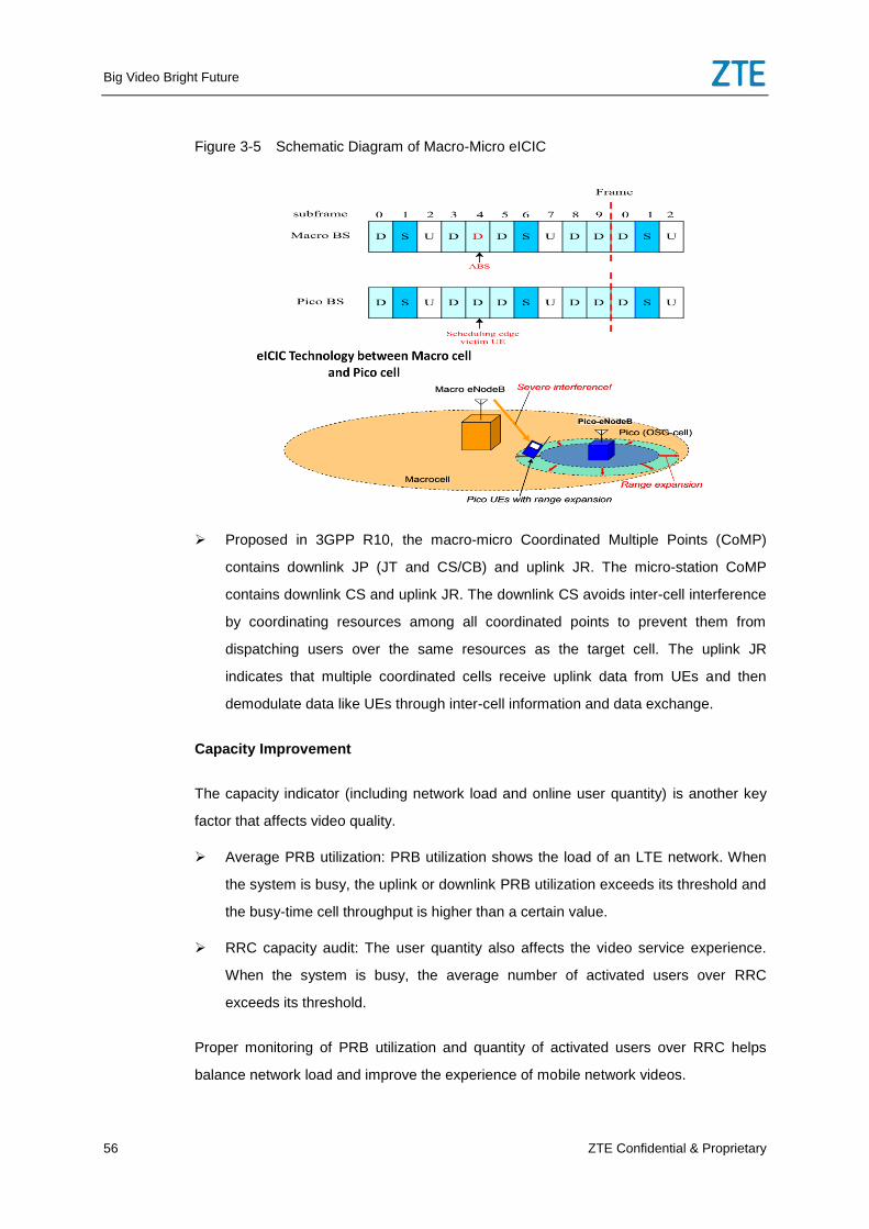
Big Video Bright Future
56 ZTE Confidential & Proprietary
Figure 3-5 Schematic Diagram of Macro-Micro eICIC
Proposed in 3GPP R10, the macro-micro Coordinated Multiple Points (CoMP)
contains downlink JP (JT and CS/CB) and uplink JR. The micro-station CoMP
contains downlink CS and uplink JR. The downlink CS avoids inter-cell interference
by coordinating resources among all coordinated points to prevent them from
dispatching users over the same resources as the target cell. The uplink JR
indicates that multiple coordinated cells receive uplink data from UEs and then
demodulate data like UEs through inter-cell information and data exchange.
Capacity Improvement
The capacity indicator (including network load and online user quantity) is another key
factor that affects video quality.
Average PRB utilization: PRB utilization shows the load of an LTE network. When
the system is busy, the uplink or downlink PRB utilization exceeds its threshold and
the busy-time cell throughput is higher than a certain value.
RRC capacity audit: The user quantity also affects the video service experience.
When the system is busy, the average number of activated users over RRC
exceeds its threshold.
Proper monitoring of PRB utilization and quantity of activated users over RRC helps
balance network load and improve the experience of mobile network videos.
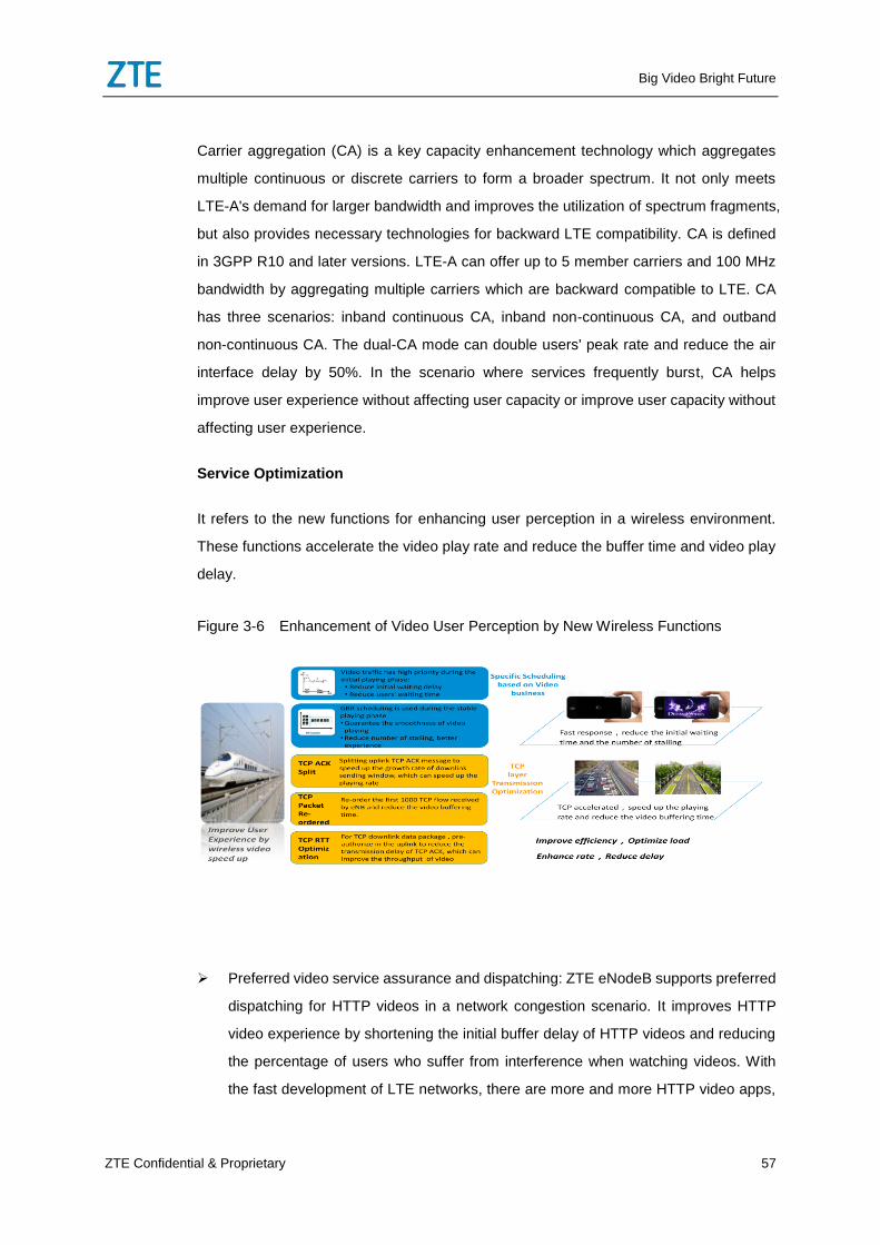
Big Video Bright Future
ZTE Confidential & Proprietary 57
Carrier aggregation (CA) is a key capacity enhancement technology which aggregates
multiple continuous or discrete carriers to form a broader spectrum. It not only meets
LTE-A's demand for larger bandwidth and improves the utilization of spectrum fragments,
but also provides necessary technologies for backward LTE compatibility. CA is defined
in 3GPP R10 and later versions. LTE-A can offer up to 5 member carriers and 100 MHz
bandwidth by aggregating multiple carriers which are backward compatible to LTE. CA
has three scenarios: inband continuous CA, inband non-continuous CA, and outband
non-continuous CA. The dual-CA mode can double users' peak rate and reduce the air
interface delay by 50%. In the scenario where services frequently burst, CA helps
improve user experience without affecting user capacity or improve user capacity without
affecting user experience.
Service Optimization
It refers to the new functions for enhancing user perception in a wireless environment.
These functions accelerate the video play rate and reduce the buffer time and video play
delay.
Figure 3-6 Enhancement of Video User Perception by New Wireless Functions
Preferred video service assurance and dispatching: ZTE eNodeB supports preferred
dispatching for HTTP videos in a network congestion scenario. It improves HTTP
video experience by shortening the initial buffer delay of HTTP videos and reducing
the percentage of users who suffer from interference when watching videos. With
the fast development of LTE networks, there are more and more HTTP video apps,
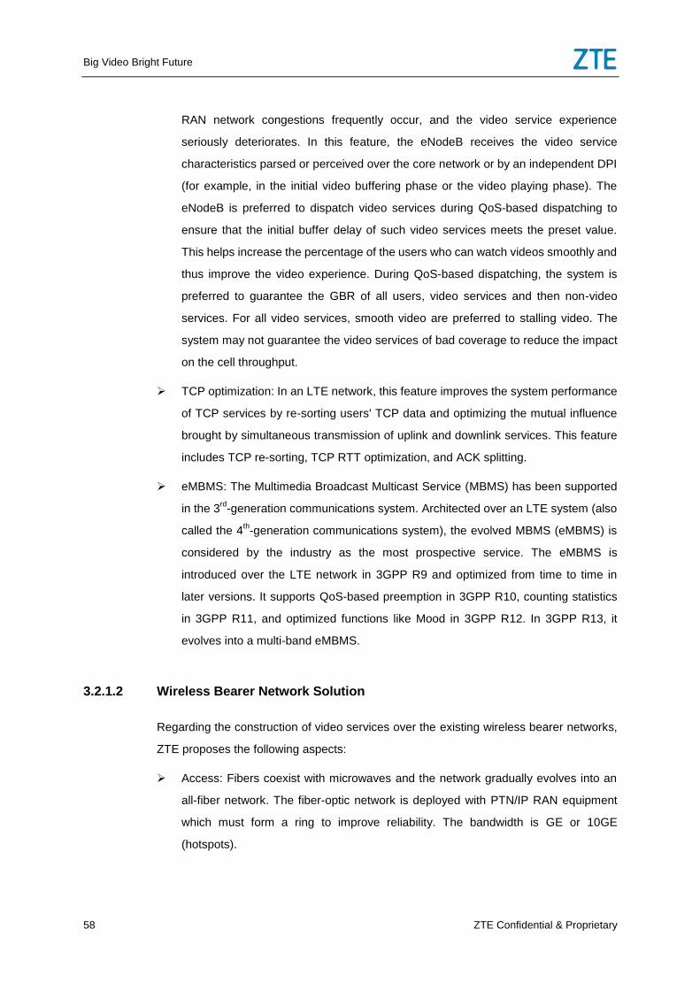
Big Video Bright Future
58 ZTE Confidential & Proprietary
RAN network congestions frequently occur, and the video service experience
seriously deteriorates. In this feature, the eNodeB receives the video service
characteristics parsed or perceived over the core network or by an independent DPI
(for example, in the initial video buffering phase or the video playing phase). The
eNodeB is preferred to dispatch video services during QoS-based dispatching to
ensure that the initial buffer delay of such video services meets the preset value.
This helps increase the percentage of the users who can watch videos smoothly and
thus improve the video experience. During QoS-based dispatching, the system is
preferred to guarantee the GBR of all users, video services and then non-video
services. For all video services, smooth video are preferred to stalling video. The
system may not guarantee the video services of bad coverage to reduce the impact
on the cell throughput.
TCP optimization: In an LTE network, this feature improves the system performance
of TCP services by re-sorting users' TCP data and optimizing the mutual influence
brought by simultaneous transmission of uplink and downlink services. This feature
includes TCP re-sorting, TCP RTT optimization, and ACK splitting.
eMBMS: The Multimedia Broadcast Multicast Service (MBMS) has been supported
in the 3rd
-generation communications system. Architected over an LTE system (also
called the 4th-generation communications system), the evolved MBMS (eMBMS) is
considered by the industry as the most prospective service. The eMBMS is
introduced over the LTE network in 3GPP R9 and optimized from time to time in
later versions. It supports QoS-based preemption in 3GPP R10, counting statistics
in 3GPP R11, and optimized functions like Mood in 3GPP R12. In 3GPP R13, it
evolves into a multi-band eMBMS.
3.2.1.2 Wireless Bearer Network Solution
Regarding the construction of video services over the existing wireless bearer networks,
ZTE proposes the following aspects:
Access: Fibers coexist with microwaves and the network gradually evolves into an
all-fiber network. The fiber-optic network is deployed with PTN/IP RAN equipment
which must form a ring to improve reliability. The bandwidth is GE or 10GE
(hotspots).
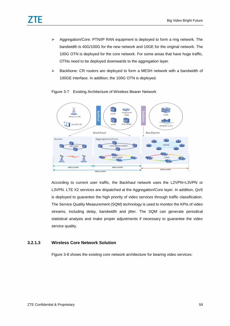
Big Video Bright Future
ZTE Confidential & Proprietary 59
Aggregation/Core: PTN/IP RAN equipment is deployed to form a ring network. The
bandwidth is 40G/100G for the new network and 10GE for the original network. The
100G OTN is deployed for the core network. For some areas that have huge traffic,
OTNs need to be deployed downwards to the aggregation layer.
Backbone: CR routers are deployed to form a MESH network with a bandwidth of
100GE interface. In addition, the 100G OTN is deployed.
Figure 3-7 Existing Architecture of Wireless Bearer Network
According to current user traffic, the Backhaul network uses the L2VPN+L3VPN or
L3VPN. LTE X2 services are dispatched at the Aggregation/Core layer. In addition, QoS
is deployed to guarantee the high priority of video services through traffic classification.
The Service Quality Measurement (SQM) technology is used to monitor the KPIs of video
streams, including delay, bandwidth and jitter. The SQM can generate periodical
statistical analysis and make proper adjustments if necessary to guarantee the video
service quality.
3.2.1.3 Wireless Core Network Solution
Figure 3-8 shows the existing core network architecture for bearing video services:
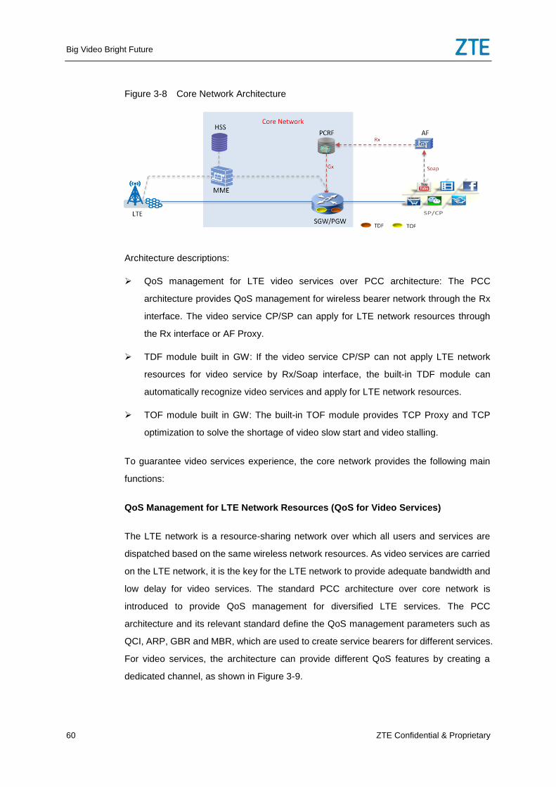
Big Video Bright Future
60 ZTE Confidential & Proprietary
Figure 3-8 Core Network Architecture
Architecture descriptions:
QoS management for LTE video services over PCC architecture: The PCC
architecture provides QoS management for wireless bearer network through the Rx
interface. The video service CP/SP can apply for LTE network resources through
the Rx interface or AF Proxy.
TDF module built in GW: If the video service CP/SP can not apply LTE network
resources for video service by Rx/Soap interface, the built-in TDF module can
automatically recognize video services and apply for LTE network resources.
TOF module built in GW: The built-in TOF module provides TCP Proxy and TCP
optimization to solve the shortage of video slow start and video stalling.
To guarantee video services experience, the core network provides the following main
functions:
QoS Management for LTE Network Resources (QoS for Video Services)
The LTE network is a resource-sharing network over which all users and services are
dispatched based on the same wireless network resources. As video services are carried
on the LTE network, it is the key for the LTE network to provide adequate bandwidth and
low delay for video services. The standard PCC architecture over core network is
introduced to provide QoS management for diversified LTE services. The PCC
architecture and its relevant standard define the QoS management parameters such as
QCI, ARP, GBR and MBR, which are used to create service bearers for different services.
For video services, the architecture can provide different QoS features by creating a
dedicated channel, as shown in Figure 3-9.
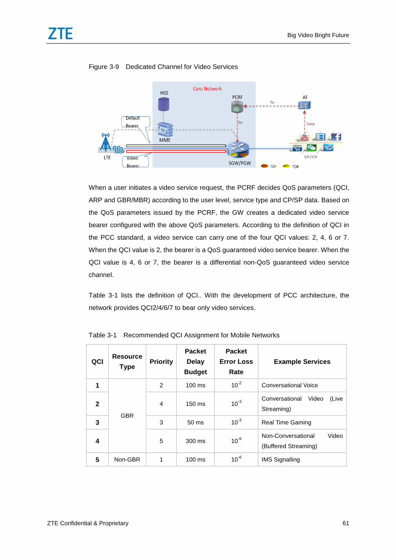
Big Video Bright Future
ZTE Confidential & Proprietary 61
Figure 3-9 Dedicated Channel for Video Services
When a user initiates a video service request, the PCRF decides QoS parameters (QCI,
ARP and GBR/MBR) according to the user level, service type and CP/SP data. Based on
the QoS parameters issued by the PCRF, the GW creates a dedicated video service
bearer configured with the above QoS parameters. According to the definition of QCI in
the PCC standard, a video service can carry one of the four QCI values: 2, 4, 6 or 7.
When the QCI value is 2, the bearer is a QoS guaranteed video service bearer. When the
QCI value is 4, 6 or 7, the bearer is a differential non-QoS guaranteed video service
channel.
Table 3-1 lists the definition of QCI.. With the development of PCC architecture, the
network provides QCI2/4/6/7 to bear only video services.
Table 3-1 Recommended QCI Assignment for Mobile Networks
QCI Resource
Type Priority
Packet
Delay
Budget
Packet
Error Loss
Rate
Example Services
1
GBR
2 100 ms 10-2
Conversational Voice
2 4 150 ms 10-3
Conversational Video (Live
Streaming)
3 3 50 ms 10-3
Real Time Gaming
4 5 300 ms 10-6
Non-Conversational Video
(Buffered Streaming)
5 Non-GBR 1 100 ms 10-6
IMS Signalling
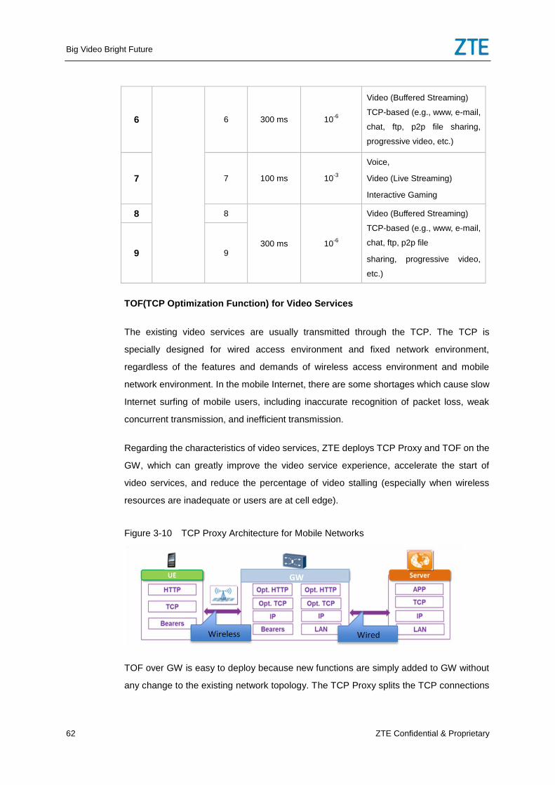
Big Video Bright Future
62 ZTE Confidential & Proprietary
6 6 300 ms 10-6
Video (Buffered Streaming)
TCP-based (e.g., www, e-mail,
chat, ftp, p2p file sharing,
progressive video, etc.)
7 7 100 ms 10-3
Voice,
Video (Live Streaming)
Interactive Gaming
8 8
300 ms 10-6
Video (Buffered Streaming)
TCP-based (e.g., www, e-mail,
chat, ftp, p2p file
sharing, progressive video,
etc.)
9 9
TOF(TCP Optimization Function) for Video Services
The existing video services are usually transmitted through the TCP. The TCP is
specially designed for wired access environment and fixed network environment,
regardless of the features and demands of wireless access environment and mobile
network environment. In the mobile Internet, there are some shortages which cause slow
Internet surfing of mobile users, including inaccurate recognition of packet loss, weak
concurrent transmission, and inefficient transmission.
Regarding the characteristics of video services, ZTE deploys TCP Proxy and TOF on the
GW, which can greatly improve the video service experience, accelerate the start of
video services, and reduce the percentage of video stalling (especially when wireless
resources are inadequate or users are at cell edge).
Figure 3-10 TCP Proxy Architecture for Mobile Networks
TOF over GW is easy to deploy because new functions are simply added to GW without
any change to the existing network topology. The TCP Proxy splits the TCP connections
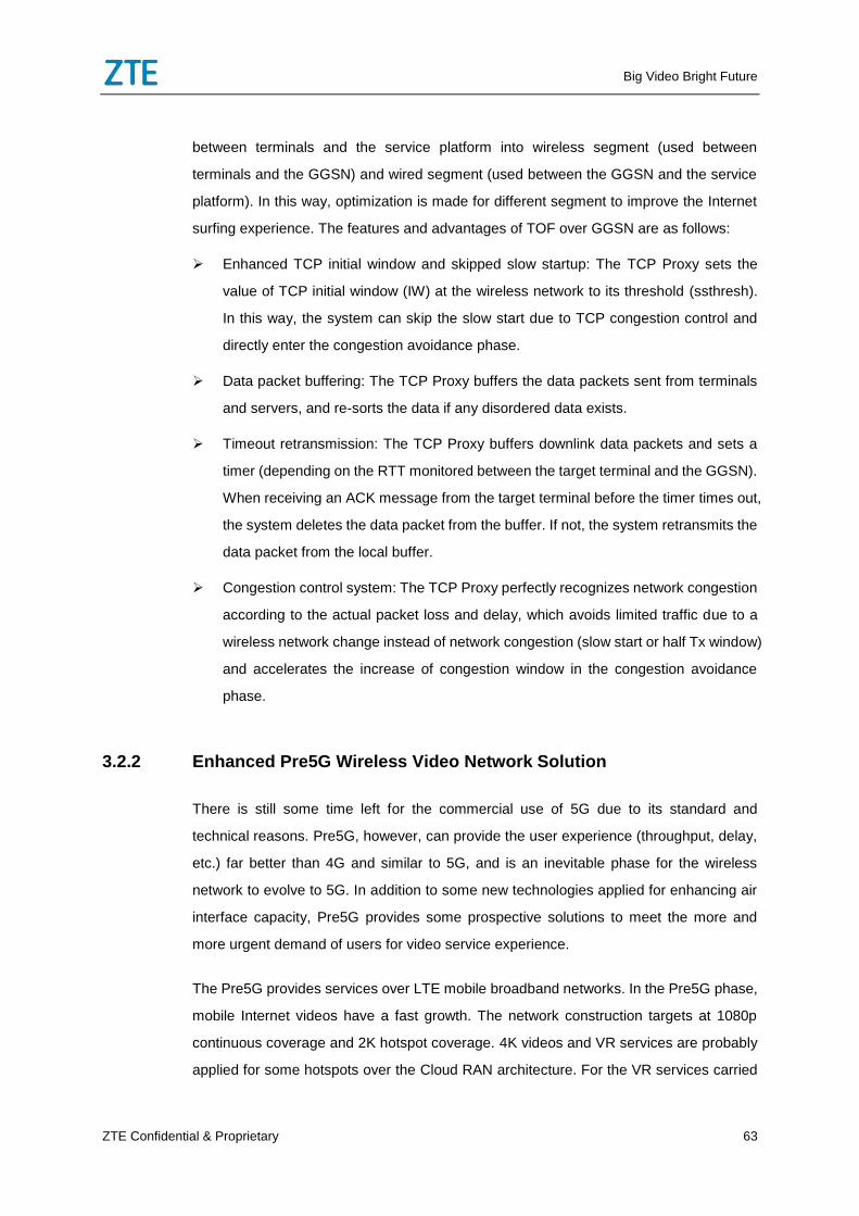
Big Video Bright Future
ZTE Confidential & Proprietary 63
between terminals and the service platform into wireless segment (used between
terminals and the GGSN) and wired segment (used between the GGSN and the service
platform). In this way, optimization is made for different segment to improve the Internet
surfing experience. The features and advantages of TOF over GGSN are as follows:
Enhanced TCP initial window and skipped slow startup: The TCP Proxy sets the
value of TCP initial window (IW) at the wireless network to its threshold (ssthresh).
In this way, the system can skip the slow start due to TCP congestion control and
directly enter the congestion avoidance phase.
Data packet buffering: The TCP Proxy buffers the data packets sent from terminals
and servers, and re-sorts the data if any disordered data exists.
Timeout retransmission: The TCP Proxy buffers downlink data packets and sets a
timer (depending on the RTT monitored between the target terminal and the GGSN).
When receiving an ACK message from the target terminal before the timer times out,
the system deletes the data packet from the buffer. If not, the system retransmits the
data packet from the local buffer.
Congestion control system: The TCP Proxy perfectly recognizes network congestion
according to the actual packet loss and delay, which avoids limited traffic due to a
wireless network change instead of network congestion (slow start or half Tx window)
and accelerates the increase of congestion window in the congestion avoidance
phase.
3.2.2 Enhanced Pre5G Wireless Video Network Solution
There is still some time left for the commercial use of 5G due to its standard and
technical reasons. Pre5G, however, can provide the user experience (throughput, delay,
etc.) far better than 4G and similar to 5G, and is an inevitable phase for the wireless
network to evolve to 5G. In addition to some new technologies applied for enhancing air
interface capacity, Pre5G provides some prospective solutions to meet the more and
more urgent demand of users for video service experience.
The Pre5G provides services over LTE mobile broadband networks. In the Pre5G phase,
mobile Internet videos have a fast growth. The network construction targets at 1080p
continuous coverage and 2K hotspot coverage. 4K videos and VR services are probably
applied for some hotspots over the Cloud RAN architecture. For the VR services carried
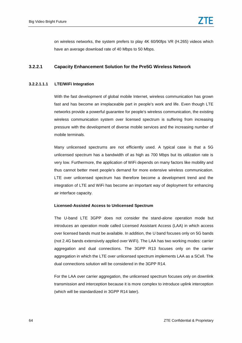
Big Video Bright Future
64 ZTE Confidential & Proprietary
on wireless networks, the system prefers to play 4K 60/90fps VR (H.265) videos which
have an average download rate of 40 Mbps to 50 Mbps.
3.2.2.1 Capacity Enhancement Solution for the Pre5G Wireless Network
3.2.2.1.1.1 LTE/WiFi Integration
With the fast development of global mobile Internet, wireless communication has grown
fast and has become an irreplaceable part in people's work and life. Even though LTE
networks provide a powerful guarantee for people's wireless communication, the existing
wireless communication system over licensed spectrum is suffering from increasing
pressure with the development of diverse mobile services and the increasing number of
mobile terminals.
Many unlicensed spectrums are not efficiently used. A typical case is that a 5G
unlicensed spectrum has a bandwidth of as high as 700 Mbps but its utilization rate is
very low. Furthermore, the application of WiFi depends on many factors like mobility and
thus cannot better meet people's demand for more extensive wireless communication.
LTE over unlicensed spectrum has therefore become a development trend and the
integration of LTE and WiFi has become an important way of deployment for enhancing
air interface capacity.
Licensed-Assisted Access to Unlicensed Spectrum
The U-band LTE 3GPP does not consider the stand-alone operation mode but
introduces an operation mode called Licensed Assistant Access (LAA) in which access
over licensed bands must be available. In addition, the U band focuses only on 5G bands
(not 2.4G bands extensively applied over WiFi). The LAA has two working modes: carrier
aggregation and dual connections. The 3GPP R13 focuses only on the carrier
aggregation in which the LTE over unlicensed spectrum implements LAA as a SCell. The
dual connections solution will be considered in the 3GPP R14.
For the LAA over carrier aggregation, the unlicensed spectrum focuses only on downlink
transmission and interception because it is more complex to introduce uplink interception
(which will be standardized in 3GPP R14 later).
Big Video Bright Future
ZTE Confidential & Proprietary 65
LTE WiFi Aggregation
In the existing LTE architecture, the LTE WiFi Aggregation (LWA) deploys transmission
over WLAN at the air interface to enhance the air interface capacity, and splits data
streams at the PDCP layer of the eNodeB side. The downlink data of users comes only
from the CN. After downlink data arrives at the eNodeB, the system uses dual
connections to split some data streams to the WLAN at the PDCP layer according to the
load at the eNodeB and WLAN sides. At present, the system supports only downlink data
splitting.
Figure 3-11 Network Architecture over LAA and LWA
LAA and LWA are two new air interface technologies which provide broader bandwidth
and new way of network integration. Video services will have a better user experience in
the Pre5G phase.
3.2.2.1.2 Downlink 256QAM
The 256QAM is introduced to enhance the downlink spectrum utilization, increase the
downlink peak rate, and cope with and resist the 256QAM supported by the 802.11ac.
Each modulation symbol carries 8 bits of data for the 256QAM and 6 bits of data for the
64QAM. Theoretically, the transmission rate or spectrum utilization of the 256QAM
increases by 33% compared to the 64QAM. The 256QAM, however, has more
constellation points than the 64QAM regarding their constellation diagrams and thus
requires a far higher SINR for demodulation than the 64QAM. To meet the far high SINR
threshold, 3GPP defines that the applicable scenario for the 256QAM is the Small Cell
scenario which is featured by low mobility, indoor deployment, and scattered deployment.
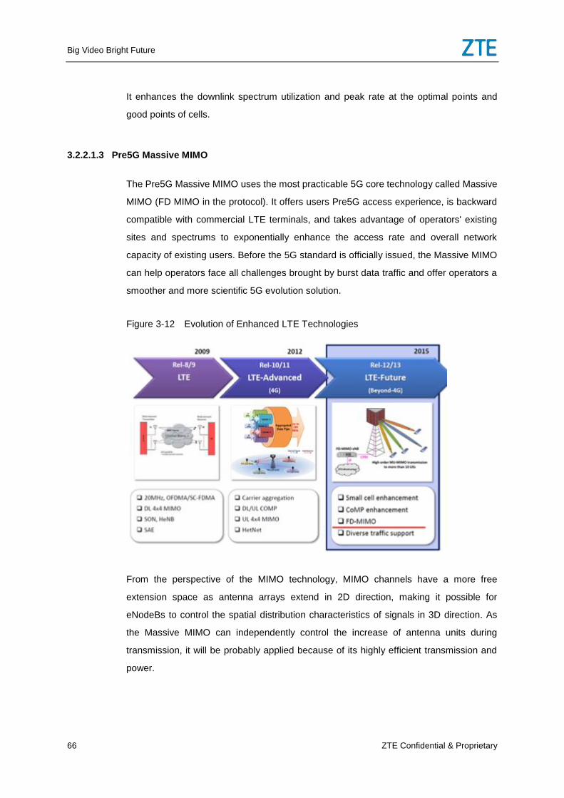
Big Video Bright Future
66 ZTE Confidential & Proprietary
It enhances the downlink spectrum utilization and peak rate at the optimal points and
good points of cells.
3.2.2.1.3 Pre5G Massive MIMO
The Pre5G Massive MIMO uses the most practicable 5G core technology called Massive
MIMO (FD MIMO in the protocol). It offers users Pre5G access experience, is backward
compatible with commercial LTE terminals, and takes advantage of operators' existing
sites and spectrums to exponentially enhance the access rate and overall network
capacity of existing users. Before the 5G standard is officially issued, the Massive MIMO
can help operators face all challenges brought by burst data traffic and offer operators a
smoother and more scientific 5G evolution solution.
Figure 3-12 Evolution of Enhanced LTE Technologies
From the perspective of the MIMO technology, MIMO channels have a more free
extension space as antenna arrays extend in 2D direction, making it possible for
eNodeBs to control the spatial distribution characteristics of signals in 3D direction. As
the Massive MIMO can independently control the increase of antenna units during
transmission, it will be probably applied because of its highly efficient transmission and
power.
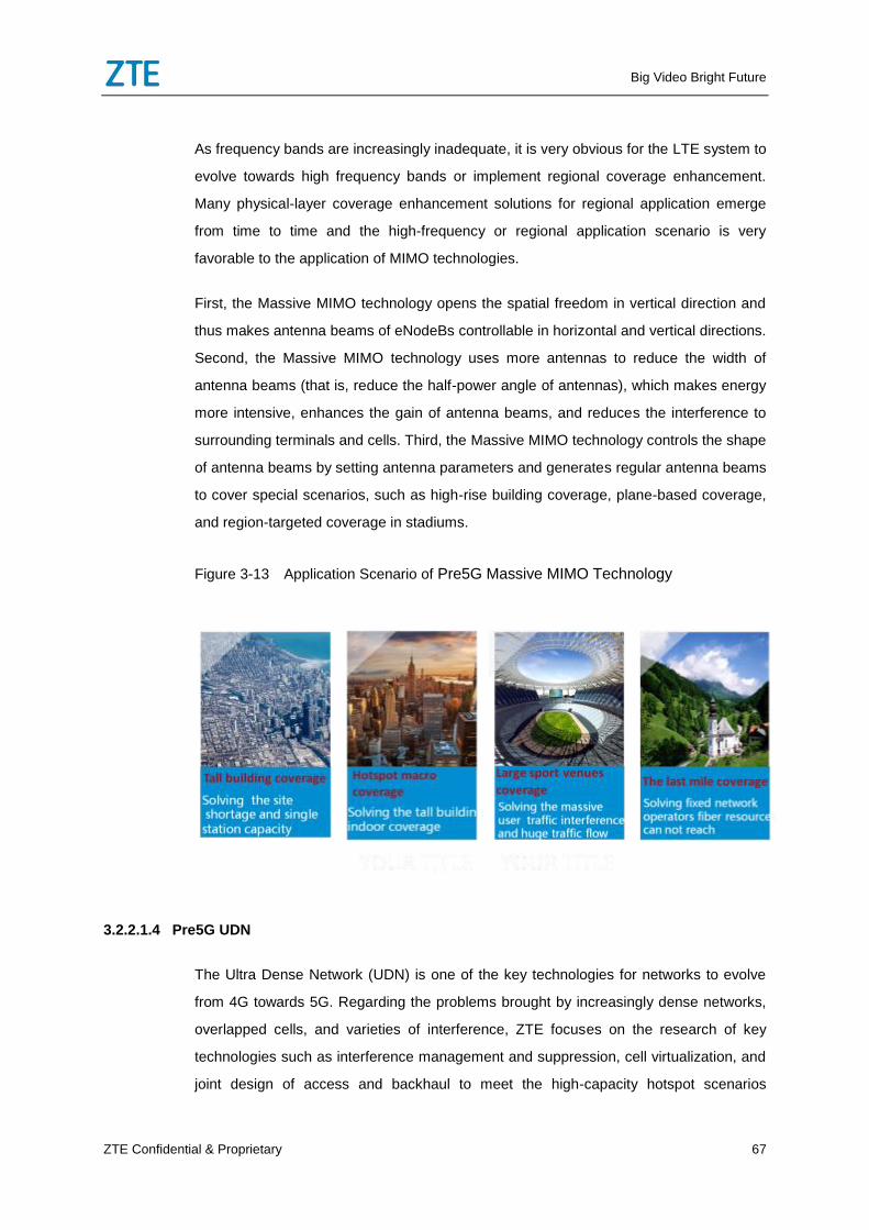
Big Video Bright Future
ZTE Confidential & Proprietary 67
As frequency bands are increasingly inadequate, it is very obvious for the LTE system to
evolve towards high frequency bands or implement regional coverage enhancement.
Many physical-layer coverage enhancement solutions for regional application emerge
from time to time and the high-frequency or regional application scenario is very
favorable to the application of MIMO technologies.
First, the Massive MIMO technology opens the spatial freedom in vertical direction and
thus makes antenna beams of eNodeBs controllable in horizontal and vertical directions.
Second, the Massive MIMO technology uses more antennas to reduce the width of
antenna beams (that is, reduce the half-power angle of antennas), which makes energy
more intensive, enhances the gain of antenna beams, and reduces the interference to
surrounding terminals and cells. Third, the Massive MIMO technology controls the shape
of antenna beams by setting antenna parameters and generates regular antenna beams
to cover special scenarios, such as high-rise building coverage, plane-based coverage,
and region-targeted coverage in stadiums.
Figure 3-13 Application Scenario of Pre5G Massive MIMO Technology
3.2.2.1.4 Pre5G UDN
The Ultra Dense Network (UDN) is one of the key technologies for networks to evolve
from 4G towards 5G. Regarding the problems brought by increasingly dense networks,
overlapped cells, and varieties of interference, ZTE focuses on the research of key
technologies such as interference management and suppression, cell virtualization, and
joint design of access and backhaul to meet the high-capacity hotspot scenarios
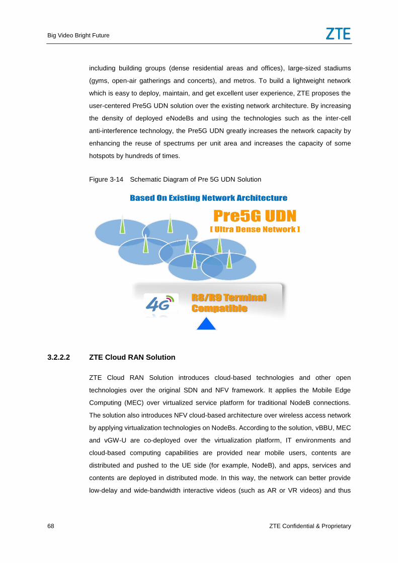
Big Video Bright Future
68 ZTE Confidential & Proprietary
including building groups (dense residential areas and offices), large-sized stadiums
(gyms, open-air gatherings and concerts), and metros. To build a lightweight network
which is easy to deploy, maintain, and get excellent user experience, ZTE proposes the
user-centered Pre5G UDN solution over the existing network architecture. By increasing
the density of deployed eNodeBs and using the technologies such as the inter-cell
anti-interference technology, the Pre5G UDN greatly increases the network capacity by
enhancing the reuse of spectrums per unit area and increases the capacity of some
hotspots by hundreds of times.
Figure 3-14 Schematic Diagram of Pre 5G UDN Solution
3.2.2.2 ZTE Cloud RAN Solution
ZTE Cloud RAN Solution introduces cloud-based technologies and other open
technologies over the original SDN and NFV framework. It applies the Mobile Edge
Computing (MEC) over virtualized service platform for traditional NodeB connections.
The solution also introduces NFV cloud-based architecture over wireless access network
by applying virtualization technologies on NodeBs. According to the solution, vBBU, MEC
and vGW-U are co-deployed over the virtualization platform, IT environments and
cloud-based computing capabilities are provided near mobile users, contents are
distributed and pushed to the UE side (for example, NodeB), and apps, services and
contents are deployed in distributed mode. In this way, the network can better provide
low-delay and wide-bandwidth interactive videos (such as AR or VR videos) and thus
Big Video Bright Future
ZTE Confidential & Proprietary 69
help operators face new challenges and meet the ever-changing commercial demands.
ZTE Cloud RAN Solution is an inevitable choice of operators.
Infinite Possibilities Brought by Virtualization Platform
ZTE Cloud RAN Solution architecture is based on software and hardware separation.
The virtualization platform supports downward migration of user-plane services from the
core network and third-party services. It also provides external interfaces for
programming and seamless integration with third-party providers.
The MEC is applied on the new cloud-based IT server to integrate huge service-layer
apps, such as local stream splitting and CDN.
Collaborative Resource Dispatching for Maximizing Network Efficiency
As more and more Hetnet networks are deployed, there are increasingly high demands
for cross-band and cross-system resource sharing. ZTE Cloud RAN Solution provides
collaborative dispatching for the wireless resources between different cells and
frequency bands to minimize network-wide interference and enhance spectrum utilization
and user experience.
Flexible Network Deployment for Enhancing Network Resource Utilization
With Virtual Network Functions (VNFs), ZTE Cloud RAN Solution helps dispatch
resources over cloud to realize auto network configuration and demand-driven network
evolution, and to simplify network management. In addition, ZTE Cloud RAN Solution
helps provide a flexible and robust network by building a CT-based reliable platform with
IT-based hardware, which minimizes the CAPEX and OPEX.
Open Interfaces for Easy Network Evolution
ZTE Cloud RAN Solution helps build a network over a unified open platform. It not only
offers users fundamental services, but also offers open interfaces for third parties to
develop new apps for users. It is easy to support new network services, which enables
the network to cope with ever-changing business models in a smooth way.
Smooth Evolution to 5G
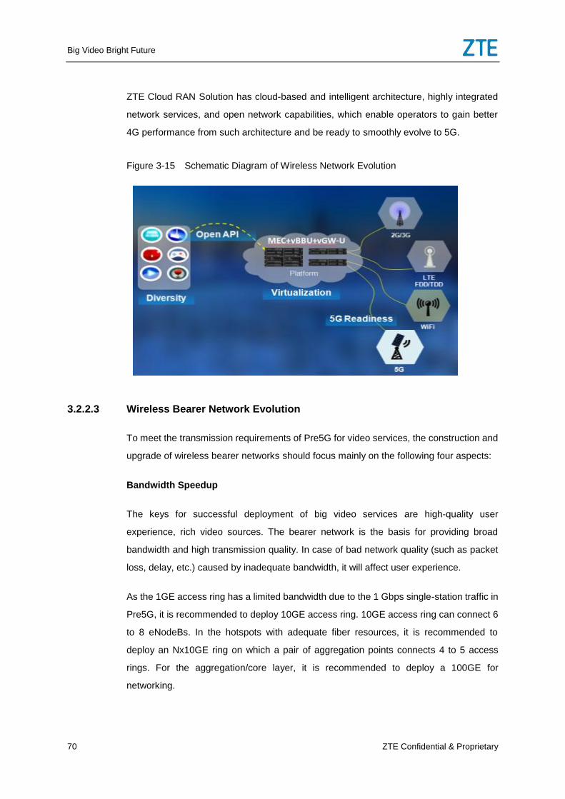
Big Video Bright Future
70 ZTE Confidential & Proprietary
ZTE Cloud RAN Solution has cloud-based and intelligent architecture, highly integrated
network services, and open network capabilities, which enable operators to gain better
4G performance from such architecture and be ready to smoothly evolve to 5G.
Figure 3-15 Schematic Diagram of Wireless Network Evolution
3.2.2.3 Wireless Bearer Network Evolution
To meet the transmission requirements of Pre5G for video services, the construction and
upgrade of wireless bearer networks should focus mainly on the following four aspects:
Bandwidth Speedup
The keys for successful deployment of big video services are high-quality user
experience, rich video sources. The bearer network is the basis for providing broad
bandwidth and high transmission quality. In case of bad network quality (such as packet
loss, delay, etc.) caused by inadequate bandwidth, it will affect user experience.
As the 1GE access ring has a limited bandwidth due to the 1 Gbps single-station traffic in
Pre5G, it is recommended to deploy 10GE access ring. 10GE access ring can connect 6
to 8 eNodeBs. In the hotspots with adequate fiber resources, it is recommended to
deploy an Nx10GE ring on which a pair of aggregation points connects 4 to 5 access
rings. For the aggregation/core layer, it is recommended to deploy a 100GE for
networking.
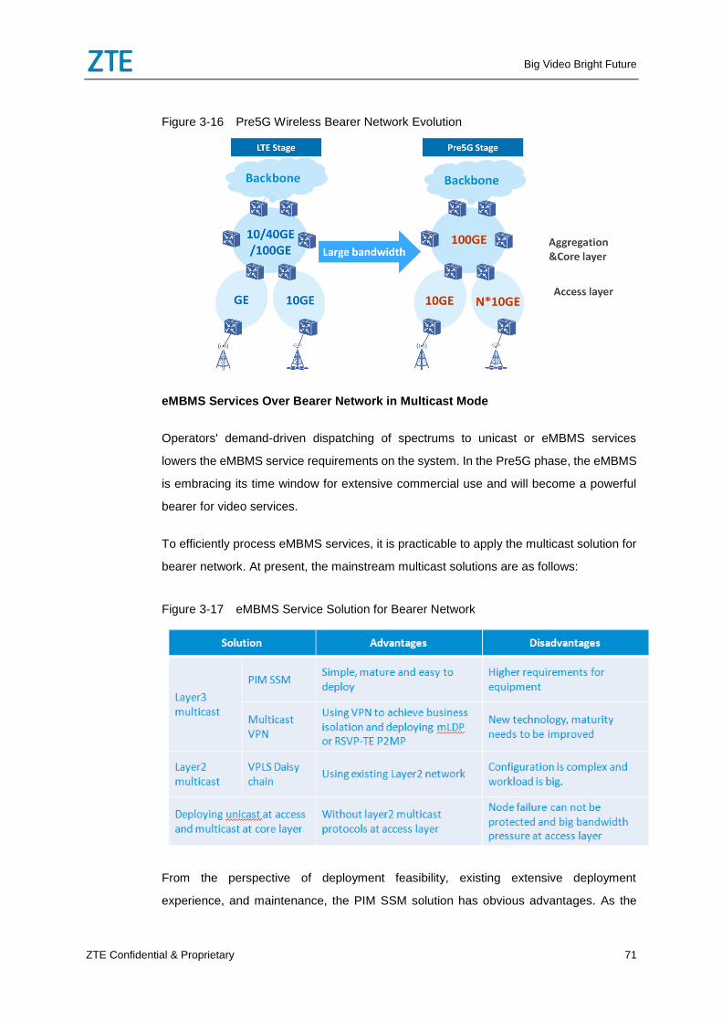
Big Video Bright Future
ZTE Confidential & Proprietary 71
Figure 3-16 Pre5G Wireless Bearer Network Evolution
eMBMS Services Over Bearer Network in Multicast Mode
Operators' demand-driven dispatching of spectrums to unicast or eMBMS services
lowers the eMBMS service requirements on the system. In the Pre5G phase, the eMBMS
is embracing its time window for extensive commercial use and will become a powerful
bearer for video services.
To efficiently process eMBMS services, it is practicable to apply the multicast solution for
bearer network. At present, the mainstream multicast solutions are as follows:
Figure 3-17 eMBMS Service Solution for Bearer Network
From the perspective of deployment feasibility, existing extensive deployment
experience, and maintenance, the PIM SSM solution has obvious advantages. As the
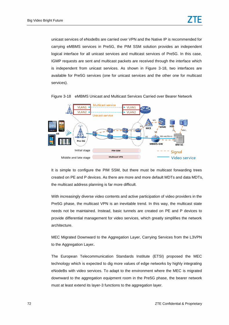
Big Video Bright Future
72 ZTE Confidential & Proprietary
unicast services of eNodeBs are carried over VPN and the Native IP is recommended for
carrying eMBMS services in Pre5G, the PIM SSM solution provides an independent
logical interface for all unicast services and multicast services of Pre5G. In this case,
IGMP requests are sent and multicast packets are received through the interface which
is independent from unicast services. As shown in Figure 3-18, two interfaces are
available for Pre5G services (one for unicast services and the other one for multicast
services).
Figure 3-18 eMBMS Unicast and Multicast Services Carried over Bearer Network
It is simple to configure the PIM SSM, but there must be multicast forwarding trees
created on PE and P devices. As there are more and more default MDTs and data MDTs,
the multicast address planning is far more difficult.
With increasingly diverse video contents and active participation of video providers in the
Pre5G phase, the multicast VPN is an inevitable trend. In this way, the multicast state
needs not be maintained. Instead, basic tunnels are created on PE and P devices to
provide differential management for video services, which greatly simplifies the network
architecture.
MEC Migrated Downward to the Aggregation Layer, Carrying Services from the L3VPN
to the Aggregation Layer.
The European Telecommunication Standards Institute (ETSI) proposed the MEC
technology which is expected to dig more values of edge networks by highly integrating
eNodeBs with video services. To adapt to the environment where the MEC is migrated
downward to the aggregation equipment room in the Pre5G phase, the bearer network
must at least extend its layer-3 functions to the aggregation layer.
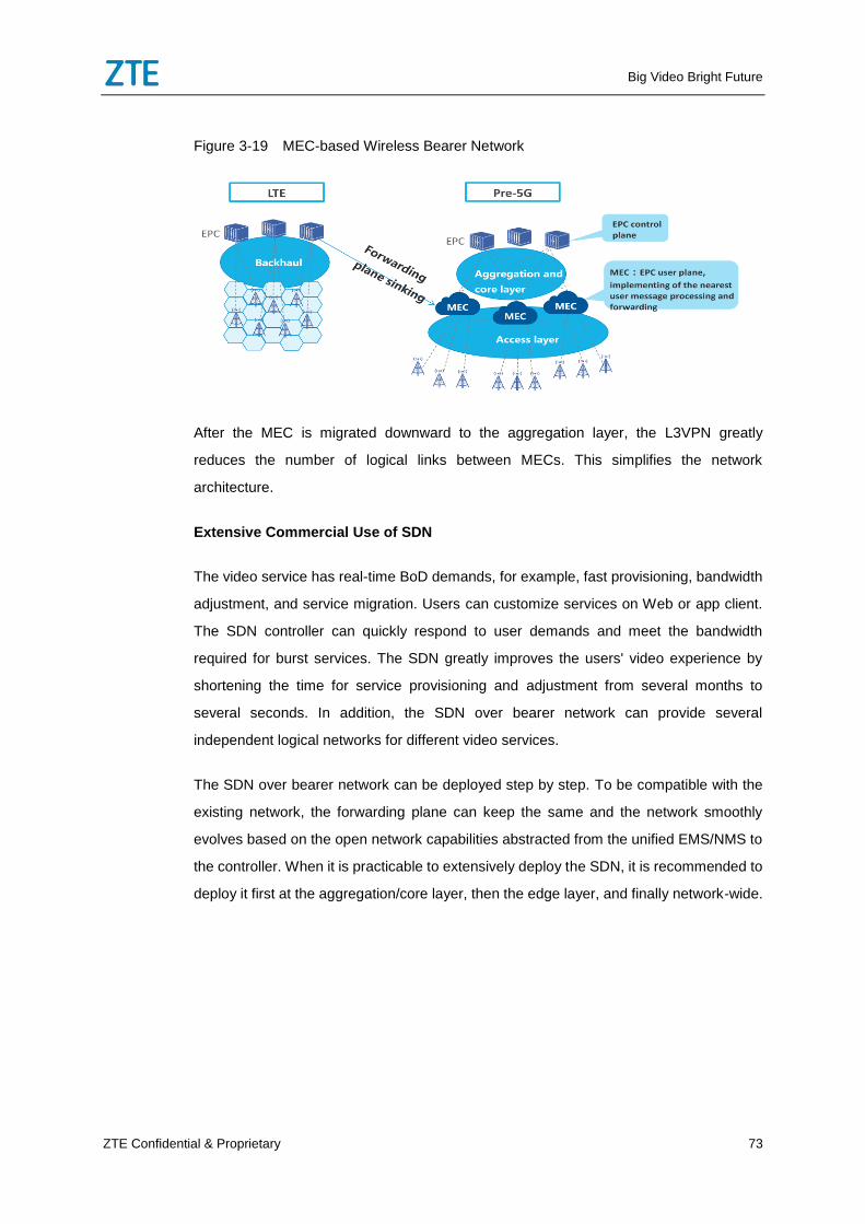
Big Video Bright Future
ZTE Confidential & Proprietary 73
Figure 3-19 MEC-based Wireless Bearer Network
After the MEC is migrated downward to the aggregation layer, the L3VPN greatly
reduces the number of logical links between MECs. This simplifies the network
architecture.
Extensive Commercial Use of SDN
The video service has real-time BoD demands, for example, fast provisioning, bandwidth
adjustment, and service migration. Users can customize services on Web or app client.
The SDN controller can quickly respond to user demands and meet the bandwidth
required for burst services. The SDN greatly improves the users' video experience by
shortening the time for service provisioning and adjustment from several months to
several seconds. In addition, the SDN over bearer network can provide several
independent logical networks for different video services.
The SDN over bearer network can be deployed step by step. To be compatible with the
existing network, the forwarding plane can keep the same and the network smoothly
evolves based on the open network capabilities abstracted from the unified EMS/NMS to
the controller. When it is practicable to extensively deploy the SDN, it is recommended to
deploy it first at the aggregation/core layer, then the edge layer, and finally network-wide.
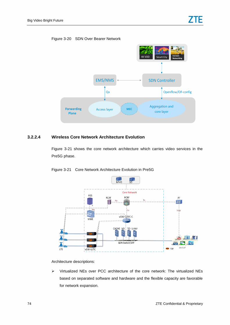
Big Video Bright Future
74 ZTE Confidential & Proprietary
Figure 3-20 SDN Over Bearer Network
3.2.2.4 Wireless Core Network Architecture Evolution
Figure 3-21 shows the core network architecture which carries video services in the
Pre5G phase.
Figure 3-21 Core Network Architecture Evolution in Pre5G
Architecture descriptions:
Virtualized NEs over PCC architecture of the core network: The virtualized NEs
based on separated software and hardware and the flexible capacity are favorable
for network expansion.
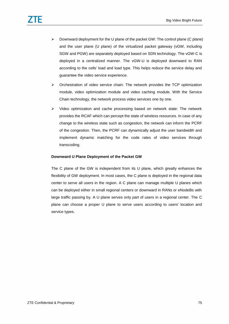
Big Video Bright Future
ZTE Confidential & Proprietary 75
Downward deployment for the U plane of the packet GW: The control plane (C plane)
and the user plane (U plane) of the virtualized packet gateway (vGW, including
SGW and PGW) are separately deployed based on SDN technology. The vGW-C is
deployed in a centralized manner. The vGW-U is deployed downward to RAN
according to the cells' load and load type. This helps reduce the service delay and
guarantee the video service experience.
Orchestration of video service chain: The network provides the TCP optimization
module, video optimization module and video caching module. With the Service
Chain technology, the network process video services one by one.
Video optimization and cache processing based on network state: The network
provides the RCAF which can percept the state of wireless resources. In case of any
change to the wireless state such as congestion, the network can inform the PCRF
of the congestion. Then, the PCRF can dynamically adjust the user bandwidth and
implement dynamic matching for the code rates of video services through
transcoding.
Downward U Plane Deployment of the Packet GW
The C plane of the GW is independent from its U plane, which greatly enhances the
flexibility of GW deployment. In most cases, the C plane is deployed in the regional data
center to serve all users in the region. A C plane can manage multiple U planes which
can be deployed either in small regional centers or downward in RANs or eNodeBs with
large traffic passing by. A U plane serves only part of users in a regional center. The C
plane can choose a proper U plane to serve users according to users' location and
service types.
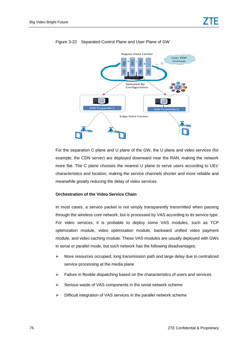
Big Video Bright Future
76 ZTE Confidential & Proprietary
Figure 3-22 Separated Control Plane and User Plane of GW
For the separation C plane and U plane of the GW, the U plane and video services (for
example, the CDN server) are deployed downward near the RAN, making the network
more flat. The C plane chooses the nearest U plane to serve users according to UEs'
characteristics and location, making the service channels shorter and more reliable and
meanwhile greatly reducing the delay of video services.
Orchestration of the Video Service Chain
In most cases, a service packet is not simply transparently transmitted when passing
through the wireless core network, but is processed by VAS according to its service type.
For video services, it is probable to deploy some VAS modules, such as TCP
optimization module, video optimization module, backward unified video payment
module, and video caching module. These VAS modules are usually deployed with GWs
in serial or parallel mode, but such network has the following disadvantages:
More resources occupied, long transmission path and large delay due to centralized
service processing at the media plane
Failure in flexible dispatching based on the characteristics of users and services
Serious waste of VAS components in the serial network scheme
Difficult integration of VAS services in the parallel network scheme
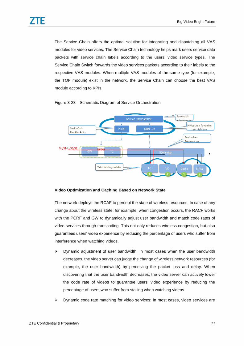
Big Video Bright Future
ZTE Confidential & Proprietary 77
The Service Chain offers the optimal solution for integrating and dispatching all VAS
modules for video services. The Service Chain technology helps mark users service data
packets with service chain labels according to the users' video service types. The
Service Chain Switch forwards the video services packets according to their labels to the
respective VAS modules. When multiple VAS modules of the same type (for example,
the TOF module) exist in the network, the Service Chain can choose the best VAS
module according to KPIs.
Figure 3-23 Schematic Diagram of Service Orchestration
Video Optimization and Caching Based on Network State
The network deploys the RCAF to percept the state of wireless resources. In case of any
change about the wireless state, for example, when congestion occurs, the RACF works
with the PCRF and GW to dynamically adjust user bandwidth and match code rates of
video services through transcoding. This not only reduces wireless congestion, but also
guarantees users' video experience by reducing the percentage of users who suffer from
interference when watching videos.
Dynamic adjustment of user bandwidth: In most cases when the user bandwidth
decreases, the video server can judge the change of wireless network resources (for
example, the user bandwidth) by perceiving the packet loss and delay. When
discovering that the user bandwidth decreases, the video server can actively lower
the code rate of videos to guarantee users' video experience by reducing the
percentage of users who suffer from stalling when watching videos.
Dynamic code rate matching for video services: In most cases, video services are
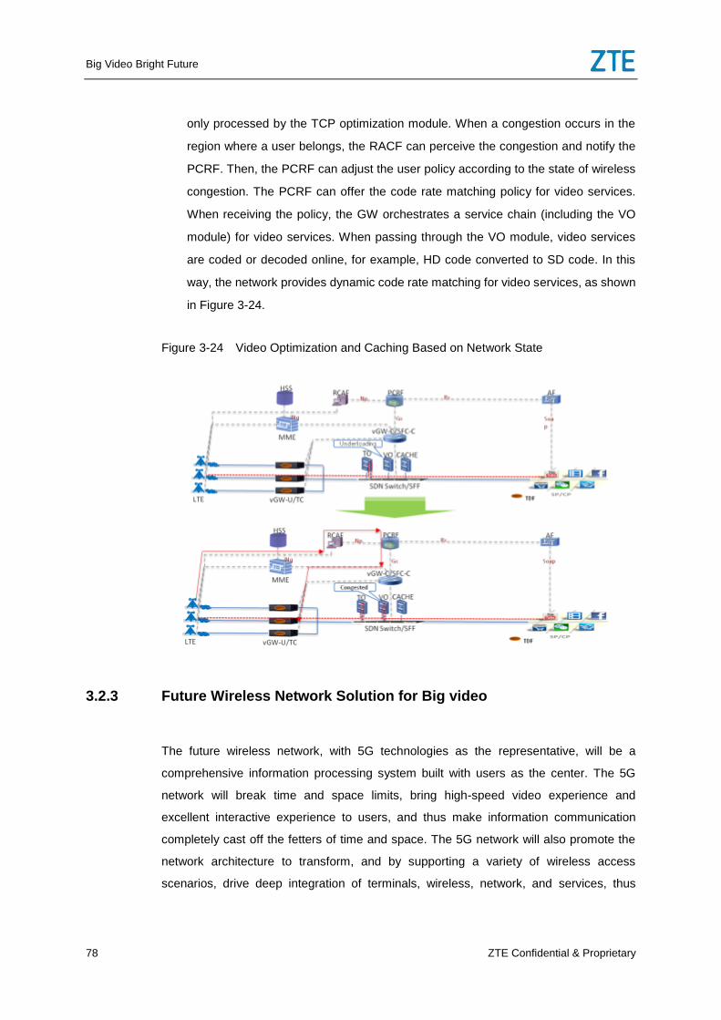
Big Video Bright Future
78 ZTE Confidential & Proprietary
only processed by the TCP optimization module. When a congestion occurs in the
region where a user belongs, the RACF can perceive the congestion and notify the
PCRF. Then, the PCRF can adjust the user policy according to the state of wireless
congestion. The PCRF can offer the code rate matching policy for video services.
When receiving the policy, the GW orchestrates a service chain (including the VO
module) for video services. When passing through the VO module, video services
are coded or decoded online, for example, HD code converted to SD code. In this
way, the network provides dynamic code rate matching for video services, as shown
in Figure 3-24.
Figure 3-24 Video Optimization and Caching Based on Network State
3.2.3 Future Wireless Network Solution for Big video
The future wireless network, with 5G technologies as the representative, will be a
comprehensive information processing system built with users as the center. The 5G
network will break time and space limits, bring high-speed video experience and
excellent interactive experience to users, and thus make information communication
completely cast off the fetters of time and space. The 5G network will also promote the
network architecture to transform, and by supporting a variety of wireless access
scenarios, drive deep integration of terminals, wireless, network, and services, thus
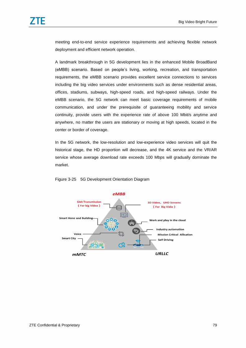
Big Video Bright Future
ZTE Confidential & Proprietary 79
meeting end-to-end service experience requirements and achieving flexible network
deployment and efficient network operation.
A landmark breakthrough in 5G development lies in the enhanced Mobile BroadBand
(eMBB) scenario. Based on people’s living, working, recreation, and transportation
requirements, the eMBB scenario provides excellent service connections to services
including the big video services under environments such as dense residential areas,
offices, stadiums, subways, high-speed roads, and high-speed railways. Under the
eMBB scenario, the 5G network can meet basic coverage requirements of mobile
communication, and under the prerequisite of guaranteeing mobility and service
continuity, provide users with the experience rate of above 100 Mbit/s anytime and
anywhere, no matter the users are stationary or moving at high speeds, located in the
center or border of coverage.
In the 5G network, the low-resolution and low-experience video services will quit the
historical stage, the HD proportion will decrease, and the 4K service and the VR/AR
service whose average download rate exceeds 100 Mbps will gradually dominate the
market.
Figure 3-25 5G Development Orientation Diagram
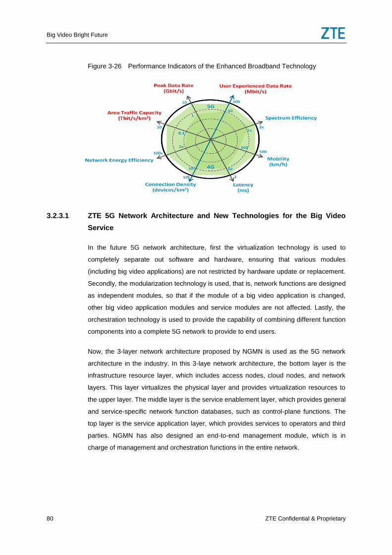
Big Video Bright Future
80 ZTE Confidential & Proprietary
Figure 3-26 Performance Indicators of the Enhanced Broadband Technology
3.2.3.1 ZTE 5G Network Architecture and New Technologies for the Big Video
Service
In the future 5G network architecture, first the virtualization technology is used to
completely separate out software and hardware, ensuring that various modules
(including big video applications) are not restricted by hardware update or replacement.
Secondly, the modularization technology is used, that is, network functions are designed
as independent modules, so that if the module of a big video application is changed,
other big video application modules and service modules are not affected. Lastly, the
orchestration technology is used to provide the capability of combining different function
components into a complete 5G network to provide to end users.
Now, the 3-layer network architecture proposed by NGMN is used as the 5G network
architecture in the industry. In this 3-laye network architecture, the bottom layer is the
infrastructure resource layer, which includes access nodes, cloud nodes, and network
layers. This layer virtualizes the physical layer and provides virtualization resources to
the upper layer. The middle layer is the service enablement layer, which provides general
and service-specific network function databases, such as control-plane functions. The
top layer is the service application layer, which provides services to operators and third
parties. NGMN has also designed an end-to-end management module, which is in
charge of management and orchestration functions in the entire network.
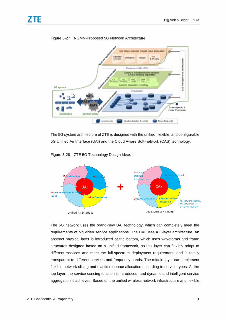
Big Video Bright Future
ZTE Confidential & Proprietary 81
Figure 3-27 NGMN-Proposed 5G Network Architecture
The 5G system architecture of ZTE is designed with the unified, flexible, and configurable
5G Unified Air Interface (UAI) and the Cloud Aware Soft-network (CAS) technology.
Figure 3-28 ZTE 5G Technology Design Ideas
The 5G network uses the brand-new UAI technology, which can completely meet the
requirements of big video service applications. The UAI uses a 3-layer architecture. An
abstract physical layer is introduced at the bottom, which uses waveforms and frame
structures designed based on a unified framework, so this layer can flexibly adapt to
different services and meet the full-spectrum deployment requirement, and is totally
transparent to different services and frequency bands. The middle layer can implement
flexible network slicing and elastic resource allocation according to service types. At the
top layer, the service sensing function is introduced, and dynamic and intelligent service
aggregation is achieved. Based on the unified wireless network infrastructure and flexible
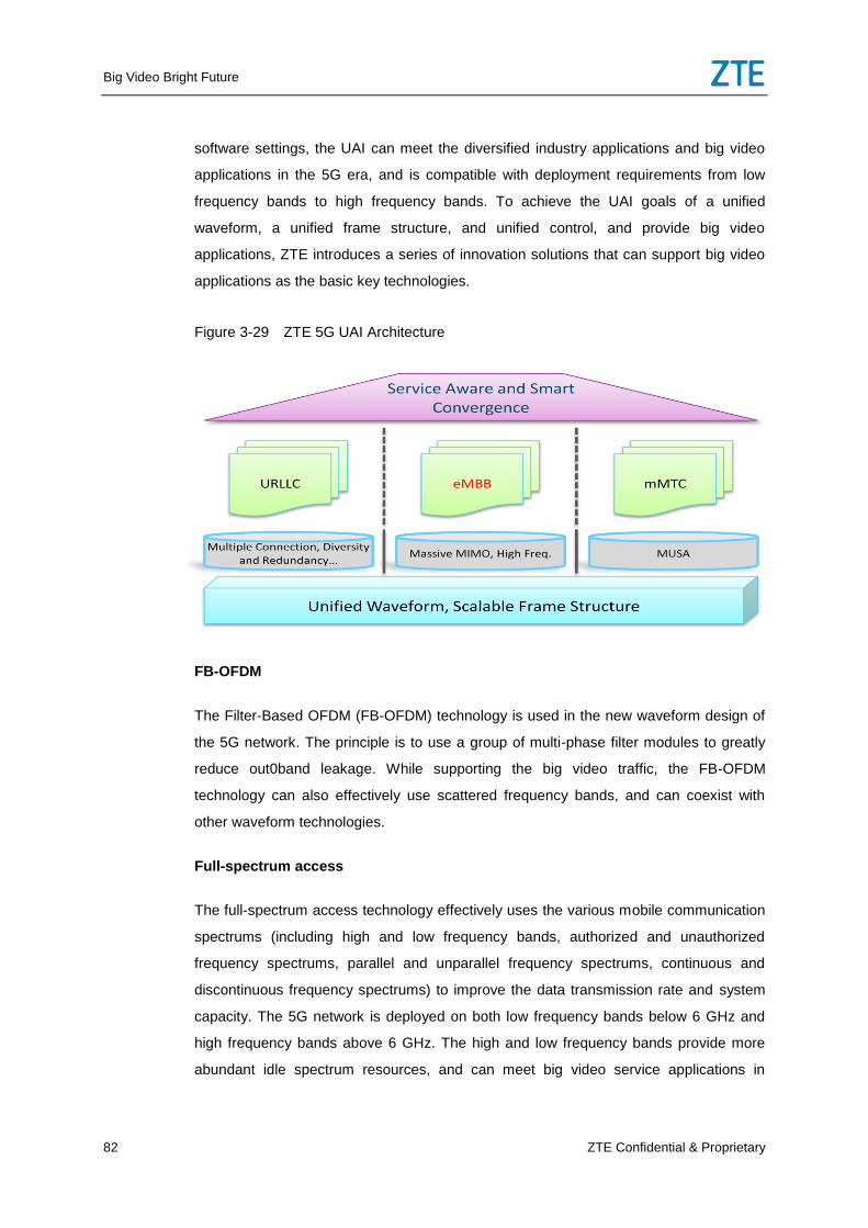
Big Video Bright Future
82 ZTE Confidential & Proprietary
software settings, the UAI can meet the diversified industry applications and big video
applications in the 5G era, and is compatible with deployment requirements from low
frequency bands to high frequency bands. To achieve the UAI goals of a unified
waveform, a unified frame structure, and unified control, and provide big video
applications, ZTE introduces a series of innovation solutions that can support big video
applications as the basic key technologies.
Figure 3-29 ZTE 5G UAI Architecture
FB-OFDM
The Filter-Based OFDM (FB-OFDM) technology is used in the new waveform design of
the 5G network. The principle is to use a group of multi-phase filter modules to greatly
reduce out0band leakage. While supporting the big video traffic, the FB-OFDM
technology can also effectively use scattered frequency bands, and can coexist with
other waveform technologies.
Full-spectrum access
The full-spectrum access technology effectively uses the various mobile communication
spectrums (including high and low frequency bands, authorized and unauthorized
frequency spectrums, parallel and unparallel frequency spectrums, continuous and
discontinuous frequency spectrums) to improve the data transmission rate and system
capacity. The 5G network is deployed on both low frequency bands below 6 GHz and
high frequency bands above 6 GHz. The high and low frequency bands provide more
abundant idle spectrum resources, and can meet big video service applications in
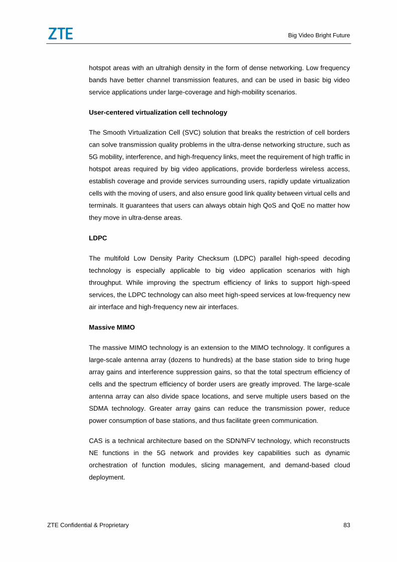
Big Video Bright Future
ZTE Confidential & Proprietary 83
hotspot areas with an ultrahigh density in the form of dense networking. Low frequency
bands have better channel transmission features, and can be used in basic big video
service applications under large-coverage and high-mobility scenarios.
User-centered virtualization cell technology
The Smooth Virtualization Cell (SVC) solution that breaks the restriction of cell borders
can solve transmission quality problems in the ultra-dense networking structure, such as
5G mobility, interference, and high-frequency links, meet the requirement of high traffic in
hotspot areas required by big video applications, provide borderless wireless access,
establish coverage and provide services surrounding users, rapidly update virtualization
cells with the moving of users, and also ensure good link quality between virtual cells and
terminals. It guarantees that users can always obtain high QoS and QoE no matter how
they move in ultra-dense areas.
LDPC
The multifold Low Density Parity Checksum (LDPC) parallel high-speed decoding
technology is especially applicable to big video application scenarios with high
throughput. While improving the spectrum efficiency of links to support high-speed
services, the LDPC technology can also meet high-speed services at low-frequency new
air interface and high-frequency new air interfaces.
Massive MIMO
The massive MIMO technology is an extension to the MIMO technology. It configures a
large-scale antenna array (dozens to hundreds) at the base station side to bring huge
array gains and interference suppression gains, so that the total spectrum efficiency of
cells and the spectrum efficiency of border users are greatly improved. The large-scale
antenna array can also divide space locations, and serve multiple users based on the
SDMA technology. Greater array gains can reduce the transmission power, reduce
power consumption of base stations, and thus facilitate green communication.
CAS is a technical architecture based on the SDN/NFV technology, which reconstructs
NE functions in the 5G network and provides key capabilities such as dynamic
orchestration of function modules, slicing management, and demand-based cloud
deployment.
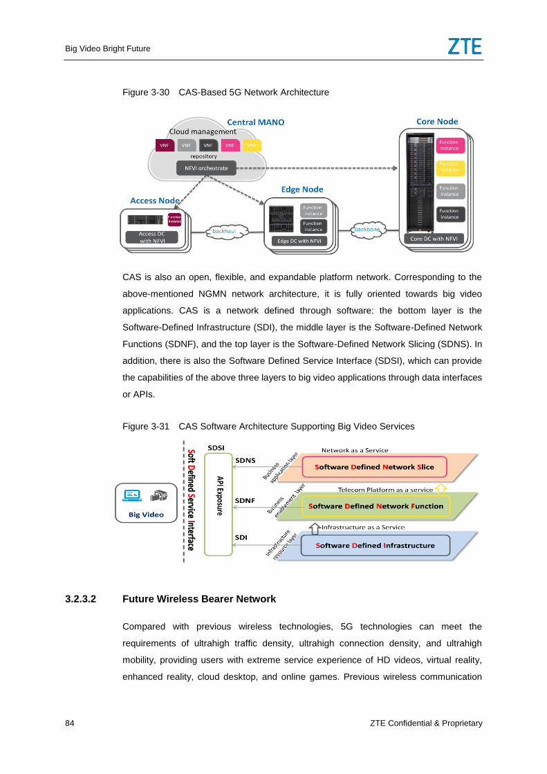
Big Video Bright Future
84 ZTE Confidential & Proprietary
Figure 3-30 CAS-Based 5G Network Architecture
CAS is also an open, flexible, and expandable platform network. Corresponding to the
above-mentioned NGMN network architecture, it is fully oriented towards big video
applications. CAS is a network defined through software: the bottom layer is the
Software-Defined Infrastructure (SDI), the middle layer is the Software-Defined Network
Functions (SDNF), and the top layer is the Software-Defined Network Slicing (SDNS). In
addition, there is also the Software Defined Service Interface (SDSI), which can provide
the capabilities of the above three layers to big video applications through data interfaces
or APIs.
Figure 3-31 CAS Software Architecture Supporting Big Video Services
3.2.3.2 Future Wireless Bearer Network
Compared with previous wireless technologies, 5G technologies can meet the
requirements of ultrahigh traffic density, ultrahigh connection density, and ultrahigh
mobility, providing users with extreme service experience of HD videos, virtual reality,
enhanced reality, cloud desktop, and online games. Previous wireless communication
Big Video Bright Future
ZTE Confidential & Proprietary 85
uses the innovation of multiple access technologies as the regeneration mark, but the 5G
concept is extended from the wireless side to the network side. A new network
architecture is used, in which 5G service requirements and new technologies
represented by SDN, NFV and virtualization together drive the innovation of the 5G
network architecture. Thus, the 5G network can support diversified wireless access
scenarios, meet end-to-end service experience requirements, and achieve flexible
network deployment and efficient network operation.
3.2.3.2.1 Fronthaul
Oriented towards evolution of the wireless access network and the requirements of 5G
key capabilities, the 5G network uses higher frequency bands, higher wireless frequency
bands, and more antennas to provide an ultrahigh wireless transmission bandwidth,
causing the bandwidth at the CPRI interface to increase rapidly. Centralized,
Cooperative, Cloud RAN (C-RAN) is an important direction for the future wireless
fronthaul access network to evolve towards. C-RAN can be further divided into two
bearing modes: CPRI over OTN and Next Generation Fronthaul Interface (NGFI).
CPRI over OTN
Small OTN devices are used to bear CPRI services. OTN bearer devices can provide
perfect protection, OAM, and fault diagnosis capabilities, and can support multiple
network architectures such as ring-shape, tree-shape (Uni-PON), and mesh-shape.
Small OTN devices use industrial components to enhance the temperature control
capability, and can adapt to severe environment applications and installation conditions,
such as corridor wall-mounted and pole-mounted installation modes. Small OTN devices
can be divided into indoor devices and outdoor devices. Indoor OTN devices can be
stacked up to meet the access requirement of BBU pools of different scales. Outdoor
OTN devices do not installed in special equipment rooms, and can be mounted to poles
and configured in different combinations, thus adapting to different environments, clients,
and networking requirements.
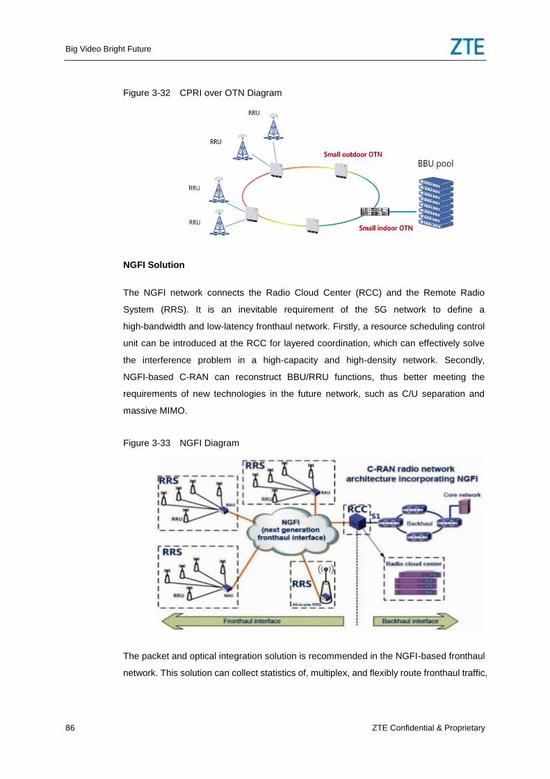
Big Video Bright Future
86 ZTE Confidential & Proprietary
Figure 3-32 CPRI over OTN Diagram
NGFI Solution
The NGFI network connects the Radio Cloud Center (RCC) and the Remote Radio
System (RRS). It is an inevitable requirement of the 5G network to define a
high-bandwidth and low-latency fronthaul network. Firstly, a resource scheduling control
unit can be introduced at the RCC for layered coordination, which can effectively solve
the interference problem in a high-capacity and high-density network. Secondly,
NGFI-based C-RAN can reconstruct BBU/RRU functions, thus better meeting the
requirements of new technologies in the future network, such as C/U separation and
massive MIMO.
Figure 3-33 NGFI Diagram
The packet and optical integration solution is recommended in the NGFI-based fronthaul
network. This solution can collect statistics of, multiplex, and flexibly route fronthaul traffic,
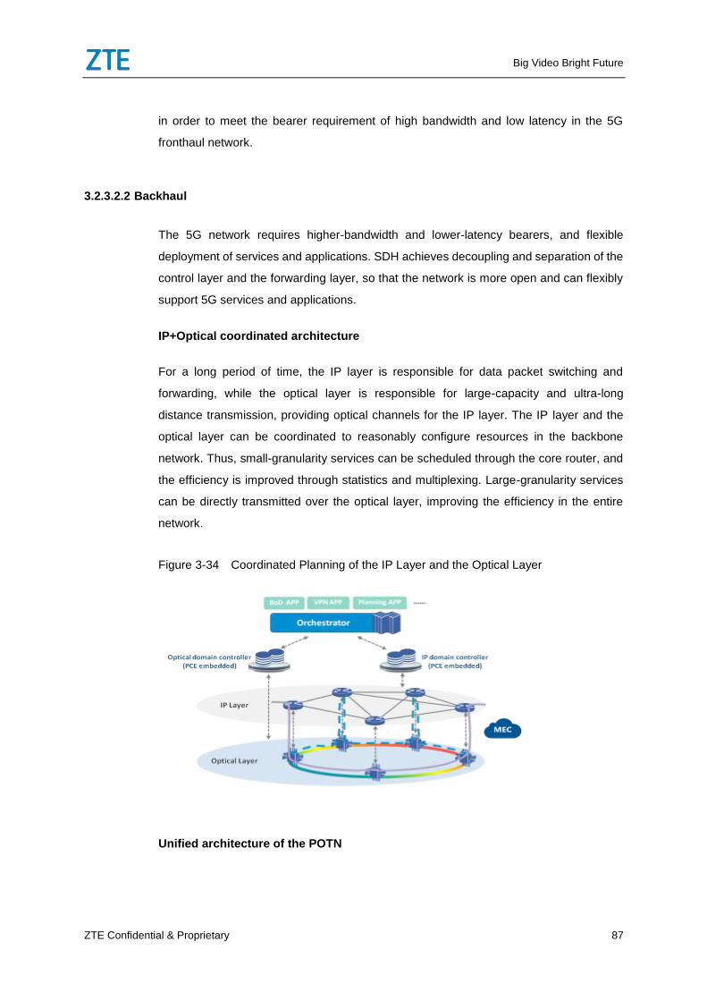
Big Video Bright Future
ZTE Confidential & Proprietary 87
in order to meet the bearer requirement of high bandwidth and low latency in the 5G
fronthaul network.
3.2.3.2.2 Backhaul
The 5G network requires higher-bandwidth and lower-latency bearers, and flexible
deployment of services and applications. SDH achieves decoupling and separation of the
control layer and the forwarding layer, so that the network is more open and can flexibly
support 5G services and applications.
IP+Optical coordinated architecture
For a long period of time, the IP layer is responsible for data packet switching and
forwarding, while the optical layer is responsible for large-capacity and ultra-long
distance transmission, providing optical channels for the IP layer. The IP layer and the
optical layer can be coordinated to reasonably configure resources in the backbone
network. Thus, small-granularity services can be scheduled through the core router, and
the efficiency is improved through statistics and multiplexing. Large-granularity services
can be directly transmitted over the optical layer, improving the efficiency in the entire
network.
Figure 3-34 Coordinated Planning of the IP Layer and the Optical Layer
Unified architecture of the POTN
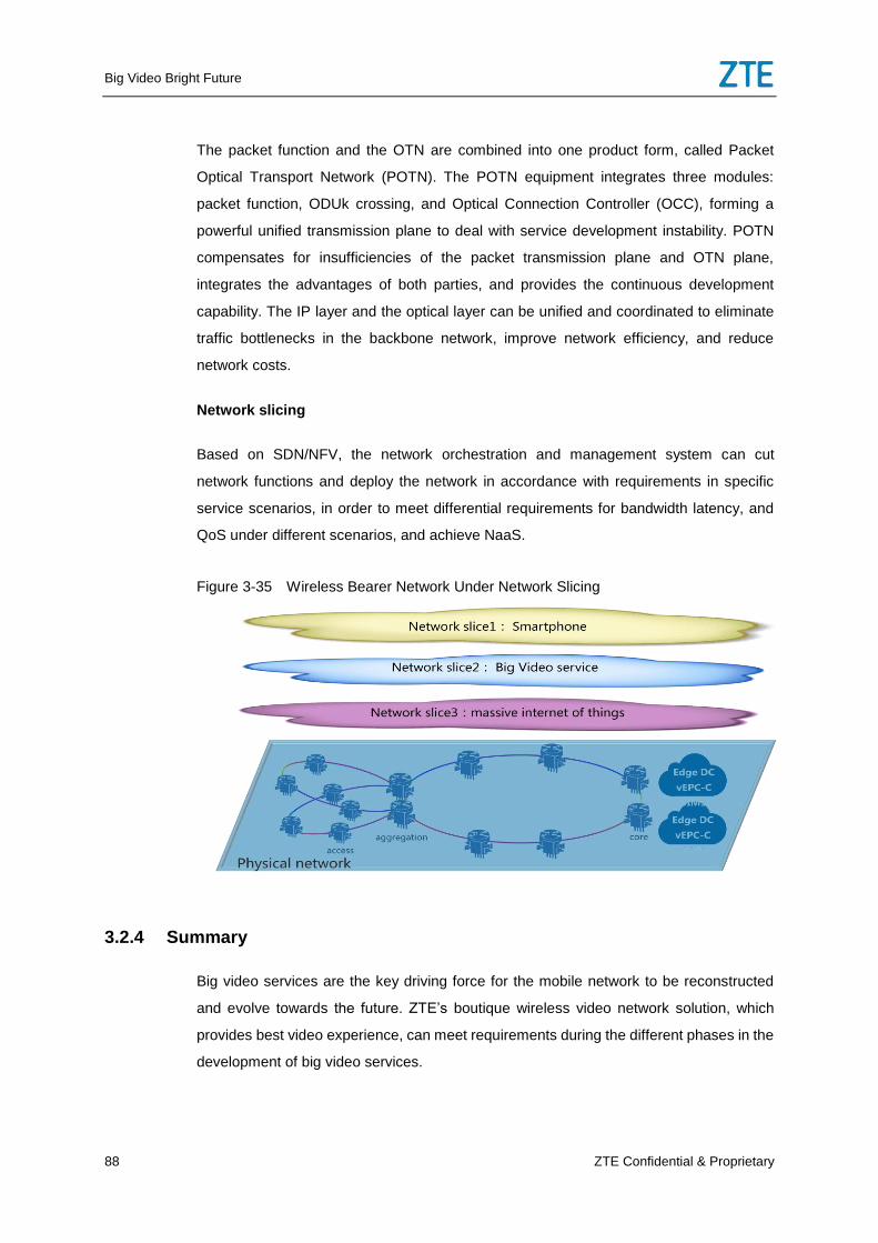
Big Video Bright Future
88 ZTE Confidential & Proprietary
The packet function and the OTN are combined into one product form, called Packet
Optical Transport Network (POTN). The POTN equipment integrates three modules:
packet function, ODUk crossing, and Optical Connection Controller (OCC), forming a
powerful unified transmission plane to deal with service development instability. POTN
compensates for insufficiencies of the packet transmission plane and OTN plane,
integrates the advantages of both parties, and provides the continuous development
capability. The IP layer and the optical layer can be unified and coordinated to eliminate
traffic bottlenecks in the backbone network, improve network efficiency, and reduce
network costs.
Network slicing
Based on SDN/NFV, the network orchestration and management system can cut
network functions and deploy the network in accordance with requirements in specific
service scenarios, in order to meet differential requirements for bandwidth latency, and
QoS under different scenarios, and achieve NaaS.
Figure 3-35 Wireless Bearer Network Under Network Slicing
3.2.4 Summary
Big video services are the key driving force for the mobile network to be reconstructed
and evolve towards the future. ZTE’s boutique wireless video network solution, which
provides best video experience, can meet requirements during the different phases in the
development of big video services.
Big Video Bright Future
ZTE Confidential & Proprietary 89
Phase 1: The wireless access network solves key shortcomings with mobile video
services through coverage optimization, interference optimization, capacity improvement,
and service optimization. QoS of video services is guaranteed through SQM in the
wireless bearer network and service detection and TCP optimization in the core network.
Phase 2: The Pre5G phase, as a key process to 5G, ensures smooth development of the
4G network and also takes the application of 5G technologies into consideration. It uses
Pre5G massive and Pre5G UDN technologies, as well as architecture evolvement
methods such as Cloud RAN, distributed deployment of the core network, and bearer
bandwidth and speed increase, to improve resource usage and efficiency.
Phase 3: The future wireless network uses flexible and configurable UAIs and the CAS,
as well as virtualization, modularization, and orchestration technologies to meet the
development trend of video services. The wireless bearer network can also guarantee
high-quality video service experience through the IP+Optical coordinated architecture.
4 Big Video Service Platform Solution
4.1 Pain Points and Innovation of the Big Video Service
Platform
Although various kinds of message are in favor of IPTV/OTT service operation of the
operator, a lot of problems are urgently solved for the operator to realize its strategic
conversion from traditional video services to big video services. The following table
contrasts and analyzes existing requirements of the operator for traditional video
services and big video services with respect to operation mode, system architecture, and
development mode to parse some pain points during the strategic conversion process.
Table 4-1 Comparison of Modes of Traditional Video Services and Big Video Services
Traditional Video Services Big Video Services
Operation
Mode
On-the-site service
Relatively fixed product packets
Relatively enclosed VAS platform
Self-help service provisioning and
online service
Ad, individual center, precise marketing
Collaborative win-to-win ecosystem
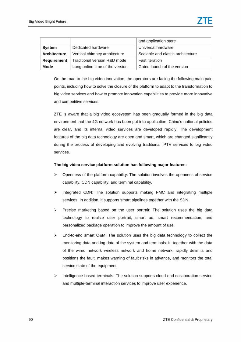
Big Video Bright Future
90 ZTE Confidential & Proprietary
and application store
System
Architecture
Dedicated hardware
Vertical chimney architecture
Universal hardware
Scalable and elastic architecture
Requirement
Mode
Traditional version R&D mode
Long online time of the version
Fast iteration
Gated launch of the version
On the road to the big video innovation, the operators are facing the following main pain
points, including how to solve the closure of the platform to adapt to the transformation to
big video services and how to promote innovation capabilities to provide more innovative
and competitive services.
ZTE is aware that a big video ecosystem has been gradually formed in the big data
environment that the 4G network has been put into application, China’s national policies
are clear, and its internal video services are developed rapidly. The development
features of the big data technology are open and smart, which are changed significantly
during the process of developing and evolving traditional IPTV services to big video
services.
The big video service platform solution has following major features:
Openness of the platform capability: The solution involves the openness of service
capability, CDN capability, and terminal capability.
Integrated CDN: The solution supports making FMC and integrating multiple
services. In addition, it supports smart pipelines together with the SDN.
Precise marketing based on the user portrait: The solution uses the big data
technology to realize user portrait, smart ad, smart recommendation, and
personalized package operation to improve the amount of use.
End-to-end smart O&M: The solution uses the big data technology to collect the
monitoring data and log data of the system and terminals. It, together with the data
of the wired network wireless network and home network, rapidly delimits and
positions the fault, makes warning of fault risks in advance, and monitors the total
service state of the equipment.
Intelligence-based terminals: The solution supports cloud end collaboration service
and multiple-terminal interaction services to improve user experience.
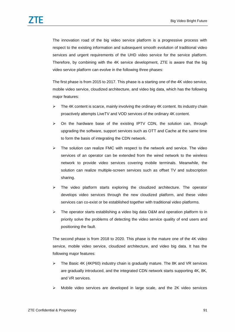
Big Video Bright Future
ZTE Confidential & Proprietary 91
The innovation road of the big video service platform is a progressive process with
respect to the existing information and subsequent smooth evolution of traditional video
services and urgent requirements of the UHD video service for the service platform.
Therefore, by combining with the 4K service development, ZTE is aware that the big
video service platform can evolve in the following three phases:
The first phase is from 2015 to 2017. This phase is a starting one of the 4K video service,
mobile video service, cloudized architecture, and video big data, which has the following
major features:
The 4K content is scarce, mainly involving the ordinary 4K content. Its industry chain
proactively attempts LiveTV and VOD services of the ordinary 4K content.
On the hardware base of the existing IPTV CDN, the solution can, through
upgrading the software, support services such as OTT and Cache at the same time
to form the basis of integrating the CDN network.
The solution can realize FMC with respect to the network and service. The video
services of an operator can be extended from the wired network to the wireless
network to provide video services covering mobile terminals. Meanwhile, the
solution can realize multiple-screen services such as offset TV and subscription
sharing.
The video platform starts exploring the cloudized architecture. The operator
develops video services through the new cloudized platform, and these video
services can co-exist or be established together with traditional video platforms.
The operator starts establishing a video big data O&M and operation platform to in
priority solve the problems of detecting the video service quality of end users and
positioning the fault.
The second phase is from 2018 to 2020. This phase is the mature one of the 4K video
service, mobile video service, cloudized architecture, and video big data. It has the
following major features:
The Basic 4K (4KP60) industry chain is gradually mature. The 8K and VR services
are gradually introduced, and the integrated CDN network starts supporting 4K, 8K,
and VR services.
Mobile video services are developed in large scale, and the 2K video services
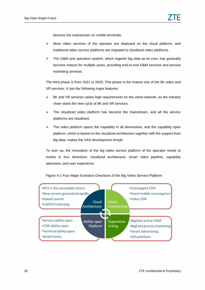
Big Video Bright Future
92 ZTE Confidential & Proprietary
become the mainstream on mobile terminals.
More video services of the operator are deployed on the cloud platform, and
traditional video service platforms are migrated to cloudized video platforms.
The O&M and operation system, which regards big data as its core, has gradually
become mature for multiple years, providing end-to-end O&M services and precise
marketing services.
The third phase is from 2021 to 2025. This phase is the mature one of the 8K video and
VR services. It has the following major features:
8K and VR services raises high requirements for the wired network, so the industry
chain starts the new cycle of 8K and VR services.
The cloudized video platform has become the mainstream, and all the service
platforms are cloudized.
The video platform opens the capability in all dimensions, and the capability open
platform, which is based on the cloudized architecture together with the support from
big data, makes the VAS development simple.
To sum up, the innovation of the big video service platform of the operator needs to
evolve in four directions: cloudized architecture, smart video pipeline, capability
openness, and user experience.
Figure 4-1 Four Major Evolution Directions of the Big Video Service Platform
Big Video Bright Future
ZTE Confidential & Proprietary 93
4.2 Architecture of the Cloudized Video Platform
Figure 4-2 Video Platform of the Cloudized Architecture
The architecture of the tradition IPTV service platform is a kind of architecture that
couples software with hardware. It couples the service processing function with the data
storage function, which is an architecture designed to realize single video services.
However, this architecture is not beneficial for developing and deploying new services or
collaborating with multiple vendors in the industry chain.
The innovation of big video needs to optimize the system architecture of which the
existing IPTV system is relatively solidified so that the architecture has features such as
open services and scalable resources. The openness of video services and capabilities
and precise marketing shall depend on the open system network architecture. System
resources can be flexibly and dynamically assembled to rapidly generate new services
and adapt to requirements for the rapid growth of new services. Therefore, coupling of all
modules in the system shall be reduced while the scalability and dynamic deployment
capability of the system shall be reinforced.
The NFV-based cloudized architecture is a better loose coupling and open system
architecture, which has features such as natural openness, scalability, and dynamic
deployment to meet the requirements of the big video service for the service platform
architecture. Therefore, the cloudized architecture is the cornerstone of the service
innovation, which is beneficial for separating hardware investment from software
investment. In addition it is beneficial for multiple vendors to provide multiple services so
that the operator can flexibly and rapidly aggregate multiple services.
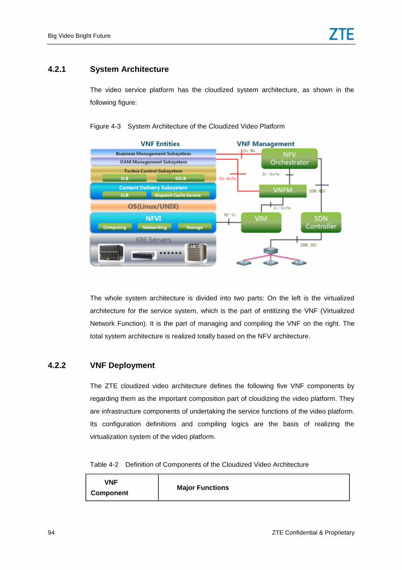
Big Video Bright Future
94 ZTE Confidential & Proprietary
4.2.1 System Architecture
The video service platform has the cloudized system architecture, as shown in the
following figure:
Figure 4-3 System Architecture of the Cloudized Video Platform
The whole system architecture is divided into two parts: On the left is the virtualized
architecture for the service system, which is the part of entitizing the VNF (Virtualized
Network Function). It is the part of managing and compiling the VNF on the right. The
total system architecture is realized totally based on the NFV architecture.
4.2.2 VNF Deployment
The ZTE cloudized video architecture defines the following five VNF components by
regarding them as the important composition part of cloudizing the video platform. They
are infrastructure components of undertaking the service functions of the video platform.
Its configuration definitions and compiling logics are the basis of realizing the
virtualization system of the video platform.
Table 4-2 Definition of Components of the Cloudized Video Architecture
VNF
Component Major Functions
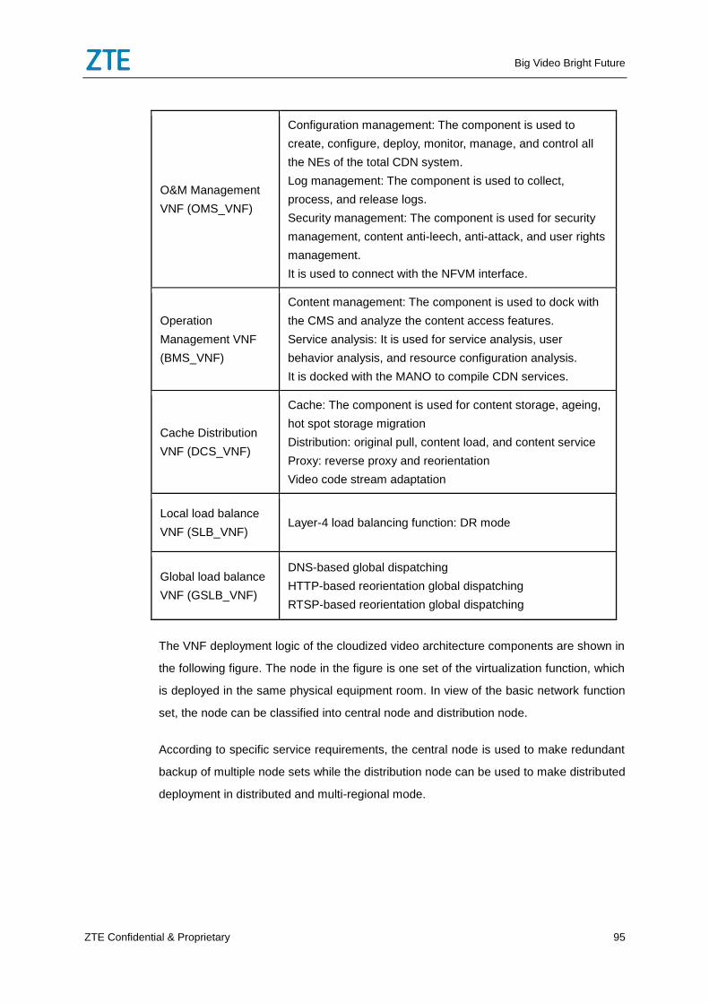
Big Video Bright Future
ZTE Confidential & Proprietary 95
O&M Management
VNF (OMS_VNF)
Configuration management: The component is used to
create, configure, deploy, monitor, manage, and control all
the NEs of the total CDN system.
Log management: The component is used to collect,
process, and release logs.
Security management: The component is used for security
management, content anti-leech, anti-attack, and user rights
management.
It is used to connect with the NFVM interface.
Operation
Management VNF
(BMS_VNF)
Content management: The component is used to dock with
the CMS and analyze the content access features.
Service analysis: It is used for service analysis, user
behavior analysis, and resource configuration analysis.
It is docked with the MANO to compile CDN services.
Cache Distribution
VNF (DCS_VNF)
Cache: The component is used for content storage, ageing,
hot spot storage migration
Distribution: original pull, content load, and content service
Proxy: reverse proxy and reorientation
Video code stream adaptation
Local load balance
VNF (SLB_VNF) Layer-4 load balancing function: DR mode
Global load balance
VNF (GSLB_VNF)
DNS-based global dispatching
HTTP-based reorientation global dispatching
RTSP-based reorientation global dispatching
The VNF deployment logic of the cloudized video architecture components are shown in
the following figure. The node in the figure is one set of the virtualization function, which
is deployed in the same physical equipment room. In view of the basic network function
set, the node can be classified into central node and distribution node.
According to specific service requirements, the central node is used to make redundant
backup of multiple node sets while the distribution node can be used to make distributed
deployment in distributed and multi-regional mode.
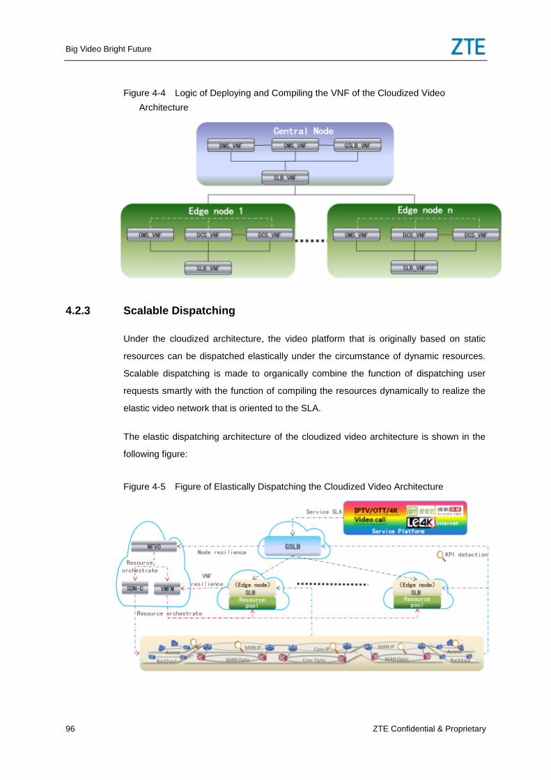
Big Video Bright Future
96 ZTE Confidential & Proprietary
Figure 4-4 Logic of Deploying and Compiling the VNF of the Cloudized Video
Architecture
4.2.3 Scalable Dispatching
Under the cloudized architecture, the video platform that is originally based on static
resources can be dispatched elastically under the circumstance of dynamic resources.
Scalable dispatching is made to organically combine the function of dispatching user
requests smartly with the function of compiling the resources dynamically to realize the
elastic video network that is oriented to the SLA.
The elastic dispatching architecture of the cloudized video architecture is shown in the
following figure:
Figure 4-5 Figure of Elastically Dispatching the Cloudized Video Architecture
Big Video Bright Future
ZTE Confidential & Proprietary 97
The elastic dispatching logic is realized through two layers: global dispatching layer and
local dispatching layer. The global dispatching layer realizes node expansion. New
nodes are deployed while old nodes are disabled. The local dispatching layer is used for
VNF expansion through the NFVM. New VNFs are deployed while old VNFs are
disabled.
With respect to the global dispatching, user requests are dispatched based on existing
resources. Only when existing resources cannot meet the SLA requirement of the user
requests, requests are made to the NFVO for expanding node resources. The monitoring
system provides the total network service quality monitoring indexes to judge whether
existing resources can meet the user request SLA. The indexes decide the dimension of
expanding node resources: horizontal expansion and vertical expansion. Horizontal
expansion is made to add edge service nodes in the same hierarchy, and vertical
expansion is made add nodes on the existing service nodes in inferior mode. When
existing node resources cannot meet the requirement of one service’s SLA for low delay
and low packet loss ratio, global dispatching can be made to add and sink nodes in
vertical mode. When there is not low delay or low packet loss ratio service request, global
dispatching can be made to float and shrink nodes. First, the user request traffic is
dispatched through the global dispatching to other nodes. Then, in the premise that the
shrunk node has no user request, global dispatching is made to request the NFVO for
deleting services of the node resources to shrink the node.
With respect to local dispatching, the solution dispatches the user request in priority to
the existing VNF resources. When the change of indexes, such as number of
connections, CPU load, network and disk IO load, storage utilization ratio, and hit rate, is
higher or less than one SLA threshold, the system implements the VNF expansion or
shrinking strategy. With respect to VNF expansion, the system supports setting the VNF
expansion threshold. When all the VNFs exceed the expansion threshold, the system
maintains a specific period of time in the case of not affecting the SLA. If the VNFs still go
up, the system makes VNF expansion. With respect to VNF shrinking, the system
supports setting the shrinking threshold. When all the VNFs are lower than the shrinking
threshold, the system reduces the dispatching weight of the longest online VNF. After a
specific period of time, if other VNF indexes have not broken through the expansion
threshold, the system supports lowering the VNF weight until the VNF is idle. If other
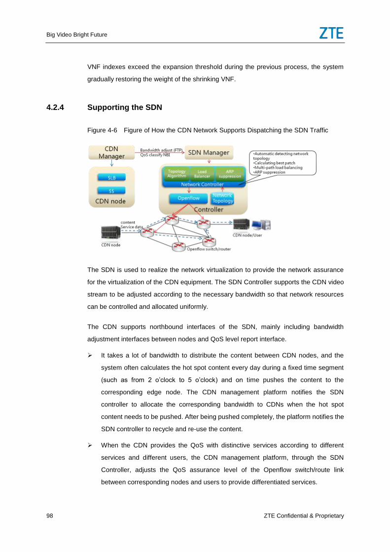
Big Video Bright Future
98 ZTE Confidential & Proprietary
VNF indexes exceed the expansion threshold during the previous process, the system
gradually restoring the weight of the shrinking VNF.
4.2.4 Supporting the SDN
Figure 4-6 Figure of How the CDN Network Supports Dispatching the SDN Traffic
The SDN is used to realize the network virtualization to provide the network assurance
for the virtualization of the CDN equipment. The SDN Controller supports the CDN video
stream to be adjusted according to the necessary bandwidth so that network resources
can be controlled and allocated uniformly.
The CDN supports northbound interfaces of the SDN, mainly including bandwidth
adjustment interfaces between nodes and QoS level report interface.
It takes a lot of bandwidth to distribute the content between CDN nodes, and the
system often calculates the hot spot content every day during a fixed time segment
(such as from 2 o’clock to 5 o’clock) and on time pushes the content to the
corresponding edge node. The CDN management platform notifies the SDN
controller to allocate the corresponding bandwidth to CDNs when the hot spot
content needs to be pushed. After being pushed completely, the platform notifies the
SDN controller to recycle and re-use the content.
When the CDN provides the QoS with distinctive services according to different
services and different users, the CDN management platform, through the SDN
Controller, adjusts the QoS assurance level of the Openflow switch/route link
between corresponding nodes and users to provide differentiated services.
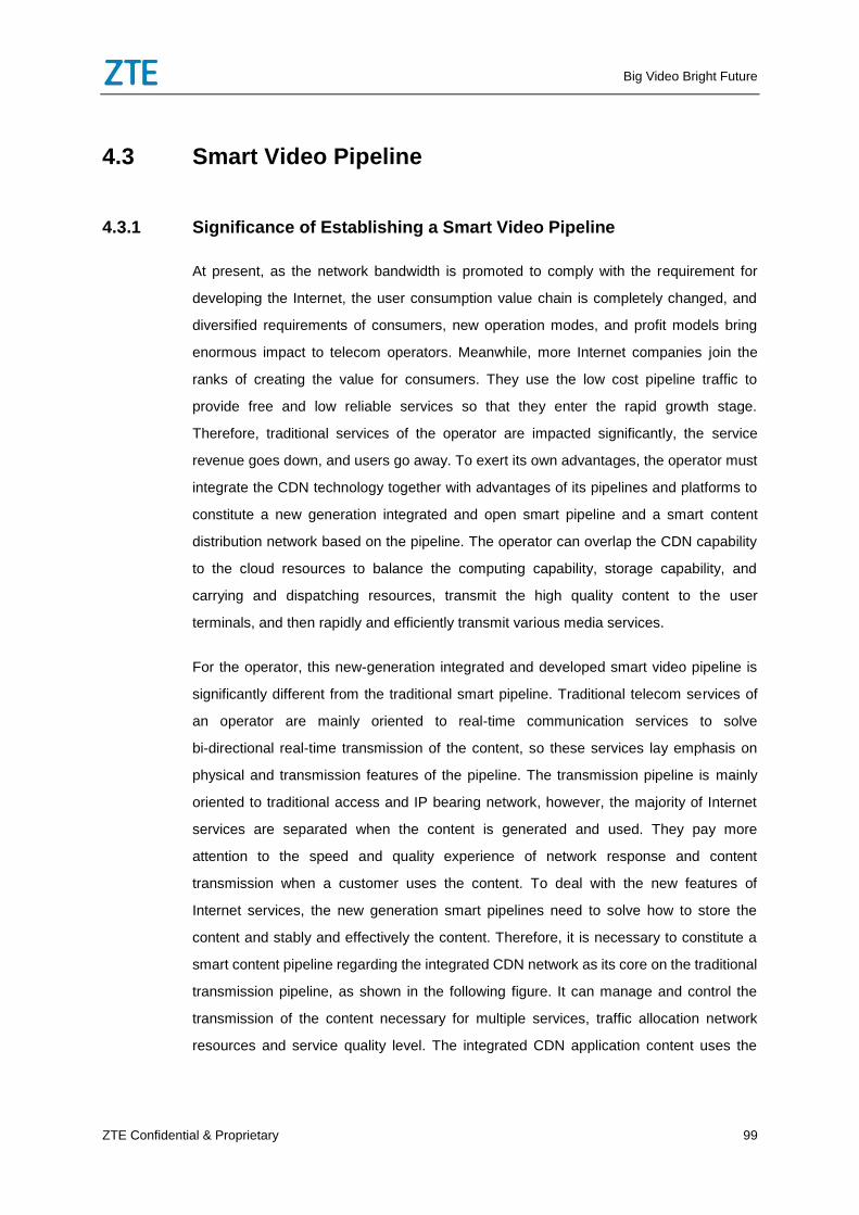
Big Video Bright Future
ZTE Confidential & Proprietary 99
4.3 Smart Video Pipeline
4.3.1 Significance of Establishing a Smart Video Pipeline
At present, as the network bandwidth is promoted to comply with the requirement for
developing the Internet, the user consumption value chain is completely changed, and
diversified requirements of consumers, new operation modes, and profit models bring
enormous impact to telecom operators. Meanwhile, more Internet companies join the
ranks of creating the value for consumers. They use the low cost pipeline traffic to
provide free and low reliable services so that they enter the rapid growth stage.
Therefore, traditional services of the operator are impacted significantly, the service
revenue goes down, and users go away. To exert its own advantages, the operator must
integrate the CDN technology together with advantages of its pipelines and platforms to
constitute a new generation integrated and open smart pipeline and a smart content
distribution network based on the pipeline. The operator can overlap the CDN capability
to the cloud resources to balance the computing capability, storage capability, and
carrying and dispatching resources, transmit the high quality content to the user
terminals, and then rapidly and efficiently transmit various media services.
For the operator, this new-generation integrated and developed smart video pipeline is
significantly different from the traditional smart pipeline. Traditional telecom services of
an operator are mainly oriented to real-time communication services to solve
bi-directional real-time transmission of the content, so these services lay emphasis on
physical and transmission features of the pipeline. The transmission pipeline is mainly
oriented to traditional access and IP bearing network, however, the majority of Internet
services are separated when the content is generated and used. They pay more
attention to the speed and quality experience of network response and content
transmission when a customer uses the content. To deal with the new features of
Internet services, the new generation smart pipelines need to solve how to store the
content and stably and effectively the content. Therefore, it is necessary to constitute a
smart content pipeline regarding the integrated CDN network as its core on the traditional
transmission pipeline, as shown in the following figure. It can manage and control the
transmission of the content necessary for multiple services, traffic allocation network
resources and service quality level. The integrated CDN application content uses the
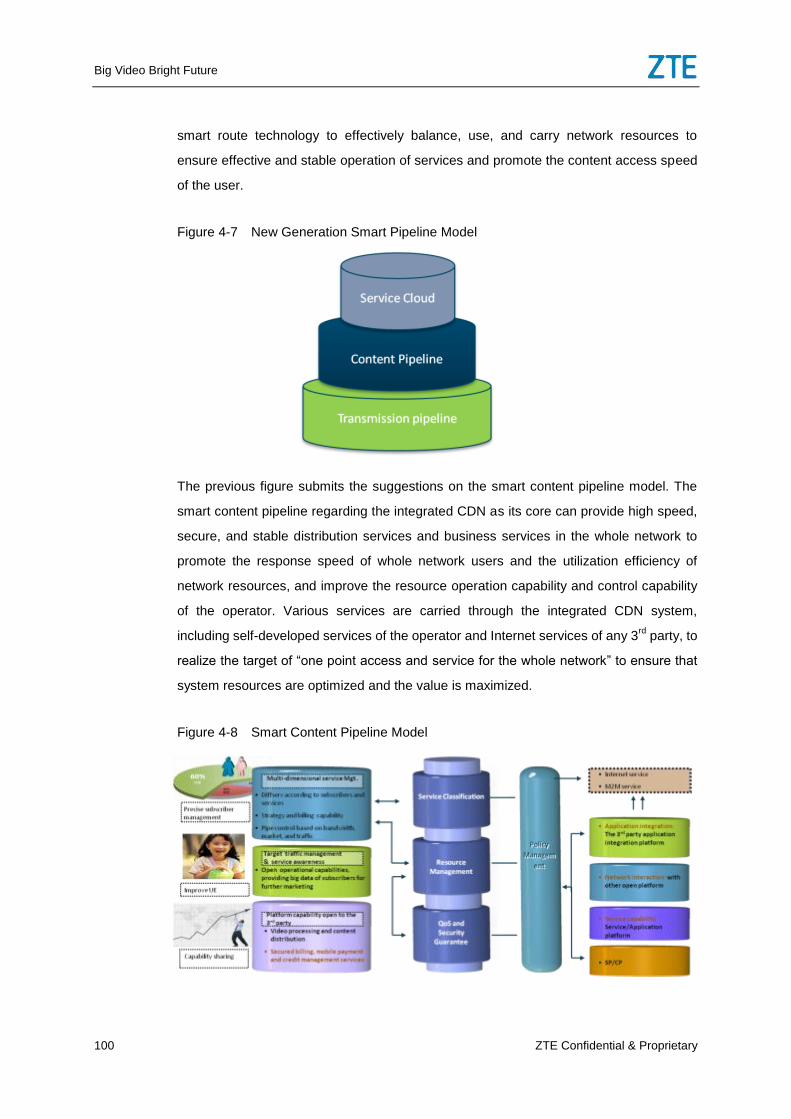
Big Video Bright Future
100 ZTE Confidential & Proprietary
smart route technology to effectively balance, use, and carry network resources to
ensure effective and stable operation of services and promote the content access speed
of the user.
Figure 4-7 New Generation Smart Pipeline Model
The previous figure submits the suggestions on the smart content pipeline model. The
smart content pipeline regarding the integrated CDN as its core can provide high speed,
secure, and stable distribution services and business services in the whole network to
promote the response speed of whole network users and the utilization efficiency of
network resources, and improve the resource operation capability and control capability
of the operator. Various services are carried through the integrated CDN system,
including self-developed services of the operator and Internet services of any 3rd
party, to
realize the target of “one point access and service for the whole network” to ensure that
system resources are optimized and the value is maximized.
Figure 4-8 Smart Content Pipeline Model
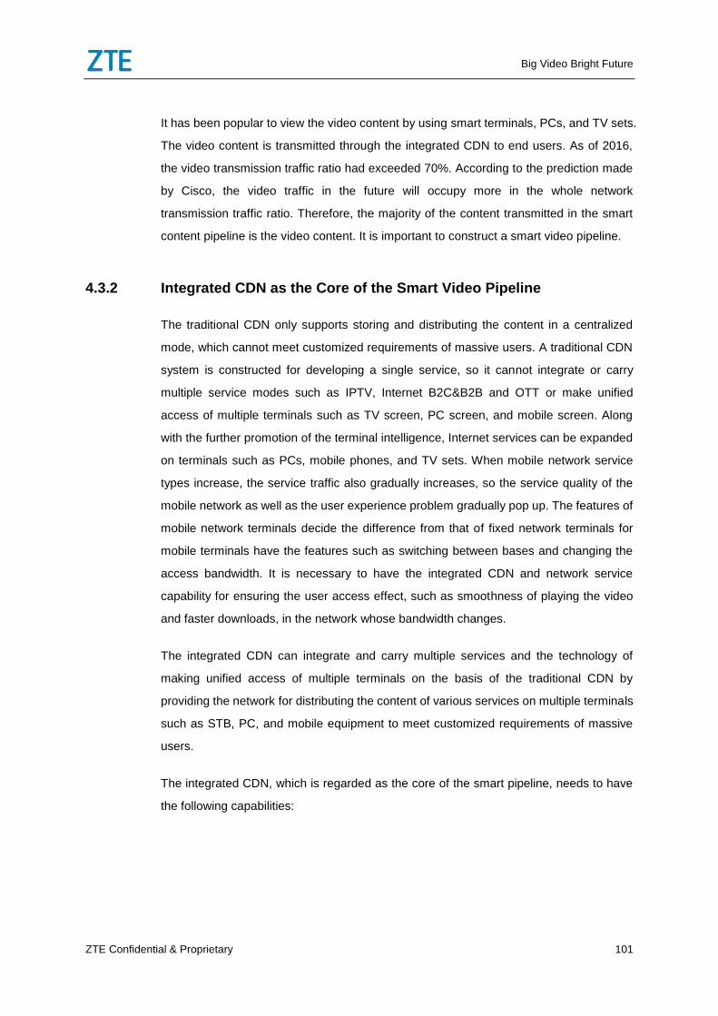
Big Video Bright Future
ZTE Confidential & Proprietary 101
It has been popular to view the video content by using smart terminals, PCs, and TV sets.
The video content is transmitted through the integrated CDN to end users. As of 2016,
the video transmission traffic ratio had exceeded 70%. According to the prediction made
by Cisco, the video traffic in the future will occupy more in the whole network
transmission traffic ratio. Therefore, the majority of the content transmitted in the smart
content pipeline is the video content. It is important to construct a smart video pipeline.
4.3.2 Integrated CDN as the Core of the Smart Video Pipeline
The traditional CDN only supports storing and distributing the content in a centralized
mode, which cannot meet customized requirements of massive users. A traditional CDN
system is constructed for developing a single service, so it cannot integrate or carry
multiple service modes such as IPTV, Internet B2C&B2B and OTT or make unified
access of multiple terminals such as TV screen, PC screen, and mobile screen. Along
with the further promotion of the terminal intelligence, Internet services can be expanded
on terminals such as PCs, mobile phones, and TV sets. When mobile network service
types increase, the service traffic also gradually increases, so the service quality of the
mobile network as well as the user experience problem gradually pop up. The features of
mobile network terminals decide the difference from that of fixed network terminals for
mobile terminals have the features such as switching between bases and changing the
access bandwidth. It is necessary to have the integrated CDN and network service
capability for ensuring the user access effect, such as smoothness of playing the video
and faster downloads, in the network whose bandwidth changes.
The integrated CDN can integrate and carry multiple services and the technology of
making unified access of multiple terminals on the basis of the traditional CDN by
providing the network for distributing the content of various services on multiple terminals
such as STB, PC, and mobile equipment to meet customized requirements of massive
users.
The integrated CDN, which is regarded as the core of the smart pipeline, needs to have
the following capabilities:
Big Video Bright Future
102 ZTE Confidential & Proprietary
4.3.2.1 Supporting the Total Network Deployment
As the use habit of Internet users is migrated to mobile terminals, good user experience
becomes an important balance factor to directly influence the user choice of applications
and pages. During the long time cache and response process, the basic problem of a
user is the communication process between the mobile and core network instead of the
bandwidth limit of the backbone transmission network. The integrated CDN should
optimize the service experience between the terminal and server and consider how to
solve the bottleneck of transmitting the data in the wireless network. When mobile
Internet services are more popular, the mobile traffic is also doomed to be larger. These
features further push the integrated CDN to be deployed to the mobile network to
promote the transmission efficiency of the mobile network.
For the 4G mobile network, the content needs to be distributed to the base station that is
closest to the user to promote the user experience by turning the base station into the
value creation engine of the user. It is the new space of developing Internet services in
the future. Small CDNs that are integrated with the base station can be deployed
between the mobile network base station side and the core network to store the hot spot
content. These CDNs have the high density data processing capability and storage
capacity to ensure the distribution of the hot spot content and the service quality of high
level users and promote user experience.
The integrated CDN that is deployed in the mobile network shall have the following
capabilities:
Dynamic adjustment of the self-adaption code rate
Although there are multiple empty ports of the 4G wireless base station, it is difficult to
catch up with the requirement for developing the video service. When access users
increase, empty ports allocated to each user also change in real time. Meanwhile, the
bandwidth of acceding mobile terminals is also affected by the strength of the wireless
network access signals. If the signal is not stable, the user can find out the problem, such
as unsmooth video and slow response. The integrated CDN of the mobile network shall
have the code rate self-adaption capability, which can dynamically detect the change
information of the user’s empty port resources and on time adjust the code rate of
sending the content to fully ensure the smoothness for the user to view the video and
Big Video Bright Future
ZTE Confidential & Proprietary 103
promote user experience. The code rate self-adaptation technology is used so that the
one code rate file needs to be saved on the mobile CDN for the same content. The
system, according to different bandwidths, in real time converts the code rate format and
ensures the continuity of playing the video to reduce the requirement for the storage
space of the mobile CDN and the bandwidth to transmit the content.
Seamless switch
When a mobile terminal user switches between base station, the integrated CDN of the
mobile network can, through the user session saving technology, ensure that the user
does not need to re-download files or stop the video when he/she views the video and
even if the base station is changed. Therefore, the function can shield the influence
caused because the user position changes.
Smart content forecasting
The hot spot content is pushed to the integrated CDN of the mobile network by using the
network idle state. When the network is busy, you can use the hot spot content pushed in
the past and use the new hot spot content that is pulled down in original pull mode to
reduce the transmission pressure between the inferior CDN and superior CDN to ensure
video experience of the user.
The integrated CDN that loads the content in advance to the mobile network on time
provides services for users in the wireless network to get rid of transmission time delay
and improve the transmission speed of the mobile network.
TCP transmission optimization
The traditional TCP is set for the scenarios where the error ratio of the wired network or
data group is small. If the group loss is caused by network congestion, the
re-transmission can further reinforce the negative information in the case that the
network environment is bad. As it have features such as high error ratio, low
transmission code rate, low transmission bandwidth, and flexible mobility, the wireless
network is not suitable for using the traditional TCP transmission mechanism.
Therefore, the integrated CDN of the mobile phone needs to optimize the TCP
transmission for the wireless network.
Big Video Bright Future
104 ZTE Confidential & Proprietary
4.3.2.2 Supporting Integrating Multiple Services
Integration of multiple services demands that the CDN be no longer the pure content
distribution network. It needs to stride out the location and boundary of its original
functions by providing an open, interconnection/interaction, and integrated total network
and total business service capability to adapt to the service development.
The integrated CDN service has the following VAS services, such as video acceleration,
Web acceleration, application acceleration, and file acceleration. To adapt to rapid
development of the service, the integrated CDN also needs to provide an all-around
flexible deployment and interconnection capability to realize centralized cloudization of
resources and service nearby deployment. In addition, through standard interfaces and
service flows, it focuses on promoting service capabilities such as content introduction,
content storage, and content distribution.
The integrated CDN faces the following requirements, including emergence of massive
content (including video, audio, and picture), data storage pressure, cloud transcoding,
and cloud processing. It also faces how to process and re-use the long tail content and
redundant data. Therefore, the integrated CDN needs to integrate new technologies such
as cloud computing, upload acceleration, cloud storage, and cloud transcoding to provide
its customers with more intimate services. Meanwhile, it needs to provide more APIs and
SDKs for further developing various customized application services.
4.3.2.3 Supporting Refined Management
To meet the requirement for customized services, the integrated CDN needs to fully mine
the association relationship between different kinds of content, different persons, and
between content and person. Through mining these relationships, the integrated CDN
can provide its users with common and customized services. It is collaborated with
specific service models to meet requirements such as customized service experience,
smart, recommendation modes, smart search, and social experience.
The big data technology is the basis of its refined operation and O&M of the integrated
CDN. Through collecting the log CDRs of the integrated CDN and parsing the big data,
the integrated CDN provides the O&M service with various index, search, and analysis
supports to realize all-around visualized O&M presence. On the O&M basis, through
Big Video Bright Future
ZTE Confidential & Proprietary 105
analyzing user behaviors, it can find out the global hot spot content, on time push the
content to the network edge, and reduce the occurrence of original pull traffic. Meanwhile,
it can assemble and analyze users, establish the user relationship network, and make
individualized and precise recommendation. Through various types of ranking, the
integrated CDN supports the user to find out his interesting content to promote the user
content consumption and promote the ARPU value by using and recommending the
orientation push function of the engine.
4.3.2.4 Supporting Distributing the HD Content (Such as 4K, 8K, and VR/AR)
As the UHD technology rises continuously and the video rate is promoted significantly,
higher requirements (including big bandwidth, low time delay, and less packet loss) are
raised for the transmission link and the integrated CDN.
First, to cope with transmitting the UHD video, the system shall try to reduce the decline
of the UHD video service quality by using advanced encoding ways at the CDN side.
According to the conclusion drawn by the BBC R&D team, in the premise of the same
quality, the transmission code rate of the content by using the code is reduced 50% in
comparison to that of the content by using the H.264/AVC code. Therefore, to save the
transmission bandwidth, the CDN needs to support the H.265/HEVC code mode when
distributing the UHD content such as 4K.
Secondly, even if the H.265/HEVC code is used, the UHD video content volume is
significantly enlarged in comparison to its original HD/SD content. Therefore, it has larger
requirements for the storage space. One way is to enlarge the storage space to meet the
requirement of the 4K content for the space. This extensive growth can cause larger fund
pressure for practical operation. Another way is to store fragments of the 4K content so
that the integrated CDN node can dispatch the content to make response to the user
service and reduce the requirement of the integrated CDN node for storage. The hot spot
fragments can be set into the high performance storage media to further improve the
external throughput service capability of a single device. ZTE submits the smart
dispatching robot algorithm, which is used to dispatch the UHD content such as 4K to
support strategies such as fragment dispatching, hot spot dispatching, and zone
dispatching.
Big Video Bright Future
106 ZTE Confidential & Proprietary
The integrated CDN service ensures the UHD content service quality through the
following technologies:
FCC (Fast Channel Change)
The FCC server issues the customized unicast program stream that regards the key
frame as its start to promote the time of switching channels. This technology can avoid
the time of waiting for the key frame and the time of interacting with the IGMP to improve
the speed of switching channels so that the user cannot feel the time delay caused by
switching channels. After the FCC technology is used, the time of switching channels is
less than 0.5s, so the user experience effect is improved significantly.
ARQ (Automatic Repeat-reQuest)
The receiving party requests the sending party to re-transmit the error data message to
restore the error message. The receiving party needs to find out the position where the
error takes place and request the sending party for re-transmitting the message. As
packet loss does not take place continuously, retransmitted packets can be generally
received by the STB to realize compensation for packet loss. If 2% of packets are lost in
a network and 5% of redundant packets are retransmitted, the user cannot feel the
packet loss in the network.
FEC (Forward Error Correction)
When the code stream is sent, the redundant data is generated through a dedicated
design to send the redundant data and original code to the network. Even if the packets
of the original code stream are lost during the transmission process, the receiving party
can restore the lost data packets by calculating the data according to the resident original
code stream and redundant data. If it finds out the error, the system with the FEC
function does not need to notify the sending party of re-transmitting the data, so the FEC
function is more applicable to transmitting the media in real time.
4.3.2.5 Supporting the Fixed/Mobile Convergence Service
Along with the rapid popularity of mobile terminals and rapid development of mobile
traffic, it has been mature to develop the FMC service (extending the service from the
Internet TV content and service experience to the mobile end).
Big Video Bright Future
ZTE Confidential & Proprietary 107
ZTE is aware that Internet TV services can be combined with the fixed network and
wireless products to promote the telecom traffic user payment transfer ratio and promote
traffic value-added management achievements.
The integrated CDN ensures that the service experience that is coherent with the IPTV
service user can be provided for mobile video users when the system has the FMC
application. The services include the following information involving the local channel,
such as high quality LiveTV content, time shift, and play back.
With the help of the FMC service, the operator can, in the fixed network and mobile
network, develop integrated services such as IPTV at the same time to enhance user
cohesion, rapidly expand the number of total IPTV users, and then maximize the value of
the existing network platform and content.
4.4 Capability Opening Platform
One major connotation of the big video service is a win-to-win ecology. Only the open
video capability platform architecture can aggregate rich services and applications
provided by multiple vendors in the industry chain to realize collaboration and win-to-win
of the ecosystem.
Along with the continuous development of the IPTV service, the interconnection between
system and terminal is solved, so the terminal openness is significantly promoted. With
respect to the video service, although the IPTV service can currently provide some basic
video services such as LiveTV, VOD, and time shift and a certain number of value-added
services, the whole industry is still calling on differentiated services that have stronger
competition advantages. The service capabilities of the big video system are being
developed in depth, involving video convergence, video association, and customization.
In addition, the business mode of the big video system is also being explored
continuously. It can be predicted that 3rd
party service providers, service developers, and
application software providers will play more important roles in the big video industry
chain. They are the core issues for a capability opening platform to consider, including
how to rapidly provide unlimited excellent access services for collaborators in API core
service mode, how to help collaborators acquire the value and promote its market
competiveness during the platform invoking capability process, and how to provide rich
Big Video Bright Future
108 ZTE Confidential & Proprietary
infrastructure methods and tools for the end users that are served by the collaborators.
In the Internet era, all the enterprises are facing the transformation problem. ZTE’s big
video team has been active in exploring the innovations in multiple realms such as
Internet+, capability openness, big data, and network transformation. The capability
opening platform can be regarded an important support platform for service
transformation, which has an important strategic significance.
The capability opening function of the big video is firstly displayed on the standardization.
Only the standardization can be used smoothly to integrate services provided by different
collaborators. ZTE’s big video capability opening platform abides by the SOA
architecture, providing the REST interface for external services and at the same time
providing the corresponding capability opening interface white paper to meet the rapid
access and invocation of collaborators. On the other hand, service is scalable and
component-oriented, which has the loose coupling function with the hardware and
network. ZTE’s big video capability opening platform supports the NFV deployment mode,
realizing scalable component instances as required, accelerating system deployment
and scalability, and making network treatment and data disaster tolerance according to
the cloudized management mode on the network.
ZTE’s capability opening platform is shown in the following figure, including infrastructure
capability opening platform, value-added application opening platform, CDN capability
opening platform, application store, and terminal component opening architecture.
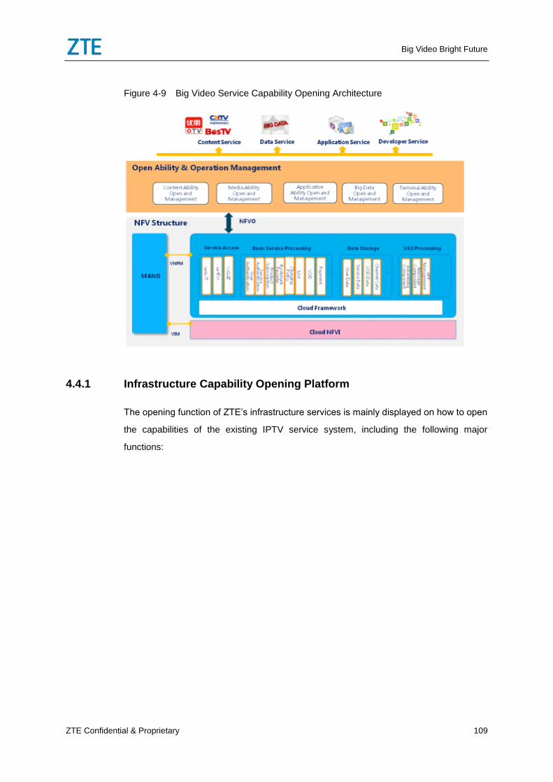
Big Video Bright Future
ZTE Confidential & Proprietary 109
Figure 4-9 Big Video Service Capability Opening Architecture
4.4.1 Infrastructure Capability Opening Platform
The opening function of ZTE’s infrastructure services is mainly displayed on how to open
the capabilities of the existing IPTV service system, including the following major
functions:
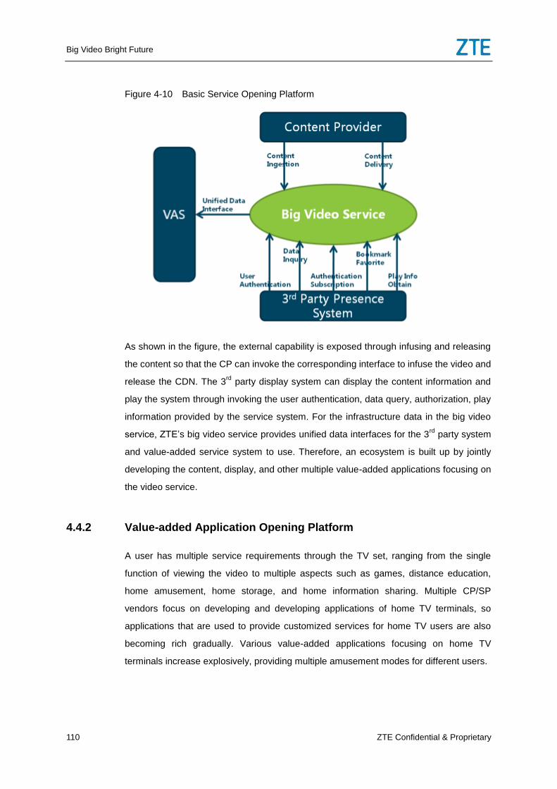
Big Video Bright Future
110 ZTE Confidential & Proprietary
Figure 4-10 Basic Service Opening Platform
As shown in the figure, the external capability is exposed through infusing and releasing
the content so that the CP can invoke the corresponding interface to infuse the video and
release the CDN. The 3rd
party display system can display the content information and
play the system through invoking the user authentication, data query, authorization, play
information provided by the service system. For the infrastructure data in the big video
service, ZTE’s big video service provides unified data interfaces for the 3rd
party system
and value-added service system to use. Therefore, an ecosystem is built up by jointly
developing the content, display, and other multiple value-added applications focusing on
the video service.
4.4.2 Value-added Application Opening Platform
A user has multiple service requirements through the TV set, ranging from the single
function of viewing the video to multiple aspects such as games, distance education,
home amusement, home storage, and home information sharing. Multiple CP/SP
vendors focus on developing and developing applications of home TV terminals, so
applications that are used to provide customized services for home TV users are also
becoming rich gradually. Various value-added applications focusing on home TV
terminals increase explosively, providing multiple amusement modes for different users.
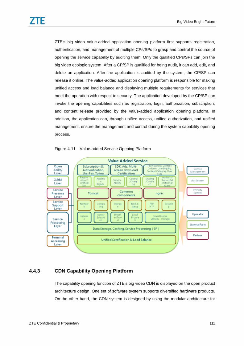
Big Video Bright Future
ZTE Confidential & Proprietary 111
ZTE’s big video value-added application opening platform first supports registration,
authentication, and management of multiple CPs/SPs to grasp and control the source of
opening the service capability by auditing them. Only the qualified CPs/SPs can join the
big video ecologic system. After a CP/SP is qualified for being audit, it can add, edit, and
delete an application. After the application is audited by the system, the CP/SP can
release it online. The value-added application opening platform is responsible for making
unified access and load balance and displaying multiple requirements for services that
meet the operation with respect to security. The application developed by the CP/SP can
invoke the opening capabilities such as registration, login, authorization, subscription,
and content release provided by the value-added application opening platform. In
addition, the application can, through unified access, unified authorization, and unified
management, ensure the management and control during the system capability opening
process.
Figure 4-11 Value-added Service Opening Platform
4.4.3 CDN Capability Opening Platform
The capability opening function of ZTE’s big video CDN is displayed on the open product
architecture design. One set of software system supports diversified hardware products.
On the other hand, the CDN system is designed by using the modular architecture for
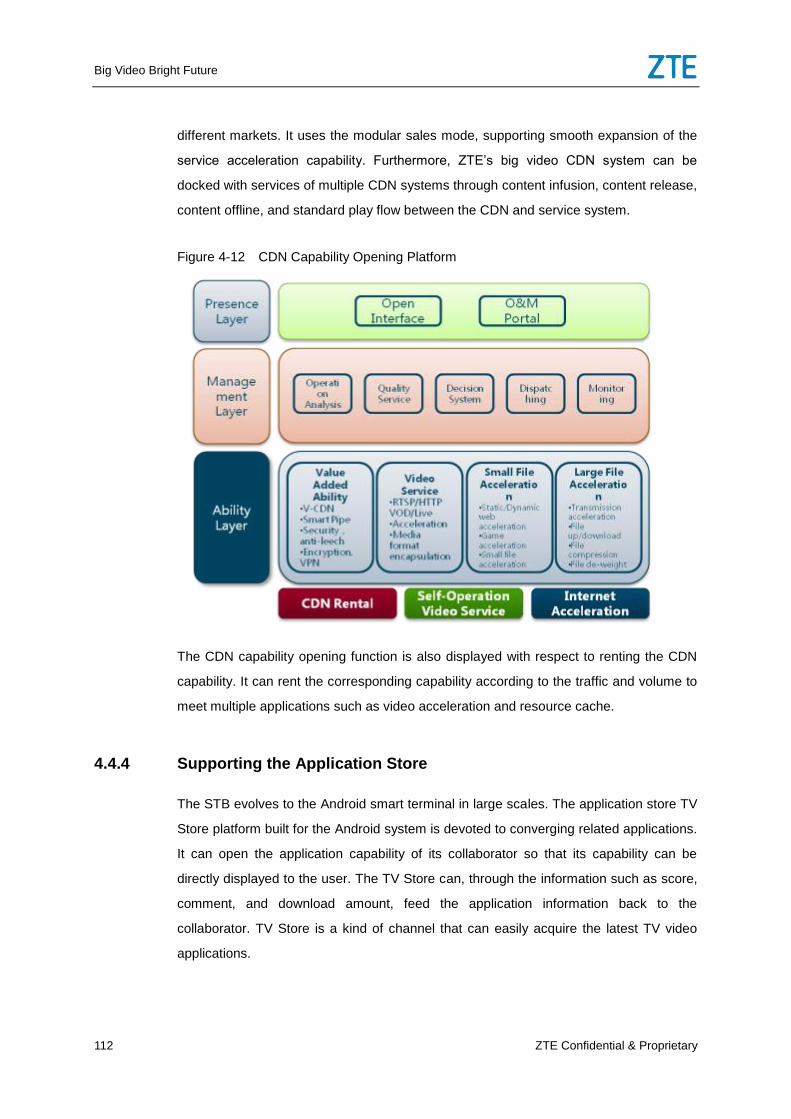
Big Video Bright Future
112 ZTE Confidential & Proprietary
different markets. It uses the modular sales mode, supporting smooth expansion of the
service acceleration capability. Furthermore, ZTE’s big video CDN system can be
docked with services of multiple CDN systems through content infusion, content release,
content offline, and standard play flow between the CDN and service system.
Figure 4-12 CDN Capability Opening Platform
The CDN capability opening function is also displayed with respect to renting the CDN
capability. It can rent the corresponding capability according to the traffic and volume to
meet multiple applications such as video acceleration and resource cache.
4.4.4 Supporting the Application Store
The STB evolves to the Android smart terminal in large scales. The application store TV
Store platform built for the Android system is devoted to converging related applications.
It can open the application capability of its collaborator so that its capability can be
directly displayed to the user. The TV Store can, through the information such as score,
comment, and download amount, feed the application information back to the
collaborator. TV Store is a kind of channel that can easily acquire the latest TV video
applications.
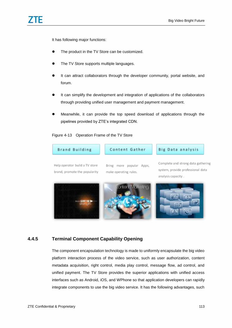
Big Video Bright Future
ZTE Confidential & Proprietary 113
It has following major functions:
The product in the TV Store can be customized.
The TV Store supports multiple languages.
It can attract collaborators through the developer community, portal website, and
forum.
It can simplify the development and integration of applications of the collaborators
through providing unified user management and payment management.
Meanwhile, it can provide the top speed download of applications through the
pipelines provided by ZTE’s integrated CDN.
Figure 4-13 Operation Frame of the TV Store
4.4.5 Terminal Component Capability Opening
The component encapsulation technology is made to uniformly encapsulate the big video
platform interaction process of the video service, such as user authorization, content
metadata acquisition, right control, media play control, message flow, ad control, and
unified payment. The TV Store provides the superior applications with unified access
interfaces such as Android, iOS, and WPhone so that application developers can rapidly
integrate components to use the big video service. It has the following advantages, such
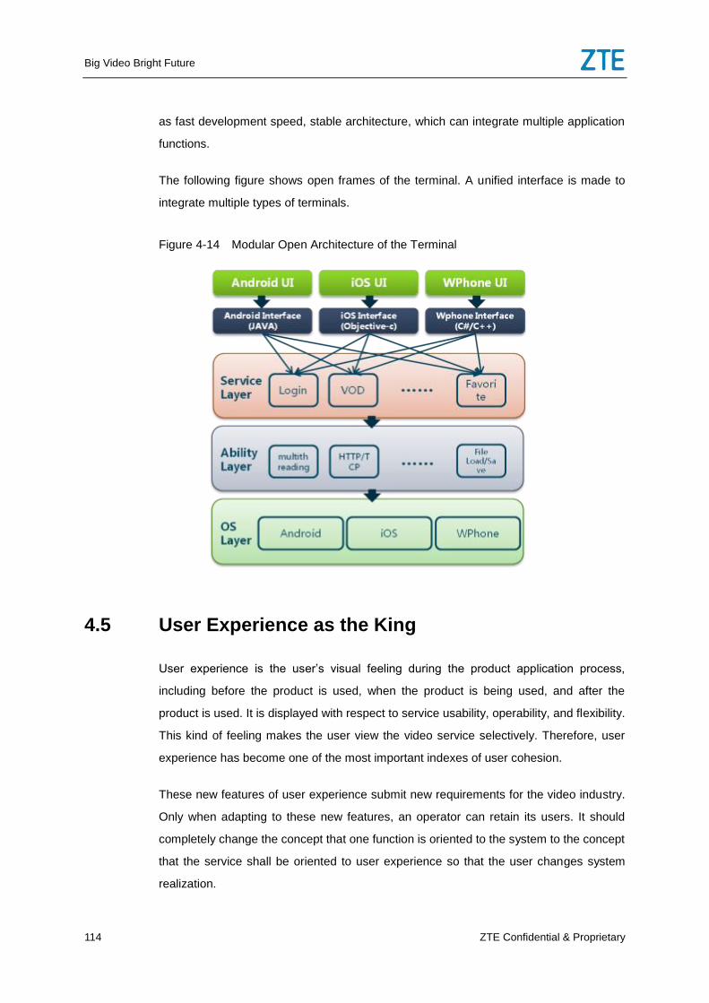
Big Video Bright Future
114 ZTE Confidential & Proprietary
as fast development speed, stable architecture, which can integrate multiple application
functions.
The following figure shows open frames of the terminal. A unified interface is made to
integrate multiple types of terminals.
Figure 4-14 Modular Open Architecture of the Terminal
4.5 User Experience as the King
User experience is the user’s visual feeling during the product application process,
including before the product is used, when the product is being used, and after the
product is used. It is displayed with respect to service usability, operability, and flexibility.
This kind of feeling makes the user view the video service selectively. Therefore, user
experience has become one of the most important indexes of user cohesion.
These new features of user experience submit new requirements for the video industry.
Only when adapting to these new features, an operator can retain its users. It should
completely change the concept that one function is oriented to the system to the concept
that the service shall be oriented to user experience so that the user changes system
realization.
Big Video Bright Future
ZTE Confidential & Proprietary 115
4.5.1 UHD Experience
With respect to the video service, the first perception is the program picture quality and
play smoothness when a user views the video content. ZTE’s big video service, which is
based on the existing high bandwidth network architecture, releases its services such as
4K LiveTV in advance in the industry, fully ensuring the picture quality of the video
content, significantly promoting the recognition of the user to view the video, and
enhancing the user cohesion. Meanwhile, when the immerse virtualized reality era
comes, ZTE’s big video service can play the video panoramically in 360°. You can use
VR glasses to enter the virtualized play environment together with G-sensor and
gyroscope operation to significantly promote the friendly degree of the TV man/machine
interaction party. At present, ZTE is also active in exploring and studying the VR
technologies in its VR video laboratory.
4.5.2 FMC
In the mobile network, the video traffic occupies over 70% of the traffic. It is important in
the future mobile market to extend traditional video services from wired network to
wireless network and provide mobile users with high quality video services.
The FMC function involves two layers:
The first layer is the network layer to realize the FMC function. On the one hand, the CDN
needs to be deployed in the IPTV private network and mobile Internet. Meanwhile, it can
support unified content management and service dispatching. On the other hand, the
CDN needs to support IPTV, OTT, and Cache services at the same time. The OTT
service includes common service capabilities of mobile terminals such as HLS, Dash,
and RTMP. For the subsequent evolution, the CDN also needs to further be sunk to end
users, such as being sunk and integrated to the OLT or base side.
The second layer is the service layer to realize the FMC function. On the one hand, the
video service on the mobile terminal needs to be combined with the IPTV and OTT
services on the cable side to realize unified user management and service management
to realize unified account and subscription management between the mobile client and
STB client to conveniently realize services such as subscription sharing and break point
sharing. On the other hand, multiple-screen gateways are deployed to push the message
Big Video Bright Future
116 ZTE Confidential & Proprietary
between the STB in the IPTV private network and the mobile phone in the Internet to
provide rich multi-screen interaction services for users, such as realizing the air play
function by playing the video from the mobile terminal to the STB and pushing the
oriented ad service from the STB to the mobile terminal.
4.5.3 Personalized Services
ZTE’s big video service solution supports the user to exchange the video presence page
style according to his/her favorites to meet the individualized perception requirements of
the user. For different family members, the solution can provide different color templates
according to features such as age and gender to make up for the disadvantages, for
example, existing TV operating interfaces are monotonous and only the information in
the EPG template is rich. Therefore, the TV big screen of the customer can be colorful.
The TV set in the hall, which is regarded as the main entrance of home amusement,
needs to meet different requirements of the family members. Its multiple-account
management function can provide the characteristic service content for all the family
members. After the user logs in to the system, the page displays the content related to
the user, such as individualized user recommendation, favorites content
recommendation, favorites, and parent lock list. The multi-account refined service
provides its family users with different service experiences.
Different family members raise different requirements for operating on the video system.
The old and young wish that the system operation is simply and rapid, but parents hope
that the system is secure and reliable. ZTE’s big video service solution lays emphasis on
different experience requirements caused by the age segment difference of the user by
providing different services in different control modes. On the mobile phone, the user can
log in to the system through facial image to verify the parent lock password or directly
order the TV through voice. The voice control mode can significantly simplify user
operation and promote the fresh feeling of the TV service. In addition, it can, based on
the facial image data and voice data, make big data analysis, output the user portrait,
and finally provide customized content recommendations and the guidance of new
services.
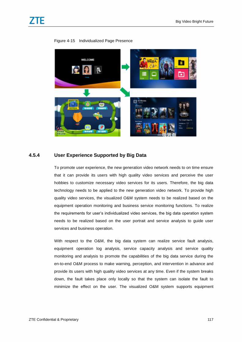
Big Video Bright Future
ZTE Confidential & Proprietary 117
Figure 4-15 Individualized Page Presence
4.5.4 User Experience Supported by Big Data
To promote user experience, the new generation video network needs to on time ensure
that it can provide its users with high quality video services and perceive the user
hobbies to customize necessary video services for its users. Therefore, the big data
technology needs to be applied to the new generation video network. To provide high
quality video services, the visualized O&M system needs to be realized based on the
equipment operation monitoring and business service monitoring functions. To realize
the requirements for user’s individualized video services, the big data operation system
needs to be realized based on the user portrait and service analysis to guide user
services and business operation.
With respect to the O&M, the big data system can realize service fault analysis,
equipment operation log analysis, service capacity analysis and service quality
monitoring and analysis to promote the capabilities of the big data service during the
en-to-end O&M process to make warning, perception, and intervention in advance and
provide its users with high quality video services at any time. Even if the system breaks
down, the fault takes place only locally so that the system can isolate the fault to
minimize the effect on the user. The visualized O&M system supports equipment
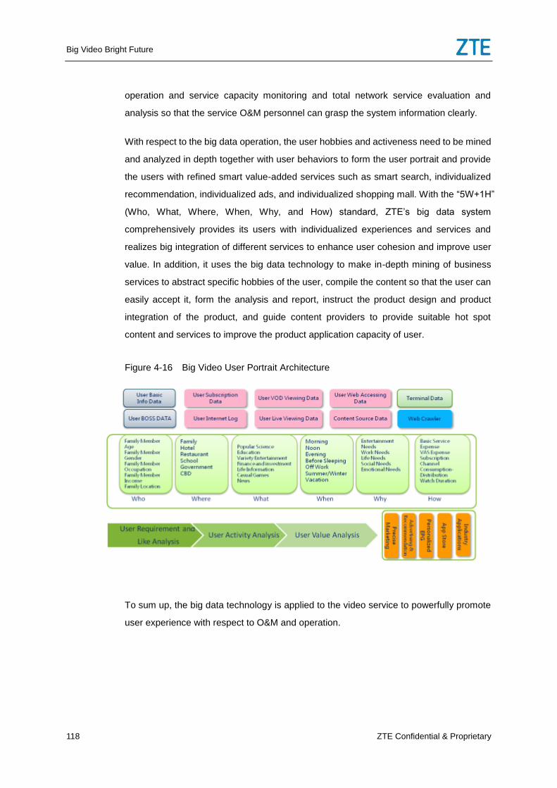
Big Video Bright Future
118 ZTE Confidential & Proprietary
operation and service capacity monitoring and total network service evaluation and
analysis so that the service O&M personnel can grasp the system information clearly.
With respect to the big data operation, the user hobbies and activeness need to be mined
and analyzed in depth together with user behaviors to form the user portrait and provide
the users with refined smart value-added services such as smart search, individualized
recommendation, individualized ads, and individualized shopping mall. With the “5W+1H”
(Who, What, Where, When, Why, and How) standard, ZTE’s big data system
comprehensively provides its users with individualized experiences and services and
realizes big integration of different services to enhance user cohesion and improve user
value. In addition, it uses the big data technology to make in-depth mining of business
services to abstract specific hobbies of the user, compile the content so that the user can
easily accept it, form the analysis and report, instruct the product design and product
integration of the product, and guide content providers to provide suitable hot spot
content and services to improve the product application capacity of user.
Figure 4-16 Big Video User Portrait Architecture
To sum up, the big data technology is applied to the video service to powerfully promote
user experience with respect to O&M and operation.
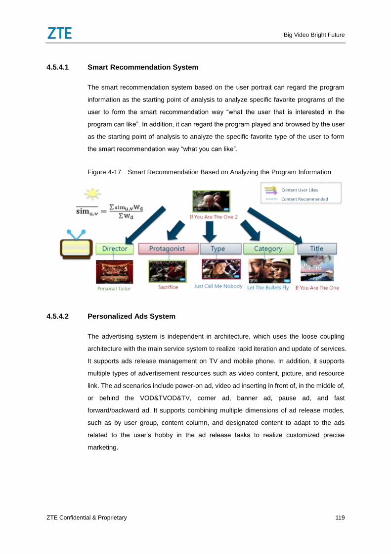
Big Video Bright Future
ZTE Confidential & Proprietary 119
4.5.4.1 Smart Recommendation System
The smart recommendation system based on the user portrait can regard the program
information as the starting point of analysis to analyze specific favorite programs of the
user to form the smart recommendation way “what the user that is interested in the
program can like”. In addition, it can regard the program played and browsed by the user
as the starting point of analysis to analyze the specific favorite type of the user to form
the smart recommendation way “what you can like”.
Figure 4-17 Smart Recommendation Based on Analyzing the Program Information
4.5.4.2 Personalized Ads System
The advertising system is independent in architecture, which uses the loose coupling
architecture with the main service system to realize rapid iteration and update of services.
It supports ads release management on TV and mobile phone. In addition, it supports
multiple types of advertisement resources such as video content, picture, and resource
link. The ad scenarios include power-on ad, video ad inserting in front of, in the middle of,
or behind the VOD&TVOD&TV, corner ad, banner ad, pause ad, and fast
forward/backward ad. It supports combining multiple dimensions of ad release modes,
such as by user group, content column, and designated content to adapt to the ads
related to the user’s hobby in the ad release tasks to realize customized precise
marketing.
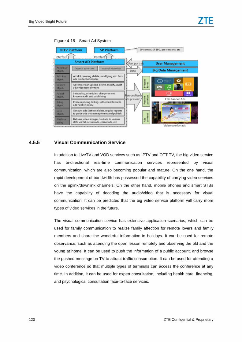
Big Video Bright Future
120 ZTE Confidential & Proprietary
Figure 4-18 Smart Ad System
4.5.5 Visual Communication Service
In addition to LiveTV and VOD services such as IPTV and OTT TV, the big video service
has bi-directional real-time communication services represented by visual
communication, which are also becoming popular and mature. On the one hand, the
rapid development of bandwidth has possessed the capability of carrying video services
on the uplink/downlink channels. On the other hand, mobile phones and smart STBs
have the capability of decoding the audio/video that is necessary for visual
communication. It can be predicted that the big video service platform will carry more
types of video services in the future.
The visual communication service has extensive application scenarios, which can be
used for family communication to realize family affection for remote lovers and family
members and share the wonderful information in holidays. It can be used for remote
observance, such as attending the open lesson remotely and observing the old and the
young at home. It can be used to push the information of a public account, and browse
the pushed message on TV to attract traffic consumption. It can be used for attending a
video conference so that multiple types of terminals can access the conference at any
time. In addition, it can be used for expert consultation, including health care, financing,
and psychological consultation face-to-face services.
Big Video Bright Future
ZTE Confidential & Proprietary 121
ZTE’s IMS visual communication total solution uses the independent private network IMS
solution, which can rapidly realize video conversation services between STB and mobile
APP, including point-to-point video conversation and multiple-party video conversation
between STBs, between STB and mobile APP, between mobile APPs. Both the STB and
mobile APP supports accessing the system in modes such as IP private line, Internet,
and Internet/private network transverse.
After the private network IMS is interconnected with the Internet IMS, both the STB and
mobile video communication APP can realize the audio conversation and video
conference conversation capability together with traditional voice equipment such as
fixed telephones and mobile phones. After being interconnected with the VoLTE network,
the private network IMS can support video conversation with the STB, mobile APP, and
VoLTE users. The operator can deploy the video communication service in phases:
Phase I: Rapid construction solution
The rapid construction solution is the IMS video communication solution in the first phase.
In the phase, you can establish one IMS node or directly use one IMS node in the big
network to rapidly realize video conversation service between STB and mobile APP.
The rapid construction solution has a simple architecture and fewer NEs, which can
support the operator to rapidly develop the video communication service. Meanwhile, the
rapid construction solution fully considers the standard of the network architecture and
NE interconnection, which can totally ensure the interconnection between the video
communication IMS node and the IMS or VoLTE in the big network.
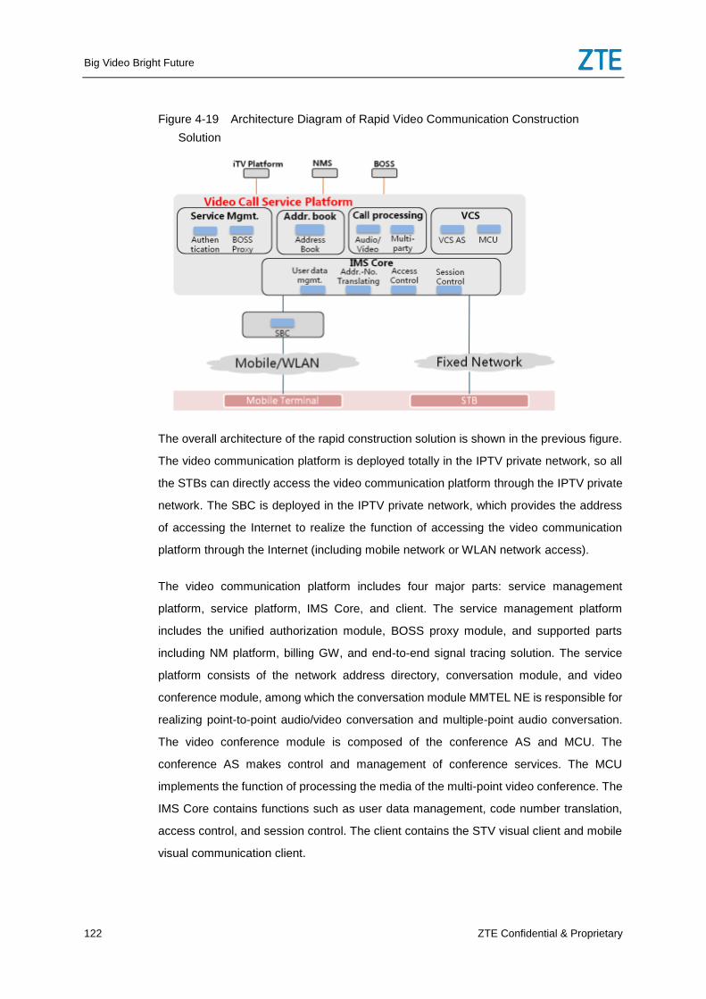
Big Video Bright Future
122 ZTE Confidential & Proprietary
Figure 4-19 Architecture Diagram of Rapid Video Communication Construction
Solution
The overall architecture of the rapid construction solution is shown in the previous figure.
The video communication platform is deployed totally in the IPTV private network, so all
the STBs can directly access the video communication platform through the IPTV private
network. The SBC is deployed in the IPTV private network, which provides the address
of accessing the Internet to realize the function of accessing the video communication
platform through the Internet (including mobile network or WLAN network access).
The video communication platform includes four major parts: service management
platform, service platform, IMS Core, and client. The service management platform
includes the unified authorization module, BOSS proxy module, and supported parts
including NM platform, billing GW, and end-to-end signal tracing solution. The service
platform consists of the network address directory, conversation module, and video
conference module, among which the conversation module MMTEL NE is responsible for
realizing point-to-point audio/video conversation and multiple-point audio conversation.
The video conference module is composed of the conference AS and MCU. The
conference AS makes control and management of conference services. The MCU
implements the function of processing the media of the multi-point video conference. The
IMS Core contains functions such as user data management, code number translation,
access control, and session control. The client contains the STV visual client and mobile
visual communication client.
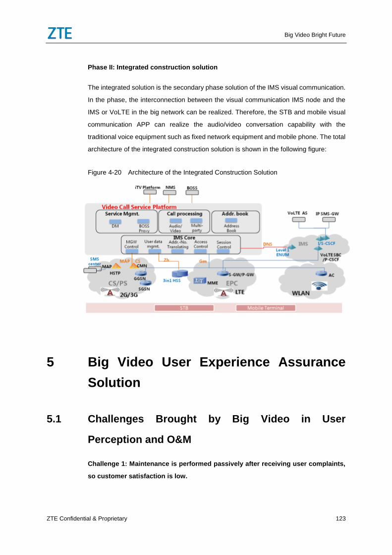
Big Video Bright Future
ZTE Confidential & Proprietary 123
Phase II: Integrated construction solution
The integrated solution is the secondary phase solution of the IMS visual communication.
In the phase, the interconnection between the visual communication IMS node and the
IMS or VoLTE in the big network can be realized. Therefore, the STB and mobile visual
communication APP can realize the audio/video conversation capability with the
traditional voice equipment such as fixed network equipment and mobile phone. The total
architecture of the integrated construction solution is shown in the following figure:
Figure 4-20 Architecture of the Integrated Construction Solution
5 Big Video User Experience Assurance
Solution
5.1 Challenges Brought by Big Video in User
Perception and O&M
Challenge 1: Maintenance is performed passively after receiving user complaints,
so customer satisfaction is low.
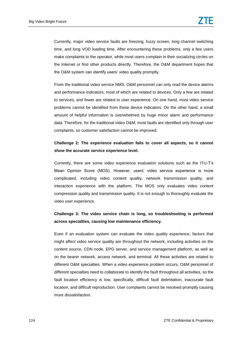
Big Video Bright Future
124 ZTE Confidential & Proprietary
Currently, major video service faults are freezing, fuzzy screen, long channel switching
time, and long VOD loading time. After encountering these problems, only a few users
make complaints to the operator, while most users complain in their socializing circles on
the Internet or find other products directly. Therefore, the O&M department hopes that
the O&M system can identify users’ video quality promptly.
From the traditional video service NMS, O&M personnel can only read the device alarms
and performance indicators, most of which are related to devices. Only a few are related
to services, and fewer are related to user experience. On one hand, most video service
problems cannot be identified from these device indicators. On the other hand, a small
amount of helpful information is overwhelmed by huge minor alarm and performance
data. Therefore, for the traditional video O&M, most faults are identified only through user
complaints, so customer satisfaction cannot be improved.
Challenge 2: The experience evaluation fails to cover all aspects, so it cannot
show the accurate service experience level.
Currently, there are some video experience evaluation solutions such as the ITU-T’s
Mean Opinion Score (MOS). However, users’ video service experience is more
complicated, including video content quality, network transmission quality, and
interaction experience with the platform. The MOS only evaluates video content
compression quality and transmission quality. It is not enough to thoroughly evaluate the
video user experience.
Challenge 3: The video service chain is long, so troubleshooting is performed
across specialties, causing low maintenance efficiency.
Even if an evaluation system can evaluate the video quality experience, factors that
might affect video service quality are throughout the network, including activities on the
content source, CDN node, EPG server, and service management platform, as well as
on the bearer network, access network, and terminal. All these activities are related to
different O&M specialties. When a video experience problem occurs, O&M personnel of
different specialties need to collaborate to identify the fault throughout all activities, so the
fault location efficiency is low, specifically, difficult fault delimitation, inaccurate fault
location, and difficult reproduction. User complaints cannot be resolved promptly causing
more dissatisfaction.
Big Video Bright Future
ZTE Confidential & Proprietary 125
This situation is because of the video service complexity and the fact that the traditional
O&M system cannot collect and process service- and user-related data so that it cannot
directly analyze the service and user experience.
Figure 5-1 Identification of Video Experience Fault Causes
Conclusion: The traditional equipment-oriented NMS and O&M cannot meet O&M
requirement of the best video experience. The current video quality evaluation solution
also needs to be improved. We need to establish an indicator system, which is related to
network factors, can thoroughly evaluate video quality experience and provide the
intelligent user-oriented O&M based on big data technology. Only in this way, can we
truly ensure best video experience for users.
5.2 Big Video User Experience Evaluation System
V-QoE
Definitely, an indicator system that can evaluate video user experience in a quantitative
manner is required to ensure that the network can provide high-quality video user
experience. Such indicator system needs to achieve three goals: objectively measures
video user experience, indicates factors affecting video user experience, and provides
input for network planning. To achieve the three goals, through years of accumulation in
the field of video research and based on the user experience management architecture
on QoE-KQI-KPI, ZTE proposed the big video user experience evaluation system V-QoE,
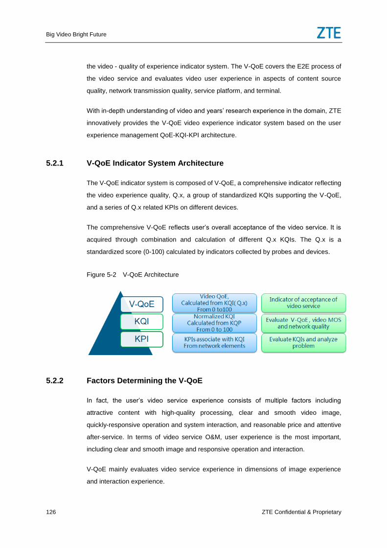
Big Video Bright Future
126 ZTE Confidential & Proprietary
the video - quality of experience indicator system. The V-QoE covers the E2E process of
the video service and evaluates video user experience in aspects of content source
quality, network transmission quality, service platform, and terminal.
With in-depth understanding of video and years’ research experience in the domain, ZTE
innovatively provides the V-QoE video experience indicator system based on the user
experience management QoE-KQI-KPI architecture.
5.2.1 V-QoE Indicator System Architecture
The V-QoE indicator system is composed of V-QoE, a comprehensive indicator reflecting
the video experience quality, Q.x, a group of standardized KQIs supporting the V-QoE,
and a series of Q.x related KPIs on different devices.
The comprehensive V-QoE reflects user’s overall acceptance of the video service. It is
acquired through combination and calculation of different Q.x KQIs. The Q.x is a
standardized score (0-100) calculated by indicators collected by probes and devices.
Figure 5-2 V-QoE Architecture
5.2.2 Factors Determining the V-QoE
In fact, the user’s video service experience consists of multiple factors including
attractive content with high-quality processing, clear and smooth video image,
quickly-responsive operation and system interaction, and reasonable price and attentive
after-service. In terms of video service O&M, user experience is the most important,
including clear and smooth image and responsive operation and interaction.
V-QoE mainly evaluates video service experience in dimensions of image experience
and interaction experience.
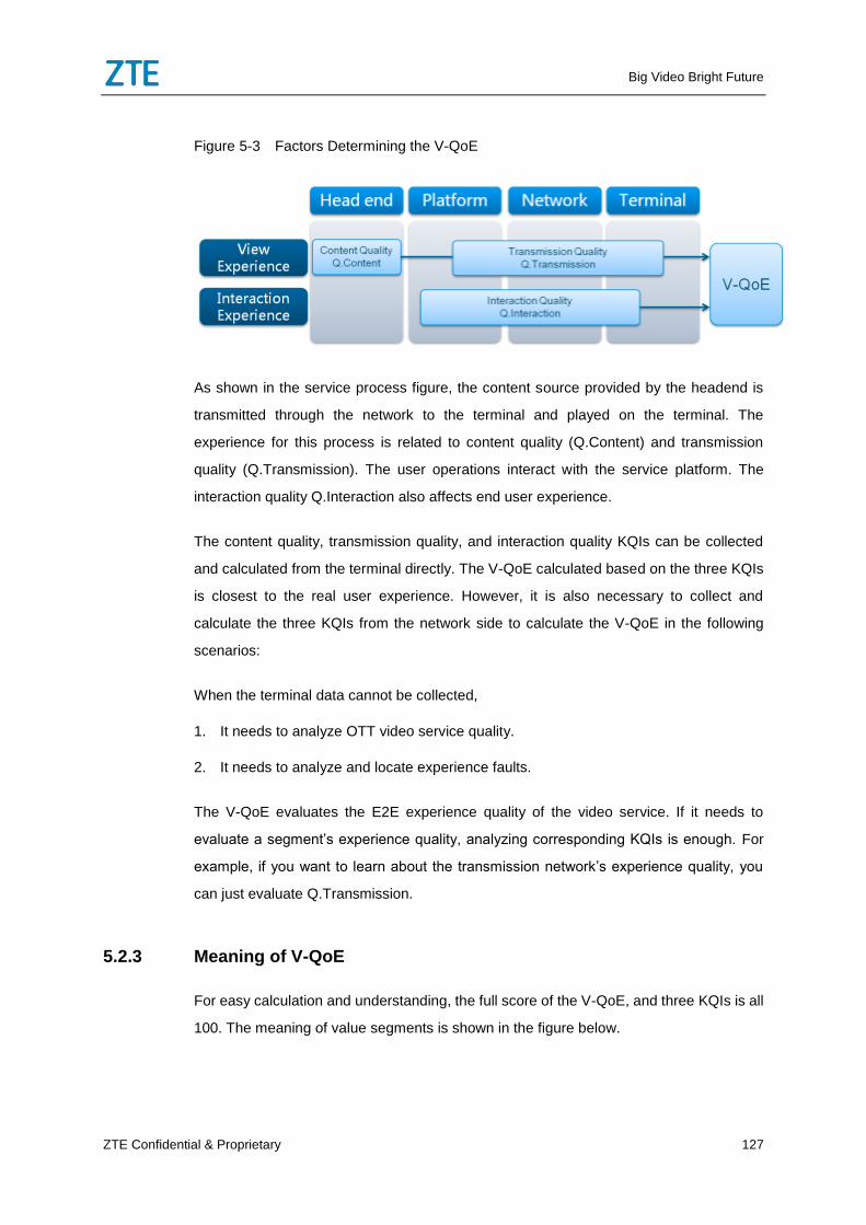
Big Video Bright Future
ZTE Confidential & Proprietary 127
Figure 5-3 Factors Determining the V-QoE
As shown in the service process figure, the content source provided by the headend is
transmitted through the network to the terminal and played on the terminal. The
experience for this process is related to content quality (Q.Content) and transmission
quality (Q.Transmission). The user operations interact with the service platform. The
interaction quality Q.Interaction also affects end user experience.
The content quality, transmission quality, and interaction quality KQIs can be collected
and calculated from the terminal directly. The V-QoE calculated based on the three KQIs
is closest to the real user experience. However, it is also necessary to collect and
calculate the three KQIs from the network side to calculate the V-QoE in the following
scenarios:
When the terminal data cannot be collected,
1. It needs to analyze OTT video service quality.
2. It needs to analyze and locate experience faults.
The V-QoE evaluates the E2E experience quality of the video service. If it needs to
evaluate a segment’s experience quality, analyzing corresponding KQIs is enough. For
example, if you want to learn about the transmission network’s experience quality, you
can just evaluate Q.Transmission.
5.2.3 Meaning of V-QoE
For easy calculation and understanding, the full score of the V-QoE, and three KQIs is all
100. The meaning of value segments is shown in the figure below.
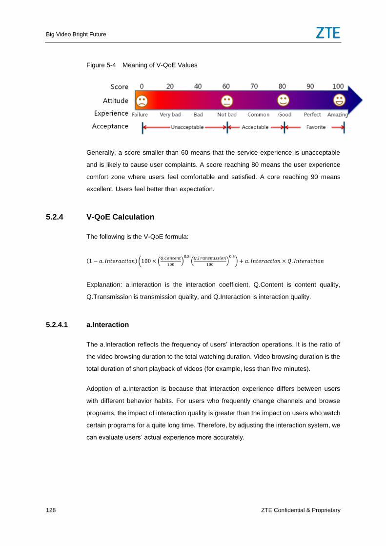
Big Video Bright Future
128 ZTE Confidential & Proprietary
Figure 5-4 Meaning of V-QoE Values
Generally, a score smaller than 60 means that the service experience is unacceptable
and is likely to cause user complaints. A score reaching 80 means the user experience
comfort zone where users feel comfortable and satisfied. A core reaching 90 means
excellent. Users feel better than expectation.
5.2.4 V-QoE Calculation
The following is the V-QoE formula:
Explanation: a.Interaction is the interaction coefficient, Q.Content is content quality,
Q.Transmission is transmission quality, and Q.Interaction is interaction quality.
5.2.4.1 a.Interaction
The a.Interaction reflects the frequency of users’ interaction operations. It is the ratio of
the video browsing duration to the total watching duration. Video browsing duration is the
total duration of short playback of videos (for example, less than five minutes).
Adoption of a.Interaction is because that interaction experience differs between users
with different behavior habits. For users who frequently change channels and browse
programs, the impact of interaction quality is greater than the impact on users who watch
certain programs for a quite long time. Therefore, by adjusting the interaction system, we
can evaluate users’ actual experience more accurately.
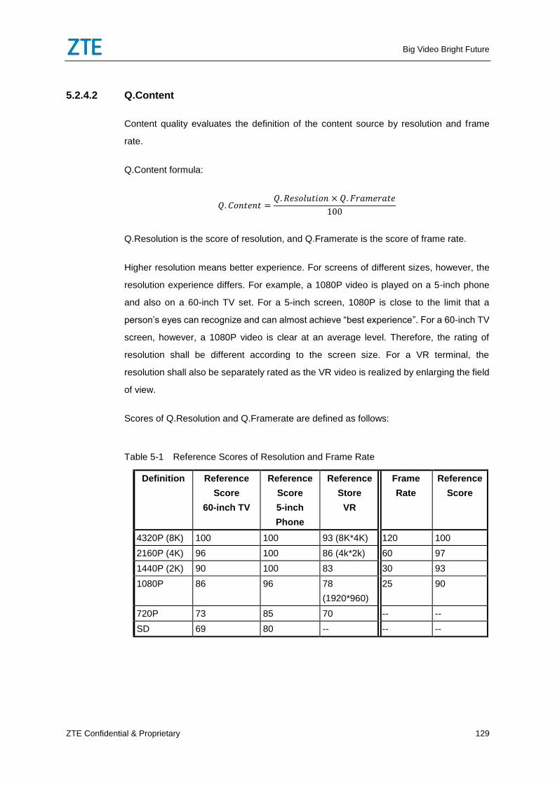
Big Video Bright Future
ZTE Confidential & Proprietary 129
5.2.4.2 Q.Content
Content quality evaluates the definition of the content source by resolution and frame
rate.
Q.Content formula:
Q.Resolution is the score of resolution, and Q.Framerate is the score of frame rate.
Higher resolution means better experience. For screens of different sizes, however, the
resolution experience differs. For example, a 1080P video is played on a 5-inch phone
and also on a 60-inch TV set. For a 5-inch screen, 1080P is close to the limit that a
person’s eyes can recognize and can almost achieve “best experience”. For a 60-inch TV
screen, however, a 1080P video is clear at an average level. Therefore, the rating of
resolution shall be different according to the screen size. For a VR terminal, the
resolution shall also be separately rated as the VR video is realized by enlarging the field
of view.
Scores of Q.Resolution and Q.Framerate are defined as follows:
Table 5-1 Reference Scores of Resolution and Frame Rate
Definition Reference
Score
60-inch TV
Reference
Score
5-inch
Phone
Reference
Store
VR
Frame
Rate
Reference
Score
4320P (8K) 100 100 93 (8K*4K) 120 100
2160P (4K) 96 100 86 (4k*2k) 60 97
1440P (2K) 90 100 83 30 93
1080P 86 96 78
(1920*960)
25 90
720P 73 85 70 -- --
SD 69 80 -- -- --
Big Video Bright Future
130 ZTE Confidential & Proprietary
5.2.4.3 Q.Transmission
Factors affecting video transmission quality mainly are delay, packet loss, and jitter.
Under UDP and TCP, transmission quality has different impact on video, so different
algorithms shall be adopted. For live TV, the UDP transmission protocol is adopted. For
VOD, both TCP and UDP could be adopted. Therefore, transmission quality is evaluated
by transmission protocol rather than live TV or VOD.
When the UDP protocol is used for transmission, the major impact factor is packet loss.
The video could be freezing or fuzzy. If the freezing mechanism is used, the decoder
freezes the video when packets are lost until the next complete I frame comes. If the
ignorance mechanism is used, the decoder keeps decoding regardless of packet loss,
and the video is fuzzy.
If the UDP protocol is used for VOD service, series packet loss and delay may cause
buffer overflow. The buffer overflow is reflected by Q.Rebuffering.
Therefore, when the UDP protocol is adopted, the live TV transmission quality
Q.Transmission is reflected by the freezing and fuzzy video score Q.Freezing, as shown
below:
When the UDP protocol is adopted, the VOD transmission quality Q.Transmission is
reflected by Q.Freezing and Q.Rebuffing, as shown below:
When the TCP protocol is used for transmission, slight packet loss can be recovered
through TCP retransmission when the bandwidth is enough and stable. When file
segments fail to be downloaded as quickly as the video is played, the buffer is used up
causing playback caching. Therefore, the TCP-based network transmission quality
Q.Transmission is reflected by the buffer overflow score Q.Rebuffering, as shown below:
User experience on freezing/fuzzy situation is affected by the number of times (frequency)
and duration (severity). The Q.Freezing score shall cover the number of times and
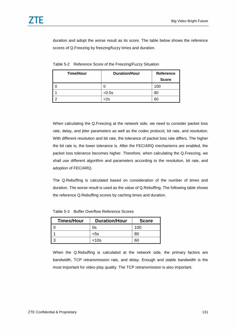
Big Video Bright Future
ZTE Confidential & Proprietary 131
duration and adopt the worse result as its score. The table below shows the reference
scores of Q.Freezing by freezing/fuzzy times and duration.
Table 5-2 Reference Score of the Freezing/Fuzzy Situation
Time/Hour Duration/Hour Reference
Score
0 0 100
1 <0.5s 80
2 <2s 60
When calculating the Q.Freezing at the network side, we need to consider packet loss
rate, delay, and jitter parameters as well as the codec protocol, bit rate, and resolution.
With different resolution and bit rate, the tolerance of packet loss rate differs. The higher
the bit rate is, the lower tolerance is. After the FEC/ARQ mechanisms are enabled, the
packet loss tolerance becomes higher. Therefore, when calculating the Q.Freezing, we
shall use different algorithm and parameters according to the resolution, bit rate, and
adoption of FEC/ARQ.
The Q.Rebuffing is calculated based on consideration of the number of times and
duration. The worse result is used as the value of Q.Rebuffing. The following table shows
the reference Q.Rebuffing scores by caching times and duration.
Table 5-3 Buffer Overflow Reference Scores
Times/Hour Duration/Hour Score
0 0s 100
1 <5s 80
3 <10s 60
When the Q.Rebuffing is calculated at the network side, the primary factors are
bandwidth, TCP retransmission rate, and delay. Enough and stable bandwidth is the
most important for video play quality. The TCP retransmission is also important.
Big Video Bright Future
132 ZTE Confidential & Proprietary
5.2.4.4 Q.Interaction
The video interaction quality shall be evaluated by service type. The live TV interaction
quality is evaluated by channel change time, and the VOD interaction quality is evaluated
by VOD loading time. The Q.Interaction calculation method is as follows:
(Live TV)
(VOD)
Reference scores of live channel change quality Q.Changechannel and VOD loading
quality Q.Loading are shown in the table below.
Table 5-4 Interaction Quality Reference Scores
Live TV VOD
Change Time Reference Score Waiting Time Reference Score
<100ms 100 <0.5s 100
500ms 80 1s 80
1000ms 60 5s 60
The channel change time is mainly affected by the IGMP Join/Leave time and the first I
frame arrival or first TS file downloading time. The VOD loading time is mainly affected by
the RTSP signal interaction time or M3U8 resolution time and the first I frame arrival or
first TS file downloading time. For Live TV, STB users may change channels frequently,
so IGMP Join/Leave indicator is critical. The performance of the multicast replication
point shall be ensured and the IGMP fast leave mechanism shall be realized. For VOD,
whether IPTV or OTT, the improvement of protocol layer’s interaction efficiency requires
the standard interface process between the terminal and CDN.
5.3 FMC IPTV End-to-end Smart O&M
5.3.1 Overview
The FMC IPTV service involves the IPTV terminal, IPTV service system, CDN network,
fixed network access, bearer network, and wireless network under the mobile TV
scenario. Any error in a cycle can affect user experience. Therefore, the IPTV end-to-end
Big Video Bright Future
ZTE Confidential & Proprietary 133
smart O&M needs multiple systems for collaboration to solve all the cycles of user
experience to ensure user experience of the IPTV system.
The IPTV end-to-end smart O&M includes the big video smart O&M platform, in-depth
network analysis platform, and wireless smart O&M platform. These three platforms are
configured on a big data platform, which use the big data technology to share, analyze
and mine the data to collaboratively realize end-to-end O&M of the IPTV service.
The big video smart O&M platform, which regards user experience as its center, realizes
the total flow end-to-end smart service O&M of the IPTV service. The system collects the
STB or CDN probe data and the IPTV service platform data. On the big data platform, the
system uses the big data analysis technology and provides capabilities such as video
service quality monitoring, service experience fault end-to-end analysis, and terminal
analysis.
The in-depth network analysis platform, which regards it as its target to promote O&M
efficiency of the operator’s network and reduce the O&M cost, realizes visualized
management of the fixed access network and bearer network to constitute the most
industrially-authorized network performance analysis and service system, simplify the
network data, and make proactive management, automatic O&M, and refined operation.
The wireless smart O&M platform, which is based on the big data technology, is the
product to support wireless network O&M and operation. It percepts and analyzes the
network and service information by setting foot on the user’s angle. Through mining and
analyzing the massive data flexibly, it can realize all-around visualization of the network
quality, service traffic, service quality, user experience, user behavior and terminal
application. It supports end-to-end user complaints processing and service quality
analysis to rapidly find out the causes of affecting the network quality and user
perception and constitute a service pipeline that can be viewed, managed, and controlled
to provide comprehensive supports for making refined operation of the total services of
the wireless network.
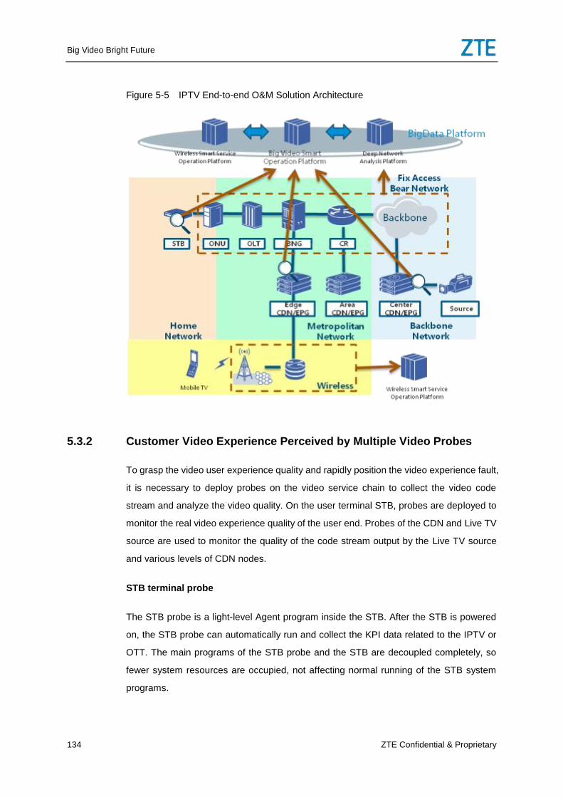
Big Video Bright Future
134 ZTE Confidential & Proprietary
Figure 5-5 IPTV End-to-end O&M Solution Architecture
5.3.2 Customer Video Experience Perceived by Multiple Video Probes
To grasp the video user experience quality and rapidly position the video experience fault,
it is necessary to deploy probes on the video service chain to collect the video code
stream and analyze the video quality. On the user terminal STB, probes are deployed to
monitor the real video experience quality of the user end. Probes of the CDN and Live TV
source are used to monitor the quality of the code stream output by the Live TV source
and various levels of CDN nodes.
STB terminal probe
The STB probe is a light-level Agent program inside the STB. After the STB is powered
on, the STB probe can automatically run and collect the KPI data related to the IPTV or
OTT. The main programs of the STB probe and the STB are decoupled completely, so
fewer system resources are occupied, not affecting normal running of the STB system
programs.
Big Video Bright Future
ZTE Confidential & Proprietary 135
The STB probe periodically collects all the network data and video data message and
periodically calculates the user service quality data. In addition, it can record the errors
(such as access failure) in the service application and errors in the media playing
process (such as blank screen and program interruption) as error codes to report them to
the smart O&M platform for processing the errors.
CDN probe
The CDN probe is used to monitor the CDN link quality and Live TV code stream quality.
According to the deployment position, it can be divided into CDN built-in probe and CDN
externally-configured network probe. The CDN built-in probe is completely decoupled
with the CDN main program, and it doesn’t affect the normal operation of the CDN
system programs.
The CDN probe can, according to different application scenarios, work in passive
monitoring mode (monitoring the channel quality for 7*24) and proactive dialing test
mode (make dialing test of the OTT source site if the system breaks down)
Mobile terminal probe
In the mobile TV application of the mobile terminal, the built-in video experience probe
has the function of estimating the video quality experience of the end user, including time
duration of playing the video, download rate, number of cache times, and cache time
duration. The probe is provided in SDK mode so that the 3rd
party APP can integrate it.
5.3.3 O&M Monitoring of the Total Network Video Service
The video service monitoring and analyzing functions are described as follows:
Real-time monitoring: The function involves total network video quality real-time
monitoring, user data monitoring, Live TV stream monitoring, video service quality
monitoring, and VOD service quality monitoring, alarm real-time monitoring, CDN
monitoring, and EPG monitoring.
Quality analysis: The function involves performance analysis, resource analysis, user
perception, and terminal analysis. Performance analysis is made for major service
experience performances. Resource analysis is made for the total network resources of
Big Video Bright Future
136 ZTE Confidential & Proprietary
the IPTV system to provide resource warning. User perception involves single user
perception and VIP user perception. Terminal analysis is mainly made for the terminal
type, including calculating and analyzing the data according to different STB models and
different mobile phone or PAD models.
5.3.4 Smartly Delimiting the Video Fault
As the IPTV service involves multiple systems, it is difficult to delimit the fault. Through
analyzing the V-QoE indexes on the terminal, CDN, and bearer network, the system can
rapidly submit the rough range of the experience quality fault.
The end-to-end smart O&M can be realized in the following steps to smartly delimit the
experience quality fault.
Step one: Monitoring the video quality experience: Through the STB built-in probe, the
system can evaluate the V-QoE. If the experience is unacceptable, the system
proactively triggers for reporting the error.
Step two: Analyzing the video quality experience exception: After receiving the V-QoE
exception information reported by the STB and when finding out that user experience
goes down, the network O&M system enables the experience exception analysis flow. At
first, it analyzes the quality of the input content source according to the probe deployed
on the CDN entrance. If the content source quality is normal, the system enters the
second step.
Step three: Restoring the dynamic path of the video service: The network O&M system
can recognize the user service path according to the user ID, and service Quintet
together with the asset library information. The system, according to the video service
stream information, restores the real-time service path of the original video according to
the information of a single NE (such as OLT, LSW, BNG. or CR), including the detailed
information of the NEs of the local MAN CR and ONU).
Step four: Delimiting the video experience quality exception: The network O&M system in
real time calculates the KQI indexes related to the equipment V-QoE on the user service
path, such as ONU, OLT, BNG, and CR to delimit the fault by comparing the KQI indexes
in different positions. The network O&M system, according to the delimited exception
path, enables the SQM active test by segments to detect the time delay and packet loss
Big Video Bright Future
ZTE Confidential & Proprietary 137
ratio in real time on the video service path and analyze the exception position according
to the tests by phases.
After making preliminary delimiting of the fault of the video experience quality, the
network O&M system can, according to the delimiting result, make more specific fault
analysis respectively on the video service network and bearer network and position the
final position of the fault.
5.3.5 Rapidly Positioning the Video Service Network Fault
Positioning the user fault
The operation personnel can, through multiple entrances, enter the fault positioning
function to query the play history record of the fault user and the service quality data and
error information corresponding to different play records. In addition, the operation
personnel can query the health degree curve at the corresponding time segment of the
user and the distribution information of user error codes in different regions. Through
positioning the fault, the O&M personnel can analyze the fault cause and distribution
information of the fault.
Positioning the service quality fault
The operation personnel can, through multiple entrances, enter the fault positioning
function. The fault positioning function can be realized:
Through the fault positioning function, you can query the play history record of the fault
user and the service quality data and error information corresponding to different play
records. In addition, the operation personnel can query the health degree curve at the
corresponding time segment of the user and the distribution information of user error
codes in different regions. Through positioning the fault, the O&M personnel can analyze
the fault cause and distribution information of the fault.
The flows of automatically positioning the fault at the IPTV platform side can be used to
determine the service capability fault at the IPTV platform side.
Big Video Bright Future
138 ZTE Confidential & Proprietary
5.3.6 Rapidly Positioning the Fault of the Bearer Network
For the wired network, the bearer network O&M system integrating the smart O&M can
be easily navigated to the associated service management interface with respect to
topology, alarm, and performance figures for positioning the fault. In the physical
topology figure, it provides different layers of service navigation such as NE, board, port,
tunnel, pseudo wire, and customer. In the alarm view figure and performance view figure,
it provides the function of querying services related to alarm and performance to position
the fault of the wired network.
For the wireless bearer network, the carrier network O&M system integrating smart O&M
can realize automatic diagnosis of services under the PTN scenario and IP RAN scenario
to implement comprehensive fault analysis and positioning of the mobile network. The
fault is diagnosed automatically to realize the capability of rapidly positioning the fault
under the typical fault scenario to make one-key smart diagnosis and analysis of the
information such as tunnel/pseudo wire OAM fault, TDM/Ethernet service fault, and CDN
fault together with the information such as configuration, alarm, performance, and
equipment state to rapidly find out the fault cause and submit the solution suggestion.
Solely respect to the IP RAN network O&M scenario, the carrier network O&M system
integrating smart O&M can provide the rapid service diagnosis function of the designated
dynamic services. It mainly involves several kinds of dynamic services in the IP RAN
application, such as dynamic tunnel and HSB FRR protection, L2VPN (including CES
and Ethernet services), and L3VPN service, to add the end-to-end path diagnosis
function in the mode of manually setting the base or RNC information. Therefore, it can
rapidly and effectively check whether dynamic services are carried effectively to evade
some faults in advance.
5.3.7 Rapidly Positioning the Fault of the Access Network
Access network is one important segment in the video service end-to-end link. The
access network O&M system participates in delimiting, positioning, and analyzing the
end-to-end fault of the video service. Firstly, it realizes topology management of the
access network equipment such as OLT and ONU, representing the topology tag of the
access network from the video service end-to-end O&M system. Secondly, through the
network fault management and performance management, it supports monitoring and
Big Video Bright Future
ZTE Confidential & Proprietary 139
evaluating the network quality. In addition, it, based on the capability of the access
equipment for collecting the video service quality index, monitors and evaluates the video
quality.
For the network quality, the access network O&M system supports testing the
performance of the service tunnel between the OLT and ONU and the performance of
the service tunnel generated from the OLT or ONU to the video head end to analyze the
capability of carrying the video service with respect to the indexes on the network layer
such as throughput, packet loss rate, time delay, and jittering.
For the video service indexes, the access network O&M system supports collecting the
OTT video and IPTV video indexes on some ONUs and OLTs. Through the ONU, it
realizes the wide coverage of the video probes and monitors and evaluates the user-level
video quality. Through the OLT, it enables the video probes to be compatible to
monitoring and evaluating the video quality under the old ONUs and ONUs of 3rd
party.
5.3.8 IPTV O&M under the Mobile Scenario
Under the integrated scenario of the fixed network and the mobile network, IPTV
intelligent O&M also requires to perform user experience evaluation, service quality
monitoring, and fault delimiting/location upon the Mobile TV service on mobile terminals.
The system performs user experience sensing and evaluation of the mobile TV service
through the built-in video experience probe inside the mobile TV application by
combining user experience data on the IPTV service platform.
If a problem occurs in user experience with the mobile TV service, the IPTV intelligent
O&M platform first makes analysis through the mobile terminal probe and CDN probe, to
delimit the problem. If the problem is not caused by the terminal or the IPTV system,
according to the user access mode (WiFi access or through the cellular network), the
system uses the user’s IP address as the index to locate the problem cause on the
in-depth network analysis platform and the wireless intelligent O&M platform, thus
achieving end-to-end intelligent O&M of the IPTV service under the mobile scenario.
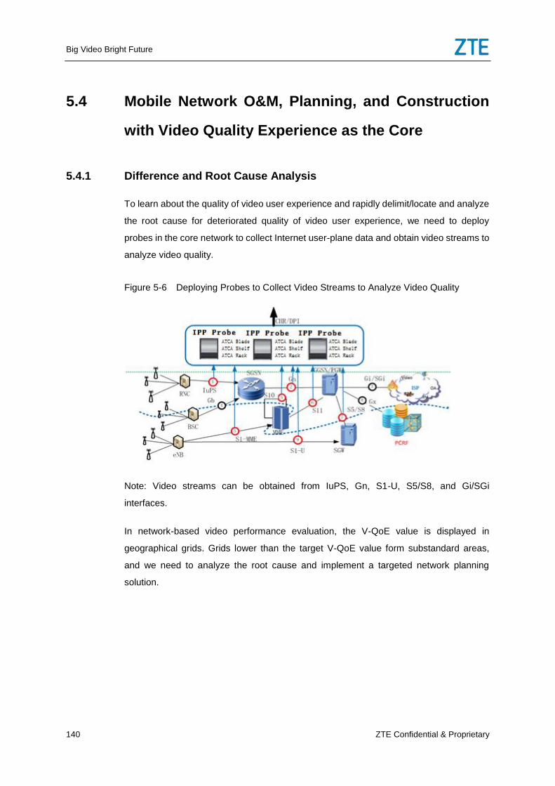
Big Video Bright Future
140 ZTE Confidential & Proprietary
5.4 Mobile Network O&M, Planning, and Construction
with Video Quality Experience as the Core
5.4.1 Difference and Root Cause Analysis
To learn about the quality of video user experience and rapidly delimit/locate and analyze
the root cause for deteriorated quality of video user experience, we need to deploy
probes in the core network to collect Internet user-plane data and obtain video streams to
analyze video quality.
Figure 5-6 Deploying Probes to Collect Video Streams to Analyze Video Quality
Note: Video streams can be obtained from IuPS, Gn, S1-U, S5/S8, and Gi/SGi
interfaces.
In network-based video performance evaluation, the V-QoE value is displayed in
geographical grids. Grids lower than the target V-QoE value form substandard areas,
and we need to analyze the root cause and implement a targeted network planning
solution.
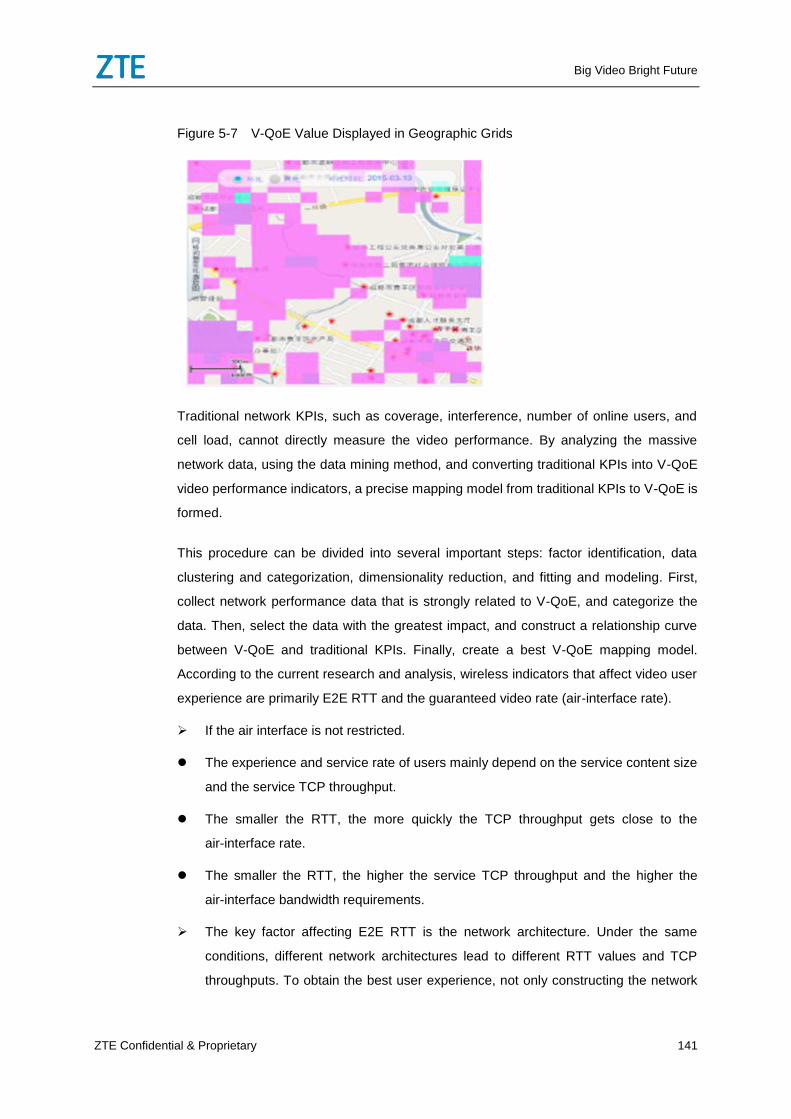
Big Video Bright Future
ZTE Confidential & Proprietary 141
Figure 5-7 V-QoE Value Displayed in Geographic Grids
Traditional network KPIs, such as coverage, interference, number of online users, and
cell load, cannot directly measure the video performance. By analyzing the massive
network data, using the data mining method, and converting traditional KPIs into V-QoE
video performance indicators, a precise mapping model from traditional KPIs to V-QoE is
formed.
This procedure can be divided into several important steps: factor identification, data
clustering and categorization, dimensionality reduction, and fitting and modeling. First,
collect network performance data that is strongly related to V-QoE, and categorize the
data. Then, select the data with the greatest impact, and construct a relationship curve
between V-QoE and traditional KPIs. Finally, create a best V-QoE mapping model.
According to the current research and analysis, wireless indicators that affect video user
experience are primarily E2E RTT and the guaranteed video rate (air-interface rate).
If the air interface is not restricted.
The experience and service rate of users mainly depend on the service content size
and the service TCP throughput.
The smaller the RTT, the more quickly the TCP throughput gets close to the
air-interface rate.
The smaller the RTT, the higher the service TCP throughput and the higher the
air-interface bandwidth requirements.
The key factor affecting E2E RTT is the network architecture. Under the same
conditions, different network architectures lead to different RTT values and TCP
throughputs. To obtain the best user experience, not only constructing the network
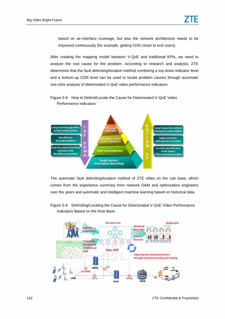
Big Video Bright Future
142 ZTE Confidential & Proprietary
based on air-interface coverage, but also the network architecture needs to be
improved continuously (for example, getting CDN closer to end users).
After creating the mapping model between V-QoE and traditional KPIs, we need to
analyze the root cause for the problem. According to research and analysis, ZTE
determines that the fault delimiting/location method combining a top-down indicator level
and a bottom-up CDR level can be used to locate problem causes through automatic
one-click analysis of deteriorated V-QoE video performance indicators.
Figure 5-8 How to Delimit/Locate the Cause for Deteriorated V-QoE Video
Performance Indicators
The automatic fault delimiting/location method of ZTE relies on the rule base, which
comes from the experience summary from network O&M and optimization engineers
over the years and automatic and intelligent machine learning based on historical data.
Figure 5-9 Delimiting/Locating the Cause for Deteriorated V-QoE Video Performance
Indicators Based on the Rule Base
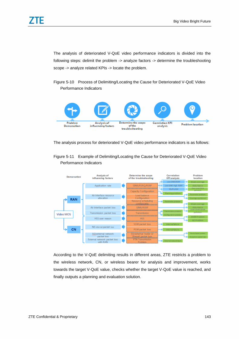
Big Video Bright Future
ZTE Confidential & Proprietary 143
The analysis of deteriorated V-QoE video performance indicators is divided into the
following steps: delimit the problem -> analyze factors -> determine the troubleshooting
scope -> analyze related KPIs -> locate the problem.
Figure 5-10 Process of Delimiting/Locating the Cause for Deteriorated V-QoE Video
Performance Indicators
The analysis process for deteriorated V-QoE video performance indicators is as follows:
Figure 5-11 Example of Delimiting/Locating the Cause for Deteriorated V-QoE Video
Performance Indicators
According to the V-QoE delimiting results in different areas, ZTE restricts a problem to
the wireless network, CN, or wireless bearer for analysis and improvement, works
towards the target V-QoE value, checks whether the target V-QoE value is reached, and
finally outputs a planning and evaluation solution.
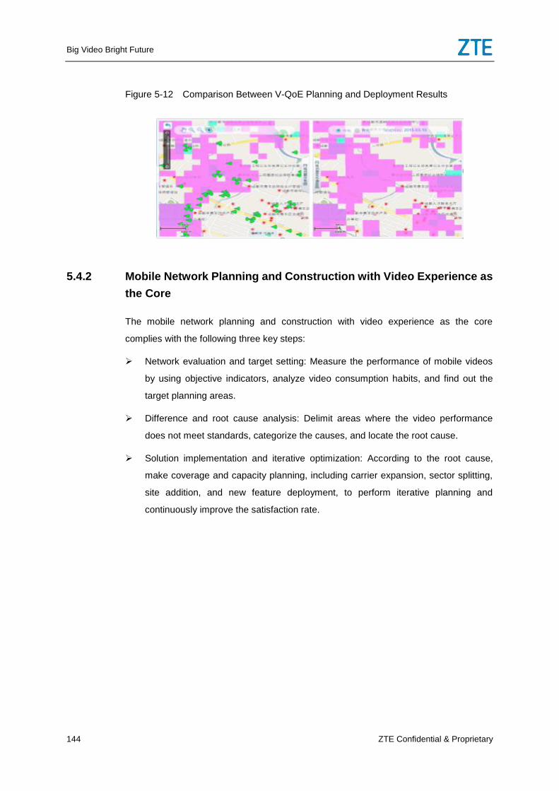
Big Video Bright Future
144 ZTE Confidential & Proprietary
Figure 5-12 Comparison Between V-QoE Planning and Deployment Results
5.4.2 Mobile Network Planning and Construction with Video Experience as
the Core
The mobile network planning and construction with video experience as the core
complies with the following three key steps:
Network evaluation and target setting: Measure the performance of mobile videos
by using objective indicators, analyze video consumption habits, and find out the
target planning areas.
Difference and root cause analysis: Delimit areas where the video performance
does not meet standards, categorize the causes, and locate the root cause.
Solution implementation and iterative optimization: According to the root cause,
make coverage and capacity planning, including carrier expansion, sector splitting,
site addition, and new feature deployment, to perform iterative planning and
continuously improve the satisfaction rate.
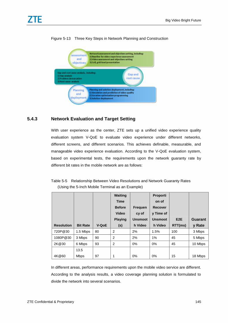
Big Video Bright Future
ZTE Confidential & Proprietary 145
Figure 5-13 Three Key Steps in Network Planning and Construction
5.4.3 Network Evaluation and Target Setting
With user experience as the center, ZTE sets up a unified video experience quality
evaluation system V-QoE to evaluate video experience under different networks,
different screens, and different scenarios. This achieves definable, measurable, and
manageable video experience evaluation. According to the V-QoE evaluation system,
based on experimental tests, the requirements upon the network guaranty rate by
different bit rates in the mobile network are as follows:
Table 5-5 Relationship Between Video Resolutions and Network Guaranty Rates
(Using the 5-Inch Mobile Terminal as an Example)
Resolution Bit Rate V-QoE
Waiting
Time
Before
Video
Playing
(s)
Frequen
cy of
Unsmoot
h Video
Proporti
on of
Recover
y Time of
Unsmoot
h Video
E2E
RTT(ms)
Guarant
y Rate
720P@30 1.5 Mbps 80 2 2% 1.5% 100 3 Mbps
1080P@30 3 Mbps 90 2 2% 1% 45 5 Mbps
2K@30 6 Mbps 93 2 0% 0% 45 10 Mbps
4K@60
13.5
Mbps 97 1 0% 0% 15 18 Mbps
In different areas, performance requirements upon the mobile video service are different.
According to the analysis results, a video coverage planning solution is formulated to
divide the network into several scenarios.
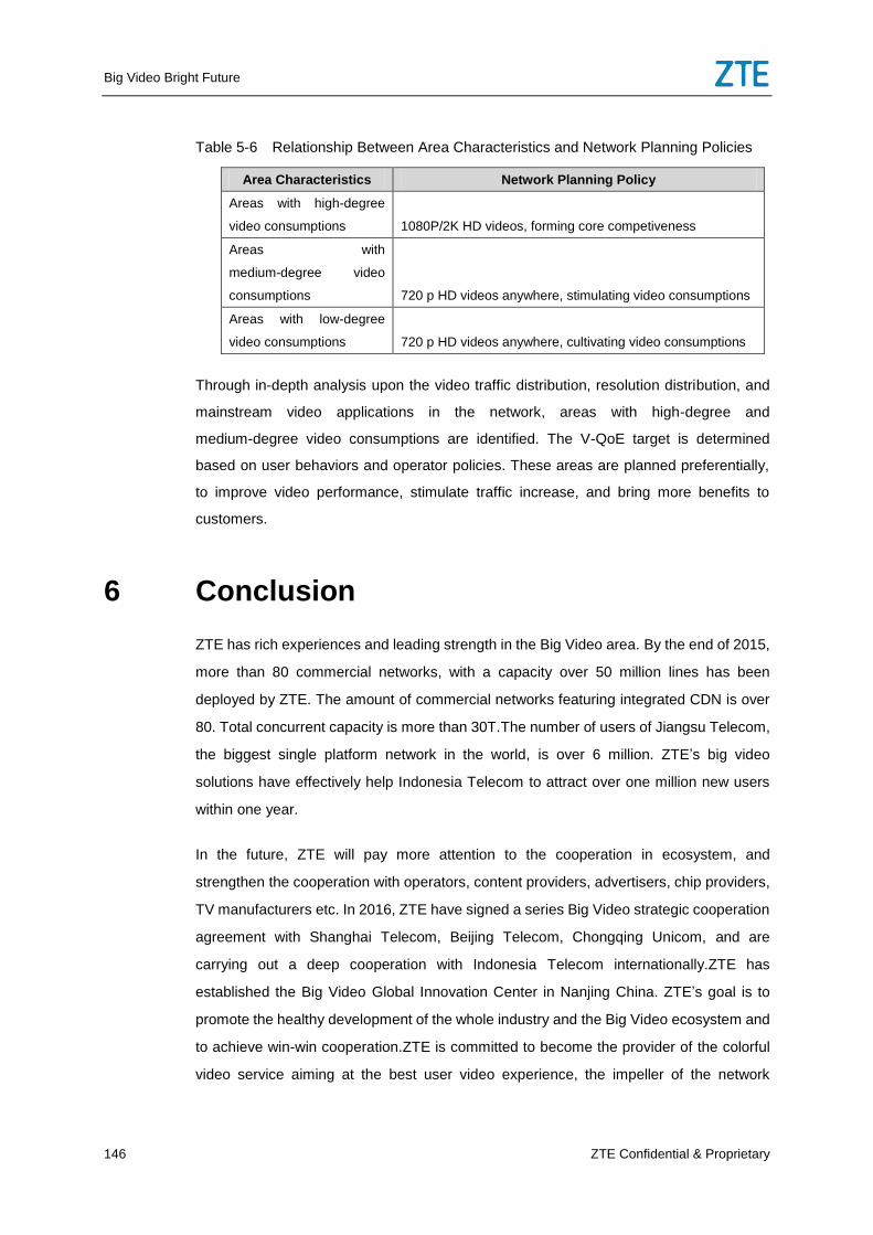
Big Video Bright Future
146 ZTE Confidential & Proprietary
Table 5-6 Relationship Between Area Characteristics and Network Planning Policies
Area Characteristics Network Planning Policy
Areas with high-degree
video consumptions 1080P/2K HD videos, forming core competiveness
Areas with
medium-degree video
consumptions 720 p HD videos anywhere, stimulating video consumptions
Areas with low-degree
video consumptions 720 p HD videos anywhere, cultivating video consumptions
Through in-depth analysis upon the video traffic distribution, resolution distribution, and
mainstream video applications in the network, areas with high-degree and
medium-degree video consumptions are identified. The V-QoE target is determined
based on user behaviors and operator policies. These areas are planned preferentially,
to improve video performance, stimulate traffic increase, and bring more benefits to
customers.
6 Conclusion
ZTE has rich experiences and leading strength in the Big Video area. By the end of 2015,
more than 80 commercial networks, with a capacity over 50 million lines has been
deployed by ZTE. The amount of commercial networks featuring integrated CDN is over
80. Total concurrent capacity is more than 30T.The number of users of Jiangsu Telecom,
the biggest single platform network in the world, is over 6 million. ZTE’s big video
solutions have effectively help Indonesia Telecom to attract over one million new users
within one year.
In the future, ZTE will pay more attention to the cooperation in ecosystem, and
strengthen the cooperation with operators, content providers, advertisers, chip providers,
TV manufacturers etc. In 2016, ZTE have signed a series Big Video strategic cooperation
agreement with Shanghai Telecom, Beijing Telecom, Chongqing Unicom, and are
carrying out a deep cooperation with Indonesia Telecom internationally.ZTE has
established the Big Video Global Innovation Center in Nanjing China. ZTE’s goal is to
promote the healthy development of the whole industry and the Big Video ecosystem and
to achieve win-win cooperation.ZTE is committed to become the provider of the colorful
video service aiming at the best user video experience, the impeller of the network
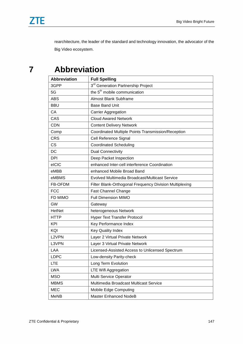
Big Video Bright Future
ZTE Confidential & Proprietary 147
rearchitecture, the leader of the standard and technology innovation, the advocator of the
Big Video ecosystem.
7 Abbreviation Abbreviation Full Spelling
3GPP 3rd
Generation Partnership Project
5G the 5th mobile communication
ABS Almost Blank Subframe
BBU Base Band Unit
CA Carrier Aggregation
CAS Cloud Awared Network
CDN Content Delivery Network
Comp Coordinated Multiple Points Transmission/Reception
CRS Cell Reference Signal
CS Coordinated Scheduling
DC Dual Connectivity
DPI Deep Packet Inspection
eICIC enhanced Inter-cell interference Coordination
eMBB enhanced Mobile Broad Band
eMBMS Evolved Multimedia Broadcast/Multicast Service
FB-OFDM Filter Blank-Orthogonal Frequency Division Multiplexing
FCC Fast Channel Change
FD MIMO Full Dimension MIMO
GW Gateway
HetNet heterogeneous Network
HTTP Hyper Text Transfer Protocol
KPI Key Performance Index
KQI Key Quality Index
L2VPN Layer 2 Virtual Private Network
L3VPN Layer 3 Virtual Private Network
LAA Licensed-Assisted Access to Unlicensed Spectrum
LDPC Low-density Parity-check
LTE Long Term Evolution
LWA LTE Wifi Aggregation
MSO Multi Service Operator
MBMS Multimedia Broadcast Multicast Service
MEC Mobile Edge Computing
MeNB Master Enhanced NodeB
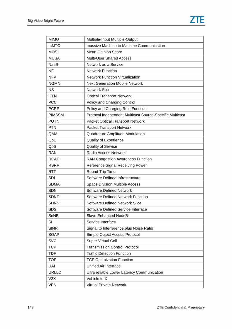
Big Video Bright Future
148 ZTE Confidential & Proprietary
MIMO Multiple-Input Multiple-Output
mMTC massive Machine to Machine Communication
MOS Mean Opinion Score
MUSA Multi-User Shared Access
NaaS Network as a Service
NF Network Function
NFV Network Function Virtualization
NGMN Next Generation Mobile Network
NS Network Slice
OTN Optical Transport Network
PCC Policy and Charging Control
PCRF Policy and Charging Rule Function
PIMSSM Protocol Independent Multicast Source-Specific Multicast
POTN Packet Optical Transport Network
PTN Packet Transport Network
QAM Quadrature Amplitude Modulation
QoE Quality of Experience
QoS Quality of Service
RAN Radio Access Network
RCAF RAN Congestion Awareness Function
RSRP Reference Signal Receiving Power
RTT Round-Trip Time
SDI Software Defined Infrastructure
SDMA Space Division Multiple Access
SDN Software Defined Network
SDNF Software Defined Network Function
SDNS Software Defined Network Slice
SDSI Software Defined Service Interface
SeNB Slave Enhanced NodeB
SI Service Interface
SINR Signal to Interference plus Noise Ratio
SOAP Simple Object Access Protocol
SVC Super Virtual Cell
TCP Transmission Control Protocol
TDF Traffic Detection Function
TOF TCP Optimization Function
UAI Unified Air Interface
URLLC Ultra reliable Lower Latency Communication
V2X Vehicle to X
VPN Virtual Private Network
Big Video Bright Future
ZTE Confidential & Proprietary 149