
Softwire L. Cai Internet-Draft ZTE Intended status ... - IETF Datatracker
325
Softwire L. Cai Internet-Draft ZTE Intended status: Standards Track J. Qin Expires: November 17, 2013 S. Tsuchiya, Ed. Cisco Systems May 16, 2013 Definitions of Managed Objects for 6rd draft-cai-softwire-6rd-mib-05 Abstract This document defines a portion of the Management Information Base (MIB) for use with network management protocols. In particular, it defines objects for managing 6rd devices. Status of This Memo This Internet-Draft is submitted in full conformance with the provisions of BCP 78 and BCP 79. Internet-Drafts are working documents of the Internet Engineering Task Force (IETF). Note that other groups may also distribute working documents as Internet-Drafts. The list of current Internet- Drafts is at http://datatracker.ietf.org/drafts/current/. Internet-Drafts are draft documents valid for a maximum of six months and may be updated, replaced, or obsoleted by other documents at any time. It is inappropriate to use Internet-Drafts as reference material or to cite them other than as "work in progress." This Internet-Draft will expire on November 17, 2013. Copyright Notice Copyright (c) 2013 IETF Trust and the persons identified as the document authors. All rights reserved. This document is subject to BCP 78 and the IETF Trust’s Legal Provisions Relating to IETF Documents (http://trustee.ietf.org/license-info) in effect on the date of publication of this document. Please review these documents carefully, as they describe your rights and restrictions with respect to this document. Code Components extracted from this document must include Simplified BSD License text as described in Section 4.e of the Trust Legal Provisions and are provided without warranty as described in the Simplified BSD License. Cai, et al. Expires November 17, 2013 [Page 1]
-
Upload
khangminh22 -
Category
Documents
-
view
1 -
download
0
Transcript of Softwire L. Cai Internet-Draft ZTE Intended status ... - IETF Datatracker
Softwire L. CaiInternet-Draft ZTEIntended status: Standards Track J. QinExpires: November 17, 2013 S. Tsuchiya, Ed. Cisco Systems May 16, 2013
Definitions of Managed Objects for 6rd draft-cai-softwire-6rd-mib-05
Abstract
This document defines a portion of the Management Information Base (MIB) for use with network management protocols. In particular, it defines objects for managing 6rd devices.
Status of This Memo
This Internet-Draft is submitted in full conformance with the provisions of BCP 78 and BCP 79.
Internet-Drafts are working documents of the Internet Engineering Task Force (IETF). Note that other groups may also distribute working documents as Internet-Drafts. The list of current Internet- Drafts is at http://datatracker.ietf.org/drafts/current/.
Internet-Drafts are draft documents valid for a maximum of six months and may be updated, replaced, or obsoleted by other documents at any time. It is inappropriate to use Internet-Drafts as reference material or to cite them other than as "work in progress."
This Internet-Draft will expire on November 17, 2013.
Copyright Notice
Copyright (c) 2013 IETF Trust and the persons identified as the document authors. All rights reserved.
This document is subject to BCP 78 and the IETF Trust’s Legal Provisions Relating to IETF Documents (http://trustee.ietf.org/license-info) in effect on the date of publication of this document. Please review these documents carefully, as they describe your rights and restrictions with respect to this document. Code Components extracted from this document must include Simplified BSD License text as described in Section 4.e of the Trust Legal Provisions and are provided without warranty as described in the Simplified BSD License.
Cai, et al. Expires November 17, 2013 [Page 1]
Internet-Draft 6rd MIB May 2013
Table of Contents
1. Introduction . . . . . . . . . . . . . . . . . . . . . . . . 2 2. The Internet-Standard Management Framework . . . . . . . . . 2 3. Conventions . . . . . . . . . . . . . . . . . . . . . . . . . 2 4. Structure of the MIB Module . . . . . . . . . . . . . . . . . 3 4.1. sixRdTable . . . . . . . . . . . . . . . . . . . . . . . 3 4.2. sixRdBrIpv4AddressTable . . . . . . . . . . . . . . . . . 3 4.3. sixRdSecurityCeck . . . . . . . . . . . . . . . . . . . . 3 5. Relationship to Other MIB Modules . . . . . . . . . . . . . . 3 5.1. Relationship to the SNMPv2-MIB . . . . . . . . . . . . . 3 5.2. Relationship to the IP Tunnel MIB . . . . . . . . . . . . 3 5.3. Relationship to the Interfaces MIB . . . . . . . . . . . 4 5.4. Relationship to the IP MIB . . . . . . . . . . . . . . . 4 5.5. MIB modules required for IMPORTS . . . . . . . . . . . . 4 6. Definitions . . . . . . . . . . . . . . . . . . . . . . . . . 4 7. Security Considerations . . . . . . . . . . . . . . . . . . . 7 8. IANA Considerations . . . . . . . . . . . . . . . . . . . . . 8 9. References . . . . . . . . . . . . . . . . . . . . . . . . . 8 9.1. Normative References . . . . . . . . . . . . . . . . . . 8 9.2. Informative References . . . . . . . . . . . . . . . . . 9 Authors’ Addresses . . . . . . . . . . . . . . . . . . . . . . . 9
1. Introduction
This draft describes the Management Information Base (MIB) module for 6rd (IPv6 Rapid Deployment, [RFC5969]), which specifies an automatic tunneling mechanism to deploy IPv6 to sites via a operator’s IPv4 network.
2. The Internet-Standard Management Framework
For a detailed overview of the documents that describe the current Internet-Standard Management Framework, please refer to section 7 of RFC 3410 [RFC3410].
Managed objects are accessed via a virtual information store, termed the Management Information Base or MIB. MIB objects are generally accessed through the Simple Network Management Protocol (SNMP). Objects in the MIB are defined using the mechanisms defined in the Structure of Management Information (SMI). This memo specifies a MIB module that is compliant to the SMIv2, which is described in STD 58, RFC 2578 [RFC2578], STD 58, RFC 2579 [RFC2579] and STD 58, RFC 2580 [RFC2580].
3. Conventions
Cai, et al. Expires November 17, 2013 [Page 2]
Internet-Draft 6rd MIB May 2013
The key words "MUST", "MUST NOT", "REQUIRED", "SHALL", "SHALL NOT", "SHOULD", "SHOULD NOT", "RECOMMENDED", "MAY", and "OPTIONAL" in this document are to be interpreted as described in RFC 2119 [RFC2119].
4. Structure of the MIB Module
The MIB Module specified herein provides one way to manage the 6rd devices through SNMP.
4.1. sixRdTable
This table contains the configuration information for 6rd.
4.2. sixRdBrIpv4AddressTable
This table contains the BR IPv4 Address for configurations on given 6rd CE device.
4.3. sixRdSecurityCeck
This table contains counter of packets drop by 6rd receiving rule.
5. Relationship to Other MIB Modules
5.1. Relationship to the SNMPv2-MIB
The ’system’ group in the SNMPv2-MIB [RFC3418] is defined as being mandatory for all systems, and the objects apply to the entity as a whole. The ’system’ group provides identification of the management entity and certain other system-wide data. The SAMPLE-MIB does not duplicate those objects.
5.2. Relationship to the IP Tunnel MIB
The IP Tunnel MIB [RFC4087] contains objects common to all IP tunnels, including 6rd. Additionally, tunnel encapsulation specific MIB (like what is defined in this document) extend the IP tunnel MIB to further describe encapsulation specific information, for example (in case of 6rd): 6rd prefix, 6rd Prefix Length, IPv4Mask Length and BR IPv4 Address.
The implementation of the IP Tunnel MIB is required for 6rd. The tunnelIfEncapsMethod in the tunnelIfEntry should be set to sixRd("xx"), and an entry in the 6rd MIB module will exist for every tunnelIfEntry with this tunnelIfEncapsMethod. The tunnelIfRemoteAddress must be set to 0.0.0.0.
Cai, et al. Expires November 17, 2013 [Page 3]
Internet-Draft 6rd MIB May 2013
[Ed.Note:]This is similar to the situation of L2TP MIB [RFC3371] case, since the IANA is requested to assign a value for sixRdMIB under the "transmission" subtree. Also, a new IANAtunnelType (rather than IANAifType) value is needed and should be recorded in the IANAifType-MIB registry, refer to Section 8.
5.3. Relationship to the Interfaces MIB
Each logical interface (physical or virtual) has an ifEntry in the Interfaces MIB[RFC2863]. Tunnels are handled by creating a logical interface (ifEntry) for each tunnel.
5.4. Relationship to the IP MIB
IP MIB[RFC4293] provides traffic statics counter and status for 6rd virtual interface.
5.5. MIB modules required for IMPORTS
This MIB module IMPORTs objects from [RFC4087], [RFC2580], [RFC2578], [RFC2863], [RFC3411].
6. Definitions
SIXRD-MIB DEFINITIONS ::= BEGIN
IMPORTS OBJECT-TYPE, transmission, Integer32 FROM SNMPv2-SMI
ifIndex FROM IF-MIB
InetAddressIPv4, InetAddressPrefixLength, InetAddressIPv6 FROM INET-ADDRESS-MIB;
sixRdMIB MODULE-IDENTITY LAST-UPDATED "201208120000Z" -- August 12, 2012 ORGANIZATION "IETF Softwire Working Group" CONTACT-INFO "Lei Cai ZTE No. 68 Zijinhua Rd., Nanjing, 210012 China Email: [email protected]
Jacni Qin
Cai, et al. Expires November 17, 2013 [Page 4]
Internet-Draft 6rd MIB May 2013
Cisco Systems Shanghai, China Email: [email protected]
Shishio Tsuchiya Cisco Systems Midtown Tower, 9-7-1, Akasaka Minato-Ku, Tokyo 107-6227 Japan Email: [email protected]"
DESCRIPTION "The MIB module defines managed objects for 6rd."
:: = { transmission XX } ---xx to be replaced
sixRdDevice OBJECT-TYPE SYNTAX Integer32 (0..1) MAX-ACCESS read-write STATUS current DESCRIPTION "A value of 1 indicates the device is a 6rd BR, or 0 indicates the device is a 6rd CE." ::= { sixRdMIB 1 }
sixRdTable OBJECT-TYPE SYNTAX SEQUENCE OF SixRdEntry MAX-ACCESS not-accessible STATUS current DESCRIPTION "The table contains the configuration information of 6rd on a particular tunnel." ::= { sixRdMIB 2 }
sixRdEntry OBJECT-TYPE SYNTAX SixRdEntry MAX-ACCESS not-accessible STATUS current DESCRIPTION "An entry containing the configuration information of 6rd on a particular tunnel." INDEX {ifIndex} ::= { sixRdTable 1 }
SixRdEntry ::= SEQUENCE { sixRdPrefix InetAddressIPv6, sixRdPrefixLen InetAddressPrefixLength,
Cai, et al. Expires November 17, 2013 [Page 5]
Internet-Draft 6rd MIB May 2013
sixRdIpv4MaskLen Integer32 }
sixRdPrefix OBJECT-TYPE SYNTAX InetAddressIPv6 MAX-ACCESS read-write STATUS current DESCRIPTION "The 6rd prefix of this 6rd domain." ::= { sixRdEntry 1 }
sixRdPrefixLen OBJECT-TYPE SYNTAX InetAddressPrefixLength MAX-ACCESS read-write STATUS current DESCRIPTION "The length of 6rd prefix." ::= { sixRdEntry 2 }
sixRdIpv4MaskLen OBJECT-TYPE SYNTAX Integer32 (0..32) MAX-ACCESS read-write STATUS current DESCRIPTION "The number of high-order bits that are identical across all CE IPv4 addresses within this 6rd domain." ::= { sixRdEntry 3 }
sixRdBrIpv4AddressTable OBJECT-TYPE SYNTAX SEQUENCE OF SixRdBrIpv4AddressEntry MAX-ACCESS not-accessible STATUS current DESCRIPTION "The table contains the BR IPv4 Address of given 6rd domain if the value of 6rdDevice is 0 (i.e., 6rd CE), or should be omitted if the value of 6rdDevice is 1 (i.e., 6rd BR)." ::= { sixRdMIB 3 }
sixRdBrIpv4AddressEntry OBJECT-TYPE SYNTAX SixRdBrIpv4AddressEntry MAX-ACCESS not-accessible STATUS current DESCRIPTION "An entry containing the BR IPv4 Address of given 6rd domain." INDEX {ifIndex,
Cai, et al. Expires November 17, 2013 [Page 6]

Internet-Draft 6rd MIB May 2013
sixRdBrIpv4Address } ::= { sixRdBrIpv4AddressTable 1 }
SixRdBrIpv4AddressEntry ::= SEQUENCE { sixRdBrIpv4Address InetAddressIPv4 }
sixRdBrIpv4Address OBJECT-TYPE SYNTAX InetAddressIPv4 MAX-ACCESS read-write STATUS current DESCRIPTION "The BR IPv4 Address of this 6rd domain." ::= { sixRdBrIpv4AddressEntry 1 }
sixRdSecurityCeck OBJECT-TYPE SYNTAX SEQUENCE OF sixRdSecurityCeckInvalidPackets MAX-ACCESS not-accessible STATUS current DESCRIPTION "This table contains counter of packets drop by 6rd receiving rule." ::= { sixRdMIB 4 }
sixRdSecurityCeckInvalidPackets OBJECT-TYPE SYNTAX Counter64 MAX-ACCESS read-only STATUS current DESCRIPTION "6rd BR/CE MUST validate the embedded IPv4 source address of the encapsulated IPv6 packet with the IPv4 source address it is encapsulated by according to the configured parameters of the 6rd domain. If the two source addresses do not match, the packet MUST be dropped and a counter incremented. This counter indicates the total number of octets dropped packets by the receiving rules." INDEX {ifIndex} ::= { sixRdSecurityCeckInvalidPackets 1 }
END
7. Security Considerations
This document does not introduce any new security concern in addition to what is discussed in Section 6 of [RFC4087].
Cai, et al. Expires November 17, 2013 [Page 7]
Internet-Draft 6rd MIB May 2013
8. IANA Considerations
The MIB module in this document uses the following IANA-assigned OBJECT IDENTIFIER values recorded in the SMI Numbers registry, and the following IANA-assigned tunnelType values recorded in the IANAifType-MIB registry:
Descriptor OBJECT IDENTIFIER value ---------- -----------------------
sixRdMIB { transmission XXX }
IANAtunnelType ::= TEXTUAL-CONVENTION SYNTAX INTEGER {
sixRd ("XX") -- 6rd encapsulation
}
9. References
9.1. Normative References
[RFC2119] Bradner, S., "Key words for use in RFCs to Indicate Requirement Levels", BCP 14, RFC 2119, March 1997.
[RFC2578] McCloghrie, K., Ed., Perkins, D., Ed., and J. Schoenwaelder, Ed., "Structure of Management Information Version 2 (SMIv2)", STD 58, RFC 2578, April 1999.
[RFC2579] McCloghrie, K., Ed., Perkins, D., Ed., and J. Schoenwaelder, Ed., "Textual Conventions for SMIv2", STD 58, RFC 2579, April 1999.
[RFC2580] McCloghrie, K., Perkins, D., and J. Schoenwaelder, "Conformance Statements for SMIv2", STD 58, RFC 2580, April 1999.
[RFC2863] McCloghrie, K. and F. Kastenholz, "The Interfaces Group MIB", RFC 2863, June 2000.
[RFC3371] Caves, E., Calhoun, P., and R. Wheeler, "Layer Two Tunneling Protocol "L2TP" Management Information Base", RFC 3371, August 2002.
Cai, et al. Expires November 17, 2013 [Page 8]
Internet-Draft 6rd MIB May 2013
[RFC3410] Case, J., Mundy, R., Partain, D., and B. Stewart, "Introduction and Applicability Statements for Internet- Standard Management Framework", RFC 3410, December 2002.
[RFC3411] Harrington, D., Presuhn, R., and B. Wijnen, "An Architecture for Describing Simple Network Management Protocol (SNMP) Management Frameworks", STD 62, RFC 3411, December 2002.
[RFC3418] Presuhn, R., "Management Information Base (MIB) for the Simple Network Management Protocol (SNMP)", STD 62, RFC 3418, December 2002.
[RFC4087] Thaler, D., "IP Tunnel MIB", RFC 4087, June 2005.
[RFC4293] Routhier, S., "Management Information Base for the Internet Protocol (IP)", RFC 4293, April 2006.
[RFC5969] Townsley, W. and O. Troan, "IPv6 Rapid Deployment on IPv4 Infrastructures (6rd) -- Protocol Specification", RFC 5969, August 2010.
9.2. Informative References
[RFC4181] Heard, C., "Guidelines for Authors and Reviewers of MIB Documents", BCP 111, RFC 4181, September 2005.
Authors’ Addresses
Lei Cai ZTE No. 68 Zijinhua Rd., Nanjing 210012 China
Phone: +86 25 5287 2205 Email: [email protected]
Jacni Qin Cisco Systems Shanghai China
Phone: +86 1891 836 3666 Email: [email protected]
Cai, et al. Expires November 17, 2013 [Page 9]

Internet-Draft 6rd MIB May 2013
Shishio Tsuchiya (editor) Cisco Systems Midtown Tower, 9-7-1, Akasaka Minato-Ku, Tokyo 107-6227 Japan
Phone: +81 3 6434 6543 Email: [email protected]
Cai, et al. Expires November 17, 2013 [Page 10]
Softwire Working Group Y. CuiInternet-Draft Tsinghua UniversityIntended status: Standards Track Q. SunExpires: August 29, 2013 China Telecom M. Boucadair France Telecom T. Tsou Huawei Technologies Y. Lee Comcast I. Farrer Deutsche Telekom AG February 25, 2013
Lightweight 4over6: An Extension to the DS-Lite Architecture draft-cui-softwire-b4-translated-ds-lite-11
Abstract
DS-Lite [RFC6333] describes an architecture for transporting IPv4 packets over an IPv6 network. This document specifies an extension to DS-Lite called Lightweight 4over6 which moves the Network Address Translation function from the DS-Lite AFTR to the B4, removing the requirement for a Carrier Grade NAT function in the AFTR. This reduces the amount of centralized state that must be held to a per- subscriber level. In order to delegate the NAPT function and make IPv4 Address sharing possible, port-restricted IPv4 addresses are allocated to the B4s.
Status of this Memo
This Internet-Draft is submitted in full conformance with the provisions of BCP 78 and BCP 79.
Internet-Drafts are working documents of the Internet Engineering Task Force (IETF). Note that other groups may also distribute working documents as Internet-Drafts. The list of current Internet- Drafts is at http://datatracker.ietf.org/drafts/current/.
Internet-Drafts are draft documents valid for a maximum of six months and may be updated, replaced, or obsoleted by other documents at any time. It is inappropriate to use Internet-Drafts as reference material or to cite them other than as "work in progress."
This Internet-Draft will expire on August 19, 2013.
Copyright Notice
Cui, et al. Expires August 19, 2013 [Page 1]

Internet-Draft B4-translated DS-Lite February 2013
Copyright (c) 2013 IETF Trust and the persons identified as the document authors. All rights reserved.
This document is subject to BCP 78 and the IETF Trust’s Legal Provisions Relating to IETF Documents (http://trustee.ietf.org/license-info) in effect on the date of publication of this document. Please review these documents carefully, as they describe your rights and restrictions with respect to this document. Code Components extracted from this document must include Simplified BSD License text as described in Section 4.e of the Trust Legal Provisions and are provided without warranty as described in the Simplified BSD License.
Table of Contents
1. Introduction . . . . . . . . . . . . . . . . . . . . . . . . . 3 2. Conventions . . . . . . . . . . . . . . . . . . . . . . . . . 4 3. Terminology . . . . . . . . . . . . . . . . . . . . . . . . . 4 4. Lightweight 4over6 Architecture . . . . . . . . . . . . . . . 5 5. Lightweight B4 Behavior . . . . . . . . . . . . . . . . . . . 7 5.1. Lightweight B4 Provisioning . . . . . . . . . . . . . . . 7 5.2. Lightweight B4 Data Plane Behavior . . . . . . . . . . . . 8 6. Lightweight AFTR Behavior . . . . . . . . . . . . . . . . . . 9 6.1. Binding Table Maintenance . . . . . . . . . . . . . . . . 9 6.2. lwAFTR Data Plane Behavior . . . . . . . . . . . . . . . . 10 7. Provisioning of IPv4 address and Port Set . . . . . . . . . . 11 8. ICMP Processing . . . . . . . . . . . . . . . . . . . . . . . 12 9. Security Considerations . . . . . . . . . . . . . . . . . . . 13 10. IANA Considerations . . . . . . . . . . . . . . . . . . . . . 13 11. Author List . . . . . . . . . . . . . . . . . . . . . . . . . 13 12. Acknowledgement . . . . . . . . . . . . . . . . . . . . . . . 16 13. References . . . . . . . . . . . . . . . . . . . . . . . . . . 16 13.1. Normative References . . . . . . . . . . . . . . . . . . . 16 13.2. Informative References . . . . . . . . . . . . . . . . . . 17 Authors’ Addresses . . . . . . . . . . . . . . . . . . . . . . . . 18
Cui, et al. Expires August 19, 2013 [Page 2]

Internet-Draft B4-translated DS-Lite February 2013
1. Introduction
Dual-Stack Lite (DS-Lite, [RFC6333]) defines a model for providing IPv4 access over an IPv6 network using two well-known technologies: IP in IP [RFC2473] and Network Address Translation (NAT). The DS- Lite architecture defines two major functional elements as follows:
Basic Bridging BroadBand element: A B4 element is a function implemented on a dual-stack capable node, either a directly connected device or a CPE, that creates a tunnel to an AFTR.
Address Family Transition Router: An AFTR element is the combination of an IPv4-in-IPv6 tunnel endpoint and an IPv4-IPv4 NAT implemented on the same node.
As the AFTR performs the centralized NAT44 function, it dynamically assigns public IPv4 addresses and ports to requesting host’s traffic (as described in [RFC3022]). To achieve this, the AFTR must dynamically maintain per-flow state in the form of active NAPT sessions. For service providers with a large number of B4 clients, the size and associated costs for scaling the AFTR can quickly become prohibitive. It can also place a large NAPT logging overhead upon the service provider in countries where legal requirements mandate this.
This document describes a mechanism called Lightweight 4 over 6 (lw4o6), which provides a solution for these problems. By relocating the NAPT functionality from the centralized AFTR to the distributed B4s, a number of benefits can be realised:
o NAPT44 functionality is already widely supported and used in today’s CPE devices. Lw4o6 uses this to provide private<->public NAPT44, meaning that the service provider does not need a centralized NAT44 function.
o The amount of state that must be maintained centrally in the AFTR can be reduced from per-flow to per-subscriber. This reduces the amount of resources (memory and processing power) necessary in the AFTR.
o The reduction of maintained state results in a greatly reduced logging overhead on the service provider.
Operator’s IPv6 and IPv4 addressing architectures remain independent of each other. Therefore, flexible IPv4/IPv6 addressing schemes can
Cui, et al. Expires August 19, 2013 [Page 3]

Internet-Draft B4-translated DS-Lite February 2013
be deployed.
Lightweight 4over6 provides a solution for a hub-and-spoke softwire architecture only. It does not offer direct, meshed IPv4 connectivity between subscribers without packets traversing the AFTR. If this type of meshed interconnectivity is required, [I-D.ietf-softwire-map] provides a suitable solution.
The tunneling mechanism remains the same for DS-Lite and Lightweight 4over6. This document describes the changes to DS-Lite that are necessary to implement Lightweight 4over6. These changes mainly concern the configuration parameters and provisioning method necessary for the functional elements.
Lightweight 4over6 features keeping per-subscriber state in the service provider’s network. It is categorized as Binding approach in [I-D.bfmk-softwire-unified-cpe] which defines a unified IPv4-in-IPv6 Softwire CPE.
This document is an extended case, which covers address sharing for [I-D.ietf-softwire-public-4over6]. It is also a variant of A+P called Binding Table Mode (see Section 4.4 of [RFC6346]).
This document focuses on architectural considerations and particularly on the expected behavior of the involved functional elements and their interfaces. Deployment-specific issues are discussed in a companion document. As such, discussions about redundancy and provisioning policy are out of scope.
2. Conventions
The key words "MUST", "MUST NOT", "REQUIRED", "SHALL", "SHALL NOT", "SHOULD", "SHOULD NOT", "RECOMMENDED", "MAY", and "OPTIONAL" in this document are to be interpreted as described in [RFC2119].
3. Terminology
The document defines the following terms:
Lightweight 4over6 (lw4o6): Lightweight 4over6 is an IPv4-over-IPv6 hub and spoke mechanism, which extends DS-Lite by moving the IPv4 translation (NAPT44) function from the AFTR to the B4.
Cui, et al. Expires August 19, 2013 [Page 4]
Internet-Draft B4-translated DS-Lite February 2013
Lightweight B4 (lwB4): A B4 element (Basic Bridging BroadBand element [RFC6333]), which supports Lightweight 4over6 extensions. An lwB4 is a function implemented on a dual- stack capable node, (either a directly connected device or a CPE), that supports port-restricted IPv4 address allocation, implements NAPT44 functionality and creates a tunnel to an lwAFTR
Lightweight AFTR (lwAFTR): An AFTR element (Address Family Transition Router element [RFC6333]), which supports Lightweight 4over6 extension. An lwAFTR is an IPv4-in- IPv6 tunnel endpoint which maintains per-subscriber address binding only and does not perform a NAPT44 function.
Restricted Port-Set: A non-overlapping range of allowed external ports allocated to the lwB4 to use for NAPT44. Source ports of IPv4 packets sent by the B4 must belong to the assigned port-set. The port set is used for all port aware IP protocols (TCP, UDP, SCTP etc.)
Port-restricted IPv4 Address: A public IPv4 address with a restricted port-set. In Lightweight 4over6, multiple B4s may share the same IPv4 address, however, their port-sets must be non-overlapping.
Throughout the remainder of this document, the terms B4/AFTR should be understood to refer specifically to a DS-Lite implementation. The terms lwB4/lwAFTR refer to a Lightweight 4over6 implementation.
4. Lightweight 4over6 Architecture
The Lightweight 4over6 architecture is functionally similar to DS- Lite. lwB4s and an lwAFTR are connected through an IPv6-enabled network. Both approaches use an IPv4-in-IPv6 encapsulation scheme to deliver IPv4 connectivity services. The following figure shows the data plane with main functional change between DS-Lite and lw4o6:
Cui, et al. Expires August 19, 2013 [Page 5]

Internet-Draft B4-translated DS-Lite February 2013
+--------+ +---------+ IPv4-in-IPv6 +------+ +-------------+|IPv4 LAN|---|lwB4/NAPT|===================|lwAFTR|------|IPv4 Internet|+--------+ +---------+ +------+ +-------------+ ^ | +--------------------------+ NAPT function relocated to lwB4 in lw4o6
Figure 1 Lightweight 4over6 Data Plane Overview
There are three main components in the Lightweight 4over6 architecture:
o The lwB4, which performs the NAPT function and encapsulation/ de-capsulation IPv4/IPv6.
o The lwAFTR, which performs the encapsulation/de-capsulation IPv4/ IPv6.
o The provisioning system, which tells the lwB4 which IPv4 address and port set to use.
The lwB4 differs from a regular B4 in that it now performs the NAPT functionality. This means that it needs to be provisioned with the public IPv4 address and port set it is allowed to use. This information is provided though a provisioning mechanism such as DHCP, PCP or TR-69.
The lwAFTR needs to know the binding between the IPv6 address of each subscriber and the IPv4 address and port set allocated to that subscriber. This information is used to perform ingress filtering upstream and encapsulation downstream. Note that this is per- subscriber state as opposed to per-flow state in the regular AFTR case.
The consequence of this architecture is that the information maintained by the provisioning mechanism and the one maintained by the lwAFTR MUST be synchronized (See figure 2). The details of this synchronization depend on the exact provisioning mechanism and will be discussed in a companion draft.
The solution specified in this document allows to assign either a full IPv4 address or shared IPv4 address to requesting CPEs. [I-D.ietf-softwire-public-4over6] provides a mechanism supporting to assign a full IPv4 address only, which could be referred to in this case.
Cui, et al. Expires August 19, 2013 [Page 6]

Internet-Draft B4-translated DS-Lite February 2013
+------------+ /-------|Provisioning|<-------\ | +------------+ | | | V V+--------+ +---------+ IPv4/IPv6 +------+ +-------------+|IPv4 LAN|---|lwB4/NAPT|===================|lwAFTR|------|IPv4 Internet|+--------+ +---------+ +------+ +-------------+
Figure 2 Lightweight 4over6 Provisioning Synchronization
5. Lightweight B4 Behavior
5.1. Lightweight B4 Provisioning
With DS-Lite, the B4 element only needs to be configured with a single DS-Lite specific parameter so that it can set up the softwire (the IPv6 address of the AFTR). Its IPv4 address can be taken from the well-known range 192.0.0.0/29.
In lw4o6, due to the distributed nature of the NAPT function, a number of lw4o6 specific configuration parameters must be provisioned to the lwB4. These are:
o IPv6 Address for the lwAFTR
o IPv4 External (Public) Address for NAPT44
o Restricted port-set to use for NAPT44
An IPv6 address from an assigned prefix is also required for the lwB4 to use as the encapsulation source address for the softwire. Normally, this is the lwB4’s globally unique WAN interface address which can be obtained via an IPv6 address allocation procedure such as SLAAC, DHCPv6 or manual configuration.
In the event that the lwB4’s encapsulation source address is changed for any reason (such as the DHCPv6 lease expiring), the lwB4’s dynamic provisioning process must be re-initiated.
For learning the IPv6 address of the lwAFTR, the lwB4 SHOULD implement the method described in section 5.4 of [RFC6333] and implement the DHCPv6 option defined in [RFC6334]. Other methods of learning this address are also possible.
An lwB4 MUST support dynamic port-restricted IPv4 address provisioning. The potential port set algorithms are described in
Cui, et al. Expires August 19, 2013 [Page 7]

Internet-Draft B4-translated DS-Lite February 2013
[I-D.sun-dhc-port-set-option], and Section 5.1 of [I-D.ietf-softwire-map]. Several different mechanisms can be used for provisioning the lwB4 with its port-restricted IPv4 address such as: DHCPv4, DHCPv6, PCP and PPP. Some alternatives are mentioned in Section 7 of this document.
In this document, lwB4 can be a binding mode CPE. Its provisioning method is RECOMMENDED to follow that is specified in section 3.3 of [I-D.bfmk-softwire-unified-cpe], which will evolve to reflect the consensus from DHC Working Group.
In the event that the lwB4 receives and ICMPv6 error message (type 1, code 5) originating from the lwAFTR, the lwB4 SHOULD interpret this to mean that no matching entry in the lwAFTR’s binding table has been found. The lwB4 MAY then re-initiate the dynamic port-restricted provisioning process. The lwB4’s re-initiation policy SHOULD be configurable.
The DNS considerations described in Section 5.5 and Section 6.4 of [RFC6333] SHOULD be followed.
5.2. Lightweight B4 Data Plane Behavior
Several sections of [RFC6333] provide background information on the B4’s data plane functionality and MUST be implemented by the lwB4 as they are common to both solutions. The relevant sections are:
5.2. Encapsulation Covering encapsulation and de- capsulation of tunneled traffic
5.3. Fragmentation and Reassembly Covering MTU and fragmentation considerations (referencing [RFC2473])
7.1. Tunneling Covering tunneling and traffic class mapping between IPv4 and IPv6 (referencing [RFC2473] and [RFC4213])
The lwB4 element performs IPv4 address translation (NAPT44) as well as encapsulation and de-capsulation. It runs standard NAPT44 [RFC3022] using the allocated port-restricted address as its external IPv4 address and port numbers.
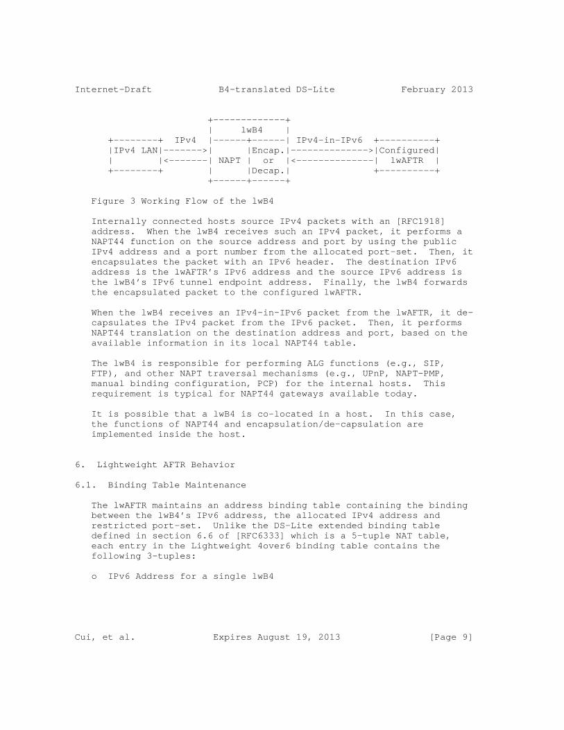
The lwB4 should behave as is depicted in (2.2) of section 3.2 of [I-D.bfmk-softwire-unified-cpe] when it starts up. The working flow of the lwB4 is illustrated with figure 3.
Cui, et al. Expires August 19, 2013 [Page 8]
Internet-Draft B4-translated DS-Lite February 2013
+-------------+ | lwB4 | +--------+ IPv4 |------+------| IPv4-in-IPv6 +----------+ |IPv4 LAN|------->| |Encap.|-------------->|Configured| | |<-------| NAPT | or |<--------------| lwAFTR | +--------+ | |Decap.| +----------+ +------+------+
Figure 3 Working Flow of the lwB4
Internally connected hosts source IPv4 packets with an [RFC1918] address. When the lwB4 receives such an IPv4 packet, it performs a NAPT44 function on the source address and port by using the public IPv4 address and a port number from the allocated port-set. Then, it encapsulates the packet with an IPv6 header. The destination IPv6 address is the lwAFTR’s IPv6 address and the source IPv6 address is the lwB4’s IPv6 tunnel endpoint address. Finally, the lwB4 forwards the encapsulated packet to the configured lwAFTR.
When the lwB4 receives an IPv4-in-IPv6 packet from the lwAFTR, it de- capsulates the IPv4 packet from the IPv6 packet. Then, it performs NAPT44 translation on the destination address and port, based on the available information in its local NAPT44 table.
The lwB4 is responsible for performing ALG functions (e.g., SIP, FTP), and other NAPT traversal mechanisms (e.g., UPnP, NAPT-PMP, manual binding configuration, PCP) for the internal hosts. This requirement is typical for NAPT44 gateways available today.
It is possible that a lwB4 is co-located in a host. In this case, the functions of NAPT44 and encapsulation/de-capsulation are implemented inside the host.
6. Lightweight AFTR Behavior
6.1. Binding Table Maintenance
The lwAFTR maintains an address binding table containing the binding between the lwB4’s IPv6 address, the allocated IPv4 address and restricted port-set. Unlike the DS-Lite extended binding table defined in section 6.6 of [RFC6333] which is a 5-tuple NAT table, each entry in the Lightweight 4over6 binding table contains the following 3-tuples:
o IPv6 Address for a single lwB4
Cui, et al. Expires August 19, 2013 [Page 9]

Internet-Draft B4-translated DS-Lite February 2013
o Public IPv4 Address
o Restricted port-set
The entry has two functions: the IPv6 encapsulation of inbound IPv4 packets destined to the lwB4 and the validation of outbound IPv4-in- IPv6 packets received from the lwB4 for de-capsulation.
The lwAFTR does not perform NAPT and so does not need session entries.
The lwAFTR MUST synchronize the binding information with the port- restricted address provisioning process. If the lwAFTR does not participate in the port-restricted address provisioning process, the binding MUST be synchronized through other methods (e.g. out-of-band static update).
If the lwAFTR participates in the port-restricted provisioning process, then its binding table MUST be created as part of this process.
For all provisioning processes, the lifetime of binding table entries MUST be synchronized with the lifetime of address allocations.
6.2. lwAFTR Data Plane Behavior
Several sections of [RFC6333] provide background information on the AFTR’s data plane functionality and MUST be implemented by the lwAFTR as they are common to both solutions. The relevant sections are:
6.2. Encapsulation Covering encapsulation and de- capsulation of tunneled traffic
6.3. Fragmentation and Reassembly Fragmentation and re-assembly considerations (referencing [RFC2473])
7.1. Tunneling Covering tunneling and traffic class mapping between IPv4 and IPv6 (referencing [RFC2473] and [RFC4213])
When the lwAFTR receives an IPv4-in-IPv6 packet from an lwB4, it de- capsulates the IPv6 header and verifies the source addresses and port in the binding table. If both the source IPv4 and IPv6 addresses match a single entry in the binding table and the source port in the allowed port-set for that entry, the lwAFTR forwards the packet to
Cui, et al. Expires August 19, 2013 [Page 10]

Internet-Draft B4-translated DS-Lite February 2013
the IPv4 destination.
If no match is found (e.g., no matching IPv4 address entry, port out of range, etc.), the lwAFTR MUST discard or implement a policy (such as redirection) on the packet. An ICMPv6 type 1, code 5 (source address failed ingress/egress policy) error message MAY be sent back to the equesting lwB4. The ICMP policy SHOULD be configurable.
When the lwAFTR receives an inbound IPv4 packet, it uses the IPv4 destination address and port to lookup the destination lwB4’s IPv6 address in its binding table. If a match is found, the lwAFTR encapsulates the IPv4 packet. The source is the lwAFTR’s IPv6 address and the destination is the lwB4’s IPv6 address from the matched entry. Then, the lwAFTR forwards the packet to the lwB4 natively over the IPv6 network.
If no match is found, the lwAFTR MUST discard the packet. An ICMPv4 type 3, code 1 (Destination unreachable, host unreachable) error message MAY be sent back. The ICMP policy SHOULD be configurable.
The lwAFTR MUST support hairpinning of traffic between two lwB4s, by performing de-capsulation and re-encapsulation of packets. The hairpinning policy MUST be configurable.
7. Provisioning of IPv4 address and Port Set
There are several dynamically provisioning protocols for IPv4 address and port set. These protocols MAY be implemented. Some possible alternatives include:
o DHCP: Extending DHCP protocol MAY be used for the provisioning [I-D.ietf-dhc-dhcpv4-over-ipv6] [I-D.ietf-softwire-map-dhcp].
o PCP[I-D.ietf-pcp-base]: a lwB4 MAY use [I-D.tsou-pcp-natcoord] to retrieve a restricted IPv4 address and a set of ports.
In a Lightweight 4over6 domain, the same provisioning mechanism MUST be enabled in the lwB4s, the AFTRs and the provisioning server.
DHCP-based provisioning mechanism (DHCPv4/DHCPv6) is RECOMMENDED in this document. The provisioning mechanism for port-restricted IPv4 address will evolve according to the consensus from DHC Working Group.
Cui, et al. Expires August 19, 2013 [Page 11]
Internet-Draft B4-translated DS-Lite February 2013
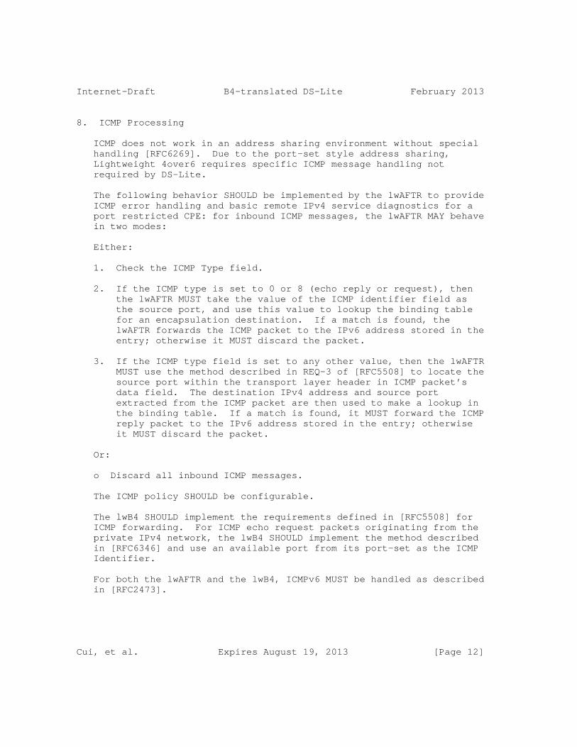
8. ICMP Processing
ICMP does not work in an address sharing environment without special handling [RFC6269]. Due to the port-set style address sharing, Lightweight 4over6 requires specific ICMP message handling not required by DS-Lite.
The following behavior SHOULD be implemented by the lwAFTR to provide ICMP error handling and basic remote IPv4 service diagnostics for a port restricted CPE: for inbound ICMP messages, the lwAFTR MAY behave in two modes:
Either:
1. Check the ICMP Type field.
2. If the ICMP type is set to 0 or 8 (echo reply or request), then the lwAFTR MUST take the value of the ICMP identifier field as the source port, and use this value to lookup the binding table for an encapsulation destination. If a match is found, the lwAFTR forwards the ICMP packet to the IPv6 address stored in the entry; otherwise it MUST discard the packet.
3. If the ICMP type field is set to any other value, then the lwAFTR MUST use the method described in REQ-3 of [RFC5508] to locate the source port within the transport layer header in ICMP packet’s data field. The destination IPv4 address and source port extracted from the ICMP packet are then used to make a lookup in the binding table. If a match is found, it MUST forward the ICMP reply packet to the IPv6 address stored in the entry; otherwise it MUST discard the packet.
Or:
o Discard all inbound ICMP messages.
The ICMP policy SHOULD be configurable.
The lwB4 SHOULD implement the requirements defined in [RFC5508] for ICMP forwarding. For ICMP echo request packets originating from the private IPv4 network, the lwB4 SHOULD implement the method described in [RFC6346] and use an available port from its port-set as the ICMP Identifier.
For both the lwAFTR and the lwB4, ICMPv6 MUST be handled as described in [RFC2473].
Cui, et al. Expires August 19, 2013 [Page 12]

Internet-Draft B4-translated DS-Lite February 2013
9. Security Considerations
As the port space for a subscriber shrinks due to address sharing, the randomness for the port numbers of the subscriber is decreased significantly. This means it is much easier for an attacker to guess the port number used, which could result in attacks ranging from throughput reduction to broken connections or data corruption.
The port-set for a subscriber can be a set of contiguous ports or non-contiguous ports. Contiguous port-sets do not reduce this threat. However, with non-contiguous port-set (which may be generated in a pseudo-random way [RFC6431]), the randomness of the port number is improved, provided that the attacker is outside the Lightweight 4over6 domain and hence does not know the port-set generation algorithm.
More considerations about IP address sharing are discussed in Section 13 of [RFC6269], which is applicable to this solution.
10. IANA Considerations
This document does not include an IANA request.
11. Author List
The following are extended authors who contributed to the effort:
Jianping Wu Tsinghua University Department of Computer Science, Tsinghua University Beijing 100084 P.R.China
Phone: +86-10-62785983 Email: [email protected]
Peng Wu Tsinghua University Department of Computer Science, Tsinghua University Beijing 100084 P.R.China
Phone: +86-10-62785822 Email: [email protected]
Cui, et al. Expires August 19, 2013 [Page 13]
Internet-Draft B4-translated DS-Lite February 2013
Qi Sun Tsinghua University Department of Computer Science, Tsinghua University Beijing 100084 P.R.China
Phone: +86-10-62785822 Email: [email protected]
Chongfeng Xie China Telecom Room 708, No.118, Xizhimennei Street Beijing 100035 P.R.China
Phone: +86-10-58552116 Email: [email protected]
Xiaohong Deng France Telecom
Email: [email protected]
Cathy Zhou Huawei Technologies Section B, Huawei Industrial Base, Bantian Longgang Shenzhen 518129 P.R.China
Email: [email protected]
Alain Durand Juniper Networks 1194 North Mathilda Avenue Sunnyvale, CA 94089-1206 USA
Cui, et al. Expires August 19, 2013 [Page 14]
Internet-Draft B4-translated DS-Lite February 2013
Email: [email protected]
Reinaldo Penno Cisco Systems, Inc. 170 West Tasman Drive San Jose, California 95134 USA
Email: [email protected]
Alex Clauberg Deutsche Telekom AG GTN-FM4 Landgrabenweg 151 Bonn, CA 53227 Germany
Email: [email protected]
Lionel Hoffmann Bouygues Telecom TECHNOPOLE 13/15 Avenue du Marechal Juin Meudon 92360 France
Email: [email protected]
Maoke Chen FreeBit Co., Ltd. 13F E-space Tower, Maruyama-cho 3-6 Shibuya-ku, Tokyo 150-0044 Japan
Email: [email protected]
Cui, et al. Expires August 19, 2013 [Page 15]
Internet-Draft B4-translated DS-Lite February 2013
12. Acknowledgement
The authors would like to thank Ole Troan, Ralph Droms and Suresh Krishnan for their comments and feedback.
This document is a merge of three documents: [I-D.cui-softwire-b4-translated-ds-lite], [I-D.zhou-softwire-b4-nat] and [I-D.penno-softwire-sdnat].
13. References
13.1. Normative References
[I-D.bfmk-softwire-unified-cpe] Boucadair, M. and I. Farrer, "Unified IPv4-in-IPv6 Softwire CPE", draft-bfmk-softwire-unified-cpe-02 (work in progress), January 2013.
[RFC1918] Rekhter, Y., Moskowitz, R., Karrenberg, D., Groot, G., and E. Lear, "Address Allocation for Private Internets", BCP 5, RFC 1918, February 1996.
[RFC2119] Bradner, S., "Key words for use in RFCs to Indicate Requirement Levels", BCP 14, RFC 2119, March 1997.
[RFC2473] Conta, A. and S. Deering, "Generic Packet Tunneling in IPv6 Specification", RFC 2473, December 1998.
[RFC3022] Srisuresh, P. and K. Egevang, "Traditional IP Network Address Translator (Traditional NAT)", RFC 3022, January 2001.
[RFC3484] Draves, R., "Default Address Selection for Internet Protocol version 6 (IPv6)", RFC 3484, February 2003.
[RFC4213] Nordmark, E. and R. Gilligan, "Basic Transition Mechanisms for IPv6 Hosts and Routers", RFC 4213, October 2005.
[RFC5508] Srisuresh, P., Ford, B., Sivakumar, S., and S. Guha, "NAT Behavioral Requirements for ICMP", BCP 148, RFC 5508, April 2009.
[RFC6269] Ford, M., Boucadair, M., Durand, A., Levis, P., and P. Roberts, "Issues with IP Address Sharing", RFC 6269, June 2011.
[RFC6333] Durand, A., Droms, R., Woodyatt, J., and Y. Lee, "Dual-
Cui, et al. Expires August 19, 2013 [Page 16]

Internet-Draft B4-translated DS-Lite February 2013
Stack Lite Broadband Deployments Following IPv4 Exhaustion", RFC 6333, August 2011.
[RFC6334] Hankins, D. and T. Mrugalski, "Dynamic Host Configuration Protocol for IPv6 (DHCPv6) Option for Dual-Stack Lite", RFC 6334, August 2011.
[RFC6346] Bush, R., "The Address plus Port (A+P) Approach to the IPv4 Address Shortage", RFC 6346, August 2011.
[RFC6431] Boucadair, M., Levis, P., Bajko, G., Savolainen, T., and T. Tsou, "Huawei Port Range Configuration Options for PPP IP Control Protocol (IPCP)", RFC 6431, November 2011.
13.2. Informative References
[I-D.cui-softwire-b4-translated-ds-lite] Cui, Y., Sun, Q., Boucadair, M., Tsou, T., Lee, Y., and I. Farrer, "Lightweight 4over6: An Extension to the DS-Lite Architecture", draft-cui-softwire-b4-translated-ds-lite-10 (work in progress), February 2013.
[I-D.ietf-dhc-dhcpv4-over-ipv6] Cui, Y., Wu, P., Wu, J., and T. Lemon, "DHCPv4 over IPv6 Transport", draft-ietf-dhc-dhcpv4-over-ipv6-05 (work in progress), September 2012.
[I-D.ietf-pcp-base] Wing, D., Cheshire, S., Boucadair, M., Penno, R., and P. Selkirk, "Port Control Protocol (PCP)", draft-ietf-pcp-base-29 (work in progress), November 2012.
[I-D.ietf-softwire-map] Troan, O., Dec, W., Li, X., Bao, C., Matsushima, S., and T. Murakami, "Mapping of Address and Port with Encapsulation (MAP)", draft-ietf-softwire-map-04 (work in progress), February 2013.
[I-D.ietf-softwire-map-dhcp] Mrugalski, T., Troan, O., Dec, W., Bao, C., [email protected], l., and X. Deng, "DHCPv6 Options for Mapping of Address and Port", draft-ietf-softwire-map-dhcp-03 (work in progress), February 2013.
[I-D.ietf-softwire-public-4over6] Cui, Y., Wu, J., Wu, P., Vautrin, O., and Y. Lee, "Public IPv4 over IPv6 Access Network",
Cui, et al. Expires August 19, 2013 [Page 17]

Internet-Draft B4-translated DS-Lite February 2013
draft-ietf-softwire-public-4over6-04 (work in progress), October 2012.
[I-D.penno-softwire-sdnat] Penno, R., Durand, A., Hoffmann, L., and A. Clauberg, "Stateless DS-Lite", draft-penno-softwire-sdnat-02 (work in progress), March 2012.
[I-D.sun-dhc-port-set-option] Sun, Q., Lee, Y., Sun, Q., Bajko, G., and M. Boucadair, "Dynamic Host Configuration Protocol (DHCP) Option for Port Set Assignment", draft-sun-dhc-port-set-option-00 (work in progress), October 2012.
[I-D.tsou-pcp-natcoord] Sun, Q., Boucadair, M., Deng, X., Zhou, C., Tsou, T., and S. Perreault, "Using PCP To Coordinate Between the CGN and Home Gateway", draft-tsou-pcp-natcoord-09 (work in progress), November 2012.
[I-D.zhou-softwire-b4-nat] Zhou, C., Boucadair, M., and X. Deng, "NAT offload extension to Dual-Stack lite", draft-zhou-softwire-b4-nat-04 (work in progress), October 2011.
Authors’ Addresses
Yong Cui Tsinghua University Department of Computer Science, Tsinghua University Beijing 100084 P.R.China
Phone: +86-10-62603059 Email: [email protected]
Qiong Sun China Telecom Room 708, No.118, Xizhimennei Street Beijing 100035 P.R.China
Phone: +86-10-58552936 Email: [email protected]
Cui, et al. Expires August 19, 2013 [Page 18]

Internet-Draft B4-translated DS-Lite February 2013
Mohamed Boucadair France Telecom Rennes 35000 France
Email: [email protected]
Tina Tsou Huawei Technologies 2330 Central Expressway Santa Clara, CA 95050 USA
Phone: +1-408-330-4424 Email: [email protected]
Yiu L. Lee Comcast One Comcast Center Philadelphia, PA 19103 USA
Email: [email protected]
Ian Farrer Deutsche Telekom AG GTN-FM4,Landgrabenweg 151 Bonn, NRW 53227 Germany
Email: [email protected]
Cui, et al. Expires August 19, 2013 [Page 19]

Softwire Y. CuiInternet-Draft J. DongIntended status: Standards Track P. WuExpires: September 13, 2012 M. Xu Tsinghua University March 12, 2012
Softwire Mesh Management Information Base(MIB) draft-cui-softwire-mesh-mib-04
Abstract
This memo defines a portion of the Management Information Base (MIB) for use with network management protocols in the Internet community. In particular it defines objects for managing softwire mesh [RFC5565].
Status of This Memo
This Internet-Draft is submitted in full conformance with the provisions of BCP 78 and BCP 79.
Internet-Drafts are working documents of the Internet Engineering Task Force (IETF). Note that other groups may also distribute working documents as Internet-Drafts. The list of current Internet- Drafts is at http://datatracker.ietf.org/drafts/current/.
Internet-Drafts are draft documents valid for a maximum of six months and may be updated, replaced, or obsoleted by other documents at any time. It is inappropriate to use Internet-Drafts as reference material or to cite them other than as "work in progress."
This Internet-Draft will expire on September 13, 2012.
Copyright Notice
Copyright (c) 2012 IETF Trust and the persons identified as the document authors. All rights reserved.
This document is subject to BCP 78 and the IETF Trust’s Legal Provisions Relating to IETF Documents (http://trustee.ietf.org/license-info) in effect on the date of publication of this document. Please review these documents carefully, as they describe your rights and restrictions with respect to this document. Code Components extracted from this document must include Simplified BSD License text as described in Section 4.e of the Trust Legal Provisions and are provided without warranty as
Cui, et al. Expires September 13, 2012 [Page 1]

Internet-Draft swmMIB March 2012
described in the Simplified BSD License.
This document may contain material from IETF Documents or IETF Contributions published or made publicly available before November 10, 2008. The person(s) controlling the copyright in some of this material may not have granted the IETF Trust the right to allow modifications of such material outside the IETF Standards Process. Without obtaining an adequate license from the person(s) controlling the copyright in such materials, this document may not be modified outside the IETF Standards Process, and derivative works of it may not be created outside the IETF Standards Process, except to format it for publication as an RFC or to translate it into languages other than English.
Table of Contents
1. Introduction . . . . . . . . . . . . . . . . . . . . . . . . . 3 2. The Internet-Standard Management Framework . . . . . . . . . . 3 3. Terminology . . . . . . . . . . . . . . . . . . . . . . . . . 3 4. Conventions . . . . . . . . . . . . . . . . . . . . . . . . . 3 5. Structure of the MIB Module . . . . . . . . . . . . . . . . . 3 5.1. The swmSupportedTunnlTable Subtree . . . . . . . . . . . . 3 5.2. The swmEncapsTable Subtree . . . . . . . . . . . . . . . . 4 5.3. The swmBGPNeighborTable Subtree . . . . . . . . . . . . . 4 5.4. The swmMIBConformance Subtree . . . . . . . . . . . . . . 4 6. Relationship to Other MIB Modules . . . . . . . . . . . . . . 4 6.1. Relationship to the IF-MIB . . . . . . . . . . . . . . . . 4 6.2. Relationship to the IP Tunnel MIB . . . . . . . . . . . . 5 6.3. MIB modules required for IMPORTS . . . . . . . . . . . . . 5 7. Definitions . . . . . . . . . . . . . . . . . . . . . . . . . 5 8. Security Considerations . . . . . . . . . . . . . . . . . . . 11 9. IANA Considerations . . . . . . . . . . . . . . . . . . . . . 11 10. References . . . . . . . . . . . . . . . . . . . . . . . . . . 12 10.1. Normative References . . . . . . . . . . . . . . . . . . . 12 10.2. Informative References . . . . . . . . . . . . . . . . . . 12 10.3. URL References . . . . . . . . . . . . . . . . . . . . . . 13
Cui, et al. Expires September 13, 2012 [Page 2]
Internet-Draft swmMIB March 2012
1. Introduction
Softwire mesh framework RFC 5565 [RFC5565]is a tunneling mechanism which enables connectivity between islands of IPv4, IPv6 or dual- stack networks across single IPv4 or IPv6 backbone networks. In softwire mesh solution, extended multiprotocol-BGP (MP-BGP)is used to set up tunnels and advertise prefixes among address family border routers (AFBRs).
This memo defines a portion of the Management Information Base (MIB) for use with network management protocols in the Internet community. In particular it defines objects for managing softwire mesh [RFC5565].
2. The Internet-Standard Management Framework
For a detailed overview of the documents that describe the current Internet-Standard Management Framework, please refer to section 7 of RFC 3410 [RFC3410].
Managed objects are accessed via a virtual information store, termed the Management Information Base or MIB. MIB objects are generally accessed through the Simple Network Management Protocol (SNMP). They are defined using the mechanisms stated in the Structure of Management Information (SMI). This memo specifies a MIB module that is compliant to the SMIv2, which is described in STD 58, RFC 2578 [RFC2578], STD 58, RFC 2579 [RFC2579] and STD 58, RFC 2580 [RFC2580].
3. Terminology
This document uses terminology from softwire problem statement RFC 4925 [RFC4925] and softwire mesh framework RFC5565 [RFC5565].
4. Conventions
The key words "MUST", "MUST NOT", "REQUIRED", "SHALL", "SHALL NOT", "SHOULD", "SHOULD NOT", "RECOMMENDED", "MAY", and "OPTIONAL" in this document are to be interpreted as described in RFC 2119 [RFC2119].
5. Structure of the MIB Module
The softwire mesh MIB provides a method to configure and manage the softwire mesh objects through SNMP.
5.1. The swmSupportedTunnlTable Subtree
Since AFBR need to negotiate with BGP peer what kind of tunnel they will use, it should firstly announce the types of tunnels it
Cui, et al. Expires September 13, 2012 [Page 3]

Internet-Draft swmMIB March 2012
supports. The swmSupportedTunnlTable subtree provides the information. According to section 4 of RFC 5512[RFC5512], current softwire mesh tunnel types include IP-IP, GRE and L2TPv3.
5.2. The swmEncapsTable Subtree
The swmEncapsTable subtree provides softwire mesh NLRI-NH information about the AFBR. It indicates which I-IP destination address will be encapsulated according to the arriving packet’s E-IP destination address. The definitions of E-IP and I-IP are explained in section 4.1 of RFC 5565[RFC5565].
5.3. The swmBGPNeighborTable Subtree
The subtree provides softwire mesh BGP neighbor information about the AFBR. It includes the address of softwire mesh BGP peer, and the kind of tunnel that the AFBR would use to communicate with this BGP peer.
5.4. The swmMIBConformance Subtree
The subtree provides conformance information of MIB objects.
6. Relationship to Other MIB Modules
6.1. Relationship to the IF-MIB
The Interfaces MIB [RFC2863] defines generic managed objects for managing interfaces. Each logical interface (physical or virtual) has an ifEntry. Tunnels are handled by creating a logical interface (ifEntry) for each tunnel. Softwire mesh tunnel also acts as a virtual interface, which has corresponding entries in IP Tunnel MIB and Interface MIB. Those corresponding entries are indexed by ifIndex.
The ifOperStatus in ifTable would be used to represent whether the mesh function of the AFBR has been started. During the BGP OPEN phase, if the softwire mesh capability is negotiated, the mesh function could be considered to be started, and ifOperStatus is "up". Otherwise the ifOperStatus is "down".
If it is IPv4-over-IPv6 softwire mesh tunnel, the ifInUcastPkts will represent the number of IPv6 packets which can be decapsulated to IPv4 in the virtual interface. The ifOutUcastPkts contains the number of IPv6 packets which have been encapsulated with IPv4 packets in it. Particularly, if these IPv4 packets need to be fragmented, the number counted here is the packets after fragmentation.
Cui, et al. Expires September 13, 2012 [Page 4]

Internet-Draft swmMIB March 2012
If it is IPv6-over-IPv4 softwire mesh tunnel, the ifInUcastPkts stands for the number of IPv4 packets which would be decapsulated to IPv6 in the virtual interface. The ifOutUcastPkts represents the number of IPv4 packets which have been encapsulated from IPv6. Particularly, if these IPv6 packets need to be fragmented, the number counted here is the packets after fragmentation. Similar definition apply to other counting objects in ifTalbe.
6.2. Relationship to the IP Tunnel MIB
The IP Tunnel MIB [RFC4087] contains objects common to all IP tunnels, including softwire mesh. Additionally, tunnel encapsulation specific MIB (as is defined in this document) extends the IP tunnel MIB to further described encapsulation specific information.
Since softwire mesh is a point to multi-point tunnel, we need to specify an encapsulation table to support E-IP routing among AFBRs. With the encapsulation information, the correct forwarding of E-IP packets will be performed among AFBRs by using I-IP encapsulation. Each AFBR also needs to know information about remote BGP peers (AFBRs), so that these AFBRs can negotiate E-IP information and the tunnel types they support.
The implementation of the IP Tunnel MIB is required for softwire mesh. The tunnelIfEncapsMethod in the tunnelIfEntry should be set to softwireMesh("xx"), and corresponding entry in the softwire mesh MIB module will exist for every tunnelIfEntry with this tunnelIfEncapsMethod. The tunnelIfRemoteInetAddress must be set to 0.0.0.0 for IPv4 or :: for IPv6 because it is a point to multi-point tunnel.
Since tunnelIfAddressType in tunnelIfTable represents the type of address in the corresponding tunnelIfLocalInetAddress and tunnelIfRemoteInetAddress objects, we can also use the tunnelIfAddressType to specify the softwire mesh tunnel is IPv4-over- IPv6 or IPv6-over-IPv4. When tunnelIfAddressType is IPv4, the encapsulation would be IPv6- over-IPv4; When tunnelIfAddressType is IPv6, the encapsulation would be IPv4-over-IPv6.
6.3. MIB modules required for IMPORTS
The following MIB module IMPORTS objects from SNMPv2-SMI [RFC2578], SNMPv2-TC [RFC2579], SNMPv2-CONF [RFC2580], IF-MIB [RFC2863] and INET-ADDRESS-MIB [RFC4001].
7. Definitions
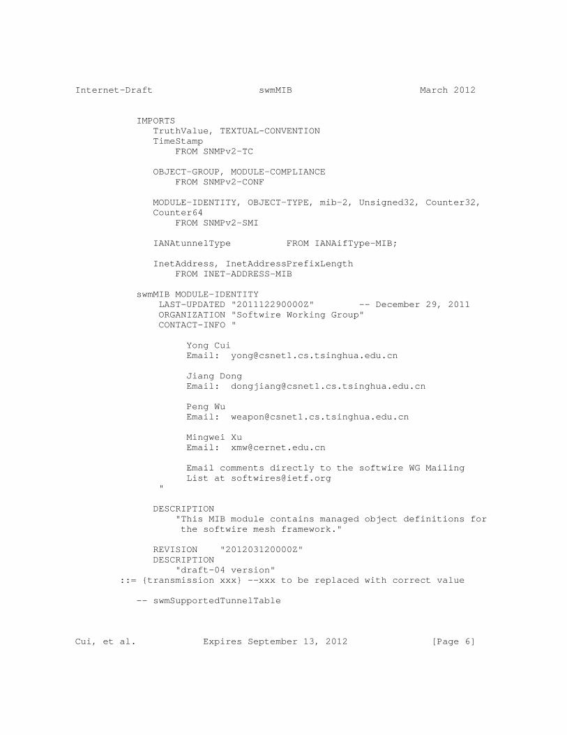
SOFTWIRE-MESH-MIB DEFINITIONS ::= BEGIN
Cui, et al. Expires September 13, 2012 [Page 5]
Internet-Draft swmMIB March 2012
IMPORTS TruthValue, TEXTUAL-CONVENTION TimeStamp FROM SNMPv2-TC
OBJECT-GROUP, MODULE-COMPLIANCE FROM SNMPv2-CONF
MODULE-IDENTITY, OBJECT-TYPE, mib-2, Unsigned32, Counter32, Counter64 FROM SNMPv2-SMI
IANAtunnelType FROM IANAifType-MIB;
InetAddress, InetAddressPrefixLength FROM INET-ADDRESS-MIB
swmMIB MODULE-IDENTITY LAST-UPDATED "201112290000Z" -- December 29, 2011 ORGANIZATION "Softwire Working Group" CONTACT-INFO "
Yong Cui Email: [email protected]
Jiang Dong Email: [email protected]
Peng Wu Email: [email protected]
Mingwei Xu Email: [email protected]
Email comments directly to the softwire WG Mailing List at [email protected] "
DESCRIPTION "This MIB module contains managed object definitions for the softwire mesh framework."
REVISION "201203120000Z" DESCRIPTION "draft-04 version" ::= {transmission xxx} --xxx to be replaced with correct value
-- swmSupportedTunnelTable
Cui, et al. Expires September 13, 2012 [Page 6]
Internet-Draft swmMIB March 2012
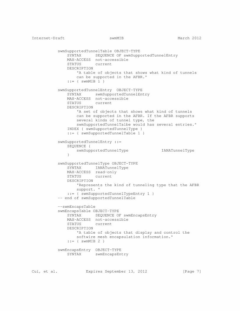
swmSupportedTunnelTable OBJECT-TYPE SYNTAX SEQUENCE OF swmSupportedTunnelEntry MAX-ACCESS not-accessible STATUS current DESCRIPTION "A table of objects that shows what kind of tunnels can be supported in the AFBR." ::= { swmMIB 1 }
swmSupportedTunnelEntry OBJECT-TYPE SYNTAX swmSupportedTunnelEntry MAX-ACCESS not-accessible STATUS current DESCRIPTION "A set of objects that shows what kind of tunnels can be supported in the AFBR. If the AFBR supports several kinds of tunnel type, the swmSupportedTunnelTalbe would has several entries." INDEX { swmSupportedTunnelType } ::= { swmSupportedTunnelTable 1 }
swmSupportedTunnelEntry ::= SEQUENCE { swmSupportedTunnelType IANATunnelType }
swmSupportedTunnelType OBJECT-TYPE SYNTAX IANATunnelType MAX-ACCESS read-only STATUS current DESCRIPTION "Represents the kind of tunneling type that the AFBR support. " ::= { swmSupportedTunnelTypeEntry 1 } -- end of swmSupportedTunnelTable
--swmEncapsTable swmEncapsTable OBJECT-TYPE SYNTAX SEQUENCE OF swmEncapsEntry MAX-ACCESS not-accessible STATUS current DESCRIPTION "A table of objects that display and control the softwire mesh encapsulation information." ::= { swmMIB 2 }
swmEncapsEntry OBJECT-TYPE SYNTAX swmEncapsEntry
Cui, et al. Expires September 13, 2012 [Page 7]
Internet-Draft swmMIB March 2012
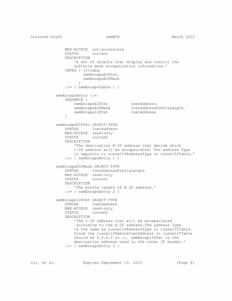
MAX-ACCESS not-accessible STATUS current DESCRIPTION "A set of objects that display and control the softwire mesh encapsulation information." INDEX { ifIndex, swmEncapsEIPDst, swmEncapsEIPMask } ::= { swmEncapsTable 1 }
swmEncapsEntry ::= SEQUENCE { swmEncapsEIPDst InetAddress, swmEncapsEIPMask InetAddressPrefixLength, swmEncapsIIPDst InetAddress }
swmEncapsEIPDst OBJECT-TYPE SYNTAX InetAddress MAX-ACCESS read-only STATUS current DESCRIPTION "The destination E-IP address that decide which I-IP address will be encapsulated. The address Type is opposite to tunnelIfAddressType in tunnelIfTable." ::= { swmEncapsEntry 1 }
swmEncapsEIPMask OBJECT-TYPE SYNTAX InetAddressPrefixLength MAX-ACCESS read-only STATUS current DESCRIPTION "The prefix length of E-IP address." ::= { swmEncapsEntry 2 }
swmEncapsIIPDst OBJECT-TYPE SYNTAX InetAddress MAX-ACCESS read-only STATUS current DESCRIPTION "The I-IP address that will be encapsulated according to the E-IP address.The address Type is the same as tunnelIfAddressType in tunnelIfTable. Since the tunnelIfRemoteInetAddress in tunnelIfTable should be 0.0.0.0 or ::, swmEncapIIPDst is the destination address used in the outer IP header." ::= { swmEncapsEntry 3 }
Cui, et al. Expires September 13, 2012 [Page 8]

Internet-Draft swmMIB March 2012
-- End of swmEncapsTable
-- swmBGPNeighborTable swmBGPNeighborTable OBJECT-TYPE SYNTAX SEQUENCE OF swmBGPNeighborEntry MAX-ACCESS not-accessible STATUS current DESCRIPTION "A table of objects that display the softwire mesh BGP neighbor information." ::= { swmMIB 3 }
swmBGPNeighborEntry OBJECT-TYPE SYNTAX swmBGPNeighborEntry MAX-ACCESS not-accessible STATUS current DESCRIPTION "A set of objects that display the softwire mesh BGP neighbor information." INDEX { ifIndex, swmBGPNeighborInetAddress } ::= { swmBGPNeighborTable 1 }
swmBGPNeighborEntry ::= SEQUENCE { swmBGPNeighborInetAddress InetAddress, swmBGPNeighborTunnelType IANATunnelType }
swmBGPNeighborInetAddress OBJECT-TYPE SYNTAX InetAddress MAX-ACCESS read-only STATUS current DESCRIPTION "The address of the ABFR’s BGP neighbor. The address type is the same as tunnelIfAddressType in tunnelIfTable" ::= { swmBGPNeighborEntry 1 }
swmBGPNeighborTunnelType OBJECT-TYPE SYNTAX IANATunnelType MAX-ACCESS read-only STATUS current DESCRIPTION "Represents the kind of tunneling type that the AFBR used to comunication with the BGP neighbor"
Cui, et al. Expires September 13, 2012 [Page 9]
Internet-Draft swmMIB March 2012
::= { swmBGPNeighborEntry 2 } -- End of swmBGPNeighborTable
-- conformance information swmMIBConformance OBJECT IDENTIFIER ::= { swmMIB 4 } swmMIBCompliances OBJECT IDENTIFIER ::= { swmMIBConformance 1 } swmMIBGroups OBJECT IDENTIFIER ::= { swmMIBConformance 2 }
-- compliance statements swmMIBCompliance MODULE-COMPLIANCE STATUS current DESCRIPTION "Describes the requirements for conformance to the softwire mesh MIB."
MODULE -- this module MANDATORY-GROUPS { swmSupportedTunnelGroup, swmEncapsGroup, swmBGPNeighborGroup } ::= { swmMIBCompliances 1 }
swmSupportedTunnelGroup OBJECT-GROUP OBJECTS { swmSupportedTunnelType } STATUS current DESCRIPTION "The collection of objects which are used to show what kind of tunnel the AFBR supports." ::= { swmMIBGroups 1 }
swmEncapsGroup OBJECT-GROUP OBJECTS { swmEncapsEIPDst, swmEncapsEIPMask, swmEncapsIIPDst } STATUS current DESCRIPTION "The collection of objects which are used to display softwire mesh encapsulation information." ::= { swmMIBGroups 2 }
Cui, et al. Expires September 13, 2012 [Page 10]
Internet-Draft swmMIB March 2012
swmBGPNeighborGroup OBJECT-GROUP OBJECTS { swmBGPNeighborInetAddress, swmBGPNeighborTunnelType } STATUS current DESCRIPTION "The collection of objects which are used to display softwire mesh BGP neighbor information." ::= { swmMIBGroups 3 }
END
8. Security Considerations
The swmMIB module can be used for configuration of certain objects, and anything that can be configured can be incorrectly configured, with potentially disastrous results. Because this MIB module reuses the IP tunnel MIB, the security considerations of the IP tunnel MIB is also applicable to the Softwire mesh MIB.
SNMP versions prior to SNMPv3 did not include adequate security. Even if the network itself is secure (for example by using IPsec), even then, there is no control as to who on the secure network is allowed to access and GET/SET (read/change/create/delete) the objects in this MIB module.
It is RECOMMENDED that implementers consider the security features as provided by the SNMPv3 framework (see [RFC3410], section 8), including full support for the SNMPv3 cryptographic mechanisms (for authentication and privacy).
Further, deployment of SNMP versions prior to SNMPv3 is NOT RECOMMENDED. Instead, it is RECOMMENDED to deploy SNMPv3 and to enable cryptographic security. It is then a customer/operator’s responsibility to ensure that the SNMP entity giving access to an instance of this MIB module is properly configured to give access to the objects only to those principals (users) that have legitimate rights to indeed GET or SET (change/create/delete) them.
9. IANA Considerations
The MIB module in this document uses the following IANA-assigned OBJECT IDENTIFIER values recorded in the SMI Numbers registry, and the following IANA-assigned tunnelType values recorded in the IANAtunnelType-MIB registry:
Cui, et al. Expires September 13, 2012 [Page 11]
Internet-Draft swmMIB March 2012
Descriptor OBJECT IDENTIFIER value ---------- ----------------------- swmMIB { transmission XXX }
IANAtunnelType ::= TEXTUAL-CONVENTION SYNTAX INTEGER {
softwireMesh ("XX") -- softwire Mesh tunnel
}
10. References
10.1. Normative References
[RFC2119] Bradner, S., "Key words for use in RFCs to Indicate Requirement Levels", BCP 14, RFC 2119, March 1997.
[RFC2578] McCloghrie, K., Ed., Perkins, D., Ed., and J. Schoenwaelder, Ed., "Structure of Management Information Version 2 (SMIv2)", STD 58, RFC 2578, April 1999.
[RFC2579] McCloghrie, K., Ed., Perkins, D., Ed., and J. Schoenwaelder, Ed., "Textual Conventions for SMIv2", STD 58, RFC 2579, April 1999.
[RFC2580] McCloghrie, K., Perkins, D., and J. Schoenwaelder, "Conformance Statements for SMIv2", STD 58, RFC 2580, April 1999.
[RFC4925] Li, X., Dawkins, S., Ward, D., and A. Durand, "Softwire Problem Statement", RFC 4925, July 2007.
[RFC5512] Mohapatra, P. and E. Rosen, "The BGP Encapsulation Subsequent Address Family Identifier (SAFI) and the BGP Tunnel Encapsulation Attribute", RFC 5512, April 2009.
[RFC5565] Wu, J., Cui, Y., Metz, C., and E. Rosen, "Softwire Mesh Framework", RFC 5565, June 2009.
10.2. Informative References
[RFC2223] Postel, J. and J. Reynolds, "Instructions to RFC Authors", RFC 2223, October 1997.
Cui, et al. Expires September 13, 2012 [Page 12]
Internet-Draft swmMIB March 2012
[RFC3410] Case, J., Mundy, R., Partain, D., and B. Stewart, "Introduction and Applicability Statements for Internet-Standard Management Framework", RFC 3410, December 2002.
[RFC2629] Rose, M., "Writing I-Ds and RFCs using XML", RFC 2629, June 1999.
[RFC4181] Heard, C., "Guidelines for Authors and Reviewers of MIB Documents", BCP 111, RFC 4181, September 2005.
10.3. URL References
[idguidelines] IETF Internet Drafts editor, "http://www.ietf.org/ietf/1id-guidelines.txt".
[idnits] IETF Internet Drafts editor, "http://www.ietf.org/ID-Checklist.html".
[xml2rfc] XML2RFC tools and documentation, "http://xml.resource.org".
[ops] the IETF OPS Area, "http://www.ops.ietf.org".
[ietf] IETF Tools Team, "http://tools.ietf.org".
Authors’ Addresses
Yong Cui Tsinghua University Department of Computer Science, Tsinghua University Beijing 100084 P.R.China
Phone: +86-10-6260-3059 EMail: [email protected]
Jiang Dong Tsinghua University Department of Computer Science, Tsinghua University Beijing 100084 P.R.China
Phone: +86-10-6278-5822 EMail: [email protected]
Cui, et al. Expires September 13, 2012 [Page 13]
Internet-Draft swmMIB March 2012
Peng Wu Tsinghua University Department of Computer Science, Tsinghua University Beijing 100084 P.R.China
Phone: +86-10-6278-5822 EMail: [email protected]
Mingwei Xu Tsinghua University Department of Computer Science, Tsinghua University Beijing 100084 P.R.China
Phone: +86-10-6278-5822 EMail: [email protected]
Cui, et al. Expires September 13, 2012 [Page 14]

Internet Engineering Task Force R. Despres, Ed.Internet-Draft RD-IPtechIntended status: Standards Track R. PennoExpires: September 29, 2012 Juniper Networks Y. Lee Comcast G. Chen China Mobile J. Qin March 28, 2012
IPv4 Residual Deployment via IPv6 - Unified Solution (4rd) draft-despres-softwire-4rd-u-06
Abstract
The 4rd automatic tunneling mechanism makes IPv4 Residual Deployment possible via IPv6 networks without maintaining for this per-customer states in 4rd-capable nodes (reverse of the IPv6 Rapid Deployment of 6rd). To cope with the IPv4 address shortage, customers can be assigned IPv4 addresses with restricted port sets. In some scenarios, 4rd-capable customer nodes can exchange packets of their IPv4-only applications via stateful NAT64s that are upgraded to support 4rd tunnels (in addition to their IP/ICMP translation of RFC6145).
Status of this Memo
This Internet-Draft is submitted in full conformance with the provisions of BCP 78 and BCP 79.
Internet-Drafts are working documents of the Internet Engineering Task Force (IETF). Note that other groups may also distribute working documents as Internet-Drafts. The list of current Internet- Drafts is at http://datatracker.ietf.org/drafts/current/.
Internet-Drafts are draft documents valid for a maximum of six months and may be updated, replaced, or obsoleted by other documents at any time. It is inappropriate to use Internet-Drafts as reference material or to cite them other than as "work in progress."
This Internet-Draft will expire on September 29, 2012.
Copyright Notice
Copyright (c) 2012 IETF Trust and the persons identified as the document authors. All rights reserved.
Despres, et al. Expires September 29, 2012 [Page 1]

Internet-Draft IPv4 Residual Deployment (4rd) March 2012
This document is subject to BCP 78 and the IETF Trust’s Legal Provisions Relating to IETF Documents (http://trustee.ietf.org/license-info) in effect on the date of publication of this document. Please review these documents carefully, as they describe your rights and restrictions with respect to this document. Code Components extracted from this document must include Simplified BSD License text as described in Section 4.e of the Trust Legal Provisions and are provided without warranty as described in the Simplified BSD License.
Table of Contents
1. Introduction . . . . . . . . . . . . . . . . . . . . . . . . . 3 2. Terminology . . . . . . . . . . . . . . . . . . . . . . . . . 3 3. The 4rd Model . . . . . . . . . . . . . . . . . . . . . . . . 5 4. Protocol Specification . . . . . . . . . . . . . . . . . . . . 6 4.1. Mapping rules and other Domain parameters . . . . . . . . 6 4.2. Tunnel-packet Format . . . . . . . . . . . . . . . . . . . 8 4.3. From IPv6 Prefixes to 4rd IPv4 prefixes and port sets . . 10 4.4. From 4rd IPv4 addresses to 4rd IPv6 Addresses . . . . . . 12 4.5. Fragmentation Considerations . . . . . . . . . . . . . . . 16 4.5.1. Fragmentation at Domain Entry . . . . . . . . . . . . 16 4.5.2. Ports of Fragments addressed to Shared-Address CEs . . 16 4.5.3. Packet Identifications from Shared-Address CEs . . . . 18 4.6. TOS and Traffic-Class Considerations . . . . . . . . . . . 18 4.7. Tunnel-Generated ICMPv6 Error Messages . . . . . . . . . . 19 4.8. Provisioning 4rd Parameters to CEs . . . . . . . . . . . . 19 5. Use-Case Examples . . . . . . . . . . . . . . . . . . . . . . 21 5.1. Textual representation of Mapping rules . . . . . . . . . 21 5.2. A pragmatic method to configure Mapping Rules . . . . . . 22 5.3. Adding Shared IPv4 Addresses to an IPv6 Network . . . . . 23 5.3.1. With CEs within CPEs . . . . . . . . . . . . . . . . . 23 5.3.2. With some CEs behind Third-party Router CPEs . . . . . 26 5.4. Replacing Dual-stack Routing by IPv6-only Routing . . . . 27 5.5. Adding IPv6 and 4rd Service to a Net-10 network . . . . . 28 6. Security Considerations . . . . . . . . . . . . . . . . . . . 29 7. IANA Considerations . . . . . . . . . . . . . . . . . . . . . 29 8. Relationship with Previous Works . . . . . . . . . . . . . . . 30 9. Acknowledgements . . . . . . . . . . . . . . . . . . . . . . . 31 10. References . . . . . . . . . . . . . . . . . . . . . . . . . . 31 10.1. Normative References . . . . . . . . . . . . . . . . . . . 31 10.2. Informative References . . . . . . . . . . . . . . . . . . 32 Authors’ Addresses . . . . . . . . . . . . . . . . . . . . . . . . 34
Despres, et al. Expires September 29, 2012 [Page 2]

Internet-Draft IPv4 Residual Deployment (4rd) March 2012
1. Introduction
For deployments of residual IPv4 service via IPv6 networks, the need for a stateless solution is expressed in [I-D.ietf-softwire-stateless-4v6-motivation] (no per customer state in IPv4-IPv6 gateway nodes of the provider). This document specifies such a solution, named "4rd" for IPv4 Residual Deployment. With it, IPv4 packets are transparently tunneled across IPv6 networks (reverse of 6rd [RFC5969] in which IPv6 packets are statelessly tunneled across IPv4 networks). While IPv6 headers are too long to be mapped into IPv4 headers, so that 6rd requires encapsulation of full IPv6 packets in IPv4 packets, IPv4 headers can be reversibly mapped into IPv6 headers so that 4rd tunnel packets can be designed to be valid IPv6 packets, thus ensuring compatibility with IPv6-only middle boxes that perform deep-packet-inspection.
In order to deal with the IPv4-address shortage, customers can be assigned shared IPv4 addresses, with statically assigned restricted port sets (a particular application of the A+P approach of [RFC6346]).
The design of 4rd builds on a number of previous proposals made for IPv4-via-IPv6 transition technologies listed in Section 9.
In some use cases, IPv4-only applications of 4rd-capable customer nodes can also work with stateful NAT64s of [RFC6146], provided these are upgraded to support 4rd tunnels in addition IP/ICMP translation of [RFC6145], with the advantage of a more complete IPv4 transparency.
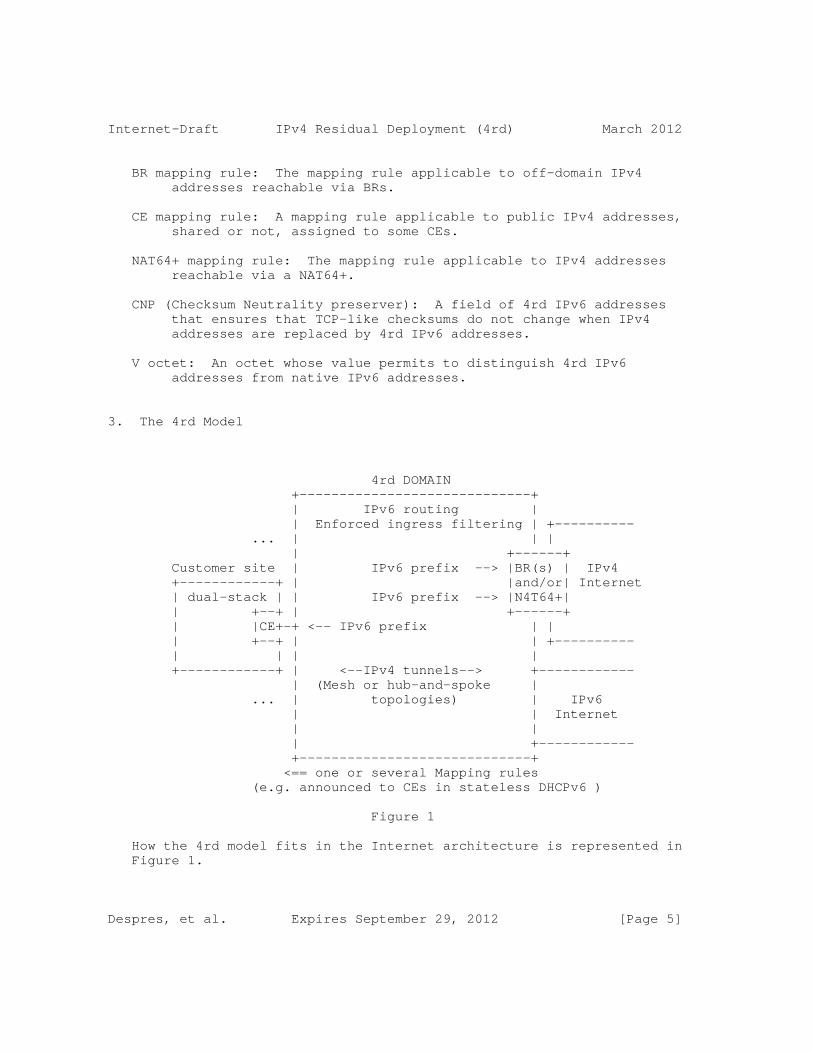
Terminology is defined in Section 2. How the 4rd model fits in the Internet architecture is summarized in Section 3. The protocol specification is detailed in Section 4. Section 5 illustrates a few typical 4rd use cases. Section 6 and Section 7 respectively deal with security and IANA considerations. Previous proposals that influenced this specification are listed in Section 9.
The key words "MUST", "SHOULD", "MAY", and "OPTIONAL" in this document are to be interpreted as described in [RFC2119].
2. Terminology
ISP: Internet-Service Provider. In this document, the service it offers can be DSL, fiber-optics, cable, or mobile. The ISP can also be a private-network operator.
Despres, et al. Expires September 29, 2012 [Page 3]

Internet-Draft IPv4 Residual Deployment (4rd) March 2012
4rd (IPv4 Residual Deployment): An extension of the IPv4 service where public-IPv4 addresses can be statically shared with restricted port sets assigned to customers.
4rd domain (or Domain): An ISP-operated IPv6 network across which 4rd is supported according to the present specification.
Tunnel packet: An IPv6 packet that transparently conveys an IPv4 packet across a 4rd domain. Its header has enough information to reconstitute the IPv4 header at Domain exit. Its payload is the original IPv4 payload.
CE (Customer Edge): A customer-side tunnel endpoint function. It can be in a node that is a host, a router, or both.
BR (Border Relay): An ISP-side tunnel-endpoint function. Because its operation is stateless (neither per CE nor per session state) it can be replicated in as many nodes as needed for scalability.
4rd IPv6 address: IPv6 address used as destination of a Tunnel packet sent to a CE or a BR.
NAT64+: An ISP NAT64 of [RFC6146] that is upgraded to support 4rd tunneling when IPv6 addresses it deals with have the 4rd-IPv6- address format.
4rd IPv4 address: A public IPv4 address or, in case of a shared IPv4 address, a public transport address (public IPv4 address plus port number).
PSID (Port-Set Identifier): A flexible-length field that algorithmically identifies a port set.
4rd IPv4 prefix: A flexible-length prefix that may be a a public IPv4 prefix, a public IPv4 address, or a public IPv4 address followed by a PSID.
Mapping rule: A set of parameters that BRs and CEs can use either to derive a 4rd IPv6 address from a 4rd IPv4 address, or that CEs can use to build an IPv6 address that will reach a NAT64+. Mapping rules are also used by CEs to derive their own 4rd IPv4 prefixes from their delegated IPv6 prefixes.
EA bits (Embedded Address bits): Bits that are the same in a 4rd IPv4 address and in the 4rd IPv6 address derived from it.
Despres, et al. Expires September 29, 2012 [Page 4]
Internet-Draft IPv4 Residual Deployment (4rd) March 2012
BR mapping rule: The mapping rule applicable to off-domain IPv4 addresses reachable via BRs.
CE mapping rule: A mapping rule applicable to public IPv4 addresses, shared or not, assigned to some CEs.
NAT64+ mapping rule: The mapping rule applicable to IPv4 addresses reachable via a NAT64+.
CNP (Checksum Neutrality preserver): A field of 4rd IPv6 addresses that ensures that TCP-like checksums do not change when IPv4 addresses are replaced by 4rd IPv6 addresses.
V octet: An octet whose value permits to distinguish 4rd IPv6 addresses from native IPv6 addresses.
3. The 4rd Model
4rd DOMAIN +-----------------------------+ | IPv6 routing | | Enforced ingress filtering | +---------- ... | | | | +------+ Customer site | IPv6 prefix --> |BR(s) | IPv4 +------------+ | |and/or| Internet | dual-stack | | IPv6 prefix --> |N4T64+| | +--+ | +------+ | |CE+-+ <-- IPv6 prefix | | | +--+ | | +---------- | | | | +------------+ | <--IPv4 tunnels--> +------------ | (Mesh or hub-and-spoke | ... | topologies) | IPv6 | | Internet | | | +------------ +-----------------------------+ <== one or several Mapping rules (e.g. announced to CEs in stateless DHCPv6 )
Figure 1
How the 4rd model fits in the Internet architecture is represented in Figure 1.
Despres, et al. Expires September 29, 2012 [Page 5]

Internet-Draft IPv4 Residual Deployment (4rd) March 2012
One or several Mapping rules are announced to CEs so that they can find, based on their delegated IPv6 prefixes, their assigned IPv4 address space. This space can be specified by a public IPv4 prefix, a public IPv4 address, or a shared public IPv4 address with a restricted port set. It can also be no IPv4 address if the ISP operates a NAT64+.
R-1: A node whose CE is assigned a shared IPv4 address MUST include a NAT44 [RFC1631]. This NAT44 MUST only use external ports that are in the CE assigned port set.
NOTE 1: An ISP NAT64 that has per-session stateful operation can be also upgraded to support 4rd Mapping rules. Thus, for each customer whose delegated IPv6 prefix matches a CE or BR mapping rule, it can have per-customer and per-session stateless operation even if this customer’s node is IPv6 only. Details of such an upgrade are beyond the scope of this specification.
NOTE 2: This specification only concerns IPv4 communication between IPv4-capable endpoints. For communication between IPv4-only endpoints and IPv6 only remote endpoints, the BIH specification of [RFC6535] can be used. It can coexist in a node with the CE function, including if the IPv4-only function is a NAT44 [RFC1631].
4. Protocol Specification
4.1. Mapping rules and other Domain parameters
R-2: CEs and BRs MUST be configured with the following Domain parameters:
A. One or several Mapping rules, each one comprising:
1. Rule IPv4 prefix
2. EA-bits length
3. Rule IPv6 prefix
4. WKPs authorized (OPTIONAL)
5. Rule IPv6 suffix (OPTIONAL)
B. Domain PMTU
C. Hub&spoke topology (Yes or No)
Despres, et al. Expires September 29, 2012 [Page 6]

Internet-Draft IPv4 Residual Deployment (4rd) March 2012
D. Tunnel traffic class (OPTIONAL)
"Rule IPv4 prefix" is used to find which Mapping rule applies to a 4rd IPv4 address (Section 4.4). Rules where it is longer than /0 are CE mapping rules. It is a /0 in BR and NAT64+ mapping rules.
"EA-bits length" specifies the number of bits of 4rd IPv4 addresses that, with this Mapping rule, are copied into the derived 4rd IPv6 address. It MUST be 32 in BR and NAT64+ mapping rules.
"Rule IPv6 prefix" is the prefix that is substituted to the Rule IPv4 prefix found in a 4rd IPv4 address to derive a 4rd IPv6 address (Section 4.4). In a BR mapping rule, it MUST be a /80 whose 9th octet is the V octet. In a NAT64+ mapping rule it MUST be a /80 whose 9th octet is the "u" octet of [RFC6052].
"WKPs authorized" can be set if the mapping rule assigns shared IPv4 addresses to CEs (length of Rule IPv4 prefix plus EA-bits length > 0). It then specifies that well-known ports can be assigned to some CEs depending on their PSID values. If not set, fairness is privileged, with no well-known port assigned to any CE, whatever its PSID value (privilege to fairness).
"Rule IPv6 suffix", if provided, is a field to be added after EA bits of a 4rd IPv6 address after its EA bits.
It is only used in Domains where a CEs can be placed in customer sites behind third-party CPEs, and where these CPEs use some address bits to route packets among their physical ports (one CE per site, always attached to the same CPE physical port). A use case where it applies is presented in Section 5.3.2.
"Hub&spoke topology", if set to Yes, requires CEs to tunnel all IPv4 packets via BRs. If set to No, CE-to-CE packets take the same routes as native IPv6 packets between the same CEs.
"Domain PMTU", is the IPv6 path MTU that the ISP can guarantee for all its IPv6 paths between CEs and between BRs and CEs. It MUST be
Despres, et al. Expires September 29, 2012 [Page 7]
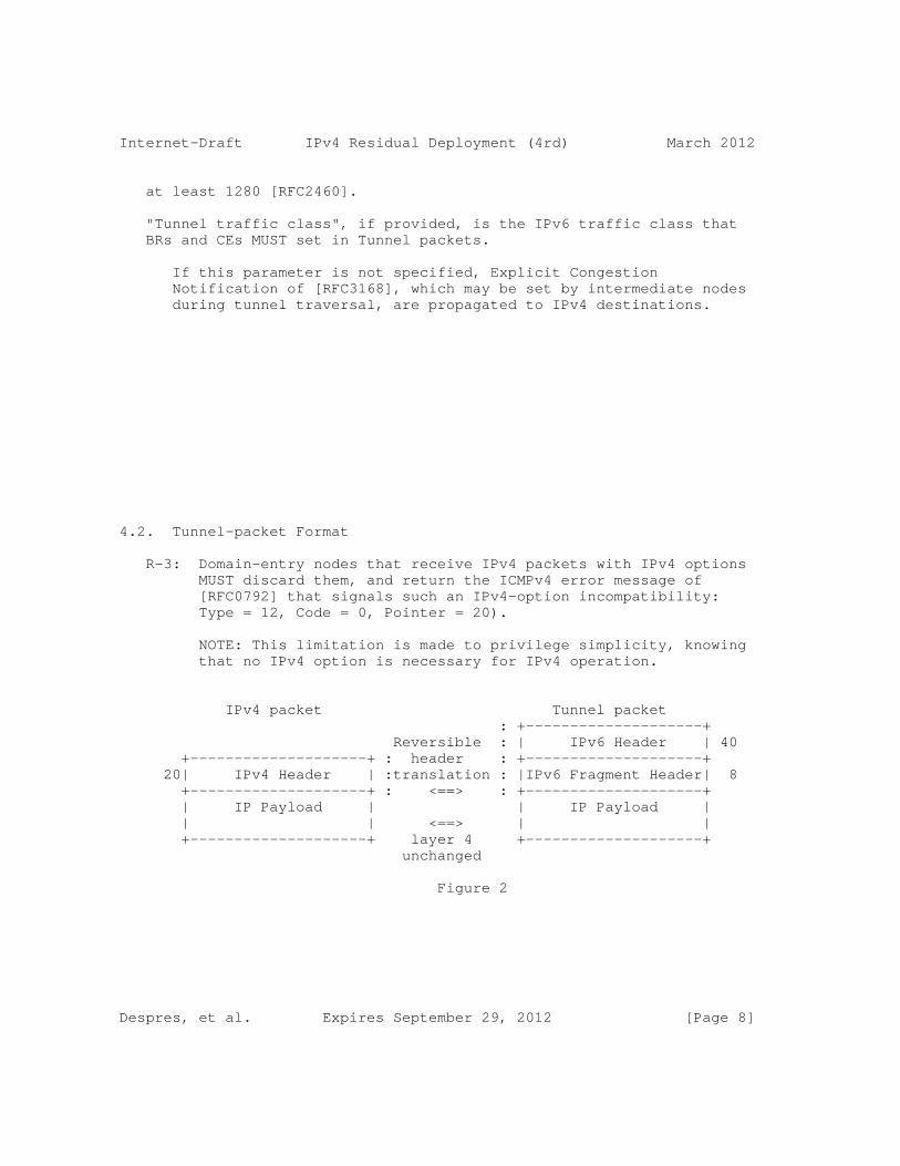
Internet-Draft IPv4 Residual Deployment (4rd) March 2012
at least 1280 [RFC2460].
"Tunnel traffic class", if provided, is the IPv6 traffic class that BRs and CEs MUST set in Tunnel packets.
If this parameter is not specified, Explicit Congestion Notification of [RFC3168], which may be set by intermediate nodes during tunnel traversal, are propagated to IPv4 destinations.
4.2. Tunnel-packet Format
R-3: Domain-entry nodes that receive IPv4 packets with IPv4 options MUST discard them, and return the ICMPv4 error message of [RFC0792] that signals such an IPv4-option incompatibility: Type = 12, Code = 0, Pointer = 20).
NOTE: This limitation is made to privilege simplicity, knowing that no IPv4 option is necessary for IPv4 operation.
IPv4 packet Tunnel packet : +--------------------+ Reversible : | IPv6 Header | 40 +--------------------+ : header : +--------------------+ 20| IPv4 Header | :translation : |IPv6 Fragment Header| 8 +--------------------+ : <==> : +--------------------+ | IP Payload | | IP Payload | | | <==> | | +--------------------+ layer 4 +--------------------+ unchanged
Figure 2
Despres, et al. Expires September 29, 2012 [Page 8]

Internet-Draft IPv4 Residual Deployment (4rd) March 2012
R-4: Domain-entry nodes that receive IPv4 packets without IPv4 options MUST convert them into Tunnel packets, and Domain-exit nodes MUST convert them back into IPv4 packets (Figure 2). Fields values to be set at Domain entry and at Domain exit are detailed in Table 1, and those to be set at Domain-exit are detailed in Table 2. IPv4 DF, IPv4 TOS, and IPv4 ID, are placed in IPv6 Identifications as detailed in Figure 3.
1 2 3 0 1 2 3 4 5 6 7 8 9 0 1 2 3 4 5 6 7 8 9 0 1 2 3 4 5 6 7 8 9 0 1 +-+-+-+-+-+-+-+-+-+-+-+-+-+-+-+-+-+-+-+-+-+-+-+-+-+-+-+-+-+-+-+-+ |.| TTL-1-7 | IPv4 TOS | IPv4 ID | +|+-+-+-+-+-+-+-+-+-+-+-+-+-+-+-+-+-+-+-+-+-+-+-+-+-+-+-+-+-+-+-+ IPv4 DF Identification field of the IPv6 Fragment header
Figure 3
+----------------------+--------------------------------+ | IPv6 FIELDS | VALUES SET AT DOMAIN ENTRY | +----------------------+--------------------------------+ | Version | 6 | | Traffic class | TOS or parameter (Section 4.6) | | Flow label | 0 | | Payload length | Total length - 12 | | Next header | 44 (Fragment header) | | Hop limit (bit 0) | Time to live (bit 0) | | Hop limit (bits 1-7) | 127 | | Source address | See Section 4.4 | | Dest. address | See Section 4.4 | | 2nd next header | Protocol | | Frag. offset | Frag. offset | | M | More fragments (MF) | | IPv4 DF | Don’t fragment (DF) | | TTL-1-7 | TTL (bits 0-7) | | IPv4 TOS | Type of service (TOS) | | IPv4 ID | Identification | +----------------------+--------------------------------+
Table 1
Despres, et al. Expires September 29, 2012 [Page 9]
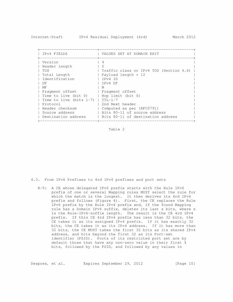
Internet-Draft IPv4 Residual Deployment (4rd) March 2012
+-------------------------+-----------------------------------------+ | IPv4 FIELDS | VALUES SET AT DOMAIN EXIT | +-------------------------+-----------------------------------------+ | Version | 4 | | Header length | 5 | | TOS | Traffic class or IPv4 TOS (Section 4.6) | | Total Length | Payload length + 12 | | Identification | IPv4 ID | | DF | IPv4 DF | | MF | M | | Fragment offset | Fragment offset | | Time to live (bit 0) | Hop limit (bit 0) | | Time to live (bits 1-7) | TTL-1-7 | | Protocol | 2nd Next header | | Header checksum | Computed as per [RFC0791] | | Source address | Bits 80-11 of source address | | Destination address | Bits 80-11 of destination address | +-------------------------+-----------------------------------------+
Table 2
4.3. From IPv6 Prefixes to 4rd IPv4 prefixes and port sets
R-5: A CE whose delegated IPv6 prefix starts with the Rule IPv6 prefix of one or several Mapping rules MUST select the rule for which the match is the longest. It then derives its 4rd IPv4 prefix and follows (Figure 4). First, the CE replaces the Rule IPv6 prefix by the Rule IPv4 prefix and, if the found Mapping rule has a Domain IPv6 suffix, deletes its last s bits, where s is the Rule-IPv6-suffix length. The result is the CE 4rd IPv4 prefix. If this CE 4rd IPv4 prefix has less than 32 bits, the CE takes it as its assigned IPv4 prefix. If it has exactly 32 bits, the CE takes it as its IPv4 address. If it has more than 32 bits, the CE MUST takes the first 32 bits as its shared IPv4 address, and bits beyond the first 32 as its Port-set identifier (PSID). Ports of its restricted port set are by default those that have any non-zero value in their first 4 bits, followed by the PSID, and followed by any values in
Despres, et al. Expires September 29, 2012 [Page 10]

Internet-Draft IPv4 Residual Deployment (4rd) March 2012
remaining bits. If the WKP authorized option is set, all ports can be assigned: there is no 4-bit offset before the PSID (Figure 4).
NOTE: The choice of the default PSID position in Port fields has been guided by the following objectives: (1) for fairness, avoid having any of the well-known ports 0-1023 in the port set specified by any PSID value (these ports have more value than others); (2) for compatibility RTP/RTCP [RFC4961], include in each port set pairs of consecutive ports; (3) in order to facilitate operation and training, have the PSID at a fixed position in port fields; (4) in order to facilitate documentation in hexadecimal notation, and to facilitate maintenance, have this position nibble aligned. With the choice made, port range 0-4095 is unassigned instead of only 0-1023, the minimum required, but this is a trade-off in view of other objectives, in particular nibble alignment and overall simplicity.
R-6: A CE whose delegated prefix matches the Rule IPv6 prefix of no CE Mapping rule, but matches that of the BR mapping rule, MUST take as it IPv4 address the 32 bit that follow this /80 prefix in its delegated IPv6 prefix. If this delegated prefix is not a /112, 4rd cannot be enabled, and an implementation-dependent administrative action MAY be taken.
A CE whose delegated prefix matches the Rule IPv6 prefix of neither any CE Mapping rule or BR mapping rule, but is in a Domain that has a NAT64+ mapping rule, MUST take as its IPv4 address the unspecified IPv4 address 0.0.0.0.
Despres, et al. Expires September 29, 2012 [Page 11]
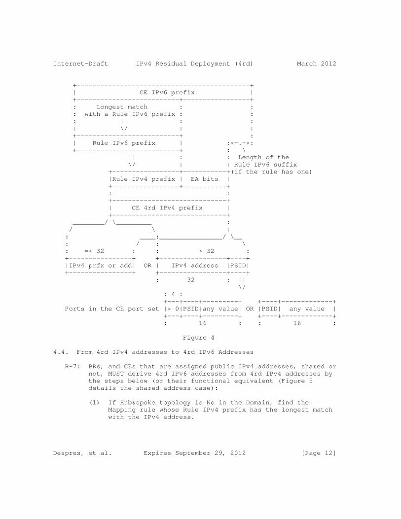
Internet-Draft IPv4 Residual Deployment (4rd) March 2012
+--------------------------------------------+ | CE IPv6 prefix | +--------------------------+-----------------+ : Longest match : : : with a Rule IPv6 prefix : : : || : : : \/ : : +--------------------------+ : | Rule IPv6 prefix | :<-.->: +--------------------------+ : \ || : : Length of the \/ : : Rule IPv6 suffix +-----------------+-----------+(if the rule has one) |Rule IPv4 prefix | EA bits | +-----------------+-----------+ : : +-----------------------------+ | CE 4rd IPv4 prefix | +-----------------------------+ ________/ \_________ : / \ : : ____:________________/ \__ : / : \ : =< 32 : : > 32 : +----------------+ +-----------------+----+ |IPv4 prfx or add| OR | IPv4 address |PSID| +----------------+ +-----------------+----+ : 32 : || \/ : 4 : +---+----+---------+ +----+-------------+ Ports in the CE port set |> 0|PSID|any value| OR |PSID| any value | +---+----+---------+ +----+-------------+ : 16 : : 16 :
Figure 4
4.4. From 4rd IPv4 addresses to 4rd IPv6 Addresses
R-7: BRs, and CEs that are assigned public IPv4 addresses, shared or not, MUST derive 4rd IPv6 addresses from 4rd IPv4 addresses by the steps below (or their functional equivalent (Figure 5 details the shared address case):
(1) If Hub&spoke topology is No in the Domain, find the Mapping rule whose Rule IPv4 prefix has the longest match with the IPv4 address.
Despres, et al. Expires September 29, 2012 [Page 12]

Internet-Draft IPv4 Residual Deployment (4rd) March 2012
(2) If none is found with an IPv4 prefix longer than /0, or if Hub&spoke topology is Yes in the Domain, take the BR mapping rule, if it exists, the NAT64+ mapping rule otherwise.
: 32 : : 16 +----------------------------+ +---------------+ | IPv4 address | |Port or ICMP ID| +----------------------------+ +---+------+----+ : Longest match : : 4 : PSID : : with a Rule IPv4 prefix : ____/length : : || :/ if > 0 in : : \/ : the rule : : : ______/ : : / +----------------+-----------+----+ |Rule IPv4 prefix|IPv4 suffix|PSID| +----------------+-----------+----+ : : : : +----------------+----------------+ |Rule IPv4 prefix| EA bits | +----------------+----------------+ || \_______ \__ \/ \ \ +--------------------------+-----------+---+ | Rule IPv6 prefix | EA bits | . | +--------------------------+-----------+--\+ : \ : :\_ Domain IPv6 suffix +------------------------------------------+ (if the rule has one) | IPv6 prefix | +------------------------------------------+ :\________________________________ / \ : _____________________\______/ \_______________ : / \ \ : =<64 : : 112 : +----------+---+-+-+------+---+ +--------------+-+-+------+---+ |CE v6 prfx| 0 |V|0|v4 add|CNP| |BR IPv6 prefix|V|0|v4 add|CNP| +----------+-|-+-+-|+-----+---+ +--------------+-+-+------+---+ : =<64 : | :8:8: 32 :16 : : 64 :8:8: 32 :16 : | Padding to /64
Figure 5
Despres, et al. Expires September 29, 2012 [Page 13]

Internet-Draft IPv4 Residual Deployment (4rd) March 2012
(3) If the Rule IPv4 prefix plus EA-bits length does not exceed 32, i.e. 4rd IPv4 prefix = 32 - k with >= 0, delete the last k bits of the IPv4 address.
Otherwise, i.e. if the Rule IPv4 prefix plus EA-bits length is 32 + k with k >= 0, take k as the PSID length, and append to the IPv4 address the PSID copied from bits 4 to 4 + k - 1 of a field whose place depends on whether the address is source or destination, on whether the packet is ICMP or not, and, if it is ICMP, whether it is an error message or an echo message:
a. If the packet Protocol is not ICMP, bits 0-15 for an IPv4 source address, and bits 16-31 for a destination address.
b. If the packet is an ICMPv4 error message, bits 240-255 for a source address; bits 224-239 for a destination address.
c. If the packet is an ICMPv4 echo or echo-reply message, the Port field is the ICMPv4 Identification field (bits 32-47).
NOTE: Using Identification fields of ICMP messages as port fields permits to exchange Echo requests and Echo replies between shared-address CEs and and IPv4 hosts having exclusive IPv4 addresses. Echo exchanges between two shared-address CEs remain impossible, but this is a limitation inherent to address sharing (one reason among many to use IPv6).
Editor’s note following questions on the WG mailing list: As specified, the PSID, when applicable, is taken in the TCP-like port field of the available IPv4 payload without checking that the protocol is one that really has a port field. This is what keeps BR operation independent from layer-4 protocols. A consequence to be noted is that a packet may go from a BR to a shared-address CE with a protocol that is not supported by this CE. In this case, the normal CE-node-NAT44 reaction is to returns an ICMPv4 "protocol unreachable" error message. The IPv4 source is thus informed of its mistake.
(4) Replace in the result the Rule IPv4 prefix by the Rule IPv6 prefix.
Despres, et al. Expires September 29, 2012 [Page 14]
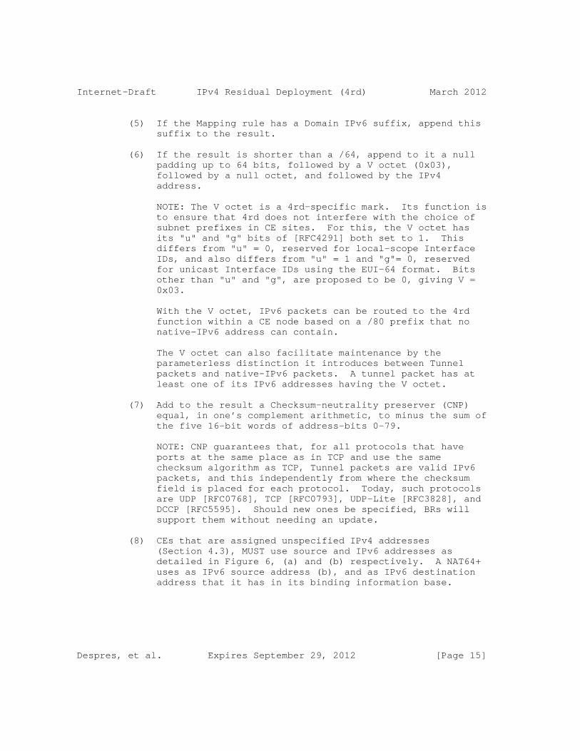
Internet-Draft IPv4 Residual Deployment (4rd) March 2012
(5) If the Mapping rule has a Domain IPv6 suffix, append this suffix to the result.
(6) If the result is shorter than a /64, append to it a null padding up to 64 bits, followed by a V octet (0x03), followed by a null octet, and followed by the IPv4 address.
NOTE: The V octet is a 4rd-specific mark. Its function is to ensure that 4rd does not interfere with the choice of subnet prefixes in CE sites. For this, the V octet has its "u" and "g" bits of [RFC4291] both set to 1. This differs from "u" = 0, reserved for local-scope Interface IDs, and also differs from "u" = 1 and "g"= 0, reserved for unicast Interface IDs using the EUI-64 format. Bits other than "u" and "g", are proposed to be 0, giving V = 0x03.
With the V octet, IPv6 packets can be routed to the 4rd function within a CE node based on a /80 prefix that no native-IPv6 address can contain.
The V octet can also facilitate maintenance by the parameterless distinction it introduces between Tunnel packets and native-IPv6 packets. A tunnel packet has at least one of its IPv6 addresses having the V octet.
(7) Add to the result a Checksum-neutrality preserver (CNP) equal, in one’s complement arithmetic, to minus the sum of the five 16-bit words of address-bits 0-79.
NOTE: CNP guarantees that, for all protocols that have ports at the same place as in TCP and use the same checksum algorithm as TCP, Tunnel packets are valid IPv6 packets, and this independently from where the checksum field is placed for each protocol. Today, such protocols are UDP [RFC0768], TCP [RFC0793], UDP-Lite [RFC3828], and DCCP [RFC5595]. Should new ones be specified, BRs will support them without needing an update.
(8) CEs that are assigned unspecified IPv4 addresses (Section 4.3), MUST use source and IPv6 addresses as detailed in Figure 6, (a) and (b) respectively. A NAT64+ uses as IPv6 source address (b), and as IPv6 destination address that it has in its binding information base.
Despres, et al. Expires September 29, 2012 [Page 15]
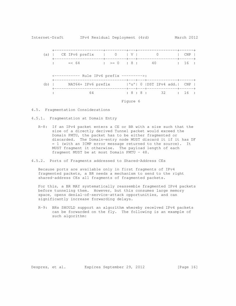
Internet-Draft IPv4 Residual Deployment (4rd) March 2012
+---------------------+---------+---+-----------------+------+ (a) | CE IPv6 prefix | 0 | V | 0 | CNP | +---------------------+---------+---+-----------------+------+ : =< 64 : >= 0 : 8 : 40 : 16 :
<----------- Rule IPv6 prefix --------->: +-------------------------------+---+---+-------------+------+ (b) | NAT64+ IPv6 prefix |"u"| 0 |DST IPv4 add.| CNP | +-------------------------------+---+---+-------------+------+ : 64 : 8 : 8 : 32 : 16 :
Figure 6
4.5. Fragmentation Considerations
4.5.1. Fragmentation at Domain Entry
R-8: If an IPv4 packet enters a CE or BR with a size such that the size of a directly derived Tunnel packet would exceed the Domain PMTU, the packet has to be either fragmented or discarded. The Domain-entry node MUST discard it if it has DF = 1 (with an ICMP error message returned to the source). It MUST fragment it otherwise. The payload length of each fragment MUST be at most Domain PMTU - 48.
4.5.2. Ports of Fragments addressed to Shared-Address CEs
Because ports are available only in first fragments of IPv4 fragmented packets, a BR needs a mechanism to send to the right shared-address CEs all fragments of fragmented packets.
For this, a BR MAY systematically reassemble fragmented IPv4 packets before tunneling them. However, but this consumes large memory space, opens denial-of-service-attack opportunities, and can significantly increase forwarding delays.
R-9: BRs SHOULD support an algorithm whereby received IPv4 packets can be forwarded on the fly. The following is an example of such algorithm:
Despres, et al. Expires September 29, 2012 [Page 16]
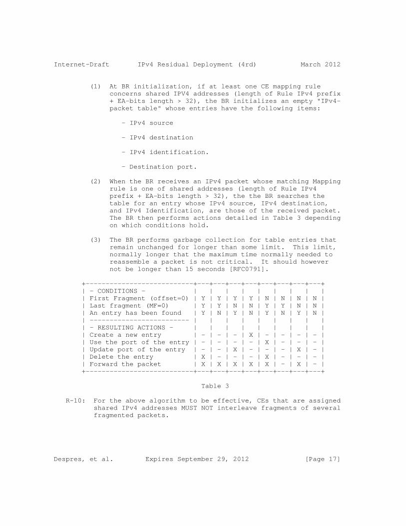
Internet-Draft IPv4 Residual Deployment (4rd) March 2012
(1) At BR initialization, if at least one CE mapping rule concerns shared IPV4 addresses (length of Rule IPv4 prefix + EA-bits length > 32), the BR initializes an empty "IPv4- packet table" whose entries have the following items:
- IPv4 source
- IPv4 destination
- IPv4 identification.
- Destination port.
(2) When the BR receives an IPv4 packet whose matching Mapping rule is one of shared addresses (length of Rule IPv4 prefix + EA-bits length > 32), the the BR searches the table for an entry whose IPv4 source, IPv4 destination, and IPv4 Identification, are those of the received packet. The BR then performs actions detailed in Table 3 depending on which conditions hold.
(3) The BR performs garbage collection for table entries that remain unchanged for longer than some limit. This limit, normally longer that the maximum time normally needed to reassemble a packet is not critical. It should however not be longer than 15 seconds [RFC0791].
+---------------------------+---+---+---+---+---+---+---+---+ | - CONDITIONS - | | | | | | | | | | First Fragment (offset=0) | Y | Y | Y | Y | N | N | N | N | | Last fragment (MF=0) | Y | Y | N | N | Y | Y | N | N | | An entry has been found | Y | N | Y | N | Y | N | Y | N | | ------------------------- | | | | | | | | | | - RESULTING ACTIONS - | | | | | | | | | | Create a new entry | - | - | - | X | - | - | - | - | | Use the port of the entry | - | - | - | - | X | - | - | - | | Update port of the entry | - | - | X | - | - | - | X | - | | Delete the entry | X | - | - | - | X | - | - | - | | Forward the packet | X | X | X | X | X | - | X | - | +---------------------------+---+---+---+---+---+---+---+---+
Table 3
R-10: For the above algorithm to be effective, CEs that are assigned shared IPv4 addresses MUST NOT interleave fragments of several fragmented packets.
Despres, et al. Expires September 29, 2012 [Page 17]

Internet-Draft IPv4 Residual Deployment (4rd) March 2012
R-11: CEs that are assigned IPv4 prefixes, and are in nodes that route public IPv4 addresses rather than only using NAT44s, MUST have the same behavior as described just above for BRs.
4.5.3. Packet Identifications from Shared-Address CEs
When packets go from CEs that share the same IPv4 address to a common destination, a precaution is needed to guarantee that packet Identifications set by sources are different. Packet reassembly at destination, which is based only on source IPv4 address and Identification, could otherwise be confused. Probability of such confusions may in theory be very low but, in order to avoid creating new attack opportunities, a safe solution is needed.
R-12: A CE that is assigned a shared IPv4 address MUST only crete packet Identifications that have the CE PSID in their bits 4 to 4 + PSID length - 1.
R-13: A BR or a CE that receives a packet from a shared-address CE MUST check that bits 4 to 4 + PSID length - 1 of the packet Identification are equal to the PSID found in source 4rd IPv4 address.
4.6. TOS and Traffic-Class Considerations
In networks that support Explicit congestion notification (ECN), the TOS of IPv4 headers and the Traffic class of IPv6 headers have the same meanings [RFC3168]. Their first 6 bits are a Differentiated Services CodePoint (DSCP), and their two last bits are an Explicit Congestion Notification (ECN). [RFC6040] details how the ECN field MAY evolve if a packet traverses a router that signals congestion condition before packets are dropped.
R-14: In a 4rd domain that has a Tunnel-traffic-class parameter, BRs and CE’s MUST, at Domain entry, copy this parameter to set Traffic-class fields of Tunnel packets they transmit, and copy the IPv4 TOS into the IPv4-TOS field of Figure 3. At Domain exit, they MUST copy back the IPv4-TOS-field value into the TOS field of the IPv4 packet.
R-15: A 4rd domain that has no Tunnel-traffic-class parameter MUST support the ECN normal mode of [RFC6040]. Its BRs and CEs MUST copy the IPv4 TOS into the IPv6 Traffic class at Domain entry, and copy back the IPv6 Traffic class (which may have a changed ECN value), into the IPv4 TOS at Domain exit.
Despres, et al. Expires September 29, 2012 [Page 18]

Internet-Draft IPv4 Residual Deployment (4rd) March 2012
4.7. Tunnel-Generated ICMPv6 Error Messages
If an Tunnel packet is discarded on its way across a 4rd domain because of an unreachable destination, an ICMPv6 error message is returned to the IPv6 source (an address starting with the BR IPv6 prefix, or with a CE IPv6 and having the V octet). For the source of the discarded IPv4 packet to be informed of packet loss, the ICMPv6 message has to be converted into an ICMPv4 message.
R-16: If a CE or BR receives an ICMPv6 error message [RFC4443], it MUST synthesize an ICMPv4 error packet [RFC0792]. This packet MUST contain the first 8 octets of the discarded-packet IP payload. If the CE or BR has a global IPv4 address, this address MUST be used as source of this packet. Otherwise, 192.70.192.254 SHOULD be used as this source (address taken in the /24 range proposed for such a purpose in draft-xli-behave-icmp-address-04, and subject to IANA confirmation). ICMPv6 Type = 1 and Code = 0 (Destination unreachable, No route to destination") MUST be translated into ICMPv4 Type = 3 and Code = 0 (Destination unreachable, Net unreachable). ICMPv6 Type = 1 and Code = 0 (Time exceeded, Hop limit exceeded in transit) MUST be translated into ICMPv4 Type = 11 and Code = 0 (Time exceeded, Time to live exceeded in transit).
4.8. Provisioning 4rd Parameters to CEs
Domain parameters listed in Section 4.1 are subject to the following constraints:
R-17: Each Domain MUST have a BR mapping rule and/or a NAT64+ mapping rule.
The BR mapping rule is used by CEs that are assigned public IPv4 addresses, shared or not, and the NAT64+ mapping rule is used by CEs that are assigned unspecified IPv4 addresses (Section 4.3).
R-18: Each CE and each BR MUST support up to 32 Mapping rules.
This number of is to ensure that independently acquired CEs an BR nodes can always interwork. (Its value, which is not critical, can easily be changed if another value is found by the WG more desirable.)
ISPs that need Mapping rules for more IPv4 prefixes than this number SHOULD split their networks into multiple Domains. Communication between these domains can be done in IPv4, or by
Despres, et al. Expires September 29, 2012 [Page 19]

Internet-Draft IPv4 Residual Deployment (4rd) March 2012
some implementation-dependent but equivalent other means.
R-19: For mesh topologies (CE-CE paths without BR traversal), all mapping rules of the Domain MUST be sent to all CEs. For hub- and-spoke topologies (all CE-CE paths via BRs), each CE MAY only be sent the BR mapping rule of the Domain plus, if different, the CE mapping rule that applies to its IPv6 prefix.
R-20: CEs MUST be able to acquire Parameter listed in Section 4.1 in DHCPv6 (ref. [RFC2131]), with formats detailed in Figure 7 and Figure 8.
0 1 2 3 0 1 2 3 4 5 6 7 8 9 0 1 2 3 4 5 6 7 8 9 0 1 2 3 4 5 6 7 8 9 0 1 +-+-+-+-+-+-+-+-+-+-+-+-+-+-+-+-+-+-+-+-+-+-+-+-+-+-+-+-+-+-+-+-+ | OPTION_4RD_RULE | option-length | +-+-+-+-+-+-+-+-+-+-+-+-+-+-+-+-+-+-+-+-+-+-+-+-+-+-+-+-+-+-+-+-+ | prefix4-len | prefix6-len | ea-len |sfx-len| sfx | +-+-+-+-+-+-+-+-+-+-+-+-+-+-+-+-+-+-+-+-+-+-+-+-+-+-+-+-+-+-+-+-+ | rule-ipv4-prefix |W| +-+-+-+-+-+-+-+-+-+-+-+-+-+-+-+-+-+-+-+-+-+-+-+-+-+-+-+-+-+-+-+-+ | | + + | rule-ipv6-prefix | + + | | +-+-+-+-+-+-+-+-+-+-+-+-+-+-+-+-+-+-+-+-+-+-+-+-+-+-+-+-+-+-+-+-+
Figure 7
o option-code: OPTION_4RD_RULE (TBD1)
o option-length: 20
o prefix4-len: number of bits of the Rule IPv4 prefix
o prefix6-len: number of bits of the Rule IPv6 prefix
o sfx-len: number of bits of the Rule IPv6 suffix (= 0 if the rule has no suffix)
o ea-len: EA-bits length
Despres, et al. Expires September 29, 2012 [Page 20]

Internet-Draft IPv4 Residual Deployment (4rd) March 2012
o rule-ipv4-prefix: Rule IPv4 prefix, left aligned
o W: WKP authorized, = 1 if set
o rule-ipv6-prefix: Rule IPv6 prefix, left aligned
0 1 2 3 0 1 2 3 4 5 6 7 8 9 0 1 2 3 4 5 6 7 8 9 0 1 2 3 4 5 6 7 8 9 0 1 +-+-+-+-+-+-+-+-+-+-+-+-+-+-+-+-+-+-+-+-+-+-+-+-+-+-+-+-+-+-+-+-+ | OPTION_4RD | option-length | +-+-+-+-+-+-+-+-+-+-+-+-+-+-+-+-+-+-+-+-+-+-+-+-+-+-+-+-+-+-+-+-+ |H| 0 |T| traffic-class | domain-pmtu | +-+-+-+-+-+-+-+-+-+-+-+-+-+-+-+-+-+-+-+-+-+-+-+-+-+-+-+-+-+-+-+-+
Figure 8
o option-code: OPTION_4RD (TBD2)
o option-length: 4
o H: Hub&spoke topology (= 1 if Yes)
o T: Traffic-class flag (= 1 if a Tunnel traffic class is provided)
o traffic-class: Tunnel-traffic class
o domain-pmtu: Domain PMTU (at least 1280)
Other means than DHCPv6 that may prove useful to provide 4rd parameters to CEs are off-scope for this document. The same or similar parameter formats would however be recommended to facilitate training and operation.
5. Use-Case Examples
5.1. Textual representation of Mapping rules
In the next sections, each Mapping rule will be represented as follows, using 0bXXX to represent binary number XXX, and square brackets [ ] for what is optional:
Despres, et al. Expires September 29, 2012 [Page 21]
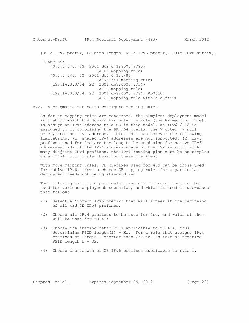
Internet-Draft IPv4 Residual Deployment (4rd) March 2012
{Rule IPv4 prefix, EA-bits length, Rule IPv6 prefix[, Rule IPv6 suffix]}
EXAMPLES: {0.0.0.0/0, 32, 2001:db8:0:1:3000::/80} (a BR mapping rule) {0.0.0.0/0, 32, 2001:db8:0:1::/80} (a NAT64+ mapping rule) {198.16.0.0/14, 22, 2001:db8:4000::/34} (a CE mapping rule) {198.16.0.0/14, 22, 2001:db8:4000::/34, 0b0010} (a CE mapping rule with a suffix)
5.2. A pragmatic method to configure Mapping Rules
As far as mapping rules are concerned, the simplest deployment model is that in which the Domain has only one rule (the BR mapping rule). To assign an IPv4 address to a CE in this model, an IPv6 /112 is assigned to it comprising the BR /64 prefix, the V octet, a null octet, and the IPv4 address. This model has however the following limitations: (1) shared IPv4 addresses are not supported; (2) IPv6 prefixes used for 4rd are too long to be used also for native IPv6 addresses; (3) if the IPv4 address space of the ISP is split with many disjoint IPv4 prefixes, the IPv6 routing plan must be as complex as an IPv4 routing plan based on these prefixes.
With more mapping rules, CE prefixes used for 4rd can be those used for native IPv6. How to choose CE mapping rules for a particular deployment needs not being standardized.
The following is only a particular pragmatic approach that can be used for various deployment scenarios, and which is used in use-cases that follow:
(1) Select a "Common IPv6 prefix" that will appear at the beginning of all 4rd CE IPv6 prefixes.
(2) Choose all IPv4 prefixes to be used for 4rd, and which of them will be used for rule i.
(3) Choose the sharing ratio 2^Ki applicable to rule i, thus determining PSID_length(i) = Ki. For a rule that assigns IPv4 prefixes of length L shorter than /32 to CEs take as negative PSID length L - 32.
(4) Choose the length of CE IPv6 prefixes applicable to rule i.
Despres, et al. Expires September 29, 2012 [Page 22]
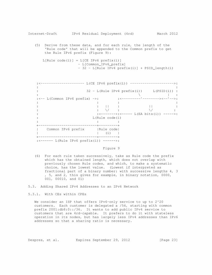
Internet-Draft IPv4 Residual Deployment (4rd) March 2012
(5) Derive from these data, and for each rule, the length of the "Rule code" that will be appended to the Common prefix to get the Rule IPv6 prefix (Figure 9):
L[Rule code(i)] = L[CE IPv6 prefix(i)] - L[Common_IPv6_prefix] - 32 - L[Rule IPv4 prefix(i)] + PSID_length(i)
:<--------------------- L(CE IPv6 prefix(i)) --------------------->: : : : 32 - L(Rule IPv4 prefix(i)) L(PSID(i)) : : \ | : :<-- L(Common IPv6 prefix) ->: :<---------’--------><--’-->: : : : : : : || : || : : : \/ : \/ : : :<------->:<----- L(EA bits(i)) ----->: : L(Rule code(i) : : : +----------------------------+---------+ | Common IPv6 prefix |Rule code| | | (i) | +----------------------------+---------+ :<------ L(Rule IPv6 prefix(i)) ------>:
Figure 9
(6) For each rule taken successively, take as Rule code the prefix which has the obtained length, which does not overlap with previously chosen Rule codes, and which, to make a systematic choice, has the lowest value. (Lowest if interpreted as fractional part of a binary number: with successive lengths 4, 3 , 5, and 2, this gives for example, in binary notation, 0000, 001, 00010, and 01)
5.3. Adding Shared IPv4 Addresses to an IPv6 Network
5.3.1. With CEs within CPEs
We consider an ISP that offers IPv6-only service to up to 2^20 customers. Each customer is delegated a /56, starting with common prefix 2001:db8:0::/36. It wants to add public IPv4 service to customers that are 4rd-capable. It prefers to do it with stateless operation in its nodes, but has largely less IPv4 addresses than IPv6 addresses so that a sharing ratio is necessary.
Despres, et al. Expires September 29, 2012 [Page 23]

Internet-Draft IPv4 Residual Deployment (4rd) March 2012
The only IPv4 prefixes it can use are 192.8.0.0/15, 192.4.0.0/16, 192.2.0.0/16, and 192.1.0.0/16 (neither overlapping nor aggregetable). This gives 2^(32-15) + 3*2^(32-16) IPv4 addresses, i.e. 2^18 + 2^16). For the 2^20 customers to have the same sharing ratio, the number of IPv4 addresses to be shared has to be a power of 2. The ISP can therefore renounce to use one /16, say the last one. (Whether it could be motivated to return it to its Internet Registry is off-scope for this document.) The sharing ratio to apply is then 2^20 / 2^18 = 2^2 = 4, giving a PSID length of 2.
Applying principles of Section 5.2 with L[Common IPv6 prefix] = 36, L[PSID] = 2 for all rules, and L[CE IPv6 prefix(i)] = 56 for all rules, Rule codes and Rule IPv6 prefixes are:
+--------------+--------+-----------+-----------+-------------------+ | CE Rule IPv4 | EA | Rule-Code | Code | CE Rule IPv6 | | prefix | bits | length | (binary) | prefix | | | length | | | | +--------------+--------+-----------+-----------+-------------------+ | 192.8.0.0/15 | 19 | 1 | 0 | 2001:db8:0::/37 | | 192.4.0.0/16 | 18 | 2 | 10 | 2001:db8:800::/38 | | 192.2.0.0/16 | 18 | 2 | 11 | 2001:db8:c00::/38 | +--------------+--------+-----------+-----------+-------------------+
Mapping rules are then the following:
{192.8.0.0/15, 19, 2001:0db8:0000::/37} {192.4.0.0/16, 18, 2001:0db8:0800::/38} {192.2.0.0/16, 18, 2001:0db8:0c00::/38} {0.0.0.0/0, 32, 2001:0db8:0000:0001:3000::/80}
The CE whose IPv6 prefix is, for example, 2001:db8:0bbb:bb00::/56, derives its IPv4 address and its port set, according to Section 4.3, as sfollows:
Despres, et al. Expires September 29, 2012 [Page 24]
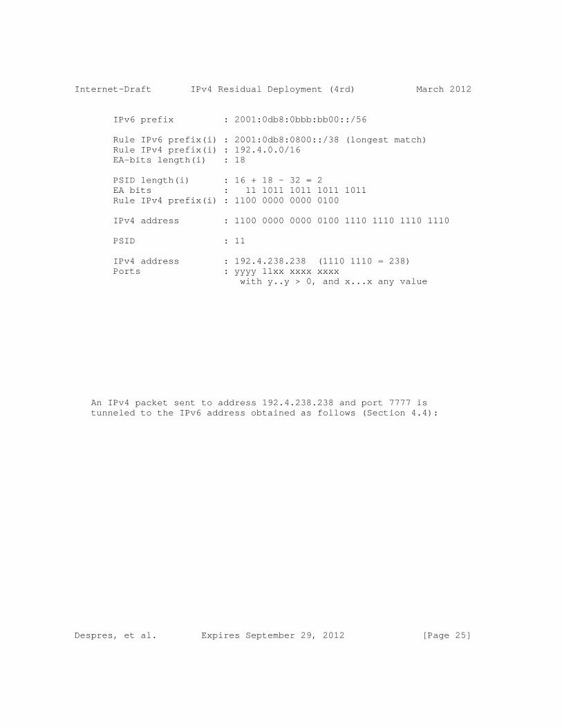
Internet-Draft IPv4 Residual Deployment (4rd) March 2012
IPv6 prefix : 2001:0db8:0bbb:bb00::/56
Rule IPv6 prefix(i) : 2001:0db8:0800::/38 (longest match) Rule IPv4 prefix(i) : 192.4.0.0/16 EA-bits length(i) : 18
PSID length(i) : 16 + 18 - 32 = 2 EA bits : 11 1011 1011 1011 1011 Rule IPv4 prefix(i) : 1100 0000 0000 0100
IPv4 address : 1100 0000 0000 0100 1110 1110 1110 1110
PSID : 11
IPv4 address : 192.4.238.238 (1110 1110 = 238) Ports : yyyy 11xx xxxx xxxx with y..y > 0, and x...x any value
An IPv4 packet sent to address 192.4.238.238 and port 7777 is tunneled to the IPv6 address obtained as follows (Section 4.4):
Despres, et al. Expires September 29, 2012 [Page 25]

Internet-Draft IPv4 Residual Deployment (4rd) March 2012
IPv4 address : 192.4.238.238 Port field : 7777 (0x1E61)
Rule IPv4 prefix (i) : 192.4.0.0/16 (longest match) EA-bits length (i) : 18 Rule IPv6 prefix (i) : 2001:0db8:0800::/38
IPv4 address : 1100 0000 0000 0100 1110 1110 1110 1110 EA bits Rule IPv4 prefix (i) : 1100 0000 0000 0100 IPv4 suffix : 1110 1110 1110 1110
PSID length (i) : 19 - 17 = 2 Port field : 0001 1110 0110 0001 (7777) PSID : 11
EA bits : 1110 1110 1110 1110 11 : 11 1011 1011 1011 1011 CE IPv6 prefix : 2001:0db8:0bbb:bb00::/56 IPv6 address : 2001:0db8:0bbb:bb00:3000:192.4.238.238:YYYY with YYYY = the computed CNP
5.3.2. With some CEs behind Third-party Router CPEs
We now consider an ISP that has the same need as in the previous section except that, instead of using only its own IPv6 infrastructure, it uses that of a third-party provider, and that some of its customers use CPEs of this provider to use specific services that it offers. In these CPEs, a non-zero index is used to route IPv6 packets to the physical port to which CEs are attached, say 0x2. Each such CPE delegates to the CE nodes the customer-site IPv6 prefix followed by this index.
The ISP is supposed to have the same IPv4 prefixes as in the previous use case, 192.8.0.0/15, 192.4.0.0/16, and 192.2.0.0/16, and to use the same Common IPv6 prefix, 2001:db8:0::/36.
We also assume that only a minority of customers use the third-party CPE, so that it is sufficient to use only one of the two /16s for them.
Despres, et al. Expires September 29, 2012 [Page 26]
Internet-Draft IPv4 Residual Deployment (4rd) March 2012
Mapping rules are then:
{192.8.0.0/15, 19, 2001:0db8:0000::/37} {192.4.0.0/16, 18, 2001:0db8:0800::/38, 0b0001} {192.2.0.0/16, 18, 2001:0db8:0c00::/38} {0.0.0.0/0, 32, 2001:0db8:0000:0001:3000::/80}
CEs that are behind third-party CPEs derive their own IPv4 addresses and port sets as in Section 5.3.1, except that, because the Mapping rule that applies to their IPv6 prefixes have a Rule IPv6 suffix, they delete this suffix from the end of their delegated IPv6 prefixes before deriving their 4rd IPv4 prefixes (Section 4.3).
In a BR, and also in a CE if the topology is mesh, the IPv6 address that is derived from IPv4 address 192.4.238.238 and port 7777 is obtained as in the previous section, except for the two last steps which become:
CE IPv6 prefix : 2001:0db8:0bbb:bb20::/60 (suffix 0x2 appended) IPv6 address : 2001:0db8:0bbb:bb20:3000:192.4.238.238:YYYY with YYYY = the computed CNP
5.4. Replacing Dual-stack Routing by IPv6-only Routing
In this use case, we consider an ISP that offers IPv4 service with public addresses individually assigned to its customers. It also offers IPv6 service, having deployed for this dual-stack routing. Because it provides its own CPEs to customers, it can upgrade all its CPEs to support 4rd. It wishes to take advantage of this capability to replace dual-stack routing by IPv6-only routing without changing any IPv4 address or IPv6 prefix.
For this, the ISP can use the single-rule model described at the beginning of Section 5.2. If the prefix routed to BRs is chosen to start with 2001:db8:0:1::/64, this rule is:
{0.0.0.0/0, 32, 2001:db8:0:1:3000::/80}
All what is needed in the network before disabling IPv4 routing is the following:
o In all routers, where there is an IPv4 route toward x.x.x.x/n, add a parallel route toward 2001:db8:0:1:3000:x.x.x.x::/(80+n)
o Where IPv4 address x.x.x.x was assigned to a CPE, now delegate IPv6 prefix 2001:db8:0:1:3000:x.x.x.x::/112.
Despres, et al. Expires September 29, 2012 [Page 27]

Internet-Draft IPv4 Residual Deployment (4rd) March 2012
NOTE: In parallel with this deployment, or after it, shared IPv4 addresses can be assigned to IPv6 customers. It is sufficient that IPv4 prefixes used for this be different from those used for exclusive-address assignments. Under this constraint, Mapping rules can be set up according to the same principles as those of Section 5.3.
5.5. Adding IPv6 and 4rd Service to a Net-10 network
In this use case, we consider an ISP that has only deployed IPv4, possibly because some of its network devices are not yet IPv6 capable. Because it did not have enough IPv4 addresses, it has assigned private IPv4 addresses of [RFC1918] to customers, say 10.x.x.x to support up to 2^24 customers ("Net-10" network, NAT444 model of [I-D.shirasaki-nat444]). It wishes to offer IPv6 service without further delay, using for this 6rd [RFC5969]. It also wishes to offer incoming IPv4 connectivity to its customers with a simpler solution than that of PCP [I-D.ietf-pcp-base].
The IPv6 prefix to be used for 6rd is supposed to be 2001:db8::/32, and the public IPv4 prefix to be used for shared addresses is supposed to be 192.16.0.0/16 (0xc610). The resulting sharing ratio is 2^24 / 2^(32-16) = 256, giving a PSID length of 8.
The ISP installs one or several BRs, at its border to the public IPv4 Internet. They support 6rd, and 4rd above it. The BR prefix /64 is supposed to be that which is derived from IPv4 address 10.0.0.1 (i.e. 2001:db8:0:100:/64).
In accordance with [RFC5969], 6rd BRs are configured with the following parameters IPv4MaskLen = 8, 6rdPrefix = 2001:db8::/32; 6rdBRIPv4Address = 192.168.0.1 (0xC0A80001).
4rd Mapping rules are then the following:
{192.16.0.0/16, 24, 2001:db8:0:0:3000::/80} {0.0.0.0/, 32, 2001:db8:0:100:3000:/80,}
Any customer device that supports 4rd can then use its assigned shared IPv4 address with 240 assigned ports. It can thus avoid cascading its NAT44 with the NAT44 carrier-grade NAT44 of the ISP.
A CE whose NAT44 supports port forwarding, to provide incoming IPv4 connectivity either statically or dynamically with UPnP an/or NAT- PMP, can use this port forwarding with ports of the assigned port set (a possibility that does not exist in Net-10 networks without 4rd/ 6rd).
Despres, et al. Expires September 29, 2012 [Page 28]

Internet-Draft IPv4 Residual Deployment (4rd) March 2012
6. Security Considerations
Spoofing attacks
R-21: Domain-exit nodes MUST check, in each Tunnel packet they receive, that source the IPv6 address is that which is derived from the source 4rd IPv4 address of the packet. If the check fails the packet MUST be silently discarded.
This is needed because IPv6 ingress filtering [RFC3704] does not guarantee that the Tunnel packets are built in compliance with rules of the present specification.
With this precaution, and provided IPv6 ingress filtering is effective in the Domain, no opportunity for spoofing attacks in IPv4 is introduced by 4rd.
Routing-loop attacks
Routing-loop attacks that may exist in some automatic-tunneling scenarios are documented in [RFC6324]. No opportunity for routing-loop attacks 4rd has been identified with 4rd.
Fragmentation-related attacks
As discussed in Section 4.5, each BR of a Domain that assigns shared IPv4 should maintain a dynamic table for fragmented packets that go to these shared-address CEs.
This opens a vulnerability to a denial of service attack from hosts that would send very large numbers of first fragments, with different Identifications, without sending last fragments having the same Identifications. This vulnerability. Compared to that of BRs that reassemble fragmented packets, This vulnerability, which is is inherent to IPv4 address sharing (static or dynamic), is mitigated by the algorithm of Section 4.5.2 (it uses much less memory space than algorithms that store some fragments for some time.
7. IANA Considerations
IANA is requested to allocate the following:
o Two DHCPv6 option codes TBD1 and TBD2 for OPTION_4RD_RULE and OPTION_4RD of Section 4.8 respectively (to be added to section 24.3 of [RFC3315]
Despres, et al. Expires September 29, 2012 [Page 29]

Internet-Draft IPv4 Residual Deployment (4rd) March 2012
o A reserved IPv4 address to be used as source of ICMPv4 messages due to ICMPv6 error messages. Its proposed value is 192.70.192.254 (Section 4.7).
o An IPv6 Interface-ID type reserved for 4rd (the V octet of Section 4.4). For this a registry is recommended for Interface-ID types of unicast addresses that have neither local scope nor the universal scope of Modified EUI-64 format [RFC4291]), i.e. that have neither "u"=0 nor "u"=1 and "g"=0. is recommended. It would be available to for new Interface IDs that may be useful in the future.
8. Relationship with Previous Works
The present specification has been influenced by many previous IETF drafts, in particular those accessible at http://tools.ietf.org/html/draft-xxxx where xxxx are the following (in order of their first versions):
o bagnulo-behave-nat64 (2008-06-10)
o xli-behave-ivi (2008-07-06)
o despres-sam-scenarios (2008-09-28)
o boucadair-port-range (2008-10-23)
o ymbk-aplusp (2008-10-27)
o xli-behave-divi (2009-10-19)
o thaler-port-restricted-ip-issues (2010-02-28)
o cui-softwire-host-4over6 (2010-05-05)
o xli-behave-divi-pd (2011-07-02)
o dec-stateless-4v6 (2011-03-05)
o matsushima-v6ops-transition-experience (2011-03-07)
o despres-intarea-4rd (2011-03-07)
o deng-aplusp-experiment-results (2011-03-08)
o murakami-softwire-4rd (2011-07-04)
Despres, et al. Expires September 29, 2012 [Page 30]
Internet-Draft IPv4 Residual Deployment (4rd) March 2012
o operators-softwire-stateless-4v6-motivation (2011-05-05)
o murakami-softwire-4v6-translation (2011-07-04)
o despres-softwire-4rd-addmapping (2011-08-19)
o boucadair-softwire-stateless-requirements (2011-09-08)
o chen-softwire-4v6-add-format (2011-10-2)
o mawatari-softwire-464xlat (2011-10-16)
o mdt-softwire-map-dhcp-option (2011-10-24)
o mdt-softwire-mapping-address-and-port (2011-11-25)
o mdt-softwire-map-translation (2012-01-10)
o mdt-softwire-map-encapsulation (2012-01-27)
9. Acknowledgements
This specification has benefited over several years from independent proposals, questions, comments, constructive suggestions, and useful criticisms, coming from numerous IETF contributors. The author would like to thank all of them, but more particularly, in first name alphabetical order, Brian Carpenter, Behcet Sarikaya, Cameron Byrne, Congxiao Bao, Dan Wing, Francis Dupont, Gabor, Bajko, Gang Chen, Hui Deng, Jan Zorz, James Huang, Jaro Arkko, Laurent Toutain, Leaf Yeh, Mark Townsley, Maoke Chen, Marcello Bagnulo, Mohamed Boucadair, Nejc Skoberne, Olaf Maennel, Ole Troan, Olivier Vautrin, Peng Wu, Qiong Sun, Rajiv Asati, Ralph Droms, Randy Bush, Satoru Matsushima, Simon Perreault, Stuart Cheshire, Teemu Savolainen, Tetsuya Murakami, Tomasz Mrugalski, Tina Tsou, Tomasz Mrugalski, Washam Fan, Wojciech Dec, Xiaohong Deng, Xing Li,
10. References
10.1. Normative References
[RFC0791] Postel, J., "Internet Protocol", STD 5, RFC 791, September 1981.
[RFC0792] Postel, J., "Internet Control Message Protocol", STD 5, RFC 792, September 1981.
Despres, et al. Expires September 29, 2012 [Page 31]
Internet-Draft IPv4 Residual Deployment (4rd) March 2012
[RFC0793] Postel, J., "Transmission Control Protocol", STD 7, RFC 793, September 1981.
[RFC2003] Perkins, C., "IP Encapsulation within IP", RFC 2003, October 1996.
[RFC2119] Bradner, S., "Key words for use in RFCs to Indicate Requirement Levels", BCP 14, RFC 2119, March 1997.
[RFC2131] Droms, R., "Dynamic Host Configuration Protocol", RFC 2131, March 1997.
[RFC2460] Deering, S. and R. Hinden, "Internet Protocol, Version 6 (IPv6) Specification", RFC 2460, December 1998.
[RFC3168] Ramakrishnan, K., Floyd, S., and D. Black, "The Addition of Explicit Congestion Notification (ECN) to IP", RFC 3168, September 2001.
[RFC3315] Droms, R., Bound, J., Volz, B., Lemon, T., Perkins, C., and M. Carney, "Dynamic Host Configuration Protocol for IPv6 (DHCPv6)", RFC 3315, July 2003.
[RFC4291] Hinden, R. and S. Deering, "IP Version 6 Addressing Architecture", RFC 4291, February 2006.
[RFC4443] Conta, A., Deering, S., and M. Gupta, "Internet Control Message Protocol (ICMPv6) for the Internet Protocol Version 6 (IPv6) Specification", RFC 4443, March 2006.
[RFC6040] Briscoe, B., "Tunnelling of Explicit Congestion Notification", RFC 6040, November 2010.
[RFC6052] Bao, C., Huitema, C., Bagnulo, M., Boucadair, M., and X. Li, "IPv6 Addressing of IPv4/IPv6 Translators", RFC 6052, October 2010.
10.2. Informative References
[I-D.ietf-pcp-base] Wing, D., Cheshire, S., Boucadair, M., Penno, R., and P. Selkirk, "Port Control Protocol (PCP)", draft-ietf-pcp-base-19 (work in progress), December 2011.
[I-D.ietf-softwire-stateless-4v6-motivation] Boucadair, M., Matsushima, S., Lee, Y., Bonness, O., Borges, I., and G. Chen, "Motivations for Stateless IPv4 over IPv6 Migration Solutions",
Despres, et al. Expires September 29, 2012 [Page 32]

Internet-Draft IPv4 Residual Deployment (4rd) March 2012
draft-ietf-softwire-stateless-4v6-motivation-00 (work in progress), September 2011.
[I-D.shirasaki-nat444] Yamagata, I., Shirasaki, Y., Nakagawa, A., Yamaguchi, J., and H. Ashida, "NAT444", draft-shirasaki-nat444-04 (work in progress), July 2011.
[RFC0768] Postel, J., "User Datagram Protocol", STD 6, RFC 768, August 1980.
[RFC1631] Egevang, K. and P. Francis, "The IP Network Address Translator (NAT)", RFC 1631, May 1994.
[RFC1918] Rekhter, Y., Moskowitz, R., Karrenberg, D., Groot, G., and E. Lear, "Address Allocation for Private Internets", BCP 5, RFC 1918, February 1996.
[RFC2473] Conta, A. and S. Deering, "Generic Packet Tunneling in IPv6 Specification", RFC 2473, December 1998.
[RFC3704] Baker, F. and P. Savola, "Ingress Filtering for Multihomed Networks", BCP 84, RFC 3704, March 2004.
[RFC3828] Larzon, L-A., Degermark, M., Pink, S., Jonsson, L-E., and G. Fairhurst, "The Lightweight User Datagram Protocol (UDP-Lite)", RFC 3828, July 2004.
[RFC4961] Wing, D., "Symmetric RTP / RTP Control Protocol (RTCP)", BCP 131, RFC 4961, July 2007.
[RFC5595] Fairhurst, G., "The Datagram Congestion Control Protocol (DCCP) Service Codes", RFC 5595, September 2009.
[RFC5969] Townsley, W. and O. Troan, "IPv6 Rapid Deployment on IPv4 Infrastructures (6rd) -- Protocol Specification", RFC 5969, August 2010.
[RFC6145] Li, X., Bao, C., and F. Baker, "IP/ICMP Translation Algorithm", RFC 6145, April 2011.
[RFC6146] Bagnulo, M., Matthews, P., and I. van Beijnum, "Stateful NAT64: Network Address and Protocol Translation from IPv6 Clients to IPv4 Servers", RFC 6146, April 2011.
[RFC6147] Bagnulo, M., Sullivan, A., Matthews, P., and I. van Beijnum, "DNS64: DNS Extensions for Network Address Translation from IPv6 Clients to IPv4 Servers", RFC 6147,
Despres, et al. Expires September 29, 2012 [Page 33]
Internet-Draft IPv4 Residual Deployment (4rd) March 2012
April 2011.
[RFC6219] Li, X., Bao, C., Chen, M., Zhang, H., and J. Wu, "The China Education and Research Network (CERNET) IVI Translation Design and Deployment for the IPv4/IPv6 Coexistence and Transition", RFC 6219, May 2011.
[RFC6324] Nakibly, G. and F. Templin, "Routing Loop Attack Using IPv6 Automatic Tunnels: Problem Statement and Proposed Mitigations", RFC 6324, August 2011.
[RFC6346] Bush, R., "The Address plus Port (A+P) Approach to the IPv4 Address Shortage", RFC 6346, August 2011.
[RFC6535] Huang, B., Deng, H., and T. Savolainen, "Dual-Stack Hosts Using "Bump-in-the-Host" (BIH)", RFC 6535, February 2012.
Authors’ Addresses
Remi Despres (editor) RD-IPtech 3 rue du President Wilson Levallois, France
Email: [email protected]
Reinaldo Penno Juniper Networks 1194 N Mathilda Avenue Sunnyvale, California 94089 USA
Email: [email protected]
Yiu Lee Comcast One Comcast Center Philadelphia, PA 1903 USA
Email: [email protected]
Despres, et al. Expires September 29, 2012 [Page 34]

Internet-Draft IPv4 Residual Deployment (4rd) March 2012
Gang Chen China Mobile 53A, Xibianmennei Ave. Xuanwu District, Beijing 100053 China
Email: [email protected]
Jacni Qin Shanghai, China
Email: [email protected]
Despres, et al. Expires September 29, 2012 [Page 35]

.

Internet Engineering Task Force R. DespresInternet-Draft RD-IPtechIntended status: Informational July 16, 2012Expires: January 17, 2013
Feature Analysis Tool for stateless IPv4/IPv6 (MAP-T, MAP-E, 4rd) draft-despres-softwire-stateless-analysis-tool-02
Abstract
This document proposes a discussion tool for the Softwire meeting at IETF 84 in Vancouver.
Significant differentiating features between the MAP approach (proposed standards MAP-T and MAP-E) and the unified approach (proposed standard 4rd) are presented in tabular format.
Its purpose is to facilitate decision making, and is therefore temporary.
Status of this Memo
This Internet-Draft is submitted in full conformance with the provisions of BCP 78 and BCP 79.
Internet-Drafts are working documents of the Internet Engineering Task Force (IETF). Note that other groups may also distribute working documents as Internet-Drafts. The list of current Internet- Drafts is at http://datatracker.ietf.org/drafts/current/.
Internet-Drafts are draft documents valid for a maximum of six months and may be updated, replaced, or obsoleted by other documents at any time. It is inappropriate to use Internet-Drafts as reference material or to cite them other than as "work in progress."
This Internet-Draft will expire on January 17, 2013.
Copyright Notice
Copyright (c) 2012 IETF Trust and the persons identified as the document authors. All rights reserved.
This document is subject to BCP 78 and the IETF Trust’s Legal Provisions Relating to IETF Documents (http://trustee.ietf.org/license-info) in effect on the date of publication of this document. Please review these documents carefully, as they describe your rights and restrictions with respect
Despres Expires January 17, 2013 [Page 1]

Internet-Draft Stateless Analysis Tool July 2012
to this document. Code Components extracted from this document must include Simplified BSD License text as described in Section 4.e of the Trust Legal Provisions and are provided without warranty as described in the Simplified BSD License.
Table of Contents
1. Introduction . . . . . . . . . . . . . . . . . . . . . . . . . 3 2. Feature-Comparison Tables . . . . . . . . . . . . . . . . . . . 4 3. Informative References . . . . . . . . . . . . . . . . . . . . 5 Author’s Address . . . . . . . . . . . . . . . . . . . . . . . . . 5
Despres Expires January 17, 2013 [Page 2]
Internet-Draft Stateless Analysis Tool July 2012
1. Introduction
Stateless solutions that are proposed for residual IPv4 service across IPv6-only networks will be discussed at IETF 84 in Vancouver, July 27 to August 3 2012. This document proposes a tool to facilitate common understanding during these discussions, and thus facilitate decision making on what to standardize and why.
It contains tables in which, for each of the major proposed specifications, MAP-T, MAP-E and 4rd, the most significant differentiating features are listed:
o Table 1 deals with features that depend on whether IPv4 packets are twice translated (MAP-T), tunneled with packet encapsulation (MAP-E), or tunneled with reversible IPv4/IPv6 header translation (4rd).
o Table 2 deals with features that depend on how IPv6 addresses are derived from IPv4 addresses, plus ports if applicable. Table 3 deals with miscellaneous features.
Documents used are:
o [I-D.ietf-softwire-map] for MAP-T and MAP-E
o [I-D.ietf-softwire-4rd] for 4rd
Issues identified on the tracker of trac.tools.ietf.org/wg/softwire/ trac/report/1 are referenced by their ticket numbers.
Despres Expires January 17, 2013 [Page 3]

Internet-Draft Stateless Analysis Tool July 2012
2. Feature-Comparison Tables
+----+------------------------------+-------+-------+-----+---------+ | | Features that depend on | MAP-T | MAP-E | 4rd | Issue # | | | header formats | | | | in | | | | | | | tracker | +----+------------------------------+-------+-------+-----+---------+ | H1 | IPv6-only ACLs applicable to | Y | N | Y | | | | IPv4 packets | | | | | | H2 | Support of DF=1 fragmented | N | Y | Y | #8 | | | packets (required by | | | | | | | RFC4821) | | | | | | H3 | Max performance where | Y | N | Y | #9 | | | TCP/IPv6 is faster than | | | | | | | TCP/IPv4/IPv6 | | | | | | H4 | For shared-address CEs, | N | Y | Y | | | | support of DCCP, UDP lite, | | | | | | | and any future protocols | | | | | | | using port fields and | | | | | | | checksum algorithm of TCP | | | | | | H5 | IPv6 congestion | Y | N | Y | | | | notifications of RFC 3168 | | | | | | | forwarded in IPv4 | | | | | | H6 | Null-checksum UDP datagrams | N | Y | Y | #6 | | | cannot be sent to wrong | | | | | | | destinations with valid | | | | | | | checksums | | | | | +----+------------------------------+-------+-------+-----+---------+
Table 1
+----+-------------------------------------+--------+-----+---------+ | | Features that depend on IPv6 | MAP-T | 4rd | Issue # | | | address formats | and | | in | | | | MAP-E | | tracker | +----+-------------------------------------+--------+-----+---------+ | A1 | Applicability to sites that use | N | Y | #5 | | | subnet ID = 0 | | | | | A2 | Applicability to CEs that are | N | Y | | | | behind third-party CPEs | | | | | A3 | IPv6 addresses of IPv4 endpoints | N | Y | | | | are recognizable without knowledge | | | | | | of Domain mapping rules (for ACLs | | | | | | etc.) | | | | +----+-------------------------------------+--------+-----+---------+
Despres Expires January 17, 2013 [Page 4]

Internet-Draft Stateless Analysis Tool July 2012
Table 2
+----+----------------------------------+-----+-----+-----+---------+ | | Miscellaneous | MAP | MAP | 4rd | Issue # | | | | -T | -E | | in | | | | | | | tracker | +----+----------------------------------+-----+-----+-----+---------+ | M1 | IPv6 Packet reassembly never | Y | N | Y | #3 | | | needed in BRs | | | | | | M3 | BR-CE compatibility guaranteed | N | N | Y | | | | by the number of mapping rules | | | | | | | CEs MUST be able to support | | | | | | M4 | IP header length | 40 | 60 | 40 | | | | | or | or | or | | | | | 48 | 68 | 48 | | +----+----------------------------------+-----+-----+-----+---------+
Table 3
3. Informative References
[I-D.ietf-softwire-4rd] Despres, R., Penno, R., Lee, Y., Chen, G., S. Jiang, and M. Chen "IPv4 Residual Deployment via IPv6 - a unified Stateless Solution (4rd)", draft-ietf-softwire-4rd-03 (work in progress), July 2012.
[I-D.ietf-softwire-map] Troan, O., Dec, W., Li, X., Bao, C., Zhai, Y., Matsushima, S., and T. Murakami, "Mapping of Address and Port (MAP)", draft-ietf-softwire-map-01 (work in progress), June 2012.
Author’s Address
Remi Despres RD-IPtech 3 rue du President Wilson Levallois, France
Email: [email protected]
Despres Expires January 17, 2013 [Page 5]


Network Working Group Y. FuInternet Draft S. JiangIntended status: Standards Track Huawei Technologies Co., LtdExpires: November 30, 2012 J. Dong Y.Chen Tsinghua University May 28, 2012
DS-Lite Management Information Base (MIB) draft-fu-softwire-dslite-mib-05
Status of this Memo
This Internet-Draft is submitted in full conformance with the provisions of BCP 78 and BCP 79.
Internet-Drafts are working documents of the Internet Engineering Task Force (IETF). Note that other groups may also distribute working documents as Internet-Drafts. The list of current Internet-Drafts is at http://datatracker.ietf.org/drafts/current/.
Internet-Drafts are draft documents valid for a maximum of six months and may be updated, replaced, or obsoleted by other documents at any time. It is inappropriate to use Internet-Drafts as reference material or to cite them other than as "work in progress."
This Internet-Draft will expire on November 30, 2012.
Copyright Notice
Copyright (c) 2012 IETF Trust and the persons identified as the document authors. All rights reserved.
This document is subject to BCP 78 and the IETF Trust’s Legal Provisions Relating to IETF Documents (http://trustee.ietf.org/license-info) in effect on the date of publication of this document. Please review these documents carefully, as they describe your rights and restrictions with respect to this document. Code Components extracted from this document must include Simplified BSD License text as described in Section 4.e of the Trust Legal Provisions and are provided without warranty as described in the Simplified BSD License.
Fu, et al. Expires November 30, 2012 [Page 1]

Internet-Draft draft-fu-softwire-dslite-mib-05.txt May 2012
Abstract
This memo defines a portion of the Management Information Base (MIB) forusing with network management protocols in the Internet community. Inparticular, it defines managed objects for DS-Lite.
Table of Contents
1. Introduction ................................................. 3 2. The Internet-Standard Management Framework ................... 3 3. Terminology .................................................. 3 4. Difference from the IP tunnel MIB and NAT MIB ................ 3 5. Relationship to the IF-MIB ................................... 5 6. Structure of the MIB Module .................................. 5 6.1. The dsliteTunnel Subtree ................................ 5 6.2. The dsliteNAT Subtree ................................... 5 6.3. The dsliteInfo Subtree .................................. 6 6.4. The dsliteTrap Subtree .................................. 6 6.5. The dsliteConformance Subtree ........................... 6 7. MIB modules required for IMPORTS ............................. 6 8. Definitions .................................................. 6 9. Extending this MIB for Gateway Initiated Dual-Stack Lite..... 27 10. IANA Considerations ........................................ 27 11. Security Considerations .................................... 28 12. References ................................................. 28 12.1. Normative References .................................. 28 12.2. Informative References ................................ 29 13. Change Log [RFC Editor please remove] ...................... 29 Author’s Addresses ............................................. 30
Fu, et al. Expires November 30, 2012 [Page 2]

Internet-Draft draft-fu-softwire-dslite-mib-05.txt May 2012
1. Introduction
Dual-Stack Lite [RFC 6333] is a solution to offer both IPv4 and IPv6 connectivity to customers crossing IPv6 only infrastructure. One of its key components is an IPv4-over-IPv6 tunnel, which is used to provide IPv4 connection across service provider IPv6 network. Another key component is a carrier-grade IPv4- IPv4 NAT to share service provider IPv4 addresses among customers.
This document defines a portion of the Management Information Base (MIB) for use with network management protocols in the Internet community. This MIB module may be used for configuration and monitoring the devices in the Dual-Stack Lite scenario. This MIB also can be extended to the application for Gateway Initiated Dual-Stack Lite.
2. The Internet-Standard Management Framework
For a detailed overview of the documents that describe the current Internet-Standard Management Framework, please refer to section 7 of [RFC3410].
Managed objects are accessed via a virtual information store, termed the MIB. MIB objects are generally accessed through the Simple Network Management Protocol (SNMP).
Objects in the MIB are defined using the mechanisms defined in the Structure of Management Information (SMI). This memo specifies a MIB module that is compliant to the SMIv2, which is described in [RFC2578], [RFC2579] and [RFC2580].
3. Terminology
The key words "MUST", "MUST NOT", "REQUIRED", "SHALL", "SHALL NOT", "SHOULD", "SHOULD NOT", "RECOMMENDED", "MAY", and "OPTIONAL" in this document are to be interpreted as described in [RFC2119].
4. Difference from the IP tunnel MIB and NAT MIB
The key technologies for DS-Lite are IP in IP (IPv4-in-IPv6) tunnel and NAT (IPv4 to IPv4 translation).
Notes: According to the section 5.2 of RFC6333, DS-Lite only defines IPv4 in IPv6 tunnels at this moment, but other types of encapsulation could be defined in the future. So this DS-Lite MIB only support IP
Fu, et al. Expires November 30, 2012 [Page 3]

Internet-Draft draft-fu-softwire-dslite-mib-05.txt May 2012
in IP encapsulation, if the RFC6333 defined other tunnel types in the future, this DS-Lite MIB will be updated then.
The NAT-MIB [RFC4008] is designed to carry translation from any address family to any address family, therefore supports IPv4 to IPv4 translation.
The tunnel MIB [RFC4087] is designed for managing tunnels of any type over IPv4 and IPv6 networks, therefore supports IP in IP tunnels.
However, NAT MIB and tunnel MIB together are not sufficient to support DS-Lite. This document describes the specific MIB requirements for DS-Lite, as below.
In DS-Lite scenario, the tunnel type is IP in IP, more precisely, is IPv4 in IPv6. Therefore, it is unnecessary to describe tunnel type in DS-Lite MIB.
In DS-Lite scenario, the translation type is IPv4 private address to IPv4 public address. Therefore, it is unnecessary to describe the type of address in the corresponding tunnelIfLocalInetAddress and tunnelIfRemoteInetAddress objects in DS-Lite MIB.
In DS-Lite scenario, the AFTR is not only the tunnel end concentrator, but also a 4-4 translator. Within the AFTR, tunnel information and translation information MUST be mapped each other. Two independent MIB is not able to reflect this mapping relationship. Therefore, a combined MIB is necessary.
If the Gateway Initiated Dual-Stack Lite scenario[I-D.ietf- softwire-gateway-init-ds-lite] is required, the MIB defined in this document could be easily extended for GI-DS-Lite. CID (Context Identifier) can be extended to the tunnel MIB to identifier the access devices which have the same IPv4 address. And both CID and SWID (Softwire Identifier) can be extended to the NAT MIB for performing the NAT binding look up.
The implementation of the IP Tunnel MIB is required for DS-Lite. The tunnelIfEncapsMethod in the tunnelIfEntry should be set to dsLite("xx"), and corresponding entry in the DS-Lite module will exist for every tunnelIfEntry with this tunnelIfEncapsMethod. The tunnelIfRemoteInetAddress must be set to ::.
Fu, et al. Expires November 30, 2012 [Page 4]

Internet-Draft draft-fu-softwire-dslite-mib-05.txt May 2012
5. Relationship to the IF-MIB
The Interfaces MIB [RFC2863] defines generic managed objects for managing interfaces. Each logical interface (physical or virtual)has an ifEntry. Tunnels are handled by creating a logical interface (ifEntry) for each tunnel. DS-Lite tunnel also acts as a virtual interface, which has corresponding entries in IP Tunnel MIB and Interface MIB. Those corresponding entries are indexed by ifIndex.
The ifOperStatus in ifTable would be used to represent whether the DS-Lite tunnel function has been originated. The ifInUcastPkts defined in ifTabel will represent the number of IPv6 packets which have been encapsulated with IPv4 packets in it. The ifOutUcastPkts defined in ifTabel contains the number of IPv6 packets which can be decapsulated to IPv4 in the virtual interface. Also, the IF-MIB defines ifMtu for the MTU of this tunnel interface, so DS-Lite MIB does not need to define the MTU for tunnel.
6. Structure of the MIB Module
The DS-Lite MIB provides a way to configure and manage the devices (AFTRs)in DS-Lite scenario through SNMP.
DS-Lite MIB is configurable on a per-interface basis. It depends on several parts of the IF-MIB [RFC2863], tunnel MIB [RFC4087], and NAT MIB [RFC4008].
6.1. The dsliteTunnel Subtree
The dsliteTunnel subtree describes managed objects used for managing tunnels in the DS-Lite scenario. Because some objects defined in Tunnel MIB are not access, a few new objects are defined in DS-Lite MIB.
6.2. The dsliteNAT Subtree
The dsliteNAT Subtree describes managed objects used for configuration as well as monitoring of AFTR which is capable of NAT function. Because the NAT MIB supports the NAT management function in DS-Lite, we may reuse it in DS-Lite MIB. The dsliteNAT Subtree also provides the information of mapping relationship between the tunnel MIB and NAT MIB by extending B4 address to the bind table in NAT MIB.
Fu, et al. Expires November 30, 2012 [Page 5]
Internet-Draft draft-fu-softwire-dslite-mib-05.txt May 2012
6.3. The dsliteInfo Subtree
The dsliteInfo Subtree provides the statistical information for DS- lite.
6.4. The dsliteTrap Subtree
The dsliteTrap Subtree provides trap information in DS-lite instance.
6.5. The dsliteConformance Subtree
The Subtree provides conformance information of MIB objects.
7. MIB modules required for IMPORTS
This MIB module IMPORTs objects from [RFC4008], [RFC2580], [RFC2578], [RFC2863], [RFC4001], [RFC3411].
8. Definitions
DSLite-MIB DEFFINITIONS ::= BEGIN
IMPORTS MODULE-IDENTITY, OBJECT-TYPE, mib-2, transmission, Gauge32, Integer32, Counter64 FROM SNMPv2-SMI
RowStatus, StorageType, DisplayString FROM SNMPv2-TC
ifIndex, InterfaceIndexOrZero FROM IF-MIB
IANAtunnelType FROM IANAifType-MIB
InetAddress, InetAddressIPv6, InetPortNumber FROM INET-ADDRESS-MIB
NatAddrMapId, natAddrMapName, natAddrMapEntryType, natAddrMapLocalAddrFrom, natAddrMapLocalAddrTo, natAddrMapLocalPortFrom, natAddrMapLocalPortTo, natAddrMapGlobalAddrFrom, natAddrMapGlobalAddrTo, natAddrMapGlobalPortFrom, natAddrMapGlobalPortTo natAddrPortBindGlobalAddr, natAddrPortBindGlobalPort, NatBindId, natAddrPortBindSessions, natAddrPortBindMaxIdleTime, natAddrPortBindCurrentIdleTime,
Fu, et al. Expires November 30, 2012 [Page 6]
Internet-Draft draft-fu-softwire-dslite-mib-05.txt May 2012
natAddrPortBindInTranslates, natAddrPortBindOutTranslates FROM natMIB
dsliteMIB MODULE-IDENTITY LAST-UPDATED "201205280000Z" -- May 28, 2012 ORGANIZATION "IETF Softwire Working Group" CONTACT-INFO "Yu Fu Huawei Technologies Co., Ltd Huawei Building, 156 Beiqing Rd., Hai-Dian District Beijing, P.R. China 100095 EMail: [email protected]
Sheng Jiang Huawei Technologies Co., Ltd Huawei Building, 156 Beiqing Rd., Hai-Dian District Beijing, P.R. China 100095 EMail: [email protected]
Jiang Dong Tsinghua University Department of Computer Science, Tsinghua University Beijing 100084 P.R. China Email: dongjiang @csnet1.cs.tsinghua.edu.cn
Yuchi Chen Tsinghua University Department of Computer Science, Tsinghua University Beijing 100084 P.R. China Email: [email protected] "
DESCRIPTION "The MIB module is defined for management of object in the DS-Lite scenario. " ::= { transmission xxx } --xxx to be replaced with correct value
dsliteTunnel OBJECT IDENTIFIER :: = { dsliteMIB 1 }
dsliteNAT OBJECT IDENTIFIER :: = { dsliteMIB 2 }
dsliteInfo OBJECT IDENTIFIER :: = { dsliteMIB 3 }
Fu, et al. Expires November 30, 2012 [Page 7]

Internet-Draft draft-fu-softwire-dslite-mib-05.txt May 2012
dsliteTraps OBJECT IDENTIFIER ::= { dsliteMIB 4 }
--Conformance dsliteConformance OBJECT IDENTIFIER :: = { dsliteMIB 5 }
--dsliteTunnel --dsliteTunnelTable
dsliteTunnelTable OBJECT-TYPE SYNTAX SEQUENCE OF dsliteTunnelEntry MAX-ACCESS not-accessible STATUS current DESCRIPTION "The (conceptual) table containing information on configured tunnels. This table can be used to map CPE address to the associated AFTR address. It can also be used for row creation." :: = { dsliteTunnel 1 }
dsliteTunnelEntry OBJECT-TYPE SYNTAX dsliteTunnelEntry MAX-ACCESS not-accessible STATUS current DESCRIPTION "Each entry in this table contains the information on a particular configured tunnel." INDEX { dsliteTunnelStartAddress, dsliteTunnelEndAddress, ifIndex } :: = { dsliteTunnelTable 1 }
dsliteTunnelEntry :: = SEQUENCE { dsliteTunnelStartAddress InetAddressIPv6, dsliteTunnelStartAddPreLen Integer32, dsliteTunnelEndAddress InetAddressIPv6, dsliteTunnelStatus RowStatus, dsliteTunnelStorageType StorageType }
dsliteTunnelStartAddress OBJECT-TYPE SYNTAX InetAddressIPv6 MAX-ACCESS read-create STATUS current DESCRIPTION
Fu, et al. Expires November 30, 2012 [Page 8]

Internet-Draft draft-fu-softwire-dslite-mib-05.txt May 2012
"The address of the start point of the tunnel." ::= { dsliteTunnelEntry 1 }
dsliteTunnelStartAddPreLen OBJECT-TYPE SYNTAX Integer32 (0..128) MAX-ACCESS read-create STATUS current DESCRIPTION "IPv6 prefix length of the IP address of the start point of the tunnel." ::= { dsliteTunnelEntry 2 }
dsliteTunnelEndAddress OBJECT-TYPE SYNTAX InetAddressIPv6 MAX-ACCESS read-create STATUS current DESCRIPTION "The address of the endpoint of the tunnel." ::= { dsliteTunnelEntry 3 }
dsliteTunnelStatus OBJECT-TYPE SYNTAX RowStatus MAX-ACCESS read-create STATUS current DESCRIPTION "The status of this row, by which new entries may be created, or old entries deleted from this table. ::= { dsliteTunnelEntry 4 }
dsliteTunnelStorageType OBJECT-TYPE SYNTAX StorageType MAX-ACCESS read-create STATUS current DESCRIPTION "The storage type of this row. If the row is permanent(4), no objects in the row need be writable." ::= { dsliteTunnelEntry 5 }
--dsliteNAT --dsliteNATMapTable(define address pool) --dsliteNATBindTable
dsliteNATMapTable OBJECT-TYPE SYNTAX SEQUENCE OF dsliteNATMapEntry MAX-ACCESS not-accessible
Fu, et al. Expires November 30, 2012 [Page 9]

Internet-Draft draft-fu-softwire-dslite-mib-05.txt May 2012
STATUS current DESCRIPTION "This table contains information about address map parameters." :: = { dsliteNAT 1 }
dsliteNATMapEntry OBJECT-TYPE SYNTAX dsliteNATMapEntry MAX-ACCESS not-accessible STATUS current DESCRIPTION " This entry represents an address map to be used for NAT and contributes to the address mapping tables of AFTR." INDEX { ifIndex, dsliteNATMapIndex } :: = { dsliteNATMapTable 1 }
dsliteNATMapEntry :: = SEQUENCE { dsliteNATMapIndex NatAddrMapId, dsliteNATMapAddrName natAddrMapName, dsliteNATMapEntryType natAddrMapEntryType, dsliteNATMapLocalAddrFrom natAddrMapLocalAddrFrom, dsliteNATMapLocalAddrTo natAddrMapLocalAddrTo, dsliteNATMapLocalPortFrom natAddrMapLocalPortFrom, dsliteNATMapLocalPortTo natAddrMapLocalPortTo, dsliteNATMapGlobalAddrFrom natAddrMapGlobalAddrFrom, dsliteNATMapGlobalAddrTo natAddrMapGlobalAddrTo, dsliteNATMapGlobalPortFrom natAddrMapGlobalPortFrom, dsliteNATMapGlobalPortTo natAddrMapGlobalPortTo, dsliteNATMapAddrUsed natAddrMapAddrUsed, dsliteNATMapStorageType StorageType, dsliteNATMapRowStatus RowStatus }
dsliteNATMapIndex OBJECT-TYPE SYNTAX NatAddrMapId MAX-ACCESS not-accessible STATUS current DESCRIPTION "Along with ifIndex, this object uniquely identifies an entry in the dsliteNATMapTable. Address map entries are applied in the order specified by dsliteNATMapIndex." ::= { dsliteNATMapEntry 1 }
Fu, et al. Expires November 30, 2012 [Page 10]
Internet-Draft draft-fu-softwire-dslite-mib-05.txt May 2012
dsliteNATMapAddrName OBJECT-TYPE SYNTAX natAddrMapName MAX-ACCESS read-create STATUS current DESCRIPTION "Name identifying all map entries in the table associated with the same interface. All map entries with the same ifIndex MUST have the same map name." ::= { dsliteNATMapEntry 2 }
dsliteNATMapEntryType OBJECT-TYPE SYNTAX natAddrMapEntryType MAX-ACCESS read-create STATUS current DESCRIPTION "This parameter can be used to set up static or dynamic address maps." ::= { dsliteNATMapEntry 3 }
dsliteNATMapLocalAddrFrom OBJECT-TYPE SYNTAX natAddrMapLocalAddrFrom MAX-ACCESS read-create STATUS current DESCRIPTION "This object specifies the first IP address of the range of IP addresses mapped by this translation entry. The value of this object must be less than or equal to the value of the dsliteNATMapLocalAddrTo object." ::= { dsliteNATMapEntry 4 }
dsliteNATMapLocalAddrTo OBJECT-TYPE SYNTAX natAddrMapLocalAddrTo MAX-ACCESS read-create STATUS current DESCRIPTION "This object specifies the last IP address of the range of IP addresses mapped by this translation entry. If only a single address is being mapped, the value of this object is equal to the value of natAddrMapLocalAddrFrom. The value of this object must be greater than or equal to the value of the natAddrMapLocalAddrFrom object." ::= { dsliteNATMapEntry 5 }
dsliteNATMapLocalPortFrom OBJECT-TYPE SYNTAX natAddrMapLocalPortFrom MAX-ACCESS read-create
Fu, et al. Expires November 30, 2012 [Page 11]

Internet-Draft draft-fu-softwire-dslite-mib-05.txt May 2012
STATUS current DESCRIPTION "The value of this object must be less than or equal to the value of the dsliteNATMapLocalPortTo object. If the translation specifies a single port, then the value of this object is equal to the value of dsliteNATMapLocalPortTo." DEFVAL { 0 } ::= { dsliteNATMapEntry 6 }
dsliteNATMapLocalPortTo OBJECT-TYPE SYNTAX natAddrMapLocalPortTo MAX-ACCESS read-create STATUS current DESCRIPTION "The value of this object must be greater than or equal to the value of the dsliteNATMapLocalPortFrom object. If the translation specifies a single port, then the value of this object is equal to the value of dsliteNATMapLocalPortFrom." DEFVAL { 0 } ::= { dsliteNATMapEntry 7 }
dsliteNATMapGlobalAddrFrom OBJECT-TYPE SYNTAX natAddrMapGlobalAddrFrom MAX-ACCESS read-create STATUS current DESCRIPTION "This object specifies the first IP address of the range of IP addresses being mapped to. The value of this object must be less than or equal to the value of the dsliteNATMapGlobalAddrTo object. ::= { dsliteNATMapEntry 8 }
dsliteNATMapGlobalAddrTo OBJECT-TYPE SYNTAX natAddrMapGlobalAddrTo MAX-ACCESS read-create STATUS current DESCRIPTION "This object specifies the last IP address of the range of IP addresses being mapped to. If only a single address is being mapped to, the value of this object is equal to the value of dsliteNATMapGlobalAddrFrom. The value of this object must be greater than or equal to the value of the dsliteNATMapGlobalAddrFrom object. ::= { dsliteNATMapEntry 9 }
Fu, et al. Expires November 30, 2012 [Page 12]
Internet-Draft draft-fu-softwire-dslite-mib-05.txt May 2012
dsliteNATMapGlobalPortFrom OBJECT-TYPE SYNTAX natAddrMapGlobalPortFrom MAX-ACCESS read-create STATUS current DESCRIPTION "The value of this object must be less than or equal to the value of the dsliteNATMapGlobalPortTo object. If the translation specifies a single port, then the value of this object is equal to the value dsliteNATMapGlobalPortTo." DEFVAL { 0 } ::= { dsliteNATMapEntry 10 }
dsliteNATMapGlobalPortTo OBJECT-TYPE SYNTAX natAddrMapGlobalPortTo MAX-ACCESS read-create STATUS current DESCRIPTION "The value of this object must be greater than or equal to the value of the dsliteNATMapGlobalPortFrom object. If the translation specifies a single port, then the value of this object is equal to the value of dsliteNATMapGlobalPortFrom." DEFVAL { 0 } ::= { dsliteNATMapEntry 11 }
dsliteNATMapAddrUsed OBJECT-TYPE SYNTAX natAddrMapAddrUsed MAX-ACCESS read-only STATUS current DESCRIPTION "The number of addresses pertaining to this address map that are currently being used from the NAT pool." ::= { dsliteNATMapEntry 12 }
dsliteNATMapStorageType OBJECT-TYPE SYNTAX StorageType MAX-ACCESS read-create STATUS current DESCRIPTION "The storage type for this conceptual row. Conceptual rows having the value ’permanent’ need not allow write-access to any columnar objects in the row." REFERENCE "Textual Conventions for SMIv2, Section 2."
Fu, et al. Expires November 30, 2012 [Page 13]

Internet-Draft draft-fu-softwire-dslite-mib-05.txt May 2012
DEFVAL { nonVolatile } ::= { dsliteNATMapEntry 13 }
dsliteNATMapRowStatus OBJECT-TYPE SYNTAX RowStatus MAX-ACCESS read-create STATUS current DESCRIPTION "The status of this conceptual row." REFERENCE "Textual Conventions for SMIv2, Section 2." ::= { dsliteNATMapEntry 14 }
dsliteNATBindTable OBJECT-TYPE SYNTAX SEQUENCE OF dsliteNATBindEntry MAX-ACCESS not-accessible STATUS current DESCRIPTION "This table contains information about currently active NAT binds in AFTR. This table extends the natAddrPortBindTable designed in NAT MIB (RFC 4008) by IPv6 address of B4." :: = { dsliteNAT 2 }
dsliteNATBindEntry OBJECT-TYPE SYNTAX dsliteNATBindEntry MAX-ACCESS not-accessible STATUS current DESCRIPTION "Each entry in this table holds the relationship between tunnel information and nat bind information. These entries are lost upon agent restart." INDEX { ifIndex, dsliteNATBindLocalAddr, dsliteNATBindLocalPort, dsliteB4Addr } :: = { dsliteNATBindTable 1 }
dsliteNATBindEntry :: = SEQUENCE { dsliteNATBindLocalAddr InetAddress, dsliteNATBindLocalPort InetPortNumber, dsliteNATBindGlobalAddr natAddrPortBindGlobalAddr, dsliteNATBindGlobalPort natAddrPortBindGlobalPort, dsliteNATBindId NatBindId, dsliteB4Addr dsliteTunnelStartAddress, dsliteB4PreLen dsliteTunnelStartAddPreLen,
Fu, et al. Expires November 30, 2012 [Page 14]

Internet-Draft draft-fu-softwire-dslite-mib-05.txt May 2012
dsliteNATBindMapIndex NatAddrMapId, dsliteNATBindSessions natAddrPortBindSessions, dsliteNATBindMaxIdleTime natAddrPortBindMaxIdleTime, dsliteNATBindCurrentIdleTime natAddrPortBindCurrentIdleTime, dsliteNATBindInTranslates natAddrPortBindInTranslates, dsliteNATBindOutTranslates natAddrPortBindOutTranslates }
dsliteNATBindLocalAddr OBJECT-TYPE SYNTAX InetAddress MAX-ACCESS read-create STATUS current DESCRIPTION "This object represents the private IP address of host." ::= { dsliteNATBindEntry 1 }
dsliteNATBindLocalPort OBJECT-TYPE SYNTAX InetPortNumber MAX-ACCESS read-create STATUS current DESCRIPTION "This object represents the private-realm Port number of host." ::= { dsliteNATBindEntry 2 }
dsliteNATBindGlobalAddr OBJECT-TYPE SYNTAX natAddrPortBindGlobalAddr MAX-ACCESS read-only STATUS current DESCRIPTION "This object represents the public-realm IP address of host." ::= { dsliteNATBindEntry 3 }
dsliteNATBindGlobalPort OBJECT-TYPE SYNTAX natAddrPortBindGlobalPort MAX-ACCESS read-only STATUS current DESCRIPTION "This object represents the public-realm Port number of host." ::= { dsliteNATBindEntry 4 }
dsliteNATBindId OBJECT-TYPE SYNTAX NatBindId MAX-ACCESS read-only STATUS current
Fu, et al. Expires November 30, 2012 [Page 15]
Internet-Draft draft-fu-softwire-dslite-mib-05.txt May 2012
DESCRIPTION "This object represents a bind id that is dynamically assigned to each bind by AFTR. Each bind is represented by a unique bind id across the dsliteNATBindTable." ::= { dsliteNATBindEntry 5 }
dsliteB4Addr OBJECT-TYPE SYNTAX dsliteTunnelStartAddress MAX-ACCESS read-only STATUS current DESCRIPTION "This object represents the relationship between tunnel start point to the Bind entry, which extends the source IPv6 address of packet to the Bind table." ::= { dsliteNATBindEntry 6 }
dsliteB4PreLen OBJECT-TYPE SYNTAX dsliteTunnelStartAddPreLen MAX-ACCESS read-only STATUS current DESCRIPTION "This object indicates the IPv6 prefix length of the start point of tunnel, which is also need to extend to the Bind table." ::= { dsliteNATBindEntry 7 }
dsliteNATBindMapIndex OBJECT-TYPE SYNTAX NatAddrMapId MAX-ACCESS read-only STATUS current DESCRIPTION "This object is a pointer to the dsliteNATMapTable entry used in creating this BIND." ::= { dsliteNATBindEntry 8 }
dsliteNATBindSessions OBJECT-TYPE SYNTAX natAddrPortBindSessions MAX-ACCESS read-only STATUS current DESCRIPTION " This object represents the number of sessions currently using this BIND." ::= { dsliteNATBindEntry 9 }
dsliteNATBindMaxIdleTime OBJECT-TYPE SYNTAX natAddrPortBindMaxIdleTime
Fu, et al. Expires November 30, 2012 [Page 16]
Internet-Draft draft-fu-softwire-dslite-mib-05.txt May 2012
MAX-ACCESS read-only STATUS current DESCRIPTION "This object indicates the maximum time for which this bind can be idle without any sessions attached to it." ::= { dsliteNATBindEntry 10 }
dsliteNATBindCurrentIdleTime OBJECT-TYPE SYNTAX natAddrPortBindCurrentIdleTime MAX-ACCESS read-only STATUS current DESCRIPTION "At any given instance, this object indicates the time that this bind has been idle without any sessions attached to it." ::= { dsliteNATBindEntry 11 }
dsliteNATBindInTranslates OBJECT-TYPE SYNTAX natAddrPortBindInTranslates MAX-ACCESS read-only STATUS current DESCRIPTION "The number of inbound packets that were translated as per this bind entry." ::= { dsliteNATBindEntry 12 }
dsliteNATBindOutTranslates OBJECT-TYPE SYNTAX natAddrPortBindOutTranslates MAX-ACCESS read-only STATUS current DESCRIPTION "The number of outbound packets that were translated as per this bind entry." ::= { dsliteNATBindEntry 13 }
--dsliteInfo
dsliteSessionLimitTable OBJECT-TYPE SYNTAX SEQUENCE OF dsliteSessionLimitEntry MAX-ACCESS not-accessible STATUS current DESCRIPTION "The (conceptual) table containing information about session limit. It can also be used for row creation." :: = { dsliteInfo 1 }
Fu, et al. Expires November 30, 2012 [Page 17]
Internet-Draft draft-fu-softwire-dslite-mib-05.txt May 2012
dsliteSessionLimitEntry OBJECT-TYPE SYNTAX dsliteSessionLimitEntry MAX-ACCESS not-accessible STATUS current DESCRIPTION "Each entry in this table contains the information to be used for configuring session limits for DS-lite." INDEX { dsliteInstanceName, dsliteSessionLimitaType } :: = { dsliteSessionLimitTable 1 }
dsliteSessionLimitEntry :: = SEQUENCE { dsliteSessionLimitInstanceName DisplayString, dsliteSessionLimitType INTEGER, dsliteSessionLimitNumber Integer32, dsliteSessionLimitStorageType StorageType, dsliteSessionLimitRowStatus RowStatus }
dsliteSessionLimitInstanceName OBJECT-TYPE SYNTAX DisplayString (SIZE (1..31)) MAX-ACCESS read-only STATUS current DESCRIPTION " This object represents the instance name that is limited." ::= { dsliteSessionLimitEntry 1 }
dsliteSessionLimitType OBJECT-TYPE SYNTAX INTEGER { tcp(0), udp(1), icmp(2), total(3) } MAX-ACCESS read-only STATUS current DESCRIPTION "This object represents the session limit type : tcp or udp or totally." ::= { dsliteSessionLimitEntry 2 }
dsliteSessionLimitNumber OBJECT-TYPE SYNTAX Integer32 (1..65535) MAX-ACCESS read-create
Fu, et al. Expires November 30, 2012 [Page 18]

Internet-Draft draft-fu-softwire-dslite-mib-05.txt May 2012
STATUS current DESCRIPTION " This table represents the limit number of the session." ::= { dsliteSessionLimitEntry 3 }
dsliteSessionLimitStorageType OBJECT-TYPE SYNTAX StorageType MAX-ACCESS read-create STATUS current DESCRIPTION "The storage type for this conceptual row. Conceptual rows having the value ’permanent’ need not allow write-access to any columnar objects in the row." ::= { dsliteSessionLimitEntry 4 }
dsliteSessionLimitRowStatus OBJECT-TYPE SYNTAX RowStatus MAX-ACCESS read-create STATUS current DESCRIPTION " The status of this conceptual row." REFERENCE "Textual Conventions for SMIv2, Section 2." DEFVAL { nonVolatile } ::= { dsliteSessionLimitEntry 5 }
dslitePortLimitTable OBJECT-TYPE SYNTAX SEQUENCE OF dslitePortLimitEntry MAX-ACCESS not-accessible STATUS current DESCRIPTION "This table is used to configure port limits for a DS-Lite instance." ::= { dsliteInfo 2 }
dslitePortLimitEntry OBJECT-TYPE SYNTAX dslitePortLimitEntry MAX-ACCESS not-accessible STATUS current DESCRIPTION "Each entry in this table contains the information to be used for configuring port limits for DS-lite." INDEX { dslitePortLimitInstanceName, dslitePortLimitType } ::= { dslitePortLimitTable 1 }
Fu, et al. Expires November 30, 2012 [Page 19]
Internet-Draft draft-fu-softwire-dslite-mib-05.txt May 2012
dslitePortLimitEntry ::= SEQUENCE { dslitePortLimitInstanceName DisplayString, dslitePortLimitType INTEGER, dslitePortLimitNumber Integer32, dslitePortLimitStorageType StorageType, dslitePortLimitRowStatus RowStatus }
dslitePortLimitInstanceName OBJECT-TYPE SYNTAX DisplayString (SIZE (1..31)) MAX-ACCESS read-only STATUS current DESCRIPTION " This object represents the instance name that is limited." ::= { dslitePortLimitEntry 1 }
dslitePortLimitType OBJECT-TYPE SYNTAX INTEGER { tcp(0), udp(1), icmp(2), total(3) } MAX-ACCESS read-only STATUS current DESCRIPTION "This object represents the port limit type: tcp or udp or totally." ::= { dslitePortLimitEntry 2 }
dslitePortLimitNumber OBJECT-TYPE SYNTAX Integer32 (1..300000) MAX-ACCESS read-create STATUS current DESCRIPTION "This object represents the limit number of the port usage." ::= { dslitePortLimitEntry 3 }
dslitePortLimitStorageType OBJECT-TYPE SYNTAX StorageType MAX-ACCESS read-create STATUS current DESCRIPTION
Fu, et al. Expires November 30, 2012 [Page 20]
Internet-Draft draft-fu-softwire-dslite-mib-05.txt May 2012
"The storage type for this conceptual row. Conceptual rows having the value ’permanent’ need not allow write-access to any columnar objects in the row." ::= { dslitePortLimitEntry 4 }
dslitePortLimitRowStatus OBJECT-TYPE SYNTAX RowStatus MAX-ACCESS read-create STATUS current DESCRIPTION "Create or delete table row." ::= { dslitePortLimitEntry 5 }
dsliteAFTRAlarmScalar OBJECT IDENTIFIER ::= { dsliteInfo 3 }
dsliteAFTRAlarmB4Addr OBJECT-TYPE SYNTAX dsliteTunnelStartAddress MAX-ACCESS accessible-for-notify STATUS current DESCRIPTION "This object indicate the IP address of B4 that send alarm " ::= { dsliteAFTRAlarmScalar 1 }
dsliteAFTRAlarmProtocolType OBJECT-TYPE SYNTAX DisplayString MAX-ACCESS accessible-for-notify STATUS current DESCRIPTION "This object indicate the procotol type of alarm, 0:tcp,1:udp,2:icmp,3:total " ::= { dsliteAFTRAlarmScalar 2 }
dsliteAFTRAlarmMapAddrName OBJECT-TYPE SYNTAX DisplayString MAX-ACCESS accessible-for-notify STATUS current DESCRIPTION "This object indicate the name of dsliteNATMapAddrName " ::= { dsliteAFTRAlarmScalar 3 }
dsliteAFTRAlarmSpecificIP OBJECT-TYPE SYNTAX DisplayString MAX-ACCESS accessible-for-notify STATUS current DESCRIPTION " This object indicate the IP address whose port usage
Fu, et al. Expires November 30, 2012 [Page 21]
Internet-Draft draft-fu-softwire-dslite-mib-05.txt May 2012
reach threshold " ::= { dsliteAFTRAlarmScalar 4 }
dsliteAFTRAlarmConnectNumber OBJECT-TYPE SYNTAX Integer32 (60..90) MAX-ACCESS read-write STATUS current DESCRIPTION " This object indicate the threshold of DS-Lite connections alarm." ::= { dsliteAFTRAlarmScalar 5 }
dsliteStatisticTable OBJECT-TYPE SYNTAX SEQUENCE OF dsliteStatisticEntry MAX-ACCESS not-accessible STATUS current DESCRIPTION "This table provides statistical information of DS-Lite." ::= { dsliteInfo 4 }
dsliteStatisticEntry OBJECT-TYPE SYNTAX dsliteStatisticEntry MAX-ACCESS not-accessible STATUS current DESCRIPTION "This table provides statistical information of DS-Lite." INDEX { dsliteStatisticInstanceName } ::= { dsliteStatisticTable 1 }
dsliteStatisticEntry ::= SEQUENCE { dsliteStatisticInstanceName DisplayString, dsliteStatisticDiscard Counter64, dsliteStatisticReceived Counter64, dsliteStatisticTransmitted Counter64, dsliteStatisticIpv4Session Counter64, dsliteStatisticIpv6Session Counter64, dsliteStatisticStorageType StorageType, dsliteStatisticRowStatus RowStatus }
dsliteStatisticInstanceName OBJECT-TYPE SYNTAX DisplayString (SIZE (1..31)) MAX-ACCESS read-only STATUS current
Fu, et al. Expires November 30, 2012 [Page 22]

Internet-Draft draft-fu-softwire-dslite-mib-05.txt May 2012
DESCRIPTION " This object indicate the instance name that is limited." ::= { dsliteStatisticEntry 1 }
dsliteStatisticDiscard OBJECT-TYPE SYNTAX Counter64 MAX-ACCESS read-create STATUS current DESCRIPTION " This object indicate the count number of the discarded packet." ::= { dsliteStatisticEntry 2 }
dsliteStatisticReceived OBJECT-TYPE SYNTAX Counter64 MAX-ACCESS read-create STATUS current DESCRIPTION "This object indicate the count number of received packet count." ::= { dsliteStatisticEntry 3 }
dsliteStatisticTransmitted OBJECT-TYPE SYNTAX Counter64 MAX-ACCESS read-create STATUS current DESCRIPTION "This object indicate the count number of transmitted packet count." ::= { dsliteStatisticEntry 4 }
dsliteStatisticIpv4Session OBJECT-TYPE SYNTAX Counter64 MAX-ACCESS read-create STATUS current DESCRIPTION " This object indicate the number of the current IPv4 Session." ::= { dsliteStatisticEntry 5 }
dsliteStatisticIpv6Session OBJECT-TYPE SYNTAX Counter64 MAX-ACCESS read-create STATUS current DESCRIPTION
Fu, et al. Expires November 30, 2012 [Page 23]
Internet-Draft draft-fu-softwire-dslite-mib-05.txt May 2012
" This object indicate the number of the current IPv6 Session." ::= { dsliteStatisticEntry 6 }
dsliteStatisticRowStatus OBJECT-TYPE SYNTAX RowStatus MAX-ACCESS read-create STATUS current DESCRIPTION "Create or delete table row." ::= { dsliteStatisticEntry 7 }
---dslite trap
dsliteTunnelNumAlarm NOTIFICATION-TYPE STATUS current DESCRIPTION "This trap is triggered when dslite tunnel reach the threshold." ::= { dsliteTraps 1 }
dsliteAFTRUserSessionNumAlarm NOTIFICATION-TYPE OBJECTS { dsliteAFTRAlarmProtocolType, dsliteAFTRAlarmB4Addr } STATUS current DESCRIPTION " This trap is triggered when sessions of user reach the threshold." ::= { dsliteTraps 2 }
dsliteAFTRPortUsageOfSpecificIpAlarm NOTIFICATION-TYPE OBJECTS { dsliteAFTRAlarmMapAddrName, dsliteAFTRAlarmSpecificIP } STATUS current DESCRIPTION "This trap is triggered when used NAT ports of map address reach the threshold." ::= { dsliteTraps 3 }
--Module Conformance statement
dsliteCompliances OBJECT IDENTIFIER ::= { dsliteConformance 1 }
dsliteCompliance MODULE-COMPLIANCE STATUS current DESCRIPTION "Description."
Fu, et al. Expires November 30, 2012 [Page 24]

Internet-Draft draft-fu-softwire-dslite-mib-05.txt May 2012
MODULE -- this module MANDATORY-GROUPS { dsliteNATMapGroup, dsliteTunnelGroup } ::= { dsliteCompliances 1 }
dsliteGroups OBJECT IDENTIFIER ::= { dsliteConformance 2 }
dsliteAFTRAlarmScalarGroup OBJECT-GROUP OBJECTS { dsliteAFTRAlarmB4Addr, dsliteAFTRAlarmProtocolType, dsliteAFTRAlarmMapAddrName, dsliteAFTRAlarmSpecificIP, dsliteAFTRAlarmConnectNumber } STATUS current DESCRIPTION " The collection of this objects are used to give the information about AFTR alarming Scalar." ::= { dsliteGroups 1 }
dsliteNATMapGroup OBJECT-GROUP OBJECTS { dsliteNATMapIndex, dsliteNATMapAddrName, dsliteNATMapEntryType, dsliteNATMapLocalAddrFrom, dsliteNATMapLocalAddrTo, dsliteNATMapLocalPortFrom, dsliteNATMapLocalPortTo, dsliteNATMapGlobalAddrFrom, dsliteNATMapGlobalAddrTo, dsliteNATMapGlobalPortFrom, dsliteNATMapGlobalPortTo, dsliteNATMapAddrUsed, dsliteNATMapStorageType, dsliteNATMapRowStatu } STATUS current DESCRIPTION " The collection of this objects are used to give the information about NAT address mapping." ::= { dsliteGroups 2 }
dsliteTunnelGroup OBJECT-GROUP OBJECTS { dsliteTunnelStartAddress, dsliteTunnelStartAddPreLen, dsliteTunnelEndAddress, dsliteTunnelStatus, dsliteTunnelStorageType } STATUS current DESCRIPTION " The collection of this objects are used to give the information of tunnel in ds-lite." ::= { dsliteGroups 3 }
dsliteNATBindGroup OBJECT-GROUP OBJECTS { dsliteNATBindLocalAddr, dsliteNATBindLocalPort, dsliteNATBindGlobalAddr, dsliteNATBindGlobalPort, dsliteNATBindId, dsliteB4Addr, dsliteB4PreLen, dsliteNATBindMapIndex, dsliteNATBindSessions,
Fu, et al. Expires November 30, 2012 [Page 25]
Internet-Draft draft-fu-softwire-dslite-mib-05.txt May 2012
dsliteNATBindMaxIdleTime, dsliteNATBindCurrentIdleTime, dsliteNATBindInTranslates, dsliteNATBindOutTranslates } STATUS current DESCRIPTION " The collection of this objects are used to give the information about NAT Bind." ::= { dsliteGroups 4 }
dsliteSessionLimitGroup OBJECT-GROUP OBJECTS { dsliteSessionLimitInstanceName, dsliteSessionLimitType, dsliteSessionLimitNumber, dsliteSessionLimitStorageType, dsliteSessionLimitRowStatus } STATUS current DESCRIPTION " The collection of this objects are used to give the information about port limit." ::= { dsliteGroups 5 }
dslitePortLimitGroup OBJECT-GROUP OBJECTS { dslitePortLimitInstanceName, dslitePortLimitType, dslitePortLimitNumber, dslitePortLimitStorageType, dslitePortLimitRowStatus } STATUS current DESCRIPTION " The collection of this objects are used to give the information about port limit." ::= { dsliteGroups 6 }
dsliteStatisticGroup OBJECT-GROUP OBJECTS { dsliteStatisticInstanceName, dsliteStatisticDiscard, dsliteStatisticReceived, dsliteStatisticTransmitted, dsliteStatisticIpv4Session, dsliteStatisticIpv6Session, dsliteStatisticStorageType, dsliteStatisticRowStatus } STATUS current DESCRIPTION " The collection of this objects are used to give the statistical information of ds-lite." ::= { dsliteGroups 7 }
Fu, et al. Expires November 30, 2012 [Page 26]

Internet-Draft draft-fu-softwire-dslite-mib-05.txt May 2012
dsliteTrapsGroup NOTIFICATION-GROUP NOTIFICATIONS { dsliteTunnelNumAlarm, dsliteAFTRUserSessionNumAlarm, dsliteAFTRPortUsageOfSpecificIpAlarm } STATUS current DESCRIPTION "The collection of this objects are used to give the trap information of ds-lite." ::= { dsliteGroups 8 }
END
9. Extending this MIB for Gateway Initiated Dual-Stack Lite
Similar to DS-lite, GI-DS-lite enables the service provider to share public IPv4 addresses among different customers by combining tunneling and NAT. GI-DS-lite extends existing access tunnels beyond the access gateway to an IPv4-IPv4 NAT using softwires with an embedded context identifier that uniquely identifies the end host the tunneled packets belong to. The MIB defined in this document can easily extended to use for GI-DS-Lite scenario. New object as CID SHOULD be extended to the dsliteTunnelTable. And a new object as dsliteTunnelID can be defined in DS-Lite MIB as SWID in GI-DS-Lite. Both CID and SWID SHOULD be extended to the dsliteNATBindTable. It will use the combination of CID and SWID as the unique identifier for the end host and store it in the NAT binding entry.
10. IANA Considerations
The MIB module in this document uses the following IANA-assigned OBJECT IDENTIFIER values recorded in the SMI Numbers registry, and the following IANA-assigned tunnelType values recorded in the IANAtunnelType-MIB registry:
Descriptor OBJECT IDENTIFIER value ---------- ----------------------- DSLite-MIB { transmission XXX }
IANAtunnelType ::= TEXTUAL-CONVENTION
SYNTAX INTEGER {
dsLite ("XX") -- dslite tunnel
}
Fu, et al. Expires November 30, 2012 [Page 27]
Internet-Draft draft-fu-softwire-dslite-mib-05.txt May 2012
Notes: As the Appendix A of the IP Tunnel MIB[RFC4087] described that it has already assigned the value direct(2) to indicate the tunnel type is IP in ip tunnel, but it is still difficult to distinguish the DS-Lite tunnel packets and the normal IP in IP tunnel packets in the scenario of the AFTR connecting to both the DS-lite tunnel and IP in IP tunnel.
11. Security Considerations
The DS-Lite MIB module can be used for configuration of certain objects, and anything that can be incorrectly configured, with potentially disastrous results. Because this MIB module reuses the IP tunnel MIB and nat MIB, the security considerations for these MIBs are also applicable to the DS-Lite MIB.
Unauthorized read access todsliteTunnelEndAddress, or any object in the dsliteBindRelationTable or dslitePortBindRelationTable would reveal information about the mapping information.
SNMP versions prior to SNMPv3 did not include adequate security. Even if the network itself is secure (for example by using IPSec), even then, there is no control as to who on the secure network is allowed to access and GET/SET (read/change/create/delete) the objects in this MIB module.
It is RECOMMENDED that implementers consider the security features as provided by the SNMPv3 framework (see [RFC3410], section 8), including full support for the SNMPv3 cryptographic mechanisms (for authentication and privacy).
Further, deployment of SNMP versions prior to SNMPv3 is NOT RECOMMENDED. Instead, it is RECOMMENDED to deploy SNMPv3 and to enable cryptographic security. It is then a customer/operator responsibility to ensure that the SNMP entity giving access to an instance of this MIB module is properly configured to give access to the objects only to those principals (users) that have legitimate rights to indeed GET or SET (change/create/delete) them.
12. References
12.1. Normative References
[RFC2119] Bradner, S., "Key words for use in RFCs to Indicate Requirement Levels", BCP 14, RFC 2119, March 1997.
Fu, et al. Expires November 30, 2012 [Page 28]

Internet-Draft draft-fu-softwire-dslite-mib-05.txt May 2012
[RFC2578] McCloghrie, K., Perkins, D., and J. Schoenwaelder, "Structure of Management Information Version 2 (SMIv2)", RFC 2578, April 1999.
[RFC2579] McCloghrie, K., Perkins, D., and J. Schoenwaelder, "Textual Conventions for SMIv2", RFC 2579, April 1999.
[RFC2580] McCloghrie, K., Perkins, D., and J. Schoenwaelder, "Conformance Statements for SMIv2", RFC 2580, April 1999.
[RFC2863] McCloghrie, K. and F. Kastenholz. "The Interfaces Group MIB", RFC 2863, June 2000.
[RFC3411] Harrington, D., Presuhn, R., and B. Wijnen, "An Architecture for Describing Simple Network Management Protocol (SNMP) Management Frameworks", RFC 3411, December 2002.
[RFC4001] Daniele, M., Haberman, B., Routhier, S., and J. Schoenwaelder, "Textual Conventions for Internet Network Addresses", RFC 4001, February 2005.
[RFC4008] Rohit, R., Srisuresh, P., Raghunarayan,R., Pai, N., and Wang, C., "Definitions of Managed Objects for Network Address Translators (NAT)", RFC 4008, March 2005.
[RFC4087] Thaler, D., "IP Tunnel MIB", RFC 4087, June 2005.
[RFC6333] Durand, A., Droms, R., Woodyatt, J., and Y. Lee, "Dual- Stack Lite Broadband Deployments Following IPv4 Exhaustion", RFC6333, August 2011.
12.2. Informative References
[I-D.ietf-softwire-gateway-init-ds-lite] Brockners, F., Gundavelli, S., Speicher, S., and D. Ward, "Gateway Initiated Dual-Stack Lite Deployment", draft-ietf-softwire-gateway-init-ds-lite-08 (work in progress), July 2011.
[RFC3410] Case, J., Mundy, R., Partain, D., and B. Stewart, "Introduction and Applicability Statements for Internet- Standard Management Framework", RFC 3410, December 2002.
13. Change Log [RFC Editor please remove]
draft-fu-softwire-dslite-mib-00, original version, 2011-05-04
Fu, et al. Expires November 30, 2012 [Page 29]
Internet-Draft draft-fu-softwire-dslite-mib-05.txt May 2012
draft-fu-softwire-dslite-mib-01, 01 version, 2011-07-11
draft-fu-softwire-dslite-mib-02, 02 version, 2011-08-27
draft-fu-softwire-dslite-mib-03, 03 version, 2012-02-22
draft-fu-softwire-dslite-mib-04, 04 version, 2012-04-24
draft-fu-softwire-dslite-mib-05, 05 version, 2012-05-28
Author’s Addresses
Yu Fu Huawei Technologies Co., Ltd Huawei Building, 156 Beiqing Rd., Hai-Dian District, Beijing 100095 P.R. China Email: [email protected]
Sheng Jiang Huawei Technologies Co., Ltd Huawei Building, 156 Beiqing Rd., Hai-Dian District, Beijing 100095 P.R. China Email: [email protected]
Jiang Dong Tsinghua University Department of Computer Science, Tsinghua University Beijing 100084 P.R. China Email: [email protected]
Yuchi Chen Tsinghua University Department of Computer Science, Tsinghua University Beijing 100084 P.R. China Email: [email protected]
Fu, et al. Expires November 30, 2012 [Page 30]


Softwire WG M. BoucadairInternet-Draft OrangeIntended status: Standards Track C. QinExpires: August 6, 2017 Cisco C. Jacquenet Orange Y. Lee Comcast Q. Wang China Telecom February 2, 2017
Delivery of IPv4 Multicast Services to IPv4 Clients over an IPv6 Multicast Network draft-ietf-softwire-dslite-multicast-18
Abstract
This document specifies a solution for the delivery of IPv4 multicast services to IPv4 clients over an IPv6 multicast network. The solution relies upon a stateless IPv4-in-IPv6 encapsulation scheme and uses an IPv6 multicast distribution tree to deliver IPv4 multicast traffic. The solution is particularly useful for the delivery of multicast service offerings to DS-Lite serviced customers.
Status of This Memo
This Internet-Draft is submitted in full conformance with the provisions of BCP 78 and BCP 79.
Internet-Drafts are working documents of the Internet Engineering Task Force (IETF). Note that other groups may also distribute working documents as Internet-Drafts. The list of current Internet- Drafts is at http://datatracker.ietf.org/drafts/current/.
Internet-Drafts are draft documents valid for a maximum of six months and may be updated, replaced, or obsoleted by other documents at any time. It is inappropriate to use Internet-Drafts as reference material or to cite them other than as "work in progress."
This Internet-Draft will expire on August 6, 2017.
Boucadair, et al. Expires August 6, 2017 [Page 1]
Internet-Draft IPv4 over IPv6 Multicast February 2017
Copyright Notice
Copyright (c) 2017 IETF Trust and the persons identified as the document authors. All rights reserved.
This document is subject to BCP 78 and the IETF Trust’s Legal Provisions Relating to IETF Documents (http://trustee.ietf.org/license-info) in effect on the date of publication of this document. Please review these documents carefully, as they describe your rights and restrictions with respect to this document. Code Components extracted from this document must include Simplified BSD License text as described in Section 4.e of the Trust Legal Provisions and are provided without warranty as described in the Simplified BSD License.
Table of Contents
1. Introduction . . . . . . . . . . . . . . . . . . . . . . . . 3 1.1. Requirements Language . . . . . . . . . . . . . . . . . . 4 2. Terminology . . . . . . . . . . . . . . . . . . . . . . . . . 4 3. Scope . . . . . . . . . . . . . . . . . . . . . . . . . . . . 5 4. Solution Overview . . . . . . . . . . . . . . . . . . . . . . 6 4.1. IPv4-Embedded IPv6 Prefixes . . . . . . . . . . . . . . . 7 4.2. Multicast Distribution Tree Computation . . . . . . . . . 7 4.3. Multicast Data Forwarding . . . . . . . . . . . . . . . . 8 5. IPv4/IPv6 Address Mapping . . . . . . . . . . . . . . . . . . 9 5.1. Prefix Assignment . . . . . . . . . . . . . . . . . . . . 9 5.2. Multicast Address Translation Algorithm . . . . . . . . . 9 5.3. Textual Representation . . . . . . . . . . . . . . . . . 10 5.4. Examples . . . . . . . . . . . . . . . . . . . . . . . . 10 6. Multicast B4 (mB4) . . . . . . . . . . . . . . . . . . . . . 10 6.1. IGMP-MLD Interworking Function . . . . . . . . . . . . . 10 6.2. Multicast Data Forwarding . . . . . . . . . . . . . . . . 11 6.3. Fragmentation . . . . . . . . . . . . . . . . . . . . . . 11 6.4. Host Built-in mB4 Function . . . . . . . . . . . . . . . 12 6.5. Preserve the Scope . . . . . . . . . . . . . . . . . . . 12 7. Multicast AFTR (mAFTR) . . . . . . . . . . . . . . . . . . . 12 7.1. Routing Considerations . . . . . . . . . . . . . . . . . 12 7.2. Processing PIM Messages . . . . . . . . . . . . . . . . . 13 7.3. Switching from Shared Tree to Shortest Path Tree . . . . 14 7.4. Multicast Data Forwarding . . . . . . . . . . . . . . . . 14 7.5. Scope . . . . . . . . . . . . . . . . . . . . . . . . . . 14 8. Deployment Considerations . . . . . . . . . . . . . . . . . . 15 8.1. Other Operational Modes . . . . . . . . . . . . . . . . . 15 8.1.1. The IPv6 DR is Co-Located with the mAFTR . . . . . . 15 8.1.2. The IPv4 DR is Co-Located with the mAFTR . . . . . . 15 8.2. Load Balancing . . . . . . . . . . . . . . . . . . . . . 15 8.3. mAFTR Policy Configuration . . . . . . . . . . . . . . . 15
Boucadair, et al. Expires August 6, 2017 [Page 2]

Internet-Draft IPv4 over IPv6 Multicast February 2017
8.4. Static vs. Dynamic PIM Triggering . . . . . . . . . . . . 16 9. Security Considerations . . . . . . . . . . . . . . . . . . . 16 9.1. Firewall Configuration . . . . . . . . . . . . . . . . . 16 10. Acknowledgments . . . . . . . . . . . . . . . . . . . . . . . 16 11. IANA Considerations . . . . . . . . . . . . . . . . . . . . . 17 12. References . . . . . . . . . . . . . . . . . . . . . . . . . 17 12.1. Normative References . . . . . . . . . . . . . . . . . . 17 12.2. Informative References . . . . . . . . . . . . . . . . . 18 Appendix A. Use Case: IPTV . . . . . . . . . . . . . . . . . . . 19 Appendix B. Older Versions of Group Membership Management Protocols . . . . . . . . . . . . . . . . . . . . . 19 Authors’ Addresses . . . . . . . . . . . . . . . . . . . . . . . 20
1. Introduction
DS-Lite [RFC6333] is an IPv4 address-sharing technique that enables operators to multiplex public IPv4 addresses while provisioning only IPv6 to users. A typical DS-Lite scenario is the delivery of an IPv4 service to an IPv4 user over an IPv6 network (denoted as a 4-6-4 scenario). [RFC6333] covers unicast services exclusively.
This document specifies a generic solution for the delivery of IPv4 multicast services to IPv4 clients over an IPv6 multicast network. The solution was developed with DS-Lite in mind (see more discussion below). The solution is however not limited to DS-Lite; it can be applied in other deployment contexts, such as [RFC7596][RFC7597].
If customers have to access IPv4 multicast-based services through a DS-Lite environment, Address Family Transition Router (AFTR) devices will have to process all the Internet Group Management Protocol (IGMP) Report messages [RFC2236] [RFC3376] that have been forwarded by the Customer Premises Equipment (CPE) into the IPv4-in-IPv6 tunnels. From that standpoint, AFTR devices are likely to behave as a replication point for downstream multicast traffic, and the multicast packets will be replicated for each tunnel endpoint that IPv4 receivers are connected to.
This kind of DS-Lite environment raises two major issues:
1. The IPv6 network loses the benefits of the multicast traffic forwarding efficiency because it is unable to deterministically replicate the data as close to the receivers as possible. As a consequence, the downstream bandwidth in the IPv6 network will be vastly consumed by sending multicast data over a unicast infrastructure.
2. The AFTR is responsible for replicating multicast traffic and forwarding it into each tunnel endpoint connecting IPv4 receivers
Boucadair, et al. Expires August 6, 2017 [Page 3]

Internet-Draft IPv4 over IPv6 Multicast February 2017
that have explicitly asked for the corresponding contents. This process may significantly consume the AFTR’s resources and overload the AFTR.
This document specifies an extension to the DS-Lite model to deliver IPv4 multicast services to IPv4 clients over an IPv6 multicast- enabled network.
This document describes a stateless translation mechanism that supports either Source Specific Multicast (SSM) or Any Source Multicast (ASM) operation. The recommendation in Section 1 of [RFC4607] is that multicast services use SSM where possible; the operation of the translation mechanism is also simplified when SSM is used, e.g., considerations for placement of the IPv6 the Rendezvous Point (RP) are no longer relevant.
1.1. Requirements Language
The key words "MUST", "MUST NOT", "REQUIRED", "SHALL", "SHALL NOT", "SHOULD", "SHOULD NOT", "RECOMMENDED", "MAY", and "OPTIONAL" in this document are to be interpreted as described in RFC 2119 [RFC2119].
2. Terminology
This document makes use of the following terms:
IPv4-embedded IPv6 address: an IPv6 address which embeds a 32-bit- encoded IPv4 address. An IPv4-embedded IPv6 address can be unicast or multicast.
mPrefix64: a dedicated multicast IPv6 prefix for constructing IPv4-embedded IPv6 multicast addresses. mPrefix64 can be of two types: ASM_mPrefix64 used in Any Source Multicast (ASM) mode or SSM_mPrefix64 used in Source Specific Multicast (SSM) mode [RFC4607]. The size of this prefix is /96.
Note: "64" is used as an abbreviation for IPv6-IPv4 interconnection.
uPrefix64: a dedicated IPv6 unicast prefix for constructing IPv4-embedded IPv6 unicast addresses [RFC6052]. This prefix may be either the Well-Known Prefix (i.e., 64:ff9b::/96) or a Network- Specific Prefix (NSP).
Multicast AFTR (mAFTR): a functional entity which supports an IPv4-IPv6 multicast interworking function (refer to Figure 3). It receives and encapsulates the IPv4 multicast packets into IPv4-in-
Boucadair, et al. Expires August 6, 2017 [Page 4]

Internet-Draft IPv4 over IPv6 Multicast February 2017
IPv6 packets. Also, it behaves as the corresponding IPv6 multicast source for the encapsulated IPv4-in-IPv6 packets.
Multicast Basic Bridging BroadBand (mB4): a functional entity which supports an IGMP-MLD interworking function (refer to Section 6.1) that translates the IGMP messages into the corresponding Multicast Listener Discovery (MLD) messages, and sends the MLD messages to the IPv6 network. In addition, the mB4 decapsulates IPv4-in-IPv6 multicast packets.
PIMv4: refers to Protocol Independent Multicast (PIM) when deployed in an IPv4 infrastructure (i.e., IPv4 transport capabilities are used to exchange PIM messages).
PIMv6: refers to PIM when deployed in an IPv6 infrastructure (i.e., IPv6 transport capabilities are used to exchange PIM messages).
Host portion of the MLD protocol: refers to the part of MLD that applies to all multicast address listeners (Section 6 of [RFC3810]). As a reminder, MLD specifies separate behaviors for multicast address listeners (i.e., hosts or routers that listen to multicast packets) and multicast routers.
Router portion of the IGMP protocol: refers to the part of IGMP that is performed by multicast routers (Section 6 of [RFC3376]).
DR: refers to the Designated Router as defined in [RFC7761].
3. Scope
This document focuses only on the subscription to IPv4 multicast groups and the delivery of IPv4-formatted content to IPv4 receivers over an IPv6-only network. In particular, only the following case is covered:
IPv4 receivers access IPv4 multicast contents over IPv6-only multicast-enabled networks.
This document does not cover the source/receiver heuristics, where IPv4 receivers can also behave as IPv4 multicast sources. This document assumes that hosts behind the mB4 are IPv4 multicast receivers only. Also, the document covers host built-in mB4 function.
Boucadair, et al. Expires August 6, 2017 [Page 5]

Internet-Draft IPv4 over IPv6 Multicast February 2017
4. Solution Overview
In the DS-Lite specification [RFC6333], an IPv4-in-IPv6 tunnel is used to carry bidirectional IPv4 unicast traffic between a B4 and an AFTR. The solution specified in this document provides an IPv4-in- IPv6 encapsulation scheme to deliver unidirectional IPv4 multicast traffic from an mAFTR to an mB4.
An overview of the solution is provided in this section which is intended as an introduction to how it works, but is not normative. For the normative specifications of the two new functional elements: mB4 and mAFTR (Figure 1), refer to Sections 6 and 7.
------------ / \ | IPv4 network | \ / ------------ IPv4 multicast : | ^ PIMv4 Join v | : +-------------+ | mAFTR | +-------------+ IPv6 multicast |:| | ^ PIMv6 Join (PIMv6 (IPv4 embedded) |:| | : routers in between) ------------ / \ | IPv6 network | \ / ------------ |:| | ^ MLD Report |v| | : +-----------+ | mB4 | +-----------+ IPv4 multicast : | ^ IGMP Report v | : +-----------+ | IPv4 | | receiver | +-----------+
Figure 1: Functional Architecture
Boucadair, et al. Expires August 6, 2017 [Page 6]

Internet-Draft IPv4 over IPv6 Multicast February 2017
4.1. IPv4-Embedded IPv6 Prefixes
In order to map the addresses of IPv4 multicast traffic with IPv6 multicast addresses, an IPv6 multicast prefix (mPrefix64) and an IPv6 unicast prefix (uPrefix64) are provided to the mAFTR and the mB4 elements, both of which contribute to the computation and the maintenance of the IPv6 multicast distribution tree that extends the IPv4 multicast distribution tree into the IPv6 multicast network. The IPv4/IPv6 address mapping is stateless.
The mAFTR and the mB4 use mPrefix64 to convert an IPv4 multicast address (G4) into an IPv4-embedded IPv6 multicast address (G6). The mAFTR and the mB4 use uPrefix64 to convert an IPv4 source address (S4) into an IPv4-embedded IPv6 address (S6). The mAFTR and the mB4 must use the same mPrefix64 and uPrefix64, and also run the same algorithm for building IPv4-embedded IPv6 addresses. Refer to Section 5 for more details about the address mapping.
4.2. Multicast Distribution Tree Computation
When an IPv4 receiver connected to the device that embeds the mB4 capability wants to subscribe to an IPv4 multicast group, it sends an IGMP Report message towards the mB4. The mB4 creates the IPv6 multicast group (G6) address using mPrefix64 and the original IPv4 multicast group address. If the receiver sends a source-specific IGMPv3 Report message, the mB4 will create the IPv6 source address (S6) using uPrefix64 and the original IPv4 source address.
The mB4 uses the G6 (and both S6 and G6 in SSM) to create the corresponding MLD Report message. The mB4 sends the Report message towards the IPv6 network. The PIMv6 Designated Router receives the MLD Report message and sends the PIMv6 Join message to join the IPv6 multicast distribution tree. It can send either PIMv6 Join (*,G6) in ASM or PIMv6 Join (S6,G6) in SSM to the mAFTR.
The mAFTR acts as the IPv6 DR to which the uPrefix64-derived S6 is connected. The mAFTR will receive the source-specific PIMv6 Join message (S6,G6) from the IPv6 multicast network. If the mAFTR is the Rendezvous Point (RP) of G6, it will receive the any-source PIMv6 Join message (*,G6) from the IPv6 multicast network. If the mAFTR is not the RP of G6, it will send the PIM Register message to the RP of G6 located in the IPv6 multicast network. For the sake of simplicity, it is recommended to configure the mAFTR as the RP for the IPv4-embedded IPv6 multicast groups it manages; no registration procedure is required under this configuration.
When the mAFTR receives the PIMv6 Join message (*,G6), it will extract the IPv4 multicast group address (G4). If the mAFTR is the
Boucadair, et al. Expires August 6, 2017 [Page 7]

Internet-Draft IPv4 over IPv6 Multicast February 2017
RP of G4 in the IPv4 multicast network, it will create a (*,G4) entry (if such entry does not already exist) in its own IPv4 multicast routing table. If the mAFTR is not the RP of G4, it will send the corresponding PIMv4 Join message (*,G4) towards the RP of G4 in the IPv4 multicast network.
When the mAFTR receives the PIMv6 Join message (S6,G6), it will extract the IPv4 multicast group address (G4) and IPv4 source address (S4) and send the corresponding (S4,G4) PIMv4 Join message directly to the IPv4 source.
A branch of the multicast distribution tree is thus constructed, comprising both an IPv4 part (from the mAFTR upstream) and an IPv6 part (from mAFTR downstream towards the mB4).
The mAFTR advertises the route of uPrefix64 with an IPv6 Interior Gateway Protocol (IGP), so as to represent the IPv4-embedded IPv6 source in the IPv6 multicast network, and to allow IPv6 routers to run the Reverse Path Forwarding (RPF) check procedure on incoming multicast traffic. Injecting internal /96 routes is not problematic given the recommendation in [RFC7608] that requires that forwarding processes must be designed to process prefixes of any length up to /128.
4.3. Multicast Data Forwarding
When the mAFTR receives an IPv4 multicast packet, it will encapsulate the packet into an IPv6 multicast packet using the IPv4-embedded IPv6 multicast address as the destination address and an IPv4-embedded IPv6 unicast address as the source address. The encapsulated IPv6 multicast packet will be forwarded down the IPv6 multicast distribution tree and the mB4 will eventually receive the packet.
The IPv6 multicast network treats the IPv4-in-IPv6 encapsulated multicast packets as native IPv6 multicast packets. The IPv6 multicast routers use the outer IPv6 header to make their forwarding decisions.
When the mB4 receives the IPv6 multicast packet (to G6) derived by mPrefix64, it decapsulates it and forwards the original IPv4 multicast packet towards the receivers subscribing to G4.
Note: At this point, only IPv4-in-IPv6 encapsulation is defined; however, other types of encapsulation could be defined in the future.
Boucadair, et al. Expires August 6, 2017 [Page 8]

Internet-Draft IPv4 over IPv6 Multicast February 2017
5. IPv4/IPv6 Address Mapping
5.1. Prefix Assignment
A dedicated IPv6 multicast prefix (mPrefix64) is provisioned to the mAFTR and the mB4. The mAFTR and the mB4 use the mPrefix64 to form an IPv6 multicast group address from an IPv4 multicast group address. The mPrefix64 can be of two types: ASM_mPrefix64 (a mPrefix64 used in ASM mode) or SSM_mPrefix64 (a mPrefix64 used in SSM mode). The mPrefix64 MUST be derived from the corresponding IPv6 multicast address space (e.g., the SSM_mPrefix64 must be in the range of multicast address space specified in [RFC4607]).
The IPv6 part of the multicast distribution tree can be seen as an extension of the IPv4 part of the multicast distribution tree. The IPv4 source address MUST be mapped to an IPv6 source address. An IPv6 unicast prefix (uPrefix64) is provisioned to the mAFTR and the mB4. The mAFTR and the mB4 use the uPrefix64 to form an IPv6 source address from an IPv4 source address as specified in [RFC6052]. The uPrefix-formed IPv6 source address will represent the original IPv4 source in the IPv6 multicast network. The uPrefix64 MUST be derived from the IPv6 unicast address space.
The multicast address translation MUST follow the algorithm defined in Section 5.2.
The mPrefix64 and uPrefix64 can be configured in the mB4 using a variety of methods, including an out-of-band mechanism, manual configuration, or a dedicated provisioning protocol (e.g., using DHCPv6 [I-D.ietf-softwire-multicast-prefix-option]).
The stateless translation mechanism described in Section 5 does not preclude use of Embedded-RP [RFC3956][RFC7371].
5.2. Multicast Address Translation Algorithm
IPv4-embedded IPv6 multicast addresses are composed according to the following algorithm:
o Concatenate the mPrefix64 96 bits and the 32 bits of the IPv4 address to obtain a 128-bit address.
The IPv4 multicast addresses are extracted from the IPv4-embedded IPv6 multicast addresses according to the following algorithm:
o If the multicast address has a pre-configured mPrefix64, extract the last 32 bits of the IPv6 multicast address.
Boucadair, et al. Expires August 6, 2017 [Page 9]

Internet-Draft IPv4 over IPv6 Multicast February 2017
An IPv4 source is represented in the IPv6 realm with its IPv4-converted IPv6 address [RFC6052].
5.3. Textual Representation
The embedded IPv4 address in an IPv6 multicast address is included in the last 32 bits; therefore, dotted decimal notation can be used.
5.4. Examples
Group address mapping example:
+---------------------+--------------+----------------------------+ | mPrefix64 | IPv4 address | IPv4-Embedded IPv6 address | +---------------------+--------------+----------------------------+ | ff0x::db8:0:0/96 | 233.252.0.1 | ff0x::db8:233.252.0.1 | +---------------------+--------------+----------------------------+
Source address mapping example when a /96 is used:
+---------------------+--------------+----------------------------+ | uPrefix64 | IPv4 address | IPv4-Embedded IPv6 address | +---------------------+--------------+----------------------------+ | 2001:db8::/96 | 192.0.2.33 | 2001:db8::192.0.2.33 | +---------------------+--------------+----------------------------+
IPv4 and IPv6 addresses used in this example are derived from the IPv4 and IPv6 blocks reserved for documentation, as per [RFC6676]. The unicast IPv4 address of the above example is derived from the documentation address block defined in [RFC6890].
6. Multicast B4 (mB4)
6.1. IGMP-MLD Interworking Function
The IGMP-MLD Interworking Function combines the IGMP/MLD Proxying function and the address synthesizing operations. The IGMP/MLD Proxying function is specified in [RFC4605]. The address translation is stateless and MUST follow the address mapping specified in Section 5.
The mB4 performs the host portion of the MLD protocol on the upstream interface. The composition of IPv6 membership in this context is constructed through address synthesizing operations and MUST synchronize with the membership database maintained in the IGMP domain. MLD messages are sent natively to the directly connected IPv6 multicast routers (it will be processed by the PIM DR). The mB4
Boucadair, et al. Expires August 6, 2017 [Page 10]
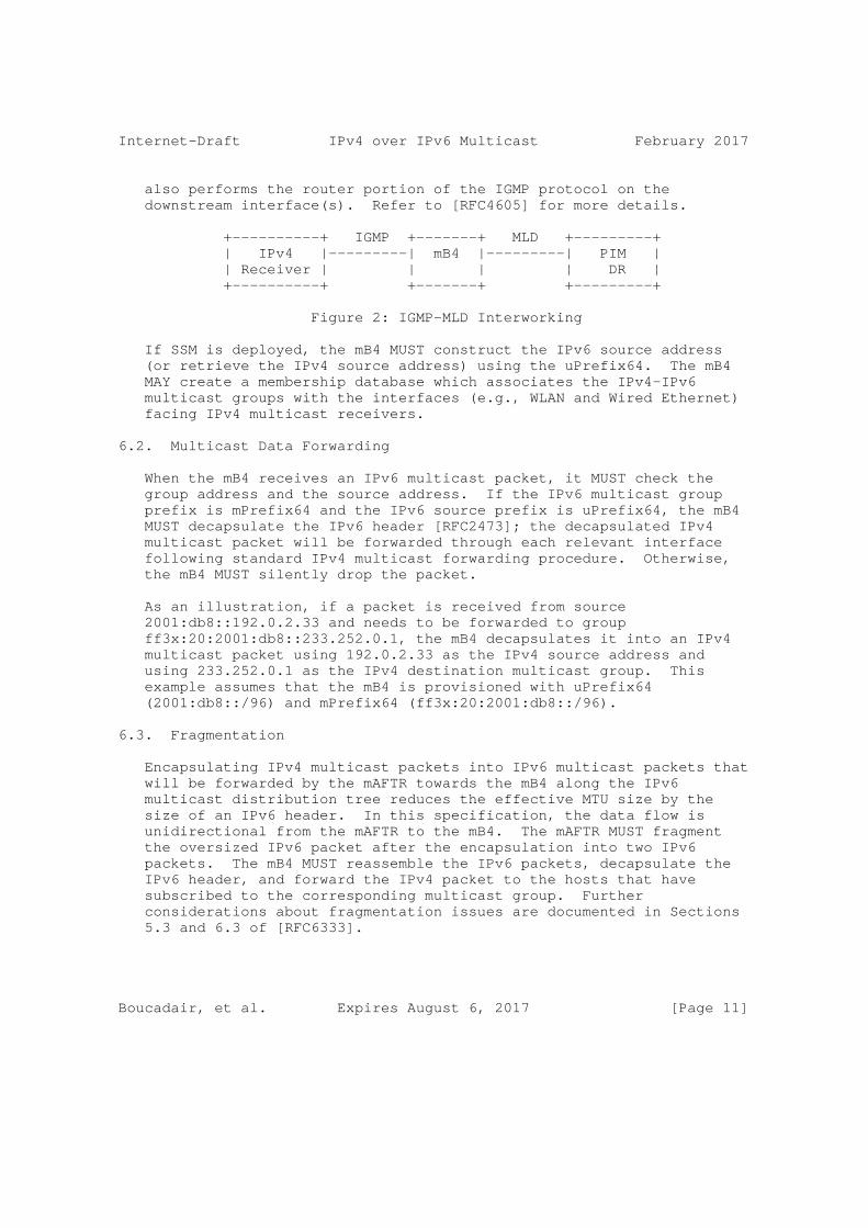
Internet-Draft IPv4 over IPv6 Multicast February 2017
also performs the router portion of the IGMP protocol on the downstream interface(s). Refer to [RFC4605] for more details.
+----------+ IGMP +-------+ MLD +---------+ | IPv4 |---------| mB4 |---------| PIM | | Receiver | | | | DR | +----------+ +-------+ +---------+
Figure 2: IGMP-MLD Interworking
If SSM is deployed, the mB4 MUST construct the IPv6 source address (or retrieve the IPv4 source address) using the uPrefix64. The mB4 MAY create a membership database which associates the IPv4-IPv6 multicast groups with the interfaces (e.g., WLAN and Wired Ethernet) facing IPv4 multicast receivers.
6.2. Multicast Data Forwarding
When the mB4 receives an IPv6 multicast packet, it MUST check the group address and the source address. If the IPv6 multicast group prefix is mPrefix64 and the IPv6 source prefix is uPrefix64, the mB4 MUST decapsulate the IPv6 header [RFC2473]; the decapsulated IPv4 multicast packet will be forwarded through each relevant interface following standard IPv4 multicast forwarding procedure. Otherwise, the mB4 MUST silently drop the packet.
As an illustration, if a packet is received from source 2001:db8::192.0.2.33 and needs to be forwarded to group ff3x:20:2001:db8::233.252.0.1, the mB4 decapsulates it into an IPv4 multicast packet using 192.0.2.33 as the IPv4 source address and using 233.252.0.1 as the IPv4 destination multicast group. This example assumes that the mB4 is provisioned with uPrefix64 (2001:db8::/96) and mPrefix64 (ff3x:20:2001:db8::/96).
6.3. Fragmentation
Encapsulating IPv4 multicast packets into IPv6 multicast packets that will be forwarded by the mAFTR towards the mB4 along the IPv6 multicast distribution tree reduces the effective MTU size by the size of an IPv6 header. In this specification, the data flow is unidirectional from the mAFTR to the mB4. The mAFTR MUST fragment the oversized IPv6 packet after the encapsulation into two IPv6 packets. The mB4 MUST reassemble the IPv6 packets, decapsulate the IPv6 header, and forward the IPv4 packet to the hosts that have subscribed to the corresponding multicast group. Further considerations about fragmentation issues are documented in Sections 5.3 and 6.3 of [RFC6333].
Boucadair, et al. Expires August 6, 2017 [Page 11]
Internet-Draft IPv4 over IPv6 Multicast February 2017
6.4. Host Built-in mB4 Function
If the mB4 function is implemented in the host which is directly connected to an IPv6-only network, the host MUST implement the behaviors specified in Sections 6.1, 6.2, and 6.3. The host MAY optimize the implementation to provide an Application Programming Interface (API) or kernel module to skip the IGMP-MLD Interworking Function. Optimization considerations are out of scope of this specification.
6.5. Preserve the Scope
When several mPrefix64s are available, if each enclosed IPv4-embedded IPv6 multicast prefix has a distinct scope, the mB4 MUST select the appropriate IPv4-embedded IPv6 multicast prefix whose scope matches the IPv4 multicast address used to synthesize an IPv4-embedded IPv6 multicast address (specific mappings are listed in Section 8 of [RFC2365]). Mapping is achieved such that the scope of the selected IPv6 multicast prefix does not exceed the original IPv4 multicast scope. If the mB4 is instructed to preserve the scope but no IPv6 multicast prefix that matches the IPv4 multicast scope is found, IPv6 multicast address mapping SHOULD fail.
The mB4 MAY be configured to not preserve the scope when enforcing the address translation algorithm.
Consider that an mB4 is configured with two mPrefix64s ff0e::db8:0:0/96 (Global scope) and ff08::db8:0:0/96 (Organization scope). If the mB4 receives an IGMP report from an IPv4 receiver to subscribe to 233.252.0.1, it checks which mPrefix64 to use in order to preserve the scope of the requested IPv4 multicast group. In this example, given that 233.252.0.1 is intended for global use, the mB4 creates the IPv6 multicast group (G6) address using ff0e::db8:0:0/96 and the original IPv4 multicast group address (233.252.0.1): ff0e::db8:233.252.0.1.
7. Multicast AFTR (mAFTR)
7.1. Routing Considerations
The mAFTR is responsible for interconnecting the IPv4 multicast distribution tree with the corresponding IPv6 multicast distribution tree. The mAFTR MUST use the uPrefix64 to build the IPv6 source addresses of the multicast group address derived from mPrefix64. In other words, the mAFTR MUST be the multicast source whose address is derived from uPrefix64.
Boucadair, et al. Expires August 6, 2017 [Page 12]
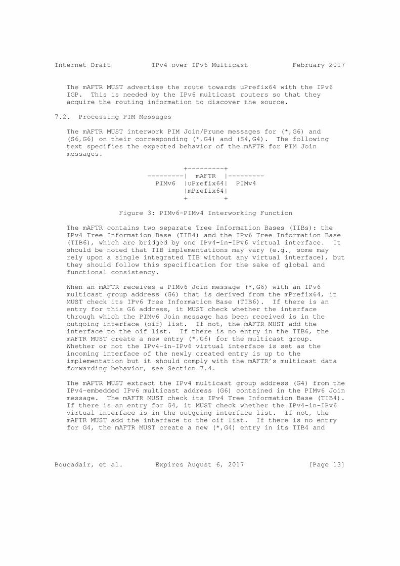
Internet-Draft IPv4 over IPv6 Multicast February 2017
The mAFTR MUST advertise the route towards uPrefix64 with the IPv6 IGP. This is needed by the IPv6 multicast routers so that they acquire the routing information to discover the source.
7.2. Processing PIM Messages
The mAFTR MUST interwork PIM Join/Prune messages for (*,G6) and (S6,G6) on their corresponding (*,G4) and (S4,G4). The following text specifies the expected behavior of the mAFTR for PIM Join messages.
+---------+ ---------| mAFTR |--------- PIMv6 |uPrefix64| PIMv4 |mPrefix64| +---------+
Figure 3: PIMv6-PIMv4 Interworking Function
The mAFTR contains two separate Tree Information Bases (TIBs): the IPv4 Tree Information Base (TIB4) and the IPv6 Tree Information Base (TIB6), which are bridged by one IPv4-in-IPv6 virtual interface. It should be noted that TIB implementations may vary (e.g., some may rely upon a single integrated TIB without any virtual interface), but they should follow this specification for the sake of global and functional consistency.
When an mAFTR receives a PIMv6 Join message (*,G6) with an IPv6 multicast group address (G6) that is derived from the mPrefix64, it MUST check its IPv6 Tree Information Base (TIB6). If there is an entry for this G6 address, it MUST check whether the interface through which the PIMv6 Join message has been received is in the outgoing interface (oif) list. If not, the mAFTR MUST add the interface to the oif list. If there is no entry in the TIB6, the mAFTR MUST create a new entry (*,G6) for the multicast group. Whether or not the IPv4-in-IPv6 virtual interface is set as the incoming interface of the newly created entry is up to the implementation but it should comply with the mAFTR’s multicast data forwarding behavior, see Section 7.4.
The mAFTR MUST extract the IPv4 multicast group address (G4) from the IPv4-embedded IPv6 multicast address (G6) contained in the PIMv6 Join message. The mAFTR MUST check its IPv4 Tree Information Base (TIB4). If there is an entry for G4, it MUST check whether the IPv4-in-IPv6 virtual interface is in the outgoing interface list. If not, the mAFTR MUST add the interface to the oif list. If there is no entry for G4, the mAFTR MUST create a new (*,G4) entry in its TIB4 and
Boucadair, et al. Expires August 6, 2017 [Page 13]
Internet-Draft IPv4 over IPv6 Multicast February 2017
initiate the procedure for building the shared tree in the IPv4 multicast network without any additional requirement.
If the mAFTR receives a source-specific Join message, the (S6,G6) is processed rather than (*,G6). The procedures of processing (S6,G6) and (*,G6) are almost the same. Differences have been detailed in [RFC7761].
7.3. Switching from Shared Tree to Shortest Path Tree
When the mAFTR receives the first IPv4 multicast packet, it may extract the source address (S4) from the packet and send an Explicit PIMv4 (S4,G4) Join message directly to S4. The mAFTR switches from the shared Rendezvous Point Tree (RPT) to the Shortest Path Tree (SPT) for G4.
For IPv6 multicast routers to switch to the SPT, there is no new requirement. IPv6 multicast routers may send an Explicit PIMv6 Join to the mAFTR once the first (S6,G6) multicast packet arrives from upstream multicast routers.
7.4. Multicast Data Forwarding
When the mAFTR receives an IPv4 multicast packet, it checks its TIB4 to find a matching entry and then forwards the packet to the interface(s) listed in the outgoing interface list. If the IPv4-in- IPv6 virtual interface also belongs to this list, the packet is encapsulated with the mPrefix64-derived and uPrefix64-derived IPv4-embedded IPv6 addresses to form an IPv6 multicast packet [RFC2473]. Then another lookup is made by the mAFTR to find a matching entry in the TIB6. Whether the RPF check for the second lookup is performed or not is up to the implementation and is out of the scope of this document. The IPv6 multicast packet is then forwarded along the IPv6 multicast distribution tree, based upon the outgoing interface list of the matching entry in the TIB6.
As an illustration, if a packet is received from source 192.0.2.33 and needs to be forwarded to group 233.252.0.1, the mAFTR encapsulates it into an IPv6 multicast packet using ff3x:20:2001:db8::233.252.0.1 as the IPv6 destination multicast group and using 2001:db8::192.0.2.33 as the IPv6 source address.
7.5. Scope
The Scope field of IPv4-in-IPv6 multicast addresses should be valued accordingly (e.g, to "E" for Global scope) in the deployment environment. This specification does not discuss the scope value that should be used.
Boucadair, et al. Expires August 6, 2017 [Page 14]
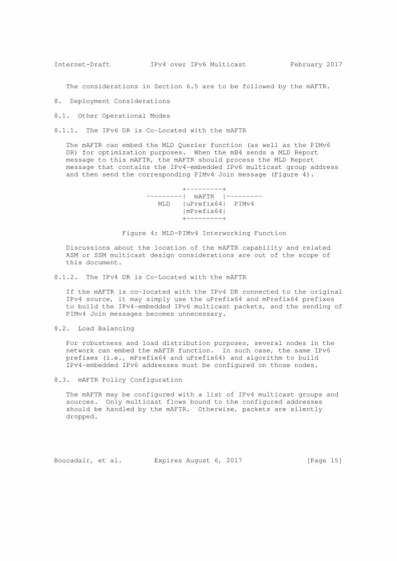
Internet-Draft IPv4 over IPv6 Multicast February 2017
The considerations in Section 6.5 are to be followed by the mAFTR.
8. Deployment Considerations
8.1. Other Operational Modes
8.1.1. The IPv6 DR is Co-Located with the mAFTR
The mAFTR can embed the MLD Querier function (as well as the PIMv6 DR) for optimization purposes. When the mB4 sends a MLD Report message to this mAFTR, the mAFTR should process the MLD Report message that contains the IPv4-embedded IPv6 multicast group address and then send the corresponding PIMv4 Join message (Figure 4).
+---------+ ---------| mAFTR |--------- MLD |uPrefix64| PIMv4 |mPrefix64| +---------+
Figure 4: MLD-PIMv4 Interworking Function
Discussions about the location of the mAFTR capability and related ASM or SSM multicast design considerations are out of the scope of this document.
8.1.2. The IPv4 DR is Co-Located with the mAFTR
If the mAFTR is co-located with the IPv4 DR connected to the original IPv4 source, it may simply use the uPrefix64 and mPrefix64 prefixes to build the IPv4-embedded IPv6 multicast packets, and the sending of PIMv4 Join messages becomes unnecessary.
8.2. Load Balancing
For robustness and load distribution purposes, several nodes in the network can embed the mAFTR function. In such case, the same IPv6 prefixes (i.e., mPrefix64 and uPrefix64) and algorithm to build IPv4-embedded IPv6 addresses must be configured on those nodes.
8.3. mAFTR Policy Configuration
The mAFTR may be configured with a list of IPv4 multicast groups and sources. Only multicast flows bound to the configured addresses should be handled by the mAFTR. Otherwise, packets are silently dropped.
Boucadair, et al. Expires August 6, 2017 [Page 15]

Internet-Draft IPv4 over IPv6 Multicast February 2017
8.4. Static vs. Dynamic PIM Triggering
To optimize the usage of network resources in current deployments, all multicast streams are conveyed in the core network while only the most popular ones are forwarded in the aggregation/access networks (static mode). Less popular streams are forwarded in the access network upon request (dynamic mode). Depending on the location of the mAFTR in the network, two modes can be envisaged: static and dynamic.
Static Mode: the mAFTR is configured to instantiate permanent (S6,G6) and (*,G6) entries in its TIB6 using a pre-configured (S4,G4) list.
Dynamic Mode: the instantiation or withdrawal of (S6,G6) or (*,G6) entries is triggered by the receipt of PIMv6 messages.
9. Security Considerations
Besides multicast scoping considerations (see Section 6.5 and Section 7.5), this document does not introduce any new security concern in addition to what is discussed in Section 5 of [RFC6052], Section 10 of [RFC3810] and Section 6 of [RFC7761].
Unlike solutions that map IPv4 multicast flows to IPv6 unicast flows, this document does not exacerbate Denial-of-Service (DoS) attacks.
An mB4 SHOULD be provided with appropriate configuration information to preserve the scope of a multicast message when mapping an IPv4 multicast address into an IPv4-embedded IPv6 multicast address and vice versa.
9.1. Firewall Configuration
The CPE that embeds the mB4 function SHOULD be configured to accept incoming MLD messages and traffic forwarded to multicast groups subscribed by receivers located in the customer premises.
10. Acknowledgments
The authors would like to thank Dan Wing for his guidance in the early discussions which initiated this work. We also thank Peng Sun, Jie Hu, Qiong Sun, Lizhong Jin, Alain Durand, Dean Cheng, Behcet Sarikaya, Tina Tsou, Rajiv Asati, Xiaohong Deng, and Stig Venaas for their valuable comments.
Many thanks to Ian Farrer for the review.
Boucadair, et al. Expires August 6, 2017 [Page 16]
Internet-Draft IPv4 over IPv6 Multicast February 2017
Thanks to Zhen Cao, Tim Chown, Francis Dupont, Jouni Korhonen, and Stig Venaas for the directorates review.
11. IANA Considerations
This document includes no request to IANA.
12. References
12.1. Normative References
[RFC2119] Bradner, S., "Key words for use in RFCs to Indicate Requirement Levels", BCP 14, RFC 2119, DOI 10.17487/RFC2119, March 1997, <http://www.rfc-editor.org/info/rfc2119>.
[RFC2365] Meyer, D., "Administratively Scoped IP Multicast", BCP 23, RFC 2365, DOI 10.17487/RFC2365, July 1998, <http://www.rfc-editor.org/info/rfc2365>.
[RFC2473] Conta, A. and S. Deering, "Generic Packet Tunneling in IPv6 Specification", RFC 2473, DOI 10.17487/RFC2473, December 1998, <http://www.rfc-editor.org/info/rfc2473>.
[RFC3376] Cain, B., Deering, S., Kouvelas, I., Fenner, B., and A. Thyagarajan, "Internet Group Management Protocol, Version 3", RFC 3376, DOI 10.17487/RFC3376, October 2002, <http://www.rfc-editor.org/info/rfc3376>.
[RFC3810] Vida, R., Ed. and L. Costa, Ed., "Multicast Listener Discovery Version 2 (MLDv2) for IPv6", RFC 3810, DOI 10.17487/RFC3810, June 2004, <http://www.rfc-editor.org/info/rfc3810>.
[RFC4605] Fenner, B., He, H., Haberman, B., and H. Sandick, "Internet Group Management Protocol (IGMP) / Multicast Listener Discovery (MLD)-Based Multicast Forwarding ("IGMP/MLD Proxying")", RFC 4605, DOI 10.17487/RFC4605, August 2006, <http://www.rfc-editor.org/info/rfc4605>.
[RFC4607] Holbrook, H. and B. Cain, "Source-Specific Multicast for IP", RFC 4607, DOI 10.17487/RFC4607, August 2006, <http://www.rfc-editor.org/info/rfc4607>.
[RFC6052] Bao, C., Huitema, C., Bagnulo, M., Boucadair, M., and X. Li, "IPv6 Addressing of IPv4/IPv6 Translators", RFC 6052, DOI 10.17487/RFC6052, October 2010, <http://www.rfc-editor.org/info/rfc6052>.
Boucadair, et al. Expires August 6, 2017 [Page 17]
Internet-Draft IPv4 over IPv6 Multicast February 2017
[RFC6333] Durand, A., Droms, R., Woodyatt, J., and Y. Lee, "Dual- Stack Lite Broadband Deployments Following IPv4 Exhaustion", RFC 6333, DOI 10.17487/RFC6333, August 2011, <http://www.rfc-editor.org/info/rfc6333>.
[RFC7608] Boucadair, M., Petrescu, A., and F. Baker, "IPv6 Prefix Length Recommendation for Forwarding", BCP 198, RFC 7608, DOI 10.17487/RFC7608, July 2015, <http://www.rfc-editor.org/info/rfc7608>.
[RFC7761] Fenner, B., Handley, M., Holbrook, H., Kouvelas, I., Parekh, R., Zhang, Z., and L. Zheng, "Protocol Independent Multicast - Sparse Mode (PIM-SM): Protocol Specification (Revised)", STD 83, RFC 7761, DOI 10.17487/RFC7761, March 2016, <http://www.rfc-editor.org/info/rfc7761>.
12.2. Informative References
[I-D.ietf-softwire-multicast-prefix-option] Boucadair, M., Qin, J., Tsou, T., and X. Deng, "DHCPv6 Option for IPv4-Embedded Multicast and Unicast IPv6 Prefixes", draft-ietf-softwire-multicast-prefix-option-13 (work in progress), February 2017.
[RFC2236] Fenner, W., "Internet Group Management Protocol, Version 2", RFC 2236, DOI 10.17487/RFC2236, November 1997, <http://www.rfc-editor.org/info/rfc2236>.
[RFC3956] Savola, P. and B. Haberman, "Embedding the Rendezvous Point (RP) Address in an IPv6 Multicast Address", RFC 3956, DOI 10.17487/RFC3956, November 2004, <http://www.rfc-editor.org/info/rfc3956>.
[RFC6676] Venaas, S., Parekh, R., Van de Velde, G., Chown, T., and M. Eubanks, "Multicast Addresses for Documentation", RFC 6676, DOI 10.17487/RFC6676, August 2012, <http://www.rfc-editor.org/info/rfc6676>.
[RFC6890] Cotton, M., Vegoda, L., Bonica, R., Ed., and B. Haberman, "Special-Purpose IP Address Registries", BCP 153, RFC 6890, DOI 10.17487/RFC6890, April 2013, <http://www.rfc-editor.org/info/rfc6890>.
[RFC7371] Boucadair, M. and S. Venaas, "Updates to the IPv6 Multicast Addressing Architecture", RFC 7371, DOI 10.17487/RFC7371, September 2014, <http://www.rfc-editor.org/info/rfc7371>.
Boucadair, et al. Expires August 6, 2017 [Page 18]

Internet-Draft IPv4 over IPv6 Multicast February 2017
[RFC7596] Cui, Y., Sun, Q., Boucadair, M., Tsou, T., Lee, Y., and I. Farrer, "Lightweight 4over6: An Extension to the Dual- Stack Lite Architecture", RFC 7596, DOI 10.17487/RFC7596, July 2015, <http://www.rfc-editor.org/info/rfc7596>.
[RFC7597] Troan, O., Ed., Dec, W., Li, X., Bao, C., Matsushima, S., Murakami, T., and T. Taylor, Ed., "Mapping of Address and Port with Encapsulation (MAP-E)", RFC 7597, DOI 10.17487/RFC7597, July 2015, <http://www.rfc-editor.org/info/rfc7597>.
Appendix A. Use Case: IPTV
IPTV generally includes two categories of service offerings:
o Video on Demand (VoD) that unicast video content to receivers.
o Multicast live TV broadcast services.
Two types of provider are involved in the delivery of this service:
o Content Providers, who usually own the contents that is multicast to receivers. Content providers may contractually define an agreement with network providers to deliver contents to receivers.
o Network Providers, who provide network connectivity services (e.g., network providers are responsible for carrying multicast flows from head-ends to receivers).
Note that some contract agreements prevent a network provider from altering the content as sent by the content provider for various reasons. Depending on these contract agreements, multicast streams should be delivered unaltered to the requesting users.
Many current IPTV contents are likely to remain IPv4-formatted and out of control of the network providers. Additionally, there are numerous legacy receivers (e.g., IPv4-only Set Top Boxes (STB)) that can’t be upgraded or be easily replaced to support IPv6. As a consequence, IPv4 service continuity must be guaranteed during the transition period, including the delivery of multicast services such as Live TV Broadcasting to users.
Appendix B. Older Versions of Group Membership Management Protocols
Given the multiple versions of group membership management protocols, mismatch issues may arise at the mB4 (refer to Section 6.1).
Boucadair, et al. Expires August 6, 2017 [Page 19]

Internet-Draft IPv4 over IPv6 Multicast February 2017
If IGMPv2 operates on the IPv4 receivers while MLDv2 operates on the MLD Querier, or if IGMPv3 operates on the IPv4 receivers while MLDv1 operates on the MLD Querier, the version mismatch issue will be encountered. To solve this problem, the mB4 should perform the router portion of IGMP which is similar to the corresponding MLD version (IGMPv2 as of MLDv1, or IGMPv3 as of MLDv2) operating in the IPv6 domain. Then, the protocol interaction approach specified in Section 7 of [RFC3376] can be applied to exchange signaling messages with the IPv4 receivers on which the different version of IGMP is operating.
Note that the support of IPv4 SSM requires MLDv2 to be enabled in the IPv6 network.
Authors’ Addresses
Mohamed Boucadair Orange Rennes 35000 France
Email: [email protected]
Chao Qin Cisco Shanghai P.R. China
Email: [email protected]
Christian Jacquenet Orange Rennes 35000 France
Email: [email protected]
Yiu L. Lee Comcast United States of America
Email: [email protected] URI: http://www.comcast.com
Boucadair, et al. Expires August 6, 2017 [Page 20]

Internet-Draft IPv4 over IPv6 Multicast February 2017
Qian Wang China Telecom P.R. China
Phone: +86 10 58502462 Email: [email protected]
Boucadair, et al. Expires August 6, 2017 [Page 21]
Network Working Group Y. CuiInternet-Draft J. WuIntended status: Informational P. WuExpires: January 30, 2014 Tsinghua University O. Vautrin Juniper Networks Y. Lee Comcast July 29, 2013
Public IPv4 over IPv6 Access Network draft-ietf-softwire-public-4over6-10
Abstract
This document describes a mechanism called Public 4over6 which is designed to provide IPv4 Internet connectivity over an IPv6 access network using global IPv4 addresses. Public 4over6 was developed in the IETF and is in use in some existing deployments, but is not recommended for new deployments. Future deployments of similar scenarios should use Lightweight 4over6. Public 4over6 follows the Hub and Spoke softwire model, and uses an IPv4-in-IPv6 tunnel to forward IPv4 packets over IPv6 access network. The bi-directionality of the IPv4 communication is achieved by explicitly allocating global non-shared IPv4 addresses to end users, as well as maintaining IPv4- IPv6 address binding on the border relay. Public 4over6 aims to provide uninterrupted IPv4 services to users, like Internet Content Providers, etc., while an operator makes the transition of the access network to an IPv6-only access network.
Status of This Memo
This Internet-Draft is submitted in full conformance with the provisions of BCP 78 and BCP 79.
Internet-Drafts are working documents of the Internet Engineering Task Force (IETF). Note that other groups may also distribute working documents as Internet-Drafts. The list of current Internet- Drafts is at http://datatracker.ietf.org/drafts/current/.
Internet-Drafts are draft documents valid for a maximum of six months and may be updated, replaced, or obsoleted by other documents at any time. It is inappropriate to use Internet-Drafts as reference material or to cite them other than as "work in progress."
This Internet-Draft will expire on January 30, 2014.
Cui, et al. Expires January 30, 2014 [Page 1]
Internet-Draft Public 4over6 July 2013
Copyright Notice
Copyright (c) 2013 IETF Trust and the persons identified as the document authors. All rights reserved.
This document is subject to BCP 78 and the IETF Trust’s Legal Provisions Relating to IETF Documents (http://trustee.ietf.org/license-info) in effect on the date of publication of this document. Please review these documents carefully, as they describe your rights and restrictions with respect to this document. Code Components extracted from this document must include Simplified BSD License text as described in Section 4.e of the Trust Legal Provisions and are provided without warranty as described in the Simplified BSD License.
Table of Contents
1. Introduction . . . . . . . . . . . . . . . . . . . . . . . . . 3 2. Terminology . . . . . . . . . . . . . . . . . . . . . . . . . 4 3. Scenario and Use Cases . . . . . . . . . . . . . . . . . . . . 5 4. Public 4over6 Address Provisioning . . . . . . . . . . . . . . 6 4.1. Basic Provisioning Steps . . . . . . . . . . . . . . . . . 6 4.2. Public IPv4 Address Allocation . . . . . . . . . . . . . . 7 5. 4over6 CE Behavior . . . . . . . . . . . . . . . . . . . . . . 7 6. 4over6 BR Behavior . . . . . . . . . . . . . . . . . . . . . . 8 7. Fragmentation and reassembly . . . . . . . . . . . . . . . . . 9 8. DNS . . . . . . . . . . . . . . . . . . . . . . . . . . . . . 9 9. IANA Considerations . . . . . . . . . . . . . . . . . . . . . 10 10. Security Considerations . . . . . . . . . . . . . . . . . . . 10 11. Change Log from the -09 Version (RFC Editors please remove this part) . . . . . . . . . . . . . . . . . . . . . . . . . . 10 12. Contributors . . . . . . . . . . . . . . . . . . . . . . . . . 11 13. References . . . . . . . . . . . . . . . . . . . . . . . . . . 12 13.1. Normative References . . . . . . . . . . . . . . . . . . . 12 13.2. Informative References . . . . . . . . . . . . . . . . . . 12
Cui, et al. Expires January 30, 2014 [Page 2]

Internet-Draft Public 4over6 July 2013
1. Introduction
When operators make the transition of their access networks to IPv6- only, they must continue to provide IPv4 services to their users to access IPv4 contents. IPv4 connectivity is required when communicating with the IPv4-only Internet. This document describes a mechanism called Public 4over6 for providing IPv4 connectivity over a native IPv6-only access network. This memo focuses on interactions between Public 4over6 elements, as well as the deployment architecture.
Public 4over6 is in active deployment in some environments, particularly in China Next Generation Internet (CNGI) and China Education and Research Network 2 (CERNET2), but is not recommended for new deployments. Documenting this approach is to benefit users and operators of existing deployments, as well as readers of other IPv4-over-IPv6 documents.
In addition to Public 4over6 and its deployment architecture described in this memo, the IETF is currently working on a more generic solution called Lightweight 4over6 [I-D.ietf-softwire-lw4over6] that is classified as the binding approach in the Unified IPv4-in-IPv6 Softwire CPE [I-D.ietf-softwire-unified-cpe]. Lightweight 4over6 covers both sharing and non-sharing global IPv4 address in Hub-and-Spoke model. Future deployments should use [I-D.ietf-softwire-lw4over6].
Public 4over6 utilizes the IPv4-in-IPv6 tunnel technique defined in [RFC2473], which enables IPv4 datagrams to traverse through native IPv6 network. IPv4 nodes connect to the Tunnel Entry-Point Node and Tunnel Exit-Point Node to communicate over the IPv6-only network. Therefore, the Internet Service Providers (ISPs) can run an IPv6-only infrastructure instead of a fully dual-stack network, as well as avoiding the need to deploy scarce IPv4 address resources throughout the network.
This mechanism focuses on providing full end-to-end transparency to the user-side. Therefore, global IPv4 addresses are expected to be provisioned to end users and carrier-side address translation can be avoided. Furthermore, global non-shared IPv4 address is preferred to shared IPv4 address so that user-side address translation is not necessary either. It is important in particular to users which require to run their applications on IP protocol different from TCP and UDP (e.g., IPSec, L2TP) or on certain well-known TCP/UDP ports (e.g., http, smtp). For many ISPs that are actually capable of provisioning non-shared unique IPv4 addresses, the mechanism provide a pure, suitable solution.
Cui, et al. Expires January 30, 2014 [Page 3]

Internet-Draft Public 4over6 July 2013
Another focus of this mechanism is deployment and operational flexibility. Public 4over6 allows IPv4 and IPv6 address architecture to be totally independent of each other: the end user’s IPv4 address is not embedded in its IPv6 address. Therefore, the IPv4 address planning has no implication to the IPv6 address planning. Operators can manage the IPv4 address resources in a flat, centralized manner. This requires the tunnel concentrator [RFC4925] to maintain the binding of IPv4 address and IPv6 address, i.e. maintaining per- subscriber binding state.
The mechanism follows the Hub and Spoke softwire model [RFC4925], and uses IPv4-in-IPv6 tunneling as the basic data plane method. Global non-shared IPv4 addresses are allocated from the ISP to end hosts or CPEs over IPv6 network. Simultaneously, the binding between the allocated IPv4 address and the end user’s IPv6 address is maintained on the tunnel concentrator for encapsulation usage.
2. Terminology
Public 4over6: Public 4over6 is a per-subscriber stateful, IPv4-in- IPv6 tunnel mechanism. Public 4over6 supports bidirectional communication between the global IPv4 Internet and IPv4 hosts or customer networks via an IPv6 access network, by leveraging IPv4-in- IPv6 tunneling [RFC2473] and global IPv4 address allocation over IPv6. The term ’public’ means the allocated IPv4 address is globally routable.
Full IPv4 address: An IPv4 address that is not shared by multiple users. The user with this IPv4 address has full access of all the available ports including the Well-Known ports.
4over6 Customer Edge (CE): A device functioning as a Customer Edge equipment in Public 4over6 environment. A 4over6 CE can be either a dual-stack capable host, or a dual-stack CPE device, both of which have a tunnel interface to support IPv4-in-IPv6 encapsulation. In the former case, the host supports both IPv4 and IPv6 stacks but its uplink is IPv6 only. In the latter case, the CPE has an IPv6 interface connecting to the ISP network, and an IPv4 or dual-stack interface connecting to the customer network; hosts in the customer network can be IPv4-only or dual-stack.
4over6 Border Relay (BR): A router deployed in the edge of the operator’s IPv6 access network which supports IPv4-in-IPv6 tunnel termination. A 4over6 BR is a dual-stack router which connects to both the IPv6 access network and the IPv4 Internet. The 4over6 BR can also work as a DHCPv4-over-IPv6 [I-D.ietf-dhc-dhcpv4-over-ipv6] server/relay for assigning and distributing global IPv4 addresses to 4over6 CEs.
Cui, et al. Expires January 30, 2014 [Page 4]
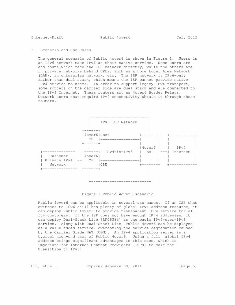
Internet-Draft Public 4over6 July 2013
3. Scenario and Use Cases
The general scenario of Public 4over6 is shown in Figure 1. Users in an IPv6 network take IPv6 as their native service. Some users are end hosts which face the ISP network directly, while the others are in private networks behind CPEs, such as a home Local Area Network (LAN), an enterprise network, etc. The ISP network is IPv6-only rather than dual-stack, which means the ISP cannot provide native IPv4 service to users. In order to support legacy IPv4 transport, some routers on the carrier side are dual-stack and are connected to the IPv4 Internet. These routers act as 4over6 Border Relays. Network users that require IPv4 connectivity obtain it through these routers.
+-------------------------+ | IPv6 ISP Network | | | +------+ | |4over6|Host +-------+ +-----------+ | CE |=================| | | | +------+ | | | | | |4over6 | | IPv4 | +--------------+ +------+ IPv4-in-IPv6 | BR |---| Internet | | Customer | |4over6| | | | | | Private IPv4 |--| CE |=================| | | | | Network | | |CPE +-------+ +-----------+ +--------------+ +------+ | | | | | +-------------------------+
Figure 1 Public 4over6 scenario
Public 4over6 can be applicable in several use cases. If an ISP that switches to IPv6 still has plenty of global IPv4 address resource, it can deploy Public 4over6 to provide transparent IPv4 service for all its customers. If the ISP does not have enough IPv4 addresses, it can deploy Dual-Stack Lite [RFC6333] as the basic IPv4-over-IPv6 service. Along with Dual-Stack Lite, Public 4over6 can be deployed as a value-added service, overcoming the service degradation caused by the Carrier Grade NAT (CGN). An IPv4 application server is a typical high-end user of Public 4over6. Using a full, global IPv4 address brings significant advantages in this case, which is important for Internet Content Providers (ICPs) to make the transition to IPv6:
Cui, et al. Expires January 30, 2014 [Page 5]
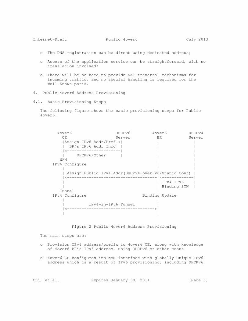
Internet-Draft Public 4over6 July 2013
o The DNS registration can be direct using dedicated address;
o Access of the application service can be straightforward, with no translation involved;
o There will be no need to provide NAT traversal mechanisms for incoming traffic, and no special handling is required for the Well-Known ports.
4. Public 4over6 Address Provisioning
4.1. Basic Provisioning Steps
The following figure shows the basic provisioning steps for Public 4over6.
4over6 DHCPv6 4over6 DHCPv4 CE Server BR Server |Assign IPv6 Addr/Pref +| | | | BR’s IPv6 Addr Info | | | |<----------------------| | | | DHCPv6/Other | | | WAN | | IPv6 Configure | | | | | | Assign Public IPv4 Addr(DHCPv4-over-v6/Static Conf) | |<-------------------------------------|<-------------| | | IPv4-IPv6 | | | Binding SYN | Tunnel | IPv4 Configure Binding Update | | | IPv4-in-IPv6 Tunnel | |<------------------------------------>| | |
Figure 2 Public 4over6 Address Provisioning
The main steps are:
o Provision IPv6 address/prefix to 4over6 CE, along with knowledge of 4over6 BR’s IPv6 address, using DHCPv6 or other means.
o 4over6 CE configures its WAN interface with globally unique IPv6 address which is a result of IPv6 provisioning, including DHCPv6,
Cui, et al. Expires January 30, 2014 [Page 6]

Internet-Draft Public 4over6 July 2013
SLAAC or manual configuration.
o Provision IPv4 address to 4over6 CE, by DHCPv4 over IPv6 or static configuration.
o 4over6 BR obtains the IPv4 and IPv6 addresses of the 4over6 CE using information provided by the DHCPv4 sever.
o 4over6 CE configures its tunnel interface, as a result of IPv4 provisioning.
o 4over6 BR updates the IPv4-IPv6 address binding table, as a result of address binding information acquired from the DHCPv4 server.
4.2. Public IPv4 Address Allocation
Usually each CE is provisioned with one global IPv4 address. However it is possible that a CE would require an IPv4 prefix. The key problem here is the mechanism for IPv4 address provisioning over IPv6 network.
There are two possibilities: DHCPv4 over IPv6, and static configuration. Public 4over6 supports both these methods. DHCPv4 over IPv6 allows DHCPv4 message to be transported in IPv6 rather than IPv4; therefore, the DHCPv4 process can be performed over an IPv6 network, between the BR and the relevant CE. [I-D.ietf-dhc-dhcpv4-over-ipv6] describes the DHCP protocol extensions needed to support this operation. For static configuration, 4over6 users and the ISP operators negotiate beforehand to authorize the IPv4 address(es). Then the tunnel interface and the address binding are configured by the user and the ISP respectively.
While regular users would probably opt for DHCPv4 over IPv6, the static configuration is particularly applicable in two cases: for application servers, which require a stable IPv4 address, and for enterprise networks, which usually require an IPv4 prefix rather than one single address (Note that DHCPv4 does not support prefix allocation).
5. 4over6 CE Behavior
A CE is provisioned with IPv6 before Public 4over6 process. It also learns the BR’s IPv6 address beforehand. This IPv6 address can be configured using a variety of methods, ranging from an out-of-band mechanism, manual configuration, or via a DHCPv6 option. In order to guarantee interoperability, the CE element implements the AFTR-Name DHCPv6 option defined in [RFC6334].
Cui, et al. Expires January 30, 2014 [Page 7]

Internet-Draft Public 4over6 July 2013
A CE supports DHCPv4 over IPv6 [I-D.ietf-dhc-dhcpv4-over-ipv6], to dynamically acquire an IPv4 address over IPv6 and assign it to the IPv4-in-IPv6 tunnel interface. The CE regards the BR as its DHCPv4- over-IPv6 server/relay, which is used to obtain its global IPv4 address allocation; its IPv6 address is learned by the CE as described above.
A CE also supports static configuration of the tunnel interface. In the case of prefix provisioning, the tunnel interface is assigned with the Well-Known IPv4 Address defined in section 5.7 of [RFC6333], rather than using an address from the prefix. If the CE has multiple IPv6 addresses on its WAN interface, it uses the same IPv6 address for DHCPv4-over-IPv6/negotiation of manual configuration, and for data plane encapsulation.
A CE performs IPv4-in-IPv6 encapsulation and decapsulation on the tunnel interface. When sending out an IPv4 packet, it performs the encapsulation, using the IPv6 address of the 4over6 BR as the IPv6 destination address, and its own IPv6 address as the IPv6 source address. The decapsulation on the 4over6 CE is simple. When receiving an IPv4-in-IPv6 packet, the CE just removes the IPv6 header, and either hands it to a local upper layer or forwards it to the customer network according to the IPv4 destination address.
A CE runs a regular IPv4 Network Address and Port Translation (NAPT) for its customer network when it is provisioned with one single IPv4 address. In that case, the assigned IPv4 address of the tunnel interface would be the external IPv4 address of the NAPT. Then the CE performs IPv4 private-to-public translation before encapsulation of IPv4 packets from the customer network, and IPv4 public-to-private translation after decapsulation of IPv4-in-IPv6 packets.
IPv4 NAPT is not necessary when the CE is provisioned with an IPv4 prefix. In this case, the detailed customer network planning is out of scope.
The 4over6 CE supports backward compatibility with DS-Lite. A CE can employ the Well-Known IPv4 Address for Basic Bridging BroadBand (B4) element [RFC6333] and switch to Dual-Stack Lite for IPv4 communications, if it can’t get a global IPv4 address from the DHCPv4 server (for instance, if the DHCPv4-over-IPv6 process fails or the DHCPv4 server refuses to allocate a global IPv4 address to it, etc.).
6. 4over6 BR Behavior
The 4over6 BR maintains the bindings between the CE IPv6 address and CE IPv4 address (prefixes). The bindings are used to provide the correct encapsulation destination address for inbound IPv4 packets,
Cui, et al. Expires January 30, 2014 [Page 8]

Internet-Draft Public 4over6 July 2013
as well as validating the IPv6-IPv4 source of the outbound IPv4-in- IPv6 packets.
The BR acquires the binding information through the IPv4 address provisioning process. For static configuration, the operator manually configures the BR using the binding information obtained through negotiation with the customer. As for DHCPv4-over-IPv6, there are multiple possibilities which are deployment-specific:
o The BR can be co-located with the DHCPv4-over-IPv6 server. Then the synchronization happens within the BR. It installs a binding when sending out an ACK for a DHCP lease, and deletes it when the lease expires or a DHCP RELEASE message is received.
o The BR can play the role of IPv6-Transport Relay Agent (TRA) as described in [I-D.ietf-dhc-dhcpv4-over-ipv6], and snoop for the DHCPv4 ACK and RELEASE messages, as well as keep a timer for each binding according to the DHCP lease time.
On the IPv6 side, the BR decapsulates IPv4-in-IPv6 packets coming from 4over6 CEs. It removes the IPv6 header of every IPv4-in-IPv6 packet and forwards it to the IPv4 Internet. Before the decapsulation, the BR checks the inner IPv4 source address against the outer IPv6 source address, by matching such a binding entry in the binding table. If no binding is found, the BR silently drops the packet. On the IPv4 side, the BR encapsulates the IPv4 packets destined to 4over6 CEs. When performing the IPv4-in-IPv6 encapsulation, the BR uses its own IPv6 address as the IPv6 source address, uses the IPv4 destination address in the packet to look up IPv6 destination address in the address binding table. After the encapsulation, the BR sends the IPv6 packet on its IPv6 interface to reach a CE.
The BR supports hairpinning of traffic between two CEs, by performing de-capsulation and re-encapsulation of packets.
In the case that the BR manages the global IPv4 address pool, it advertises the routing information of IPv4 addresses to the IPv4 Internet.
7. Fragmentation and reassembly
The same considerations as described in section 5.3 and section 6.3 of [RFC6333] are taken into account for the CE and the BR respectively.
8. DNS
Cui, et al. Expires January 30, 2014 [Page 9]
Internet-Draft Public 4over6 July 2013
The procedure described in Section 5.5 and Section 6.4 of [RFC6333] is followed by the CE and the BR respectively.
9. IANA Considerations
This document has no IANA actions.
10. Security Considerations
The 4over6 BR implements methods to limit service only to registered customers. On the control plane, the BR allocates IPv4 addresses only to registered customers. The BR can filter on the IPv6 source addresses of incoming DHCP requests and only respond to the ones that are conveyed by registered IPv6 source addresses. But this doesn’t work in situations where multi-homing is present. In the networks that Public 4over6 is deployed, multi-homing is disallowed to avoid this issue.
Alternatively, the BR can filter out the unregistered CEs’ requests during the DHCP process. For data packets, the BR does the ingress filtering by looking up the IPv4-IPv6 address binding table for the related matches as described in Section 6.
In the case of fallback to DS-Lite, security considerations in Section 11 of [RFC6333] is followed.
11. Change Log from the -09 Version (RFC Editors please remove this part)
1. Update the Abstract and the Introduction to specify the purpose of the doc.
2. Add the definition of ’Full IPv4 Address’ in the Terminology.
3. Update the definition of ’4over6 Border Relay’ in the Terminology.
4. Replace ’public IPv4 address’ with ’global IPv4 address’ to consistent with RFC1918.
5. Polish the text in the Introduction to make it more RFC compliant.
6. Update the Security Considerations to make it more accurate. And add the reference to RFC6333 in the case of fallback to DS-Lite.
7. Correct some nits.
Cui, et al. Expires January 30, 2014 [Page 10]
Internet-Draft Public 4over6 July 2013
8. Update the references.
12. Contributors
The following are those who have made contributions to the effort:
Huiling Zhao China Telecom Room 502, No.118, Xizhimennei Street Beijing 100035 P.R.China
Phone: +86-10-58552002 Email: [email protected]
Chongfeng Xie China Telecom Room 708, No.118, Xizhimennei Street Beijing 100035 P.R.China
Phone: +86-10-58552116 Email: [email protected]
Qiong Sun China Telecom Room 708, No.118, Xizhimennei Street Beijing 100035 P.R.China
Phone: +86-10-58552936 Email: [email protected]
Qi Sun Tsinghua University Beijing 100084 P.R.China
Phone: +86-10-62785822 Email: [email protected]
Cui, et al. Expires January 30, 2014 [Page 11]
Internet-Draft Public 4over6 July 2013
Chris Metz Cisco Systems 3700 Cisco Way San Jose, CA 95134 USA
Email: [email protected]
13. References
13.1. Normative References
[RFC2473] Conta, A. and S. Deering, "Generic Packet Tunneling in IPv6 Specification", RFC 2473, December 1998.
[RFC4925] Li, X., Dawkins, S., Ward, D., and A. Durand, "Softwire Problem Statement", RFC 4925, July 2007.
[RFC6333] Durand, A., Droms, R., Woodyatt, J., and Y. Lee, "Dual-Stack Lite Broadband Deployments Following IPv4 Exhaustion", RFC 6333, August 2011.
[RFC6334] Hankins, D. and T. Mrugalski, "Dynamic Host Configuration Protocol for IPv6 (DHCPv6) Option for Dual- Stack Lite", RFC 6334, August 2011.
13.2. Informative References
[I-D.ietf-dhc-dhcpv4-over-ipv6] Cui, Y., Wu, P., Wu, J., and T. Lemon, "DHCPv4 over IPv6 Transport", draft-ietf-dhc-dhcpv4-over-ipv6-06 (work in progress), March 2013.
[I-D.ietf-softwire-lw4over6] Cui, Y., Sun, Q., Boucadair, M., Tsou, T., Lee, Y., and I. Farrer, "Lightweight 4over6: An Extension to the DS-Lite Architecture", draft-ietf-softwire-lw4over6-01 (work in progress), July 2013.
[I-D.ietf-softwire-unified-cpe] Boucadair, M., Farrer, I., Perreault, S., and S. Sivakumar, "Unified IPv4-in-IPv6 Softwire CPE",
Cui, et al. Expires January 30, 2014 [Page 12]
Internet-Draft Public 4over6 July 2013
draft-ietf-softwire-unified-cpe-01 (work in progress), May 2013.
Authors’ Addresses
Yong Cui Tsinghua University Department of Computer Science, Tsinghua University Beijing 100084 P.R.China
Phone: +86-10-6260-3059 EMail: [email protected]
Jianping Wu Tsinghua University Department of Computer Science, Tsinghua University Beijing 100084 P.R.China
Phone: +86-10-6278-5983 EMail: [email protected]
Peng Wu Tsinghua University Department of Computer Science, Tsinghua University Beijing 100084 P.R.China
Phone: +86-10-6278-5822 EMail: [email protected]
Olivier Vautrin Juniper Networks 1194 N Mathilda Avenue Sunnyvale, CA 94089 USA
EMail: [email protected]
Yiu L. Lee Comcast One Comcast Center Philadelphia, PA 19103
Cui, et al. Expires January 30, 2014 [Page 13]

Internet-Draft Public 4over6 July 2013
USA
EMail: [email protected]
Cui, et al. Expires January 30, 2014 [Page 14]

Softwire WG T. MrugalskiInternet-Draft ISCIntended status: Standards Track O. TroanExpires: January 5, 2013 Cisco C. Bao Tsinghua University W. Dec Cisco July 4, 2012
DHCPv6 Options for Mapping of Address and Port draft-mdt-softwire-map-dhcp-option-03
Abstract
This document specifies DHCPv6 options for the provisioning of Mapping of Address and Port (MAP) Customer Edge (CE) devices, based on the MAP paramaters defined in [I-D.ietf-softwire-map].
Status of this Memo
This Internet-Draft is submitted in full conformance with the provisions of BCP 78 and BCP 79.
Internet-Drafts are working documents of the Internet Engineering Task Force (IETF). Note that other groups may also distribute working documents as Internet-Drafts. The list of current Internet- Drafts is at http://datatracker.ietf.org/drafts/current/.
Internet-Drafts are draft documents valid for a maximum of six months and may be updated, replaced, or obsoleted by other documents at any time. It is inappropriate to use Internet-Drafts as reference material or to cite them other than as "work in progress."
This Internet-Draft will expire on January 5, 2013.
Copyright Notice
Copyright (c) 2012 IETF Trust and the persons identified as the document authors. All rights reserved.
This document is subject to BCP 78 and the IETF Trust’s Legal Provisions Relating to IETF Documents (http://trustee.ietf.org/license-info) in effect on the date of publication of this document. Please review these documents carefully, as they describe your rights and restrictions with respect
Mrugalski, et al. Expires January 5, 2013 [Page 1]

Internet-Draft MAP DHCPv6 Options July 2012
to this document. Code Components extracted from this document must include Simplified BSD License text as described in Section 4.e of the Trust Legal Provisions and are provided without warranty as described in the Simplified BSD License.
Table of Contents
1. Introduction . . . . . . . . . . . . . . . . . . . . . . . . . 3 2. Conventions . . . . . . . . . . . . . . . . . . . . . . . . . 3 3. MAP Information . . . . . . . . . . . . . . . . . . . . . . . 4 4. DHCPv6 MAP Options Format . . . . . . . . . . . . . . . . . . 4 4.1. MAP Option . . . . . . . . . . . . . . . . . . . . . . . . 5 4.2. MAP Rule Option . . . . . . . . . . . . . . . . . . . . . 6 4.3. MAP DMR Option . . . . . . . . . . . . . . . . . . . . . . 8 4.4. MAP Port Parameters Option . . . . . . . . . . . . . . . . 8 5. MAP Options Examples . . . . . . . . . . . . . . . . . . . . . 9 5.1. BMR Option Example . . . . . . . . . . . . . . . . . . . . 9 5.2. FMR Option Example . . . . . . . . . . . . . . . . . . . . 10 5.3. DMR Option Example . . . . . . . . . . . . . . . . . . . . 10 6. DHCPv6 Server Behavior . . . . . . . . . . . . . . . . . . . . 10 7. DHCPv6 Client Behavior . . . . . . . . . . . . . . . . . . . . 10 8. Usage of flags and paramaters . . . . . . . . . . . . . . . . 11 9. Deployment considerations . . . . . . . . . . . . . . . . . . 12 10. IANA Considerations . . . . . . . . . . . . . . . . . . . . . 12 11. Security Considerations . . . . . . . . . . . . . . . . . . . 13 12. Acknowledgements . . . . . . . . . . . . . . . . . . . . . . . 13 13. References . . . . . . . . . . . . . . . . . . . . . . . . . . 13 13.1. Normative References . . . . . . . . . . . . . . . . . . . 13 13.2. Informative References . . . . . . . . . . . . . . . . . . 14 Authors’ Addresses . . . . . . . . . . . . . . . . . . . . . . . . 15
Mrugalski, et al. Expires January 5, 2013 [Page 2]

Internet-Draft MAP DHCPv6 Options July 2012
1. Introduction
Mapping of Address and Port (MAP) defined in [I-D.ietf-softwire-map] is a mechanism for providing IPv4 connectivity service to end users over a service provider’s IPv6 network, allowing for shared or dedicated IPv4 addressing. It consists of a set of one or more MAP Border Relay (BR) routers, responsible for stateless forwarding, and one or more MAP Customer Edge (CE) routers, that collectively form a MAP Domain when configured with common MAP rule-sets. In a residential broadband deployment the CE is sometimes referred to as a Residential Gateway (RG) or Customer Premises Equipment (CPE).
A typical MAP CE will serve its end-user with one WAN side interface connected to an operator domain providing a MAP service. To function in the MAP domain, the CE requires to be provisioned with the appropiate MAP service paramaters for that domain. Particularly in larger networks it is not feasible to configure such parameters manually, which forms the requirement for a dynamic MAP provisioning mechanism that is defined in this document based on the existing DHCPv6 [RFC3315] protocol. The configuration of the MAP BR is outside of scope of this document.
This document specifies the DHCPv6 options that allow MAP CE provisioning, based on the definitions of parameters provided in [I-D.ietf-softwire-map], and is applicable to both MAP-E and MAP-T transport variants. The definition of DHCPv6 options for MAP CE provisioning does not preclude the definition of other dynamic methods for configuring MAP devices, or supplementing such configuration, nor is the use of DHCPv6 provisioning mandatory for MAP operation.
Since specification of MAP architecture is still expected to evolve, DHCPv6 options may have to evolve too to fit the revised MAP specification.
Described proposal is not a dynamic port allocation mechanism.
Readers interested in deployment considerations are encouraged to read [I-D.mdt-softwire-map-deployment].
2. Conventions
The key words "MUST", "MUST NOT", "REQUIRED", "SHALL", "SHALL NOT", "SHOULD", "SHOULD NOT", "RECOMMENDED", "MAY", and "OPTIONAL" in this document are to be interpreted as described in RFC 2119 [RFC2119].
Mrugalski, et al. Expires January 5, 2013 [Page 3]
Internet-Draft MAP DHCPv6 Options July 2012
3. MAP Information
The following presents the information parameters that are used to configure a MAP CE:
o A Default Mapping Rule (DMR). This rule governs the default forwarding/mapping behaviour of the MAP CE, ie it informs the CE of the BR router’s address or prefix that is typically used as a default. The DMR is a mandatory parameter for a MAP CE. o A Basic Mapping Rule (BMR). This rule governs the MAP configuration of the CE, including that of completing the CE’s MAP IPv6 address, as well as deriving the CEs IPv4 parameters. Key parameters of a BMR include: i) The IPv4 Prefix - Used to derive the CE’s IPv4 address; ii) The Embedded Address bit length - Used to derive how many, if any, of the CE’s IPv6 address is mapped to the IPv4 address. iii) The IPv6 prefix - used to determine the CE’s IPv6 MAP domain prefix that is to form the base for the CE’s MAP address. The BMR is an optional rule for a MAP CE. o A Forward Mapping Rule (FMR). This rule governs the MAP CE-CE forwarding behaviour for IPv4 destinations covered by the rule. The FMR is effectively a special type of an BMR, given that it shares exactly the same configuration parameters, except that these parameters are only applied for setting up forwarding. Its presence enables a given CE to communicate directly in "mesh mode" with other CEs. The FMR is an optional rule, and the absence of such a rule indicates that the CE is to simply use its default mapping rule for all destinations. o Transport mode; encapsulation (MAP-E) or translation (MAP-T) modes to be used for the MAP CE Domain. o Additional parameters. The MAP specification allows great flexibility in the level of automation a CE uses to derive its IPv4 address and port-sharing (PSID), ranging from full derivation of these parameters from the CE’s IPv6 prefix, to full parametrization of MAP configuration independent of the CE’s IPv6 prefix. Optional parameters such as the PSID allow this flexibility.
4. DHCPv6 MAP Options Format
The DHCPv6 protocol is used for MAP CE provisioning following regular DHCPv6 notions, with the MAP CE assuming a DHCPv6 client role, and the MAP parameters provided by the DHCPv6 server following server side policies. The format and usage of the MAP options is defined in the following sections.
Discussion: As the exact parameters required to configure MAP rules and MAP in general are expected to change, this section is expected
Mrugalski, et al. Expires January 5, 2013 [Page 4]

Internet-Draft MAP DHCPv6 Options July 2012
to be updated and follow change in the [I-D.ietf-softwire-map].
Discussion: It should be noted that initial concept of 4rd/MAP provisioning was presented in DHC working group meeting. It used one complex option to convey all required parameters. Strong suggestion from DHC WG was to use several simpler options. Options (possibly nested) are preferred over conditional option formatting. See DHCP option guidelines document [I-D.ietf-dhc-option-guidelines]).
Server that supports MAP configuration and is configured to provision requesting CE MUST include exactly one OPTION_MAP option in a REPLY message for each MAP domain. It is envisaged that in typical network, there will be only one MAP domain deployed.
4.1. MAP Option
This MAP Option specifies the container option used to group all rules for a specified MAP domain.
0 1 2 3 0 1 2 3 4 5 6 7 8 9 0 1 2 3 4 5 6 7 8 9 0 1 2 3 4 5 6 7 8 9 0 1 +-+-+-+-+-+-+-+-+-+-+-+-+-+-+-+-+-+-+-+-+-+-+-+-+-+-+-+-+-+-+-+-+ | OPTION_MAP | option-length | +-+-+-+-+-+-+-+-+-+-+-+-+-+-+-+-+-+-+-+-+-+-+-+-+-+-+-+-+-+-+-+-+ | flags | . +-+-+-+-+-+-+-+-+ sub-options (variable length) . . . +---------------------------------------------------------------+
Figure 1: MAP Option
o option-code: OPTION_MAP (TBD1) o option-length: 1 + Length of the sub-options o flags: This 8-bits long conveys the MAP Option Flags. The meaning of specific bits is explained in Figure 2. o sub-options: options associatied to this MAP option.
The sub options field encapsulates those options that are specific to this MAP Option. For example, all of the MAP Rule Options are in the sub-options field. A DHCP message may contain multiple MAP Options.
The Format of the MAP Option Flags field is:
Mrugalski, et al. Expires January 5, 2013 [Page 5]
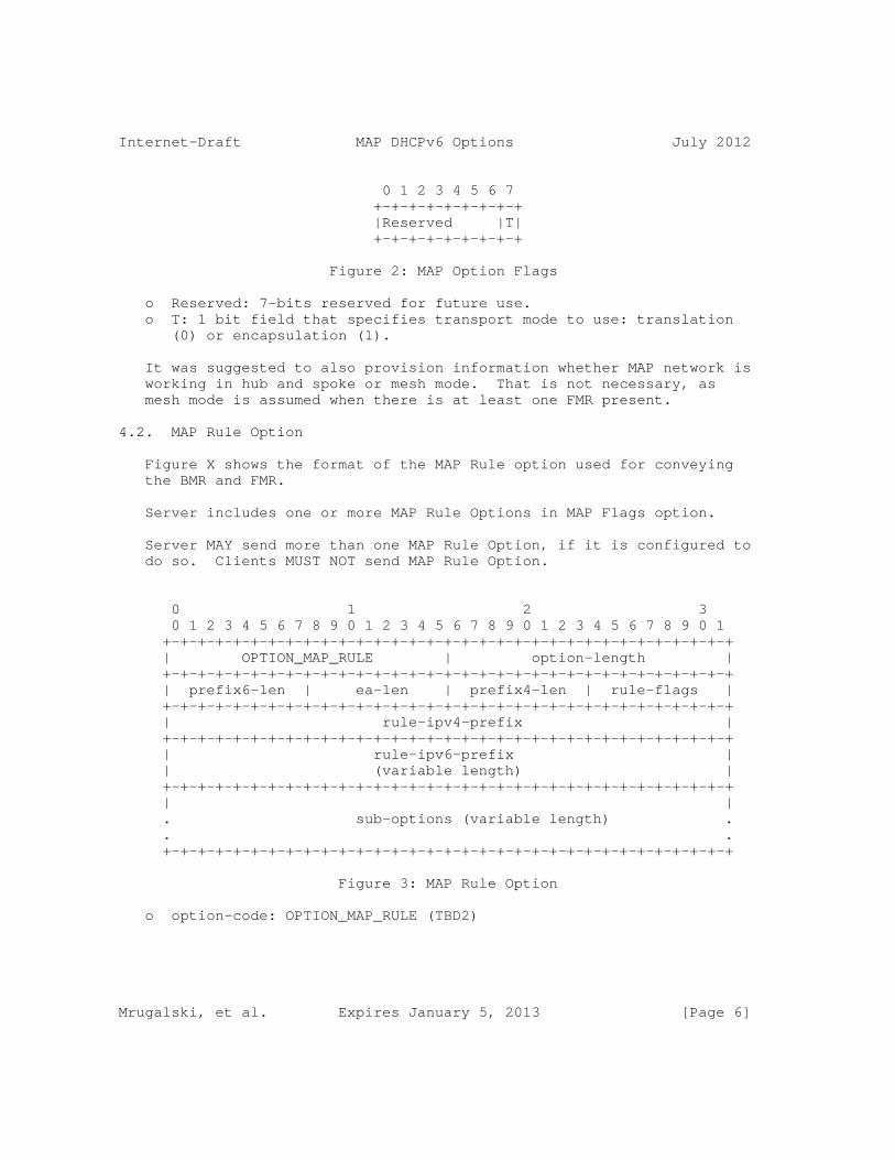
Internet-Draft MAP DHCPv6 Options July 2012
0 1 2 3 4 5 6 7 +-+-+-+-+-+-+-+-+ |Reserved |T| +-+-+-+-+-+-+-+-+
Figure 2: MAP Option Flags
o Reserved: 7-bits reserved for future use. o T: 1 bit field that specifies transport mode to use: translation (0) or encapsulation (1).
It was suggested to also provision information whether MAP network is working in hub and spoke or mesh mode. That is not necessary, as mesh mode is assumed when there is at least one FMR present.
4.2. MAP Rule Option
Figure X shows the format of the MAP Rule option used for conveying the BMR and FMR.
Server includes one or more MAP Rule Options in MAP Flags option.
Server MAY send more than one MAP Rule Option, if it is configured to do so. Clients MUST NOT send MAP Rule Option.
0 1 2 3 0 1 2 3 4 5 6 7 8 9 0 1 2 3 4 5 6 7 8 9 0 1 2 3 4 5 6 7 8 9 0 1 +-+-+-+-+-+-+-+-+-+-+-+-+-+-+-+-+-+-+-+-+-+-+-+-+-+-+-+-+-+-+-+-+ | OPTION_MAP_RULE | option-length | +-+-+-+-+-+-+-+-+-+-+-+-+-+-+-+-+-+-+-+-+-+-+-+-+-+-+-+-+-+-+-+-+ | prefix6-len | ea-len | prefix4-len | rule-flags | +-+-+-+-+-+-+-+-+-+-+-+-+-+-+-+-+-+-+-+-+-+-+-+-+-+-+-+-+-+-+-+-+ | rule-ipv4-prefix | +-+-+-+-+-+-+-+-+-+-+-+-+-+-+-+-+-+-+-+-+-+-+-+-+-+-+-+-+-+-+-+-+ | rule-ipv6-prefix | | (variable length) | +-+-+-+-+-+-+-+-+-+-+-+-+-+-+-+-+-+-+-+-+-+-+-+-+-+-+-+-+-+-+-+-+ | | . sub-options (variable length) . . . +-+-+-+-+-+-+-+-+-+-+-+-+-+-+-+-+-+-+-+-+-+-+-+-+-+-+-+-+-+-+-+-+
Figure 3: MAP Rule Option
o option-code: OPTION_MAP_RULE (TBD2)
Mrugalski, et al. Expires January 5, 2013 [Page 6]

Internet-Draft MAP DHCPv6 Options July 2012
o option-length: length of the option, excluding option-code and option-length fields, including length of all sub-options. o prefix6-len: 8 bits long field expressing the bit mask length of the IPv6 prefix specified in the rule-ipv6-prefix field. o ea-len: 8-bits long field that specifies the Embedded-Address (EA) bit length. Values allowed range from 0 to 48. o prefix4-len: 8 bits long field expressing the bit mask length of the IPv4 prefix specified in the rule-ipv4-prefix field. o rule-flags: 8 bit long field carrying flags applicable to the rule. The meaning of specific bits is explained in Figure 4. o rule-ipv4-prefix: a 32 bit fixed length field that specifies the IPv4 prefix for the MAP rule. o rule-ipv6-prefix: a variable length field that specifies the IPv6 domain prefix for the MAP rule. The field is padded with zeros up to the nearest octet boundary when prefix6-len is not divisible by 8. o rule sub-options: a variable field that may contain zero or more options that specify additional parameters for this MAP BMR/FMR rule. Currently there is only one option defined that may appear in rule sub-options field, eg the OPTION_MAP_PORTPARAMS, defined in section Section 4.4.
The value of the EA-len and prefix4-len SHOULD be equal to or greater than 32.
The Format of the MAP Rule Flags field is:
0 1 2 3 4 5 6 7 +-+-+-+-+-+-+-+-+ |Reserved |F| +-+-+-+-+-+-+-+-+
Figure 4: MAP Rule Flags
o Reserved: 7-bits reserved for future use as flags. o F-Flag: 1 bit field that specifies whether the rule is to be used for forwarding (FMR). 0x0 = This rule is NOT used as an FMR. 0x1 = This rule is also an FMR. o Note: BMR rules can be also FMR rules by setting the F flag. BMR rules are determined by a match of the Rule-IPv6-prefix against the CPE’s prefix(es).
It is expected that in a typical MAP deployment scenarios, there will be a single DMR and a single BMR, which could also be designated as an FMR using the F-Flag.
Mrugalski, et al. Expires January 5, 2013 [Page 7]
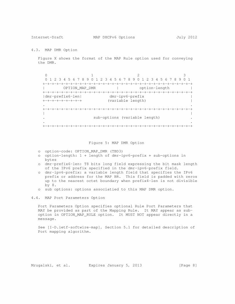
Internet-Draft MAP DHCPv6 Options July 2012
4.3. MAP DMR Option
Figure X shows the format of the MAP Rule option used for conveying the DMR.
0 1 2 3 0 1 2 3 4 5 6 7 8 9 0 1 2 3 4 5 6 7 8 9 0 1 2 3 4 5 6 7 8 9 0 1 +-+-+-+-+-+-+-+-+-+-+-+-+-+-+-+-+-+-+-+-+-+-+-+-+-+-+-+-+-+-+-+-+ | OPTION_MAP_DMR | option-length | +-+-+-+-+-+-+-+-+-+-+-+-+-+-+-+-+-+-+-+-+-+-+-+-+-+-+-+-+-+-+-+-+ |dmr-prefix6-len| dmr-ipv6-prefix | +-+-+-+-+-+-+-+-+ (variable length) | . . +-+-+-+-+-+-+-+-+-+-+-+-+-+-+-+-+-+-+-+-+-+-+-+-+-+-+-+-+-+-+-+-+ | | . sub-options (variable length) . . . +-+-+-+-+-+-+-+-+-+-+-+-+-+-+-+-+-+-+-+-+-+-+-+-+-+-+-+-+-+-+-+-+
Figure 5: MAP DMR Option
o option-code: OPTION_MAP_DMR (TBD3) o option-length: 1 + length of dmr-ipv6-prefix + sub-options in bytes o dmr-prefix6-len: T8 bits long field expressing the bit mask length of the IPv6 prefix specified in the dmr-ipv6-prefix field. o dmr-ipv6-prefix: a variable length field that specifies the IPv6 prefix or address for the MAP BR. This field is padded with zeros up to the nearest octet boundary when prefix4-len is not divisible by 8. o sub options: options associatied to this MAP DMR option.
4.4. MAP Port Parameters Option
Port Parameters Option specifies optional Rule Port Parameters that MAY be provided as part of the Mapping Rule. It MAY appear as sub- option in OPTION_MAP_RULE option. It MUST NOT appear directly in a message.
See [I-D.ietf-softwire-map], Section 5.1 for detailed description of Port mapping algorithm.
Mrugalski, et al. Expires January 5, 2013 [Page 8]
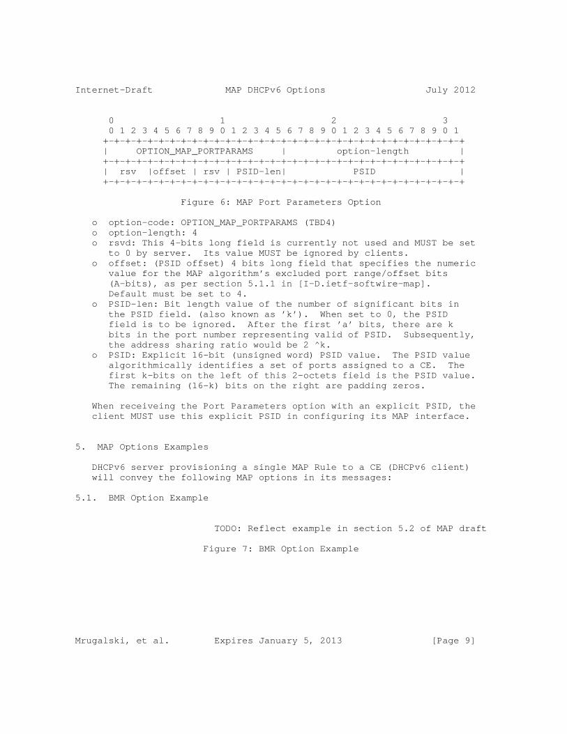
Internet-Draft MAP DHCPv6 Options July 2012
0 1 2 3 0 1 2 3 4 5 6 7 8 9 0 1 2 3 4 5 6 7 8 9 0 1 2 3 4 5 6 7 8 9 0 1 +-+-+-+-+-+-+-+-+-+-+-+-+-+-+-+-+-+-+-+-+-+-+-+-+-+-+-+-+-+-+-+-+ | OPTION_MAP_PORTPARAMS | option-length | +-+-+-+-+-+-+-+-+-+-+-+-+-+-+-+-+-+-+-+-+-+-+-+-+-+-+-+-+-+-+-+-+ | rsv |offset | rsv | PSID-len| PSID | +-+-+-+-+-+-+-+-+-+-+-+-+-+-+-+-+-+-+-+-+-+-+-+-+-+-+-+-+-+-+-+-+
Figure 6: MAP Port Parameters Option
o option-code: OPTION_MAP_PORTPARAMS (TBD4) o option-length: 4 o rsvd: This 4-bits long field is currently not used and MUST be set to 0 by server. Its value MUST be ignored by clients. o offset: (PSID offset) 4 bits long field that specifies the numeric value for the MAP algorithm’s excluded port range/offset bits (A-bits), as per section 5.1.1 in [I-D.ietf-softwire-map]. Default must be set to 4. o PSID-len: Bit length value of the number of significant bits in the PSID field. (also known as ’k’). When set to 0, the PSID field is to be ignored. After the first ’a’ bits, there are k bits in the port number representing valid of PSID. Subsequently, the address sharing ratio would be 2 ^k. o PSID: Explicit 16-bit (unsigned word) PSID value. The PSID value algorithmically identifies a set of ports assigned to a CE. The first k-bits on the left of this 2-octets field is the PSID value. The remaining (16-k) bits on the right are padding zeros.
When receiveing the Port Parameters option with an explicit PSID, the client MUST use this explicit PSID in configuring its MAP interface.
5. MAP Options Examples
DHCPv6 server provisioning a single MAP Rule to a CE (DHCPv6 client) will convey the following MAP options in its messages:
5.1. BMR Option Example
TODO: Reflect example in section 5.2 of MAP draft
Figure 7: BMR Option Example
Mrugalski, et al. Expires January 5, 2013 [Page 9]
Internet-Draft MAP DHCPv6 Options July 2012
5.2. FMR Option Example
TODO: Reflect example in section 5.3 of MAP draft
Figure 8: FMR Option Example
5.3. DMR Option Example
TODO: Reflect example in section 5.4 of MAP draft
Figure 9: DMR Option Examples
6. DHCPv6 Server Behavior
RFC 3315 Section 17.2.2 [RFC3315] describes how a DHCPv6 client and server negotiate configuration values using the ORO. As a convenience to the reader, we mention here that a server will by default not reply with a MAP Rule Option if the client has not explicitly enumerated it on its Option Request Option.
A Server following this specification MUST allow the configuration of one or more MAP Rule Options, and SHOULD send such options grouped under a single MAP_OPTION.
Server MUST transmit all configured instances of the Mapping Rule Options with all sub-options, if client requested it using OPTION_MAP_RULE in its Option Request Option (ORO). Server MUST transmit MAP Flags Option if client requested OPTION_MAP in its ORO.
The server MUST be capable of following per client assignment rules when assigning MAP options.
7. DHCPv6 Client Behavior
A MAP CE acting as DHCPv6 client will request MAP configuration to be assigned by the DHCPv6 server located in the ISP network. A client supporting MAP functionality SHOULD request OPTION_MAP, OPTION_MAP_RULE and OPTION_MAP_DMR options in its ORO in SOLICIT, REQUEST, RENEW, REBIND and INFORMATION-REQUEST messages.
When processing received MAP options the following behaviour is expected:
Mrugalski, et al. Expires January 5, 2013 [Page 10]

Internet-Draft MAP DHCPv6 Options July 2012
o A client MUST support processing multiple received OPTION_MAP_RULE options in a OPTION_MAP option o A client receiving an unsupported MAP option, or an unrecognized parameter value SHOULD discard the entire OPTION_MAP. o Only one OPTION_MAP_DMR is allowed per OPTION_MAP option.
The client MUST be capable of applying the received MAP option parameters for the configuration of the local MAP instance.
Note that system implementing MAP CE functionality may have multiple network interfaces, and these interfaces may be configured differently; some may be connected to networks that call for MAP, and some may be connected to networks that are using normal dual stack or other means. The MAP CE system should approach this specification on an interface-by-interface basis. For example, if the CE system is attached to multiple networks that provide the MAP Mapping Rule Option, then the CE system MUST configure a MAP connection (i.e. a translation or encapsulation) for each interface separately as each MAP provides IPv4 connectivity for each distinct interface. Means to bind a MAP configuration to a given interface in a multiple interfaces device are out of scope of this document.
8. Usage of flags and paramaters
The defined MAP options contain a number of flags and parameters that are intended to provide full flexibility in the configuration of a MAP CE. Some usage examples are:
o A MAP CE receiving an OPTION_MAP option with the T flag set to 1 will assume a MAP-E (encapsulation) mode of operation for the domain and all associated rules. Conversely, when the received option has the T flag set to 0, the CE will assume a MAP-T (stateless NAT46 translation) mode of operation. o The presence of a OPTION_MAP_RULE option, along with IPv4 prefix parameters, indicates to the MAP CE that NAPT44 mode of operation is expected, following the address mapping rules defined in [I-D.ietf-softwire-map]. Conversely, the absence of an OPTION_MAP_RULE option indicates that NAT44 mode is not required, and that the MAP CE is to plainly encapsulate (MAP-E mode) or statelessly translate using NAT64 (MAP-T mode) any IPv4 traffic sent following the DMR. o The MAP domain ipv6-prefix in the BMR should correspond to a service prefix assigned to the CPE by the operator, with the latter being assigned using regular IPv6 means, eg DHCP PD or SLAAC. This parameter allows the CPE to select the prefix for MAP operation.
Mrugalski, et al. Expires January 5, 2013 [Page 11]
Internet-Draft MAP DHCPv6 Options July 2012
o The EA_LEN parameter, along with the length of the IPv4 prefix in the BMR option, allows the MAP CE to determine whether address sharing is in effect, and what is the address sharing ratio. Eg: A prefix4-len of 16 bits, and EA-len of 18 combines to a 32 bit IPv4 address with a sharing ratio of 4. o The use of the F(orward) flag in the BMR allows a CE to apply a received BMR as an FMR, thereby enabling mesh-mode for the domain covered by the BMR rule. o In the absence of a BMR, the presence of the mandatory DMR indicates to the CPE the address or prefix of a BR, and makes the MAP CE fully compatible with DS-Lite and stateful or stateless NAT64 core nodes. Eg a MAP CE configured in MAP-E mode, with just a DMR and a BR IPv6 address equivalent to that of the AFTR, effectively acts as a DS-Lite B4 element. For more discussion about MAP deployment considerations, see [I-D.mdt-softwire-map-deployment].
9. Deployment considerations
Usage of PSID Option should be avoided if possible and PSID embedded in the delegated prefix should be used instead. This allows MAP deployment to not introduce any additional state in DHCP server. PSID Option must be assigned on a per CE basis, thus requiring more complicated server configuration.
In a typical environment, there will be only one MAP domain, so server will provide only a single instance of MAP option that acts a container for MAP Rule Options and other options that are specific to that MAP domain.
In case of multiple provisioning domains, as defined in [I-D.ietf-homenet-arch], one server may be required to provide information about more than one MAP domain. In such case, server will provide two or more instances of MAP Options, each with its own set of sub-option that define MAP rules for each specific MAP domain. Details of mulitple provisioning domains are discussed in Section 4.1 of [I-D.mdt-softwire-map-deployment].
10. IANA Considerations
IANA is kindly requested to allocate DHCPv6 option codes for TBD1 for OPTION_MAP, TBD2 for OPTION_MAP_RULE, TBD3 for OPTION_MAP_DMR, and TBD4 for OPTION_MAP_Port. All values should be added to the DHCPv6 option code space defined in Section 24.3 of [RFC3315].
Mrugalski, et al. Expires January 5, 2013 [Page 12]
Internet-Draft MAP DHCPv6 Options July 2012
11. Security Considerations
Implementation of this document does not present any new security issues, but as with all DHCPv6-derived configuration state, it is completely possible that the configuration is being delivered by a third party (Man In The Middle). As such, there is no basis to trust that the access over the MAP can be trusted, and it should not therefore bypass any security mechanisms such as IP firewalls.
Readers concerned with security of MAP provisioning over DHCPv6 are encouraged to familiarize with [I-D.ietf-dhc-secure-dhcpv6].
Section XX of [I-D.ietf-softwire-map] discusses security issues of the MAP mechanism.
Section 23 of [RFC3315] discusses DHCPv6-related security issues.
12. Acknowledgements
This document was created as a product of a MAP design team. Following people were members of that team: Congxiao Bao, Mohamed Boucadair, Gang Chen, Maoke Chen, Wojciech Dec, Xiaohong Deng, Jouni Korhonen, Xing Li, Satoru Matsushima, Tomasz Mrugalski, Tetsuya Murakami, Jacni Qin, Necj Scoberne, Qiong Sun, Tina Tsou, Dan Wing, Leaf Yeh and Jan Zorz.
Former MAP design team members are: Remi Despres.
13. References
13.1. Normative References
[I-D.ietf-softwire-map] Troan, O., Dec, W., Li, X., Bao, C., Zhai, Y., Matsushima, S., and T. Murakami, "Mapping of Address and Port (MAP)", draft-ietf-softwire-map-01 (work in progress), June 2012.
[RFC2119] Bradner, S., "Key words for use in RFCs to Indicate Requirement Levels", BCP 14, RFC 2119, March 1997.
[RFC3315] Droms, R., Bound, J., Volz, B., Lemon, T., Perkins, C., and M. Carney, "Dynamic Host Configuration Protocol for IPv6 (DHCPv6)", RFC 3315, July 2003.
[RFC3633] Troan, O. and R. Droms, "IPv6 Prefix Options for Dynamic Host Configuration Protocol (DHCP) version 6", RFC 3633,
Mrugalski, et al. Expires January 5, 2013 [Page 13]

Internet-Draft MAP DHCPv6 Options July 2012
December 2003.
13.2. Informative References
[I-D.boucadair-dhcpv6-shared-address-option] Boucadair, M., Levis, P., Grimault, J., Savolainen, T., and G. Bajko, "Dynamic Host Configuration Protocol (DHCPv6) Options for Shared IP Addresses Solutions", draft-boucadair-dhcpv6-shared-address-option-01 (work in progress), December 2009.
[I-D.ietf-dhc-option-guidelines] Hankins, D., Mrugalski, T., Siodelski, M., Jiang, S., and S. Krishnan, "Guidelines for Creating New DHCPv6 Options", draft-ietf-dhc-option-guidelines-08 (work in progress), June 2012.
[I-D.ietf-dhc-secure-dhcpv6] Jiang, S. and S. Shen, "Secure DHCPv6 Using CGAs", draft-ietf-dhc-secure-dhcpv6-06 (work in progress), March 2012.
[I-D.ietf-homenet-arch] Chown, T., Arkko, J., Brandt, A., Troan, O., and J. Weil, "Home Networking Architecture for IPv6", draft-ietf-homenet-arch-03 (work in progress), June 2012.
[I-D.ietf-tsvwg-iana-ports] Cotton, M., Eggert, L., Touch, J., Westerlund, M., and S. Cheshire, "Internet Assigned Numbers Authority (IANA) Procedures for the Management of the Service Name and Transport Protocol Port Number Registry", draft-ietf-tsvwg-iana-ports-10 (work in progress), February 2011.
[I-D.mdt-softwire-map-deployment] Sun, Q., Chen, M., Chen, G., Sun, C., Tsou, T., and S. Perreault, "Mapping of Address and Port (MAP) - Deployment Considerations", draft-mdt-softwire-map-deployment-02 (work in progress), June 2012.
[I-D.mrugalski-dhc-dhcpv6-4rd] Mrugalski, T., "DHCPv6 Options for IPv4 Residual Deployment (4rd)", draft-mrugalski-dhc-dhcpv6-4rd-00 (work in progress), July 2011.
[I-D.murakami-softwire-4rd] Murakami, T., Troan, O., and S. Matsushima, "IPv4 Residual
Mrugalski, et al. Expires January 5, 2013 [Page 14]
Internet-Draft MAP DHCPv6 Options July 2012
Deployment on IPv6 infrastructure - protocol specification", draft-murakami-softwire-4rd-01 (work in progress), September 2011.
[RFC5226] Narten, T. and H. Alvestrand, "Guidelines for Writing an IANA Considerations Section in RFCs", BCP 26, RFC 5226, May 2008.
Authors’ Addresses
Tomasz Mrugalski Internet Systems Consortium, Inc. 950 Charter Street Redwood City, CA 94063 USA
Phone: +1 650 423 1345 Email: [email protected] URI: http://www.isc.org/
Ole Troan Cisco Systems, Inc. Telemarksvingen 20 Oslo N-0655 Norway
Email: [email protected] URI: http://cisco.com
Congxiao Bao CERNET Center/Tsinghua University Room 225, Main Building, Tsinghua University Beijing 100084 CN
Phone: +86 10-62785983 Email: [email protected]
Mrugalski, et al. Expires January 5, 2013 [Page 15]

Internet-Draft MAP DHCPv6 Options July 2012
Wojciech Dec Cisco Systems, Inc. The Netherlands
Phone: Fax: Email: [email protected] URI:
Mrugalski, et al. Expires January 5, 2013 [Page 16]

Internet Engineering Task Force T. Murakami, Ed.Internet-Draft IP InfusionIntended status: Standards Track O. TroanExpires: July 30, 2012 cisco S. Matsushima SoftBank January 27, 2012
MAP Encapsulation (MAP-E) - specification draft-mdt-softwire-map-encapsulation-00
Abstract
This document specifies the "Mapping of Address and Port" (MAP) encapsulation based solution (MAP-E) with an automatic tunneling mechanism for providing IPv4 connectivity service to end users over a service provider’s IPv6 network.
Status of this Memo
This Internet-Draft is submitted in full conformance with the provisions of BCP 78 and BCP 79.
Internet-Drafts are working documents of the Internet Engineering Task Force (IETF). Note that other groups may also distribute working documents as Internet-Drafts. The list of current Internet- Drafts is at http://datatracker.ietf.org/drafts/current/.
Internet-Drafts are draft documents valid for a maximum of six months and may be updated, replaced, or obsoleted by other documents at any time. It is inappropriate to use Internet-Drafts as reference material or to cite them other than as "work in progress."
This Internet-Draft will expire on July 30, 2012.
Copyright Notice
Copyright (c) 2012 IETF Trust and the persons identified as the document authors. All rights reserved.
This document is subject to BCP 78 and the IETF Trust’s Legal Provisions Relating to IETF Documents (http://trustee.ietf.org/license-info) in effect on the date of publication of this document. Please review these documents carefully, as they describe your rights and restrictions with respect to this document. Code Components extracted from this document must include Simplified BSD License text as described in Section 4.e of
Murakami, et al. Expires July 30, 2012 [Page 1]
Internet-Draft MAP Encapsulation (MAP-E) January 2012
the Trust Legal Provisions and are provided without warranty as described in the Simplified BSD License.
Table of Contents
1. Introduction . . . . . . . . . . . . . . . . . . . . . . . . . 3 2. Requirements Language . . . . . . . . . . . . . . . . . . . . 4 3. Terminology . . . . . . . . . . . . . . . . . . . . . . . . . 4 4. MAP-E Configuration . . . . . . . . . . . . . . . . . . . . . 5 5. MAP-E Node Behavior . . . . . . . . . . . . . . . . . . . . . 5 5.1. Provisioning of MAP-E BR . . . . . . . . . . . . . . . . . 5 5.2. Packet Forwarding Behavior on MAP-E BR . . . . . . . . . . 6 5.3. Provisioning of MAP-E CE . . . . . . . . . . . . . . . . . 7 5.4. Packet Forwarding Behavior on MAP-E CE . . . . . . . . . . 8 6. Deriving IPv6 address from IPv4 . . . . . . . . . . . . . . . 9 6.1. Deriving IPv6 address from IPv4 Address and Port Number at the BR . . . . . . . . . . . . . . . . . . . . . 9 6.2. Deriving IPv6 address from IPv4 Address and Port Number at the CE . . . . . . . . . . . . . . . . . . . . . 10 7. Encapsulation and Fragmentation Considerations . . . . . . . . 10 8. Packet Forwarding Considerations . . . . . . . . . . . . . . . 11 8.1. Mesh model . . . . . . . . . . . . . . . . . . . . . . . . 12 8.2. Hub & Spoke model . . . . . . . . . . . . . . . . . . . . 12 9. NAT Considerations . . . . . . . . . . . . . . . . . . . . . . 12 10. ICMP Considerations . . . . . . . . . . . . . . . . . . . . . 12 11. Security Considerations . . . . . . . . . . . . . . . . . . . 13 12. IANA Consideration . . . . . . . . . . . . . . . . . . . . . . 14 13. Acknowledgements . . . . . . . . . . . . . . . . . . . . . . . 14 14. References . . . . . . . . . . . . . . . . . . . . . . . . . . 14 14.1. Normative References . . . . . . . . . . . . . . . . . . . 14 14.2. Informative References . . . . . . . . . . . . . . . . . . 15 Authors’ Addresses . . . . . . . . . . . . . . . . . . . . . . . . 16
Murakami, et al. Expires July 30, 2012 [Page 2]
Internet-Draft MAP Encapsulation (MAP-E) January 2012
1. Introduction
MAP-E is a protocol mechanism of the &ldque;Mapping of Address and Port" (MAP) encapsulation based solution to deploy IPv4 to sites via a service provider’s (SP’s) IPv6 network with the automatic tunneling mechanism (IPv4-in-IPv6). Similar to Dual-Stack Lite [I-D.ietf-softwire-dual-stack-lite], MAP-E is designed to allow IPv4 traffic to be delivered over an IPv6 network without the direct provisioning of IPv4 addresses. Like 6rd [RFC5969], MAP-E is operated in a fully stateless manner within the SP network.
MAP-E relies on IPv6 and is designed to deliver production-quality dual-stack service while allowing IPv4 to be phased out within the SP network. The phasing out of IPv4 within the SP network is independent of whether the end user disables IPv4 service or not. Further, &ldque;Greenfield&ldque; IPv6-only networks may use MAP-E in order to deliver IPv4 to sites via the IPv6 network in a way that does not require protocol translation between IPv4 and IPv6.
MAP-E utilizes an algorithmic mapping, defined in MAP [I-D.mdt-softwire-mapping-address-and-port], between the IPv6 and IPv4 addresses that are assigned for use within the SP network. This mapping can provide automatic determination of IPv6 tunnel endpoints from IPv4 destination addresses, allowing the stateless operation of MAP-E. MAP-E views the IPv6 network as a link layer for IPv4 and supports an automatic tunneling abstraction similar to the Non- Broadcast Multiple Access (NBMA) [RFC2491] model.
The MAP algorithmic mapping is also used to automatically provision IPv4 addresses and allocating a set of non-overlapping ports for each MAP-E CE. The "SP-facing" (i.e., "WAN") side of the MAP-E CE, operate as native IPv6 interface with no need for IPv4 operation or support. On the "end-user-facing" (i.e., "LAN") side of a CE, IPv6 and IPv4 might be implemented as for any native dual-stack service delivered by the SP.
A MAP-E domain consists of MAP-E Customer Edge (CE) routers and one or more MAP-E Border Relays (BRs). IPv4 packets encapsulated by MAP-E follow the IPv6 routing topology within the SP network between CEs and among CEs and BRs. CE to CE traffic is direct, while BRs are traversed only for IPv4 packets that are destined to or are arriving from outside a given MAP-E domain. As MAP-E is stateless, BRs may be reached using anycast for failover and resiliency.
MAP-E does not require any stateful NAPT [RFC3022] functions at the BRs or elsewhere within the SP network. Instead, MAP-E allows for sharing of IPv4 addresses among multiple sites by automatically allocating a set of non-overlapping ports for each CE as part of the
Murakami, et al. Expires July 30, 2012 [Page 3]
Internet-Draft MAP Encapsulation (MAP-E) January 2012
stateless mapping function. It is expected that the CE will, in turn, perform local IPv4 Network Address and Port Translation (NAPT) [RFC3022] functions for the site as is commonly performed today, except avoiding ports outside of the allocated port set. Although MAP-E is designed primarily to support IPv4 deployment to a customer site (such as a residential home network) by an SP, it can equally be applied to an individual host acting as a CE router.
2. Requirements Language
The key words "MUST", "MUST NOT", "REQUIRED", "SHALL", "SHALL NOT", "SHOULD", "SHOULD NOT", "RECOMMENDED", "MAY", and "OPTIONAL" in this document are to be interpreted as described in RFC 2119 [RFC2119].
3. Terminology
MAP-E: Mapping of Address and Port - Encapsulation mode. MAP-E utilizes a simple IPv4-in-IPv6 tunneling along with the MAP extensions for mapping between IPv4 and IPv6 defined in MAP [I-D.mdt-softwire-mapping-address-and-port] and this draft.
MAP-E domain (Domain): A set of MAP-E CEs and BRs connected to the same virtual MAP-E link. A service provider may deploy MAP-E with a single MAP-E domain, or may utilize multiple MAP-E domains. Each domain requires a separate MAP-E rule set.
MAP-E Border Relay (BR): A MAP-E enabled router managed by the service provider at the edge of a MAP-E domain. A Border Relay router has at least one of each of the following: an IPv6-enabled interface, a MAP-E virtual interface acting as an endpoint for the MAP-E IPv4 in IPv6 tunnel, and an IPv4 interface connected to the native IPv4 network. A MAP-E BR may also be referred to simply as a "BR" within the context of MAP-E.
MAP-E Customer Edge (CE): A device functioning as a Customer Edge router in a MAP-E deployment. In a residential broadband deployment, this type of device is sometimes referred to as a "Residential Gateway" (RG) or "Customer Premises Equipment" (CPE). A typical MAP-E CE serving a residential site has one WAN side interface,
Murakami, et al. Expires July 30, 2012 [Page 4]
Internet-Draft MAP Encapsulation (MAP-E) January 2012
one or more LAN side interfaces, and a MAP-E virtual interface. A MAP-E CE may also be referred to simply as a "CE" within the context of MAP-E.
Shared IPv4 address: An IPv4 address that is shared among multiple nodes. Each node has a separate part of the transport layer port space.
MAP-E Rule: A MAP rule defining the mapping relationship for a given MAP-E domain between IPv4 and IPv6, defined in MAP [I-D.mdt-softwire-mapping-address-and-port]
4. MAP-E Configuration
The IPv4 prefix, IPv4 address or shared IPv4 address for use at a customer site is automatically obtained based on BMR defined in MAP [I-D.mdt-softwire-mapping-address-and-port] from the IPv6 prefix delegated to the site.
For a given MAP-E domain, the BR and CE MUST be configured with a set of mapping rules (BMR, FMR and DMR) defined in [I-D.mdt-softwire-mapping-address-and-port] . The configured values for these elements MUST be consistent for all CEs and BRs within a given MAP-E domain.
The configuration elements in the set of mapping rules (BMR, FMR and DMR) may be provisioned via IPv6 DHCP defined in [I-D.mdt-softwire-map-dhcp-option] or manually.
The only remaining provisioning information in order to enable MAP-E is an IPv6 prefix. This IPv6 prefix is configured as part of obtaining IPv6 Internet access (i.e., configured via SLAAC, DHCPv6, DHCPv6 PD, manual or otherwise).
5. MAP-E Node Behavior
5.1. Provisioning of MAP-E BR
The MAP-E BR needs to be provisioned with information for the MAP-E domain or domains it is expected to handle, along with any necessary routing processes. For each MAP-E domain, the BR will have the following parameters:
o The MAP Domain IPv4 and IPv6 prefix, and their lengths (Basic
Murakami, et al. Expires July 30, 2012 [Page 5]
Internet-Draft MAP Encapsulation (MAP-E) January 2012
Mapping Rule)
o The MAP EA-bits (CE index), including IPv4 suffix, length and any port-range (including any excluded ports and the port number continuity parameter)
o The BR prefix and its length (Default Mapping Rule)
o The subnet ID
A BR when configured for BMR, FMR and DMR, and performs the following functions:
o Configures the IPv4/IPv6 stateless encapsulation parameters (BMR, FMR and DMR)
Based on the above configuration, the IPv4-in-IPv6 encapsulation function can be performed by the BR.
o Derive IPv4 address along with any applicable port-range from IPv4- translatable address (BMR)
o Derive IPv4-translatable address from IPv4 address and port number (FMR)
5.2. Packet Forwarding Behavior on MAP-E BR
(a) BR reception of an IPv4 packet
Step 1 BR looks up an appropriate mapping rule (FMR) with a specific Domain IPv4 prefix which has the longest match with an IPv4 destination address in the received IPv4 packet. If the FMR is not found, the received packet should be discarded. If the length of Domain IPv4 prefix plus EA-bits associated with the FMR does not exceed 32 bits, BR proceeds to step 2. If the length exceeds 32 bits, BR checks that the received packet contains a complete IPv4 datagram. If the packet is fragmented, BR should reassemble the packet. Once BR can obtain the complete IPv4 datagram, BR proceeds to step 2 as though the datagram has been received in a single packet.
Murakami, et al. Expires July 30, 2012 [Page 6]
Internet-Draft MAP Encapsulation (MAP-E) January 2012
Step 2 BR generates a CE IPv6 address from the IPv4 destination address or the IPv4 destination address and the destination port based on the FMR found in step 1. If the CE IPv6 address can be successfully generated, BR encapsulates the IPv4 packet in IPv6 and forwards the IPv6 packet via the IPv6 interface. If the length of the IPv6 encapsulated packet exceeds the MTU of the IPv6 interface, the fragmentation should be done in IPv6.
(b) BR reception of an IPv6 packet
Step 1 If the received IPv6 packet is fragmented, the reassembly should be done in IPv6 at first. Once BR obtains a complete IPv6 packet, BR looks up an appropriate mapping rule (BMR) with a specific Domain IPv6 prefix which has the longest match with an IPv6 source address in the received IPv6 packet. If the BMR rule is not found, the received IPv6 packet should be discarded. BR derives a CE IPv6 address from the IPv4 source address or the IPv4 source address and the source port in the encapsulated IPv4 packet based on the BMR. If the CE IPv6 address is eqaul to the IPv6 source address in the received IPv6 packet, BR decapsulates the IPv4 packet and then forward it via the IPv4 interface.
5.3. Provisioning of MAP-E CE
A MAP-E CE requires the following parameters for provisioning:
o The MAP Domain IPv4 and IPv6 prefix, and their lengths (Basic Mapping Rule)
o The MAP EA-bits (CE index), including IPv4 suffix, length and any port-range (including any excluded ports and the port number continuity parameter)
o The BR prefix and its length (Default Mapping Rule)
A MAP-E CE that receives a MAP DHCP option [I-D.mdt-softwire-map-dhcp-option] for BMR, FMR and DMR and performs the following (MAP initialization) functions:
o Configures the NAT44 port-range mapping function parameters (BMR)
Murakami, et al. Expires July 30, 2012 [Page 7]
Internet-Draft MAP Encapsulation (MAP-E) January 2012
o Configures the IPv4/IPv6 stateless encapsulation parameters (BMR, FMR and DMR) Based on the above configuration, the IPv4/IPv6 encapsulation function can be performed in CE.
o Derives IPv4 address along with any applicable port-range from IPv4-translatable address (BMR)
o Derives IPv4-translatable address from IPv4 address (FMR)
5.4. Packet Forwarding Behavior on MAP-E CE
(a) CE reception of an IPv4 packet
Step 1 CE looks up an appropriate mapping rule (FMR) with a specific Doamin IPv4 prefix which has the longest match with an IPv4 destination address in the received IPv4 packet. If the FMR is found, the length of Domain IPv4 prefix plus EA-bits must be checked. If the length does not exceeds 32 bits, CE proceeds to step 2. If the length exceeds 32 bits, CE checks that the received IPv4 packet contains a complete IPv4 datagram. If the packet is fragmented, CE should reassemble the packet. Once CE can obtain the complete IPv4 datagram, CE proceeds to step 2 as though the datagram has been received in a single packet. If the FMR is not found, CE proceeds to step 2.
Step 2 If the FMR is found in step 1, CE derives a IPv6 destination address from the IPv4 destination address or the IPv4 destination address and the destination port based on the FMR. If the IPv6 destination address can be derived successfully, CE encapsulates the IPv4 packet in IPv6 whose destination address is set to the derived IPv6 address. If the FMR is not found in step 1, CE uses the DMR and then CE encapsulates the IPv4 packet in IPv6 whose destination address is set to the BR IPv6 address. Then CE forwards the IPv6 packet via IPv6 interface. If the length of the IPv6 packet exceeds the MTU of the IPv6 interface, the fragmentation should be done in IPv6. Moreover, if using IPv4 shared address, a Datagram ID in the received IPv4 header must be over-written before encapsulating the IPv4 packet in IPv6. In case of shared IPv4
Murakami, et al. Expires July 30, 2012 [Page 8]

Internet-Draft MAP Encapsulation (MAP-E) January 2012
address, the Datagram ID must be unique among CEs sharing the same IPv4 address. Hence, CE should assign the unique value and set this value to the datagram ID in IPv4 header. This value may be generated from the port-range assigned to the CE to keep the uniqueness among CEs sharing same IPv4 address.
(b) CE reception of an IPv6 packet
Step 1 If the received IPv6 packet is fragmented, the reassembly should be done in IPv6 at first. Once CE obtains a complete IPv6 packet, CE looks up an appropriate mapping rule (BMR) with a specific Domain IPv6 prefix which has the longest match with an IPv6 source address in the recieved IPv6 packet. If the BMR is found, the CE derives a CE IPv6 address from the IPv4 source address or the IPv4 source address and the source port based on the BMR and then checks that the IPv6 source address of the received IPv6 packet is matched to it. If the BMR is not found, CE checks that the IPv6 source address is matched to the BR IPv6 address. In case of success, the CE can decapsulate the IPv4 packet and forward it via the IPv4 interface.
6. Deriving IPv6 address from IPv4
6.1. Deriving IPv6 address from IPv4 Address and Port Number at the BR
IPv6 Source Address and Source Port Number:
At the BR, the IPv6 source address MUST be set to the BR IPv6 address as per DMR MAP [I-D.mdt-softwire-mapping-address-and-port]. The source Layer 4 port number MUST be unchanged.
IPv6 Destination Address and Destination Port Number:
At the BR, the IPv6 destination address (IPv4-translatable address) MUST be derived from the IPv4 destination address and the destination port number per FMR MAP [I-D.mdt-softwire-mapping-address-and-port]. The destination Layer 4 port number MUST be unchanged.
Murakami, et al. Expires July 30, 2012 [Page 9]

Internet-Draft MAP Encapsulation (MAP-E) January 2012
6.2. Deriving IPv6 address from IPv4 Address and Port Number at the CE
IPv6 Source Address and Source Port Number:
At the CE, the IPv6 source address (IPv4-translatable address) MUST be derived from the IPv4 source address as per BMR MAP [I-D.mdt-softwire-mapping-address-and-port]. The source port number MUST be unchanged.
IPv6 Destination Address and Destination Port Number:
At the CE, if Forwarding Mapping Rules (FMRs) are enabled, the IPv4 packet MUST be checked to see if the IPv4 destination address matches the FMR. If matching, the IPv6 destination address (IPv4-converted address) MUST be derived from the IPv4 destination address and the destination port number as per FMR. Otherwise, the IPv6 destination address MUST be set to the BR IPv6 address per DMR MAP [I-D.mdt-softwire-mapping-address-and-port]. The destination port number MUST be unchanged.
7. Encapsulation and Fragmentation Considerations
Maximum transmission unit (MTU) and fragmentation issues for IPv4 in IPv6 tunneling are discussed in detail in Section 7.2 of [RFC2473]. MAP-E’s scope is limited to a service provider network. IPv6 Path MTU discovery MAY be used to adjust the MTU of the tunnel as described in Section 7.2 of [RFC2473], or the MAP-E Tunnel MTU might be explicitly configured.
The use of an anycast source address could lead to any ICMP error message generated on the path being sent to a different BR. Therefore, using dynamic tunnel MTU Section 7.2 of [RFC2473] is subject to IPv6 Path MTU blackholes.
Multiple BRs using the same anycast source address could send fragmented packets to the same MAP-E CE at the same time. If the fragmented packets from different BRs happen to use the same fragment ID, incorrect reassembly might occur. For this reason, a BR using an anycast source address MUST NOT fragment the IPv6 encapsulated packet unless BR’s having identical rules are required to use disjoint ranges of fragment ID.
If the MTU is well-managed such that the IPv6 MTU on the CE WAN side interface is set so that no fragmentation occurs within the boundary of the SP, then the MAP-E Tunnel MTU should be set to the known IPv6 MTU minus the size of the encapsulating IPv6 header (40 bytes). For example, if the IPv6 MTU is known to be 1500 bytes, the MAP-E Tunnel
Murakami, et al. Expires July 30, 2012 [Page 10]

Internet-Draft MAP Encapsulation (MAP-E) January 2012
MTU might be set to 1460 bytes. Absent more specific information, the MAP-E Tunnel MTU SHOULD default to 1280 bytes.
Alternatively, if BR’s having identical rule are required to use disjoint ranges of fragment ID, a BR using an anycast source address SHOULD fragment the IPv6 encapsulated packet correctly.
For MAP-E domain traversal, IPv4 packets are encapsulated in IPv6 packets whose Next header is set to 4 (i.e. IPv4). If fragmentation of IPv6 packets is needed, it is performed according to [RFC2460]. Absent more specific information, the path MTU of a MAP-E Domain has to be set to 1280 [RFC2460].
In domains where IPv4 addresses are not shared, IPv6 destinations are derived from IPv4 addresses alone. Thus, each IPv4 packet can be encapsulated and decapsulated independently of each other. MAP-E processing is completely stateless.
On the other hand, in domains where IPv4 addresses are shared, BR’s and CE’s can have to encapsulate IPv4 packets whose IPv6 destinations depend on destination ports. Precautions are needed, due to the fact that the destination port of a fragmented datagram is available only in its first fragment. A sufficient precaution consists in reassembling each datagram received in multiple packets, and to treat it as though it would have been received in single packet. This function is such that MAP-E is in this case stateful at the IP layer. (This is common with DS-lite and NAT64/DNS64 which, in addition, are stateful at the transport layer.) At Domain entrance, this ensures that all pieces of all received IPv4 datagrams go to the right IPv6 destinations.
Another peculiarity of shared IPv4 addresses is that, without precaution, a destination could simultaneously receive from different sources fragmented datagrams that have the same Datagram ID (the Identification field of [RFC0791]. This would disturb the reassembly process. To eliminate this risk, CE MUST rewrite the datagram ID to an unique value among CEs having same shared IPv4 address upon sending the packets over MAP-E tunnel. This value SHOULD be generated locally within the port-range assigned to a given CE. Note that replacing a Datagram ID in an IPv4 header implies an update of its Header-checksum fieald, by adding to it the one’s complement difference between the old and the new values.
8. Packet Forwarding Considerations
Murakami, et al. Expires July 30, 2012 [Page 11]
Internet-Draft MAP Encapsulation (MAP-E) January 2012
8.1. Mesh model
Basically, MAP-E should allow the mesh model in order for all CEs to communicate each others directly. If one mapping rules is applied to a given MAP-E domain, all CEs can communicate each others directly. If multiple mapping rules are applied to a given MAP-E domain, or if multiple MAP-E domains are existed, CE can communicate each others directly only if all CEs know all mapping rules. When a CE receives an IPv4 packet from its LAN side, the CE looks up a mapping rule corresponding to an IPv4 destination address in the received IPv4 packet. If the corresponding mapping rule is found, CE can communicate to another CE directly based on the mapping rule defined as Forwarding mapping rule (FMR) in [I-D.mdt-softwire-mapping-address-and-port] . If the corresponding mapping rule is not found, CE must forward the packet to a given BR.
8.2. Hub & Spoke model
In order to allow the mesh topology so that all CEs can communicate each others directly, all CE should know all mapping rules applied to a given MAP-E domain or MAP-E domains. However, if a CE knows only subset of mapping rules applied to a given MAP-E domain or MAP-E domains, a CE can not communicate to some CEs due to the lack of mapping rules. In this case, an IPv4 packet toward to these CEs must be forwarded to a given BR. In order to achieve the hub & spoke mode fully, Forwarding mapping rule (FMR) defined in [I-D.mdt-softwire-mapping-address-and-port] should be disabled. In this case, all CEs do not look up the mapping rules upon receiving an IPv4 packet from its LAN side and then CE must encapsulate the IPv4 packet with IPv6 whose destination must be a given BR.
9. NAT Considerations
NAT44 should be implemented in CPE which has MAP-E CE function. The NAT44 must conform that best current practice documented in [RFC4787], [RFC5508] and [RFC5382]. When there are restricted available port numbers in a given MAP-E CE, the NAT44 must restrict mapping ports within the port-set.
10. ICMP Considerations
ICMP message should be supported in MAP-E domain. Hence, the NAT44 in MAP-E CE must implement the behavior for ICMP message conforming to the best current practice documented in [RFC5508].
If a MAP-E CE receives an ICMP message having ICMP identifier field
Murakami, et al. Expires July 30, 2012 [Page 12]
Internet-Draft MAP Encapsulation (MAP-E) January 2012
in ICMP header, NAT44 in the MAP-E CE must rewrite this field to a specific value assigned from the port-set. BR and other CEs must handle this field similar to the port number in tcp/udp header upon receiving the ICMP message with ICMP identifier field.
If a MAP-E BR and CE receives an ICMP error message without ICMP identifier field for some errors that is detected inside a IPv6 tunnel, a MAP-E BR and CE should replay the ICMP error message to the original source. This behavior should be implemented conforming to the section 8 of [RFC2473]. The MAP-E BR and CE obtain the origianl IPv6 tunnel packet storing in ICMP payload and then decapsulate IPv4 packet. Finally the MAP-E BR and CE generate a new ICMP error message from the decapsulated IPv4 packet and then forward it.
If a MAP-E BR receives an ICMP error message on its IPv4 interface, the MAP-E BR should replay the ICMP message to an appropriate MAP-E CE. If IPv4 address is not shared, the MAP-E BR generates a CE IPv6 address from the IPv4 destination address in the ICMP error message and encapsulates the ICMP message in IPv6. If IPv4 address is shared, the MAP-E BR derives an original IPv4 packet from the ICMP payload and generates a CE IPv6 address from the source address and the source port in the original IPv4 packet. If the MAP-E BR can generate the CE IPv6 address, the MAP-E BR encapsulates the ICMP error message in IPv6 and then forward it to its IPv6 interface.
11. Security Considerations
Spoofing attacks: With consistency checks between IPv4 and IPv6 sources that are performed on IPv4/IPv6 packets received by BR’s and CE’s (Section 5), MAP-E does not introduce any opportunity for spoofing attack that would not pre-exist in IPv6.
Denial-of-service attacks: In MAP-E domains where IPv4 addresses are shared, the fact that IPv4 datagram reassembly may be necessary introduces an opportunity for DOS attacks. This is inherent to address sharing, and is common with other address sharing approaches such as DS-lite and NAT64/ DNS64. The best protection against such attacks is to accelerate IPv6 enablement in both clients and servers so that, where MAP-E is supported, it is less and less used.
Murakami, et al. Expires July 30, 2012 [Page 13]

Internet-Draft MAP Encapsulation (MAP-E) January 2012
Routing-loop attacks: This attack may exist in some automatic- tunneling scenarios are documented in [I-D.ietf-v6ops-tunnel-loops]. They cannot exist with MAP-E because each BRs checks that the IPv6 source address of a received IPv6 packet is a CE address.
Attacks facilitated by restricted port set: From hosts that are not subject to ingress filtering of [RFC2827], some attacks are possible by intervening with faked packets during ongoing transport connections ([RFC4953], [RFC5961], [RFC6056]. The attacks depend on guessing which ports are currently used by target hosts. Using unrestricted port set which mean that are IPv6 is exactly preferable. To avoid this attacks using restricted port set, NAT44 filtering behavior SHOULD be "Address-Dependent Filtering".
12. IANA Consideration
This document makes no request of IANA.
13. Acknowledgements
This draft is based on original idea described in [I-D.despres-softwire-sam]. The authors would like to thank Remi Despres, Mark Townsley, Wojciech Dec and Olivier Vautrin.
14. References
14.1. Normative References
[I-D.mdt-softwire-map-dhcp-option] Mrugalski, T., Boucadair, M., Troan, O., Deng, X., and C. Bao, "DHCPv6 Options for Mapping of Address and Port", draft-mdt-softwire-map-dhcp-option-01 (work in progress), October 2011.
[I-D.mdt-softwire-mapping-address-and-port] Troan, O., "Mapping of Address and Port (MAP)", draft-mdt-softwire-mapping-address-and-port-01 (work in progress), October 2011.
[RFC0791] Postel, J., "Internet Protocol", STD 5, RFC 791,
Murakami, et al. Expires July 30, 2012 [Page 14]
Internet-Draft MAP Encapsulation (MAP-E) January 2012
September 1981.
[RFC2119] Bradner, S., "Key words for use in RFCs to Indicate Requirement Levels", BCP 14, RFC 2119, March 1997.
[RFC2460] Deering, S. and R. Hinden, "Internet Protocol, Version 6 (IPv6) Specification", RFC 2460, December 1998.
[RFC2491] Armitage, G., Schulter, P., Jork, M., and G. Harter, "IPv6 over Non-Broadcast Multiple Access (NBMA) networks", RFC 2491, January 1999.
[RFC3315] Droms, R., Bound, J., Volz, B., Lemon, T., Perkins, C., and M. Carney, "Dynamic Host Configuration Protocol for IPv6 (DHCPv6)", RFC 3315, July 2003.
[RFC4291] Hinden, R. and S. Deering, "IP Version 6 Addressing Architecture", RFC 4291, February 2006.
14.2. Informative References
[I-D.despres-softwire-sam] Despres, R., "Stateless Address Mapping (SAM) - a Simplified Mesh-Softwire Model", draft-despres-softwire-sam-01 (work in progress), July 2010.
[I-D.ietf-softwire-dual-stack-lite] Durand, A., Droms, R., Woodyatt, J., and Y. Lee, "Dual- Stack Lite Broadband Deployments Following IPv4 Exhaustion", draft-ietf-softwire-dual-stack-lite-11 (work in progress), May 2011.
[I-D.ietf-v6ops-tunnel-loops] Nakibly, G. and F. Templin, "Routing Loop Attack using IPv6 Automatic Tunnels: Problem Statement and Proposed Mitigations", draft-ietf-v6ops-tunnel-loops-07 (work in progress), May 2011.
[I-D.operators-softwire-stateless-4v6-motivation] Boucadair, M., Matsushima, S., Lee, Y., Bonness, O., Borges, I., and G. Chen, "Motivations for Stateless IPv4 over IPv6 Migration Solutions", draft-operators-softwire-stateless-4v6-motivation-02 (work in progress), June 2011.
[RFC2473] Conta, A. and S. Deering, "Generic Packet Tunneling in IPv6 Specification", RFC 2473, December 1998.
Murakami, et al. Expires July 30, 2012 [Page 15]
Internet-Draft MAP Encapsulation (MAP-E) January 2012
[RFC2827] Ferguson, P. and D. Senie, "Network Ingress Filtering: Defeating Denial of Service Attacks which employ IP Source Address Spoofing", BCP 38, RFC 2827, May 2000.
[RFC3022] Srisuresh, P. and K. Egevang, "Traditional IP Network Address Translator (Traditional NAT)", RFC 3022, January 2001.
[RFC4787] Audet, F. and C. Jennings, "Network Address Translation (NAT) Behavioral Requirements for Unicast UDP", BCP 127, RFC 4787, January 2007.
[RFC4953] Touch, J., "Defending TCP Against Spoofing Attacks", RFC 4953, July 2007.
[RFC5382] Guha, S., Biswas, K., Ford, B., Sivakumar, S., and P. Srisuresh, "NAT Behavioral Requirements for TCP", BCP 142, RFC 5382, October 2008.
[RFC5508] Srisuresh, P., Ford, B., Sivakumar, S., and S. Guha, "NAT Behavioral Requirements for ICMP", BCP 148, RFC 5508, April 2009.
[RFC5961] Ramaiah, A., Stewart, R., and M. Dalal, "Improving TCP’s Robustness to Blind In-Window Attacks", RFC 5961, August 2010.
[RFC5969] Townsley, W. and O. Troan, "IPv6 Rapid Deployment on IPv4 Infrastructures (6rd) -- Protocol Specification", RFC 5969, August 2010.
[RFC6056] Larsen, M. and F. Gont, "Recommendations for Transport- Protocol Port Randomization", BCP 156, RFC 6056, January 2011.
Authors’ Addresses
Tetsuya Murakami (editor) IP Infusion 1188 East Arques Avenue Sunnyvale USA
Email: [email protected]
Murakami, et al. Expires July 30, 2012 [Page 16]
Internet-Draft MAP Encapsulation (MAP-E) January 2012
Ole Troan cisco Oslo Norway
Email: [email protected]
Satoru Matsushima SoftBank 1-9-1 Higashi-Shinbashi, Munato-ku Tokyo Japan
Email: [email protected]
Murakami, et al. Expires July 30, 2012 [Page 17]


Softwires C. BaoInternet-Draft X. LiIntended status: Standards Track Y. ZhaiExpires: September 10, 2012 CERNET Center/Tsinghua University T. Murakami, Ed. IP Infusion W. Dec, Ed. Cisco Systems March 9, 2012
MAP Translation (MAP-T) - specification draft-mdt-softwire-map-translation-01
Abstract
This document specifies the "Mapping of Address and Port" (MAP) double stateless translation based solution (MAP-T) for providing IPv4 hosts connectivity to and across an IPv6 domain.
Status of this Memo
This Internet-Draft is submitted in full conformance with the provisions of BCP 78 and BCP 79.
Internet-Drafts are working documents of the Internet Engineering Task Force (IETF). Note that other groups may also distribute working documents as Internet-Drafts. The list of current Internet- Drafts is at http://datatracker.ietf.org/drafts/current/.
Internet-Drafts are draft documents valid for a maximum of six months and may be updated, replaced, or obsoleted by other documents at any time. It is inappropriate to use Internet-Drafts as reference material or to cite them other than as "work in progress."
This Internet-Draft will expire on September 10, 2012.
Copyright Notice
Copyright (c) 2012 IETF Trust and the persons identified as the document authors. All rights reserved.
This document is subject to BCP 78 and the IETF Trust’s Legal Provisions Relating to IETF Documents (http://trustee.ietf.org/license-info) in effect on the date of publication of this document. Please review these documents carefully, as they describe your rights and restrictions with respect
Bao, et al. Expires September 10, 2012 [Page 1]
Internet-Draft Map Translation March 2012
to this document. Code Components extracted from this document must include Simplified BSD License text as described in Section 4.e of the Trust Legal Provisions and are provided without warranty as described in the Simplified BSD License.
Table of Contents
1. Extended Contributors List . . . . . . . . . . . . . . . . . . 3 2. Introduction . . . . . . . . . . . . . . . . . . . . . . . . . 4 3. Requirements Language . . . . . . . . . . . . . . . . . . . . 5 4. Terminology . . . . . . . . . . . . . . . . . . . . . . . . . 5 5. MAP-T Translation Framework . . . . . . . . . . . . . . . . . 7 6. MAP-T Node Behavior . . . . . . . . . . . . . . . . . . . . . 8 6.1. Provisioning of MAP-T CE . . . . . . . . . . . . . . . . . 8 6.2. Packet Forwarding Behavior of MAP-T CE . . . . . . . . . . 9 6.2.1. IPv4 to IPv6 . . . . . . . . . . . . . . . . . . . . . 9 6.2.2. IPv6 to IPv4 . . . . . . . . . . . . . . . . . . . . . 9 6.3. Provisioning of MAP-T BR . . . . . . . . . . . . . . . . . 9 6.4. Packet Forwarding Behavior on MAP-T BR . . . . . . . . . . 10 6.4.1. IPv6 to IPv4 . . . . . . . . . . . . . . . . . . . . . 10 6.4.2. IPv4 to IPv6 . . . . . . . . . . . . . . . . . . . . . 10 7. MAP-T IPv4/IPv6 Translation Specifications . . . . . . . . . . 10 7.1. Address Formats . . . . . . . . . . . . . . . . . . . . . 11 7.2. Translating IPv4 Address and Port Number into IPv6 Address and Port Number at the BR . . . . . . . . . . . . 11 7.3. Translating IPv6 Address and Port Number into IPv4 Address and Port Number at the BR . . . . . . . . . . . . 12 7.4. Translating IPv4 Address and Port Number into IPv6 Address and Port Number at the CE . . . . . . . . . . . . 12 7.5. Translating IPv6 Address and Port Number into IPv4 Address and Port Number at the CE . . . . . . . . . . . . 13 7.6. Translating ICMP/ICMPv6 Headers . . . . . . . . . . . . . 13 7.7. Path MTU Discovery and Fragmentation . . . . . . . . . . . 13 8. MAP-T Packet Forwarding considerations . . . . . . . . . . . . 14 8.1. Mesh Model . . . . . . . . . . . . . . . . . . . . . . . . 14 8.2. Hub & Spoke model . . . . . . . . . . . . . . . . . . . . 15 8.3. Communication with IPv6 servers in the MAP-T domain . . . 15 9. NAT44 considerations . . . . . . . . . . . . . . . . . . . . . 15 10. Security Considerations . . . . . . . . . . . . . . . . . . . 15 11. IANA Consideration . . . . . . . . . . . . . . . . . . . . . . 16 12. Acknowledgements . . . . . . . . . . . . . . . . . . . . . . . 16 13. References . . . . . . . . . . . . . . . . . . . . . . . . . . 16 13.1. Normative References . . . . . . . . . . . . . . . . . . . 16 13.2. Informative References . . . . . . . . . . . . . . . . . . 17 Appendix A. Example of MAP-T translation . . . . . . . . . . . . 19 Authors’ Addresses . . . . . . . . . . . . . . . . . . . . . . . . 21
Bao, et al. Expires September 10, 2012 [Page 2]

Internet-Draft Map Translation March 2012
1. Extended Contributors List
This document is the result of the IETF Softwire MAP design team effort and numerous previous individual contributions in this area initiated by dIVI [I-D.xli-behave-divi] along with a similar idea proposed by [I-D.murakami-softwire-4v6-translation]. The following are the authors who contributed in a major way to this document:
Chongfeng Xie (China Telecom)
Room 708, No.118, Xizhimennei Street Beijing 100035 CN
Phone: +86-10-58552116
Email: [email protected]
Chongfeng Xie (China Telecom) Room 708, No.118, Xizhimennei Street Beijing 100035 CN Phone: +86-10-58552116 Email: [email protected]
Qiong Sun (China Telecom) Room 708, No.118, Xizhimennei Street Beijing 100035 CN Phone: +86-10-58552936 Email: [email protected]
Satoru Matsushima (Softbank Telecom) 1-9-1 Higashi-Shinbashi, Munato-ku, Tokyo, Japan Email: [email protected]
Gang Chen (China Mobile) 53A,Xibianmennei Ave. Beijing 100053 P.R.China Email: [email protected]
Wentao Shang (CERNET Center/Tsinghua University) Room 225, Main Building, Tsinghua University Beijing 100084 CN Email: [email protected]
Bao, et al. Expires September 10, 2012 [Page 3]

Internet-Draft Map Translation March 2012
Guoliang Han (CERNET Center/Tsinghua University) Room 225, Main Building, Tsinghua University Beijing 100084 CN Email: [email protected]
Rajiv Asati (Cisco Systems) 7025-6 Kit Creek Road Research Triangle Park NC 27709 USA Email: [email protected]
2. Introduction
Experiences from several years of IPv6 deployment [RFC6219] indicates that transitioning a service providers’ domain fully to IPv6-only requires not only the continued support of legacy IPv4 communication across that domain, but also the need for an ultimate IPv4 exit strategy allowing communication between IPv4 and IPv6 address families in that domain. The use of an IPv4/IPv6 translation based solution is an optimal way to address these requirements, particularly in combination with stateless translation techniques that seek to minimize complexities as described in [I-D.operators-softwire-stateless-4v6-motivation]. The double Pv4/ IPv6 translation based solution, MAP-T, is such a solution, and one that builds on existing stateless IPv4/IPv6 address translation techniques specified in [RFC6052], [RFC6144], and [RFC6145], by:
o Extending stateless IPv4/IPv6 translation with algorithmic address and port mapping rules as defined in MAP MAP [I-D.mdt-softwire-mapping-address-and-port].
o Introducing the notion of stateless double IPv4/IPv6 translation that can restore the original IPv4 address.
o Allowing IPv4-translatable addresses to be either fully or partially encoded in IPv6 prefixes (or addresses) assigned to customers.
The MAP-T solution presents an operator with the prospect of a full transition of a domain to IPv6-only, in a manner that:
Bao, et al. Expires September 10, 2012 [Page 4]
Internet-Draft Map Translation March 2012
o Retains the ability for IPv4 end hosts to communicate across the IPv6 domain with other IPv4 hosts.
o Permits both individual IPv4 address assignment as well as IPv4 address sharing, with predefined port ranges, to be enacted using IPv6.
o Allows communication between IPv4-only, as well as any IPv6 enabled end hosts, to native IPv6-only servers in the domain that are using IPv4-mapped IPv6 address.
o Does not require the operation of an IPv4 overlay network, nor the introduction of non native-IPv6 network device or server functionality.
o Allows the use of IPv6 native network operations, including the ability to classify IP traffic, as well as to perform IP traffic routing optimization policies, e.g. routing optimization based on peering policies for Internet IPv4 destinations outside of the domain.
3. Requirements Language
The key words "MUST", "MUST NOT", "REQUIRED", "SHALL", "SHALL NOT", "SHOULD", "SHOULD NOT", "RECOMMENDED", "MAY", and "OPTIONAL" in this document are to be interpreted as described in RFC 2119 [RFC2119].
4. Terminology
MAP-T: Mapping of Address and Port - Translation mode. MAP-T utilizes IPv4/IP6 translation as per [RFC6145] along with the MAP extensions for mapping between IPv4 and IPv6 defined in MAP [I-D.mdt-softwire-mapping-address-and-port] and this draft.
MAP-T domain (Domain): A set of MAP-T CEs and BRs,. A service provider may deploy MAP-T with a single MAP-T domain, or may utilize multiple MAP-T domains. Each domain requires a separate MAP-T rule set.
MAP-T Border Relay (BR): A MAP-T enabled router/translator at the edge of a MAP-T domain, providing connectivity to the MAP-T domain. A Border Relay router has at least an IPv6- enabled interface and an IPv4 interface connected to the native IPv4 network,
Bao, et al. Expires September 10, 2012 [Page 5]
Internet-Draft Map Translation March 2012
and it can serve multiple MAP-T domains.
MAP-T Customer Edge (CE): A router/translator node functioning as a Customer Edge Router/translator in a MAP-T domain. This type of device is sometimes referred to as a "Residential Gateway" (RG) or "Customer Premises Equipment" (CPE). A typical MAP-T CE adopting MAP rules will serve a residential site with one WAN side interface, one or more LAN side interfaces. A MAP-T CE may also be referred to simply as a "CE" within the context of MAP-T.
Shared IPv4 address: An IPv4 address that is shared among multiple MAP CE nodes. Each node has a separate part of the transport layer port space.
MAP-T Rule: A MAP rule defining the mapping relationship for a given MAP-T domain between IPv4 and IPv6, defined in MAP [I-D.mdt-softwire-mapping-address-and-port]. Three such rules are the BMR, DMR, and FMR.
Basic Mapping Rule (BMR): A mandatory rule governing the relationship between the IPv4 prefix, address or port set IPv6 address and MAP domain configuration information. The BMR is used for configuring the MAP CE. The BMR is effectively a type of FMR.
Default Mapping Rule (DMR): A mandatory rule used for mapping of IPv4 information into IPv6 for destinations outside a MAP domain. Can be thought of as representing an IPv4 0.0.0.0/0 default route.
Forward Mapping Rule (FMR): An optional rule for mapping between specific IPv4 and IPv6 destinations within a MAP domain. Can be thought of as representing a more specific IPv4 route in the MAP domain. Finds application primarily on CEs where forwarding using more specific routes is desired. To a BR, the BMR and FMR are effectively the same.
Bao, et al. Expires September 10, 2012 [Page 6]
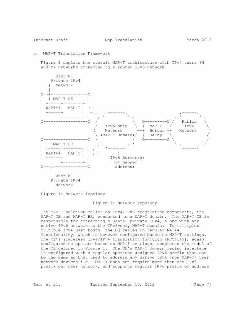
Internet-Draft Map Translation March 2012
5. MAP-T Translation Framework
Figure 1 depicts the overall MAP-T architecture with IPv4 users (N and M) networks connected to a routed IPv6 network.
User N Private IPv4 | Network | O--+---------------O | | MAP-T CE | | +-----+--------+ | | NAPT44| MAP-T | ‘-. | +-----+ | | -._ ,-------. .------. | +--------+ | ,-’ ‘-. ,-’ ‘-. O------------------O / \ O---------O / Public \ / IPv6 only \ | MAP-T |/ IPv4 \ ( Network --+ Border +- Network ) \ (MAP-T Domain)/ | Relay |\ / O------------------O \ / O---------O \ / | MAP-T CE | ;". ,-’ ‘-. ,-’ | +-----+--------+ | ," ‘----+--’ ------’ | NAPT44| MAP-T | | ," | | +-----+ | | IPv6 Server(s) | | +--------+ | (v4 mapped O---.--------------O address) | User M Private IPv4 Network
Figure 1: Network Topology
Figure 1: Network Topology
The MAP-T solution relies on IPv4/IPv6 translating components, the MAP-T CE and MAP-T BR, connected to a MAP-T domain. The MAP-T CE is responsible for connecting a users’ private IPv4, along with any native IPv6 network to the IPv6-only MAP-T domain. To multiplex multiple IPv4 user hosts, the CE relies on regular NAT44 functionality, which is however configured based on MAP-T settings. The CE’s stateless IPv4/IPv6 translation function [RFC6145], again configured to operate based on MAP-T settings, completes the model of the CE defined in Figure 1. The CE’s MAP-T domain facing interface is configured with a regular operator assigned IPv6 prefix that can be the same as that used to address any native IPv6 (non MAP-T) user network devices i.e. MAP-T does not require more than one IPv6 prefix per user network, and supports regular IPv6 prefix or address
Bao, et al. Expires September 10, 2012 [Page 7]
Internet-Draft Map Translation March 2012
assignment mechanism including SLAAC and DHCPv6 stateful.
The MAP-T BR is responsible for connecting external IPv4 networks to all devices in one or more MAP-T domains, using stateless IPv4/IPv6 translation [RFC6145]extended by the MAP-T rules as per this document. Besides the CE and BR, the MAP-T domain can contain any regular IPv6-only hosts/servers that have an IPv4 mapped IPv6 address (IPv4-translatable address per [RFC6052]) using a prefix assigned to the MAP-T domain. Communication with such devices is naturally possible using native IPv6 means from inside or outside the domain as well as from any IPv4-only hosts inside or outside of the MAP-T domain.
The IPv4 in IPv6 address mapping scheme employed by the MAP-T solution, along with the avoidance of using any additional encapsulating headers allows the MAP-T domain to be operated using regular native IPv6 functionality. This includes also the ability to classify traffic based on specific source and destination addresses (including any IPv4 in IPv6 mapped source and destinations), and higher layer packet payload. Similarly, the address mapping characteristic allows IPv6 traffic forwarding in the MAP-T domain to be optimized in line with an operators’ policies, e.g. native IPv6 routing selection of MAP-T domain egress points based on peering policies bound to IPv4 destination. IP Traffic between CEs in any MAP-T can flow either in hub & spoke modes, with a BR acting as the spoke, or in mesh mode directly between the CEs.
6. MAP-T Node Behavior
6.1. Provisioning of MAP-T CE
A MAP-T CE requires the following parameters for provisioning:
o The MAP Domain IPv4 and IPv6 prefix, and their lengths (Basic Mapping Rule)
o The MAP EA-bits (CE index), including IPv4 suffix, length and any port-range (including any excluded ports and the port number continuity parameter)
o The MAP domain BR IPv6 prefix and its length (Default Mapping Rule)
A MAP-T CE that receives a MAP DHCP option [I-D.mdt-softwire-map-dhcp-option] and performs the following (MAP initialization) functions:
o Configures the IPv4 address along with any applicable NAT44 port-
Bao, et al. Expires September 10, 2012 [Page 8]

Internet-Draft Map Translation March 2012
range function parameters (BMR)
o Configures additional IPv4/IPv6 stateless translation parameters - optional FMRs.
6.2. Packet Forwarding Behavior of MAP-T CE
6.2.1. IPv4 to IPv6
A MAP-T CE receiving IPv4 packets SHOULD perform NAT44 function first and create appropriate NAT44 stateful bindings. The resulting IPv4 packets MUST contain the source IPv4 address and source transport number defined by MAP-T. The resulting IPv4 packet is forwarded to the CE’s MAP-T function that performs IPv4 to IPv6 stateless translation. The IPv6 source and destination addresses MUST then be derived as per Section 6 of this draft, and the IPv4 header MUST be replaced with an IPv6 header following [RFC6145].
6.2.2. IPv6 to IPv4
A MAP-T CE receiving an IPv6 packet performs its regular IPv6 operations, whereby only packets that are addressed to the MAP-T CE’s MAP derived BMR address are forwarded to the CE’s MAP-T function. All other IPv6 traffic is forwarded as per the CE’s IPv6 routing rules. The CE SHOULD check that MAP-T received packets’ transport- layer destination port number is in the range configured by MAP for the CE and the CE SHOULD drop any non conforming packet and respond with an ICMPv6 "Address Unreachable" (Type 1, Code 3). In other cases, the MAP-T function MUST derive the IPv4 source and destination addresses as per Section 6 of this draft and MUST replace the IPv6 header with an IPv4 header in accordance with [RFC6145]. The resulting IPv4 packet is then forwarded to the CE’s NAT44 function where the destination port number MUST be checked against the stateful port mapping session table and the destination port number MUST be mapped to its original value.
6.3. Provisioning of MAP-T BR
The MAP-T BR needs to be provisioned with information for the MAP-T domain or domains it is expected to handle, along with any necessary routing processes. For each MAP-T domain, the BR will have the following parameters:
o The MAP Domain IPv4 and IPv6 prefix and their lengths (Basic Mapping Rule).
o The BR prefix and its length (Default Mapping Rule)
Bao, et al. Expires September 10, 2012 [Page 9]
Internet-Draft Map Translation March 2012
o Optionally, any specific Forward Mapping Rules applicable to the domain.
6.4. Packet Forwarding Behavior on MAP-T BR
6.4.1. IPv6 to IPv4
A MAP-T BR receiving IPv6 packets selects a best matching MAP-T domain rule based on a longest address match of the packets’ source address against the BR’s configured MAP-T BMR prefix(es), as well as a match of the packet destination address against the configured BR prefixes or FMR prefix(es). The selected MAP rule allows the BR to determine the CE-index from the source IPv6 address. The BR MUST perform a validation of the consistency of the source IPv6 address and source port number for the packet using BMR. If the packets source port number is found to be outside the range allowed for this CE-index and the BMR, the BR MUST drop the packet and respond with an ICMPv6 "Destination Unreachable, Source address failed ingress/egress policy" (Type 1, Code 5).
For packets that are to be forwarded outside of a MAP-T domain, the BR MUST derive the source and destination IPv4 addresses as per Section 7 of this draft and translate the IPv6 to IPv4 headers following [RFC6145]. The resulting IPv4 packets are then passed to regular IPv4 forwarding.
6.4.2. IPv4 to IPv6
A MAP-T BR receiving IPv4 packets uses a longest match IPv4 lookup to select the target MAP-T domain and rule. The BR MUST then derive the IPv6 source and destination addresses from the IPv4 source and destination address and port as per Section 7 of this draft. Following this, the BR MUST translate the IPv4 to IPv6 headers following [RFC6145]. The resulting IPv6 packets are then passed to regular IPv6 forwarding.
Note that the operation of a BR when forwarding to MAP-T domains that do not utilize IPv4 address sharing, is the same as stateless IPv4/ IPv6 translation.
7. MAP-T IPv4/IPv6 Translation Specifications
This section specifies the MAP-T IPv6 address format and IPv4-IPv6 address mapping behaviour, based on the MAP MAP [I-D.mdt-softwire-mapping-address-and-port] specification. Numeric examples of the MAP-T address translation in action are given in Appendix A.
Bao, et al. Expires September 10, 2012 [Page 10]

Internet-Draft Map Translation March 2012
7.1. Address Formats
The MAP-T address format of the (mapped) CE address adopts the format defined in MAP [I-D.mdt-softwire-mapping-address-and-port]. It is used in mapping rules operations to construct the source and destination IPv6 addresses. An example, is shown in Figure 2 for the specific case of n+o+m bits less or equal to 64 bit length, where the (optional) well known m subnet-Id bits are used to auto-complete a prefix up to the 64th bit. In cases where the End-user IPv6 prefix n+o bits exceed a length of 64, the excess bits are "bit spread" across the fixed u-octet boundary as needed, however for practical purposes operators may find it easier to work at octet aligned boundaries. In any case, the maximum length of the End-user IPv6 prefix is 96 minus the length of PSID, to allow for the encoding of the IPv4 address and PSID. The EA bits are composed of the IPv4 suffix and PSID as per MAP [I-D.mdt-softwire-mapping-address-and-port], and thus the same PSID is repeated twice in the overall encoding. <-- n bits -->|<o bits>|<-m bits>|< 8>|<----- L>=32 ----->|<--56-L--> +-------------+--------+---------+----+--------------+----+---------+ | IPv6 prefix |EA bits |Subnet-id| u | IPv4 address |PSID| 0 | +-------------+--------+---------+----+--------------+----+---------+ <End-user IPv6 prefix >|
Figure 2: IPv4-translatable address for BMR and FMR
The address format used by the MAP-T Default Mapping Rule (DMR, IPv4 converted address used to represent IPv4 destinations outside of the MAP-T domain) is specific to MAP-T. An example is as shown in Figure 3. Note that the BR-prefix length is variable and can be both shorter or longer than 64 bits, up to 96 bits. In the respective cases the IPv4 address and the BR prefix are shifted and "bit spread" across the fixed u-octet boundary as per [RFC6052]. All trailing bits after the IPv4 address are set to 0x0.
<---------- 64 ------------>< 8 ><----- 32 -----><--- 24 ---> +--------------------------+----+---------------+-----------+ | BR prefix | u | IPv4 address | 0 | +--------------------------+----+---------------+-----------+
Figure 3: Example of IPv4-converted address for DMR
In all cases the "u-octet" is taken to be 0x00.
7.2. Translating IPv4 Address and Port Number into IPv6 Address and Port Number at the BR
IPv6 Source Address and Source Port Number:
Bao, et al. Expires September 10, 2012 [Page 11]
Internet-Draft Map Translation March 2012
At the BR, the IPv6 source address (IPv4-converted address) MUST be derived from the IPv4 source Address as per DMR. The source Layer 4 TCP/UDP port number MUST be unchanged.
IPv6 Destination Address and Destination Port Number:
At the BR, the IPv6 destination address (IPv4-translatable address) MUST be derived from the IPv4 destination address and the destination port number as per FMR. The destination port number MUST be unchanged.
7.3. Translating IPv6 Address and Port Number into IPv4 Address and Port Number at the BR
IPv4 Source Address and Source Port Number:
At the BR, the IPv4 source address MUST be derived from the IPv6 source address (IPv4-translatable address) as per FMR. The source port number MUST be unchanged.
IPv4 Destination Address and Destination Port Number:
At the BR, the IPv4 destination address MUST be derived from the IPv6 destination address (IPv4-converted address) as per DMR. The destination port number MUST be unchanged.
7.4. Translating IPv4 Address and Port Number into IPv6 Address and Port Number at the CE
IPv6 Source Address and Source Port Number:
At the CE, the IPv6 source address (IPv4-translatable address) MUST be derived from the IPv4 source address as per BMR. The source port number MUST be unchanged.
IPv6 Destination Address and Destination Port Number:
At the CE, if Forwarding Mapping Rules (FMRs) are enabled, the IPv4 packet MUST be checked to see if the IPv4 destination address matches the FMR. If matching, the IPv6 destination address (IPv4- translatable address) MUST be derived from the IPv4 destination address and the destination port number per FMR. Otherwise, the IPv6 destination address (IPv4-translateable address) MUST be derived from the received IPv4 destination address per DMR. The destination port number MUST be unchanged.
Bao, et al. Expires September 10, 2012 [Page 12]
Internet-Draft Map Translation March 2012
7.5. Translating IPv6 Address and Port Number into IPv4 Address and Port Number at the CE
IPv4 Source Address and Source Port Number:
At the CE, the IPv4 source address MUST be derived from the IPv6 source address (IPv6-converted address) as per the DMR, or as per the FMR. The source port number MUST be unchanged.
IPv4 Destination Address and Destination Port Number: At the CE, the IPv4 destination address MUST be derived from the IPv6 destination address (IPv6-translatable address) as per BMR. The destination port number MUST be unchanged.
7.6. Translating ICMP/ICMPv6 Headers
MAP-T CEs and BRs MUST follow ICMP/ICMPv6 translation as per [RFC6145], with the following extension to cover the address sharing/ port-range feature.
Unlike TCP and UDP, which each provide two port fields to represent both source and destination, the ICMP/ICMPv6 Query message header has only one ID field [RFC0792], [RFC4443]. Thus, if the ICMP Query message is originated from an IPv4 host behind a MAP-T CE, the ICMP ID field SHOULD be used to exclusively identify that IPv4 host. This means that the MAP-T CE SHOULD rewrite the ID field to a port-set value obtained via the BMR during the IPv4 to IPv6 ICMPv6 translation operation. A BR can translate the resulting ICMPv6 packets back to ICMP preserving the ID field on its way to an IPv4 destination. In the return path, when MAP-T BR receives an ICMP packet containing an ID field which is bound for a shared address in the MAP-T domain, the MAP-T BR SHOULD use the ID value as a substitute for the destination port in determining the IPv6 destination address according to Section 5.1. In all other cases, the MAP-T BR MUST derive the destination IPv6 address by simply mapping the destination IPv4 address without additional port info.
7.7. Path MTU Discovery and Fragmentation
Due to the different sizes of the IPv4 and IPv6 header, which are 20+ octets and 40 octets respectively, handling the maximum packet size is relevant for the operation of any system connecting the two address families. There are three mechanisms to handle this issue: path MTU discovery (PMTUD), fragmentation, and transport-layer negotiation such as the TCP Maximum Segment Size (MSS) option [RFC0897]. MAP-T uses all three mechanisms to deal with different cases.
Bao, et al. Expires September 10, 2012 [Page 13]
Internet-Draft Map Translation March 2012
Following [RFC6145], when an IPv4 node performs path MTU discovery (by setting the Don’t Fragment (DF) bit in the header), path MTU discovery can operate end-to-end across the MAP-T BR and CE translators. In this case, either IPv4 or IPv6 routers (including the translators) can send back ICMP Packet Too Big messages to the sender. When IPv6 routers send these as ICMPv6 errors, these packets will pass through the translator and will result in an appropriate ICMP error sent to the IPv4 sender. When the IPv4 sender does not set the DF bit, the translator MUST ensure that the packet does not exceed the path MTU on the IPv6 side. This is done, if necessary, by fragmenting the IPv4 packet and including with Fragment Headers to fit in the minimum MTU 1280-byte IPv6 packets. When the IPv4 sender does not set the DF bit, the translator SHOULD include an IPv6 Fragment Header to indicate that the sender allows fragmentation. The rules defined in [RFC6145] ensure that when packets are fragmented, either by the sender or by IPv4 routers, the low-order 16 bits of the fragment identification are carried end-to-end, ensuring that packets are correctly reassembled. The above mechanism ensures that the Don’t Fragment (DF) bit in the IPv4 header can be carried end-to-end via double stateless translation in most of the cases. For example, the IPv4 packets with DF=1 will be translated to IPv6 packets without fragmentation header and will be translated back to IPv4 packets with DF=1. The IPv4 packets with DF=0 will be translated to IPv6 packets with fragmentation header (keeping the ID value) and will be translated back to IPv4 packets with DF=0. An open corner case left up for specific handling by implementations [RFC6145] is for when IPv4 packets with DF=1 and MF=1 are received by a translator. MAP-T devices SHOULD translate such IPv4 packets into IPv6 with a fragmentation header present. Experimental evidence [operational-exp] and [IMC-07}, indicate that only 27,474 packets observed with DF=1/MF=1 among 10 billion samples. This indicates that IPv4 packets with DF=1 and MF=1 are rare in production networks (10e-5) and that their handling by this rule causes no negative effects in practice.
8. MAP-T Packet Forwarding considerations
8.1. Mesh Model
MAP-T allows the use of the mesh model in order for all CEs to communicate with each other directly (i.e bypassing the BR). When a CE receives an IPv4 packet from its LAN side, the CE looks up a mapping rule corresponding to an IPv4 destination address in the received IPv4 packet. If the corresponding mapping rule is found, CE can communicate to another CE directly based on the mapping rule defined as Forwarding mapping rule (FMR) in MAP. If the corresponding mapping rule is not found, CE must forward the packet
Bao, et al. Expires September 10, 2012 [Page 14]
Internet-Draft Map Translation March 2012
to a given BR.
8.2. Hub & Spoke model
In order to allow the mesh topology so that all CEs can communicate each others directly, all CE should know all mapping rules applied to a given MAP-T domain or MAP-T domains. However, if a CE knows only a subset of the mapping rules applied to a given MAP-T domain, a CE can not communicate directly with some of the CEs in that domain due to the lack of mapping rules. In this case, an IPv4 packet toward to these CEs must be forwarded to a given BR. In order to achieve the hub & spoke mode fully, the Forwarding mapping rule (FMR) defined in MAP need to be disabled (not defined).
8.3. Communication with IPv6 servers in the MAP-T domain
MAP-T allows communication between both IPv4-only and any IPv6 enabled end hosts, with native IPv6-only servers which are using IPv4-mapped IPv6 address based on DMR in the MAP-T domain. In this mode, the IPv6-only servers SHOULD have both A and AAAA records in the authorities DNS server [RFC6219]. DNS64 [RFC6147] become required only when IPv6 servers in the MAP-T domain are expected themselves to initiate communication to external IPv4-only hosts.
9. NAT44 considerations
The NAT44 implemented in MAP-T CE SHOULD conform with the behavior and best current practice documented in [RFC4787], [RFC5508] and [RFC5382]. In MAP-T address sharing mode (determined by the MAP-T configuration parameters) the operation of the NAT44 must be restricted to the available port numbers derived via BMR.
10. Security Considerations
Spoofing attacks: With consistency checks between IPv4 and IPv6 sources that are performed on IPv4/IPv6 packets received by BR’s and CE’s (Section 6), MAP-T does not introduce any opportunity for spoofing attack that would not pre-exist in IPv6.
Denial-of-service attacks: In MAP-T domains where IPv4 addresses are shared, the fact that IPv4 datagram reassembly may be necessary introduces an opportunity for DOS attacks. This is inherent to address sharing, and is common with other address sharing approaches such as DS-Lite and NAT64/ DNS64. The best protection against such attacks is to accelerate IPv6 enablement in both clients and servers so that, where MAP-T is supported, it is less
Bao, et al. Expires September 10, 2012 [Page 15]
Internet-Draft Map Translation March 2012
and less used.
Routing-loop attacks: This attack may exist in some automatic- tunneling scenarios are documented in [I-D.ietf-v6ops-tunnel-loops]. They cannot exist with MAP-T because each BRs checks that the IPv6 source address of a received IPv6 packet is a CE address based on Forwarding Mapping Rule defined in MAP [I-D.mdt-softwire-mapping-address-and-port].
Attacks facilitated by restricted port set: From hosts that are not subject to ingress filtering of [RFC2827], some attacks are possible by intervening with faked packets during ongoing transport connections ([RFC4953], [RFC5961], [RFC6056]. The attacks depend on guessing which ports are currently used by target hosts, and using an unrestricted port set is preferable, i.e. using native IPv6 connections that are not subject to MAP port range restrictions. To minimize this type of attacks when using a restricted port set, the MAP CE’s NAT44 filtering behavior SHOULD be "Address-Dependent Filtering". Furthermore, the MAP CEs SHOULD use a DNS transport proxy function to handle DNS traffic, and source such traffic from IPv6 interfaces not assigned to MAP-T. Practicalities of these methods are discussed in Section 5.9 of [I-D.dec-stateless-4v6].
11. IANA Consideration
This document has no IANA actions.
12. Acknowledgements
The authors would like to thank Maoke Chen, Leaf Yeh and Senthil Sivakumar for their review and comments.
13. References
13.1. Normative References
[I-D.mdt-softwire-mapping-address-and-port] Troan, O., "Mapping of Address and Port (MAP)", draft-mdt-softwire-mapping-address-and-port-02 (work in progress), November 2011.
[RFC2119] Bradner, S., "Key words for use in RFCs to Indicate Requirement Levels", BCP 14, RFC 2119, March 1997.
Bao, et al. Expires September 10, 2012 [Page 16]
Internet-Draft Map Translation March 2012
[RFC6145] Li, X., Bao, C., and F. Baker, "IP/ICMP Translation Algorithm", RFC 6145, April 2011.
13.2. Informative References
[I-D.dec-stateless-4v6] Dec, W., Asati, R., and H. Deng, "Stateless 4Via6 Address Sharing", draft-dec-stateless-4v6-04 (work in progress), October 2011.
[I-D.ietf-v6ops-tunnel-loops] Nakibly, G. and F. Templin, "Routing Loop Attack using IPv6 Automatic Tunnels: Problem Statement and Proposed Mitigations", draft-ietf-v6ops-tunnel-loops-07 (work in progress), May 2011.
[I-D.mdt-softwire-map-dhcp-option] Mrugalski, T., Boucadair, M., and O. Troan, "DHCPv6 Options for Mapping of Address and Port", draft-mdt-softwire-map-dhcp-option-00 (work in progress), October 2011.
[I-D.murakami-softwire-4v6-translation] Murakami, T., Chen, G., Deng, H., Dec, W., and S. Matsushima, "4via6 Stateless Translation", draft-murakami-softwire-4v6-translation-00 (work in progress), July 2011.
[I-D.operators-softwire-stateless-4v6-motivation] Boucadair, M., Matsushima, S., Lee, Y., Bonness, O., Borges, I., and G. Chen, "Motivations for Stateless IPv4 over IPv6 Migration Solutions", draft-operators-softwire-stateless-4v6-motivation-02 (work in progress), June 2011.
[I-D.xli-behave-divi] Shang, W., Li, X., Zhai, Y., and C. Bao, "dIVI: Dual- Stateless IPv4/IPv6 Translation", draft-xli-behave-divi-04 (work in progress), October 2011.
[RFC0792] Postel, J., "Internet Control Message Protocol", STD 5, RFC 792, September 1981.
[RFC0897] Postel, J., "Domain name system implementation schedule", RFC 897, February 1984.
[RFC2827] Ferguson, P. and D. Senie, "Network Ingress Filtering: Defeating Denial of Service Attacks which employ IP Source
Bao, et al. Expires September 10, 2012 [Page 17]
Internet-Draft Map Translation March 2012
Address Spoofing", BCP 38, RFC 2827, May 2000.
[RFC4443] Conta, A., Deering, S., and M. Gupta, "Internet Control Message Protocol (ICMPv6) for the Internet Protocol Version 6 (IPv6) Specification", RFC 4443, March 2006.
[RFC4787] Audet, F. and C. Jennings, "Network Address Translation (NAT) Behavioral Requirements for Unicast UDP", BCP 127, RFC 4787, January 2007.
[RFC4953] Touch, J., "Defending TCP Against Spoofing Attacks", RFC 4953, July 2007.
[RFC5382] Guha, S., Biswas, K., Ford, B., Sivakumar, S., and P. Srisuresh, "NAT Behavioral Requirements for TCP", BCP 142, RFC 5382, October 2008.
[RFC5508] Srisuresh, P., Ford, B., Sivakumar, S., and S. Guha, "NAT Behavioral Requirements for ICMP", BCP 148, RFC 5508, April 2009.
[RFC5961] Ramaiah, A., Stewart, R., and M. Dalal, "Improving TCP’s Robustness to Blind In-Window Attacks", RFC 5961, August 2010.
[RFC6052] Bao, C., Huitema, C., Bagnulo, M., Boucadair, M., and X. Li, "IPv6 Addressing of IPv4/IPv6 Translators", RFC 6052, October 2010.
[RFC6056] Larsen, M. and F. Gont, "Recommendations for Transport- Protocol Port Randomization", BCP 156, RFC 6056, January 2011.
[RFC6144] Baker, F., Li, X., Bao, C., and K. Yin, "Framework for IPv4/IPv6 Translation", RFC 6144, April 2011.
[RFC6147] Bagnulo, M., Sullivan, A., Matthews, P., and I. van Beijnum, "DNS64: DNS Extensions for Network Address Translation from IPv6 Clients to IPv4 Servers", RFC 6147, April 2011.
[RFC6219] Li, X., Bao, C., Chen, M., Zhang, H., and J. Wu, "The China Education and Research Network (CERNET) IVI Translation Design and Deployment for the IPv4/IPv6 Coexistence and Transition", RFC 6219, May 2011.
[operational-exp] John, Wolfgang; Tafvelin, Sven: Analysis of Internet Backbone Traffic and Header Anomalies Observed. IMC ’07: Proceedings of the 7th ACM SIGCOMM conference on Internet measurement, pp. 111-116. ISBN/ISSN: 978-1-59593-908-1 http://conferences.sigcomm.org/imc/2007/papers/imc91.pdf
Bao, et al. Expires September 10, 2012 [Page 18]

Internet-Draft Map Translation March 2012
Appendix A. Example of MAP-T translation
The following is a MAP-T example derived from the general MAP example in MAP [I-D.mdt-softwire-mapping-address-and-port].
Example 1.
Given the MAP domain information and an IPv6 address of an endpoint:
IPv6 prefix assigned to the end user: 2001:db8:0012:3400::/56
Basic Mapping Rule: {2001:db8:0000::/40 (Rule IPv6 prefix), 192.0.2.0/24 (Rule IPv4 prefix), 16 (Rule EA-bits length)}
Sharing ratio: 256 (16 - (32 - 24) = 8. 2^8 = 256)
PSID offset: 4
A MAP node (CE or BR) can via the BMR determine the IPv4 address and port-set as shown below:
EA bits offset: 40
IPv4 suffix bits (p) Length of IPv4 address (32) - IPv4 prefix length (24) = 8
IPv4 address 192.0.2.18 (0xc0000212)
PSID start: 40 + p = 40 + 8 = 48
PSID length: o - p = 16 (56 - 40) - 8 = 8
PSID: 0x34
Port-set-1: 4928, 4929, 4930, 4931, 4932, 4933, 4934, 4935, 4936, 4937, 4938, 4939, 4940, 4941, 4942, 4943
Port-set-2: 9024, 9025, 9026, 9027, 9028, 9029, 9030, 9031, 9032, 9033, 9034, 9035, 9036, 9037, 9038, 9039
... ...
Port-set-15 62272, 62273, 62274, 62275, 62276, 62277, 62278, 62279, 62280, 62281, 62282, 62283, 62284, 62285, 62286, 62287
The BMR information allows a MAP-T CE also to determine (complete) its IPv6 address within the indicated IPv6 prefix.
Bao, et al. Expires September 10, 2012 [Page 19]

Internet-Draft Map Translation March 2012
IPv6 address of MAP-T CE: 2001:db8:0012:3400:00c0:0002:1200:3400
Example 2.
Another example can be made of a hypothetical MAP-T BR, configured with the following FMR when receiving a packet with the following characteristics:
IPv4 source address: 1.2.3.4 (0x01020304)
IPv4 source port: 80
IPv4 destination address: 192.0.2.18 (0xc0000212)
IPv4 destination port: 9030
Configured Forwarding Mapping Rule: {2001:db8:0000::/40 (Rule IPv6 prefix), 192.0.2.0/24 (Rule IPv4 prefix), 16 (Rule EA-bits length)}
MAP-T BR Prefix 2001:db8:ffff::/64
The above information allows the BR to derive as follows the mapped destination IPv6 address for the corresponding MAP-T CE, and also the mapped source IPv6 address for the IPv4 source.
IPv4 suffix bits (p) 32 - 24 = 8 (18 (0x12))
PSID length: 8
PSID: 0x34 (9030 (0x2346))
The resulting IPv6 packet will have the following key fields
IPv6 source address 2001:db8:ffff:0:0001:0203:0400::
IPv6 destination address: 2001:db8:0012:3400:00c0:0002:1200:3400
IPv6 source Port: 80
IPv6 destination Port: 9030
Example 3:
An IPv4 host behind the MAP-T CE (addressed as per the previous examples) corresponding with IPv4 host 1.2.3.4 will have its packets converted into IPv6 using the DMR configured on the MAP-T CE as follows:
Bao, et al. Expires September 10, 2012 [Page 20]
Internet-Draft Map Translation March 2012
Default Mapping Rule used by MAP-T CE: {2001:db8:ffff::/64 (Rule IPv6 prefix), 0.0.0.0/0 (Rule IPv4 prefix), null (BR IPv4 address)}
IPv4 source address (post NAT44 if present) 192.0.2.18
IPv4 destination address: 1.2.3.4
IPv4 source port (post NAT44 if present): 9030
IPv4 destination port: 80
IPv6 source address of MAP-T CE: 2001:db8:0012:3400:00c0:0002:1200: 3400
IPv6 destination address: 2001:db8:ffff:0:0001:0203:0400::
Authors’ Addresses
Congxiao Bao CERNET Center/Tsinghua University Room 225, Main Building, Tsinghua University Beijing 100084 CN
Email: [email protected]
Xing Li CERNET Center/Tsinghua University Room 225, Main Building, Tsinghua University Beijing 100084 CN
Email: [email protected]
Yu Zhai CERNET Center/Tsinghua University Room 225, Main Building, Tsinghua University Beijing 100084 CN
Email: [email protected]
Bao, et al. Expires September 10, 2012 [Page 21]
Internet-Draft Map Translation March 2012
Tetsuya Murakami (editor) IP Infusion 1188 East Arques Avenue Sunnyvale USA
Email: [email protected]
Wojciech Dec (editor) Cisco Systems Haarlerbergpark Haarlerbergweg 13-19 Amsterdam, NOORD-HOLLAND 1101 CH Netherlands
Phone: Email: [email protected]
Bao, et al. Expires September 10, 2012 [Page 22]

Network Working Group O. TroanInternet-Draft ciscoIntended status: Standards Track S. MatsushimaExpires: August 2, 2012 SoftBank Telecom T. Murakami IP Infusion X. Li C. Bao CERNET Center/Tsinghua University January 30, 2012
Mapping of Address and Port (MAP) draft-mdt-softwire-mapping-address-and-port-03
Abstract
This document describes a generic mechanism for mapping between IPv4 addresses and IPv6 addresses and transport layer ports.
Status of this Memo
This Internet-Draft is submitted in full conformance with the provisions of BCP 78 and BCP 79.
Internet-Drafts are working documents of the Internet Engineering Task Force (IETF). Note that other groups may also distribute working documents as Internet-Drafts. The list of current Internet- Drafts is at http://datatracker.ietf.org/drafts/current/.
Internet-Drafts are draft documents valid for a maximum of six months and may be updated, replaced, or obsoleted by other documents at any time. It is inappropriate to use Internet-Drafts as reference material or to cite them other than as "work in progress."
This Internet-Draft will expire on August 2, 2012.
Copyright Notice
Copyright (c) 2012 IETF Trust and the persons identified as the document authors. All rights reserved.
This document is subject to BCP 78 and the IETF Trust’s Legal Provisions Relating to IETF Documents (http://trustee.ietf.org/license-info) in effect on the date of publication of this document. Please review these documents carefully, as they describe your rights and restrictions with respect
Troan, et al. Expires August 2, 2012 [Page 1]

Internet-Draft MAP January 2012
to this document. Code Components extracted from this document must include Simplified BSD License text as described in Section 4.e of the Trust Legal Provisions and are provided without warranty as described in the Simplified BSD License.
Table of Contents
1. Introduction . . . . . . . . . . . . . . . . . . . . . . . . . 3 2. Conventions . . . . . . . . . . . . . . . . . . . . . . . . . 4 3. Terminology . . . . . . . . . . . . . . . . . . . . . . . . . 5 4. Architecture . . . . . . . . . . . . . . . . . . . . . . . . . 6 5. Mapping Rules . . . . . . . . . . . . . . . . . . . . . . . . 7 5.1. Port mapping algorithm . . . . . . . . . . . . . . . . . . 8 5.1.1. Bit Representation of the Algorithm . . . . . . . . . 9 5.1.2. GMA examples . . . . . . . . . . . . . . . . . . . . . 9 5.1.3. GMA Provisioning Considerations . . . . . . . . . . . 10 5.2. Basic mapping rule (BMR) . . . . . . . . . . . . . . . . . 10 5.3. Forwarding mapping rule (FMR) . . . . . . . . . . . . . . 13 5.4. Default mapping rule (DMR) . . . . . . . . . . . . . . . . 14 6. The IPv6 Interface Identifier . . . . . . . . . . . . . . . . 15 7. IANA Considerations . . . . . . . . . . . . . . . . . . . . . 16 8. Security Considerations . . . . . . . . . . . . . . . . . . . 16 9. Contributors . . . . . . . . . . . . . . . . . . . . . . . . . 16 10. Acknowledgements . . . . . . . . . . . . . . . . . . . . . . . 16 11. References . . . . . . . . . . . . . . . . . . . . . . . . . . 17 11.1. Normative References . . . . . . . . . . . . . . . . . . . 17 11.2. Informative References . . . . . . . . . . . . . . . . . . 17 Authors’ Addresses . . . . . . . . . . . . . . . . . . . . . . . . 19
Troan, et al. Expires August 2, 2012 [Page 2]

Internet-Draft MAP January 2012
1. Introduction
The mechanism of mapping IPv4 addresses in IPv6 addresses has been described in numerous mechanisms dating back to 1996 [RFC1933]. The Automatic tunneling mechanism described in RFC1933, assigned a globally unique IPv6 address to a host by combining the host’s IPv4 address with a well-known IPv6 prefix. Given an IPv6 packet with a destination address with an embedded IPv4 address, a node could automatically tunnel this packet by extracting the IPv4 tunnel end- point address from the IPv6 destination address.
There are numerous variations of this idea, described in 6over4 [RFC2529], 6to4 [RFC3056], ISATAP [RFC5214], and 6rd [RFC5969]. The differences between these are the use of well-known IPv6 prefixes, or Service Provider assigned IPv6 prefixes, and the position of the embedded IPv4 bits in the IPv6 address. Teredo [RFC4380] added a twist to this to achieve NAT traversal by also encoding transport layer ports into the IPv6 address. 6rd, to achieve more efficient encoding, allowed for only the suffix of an IPv4 address to be embedded, with the IPv4 prefix being deduced from other provisioning mechanisms.
NAT-PT [RFC2766](deprecated) combined with a DNS ALG used address mapping to put NAT state, namely the IPv6 to IPv4 binding encoded in an IPv6 address. This characteristic has been inherited by NAT64 [RFC6146] and DNS64 [RFC6147] which rely on an address format defined in [RFC6052]. [RFC6052] specifies the algorithmic translation of an IPv6 address to IPv4 address. In particular, [RFC6052] specifies the address format to build IPv4-converted and IPv4-translatable IPv6 addresses. RFC6052 discusses the transport of the port-set information in an IPv4-embedded IPv6 address but the conclusion was the following (excerpt from [RFC6052]):
"There have been proposals to complement stateless translation with a port range feature. Instead of mapping an IPv4 address to exactly one IPv6 prefix, the options would allow several IPv6 nodes to share an IPv4 address, with each node managing a different set of ports. If a port-set extension is needed, it could be defined later, using bits currently reserved as null in the suffix."
The commonalities of all these IPv6 over IPv4 mechanisms are:
o Automatically provisions an IPv6 address for a host or an IPv6 prefix for a site
o Algorithmic or implicit address resolution for tunneling or encapsulation. Given an IPv6 destination address, an IPv4 tunnel endpoint address can be calculated. Likewise for translation, an
Troan, et al. Expires August 2, 2012 [Page 3]

Internet-Draft MAP January 2012
IPv4 address can be calculated from an IPv6 destination address and vice versa.
o Embedding of an IPv4 address or part thereof and optionally transport layer ports into an IPv6 address.
In phases of IPv4 to IPv6 migration, IPv6 only networks will be common, while there will still be a need for residual IPv4 deployment. This document describes a more generic mapping of IPv4 to IPv6 that can be used both for encapsulation (IPv4 over IPv6) and for translation between the two protocols.
Just as the IPv6 over IPv4 mechanisms referred to above, the residual IPv4 over IPv6 mechanisms must be capable of:
o Provisioning an IPv4 prefix, an IPv4 address or a shared IPv4 address.
o Algorithmically map between an IPv4 prefix, IPv4 address or a shared IPv4 address and an IPv6 address.
The unified mapping scheme described here supports translation mode, encapsulation mode, in both mesh and hub and spoke topologies.
This document describes delivery of IPv4 unicast service across an IPv6 infrastructure. IPv4 multicast is not considered further in this document.
The A+P (Address and Port) architecture of sharing an IPv4 address by distributing the port space is described in [RFC6346]. Specifically section 4 of [RFC6346] covers stateless mapping. The corresponding stateful solution DS-lite is described in [RFC6333]. The motivation for work is described in [I-D.ietf-softwire-stateless-4v6-motivation].
A companion document defines a DHCPv6 option for provisioning of MAP [I-D.mdt-softwire-map-dhcp-option]. Deployment considerations are described in [I-D.mdt-softwire-map-deployment].
2. Conventions
The key words "MUST", "MUST NOT", "REQUIRED", "SHALL", "SHALL NOT", "SHOULD", "SHOULD NOT", "RECOMMENDED", "MAY", and "OPTIONAL" in this document are to be interpreted as described in RFC 2119 [RFC2119].
Troan, et al. Expires August 2, 2012 [Page 4]
Internet-Draft MAP January 2012
3. Terminology
MAP domain: A set of MAP CEs and BRs connected to the same virtual link. A service provider may deploy a single MAP domain, or may utilize multiple MAP domains.
MAP Rule A set of parameters describing the mapping between an IPv4 prefix, IPv4 address or shared IPv4 address and an IPv6 prefix or address. Each MAP node in the domain has the same set of rules.
MAP node A device that implements MAP.
MAP Border Relay (BR): A MAP enabled router managed by the service provider at the edge of a MAP domain. A Border Relay router has at least an IPv6-enabled interface and an IPv4 interface connected to the native IPv4 network. A MAP BR may also be referred to simply as a "BR" within the context of MAP.
MAP Customer Edge (CE): A device functioning as a Customer Edge router in a MAP deployment. A typical MAP CE adopting MAP rules will serve a residential site with one WAN side interface, and one or more LAN side interfaces. A MAP CE may also be referred to simply as a "CE" within the context of MAP.
Port-set: Each node has a separate part of the transport layer port space; denoted as a port-set.
Port-set ID (PSID): Algorithmically identifies a set of ports exclusively assigned to the CE.
Shared IPv4 address: An IPv4 address that is shared among multiple CEs. Only ports that belong to the assigned port-set can be used for communication. Also known as a Port-Restricted IPv4 address.
End-user IPv6 prefix: The IPv6 prefix assigned to an End-user CE by other means than MAP itself. E.g. provisioned using DHCPv6 PD [RFC3633] or configured manually. It is unique for each CE.
Troan, et al. Expires August 2, 2012 [Page 5]

Internet-Draft MAP January 2012
MAP IPv6 address: The IPv6 address used to reach the MAP function of a CE from other CE’s and from BR’s.
Rule IPv6 prefix: An IPv6 prefix assigned by a Service Provider for a mapping rule.
Rule IPv4 prefix: An IPv4 prefix assigned by a Service Provider for a mapping rule.
IPv4 Embedded Address (EA) bits: The IPv4 EA-bits in the IPv6 address identify an IPv4 prefix/address (or part thereof) or a shared IPv4 address (or part thereof) and a port-set identifier.
MRT: MAP Rule table. Address and Port aware datastructure, supporting longest match lookups. The MRT is used by the MAP forwarding function.
4. Architecture
A full IPv4 address or IPv4 prefix can be used like today, e.g. for identifying an interface or as a DHCP pool. A shared IPv4 address on the other hand, MUST NOT be used to identify an interface. While it is theoretically possible to make host stacks and applications port- aware, that is considered a too drastic change to the IP model [RFC6250].
The MAP architecture described here, restricts the use of the shared IPv4 address to only be used as the global address (outside) of the NAPT [RFC2663] running on the CE. The NAPT MUST in turn be connected to a MAP aware forwarding function, that does encapsulation/ decapsulation or translation to IPv6.
For packets outbound from the private IPv4 network, the CE NAPT MUST translate transport identifiers (e.g. TCP and UDP port numbers) so that they fall within the assigned CE’s port-range.
The forwarding function uses the MRT to make forwarding decisions. The table consist of the mapping rules. An entry in the table consists of an IPv4 prefix and PSID. The normal best matching prefix algorithm is used. With a maximum key length of 48 (32 + 16). E.g. with a sharing ratio of 64 (6 bit PSID length) a host route for this CE would be a /38 (32 + 6).
Troan, et al. Expires August 2, 2012 [Page 6]

Internet-Draft MAP January 2012
5. Mapping Rules
A MAP node is provisioned with one or more mapping rules.
Mapping rules are used differently depending on their function. Every MAP node must be provisioned with a Basic mapping rule. This is used by the node to configure itself with an IPv4 address, IPv4 prefix or shared IPv4 address from an End-user IPv6 prefix. This same basic rule can also be used for forwarding, where an IPv4 destination address and optionally a destination port is mapped into an IPv6 address or prefix. Additional mapping rules can be specified to allow for e.g. multiple different IPv4 subnets to exist within the domain. Additional mapping rules are recognized by having a Rule IPv6 prefix different from the base End-user IPv6 prefix.
Traffic outside of the domain (IPv4 address not matching (using longest matching prefix) any Rule IPv4 prefix in the Rules database) will be forward using the Default mapping rule. The Default mapping rule maps outside destinations to the BR’s IPv6 address or prefix.
There are three types of mapping rules:
1. Basic Mapping Rule - used for IPv4 prefix, address or port set assignment. There can only be one Basic Mapping Rule per End- user IPv6 prefix. The Basic Mapping Rule is used to configure the MAP IPv6 address or prefix.
* Rule IPv6 prefix (including prefix length)
* Rule IPv4 prefix (including prefix length)
* Rule EA-bits length (in bits)
* Rule Port Parameters (optional)
2. Forwarding Mapping Rule - used for forwarding. The Basic Mapping Rule is also a Forwarding Mapping Rule. Each Forwarding Mapping Rule will result in an entry in the MRT for the Rule IPv4 prefix.
* Rule IPv6 prefix (including prefix length)
* Rule IPv4 prefix (including prefix length)
* Rule EA-bits length (in bits)
* Rule Port Parameters (optional)
Troan, et al. Expires August 2, 2012 [Page 7]

Internet-Draft MAP January 2012
3. Default Mapping Rule - used for destinations outside the MAP domain. A 0.0.0.0/0 entry is installed in the MRT for this rule.
* Rule IPv6 prefix (including prefix length)
* Rule BR IPv4 address
A MAP node finds its Basic Mapping Rule by doing a longest match between the End-user IPv6 prefix and the Rule IPv6 prefix in the Mapping Rule database. The rule is then used for IPv4 prefix, address or shared address assignment.
A MAP IPv6 address (or prefix) is formed from the BMR Rule IPv6 prefix. This address MUST be assigned to an interface of the MAP node and is used to terminate all MAP traffic being sent or received to the node.
Port-aware IPv4 entries in the MRT are installed for all the Forwarding Mapping Rules and an IPv4 default route for the Default Mapping Rule.
In hub and spoke mode, all traffic MUST be forwarded using the Default Mapping Rule.
5.1. Port mapping algorithm
Different Port-Set Identifiers (PSID) MUST have non-overlapping port- sets. The two extreme cases are: (1) the port numbers are not contiguous for each PSID, but uniformly distributed across the port range (0-65535); (2) the port numbers are contiguous in a single range for each PSID. The port mapping algorithm proposed here is called the Generalized Modulus Algorithm (GMA) and supports both these cases.
For a given sharing ratio (R) and the maximum number of contiguous ports (M), the GMA algorithm is defined as:
1. The port number (P) of a given PSID (K) is composed of:
P = R * M * j + M * K + i
Where:
* PSID: K = 0 to R - 1
* Port range index: j = (4096 / M) / R to ((65536 / M) / R) - 1, if the port numbers (0 - 4095) are excluded.
Troan, et al. Expires August 2, 2012 [Page 8]

Internet-Draft MAP January 2012
* Contiguous Port index: i = 0 to M - 1
2. The PSID (K) of a given port number (P) is determined by:
K = (floor(P/M)) % R
Where:
* % is the modulus operator
* floor(arg) is a function that returns the largest integer not greater than arg.
5.1.1. Bit Representation of the Algorithm
Given a sharing ratio (R=2^k), the maximum number of contiguous ports (M=2^m), for any PSID (K) and available ports (P) can be represented as:
0 8 15 +---------------+----------+------+-------------------+ | P | ----------------+-----------------+-------------------+ | A (j) | PSID (K) | M (i) | +---------------+----------+------+-------------------+ |<----a bits--->|<-----k bits---->|<------m bits----->|
Figure 1: Bit representation
Where j and i are the same indexes defined in the port mapping algorithm.
For any port number, the PSID can be obtained by bit mask operation.
For a > 0, j MUST be larger than 0. This ensures that the algorithm excludes the system ports ([I-D.ietf-tsvwg-iana-ports]). For a = 0, j MAY be 0 to allow for the provisioning of the system ports.
5.1.2. GMA examples
Troan, et al. Expires August 2, 2012 [Page 9]

Internet-Draft MAP January 2012
For example, for R = 1024, PSID offset: a = 4 and PSID length: k = 10 bits
Port-set-1 Port-set-2 PSID=0 | 4096, 4097, 4098, 4099, | 8192, 8193, 8194, 8195, | ... PSID=1 | 4100, 4101, 4102, 4103, | 8196, 8197, 8198, 8199, | ... PSID=2 | 4104, 4105, 4106, 4107, | 8200, 8201, 8202, 8203, | ... PSID=3 | 4108, 4109, 4110, 4111, | 8204, 8205, 8206, 8207, | ... ... PSID=1023| 8188, 8189, 8190, 8191, | 12284, 12285, 12286, 12287,| ...
Example 1: with offset = 4 (a = 4)
For example, for R = 64, a = 0 (PSID offset = 0 and PSID length = 6 bits):
Port-set PSID=0 | [ 0 - 1023] PSID=1 | [1024 - 2047] PSID=2 | [2048 - 3071] PSID=3 | [3072 - 4095] ... PSID=63 | [64512 - 65535]
Example 2: with offset = 0 (a = 0)
5.1.3. GMA Provisioning Considerations
The number of offset bits (a) and excluded ports are optionally provisioned via the "Rule Port Mapping Parameters" in the Basic Mapping Rule.
The defaults are:
o Excluded ports : 0-4095
o Offset bits (a) : 4
To simplify the GMA port mapping algorithm the defaults are chosen so that the PSID field starts on a nibble boundary and the excluded port range (0-1023) is extended to 0-4095.
5.2. Basic mapping rule (BMR)
Troan, et al. Expires August 2, 2012 [Page 10]

Internet-Draft MAP January 2012
| n bits | o bits | m bits | 128-n-o-m bits | +--------------------+-----------+---------+------------+----------+ | Rule IPv6 prefix | EA bits |subnet ID| interface ID | +--------------------+-----------+---------+-----------------------+ |<--- End-user IPv6 prefix --->|
Figure 2: IPv6 address format
The Embedded Address bits (EA bits) are unique per end user within a Rule IPv6 prefix. The Rule IPv6 prefix is the part of the End-user IPv6 prefix that is common among all CEs using the same Basic Mapping Rule within the MAP domain. The EA bits encode the CE specific IPv4 address and port information. The EA bits can contain a full or part of an IPv4 prefix or address, and in the shared IPv4 address case contains a Port-Set Identifier (PSID).
The MAP IPv6 address is created by concatenating the End-user IPv6 prefix with the MAP subnet-id and the interface-id as specified in Section 6.
The MAP subnet ID is defined to be the first subnet (all bits set to zero). A MAP node MUST reserve the first IPv6 prefix in a End-user IPv6 prefix for the purpose of MAP.
Shared IPv4 address:
| r bits | p bits | | q bits | +-------------+---------------------+ +------------+ | Rule IPv4 | IPv4 Address suffix | |Port-Set ID | +-------------+---------------------+ +------------+ | 32 bits |
Figure 3: Shared IPv4 address
Complete IPv4 address:
| r bits | p bits | +-------------+---------------------+ | Rule IPv4 | IPv4 Address suffix | +-------------+---------------------+ | 32 bits |
Figure 4: Complete IPv4 address
Troan, et al. Expires August 2, 2012 [Page 11]

Internet-Draft MAP January 2012
IPv4 prefix:
| r bits | p bits | +-------------+---------------------+ | Rule IPv4 | IPv4 Address suffix | +-------------+---------------------+ | < 32 bits |
Figure 5: IPv4 prefix
The length of r MAY be zero, in which case the complete IPv4 address or prefix is encoded in the EA bits. If only a part of the IPv4 address/prefix is encoded in the EA bits, the Rule IPv4 prefix is provisioned to the CE by other means (e.g. a DHCPv6 option). To create a complete IPv4 address (or prefix), the IPv4 address suffix (p) from the EA bits, are concatenated with the Rule IPv4 prefix (r bits).
The offset of the EA bits field in the IPv6 address is equal to the BMR Rule IPv6 prefix length. The length of the EA bits field (o) is given by the BMR Rule EA-bits length. The sum of the Rule IPv6 Prefix length and the Rule EA-bits length MUST be less or equal than the End-user IPv6 prefix length.
If o + r < 32 (length of the IPv4 address in bits), then an IPv4 prefix is assigned.
If o + r is equal to 32, then a full IPv4 address is to be assigned. The address is created by concatenating the Rule IPv4 prefix and the EA-bits.
If o + r is > 32, then a shared IPv4 address is to be assigned. The number of IPv4 address suffix bits (p) in the EA bits is given by 32 - r bits. The PSID bits are used to create a port-set. The length of the PSID bit field within EA bits is: o - p.
In the following examples, only the suffix (last 8 bits) of the IPv4 address is embedded in the EA bits (r = 24), while the IPv4 prefix (first 24 bits) is given in the BMR Rule IPv4 prefix.
Troan, et al. Expires August 2, 2012 [Page 12]

Internet-Draft MAP January 2012
Example:
Given: End-user IPv6 prefix: 2001:db8:0012:3400::/56 Basic Mapping Rule: {2001:db8:0000::/40 (Rule IPv6 prefix), 192.0.2.0/24 (Rule IPv4 prefix), 16 (Rule EA-bits length)} Sharing ratio: 256 (16 - (32 - 24) = 8. 2^8 = 256) PSID offset: 4
We get IPv4 address and port-set: EA bits offset: 40 IPv4 suffix bits (p): Length of IPv4 address (32) - IPv4 prefix length (24) = 8 IPv4 address: 192.0.2.18
PSID start: 40 + p = 40 + 8 = 48 PSID length: o - p = 16 (56 - 40) - 8 = 8 PSID: 0x34 Port-set-1: 4928, 4929, 4930, 4931, 4932, 4933, 4934, 4935, 4936, 4937, 4938, 4939, 4940, 4941, 4942, 4943 Port-set-2: 9024, 9025, 9026, 9027, 9028, 9029, 9030, 9031, 9032, 9033, 9034, 9035, 9036, 9037, 9038, 9039 ... Port-set-15: 62272, 62273, 62274, 62275, 62276, 62277, 62278, 62279, 62280, 62281, 62282, 62283, 62284, 62285, 62286, 62287,
5.3. Forwarding mapping rule (FMR)
On adding an FMR rule, an IPv4 route is installed in the AP RIB for the Rule IPv4 prefix.
On forwarding an IPv4 packet, a best matching prefix lookup is done in the IPv4 routing table and the correct FMR is chosen.
Troan, et al. Expires August 2, 2012 [Page 13]
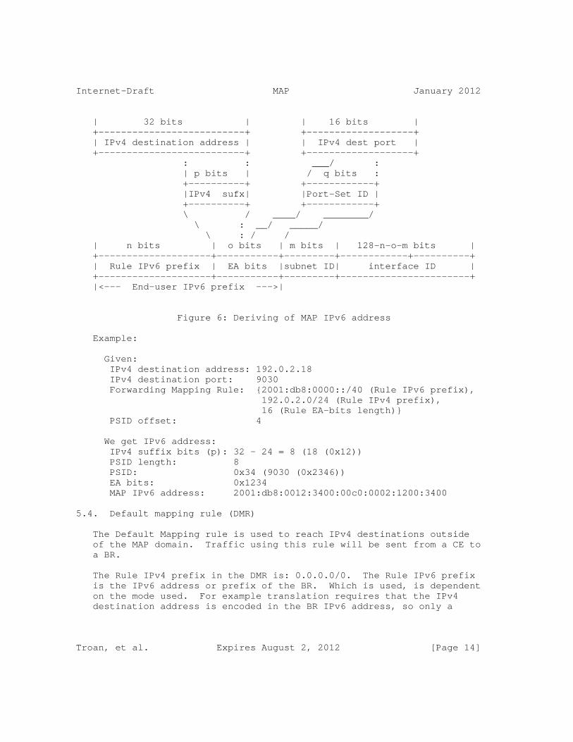
Internet-Draft MAP January 2012
| 32 bits | | 16 bits | +--------------------------+ +-------------------+ | IPv4 destination address | | IPv4 dest port | +--------------------------+ +-------------------+ : : ___/ : | p bits | / q bits : +----------+ +------------+ |IPv4 sufx| |Port-Set ID | +----------+ +------------+ \ / ____/ ________/ \ : __/ _____/ \ : / / | n bits | o bits | m bits | 128-n-o-m bits | +--------------------+-----------+---------+------------+----------+ | Rule IPv6 prefix | EA bits |subnet ID| interface ID | +--------------------+-----------+---------+-----------------------+ |<--- End-user IPv6 prefix --->|
Figure 6: Deriving of MAP IPv6 address
Example:
Given: IPv4 destination address: 192.0.2.18 IPv4 destination port: 9030 Forwarding Mapping Rule: {2001:db8:0000::/40 (Rule IPv6 prefix), 192.0.2.0/24 (Rule IPv4 prefix), 16 (Rule EA-bits length)} PSID offset: 4
We get IPv6 address: IPv4 suffix bits (p): 32 - 24 = 8 (18 (0x12)) PSID length: 8 PSID: 0x34 (9030 (0x2346)) EA bits: 0x1234 MAP IPv6 address: 2001:db8:0012:3400:00c0:0002:1200:3400
5.4. Default mapping rule (DMR)
The Default Mapping rule is used to reach IPv4 destinations outside of the MAP domain. Traffic using this rule will be sent from a CE to a BR.
The Rule IPv4 prefix in the DMR is: 0.0.0.0/0. The Rule IPv6 prefix is the IPv6 address or prefix of the BR. Which is used, is dependent on the mode used. For example translation requires that the IPv4 destination address is encoded in the BR IPv6 address, so only a
Troan, et al. Expires August 2, 2012 [Page 14]
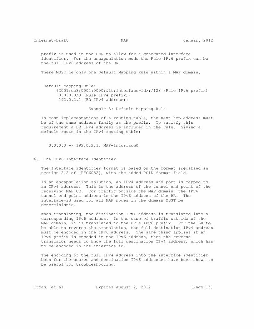
Internet-Draft MAP January 2012
prefix is used in the DMR to allow for a generated interface identifier. For the encapsulation mode the Rule IPv6 prefix can be the full IPv6 address of the BR.
There MUST be only one Default Mapping Rule within a MAP domain.
Default Mapping Rule: {2001:db8:0001:0000:<interface-id>:/128 (Rule IPv6 prefix), 0.0.0.0/0 (Rule IPv4 prefix), 192.0.2.1 (BR IPv4 address)}
Example 3: Default Mapping Rule
In most implementations of a routing table, the next-hop address must be of the same address family as the prefix. To satisfy this requirement a BR IPv4 address is included in the rule. Giving a default route in the IPv4 routing table:
0.0.0.0 -> 192.0.2.1, MAP-Interface0
6. The IPv6 Interface Identifier
The Interface identifier format is based on the format specified in section 2.2 of [RFC6052], with the added PSID format field.
In an encapsulation solution, an IPv4 address and port is mapped to an IPv6 address. This is the address of the tunnel end point of the receiving MAP CE. For traffic outside the MAP domain, the IPv6 tunnel end point address is the IPv6 address of the BR. The interface-id used for all MAP nodes in the domain MUST be deterministic.
When translating, the destination IPv4 address is translated into a corresponding IPv6 address. In the case of traffic outside of the MAP domain, it is translated to the BR’s IPv6 prefix. For the BR to be able to reverse the translation, the full destination IPv4 address must be encoded in the IPv6 address. The same thing applies if an IPv4 prefix is encoded in the IPv6 address, then the reverse translator needs to know the full destination IPv4 address, which has to be encoded in the interface-id.
The encoding of the full IPv4 address into the interface identifier, both for the source and destination IPv6 addresses have been shown to be useful for troubleshooting.
Troan, et al. Expires August 2, 2012 [Page 15]

Internet-Draft MAP January 2012
+--+---+---+---+---+---+---+---+---+ |PL| 8 16 24 32 40 48 56 | +--+---+---+---+---+---+---+---+---+ |64| u | IPv4 address | PSID | 0 | +--+---+---+---+---+---+---+---+---+
Figure 7
In the case of an IPv4 prefix, the IPv4 address field is right-padded with zeroes up to 32 bits. The PSID field is left-padded to create a 16 bit field. For an IPv4 prefix or a complete IPv4 address, the PSID field is zero.
If the End-user IPv6 prefix length is larger than 64, the most significant parts of the interface identifier is overwritten by the prefix. For translation mode the End-user IPv6 prefix MUST be 64 or shorter.
7. IANA Considerations
This specification does not require any IANA actions.
8. Security Considerations
Specific security considerations with the MAP mechanism are detailed in the encapsulation and translation documents [I-D.mdt-map-t/ I-D.mdt-map-e].
[RFC6269] outlines general issues with IPv4 address sharing.
9. Contributors
Mohamed Boucadair, Gang Chen, Maoke Chen, Wojciech Dec, Xiaohong Deng, Jouni Korhonen, Tomasz Mrugalski, Jacni Qin, Chunfa Sun, Qiong Sun, Leaf Yeh.
10. Acknowledgements
This document is based on the ideas of many. In particular Remi Despres, who has tirelessly worked on generalized mechanisms for stateless address mapping.
The authors would like to thank Guillaume Gottard, Dan Wing, Jan
Troan, et al. Expires August 2, 2012 [Page 16]

Internet-Draft MAP January 2012
Zorz, Necj Scoberne, Tina Tsou for their thorough review and comments.
11. References
11.1. Normative References
[I-D.mdt-softwire-map-dhcp-option] Mrugalski, T., Boucadair, M., Deng, X., Troan, O., and C. Bao, "DHCPv6 Options for Mapping of Address and Port", draft-mdt-softwire-map-dhcp-option-02 (work in progress), January 2012.
[RFC2119] Bradner, S., "Key words for use in RFCs to Indicate Requirement Levels", BCP 14, RFC 2119, March 1997.
[RFC6346] Bush, R., "The Address plus Port (A+P) Approach to the IPv4 Address Shortage", RFC 6346, August 2011.
11.2. Informative References
[I-D.ietf-softwire-stateless-4v6-motivation] Boucadair, M., Matsushima, S., Lee, Y., Bonness, O., Borges, I., and G. Chen, "Motivations for Stateless IPv4 over IPv6 Migration Solutions", draft-ietf-softwire-stateless-4v6-motivation-00 (work in progress), September 2011.
[I-D.ietf-tsvwg-iana-ports] Cotton, M., Eggert, L., Touch, J., Westerlund, M., and S. Cheshire, "Internet Assigned Numbers Authority (IANA) Procedures for the Management of the Service Name and Transport Protocol Port Number Registry", draft-ietf-tsvwg-iana-ports-10 (work in progress), February 2011.
[RFC1933] Gilligan, R. and E. Nordmark, "Transition Mechanisms for IPv6 Hosts and Routers", RFC 1933, April 1996.
[RFC2529] Carpenter, B. and C. Jung, "Transmission of IPv6 over IPv4 Domains without Explicit Tunnels", RFC 2529, March 1999.
[RFC2663] Srisuresh, P. and M. Holdrege, "IP Network Address Translator (NAT) Terminology and Considerations", RFC 2663, August 1999.
[RFC2766] Tsirtsis, G. and P. Srisuresh, "Network Address
Troan, et al. Expires August 2, 2012 [Page 17]
Internet-Draft MAP January 2012
Translation - Protocol Translation (NAT-PT)", RFC 2766, February 2000.
[RFC3056] Carpenter, B. and K. Moore, "Connection of IPv6 Domains via IPv4 Clouds", RFC 3056, February 2001.
[RFC3633] Troan, O. and R. Droms, "IPv6 Prefix Options for Dynamic Host Configuration Protocol (DHCP) version 6", RFC 3633, December 2003.
[RFC4380] Huitema, C., "Teredo: Tunneling IPv6 over UDP through Network Address Translations (NATs)", RFC 4380, February 2006.
[RFC5214] Templin, F., Gleeson, T., and D. Thaler, "Intra-Site Automatic Tunnel Addressing Protocol (ISATAP)", RFC 5214, March 2008.
[RFC5969] Townsley, W. and O. Troan, "IPv6 Rapid Deployment on IPv4 Infrastructures (6rd) -- Protocol Specification", RFC 5969, August 2010.
[RFC6052] Bao, C., Huitema, C., Bagnulo, M., Boucadair, M., and X. Li, "IPv6 Addressing of IPv4/IPv6 Translators", RFC 6052, October 2010.
[RFC6146] Bagnulo, M., Matthews, P., and I. van Beijnum, "Stateful NAT64: Network Address and Protocol Translation from IPv6 Clients to IPv4 Servers", RFC 6146, April 2011.
[RFC6147] Bagnulo, M., Sullivan, A., Matthews, P., and I. van Beijnum, "DNS64: DNS Extensions for Network Address Translation from IPv6 Clients to IPv4 Servers", RFC 6147, April 2011.
[RFC6250] Thaler, D., "Evolution of the IP Model", RFC 6250, May 2011.
[RFC6269] Ford, M., Boucadair, M., Durand, A., Levis, P., and P. Roberts, "Issues with IP Address Sharing", RFC 6269, June 2011.
[RFC6333] Durand, A., Droms, R., Woodyatt, J., and Y. Lee, "Dual- Stack Lite Broadband Deployments Following IPv4 Exhaustion", RFC 6333, August 2011.
Troan, et al. Expires August 2, 2012 [Page 18]
Internet-Draft MAP January 2012
Authors’ Addresses
Ole Troan cisco Oslo Norway
Email: [email protected]
Satoru Matsushima SoftBank Telecom 1-9-1 Higashi-Shinbashi, Munato-ku Tokyo Japan
Email: [email protected]
Tetsuya Murakami IP Infusion 1188 East Arques Avenue Sunnyvale USA
Email: [email protected]
Xing Li CERNET Center/Tsinghua University Room 225, Main Building, Tsinghua University Beijing 100084 CN
Email: [email protected]
Congxiao Bao CERNET Center/Tsinghua University Room 225, Main Building, Tsinghua University Beijing 100084 CN
Email: [email protected]
Troan, et al. Expires August 2, 2012 [Page 19]


Internet Engineering Task Force R. PennoInternet-Draft A. DurandIntended status: Standards Track Juniper NetworksExpires: September 12, 2012 A. Clauberg Deutsche Telekom AG L. Hoffmann Bouygues Telecom March 11, 2012
Stateless DS-Lite draft-penno-softwire-sdnat-02
Abstract
This memo define a simple stateless and deterministic mode of operating a carrier-grade NAT as a backward compatible evolution of DS-Lite.
Status of this Memo
This Internet-Draft is submitted in full conformance with the provisions of BCP 78 and BCP 79.
Internet-Drafts are working documents of the Internet Engineering Task Force (IETF). Note that other groups may also distribute working documents as Internet-Drafts. The list of current Internet- Drafts is at http://datatracker.ietf.org/drafts/current/.
Internet-Drafts are draft documents valid for a maximum of six months and may be updated, replaced, or obsoleted by other documents at any time. It is inappropriate to use Internet-Drafts as reference material or to cite them other than as "work in progress."
This Internet-Draft will expire on September 12, 2012.
Copyright Notice
Copyright (c) 2012 IETF Trust and the persons identified as the document authors. All rights reserved.
This document is subject to BCP 78 and the IETF Trust’s Legal Provisions Relating to IETF Documents (http://trustee.ietf.org/license-info) in effect on the date of publication of this document. Please review these documents carefully, as they describe your rights and restrictions with respect to this document. Code Components extracted from this document must include Simplified BSD License text as described in Section 4.e of
Penno, et al. Expires September 12, 2012 [Page 1]

Internet-Draft Stateless DS-Lite March 2012
the Trust Legal Provisions and are provided without warranty as described in the Simplified BSD License.
Table of Contents
1. Introduction . . . . . . . . . . . . . . . . . . . . . . . . . 3 2. Stateless DS-Lite CPE . . . . . . . . . . . . . . . . . . . . 4 2.1. Learning external IPv4 address . . . . . . . . . . . . . . 4 2.2. Learning external port range . . . . . . . . . . . . . . . 4 2.3. Stateless DS-Lite CPE operation . . . . . . . . . . . . . 5 2.4. Host-based Stateless DS-Lite . . . . . . . . . . . . . . . 5 3. Stateless AFTR . . . . . . . . . . . . . . . . . . . . . . . . 5 3.1. Anycast IPv6 address for Stateless AFTR . . . . . . . . . 5 3.2. Stateless AFTR IPv4 address pool . . . . . . . . . . . . . 5 3.3. Stateless AFTR per-subscriber mapping table . . . . . . . 5 3.4. Stateless AFTR decapsulation rules . . . . . . . . . . . . 6 3.5. Stateless AFTR encapsulation rules . . . . . . . . . . . . 6 3.6. Redundancy and fail over . . . . . . . . . . . . . . . . . 7 3.7. SD-AFTR stateless domain . . . . . . . . . . . . . . . . . 7 4. Backward compatibility with DS-Lite . . . . . . . . . . . . . 7 5. ICMP port restricted message . . . . . . . . . . . . . . . . . 8 5.1. Introduction . . . . . . . . . . . . . . . . . . . . . . . 8 5.2. Source port restricted ICMP . . . . . . . . . . . . . . . 8 5.3. Host behavior . . . . . . . . . . . . . . . . . . . . . . 9 6. IANA Considerations . . . . . . . . . . . . . . . . . . . . . 9 7. Security Considerations . . . . . . . . . . . . . . . . . . . 9 8. References . . . . . . . . . . . . . . . . . . . . . . . . . . 10 8.1. Normative references . . . . . . . . . . . . . . . . . . . 10 8.2. Informative references . . . . . . . . . . . . . . . . . . 10 Authors’ Addresses . . . . . . . . . . . . . . . . . . . . . . . . 11
Penno, et al. Expires September 12, 2012 [Page 2]

Internet-Draft Stateless DS-Lite March 2012
1. Introduction
DS-Lite [RFC6333],is a solution to deal with the IPv4 exhaustion problem once an IPv6 access network is deployed. It enables unmodified IPv4 application to access the IPv4 Internet over the IPv6 access network. In the DS-Lite architecture, global IPv4 addresses are shared among subscribers in the AFTR, acting as a Carrier-Grade NAT (CGN).
[I-D.ietf-softwire-public-4over6] extends the original DS-Lite model to offer a mode where the NAT function is performed in the CPE. This simplifies the AFTR operation as it does not have to perform the NAT function anymore, however, the flip side is that the address sharing function among subscribers was no longer available. [I-D.cui-softwire-b4-translated-ds-lite] introduces port restrictions, but does not completely specifies how the CPE acquires the information about its IPv4 address and its port range. More importantly, that draft does not explain how this solution can be deployed in a regular DS-Lite environment. This memo addresses these issues and clarifies the operation model.
Other approaches like variations of 4rd allows also for a full stateless operation of the decapsulation device. By introducing a strong coupling between the IPv6 address and the derived IPv4 address, they get rid of the per-subscriber state on the decapsulation devices. The approach take here argues that such per- subscriber state is not an issue as it is easily replicated among all decapsulation devices. Eliminating the strong coupling between IPv6 and IPv4 derived addresses, the approach presented here enables service providers a greater flexibility on how their limited pool of IPv4 addresses is managed. It also provide greater freedom on how IPv6 addresses are allocated, as sequential allocation is no longer a pre-requisite.
The approach presented here is stateless and deterministic. It is stateless is NAT bindings are maintained on the CPE, not on the AFTR. It is deterministic as no logs are required on the AFTR to identify which subscriber is using an external Ipv4 address and port.
The stateless DS-Lite architecture has the following characteristics:
o Backward compatible with DS-Lite. A mix of regular DS-Lite CPE and stateless DS-Lite CPEs can interoperate with a stateless DS- Lite AFTR.
o Zero log: Because the AFTR relies only on a per-subscriber mapping table that is reversible, the ISP does not need to keep any NAT binding logs.
Penno, et al. Expires September 12, 2012 [Page 3]

Internet-Draft Stateless DS-Lite March 2012
o Stateless AFTR: There is no per-session state on the AFTRs. By leveraging this stateless and deterministic mode of operation, an ISP can deploy any number of AFTRs to provide redundancy and scalability at low cost. Because there is no per-flow state to maintain, AFTR can implement the functionality in hardware and perform it at high speed with low latency.
o Flexibility of operation: The ISP can add or remove addresses from the NAT pool without having to renumber the access network.
o Leverage IPv6: This stateless DS-Lite model leverage the IPv6 access network deployed by the ISPs.
2. Stateless DS-Lite CPE
The key words "MUST", "MUST NOT", "REQUIRED", "SHALL", "SHALL NOT", "SHOULD", "SHOULD NOT", "RECOMMENDED", "MAY", and "OPTIONAL" in this document are to be interpreted as described in RFC 2119 [RFC2119].
A Stateless DS-Lite CPE operates in similar fashion than a regular DS-Lite CPE, where the NAT function is re-introduced in CPE with a modification on how ports are managed.
2.1. Learning external IPv4 address
A stateless DS-Lite CPE MUST implement the DHCPv4 client relay option defined in [I-D.ietf-dhc-dhcpv4-over-ipv6] to learn is external IPv4 address. Other mechanism, such as manual configuration or TR69, MAY be implemented.
2.2. Learning external port range
A stateless DS-Lite CPE MUST implement the ICMP "port restricted" option defined later in this memo.
At boot time and later at intervals of 1h +/- a random number of seconds between 0 and 900), the stateless DS-Lite CPE MUST send packets with source port 0, source IPv4 address of the B4 element, destination IPv4 address 192.0.0.1 (the AFTR well-known IPv4 address) destination port 0, for each of the supported transport protocols (usually TCP and UDP). This will trigger an ICMP "port restricted" message from the AFTR.
After validating the content of the "ICMP port restricted" message, the stateless DS-Lite CPE MUST configure its port pool with it. If existing connections were using source ports outside of that range, the stateless DS-Lite CPE MUST terminate them.
Penno, et al. Expires September 12, 2012 [Page 4]
Internet-Draft Stateless DS-Lite March 2012
2.3. Stateless DS-Lite CPE operation
The stateless DS-Lite CPE performs IPv4 NAPT from the internal RFC1918 addresses to the IPv4 address configured on the WAN interface, restricting its available ports to the range obtained as described above.
2.4. Host-based Stateless DS-Lite
Any host initiating directly a DS-Lite IPv4 over IPv6 tunnel can benefit from this techniques by implementing a ’virtual’ stateless DS-Lite CPE function within its IP stack.
3. Stateless AFTR
3.1. Anycast IPv6 address for Stateless AFTR
All stateless AFTRs associated to a domain (or group of subscribers) will be configured with the same IPv6 address on the interface facing IPv6 subscribers. A route for that IPv6 address will be anycasted within the access network.
3.2. Stateless AFTR IPv4 address pool
All stateless AFTRs associated to a domain (or group of subscribers) MUST be configured with the same pool of global IPv4 addresses.
Routes to the pool of global IPv4 addresses configured on the stateless AFTRs will be anycasted by the relevant AFTRs within the ISP routing domain.
3.3. Stateless AFTR per-subscriber mapping table
Stateless AFTRs associated to a domain (or group of subscribers) MUST be configured with the same per-subscriber mapping table, associating the IPv6 address of the subscriber CPE to the external IPv4 address and port range provisioned for this subscriber.
Because the association IPv6 address --- IPv4 address + port range is not tied to a mathematical formula, the ISP maintains all flexibility to allocate independently IPv6 address and IPv4 addresses. In particular, IPv6 addresses do not have to be allocated sequentially and IPv4 resources can be modified freely.
Penno, et al. Expires September 12, 2012 [Page 5]

Internet-Draft Stateless DS-Lite March 2012
+--------------+------------+----------+ | IPv6 address |IPv4 address|port-range| +--------------+------------+----------+ |2001:db8::1 | 1.2.3.4 | 1000-1999| |2001:db8::5 | 1.2.3.4 | 2000-2999| |2001:db8::a:1 | 1.2.3.4 | 3000-3999| +--------------+------------+----------+
Figure 1: Per-subscriber mapping table example
This per-subscriber mapping table can be implemented in various ways which details are out of scope for this memo. In its simplest form, it can be a static file that is replicated out-of-band on the AFTRs. In a more elaborated way, this table can be dynamically built using radius queries to a subscriber database.
3.4. Stateless AFTR decapsulation rules
Upstream IPv4 over IPv6 traffic will be decapsulated by the AFTR. The AFTR MUST check the outer IPv6 source address belongs to an identified subscriber and drop the traffic if not. The AFTR MUST then check the inner IPv4 header to make sure the IPv4 source address and ports are valid according to the per-subscriber mapping table.
If the inner IPv4 source address does not match the entry in the per- subscriber mapping table, the packet MUST be discarded and an ICMP ’administratively prohibited’ message MAY be returned.
If the IPv4 source port number falls outside of the range allocated to the subscriber, the AFTR MUST discard the datagram and MUST send back an ICMP "port restricted" message to the IPv6 source address of the packet.
Fragmentation and reassembly is treated as in DS-Lite [RFC6333].
3.5. Stateless AFTR encapsulation rules
Downstream traffic is validated using the per-subscriber mapping table. Traffic that falls outside of the IPv4 address/port range entries in that table MUST be discarded. Validated traffic is then encapsulated in IPv6 and forwarded to the associated IPv6 address.
Fragmentation and reassembly is treated as in DS-Lite [RFC6333].
Penno, et al. Expires September 12, 2012 [Page 6]

Internet-Draft Stateless DS-Lite March 2012
3.6. Redundancy and fail over
Because there is no per-flow state, upstream and downstream traffic can use any stateless AFTR.
3.7. SD-AFTR stateless domain
Using the DHCPv6 DS-Lite tunnel-end-point option, groups of subscribers and can be associated to a different stateless AFTR domain. That can allow for differentiated level of services, e.g. number of ports per customer device, QoS, bandwidth, value added services,...
4. Backward compatibility with DS-Lite
A number of service providers are, or are in the process of, deploying DS-Lite in their network. They are interested in evolving their design toward a stateless model. Backward compatibility is a critical issue, as, from an operational perspective, it is difficult to get all CPEs evolve at the same time.
So AFTRs have to be ready to service CPEs that are pure DS-Lite, some that are implementing only DHCPv4 over IPv6 and handle the NAT on the full IPv4 address themselves and some that also implement port restrictions via the ICMP message described here. For this reason, a AFTR operating in backward compatibility mode MAY decide to re-NAT upstream packets which source port number do not fall into the predefined range instead of simply dropping the packets.
The operating model is the following:
o Stateless DS-Lite: for CPEs that pre-NAT and pre-shape the source port space into the range assigned to the subscriber: decapsulate, check per-subscriber mapping, forward.
o B4-translated DS-Lite: for CPEs that performs NAT before encapsulation and are allocated a full IPv4 address: decapsulate, check per-subscriber mapping, forward.
o Re-shaper DS-Lite: for CPEs that pre NAT but fail to restrict the source ports: decapsulate, check per-subscriber mapping, re-NAT statefully the packets into the restricted port range, mark range as ’stateful’, forward.
o Regular DS-Lite: for regular DS-Lite CPEs that do not pre-NAT: decapsulate, NAT statefully, forward.
Penno, et al. Expires September 12, 2012 [Page 7]

Internet-Draft Stateless DS-Lite March 2012
In such a backward compatibility mode, the AFTR is only operating statelessly for the stateless DS-Lite CPEs. It needs to maintain per-flow state for the regular DS-Lite CPEs and the non-ICMP port restricted compliant CPEs. In this legacy mode where per-flow state is required, the simple anycast-based fail-over mechanism is no longer available.
5. ICMP port restricted message
Note: this section may end-up being a separate Internet draft.
5.1. Introduction
In the framework of A+P RFC 6346 [RFC6346], sources may be restricted to use only a subset of the port range of a transport protocol associated with an IPv4 address. When that source transmit a packet with a source outside of the pre-authorized range, the upstream NAT will drop the packet and use the ICMP message defined here to inform the source of the actual port range allocated.
This memo defines such ICMP messages for TCP and UDP and leaves the definition of the ICMP option for other transport protocol for future work.
The key words "MUST", "MUST NOT", "REQUIRED", "SHALL", "SHALL NOT", "SHOULD", "SHOULD NOT", "RECOMMENDED", "MAY", and "OPTIONAL" in this document are to be interpreted as described in RFC 2119 [RFC2119].
5.2. Source port restricted ICMP
+-+-+-+-+-+-+-+-+-+-+-+-+-+-+-+-+-+-+-+-+-+-+-+-+-+-+-+-+-+-+-+-+ | Type | Code | Checksum | +-+-+-+-+-+-+-+-+-+-+-+-+-+-+-+-+-+-+-+-+-+-+-+-+-+-+-+-+-+-+-+-+ | Min Port | Max Port | +-+-+-+-+-+-+-+-+-+-+-+-+-+-+-+-+-+-+-+-+-+-+-+-+-+-+-+-+-+-+-+-+ | | ˜ Original Internet Headers + 64 bits of Payload ˜ | | +-+-+-+-+-+-+-+-+-+-+-+-+-+-+-+-+-+-+-+-+-+-+-+-+-+-+-+-+-+-+-+-+
Figure 2: Source Port Restricted ICMP
Type: TBD for Source Port Restricted
Checksum: The checksum is the 16-bit ones’s complement of the one’s complement sum of the ICMP message starting with the ICMP Type. For
Penno, et al. Expires September 12, 2012 [Page 8]
Internet-Draft Stateless DS-Lite March 2012
computing the checksum , the checksum field should be zero. This checksum may be replaced in the future.
Code: 6 for TCP, 17 for UDP
Min Port: The lowest port number allocated for that source.
Max Port: The highest port number allocated for that source.
5.3. Host behavior
A host receiving an ICMP type TBD message for a given transport protocol SHOULD NOT send packets sourced by the IP address(es) corresponding to the interface that received that ICMP message with source ports outside of the range specified for the given transport protocol.
Packets sourced with port numbers outside of the restricted range MAY be dropped or NATed upstream to fit within the restricted range.
A host MUST NOT take port restriction information applying to a given IP address and transport protocol and applies it to other IP addresses on other interfaces and/or other transport protocols.
If Min Port = 0 and Max Port = 65535, it indicates that the entire port range for the given transport protocol is available. If such ’full range’ messages are received for all transport protocols, the host can take this as an indication that its IP address is probably not shared with other devices.
In order to mitigate possible man in the middle attacks, a host MUST discard ICMP type TBD messages if the associated port range (Max Port - Min Port) is lower than 64.
6. IANA Considerations
IANA is to allocated a code point for this ICMP message type.
7. Security Considerations
This ICMP message type has the same security properties as other ICMP messages such as Redirect or Destination Unreachable. A man-in-the- middle attack can be mounted to create a DOS attack on the source. Ingress filtering on network boundary can mitigate such attacks. However, in case such filtering measures are not enough, the additional provision that a host MUST discard such ICMP message with
Penno, et al. Expires September 12, 2012 [Page 9]
Internet-Draft Stateless DS-Lite March 2012
a port range smaller than 64 can mitigate even further such attacks.
As described in [RFC6269], with any fixed size address sharing techniques, port randomization is achieved with a smaller entropy.
Recommendations listed in [RFC6302] applies.
8. References
8.1. Normative references
[I-D.ietf-dhc-dhcpv4-over-ipv6] Lemon, T., Cui, Y., Wu, P., and J. Wu, "DHCPv4 over IPv6 Transport", draft-ietf-dhc-dhcpv4-over-ipv6-00 (work in progress), November 2011.
[RFC0792] Postel, J., "Internet Control Message Protocol", STD 5, RFC 792, September 1981.
[RFC2119] Bradner, S., "Key words for use in RFCs to Indicate Requirement Levels", BCP 14, RFC 2119, March 1997.
[RFC6333] Durand, A., Droms, R., Woodyatt, J., and Y. Lee, "Dual- Stack Lite Broadband Deployments Following IPv4 Exhaustion", RFC 6333, August 2011.
8.2. Informative references
[I-D.cui-softwire-b4-translated-ds-lite] Boucadair, M., Sun, Q., Tsou, T., Lee, Y., and Y. Cui, "Lightweight 4over6: An Extension to DS-Lite Architecture", draft-cui-softwire-b4-translated-ds-lite-05 (work in progress), February 2012.
[I-D.ietf-pcp-base] Cheshire, S., Boucadair, M., Selkirk, P., Wing, D., and R. Penno, "Port Control Protocol (PCP)", draft-ietf-pcp-base-23 (work in progress), February 2012.
[I-D.ietf-softwire-public-4over6] Cui, Y., Wu, J., Wu, P., Metz, C., Vautrin, O., and Y. Lee, "Public IPv4 over Access IPv6 Network", draft-ietf-softwire-public-4over6-00 (work in progress), September 2011.
[RFC6269] Ford, M., Boucadair, M., Durand, A., Levis, P., and P. Roberts, "Issues with IP Address Sharing", RFC 6269,
Penno, et al. Expires September 12, 2012 [Page 10]

Internet-Draft Stateless DS-Lite March 2012
June 2011.
[RFC6302] Durand, A., Gashinsky, I., Lee, D., and S. Sheppard, "Logging Recommendations for Internet-Facing Servers", BCP 162, RFC 6302, June 2011.
[RFC6346] Bush, R., "The Address plus Port (A+P) Approach to the IPv4 Address Shortage", RFC 6346, August 2011.
Authors’ Addresses
Reinaldo Penno Juniper Networks 1194 North Mathilda Avenue Sunnyvale, CA 94089-1206 USA
Email: [email protected]
Alain Durand Juniper Networks 1194 North Mathilda Avenue Sunnyvale, CA 94089-1206 USA
Email: [email protected]
Alex Clauberg Deutsche Telekom AG GTN-FM4 Landgrabenweg 151 Bonn, CA 53227 Germany
Email: [email protected]
Penno, et al. Expires September 12, 2012 [Page 11]

Internet-Draft Stateless DS-Lite March 2012
Lionel Hoffmann Bouygues Telecom TECHNOPOLE 13/15 Avenue du Marechal Juin Meudon 92360 France
Email: [email protected]
Penno, et al. Expires September 12, 2012 [Page 12]


Softwire WG J. QinInternet-Draft ZTEIntended status: Standards Track M. BoucadairExpires: May 3, 2012 France Telecom T. Tsou Huawei Technologies (USA) October 31, 2011
DHCPv6 Options for IPv6 DS-Lite Multicast Prefix draft-qin-softwire-multicast-prefix-option-01
Abstract
This document defines Dynamic Host Configuration Protocol version 6 (DHCPv6) Options for multicast transition solutions, aiming to convey the IPv6 prefixes to be used to build unicast and multicast IPv4- embedded IPv6 addresses.
These options can be in particular used in the context of DS-Lite, Stateless A+P and other IPv4-IPv6 interconnection techniques.
Status of this Memo
This Internet-Draft is submitted in full conformance with the provisions of BCP 78 and BCP 79.
Internet-Drafts are working documents of the Internet Engineering Task Force (IETF). Note that other groups may also distribute working documents as Internet-Drafts. The list of current Internet- Drafts is at http://datatracker.ietf.org/drafts/current/.
Internet-Drafts are draft documents valid for a maximum of six months and may be updated, replaced, or obsoleted by other documents at any time. It is inappropriate to use Internet-Drafts as reference material or to cite them other than as "work in progress."
This Internet-Draft will expire on May 3, 2012.
Copyright Notice
Copyright (c) 2011 IETF Trust and the persons identified as the document authors. All rights reserved.
This document is subject to BCP 78 and the IETF Trust’s Legal Provisions Relating to IETF Documents (http://trustee.ietf.org/license-info) in effect on the date of publication of this document. Please review these documents
Qin, et al. Expires May 3, 2012 [Page 1]

Internet-Draft Multicast Prefix Option October 2011
carefully, as they describe your rights and restrictions with respect to this document. Code Components extracted from this document must include Simplified BSD License text as described in Section 4.e of the Trust Legal Provisions and are provided without warranty as described in the Simplified BSD License.
Table of Contents
1. Introduction . . . . . . . . . . . . . . . . . . . . . . . . . 3 1.1. Requirements Language . . . . . . . . . . . . . . . . . . . 3 2. Terminology . . . . . . . . . . . . . . . . . . . . . . . . . . 3 3. PREFIX64 DHCPv6 Option . . . . . . . . . . . . . . . . . . . . 4 3.1. Option Format . . . . . . . . . . . . . . . . . . . . . . . 4 3.2. M_PREFIX64 Sub-option . . . . . . . . . . . . . . . . . . . 4 3.3. U_PREFIX64 Sub-option . . . . . . . . . . . . . . . . . . . 5 4. Client Behaviour . . . . . . . . . . . . . . . . . . . . . . . 6 5. Server Behaviour . . . . . . . . . . . . . . . . . . . . . . . 6 6. Security Considerations . . . . . . . . . . . . . . . . . . . . 7 7. Acknowledgements . . . . . . . . . . . . . . . . . . . . . . . 7 8. IANA Considerations . . . . . . . . . . . . . . . . . . . . . . 7 9. References . . . . . . . . . . . . . . . . . . . . . . . . . . 8 9.1. Normative References . . . . . . . . . . . . . . . . . . . 8 9.2. Informative References . . . . . . . . . . . . . . . . . . 8 Authors’ Addresses . . . . . . . . . . . . . . . . . . . . . . . . 9
Qin, et al. Expires May 3, 2012 [Page 2]

Internet-Draft Multicast Prefix Option October 2011
1. Introduction
[I-D.ietf-softwire-dslite-multicast] and several other solutions (e.g., [I-D.ietf-softwire-mesh-multicast], [I-D.venaas-behave-mcast46], etc.) are proposed for the delivery of multicast services in the context of transition to IPv6. Even these solutions may have different applicable use cases, they all use specific IPv6 addresses to embed IPv4 addresses, for both the multicast group addresses [I-D.boucadair-behave-64-multicast-address-format], and the multicast source addresses [RFC6052].
This document defines DHCPv6 options [RFC3315] to convey the IPv6 prefixes (a.k.a., PREFIX64) to be used for constructing these IPv4- embedded IPv6 addresses.
These options can be in particular used in the context of DS-Lite [RFC6333], Stateless A+P [RFC6346] and other IPv4-IPv6 interconnection techniques.
1.1. Requirements Language
The key words "MUST", "MUST NOT", "REQUIRED", "SHALL", "SHALL NOT", "SHOULD", "SHOULD NOT", "RECOMMENDED", "MAY", and "OPTIONAL" in this document are to be interpreted as described in RFC 2119 [RFC2119].
2. Terminology
This document makes use of the following terms:
o IPv4-embedded IPv6 address: is an IPv6 address which embeds a 32 bit-encoded IPv4 address [RFC6052]. An IPv4-embedded IPv6 address can be unicast or multicast address.
o PREFIX64: is a dedicated IPv6 prefix for building IPv4-embedded IPv6 addresses. A PREFIX64 can be of unicast or multicast.
o M_PREFIX64: denotes a multicast PREFIX64. It may belong to the SSM range (i.e., ff3x::/32 [RFC4607]) or ASM range.
o U_PREFIX64: denotes a unicast PREFIX64 for building the IPv4- embedded IPv6 addresses of multicast sources in SSM mode.
Qin, et al. Expires May 3, 2012 [Page 3]
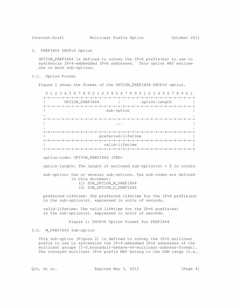
Internet-Draft Multicast Prefix Option October 2011
3. PREFIX64 DHCPv6 Option
OPTION_PREFIX64 is defined to convey the IPv6 prefix(es) to use to synthesize IPv4-embbedded IPv6 addresses. This option MAY enclose one or more sub-options.
3.1. Option Format
Figure 1 shows the format of the OPTION_PREFIX64 DHCPv6 option.
0 1 2 3 4 5 6 7 8 9 0 1 2 3 4 5 6 7 8 9 0 1 2 3 4 5 6 7 8 9 0 1 +-+-+-+-+-+-+-+-+-+-+-+-+-+-+-+-+-+-+-+-+-+-+-+-+-+-+-+-+-+-+-+-+ | OPTION_PREFIX64 | option-length | +-+-+-+-+-+-+-+-+-+-+-+-+-+-+-+-+-+-+-+-+-+-+-+-+-+-+-+-+-+-+-+-+ | sub-option | . . +-+-+-+-+-+-+-+-+-+-+-+-+-+-+-+-+-+-+-+-+-+-+-+-+-+-+-+-+-+-+-+-+ | ... | . . +-+-+-+-+-+-+-+-+-+-+-+-+-+-+-+-+-+-+-+-+-+-+-+-+-+-+-+-+-+-+-+-+ | preferred-lifetime | +-+-+-+-+-+-+-+-+-+-+-+-+-+-+-+-+-+-+-+-+-+-+-+-+-+-+-+-+-+-+-+-+ | valid-lifetime | +-+-+-+-+-+-+-+-+-+-+-+-+-+-+-+-+-+-+-+-+-+-+-+-+-+-+-+-+-+-+-+-+
option-code: OPTION_PREFIX64 (TBD)
option-length: The length of enclosed sub-option(s) + 8 in octets
sub-option: One or several sub-obtions. Two sub-codes are defined in this document: (1) SUB_OPTION_M_PREFIX64 (2) SUB_OPTION_U_PREFIX64
preferred-lifetime: The preferred lifetime for the IPv6 prefix(es) in the sub-option(s), expressed in units of seconds.
valid-lifetime: The valid lifetime for the IPv6 prefix(es) in the sub-option(s), expressed in units of seconds.
Figure 1: DHCPv6 Option Format for PREFIX64
3.2. M_PREFIX64 Sub-option
This sub-option (Figure 2) is defined to convey the IPv6 multicast prefix to use to synthesize the IPv4-embedded IPv6 addresses of the multicast groups [I-D.boucadair-behave-64-multicast-address-format]. The conveyed multicast IPv6 prefix MAY belong to the SSM range (i.e.,
Qin, et al. Expires May 3, 2012 [Page 4]
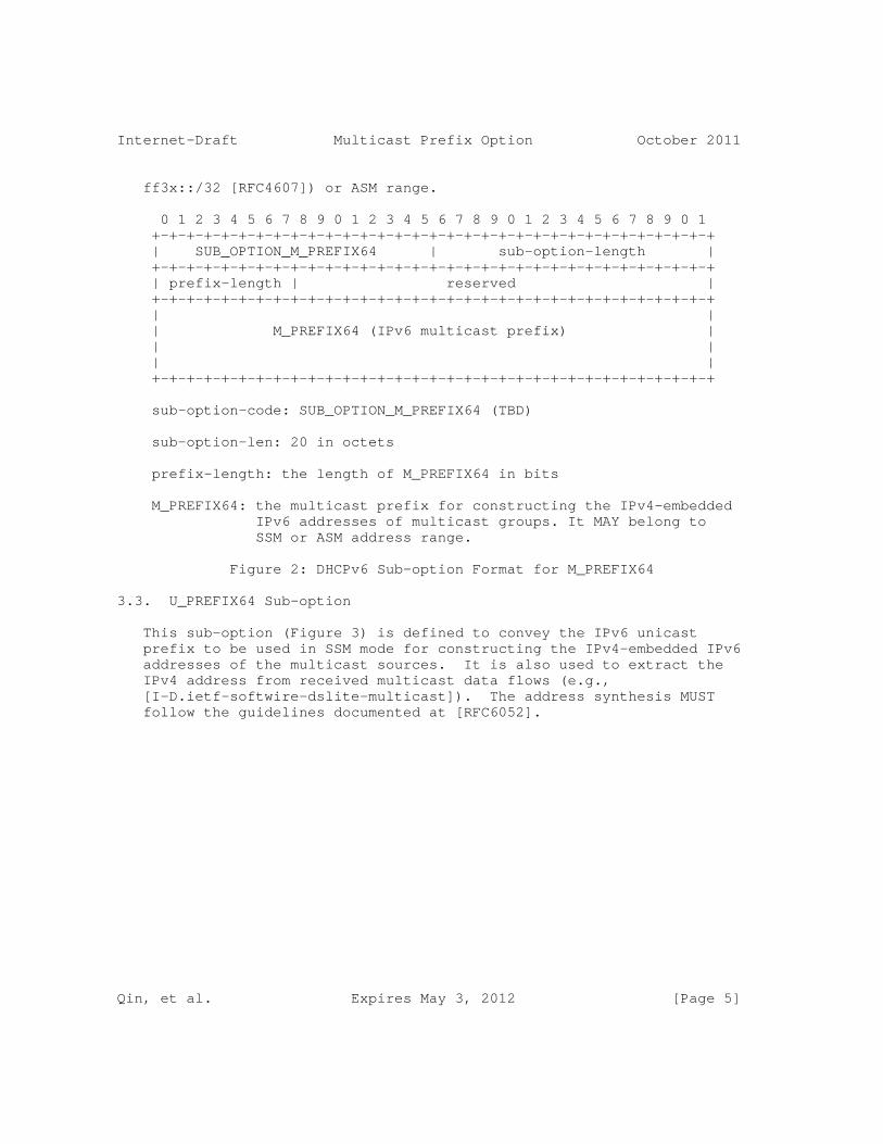
Internet-Draft Multicast Prefix Option October 2011
ff3x::/32 [RFC4607]) or ASM range.
0 1 2 3 4 5 6 7 8 9 0 1 2 3 4 5 6 7 8 9 0 1 2 3 4 5 6 7 8 9 0 1 +-+-+-+-+-+-+-+-+-+-+-+-+-+-+-+-+-+-+-+-+-+-+-+-+-+-+-+-+-+-+-+-+ | SUB_OPTION_M_PREFIX64 | sub-option-length | +-+-+-+-+-+-+-+-+-+-+-+-+-+-+-+-+-+-+-+-+-+-+-+-+-+-+-+-+-+-+-+-+ | prefix-length | reserved | +-+-+-+-+-+-+-+-+-+-+-+-+-+-+-+-+-+-+-+-+-+-+-+-+-+-+-+-+-+-+-+-+ | | | M_PREFIX64 (IPv6 multicast prefix) | | | | | +-+-+-+-+-+-+-+-+-+-+-+-+-+-+-+-+-+-+-+-+-+-+-+-+-+-+-+-+-+-+-+-+
sub-option-code: SUB_OPTION_M_PREFIX64 (TBD)
sub-option-len: 20 in octets
prefix-length: the length of M_PREFIX64 in bits
M_PREFIX64: the multicast prefix for constructing the IPv4-embedded IPv6 addresses of multicast groups. It MAY belong to SSM or ASM address range.
Figure 2: DHCPv6 Sub-option Format for M_PREFIX64
3.3. U_PREFIX64 Sub-option
This sub-option (Figure 3) is defined to convey the IPv6 unicast prefix to be used in SSM mode for constructing the IPv4-embedded IPv6 addresses of the multicast sources. It is also used to extract the IPv4 address from received multicast data flows (e.g., [I-D.ietf-softwire-dslite-multicast]). The address synthesis MUST follow the guidelines documented at [RFC6052].
Qin, et al. Expires May 3, 2012 [Page 5]
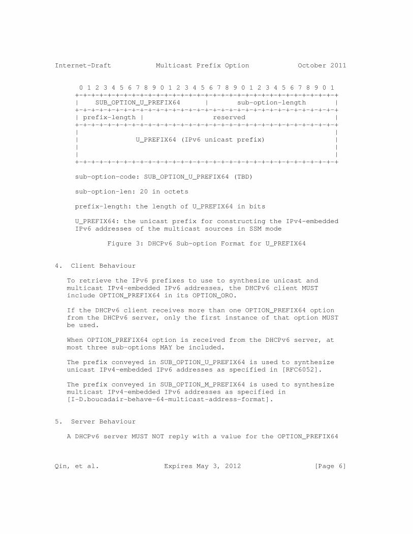
Internet-Draft Multicast Prefix Option October 2011
0 1 2 3 4 5 6 7 8 9 0 1 2 3 4 5 6 7 8 9 0 1 2 3 4 5 6 7 8 9 0 1 +-+-+-+-+-+-+-+-+-+-+-+-+-+-+-+-+-+-+-+-+-+-+-+-+-+-+-+-+-+-+-+-+ | SUB_OPTION_U_PREFIX64 | sub-option-length | +-+-+-+-+-+-+-+-+-+-+-+-+-+-+-+-+-+-+-+-+-+-+-+-+-+-+-+-+-+-+-+-+ | prefix-length | reserved | +-+-+-+-+-+-+-+-+-+-+-+-+-+-+-+-+-+-+-+-+-+-+-+-+-+-+-+-+-+-+-+-+ | | | U_PREFIX64 (IPv6 unicast prefix) | | | | | +-+-+-+-+-+-+-+-+-+-+-+-+-+-+-+-+-+-+-+-+-+-+-+-+-+-+-+-+-+-+-+-+
sub-option-code: SUB_OPTION_U_PREFIX64 (TBD)
sub-option-len: 20 in octets
prefix-length: the length of U_PREFIX64 in bits
U_PREFIX64: the unicast prefix for constructing the IPv4-embedded IPv6 addresses of the multicast sources in SSM mode
Figure 3: DHCPv6 Sub-option Format for U_PREFIX64
4. Client Behaviour
To retrieve the IPv6 prefixes to use to synthesize unicast and multicast IPv4-embedded IPv6 addresses, the DHCPv6 client MUST include OPTION_PREFIX64 in its OPTION_ORO.
If the DHCPv6 client receives more than one OPTION_PREFIX64 option from the DHCPv6 server, only the first instance of that option MUST be used.
When OPTION_PREFIX64 option is received from the DHCPv6 server, at most three sub-options MAY be included.
The prefix conveyed in SUB_OPTION_U_PREFIX64 is used to synthesize unicast IPv4-embedded IPv6 addresses as specified in [RFC6052].
The prefix conveyed in SUB_OPTION_M_PREFIX64 is used to synthesize multicast IPv4-embedded IPv6 addresses as specified in [I-D.boucadair-behave-64-multicast-address-format].
5. Server Behaviour
A DHCPv6 server MUST NOT reply with a value for the OPTION_PREFIX64
Qin, et al. Expires May 3, 2012 [Page 6]
Internet-Draft Multicast Prefix Option October 2011
if the DHCPv6 client has not explicitly included OPTION_PREFIX64 in its OPTION_ORO.
If OPTION_PREFIX64 option is requested by the DHCPv6 client, the DHCPv6 server MUST NOT send more than one OPTION_PREFIX64 option in the response.
One or two SUB_OPTION_M_PREFIX64 sub-options MAY be enclosed in OPTION_PREFIX64 DHCPv6 option. In particular, if only SSM or ASM mode is supported, only one SUB_OPTION_M_PREFIX64 sub-option MUST be returned to the requesting client. If both SSM and ASM mode are supported, two SUB_OPTION_M_PREFIX64 sub-options MUST be returned.
When two SUB_OPTION_M_PREFIX64 sub-options are present, one SUB_OPTION_M_PREFIX64 sub-option MUST convey an IPv6 prefix in SSM range and the other one MUST enclose an IPv6 prefix in the ASM range.
If the IPv6 multicast prefix conveyed in SUB_OPTION_M_PREFIX64 is an SSM prefix, U_PREFIX64 sub-option MUST also be present.
6. Security Considerations
The security considerations in [RFC3315] are to be considered.
7. Acknowledgements
TBD
8. IANA Considerations
A new DHCPv6 option:
OPTION_PREFIX64
and two sub-options:
SUB_OPTION_M_PREFIX64,
SUB_OPTION_U_PREFIX64
need to be assigned by IANA.
9. References
Qin, et al. Expires May 3, 2012 [Page 7]
Internet-Draft Multicast Prefix Option October 2011
9.1. Normative References
[I-D.boucadair-behave-64-multicast-address-format] Boucadair, M., Qin, J., Lee, Y., Venaas, S., Li, X., and M. Xu, "IPv4-Embedded IPv6 Multicast Address Format", draft-boucadair-behave-64-multicast-address-format-03 (work in progress), October 2011.
[RFC2119] Bradner, S., "Key words for use in RFCs to Indicate Requirement Levels", BCP 14, RFC 2119, March 1997.
[RFC3315] Droms, R., Bound, J., Volz, B., Lemon, T., Perkins, C., and M. Carney, "Dynamic Host Configuration Protocol for IPv6 (DHCPv6)", RFC 3315, July 2003.
[RFC4607] Holbrook, H. and B. Cain, "Source-Specific Multicast for IP", RFC 4607, August 2006.
[RFC6052] Bao, C., Huitema, C., Bagnulo, M., Boucadair, M., and X. Li, "IPv6 Addressing of IPv4/IPv6 Translators", RFC 6052, October 2010.
9.2. Informative References
[I-D.ietf-softwire-dslite-multicast] Wang, Q., Qin, J., Boucadair, M., Jacquenet, C., and Y. Lee, "Multicast Extensions to DS-Lite Technique in Broadband Deployments", draft-ietf-softwire-dslite-multicast-00 (work in progress), September 2011.
[I-D.ietf-softwire-mesh-multicast] Xu, M., Cui, Y., Yang, S., Wu, J., Metz, C., and G. Shepherd, "Softwire Mesh Multicast", draft-ietf-softwire-mesh-multicast-01 (work in progress), October 2011.
[I-D.venaas-behave-mcast46] Venaas, S., Asaeda, H., SUZUKI, S., and T. Fujisaki, "An IPv4 - IPv6 multicast translator", draft-venaas-behave-mcast46-02 (work in progress), December 2010.
[RFC6333] Durand, A., Droms, R., Woodyatt, J., and Y. Lee, "Dual- Stack Lite Broadband Deployments Following IPv4 Exhaustion", RFC 6333, August 2011.
[RFC6346] Bush, R., "The Address plus Port (A+P) Approach to the
Qin, et al. Expires May 3, 2012 [Page 8]
Internet-Draft Multicast Prefix Option October 2011
IPv4 Address Shortage", RFC 6346, August 2011.
Authors’ Addresses
Jacni Qin ZTE Shanghai, China
Phone: +86 1391 8619 913 Email: [email protected]
Mohamed Boucadair France Telecom Rennes, 35000 France
Phone: Email: [email protected]
Tina Tsou Huawei Technologies (USA) 2330 Central Expressway Santa Clara, CA 95050 USA
Phone: +1 408 330 4424 Email: [email protected]
Qin, et al. Expires May 3, 2012 [Page 9]

Internet Engineering Task Force B. SarikayaInternet-Draft T. TsouIntended status: Informational Huawei Technologies (USA)Expires: March 15, 2014 H. Ji China Telecom C. Zhou Huawei Technologies September 11, 2013
IPv6 Multicast in a 6rd Deployment draft-sarikaya-softwire-6rdmulticast-06
Abstract
This memo specifies 6rd’s multicast component so that IPv6 hosts can receive multicast data from IPv6 servers. In the 6rd encapsulation solution, multicast communication is completely integrated into the 6rd tunnel. In the 6rd translation solution, the protocol is based on proxying MLD at the 6rd Customer Edge router interworking the MLD messages to IGMP messages and sending them upstream through a network which supports IPv4 multicast. The 6rd Border Relay is a multicast router and interworks the IGMP to MLD for onward propasgation toward the IPv6 multicast source. IPv6 Multicast data received at 6rd Border Relay is translated into IPv4 multicast data and and delivered through the IPv4 multicast tree downstream to the 6rd Customer Edge. The latter translates it back to IPv6 multicast data then delivers it to the hosts.
Status of This Memo
This Internet-Draft is submitted in full conformance with the provisions of BCP 78 and BCP 79.
Internet-Drafts are working documents of the Internet Engineering Task Force (IETF). Note that other groups may also distribute working documents as Internet-Drafts. The list of current Internet- Drafts is at http://datatracker.ietf.org/drafts/current/.
Internet-Drafts are draft documents valid for a maximum of six months and may be updated, replaced, or obsoleted by other documents at any time. It is inappropriate to use Internet-Drafts as reference material or to cite them other than as "work in progress."
This Internet-Draft will expire on March 15, 2014.
Copyright Notice
Sarikaya, et al. Expires March 15, 2014 [Page 1]
Internet-Draft IPv6 Multicast in a 6rd Deployment September 2013
Copyright (c) 2013 IETF Trust and the persons identified as the document authors. All rights reserved.
This document is subject to BCP 78 and the IETF Trust’s Legal Provisions Relating to IETF Documents (http://trustee.ietf.org/license-info) in effect on the date of publication of this document. Please review these documents carefully, as they describe your rights and restrictions with respect to this document. Code Components extracted from this document must include Simplified BSD License text as described in Section 4.e of the Trust Legal Provisions and are provided without warranty as described in the Simplified BSD License.
Table of Contents
1. Introduction . . . . . . . . . . . . . . . . . . . . . . . . 2 2. Terminology . . . . . . . . . . . . . . . . . . . . . . . . . 3 3. Requirements . . . . . . . . . . . . . . . . . . . . . . . . 3 4. Architecture . . . . . . . . . . . . . . . . . . . . . . . . 4 4.1. 6rd Tunneling Architecture . . . . . . . . . . . . . . . 4 4.2. Translation Architecture . . . . . . . . . . . . . . . . 5 5. 6rd Tunneling Multicast Operation . . . . . . . . . . . . . . 6 5.1. Tunnel Interface Considerations . . . . . . . . . . . . . 7 5.2. Avalanche Problem . . . . . . . . . . . . . . . . . . . . 8 6. 6rd Translation Multicast Operation . . . . . . . . . . . . . 8 6.1. Solution Based on Layer 2 Multicast Support . . . . . . . 10 6.2. Analysis . . . . . . . . . . . . . . . . . . . . . . . . 11 7. Security Considerations . . . . . . . . . . . . . . . . . . . 11 8. IANA Considerations . . . . . . . . . . . . . . . . . . . . . 11 9. Acknowledgements . . . . . . . . . . . . . . . . . . . . . . 12 10. References . . . . . . . . . . . . . . . . . . . . . . . . . 12 10.1. Normative References . . . . . . . . . . . . . . . . . . 12 10.2. Informative References . . . . . . . . . . . . . . . . . 13 Authors’ Addresses . . . . . . . . . . . . . . . . . . . . . . . 13
1. Introduction
With IPv4 address depletion on the horizon, many techniques are being standardized for IPv6 migration including 6rd [RFC5969]. 6rd enables IPv6 hosts to communicate with external hosts using an IPv4-only legacy ISP network. The 6rd Customer Edge (CE) device’s LAN side is dual stack and the WAN side is IPv4 only. The CE tunnels IPv6 packets received from the LAN side to 6rd Border Relays (BR) after encapsulating them as IPv4 packets. The BRs have anycast IPv4 addresses and receive encapsulated packets from CEs over a virtual interface. 6rd operation is stateless. Packets are received/ sent independently of each other and no state needs to be maintained.
Sarikaya, et al. Expires March 15, 2014 [Page 2]

Internet-Draft IPv6 Multicast in a 6rd Deployment September 2013
It should be noted that there is no depletion problem for IPv4 address space allocated for any source multicast and source specific multicast [RFC3171]. This document is not motivated by the depletion of IPv4 multicast addresses.
6rd as defined in [RFC5969] and [RFC5569] is unicast only. It does not support multicast. In this document we specify how multicast from home IPv6 users can be supported in 6rd. This is what is meant by 6rd multicast protocol.
In the 6rd encapsulation approach, 6rd multicast is integrated into the 6rd unicast solution. 6rd customer premise equipment (CPE) is extended to support an MLD proxy [RFC4605]. This proxy receives MLD Membership Report messages [RFC4601] requesting to join a multicast group from its subtended hosts. It tunnels aggregated join requests upstream to the 6rd Border Router (BR) using IPv6 in IPv4 encapsulation. The 6rd Border Router is extended to support an MLD querier, which sends join requests upstream towards the multicast source(s, becomes part of the multicast tree, and thus receives IPv6 multicast data. The 6rd Border Router encapsulates the IPv6 multicast data using 6rd’s IPv6 in IPv4 encapsulation and sends it to each member CPE that has joined the stream concerned. The CPE decapsulates the packet and the MLD proxy sends the IPv6 multicast data downstream to the member hosts.
In the translation approach, native IPv4 multicast support in the network between Customer Edge routers and Border Router can be exploited. The translation approach requires MLD to IGMP interworking at the Customer Edge and IGMP to MLD interworking at the border router. The border router needs to translate IPv6 multicast data into IPv4 multicast data and the Customer Edge router needs to translate IPv4 multicast data back into IPv6 multicast data.
6rd’s CE to CE forwarding feature is not used in either approach.
2. Terminology
This document uses the terminology defined in [RFC5969], [RFC5569], [RFC3810], [RFC3376], and [I-D.ietf-softwire-dslite-multicast].
The key words "MUST", "MUST NOT", "REQUIRED", "SHALL", "SHALL NOT", "SHOULD", "SHOULD NOT", "RECOMMENDED", "MAY", and "OPTIONAL" in this document are to be interpreted as described in RFC 2119 [RFC2119].
3. Requirements
This section states requirements on 6rd multicast support protocol.
Sarikaya, et al. Expires March 15, 2014 [Page 3]

Internet-Draft IPv6 Multicast in a 6rd Deployment September 2013
IPv6 hosts connected to 6rd CE router MUST be able to join multicast groups in IPv6 and receive multicast data.
Both any source multicast (ASM) and source specific multicast (SSM) MUST be supported.
6rd multicast MUST NOT introduce the need to use more IPv4 addresses, thereby contributing to public IPv4 address depletion.
4. Architecture
In 6rd, IPv6 or IPv4/IPv6 dual stack hosts are served by the 6rd Customer Edge device (CE). The CE is dual stack facing the hosts and IPv4 only facing the network or WAN side. The CE tunnels IPv6 packets in IPv4 to the 6rd Border Relay (BR). The BR decapsulates the tunneled packets and forwards them to the IPv6 network. In the reverse direction, the BR receives IPv6 packets from the IPv6 network tunnels them in IPv4 to the CE. The CE decapsulates the IPv6 packets and forwards them to the hosts.
Unicast 6rd is stateless. Each IPv6 packet sent by the CE is treated separately and different packets from the same CE may go to different BRs. The CE encapsulates IPv6 packets in IPv4 with the IPv4 destination address set to the BR address (usually an anycast IPv4 address). BRs are placed where IPv6 native connectivity exists to other networks. A CE is configured with its own IPv4 address (public or private), with a 6rd IPv6 prefix from which the CE’s IPv4 address can be derived, and with one or more BR IPv4 addresses. When the BR receives IPv6 packets addressed to the CE, it extracts the CE’s IPv4 address from the destination IPv6 address and uses this address as the destination address for the IPv4 encapsulation of the IPv6 packet. 6rd views the IPv4-only network as an NBMA link from the IPv6 point of view and all 6rd CEs and BRs are defined as off-link neighbors from one other.
4.1. 6rd Tunneling Architecture
In order to support multicast, the CE implements an MLD Proxy function [RFC4605]. IPv6 hosts send their join requests (MLD Membership Report messages) to CE. The CE as a proxy sends aggregated Report messages upstream towards BR in unicast using IPv6 in IPv4 encapsulation.
Dual Stack Hosts IPv4 +----+ Network | H1 | IPv4 +----+ +-----+ only +-------+ +
Sarikaya, et al. Expires March 15, 2014 [Page 4]

Internet-Draft IPv6 Multicast in a 6rd Deployment September 2013
+----+ | CE | network -- | BR | | H2 | ---| MLD |--- IPv6 | MLD | IPv6 +----+ |Proxy| in |Querier| Network +----+ +-----+ IPv4 +-------+ | H3 | Encapsulation +----+
Figure 1: Architecture of 6rd Tunneling Multicast Protocol
The BR is the default multicast querier for the CE. The BR implements a multicast router function or it could be another MLD proxy.
All the elements of 6rd multicast support system are shown in Figure 1.
4.2. Translation Architecture
In order to support multicast, CE implements MLD Proxy [RFC4605] and MLD to IGMP interworking function [ID.perreault-igmp-mld-translation]. IPv6 hosts send their join requests (MLD Membership Report messages) to CE. CE as a proxy sends aggregated IGMP Report messages upstream towards BR.
In order to support SSM, MLDv2 [RFC3810] and IGMPv3 [RFC3376] must be supported by the CE and BR, and MLDv2 must be supported by the host.
The BR is the default multicast querier for the CE. The BR implements an IGMP to MLD interworking function and multicast router function or it could be another MLD proxy.
It is assumed that the IPv4 only network to which the CE and the BR are connected supports native IPv4 multicast.
All the elements of 6rd translation-based multicast support system are shown in Figure 2.
Sarikaya, et al. Expires March 15, 2014 [Page 5]

Internet-Draft IPv6 Multicast in a 6rd Deployment September 2013
Dual Stack Hosts IPv4 +----+ Network | H1 | IPv4 +----+ +----------------+ only +------------------+ +----+ | CE MLD | network |IGMP BR | + | H2 | ---| MLD IGMP |-----------| MLD MLD | +----+ |Proxy Translator| |Translator Querier| +----+ +----------------+ +------------------+ | H3 | IPv6 +----+ Network
Figure 2: Architecture of 6rd Translation-Based Multicast
5. 6rd Tunneling Multicast Operation
In this section we specify how the host can subscribe and receive IPv6 multicast data from IPv6 content providers based on the architecture defined in Figure 1.
The hosts will send their subscription requests for IPv6 multicast groups upstream to the default router, i.e., Costumer Edge device. After subscribing the group, the host can receive multicast data from the CE. The host implements MLD protocol’s host part.
The Customer Edge device is an MLD Proxy. After receiving the first MLD Report message requesting subscription to an IPv6 multicast group, the CE establishes a tunnel interface with a Border Relay. The tunnel is IPv4 based but it will carry MLD messages back and forth and IPv6 multicast data messages downstream.
The CE is a regular MLD proxy and it keeps an MLD proxy membership database. The CE inserts multicast forwarding state on the incoming interface, and merges state updates into the MLD proxy membership database. The CE updates or remove elements from the database as required. The CE will then send an aggregated Report via the upstream tunnel to the BR when the membership database changes.
The CE answers MLD queries from the BR based on the membership database. The CE’s downstream link follows the traditional multipoint channel forwarding and does not pose any specific problems.
The CE receives IPv6 multicast data from the BR tunneled over the tunnel interface. The CE decapsulates the packet and then forwards it downstream. Each member host receives the data packet based on the Layer 2 multicast interface. No packet duplication is necessary.
Sarikaya, et al. Expires March 15, 2014 [Page 6]

Internet-Draft IPv6 Multicast in a 6rd Deployment September 2013
The Border Relay acts as the default multicast querier for all CEs that have established an IPv4 tunnel with it. In order to keep a consistent multicast state between a CE and BR, once a CE is connected it will stay connected until the state becomes empty. After that point, the CE may establish another tunnel to a different BR.
According to aggregated MLD reports received from subtending CEs, the BR establishes group/source-specific multicast forwarding states at its corresponding downstream tunnel interfaces. After that, the BR maintains or removes the state as required by the aggregated reports received from CEs.
At the upstream interface, the BR procures for aggregated multicast membership maintenance. Based on the multicast-transparent operations of the CEs, the BR treats its tunnel interfaces as multicast enabled downstream links, serving zero to many listening nodes.
When the BR receives MLD join requests from downstream CEs, the BR sends PIM join messages upstream towards multicast source(s). This results in a multicast tree formation where the BR is at the leaf of the multicast tree, enabling the BR to receive IPv6 multicast data sent by the source.
Multicast traffic arriving at the BR is transparently forwarded according to its multicast forwarding information base. Multicast data is first replicated according to MLD multicast group state and then forwarded in IPv6-in-IPv4 tunnels from the BR to the corresponding CEs.
5.1. Tunnel Interface Considerations
IPv6 in IPv4 tunneling is performed as specified in [RFC4213]. Considerations specified in [RFC5969] apply. Packets passing upstream from the CE carry only MLD signaling messages and they are not expected to be fragmented. However packets downstream, i.e., multicast data to the CEs, may be subject to fragmentation.
Source and destination addresses of MLD messages in IPv6-in-IPv4 tunnel from CE are as follows:
o The source address of IPv4 header is the CE WAN interface IPv4 address. The destination address is the BR anycast address when an invite message is sent to group G. Subsequent messages to group G contain the BR unicast address as destination address.
Sarikaya, et al. Expires March 15, 2014 [Page 7]

Internet-Draft IPv6 Multicast in a 6rd Deployment September 2013
o The source address of the inner MLD message is the link local address. The destination address is all MLDv2-capable multicast routers or FF02::16 for MLD Version 2 Multicast Listener Reports.
The source and destination addresses of MLD messages in the IPv6- in- IPv4 softwire from BR are as follows:
o The source address of the IPv4 header is the BR IPv4 unicast address. The destination address is the CE IPv4 address. This also holds for multicast data.
o The source address of the inner MLD message is the link local address. The destination address is the link-scope all-nodes multicast address (FF02::1) for General Queries, or the IPv6 multicast group address for specific queries.
The source address of IPv6 multicast data is the unicast IPv6 address of the multicast source, e.g., the content provider. The destination address is the3 IPv6 multicast group address.
5.2. Avalanche Problem
In Section 5.1, multicast data is replicated to all interfaces, i.e., to all member CEs at the BR. This replication (often called avalanche problem) can be very costly if is a very large number of downstream member CEs such as in the IPTV application. See Appendix A in [I-D.ietf-softwire-dslite-multicast].
In 6rd tunneling multicast, the avalanche problem can be reduced by careful network partitioning. More BRs can be deployed in areas where IPv6 users are increasing in numbers. Deploying BRs by collocating them with the access network gateway as with the Border Network Gateway (BNG) is another possibility.
In the 6rd tunneling multicast operation, CEs are enabled to exploit multiple BRs that can be deployed in the network by using the BR anycast address any time they send an upstream MLD join request and then using the same BR that received the join message in subsequent MLD messages by using the same BR’s unicast address.
6. 6rd Translation Multicast Operation
In this section we specify how the host can subscribe and receive IPv6 multicast data from IPv6 content providers based on the architecture defined in Figure 2.
The hosts will send their subscription requests for IPv6 multicast groups upstream to the default router, i.e., the Costumer Edge
Sarikaya, et al. Expires March 15, 2014 [Page 8]

Internet-Draft IPv6 Multicast in a 6rd Deployment September 2013
device. After subscribing the group, the host can receive multicast data from the CE. The host implements the MLD protocol’s host part.
The Customer Edge device is an MLD Proxy. After receiving the first MLD Report message requesting subscription to an IPv6 multicast group, the CE interworks the MLD Membership Report message to an IGMP Membership report message. It sends it upstream only if joining a new group is needed.
Address translation in generating an IGMP Membership report message is done as follows: the destination address is copied from the last 32 bits of IPv6 multicast group address. The CE inserts the IPv4 address of its WAN interface into the source address. It is assumed that the IPv6 multicast group address in MLD Report message conforms to the addressing scheme described in [I-D.ietf-mboned-64-multicast-address-format], for any-source and source-specific multicast address formats.
Source addresses in the MLDv2 payload are translated as follows. Multicast source addresses in MLD Membership Report message MUST use uPrefix64, i.e. 64:ff9b::/96 defined in [RFC6052]. uPrefix64 facilitates translation into an IPv4 source address to be used in IGMPv3 Membership Report messages for source-specific multicast, i.e., by extracting the last 32 bits of IPv6 source address.
The IGMP Report message is received by the IGMP Querier/Proxy upstream on the link. (Normally this node is the Broadband Network Gateway, BNG in broadband networks.) The IGMP Querier/Proxy sends IGMPv3 Report message to the neighboring routers to join the group. In networks where PIM is supported, the IGMP Report message may be received by the PIM Designated Router. The PIM router sends a PIMv4 join message to join an IPv4 group.
The border router that receives the join message translates the message into MLD. To join an IPv6 group for any-source multicast, the IPv6 Multicast group address is obtained from the destination address. For source-specific multicast, the IPv6 source address is generated after obtaining the IPv4 source address of Membership Report message’s Group Record Source Address field. The BR sends the PIMv6 join message upstream towards the source.
The BR MUST act as the designated router to which the source of the source-specific IGMP join message is connected. The BR MUST act as the rendez-vous point (RP) of the multicast group for the any-source multicast IGMP join message. Normally there is one such BR in an operator’s network. An IPv4 multicast tree eventually forms in the network between the CE and BR and an IPv6 multicast tree upstream from the BR for the same ASM or SSM group.
Sarikaya, et al. Expires March 15, 2014 [Page 9]

Internet-Draft IPv6 Multicast in a 6rd Deployment September 2013
IPv6 multicast data received at the border router from the source is translated into IPv4. The last 32 bits of the source and destination address fields determine the source and destination addresses of the IPv4 multicast data packet. This packet is sent downstream on the multicast tree already formed for this IPv4 multicast group.
Multicast data packet address translation follows the rules in [I-D.ietf-mboned-64-multicast-address-format] for the multicast group address and [RFC6052] for source- specific multicast source address, i.e. using uPrefix64. For any- source multicast, the Border Router inserts an IPv4 source address, different for each source.
Packet header translation follows the rules in [RFC6145]. Fragmentation and reassembly are handled as described in [RFC6145]. After the IPv4 multicast data packet is sent downstream from the BR it may be fragmented by the routers.
The CE receives the IPv4 multicast data packet, possibly in fragments, and reassembles the fragments. The CE translates the IPv4 multicast data packet back to an IPv6 multicast data packet. Address translation is done following [I-D.ietf-mboned-64-multicast-address-format] for multicast group addresses and [RFC6052] for unicast SSM source addresses. Header translation is done as in [RFC6145].
IPv6 multicast data is sent on the home link to the host(s). IEEE 802.3 or IEEE 802.11 multicast link support usually handles this delivery in Layer 2 without any packet duplication if there are more than one members to the any-source multicast group or SSM source and multicast group.
6.1. Solution Based on Layer 2 Multicast Support
In this section we assume that Layer 2 multicast is supported in the network. Layer 2 multicast support is done in order to forward multicast data downstream to the ports of Layer 2 devices, i.e. switches that requested a multicast group instead of flooding the data to all the ports.
In the switches, called snooping switches, multicast MAC address based filters are set up which link layer 2 multicast groups to the egress ports. IGMP snooping switches are commonly used in operators’ networks, most commonly at the access nodes (AN) [RFC6788].
When an IGMP Report message is received, the bridge will set up a multicast filter entry that allows (in case of a join message) or prevents (in case of a leave message) packets to flow on the port on which the IGMP Report message was received. In terms of IPv4
Sarikaya, et al. Expires March 15, 2014 [Page 10]
Internet-Draft IPv6 Multicast in a 6rd Deployment September 2013
multicast addresses, the mapping is not unique as 32 IPv4 multicast addresses map to a single Ethernet multicast MAC address [RFC4541].
The main functionality of a snooping switch is to forward multicast data packets based on the filters that are setup, i.e. to those egress ports with multicast groups downstream and also to the router ports.
In a 6rd network the snooping switches must detect IGMP packets sent upstream by the CE and set the filtering rules accordingly. When IPv4 data packets are received the IGMP snooping switches forward these packets towards all CEs that have members, effectively achieving packet duplication at the access node level.
6.2. Analysis
An analysis of the translation solution reveals the following:\
o The translation solution imposes a requirement on the IPv6 source- specific multicast sources to use uPrefix64 compatible source addresses. This requirement cannot be satified with simple configuration of the CPE router and Border Router.
o In the case of any-source multicast, the border router must use a public IPv4 address distinctively to represent each IPv6 any- source multicast source.
o In deployments which use IGMP routers, not PIM routers, source- specific multicast can be supported only if all routers have been upgraded to IGMPv3 and no IGMPv1 or IGMPv2 systems are present. Otherwise the operation reverts to the older version of IGMP to preserve compatibility and thus SSM can not be supported. With the use of PIM routers, this is avoided.
o The border router must act as the designated router or the rendez- vous point for the IPv4/IPv6 multicast group and this may lead to the use of a single border router in the network instead of load sharing with various border routers.
7. Security Considerations
6rd Translation Multicast control and data message security are as described in [RFC5969]. The threats and their mitigation described in [RFC5969] apply to multicast communication as well.
8. IANA Considerations
TBD.
Sarikaya, et al. Expires March 15, 2014 [Page 11]

Internet-Draft IPv6 Multicast in a 6rd Deployment September 2013
9. Acknowledgements
We would like to specially thank Mark Townsley for his constructive comments. Steve Wright’s online and very many offline comments helped us improve the document.
10. References
10.1. Normative References
[I-D.ietf-mboned-64-multicast-address-format] Boucadair, M., Qin, J., Lee, Y., Venaas, S., Li, X., and M. Xu, "IPv4-Embedded IPv6 Multicast Address Format (Work in progress)", August 2012.
[I-D.ietf-mboned-auto-multicast] Bumgardner, G., "Automatic Multicast Tunneling (work in progress)", June 2012.
[I-D.ietf-softwire-dslite-multicast] Qin, J., Boucadair, M., Jacquenet, C., Lee, Y., and Q. Wang, "Delivery of IPv4 Multicast Services to IPv4 Clients over an IPv6 Multicast Network", draft-ietf-softwire- dslite-multicast-05 (work in progress), April 2013.
[ID.perreault-igmp-mld-translation] Perrault, S. and T. Tsou, "Internet Group Management Protocol (IGMP) / Multicast Listener Discovery (MLD)-Based Multicast Translation ("IGMP/MLD Translation") (Work in progress)", February 2013.
[RFC2119] Bradner, S., "Key words for use in RFCs to Indicate Requirement Levels", BCP 14, RFC 2119, March 1997.
[RFC2491] Armitage, G., Schulter, P., Jork, M., and G. Harter, "IPv6 over Non-Broadcast Multiple Access (NBMA) networks", RFC 2491, January 1999.
[RFC2629] Rose, M., "Writing I-Ds and RFCs using XML", RFC 2629, June 1999.
[RFC3376] Cain, B., Deering, S., Kouvelas, I., Fenner, B., and A. Thyagarajan, "Internet Group Management Protocol, Version 3", RFC 3376, October 2002.
[RFC3810] Vida, R. and L. Costa, "Multicast Listener Discovery Version 2 (MLDv2) for IPv6", RFC 3810, June 2004.
Sarikaya, et al. Expires March 15, 2014 [Page 12]
Internet-Draft IPv6 Multicast in a 6rd Deployment September 2013
[RFC4213] Nordmark, E. and R. Gilligan, "Basic Transition Mechanisms for IPv6 Hosts and Routers", RFC 4213, October 2005.
[RFC4286] Haberman, B. and J. Martin, "Multicast Router Discovery", RFC 4286, December 2005.
[RFC4541] Christensen, M., Kimball, K., and F. Solensky, "Considerations for Internet Group Management Protocol (IGMP) and Multicast Listener Discovery (MLD) Snooping Switches", RFC 4541, May 2006.
[RFC4601] Fenner, B., Handley, M., Holbrook, H., and I. Kouvelas, "Protocol Independent Multicast - Sparse Mode (PIM-SM): Protocol Specification (Revised)", RFC 4601, August 2006.
[RFC4605] Fenner, B., He, H., Haberman, B., and H. Sandick, "Internet Group Management Protocol (IGMP) / Multicast Listener Discovery (MLD)-Based Multicast Forwarding ("IGMP /MLD Proxying")", RFC 4605, August 2006.
[RFC5569] Despres, R., "IPv6 Rapid Deployment on IPv4 Infrastructures (6rd)", RFC 5569, January 2010.
[RFC5969] Townsley, W. and O. Troan, "IPv6 Rapid Deployment on IPv4 Infrastructures (6rd) -- Protocol Specification", RFC 5969, August 2010.
[RFC6052] Bao, C., Huitema, C., Bagnulo, M., Boucadair, M., and X. Li, "IPv6 Addressing of IPv4/IPv6 Translators", RFC 6052, October 2010.
[RFC6145] Li, X., Bao, C., and F. Baker, "IP/ICMP Translation Algorithm", RFC 6145, April 2011.
10.2. Informative References
[RFC3171] Albanna, Z., Almeroth, K., Meyer, D., and M. Schipper, "IANA Guidelines for IPv4 Multicast Address Assignments", RFC 3171, August 2001.
[RFC6788] Krishnan, S., Kavanagh, A., Varga, B., Ooghe, S., and E. Nordmark, "The Line-Identification Option", RFC 6788, November 2012.
Authors’ Addresses
Sarikaya, et al. Expires March 15, 2014 [Page 13]
Internet-Draft IPv6 Multicast in a 6rd Deployment September 2013
B. Sarikaya Huawei Technologies (USA) 5340 Legacy Dr. Building 175 Plano, TX 75024 USA
Email: [email protected]
Tina Tsou Huawei Technologies (USA) 2330 Central Expressway Santa Clara, CA 95050 USA
Phone: +1 408 330 4424 Email: [email protected] URI: http://tinatsou.weebly.com/contact.html
Hui Ji China Telecom NO19.North Street Beijing, Chaoyangmen,Dongcheng District P.R. China
Email: [email protected]
Cathy Zhou Huawei Technologies Bantian, Longgang District Shenzhen 518129 P.R. China
Email: [email protected]
Sarikaya, et al. Expires March 15, 2014 [Page 14]
Network Working Group Q. SunInternet-Draft C. XieIntended status: Standards Track China TelecomExpires: January 15, 2014 Y. Lee Comcast M. Chen FreeBit July 14, 2013
Deployment Considerations for Lightweight 4over6 draft-sun-softwire-lightweigh-4over6-deployment-04
Abstract
Lightweight 4over6 is a mechanism which moves the translation function from tunnel lwAFTR (AFTR) to lwB4s (B4s), and hence reduces the mapping scale on the lwAFTR to per-customer level. This document discusses various deployment models of Lightweight 4over6. It also describes the deployment considerations and applicability of the Lightweight 4over6 architecture.
Status of this Memo
This Internet-Draft is submitted in full conformance with the provisions of BCP 78 and BCP 79.
Internet-Drafts are working documents of the Internet Engineering Task Force (IETF). Note that other groups may also distribute working documents as Internet-Drafts. The list of current Internet- Drafts is at http://datatracker.ietf.org/drafts/current/.
Internet-Drafts are draft documents valid for a maximum of six months and may be updated, replaced, or obsoleted by other documents at any time. It is inappropriate to use Internet-Drafts as reference material or to cite them other than as "work in progress."
This Internet-Draft will expire on January 15, 2014.
Copyright Notice
Copyright (c) 2013 IETF Trust and the persons identified as the document authors. All rights reserved.
This document is subject to BCP 78 and the IETF Trust’s Legal Provisions Relating to IETF Documents (http://trustee.ietf.org/license-info) in effect on the date of publication of this document. Please review these documents
Sun, et al. Expires January 15, 2014 [Page 1]
Internet-Draft lightweigh-4over6-deployment July 2013
carefully, as they describe your rights and restrictions with respect to this document. Code Components extracted from this document must include Simplified BSD License text as described in Section 4.e of the Trust Legal Provisions and are provided without warranty as described in the Simplified BSD License.
Table of Contents
1. Introduction . . . . . . . . . . . . . . . . . . . . . . . . . 3 2. Requirements Language . . . . . . . . . . . . . . . . . . . . 4 3. Deployment Model . . . . . . . . . . . . . . . . . . . . . . . 5 4. Overall Deployment Considerations . . . . . . . . . . . . . . 7 4.1. Addressing and Routing . . . . . . . . . . . . . . . . . . 7 4.2. Port-set Management . . . . . . . . . . . . . . . . . . . 7 4.3. lwAFTR Discovery . . . . . . . . . . . . . . . . . . . . . 8 4.4. Impacts on Accouting . . . . . . . . . . . . . . . . . . . 8 5. lwAFTR Deployment Consideration . . . . . . . . . . . . . . . 9 5.1. Logging at the lwAFTR . . . . . . . . . . . . . . . . . . 9 5.2. MTU and Fragmentation Considerations . . . . . . . . . . . 9 5.3. Reliability Considerations of lwAFTR . . . . . . . . . . . 9 5.4. Placement of AFTR . . . . . . . . . . . . . . . . . . . . 10 5.5. Port set algorithm consideration . . . . . . . . . . . . . 10 5.6. Path Consistency Consideration . . . . . . . . . . . . . . 10 6. lwB4 Deployment Consideration . . . . . . . . . . . . . . . . 12 6.1. NAT traversal issue . . . . . . . . . . . . . . . . . . . 12 6.2. Static Port Forwarding Configuration . . . . . . . . . . . 12 7. DS-Lite Compatibility Consideration . . . . . . . . . . . . . 13 7.1. Case 1: Integrated Network Element with Lightweight 4over6 and DS-Lite AFTR Scenario . . . . . . . . . . . . . 13 7.2. Case 2: DS-Lite Coexistent scenario with Separated AFTR . 14 8. Acknowledgement . . . . . . . . . . . . . . . . . . . . . . . 15 9. References . . . . . . . . . . . . . . . . . . . . . . . . . . 16 Appendix 1. Appendix:Experimental Result . . . . . . . . . . . . 19 1.1. Experimental environment . . . . . . . . . . . . . . . . . 19 1.2. Experimental results . . . . . . . . . . . . . . . . . . . 20 1.3. Conclusions . . . . . . . . . . . . . . . . . . . . . . . 21 Authors’ Addresses . . . . . . . . . . . . . . . . . . . . . . . . 22
Sun, et al. Expires January 15, 2014 [Page 2]
Internet-Draft lightweigh-4over6-deployment July 2013
1. Introduction
Lightweight 4over6 [I-D.ietf-softwire-lw4over6] is an extension to DS-Lite which simplifies the AFTR module [RFC6333] with distributed NAT function among B4 elements. The lwB4 in Lightweight 4over6 is provisioned with an IPv6 address, an IPv4 address and a port-set. It performs NAPT on end user’s packets with the provisioned IPv4 address and port-set. IPv4 packets are forwarded between the lwB4 and the lwAFTR over a Softwire using IPv4-in-IPv6 encapsulation. The lwAFTR maintains one mapping entry per subscriber with the IPv6 address, IPv4 address and port-set. Therefore, this extension removes the NAT44 module from the AFTR and replaces the session-based NAT table to a per-subscriber based mapping table. This should relax the requirement to create dynamic session-based log entries. This mechanism preserves the dynamic feature of IPv4/IPv6 address binding as in DS-Lite, so it has no coupling between IPv6 address and IPv4 address/port-set as any full stateless solution ([RFC6052] or [I-D.ietf-softwire-map]) requires. This document discusses deployment models of Lightweight 4over6. It also describes the deployment considerations and applicability of the Lightweight 4over6 architecture.
Terminology of this document follows the definitions and abbreviations of [I-D.ietf-softwire-lw4over6].
Sun, et al. Expires January 15, 2014 [Page 3]

Internet-Draft lightweigh-4over6-deployment July 2013
2. Requirements Language
The key words "MUST", "MUST NOT", "REQUIRED", "SHALL", "SHALL NOT", "SHOULD", "SHOULD NOT", "RECOMMENDED", "MAY", and "OPTIONAL" in this document are to be interpreted as described in [RFC2119].
Sun, et al. Expires January 15, 2014 [Page 4]
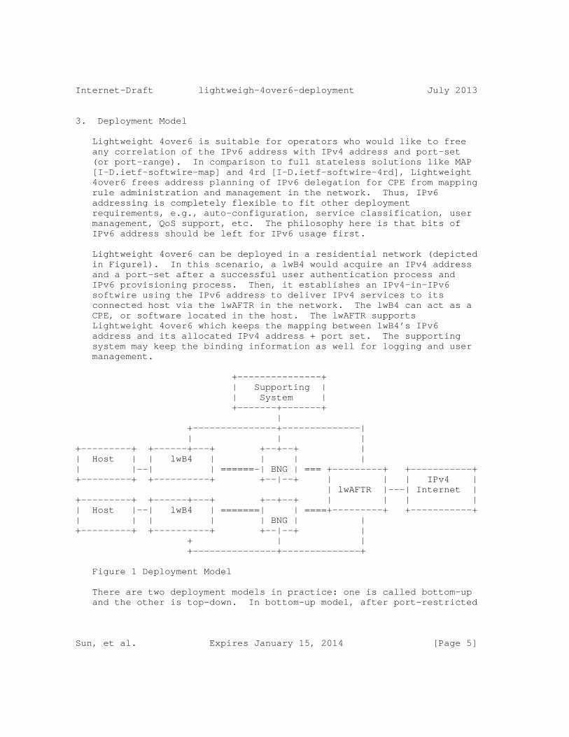
Internet-Draft lightweigh-4over6-deployment July 2013
3. Deployment Model
Lightweight 4over6 is suitable for operators who would like to free any correlation of the IPv6 address with IPv4 address and port-set (or port-range). In comparison to full stateless solutions like MAP [I-D.ietf-softwire-map] and 4rd [I-D.ietf-softwire-4rd], Lightweight 4over6 frees address planning of IPv6 delegation for CPE from mapping rule administration and management in the network. Thus, IPv6 addressing is completely flexible to fit other deployment requirements, e.g., auto-configuration, service classification, user management, QoS support, etc. The philosophy here is that bits of IPv6 address should be left for IPv6 usage first.
Lightweight 4over6 can be deployed in a residential network (depicted in Figure1). In this scenario, a lwB4 would acquire an IPv4 address and a port-set after a successful user authentication process and IPv6 provisioning process. Then, it establishes an IPv4-in-IPv6 softwire using the IPv6 address to deliver IPv4 services to its connected host via the lwAFTR in the network. The lwB4 can act as a CPE, or software located in the host. The lwAFTR supports Lightweight 4over6 which keeps the mapping between lwB4’s IPv6 address and its allocated IPv4 address + port set. The supporting system may keep the binding information as well for logging and user management.
+---------------+ | Supporting | | System | +-------+-------+ | +---------------+--------------| | | |+---------+ +------+---+ +--+--+ || Host | | lwB4 | | | || |--| | ======-| BNG | === +---------+ +-----------++---------+ +----------+ +--|--+ | | | IPv4 | | lwAFTR |---| Internet |+---------+ +------+---+ +--+--+ | | | || Host |--| lwB4 | =======| | ====+---------+ +-----------+| | | | | BNG | |+---------+ +----------+ +--|--+ | + | | +---------------+--------------+
Figure 1 Deployment Model
There are two deployment models in practice: one is called bottom-up and the other is top-down. In bottom-up model, after port-restricted
Sun, et al. Expires January 15, 2014 [Page 5]

Internet-Draft lightweigh-4over6-deployment July 2013
IPv4 address is allocated to a given subscriber, the lwAFTR will report mapping records to the supporting system on creating a binding for traffic logging if necessary. Operators may use [I-D.ietf-behave-syslog-nat-logging] or [I-D.ietf-behave-ipfix-nat-logging] to report the port set allocated by lwAFTR. In this way, the lwAFTR can determine the binding by its own and there is little impact on existing network architecture. In top-down model, the Supporting system should firstly determine the binding information for each subscriber and then synchronize it with the lwAFTR. With this method, one binding record can be easily synchronized with multiple lwAFTRs and stateless failover can be achieved. However, new mechanism (e.g. [I-D.zhou-dime-4over6-provisioning]) needs to be introduced to notify each individual binding record between the Supporting system and the lwAFTR.
Sun, et al. Expires January 15, 2014 [Page 6]
Internet-Draft lightweigh-4over6-deployment July 2013
4. Overall Deployment Considerations
4.1. Addressing and Routing
In Lightweight 4over6, there is no inter-dependency between IPv4 and IPv6 addressing schemes. IPv4 address pools are configured centralized in lwAFTR for IPv6 subscribers. These IPv4 prefix must advertise to IPv4 Internet accordingly.
For IPv6 addressing and routing, there are no additional addressing and routing requirements. The existing IPv6 address assignment and routing announcement should not be affected. For example, in PPPoE scenario, a CPE could obtain a prefix via prefix delegation procedure, and the hosts behind CPE would get its own IPv6 addresses within the prefix through SLAAC or DHCPv6 statefully. This IPv6 address assignment procedure has nothing to do with restricted IPv4 address allocation.
4.2. Port-set Management
In Lightweight 4over6, each lwB4 will get its restricted IPv4 address and a port-set after successful user authentication process and IPv6 provisioning process. This port-set assignment can been achieved by DHCPv4-over-DHCPv6 [I-D.ietf-dhc-dhcpv4-over-dhcpv6] and PCP [I-D.ietf-pcp-port-set].
Operator may use DHCPv4 to provision IPv4 address to the lwB4. In a typical deployment, the DHCP server is a centralized DHCP server and lwAFTR is the DHCP relay agent to relay the dhcp messages to the server over unicast. Rarely DHCP server will collocate with the lwAFTR to provision IPv4 resources to the lwB4.
Operator may also use PCP Port-set Option to provision IPv4 address and port-set to the lwB4. In a typical deployment, PCP server will collocate with lwAFTR, and the subscriber’s binding can be determined by lwAFTR. The PCP request should be sent to the lwAFTR’s tunnel end-point address. It is not common that PCP server will be centralized deployed in which the lwAFTR is the PCP proxy to relay PCP requests.
It is also possible that subscriber’s binding is determined in AAA server. In this case, the BNGs will embed with a DHCPv4-over-DHCPv6 server function which allows them to locally handle any DHCPv4-over- DHCPv6 requests initiated by hosts. The AAA server will pass the subscriber’s binding to a BNG using the AAA attribute in [I-D.sun- softwire-lw4over6-radext] and in turn populates the mapping of the lwB4.
Sun, et al. Expires January 15, 2014 [Page 7]

Internet-Draft lightweigh-4over6-deployment July 2013
Some operators may offer different service level agreements (SLA) to users that some users may require more ports then others. In this deployment scenario, the operator can implement differentiated policies in provisioning system specified to a user’s lwB4 or a group of lwB4s to allocate a certain range of port-set. The lwAFTR may also run multiple instances with different port-set sizes to build the mapping table.
4.3. lwAFTR Discovery
A Lightweight 4over6 lwB4 must discover the lwAFTR’s IPv6 address before offering any IPv4 services. This IPv6 address can be learned through an out-of-band channel, static configuration, or dynamic configuration. In practice, Lightweight 4over6 lwB4 can use the same DHCPv6 option [RFC6334]to discover the FQDN of the lwAFTR.
When Lightweight 4over6 is deployed in the same place with DS-Lite, either different FQDNs can be configured for Lightweight 4over6 and DS-Lite separately or different DHCPv6 options can be used for Lightweight 4over6 [I-D.sun-softwire-lw4over6-dhcpv6] and DS-Lite. More detailed considerations on DS-Lite compatibility will be discussed in Section6.
4.4. Impacts on Accouting
In Lightweight 4over6, the accounting impact due to the tunneling protocol is the same with DS-Lite (see section 6.2 of [RFC6908]). However, since in Lightweight 4over6, the IPv4 service is only available after port-set allocation, if operators will regard IPv4 service as a on-demand value-added service, e.g. IPv6 connectivity is offered by default, while IPv4 connectivity will be offered untill a subscriber requires, etc., IPv4 service accounting should start after port-set allocation has completely.
Sun, et al. Expires January 15, 2014 [Page 8]
Internet-Draft lightweigh-4over6-deployment July 2013
5. lwAFTR Deployment Consideration
As Lightweight 4over6 is an extension to DS-Lite, both technologies share similar deployment considerations. For example: Interface consideration, Lawful Intercept Considerations, Blacklisting a shared IPv4 Address, AFTR’s Policies, AFTR Impacts on Accounting Process, etc., in [RFC6908] can also be applied here. This document only discusses new considerations specific to Lightweight 4over6.
5.1. Logging at the lwAFTR
In Lightweight 4over6, operators only log one entry per subscriber. The log should include subscriber’s IPv6 address used for the softwire, the public IPv4 address and the port-set. The port set algorithm implemented in Lightweight 4over6 lwAFTR should be synchronized with the one implemented in logging system. For example, if contiguous port set algorithm is adopted in the lwAFTR, the same algorithm should also been applied to the logging system.
Since the mapping in lwAFTR does not contain destination-specific information, operator should be aware that they will not be able to have destination-specific log.
5.2. MTU and Fragmentation Considerations
As Lightweight 4over6 is also a tunneling protocol, the same consideration regarding to the fragmentation and reassembly in DS- Lite [RFC6908] can also be applied. The only difference is that NAT functionality has been removed to lwB4 from lwAFTR in Lightweight 4over6. Therefore, on receiving an IPv4 fragmented packet after decapsulation in the lwB4, the lwB4 should further re-assemble the packets before doing NAT since the transport protocol information is only available in the first fragment.
5.3. Reliability Considerations of lwAFTR
Operators may deploy multiple lwAFTRs for robustness, reliability, and load balancing. In Lightweight 4over6, subscriber to IPv4 and port-set mapping must be pre-provisioned in the lwAFTR before providing IPv4 serives. For redundancy, the backup lwAFTR must either have the subscriber mapping already provisioned or notify the lwB4 to create a new mapping in the backup lwAFTR. The first option can be considered as Hot Standby mode, which requires state syncronization between multiple lwAFTRs. In Hot Standby mode, the bindings are replicated on-the-fly from the Primary lwAFTR to the Backup lwAFTR. When the Primary lwAFTR fails, the Backup lwAFTR will take over all the existing established sessions. In this mode, the internal hosts are not required to re-initiate the bindings with the
Sun, et al. Expires January 15, 2014 [Page 9]
Internet-Draft lightweigh-4over6-deployment July 2013
external hosts. In Lightweight 4over6, since the number of mapping states has been greatly reduced compared to DS-Lite, it is reasonable to adopt Hot Standby mode when there are only two lwAFTRs (one for Primary lwAFTR and one for Backup lwAFTR). However, if the number of lwAFTRs is larger than two, it is not scalable to deploy Hot Standby mode since each two of the lwAFTRs should to syncronize the binding states.
The second option is to use Cold Standby mode which does not require a Backup Standby lwAFTR to synchronize binding states. In failover, the lwAFTR has to notify the lwB4 to create a new binding, or fetch the binding by itself. [I-D.lee-softwire-lw4over6-failover] describes these two approaches for simple Cold Standby mode. For most deployment scenarios, we believe that Cold Standby mode should be sufficient enough and is thus recommended.
5.4. Placement of AFTR
The lwAFTR can be deployed in a "centralized model" or a "distributed model".
In the "centralized model", the lwAFTR could be located at the higher place, e.g. at the exit of MAN, etc. Since the lwAFTR has good scalability and can handle numerous concurrent sessions, we recommend to adopt the "centralized model" for Lightweight 4over6 as it is cost-effective and easy to manage.
In the "distributed model", lwAFTR is usually integrated with the BRAS/SR. Since newly emerging customers might be distributed in the whole Metro area, we have to deploy lwAFTR on all BRAS/SRs. This will cost a lot in the initial phase of the IPv6 transition period.
5.5. Port set algorithm consideration
If each lwB4 is given a set of ports, port randomization algorithm can only select port in the given port-set. This may introduce security risk because hackers can make a more predictable guess of what port a subscriber may use. Therefore, non-continuous port set algorithms (e.g. as defined in [I-D.ietf-softwire-map]) can be used to improve security.
5.6. Path Consistency Consideration
In Lightweight 4over6, if the binding state is not syncronized among multiple lwAFTRs, the lwAFTR in which the subscriber’s binding state is stored should be exactly the one to service the subscriber. Otherwise, there will be no match in lwAFTR. This requires the provionsion packets (either using DHCPv4-over-DHCPv6 or PCP Port-set)
Sun, et al. Expires January 15, 2014 [Page 10]

Internet-Draft lightweigh-4over6-deployment July 2013
should arrive at the same lwAFTR as the subsquent IP-in-IP traffic. If multiple lwAFTRs are using the same Tunnel End Point address and there are intermediate routers between lwB4 and lwAFTR, there might be a problem when intermediate routers perform ECMP based on L4 hash for the plain provionsion packets while doing L3 hash for subsequent IP-in-IP traffic. In this case, it is recommended that the privioning packet is sent over IPv6 tunnel so that intermediate routers can only process ECMP using L3 hash.
Sun, et al. Expires January 15, 2014 [Page 11]

Internet-Draft lightweigh-4over6-deployment July 2013
6. lwB4 Deployment Consideration
For lwB4 consideration, the DNS Deployment Considerations and B4 Remote Management in [RFC6908] can also be applied here. In this section, we only describe the considerations sepcific to Lightweight 4over6.
6.1. NAT traversal issue
In Lightweight 4over6, since the subscriber’s source port will be restricted to the port-set allocated from the provisioning system, this will have impact on some NAT traversal mechanisms. For example, in UPnP 1.0, the external port number which can be used by remote peer is selected by UPnP client in end host. If the client randomly selects a port number which is not in that valid port-set, the UPnP process will fail. This is likely to happen because end-host does not know the port-set in lwB4. More detailed experimental results can be found in [I-D.deng-aplusp-experiment-results]. This problem will not exist in UPnP 2.0 because the UPnP client in the end-host will negotiate the external port number with the server. Another way is to implement a mechanism (e.g. [I-D.ietf-pcp-port-set], etc.) in end host to fetch the port-set from lwB4. The UPnP client can then select the port number within the port-set.
6.2. Static Port Forwarding Configuration
Currently, some external initiated applications rely on manual port configuration to reserve a port in the CPE. The restricted port-set in lwB4 will also have impacts on manual port forwarding configuration. It is recommended that the port-set allocated from the provioning system should be shown explicitly in the lwB4, which can be used as a hint for subscribers to add port forwarding mapping.
Sun, et al. Expires January 15, 2014 [Page 12]

Internet-Draft lightweigh-4over6-deployment July 2013
7. DS-Lite Compatibility Consideration
Lightweight 4over6 can be either deployed all alone, or combined with DS-Lite [RFC6333]. Since Lightweight 4over6 does not any have extra requirement on IPv6 addressing, it can use use the same addressing scheme with DS-Lite, together with routing policy, user management policy, etc. Besides, the bottom-up model has quite similar requirement and workflow on the supporting system with DS-Lite. Therefore, it is suitable for operators to deploy incrementally in existing DS-Lite network
7.1. Case 1: Integrated Network Element with Lightweight 4over6 and DS- Lite AFTR Scenario
In this case, DS-Lite has been deployed in the network. Later in the deployment schedule, the operator decided to implement Lightweight 4over6 lwAFTR function in the same network element(depicted in Figure2). Therefore, the same network element needs to support both transition mechanisms.
There are two options to distinguish the traffic from two transition mechanisms.
The first one is to distinguish using the client’s source IPv4 address. The IPv4 address from Lightweight 4over6 is public address as NAT has been done in the lwB4, and IPv4 address for DS-lite is private address as NAT will be done on AFTR. When the network element receives an encapsulated packet, it would de-capsulate packet and apply the transition mechanism based on the IPv4 source address in the packet. This requires the network element to examine every packet and may introduce significant extra load to the network element. However, both the B4 element and Lightweight 4over6 lwB4 can use the same DHCPv6 option [RFC6334] with the same FQDN of the AFTR and lwAFTR.
The second one is to distinguish using the destination’s tunnel IPv6 address. One network element can run separated instances for Lightweight 4over6 and DS-Lite with different tunnel addresses. Then B4 element and Lightweight 4over6 lwB4 can use the same DHCPv6 option [RFC6334] with different FQDNs pointing to corresponding tunnel addresses. This requires the supporting system should distinguish different types of users when assigning the FQDNs in DHCPv6 process. Another option is to use a new DHCPv6 option [I-D.sun-softwire-lw4over6-dhcpv6] to discover lwAFTR’s FQDN.
+---------------+--------------| + | |+---------+ +------+---+ +--+--+ |
Sun, et al. Expires January 15, 2014 [Page 13]
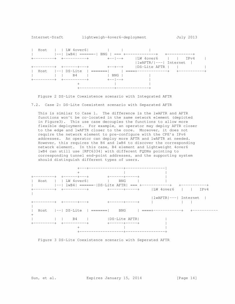
Internet-Draft lightweigh-4over6-deployment July 2013
| Host | | LW 4over6| | | || |--| lwB4| ======-| BNG | === +-------------+ +-----------++---------+ +----------+ +--|--+ |LW 4over6 | | IPv4 | |lwAFTR/|---| Internet |+---------+ +------+---+ +--+--+ |DS-Lite AFTR | | || Host |--| DS-Lite | =======| | ====+-------------+ +-----------+| | | B4 | | BNG | |+---------+ +----------+ +--|--+ | + | | +---------------+--------------+
Figure 2 DS-Lite Coexistence scenario with Integrated AFTR
7.2. Case 2: DS-Lite Coexistent scenario with Separated AFTR
This is similar to Case 1. The difference is the lwAFTR and AFTR functions won’t be co-located in the same network element (depicted in Figure3). This use case decouples the functions to allow more flexible deployment. For example, an operator may deploy AFTR closer to the edge and lwAFTR closer to the core. Moreover, it does not require the network element to pre-configure with the CPE’s IPv6 addresses. An operator can deploy more AFTR and lwAFTR at needed. However, this requires the B4 and lwB4 to discover the corresponding network element. In this case, B4 element and Lightweight 4over6 lwB4 can still use [RFC6334] with different FQDNs pointing to corresponding tunnel end-point addresses, and the supporting system should distinguish different types of users.
+---+---------------+-----------------| + | |+---------+ +------+---+ +------+-----+ || Host | | LW 4over6| | BNG | || |--| lwB4| ======-|DS-Lite AFTR| === +------------+ +-----------++---------+ +----------+ +------+-----+ |LW 4over6 | | IPv4 | |lwAFTR|---| Internet |+---------+ +------+---+ +------+-----+ | | | || Host |--| DS-Lite | =======| BNG | ====+------------+ +-----------+| | | B4 | |DS-Lite AFTR| |+---------+ +----------+ +------+-----+ | + | | +-------------------+-----------------+
Figure 3 DS-Lite Coexistence scenario with Seperated AFTR
Sun, et al. Expires January 15, 2014 [Page 14]

Internet-Draft lightweigh-4over6-deployment July 2013
8. Acknowledgement
TBD
Sun, et al. Expires January 15, 2014 [Page 15]

Internet-Draft lightweigh-4over6-deployment July 2013
9. References
[I-D.bajko-pripaddrassign] Bajko, G., Savolainen, T., Boucadair, M., and P. Levis, "Port Restricted IP Address Assignment", draft-bajko-pripaddrassign-04 (work in progress), April 2012.
[I-D.cui-softwire-b4-translated-ds-lite] Cui, Y., Sun, Q., Boucadair, M., Tsou, T., Lee, Y., and I. Farrer, "Lightweight 4over6: An Extension to the DS-Lite Architecture", draft-cui-softwire-b4-translated-ds-lite-11 (work in progress), February 2013.
[I-D.deng-aplusp-experiment-results] Deng, X., Boucadair, M., and F. Telecom, "Implementing A+P in the provider’s IPv6-only network", draft-deng-aplusp-experiment-results-00 (work in progress), March 2011.
[I-D.ietf-behave-ipfix-nat-logging] Sivakumar, S. and R. Penno, "IPFIX Information Elements for logging NAT Events", draft-ietf-behave-ipfix-nat-logging-00 (work in progress), March 2013.
[I-D.ietf-behave-syslog-nat-logging] Chen, Z., Zhou, C., Tsou, T., and T. Taylor, "Syslog Format for NAT Logging", draft-ietf-behave-syslog-nat-logging-01 (work in progress), May 2013.
[I-D.ietf-dhc-dhcpv4-over-ipv6] Cui, Y., Wu, P., Wu, J., and T. Lemon, "DHCPv4 over IPv6 Transport", draft-ietf-dhc-dhcpv4-over-ipv6-06 (work in progress), March 2013.
[I-D.ietf-pcp-base] Wing, D., Cheshire, S., Boucadair, M., Penno, R., and P. Selkirk, "Port Control Protocol (PCP)", draft-ietf-pcp-base-29 (work in progress), November 2012.
[I-D.ietf-pcp-port-set] Sun, Q., Boucadair, M., Sivakumar, S., Zhou, C., Tsou, T., and S. Perreault, "Port Control Protocol (PCP) Extension for Port Set Allocation", draft-ietf-pcp-port-set-01 (work in progress), May 2013.
Sun, et al. Expires January 15, 2014 [Page 16]

Internet-Draft lightweigh-4over6-deployment July 2013
[I-D.ietf-softwire-4rd] Despres, R., Jiang, S., Penno, R., Lee, Y., Chen, G., and M. Chen, "IPv4 Residual Deployment via IPv6 - a Stateless Solution (4rd)", draft-ietf-softwire-4rd-06 (work in progress), July 2013.
[I-D.ietf-softwire-dslite-deployment] Lee, Y., Maglione, R., Williams, C., Jacquenet, C., and M. Boucadair, "Deployment Considerations for Dual-Stack Lite", draft-ietf-softwire-dslite-deployment-08 (work in progress), January 2013.
[I-D.ietf-softwire-lw4over6] Cui, Y., Sun, Q., Boucadair, M., Tsou, T., Lee, Y., and I. Farrer, "Lightweight 4over6: An Extension to the DS-Lite Architecture", draft-ietf-softwire-lw4over6-00 (work in progress), April 2013.
[I-D.ietf-softwire-map] Troan, O., Dec, W., Li, X., Bao, C., Matsushima, S., Murakami, T., and T. Taylor, "Mapping of Address and Port with Encapsulation (MAP)", draft-ietf-softwire-map-07 (work in progress), May 2013.
[I-D.lee-softwire-lw4over6-failover] Lee, Y., Sun, Q., and C. Liu, "Simple Failover Mechanism for Lightweight 4over6", draft-lee-softwire-lw4over6-failover-00 (work in progress), July 2013.
[I-D.sun-softwire-lw4over6-dhcpv6] Xie, C., Sun, Q., Lee, Y., Tsou, T., and P. Wu, "Dynamic Host Configuration Protocol for IPv6 (DHCPv6) Option for Lightweight 4over6", draft-sun-softwire-lw4over6-dhcpv6-00 (work in progress), July 2013.
[I-D.zhou-dime-4over6-provisioning] Zhou, C. and T. Taylor, "Attribute-Value Pairs For Provisioning Customer Equipment Supporting IPv4-Over-IPv6 Transitional Solutions", draft-zhou-dime-4over6-provisioning-00 (work in progress), March 2013.
[RFC2119] Bradner, S., "Key words for use in RFCs to Indicate Requirement Levels", BCP 14, RFC 2119, March 1997.
[RFC6052] Bao, C., Huitema, C., Bagnulo, M., Boucadair, M., and X. Li, "IPv6 Addressing of IPv4/IPv6 Translators", RFC 6052,
Sun, et al. Expires January 15, 2014 [Page 17]

Internet-Draft lightweigh-4over6-deployment July 2013
October 2010.
[RFC6333] Durand, A., Droms, R., Woodyatt, J., and Y. Lee, "Dual- Stack Lite Broadband Deployments Following IPv4 Exhaustion", RFC 6333, August 2011.
[RFC6334] Hankins, D. and T. Mrugalski, "Dynamic Host Configuration Protocol for IPv6 (DHCPv6) Option for Dual-Stack Lite", RFC 6334, August 2011.
[RFC6431] Boucadair, M., Levis, P., Bajko, G., Savolainen, T., and T. Tsou, "Huawei Port Range Configuration Options for PPP IP Control Protocol (IPCP)", RFC 6431, November 2011.
[RFC6908] Lee, Y., Maglione, R., Williams, C., Jacquenet, C., and M. Boucadair, "Deployment Considerations for Dual-Stack Lite", RFC 6908, March 2013.
Sun, et al. Expires January 15, 2014 [Page 18]
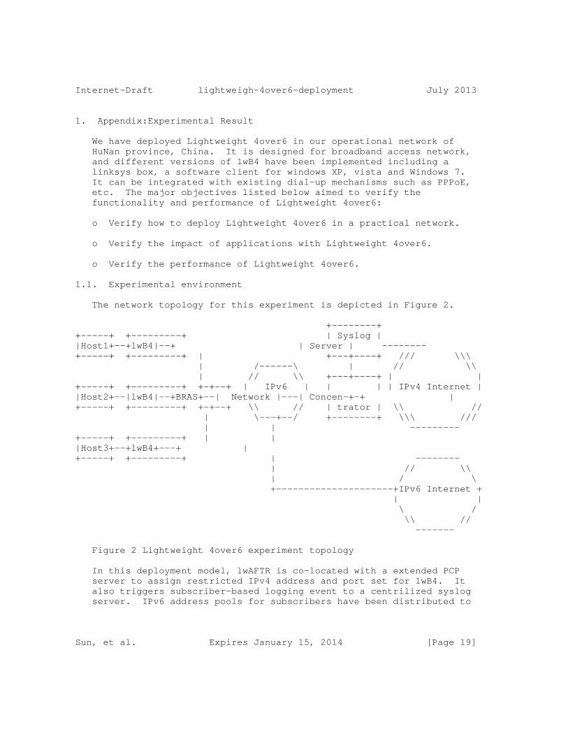
Internet-Draft lightweigh-4over6-deployment July 2013
1. Appendix:Experimental Result
We have deployed Lightweight 4over6 in our operational network of HuNan province, China. It is designed for broadband access network, and different versions of lwB4 have been implemented including a linksys box, a software client for windows XP, vista and Windows 7. It can be integrated with existing dial-up mechanisms such as PPPoE, etc. The major objectives listed below aimed to verify the functionality and performance of Lightweight 4over6:
o Verify how to deploy Lightweight 4over6 in a practical network.
o Verify the impact of applications with Lightweight 4over6.
o Verify the performance of Lightweight 4over6.
1.1. Experimental environment
The network topology for this experiment is depicted in Figure 2.
+--------++-----+ +---------+ | Syslog ||Host1+--+lwB4|--+ | Server | --------+-----+ +---------+ | +---+----+ /// \\\ | /------\ | // \\ | // \\ +---+----+ | |+-----+ +---------+ +-+--+ | IPv6 | | | | IPv4 Internet ||Host2+--|lwB4|--+BRAS+--| Network |---| Concen-+-+ |+-----+ +---------+ +-+--+ \\ // | trator | \\ // | \---+--/ +--------+ \\\ /// | | ---------+-----+ +---------+ | ||Host3+--+lwB4+---+ |+-----+ +---------+ | -------- | // \\ | / \ +---------------------+IPv6 Internet + | | \ / \\ // -------
Figure 2 Lightweight 4over6 experiment topology
In this deployment model, lwAFTR is co-located with a extended PCP server to assign restricted IPv4 address and port set for lwB4. It also triggers subscriber-based logging event to a centrilized syslog server. IPv6 address pools for subscribers have been distributed to
Sun, et al. Expires January 15, 2014 [Page 19]
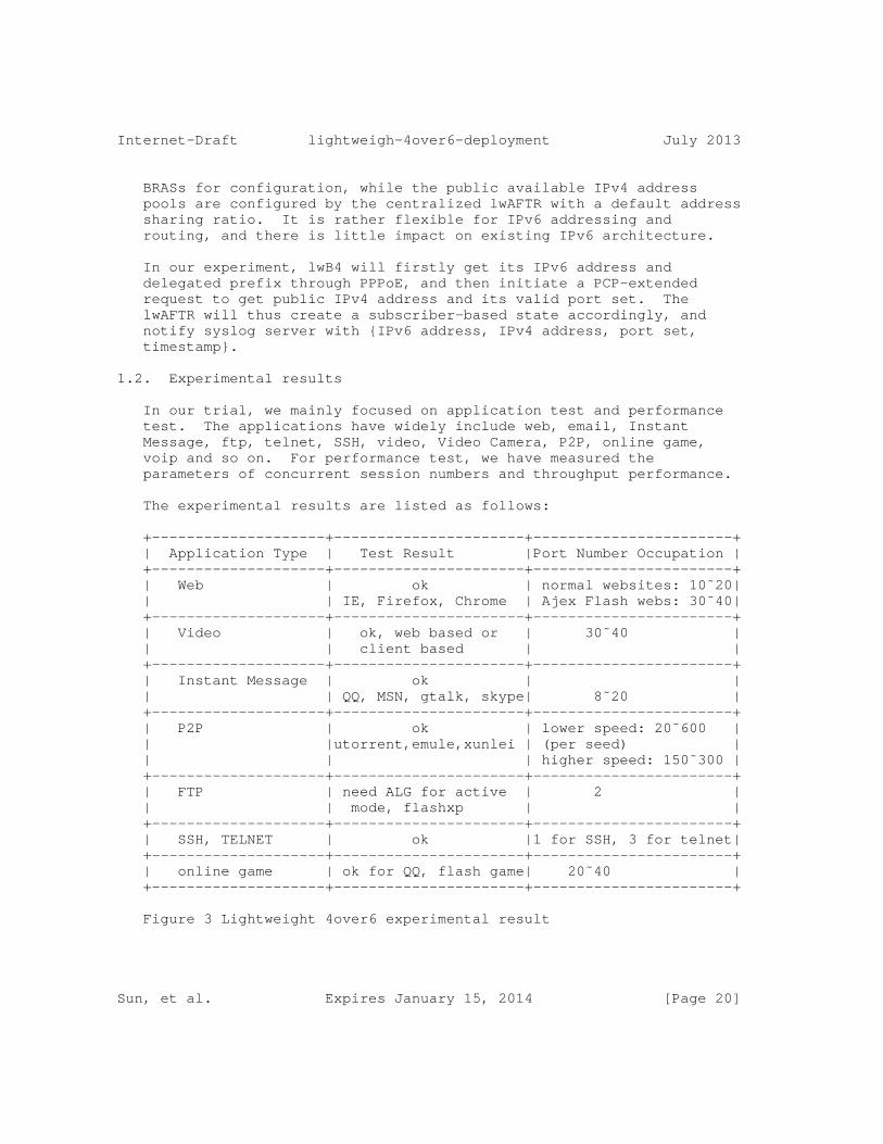
Internet-Draft lightweigh-4over6-deployment July 2013
BRASs for configuration, while the public available IPv4 address pools are configured by the centralized lwAFTR with a default address sharing ratio. It is rather flexible for IPv6 addressing and routing, and there is little impact on existing IPv6 architecture.
In our experiment, lwB4 will firstly get its IPv6 address and delegated prefix through PPPoE, and then initiate a PCP-extended request to get public IPv4 address and its valid port set. The lwAFTR will thus create a subscriber-based state accordingly, and notify syslog server with {IPv6 address, IPv4 address, port set, timestamp}.
1.2. Experimental results
In our trial, we mainly focused on application test and performance test. The applications have widely include web, email, Instant Message, ftp, telnet, SSH, video, Video Camera, P2P, online game, voip and so on. For performance test, we have measured the parameters of concurrent session numbers and throughput performance.
The experimental results are listed as follows:
+--------------------+----------------------+-----------------------+ | Application Type | Test Result |Port Number Occupation | +--------------------+----------------------+-----------------------+ | Web | ok | normal websites: 10˜20| | | IE, Firefox, Chrome | Ajex Flash webs: 30˜40| +--------------------+----------------------+-----------------------+ | Video | ok, web based or | 30˜40 | | | client based | | +--------------------+----------------------+-----------------------+ | Instant Message | ok | | | | QQ, MSN, gtalk, skype| 8˜20 | +--------------------+----------------------+-----------------------+ | P2P | ok | lower speed: 20˜600 | | |utorrent,emule,xunlei | (per seed) | | | | higher speed: 150˜300 | +--------------------+----------------------+-----------------------+ | FTP | need ALG for active | 2 | | | mode, flashxp | | +--------------------+----------------------+-----------------------+ | SSH, TELNET | ok |1 for SSH, 3 for telnet| +--------------------+----------------------+-----------------------+ | online game | ok for QQ, flash game| 20˜40 | +--------------------+----------------------+-----------------------+
Figure 3 Lightweight 4over6 experimental result
Sun, et al. Expires January 15, 2014 [Page 20]

Internet-Draft lightweigh-4over6-deployment July 2013
The performance test for lwAFTR is taken on a normal PC. Due to limitations of the PC hardware, the overall throughput is limited to around 800 Mbps. However, it can still support more than one hundred million concurrent sessions.
1.3. Conclusions
From the experiment, we can have the following conclusions:
o Lightweight 4over6 has good scalability. As it is a lightweight solution which only maintains per-subscription state information, it can easily support a large amount of concurrent subscribers.
o Lightweight 4over6 can be deployed rapidly. There is no modification to existing addressing and routing system in our operational network. And it is simple to achieve traffic logging.
o Lightweight 4over6 can support a majority of current IPv4 applications.
Sun, et al. Expires January 15, 2014 [Page 21]
Internet-Draft lightweigh-4over6-deployment July 2013
Authors’ Addresses
Qiong Sun China Telecom Room 708, No.118, Xizhimennei Street Beijing 100035 P.R.China
Phone: +86-10-58552936> Email: [email protected]
Chongfeng Xie China Telecom Room 708, No.118, Xizhimennei Street Beijing 100035 P.R.China
Phone: +86-10-58552116> Email: [email protected]
Yiu L. Lee Comcast One Comcast Center Philadelphia, PA 19103 USA
Email: [email protected]
Maoke Chen FreeBit Co., Ltd. 13F E-space Tower, Maruyama-cho 3-6 Shibuya-ku, Tokyo 150-0044 Japan
Email: [email protected]
Sun, et al. Expires January 15, 2014 [Page 22]


Internet Engineering Task Force M. TownsleyInternet-Draft O. TroanIntended status: Informational ciscoExpires: June 18, 2012 December 16, 2011
Basic Requirements for Customer Edge Routers - multihoming and transition draft-townsley-troan-ipv6-ce-transitioning-02
Abstract
This document specifies general IPv6 multihoming and specific 6rd transitioning requirements for an IPv6 Customer Edge (CE) router. It also provides an illustrative implementation model for IPv4 multihoming in order to support shared IPv4 transition mechanisms that utilize IPv6 as a transport for IPv4.
Status of this Memo
This Internet-Draft is submitted in full conformance with the provisions of BCP 78 and BCP 79.
Internet-Drafts are working documents of the Internet Engineering Task Force (IETF). Note that other groups may also distribute working documents as Internet-Drafts. The list of current Internet- Drafts is at http://datatracker.ietf.org/drafts/current/.
Internet-Drafts are draft documents valid for a maximum of six months and may be updated, replaced, or obsoleted by other documents at any time. It is inappropriate to use Internet-Drafts as reference material or to cite them other than as "work in progress."
This Internet-Draft will expire on June 18, 2012.
Copyright Notice
Copyright (c) 2011 IETF Trust and the persons identified as the document authors. All rights reserved.
This document is subject to BCP 78 and the IETF Trust’s Legal Provisions Relating to IETF Documents (http://trustee.ietf.org/license-info) in effect on the date of publication of this document. Please review these documents carefully, as they describe your rights and restrictions with respect to this document. Code Components extracted from this document must include Simplified BSD License text as described in Section 4.e of the Trust Legal Provisions and are provided without warranty as
Townsley & Troan Expires June 18, 2012 [Page 1]
Internet-Draft CE router requirements December 2011
described in the Simplified BSD License.
Table of Contents
1. Introduction . . . . . . . . . . . . . . . . . . . . . . . . . 3 1.1. Requirements Language . . . . . . . . . . . . . . . . . . 4 2. Terminology . . . . . . . . . . . . . . . . . . . . . . . . . 4 3. IPv6 MultiPrefix Multihoming . . . . . . . . . . . . . . . . . 4 3.1. Multihoming requirements . . . . . . . . . . . . . . . . . 5 3.2. 6rd Sunsetting Requirements . . . . . . . . . . . . . . . 5 4. IPv4 NAT Multihoming . . . . . . . . . . . . . . . . . . . . . 6 4.1. IPv4 Multihoming Data Structures . . . . . . . . . . . . . 6 4.2. IPv4 Packet flow . . . . . . . . . . . . . . . . . . . . . 7 4.3. Example RIB Policy for IPv4 to IPv6 Transition . . . . . . 7 5. Security Considerations . . . . . . . . . . . . . . . . . . . 8 6. Acknowledgements . . . . . . . . . . . . . . . . . . . . . . . 8 7. IANA Considerations . . . . . . . . . . . . . . . . . . . . . 9 8. References . . . . . . . . . . . . . . . . . . . . . . . . . . 9 8.1. Normative References . . . . . . . . . . . . . . . . . . . 9 8.2. Informative References . . . . . . . . . . . . . . . . . . 9 Appendix A. Configuration-oriented multihoming . . . . . . . . . 10 Authors’ Addresses . . . . . . . . . . . . . . . . . . . . . . . . 10
Townsley & Troan Expires June 18, 2012 [Page 2]

Internet-Draft CE router requirements December 2011
1. Introduction
The CE requirements specified in RFC 6204 are based on a fundamental assumption that a CE router has a single active WAN interface for forwarding IPv4 and IPv6 traffic towards an ISP. The operation of IPv6 via 6rd, IPv6 via Native, IPv4 via DS-lite and IPv4 via Native together, forces us to reconsider this basic assumption.
There are three possible steady-state combinations of "native" and "virtual" (tunneled) dual-stack service models (an IPv6-only service model, while imperative for finalizing the transition to IPv6, is currently out of scope in [RFC6204] and [I-D.ietf-v6ops-6204bis]) that do not break the fundamental assumption of having no more than one WAN interface per IP version.
1. One Native IPv4 and IPv6 interface (Classic Dual-Stack)
2. One Native IPv4 and one Virtual IPv6 interface (6rd, Softwires Hub and Spoke via L2TP, TSP, etc)
3. One Virtual IPv4 and one Native IPv6 interface (DS-Lite, 4rd, etc)
For (1), IPv4 and IPv6 each share a single WAN interface, so there is no problem when enabling one vs. the other.
For (2), when enabling tunneled IPv6 on an existing IPv4-only network there is no significant change in the basic model as each IP version still has its own distinct single WAN interface. Multihoming issues arise when enabling native IPv6 alongside tunneled IPv6 (needed for "6rd sunsetting") as IPv6 may be enabled on two distinct interfaces at the same time.
For (3) there similarly is no problem when enabling tunneled IPv4 on an existing IPv6-only network, and we understand that there are greenfield deployments just like this happening. Multihoming issues arise when enabling tunneled IPv4 on a network that has native IPv4 available at the same time.
The multihoming model described in this document assumes the operator or user can configure any WAN interface type at any time. The CE follows forwarding rules defined in this document in order to ensure packets make it out the right interface on WAN egress, and liberally accepts packets on WAN ingress. This is "classic multihoming" and should work for any order of planned incremental transition steps, as well as failover and/or transient situations.
While this authors of this document believe that the forward-oriented
Townsley & Troan Expires June 18, 2012 [Page 3]
Internet-Draft CE router requirements December 2011
model, there is another approach which we identify as "Configuration- oriented" and describe briefly in Appendix A.
1.1. Requirements Language
The key words "MUST", "MUST NOT", "REQUIRED", "SHALL", "SHALL NOT", "SHOULD", "SHOULD NOT", "RECOMMENDED", "MAY", and "OPTIONAL" in this document are to be interpreted as described in RFC 2119 [RFC2119].
2. Terminology
SRIB A Source Address Routing Information Base containing an entry per delegated prefix. Each entry points to one or more Destination Address Routing Tables (DRIB).
DRIB A Destination Address Routing Information Base used for destination address longest matching lookups. Each entry points to one or more next-hops.
NPIB Network Address and Port Translation (NAPT) Information Base used binding "flows" to an egress WAN interface.
NPIB entry The address and port mapping state [RFC4787] at the NAT necessary for network address and port translation.
3. IPv6 MultiPrefix Multihoming
A multihomed, multiprefix, IPv6 CE router has multiple WAN interfaces connecting it to one or more Service Providers. The interfaces may be "real" or "virtual" in the case of tunneling technology such as 6rd [RFC5969]. The CE router receives one or more delegated prefixes, each associated with one or more WAN interfaces. The CE router has a single SRIB, and one DRIB associated with each WAN Interface.
WAN interfaces are used to send Ingress traffic from the Internet to the End-User, and Egress traffic from the End-User network to the Internet. Ingress traffic may be received on any active interface at any time. Egress traffic follows a set of rules within the CE in order to choose the proper WAN interface. This is important not only in order to choose the best path, but also because the networks that the CE are connected to typically employ source address verification
Townsley & Troan Expires June 18, 2012 [Page 4]

Internet-Draft CE router requirements December 2011
mechanisms.
Packets arriving at the CE have an IPv6 source address chosen by the host [RFC3484]. The SRIB contains an entry for each delegated prefix with a pointer to one or more DRIBs. A longest matching lookup based upon the source address of each arriving packet is performed within the SRIB to determine the DRIB(s). The egress WAN interface to use for sending a packet is then chosen by performing a longest matching lookup within the resulting DRIB(s).
3.1. Multihoming requirements
MH-1: An IPv6 CE router MUST create a separate DRIB for each WAN interface (real or virtual) and installs a route for the associated delegated prefix, default route and more specific routes.
MH-2: An IPv6 CE router MUST create an SRIB containing entries for associated delegated prefixes. Each entry points to one or more DRIBs. An entry points to multiple DRIBs only in the case where an identical delegated prefix is associated with multiple WAN interfaces.
MH-3: When forwarding a packet from a LAN interface, the CE router MUST do a longest matching lookup based on the packet’s Source Address in the SRIB. A Destination Address lookup is then performed in the corresponding DRIB or DRIBs. When there are multiple equal matches, the route with the lowest cost is chosen.
3.2. 6rd Sunsetting Requirements
6RDS-1: Multihoming as defined in section Section 3 MUST be supported, allowing 6rd and native packets to be sent and received as long as 6rd configuration is provided by the ISP.
6RDS-2: By default, the 6rd virtual interface MUST be assigned a higher routing cost than a native IPv6 interface.
6RDS-3: The IPv6 CE router MUST support that 6rd and native IPv6 delegated prefixes are identical or different, and operate as defined in the multihoming section.
Townsley & Troan Expires June 18, 2012 [Page 5]

Internet-Draft CE router requirements December 2011
4. IPv4 NAT Multihoming
This section describes a general implementation model used to illustrate CE IPv4 multihoming, alongside specifics for using the model to support IPv6 transition technologies aimed at delivering IPv4 within an IPv6 transport (e.g., DS-Lite).
A multihomed IPv4 CE router has multiple "physical" or "virtual" WAN interfaces connecting it to one or more Service Providers. WAN interfaces are used to send Ingress traffic from the Internet to the End-User, and Egress traffic from the End-User network to the Internet. Each WAN interface may be configured with a single public IPv4 address, private IPv4 address [RFC1918], a shared IPv4 address [A+P], or no IPv4 address at all.
An IPv4 CE router WAN interface is often configured in the same manner as a single host, i.e., with a single 32-bit IPv4 address. A CE router NAPT function, in turn, allows more than one device within the end-user network to appear as a single host with a single IPv4 address facing the ISP network. The CE router NAPT function is responsible for rewriting IPv4 headers with the address assigned to the associated WAN interface with the expectation that return traffic will be sent back to that address.
IPv4 WAN interfaces which are not configured with an IPv4 address by the ISP (e.g., DS-Lite, L2-aware NAT), bypass the translation function of the NAPT when forwarding traffic. In this case, the ISP’s centralized NAPT function is responsible for rewriting IPv4 headers with a source address which ensures return traffic will reach the proper NAPT binding within the ISP.
4.1. IPv4 Multihoming Data Structures
The CE router has a single NAPT Information Base (NPIB) which consists of Dynamic and Configured entries. A WAN interface provisioned with an IPv4 address has an associated NAPT function which examines packet flow and programs the NPIB with Dynamic entries as they are identified. For example, an active TCP session on the CE correlates to a single Dynamic entry within the NPIB. A Dynamic entry in the NPIB table unambiguously identifies packets that are associated with it when an NPIB Lookup is performed.
Configured NPIB entries allow for rules to be specified which direct traffic in a specific manner. Unlike Dynamic entries, Configured entries allow for "wildcards", and may be end-user configured or configured by a protocol such as NAT-PMP, UPnP, PCP, etc. Packets directed by configured entries may or may not instantiate Dynamic NPIB entries for specific flows.
Townsley & Troan Expires June 18, 2012 [Page 6]

Internet-Draft CE router requirements December 2011
Finally, the CE router also has a single IPv4 Routing Information Base (RIB), containing IPv4 routes learned from active LAN and WAN interfaces. The RIB is only consulted for packets that fail to match an NPIB entry. The RIB supports a classic IPv4 routing function, including use of the longest matching algorithm and preferences that may be assigned to each interface. A RIB lookup ultimately resolves to an output interface which, in turn may have an NAPT function enabled. If the output interface has an NAPT function enabled, it is responsible for programming the NPIB with a new Dynamic entry and translating the packet before sending.
4.2. IPv4 Packet flow
Ingress (from the Internet to the End-User) traffic may be received on any active interface at any time. Egress (from the End-User to the Internet) traffic follows a set of rules within the CE in order to choose the proper WAN interface and associated NAPT function on that interface if present.
Egress packets arriving at the CE trigger a lookup in the NPIB. A successful match on a Dynamic entry in the NPIB provides all information necessary to translate and send a packet out the proper interface (e.g., no additional lookup in the RIB or elsewhere is required). Packets which do not have a matching NPIB entry but match a Configured entry are treated similarly. Packets which fail the NPIB lookup entirely are sent to the RIB.
The RIB performs a classic IPv4 longest-matching routing lookup based on the destination address of the IPv4 packet. If more than one interface is selected (which will be the case when more than one active WAN interface programs a default route in the RIB), then packets are sent via the interface with the highest configured preference. If the preference is the same, packets may be load- balanced. After selecting the proper output interface for the packet, the packet is either sent immediately or translated and sent if a NAPT function is enabled. If NAPT function is enabled on that interface, it is responsible for programming the NPIB with a new Dynamic entry and translating the packet before sending.
4.3. Example RIB Policy for IPv4 to IPv6 Transition
Interface preferences in the RIB allow policy definition for choosing one type of interface over another. Well-defined defaults which encourage transition to IPv6, less use of NAPT, and more distributed state may be defined. The policy may be represented as a simple table which may be altered by the operator or user without any change to the CE packet forwarding implementation itself.
Townsley & Troan Expires June 18, 2012 [Page 7]
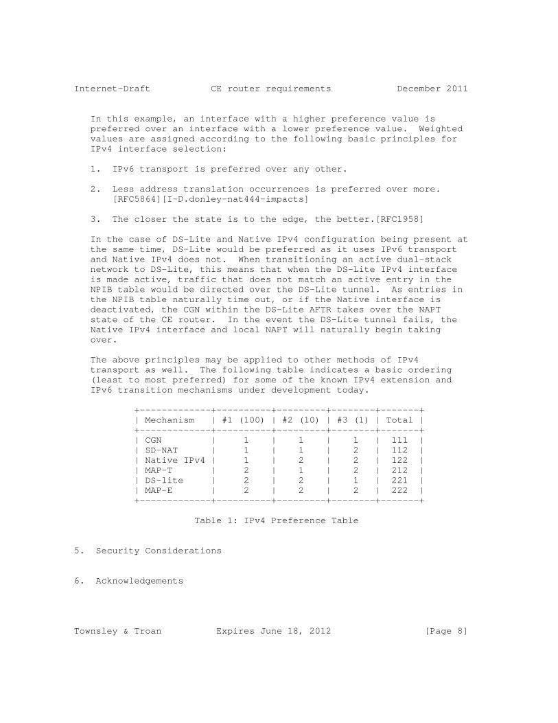
Internet-Draft CE router requirements December 2011
In this example, an interface with a higher preference value is preferred over an interface with a lower preference value. Weighted values are assigned according to the following basic principles for IPv4 interface selection:
1. IPv6 transport is preferred over any other.
2. Less address translation occurrences is preferred over more. [RFC5864][I-D.donley-nat444-impacts]
3. The closer the state is to the edge, the better.[RFC1958]
In the case of DS-Lite and Native IPv4 configuration being present at the same time, DS-Lite would be preferred as it uses IPv6 transport and Native IPv4 does not. When transitioning an active dual-stack network to DS-Lite, this means that when the DS-Lite IPv4 interface is made active, traffic that does not match an active entry in the NPIB table would be directed over the DS-Lite tunnel. As entries in the NPIB table naturally time out, or if the Native interface is deactivated, the CGN within the DS-Lite AFTR takes over the NAPT state of the CE router. In the event the DS-Lite tunnel fails, the Native IPv4 interface and local NAPT will naturally begin taking over.
The above principles may be applied to other methods of IPv4 transport as well. The following table indicates a basic ordering (least to most preferred) for some of the known IPv4 extension and IPv6 transition mechanisms under development today.
+-------------+----------+---------+--------+-------+ | Mechanism | #1 (100) | #2 (10) | #3 (1) | Total | +-------------+----------+---------+--------+-------+ | CGN | 1 | 1 | 1 | 111 | | SD-NAT | 1 | 1 | 2 | 112 | | Native IPv4 | 1 | 2 | 2 | 122 | | MAP-T | 2 | 1 | 2 | 212 | | DS-lite | 2 | 2 | 1 | 221 | | MAP-E | 2 | 2 | 2 | 222 | +-------------+----------+---------+--------+-------+
Table 1: IPv4 Preference Table
5. Security Considerations
6. Acknowledgements
Townsley & Troan Expires June 18, 2012 [Page 8]
Internet-Draft CE router requirements December 2011
7. IANA Considerations
This memo includes no request to IANA.
8. References
8.1. Normative References
[RFC2119] Bradner, S., "Key words for use in RFCs to Indicate Requirement Levels", BCP 14, RFC 2119, March 1997.
[RFC2131] Droms, R., "Dynamic Host Configuration Protocol", RFC 2131, March 1997.
[RFC5969] Townsley, W. and O. Troan, "IPv6 Rapid Deployment on IPv4 Infrastructures (6rd) -- Protocol Specification", RFC 5969, August 2010.
8.2. Informative References
[I-D.donley-nat444-impacts] Donley, C., Howard, L., Kuarsingh, V., Berg, J., and U. Colorado, "Assessing the Impact of Carrier-Grade NAT on Network Applications", draft-donley-nat444-impacts-03 (work in progress), November 2011.
[I-D.ietf-v6ops-6204bis] Singh, H., Beebee, W., Donley, C., Stark, B., and O. Troan, "Basic Requirements for IPv6 Customer Edge Routers", draft-ietf-v6ops-6204bis-04 (work in progress), December 2011.
[RFC1918] Rekhter, Y., Moskowitz, R., Karrenberg, D., Groot, G., and E. Lear, "Address Allocation for Private Internets", BCP 5, RFC 1918, February 1996.
[RFC1958] Carpenter, B., "Architectural Principles of the Internet", RFC 1958, June 1996.
[RFC3484] Draves, R., "Default Address Selection for Internet Protocol version 6 (IPv6)", RFC 3484, February 2003.
[RFC4787] Audet, F. and C. Jennings, "Network Address Translation (NAT) Behavioral Requirements for Unicast UDP", BCP 127, RFC 4787, January 2007.
[RFC5864] Allbery, R., "DNS SRV Resource Records for AFS", RFC 5864,
Townsley & Troan Expires June 18, 2012 [Page 9]
Internet-Draft CE router requirements December 2011
April 2010.
[RFC6204] Singh, H., Beebee, W., Donley, C., Stark, B., and O. Troan, "Basic Requirements for IPv6 Customer Edge Routers", RFC 6204, April 2011.
Appendix A. Configuration-oriented multihoming
This method attempts to actively avoid multihoming by forcing only a single configured WAN egress interface to be active at any time for a given IP version. For this to work, one of the following assumptions must hold.
a. From the perspective of the CE router, the network supports only one type of interface for a given IP version, or
b. The CE router is configured in advance of any IP configuration to support only one type of interface for a given IP version, or
c. The CE router goes through an ordered set of configuration attempts in series, each requiring a timeout before moving to the next. Transition-oriented changes after steady-state is reached will require "reboot" to go through the ordered process from scratch.
d. The CE router chooses one type of interface and shuts down all others based on a predetermined priority when more than one interface with the same IP version is configured. This allows parallel configuration attempts and changes after reaching steady-state, but requires the CE router and network to manage a "flash cut" from one configured interface to the other and may be prone to tricky race-conditions.
Authors’ Addresses
Mark Townsley cisco
Email: [email protected]
Townsley & Troan Expires June 18, 2012 [Page 10]

Internet-Draft CE router requirements December 2011
Ole Troan cisco
Email: [email protected]
Townsley & Troan Expires June 18, 2012 [Page 11]


Internet Engineering Task Force T. TsouInternet-Draft Huawei Technologies (USA)Intended status: Informational T. TaylorExpires: March 8, 2013 C. Zhou Huawei Technologies H. Ji China Telecom September 4, 2012
IPv6 Multicast Using Native IPv4 Capabilities in a 6rd Deployment draft-tsou-softwire-6rd-multicast-02
Abstract
This document describes how IPv6 multicast can be extended across an IPv4 network to an IPv6 host, using the native multicast capabilities of the IPv4 network.
Status of this Memo
This Internet-Draft is submitted in full conformance with the provisions of BCP 78 and BCP 79.
Internet-Drafts are working documents of the Internet Engineering Task Force (IETF). Note that other groups may also distribute working documents as Internet-Drafts. The list of current Internet- Drafts is at http://datatracker.ietf.org/drafts/current/.
Internet-Drafts are draft documents valid for a maximum of six months and may be updated, replaced, or obsoleted by other documents at any time. It is inappropriate to use Internet-Drafts as reference material or to cite them other than as "work in progress."
This Internet-Draft will expire on March 8, 2013.
Copyright Notice
Copyright (c) 2012 IETF Trust and the persons identified as the document authors. All rights reserved.
This document is subject to BCP 78 and the IETF Trust’s Legal Provisions Relating to IETF Documents (http://trustee.ietf.org/license-info) in effect on the date of publication of this document. Please review these documents carefully, as they describe your rights and restrictions with respect to this document. Code Components extracted from this document must include Simplified BSD License text as described in Section 4.e of
Tsou, et al. Expires March 8, 2013 [Page 1]

Internet-Draft IPv6 Multicast With 6rd September 2012
the Trust Legal Provisions and are provided without warranty as described in the Simplified BSD License.
Table of Contents
1. Introduction . . . . . . . . . . . . . . . . . . . . . . . . . 3 1.1. Terminology . . . . . . . . . . . . . . . . . . . . . . . . 3 2. Description of the Solution . . . . . . . . . . . . . . . . . . 3 2.1. Assumed Architecture . . . . . . . . . . . . . . . . . . . 3 2.2. Components of the Proposed Solution . . . . . . . . . . . . 4 2.2.1. Address Mapping . . . . . . . . . . . . . . . . . . . . 4 2.2.2. Multicast Routing . . . . . . . . . . . . . . . . . . . 5 2.2.3. Translation From MLD To IGMP . . . . . . . . . . . . . 5 2.2.4. Interworking Between PIM With IPv4 and PIM with IPv6 At the 6rd BR . . . . . . . . . . . . . . . . . . 5 2.2.5. Transport of Multicast Data Packets and Unicast RTCP Feedback . . . . . . . . . . . . . . . . . . . . . 5 3. Acknowledgements . . . . . . . . . . . . . . . . . . . . . . . 6 4. IANA Considerations . . . . . . . . . . . . . . . . . . . . . . 6 5. Security Considerations . . . . . . . . . . . . . . . . . . . . 6 6. References . . . . . . . . . . . . . . . . . . . . . . . . . . 6 6.1. Normative References . . . . . . . . . . . . . . . . . . . 6 6.2. Informative References . . . . . . . . . . . . . . . . . . 7 Authors’ Addresses . . . . . . . . . . . . . . . . . . . . . . . . 7
Tsou, et al. Expires March 8, 2013 [Page 2]

Internet-Draft IPv6 Multicast With 6rd September 2012
1. Introduction
6rd ([RFC5569], [RFC5969]) provides a means to connect IPv6 hosts to the IPv6 Internet across an IPv4 provider network. Unicast traffic is carried through IPv6-in-IPv4 tunnels. It is possible to carry multicast traffic from the IPv6 network through the IPv4 network in the same way, but if multiple customers wish access to the same multicast channels, the failure to use the native multicast capabilities of the IPv4 network wastes resources in that network.
This document describes a solution using the native multicast capabilities of the IPv4 network to acquire and forward multicast traffic from the IPv6 Internet to an IPv6 host attached to the IPv4 network. Typically this solution will operate in combination with 6rd for unicast traffic. However, no IPv6-in-IPv4 tunneling is required for signalling, only the ability to interwork between IPv4 and IPv6 at the 6rd Customer Equipment (6rd CE) and the 6rd Border Relay (6rd BR).
1.1. Terminology
The term "address pair" is used to denote the combination of unicast source address and multicast group address corresponding to a given multicast stream at a given point along the path between the source and receiver.
2. Description of the Solution
A number of problems have to be solved to allow an IPv6 host attached to an IPv4 network to request and receive a multicast stream originating in a neighbouring IPv6 network and passing through the IPv4 network using the native multicast facilities of that network. These problems are described in detail in the course of presenting proposed solutions to them.
It is assumed that the IPv6 host wishing to receive a multicast stream acquires the corresponding IPv6 address pair by means out of scope of this document. See [ID.mboned-multrans-addr-acq].
2.1. Assumed Architecture
This document assumes an architecture similar to that of 6rd [RFC5569], [RFC5969], with additional capabilities for the 6rd Customer Edge (CE) and the 6rd Border Relay (6rd BR). See Figure 1.
Tsou, et al. Expires March 8, 2013 [Page 3]
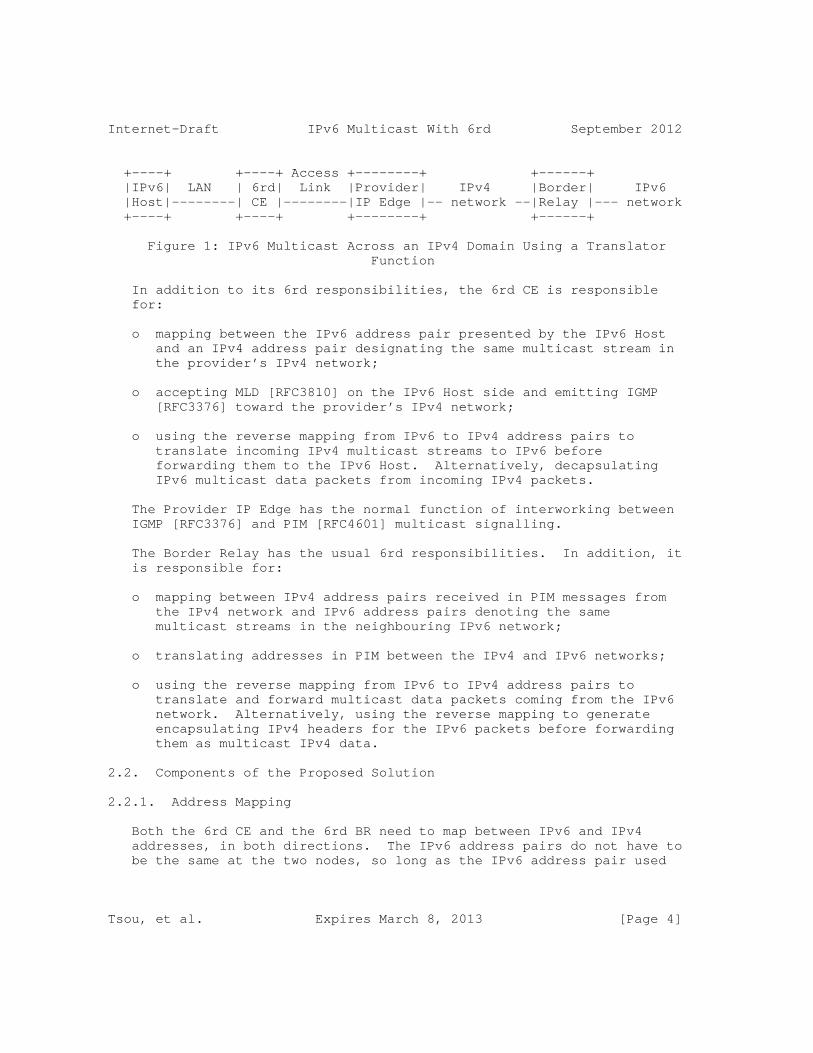
Internet-Draft IPv6 Multicast With 6rd September 2012
+----+ +----+ Access +--------+ +------+ |IPv6| LAN | 6rd| Link |Provider| IPv4 |Border| IPv6 |Host|--------| CE |--------|IP Edge |-- network --|Relay |--- network +----+ +----+ +--------+ +------+
Figure 1: IPv6 Multicast Across an IPv4 Domain Using a Translator Function
In addition to its 6rd responsibilities, the 6rd CE is responsible for:
o mapping between the IPv6 address pair presented by the IPv6 Host and an IPv4 address pair designating the same multicast stream in the provider’s IPv4 network;
o accepting MLD [RFC3810] on the IPv6 Host side and emitting IGMP [RFC3376] toward the provider’s IPv4 network;
o using the reverse mapping from IPv6 to IPv4 address pairs to translate incoming IPv4 multicast streams to IPv6 before forwarding them to the IPv6 Host. Alternatively, decapsulating IPv6 multicast data packets from incoming IPv4 packets.
The Provider IP Edge has the normal function of interworking between IGMP [RFC3376] and PIM [RFC4601] multicast signalling.
The Border Relay has the usual 6rd responsibilities. In addition, it is responsible for:
o mapping between IPv4 address pairs received in PIM messages from the IPv4 network and IPv6 address pairs denoting the same multicast streams in the neighbouring IPv6 network;
o translating addresses in PIM between the IPv4 and IPv6 networks;
o using the reverse mapping from IPv6 to IPv4 address pairs to translate and forward multicast data packets coming from the IPv6 network. Alternatively, using the reverse mapping to generate encapsulating IPv4 headers for the IPv6 packets before forwarding them as multicast IPv4 data.
2.2. Components of the Proposed Solution
2.2.1. Address Mapping
Both the 6rd CE and the 6rd BR need to map between IPv6 and IPv4 addresses, in both directions. The IPv6 address pairs do not have to be the same at the two nodes, so long as the IPv6 address pair used
Tsou, et al. Expires March 8, 2013 [Page 4]

Internet-Draft IPv6 Multicast With 6rd September 2012
by the host designates the same multicast stream as the IPv6 address pair generated at the 6rd BR or received from the source IPv6 network.
Because the source network uses IPv6, mapping between the addresses used in that network and the IPv4 addresses used in the provider network is in general a difficult problem. The most general solution is to configure static mappings between the IPv6 and corresponding IPv4 address pairs at the 6rd BR. Mapping at the 6rd CE can use IPv4-embedded IPv6 addresses as defined in [RFC6052] for the unicast source addresses, and [ID.mboned-64-mcast-addr-fmt] for the multicast group addresses. This assumes that the IPv6 host has been provided with such addresses in the first place. It also assumes that the IPv4 network provider can configure suitable prefixes at the 6rd CE for the purpose of such mapping.
With restrictions on the IPv6 addresses used for multicast source and group addresses in the IPv6 network, it may be possible to use algorithmic instead of static mapping at the 6rd BR. This generally requires coordination between the IPv4 and IPv6 network operators.
2.2.2. Multicast Routing
For each IPv4 address to which an IPv6 source address is mapped, the routing tables that PIM uses must result in a path that passes through a multicast-enabled 6rd BR. At the routing level, this means that the 6rd BR must advertise reachability to the mapped IPv4 source addresses it knows about into the IPv4 domain. Its distance metrics to those addresses must reflect the routing information it receives on the IPv6 side for their IPv6 counterparts.
2.2.3. Translation From MLD To IGMP
See [ID.perreault-igmp-mld-translation].
2.2.4. Interworking Between PIM With IPv4 and PIM with IPv6 At the 6rd BR
See [ID.taylor-pim-v4v6-translation].
2.2.5. Transport of Multicast Data Packets and Unicast RTCP Feedback
The documents cited in the previous two sections describe the process of header translation for multicast data packets. The address mapping aspect of that translation was discussed in Section 2.2.1. If the 6rd BR and 6rd CE are configured to use encapsulation/ decapsulation of multicast data packets instead, the encapsulating IPv4 header uses the IPv4 address pair mapped from the original IPv6
Tsou, et al. Expires March 8, 2013 [Page 5]

Internet-Draft IPv6 Multicast With 6rd September 2012
address pair as source and destination. However, this requires that the IPv6 host uses the same IPv6 addresses as the source IPv6 network for each multicast stream it receives. That may force the 6rd CE to use static rather than algorithmic mapping for address pairs for its MLD/IGMP translation.
When the IPv6 Host sends unicast RTCP [RFC3550] feedback toward the source, the packets are treated by the 6rd CE and 6rd BR like any other unicast packets. That is, they are encapsulated at the 6rd CE, transported across the IPv4 network as IPv6-in-IPv4, and decapsulated at the 6rd BR before forwarding into the IPv6 network.
3. Acknowledgements
Awaiting comments.
4. IANA Considerations
This memo currently includes no request to IANA.
5. Security Considerations
To come.
6. References
6.1. Normative References
[ID.mboned-64-mcast-addr-fmt] Boucadair, M., Qin, J., Lee, Y., Venaas, S., Li, X., and M. Xu, "IPv4-Embedded IPv6 Multicast Address Format (Work in progress)", August 2012.
[ID.perreault-igmp-mld-translation] Perrault, S. and T. Tsou, "Internet Group Management Protocol (IGMP) / Multicast Listener Discovery (MLD)-Based Multicast Translation ("IGMP/MLD Translation") (Work in progress)", April 2012.
[RFC2119] Bradner, S., "Key words for use in RFCs to Indicate Requirement Levels", BCP 14, RFC 2119, March 1997.
[RFC3376] Cain, B., Deering, S., Kouvelas, I., Fenner, B., and A. Thyagarajan, "Internet Group Management Protocol, Version
Tsou, et al. Expires March 8, 2013 [Page 6]
Internet-Draft IPv6 Multicast With 6rd September 2012
3", RFC 3376, October 2002.
[RFC3810] Vida, R. and L. Costa, "Multicast Listener Discovery Version 2 (MLDv2) for IPv6", RFC 3810, June 2004.
[RFC3973] Adams, A., Nicholas, J., and W. Siadak, "Protocol Independent Multicast - Dense Mode (PIM-DM): Protocol Specification (Revised)", RFC 3973, January 2005.
[RFC4601] Fenner, B., Handley, M., Holbrook, H., and I. Kouvelas, "Protocol Independent Multicast - Sparse Mode (PIM-SM): Protocol Specification (Revised)", RFC 4601, August 2006.
[RFC5969] Townsley, W. and O. Troan, "IPv6 Rapid Deployment on IPv4 Infrastructures (6rd) -- Protocol Specification", RFC 5969, August 2010.
[RFC6052] Bao, C., Huitema, C., Bagnulo, M., Boucadair, M., and X. Li, "IPv6 Addressing of IPv4/IPv6 Translators", RFC 6052, October 2010.
6.2. Informative References
[ID.mboned-multrans-addr-acq] Tsou, T., Clauberg, A., Boucadair, M., Venaas, S., and Q. Sun, "Address Acquisition For Multicast Content When Source and Receiver Support Differing IP Versions (Work in progress)", March 2012.
[ID.taylor-pim-v4v6-translation] Taylor, T. and C. Zhou, "Operation of a Dual-Stack Multicast Router With Address Translation (Work in progress)", July 2012.
[RFC3550] Schulzrinne, H., Casner, S., Frederick, R., and V. Jacobson, "RTP: A Transport Protocol for Real-Time Applications", STD 64, RFC 3550, July 2003.
[RFC5569] Despres, R., "IPv6 Rapid Deployment on IPv4 Infrastructures (6rd)", RFC 5569, January 2010.
Tsou, et al. Expires March 8, 2013 [Page 7]

Internet-Draft IPv6 Multicast With 6rd September 2012
Authors’ Addresses
Tina Tsou Huawei Technologies (USA) 2330 Central Expressway Santa Clara, CA 95050 USA
Phone: +1 408 330 4424 Email: [email protected] URI: http://tinatsou.weebly.com/contact.html
Tom Taylor Huawei Technologies Ottawa, Ontario Canada
Phone: Email: [email protected]
Cathy Zhou Huawei Technologies Bantian, Longgang District Shenzhen 518129 P.R. China
Phone: Email: [email protected]
Hui Ji China Telecom NO19.North Street Beijing, Chaoyangmen,Dongcheng District P.R. China
Phone: Email: [email protected]
Tsou, et al. Expires March 8, 2013 [Page 8]

Internet Engineering Task Force T. TsouInternet-Draft Huawei Technologies (USA)Intended status: Informational B. LiExpires: August 17, 2014 C. Zhou Huawei Technologies J. Schoenwaelder Jacobs University Bremen R. Penno Cisco Systems, Inc. M. Boucadair France Telecom February 13, 2014
DS-Lite Failure Detection and Failover draft-tsou-softwire-bfd-ds-lite-06
Abstract
In DS-Lite, the tunnel is stateless, not associated with any state information, and the CGN function at the AFTR is stateful. Currently, there is no failure detection and failover mechanism for both stateless tunnel and stateful CGN function, which makes it difficult to manage and diagnose if there is a problem. This draft analyzes the applicability of some of the possible solutions.
Status of this Memo
This Internet-Draft is submitted in full conformance with the provisions of BCP 78 and BCP 79.
Internet-Drafts are working documents of the Internet Engineering Task Force (IETF). Note that other groups may also distribute working documents as Internet-Drafts. The list of current Internet- Drafts is at http://datatracker.ietf.org/drafts/current/.
Internet-Drafts are draft documents valid for a maximum of six months and may be updated, replaced, or obsoleted by other documents at any time. It is inappropriate to use Internet-Drafts as reference material or to cite them other than as "work in progress."
This Internet-Draft will expire on August 17, 2014.
Copyright Notice
Copyright (c) 2014 IETF Trust and the persons identified as the document authors. All rights reserved.
Tsou, et al. Expires August 17, 2014 [Page 1]

Internet-Draft DS-Lite Failure Detection and Failover February 2014
This document is subject to BCP 78 and the IETF Trust’s Legal Provisions Relating to IETF Documents (http://trustee.ietf.org/license-info) in effect on the date of publication of this document. Please review these documents carefully, as they describe your rights and restrictions with respect to this document. Code Components extracted from this document must include Simplified BSD License text as described in Section 4.e of the Trust Legal Provisions and are provided without warranty as described in the Simplified BSD License.
Table of Contents
1. Introduction . . . . . . . . . . . . . . . . . . . . . . . . . 3 2. Terminology . . . . . . . . . . . . . . . . . . . . . . . . . 3 3. Failover Mechanisms . . . . . . . . . . . . . . . . . . . . . 3 3.1. Anycast Approach . . . . . . . . . . . . . . . . . . . . . 4 3.2. VRRP Approach . . . . . . . . . . . . . . . . . . . . . . 4 4. Solutions . . . . . . . . . . . . . . . . . . . . . . . . . . 4 4.1. Bidirectional Forwarding Detection (BFD) . . . . . . . . . 4 4.1.1. DS-Lite Scenario . . . . . . . . . . . . . . . . . . . 5 4.1.2. Parameters for BFD . . . . . . . . . . . . . . . . . . 5 4.1.3. Elements of Procedure . . . . . . . . . . . . . . . . 6 4.1.4. BFD for NAT failure detection . . . . . . . . . . . . 6 4.1.5. Implementation Considerations . . . . . . . . . . . . 6 4.2. Port Control Protocol (PCP) . . . . . . . . . . . . . . . 7 4.3. ICMP Echo Request / Echo Reply (PING) . . . . . . . . . . 7 4.4. Comparison of Different Solutions . . . . . . . . . . . . 8 5. State Synchronization and Session Re-establishment . . . . . . 8 6. IANA Considerations . . . . . . . . . . . . . . . . . . . . . 9 7. Security Considerations . . . . . . . . . . . . . . . . . . . 9 8. Acknowledgements . . . . . . . . . . . . . . . . . . . . . . . 9 9. References . . . . . . . . . . . . . . . . . . . . . . . . . . 9 9.1. Normative References . . . . . . . . . . . . . . . . . . . 9 9.2. Informative References . . . . . . . . . . . . . . . . . . 10 Authors’ Addresses . . . . . . . . . . . . . . . . . . . . . . . . 10
Tsou, et al. Expires August 17, 2014 [Page 2]
Internet-Draft DS-Lite Failure Detection and Failover February 2014
1. Introduction
In DS-Lite [RFC6333], the IPv4-in-IPv6 DS-Lite tunnel is stateless, no status information about the tunnel is available, and no keep- alive mechanism is available. It is difficult to know whether the tunnel is up or down; and if there is a link problem, the Basic Bridging BroadBand (B4) element can not automatically switch to another Address Family Transition Router (AFTR) so as to continue the network service automatically, without the involvement of operators. Besides, In DS-Lite [RFC6333], the CGN function at the AFTR is stateful and there is no mechanism to detect whether the NAT44 CGN is functioning in the AFTR. These will create problems for network operation and maintenance.
Possible solutions for failure detection include the usage of Bidirectional Forwarding Detection (BFD), the Port Control Protocol (PCP), and ICMP Echo Request / Echo Reply (PING). The properties of these solutions are discussed in this document and guidelines are provided how to implement failure detection and automatic failover.
The key words "MUST", "MUST NOT", "REQUIRED", "SHALL", "SHALL NOT", "SHOULD", "SHOULD NOT", "RECOMMENDED", "MAY", and "OPTIONAL" in this document are to be interpreted as described in RFC 2119 [RFC2119].
2. Terminology
AFTR: Address Family Transition Router.
B4: Basic Bridging BroadBand.
BBF: BroadBand Forum.
BFD: Bidirectional Forwarding Detection.
CPE: Customer Premise Equipment (i.e., the DS-Lite B4).
FQDN Fully Qualified Domain Name.
PCP Port Control Protocol.
3. Failover Mechanisms
The FQDN of the AFTR is sent to the B4 element via a DHCP option, as defined in [RFC6334]. Multiple IP addresses can be configured for the FQDN of an AFTR on the DNS server. If a B4 element detects a failure on the link to the AFTR, the B4 element MUST terminate the
Tsou, et al. Expires August 17, 2014 [Page 3]
Internet-Draft DS-Lite Failure Detection and Failover February 2014
current DS-Lite tunnel, choose another AFTR address in the list, and create a tunnel to the new AFTR. If necessary, the B4 element SHOULD re-configure the connectivity test tool accordingly and restart the test procedures.
3.1. Anycast Approach
Anycasts may also be used for failover. But there is an ICMP-error- message problem with anycast, that is, when a packet is sent from the AFTR to a B4 element, if one of the routers along the path generates an ICMP error message, e.g., Packet Too Big (PTB), then the error message may not be sent back to the source AFTR but to another AFTR.
There’s also a problem with anycast for stateful CGN/AFTR. If there is an asymmetric path though the CGNs, then return path traffic will be dropped as there is no corresponding state table entry in the AFTR.
3.2. VRRP Approach
For active/passive HA in NAT gateways, it’s quite common to have a single virtual address offered by VRRP (or a proprietary equivalent) that the upstream routers will use as their next hop. In the event that the master CGN fails, the standby takes over the virtual L3 address. If a VRRP based virtual address is used as the tunnel endpoint, then the clients wouldn’t need to be aware of the failover.
4. Solutions
4.1. Bidirectional Forwarding Detection (BFD)
Bidirectional Forwarding Detection [RFC5880] (BFD) is a mechanism intended to detect faults in a bidirectional path. It is usually used in conjunction with applications like OSPF, IS-IS, for fast fault recovery and fast re-route [RFC5882]. BFD is being made mandatory for keep-alive for subscriber sessions, including DS-Lite, by the BroadBand Forum (BBF) [WT-146].
BFD can be used in DS-Lite, by creating a BFD session between the B4 element and the AFTR to provide tunnel status information. If a fault is detected, the B4 element can try to create a DS-Lite tunnel with another AFTR and terminate the existing one, so as to continue network service. BFD could also be used to detect the CGN state at the AFTR, but the detection should be based on per-user.
[I-D.vinokour-bfd-dhcp] proposes using a DHCP option to distribute BFD parameters to B4 elements. But in case of DS-Lite, some of the
Tsou, et al. Expires August 17, 2014 [Page 4]

Internet-Draft DS-Lite Failure Detection and Failover February 2014
key BFD parameters are already available (e.g., peer IP address), and other parameters can be negotiated by BFD signaling or statically configured, so that no extra DHCP option(s) need to be defined.
4.1.1. DS-Lite Scenario
In DS-Lite [RFC6333], the BFD packet SHOULD be sent through an IPv4- in-IPv6 tunnel, as shown in Figure 1. The IPv4 addresses of the B4 element and the AFTR SHOULD be the endpoints of a BFD session.
+--------------+ +--------------+ +------+ | | +------+ | | | |-----+--------------+-----| | | | | CPE | IPv6 Tunnel | AFTR |-----| IPv4 Network | | (B4) |-----+--------------+-----| | | | +------+ | IPv6 Network | +------+ | | 192.0.0.2 +--------------+ 192.0.0.1 +--------------+
Figure 1: DS-Lite Scenario
4.1.2. Parameters for BFD
In order to set up a BFD session, the following parameters are needed, as shown in Section 4.1 of [RFC5880]:
o Peer IP address
o My Discriminator
o Your Discriminator
o Desired Min TX Interval
o Required Min RX Interval
o Required Min Echo RX Interval
B4’s WAN-side IPv4 address is the well-known address 192.0.0.2, and the AFTR’s well-known IPv4 address is 192.0.0.1, as defined in section 5.7 of [RFC6333]. The B4 element needs to create an IPv6 tunnel to an AFTR so as to get network connectivity to the AFTR, and send IPv4 BFD packets through the tunnel to manage it.
The other parameters listed above can be negotiated by BFD signaling, and initial values can be configured on B4 elements and AFTRs.
Tsou, et al. Expires August 17, 2014 [Page 5]
Internet-Draft DS-Lite Failure Detection and Failover February 2014
4.1.3. Elements of Procedure
When a B4 element gets online, it will be assigned an IPv6 prefix or address, and also the FQDN of the AFTR, as defined in [RFC6334]. The B4 element will create an IPv6 tunnel to the AFTR with which the B4 element can initiate a BFD session to the AFTR. BFD packets will be sent through the DS-Lite tunnel. As defined in section 4 of [RFC5881], BFD control packets MUST be sent in UDP packets with destination port 3784, and BFD echo packets MUST be sent in UDP packets with destination port 3785.
When sending out the first BFD packet, the B4 element can generate a unique local discriminator, and set the remote discriminator to zero. When the AFTR receives the first BFD packet from a B4 element, the AFTR will also generate a corresponding local discriminator, and put it in the response packet to the B4 element. This will finish the discriminator negotiation in the B4 to AFTR direction, without any manual configuration.
When an AFTR receives the first packet from a B4 element, the AFTR will get the IPv6 address and discriminator of the B4 element, so that the AFTR can initiate the BFD session in the other direction and a similar discriminator negotiation can be carried out.
4.1.4. BFD for NAT failure detection
B4 creates PCP mapping. BFD at AFTR uses an external public interface (or another external mapping) to send a BFD packet to the public PCP mapping created by B4. In this case, the AFTR BFD packet will have a public source IP of interface, which will go through the NAT, therefore exercising the NAT function. B4 will reply to the AFTR external interface.
4.1.5. Implementation Considerations
BFD is usually used for quick fault detection, at a very small time scale, e.g. milliseconds. But in DS-Lite, it may not be necessary to detect faults in such a short time. On the other hand, an AFTR may need to support tens of thousands of B4 elements, which means an AFTR will need to support the same number of BFD sessions. In order to meet performance requirements on an AFTR, it may be necessary to extend the time period between BFD packet transmissions to a longer time, e.g., 10s or 30s.
Compared to other solutions, BFD has a simple and fixed packet format, which is easy to implement by logic devices (e.g., ASIC, FPGA). Complicated protocols are usually processed by software which is relatively slow. An AFTR may need to support 10000-20000 users,
Tsou, et al. Expires August 17, 2014 [Page 6]
Internet-Draft DS-Lite Failure Detection and Failover February 2014
and if the protocol is handled by software, it will bring extra load to the AFTR.
4.2. Port Control Protocol (PCP)
[RFC6887]PCP is a NAT traversal tool. It can also be used for network connectivity test if PCP is supported in the network. A common use case of PCP is to create a pinhole so that external users can visit the servers located behind a NAT. The lifetime of the pinhole mapping is usually long, e.g., hours, and the lifetime will be refreshed periodically by the client before it is expired. For the purpose of network connectivity tests, a B4 element can create a mapping in the CGN via PCP, with a short life time, e.g., 10s of seconds, and keep on refreshing the mapping before it expires. If any refresh requests fail, the B4 element knows that something is wrong with the link or the PCP server or the CGN.
In order to detect the network connectivity of the DS-Lite tunnel, the encapsulation mode MUST be used for PCP: PCP packets are sent through the DS-Lite tunnel.
PCP can detect the failure of more components of the DS-Lite system. Besides failures of the link and the routing, it also covers NAT functions.
4.3. ICMP Echo Request / Echo Reply (PING)
PING is commonly implemented using the Echo Request and Echo Response messages of the Internet Control Message Protocol (ICMP) [RFC0792] [RFC4443]. In case of DS-Lite, a B4 element can send Echo Request packets to the AFTR periodically. If the B4 element does not receive Echo Response packets for a certain number (e.g., 3) of Echo Request packets, then the B4 element decides that a fault has been detected.
In order to test the connectivity of DS-Lite tunnel, Echo Request packets MUST be sent using ICMPv4, rather than ICMPv6.
Since ICMP is an integral part of any IP implementation, the usage of PING to detect tunnel failures does not require any special implementation efforts on the B4 elements. However, on AFTRs that process ICMP messages in software rather than in hardware, the usage of PING might lead to scalability issues.
Tsou, et al. Expires August 17, 2014 [Page 7]
Internet-Draft DS-Lite Failure Detection and Failover February 2014
4.4. Comparison of Different Solutions
+--------+-------------+------+-------------------+-------------+ | | |Packet|Additional |Configuration| | |Availablility|format|functionality |/provisioning| | | | |ontop of keepalives| overheads | +--------+-------------+------+-------------------+-------------+ | BFD |Widely used/ | | | | | |network side,|Simple|Bidirectional | | | |less used/ |fixed |status | | | |terminal side| |synchronization | | +--------+-------------+------+-------------------+ Similar | | PCP |Less than | |No bidirectional | | | |BFD/ICMP |Vari- | detection | | +--------+-------------+able +-------------------+ | | ICMP |Ubiquitous | |Network/CGN | | | | | |initiated detection| | +--------+-------------+------+-------------------+-------------+
Figure 2: Comparison of different solutions
Figure 2 gives a direct comparison among different solutions. Compared to other solutions, BFD has a simple and fixed packet format, which is easy to implement by logic devices (e.g., ASIC, FPGA). Complicated protocols are usually processed by software which is relatively slow. ICMP is widely used than PCP/BFD, while BFD is more widely used in the router and CGN side than in the terminal side. However, from the aspect of failure detection, BFD has explicit capability of bidirectional status synchronization to guarantee the consistency of the failure status of both sides. ICMP could actively initiate status detection from the network side or CGN side, while PCP could not. PCP has no capability of bidirectional detection. Considering the configuration/provisioning overheads, since there is normally TR-069 server at the network management side. So it is similar for each approach.
From the above comparison, BFD is selected as the failure detection approach in this document.
5. State Synchronization and Session Re-establishment
There should be a state sync mechanism between active AFTR and backup AFTR, to synchronize the state of each user between the two AFTRs. This mechanism is to guarantee that the traffic returning to the B4 is from the backup AFTR, if the service is shifted to that AFTR. The BFD link for both active AFTR and backup AFTR should be set up in the
Tsou, et al. Expires August 17, 2014 [Page 8]
Internet-Draft DS-Lite Failure Detection and Failover February 2014
initial state. When the active AFTR is detected in failure, the service will be shifted to the backup AFTR. If the backup AFTR is detected in failure, it will notify the network management server to fix the failure.
In the hot-standby case, the master AFTR and the backup AFTR will synchronize and backup the session. So there is no need to re- establish the TCP session in the event of an AFTR failure. But in the cold-standby case, if there is an active TCP session through the CGN function of an AFTR, and this AFTR fails, then the TCP session will need to be re-established by the client because only the capability is reserved but the session is not backup.
6. IANA Considerations
This memo includes no request to IANA.
7. Security Considerations
In the DS-Lite [RFC6333] application, the B4 element may not be directly connected to the AFTR; there may be other routers between them. In such a deployment, there are potential spoofing problems, as described in [RFC5883]. Hence cryptographic authentication SHOULD be used with BFD as described in [RFC5880] if security is concerned.
8. Acknowledgements
The authors would like to thank Ian Farrer for his valuable comments.
9. References
9.1. Normative References
[RFC0792] Postel, J., "Internet Control Message Protocol", STD 5, RFC 792, September 1981.
[RFC2119] Bradner, S., "Key words for use in RFCs to Indicate Requirement Levels", BCP 14, RFC 2119, March 1997.
[RFC4443] Conta, A., Deering, S., and M. Gupta, "Internet Control Message Protocol (ICMPv6) for the Internet Protocol Version 6 (IPv6) Specification", RFC 4443, March 2006.
[RFC5880] Katz, D. and D. Ward, "Bidirectional Forwarding Detection
Tsou, et al. Expires August 17, 2014 [Page 9]

Internet-Draft DS-Lite Failure Detection and Failover February 2014
(BFD)", RFC 5880, June 2010.
[RFC5881] Katz, D. and D. Ward, "Bidirectional Forwarding Detection (BFD) for IPv4 and IPv6 (Single Hop)", RFC 5881, June 2010.
[RFC5882] Katz, D. and D. Ward, "Generic Application of Bidirectional Forwarding Detection (BFD)", RFC 5882, June 2010.
[RFC5883] Katz, D. and D. Ward, "Bidirectional Forwarding Detection (BFD) for Multihop Paths", RFC 5883, June 2010.
[RFC6333] Durand, A., Droms, R., Woodyatt, J., and Y. Lee, "Dual- Stack Lite Broadband Deployments Following IPv4 Exhaustion", RFC 6333, August 2011.
[RFC6334] Hankins, D. and T. Mrugalski, "Dynamic Host Configuration Protocol for IPv6 (DHCPv6) Option for Dual-Stack Lite", RFC 6334, August 2011.
[RFC6887] Wing, D., Cheshire, S., Boucadair, M., Penno, R., and P. Selkirk, "Port Control Protocol (PCP)", RFC 6887, April 2013.
[WT-146] Kavanagh, A., Klamm, F., Boucadair, W., and R. Dec, "WT- 146 Subscriber Sessions (work in progress)", Apr 2012.
9.2. Informative References
[I-D.vinokour-bfd-dhcp] Vinokour, V., "Configuring BFD with DHCP and Other Musings", May 2008.
Authors’ Addresses
Tina Tsou Huawei Technologies (USA) 2330 Central Expressway Santa Clara CA 95050 USA
Phone: +1 408 330 4424 Email: [email protected]
Tsou, et al. Expires August 17, 2014 [Page 10]

Internet-Draft DS-Lite Failure Detection and Failover February 2014
Brandon Li Huawei Technologies M6, No. 156, Beiqing Road, Haidian District Beijing 100094 China
Phone: Email: [email protected]
Cathy Zhou Huawei Technologies China
Phone: Email: [email protected]
Juergen Schoenwaelder Jacobs University Bremen Campus Ring 1 Bremen 28759 Germany
Phone: Email: [email protected]
Reinaldo Penno Cisco Systems, Inc. 170 West Tasman Drivee San Jose, California 95134 USA
Phone: Email: [email protected]
Mohamed Boucadair France Telecom Rennes,35000 France
Phone: Email: [email protected]
Tsou, et al. Expires August 17, 2014 [Page 11]