Varga Ágnes (2011): A nemi egyenlőtlenég és annak háttere a dél-ázsiai országok oktatásában
Upload
khangminh22Category
view
0download
0
DetNet J. FarkasInternet-Draft B. VargaIntended status: Standards Track EricssonExpires: May 3, 2018 R. Cummings National Instruments J. Yuanlong Z. Yiyong Huawei October 30, 2017
DetNet Flow Information Model draft-farkas-detnet-flow-information-model-02
Abstract
This document describes flow and service information model for Deterministic Networking (DetNet). The DetNet service is provided either for a Layer 3 or a Layer 2 flow. This document provides DetNet flow and service information model both for Layer 3 and Layer 2 flows in an integrated fashion.
Status of This Memo
This Internet-Draft is submitted in full conformance with the provisions of BCP 78 and BCP 79.
Internet-Drafts are working documents of the Internet Engineering Task Force (IETF). Note that other groups may also distribute working documents as Internet-Drafts. The list of current Internet- Drafts is at https://datatracker.ietf.org/drafts/current/.
Internet-Drafts are draft documents valid for a maximum of six months and may be updated, replaced, or obsoleted by other documents at any time. It is inappropriate to use Internet-Drafts as reference material or to cite them other than as "work in progress."
This Internet-Draft will expire on May 3, 2018.
Copyright Notice
Copyright (c) 2017 IETF Trust and the persons identified as the document authors. All rights reserved.
This document is subject to BCP 78 and the IETF Trust’s Legal Provisions Relating to IETF Documents (https://trustee.ietf.org/license-info) in effect on the date of publication of this document. Please review these documents
Farkas, et al. Expires May 3, 2018 [Page 1]
Internet-Draft DetNet Flow Information Model October 2017
carefully, as they describe your rights and restrictions with respect to this document. Code Components extracted from this document must include Simplified BSD License text as described in Section 4.e of the Trust Legal Provisions and are provided without warranty as described in the Simplified BSD License.
Table of Contents
1. Introduction . . . . . . . . . . . . . . . . . . . . . . . . 3 1.1. Goals . . . . . . . . . . . . . . . . . . . . . . . . . . 4 1.2. Non Goals . . . . . . . . . . . . . . . . . . . . . . . . 5 2. Conventions Used in This Document . . . . . . . . . . . . . . 5 3. Terminology and Definitions . . . . . . . . . . . . . . . . . 5 4. Naming Conventions . . . . . . . . . . . . . . . . . . . . . 5 5. End System and DetNet domain . . . . . . . . . . . . . . . . 6 6. Flow . . . . . . . . . . . . . . . . . . . . . . . . . . . . 8 6.1. Identification and Specification of Flows . . . . . . . . 8 6.1.1. DetNet L3 Flow Identification and Specification at UNI . . . . . . . . . . . . . . . . . . . . . . . . . 9 6.1.2. DetNet L2 Flow Identification and Specification at UNI . . . . . . . . . . . . . . . . . . . . . . . . . 9 6.1.3. DetNetwork Flow Identification and Specification . . 10 6.2. Traffic Specification . . . . . . . . . . . . . . . . . . 10 6.3. Flow Rank . . . . . . . . . . . . . . . . . . . . . . . . 11 6.4. Service Rank . . . . . . . . . . . . . . . . . . . . . . 12 7. Source . . . . . . . . . . . . . . . . . . . . . . . . . . . 12 8. Destination . . . . . . . . . . . . . . . . . . . . . . . . . 13 9. Common Attributes of Source and Destination . . . . . . . . . 13 9.1. End System Interfaces . . . . . . . . . . . . . . . . . . 13 9.2. Interface Capabilities . . . . . . . . . . . . . . . . . 13 9.3. User to Network Requirements . . . . . . . . . . . . . . 14 10. Ingress . . . . . . . . . . . . . . . . . . . . . . . . . . . 15 11. Egress . . . . . . . . . . . . . . . . . . . . . . . . . . . 15 12. DetNet Domain . . . . . . . . . . . . . . . . . . . . . . . . 15 12.1. DetNet Domain Capabilities . . . . . . . . . . . . . . . 16 13. Flow-status . . . . . . . . . . . . . . . . . . . . . . . . . 16 13.1. Status Info . . . . . . . . . . . . . . . . . . . . . . 17 13.2. Interface Configuration . . . . . . . . . . . . . . . . 18 13.3. Failed Interfaces . . . . . . . . . . . . . . . . . . . 19 14. Service-status . . . . . . . . . . . . . . . . . . . . . . . 19 15. Summary . . . . . . . . . . . . . . . . . . . . . . . . . . . 19 16. IANA Considerations . . . . . . . . . . . . . . . . . . . . . 19 17. Security Considerations . . . . . . . . . . . . . . . . . . . 19 18. References . . . . . . . . . . . . . . . . . . . . . . . . . 19 18.1. Normative References . . . . . . . . . . . . . . . . . . 19 18.2. Informative References . . . . . . . . . . . . . . . . . 20 Authors’ Addresses . . . . . . . . . . . . . . . . . . . . . . . 21
Farkas, et al. Expires May 3, 2018 [Page 2]

Internet-Draft DetNet Flow Information Model October 2017
1. Introduction
A Deterministic Networking (DetNet) service provides a capability to carry a unicast or a multicast data flow for an application with constrained requirements on network performance, e.g., low packet loss rate and/or latency. The DetNet service is provided either for a Layer 3 (L3) flow or a Layer 2 (L2) flow by an IP/MPLS network, see, e.g., [I-D.ietf-detnet-dp-alt]. Similarly, Time-Sensitive Networking (TSN) [IEEE8021TSN]) can be used for L2 flows in a bridged network. DetNet and TSN have common architecture as expressed in [IETFDetNet] and [I-D.ietf-detnet-architecture]. DetNet service can be leveraged both by L3 and L2 flows, i.e., by DetNet L3 flows and DetNet L2 flows. Therefore, the DetNet flow and service information model provided by this document covers both DetNet L3 flows and DetNet L2 flows in an integrated fashion.
In a given network scenario three information models can distinguished:
o Flow models describe characteristics of data flows. These models describe in detail all relevant aspects of a flow that are needed to support the flow properly by the network between the source and the destination(s).
o Service models describe characteristics of services being provided for data flows over a network. These models can be treated as a network operator independent information model.
o Configuration models describe in detail the settings required on network nodes to serve a data flow properly.
Service and flow information models are used between the user and the network operator. Configuration information models are used between the management/control plane entity of the network and the network nodes. They are shown in Figure 1.
Farkas, et al. Expires May 3, 2018 [Page 3]

Internet-Draft DetNet Flow Information Model October 2017
User Network Operator flow/service /\ info model +---+ / \ <---------------> | X | management/control ---- +-+-+ plane entity ^ | configuration | info model +------------+ v | | +-+ | v Network +-+ v +-+ nodes +-+ +-+ +-+
Figure 1: Usage of Information models (flow, service and configuration)
DetNet flow and service information model is based on [I-D.ietf-detnet-architecture] and on the data model specified by [IEEE8021Qcc]. Furthermore, the DetNet flow information model relies on the flow identification possibilities described in [IEEE8021CB], which is used by [IEEE8021Qcc] as well. In addition to TSN data model, [IEEE8021Qcc] also specifies configuration of TSN features (e.g., traffic scheduling specified by [IEEE8021Qbv]). Due to the common architecture and flow model, configuration features can be leveraged in certain deployment scenarios, e.g., when the network that provides the DetNet service includes both L3 and L2 network segments.
Based on the DetNet architecture [I-D.ietf-detnet-architecture] (see Section 4), this document (this revision) only considers the Centralized Network / Distributed User Model out of the models specified by [IEEE8021Qcc]. That is, there is a User-Network Interface (UNI) between an end system and a network. Furthermore, there is a central entity for the control of the network. For instance, the central entity implements a Path Computation Element (PCE) for the calculation and establishment of paths needed for packet replication and elimination, if any.
1.1. Goals
As it is expressed in the Charter [IETFDetNet], the DetNet WG collaborates with IEEE 802.1 TSN in order to define a common architecture for both Layer 2 and Layer 3, which is beneficial for various reasons, e.g., in order to simplify implementations. The flow and service information models should be also common along those lines. As the TSN flow information/data model specified by
Farkas, et al. Expires May 3, 2018 [Page 4]

Internet-Draft DetNet Flow Information Model October 2017
[IEEE8021Qcc] is mature, the DetNet flow and service information models described in this document are based on [IEEE8021Qcc], which is an amendment to [IEEE8021Q].
This document intends to specify flow and service information models only.
1.2. Non Goals
This document (this revision) does not intend to specify either flow data model or DetNet configuration. From these aspects, the goals of this document differ from the goals of [IEEE8021Qcc], which also specifies data model and configuration of certain TSN features.
2. Conventions Used in This Document
The key words "MUST", "MUST NOT", "REQUIRED", "SHALL", "SHALL NOT", "SHOULD", "SHOULD NOT", "RECOMMENDED", "MAY", and "OPTIONAL" in this document are to be interpreted as described in [RFC2119].
The lowercase forms with an initial capital "Must", "Must Not", "Shall", "Shall Not", "Should", "Should Not", "May", and "Optional" in this document are to be interpreted in the sense defined in [RFC2119], but are used where the normative behavior is defined in documents published by SDOs other than the IETF.
3. Terminology and Definitions
This document uses the terminology established in Section 2 of the DetNet architecture document [I-D.ietf-detnet-architecture]. The DetNet <=> TSN dictionary of [I-D.ietf-detnet-architecture] is used to perform translation from [IEEE8021Qcc] to this document. Additional terms used in this document:
DetNet L3 Flow: Layer 3 (L3) flow leveraging DetNet service.
DetNet L2 Flow: Layer 2 (L2) flow leveraging DetNet service.
DetNetwork Flow: DetNet data plane specific encapsulated format of a DetNet L2 or L3 flow leveraging DetNet service.
4. Naming Conventions
The following naming conventions were used for naming information model components in this document. It is recommended that extensions of the model use the same conventions.
o Names SHOULD be descriptive.
Farkas, et al. Expires May 3, 2018 [Page 5]

Internet-Draft DetNet Flow Information Model October 2017
o Names MUST start with uppercase letters.
o Composed names MUST use capital letters for the first letter of each component. All other letters are lowercase, even for acronyms. Exceptions are made for acronyms containing a mixture of lowercase and capital letters, such as IPv6. Examples are SourceMacAddress and DestinationIPv6Address.
5. End System and DetNet domain
Deterministic service is required by time/loss sensitive application(s) running on an end system during communication with its peer(s). Such a data exchange has various requirements on delay and/ or loss parameters.
The DetNet architecture [I-D.ietf-detnet-architecture] distinguishes two kinds of end systems: Source and Destination. The same distinction is applied for the DetNet flow information model. In addition to the end systems interested in a flow, the status information of the flow is also important. Therefore, the DetNet flow information model relies on three high level groups:
o Source: an end system capable of sourcing a DetNet flow. The Source information group includes elements that specify the Source for a single flow. This information group is applied from the user to the network.
o Destination: an end system that is a destination of a DetNet flow. The Destination information group includes elements that specify the Destination for a single flow. This information group is applied from the user to the network.
o Flow-Status: the status of a DetNet flow. The status information group includes elements that specify the status of the flow in the network. This information group is applied from the network to the user. This information group informs the user whether or not the flow is ready for use.
From service perspective two kinds of edge nodes can be distinguished: Ingress and Egress. In addition the technology of the DetNet domain and the status of the service are also important. Therefore, the DetNet service information model relies on four high level groups:
o Ingress: an edge system receiving a DetNet flow from a Source. The Ingress information group includes elements that specify the entry point for a single flow. This information group is applied from the network to the user.
Farkas, et al. Expires May 3, 2018 [Page 6]
Internet-Draft DetNet Flow Information Model October 2017
o Egress: an edge system sending traffic towards a Destination of a DetNet flow. The Egress information group includes elements that specify the egress point for a single flow. This information group is applied from the network to the user.
o DetNet Domain: an administrative domain providing the DetNet service. The DetNet domain information group includes elements that specify the forwarding capabilities and methods for a single flow. This information group is applied within the network.
o Service-Status: the status of a DetNet service. The status information group includes elements that specify the status of the service specific state of the network. This information group is applied from the network to the user. This information group informs the user whether or not the service is ready for use.
There are two operations for each flow with respect to a Source or a Destination (and an Ingress or an Egress):
o Join: Source/Destination request to join the flow.
o Leave: Source/Destination request to leave the flow.
o Modify: Source/Destination request to change the flow.
Modify operation can be considered to address cases when a flow is slightly changed, e.g., only MaxPayloadSize (Section 6.2) has been changed. The advantage of having a Modify is that it allows to initiate a change of flow spec while leaving the current flow is operating until the change is accepted. If there is no linkage between the Join and the Leave, then in figuring out whether the new flow spec can be supported, the central entity has to assume that the resources committed to the current flow are in use. Via Modify the central entity knows that the resources supporting the current flow can be available for supporting the altered flow. Modify is considered to be an optional operation due to possible control-plane limitations.
As the DetNet UNI can provide service for both L3 and L2 flows, end systems may not need to implement the L3 <=> L2 Transfer Function specified by [IEEE8021CB] (see, e.g., subclause 6.3; see also subclause 46.1 in [IEEE8021Qcc]). An edge node may implement a function similar to the Transfer Function, see, e.g., the Svc Proxy in Figure 1 in [I-D.ietf-detnet-dp-alt].
Farkas, et al. Expires May 3, 2018 [Page 7]

Internet-Draft DetNet Flow Information Model October 2017
6. Flow
The flows leveraging DetNet service can be unicast or multicast data flows for an application with constrained requirements on network performance, e.g., low packet loss rate and/or latency. Therefore, they can require different connectivity types: point-to-point (p2p) or point-to-multipoint (p2mp). The p2mp connectivity is created by a transport layer function (e.g., p2mp LSP) [I-D.ietf-detnet-dp-alt]. (Note that mp2mp connectivity is a superposition of p2mp connections.)
Many flows using DetNet service are periodic with fix packet size (i.e., Constant Bit Rate (CBR) flows), or periodic with variable packet size.
Delay and loss parameters are correlated because the effect of late delivery can result data loss for an application. However, not all applications require hard limits on both parameters (delay and loss). For example, some real-time applications allow graceful degradation if loss happens (e.g., sample-based processing, media distribution). Some others may require high-bandwidth connections that make the usage of techniques like packet replication economically challenging or even impossible. Some applications may not tolerate loss, but are not delay sensitive (e.g., bufferless sensors). Time/loss sensitive applications may have somewhat special requirements especially for loss (e.g., no loss in two consecutive communication cycles; very low outage time, etc.).
Flows have the following attributes:
a. DataFlowSpecification (Section 6.1)
b. TrafficSpecification (Section 6.2)
c. FlowRank (Section 6.3)
Flow attributes are described in the following sections.
6.1. Identification and Specification of Flows
Identification options for DetNet flows at the UNI and within the DetNet domain are specified as follows; see Section 6.1.1 for DetNet L3 flows (at UNI), Section 6.1.2 for DetNet L2 flows (at UNI) and Section 6.1.3 for DetNetwork flows (within the network).
Farkas, et al. Expires May 3, 2018 [Page 8]

Internet-Draft DetNet Flow Information Model October 2017
6.1.1. DetNet L3 Flow Identification and Specification at UNI
DetNet L3 flows can be identified and specified by the following attributes:
a. SourceIpAddress
b. DestinationIpAddress
c. IPv6FlowLabel
d. Dscp
e. Protocol
f. SourcePort
g. DestinationPort
6.1.2. DetNet L2 Flow Identification and Specification at UNI
DetNet L2 flows can be identified and specified by the following attributes:
a. DestinationMacAddress
b. SourceMacAddress
c. Pcp
d. VlanId
e. EtherType
Note: The Multiple Stream Registration Protocol (MSRP) [IEEE8021Q] uses StreamID to match Talker registrations with their corresponding Listener registrations, i.e., to identify Streams (L2 TSN flows). The StreamID includes the following subcomponents:
o A 48-bit MAC Address associated with the Talker sourcing the stream to the bridged network.
o A 16-bit unsigned integer value, Unique ID, used to distinguish among multiple streams sourced by the same Talker.
Farkas, et al. Expires May 3, 2018 [Page 9]

Internet-Draft DetNet Flow Information Model October 2017
6.1.3. DetNetwork Flow Identification and Specification
Identification of DetNet flows within the DetNet domain are used in the service information model. The attributes are specific to the forwarding paradigm within the DetNet domain. DetNetwork flows can be identified and specified by the following attributes:
a. SourceIpAddress
b. DestinationIpAddress
c. IPv6FlowLabel
d. MplsLabel
6.2. Traffic Specification
TrafficSpecification specifies how the Source transmits packets for the flow. This is effectively the promise/request of the Source to the network. The network uses this traffic specification to allocate resources and adjust queue parameters in network nodes.
TrafficSpecification has the following attributes:
a. Interval: the period of time in which the traffic specification cannot be exceeded.
b. MaxPacketsPerInterval: the maximum number of packets that the Source will transmit in one Interval.
c. MaxPayloadSize: the maximum payload size that the Source will transmit.
[[NOTE (to be removed from a future revision): These attributes can be used to describe any type of traffic (e.g., CBR, VBR, etc.) and can be used during resource allocation to represent worst case scenarios. Further optional attributes can be considered to achieve more efficient resource allocation. Such optional attributes might be worth for flows with soft requirements (i.e., the flow is only loss sensitive or only delay sensitive, but not both delay-and-loss sensitive). Possible options how to extend TrafficSpecification attributes is for further discussion. Identified options are described in the following notes.]]
[[NOTE1: Based on the already defined attributes the most similar additional attributes for VBR type flows can be defined as follows:
Farkas, et al. Expires May 3, 2018 [Page 10]
Internet-Draft DetNet Flow Information Model October 2017
o AveragePacketsPerInterval: the average number of packets that the Source will transmit in one Interval.
o AveragePayloadSize: the average payload size that the Source will transmit.
]]
[[NOTE2: another alternative to deal better with various traffic types can rely on [RFC6003], which describes the support of Metro Ethernet Forum (MEF) Ethernet traffic parameters for using for resource reservation purposes. Such a Bandwidth Profile can be also adapted to describe the set of traffic parameters for a Detnet flow. Committed Rate indicates the rate at which traffic commits to be sent by the source (described in terms of the CIR (Committed Information Rate) and CBS (Committed Burst Size) attributes.) Excess Rate indicates the extent by which the traffic sent by the source exceeds the committed rate. The Excess Rate is described in terms of the EIR (Excess Information Rate) and EBS (Excess Burst Size) attributes. ]]
[[NOTE3: a third alternative is to define application based traffic models such as [GPP22885] defines periodic and event-driven traffic model, and 5G PPP work defines traffic model for MTC (Machine Type Communication) use cases. Periodic traffic type is usually for status update between devices or devices transmit status report to a central unit in regular basis. TrafficPeriod, defines the period of the status update message. DataSize, defines the data size of the massage which is constant. 3GPP also defines approximately-periodic transmission with variations on period and uncertainty in the time arrival of the packets. Event-triggered traffic type corresponds traffic being triggered by an MTC device event. MinIntervalBetweenEvent, defines the minimum interval between two events. Event-triggered transmission will not happen all the time, whenever an alert is sent, it waits until the issue being solved to be able to send another alert. MaxPacketPerEvent, defines the max number of packets within one message. ]]
6.3. Flow Rank
FlowRank provides the rank of this flow relative to other flows in the network. This rank is used to determine success/failure of flow establishment. Rank (boolean) is used by the network to decide which flows can and cannot exist when network resources reach their limit. Rank is used to help to determine which flows can be dropped (i.e., removed from node configuration) if a port of a node becomes oversubscribed (e.g., due to network reconfiguration). The true value is more important than the false value (i.e., flows with false are dropped first).
Farkas, et al. Expires May 3, 2018 [Page 11]

Internet-Draft DetNet Flow Information Model October 2017
6.4. Service Rank
ServiceRank provides the rank of this service instance relative to other services in the network. This rank is used to determine success/failure of service instance establishment. Rank (boolean) is used by the network to decide which services can and cannot exist when network resources reach their limit. Rank is used to help to determine which services can be dropped (i.e., removed from node configuration) if a port of a node becomes oversubscribed (e.g., due to network reconfiguration). The true value is more important than the false value (i.e., services with false are dropped first).
7. Source
The Source object specifies:
o The behavior of the Source for the flow (how/when the Source transmits).
o The requirements of the Source from the network.
o The capabilities of the interface(s) of the Source.
The Source object includes the following attributes:
a. DataFlowSpecification (Section 6.1)
b. TrafficSpecification (Section 6.2)
c. FlowRank (Section 6.3)
d. EndSystemInterfaces (Section 9.1)
e. InterfaceCapabilities (Section 9.2)
f. UserToNetworkRequirements (Section 9.3)
For the join operation, the DataFlowSpecification, FlowRank, EndSystemInterfaces, and TrafficSpecification SHALL be included within the Source. For the join operation, the UserToNetworkRequirements and InterfaceCapabilities groups MAY be included within the Source.
For the leave operation, the DataFlowSpecification and EndSystemInterfaces SHALL be included within the Source.
For the modify operation, the same object SHALL and MAY included as for the join operation.
Farkas, et al. Expires May 3, 2018 [Page 12]
Internet-Draft DetNet Flow Information Model October 2017
8. Destination
The Destination object includes the following attributes:
a. DataFlowSpecification (Section 6.1)
b. EndSystemInterfaces (Section 9.1)
c. InterfaceCapabilities (Section 9.2)
d. UserToNetworkRequirements (Section 9.3)
For the join operation, the DataFlowSpecification and EndSystemInterfaces SHALL be included within the Destination. For the join operation, the UserToNetworkRequirements and InterfaceCapabilities groups MAY be included within the Destination.
For the leave operation, the DataFlowSpecification and EndSystemInterfaces SHALL be included within the Destination.
For the modify operation, the same object SHALL and MAY included as for the join operation.
[[NOTE (to be removed from a future revision): Should we add DestinationRank? It could distinguish the importance of Destinations if the flow cannot be provided for all Destinations.]]
9. Common Attributes of Source and Destination
Source and Destination end systems have the following common attributes in addition to DataFlowSpecification (Section 6.1).
9.1. End System Interfaces
EndSystemInterfaces is a list of identifiers, one for each physical interface (port) in the end system acting as a Source or Destination. An interface is identified by an IP or a MAC address.
EndSystemInterfaces can refer also to logical sub-Interfaces if supported by the end system, e.g., based on IfIndex parameter.
9.2. Interface Capabilities
InterfaceCapabilities specifies the network capabilities of all interfaces (ports) contained in the EndSystemInterfaces object (Section 9.1). These capabilities may be configured via the InterfaceConfiguration object (Section 13.2) of the Status object (Section 13).
Farkas, et al. Expires May 3, 2018 [Page 13]
Internet-Draft DetNet Flow Information Model October 2017
Note that an end system may have multiple interfaces with different network capabilities. In this case, each interface should be specified in a distinct top-level Source or Destination object (i.e., one entry in EndSystemInterfaces (Section 9.1)). Use of multiple entries in EndSystemInterfaces is intended for network capabilities that span multiple interfaces (e.g., packet replication and elimination).";.
InterfaceCapabilities attributes:
a. SubInterfaceCapable (sub-interface capable)
b. PREF-Capable (packet replication and elimination capable)
[[NOTE (to be removed from a future revision): InterfaceCapabilities attributes are to be defined. For information, [IEEE8021Qcc] specifies the following attributes:
o VlanTagCapable (Customer VLAN Tag capable)
o CB-Capable (frame replication and elimination capable)
o CB-StreamIdenTypeList (a list of the optional Stream Identification types supported by the interface as specified in [IEEE8021CB].)
o CB-SequenceTypeList (a list of the optional Sequence Encode/Decode types supported by the interface as specified in [IEEE8021CB].)
]]
9.3. User to Network Requirements
UserToNetworkRequirements specifies user requirements for the flow, such as latency and reliability.
The UserToNetworkRequirements object includes the following attributes:
a. NumReplicationTrees
b. MaxLatency
NumReplicationTrees specifies the number of maximally disjoint trees that the network should configure to provide packet replication and elimination for the flow. NumReplicationTrees is provided by the Source only. Destinations SHALL set this element to one. Value zero and one indicate no packet replication and elimination for the flow.
Farkas, et al. Expires May 3, 2018 [Page 14]
Internet-Draft DetNet Flow Information Model October 2017
When NumReplicationTrees is greater than one, packet replication and elimination is to be used for the flow. If the Source sets this element to greater than one, and packet replication and elimination is not possible in the network (e.g., no disjoint paths, or the nodes do not support packet replication and elimination), then the FailureCode of the Status object is non-zero (Section 13.1).
MaxLatency is the maximum latency from Source to Destination(s) for a single packet of the flow. MaxLatency is specified as an integer number of nanoseconds. When this requirement is specified by the Source, it must be satisfied for all Destinations. When this requirement is specified by a Destination, it must be satisfied for that particular Destination only. If the UserToNetworkRequirements group is not provided within the Source or Destination object, then value zero SHALL be used for this element. Value zero represents a special use for the maximum latency requirement. Value zero locks- down the initial latency that the network provides in the AccumulatedLatency parameter of the Status object (Section 13) after the successful configuration of the flow, such that any subsequent increase in the latency beyond that initial value causes the flow to fail.
[[NOTE-1 (to be removed from a future revision): Should we add a parameter to specify the maximum packet loss rate that can be tolerated for the flow?]]
[[NOTE-2 (to be removed from a future revision): TrafficSpecification (Section 6.2) specifies the Peak Information Rate (PIR) of the flow, which is a kind of user requirement to the network. Should we add Committed Information Rate (CIR), i.e., the minimum rate the user requests to be guaranteed for the flow by the network?]]
10. Ingress
Placeholder ...
11. Egress
Placeholder ...
12. DetNet Domain
The DetNet Domain may change the encapsulation of a DetNet L2 or L3 flow at the UNI. That impacts not only how a flow can be recognised inside the DetNet domain but also the resource reservation calculations.
The DetNet Domain object specifies:
Farkas, et al. Expires May 3, 2018 [Page 15]

Internet-Draft DetNet Flow Information Model October 2017
o The behavior of the flow (how/when it is transmited).
o The requirements of the flow from the network.
o The capabilities of the DetNet domain.
The DetNet domain object includes the following attributes:
a. DataFlowSpecification (Section 6.1)
b. TrafficSpecification (Section 6.2)
c. ServiceRank (Section 6.4)
d. DetnetDomainCapabilities (Section 12.1)
e. UserToNetworkRequirements (Section 9.3)
12.1. DetNet Domain Capabilities
DetnetDomainCapabilities specifies the network capabilities, which can be used to provide DetNet service. DetNet Edge nodes may change the encapsulation of a flow according to the data plane used inside the DetNet domain.
DetnetDomainCapabilities object includes the following attributes:
a. EncapsulationFormat (data plane specific encapsulation)
b. PREF-Capable (packet replication and elimination capable)
13. Flow-status
The FlowStatus object is provided by the network each Source and Destination of the flow. The Status object provides the status of the flow with respect to the establishment of the flow by the network. The Status object is delivered via the corresponding UNI to each Source and Destination end system of the flow. The Status is distinct for each Source or Destination because the AccumulatedLatency and InterfaceConfiguration objects are distinct, see below.
The Status object SHALL include the attributes a), b), c); and MAY include attributes d), e):
a. DataFlowSpecification (Section 6.1)
b. StatusInfo (Section 13.1)
Farkas, et al. Expires May 3, 2018 [Page 16]

Internet-Draft DetNet Flow Information Model October 2017
c. AccumulatedLatency (this section below)
d. InterfaceConfiguration (Section 13.2)
e. FailedInterfaces (Section 13.3)
DataFlowSpecification identifies the flow for which status is provided. DataFlowSpecification is described in (Section 6.1) If the Status object is provided without a Source or Destination object in a protocol message via a UNI, then the DataFlowSpecification object SHALL be included within the Status object for both join and leave operations. If the Status object immediately follows a Source or Destination object in the protocol message, then the DataFlowSpecification object is obtained from the Source/Destination object, and therefore DataFlowSpecification is not required within the Status object.
AccumulatedLatency provides the worst-case latency that a single packet of the flow can encounter along its current path(s) in the network. When provided to a Source, AccumulatedLatency is the worst- case latency for all Destinations (worst path). AccumulatedLatency is specified as an integer number of nanoseconds. Latency is measured using the time at which the data frame’s message timestamp point passes the reference plane marking the boundary between the network media and PHY. The message timestamp point is specified by IEEE Std 802.1AS [IEEE8021AS] for various media. For a successful Status, the network returns a value less than or equal to the MaxLatency of the UserToNetworkRequirements (Section 9.3). If the NumReplicationTrees of the UserToNetworkRequirements (Section 9.3) is one, then the AccumlatedLatency SHALL provide the worst latency for the current path from the Source to each Destination. If the path is changed (e.g., due to rerouting), then the AccumulatedLatency changes accordingly. If the NumReplicationTrees of the UserToNetworkRequirements (Section 9.3) is greater than one, AccumlatedLatency SHALL provide the worst latency for all paths in use from the Source to each Destination.
13.1. Status Info
StatusInfo provides information regarding the status of a flow’s configuration in the network.
The StatusInfo object MAY include the following attributes:
a. SourceStatus is an enumeration for the status of the flow’s Source:
* None: no Source
Farkas, et al. Expires May 3, 2018 [Page 17]

Internet-Draft DetNet Flow Information Model October 2017
* Ready: Source is ready
* Failed: Source failed
b. DestinationStatus is an enumeration for the status of the flow’s Destinations:
* None: no Destination
* Ready: all Destinations are ready
* PartialFailed: One or more Destinations ready, and one or more Listeners failed. The flow can be used if the Source is Ready.
* Failed: All Destinations failed.
c. FailureCode: A non-zero code that specifies the problem if the flow encounters a failure (e.g., packet replication and elimination is requested but not possible, or SourceStatus is Failed, or DestinationStatus is Failed, or DestinationStatus is PartialFailed).
[[NOTE (to be removed from a future revision): FailureCodes to be defined for DetNet. Table 46-1 of [IEEE8021Qcc] describes TSN failure codes.]]
13.2. Interface Configuration
InterfaceConfiguration provides information about of interfaces in the Source/Destination. This configuration related information assists the network in meeting the requirements of the flow. The InterfaceConfiguration object is according to the capabilities of the interface. InterfaceConfiguration can be distinct for each Source or Destination of each flow. If the InterfaceConfiguration object is not provided within the Status object, then the network SHALL assume zero elements as the default (no interface configuration).
The InterfaceConfiguration object MAY include one or more the following attributes:
a. MAC or IP Address to identify the interface
b. DataFlowSpecification (Section 6.1)
Farkas, et al. Expires May 3, 2018 [Page 18]
Internet-Draft DetNet Flow Information Model October 2017
13.3. Failed Interfaces
FailedInterfaces provides a list of one or more physical interfaces (ports) in the failed node when a failure occurs in the network.
The FailedInterface object includes the following attributes:
a. MAC or IP Address to identify the interface
b. InterfaceName
InterfaceName is the name of the interface (port) within the node. This interface name SHALL be persistent, and unique within the node.
14. Service-status
Placeholder ...
15. Summary
This document describes DetNet flow information model both for DetNet L3 flows and DetNet L2 flows based on the TSN data model specified by [IEEE8021Qcc]. This revision is extended with DetNet specific flow information model elements.
16. IANA Considerations
N/A.
17. Security Considerations
N/A.
18. References
18.1. Normative References
[I-D.ietf-detnet-architecture] Finn, N., Thubert, P., Varga, B., and J. Farkas, "Deterministic Networking Architecture", draft-ietf- detnet-architecture-03 (work in progress), August 2017.
[I-D.ietf-detnet-dp-alt] Korhonen, J., Farkas, J., Mirsky, G., Thubert, P., Zhuangyan, Z., and L. Berger, "DetNet Data Plane Protocol and Solution Alternatives", draft-ietf-detnet-dp-alt-00 (work in progress), October 2016.
Farkas, et al. Expires May 3, 2018 [Page 19]

Internet-Draft DetNet Flow Information Model October 2017
[I-D.ietf-detnet-use-cases] Grossman, E., Gunther, C., Thubert, P., Wetterwald, P., Raymond, J., Korhonen, J., Kaneko, Y., Das, S., Zha, Y., Varga, B., Farkas, J., Goetz, F., Schmitt, J., Vilajosana, X., Mahmoodi, T., Spirou, S., Vizarreta, P., Huang, D., Geng, X., Dujovne, D., and M. Seewald, "Deterministic Networking Use Cases", draft-ietf-detnet-use-cases-13 (work in progress), September 2017.
[RFC2119] Bradner, S., "Key words for use in RFCs to Indicate Requirement Levels", BCP 14, RFC 2119, DOI 10.17487/RFC2119, March 1997, <https://www.rfc-editor.org/info/rfc2119>.
[RFC6003] Papadimitriou, D., "Ethernet Traffic Parameters", RFC 6003, DOI 10.17487/RFC6003, October 2010, <https://www.rfc-editor.org/info/rfc6003>.
18.2. Informative References
[GPP22885] 3GPP, "Study on LTE support for Vehicle-to-Everything (V2X) services", <http://www.3gpp.org/DynaReport/22885.html>.
[IEEE8021AS] IEEE 802.1, "IEEE 802.1AS-2011: IEEE Standard for Local and metropolitan area networks - Timing and Synchronization for Time-Sensitive Applications in Bridged Local Area Networks", 2011, <http://standards.ieee.org/getieee802/ download/802.1AS-2011.pdf>.
[IEEE8021CB] IEEE 802.1, "IEEE P802.1CB: IEEE Draft Standard for Local and metropolitan area networks - Frame Replication and Elimination for Reliability", 2017, <http://www.ieee802.org/1/pages/802.1cb.html>.
[IEEE8021Q] IEEE 802.1, "IEEE 802.1Q-2014: IEEE Standard for Local and metropolitan area networks - Bridges and Bridged Networks", 2014, <http://standards.ieee.org/getieee802/ download/802-1Q-2014.pdf>.
Farkas, et al. Expires May 3, 2018 [Page 20]

Internet-Draft DetNet Flow Information Model October 2017
[IEEE8021Qbv] IEEE 802.1, "IEEE 802.1Qbv-2015: IEEE Standard for Local and metropolitan area networks - Bridges and Bridged Networks -- Amendment 25: Enhancements for Scheduled Traffic", 2015, <https://standards.ieee.org/findstds/ standard/802.1Qbv-2015.html>.
[IEEE8021Qcc] IEEE 802.1, "IEEE P802.1Qcc-2015: IEEE Draft Standard for Local and metropolitan area networks - Bridges and Bridged Networks -- Amendment: Stream Reservation Protocol (SRP) Enhancements and Performance Improvements", 2017, <http://www.ieee802.org/1/pages/802.1cc.html>.
[IEEE8021TSN] IEEE 802.1, "IEEE 802.1 Time-Sensitive Networking (TSN) Task Group", <http://www.ieee802.org/1/pages/tsn.html>.
[IETFDetNet] IETF, "IETF Deterministic Networking (DetNet) Working Group", <https://datatracker.ietf.org/wg/detnet/charter/>.
Authors’ Addresses
Janos Farkas Ericsson Konyves Kalman krt. 11/B Budapest 1097 Hungary
Email: [email protected]
Balazs Varga Ericsson Konyves Kalman krt. 11/B Budapest 1097 Hungary
Email: [email protected]
Farkas, et al. Expires May 3, 2018 [Page 21]

Internet-Draft DetNet Flow Information Model October 2017
Rodney Cummings National Instruments 11500 N. Mopac Expwy Bldg. C Austin, TX 78759-3504 USA
Email: [email protected]
Jiang Yuanlong Huawei
Email: [email protected]
Zha Yiyong Huawei
Email: [email protected]
Farkas, et al. Expires May 3, 2018 [Page 22]
DetNet N. FinnInternet-Draft Huawei Technologies Co. LtdIntended status: Standards Track B. VargaExpires: May 3, 2018 J. Farkas Ericsson October 30, 2017
DetNet Bounded Latency draft-finn-bounded-latency-00
Abstract
This document a model for DetNet to achieve bounded latency and zero congestion loss using existing and in-progress standards from IEEE 802 and RFCs from IETF.
Status of This Memo
This Internet-Draft is submitted in full conformance with the provisions of BCP 78 and BCP 79.
Internet-Drafts are working documents of the Internet Engineering Task Force (IETF). Note that other groups may also distribute working documents as Internet-Drafts. The list of current Internet- Drafts is at https://datatracker.ietf.org/drafts/current/.
Internet-Drafts are draft documents valid for a maximum of six months and may be updated, replaced, or obsoleted by other documents at any time. It is inappropriate to use Internet-Drafts as reference material or to cite them other than as "work in progress."
This Internet-Draft will expire on May 3, 2018.
Copyright Notice
Copyright (c) 2017 IETF Trust and the persons identified as the document authors. All rights reserved.
This document is subject to BCP 78 and the IETF Trust’s Legal Provisions Relating to IETF Documents (https://trustee.ietf.org/license-info) in effect on the date of publication of this document. Please review these documents carefully, as they describe your rights and restrictions with respect to this document. Code Components extracted from this document must include Simplified BSD License text as described in Section 4.e of the Trust Legal Provisions and are provided without warranty as described in the Simplified BSD License.
Finn, et al. Expires May 3, 2018 [Page 1]

Internet-Draft DetNet Bounded Latency October 2017
Table of Contents
1. Introduction . . . . . . . . . . . . . . . . . . . . . . . . 2 2. Conventions Used in This Document . . . . . . . . . . . . . . 3 3. Terminology and Definitions . . . . . . . . . . . . . . . . . 3 4. Timing Model . . . . . . . . . . . . . . . . . . . . . . . . 3 4.1. Delay Model . . . . . . . . . . . . . . . . . . . . . . . 3 4.2. Achieving zero congestion loss . . . . . . . . . . . . . 5 5. Queuing model . . . . . . . . . . . . . . . . . . . . . . . . 6 5.1. Queuing data model . . . . . . . . . . . . . . . . . . . 6 5.2. Queuing Data Model with Preemption . . . . . . . . . . . 8 5.3. Transmission Selection Model . . . . . . . . . . . . . . 9 6. Extending the queuing model . . . . . . . . . . . . . . . . . 11 6.1. Complex delay models . . . . . . . . . . . . . . . . . . 11 6.2. Extending the 802.1Q model to routers . . . . . . . . . . 12 7. References . . . . . . . . . . . . . . . . . . . . . . . . . 13 7.1. Normative References . . . . . . . . . . . . . . . . . . 14 7.2. Informative References . . . . . . . . . . . . . . . . . 15 Authors’ Addresses . . . . . . . . . . . . . . . . . . . . . . . 16
1. Introduction
The ability for IETF Deterministic Networking (DetNet) or IEEE 802.1 Time-Sensitive Networking (TSN) to provide bounded latency and zero congestion loss depends upon A) configuring and allocating network resources for the exclusive use of DetNet/TSN flows; B) identifying, in the data plane, the resources to be utilized by any given packet, and C) the detailed behavior of those resources, especially transmission queue selection, so that latency bounds can be reliably assured. Thus, DetNet is an example of an INTSERV Guaranteed Quality of Service [RFC2212]
As explained in [I-D.ietf-detnet-architecture], DetNet flows are characterized by 1) a maximum bandwidth, guaranteed either by the transmitter or by strict input metering; and 2) a requirement for a guaranteed worst-case end-to-end latency. That latency guarantee, in turn, provides the opportunity to supply enough buffer space to guarantee zero congestion loss. To be of use to the applications identified in [I-D.ietf-detnet-use-cases], it must be possible to calculate, before the transmission of a DetNet flow commences, the worst-case network latency and the amount of buffer space required at each hop to ensure against congestion loss. The detailed behavior of the mechanism(s) used to select the next packet for transmission at each output port is critical in making this determination. A detailed timing model, breaking down the time taken for each packet to traverse each element in the model, along with possible variations, is required, because seemingly minor implementation variations can generate large uncertainties in the number of required
Finn, et al. Expires May 3, 2018 [Page 2]

Internet-Draft DetNet Bounded Latency October 2017
buffers. Such inconsistencies must be identified, and where possible, minimized. This timing model must also include non-TSN/ DetNet queuing techniques insofar their use can affect the DetNet flows.
The IEEE 802.1 Working Group has standardized a number of specific techniqueues that can be used by routers or hosts. These documents include [IEEE8021Q] (Clause 34), [IEEE802.1Qch], [IEEE802.1Qci], [IEEE8021Qbv], [IEEE8021Qbu], [IEEE8023br].
[[NOTE (to be removed from a future revision): The queuing and transmission selection methods defined in IEEE 802.1Q and its amendments are all in the context of implementing those methods in an 802.1Q bridge; they are not all specified for use in an end station, much less in a router. It is the intention of the authors of this draft to create a document in some Standards Development Organization (SDO) that provides normative reference points for a document from any SDO describing any device, e.g. a host or a router. That would make the 802.1 queuing techniques readily available to a router or host. As that document develops, so too will this draft evolve.]]
2. Conventions Used in This Document
The key words "MUST", "MUST NOT", "REQUIRED", "SHALL", "SHALL NOT", "SHOULD", "SHOULD NOT", "RECOMMENDED", "MAY", and "OPTIONAL" in this document are to be interpreted as described in [RFC2119].
The lowercase forms with an initial capital "Must", "Must Not", "Shall", "Shall Not", "Should", "Should Not", "May", and "Optional" in this document are to be interpreted in the sense defined in [RFC2119], but are used where the normative behavior is defined in documents published by SDOs other than the IETF.
3. Terminology and Definitions
This document uses the terms defined in [I-D.ietf-detnet-architecture].
4. Timing Model
4.1. Delay Model
In Figure 1 we see a breakdown of the per-hop latency experienced by a packet in terms that are suitable for computing both hop-by-hop latency, and per-hop buffer requirements.
Finn, et al. Expires May 3, 2018 [Page 3]

Internet-Draft DetNet Bounded Latency October 2017
DetNet relay node A DetNet relay node B +-----------------+ +-----------------+ | Queue | | Queue | | +-+-+-+ | | +-+-+-+ | -->+ | | | + +------->+ | | | + +---> | +-+-+-+ | | +-+-+-+ | | | | | +-----------------+ +-----------------+ |<----->|<--->|<->|<------>|<----->|<--->|<->|<-- 2,3 4 5 1 2,3 4 5 1 2,3 1: Output delay 3: Preemption delay 2: Link delay 4: Processing delay 5: Queuing delay
Figure 1: Timing model for DetNet or TSN
In Figure 1, we see two DetNet relay nodes (typically, bridges or routers), with a wired link between them. In this model, the only queues we deal with explicitly are attached to the output port; other queues are modeled as variations in the other delay times. (E.g., an input queue could be modeled as either a variation in the link delay [2] or the processing delay [4].) There are five delays that a packet can experience from hop to hop.
1. Output delay The time taken from the selection of a packet for output from a queue to the transmission of the first bit of the packet on the physical link. If the queue is directly attached to the physical port, output delay can be a constant. But, in many implementations, the queuing mechanism in a forwarding ASIC is separated from a multi-port MAC/PHY, in a second ASIC, by a multiplexed connection. This causes variations in the output delay that are hard for the forwarding node to predict or control.
1. Link delay The time taken from the transmission of the first bit of the packet to the reception of the last bit, assuming that the transmission is not suspended by a preemption event. This delay has two components, the first-bit-out to first-bit-in delay and the first-bit-in to last-bit-in delay that varies with packet size. The former is typically measured by the Precision Time Protocol and is constant (see [I-D.ietf-detnet-architecture]). However, a virtual "link" could exhibit a variable link delay.
3. Preemption delay If the packet is interrupted (e.g. [IEEE8023br] preemption) in order to transmit another packet or packets, an arbitrary delay can result.
Finn, et al. Expires May 3, 2018 [Page 4]
Internet-Draft DetNet Bounded Latency October 2017
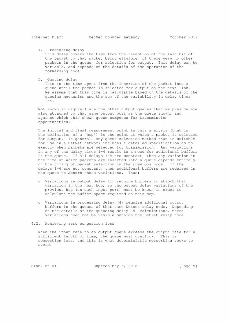
4. Processing delay This delay covers the time from the reception of the last bit of the packet to that packet being eligible, if there were no other packets in the queue, for selection for output. This delay can be variable, and depends on the details of the operation of the forwarding node.
5. Queuing delay This is the time spent from the insertion of the packet into a queue until the packet is selected for output on the next link. We assume that this time is calculable based on the details of the queuing mechanism and the sum of the variability in delay times 1-4.
Not shown in Figure 1 are the other output queues that we presume are also attached to that same output port as the queue shown, and against which this shown queue competes for transmission opportunities.
The initial and final measurement point in this analysis (that is, the definition of a "hop") is the point at which a packet is selected for output. In general, any queue selection method that is suitable for use in a DetNet network includes a detailed specification as to exactly when packets are selected for transmission. Any variations in any of the delay times 1-4 result in a need for additional buffers in the queue. If all delays 1-4 are constant, then any variation in the time at which packets are inserted into a queue depends entirely on the timing of packet selection in the previous node. If the delays 1-4 are not constant, then additional buffers are required in the queue to absorb these variations. Thus:
o Variations in output delay (1) require buffers to absorb that variation in the next hop, so the output delay variations of the previous hop (on each input port) must be known in order to calculate the buffer space required on this hop.
o Variations in processing delay (4) require additional output buffers in the queues of that same Detnet relay node. Depending on the details of the queueing delay (5) calculations, these variations need not be visible outside the DetNet relay node.
4.2. Achieving zero congestion loss
When the input rate to an output queue exceeds the output rate for a sufficient length of time, the queue must overflow. This is congestion loss, and this is what deterministic networking seeks to avoid.
Finn, et al. Expires May 3, 2018 [Page 5]
Internet-Draft DetNet Bounded Latency October 2017
Imagine a completely saturated DetNet network, in which all is part of some number of DetNet flows, and 100% of each link’s bandwidth is allocated to some number of DetNet Flows using that link. Every source is transmitting at exactly its allotted rate. The DetNet flows traverse the network in all directions; no two DetNet flows take exactly the same path through the network. Imagine that there are no variations in the output delay (1), link delay (2), and processing delay (4), and there is no preemption delay (3).
Imagine now that one DetNet flow, DetNet flow A, stops. On some output port through which DetNet flow A was passing, when the transmission opportunity for one of DetNet flow A’s packets comes up, the DetNet relay node must either output nothing, or output a packet belonging to some other DetNet flow B. If it outputs a packet from DetNet flow B, then in the long term, it is exceeding the normal rate for DetNet flow B, and runs the risk of overflowing the queues for DetNet flow B in the next hop. With sufficient analysis, it may be possible to determine the limits for how much excess data in DetNet flow B, or DetNet flow C, from this and from other ports feeding the next hop, can be accommodated before causing an overflow.
However, this analysis is very difficult. DetNet avoids the analysis by transmitting nothing (or transmitting a non-DetNet packet) when it has nothing to transmit for a given DetNet flow. This leads to DetNet making the following requirement for DetNet relay nodes:
For every DetNet flow traversing a DetNet relay node, sufficient data is buffered in that a DetNet relay node to ensure that a transmission opportunity for that DetNet flow is never missed, unless the source of the DetNet flow slows or stops. That is, for every DetNet flow, over some finite time scale, the input rate equals the output rate.
5. Queuing model
5.1. Queuing data model
Sophisticated QoS mechanisms are available in Layer 3 (L3), see, e.g., [RFC7806] for an overview. In general, we assume that "Layer 3" queues, shapers, meters, etc., are instantiated hierarchically above the "Layer 2" queuing mechanisms, among which packets compete for opportunities to be transmitted on a physical (or sometimes, logical) medium. These "Layer 2 queuing mechanisms" are not the province solely of bridges; they are an essential part of any DetNet relay node. As illustrated by numerous implementation examples, the "Layer 3" some of mechanisms described in documents such as [RFC7806] are often integrated, in an implementation, with the "Layer 2" mechanisms also implemented in the same system. An integrated model is needed in order to successfully predict the interactions among the
Finn, et al. Expires May 3, 2018 [Page 6]

Internet-Draft DetNet Bounded Latency October 2017
different queuing mechanisms needed in a network carrying both DetNet flows and non-DetNet flows. See Section 6 for a more complete discussion of the expanded model.
Figure 2 shows the (very simple) model for the flow of packets through the queues of an IEEE 802.1Q bridge. Packets are assigned to a class of service. The classes of service are mapped to some number of physical FIFO queues. IEEE 802.1Q allows a maximum of 8 classes of service, but it is more common to implement 2 or 4 queues on most ports.
| +--------------V---------------+ | Class of Service Assignment | +--+-------+---------------+---+ | | | +--V--+ +--V--+ +--V--+ |Class| |Class| |Class| | 0 | | 1 | . . . | n | |queue| |queue| |queue| +--+--+ +--+--+ +--+--+ | | | +--V-------V---------------V--+ | Transmission selection | +--------------+--------------+ | V
Figure 2: IEEE 802.1Q Queuing Model: Data flow
Some relevant mechanisms are hidden in this figure, and are performed in the "Class n queue" box:
o Discarding packets because a queue is full.
o Discarding packets marked "yellow" by a metering function, in preference to discarding "green" packets.
The Class of Service Assignment function can be quite complex, since the introduction of [IEEE802.1Qci]. In addition to the Layer 2 priority expressed in the 802.1Q VLAN tag, a bridge can utilize any of the following information to assign a packet to a particular class of service (queue):
o Input port.
o Selector based on a rotating schedule that starts at regular, time-synchronized intervals and has nanosecond precision.
Finn, et al. Expires May 3, 2018 [Page 7]

Internet-Draft DetNet Bounded Latency October 2017
o MAC addresses, VLAN ID, IP addresses, Layer 4 port numbers, DSCP. (Work items expected to add MPC and other indicators.)
o The Class of Service Assignment function can contain metering and policing functions.
The "Transmission selection" function decides which queue is to transfer its oldest packet to the output port when a transmission opportunity arises.
5.2. Queuing Data Model with Preemption
Figure 2 must be modified if the output port supports preemption ([IEEE8021Qbu] and [IEEE8023br]). This modification is shown in Figure 3.
| +------------------------------V------------------------------+ | Class of Service Assignment | +--+-------+-------+-------+-------+-------+-------+-------+--+ | | | | | | | | +--V--+ +--V--+ +--V--+ +--V--+ +--V--+ +--V--+ +--V--+ +--V--+ |Class| |Class| |Class| |Class| |Class| |Class| |Class| |Class| | a | | b | | c | | d | | e | | f | | g | | h | |queue| |queue| |queue| |queue| |queue| |queue| |queue| |queue| +--+--+ +--+--+ +--+--+ +--+--+ +--+--+ +--+--+ +--+--+ +--+--+ | | | +-+ | | | | | | | | | | | | +--V-------V-------V------+ +V-----V-------V-------V-------V--+ | Interrupted xmit select | | Preempting xmit select | 802.1 +-------------+-----------+ +----------------+----------------+ | | ====== +-------------V-----------+ +----------------V----------------+ | Preemptible MAC | | Express MAC | 802.3 +--------+----------------+ +----------------+----------------+ | | +--------V-----------------------------------V----------------+ | MAC merge sublayer | +--------------------------+----------------------------------+ | +--------------------------V----------------------------------+ | PHY (unaware of preemption) | +--------------------------+----------------------------------+ | V
Figure 3: IEEE 802.1Q Queuing Model: Data flow with preemption
Finn, et al. Expires May 3, 2018 [Page 8]

Internet-Draft DetNet Bounded Latency October 2017
From Figure 3, we can see that, in the IEEE 802 model, the preemption feature is modeled as consisting of two MAC/PHY stacks, one for packets that can be interrupted, and one for packets that can interrupt the interruptible packets. The Class of Service (queue) determines which packets are which. In Figure 3, the classes of service are marked "a, b, ..." instead of with numbers, in order to avoid any implication about which numeric Layer 2 priority values correspond to preemptible or preempting queues. Although it shows three queues going to the preemptible MAC/PHY, any assignment is possible.
5.3. Transmission Selection Model
In Figure 4, we expand the "Transmission selection" function of Figure 3.
Figure 4 does NOT show the data path. It shows an example of a configuration of the IEEE 802.1Q transmission selection box shown in Figure 2 and Figure 3. Each queue m presents a "Class m Ready" signal. These signals go through various logic, filters, and state machines, until a single queue’s "not empty" signal is chosen for presentation to the underlying MAC/PHY. When the MAC/PHY is ready to take another output packet, then a packet is selected from the one queue (if any) whose signal manages to pass all the way through the transmission selection function.
Finn, et al. Expires May 3, 2018 [Page 9]

Internet-Draft DetNet Bounded Latency October 2017
+-----+ +-----+ +-----+ +-----+ +-----+ +-----+ +-----+ +-----+ |Class| |Class| |Class| |Class| |Class| |Class| |Class| |Class| | 1 | | 0 | | 4 | | 5 | | 6 | | 7 | | 2 | | 3 | |Ready| |Ready| |Ready| |Ready| |Ready| |Ready| |Ready| |Ready| +--+--+ +--+--+ +--+--+ +-XXX-+ +--+--+ +--+--+ +--+--+ +--+--+ | | | | | | | | +--V--+ +--V--+ +--+--+ +--V--+ | +--V--+ +--V--+ | |Prio.| |Prio.| |Prio.| |Prio.| | |Sha- | |Sha- | | | 0 | | 4 | | 5 | | 6 | | | per| | per| | | PFC | | PFC | | PFC | | PFC | | | A | | B | | +--+--+ +--+--+ +-XXX-+ +-XXX-+ | +--+--+ +-XXX-+ | | | | | +--V--+ +--V--+ +--V--+ +--+--+ +--+--+ +--V--+ +--V--+ +--+--+ |Time | |Time | |Time | |Time | |Time | |Time | |Time | |Time | | Gate| | Gate| | Gate| | Gate| | Gate| | Gate| | Gate| | Gate| | 1 | | 0 | | 4 | | 5 | | 6 | | 7 | | 2 | | 3 | +--+--+ +-XXX-+ +--+--+ +--+--+ +-XXX-+ +--+--+ +-XXX-+ +--+--+ | | | +--V-------+-------V-------+--+ | |802.1Q Enhanced Transmission | | | Selection (ETS) = Weighted | | | Fair Queuing (WFQ) | | +--+-------+------XXX------+--+ | | | +--V-------+-------+-------+-------+-------V-------+-------+--+ | Strict Priority selection (rightmost first) | +-XXX------+-------+-------+-------+-------+-------+-------+--+ | V
Figure 4: 802.1Q Transmission Selection
The following explanatory notes apply to Figure 4
o The numbers in the "Class n Ready" boxes are the values of the Layer 2 priority that are assigned to that Class of Service in this example. The rightmost CoS is the most important, the leftmost the least. Classes 2 and 3 are made the most important, because they carry DetNet flows. It is all right to make them more important than the priority 7 queue, which typically carries critical network control protocols such as spanning tree or IS-IS, because the shaper ensures that the highest priority best-effort queue (7) will get reasonable access to the MAC/PHY. Note that Class 5 has no Ready signal, indicating that that queue is empty.
o Below the Class Ready signals are shown the Priority Flow Control gates (IEEE Std 802.1Qbb-2011 Priority-based Flow Control, now [IEEE8021Q] clause 36) on Classes of Service 1, 0, 4, and 5, and
Finn, et al. Expires May 3, 2018 [Page 10]
Internet-Draft DetNet Bounded Latency October 2017
two 802.1Q shapers, A and B. Perhaps shaper A conforms to the IEEE Std 802.1Qav-2009 (now [IEEE8021Q] clause 34) credit-based shaper, and shaper B conforms to [IEEE8021Qcr] Asynchronous Traffic Shaper. Any given Class of Service can have either a PFC function or a shaper, but not both.
o Next are the IEEE Std 802.1Qbv time gates ([IEEE8021Qbv]). Each one of the 8 Classes of Service has a time gate. The gates are controlled by a repeating schedule that restarts periodically, and can be programmed to turn any combination of gates on or off with nanosecond precision. (Although the implementation is not necessarily that accurate.)
o Following the time gates, any number of Classes of Service can be linked to one ore more instances of the Enhanced Transmission Selection function. This does weighted fair queuing among the members of its group.
o A final selection of the one queue to be selected for output is made by strict priority. Note that the priority is determined not by the Layer 2 priority, but by the Class of Service.
o An "XXX" in the lower margin of a box (e.g. "Prio. 5 PFC" indicates that the box has blocked the "Class n Ready" signal.
o IEEE 802.1Qch Cyclic Queuing and Forwarding [IEEE802.1Qch] is accomplished using two or three queues (e.g. 2 and 3 in the figure), using sophisticated time-based schedules in the Class of Service Assignment function, and using the IEEE 802.1Qbv time gates [IEEE8021Qbv] to swap between the output buffers.
6. Extending the queuing model
6.1. Complex delay models
Using the model of Section 4, we can model any system, even one that is very complex, including separate line cards, MAC/PHY modules, mid- planes, backplanes, control/forwarding boards, etc. However, in a complex case, the variations in the processing delay (4) may become so large as to make any latency or buffer requirement analysis relatively useless.
If a DetNet node is sufficiently complex that simply assigning a minimum and maximum to the some delay (typically, the processing delay, 4) results in insufficiently accurate computations for latency or buffer requirements, the DetNet node can be modeled as a federation of DetNet relay nodes, each conforming to the model.
Finn, et al. Expires May 3, 2018 [Page 11]
Internet-Draft DetNet Bounded Latency October 2017
In the simplest example, system with input queues on each port could be modeled having a two-port DetNet relay node inserted into each input port, each with some number of output queues (which model the input queues).
6.2. Extending the 802.1Q model to routers
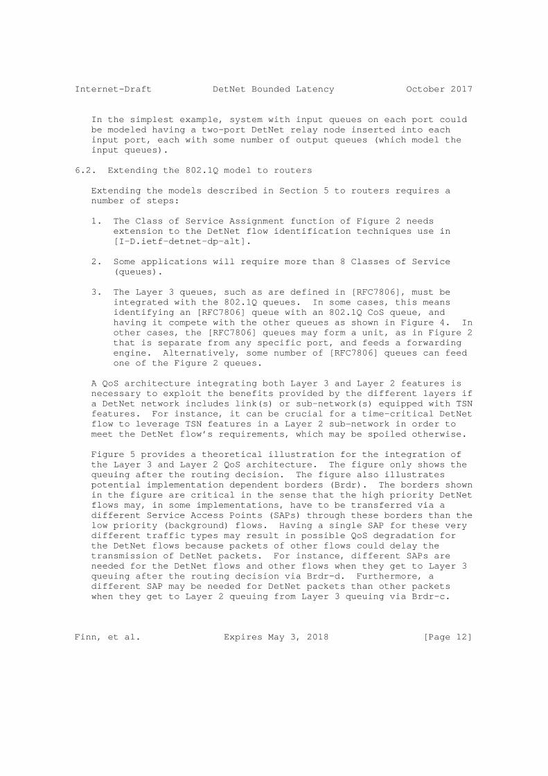
Extending the models described in Section 5 to routers requires a number of steps:
1. The Class of Service Assignment function of Figure 2 needs extension to the DetNet flow identification techniques use in [I-D.ietf-detnet-dp-alt].
2. Some applications will require more than 8 Classes of Service (queues).
3. The Layer 3 queues, such as are defined in [RFC7806], must be integrated with the 802.1Q queues. In some cases, this means identifying an [RFC7806] queue with an 802.1Q CoS queue, and having it compete with the other queues as shown in Figure 4. In other cases, the [RFC7806] queues may form a unit, as in Figure 2 that is separate from any specific port, and feeds a forwarding engine. Alternatively, some number of [RFC7806] queues can feed one of the Figure 2 queues.
A QoS architecture integrating both Layer 3 and Layer 2 features is necessary to exploit the benefits provided by the different layers if a DetNet network includes link(s) or sub-network(s) equipped with TSN features. For instance, it can be crucial for a time-critical DetNet flow to leverage TSN features in a Layer 2 sub-network in order to meet the DetNet flow’s requirements, which may be spoiled otherwise.
Figure 5 provides a theoretical illustration for the integration of the Layer 3 and Layer 2 QoS architecture. The figure only shows the queuing after the routing decision. The figure also illustrates potential implementation dependent borders (Brdr). The borders shown in the figure are critical in the sense that the high priority DetNet flows may, in some implementations, have to be transferred via a different Service Access Points (SAPs) through these borders than the low priority (background) flows. Having a single SAP for these very different traffic types may result in possible QoS degradation for the DetNet flows because packets of other flows could delay the transmission of DetNet packets. For instance, different SAPs are needed for the DetNet flows and other flows when they get to Layer 3 queuing after the routing decision via Brdr-d. Furthermore, a different SAP may be needed for DetNet packets than other packets when they get to Layer 2 queuing from Layer 3 queuing via Brdr-c.
Finn, et al. Expires May 3, 2018 [Page 12]

Internet-Draft DetNet Bounded Latency October 2017
Certainly, in the 802.1/802.3 model, different SAPs are needed for the express and for the preemptible frames when they get to the MAC layer from Layer 2 queuing via Brdr-b, which is provided by the IEEE 802.1Q architecture as shown in Figure 3. It depends on the implementation whether or not Brdr-a exists.
| +---------------V-----------+ | Forwarding | +--------+----------+--+----+ | | | === Brdr-d +--------V--------+ | | | CoS Assignment | | | +-----------------+ | | |Que-|Que-|..|Que-| | | Layer 3 queuing | ue | ue |..| ue | | | and shaping +-----------------+ | | (optional) | Xmit selection | | | +--------+----+---+ | | | | | | === Brdr-c +-V----V-----V--V-+ | CoS Assignment | +-----------------+ Layer 2 queuing |Que-|Que-|..|Que-| and shapng | ue | ue |..| ue | (always present) +-----------------+ | Xmit selection | +--+-----------+--+ | | === Brdr-b +------V----+ +---V-------+ |Preemptible| | Express | | MAC | | MAC | +------+----+ +----+------+ | | === Brdr-a +------V------------V------+ | PHY | +------------+-------------+ | V
Figure 5: Combined L2/L3 Queueing Data Model
7. References
Finn, et al. Expires May 3, 2018 [Page 13]

Internet-Draft DetNet Bounded Latency October 2017
7.1. Normative References
[I-D.ietf-detnet-architecture] Finn, N. and P. Thubert, "Deterministic Networking Architecture", draft-ietf-detnet-architecture-00 (work in progress), September 2016.
[I-D.ietf-detnet-dp-alt] Korhonen, J., Farkas, J., Mirsky, G., Thubert, P., Zhuangyan, Z., and L. Berger, "DetNet Data Plane Protocol and Solution Alternatives", draft-ietf-detnet-dp-alt-00 (work in progress), October 2016.
[I-D.ietf-detnet-use-cases] Grossman, E., Gunther, C., Thubert, P., Wetterwald, P., Raymond, J., Korhonen, J., Kaneko, Y., Das, S., Zha, Y., Varga, B., Farkas, J., Goetz, F., Schmitt, J., Vilajosana, X., Mahmoodi, T., Spirou, S., Vizarreta, P., Huang, D., Geng, X., Dujovne, D., and M. Seewald, "Deterministic Networking Use Cases", draft-ietf-detnet-use-cases-13 (work in progress), September 2017.
[RFC2119] Bradner, S., "Key words for use in RFCs to Indicate Requirement Levels", BCP 14, RFC 2119, DOI 10.17487/RFC2119, March 1997, <https://www.rfc-editor.org/info/rfc2119>.
[RFC2212] Shenker, S., Partridge, C., and R. Guerin, "Specification of Guaranteed Quality of Service", RFC 2212, DOI 10.17487/RFC2212, September 1997, <https://www.rfc-editor.org/info/rfc2212>.
[RFC4364] Rosen, E. and Y. Rekhter, "BGP/MPLS IP Virtual Private Networks (VPNs)", RFC 4364, DOI 10.17487/RFC4364, February 2006, <https://www.rfc-editor.org/info/rfc4364>.
[RFC6658] Bryant, S., Ed., Martini, L., Swallow, G., and A. Malis, "Packet Pseudowire Encapsulation over an MPLS PSN", RFC 6658, DOI 10.17487/RFC6658, July 2012, <https://www.rfc-editor.org/info/rfc6658>.
[RFC7806] Baker, F. and R. Pan, "On Queuing, Marking, and Dropping", RFC 7806, DOI 10.17487/RFC7806, April 2016, <https://www.rfc-editor.org/info/rfc7806>.
Finn, et al. Expires May 3, 2018 [Page 14]

Internet-Draft DetNet Bounded Latency October 2017
7.2. Informative References
[IEEE802.1Qch] IEEE, "IEEE Std 802.1Qch-2017 IEEE Standard for Local and metropolitan area networks - Bridges and Bridged Networks Amendment 29: Cyclic Queuing and Forwarding (amendment to 802.1Q-2014)", 2017, <http://www.ieee802.org/1/files/private/ch-drafts/>.
[IEEE802.1Qci] IEEE, "IEEE Std 802.1Qci-2017 IEEE Standard for Local and metropolitan area networks - Bridges and Bridged Networks - Amendment 30: Per-Stream Filtering and Policing", 2017, <http://www.ieee802.org/1/files/private/ci-drafts/>.
[IEEE8021Q] IEEE 802.1, "IEEE Std 802.1Q-2014: IEEE Standard for Local and metropolitan area networks - Bridges and Bridged Networks", 2014, <http://standards.ieee.org/getieee802/ download/802-1Q-2014.pdf>.
[IEEE8021Qbu] IEEE, "IEEE Std 802.1Qbu-2016 IEEE Standard for Local and metropolitan area networks - Bridges and Bridged Networks - Amendment 26: Frame Preemption", 2016, <http://standards.ieee.org/getieee802/ download/802.1Qbu-2016.zip>.
[IEEE8021Qbv] IEEE 802.1, "IEEE Std 802.1Qbv-2015: IEEE Standard for Local and metropolitan area networks - Bridges and Bridged Networks - Amendment 25: Enhancements for Scheduled Traffic", 2015, <http://standards.ieee.org/getieee802/ download/802.1Qbv-2015.zip>.
[IEEE8021Qcr] IEEE 802.1, "IEEE P802.1Qcr: IEEE Draft Standard for Local and metropolitan area networks - Bridges and Bridged Networks - Amendment: Asynchronous Traffic Shaping", 2017, <http://www.ieee802.org/1/files/private/cr-drafts/>.
[IEEE8021TSN] IEEE 802.1, "IEEE 802.1 Time-Sensitive Networking (TSN) Task Group", <http://www.ieee802.org/1/>.
Finn, et al. Expires May 3, 2018 [Page 15]

Internet-Draft DetNet Bounded Latency October 2017
[IEEE8023] IEEE 802.3, "IEEE Std 802.3-2015: IEEE Standard for Local and metropolitan area networks - Ethernet", 2015, <http://standards.ieee.org/getieee802/ download/802.3-2015.zip>.
[IEEE8023br] IEEE 802.3, "IEEE Std 802.3br-2016: IEEE Standard for Local and metropolitan area networks - Ethernet - Amendment 5: Specification and Management Parameters for Interspersing Express Traffic", 2016, <http://standards.ieee.org/getieee802/ download/802.3br-2016.pdf>.
Authors’ Addresses
Norman Finn Huawei Technologies Co. Ltd 3101 Rio Way Spring Valley, California 91977 US
Phone: +1 925 980 6430 Email: [email protected]
Balazs Varga Ericsson Konyves Kalman krt. 11/B Budapest 1097 Hungary
Email: [email protected]
Janos Farkas Ericsson Konyves Kalman krt. 11/B Budapest 1097 Hungary
Email: [email protected]
Finn, et al. Expires May 3, 2018 [Page 16]

DetNet J. Korhonen, Ed.Internet-Draft NordicIntended status: Standards Track L. AnderssonExpires: May 3, 2018 Y. Jiang N. Finn Huawei B. Varga J. Farkas Ericsson CJ. Bernardos UC3M T. Mizrahi Marvell L. Berger LabN October 30, 2017
DetNet Data Plane Encapsulation draft-ietf-detnet-dp-sol-00
Abstract
This document specifies Deterministic Networking data plane encapsulation solutions. The described data plane solutions can be applied over either IP or MPLS Packet Switched Networks.
Comment #1: SB> An overarching comment is that the early part of the document is really fundamental architecture and perhaps belongs in the arch draft, leaving this draft to be more specific about solutions. Indeed if we cannot find a single solution that maps to both IP and MPLS underlays I wonder if we should publish two specialist RFCs?
Discussion: One document at the beginning, split into two if/when needed. Would be post adoption in any case.
Comment #2: SB> Whilst I think we should look for a common solution to IP and MPLS I do not think that this is where the DT ended up.
Discussion: Agree.
Status of This Memo
This Internet-Draft is submitted in full conformance with the provisions of BCP 78 and BCP 79.
Korhonen, et al. Expires May 3, 2018 [Page 1]

Internet-Draft DetNet Data Plane Encapsulation October 2017
Internet-Drafts are working documents of the Internet Engineering Task Force (IETF). Note that other groups may also distribute working documents as Internet-Drafts. The list of current Internet- Drafts is at https://datatracker.ietf.org/drafts/current/.
Internet-Drafts are draft documents valid for a maximum of six months and may be updated, replaced, or obsoleted by other documents at any time. It is inappropriate to use Internet-Drafts as reference material or to cite them other than as "work in progress."
This Internet-Draft will expire on May 3, 2018.
Copyright Notice
Copyright (c) 2017 IETF Trust and the persons identified as the document authors. All rights reserved.
This document is subject to BCP 78 and the IETF Trust’s Legal Provisions Relating to IETF Documents (https://trustee.ietf.org/license-info) in effect on the date of publication of this document. Please review these documents carefully, as they describe your rights and restrictions with respect to this document. Code Components extracted from this document must include Simplified BSD License text as described in Section 4.e of the Trust Legal Provisions and are provided without warranty as described in the Simplified BSD License.
Table of Contents
1. Introduction . . . . . . . . . . . . . . . . . . . . . . . . 3 2. Terminology . . . . . . . . . . . . . . . . . . . . . . . . . 5 2.1. Terms used in this document . . . . . . . . . . . . . . . 5 2.2. Abbreviations . . . . . . . . . . . . . . . . . . . . . . 7 3. Requirements language . . . . . . . . . . . . . . . . . . . . 8 4. DetNet data plane overview . . . . . . . . . . . . . . . . . 8 4.1. DetNet data plane encapsulation requirements . . . . . . 10 5. DetNet data plane solution . . . . . . . . . . . . . . . . . 12 5.1. DetNet specific packet fields . . . . . . . . . . . . . . 12 5.2. DetNet encapsulation . . . . . . . . . . . . . . . . . . 12 5.2.1. PseudoWire-based data plane encapsulation . . . . . . 13 5.2.2. Native IPv6-based data plane encapsulation . . . . . 15 5.3. DetNet flow identification for duplicate detection . . . 17 5.3.1. PseudoWire encapsulation . . . . . . . . . . . . . . 17 5.3.2. Native IPv6 encapsulation . . . . . . . . . . . . . . 18 6. PREF specific considerations . . . . . . . . . . . . . . . . 18 6.1. PseudoWire-based data plane . . . . . . . . . . . . . . . 18 6.1.1. Forwarder clarifications . . . . . . . . . . . . . . 18 6.1.2. Edge node processing clarifications . . . . . . . . . 19
Korhonen, et al. Expires May 3, 2018 [Page 2]

Internet-Draft DetNet Data Plane Encapsulation October 2017
6.1.3. Relay node processing clarifications . . . . . . . . 21 6.2. Native IPv6-based data plane . . . . . . . . . . . . . . 23 7. Other DetNet data plane considerations . . . . . . . . . . . 23 7.1. Class of Service . . . . . . . . . . . . . . . . . . . . 23 7.2. Quality of Service . . . . . . . . . . . . . . . . . . . 24 7.3. Cross-DetNet flow resource aggregation . . . . . . . . . 25 7.4. Bidirectional traffic . . . . . . . . . . . . . . . . . . 26 7.5. Layer 2 addressing and QoS Considerations . . . . . . . . 27 7.6. Interworking between PW- and IPv6-based encapsulations . 27 8. Time synchronization . . . . . . . . . . . . . . . . . . . . 27 9. Management and control considerations . . . . . . . . . . . . 29 9.1. PW Label and IPv6 Flow Label assignment and distribution 29 9.2. Packet replication and elimination . . . . . . . . . . . 30 9.3. Explicit paths . . . . . . . . . . . . . . . . . . . . . 30 9.4. Congestion protection and latency control . . . . . . . . 30 9.5. Flow aggregation control . . . . . . . . . . . . . . . . 30 10. Security considerations . . . . . . . . . . . . . . . . . . . 30 11. IANA considerations . . . . . . . . . . . . . . . . . . . . . 30 12. Acknowledgements . . . . . . . . . . . . . . . . . . . . . . 30 13. References . . . . . . . . . . . . . . . . . . . . . . . . . 31 13.1. Normative references . . . . . . . . . . . . . . . . . . 31 13.2. Informative references . . . . . . . . . . . . . . . . . 33 Appendix A. Example of DetNet data plane operation . . . . . . . 34 Appendix B. Example of pinned paths using IPv6 . . . . . . . . . 35 Authors’ Addresses . . . . . . . . . . . . . . . . . . . . . . . 35
1. Introduction
Deterministic Networking (DetNet) is a service that can be offered by a network to DetNet flows. DetNet provides these flows extremely low packet loss rates and assured maximum end-to-end delivery latency. General background and concepts of DetNet can be found in [I-D.ietf-detnet-architecture].
This document specifies the DetNet data plane. It defines how DetNet traffic is encapsulated at the network layer, and how DetNet-aware nodes can identity DetNet flows. Two data plane definitions are given.
o PW-based: One solution is based on PseudoWires (PW) [RFC3985] and [RFC5036] and makes use of multi-segment pseudowires (MS-PW) [RFC6073] to map DetNet Relay and Edge Nodes [I-D.ietf-detnet-architecture] [I-D.ietf-detnet-dp-alt] to PW architecture. The PW-based data plane can be run over an MPLS [RFC4448] [RFC6658] Packet Switched Network (PSN).
Comment #3: SB> This is really an MPLS one. The world of IP PWs is a bit scruffy with some work in PWE3 and some in L2TPext which
Korhonen, et al. Expires May 3, 2018 [Page 3]

Internet-Draft DetNet Data Plane Encapsulation October 2017
really went their own ways. There is for example no MS-PW IP design. The MS-PW approach needs to be examined more closely by the WG and thus at this stage be marked as provisional.
Discussion: Agree. "can be" -> "is".
Comment #3.1 LB> EVPN-based encapsulation is also a potential candidate. In general DetNet should look more closely to the delevopment around EVPN.
Discussion Agree. EVPN could be a potential solution and the on- wire encapsuations are likely to be the same as PW-based encapsulation would be. EVPN even recommends using Control Word [RFC8214] (in the absence of entropy labels).
o Native-IP: The other solution is based on IP header fields, namely on the IPv6 Flow Label and a new DetNet Control Word extension header option. It is targeted for native IPv6 networks.
Comment #4: SB> The IP solution has not been properly examined by the WG and needs to be marked as provisional.
Discussion: IP vs. MPLS is a deployment choice.
It is worth noting that while PWs are designed to work over IP PSNs this document describes a native-IP solution that operates without PWs. The primary reason for this is the benefit gained by enabling the use of a normal application stack, where transport protocols such as TCP or UDP are directly encapsulated in IP.
Comment #5: SB> We clearly need to look at the implications of running this with a new IP header extension. Firstly we need input from 6man, but we also need to understand what happens in middle boxes, other components of the host stack etc.
Discussion: A WG can develop their own extensions and then get approval from 6man. Sometimes that ends up redoing extensions in 6man but not always.
This document specifies the encapsulation for DetNet flows, including a DetNet Control Word (CW). Furthermore, it describes how DetNet flows are identified, how DetNet Relay and Edge nodes work, and how the Packet Replication and Elimination function (PREF) is implemented with these two data plane solutions. This document does not define the associated control plane functions, or Operations, Administration, and Maintenance (OAM). It also does not specify traffic handling capabilities required to deliver congestion
Korhonen, et al. Expires May 3, 2018 [Page 4]

Internet-Draft DetNet Data Plane Encapsulation October 2017
protection and latency control to DetNet flows as this is defined to be provided by the underlying MPLS or IP network.
Comment #6: SB> OK, although I think that this may be a mistake. There may well be some coupling needed between the Detnet DP and the substrate/transport/underlay needed to make this work. If this is a genuine technical layering we should talk about it. If this is an artificial constraint imposed by the IESG we need to talk to them.
Discussion: The only interaction needed is that the flow identification is possible. That needs to be available for lower layers.
Comment #6.1: LA> Even though this document does not specify any OAM functions, we will need to verify that the GACh (Generalized Associate Channel) works correctly in a network that has replication and elimination.
Discussion: --
2. Terminology
2.1. Terms used in this document
This document uses the terminology established in the DetNet architecture [I-D.ietf-detnet-architecture] and the DetNet Data Plane Solution Alternatives [I-D.ietf-detnet-dp-alt].
The following terms are also used in this document:
DA-T-PE MPLS based DetNet edge node: a DetNet-aware PseudoWire Terminating Provider Edge (T-PE).
DA-S-PE MPLS based DetNet relay node: a DetNet-aware PseudoWire Switching Provider Edge (S-PE).
Comment #7 SB> We need to look at whether the S-PE concept is the best fit, or whether we should use introduce a Detnet relay to do this. An S-PE just swaps the PW label, but Detnet needs it to do more and a better model might be a new construct. However we could also discard the relay concept and run 1+n end to end, in which case the S-PEs would retain heir original function.
Discussion: Disagree of the dropping comment. However, the issues are most likely terminology related. The relay concept is part of the DetNet architecture A DA-S-PE was intended to be a DetNet relay, which may do more than just swapping labels (PREF
Korhonen, et al. Expires May 3, 2018 [Page 5]

Internet-Draft DetNet Data Plane Encapsulation October 2017
functionality). Current text is quite biased to MS-PW, which was the starting point for the DetNet relay in a MPLS PW network.
T-Label A label used to identify the LSP used to transport a DetNet flow across an MPLS PSN, e.g., a hop-by-hop label used between label switching routers (LSR).
S-Label A DetNet node to DetNet node "service" label that is used between DA-*-PE devices.
PW Label A PseudoWire label that is used to identify DetNet flow related PW Instances within a PE node.
Flow Label IPv6 header field that is used to identify a DetNet flow (together with the source IP address field).
Comment #8 SB> If this is the IPv6 Flow label I think caution is needed as I don’t think the handling of this is well defined or consistently implemented in networking equipment.
Discussion: DetNet specifies the use and discusses possible interaction with RFC6347 in this I-D.
local-ID An edge and relay node internal construct that uniquely identifies a DetNet flow. It may be used to select proper forwarding and/or DetNet specific service function.
Comment #9 SB> Is this really an internal construct, or is it an on the wire construct? If it is needed end to end, I don’t think it is correct to describe it as an internal construct. When you say "select" presumably you mean by potentially any DN aware node on the path?
Discussion: It is an internal construct, so yes.
PREF A Packet Replication and Elimination Function (PREF) does the replication and elimination processing of DetNet flow packets in edge or relay nodes. The replication function is essentially the existing 1+1 protection mechanism. The elimination function reuses and extends the existing duplicate detection mechanism to operate over multiple (separate) DetNet member flows of a DetNet compound flow.
Comment #10 SB> I wonder if 1+1 is the right way to go, or whether 1+n is better. A bunch of new techniques have emerged over the years and we really ought to look at creating paths with MRT.
Korhonen, et al. Expires May 3, 2018 [Page 6]
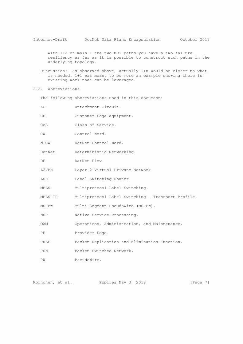
Internet-Draft DetNet Data Plane Encapsulation October 2017
With 1+2 on main + the two MRT paths you have a two failure resiliency as far as it is possible to construct such paths in the underlying topology.
Discussion: As observed above, actually 1+n would be closer to what is needed. 1+1 was meant to be more an example showing there is existing work that can be leveraged.
2.2. Abbreviations
The following abbreviations used in this document:
AC Attachment Circuit.
CE Customer Edge equipment.
CoS Class of Service.
CW Control Word.
d-CW DetNet Control Word.
DetNet Deterministic Networking.
DF DetNet Flow.
L2VPN Layer 2 Virtual Private Network.
LSR Label Switching Router.
MPLS Multiprotocol Label Switching.
MPLS-TP Multiprotocol Label Switching - Transport Profile.
MS-PW Multi-Segment PseudoWire (MS-PW).
NSP Native Service Processing.
OAM Operations, Administration, and Maintenance.
PE Provider Edge.
PREF Packet Replication and Elimination Function.
PSN Packet Switched Network.
PW PseudoWire.
Korhonen, et al. Expires May 3, 2018 [Page 7]
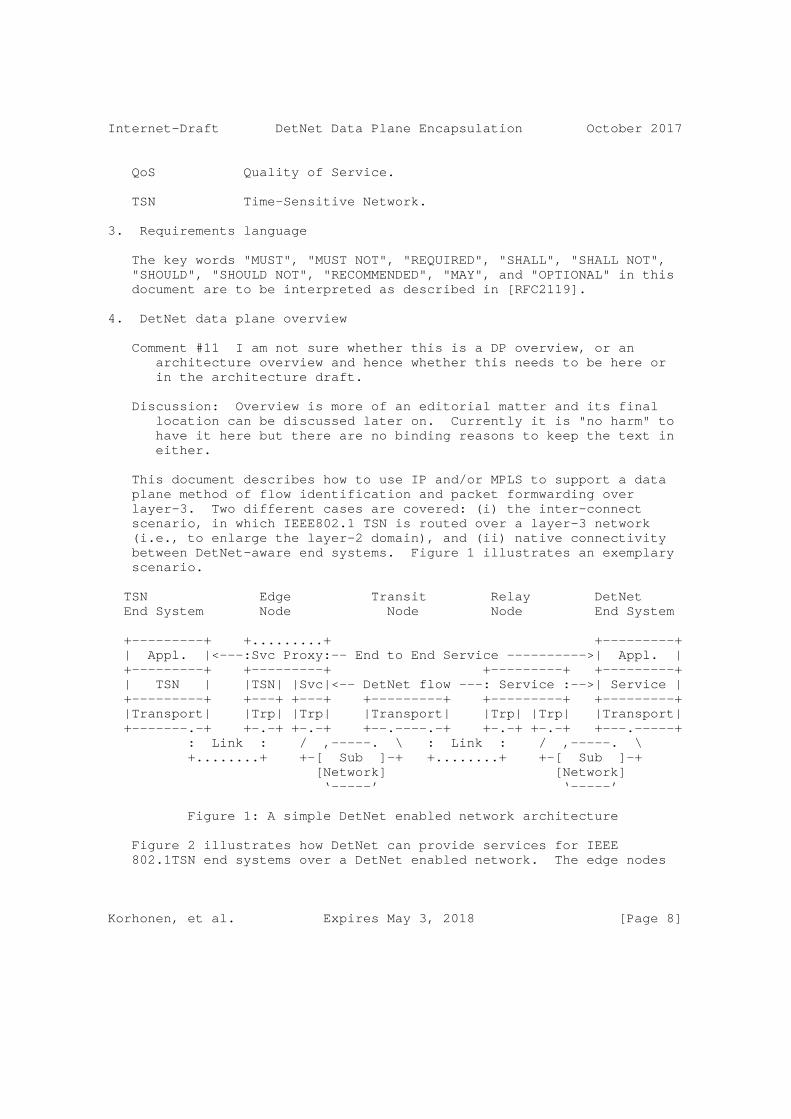
Internet-Draft DetNet Data Plane Encapsulation October 2017
QoS Quality of Service.
TSN Time-Sensitive Network.
3. Requirements language
The key words "MUST", "MUST NOT", "REQUIRED", "SHALL", "SHALL NOT", "SHOULD", "SHOULD NOT", "RECOMMENDED", "MAY", and "OPTIONAL" in this document are to be interpreted as described in [RFC2119].
4. DetNet data plane overview
Comment #11 I am not sure whether this is a DP overview, or an architecture overview and hence whether this needs to be here or in the architecture draft.
Discussion: Overview is more of an editorial matter and its final location can be discussed later on. Currently it is "no harm" to have it here but there are no binding reasons to keep the text in either.
This document describes how to use IP and/or MPLS to support a data plane method of flow identification and packet formwarding over layer-3. Two different cases are covered: (i) the inter-connect scenario, in which IEEE802.1 TSN is routed over a layer-3 network (i.e., to enlarge the layer-2 domain), and (ii) native connectivity between DetNet-aware end systems. Figure 1 illustrates an exemplary scenario.
TSN Edge Transit Relay DetNet End System Node Node Node End System
+---------+ +.........+ +---------+ | Appl. |<---:Svc Proxy:-- End to End Service ---------->| Appl. | +---------+ +---------+ +---------+ +---------+ | TSN | |TSN| |Svc|<-- DetNet flow ---: Service :-->| Service | +---------+ +---+ +---+ +---------+ +---------+ +---------+ |Transport| |Trp| |Trp| |Transport| |Trp| |Trp| |Transport| +-------.-+ +-.-+ +-.-+ +--.----.-+ +-.-+ +-.-+ +---.-----+ : Link : / ,-----. \ : Link : / ,-----. \ +........+ +-[ Sub ]-+ +........+ +-[ Sub ]-+ [Network] [Network] ‘-----’ ‘-----’
Figure 1: A simple DetNet enabled network architecture
Figure 2 illustrates how DetNet can provide services for IEEE 802.1TSN end systems over a DetNet enabled network. The edge nodes
Korhonen, et al. Expires May 3, 2018 [Page 8]

Internet-Draft DetNet Data Plane Encapsulation October 2017
insert and remove required DetNet data plane encapsulation. The ’X’ in the edge and relay nodes represents a potential DetNet flow packet replication and elimination point. This conceptually parallels L2VPN services, and could leverage existing related solutions as discussed below.
TSN |<---------- End to End DetNet Service ------>| TSN Service | Transit Transit | Service TSN (AC) | |<-Tunnel->| |<-Tnl->| | (AC) TSN End | V V 1 V V 2 V V | End System | +--------+ +--------+ +--------+ | System +---+ | | E1 |==========| R1 |=======| E2 | | +---+ | |--|----|._X_....|..DetNet..|.._ _...|..DF3..|...._X_.|---|---| | |CE1| | | \ | Flow 1 | X | | / | | |CE2| | | | \_.|...DF2....|._/ \_..|..DF4..|._/ | | | +---+ | |==========| |=======| | +---+ ^ +--------+ +--------+ +--------+ ^ | Edge Node Relay Node Edge Node | | | |<----- Emulated Time Sensitive Networking (TSN) Service ---->|
Figure 2: IEEE 802.1TSN over DetNet
Figure 3 illustrates how end to end PW-based DetNet service can be provided. In this case, the end systems are able to send and receive DetNet flows. For example, an end system sends data encapsulated in PseudoWire (PW) and in MPLS. Like earlier the ’X’ in the end systems, edge and relay nodes represents potential DetNet flow packet replication and elimination points. Here the relay nodes may change the underlying transport, for example tunneling IP over MPLS, or simply interconnect network segments.
Korhonen, et al. Expires May 3, 2018 [Page 9]

Internet-Draft DetNet Data Plane Encapsulation October 2017
DetNet DetNet Service Transit Transit Service DetNet | |<-Tnl->| |<-Tnl->| | DetNet End | V 1 V V 2 V | End System | +--------+ +--------+ +--------+ | System +---+ | | R1 |=======| R2 |=======| R3 | | +---+ | X...DFa...|._X_....|..DF1..|.__ ___.|..DF3..|...._X_.|.DFa..|.X | |CE1|========| \ | | X | | / |======|CE2| | | | | \_.|..DF2..|._/ \__.|..DF4..|._/ | | | | +---+ | |=======| |=======| | +---+ ^ +--------+ +--------+ +--------+ ^ | Relay Node Relay Node Relay Node | | | |<--------------- End to End DetNet Service -------------->|
Figure 3: PW-Based Native DetNet
Figure 4 illustrates how end to end IP-based DetNet service can be provided. In this case, the end systems are able to send and receive DetNet flows. [Editor’s note: TBD]
NOTE: This figures is TBD
DetNet DetNet Service Transit Transit Service DetNet | |<-Tnl->| |<-Tnl->| | DetNet End | V 1 V V 2 V | End System | +--------+ +--------+ +--------+ | System +---+ | | R1 |=======| R2 |=======| R3 | | +---+ | X...DFa...| | | | | | .|.X | | H1|========| | | | | |======| H2| | | | | | | | | | | | | +---+ | |=======| |=======| | +---+ ^ +--------+ +--------+ +--------+ ^ | Relay Node Relay Node Relay Node | | | |<--------------- End to End DetNet Service -------------->|
Figure 4: IP-Based Native DetNet
4.1. DetNet data plane encapsulation requirements
Two major groups of scenarios can be distinguished which require flow identification during transport:
1. DetNet function related scenarios:
Korhonen, et al. Expires May 3, 2018 [Page 10]
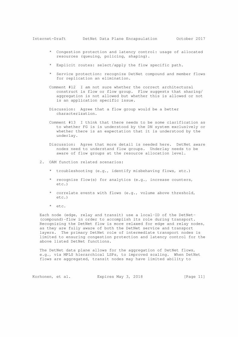
Internet-Draft DetNet Data Plane Encapsulation October 2017
* Congestion protection and latency control: usage of allocated resources (queuing, policing, shaping).
* Explicit routes: select/apply the flow specific path.
* Service protection: recognize DetNet compound and member flows for replication an elimination.
Comment #12 I am not sure whether the correct architectural construct is flow or flow group. Flow suggests that sharing/ aggregation is not allowed but whether this is allowed or not is an application specific issue.
Discussion: Agree that a flow group would be a better characterization.
Comment #13 I think that there needs to be some clarification as to whether FG is is understood by the DN system exclusively or whether there is an expectation that it is understood by the underlay.
Discussion: Agree that more detail is needed here. DetNet aware nodes need to understand flow groups. Underlay needs to be aware of flow groups at the resource allocation level.
2. OAM function related scenarios:
* troubleshooting (e.g., identify misbehaving flows, etc.)
* recognize flow(s) for analytics (e.g., increase counters, etc.)
* correlate events with flows (e.g., volume above threshold, etc.)
* etc.
Each node (edge, relay and transit) use a local-ID of the DetNet- (compound)-flow in order to accomplish its role during transport. Recognizing the DetNet flow is more relaxed for edge and relay nodes, as they are fully aware of both the DetNet service and transport layers. The primary DetNet role of intermediate transport nodes is limited to ensuring congestion protection and latency control for the above listed DetNet functions.
The DetNet data plane allows for the aggregation of DetNet flows, e.g., via MPLS hierarchical LSPs, to improved scaling. When DetNet flows are aggregated, transit nodes may have limited ability to
Korhonen, et al. Expires May 3, 2018 [Page 11]

Internet-Draft DetNet Data Plane Encapsulation October 2017
provide service on per-flow DetNet identifiers. Therefore, identifying each individual DetNet flow on a transit node may not be achieved in some network scenarios, but DetNet service can still be assured in these scenarios through resource allocation and control.
Comment #14 You could introduce the concept of a flow group identified into the packet. You may also include a flow id at a lower layer.
Discussion: Agree on the identification properties. Adding a specific id into actual on-wire formats is not necessarily needed.
On each node dealing with DetNet flows, a local-ID is assumed to determine what local operation a packet goes through. Therefore, local-IDs MUST be unique on each edge and relay nodes. Local-ID MUST be unambiguously bound to the DetNet flow.
Comment #15 I am confused as to what you mean by local ID. Is this an internal construct which packet parameters map to, in which case why is it being called up? IETF practise is to specify on the wire behaviour but not internal behaviour of equipments.
Discussion: Local-id is an internal construct, which was intended to clarify the discussion in the I-D. Obviously it did not work as intended.
5. DetNet data plane solution
5.1. DetNet specific packet fields
The DetNet data plane encapsulation should include two DetNet specific information element in each packet of a DetNet flow: (1) flow identification and (2) sequence number.
Comment #16 should, SHOULD, must or MUST?
Discussion: SHOULD or MUST is ok. MUST is probably more appropriate.
The DetNet data plane encapsulation may consists further elements used for overlay tunneling, to distinguish between DetNet member flows of the same DetNet compound flow or to support OAM functions.
5.2. DetNet encapsulation
This document specifies two encapsulations for the DetNet data plane: (1) PseudoWire (PW) for MPLS PSN and (2) native IPv6 based encapsulation for IP PSN.
Korhonen, et al. Expires May 3, 2018 [Page 12]
Internet-Draft DetNet Data Plane Encapsulation October 2017
5.2.1. PseudoWire-based data plane encapsulation
Figure 5 illustrates a DetNet PW encapsulation over an MPLS PSN. The PW-based encapsulation of the DetNet flows fits perfectly for the Layer-2 interconnect deployment cases (see Figure 2). Furthermore, end to end DetNet service i.e., native DetNet deployment (see Figure 3) is also possible if DetNet-aware end systems are capable of initiating and termination MPLS encapsulated PWs. It is also possible use the same encapsulation format with a Packet PW over MPLS [RFC6658]. Transport of IP encapsulated DetNet flows, see Section 5.2.2, over DetNet PWs is also possible. Interworking between PW- and IPv6-based encapsulations is discussed further in Section 7.6.
The PW-based DetNet data plane encapsulation consists of:
o DetNet control word (d-CW) containing sequencing information for packet replication and duplicate elimination purposes. There is a separate sequence number space for each DetNet flow.
o PseudoWire Label (PW Label) that is a standard PW label identifying a DetNet flow and a PW Instance within a (DA-)T-PE or (DA-)S-PE device.
o An optional S-Label that represents DetNet Service LSP used between (DA-)T-PE or (DA-)S-PE nodes. One possible use of an S-Label is to identify the different DetNet member flows used to provide protection to a DetNet composite flow, perhaps even when both LSPs appear on the same link for some reason.
Comment #17 This needs some discussion by the WG.
Discussion: Agree, specifically if the I-D becomes WG document.
o MPLS transport LSP label(s) (T-label) which may be a hop-by-hop label used between LSRs.
Comment #18 Ordinarily this will of course be PHPed before arrival at an x-PE.
Discussion: In most cases yes - depends on the network configuration. PHP is not mandatory and TP does not even have PHP.
Korhonen, et al. Expires May 3, 2018 [Page 13]

Internet-Draft DetNet Data Plane Encapsulation October 2017
RFC3985 Encapsulation DetNet PW Encapsulation
+---------------------+ | Payload | +---------------------------------+ /=====================\ | | H Payload Convergence H--. | DetNet Flow | H---------------------H | | Payload Packet | H Timing H +-\ | | H---------------------H | \ /=================================\ H Sequencing H--’ \-->H DetNet Control Word H \=====================/ \=================================/ | PW Demultiplexer |--------->| PW Label | +---------------------+ +---------------------------------+ | PSN Convergence | .--->| Optional MPLS S-Label | +---------------------+ | +---------------------------------+ | PSN |-----+--->| MPLS T-Label(s) | +---------------------+ +---------------------------------+ | Data-Link | +---------------------+ | Physical | +---------------------+
Figure 5: Encapsulation of a DetNet flow in a PW with MPLS(-TP) PSN
The DetNet control word (d-CW) is identical to the control word defined for Ethernet over MPLS networks in [RFC4448]. The DetNet control word is illustrated in Figure 6.
0 1 2 3 0 1 2 3 4 5 6 7 8 9 0 1 2 3 4 5 6 7 8 9 0 1 2 3 4 5 6 7 8 9 0 1 +-+-+-+-+-+-+-+-+-+-+-+-+-+-+-+-+-+-+-+-+-+-+-+-+-+-+-+-+-+-+-+-+ |0 0 0 0| reserved - set to 0 | 16 bit Sequence Number | +-+-+-+-+-+-+-+-+-+-+-+-+-+-+-+-+-+-+-+-+-+-+-+-+-+-+-+-+-+-+-+-+
Figure 6: DetNet Control Word
Comment #19 We need to think about whether "identical is the correct term. The Ethernet S/N skips zero (it uses zero to mean no S/N in use). is that the behaviour that we want?
Discussion: Good point. Identical is a wrong statement. The format is the same the behaviour of SN is slightly different as 0 is assumed to be a valid SN.
Korhonen, et al. Expires May 3, 2018 [Page 14]

Internet-Draft DetNet Data Plane Encapsulation October 2017
5.2.2. Native IPv6-based data plane encapsulation
Comment #20 SB> This part of the design needs to be marked as provisional until it has a more thorough WG review.
Discussion: Ok, however, this is still an individual I-D.
Figure 7 illustrates a DetNet native IPv6 encapsulation. The native IPv6 encapsulation is meant for end to end Detnet service use cases, where the end stations are DetNet-aware (see Figure 4). Technically it is possible to use the IPv6 encapsulation to tunnel any traffic over a DetNet enabled network, which would make native IPv6 encapsulation also a valid data plane choice for an interconnect use case (see Figure 2).
The native IPv6-based DetNet data plane encapsulation consists of:
o IPv6 header as the transport protocol.
o IPv6 header Flow Label that is used to help to identify a DetNet flow (i.e., roughly an equivalent to the PW Label). A Flow Label together with the IPv6 source address uniquely identifies a DetNet flow.
Comment #21 SB> Have we validated that it is unconditionally safe to make this assumption about the use of the FL?
Discussion: RFC6437 does not restrict such use and DetNet DP solution can always define their own use of flow label. It should be noted that a DetNet aware node will always contain new code and is not a load balancer.
o DetNet Control Word IPv6 Destination Option containing sequencing information for packet replication and duplicate elimination function (PREF) purposes. The DetNet Destination Option is equivalent to the DetNet Control Word.
A DetNet-aware end station (a host) or an intermediate node initiating an IPv6 packet is responsible for setting the Flow Label, adding the required DetNet Destination Option, and possibly adding a routing header such as the segment routing option (for pre-defined paths [I-D.ietf-6man-segment-routing-header]). The payload of the native IPv6 encapsulation is any payload protocol that can be identified using the Next Header field either in the IPv6 packet header or in the last IPv6 extension header.
Korhonen, et al. Expires May 3, 2018 [Page 15]
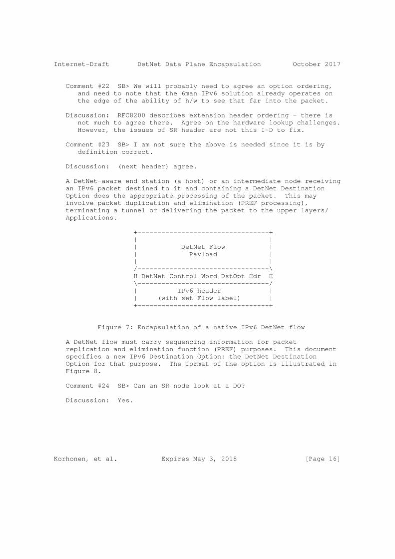
Internet-Draft DetNet Data Plane Encapsulation October 2017
Comment #22 SB> We will probably need to agree an option ordering, and need to note that the 6man IPv6 solution already operates on the edge of the ability of h/w to see that far into the packet.
Discussion: RFC8200 describes extension header ordering - there is not much to agree there. Agree on the hardware lookup challenges. However, the issues of SR header are not this I-D to fix.
Comment #23 SB> I am not sure the above is needed since it is by definition correct.
Discussion: (next header) agree.
A DetNet-aware end station (a host) or an intermediate node receiving an IPv6 packet destined to it and containing a DetNet Destination Option does the appropriate processing of the packet. This may involve packet duplication and elimination (PREF processing), terminating a tunnel or delivering the packet to the upper layers/ Applications.
+---------------------------------+ | | | DetNet Flow | | Payload | | | /---------------------------------\ H DetNet Control Word DstOpt Hdr H \---------------------------------/ | IPv6 header | | (with set Flow label) | +---------------------------------+
Figure 7: Encapsulation of a native IPv6 DetNet flow
A DetNet flow must carry sequencing information for packet replication and elimination function (PREF) purposes. This document specifies a new IPv6 Destination Option: the DetNet Destination Option for that purpose. The format of the option is illustrated in Figure 8.
Comment #24 SB> Can an SR node look at a DO?
Discussion: Yes.
Korhonen, et al. Expires May 3, 2018 [Page 16]

Internet-Draft DetNet Data Plane Encapsulation October 2017
0 1 2 3 0 1 2 3 4 5 6 7 8 9 0 1 2 3 4 5 6 7 8 9 0 1 2 3 4 5 6 7 8 9 0 1 +-+-+-+-+-+-+-+-+-+-+-+-+-+-+-+-+-+-+-+-+-+-+-+-+-+-+-+-+-+-+-+-+ | TBD1 | 4 | Reserved | +-+-+-+-+-+-+-+-+-+-+-+-+-+-+-+-+-+-+-+-+-+-+-+-+-+-+-+-+-+-+-+-+ | 16 bit Sequence Number | +-+-+-+-+-+-+-+-+-+-+-+-+-+-+-+-+
Figure 8: DetNet Destination Option
The Option Type for the DetNet Destination Option is set to TBD1. [To be removed from the final version of the document: The Option Type MUST have the two most significant bits set to 10b]
5.3. DetNet flow identification for duplicate detection
Duplicate elimination depends on flow identification. Mapping between packet fields and Local-ID may impact the implementation of duplicate elimination.
Comment #25 SB> So I wonder if the right place to put the FI is in the IPv6 FI, or in the IPv6 address itself?
Discussion: Each flow having different address is challenging if we want to terminate multiple flows into the same node with one address or originate multiple flows from a node with one address (note, we are aware of the one /64 per node discussion but cannot assume it here, at least not yet).
5.3.1. PseudoWire encapsulation
RFC3985 Section 5.2.1. describes PW sequencing provides a duplicate detection service among other things. This specification clarifies this definition as follows:
DetNet flows that need to undergo PREF processing MUST have the same PW Label when they arrive at the DA-*-PE node.
From the label stack processing point of view receiving the same label from multiple sources is analogous to Fast Reroute backup tunnel behavior [RFC4090]. The PW Label for a DetNet flow can be different on each PW segment.
Comment #26 SB> I am not sure of the utility of this reference. In FRR you should not receive packets concurrently on two paths. It seems fine to state the the requirement that a single label is used for both paths.
Korhonen, et al. Expires May 3, 2018 [Page 17]
Internet-Draft DetNet Data Plane Encapsulation October 2017
Discussion: OK with the same label comment. OK to remove the FRR reference here.
5.3.2. Native IPv6 encapsulation
The DetNet flow identification is based on the IPv6 Flow Label and the source address combination. The two fields uniquelly identify the end to end native IPv6 encapsulated DetNet flow. Obviously, the identification fails if any intermediate node modifies either the source address or the Flow Label.
Comment #27 SB> See earlier. If there are enough IPv6 addresses to address video fragments, why not DN flows? Then this problem goes away.
Discussion: See the earlier comment #25 discussion. If nodes get their addressies via DHCPv6 basically ruins this mechanism. Also the assumption for this to work is that the node has a full /64 to use, which is not always the case. Otherwise the idea is just fine.
6. PREF specific considerations
This section applies equally to DetNet flows transported via IPv6 and MPLS. While flow identification and some header related processing will differ between the two, the considerations covered in this section are common to both.
6.1. PseudoWire-based data plane
6.1.1. Forwarder clarifications
The DetNet specific new functionality in an edge or relay node processing is the packet replication and duplication elimination function (PREF). This function is a part of the DetNet-aware "extended" forwarder. The PREF processing is triggered by the received packet of a DetNet flow.
Comment #28 SB> I am not sure what you mean by triggered here. Hopefully we are not thinking of dataplane triggered configuration?
Discussion: "Initiated" is probably more appropriate wording.
Basically the forwarding entry has to be extended with a "PREF enabled" boolean configuration switch that is associated with the normal forwarding actions (e.g., in case of MPLS a swap, push, pop, ..). The output of the PREF elimination function is always a single
Korhonen, et al. Expires May 3, 2018 [Page 18]

Internet-Draft DetNet Data Plane Encapsulation October 2017
packet. The output of the PREF replication function is always one or more packets (i.e., 1:M replication). The replicated packets MUST share the same DetNet control word sequence number.
The complex part of the DetNet PREF processing is tracking the history of received packets for multiple DetNet member flows. These ingress DetNet member flows (to a node) MUST have the same local-ID if they belong to the same DetNet-(compound)-flow and share the same sequence number counter and the history information.
The edge and relay node internal procedures of the PREF are implementation specific. The order of a packet elimination or replication is out of scope in this specification. However, care should be taken that the replication function does not actually loopback packets as "replicas". Looped back packets include artificial delay when the node that originally initiated the packet receives it again. Also, looped back packets may make the network condition to look healthier than it actually is (in some cases link failures are not reflected properly because looped back packets make the situation appear better than it actually is).
Comment #29: SB> There needs to be some text about preventing a node ever receiving its own replicated packets. Indeed that would suggest that the flow id should be changed and replication should only take place on configured flow IDs. I have a feeling that this would all be a lot safer if replication only happened at ingress and we managed the diversity of the paths.
Discussion: Agree on hardening the loopback text considerations.
6.1.2. Edge node processing clarifications
The DetNet data plane solution overloads the edge node with DetNet Edge Node functions. Edge nodes are also aware of DetNet flows and may need to operate upon those. Figure 9 illustrates the overall edge device functions. The figure shows both physical attachment circuit (AC) (e.g., Ethernet [RFC4448]) connecting to the edge node, and a packet service connecting to the edge node via an embedded router function (similarly as described e.g., in [RFC6658]). Whether traffic flow from a client AC and PSN tunnel receives DetNet specific treatment is up to a local configuration and policy.
Comment #30: SB> Shouldn’t the behaviour simply be a property of a given PW?
Discussion: Agree in principle.
Korhonen, et al. Expires May 3, 2018 [Page 19]

Internet-Draft DetNet Data Plane Encapsulation October 2017
+---------------------------------------+ | DetNet Edge Device | +---------------------------------------+ Egress/ | | Forwarder | | Ingress | | | Single | member Inst. Client PSN | "Packet o <-X-----> o Service o<----------> tunnels | NSP" | | Repl. | Instance | <---------->o | | Elim. +-------------+ Duplicate | | : | | Egress | | . | Single | member Inst. | | +-> o Service o<----------> | | | | Instance | +-------------+ | +-------------+ Egress/ | | | | | Ingress Client AC | NSP | Repl. | | Single | member Inst. <---------->o o <-----X-> o Service o<----------> | | Elim. | Instance | +-------------+ +-------------+ Egress/ | | | | Ingress Client AC | NSP | | Single | member Inst. <---------->o o <-------> o Service o<----------> | | | Instance | +---------------------------------------+
Figure 9: DetNet Edge Node processing
An edge node participates to the packet replication and duplication elimination. Required processing is done within an extended forwarder function. In the case the native service processing (NSP) is IEEE 802.1CB [IEEE8021CB] capable, the packet replication and duplicate elimination MAY entirely be done in the NSP and bypassing the DetNet flow encapsulation and logic entirely, and thus is able to operate over unmodified implementation and deployment. The NSP approach works only between edge nodes and cannot make use of relay nodes (see Section 6.1.3).
Comment #31 SB> This would be a fine way to operate the PW system - edge to edge.
Discussion: When it comes to use of NSPs, agree. Also for "island interconnect" this is a fine. However, when there is a need to do PREF in a middle, plain edge to edge is not enough.
The DetNet-aware extended forwarder selects the egress DetNet member flow based on the DetNet forwarding rules. In both "normal AC" and "Packet AC" cases there may be no DetNet encapsulation header available yet as it is the case with relay nodes (see Section 6.1.3).
Korhonen, et al. Expires May 3, 2018 [Page 20]
Internet-Draft DetNet Data Plane Encapsulation October 2017
It is the responsibility of the extended forwarder within the edge node to push the DetNet specific encapsulation (if not already present) to the packet before forwarding it to the appropriate egress DetNet member flow instance(s).
Comment #32 SB> I am not convinced of the wisdom of having a mid- point node convert a flow into a DN flow, which is what you are implying here. This seems like an ingress function.
Discussion: OK. The text here has issues and seems to mix relay and edge.
The extended forwarder MAY copy the sequencing information from the native DetNet packet into the DetNet sequence number field and vice versa. If there is no existing sequencing information available in the native packet or the forwarder chose not to copy it from the native packet, then the extended forwarder MUST maintain a sequence number counter for each DetNet flow (indexed by the DetNet flow identification).
6.1.3. Relay node processing clarifications
The DetNet data plane solution overloads a relay node with DetNet Relay node functions. Relay node is aware of DetNet flows and may operate upon those. Figure 10 illustrates the overall DetNet relay device functions.
Comment #33 SB> I don’t think that a relay node in not a normal construct so I am not sure "overload" is the right term here.
Discussion: Agree. There is a terminology issue here.
A DetNet Relay node participates to the packet replication and duplication elimination. This processing is done within an extended forwarder function. Whether an ingress DetNet member flow receives DetNet specific processing depends on how the forwarding is programmed. For some DetNet member flows the relay node can act as a normal relay node and for some apply the DetNet specific processing (i.e., PREF).
Comment #34 SB> Again relay node is not a normal term, so am not sure what it does in the absence of a PREF function.
Discussion: Relay node was a DetNet aware S-PE originally, which is not explicitly stated here anymore, thus slightly confusing text here. The text here needs to clarify the roles of PREF and switching functions. A DetNet relay is described in the
Korhonen, et al. Expires May 3, 2018 [Page 21]
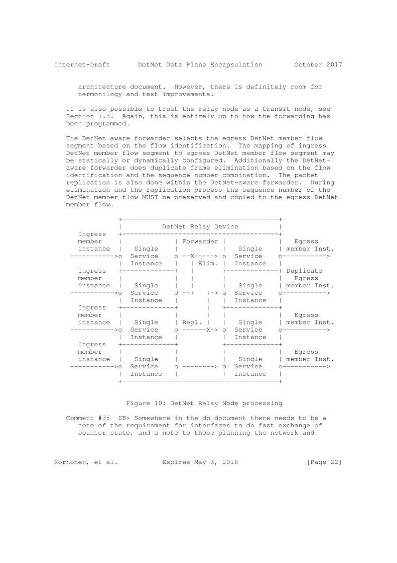
Internet-Draft DetNet Data Plane Encapsulation October 2017
architecture document. However, there is definitely room for termonilogy and text improvements.
It is also possible to treat the relay node as a transit node, see Section 7.3. Again, this is entirely up to how the forwarding has been programmed.
The DetNet-aware forwarder selects the egress DetNet member flow segment based on the flow identification. The mapping of ingress DetNet member flow segment to egress DetNet member flow segment may be statically or dynamically configured. Additionally the DetNet- aware forwarder does duplicate frame elimination based on the flow identification and the sequence number combination. The packet replication is also done within the DetNet-aware forwarder. During elimination and the replication process the sequence number of the DetNet member flow MUST be preserved and copied to the egress DetNet member flow.
+---------------------------------------+ | DetNet Relay Device | Ingress +---------------------------------------+ member | | Forwarder | | Egress instance | Single | | Single | member Inst. ----------->o Service o --X-----> o Service o-----------> | Instance | | Elim. | Instance | Ingress +-------------+ | +-------------+ Duplicate member | | | | | Egress instance | Single | | | Single | member Inst. ----------->o Service o --+ +-> o Service o-----------> | Instance | | | Instance | Ingress +-------------+ | +-------------+ member | | | | | Egress instance | Single | Repl. | | Single | member Inst. ----------->o Service o ------X-> o Service o-----------> | Instance | | Instance | Ingress +-------------+ +-------------+ member | | | | Egress instance | Single | | Single | member Inst. ----------->o Service o --------> o Service o-----------> | Instance | | Instance | +---------------------------------------+
Figure 10: DetNet Relay Node processing
Comment #35 SB> Somewhere in the dp document there needs to be a note of the requirement for interfaces to do fast exchange of counter state, and a note to those planning the network and
Korhonen, et al. Expires May 3, 2018 [Page 22]

Internet-Draft DetNet Data Plane Encapsulation October 2017
designing the control plane that they need to provide support for this.
Discussion: We kinf of agree but also think the above exchange or synchronization of counter states is not in our scope to solve.
6.2. Native IPv6-based data plane
[Editor’s note: this section is TBD.]
7. Other DetNet data plane considerations
7.1. Class of Service
Class and quality of service, i.e., CoS and QoS, are terms that are often used interchangeably and confused. In the context of DetNet, CoS is used to refer to mechanisms that provide traffic forwarding treatment based on aggregate group basis and QoS is used to refer to mechanisms that provide traffic forwarding treatment based on a specific DetNet flow basis. Examples of existing network level CoS mechanisms include DiffServ which is enabled by IP header differentiated services code point (DSCP) field [RFC2474] and MPLS label traffic class field [RFC5462], and at Layer-2, by IEEE 802.1p priority code point (PCP).
CoS for DetNet flows carried in PWs and MPLS is provided using the existing MPLS Differentiated Services (DiffServ) architecture [RFC3270]. Both E-LSP and L-LSP MPLS DiffServ modes MAY be used to support DetNet flows. The Traffic Class field (formerly the EXP field) of an MPLS label follows the definition of [RFC5462] and [RFC3270]. The Uniform, Pipe, and Short Pipe DiffServ tunneling and TTL processing models are described in [RFC3270] and [RFC3443] and MAY be used for MPLS LSPs supporting DetNet flows. MPLS ECN MAY also be used as defined in ECN [RFC5129] and updated by [RFC5462].
CoS for DetNet flows carried in IPv6 is provided using the standard differentiated services code point (DSCP) field [RFC2474] and related mechanisms. The 2-bit explicit congestion notification (ECN) [RFC3168] field MAY also be used.
One additional consideration for DetNet nodes which support CoS services is that they MUST ensure that the CoS service classes do not impact the congestion protection and latency control mechanisms used to provide DetNet QoS. This requirement is similar to requirement for MPLS LSRs to that CoS LSPs do not impact the resources allocated to TE LSPs via [RFC3473].
Korhonen, et al. Expires May 3, 2018 [Page 23]

Internet-Draft DetNet Data Plane Encapsulation October 2017
7.2. Quality of Service
Quality of Service (QoS) mechanisms for flow specific traffic treatment typically includes a guarantee/agreement for the service, and allocation of resources to support the service. Example QoS mechanisms include discrete resource allocation, admission control, flow identification and isolation, and sometimes path control, traffic protection, shaping, policing and remarking. Example protocols that support QoS control include Resource ReSerVation Protocol (RSVP) [RFC2205] (RSVP) and RSVP-TE [RFC3209] and [RFC3473]. The existing MPLS mechanisms defined to support CoS [RFC3270] can also be used to reserve resources for specific traffic classes.
In addition to path pinning and packet replication and elimination, described in Section 5 above, DetNet provides zero congestion loss and bounded latency and jitter.
Comment #36 SB> I just searched from the beginning of the document and this was the the first reference I found to pinning.
Discussion: Terminology isssue. Should use, for example, explicit paths which is used in the architecture I-D.
As described in [I-D.ietf-detnet-architecture], there are different mechanisms that maybe used separately or in combination to deliver a zero congestion loss service. These mechanisms are provided by the either the MPLS or IP layers, and may be combined with the mechanisms defined by the underlying network layer such as 802.1TSN.
A baseline set of QoS capabilities for DetNet flows carried in PWs and MPLS can provided by MPLS with Traffic Engineering (MPLS-TE) [RFC3209] and [RFC3473]. TE LSPs can also support explicit routes (path pinning). Current service definitions for packet TE LSPs can be found in "Specification of the Controlled Load Quality of Service", [RFC2211], "Specification of Guaranteed Quality of Service", [RFC2212], and "Ethernet Traffic Parameters", [RFC6003]. Additional service definitions are expected in future documents to support the full range of DetNet services. In all cases, the existing label-based marking mechanisms defined for TE-LSPs and even E-LSPs are use to support the identification of flows requiring DetNet QoS.
QoS for DetNet flows carried in IPv6 MUST be provided locally by the DetNet-aware hosts and routers supporting DetNet flows. Such support will leverage the underlying network layer such as 802.1TSN. The traffic control mechanisms used to deliver QoS for IP encapsulated DetNet flows are expected to be defined in a future document. From an encapsulation perspective, and as defined in Section 5.2.2, the
Korhonen, et al. Expires May 3, 2018 [Page 24]
Internet-Draft DetNet Data Plane Encapsulation October 2017
combination of the Flow Label together with the IP source address uniquely identifies a DetNet flow.
Packets that are marked with a DetNet Class of Service value, but that have not been the subject of a completed reservation, can disrupt the QoS offered to properly reserved DetNet flows by using resources allocated to the reserved flows. Therefore, the network nodes of a DetNet network SHOULD:
Comment #37 SB> Why not MUST?
Discussion: OK with MUST.
o Defend the DetNet QoS by discarding or remarking (to a non-DetNet CoS) packets received that are not the subject of a completed reservation.
o Not use a DetNet reserved resource, e.g. a queue or shaper reserved for DetNet flows, for any packet that does not carry a DetNet Class of Service marker.
7.3. Cross-DetNet flow resource aggregation
The ability to aggregate individual flows, and their associated resource control, into a larger aggregate is an important technique for improving scaling of control in the data, management and control planes. This document identifies the traffic identification related aspects of aggregation of DetNet flows. The resource control and management aspects of aggregation (including the queuing/shaping/ policing implications) will be covered in other documents. The data plane implications of aggregation are independent for PW/MPLS and IP encapsulated DetNet flows.
DetNet flows transported via MPLS can leverage MPLS-TE’s existing support for hierarchical LSPs (H-LSPs), see [RFC4206]. H-LSPs are typically used to aggregate control and resources, they may also be used to provide OAM or protection for the aggregated LSPs. Arbitrary levels of aggregation naturally falls out of the definition for hierarchy and the MPLS label stack [RFC3032]. DetNet nodes which support aggregation (LSP hierarchy) map one or more LSPs (labels) into and from an H-LSP. Both carried LSPs and H-LSPs may or may not use the TC field, i.e., L-LSPs or E-LSPs. Such nodes will need to ensure that traffic from aggregated LSPs are placed (shaped/policed/ enqueued) onto the H-LSPs in a fashion that ensures the required DetNet service is preserved.
DetNet flows transported via IP have more limited aggregation options, due to the available traffic flow identification fields of
Korhonen, et al. Expires May 3, 2018 [Page 25]

Internet-Draft DetNet Data Plane Encapsulation October 2017
the IP solution. One available approach is to manage the resources associated with a DSCP identified traffic class and to map (remark) individually controlled DetNet flows onto that traffic class. This approach also requires that nodes support aggregation ensure that traffic from aggregated LSPs are placed (shaped/policed/enqueued) in a fashion that ensures the required DetNet service is preserved.
Comment #38 SB> I am sure we can do better than this with SR, or the use of routing techniques that map certain addresses to certain paths.
Discussion: --
In both the MPLS and IP cases, additional details of the traffic control capabilities needed at a DetNet-aware node may be covered in the new service descriptions mentioned above or in separate future documents. Management and control plane mechanisms will also need to ensure that the service required on the aggregate flow (H-LSP or DSCP) are provided, which may include the discarding or remarking mentioned in the previous sections.
7.4. Bidirectional traffic
Some DetNet applications generate bidirectional traffic. Using MPLS definitions [RFC5654] there are associated bidirectional flows, and co-routed bidirectional flows. MPLS defines a point-to-point associated bidirectional LSP as consisting of two unidirectional point-to-point LSPs, one from A to B and the other from B to A, which are regarded as providing a single logical bidirectional transport path. This would be analogous of standard IP routing, or PWs running over two reciprocal unidirection LSPs. MPLS defines a point-to-point co-routed bidirectional LSP as an associated bidirectional LSP which satisfies the additional constraint that its two unidirectional component LSPs follow the same path (in terms of both nodes and links) in both directions. An important property of co-routed bidirectional LSPs is that their unidirectional component LSPs share fate. In both types of bidirectional LSPs, resource allocations may differ in each direction. The concepts of associated bidirectional flows and co-routed bidirectional flows can be applied to DetNet flows as well whether IPv6 or MPLS is used.
While the IPv6 and MPLS data planes must support bidirectional DetNet flows, there are no special bidirectional features with respect to the data plane other than need for the two directions take the same paths. Fate sharing and associated vs co-routed bidirectional flows can be managed at the control level. Note, that there is no stated requirement for bidirectional DetNet flows to be supported using the same IPv6 Flow Labels or MPLS Labels in each direction. Control
Korhonen, et al. Expires May 3, 2018 [Page 26]

Internet-Draft DetNet Data Plane Encapsulation October 2017
mechanisms will need to support such bidirectional flows for both IPv6 and MPLS, but such mechanisms are out of scope of this document. An example control plane solution for MPLS can be found in [RFC7551].
7.5. Layer 2 addressing and QoS Considerations
The Time-Sensitive Networking (TSN) Task Group of the IEEE 802.1 Working Group have defined (and are defining) a number of amendments to IEEE 802.1Q [IEEE8021Q] that provide zero congestion loss and bounded latency in bridged networks. IEEE 802.1CB [IEEE8021CB] defines packet replication and elimination functions that should prove both compatible with and useful to, DetNet networks.
As is the case for DetNet, a Layer 2 network node such as a bridge may need to identify the specific DetNet flow to which a packet belongs in order to provide the TSN/DetNet QoS for that packet. It also will likely need a CoS marking, such as the priority field of an IEEE Std 802.1Q VLAN tag, to give the packet proper service.
Although the flow identification methods described in IEEE 802.1CB [IEEE8021CB] are flexible, and in fact, include IP 5-tuple identification methods, the baseline TSN standards assume that every Ethernet frame belonging to a TSN stream (i.e. DetNet flow) carries a multicast destination MAC address that is unique to that flow within the bridged network over which it is carried. Furthermore, IEEE 802.1CB [IEEE8021CB] describes three methods by which a packet sequence number can be encoded in an Ethernet frame.
Ensuring that the proper Ethernet VLAN tag priority and destination MAC address are used on a DetNet/TSN packet may require further clarification of the customary L2/L3 transformations carried out by routers and edge label switches. Edge nodes may also have to move sequence number fields among Layer 2, PW, and IPv6 encapsulations.
7.6. Interworking between PW- and IPv6-based encapsulations
[Editor’s note: add considerations for interworking between PW-based and native IPv6-based DetNet encapsuations.]
8. Time synchronization
Comment #39 SB> This section should point the reader to RFC8169 (residence time in MPLS n/w. We need to consider if we need to introduce the same concept in IP.
Discussion: agree.
Korhonen, et al. Expires May 3, 2018 [Page 27]
Internet-Draft DetNet Data Plane Encapsulation October 2017
[Editor’s note: describe a bit of issues and deployment considerations related to time-synchronization within DetNet. Refer to DT discussion and the slides that summarize different approaches and rough synchronization performance numbers. Finally, scope time- synchronization solution outside data plane.]
When DetNet is used, there is an underlying assumption that the applicaton(s) require clock synchronization such as the Precision Time Protocol (PTP) [IEEE1588]. The relay nodes may or may not utilize clock synchronization in order to provide zero congestion loss and controlled latency delivery. In either case, there are a few possible approaches of how synchronization protocol packets are forwarded and handled by the network:
o PTP packets can be sent either as DetNet flows or as high-priority best effort packets. Using DetNet for PTP packets requires careful consideration to prevent unwanted interactions between clock-synchronized network nodes and the packets that synchronize the clocks.
o PTP packets are sent as a normal DetNet flow through network nodes that are not time-synchronized: in this approach PTP traffic is forwarded as a DetNet flow, and as such it is forwarded in a way that allows a low delay variation. However, since intermediate nodes do not take part in the synchronization protocol, this approach provides a relatively low degree of accuracy.
o PTP with on-path support: in this approach PTP packets are sent as ordinary or as DetNet flows, and intermediate nodes take part in the protocol as Transparent Clocks or Boundary Clocks [IEEE1588]. The on-path PTP support by intermediate nodes provides a higher degree of accuracy than the previous approach. The actual accuracy depends on whether all intermediate nodes are PTP- capable, or only a subset of them.
o Time-as-a-service: in this approach accurate time is provided as- a-service to the DetNet source and destination, as well as the intermediate nodes. Since traffic between the source and destination is sent over a provider network, if the provider supports time-as-a-service, then accurate time can be provided to both the source and the destination of DetNet traffic. This approach can potentially provide the highest degree of accuracy.
It is expected that the latter approach will be the most common one, as it provides the highest degree of accuracy, and creates a layer separation between the DetNet data and the synchronization service.
Korhonen, et al. Expires May 3, 2018 [Page 28]
Internet-Draft DetNet Data Plane Encapsulation October 2017
It should be noted that in all four approaches it is not recommended to use replication and elimination for synchronization packets; the replication/elimination approach may in some cases reduce the synchronization accuracy, since the observed path delay will be bivalent.
Comment #40 SB> I am not sure why we sould not use PREP. We should explain to the reader.
Discussion: Agree that a this can be opened a bit more in detail. The issue is explained briefly in the last sentence but it could be more clear.
9. Management and control considerations
While management plane and control planes are traditionally considered separately, from the Data Plane perspective there is no practical difference based on the origin of flow provisioning information. This document therefore does not distinguish between information provided by a control plane protocol, e.g., RSVP-TE [RFC3209] and [RFC3473], or by a network management mechanisms, e.g., RestConf [RFC8040] and YANG [RFC7950].
[Editor’s note: This section is a work in progress. discuss here what kind of enhancements are needed for DetNet and specifically for PREF and DetNet zero congest loss and latency control. Need to cover both traffic control (queuing) and connection control (control plane).]
9.1. PW Label and IPv6 Flow Label assignment and distribution
The PW label distribution follows the same mechanisms specified for MS-PW [RFC6073]. The details of the control plane protocol solution required for the label distribution and the management of the label number space are out of scope of this document.
The IPv6 Flow Label distribution and the label number space are out of scope of this document. However, it should be noted that the combination of the IPv6 source address and the IPv6 Flow Label is assumed to be unique within the DetNet-enabled network. Therefore, as long as each node is able to assign unique Flow Labels for the source address(es) it is using the DetNet-enabled network wide flow identification uniqueness is guaranteed.
Korhonen, et al. Expires May 3, 2018 [Page 29]
Internet-Draft DetNet Data Plane Encapsulation October 2017
9.2. Packet replication and elimination
The control plane protocol solution required for managing the PREF processing is outside the scope of this document.
9.3. Explicit paths
[TBD: based on MPLS TE and SR.]
9.4. Congestion protection and latency control
[TBD]
9.5. Flow aggregation control
[TBD]
10. Security considerations
The security considerations of DetNet in general are discussed in [I-D.ietf-detnet-architecture] and [I-D.sdt-detnet-security]. Other security considerations will be added in a future version of this draft.
11. IANA considerations
TBD.
12. Acknowledgements
The author(s) ACK and NACK.
The following people were part of the DetNet Data Plane Solution Design Team:
Jouni Korhonen
Janos Farkas
Norman Finn
Balazs Varga
Loa Andersson
Tal Mizrahi
David Mozes
Korhonen, et al. Expires May 3, 2018 [Page 30]

Internet-Draft DetNet Data Plane Encapsulation October 2017
Yuanlong Jiang
Carlos J. Bernardos
The DetNet chairs serving during the DetNet Data Plane Solution Design Team:
Lou Berger
Pat Thaler
13. References
13.1. Normative references
[RFC2119] Bradner, S., "Key words for use in RFCs to Indicate Requirement Levels", BCP 14, RFC 2119, DOI 10.17487/RFC2119, March 1997, <https://www.rfc-editor.org/info/rfc2119>.
[RFC2211] Wroclawski, J., "Specification of the Controlled-Load Network Element Service", RFC 2211, DOI 10.17487/RFC2211, September 1997, <https://www.rfc-editor.org/info/rfc2211>.
[RFC2212] Shenker, S., Partridge, C., and R. Guerin, "Specification of Guaranteed Quality of Service", RFC 2212, DOI 10.17487/RFC2212, September 1997, <https://www.rfc-editor.org/info/rfc2212>.
[RFC2474] Nichols, K., Blake, S., Baker, F., and D. Black, "Definition of the Differentiated Services Field (DS Field) in the IPv4 and IPv6 Headers", RFC 2474, DOI 10.17487/RFC2474, December 1998, <https://www.rfc-editor.org/info/rfc2474>.
[RFC3032] Rosen, E., Tappan, D., Fedorkow, G., Rekhter, Y., Farinacci, D., Li, T., and A. Conta, "MPLS Label Stack Encoding", RFC 3032, DOI 10.17487/RFC3032, January 2001, <https://www.rfc-editor.org/info/rfc3032>.
[RFC3168] Ramakrishnan, K., Floyd, S., and D. Black, "The Addition of Explicit Congestion Notification (ECN) to IP", RFC 3168, DOI 10.17487/RFC3168, September 2001, <https://www.rfc-editor.org/info/rfc3168>.
Korhonen, et al. Expires May 3, 2018 [Page 31]
Internet-Draft DetNet Data Plane Encapsulation October 2017
[RFC3209] Awduche, D., Berger, L., Gan, D., Li, T., Srinivasan, V., and G. Swallow, "RSVP-TE: Extensions to RSVP for LSP Tunnels", RFC 3209, DOI 10.17487/RFC3209, December 2001, <https://www.rfc-editor.org/info/rfc3209>.
[RFC3270] Le Faucheur, F., Wu, L., Davie, B., Davari, S., Vaananen, P., Krishnan, R., Cheval, P., and J. Heinanen, "Multi- Protocol Label Switching (MPLS) Support of Differentiated Services", RFC 3270, DOI 10.17487/RFC3270, May 2002, <https://www.rfc-editor.org/info/rfc3270>.
[RFC3443] Agarwal, P. and B. Akyol, "Time To Live (TTL) Processing in Multi-Protocol Label Switching (MPLS) Networks", RFC 3443, DOI 10.17487/RFC3443, January 2003, <https://www.rfc-editor.org/info/rfc3443>.
[RFC3473] Berger, L., Ed., "Generalized Multi-Protocol Label Switching (GMPLS) Signaling Resource ReserVation Protocol- Traffic Engineering (RSVP-TE) Extensions", RFC 3473, DOI 10.17487/RFC3473, January 2003, <https://www.rfc-editor.org/info/rfc3473>.
[RFC4206] Kompella, K. and Y. Rekhter, "Label Switched Paths (LSP) Hierarchy with Generalized Multi-Protocol Label Switching (GMPLS) Traffic Engineering (TE)", RFC 4206, DOI 10.17487/RFC4206, October 2005, <https://www.rfc-editor.org/info/rfc4206>.
[RFC4448] Martini, L., Ed., Rosen, E., El-Aawar, N., and G. Heron, "Encapsulation Methods for Transport of Ethernet over MPLS Networks", RFC 4448, DOI 10.17487/RFC4448, April 2006, <https://www.rfc-editor.org/info/rfc4448>.
[RFC5129] Davie, B., Briscoe, B., and J. Tay, "Explicit Congestion Marking in MPLS", RFC 5129, DOI 10.17487/RFC5129, January 2008, <https://www.rfc-editor.org/info/rfc5129>.
[RFC5462] Andersson, L. and R. Asati, "Multiprotocol Label Switching (MPLS) Label Stack Entry: "EXP" Field Renamed to "Traffic Class" Field", RFC 5462, DOI 10.17487/RFC5462, February 2009, <https://www.rfc-editor.org/info/rfc5462>.
[RFC6003] Papadimitriou, D., "Ethernet Traffic Parameters", RFC 6003, DOI 10.17487/RFC6003, October 2010, <https://www.rfc-editor.org/info/rfc6003>.
Korhonen, et al. Expires May 3, 2018 [Page 32]

Internet-Draft DetNet Data Plane Encapsulation October 2017
[RFC6073] Martini, L., Metz, C., Nadeau, T., Bocci, M., and M. Aissaoui, "Segmented Pseudowire", RFC 6073, DOI 10.17487/RFC6073, January 2011, <https://www.rfc-editor.org/info/rfc6073>.
[RFC6658] Bryant, S., Ed., Martini, L., Swallow, G., and A. Malis, "Packet Pseudowire Encapsulation over an MPLS PSN", RFC 6658, DOI 10.17487/RFC6658, July 2012, <https://www.rfc-editor.org/info/rfc6658>.
13.2. Informative references
[I-D.ietf-6man-segment-routing-header] Previdi, S., Filsfils, C., Raza, K., Leddy, J., Field, B., [email protected], d., [email protected], d., Matsushima, S., Leung, I., Linkova, J., Aries, E., Kosugi, T., Vyncke, E., Lebrun, D., Steinberg, D., and R. Raszuk, "IPv6 Segment Routing Header (SRH)", draft-ietf-6man- segment-routing-header-07 (work in progress), July 2017.
[I-D.ietf-detnet-architecture] Finn, N., Thubert, P., Varga, B., and J. Farkas, "Deterministic Networking Architecture", draft-ietf- detnet-architecture-03 (work in progress), August 2017.
[I-D.ietf-detnet-dp-alt] Korhonen, J., Farkas, J., Mirsky, G., Thubert, P., Zhuangyan, Z., and L. Berger, "DetNet Data Plane Protocol and Solution Alternatives", draft-ietf-detnet-dp-alt-00 (work in progress), October 2016.
[I-D.sdt-detnet-security] Mizrahi, T., Grossman, E., Hacker, A., Das, S., "Deterministic Networking (DetNet) Security Considerations, draft-sdt-detnet-security, work in progress", 2017.
[IEEE1588] IEEE, "IEEE 1588 Standard for a Precision Clock Synchronization Protocol for Networked Measurement and Control Systems Version 2", 2008.
[IEEE8021CB] Finn, N., "Draft Standard for Local and metropolitan area networks - Seamless Redundancy", IEEE P802.1CB /D2.1 P802.1CB, December 2015, <http://www.ieee802.org/1/files/private/cb-drafts/ d2/802-1CB-d2-1.pdf>.
Korhonen, et al. Expires May 3, 2018 [Page 33]

Internet-Draft DetNet Data Plane Encapsulation October 2017
[IEEE8021Q] IEEE 802.1, "Standard for Local and metropolitan area networks--Bridges and Bridged Networks (IEEE Std 802.1Q- 2014)", 2014, <http://standards.ieee.org/about/get/>.
[RFC2205] Braden, R., Ed., Zhang, L., Berson, S., Herzog, S., and S. Jamin, "Resource ReSerVation Protocol (RSVP) -- Version 1 Functional Specification", RFC 2205, DOI 10.17487/RFC2205, September 1997, <https://www.rfc-editor.org/info/rfc2205>.
[RFC3985] Bryant, S., Ed. and P. Pate, Ed., "Pseudo Wire Emulation Edge-to-Edge (PWE3) Architecture", RFC 3985, DOI 10.17487/RFC3985, March 2005, <https://www.rfc-editor.org/info/rfc3985>.
[RFC4090] Pan, P., Ed., Swallow, G., Ed., and A. Atlas, Ed., "Fast Reroute Extensions to RSVP-TE for LSP Tunnels", RFC 4090, DOI 10.17487/RFC4090, May 2005, <https://www.rfc-editor.org/info/rfc4090>.
[RFC5036] Andersson, L., Ed., Minei, I., Ed., and B. Thomas, Ed., "LDP Specification", RFC 5036, DOI 10.17487/RFC5036, October 2007, <https://www.rfc-editor.org/info/rfc5036>.
[RFC5654] Niven-Jenkins, B., Ed., Brungard, D., Ed., Betts, M., Ed., Sprecher, N., and S. Ueno, "Requirements of an MPLS Transport Profile", RFC 5654, DOI 10.17487/RFC5654, September 2009, <https://www.rfc-editor.org/info/rfc5654>.
[RFC7551] Zhang, F., Ed., Jing, R., and R. Gandhi, Ed., "RSVP-TE Extensions for Associated Bidirectional Label Switched Paths (LSPs)", RFC 7551, DOI 10.17487/RFC7551, May 2015, <https://www.rfc-editor.org/info/rfc7551>.
[RFC7950] Bjorklund, M., Ed., "The YANG 1.1 Data Modeling Language", RFC 7950, DOI 10.17487/RFC7950, August 2016, <https://www.rfc-editor.org/info/rfc7950>.
[RFC8040] Bierman, A., Bjorklund, M., and K. Watsen, "RESTCONF Protocol", RFC 8040, DOI 10.17487/RFC8040, January 2017, <https://www.rfc-editor.org/info/rfc8040>.
Appendix A. Example of DetNet data plane operation
[Editor’s note: Add a simplified example of DetNet data plane and how labels etc work in the case of MPLS-based PSN and utilizing PREF. The figure is subject to change depending on the further DT decisions on the label handling..]
Korhonen, et al. Expires May 3, 2018 [Page 34]

Internet-Draft DetNet Data Plane Encapsulation October 2017
Appendix B. Example of pinned paths using IPv6
TBD.
Authors’ Addresses
Jouni Korhonen (editor) Nordic Semiconductor
Email: [email protected]
Loa Andersson Huawei
Email: [email protected]
Yuanlong Jiang Huawei
Email: [email protected]
Norman Finn Huawei 3101 Rio Way Spring Valley, CA 91977 USA
Email: [email protected]
Balazs Varga Ericsson Konyves Kalman krt. 11/B Budapest 1097 Hungary
Email: [email protected]
Korhonen, et al. Expires May 3, 2018 [Page 35]

Internet-Draft DetNet Data Plane Encapsulation October 2017
Janos Farkas Ericsson Konyves Kalman krt. 11/B Budapest 1097 Hungary
Email: [email protected]
Carlos J. Bernardos Universidad Carlos III de Madrid Av. Universidad, 30 Leganes, Madrid 28911 Spain
Phone: +34 91624 6236 Email: [email protected] URI: http://www.it.uc3m.es/cjbc/
Tal Mizrahi Marvell 6 Hamada st. Yokneam Israel
Email: [email protected]
Lou Berger LabN Consulting, L.L.C.
Email: [email protected]
Korhonen, et al. Expires May 3, 2018 [Page 36]

DetNet J. Korhonen, Ed.Internet-Draft NordicIntended status: Standards Track L. AnderssonExpires: September 23, 2018 Y. Jiang N. Finn Huawei B. Varga J. Farkas Ericsson CJ. Bernardos UC3M T. Mizrahi Marvell L. Berger LabN March 22, 2018
DetNet Data Plane Encapsulation draft-ietf-detnet-dp-sol-04
Abstract
This document specifies Deterministic Networking data plane encapsulation solutions. The described data plane solutions can be applied over either IP or MPLS Packet Switched Networks.
Status of This Memo
This Internet-Draft is submitted in full conformance with the provisions of BCP 78 and BCP 79.
Internet-Drafts are working documents of the Internet Engineering Task Force (IETF). Note that other groups may also distribute working documents as Internet-Drafts. The list of current Internet- Drafts is at https://datatracker.ietf.org/drafts/current/.
Internet-Drafts are draft documents valid for a maximum of six months and may be updated, replaced, or obsoleted by other documents at any time. It is inappropriate to use Internet-Drafts as reference material or to cite them other than as "work in progress."
This Internet-Draft will expire on September 23, 2018.
Korhonen, et al. Expires September 23, 2018 [Page 1]

Internet-Draft DetNet Data Plane Encapsulation March 2018
Copyright Notice
Copyright (c) 2018 IETF Trust and the persons identified as the document authors. All rights reserved.
This document is subject to BCP 78 and the IETF Trust’s Legal Provisions Relating to IETF Documents (https://trustee.ietf.org/license-info) in effect on the date of publication of this document. Please review these documents carefully, as they describe your rights and restrictions with respect to this document. Code Components extracted from this document must include Simplified BSD License text as described in Section 4.e of the Trust Legal Provisions and are provided without warranty as described in the Simplified BSD License.
Table of Contents
1. Introduction . . . . . . . . . . . . . . . . . . . . . . . . 3 2. Terminology . . . . . . . . . . . . . . . . . . . . . . . . . 4 2.1. Terms used in this document . . . . . . . . . . . . . . . 4 2.2. Abbreviations . . . . . . . . . . . . . . . . . . . . . . 5 3. Requirements language . . . . . . . . . . . . . . . . . . . . 6 4. DetNet data plane overview . . . . . . . . . . . . . . . . . 6 4.1. DetNet data plane encapsulation requirements . . . . . . 8 4.2. Packet replication and elimination considerations . . . . 10 4.3. Packet reordering considerations . . . . . . . . . . . . 10 5. DetNet encapsulation . . . . . . . . . . . . . . . . . . . . 10 5.1. End-system specific considerations . . . . . . . . . . . 10 5.2. DetNet domain specific considerations . . . . . . . . . . 12 5.2.1. DetNet Bridging Service . . . . . . . . . . . . . . . 13 5.2.2. DetNet Routing Service . . . . . . . . . . . . . . . 14 5.3. DetNet Inter-Working Function (DN-IWF) . . . . . . . . . 17 5.3.1. Networks with multiple technology segments . . . . . 17 5.3.2. DN-IWF related considerations . . . . . . . . . . . . 18 6. MPLS-based DetNet data plane solution . . . . . . . . . . . . 19 6.1. DetNet specific packet fields . . . . . . . . . . . . . . 19 6.2. Data plane encapsulation . . . . . . . . . . . . . . . . 19 6.3. DetNet control word . . . . . . . . . . . . . . . . . . . 20 6.4. Flow identification . . . . . . . . . . . . . . . . . . . 21 6.5. Service layer considerations . . . . . . . . . . . . . . 21 6.5.1. Edge node processing . . . . . . . . . . . . . . . . 22 6.5.2. Relay node processing . . . . . . . . . . . . . . . . 23 6.5.3. End system processing . . . . . . . . . . . . . . . . 25 6.6. Transport node considerations . . . . . . . . . . . . . . 25 6.6.1. Congestion protection . . . . . . . . . . . . . . . . 25 6.6.2. Explicit routes . . . . . . . . . . . . . . . . . . . 25 7. Simplified IP based DetNet data plane solution . . . . . . . 25 8. Other DetNet data plane considerations . . . . . . . . . . . 25
Korhonen, et al. Expires September 23, 2018 [Page 2]

Internet-Draft DetNet Data Plane Encapsulation March 2018
8.1. Class of Service . . . . . . . . . . . . . . . . . . . . 25 8.2. Quality of Service . . . . . . . . . . . . . . . . . . . 26 8.3. Cross-DetNet flow resource aggregation . . . . . . . . . 27 8.4. Bidirectional traffic . . . . . . . . . . . . . . . . . . 28 8.5. Layer 2 addressing and QoS Considerations . . . . . . . . 29 8.6. Interworking between MPLS- and IPv6-based encapsulations 29 8.7. IPv4 considerations . . . . . . . . . . . . . . . . . . . 30 9. Time synchronization . . . . . . . . . . . . . . . . . . . . 30 10. Management and control considerations . . . . . . . . . . . . 31 10.1. MPLS-based data plane . . . . . . . . . . . . . . . . . 32 10.1.1. S-Label assignment and distribution . . . . . . . . 32 10.1.2. Explicit routes . . . . . . . . . . . . . . . . . . 32 10.2. IPv6-based data plane . . . . . . . . . . . . . . . . . 32 10.2.1. Flow Label assignment and distribution . . . . . . . 32 10.2.2. Explicit routes . . . . . . . . . . . . . . . . . . 32 10.3. Packet replication and elimination . . . . . . . . . . . 32 10.4. Congestion protection and latency control . . . . . . . 33 10.5. Flow aggregation control . . . . . . . . . . . . . . . . 33 11. Security considerations . . . . . . . . . . . . . . . . . . . 33 12. IANA considerations . . . . . . . . . . . . . . . . . . . . . 33 13. Acknowledgements . . . . . . . . . . . . . . . . . . . . . . 33 14. References . . . . . . . . . . . . . . . . . . . . . . . . . 34 14.1. Normative references . . . . . . . . . . . . . . . . . . 34 14.2. Informative references . . . . . . . . . . . . . . . . . 36 Appendix A. Example of DetNet data plane operation . . . . . . . 37 Appendix B. Example of pinned paths using IPv6 . . . . . . . . . 38 Authors’ Addresses . . . . . . . . . . . . . . . . . . . . . . . 38
1. Introduction
Deterministic Networking (DetNet) is a service that can be offered by a network to DetNet flows. DetNet provides these flows extremely low packet loss rates and assured maximum end-to-end delivery latency. General background and concepts of DetNet can be found in [I-D.ietf-detnet-architecture].
This document specifies the DetNet data plane and the on-wire encapsulation of DetNet flows. The specified encapsulation provides the building blocks to enable the DetNet service layer functions and allow flow identification as described in the DetNet Architecture. Two data plane definitions are given.
1. MPLS-based: The enacapsulation resembles PseudoWires (PW) with an MPLS Packet Switched Network (PSN) [RFC3985][RFC4385].
2. Native-IP-based: The encapsulating protocol is IPv6 and the solution relies on IP header fields, existing and DetNet specific IPv6 eaxtension header options [RFC8200].
Korhonen, et al. Expires September 23, 2018 [Page 3]

Internet-Draft DetNet Data Plane Encapsulation March 2018
[Editor’s note: MPLS- and IPv6-based solutions are likely to be split into different documents.]
It is worth noting that while MPLS-based solution can transport IP packets a native-IP solution is meant for deployments where the DetNet service layer functions are provided at the IP-layer rather than the underlying transport network. The primary reason for this is the benefit gained by enabling the use of a normal application stack, where transport protocols such as TCP or UDP are directly encapsulated in IP.
The DetNet transport layer functionality that provides congestion protection for DetNet flows is assumed to be in place in a DetNet node.
Furthermore, this document also describes how DetNet flows are identified, how a DetNet Relay/Edge/Transit nodes work, and how the Packet Replication and Elimination function (PREF) is implemented with the two data plane solutions.
This document does not define the associated control plane functions, or Operations, Administration, and Maintenance (OAM). It also does not specify traffic handling capabilities required to deliver congestion protection and latency control for DetNet flows at the DetNet transport layer.
2. Terminology
2.1. Terms used in this document
This document uses the terminology established in the DetNet architecture [I-D.ietf-detnet-architecture] and the DetNet Data Plane Solution Alternatives [I-D.ietf-detnet-dp-alt].
T-Label A label used to identify the LSP used to transport a DetNet flow across an MPLS PSN, e.g., a hop-by-hop label used between label switching routers (LSR).
S-Label A DetNet "service" label that is used between DetNet nodes that implment also the DetNet service layer functions. An S-Label is also used to identify a DetNet flow at DetNet service layer.
Flow Label IPv6 header field that is used to identify a DetNet flow (together with the source IP address field).
Local-ID A DetNet Edge and Relay node internal construct that uniquely identifies a DetNet flow within a node and
Korhonen, et al. Expires September 23, 2018 [Page 4]

Internet-Draft DetNet Data Plane Encapsulation March 2018
never appear on-wire. It may be used to select proper forwarding and/or DetNet specific service function.
PREF A Packet Replication and Elimination Function (PREF) does the replication and elimination processing of DetNet flow packets in edge or relay nodes. The replication function is essentially the existing 1+1 protection mechanism. The elimination function reuses and extends the existing duplicate detection mechanism to operate over multiple (separate) DetNet member flows of a DetNet compound flow.
DetNet Control Word A control word used for sequencing and identifying duplaicate packets at the DetNet service layer.
2.2. Abbreviations
The following abbreviations used in this document:
AC Attachment Circuit.
CE Customer Edge equipment.
CoS Class of Service.
CW Control Word.
d-CW DetNet Control Word.
DetNet Deterministic Networking.
DF DetNet Flow.
L2VPN Layer 2 Virtual Private Network.
LSR Label Switching Router.
MPLS Multiprotocol Label Switching.
MPLS-TP Multiprotocol Label Switching - Transport Profile.
MS-PW Multi-Segment PseudoWire (MS-PW).
NSP Native Service Processing.
OAM Operations, Administration, and Maintenance.
Korhonen, et al. Expires September 23, 2018 [Page 5]

Internet-Draft DetNet Data Plane Encapsulation March 2018
PE Provider Edge.
PREF Packet Replication and Elimination Function.
PSN Packet Switched Network.
PW PseudoWire.
QoS Quality of Service.
TSN Time-Sensitive Network.
3. Requirements language
The key words "MUST", "MUST NOT", "REQUIRED", "SHALL", "SHALL NOT", "SHOULD", "SHOULD NOT", "RECOMMENDED", "MAY", and "OPTIONAL" in this document are to be interpreted as described in [RFC2119].
4. DetNet data plane overview
This document describes how to use IP and/or MPLS to support a data plane method of flow identification and packet formwarding over layer-3. Two different cases are covered: (i) the inter-connect scenario, in which IEEE802.1 TSN is routed over a layer-3 network (i.e., to enlarge the layer-2 domain), and (ii) native connectivity between DetNet-aware end systems.
Figure 1 illustrates how DetNet can provide services for IEEE 802.1TSN end systems over a DetNet enabled network. The edge nodes insert and remove required DetNet data plane encapsulation. The ’X’ in the edge and relay nodes represents a potential DetNet flow packet replication and elimination point. This conceptually parallels L2VPN services, and could leverage existing related solutions as discussed below.
Korhonen, et al. Expires September 23, 2018 [Page 6]

Internet-Draft DetNet Data Plane Encapsulation March 2018
TSN |<---------- End to End DetNet Service ------>| TSN Service | Transit Transit | Service TSN (AC) | |<-Tunnel->| |<-Tnl->| | (AC) TSN End | V V 1 V V 2 V V | End System | +--------+ +--------+ +--------+ | System +---+ | | E1 |==========| R1 |=======| E2 | | +---+ | |--|----|._X_....|..DetNet..|.._ _...|..DF3..|...._X_.|---|---| | |CE1| | | \ | Flow 1 | X | | / | | |CE2| | | | \_.|...DF2....|._/ \_..|..DF4..|._/ | | | +---+ | |==========| |=======| | +---+ ^ +--------+ +--------+ +--------+ ^ | Edge Node Relay Node Edge Node | | | |<----- Emulated Time Sensitive Networking (TSN) Service ---->|
Figure 1: IEEE 802.1TSN over DetNet
Figure 2 illustrates how end to end MPLS-based DetNet service can be provided. In this case, the end systems are able to send and receive DetNet flows. For example, an end system sends data encapsulated in MPLS. Like earlier the ’X’ in the end systems, edge and relay nodes represents potential DetNet flow packet replication and elimination points. Here the relay nodes may change the underlying transport, for example tunneling IP over MPLS, or simply interconnect network segments.
DetNet DetNet Service Transit Transit Service DetNet | |<-Tnl->| |<-Tnl->| | DetNet End | V 1 V V 2 V | End System | +--------+ +--------+ +--------+ | System +---+ | | R1 |=======| R2 |=======| R3 | | +---+ | X...DFa...|._X_....|..DF1..|.__ ___.|..DF3..|...._X_.|.DFa..|.X | |CE1|========| \ | | X | | / |======|CE2| | | | | \_.|..DF2..|._/ \__.|..DF4..|._/ | | | | +---+ | |=======| |=======| | +---+ ^ +--------+ +--------+ +--------+ ^ | Relay Node Relay Node Relay Node | | | |<--------------- End to End DetNet Service -------------->|
Figure 2: MPLS-Based Native DetNet
Figure 3 illustrates how end to end IP-based DetNet service can be provided. In this case, the end systems are able to send and receive DetNet flows. [Editor’s note: TBD]
Korhonen, et al. Expires September 23, 2018 [Page 7]
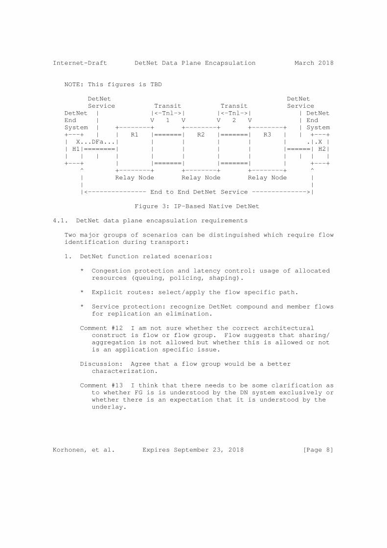
Internet-Draft DetNet Data Plane Encapsulation March 2018
NOTE: This figures is TBD
DetNet DetNet Service Transit Transit Service DetNet | |<-Tnl->| |<-Tnl->| | DetNet End | V 1 V V 2 V | End System | +--------+ +--------+ +--------+ | System +---+ | | R1 |=======| R2 |=======| R3 | | +---+ | X...DFa...| | | | | | .|.X | | H1|========| | | | | |======| H2| | | | | | | | | | | | | +---+ | |=======| |=======| | +---+ ^ +--------+ +--------+ +--------+ ^ | Relay Node Relay Node Relay Node | | | |<--------------- End to End DetNet Service -------------->|
Figure 3: IP-Based Native DetNet
4.1. DetNet data plane encapsulation requirements
Two major groups of scenarios can be distinguished which require flow identification during transport:
1. DetNet function related scenarios:
* Congestion protection and latency control: usage of allocated resources (queuing, policing, shaping).
* Explicit routes: select/apply the flow specific path.
* Service protection: recognize DetNet compound and member flows for replication an elimination.
Comment #12 I am not sure whether the correct architectural construct is flow or flow group. Flow suggests that sharing/ aggregation is not allowed but whether this is allowed or not is an application specific issue.
Discussion: Agree that a flow group would be a better characterization.
Comment #13 I think that there needs to be some clarification as to whether FG is is understood by the DN system exclusively or whether there is an expectation that it is understood by the underlay.
Korhonen, et al. Expires September 23, 2018 [Page 8]
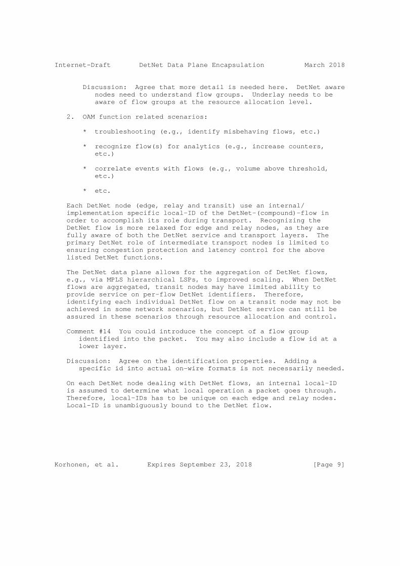
Internet-Draft DetNet Data Plane Encapsulation March 2018
Discussion: Agree that more detail is needed here. DetNet aware nodes need to understand flow groups. Underlay needs to be aware of flow groups at the resource allocation level.
2. OAM function related scenarios:
* troubleshooting (e.g., identify misbehaving flows, etc.)
* recognize flow(s) for analytics (e.g., increase counters, etc.)
* correlate events with flows (e.g., volume above threshold, etc.)
* etc.
Each DetNet node (edge, relay and transit) use an internal/ implementation specific local-ID of the DetNet-(compound)-flow in order to accomplish its role during transport. Recognizing the DetNet flow is more relaxed for edge and relay nodes, as they are fully aware of both the DetNet service and transport layers. The primary DetNet role of intermediate transport nodes is limited to ensuring congestion protection and latency control for the above listed DetNet functions.
The DetNet data plane allows for the aggregation of DetNet flows, e.g., via MPLS hierarchical LSPs, to improved scaling. When DetNet flows are aggregated, transit nodes may have limited ability to provide service on per-flow DetNet identifiers. Therefore, identifying each individual DetNet flow on a transit node may not be achieved in some network scenarios, but DetNet service can still be assured in these scenarios through resource allocation and control.
Comment #14 You could introduce the concept of a flow group identified into the packet. You may also include a flow id at a lower layer.
Discussion: Agree on the identification properties. Adding a specific id into actual on-wire formats is not necessarily needed.
On each DetNet node dealing with DetNet flows, an internal local-ID is assumed to determine what local operation a packet goes through. Therefore, local-IDs has to be unique on each edge and relay nodes. Local-ID is unambiguously bound to the DetNet flow.
Korhonen, et al. Expires September 23, 2018 [Page 9]

Internet-Draft DetNet Data Plane Encapsulation March 2018
4.2. Packet replication and elimination considerations
DetNet service layer introduces packet replication and elimination functionality (PREF) for use in DetNet edge and relay node and end system packet processing. PREF MAY be enabled in a DetNet node and the required processing is only applied to packets with a positive flow identification at the DetNet service layer. PREF utilizes a sequence number carried within a DetNet flow packets.
At a DetNet node level the output of the PREF elimination function is always a single packet. The output of the PREF replication function at a DetNet node level is always one or more packets (i.e., 1:M replication). The replicated packets MUST share the same d-CW i.e., the sequence number is the same for each member flow of the compound flow. The location and mechanism on the packet processing pipeline used for replication is implementation specific.
The complex part of the DetNet PREF processing is tracking the history of received packets for multiple DetNet member flows. These ingress DetNet member flows (to a node) MUST have the same local-ID if they belong to the same DetNet (compound) flow and share the same sequence number counter and the history information. The location of the packet elimination on the packet processing pipeline is implementation specific.
4.3. Packet reordering considerations
DetNet service layer introduces also packet reordering functionality for use in DetNet edge and relay node and end system packet processing. The reordering functionality MAY be enabled in a DetNet node. The reordeing functionality relies on a presence of sequence numbers in a DetNet (compound) flows. The reordering processing is only applied to packets with a positive flow identification at the DetNet service layer.
5. DetNet encapsulation
5.1. End-system specific considerations
Data-flows requiring DetNet service are generated and terminated on end-systems. Encapsulation depends on application and its preferences. In a DetNet (or even a TSN) domain the DN (TSN) functions use at most two flow parameters, namely Flow-ID and Seq.Number. However, an application may exchange further flow related parameters (e.g., time-stamp), which are not considered by DN functions.
Two types of end-systems are distinguished:
Korhonen, et al. Expires September 23, 2018 [Page 10]
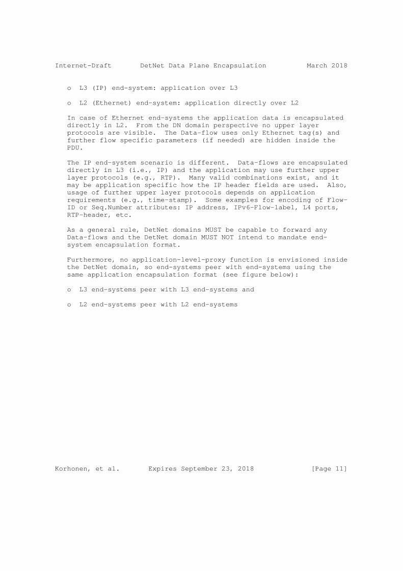
Internet-Draft DetNet Data Plane Encapsulation March 2018
o L3 (IP) end-system: application over L3
o L2 (Ethernet) end-system: application directly over L2
In case of Ethernet end-systems the application data is encapsulated directly in L2. From the DN domain perspective no upper layer protocols are visible. The Data-flow uses only Ethernet tag(s) and further flow specific parameters (if needed) are hidden inside the PDU.
The IP end-system scenario is different. Data-flows are encapsulated directly in L3 (i.e., IP) and the application may use further upper layer protocols (e.g., RTP). Many valid combinations exist, and it may be application specific how the IP header fields are used. Also, usage of further upper layer protocols depends on application requirements (e.g., time-stamp). Some examples for encoding of Flow- ID or Seq.Number attributes: IP address, IPv6-Flow-label, L4 ports, RTP-header, etc.
As a general rule, DetNet domains MUST be capable to forward any Data-flows and the DetNet domain MUST NOT intend to mandate end- system encapsulation format.
Furthermore, no application-level-proxy function is envisioned inside the DetNet domain, so end-systems peer with end-systems using the same application encapsulation format (see figure below):
o L3 end-systems peer with L3 end-systems and
o L2 end-systems peer with L2 end-systems
Korhonen, et al. Expires September 23, 2018 [Page 11]
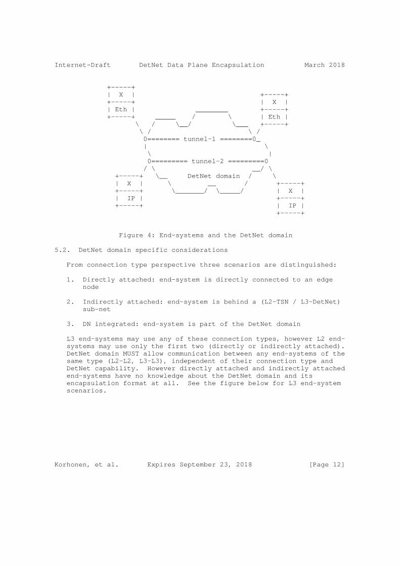
Internet-Draft DetNet Data Plane Encapsulation March 2018
+-----+ | X | +-----+ +-----+ | X | | Eth | ________ +-----+ +-----+ _____ / \ | Eth | \ / \__/ \___ +-----+ \ / \ / 0======== tunnel-1 ========0_ | \ \ | 0========= tunnel-2 =========0 / \ __/ \ +-----+ \__ DetNet domain / \ | X | \ __ / +-----+ +-----+ \_______/ \_____/ | X | | IP | +-----+ +-----+ | IP | +-----+
Figure 4: End-systems and the DetNet domain
5.2. DetNet domain specific considerations
From connection type perspective three scenarios are distinguished:
1. Directly attached: end-system is directly connected to an edge node
2. Indirectly attached: end-system is behind a (L2-TSN / L3-DetNet) sub-net
3. DN integrated: end-system is part of the DetNet domain
L3 end-systems may use any of these connection types, however L2 end- systems may use only the first two (directly or indirectly attached). DetNet domain MUST allow communication between any end-systems of the same type (L2-L2, L3-L3), independent of their connection type and DetNet capability. However directly attached and indirectly attached end-systems have no knowledge about the DetNet domain and its encapsulation format at all. See the figure below for L3 end-system scenarios.
Korhonen, et al. Expires September 23, 2018 [Page 12]

Internet-Draft DetNet Data Plane Encapsulation March 2018
____+----+ +----+ _____ / | ES3| | ES1|____ / \__/ +----+___ +----+ \ / \ + | ____ \ _/ +----+ __/ \ +__ DetNet domain / | ES2|____/ L2/L3 |___/ \ __ __/ +----+ \_______/ \_______/ \___/
Figure 5: Connection types of L3 end-systems
5.2.1. DetNet Bridging Service
The simplest DetNet service is to provide bridging (i.e., tunneling for L2), where the connected hosts are in the same broadcast (BC) domain. Forwarding over the DetNet domain is based on L2 (MAC) addresses (i.e. dst-MAC), so L2 headers MUST be kept. For both IP and MPLS PSN a DetNet specific tunnel encapsulation MUST be introduced.
Korhonen, et al. Expires September 23, 2018 [Page 13]

Internet-Draft DetNet Data Plane Encapsulation March 2018
+------+ | X | +------+ +------+ | X | | IP | +------+ +------+ End+system | L2 | | L2 | +-----+======+-+======+--+======+-+======++ DetNet tunnel | IP | | MPLS | +------+ +------+ | L2 | | L2 | +------+ +------+
Examples
+------+ +------+ | X | | X | +------+ +------+ +------+ +------+ | X | | X | | IP | | IP | +------+ +------+ +------+ +------+ | L2 | | L2 | | L2 | | L2 | ++======+-+======+--+======+-+======++ | IP | | MPLS | | IP | | MPLS | +------+ +------+ +------+ +------+ | L2 | | L2 | | L2 | | L2 | +------+ +------+ +------+ +------+
Figure 6: Encapsulation format for DetNet Bridging
As shown on the figure both L2 and L3 end-systems can be served by such a DetNet Bridging service.
5.2.2. DetNet Routing Service
DetNet Routing service provides routing, therefore available only for L3 hosts that are in different BC domains. Forwarding over the DetNet domain is based on L3 (IP) addresses (i.e. dst-IP).
5.2.2.1. MPLS PSN
In case of an MPLS PSN at the ingress/egress (i.e., PE nodes of DetNet domain) the IP packets are encapsulated in MPLS. The data- flow IP header MUST be preserved as-is.
Korhonen, et al. Expires September 23, 2018 [Page 14]

Internet-Draft DetNet Data Plane Encapsulation March 2018
+------+ +------+ | X | | X | +------+ +------+ End+system | IP | | IP | -----+------+-------+======+--- --+======+-- DetNet | MPLS | | MPLS | +------+ +------+ | L2 | | L2 | +------+ +------+
Figure 7: Encapsulation format for DetNet Routing in MPLS PSN for L3 end-systems
5.2.2.2. IP PSN
In case of an IP PSN the same tunneling concept can be used as for an MPLS PSN, but the tunnel is constructed by a new IP header (and possible upper layer fields). The data-flow IP header MUST be preserved as-is.
+------+ +------+ | X | | X | +======+ +------+ End-system | IP | | IP | -----+------+-------+======+--- --+======+-- DetNet | IP | | IP | +------+ +------+ | L2 | | L2 | +------+ +------+
Figure 8: Encapsulation format for DetNet Routing in IP PSN for L3 end-systems
DetNet IP header contains the IP addresses of the ingress/egress PE nodes of DetNet domain. The End-system IP header contains the IP addresses of the end-systems.
Note: In case of IP PSN one may consider avoiding the additional IP encapsulation, however there are many issues with such an approach. First, the DetNet nodes MUST be able to extract from the IP header (and maybe upper layers) the attributes required by DetNet functions (i.e. Flow-ID, Seq.Number). The challenge is that encoding of those attributes may be application specific, so DetNet nodes MUST be prepared to handle all application specific formats. Second, adding further fields (e.g., explicit path information) to an existing IP header may be impossible (e.g., due to security/encryption).
Korhonen, et al. Expires September 23, 2018 [Page 15]

Internet-Draft DetNet Data Plane Encapsulation March 2018
Furthermore, DetNet domain IP-header format may collide with IP- header format used by the source of a flow. Implementing such an approach requires that source encapsulation is in-line with DetNet domain encapsulation format, however we do not intend to mandate end- systems’ encapsulation format (see former text: As a general rule, DetNet domains MUST be capable to forward any Data-flows and the DetNet domain MUST NOT intend to mandate end-system encapsulation format).
Another approach with IP PSN can be based on MPLS over IP [RFC4023] and/or MPLS over UDP/IP [RFC7510]. In this case the encapsulations over the PSNs were the same i.e., basically the DetNet MPLS-based data plane encapsulation as described in Section 6.2 for both IP and MPLS PSNs.
[Editor’s node: this approach was actually proposed earlier in draft-dt-detnet-dp-sol-00 in a PseudoWire context for IP PSN]
5.2.2.3. Simplified IP Service
In this case there is no "tunneling" below the DetNet Service, but the DetNet Service flows are mapped to each link / sub net using its technology specific methods. The DetNet IP header containes the IP address destination DetNet end system. The data-flow IP header MUST be preserved as-is.
This solution provides end to end DetNet service consisting of congestion protection and latency control and the rouse allocation (queuing, policing, shaping) done using the underlying link / sub net specific mechanisms. Compared to previously described DetNet routing services, the service protections (packet replication and packet emilination functions) and not provided end to end, but per underlying layer-2 link / sub net.
+------+ +------+ | X | | X | +======+ +------+ End-system | IP | | IP | -----+------+-------+======+--- --+======+-- DetNet |L2/SbN| |L2/SbN| +------+ +------+
Figure 9: Encapsulation of DetNet Routing in simplified IP service L3 end-systems
Note: the DetNet Service Flow MUST be mapped to the link / sub net specific resources using an underlying system specific means. This
Korhonen, et al. Expires September 23, 2018 [Page 16]
Internet-Draft DetNet Data Plane Encapsulation March 2018
implies each DetNet aware node on path MUST look into the transported DetNet Service Flow packet and utilize e.g., a five tuple to find out the required mapping in a node. As noted earlier, the Service Protection is done within each link / sub net independently using the domain specific mechanisms (due the lack of a unified end to end sequencing information that would be available for intermediate nodes). If end to end service protection is desired that can be implemented, for example, by the DetNet end systems using Layer-4 transport protocols or application protocols. However, these are out of scope of this document.
[Editor’s note: the service protection to be clarified further.]
5.3. DetNet Inter-Working Function (DN-IWF)
5.3.1. Networks with multiple technology segments
There are network scenarios, where the DetNet domain contains multiple technology segments (IP, MPLS) and all those segments are under the same administrative control (see Figure 10). Furthermore, DetNet nodes may be interconnected via TSN segments.
An important aspect of DetNet network design is placement of DetNet functions across the domain. Designs based on segment-by-segment optimization can provide only suboptimal solutions. In order to achieve global optimum Inter-Working Functions (DN-IWF) can be placed at segment border nodes, which stich together DetNet flows across connected segments.
DN-IWF may ensure that flow attributes are correlated across segment borders. For example, there are two DetNet functions which require Seq.Numbers: (1) Elimination: removes duplications from flows and (2) IOD: ensures in-order-delivery of packet in a flow. Stitching flows together and correlating attributes means for example that replication of packets can happen in one segment and elimination of duplicates in a different one.
Korhonen, et al. Expires September 23, 2018 [Page 17]

Internet-Draft DetNet Data Plane Encapsulation March 2018
______ _____ / \__ ____ / \__/ \___ ______+----+ __/ +======+ +==+ \ +----+|src |__/ Seg1 ) | | \ Seg3 \____| dst|+----+ \_______+ \ Segment-2 | \+_____/ +----+ \======+__ _+===/ \ __ __/ \_______/ \___/
+------------+ +------------------E----+ | |+----+ | | +----R---+ | +----+|src |-------R +---+ | E----------+ dst|+----+ | | E--------+ +----+ +--------------R | +-----------------+
Figure 10: Optimal replication and elimination placement across technology segments example
5.3.2. DN-IWF related considerations
The ultimate goal of DN-IWF is to (1) match and (2) translate segment specific flow attributes. The DN-IWF ensures that segment specific attributes comprise per domain unique attributes for the whole DetNet domain. This characteristic can ensure that DetNet functions can be based on per domain attributes and not per segment attributes.
The two DetNet specific attributes have the following characteristics:
o Flow-ID: it is same in all packets of a flow
o Seq.Number: it is different packet-by-packet
For the Flow-ID the DN-IWF can implement a static mapping. The situation is more complicated for Seq.Number as it is different packet-by-packet, so it may need more sophisticated translation unless its format is exactly the same in the two technology segments. In this later case the DN-IWF can simple copy the Seq.Number field between the tunneling encapsulation of the two technology segments.
In case of three technology segments (IP, MPLS and TSN) three DN-IWF functions can be specified. In the rest of this section the focus is on the (1) IP - MPLS network scenario. Note: the use-cases are out-
Korhonen, et al. Expires September 23, 2018 [Page 18]
Internet-Draft DetNet Data Plane Encapsulation March 2018
of-scope for (2) TSN - IP, (3) TSN - MPLS. Note2: incompatible format of Seq.Number with TSN.
Simplest implementation of DN-IWF is provided if the flow attributes have the same format. Such a common denominator of the tunnel encapsulation format is the pseudowire encapsulation over both IP and MPLS.
Placeholder
Figure 11: FIGURE Placeholder PW over X
6. MPLS-based DetNet data plane solution
6.1. DetNet specific packet fields
The DetNet data plane encapsulation MUST include two DetNet specific information elements in each packet of a DetNet flow: (1) a flow identification and (2) a sequence number.
The DetNet data plane encapsulation may consists further elements used for overlay tunneling, to distinguish between DetNet member flows of the same DetNet compound flow or to support OAM functions.
6.2. Data plane encapsulation
Figure 12 illustrates a DetNet data plane MPLS encapsulation. The MPLS-based encapsulation of the DetNet flows is a good fit for the Layer-2 interconnect deployment cases (see Figure 1). Furthermore, end to end DetNet service i.e., native DetNet deployment (see Figure 2) is also possible if DetNet end systems are capable of initiating and termination MPLS encapsulated packets. Transport of IP encapsulated DetNet flows, see Section 7, over MPLS-based DetNet data plane is also possible. Interworking between PW- and IPv6-based encapsulations is discussed further in Section 8.6.
The MPLS-based DetNet data plane encapsulation consists of:
o DetNet control word (d-CW) containing sequencing information for packet replication and duplicate elimination purposes. There MUST a separate sequence number space for each DetNet flow.
o DetNet Label that identifies a DetNet flow within a DetNet Edge or a Relay node. The DetNet label MUST be at the bottom of the label stack.
Korhonen, et al. Expires September 23, 2018 [Page 19]
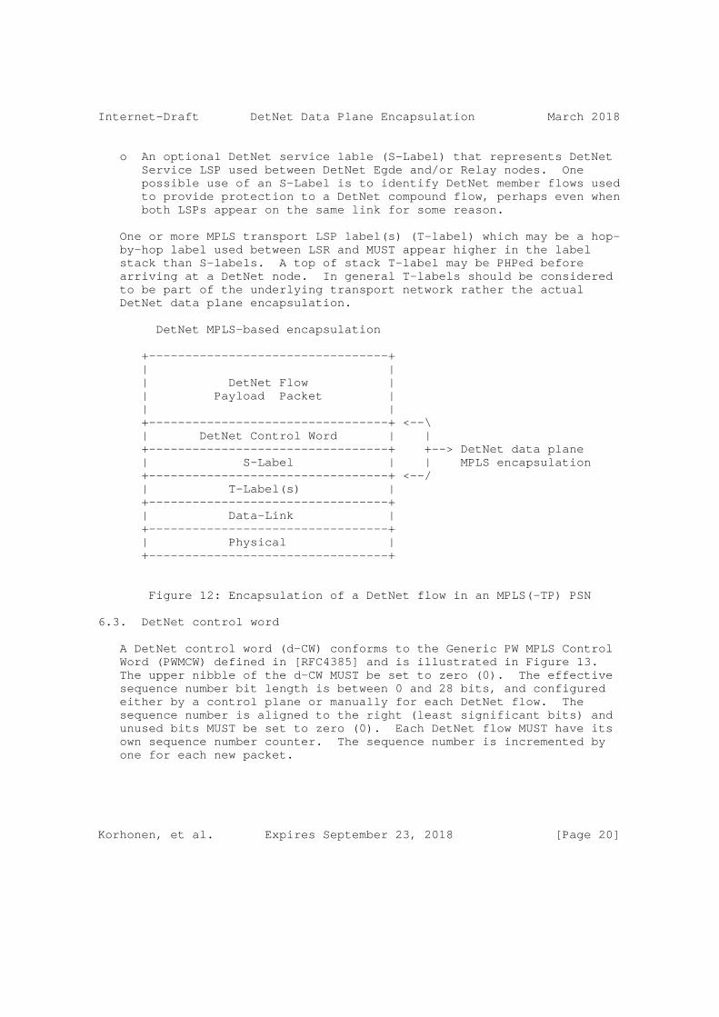
Internet-Draft DetNet Data Plane Encapsulation March 2018
o An optional DetNet service lable (S-Label) that represents DetNet Service LSP used between DetNet Egde and/or Relay nodes. One possible use of an S-Label is to identify DetNet member flows used to provide protection to a DetNet compound flow, perhaps even when both LSPs appear on the same link for some reason.
One or more MPLS transport LSP label(s) (T-label) which may be a hop- by-hop label used between LSR and MUST appear higher in the label stack than S-labels. A top of stack T-label may be PHPed before arriving at a DetNet node. In general T-labels should be considered to be part of the underlying transport network rather the actual DetNet data plane encapsulation.
DetNet MPLS-based encapsulation
+---------------------------------+ | | | DetNet Flow | | Payload Packet | | | +---------------------------------+ <--\ | DetNet Control Word | | +---------------------------------+ +--> DetNet data plane | S-Label | | MPLS encapsulation +---------------------------------+ <--/ | T-Label(s) | +---------------------------------+ | Data-Link | +---------------------------------+ | Physical | +---------------------------------+
Figure 12: Encapsulation of a DetNet flow in an MPLS(-TP) PSN
6.3. DetNet control word
A DetNet control word (d-CW) conforms to the Generic PW MPLS Control Word (PWMCW) defined in [RFC4385] and is illustrated in Figure 13. The upper nibble of the d-CW MUST be set to zero (0). The effective sequence number bit length is between 0 and 28 bits, and configured either by a control plane or manually for each DetNet flow. The sequence number is aligned to the right (least significant bits) and unused bits MUST be set to zero (0). Each DetNet flow MUST have its own sequence number counter. The sequence number is incremented by one for each new packet.
Korhonen, et al. Expires September 23, 2018 [Page 20]
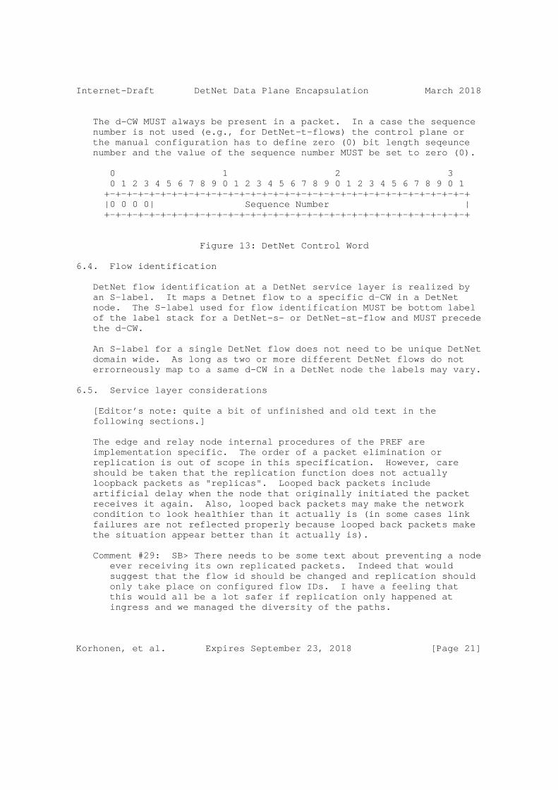
Internet-Draft DetNet Data Plane Encapsulation March 2018
The d-CW MUST always be present in a packet. In a case the sequence number is not used (e.g., for DetNet-t-flows) the control plane or the manual configuration has to define zero (0) bit length seqeunce number and the value of the sequence number MUST be set to zero (0).
0 1 2 3 0 1 2 3 4 5 6 7 8 9 0 1 2 3 4 5 6 7 8 9 0 1 2 3 4 5 6 7 8 9 0 1 +-+-+-+-+-+-+-+-+-+-+-+-+-+-+-+-+-+-+-+-+-+-+-+-+-+-+-+-+-+-+-+-+ |0 0 0 0| Sequence Number | +-+-+-+-+-+-+-+-+-+-+-+-+-+-+-+-+-+-+-+-+-+-+-+-+-+-+-+-+-+-+-+-+
Figure 13: DetNet Control Word
6.4. Flow identification
DetNet flow identification at a DetNet service layer is realized by an S-label. It maps a Detnet flow to a specific d-CW in a DetNet node. The S-label used for flow identification MUST be bottom label of the label stack for a DetNet-s- or DetNet-st-flow and MUST precede the d-CW.
An S-label for a single DetNet flow does not need to be unique DetNet domain wide. As long as two or more different DetNet flows do not errorneously map to a same d-CW in a DetNet node the labels may vary.
6.5. Service layer considerations
[Editor’s note: quite a bit of unfinished and old text in the following sections.]
The edge and relay node internal procedures of the PREF are implementation specific. The order of a packet elimination or replication is out of scope in this specification. However, care should be taken that the replication function does not actually loopback packets as "replicas". Looped back packets include artificial delay when the node that originally initiated the packet receives it again. Also, looped back packets may make the network condition to look healthier than it actually is (in some cases link failures are not reflected properly because looped back packets make the situation appear better than it actually is).
Comment #29: SB> There needs to be some text about preventing a node ever receiving its own replicated packets. Indeed that would suggest that the flow id should be changed and replication should only take place on configured flow IDs. I have a feeling that this would all be a lot safer if replication only happened at ingress and we managed the diversity of the paths.
Korhonen, et al. Expires September 23, 2018 [Page 21]

Internet-Draft DetNet Data Plane Encapsulation March 2018
Discussion: Agree on hardening the loopback text considerations.
6.5.1. Edge node processing
TBD.
[Editor’s note: Since we are not defining the inner workings and implementation of the DetNet Egde node - rather only what goes in and what comes out, and of course the on-wire details, then the figures shown in the coming section would not need to detail the inner architecture of a DetNet Node.]
+---------------------------------------+ | DetNet Edge Node | +---------------------------------------+ | | | | | | | | Client AC | +---o <-------> o o<----------> | Elim. | | | | <---------->o <-------| | +-------------+ | | | | | | +---o <-------> o | | | | o<----------> | | +-> o | +-------------+ | +-------------+ | | | | | Client AC | | Repl. | | | <---------->o o <-----X-> o o<----------> | | Elim. | | +-------------+ +-------------+ | | | | Client AC | | | | <---------->o o <-------> o o<----------> | | | | +---------------------------------------+
Figure 14: DetNet Edge Node processing
An edge node participates to the packet replication and duplication elimination. Required processing is done within an extended forwarder function. In the case the native service processing (NSP) is IEEE 802.1CB [IEEE8021CB] capable, the packet replication and duplicate elimination MAY entirely be done in the NSP and bypassing the DetNet flow encapsulation and logic entirely, and thus is able to operate over unmodified implementation and deployment. The NSP approach works only between edge nodes and cannot make use of relay nodes (see Section 6.5.2).
Korhonen, et al. Expires September 23, 2018 [Page 22]

Internet-Draft DetNet Data Plane Encapsulation March 2018
Comment #31 SB> This would be a fine way to operate the PW system - edge to edge.
Discussion: When it comes to use of NSPs, agree. Also for "island interconnect" this is a fine. However, when there is a need to do PREF in a middle, plain edge to edge is not enough.
The DetNet-aware extended forwarder selects the egress DetNet member flow based on the DetNet forwarding rules. In both "normal AC" and "Packet AC" cases there may be no DetNet encapsulation header available yet as it is the case with relay nodes (see Section 6.5.2). It is the responsibility of the extended forwarder within the edge node to push the DetNet specific encapsulation (if not already present) to the packet before forwarding it to the appropriate egress DetNet member flow instance(s).
Comment #32 SB> I am not convinced of the wisdom of having a mid- point node convert a flow into a DN flow, which is what you are implying here. This seems like an ingress function.
Discussion: OK. The text here has issues and seems to mix relay and edge.
The extended forwarder MAY copy the sequencing information from the native DetNet packet into the DetNet sequence number field and vice versa. If there is no existing sequencing information available in the native packet or the forwarder chose not to copy it from the native packet, then the extended forwarder MUST maintain a sequence number counter for each DetNet flow (indexed by the DetNet flow identification).
6.5.2. Relay node processing
A DetNet Relay node participates to the packet replication and duplication elimination. This processing is done within an extended forwarder function. Whether an ingress DetNet member flow receives DetNet specific processing depends on how the forwarding is programmed. For some DetNet member flows the relay node can act as a normal relay node and for some apply the DetNet specific processing (i.e., PREF).
Comment #34 SB> Again relay node is not a normal term, so am not sure what it does in the absence of a PREF function.
Discussion: Relay node was a DetNet aware S-PE originally, which is not explicitly stated here anymore, thus slightly confusing text here. The text here needs to clarify the roles of PREF and switching functions. A DetNet relay is described in the
Korhonen, et al. Expires September 23, 2018 [Page 23]
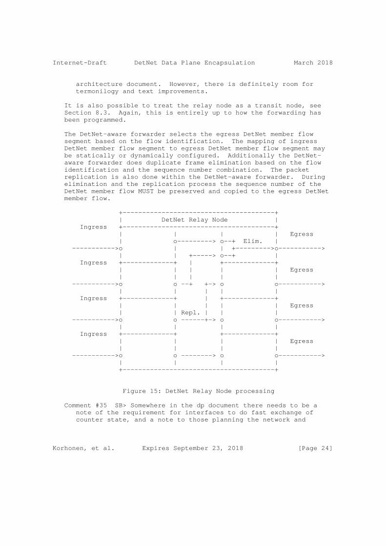
Internet-Draft DetNet Data Plane Encapsulation March 2018
architecture document. However, there is definitely room for termonilogy and text improvements.
It is also possible to treat the relay node as a transit node, see Section 8.3. Again, this is entirely up to how the forwarding has been programmed.
The DetNet-aware forwarder selects the egress DetNet member flow segment based on the flow identification. The mapping of ingress DetNet member flow segment to egress DetNet member flow segment may be statically or dynamically configured. Additionally the DetNet- aware forwarder does duplicate frame elimination based on the flow identification and the sequence number combination. The packet replication is also done within the DetNet-aware forwarder. During elimination and the replication process the sequence number of the DetNet member flow MUST be preserved and copied to the egress DetNet member flow.
+---------------------------------------+ | DetNet Relay Node | Ingress +---------------------------------------+ | | | | Egress | o---------> o--+ Elim. | ----------->o | | +--------->o-----------> | | +-----> o--+ | Ingress +-------------+ | +-------------+ | | | | | Egress | | | | | ----------->o o --+ +-> o o-----------> | | | | | Ingress +-------------+ | +-------------+ | | | | | Egress | | Repl. | | | ----------->o o ------+-> o o-----------> | | | | Ingress +-------------+ +-------------+ | | | | Egress | | | | ----------->o o --------> o o-----------> | | | | +---------------------------------------+
Figure 15: DetNet Relay Node processing
Comment #35 SB> Somewhere in the dp document there needs to be a note of the requirement for interfaces to do fast exchange of counter state, and a note to those planning the network and
Korhonen, et al. Expires September 23, 2018 [Page 24]

Internet-Draft DetNet Data Plane Encapsulation March 2018
designing the control plane that they need to provide support for this.
Discussion: We kinf of agree but also think the above exchange or synchronization of counter states is not in our scope to solve.
6.5.3. End system processing
TBD.
6.6. Transport node considerations
6.6.1. Congestion protection
TBD.
6.6.2. Explicit routes
TBD.
7. Simplified IP based DetNet data plane solution
[Editor’s note: describe the 6 tuple way of doing DetNet service flows. Also stress that PREF is per network segment as described in Section 5.3.1]
Section 5.2.2.3 illustrated the case for DetNet simplified IP data plane solution.
8. Other DetNet data plane considerations
8.1. Class of Service
Class and quality of service, i.e., CoS and QoS, are terms that are often used interchangeably and confused. In the context of DetNet, CoS is used to refer to mechanisms that provide traffic forwarding treatment based on aggregate group basis and QoS is used to refer to mechanisms that provide traffic forwarding treatment based on a specific DetNet flow basis. Examples of existing network level CoS mechanisms include DiffServ which is enabled by IP header differentiated services code point (DSCP) field [RFC2474] and MPLS label traffic class field [RFC5462], and at Layer-2, by IEEE 802.1p priority code point (PCP).
CoS for DetNet flows carried in PWs and MPLS is provided using the existing MPLS Differentiated Services (DiffServ) architecture [RFC3270]. Both E-LSP and L-LSP MPLS DiffServ modes MAY be used to support DetNet flows. The Traffic Class field (formerly the EXP
Korhonen, et al. Expires September 23, 2018 [Page 25]

Internet-Draft DetNet Data Plane Encapsulation March 2018
field) of an MPLS label follows the definition of [RFC5462] and [RFC3270]. The Uniform, Pipe, and Short Pipe DiffServ tunneling and TTL processing models are described in [RFC3270] and [RFC3443] and MAY be used for MPLS LSPs supporting DetNet flows. MPLS ECN MAY also be used as defined in ECN [RFC5129] and updated by [RFC5462].
CoS for DetNet flows carried in IPv6 is provided using the standard differentiated services code point (DSCP) field [RFC2474] and related mechanisms. The 2-bit explicit congestion notification (ECN) [RFC3168] field MAY also be used.
One additional consideration for DetNet nodes which support CoS services is that they MUST ensure that the CoS service classes do not impact the congestion protection and latency control mechanisms used to provide DetNet QoS. This requirement is similar to requirement for MPLS LSRs to that CoS LSPs do not impact the resources allocated to TE LSPs via [RFC3473].
8.2. Quality of Service
Quality of Service (QoS) mechanisms for flow specific traffic treatment typically includes a guarantee/agreement for the service, and allocation of resources to support the service. Example QoS mechanisms include discrete resource allocation, admission control, flow identification and isolation, and sometimes path control, traffic protection, shaping, policing and remarking. Example protocols that support QoS control include Resource ReSerVation Protocol (RSVP) [RFC2205] (RSVP) and RSVP-TE [RFC3209] and [RFC3473]. The existing MPLS mechanisms defined to support CoS [RFC3270] can also be used to reserve resources for specific traffic classes.
In addition to explicit routes, and packet replication and elimination, described in Section 6 above, DetNet provides zero congestion loss and bounded latency and jitter. As described in [I-D.ietf-detnet-architecture], there are different mechanisms that maybe used separately or in combination to deliver a zero congestion loss service. These mechanisms are provided by the either the MPLS or IP layers, and may be combined with the mechanisms defined by the underlying network layer such as 802.1TSN.
A baseline set of QoS capabilities for DetNet flows carried in PWs and MPLS can provided by MPLS with Traffic Engineering (MPLS-TE) [RFC3209] and [RFC3473]. TE LSPs can also support explicit routes (path pinning). Current service definitions for packet TE LSPs can be found in "Specification of the Controlled Load Quality of Service", [RFC2211], "Specification of Guaranteed Quality of Service", [RFC2212], and "Ethernet Traffic Parameters", [RFC6003]. Additional service definitions are expected in future documents to
Korhonen, et al. Expires September 23, 2018 [Page 26]

Internet-Draft DetNet Data Plane Encapsulation March 2018
support the full range of DetNet services. In all cases, the existing label-based marking mechanisms defined for TE-LSPs and even E-LSPs are use to support the identification of flows requiring DetNet QoS.
QoS for DetNet service flows carried in IP MUST be provided locally by the DetNet-aware hosts and routers supporting DetNet flows. Such support will leverage the underlying network layer such as 802.1TSN. The traffic control mechanisms used to deliver QoS for IP encapsulated DetNet flows are expected to be defined in a future document. From an encapsulation perspective, and as defined in Section 7, the combination of the "6 tuple" i.e., the typical 5 tuple enhanced with the DSCP code, uniquely identifies a DetNet service flow.
Packets that are marked with a DetNet Class of Service value, but that have not been the subject of a completed reservation, can disrupt the QoS offered to properly reserved DetNet flows by using resources allocated to the reserved flows. Therefore, the network nodes of a DetNet network MUST:
o Defend the DetNet QoS by discarding or remarking (to a non-DetNet CoS) packets received that are not the subject of a completed reservation.
o Not use a DetNet reserved resource, e.g. a queue or shaper reserved for DetNet flows, for any packet that does not carry a DetNet Class of Service marker.
8.3. Cross-DetNet flow resource aggregation
The ability to aggregate individual flows, and their associated resource control, into a larger aggregate is an important technique for improving scaling of control in the data, management and control planes. This document identifies the traffic identification related aspects of aggregation of DetNet flows. The resource control and management aspects of aggregation (including the queuing/shaping/ policing implications) will be covered in other documents. The data plane implications of aggregation are independent for PW/MPLS and IP encapsulated DetNet flows.
DetNet flows transported via MPLS can leverage MPLS-TE’s existing support for hierarchical LSPs (H-LSPs), see [RFC4206]. H-LSPs are typically used to aggregate control and resources, they may also be used to provide OAM or protection for the aggregated LSPs. Arbitrary levels of aggregation naturally falls out of the definition for hierarchy and the MPLS label stack [RFC3032]. DetNet nodes which support aggregation (LSP hierarchy) map one or more LSPs (labels)
Korhonen, et al. Expires September 23, 2018 [Page 27]

Internet-Draft DetNet Data Plane Encapsulation March 2018
into and from an H-LSP. Both carried LSPs and H-LSPs may or may not use the TC field, i.e., L-LSPs or E-LSPs. Such nodes will need to ensure that traffic from aggregated LSPs are placed (shaped/policed/ enqueued) onto the H-LSPs in a fashion that ensures the required DetNet service is preserved.
DetNet flows transported via IP have more limited aggregation options, due to the available traffic flow identification fields of the IP solution. One available approach is to manage the resources associated with a DSCP identified traffic class and to map (remark) individually controlled DetNet flows onto that traffic class. This approach also requires that nodes support aggregation ensure that traffic from aggregated LSPs are placed (shaped/policed/enqueued) in a fashion that ensures the required DetNet service is preserved.
Comment #38 SB> I am sure we can do better than this with SR, or the use of routing techniques that map certain addresses to certain paths.
Discussion: --
In both the MPLS and IP cases, additional details of the traffic control capabilities needed at a DetNet-aware node may be covered in the new service descriptions mentioned above or in separate future documents. Management and control plane mechanisms will also need to ensure that the service required on the aggregate flow (H-LSP or DSCP) are provided, which may include the discarding or remarking mentioned in the previous sections.
8.4. Bidirectional traffic
Some DetNet applications generate bidirectional traffic. Using MPLS definitions [RFC5654] there are associated bidirectional flows, and co-routed bidirectional flows. MPLS defines a point-to-point associated bidirectional LSP as consisting of two unidirectional point-to-point LSPs, one from A to B and the other from B to A, which are regarded as providing a single logical bidirectional transport path. This would be analogous of standard IP routing, or PWs running over two reciprocal unidirection LSPs. MPLS defines a point-to-point co-routed bidirectional LSP as an associated bidirectional LSP which satisfies the additional constraint that its two unidirectional component LSPs follow the same path (in terms of both nodes and links) in both directions. An important property of co-routed bidirectional LSPs is that their unidirectional component LSPs share fate. In both types of bidirectional LSPs, resource allocations may differ in each direction. The concepts of associated bidirectional flows and co-routed bidirectional flows can be applied to DetNet flows as well whether IPv6 or MPLS is used.
Korhonen, et al. Expires September 23, 2018 [Page 28]

Internet-Draft DetNet Data Plane Encapsulation March 2018
While the IPv6 and MPLS data planes must support bidirectional DetNet flows, there are no special bidirectional features with respect to the data plane other than need for the two directions take the same paths. Fate sharing and associated vs co-routed bidirectional flows can be managed at the control level. Note, that there is no stated requirement for bidirectional DetNet flows to be supported using the same IPv6 Flow Labels or MPLS Labels in each direction. Control mechanisms will need to support such bidirectional flows for both IPv6 and MPLS, but such mechanisms are out of scope of this document. An example control plane solution for MPLS can be found in [RFC7551].
8.5. Layer 2 addressing and QoS Considerations
The Time-Sensitive Networking (TSN) Task Group of the IEEE 802.1 Working Group have defined (and are defining) a number of amendments to IEEE 802.1Q [IEEE8021Q] that provide zero congestion loss and bounded latency in bridged networks. IEEE 802.1CB [IEEE8021CB] defines packet replication and elimination functions that should prove both compatible with and useful to, DetNet networks.
As is the case for DetNet, a Layer 2 network node such as a bridge may need to identify the specific DetNet flow to which a packet belongs in order to provide the TSN/DetNet QoS for that packet. It also will likely need a CoS marking, such as the priority field of an IEEE Std 802.1Q VLAN tag, to give the packet proper service.
Although the flow identification methods described in IEEE 802.1CB [IEEE8021CB] are flexible, and in fact, include IP 5-tuple identification methods, the baseline TSN standards assume that every Ethernet frame belonging to a TSN stream (i.e. DetNet flow) carries a multicast destination MAC address that is unique to that flow within the bridged network over which it is carried. Furthermore, IEEE 802.1CB [IEEE8021CB] describes three methods by which a packet sequence number can be encoded in an Ethernet frame.
Ensuring that the proper Ethernet VLAN tag priority and destination MAC address are used on a DetNet/TSN packet may require further clarification of the customary L2/L3 transformations carried out by routers and edge label switches. Edge nodes may also have to move sequence number fields among Layer 2, PW, and IPv6 encapsulations.
8.6. Interworking between MPLS- and IPv6-based encapsulations
[Editor’s note: add considerations for interworking between MPLS- based and native IPv6-based DetNet encapsuations.]
Korhonen, et al. Expires September 23, 2018 [Page 29]

Internet-Draft DetNet Data Plane Encapsulation March 2018
8.7. IPv4 considerations
[Editor’s note: The fact is that there are and will be deployments using IPv4. Neglecting it entirely is not feasible.]
9. Time synchronization
Comment #39 SB> This section should point the reader to RFC8169 (residence time in MPLS n/w. We need to consider if we need to introduce the same concept in IP.
Discussion: Agree. For IP we could reference to PTPv2 or v3 over UDP/IP, since it measures residence time among other things.
[Editor’s note: describe a bit of issues and deployment considerations related to time-synchronization within DetNet. Refer to DT discussion and the slides that summarize different approaches and rough synchronization performance numbers. Finally, scope time- synchronization solution outside data plane.]
When DetNet is used, there is an underlying assumption that the applicaton(s) require clock synchronization such as the Precision Time Protocol (PTP) [IEEE1588]. The relay nodes may or may not utilize clock synchronization in order to provide zero congestion loss and controlled latency delivery. In either case, there are a few possible approaches of how synchronization protocol packets are forwarded and handled by the network:
o PTP packets can be sent either as DetNet flows or as high-priority best effort packets. Using DetNet for PTP packets requires careful consideration to prevent unwanted interactions between clock-synchronized network nodes and the packets that synchronize the clocks.
o PTP packets are sent as a normal DetNet flow through network nodes that are not time-synchronized: in this approach PTP traffic is forwarded as a DetNet flow, and as such it is forwarded in a way that allows a low delay variation. However, since intermediate nodes do not take part in the synchronization protocol, this approach provides a relatively low degree of accuracy.
o PTP with on-path support: in this approach PTP packets are sent as ordinary or as DetNet flows, and intermediate nodes take part in the protocol as Transparent Clocks or Boundary Clocks [IEEE1588]. The on-path PTP support by intermediate nodes provides a higher degree of accuracy than the previous approach. The actual accuracy depends on whether all intermediate nodes are PTP- capable, or only a subset of them.
Korhonen, et al. Expires September 23, 2018 [Page 30]

Internet-Draft DetNet Data Plane Encapsulation March 2018
o Time-as-a-service: in this approach accurate time is provided as- a-service to the DetNet source and destination, as well as the intermediate nodes. Since traffic between the source and destination is sent over a provider network, if the provider supports time-as-a-service, then accurate time can be provided to both the source and the destination of DetNet traffic. This approach can potentially provide the highest degree of accuracy.
It is expected that the latter approach will be the most common one, as it provides the highest degree of accuracy, and creates a layer separation between the DetNet data and the synchronization service.
It should be noted that in all four approaches it is not recommended to use replication and elimination for synchronization packets; the replication/elimination approach may in some cases reduce the synchronization accuracy, since the observed path delay will be bivalent.
Comment #40 SB> I am not sure why we sould not use PREP. We should explain to the reader.
Discussion: Agree that a this can be opened a bit more in detail. The issue is explained briefly in the last sentence but it could be more clear.
10. Management and control considerations
[Editor’s note: This section needs to be different for MPLS and IPv6 solutions. Most solutions are technology dependant,]
While management plane and control planes are traditionally considered separately, from the Data Plane perspective there is no practical difference based on the origin of flow provisioning information. This document therefore does not distinguish between information provided by a control plane protocol, e.g., RSVP-TE [RFC3209] and [RFC3473], or by a network management mechanisms, e.g., RestConf [RFC8040] and YANG [RFC7950].
[Editor’s note: This section is a work in progress. discuss here what kind of enhancements are needed for DetNet and specifically for PREF and DetNet zero congest loss and latency control. Need to cover both traffic control (queuing) and connection control (control plane).]
Korhonen, et al. Expires September 23, 2018 [Page 31]
Internet-Draft DetNet Data Plane Encapsulation March 2018
10.1. MPLS-based data plane
10.1.1. S-Label assignment and distribution
[Editor’s note: Outdated and MPLS specific.. and needs more work.]
The DetNet S-Label distribution follows the same mechanisms specified for XYZ . The details of the control plane protocol solution required for the label distribution and the management of the label number space are out of scope of this document.
10.1.2. Explicit routes
[Editor’s note: Outdated.. and needs more work.]
[TBD: based on MPLS TE and possibly IPv6 SR]
10.2. IPv6-based data plane
10.2.1. Flow Label assignment and distribution
[Editor’s note: Outdated and IPv6 Specific.. and needs more work.]
The IPv6 Flow Label distribution and the label number space are out of scope of this document. However, it should be noted that the combination of the IPv6 source address and the IPv6 Flow Label is assumed to be unique within the DetNet-enabled network. Therefore, as long as each node is able to assign unique Flow Labels for the source address(es) it is using the DetNet-enabled network wide flow identification uniqueness is guaranteed.
10.2.2. Explicit routes
[Editor’s note: Outdated.. and needs more work.]
[TBD: What we have there for IPv6 and explicit routes]
10.3. Packet replication and elimination
[Editor’s note: Outdated and at the functional level technology independent.. but needs more work.]
The control plane protocol solution required for managing the PREF processing is outside the scope of this document.
Korhonen, et al. Expires September 23, 2018 [Page 32]
Internet-Draft DetNet Data Plane Encapsulation March 2018
10.4. Congestion protection and latency control
[TBD]
10.5. Flow aggregation control
[TBD]
11. Security considerations
The security considerations of DetNet in general are discussed in [I-D.ietf-detnet-architecture] and [I-D.sdt-detnet-security]. Other security considerations will be added in a future version of this draft.
12. IANA considerations
TBD.
13. Acknowledgements
The author(s) ACK and NACK.
The following people were part of the DetNet Data Plane Solution Design Team:
Jouni Korhonen
Janos Farkas
Norman Finn
Balazs Varga
Loa Andersson
Tal Mizrahi
David Mozes
Yuanlong Jiang
Carlos J. Bernardos
The DetNet chairs serving during the DetNet Data Plane Solution Design Team:
Lou Berger
Korhonen, et al. Expires September 23, 2018 [Page 33]
Internet-Draft DetNet Data Plane Encapsulation March 2018
Pat Thaler
14. References
14.1. Normative references
[RFC2119] Bradner, S., "Key words for use in RFCs to Indicate Requirement Levels", BCP 14, RFC 2119, DOI 10.17487/RFC2119, March 1997, <https://www.rfc-editor.org/info/rfc2119>.
[RFC2211] Wroclawski, J., "Specification of the Controlled-Load Network Element Service", RFC 2211, DOI 10.17487/RFC2211, September 1997, <https://www.rfc-editor.org/info/rfc2211>.
[RFC2212] Shenker, S., Partridge, C., and R. Guerin, "Specification of Guaranteed Quality of Service", RFC 2212, DOI 10.17487/RFC2212, September 1997, <https://www.rfc-editor.org/info/rfc2212>.
[RFC2474] Nichols, K., Blake, S., Baker, F., and D. Black, "Definition of the Differentiated Services Field (DS Field) in the IPv4 and IPv6 Headers", RFC 2474, DOI 10.17487/RFC2474, December 1998, <https://www.rfc-editor.org/info/rfc2474>.
[RFC3032] Rosen, E., Tappan, D., Fedorkow, G., Rekhter, Y., Farinacci, D., Li, T., and A. Conta, "MPLS Label Stack Encoding", RFC 3032, DOI 10.17487/RFC3032, January 2001, <https://www.rfc-editor.org/info/rfc3032>.
[RFC3168] Ramakrishnan, K., Floyd, S., and D. Black, "The Addition of Explicit Congestion Notification (ECN) to IP", RFC 3168, DOI 10.17487/RFC3168, September 2001, <https://www.rfc-editor.org/info/rfc3168>.
[RFC3209] Awduche, D., Berger, L., Gan, D., Li, T., Srinivasan, V., and G. Swallow, "RSVP-TE: Extensions to RSVP for LSP Tunnels", RFC 3209, DOI 10.17487/RFC3209, December 2001, <https://www.rfc-editor.org/info/rfc3209>.
[RFC3270] Le Faucheur, F., Wu, L., Davie, B., Davari, S., Vaananen, P., Krishnan, R., Cheval, P., and J. Heinanen, "Multi- Protocol Label Switching (MPLS) Support of Differentiated Services", RFC 3270, DOI 10.17487/RFC3270, May 2002, <https://www.rfc-editor.org/info/rfc3270>.
Korhonen, et al. Expires September 23, 2018 [Page 34]

Internet-Draft DetNet Data Plane Encapsulation March 2018
[RFC3443] Agarwal, P. and B. Akyol, "Time To Live (TTL) Processing in Multi-Protocol Label Switching (MPLS) Networks", RFC 3443, DOI 10.17487/RFC3443, January 2003, <https://www.rfc-editor.org/info/rfc3443>.
[RFC3473] Berger, L., Ed., "Generalized Multi-Protocol Label Switching (GMPLS) Signaling Resource ReserVation Protocol- Traffic Engineering (RSVP-TE) Extensions", RFC 3473, DOI 10.17487/RFC3473, January 2003, <https://www.rfc-editor.org/info/rfc3473>.
[RFC4023] Worster, T., Rekhter, Y., and E. Rosen, Ed., "Encapsulating MPLS in IP or Generic Routing Encapsulation (GRE)", RFC 4023, DOI 10.17487/RFC4023, March 2005, <https://www.rfc-editor.org/info/rfc4023>.
[RFC4206] Kompella, K. and Y. Rekhter, "Label Switched Paths (LSP) Hierarchy with Generalized Multi-Protocol Label Switching (GMPLS) Traffic Engineering (TE)", RFC 4206, DOI 10.17487/RFC4206, October 2005, <https://www.rfc-editor.org/info/rfc4206>.
[RFC4385] Bryant, S., Swallow, G., Martini, L., and D. McPherson, "Pseudowire Emulation Edge-to-Edge (PWE3) Control Word for Use over an MPLS PSN", RFC 4385, DOI 10.17487/RFC4385, February 2006, <https://www.rfc-editor.org/info/rfc4385>.
[RFC5129] Davie, B., Briscoe, B., and J. Tay, "Explicit Congestion Marking in MPLS", RFC 5129, DOI 10.17487/RFC5129, January 2008, <https://www.rfc-editor.org/info/rfc5129>.
[RFC5462] Andersson, L. and R. Asati, "Multiprotocol Label Switching (MPLS) Label Stack Entry: "EXP" Field Renamed to "Traffic Class" Field", RFC 5462, DOI 10.17487/RFC5462, February 2009, <https://www.rfc-editor.org/info/rfc5462>.
[RFC6003] Papadimitriou, D., "Ethernet Traffic Parameters", RFC 6003, DOI 10.17487/RFC6003, October 2010, <https://www.rfc-editor.org/info/rfc6003>.
[RFC6073] Martini, L., Metz, C., Nadeau, T., Bocci, M., and M. Aissaoui, "Segmented Pseudowire", RFC 6073, DOI 10.17487/RFC6073, January 2011, <https://www.rfc-editor.org/info/rfc6073>.
Korhonen, et al. Expires September 23, 2018 [Page 35]
Internet-Draft DetNet Data Plane Encapsulation March 2018
[RFC7510] Xu, X., Sheth, N., Yong, L., Callon, R., and D. Black, "Encapsulating MPLS in UDP", RFC 7510, DOI 10.17487/RFC7510, April 2015, <https://www.rfc-editor.org/info/rfc7510>.
[RFC8200] Deering, S. and R. Hinden, "Internet Protocol, Version 6 (IPv6) Specification", STD 86, RFC 8200, DOI 10.17487/RFC8200, July 2017, <https://www.rfc-editor.org/info/rfc8200>.
14.2. Informative references
[I-D.ietf-6man-segment-routing-header] Previdi, S., Filsfils, C., Raza, K., Dukes, D., Leddy, J., Field, B., [email protected], d., [email protected], d., Matsushima, S., Leung, I., Linkova, J., Aries, E., Kosugi, T., Vyncke, E., Lebrun, D., Steinberg, D., and R. Raszuk, "IPv6 Segment Routing Header (SRH)", draft-ietf-6man-segment-routing-header-09 (work in progress), March 2018.
[I-D.ietf-detnet-architecture] Finn, N., Thubert, P., Varga, B., and J. Farkas, "Deterministic Networking Architecture", draft-ietf- detnet-architecture-04 (work in progress), October 2017.
[I-D.ietf-detnet-dp-alt] Korhonen, J., Farkas, J., Mirsky, G., Thubert, P., Zhuangyan, Z., and L. Berger, "DetNet Data Plane Protocol and Solution Alternatives", draft-ietf-detnet-dp-alt-00 (work in progress), October 2016.
[I-D.sdt-detnet-security] Mizrahi, T., Grossman, E., Hacker, A., Das, S., "Deterministic Networking (DetNet) Security Considerations, draft-sdt-detnet-security, work in progress", 2017.
[IEEE1588] IEEE, "IEEE 1588 Standard for a Precision Clock Synchronization Protocol for Networked Measurement and Control Systems Version 2", 2008.
Korhonen, et al. Expires September 23, 2018 [Page 36]
Internet-Draft DetNet Data Plane Encapsulation March 2018
[IEEE8021CB] Finn, N., "Draft Standard for Local and metropolitan area networks - Seamless Redundancy", IEEE P802.1CB /D2.1 P802.1CB, December 2015, <http://www.ieee802.org/1/files/private/cb-drafts/ d2/802-1CB-d2-1.pdf>.
[IEEE8021Q] IEEE 802.1, "Standard for Local and metropolitan area networks--Bridges and Bridged Networks (IEEE Std 802.1Q- 2014)", 2014, <http://standards.ieee.org/about/get/>.
[RFC2205] Braden, R., Ed., Zhang, L., Berson, S., Herzog, S., and S. Jamin, "Resource ReSerVation Protocol (RSVP) -- Version 1 Functional Specification", RFC 2205, DOI 10.17487/RFC2205, September 1997, <https://www.rfc-editor.org/info/rfc2205>.
[RFC3985] Bryant, S., Ed. and P. Pate, Ed., "Pseudo Wire Emulation Edge-to-Edge (PWE3) Architecture", RFC 3985, DOI 10.17487/RFC3985, March 2005, <https://www.rfc-editor.org/info/rfc3985>.
[RFC5654] Niven-Jenkins, B., Ed., Brungard, D., Ed., Betts, M., Ed., Sprecher, N., and S. Ueno, "Requirements of an MPLS Transport Profile", RFC 5654, DOI 10.17487/RFC5654, September 2009, <https://www.rfc-editor.org/info/rfc5654>.
[RFC7551] Zhang, F., Ed., Jing, R., and R. Gandhi, Ed., "RSVP-TE Extensions for Associated Bidirectional Label Switched Paths (LSPs)", RFC 7551, DOI 10.17487/RFC7551, May 2015, <https://www.rfc-editor.org/info/rfc7551>.
[RFC7950] Bjorklund, M., Ed., "The YANG 1.1 Data Modeling Language", RFC 7950, DOI 10.17487/RFC7950, August 2016, <https://www.rfc-editor.org/info/rfc7950>.
[RFC8040] Bierman, A., Bjorklund, M., and K. Watsen, "RESTCONF Protocol", RFC 8040, DOI 10.17487/RFC8040, January 2017, <https://www.rfc-editor.org/info/rfc8040>.
Appendix A. Example of DetNet data plane operation
[Editor’s note: Add a simplified example of DetNet data plane and how labels etc work in the case of MPLS-based PSN and utilizing PREF. The figure is subject to change depending on the further DT decisions on the label handling..]
Korhonen, et al. Expires September 23, 2018 [Page 37]

Internet-Draft DetNet Data Plane Encapsulation March 2018
Appendix B. Example of pinned paths using IPv6
TBD.
Authors’ Addresses
Jouni Korhonen (editor) Nordic Semiconductor
Email: [email protected]
Loa Andersson Huawei
Email: [email protected]
Yuanlong Jiang Huawei
Email: [email protected]
Norman Finn Huawei 3101 Rio Way Spring Valley, CA 91977 USA
Email: [email protected]
Balazs Varga Ericsson Konyves Kalman krt. 11/B Budapest 1097 Hungary
Email: [email protected]
Korhonen, et al. Expires September 23, 2018 [Page 38]

Internet-Draft DetNet Data Plane Encapsulation March 2018
Janos Farkas Ericsson Konyves Kalman krt. 11/B Budapest 1097 Hungary
Email: [email protected]
Carlos J. Bernardos Universidad Carlos III de Madrid Av. Universidad, 30 Leganes, Madrid 28911 Spain
Phone: +34 91624 6236 Email: [email protected] URI: http://www.it.uc3m.es/cjbc/
Tal Mizrahi Marvell 6 Hamada st. Yokneam Israel
Email: [email protected]
Lou Berger LabN Consulting, L.L.C.
Email: [email protected]
Korhonen, et al. Expires September 23, 2018 [Page 39]

Internet Engineering Task Force E. Grossman, Ed.Internet-Draft DOLBYIntended status: Informational T. MizrahiExpires: September 3, 2021 HUAWEI A. Hacker MISTIQ March 2, 2021
Deterministic Networking (DetNet) Security Considerations draft-ietf-detnet-security-16
Abstract
A DetNet (deterministic network) provides specific performance guarantees to its data flows, such as extremely low data loss rates and bounded latency (including bounded latency variation, i.e. "jitter"). As a result, securing a DetNet requires that in addition to the best practice security measures taken for any mission-critical network, additional security measures may be needed to secure the intended operation of these novel service properties.
This document addresses DetNet-specific security considerations from the perspectives of both the DetNet system-level designer and component designer. System considerations include a taxonomy of relevant threats and attacks, and associations of threats versus use cases and service properties. Component-level considerations include ingress filtering and packet arrival time violation detection.
This document also addresses security considerations specific to the IP and MPLS data plane technologies, thereby complementing the Security Considerations sections of those documents.
Status of This Memo
This Internet-Draft is submitted in full conformance with the provisions of BCP 78 and BCP 79.
Internet-Drafts are working documents of the Internet Engineering Task Force (IETF). Note that other groups may also distribute working documents as Internet-Drafts. The list of current Internet- Drafts is at https://datatracker.ietf.org/drafts/current/.
Internet-Drafts are draft documents valid for a maximum of six months and may be updated, replaced, or obsoleted by other documents at any time. It is inappropriate to use Internet-Drafts as reference material or to cite them other than as "work in progress."
Grossman, et al. Expires September 3, 2021 [Page 1]

Internet-Draft DetNet Security March 2021
This Internet-Draft will expire on September 3, 2021.
Copyright Notice
Copyright (c) 2021 IETF Trust and the persons identified as the document authors. All rights reserved.
This document is subject to BCP 78 and the IETF Trust’s Legal Provisions Relating to IETF Documents (https://trustee.ietf.org/license-info) in effect on the date of publication of this document. Please review these documents carefully, as they describe your rights and restrictions with respect to this document. Code Components extracted from this document must include Simplified BSD License text as described in Section 4.e of the Trust Legal Provisions and are provided without warranty as described in the Simplified BSD License.
Table of Contents
1. Introduction . . . . . . . . . . . . . . . . . . . . . . . . 4 2. Abbreviations and Terminology . . . . . . . . . . . . . . . . 7 3. Security Considerations for DetNet Component Design . . . . . 8 3.1. Resource Allocation . . . . . . . . . . . . . . . . . . . 8 3.1.1. Inviolable Flows . . . . . . . . . . . . . . . . . . 8 3.1.2. Design Trade-Off Considerations in the Use Cases Continuum . . . . . . . . . . . . . . . . . . . . . . 9 3.1.3. Documenting the Security Properties of a Component . 10 3.1.4. Fail-Safe Component Behavior . . . . . . . . . . . . 10 3.1.5. Flow Aggregation Example . . . . . . . . . . . . . . 10 3.2. Explicit Routes . . . . . . . . . . . . . . . . . . . . . 11 3.3. Redundant Path Support . . . . . . . . . . . . . . . . . 11 3.4. Timing (or other) Violation Reporting . . . . . . . . . . 12 4. DetNet Security Considerations Compared With DiffServ Security Considerations . . . . . . . . . . . . . . . . . . . 13 5. Security Threats . . . . . . . . . . . . . . . . . . . . . . 14 5.1. Threat Taxonomy . . . . . . . . . . . . . . . . . . . . . 15 5.2. Threat Analysis . . . . . . . . . . . . . . . . . . . . . 16 5.2.1. Delay . . . . . . . . . . . . . . . . . . . . . . . . 16 5.2.2. DetNet Flow Modification or Spoofing . . . . . . . . 16 5.2.3. Resource Segmentation (Inter-segment Attack) Vulnerability . . . . . . . . . . . . . . . . . . . . 16 5.2.4. Packet Replication and Elimination . . . . . . . . . 17 5.2.4.1. Replication: Increased Attack Surface . . . . . . 17 5.2.4.2. Replication-related Header Manipulation . . . . . 17 5.2.5. Controller Plane . . . . . . . . . . . . . . . . . . 18 5.2.5.1. Path Choice Manipulation . . . . . . . . . . . . 18 5.2.5.2. Compromised Controller . . . . . . . . . . . . . 18 5.2.6. Reconnaissance . . . . . . . . . . . . . . . . . . . 19
Grossman, et al. Expires September 3, 2021 [Page 2]
Internet-Draft DetNet Security March 2021
5.2.7. Time Synchronization Mechanisms . . . . . . . . . . . 19 5.3. Threat Summary . . . . . . . . . . . . . . . . . . . . . 19 6. Security Threat Impacts . . . . . . . . . . . . . . . . . . . 20 6.1. Delay-Attacks . . . . . . . . . . . . . . . . . . . . . . 23 6.1.1. Data Plane Delay Attacks . . . . . . . . . . . . . . 23 6.1.2. Controller Plane Delay Attacks . . . . . . . . . . . 23 6.2. Flow Modification and Spoofing . . . . . . . . . . . . . 23 6.2.1. Flow Modification . . . . . . . . . . . . . . . . . . 24 6.2.2. Spoofing . . . . . . . . . . . . . . . . . . . . . . 24 6.2.2.1. Dataplane Spoofing . . . . . . . . . . . . . . . 24 6.2.2.2. Controller Plane Spoofing . . . . . . . . . . . . 24 6.3. Segmentation Attacks (injection) . . . . . . . . . . . . 24 6.3.1. Data Plane Segmentation . . . . . . . . . . . . . . . 25 6.3.2. Controller Plane Segmentation . . . . . . . . . . . . 25 6.4. Replication and Elimination . . . . . . . . . . . . . . . 25 6.4.1. Increased Attack Surface . . . . . . . . . . . . . . 26 6.4.2. Header Manipulation at Elimination Routers . . . . . 26 6.5. Control or Signaling Packet Modification . . . . . . . . 26 6.6. Control or Signaling Packet Injection . . . . . . . . . . 26 6.7. Reconnaissance . . . . . . . . . . . . . . . . . . . . . 26 6.8. Attacks on Time Synchronization Mechanisms . . . . . . . 27 6.9. Attacks on Path Choice . . . . . . . . . . . . . . . . . 27 7. Security Threat Mitigation . . . . . . . . . . . . . . . . . 27 7.1. Path Redundancy . . . . . . . . . . . . . . . . . . . . . 27 7.2. Integrity Protection . . . . . . . . . . . . . . . . . . 28 7.3. DetNet Node Authentication . . . . . . . . . . . . . . . 29 7.4. Dummy Traffic Insertion . . . . . . . . . . . . . . . . . 30 7.5. Encryption . . . . . . . . . . . . . . . . . . . . . . . 31 7.5.1. Encryption Considerations for DetNet . . . . . . . . 32 7.6. Control and Signaling Message Protection . . . . . . . . 33 7.7. Dynamic Performance Analytics . . . . . . . . . . . . . . 33 7.8. Mitigation Summary . . . . . . . . . . . . . . . . . . . 36 8. Association of Attacks to Use Cases . . . . . . . . . . . . . 37 8.1. Association of Attacks to Use Case Common Themes . . . . 38 8.1.1. Sub-Network Layer . . . . . . . . . . . . . . . . . . 38 8.1.2. Central Administration . . . . . . . . . . . . . . . 38 8.1.3. Hot Swap . . . . . . . . . . . . . . . . . . . . . . 38 8.1.4. Data Flow Information Models . . . . . . . . . . . . 39 8.1.5. L2 and L3 Integration . . . . . . . . . . . . . . . . 39 8.1.6. End-to-End Delivery . . . . . . . . . . . . . . . . . 40 8.1.7. Replacement for Proprietary Fieldbuses and Ethernet- based Networks . . . . . . . . . . . . . . . . . . . 40 8.1.8. Deterministic vs Best-Effort Traffic . . . . . . . . 41 8.1.9. Deterministic Flows . . . . . . . . . . . . . . . . . 42 8.1.10. Unused Reserved Bandwidth . . . . . . . . . . . . . . 42 8.1.11. Interoperability . . . . . . . . . . . . . . . . . . 42 8.1.12. Cost Reductions . . . . . . . . . . . . . . . . . . . 43 8.1.13. Insufficiently Secure Components . . . . . . . . . . 43
Grossman, et al. Expires September 3, 2021 [Page 3]

Internet-Draft DetNet Security March 2021
8.1.14. DetNet Network Size . . . . . . . . . . . . . . . . . 43 8.1.15. Multiple Hops . . . . . . . . . . . . . . . . . . . . 44 8.1.16. Level of Service . . . . . . . . . . . . . . . . . . 44 8.1.17. Bounded Latency . . . . . . . . . . . . . . . . . . . 45 8.1.18. Low Latency . . . . . . . . . . . . . . . . . . . . . 45 8.1.19. Bounded Jitter (Latency Variation) . . . . . . . . . 45 8.1.20. Symmetrical Path Delays . . . . . . . . . . . . . . . 45 8.1.21. Reliability and Availability . . . . . . . . . . . . 46 8.1.22. Redundant Paths . . . . . . . . . . . . . . . . . . . 46 8.1.23. Security Measures . . . . . . . . . . . . . . . . . . 46 8.2. Summary of Attack Types per Use Case Common Theme . . . . 47 9. Security Considerations for OAM Traffic . . . . . . . . . . . 49 10. DetNet Technology-Specific Threats . . . . . . . . . . . . . 49 10.1. IP . . . . . . . . . . . . . . . . . . . . . . . . . . . 50 10.2. MPLS . . . . . . . . . . . . . . . . . . . . . . . . . . 51 11. IANA Considerations . . . . . . . . . . . . . . . . . . . . . 52 12. Security Considerations . . . . . . . . . . . . . . . . . . . 52 13. Privacy Considerations . . . . . . . . . . . . . . . . . . . 52 14. Contributors . . . . . . . . . . . . . . . . . . . . . . . . 53 15. References . . . . . . . . . . . . . . . . . . . . . . . . . 53 15.1. Normative References . . . . . . . . . . . . . . . . . . 53 15.2. Informative References . . . . . . . . . . . . . . . . . 54 Authors’ Addresses . . . . . . . . . . . . . . . . . . . . . . . 59
1. Introduction
A deterministic IP network (IETF DetNet, [RFC8655]) can carry data flows for real-time applications with extremely low data loss rates and bounded latency. The bounds on latency defined by DetNet (as described in [I-D.ietf-detnet-flow-information-model]) include both worst case latency (Maximum Latency, Section 5.9.2) and worst case jitter (Maximum Latency Variation, Section 5.9.3). Data flows with deterministic properties are well-established for Ethernet networks (see TSN, [IEEE802.1BA]); DetNet brings these capabilities to the IP network.
Deterministic IP networks have been successfully deployed in real- time Operational Technology (OT) applications for some years, however such networks are typically isolated from external access, and thus the security threat from external attackers is low. An example of such an isolated network is a network deployed within an aircraft, which is "air gapped" from the outside world. DetNet specifies a set of technologies that enable creation of deterministic flows on IP- based networks of potentially wide area (on the scale of a corporate network), potentially merging OT traffic with best-effort (Information Technology, IT) traffic, and placing OT network components into contact with IT network components, thereby exposing
Grossman, et al. Expires September 3, 2021 [Page 4]

Internet-Draft DetNet Security March 2021
the OT traffic and components to security threats that were not present in an isolated OT network.
These DetNet (OT-type) technologies may not have previously been deployed on a wide area IP-based network that also carries IT traffic, and thus can present security considerations that may be new to IP-based wide area network designers; this document provides insight into such system-level security considerations. In addition, designers of DetNet components (such as routers) face new security- related challenges in providing DetNet services, for example maintaining reliable isolation between traffic flows in an environment where IT traffic co-mingles with critical reserved- bandwidth OT traffic; this document also examines security implications internal to DetNet components.
Security is of particularly high importance in DetNet because many of the use cases which are enabled by DetNet [RFC8578] include control of physical devices (power grid devices, industrial controls, building controls) which can have high operational costs for failure, and present potentially attractive targets for cyber-attackers.
This situation is even more acute given that one of the goals of DetNet is to provide a "converged network", i.e. one that includes both IT traffic and OT traffic, thus exposing potentially sensitive OT devices to attack in ways that were not previously common (usually because they were under a separate control system or otherwise isolated from the IT network, for example [ARINC664P7]). Security considerations for OT networks are not a new area, and there are many OT networks today that are connected to wide area networks or the Internet; this document focuses on the issues that are specific to the DetNet technologies and use cases.
Given the above considerations, securing a DetNet starts with a scrupulously well-designed and well-managed engineered network following industry best practices for security at both the data plane and controller plane, as well as for any OAM implementation; this is the assumed starting point for the considerations discussed herein. Such assumptions also depend on the network components themselves upholding the security-related properties that are to be assumed by DetNet system-level designers; for example, the assumption that network traffic associated with a given flow can never affect traffic associated with a different flow is only true if the underlying components make it so. Such properties, which may represent new challenges to component designers, are also considered herein.
Starting with a "well-managed network" as noted above enables us to exclude some of the more powerful adversary capabilities from the Internet Threat Model of BCP 72 ([RFC3552]), such as the ability to
Grossman, et al. Expires September 3, 2021 [Page 5]
Internet-Draft DetNet Security March 2021
arbitrarily drop or delay any or all traffic. Given this reduced attacker capability, we can present security considerations based on attacker capabilities that are more directly relevant to a DetNet.
In this context we view the "traditional" (i.e. non-time-sensitive) network design and management aspects of network security as being primarily concerned with denial-of service prevention, i.e. they must ensure that DetNet traffic goes where it’s supposed to and that an external attacker can’t inject traffic that disrupts the delivery timing assurance of the DetNet. The time-specific aspects of DetNet security presented here take up where those "traditional" design and management aspects leave off.
However note that "traditional" methods for mitigating (among all the others) denial-of service attack (such as throttling) can only be effectively used in a DetNet when their use does not compromise the required time-sensitive or behavioral properties required for the OT flows on the network. For example, a "retry" protocol is typically not going to be compatible with a low-latency (worst-case maximum latency) requirement, however if in a specific use case and implementation such a retry protocol is able to meet the timing constraints, then it may well be used in that context. Similarly if common security protocols such as TLS/DTLS or IPsec are to be used, it must be verified that their implementations are able to meet the timing and behavioral requirements of the time-sensitive network as implemented for the given use case. An example of "behavioral properties" might be that dropping of more than a specific number of packets in a row is not acceptable according to the service level agreement.
The exact security requirements for any given DetNet are necessarily specific to the use cases handled by that network. Thus the reader is assumed to be familiar with the specific security requirements of their use cases, for example those outlined in the DetNet Use Cases [RFC8578] and the Security Considerations sections of the DetNet documents applicable to the network technologies in use, for example [RFC8939] for an IP data plane and [RFC8964] for an MPLS data plane. Readers can find a general introduction to the DetNet Architecture in [RFC8655], the DetNet Data Plane in [RFC8938], and the Flow Information Model in [I-D.ietf-detnet-flow-information-model].
The DetNet technologies include ways to:
o Assign data plane resources for DetNet flows in some or all of the intermediate nodes (routers) along the path of the flow
Grossman, et al. Expires September 3, 2021 [Page 6]
Internet-Draft DetNet Security March 2021
o Provide explicit routes for DetNet flows that do not dynamically change with the network topology in ways that affect the quality of service received by the affected flow(s)
o Distribute data from DetNet flow packets over time and/or space to ensure delivery of the data in each packet in spite of the loss of a path.
This document includes sections considering DetNet component design as well as system design. The latter includes a taxonomy and analysis of threats, threat impacts and mitigations, and an association of attacks with use cases (based on the Use Case Common Themes section of the DetNet Use Cases [RFC8578]).
This document is based on the premise that there will be a very broad range of DetNet applications and use cases, ranging in size and scope from individual industrial machines to networks that span an entire country ([RFC8578]). Thus no single set of prescriptions (such as exactly which mitigation should be applied to which segment of a DetNet) can be applicable to all of them, and indeed any single one that we might prescribe would inevitably prove impractical for some use case, perhaps one that does not even exist at the time of this writing. Thus we are not prescriptive here - we are stating the desired end result, with the understanding that most DetNet use cases will necessarily differ from each other, and there is no "one size fits all".
2. Abbreviations and Terminology
IT: Information Technology (the application of computers to store, study, retrieve, transmit, and manipulate data or information, often in the context of a business or other enterprise - [IT_DEF]).
OT: Operational Technology (the hardware and software dedicated to detecting or causing changes in physical processes through direct monitoring and/or control of physical devices such as valves, pumps, etc. - [OT_DEF])
Component: A component of a DetNet system - used here to refer to any hardware or software element of a DetNet which implements DetNet- specific functionality, for example all or part of a router, switch, or end system.
Device: Used here to refer to a physical entity controlled by the DetNet, for example a motor.
Grossman, et al. Expires September 3, 2021 [Page 7]
Internet-Draft DetNet Security March 2021
Resource Segmentation: Used as a more general form for Network Segmentation (the act or practice of splitting a computer network into subnetworks, each being a network segment - [RS_DEF])
Controller Plane: In DetNet the Controller Plane corresponds to the aggregation of the Control and Management Planes (see [RFC8655] section 4.4.2).
3. Security Considerations for DetNet Component Design
This section provides guidance for implementers of components to be used in a DetNet.
As noted above, DetNet provides resource allocation, explicit routes and redundant path support. Each of these has associated security implications, which are discussed in this section, in the context of component design. Detection, reporting and appropriate action in the case of packet arrival time violations are also discussed.
3.1. Resource Allocation
3.1.1. Inviolable Flows
A DetNet system security designer relies on the premise that any resources allocated to a resource-reserved (OT-type) flow are inviolable; in other words there is no physical possibility within a DetNet component that resources allocated to a given DetNet flow can be compromised by any type of traffic in the network; this includes malicious traffic as well as inadvertent traffic such as might be produced by a malfunctioning component, or due to interactions between components that were not sufficiently tested for interoperability. From a security standpoint this is a critical assumption, for example when designing against DOS attacks. In other words, with correctly designed components and security mechanisms, one can prevent malicious activities from impacting other resources.
However, achieving the goal of absolutely inviolable flows may not be technically or economically feasible for any given use case, given the broad range of possible use cases (e.g. [reference to DetNet Use Cases RFC8578]) and their associated security considerations as outlined in this document. It can be viewed as a continuum of security requirements, from isolated ultra-low latency systems that may have little security vulnerability (such as an industrial machine) to broadly distributed systems with many possible attack vectors and OT security concerns (such as a utility network). Given this continuum, the design principle employed in this document is to specify the desired end results, without being overly prescriptive in how the results are achieved, reflecting the understanding that no
Grossman, et al. Expires September 3, 2021 [Page 8]
Internet-Draft DetNet Security March 2021
individual implementation is likely to be appropriate for every DetNet use case.
3.1.2. Design Trade-Off Considerations in the Use Cases Continuum
It is important for the DetNet system designer to understand, for any given DetNet use case and its associated security requirements, the interaction and design trade-offs that inevitably need to be reconciled between the desired end results and the DetNet protocols, as well as the DetNet system and component design.
For any given component, as designed for any given use case (or scope of use cases), it is the responsibility of the component designer to ensure that the premise of inviolable flows is supported, to the extent that they deem necessary to support their target use cases.
For example, the component may include traffic shaping and policing at the ingress, to prevent corrupted or malicious or excessive packets from entering the network, thereby decreasing the likelihood that any traffic will interfere with any DetNet OT flow. The component may include integrity protection for some or all of the header fields such as those used for flow ID, thereby decreasing the likelihood that a packet whose flow ID has been compromised might be directed into a different flow path. The component may verify every single packet header at every forwarding location, or only at certain points. In any of these cases the component may use dynamic performance analytics (Section 7.7) to cause action to be initiated to address the situation in an appropriate and timely manner, either at the data plane or controller plane, or both in concert. The component’s software and hardware may include measures to ensure the integrity of the resource allocation/deallocation process. Other design aspects of the component may help ensure that the adverse effects of malicious traffic are more limited, for example by protecting network control interfaces, or minimizing cascade failures. The component may include features specific to a given use case, such as configuration of the response to a given sequential packet loss count.
Ultimately, due to cost and complexity factors, the security properties of a component designed for low-cost systems may be (by design) far inferior to a component with similar intended functionality, but designed for highly secure or otherwise critical applications, perhaps at substantially higher cost. Any given component is designed for some set of use cases and accordingly will have certain limitations on its security properties and vulnerabilities. It is thus the responsibility of the system designer to assure themselves that the components they use in their
Grossman, et al. Expires September 3, 2021 [Page 9]
Internet-Draft DetNet Security March 2021
design are capable of satisfying their overall system security requirements.
3.1.3. Documenting the Security Properties of a Component
In order for the system designer to adequately understand the security related behavior of a given component, the designer of any component intended for use with DetNet needs to clearly document the security properties of that component. For example, to address the case where a corrupted packet in which the flow identification information is compromised and thus may incidentally match the flow ID of another ("victim") DetNet flow, resulting in additional unauthorized traffic on the victim, the documentation might state that the component employs integrity protection on the flow identification fields.
3.1.4. Fail-Safe Component Behavior
Even when the security properties of a component are understood and well specified, if the component malfunctions, for example due to physical circumstances unpredicted by the component designer, it may be difficult or impossible to fully prevent malfunction of the network. The degree to which a component is hardened against various types of failures is a distinguishing feature of the component and its design, and the overall system design can only be as strong as its weakest link.
However, all networks are subject to this level of uncertainty; it is not unique to DetNet. Having said that, DetNet raises the bar by changing many added latency scenarios from tolerable annoyances to unacceptable service violations. That in turn underscores the importance of system integrity, as well as correct and stable configuration of the network and its nodes, as discussed in Section 1.
3.1.5. Flow Aggregation Example
As another example regarding resource allocation implementation, consider the implementation of Flow Aggregation for DetNet flows (as discussed in [RFC8938]). In this example say there are N flows that are to be aggregated, thus the bandwidth resources of the aggregate flow must be sufficient to contain the sum of the bandwidth reservation for the N flows. However if one of those flows were to consume more than its individually allocated bandwidth, this could cause starvation of the other flows. Thus simply providing and enforcing the calculated aggregate bandwidth may not be a complete solution - the bandwidth for each individual flow must still be guaranteed, for example via ingress policing of each flow (i.e.
Grossman, et al. Expires September 3, 2021 [Page 10]
Internet-Draft DetNet Security March 2021
before it is aggregated). Alternatively, if by some other means each flow to be aggregated can be trusted not to exceed its allocated bandwidth, the same goal can be achieved.
3.2. Explicit Routes
The DetNet-specific purpose for constraining the ability of the DetNet to re-route OT traffic is to maintain the specified service parameters (such as upper and lower latency boundaries) for a given flow. For example if the network were to re-route a flow (or some part of a flow) based exclusively on statistical path usage metrics, or due to malicious activity, it is possible that the new path would have a latency that is outside the required latency bounds which were designed into the original TE-designed path, thereby violating the quality of service for the affected flow (or part of that flow).
However, it is acceptable for the network to re-route OT traffic in such a way as to maintain the specified latency bounds (and any other specified service properties) for any reason, for example in response to a runtime component or path failure.
So from a DetNet security standpoint, the DetNet system designer can expect that any component designed for use in a DetNet will deliver the packets within the agreed-upon service parameters. For the component designer, this means that in order for a component to achieve that expectation, any component that is involved in controlling or implementing any change of the initially TE-configured flow routes must prevent re-routing of OT flows (whether malicious or accidental) which might adversely affect delivering the traffic within the specified service parameters.
3.3. Redundant Path Support
The DetNet provision for redundant paths (PREOF) (as defined in the DetNet Architecture [RFC8655]) provides the foundation for high reliability of a DetNet, by virtually eliminating packet loss (i.e. to a degree which is implementation-dependent) through hitless redundant packet delivery. Note: At the time of this writing, PREOF is not defined for the IP data plane.
It is the responsibility of the system designer to determine the level of reliability required by their use case, and to specify redundant paths sufficient to provide the desired level of reliability (in as much as that reliability can be provided through the use of redundant paths). It is the responsibility of the component designer to ensure that the relevant PREOF operations are executed reliably and securely, to avoid potentially catastrophic situations for the operational technology relying on them.
Grossman, et al. Expires September 3, 2021 [Page 11]

Internet-Draft DetNet Security March 2021
However, note that not all PREOF operations are necessarily implemented in every network; for example a packet re-ordering function may not be necessary if the packets are either not required to be in order, or if the ordering is performed in some other part of the network.
Ideally a redundant path for a flow could be specified from end to end, however given that this is not always possible (as described in [RFC8655]) the system designer will need to consider the resulting end-to-end reliability and security resulting from any given arrangement of network segments along the path, each of which provides its individual PREOF implementation and thus its individual level of reliability and security.
At the data plane the implementation of PREOF depends on the correct assignment and interpretation of packet sequence numbers, as well as the actions taken based on them, such as elimination (including elimination of packets with spurious sequence numbers). Thus the integrity of these values must be maintained by the component as they are assigned by the DetNet Data Plane Service sub-layer, and transported by the Forwarding sub-layer. This is no different than the integrity of the values in any header used by the DetNet (or any other) data plane, and is not unique to redundant paths. The integrity protection of header values is technology-dependent; for example, in Layer 2 networks the integrity of the header fields can be protected by using MACsec [IEEE802.1AE-2018]. Similarly, from the sequence number injection perspective, it is no different from any other protocols that use sequence numbers. In particular IPSec Authentication Header ([RFC4302], Sec. 3 Authentication Header (AH) Processing) provides useful insights.
3.4. Timing (or other) Violation Reporting
A task of the DetNet system designer is to create a network such that for any incoming packet which arrives with any timing or bandwidth violation, an appropriate action can be taken in order to prevent damage to the system. The reporting step may be accomplished through dynamic performance analysis (see Section 7.7) or by any other means as implemented in one or more components. The action to be taken for any given circumstance within any given application will depend on the use case. The action may involve intervention from the controller plane, or it may be taken "immediately" by an individual component, for example if very fast response is required.
The definitions and selections of the actions that can be taken are properties of the components. The component designer implements these options according to their expected use cases, which may vary widely from component to component. Clearly selecting an
Grossman, et al. Expires September 3, 2021 [Page 12]

Internet-Draft DetNet Security March 2021
inappropriate response to a given condition may cause more problems than it is intending to mitigate; for example, a naive approach might be to have the component shut down the link if a packet arrives outside of its prescribed time window; however such a simplistic action may serve the attacker better than it serves the network. Similarly, simple logging of such issues may not be adequate, since a delay in response could result in material damage, for example to mechanical devices controlled by the network. Thus a breadth of possible and effective security-related actions and their configuration is a positive attribute for a DetNet component.
Some possible violations that warrant detection include cases where a packet arrives:
o Outside of its prescribed time window
o Within its time window but with a compromised time stamp that makes it appear that it is not within its window
o Exceeding the reserved flow bandwidth
Some possible direct actions that may be taken at the data plane include traffic policing and shaping functions (e.g., those described in [RFC2475]), separating flows into per-flow rate-limited queues, and potentially applying active queue management [RFC7567]. However if those (or any other) actions are to be taken, the system designer must ensure that the results of such actions do not compromise the continued safe operation of the system. For example, the network (i.e. the controller plane and data plane working together) must mitigate in a timely fashion any potential adverse effect on mechanical devices controlled by the network.
4. DetNet Security Considerations Compared With DiffServ Security Considerations
DetNet is designed to be compatible with DiffServ [RFC2474] as applied to IT traffic in the DetNet. DetNet also incorporates the use of the 6-bit value of the DCSP field of the Type of Service (IPv4) and Traffic Class (IPv6) bytes for flow identification. However, the DetNet interpretation of the DSCP value for OT traffic is not equivalent to the PHB selection behavior as defined by DiffServ.
Thus security consideration for DetNet have some aspects in common with DiffServ, in fact overlapping 100% with respect to IP IT traffic. Security considerations for these aspects are part of the existing literature on IP network security, specifically the Security Considerations sections of [RFC2474] and [RFC2475]. However, DetNet
Grossman, et al. Expires September 3, 2021 [Page 13]

Internet-Draft DetNet Security March 2021
also introduces timing and other considerations which are not present in DiffServ, so the DiffServ security considerations are a subset of the DetNet security considerations.
In the case of DetNet OT traffic, the DSCP value is interpreted differently than in DiffServ and contribute to determination of the service provided to the packet. In DetNet, there are similar consequences to DiffServ for lack of detection of, or incorrect handling of, packets with mismarked DSCP values, and many of the points made in the DiffServ Security discussions ([RFC2475] Sec. 6.1 , [RFC2474] Sec. 7 and [RFC6274] Sec 3.3.2.1) are also relevant to DetNet OT traffic, though perhaps in modified form. For example, in DetNet the effect of an undetected or incorrectly handled maliciously mismarked DSCP field in an OT packet is not identical to affecting the PHB of that packet, since DetNet does not use the PHB concept for OT traffic; but nonetheless the service provided to the packet could be affected, so mitigation measures analogous to those prescribed by DiffServ would be appropriate for DetNet. For example, mismarked DSCP values should not cause failure of network nodes. The remarks in [RFC2474] regarding IPsec and Tunnelling Interactions are also relevant (though this is not to say that other sections are less relevant).
In this discussion, interpretation (and any possible intentional re- marking) of the DSCP values of packets destined for DetNet OT flows is expected to occur at the ingress to the DetNet domain; once inside the domain, maintaining the integrity of the DSCP values is subject to the same handling considerations as any other field in the packet.
5. Security Threats
This section presents a taxonomy of threats, and analyzes the possible threats in a DetNet-enabled network. The threats considered in this section are independent of any specific technologies used to implement the DetNet; Section 10 considers attacks that are associated with the DetNet technologies encompassed by [RFC8938].
We distinguish controller plane threats from data plane threats. The attack surface may be the same, but the types of attacks as well as the motivation behind them, are different. For example, a delay attack is more relevant to data plane than to controller plane. There is also a difference in terms of security solutions: the way you secure the data plane is often different than the way you secure the controller plane.
Grossman, et al. Expires September 3, 2021 [Page 14]

Internet-Draft DetNet Security March 2021
5.1. Threat Taxonomy
This document employs organizational elements of the threat models of [RFC7384] and [RFC7835]. This model classifies attackers based on two criteria:
o Internal vs. external: internal attackers either have access to a trusted segment of the network or possess the encryption or authentication keys. External attackers, on the other hand, do not have the keys and have access only to the encrypted or authenticated traffic.
o On-path vs. off-path: on-path attackers are located in a position that allows interception, modification, or dropping of in-flight protocol packets, whereas off-path attackers can only attack by generating protocol packets.
Regarding the boundary between internal vs. external attackers as defined above, please note that in this document we do not make concrete recommendations regarding which specific segments of the network are to be protected in any specific way, for example via encryption or authentication. As a result, the boundary as defined above is not unequivocally specified here. Given that constraint, the reader can view an internal attacker as one who can operate within the perimeter defined by the DetNet Edge Nodes (as defined in the DetNet Architecture [RFC8655]), allowing that the specifics of what is encrypted or authenticated within this perimeter will vary depending on the implementation.
Care has also been taken to adhere to Section 5 of [RFC3552], both with respect to which attacks are considered out-of-scope for this document, but also which are considered to be the most common threats (explored further in Section 5.2, Threat Analysis). Most of the direct threats to DetNet are active attacks (i.e. attacks that modify DetNet traffic), but it is highly suggested that DetNet application developers take appropriate measures to protect the content of the DetNet flows from passive attacks (i.e. attacks that observe but do not modify DetNet traffic) for example through the use of TLS or DTLS.
DetNet-Service, one of the service scenarios described in [I-D.varga-detnet-service-model], is the case where a service connects DetNet islands, i.e. two or more otherwise independent DetNets are connected via a link that is not intrinsically part of either network. This implies that there could be DetNet traffic flowing over a non-DetNet link, which may provide an attacker with an advantageous opportunity to tamper with DetNet traffic. The security properties of non-DetNet links are outside of the scope of DetNet
Grossman, et al. Expires September 3, 2021 [Page 15]
Internet-Draft DetNet Security March 2021
Security, but it should be noted that use of non-DetNet services to interconnect DetNets merits security analysis to ensure the integrity of the networks involved.
5.2. Threat Analysis
5.2.1. Delay
An attacker can maliciously delay DetNet data flow traffic. By delaying the traffic, the attacker can compromise the service of applications that are sensitive to high delays or to high delay variation. The delay may be constant or modulated.
5.2.2. DetNet Flow Modification or Spoofing
An attacker can modify some header fields of en route packets in a way that causes the DetNet flow identification mechanisms to misclassify the flow. Alternatively, the attacker can inject traffic that is tailored to appear as if it belongs to a legitimate DetNet flow. The potential consequence is that the DetNet flow resource allocation cannot guarantee the performance that is expected when the flow identification works correctly.
5.2.3. Resource Segmentation (Inter-segment Attack) Vulnerability
DetNet components are expected to split their resources between DetNet flows in a way that prevents traffic from one DetNet flow from affecting the performance of other DetNet flows, and also prevents non-DetNet traffic from affecting DetNet flows. However, perhaps due to implementation constraints, some resources may be partially shared, and an attacker may try to exploit this property. For example, an attacker can inject traffic in order to exhaust network resources such that DetNet packets which share resources with the injected traffic may be dropped or delayed. Such injected traffic may be part of DetNet flows or non-DetNet traffic.
Another example of a resource segmentation attack is the case in which an attacker is able to overload the exception path queue on the router, i.e. a "slow path" typically taken by control or OAM packets which are diverted from the data plane because they require processing by a CPU. DetNet OT flows are typically configured to take the "fast path" through the data plane, to minimize latency. However if there is only one queue from the forwarding ASIC to the exception path, and for some reason the system is configured such that any DetNet packets must be handled on this exception path, then saturating the exception path could result in delaying or dropping of DetNet packets.
Grossman, et al. Expires September 3, 2021 [Page 16]
Internet-Draft DetNet Security March 2021
5.2.4. Packet Replication and Elimination
5.2.4.1. Replication: Increased Attack Surface
Redundancy is intended to increase the robustness and survivability of DetNet flows, and replication over multiple paths can potentially mitigate an attack that is limited to a single path. However, the fact that packets are replicated over multiple paths increases the attack surface of the network, i.e., there are more points in the network that may be subject to attacks.
5.2.4.2. Replication-related Header Manipulation
An attacker can manipulate the replication-related header fields. This capability opens the door for various types of attacks. For example:
o Forward both replicas - malicious change of a packet SN (Sequence Number) can cause both replicas of the packet to be forwarded. Note that this attack has a similar outcome to a replay attack.
o Eliminate both replicas - SN manipulation can be used to cause both replicas to be eliminated. In this case an attacker that has access to a single path can cause packets from other paths to be dropped, thus compromising some of the advantage of path redundancy.
o Flow hijacking - an attacker can hijack a DetNet flow with access to a single path by systematically replacing the SNs on the given path with higher SN values. For example, an attacker can replace every SN value S with a higher value S+C, where C is a constant integer. Thus, the attacker creates a false illusion that the attacked path has the lowest delay, causing all packets from other paths to be eliminated in favor of the attacked path. Once the flow from the compromised path is favored by the eliminating bridge, the flow has effectively been hijacked by the attacker. It is now possible for the attacker to either replace en route packets with malicious packets, or to simply inject errors into the packets, causing the packets to be dropped at their destination.
o Amplification - an attacker who injects packets into a flow that is to be replicated will have their attack amplified through the replication process. This is no different than any attacker who injects packets that are delivered through multicast, broadcast, or other point-to-multi-point mechanisms.
Grossman, et al. Expires September 3, 2021 [Page 17]
Internet-Draft DetNet Security March 2021
5.2.5. Controller Plane
5.2.5.1. Path Choice Manipulation
5.2.5.1.1. Control or Signaling Packet Modification
An attacker can maliciously modify en route control packets in order to disrupt or manipulate the DetNet path/resource allocation.
5.2.5.1.2. Control or Signaling Packet Injection
An attacker can maliciously inject control packets in order to disrupt or manipulate the DetNet path/resource allocation.
5.2.5.1.3. Increased Attack Surface
One of the possible consequences of a path manipulation attack is an increased attack surface. Thus, when the attack described in the previous subsection is implemented, it may increase the potential of other attacks to be performed.
5.2.5.2. Compromised Controller
An attacker can subvert a legitimate controller (or subvert another component such that it represents itself as a legitimate controller) with the result that the network nodes incorrectly believe it is authorized to instruct them.
The presence of a compromised node or controller in a DetNet is not a threat that arises as a result of determinism or time sensitivity; the same techniques used to prevent or mitigate against compromised nodes in any network are equally applicable in the DetNet case. The act of compromising a controller may not even be within the capabilities of our defined attacker types - in other words it may not be achievable via packet traffic at all, whether internal or external, on-path or off-path. It might be accomplished for example by a human with physical access to the component, who could upload bogus firmware to it via a USB stick. All of this underscores the requirement for careful overall system security design in a DetNet, given that the effects of even one bad actor on the network can be potentially catastrophic.
Security concerns specific to any given controller plane technology used in DetNet will be addressed by the DetNet documents associated with that technology.
Grossman, et al. Expires September 3, 2021 [Page 18]
Internet-Draft DetNet Security March 2021
5.2.6. Reconnaissance
A passive eavesdropper can identify DetNet flows and then gather information about en route DetNet flows, e.g., the number of DetNet flows, their bandwidths, their schedules, or other temporal or statistical properties. The gathered information can later be used to invoke other attacks on some or all of the flows.
DetNet flows are typically uniquely identified by their 6-tuple, i.e. fields within the L3 or L4 header, however in some implementations the flow ID may also be augmented by additional per-flow attributes known to the system, e.g. above L4. For the purpose of this document we assume any such additional fields used for flow ID are encrypted and/or integrity-protected from external attackers. Note however that existing OT protocols designed for use on dedicated secure networks may not intrinsically provide such protection, in which case IPsec or transport layer security mechanisms may be needed.
5.2.7. Time Synchronization Mechanisms
An attacker can use any of the attacks described in [RFC7384] to attack the synchronization protocol, thus affecting the DetNet service.
5.3. Threat Summary
A summary of the attacks that were discussed in this section is presented in Figure 1. For each attack, the table specifies the type of attackers that may invoke the attack. In the context of this summary, the distinction between internal and external attacks is under the assumption that a corresponding security mechanism is being used, and that the corresponding network equipment takes part in this mechanism.
Grossman, et al. Expires September 3, 2021 [Page 19]

Internet-Draft DetNet Security March 2021
+-------------------------------------------+----+-----+----+-----+ | Attack | Attacker Type | | +----------+----------+ | | Internal | External | | |On-P|Off-P|On-P|Off-P| +-------------------------------------------+----+-----+----+-----+ |Delay attack | + | | + | | +-------------------------------------------+----+-----+----+-----+ |DetNet Flow Modification or Spoofing | + | + | | | +-------------------------------------------+----+-----+----+-----+ |Inter-segment Attack | + | + | + | + | +-------------------------------------------+----+-----+----+-----+ |Replication: Increased Attack Surface | + | + | + | + | +-------------------------------------------+----+-----+----+-----+ |Replication-related Header Manipulation | + | | | | +-------------------------------------------+----+-----+----+-----+ |Path Manipulation | + | + | | | +-------------------------------------------+----+-----+----+-----+ |Path Choice: Increased Attack Surface | + | + | + | + | +-------------------------------------------+----+-----+----+-----+ |Control or Signaling Packet Modification | + | | | | +-------------------------------------------+----+-----+----+-----+ |Control or Signaling Packet Injection | + | + | | | +-------------------------------------------+----+-----+----+-----+ |Reconnaissance | + | | + | | +-------------------------------------------+----+-----+----+-----+ |Attacks on Time Synchronization Mechanisms | + | + | + | + | +-------------------------------------------+----+-----+----+-----+
Figure 1: Threat Analysis Summary
6. Security Threat Impacts
When designing security for a DetNet, as with any network, it may be prohibitively expensive or technically infeasible to thoroughly protect against every possible threat. Thus the security designer must be informed (for example by an application domain expert such as a product manager) regarding the relative significance of the various threats and their impact if a successful attack is carried out. In this section we present an example of a possible template for such a communication, culminating in a table (Figure 2) which lists a set of threats under consideration, and some values characterizing their relative impact in the context of a given industry. The specific threats, industries, and impact values in the table are provided only as an example of this kind of assessment and its communication; they are not intended to be taken literally.
Grossman, et al. Expires September 3, 2021 [Page 20]
Internet-Draft DetNet Security March 2021
This section considers assessment of the relative impacts of the attacks described in Section 5, Security Threats. In this section, the impacts as described assume that the associated mitigation is not present or has failed. Mitigations are discussed in Section 7, Security Threat Mitigation.
In computer security, the impact (or consequence) of an incident can be measured in loss of confidentiality, integrity or availability of information. In the case of time sensitive or OT networks (though not to the exclusion of IT or non-time-sensitive networks) the impact of an exploit can also include failure or malfunction of mechanical and/or other physical systems.
DetNet raises these stakes significantly for OT applications, particularly those which may have been designed to run in an OT-only environment and thus may not have been designed for security in an IT environment with its associated components, services and protocols.
The extent of impact of a successful vulnerability exploit varies considerably by use case and by industry; additional insights regarding the individual use cases is available from [RFC8578], DetNet Use Cases. Each of those use cases is represented in Figure 2, including Pro Audio, Electrical Utilities, Industrial M2M (split into two areas, M2M Data Gathering and M2M Control Loop), and others.
Aspects of Impact (left column) include Criticality of Failure, Effects of Failure, Recovery, and DetNet Functional Dependence. Criticality of failure summarizes the seriousness of the impact. The impact of a resulting failure can affect many different metrics that vary greatly in scope and severity. In order to reduce the number of variables, only the following were included: Financial, Health and Safety, Effect on a Single Organization, and Effect on Multiple Organizations. Recovery outlines how long it would take for an affected use case to get back to its pre-failure state (Recovery time objective, RTO), and how much of the original service would be lost in between the time of service failure and recovery to original state (Recovery Point Objective, RPO). DetNet dependence maps how much the following DetNet service objectives contribute to impact of failure: Time dependency, data integrity, source node integrity, availability, latency/jitter.
The scale of the Impact mappings is low, medium, and high. In some use cases there may be a multitude of specific applications in which DetNet is used. For simplicity this section attempts to average the varied impacts of different applications. This section does not address the overall risk of a certain impact which would require the likelihood of a failure happening.
Grossman, et al. Expires September 3, 2021 [Page 21]
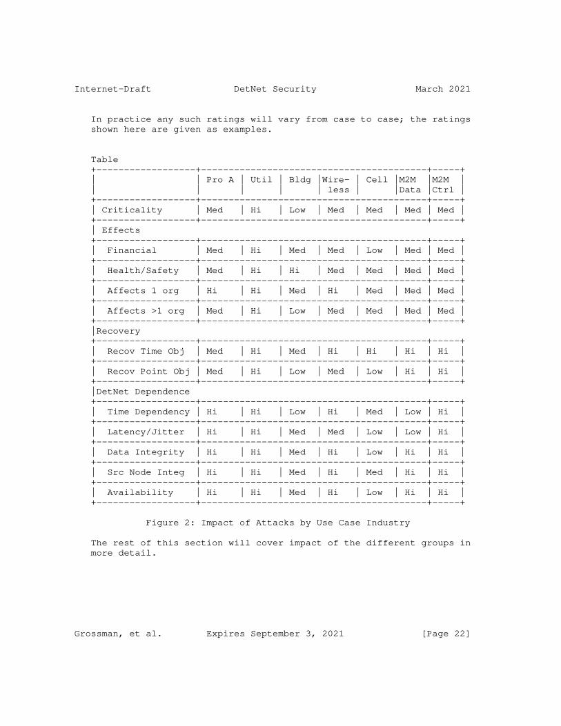
Internet-Draft DetNet Security March 2021
In practice any such ratings will vary from case to case; the ratings shown here are given as examples.
Table +------------------+-----------------------------------------+-----+ | | Pro A | Util | Bldg |Wire- | Cell |M2M |M2M | | | | | | less | |Data |Ctrl | +------------------+-----------------------------------------+-----+ | Criticality | Med | Hi | Low | Med | Med | Med | Med | +------------------+-----------------------------------------+-----+ | Effects +------------------+-----------------------------------------+-----+ | Financial | Med | Hi | Med | Med | Low | Med | Med | +------------------+-----------------------------------------+-----+ | Health/Safety | Med | Hi | Hi | Med | Med | Med | Med | +------------------+-----------------------------------------+-----+ | Affects 1 org | Hi | Hi | Med | Hi | Med | Med | Med | +------------------+-----------------------------------------+-----+ | Affects >1 org | Med | Hi | Low | Med | Med | Med | Med | +------------------+-----------------------------------------+-----+ |Recovery +------------------+-----------------------------------------+-----+ | Recov Time Obj | Med | Hi | Med | Hi | Hi | Hi | Hi | +------------------+-----------------------------------------+-----+ | Recov Point Obj | Med | Hi | Low | Med | Low | Hi | Hi | +------------------+-----------------------------------------+-----+ |DetNet Dependence +------------------+-----------------------------------------+-----+ | Time Dependency | Hi | Hi | Low | Hi | Med | Low | Hi | +------------------+-----------------------------------------+-----+ | Latency/Jitter | Hi | Hi | Med | Med | Low | Low | Hi | +------------------+-----------------------------------------+-----+ | Data Integrity | Hi | Hi | Med | Hi | Low | Hi | Hi | +------------------+-----------------------------------------+-----+ | Src Node Integ | Hi | Hi | Med | Hi | Med | Hi | Hi | +------------------+-----------------------------------------+-----+ | Availability | Hi | Hi | Med | Hi | Low | Hi | Hi | +------------------+-----------------------------------------+-----+
Figure 2: Impact of Attacks by Use Case Industry
The rest of this section will cover impact of the different groups in more detail.
Grossman, et al. Expires September 3, 2021 [Page 22]
Internet-Draft DetNet Security March 2021
6.1. Delay-Attacks
6.1.1. Data Plane Delay Attacks
Note that ’delay attack’ also includes the possibility of a ’negative delay’ or early arrival of a packet, or possibly adversely changing the timestamp value.
Delayed messages in a DetNet link can result in the same behavior as dropped messages in ordinary networks, since the services attached to the DetNet flow are likely to have strict delivery time requirements.
For a single path scenario, disruption within the single flow is a real possibility. In a multipath scenario, large delays or instabilities in one DetNet flow can also lead to increased buffer and processor resource consumption at the eliminating router.
A data-plane delay attack on a system controlling substantial moving devices, for example in industrial automation, can cause physical damage. For example, if the network promises a bounded latency of 2ms for a flow, yet the machine receives it with 5ms latency, the control loop of the machine may become unstable.
6.1.2. Controller Plane Delay Attacks
In and of itself, this is not directly a threat to the DetNet service, but the effects of delaying control messages can have quite adverse effects later.
o Delayed tear-down can lead to resource leakage, which in turn can result in failure to allocate new DetNet flows, finally giving rise to a denial of service attack.
o Failure to deliver, or severely delaying, controller plane messages adding an endpoint to a multicast-group will prevent the new endpoint from receiving expected frames thus disrupting expected behavior.
o Delaying messages removing an endpoint from a group can lead to loss of privacy as the endpoint will continue to receive messages even after it is supposedly removed.
6.2. Flow Modification and Spoofing
Grossman, et al. Expires September 3, 2021 [Page 23]

Internet-Draft DetNet Security March 2021
6.2.1. Flow Modification
If the contents of a packet header or body can be modified by the attacker, this can cause the packet to be routed incorrectly or dropped, or the payload to be corrupted or subtly modified. Thus, the potential impact of a modification attack includes disrupting the application as well as the network equipment.
6.2.2. Spoofing
6.2.2.1. Dataplane Spoofing
Spoofing dataplane messages can result in increased resource consumptions on the routers throughout the network as it will increase buffer usage and processor utilization. This can lead to resource exhaustion and/or increased delay.
If the attacker manages to create valid headers, the false messages can be forwarded through the network, using part of the allocated bandwidth. This in turn can cause legitimate messages to be dropped when the resource budget has been exhausted.
Finally, the endpoint will have to deal with invalid messages being delivered to the endpoint instead of (or in addition to) a valid message.
6.2.2.2. Controller Plane Spoofing
A successful controller plane spoofing-attack will potentially have adverse effects. It can do virtually anything from:
o modifying existing DetNet flows by changing the available bandwidth
o add or remove endpoints from a DetNet flow
o drop DetNet flows completely
o falsely create new DetNet flows (exhaust the systems resources, or to enable DetNet flows that are outside the control of the Network Engineer)
6.3. Segmentation Attacks (injection)
Grossman, et al. Expires September 3, 2021 [Page 24]

Internet-Draft DetNet Security March 2021
6.3.1. Data Plane Segmentation
Injection of false messages in a DetNet flow could lead to exhaustion of the available bandwidth for that flow if the routers attribute these false messages to the resource budget of that flow.
In a multipath scenario, injected messages will cause increased processor utilization in elimination routers. If enough paths are subject to malicious injection, the legitimate messages can be dropped. Likewise it can cause an increase in buffer usage. In total, it will consume more resources in the routers than normal, giving rise to a resource exhaustion attack on the routers.
If a DetNet flow is interrupted, the end application will be affected by what is now a non-deterministic flow. Note that there are many possible sources of flow interruptions, for example, but not limited to, such physical layer conditions as a broken wire or a radio link which is compromised by interference.
6.3.2. Controller Plane Segmentation
In a successful controller plane segmentation attack, control messages are acted on by nodes in the network, unbeknownst to the central controller or the network engineer. This has the potential to:
o create new DetNet flows (exhausting resources)
o drop existing DetNet flows (denial of service)
o add end-stations to a multicast group (loss of privacy)
o remove end-stations from a multicast group (reduction of service)
o modify the DetNet flow attributes (affecting available bandwidth)
If an attacker can inject control messages without the central controller knowing, then one or more components in the network may get into a state that is not expected by the controller. At that point, if the controller initiates a command, the effect of that command may not be as expected, since the target of the command may have started from a different initial state.
6.4. Replication and Elimination
The Replication and Elimination is relevant only to data plane messages as controller plane messages are not subject to multipath routing.
Grossman, et al. Expires September 3, 2021 [Page 25]

Internet-Draft DetNet Security March 2021
6.4.1. Increased Attack Surface
The impact of an increased attack surface is that it increases the probability that the network can be exposed to an attacker. This can facilitate a wide range of specific attacks, and their respective impacts are discussed in other subsections of this section.
6.4.2. Header Manipulation at Elimination Routers
This attack can potentially cause DoS to the application that uses the attacked DetNet flows or to the network equipment that forwards them. Furthermore, it can allow an attacker to manipulate the network paths and the behavior of the network layer.
6.5. Control or Signaling Packet Modification
If control packets are subject to manipulation undetected, the network can be severely compromised.
6.6. Control or Signaling Packet Injection
If an attacker can inject control packets undetected, the network can be severely compromised.
6.7. Reconnaissance
Of all the attacks, this is one of the most difficult to detect and counter.
An attacker can, at their leisure, observe over time various aspects of the messaging and signalling, learning the intent and purpose of the traffic flows. Then at some later date, possibly at an important time in the operational context, they might launch an attack based on that knowledge.
The flow-id in the header of the data plane messages gives an attacker a very reliable identifier for DetNet traffic, and this traffic has a high probability of going to lucrative targets.
Applications which are ported from a private OT network to the higher visibility DetNet environment may need to be adapted to limit distinctive flow properties that could make them susceptible to reconnaissance.
Grossman, et al. Expires September 3, 2021 [Page 26]

Internet-Draft DetNet Security March 2021
6.8. Attacks on Time Synchronization Mechanisms
DetNet relies on an underlying time synchronization mechanism, and therefore a compromised synchronization mechanism may cause DetNet nodes to malfunction. Specifically, DetNet flows may fail to meet their latency requirements and deterministic behavior, thus causing DoS to DetNet applications.
6.9. Attacks on Path Choice
This is covered in part in Section 6.3, Segmentation Attacks, and as with Replication and Elimination ( Section 6.4), this is relevant for DataPlane messages.
7. Security Threat Mitigation
This section describes a set of measures that can be taken to mitigate the attacks described in Section 5, Security Threats. These mitigations should be viewed as a set of tools, any of which can be used individually or in concert. The DetNet component and/or system and/or application designer can apply these tools, as necessary based on a system-specific threat analysis.
Some of the technology-specific security considerations and mitigation approaches are further discussed in the DetNet data plane solution documents, such as [RFC8938], [RFC8939], [RFC8964], [I-D.ietf-detnet-mpls-over-udp-ip], and [I-D.ietf-detnet-ip-over-mpls].
7.1. Path Redundancy
Description
A DetNet flow that can be forwarded simultaneously over multiple paths. Packet replication and elimination [RFC8655] provides resiliency to dropped or delayed packets. This redundancy improves the robustness to failures and to on-path attacks. Note: At the time of this writing, PREOF is not defined for the IP data plane.
Related attacks
Path redundancy can be used to mitigate various on-path attacks, including attacks described in Section 5.2.1, Section 5.2.2, Section 5.2.3, and Section 5.2.7. However it is also possible that multiple paths may make it more difficult to locate the source of an on-path attacker.
Grossman, et al. Expires September 3, 2021 [Page 27]

Internet-Draft DetNet Security March 2021
A delay modulation attack could result in extensively exercising parts of the code that wouldn’t normally be extensively exercised and thus might expose flaws in the system that might otherwise not be exposed.
7.2. Integrity Protection
Description
Integrity Protection in the scope of DetNet is the ability to detect if a packet header has been modified (maliciously or otherwise) and if so, take some appropriate action (as discussed in Section 7.7). The decision on where in the network to apply integrity protection is part of the DetNet system design, and the implementation of the protection method itself is a part of a DetNet component design.
The most common technique for detecting header modification is the use of a Message Authentication Code (MAC) (for examples see Section 10). The MAC can be distributed either in-line (included in the same packet) or via a side channel. Of these, the in-line method is generally preferred due to the low latency that may be required on DetNet flows and the relative complexity and computational overhead of a sideband approach.
There are different levels of security available for integrity protection, ranging from the basic ability to detect if a header has been corrupted in transit (no malicious attack) to stopping a skilled and determined attacker capable of both subtly modifying fields in the headers as well as updating an unkeyed checksum. Common for all are the 2 steps that need to be performed in both ends. The first is computing the checksum or MAC. The corresponding verification step must perform the same steps before comparing the provided with the computed value. Only then can the receiver be reasonably sure that the header is authentic.
The most basic protection mechanism consists of computing a simple checksum of the header fields and provide it to the next entity in the packets path for verification. Using a MAC combined with a secret key provides the best protection against modification and replication attacks (see Section 5.2.2 and Section 5.2.4). This MAC usage needs to be part of a security association that is established and managed by a security association protocol (such as IKEv2 for IPsec security associations). Integrity protection in the controller plane is discussed in Section 7.6. The secret key, regardless of MAC used, must be protected from falling into the hands of unauthorized users. Once key management becomes a topic, it is important to understand that this is a delicate
Grossman, et al. Expires September 3, 2021 [Page 28]

Internet-Draft DetNet Security March 2021
process and should not be undertaken lightly. BCP 107 [RFC4107] provides best practices in this regard.
DetNet system and/or component designers need to be aware of these distinctions and enforce appropriate integrity protection mechanisms as needed based on a threat analysis. Note that adding integrity protection mechanisms may introduce latency, thus many of the same considerations in Section 7.5.1 also apply here.
Packet Sequence Number Integrity Considerations
The use of PREOF in a DetNet implementation implies the use of a sequence number for each packet. There is a trust relationship between the component that adds the sequence number and the component that removes the sequence number. The sequence number may be end-to-end source to destination, or may be added/deleted by network edge components. The adder and remover(s) have the trust relationship because they are the ones that ensure that the sequence numbers are not modifiable. Thus, sequence numbers can be protected by using authenticated encryption, or by a MAC without using encryption. Between the adder and remover there may or may not be replication and elimination functions. The elimination functions must be able to see the sequence numbers. Therefore, if encryption is done between adders and removers it must not obscure the sequence number. If the sequence removers and the eliminators are in the same physical component, it may be possible to obscure the sequence number, however that is a layer violation, and is not recommended practice. Note: At the time of this writing, PREOF is not defined for the IP data plane.
Related attacks
Integrity protection mitigates attacks related to modification and tampering, including the attacks described in Section 5.2.2 and Section 5.2.4.
7.3. DetNet Node Authentication
Description
Authentication verifies the identity of DetNet nodes (including DetNet Controller Plane nodes), and this enables mitigation of spoofing attacks. While integrity protection ( Section 7.2) prevents intermediate nodes from modifying information, authentication can provide traffic origin verification, i.e. to verify that each packet in a DetNet flow is from a known source. Although node authentication and integrity protection are two different goals of a security protocol, in most cases a common
Grossman, et al. Expires September 3, 2021 [Page 29]

Internet-Draft DetNet Security March 2021
protocol (such as IPsec [RFC4301] or MACsec [IEEE802.1AE-2018]) is used for achieving both purposes.
Related attacks
DetNet node authentication is used to mitigate attacks related to spoofing, including the attacks of Section 5.2.2, and Section 5.2.4.
7.4. Dummy Traffic Insertion
Description
With some queueing methods such as [IEEE802.1Qch-2017] it is possible to introduce dummy traffic in order to regularize the timing of packet transmission. This will subsequently reduce the value of passive monitoring from internal threats (see Section 5) as it will be much more difficult to associate discrete events with particular network packets.
Related attacks
Removing distinctive temporal properties of individual packets or flows can be used to mitigate against reconnaissance attacks Section 5.2.6. For example, dummy traffic can be used to synthetically maintain constant traffic rate even when no user data is transmitted, thus making it difficult to collect information about the times at which users are active, and the times at which DetNet flows are added or removed.
Traffic Insertion Challenges
Once an attacker is able to monitor the frames traversing a network to such a degree that they can differentiate between best- effort traffic and traffic belonging to a specific DetNet flow, it becomes difficult to not reveal to the attacker whether a given frame is valid traffic or an inserted frame. Thus, having the DetNet components generate and remove the dummy traffic may or may not be a viable option, unless certain challenges are solved; for example, but not limited to:
o Inserted traffic must be indistinguishable from valid stream traffic from the viewpoint of the attacker.
o DetNet components must be able to safely identify and remove all inserted traffic (and only inserted traffic).
Grossman, et al. Expires September 3, 2021 [Page 30]

Internet-Draft DetNet Security March 2021
o The controller plane must manage where to insert and remove dummy traffic, but this information must not be revealed to an attacker.
An alternative design is to have the insertion and removal of dummy traffic be performed at the application layer, rather than by the DetNet itself. Further discussions and reading about how sRTP handles this can be found in [RFC6562]
7.5. Encryption
Description
Reconnaissance attacks (Section 5.2.6) can be mitigated to some extent through the use of encryption, thereby preventing the attacker from accessing the packet header or contents. Specific encryption protocols will depend on the lower layers that DetNet is forwarded over. For example, IP flows may be forwarded over IPsec [RFC4301], and Ethernet flows may be secured using MACsec [IEEE802.1AE-2018].
However, despite the use of encryption, a reconnaissance attack can provide the attacker with insight into the network, even without visibility into the packet. For example, an attacker can observe which nodes are communicating with which other nodes, including when, how often, and with how much data. In addition, the timing of packets may be correlated in time with external events such as action of an external device. Such information may be used by the attacker, for example in mapping out specific targets for a different type of attack at a different time.
DetNet nodes do not have any need to inspect the payload of any DetNet packets, making them data-agnostic. This means that end- to-end encryption at the application layer is an acceptable way to protect user data.
Note that reconnaissance is a threat that is not specific to DetNet flows, and therefore reconnaissance mitigation will typically be analyzed and provided by a network operator regardless of whether DetNet flows are deployed. Thus, encryption requirements will typically not be defined in DetNet technology- specific specifications, but considerations of using DetNet in encrypted environments will be discussed in these specifications. For example, Section 5.1.2.3. of [RFC8939] discusses flow identification of DetNet flows running over IPsec.
Related attacks
Grossman, et al. Expires September 3, 2021 [Page 31]

Internet-Draft DetNet Security March 2021
As noted above, encryption can be used to mitigate reconnaissance attacks ( Section 5.2.6). However, for a DetNet to provide differentiated quality of service on a flow-by-flow basis, the network must be able to identify the flows individually. This implies that in a reconnaissance attack the attacker may also be able to track individual flows to learn more about the system.
7.5.1. Encryption Considerations for DetNet
Any compute time which is required for encryption and decryption processing (’crypto’) must be included in the flow latency calculations. Thus, crypto algorithms used in a DetNet must have bounded worst-case execution times, and these values must be used in the latency calculations. Fortunately, encryption and decryption operations typically are designed to have constant execution times, in order to avoid side channel leakage.
Some crypto algorithms are symmetric in encode/decode time (such as AES) and others are asymmetric (such as public key algorithms). There are advantages and disadvantages to the use of either type in a given DetNet context. The discussion in this document relates to the timing implications of crypto for DetNet; it is assumed that integrity considerations are covered elsewhere in the literature.
Asymmetrical crypto is typically not used in networks on a packet-by- packet basis due to its computational cost. For example, if only endpoint checks or checks at a small number of intermediate points are required, asymmetric crypto can be used to authenticate distribution or exchange of a secret symmetric crypto key; a successful check based on that key will provide traffic origin verification, as long as the key is kept secret by the participants. TLS (v1.3 [RFC8446], in particular section 4.1 "Key exchange") and IKEv2 [RFC6071]) are examples of this for endpoint checks.
However, if secret symmetric keys are used for this purpose the key must be given to all relays, which increases the probability of a secret key being leaked. Also, if any relay is compromised or faulty then it may inject traffic into the flow. Group key management protocols can be used to automate management of such symmetric keys; for an example in the context of IPsec, see [I-D.ietf-ipsecme-g-ikev2].
Alternatively, asymmetric crypto can provide traffic origin verification at every intermediate node. For example, a DetNet flow can be associated with an (asymmetric) keypair, such that the private key is available to the source of the flow and the public key is distributed with the flow information, allowing verification at every
Grossman, et al. Expires September 3, 2021 [Page 32]

Internet-Draft DetNet Security March 2021
node for every packet. However, this is more computationally expensive.
In either case, origin verification also requires replay detection as part of the security protocol to prevent an attacker from recording and resending traffic, e.g., as a denial of service attack on flow forwarding resources.
In the general case, cryptographic hygiene requires the generation of new keys during the lifetime of an encrypted flow (e.g. see [RFC4253] section 9), and any such key generation (or key exchange) requires additional computing time which must be accounted for in the latency calculations for that flow. For modern ECDH (Elliptical Curve Diffie-Hellman) key-exchange operations (such as x25519, see [RFC7748]) these operations can be performed in constant (predictable) time, however this is not universally true (for example for legacy RSA key exchange, [RFC4432]). Thus implementers should be aware of the time properties of these algorithms and avoid algorithms that make constant-time implementation difficult or impossible.
7.6. Control and Signaling Message Protection
Description
Control and signaling messages can be protected through the use of any or all of encryption, authentication, and integrity protection mechanisms. Compared with data-flows, the timing constraints for controller and signaling messages may be less strict, and the number of such packets may be fewer. If that is the case in a given application, then it may enable the use of asymmetric cryptography for signing of both payload and headers for such messages, as well as encrypting the payload. Given that a DetNet is managed by a central controller, the use of a shared public key approach for these processes is well-proven. This is further discussed in Section 7.5.1.
Related attacks
These mechanisms can be used to mitigate various attacks on the controller plane, as described in Section 5.2.5, Section 5.2.7 and Section 5.2.5.1.
7.7. Dynamic Performance Analytics
Description
Incorporating Dynamic Performance Analytics ("DPA") implies that the DetNet design includes a performance monitoring system to
Grossman, et al. Expires September 3, 2021 [Page 33]

Internet-Draft DetNet Security March 2021
validate that timing guarantees are being met and to detect timing violations or other anomalies that may be the symptom of a security attack or system malfunction. If this monitoring system detects unexpected behavior, it must then cause action to be initiated to address the situation in an appropriate and timely manner, either at the data plane or controller plane, or both in concert.
The overall DPA system can thus be decomposed into the "detection" and "notification" functions. Although the time-specific DPA performance indicators and their implementation will likely be specific to a given DetNet, and as such are nascent technology at the time of this writing, DPA is commonly used in existing networks so we can make some observations on how such a system might be implemented for a DetNet, given that it would need to be adapted to address the time-specific performance indicators.
Detection Mechanisms
Measurement of timing performance can be done via "passive" or "active" monitoring, as discussed below.
Examples of passive monitoring strategies include
* Monitoring of queue and buffer levels, e.g. via Active Queue Management (e.g. [RFC7567]
* Monitoring of per-flow counters
* Measurement of link statistics such as traffic volume, bandwidth, and QoS
* Detection of dropped packets
* Use of commercially available Network Monitoring tools
Examples of active monitoring include
* In-band timing measurements (such as packet arrival times) e.g. by timestamping and packet inspection
* Use of OAM. For DetNet-specific OAM considerations see [I-D.ietf-detnet-ip-oam], [I-D.ietf-detnet-mpls-oam]. Note: At the time of this writing, specifics of DPA have not been
Grossman, et al. Expires September 3, 2021 [Page 34]
Internet-Draft DetNet Security March 2021
developed for the DetNet OAM, but could be a subject for future investigation
* For OAM for Ethernet specifically, see also Connectivity Fault Management (CFM, [IEEE802.1Q]) which defines protocols and practices for OAM for paths through 802.1 bridges and LANs
* Out-of-band detection. following the data path or parts of a data path, for example Bidirectional Forwarding Detection (BFD, e.g. [RFC5880])
Note that for some measurements (e.g. packet delay) it may be necessary to make and reconcile measurements from more than one physical location (e.g. a source and destination), possibly in both directions, in order to arrive at a given performance indicator value.
Notification Mechanisms
Making DPA measurement results available at the right place(s) and time(s) to effect timely response can be challenging. Two notification mechanisms that are in general use are Netconf/YANG Notifications (e.g. [RFC5880]) and the proprietary local telemetry interfaces provided with components from some vendors. The CoAP Observe Option ([RFC7641]) could also be relevant to such scenarios.
At the time of this writing YANG Notifications are not addressed by the DetNet YANG drafts, however this may be a topic for future work. It is possible that some of the passive mechanisms could be covered by notifications from non-DetNet-specific YANG modules; for example if there is OAM or other performance monitoring that can monitor delay bounds then that could have its own associated YANG model which could be relevant to DetNet, for example some "threshold" values for timing measurement notifications.
At the time of this writing there is an IETF Working Group for network/performance monitoring (IP Performance Measurement, ippm). See also previous work by the completed Remote Network Monitoring Working Group (rmonmib). See also [RFC6632], An Overview of the IETF Network Management Standards.
Vendor-specific local telemetry may be available on some commercially available systems, whereby the system can be programmed (via a proprietary dedicated port and API) to monitor and report on specific conditions, based on both passive and active measurements.
Grossman, et al. Expires September 3, 2021 [Page 35]

Internet-Draft DetNet Security March 2021
Related attacks
Performance analytics can be used to detect various attacks, including the ones described in Section 5.2.1 (Delay Attack), Section 5.2.3 (Resource Segmentation Attack), and Section 5.2.7 (Time Synchronization Attack). Once detection and notification have occurred, the appropriate action can be taken to mitigate the threat.
For example, in the case of data plane delay attacks, one possible mitigation is to timestamp the data at the source, and timestamp it again at the destination, and if the resulting latency does not meet the service agreement, take appropriate action. Note that DetNet specifies packet sequence numbering, however it does not specify use of packet timestamps, although they may be used by the underlying transport (for example TSN, [IEEE802.1BA]) to provide the service.
7.8. Mitigation Summary
The following table maps the attacks of Section 5, Security Threats, to the impacts of Section 6, Security Threat Impacts, and to the mitigations of the current section. Each row specifies an attack, the impact of this attack if it is successfully implemented, and possible mitigation methods.
+----------------------+---------------------+---------------------+ | Attack | Impact | Mitigations | +----------------------+---------------------+---------------------+ |Delay Attack |-Non-deterministic |-Path redundancy | | | delay |-Performance | | |-Data disruption | analytics | | |-Increased resource | | | | consumption | | +----------------------+---------------------+---------------------+ |Reconnaissance |-Enabler for other |-Encryption | | | attacks |-Dummy traffic | | | | insertion | +----------------------+---------------------+---------------------+ |DetNet Flow Modificat-|-Increased resource |-Path redundancy | |ion or Spoofing | consumption |-Integrity protection| | |-Data disruption |-DetNet Node | | | | authentication | +----------------------+---------------------+---------------------+ |Inter-Segment Attack |-Increased resource |-Path redundancy | | | consumption |-Performance | | |-Data disruption | analytics |
Grossman, et al. Expires September 3, 2021 [Page 36]

Internet-Draft DetNet Security March 2021
+----------------------+---------------------+---------------------+ |Replication: Increased|-All impacts of other|-Integrity protection| |attack surface | attacks |-DetNet Node | | | | authentication | | | |-Encryption | +----------------------+---------------------+---------------------+ |Replication-related |-Non-deterministic |-Integrity protection| |Header Manipulation | delay |-DetNet Node | | |-Data disruption | authentication | +----------------------+---------------------+---------------------+ |Path Manipulation |-Enabler for other |-Control and | | | attacks | signaling message | | | | protection | +----------------------+---------------------+---------------------+ |Path Choice: Increased|-All impacts of other|-Control and | |Attack Surface | attacks | signaling message | | | | protection | +----------------------+---------------------+---------------------+ |Control or Signaling |-Increased resource |-Control and | |Packet Modification | consumption | signaling message | | |-Non-deterministic | protection | | | delay | | | |-Data disruption | | +----------------------+---------------------+---------------------+ |Control or Signaling |-Increased resource |-Control and | |Packet Injection | consumption | signaling message | | |-Non-deterministic | protection | | | delay | | | |-Data disruption | | +----------------------+---------------------+---------------------+ |Attacks on Time |-Non-deterministic |-Path redundancy | |Synchronization | delay |-Control and | |Mechanisms |-Increased resource | signaling message | | | consumption | protection | | |-Data disruption |-Performance | | | | analytics | +----------------------+---------------------+---------------------+
Figure 3: Mapping Attacks to Impact and Mitigations
8. Association of Attacks to Use Cases
Different attacks can have different impact and/or mitigation depending on the use case, so we would like to make this association in our analysis. However since there is a potentially unbounded list of use cases, we categorize the attacks with respect to the common themes of the use cases as identified in the Use Case Common Themes section of the DetNet Use Cases [RFC8578].
Grossman, et al. Expires September 3, 2021 [Page 37]
Internet-Draft DetNet Security March 2021
See also Figure 2 for a mapping of the impact of attacks per use case by industry.
8.1. Association of Attacks to Use Case Common Themes
In this section we review each theme and discuss the attacks that are applicable to that theme, as well as anything specific about the impact and mitigations for that attack with respect to that theme. The table Figure 5, Mapping Between Themes and Attacks, then provides a summary of the attacks that are applicable to each theme.
8.1.1. Sub-Network Layer
DetNet is expected to run over various transmission mediums, with Ethernet being the first identified. Attacks such as Delay or Reconnaissance might be implemented differently on a different transmission medium, however the impact on the DetNet as a whole would be essentially the same. We thus conclude that all attacks and impacts that would be applicable to DetNet over Ethernet (i.e. all those named in this document) would also be applicable to DetNet over other transmission mediums.
With respect to mitigations, some methods are specific to the Ethernet medium, for example time-aware scheduling using 802.1Qbv [IEEE802.1Qbv-2015] can protect against excessive use of bandwidth at the ingress - for other mediums, other mitigations would have to be implemented to provide analogous protection.
8.1.2. Central Administration
A DetNet network can be controlled by a centralized network configuration and control system. Such a system may be in a single central location, or it may be distributed across multiple control entities that function together as a unified control system for the network.
All attacks named in this document which are relevant to controller plane packets (and the controller itself) are relevant to this theme, including Path Manipulation, Path Choice, Control Packet Modification or Injection, Reconnaissance and Attacks on Time Synchronization Mechanisms.
8.1.3. Hot Swap
A DetNet network is not expected to be "plug and play" - it is expected that there is some centralized network configuration and control system. However, the ability to "hot swap" components (e.g. due to malfunction) is similar enough to "plug and play" that this
Grossman, et al. Expires September 3, 2021 [Page 38]

Internet-Draft DetNet Security March 2021
kind of behavior may be expected in DetNet networks, depending on the implementation.
An attack surface related to Hot Swap is that the DetNet network must at least consider input at runtime from components that were not part of the initial configuration of the network. Even a "perfect" (or "hitless") replacement of a component at runtime would not necessarily be ideal, since presumably one would want to distinguish it from the original for OAM purposes (e.g. to report hot swap of a failed component).
This implies that an attack such as Flow Modification, Spoofing or Inter-segment (which could introduce packets from a "new" component, i.e. one heretofore unknown on the network) could be used to exploit the need to consider such packets (as opposed to rejecting them out of hand as one would do if one did not have to consider introduction of a new component).
To mitigate this situation, deployments should provide a method for dynamic and secure registration of new components, and (possibly manual) deregistration and re-keying of retired components. This would avoid the situation in which the network must accommodate potentially insecure packet flows from unknown components.
Similarly if the network was designed to support runtime replacement of a clock component, then presence (or apparent presence) and thus consideration of packets from a new such component could affect the network, or the time synchronization of the network, for example by initiating a new Best Master Clock selection process. These types of attacks should therefore be considered when designing hot swap type functionality (see [RFC7384]).
8.1.4. Data Flow Information Models
DetNet specifies new YANG models ([I-D.ietf-detnet-yang])which may present new attack surfaces. Per IETF guidelines, security considerations for any YANG model are expected to be part of the YANG model specification, as described in [IETF_YANG_SEC].
8.1.5. L2 and L3 Integration
A DetNet network integrates Layer 2 (bridged) networks (e.g. AVB/TSN LAN) and Layer 3 (routed) networks (e.g. IP) via the use of well- known protocols such as IP, MPLS Pseudowire, and Ethernet. Various DetNet drafts address many specific aspects of Layer 2 and Layer 3 integration within a DetNet, and these are not individually referenced here; security considerations for those aspects are
Grossman, et al. Expires September 3, 2021 [Page 39]

Internet-Draft DetNet Security March 2021
covered within those drafts or within the related subsections of the present document.
Please note that although there are no entries in the L2 and L3 Integration line of the Mapping Between Themes and Attacks table Figure 4, this does not imply that there could be no relevant attacks related to L2-L3 integration.
8.1.6. End-to-End Delivery
Packets that are part of a resource-reserved DetNet flow are not to be dropped by the DetNet due to congestion. Packets may however be dropped for intended reasons, for example security measures. For example, consider the case in which a packet becomes corrupted (whether incidentally or maliciously) such that the resulting flow ID incidentally matches the flow ID of another DetNet flow, potentially resulting in additional unauthorized traffic on the latter. In such a case it may be a security requirement that the system report and/or take some defined action, perhaps when a packet drop count threshold has been reached (see also Section 7.7).
A data plane attack may force packets to be dropped, for example as a result of a Delay attack, Replication/Elimination attack, or Flow Modification attack.
The same result might be obtained by a controller plane attack, e.g. Path Manipulation or Signaling Packet Modification.
An attack may also cause packets that should not be delivered to be delivered, such as by forcing packets from one (e.g. replicated) path to be preferred over another path when they should not be (Replication attack), or by Flow Modification, or by Path Choice or Packet Injection. A Time Synchronization attack could cause a system that was expecting certain packets at certain times to accept unintended packets based on compromised system time or time windowing in the scheduler.
8.1.7. Replacement for Proprietary Fieldbuses and Ethernet-based Networks
There are many proprietary "field buses" used in Industrial and other industries, as well as proprietary non-interoperable deterministic Ethernet-based networks. DetNet is intended to provide an open- standards-based alternative to such buses/networks. In cases where a DetNet intersects with such fieldbuses/networks or their protocols, such as by protocol emulation or access via a gateway, new attack surfaces can be opened.
Grossman, et al. Expires September 3, 2021 [Page 40]

Internet-Draft DetNet Security March 2021
For example an Inter-Segment or Controller plane attack such as Path Manipulation, Path Choice or Control Packet Modification/Injection could be used to exploit commands specific to such a protocol, or that are interpreted differently by the different protocols or gateway.
8.1.8. Deterministic vs Best-Effort Traffic
Most of the themes described in this document address OT (reserved) DetNet flows - this item is intended to address issues related to IT traffic on a DetNet.
DetNet is intended to support coexistence of time-sensitive operational (OT, deterministic) traffic and information (IT, "best effort") traffic on the same ("unified") network.
With DetNet, this coexistence will become more common, and mitigations will need to be established. The fact that the IT traffic on a DetNet is limited to a corporate controlled network makes this a less difficult problem compared to being exposed to the open Internet, however this aspect of DetNet security should not be underestimated.
An Inter-segment attack can flood the network with IT-type traffic with the intent of disrupting handling of IT traffic, and/or the goal of interfering with OT traffic. Presumably if the DetNet flow reservation and isolation of the DetNet is well-designed (better- designed than the attack) then interference with OT traffic should not result from an attack that floods the network with IT traffic.
The handling of IT traffic (i.e. traffic which by definition is not guaranteed any given deterministic service properties) by the DetNet will by definition not be given the DetNet-specific protections provided to DetNet (resource-reserved) flows. The implication is that the IT traffic on the DetNet network will necessarily have its own specific set of product (component or system) requirements for protection against attacks such as DOS; presumably they will be less stringent than those for OT flows, but nonetheless component and system designers must employ whatever mitigations will meet the specified security requirements for IT traffic for the given component or DetNet.
The network design as a whole also needs to consider possible application-level dependencies of "OT"-type applications on services provided by the "IT part" of the network; for example, does the OT application depend on IT network services such as DNS or OAM? If such dependencies exist, how are malicious packet flows handled? Such considerations are typically outside the scope of DetNet proper,
Grossman, et al. Expires September 3, 2021 [Page 41]

Internet-Draft DetNet Security March 2021
but nonetheless need to be addressed in the overall DetNet network design for a given use case.
8.1.9. Deterministic Flows
Reserved bandwidth data flows (deterministic flows) must provide the allocated bandwidth, and must be isolated from each other.
A Spoofing or Inter-segment attack which adds packet traffic to a bandwidth-reserved DetNet flow could cause that flow to occupy more bandwidth than it was allocated, resulting in interference with other DetNet flows.
A Flow Modification or Spoofing or Header Manipulation or Control Packet Modification attack could cause packets from one flow to be directed to another flow, thus breaching isolation between the flows.
8.1.10. Unused Reserved Bandwidth
If bandwidth reservations are made for a DetNet flow but the associated bandwidth is not used at any point in time, that bandwidth is made available on the network for best-effort traffic. However, note that security considerations for best-effort traffic on a DetNet network is out of scope of the present document, provided that any such attacks on best-effort traffic do not affect performance for DetNet OT traffic.
8.1.11. Interoperability
The DetNet specifications as a whole are intended to enable an ecosystem in which multiple vendors can create interoperable products, thus promoting component diversity and potentially higher numbers of each component manufactured. Toward that end, the security measures and protocols discussed in this document are intended to encourage interoperability.
Given that the DetNet specifications are unambiguously written and that the implementations are accurate, the property of interoperability should not in and of itself cause security concerns; however, flaws in interoperability between components could result in security weaknesses. The network operator as well as system and component designer can all contribute to reducing such weaknesses through interoperability testing.
Grossman, et al. Expires September 3, 2021 [Page 42]

Internet-Draft DetNet Security March 2021
8.1.12. Cost Reductions
The DetNet network specifications are intended to enable an ecosystem in which multiple vendors can create interoperable products, thus promoting higher numbers of each component manufactured, promoting cost reduction and cost competition among vendors.
This envisioned breadth of DetNet-enabled products is in general a positive factor, however implementation flaws in any individual component can present an attack surface. In addition, implementation differences between components from different vendors can result in attack surfaces (resulting from their interaction) which may not exist in any individual component.
Network operators can mitigate such concerns through sufficient product and interoperability testing.
8.1.13. Insufficiently Secure Components
The DetNet network specifications are intended to enable an ecosystem in which multiple vendors can create interoperable products, thus promoting component diversity and potentially higher numbers of each component manufactured. However this raises the possibility that a vendor might repurpose for DetNet applications a hardware or software component that was originally designed for operation in an isolated OT network, and thus may not have been designed to be sufficiently secure, or secure at all, against the sorts of attacks described in this document. Deployment of such a component on a DetNet network that is intended to be highly secure may present an attack surface; thus the DetNet network operator may need to take specific actions to protect such components, for example by implementing a secure interface (such as a firewall) to isolate the component from the threats that may be present in the greater network.
8.1.14. DetNet Network Size
DetNet networks range in size from very small, e.g. inside a single industrial machine, to very large, for example a Utility Grid network spanning a whole country.
The size of the network might be related to how the attack is introduced into the network, for example if the entire network is local, there is a threat that power can be cut to the entire network. If the network is large, perhaps only a part of the network is attacked.
A Delay attack might be as relevant to a small network as to a large network, although the amount of delay might be different.
Grossman, et al. Expires September 3, 2021 [Page 43]

Internet-Draft DetNet Security March 2021
Attacks sourced from IT traffic might be more likely in large networks, since more people might have access to the network, presenting a larger attack surface. Similarly Path Manipulation, Path Choice and Time Synchronization attacks seem more likely relevant to large networks.
8.1.15. Multiple Hops
Large DetNet networks (e.g. a Utility Grid network) may involve many "hops" over various kinds of links for example radio repeaters, microwave links, fiber optic links, etc.
An attacker who has knowledge of the operation of a component or device’s internal software (such as "device drivers") may be able to take advantage of this knowledge to design an attack that could exploit flaws (or even the specifics of normal operation) in the communication between the various links.
It is also possible that a large scale DetNet topology containing various kinds of links may not be in as common use as other more homogeneous topologies. This situation may present more opportunity for attackers to exploit software and/or protocol flaws in or between these components, because these components or configurations may not have been sufficiently tested for interoperability (in the way they would be as a result of broad usage). This may be of particular concern to early adopters of new DetNet components or technologies.
Of the attacks we have defined, the ones identified in Section 8.1.14 as germane to large networks are the most relevant.
8.1.16. Level of Service
A DetNet is expected to provide means to configure the network that include querying network path latency, requesting bounded latency for a given DetNet flow, requesting worst case maximum and/or minimum latency for a given path or DetNet flow, and so on. It is an expected case that the network cannot provide a given requested service level. In such cases the network control system should reply that the requested service level is not available (as opposed to accepting the parameter but then not delivering the desired behavior).
Controller plane attacks such as Signaling Packet Modification and Injection could be used to modify or create control traffic that could interfere with the process of a user requesting a level of service and/or the reply from the network.
Grossman, et al. Expires September 3, 2021 [Page 44]
Internet-Draft DetNet Security March 2021
Reconnaissance could be used to characterize flows and perhaps target specific flows for attack via the controller plane as noted in Section 6.7.
8.1.17. Bounded Latency
DetNet provides the expectation of guaranteed bounded latency.
Delay attacks can cause packets to miss their agreed-upon latency boundaries.
Time Synchronization attacks can corrupt the time reference of the system, resulting in missed latency deadlines (with respect to the "correct" time reference).
8.1.18. Low Latency
Applications may require "extremely low latency" however depending on the application these may mean very different latency values; for example "low latency" across a Utility grid network is on a different time scale than "low latency" in a motor control loop in a small machine. The intent is that the mechanisms for specifying desired latency include wide ranges, and that architecturally there is nothing to prevent arbitrarily low latencies from being implemented in a given network.
Attacks on the controller plane (as described in the Level of Service theme Section 8.1.16) and Delay and Time attacks (as described in the Bounded Latency theme Section 8.1.17) both apply here.
8.1.19. Bounded Jitter (Latency Variation)
DetNet is expected to provide bounded jitter (packet to packet latency variation).
Delay attacks can cause packets to vary in their arrival times, resulting in packet to packet latency variation, thereby violating the jitter specification.
8.1.20. Symmetrical Path Delays
Some applications would like to specify that the transit delay time values be equal for both the transmit and return paths.
Delay attacks can cause path delays to materially differ between paths.
Grossman, et al. Expires September 3, 2021 [Page 45]

Internet-Draft DetNet Security March 2021
Time Synchronization attacks can corrupt the time reference of the system, resulting in path delays that may be perceived to be different (with respect to the "correct" time reference) even if they are not materially different.
8.1.21. Reliability and Availability
DetNet based systems are expected to be implemented with essentially arbitrarily high availability (for example 99.9999% up time, or even 12 nines). The intent is that the DetNet designs should not make any assumptions about the level of reliability and availability that may be required of a given system, and should define parameters for communicating these kinds of metrics within the network.
Any attack on the system, of any type, can affect its overall reliability and availability, thus in the mapping table Figure 4 we have marked every attack. Since every DetNet depends to a greater or lesser degree on reliability and availability, this essentially means that all networks have to mitigate all attacks, which to a greater or lesser degree defeats the purpose of associating attacks with use cases. It also underscores the difficulty of designing "extremely high reliability" networks.
In practice, network designers can adopt a risk-based approach, in which only those attacks are mitigated whose potential cost is higher than the cost of mitigation.
8.1.22. Redundant Paths
This document expects that each DetNet system will be implemented to some essentially arbitrary level of reliability and/or availability, depending on the use case. A strategy used by DetNet for providing extraordinarily high levels of reliability when justified is to provide redundant paths between which traffic can be seamlessly switched, all the while maintaining the required performance of that system.
Replication-related attacks are by definition applicable here. Controller plane attacks can also interfere with the configuration of redundant paths.
8.1.23. Security Measures
If any of the security mechanisms which protect the DetNet are attacked or subverted, this can result in malfunction of the network. Thus the security systems themselves needs to be robust against attacks.
Grossman, et al. Expires September 3, 2021 [Page 46]

Internet-Draft DetNet Security March 2021
The general topic of protection of security mechanisms is not unique to DetNet; it is identical to the case of securing any security mechanism for any network. This document addresses these concerns only to the extent that they are unique to DetNet.
8.2. Summary of Attack Types per Use Case Common Theme
The List of Attacks table Figure 4 lists the attacks of Section 5, Security Threats, assigning a number to each type of attack. That number is then used as a short form identifier for the attack in Figure 5, Mapping Between Themes and Attacks.
+----+-------------------------------------------+ | | Attack | +----+-------------------------------------------+ | 1 |Delay Attack | +----+-------------------------------------------+ | 2 |DetNet Flow Modification or Spoofing | +----+-------------------------------------------+ | 3 |Inter-Segment Attack | +----+-------------------------------------------+ | 4 |Replication: Increased attack surface | +----+-------------------------------------------+ | 5 |Replication-related Header Manipulation | +----+-------------------------------------------+ | 6 |Path Manipulation | +----+-------------------------------------------+ | 7 |Path Choice: Increased Attack Surface | +----+-------------------------------------------+ | 8 |Control or Signaling Packet Modification | +----+-------------------------------------------+ | 9 |Control or Signaling Packet Injection | +----+-------------------------------------------+ | 10 |Reconnaissance | +----+-------------------------------------------+ | 11 |Attacks on Time Synchronization Mechanisms | +----+-------------------------------------------+
Figure 4: List of Attacks
The Mapping Between Themes and Attacks table Figure 5 maps the use case themes of [RFC8578] (as also enumerated in this document) to the attacks of Figure 4. Each row specifies a theme, and the attacks relevant to this theme are marked with a ’+’. The row items which have no threats associated with them are included in the table for completeness of the list of Use Case Common Themes, and do not have DetNet-specific threats associated with them.
Grossman, et al. Expires September 3, 2021 [Page 47]
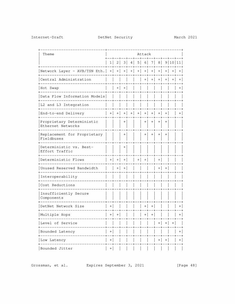
Internet-Draft DetNet Security March 2021
+----------------------------+--------------------------------+ | Theme | Attack | | +--+--+--+--+--+--+--+--+--+--+--+ | | 1| 2| 3| 4| 5| 6| 7| 8| 9|10|11| +----------------------------+--+--+--+--+--+--+--+--+--+--+--+ |Network Layer - AVB/TSN Eth.| +| +| +| +| +| +| +| +| +| +| +| +----------------------------+--+--+--+--+--+--+--+--+--+--+--+ |Central Administration | | | | | | +| +| +| +| +| +| +----------------------------+--+--+--+--+--+--+--+--+--+--+--+ |Hot Swap | | +| +| | | | | | | | +| +----------------------------+--+--+--+--+--+--+--+--+--+--+--+ |Data Flow Information Models| | | | | | | | | | | | +----------------------------+--+--+--+--+--+--+--+--+--+--+--+ |L2 and L3 Integration | | | | | | | | | | | | +----------------------------+--+--+--+--+--+--+--+--+--+--+--+ |End-to-end Delivery | +| +| +| +| +| +| +| +| +| | +| +----------------------------+--+--+--+--+--+--+--+--+--+--+--+ |Proprietary Deterministic | | | +| | | +| +| +| +| | | |Ethernet Networks | | | | | | | | | | | | +----------------------------+--+--+--+--+--+--+--+--+--+--+--+ |Replacement for Proprietary | | | +| | | +| +| +| +| | | |Fieldbuses | | | | | | | | | | | | +----------------------------+--+--+--+--+--+--+--+--+--+--+--+ |Deterministic vs. Best- | | | +| | | | | | | | | |Effort Traffic | | | | | | | | | | | | +----------------------------+--+--+--+--+--+--+--+--+--+--+--+ |Deterministic Flows | +| +| +| | +| +| | +| | | | +----------------------------+--+--+--+--+--+--+--+--+--+--+--+ |Unused Reserved Bandwidth | | +| +| | | | | +| +| | | +----------------------------+--+--+--+--+--+--+--+--+--+--+--+ |Interoperability | | | | | | | | | | | | +----------------------------+--+--+--+--+--+--+--+--+--+--+--+ |Cost Reductions | | | | | | | | | | | | +----------------------------+--+--+--+--+--+--+--+--+--+--+--+ |Insufficiently Secure | | | | | | | | | | | | |Components | | | | | | | | | | | | +----------------------------+--+--+--+--+--+--+--+--+--+--+--+ |DetNet Network Size | +| | | | | +| +| | | | +| +----------------------------+--+--+--+--+--+--+--+--+--+--+--+ |Multiple Hops | +| +| | | | +| +| | | | +| +----------------------------+--+--+--+--+--+--+--+--+--+--+--+ |Level of Service | | | | | | | | +| +| +| | +----------------------------+--+--+--+--+--+--+--+--+--+--+--+ |Bounded Latency | +| | | | | | | | | | +| +----------------------------+--+--+--+--+--+--+--+--+--+--+--+ |Low Latency | +| | | | | | | +| +| | +| +----------------------------+--+--+--+--+--+--+--+--+--+--+--+ |Bounded Jitter | +| | | | | | | | | | |
Grossman, et al. Expires September 3, 2021 [Page 48]

Internet-Draft DetNet Security March 2021
+----------------------------+--+--+--+--+--+--+--+--+--+--+--+ |Symmetric Path Delays | +| | | | | | | | | | +| +----------------------------+--+--+--+--+--+--+--+--+--+--+--+ |Reliability and Availability| +| +| +| +| +| +| +| +| +| +| +| +----------------------------+--+--+--+--+--+--+--+--+--+--+--+ |Redundant Paths | | | | +| +| | | +| +| | | +----------------------------+--+--+--+--+--+--+--+--+--+--+--+ |Security Measures | | | | | | | | | | | | +----------------------------+--+--+--+--+--+--+--+--+--+--+--+
Figure 5: Mapping Between Themes and Attacks
9. Security Considerations for OAM Traffic
This section considers DetNet-specific security considerations for packet traffic that is generated and transmitted over a DetNet as part of OAM (Operations, Administration, and Maintenance). For the purposes of this discussion, OAM traffic falls into one of two basic types:
o OAM traffic generated by the network itself. The additional bandwidth required for such packets is added by the network administration, presumably transparent to the customer. Security considerations for such traffic are not DetNet-specific (apart from such traffic being subject to the same DetNet-specific security considerations as any other DetNet data flow) and are thus not covered in this document.
o OAM traffic generated by the customer. From a DetNet security point of view, DetNet security considerations for such traffic are exactly the same as for any other customer data flows.
From the perspective of an attack, OAM traffic is indistinguishable from DetNet traffic and the network needs to be secure against injection, removal, or modification of traffic of any kind, including OAM traffic. A DetNet is sensitive to any form of packet injection, removal or manipulation and in this respect DetNet OAM traffic is no different. Techniques for securing a DetNet against these threats have been discussed elsewhere in this document.
10. DetNet Technology-Specific Threats
Section 5, Security Threats, described threats which are independent of a DetNet implementation. This section considers threats specifically related to the IP- and MPLS-specific aspects of DetNet implementations.
Grossman, et al. Expires September 3, 2021 [Page 49]

Internet-Draft DetNet Security March 2021
The primary security considerations for the data plane specifically are to maintain the integrity of the data and the delivery of the associated DetNet service traversing the DetNet network.
The primary relevant differences between IP and MPLS implementations are in flow identification and OAM methodologies.
As noted in [RFC8655], DetNet operates at the IP layer ( [RFC8939]) and delivers service over sub-layer technologies such as MPLS ([RFC8964]) and IEEE 802.1 Time-Sensitive Networking (TSN) ([I-D.ietf-detnet-ip-over-tsn]). Application flows can be protected through whatever means are provided by the layer and sub-layer technologies. For example, technology-specific encryption may be used, for example for IP flows, IPSec [RFC4301]. For IP over Ethernet (Layer 2) flows using an underlying sub-net, MACSec [IEEE802.1AE-2018] may be appropriate. For some use cases packet integrity protection without encryption may be sufficient.
However, if the DetNet nodes cannot decrypt IPsec traffic, then DetNet flow identification for encrypted IP traffic flows must be performed in a different way than it would be for unencrypted IP DetNet flows. The DetNet IP Data Plane identifies unencrypted flows via a 6-tuple that consists of two IP addresses, the transport protocol ID, two transport protocol port numbers and the DSCP in the IP header. When IPsec is used, the transport header is encrypted and the next protocol ID is an IPsec protocol, usually ESP, and not a transport protocol, leaving only three components of the 6-tuple, which are the two IP addresses and the DSCP. If the IPsec sessions are established by a controller, then this controller could also transmit (in the clear) the Security Parameter Index (SPI) and thus the SPI could be used (in addition to the pair of IP addresses) for flow identification. Identification of DetNet flows over IPsec is further discussed in Section 5.1.2.3. of [RFC8939].
Sections below discuss threats specific to IP and MPLS in more detail.
10.1. IP
The IP protocol has a long history of security considerations and architectural protection mechanisms. From a data plane perspective DetNet does not add or modify any IP header information, so the carriage of DetNet traffic over an IP data plane does not introduce any new security issues that were not there before, apart from those already described in the data-plane-independent threats section Section 5, Security Threats.
Grossman, et al. Expires September 3, 2021 [Page 50]
Internet-Draft DetNet Security March 2021
Thus the security considerations for a DetNet based on an IP data plane are purely inherited from the rich IP Security literature and code/application base, and the data-plane-independent section of this document.
Maintaining security for IP segments of a DetNet may be more challenging than for the MPLS segments of the network, given that the IP segments of the network may reach the edges of the network, which are more likely to involve interaction with potentially malevolent outside actors. Conversely MPLS is inherently more secure than IP since it is internal to routers and it is well-known how to protect it from outside influence.
Another way to look at DetNet IP security is to consider it in the light of VPN security; as an industry we have a lot of experience with VPNs running through networks with other VPNs, it is well known how to secure the network for that. However for a DetNet we have the additional subtlety that any possible interaction of one packet with another can have a potentially deleterious effect on the time properties of the flows. So the network must provide sufficient isolation between flows, for example by protecting the forwarding bandwidth and related resources so that they are available to detnet traffic, by whatever means are appropriate for the data plane of that network, for example through the use of queueing mechanisms.
In a VPN, bandwidth is generally guaranteed over a period of time, whereas in DetNet it is not aggregated over time. This implies that any VPN-type protection mechanism must also maintain the DetNet timing constraints.
10.2. MPLS
An MPLS network carrying DetNet traffic is expected to be a "well- managed" network. Given that this is the case, it is difficult for an attacker to pass a raw MPLS encoded packet into a network because operators have considerable experience at excluding such packets at the network boundaries, as well as excluding MPLS packets being inserted through the use of a tunnel.
MPLS security is discussed extensively in [RFC5920] ("Security Framework for MPLS and GMPLS Networks") to which the reader is referred.
[RFC6941] builds on [RFC5920] by providing additional security considerations that are applicable to the MPLS-TP extensions appropriate to the MPLS Transport Profile [RFC5921], and thus to the operation of DetNet over some types of MPLS network.
Grossman, et al. Expires September 3, 2021 [Page 51]
Internet-Draft DetNet Security March 2021
[RFC5921] introduces to MPLS new Operations, Administration, and Maintenance (OAM) capabilities, a transport-oriented path protection mechanism, and strong emphasis on static provisioning supported by network management systems.
The operation of DetNet over an MPLS network builds on MPLS and pseudowire encapsulation. Thus for guidance on securing the DetNet elements of DetNet over MPLS the reader is also referred to the security considerations of [RFC4385], [RFC5586], [RFC3985], [RFC6073], and [RFC6478].
Having attended to the conventional aspects of network security it is necessary to attend to the dynamic aspects. The closest experience that the IETF has with securing protocols that are sensitive to manipulation of delay are the two way time transfer protocols (TWTT), which are NTP [RFC5905] and Precision Time Protocol [IEEE1588]. The security requirements for these are described in [RFC7384].
One particular problem that has been observed in operational tests of TWTT protocols is the ability for two closely but not completely synchronized flows to beat and cause a sudden phase hit to one of the flows. This can be mitigated by the careful use of a scheduling system in the underlying packet transport.
Some investigations into protection of MPLS systems against dynamic attacks exist, such as [I-D.ietf-mpls-opportunistic-encrypt]; perhaps deployment of DetNets will encourage additional such investigations.
11. IANA Considerations
This document includes no requests from IANA.
12. Security Considerations
The security considerations of DetNet networks are presented throughout this document.
13. Privacy Considerations
Privacy in the context of DetNet is maintained by the base technologies specific to the DetNet and user traffic. For example TSN can use MACsec, IP can use IPsec, applications can use IP transport protocol-provided methods e.g. TLS and DTLS. MPLS typically uses L2/L3 VPNs combined with the previously mentioned privacy methods.
Grossman, et al. Expires September 3, 2021 [Page 52]

Internet-Draft DetNet Security March 2021
However, note that reconnaissance threats such as traffic analysis and monitoring of electrical side channels can still cause there to be privacy considerations even when traffic is encrypted.
14. Contributors
The Editor would like to recognize the contributions of the following individuals to this draft.
Subir Das (Applied Communication Sciences) 150 Mount Airy Road, Basking Ridge, New Jersey, 07920, USA email [email protected]
John Dowdell (Airbus Defence and Space) Celtic Springs, Newport, NP10 8FZ, United Kingdom email [email protected]
Henrik Austad (SINTEF Digital) Klaebuveien 153, Trondheim, 7037, Norway email [email protected]
Norman Finn (Huawei) 3101 Rio Way, Spring Valley, California 91977, USA email [email protected]
Stewart Bryant (Futurewei Technologies)
email: [email protected]
David Black (Dell EMC) 176 South Street, Hopkinton, MA 01748, USA email: [email protected]
Carsten Bormann (Universitat Bremen TZI) Postfach 330440, D-28359 Bremen, Germany email: [email protected]
15. References
15.1. Normative References
[RFC8655] Finn, N., Thubert, P., Varga, B., and J. Farkas, "Deterministic Networking Architecture", RFC 8655, DOI 10.17487/RFC8655, October 2019, <https://www.rfc-editor.org/info/rfc8655>.
Grossman, et al. Expires September 3, 2021 [Page 53]
Internet-Draft DetNet Security March 2021
[RFC8938] Varga, B., Ed., Farkas, J., Berger, L., Malis, A., and S. Bryant, "Deterministic Networking (DetNet) Data Plane Framework", RFC 8938, DOI 10.17487/RFC8938, November 2020, <https://www.rfc-editor.org/info/rfc8938>.
[RFC8939] Varga, B., Ed., Farkas, J., Berger, L., Fedyk, D., and S. Bryant, "Deterministic Networking (DetNet) Data Plane: IP", RFC 8939, DOI 10.17487/RFC8939, November 2020, <https://www.rfc-editor.org/info/rfc8939>.
[RFC8964] Varga, B., Ed., Farkas, J., Berger, L., Malis, A., Bryant, S., and J. Korhonen, "Deterministic Networking (DetNet) Data Plane: MPLS", RFC 8964, DOI 10.17487/RFC8964, January 2021, <https://www.rfc-editor.org/info/rfc8964>.
15.2. Informative References
[ARINC664P7] ARINC, "ARINC 664 Aircraft Data Network, Part 7, Avionics Full-Duplex Switched Ethernet Network", 2009.
[I-D.ietf-detnet-flow-information-model] Varga, B., Farkas, J., Cummings, R., Jiang, Y., and D. Fedyk, "DetNet Flow and Service Information Model", draft- ietf-detnet-flow-information-model-14 (work in progress), January 2021.
[I-D.ietf-detnet-ip-oam] Mirsky, G., Chen, M., and D. Black, "Operations, Administration and Maintenance (OAM) for Deterministic Networks (DetNet) with IP Data Plane", draft-ietf-detnet- ip-oam-01 (work in progress), January 2021.
[I-D.ietf-detnet-ip-over-mpls] Varga, B., Berger, L., Fedyk, D., Bryant, S., and J. Korhonen, "DetNet Data Plane: IP over MPLS", draft-ietf- detnet-ip-over-mpls-09 (work in progress), October 2020.
[I-D.ietf-detnet-ip-over-tsn] Varga, B., Farkas, J., Malis, A., and S. Bryant, "DetNet Data Plane: IP over IEEE 802.1 Time Sensitive Networking (TSN)", draft-ietf-detnet-ip-over-tsn-05 (work in progress), December 2020.
Grossman, et al. Expires September 3, 2021 [Page 54]

Internet-Draft DetNet Security March 2021
[I-D.ietf-detnet-mpls-oam] Mirsky, G. and M. Chen, "Operations, Administration and Maintenance (OAM) for Deterministic Networks (DetNet) with MPLS Data Plane", draft-ietf-detnet-mpls-oam-02 (work in progress), January 2021.
[I-D.ietf-detnet-mpls-over-udp-ip] Varga, B., Farkas, J., Berger, L., Malis, A., and S. Bryant, "DetNet Data Plane: MPLS over UDP/IP", draft-ietf- detnet-mpls-over-udp-ip-08 (work in progress), December 2020.
[I-D.ietf-detnet-yang] Geng, X., Chen, M., Ryoo, Y., Fedyk, D., Rahman, R., and Z. Li, "Deterministic Networking (DetNet) Configuration YANG Model", draft-ietf-detnet-yang-09 (work in progress), November 2020.
[I-D.ietf-ipsecme-g-ikev2] Smyslov, V. and B. Weis, "Group Key Management using IKEv2", draft-ietf-ipsecme-g-ikev2-02 (work in progress), January 2021.
[I-D.ietf-mpls-opportunistic-encrypt] Farrel, A. and S. Farrell, "Opportunistic Security in MPLS Networks", draft-ietf-mpls-opportunistic-encrypt-03 (work in progress), March 2017.
[I-D.varga-detnet-service-model] Varga, B. and J. Farkas, "DetNet Service Model", draft- varga-detnet-service-model-02 (work in progress), May 2017.
[IEEE1588] IEEE, "IEEE 1588 Standard for a Precision Clock Synchronization Protocol for Networked Measurement and Control Systems Version 2", 2008.
[IEEE802.1AE-2018] IEEE Standards Association, "IEEE Std 802.1AE-2018 MAC Security (MACsec)", 2018, <https://ieeexplore.ieee.org/document/8585421>.
[IEEE802.1BA] IEEE Standards Association, "IEEE Standard for Local and Metropolitan Area Networks -- Audio Video Bridging (AVB) Systems", 2011, <https://ieeexplore.ieee.org/document/6032690>.
Grossman, et al. Expires September 3, 2021 [Page 55]
Internet-Draft DetNet Security March 2021
[IEEE802.1Q] IEEE Standards Association, "IEEE Standard for Local and metropolitan area networks--Bridges and Bridged Networks - Annex J - Connectivity Fault Management", 2014, <https://ieeexplore.ieee.org/document/6991462>.
[IEEE802.1Qbv-2015] IEEE Standards Association, "IEEE Standard for Local and metropolitan area networks -- Bridges and Bridged Networks - Amendment 25: Enhancements for Scheduled Traffic", 2015, <https://ieeexplore.ieee.org/document/8613095>.
[IEEE802.1Qch-2017] IEEE Standards Association, "IEEE Standard for Local and metropolitan area networks--Bridges and Bridged Networks-- Amendment 29: Cyclic Queuing and Forwarding", 2017, <https://ieeexplore.ieee.org/document/7961303>.
[IETF_YANG_SEC] IETF, "YANG Module Security Considerations", 2018, <https://trac.ietf.org/trac/ops/wiki/yang-security- guidelines>.
[IT_DEF] Wikipedia, "IT Definition", 2020, <https://en.wikiquote.org/wiki/Information_technology>.
[OT_DEF] Wikipedia, "OT Definition", 2020, <https://en.wikipedia.org/wiki/Operational_technology>.
[RFC2474] Nichols, K., Blake, S., Baker, F., and D. Black, "Definition of the Differentiated Services Field (DS Field) in the IPv4 and IPv6 Headers", RFC 2474, DOI 10.17487/RFC2474, December 1998, <https://www.rfc-editor.org/info/rfc2474>.
[RFC2475] Blake, S., Black, D., Carlson, M., Davies, E., Wang, Z., and W. Weiss, "An Architecture for Differentiated Services", RFC 2475, DOI 10.17487/RFC2475, December 1998, <https://www.rfc-editor.org/info/rfc2475>.
[RFC3552] Rescorla, E. and B. Korver, "Guidelines for Writing RFC Text on Security Considerations", BCP 72, RFC 3552, DOI 10.17487/RFC3552, July 2003, <https://www.rfc-editor.org/info/rfc3552>.
Grossman, et al. Expires September 3, 2021 [Page 56]

Internet-Draft DetNet Security March 2021
[RFC3985] Bryant, S., Ed. and P. Pate, Ed., "Pseudo Wire Emulation Edge-to-Edge (PWE3) Architecture", RFC 3985, DOI 10.17487/RFC3985, March 2005, <https://www.rfc-editor.org/info/rfc3985>.
[RFC4107] Bellovin, S. and R. Housley, "Guidelines for Cryptographic Key Management", BCP 107, RFC 4107, DOI 10.17487/RFC4107, June 2005, <https://www.rfc-editor.org/info/rfc4107>.
[RFC4253] Ylonen, T. and C. Lonvick, Ed., "The Secure Shell (SSH) Transport Layer Protocol", RFC 4253, DOI 10.17487/RFC4253, January 2006, <https://www.rfc-editor.org/info/rfc4253>.
[RFC4301] Kent, S. and K. Seo, "Security Architecture for the Internet Protocol", RFC 4301, DOI 10.17487/RFC4301, December 2005, <https://www.rfc-editor.org/info/rfc4301>.
[RFC4302] Kent, S., "IP Authentication Header", RFC 4302, DOI 10.17487/RFC4302, December 2005, <https://www.rfc-editor.org/info/rfc4302>.
[RFC4385] Bryant, S., Swallow, G., Martini, L., and D. McPherson, "Pseudowire Emulation Edge-to-Edge (PWE3) Control Word for Use over an MPLS PSN", RFC 4385, DOI 10.17487/RFC4385, February 2006, <https://www.rfc-editor.org/info/rfc4385>.
[RFC4432] Harris, B., "RSA Key Exchange for the Secure Shell (SSH) Transport Layer Protocol", RFC 4432, DOI 10.17487/RFC4432, March 2006, <https://www.rfc-editor.org/info/rfc4432>.
[RFC5586] Bocci, M., Ed., Vigoureux, M., Ed., and S. Bryant, Ed., "MPLS Generic Associated Channel", RFC 5586, DOI 10.17487/RFC5586, June 2009, <https://www.rfc-editor.org/info/rfc5586>.
[RFC5880] Katz, D. and D. Ward, "Bidirectional Forwarding Detection (BFD)", RFC 5880, DOI 10.17487/RFC5880, June 2010, <https://www.rfc-editor.org/info/rfc5880>.
[RFC5905] Mills, D., Martin, J., Ed., Burbank, J., and W. Kasch, "Network Time Protocol Version 4: Protocol and Algorithms Specification", RFC 5905, DOI 10.17487/RFC5905, June 2010, <https://www.rfc-editor.org/info/rfc5905>.
[RFC5920] Fang, L., Ed., "Security Framework for MPLS and GMPLS Networks", RFC 5920, DOI 10.17487/RFC5920, July 2010, <https://www.rfc-editor.org/info/rfc5920>.
Grossman, et al. Expires September 3, 2021 [Page 57]

Internet-Draft DetNet Security March 2021
[RFC5921] Bocci, M., Ed., Bryant, S., Ed., Frost, D., Ed., Levrau, L., and L. Berger, "A Framework for MPLS in Transport Networks", RFC 5921, DOI 10.17487/RFC5921, July 2010, <https://www.rfc-editor.org/info/rfc5921>.
[RFC6071] Frankel, S. and S. Krishnan, "IP Security (IPsec) and Internet Key Exchange (IKE) Document Roadmap", RFC 6071, DOI 10.17487/RFC6071, February 2011, <https://www.rfc-editor.org/info/rfc6071>.
[RFC6073] Martini, L., Metz, C., Nadeau, T., Bocci, M., and M. Aissaoui, "Segmented Pseudowire", RFC 6073, DOI 10.17487/RFC6073, January 2011, <https://www.rfc-editor.org/info/rfc6073>.
[RFC6274] Gont, F., "Security Assessment of the Internet Protocol Version 4", RFC 6274, DOI 10.17487/RFC6274, July 2011, <https://www.rfc-editor.org/info/rfc6274>.
[RFC6478] Martini, L., Swallow, G., Heron, G., and M. Bocci, "Pseudowire Status for Static Pseudowires", RFC 6478, DOI 10.17487/RFC6478, May 2012, <https://www.rfc-editor.org/info/rfc6478>.
[RFC6562] Perkins, C. and JM. Valin, "Guidelines for the Use of Variable Bit Rate Audio with Secure RTP", RFC 6562, DOI 10.17487/RFC6562, March 2012, <https://www.rfc-editor.org/info/rfc6562>.
[RFC6632] Ersue, M., Ed. and B. Claise, "An Overview of the IETF Network Management Standards", RFC 6632, DOI 10.17487/RFC6632, June 2012, <https://www.rfc-editor.org/info/rfc6632>.
[RFC6941] Fang, L., Ed., Niven-Jenkins, B., Ed., Mansfield, S., Ed., and R. Graveman, Ed., "MPLS Transport Profile (MPLS-TP) Security Framework", RFC 6941, DOI 10.17487/RFC6941, April 2013, <https://www.rfc-editor.org/info/rfc6941>.
[RFC7384] Mizrahi, T., "Security Requirements of Time Protocols in Packet Switched Networks", RFC 7384, DOI 10.17487/RFC7384, October 2014, <https://www.rfc-editor.org/info/rfc7384>.
[RFC7567] Baker, F., Ed. and G. Fairhurst, Ed., "IETF Recommendations Regarding Active Queue Management", BCP 197, RFC 7567, DOI 10.17487/RFC7567, July 2015, <https://www.rfc-editor.org/info/rfc7567>.
Grossman, et al. Expires September 3, 2021 [Page 58]

Internet-Draft DetNet Security March 2021
[RFC7641] Hartke, K., "Observing Resources in the Constrained Application Protocol (CoAP)", RFC 7641, DOI 10.17487/RFC7641, September 2015, <https://www.rfc-editor.org/info/rfc7641>.
[RFC7748] Langley, A., Hamburg, M., and S. Turner, "Elliptic Curves for Security", RFC 7748, DOI 10.17487/RFC7748, January 2016, <https://www.rfc-editor.org/info/rfc7748>.
[RFC7835] Saucez, D., Iannone, L., and O. Bonaventure, "Locator/ID Separation Protocol (LISP) Threat Analysis", RFC 7835, DOI 10.17487/RFC7835, April 2016, <https://www.rfc-editor.org/info/rfc7835>.
[RFC8446] Rescorla, E., "The Transport Layer Security (TLS) Protocol Version 1.3", RFC 8446, DOI 10.17487/RFC8446, August 2018, <https://www.rfc-editor.org/info/rfc8446>.
[RFC8578] Grossman, E., Ed., "Deterministic Networking Use Cases", RFC 8578, DOI 10.17487/RFC8578, May 2019, <https://www.rfc-editor.org/info/rfc8578>.
[RS_DEF] Wikipedia, "RS Definition", 2020, <https://en.wikipedia.org/wiki/Network_segmentation>.
Authors’ Addresses
Ethan Grossman (editor) Dolby Laboratories, Inc. 1275 Market Street San Francisco, CA 94103 USA
Phone: +1 415 465 4339 Email: [email protected] URI: http://www.dolby.com
Tal Mizrahi Huawei Network.IO Innovation Lab
Email: [email protected]
Grossman, et al. Expires September 3, 2021 [Page 59]

Internet-Draft DetNet Security March 2021
Andrew J. Hacker MistIQ Technologies, Inc Harrisburg, PA USA
Email: [email protected]
Grossman, et al. Expires September 3, 2021 [Page 60]
Internet Engineering Task Force E. Grossman, Ed.Internet-Draft DOLBYIntended status: Informational December 19, 2018Expires: June 22, 2019
Deterministic Networking Use Cases draft-ietf-detnet-use-cases-20
Abstract
This draft presents use cases from diverse industries which have in common a need for "deterministic flows". "Deterministic" in this context means that such flows provide guaranteed bandwidth, bounded latency, and other properties germane to the transport of time- sensitive data. These use cases differ notably in their network topologies and specific desired behavior, providing as a group broad industry context for DetNet. For each use case, this document will identify the use case, identify representative solutions used today, and describe potential improvements that DetNet can enable. The Use Case Common Themes section then extracts and enumerates the set of common properties implied by these use cases.
Status of This Memo
This Internet-Draft is submitted in full conformance with the provisions of BCP 78 and BCP 79.
Internet-Drafts are working documents of the Internet Engineering Task Force (IETF). Note that other groups may also distribute working documents as Internet-Drafts. The list of current Internet- Drafts is at https://datatracker.ietf.org/drafts/current/.
Internet-Drafts are draft documents valid for a maximum of six months and may be updated, replaced, or obsoleted by other documents at any time. It is inappropriate to use Internet-Drafts as reference material or to cite them other than as "work in progress."
This Internet-Draft will expire on June 22, 2019.
Copyright Notice
Copyright (c) 2018 IETF Trust and the persons identified as the document authors. All rights reserved.
This document is subject to BCP 78 and the IETF Trust’s Legal Provisions Relating to IETF Documents (https://trustee.ietf.org/license-info) in effect on the date of
Grossman Expires June 22, 2019 [Page 1]

Internet-Draft DetNet Use Cases December 2018
publication of this document. Please review these documents carefully, as they describe your rights and restrictions with respect to this document. Code Components extracted from this document must include Simplified BSD License text as described in Section 4.e of the Trust Legal Provisions and are provided without warranty as described in the Simplified BSD License.
Table of Contents
1. Introduction . . . . . . . . . . . . . . . . . . . . . . . . 5 2. Pro Audio and Video . . . . . . . . . . . . . . . . . . . . . 7 2.1. Use Case Description . . . . . . . . . . . . . . . . . . 7 2.1.1. Uninterrupted Stream Playback . . . . . . . . . . . . 7 2.1.2. Synchronized Stream Playback . . . . . . . . . . . . 8 2.1.3. Sound Reinforcement . . . . . . . . . . . . . . . . . 8 2.1.4. Secure Transmission . . . . . . . . . . . . . . . . . 9 2.1.4.1. Safety . . . . . . . . . . . . . . . . . . . . . 9 2.2. Pro Audio Today . . . . . . . . . . . . . . . . . . . . . 9 2.3. Pro Audio Future . . . . . . . . . . . . . . . . . . . . 9 2.3.1. Layer 3 Interconnecting Layer 2 Islands . . . . . . . 9 2.3.2. High Reliability Stream Paths . . . . . . . . . . . . 10 2.3.3. Integration of Reserved Streams into IT Networks . . 10 2.3.4. Use of Unused Reservations by Best-Effort Traffic . . 10 2.3.5. Traffic Segregation . . . . . . . . . . . . . . . . . 11 2.3.5.1. Packet Forwarding Rules, VLANs and Subnets . . . 11 2.3.5.2. Multicast Addressing (IPv4 and IPv6) . . . . . . 11 2.3.6. Latency Optimization by a Central Controller . . . . 12 2.3.7. Reduced Device Cost Due To Reduced Buffer Memory . . 12 2.4. Pro Audio Asks . . . . . . . . . . . . . . . . . . . . . 12 3. Electrical Utilities . . . . . . . . . . . . . . . . . . . . 13 3.1. Use Case Description . . . . . . . . . . . . . . . . . . 13 3.1.1. Transmission Use Cases . . . . . . . . . . . . . . . 13 3.1.1.1. Protection . . . . . . . . . . . . . . . . . . . 13 3.1.1.2. Intra-Substation Process Bus Communications . . . 18 3.1.1.3. Wide Area Monitoring and Control Systems . . . . 19 3.1.1.4. IEC 61850 WAN engineering guidelines requirement classification . . . . . . . . . . . . . . . . . 20 3.1.2. Generation Use Case . . . . . . . . . . . . . . . . . 21 3.1.2.1. Control of the Generated Power . . . . . . . . . 21 3.1.2.2. Control of the Generation Infrastructure . . . . 22 3.1.3. Distribution use case . . . . . . . . . . . . . . . . 27 3.1.3.1. Fault Location Isolation and Service Restoration (FLISR) . . . . . . . . . . . . . . . . . . . . . 27 3.2. Electrical Utilities Today . . . . . . . . . . . . . . . 28 3.2.1. Security Current Practices and Limitations . . . . . 28 3.3. Electrical Utilities Future . . . . . . . . . . . . . . . 30 3.3.1. Migration to Packet-Switched Network . . . . . . . . 31 3.3.2. Telecommunications Trends . . . . . . . . . . . . . . 31
Grossman Expires June 22, 2019 [Page 2]

Internet-Draft DetNet Use Cases December 2018
3.3.2.1. General Telecommunications Requirements . . . . . 31 3.3.2.2. Specific Network topologies of Smart Grid Applications . . . . . . . . . . . . . . . . . . 32 3.3.2.3. Precision Time Protocol . . . . . . . . . . . . . 33 3.3.3. Security Trends in Utility Networks . . . . . . . . . 34 3.4. Electrical Utilities Asks . . . . . . . . . . . . . . . . 36 4. Building Automation Systems . . . . . . . . . . . . . . . . . 36 4.1. Use Case Description . . . . . . . . . . . . . . . . . . 36 4.2. Building Automation Systems Today . . . . . . . . . . . . 37 4.2.1. BAS Architecture . . . . . . . . . . . . . . . . . . 37 4.2.2. BAS Deployment Model . . . . . . . . . . . . . . . . 38 4.2.3. Use Cases for Field Networks . . . . . . . . . . . . 40 4.2.3.1. Environmental Monitoring . . . . . . . . . . . . 40 4.2.3.2. Fire Detection . . . . . . . . . . . . . . . . . 40 4.2.3.3. Feedback Control . . . . . . . . . . . . . . . . 41 4.2.4. Security Considerations . . . . . . . . . . . . . . . 41 4.3. BAS Future . . . . . . . . . . . . . . . . . . . . . . . 41 4.4. BAS Asks . . . . . . . . . . . . . . . . . . . . . . . . 42 5. Wireless for Industrial Applications . . . . . . . . . . . . 42 5.1. Use Case Description . . . . . . . . . . . . . . . . . . 42 5.1.1. Network Convergence using 6TiSCH . . . . . . . . . . 43 5.1.2. Common Protocol Development for 6TiSCH . . . . . . . 43 5.2. Wireless Industrial Today . . . . . . . . . . . . . . . . 44 5.3. Wireless Industrial Future . . . . . . . . . . . . . . . 44 5.3.1. Unified Wireless Network and Management . . . . . . . 44 5.3.1.1. PCE and 6TiSCH ARQ Retries . . . . . . . . . . . 46 5.3.2. Schedule Management by a PCE . . . . . . . . . . . . 47 5.3.2.1. PCE Commands and 6TiSCH CoAP Requests . . . . . . 47 5.3.2.2. 6TiSCH IP Interface . . . . . . . . . . . . . . . 48 5.3.3. 6TiSCH Security Considerations . . . . . . . . . . . 49 5.4. Wireless Industrial Asks . . . . . . . . . . . . . . . . 49 6. Cellular Radio . . . . . . . . . . . . . . . . . . . . . . . 49 6.1. Use Case Description . . . . . . . . . . . . . . . . . . 49 6.1.1. Network Architecture . . . . . . . . . . . . . . . . 49 6.1.2. Delay Constraints . . . . . . . . . . . . . . . . . . 50 6.1.3. Time Synchronization Constraints . . . . . . . . . . 52 6.1.4. Transport Loss Constraints . . . . . . . . . . . . . 54 6.1.5. Security Considerations . . . . . . . . . . . . . . . 54 6.2. Cellular Radio Networks Today . . . . . . . . . . . . . . 55 6.2.1. Fronthaul . . . . . . . . . . . . . . . . . . . . . . 55 6.2.2. Midhaul and Backhaul . . . . . . . . . . . . . . . . 55 6.3. Cellular Radio Networks Future . . . . . . . . . . . . . 56 6.4. Cellular Radio Networks Asks . . . . . . . . . . . . . . 58 7. Industrial Machine to Machine (M2M) . . . . . . . . . . . . . 59 7.1. Use Case Description . . . . . . . . . . . . . . . . . . 59 7.2. Industrial M2M Communication Today . . . . . . . . . . . 60 7.2.1. Transport Parameters . . . . . . . . . . . . . . . . 60 7.2.2. Stream Creation and Destruction . . . . . . . . . . . 61
Grossman Expires June 22, 2019 [Page 3]
Internet-Draft DetNet Use Cases December 2018
7.3. Industrial M2M Future . . . . . . . . . . . . . . . . . . 61 7.4. Industrial M2M Asks . . . . . . . . . . . . . . . . . . . 62 8. Mining Industry . . . . . . . . . . . . . . . . . . . . . . . 62 8.1. Use Case Description . . . . . . . . . . . . . . . . . . 62 8.2. Mining Industry Today . . . . . . . . . . . . . . . . . . 63 8.3. Mining Industry Future . . . . . . . . . . . . . . . . . 63 8.4. Mining Industry Asks . . . . . . . . . . . . . . . . . . 64 9. Private Blockchain . . . . . . . . . . . . . . . . . . . . . 64 9.1. Use Case Description . . . . . . . . . . . . . . . . . . 64 9.1.1. Blockchain Operation . . . . . . . . . . . . . . . . 65 9.1.2. Blockchain Network Architecture . . . . . . . . . . . 65 9.1.3. Security Considerations . . . . . . . . . . . . . . . 66 9.2. Private Blockchain Today . . . . . . . . . . . . . . . . 66 9.3. Private Blockchain Future . . . . . . . . . . . . . . . . 66 9.4. Private Blockchain Asks . . . . . . . . . . . . . . . . . 67 10. Network Slicing . . . . . . . . . . . . . . . . . . . . . . . 67 10.1. Use Case Description . . . . . . . . . . . . . . . . . . 67 10.2. DetNet Applied to Network Slicing . . . . . . . . . . . 67 10.2.1. Resource Isolation Across Slices . . . . . . . . . . 67 10.2.2. Deterministic Services Within Slices . . . . . . . . 68 10.3. A Network Slicing Use Case Example - 5G Bearer Network . 68 10.4. Non-5G Applications of Network Slicing . . . . . . . . . 69 10.5. Limitations of DetNet in Network Slicing . . . . . . . . 69 10.6. Network Slicing Today and Future . . . . . . . . . . . . 69 10.7. Network Slicing Asks . . . . . . . . . . . . . . . . . . 69 11. Use Case Common Themes . . . . . . . . . . . . . . . . . . . 69 11.1. Unified, standards-based network . . . . . . . . . . . . 70 11.1.1. Extensions to Ethernet . . . . . . . . . . . . . . . 70 11.1.2. Centrally Administered . . . . . . . . . . . . . . . 70 11.1.3. Standardized Data Flow Information Models . . . . . 70 11.1.4. L2 and L3 Integration . . . . . . . . . . . . . . . 70 11.1.5. Consideration for IPv4 . . . . . . . . . . . . . . . 70 11.1.6. Guaranteed End-to-End Delivery . . . . . . . . . . . 71 11.1.7. Replacement for Multiple Proprietary Deterministic Networks . . . . . . . . . . . . . . . . . . . . . . 71 11.1.8. Mix of Deterministic and Best-Effort Traffic . . . . 71 11.1.9. Unused Reserved BW to be Available to Best-Effort Traffic . . . . . . . . . . . . . . . . . . . . . . 71 11.1.10. Lower Cost, Multi-Vendor Solutions . . . . . . . . . 71 11.2. Scalable Size . . . . . . . . . . . . . . . . . . . . . 71 11.2.1. Scalable Number of Flows . . . . . . . . . . . . . . 72 11.3. Scalable Timing Parameters and Accuracy . . . . . . . . 72 11.3.1. Bounded Latency . . . . . . . . . . . . . . . . . . 72 11.3.2. Low Latency . . . . . . . . . . . . . . . . . . . . 72 11.3.3. Bounded Jitter (Latency Variation) . . . . . . . . . 72 11.3.4. Symmetrical Path Delays . . . . . . . . . . . . . . 72 11.4. High Reliability and Availability . . . . . . . . . . . 73 11.5. Security . . . . . . . . . . . . . . . . . . . . . . . . 73
Grossman Expires June 22, 2019 [Page 4]
Internet-Draft DetNet Use Cases December 2018
11.6. Deterministic Flows . . . . . . . . . . . . . . . . . . 73 12. Security Considerations . . . . . . . . . . . . . . . . . . . 73 13. Contributors . . . . . . . . . . . . . . . . . . . . . . . . 74 14. Acknowledgments . . . . . . . . . . . . . . . . . . . . . . . 75 14.1. Pro Audio . . . . . . . . . . . . . . . . . . . . . . . 75 14.2. Utility Telecom . . . . . . . . . . . . . . . . . . . . 76 14.3. Building Automation Systems . . . . . . . . . . . . . . 76 14.4. Wireless for Industrial Applications . . . . . . . . . . 76 14.5. Cellular Radio . . . . . . . . . . . . . . . . . . . . . 76 14.6. Industrial Machine to Machine (M2M) . . . . . . . . . . 77 14.7. Internet Applications and CoMP . . . . . . . . . . . . . 77 14.8. Network Slicing . . . . . . . . . . . . . . . . . . . . 77 14.9. Mining . . . . . . . . . . . . . . . . . . . . . . . . . 77 14.10. Private Blockchain . . . . . . . . . . . . . . . . . . . 77 15. IANA Considerations . . . . . . . . . . . . . . . . . . . . . 77 16. Informative References . . . . . . . . . . . . . . . . . . . 77 Appendix A. Use Cases Explicitly Out of Scope for DetNet . . . . 84 A.1. DetNet Scope Limitations . . . . . . . . . . . . . . . . 85 A.2. Internet-based Applications . . . . . . . . . . . . . . . 85 A.2.1. Use Case Description . . . . . . . . . . . . . . . . 86 A.2.1.1. Media Content Delivery . . . . . . . . . . . . . 86 A.2.1.2. Online Gaming . . . . . . . . . . . . . . . . . . 86 A.2.1.3. Virtual Reality . . . . . . . . . . . . . . . . . 86 A.2.2. Internet-Based Applications Today . . . . . . . . . . 86 A.2.3. Internet-Based Applications Future . . . . . . . . . 86 A.2.4. Internet-Based Applications Asks . . . . . . . . . . 86 A.3. Pro Audio and Video - Digital Rights Management (DRM) . . 87 A.4. Pro Audio and Video - Link Aggregation . . . . . . . . . 87 A.5. Pro Audio and Video - Deterministic Time to Establish Streaming . . . . . . . . . . . . . . . . . . . . . . . . 87 Author’s Address . . . . . . . . . . . . . . . . . . . . . . . . 88
1. Introduction
This draft documents use cases in diverse industries which require deterministic flows over multi-hop paths. DetNet flows can be established from either a Layer 2 or Layer 3 (IP) interface, and such flows can co-exist on an IP network with best-effort traffic. DetNet also provides for highly reliable flows through provision for redundant paths.
The DetNet Use Cases explicitly do not suggest any specific design for DetNet architecture or protocols; these are topics of other DetNet drafts.
The DetNet use cases as originally submitted explicitly were not considered by the DetNet Working Group to be concrete requirements; The DetNet Working Group and Design Team considered these use cases,
Grossman Expires June 22, 2019 [Page 5]

Internet-Draft DetNet Use Cases December 2018
identifying which elements of them could be feasibly implemented within the charter of DetNet, and as a result certain of the originally submitted use cases (or elements of them) have been be moved to the Use Cases Explicitly Out of Scope for DetNet section.
The DetNet Use Cases document provide context regarding DetNet design decisions. It also serves a long-lived purpose of helping those learning (or new to) DetNet to understand the types of applications that can be supported by DetNet. It also allow those WG contributors who are users to ensure that their concerns are addressed by the WG; for them this document both covers their contribution and provides a long term reference to the problems they expect to be served by the technology, both in the short term deliverables and as the technology evolves in the future.
The DetNet Use Cases document has served as a "yardstick" against which proposed DetNet designs can be measured, answering the question "to what extent does a proposed design satisfy these various use cases?"
The Use Case industries covered are professional audio, electrical utilities, building automation systems, wireless for industrial applications, cellular radio, industrial machine-to-machine, mining, private blockchain, and network slicing. For each use case the following questions are answered:
o What is the use case?
o How is it addressed today?
o How should it be addressed in the future?
o What should the IETF deliver to enable this use case?
The level of detail in each use case is intended to be sufficient to express the relevant elements of the use case, but not greater than that.
DetNet does not directly address clock distribution or time synchronization; these are considered to be part of the overall design and implementation of a time-sensitive network, using existing (or future) time-specific protocols (such as [IEEE8021AS] and/or [RFC5905]).
Grossman Expires June 22, 2019 [Page 6]

Internet-Draft DetNet Use Cases December 2018
2. Pro Audio and Video
2.1. Use Case Description
The professional audio and video industry ("ProAV") includes:
o Music and film content creation
o Broadcast
o Cinema
o Live sound
o Public address, media and emergency systems at large venues (airports, stadiums, churches, theme parks).
These industries have already transitioned audio and video signals from analog to digital. However, the digital interconnect systems remain primarily point-to-point with a single (or small number of) signals per link, interconnected with purpose-built hardware.
These industries are now transitioning to packet-based infrastructure to reduce cost, increase routing flexibility, and integrate with existing IT infrastructure.
Today ProAV applications have no way to establish deterministic flows from a standards-based Layer 3 (IP) interface, which is a fundamental limitation to the use cases described here. Today deterministic flows can be created within standards-based layer 2 LANs (e.g. using IEEE 802.1 AVB) however these are not routable via IP and thus are not effective for distribution over wider areas (for example broadcast events that span wide geographical areas).
It would be highly desirable if such flows could be routed over the open Internet, however solutions with more limited scope (e.g. enterprise networks) would still provide a substantial improvement.
The following sections describe specific ProAV use cases.
2.1.1. Uninterrupted Stream Playback
Transmitting audio and video streams for live playback is unlike common file transfer because uninterrupted stream playback in the presence of network errors cannot be achieved by re-trying the transmission; by the time the missing or corrupt packet has been identified it is too late to execute a re-try operation. Buffering can be used to provide enough delay to allow time for one or more
Grossman Expires June 22, 2019 [Page 7]
Internet-Draft DetNet Use Cases December 2018
retries, however this is not an effective solution in applications where large delays (latencies) are not acceptable (as discussed below).
Streams with guaranteed bandwidth can eliminate congestion on the network as a cause of transmission errors that would lead to playback interruption. Use of redundant paths can further mitigate transmission errors to provide greater stream reliability.
Additional techniques such as forward error correction can also be used to improve stream reliability.
2.1.2. Synchronized Stream Playback
Latency in this context is the time between when a signal is initially sent over a stream and when it is received. A common example in ProAV is time-synchronizing audio and video when they take separate paths through the playback system. In this case the latency of both the audio and video streams must be bounded and consistent if the sound is to remain matched to the movement in the video. A common tolerance for audio/video sync is one NTSC video frame (about 33ms) and to maintain the audience perception of correct lip sync the latency needs to be consistent within some reasonable tolerance, for example 10%.
A common architecture for synchronizing multiple streams that have different paths through the network (and thus potentially different latencies) is to enable measurement of the latency of each path, and have the data sinks (for example speakers) delay (buffer) all packets on all but the slowest path. Each packet of each stream is assigned a presentation time which is based on the longest required delay. This implies that all sinks must maintain a common time reference of sufficient accuracy, which can be achieved by any of various techniques.
This type of architecture is commonly implemented using a central controller that determines path delays and arbitrates buffering delays.
2.1.3. Sound Reinforcement
Consider the latency (delay) from when a person speaks into a microphone to when their voice emerges from the speaker. If this delay is longer than about 10-15 milliseconds it is noticeable and can make a sound reinforcement system unusable (see slide 6 of [SRP_LATENCY]). (If you have ever tried to speak in the presence of a delayed echo of your voice you may know this experience).
Grossman Expires June 22, 2019 [Page 8]

Internet-Draft DetNet Use Cases December 2018
Note that the 15ms latency bound includes all parts of the signal path, not just the network, so the network latency must be significantly less than 15ms.
In some cases local performers must perform in synchrony with a remote broadcast. In such cases the latencies of the broadcast stream and the local performer must be adjusted to match each other, with a worst case of one video frame (33ms for NTSC video).
In cases where audio phase is a consideration, for example beam- forming using multiple speakers, latency can be in the 10 microsecond range (1 audio sample at 96kHz).
2.1.4. Secure Transmission
2.1.4.1. Safety
Professional audio systems can include amplifiers that are capable of generating hundreds or thousands of watts of audio power which if used incorrectly can cause hearing damage to those in the vicinity. Apart from the usual care required by the systems operators to prevent such incidents, the network traffic that controls these devices must be secured (as with any sensitive application traffic).
2.2. Pro Audio Today
Some proprietary systems have been created which enable deterministic streams at Layer 3 however they are "engineered networks" which require careful configuration to operate, often require that the system be over-provisioned, and it is implied that all devices on the network voluntarily play by the rules of that network. To enable these industries to successfully transition to an interoperable multi-vendor packet-based infrastructure requires effective open standards, and establishing relevant IETF standards is a crucial factor.
2.3. Pro Audio Future
2.3.1. Layer 3 Interconnecting Layer 2 Islands
It would be valuable to enable IP to connect multiple Layer 2 LANs.
As an example, ESPN constructed a state-of-the-art 194,000 sq ft, $125 million broadcast studio called DC2. The DC2 network is capable of handling 46 Tbps of throughput with 60,000 simultaneous signals. Inside the facility are 1,100 miles of fiber feeding four audio control rooms (see [ESPN_DC2] ).
Grossman Expires June 22, 2019 [Page 9]

Internet-Draft DetNet Use Cases December 2018
In designing DC2 they replaced as much point-to-point technology as they could with packet-based technology. They constructed seven individual studios using layer 2 LANS (using IEEE 802.1 AVB) that were entirely effective at routing audio within the LANs. However to interconnect these layer 2 LAN islands together they ended up using dedicated paths in a custom SDN (Software Defined Networking) router because there is no standards-based routing solution available.
2.3.2. High Reliability Stream Paths
On-air and other live media streams are often backed up with redundant links that seamlessly act to deliver the content when the primary link fails for any reason. In point-to-point systems this is provided by an additional point-to-point link; the analogous requirement in a packet-based system is to provide an alternate path through the network such that no individual link can bring down the system.
2.3.3. Integration of Reserved Streams into IT Networks
A commonly cited goal of moving to a packet based media infrastructure is that costs can be reduced by using off the shelf, commodity network hardware. In addition, economy of scale can be realized by combining media infrastructure with IT infrastructure. In keeping with these goals, stream reservation technology should be compatible with existing protocols, and not compromise use of the network for best-effort (non-time-sensitive) traffic.
2.3.4. Use of Unused Reservations by Best-Effort Traffic
In cases where stream bandwidth is reserved but not currently used (or is under-utilized) that bandwidth must be available to best- effort (i.e. non-time-sensitive) traffic. For example a single stream may be nailed up (reserved) for specific media content that needs to be presented at different times of the day, ensuring timely delivery of that content, yet in between those times the full bandwidth of the network can be utilized for best-effort tasks such as file transfers.
This also addresses a concern of IT network administrators that are considering adding reserved bandwidth traffic to their networks that "users will reserve large quantities of bandwidth and then never un- reserve it even though they are not using it, and soon the network will have no bandwidth left".
Grossman Expires June 22, 2019 [Page 10]

Internet-Draft DetNet Use Cases December 2018
2.3.5. Traffic Segregation
Sink devices may be low cost devices with limited processing power. In order to not overwhelm the CPUs in these devices it is important to limit the amount of traffic that these devices must process.
As an example, consider the use of individual seat speakers in a cinema. These speakers are typically required to be cost reduced since the quantities in a single theater can reach hundreds of seats. Discovery protocols alone in a one thousand seat theater can generate enough broadcast traffic to overwhelm a low powered CPU. Thus an installation like this will benefit greatly from some type of traffic segregation that can define groups of seats to reduce traffic within each group. All seats in the theater must still be able to communicate with a central controller.
There are many techniques that can be used to support this feature including (but not limited to) the following examples.
2.3.5.1. Packet Forwarding Rules, VLANs and Subnets
Packet forwarding rules can be used to eliminate some extraneous streaming traffic from reaching potentially low powered sink devices, however there may be other types of broadcast traffic that should be eliminated using other means for example VLANs or IP subnets.
2.3.5.2. Multicast Addressing (IPv4 and IPv6)
Multicast addressing is commonly used to keep bandwidth utilization of shared links to a minimum.
Because of the MAC Address forwarding nature of Layer 2 bridges it is important that a multicast MAC address is only associated with one stream. This will prevent reservations from forwarding packets from one stream down a path that has no interested sinks simply because there is another stream on that same path that shares the same multicast MAC address.
Since each multicast MAC Address can represent 32 different IPv4 multicast addresses there must be a process put in place to make sure this does not occur. Requiring use of IPv6 address can achieve this, however due to their continued prevalence, solutions that are effective for IPv4 installations are also desirable.
Grossman Expires June 22, 2019 [Page 11]
Internet-Draft DetNet Use Cases December 2018
2.3.6. Latency Optimization by a Central Controller
A central network controller might also perform optimizations based on the individual path delays, for example sinks that are closer to the source can inform the controller that they can accept greater latency since they will be buffering packets to match presentation times of farther away sinks. The controller might then move a stream reservation on a short path to a longer path in order to free up bandwidth for other critical streams on that short path. See slides 3-5 of [SRP_LATENCY].
Additional optimization can be achieved in cases where sinks have differing latency requirements, for example in a live outdoor concert the speaker sinks have stricter latency requirements than the recording hardware sinks. See slide 7 of [SRP_LATENCY].
2.3.7. Reduced Device Cost Due To Reduced Buffer Memory
Device cost can be reduced in a system with guaranteed reservations with a small bounded latency due to the reduced requirements for buffering (i.e. memory) on sink devices. For example, a theme park might broadcast a live event across the globe via a layer 3 protocol; in such cases the size of the buffers required is proportional to the latency bounds and jitter caused by delivery, which depends on the worst case segment of the end-to-end network path. For example on todays open internet the latency is typically unacceptable for audio and video streaming without many seconds of buffering. In such scenarios a single gateway device at the local network that receives the feed from the remote site would provide the expensive buffering required to mask the latency and jitter issues associated with long distance delivery. Sink devices in the local location would have no additional buffering requirements, and thus no additional costs, beyond those required for delivery of local content. The sink device would be receiving the identical packets as those sent by the source and would be unaware that there were any latency or jitter issues along the path.
2.4. Pro Audio Asks
o Layer 3 routing on top of AVB (and/or other high QoS networks)
o Content delivery with bounded, lowest possible latency
o IntServ and DiffServ integration with AVB (where practical)
o Single network for A/V and IT traffic
o Standards-based, interoperable, multi-vendor
Grossman Expires June 22, 2019 [Page 12]

Internet-Draft DetNet Use Cases December 2018
o IT department friendly
o Enterprise-wide networks (e.g. size of San Francisco but not the whole Internet (yet...))
3. Electrical Utilities
3.1. Use Case Description
Many systems that an electrical utility deploys today rely on high availability and deterministic behavior of the underlying networks. Presented here are use cases in Transmission, Generation and Distribution, including key timing and reliability metrics. In addition, security issues and industry trends which affect the architecture of next generation utility networks are discussed.
3.1.1. Transmission Use Cases
3.1.1.1. Protection
Protection means not only the protection of human operators but also the protection of the electrical equipment and the preservation of the stability and frequency of the grid. If a fault occurs in the transmission or distribution of electricity then severe damage can occur to human operators, electrical equipment and the grid itself, leading to blackouts.
Communication links in conjunction with protection relays are used to selectively isolate faults on high voltage lines, transformers, reactors and other important electrical equipment. The role of the teleprotection system is to selectively disconnect a faulty part by transferring command signals within the shortest possible time.
3.1.1.1.1. Key Criteria
The key criteria for measuring teleprotection performance are command transmission time, dependability and security. These criteria are defined by the IEC standard 60834 as follows:
o Transmission time (Speed): The time between the moment where state changes at the transmitter input and the moment of the corresponding change at the receiver output, including propagation delay. Overall operating time for a teleprotection system includes the time for initiating the command at the transmitting end, the propagation delay over the network (including equipments) and the selection and decision time at the receiving end, including any additional delay due to a noisy environment.
Grossman Expires June 22, 2019 [Page 13]

Internet-Draft DetNet Use Cases December 2018
o Dependability: The ability to issue and receive valid commands in the presence of interference and/or noise, by minimizing the probability of missing command (PMC). Dependability targets are typically set for a specific bit error rate (BER) level.
o Security: The ability to prevent false tripping due to a noisy environment, by minimizing the probability of unwanted commands (PUC). Security targets are also set for a specific bit error rate (BER) level.
Additional elements of the teleprotection system that impact its performance include:
o Network bandwidth
o Failure recovery capacity (aka resiliency)
3.1.1.1.2. Fault Detection and Clearance Timing
Most power line equipment can tolerate short circuits or faults for up to approximately five power cycles before sustaining irreversible damage or affecting other segments in the network. This translates to total fault clearance time of 100ms. As a safety precaution, however, actual operation time of protection systems is limited to 70- 80 percent of this period, including fault recognition time, command transmission time and line breaker switching time.
Some system components, such as large electromechanical switches, require particularly long time to operate and take up the majority of the total clearance time, leaving only a 10ms window for the telecommunications part of the protection scheme, independent of the distance to travel. Given the sensitivity of the issue, new networks impose requirements that are even more stringent: IEC standard 61850 limits the transfer time for protection messages to 1/4 - 1/2 cycle or 4 - 8ms (for 60Hz lines) for the most critical messages.
3.1.1.1.3. Symmetric Channel Delay
Teleprotection channels which are differential must be synchronous, which means that any delays on the transmit and receive paths must match each other. Teleprotection systems ideally support zero asymmetric delay; typical legacy relays can tolerate delay discrepancies of up to 750us.
Some tools available for lowering delay variation below this threshold are:
Grossman Expires June 22, 2019 [Page 14]

Internet-Draft DetNet Use Cases December 2018
o For legacy systems using Time Division Multiplexing (TDM), jitter buffers at the multiplexers on each end of the line can be used to offset delay variation by queuing sent and received packets. The length of the queues must balance the need to regulate the rate of transmission with the need to limit overall delay, as larger buffers result in increased latency.
o For jitter-prone IP packet networks, traffic management tools can ensure that the teleprotection signals receive the highest transmission priority to minimize jitter.
o Standard packet-based synchronization technologies, such as 1588-2008 Precision Time Protocol (PTP) and Synchronous Ethernet (Sync-E), can help keep networks stable by maintaining a highly accurate clock source on the various network devices.
3.1.1.1.4. Teleprotection Network Requirements (IEC 61850)
The following table captures the main network metrics as based on the IEC 61850 standard.
+-----------------------------+-------------------------------------+ | Teleprotection Requirement | Attribute | +-----------------------------+-------------------------------------+ | One way maximum delay | 4-10 ms | | Asymetric delay required | Yes | | Maximum jitter | less than 250 us (750 us for legacy | | | IED) | | Topology | Point to point, point to Multi- | | | point | | Availability | 99.9999 | | precise timing required | Yes | | Recovery time on node | less than 50ms - hitless | | failure | | | performance management | Yes, Mandatory | | Redundancy | Yes | | Packet loss | 0.1% to 1% | +-----------------------------+-------------------------------------+
Table 1: Teleprotection network requirements
3.1.1.1.5. Inter-Trip Protection scheme
"Inter-tripping" is the signal-controlled tripping of a circuit breaker to complete the isolation of a circuit or piece of apparatus in concert with the tripping of other circuit breakers.
Grossman Expires June 22, 2019 [Page 15]
Internet-Draft DetNet Use Cases December 2018
+--------------------------------+----------------------------------+ | Inter-Trip protection | Attribute | | Requirement | | +--------------------------------+----------------------------------+ | One way maximum delay | 5 ms | | Asymetric delay required | No | | Maximum jitter | Not critical | | Topology | Point to point, point to Multi- | | | point | | Bandwidth | 64 Kbps | | Availability | 99.9999 | | precise timing required | Yes | | Recovery time on node failure | less than 50ms - hitless | | performance management | Yes, Mandatory | | Redundancy | Yes | | Packet loss | 0.1% | +--------------------------------+----------------------------------+
Table 2: Inter-Trip protection network requirements
3.1.1.1.6. Current Differential Protection Scheme
Current differential protection is commonly used for line protection, and is typical for protecting parallel circuits. At both end of the lines the current is measured by the differential relays, and both relays will trip the circuit breaker if the current going into the line does not equal the current going out of the line. This type of protection scheme assumes some form of communications being present between the relays at both end of the line, to allow both relays to compare measured current values. Line differential protection schemes assume a very low telecommunications delay between both relays, often as low as 5ms. Moreover, as those systems are often not time-synchronized, they also assume symmetric telecommunications paths with constant delay, which allows comparing current measurement values taken at the exact same time.
Grossman Expires June 22, 2019 [Page 16]
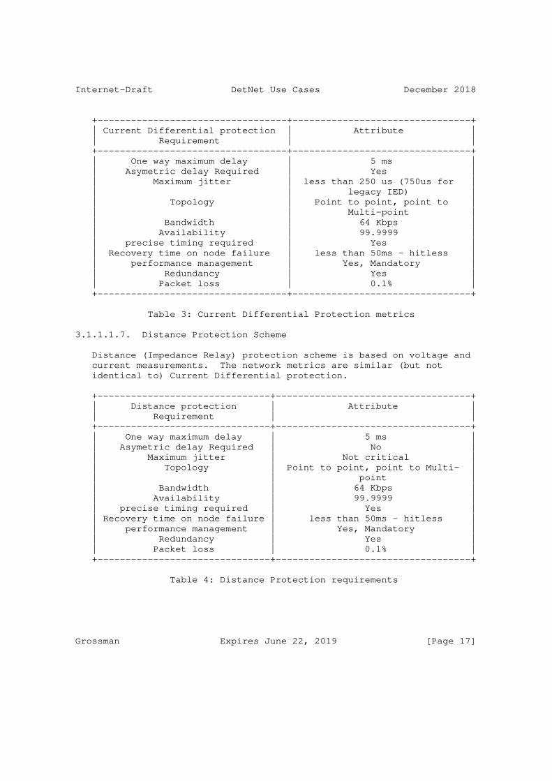
Internet-Draft DetNet Use Cases December 2018
+----------------------------------+--------------------------------+ | Current Differential protection | Attribute | | Requirement | | +----------------------------------+--------------------------------+ | One way maximum delay | 5 ms | | Asymetric delay Required | Yes | | Maximum jitter | less than 250 us (750us for | | | legacy IED) | | Topology | Point to point, point to | | | Multi-point | | Bandwidth | 64 Kbps | | Availability | 99.9999 | | precise timing required | Yes | | Recovery time on node failure | less than 50ms - hitless | | performance management | Yes, Mandatory | | Redundancy | Yes | | Packet loss | 0.1% | +----------------------------------+--------------------------------+
Table 3: Current Differential Protection metrics
3.1.1.1.7. Distance Protection Scheme
Distance (Impedance Relay) protection scheme is based on voltage and current measurements. The network metrics are similar (but not identical to) Current Differential protection.
+-------------------------------+-----------------------------------+ | Distance protection | Attribute | | Requirement | | +-------------------------------+-----------------------------------+ | One way maximum delay | 5 ms | | Asymetric delay Required | No | | Maximum jitter | Not critical | | Topology | Point to point, point to Multi- | | | point | | Bandwidth | 64 Kbps | | Availability | 99.9999 | | precise timing required | Yes | | Recovery time on node failure | less than 50ms - hitless | | performance management | Yes, Mandatory | | Redundancy | Yes | | Packet loss | 0.1% | +-------------------------------+-----------------------------------+
Table 4: Distance Protection requirements
Grossman Expires June 22, 2019 [Page 17]
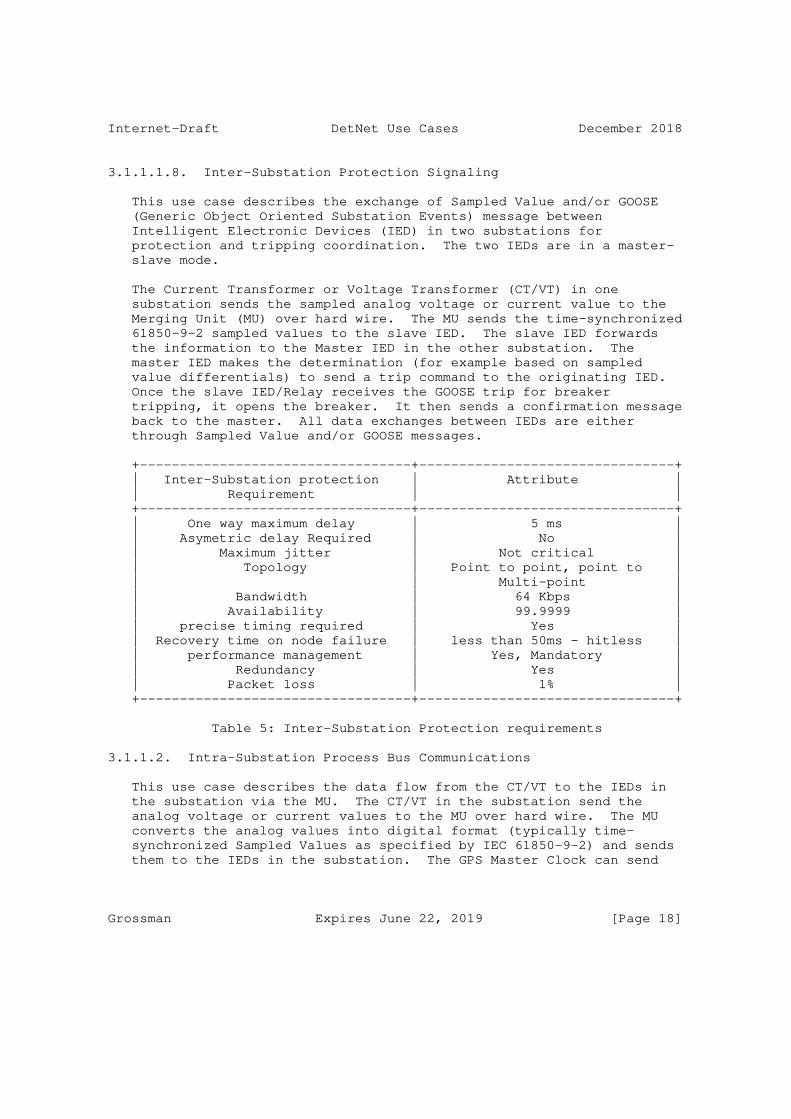
Internet-Draft DetNet Use Cases December 2018
3.1.1.1.8. Inter-Substation Protection Signaling
This use case describes the exchange of Sampled Value and/or GOOSE (Generic Object Oriented Substation Events) message between Intelligent Electronic Devices (IED) in two substations for protection and tripping coordination. The two IEDs are in a master- slave mode.
The Current Transformer or Voltage Transformer (CT/VT) in one substation sends the sampled analog voltage or current value to the Merging Unit (MU) over hard wire. The MU sends the time-synchronized 61850-9-2 sampled values to the slave IED. The slave IED forwards the information to the Master IED in the other substation. The master IED makes the determination (for example based on sampled value differentials) to send a trip command to the originating IED. Once the slave IED/Relay receives the GOOSE trip for breaker tripping, it opens the breaker. It then sends a confirmation message back to the master. All data exchanges between IEDs are either through Sampled Value and/or GOOSE messages.
+----------------------------------+--------------------------------+ | Inter-Substation protection | Attribute | | Requirement | | +----------------------------------+--------------------------------+ | One way maximum delay | 5 ms | | Asymetric delay Required | No | | Maximum jitter | Not critical | | Topology | Point to point, point to | | | Multi-point | | Bandwidth | 64 Kbps | | Availability | 99.9999 | | precise timing required | Yes | | Recovery time on node failure | less than 50ms - hitless | | performance management | Yes, Mandatory | | Redundancy | Yes | | Packet loss | 1% | +----------------------------------+--------------------------------+
Table 5: Inter-Substation Protection requirements
3.1.1.2. Intra-Substation Process Bus Communications
This use case describes the data flow from the CT/VT to the IEDs in the substation via the MU. The CT/VT in the substation send the analog voltage or current values to the MU over hard wire. The MU converts the analog values into digital format (typically time- synchronized Sampled Values as specified by IEC 61850-9-2) and sends them to the IEDs in the substation. The GPS Master Clock can send
Grossman Expires June 22, 2019 [Page 18]
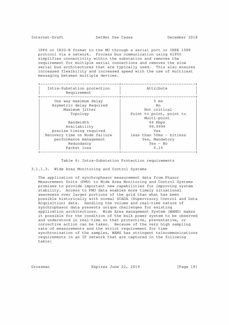
Internet-Draft DetNet Use Cases December 2018
1PPS or IRIG-B format to the MU through a serial port or IEEE 1588 protocol via a network. Process bus communication using 61850 simplifies connectivity within the substation and removes the requirement for multiple serial connections and removes the slow serial bus architectures that are typically used. This also ensures increased flexibility and increased speed with the use of multicast messaging between multiple devices.
+----------------------------------+--------------------------------+ | Intra-Substation protection | Attribute | | Requirement | | +----------------------------------+--------------------------------+ | One way maximum delay | 5 ms | | Asymetric delay Required | No | | Maximum jitter | Not critical | | Topology | Point to point, point to | | | Multi-point | | Bandwidth | 64 Kbps | | Availability | 99.9999 | | precise timing required | Yes | | Recovery time on Node failure | less than 50ms - hitless | | performance management | Yes, Mandatory | | Redundancy | Yes - No | | Packet loss | 0.1% | +----------------------------------+--------------------------------+
Table 6: Intra-Substation Protection requirements
3.1.1.3. Wide Area Monitoring and Control Systems
The application of synchrophasor measurement data from Phasor Measurement Units (PMU) to Wide Area Monitoring and Control Systems promises to provide important new capabilities for improving system stability. Access to PMU data enables more timely situational awareness over larger portions of the grid than what has been possible historically with normal SCADA (Supervisory Control and Data Acquisition) data. Handling the volume and real-time nature of synchrophasor data presents unique challenges for existing application architectures. Wide Area management System (WAMS) makes it possible for the condition of the bulk power system to be observed and understood in real-time so that protective, preventative, or corrective action can be taken. Because of the very high sampling rate of measurements and the strict requirement for time synchronization of the samples, WAMS has stringent telecommunications requirements in an IP network that are captured in the following table:
Grossman Expires June 22, 2019 [Page 19]

Internet-Draft DetNet Use Cases December 2018
+----------------------+--------------------------------------------+ | WAMS Requirement | Attribute | +----------------------+--------------------------------------------+ | One way maximum | 50 ms | | delay | | | Asymetric delay | No | | Required | | | Maximum jitter | Not critical | | Topology | Point to point, point to Multi-point, | | | Multi-point to Multi-point | | Bandwidth | 100 Kbps | | Availability | 99.9999 | | precise timing | Yes | | required | | | Recovery time on | less than 50ms - hitless | | Node failure | | | performance | Yes, Mandatory | | management | | | Redundancy | Yes | | Packet loss | 1% | | Consecutive Packet | At least 1 packet per application cycle | | Loss | must be received. | +----------------------+--------------------------------------------+
Table 7: WAMS Special Communication Requirements
3.1.1.4. IEC 61850 WAN engineering guidelines requirement classification
The IEC (International Electrotechnical Commission) has published a Technical Report which offers guidelines on how to define and deploy Wide Area Networks for the interconnections of electric substations, generation plants and SCADA operation centers. The IEC 61850-90-12 is providing a classification of WAN communication requirements into 4 classes. Table 8 summarizes these requirements:
Grossman Expires June 22, 2019 [Page 20]
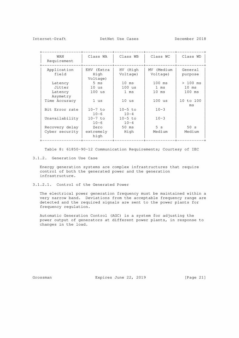
Internet-Draft DetNet Use Cases December 2018
+----------------+------------+------------+------------+-----------+ | WAN | Class WA | Class WB | Class WC | Class WD | | Requirement | | | | | +----------------+------------+------------+------------+-----------+ | Application | EHV (Extra | HV (High | MV (Medium | General | | field | High | Voltage) | Voltage) | purpose | | | Voltage) | | | | | Latency | 5 ms | 10 ms | 100 ms | > 100 ms | | Jitter | 10 us | 100 us | 1 ms | 10 ms | | Latency | 100 us | 1 ms | 10 ms | 100 ms | | Asymetry | | | | | | Time Accuracy | 1 us | 10 us | 100 us | 10 to 100 | | | | | | ms | | Bit Error rate | 10-7 to | 10-5 to | 10-3 | | | | 10-6 | 10-4 | | | | Unavailability | 10-7 to | 10-5 to | 10-3 | | | | 10-6 | 10-4 | | | | Recovery delay | Zero | 50 ms | 5 s | 50 s | | Cyber security | extremely | High | Medium | Medium | | | high | | | | +----------------+------------+------------+------------+-----------+
Table 8: 61850-90-12 Communication Requirements; Courtesy of IEC
3.1.2. Generation Use Case
Energy generation systems are complex infrastructures that require control of both the generated power and the generation infrastructure.
3.1.2.1. Control of the Generated Power
The electrical power generation frequency must be maintained within a very narrow band. Deviations from the acceptable frequency range are detected and the required signals are sent to the power plants for frequency regulation.
Automatic Generation Control (AGC) is a system for adjusting the power output of generators at different power plants, in response to changes in the load.
Grossman Expires June 22, 2019 [Page 21]
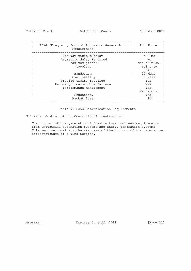
Internet-Draft DetNet Use Cases December 2018
+---------------------------------------------------+---------------+ | FCAG (Frequency Control Automatic Generation) | Attribute | | Requirement | | +---------------------------------------------------+---------------+ | One way maximum delay | 500 ms | | Asymetric delay Required | No | | Maximum jitter | Not critical | | Topology | Point to | | | point | | Bandwidth | 20 Kbps | | Availability | 99.999 | | precise timing required | Yes | | Recovery time on Node failure | N/A | | performance management | Yes, | | | Mandatory | | Redundancy | Yes | | Packet loss | 1% | +---------------------------------------------------+---------------+
Table 9: FCAG Communication Requirements
3.1.2.2. Control of the Generation Infrastructure
The control of the generation infrastructure combines requirements from industrial automation systems and energy generation systems. This section considers the use case of the control of the generation infrastructure of a wind turbine.
Grossman Expires June 22, 2019 [Page 22]

Internet-Draft DetNet Use Cases December 2018
| | | +-----------------+ | | +----+ | | | |WTRM| WGEN | WROT x==|===| | | | | +----+ WCNV| | |WNAC | | +---+---WYAW---+--+ | | | | | | +----+ |WTRF | |WMET| | | | | Wind Turbine | +--+-+ Controller | | WTUR | | | WREP | | | WSLG | | | WALG | WTOW | |
Figure 1: Wind Turbine Control Network
Figure 1 presents the subsystems that operate a wind turbine. These subsystems include
o WROT (Rotor Control)
o WNAC (Nacelle Control) (nacelle: housing containing the generator)
o WTRM (Transmission Control)
o WGEN (Generator)
o WYAW (Yaw Controller) (of the tower head)
o WCNV (In-Turbine Power Converter)
o WMET (External Meteorological Station providing real time information to the controllers of the tower)
Traffic characteristics relevant for the network planning and dimensioning process in a wind turbine scenario are listed below. The values in this section are based mainly on the relevant references [Ahm14] and [Spe09]. Each logical node (Figure 1) is a part of the metering network and produces analog measurements and status information which must comply with their respective data rate constraints.
Grossman Expires June 22, 2019 [Page 23]

Internet-Draft DetNet Use Cases December 2018
+-----------+--------+--------+-------------+---------+-------------+ | Subsystem | Sensor | Analog | Data Rate | Status | Data rate | | | Count | Sample | (bytes/sec) | Sample | (bytes/sec) | | | | Count | | Count | | +-----------+--------+--------+-------------+---------+-------------+ | WROT | 14 | 9 | 642 | 5 | 10 | | WTRM | 18 | 10 | 2828 | 8 | 16 | | WGEN | 14 | 12 | 73764 | 2 | 4 | | WCNV | 14 | 12 | 74060 | 2 | 4 | | WTRF | 12 | 5 | 73740 | 2 | 4 | | WNAC | 12 | 9 | 112 | 3 | 6 | | WYAW | 7 | 8 | 220 | 4 | 8 | | WTOW | 4 | 1 | 8 | 3 | 6 | | WMET | 7 | 7 | 228 | - | - | +-----------+--------+--------+-------------+---------+-------------+
Table 10: Wind Turbine Data Rate Constraints
Quality of Service (QoS) constraints for different services are presented in Table 11. These constraints are defined by IEEE 1646 standard [IEEE1646] and IEC 61400 standard [IEC61400].
+---------------------+---------+-------------+---------------------+ | Service | Latency | Reliability | Packet Loss Rate | +---------------------+---------+-------------+---------------------+ | Analogue measure | 16 ms | 99.99% | < 10-6 | | Status information | 16 ms | 99.99% | < 10-6 | | Protection traffic | 4 ms | 100.00% | < 10-9 | | Reporting and | 1 s | 99.99% | < 10-6 | | logging | | | | | Video surveillance | 1 s | 99.00% | No specific | | | | | requirement | | Internet connection | 60 min | 99.00% | No specific | | | | | requirement | | Control traffic | 16 ms | 100.00% | < 10-9 | | Data polling | 16 ms | 99.99% | < 10-6 | +---------------------+---------+-------------+---------------------+
Table 11: Wind Turbine Reliability and Latency Constraints
3.1.2.2.1. Intra-Domain Network Considerations
A wind turbine is composed of a large set of subsystems including sensors and actuators which require time-critical operation. The reliability and latency constraints of these different subsystems is shown in Table 11. These subsystems are connected to an intra-domain network which is used to monitor and control the operation of the turbine and connect it to the SCADA subsystems. The different
Grossman Expires June 22, 2019 [Page 24]
Internet-Draft DetNet Use Cases December 2018
components are interconnected using fiber optics, industrial buses, industrial Ethernet, EtherCat, or a combination of them. Industrial signaling and control protocols such as Modbus, Profibus, Profinet and EtherCat are used directly on top of the Layer 2 transport or encapsulated over TCP/IP.
The Data collected from the sensors and condition monitoring systems is multiplexed onto fiber cables for transmission to the base of the tower, and to remote control centers. The turbine controller continuously monitors the condition of the wind turbine and collects statistics on its operation. This controller also manages a large number of switches, hydraulic pumps, valves, and motors within the wind turbine.
There is usually a controller both at the bottom of the tower and in the nacelle. The communication between these two controllers usually takes place using fiber optics instead of copper links. Sometimes, a third controller is installed in the hub of the rotor and manages the pitch of the blades. That unit usually communicates with the nacelle unit using serial communications.
3.1.2.2.2. Inter-Domain network considerations
A remote control center belonging to a grid operator regulates the power output, enables remote actuation, and monitors the health of one or more wind parks in tandem. It connects to the local control center in a wind park over the Internet (Figure 2) via firewalls at both ends. The AS path between the local control center and the Wind Park typically involves several ISPs at different tiers. For example, a remote control center in Denmark can regulate a wind park in Greece over the normal public AS path between the two locations.
The remote control center is part of the SCADA system, setting the desired power output to the wind park and reading back the result once the new power output level has been set. Traffic between the remote control center and the wind park typically consists of protocols like IEC 60870-5-104 [IEC-60870-5-104], OPC XML-DA [OPCXML], Modbus [MODBUS], and SNMP [RFC3411]. At the time of this writing, traffic flows between the wind farm and the remote control center are best effort. QoS requirements are not strict, so no SLAs or service provisioning mechanisms (e.g., VPN) are employed. In case of events like equipment failure, tolerance for alarm delay is on the order of minutes, due to redundant systems already in place.
Grossman Expires June 22, 2019 [Page 25]
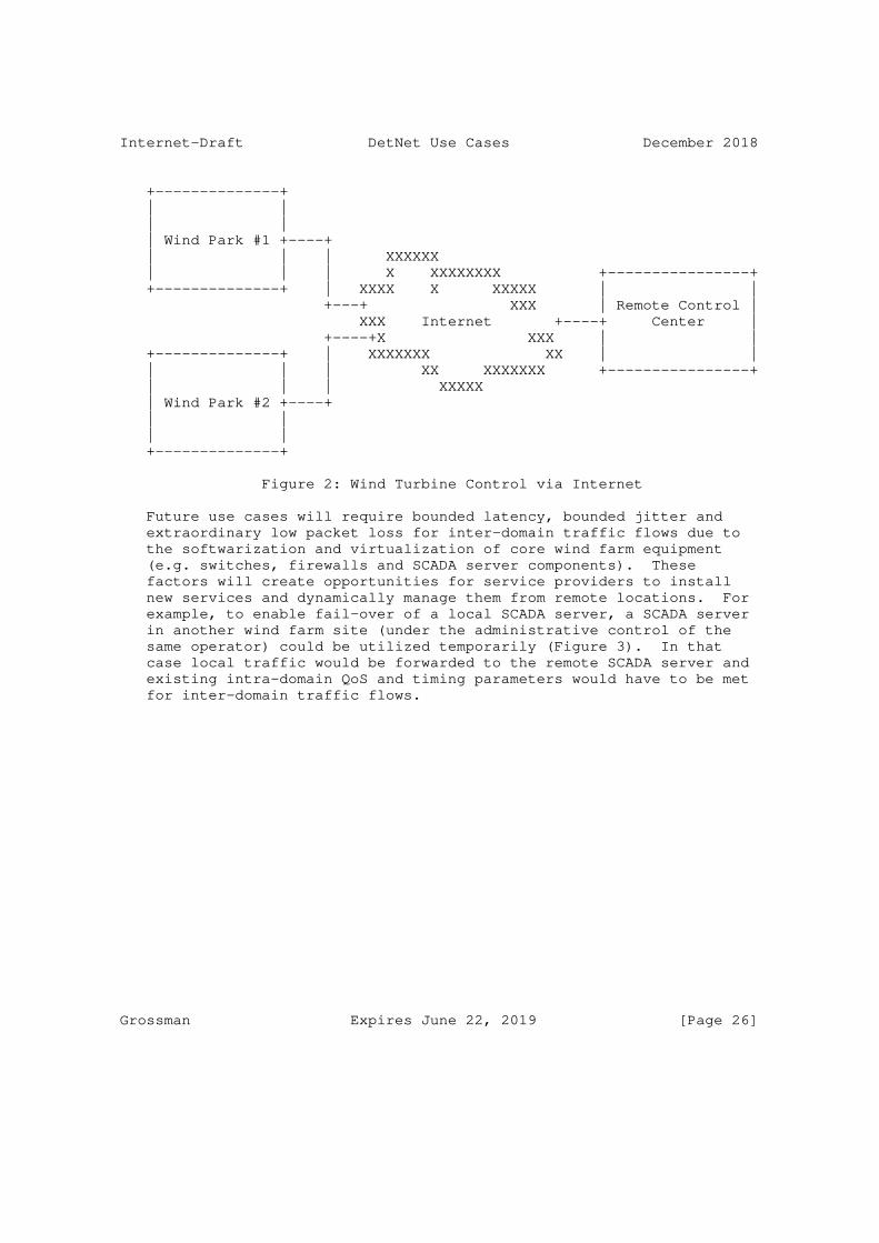
Internet-Draft DetNet Use Cases December 2018
+--------------+ | | | | | Wind Park #1 +----+ | | | XXXXXX | | | X XXXXXXXX +----------------+ +--------------+ | XXXX X XXXXX | | +---+ XXX | Remote Control | XXX Internet +----+ Center | +----+X XXX | | +--------------+ | XXXXXXX XX | | | | | XX XXXXXXX +----------------+ | | | XXXXX | Wind Park #2 +----+ | | | | +--------------+
Figure 2: Wind Turbine Control via Internet
Future use cases will require bounded latency, bounded jitter and extraordinary low packet loss for inter-domain traffic flows due to the softwarization and virtualization of core wind farm equipment (e.g. switches, firewalls and SCADA server components). These factors will create opportunities for service providers to install new services and dynamically manage them from remote locations. For example, to enable fail-over of a local SCADA server, a SCADA server in another wind farm site (under the administrative control of the same operator) could be utilized temporarily (Figure 3). In that case local traffic would be forwarded to the remote SCADA server and existing intra-domain QoS and timing parameters would have to be met for inter-domain traffic flows.
Grossman Expires June 22, 2019 [Page 26]

Internet-Draft DetNet Use Cases December 2018
+--------------+ | | | | | Wind Park #1 +----+ | | | XXXXXX | | | X XXXXXXXX +----------------+ +--------------+ | XXXX XXXXX | | +---+ Operator XXX | Remote Control | XXX Administered +----+ Center | +----+X WAN XXX | | +--------------+ | XXXXXXX XX | | | | | XX XXXXXXX +----------------+ | | | XXXXX | Wind Park #2 +----+ | | | | +--------------+
Figure 3: Wind Turbine Control via Operator Administered WAN
3.1.3. Distribution use case
3.1.3.1. Fault Location Isolation and Service Restoration (FLISR)
Fault Location, Isolation, and Service Restoration (FLISR) refers to the ability to automatically locate the fault, isolate the fault, and restore service in the distribution network. This will likely be the first widespread application of distributed intelligence in the grid.
Static power switch status (open/closed) in the network dictates the power flow to secondary substations. Reconfiguring the network in the event of a fault is typically done manually on site to energize/ de-energize alternate paths. Automating the operation of substation switchgear allows the flow of power to be altered automatically under fault conditions.
FLISR can be managed centrally from a Distribution Management System (DMS) or executed locally through distributed control via intelligent switches and fault sensors.
Grossman Expires June 22, 2019 [Page 27]

Internet-Draft DetNet Use Cases December 2018
+----------------------+--------------------------------------------+ | FLISR Requirement | Attribute | +----------------------+--------------------------------------------+ | One way maximum | 80 ms | | delay | | | Asymetric delay | No | | Required | | | Maximum jitter | 40 ms | | Topology | Point to point, point to Multi-point, | | | Multi-point to Multi-point | | Bandwidth | 64 Kbps | | Availability | 99.9999 | | precise timing | Yes | | required | | | Recovery time on | Depends on customer impact | | Node failure | | | performance | Yes, Mandatory | | management | | | Redundancy | Yes | | Packet loss | 0.1% | +----------------------+--------------------------------------------+
Table 12: FLISR Communication Requirements
3.2. Electrical Utilities Today
Many utilities still rely on complex environments formed of multiple application-specific proprietary networks, including TDM networks.
In this kind of environment there is no mixing of OT and IT applications on the same network, and information is siloed between operational areas.
Specific calibration of the full chain is required, which is costly.
This kind of environment prevents utility operations from realizing the operational efficiency benefits, visibility, and functional integration of operational information across grid applications and data networks.
In addition, there are many security-related issues as discussed in the following section.
3.2.1. Security Current Practices and Limitations
Grid monitoring and control devices are already targets for cyber attacks, and legacy telecommunications protocols have many intrinsic network-related vulnerabilities. For example, DNP3, Modbus,
Grossman Expires June 22, 2019 [Page 28]
Internet-Draft DetNet Use Cases December 2018
PROFIBUS/PROFINET, and other protocols are designed around a common paradigm of request and respond. Each protocol is designed for a master device such as an HMI (Human Machine Interface) system to send commands to subordinate slave devices to retrieve data (reading inputs) or control (writing to outputs). Because many of these protocols lack authentication, encryption, or other basic security measures, they are prone to network-based attacks, allowing a malicious actor or attacker to utilize the request-and-respond system as a mechanism for command-and-control like functionality. Specific security concerns common to most industrial control, including utility telecommunication protocols include the following:
o Network or transport errors (e.g. malformed packets or excessive latency) can cause protocol failure.
o Protocol commands may be available that are capable of forcing slave devices into inoperable states, including powering-off devices, forcing them into a listen-only state, disabling alarming.
o Protocol commands may be available that are capable of restarting communications and otherwise interrupting processes.
o Protocol commands may be available that are capable of clearing, erasing, or resetting diagnostic information such as counters and diagnostic registers.
o Protocol commands may be available that are capable of requesting sensitive information about the controllers, their configurations, or other need-to-know information.
o Most protocols are application layer protocols transported over TCP; therefore it is easy to transport commands over non-standard ports or inject commands into authorized traffic flows.
o Protocol commands may be available that are capable of broadcasting messages to many devices at once (i.e. a potential DoS).
o Protocol commands may be available to query the device network to obtain defined points and their values (i.e. a configuration scan).
o Protocol commands may be available that will list all available function codes (i.e. a function scan).
These inherent vulnerabilities, along with increasing connectivity between IT an OT networks, make network-based attacks very feasible.
Grossman Expires June 22, 2019 [Page 29]

Internet-Draft DetNet Use Cases December 2018
Simple injection of malicious protocol commands provides control over the target process. Altering legitimate protocol traffic can also alter information about a process and disrupt the legitimate controls that are in place over that process. A man-in-the-middle attack could provide both control over a process and misrepresentation of data back to operator consoles.
3.3. Electrical Utilities Future
The business and technology trends that are sweeping the utility industry will drastically transform the utility business from the way it has been for many decades. At the core of many of these changes is a drive to modernize the electrical grid with an integrated telecommunications infrastructure. However, interoperability concerns, legacy networks, disparate tools, and stringent security requirements all add complexity to the grid transformation. Given the range and diversity of the requirements that should be addressed by the next generation telecommunications infrastructure, utilities need to adopt a holistic architectural approach to integrate the electrical grid with digital telecommunications across the entire power delivery chain.
The key to modernizing grid telecommunications is to provide a common, adaptable, multi-service network infrastructure for the entire utility organization. Such a network serves as the platform for current capabilities while enabling future expansion of the network to accommodate new applications and services.
To meet this diverse set of requirements, both today and in the future, the next generation utility telecommunnications network will be based on open-standards-based IP architecture. An end-to-end IP architecture takes advantage of nearly three decades of IP technology development, facilitating interoperability and device management across disparate networks and devices, as it has been already demonstrated in many mission-critical and highly secure networks.
IPv6 is seen as a future telecommunications technology for the Smart Grid; the IEC (International Electrotechnical Commission) and different National Committees have mandated a specific adhoc group (AHG8) to define the migration strategy to IPv6 for all the IEC TC57 power automation standards. The AHG8 has finalised the work on the migration strategy and the following Technical Report has been issued: IEC TR 62357-200:2015: Guidelines for migration from Internet Protocol version 4 (IPv4) to Internet Protocol version 6 (IPv6).
Cloud-based SCADA systems will control and monitor the critical and non-critical subsystems of generation systems, for example wind farms.
Grossman Expires June 22, 2019 [Page 30]
Internet-Draft DetNet Use Cases December 2018
3.3.1. Migration to Packet-Switched Network
Throughout the world, utilities are increasingly planning for a future based on smart grid applications requiring advanced telecommunications systems. Many of these applications utilize packet connectivity for communicating information and control signals across the utility’s Wide Area Network (WAN), made possible by technologies such as multiprotocol label switching (MPLS). The data that traverses the utility WAN includes:
o Grid monitoring, control, and protection data
o Non-control grid data (e.g. asset data for condition-based monitoring)
o Physical safety and security data (e.g. voice and video)
o Remote worker access to corporate applications (voice, maps, schematics, etc.)
o Field area network backhaul for smart metering, and distribution grid management
o Enterprise traffic (email, collaboration tools, business applications)
WANs support this wide variety of traffic to and from substations, the transmission and distribution grid, generation sites, between control centers, and between work locations and data centers. To maintain this rapidly expanding set of applications, many utilities are taking steps to evolve present time-division multiplexing (TDM) based and frame relay infrastructures to packet systems. Packet- based networks are designed to provide greater functionalities and higher levels of service for applications, while continuing to deliver reliability and deterministic (real-time) traffic support.
3.3.2. Telecommunications Trends
These general telecommunications topics are in addition to the use cases that have been addressed so far. These include both current and future telecommunications related topics that should be factored into the network architecture and design.
3.3.2.1. General Telecommunications Requirements
o IP Connectivity everywhere
o Monitoring services everywhere and from different remote centers
Grossman Expires June 22, 2019 [Page 31]

Internet-Draft DetNet Use Cases December 2018
o Move services to a virtual data center
o Unify access to applications / information from the corporate network
o Unify services
o Unified Communications Solutions
o Mix of fiber and microwave technologies - obsolescence of SONET/ SDH or TDM
o Standardize grid telecommunications protocol to opened standard to ensure interoperability
o Reliable Telecommunications for Transmission and Distribution Substations
o IEEE 1588 time synchronization Client / Server Capabilities
o Integration of Multicast Design
o QoS Requirements Mapping
o Enable Future Network Expansion
o Substation Network Resilience
o Fast Convergence Design
o Scalable Headend Design
o Define Service Level Agreements (SLA) and Enable SLA Monitoring
o Integration of 3G/4G Technologies and future technologies
o Ethernet Connectivity for Station Bus Architecture
o Ethernet Connectivity for Process Bus Architecture
o Protection, teleprotection and PMU (Phaser Measurement Unit) on IP
3.3.2.2. Specific Network topologies of Smart Grid Applications
Utilities often have very large private telecommunications networks. It covers an entire territory / country. The main purpose of the network, until now, has been to support transmission network monitoring, control, and automation, remote control of generation
Grossman Expires June 22, 2019 [Page 32]
Internet-Draft DetNet Use Cases December 2018
sites, and providing FCAPS (Fault, Configuration, Accounting, Performance, Security) services from centralized network operation centers.
Going forward, one network will support operation and maintenance of electrical networks (generation, transmission, and distribution), voice and data services for ten of thousands of employees and for exchange with neighboring interconnections, and administrative services. To meet those requirements, utility may deploy several physical networks leveraging different technologies across the country: an optical network and a microwave network for instance. Each protection and automatism system between two points has two telecommunications circuits, one on each network. Path diversity between two substations is key. Regardless of the event type (hurricane, ice storm, etc.), one path needs to stay available so the system can still operate.
In the optical network, signals are transmitted over more than tens of thousands of circuits using fiber optic links, microwave and telephone cables. This network is the nervous system of the utility’s power transmission operations. The optical network represents ten of thousands of km of cable deployed along the power lines, with individual runs as long as 280 km.
3.3.2.3. Precision Time Protocol
Some utilities do not use GPS clocks in generation substations. One of the main reasons is that some of the generation plants are 30 to 50 meters deep under ground and the GPS signal can be weak and unreliable. Instead, atomic clocks are used. Clocks are synchronized amongst each other. Rubidium clocks provide clock and 1ms timestamps for IRIG-B.
Some companies plan to transition to the Precision Time Protocol (PTP, [IEEE1588]), distributing the synchronization signal over the IP/MPLS network. PTP provides a mechanism for synchronizing the clocks of participating nodes to a high degree of accuracy and precision.
PTP operates based on the following assumptions:
It is assumed that the network eliminates cyclic forwarding of PTP messages within each communication path (e.g. by using a spanning tree protocol).
PTP is tolerant of an occasional missed message, duplicated message, or message that arrived out of order. However, PTP assumes that such impairments are relatively rare.
Grossman Expires June 22, 2019 [Page 33]

Internet-Draft DetNet Use Cases December 2018
PTP was designed assuming a multicast communication model, however PTP also supports a unicast communication model as long as the behavior of the protocol is preserved.
Like all message-based time transfer protocols, PTP time accuracy is degraded by delay asymmetry in the paths taken by event messages. Asymmetry is not detectable by PTP, however, if such delays are known a priori, PTP can correct for asymmetry.
IEC 61850 defines the use of IEC/IEEE 61850-9-3:2016. The title is: Precision time protocol profile for power utility automation. It is based on Annex B/IEC 62439 which offers the support of redundant attachment of clocks to Parallel Redundancy Protocol (PRP) and High- availability Seamless Redundancy (HSR) networks.
3.3.3. Security Trends in Utility Networks
Although advanced telecommunications networks can assist in transforming the energy industry by playing a critical role in maintaining high levels of reliability, performance, and manageability, they also introduce the need for an integrated security infrastructure. Many of the technologies being deployed to support smart grid projects such as smart meters and sensors can increase the vulnerability of the grid to attack. Top security concerns for utilities migrating to an intelligent smart grid telecommunications platform center on the following trends:
o Integration of distributed energy resources
o Proliferation of digital devices to enable management, automation, protection, and control
o Regulatory mandates to comply with standards for critical infrastructure protection
o Migration to new systems for outage management, distribution automation, condition-based maintenance, load forecasting, and smart metering
o Demand for new levels of customer service and energy management
This development of a diverse set of networks to support the integration of microgrids, open-access energy competition, and the use of network-controlled devices is driving the need for a converged security infrastructure for all participants in the smart grid, including utilities, energy service providers, large commercial and industrial, as well as residential customers. Securing the assets of electric power delivery systems (from the control center to the
Grossman Expires June 22, 2019 [Page 34]
Internet-Draft DetNet Use Cases December 2018
substation, to the feeders and down to customer meters) requires an end-to-end security infrastructure that protects the myriad of telecommunications assets used to operate, monitor, and control power flow and measurement.
"Cyber security" refers to all the security issues in automation and telecommunications that affect any functions related to the operation of the electric power systems. Specifically, it involves the concepts of:
o Integrity : data cannot be altered undetectably
o Authenticity (data origin authentication): the telecommunications parties involved must be validated as genuine
o Authorization : only requests and commands from the authorized users can be accepted by the system
o Confidentiality : data must not be accessible to any unauthenticated users
When designing and deploying new smart grid devices and telecommunications systems, it is imperative to understand the various impacts of these new components under a variety of attack situations on the power grid. Consequences of a cyber attack on the grid telecommunications network can be catastrophic. This is why security for smart grid is not just an ad hoc feature or product, it’s a complete framework integrating both physical and Cyber security requirements and covering the entire smart grid networks from generation to distribution. Security has therefore become one of the main foundations of the utility telecom network architecture and must be considered at every layer with a defense-in-depth approach. Migrating to IP based protocols is key to address these challenges for two reasons:
o IP enables a rich set of features and capabilities to enhance the security posture
o IP is based on open standards, which allows interoperability between different vendors and products, driving down the costs associated with implementing security solutions in OT networks.
Securing OT (Operation technology) telecommunications over packet- switched IP networks follow the same principles that are foundational for securing the IT infrastructure, i.e., consideration must be given to enforcing electronic access control for both person-to-machine and machine-to-machine communications, and providing the appropriate
Grossman Expires June 22, 2019 [Page 35]

Internet-Draft DetNet Use Cases December 2018
levels of data privacy, device and platform integrity, and threat detection and mitigation.
3.4. Electrical Utilities Asks
o Mixed L2 and L3 topologies
o Deterministic behavior
o Bounded latency and jitter
o Tight feedback intervals
o High availability, low recovery time
o Redundancy, low packet loss
o Precise timing
o Centralized computing of deterministic paths
o Distributed configuration may also be useful
4. Building Automation Systems
4.1. Use Case Description
A Building Automation System (BAS) manages equipment and sensors in a building for improving residents’ comfort, reducing energy consumption, and responding to failures and emergencies. For example, the BAS measures the temperature of a room using sensors and then controls the HVAC (heating, ventilating, and air conditioning) to maintain a set temperature and minimize energy consumption.
A BAS primarily performs the following functions:
o Periodically measures states of devices, for example humidity and illuminance of rooms, open/close state of doors, FAN speed, etc.
o Stores the measured data.
o Provides the measured data to BAS systems and operators.
o Generates alarms for abnormal state of devices.
o Controls devices (e.g. turn off room lights at 10:00 PM).
Grossman Expires June 22, 2019 [Page 36]

Internet-Draft DetNet Use Cases December 2018
4.2. Building Automation Systems Today
4.2.1. BAS Architecture
A typical BAS architecture of today is shown in Figure 4.
+----------------------------+ | | | BMS HMI | | | | | | +----------------------+ | | | Management Network | | | +----------------------+ | | | | | | LC LC | | | | | | +----------------------+ | | | Field Network | | | +----------------------+ | | | | | | | | Dev Dev Dev Dev | | | +----------------------------+
BMS := Building Management Server HMI := Human Machine Interface LC := Local Controller
Figure 4: BAS architecture
There are typically two layers of network in a BAS. The upper one is called the Management Network and the lower one is called the Field Network. In management networks an IP-based communication protocol is used, while in field networks non-IP based communication protocols ("field protocols") are mainly used. Field networks have specific timing requirements, whereas management networks can be best-effort.
A Human Machine Interface (HMI) is typically a desktop PC used by operators to monitor and display device states, send device control commands to Local Controllers (LCs), and configure building schedules (for example "turn off all room lights in the building at 10:00 PM").
A Building Management Server (BMS) performs the following operations.
o Collect and store device states from LCs at regular intervals.
o Send control values to LCs according to a building schedule.
Grossman Expires June 22, 2019 [Page 37]

Internet-Draft DetNet Use Cases December 2018
o Send an alarm signal to operators if it detects abnormal devices states.
The BMS and HMI communicate with LCs via IP-based "management protocols" (see standards [bacnetip], [knx]).
A LC is typically a Programmable Logic Controller (PLC) which is connected to several tens or hundreds of devices using "field protocols". An LC performs the following kinds of operations:
o Measure device states and provide the information to BMS or HMI.
o Send control values to devices, unilaterally or as part of a feedback control loop.
There are many field protocols used at the time of this writing; some are standards-based and others are proprietary (see standards [lontalk], [modbus], [profibus] and [flnet]). The result is that BASs have multiple MAC/PHY modules and interfaces. This makes BASs more expensive, slower to develop, and can result in "vendor lock-in" with multiple types of management applications.
4.2.2. BAS Deployment Model
An example BAS for medium or large buildings is shown in Figure 5. The physical layout spans multiple floors, and there is a monitoring room where the BAS management entities are located. Each floor will have one or more LCs depending upon the number of devices connected to the field network.
Grossman Expires June 22, 2019 [Page 38]

Internet-Draft DetNet Use Cases December 2018
+--------------------------------------------------+ | Floor 3 | | +----LC˜˜˜˜+˜˜˜˜˜+˜˜˜˜˜+ | | | | | | | | | Dev Dev Dev | | | | |--- | ------------------------------------------| | | Floor 2 | | +----LC˜˜˜˜+˜˜˜˜˜+˜˜˜˜˜+ Field Network | | | | | | | | | Dev Dev Dev | | | | |--- | ------------------------------------------| | | Floor 1 | | +----LC˜˜˜˜+˜˜˜˜˜+˜˜˜˜˜+ +-----------------| | | | | | | Monitoring Room | | | Dev Dev Dev | | | | | BMS HMI | | | Management Network | | | | | +--------------------------------+-----+ | | | | +--------------------------------------------------+
Figure 5: BAS Deployment model for Medium/Large Buildings
Each LC is connected to the monitoring room via the Management network, and the management functions are performed within the building. In most cases, fast Ethernet (e.g. 100BASE-T) is used for the management network. Since the management network is non- realtime, use of Ethernet without quality of service is sufficient for today’s deployment.
In the field network a variety of physical interfaces such as RS232C and RS485 are used, which have specific timing requirements. Thus if a field network is to be replaced with an Ethernet or wireless network, such networks must support time-critical deterministic flows.
In Figure 6, another deployment model is presented in which the management system is hosted remotely. This is becoming popular for small office and residential buildings in which a standalone monitoring system is not cost-effective.
Grossman Expires June 22, 2019 [Page 39]

Internet-Draft DetNet Use Cases December 2018
+---------------+ | Remote Center | | | | BMS HMI | +------------------------------------+ | | | | | Floor 2 | | +---+---+ | | +----LC˜˜˜˜+˜˜˜˜˜+ Field Network| | | | | | | | | | Router | | | Dev Dev | +-------|-------+ | | | | |--- | ------------------------------| | | | Floor 1 | | | +----LC˜˜˜˜+˜˜˜˜˜+ | | | | | | | | | | Dev Dev | | | | | | | | Management Network | WAN | | +------------------------Router-------------+ | | +------------------------------------+
Figure 6: Deployment model for Small Buildings
Some interoperability is possible today in the Management Network, but not in today’s field networks due to their non-IP-based design.
4.2.3. Use Cases for Field Networks
Below are use cases for Environmental Monitoring, Fire Detection, and Feedback Control, and their implications for field network performance.
4.2.3.1. Environmental Monitoring
The BMS polls each LC at a maximum measurement interval of 100ms (for example to draw a historical chart of 1 second granularity with a 10x sampling interval) and then performs the operations as specified by the operator. Each LC needs to measure each of its several hundred sensors once per measurement interval. Latency is not critical in this scenario as long as all sensor values are completed in the measurement interval. Availability is expected to be 99.999 %.
4.2.3.2. Fire Detection
On detection of a fire, the BMS must stop the HVAC, close the fire shutters, turn on the fire sprinklers, send an alarm, etc. There are typically ˜10s of sensors per LC that BMS needs to manage. In this
Grossman Expires June 22, 2019 [Page 40]
Internet-Draft DetNet Use Cases December 2018
scenario the measurement interval is 10-50ms, the communication delay is 10ms, and the availability must be 99.9999 %.
4.2.3.3. Feedback Control
BAS systems utilize feedback control in various ways; the most time- critial is control of DC motors, which require a short feedback interval (1-5ms) with low communication delay (10ms) and jitter (1ms). The feedback interval depends on the characteristics of the device and a target quality of control value. There are typically ˜10s of such devices per LC.
Communication delay is expected to be less than 10ms, jitter less than 1ms while the availability must be 99.9999% .
4.2.4. Security Considerations
When BAS field networks were developed it was assumed that the field networks would always be physically isolated from external networks and therefore security was not a concern. In today’s world many BASs are managed remotely and are thus connected to shared IP networks and so security is definitely a concern, yet security features are not available in the majority of BAS field network deployments .
The management network, being an IP-based network, has the protocols available to enable network security, but in practice many BAS systems do not implement even the available security features such as device authentication or encryption for data in transit.
4.3. BAS Future
In the future more fine-grained environmental monitoring and lower energy consumption will emerge which will require more sensors and devices, thus requiring larger and more complex building networks.
Building networks will be connected to or converged with other networks (Enterprise network, Home network, and Internet).
Therefore better facilities for network management, control, reliability and security are critical in order to improve resident and operator convenience and comfort. For example the ability to monitor and control building devices via the internet would enable (for example) control of room lights or HVAC from a resident’s desktop PC or phone application.
Grossman Expires June 22, 2019 [Page 41]

Internet-Draft DetNet Use Cases December 2018
4.4. BAS Asks
The community would like to see an interoperable protocol specification that can satisfy the timing, security, availability and QoS constraints described above, such that the resulting converged network can replace the disparate field networks. Ideally this connectivity could extend to the open Internet.
This would imply an architecture that can guarantee
o Low communication delays (from <10ms to 100ms in a network of several hundred devices)
o Low jitter (< 1 ms)
o Tight feedback intervals (1ms - 10ms)
o High network availability (up to 99.9999% )
o Availability of network data in disaster scenario
o Authentication between management and field devices (both local and remote)
o Integrity and data origin authentication of communication data between field and management devices
o Confidentiality of data when communicated to a remote device
5. Wireless for Industrial Applications
5.1. Use Case Description
Wireless networks are useful for industrial applications, for example when portable, fast-moving or rotating objects are involved, and for the resource-constrained devices found in the Internet of Things (IoT).
Such network-connected sensors, actuators, control loops (etc.) typically require that the underlying network support real-time quality of service (QoS), as well as specific classes of other network properties such as reliability, redundancy, and security.
These networks may also contain very large numbers of devices, for example for factories, "big data" acquisition, and the IoT. Given the large numbers of devices installed, and the potential pervasiveness of the IoT, this is a huge and very cost-sensitive
Grossman Expires June 22, 2019 [Page 42]

Internet-Draft DetNet Use Cases December 2018
market such that small cost reductions can save large amounts of money.
5.1.1. Network Convergence using 6TiSCH
Some wireless network technologies support real-time QoS, and are thus useful for these kinds of networks, but others do not.
This use case focuses on one specific wireless network technology which provides the required deterministic QoS, which is "IPv6 over the TSCH mode of IEEE 802.15.4e" (6TiSCH, where TSCH stands for "Time-Slotted Channel Hopping", see [I-D.ietf-6tisch-architecture], [IEEE802154], [IEEE802154e], and [RFC7554]).
There are other deterministic wireless busses and networks available today, however they are imcompatible with each other, and incompatible with IP traffic (for example [ISA100], [WirelessHART]).
Thus the primary goal of this use case is to apply 6TiSCH as a converged IP- and standards-based wireless network for industrial applications, i.e. to replace multiple proprietary and/or incompatible wireless networking and wireless network management standards.
5.1.2. Common Protocol Development for 6TiSCH
Today there are a number of protocols required by 6TiSCH which are still in development, and a second intent of this use case is to highlight the ways in which these "missing" protocols share goals in common with DetNet. Thus it is possible that some of the protocol technology developed for DetNet will also be applicable to 6TiSCH.
These protocol goals are identified here, along with their relationship to DetNet. It is likely that ultimately the resulting protocols will not be identical, but will share design principles which contribute to the eficiency of enabling both DetNet and 6TiSCH.
One such commonality is that although at a different time scale, in both TSN [IEEE802.1TSNTG] and TSCH a packet crosses the network from node to node follows a precise schedule, as a train that leaves intermediate stations at precise times along its path. This kind of operation reduces collisions, saves energy, and enables engineering the network for deterministic properties.
Another commonality is remote monitoring and scheduling management of a TSCH network by a Path Computation Element (PCE) and Network Management Entity (NME). The PCE/NME manage timeslots and device resources in a manner that minimizes the interaction with and the
Grossman Expires June 22, 2019 [Page 43]

Internet-Draft DetNet Use Cases December 2018
load placed on resource-constrained devices. For example, a tiny IoT device may have just enough buffers to store one or a few IPv6 packets, and will have limited bandwidth between peers such that it can maintain only a small amount of peer information, and will not be able to store many packets waiting to be forwarded. It is advantageous then for it to only be required to carry out the specific behavior assigned to it by the PCE/NME (as opposed to maintaining its own IP stack, for example).
It is possible that there will be some peer-to-peer communication, for example the PCE may communicate only indirectly with some devices in order to enable hierarchical configuration of the system.
6TiSCH depends on [PCE] and [I-D.ietf-detnet-architecture].
6TiSCH also depends on the fact that DetNet will maintain consistency with [IEEE802.1TSNTG].
5.2. Wireless Industrial Today
Today industrial wireless is accomplished using multiple deterministic wireless networks which are incompatible with each other and with IP traffic.
6TiSCH is not yet fully specified, so it cannot be used in today’s applications.
5.3. Wireless Industrial Future
5.3.1. Unified Wireless Network and Management
DetNet and 6TiSCH together can enable converged transport of deterministic and best-effort traffic flows between real-time industrial devices and wide area networks via IP routing. A high level view of a basic such network is shown in Figure 7.
Grossman Expires June 22, 2019 [Page 44]

Internet-Draft DetNet Use Cases December 2018
---+-------- ............ ------------ | External Network | | +-----+ +-----+ | NME | | | LLN Border | | | | router +-----+ +-----+ o o o o o o o o o LLN o o o o o o o o
Figure 7: Basic 6TiSCH Network
Figure 8 shows a backbone router federating multiple synchronized 6TiSCH subnets into a single subnet connected to the external network.
---+-------- ............ ------------ | External Network | | +-----+ | +-----+ | NME | +-----+ | +-----+ | | | | Router | | PCE | +-----+ | | +--| | +-----+ +-----+ | | | Subnet Backbone | +--------------------+------------------+ | | | +-----+ +-----+ +-----+ | | Backbone | | Backbone | | Backbone o | | router | | router | | router +-----+ +-----+ +-----+ o o o o o o o o o o o o o o o o o o o LLN o o o o o o o o o o o o o o o o
Figure 8: Extended 6TiSCH Network
The backbone router must ensure end-to-end deterministic behavior between the LLN and the backbone. This should be accomplished in conformance with the work done in [I-D.ietf-detnet-architecture] with respect to Layer-3 aspects of deterministic networks that span multiple Layer-2 domains.
Grossman Expires June 22, 2019 [Page 45]

Internet-Draft DetNet Use Cases December 2018
The PCE must compute a deterministic path end-to-end across the TSCH network and IEEE802.1 TSN Ethernet backbone, and DetNet protocols are expected to enable end-to-end deterministic forwarding.
+-----+ | IoT | | G/W | +-----+ ^ <---- Elimination | | Track branch | | +-------+ +--------+ Subnet Backbone | | +--|--+ +--|--+ | | | Backbone | | | Backbone o | | | router | | | router +--/--+ +--|--+ o / o o---o----/ o o o---o--/ o o o o o o \ / o o LLN o o v <---- Replication o
Figure 9: 6TiSCH Network with PRE
5.3.1.1. PCE and 6TiSCH ARQ Retries
6TiSCH uses the IEEE802.15.4 Automatic Repeat-reQuest (ARQ) mechanism to provide higher reliability of packet delivery. ARQ is related to packet replication and elimination because there are two independent paths for packets to arrive at the destination, and if an expected packed does not arrive on one path then it checks for the packet on the second path.
Although to date this mechanism is only used by wireless networks, this may be a technique that would be appropriate for DetNet and so aspects of the enabling protocol could be co-developed.
For example, in Figure 9, a Track is laid out from a field device in a 6TiSCH network to an IoT gateway that is located on a IEEE802.1 TSN backbone.
In ARQ the Replication function in the field device sends a copy of each packet over two different branches, and the PCE schedules each hop of both branches so that the two copies arrive in due time at the gateway. In case of a loss on one branch, hopefully the other copy
Grossman Expires June 22, 2019 [Page 46]

Internet-Draft DetNet Use Cases December 2018
of the packet still arrives within the allocated time. If two copies make it to the IoT gateway, the Elimination function in the gateway ignores the extra packet and presents only one copy to upper layers.
At each 6TiSCH hop along the Track, the PCE may schedule more than one timeSlot for a packet, so as to support Layer-2 retries (ARQ).
In deployments at the time of this writing, a TSCH Track does not necessarily support PRE but is systematically multi-path. This means that a Track is scheduled so as to ensure that each hop has at least two forwarding solutions, and the forwarding decision is to try the preferred one and use the other in case of Layer-2 transmission failure as detected by ARQ.
5.3.2. Schedule Management by a PCE
A common feature of 6TiSCH and DetNet is the action of a PCE to configure paths through the network. Specifically, what is needed is a protocol and data model that the PCE will use to get/set the relevant configuration from/to the devices, as well as perform operations on the devices. This protocol should be developed by DetNet with consideration for its reuse by 6TiSCH. The remainder of this section provides a bit more context from the 6TiSCH side.
5.3.2.1. PCE Commands and 6TiSCH CoAP Requests
The 6TiSCH device does not expect to place the request for bandwidth between itself and another device in the network. Rather, an operation control system invoked through a human interface specifies the required traffic specification and the end nodes (in terms of latency and reliability). Based on this information, the PCE must compute a path between the end nodes and provision the network with per-flow state that describes the per-hop operation for a given packet, the corresponding timeslots, and the flow identification that enables recognizing that a certain packet belongs to a certain path, etc.
For a static configuration that serves a certain purpose for a long period of time, it is expected that a node will be provisioned in one shot with a full schedule, which incorporates the aggregation of its behavior for multiple paths. 6TiSCH expects that the programing of the schedule will be done over COAP as discussed in [I-D.ietf-6tisch-coap].
6TiSCH expects that the PCE commands will be mapped back and forth into CoAP by a gateway function at the edge of the 6TiSCH network. For instance, it is possible that a mapping entity on the backbone transforms a non-CoAP protocol such as PCEP into the RESTful
Grossman Expires June 22, 2019 [Page 47]

Internet-Draft DetNet Use Cases December 2018
interfaces that the 6TiSCH devices support. This architecture will be refined to comply with DetNet [I-D.ietf-detnet-architecture] when the work is formalized. Related information about 6TiSCH can be found at [I-D.ietf-6tisch-6top-interface] and RPL [RFC6550].
A protocol may be used to update the state in the devices during runtime, for example if it appears that a path through the network has ceased to perform as expected, but in 6TiSCH that flow was not designed and no protocol was selected. DetNet should define the appropriate end-to-end protocols to be used in that case. The implication is that these state updates take place once the system is configured and running, i.e. they are not limited to the initial communication of the configuration of the system.
A "slotFrame" is the base object that a PCE would manipulate to program a schedule into an LLN node ([I-D.ietf-6tisch-architecture]).
The PCE should read energy data from devices and compute paths that will implement policies on how energy in devices is consumed, for instance to ensure that the spent energy does not exceeded the available energy over a period of time. Note: this statement implies that an extensible protocol for communicating device info to the PCE and enabling the PCE to act on it will be part of the DetNet architecture, however for subnets with specific protocols (e.g. CoAP) a gateway may be required.
6TiSCH devices can discover their neighbors over the radio using a mechanism such as beacons, but even though the neighbor information is available in the 6TiSCH interface data model, 6TiSCH does not describe a protocol to proactively push the neighborhood information to a PCE. DetNet should define such a protocol; one possible design alternative is that it could operate over CoAP, alternatively it could be converted to/from CoAP by a gateway. Such a protocol could carry multiple metrics, for example similar to those used for RPL operations [RFC6551]
5.3.2.2. 6TiSCH IP Interface
"6top" ([I-D.wang-6tisch-6top-sublayer]) is a logical link control sitting between the IP layer and the TSCH MAC layer which provides the link abstraction that is required for IP operations. The 6top data model and management interfaces are further discussed in [I-D.ietf-6tisch-6top-interface] and [I-D.ietf-6tisch-coap].
An IP packet that is sent along a 6TiSCH path uses the Differentiated Services Per-Hop-Behavior Group called Deterministic Forwarding, as described in [I-D.svshah-tsvwg-deterministic-forwarding].
Grossman Expires June 22, 2019 [Page 48]

Internet-Draft DetNet Use Cases December 2018
5.3.3. 6TiSCH Security Considerations
On top of the classical requirements for protection of control signaling, it must be noted that 6TiSCH networks operate on limited resources that can be depleted rapidly in a DoS attack on the system, for instance by placing a rogue device in the network, or by obtaining management control and setting up unexpected additional paths.
5.4. Wireless Industrial Asks
6TiSCH depends on DetNet to define:
o Configuration (state) and operations for deterministic paths
o End-to-end protocols for deterministic forwarding (tagging, IP)
o Protocol for packet replication and elimination
6. Cellular Radio
6.1. Use Case Description
This use case describes the application of deterministic networking in the context of cellular telecom transport networks. Important elements include time synchronization, clock distribution, and ways of establishing time-sensitive streams for both Layer-2 and Layer-3 user plane traffic.
6.1.1. Network Architecture
Figure 10 illustrates a 3GPP-defined cellular network architecture typical at the time of this writing, which includes "Fronthaul", "Midhaul" and "Backhaul" network segments. The "Fronthaul" is the network connecting base stations (baseband processing units) to the remote radio heads (antennas). The "Midhaul" is the network inter- connecting base stations (or small cell sites). The "Backhaul" is the network or links connecting the radio base station sites to the network controller/gateway sites (i.e. the core of the 3GPP cellular network).
In Figure 10 "eNB" ("E-UTRAN Node B") is the hardware that is connected to the mobile phone network which communicates directly with mobile handsets ([TS36300]).
Grossman Expires June 22, 2019 [Page 49]

Internet-Draft DetNet Use Cases December 2018
Y (remote radio heads (antennas)) \ Y__ \.--. .--. +------+ \_( ‘. +---+ _(Back‘. | 3GPP | Y------( Front )----|eNB|----( Haul )----| core | ( ‘ .Haul ) +---+ ( ‘ . ) ) | netw | /‘--(___.-’ \ ‘--(___.-’ +------+ Y_/ / \.--. \ Y_/ _( Mid‘. \ ( Haul ) \ ( ‘ . ) ) \ ‘--(___.-’\_____+---+ (small cell sites) \ |SCe|__Y +---+ +---+ Y__|eNB|__Y +---+ Y_/ \_Y ("local" radios)
Figure 10: Generic 3GPP-based Cellular Network Architecture
6.1.2. Delay Constraints
The available processing time for Fronthaul networking overhead is limited to the available time after the baseband processing of the radio frame has completed. For example in Long Term Evolution (LTE) radio, processing of a radio frame is allocated 3ms but typically the processing uses most of it, allowing only a small fraction to be used by the Fronthaul network (e.g. up to 250us one-way delay, though the existing spec ([NGMN-fronth]) supports delay only up to 100us). This ultimately determines the distance the remote radio heads can be located from the base stations (e.g., 100us equals roughly 20 km of optical fiber-based transport). Allocation options of the available time budget between processing and transport are under heavy discussions in the mobile industry.
For packet-based transport the allocated transport time (e.g. CPRI would allow for 100us delay [CPRI]) is consumed by all nodes and buffering between the remote radio head and the baseband processing unit, plus the distance-incurred delay.
The baseband processing time and the available "delay budget" for the fronthaul is likely to change in the forthcoming "5G" due to reduced radio round trip times and other architectural and service requirements [NGMN].
The transport time budget, as noted above, places limitations on the distance that remote radio heads can be located from base stations (i.e. the link length). In the above analysis, the entire transport
Grossman Expires June 22, 2019 [Page 50]
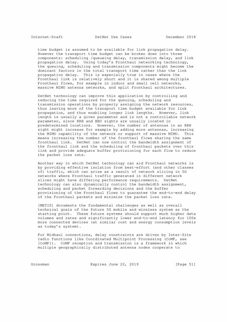
Internet-Draft DetNet Use Cases December 2018
time budget is assumed to be available for link propagation delay. However the transport time budget can be broken down into three components: scheduling /queueing delay, transmission delay, and link propagation delay. Using today’s Fronthaul networking technology, the queuing, scheduling and transmission components might become the dominant factors in the total transport time rather than the link propagation delay. This is especially true in cases where the Fronthaul link is relatively short and it is shared among multiple Fronthaul flows, for example in indoor and small cell networks, massive MIMO antenna networks, and split Fronthaul architectures.
DetNet technology can improve this application by controlling and reducing the time required for the queuing, scheduling and transmission operations by properly assigning the network resources, thus leaving more of the transport time budget available for link propagation, and thus enabling longer link lengths. However, link length is usually a given parameter and is not a controllable network parameter, since RRH and BBU sights are usually located in predetermined locations. However, the number of antennas in an RRH sight might increase for example by adding more antennas, increasing the MIMO capability of the network or support of massive MIMO. This means increasing the number of the fronthaul flows sharing the same fronthaul link. DetNet can now control the bandwidth assignment of the fronthaul link and the scheduling of fronthaul packets over this link and provide adequate buffer provisioning for each flow to reduce the packet loss rate.
Another way in which DetNet technology can aid Fronthaul networks is by providing effective isolation from best-effort (and other classes of) traffic, which can arise as a result of network slicing in 5G networks where Fronthaul traffic generated in different network slices might have differing performance requirements. DetNet technology can also dynamically control the bandwidth assignment, scheduling and packet forwarding decisions and the buffer provisioning of the Fronthaul flows to guarantee the end-to-end delay of the Fronthaul packets and minimize the packet loss rate.
[METIS] documents the fundamental challenges as well as overall technical goals of the future 5G mobile and wireless system as the starting point. These future systems should support much higher data volumes and rates and significantly lower end-to-end latency for 100x more connected devices (at similar cost and energy consumption levels as today’s system).
For Midhaul connections, delay constraints are driven by Inter-Site radio functions like Coordinated Multipoint Processing (CoMP, see [CoMP]). CoMP reception and transmission is a framework in which multiple geographically distributed antenna nodes cooperate to
Grossman Expires June 22, 2019 [Page 51]

Internet-Draft DetNet Use Cases December 2018
improve the performance of the users served in the common cooperation area. The design principal of CoMP is to extend single-cell to multi-UE (User Equipment) transmission to a multi-cell-to-multi-UEs transmission by base station cooperation.
CoMP has delay-sensitive performance parameters, which are "midhaul latency" and "CSI (Channel State Information) reporting and accuracy". The essential feature of CoMP is signaling between eNBs, so Midhaul latency is the dominating limitation of CoMP performance. Generally, CoMP can benefit from coordinated scheduling (either distributed or centralized) of different cells if the signaling delay between eNBs is within 1-10ms. This delay requirement is both rigid and absolute because any uncertainty in delay will degrade the performance significantly.
Inter-site CoMP is one of the key requirements for 5G and is also a goal for 4.5G network architecture.
6.1.3. Time Synchronization Constraints
Fronthaul time synchronization requirements are given by [TS25104], [TS36104], [TS36211], and [TS36133]. These can be summarized for the 3GPP LTE-based networks as:
Delay Accuracy: +-8ns (i.e. +-1/32 Tc, where Tc is the UMTS Chip time of 1/3.84 MHz) resulting in a round trip accuracy of +-16ns. The value is this low to meet the 3GPP Timing Alignment Error (TAE) measurement requirements. Note: performance guarantees of low nanosecond values such as these are considered to be below the DetNet layer - it is assumed that the underlying implementation, e.g. the hardware, will provide sufficient support (e.g. buffering) to enable this level of accuracy. These values are maintained in the use case to give an indication of the overall application.
Timing Alignment Error: Timing Alignment Error (TAE) is problematic to Fronthaul networks and must be minimized. If the transport network cannot guarantee low enough TAE then additional buffering has to be introduced at the edges of the network to buffer out the jitter. Buffering is not desirable as it reduces the total available delay budget. Packet Delay Variation (PDV) requirements can be derived from TAE for packet based Fronthaul networks.
Grossman Expires June 22, 2019 [Page 52]

Internet-Draft DetNet Use Cases December 2018
* For multiple input multiple output (MIMO) or TX diversity transmissions, at each carrier frequency, TAE shall not exceed 65 ns (i.e. 1/4 Tc).
* For intra-band contiguous carrier aggregation, with or without MIMO or TX diversity, TAE shall not exceed 130 ns (i.e. 1/2 Tc).
* For intra-band non-contiguous carrier aggregation, with or without MIMO or TX diversity, TAE shall not exceed 260 ns (i.e. one Tc).
* For inter-band carrier aggregation, with or without MIMO or TX diversity, TAE shall not exceed 260 ns.
Transport link contribution to radio frequency error: +-2 PPB. This value is considered to be "available" for the Fronthaul link out of the total 50 PPB budget reserved for the radio interface. Note: the reason that the transport link contributes to radio frequency error is as follows. At the time of this writing, Fronthaul communication is from the radio unit to remote radio head directly. The remote radio head is essentially a passive device (without buffering etc.) The transport drives the antenna directly by feeding it with samples and everything the transport adds will be introduced to radio as-is. So if the transport causes additional frequency error that shows immediately on the radio as well. Note: performance guarantees of low nanosecond values such as these are considered to be below the DetNet layer - it is assumed that the underlying implementation, e.g. the hardware, will provide sufficient support to enable this level of performance. These values are maintained in the use case to give an indication of the overall application.
The above listed time synchronization requirements are difficult to meet with point-to-point connected networks, and more difficult when the network includes multiple hops. It is expected that networks must include buffering at the ends of the connections as imposed by the jitter requirements, since trying to meet the jitter requirements in every intermediate node is likely to be too costly. However, every measure to reduce jitter and delay on the path makes it easier to meet the end-to-end requirements.
In order to meet the timing requirements both senders and receivers must remain time synchronized, demanding very accurate clock distribution, for example support for IEEE 1588 transparent clocks or boundary clocks in every intermediate node.
Grossman Expires June 22, 2019 [Page 53]
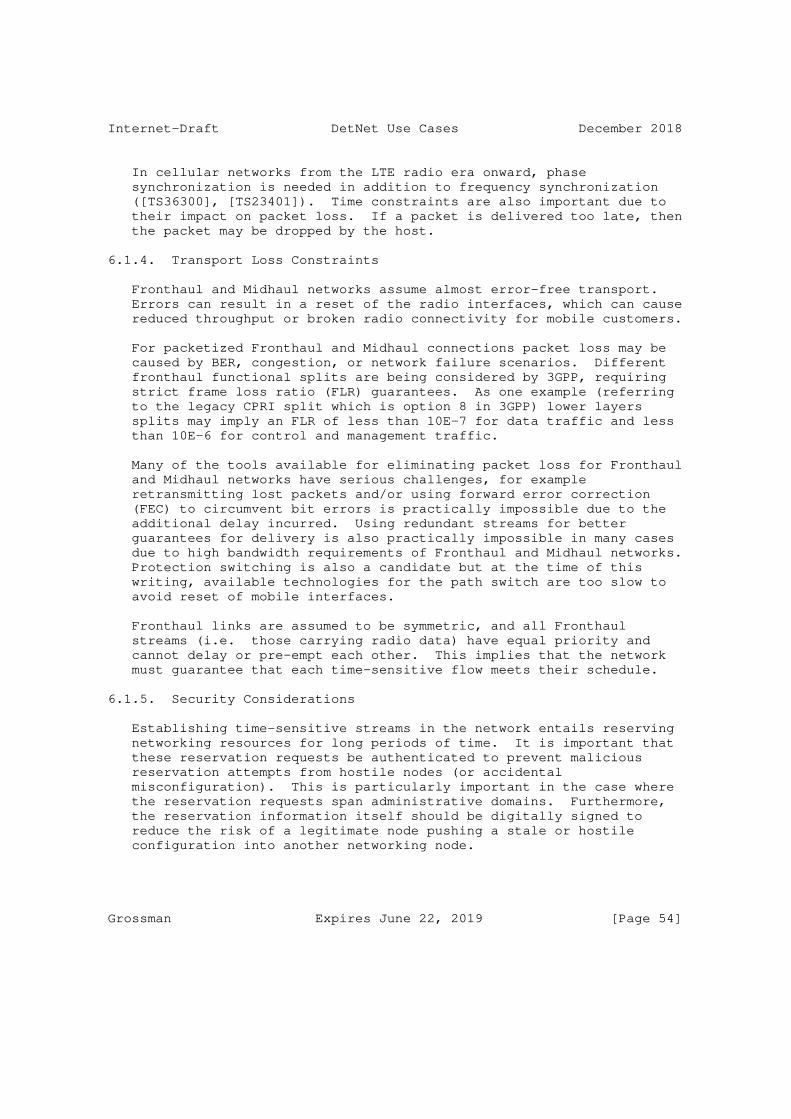
Internet-Draft DetNet Use Cases December 2018
In cellular networks from the LTE radio era onward, phase synchronization is needed in addition to frequency synchronization ([TS36300], [TS23401]). Time constraints are also important due to their impact on packet loss. If a packet is delivered too late, then the packet may be dropped by the host.
6.1.4. Transport Loss Constraints
Fronthaul and Midhaul networks assume almost error-free transport. Errors can result in a reset of the radio interfaces, which can cause reduced throughput or broken radio connectivity for mobile customers.
For packetized Fronthaul and Midhaul connections packet loss may be caused by BER, congestion, or network failure scenarios. Different fronthaul functional splits are being considered by 3GPP, requiring strict frame loss ratio (FLR) guarantees. As one example (referring to the legacy CPRI split which is option 8 in 3GPP) lower layers splits may imply an FLR of less than 10E-7 for data traffic and less than 10E-6 for control and management traffic.
Many of the tools available for eliminating packet loss for Fronthaul and Midhaul networks have serious challenges, for example retransmitting lost packets and/or using forward error correction (FEC) to circumvent bit errors is practically impossible due to the additional delay incurred. Using redundant streams for better guarantees for delivery is also practically impossible in many cases due to high bandwidth requirements of Fronthaul and Midhaul networks. Protection switching is also a candidate but at the time of this writing, available technologies for the path switch are too slow to avoid reset of mobile interfaces.
Fronthaul links are assumed to be symmetric, and all Fronthaul streams (i.e. those carrying radio data) have equal priority and cannot delay or pre-empt each other. This implies that the network must guarantee that each time-sensitive flow meets their schedule.
6.1.5. Security Considerations
Establishing time-sensitive streams in the network entails reserving networking resources for long periods of time. It is important that these reservation requests be authenticated to prevent malicious reservation attempts from hostile nodes (or accidental misconfiguration). This is particularly important in the case where the reservation requests span administrative domains. Furthermore, the reservation information itself should be digitally signed to reduce the risk of a legitimate node pushing a stale or hostile configuration into another networking node.
Grossman Expires June 22, 2019 [Page 54]

Internet-Draft DetNet Use Cases December 2018
Note: This is considered important for the security policy of the network, but does not affect the core DetNet architecture and design.
6.2. Cellular Radio Networks Today
6.2.1. Fronthaul
Today’s Fronthaul networks typically consist of:
o Dedicated point-to-point fiber connection is common
o Proprietary protocols and framings
o Custom equipment and no real networking
At the time of this writing, solutions for Fronthaul are direct optical cables or Wavelength-Division Multiplexing (WDM) connections.
6.2.2. Midhaul and Backhaul
Today’s Midhaul and Backhaul networks typically consist of:
o Mostly normal IP networks, MPLS-TP, etc.
o Clock distribution and sync using 1588 and SyncE
Telecommunication networks in the Mid- and Backhaul are already heading towards transport networks where precise time synchronization support is one of the basic building blocks. While the transport networks themselves have practically transitioned to all-IP packet- based networks to meet the bandwidth and cost requirements, highly accurate clock distribution has become a challenge.
In the past, Mid- and Backhaul connections were typically based on Time Division Multiplexing (TDM-based) and provided frequency synchronization capabilities as a part of the transport media. Alternatively other technologies such as Global Positioning System (GPS) or Synchronous Ethernet (SyncE) are used [SyncE].
Both Ethernet and IP/MPLS [RFC3031] (and PseudoWires (PWE) [RFC3985] for legacy transport support) have become popular tools to build and manage new all-IP Radio Access Networks (RANs) [I-D.kh-spring-ip-ran-use-case]. Although various timing and synchronization optimizations have already been proposed and implemented including 1588 PTP enhancements [I-D.ietf-tictoc-1588overmpls] and [RFC8169], these solution are not necessarily sufficient for the forthcoming RAN architectures nor do
Grossman Expires June 22, 2019 [Page 55]

Internet-Draft DetNet Use Cases December 2018
they guarantee the more stringent time-synchronization requirements such as [CPRI].
There are also existing solutions for TDM over IP such as [RFC4553], [RFC5086], and [RFC5087], as well as TDM over Ethernet transports such as [MEF8].
6.3. Cellular Radio Networks Future
Future Cellular Radio Networks will be based on a mix of different xHaul networks (xHaul = front-, mid- and backhaul), and future transport networks should be able to support all of them simultaneously. It is already envisioned today that:
o Not all "cellular radio network" traffic will be IP, for example some will remain at Layer 2 (e.g. Ethernet based). DetNet solutions must address all traffic types (Layer 2, Layer 3) with the same tools and allow their transport simultaneously.
o All forms of xHaul networks will need some form of DetNet solutions. For example with the advent of 5G some Backhaul traffic will also have DetNet requirements, for example traffic belonging to time-critical 5G applications.
o Different splits of the functionality run on the base stations and the on-site units could co-exist on the same Fronthaul and Backhaul network.
Future Cellular Radio networks should contain the following:
o Unified standards-based transport protocols and standard networking equipment that can make use of underlying deterministic link-layer services
o Unified and standards-based network management systems and protocols in all parts of the network (including Fronthaul)
New radio access network deployment models and architectures may require time- sensitive networking services with strict requirements on other parts of the network that previously were not considered to be packetized at all. Time and synchronization support are already topical for Backhaul and Midhaul packet networks [MEF22.1.1] and are becoming a real issue for Fronthaul networks also. Specifically in Fronthaul networks the timing and synchronization requirements can be extreme for packet based technologies, for example, on the order of sub +-20 ns packet delay variation (PDV) and frequency accuracy of +0.002 PPM [Fronthaul].
Grossman Expires June 22, 2019 [Page 56]

Internet-Draft DetNet Use Cases December 2018
The actual transport protocols and/or solutions to establish required transport "circuits" (pinned-down paths) for Fronthaul traffic are still undefined. Those are likely to include (but are not limited to) solutions directly over Ethernet, over IP, and using MPLS/ PseudoWire transport.
Interesting and important work for time-sensitive networking has been done for Ethernet [TSNTG], which specifies the use of IEEE 1588 time precision protocol (PTP) [IEEE1588] in the context of IEEE 802.1D and IEEE 802.1Q. [IEEE8021AS] specifies a Layer 2 time synchronizing service, and other specifications such as IEEE 1722 [IEEE1722] specify Ethernet-based Layer-2 transport for time-sensitive streams.
However even these Ethernet TSN features may not be sufficient for Fronthaul traffic. Therefore, having specific profiles that take the requirements of Fronthaul into account is desirable [IEEE8021CM].
New promising work seeks to enable the transport of time-sensitive fronthaul streams in Ethernet bridged networks [IEEE8021CM]. Analogous to IEEE 1722 there is an ongoing standardization effort to define the Layer-2 transport encapsulation format for transporting radio over Ethernet (RoE) in the IEEE 1904.3 Task Force [IEEE19143].
As mentioned in Section 6.1.2, 5G communications will provide one of the most challenging cases for delay sensitive networking. In order to meet the challenges of ultra-low latency and ultra-high throughput, 3GPP has studied various "functional splits" for 5G, i.e., physical decomposition of the gNodeB base station and deployment of its functional blocks in different locations [TR38801].
These splits are numbered from split option 1 (Dual Connectivity, a split in which the radio resource control is centralized and other radio stack layers are in distributed units) to split option 8 (a PHY-RF split in which RF functionality is in a distributed unit and the rest of the radio stack is in the centralized unit), with each intermediate split having its own data rate and delay requirements. Packetized versions of different splits have been proposed including eCPRI [eCPRI] and RoE (as previously noted). Both provide Ethernet encapsulations, and eCPRI is also capable of IP encapsulation.
All-IP RANs and xHaul networks would benefit from time synchronization and time-sensitive transport services. Although Ethernet appears to be the unifying technology for the transport, there is still a disconnect providing Layer 3 services. The protocol stack typically has a number of layers below the Ethernet Layer 2 that shows up to the Layer 3 IP transport. It is not uncommon that on top of the lowest layer (optical) transport there is the first layer of Ethernet followed one or more layers of MPLS, PseudoWires
Grossman Expires June 22, 2019 [Page 57]

Internet-Draft DetNet Use Cases December 2018
and/or other tunneling protocols finally carrying the Ethernet layer visible to the user plane IP traffic.
While there are existing technologies to establish circuits through the routed and switched networks (especially in MPLS/PWE space), there is still no way to signal the time synchronization and time- sensitive stream requirements/reservations for Layer-3 flows in a way that addresses the entire transport stack, including the Ethernet layers that need to be configured.
Furthermore, not all "user plane" traffic will be IP. Therefore, the same solution also must address the use cases where the user plane traffic is a different layer, for example Ethernet frames.
There is existing work describing the problem statement [I-D.ietf-detnet-problem-statement] and the architecture [I-D.ietf-detnet-architecture] for deterministic networking (DetNet) that targets solutions for time-sensitive (IP/transport) streams with deterministic properties over Ethernet-based switched networks.
6.4. Cellular Radio Networks Asks
A standard for data plane transport specification which is:
o Unified among all xHauls (meaning that different flows with diverse DetNet requirements can coexist in the same network and traverse the same nodes without interfering with each other)
o Deployed in a highly deterministic network environment
o Capable of supporting multiple functional splits simultaneously, including existing Backhaul and CPRI Fronthaul and potentially new modes as defined for example in 3GPP; these goals can be supported by the existing DetNet Use Case Common Themes, notably "Mix of Deterministic and Best-Effort Traffic", "Bounded Latency", "Low Latency", "Symmetrical Path Delays", and "Deterministic Flows".
o Capable of supporting Network Slicing and Multi-tenancy; these goals can be supported by the same DetNet themes noted above.
o Capable of transporting both in-band and out-band control traffic (OAM info, ...).
o Deployable over multiple data link technologies (e.g., IEEE 802.3, mmWave, etc.).
A standard for data flow information models that are:
Grossman Expires June 22, 2019 [Page 58]
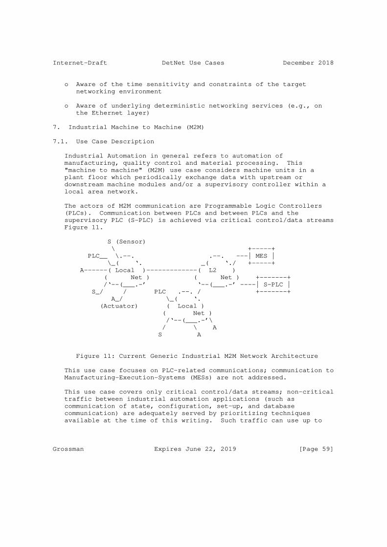
Internet-Draft DetNet Use Cases December 2018
o Aware of the time sensitivity and constraints of the target networking environment
o Aware of underlying deterministic networking services (e.g., on the Ethernet layer)
7. Industrial Machine to Machine (M2M)
7.1. Use Case Description
Industrial Automation in general refers to automation of manufacturing, quality control and material processing. This "machine to machine" (M2M) use case considers machine units in a plant floor which periodically exchange data with upstream or downstream machine modules and/or a supervisory controller within a local area network.
The actors of M2M communication are Programmable Logic Controllers (PLCs). Communication between PLCs and between PLCs and the supervisory PLC (S-PLC) is achieved via critical control/data streams Figure 11.
S (Sensor) \ +-----+ PLC__ \.--. .--. ---| MES | \_( ‘. _( ‘./ +-----+ A------( Local )-------------( L2 ) ( Net ) ( Net ) +-------+ /‘--(___.-’ ‘--(___.-’ ----| S-PLC | S_/ / PLC .--. / +-------+ A_/ \_( ‘. (Actuator) ( Local ) ( Net ) /‘--(___.-’\ / \ A S A
Figure 11: Current Generic Industrial M2M Network Architecture
This use case focuses on PLC-related communications; communication to Manufacturing-Execution-Systems (MESs) are not addressed.
This use case covers only critical control/data streams; non-critical traffic between industrial automation applications (such as communication of state, configuration, set-up, and database communication) are adequately served by prioritizing techniques available at the time of this writing. Such traffic can use up to
Grossman Expires June 22, 2019 [Page 59]

Internet-Draft DetNet Use Cases December 2018
80% of the total bandwidth required. There is also a subset of non- time-critical traffic that must be reliable even though it is not time-sensitive.
In this use case the primary need for deterministic networking is to provide end-to-end delivery of M2M messages within specific timing constraints, for example in closed loop automation control. Today this level of determinism is provided by proprietary networking technologies. In addition, standard networking technologies are used to connect the local network to remote industrial automation sites, e.g. over an enterprise or metro network which also carries other types of traffic. Therefore, flows that should be forwarded with deterministic guarantees need to be sustained regardless of the amount of other flows in those networks.
7.2. Industrial M2M Communication Today
Today, proprietary networks fulfill the needed timing and availability for M2M networks.
The network topologies used today by industrial automation are similar to those used by telecom networks: Daisy Chain, Ring, Hub and Spoke, and Comb (a subset of Daisy Chain).
PLC-related control/data streams are transmitted periodically and carry either a pre-configured payload or a payload configured during runtime.
Some industrial applications require time synchronization at the end nodes. For such time-coordinated PLCs, accuracy of 1 microsecond is required. Even in the case of "non-time-coordinated" PLCs time sync may be needed e.g. for timestamping of sensor data.
Industrial network scenarios require advanced security solutions. At the time of this writing, many industrial production networks are physically separated. Preventing critical flows from being leaked outside a domain is handled by filtering policies that are typically enforced in firewalls.
7.2.1. Transport Parameters
The Cycle Time defines the frequency of message(s) between industrial actors. The Cycle Time is application dependent, in the range of 1ms - 100ms for critical control/data streams.
Because industrial applications assume deterministic transport for critical Control-Data-Stream parameters (instead of defining latency and delay variation parameters) it is sufficient to fulfill the upper
Grossman Expires June 22, 2019 [Page 60]

Internet-Draft DetNet Use Cases December 2018
bound of latency (maximum latency). The underlying networking infrastructure must ensure a maximum end-to-end delivery time of messages in the range of 100 microseconds to 50 milliseconds depending on the control loop application.
The bandwidth requirements of control/data streams are usually calculated directly from the bytes-per-cycle parameter of the control loop. For PLC-to-PLC communication one can expect 2 - 32 streams with packet size in the range of 100 - 700 bytes. For S-PLC to PLCs the number of streams is higher - up to 256 streams. Usually no more than 20% of available bandwidth is used for critical control/data streams. In today’s networks 1Gbps links are commonly used.
Most PLC control loops are rather tolerant of packet loss, however critical control/data streams accept no more than 1 packet loss per consecutive communication cycle (i.e. if a packet gets lost in cycle "n", then the next cycle ("n+1") must be lossless). After two or more consecutive packet losses the network may be considered to be "down" by the Application.
As network downtime may impact the whole production system the required network availability is rather high (99.999%).
Based on the above parameters some form of redundancy will be required for M2M communications, however any individual solution depends on several parameters including cycle time, delivery time, etc.
7.2.2. Stream Creation and Destruction
In an industrial environment, critical control/data streams are created rather infrequently, on the order of ˜10 times per day / week / month. Most of these critical control/data streams get created at machine startup, however flexibility is also needed during runtime, for example when adding or removing a machine. Going forward as production systems become more flexible, there will be a significant increase in the rate at which streams are created, changed and destroyed.
7.3. Industrial M2M Future
We foresee a converged IP-standards-based network with deterministic properties that can satisfy the timing, security and reliability constraints described above. Today’s proprietary networks could then be interfaced to such a network via gateways or, in the case of new installations, devices could be connected directly to the converged network.
Grossman Expires June 22, 2019 [Page 61]

Internet-Draft DetNet Use Cases December 2018
For this use case time synchronization accuracy on the order of 1us is expected.
7.4. Industrial M2M Asks
o Converged IP-based network
o Deterministic behavior (bounded latency and jitter )
o High availability (presumably through redundancy) (99.999 %)
o Low message delivery time (100us - 50ms)
o Low packet loss (with bounded number of consecutive lost packets)
o Security (e.g. prevent critical flows from being leaked between physically separated networks)
8. Mining Industry
8.1. Use Case Description
The mining industry is highly dependent on networks to monitor and control their systems both in open-pit and underground extraction, transport and refining processes. In order to reduce risks and increase operational efficiency in mining operations, a number of processes have migrated the operators from the extraction site to remote control and monitoring.
In the case of open pit mining, autonomous trucks are used to transport the raw materials from the open pit to the refining factory where the final product (e.g. Copper) is obtained. Although the operation is autonomous, the tracks are remotely monitored from a central facility.
In pit mines, the monitoring of the tailings or mine dumps is critical in order to minimize environmental pollution. In the past, monitoring has been conducted through manual inspection of pre- installed dataloggers. Cabling is not usually exploited in such scenarios due to the cost and complex deployment requirements. At the time of this writing, wireless technologies are being employed to monitor these cases permanently. Slopes are also monitored in order to anticipate possible mine collapse. Due to the unstable terrain, cable maintenance is costly and complex and hence wireless technologies are employed.
In the underground monitoring case, autonomous vehicles with extraction tools travel autonomously through the tunnels, but their
Grossman Expires June 22, 2019 [Page 62]

Internet-Draft DetNet Use Cases December 2018
operational tasks (such as excavation, stone breaking and transport) are controlled remotely from a central facility. This generates video and feedback upstream traffic plus downstream actuator control traffic.
8.2. Mining Industry Today
At the time of this writing, the mining industry uses a packet switched architecture supported by high speed ethernet. However in order to achieve the delay and packet loss requirements the network bandwidth is overestimated, thus providing very low efficiency in terms of resource usage.
QoS is implemented at the Routers to separate video, management, monitoring and process control traffic for each stream.
Since mobility is involved in this process, the connection between the backbone and the mobile devices (e.g. trucks, trains and excavators) is solved using a wireless link. These links are based on 802.11 for open-pit mining and "leaky feeder" communications for underground mining. (A "leaky feeder" communication system consists of a coaxial cable run along tunnels which emits and receives radio waves, functioning as an extended antenna. The cable is "leaky" in that it has gaps or slots in its outer conductor to allow the radio signal to leak into or out of the cable along its entire length.)
Lately in pit mines the use of LPWAN technologies has been extended: Tailings, slopes and mine dumps are monitored by battery-powered dataloggers that make use of robust long range radio technologies. Reliability is usually ensured through retransmissions at L2. Gateways or concentrators act as bridges forwarding the data to the backbone ethernet network. Deterministic requirements are biased towards reliability rather than latency as events are slowly triggered or can be anticipated in advance.
At the mineral processing stage, conveyor belts and refining processes are controlled by a SCADA system, which provides the in- factory delay-constrained networking requirements.
At the time of this writing, voice communications are served by a redundant trunking infrastructure, independent from data networks.
8.3. Mining Industry Future
Mining operations and management are converging towards a combination of autonomous operation and teleoperation of transport and extraction machines. This means that video, audio, monitoring and process
Grossman Expires June 22, 2019 [Page 63]

Internet-Draft DetNet Use Cases December 2018
control traffic will increase dramatically. Ideally, all activities on the mine will rely on network infrastructure.
Wireless for open-pit mining is already a reality with LPWAN technologies and it is expected to evolve to more advanced LPWAN technologies such as those based on LTE to increase last hop reliability or novel LPWAN flavours with deterministic access.
One area in which DetNet can improve this use case is in the wired networks that make up the "backbone network" of the system, which connect together many wireless access points (APs). The mobile machines (which are connected to the network via wireless) transition from one AP to the next as they move about. A deterministic, reliable, low latency backbone can enable these transitions to be more reliable.
Connections which extend all the way from the base stations to the machinery via a mix of wired and wireless hops would also be beneficial, for example to improve remote control responsiveness of digging machines. However to guarantee deterministic performance of a DetNet, the end-to-end underlying network must be deterministic. Thus for this use case if a deterministic wireless transport is integrated with a wire-based DetNet network, it could create the desired wired plus wireless end-to-end deterministic network.
8.4. Mining Industry Asks
o Improved bandwidth efficiency
o Very low delay to enable machine teleoperation
o Dedicated bandwidth usage for high resolution video streams
o Predictable delay to enable realtime monitoring
o Potential to construct a unified DetNet network over a combination of wired and deterministic wireless links
9. Private Blockchain
9.1. Use Case Description
Blockchain was created with bitcoin as a ’public’ blockchain on the open Internet, however blockchain has also spread far beyond its original host into various industries such as smart manufacturing, logistics, security, legal rights and others. In these industries blockchain runs in designated and carefully managed networks in which
Grossman Expires June 22, 2019 [Page 64]

Internet-Draft DetNet Use Cases December 2018
deterministic networking requirements could be addressed by DetNet. Such implementations are referred to as ’private’ blockchain.
The sole distinction between public and private blockchain is defined by who is allowed to participate in the network, execute the consensus protocol, and maintain the shared ledger.
Today’s networks treat the traffic from blockchain on a best-effort basis, but blockchain operation could be made much more efficient if deterministic networking services were available to minimize latency and packet loss in the network.
9.1.1. Blockchain Operation
A ’block’ runs as a container of a batch of primary items such as transactions, property records etc. The blocks are chained in such a way that the hash of the previous block works as the pointer to the header of the new block. Confirmation of each block requires a consensus mechanism. When an item arrives at a blockchain node, the latter broadcasts this item to the rest of the nodes which receive and verify it and put it in the ongoing block. The block confirmation process begins as the number of items reaches the predefined block capacity, at which time the node broadcasts its proved block to the rest of the nodes, to be verified and chained. The result is that block N+1 of each chain transitively vouches for blocks N and before of that chain.
9.1.2. Blockchain Network Architecture
Blockchain node communication and coordination is achieved mainly through frequent point-to-multi-point communication, however persistent point-to-point connections are used to transport both the items and the blocks to the other nodes. For example, consider the following implementation.
When a node is initiated, it first requests the other nodes’ address from a specific entity such as DNS, then it creates persistent connections each of with other nodes. If a node confirms an item, it sends the item to the other nodes via these persistent connections.
As a new block in a node is completed and is proven by the surrounding nodes, it propagates towards its neighbor nodes. When node A receives a block, it verifies it, then sends an invite message to its neighbor B. Neighbor B checks to see if the designated block is available, and responds to A if it is unavailable, then A sends the complete block to B. B repeats the process (as done by A above) to start the next round of block propagation.
Grossman Expires June 22, 2019 [Page 65]
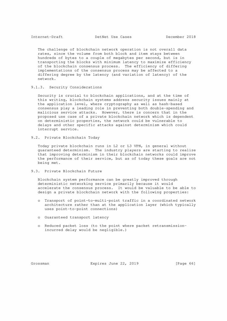
Internet-Draft DetNet Use Cases December 2018
The challenge of blockchain network operation is not overall data rates, since the volume from both block and item stays between hundreds of bytes to a couple of megabytes per second, but is in transporting the blocks with minimum latency to maximize efficiency of the blockchain consensus process. The efficiency of differing implementations of the consensus process may be affected to a differing degree by the latency (and variation of latency) of the network.
9.1.3. Security Considerations
Security is crucial to blockchain applications, and at the time of this writing, blockchain systems address security issues mainly at the application level, where cryptography as well as hash-based consensus play a leading role in preventing both double-spending and malicious service attacks. However, there is concern that in the proposed use case of a private blockchain network which is dependent on deterministic properties, the network could be vulnerable to delays and other specific attacks against determinism which could interrupt service.
9.2. Private Blockchain Today
Today private blockchain runs in L2 or L3 VPN, in general without guaranteed determinism. The industry players are starting to realize that improving determinism in their blockchain networks could improve the performance of their service, but as of today these goals are not being met.
9.3. Private Blockchain Future
Blockchain system performance can be greatly improved through deterministic networking service primarily because it would accelerate the consensus process. It would be valuable to be able to design a private blockchain network with the following properties:
o Transport of point-to-multi-point traffic in a coordinated network architecture rather than at the application layer (which typically uses point-to-point connections)
o Guaranteed transport latency
o Reduced packet loss (to the point where packet retransmission- incurred delay would be negligible.)
Grossman Expires June 22, 2019 [Page 66]

Internet-Draft DetNet Use Cases December 2018
9.4. Private Blockchain Asks
o Layer 2 and Layer 3 multicast of blockchain traffic
o Item and block delivery with bounded, low latency and negligible packet loss
o Coexistence in a single network of blockchain and IT traffic.
o Ability to scale the network by distributing the centralized control of the network across multiple control entities.
10. Network Slicing
10.1. Use Case Description
Network Slicing divides one physical network infrastructure into multiple logical networks. Each slice, corresponding to a logical network, uses resources and network functions independently from each other. Network Slicing provides flexibility of resource allocation and service quality customization.
Future services will demand network performance with a wide variety of characteristics such as high data rate, low latency, low loss rate, security and many other parameters. Ideally every service would have its own physical network satisfying its particular performance requirements, however that would be prohibitively expensive. Network Slicing can provide a customized slice for a single service, and multiple slices can share the same physical network. This method can optimize the performance for the service at lower cost, and the flexibility of setting up and release the slices also allows the user to allocate the network resources dynamically.
Unlike the other use cases presented here, Network Slicing is not a specific application that depends on specific deterministic properties; rather it is introduced as an area of networking to which DetNet might be applicable.
10.2. DetNet Applied to Network Slicing
10.2.1. Resource Isolation Across Slices
One of the requirements discussed for Network Slicing is the "hard" separation of various users’ deterministic performance. That is, it should be impossible for activity, lack of activity, or changes in activity of one or more users to have any appreciable effect on the deterministic performance parameters of any other slices. Typical techniques used today, which share a physical network among users, do
Grossman Expires June 22, 2019 [Page 67]

Internet-Draft DetNet Use Cases December 2018
not offer this level of isolation. DetNet can supply point-to-point or point-to-multipoint paths that offer bandwidth and latency guarantees to a user that cannot be affected by other users’ data traffic. Thus DetNet is a powerful tool when latency and reliability are required in Network Slicing.
10.2.2. Deterministic Services Within Slices
Slices may need to provide services with DetNet-type performance guarantees, however note that a system can be implemented to provide such services in more than one way. For example the slice itself might be implemented using DetNet, and thus the slice can provide service guarantees and isolation to its users without any particular DetNet awareness on the part of the users’ applications. Alternatively, a "non-DetNet-aware" slice may host an application that itself implements DetNet services and thus can enjoy similar service guarantees.
10.3. A Network Slicing Use Case Example - 5G Bearer Network
Network Slicing is a core feature of 5G defined in 3GPP, which is under development at the time of this writing [TR38501]. A network slice in a mobile network is a complete logical network including Radio Access Network (RAN) and Core Network (CN). It provides telecommunication services and network capabilities, which may vary from slice to slice. A 5G bearer network is a typical use case of Network Slicing; for example consider three 5G service scenarios: eMMB, URLLC, and mMTC.
o eMBB (Enhanced Mobile Broadband) focuses on services characterized by high data rates, such as high definition videos, virtual reality, augmented reality, and fixed mobile convergence.
o URLLC (Ultra-Reliable and Low Latency Communications) focuses on latency-sensitive services, such as self-driving vehicles, remote surgery, or drone control.
o mMTC (massive Machine Type Communications) focuses on services that have high requirements for connection density, such as those typical for smart city and smart agriculture use cases.
A 5G bearer network could use DetNet to provide hard resource isolation across slices and within the slice. For example consider Slice-A and Slice-B, with DetNet used to transit services URLLC-A and URLLC-B over them. Without DetNet, URLLC-A and URLLC-B would compete for bandwidth resource, and latency and reliability would not be guaranteed. With DetNet, URLLC-A and URLLC-B have separate bandwidth
Grossman Expires June 22, 2019 [Page 68]

Internet-Draft DetNet Use Cases December 2018
reservation and there is no resource conflict between them, as though they were in different logical networks.
10.4. Non-5G Applications of Network Slicing
Although operation of services not related to 5G is not part of the 5G Network Slicing definition and scope, Network Slicing is likely to become a preferred approach to providing various services across a shared physical infrastructure. Examples include providing electrical utilities services and pro audio services via slices. Use cases like these could become more common once the work for the 5G core network evolves to include wired as well as wireless access.
10.5. Limitations of DetNet in Network Slicing
DetNet cannot cover every Network Slicing use case. One issue is that DetNet is a point-to-point or point-to-multipoint technology, however Network Slicing ultimately needs multi-point to multi-point guarantees. Another issue is that the number of flows that can be carried by DetNet is limited by DetNet scalability; flow aggregation and queuing management modification may help address this. Additional work and discussion are needed to address these topics.
10.6. Network Slicing Today and Future
Network Slicing has the promise to satisfy many requirements of future network deployment scenarios, but it is still a collection of ideas and analysis, without a specific technical solution. DetNet is one of various technologies that have potential to be used in Network Slicing, along with for example Flex-E and Segment Routing. For more information please see the IETF99 Network Slicing BOF session agenda and materials.
10.7. Network Slicing Asks
o Isolation from other flows through Queuing Management
o Service Quality Customization and Guarantee
o Security
11. Use Case Common Themes
This section summarizes the expected properties of a DetNet network, based on the use cases as described in this draft.
Grossman Expires June 22, 2019 [Page 69]

Internet-Draft DetNet Use Cases December 2018
11.1. Unified, standards-based network
11.1.1. Extensions to Ethernet
A DetNet network is not "a new kind of network" - it based on extensions to existing Ethernet standards, including elements of IEEE 802.1 AVB/TSN and related standards. Presumably it will be possible to run DetNet over other underlying transports besides Ethernet, but Ethernet is explicitly supported.
11.1.2. Centrally Administered
In general a DetNet network is not expected to be "plug and play" - it is expected that there is some centralized network configuration and control system. Such a system may be in a single central location, or it maybe distributed across multiple control entities that function together as a unified control system for the network. However, the ability to "hot swap" components (e.g. due to malfunction) is similar enough to "plug and play" that this kind of behavior may be expected in DetNet networks, depending on the implementation.
11.1.3. Standardized Data Flow Information Models
Data Flow Information Models to be used with DetNet networks are to be specified by DetNet.
11.1.4. L2 and L3 Integration
A DetNet network is intended to integrate between Layer 2 (bridged) network(s) (e.g. AVB/TSN LAN) and Layer 3 (routed) network(s) (e.g. using IP-based protocols). One example of this is "making AVB/TSN- type deterministic performance available from Layer 3 applications, e.g. using RTP". Another example is "connecting two AVB/TSN LANs ("islands") together through a standard router".
11.1.5. Consideration for IPv4
This Use Cases draft explicitly does not specify any particular implementation or protocol, however it has been observed that various of the use cases described (and their associated industries) are explicitly based on IPv4 (as opposed to IPv6) and it is not considered practical to expect them to migrate to IPv6 in order to use DetNet. Thus the expectation is that even if not every feature of DetNet is available in an IPv4 context, at least some of the significant benefits (such as guaranteed end-to-end delivery and low latency) are expected to be available.
Grossman Expires June 22, 2019 [Page 70]

Internet-Draft DetNet Use Cases December 2018
11.1.6. Guaranteed End-to-End Delivery
Packets in a DetNet flow are guaranteed not to be dropped by the network due to congestion. However, the network may drop packets for intended reasons, e.g. per security measures. Similarly best-effort traffic on a DetNet is subject to being dropped (as on a non-DetNet IP network). Also note that this guarantee applies to the actions of DetNet protocol software, and does not provide any guarantee against lower level errors such as media errors or checksum errors.
11.1.7. Replacement for Multiple Proprietary Deterministic Networks
There are many proprietary non-interoperable deterministic Ethernet- based networks available; DetNet is intended to provide an open- standards-based alternative to such networks.
11.1.8. Mix of Deterministic and Best-Effort Traffic
DetNet is intended to support coexistance of time-sensitive operational (OT) traffic and information (IT) traffic on the same ("unified") network.
11.1.9. Unused Reserved BW to be Available to Best-Effort Traffic
If bandwidth reservations are made for a stream but the associated bandwidth is not used at any point in time, that bandwidth is made available on the network for best-effort traffic. If the owner of the reserved stream then starts transmitting again, the bandwidth is no longer available for best-effort traffic, on a moment-to-moment basis. Note that such "temporarily available" bandwidth is not available for time-sensitive traffic, which must have its own reservation.
11.1.10. Lower Cost, Multi-Vendor Solutions
The DetNet network specifications are intended to enable an ecosystem in which multiple vendors can create interoperable products, thus promoting device diversity and potentially higher numbers of each device manufactured, promoting cost reduction and cost competition among vendors. The intent is that DetNet networks should be able to be created at lower cost and with greater diversity of available devices than existing proprietary networks.
11.2. Scalable Size
DetNet networks range in size from very small, e.g. inside a single industrial machine, to very large, for example a Utility Grid network spanning a whole country, and involving many "hops" over various
Grossman Expires June 22, 2019 [Page 71]

Internet-Draft DetNet Use Cases December 2018
kinds of links for example radio repeaters, microwave linkes, fiber optic links, etc.. However recall that the scope of DetNet is confined to networks that are centrally administered, and explicitly excludes unbounded decentralized networks such as the Internet.
11.2.1. Scalable Number of Flows
The number of flows in a given network application can potentially be large, and can potentially grow faster than the number of nodes and hops. So the network should provide a sufficient (perhaps configurable) maximum number of flows for any given application.
11.3. Scalable Timing Parameters and Accuracy
11.3.1. Bounded Latency
The DetNet Data Flow Information Model is expected to provide means to configure the network that include parameters for querying network path latency, requesting bounded latency for a given stream, requesting worst case maximum and/or minimum latency for a given path or stream, and so on. It is an expected case that the network may not be able to provide a given requested service level, and if so the network control system should reply that the requested services is not available (as opposed to accepting the parameter but then not delivering the desired behavior).
11.3.2. Low Latency
Applications may require "extremely low latency" however depending on the application these may mean very different latency values; for example "low latency" across a Utility grid network is on a different time scale than "low latency" in a motor control loop in a small machine. The intent is that the mechanisms for specifying desired latency include wide ranges, and that architecturally there is nothing to prevent arbirtrarily low latencies from being implemented in a given network.
11.3.3. Bounded Jitter (Latency Variation)
As with the other Latency-related elements noted above, parameters should be available to determine or request the allowed variation in latency.
11.3.4. Symmetrical Path Delays
Some applications would like to specify that the transit delay time values be equal for both the transmit and return paths.
Grossman Expires June 22, 2019 [Page 72]
Internet-Draft DetNet Use Cases December 2018
11.4. High Reliability and Availability
Reliablity is of critical importance to many DetNet applications, in which consequences of failure can be extraordinarily high in terms of cost and even human life. DetNet based systems are expected to be implemented with essentially arbitrarily high availability (for example 99.9999% up time, or even 12 nines). The intent is that the DetNet designs should not make any assumptions about the level of reliability and availability that may be required of a given system, and should define parameters for communicating these kinds of metrics within the network.
A strategy used by DetNet for providing such extraordinarily high levels of reliability is to provide redundant paths that can be seamlessly switched between, while maintaining the required performance of that system.
11.5. Security
Security is of critical importance to many DetNet applications. A DetNet network must be able to be made secure against devices failures, attackers, misbehaving devices, and so on. In a DetNet network the data traffic is expected to be be time-sensitive, thus in addition to arriving with the data content as intended, the data must also arrive at the expected time. This may present "new" security challenges to implementers, and must be addressed accordingly. There are other security implications, including (but not limited to) the change in attack surface presented by packet replication and elimination.
11.6. Deterministic Flows
Reserved bandwidth data flows must be isolated from each other and from best-effort traffic, so that even if the network is saturated with best-effort (and/or reserved bandwidth) traffic, the configured flows are not adversely affected.
12. Security Considerations
This document covers a number of representative applications and network scenarios that are expected to make use of DetNet technologies. Each of the potential DetNet uses cases will have security considerations from both the use-specific and DetNet technology perspectives. While some use-specific security considerations are discussed above, a more comprehensive discussion of such considerations is captured in DetNet Security Considerations [I-D.ietf-detnet-security]. Readers are encouraged to review this
Grossman Expires June 22, 2019 [Page 73]

Internet-Draft DetNet Use Cases December 2018
document to gain a more complete understanding of DetNet related security considerations.
13. Contributors
RFC7322 limits the number of authors listed on the front page of a draft to a maximum of 5, far fewer than the 20 individuals below who made important contributions to this draft. The editor wishes to thank and acknowledge each of the following authors for contributing text to this draft. See also Section 14.
Craig Gunther (Harman International) 10653 South River Front Parkway, South Jordan,UT 84095 phone +1 801 568-7675, email [email protected]
Pascal Thubert (Cisco Systems, Inc) Building D, 45 Allee des Ormes - BP1200, MOUGINS Sophia Antipolis 06254 FRANCE phone +33 497 23 26 34, email [email protected]
Patrick Wetterwald (Cisco Systems) 45 Allees des Ormes, Mougins, 06250 FRANCE phone +33 4 97 23 26 36, email [email protected]
Jean Raymond (Hydro-Quebec) 1500 University, Montreal, H3A3S7, Canada phone +1 514 840 3000, email [email protected]
Jouni Korhonen (Broadcom Corporation) 3151 Zanker Road, San Jose, 95134, CA, USA email [email protected]
Yu Kaneko (Toshiba) 1 Komukai-Toshiba-cho, Saiwai-ku, Kasasaki-shi, Kanagawa, Japan email [email protected]
Subir Das (Vencore Labs) 150 Mount Airy Road, Basking Ridge, New Jersey, 07920, USA email [email protected]
Balazs Varga (Ericsson) Konyves Kalman krt. 11/B, Budapest, Hungary, 1097 email [email protected]
Janos Farkas (Ericsson) Konyves Kalman krt. 11/B, Budapest, Hungary, 1097 email [email protected]
Grossman Expires June 22, 2019 [Page 74]
Internet-Draft DetNet Use Cases December 2018
Franz-Josef Goetz (Siemens) Gleiwitzerstr. 555, Nurnberg, Germany, 90475 email [email protected]
Juergen Schmitt (Siemens) Gleiwitzerstr. 555, Nurnberg, Germany, 90475 email [email protected]
Xavier Vilajosana (Worldsensing) 483 Arago, Barcelona, Catalonia, 08013, Spain email [email protected]
Toktam Mahmoodi (King’s College London) Strand, London WC2R 2LS, United Kingdom email [email protected]
Spiros Spirou (Intracom Telecom) 19.7 km Markopoulou Ave., Peania, Attiki, 19002, Greece email [email protected]
Petra Vizarreta (Technical University of Munich) Maxvorstadt, ArcisstraBe 21, Munich, 80333, Germany email [email protected]
Daniel Huang (ZTE Corporation, Inc.) No. 50 Software Avenue, Nanjing, Jiangsu, 210012, P.R. China email [email protected]
Xuesong Geng (Huawei Technologies) email [email protected]
Diego Dujovne (Universidad Diego Portales) email [email protected]
Maik Seewald (Cisco Systems) email [email protected]
14. Acknowledgments
14.1. Pro Audio
This section was derived from draft-gunther-detnet-proaudio-req-01.
The editors would like to acknowledge the help of the following individuals and the companies they represent:
Jeff Koftinoff, Meyer Sound
Grossman Expires June 22, 2019 [Page 75]

Internet-Draft DetNet Use Cases December 2018
Jouni Korhonen, Associate Technical Director, Broadcom
Pascal Thubert, CTAO, Cisco
Kieran Tyrrell, Sienda New Media Technologies GmbH
14.2. Utility Telecom
This section was derived from draft-wetterwald-detnet-utilities-reqs- 02.
Faramarz Maghsoodlou, Ph. D. IoT Connected Industries and Energy Practice Cisco
Pascal Thubert, CTAO Cisco
The wind power generation use case has been extracted from the study of Wind Farms conducted within the 5GPPP Virtuwind Project. The project is funded by the European Union’s Horizon 2020 research and innovation programme under grant agreement No 671648 (VirtuWind).
14.3. Building Automation Systems
This section was derived from draft-bas-usecase-detnet-00.
14.4. Wireless for Industrial Applications
This section was derived from draft-thubert-6tisch-4detnet-01.
This specification derives from the 6TiSCH architecture, which is the result of multiple interactions, in particular during the 6TiSCH (bi)Weekly Interim call, relayed through the 6TiSCH mailing list at the IETF.
The authors wish to thank: Kris Pister, Thomas Watteyne, Xavier Vilajosana, Qin Wang, Tom Phinney, Robert Assimiti, Michael Richardson, Zhuo Chen, Malisa Vucinic, Alfredo Grieco, Martin Turon, Dominique Barthel, Elvis Vogli, Guillaume Gaillard, Herman Storey, Maria Rita Palattella, Nicola Accettura, Patrick Wetterwald, Pouria Zand, Raghuram Sudhaakar, and Shitanshu Shah for their participation and various contributions.
14.5. Cellular Radio
This section was derived from draft-korhonen-detnet-telreq-00.
Grossman Expires June 22, 2019 [Page 76]
Internet-Draft DetNet Use Cases December 2018
14.6. Industrial Machine to Machine (M2M)
The authors would like to thank Feng Chen and Marcel Kiessling for their comments and suggestions.
14.7. Internet Applications and CoMP
This section was derived from draft-zha-detnet-use-case-00 by Yiyong Zha.
This document has benefited from reviews, suggestions, comments and proposed text provided by the following members, listed in alphabetical order: Jing Huang, Junru Lin, Lehong Niu and Oilver Huang.
14.8. Network Slicing
This section was written by Xuesong Geng, who would like to acknowledge Norm Finn and Mach Chen for their useful comments.
14.9. Mining
This section was written by Diego Dujovne in conjunction with Xavier Vilasojana.
14.10. Private Blockchain
This section was written by Daniel Huang.
15. IANA Considerations
This memo includes no requests from IANA.
16. Informative References
[Ahm14] Ahmed, M. and R. Kim, "Communication network architectures for smart-wind power farms.", Energies, p. 3900-3921. , June 2014.
[bacnetip] ASHRAE, "Annex J to ANSI/ASHRAE 135-1995 - BACnet/IP", January 1999.
[CoMP] NGMN Alliance, "RAN EVOLUTION PROJECT COMP EVALUATION AND ENHANCEMENT", NGMN Alliance NGMN_RANEV_D3_CoMP_Evaluation_ and_Enhancement_v2.0, March 2015, <https://www.ngmn.org/uploads/media/ NGMN_RANEV_D3_CoMP_Evaluation_and_Enhancement_v2.0.pdf>.
Grossman Expires June 22, 2019 [Page 77]

Internet-Draft DetNet Use Cases December 2018
[CONTENT_PROTECTION] Olsen, D., "1722a Content Protection", 2012, <http://grouper.ieee.org/groups/1722/contributions/2012/ avtp_dolsen_1722a_content_protection.pdf>.
[CPRI] CPRI Cooperation, "Common Public Radio Interface (CPRI); Interface Specification", CPRI Specification V6.1, July 2014, <http://www.cpri.info/downloads/ CPRI_v_6_1_2014-07-01.pdf>.
[DCI] Digital Cinema Initiatives, LLC, "DCI Specification, Version 1.2", 2012, <http://www.dcimovies.com/>.
[eCPRI] IEEE Standards Association, "Common Public Radio Interface, "Common Public Radio Interface: eCPRI Interface Specification V1.0", 2017, <http://www.cpri.info/>.
[ESPN_DC2] Daley, D., "ESPN’s DC2 Scales AVB Large", 2014, <http://sportsvideo.org/main/blog/2014/06/ espns-dc2-scales-avb-large>.
[flnet] Japan Electrical Manufacturers Association, "JEMA 1479 - English Edition", September 2012.
[Fronthaul] Chen, D. and T. Mustala, "Ethernet Fronthaul Considerations", IEEE 1904.3, February 2015, <http://www.ieee1904.org/3/meeting_archive/2015/02/ tf3_1502_che n_1a.pdf>.
[I-D.ietf-6tisch-6top-interface] Wang, Q. and X. Vilajosana, "6TiSCH Operation Sublayer (6top) Interface", draft-ietf-6tisch-6top-interface-04 (work in progress), July 2015.
[I-D.ietf-6tisch-architecture] Thubert, P., "An Architecture for IPv6 over the TSCH mode of IEEE 802.15.4", draft-ietf-6tisch-architecture-19 (work in progress), December 2018.
[I-D.ietf-6tisch-coap] Sudhaakar, R. and P. Zand, "6TiSCH Resource Management and Interaction using CoAP", draft-ietf-6tisch-coap-03 (work in progress), March 2015.
Grossman Expires June 22, 2019 [Page 78]
Internet-Draft DetNet Use Cases December 2018
[I-D.ietf-detnet-architecture] Finn, N., Thubert, P., Varga, B., and J. Farkas, "Deterministic Networking Architecture", draft-ietf- detnet-architecture-09 (work in progress), October 2018.
[I-D.ietf-detnet-problem-statement] Finn, N. and P. Thubert, "Deterministic Networking Problem Statement", draft-ietf-detnet-problem-statement-08 (work in progress), December 2018.
[I-D.ietf-detnet-security] Mizrahi, T., Grossman, E., Hacker, A., Das, S., Dowdell, J., Austad, H., Stanton, K., and N. Finn, "Deterministic Networking (DetNet) Security Considerations", draft-ietf- detnet-security-03 (work in progress), October 2018.
[I-D.ietf-tictoc-1588overmpls] Davari, S., Oren, A., Bhatia, M., Roberts, P., and L. Montini, "Transporting Timing messages over MPLS Networks", draft-ietf-tictoc-1588overmpls-07 (work in progress), October 2015.
[I-D.kh-spring-ip-ran-use-case] Khasnabish, B., hu, f., and L. Contreras, "Segment Routing in IP RAN use case", draft-kh-spring-ip-ran-use-case-02 (work in progress), November 2014.
[I-D.svshah-tsvwg-deterministic-forwarding] Shah, S. and P. Thubert, "Deterministic Forwarding PHB", draft-svshah-tsvwg-deterministic-forwarding-04 (work in progress), August 2015.
[I-D.wang-6tisch-6top-sublayer] Wang, Q. and X. Vilajosana, "6TiSCH Operation Sublayer (6top)", draft-wang-6tisch-6top-sublayer-04 (work in progress), November 2015.
[IEC-60870-5-104] International Electrotechnical Commission, "International Standard IEC 60870-5-104: Network access for IEC 60870-5-101 using standard transport profiles", June 2006.
[IEC61400] "International standard 61400-25: Communications for monitoring and control of wind power plants", June 2013.
Grossman Expires June 22, 2019 [Page 79]

Internet-Draft DetNet Use Cases December 2018
[IEEE1588] IEEE, "IEEE Standard for a Precision Clock Synchronization Protocol for Networked Measurement and Control Systems", IEEE Std 1588-2008, 2008, <http://standards.ieee.org/findstds/ standard/1588-2008.html>.
[IEEE1646] "Communication Delivery Time Performance Requirements for Electric Power Substation Automation", IEEE Standard 1646-2004 , Apr 2004.
[IEEE1722] IEEE, "1722-2011 - IEEE Standard for Layer 2 Transport Protocol for Time Sensitive Applications in a Bridged Local Area Network", IEEE Std 1722-2011, 2011, <http://standards.ieee.org/findstds/ standard/1722-2011.html>.
[IEEE19143] IEEE Standards Association, "P1914.3/D3.1 Draft Standard for Radio over Ethernet Encapsulations and Mappings", IEEE 1914.3, 2018, <https://standards.ieee.org/develop/project/1914.3.html>.
[IEEE802.1TSNTG] IEEE Standards Association, "IEEE 802.1 Time-Sensitive Networks Task Group", March 2013, <http://www.ieee802.org/1/pages/avbridges.html>.
[IEEE802154] IEEE standard for Information Technology, "IEEE std. 802.15.4, Part. 15.4: Wireless Medium Access Control (MAC) and Physical Layer (PHY) Specifications for Low-Rate Wireless Personal Area Networks".
[IEEE802154e] IEEE standard for Information Technology, "IEEE standard for Information Technology, IEEE std. 802.15.4, Part. 15.4: Wireless Medium Access Control (MAC) and Physical Layer (PHY) Specifications for Low-Rate Wireless Personal Area Networks, June 2011 as amended by IEEE std. 802.15.4e, Part. 15.4: Low-Rate Wireless Personal Area Networks (LR-WPANs) Amendment 1: MAC sublayer", April 2012.
Grossman Expires June 22, 2019 [Page 80]

Internet-Draft DetNet Use Cases December 2018
[IEEE8021AS] IEEE, "Timing and Synchronizations (IEEE 802.1AS-2011)", IEEE 802.1AS-2001, 2011, <http://standards.ieee.org/getIEEE802/ download/802.1AS-2011.pdf>.
[IEEE8021CM] Farkas, J., "Time-Sensitive Networking for Fronthaul", Unapproved PAR, PAR for a New IEEE Standard; IEEE P802.1CM, April 2015, <http://www.ieee802.org/1/files/public/docs2015/ new-P802-1CM-dr aft-PAR-0515-v02.pdf>.
[ISA100] ISA/ANSI, "ISA100, Wireless Systems for Automation", <https://www.isa.org/isa100/>.
[knx] KNX Association, "ISO/IEC 14543-3 - KNX", November 2006.
[lontalk] ECHELON, "LonTalk(R) Protocol Specification Version 3.0", 1994.
[MEF22.1.1] MEF, "Mobile Backhaul Phase 2 Amendment 1 -- Small Cells", MEF 22.1.1, July 2014, <http://www.mef.net/Assets/Technical_Specifications/PDF/ MEF_22.1.1.pdf>.
[MEF8] MEF, "Implementation Agreement for the Emulation of PDH Circuits over Metro Ethernet Networks", MEF 8, October 2004, <https://www.mef.net/Assets/Technical_Specifications/PDF/ MEF_8.pdf>.
[METIS] METIS, "Scenarios, requirements and KPIs for 5G mobile and wireless system", ICT-317669-METIS/D1.1 ICT- 317669-METIS/D1.1, April 2013, <https://www.metis2020.com/ wp-content/uploads/deliverables/METIS_D1.1_v1.pdf>.
[modbus] Modbus Organization, "MODBUS APPLICATION PROTOCOL SPECIFICATION V1.1b", December 2006.
[MODBUS] Modbus Organization, Inc., "MODBUS Application Protocol Specification", Apr 2012.
[NGMN] NGMN Alliance, "5G White Paper", NGMN 5G White Paper v1.0, February 2015, <https://www.ngmn.org/uploads/media/ NGMN_5G_White_Paper_V1_0.pdf>.
Grossman Expires June 22, 2019 [Page 81]
Internet-Draft DetNet Use Cases December 2018
[NGMN-fronth] NGMN Alliance, "Fronthaul Requirements for C-RAN", March 2015, <https://www.ngmn.org/uploads/media/ NGMN_RANEV_D1_C-RAN_Fronthaul_Requirements_v1.0.pdf>.
[OPCXML] OPC Foundation, "OPC XML-Data Access Specification", Dec 2004.
[PCE] IETF, "Path Computation Element", <https://datatracker.ietf.org/doc/charter-ietf-pce/>.
[profibus] IEC, "IEC 61158 Type 3 - Profibus DP", January 2001.
[RFC3031] Rosen, E., Viswanathan, A., and R. Callon, "Multiprotocol Label Switching Architecture", RFC 3031, DOI 10.17487/RFC3031, January 2001, <https://www.rfc-editor.org/info/rfc3031>.
[RFC3411] Harrington, D., Presuhn, R., and B. Wijnen, "An Architecture for Describing Simple Network Management Protocol (SNMP) Management Frameworks", STD 62, RFC 3411, DOI 10.17487/RFC3411, December 2002, <https://www.rfc-editor.org/info/rfc3411>.
[RFC3985] Bryant, S., Ed. and P. Pate, Ed., "Pseudo Wire Emulation Edge-to-Edge (PWE3) Architecture", RFC 3985, DOI 10.17487/RFC3985, March 2005, <https://www.rfc-editor.org/info/rfc3985>.
[RFC4553] Vainshtein, A., Ed. and YJ. Stein, Ed., "Structure- Agnostic Time Division Multiplexing (TDM) over Packet (SAToP)", RFC 4553, DOI 10.17487/RFC4553, June 2006, <https://www.rfc-editor.org/info/rfc4553>.
[RFC5086] Vainshtein, A., Ed., Sasson, I., Metz, E., Frost, T., and P. Pate, "Structure-Aware Time Division Multiplexed (TDM) Circuit Emulation Service over Packet Switched Network (CESoPSN)", RFC 5086, DOI 10.17487/RFC5086, December 2007, <https://www.rfc-editor.org/info/rfc5086>.
[RFC5087] Stein, Y(J)., Shashoua, R., Insler, R., and M. Anavi, "Time Division Multiplexing over IP (TDMoIP)", RFC 5087, DOI 10.17487/RFC5087, December 2007, <https://www.rfc-editor.org/info/rfc5087>.
Grossman Expires June 22, 2019 [Page 82]

Internet-Draft DetNet Use Cases December 2018
[RFC5905] Mills, D., Martin, J., Ed., Burbank, J., and W. Kasch, "Network Time Protocol Version 4: Protocol and Algorithms Specification", RFC 5905, DOI 10.17487/RFC5905, June 2010, <https://www.rfc-editor.org/info/rfc5905>.
[RFC6550] Winter, T., Ed., Thubert, P., Ed., Brandt, A., Hui, J., Kelsey, R., Levis, P., Pister, K., Struik, R., Vasseur, JP., and R. Alexander, "RPL: IPv6 Routing Protocol for Low-Power and Lossy Networks", RFC 6550, DOI 10.17487/RFC6550, March 2012, <https://www.rfc-editor.org/info/rfc6550>.
[RFC6551] Vasseur, JP., Ed., Kim, M., Ed., Pister, K., Dejean, N., and D. Barthel, "Routing Metrics Used for Path Calculation in Low-Power and Lossy Networks", RFC 6551, DOI 10.17487/RFC6551, March 2012, <https://www.rfc-editor.org/info/rfc6551>.
[RFC7554] Watteyne, T., Ed., Palattella, M., and L. Grieco, "Using IEEE 802.15.4e Time-Slotted Channel Hopping (TSCH) in the Internet of Things (IoT): Problem Statement", RFC 7554, DOI 10.17487/RFC7554, May 2015, <https://www.rfc-editor.org/info/rfc7554>.
[RFC8169] Mirsky, G., Ruffini, S., Gray, E., Drake, J., Bryant, S., and A. Vainshtein, "Residence Time Measurement in MPLS Networks", RFC 8169, DOI 10.17487/RFC8169, May 2017, <https://www.rfc-editor.org/info/rfc8169>.
[Spe09] Sperotto, A., Sadre, R., Vliet, F., and A. Pras, "A First Look into SCADA Network Traffic", IP Operations and Management, p. 518-521. , June 2009.
[SRP_LATENCY] Gunther, C., "Specifying SRP Latency", 2014, <http://www.ieee802.org/1/files/public/docs2014/ cc-cgunther-acceptable-latency-0314-v01.pdf>.
[SyncE] ITU-T, "G.8261 : Timing and synchronization aspects in packet networks", Recommendation G.8261, August 2013, <http://www.itu.int/rec/T-REC-G.8261>.
[TR38501] 3GPP, "3GPP TS 38.501, Technical Specification System Architecture for the 5G System (Release 15)", 2017, <https://portal.3gpp.org/desktopmodules/Specifications/ SpecificationDetails.aspx?specificationId=3144>.
Grossman Expires June 22, 2019 [Page 83]

Internet-Draft DetNet Use Cases December 2018
[TR38801] 3GPP, "3GPP TR 38.801, Technical Specification Group Radio Access Network; Study on new radio access technology: Radio access architecture and interfaces (Release 14)", 2017, <https://portal.3gpp.org/desktopmodules/Specifications/ SpecificationDetails.aspx?specificationId=3056>.
[TS23401] 3GPP, "General Packet Radio Service (GPRS) enhancements for Evolved Universal Terrestrial Radio Access Network (E-UTRAN) access", 3GPP TS 23.401 10.10.0, March 2013.
[TS25104] 3GPP, "Base Station (BS) radio transmission and reception (FDD)", 3GPP TS 25.104 3.14.0, March 2007.
[TS36104] 3GPP, "Evolved Universal Terrestrial Radio Access (E-UTRA); Base Station (BS) radio transmission and reception", 3GPP TS 36.104 10.11.0, July 2013.
[TS36133] 3GPP, "Evolved Universal Terrestrial Radio Access (E-UTRA); Requirements for support of radio resource management", 3GPP TS 36.133 12.7.0, April 2015.
[TS36211] 3GPP, "Evolved Universal Terrestrial Radio Access (E-UTRA); Physical channels and modulation", 3GPP TS 36.211 10.7.0, March 2013.
[TS36300] 3GPP, "Evolved Universal Terrestrial Radio Access (E-UTRA) and Evolved Universal Terrestrial Radio Access Network (E-UTRAN); Overall description; Stage 2", 3GPP TS 36.300 10.11.0, September 2013.
[TSNTG] IEEE Standards Association, "IEEE 802.1 Time-Sensitive Networks Task Group", 2013, <http://www.IEEE802.org/1/pages/avbridges.html>.
[WirelessHART] www.hartcomm.org, "Industrial Communication Networks - Wireless Communication Network and Communication Profiles - WirelessHART - IEC 62591", 2010.
Appendix A. Use Cases Explicitly Out of Scope for DetNet
This section contains use case text that has been determined to be outside of the scope of the present DetNet work.
Grossman Expires June 22, 2019 [Page 84]

Internet-Draft DetNet Use Cases December 2018
A.1. DetNet Scope Limitations
The scope of DetNet is deliberately limited to specific use cases that are consistent with the WG charter, subject to the interpretation of the WG. At the time the DetNet Use Cases were solicited and provided by the authors the scope of DetNet was not clearly defined, and as that clarity has emerged, certain of the use cases have been determined to be outside the scope of the present DetNet work. Such text has been moved into this section to clarify that these use cases will not be supported by the DetNet work.
The text in this section was moved here based on the following "exclusion" principles. Or, as an alternative to moving all such text to this section, some draft text has been modified in situ to reflect these same principles.
The following principles have been established to clarify the scope of the present DetNet work.
o The scope of network addressed by DetNet is limited to networks that can be centrally controlled, i.e. an "enterprise" aka "corporate" network. This explicitly excludes "the open Internet".
o Maintaining synchronized time across a DetNet network is crucial to its operation, however DetNet assumes that time is to be maintained using other means, for example (but not limited to) Precision Time Protocol ([IEEE1588]). A use case may state the accuracy and reliability that it expects from the DetNet network as part of a whole system, however it is understood that such timing properties are not guaranteed by DetNet itself. At the time of this writing it is an open question as to whether DetNet protocols will include a way for an application to communicate such timing expectations to the network, and if so whether they would be expected to materially affect the performance they would receive from the network as a result.
A.2. Internet-based Applications
There are many applications that communicate over the open Internet that could benefit from guaranteed delivery and bounded latency. However as noted above, all such applications when run over the open Internet are out of scope for DetNet. These same applications may be in-scope when run in constrained environments, i.e. within a centrally controlled DetNet network. The following are some examples of such applications.
Grossman Expires June 22, 2019 [Page 85]

Internet-Draft DetNet Use Cases December 2018
A.2.1. Use Case Description
A.2.1.1. Media Content Delivery
Media content delivery continues to be an important use of the Internet, yet users often experience poor quality audio and video due to the delay and jitter inherent in today’s Internet.
A.2.1.2. Online Gaming
Online gaming is a significant part of the gaming market, however latency can degrade the end user experience. For example "First Person Shooter" games are highly delay-sensitive.
A.2.1.3. Virtual Reality
Virtual reality has many commercial applications including real estate presentations, remote medical procedures, and so on. Low latency is critical to interacting with the virtual world because perceptual delays can cause motion sickness.
A.2.2. Internet-Based Applications Today
Internet service today is by definition "best-effort", with no guarantees on delivery or bandwidth.
A.2.3. Internet-Based Applications Future
An Internet from which one can play a video without glitches and play games without lag.
For online gaming, the maximum round-trip delay can be 100ms and stricter for FPS gaming which can be 10-50ms. Transport delay is the dominate part with a 5-20ms budget.
For VR, 1-10ms maximum delay is needed and total network budget is 1-5ms if doing remote VR.
Flow identification can be used for gaming and VR, i.e. it can recognize a critical flow and provide appropriate latency bounds.
A.2.4. Internet-Based Applications Asks
o Unified control and management protocols to handle time-critical data flow
o Application-aware flow filtering mechanism to recognize the timing critical flow without doing 5-tuple matching
Grossman Expires June 22, 2019 [Page 86]
Internet-Draft DetNet Use Cases December 2018
o Unified control plane to provide low latency service on Layer-3 without changing the data plane
o OAM system and protocols which can help to provide E2E-delay sensitive service provisioning
A.3. Pro Audio and Video - Digital Rights Management (DRM)
This section was moved here because this is considered a Link layer topic, not direct responsibility of DetNet.
Digital Rights Management (DRM) is very important to the audio and video industries. Any time protected content is introduced into a network there are DRM concerns that must be maintained (see [CONTENT_PROTECTION]). Many aspects of DRM are outside the scope of network technology, however there are cases when a secure link supporting authentication and encryption is required by content owners to carry their audio or video content when it is outside their own secure environment (for example see [DCI]).
As an example, two techniques are Digital Transmission Content Protection (DTCP) and High-Bandwidth Digital Content Protection (HDCP). HDCP content is not approved for retransmission within any other type of DRM, while DTCP may be retransmitted under HDCP. Therefore if the source of a stream is outside of the network and it uses HDCP protection it is only allowed to be placed on the network with that same HDCP protection.
A.4. Pro Audio and Video - Link Aggregation
Note: The term "Link Aggregation" is used here as defined by the text in the following paragraph, i.e. not following a more common Network Industry definition.
For transmitting streams that require more bandwidth than a single link in the target network can support, link aggregation is a technique for combining (aggregating) the bandwidth available on multiple physical links to create a single logical link of the required bandwidth. However, if aggregation is to be used, the network controller (or equivalent) must be able to determine the maximum latency of any path through the aggregate link.
A.5. Pro Audio and Video - Deterministic Time to Establish Streaming
The DetNet Working Group has decided that guidelines for establishing a deterministic time to establish stream startup are not within scope of DetNet. If bounded timing of establishing or re-establish streams
Grossman Expires June 22, 2019 [Page 87]
Internet-Draft DetNet Use Cases December 2018
is required in a given use case, it is up to the application/system to achieve this.
Author’s Address
Ethan Grossman (editor) Dolby Laboratories, Inc. 1275 Market Street San Francisco, CA 94103 USA
Phone: +1 415 645 4726 Email: [email protected] URI: http://www.dolby.com
Grossman Expires June 22, 2019 [Page 88]

TSVWG P. Thubert, Ed.Internet-Draft CiscoIntended status: Standards Track October 30, 2017Expires: May 3, 2018
A Transport Layer for Deterministic Networks draft-thubert-tsvwg-detnet-transport-01
Abstract
This document specifies the behavior of a Transport Layer operating over a Deterministic Network and implementing a DetNet Service Layer and a Northbound side of the DetNet User-to-Network Interface.
Status of This Memo
This Internet-Draft is submitted in full conformance with the provisions of BCP 78 and BCP 79.
Internet-Drafts are working documents of the Internet Engineering Task Force (IETF). Note that other groups may also distribute working documents as Internet-Drafts. The list of current Internet- Drafts is at https://datatracker.ietf.org/drafts/current/.
Internet-Drafts are draft documents valid for a maximum of six months and may be updated, replaced, or obsoleted by other documents at any time. It is inappropriate to use Internet-Drafts as reference material or to cite them other than as "work in progress."
This Internet-Draft will expire on May 3, 2018.
Copyright Notice
Copyright (c) 2017 IETF Trust and the persons identified as the document authors. All rights reserved.
This document is subject to BCP 78 and the IETF Trust’s Legal Provisions Relating to IETF Documents (https://trustee.ietf.org/license-info) in effect on the date of publication of this document. Please review these documents carefully, as they describe your rights and restrictions with respect to this document. Code Components extracted from this document must include Simplified BSD License text as described in Section 4.e of the Trust Legal Provisions and are provided without warranty as described in the Simplified BSD License.
Thubert Expires May 3, 2018 [Page 1]
Internet-Draft DetTrans October 2017
Table of Contents
1. Introduction . . . . . . . . . . . . . . . . . . . . . . . . 2 2. Terminology . . . . . . . . . . . . . . . . . . . . . . . . . 5 3. On Deterministic Networking . . . . . . . . . . . . . . . . . 5 3.1. Applications and Requirements . . . . . . . . . . . . . . 5 3.2. The DetNet User-to-Network Interface (UNI) . . . . . . . 7 3.3. The DetNet Stack . . . . . . . . . . . . . . . . . . . . 8 3.4. The DetNet Service Model . . . . . . . . . . . . . . . . 8 4. DetTrans Operations . . . . . . . . . . . . . . . . . . . . . 9 4.1. DetTrans Overview . . . . . . . . . . . . . . . . . . . . 9 4.2. Application Requirements . . . . . . . . . . . . . . . . 9 4.2.1. Packet Normalization . . . . . . . . . . . . . . . . 9 4.2.2. Packet Streaming . . . . . . . . . . . . . . . . . . 10 4.3. Deterministic Flow Services . . . . . . . . . . . . . . . 10 4.3.1. Deterministic Flows . . . . . . . . . . . . . . . . . 10 4.3.2. Deterministic Flow Encapsulation and Stitching . . . 11 4.3.2.1. Flow Stitching . . . . . . . . . . . . . . . . . 11 4.3.2.2. Load Sharing . . . . . . . . . . . . . . . . . . 11 4.3.2.3. Flow Aggregation . . . . . . . . . . . . . . . . 12 4.3.3. Deterministic Service Protection . . . . . . . . . . 13 4.3.3.1. PRE vs. 1+1 Redundancy . . . . . . . . . . . . . 13 4.3.3.2. Network Coding . . . . . . . . . . . . . . . . . 13 4.3.3.3. Multipath DetTrans Services . . . . . . . . . . . 13 5. The DetNet-UNI . . . . . . . . . . . . . . . . . . . . . . . 14 5.1. Local Loop Flow Control . . . . . . . . . . . . . . . . . 16 5.1.1. Dichotomy of a DetNet End System . . . . . . . . . . 16 5.1.2. Local Loop Location . . . . . . . . . . . . . . . . . 17 5.1.3. Network Pull vs. Rate Based Flow Control . . . . . . 18 5.2. DetNet-UNI Protocol Exchanges . . . . . . . . . . . . . . 18 5.2.1. the "More" Message . . . . . . . . . . . . . . . . . 18 5.2.2. the "Time-Correction" Message . . . . . . . . . . . . 19 5.2.3. Loss of a Control Message . . . . . . . . . . . . . . 19 6. Security Considerations . . . . . . . . . . . . . . . . . . . 20 7. IANA Considerations . . . . . . . . . . . . . . . . . . . . . 20 8. Acknowledgments . . . . . . . . . . . . . . . . . . . . . . . 20 9. Informative References . . . . . . . . . . . . . . . . . . . 20 Author’s Address . . . . . . . . . . . . . . . . . . . . . . . . 22
1. Introduction
Over last twenty years, voice, data and video networks have converged to digital over IP. Mail delivery has become quasi-immediate and volumes have multiplied; long distance voice is now mostly free and the videophone is finally a reality; TV is available on-demand and games became interactive and massively multi-player. The convergence of highly heterogeneous networks over IP resulted in significant drops in price for the end-user while adding new distinct value to
Thubert Expires May 3, 2018 [Page 2]
Internet-Draft DetTrans October 2017
the related services. Yet, and even though similar benefits can be envisioned when converging new applications over the Internet, there are still many disjoint branches in the networking family tree, many use-cases where mission-specific applications continue to utilize dedicated point-to-point analog and digital technologies for their operations.
Forty years ago, Control Information was first encoded as an analog modulation of current (typically 4 to 20 mA) that can be carried virtually instantly and with no loss over a distance. Then came digitization, which enabled to multiplex data with the control signal and manage the devices, but at the same time introduced latency to industrial processes, the necessary delay to encode a series of bits on a link and transport them along, which in turn may limit the amount of transported information. The need to save cable and simplify wiring lead to the Time Division Multiplexing (TDM) of signals from multiple devices over shared digital buses, each signal being granted access to the medium at a fixed period for a fixed duration; with TDM, came more latency, waiting for the next reserved access time. Statistical multiplexing, with Ethernet and IP, was then introduced to achieve higher speeds at lower cost, and with it came jitter and congestion loss.
A number of Operational Technology (OT) applications are now migrating to Ethernet and IP, but that comes at the expense of additional latency for the flows, to compensate for the degradation of the transport discussed above. This also comes at the expense of additional complexity in particular, applications may need to transport a sense of time, provide some Forward Error Correction (FEC) and include a jitter absorption buffer. for that reason, many applications were never ported and OT networks are still largely operated on point-to-point serial links and TDM buses.
A sense of what Deterministic Networking is has emerged as the capability to make the Application simple again and enable a larger migration of existing applicationsby absorbing the complexity lower in the stack, at the Transport, Network and Link layers. A Deterministic Network should be capable to emulate point-to-point wires over a packet network, sharing the network resources between deterministic and non-deterministic flows in such a fashion that there can no observable influence whatsoever on a deterministic flow from any other flow, regardless of the load of the network.
The generalization of the needs for more deterministic networks have led to the IEEE 802.1 AVB Task Group becoming the Time-Sensitive Networking (TSN) [IEEE802.1TSNTG] Task Group (TG), with a much- expanded constituency from the industrial and vehicular markets. In order to address the problem at the network layer, the DetNet Working
Thubert Expires May 3, 2018 [Page 3]

Internet-Draft DetTrans October 2017
Group was formed to specify the signaling elements to be used to establish a path and the tagging elements to be used identify the flows that are to be forwarded along that path.
The "Deterministic Networking Use Cases" [I-D.ietf-detnet-use-cases] indicates that beyond the classical case of industrial automation and control systems (IACS), there are in fact multiple industries with strong and yet relatively similar needs for deterministic network services such as latency guarantees and ultra-low packet loss. The "Deterministic Networking Problem Statement" [I-D.ietf-detnet-problem-statement] documents the specific requirements for the use of routed networks to support these applications and the "Deterministic Networking Architecture" [I-D.ietf-detnet-architecture] introduces the model that must be proposed to integrate determinism in IT technology.
A DetNet network will guarantee a bounded latency and a very low packet loss as long as the incoming flows respect a certain Service Level Agreement (SLA), as typically expressed in the form of a maximum packet size, a time window of observation and a maximum number of packets per time window.
Outside the scope of DetNet, the IETF will also need to specify the necessary protocols, or protocol additions, based on relevant IETF technologies, to enable end-to-end deterministic flows. One critical element is the Deterministic Transport Layer (DetTrans) that adapts the flows coming from the Application Layer to the SLA of the DetNet Network and provide end-to-end guarantees such as loss, latency and timeliness.
The DetTrans Layer should in particular ensure that:
o the Deterministic Network setup matches the needs of the Application
o the Application flows are presented to the Deterministic Network in accordance to the SLA regardless of the way the data is passed from the application
o the use of the network is optimized so as to ensure that every byte from the application can effectively be transported
o the application flow is delivered reliably and with a bounded latency to the other Transport End Point, which may imply a FEC technique such as Network Coding, Packet Replication and Elimination (PRE), or basic 1+1 redundancy.
Thubert Expires May 3, 2018 [Page 4]
Internet-Draft DetTrans October 2017
o the full of the application flow is served, which may require the use of multiple reservations in parallel, and the reordering of the flows
On the one hand, the Deterministic Network will typically guarantee a constant rate, so the classical Transport feature of flow control will not be needed in a Deterministic Transport. On the other hand, the Application and Transport layers may not reside in the same device as the DetNet Router and/or the IEEE Std. 802.1 TSN Bridge that acts as ingress point to the Deterministic Network. It results that a minimum reliability and flow control must take place over the Local Loop between these devices to ensure that the Deterministic Network is kept optimally fed, meaning that packets are received just in time for their scheduled transmission opportunities.
2. Terminology
The key words "MUST", "MUST NOT", "REQUIRED", "SHALL", "SHALL NOT", "SHOULD", "SHOULD NOT", "RECOMMENDED", "MAY", and "OPTIONAL" in this document are to be interpreted as described in [RFC2119].
3. On Deterministic Networking
3.1. Applications and Requirements
The Internet is not the only digital network that has grown dramatically over the last 30-40 years. Video and audio entertainment, and control systems for machinery, manufacturing processes, and vehicles are also ubiquitous, and are now based almost entirely on digital technologies. Over the past 10 years, engineers in these fields have come to realize that significant advantages in both cost and in the ability to accelerate growth can be obtained by basing all of these disparate digital technologies on packet networks.
The goals of Deterministic Networking are to enable the migration of applications that use special-purpose fieldbus technologies (HDMI, CANbus, ProfiBus, etc... even RS-232!) to packet technologies in general, and the Internet Protocol in particular, and to support both these new applications, and existing packet network applications, over the same physical network.
Considerable experience ([ODVA]/[EIP], [AVnu], [Profinet],[HART], [IEC62439], [ISA100.11a] and [WirelessHART], etc...) has shown that these applications need a some or all of a suite of deterministic features.
That suite of deterministic features includes:
Thubert Expires May 3, 2018 [Page 5]
Internet-Draft DetTrans October 2017
1. Time synchronization of all Host and network nodes (Routers and/ or Bridges), accurate to something between 10 nanoseconds and 10 microseconds, depending on the application.
2. Support for critical packet flows that:
* Can be unicast or multicast;
* Need absolute guarantees of minimum and maximum latency end- to-end across the network; sometimes a tight jitter is required as well;
* Need a packet loss ratio beyond the classical range for a particular medium, in the range of 10^-9 to 10^-12, or better, on Ethernet, and in the order of 10^-5 in Wireless Sensor Mesh Networks;
* Can, in total, absorb more than half of the network’s available bandwidth (that is, massive over-provisioning is ruled out as a solution);
* Cannot suffer throttling, flow control, or any other network- imposed latency, for flows that can be meaningfully characterized either by a fixed, repeating transmission schedule, or by a maximum bandwidth and packet size;
3. Multiple methods to schedule, shape, limit, and otherwise control the transmission of critical packets at each hop through the network data plane;
4. Robust defenses against misbehaving Hosts, Routers, or Bridges, both in the data and control planes, with guarantees that a critical flow within its guaranteed resources cannot be affected by other flows whatever the pressures on the network;
5. One or more methods to reserve resources in Bridges and Routers to carry these flows.
Robustness is a common need for networking protocols, but plays a more important part in real-time control networks, where expensive equipment, and even lives, can be lost due to misbehaving equipment. Reserving resources before packet transmission is the one fundamental shift in the behavior of network applications that is impossible to avoid. In the first place, a network cannot deliver finite latency and practically zero packet loss to an arbitrarily high offered load. Secondly, achieving practically zero packet loss for un-throttled (though bandwidth limited) flows means that Bridges and Routers have to dedicate buffer resources to specific flows or to classes of
Thubert Expires May 3, 2018 [Page 6]

Internet-Draft DetTrans October 2017
flows. The requirements of each reservation have to be translated into the parameters that control each Host’s, Bridge’s, and Router’s queuing, shaping, and scheduling functions and delivered to the Hosts, Bridges, and Routers.
3.2. The DetNet User-to-Network Interface (UNI)
The "Deterministic Networking Architecture" [I-D.ietf-detnet-architecture] presents the end-to-end networking model and the DetNet services; in particular, it depicts the DetNet User-to-Network Interfaces (DetNet-UNIs) ("U" in Figure 1) between the Edge nodes (PE) of the Deterministic Network and the End Systems. These UNIs are assumed to be packet-based reference points and provide connectivity over the packet network. The Architecture also mentions internal reference points between the Central Processing Unit (CPU) and the Network Interface Card (NIC) in the End System. The DetNet-UNIs provide congestion protection services and belong to the DetNet Transport Layer.
DetNet DetNetEnd System End System _ _ / \ +----DetNet-UNI (U) / \ /App\ | /App\/-----\ | /-----\| NIC | v ________ | NIC |+--+--+ _____ / \ DetNet-UNI (U) --+ +--+--+ | / \__/ \ | | | / +----+ +----+ \_____ | | | / | | | | \_______ | | +------U PE +----+ P +----+ \ _ v | | | | | | | | ___/ \ | | +--+-+ +----+ | +----+ | / \_ | \ | | | | | / \ | \ | +----+ +--+-+ +--+PE |-------- U------+ \ | | | | | | | | | \_ _/ \ +---+ P +----+ P +--+ +----+ | \____/ \___ | | | | / \ +----+__ +----+ DetNet-1 DetNet-2 | \_____/ \___________/ | | | | | End-to-End-Service | | | | <----------------------------------------------------------------> | | DetNet-Service | | | | | <--------------------------------------------------> | | | | | | |
Figure 1: DetNet Service Reference Model (multi-domain)
Thubert Expires May 3, 2018 [Page 7]

Internet-Draft DetTrans October 2017
A specific hardware is necessary for the time-sensitive functions of synchronization, shaping and scheduling. This hardware may or may not be fully available on a NIC inside the Host system. This specification makes a distinction between a fully DetNet-Capable NIC, and a DetNet-Aware NIC that participates to the DetNet-UNI, but is not synchronized and scheduled with the Deterministic Network.
3.3. The DetNet Stack
The "Deterministic Networking Architecture" [I-D.ietf-detnet-architecture] presents a conceptual DetNet data plane layering model. The protocol stack includes a Service Layer and a Transport Layer and is illustrated in Figure 2.
| packets going | ^ packets coming ^ v down the stack v | up the stack | +------------------------+ +------------------------+ | Source | | Destination | +------------------------+ +------------------------+ | Service layer | | Service layer | | ------------------- | | -------------------- | | Adaptation | | Presentation | | Packet | Network | | Duplicate | Network | | sequencing | Coding | | elimination | Coding | | Flow | Packet | | Flow | Packet | | duplication | encoding | | merging | decoding | +-------------+----------+ +-------------+----------+ | Transport layer | | Transport layer | | ------------------- | | ------------------- | | Encapsulation | | Decapsulation | | Congestion protection | | Congestion protection | +------------------------+ +------------------------+ | Lower layers | | Lower layers | +------------------------+ +------------------------+ DetNet End System DetNet End System v ^ \________DetNet Transport______/
Figure 2: DetNet-Capable End-System Protocol Stack
3.4. The DetNet Service Model
The "DetNet Service Model" [I-D.varga-detnet-service-model] provides more details on the distribution of DetNet awareness and services.
Thubert Expires May 3, 2018 [Page 8]

Internet-Draft DetTrans October 2017
4. DetTrans Operations
4.1. DetTrans Overview
The DetNet Service Layer mostly operates between the end-points, though it is possible that some operations such as Packet Replication and Elimination are also performed in selected intermediate nodes. The DetNet Transport Layer represents the methods that ensure that a packet is deterministically forwarded hop-by-hop from a Detnet Relay to the next. The term "Transport" in the DetNet terminology must not be confused with the function described in this document. This document defines Detrans as a Layer-4 operation and an IETF Transport Layer; DetTrans provides DetNet End-To-End Services for its Applications, as well as intermediate services in selected points.
Following the DetNet Architecture, DetTrans mostly corresponds to the DetNet Service Layer and its interface with the Detnet Transport Layer for congestion protection services through the DetNet_UNI, as well as for encapsulation and decapsulation services. Compared to a traditional IETF Transport Layer, DetTrans performs similar operation of end-to-end reliability, flow control and multipath load sharing, but differs on how those functionalities are achieved.
Architectural variations are also introduced, for instance:
o Multipath operations are not necessarily end-to-end and a DetTrans function may be present inside the network to relay between N parallel paths and M parallel path, and or perform reliability functionality such as Packet Replication and Elimination.
o The flow control is only needed between the DetTrans Layer and the first Deterministic Transit or Relay Node, for instance a DetNet Router or an IEEE Std. 802.1 TSN Bridge. From that point on, the flow is strictly controlled by the DetNet operation. Architecturally speaking, the flow control does not belong to the DetNet Service Layer but to the DetNet Transport Layer, which means that this specification also defines a sublayer from the DetNet Transport Layer for DetNet-UNI operations.
4.2. Application Requirements
4.2.1. Packet Normalization
A typical SLA for DetNet must be simple, for instance a maximum packet size, and a maximum number of packets per window of time. Smaller packets will mean wasted bandwidth, and excess packets within a time window will be destroyed by the ingress shaping at the first DetNet Bridge or Router.
Thubert Expires May 3, 2018 [Page 9]

Internet-Draft DetTrans October 2017
The way the application layer feed the DetTrans layer may not necessarily match the SLA with the Deterministic Network and in order to provide the expected service, the DetTrans layer must pack the data in packets that are as close to the maximum packet size as possible, and yet make them available for transmission before scheduled time.
4.2.2. Packet Streaming
The DetTrans Layer operates on its own sense of time which may be loosely connected to the shared sense of time in the Deterministic Network.
The DetTrans layer must shape its transmissions so as to ensure that packets are delivered just in time to be injected along schedule in the Deterministic Network.
4.3. Deterministic Flow Services
4.3.1. Deterministic Flows
Deterministic forwarding can only apply on flows with well-defined characteristics such as periodicity and burstiness. Before a path can be established to serve them, the expression of those characteristics, and how the network can serve them, for instance in shaping and forwarding operations, must be specified.
At the time of this writing, the distinction between application layer flows and lower layer flows is not clearly stated in the "Deterministic Networking Architecture" [I-D.ietf-detnet-architecture]. For the purpose of this document, we use the term Determistic End-to-End Service Flow (DEESF), or DetTrans Flow, to refer to an end-to-end application flow, and the term Determistic Service Flow (DSF), or DetNet Flow, to refer to a lower layer deterministic transport. This is illustrated in Figure 3.
+---------------+ +---------------+| Application | | Application |+---------------+ +---------------+| Service >--------- DetNet End-to-End Service Flow ---------> Service |+---------------+ +--------+ +--------+ +---------------+| Transport | | | | | | Transport |+---------------+ |>-- DetNet Service -->| +---------------+| Lower Layers | | Flow | | Lower Layers |+---------------+ +--------+ +--------+ +---------------+
Figure 3: DetTrans vs. DetNet Flows
Thubert Expires May 3, 2018 [Page 10]
Internet-Draft DetTrans October 2017
An application flow is established end-to-end between the DetTrans layers and uses one or more lower-layer deterministic flows either in parallel or in serial modes.
At Application and DetTrans Layers, the characteristics of a flow relate to aggregate properties such as throughput, loss, and traffic shape, and the Traffic Specification (TSPec) is expressed as a Constant Bit Rate (CBR) or a Variable Bit Rate (VBR), burstiness (e.g. video I-Frames), reliability (e.g. five nines), worst case latency, amount of data to transfer, and expected duration of the flow.
At the DetNet Transport Layer (between Relays), metrics are very different, and relate to immediate actions on a packet as opposed to general characteristics of a flow. DetNet Transport Layer characteristics include time sync precision, time interval between packets, packet size, jitter, and number of packets per window of time. This is how the network SLA is defined, but this is not the native terms for the application and a complex mapping must ensure that the path that is setup and the DetNet Transport Layer effectively matches the requirements from the DetNet Services Layer and above.
4.3.2. Deterministic Flow Encapsulation and Stitching
4.3.2.1. Flow Stitching
The DetNet encapsulation and decapsulation of one-in-one, one-in-many and many-in-one Deterministic flows belongs to the DetNet Transport Layer. Direct one-in-one flow stitching also belongs to the DetNet Transport Layer. This happens when a deterministic flow can be directly bridged into another, resource-to-resource, without the need of an upper layer adaptation such as service protection from the Service Layer. A Detnet End-to-End Service flow may be stitched into one Detnet Service flow, or encapsulated in one or multiple Detnet Service flows.
4.3.2.2. Load Sharing
Load Sharing refers to the encapsulation of a DetNet Flow in more than one DetNet flows, for instance using multiple small and more manageable DetNet Service Flows in parallel to carry a large Determistic End-to-End Service Flow, in order to avoid the need to periodically defragment the network. Packets are sequenced at the DetTrans Layer and distributed over the DetNet Transports paths in accordance to their relative capacities. In case of inconsistent jitter and Latency characteristics, packets may need to be reordered at the receiving DetTrans Layer based on the DSF Sequence.
Thubert Expires May 3, 2018 [Page 11]
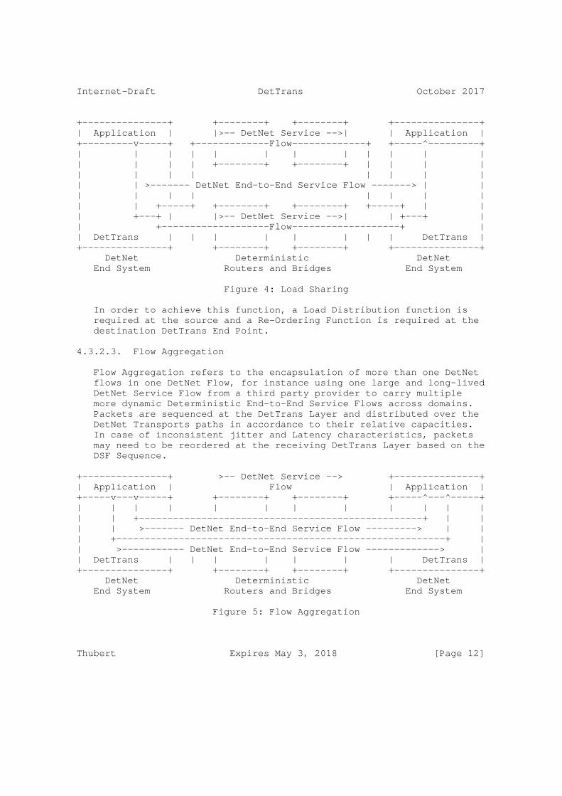
Internet-Draft DetTrans October 2017
+---------------+ +--------+ +--------+ +---------------+| Application | |>-- DetNet Service -->| | Application |+---------v-----+ +-------------Flow-------------+ +-----^---------+| | | | | | | | | | | || | | | +--------+ +--------+ | | | || | | | | | | || | >------- DetNet End-to-End Service Flow -------> | || | | | | | | || | +-----+ +--------+ +--------+ +-----+ | || +---+ | |>-- DetNet Service -->| | +---+ || +-------------------Flow-------------------+ || DetTrans | | | | | | | | DetTrans |+---------------+ +--------+ +--------+ +---------------+ DetNet Deterministic DetNet End System Routers and Bridges End System
Figure 4: Load Sharing
In order to achieve this function, a Load Distribution function is required at the source and a Re-Ordering Function is required at the destination DetTrans End Point.
4.3.2.3. Flow Aggregation
Flow Aggregation refers to the encapsulation of more than one DetNet flows in one DetNet Flow, for instance using one large and long-lived DetNet Service Flow from a third party provider to carry multiple more dynamic Deterministic End-to-End Service Flows across domains. Packets are sequenced at the DetTrans Layer and distributed over the DetNet Transports paths in accordance to their relative capacities. In case of inconsistent jitter and Latency characteristics, packets may need to be reordered at the receiving DetTrans Layer based on the DSF Sequence.
+---------------+ >-- DetNet Service --> +---------------+| Application | Flow | Application |+-----v---v-----+ +--------+ +--------+ +-----^---^-----+| | | | | | | | | | | || | +--------------------------------------------------+ | || | >------- DetNet End-to-End Service Flow ---------> | || +----------------------------------------------------------+ || >----------- DetNet End-to-End Service Flow -------------> || DetTrans | | | | | | | DetTrans |+---------------+ +--------+ +--------+ +---------------+ DetNet Deterministic DetNet End System Routers and Bridges End System
Figure 5: Flow Aggregation
Thubert Expires May 3, 2018 [Page 12]

Internet-Draft DetTrans October 2017
In order to achieve this function, a multiplexing function is required at the source and a demultiplexing function is required at the destination DetTrans End Point.
4.3.3. Deterministic Service Protection
4.3.3.1. PRE vs. 1+1 Redundancy
The DetNet Flows may also be used for Packet Replication and Elimination, in which case an elimination function is required at the DetTrans Termination.
1+1 Redundancy refers to injecting identical copies of a packet at the ingress of two non-congruent paths, and eliminating the excess copy when both are received at the egress of the paths. Packet Replication and Elimination extends the concept by enabling more than 2 paths, and allowing non-end-to-end redundant paths with intermediate Replication and Elimination points.
4.3.3.2. Network Coding
Redundancy and Load Sharing may be combined with the use of Network Coding whereby a coded packet may carry redundancy information for previous data packet and cover the loss of one, in which case the recovery function is required at the other DetTrans End Point. Network Coding provides a Forward Error Correction between multiple packets or multiple fragments of a packet. It may be used at the DSF layer to enable an efficient combination of redundancy and load sharing.
4.3.3.3. Multipath DetTrans Services
A DetTrans Flow may leverage multiple DetNet Flows in parallel in order to achieve its requirements in terms of reliability and Aggregate throughput. The "Deterministic Networking Architecture" [I-D.ietf-detnet-architecture] clearly states that the capability of Replication and Elimination is not limited to the DetNet End Systems. DetNet Relay Nodes that operate DetTrans but then relay the packets are needed when the DetTrans operations are not end-to-end.
It may be that the DetTrans flow may need to traverse different domains where those Services are operated differently, e.g. controlled by different controllers or leveraging different technologies. It may also be that the bandwidth that is required is only available one segemnt at a time, and that for each segment, a different number of DetNet flows must be setup to transport the full amount of the DetTrans flow.
Thubert Expires May 3, 2018 [Page 13]
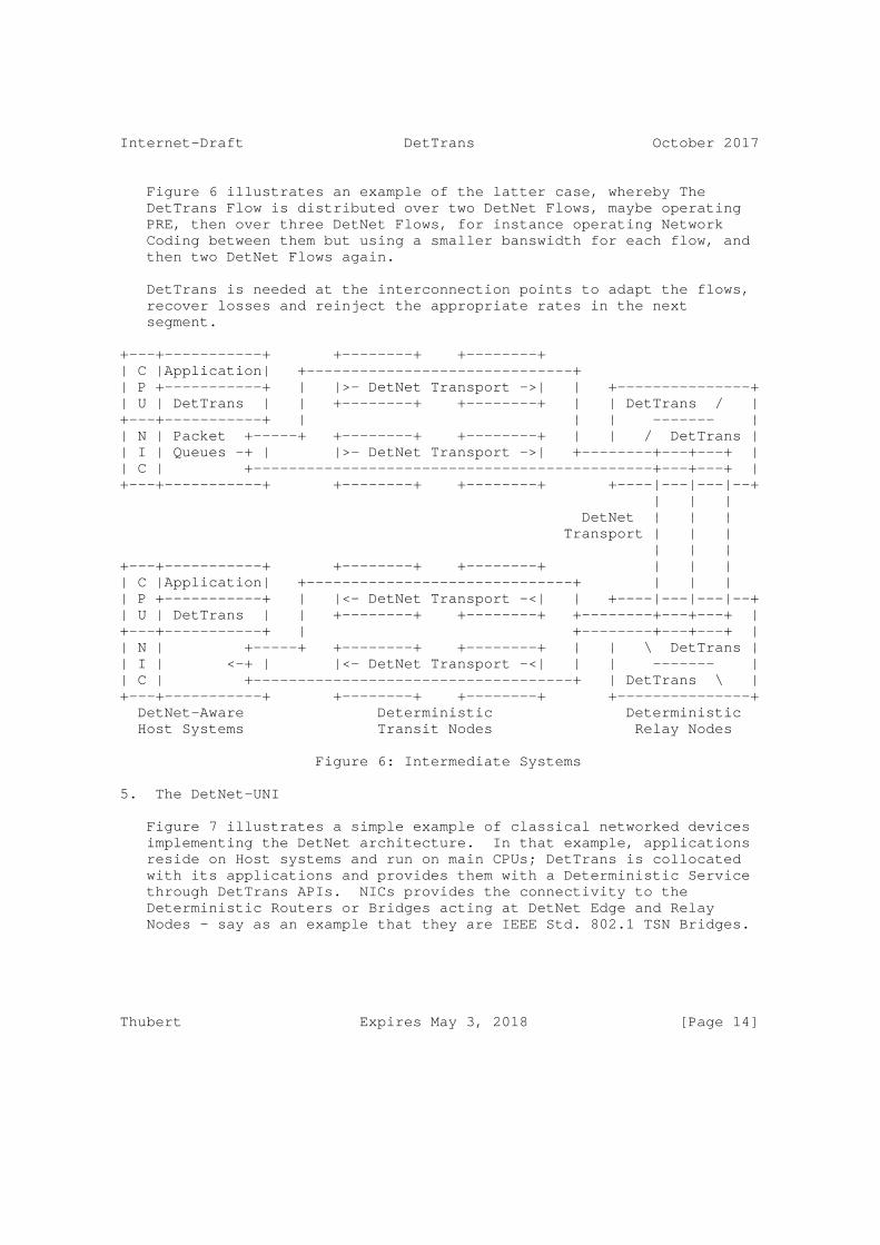
Internet-Draft DetTrans October 2017
Figure 6 illustrates an example of the latter case, whereby The DetTrans Flow is distributed over two DetNet Flows, maybe operating PRE, then over three DetNet Flows, for instance operating Network Coding between them but using a smaller banswidth for each flow, and then two DetNet Flows again.
DetTrans is needed at the interconnection points to adapt the flows, recover losses and reinject the appropriate rates in the next segment.
+---+-----------+ +--------+ +--------+| C |Application| +------------------------------+| P +-----------+ | |>- DetNet Transport ->| | +---------------+| U | DetTrans | | +--------+ +--------+ | | DetTrans / |+---+-----------+ | | | ------- || N | Packet +-----+ +--------+ +--------+ | | / DetTrans || I | Queues -+ | |>- DetNet Transport ->| +--------+---+---+ || C | +---------------------------------------------+---+---+ |+---+-----------+ +--------+ +--------+ +----|---|---|--+ | | | DetNet | | | Transport | | | | | |+---+-----------+ +--------+ +--------+ | | || C |Application| +------------------------------+ | | || P +-----------+ | |<- DetNet Transport -<| | +----|---|---|--+| U | DetTrans | | +--------+ +--------+ +--------+---+---+ |+---+-----------+ | +--------+---+---+ || N | +-----+ +--------+ +--------+ | | \ DetTrans || I | <-+ | |<- DetNet Transport -<| | | ------- || C | +------------------------------------+ | DetTrans \ |+---+-----------+ +--------+ +--------+ +---------------+ DetNet-Aware Deterministic Deterministic Host Systems Transit Nodes Relay Nodes
Figure 6: Intermediate Systems
5. The DetNet-UNI
Figure 7 illustrates a simple example of classical networked devices implementing the DetNet architecture. In that example, applications reside on Host systems and run on main CPUs; DetTrans is collocated with its applications and provides them with a Deterministic Service through DetTrans APIs. NICs provides the connectivity to the Deterministic Routers or Bridges acting at DetNet Edge and Relay Nodes - say as an example that they are IEEE Std. 802.1 TSN Bridges.
Thubert Expires May 3, 2018 [Page 14]
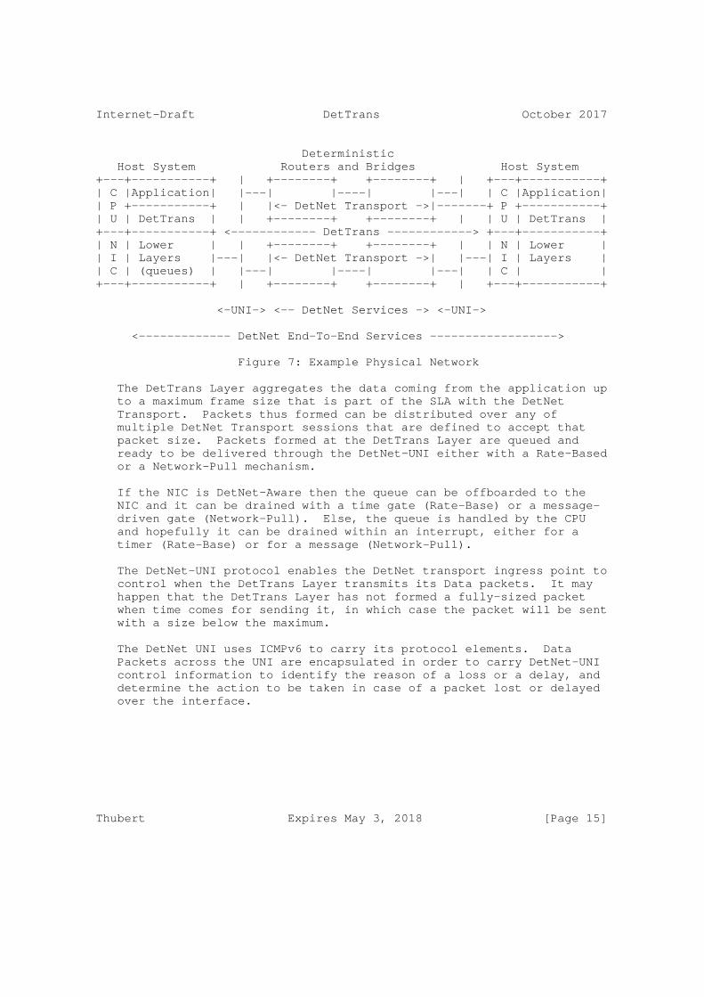
Internet-Draft DetTrans October 2017
Deterministic Host System Routers and Bridges Host System+---+-----------+ | +--------+ +--------+ | +---+-----------+| C |Application| |---| |----| |---| | C |Application|| P +-----------+ | |<- DetNet Transport ->|-------+ P +-----------+| U | DetTrans | | +--------+ +--------+ | | U | DetTrans |+---+-----------+ <------------ DetTrans ------------> +---+-----------+| N | Lower | | +--------+ +--------+ | | N | Lower || I | Layers |---| |<- DetNet Transport ->| |---| I | Layers || C | (queues) | |---| |----| |---| | C | |+---+-----------+ | +--------+ +--------+ | +---+-----------+
<-UNI-> <-- DetNet Services -> <-UNI->
<------------- DetNet End-To-End Services ------------------>
Figure 7: Example Physical Network
The DetTrans Layer aggregates the data coming from the application up to a maximum frame size that is part of the SLA with the DetNet Transport. Packets thus formed can be distributed over any of multiple DetNet Transport sessions that are defined to accept that packet size. Packets formed at the DetTrans Layer are queued and ready to be delivered through the DetNet-UNI either with a Rate-Based or a Network-Pull mechanism.
If the NIC is DetNet-Aware then the queue can be offboarded to the NIC and it can be drained with a time gate (Rate-Base) or a message- driven gate (Network-Pull). Else, the queue is handled by the CPU and hopefully it can be drained within an interrupt, either for a timer (Rate-Base) or for a message (Network-Pull).
The DetNet-UNI protocol enables the DetNet transport ingress point to control when the DetTrans Layer transmits its Data packets. It may happen that the DetTrans Layer has not formed a fully-sized packet when time comes for sending it, in which case the packet will be sent with a size below the maximum.
The DetNet UNI uses ICMPv6 to carry its protocol elements. Data Packets across the UNI are encapsulated in order to carry DetNet-UNI control information to identify the reason of a loss or a delay, and determine the action to be taken in case of a packet lost or delayed over the interface.
Thubert Expires May 3, 2018 [Page 15]
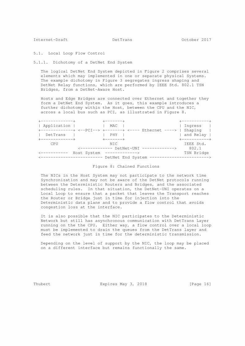
Internet-Draft DetTrans October 2017
5.1. Local Loop Flow Control
5.1.1. Dichotomy of a DetNet End System
The logical DetNet End System depicted in Figure 2 comprises several elements which may implemented in one or separate physical Systems. The example dichotomy in Figure 3 segregates ingress shaping and DetNet Relay functions, which are performed by IEEE Std. 802.1 TSN Bridges, from a DetNet-Aware Host.
Hosts and Edge Bridges are connected over Ethernet and together they form a DetNet End System. As it goes, this example introduces a further dichotomy within the Host, between the CPU and the NIC, across a local bus such as PCI, as illustrated in Figure 8.
+-------------+ +-------+ +-----------+ | Application | | MAC | | Ingress | +-------------+ <--PCI--> +-------+ <---- Ethernet ----> | Shaping | | DetTrans | | PHY | | and Relay | +-------------+ +-------+ +-----------+ CPU NIC IEEE Std. <------------- DetNet-UNI -------------> 802.1 <----------- Host System -------------> TSN Bridge <------------------------- DetNet End System ------------------------>
Figure 8: Chained Functions
The NICs in the Host System may not participate to the network time Synchronization and may not be aware of the DetNet protocols running between the Deterministic Routers and Bridges, and the associated scheduling rules. In that situation, the DetNet-UNI operates on a Local Loop to ensure that a packet that leaves the Transport reaches the Router or Bridge just in time for injection into the Deterministic data plane and to provide a flow control that avoids congestion loss at the interface.
It is also possible that the NIC participates to the Deterministic Network but still has asynchronous communication with DetTrans Layer running on the the CPU. Either way, a flow control over a local loop must be implemented to drain the queues from the DetTrans layer and feed the network just in time for the deterministic transmission.
Depending on the level of support by the NIC, the loop may be placed on a different interface but remains functionally the same.
Thubert Expires May 3, 2018 [Page 16]

Internet-Draft DetTrans October 2017
5.1.2. Local Loop Location
If the NIC is not aware at all of DetNet, then it is a plain pipe for the Deterministic Traffic. The Local Loop operates between the Edge TSN Bridge and the CPU as illustrated in Figure 9.
+---+-----------+ +---+-------+ +-----------+| C |Application| | N | MAC | | Ingress || P +-----------+ <--PCI--> | I +-------+ <-- Ethernet --> | Shaping || U |DetTrans | | C | PHY | (Bridged | / Transit |+---+-----------+ +---+-------+ or P2P) +-----------+
<------------- Local Loop -------------> Edge 802.1<----------- Host System -------------> TSN Bridge
Figure 9: DetNet Unaware NIC
If the NIC is fully DetNet-Capable and participates to the deterministic Network including time synchronization and scheduling, then the local loop operates between the CPU and the NIC as illustrated in Figure 10.
+---+-----------+ +---+-----------+ +----------+ | C |Application| | N | Ingress | | DetNet | | P +-----------+ <--PCI--> | I + Shaping | <--DetNet--> | Transit | | U |DetTrans | | C | / Transit | Transport | Node | +---+-----------+ +---+-----------+ +----------+ <-Local- -Loop -> <-------------- Host System --------------> TSN Bridge
Figure 10: DetNet Capable NIC
If the NIC is DetNet-Aware and does not participates to the deterministic Network including time synchronization and scheduling, then there are two local loops, one that operates between the CPU and the NIC and one that operates between the NIC and the Edge TSN Bridge as illustrated in Figure 11.
+---+-----------+ +---+-------+ +-----------+| C |Application| | N | MAC | Ethernet | Ingress || P +-----------+ <--PCI--> | I +-------+ <-- (Bridged --> | Shaping || U |DetTrans | | C | PHY | or P2P) | / Transit |+---+-----------+ <-Local- +---+-------+ +-----------+ -Loop -> <-- Local Loop --> Edge<----------- Host System -------------> DetNet Transit
Figure 11: DetNet Capable NIC
Thubert Expires May 3, 2018 [Page 17]
Internet-Draft DetTrans October 2017
5.1.3. Network Pull vs. Rate Based Flow Control
The flow control at the DetNet-UNI can take any of two forms:
Network Pull In that Model, the DetNet Edge node drains the DetTrans queue by sending a DetNet-UNI "More" command some estimated amount of time ahead of the scheduled time of transmission for each packet; in case of load sharing, multiple DetNet Edge nodes may drain a queue at their own rates; in case of a high jitter on the UNI Local Loop (e.g. there is a non-deterministic Bridge in between, or the NIC is not DetNet-Aware and the flows suffer from the more erratic response time of the CPU), the DetNet Edge node may need to pull a window of packets to maintain its own transmission queues fed at all times
Rate Based In that model, the NIC is aware of the rate of the deterministic transmission and is drained by its internal timers. Since the NIC is not synchronized with the Deterministic Network, the Bridge uses a DetNet-UNI "Time-Correction" command asynchronously to move forward or backward the next timeout of the NIC for that flow, in order to keep the Rate-Based transmission by the NIC in rough alignment with the scheduled transmission over the DetNet network.
if the NIC is DetNet-Aware, it is expected that it maintains the DetTrans queues in order to provide a deterministic response to the DetNet-UNI, and in that case another control loop between the NIC and the CPU is needed to ensure that the queue in the NIC is always fed in time by the DetTrans Layer; this second loop may be of a different nature than the DetNet-UNI one and may for instance be operated within an interrupt to limit the asynchronism related to message queueing.
5.2. DetNet-UNI Protocol Exchanges
5.2.1. the "More" Message
The "More" message enables a DetNet Transport Edge to pull one packet from the DetTrans Layer in Network-Pull mode. The message is associated with a future transmission opportunity for a packet. The "More" messages are indexed by a wrapping More Sequence Counter (MSC). The Transport Edge also maintains wrapping counters of Successful Packet Transmissions (SPT) and Missed Transmit Opportunities (MTO). The current value of these counters is placed in the "More "message.
Upon reception of a "More" message, the DetTrans Layer, or the NIC on behalf of the DetTrans Layer, sends the next available packet for
Thubert Expires May 3, 2018 [Page 18]
Internet-Draft DetTrans October 2017
that session. The packet is encapsulated and the encapsulation indicates the MSC. This enables the DetNet Transport Edge to correlate the packet with the transmission opportunity and drop packets that are overly delayed.
5.2.2. the "Time-Correction" Message
The "Time-Correction" message enables a DetNet Transport Edge to adjust the timer associated to the DetNet-UNI session in Rate-Based mode. In that mode, the DetTrans Layer sends a packet and restarts a timer at a period that corresponds to the transmission opportunity of the DetNet Transport Edge. If the clock in the CPU drifts, the DetNet Transport Edge will start receiving packets increasingly ahead of expected time or behind expected time. It is expected that the DetNet Transport Edge is protected against a minimum drift by a guard time, but if the drift becomes too important, then the DetNet Transport Edge issues a "Time-Correction" message indicating a number of time units (e.g. microseconds) by which the DetTrans Layer should advance or delay is next time out.
5.2.3. Loss of a Control Message
The loss of a packet beween the DetTrans Layer and the DetNet Transport Edge will correspond to a missed Transmission Opportunity but this does not mean that packets are piling up at the DetTrans Layer. OTOH, if a "More" message is lost, then one packet will not be dequeued and the Detrans queue might grow, increasingly augmenting the latency. It is thus important to differentiate these situations, and in the latter case, discard an extraneous packet to restore the normal level in the DetTrans queue for that session.
In order to do so, the DetTrans Layer maintains the record of the Number of Packets Sent (NPS), that it compares with the variation of the MTO and SPT counters in the "More" message. Upon a "More" message, the DetTrans Layer computes the variation of NPS (dNPS=NPS2-NPS1) and the variation of SPT (dSPT=SPT2-SPT1) since the previous "More" Message . dNPS is typically 1 if the transport always has data to send. Packets in flight when the "More" message is sent are considered lost since they will be received after their scheduled transmission opportunity, so the Number of Packets Losses (NPL) is (NPL=dNPS-dSPT). The DetTrans Layer also computes the variation of MTO since the previous "More" Message (dMTO=MTO2-MTO1). Since a packet loss implies a missed transmission opportunity, there cannot be more packets losses than missed opportunities, so we have dMTO>=NPL. dMTO-NPL represents the number of missed opportunities that are not due to a packet lost or late arrival, thus this is the sub-count of MTOs due to the loss of a "More" message.
Thubert Expires May 3, 2018 [Page 19]
Internet-Draft DetTrans October 2017
For each loss of a "More" message, a packet in the DetTrans queue should be discarded. In order to simplify that operation and outboard it to the NIC, the Transports marks some packets as "Discard Eligible" (DE). A packet can be marked DE if there are enough alternate transmissions of non-DE packets to recover this. For instance, in case of Packet Replication and Elimination only one copy can be marked DE, and the marking should alternate between the sessions to cover a loss on either one rapidly.
6. Security Considerations
The generic threats against Deterministic Networking are discussed in the "Deterministic Networking Security" [I-D.ietf-detnet-security] document.
Security in the context of Deterministic Networking has an added dimension; the time of delivery of a packet can be just as important as the contents of the packet, itself. A man-in-the-middle attack, for example, can impose, and then systematically adjust, additional delays into a link, and thus disrupt or subvert a real-time application without having to crack any encryption methods employed. See [RFC7384] for an exploration of this issue in a related context.
Packet Replication and Elimination of done right can prevent a man- in-the-middle attack on one leg to actually impact the flow beyond the loss of an individual packet for lack of redundancy. This specification expects that PRE is performed at the transport level and provides specific means to protect one leg against misuse of the other.
7. IANA Considerations
This document does not require an action from IANA.
8. Acknowledgments
The authors wish to thank Patrick Wetterwald, Leon Turkevitch, Balazs Varga and Janos Farkas for their various contributions to this work. Special thanks to Norm Finn for being a (if not the) major thought leader to the whole deterministic effort, and for some text that is inlined here from other IETF documents, for the convenience of the reader.
9. Informative References
Thubert Expires May 3, 2018 [Page 20]
Internet-Draft DetTrans October 2017
[AVnu] http://www.avnu.org/, "The AVnu Alliance tests and certifies devices for interoperability, providing a simple and reliable networking solution for AV network implementation based on the IEEE Audio Video Bridging (AVB) and Time-Sensitive Networking (TSN) standards.".
[EIP] http://www.odva.org/, "EtherNet/IP provides users with the network tools to deploy standard Ethernet technology (IEEE 802.3 combined with the TCP/IP Suite) for industrial automation applications while enabling Internet and enterprise connectivity data anytime, anywhere.", <http://www.odva.org/Portals/0/Library/ Publications_Numbered/ PUB00138R3_CIP_Adv_Tech_Series_EtherNetIP.pdf>.
[HART] www.hartcomm.org, "Highway Addressable Remote Transducer, a group of specifications for industrial process and control devices administered by the HART Foundation".
[I-D.ietf-detnet-architecture] Finn, N., Thubert, P., Varga, B., and J. Farkas, "Deterministic Networking Architecture", draft-ietf- detnet-architecture-03 (work in progress), August 2017.
[I-D.ietf-detnet-problem-statement] Finn, N. and P. Thubert, "Deterministic Networking Problem Statement", draft-ietf-detnet-problem-statement-02 (work in progress), September 2017.
[I-D.ietf-detnet-security] Mizrahi, T., Grossman, E., Hacker, A., Das, S., Dowdell, J., Austad, H., Stanton, K., and N. Finn, "Deterministic Networking (DetNet) Security Considerations", draft-ietf- detnet-security-00 (work in progress), October 2017.
[I-D.ietf-detnet-use-cases] Grossman, E., Gunther, C., Thubert, P., Wetterwald, P., Raymond, J., Korhonen, J., Kaneko, Y., Das, S., Zha, Y., Varga, B., Farkas, J., Goetz, F., Schmitt, J., Vilajosana, X., Mahmoodi, T., Spirou, S., Vizarreta, P., Huang, D., Geng, X., Dujovne, D., and M. Seewald, "Deterministic Networking Use Cases", draft-ietf-detnet-use-cases-13 (work in progress), September 2017.
[I-D.varga-detnet-service-model] Varga, B. and J. Farkas, "DetNet Service Model", draft- varga-detnet-service-model-02 (work in progress), May 2017.
Thubert Expires May 3, 2018 [Page 21]

Internet-Draft DetTrans October 2017
[IEC62439] IEC, "Industrial communication networks - High availability automation networks - Part 3: Parallel Redundancy Protocol (PRP) and High-availability Seamless Redundancy (HSR) - IEC62439-3", 2012, <https://webstore.iec.ch/publication/7018>.
[IEEE802.1TSNTG] IEEE Standards Association, "IEEE 802.1 Time-Sensitive Networks Task Group", 2013, <http://www.ieee802.org/1/pages/avBridges.html>.
[ISA100.11a] ISA/IEC, "ISA100.11a, Wireless Systems for Automation, also IEC 62734", 2011, < http://www.isa100wci.org/en- US/Documents/PDF/3405-ISA100-WirelessSystems-Future-broch- WEB-ETSI.aspx>.
[ODVA] http://www.odva.org/, "The organization that supports network technologies built on the Common Industrial Protocol (CIP) including EtherNet/IP.".
[Profinet] http://us.profinet.com/technology/profinet/, "PROFINET is a standard for industrial networking in automation.", <http://us.profinet.com/technology/profinet/>.
[RFC2119] Bradner, S., "Key words for use in RFCs to Indicate Requirement Levels", BCP 14, RFC 2119, DOI 10.17487/RFC2119, March 1997, <https://www.rfc-editor.org/info/rfc2119>.
[RFC7384] Mizrahi, T., "Security Requirements of Time Protocols in Packet Switched Networks", RFC 7384, DOI 10.17487/RFC7384, October 2014, <https://www.rfc-editor.org/info/rfc7384>.
[WirelessHART] www.hartcomm.org, "Industrial Communication Networks - Wireless Communication Network and Communication Profiles - WirelessHART - IEC 62591", 2010.
Author’s Address
Thubert Expires May 3, 2018 [Page 22]

Internet-Draft DetTrans October 2017
Pascal Thubert (editor) Cisco Systems, Inc Building D (Regus) 45 Allee des Ormes MOUGINS - Sophia Antipolis FRANCE
Phone: +33 4 97 23 26 34 Email: [email protected]
Thubert Expires May 3, 2018 [Page 23]
Copyright © 2022 FDOKUMEN


![A PROFESSZOR IS CSAK EMBER… DR. VARGA CSABA – KICSIT MÁSKÉPP [Gurbán Györgyi interjúja] [The professor is also a human... Dr Csaba Varga, approached in a personal tone: an](https://static.fdokumen.com/doc/165x107/6317ca0765e4a6af370f1f87/a-professzor-is-csak-ember-dr-varga-csaba-kicsit-maskepp-gurban-gyoergyi.jpg)
![HORVÁTH SÁNDOR: A TERMÉSZETJOGRÓL (szerk. Varga Csaba) [Alexander Horváth: On natural law] (ed. Csaba Varga)](https://static.fdokumen.com/doc/165x107/6317858ee88f2a90c80132d2/horvath-sandor-a-termeszetjogrol-szerk-varga-csaba-alexander-horvath.jpg)