Woodpeckers White-naped Tit Oriental White-eye - Indian Birds
Upload
khangminh22Category
view
5download
0
Technical White Paper of ZTECO Re-Architecting


Technical White Paper of ZTE CO Re-Architecting
ZTE Confidential & Proprietary 1
Technical White Paper of ZTE CO Re-Architecting
Version Date Author Reviewer Notes
V1.0 ZTE Not open to the third party
© 2017 ZTE Corporation. All rights reserved.
ZTE CONFIDENTIAL: This document contains proprietary information of ZTE and is not to be disclosed or used
without the prior written permission of ZTE.
Due to update and improvement of ZTE products and technologies, information in this document is subjected to
change without notice.

Technical White Paper of ZTE CO Re-Architecting
2 ZTE Confidential & Proprietary
TABLE OF CONTENTS
1 CO Re-Architecting Driven by Services and Technologies.................................51.1 Challenges and Opportunities of Telecom Services....................................................51.2 Internal Drive of CO Re-Architecting.............................................................................. 6
2 Key Technologies and Challenges of CO Re-Architecting..................................82.1 Key Technologies and Trends.........................................................................................82.1.1 Cloud Computing...............................................................................................................82.1.2 Edge Computing................................................................................................................ 82.1.3 SDN......................................................................................................................................92.1.4 NFV......................................................................................................................................92.1.5 CORD................................................................................................................................102.2 Challenges........................................................................................................................102.2.1 “Platform + Application” Architecture Challenges the Existing Investment and
O&M Models.....................................................................................................................102.2.2 Challenges of Virtualized Infrastructure Performance...............................................11
3 Technical Solution of ZTE CO Re-Architecting....................................................123.1 Implementation Phases and Key Services of the CO Re-Architecting...................123.1.1 Implementation Phase....................................................................................................123.1.2 Proposals for Deploying Key Services.........................................................................133.2 General Solution of CO Re-Architecting......................................................................143.2.1 General Solution of ZTE CO Re-Architecting............................................................. 143.2.2 Proposals for Selecting CO Equipment Rooms and Deploying Services.............. 153.2.3 MAN and EDC Re-Architecting.....................................................................................173.3 Cloudified Infrastructure................................................................................................. 183.3.1 General Solution of CO Data Center............................................................................183.3.2 Distributed Telecom Cloud Solution.............................................................................203.3.3 Key Technical Features..................................................................................................213.3.4 Data Center Network Capabilities.................................................................................233.3.5 Carrier-grade Reliability..................................................................................................233.3.6 Security Design of the Data Center..............................................................................243.4 MAN Re-Architecting.......................................................................................................263.4.1 Re-Architecting of Metro Access Networks.................................................................263.4.2 Future Architecture Evolution........................................................................................ 273.5 vBRAS Solution............................................................................................................... 283.5.1 C/U Separated vBRAS Architecture.............................................................................293.5.2 Key Features of ZTE vBRAS Solution......................................................................... 303.5.3 vBRAS Deployment.........................................................................................................323.6 FMC Access Solution......................................................................................................32

Technical White Paper of ZTE CO Re-Architecting
ZTE Confidential & Proprietary 3
3.7 Elastic SD-WAN On Demand Solution.........................................................................333.7.1 Enterprise Branch Network On Demand Solution......................................................353.7.2 Public Cloud Access Solution........................................................................................363.7.3 Unified On-Demand Underlay and Overlay Networks Based on Co
Re-Architecting.................................................................................................................373.8 Intelligent O&M.................................................................................................................373.8.1 UME for All-in-One Network O&M................................................................................ 373.8.2 BigDNA for Intelligent Network Data Analysis............................................................ 383.9 Establishment of an Open Ecosystem.........................................................................39
4 Field Experiences of ZTE CO Re-Architecting......................................................40
5 Prospects for the Trends............................................................................................415.1 Ecosystem Re-Architecting............................................................................................415.2 Future White Box-based Development........................................................................42
6 Glossary..........................................................................................................................44
Appendix: References...................................................................................................................... 45

Technical White Paper of ZTE CO Re-Architecting
4 ZTE Confidential & Proprietary
FIGURES
Figure 3-1 ZTE End-to-End SDN/NFV Architecture...................................................................14
Figure 3-2 Architecture of the EDC and MAN Re-Architecting.................................................17
Figure 3-3 Multi-DC Cloudified Data Center................................................................................19
Figure 3-4 Distributed Telecom Cloud..........................................................................................20
Figure 3-5 Logical Architecture of the vBRAS.............................................................................30
Figure 3-6 Architecture of the Enterprise Branch Network Solution........................................35
Figure 3-7 Public Cloud Access Scenario....................................................................................36

Technical White Paper of ZTE CO Re-Architecting
ZTE Confidential & Proprietary 5
1 CO Re-Architecting Driven by Servicesand Technologies
1.1 Challenges and Opportunities of Telecom Services
In the past 10 years, IP traffic of fixed networks increased by 13.5 times. The popularity
of smart phone lifted traffic of mobile networks up by 280 times. It is said between 2012
and 2016, the growth rate of the mobile traffic reached 108%. However, operators’
revenues of communications services decrease by 3% during this period.
Regarding to current industry environments, the dramatic traffic growth driven by
booming intelligent terminals, internet services, network technologies, as well as severe
marketing competition, in addition to improve user-oriented services, does not make the
operators more benefited from the traffic consumption. At the same time, extremely high
penetration rate exposes a saturated communications market, for instance, in 2017
mobile network subscribers have exceeded 7.6 billion that equals to the total population
of the world, so it is impossible for the operators to keep its revenue increase and traffic
growth in a consistent manner. Take Intel CPU as an example, the processing
capabilities doubled every 2 years cannot arouse any price change. Besides, carrier
networks also have lots of non-silicified assets like equipment rooms, power supply and
cables, so the changes of the cost and performance do not always completely follow the
Moore’s Law. The customer’s rate of return on investment (ROI) keeps declining.
For economics, all products/services are competitors fighting against each other in term
of the customer/organization’s expenditure budget and time. With similar value in use,
different communication methods compete with one another more directly and
intensively in the saturating market. According to statistics reports, dramatic traffic growth
leads to obvious data communications revenue increase. However, due to the
customer’s solid budget and small price elasticity of demand (PED), the increasing data
services will definitely cut down the market share of the traditional voice and SMS

Technical White Paper of ZTE CO Re-Architecting
6 ZTE Confidential & Proprietary
services. In conclusion, to be more profitable, the communications network should
provide more value-added services rather than simply accelerate the services.
1. Horizontal expansion: Fast development of Internet of Things (IoT) enables the
evolution from man-man/man-service communication to
man-machine/machine-machine communication.
2. Vertical expansion: Huge revolutions take place: 1). Providing IT infrastructure
rather than communications capabilities; 2). Developing from communications
service providers to IT infrastructure service providers in the digital era.
3. Further vertical development: Extend from the IT infrastructure to other industries,
including improvement of the existing IPTV services and cooperation with
third-party content providers for entertainment.
1.2 Internal Drive of CO Re-Architecting
Over the past decade, most operators have finished their FTTx construction. Currently,
their networks ranging from access layers to backbone layers mainly focus on service
transport, which not only enables more powerful network service transport, but also
consolidates future network development. To comply with the increasing Internet
services, the operators have to take challenges in both business models and
technologies.
Since 2008, the operators started showing their interests in cloudified transformation, for
instance, AT&T unveiled its Synaptic cloud service, and other operators like BT and
Verizon cannot wait entering the cloud computing field. However, it seems that the
operator’s cloudified transformation is not so smooth during the last 10 years. In
particular, public clouds have already been monopolized by several big companies such
as Amazon, Microsoft and Google; the traditional operator’s personnel qualification,
operating mechanism and software research and development (R&D) strength cannot
completely satisfy IT-based cloud operation. Moreover, the operation based on different
regions and fields cannot compete with Over The Top (OTT) in term of global centralized
operation.

Technical White Paper of ZTE CO Re-Architecting
ZTE Confidential & Proprietary 7
In the view of the application, non-structured data that mainly refer to videos services
consume over 90% bandwidth and computing storage capability of the Internet. The
development of 4K/8K/VR services showing the customer’s continuous pursuit of
interaction authenticity makes the applications demanding larger bandwidth all the time,
the unit bandwidth cost of wide area networks (WAN) increasing and latency of the
applications such as VR more sensitive. For the network, adding one ASIC switch
generates latency lasting for hundreds of nanoseconds to several microseconds. Adding
one rackmount router results in a delay for tens of microseconds. Besides, round-trip
time (RTT) caused during the optical transport for 1000 kilometers is up to 10ms. So
shortening the distance between the client and server is the best cure for the services
care latency a lot. Reducing the average network distance of application streams greatly
decreases the transport cost at the same time.
For operators, the FTTx construction leaves lots of spare CO equipment rooms in cities
and counties with proper conditions and power supply facilities. As these equipment
rooms are only tens of kilometers or even several kilometers away from terminal users,
they can be used to restructure DCs so as to support telecom operation transformation
and provide new IT infrastructure services.
1. Support traditional service infrastructure to step forward from a closed device
system to a Commercial Off-The-Shelf (COTS) hardware + software-based
SDN/NFV architecture. Development and Operations (DevOps) capability shall be
developed to shorten new service provisioning cycle from years to months or even
to weeks. Thus, the company can be as competitive as other benchmarking
companies in the industry.
2. Ubiquitous information infrastructure provided in the future digital transformation
employs the edge DC which not only is closer to the user but also owns low latency
to extend the cloud edge to enterprises, residents and even individual terminals.
Thus, the cloud services can be provided everywhere via the
enterprise/residential/individual virtual private clouds. At that moment, the network
and cloud are perfectly bound together. Localized access offered by the edge DC
with low latency is not only a sharp weapon used for fighting against the large-scale

Technical White Paper of ZTE CO Re-Architecting
8 ZTE Confidential & Proprietary
centralized public cloud, but also serves for an effective supplement of the public
cloud in the future digital society.
2 Key Technologies and Challenges of CORe-Architecting
2.1 Key Technologies and Trends
CO re-architecting is to convert the existing CT-based infrastructure to future-oriented
ICT-based infrastructure, so as to carry telecom services and IT services pertaining to
the operator. As three key technologies, the cloud, SDN and NFV play fundamental roles
in providing IT services. In particular, the cloudified data center technology works as the
foundation. The SDN technology is used to build an on-demand multi-tenant network.
Multiple sorts of NFV network elements from different vendors can be carried at the
same time.
2.1.1 Cloud Computing
In 2006, the birth of AWS indicates the beginning of the cloud computing technology.
After being developed for more than 10 years, a 3-tier architecture model including IaaS,
PaaS and Saas has already formed. Developing from the initial virtualized resource
management to integrated management of virtual devices, bare metals and containers,
the IaaS layer today is able to support diversified applications. As the container
technology is getting mature, the boundary of the LaaS and PaaS becomes vague.
Besides, OpenStack defeating all other open source cloud platforms becomes the only
platform used by global operators to implement their NFV services.
2.1.2 Edge Computing
The construction of cloud infrastructure soundly interprets economies of
scale. Specifically speaking, the large-scale data center based on integrated construction
saves unit maintenance cost, power supply and other network cost by 5-10 times when
Technical White Paper of ZTE CO Re-Architecting
ZTE Confidential & Proprietary 9
compared with the small and medium-sized data center. At the same time, advanced
technologies required by the public cloud enable the provider to seize marketing
opportunities before others. As per statistics, currently the top 5 public cloud service
providers take up 2/3 market shares. However, integration always makes the large-scale
data center away from the customer, which accordingly leads to bigger latency,
uncontrollable network quality and more investment in getting larger network bandwidth
for long-distance service transport. So it is difficult for the integrated large-scale data
center to carry the services that are sensitive to latency and bandwidth, for example, the
VR service and large-scale service collection. On the contrary, the cloud service based
on the edge data center on one hand shows significant competitive advantages; it on the
other hand makes people getting closer to the edge computing technology of the access
network. In September 2014, ETSI's Industry Specification Group on Mobile Edge
Computing (ETSI ISG MEC) was built to study MEC standardization. In 2016, the
research expanded to the fixed network access field, and the philosophy of the MEC had
developed from Mobile Edge Computing to Multi-Access Edge Computing.
2.1.3 SDN
The SDN technology urged by multi-tenant cloud, automatic network management and
control, and visible operation and maintenance (O&M) allows automated orchestration
and immediate implementation of computing, storage and network services at the LaaS
tier. The Overlay technology used extensively by the SDN in the DC enables decoupled
network software and hardware, as well as multi-vendor deployment. Instead of paying
attention to process network topology fault convergence, the SDN technology is
committed to supporting cloud network virtualization. Multi-cloud interconnection makes
the SDN applicable to the inter-DC and operator network scenarios too. In addition to DC
virtualization, it now can be applied in a lot of other application scenarios, for example
optimizing traffic on the WAN network, implementing VPN provisioning in real time and
enabling IP+Optical cross-layer optimization.
2.1.4 NFV
The popularity of the cloud technology and improvement of computing capability make
the cloud technology possible to carry telecom network elements. Universal hardware

Technical White Paper of ZTE CO Re-Architecting
10 ZTE Confidential & Proprietary
and decoupled software/hardware on one hand helps the operator reduce their CAPEX
and spare components in store; on the other hand, they enable faster service
provisioning, higher network utilization based on improved network elasticity and
enhanced service quality in rush hours. Since 2012 when the ETSI NFV ISG was
established, the NFV technology is gradually getting mature. From 2015, the
commercialization of the technology around the world never stops accelerating.
2.1.5 CORD
In 2015, to focus on the operator’s CO re-architecting, the ON.Lab together with AT&T
set up a Central Office Re-Architected as Datacenter (CORD) project as the subproject
of the Open Network Operating System (ONOS) Community. Existing from the ONOS
Community in March 2016 and accomplishing project establishment at Linux Foundation
in July, the CORD mainly contains M-CORD for mobile networks, E-CORD for
enterprises and R-CORD for residents. In addition to be an integration of the SDN and
NFV, it also pays attention to the edge computing. By using a radical methodology on the
basis of control plane and user plane separated architecture, white box devices and
complete open source software, the CORD covers a broad range of fields, for example
the data center network, vOLT and vBRAS. Although the way to evolve the existing
networks to target architecture of the CORD is not addressed in the project, it is still an
important filed to be studied in the future.
2.2 Challenges
2.2.1 “Platform + Application” Architecture Challenges the ExistingInvestment and O&M Models
As the CO re-architecting is to build architecture on the basis of a cloudified infrastructure
platform + software application model, the maintenance and operation modes
implemented by the traditional network built as per different professional segments are
no long adaptive. The operator needs to restructure the mode to match the NFV
technical architecture. If the operator tries to build the NFV infrastructure according to
different professional segments, the infrastructure won’t be shared so extensively. In

Technical White Paper of ZTE CO Re-Architecting
ZTE Confidential & Proprietary 11
other words, it will increase the construction investment and make the NFV technology
less cost-effective.
2.2.2 Challenges of Virtualized Infrastructure Performance
As for the network elements used for service forwarding, the performance of the NFV
network elements so far is not as powerful as the traditional private hardware devices.
For example, with 10 times performance difference, 5-10 times integration difference and
similar power consumption, a typical vBRAS module can process 200-400Gbp user
services, while, a server can process 20-40Gbps services. At the same time, the vSwitch
on the NFVI layer also shows obvious weaknesses in performance, which further
constrains the VNF performance. To tackle this problem, the following solutions can be
implemented:
a)Employing the SR-IOV technology to transfer the VNF effectively avoids the
performance weakness of the vSwitch. But the SR-IOV also has obvious defects
including 1). It does not support live migration of virtual machines (VM). 2). Constrained
by the PCIe, the number of the virtual network adapters supported by the SR-IOV
technology is limited. So the VNFs which require a large number of the virtual network
adapters are easily used out. 3). With no security mechanism and poor isolation, any
improper behavior of the VMs that share one physical network adapter through the
SR-IOV technology may damage the entire blade server.
b)Use the software acceleration technology. Data plane development kit (DPDK) that is
very popular in the industry only solves performance issues during the packet processing.
Most VNFs and vSwitches that utilize the DPDK technology do not show obvious
performance improvement. The open source VPP technology utilizes CPU features and
extended instructions to enhance CPU Cache hit ratio, success rate of branch prediction
and memory utilization, so as to improve the performance of message processing.
However, the VPP also has disadvantages, for example, difficult programming, and
uncontrollable latency and throughput shown when the memory bandwidth and CPU
reach peak values.
c)Employ the intelligent network adapter acceleration technology to forward services.
The vSwitch is merely the control plane of the intelligent network adapter. The intelligent
adapter can be base on NP, ASIC, multi-core CPU or FPGA. Compared with the
software-based acceleration technology, it reduces the vSwitch’s CPU overhead (usually

Technical White Paper of ZTE CO Re-Architecting
12 ZTE Confidential & Proprietary
2-6 vCPU) and guarantees the latency during the service forwarding at the same time.
The biggest drawback of the technology is the poor hardware versatility. In the future,
development of standardization and establishment of homogeneous hardware for
accelerated resource pools may improve the versatility.
So the intelligent network adapter for acceleration will be popular on the infrastructure
layer later. So the host forwarding performance can reach 40/50G or even 100G at wire
speed. The CPU overhead is very close to 0. The DPDK+VPP technology is applied on
the VNF layer. The VNF message encapsulation and encryption can be done on the
infrastructure layer if necessary.
3 Technical Solution of ZTE CORe-Architecting
3.1 Implementation Phases and Key Services of the CO
Re-Architecting
3.1.1 Implementation Phase
ZTE believes the CO re-architecting consists of the following three phases:
1. Conceptual phase (2014-2016): In this stage, research and storage of key
technologies, as well as some study on PoC pilots are carried out. At the same time,
commercial applications of the SDN and NFV also accumulate precious
experiences for the CORD.
2. Small-scale commercial use (2017-early 2019): In this stage, small-scale
commercial pilots can be built. At the end of this period, some official small-scale
commercial use can be carried out. The operators can make their CO
re-architecting dreams come true by providing cloudified telecom services and
cloudified enterprise services. During this period, the operator also needs to
Technical White Paper of ZTE CO Re-Architecting
ZTE Confidential & Proprietary 13
restructure its organization so as to convert its old vertical architecture to a
brand-new architecture based on infrastructure operation + application operation.
3. Large-scale commercial use (2019 or later): Based on rich experiences
accumulated in earlier small-scale commercial use, the operators start
implementing cloudified infrastructure extensively in this stage. They intend to
change the network to a cloud + software service mode. Some of them are even
capable of carrying out R&D on the cloudified platform through DevOps to optimize
their service software systems.
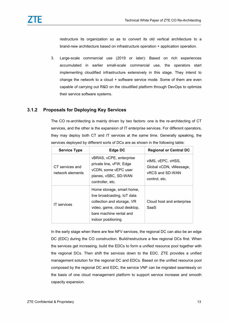
3.1.2 Proposals for Deploying Key Services
The CO re-architecting is mainly driven by two factors: one is the re-architecting of CT
services, and the other is the expansion of IT enterprise services. For different operators,
they may deploy both CT and IT services at the same time. Generally speaking, the
services deployed by different sorts of DCs are as shown in the following table:
Service Type Edge DC Regional or Central DC
CT services andnetwork elements
vBRAS, vCPE, enterpriseprivate line, vFW, EdgevCDN, some vEPC userplanes, vSBC, SD-WANcontroller, etc.
vIMS, vEPC, vHSS,Global vCDN, vMessage,vRCS and SD-WANcontrol, etc.
IT services
Home storage, smart home,live broadcasting, IoT datacollection and storage, VRvideo, game, cloud desktop,bare machine rental andindoor positioning
Cloud host and enterpriseSaaS
In the early stage when there are few NFV services, the regional DC can also be an edge
DC (EDC) during the CO construction. Build/restructure a few regional DCs first. When
the services get increasing, build the EDCs to form a unified resource pool together with
the regional DCs. Then shift the services down to the EDC. ZTE provides a unified
management solution for the regional DC and EDCs. Based on the unified resource pool
composed by the regional DC and EDC, the service VNF can be migrated seamlessly on
the basis of one cloud management platform to support service increase and smooth
capacity expansion.

Technical White Paper of ZTE CO Re-Architecting
14 ZTE Confidential & Proprietary
3.2 General Solution of CO Re-Architecting
Taking OpenStack+SDN open cloudified infrastructure as the center, ZTE CO
Re-Architecting solution carries CT and IT services together, so as to support the
re-architecting of the operator’s MAN and exploration of IT service markets.
3.2.1 General Solution of ZTE CO Re-Architecting
Figure 3- 1 ZTE End-to-End SDN/NFV Architecture
ZTE believes to face the inevitable social informatization cloud must be the most critical
infrastructure. The cloud–centric network shall provide agile, on-demand connections
and network virtualization capabilities, so as to support computing, storage and highly
efficient application delivery. ZTE offers diversified cloud access, cloud network and
cloud interconnections solutions, including
Customer-oriented vBRAS solution
Enterprise-oriented ElasticNet SD-WAN solution
BackHaul-oriented ElasticNet IPRAN solution

Technical White Paper of ZTE CO Re-Architecting
ZTE Confidential & Proprietary 15
Cloud infrastructure ElasticNet VDC network solution
Cloud connection-oriented ElasticNet IPO/DCI solution
3.2.2 Proposals for Selecting CO Equipment Rooms and Deploying Services
The DCs can be split into two categories as per the existing operators CO equipment
rooms and service features:
1. Edge DC: Deployed close to the client side, the edge DC is used to deploy the CT
services for network elements on the user plane and the IT services that are
sensitive to the latency.
2. Regional and central DC: It is used for deploying the services on the control plane
and the IT services that demand huge resources to serve the customers around the
world. The location and positioning of the regional and central DCs may be slightly
different due to the operators’ different sizes. Usually, the central city’ CO is used for
re-architecting. But to provide a sound interpretation for intensification, unified
construction can be implemented together with the IT cloud.
3. Compared with the centralized public cloud and IT cloud, changing the edge CO
into cloudified miniature EDC has obvious pros and cons.
Advantages: As the edge CO is close to the client, both the client access latency
and unit bandwidth cost are low. So it is suitable for the traffic aggregation services,
latency-sensitive services and data-density services for instance the
residential/enterprise customer’s connection services, CDNs, games, HD videos,
AR/VR, enterprise/residential storage services and IoT applications for collecting
massive data. On the contrary, the public cloud usually is built at cold and low-cost
areas. As the average distance between the public cloud and the terminal customer
is around 1000KM, only the transport RTT will be more than 10ms. Considering the
practical network paths and device latency, the end-to-end latency will definitely be
more than 20ms. However, the distance between the edge DC and the client is only
tens of several kilometers, so the transport latency can be controlled within 1ms.
Disadvantage: One single DC is too small to enhance the utilization of the resource
pool. The cost of unit equipment room power and maintenance is relatively higher[1].

Technical White Paper of ZTE CO Re-Architecting
16 ZTE Confidential & Proprietary
So on one hand, the EDC and public cloud shall be oriented differently; on the other
hand, the unified management scheduling technology should be employed to
combine multiple DCs to one resource pool for improvement in both user services
and resource utilization.
As it is mentioned before, the latency is as low as it requires when the EDC is within
a certain distance (for example100KM). Further moving down the EDC cannot
effectively improve the customer’s user experience any more. Besides, some
services can only be meaningful when there’s enough user access. Take CDN as
an example. Only when enough visits guarantee centralization of the hot content,
the cache hit ratio can lift up to the value that big enough to complement the CDN
construction cost. So when deciding the location of the EDC, the user should take
the use density into consideration. In conclusion, the following factors should be
considered in the course of setting the EDC:
1. Enough user coverage. Usually 100 thousand residential users and 10 thousand
enterprise customers should be covered.
2. Cover a radius of 50KM. Referring to the fist condition, in densely populated area,
this distance can be greatly shortened. For example, in Shanghai, the coverage
radius is around 5KM in urban area, while, in the suburbs, the distance can be
extended to 100KM or even farther.
3. The conditions of the related CO equipment room including the space of the
equipment room, load bearing, power supply conditions and standby power supply:
Get the required device capacities used for computing and storage, power
consumption and weight via the quantity of the running customers and services, so
as to select the most proper DC or make a plan for re-architecting the DC.
4. Network topology: When people are selecting the EDC, in addition to the customer
coverage and service planning, they shall also take balance between the
applications like computing/storage and the network cost into consideration. The
EDC not only serves the customer as a traffic bandwidth aggregation point, but also
as a terminating point of some services, for example, CDN services, services
between terminals and some IT services, so it saves the cost of the uplink network
of the EDC. In short, both CAPEX/OPEX and the uplink network cost of the EDC
are critical, so they both deserve thoughtful consideration.

Technical White Paper of ZTE CO Re-Architecting
ZTE Confidential & Proprietary 17
3.2.3 MAN and EDC Re-Architecting
As a very important part of the CO re-architecting, the EDC carries most user plane
services and latency-sensitive services. The construction of the EDC is closely related to
the MAN re-architecting.
Figure 3- 2 Architecture of the EDC and MAN Re-Architecting
Taking the cloudified infrastructure as the center, ZTE MAN re-architecting solution
carries all sorts of mobile services, fixed network CT services and new IT services. Its
key features include:
Integration: ICT integration and the integration of the fixed network and mobile network
come into being. Concentrating on the cloudified infrastructure, the solution integrates
the EDC and central/regional DC to build an infrastructure platform that can carry all
kinds of NFV CT services like the vBNG/vCPE/vEPC and the IT services such as the
enterprise cloud hosting service. By integrating multi-access edge computing
technologies and shifting the vEPC down to the user plane or controlling the remote MEC
server, the solution enables the integrated access of both fixed network and mobile
network services.

Technical White Paper of ZTE CO Re-Architecting
18 ZTE Confidential & Proprietary
Excellent efficiency: Software-based edge and hardware-based gateway provide
exceptional efficiency. The vCPE based on X86 servers transfers the services to the
enterprise edge. The data center uses the vSwitch based on the intelligent network
adapter and DPDK accerleration technology to deploy the large-capacity SDN-based
hardware egress gateway. So that, with sound flexibility, the best performance and the
shortest latency, the solution ensures the customer has superior user experience while
enjoying VR and low-latency 5G services.
Decoupling: The software and hardware are decoupled. Network intelligence integrated
on the SDN controller is to support fast network service provisioning. CTOS hardware is
employed to carry multiple NFV applications. Service access and transport are
decoupled. VxLAN Overlay networking model is deployed on the data center or on the
user’s access network element such as OLT/uCPE to separate the user, service access
and service transport. So that, not only does diversified MAN architecture can be
supported, but also multiple coexisting technical routes heading to the future MAN
transport architecture.
Intelligence: The SDN-based centralized control, orchestration, management and
analysis architecture combines the ZENIC controller, UME intelligent network
management and BigDNA network a big data analysis product together to provide the
network with end-to-end automated service distribution, network status self-healing,
status analysis and visualized O&M measures.
Security: The all-in-one boundaryless security design includes microsegmentation
within the data center, firewall partitions, enterprise-oriented security services. ZTE
works together with partners from the leading security vendors to provide the customers
with the optimal security solutions.
3.3 Cloudified Infrastructure
3.3.1 General Solution of CO Data Center
Technical White Paper of ZTE CO Re-Architecting
ZTE Confidential & Proprietary 19
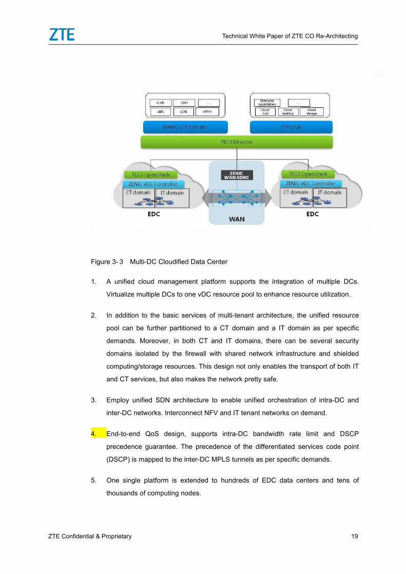
Figure 3- 3 Multi-DC Cloudified Data Center
1. A unified cloud management platform supports the integration of multiple DCs.
Virtualize multiple DCs to one vDC resource pool to enhance resource utilization.
2. In addition to the basic services of multi-tenant architecture, the unified resource
pool can be further partitioned to a CT domain and a IT domain as per specific
demands. Moreover, in both CT and IT domains, there can be several security
domains isolated by the firewall with shared network infrastructure and shielded
computing/storage resources. This design not only enables the transport of both IT
and CT services, but also makes the network pretty safe.
3. Employ unified SDN architecture to enable unified orchestration of intra-DC and
inter-DC networks. Interconnect NFV and IT tenant networks on demand.
4. End-to-end QoS design, supports intra-DC bandwidth rate limit and DSCP
precedence guarantee. The precedence of the differentiated services code point
(DSCP) is mapped to the inter-DC MPLS tunnels as per specific demands.
5. One single platform is extended to hundreds of EDC data centers and tens of
thousands of computing nodes.

Technical White Paper of ZTE CO Re-Architecting
20 ZTE Confidential & Proprietary
3.3.2 Distributed Telecom Cloud Solution
Figure 3- 4 Distributed Telecom Cloud
At the initial stage of the CO re-architecting, as the size of EDC is small, a single
management domain can be deployed to manage multiple EDCs so as to reduce the
investment in the cloud management and SDN system. When the maximum distance
between EDCs is within 500 kilometers, ZTE’s OpenStack+SDN solution can be
performed to manage hundreds of EDCs. The DCs interconnect each other via the
VxLAN technology. Every EDC has its independent traffic egress.
Both the enterprise NFV-based uCPE and the MEC node that supports co-site BBUs
are remote computing nodes of the distributed telecom cloud system. So unified
management, control and service deployment can be performed. To get rid of the
huge overhead generated by the cloud management system, the uCPE can also be
controlled by the ZENIC WAN controller alone as an independent component of the
SD-WAN solution.

Technical White Paper of ZTE CO Re-Architecting
ZTE Confidential & Proprietary 21
3.3.3 Key Technical Features
3.3.3.1 Unified Cloud Management Platform
The openStack-baed unified cloud management platform offers open computing, storage
and unified scheduling of network resources. The TECS Director, a cloud resource
orchestrator, enables unified management and orchestration of the DC resources. Also,
the platform provides the NFV-based telecom network elements that require high
performance and availability with huge page memory management, co-existence of
SR-IOV and vSwitch and SR-IOV Bond. Regarding to network applications with harsh
requirements for performance and flexibility, the intelligent network adapter for network
acceleration is provided to help the users out.
3.3.3.2 VxLAN Overlay Network Based on SDN Control
The Overlay technology enables the user to build a virtual L2 network on the scalable L3
IP Underlay network. So that, the predominant features of the VM such as transparent
location and live migration, as well as the key capabilities of the cloud networks, for
instance network as a service and network virtualization are perfectly supported. At the
same time, both the Overlay and Underlay networks allow hybrid deployment on the
basis of the devices from different vendors, which effectively reduces the customer’s cost
by offering them more choices.
3.3.3.3 Software-based Edge and Hardware-based Gateway
The vSwitch/Intelligent network adapter can be used as an access VxLAN tunneling end
point (VTEP) of the VM/container in order to support flexible security and QoS policies.
Compared with the solution in which the ToR switch serving for a VTEP, ZTE’s solution
shows obvious advantages in supporting stateful lightweight L4 distributed firewalls,
boundaryless cloud network security protection, flexible SFC policies and more QoS
policies. The hardware gateway with built-in network virtualized functions enlarges the
bandwidth and makes the entire solution more cost-effective.
So ToR serving for the VTEP is only used when bare metal servers are employed for
the service deployment. The SDN network must be a hybrid network composed by

Technical White Paper of ZTE CO Re-Architecting
22 ZTE Confidential & Proprietary
the vSwitches and ToR VTEPs together.
3.3.3.4 Multi-DC&DCI Resource Pooling Networking
Heterogeneous resource pools are supported to enable co-management of
computing virtualization implemented by different vendors.
Regarding to the scenario in which one CO contains lots of miniature EDCs, a set of
cloud management system and an SDN controller are proposed to combine the
miniature COs close to each other to one logical resource pool. Si that, the unified
service scheduling and deployment, VM scaling and live migration within the
resource pool can be implemented. The Openstack and controller cluster
technologies enable one single resource pool to have more than 4K hosts, which
makes the resource utilization greatly improved.
Regional and group DC resource pools support DCI orchestration, so multi-cloud
CO resources in a more extensive range can be integrated to one logical DC.
Unified resource scheduling and service orchestration over entire network, together
with cross-cloud resource orchestration and deployment are supported.
3.3.3.5 Visualized Management and Optimized Network Scheduling
The SDN VDC technology employs the centralized SDN controller to manage the
network control plane. It provides a number of features of visualized management, for
example the device access management, automatic discovery of the network topology,
forwarding path computation, fault diagnosis and traffic engineering. The application
topology, logical topology and physical topology are mutually visible to each other. The
In-Band Network Telemetry technology is utilized to measure the real-time network
latency, so that detection of congestion points and network path adjustment can be
implemented rapidly.
3.3.3.6 Service Chaining for Customized Network Service Orchestration
The tenant of the vDC data center selects service types (for instance, FW, LB and VPN)
dynamically as per its specific service models. Also the tenant is able to orchestrate

Technical White Paper of ZTE CO Re-Architecting
ZTE Confidential & Proprietary 23
sequence of the service implementation. The elastic vDC network solution provided by
ZTE makes good use of the service chain technology to perform on-demand network
service orchestration, which satisfies the user’s demands for characteristic deployment.
3.3.4 Data Center Network Capabilities
Spine-Leaf, L3 and Leaf networking can be located at remote access equipment
rooms. As the Spine and Leaf support independent capacity expansion, there’s no
need to restructure the network when they add additional nodes. Both SDN GW and
Spine provide small-capacity cassette devices and large-capacity rack-mounted
device models to comply with different egress bandwidth. A pair of ZXR10 5960
cassette switches can maximally provide 3.2Tbps egress bandwidth, while a pair of
ZXR10 9916 offers 57.6Tbps egress bandwidth.
Computing, storage and management control network planes are separated from
each other to avoid potential security risks.
The Overlay network follows VxLAN networking. The VxLAN UDP source port is
generated via the payload 5-tuple hash algorithm. It perfectly utilizes the Hash load
balancing mechanism of the ECMP/LAG link on the Underlay network.
Partition different security domains. Use different firewalls to isolated different
security domains.
Multiple gateway egresses are supported to match the EDC local egress in some
distributed telecom cloud scenarios.
The comprehensive Network As a Service (NaaS) service is supported. The
tenants and the tenant security domains are safely mapped to the VRF to enable
complete address isolation. The software and hardware firewalls, as well as the
load balancer all support FWaaS/LBaaS/VPNaaS service interfaces.
3.3.5 Carrier-grade Reliability
With considerate thoughts to controllers, devices on the user plane and L4-L7 devices,
the data center based on CO re-architecting without any single-point of failure allows
carrier-grade feasibility.

Technical White Paper of ZTE CO Re-Architecting
24 ZTE Confidential & Proprietary
The controller employs the cluster technology to make the node failover and recovery
implemented in seconds. Hardware switches offers comprehensive support to stacking,
non-stop routing (NSR), cross-rack binding and fast link and node convergence within
100 milliseconds. Both the firewall and LB support 1+1 active/standby redundancy. The
node failure protection switchover can be done in seconds. At the computing node side,
the vSwitch provides multiple Bond modes to protect uplink network links. At the same
time, built-in link binding mechanism is provided for the SR-IOV VM to completely
eliminate the end-to-end single-point of failure.
3.3.6 Security Design of the Data Center
3.3.6.1 Security of the Management Control Plane/Control Plane
Strict physical isolation between the management plane and service plane: When
the management plane (including management & orchestration (MANO) and virtualized
network function manager (VNFM)) of the NFV network element on the cloud needs to
interconnect the system management plane, the firewall must be used for isolation.
The management network of the large-scale network based on L3 networking: It
prevents broadcast storms from spreading over the entire network. The ACL policies
configured by all the network elements’ management interfaces only allows the access
through some designated management ports and IP addresses.
The auditable feature: As the data center based on the CO re-architecting asks for
more proved security, all the operations (including both succeeded or failed login
operation) will be recorded by the system in real time. Besides, tools for checking the
operation logs are provided to make source tracing very convenient.
Vulnerability scanning and periodical security patch: In addition to consolidate
the operating system, the network shall scan vulnerability of the network elements on
the management plane on a regular basis, and upgrade security patches in time.
Control plane security: All the devices and controllers support queues and rate limits
based on protocol priority, so that the control plane protocols can be much safer.
Overload of unknown unicast/ broadcast/OSF/BGP/OpenFlow protocols is controlled to

Technical White Paper of ZTE CO Re-Architecting
ZTE Confidential & Proprietary 25
make sure the control plane is safe in extreme situations, for example, the control plane
is attacked.
3.3.6.2 Security of the Service plane
Security based on multi-tenant isolation: The SDN is embedded with the multi-tenant
security isolation service. Different tenants’ flows and addresses are completely isolated
from each other. Both the IT user tenants and NFVI network elements shall be classified
into different tenants. The SDN network using the VRF for isolation makes sure multiple
tenants’ different flows are well shielded. The IP addresses can be overlapping.
Boundary security protection: FWaaS is deployed to provide tenant-class boundary
security protection, so that, attacks can be stopped at the boundary. The FWaaS can
either be implemented via 1-to-N virtualized hardware firewall or via vFWs. The user can
make its own choices as per specific traffic.
Isolation of security domains belonging to the same tenant: The SDN supports
automated partitioning of security domains. Split the network into trust and untrusted
domains as per different authority of the network element in term of accessing external
networks. The untrusted domain is set with a demilitarized zone (DMZ). When the DMZ
accesses the trust domain, it must be verified by the firewall first. The SDN enables one
tenant to create multiple routers. Then the resources tagged along with different routers
will be mapped to different security domains. Each router is associated with its own
FWaaS. And rules for interconnecting different security domains via FWaaS can be
orchestrated. So intruders intending to damage the hosts in the untrusted domain cannot
really threat the core system data.
East-West Security isolation: Regarding to the VM/container, the SDN provides
microsegmentation (corresponding to the OpenStack security group) for further
partitioning of the security boundary of the same tenant. One tenant can classify applied
cloud hosts into different security groups according to application types and access
relationship. The hosts in the same security group can interconnect each other, while the
hosts belonging to different security groups cannot. As boundary hosts crossing different
security groups may belong to different security groups, inter-security domain
interconnection can be implemented via those specific hosts. As per default configuration,
the security group supports prevention of IP/MAC address spoofing and stateful ACL

Technical White Paper of ZTE CO Re-Architecting
26 ZTE Confidential & Proprietary
policy protection. For IT services and the network elements on the NFV control plane, the
security group is proposed. However, as the network elements on the user plane always
serve as the switches or routers that do not have fixed IP/MAC addresses, the security
group service shall be disabled.
Priority bandwidth rate limit: Every tenant should be configured with egress
priority and bandwidth rate limit. So besides paid bandwidth, big traffic bandwidth of
a single tenant /network element won’t block the egress of the services with high
priority when virus or software bugs occur.
Other security mechanism: Deploy WAF, DDOS and IPS network elements on the
egress of the DC public network as per specific demands.
3.4 MAN Re-Architecting
3.4.1 Re-Architecting of Metro Access Networks
The virtualized architecture of the access network is introduced to separate the user,
service access and service transport. The VxLAN VTEP is extended to the existing
optical line terminals (OLTs) of the fixed network and enterprise uCPE devices. The other
point that the user connects the VxLAN tunnel either terminates at the vCPE of the
vBRAS user or EDC or the enterprise’s virtual private cloud of the EDC. The SDN
controller binds the residential and enterprise users to vBRAS, vCPE or VPC in the
corresponding EDCs according to commands of the service orchestration system, global
load balancing and disaster recovery policies.
The VxLAN Overlay technology enables the user to access the EDC directly, so the user
address does not need to be exposed at the metro aggregation network, which
accordingly simplifies the networking a lot. Under this circumstance, the user only needs
to consider the network topology design and cost rationality when deploying
switch-based aggregation, fiber-based direct connection or OTN aggregation on its MAN.
ZTE large-capacity C600 OLT, M6000-S-based BRAS/vBRAS and NFV-based vBRAS
give complete support for the VxLAN user access.

Technical White Paper of ZTE CO Re-Architecting
ZTE Confidential & Proprietary 27
For the evolution of the existing network, ZTE proposes three access network
virtualization solutions:
1. Upgrade the existing BRAS in the following steps: 1). Implement service diversion;
2) Define CPE-side services as per the VLAN; 3). Configure VLAN or stream-based
diversion policy via the BRAS; 4) Perform PPPoE–based ordinary home broadband
service authentication; and 5). Make the enterprise cloud private line services
access the vCPE tenant in the DC via the VxLAN tunnel.
2. Upgrade the existing OLT devices. Support the SDN service control and VxLAN
encapsulation. Offload the common home broadband services to the BRAS/vBRAS.
Branch the enterprise cloud private services to the vCPE tenants of the EDC.
Controlled by the ZENIC WAN, the OLT can connect multiple BRAS devices. The
BRAS Pool-based architecture is supported. ZTE C600 OLT devices support
complete SDN capabilities.
3. In term of the scenarios in which the upgrade of OLT and BRAS is very difficult, ZTE
also allows the service diversion on the basis of the aggregation switch. Set the
aggregation switch on the EDC to aggregate the OLT services. Upwardly, it
connects traditional BRAS pools and the DC’s Border-Leaf. According to the outer
VLAN ranges of the downlink services, offload the services to the BRAS Pool or
vBRAS and vCPE tenants on the DC.
3.4.2 Future Architecture Evolution
Aiming at providing every residential and enterprise customers with the virtualized private
cloud service, the CO re-architecting is to extend the cloud services to the
enterprise/client side to make the NaaS come true. The CO re-architecting lays solid
foundation for the future digital society.
Based on the expected architecture, the access network needs to aggregate a large
number of enterprises and user terminals. For example, when one EDC with 100
thousand residential broadband users (10 terminals per resident) and 10 thousand small
and medium enterprises (SMEs) (50 terminals and 2 subnets per enterprise) can support
localized virtual L2 access, it requires 120 thousand networks with 1.5 million MAC
addresses. As such a large network is really too big for the legacy switching-based

Technical White Paper of ZTE CO Re-Architecting
28 ZTE Confidential & Proprietary
aggregation network, the following proposals for the network architecture should be
followed:
The user services shall be encapsulated in the VxLAN tunnel as soon as possible, so the
devices on the aggregation layer without requiring learning lots of MAC addresses and
supporting massive L2 broadcast domains can only see the tunnel. The starting point of
the VxLAN tunnel is proposed on the enterprise CPE and OLT. Controlled by the SDN,
the CPE and OLT implements the traffic diversion policy to decide the services shall be
sent to the traditional BRAS or the EDC.
At the EDC side, the aggregation switches are merely responsible for aggregating the
services and forwarding them out as per the VxLAN outer tags. The VxLAN tunnel is not
terminated here. The VTEP is located on the BRAS, vCPE software of the DC or IPSec
VPN of the tenant. As the vCPE supports the multi-tenant scenario, it consumes less
computing resources when massive tenants get accessed.
The data center is built on the basis of the solution composed by the software-based
edge and hardware-based gateway. The software-based VTEP free from capacity
constraint processes massive tenant MAC/ARP records, so as to support the future
NaaS infrastructure.
3.5 vBRAS Solution
As the traffic running on the fixed network is about 10 times larger than it is on the mobile
network, the solution based on X86 server-based virtualization is not so competitive.
Compared with the comprehensive virtualization enabled by the mobile network vEPC,
the process of developing the fixed network access virtualization seems a little bit slow.
Currently, in the representative configuration, the service processing capability of the
servers with dual XEON CPU reaches 100Gbps. However, in some commercial
application scenarios where diversified services to be processed, the performance of unit
flow and power consumption provided by one single X86 server with 20-40Gbps service
processing capability and the BRAS based on the special NP processor with
200-400Gbps service processing capability are quite different. As a result, ZTE unveils
two sorts of vBNG solutions for different scenarios:

Technical White Paper of ZTE CO Re-Architecting
ZTE Confidential & Proprietary 29
1. The vBRAS with control plane and user plane separated (C/U separated)
architecture: The vBRAS with a completely virtualized control plane and a user
plane that still employs NP hardware devices on one hand eliminates the
performance weaknesses resulted from the old control plane based on hardware
devices; it on the other hand supports up to 10 million sessions with excellent
high-performance service forwarding. So it is suitable for common fixed network
user access.
2. Completely virtualized vBRAS: Although it still has C/U separated architecture, the
user plane is implemented on the basis of the X86 server-based virtualization. So,
this solution is suitable for the scenarios with small traffic but high sessions, for
example, WLAN hotspot coverage, integrated terminal management system (ITMS)
and the supplement of the existing BRAS without adequate traffic/session
processing capabilities.
3.5.1 C/U Separated vBRAS Architecture
The vBRAS of ZTE with integrated architecture based on C/U separation technology
consists of a separated control plane (vBRAS-C) and a separated user plane (vBRAS-U).
The vBRAS-U either based on the special high-performance hardware or the X86 server
complies with European Telecommunications Standards Institution ( ETSI) NFV
standards. The logical architecture is as shown in the following figure:

Technical White Paper of ZTE CO Re-Architecting
30 ZTE Confidential & Proprietary
Figure 3- 5 Logical Architecture of the vBRAS
In the vBRAS system, the vBRAS-C on the cloud running on the basis of the NM or
container solution deployed on the cloud takes responsibility for user management,
address management and PPPoE/IPoE authentication. The vBRAS-U responsible for
routing or forwarding the services on the user plane can support NP-based high-speed
forwarding pool and the X86 server-based virtualized user plane on the cloud. The
orchestration and life cycle management of both vBRAS-C and X86 server-based
vBRAS-U are implemented by the MANO system. Both of them are dynamically elastic
according to CPU load and specific traffic. The vBRAS supports the MANO system used
also by the wireless core network.
With unchanged outward service interfaces for example the interfaces interconnecting
the existing Radius system, DHCP Server, authentication Portal and EMS system, the
vBRAS gives maximum protection to the existing operators’ investment and help with
their smooth network evolution.
3.5.2 Key Features of ZTE vBRAS Solution
Inherit all the services provided by traditional multi-service edge (MSE) devices.

Technical White Paper of ZTE CO Re-Architecting
ZTE Confidential & Proprietary 31
PPPoE, IPoE, IPTV multicast, residential triple-play and individual WiFi services;
IP Host, L2/L3 VPN, L2TP access, enterprise interconnection private line and VPN
services;
Powerful CGN capabilities for the development and reliability of the IPv4 services
running on the private network;
Hardware-based high-performance H-QoS for smart acceleration and better fixed
network service operation.
Superior and mature security mechanism
The control plane known for load balancing and elastic scaling enables rational use
of the resources on the control plane.
Pooling the forwarding resources enables redundant load protection, which shows
outstanding flexibility and reliability when compared with the traditional BRAS hot
backup technology.
By discarding attack messages directly, the forwarding pool makes the control
plane very safe.
Open interface capabilities and promising network architecture
Based on standard ETSI NFV architecture, it provides open northbound interfaces
to enable synergic control of end-to-end network resources, service chain
orchestration and open network capabilities. By tackling the bottleneck of the policy
control, it facilitates the broadband service innovation.
The completely decoupled control plane and user plane with super flexibility can
either be deployed on the MAN service edge or used for the seamless evolution to
the future cloudified network architecture
Extremely simple O&M
On-touch deployment enables one-stop deployment of vBRAS instances.

Technical White Paper of ZTE CO Re-Architecting
32 ZTE Confidential & Proprietary
Unified network management for the control plane’s forwarding pool enables smart
configuration.
Graphic interfaces enable clear performance statistics.
3.5.3 vBRAS Deployment
In addition to all the advantages brought by the SDN/NFV technology, ZTE vBRAS also
provides the following features in term of the carrier network:
The two models of vBRA-U based either on the NP-based high-performance
forwarding pool or on the X86 server-based virtualized forwarding pool employ the
unified vBRAS control plane to provide centralized and unified management.
Without changing the entire network architecture, the forwarding pools of both
architecture can make networking jointly, which enables synergic optimization of the
services and resources.
The high-performance forwarding pool capable of providing Tbit service forwarding
can carry the services with high bandwidth and strong QoS demands (for example,
HIS, IPTV and OTT services). so it satisfies the increasing bandwidth demands of
the telecom network.
Running on the universal X86 server, the X86 forwarding pool supports elastic
capacity scaling. It is suitable for carrying the services with low-bandwidth and weak
QoS demands (for example TR069, VoIP and WLAN). It shares the user’s sessions
and saves the forwarding tables of the high-performance forwarding pool.
3.6 FMC Access Solution
To make the future 5G networks offer low latency, the EDC in addition to carry fixed
network access services has to bear mobile network services at the same time. In
consideration of little mobile network traffic before the 4G era and the CAPEX/OPEX, the
existing EPC is usually positioned high. However, in the 5G era, due to the increasing
mobile network traffic and NFV-based core networks, shifting down the EPC hardly
causes any additional cost.

Technical White Paper of ZTE CO Re-Architecting
ZTE Confidential & Proprietary 33
To 2021, the proportion of the mobile network traffic will be doubled and lift up to 18%.
Also, the VR and live broadcast services raise stricter demands for service latency and
bandwidth.
When the DDC/EDC shares the unified resource pool and enjoys the unified MANO
scheduling, deploying some vEPC user plane to the EDC as per specific demands will
not increase the user’s cost.
ZTE provides two solutions to accomplish the integration of the fixed network and mobile
network:
Regarding to the network that hasn’t been re-architected, the vEPC is not shifted
down to the EDC. A co-site mobile edge computing (MEC) service processing
server deployed at the BBU side serves for a remote node of the EDC. The service
is managed uniformly together with the fixed services. Configure service diversion
policies on the switching unit of the BBU to redirect some special services to the
MEC server. Then the MEC server resolves the GTP-U tunnel, processes services
and finishes necessary accounting services. For example, when a large-scale live
broadcasting service is implemented, the EDC will send the services to the MEC
server first, and let the MEC broadcast the media streams to the wireless network.
This method saves a lot of BackHaul bandwidth.
With the brand-new 5G network architecture, some vEPC user planes will be shifted
down to the EDC by the MANO according to the specific service planning and
demands. When the MEC services are deployed to the vEPC, the vEPC identifies
the service streams to be processed on the EDC, and sends them to the MEC
service system via service chaining or routing. In this way, the fixed network and
mobile network services can be carried on the EDC uniformly.
3.7 Elastic SD-WAN On Demand Solution
ZTE Elastic SD-WAN solution provides an enterprise-oriented elastic access solution in
support of the following application scenarios:
As one of the solutions oriented to enterprise customer markets, it supports
centralized deployment, distributed deployment on vCPE and hybrid deployment of

Technical White Paper of ZTE CO Re-Architecting
34 ZTE Confidential & Proprietary
the VNF service. Not only does the solution supports the X86 server-based CPE
and router-based CPE, it but also controls OLTs or metro aggregation switches
directly to allow FTTx customers to implement ShortCut access.
In enterprise customer public cloud/hybrid cloud access scenarios, it supports
SD-WAN access gateway aggregation, and provides automatic path selection
(among enterprise->PoP point->operator public cloud->third-party public cloud) and
optimization.
The major features, functions and services provided by ZTE Elastic SD-WAN solution
are as follows:
A unified portal is provided, so that the administrator or user can implement
one-touch provisioning of the on-demand network services.
The plug-and-play CPE employs the service orchestration system and controller to
implement automatic authentication, network connection provisioning and service
deployment.
The CPE provides measurement methods on the basis of the network topology and
path quality. Select multiple egresses as per the measuring results.
The dynamic multipoint VPN (DMVPN) service is supported, so as to support the
interconnection between complicated branches and headquarters.
Flexible service orchestration is supported to enable flexible on-demand services.
For example, to dynamically enable the WAN acceleration services such as TCP
acceleration, SSL Offload and Caching services at the CPE side, or to provide VNF
services such as IPS and flow cleaning services for the headquarters or cloud
service center.
Work together with a third party to provide other enhanced VNF services.
Technical White Paper of ZTE CO Re-Architecting
ZTE Confidential & Proprietary 35
3.7.1 Enterprise Branch Network On Demand Solution
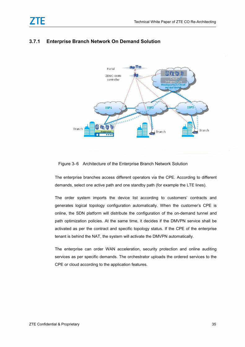
Figure 3- 6 Architecture of the Enterprise Branch Network Solution
The enterprise branches access different operators via the CPE. According to different
demands, select one active path and one standby path (for example the LTE lines).
The order system imports the device list according to customers’ contracts and
generates logical topology configuration automatically. When the customer’s CPE is
online, the SDN platform will distribute the configuration of the on-demand tunnel and
path optimization policies. At the same time, it decides if the DMVPN service shall be
activated as per the contract and specific topology status. If the CPE of the enterprise
tenant is behind the NAT, the system will activate the DMVPN automatically.
The enterprise can order WAN acceleration, security protection and online auditing
services as per specific demands. The orchestrator uploads the ordered services to the
CPE or cloud according to the application features.

Technical White Paper of ZTE CO Re-Architecting
36 ZTE Confidential & Proprietary
3.7.2 Public Cloud Access Solution
Figure 3- 7 Public Cloud Access Scenario
The SD-WAN operators work together with public cloud operators to set a cloud point of
presence (PoP) at a proper place and build private connections with the CSP in advance.
The enterprise customer only needs to sign an agreement with the SD-WAN operator to
deploy the uCPE device. The SD-WAN platform is responsible for selecting the best PoP
for the CPE to access the E2E network automatically. Also the VxLAN tunnels are built
automatically. At the same time, the intercommunication between the PoP and the
private sub-interface to the virtual private cloud (VPC) in the public cloud is activated
automatically, so the VPN connecting the enterprise customer, operator PoP and public
cloud provider can be officially built. If the customer is capable of connecting multiple
PoPs, the Elastic SD-WAN platform will choose a new PoP for the customer to ensure
the best communication quality when the communication quality of one network segment
deteriorates.

Technical White Paper of ZTE CO Re-Architecting
ZTE Confidential & Proprietary 37
3.7.3 Unified On-Demand Underlay and Overlay Networks Based on CoRe-Architecting
It is obvious that the on-demand solution based on Internet access is not good enough
for the fixed network access operators who have already owned lots of FTTx access
lines. The flows may pass the entire metro and CR to form loopback, which not only
seriously risks the service quality, but also greatly wastes metro bandwidth.
The Elastic SD-WAN solution provides OLT control capability via which the enterprise
customers accessing the network via the operator’s PON can control the OLT via the
SDN controller. In this way, the services running on the enterprise private line can be
offloaded to the EDC directly. On-demand tunnels are built to avoid traffic loopback on
the MAN and provide better service quality.
If the existing OLT does not support tunneling technology such as VxLAN, the user can
add/change the aggregation switches so as to make the network adaptive to the Elastic
SD-WAN. If the existing aggregation switch cannot be changed, the customer can add an
independent SD-WAN aggregation switch connecting multiple OLTs to distribute
independent VLAN ranges for the enterprise private line services. Besides, VLAN traffic
diversion policy implemented on the OLT side offloads the services running on the
enterprise private line to independent aggregation switch first. Then those services will
be accessed to the EDC.
3.8 Intelligent O&M
3.8.1 UME for All-in-One Network O&M
Based on considerate thoughts on all the challenges emerging in the cloudified operation
transformation and the profound understanding of telecom network O&M, ZTE releases
the next-generation network management system ElasticNet UME orienting to the
cloudified O&M. On the basis of ZTE’s ElasticNet OES solution, the ElasticNet UME
employs intelligent, integrated, policy-based and automated O&M to reduce OPEX,
enhance network resource utilization and accelerate network service provisioning. So it
is a decent answer to tackle all the issues of the bearer network O&M in the
SDN/NFV/cloud computing environment.

Technical White Paper of ZTE CO Re-Architecting
38 ZTE Confidential & Proprietary
With browser/server (B/S architecture), the UME system is armed with professional
intelligent O&M capability for resource monitoring management, fault diagnosis and
troubleshooting. It provides a number of powerful management services, for example,
resource management, network element management intelligent fault diagnosis, alarm
management, traffic analysis, network and service quality analysis, network adjustment,
service adjustment and service management.
The UME system manages the underlay, overlay, physical and virtual devices uniformly.
It offers a unified Portal to enable unified interface ingress and services. By keeping
unified O&M habits, the UME system effectively reduces the customer’s OPEX.
Moreover, with multiple sorts of unified northbound interfaces such as Corba, SNMP,
FTP, XML and Rest interfaces, the system can interconnect all sorts of upper layer
application systems rapidly, which accordingly makes the network management more
efficient.
3.8.2 BigDNA for Intelligent Network Data Analysis
By collecting real-time data such as the entire network traffic, network quality and
resource status, the BigDNA employs some big data analysis methods and diversified
visible means to help the O&M engineers get the network performance status easily. It
really makes the end-to-end network performance monitoring management and fault
localization come true. At the same time, the BigDNA helps the network operator
implement accurate traffic prediction, finish traffic optimization in the SDN scenario, build
a service index perception system, and localize end-to-end failures of wireless/home/big
video services.
The BigDNA pertains to the following application scenarios:
Comprehensive user experience management: Show individual or regional home
broadband user experience via the user experience index. Track negative comments and
send feedback in time.
Market service analysis: Analyze the quantity of 2G, 3G, LTE, group customer, WLAN
and OLT backhaul services and the service return on investment (RoI) to predict the
customer’s demands and develop potential opportunities.
Network capacity planning: Analyze the performance baseline of the end-to-end

Technical White Paper of ZTE CO Re-Architecting
ZTE Confidential & Proprietary 39
network, predict the network bandwidth demands, and output proposals for the capacity
expansion.
Real-time traffic guarantee: Real-time network traffic collection and display show
network hotspots and problems vividly, which actually provides real-time guarantee for
the network performance.
Network quality analysis: Measure the network quality through all sorts of protocols.
Some index of the link for example jitter and latency can be checked vividly, which makes
failure localization much easier.
Bandwidth configuration adjustment: Analyze network resource performance
bandwidth data, output proposals for CIR and PIR settings, generate optimization
policies and implement semi-automatic and automatic bandwidth adjustment together
with the SPTN controller.
IP + Optical traffic optimization: By implementing real-time and long-term monitoring
and analysis of the traffic on the VTE-LINK in the IP+Optical scenario, the real-time BOD
and bandwidth calendaring policy can be exported to perform automatic bandwidth
adjustment together with the ZENIC controller.
Localization of LTE (wireless)/home broadband service failures: As for the
wireless/home broadband services, the user experience management and end-to-end
network quality monitoring are implemented. When the network quality turns
deteriorating, embedded or extra probes can help the user to localize the service fault
quickly.
Localization of big video service failures: Visible O&M methods are provided at the
bearer network side for the big video service. RFC2544 monitoring and MDI performance
computing technologies are used to enable the localization of the big video service
failures.
3.9 Establishment of an Open Ecosystem
Persisting in adopting open architecture, ZTE CO re-architecting solution is always
committed to growing together with both upstream and downstream providers in the

Technical White Paper of ZTE CO Re-Architecting
40 ZTE Confidential & Proprietary
industry. Concentrating on the cloud and SDN, it so far has set up partnership with more
than 50 suppliers in server, computing virtualization, security and VNF fields.
In term of technologies, ZTE believes in open source technologies and insists on making
contributions to the open source community. ZTE is always an active member and an
excellent contributor in all sorts of open source communities like CEPH and Kubernetes.
In particular, now it is a platinum member of the Open Network Automation Platform
(ONAP), Open Platform for NFV (OPNFV) and OpenDayLight Community, and a gold
member of the OpenStack Community.
4 Field Experiences of ZTE CORe-Architecting
Since early 2016, ZTE has started setting up more than 10 CO re-architecting pilots
together with three biggest operators in China. At the same time, it also joined in a team
made up of multiple overseas operators committed to designing concepts of the early CO
re-architecting projects. Besides, in China ZTE also has more than 10 independent
vBRAS pilots. The major models of the CO re-architecting pilots are as follows:
The CO re-architecting pilot based on a single EDC includes massive fixed network
and mobile network services for example vBRAS, vCPE, vEPC and vCDN services.
In China Telecom Shanghai LSN and China Telecom Guangxi, ZTE enables unified
management of the VMWare resource pool.
Focus on the fixed network access service on the basis of one single EDC.
The CO re-architecting pilots based on the DDC+ multi-EDC integrated resource
pool carry all sorts of fixed and mobile integrated services.
Generally speaking, OpenStack+SDN-baesd NFVI has already been mature enough for
the commercial market. Regarding to MAN re-architecting, due to different transport
resources, geographic features and population distribution in different provinces,
different operators or one operator’ different branches locating at different regions may
have quite different MAN architecture. For example, different provincial companies of an
Technical White Paper of ZTE CO Re-Architecting
ZTE Confidential & Proprietary 41
operator connect the BRAS through different ways, for instance, some of them directly
connect the BRAS via the uplink OLT; some employ OTN transport to aggregate the
resources to the BRAS; and a few of them use the aggregation switches to connect the
BRAS. As the architecture difference cannot be eliminated in a short time, selecting the
most proper MAN virtualization and service offloading solution so as to step forward to
the target architecture becomes even more important.
5 Prospects for the Trends
5.1 Ecosystem Re-Architecting
Aiming at employing software-based SDN/NFV technologies to rebuild the operator
networks, the CO re-architecting on one hand decreases the CAPEX/OPEX, on the other
hand it enables agile services and implementation. During this period, some operators
start developing their own capabilities in network service R&D, so that they can give
quick responses to the market demands. In conclusion, the traditional provider-operator
ecosystem will be completely devastated.
The development trend keeps evolving during the last 30 years. For example, operators
try to develop the upper layer Business & Operation Support (BOSS) system and some
software service system either by themselves or by some authorized partners. As the
SDN/NFV technology further facilitates the development of software-based networks with
open network capabilities, the operators can even research and develop their own
network services.
Re-Architecting of the CT infrastructure and further development of software-based
networks make the network industry much more like a software industry in which
hardware suppliers, platform suppliers, application software suppliers and system
integrators play different roles. The operators with large-scale networks and a powerful
self-research team running based on balanced income and expenditure prefer to develop
service orchestration and application software by themselves. Then they utilize the
components provided by the device suppliers to build their own networks. Other
operators still employ the CT service providers to serve as integrators taking

Technical White Paper of ZTE CO Re-Architecting
42 ZTE Confidential & Proprietary
responsibility for implementing network system delivery and providing long-term
after-sales services.
The operator even the one who is well-known for its self-research capability still has to
face standardization or maintenance interface issues in a multi-vendor environment as
long as it develops the applications via building blocks (such as the hardware devices,
VNF and SDN open interfaces) offered by the suppliers. Particularly, the multi-vendor
standardization and agile response are conflicting in the long run. Most operators are
keen on setting up a long-term partnership for coordinative planning, further cooperation
and fast iterative service delivery.
5.2 Future White Box-based Development
So far, due to the field experiences marked by some internet companies such as Google,
white box switches have already been popular in the DC field. At the same time, some
operators are also trying to introduce the white box devices to the Backhaul and CPE
fields. The white box market is mainly driven by:
1. Separated software and hardware, reduced hardware cost and simplified software
for special application scenarios and less investment in software R&D
2. The operators’ software self-research capabilities and all-in-one DevOps for
controllable service R&D progress and faster new service provisioning
The two points are raised on the basis of hardware universalization and self-research
capabilities. The universal hardware architecture means multiple qualified providers in
the market can offer the devices, which is the Prerequisite of in-batch procurement. The
self-research capabilities reduce the CAPEX resulted from one-time software
purchasing.
In today’s DC field, simple and fixed networking schemes, standard device models, and
increasing switching/routing services and other services from L4 to L7 shifted down to
the vSwitch and intelligent network adapter of the server allow the entire solution to have
less demands for the services of the hardware switch, which weakens the software
service demerits of the white box switch, making it successfully take up fixed market
share.

Technical White Paper of ZTE CO Re-Architecting
ZTE Confidential & Proprietary 43
Traditionally, the operator’s network always has lots of harsh requirements for device
specifications, services and reliability. The white box-based revolution shall change all
these access evaluation systems by making the operator network simpler first. For
example, delete MPLS TE and SR series to make the MAN a flat IP Fabric with
aggregated addresses and shift flexible service functions and the QoS service down to
the CPE and NFV network elements on the EDC. All in all, it is going to be long-term
evolution.
As the operator is quite different from individual or regular SME customers, the white box
system needs the devices designed with excellent accessibility, integrality and long-term
quality guarantee. So the white box should also be provided by famous providers
equipped with all these capabilities. In addition to some special customers like Google,
the current white-box business model can hardly meet the critical requirements of
enterprise customers due to their confined selling modes. So branded white-box
hardware and software providers may still be the mainstream in the market.
But inevitibly, today’s marketing value is now changing from the hardware to software.
We firmly believe this process will keep accelerating all the time.

Technical White Paper of ZTE CO Re-Architecting
44 ZTE Confidential & Proprietary
6 GlossaryAbbreviation Full Name
AWS Amazon Web Service
BNG Broadband Network Gateway
BRAS Broadband Romote Access Server
CORD Central Office Re-architected as Datacenter
CPE Customer Premise Equipment
DDC Domain DataCenter
DDoS Distributed Deny of Service
EDC Edge DataCenter
EPC Evolved Packet Core
EVPN Ethernet VPN
IPS Intrusion Protection System
MEC Multi-access(Mobile)-Edge Computing
MPLS Multi-Protocol Label Switching
NFV Network Function Virtualization
NVE Network Virtualization Edge
ONF Open Networking Foundation
ONOS Open Networking Operating System
OLT Optical Line Terminal
PBB Provider Backbone Bridge
RTT Round Trip Time
SDN Software Defined Networking
ToR Top of Rack
VNF Virtual Network Function
VPC Virtual Private Cloud
VPN Virtual Private Network
VTEP VXLAN Tunnel End Point
VXLAN Virtual eXtensible LAN

Technical White Paper of ZTE CO Re-Architecting
ZTE Confidential & Proprietary 45
WAF Web Application Firewall
ZENIC ZTE Elastic Network Intelligent Controller
Appendix: References[1]UC Berkeley, Above the Clouds: A Berkeley View of Cloud Computing, 2009
[2]Cisco, Visual NetworkingIndex: Forecast andMethodology, 2016–2021
[3]http://www.openstack.org
[4]http://www.openvSwitch.org/
[5]ETSI, Mobile Edge Computing (MEC);Framework and Reference Architecture,
2016-3
[6]BBF, WT-384 Cloud Central Office Reference Architectural Framework, 2017-8
[7]OpenFog Consortium, OpenFog Reference Architecture for Fog Computing,
2017-2
Copyright © 2022 FDOKUMEN