
Customer value-chain involvement for co-creating customer delight
Upload
khangminh22Category
view
0download
0
Bright Cluster Manager 9.0
Cloudbursting ManualRevision: e08d0ed
Date: Thu Jun 23 2022

©2020 Bright Computing, Inc. All Rights Reserved. This manual or parts thereof may not be reproducedin any form unless permitted by contract or by written permission of Bright Computing, Inc.
TrademarksLinux is a registered trademark of Linus Torvalds. PathScale is a registered trademark of Cray, Inc. RedHat and all Red Hat-based trademarks are trademarks or registered trademarks of Red Hat, Inc. SUSE isa registered trademark of Novell, Inc. PGI is a registered trademark of NVIDIA Corporation. FLEXlm isa registered trademark of Flexera Software, Inc. PBS Professional, PBS Pro, and Green Provisioning aretrademarks of Altair Engineering, Inc. All other trademarks are the property of their respective owners.
Rights and RestrictionsAll statements, specifications, recommendations, and technical information contained herein are currentor planned as of the date of publication of this document. They are reliable as of the time of this writingand are presented without warranty of any kind, expressed or implied. Bright Computing, Inc. shallnot be liable for technical or editorial errors or omissions which may occur in this document. BrightComputing, Inc. shall not be liable for any damages resulting from the use of this document.
Limitation of Liability and Damages Pertaining to Bright Computing, Inc.The Bright Cluster Manager product principally consists of free software that is licensed by the Linuxauthors free of charge. Bright Computing, Inc. shall have no liability nor will Bright Computing, Inc.provide any warranty for the Bright Cluster Manager to the extent that is permitted by law. Unlessconfirmed in writing, the Linux authors and/or third parties provide the program as is without anywarranty, either expressed or implied, including, but not limited to, marketability or suitability for aspecific purpose. The user of the Bright Cluster Manager product shall accept the full risk for the qual-ity or performance of the product. Should the product malfunction, the costs for repair, service, orcorrection will be borne by the user of the Bright Cluster Manager product. No copyright owner orthird party who has modified or distributed the program as permitted in this license shall be held liablefor damages, including general or specific damages, damages caused by side effects or consequentialdamages, resulting from the use of the program or the un-usability of the program (including, but notlimited to, loss of data, incorrect processing of data, losses that must be borne by you or others, or theinability of the program to work together with any other program), even if a copyright owner or thirdparty had been advised about the possibility of such damages unless such copyright owner or thirdparty has signed a writing to the contrary.
Table of Contents
Table of Contents . . . . . . . . . . . . . . . . . . . . . . . . . . . . . . . . . . . . . . . . . . . . . i0.1 About This Manual . . . . . . . . . . . . . . . . . . . . . . . . . . . . . . . . . . . . . . . . . v0.2 About The Manuals In General . . . . . . . . . . . . . . . . . . . . . . . . . . . . . . . . . . v0.3 Getting Administrator-Level Support . . . . . . . . . . . . . . . . . . . . . . . . . . . . . . vi0.4 Getting Professional Services . . . . . . . . . . . . . . . . . . . . . . . . . . . . . . . . . . . vi
1 Introduction 1
2 Cluster On Demand Cloudbursting With Azure Or AWS 32.1 Requirements For COD Cloudbursting . . . . . . . . . . . . . . . . . . . . . . . . . . . . . . 32.2 COD Via Bright Computing Customer Portal . . . . . . . . . . . . . . . . . . . . . . . . . . 52.3 COD Via Docker Image . . . . . . . . . . . . . . . . . . . . . . . . . . . . . . . . . . . . . . . 10
2.3.1 COD Via Docker Image–Procedure Summary . . . . . . . . . . . . . . . . . . . . . 102.3.2 COD Via Docker Image–Procedure Details . . . . . . . . . . . . . . . . . . . . . . . 11
2.4 Using The AWS EC2 Management Console . . . . . . . . . . . . . . . . . . . . . . . . . . . 182.4.1 Status Checking Via Instance Selection From Instances List . . . . . . . . . . . . . . 182.4.2 Acting On An Instance From The AWS EC2 Management Console . . . . . . . . . 202.4.3 Connecting To An Instance From The AWS EC2 Management Console . . . . . . . 202.4.4 Viewing The Head Node Console . . . . . . . . . . . . . . . . . . . . . . . . . . . . 202.4.5 Security Group Configuration To Allow Access To The Head Node Via cmsh Or
Bright View . . . . . . . . . . . . . . . . . . . . . . . . . . . . . . . . . . . . . . . . . 212.5 Using The Azure Dashboard . . . . . . . . . . . . . . . . . . . . . . . . . . . . . . . . . . . . 222.6 COD: Cloud Node Start-up . . . . . . . . . . . . . . . . . . . . . . . . . . . . . . . . . . . . 23
2.6.1 COD: IP Addresses In The Cloud . . . . . . . . . . . . . . . . . . . . . . . . . . . . . 242.7 COD With AWS: Optimizing AWS For High Performance Computing (HPC) . . . . . . . 24
3 Cluster Extension Cloudbursting 253.1 Cluster Extension With AWS: The Bright View Cluster Extension Wizard . . . . . . . . . . 27
3.1.1 Introduction . . . . . . . . . . . . . . . . . . . . . . . . . . . . . . . . . . . . . . . . . 273.1.2 AWS Credentials . . . . . . . . . . . . . . . . . . . . . . . . . . . . . . . . . . . . . . 273.1.3 Select Regions . . . . . . . . . . . . . . . . . . . . . . . . . . . . . . . . . . . . . . . . 283.1.4 Select Software Images . . . . . . . . . . . . . . . . . . . . . . . . . . . . . . . . . . . 303.1.5 Summary & Deployment . . . . . . . . . . . . . . . . . . . . . . . . . . . . . . . . . 303.1.6 Deploy . . . . . . . . . . . . . . . . . . . . . . . . . . . . . . . . . . . . . . . . . . . . 31
3.2 Cluster Extension With AWS: Cloud Director Startup From Scratch . . . . . . . . . . . . . 323.2.1 Setting The Cloud Director Disk Storage Device Type . . . . . . . . . . . . . . . . . 333.2.2 Setting The Cloud Director Disk Size . . . . . . . . . . . . . . . . . . . . . . . . . . . 343.2.3 Tracking Cloud Director Startup . . . . . . . . . . . . . . . . . . . . . . . . . . . . . 35
3.3 Cluster Extension With AWS: Cloud Node Startup From Scratch . . . . . . . . . . . . . . . 373.4 Cluster Extension With AWS: Cloud Director And Cloud Node Startup From Snapshots . 37
3.4.1 Cloud Director Startup From Snapshots . . . . . . . . . . . . . . . . . . . . . . . . . 37
ii Table of Contents
3.4.2 Cloud Node Startup From Snapshots . . . . . . . . . . . . . . . . . . . . . . . . . . 393.5 Cluster Extension With AWS: Optimizing AWS For High Performance Computing (HPC) 39
3.5.1 Optimizing HPC Performance: EBS Volume Type . . . . . . . . . . . . . . . . . . . 403.5.2 Optimizing HPC Performance: Placement Groups . . . . . . . . . . . . . . . . . . . 403.5.3 Optimizing HPC Performance: Disabling Hyper-Threading . . . . . . . . . . . . . 403.5.4 Optimizing HPC Performance: Using Elastic Network Adapter Instances . . . . . 413.5.5 Optimizing HPC Performance: Using A Different Clock Source . . . . . . . . . . . 413.5.6 Optimizing HPC Performance: Setting The Socket Buffer Sizes And TCP/IP Pa-
rameters In The Sofware Image . . . . . . . . . . . . . . . . . . . . . . . . . . . . . . 41
4 Cluster Extension Cloudbursting With AWS Using The Command Line And cmsh 434.1 The cm-cluster-extension Script For Cluster Extension Clusters . . . . . . . . . . . . . . 43
4.1.1 Running The cm-cluster-extension Script On The Head Node For Cluster Ex-tension Clusters . . . . . . . . . . . . . . . . . . . . . . . . . . . . . . . . . . . . . . . 43
4.1.2 Launching The Cloud Director For Cluster Extension Clusters . . . . . . . . . . . . 484.2 Launching The Cloud Nodes . . . . . . . . . . . . . . . . . . . . . . . . . . . . . . . . . . . 49
4.2.1 Creating And Powering Up Many Nodes . . . . . . . . . . . . . . . . . . . . . . . . 494.3 Submitting Jobs With cmjob And Cloud Storage Nodes, For Cluster Extension Clusters . 49
4.3.1 Installation And Configuration of cmjob For Data-aware Scheduling To The Cloud 504.3.2 Integration Of cmjob With AWS FSx For Lustre . . . . . . . . . . . . . . . . . . . . . 56
4.4 Miscellaneous Cloud Tools . . . . . . . . . . . . . . . . . . . . . . . . . . . . . . . . . . . . . 614.4.1 Setting Exclude Lists With excludelistsnippets . . . . . . . . . . . . . . . . . . . 614.4.2 The provisioningassociations Mode . . . . . . . . . . . . . . . . . . . . . . . . . 62
4.5 Connecting To AWS With Direct Connect Or A Hardware VPN . . . . . . . . . . . . . . . 634.5.1 Creating a VPC . . . . . . . . . . . . . . . . . . . . . . . . . . . . . . . . . . . . . . . 644.5.2 Connecting The Local Network To The VPC . . . . . . . . . . . . . . . . . . . . . . 644.5.3 Configuring And Deploying The Cluster Extension . . . . . . . . . . . . . . . . . . 65
5 Cluster Extension Cloudbursting With Azure 675.1 Introduction To Cluster Extension Cloudbursting With Azure . . . . . . . . . . . . . . . . 675.2 Cluster Extension Into Azure . . . . . . . . . . . . . . . . . . . . . . . . . . . . . . . . . . . 675.3 Cluster Extension Into Azure: Cloud Node Startup From Scratch . . . . . . . . . . . . . . 745.4 Cluster Extension Into Azure: shutdown Vs power off . . . . . . . . . . . . . . . . . . . . 745.5 Submitting Jobs With cmjob And Cloud Storage Nodes, For Azure Cluster Extension
Clusters . . . . . . . . . . . . . . . . . . . . . . . . . . . . . . . . . . . . . . . . . . . . . . . . 755.5.1 Integration Of cmjob With Azure NetApp Files . . . . . . . . . . . . . . . . . . . . . 75
5.6 Creating An Azure Cluster Extension Using ExpressRoute Or A Hardware VPN . . . . . 795.6.1 Creating A Virtual Network . . . . . . . . . . . . . . . . . . . . . . . . . . . . . . . . 805.6.2 Connecting The Local Network To The Virtual Network . . . . . . . . . . . . . . . 845.6.3 Configuring And Deploying The Cluster Extension . . . . . . . . . . . . . . . . . . 85
6 Cluster Extension Cloudbursting With OpenStack 876.1 Introduction . . . . . . . . . . . . . . . . . . . . . . . . . . . . . . . . . . . . . . . . . . . . . 87
6.1.1 Cluster Extension In General . . . . . . . . . . . . . . . . . . . . . . . . . . . . . . . 876.1.2 Overview Of Carrying Out Cluster Extension Into OpenStack . . . . . . . . . . . . 87
6.2 Deploying A Cluster Extension Into OpenStack Via An Ncurses Dialog . . . . . . . . . . . 876.3 Deploying A Cluster Extension Into An OpenStack Instance Via A Bright View Wizard . . 92
Table of Contents iii
6.4 Connectivity To The Internet For OpenStack Compute Nodes . . . . . . . . . . . . . . . . 93
7 Cloud Considerations And Choices With Bright Cluster Manager 957.1 Differences Between Cluster On Demand And Cluster Extension . . . . . . . . . . . . . . 957.2 Hardware And Software Availability . . . . . . . . . . . . . . . . . . . . . . . . . . . . . . . 957.3 Reducing Running Costs . . . . . . . . . . . . . . . . . . . . . . . . . . . . . . . . . . . . . . 95
7.3.1 Spot Pricing . . . . . . . . . . . . . . . . . . . . . . . . . . . . . . . . . . . . . . . . . 967.3.2 Storage Space Reduction . . . . . . . . . . . . . . . . . . . . . . . . . . . . . . . . . . 96
7.4 Ignoring Prepaid Node Limits With Pay-Per-Use Images . . . . . . . . . . . . . . . . . . . 967.4.1 Bursting Past The Prepaid Limit In AWS . . . . . . . . . . . . . . . . . . . . . . . . 977.4.2 Bursting Past The Prepaid Limit In Azure . . . . . . . . . . . . . . . . . . . . . . . . 99
7.5 Address Resolution In Cluster Extension Networks . . . . . . . . . . . . . . . . . . . . . . 1017.5.1 Resolution And globalnet . . . . . . . . . . . . . . . . . . . . . . . . . . . . . . . . 1017.5.2 Resolution In And Out Of The Cloud . . . . . . . . . . . . . . . . . . . . . . . . . . 101
7.6 Internet Connectivity For Cloud Nodes . . . . . . . . . . . . . . . . . . . . . . . . . . . . . 1037.7 Passing Kernel Parameters To Cloud Nodes . . . . . . . . . . . . . . . . . . . . . . . . . . . 1057.8 Setting Up And Creating A Custom VPC . . . . . . . . . . . . . . . . . . . . . . . . . . . . 105
7.8.1 Elastic IP Addresses And Their Use In Configuring Static IP Addresses . . . . . . 1057.8.2 Subnets In A Custom VPC . . . . . . . . . . . . . . . . . . . . . . . . . . . . . . . . . 1057.8.3 Creating The Custom VPC . . . . . . . . . . . . . . . . . . . . . . . . . . . . . . . . 106

Preface
Welcome to the Cloudbursting Manual for Bright Cluster Manager 9.0.
0.1 About This ManualThis manual is aimed at helping cluster administrators install, understand, configure, and manage thecloud capabilities of Bright Cluster Manager. The administrator is expected to be reasonably familiarwith the Administrator Manual.
0.2 About The Manuals In GeneralRegularly updated versions of the Bright Cluster Manager 9.0 manuals are available on updated clus-ters by default at /cm/shared/docs/cm. The latest updates are always online at http://support.brightcomputing.com/manuals.
• The Installation Manual describes installation procedures for the basic cluster.
• The Administrator Manual describes the general management of the cluster.
• The User Manual describes the user environment and how to submit jobs for the end user.
• The Developer Manual has useful information for developers who would like to program withBright Cluster Manager.
• The OpenStack Deployment Manual describes how to deploy OpenStack with Bright Cluster Man-ager.
• The Edge Manual describes how to deploy Bright Edge with Bright Cluster Manager.
• The Machine Learning Manual describes how to install and configure machine learning capabilitieswith Bright Cluster Manager.
If the manuals are downloaded and kept in one local directory, then in most pdf viewers, clickingon a cross-reference in one manual that refers to a section in another manual opens and displays thatsection in the second manual. Navigating back and forth between documents is usually possible withkeystrokes or mouse clicks.
For example: <Alt>-<Backarrow> in Acrobat Reader, or clicking on the bottom leftmost navigationbutton of xpdf, both navigate back to the previous document.
The manuals constantly evolve to keep up with the development of the Bright Cluster Manager envi-ronment and the addition of new hardware and/or applications. The manuals also regularly incorporatecustomer feedback. Administrator and user input is greatly valued at Bright Computing. So any com-ments, suggestions or corrections will be very gratefully accepted at [email protected].
There is also a feedback form available via Bright View, via the Account icon, , following theclickpath:
Account→Help→Feedback

vi Table of Contents
0.3 Getting Administrator-Level SupportIf the reseller from whom Bright Cluster Manager was bought offers direct support, then the resellershould be contacted.
Otherwise the primary means of support is via the website https://support.brightcomputing.com. This allows the administrator to submit a support request via a web form, and opens up a troubleticket. It is a good idea to try to use a clear subject header, since that is used as part of a reference tagas the ticket progresses. Also helpful is a good description of the issue. The followup communicationfor this ticket goes via standard e-mail. Section 13.2 of the Administrator Manual has more details onworking with support.
0.4 Getting Professional ServicesBright Computing normally differentiates between professional services (customer asks Bright Comput-ing to do something or asks Bright Computing to provide some service) and support (customer has aquestion or problem that requires an answer or resolution). Professional services can be provided afterconsulting with the reseller, or the Bright account manager.

1Introduction
In weather, a cloudburst is used to convey the idea that a sudden flood of cloud contents takes place. Incluster computing, the term cloudbursting conveys the idea that a flood of extra cluster capacity is madeavailable when needed from a cloud computing services provider such as Amazon.
Bright Cluster Manager implements cloudbursting for two scenarios:
1. A “Cluster On Demand”, or a “pure” cloud cluster (chapter 2). In this scenario, the entire clustercan be started up on demand from a state of non-existence. All nodes, including the head node,are instances running in a coordinated manner entirely inside the cloud computing service.
2. A “Cluster Extension”, or a “hybrid” cloud cluster (chapter 3). In this scenario, the head nodeis kept outside the cloud. Zero or more regular nodes are also run outside the cloud. Whenadditional capacity is required, the cluster is extended via cloudbursting to make additional nodesavailable from within the cloud.
Chapters 2 and 3 deal with mainly the GUI configuration of the Cluster On Demand and ClusterExtension scenarios.
Chapter 4 looks at mainly command line tools for configuration of the Cluster On Demand andCluster Extension scenarios, considering mainly AWS.
Chapter 5 looks at Cluster Extension for Azure.Chapter 7 discusses some miscellaneous aspects of cloudbursting.
© Bright Computing, Inc.

2Cluster On Demand
Cloudbursting With Azure OrAWS
Cluster On Demand (COD) cloudbursting is when a separate cluster is started up in a cloud, with thecluster head node that manages the cluster also in that cloud. A COD cluster is regarded as an indepen-dent virtual cluster (sometimes described as a ’pure’ cloud cluster), and not an extension of an existingphysical cluster.
2.1 Requirements For COD CloudburstingCOD can run in Azure (COD-Azure), in AWS (COD-AWS), or in Bright OpenStack (COD-OS). Thischapter discusses COD-Azure and COD-AWS. COD-OS is discussed in Chapter 6 of the OpenStack De-ployment Manual.
The requirements for COD-Azure and COD-AWS are:
• an account on the Bright Computing Customer Portal website at http://customer.brightcomputing.com/Customer-Login from which to run the COD (section 2.2), or a Dockercontainer to run an image that requests the COD (section 2.3).
• a Bright Cluster Manager product key. This key is later activated when the license is installed(Chapter 4 of the Installation Manual) on the head node. The head node and regular nodes in thiscase are in the cloud.
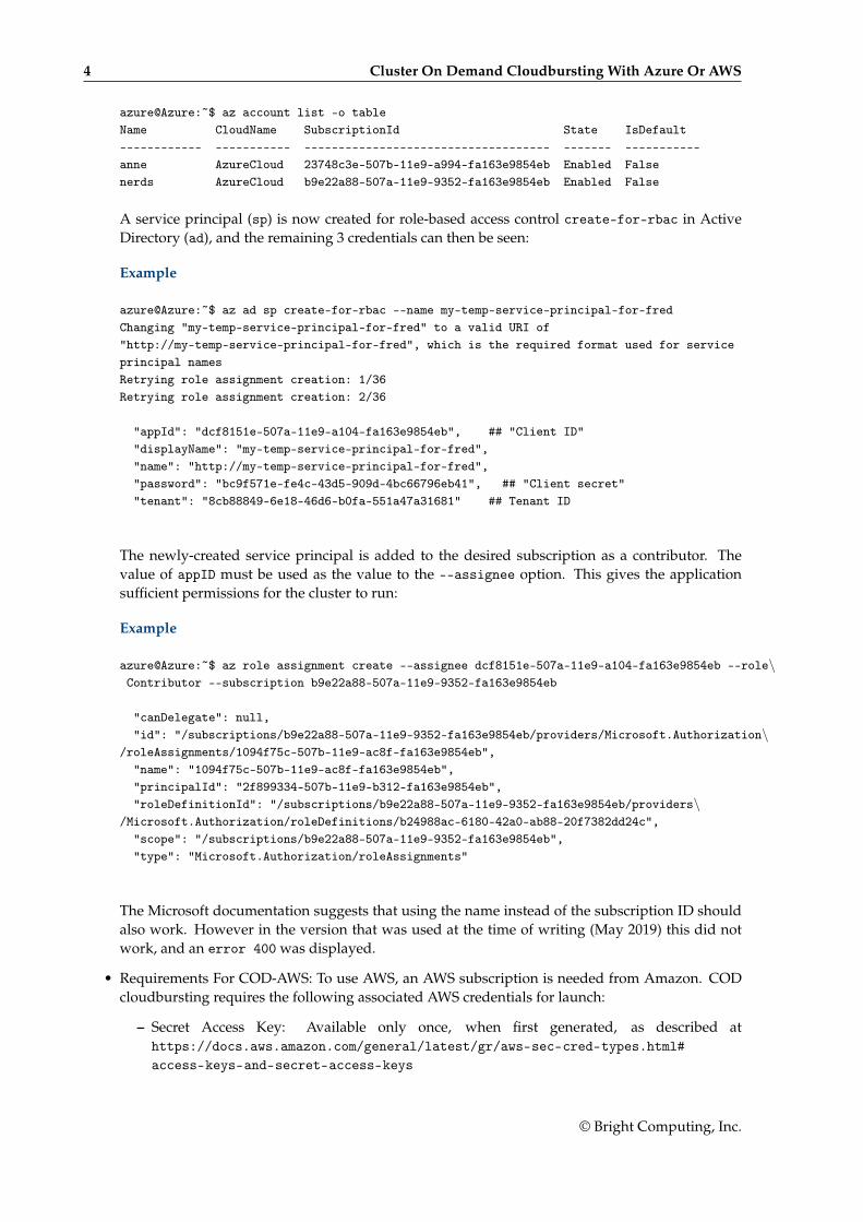
• Requirements For COD-Azure: To use Azure, an Azure account subscription is needed from Mi-crosoft. COD cloudbursting requires the following associated Azure credentials to launch:
– tenant ID
– subscription ID
– Client ID
– Client Secret
A CLI-centric way to obtain these credentials requires logging into the Azure web portal usingan account that has sufficient privileges. The Azure web bash console is then opened, and thesubscription ID can then be listed for the account with:
Example
© Bright Computing, Inc.
4 Cluster On Demand Cloudbursting With Azure Or AWS
azure@Azure:~$ az account list -o tableName CloudName SubscriptionId State IsDefault------------ ----------- ------------------------------------ ------- -----------anne AzureCloud 23748c3e-507b-11e9-a994-fa163e9854eb Enabled Falsenerds AzureCloud b9e22a88-507a-11e9-9352-fa163e9854eb Enabled False
A service principal (sp) is now created for role-based access control create-for-rbac in ActiveDirectory (ad), and the remaining 3 credentials can then be seen:
Example
azure@Azure:~$ az ad sp create-for-rbac --name my-temp-service-principal-for-fredChanging "my-temp-service-principal-for-fred" to a valid URI of"http://my-temp-service-principal-for-fred", which is the required format used for serviceprincipal namesRetrying role assignment creation: 1/36Retrying role assignment creation: 2/36
"appId": "dcf8151e-507a-11e9-a104-fa163e9854eb", ## "Client ID""displayName": "my-temp-service-principal-for-fred","name": "http://my-temp-service-principal-for-fred","password": "bc9f571e-fe4c-43d5-909d-4bc66796eb41", ## "Client secret""tenant": "8cb88849-6e18-46d6-b0fa-551a47a31681" ## Tenant ID
The newly-created service principal is added to the desired subscription as a contributor. Thevalue of appID must be used as the value to the --assignee option. This gives the applicationsufficient permissions for the cluster to run:
Example
azure@Azure:~$ az role assignment create --assignee dcf8151e-507a-11e9-a104-fa163e9854eb --role\Contributor --subscription b9e22a88-507a-11e9-9352-fa163e9854eb
"canDelegate": null,"id": "/subscriptions/b9e22a88-507a-11e9-9352-fa163e9854eb/providers/Microsoft.Authorization\
/roleAssignments/1094f75c-507b-11e9-ac8f-fa163e9854eb","name": "1094f75c-507b-11e9-ac8f-fa163e9854eb","principalId": "2f899334-507b-11e9-b312-fa163e9854eb","roleDefinitionId": "/subscriptions/b9e22a88-507a-11e9-9352-fa163e9854eb/providers\
/Microsoft.Authorization/roleDefinitions/b24988ac-6180-42a0-ab88-20f7382dd24c","scope": "/subscriptions/b9e22a88-507a-11e9-9352-fa163e9854eb","type": "Microsoft.Authorization/roleAssignments"
The Microsoft documentation suggests that using the name instead of the subscription ID shouldalso work. However in the version that was used at the time of writing (May 2019) this did notwork, and an error 400 was displayed.
• Requirements For COD-AWS: To use AWS, an AWS subscription is needed from Amazon. CODcloudbursting requires the following associated AWS credentials for launch:
– Secret Access Key: Available only once, when first generated, as described athttps://docs.aws.amazon.com/general/latest/gr/aws-sec-cred-types.html#access-keys-and-secret-access-keys
© Bright Computing, Inc.

2.2 COD Via Bright Computing Customer Portal 5
– Access Key ID: as described at https://docs.aws.amazon.com/general/latest/gr/aws-sec-cred-types.html#access-keys-and-secret-access-keys
– AWS Account ID, as described at https://docs.aws.amazon.com/general/latest/gr/acct-identifiers.html
– AWS Username: This can be either the AWS account root user (the e-mail address of the rootuser), or it can be an IAM username with sufficient permissions to launch the cluster.
COD cloudbursting can be configured and started up via the Bright Computing customer portal(section 2.2), or via a Docker image (section 2.3).
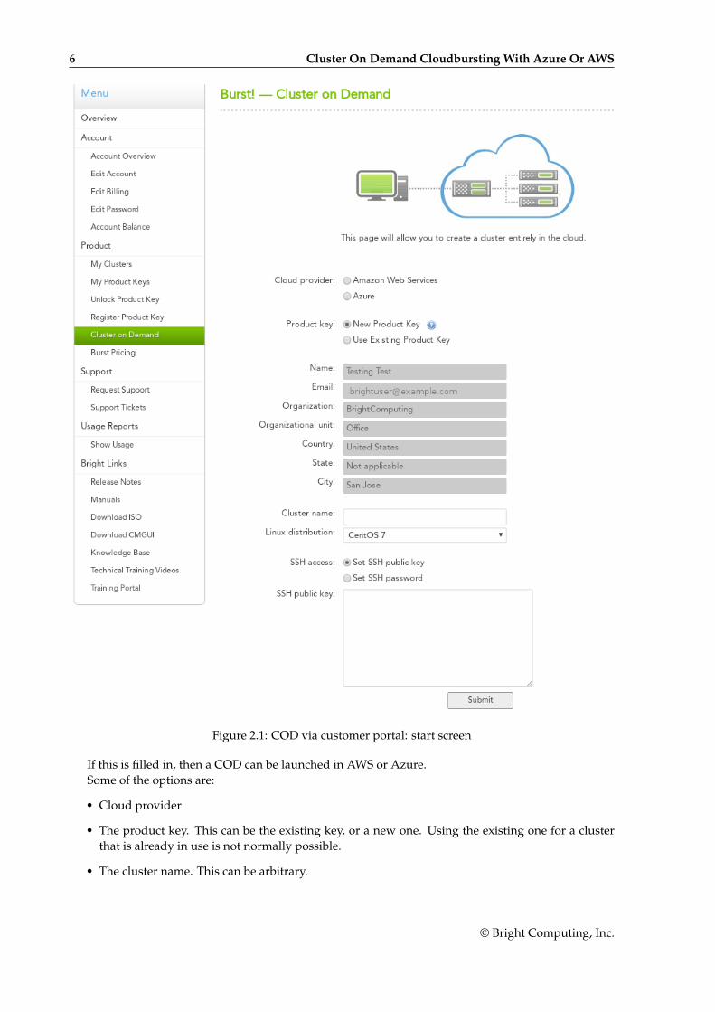
2.2 COD Via Bright Computing Customer PortalThe customer portal (section 2.1) has a menu option Cluster on Demand. Selecting this displays aninput form (figure 2.1).
© Bright Computing, Inc.
6 Cluster On Demand Cloudbursting With Azure Or AWS
Figure 2.1: COD via customer portal: start screen
If this is filled in, then a COD can be launched in AWS or Azure.Some of the options are:
• Cloud provider
• The product key. This can be the existing key, or a new one. Using the existing one for a clusterthat is already in use is not normally possible.
• The cluster name. This can be arbitrary.
© Bright Computing, Inc.

2.2 COD Via Bright Computing Customer Portal 7
• The SSH access method.
– SSH public key access is recommended, and should then be pasted into the text field. Usingkey access disables SSH password authentication.
– Alternatively, a password can be set instead. This generates a somewhat random passwordfor SSH password authentication that is not very strong. The password should normally bechanged and saved, because brute force password attacks in the AWS and Azure IP addressranges are common.
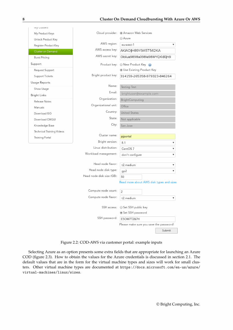
Selecting AWS as an option presents some extra fields that are appropriate for launching an AWSCOD (figure 2.2). How to obtain the values for the AWS keys is discussed in section 2.1. The defaultvalues that are in the form for the virtual machine types and sizes will work for small clusters. Othervirtual machine types are documented at https://aws.amazon.com/ec2/instance-types/.
© Bright Computing, Inc.
8 Cluster On Demand Cloudbursting With Azure Or AWS
Figure 2.2: COD-AWS via customer portal: example inputs
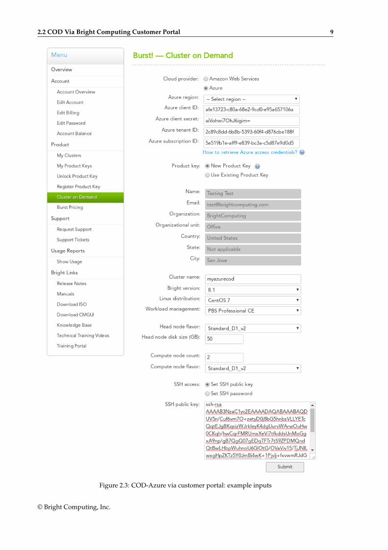
Selecting Azure as an option presents some extra fields that are appropriate for launching an AzureCOD (figure 2.3). How to obtain the values for the Azure credentials is discussed in section 2.1. Thedefault values that are in the form for the virtual machine types and sizes will work for small clus-ters. Other virtual machine types are documented at https://docs.microsoft.com/en-us/azure/virtual-machines/linux/sizes.
© Bright Computing, Inc.
2.2 COD Via Bright Computing Customer Portal 9
Figure 2.3: COD-Azure via customer portal: example inputs
© Bright Computing, Inc.
10 Cluster On Demand Cloudbursting With Azure Or AWS
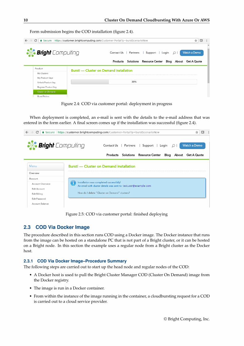
Form submission begins the COD installation (figure 2.4).
Figure 2.4: COD via customer portal: deployment in progress
When deployment is completed, an e-mail is sent with the details to the e-mail address that wasentered in the form earlier. A final screen comes up if the installation was successful (figure 2.4).
Figure 2.5: COD via customer portal: finished deploying
2.3 COD Via Docker ImageThe procedure described in this section runs COD using a Docker image. The Docker instance that runsfrom the image can be hosted on a standalone PC that is not part of a Bright cluster, or it can be hostedon a Bright node. In this section the example uses a regular node from a Bright cluster as the Dockerhost.
2.3.1 COD Via Docker Image–Procedure SummaryThe following steps are carried out to start up the head node and regular nodes of the COD:
• A Docker host is used to pull the Bright Cluster Manager COD (Cluster On Demand) image fromthe Docker registry.
• The image is run in a Docker container.
• From within the instance of the image running in the container, a cloudbursting request for a CODis carried out to a cloud service provider.
© Bright Computing, Inc.
2.3 COD Via Docker Image 11
• When the request completes successfully, a cluster that is running in the cloud is ready for use.
These steps are now covered in more detail.
2.3.2 COD Via Docker Image–Procedure DetailsA COD can be launched from a Bright COD Docker image running inside Docker.
This is typically run from a standalone machine, such as, for example, a laptop that is not part of aBright cluster.
However, launching a COD from a Bright cluster is also possible, and can be carried out as follows:
• Docker is installed in Bright Cluster Manager with cm-docker-setup (section 9.1.1 of the Adminis-trator Manual), or using the Bright View Docker setup wizard.
• The node that is to run the Docker image is used to pull the image to the node
Example
[root@bright90 ~]# ssh node001[root@node001 ~]# module load docker[root@node001 ~]# docker pull brightcomputing/cod:latest...cac15ba059ef: Pull completeDigest: sha256:19b263033090e1a70043989decdf3c3870d3def8c2e69b2a85ac293fd7d149abStatus: Downloaded newer image for brightcomputing/cod:latest
• The appropriate image ID can be found. For example:
Example
[root@node001 ~]# docker imagesREPOSITORY TAG IMAGE ID CREATED SIZEbrightcomputing/cod latest aeddb120e78f 5 hours ago 593 MB
• The image can be run in a Docker container. This is done by running the image by specifyingits ID from the preceding output. The container with that image (aeddb120e78f) can run (run)interactively (-i), over a pseudo-tty (-t), using the host (host option, which in this case is node001)network (–network) stack, and running, for example, a Bash shell (/bin/bash):
Example
[root@node001 ~]# docker run --network host -it aeddb120e78f /bin/bash[root@node001 /]#
Without --network host Docker allows only outgoing connections by default.
• In that container an existing SSH public key should be saved, so that it can be specified as anoption to the COD cluster creation command. The associated private key should be located on anymachine that is to be used to access the COD via SSH.
Instead of using an existing SSH key pair, it may be convenient to generate a completely new keypair within the container, using ssh-keygen. In that case, the following may have to be borne inmind:
– If exiting from the container, then returning to that container is possible after restarting andattaching to the container again, so that the keys to the cluster remain accessible.
© Bright Computing, Inc.
12 Cluster On Demand Cloudbursting With Azure Or AWS
– However, if the container is to be removed, then a copy of the keys, or at least the private key,should exist outside the container, so that the cluster can still be accessed. For example thekeys can be displayed with the cat command and then copied and pasted (some text elided):
Example
[root@256ac248b583 /]# cat /root/.ssh/id_rsa-----BEGIN RSA PRIVATE KEY-----...-----END RSA PRIVATE KEY-----[root@256ac248b583 /]# cat /root/.ssh/id_rsa.pubssh-rsa AAAAB3NzaC1yc2EAAAADAQABAAABAQDOXPZUImfrolTHJQT5DepyCQ...
It is a good idea for the administrator to plan key management, in order to minimize the spread ofthe private key in general, and to manage keys in a way that works well with the work flow anduse.
Up to this point, the preparation for running a COD from Docker has been the same for whetherAzure or AWS are to be used as the cloud provider. The next stage is to launch the COD inside the cloudservice.
There are two cloud services that a COD from Docker can be launched into. These are:
• AWS (Amazon Web Services), made available by Amazon. The CLI utility in the Docker instancethat launches the COD is then cm-cod-aws (page 15).
• Azure, made available by Microsoft. The CLI utility in the Docker instance that launches the CODis then cm-cod-azure (page 12).
For completeness, a non-Dockerized COD can also be launched into the Bright OpenStack privatecloud service. The Bright OpenStack private cloud service is a cloud service that can be provided withthe Bright OpenStack edition of Bright Cluster Manager. The launch utility for this third type of COD iscm-cod-os, and its use is described in detail in Chapter 6 of the OpenStack Deployment Manual.
Procedure When Running cm-cod-azureLaunching a COD inside Azure is carried by running cm-cod-azure from within the Docker containerthat is outside Azure.
Running cm-cod-azure from within the Docker container that is outside Azure, launches a CODwithin Azure.
Options For cm-cod-azure: The cm-cod-azure command options include the cluster name, node types,credentials, and so on. Running cm-cod-azure cluster create -h displays a list of options and ex-planations for the options.
Some of the options are described in table 2.1:
Option Example Value
--azure-client-id afe13723-c80a-68e2-9cd0-e95a657106a
--azure-client-secret aiVohwi7OhJ6igim=
--azure-tenant-id 2c89c8dd-6b8b-5393-60f4-d876cbe188f
--azure-subscription-id 5e519b1e-aff9-e839-bc3a-c5d87e9d0d5
--azure-location westeurope
<cluster_name> noviceazurecluster
--node-type Standard_D1_v2
--head-node-type Standard_D1_v2
...continues
© Bright Computing, Inc.

2.3 COD Via Docker Image 13
...continued
Option Example Value
--version 9.0
--wlm dont-configure
--head-node-root-volume-size 50
--nodes 3
--ssh-pub-key-path /root/.ssh/id_rsa.pub
--license-organization Illuminati
--license-unit Eleusis
--license-locality Munich
--license-state Bavaria
--license-country Germany
--license-product-key 12334-324234-3413413-32-324
The example values for the credentials given here, if used literally, will not work. They are justto show the rough format of the values.
Table 2.1: cm-cod-azure options
The first four –azure-* options in the preceding table require the actual Azure credentials that thecluster adminstrator obtains from Microsoft.
For the distinguished name values (organization, unit, and so on), the values can be arbitrary, al-though the administrator may find it useful to have them match the ones set in the product key license.
The verify-license utility shows the distinguished name values that were set in the product keylicense.
For example:
[root@bright90 ~]# verify-license /cm/local/apps/cmd/etc/cluster.pem \/cm/local/apps/cmd/etc/cluster.key info========= Certificate Information ========settings for organization, unit, etc, are displayed
It is normally not possible to use the product key of the host cluster itself. So, normally a freshproduct key must be used with the cm-cod-azure command.
Cluster creation run with cm-cod-azure: An example of a cm-cod-azure command that can be run isthen:
Example
cm-cod-azure cluster create \--azure-location 'westeurope' \--azure-client-id 'afe13723-c80a-68e2-9cd0-e95a657106a' \--azure-client-secret 'aiVohwi7OhJ6igim=' \--azure-tenant-id '2c89c8dd-6b8b-5393-60f4-d876cbe188f' \--azure-subscription-id '5e519b1e-aff9-e839-bc3a-c5d87e9d0d5' \--head-node-type 'Standard_D1_v2' --head-node-root-volume-size '50' \--nodes '3' --node-type 'Standard_D1_v2' \--ssh-pub-key-path '/root/.ssh/id_rsa.pub' \--license-product-key '12334-324234-3413413-32-324' 'noviceazurecluster'
If all is well, then something similar to the following is displayed (some output elided):
© Bright Computing, Inc.

14 Cluster On Demand Cloudbursting With Azure Or AWS
13:22:50: INFO: Credentials are valid and have read/write authorizations13:23:23: INFO: Cluster Create13:23:24: INFO: ---------------------------------------------------------------------13:23:24: INFO: Cluster: noviceazurecluster13:23:24: INFO: ---------------------------------------------------------------------13:23:24: INFO: Image: bcm-cod-image-latest-4.vhd13:23:24: INFO: Image date: 2018-02-27 09:01:27+00:0013:23:24: INFO: Head nodes: 1 (Standard_D1_V2)13:23:24: INFO: Nodes: 3 (Standard_D1_v2)13:23:24: INFO: Region: westeurope13:23:24: INFO: Key path: /root/.ssh/id_rsa.pub13:23:24: INFO: ---------------------------------------------------------------------Press ENTER to continue and create the cluster.Press ctrl+c (or type 'a') to abort. Type 'i' for more info.
13:23:56: INFO: ## Progress: 213:23:56: INFO: #### stage: Creating resource group noviceazurecluster_cod_resource_group13:23:58: INFO: Creating storage account noviceazureclusterstorageaccount13:24:22: INFO: ## Progress: 513:24:22: INFO: #### stage: Building deployment template13:24:22: INFO: generating cloud-init script13:24:22: INFO: ## Progress: 713:24:22: INFO: #### stage: Copying head node image13:24:22: INFO: Copying https://brightimages.blob.core.windows.net/images/bcm-cod-image-\latest-4.vhd to noviceazureclusterstorageaccount/images/noviceazurecluster-head-node-os-disk.vhd13:24:22: INFO: ## Progress: 12.013:24:22: INFO: #### stage: Server side copy13:25:01: INFO: ## Progress: 12.213:25:01: INFO: #### stage: Server side copy13:25:05: INFO: ## Progress: 12.413:25:05: INFO: #### stage: Server side copy13:25:09: INFO: ## Progress: 12.6...13:35:32: INFO: #### stage: Server side copy13:35:35: INFO: ## Progress: 61.7713:35:35: INFO: #### stage: Server side copy13:35:38: INFO: ## Progress: 61.9713:35:38: INFO: #### stage: Server side copy13:35:40: INFO: Elapsed: 11:18 min13:35:40: INFO: ## Progress: 8513:35:40: INFO: #### stage: Creating and deploying Head node13:39:53: INFO: Waiting for CMDaemon to come up...13:41:34: INFO: Waiting for CMDaemon to come up13:41:34: INFO: CMDaemon is not up yet, waiting 10 seconds...13:41:34: INFO: ## Progress: 10013:41:34: INFO: #### stage: Deployment finished successfully.13:41:34: INFO: ----------------------------------------------------------------13:41:34: INFO: Cluster: noviceazurecluster13:41:34: INFO: ----------------------------------------------------------------13:41:34: INFO: Image: bcm-cod-image-latest-4.vhd13:41:34: INFO: Image date: 2018-02-27 09:01:27+00:0013:41:34: INFO: Head nodes: 1 (Standard_D1_V2)13:41:34: INFO: Nodes: 3 (Standard]_D1_v2)13:41:34: INFO: Region: westeurope
© Bright Computing, Inc.
2.3 COD Via Docker Image 15
13:41:34: INFO: Key path: /root/.ssh/id_rsa.pub13:41:34: INFO: Head node ID: 3e6d2b24-2c7b-40cb-a594-fb3e66f3131913:41:34: INFO: Public IP: 13.93.90.513:41:34: INFO: ----------------------------------------------------------------[root@743d346dca20 /]#
The cluster can now be logged into by using the SSH keys generated earlier, and using the public IPaddress shown in the last few lines of the preceding output.
Listing with cm-cod-azure: The clusters that are running from the container can be listed with theirproperties, using the credentials, as follows:
Example
[root@743d346dca20 /]# cm-cod-azure cluster list \--azure-location 'westeurope' \--azure-client-id 'afe13723-c80a-68e2-9cd0-e95a657106a' \--azure-client-secret 'aiVohwi7OhJ6igim=' \--azure-tenant-id '2c89c8dd-6b8b-5393-60f4-d876cbe188f' \--azure-subscription-id '5e519b1e-aff9-e839-bc3a-c5d87e9d0d5'
+--------------------+------------------------------+------------+------------+-...| Cluster Name | Head node name | Public IP | Location | ...+--------------------+------------------------------+------------+------------+-...| noviceazurecluster | noviceazurecluster-head_node | 13.98.90.5 | westeurope | ...+--------------------+------------------------------+------------+------------+-...
Removal with cm-cod-azure A cluster can be removed from the container with:
[root@743d346dca20 /]# cm-cod-azure cluster delete \--azure-location 'westeurope' \--azure-client-id 'afe13723-c80a-68e2-9cd0-e95a657106a' \--azure-client-secret 'aiVohwi7OhJ6igim=' \--azure-tenant-id '2c89c8dd-6b8b-5393-60f4-d876cbe188f' \--azure-subscription-id '5e519b1e-aff9-e839-bc3a-c5d87e9d0d5' \'noviceazurecluster'
Procedure When Running cm-cod-awsLaunching a COD from within AWS is carried by running cm-cod-aws from within the Docker container.This process is similar to that of launching within Azure (page 15).
Options For cm-cod-aws: The cm-cod-aws command takes options to create a cluster. Running cm-cod-awscluster create -h displays a list of options and explanations for the options.
Some of the options are described in table 2.2:
Table 2.2: cm-cod-aws options
Option Example Value
...continues
© Bright Computing, Inc.
16 Cluster On Demand Cloudbursting With Azure Or AWS
...continued
Option Example Value
--aws-region eu-central-1
--aws-secret-key Oocei6eiieshahG7IiJe9Quoud0oo
--aws-access-key-id AKIAJAICHAZI7OHH1EEGO
--head-node-type t2.medium
--node-type t2.medium
--license-product-key 12334-324234-3413413-32-324
--cluster-password justinbieberrocks
--log-cluster-password does not take a value
--ssh-pub-key-path /root/.ssh/id_rsa.pub
--nodes 3
<cluster_name> [...] noobawscluster
The example values for the credentials given here, if used literally, will not work. They are justto show the rough format of the values.
The --aws-secret-key and --aws-access-key-id options in the preceding table require the actualAWS credentials that the cluster adminstrator obtains from Amazon.
Setting a root password via the --cluster-password option is a possible way to configure a login tothe cluster. Another possibility is to use ssh keys. The keys generated within the docker instance usingssh-keygen earlier on can be used for this.
The password can be seen in the logs of the command if the --log-cluster-password option isused.
If the root password is not set with --cluster-password, then a random password is set, andssh keys can be used to login to the cluster. A root password can always be specified later usingcm-change-password, after logging into the cluster via SSH key access or the root password. The defaultlogin to Bright View also uses the root password.
For the product key of cluster in AWS, it is normally not possible to use the product key of the hostcluster itself. So, normally a fresh product key must be used with the cm-cod-azure command.
Cluster creation run with cm-cod-aws: An example of a cm-cod-aws command that can be run is then:
Example
cm-cod-aws cluster create \--aws-region 'eu-central' \--aws-secret-key 'Oocei6eiieshahG7IiJe9Quoud0oo' \--aws-access-key-id 'AKIAJAICHAZI7OHH1EEGO' \--nodes '3' --node-type 't2.medium' \--ssh-pub-key-path '/root/.ssh/id_rsa.pub' \--license-product-key '12334-324234-3413413-32-324' 'noobawscluster'
If all is well, then the output is similar to (some output elided):
12:06:57: INFO: ---------------------------------------------------------------------12:06:57: INFO: Cluster: noobawscluster12:06:57: INFO: ---------------------------------------------------------------------12:06:57: INFO: Image: brightheadnode-latest-centos7u4-hvm-3 (ami-71691308)12:06:57: INFO: Image date: 2018-02-26 16:10 (27d 19h ago)12:06:57: INFO: Head nodes: 1 (t2.medium)12:06:57: INFO: Nodes: 5 (t2.medium)
© Bright Computing, Inc.

2.3 COD Via Docker Image 17
12:06:57: INFO: Region: eu-west-112:06:57: INFO: ssh pub key: /root/.ssh/id_rsa.pub12:06:57: INFO: ---------------------------------------------------------------------Press ENTER to continue and create the cluster.Press ctrl+c (or type 'a') to abort. Type 'i' for more info.
12:07:01: INFO: ## Progress: 212:07:01: INFO: #### stage: Setting up VPC12:07:01: INFO: ## Progress: 512:07:01: INFO: #### stage: Creating VPC for noobawscluster in eu-west-1...12:07:02: INFO: ## Progress: 1012:07:02: INFO: #### stage: Adding internet connectivity...12:07:03: INFO: ## Progress: 1212:07:03: INFO: #### stage: Creating public subnet...12:07:04: INFO: ## Progress: 1612:07:04: INFO: #### stage: Creating head node (t2.medium)...12:07:04: INFO: ## Progress: 2012:07:04: INFO: #### stage: Public key specified, no need to enable password authentication12:07:04: INFO: Scheduling cm-bright-setup.12:07:06: INFO: ## Progress: 2212:07:06: INFO: #### stage: Done setting up VPC for noobawscluster.12:07:06: INFO: ## Progress: 2212:07:06: INFO: #### stage: Starting head nodes...12:07:06: INFO: ## Progress: 3012:07:06: INFO: #### stage: Waiting for head nodes to start...12:07:38: INFO: ## Progress: 3012:07:38: INFO: #### stage: Wait for cloud-init to finish on cluster noobawscluster...12:07:43: INFO: ## Progress: 3012:07:43: INFO: #### stage: Cloud-init is not finished, waiting 10 seconds...12:07:53: INFO: ## Progress: 30...12:10:34: INFO: #### stage: Cloud-init is not finished, waiting 10 seconds...12:10:44: INFO: ## Progress: 3012:10:44: INFO: #### stage: Wait for cloud-init to finish on cluster noobawscluster...12:10:44: INFO: ## Progress: 10012:10:44: INFO: #### stage: Deployment of cluster: noobawscluster finished successfully.12:10:54: INFO: Script completed.12:10:54: INFO: ---------------------------------------------------------------------12:10:54: INFO: Time it took: 03:5212:10:54: INFO: SSH string: ssh [email protected] noobawscluster12:10:54: INFO: Head node ID: i-0120058780aa736eb[root@256ac248b583 /]# ssh [email protected]
At this point, the head node running on AWS is ready for use. It can be accessed via ssh, as suggestedin the last line of the preceding output.
The regular nodes running on AWS are configured for use, but are not powered on. They can bepowered on using the cmsh or Bright View front ends, just as in a regular cluster.
From cmsh, the first cloud node can be powered on with, for example:
[noobawscluster->device]% power on cnode001
Listing with cm-cod-aws: The clusters that are running from the container can be listed with theirproperties, using the credentials with the region, as follows:
Example
© Bright Computing, Inc.
18 Cluster On Demand Cloudbursting With Azure Or AWS
[root@743d346dca20 /]# cm-cod-aws cluster list \--aws-region 'eu-west-1' \--aws-secret-key 'Oocei6eiieshahG7IiJe9Quoud0oo' \--aws-access-key-id 'AKIAJAICHAZI7OHH1EEGO' \--license-product-key '12334-324234-3413413-32-324'
+--------------------+------------------------------+-------------+| Cluster Name | Head node name | VPC ID |...+--------------------+------------------------------+-------------+| noobawscluster | noobawscluster-head_node | vpc-as89ada |...+--------------------+------------------------------+-------------+
Removal with cm-cod-aws A cluster can be removed from the container with:
[root@743d346dca20 /]# cm-cod-aws cluster delete \--aws-region 'eu-west-1' \--aws-secret-key 'Oocei6eiieshahG7IiJe9Quoud0oo' \--aws-access-key-id 'AKIAJAICHAZI7OHH1EEGO' \--license-product-key '12334-324234-3413413-32-324' \noobawscluster
2.4 Using The AWS EC2 Management ConsoleThe recommended way of managing COD is using Bright View via its public IP address, or by usingcmsh via the head node (section 2.4.5). This section (section 2.4) describes how the Amazon managementconsole can also be used, to manage some AWS aspects of the instance.
A login is possible from https://console.aws.amazon.com/console/ by using the e-mail addressand password of the associated AWS root account, or AWS IAM user account.
The head node instance can be watched and managed without Bright Cluster Manager in the follow-ing ways.
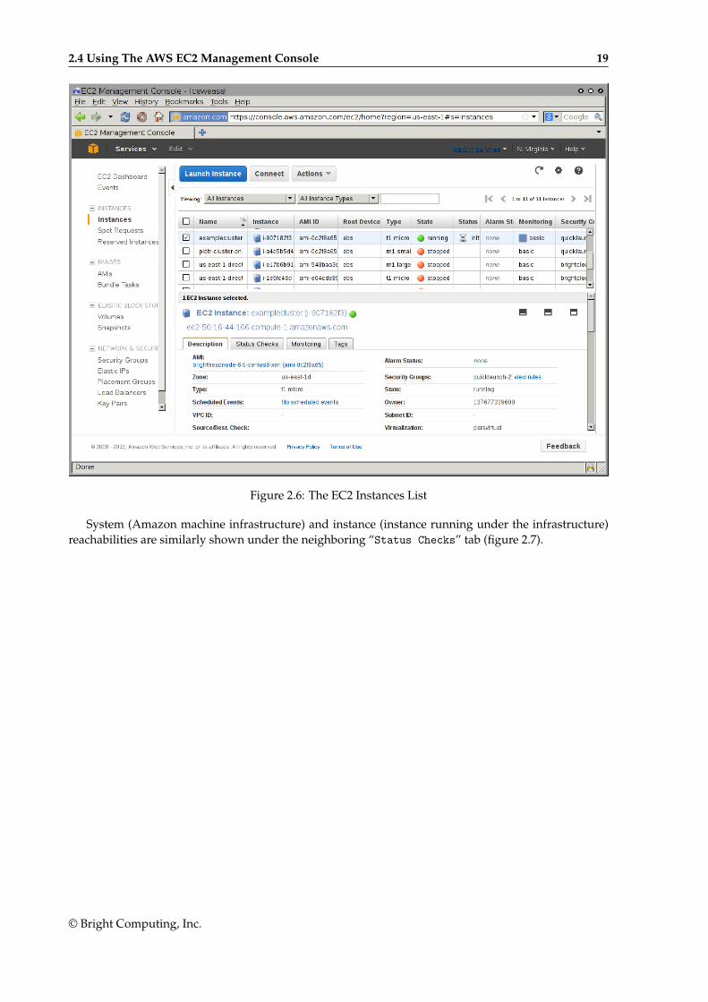
2.4.1 Status Checking Via Instance Selection From Instances ListClicking the Instances menu resource item from the navigation pane opens up the “Instances” pane.This lists instances belonging to the account owner. An instance can be marked by ticking its checkbox.Information for the selected instance is then displayed in the lower main pane (figure 2.6).
© Bright Computing, Inc.
2.4 Using The AWS EC2 Management Console 19
Figure 2.6: The EC2 Instances List
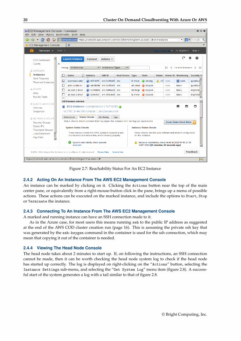
System (Amazon machine infrastructure) and instance (instance running under the infrastructure)reachabilities are similarly shown under the neighboring “Status Checks” tab (figure 2.7).
© Bright Computing, Inc.
20 Cluster On Demand Cloudbursting With Azure Or AWS
Figure 2.7: Reachability Status For An EC2 Instance
2.4.2 Acting On An Instance From The AWS EC2 Management ConsoleAn instance can be marked by clicking on it. Clicking the Actions button near the top of the maincenter pane, or equivalently from a right-mouse-button click in the pane, brings up a menu of possibleactions. These actions can be executed on the marked instance, and include the options to Start, Stopor Terminate the instance.
2.4.3 Connecting To An Instance From The AWS EC2 Management ConsoleA marked and running instance can have an SSH connection made to it.
As in the Azure case, for most users this means running ssh to the public IP address as suggestedat the end of the AWS COD cluster creation run (page 16). This is assuming the private ssh key thatwas generated by the ssh-keygen command in the container is used for the ssh connection, which maymean that copying it out of the container is needed.
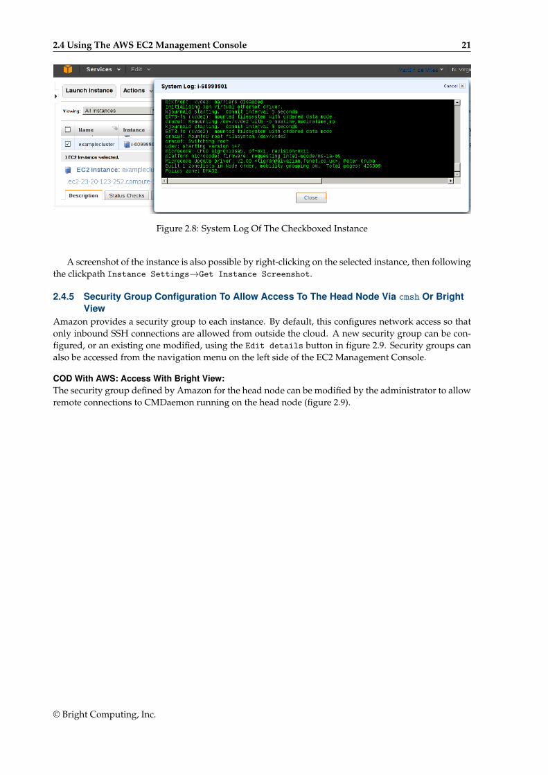
2.4.4 Viewing The Head Node ConsoleThe head node takes about 2 minutes to start up. If, on following the instructions, an SSH connectioncannot be made, then it can be worth checking the head node system log to check if the head nodehas started up correctly. The log is displayed on right-clicking on the “Actions” button, selecting theInstance Settings sub-menu, and selecting the “Get System Log” menu item (figure 2.8). A success-ful start of the system generates a log with a tail similar to that of figure 2.8.
© Bright Computing, Inc.
2.4 Using The AWS EC2 Management Console 21
Figure 2.8: System Log Of The Checkboxed Instance
A screenshot of the instance is also possible by right-clicking on the selected instance, then followingthe clickpath Instance Settings→Get Instance Screenshot.
2.4.5 Security Group Configuration To Allow Access To The Head Node Via cmsh Or BrightView
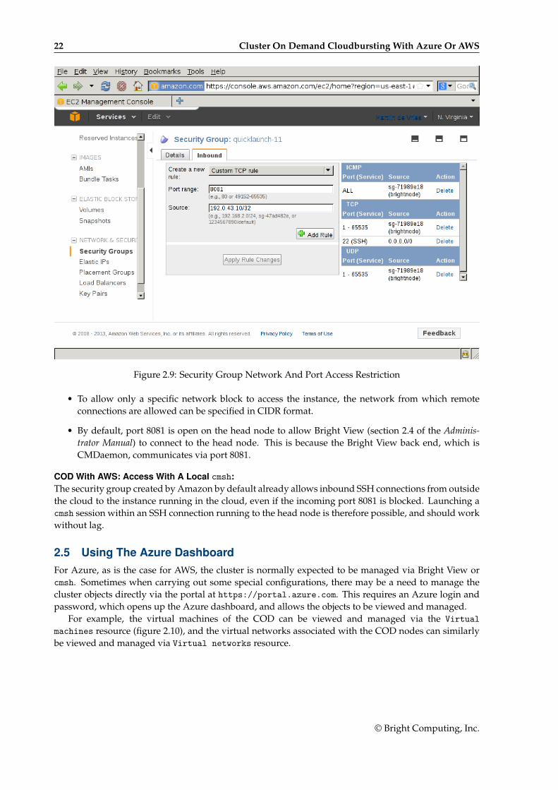
Amazon provides a security group to each instance. By default, this configures network access so thatonly inbound SSH connections are allowed from outside the cloud. A new security group can be con-figured, or an existing one modified, using the Edit details button in figure 2.9. Security groups canalso be accessed from the navigation menu on the left side of the EC2 Management Console.
COD With AWS: Access With Bright View:The security group defined by Amazon for the head node can be modified by the administrator to allowremote connections to CMDaemon running on the head node (figure 2.9).
© Bright Computing, Inc.
22 Cluster On Demand Cloudbursting With Azure Or AWS
Figure 2.9: Security Group Network And Port Access Restriction
• To allow only a specific network block to access the instance, the network from which remoteconnections are allowed can be specified in CIDR format.
• By default, port 8081 is open on the head node to allow Bright View (section 2.4 of the Adminis-trator Manual) to connect to the head node. This is because the Bright View back end, which isCMDaemon, communicates via port 8081.
COD With AWS: Access With A Local cmsh:The security group created by Amazon by default already allows inbound SSH connections from outsidethe cloud to the instance running in the cloud, even if the incoming port 8081 is blocked. Launching acmsh session within an SSH connection running to the head node is therefore possible, and should workwithout lag.
2.5 Using The Azure DashboardFor Azure, as is the case for AWS, the cluster is normally expected to be managed via Bright View orcmsh. Sometimes when carrying out some special configurations, there may be a need to manage thecluster objects directly via the portal at https://portal.azure.com. This requires an Azure login andpassword, which opens up the Azure dashboard, and allows the objects to be viewed and managed.
For example, the virtual machines of the COD can be viewed and managed via the Virtualmachines resource (figure 2.10), and the virtual networks associated with the COD nodes can similarlybe viewed and managed via Virtual networks resource.
© Bright Computing, Inc.
2.6 COD: Cloud Node Start-up 23
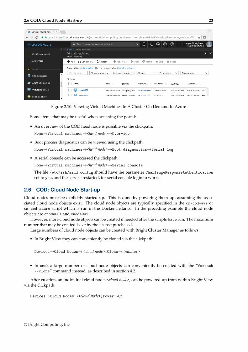
Figure 2.10: Viewing Virtual Machines In A Cluster On Demand In Azure
Some items that may be useful when accessing the portal:
• An overview of the COD head node is possible via the clickpath:
Home→Virtual machines→<head node>→Overview
• Boot process diagnostics can be viewed using the clickpath:
Home→Virtual machines→<head node>→Boot diagnostics→Serial log
• A serial console can be accessed the clickpath:
Home→Virtual machines→<head node>→Serial console
The file /etc/ssh/sshd_config should have the parameter ChallengeResponseAuthenticationset to yes, and the service restarted, for serial console login to work.
2.6 COD: Cloud Node Start-upCloud nodes must be explicitly started up. This is done by powering them up, assuming the asso-ciated cloud node objects exist. The cloud node objects are typically specified in the cm-cod-aws orcm-cod-azure script which is run in the Docker instance. In the preceding example the cloud nodeobjects are cnode001 and cnode002.
However, more cloud node objects can be created if needed after the scripts have run. The maximumnumber that may be created is set by the license purchased.
Large numbers of cloud node objects can be created with Bright Cluster Manager as follows:
• In Bright View they can conveniently be cloned via the clickpath:
Devices→Cloud Nodes→<cloud node>↓Clone→<number>
• In cmsh a large number of cloud node objects can conveniently be created with the “foreach--clone” command instead, as described in section 4.2.
After creation, an individual cloud node, <cloud node>, can be powered up from within Bright Viewvia the clickpath:
Devices→Cloud Nodes→<cloud node>↓Power→On
© Bright Computing, Inc.

24 Cluster On Demand Cloudbursting With Azure Or AWS
As with regular non-cloud nodes, cloud nodes can also be powered up from within the device modeof cmsh. The initial power status (section 4.1 of the Administrator Manual) of cloud nodes is FAILED,because they cannot be communicated with. As they start up, their power status changes to OFF, andthen to ON. Some time after that they are connected to the cluster and ready for use. The device status(as opposed to the power status) remains DOWN until it is ready for use, at which point it switches to UP:
Example
[head1->device]% power statuscloud ................. [ FAILED ] cnode001 (Cloud instance ID not set)cloud ................. [ FAILED ] cnode002 (Cloud instance ID not set)No power control ...... [ UNKNOWN ] head1[head1->device]% power on -n cnode001cloud ................. [ ON ] cnode001[head1->device]% power statuscloud ................. [ OFF ] cnode001 (pending)cloud ................. [ FAILED ] cnode002 (Cloud instance ID not set)No power control ...... [ UNKNOWN ] head1[head1->device]% power on -n cnode002cloud ................. [ ON ] cnode002[head1->device]% power statuscloud ................. [ ON ] cnode001 (running)cloud ................. [ OFF ] cnode002 (pending)No power control ...... [ UNKNOWN ] head1[head1->device]% !ping -c1 cnode001ping: unknown host cnode001[head1->device]% statushead1 .................... [ UP ]node001 .................. [ UP ]node002 .................. [ DOWN ][head1->device]% !ping -c1 cnode001PING cnode001.cm.cluster (10.234.226.155) 56(84) bytes of data.64 bytes from cnode001.cm.cluster (10.234.226.155): icmp_seq=1 ttl=63 t\ime=3.94 ms
Multiple cloud nodes can be powered up at a time in cmsh with the “power on” command usingranges and other options (section 4.2.3 of the Administrator Manual).
2.6.1 COD: IP Addresses In The Cloud• The IP addresses assigned to cloud nodes on powering them up are arbitrarily scattered over the
10.0.0.0/8 network and its subnets
– No pattern should therefore be relied upon in the addressing scheme of cloud nodes
• Shutting down and starting up head and regular cloud nodes can cause their IP address to change.
– However, Bright Cluster Manager managing the nodes means that a regular cloud node re-establishes its connection to the cluster when it comes up, and will have the same node nameas before.
2.7 COD With AWS: Optimizing AWS For High Performance Computing (HPC)Optimization of cloud nodes for HPC in AWS is discussed in section 3.5.
© Bright Computing, Inc.

3Cluster Extension Cloudbursting
Cluster Extension cloudbursting (“hybrid” cloudbursting) in Bright Cluster Manager is the case when acloud service provider is used to provide nodes that are in the cloud as an extension to the number ofregular nodes in a cluster. Thus, the head node in a Cluster Extension configuration is always outsidethe cloud, and there may be some non-cloud-extension regular nodes that are outside the cloud too.
Cluster Extension cloudbursting can burst into a cloud that is running within:
• AWS (CX-AWS). This is described in Chapters 3 and 4 of the Cloudbursting Manual.
• Azure (CX-Azure). This is described in Chapter 5 of the Cloudbursting Manual.
• OpenStack (CX-OS). This is described in Chapter 6.
RequirementsCluster Extension cloudbursting requires:
• An activated cluster license.
One does not simply cloudburst right away in a Cluster Extension configuration. The license mustfirst be made active, or the attempt will fail.
A check on the state of the license can be carried out with:
Example
[root@bright90 ~]# cmsh -c "main; licenseinfo"License Information---------------------------- ----------------------------------------Licensee /C=US/ST=NY/L=WS/O=Bright
Mordor/OU=Mt. Doom/CN=Bright 9.0 ClusterSerial Number 54750Start Time Mon Oct 16 01:00:00 2017End Time Fri Dec 31 23:59:00 2038Version 7.0 and aboveEdition AdvancedPre-paid Nodes 100Pay-per-use Nodes yesMax Accelerator Nodes 80Max OpenStack Nodes 70Node Count 6Allow edge sites YesAccelerator Node Count 6OpenStack Node Count 0MAC Address / Cloud ID FA:16:3E:85:C7:62
© Bright Computing, Inc.

26 Cluster Extension Cloudbursting
The value of End Time, Pre-paid Nodes, and Pay-per-use Nodes in the preceding license shouldbe checked. Pre-paid nodes are nodes that may be started without incurring any additionalcharges. Pay-per-use nodes are nodes that incur additional charges when started. Both pre-paidand pay-per-use can be on-premise or off-premise. That is, both kinds can be used for clusterextension cloudbursting.
If activation is indeed needed, then simply running the request-license command with the prod-uct key should in most cases provide activation. Further details on activating the license are givenin Chapter 4 of the Administrator Manual.
• An Amazon account, if the cloud provider is Amazon.
• An Azure account, if the cloud provider is Microsoft Azure.
• An open UDP port.
By default, this is port 1194. It is used for the OpenVPN connection from the head node to thecloud and back. To use TCP, and/or ports other than 1194, the Bright Computing knowledgebaseat http://kb.brightcomputing.com can be consulted using the keywords “openvpn port”.
Outbound SSH access from the head node is also useful, but not strictly required.
By default, the Shorewall firewall as provided by Bright Cluster Manager on the head node isconfigured to allow all outbound connections, but other firewalls may need to be considered too.
• A special proxy environment configuration setting, if an HTTP proxy is used to access the AWSor Azure APIs.
The proxy environment configuration is carried out using the ScriptEnvironment directive(page 717 of the Administrator Manual), which is a CMDaemon directive that can be set and ac-tivated (page 699 of the Administrator Manual).
For example, if the proxy host is my.proxy and accepting connections on port 8080 with a user-name my and password pass, then the setting can be specified as:
ScriptEnvironment = { "http_proxy=http://my:[email protected]:8080", \"https_proxy=http://my:[email protected]:8080", "ftp_proxy=http://my:[email protected]:8080" }
StepsCluster Extension cloudbursting uses a cloud director. A cloud director is a specially connected cloudnode used to manage regular cloud nodes, and is described more thoroughly in section 3.2. Assumingthe administrator has ownership of a cloud provider account, the following steps can be followed tolaunch Cluster Extension cloud nodes:
1. The cloud provider is logged into from Bright View, and a cloud director is configured (section 3.1).
2. The cloud director is started up (section 3.2).
3. The cloud nodes are provisioned from the cloud director (section 3.3).
The cloud nodes then become available for general use by the cluster.
Cluster Extension Cloudbursting With A Hardware VPNBright Cluster Manager recommends, and provides, OpenVPN by default for Cluster Extension cloud-bursting VPN connectivity. If there is a wish to use a hardware VPN, for example if there is an existinghardware VPN network already in use at the deployment site, then Bright Cluster Manager can option-ally be configured to work with the hardware VPN. The configuration details can be found in the BrightComputing knowledgebase at http://kb.brightcomputing.com by carrying out a search on the siteusing the keywords “cloudbursting without openvpn”.
© Bright Computing, Inc.
3.1 Cluster Extension With AWS: The Bright View Cluster Extension Wizard 27
Cluster Extension Cloudbursting LoggingAll AWS logging goes to the CMDaemon log in /var/log/cmdaemon. The CLOUD tag in the log is used toindicate cloud-related operations.
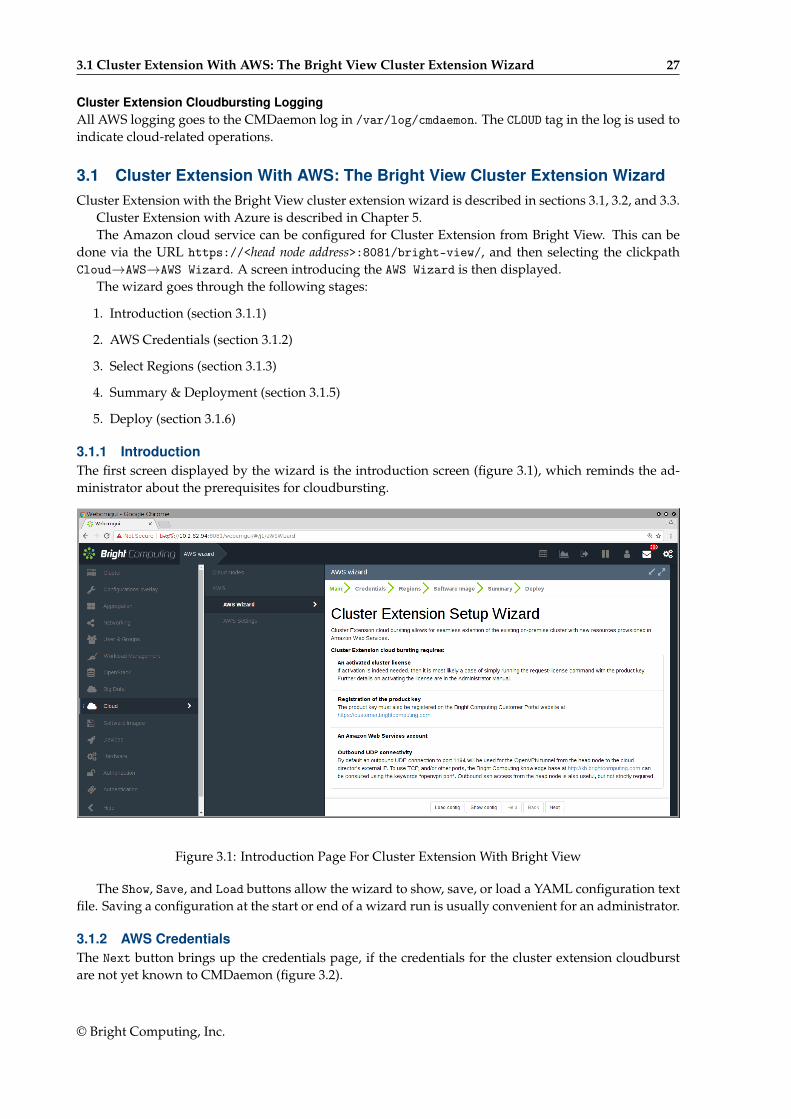
3.1 Cluster Extension With AWS: The Bright View Cluster Extension WizardCluster Extension with the Bright View cluster extension wizard is described in sections 3.1, 3.2, and 3.3.
Cluster Extension with Azure is described in Chapter 5.The Amazon cloud service can be configured for Cluster Extension from Bright View. This can be
done via the URL https://<head node address>:8081/bright-view/, and then selecting the clickpathCloud→AWS→AWS Wizard. A screen introducing the AWS Wizard is then displayed.
The wizard goes through the following stages:
1. Introduction (section 3.1.1)
2. AWS Credentials (section 3.1.2)
3. Select Regions (section 3.1.3)
4. Summary & Deployment (section 3.1.5)
5. Deploy (section 3.1.6)
3.1.1 IntroductionThe first screen displayed by the wizard is the introduction screen (figure 3.1), which reminds the ad-ministrator about the prerequisites for cloudbursting.
Figure 3.1: Introduction Page For Cluster Extension With Bright View
The Show, Save, and Load buttons allow the wizard to show, save, or load a YAML configuration textfile. Saving a configuration at the start or end of a wizard run is usually convenient for an administrator.
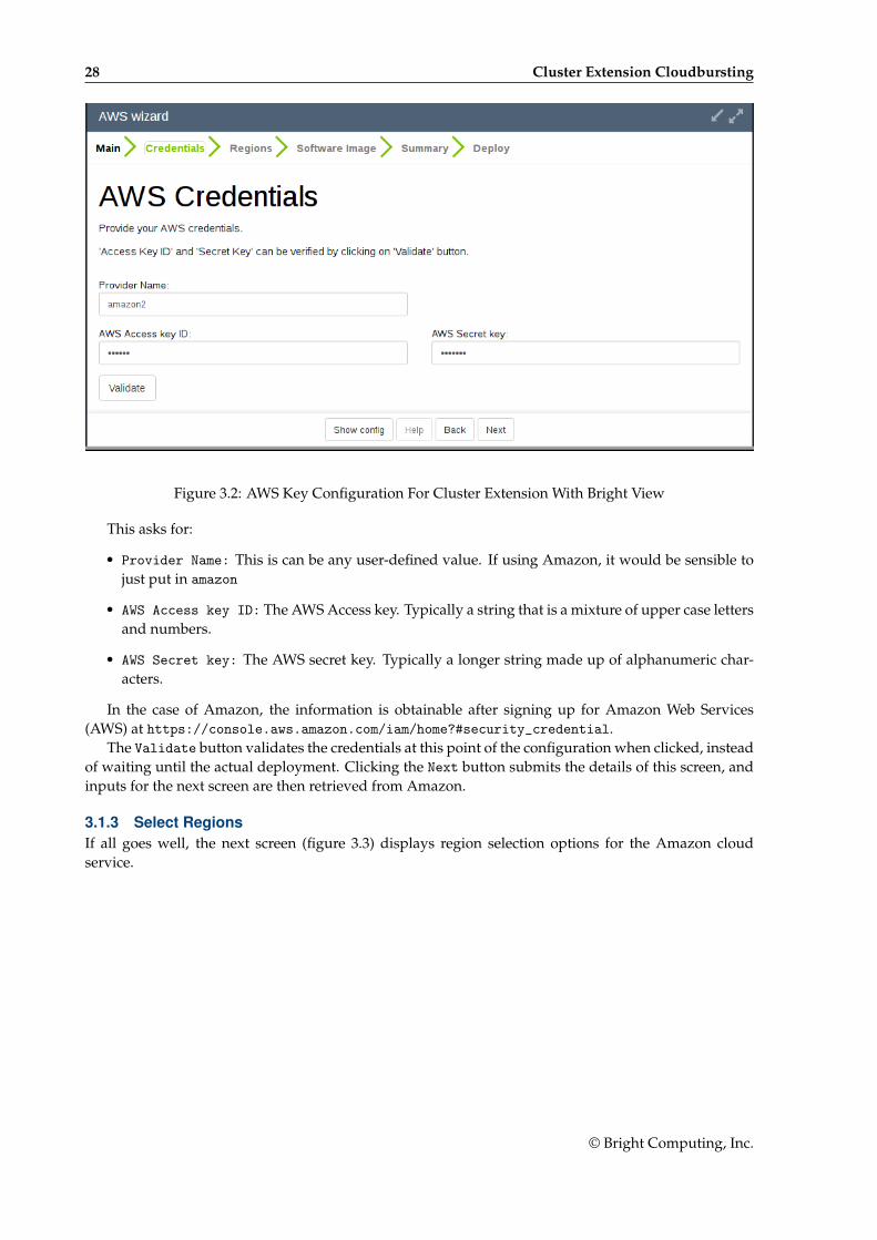
3.1.2 AWS CredentialsThe Next button brings up the credentials page, if the credentials for the cluster extension cloudburstare not yet known to CMDaemon (figure 3.2).
© Bright Computing, Inc.
28 Cluster Extension Cloudbursting
Figure 3.2: AWS Key Configuration For Cluster Extension With Bright View
This asks for:
• Provider Name: This is can be any user-defined value. If using Amazon, it would be sensible tojust put in amazon
• AWS Access key ID: The AWS Access key. Typically a string that is a mixture of upper case lettersand numbers.
• AWS Secret key: The AWS secret key. Typically a longer string made up of alphanumeric char-acters.
In the case of Amazon, the information is obtainable after signing up for Amazon Web Services(AWS) at https://console.aws.amazon.com/iam/home?#security_credential.
The Validate button validates the credentials at this point of the configuration when clicked, insteadof waiting until the actual deployment. Clicking the Next button submits the details of this screen, andinputs for the next screen are then retrieved from Amazon.
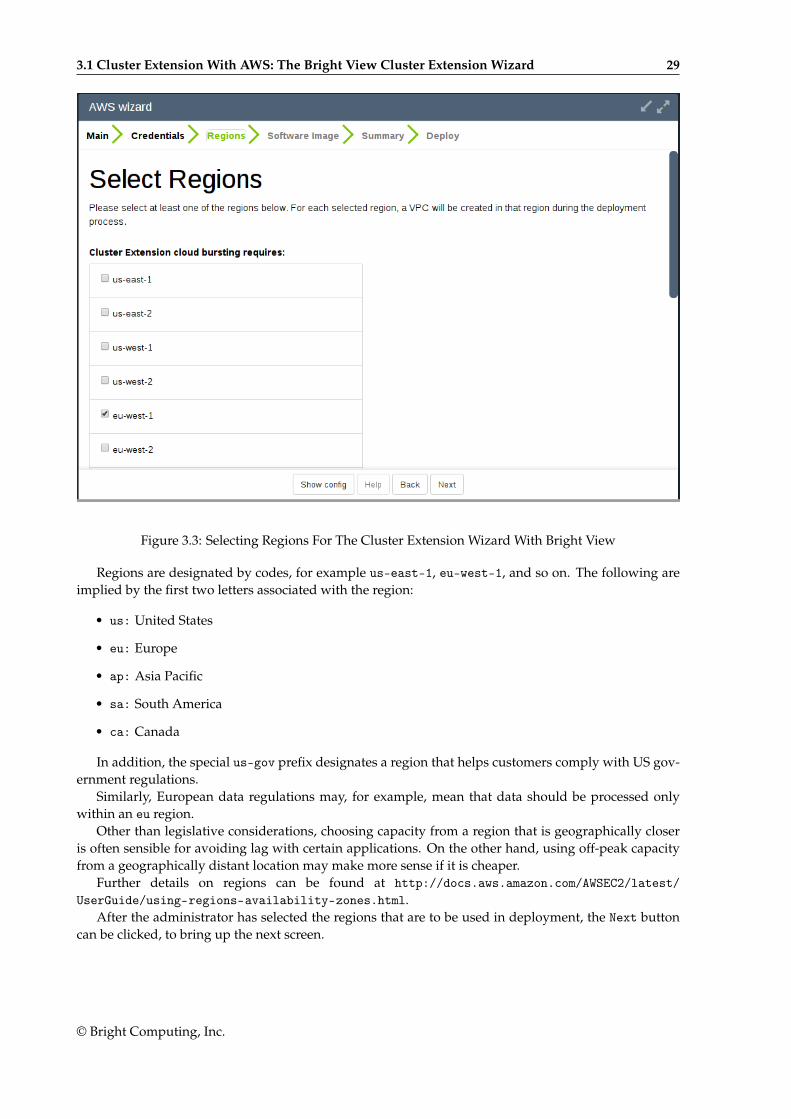
3.1.3 Select RegionsIf all goes well, the next screen (figure 3.3) displays region selection options for the Amazon cloudservice.
© Bright Computing, Inc.
3.1 Cluster Extension With AWS: The Bright View Cluster Extension Wizard 29
Figure 3.3: Selecting Regions For The Cluster Extension Wizard With Bright View
Regions are designated by codes, for example us-east-1, eu-west-1, and so on. The following areimplied by the first two letters associated with the region:
• us: United States
• eu: Europe
• ap: Asia Pacific
• sa: South America
• ca: Canada
In addition, the special us-gov prefix designates a region that helps customers comply with US gov-ernment regulations.
Similarly, European data regulations may, for example, mean that data should be processed onlywithin an eu region.
Other than legislative considerations, choosing capacity from a region that is geographically closeris often sensible for avoiding lag with certain applications. On the other hand, using off-peak capacityfrom a geographically distant location may make more sense if it is cheaper.
Further details on regions can be found at http://docs.aws.amazon.com/AWSEC2/latest/UserGuide/using-regions-availability-zones.html.
After the administrator has selected the regions that are to be used in deployment, the Next buttoncan be clicked, to bring up the next screen.
© Bright Computing, Inc.
30 Cluster Extension Cloudbursting
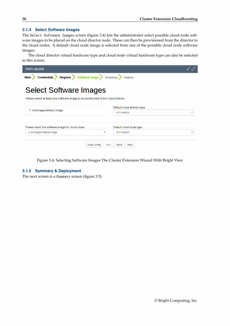
3.1.4 Select Software ImagesThe Select Software Images screen (figure 3.4) lets the administrator select possible cloud node soft-ware images to be placed on the cloud director node. These can then be provisioned from the director tothe cloud nodes. A default cloud node image is selected from one of the possible cloud node softwareimages.
The cloud director virtual hardware type and cloud node virtual hardware type can also be selectedin this screen.
Figure 3.4: Selecting Software Images The Cluster Extension Wizard With Bright View
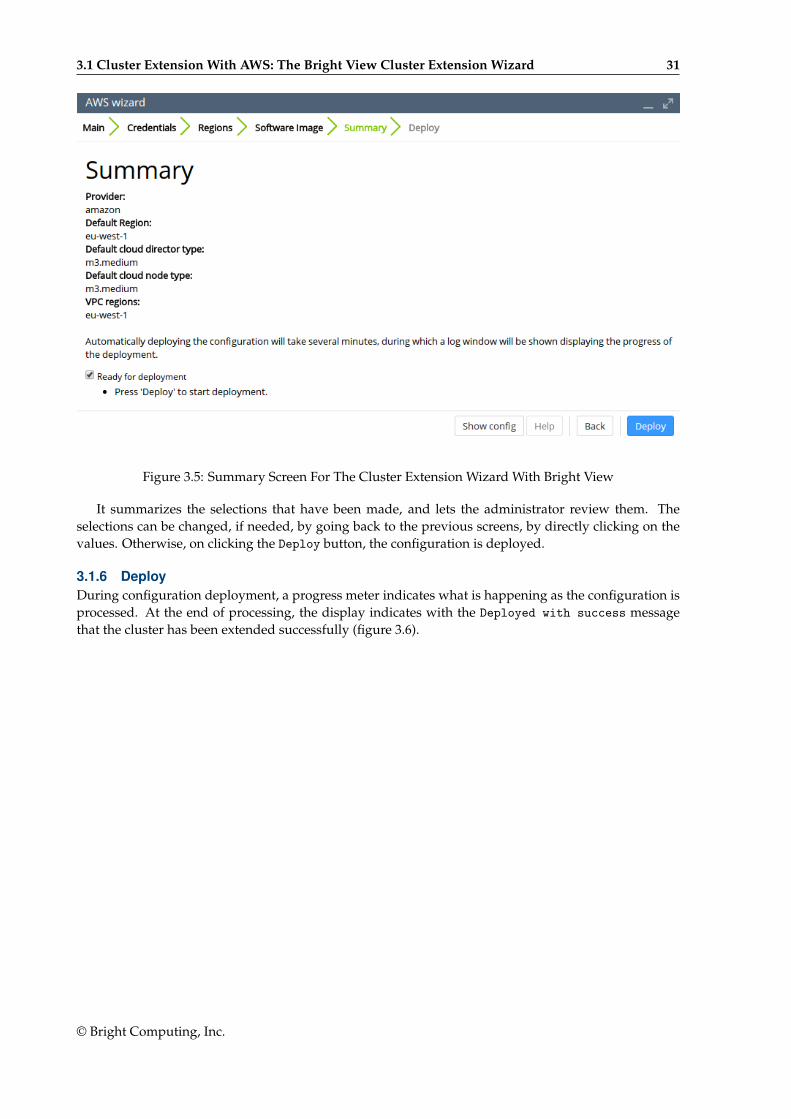
3.1.5 Summary & DeploymentThe next screen is a Summary screen (figure 3.5).
© Bright Computing, Inc.
3.1 Cluster Extension With AWS: The Bright View Cluster Extension Wizard 31
Figure 3.5: Summary Screen For The Cluster Extension Wizard With Bright View
It summarizes the selections that have been made, and lets the administrator review them. Theselections can be changed, if needed, by going back to the previous screens, by directly clicking on thevalues. Otherwise, on clicking the Deploy button, the configuration is deployed.
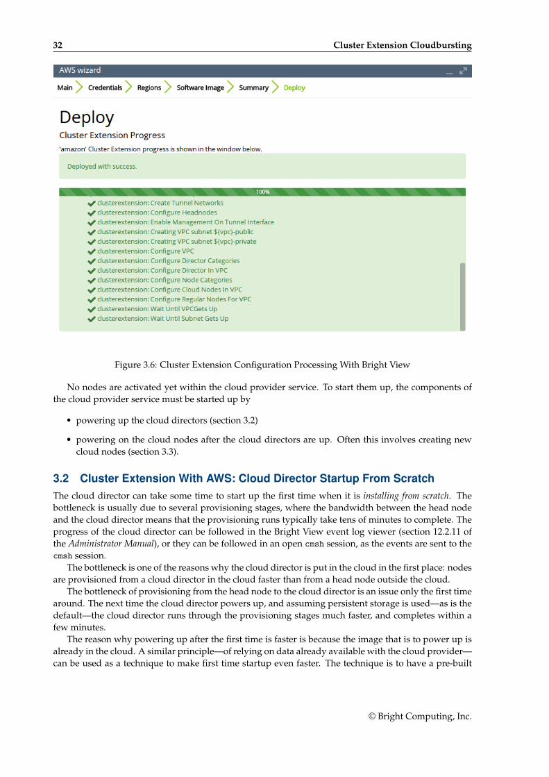
3.1.6 DeployDuring configuration deployment, a progress meter indicates what is happening as the configuration isprocessed. At the end of processing, the display indicates with the Deployed with success messagethat the cluster has been extended successfully (figure 3.6).
© Bright Computing, Inc.
32 Cluster Extension Cloudbursting
Figure 3.6: Cluster Extension Configuration Processing With Bright View
No nodes are activated yet within the cloud provider service. To start them up, the components ofthe cloud provider service must be started up by
• powering up the cloud directors (section 3.2)
• powering on the cloud nodes after the cloud directors are up. Often this involves creating newcloud nodes (section 3.3).
3.2 Cluster Extension With AWS: Cloud Director Startup From ScratchThe cloud director can take some time to start up the first time when it is installing from scratch. Thebottleneck is usually due to several provisioning stages, where the bandwidth between the head nodeand the cloud director means that the provisioning runs typically take tens of minutes to complete. Theprogress of the cloud director can be followed in the Bright View event log viewer (section 12.2.11 ofthe Administrator Manual), or they can be followed in an open cmsh session, as the events are sent to thecmsh session.
The bottleneck is one of the reasons why the cloud director is put in the cloud in the first place: nodesare provisioned from a cloud director in the cloud faster than from a head node outside the cloud.
The bottleneck of provisioning from the head node to the cloud director is an issue only the first timearound. The next time the cloud director powers up, and assuming persistent storage is used—as is thedefault—the cloud director runs through the provisioning stages much faster, and completes within afew minutes.
The reason why powering up after the first time is faster is because the image that is to power up isalready in the cloud. A similar principle—of relying on data already available with the cloud provider—can be used as a technique to make first time startup even faster. The technique is to have a pre-built
© Bright Computing, Inc.
3.2 Cluster Extension With AWS: Cloud Director Startup From Scratch 33
image—a snapshot—of the cloud director stored already with the cloud provider. The first-time startupof a cloud director based on a snapshot restoration is discussed in section 3.4.
The remainder of this section is about starting up a cloud director from scratch—that is, a first timestart, and without a pre-built image.
To recap: by default, a cloud director object is created during a run of the Cluster Extension wizard(section 3.1).
There can be only one cloud director per region. Because a cloud director also has properties specificto the region within which it directs nodes, it means that cloud directors can only be created from scratch,via cluster extension.
Once a cloud director object has been made in CMDaemon, then the cloud director is ready to bestarted up. In Bright View the cloud director can be started by powering it up from its node settings,just like a regular node. If the cloud director node is not visible, then a browser refresh should clear upthe cache so that it becomes visible. For the cloud director a clickpath to power it up is:
Devices→Cloud Nodes→Cloud director→↓Power→On
As indicated earlier on, the cloud director acts as a helper instance in the cloud. It provides someof the functions of the head node within the cloud, in order to speed up communications and ensuregreater resource efficiency. Amongst the functions the cloud director provides are:
• Cloud nodes provisioning
• Exporting a copy of the shared directory /cm/shared to the cloud nodes so that they can mount it
• Providing routing services using an OpenVPN server. While cloud nodes within a region commu-nicate directly with each other, cloud nodes in one region use the OpenVPN server of their clouddirector to communicate with the other cloud regions and to communicate with the head node ofthe cluster.
Cloud directors are not regular nodes, so they have their own category, cloud-director, into whichthey are placed by default.
The cloud-related properties of the cloud director can be viewed and edited via the clickpath:
Devices→Cloud Nodes→Cloud director→Edit
3.2.1 Setting The Cloud Director Disk Storage Device TypeAmazon provides two kinds of storage types as part of EC2:
1. Instance storage, using so-called ephemeral devices. Ephemeral means that the device is tempo-rary, and means that whatever is placed on it is lost if the instance is stopped, terminated, or if theunderlying disk drive fails.
Some instances have ephemeral storage associated with the instance type. For example, at the timeof writing (May 2017), the m3.medium type of instance has 4GB of SSD storage associated with it.
Details on instance storage can be found at http://docs.aws.amazon.com/AWSEC2/latest/UserGuide/InstanceStorage.html#instance-store-volumes.
2. Elastic Block Storage (EBS) volumes: EBS is a persistent, reliable, and highly available storage.Normally, EBS is suggested for cloud director and cloud node use. The reasons for this include:
• it can be provided to all nodes in the same availability zone
• unlike instance storage, EBS remains available for use when an instance using it is stoppedor terminated.
• instance storage is not available for many instance types such as t2.micro, t2.small,c4.large.
© Bright Computing, Inc.
34 Cluster Extension Cloudbursting
Using The Ephemeral Device As The Drive For The Cloud Director:Since the cloud director instance type is essential, and contains so much data, it is rare to use anephemeral device for its storage.
However, if for some reason the administrator would like to avoid using EBS, and use the instancestorage, then this can be done by removing the default EBS volume suggestion for the cloud directorprovided by Bright Cluster Manager. When doing this, the ephemeral device that is used as the re-placement must be renamed. It must take over the name that the EBS volume device had before it wasremoved.
• In Bright View, this can be done in the EC2 Storages window, which for a cloud director <clouddirector hostname> can be viewed and modified via the clickpath:
Devices→Cloud Nodes→<cloud director hostname>→Edit→Settings→Cloud settings→STORAGE→Storage→<storage type>→Edit
• In cmsh, this can be done in device mode, by going into the cloudsettings submode for the clouddirector, and then going a level deeper into the storage submode. Within the storage submode,the list command shows the values of the storage devices associated with the cloud director. Thevalues can be modified as required with the usual object commands. The set command can beused to modify the values.
Example
[bright90]% device use us-east-1-director[bright90->device[us-east-1-director]]% cloudsettings[bright90->device[us-east-1-director]->cloudsettings]% storage[bright90->...->cloudsettings->storage]% listType Name (key) Drive Size Volume ID---------- ------------ --------- ------- ----------ebs ebs sdb 42GBephemeral ephemeral0 sdc 0B ephemeral0[bright90->...->cloudsettings->storage]% remove ebs[bright90->...->cloudsettings*->storage*]% set ephemeral0 drive sdb[bright90->...->cloudsettings*->storage*]% listType Name (key) Drive Size Volume ID---------- ------------ --------- ------- ---------ephemeral ephemeral0 sdb 0B ephemeral0[bright90->...->cloudsettings*->storage*]% commit
3.2.2 Setting The Cloud Director Disk SizeThe disk size for the cloud director can be set in Bright View using the EC2 Storages window (sec-tion 3.2.1).
By default, an EBS volume size of 42GB is suggested. This is as for a standard node layout (sec-tion D.3 of the Administrator Manual), and no use is then made of the ephemeral device.
42GB on its own is unlikely to be enough for most purposes other than running basic hello worldtests. In actual use, the most important considerations are likely to be that the cloud director shouldhave enough space for:
• the user home directories (under /home/)
• the cluster manager shared directory contents, (under /cm/shared/)
• the software image directories (under /cm/images/)
© Bright Computing, Inc.
3.2 Cluster Extension With AWS: Cloud Director Startup From Scratch 35
The cluster administrator should therefore properly consider the allocation of space, and decide ifthe disk layout should be modified. An example of how to access the disk setup XML file to modify thedisk layout is given in section 3.9.3 of the Administrator Manual.
For the cloud director, an additional sensible option may be to place /tmp and the swap space on anephemeral device, by appropriately modifying the XML layout for the cloud director.
3.2.3 Tracking Cloud Director StartupTracking Cloud Director Startup From The EC2 Management ConsoleThe boot progress of the cloud director <cloud director> can be followed by watching the status of theinstance in the Amazon EC2 management console, as illustrated in figure 2.7. The Instance ID that isused to identify the instance can be found
• with Bright View, within the clickpathDevices→Cloud Nodes→<cloud director>→Edit→Settings→Cloud settings→Instance ID
• with cmsh, by running something like:
Example
[bright90]% device use us-east-1-director[bright90->device[us-east-1-director]]% get cloudidi-f98e7441[bright90->device[us-east-1-director]]% cloudsettings[bright90->device[us-east-1-director]-cloudsettings]% get instanceidi-f98e7441
Tracking Cloud Director Startup From Bright ViewThe boot progress of the cloud director can also be followed by
• watching the icon changes for the cloud node states in the clickpath Devices→Cloud Nodes. Theicons indicating the state follow the description given in section 5.5.1 of the Administrator Manual
Tracking Cloud Director Startup From The Bash Shell Of The Head NodeThere are some further possibilities to view the progress of the cloud director after it has reached at leastthe initrd stage. These possibilities include:
• an SSH connection to the cloud director can be made during the pre-init, initrd stage, after thecloud director system has been set up via an rsync. This allows a login to the node-installer shell.
• an SSH connection to the cloud director can be also be made after the initrd stage has ended, afterthe init process runs making an SSH daemon available again. This allows a login on the clouddirector when it is fully up.
During the initrd stage, the cloud director is provisioned first. The cloud node image(s) and shareddirectory are then provisioned on the cloud director, still within the initrd stage. To see what rsync issupplying to the cloud director, the command “ps uww -C rsync” can be run on the head node. Itsoutput can then be parsed to make obvious the source and target directories currently being transferred:
Example
[root@bright90 ~]# ps uww -C rsync | grep -o ' /cm/.*$'/cm/shared/ [email protected]::target//cm/shared/
© Bright Computing, Inc.
36 Cluster Extension Cloudbursting
Tracking Cloud Director Startup From cmshThe provisioningstatus command in cmsh can be used to view the provisioning status (some outputelided):
Example
[root@bright90 ~]# cmsh -c "softwareimage provisioningstatus"...+ us-east-1-director...
Up to date images: noneOut of date images: default-image
In the preceding output, the absence of an entry for “Up to date images” shows that the clouddirector does not yet have an image that it can provision to the cloud nodes. After some time, the lastfew lines of output should change to something like:
Example
+ us-east-1-director...
Up to date images: default-image
This indicates the image for the cloud nodes is now ready.With the -a option, the provisioningstatus -a command gives details that may be helpful. For
example, while the cloud director is having the default software image placed on it for provisioningpurposes, the source and destination paths are /cm/images/default-image:
Example
[root@bright90 ~]# cmsh -c "softwareimage provisioningstatus -a"Request ID(s): 4Source node: bright90Source path: /cm/images/default-imageDestination node: us-east-1-directorDestination path: /cm/images/default-image...
After some time, when the shared filesystem is being provisioned, the source and destination pathsshould change to the /cm/shared directory:
[root@bright90 ~]# cmsh -c "softwareimage provisioningstatus -a"Request ID(s): 5Source node: bright90Source path: /cm/sharedDestination node: us-east-1-directorDestination path: /cm/shared...
After the shared directory and the cloud node software images are provisioned, the cloud director isfully up. Cloud node instances can then be powered up and provisioned from the cloud director.
© Bright Computing, Inc.
3.3 Cluster Extension With AWS: Cloud Node Startup From Scratch 37
3.3 Cluster Extension With AWS: Cloud Node Startup From ScratchThis section discusses the configuration of regular cloud node startup from scratch. Configuration ofcloud node startup from snapshot is discussed in section 3.4. Regular cloud nodes are the cloud nodesthat the cloud director starts up.
To configure the regular cloud nodes does not require a working cloud director. However to boot upthe regular cloud nodes does require that the cloud director be up, and that the associated networks tothe regular cloud nodes and to the head node be configured correctly.
If needed, additional cloud provisioning nodes (section 5.2 of the Administrator Manual) can be con-figured by assigning the provisioning role to cloud nodes, along with appropriate nodegroups (page 155of the Administrator Manual) values, in order to create a provisioning hierarchy.
Creation and configuration of regular cloud node objects is conveniently carried out by cloning an-other regular cloud node from one of the default cloud nodes already created by the cluster extensionwizard (section 3.1). A clickpath is:
Device→Cloud Nodes→<cloud node hostname>→↓Clone
Cloud node objects can also be created in cmsh as described in section 4.2.The internal network for the regular cloud nodes is by default set to the VPC private network, and is
somewhat similar to the internal network for regular nodes. The VPC private network can be contrastedwith the VPC public network for cloud directors, which is a network that is by default assigned tocloud directors, and which floating IP addresses can connect to. Both the VPC private and VPC publicnetworks are subnets of a cloud network. If the administrator would like to do so, the regular cloudnodes can be placed in the VPC public network and become directly accessible to the public.
If the cloud director is up, then the cloud nodes can be booted up by powering them up (section 4.2of the Administrator Manual) by category, or individually.
3.4 Cluster Extension With AWS: Cloud Director And Cloud Node StartupFrom Snapshots
A technique that speeds up cluster deployment in the cloud is to use snapshots to start up the nodesin the cloud. Snapshots are snapshots of a shutdown state, and are stored by the cloud provider. InAmazon, they can be stored in EBS. It is cheaper to keep a machine in a stored state, rather than have itup but idling. Restoring from a snapshot is also significantly faster than starting up from scratch, due tooptimizations by the cloud provider. An administrator should therefore get around to looking at usingsnapshots once cloudbursting is set up and the usage pattern has become clearer.
As a part of regular maintenance, snapshot configuration can be repeated whenever cloud directorand cloud node files change significantly, in order to keep usage efficiency up.
3.4.1 Cloud Director Startup From SnapshotsCloud Director Snapshot PreparationA cloud director, for example us-east-1-director, can have a snapshot of its state prepared as followsby the administrator:
• The cloud director is started up from scratch (section 3.2)
• After it comes up for the first time, the administrator shuts it down cleanly. For example, with acommand similar to cmsh -c "device use us-east-1-director; shutdown"
• After the cloud-director shutdown is complete, the administrator creates a snapshot of a clouddirector using the EC2 Management Console. This can be done by selecting Elastic Block Store inthe navigator column, then selecting the Volumes item within that menu. The volume associatedwith the cloud director can be identified by matching the Attachment Information column value
© Bright Computing, Inc.
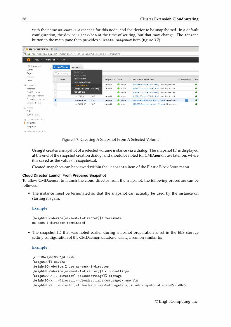
38 Cluster Extension Cloudbursting
with the name us-east-1-director for this node, and the device to be snapshotted. In a defaultconfiguration, the device is /dev/sdb at the time of writing, but that may change. The Actionsbutton in the main pane then provides a Create Snapshot item (figure 3.7).
Figure 3.7: Creating A Snapshot From A Selected Volume
Using it creates a snapshot of a selected volume instance via a dialog. The snapshot ID is displayedat the end of the snapshot creation dialog, and should be noted for CMDaemon use later on, whereit is saved as the value of snapshotid.
Created snapshots can be viewed within the Snapshots item of the Elastic Block Store menu.
Cloud Director Launch From Prepared SnapshotTo allow CMDaemon to launch the cloud director from the snapshot, the following procedure can befollowed:
• The instance must be terminated so that the snapshot can actually be used by the instance onstarting it again:
Example
[bright90->device[us-east-1-director]]% terminateus-east-1-director terminated
• The snapshot ID that was noted earlier during snapshot preparation is set in the EBS storagesetting configuration of the CMDaemon database, using a session similar to:
Example
[root@bright90 ~]# cmsh[bright90]% device[bright90->device]% use us-east-1-director[bright90->device[us-east-1-director]]% cloudsettings[bright90->...-director]->cloudsettings]% storage[bright90->...-director]->cloudsettings->storage]% use ebs[bright90->...-director]->cloudsettings->storage[ebs]]% set snapshotid snap-2a96d0c6
© Bright Computing, Inc.
3.5 Cluster Extension With AWS: Optimizing AWS For High Performance Computing (HPC) 39
The cloud director can now be powered on:
Example
[bright90->device[us-east-1-director]]% power on
The cloud director now starts up much faster than when starting up from scratch.
3.4.2 Cloud Node Startup From SnapshotsWhen a regular cloud node is launched from scratch (section 3.3), it uses the cloud director for provi-sioning, rather than a node outside the cloud, because this is faster. However, having the cloud directorcreate an EBS volume from its storage in the cloud, and then providing the image to the cloud com-pute nodes still involves a lot of data I/O. On the other hand, a cloud provider such as Amazon canoptimize many of these steps when creating an EBS volume from a snapshot, for example, by usingcopy-on-write. This means that snapshot-based provisioning is even speedier than the non-snapshot,“from scratch” method.
If the administrator wants to make a snapshot that can be used as the base for speedily launchingregular cloud nodes, then the same snapshot method that is used for cloud directors (section 3.4.1)should be followed to make a snapshot for a regular cloud node.
A summary of the steps that can be followed is:
• a regular cloud node is started up from scratch (section 3.3), after the cloud director is up
• after the regular cloud node has come up, it is shut down cleanly
• a snapshot is created of the cloud node using the EC2 Management Console
• the cloud node is terminated
• the snapshot ID is set:
Example
[bright90->device[cnode001]->cloudsettings->storage[ebs]]% set snapshotid snap-5c9s3991
Powering on the node now launches the regular cloud node much faster than the non-snapshotmethod.
CMDaemon ensures that a snapshot for one cloud node can be used by other cloud nodes too, if thedisk partitioning is the same. This is useful when launching cloud nodes that do not differ much fromthe snapshot.
It also means that even the cloud director image can be used as a snapshot to launch a regular cloudnode, if the disk partitioning and other settings allow it. However, using a regular node snapshot forlaunch is usually much wiser, due to the extra filesystems that a cloud director has.
3.5 Cluster Extension With AWS: Optimizing AWS For High PerformanceComputing (HPC)
For HPC, performance is a central concern. Optimization for the jobs that are run can be carried outby the administrator considering what are the most cost-effective aspects of the system that can beimproved. The considerations in this section for AWS, apply to COD instances as well as to ClusterExtension instances.
© Bright Computing, Inc.
40 Cluster Extension Cloudbursting
3.5.1 Optimizing HPC Performance: EBS Volume TypeThe volume type used for EBS storage can be considered. AWS provides the gp2, io1, sc1, st1, and stan-dard storage volume types. These volume types, and their associated IOPS performances, are describedat https://docs.aws.amazon.com/AWSEC2/latest/UserGuide/EBSVolumeTypes.html.
• In cmsh these can be set in the storage mode:
Example
[bright90->device[cnode001]->cloudsettings->storage[ebs]]% set volumetype io1
• In Bright View, the equivalent clickpath is:
Devices→Cloud Nodes→<cloud node hostname>→Edit→Settings→Cloud settings→STORAGE→Storage→ebs→CREATION TIME→Volume type
3.5.2 Optimizing HPC Performance: Placement GroupsThe locality of the cloud nodes with respect to each other and with respect to the cluster that they extendfrom can be considered.
For cloud nodes in the same placement group, lag times are minimized between the nodes. For cloudnodes that are geographically near cluster that they extend from, the lag times are reduced between thecloud nodes and the cluster they extend from.
Localizing HPC cloud nodes within the same placement group is usually desirable. This can beachieved using the AWS web console to access the cluster extension AWS account. A placement groupcan be created for a region via the AWS web console for the instance.
The clickpath to carry this out is Services→EC2→Services→Placement Groups→Create PlacementGroup. A name should be set. The value of Strategy should be set to Cluster, to localize the nodes.
The same placement group name can then be set via cmsh for the not-yet-instantiated cloud nodes.Setting this means that those nodes are now started in that placement group.
Example
[bright90->device[cnode001]->cloudsettings]% set placementgroup indahood
3.5.3 Optimizing HPC Performance: Disabling Hyper-ThreadingHyper-Threading (HT) in many cases hinders HPC performance. When running cluster extension cloudnodes, HT can be left enabled on some instancesm and disabled on others, depending on the need.
To disable HT, the following can be inserted into the /etc/rc.local file for the cloud node image,and made executable with a chmod +x:
for cpunum in $(cat /sys/devices/system/cpu/cpu*/topology/thread_siblings_list | \cut -s -d\- -f2- | tr ',' '\n' | sort -un)
do echo 0 > /sys/devices/system/cpu/cpu$cpunum/online; done;
The delimiter used in the cut command is “-” instead of a “,”.If HT is disabled on the cloud node, then it can be confirmed by checking the output of the lscpu
–extended command (output truncated):
Example
[root@cnode001 ~]# lscpu --extendedCPU NODE SOCKET CORE L1d:L1i:L2:L3 ONLINE0 0 0 0 0:0:0:0 yes1 - - - ::: no...
In the line just before the “...”, the “no” indicates that that logical CPU (CPU1 in this case) has beendisabled.
© Bright Computing, Inc.
3.5 Cluster Extension With AWS: Optimizing AWS For High Performance Computing (HPC) 41
3.5.4 Optimizing HPC Performance: Using Elastic Network Adapter InstancesEnhanced networking that is needed for some instance types is possible if the AMI used has the ElasticNetwork Adapter (ENA) support attribute set. By default, all AMIs provided by Bright Cluster Managersince release 8.1-9 have ENA, as provided by the ena kernel module. If this kernel module is absent, theadministrator should update the AMI.
3.5.5 Optimizing HPC Performance: Using A Different Clock SourceXen is the default clocksource on AWS. Occasionally, some applications can benefit from using the TSCclocksource. Because of this, the clock source is generally changed as a best practice. The clock sourcecan be changed with the following command:
Example
[root@cnode001 ~]# echo "tsc" > /sys/devices/system/cl*/cl*/current_clocksource
3.5.6 Optimizing HPC Performance: Setting The Socket Buffer Sizes And TCP/IPParameters In The Sofware Image
The socket and TCP/IP window values can be modified by inserting the following values into thesysctl.conf file in the image:
Example
[root@bright90 ~]# cat >> /cm/images/default-image/etc/sysctl.conf << EOFnet.core.netdev_max_backlog = 1000000
net.core.rmem_default = 124928net.core.rmem_max = 67108864net.core.wmem_default = 124928net.core.wmem_max = 67108864
net.ipv4.tcp_keepalive_time = 1800net.ipv4.tcp_mem = 12184608 16246144 24369216net.ipv4.tcp_rmem = 4194304 8388608 67108864net.ipv4.tcp_syn_retries = 5net.ipv4.tcp_wmem = 4194304 8388608 67108864EOF
© Bright Computing, Inc.

4Cluster Extension CloudburstingWith AWS Using The Command
Line And cmshThe command line and cmsh can be used to set up Cluster On Demand clusters for AWS and Azure,as discussed in Chapter 2. The command line and cmsh can also be used to set up Cluster Extensionclusters, as are discussed in this chapter for AWS, and in Chapter 5 for Azure.
4.1 The cm-cluster-extension Script For Cluster Extension Clusters4.1.1 Running The cm-cluster-extension Script On The Head Node For Cluster Extension
ClustersThe cm-cluster-extension script is run from the head node. It is a part of the Bright Cluster Managercluster-tools package. It allows cloudbursting to be carried out entirely from the command line forCluster Extension setups. It is a command line way of carrying out the configuration carried out by theGUI steps of section 3.1 for cloud provider login and cloud director configuration. After the script hascompleted its setup, then cmsh power commands can launch the required cloud nodes (sections 4.1.2and 4.2).
The cm-cluster-extension script can be run in plain dialog mode (page 43) , or as an Ncurses dialog(page 45).
Running The cm-cluster-extension Command Line Options As A Shell DialogThe administrator can specify command line options to cm-cluster-extension, as shown in its helptext. The help text is displayed with the -h|--help option:
[root@bright90 ~]# cm-cluster-extension -hPlease wait...usage: cm-cluster-extension
[-v] [-h] [-c <config_file>][--skip-modules <mod1,mod2,...>][--only-these-modules <mod1,mod2,...>][--dev][--on-error-action {debug,remotedebug,undo,abort}][--output-remote-execution-runner][--json] [--no-distro-checks][--min-reboot-timeout <reboot_timeout_seconds>][--remove][--terminate-instances][--remove-fsx-instances][--force]
© Bright Computing, Inc.
44 Cluster Extension Cloudbursting With AWS Using The Command Line And cmsh
[--yes-i-know-this-is-dangerous-for-this-cluster <headnode_hostname>][--test-networking][--test-environment][--test-configuration][--test-everything][--enable-external-network-connectivity]
common:Common arguments
-v Verbose output-h, --help Print this screen-c <config_file> Load runtime configuration for modules from a YAML config file
advanced:Various *advanced* configuration options flags.
--skip-modules <mod1,mod2,...>Load and use all the default plugins (cloudstorage, clusterextension),except for these. Comma-separated list.
--only-these-modules <mod1,mod2,...>Out of all default plugins, load and use only these. Comma-separatedlist.
--dev Enables additional command line arguments--on-error-action {debug,remotedebug,undo,abort}
Upon encountering a critical error, instead of asking the user for choice,setup will undo (revert) the deployment stages.
--output-remote-execution-runnerFormat output for CMDaemon
--json Use json formatting for log lines printed to stdout--no-distro-checks Disable distribution checks based on ds.json--min-reboot-timeout <reboot_timeout_seconds>
How long to wait for nodes to finish reboot (default and minimum allowed:300 seconds).
removing cluster extension:Flags which can be used for removing AWS integration
--remove Remove definitions of all objects required for cluster extension,e.g. cloud nodes, directors, cloud networks and cloud interfaces
--terminate-instances Terminate all non-terminated VMs.--remove-fsx-instances
Remove FSX instances.--force Skip interactive confirmation for --remove--yes-i-know-this-is-dangerous-for-this-cluster <headnode_hostname>
Additional confirmation
testing cluster extension:Flags which can be used for troubleshooting
--test-networking Perform networking checks (e.g. check if API endpoints are reachable)--test-environment Run environment checks (e.g. if proper RPMs are installed)--test-configuration Run configuration checks, which check if cluster extension is properly
configured (e.g. if cloud director has correct interfaces, if cloudcredentials are valid, if CMDaemon can create/delete objects in the
© Bright Computing, Inc.
4.1 The cm-cluster-extension Script For Cluster Extension Clusters 45
cloud)--test-everything Run all of the abovementioned checks.
cluster extension to Bright OpenStack:Options specific to this cloud type.
--enable-external-network-connectivityEnable external network connectivity for cloud nodes. Note that thisdisables security groups for the cloud director, which may be a securityrisk. Requires Neutron Port Security extension driver.
examples:cm-cluster-extension (start interactive menu, wizard)cm-cluster-extension -c <config> (configure bursting to AWS)
cm-cluster-extension --remove (remove bursting)cm-cluster-extension --remove --force --yes-i-know-this-is-dangerous-for-this-cluster <hostname>
(remove bursting, no confirmation)*WARNING* This will remove the cloud extension configuration. Any data located on yourcloud nodes will be lost, unless you back it up beforehand.
cm-cluster-extension --test-everything
This tool looks for the following environment variables, and uses them if found:AWS_USERNAME, AWS_ACCOUNT_ID, AWS_ACCESS_KEY_ID, AWS_SECRET_ACCESS_KEYAZURE_SUBSCRIPTION_ID, AZURE_TENANT_ID, AZURE_CLIENT_ID, AZURE_CLIENT_SECRET
It can be run with the options directly (some output skipped):
Example
[root@bright90 ~]# cm-cluster-extension --test-networkingPlease wait...Found an optional config file, '/root/cm-setup.conf'. Will attempt to load it.Executing 26 stages################### Starting execution for 'Running networking checks'Connecting to CMDaemon
- cloudstorage- clusterextension
#### stage: clusterextension: Testing tcp connection to ec2.us-east-1.amazonaws.com:443#### stage: clusterextension: Testing tcp connection to ec2.us-west-1.amazonaws.com:443...#### stage: clusterextension: Testing udp OpenVPN connectivity
Took: 00:09 min.################### Finished execution for 'Running networking checks', status: completed
Running networking checks finished!
Running The cm-cluster-extension Ncurses DialogThe more user-friendly way to run cm-cluster-extension is to run it without options. This brings upthe main screen for its Ncurses dialog (figure 4.1).
© Bright Computing, Inc.
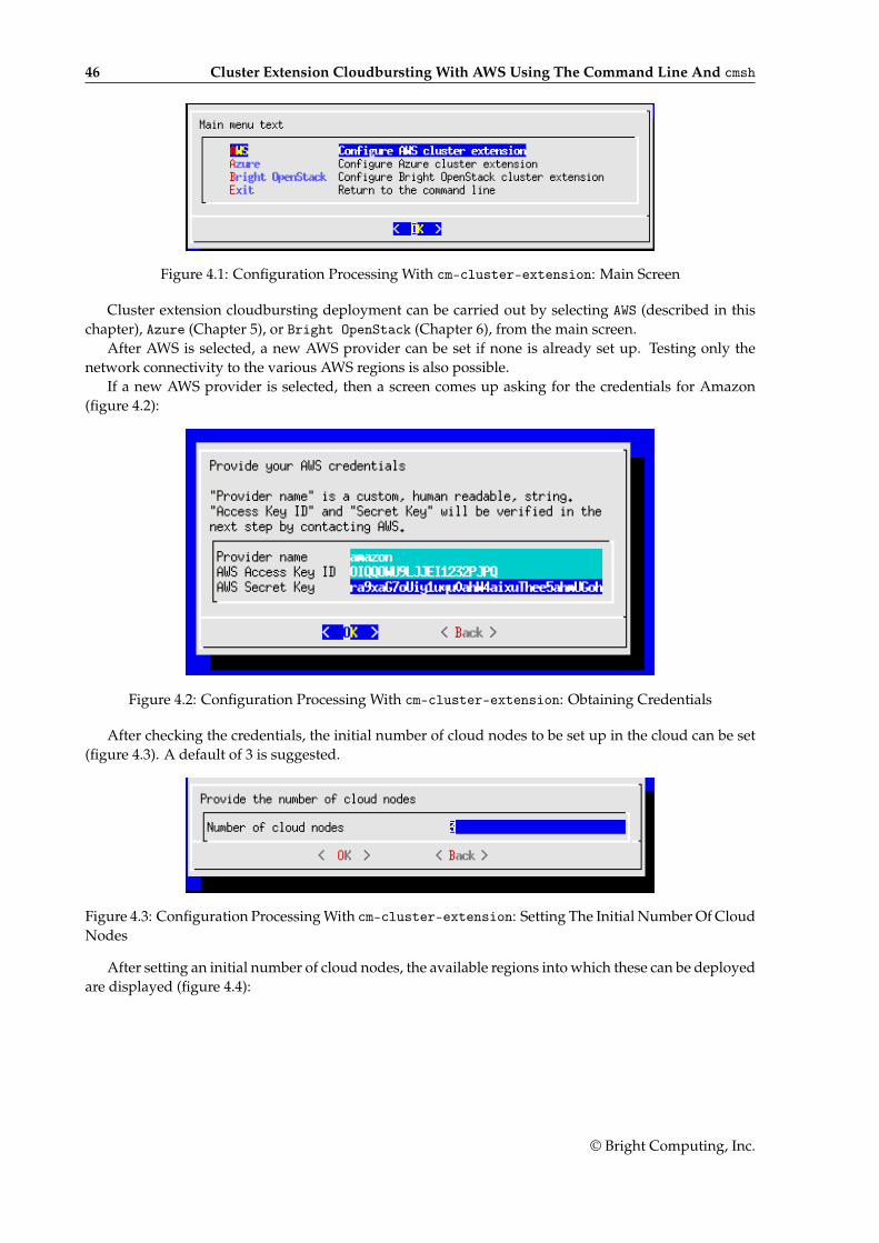
46 Cluster Extension Cloudbursting With AWS Using The Command Line And cmsh
Figure 4.1: Configuration Processing With cm-cluster-extension: Main Screen
Cluster extension cloudbursting deployment can be carried out by selecting AWS (described in thischapter), Azure (Chapter 5), or Bright OpenStack (Chapter 6), from the main screen.
After AWS is selected, a new AWS provider can be set if none is already set up. Testing only thenetwork connectivity to the various AWS regions is also possible.
If a new AWS provider is selected, then a screen comes up asking for the credentials for Amazon(figure 4.2):
Figure 4.2: Configuration Processing With cm-cluster-extension: Obtaining Credentials
After checking the credentials, the initial number of cloud nodes to be set up in the cloud can be set(figure 4.3). A default of 3 is suggested.
Figure 4.3: Configuration Processing With cm-cluster-extension: Setting The Initial Number Of CloudNodes
After setting an initial number of cloud nodes, the available regions into which these can be deployedare displayed (figure 4.4):
© Bright Computing, Inc.
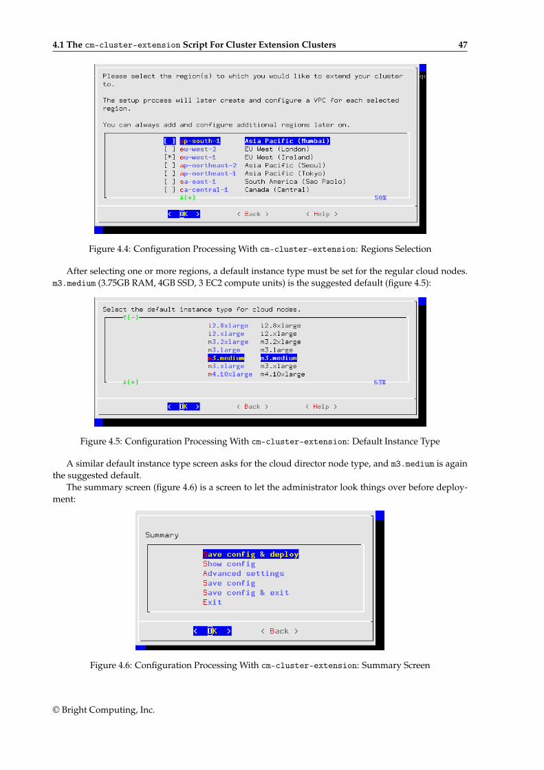
4.1 The cm-cluster-extension Script For Cluster Extension Clusters 47
Figure 4.4: Configuration Processing With cm-cluster-extension: Regions Selection
After selecting one or more regions, a default instance type must be set for the regular cloud nodes.m3.medium (3.75GB RAM, 4GB SSD, 3 EC2 compute units) is the suggested default (figure 4.5):
Figure 4.5: Configuration Processing With cm-cluster-extension: Default Instance Type
A similar default instance type screen asks for the cloud director node type, and m3.medium is againthe suggested default.
The summary screen (figure 4.6) is a screen to let the administrator look things over before deploy-ment:
Figure 4.6: Configuration Processing With cm-cluster-extension: Summary Screen
© Bright Computing, Inc.
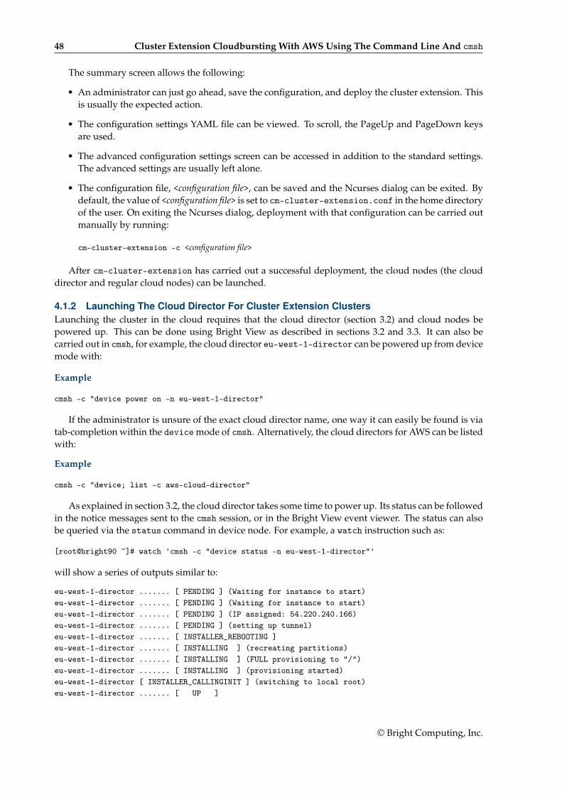
48 Cluster Extension Cloudbursting With AWS Using The Command Line And cmsh
The summary screen allows the following:
• An administrator can just go ahead, save the configuration, and deploy the cluster extension. Thisis usually the expected action.
• The configuration settings YAML file can be viewed. To scroll, the PageUp and PageDown keysare used.
• The advanced configuration settings screen can be accessed in addition to the standard settings.The advanced settings are usually left alone.
• The configuration file, <configuration file>, can be saved and the Ncurses dialog can be exited. Bydefault, the value of <configuration file> is set to cm-cluster-extension.conf in the home directoryof the user. On exiting the Ncurses dialog, deployment with that configuration can be carried outmanually by running:
cm-cluster-extension -c <configuration file>
After cm-cluster-extension has carried out a successful deployment, the cloud nodes (the clouddirector and regular cloud nodes) can be launched.
4.1.2 Launching The Cloud Director For Cluster Extension ClustersLaunching the cluster in the cloud requires that the cloud director (section 3.2) and cloud nodes bepowered up. This can be done using Bright View as described in sections 3.2 and 3.3. It can also becarried out in cmsh, for example, the cloud director eu-west-1-director can be powered up from devicemode with:
Example
cmsh -c "device power on -n eu-west-1-director"
If the administrator is unsure of the exact cloud director name, one way it can easily be found is viatab-completion within the device mode of cmsh. Alternatively, the cloud directors for AWS can be listedwith:
Example
cmsh -c "device; list -c aws-cloud-director"
As explained in section 3.2, the cloud director takes some time to power up. Its status can be followedin the notice messages sent to the cmsh session, or in the Bright View event viewer. The status can alsobe queried via the status command in device node. For example, a watch instruction such as:
[root@bright90 ~]# watch 'cmsh -c "device status -n eu-west-1-director"'
will show a series of outputs similar to:
eu-west-1-director ....... [ PENDING ] (Waiting for instance to start)eu-west-1-director ....... [ PENDING ] (Waiting for instance to start)eu-west-1-director ....... [ PENDING ] (IP assigned: 54.220.240.166)eu-west-1-director ....... [ PENDING ] (setting up tunnel)eu-west-1-director ....... [ INSTALLER_REBOOTING ]eu-west-1-director ....... [ INSTALLING ] (recreating partitions)eu-west-1-director ....... [ INSTALLING ] (FULL provisioning to "/")eu-west-1-director ....... [ INSTALLING ] (provisioning started)eu-west-1-director [ INSTALLER_CALLINGINIT ] (switching to local root)eu-west-1-director ....... [ UP ]
© Bright Computing, Inc.
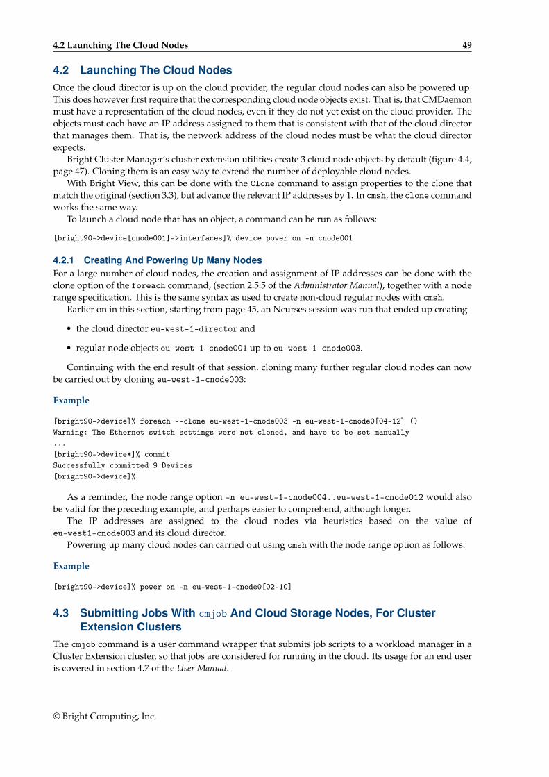
4.2 Launching The Cloud Nodes 49
4.2 Launching The Cloud NodesOnce the cloud director is up on the cloud provider, the regular cloud nodes can also be powered up.This does however first require that the corresponding cloud node objects exist. That is, that CMDaemonmust have a representation of the cloud nodes, even if they do not yet exist on the cloud provider. Theobjects must each have an IP address assigned to them that is consistent with that of the cloud directorthat manages them. That is, the network address of the cloud nodes must be what the cloud directorexpects.
Bright Cluster Manager’s cluster extension utilities create 3 cloud node objects by default (figure 4.4,page 47). Cloning them is an easy way to extend the number of deployable cloud nodes.
With Bright View, this can be done with the Clone command to assign properties to the clone thatmatch the original (section 3.3), but advance the relevant IP addresses by 1. In cmsh, the clone commandworks the same way.
To launch a cloud node that has an object, a command can be run as follows:
[bright90->device[cnode001]->interfaces]% device power on -n cnode001
4.2.1 Creating And Powering Up Many NodesFor a large number of cloud nodes, the creation and assignment of IP addresses can be done with theclone option of the foreach command, (section 2.5.5 of the Administrator Manual), together with a noderange specification. This is the same syntax as used to create non-cloud regular nodes with cmsh.
Earlier on in this section, starting from page 45, an Ncurses session was run that ended up creating
• the cloud director eu-west-1-director and
• regular node objects eu-west-1-cnode001 up to eu-west-1-cnode003.
Continuing with the end result of that session, cloning many further regular cloud nodes can nowbe carried out by cloning eu-west-1-cnode003:
Example
[bright90->device]% foreach --clone eu-west-1-cnode003 -n eu-west-1-cnode0[04-12] ()Warning: The Ethernet switch settings were not cloned, and have to be set manually...[bright90->device*]% commitSuccessfully committed 9 Devices[bright90->device]%
As a reminder, the node range option -n eu-west-1-cnode004..eu-west-1-cnode012 would alsobe valid for the preceding example, and perhaps easier to comprehend, although longer.
The IP addresses are assigned to the cloud nodes via heuristics based on the value ofeu-west1-cnode003 and its cloud director.
Powering up many cloud nodes can carried out using cmsh with the node range option as follows:
Example
[bright90->device]% power on -n eu-west-1-cnode0[02-10]
4.3 Submitting Jobs With cmjob And Cloud Storage Nodes, For ClusterExtension Clusters
The cmjob command is a user command wrapper that submits job scripts to a workload manager in aCluster Extension cluster, so that jobs are considered for running in the cloud. Its usage for an end useris covered in section 4.7 of the User Manual.
© Bright Computing, Inc.
50 Cluster Extension Cloudbursting With AWS Using The Command Line And cmsh
The cmjob command is available from the Bright Cluster Manager repository as part of thecmdaemon-cmjob package. The cmjob command needs the cmjob environment module (section 2.2 ofthe Administrator Manual) to be loaded by the end user before use. In addition, an administrator mustassign the cloudjob profile (section 6.4 of the Administrator Manual) to cmjob users.
Example
[root@bright90 ~]# cmsh[bright90]% user use henry[bright90->user[henry]]% set profile cloudjob; commit
If the cmjob command is run by the user to submit a job, then the job is submitted to the workloadmanager, and the data-aware scheduling mechanism is initiated.
A cluster with data-aware scheduling is a cluster that ensures that it has the data needed for thecloud computing job already accessible on cloud storage nodes.
Cloud storage nodes are nodes that are set up by the cluster manager, before the job is executed inthe cloud. Because data stored can be written and read from many cloud storage nodes for each job thatis placed in the cloud, the data throughput in the cloud becomes more efficient than if only one storagespace were used.
Cloud storage nodes are powered up automatically if cmjob has been installed and configured. Theymust however be powered down explicitly, and this must be done before the cloud director that itdepends on is powered down.
4.3.1 Installation And Configuration of cmjob For Data-aware Scheduling To The CloudThe configuration of data-aware scheduling means configuring the cluster so that the tools that allowdata-aware scheduling to work correctly are configured. The configuration that is carried out dependson the workload manager that is to be used.
If cmjob has not yet been set up, or if it needs reconfiguration, then the following steps should becarried out:
1. The cmdaemon-cmjob package is installed. It must be installed on the head node and in the softwareimage that is to be used for compute cloud nodes and storage cloud nodes.
Example
[root@bright90 ~]# yum install cmdaemon-cmjob[...][root@bright90 ~]# yum --installroot /cm/images/default-image install cmdaemon-cmjob[...]
2. The cm-cloud-storage-setup utility is run. Example runs are provided later, starting on page 51,but an explanatory background is given here first.
The utility is part of the cluster-tools package, which is installed by default. The utility
• configures cmjob properties
• creates
– templates for cloud storage nodes– storage policies for cmjob
© Bright Computing, Inc.
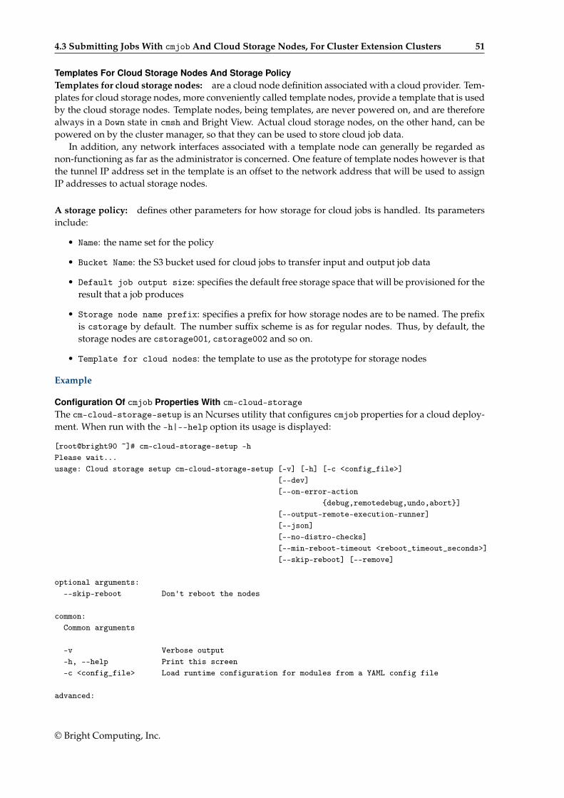
4.3 Submitting Jobs With cmjob And Cloud Storage Nodes, For Cluster Extension Clusters 51
Templates For Cloud Storage Nodes And Storage PolicyTemplates for cloud storage nodes: are a cloud node definition associated with a cloud provider. Tem-plates for cloud storage nodes, more conveniently called template nodes, provide a template that is usedby the cloud storage nodes. Template nodes, being templates, are never powered on, and are thereforealways in a Down state in cmsh and Bright View. Actual cloud storage nodes, on the other hand, can bepowered on by the cluster manager, so that they can be used to store cloud job data.
In addition, any network interfaces associated with a template node can generally be regarded asnon-functioning as far as the administrator is concerned. One feature of template nodes however is thatthe tunnel IP address set in the template is an offset to the network address that will be used to assignIP addresses to actual storage nodes.
A storage policy: defines other parameters for how storage for cloud jobs is handled. Its parametersinclude:
• Name: the name set for the policy
• Bucket Name: the S3 bucket used for cloud jobs to transfer input and output job data
• Default job output size: specifies the default free storage space that will be provisioned for theresult that a job produces
• Storage node name prefix: specifies a prefix for how storage nodes are to be named. The prefixis cstorage by default. The number suffix scheme is as for regular nodes. Thus, by default, thestorage nodes are cstorage001, cstorage002 and so on.
• Template for cloud nodes: the template to use as the prototype for storage nodes
Example
Configuration Of cmjob Properties With cm-cloud-storageThe cm-cloud-storage-setup is an Ncurses utility that configures cmjob properties for a cloud deploy-ment. When run with the -h|--help option its usage is displayed:
[root@bright90 ~]# cm-cloud-storage-setup -hPlease wait...usage: Cloud storage setup cm-cloud-storage-setup [-v] [-h] [-c <config_file>]
[--dev][--on-error-action
{debug,remotedebug,undo,abort}][--output-remote-execution-runner][--json][--no-distro-checks][--min-reboot-timeout <reboot_timeout_seconds>][--skip-reboot] [--remove]
optional arguments:--skip-reboot Don't reboot the nodes
common:Common arguments
-v Verbose output-h, --help Print this screen-c <config_file> Load runtime configuration for modules from a YAML config file
advanced:
© Bright Computing, Inc.

52 Cluster Extension Cloudbursting With AWS Using The Command Line And cmsh
Various *advanced* configuration options flags.
--dev Enables additional command line arguments--on-error-action {debug,remotedebug,undo,abort}
Upon encountering a critical error, instead of asking the user forchoice,setup will undo (revert) the deployment stages.
--output-remote-execution-runnerFormat output for CMDaemon
--json Use json formatting for log lines printed to stdout--no-distro-checks--min-reboot-timeout <reboot_timeout_seconds>
How long to wait for nodes to finish reboot (default and minimum allowed:300 seconds).
Remove storage:--remove Cleanup storage setup
The administrator is usually expected to run cm-cloud-storage-setup without arguments. Thisbrings up the Ncurses-based dialog, which starts with an introductory page (figure 4.7):
Figure 4.7: Cloud Storage Configuration Processing With cm-cloud-storage: Main Screen
Continuing on brings up the network selection screen, which sets the network in which the cloudstorage is to be placed (figure 4.8):
Figure 4.8: Cloud Storage Configuration Processing With cm-cloud-storage: Network Selection
After having selected the network, a category for the storage nodes is set (figure 4.9):
© Bright Computing, Inc.
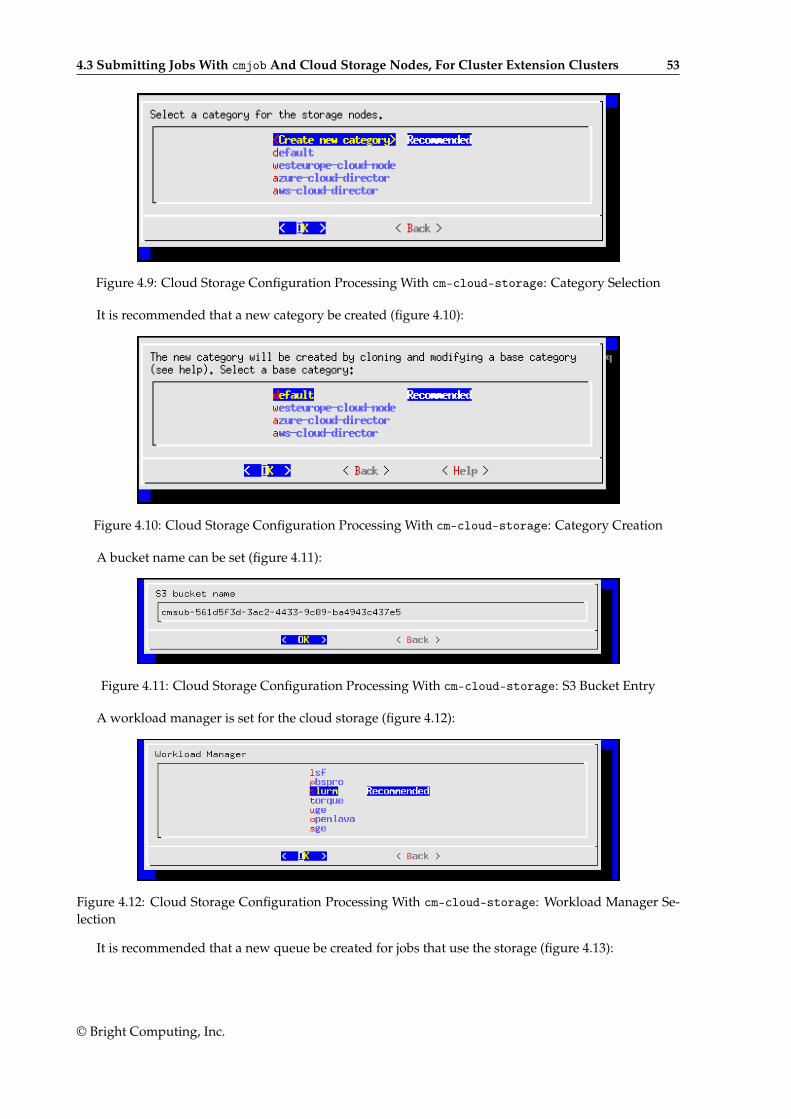
4.3 Submitting Jobs With cmjob And Cloud Storage Nodes, For Cluster Extension Clusters 53
Figure 4.9: Cloud Storage Configuration Processing With cm-cloud-storage: Category Selection
It is recommended that a new category be created (figure 4.10):
Figure 4.10: Cloud Storage Configuration Processing With cm-cloud-storage: Category Creation
A bucket name can be set (figure 4.11):
Figure 4.11: Cloud Storage Configuration Processing With cm-cloud-storage: S3 Bucket Entry
A workload manager is set for the cloud storage (figure 4.12):
Figure 4.12: Cloud Storage Configuration Processing With cm-cloud-storage: Workload Manager Se-lection
It is recommended that a new queue be created for jobs that use the storage (figure 4.13):
© Bright Computing, Inc.
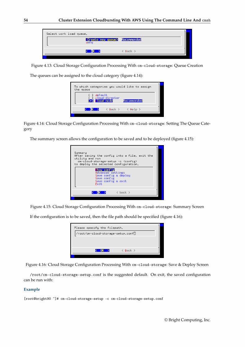
54 Cluster Extension Cloudbursting With AWS Using The Command Line And cmsh
Figure 4.13: Cloud Storage Configuration Processing With cm-cloud-storage: Queue Creation
The queues can be assigned to the cloud category (figure 4.14):
Figure 4.14: Cloud Storage Configuration Processing With cm-cloud-storage: Setting The Queue Cate-gory
The summary screen allows the configuration to be saved and to be deployed (figure 4.15):
Figure 4.15: Cloud Storage Configuration Processing With cm-cloud-storage: Summary Screen
If the configuration is to be saved, then the file path should be specified (figure 4.16):
Figure 4.16: Cloud Storage Configuration Processing With cm-cloud-storage: Save & Deploy Screen
/root/cm-cloud-storage-setup.conf is the suggested default. On exit, the saved configurationcan be run with:
Example
[root@bright90 ~]# cm-cloud-storage-setup -c cm-cloud-storage-setup.conf
© Bright Computing, Inc.
4.3 Submitting Jobs With cmjob And Cloud Storage Nodes, For Cluster Extension Clusters 55
Configuring cmjob Properties With cmshThe storage node policy settings can be modified via CMDaemon using cmsh:
[root@bright90 ~]# cmsh[bright90]% cmjob[bright90->cmjob[cmjob]]% storagenodepolicies[bright90->cmjob[cmjob]->storagenodepolicies]% listName (key) Template for cloud nodes----------------- ---------------------------us-east-1-policy us-east-1-storage-template[bright90->cmjob[cmjob]->storagenodepolicies]% use us-east-1-policy[bright90->cmjob[cmjob]->storagenodepolicies[us-east-1-policy]]% showParameter Value-------------------------------- ------------------------------------------------Default job output size 30.0GiBExported directories homeIntermediate storage <submode>Max download time 2hMax jobs per node 10Max storage nodes 5Max upload time 2hMinimum Storage volume size 30.0GiBName us-east-1-policyRevisionStorage node idle time limit 15mStorage node name prefix us-east-1-cstorageStorage volume filesystem ext3Template for cloud nodes us-east-1-storage-templateTunnel IP start address 0.0.100.0[bright90->cmjob[cmjob]->storagenodepolicies[us-east-1-policy]]% intermediatestorage[bright90->cmjob[cmjob]->storagenodepolicies[us-east-1-policy]->intermediatestorage]% showParameter Value------------------------------------- ------------------------------------------------Bucket name bright901b86bdc32219494f9a21Max object lifetime 4w 2dRegion us-east-1RevisionType AWSIntermediateStorageSecGroupFSx sg-0f1fe4fc6d3d49e66Default FSx Instance Capacity (GiB) 1200Max FSx Instance Capacity (GiB) 7200Max FSx Instance Count Per User 5[bright90->cmjob[cmjob]->storagenodepolicies[us-east-1-policy]->intermediatestorage]%
By default the S3 bucket storage expires after 30 days.Cloud jobs running under cmjob are listed under the cloudjobs submode:
[root@bright90 ~]# cmsh[bright90]% cmjob[bright90->cmjob[cmjob]]% cloudjobs[bright90->cmjob[cmjob]->cloudjobs]% listName (key) jobStatus storageNode user----------- ------------------------------------------------ ---------------------- ----slurm-35 Error: Job failed. Exit code: 0. Status: FAILED us-east-1-cstorage001 fredslurm-36 Error: Failed to acquire storage node: Failed t+ fredslurm-37 Running... us-east-1-cstorage001 fred
© Bright Computing, Inc.
56 Cluster Extension Cloudbursting With AWS Using The Command Line And cmsh
4.3.2 Integration Of cmjob With AWS FSx For LustreFSx for Lustre is a high-performance highly scalable distributed file system that is available as a cloudservice within some AWS regions. A Bright cluster that has burst into such a region can use FSx forLustre to create a shared storage volume that can be read from, and can be written to, by many computenodes simultaneously.
On a cluster that has burst into such a region, cmjob can provide workload managers with an FSx forLustre instance to store input and output data.
Sequential workload manager jobs can then continue to use the same FSx for Lustre instance. Thismeans that the output of one job can immediately become the input of the next one without having totransmit the data to and from an S3 bucket, or to and from the head node.
Additionally, workload manager jobs that run on multiple compute nodes in parallel can obtain theirshared input from the same FSx for Lustre instance.
Providing shared storage to cloud compute nodes via FSx for Lustre is an alternative to providingit via cloud storage nodes (section 4.3). The storage node approach is not sufficiently scalable whenthere are more than several dozen compute nodes working simultaneously with the same storage node.FSx for Lustre is significantly more scalable and far more performant than storage nodes—although ata higher cost.
Bright Cluster Manager currently offers three different methods of integrating cmjob with FSx forLustre:
1. On-demand FSx: An FSx file system is created on a per-job basis and is deleted automatically whenthe job completes.
2. User-managed FSx: A user creates an FSx instance and then submits one or more jobs that use thatsame FSx instance. These jobs can execute in sequence or simultaneously. When the last job hasfinished, the user is responsible for deleting the FSx instance.
3. Admin-managed FSx: An administrator creates an FSx instance and shares it with one or moreusers. These users are able to use the instance in the same way as with User-managed FSx, butthey cannot delete the instance or see each other’s files.
PrerequisitesTo be able to use the integration of cmjob with FSx for Lustre, the following requirements need to bemet:
• The cluster must be bursting into an AWS region that supports FSx for Lustre. AWS does not of-fer this feature in all regions. The AWS documentation at https://aws.amazon.com/about-aws/global-infrastructure/regional-product-services/ describes the regions that support FSxfor Lustre.
• AWS needs to offer Lustre installation packages for the operating system and kernel that is used toextend into AWS. While the necessary Lustre package could perhaps be obtained directly from theLustre project, it cannot be guaranteed that these packages are compatible with the FSx for Lustrefile systems that are offered by AWS. The AWS packages are built and tested to work only withspecific kernel versions.
• At the time of writing (May 2020), the supported operating systems are CentOS and Redhat 7.5,7.6, 7.7. A list of supported operating systems as well as the packages for installing the Lustre clientfor such systems can be found at https://docs.aws.amazon.com/fsx/latest/LustreGuide/install-lustre-client.html.
Enabling cmjob integration with FSx for Lustre:The integration of cmjob with FSx for Lustre can be accomplished in two ways, either:
© Bright Computing, Inc.
4.3 Submitting Jobs With cmjob And Cloud Storage Nodes, For Cluster Extension Clusters 57
• through the cm-cloud-storage-setup wizard (section 4.3.1)
or
• manually
The cm-cloud-storage-setup wizard can be used if the preceding prerequisites have been met. Inany case, during the wizard interaction, the administrator is asked to choose if FSx support should beenabled. If it is chosen, then:
• If FSx support is not available, then the administrator is informed that one of the requirementswas not met.
• If FSx support is available, then no further action is required from the administrator.
After the deployment has finished, all users belonging to the cloudjob profile are able to create user-managed and on-demand FSx volumes through cmjob.
Enabling cmjob integration manually: The manual integration approach should be followed whencmjob has already been configured on a cluster. That is, if the cm-cloud-storage-setup tool has alreadybeen run but the cluster has been running without FSx support so far.
Two separate actions need to be executed to manually add FSx for Lustre integration:
1. Installation of the required packages to the images
The AWS documentation should mention the packages that are required to install the LustreClient. Often these two packages are needed: kmod-lustre-client and lustre-client. Caremust be taken to match the package version to the Linux kernel version of the images. The pack-ages must be installed to the images under /cm/images that are used by the director and by allcompute nodes within that cluster extension.
Example
At the time of writing (May 2020), for a CentOS 7.7 system, with a 3.10 kernel, the instructions athttps://docs.aws.amazon.com/fsx/latest/LustreGuide/install-lustre-client.html sug-gested the following steps:
[root@bright90 ~]# cm-chroot-sw-img /cm/images/<image used by director and compute nodes>...[root@bright90 /]# wget https://fsx-lustre-client-repo-public-keys.s3.amazonaws.com/\fsx-rpm-public-key.asc -O /tmp/fsx-rpm-public-key.asc...[root@bright90 /]# wget https://fsx-lustre-client-repo.s3.amazonaws.com/el/7/\fsx-lustre-client.repo -O /etc/yum.repos.d/aws-fsx.repo rpm --import /tmp/fsx-rpm-public-key.asc...[root@bright90 /]# vi /etc/yum.repos.d/aws-fsx.repo
change references from el/7/ to el/7.7/ and exit out of editor
[root@bright90 /]# yum clean all...[root@bright90 /]# yum install -y kmod-lustre-client lustre-client...[root@bright90 /]# exit
© Bright Computing, Inc.
58 Cluster Extension Cloudbursting With AWS Using The Command Line And cmsh
2. Addition of the FSx tokens to the user profiles
Profiles (section 6.4 of the Administrator Manual) can be set for FSx users. Every user that should beable to create FSx for Lustre instances should have one or both of the follwing FSx tokens appendedto their profile:
• ON_DEMAND_FSX_TOKEN
• USER_MANAGED_FSX_TOKEN.
Example
A user, fred is already using cluster extension with AWS, but without FSx. Now the user wouldlike to launch and manage FSx storage on demand.
The existing profile of fred can be cloned in profile mode. The tokens needed can be appendedto the new profile, and the modified profile can then be set for fred. The following cmsh sessionsuggests how this can be carried out:
[bright90->user[fred]]% get profilecloudjob[bright90->user[fred]]% profile[bright90->profile]% clone cloudjob cloudjobfsx[bright90->profile*[cloudjobfsx*]]% get tokensSUBMIT_CLOUD_JOB_DESCRIPTION_TOKENGET_CLOUD_JOB_DESCRIPTION_TOKEN[bright90->profile*[cloudjobfsx*]]% append tokens ON_DEMAND_FSX_TOKEN USER_MANAGED_FSX_TOKEN[bright90->profile*[cloudjobfsx*]]% get tokensSUBMIT_CLOUD_JOB_DESCRIPTION_TOKENGET_CLOUD_JOB_DESCRIPTION_TOKENON_DEMAND_FSX_TOKENUSER_MANAGED_FSX_TOKEN[bright90->profile*[cloudjobfsx*]]% commit[bright90->profile[cloudjobfsx]]% user use fred[bright90->user[fred]]% set profile cloudjobfsx[bright90->user*[fred*]]% commit
When the two preceding actions have been carried out, the director and all compute nodes shouldbe rebooted. A user should then be able to create and submit jobs with a user-managed FSx instance, orsubmit jobs with an OnDemand FSx instance, depending on which tokens were assigned to the profileof the user.
ConfigurationThrough cmsh, an administrator can set profile tokens (section 6.4 of the Administrator Manual) to controlhow users can work with FSx for Lustre. An administrator can also set quotas that control how manyFSx instances a user can have simultaneously, and how large these FSx instances can be. The aim of thisis to help manage costs.
Profile tokens: The following profile tokens are available for user management in FSx for Lustre:
• ON_DEMAND_FSX_TOKEN: allows a user to use the --on-demand-fsx flag when submitting jobs withcmjob.
• USER_MANAGED_FSX_TOKEN: allows a user to create, manage and delete FSx instances.
• DELETE_ANY_FSX_INSTANCE_TOKEN: allows a user to delete FSx instances that are owned by otherusers. Normally reserved for root only.
© Bright Computing, Inc.
4.3 Submitting Jobs With cmjob And Cloud Storage Nodes, For Cluster Extension Clusters 59
• LIST_ALL_FSX_INSTANCES_TOKEN: allows a user to see FSx instances owned by other users that are notshared with that user. Normally reserved for root only.
• SHARE_FSX_INSTANCE_TOKEN: allows a user to share FSx instances with other users. Only the owneris allowed to share it. Normally reserved for root only.
Settings: The following cmsh navigation path:
cmsh→cmjob→storagenodepolicies→use <policy>→intermediatestorage
leads to these storage parameters:
• Max FSx Instance Capacity (GiB)
• Max FSx Instance Count Per User
which control quota limits for FSx instances.Each quota affects both on-demand and user-managed FSx instances. So if a user has already reached
the maximum number of user-managed FSx instances, then the user cannot submit a job that uses anOnDemand FSx instance.
The same navigation path also leads to the storage parameter:
• Default FSx Instance Capacity (GiB)
which controls the default capacity when a user or admin creates a user-managed or admin-managedFSx instance.
UsageAs listed earlier, the three methods that Bright Cluster Manager provides for cmjob integration with FSxfor Lustre are:
1. on-demand FSx,
2. user-managed FSx, and
3. admin-managed FSx.
How to run these methods using cmjob is covered in the next sections.
Using on-demand FSx: When using cmjob to submit a job, a user can now choose whether to use EBS-backed storage nodes or an FSx for Lustre file system to host the input data and output data. For a userthere is little difference between how two shared storage options are used, besides their performance.
The steps are:
1. an EBS volume or FSx for Lustre file system is created as shared storage,
2. the input data is copied from the head node to this shared storage
3. all compute nodes chosen by the workload manager mount this shared storage, and then run theirjobs,
4. storing their output data on the same shared storage.
5. the output data is uploaded from the shared storage to the head node
6. the EBS volume or FSx for Lustre file system is deleted.
© Bright Computing, Inc.
60 Cluster Extension Cloudbursting With AWS Using The Command Line And cmsh
Submitting a job to run with storage nodes is the default.If a user wants a job to use FSx for Lustre, then the user must set the --on-demand-fsx flag when
submitting the job:
Example
cmjob submit --on-demand-fsx job.sh
The capacity of the on-demand FSx instance is determined by doubling the size of the input data.This calculation takes into account both the data uploaded from the head node, and labeled data down-loaded from an S3 bucket. If the user thinks that the calculated capacity is not large enough to holdthe output data (the output includes temporary data), then the capacity can be increased with the--expected-output-size option. The specified size is combined with the size of the input data androunded up to the nearest valid FSx volume size. The option also works for EBS storage.
Using user-managed FSx: cmjob with a user-managed FSx file system operates differently from anon-demand system. With user-managed FSx, the user is responsible for creating and deleting the FSxfile system.
In some cases this can be more expensive than using the on-demand approach, especially if the userforgets to delete an FSx instance after no longer needing it.
However with user-managed FSx a user can run multiple concurrent jobs with the same FSx filesystem. It is also possible to run multiple jobs in sequence, each using the output of the previous job asinput, without having the overhead of copying files over from the FSx file system to an S3 bucket, andvice versa. Depending on the size of the workload, this option may be cheaper, or more desirable, thanon-demand FSx.
To create an FSx instance, the user executes cmjob with the create-fs-instance option as follows:
Example
cmjob create-fsx-instance <name> --capacity <capacity>
<name> can be a sequence of alphanumeric characters and dashes, and <capacity> is the total size ofthe FSx file system in gigabytes and is ideally set to a multiple of 1200, to prevent rejection by AWS. Ifnot specified, the default value is used. The name does not have to be unique.
To delete an FSx instance, the user can run cmjob with the delete-fsx-instance option:
Example
cmjob delete-fsx-instance <name or FSx ID>
If the name is not unique, then the user can always specify the FSx ID. The ID can be found using thelist-fsx-instances option. This lists all existing FSx instances, their names, unique IDs and statuses:
Example
cmjob list-fsx-instances
Once the FSx instance has reached a status of Available (which can take a few minutes), it is possibleto submit a job with this instance.
Example
cmjob submit job.sh --fsx-instance <name or FSx ID>
© Bright Computing, Inc.
4.4 Miscellaneous Cloud Tools 61
Using admin-managed FSx: Using cmjob with an admin-managed file system is very similar to usingit with a user-managed file system. The main difference is that the admin is responsible for creating anddeleting the file system, and that the file system of the admin is shared with specific users. To share thefile system, the share-fsx-instance option can be run by the admin, together with the --with option,as follows:
Example
cmjob share-fsx-instance <name or FSx ID> --with <user names>
Users do not need FSx-specific tokens to submit a job with an FSx instance. Using this approach foruser-managed FSx instances gives the cluster administrator more control over the creation and deletionof FSx instances. By managing profiles, the administrator is free to divide users into a group of userswho are allowed to create and delete their own instances, and a group of users who are only allowed tosubmit jobs with instances that are shared with them.
To stop sharing an FSx instance, the admin can run the --stop-sharing option:
Example
cmjob share-fsx-instance <name or FSx ID> --stop-sharing
Tracking FSx costs: All FSx instances created via cmjob have a BCM Owner tag assigned to them. Thistag allows the cluster administrator to track the FSx costs on a per-user basis using AWS’s cost manage-ment capabilities.
4.4 Miscellaneous Cloud Tools4.4.1 Setting Exclude Lists With excludelistsnippetsThe excludelistsnippets submode of cmsh in Bright Cluster Manager 9.1 onwards allows extra ex-clude list entries to be created and configured for a provisioned file system. In Bright Cluster Manager9.0 the 9.1 implementation has not been fully backported, although the entries can be implementedusing cmsh with a little extra work.
The Bright Cluster Manager 9.1 implementation is described first in this section, and the implemen-tation for Bright Cluster Manager 9.0 is then explained.
These extra exclude list entries, or snippets, are added to the regular exclude lists described in sec-tion 5.6 of the Administrator Manual. The addition of these exclude list snippets to the regular lists isdone by setting a mode parameter to the snippets. The mode parameter sets the exclude list that isassociated with an exclude list snippet, as indicated by the following table:
Mode Exclude list
sync excludelistsyncinstall (active by default)
full excludelistfullinstall
update excludelistupdate (active by default)
grab excludelistgrab
grab new excludelistgrabnew
An exclude list snippet with an associated mode parameter behaves as if its entries are run alongwith the regular exclude list that is associated with it.
For example, to exclude the files /useless/test1 and /useless/test2, in Bright Cluster Managerversion 9.1 onwards, a snippet called test may be created as follows:
Example
© Bright Computing, Inc.
62 Cluster Extension Cloudbursting With AWS Using The Command Line And cmsh
[bright90->fspart]% use /cm/shared[bright90->fspart[/cm/shared]]% excludelistsnippets[bright90->fspart[/cm/shared]->excludelistsnippets]%[bright90->fspart[/cm/shared]->excludelistsnippets]% add test[bright90->fspart*[/cm/shared*]->excludelistsnippets*[test*]]% set modefull yes[bright90->fspart*[/cm/shared*]->excludelistsnippets*[test*]]% set excludelist[bright90->fspart*[/cm/shared*]->excludelistsnippets*[test*]]% set excludelist /useless/test1[bright90->fspart*[/cm/shared*]->excludelistsnippets*[test*]]% append excludelist /useless/test2[bright90->fspart*[/cm/shared*]->excludelistsnippets*[test*]]% show
Parameter Value-------------------------------- ------------------------------------------------Lines 2Name testRevisionExclude list /useless/test1,/useless/test2Disabled noNo new files noMode sync yesMode full yesMode update yesMode grab noMode grab new no
When the test snippet is used, its corresponding .rsync file has the following configuration:
[root@bright90 cmd]# grep useless /var/spool/cmd/*shared.rsync
- /useless/test1- /useless/test2
In Bright Cluster Manager 9.0, there is no full implementation of excludelistsnippets mode incmsh. However, it is available as a free text field:
Example
[bright90->fspart[/cm/shared]]% set excludelist...[excludelistsnippet is defined]...[bright90->fspart*[/cm/shared*]]% get excludelist- /useless//test1- /useless//test2[bright90->fspart*[/cm/shared*]]% commit[bright90->fspart[/cm/shared]]%
4.4.2 The provisioningassociations ModeThe provisioningassociations mode is not strictly restricted to cloud use, because it can also be usedoutside the cloud.
It allows direct access to provisioning associations via cmsh.The provisioningassociations modecan be used to set properties for the following file systems:
1. /cm/shared: as used by the cloud director
2. /cm/shared: as used by the edge director
3. /tftpboot: as used by the boot role
4. /cm/node-installer: as used by the boot role
© Bright Computing, Inc.
4.5 Connecting To AWS With Direct Connect Or A Hardware VPN 63
5. <image>: for nodes with a provisioning role: for the image-to-image rsync to other provisioningnodes
The exclude lists for standard image-to-node sync to a regular (non-provisioning) node cannot bealtered this way, and should be done in the normal category exclude list way (section 5.6 of the Admin-istrator Manual), or via excludelistsnippets (section 4.4.1).
The provisioning associations properties can be accessed for an edge director as follows:
Example
[bright90]% device use edge-director[bright90->device[edge-director]]% roles[bright90->device[edge-director]->roles]% use edgedirector[bright90->device[edge-director]->roles[edgedirector]]%provisioningassociations[bright90->device[edge-director]->roles[edgedirector]->provisioningassociations]% listFSPart (key) Sync point Disabled---------------- ---------------- ----------/cm/shared no[bright90->device[edge-director]->roles[edgedirector]->provisioningassociations]% show /cm/sharedParameter Value-------------------------------- ------------------------------------------------RevisionSync pointType FSPartBasicAssociationFSPart /cm/sharedOn shared storage noDisabled noBackup directoryIs root no
The trigger command in fspart mode triggers an update for a non-image partition. It is not neededfor images under /cm/image, such as item 5 in the exclude list items that the provisioningassociationsmode can be used for (page 63).
4.5 Connecting To AWS With Direct Connect Or A Hardware VPNFor simple configurations, Bright Cluster Manager recommends, and provides, OpenVPN by default forcluster extension cloudbursting VPN connectivity. If there is a wish to use Direct Connect or a hardwareVPN (for example, an IPSec tunnel), then Bright Cluster Manager can be configured to work with those.
The AWS cluster extension always runs in an AWS Virtual Private Cloud (VPC). In the default de-ployment scenario, the head node communicates with the cloud nodes using an OpenVPN connectionbetween the head node and the cloud director. In the case of a Direct Connect connection or a hardwareVPN, the head node can be configured to communicate directly with the cloud director and cloud nodes.
Setting up Direct Connect or a VPN for a cluster extension can be carried out according to these threesteps:
1. VPC creation (section 4.5.1). This step can be skipped if an existing VPC is to be used.
2. Connecting the local network to the VPC (section 4.5.2). The connection can be with, for exam-ple, Direct Connect, or a hardware VPN. This step can be skipped if the local network is alreadyconnected to an existing VPC via a Direct Connect or a hardware VPN connection.
3. Configuring and deploying the cluster extension (section 4.5.3).
© Bright Computing, Inc.
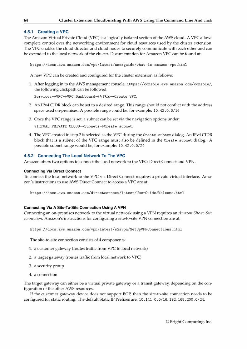
64 Cluster Extension Cloudbursting With AWS Using The Command Line And cmsh
4.5.1 Creating a VPCThe Amazon Virtual Private Cloud (VPC) is a logically isolated section of the AWS cloud. A VPC allowscomplete control over the networking environment for cloud resources used by the cluster extension.The VPC enables the cloud director and cloud nodes to securely communicate with each other and canbe extended to the local network of the cluster. Documentation for Amazon VPC can be found at:
https://docs.aws.amazon.com/vpc/latest/userguide/what-is-amazon-vpc.html
A new VPC can be created and configured for the cluster extension as follows:
1. After logging in to the AWS management console, https://console.aws.amazon.com/console/,the following clickpath can be followed:
Services→VPC→VPC Dashboard→VPCs→Create VPC.
2. An IPv4 CIDR block can be set to a desired range. This range should not conflict with the addressspace used on-premises. A possible range could be, for example: 10.42.0.0/16
3. Once the VPC range is set, a subnet can be set via the navigation options under:
VIRTUAL PRIVATE CLOUD→Subnets→Create subnet.
4. The VPC created in step 2 is selected as the VPC during the Create subnet dialog. An IPv4 CIDRblock that is a subnet of the VPC range must also be defined in the Create subnet dialog. Apossible subnet range would be, for example: 10.42.0.0/24
4.5.2 Connecting The Local Network To The VPCAmazon offers two options to connect the local network to the VPC: Direct Connect and VPN.
Connecting Via Direct ConnectTo connect the local network to the VPC via Direct Connect requires a private virtual interface. Ama-zon’s instructions to use AWS Direct Connect to access a VPC are at:
https://docs.aws.amazon.com/directconnect/latest/UserGuide/Welcome.html
Connecting Via A Site-To-Site Connection Using A VPNConnecting an on-premises network to the virtual network using a VPN requires an Amazon Site-to-Siteconnection. Amazon’s instructions for configuring a site-to-site VPN connection are at:
https://docs.aws.amazon.com/vpn/latest/s2svpn/SetUpVPNConnections.html
The site-to-site connection consists of 4 components:
1. a customer gateway (routes traffic from VPC to local network)
2. a target gateway (routes traffic from local network to VPC)
3. a security group
4. a connection
The target gateway can either be a virtual private gateway or a transit gateway, depending on the con-figuration of the other AWS resources.
If the customer gateway device does not support BGP, then the site-to-site connection needs to beconfigured for static routing. The default Static IP Prefixes are: 10.141.0.0/16, 192.168.200.0/24.
© Bright Computing, Inc.
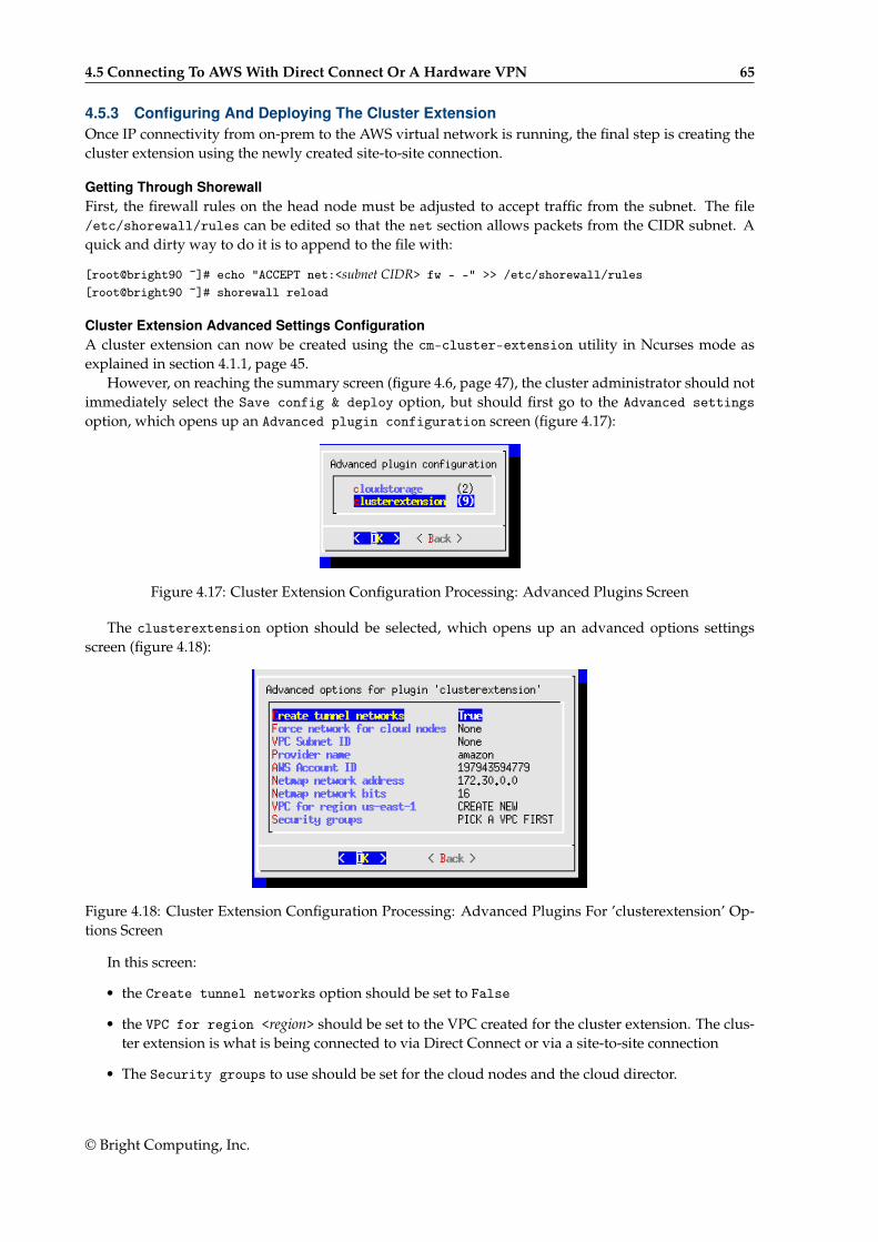
4.5 Connecting To AWS With Direct Connect Or A Hardware VPN 65
4.5.3 Configuring And Deploying The Cluster ExtensionOnce IP connectivity from on-prem to the AWS virtual network is running, the final step is creating thecluster extension using the newly created site-to-site connection.
Getting Through ShorewallFirst, the firewall rules on the head node must be adjusted to accept traffic from the subnet. The file/etc/shorewall/rules can be edited so that the net section allows packets from the CIDR subnet. Aquick and dirty way to do it is to append to the file with:
[root@bright90 ~]# echo "ACCEPT net:<subnet CIDR> fw - -" >> /etc/shorewall/rules[root@bright90 ~]# shorewall reload
Cluster Extension Advanced Settings ConfigurationA cluster extension can now be created using the cm-cluster-extension utility in Ncurses mode asexplained in section 4.1.1, page 45.
However, on reaching the summary screen (figure 4.6, page 47), the cluster administrator should notimmediately select the Save config & deploy option, but should first go to the Advanced settingsoption, which opens up an Advanced plugin configuration screen (figure 4.17):
Figure 4.17: Cluster Extension Configuration Processing: Advanced Plugins Screen
The clusterextension option should be selected, which opens up an advanced options settingsscreen (figure 4.18):
Figure 4.18: Cluster Extension Configuration Processing: Advanced Plugins For ’clusterextension’ Op-tions Screen
In this screen:
• the Create tunnel networks option should be set to False
• the VPC for region <region> should be set to the VPC created for the cluster extension. The clus-ter extension is what is being connected to via Direct Connect or via a site-to-site connection
• The Security groups to use should be set for the cloud nodes and the cloud director.
© Bright Computing, Inc.
66 Cluster Extension Cloudbursting With AWS Using The Command Line And cmsh
Custom Security Groups ConfigurationFor the security group it is important to realize that the default security groups, as created by the clusterextension utility, do not accept traffic from the IPSec tunnel. It is recommended to create a customsecurity group, and to use that for both the director and the nodes. To create this security group:
1. From the AWS management console, the following clickpath is followed:
VPC Dashboard→Security Groups→Create security group
2. The cluster extension VPC is selected
3. A new inbound rule is added, to accept all traffic from the cluster and the VPC. For example:192.168.200.0/24 and 10.42.0.0/16.
The Ncurses advanced settings screens can be backed out of by selecting Back twice. The optionSave config & deploy can then be selected to create the cluster extension.
Cloud Node Certificate AutosigningBy default Bright Cluster Manager does not issue certificates for nodes on the external network. Thismeans that for cloud nodes the certificates need to be issued manually, once for every new cloud node.
Alternatively, to automatically sign certificate requests by cloud nodes, autosign can be enabled bythe administrator for external networks. Autosigning may be a security concern, as this allows anyoneon the external network to request a node certificate. Autosign can be enabled on externalnet in cmsh asfollows:
[root@bright90~]# cmsh[bright90]% network[bright90->network]% set externalnet allowautosign always[bright90->network]% commit
The cluster extension can now be deployed as explained in section 4.1.2.
© Bright Computing, Inc.
5Cluster Extension Cloudbursting
With Azure5.1 Introduction To Cluster Extension Cloudbursting With AzureCluster extension cloudbursting with AWS is covered in Chapter 3, where a GUI approach is described,and is also covered in section 4.1, where a text interface approach is described,
Cluster extension cloudbursting with Microsoft Azure is covered in this chapter (Chapter 5). Theprocedure is somewhat similar to that for AWS:
• The prerequisites to cloudburst into Azure are the same as those of cloudbursting into AWS, andare as previously described on page 25.
In summary, the prerequisites are as follows:
– an activated cluster license should be ensured
– an Azure account should exist
– Bright Cluster Manager must be registered as an Azure AD application (page 68)
– UDP port 1194 should be open
• The techniques to cloudburst into Azure are also the same as that of cloudbursting into AWS, andare as previously described on page 26.
In summary, the techniques are as follows:
– a cloud director is set up in the cloud then started up
– cloud nodes are then provisioned from the cloud director
• The deployment of cluster extension cloudbursting for Azure is carried out in a similar way tohow it is done for AWS.
In summary, the tools used to deploy cluster extension cloudbursting for Azure are as follows:
– the Ncurses cm-cluster-extension utility, run from the command line (section 5.2)
– the Azure Wizard, run from Bright View.
5.2 Cluster Extension Into AzureSection 4.1.1 introduces the cm-cluster-extension Ncurses wizard, which is run on the head nodewhen configuring a cluster extension for Azure or AWS. After the cluster extension configuration iscompleted, the cluster is capable of extending into the cloud by having cloud nodes power up into thecloud. This section (section 5.2) covers how cm-cluster-extension can be run for Azure, and howclouds nodes can be deployed for Azure.
© Bright Computing, Inc.
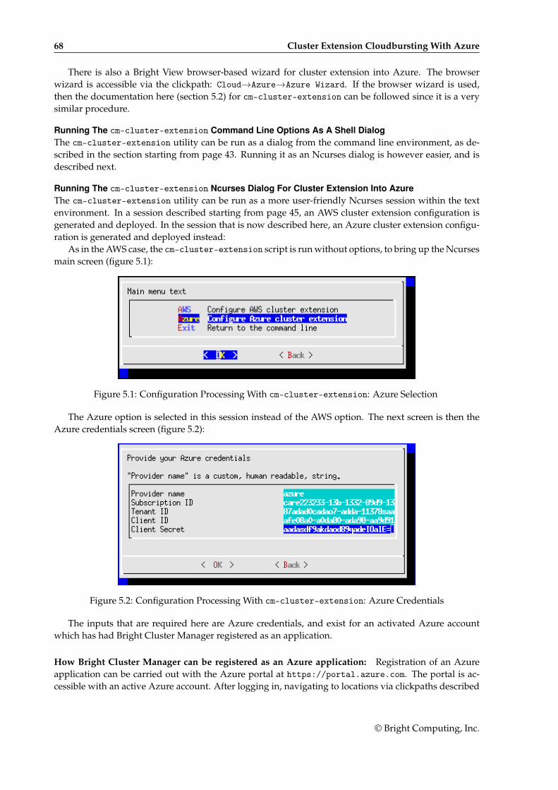
68 Cluster Extension Cloudbursting With Azure
There is also a Bright View browser-based wizard for cluster extension into Azure. The browserwizard is accessible via the clickpath: Cloud→Azure→Azure Wizard. If the browser wizard is used,then the documentation here (section 5.2) for cm-cluster-extension can be followed since it is a verysimilar procedure.
Running The cm-cluster-extension Command Line Options As A Shell DialogThe cm-cluster-extension utility can be run as a dialog from the command line environment, as de-scribed in the section starting from page 43. Running it as an Ncurses dialog is however easier, and isdescribed next.
Running The cm-cluster-extension Ncurses Dialog For Cluster Extension Into AzureThe cm-cluster-extension utility can be run as a more user-friendly Ncurses session within the textenvironment. In a session described starting from page 45, an AWS cluster extension configuration isgenerated and deployed. In the session that is now described here, an Azure cluster extension configu-ration is generated and deployed instead:
As in the AWS case, the cm-cluster-extension script is run without options, to bring up the Ncursesmain screen (figure 5.1):
Figure 5.1: Configuration Processing With cm-cluster-extension: Azure Selection
The Azure option is selected in this session instead of the AWS option. The next screen is then theAzure credentials screen (figure 5.2):
Figure 5.2: Configuration Processing With cm-cluster-extension: Azure Credentials
The inputs that are required here are Azure credentials, and exist for an activated Azure accountwhich has had Bright Cluster Manager registered as an application.
How Bright Cluster Manager can be registered as an Azure application: Registration of an Azureapplication can be carried out with the Azure portal at https://portal.azure.com. The portal is ac-cessible with an active Azure account. After logging in, navigating to locations via clickpaths described
© Bright Computing, Inc.
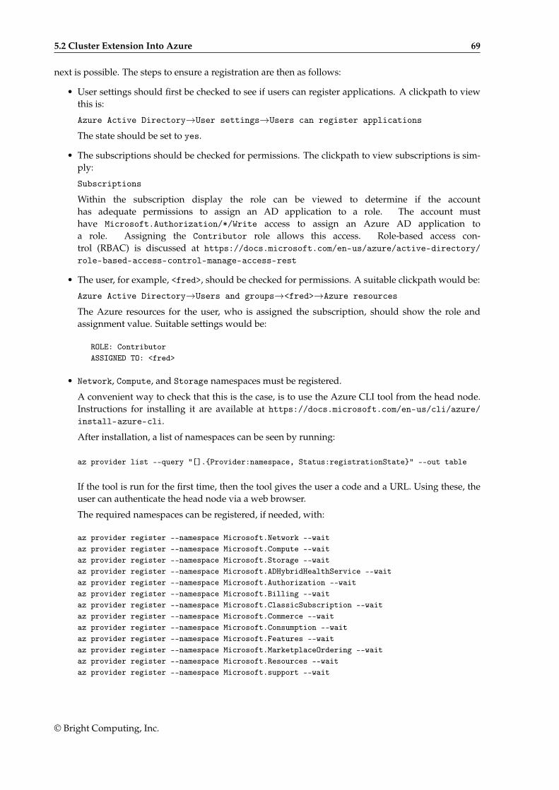
5.2 Cluster Extension Into Azure 69
next is possible. The steps to ensure a registration are then as follows:
• User settings should first be checked to see if users can register applications. A clickpath to viewthis is:
Azure Active Directory→User settings→Users can register applications
The state should be set to yes.
• The subscriptions should be checked for permissions. The clickpath to view subscriptions is sim-ply:
Subscriptions
Within the subscription display the role can be viewed to determine if the accounthas adequate permissions to assign an AD application to a role. The account musthave Microsoft.Authorization/*/Write access to assign an Azure AD application toa role. Assigning the Contributor role allows this access. Role-based access con-trol (RBAC) is discussed at https://docs.microsoft.com/en-us/azure/active-directory/role-based-access-control-manage-access-rest
• The user, for example, <fred>, should be checked for permissions. A suitable clickpath would be:
Azure Active Directory→Users and groups→<fred>→Azure resources
The Azure resources for the user, who is assigned the subscription, should show the role andassignment value. Suitable settings would be:
ROLE: ContributorASSIGNED TO: <fred>
• Network, Compute, and Storage namespaces must be registered.
A convenient way to check that this is the case, is to use the Azure CLI tool from the head node.Instructions for installing it are available at https://docs.microsoft.com/en-us/cli/azure/install-azure-cli.
After installation, a list of namespaces can be seen by running:
az provider list --query "[].{Provider:namespace, Status:registrationState}" --out table
If the tool is run for the first time, then the tool gives the user a code and a URL. Using these, theuser can authenticate the head node via a web browser.
The required namespaces can be registered, if needed, with:
az provider register --namespace Microsoft.Network --waitaz provider register --namespace Microsoft.Compute --waitaz provider register --namespace Microsoft.Storage --waitaz provider register --namespace Microsoft.ADHybridHealthService --waitaz provider register --namespace Microsoft.Authorization --waitaz provider register --namespace Microsoft.Billing --waitaz provider register --namespace Microsoft.ClassicSubscription --waitaz provider register --namespace Microsoft.Commerce --waitaz provider register --namespace Microsoft.Consumption --waitaz provider register --namespace Microsoft.Features --waitaz provider register --namespace Microsoft.MarketplaceOrdering --waitaz provider register --namespace Microsoft.Resources --waitaz provider register --namespace Microsoft.support --wait
© Bright Computing, Inc.
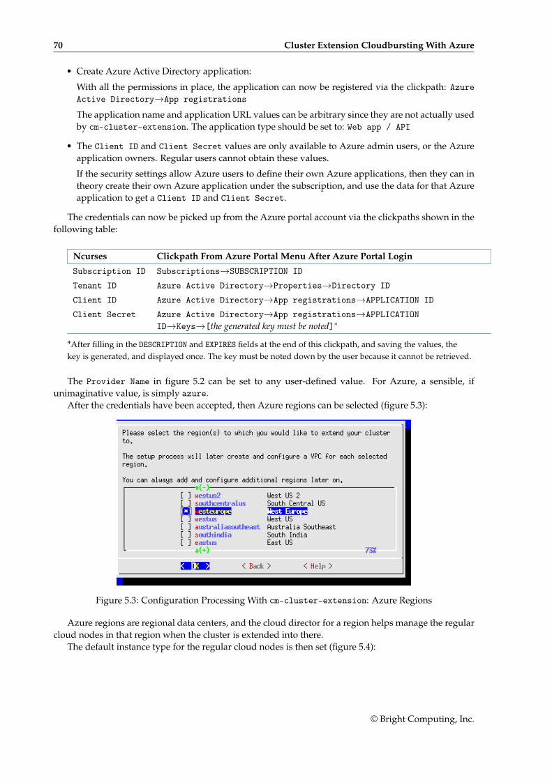
70 Cluster Extension Cloudbursting With Azure
• Create Azure Active Directory application:
With all the permissions in place, the application can now be registered via the clickpath: AzureActive Directory→App registrations
The application name and application URL values can be arbitrary since they are not actually usedby cm-cluster-extension. The application type should be set to: Web app / API
• The Client ID and Client Secret values are only available to Azure admin users, or the Azureapplication owners. Regular users cannot obtain these values.
If the security settings allow Azure users to define their own Azure applications, then they can intheory create their own Azure application under the subscription, and use the data for that Azureapplication to get a Client ID and Client Secret.
The credentials can now be picked up from the Azure portal account via the clickpaths shown in thefollowing table:
Ncurses Clickpath From Azure Portal Menu After Azure Portal Login
Subscription ID Subscriptions→SUBSCRIPTION ID
Tenant ID Azure Active Directory→Properties→Directory ID
Client ID Azure Active Directory→App registrations→APPLICATION ID
Client Secret Azure Active Directory→App registrations→APPLICATIONID→Keys→[the generated key must be noted]∗
*After filling in the DESCRIPTION and EXPIRES fields at the end of this clickpath, and saving the values, thekey is generated, and displayed once. The key must be noted down by the user because it cannot be retrieved.
The Provider Name in figure 5.2 can be set to any user-defined value. For Azure, a sensible, ifunimaginative value, is simply azure.
After the credentials have been accepted, then Azure regions can be selected (figure 5.3):
Figure 5.3: Configuration Processing With cm-cluster-extension: Azure Regions
Azure regions are regional data centers, and the cloud director for a region helps manage the regularcloud nodes in that region when the cluster is extended into there.
The default instance type for the regular cloud nodes is then set (figure 5.4):
© Bright Computing, Inc.
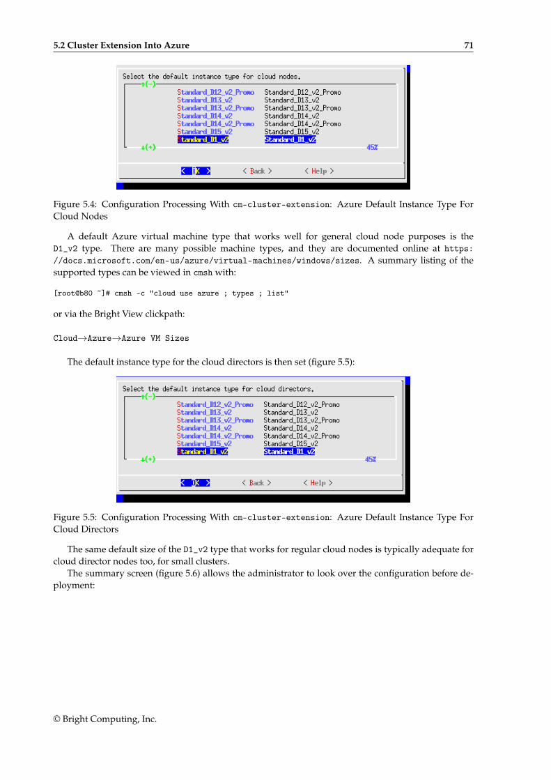
5.2 Cluster Extension Into Azure 71
Figure 5.4: Configuration Processing With cm-cluster-extension: Azure Default Instance Type ForCloud Nodes
A default Azure virtual machine type that works well for general cloud node purposes is theD1_v2 type. There are many possible machine types, and they are documented online at https://docs.microsoft.com/en-us/azure/virtual-machines/windows/sizes. A summary listing of thesupported types can be viewed in cmsh with:
[root@b80 ~]# cmsh -c "cloud use azure ; types ; list"
or via the Bright View clickpath:
Cloud→Azure→Azure VM Sizes
The default instance type for the cloud directors is then set (figure 5.5):
Figure 5.5: Configuration Processing With cm-cluster-extension: Azure Default Instance Type ForCloud Directors
The same default size of the D1_v2 type that works for regular cloud nodes is typically adequate forcloud director nodes too, for small clusters.
The summary screen (figure 5.6) allows the administrator to look over the configuration before de-ployment:
© Bright Computing, Inc.
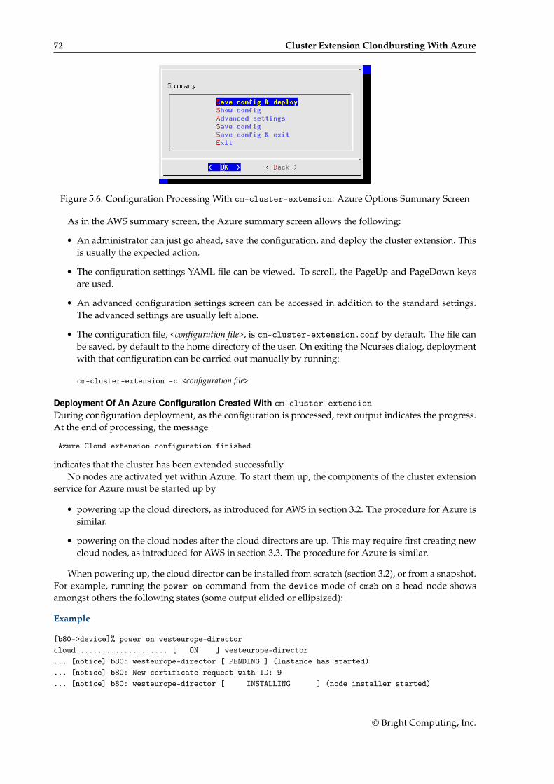
72 Cluster Extension Cloudbursting With Azure
Figure 5.6: Configuration Processing With cm-cluster-extension: Azure Options Summary Screen
As in the AWS summary screen, the Azure summary screen allows the following:
• An administrator can just go ahead, save the configuration, and deploy the cluster extension. Thisis usually the expected action.
• The configuration settings YAML file can be viewed. To scroll, the PageUp and PageDown keysare used.
• An advanced configuration settings screen can be accessed in addition to the standard settings.The advanced settings are usually left alone.
• The configuration file, <configuration file>, is cm-cluster-extension.conf by default. The file canbe saved, by default to the home directory of the user. On exiting the Ncurses dialog, deploymentwith that configuration can be carried out manually by running:
cm-cluster-extension -c <configuration file>
Deployment Of An Azure Configuration Created With cm-cluster-extensionDuring configuration deployment, as the configuration is processed, text output indicates the progress.At the end of processing, the message
Azure Cloud extension configuration finished
indicates that the cluster has been extended successfully.No nodes are activated yet within Azure. To start them up, the components of the cluster extension
service for Azure must be started up by
• powering up the cloud directors, as introduced for AWS in section 3.2. The procedure for Azure issimilar.
• powering on the cloud nodes after the cloud directors are up. This may require first creating newcloud nodes, as introduced for AWS in section 3.3. The procedure for Azure is similar.
When powering up, the cloud director can be installed from scratch (section 3.2), or from a snapshot.For example, running the power on command from the device mode of cmsh on a head node showsamongst others the following states (some output elided or ellipsized):
Example
[b80->device]% power on westeurope-directorcloud .................... [ ON ] westeurope-director... [notice] b80: westeurope-director [ PENDING ] (Instance has started)... [notice] b80: New certificate request with ID: 9... [notice] b80: westeurope-director [ INSTALLING ] (node installer started)
© Bright Computing, Inc.
5.2 Cluster Extension Into Azure 73
... [notice] b80: New certificate request with ID: 10 (ldaps)
... [notice] b80: westeurope-director [ INSTALLER_CALLINGINIT ] (switching to local root)
...
... [notice] b80: westeurope-director [ UP ]
Example
[root@bright90 ~]# ps uww -C rsync | grep -o ' /cm/.*$'/cm/shared/ [email protected]::target//cm/shared/
Tracking Cloud Director Startup From cmshThe provisioningstatus command in the softwareimage mode of cmsh can be used to view the provi-sioning status (some output elided):
Example
[root@bright90 ~]# cmsh -c "softwareimage provisioningstatus"...+ westeurope-director...
Up to date images: noneOut of date images: default-image
In the preceding output, the absence of an entry for “Up to date images” shows that the clouddirector does not yet have an image that it can provision to the cloud nodes. After some time, the lastfew lines of output should change to something like:
Example
+ westeurope-director...
Up to date images: default-image
This indicates the image for the cloud nodes is now ready.With the -a option, the provisioningstatus -a command gives details that may be helpful. For
example, while the cloud director is having the default software image placed on it for provisioningpurposes, the source and destination paths are /cm/images/default-image:
Example
[root@bright90 ~]# cmsh -c "softwareimage provisioningstatus -a"Request ID(s): 4Source node: bright90Source path: /cm/images/default-imageDestination node: westeurope-directorDestination path: /cm/images/default-image...
After some time, when the shared filesystem is being provisioned, then an indication of progress isshown by the Request ID incrementing, and the source and destination paths changing to the /cm/shareddirectory:
[root@bright90 ~]# cmsh -c "softwareimage provisioningstatus -a"Request ID(s): 5Source node: bright90Source path: /cm/sharedDestination node: westeurope-directorDestination path: /cm/shared...
© Bright Computing, Inc.
74 Cluster Extension Cloudbursting With Azure
After the shared directory and the cloud node software images are provisioned, the cloud director isfully up. Cloud node instances can then be powered up and provisioned from the cloud director. Theinstances can be started up from scratch (section 3.2), or from snapshot (section 3.4).
Cluster Extension Cloudbursting LoggingAll Azure logging goes to the CMDaemon log in /var/log/cmdaemon, where the CLOUD tag is used toindicate cloud-related operations.
5.3 Cluster Extension Into Azure: Cloud Node Startup From ScratchThis section discusses the configuration of regular cloud node startup from scratch.1
To configure regular cloud nodes in Azure from scratch does not require a working cloud director.However to boot up the regular cloud nodes does require that the cloud director be up, and that theassociated networks to the regular cloud nodes and to the head node be configured correctly.
If needed, additional cloud provisioning nodes (section 5.2 of the Administrator Manual) can be con-figured by assigning the provisioning role to cloud nodes, along with appropriate nodegroups (page 155of the Administrator Manual) values, in order to create a provisioning hierarchy.
Similarly to how it is done in AWS, the creation and configuration of regular cloud node objects inAzure is conveniently carried out by cloning another regular cloud node, from one of the default cloudnodes already created by the cluster extension wizard (section 5.2). A clickpath to do this cloning inBright View is:
Devices→Cloud Nodes→<cloud node hostname>→↓Clone
Cloud node objects can also be created in cmsh as described in section 4.2.
5.4 Cluster Extension Into Azure: shutdown Vs power off
An Azure cloud node has two stopped states:
1. stopped: A node running within Azure can be set to this state by running the shutdown command:
• within the device mode of cmsh
• with Bright View, using the clickpath:Devices→ Cloud Nodes→ <cloud node hostname>→↓OS→ Shutdown
• Or by clicking the stop button for that node within the Azure web portal, once.
2. stopped (deallocated): A node running within Azure can be set to this state by running thepower off command:
• within the device mode of cmsh
• with Bright View, using the clickpath:Devices→Cloud Nodes→<cloud node hostname>→↓Power→Off
• Or by clicking on the stop button within the Azure web portal, twice.
Carrying out a power off command is like a hard power off command, which can under someunusual conditions cause filesystem corruption. It is therefore safer to run the shutdown command first,wait for the node to shut down via the OS. After that, running the power off command ensures that thenode is deallocated.
From a financial point of view when using Azure, a node that is shut down but not deallocatedcontinues to incur costs. However, a node that is deallocated does not continue to incur costs.
1The configuration of cloud director and node startup from snapshot is also possible. How to do this for AWS is discussed insection 3.4. Doing this for Azure is rather more complicated and confusing. At the time of writing (August 2017), configuring thisis therefore planned as a wizard-assisted option for a future version of Bright Cluster Manager, with a priority that depends onthe level of interest for this feature from customers.
© Bright Computing, Inc.
5.5 Submitting Jobs With cmjob And Cloud Storage Nodes, For Azure Cluster Extension Clusters 75
5.5 Submitting Jobs With cmjob And Cloud Storage Nodes, For Azure ClusterExtension Clusters
The cmjob utility, a job submission wrapper for end users for cluster extension clusters, is introducedand documented for AWS cluster extension in section 4.3. As a summary, its configuration procedureconsists of:
• Making sure the cmdaemon-cmjob package is installed on the head node and the cloud image
• Ensuring the users that are to use cmjob have the cloudjob profile
• Making sure that cloud storage nodes are set up. The administrator can runcm-cloud-storage-setup to configure the cloud storage nodes.
The details of the configuration procedure for cmjob for Azure cluster extension is almost identicalto that for AWS. The configuration procedure documented in section 4.3 can therefore also be followedfor Azure.
How the end user can use cmjob is documented in section 4.7 of the User Manual.
5.5.1 Integration Of cmjob With Azure NetApp FilesAzure NetApp Files (ANF) is a high-performance highly scalable network file service that is available asa cloud service within most Azure regions. A Bright cluster that has burst into such a region can useANF to create a shared storage volume that can be read from, and can be written to, by many computenodes simultaneously.
On a cluster that has burst into such a region, cmjob can provide workload managers with an ANFvolume to store input and output data.
Sequential workload manager jobs can use the same ANF volume. This means that the output of onejob can immediately become the input of the next one without having to transmit the data to and fromAzure cloud storage, or to and from the head node.
Additionally, workload manager jobs that run on multiple compute nodes in parallel can obtain theirshared input from the same ANF volume.
Providing shared storage to cloud compute nodes via ANF is an alternative to providing it via viacloud storage nodes (section 4.3). The storage node approach is not sufficiently scalable when there aremore than several dozen compute nodes working simultaneously with the same storage node. ANF issignificantly more scalable and far more performant, although at a higher cost.
Bright Cluster Manager currently offer three different methods of integrating cmjob with Azure Net-App Files:
1. On-Demand ANF: An ANF file system is created on a per-job basis and is deleted automaticallywhen the job completes.
2. User-managed ANF: A user creates an ANF volume and then submits one or more jobs that use thatsame ANF volume. These jobs can execute in sequence or simultaneously. When the last job hasfinished, the user is responsible for deleting the ANF volume.
3. Admin-managed ANF: An administrator creates an ANF volume and shares it with one or moreusers. These users are able to use the volume in the same way as with user-managed ANF, butthey cannot delete the volume or see each other’s files.
PrerequisiteTo be able to use the integration of cmjob with ANF NetApp Files, the cluster must be bursting into anAzure region that supports Azure NetApp Files. Azure does not offer this feature in all regions. TheAzure documentation should be checked to see if a region offers ANF for Azure.
© Bright Computing, Inc.
76 Cluster Extension Cloudbursting With Azure
Enabling cmjob Integration With Azure NetAppThe integration of cmjob with ANF can be accomplished in two ways, either:
• through the cm-cloud-storage-setup wizard (section 4.3.1)
or
• manually
During the cm-cloud-storage-setup wizard run, when the guidance for the Azure extension is beingcarried out, the administrator is asked if ANF support should be enabled. If the administrator agrees tothis, then ANF support is set up. After the deployment has finished, all users that have the cloudjobprofile can then create user-managed and on-demand ANF volumes through cmjob.
Enabling cmjob integration manually: The manual integration approach should be followed whencmjob has already been configured on a cluster. That is, if the cm-cloud-storage-setup tool has beenrun, but the cluster has been running without ANF support so far.
To add cmjob integration with ANF manually, the following manual action is all that is needed:Every user that should be able to create ANF volumes should have one or both of these tokens set
on their profile (profiles are explained in section 6.4 of the Administrator Manual):
• ON_DEMAND_ANF_TOKEN
• USER_MANAGED_ANF_TOKEN.
Example
A user, fred is already using cluster extension with Azure, but without ANF. Now the user would liketo be able to launch and manage ANF storage on demand.
To allow fred to do that, the steps that are carried out could be as follows: The existing profile offred can be cloned in profile mode. The tokens needed can be appended to the new profile, and themodified profile can then be set for fred.
The following cmsh session shows these steps:
[bright90->user[fred]]% get profilecloudjob[bright90->user[fred]]% profile[bright90->profile]% clone cloudjob cloudjobanf[bright90->profile*[cloudjobanf*]]% get tokensSUBMIT_CLOUD_JOB_DESCRIPTION_TOKENGET_CLOUD_JOB_DESCRIPTION_TOKEN[bright90->profile*[cloudjobanf*]]% append tokens ON_DEMAND_ANF_TOKEN USER_MANAGED_ANF_TOKEN[bright90->profile*[cloudjobanf*]]% get tokensSUBMIT_CLOUD_JOB_DESCRIPTION_TOKENGET_CLOUD_JOB_DESCRIPTION_TOKENON_DEMAND_ANF_TOKENUSER_MANAGED_ANF_TOKEN[bright90->profile*[cloudjobanf*]]% commit[bright90->profile[cloudjobanf]]% user use fred[bright90->user[fred]]% set profile cloudjobanf[bright90->user*[fred*]]% commit
No directors need to be updated or rebooted when the necessary user profiles have been updated.All users with profiles with those ANF tokens should then be able to create and submit jobs with a user-managed ANF volume, or submit jobs with an on-demand ANF volume, depending on which tokenswere assigned to the profile of the user.
© Bright Computing, Inc.
5.5 Submitting Jobs With cmjob And Cloud Storage Nodes, For Azure Cluster Extension Clusters 77
ConfigurationThrough cmsh, an administrator can use profile tokens (section 6.4 of the Administrator Manual) to con-trol how users can work with ANF. An administrator can also set quotas that control how many ANFvolumes a user can have simultaneously and how large these ANF volumes can be. The aim of this is tohelp manage costs.
Profile tokens:
• ON_DEMAND_ANF_TOKEN: allows a user to use the --on-demand-anf flag when submitting jobs withcmjob.
• USER_MANAGED_ANF_TOKEN: allows a user to create, manage and delete ANF volumes.
• DELETE_ANY_ANF_VOLUME_TOKEN: allows a user to delete ANF volumes that are owned by other users.Normally reserved for root only.
• LIST_ALL_ANF_VOLUMES_TOKEN: allows a user to see ANF volumes owned by other users. Normallyreserved for root only.
• SHARE_ANF_VOLUME_TOKEN: allows a user to share ANF volumes with other users. Only the owner isallowed to share it. Normally reserved for root only.
Settings: The following cmsh navigation path
cmsh→cmjob→storagenodepolicies→use <policy>→intermediatestorage
leads to these storage parameters:
• Max ANF Volume Capacity (TiB)
• Max ANF Volume Count Per User
which control quota limits for ANF volumes for the number and size of ANF volumes, for when a useror an administrator creates a user-managed or administrator-managed ANF volume.
The count is combined. If a user has already reached the maximum number of user-managed ANFvolumes, then the user cannot submit a job that uses an on-demand ANF volume.
Also in the same navigation path is the storage parameter:
• Default ANF Volume Capacity (TiB)
which controls the default capacity when a user or admin creates a user-managed or admin-managedANF volume.
UsageAs listed earlier, the three methods that Bright Cluster Manager provides for cmjob integration withANF are:
1. on-demand ANF,
2. user-managed ANF, and
3. admin-managed ANF.
How to run these methods using cmjob is covered in the next sections.
© Bright Computing, Inc.
78 Cluster Extension Cloudbursting With Azure
Using on-demand ANF: When using cmjob to submit a job, a user can choose whether to use an Azurestorage volume or an ANF file system to host the input data and output data. For a user there is littledifference between the ways in which the two shared storage options are used, beside performance.
The steps are:
1. an Azure storage volume or an ANF file system is created as shared storage,
2. the input data is copied from the head node to this shared storage
3. all compute nodes chosen by the workload manager mount this shared storage, and then run theirjobs,
4. storing their output data on the same shared storage.
5. the output data is uploaded from the shared storage to the head node
6. the Azure volume or ANF file system is deleted.
Submitting a job to run with Azure storage nodes is the default.If a user wants a job to use ANF, then the user must set the --on-demand-anf flag when submitting
the job:
Example
cmjob submit --on-demand-anf job.sh
The capacity of the OnDemand ANF volume is determined by doubling the size of the input data.This calculation takes into account both the data uploaded from the head node, and labeled data down-loaded from the Azure cloud storage. If the user thinks that the calculated capacity is not large enoughto hold the output data (the output includes temporary data), then the user can increase the capacitywith the --expected-output-size parameter. The specified size is combined with the size of the inputdata and rounded up to the nearest valid ANF volume size.
Using user-managed ANF cmjob with a user-managed ANF file system operates differently from anon-demand system. With user-managed ANF, the user is responsible for creating and deleting the ANFfile system.
In some cases, this can be more expensive than using the on-demand approach, especially if the userforgets to delete the ANF volume after no longer needing it.
However, with user-managed ANF a user can run multiple concurrent jobs with the same ANF filesystem. It is also possible to run multiple jobs in sequence, each using the output of the previous job asinput, without having the overhead of the files being copied from the ANF file system to Azure cloudstorage, and vice versa. Depending on the size of the workload, this option may be cheaper, or moredesirable, than on-demand ANF.
To create an ANF volume, the user can execute cmjob with the create-anf-volume option:
Example
cmjob create-anf-volume <name or ID> --capacity <capacity>
Here:
• <name or ID> can be a sequence of alphanumeric characters and dashes. It does not have to beunique.
• <capacity> is the total size of the ANF file system in terabytes. If not specified, the default value isused. The default value can be managed via:cmsh→cmjob→storagenodepolicies→use <policy>→intermediatestorage.
© Bright Computing, Inc.
5.6 Creating An Azure Cluster Extension Using ExpressRoute Or A Hardware VPN 79
To delete an ANF volume, a user can run cmjob with the delete-anf-volume option:
Example
cmjob delete-anf-volume <name or ID>
To obtain a list of all existing ANF volumes with their names and statuses, the user can run cmjobwith the list-anf-volumes option:
Example
cmjob list-anf-volumes
Once the ANF volume has reached a status of AVAILABLE (which can take a few minutes), it is possi-ble to submit a job with this volume name or ID with the --anf-volume option.
Example
cmjob submit job.sh --anf-volume <name or ID>
Using admin-managed ANF Using cmjob with an admin-managed file system is very similar to usingit with a user-managed file system. The main difference is that the administrator is responsible forcreating and deleting the file system, and that the file system of the administrator is shared with specificusers. To share the file system, the share-anf-volume option can be run by the administrator, togetherwith the --with option, as follows:
Example
cmjob share-anf-volume <name or ID> --with <user names>
With admin-managed ANF, users do not need any ANF-specific tokens to submit a job with anANF volume. Using admin-managed ANF volumes instead of user-managed ANF volumes gives theadministrator more control over the creation and deletion of ANF volumes. By managing profiles, theadministrator is free to divide users into a group of users that are allowed to create and delete their ownvolumes, and a group of users that are only allowed to submit jobs with volumes that are shared withthem.
To stop sharing the ANF volume, the admin can run the --stop-sharing option:
Example
cmjob share-anf-volume <name or ID> --stop-sharing
Tracking NetApp costs: All Azure NetApp Files capacity pools created via cmjob have a BCM Ownertag assigned to them. This tag allows the cluster administrator to track the NetApp costs on a per-userbasis using Azure’s cost management capabilities.
5.6 Creating An Azure Cluster Extension Using ExpressRoute Or A HardwareVPN
For simple configurations, Bright Cluster Manager recommends, and provides, OpenVPN by default forcluster extension cloudbursting VPN connectivity. If there is a wish to use Direct Connect or a hardwareVPN (for example, an IPSec tunnel), then Bright Cluster Manager can be configured to work with those.
The Azure cluster extension always runs in an Azure Virtual Network. In the default deploymentscenario, the head node communicates with the cloud nodes using an OpenVPN connection betweenthe head node and the cloud director. In the case of an ExpressRoute connection or a hardware VPN,the head node can be configured to communicate directly with the cloud director and cloud nodes.
Setting up ExpressRoute or a VPN for a cluster extension can be carried out according to these threesteps:
© Bright Computing, Inc.
80 Cluster Extension Cloudbursting With Azure
1. Virtual network creation (section 5.6.1). This step can be skipped if an existing virtual network isto be used.
2. Connecting the local network to the virtual network (section 5.6.2). The connection can be with,for example, ExpressRoute, or a hardware VPN. This step can be skipped if the local network isalready connected to an existing virtual network via an ExpressRoute or a hardware VPN connec-tion.
3. Configuring and deploying the cluster extension (section 5.6.3).
5.6.1 Creating A Virtual NetworkThe Azure virtual network is the fundamental building block for building private networks in Azure.A virtual network allows the cloud director and cloud nodes to communicate with each other securely,and can be extended to the on-premise networks. Documentation for creating a virtual network can befound at:
https://docs.microsoft.com/en-us/azure/virtual-network/quick-create-portal
A new virtual network can be created and configured for the cluster extension as follows:
1. After logging in to the Azure portal, https://portal.azure.com, from the home page, https://portal.azure.com/#home, the following clickpath can be followed:
+ Create a resource→Azure Marketplace→Networking→Virtual network
© Bright Computing, Inc.
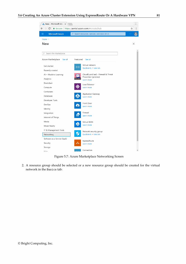
5.6 Creating An Azure Cluster Extension Using ExpressRoute Or A Hardware VPN 81
Figure 5.7: Azure Marketplace Networking Screen
2. A resource group should be selected or a new resource group should be created for the virtualnetwork in the Basics tab:
© Bright Computing, Inc.
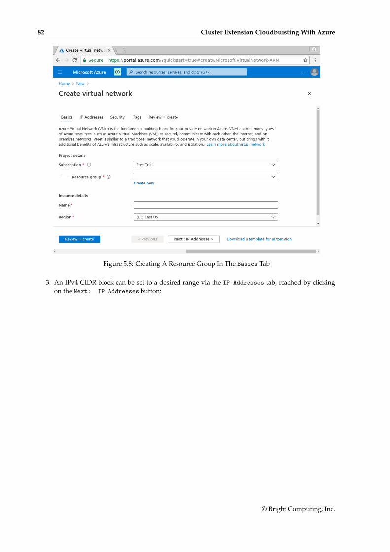
82 Cluster Extension Cloudbursting With Azure
Figure 5.8: Creating A Resource Group In The Basics Tab
3. An IPv4 CIDR block can be set to a desired range via the IP Addresses tab, reached by clickingon the Next: IP Addresses button:
© Bright Computing, Inc.
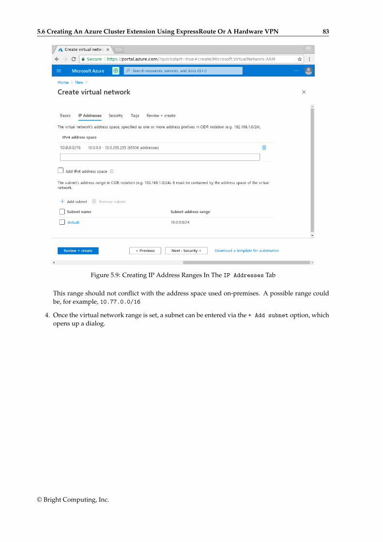
5.6 Creating An Azure Cluster Extension Using ExpressRoute Or A Hardware VPN 83
Figure 5.9: Creating IP Address Ranges In The IP Addresses Tab
This range should not conflict with the address space used on-premises. A possible range couldbe, for example, 10.77.0.0/16
4. Once the virtual network range is set, a subnet can be entered via the + Add subnet option, whichopens up a dialog.
© Bright Computing, Inc.
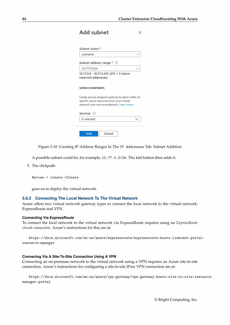
84 Cluster Extension Cloudbursting With Azure
Figure 5.10: Creating IP Address Ranges In The IP Addresses Tab: Subnet Addition
A possible subnet could be, for example, 10.77.0.0/24. The Add button then adds it.
5. The clickpath:
Review + create→Create
goes on to deploy the virtual network.
5.6.2 Connecting The Local Network To The Virtual NetworkAzure offers two virtual network gateway types to connect the local network to the virtual network:ExpressRoute and VPN.
Connecting Via ExpressRouteTo connect the local network to the virtual network via ExpressRoute requires using an ExpressRoutecircuit connection. Azure’s instructions for this are at:
https://docs.microsoft.com/en-us/azure/expressroute/expressroute-howto-linkvnet-portal-resource-manager
Connectng Via A Site-To-Site Connection Using A VPNConnecting an on-premises network to the virtual network using a VPN requires an Azure site-to-siteconnection. Azure’s instructions for configuring a site-to-site IPsec VPN connection are at:
https://docs.microsoft.com/en-us/azure/vpn-gateway/vpn-gateway-howto-site-to-site-resource-manager-portal
© Bright Computing, Inc.
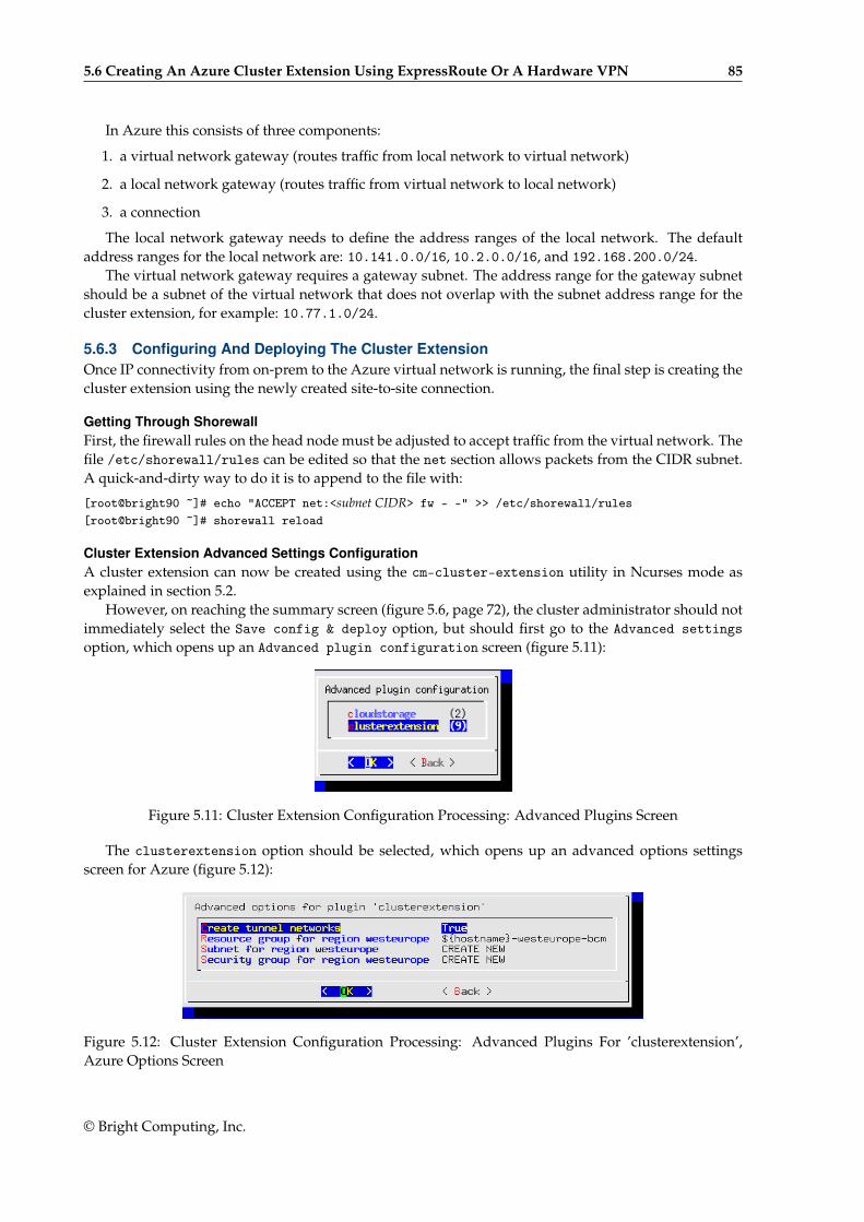
5.6 Creating An Azure Cluster Extension Using ExpressRoute Or A Hardware VPN 85
In Azure this consists of three components:
1. a virtual network gateway (routes traffic from local network to virtual network)
2. a local network gateway (routes traffic from virtual network to local network)
3. a connection
The local network gateway needs to define the address ranges of the local network. The defaultaddress ranges for the local network are: 10.141.0.0/16, 10.2.0.0/16, and 192.168.200.0/24.
The virtual network gateway requires a gateway subnet. The address range for the gateway subnetshould be a subnet of the virtual network that does not overlap with the subnet address range for thecluster extension, for example: 10.77.1.0/24.
5.6.3 Configuring And Deploying The Cluster ExtensionOnce IP connectivity from on-prem to the Azure virtual network is running, the final step is creating thecluster extension using the newly created site-to-site connection.
Getting Through ShorewallFirst, the firewall rules on the head node must be adjusted to accept traffic from the virtual network. Thefile /etc/shorewall/rules can be edited so that the net section allows packets from the CIDR subnet.A quick-and-dirty way to do it is to append to the file with:
[root@bright90 ~]# echo "ACCEPT net:<subnet CIDR> fw - -" >> /etc/shorewall/rules[root@bright90 ~]# shorewall reload
Cluster Extension Advanced Settings ConfigurationA cluster extension can now be created using the cm-cluster-extension utility in Ncurses mode asexplained in section 5.2.
However, on reaching the summary screen (figure 5.6, page 72), the cluster administrator should notimmediately select the Save config & deploy option, but should first go to the Advanced settingsoption, which opens up an Advanced plugin configuration screen (figure 5.11):
Figure 5.11: Cluster Extension Configuration Processing: Advanced Plugins Screen
The clusterextension option should be selected, which opens up an advanced options settingsscreen for Azure (figure 5.12):
Figure 5.12: Cluster Extension Configuration Processing: Advanced Plugins For ’clusterextension’,Azure Options Screen
© Bright Computing, Inc.
86 Cluster Extension Cloudbursting With Azure
In this screen:
• the Create tunnel networks option should be set to False
• the Subnet for region <region> should be set to the subnet that has been created for the clusterextension. The cluster extension is what is being connected to via ExpressRoute or via site-to-siteconnection
The Ncurses advanced settings screens can be backed out of by selecting Back twice. The optionSave config & deploy can then be selected to create the cluster extension.
Cloud Node Certificate AutosigningBy default Bright Cluster Manager does not issue certificates for nodes on the external network. Thismeans that for cloud nodes the certificates need to be issued manually, once for every new cloud node.
Alternatively, to automatically sign certificate requests by cloud nodes, autosign can be enabled bythe administrator for external networks. Autosigning may be a security concern, as this allows anyoneon the external network to request a node certificate. Autosign can be enabled on externalnet in cmsh asfollows:
[root@bright90~]# cmsh[bright90]% network[bright90->network]% set externalnet allowautosign always[bright90->network]% commit
The cluster extension can now be deployed as explained on page 72.
© Bright Computing, Inc.
6Cluster Extension Cloudbursting
With OpenStack6.1 Introduction6.1.1 Cluster Extension In GeneralIf Bright OpenStack is running on a cluster (the host cluster) that a user can access and run OpenStackinstances on, then the user can become an administrator of a local OpenStack Bright cluster instance (theclient cluster) running within the host cluster.
Users, instead of using up resources on their own local client cluster, may sometimes wish to extendinto a second, remote, Bright OpenStack, cluster. This second cluster can then be regarded as a cloudservice host that provides Bright OpenStack services.
This kind of setup is a case of running a cluster within a cloud service.Thus, for this case, the cloud service is provided by Bright OpenStack. Analogous setups where
the cloud service is provided by AWS or Azure can also be managed with Bright Cluster Manager(Chapter 3). In Bright jargon these cluster extension setups are conveniently abbreviated as:
• CX-OS, for cluster extension into OpenStack
• CX-AWS, for cluster extension into Amazon Web Services
• CX-Azure, for cluster extension into Microsoft Azure
This chapter explains cluster extension into OpenStack.
6.1.2 Overview Of Carrying Out Cluster Extension Into OpenStackBright provides a client, cm-cluster-extension, to set up and launch a CX-OS. It is run from the headnode of a client cluster. Bursting in Bright Cluster Manager version 8.2 is possible into Bright ClusterManager host clusters of versions 8.0, 8.1, and 8.2 that are running Bright OpenStack.
The cm-cluster-extension client is provided by default with Bright Cluster Manager as part of thecm-setup package. Its CLI options are covered in Chapter 4.1.
Running it without CLI options is recommended, and brings up an Ncurses dialog, which providesan easier option to deploy a CX-OS (section 6.2).
Another option to deploy CX-OS is via a Bright View wizard (section 6.3).
6.2 Deploying A Cluster Extension Into OpenStack Via An Ncurses DialogThe sequence of screens that follows shows the Ncurses-based procedure for CX-OS deployment. It hassome parallels with the Ncurses-based procedure for CX-AWS deployment (page 45).
Figure 6.1 shows the introductory window after running cm-cluster-extension as root:
© Bright Computing, Inc.
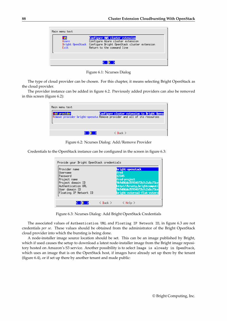
88 Cluster Extension Cloudbursting With OpenStack
Figure 6.1: Ncurses Dialog
The type of cloud provider can be chosen. For this chapter, it means selecting Bright OpenStack asthe cloud provider.
The provider instance can be added in figure 6.2. Previously added providers can also be removedin this screen (figure 6.2):
Figure 6.2: Ncurses Dialog: Add/Remove Provider
Credentials to the OpenStack instance can be configured in the screen in figure 6.3:
Figure 6.3: Ncurses Dialog: Add Bright OpenStack Credentials
The associated values of Authentication URL and Floating IP Network ID, in figure 6.3 are notcredentials per se. These values should be obtained from the administrator of the Bright OpenStackcloud provider into which the bursting is being done.
A node-installer image source location should be set. This can be an image published by Bright,which if used causes the setup to download a latest node-installer image from the Bright image reposi-tory hosted on Amazon’s S3 service. Another possibility is to select Image is already in OpenStack,which uses an image that is on the OpenStack host, if images have already set up there by the tenant(figure 6.4), or if set up there by another tenant and made public:
© Bright Computing, Inc.
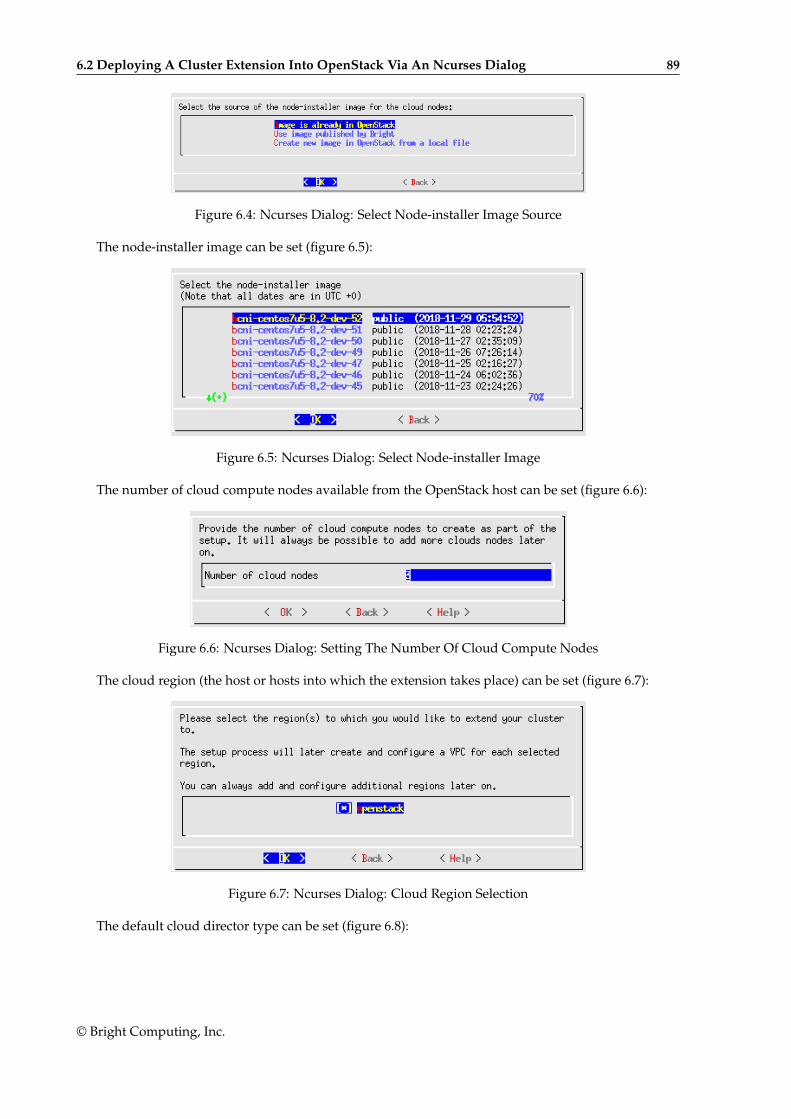
6.2 Deploying A Cluster Extension Into OpenStack Via An Ncurses Dialog 89
Figure 6.4: Ncurses Dialog: Select Node-installer Image Source
The node-installer image can be set (figure 6.5):
Figure 6.5: Ncurses Dialog: Select Node-installer Image
The number of cloud compute nodes available from the OpenStack host can be set (figure 6.6):
Figure 6.6: Ncurses Dialog: Setting The Number Of Cloud Compute Nodes
The cloud region (the host or hosts into which the extension takes place) can be set (figure 6.7):
Figure 6.7: Ncurses Dialog: Cloud Region Selection
The default cloud director type can be set (figure 6.8):
© Bright Computing, Inc.
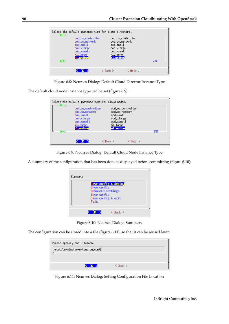
90 Cluster Extension Cloudbursting With OpenStack
Figure 6.8: Ncurses Dialog: Default Cloud Director Instance Type
The default cloud node instance type can be set (figure 6.9):
Figure 6.9: Ncurses Dialog: Default Cloud Node Instance Type
A summary of the configuration that has been done is displayed before committing (figure 6.10):
Figure 6.10: Ncurses Dialog: Summary
The configuration can be stored into a file (figure 6.11), so that it can be reused later:
Figure 6.11: Ncurses Dialog: Setting Configuration File Location
© Bright Computing, Inc.
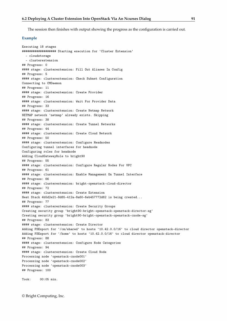
6.2 Deploying A Cluster Extension Into OpenStack Via An Ncurses Dialog 91
The session then finishes with output showing the progress as the configuration is carried out.
Example
Executing 18 stages################### Starting execution for 'Cluster Extension'
- cloudstorage- clusterextension
## Progress: 0#### stage: clusterextension: Fill Out Aliases In Config## Progress: 5#### stage: clusterextension: Check Subnet ConfigurationConnecting to CMDaemon## Progress: 11#### stage: clusterextension: Create Provider## Progress: 16#### stage: clusterextension: Wait For Provider Data## Progress: 33#### stage: clusterextension: Create Netmap NetworkNETMAP network 'netmap' already exists. Skipping## Progress: 38#### stage: clusterextension: Create Tunnel Networks## Progress: 44#### stage: clusterextension: Create Cloud Network## Progress: 50#### stage: clusterextension: Configure HeadnodesConfiguring tunnel interfaces for headnodeConfiguring roles for headnodeAdding CloudGatewayRole to bright90## Progress: 55#### stage: clusterextension: Configure Regular Nodes For VPC## Progress: 61#### stage: clusterextension: Enable Management On Tunnel Interface## Progress: 66#### stage: clusterextension: bright-openstack-cloud-director## Progress: 72#### stage: clusterextension: Create ExtensionHeat Stack 4b5d2e21-8d65-412a-8a60-6eb457772d62 is being created...## Progress: 77#### stage: clusterextension: Create Security GroupsCreating security group 'bright90-bright-openstack-openstack-director-sg'Creating security group 'bright90-bright-openstack-openstack-cnode-sg'## Progress: 83#### stage: clusterextension: Create DirectorAdding FSExport for '/cm/shared' to hosts '10.42.0.0/16' to cloud director openstack-directorAdding FSExport for '/home' to hosts '10.42.0.0/16' to cloud director openstack-director## Progress: 88#### stage: clusterextension: Configure Node Categories## Progress: 94#### stage: clusterextension: Create Cloud NodeProcessing node 'openstack-cnode001'Processing node 'openstack-cnode002'Processing node 'openstack-cnode003'## Progress: 100
Took: 00:05 min.
© Bright Computing, Inc.
92 Cluster Extension Cloudbursting With OpenStack
Progress: 100/100################### Finished execution for 'Cluster Extension', status: completed
Cluster Extension finished!
After the cloud director and associated cloud compute nodes are configured, they can be poweredup (some output elided):
Example
[root@bright90 ~]# cmsh[bright90]% device[bright90->device]% listType Hostname (key) Category Ip Status------------ ------------------- -------------------------------- --------------- ----------CloudNode openstack-cnode001 openstack-cloud-node 172.16.0.1 [ DOWN ]CloudNode openstack-cnode002 openstack-cloud-node 172.16.0.2 [ DOWN ]CloudNode openstack-cnode003 openstack-cloud-node 172.16.0.3 [ DOWN ]CloudNode openstack-director bright-openstack-cloud-director 172.16.255.251 [ DOWN ]...[bright90->device]% power on openstack-directorcloud .................... [ PENDING ] openstack-director (Powering on)Thu Nov 29 18:04:55 2018 [notice] bright90: openstack-director [ PENDING ] (Instance has started)...Thu Nov 29 18:10:33 2018 [notice] bright90: openstack-director [ UP ][bright90->device]% power on -n openstack-cnode00[1-3]cloud .................... [ PENDING ] openstack-cnode001 (Powering on)cloud .................... [ PENDING ] openstack-cnode002 (Powering on)cloud .................... [ PENDING ] openstack-cnode003 (Powering on)...Fri Nov 30 12:55:37 2018 [notice] bright90: openstack-cnode002 [ PENDING ] (Instance has started)Fri Nov 30 12:55:37 2018 [notice] bright90: openstack-cnode001 [ PENDING ] (Instance has started)Fri Nov 30 12:55:37 2018 [notice] bright90: openstack-cnode003 [ PENDING ] (Instance has started)...Fri Nov 30 13:00:33 2018 [notice] bright90: openstack-cnode003 [ UP ]Fri Nov 30 13:00:34 2018 [notice] bright90: openstack-cnode002 [ UP ]Fri Nov 30 13:01:04 2018 [notice] bright90: openstack-cnode001 [ UP ]
6.3 Deploying A Cluster Extension Into An OpenStack Instance Via A BrightView Wizard
Bright View can be used to deploy a cluster extension into OpenStack via a wizard that can be run fromthe clickpath:
Cloud→OpenStack→OpenStack WizardThis then brings up the following display:
© Bright Computing, Inc.
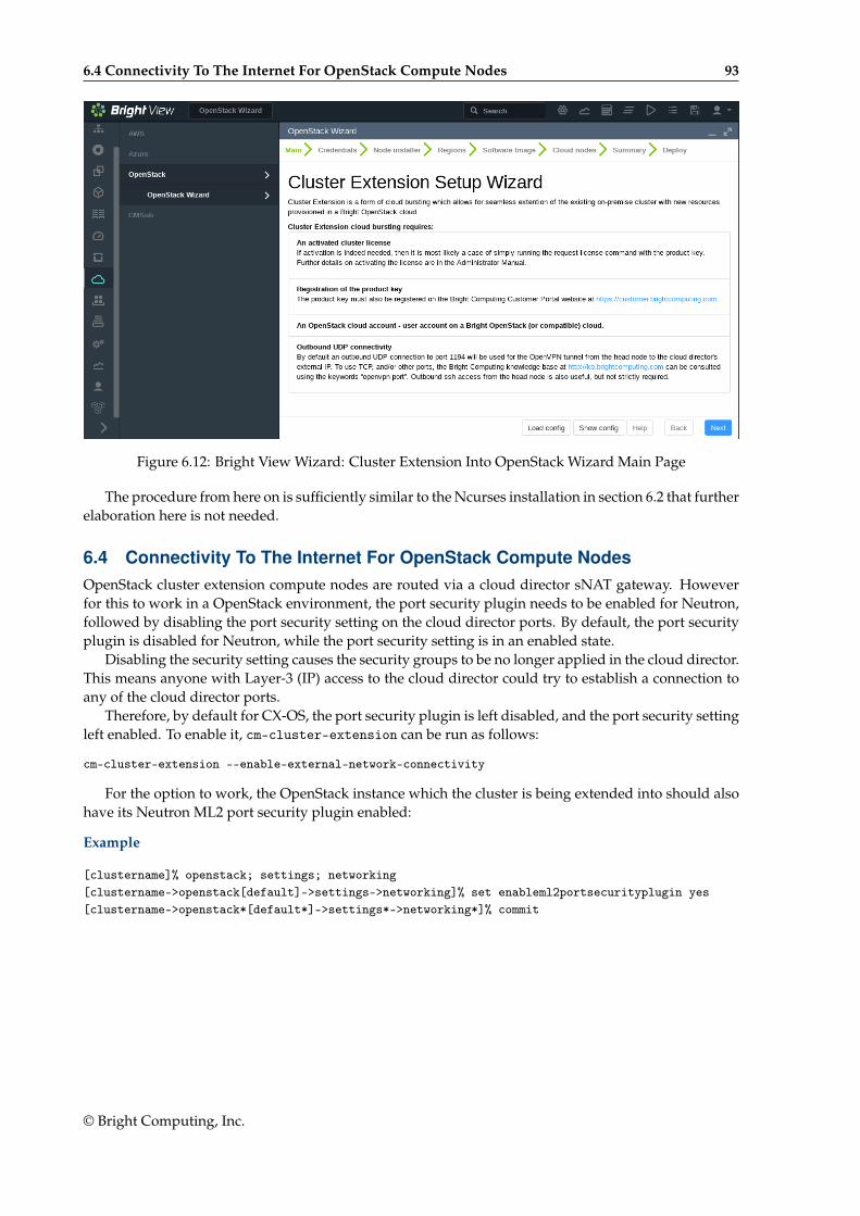
6.4 Connectivity To The Internet For OpenStack Compute Nodes 93
Figure 6.12: Bright View Wizard: Cluster Extension Into OpenStack Wizard Main Page
The procedure from here on is sufficiently similar to the Ncurses installation in section 6.2 that furtherelaboration here is not needed.
6.4 Connectivity To The Internet For OpenStack Compute NodesOpenStack cluster extension compute nodes are routed via a cloud director sNAT gateway. Howeverfor this to work in a OpenStack environment, the port security plugin needs to be enabled for Neutron,followed by disabling the port security setting on the cloud director ports. By default, the port securityplugin is disabled for Neutron, while the port security setting is in an enabled state.
Disabling the security setting causes the security groups to be no longer applied in the cloud director.This means anyone with Layer-3 (IP) access to the cloud director could try to establish a connection toany of the cloud director ports.
Therefore, by default for CX-OS, the port security plugin is left disabled, and the port security settingleft enabled. To enable it, cm-cluster-extension can be run as follows:
cm-cluster-extension --enable-external-network-connectivity
For the option to work, the OpenStack instance which the cluster is being extended into should alsohave its Neutron ML2 port security plugin enabled:
Example
[clustername]% openstack; settings; networking[clustername->openstack[default]->settings->networking]% set enableml2portsecurityplugin yes[clustername->openstack*[default*]->settings*->networking*]% commit
© Bright Computing, Inc.

7Cloud Considerations And
Choices With Bright ClusterManager
7.1 Differences Between Cluster On Demand And Cluster ExtensionSome explicit differences between Cluster On Demand and Cluster Extension clusters are:
Cluster On Demand Cluster Extension
cloud nodes only in 1 region cloud nodes can use many regions
no cloud director uses one or more cloud directors per region
no failover head node failover head node possible
no VPN or NetMap VPN and NetMap
no externalnet interface on head can have an external interface
cluster has publicly accessible IP address cloud directors have publicly accessible IP addresses
A note about the last entry: The access to the cloud director addresses can be restricted to anadministrator-defined set of IP addresses, using the “Externally visible IP” entry in figure 3.1 ofthe Administrator Manual.
7.2 Hardware And Software AvailabilityBright Computing head node AMIs are available for the following distributions: RHEL7 and CentOS7.
AMIs with GPU computing instances are available with Amazon cloud computing services, and canbe used with Bright Computing AMIs with hvm in the name (not xen in the name).
To power the system off, a shutdown -h now can be used, or the power commands for Bright View orcmsh can be executed. These commands stop the instance, without terminating it. Any associated extradrives that were created need to be removed manually, via the Volumes screen in the Elastic BlockStore resource item in the navigation menu of the AWS Management Console.
7.3 Reducing Running Costs
© Bright Computing, Inc.
96 Cloud Considerations And Choices With Bright Cluster Manager
7.3.1 Spot PricingThe spot price field is a mechanism to take advantage of cheaper pricing made available at irregular1
times. The mechanism allows the user to decide a threshold spot price (a price quote) in US dollars perhour for instances. Instances that run while under the threshold are called spot instances. Spot instancesare described further at http://aws.amazon.com/ec2/spot-instances/.
With the pricing threshold set:
• If the set spot price threshold is above the instantaneous spot price, then the spot instances run.
• If the set spot price threshold is below the instantaneous spot price, then the spot instances arekilled.
• If the set spot price threshold is N/A, then no conditions apply, and the instances will run on de-mand regardless of the instantaneous spot price.
An on demand instance is one that runs regardless of the price, according to the pricing at http://aws.amazon.com/ec2/pricing/.
A persistent request is one that will retry running a spot instance if the conditions allow it.
7.3.2 Storage Space ReductionReducing the amount of EBS disk storage used per cloud node or per cloud director is often feasible. 15GB is usually enough for a cloud director, and 5 GB is usually enough for a cloud node with commonrequirements. In cmsh these values can be set with:
Example
[bright90]% device cloudsettings eu-west-1-director[bright90->device[eu-west-1-director]->cloudsettings]% storage[bright90->...->cloudsettings->storage]% set ebs size 15GB; commit[bright90->...->cloudsettings->storage]% device cloudsettings cnode001[bright90->device[cnode001]->cloudsettings]% storage[bright90->...->cloudsettings->storage]% set ebs size 5GB; commit
The value for the cloud node EBS storage can also be set via Bright View, using the clickpath:
Devices→Cloud Nodes→Edit→Settings→Cloud settings→STORAGE→Storage→ebs→Edit→size
7.4 Ignoring Prepaid Node Limits With Pay-Per-Use ImagesBy default a user is restricted by the cloud licence from running more VMs in the cloud than a limit setwithin the license. This is a wise default, because as a general principle cluster administrators wish tokeep costs within a planned budget.
However, there are times when a cluster administrator may wish to ignore this restriction. Ignoringthe restriction is possible—at a price.
A use case for this might be a cluster that uses only a regular amount of cloudbursting most of thetime, but on certain rare days it may need to burst beyond this regular amount.
Another use case might be an IT department that runs a cluster, suddenly finds itself with a largeamount of unused budget, and it turns out that it is sensible to use the budget up on bursting runs.
How to allow bursting past the prepaid limit is described in the following sections for AWS (sec-tion 7.4.1) and for Azure (section 7.4.2).
1irregular turns out to be random within a tight range, bound to a reserve price. Or rather, that was the case during the period20th January–13th July, 2010 that was analyzed by Ben-Yehuda et al, http://www.cs.technion.ac.il/users/wwwb/cgi-bin/tr-info.cgi/2011/CS/CS-2011-09
© Bright Computing, Inc.
7.4 Ignoring Prepaid Node Limits With Pay-Per-Use Images 97
7.4.1 Bursting Past The Prepaid Limit In AWSNode-installer Image Types For AWS Cloud NodesBright Cluster Manager version 9.0 introduced a way to set the node-installer image type for AWS cloudnodes. The possible cloud node node-installer image types provided by Bright Cluster Manager are:
• prepaid image type: a free node-installer image type, used to power on all nodes within the licenselimit.
• pay-per-use image type: a paid node-installer image type, used to power on all nodes beyond thelicense limit. Using this as the node-installer image incurs additional hourly costs for the licensingpart as well as for the AWS infrastructure.
Default Policy For Node-installer Image Type For AWS Cloud NodesA default policy to set the cloud node node-installer image type can be defined at cloud provider levelusing usepaidmarketplaceamis.
Example
[root@bright90 ~]# cmsh[bright90]% cloud[bright90->cloud[amazon]]% showParameter Value-------------------------------- ------------------------------------------------Access key ID *********Account ID 197943594779Billing access key ID < not set >Cloud job tagging noDefault AMI latest:brightinstaller-42Default director type m3.mediumDefault region eu-west-1Default type m3.mediumName amazonRevisionSecret access key *********Secret billing access key < not set >Tags COD_PREFIX=PJ,BCM Bursting=extension,Name=bright90Type ec2Use paid Market place AMIs NEVERUsername krusty-clustersVPCs <1 in submode>[bright90->cloud[amazon]]% set usepaidmarketplaceamis <TAB><TAB>always as_needed never[bright90->cloud[amazon]]% set usepaidmarketplaceamis as_needed[bright90->cloud*[amazon*]]% commit
There are 3 possible values for usepaidmarketplaceamis:
1. never: paid marketplace images are never used. Any attempt to power on any extra cloud nodesbeyond the license limit fails.
2. always: The paid marketplace image is always used when powering on cloud nodes.
3. as_needed: The free image is used as a default so long as the prepaid node count limit has notbeen exceeded. Beyond the prepaid node count limit, all additional cloud nodes use the paidmarketplace image.
It should be noted that once a cloud node is up, and using a paid marketplace image, then itcontinues to run as a paid node, even if the node count goes under the prepaid node count limit
© Bright Computing, Inc.
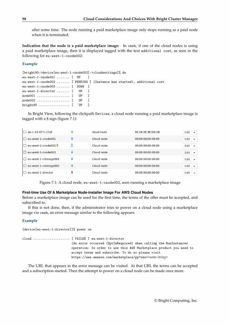
98 Cloud Considerations And Choices With Bright Cluster Manager
after some time. The node running a paid marketplace image only stops running as a paid nodewhen it is terminated.
Indication that the node is a paid marketplace image: In cmsh, if one of the cloud nodes is usinga paid marketplace image, then it is displayed tagged with the text additional cost, as seen in thefollowing for eu-west-1-cnode002:
Example
[bright90->device[eu-west-1-cnode002]->cloudsettings]% dseu-west-1-cnode001 ....... [ UP ]eu-west-1-cnode002 ....... [ PENDING ] (Instance has started), additional costeu-west-1-cnode003 ....... [ DOWN ]eu-west-1-director ....... [ UP ]node001 .................. [ UP ]node002 .................. [ UP ]bright90 ................. [ UP ]
In Bright View, following the clickpath Devices, a cloud node running a paid marketplace image istagged with a $ sign (figure 7.1):
Figure 7.1: A cloud node, eu-west-1-cnode002, seen running a marketplace image
First-time Use Of A Marketplace Node-installer Image For AWS Cloud NodesBefore a marketplace image can be used for the first time, the terms of the offer must be accepted, andsubscribed to.
If this is not done, then, if the administrator tries to power on a cloud node using a marketplaceimage via cmsh, an error message similar to the following appears:
Example
[device[eu-west-1-director]]% power on
cloud .................... [ FAILED ] eu-west-1-director(An error occurred (OptInRequired) when calling the RunInstancesoperation: In order to use this AWS Marketplace product you need toaccept terms and subscribe. To do so please visithttps://aws.amazon.com/marketplace/pp?sku=<some string>
The URL that appears in the error message can be visited. At that URL the terms can be acceptedand a subscription started. Then the attempt to power on a cloud node can be made once more.
© Bright Computing, Inc.
7.4 Ignoring Prepaid Node Limits With Pay-Per-Use Images 99
7.4.2 Bursting Past The Prepaid Limit In AzureNode-installer Image Types For Azure Cloud NodesIn Azure, as for AWS, the possible cloud node node-installer image types provided by Bright ClusterManager are:
• a prepaid image type: a free node-installer image type, used to power on all nodes within thelicense limit.
• pay-per-use image type: a paid node-installer image type, used to power on all nodes beyond thelicense limit. Using this as the node-installer image incurs additional hourly costs for the licensingpart as well as for the Azure infrastructure.
Default Policy For Node-installer Image Type For Azure Cloud NodesIn Azure a default policy to set the cloud node node-installer image type can be defined at cloudprovider level using usepaidmarketplaceimages.
Example
[root@bright90 ~]# cmsh[bright90]% cloud[bright90->cloud[azure]]% showParameter Value-------------------------------- ------------------------------------------------Client ID afe23456-06b9-4241-80a9-17ba71ccb911Client secret *********Default Cloud Director VM Size Standard_D2_v3Default Location germanywestcentralDefault VM Size Standard_D2_v3Default node-installer image https://brightimages.blob.core.windows.net/images/Extensions <1 in submode>Name azureRevisionSubscription ID 2b8fad2b-aaf1-425a-bf45-36cfd495107eTags COD_PREFIX=PJ,BCM Bursting=extensionTenant ID 8cb88849-6e18-46d6-b0fa-551a47a31681Type azureUse paid Marketplace images NEVER
[bright90->cloud[azure]]% set usepaidmarketplaceimages <TAB><TAB>always as_needed never[bright90->cloud[azure]]% set usepaidmarketplaceimages as_needed[bright90->cloud*[azure*]]% commit
In an Azure cloud, just as for the AWS case for usepaidmarketplaceamis, there are 3 possible valuesfor usepaidmarketplaceimages at the cloud provider level:
1. never: paid marketplace images are never used. Any attempt to power on any extra cloud nodesbeyond the license limit fails.
2. always: The paid marketplace image is always used when powering on cloud nodes.
3. as_needed: The free image is used as a default so long as the prepaid node count limit has notbeen exceeded. Beyond the prepaid node count limit, all additional cloud nodes use the paidmarketplace image.
© Bright Computing, Inc.
100 Cloud Considerations And Choices With Bright Cluster Manager
Setting A Node-installer Image For Azure Cloud NodesIt is possible to set an Azure cloud node, for example germanywestcentral-cnode001, to follow a dif-ferent policy by specifying it in the cloudsettings submode within the device mode:
Example
[root@bright90 ~]# cmsh[bright90]% device[bright90->device]% use <TAB><TAB>germanywestcentral-cnode001 germanywestcentral-cnode003 master node002germanywestcentral-cnode002 germanywestcentral-director node001 bright90[bright90->device]% use germanywestcentral-cnode001[bright90->device[germanywestcentral-cnode001]]% cloudsettings[bright90->device[germanywestcentral-cnode001]->cloudsettings]% get usepaidmarketplaceimagesNever (azure)[bright90->device[germanywestcentral-cnode001]->cloudsettings]% set usepaidmarketplaceimages <TAB><TAB>always as needed follow provider never[bright90->device[germanywestcentral-cnode001]->cloudsettings]% set usepaidmarketplaceimages always[bright90->device*[germanywestcentral-cnode001*]->cloudsettings*]% commit
This overrides the policy set at the cloud provider level, until the instance is terminated.
First-time Use Of A Marketplace Image Provided By Bright For Azure Cloud NodesBefore using the Azure marketplace image provided by Bright for the first time, the legal terms of thesubscription must be agreed to. This is done via the Azure CLI.
The Azure CLI must therefore be installed.The agreement process is then carried out by running the following command:
$ az vm image accept-terms --urn <publisher>:<offer>:<sku>:<version>
There are 4 items of information that need to be supplied to the command:
1. publisher: brightcomputing
2. offer:
In order to obtain this item of information, the available offers published by the publisher brightcomputingshould be listed first:
Example
$ az vm image list-offers --location westus --publisher brightcomputing --output table
Location Name---------- ---------------westus bcmni-azure-9-0
From the list, the item corresponding to the version of the product in use should be used. Herethe version is the one corresponding to Bright Cluster Manager version 9.0, and the offer isbcmni-azure-9-0.
3. sku: In a similar way to the previous step, the SKU is listed, and the corresponding version selected:
Example
© Bright Computing, Inc.
7.5 Address Resolution In Cluster Extension Networks 101
$ az vm image list-skus --location westus --publisher brightcomputing --offer bcmni-azure-9-0--output table
Location Name---------- ----------------westus bcm-ni-azure-9-0
Here the SKU is bcm-ni-azure-9-0.
4. version: latest
The agreement command in this case would then be:
Example
$ az vm image accept-terms --urn brightcomputing:bcmni-azure-9-0:bcm-ni-azure-9-0:latest
7.5 Address Resolution In Cluster Extension Networks7.5.1 Resolution And globalnetThe globalnet network is introduced in section 3.2.3 of the Administrator Manual. It allows an extralevel of redirection during node resolution. The reason for the redirection is that it allows the resolutionof node names across the entire cluster in a hybrid cluster, regardless of whether the node is a cloudnode (cloud director node or regular cloud node) or a non-cloud node (head node, regular node ornetworked device). A special way of resolving nodes is needed because the Amazon IP addresses arein the 10.0.0.0/8 network space, which conflicts with some of the address spaces used by Bright ClusterManager.
There are no IP addresses defined by globalnet itself. Instead, a node, with its domain defined bythe globalnet network parameters, has its name resolved by another network to an IP address. Theresolution is done by the nameserver on the head node for all nodes.
7.5.2 Resolution In And Out Of The CloudThe networks, their addresses, their types, and their domains can be listed from the network mode incmsh:
[bright73->network]% list -f name:26,type:12,netmaskbits:8,baseaddress:13,domainname:24name (key) type netmaskb baseaddress domainname-------------------------- ------------ -------- ------------- ------------------------us-east-1 Tunnel 16 172.21.0.0externalnet External 24 192.168.100.0 brightcomputing.comglobalnet Global 0 0.0.0.0 cm.clusterinternalnet Internal 16 10.141.0.0 eth.clusternetmap NetMap 16 172.30.0.0vpc-eu-central-1-private Cloud (VPC) 17 10.42.128.0 vpc-eu-central-1.clustervpc-eu-central-1-public Cloud (VPC) 24 10.42.0.0 vpc-eu-central-1.cluster
In a Type 1 network (section 3.3.9 of the Installation Manual), the head node is connected tointernalnet. When a cloud service is configured, the head node is also “connected” to the CMDaemon-managed NetMap “network”. It is useful to think of NetMap as a special network, although it is actuallya network mapping from the cloud to internalnet. That is, it connects (maps) from the nodes in one ormore cloud networks such as the us-east-1 network provided by Amazon, to IP addresses providedby netmap. The mapping is set up when a cloud extension is set up. With this mapping, packets usingNetMap go from the cloud, via an OpenVPN connection to the NetMap IP address. Once the packetsreach the OpenVPN interface for that address, which is actually on the head node, they are forwardedvia Shorewall’s IPtables rules to their destination nodes on internalnet.
© Bright Computing, Inc.

102 Cloud Considerations And Choices With Bright Cluster Manager
With default settings, nodes on the network internalnet and nodes in a cloud network such asus-east-1 are both resolved with the help of the cm.cluster domain defined in globalnet. For acluster with default settings and using the cloud network us-east-1, the resolution of the IP addressof 1. a regular node and 2. a regular cloud node, takes place as follows:
1. node001, a regular node in the internalnet network, is resolved for node001.cm.cluster to
(a) 10.141.0.1, when at the head node. The cluster manager assigns this address, which is oninternalnet. It could also be an ibnet address instead, such as 10.149.0.1, if InfiniBandhas been configured for the nodes instead of Ethernet.
(b) 172.30.0.1 when at the cloud director or regular cloud node. The cluster manager assignsthis address, which is a NetMap address. It helps route from the cloud to a regular node. It isnot actually an IP address on the interface of the regular node, but it is convenient to think ofit as being the IP address of the regular node.
2. cnode001, a regular cloud node in the us-east-1 network, is resolved for cnode001.cm.clusterto:
(a) 172.21.0.1 when at the head node. The cluster manager assigns this address, which is anOpenVPN tunnel address on us-east-1.
(b) an IP address within 10.0.0.0/8 (10.0.0.1–10.255.255.254) when at a regular cloud node or at acloud director. The Amazon cloud network service assigns the addresses in this network tothe cloud director and regular cloud nodes after it notices the regular cloud node interface isup.
An explanation of the networks mentioned in the preceding list follows:
• The nodes within all available cloud networks (all networks such as for example, us-east-1,us-west-1, and so on) are given CMDaemon-assigned addresses in the cloud node space range172.16.0.0–172.29.255.255. In CIDR notation that is: 172.16.0.0/12 (172.16.0.0–172.31.255.255), ex-cept for 172.31.0.0/15 (172.30.0.0–172.31.255.255).
• The network address space 172.30.0.0/16 (172.30.0.0–172.30.255.255) is taken by the CMDaemon-assigned NetMap network, explained shortly.
• Each node in a cloud network is also assigned an address in the network addressing space pro-vided by Amazon VPC networking. The assignment of IP addresses to nodes within the 10.0.0.0/8range is decided by Amazon via DHCP.
The VPC networks for regular cloud nodes and cloud director nodes are subnets in this range.
• The netmap “network” (figure 7.2) is a helper mapping reserved for use in routing from thecloud (that is, from a cloud director or a cloud node) to a regular node. The mapping uses the172.30.0.0/16 addressing scheme. Its routing is asymmetrical, that is, a NetMap mapping from aregular node to the cloud does not exist. Packets from a regular node to the cloud do howeverresolve to the cloud network as indicated by 2(a) in the preceding.
© Bright Computing, Inc.
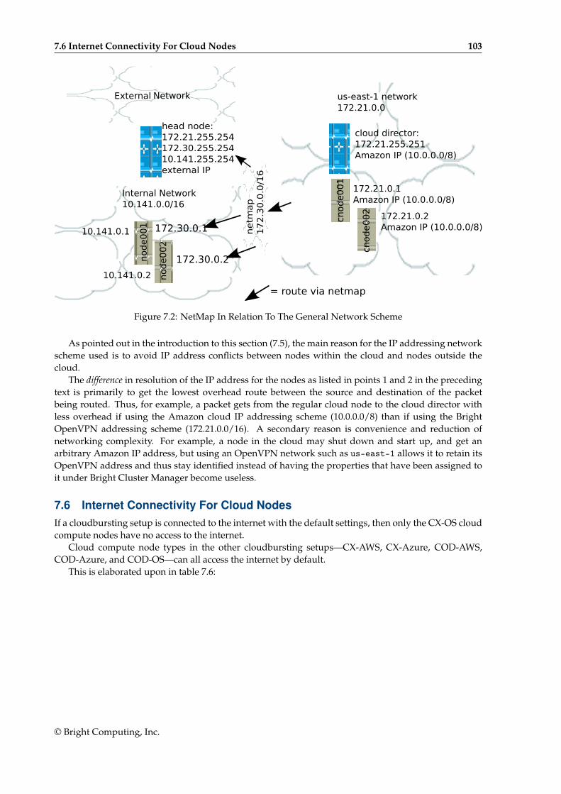
7.6 Internet Connectivity For Cloud Nodes 103
External Network
Internal Network10.141.0.0/16
us-east-1 network172.21.0.0
cloud director:172.21.255.251Amazon IP (10.0.0.0/8)
cnode0
02
cnode0
01
netm
ap
17
2.3
0.0
.0/1
6
node0
01
node0
02
172.21.0.1Amazon IP (10.0.0.0/8)
172.21.0.2Amazon IP (10.0.0.0/8)
head node:172.21.255.254172.30.255.25410.141.255.254external IP
172.30.0.1
172.30.0.2
10.141.0.1
10.141.0.2
= route via netmap
Figure 7.2: NetMap In Relation To The General Network Scheme
As pointed out in the introduction to this section (7.5), the main reason for the IP addressing networkscheme used is to avoid IP address conflicts between nodes within the cloud and nodes outside thecloud.
The difference in resolution of the IP address for the nodes as listed in points 1 and 2 in the precedingtext is primarily to get the lowest overhead route between the source and destination of the packetbeing routed. Thus, for example, a packet gets from the regular cloud node to the cloud director withless overhead if using the Amazon cloud IP addressing scheme (10.0.0.0/8) than if using the BrightOpenVPN addressing scheme (172.21.0.0/16). A secondary reason is convenience and reduction ofnetworking complexity. For example, a node in the cloud may shut down and start up, and get anarbitrary Amazon IP address, but using an OpenVPN network such as us-east-1 allows it to retain itsOpenVPN address and thus stay identified instead of having the properties that have been assigned toit under Bright Cluster Manager become useless.
7.6 Internet Connectivity For Cloud NodesIf a cloudbursting setup is connected to the internet with the default settings, then only the CX-OS cloudcompute nodes have no access to the internet.
Cloud compute node types in the other cloudbursting setups—CX-AWS, CX-Azure, COD-AWS,COD-Azure, and COD-OS—can all access the internet by default.
This is elaborated upon in table 7.6:
© Bright Computing, Inc.
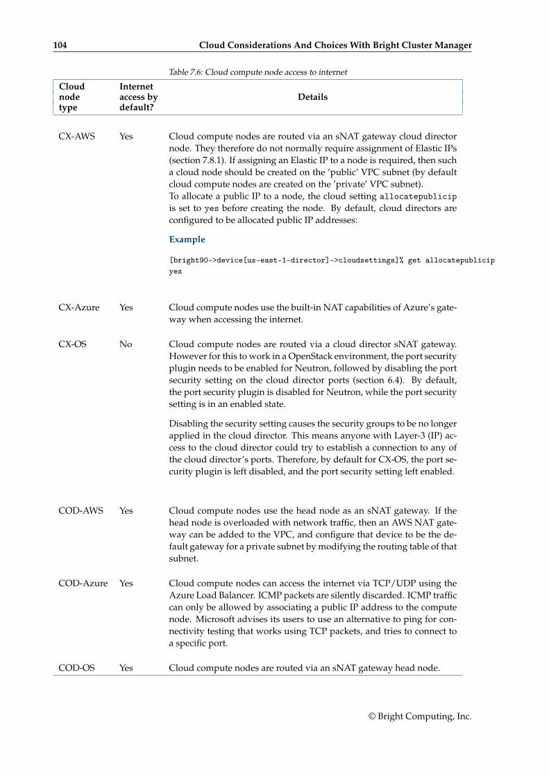
104 Cloud Considerations And Choices With Bright Cluster Manager
Table 7.6: Cloud compute node access to internet
Cloud Internetnode access by Detailstype default?
CX-AWS Yes Cloud compute nodes are routed via an sNAT gateway cloud directornode. They therefore do not normally require assignment of Elastic IPs(section 7.8.1). If assigning an Elastic IP to a node is required, then sucha cloud node should be created on the ’public’ VPC subnet (by defaultcloud compute nodes are created on the ’private’ VPC subnet).To allocate a public IP to a node, the cloud setting allocatepublicipis set to yes before creating the node. By default, cloud directors areconfigured to be allocated public IP addresses:
Example
[bright90->device[us-east-1-director]->cloudsettings]% get allocatepublicipyes
CX-Azure Yes Cloud compute nodes use the built-in NAT capabilities of Azure’s gate-way when accessing the internet.
CX-OS No Cloud compute nodes are routed via a cloud director sNAT gateway.However for this to work in a OpenStack environment, the port securityplugin needs to be enabled for Neutron, followed by disabling the portsecurity setting on the cloud director ports (section 6.4). By default,the port security plugin is disabled for Neutron, while the port securitysetting is in an enabled state.
Disabling the security setting causes the security groups to be no longerapplied in the cloud director. This means anyone with Layer-3 (IP) ac-cess to the cloud director could try to establish a connection to any ofthe cloud director’s ports. Therefore, by default for CX-OS, the port se-curity plugin is left disabled, and the port security setting left enabled.
COD-AWS Yes Cloud compute nodes use the head node as an sNAT gateway. If thehead node is overloaded with network traffic, then an AWS NAT gate-way can be added to the VPC, and configure that device to be the de-fault gateway for a private subnet by modifying the routing table of thatsubnet.
COD-Azure Yes Cloud compute nodes can access the internet via TCP/UDP using theAzure Load Balancer. ICMP packets are silently discarded. ICMP trafficcan only be allowed by associating a public IP address to the computenode. Microsoft advises its users to use an alternative to ping for con-nectivity testing that works using TCP packets, and tries to connect toa specific port.
COD-OS Yes Cloud compute nodes are routed via an sNAT gateway head node.
© Bright Computing, Inc.
7.7 Passing Kernel Parameters To Cloud Nodes 105
7.7 Passing Kernel Parameters To Cloud NodesIf a cluster administrator configures a non-cloud cluster, then kernel parameters can be set for a partic-ular software image used by the regular nodes. For example, in cmsh, if a software image <image name>is used, then kernel parameters such as root=/dev/sda2 rootdelay=10 pti=auto can be set via thenavigation path:
cmsh→softwareimage→use <image name>→set kernelparams "root=/dev/sda2 rootdelay=10 pti=auto"
However, kernel parameters are not passed to cloud nodes via this mechanism at the time of writing(November 2019). If there is a need to pass kernel parameters to cloud nodes, then Bright Computingsupport should be contacted.
7.8 Setting Up And Creating A Custom VPCFrom Bright Cluster Manager version 7.3 onwards, the Amazon EC2-classic platform is no longer avail-able, and all nodes run via Bright Cluster Manager within Amazon always run within an EC2-VPCplatform.
Custom VPC for Bright Cluster Manager 9.0 subnet allocation, and allocation of EIPs (External IPs,public IP addresses) is described in sections 7.8.1–7.8.3.
7.8.1 Elastic IP Addresses And Their Use In Configuring Static IP AddressesAmazon elastic IP addresses (EIPs) can be used to assign a public IP address to a custom VPC.
EIP addresses are the public IP addresses that Amazon provides for the AWS account. These ad-dresses can be associated with custom VPC instances. The public addresses in the set of addresses canthen be used to expose the custom VPC instance. In this manual and in Bright Cluster Manager, EIPsare referred to as “public IPs” in the cloud context. When allocating a public IP address, the exact IPaddress that is allocated is a random IP address from the pool of all public IP addresses made availablein the specified region by the configured cloud provider.
7.8.2 Subnets In A Custom VPCThe components of a custom VPC include subnets, the nodes that run in them, and static IP addresses.The subnets are logical network segments within the network range of that custom VPC. Subnets can bethought of as interconnected with a central “magic” router, with Bright Cluster Manager managing therouting tables on that router. The routing ensures correct subnet communication. Inside Bright ClusterManager, subnets are represented as a type of network (section 3.2 of the Administrator Manual), with avalue for type set in cmsh to Cloud (VPC), or in Bright View set to CLOUD.
Subnets for a custom VPC must have non-overlapping ranges. If there are multiple custom VPCsbeing managed by Bright Cluster Manager, then a particular subnet may be assigned to one customVPC at the most.
Two series of valid network ranges could be:
Example
1. 10.0.0.0-10.0.31.255 (10.0.0.0/19),
10.0.32.0-10.0.63.255 (10.0.32.0/19),
10.0.64.0-10.0.95.255 (10.0.64.0/19).
2. 192.168.0.0-192.168.0.255 (192.168.0.0/24),
192.168.1.0-192.168.1.255 (192.168.1.0/24).
The sipcalc command (page 65 of the Administrator Manual) is a useful tool for calculating appro-priate subnet ranges. At least one subnet must be assigned to a custom VPC before an instance can be
© Bright Computing, Inc.
106 Cloud Considerations And Choices With Bright Cluster Manager
created in that cloud. Typically two or more subnets are assigned, as shown in the custom VPC creationexample in the following section.
7.8.3 Creating The Custom VPCAfter subnets have been configured, a custom VPC can be created by specifying:
• the name
• the default region
• base address
• number of netmask bits
The network of the custom VPC must obviously be a superset of its subnets. Any subnets of thecustom VPC must also be specified. Subnets can be added to or removed from an already-createdcustom VPC, but only if any cloud node instances within them are terminated first.
There are several ways to set up and create the subnets and custom VPC instance in Bright ClusterManager:
1. by using Advanced settings options in the clusterextension plugin options, in the commandline cm-cluster-extension utility (section 4.1),
2. by using the Bright View private cloud creation wizard (section 3.1),
3. by manually creating and configuring the private cloud object using cmsh.
Option 3 is tedious, but does show to the reader some of what the cm-cluster-extension utility andcloud creation wizard do. To create and configure a private cloud as in option 3, the following examplesessions show how a private cloud can be built with cmsh. In the sessions, the subnets to be used for thecustom VPC are created first, before creating the private cloud:
• Subnet creation and cloning: In the following example session, an arbitrary naming scheme isused for subnets, with a pattern of: <name of custom VPC>-sn-<number>. Here, sn is an arbitraryabbreviation for “subnet”:
Example
[bright90->network]% add vpc-0-sn-0[bright90->network*[vpc-0-sn-0*]]% set type cloud[bright90->network*[vpc-0-sn-0*]]% set baseaddress 10.0.0.0[bright90->network*[vpc-0-sn-0*]]% set netmaskbits 24[bright90->network*[vpc-0-sn-0*]]% commit
Once the first subnet has been created, it can be cloned:
Example
[bright90->network]% clone vpc-0-sn-0 vpc-0-sn-1[bright90->network*[vpc-0-sn-1*]]% set baseaddress 10.0.1.0[bright90->network*[vpc-0-sn-1*]]% commit
• Custom VPC creation: The following example session in the vpc submode of the cloud mode,creates a private cloud called vpc-0. The private cloud is actually a custom VPC, and belongs to anetwork that contains the two subnets specified earlier.
© Bright Computing, Inc.

7.8 Setting Up And Creating A Custom VPC 107
Example
[bright90->cloud[Amazon EC2]->vpcs]%[bright90->...->vpcs]% add vpc-0[bright90->...->vpcs*[vpc-0*]]% set region eu-west-1[bright90->...*[vpc-0*]]% set baseaddress 10.10.0.0[bright90->...*[vpc-0*]]% set netmaskbits 16[bright90->...*[vpc-0*]]% set subnets vpc-0-sn-0 vpc-0-sn-1[bright90->...*[vpc-0*]]% commit
© Bright Computing, Inc.
Copyright © 2022 FDOKUMEN