SPACE VECTOR PULSE WIDTH MODULATION BASED INDIRECT VECTOR CONTROL OF INDUCTION MOTOR
Upload
khangminh22Category
view
3download
0
International Journal of Applied Control, Electrical and Electronics Engineering (IJACEEE) Volume 1, Number 1,May 2013
1
FAULTDIAGNOSTIC ANDMONITORINGMETHODSOF INDUCTIONMOTOR: A REVIEW
Partha Sarathee Bhowmik1, Sourav Pradhan2 and Mangal Prakash3
1Department of Electrical Engineering, National Institute of Technology, Durgapur, [email protected]
2 Department of Electrical Engineering, National Institute of Technology, Durgapur,[email protected]
3 Department of Electrical Engineering, National Institute of Technology, Durgapur,[email protected]
ABSTRACT
Induction motors are widely used in transportation, mining, petrochemical, manufacturing and in almostevery other field dealing with electrical power. These motors are simple, efficient, highly robust and ruggedthus offering a very high degree of reliability. But like any other machine, they are vulnerable to faults,which if left unmonitored, might lead to catastrophic failure of the machine in the long run. On-linecondition monitoring of the induction motors has been widely used in the detection of faults. This paperdelves into the various faults and study of conventional and innovative techniques for induction motorfaults with an identification of future research areas.
KEYWORDS
Artificial Neural Networks, Computer Simulation, Data Acquisition, Fast Fourier Transforms, FaultDiagnosis, Fuzzy Logic, Induction Motors, Parameter Estimation, Vibration Measurement, WaveletTransforms
1.INTRODUCTION
Induction motors are the mainstay for every industry. However like any other machine, they willeventually fail because of heavy duty cycles, poor working environment, installation andmanufacturing factors, etc. With escalating demands for reliability and efficiency, the field offault diagnosis in induction motors is gaining importance. If the faults are not prognosticatedbeforehand, it may result in large revenue losses as well as pose threat to reliability and safety ofoperation. However, many methods have been proposed for fault detection and diagnosis, butmost of the methods require a good deal of expertise to apply them successfully. Simplerapproaches are needed to enable even amateurish operators with nominal knowledge of thesystem to scan the fault condition and make reliable decisions.
The induction motor is subjected to primary types of fault and related secondary faults. Fig.1 (a)classifies the sources of induction motor faults. In Fig. 1(b), the internal fault tree is depicted andFig. 1(c) illustrates the external fault tree for an induction motor.
Broadly, an induction motor can develop either internal fault or external fault. With reference tothe origin, a fault may be mechanical or electrical. Fault can be classified as stator fault or rotorfault depending on the location of the fault. Faults associated with the moving parts like bearing

International Journal of Applied Control, Electrical and Electronics Engineering (IJACEEE) Volume 1, Number 1,May 2013
2
and cooling faults are categorized as rotor faults [1]. Specifically, induction motor faults can bebroadly classified into bearing failures, stator faults, rotor faults, air gap eccentricity, mechanicalvibrations, etc. Fig. 2 illustrates the relative probability of occurrences of various faults in aninduction machine [2].
This paper presents a detailed analysis of methods to detect induction motor faults and proposesfuture research areas. Systematic approaches must be exploited to predict incipient machinefaults.
Fig.1(a) Sources of Machine Faults
Fig. 1(b) Block Diagram Presentation of Internal Faults
Fig. 1(c) Block Diagram Representation of External Faults

International Journal of Applied Control, Electrical and Electronics Engineering (IJACEEE) Volume 1, Number 1,May 2013
3
0% 10% 20% 30% 40% 50%
Bearing Faults
Stator Faults
Rotor Faults
Others
Probability of Occurences of Faults
Fig.2. Faults by % in an Induction Motor
A typical diagnosis system [3] shown in Fig. 3 consists of a sensor assembly which providesthe fault signal to a signal processing unit, which further sends its result to be analyzed by expertsystems, where the corresponding fault is ultimately detected.
Fig. 3. On-Line Fault Monitoring of Induction Motor
Condition monitoring and fault diagnostics are usually implemented by investigating thecorresponding anomalies in machine current, voltage and leakage flux. Other methods [4-5]including monitoring the core temperature, bearing vibration level and pyrolyzed products, havebeen reported to diagnose fault conditions such as insulation defects [6], partial discharge [7] andlubrication oil and bearing degradation [8] .
Numerous induction motor fault techniques are based on Fast Fourier Transform SpectralSignature analysis [9-11], vibration analysis [12-13], temperature measurements [14-16],harmonic analysis of speed fluctuations [17-19], state or parameters estimation [20-22], eitheraxial flux or air gap torque analysis [23-25], acoustic noise arrangement [26-27],magnetic field analysis [28-30], fuzzy logic and neural networks [31-33], etc.
2. INDUCTION MOTOR FAULTS
Profound efforts have been devoted to Induction motor fault diagnosis. Depending on the regionof fault occurrence, induction motor faults are mainly put under the following five categories.
2.1. Bearing Faults
Generally, a rolling-element bearing is an arrangement of two concentric rings. A set of balls orrollers spin in raceways between the inner ring and outer ring. Bearing defects [34] may becategorized as “distributed” or “local”. Distributed defects include misaligned races, waviness,surface roughness and off-size rolling elements. Localized defects include spalls, pits and cracks

International Journal of Applied Control, Electrical and Electronics Engineering (IJACEEE) Volume 1, Number 1,May 2013
4
on the rolling surfaces. These localized defects create a series of impact vibrations at the instantwhen a running roller passes over the surface of a defect whose period and amplitude arecalculated by the anomaly’s position, speed and bearing dimension. Mechanical vibrations areproduced by the flawed bearings. These vibrations are at the rotational speed of every component.The bearing dimensions and the rotational speed of the machine are used to determine thecharacteristic frequencies associated to the raceways and the balls or rollers. The condition of thebearing is ascertained by examining these frequencies. This task is accomplished usingmechanical vibration analysis techniques.
2.2. Stator Faults
An induction motor is subjected to various stresses like thermal, electrical, mechanical, andenvironmental [35-37]. Most stator faults can be attributed to such stressful operating conditions.Faults in the stator winding such as turn-to-turn, coil-to-coil, open circuit, phase-to-phase andcoil-to-ground [38], are some of the more prevalent and potentially destructive faults. If leftundetected, these may eventually cause cataclysmic failure of the motor. The three main divisionsdiscussed in [39] of stator faults are the following.
a) Frame :
• Vibration• Circulating currents• Earth faults• Loss of coolants
b) Lamination:
• Core slackening• Core hot spot
c) Stator windings faults:
• End winding portion (turn-to-turn faults , fretting of insulation, local damage toinsulation, damage to connectors, discharge erosion of insulation, displacementof conductors, contamination of insulation by moisture, oil or dirt, cracking ofinsulation and so forth).
• Slot portion (insulation fretting, displacement of conductors).
2.3. Rotor Faults
Rotor faults [40] can be induced by electrical failures such as a bar defect or bar breakage ormechanical failures such as rotor eccentricity. The first fault occurs from thermal stresses, hotspots, or fatigue stresses during transient operations such as start-up, especially in large motors. Abroken bar changes torque significantly and became dangerous to the safety and consistentoperation of electric machines [41]. The second type of rotor fault is related to air gapeccentricity. This fault is a common effect related to a range of mechanical problems in inductionmotors such as load unbalance or shaft misalignment. Long-term load unbalance can damage thebearings and the bearing housing and influence air gap symmetry. Shaft misalignment meanshorizontal, vertical or radial misalignment between a shaft and its coupled load. With shaftmisalignment, the rotor will be displaced from its normal position because of a constant radialforce.

International Journal of Applied Control, Electrical and Electronics Engineering (IJACEEE) Volume 1, Number 1,May 2013
5
2.4. Eccentricity Faults
Unequal air gap between stator and rotor results in eccentricity [42] of induction motor. Ingeneral, air-gap eccentricity can be of two types: the static air-gap eccentricity and the dynamicair-gap eccentricity. A mixture of both forms, called mixed eccentricity [43] and the axial nonuniformity of air gap, known as inclined eccentricity [44] have also been accounted. The minimalradial air-gap length is fixed in space for static air-gap eccentricity. On the contrary, the center ofrotor and the center of rotation do not coincide for dynamic eccentricity. In this case, the positionof minimum air gap is not fixed in space but rotates with the rotor. An erroneous positioning ofthe rotor or stator during the commissioning phase may give rise to static eccentricity. It may alsobe caused by stator core ovality. A cause of dynamic eccentricity can be a bent shaft, bearingwear and movement, or mechanical resonances at critical speeds.
2.5. Vibration Faults
Vibrations are natural processes in induction motors which are caused by the oscillations ofmechanical parts of the motors. These oscillations are reflected in the external system attachedwith the machine shaft. Consequently, machine related frequency spectrum is generated which isunique for a healthy motor. Each fault in the motor changes the frequency component of thespectrum. This can be compared with the reference spectrum to perform fault detection anddiagnosis.
3. FAULT DIAGNOSIS
The spectrum of supply current of an induction motor can be analyzed for the diagnosis of faultsappearing in it. For a healthy motor, there will be no existence of backward rotating field and onlythe forward rotating magnetic field rotates at synchronous speed. In the occurrence of any fault,there will be a resultant backward rotating field in the air gap and the spectrum of stator currentwill change. In Table 1 various frequency components introduced in supply current spectrum dueto faults [45] has been summarized. By monitoring the various frequencies in Table 1, it ispossible to diagnose the corresponding motor faults. Nevertheless, it has been observed [46-47]that these frequency components cannot be treated as exact signs of occurrence of motor faults asthese frequencies can be detected in the spectrum of even healthy motors due to unavoidablemanufacturing symmetries and misalignment etc., Many techniques [48-49] have been proposedand developed over years that provide a good measure of occurrence of faults in inductionmotors.

International Journal of Applied Control, Electrical and Electronics Engineering (IJACEEE) Volume 1, Number 1,May 2013
6
Table 1. Frequency Components of Induction Motor Faults
Faults Frequency
Bearing Fault
rcscbf nfff ±=
±= cos1
2 p
bsbrc D
DfNf
Rotor Fault
( )
±−= s
P
snff scbrf
1
Eccentricity( ) ( )
±−±= smhressce O
P
sOnRff
1
where,
fcbf = components generated by bearing faultsfs = supply frequencyn = 1,2,3… [Integral values]frc = characteristics race frequenciesNb = number of bearing ballsDb = ball diameterDp = bearing pitch diameterθ = contact angle of the ball on the racesfcbrf = components generated by broken rotor faultsP = number of pole-pairss = per-unit slipfce = components associated with eccentricityOre = rotating eccentricity orderOsmh = stator MMF harmonic orderRs = number of rotor slots
3.1. Detection of Bearing Faults
3.1.1. Vibration Spectrum Analysis
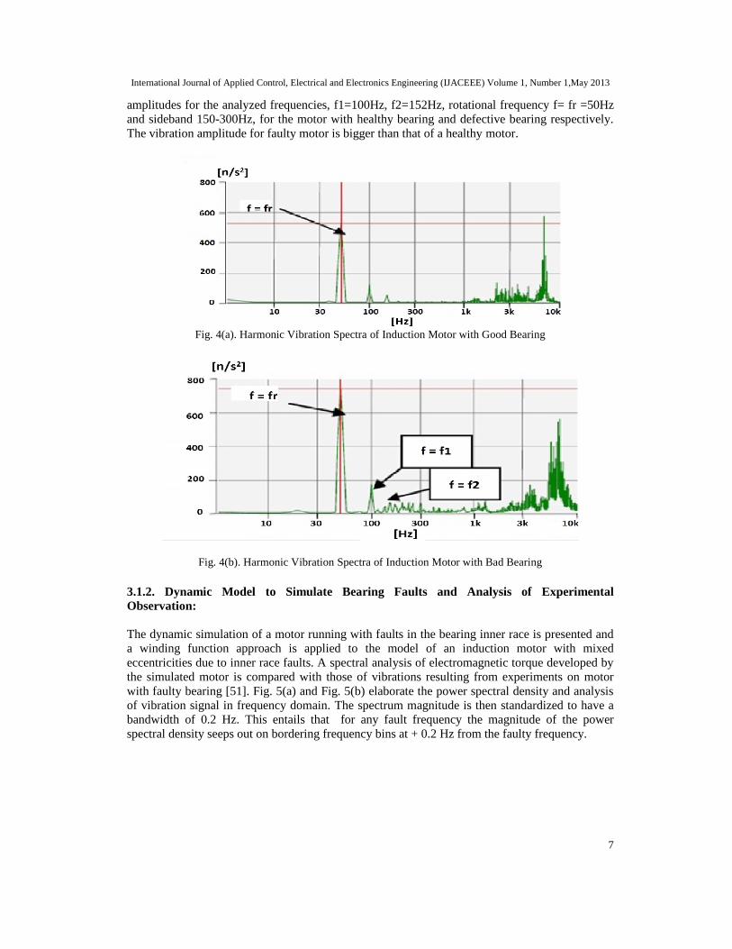
The forces occurring in the rolling element bearing in electrical machines create high frequencycomponents of vibration. During normal conditions, these high frequency components are mainlybecause of friction but in case of a defect in bearings shock pulses can also be found due to breaksin lubrication layer between the friction surfaces. This method analyses the vibration spectrum ofan induction machine using piezoelectric accelerometer which works on Fast Fourier Transformto extract from a time domain signal the frequency domain representation.
For instance, a 0.75 kW induction motor with 6202 ball bearing type having number of balls N= 8, is taken for experimentation [50]. The harmonic vibration spectrum of the healthy motor andthat with defective bearing is analyzed individually. Fig. 4(a) and Fig. 4(b) portray the vibration
International Journal of Applied Control, Electrical and Electronics Engineering (IJACEEE) Volume 1, Number 1,May 2013
7
amplitudes for the analyzed frequencies, f1=100Hz, f2=152Hz, rotational frequency f= fr =50Hzand sideband 150-300Hz, for the motor with healthy bearing and defective bearing respectively.The vibration amplitude for faulty motor is bigger than that of a healthy motor.
Fig. 4(a). Harmonic Vibration Spectra of Induction Motor with Good Bearing
Fig. 4(b). Harmonic Vibration Spectra of Induction Motor with Bad Bearing
3.1.2. Dynamic Model to Simulate Bearing Faults and Analysis of ExperimentalObservation:
The dynamic simulation of a motor running with faults in the bearing inner race is presented anda winding function approach is applied to the model of an induction motor with mixedeccentricities due to inner race faults. A spectral analysis of electromagnetic torque developed bythe simulated motor is compared with those of vibrations resulting from experiments on motorwith faulty bearing [51]. Fig. 5(a) and Fig. 5(b) elaborate the power spectral density and analysisof vibration signal in frequency domain. The spectrum magnitude is then standardized to have abandwidth of 0.2 Hz. This entails that for any fault frequency the magnitude of the powerspectral density seeps out on bordering frequency bins at + 0.2 Hz from the faulty frequency.

International Journal of Applied Control, Electrical and Electronics Engineering (IJACEEE) Volume 1, Number 1,May 2013
8
Fig.5(a). Frequency Spectrum of Electromagnetic Torque of Dynamic Simulation Motor withBearing Fault
Fig.5(b). Characteristic Frequencies in the Spectral Analysis of Vibration of Induction Motorwith Inner Race Bearing Fault
3.2. Detection of Stator Faults
3.2.1. Using Park Vector Approach and Complex Wavelets
The impact of stator fault on machine current can be examined through Park vectortransformation approach. The locus of instantaneous spatial vector sum of the three phase statorcurrents forms the basis for Park’s vector. Generally, a three phase induction motor does notinvolve the connection to the neutral. It only involves the connection with the three phase mains.Hence, the mains current has no homopolar current. A two dimensional representation of threephase current of induction motor can be achieved using Park’s Transform. As a function of mainsphase variable (Ia, Ib, Ic), the Park’s vector components (ID, IQ) are:

International Journal of Applied Control, Electrical and Electronics Engineering (IJACEEE) Volume 1, Number 1,May 2013
9
This maps a circle .This circle has its centre at the origin (0, 0) of the coordinates. This locus isdistorted by stator winding faults and thus provides easy fault diagnosis. Besides making analysisand calculations easier, Park’s Transform scores over traditional methods in terms of beingeconomical, especially for small and medium-sized motors. Also it can diagnose the faultswithout requiring access to motor.
In order to investigate the proposed technique [52], a 3 phase, 4 pole induction motor model with36 stator slots and 55 turns per slot is simulated. The 3 phase supply currents are measured andPark vector currents are calculated using Park’s Transform. Considering no fault in the stator, themotor current’s Park vector is presented in Fig. 6(a). In case of a stator fault, the motor current’sPark vector is shown in Fig. 6(b). The current Park’s vector for a healthy motor corresponds to acircle whereas for a faulty one, the shape distorts to an ellipse depending upon the amount of faultlevel. Simulation and experimental results are finally analyzed using complex wavelets.
Fig.6(a). Motor Current’s Park’s Vector Representation at Healthy Case
Fig.6(b). Motor Current’s Park’s Vector Representation at Faulty Case

International Journal of Applied Control, Electrical and Electronics Engineering (IJACEEE) Volume 1, Number 1,May 2013
10
3.3. Detection of Rotor Faults and Eccentricity
3.3.1. Motor Current Signature Analysis (MCSA)
Current harmonics in the stator current are analyzed by MCSA [53-59]. These harmonics arecaused by new rotating flux components on account of a fault. It needs only one current sensorand is based on signal processing techniques like FFT [60]. The equipment set up for measuringmotor current is shown in Fig. 7. Data acquisition is achieved by performing FFT on the statorcurrent. The data obtained after FFT is normalized as a function of the first harmonic amplitude isthen analyzed. Fig. 8(a) and Fig. 8(b) illustrates FFT with initial condition of rotor bars and with3 broken rotor bars respectively.
Fig.7 Set-Up for Measuring Motor Current
Fig. 8(a) FFT with initial condition for broken bars

International Journal of Applied Control, Electrical and Electronics Engineering (IJACEEE) Volume 1, Number 1,May 2013
11
Fig .8 ( b) FFT with 3 broken bars
Table 2 indicates the percentage amplitude for harmonics with different number of broken rotorbars. Evidently, the harmonic contents increase with increase in fault level i.e. rise of count ofbroken rotor bars.
Table 2. Results of Broken Bar Faults
Frequency(Hz) Amplitude% No. ofBroken Bars
45.25 0.2937 045.25 1.028 145.25 1.83 245.25 1.962 3
Similarly, eccentricity also causes a change in the FFT of induction motor. Fig. 9(a) and Fig. 9(b)illustrate the FFT with initial condition of rotor bars and with 87.3% eccentricity respectively.
Fig. 9 (a) FFT with initial condition of Rotor’s eccentricity

International Journal of Applied Control, Electrical and Electronics Engineering (IJACEEE) Volume 1, Number 1,May 2013
12
Fig. 9 (b) FFT with 87.3% of Rotor’s eccentricity
Table 3 specifies the percentage amplitude for harmonics with varying levels of eccentricity.Markedly, the harmonic contents increase with increase in fault level i.e. increase of eccentricity.
Table 3. Results of eccentricity
Eccentricity (%) Amplitude%0 0.59
44.5 1.9687.3 4.94
3.3.2. Intelligent Techniques
Several Intelligent techniques like Fuzzy logic systems [61-63], Artificial Neural Networks [64-66], Neuro-Fuzzy Systems [67-69] etc. have been elaborately discussed for induction motorcondition monitoring. Usually, any Artificial Intelligence (AI) based diagnostic technique hasthree prime steps- i) Signature extraction ii) Fault detection and iii) Fault severity estimation. InFig. 10, a schematic of Neural Networks for condition monitoring of an induction motor ispresented [70].

International Journal of Applied Control, Electrical and Electronics Engineering (IJACEEE) Volume 1, Number 1,May 2013
13
Fig. 10 Neural Network Schematic for Condition Monitoring of Induction Motor
Apart from these techniques, some other methods for the incipient fault detection of inductionmotor have found a mention in other literature [71-77]. Table 4 presents an elaborate comparisonof several fault detection techniques and the faults generally detected by them.
Table 4. Comparison of various fault detection techniques
Fault Detection Techniques Detected FaultsMCSA Bearing, Rotor, Stator and Vibration Faults
Park’s Transform Bearing and Stator FaultsArtificial Neural Networks Bearing and Rotor Faults
Wavelet Analysis Bearing, Rotor, Stator and Vibration Faults
Finite Element Method Rotor, Stator and Vibration Faults
Vibration Testing and Analysis Bearing and Vibration Faults
Concordia Transform Bearing FaultsExternal Magnetic Field Analysis Rotor Faults
Multiple Reference Frames Theory Eccentricity
Power Decomposition Technique Stator FaultsKU Transformation Theory Stator FaultsZero Crossing Time Method Stator Faults
Modal Analysis Method Vibration Faults

International Journal of Applied Control, Electrical and Electronics Engineering (IJACEEE) Volume 1, Number 1,May 2013
14
4. SCOPE OF FUTURE WORK
Expert systems can be employed for fault diagnosis using rules obtained from the connectionweight of a supervised neural network and rules extracted from heuristic knowledge. Thiscombination of Artificial Neural Networks and expert knowledge may enhance the monitoringsystem for diagnosis.
Moreover, a data base for vibration harmonics using experimental and theoretical investigationsfor various sizes and design standard of three phase induction motors can be created. Through thisdatabase, a new standard for vibration can be established instead of the traditional one, whichdepends upon RMS velocity of vibration rather than harmonic amplitude.
5. CONCLUSION
This paper attempts to summarize recent developments in induction motor fault diagnostics andprognostics. Various techniques, models and algorithms have been analyzed and the suitability of aparticular technique for a specific fault diagnosis has been focused upon in this paper.
REFERENCES
[1] G.K. Singh and Sa’ad Ahmed Saleh Al Kazzaz, “Induction Machine Drive Condition Monitoring andDiagnostic Research-A Survey”, Electric Power Systems Research, vol. 64, pp. 145-158, 2003.
[2] M. L. Sin, W.L.Soong and N.Ertugrul, "Induction Machine On-Line Condition Monitoring and FaultDiagnosis - A Survey", AUPEC2003, Australasian Universities Power Engineering Conference,Christchurch, New Zealand, pp. 1-6, 2003.
[3] Neelam Mehala and Ratna Dahiya “Condition Monitoring and Fault Diagnosis of Induction MotorUsing Motor Current Signature Analysis”, A Ph.D Thesis submitted to the Electrical EngineeringDepartment, National Institute of Technology, Kurushetra, India, October, 2010.
[4] P. J. Tavner and J. Penman, "Condition Monitoring of Electrical Machines", Letchworth, England:Research Studies Press Ltd., 1987.
[5] Shuo Chen, “Induction Machine Broken Rotor Bar Diagnostics Using Prony Analysis”, A Ph.DThesis submitted to the School of Electrical and Electronic Engineering of the University ofAdelaide, April 2008.
[6] Olav Vaag Thorsen and Magnus Dalva, "A survey of Faults on Induction Motors in Offshore OilIndustry, Petrochemical Industry, Gas terminals, and Oil Refineries", IEEE Transactions on IndustryApplications, vol. 31, no. 5, September/October 1995.
[7] William Torbat Thomson and Mark Fenger, "Industrial Application of Current Signature Analysis todiagnose Faults in 3-Phase Squirrel Cage Induction Motors", Pulp and Paper Industry TechnicalConference, Conference Record of 2000 Annual, pp. 205-211, 19-23 June, 2000.
[8] Andrew M.Knight and Sergio P.Bertani, "Mechanical Fault Detection in a Medium-Sized InductionMotor Using Stator Current Monitoring", IEEE Transactions on Energy Conversion, vol. 20, no.4, pp.753-760.
[9] Neelam Mehala and Ratna Dahiya, “Condition Montoring Methods, Failure Identification andAnalysis for Induction Machines”, International Journal of Circuits, Systems and Signal Processing,vol. 3, no. 1, pp. 29-35, 2009.
[10]Mohamed El Hachemi Benbouzid, "A Review of Induction Motors Signature Analysis as a Medium forFaults Detection", IEEE Transactions on Industrial Electronics, vol.47, no.5, pp. 984-993, October2000.
[11] Castelli Marcelo, Juan Pablo Fossatti and Jose Ignacio Terra, "Fault Diagnosis of Induction MotorsBased on FFT", Fourier Transform - Signal Processing, ISBN: 978-953-51- 0453-7, InTech, 2012.
[12] Mounir Djeddi, Pierre Granjon and Benoit Leprettre, "Bearing Fault Diagnosis in Induction MachineBased on Current Analysis Using High-Resolution Technique", Power Electronics and Drives, 2007.

International Journal of Applied Control, Electrical and Electronics Engineering (IJACEEE) Volume 1, Number 1,May 2013
15
SDEMPED 2007. IEEE International Symposium on Diagnostics for Electric Machines,10.1109/DEMPED.2007.4393066, 2007, pp. 23-28, 2012.
[13] Van Tuan Do and Ui-Pil Chong, "Signal Model-Based Fault Detection and Diagnosis for InductionMotors Using Features of Vibration Signal in Two-Dimension Domain", Strojniski vestnik - Journalof Mechanical Engineering, vol. 57, no. 9, pp. 655-666, 2011.
[14] Aderiano M. da Silva, “Induction Motor Fault Diagnostic and Monitoring Methods”, A Thesissubmitted to the Faculty of the Graduate School, Marquette University, Milwaukee, Wisconsin, May2006.
[15] Jordi Cusidó i Roura and Jose Luis Romeral Martínez (2011), "Transient Analysis and Motor FaultDetection using the Wavelet Transform", Discrete Wavelet Transforms - Theory and Applications,Dr. Juuso T. Olkkonen (Ed.), ISBN: 978-953-307-185-5, InTech.
[16] El Houssin El Bouchikhi, Vincent Choqueuse, Mohamed Benbouzid and Jean Fred´ eric Charpentier,"Induction Machine Bearing Failures Detection Using Stator Current Frequency SpectralSubtraction", 2012 IEEE International Symposium on Industrial Electronics (ISIE),10.1109/ISIE.2012.6237265, pp. 1228-1233, 2012 .
[17] B. G. Gaydon, “An instrument to detect induction motor rotor circuit defects by speed fluctuationmeasurements,” in Proc. Electric Test Measuring Instrumentation—Testmex Conf. Paper, pp. 5–8,1979.
[18] J. R. Stack, T. G. Habetler and R. G. Harley, “Effects of machine speed on the development anddetection of rolling element bearing faults,” IEEE Power Electron. Lett., vol. 1, no. 1, pp. 19–21, Mar.2003.
[19] C. J. Diste and R. Schiferl, “Using temperature, voltage, and/or, speed measurements to improvetrending of induction motor rms currents in process control and diagnostics,” in Proc. IEEE IndustryApplications Soc. Annual Meeting Conf., vol. 1, pp. 312–318, 1994.
[20] K. R. Cho, J. H. Lang and S. D. Umans, “Detection of broken rotor bars in induction motors usingstate and parameter estimation,” IEEE Trans. Ind. Appl., vol. 28, no. 3, pp. 702–709, May/Jun. 1992.
[21] F. Filippetti, G. Franceschini, C. Tassoni and P. Vas, “Broken bar detection in induction machines:Comparison between current spectrum approach and parameter estimation approach,” in Proc. IEEEIndustry Applications Soc. Annual Meeting Conf., Denver, vol. 1, pp. 95-102, 1994.
[22] P. Vas, "Parameter Estimation, Condition Monitoring, and Diagnosis of Electrical Machines",Oxford, U.K.: Clarendon, 1993.
[23] J. Penman, H. G. Sedding, B. A. Lloyd and W. T. Fink, “Detection and location of interturn shortcircuits in the stator windings of operating motors,” IEEE Trans. Energy Convers., vol. 9, no. 4, pp.652– 658, Dec.1994.
[24] H. Henao, C. Demian and G. A. Capolino, “A frequency-domain detection of stator winding faults ininduction machines using an external flux sensor,” IEEE Trans. Ind. Appl., vol. 39, no. 5, pp. 1272–1279, Sep./Oct. 2003.
[25] J. F. Bangura, R. J. Povinelli, N. A. O. Demerdash and R. H. Brown, “Diagnostics of eccentricitiesand bar/end-ring connector breakages in polyphase induction motors through a combination of time-series data mining and time-stepping coupled FE- state-space techniques,” IEEE Trans. Ind. Appl.,vol. 39, no. 4, pp. 1005–1013, Jul./Aug. 2003.
[26] A. Ganguly, Manoj K Kowar and H. Chandra, "Preventive Maintenance of Rotating Machines UsingSignal Processing" Techniques", International Journal of Soft Computing and Engineering (IJSCE)ISSN: 2231-2307, vol.2, no. 2, May 2012.
[27] J. Ellison , C. J. Moore and S. J. Yang, “Methods of measurement of acoustic noise radiated by anelectric machine”, Proceeding of IEEE, pp. 174-184, 1971.
[28] J.Faiz and B.M.Ebrahimi, "Mixed Fault Diagnosis in Three-Phase Squirrel-Cage Induction MotorUsing Analysis of Air-Gap Magnetic Field", Progress In Electromagnetics Research (PIER), vol. 64,pp. 239–255, 2006.
[29] A. M.Trzynadlosky, “Diagnostic of mechanical abnormalities in induction motor using instantaneouselectrical power”, Conference Proceedings of The 1997 International Electric Machines and Drives,pp. 91–93, 1997.
[30] A. Ceban, V. Fireteanu, R. Romary, R. Pusca and P. Taras, "Finite Element Diagnosis of RotorFaults in Induction Motors based on Low Frequency Harmonics of the Near-Magnetic Field", PowerElectronics & Drives (SDEMPED), 2011 IEEE International Symposium on Diagnostics for ElectricMachines, 10.1109/DEMPED.2011.6063623, 2011, pp. 192-198.

International Journal of Applied Control, Electrical and Electronics Engineering (IJACEEE) Volume 1, Number 1,May 2013
16
[31] P. Vas, Artificial—Intelligence-Based Electrical Machines and Drives: Applications of Fuzzy, Neural,Fuzzy-Neural and Genetic Algorithm Based Techniques. New York: Oxford Univ. Press, 1999.
[32] M. Y. Chow, Methodologies of Using Neural Network and Fuzzy Logic Technologies for MotorIncipient Fault Detection, Singapore: World Scientific, 1997.
[33] F. Zidani, M. E. H. Benbouzid, D. Diallo and M. S. Nait-Said, “Induction motor stator faultsdiagnosis by a current Concordia pattern-based fuzzy decision system,” IEEE Trans. EnergyConvers., vol. 18, no. 4, pp. 469–475, Dec. 2003.
[34] Jafar Zarei, Javad Poshtan, “Bearing Fault Detection In Induction Motor Using Pattern RecognitionTechniques”, 2nd IEEE International Conference on Power and Energy (PECon 08), December 1-3,2008, Johor Baharu, Malaysia, pp. 749-753.
[35] A. H. Bonnet, “Cause and analysis of stator and rotor failures in threephase squirrel-cage inductionmotors,” IEEE Trans. Ind. Appl., vol. 28, no. 4, pp. 921–437, Jul./Aug. 1992.
[36] A. H. Bonnett and G. C. Soukpup, “Rotor failures in squirrel cage induction motors,” IEEE Trans.Ind. Appl., vol. IA-22, no. 6, pp. 1165–1173,Nov./Dec.1986.
[37] P. J. Tanver and J. Penman, "Condition Monitoring Electrical Machines", Hertfordshire, U.K.:Research Studies Press, 1987.
[38] M.Arkan, D.K.PeroviC and Punsworth, “Online stator fault diagnosis in induction motors”, IEEEProc-Electr. Power Appl. vol. 148, no. 6, November 2001.
[39] Arfat Siddhiqui, G.S.Yadava and Bhim Singh, "A Review of Stator Fault Monitoring Techniques ofInduction Motors", IEEE Transactions on Energy Conversion, vol.20, no.1, March 2005.
[40] S. Hamdani, O. Touhami, R. Ibtiouen and M. Fadel, “Neural Network technique for induction motorrotor faults classification –Dynamic eccentricity and broken bar faults”, Power Electronics & Drives(SDEMPED), 2011 IEEE International Symposium on Diagnostics for Electric Machines,10.1109/DEMPED.2011.6063689, 2011, pp. 626-631.
[41] A. H. Bonnett ‘Root Cause AC Motor Failure Analysis with a Focus on Shaft Failures’ IEEEtransactions on industry applications, vol. 36, no. 5, september/october 2000.
[42] Subhasis Nandi, Thirumarai Chelvan Ilamparithi, Sang Bin Lee and Doosoo Hyun, “Detection ofEccentricity Faults in Induction Machines Based on Nameplate Parameters”, IEEE Transactions onIndustrial Electronics, vol. 58, no. 5, May 2011.
[43] S. Nandi, R. M. Bharadwaj, and H. A. Toliyat, “Performance analysis of a three phase inductionmotor under incipient mixed eccentricity condition,” IEEE Trans. Energy Convers., vol. 17, no. 3, pp.392–399, Sep. 2002.
[44] X. Li, Q. Wu, and S. Nandi, “Performance analysis of a three-phase induction machine with inclinedstatic eccentricity,” IEEE Trans. Ind. Appl., vol. 43, no. 2, pp. 531–541, Mar./Apr. 2007.
[45] Pedro Vicente Jover Rodriguez, Marian Negrei and Antero Arkkio, “A General Scheme for InductionMotorCondition Monitoring”, SDEMPED 2005, International Symposium on Diagnostics forElectric Machines, Power Electronics and Drives Vienna, Austria, 7-9 September 2005.
[46] G.B. Kliman, R.A.Koegl, J.Stein and R.D.Endicott, “Noninvasive Detection of Broken Rotor Bars inOperating Induction Motors”, IEEE Trans. Energy Conversion, vol. 3, pp. 873-879, December 1988.
[47] Joksimovic G.M. and Penman J., “ The Detection of Inter-Turn Short Circuits in the Stator Windingof Operating Motors”, IEEE Transactions on Industrial Applications, vol. 47, no. 5, pp. 1078-1084,October 2000.
[48] Lovi Kaushal Agrawal and SBL Tripathi, "Study of Fault Detecting Techniques in ElectricalMachine", VSRD-IJEECE, vol. 1, no. 8, pp. 478-489, 2011.
[49] YE Zhongming and WU Bin, "A Review on Enduction Motor Online Fault Diagnosis”, The ThirdInternational Power Electronics and Motion Control Conference, 2000, Proceedings. IPEMC 2000,10.1109/IPEMC.2000.883050 , vol.3, pp. 1353-1358, 2000.
[50] Mariana Iorgulescu, Robert Beloiu, “Vibration and Current Monitoring for Fault’s Diagnosis ofInduction Motors”, Annals of the University of Craiova, Electrical Engineering series, no. 32, ISSN1842-4805, 2008.
[51] Dr. Ariunbolor Purvee and Dr. Gautam Banerjee, “Dynamic Simulation and Experimental Results ofBearing Faults of Squirrel Cage Induction Motor”, 2012 IEEE International Conference on ConditionMonitoring and Diagnosis, 23-27 September 2012, Bali, Indonesia, pp. 718-722.
[52] Dionysios V. Spyropoulos and Epaminondas D. Mitronikas,”Induction Motor Stator Fault DiagnosisTechnique Using Park Vector Approach and Complex Wavelets”, Electrical Machines (ICEM), 2012XXth International Conference on, 2-5 September, pp. 1730-1734, 2012.

International Journal of Applied Control, Electrical and Electronics Engineering (IJACEEE) Volume 1, Number 1,May 2013
17
[53] Ruiming Fang and Hongzhong Ma, "Application of MCSA and SVM to Induction Machine RotorFault Diagnosis", Proceedings of the 6th World Congress on Intelligent Control and Automation, June21 - 23, 2006, Dalian, China.
[54] Chiara Boccaletti, Claudio Bruzzese, Onorato Honorati and Ezio Santini, "Rotor Bars Breakage inRailway Traction Squirrel Cage Induction Motors and Diagnosis by MCSA Technique Part II :Theoretical Arrangements for Fault-Related Current Sidebands", SDEMPED 2005 - InternationalSymposium on Diagnostics for Electric Machines, Power Electronics and Drives, Vienna, Austria, 7-9September 2005.
[55] A Alwodai, F Gu and A D Ball, "A Comparison of Different Techniques for Induction Motor RotorFault Diagnosis", 25th International Congress on Condition Monitoring and Diagnostic Engineering,IOP Publishing, Journal of Physics: Conference Series 364, 012066, 2012.
[56] Neelam Mehala and Ratna Dahiya, "Motor Current Signature Analysis and its Applications inInduction Motor Fault Diagnosis", International Journal of Systems Applications, Engineering &Development, vol. 2, no. 1, 2007.
[57] Alan Miletic and Mirko Cettolo, "Frequency Converter Influence on Induction Motor Rotor FaultsDetection Using Motor Current Signature Analysis – Experimental Research", Symposium onDiagnostics for Electric Machines, Power Electronics and Drives, Atlanta, GA, USA, 24-26 August2003.
[58] D. M. Sonje and R. K. Munje, "Rotor Cage Fault Detection in Induction Motors by Motor CurrentSignature Analysis", IJCA Proceedings on International Conference in Computational Intelligence(ICCIA2012), no. 2, 2012.
[59] S.Guedidi, S.E.Zouzou, W.Laala, M.Sahraoui and K.Yahia, "Broken Bar Fault Diagnosis of InductionMotors Using MCSA and Neural Network", 8th IEEE Symposium on Diagnostics for ElectricalMachines Power Electronics Drives, no. 1, pp. 632-637, 2011.
[60] José Ignacio Terra, Marcelo Castelli, Juan Pablo Fossati, Marcos Andrade, Analía Conde and MiguelMartínez-Iturralde, “Faults Detection and Remote Monitoring System for Induction Motors usingMCSA Technique”.
[61] Sinan Altug, Mo-Yuen Chow and H. Joel Trussell, "Fuzzy Inference Systems Implemented on NeuralArchitectures for Motor Fault Detection and Diagnosis", IEEE Transactions on Industrial Electronics,vol. 46, no. 6, December 1999.
[62] Fatiha Zidani, Demba Diallo, Mohamed El Hachemi Benbouzid and Rachid Naït-Saïd, "A Fuzzy-Based Approach for the Diagnosis of Fault Modes in a Voltage-Fed PWM Inverter Induction MotorDrive", IEEE Transactions on Industrial Electronics, vol. 55, no. 2, February 2008.
[63] Mohamed A. Awadallah and Medhat M. Morcos, "Application of AI Tools in Fault DiagnosisofElectrical Machines and Drives—An Overview", IEEE Transactions on Energy Conversion, vol.18, no. 2, June 2003.
[64] Paul V. Goode and MO-pen Chow, "Using a Neural/Fuzzy System to Extract Heuristic Knowledgeof Incipient Faults in Induction Motors: Part I-Methodology", IEEE Transactions on IndustrialElectronics, vol. 42, no. 2, April 1995.
[65] Mo-yuen Chow, Robert N. Sharpe, and James C. Hung, "On the Application and Design of ArtificialNeural Networks for Motor Fault Detection-Part I", IEEE Transactions on Industrial Electronics, vol.40, no. 2, April 1993.
[66] Arfat Siddique, G.S.Yadava and Bhim Singh, "Status Review On Neural / Fuzzy Logic TechniquesFor Induction Motor Condition Monitoring".
[67] Y.Zhongming, W.Bin and A.R.Sadeghian, "Electrical Machine Fault Detection using AdaptiveNeuro-Fuzzy Inference", Proceedings in Joint 9th IFSA World Congress and 20th NAFIPS WorldCongress, pp.390-394, 2001.
[68] R.M.Tallam, T.G.Habetler and R.G.Harley, “Continual on-line training of neural networks withapplications in electric machines fault diagnosis", IEEE 32nd Power Electronics SpecialistsConference, pp.2224-2228, 2001.
[69] D.T.Pham and P.T.N.Pham, "Artificial Intelligence in Engineering", Intl. J. of Machine Tools &Manufacture, vol.39, pp. 937-949, 1999.
[70] Vilas N. Ghate and Sanjay V. Dudul, "Optimal MLP neural network classifier for fault detection ofthree phase induction motor", Expert Systems with Applications, vol.37, pp. 3468–3481, 2010.
[71] Izzet Y O¨ Nel, K Burak Dalci and I˙Brahim Senol, “Detection of bearing defects in three-phaseinduction motors using Park’s transform and radial basis functionneural networks”, Sadhana vol. 31,Part 3, June 2006, pp. 235–244, June 2006.

International Journal of Applied Control, Electrical and Electronics Engineering (IJACEEE) Volume 1, Number 1,May 2013
18
[72] Izzet Yilmaz O¨ nel and Mohamed El Hachemi Benbouzid, “Induction Motor Bearing FailureDetection and Diagnosis: Park and Concordia Transform Approaches Comparative Study”,IEEE/ASME Transactions on Mechatronics, vol. 13, no. 2, April 2008.
[73] Kyusung Kim and Alexander G. Parlos, “Induction Motor Fault Diagnosis Based on Neuropredictorsand Wavelet Signal Processing”, IEEE/ASME Transactions on Mechatronics, vol. 7, no. 2, June 2002.
[74]S. M. A. Cruz, H. A. Toliyat and A. J. M. Cardoso “Diagnosis of Stator, Rotor and Airgap EccentricityFaults in Three-Phase Induction Motors Based on the Multiple Reference Frames Theory”, IndustryApplications Conference, 2003. 38th IAS Annual Meeting, 2003 , 10.1109/IAS.2003.1257725, Vol.2, pp. 1340-1346.
[75] Andrian Ceban, Remus Pusca, and Raphaël Romary, “Study of Rotor Faults in Induction MotorsUsing External Magnetic Field Analysis”, IEEE Transactions on Industrial Electronics, vol. 59, no. 5,May 2012.
[76] Hongzhong Ma, Huamin Li, Weifang Xie and Fen Chen, “Vibration Research on Winding Faults ofInduction Motor Based on Experiment Modal Analysis Method”, Hohai University, Nanjing, 210098,China. International Power Engineering Conference, 2007. IPEC 2007, 2007, pp. 366-370
[77] F. Babaa, A. Khezzar, M. Boucherma, A. L. Nemmour , “Condition monitoring of stator faults ininduction motors: Part I— Analytical investigation on the effect of the negative voltage Sequence”,ACEMP '07, International Aegean Conference on Electrical Machines and Power Electronics, 2007.10.1109/ACEMP.2007.4510503, 2007, pp. 205-210.
Authors
Partha S. Bhowmik (M’03) received the B.E. degree in Electrical Engineering fromNational Institute of Technology, Agartala, India in 2000, and the M. Tech. degree fromthe University College of Technology, University of Calcutta, India in 2002.Currently, heis employed as an Assistant Professor in Electrical Engineering Department, NationalInstitute of Technology, Durgapur. His current research includes in energy systemengineering and advanced signal processing applications in electrical machines & powersystem engineering.
Sourav Pradhan was born in Midnapore, India in 1992. He is pursuing B.Tech Degree inElectrical Engineering from National Institute of Technology Durgapur. His currentresearch interests include Electrical Machines, Power Systems, Control Systems,Embedded Systems and Power Electronics.
Mangal Prakash was born in Ara, India in 1992. He is pursuing B.Tech Degree inElectrical Engineering from National Institute of Technology Durgapur. His currentresearch interests include Electrical Machines, Power Systems and Control Systems.
Copyright © 2022 FDOKUMEN