Output Current Regulation with PWM Inverter--Induction Motor Drives
9
IEEE TRANSACTIONS ON INDUSTRY APPLICATIONS, VOL. IA-1l, NO. 5, SEPTEMBER/OCTOBER 1975 Output Current Regulation with PWM Inverter-induction Motor Drives JANIES B. FORSYTHE, MEMBER, IEEE, AND S. B. DEWAN, MEMBER, IEEE Abstract-Current regulation plays an important part in the protec- tion of solid-state drives operating from stiff voltage sources. Certain types of pulsewidth modulated (PWM) inverters, however, are not directly suited for peak or average output current regulation with induction motor loading. It is established in the paper that the typical output voltage response times of defined voltage waveform PWM inverters are 1) too high for peak output current regulation, and 2) too low for average output current regulation-i.e., for stable current regulation, the control system must limit the rate of inverter output voltage reduction. Inverter voltage control requirements and inverter deratings necessary to implement average output current regulation are presented. Experimental results from a 15-hp bread- board are included. NOMENCLATURE Ed, Inverter dc bus supply voltage. ZV state Inverter output voltages Vab,Vbc,Vca = 0; SCR's (1,3,5) or (4,6,2) are gated. FV state Within the 1200 envelopes, inverter output voltages Vab,Vbc,Vca = ±EdC; SCR's (1,6,5), (1,3,2), (1,6,2),(4,3,2), (4,3,5), or (4,6,5) are gated. Tp AMultipulse (chopping frequency) period. T,0 Induction motor short circuit time constant. Tr Inverter output voltage pulsewidth ramp period. ia1 Average load current. iar Average load current reference. ip, Load phase current (noninductive shunt). ip8 Load phase current (Hall effect transducer). vpw Inverter voltage (pulsewidth) control signal. vpwl Inverter voltage required to maintain the average load current at the reference value. ur Inverter output voltage reference. fr Fundamental frequency reference. ft Fundamental frequency limit. fi Inverter fundamental frequency control signal. rp Multipulse (chopping) frequenev. Iavl Average current limit, voltage regulated. Ipk Peak load current limit. Iaf Average current limit, frequency regulated. Vdc de generator armature voltage. idc de generator armature current. Paper TOD-75-52, approved by the Power Semiconductor Com- mittee of the IEEE Industry Applications Society for presentation at the 1974 Ninth Annual Meeting of the IEEE Industry Applica- tions Society, Pittsburgh, Pa., October 7-10. Manuscript released for publication May 5, 1975. J. B. Forsythe is with AiResearch Manufacturing Company, Division of Garrett Corporation, Torrance, Calif. 90509. S. B. Dewan is with the Department of Electrical Engineering, University of Toronto, Toronto, Ont., Canada M5S 1A4. I. INTRODUCTION CIURRENT regulation offers numerous advantages for inverter-induction miotor drives. The induction motor presents highly current sensitive inverters with a loading that is wide ranige and capable of rapid change. It is im- portant that the current be regulated to limit both voltage and current ratings. A variable-frequency pulsewidth modulated (PWM) inverter-squirrel-cage induction motor drive which is self- protecting for a number of overload conditions is pre- sented in this paper. Specifically, the characteristics of high speed output current regulation using voltage modu- lation are reported. The minimum objectives of overload protection for variable-frequency ac motor drives are twofold [11: 1) to protect the inverter from "shoot through" due to commu- tation failure and component overheating due to high current levels, and 2) to provide the comparable solid- state dc motor drive performance under overload con- ditions. Variable-frequency inverters differ widely in current regulation capability. Current source inverters, such as those with a large series inductance in the dc bus [2], [31, have an "inherently current limited" characteristic. Certain voltage source inverters, such as the dc side commutated inverter [4], readily handle overloads by simply commutating all load SCR's off whenever the load current approaches the commutation limnit. Other voltage source inverters, particularly PWM in- verters using the McMurray-Bedford commutation cir- cuits, cannot rapidly turn all of the load SCR's off and on to regulate the peak load current below the commutation limit. These inverters are not inherently current limited but are characterized by a relatively low output voltage response time. This paper shows that the low response time can be used to provide a quasi inherently current limited or current source characteristic for PWM in- verters with induction motor loading. All of the experimental results are derived from a 30- kVA complementary cominutated inverter (CCI)-15-hp, 220-V four-pole design class B squirrel-cage induction motor drive coupled to a 7k-hp dc generator. In Section II, the low response time characteristics of PWM inverters and induction motors that are important to current regulation are described. Section III details the limitations of peak output current regulation for one class of inverters. A voltage supervised average current regu- lator is described in Section IV, and the performance of a 517
-
Upload
independent -
Category
Documents
-
view
3 -
download
0
Transcript of Output Current Regulation with PWM Inverter--Induction Motor Drives

IEEE TRANSACTIONS ON INDUSTRY APPLICATIONS, VOL. IA-1l, NO. 5, SEPTEMBER/OCTOBER 1975
Output Current Regulation with PWMInverter-induction Motor Drives
JANIES B. FORSYTHE, MEMBER, IEEE, AND S. B. DEWAN, MEMBER, IEEE
Abstract-Current regulation plays an important part in the protec-tion of solid-state drives operating from stiff voltage sources. Certaintypes of pulsewidth modulated (PWM) inverters, however, are notdirectly suited for peak or average output current regulation withinduction motor loading. It is established in the paper that thetypical output voltage response times of defined voltage waveformPWM inverters are 1) too high for peak output current regulation,and 2) too low for average output current regulation-i.e., for stablecurrent regulation, the control system must limit the rate of inverteroutput voltage reduction. Inverter voltage control requirements andinverter deratings necessary to implement average output currentregulation are presented. Experimental results from a 15-hp bread-board are included.
NOMENCLATURE
Ed, Inverter dc bus supply voltage.ZV state Inverter output voltages Vab,Vbc,Vca = 0; SCR's
(1,3,5) or (4,6,2) are gated.FV state Within the 1200 envelopes, inverter output
voltages Vab,Vbc,Vca = ±EdC; SCR's (1,6,5),(1,3,2), (1,6,2),(4,3,2), (4,3,5), or (4,6,5) are
gated.Tp AMultipulse (chopping frequency) period.T,0 Induction motor short circuit time constant.Tr Inverter output voltage pulsewidth ramp
period.ia1 Average load current.iar Average load current reference.ip, Load phase current (noninductive shunt).ip8 Load phase current (Hall effect transducer).vpw Inverter voltage (pulsewidth) control signal.vpwl Inverter voltage required to maintain the
average load current at the reference value.ur Inverter output voltage reference.fr Fundamental frequency reference.ft Fundamental frequency limit.fi Inverter fundamental frequency control signal.rp Multipulse (chopping) frequenev.Iavl Average current limit, voltage regulated.Ipk Peak load current limit.Iaf Average current limit, frequency regulated.Vdc de generator armature voltage.idc de generator armature current.
Paper TOD-75-52, approved by the Power Semiconductor Com-mittee of the IEEE Industry Applications Society for presentationat the 1974 Ninth Annual Meeting of the IEEE Industry Applica-tions Society, Pittsburgh, Pa., October 7-10. Manuscript releasedfor publication May 5, 1975.
J. B. Forsythe is with AiResearch Manufacturing Company,Division of Garrett Corporation, Torrance, Calif. 90509.
S. B. Dewan is with the Department of Electrical Engineering,University of Toronto, Toronto, Ont., Canada M5S 1A4.
I. INTRODUCTIONCIURRENT regulation offers numerous advantages for
inverter-induction miotor drives. The induction motorpresents highly current sensitive inverters with a loadingthat is wide ranige and capable of rapid change. It is im-portant that the current be regulated to limit both voltageand current ratings.A variable-frequency pulsewidth modulated (PWM)
inverter-squirrel-cage induction motor drive which is self-protecting for a number of overload conditions is pre-sented in this paper. Specifically, the characteristics ofhigh speed output current regulation using voltage modu-lation are reported.The minimum objectives of overload protection for
variable-frequency ac motor drives are twofold [11: 1) toprotect the inverter from "shoot through" due to commu-tation failure and component overheating due to highcurrent levels, and 2) to provide the comparable solid-state dc motor drive performance under overload con-ditions.
Variable-frequency inverters differ widely in currentregulation capability. Current source inverters, such asthose with a large series inductance in the dc bus [2], [31,have an "inherently current limited" characteristic.
Certain voltage source inverters, such as the dc sidecommutated inverter [4], readily handle overloads bysimply commutating all load SCR's off whenever the loadcurrent approaches the commutation limnit.
Other voltage source inverters, particularly PWM in-verters using the McMurray-Bedford commutation cir-cuits, cannot rapidly turn all of the load SCR's off and onto regulate the peak load current below the commutationlimit. These inverters are not inherently current limitedbut are characterized by a relatively low output voltageresponse time. This paper shows that the low responsetime can be used to provide a quasi inherently currentlimited or current source characteristic for PWM in-verters with induction motor loading.
All of the experimental results are derived from a 30-kVA complementary cominutated inverter (CCI)-15-hp,220-V four-pole design class B squirrel-cage inductionmotor drive coupled to a 7k-hp dc generator.
In Section II, the low response time characteristics ofPWM inverters and induction motors that are importantto current regulation are described. Section III details thelimitations of peak output current regulation for one classof inverters. A voltage supervised average current regu-lator is described in Section IV, and the performance of a
517

I5EIE TRANSACTIONS ON INDUSTRY APPLICATIONS, SEPTEMBER/OCTOBER 1975
complete variable speed drive using this regulator is pre-sented in Section V. Several results concerning high speedcurrent regulation are summarized in Section VI.
Il. LOW RESPONSE TIME CHARACTERISTICSThe low output voltage response time of the PWM in-
verter, necessary for high performance regulation, presentsa serious induction motor current regulation problem thatdoes not occur with voltage sources having higher responsetimes. This problem differs from the usual regulationproblem of inverter-induction motor drives that arisesfrom the lightly damped second-order characteristic atlow fundamental frequencies [5]. Characteristics of PWMinverters and induction motors contributing to the currentregulation problem are described here.
A. Defined Output Voltage PWM InverterWithin the PWM class of inverters, there are a number
of configurations and gating policies that result in definedoutput voltage waveforms. A defined output voltage wave-form tracks specific control signals (fundamental fre-quency, multipulse frequency, pulsewidth) and is essen-tially independent of loading. Several PWM invertersusing defined output voltage waveforms have been re-ported [6]-[9].
Fig. 1 illustrates a series of PWMI waveforms (syn-chronized, variable multipulse frequency, harmonic con-trol policy [10], [11]) that track the control signals inFig. 2 over the fundamental frequency range, 2-60 cls.These line-to-line output voltages show that the inverteris in either the full voltage (FV) state (line-to-line volt-ages = ±Ed, within the 1200 envelopes) or the zerovoltage (ZV) state (line-to-line voltages = 0).The waveforms are generated by the CCI illustrated in
Fig. 3. It is similar to the McMurray-Bedford inverterand has been described elsewhere [11], [12]. Due tonecessary complementary gating for commutation pur-poses, only the FV and ZV states are available for theoutput voltage. This restriction also applies generally toinverters based on the McMurray inverter commutationcircuit.PWM inverters are characterized by low response times
[6]. The CCI response time from the FV to ZV state isvery low-of the order of 100 us. The response time fromthe ZV to the FV state, is a variable within the range0-T, s, where Tp is the multipulse period. These responsetimes are essentially independent of the inverter loading.To maintain reasonable inverter efficiency and componentratings, T, is normally limited to 1-3 ms minimum.
B. Induction Motor1) Stator Short Circuit: It is well known that transient
current of the order of 5-10 per unit (pu) will flow in theinduction motor stator if a three-phase stator short circuitis applied with the motor operating at rated flux, fre-quency, and speed [13], [14].These fault currents, fed by "trapped flux linkages,"
contain dc and ac components and decay at a rate deter-
(a)
(b)
_ i liii;i i ~~~~~~~~(a)
Fig. 1. PWM lineto-line voltages for various fundamental fre-quencies, f (400 V/div). (a) f = 2 G/s. (b) f = 30c/s. (c) f = 60 c/s.
PWms
'o o
0 20 40 60
t C/S~ ~~~.
Fig. 2. Inverter multipulse frequency (fr) and pulsewidth (PW)variable frequency functions for approximately rated inductionmotor flux.
ijT 4T
74 i
I
TnT
I*JI)~T2
-- - - b
Fig. 3. Complementary commuated PWM inverter.
mined by the short circuit time constant of the motor(T20). The initial magnitudes of the dc and ac componentsare essentially proportional to the pre-fault excitation.The frequency of the ac component is given by the elec-trical rotor speed.For constant pre-fault flux, the peak fault current de-
creases as the pre-fault stator frequency and rotor speedare reduced (see Fig. 4(a)). The exact phase currentwaveform generated after a three-phase short circuit isapplied depends on the phase angle at which the fault isapplied.
Analysis of the induction motor stator currents at ratedconditions indicates that immediately after a stator three-phase short circuit is applied 1) all stator phase currentsdecrease, and 2) approximately 1 ms later, the fault cur-rent in at least one phase is equal to the peak rated cur-rent [11].The experimental fault currents in Fig. 5 generally
confirm the predicted behavior after a three-phase shortcircuit from approximately rated flux is applied. Eachphotograph represents the maximum phase fault currentobserved with the inverter-induction motor at differentpre-fault frequencies (no load). As the frequency androtor speed increase (rated flux maintained), the peakfault current increases. At 30 c/s, the peak fault is just
51S
fp c/s
60
40
20

FORSYTHE AND DEWAN: OUTPUT CURRENT REGULATION
TscIl
p.v'
2-
v~ 0-2
(i)
pv p.v.-22-
-2 -2 ii)M) ~~~~~~~(ii)(a) (b)
Fig. 4. General phase current behavior for different voltage reduc-tion rates and frequencies. (a) threephase stator short circuitfrom rated flux: (i) 60 c/s; (ii) 10 c/s. (b) three-phase ramp re-duction in stator voltage at 60 c/s: (i) Tr .- T.e; (ii) Tr >> T.c-
4(
i spk(A)
2(°° Lipk rated load, 100 % pulse width
O~~~~-
Tr ms
Fig. 6. Peak stator current (in,k) for various stator voltageramp periods (T1) with ramps started at rated conditions (100A/div, 20 ms/div).
(a)
(a)
(b)
(b)Fig. 5. Stator phase current (ip) for rated flux (V = 1) followedby three-phase stator short circuit (V = 0, 100 jus transient)(50 ms/div, 100 A/div). (a) f = 10 e/s. (b) f = 30 c/s.
below the inverter commutation limit (150 A). Analysisindicates that the 60-c/s peak stator fault is approximately5 pu (280 A). The short circuit time constant (T5G) of the15-hp induction motor is approximately 30 ms.
2) Controlled Reduction of Stator Voltages: To avoidgenerating fault-type currents when reducing the statorvoltage, the rate of voltage reduction must be limited[11].The general effect of linearly reducing (ramp) the
inverter voltage to zero on the phase current waveformis sketched in Fig. 4(b). By providing time for the decayof rotor-stator flux linkages, the degree of fault-typecurrent generation is reduced. The peak stator current is2-3 pu (from rated conditions) for a ramp period (T,)equal to the short circuit time constant.
Fig. 6 illustrates the peak stator current as a functionof the ramp period Tr. The results, obtained from digitalsimulation of the inverter are for a 15-hp induction motordrive, apply at rated voltage, frequency, and loading. Forvery short ramp periods, the peak stator current is approxi-mately 6 pu. For ramp periods above the short circuittime constant, the peak stator current approaches 1.4 pu,a limit that is primarily due to the increased harmoniccontent of the voltage waveform.A maximum 3.0 V/ms constraint is used in the average
current regulator described in Sections IV and V. The
(c)
Fig. 7. Stator phase current (ip,) for rated flux (V = 1) followedby a linear decrease in stator voltage to a short circuit (V = 0)(100 A/div, 50 ms/div). (a) f = 10 c/s. (b) f = 30 c/s. (c) f =60 c/s.
stator phase current behavior for this constant rate ofvoltage reduction is illustrated in Fig. 7. At low fre-quencies, the ramp period is negligible and the peakstator current is equal to the peak short circuit current.As the frequency is raised, the ramp period increases,which causes an increasing reduction in the peak statorcurrent as compared to the corresponding peak shortcircuit current. At 30 c/s, the 35-ms dvldt ramp reducesthe peak stator current from 150 A to 100 A. The 70-msramp at 60 c/s reduces the peak phase current from 280 A(calculated) to 100 A.The next section demonstrates how the behavior of the
induction motor fault currents severely limits the inverterpeak output current regulation capability. In Section IV,an average current control loop incorporating the afore-mentioned inverter voltage dv/dt constraint is described.
III. PEAK OUTPUT CURRENT REGULATIONThe current limit policy of applying a short circuit
(ZV state) to the induction motor at the instant the peakcurrent limit is detected provides a limited peak currentregulation capability [11].
519
60 120

IEEE TRANSACTIONS ON INDUSTRY APPLiCATIONS, SEPTEMBER/OCTOBER 1975
This policy protects the inverter for several operatingconditions. In Fig. 8, continuous inverter operationthroughout line starting and overload conditions with theload current limited to 65 A peak are illustrated (Ed0 =
0.5 pu for these photographs). Inverter protection isprovided for the following: 1) high-frequency high-voltagestarting, 2) all overloading at low speeds and moderateoverloading near rated speed, and 3) moderate degrees ofexcessive acceleration.More specifically, the preceding current limit policy
successfully limits the peak load current provided that
1) the fundamental power factor angle is within ±60'(a different policy is required for regeneration)
2) the overload on the induction motor is not severeenough to cause a rapid reduction in the appliedstator voltage due to the current limit feedback
3) the current limit value is greater than a minimumvalue which is determined by the maximum ZYstate interval (Tn) and the rate of rise of the shortcircuit phase current.
Condition 2) is required in order to prevent the genera-tion of fault currents as described in the previous section.Condition 3) is related to the ZV to FV state responsetime of the inverter. In Fig. 9 (a), the current limit policyfails for a multipulse frequency of 360 c/s or a ZV to FYstate response time of 2.78 ms. The failure is due to therapid rise of the phase c fault current after the phase acurrent trips the ZV state. With a lower response timeof 0.93 ins (1080 e/s), the peak phase currents are suc-cessfully limited as shown in Fig. 9(b). These results areconsistent with the analysis in the previous section of thephase current behavior immediately after application ofthe ZV state.The high multipulse frequency (low T,), necessary for
peak current regulation, is, however, unacceptable for theinverter in terms of component ratings and efficiency.Consequently, the normal complementary commutatedinverter ZV to FV state response time is too high for peakoutput current regulation during wide range overloading.An alternative method of inverter overcurrent protec-
tion is described in the following section.
IV. AVERAGE OUTPUT CURRENT REGULATIONWITH VOLTAGE SUPERVISION
Average current regulation is commonly used to limitinverter and load heating. This section demonstrates thatfor a wide range of induction motor overloads, averagecurrent regulation essentially limits the peak phase cur-rent as well. The following regulator is used in the variablespeed drive described in Section V.
A. Control StrategyA voltage supervised average current regulator is used
in the PWM inverter-induction motor system for fluxcontrol and current limit (Fig. 10). Speed control isobtained by a separate inverter frequency control (Sec-tion V).
(tS3~~~~~~~~~~~~~~i
__ ~~~~~~~~~~~~(iii1
(a)
_( i3~~~~~~~~~~~~~~i
(ii)
_l ~ ~~~~~~~~~(iii)
(b)
Fig. 8. Inverter-induction motor peak current regulation withEd0 = 0.5 pu, f, = 360 c/s. (i) current limit function (low levelimplements the ZV state); (ii) rotor speed; (iii) stator phase cur-rent (65 A peak). (a) No load. 15 c/s starting (0.5 s/div). (b)30 c/s induction motor transient overloading (for 3.8 div) (2.s/div).
toL
+CL
-dL
tcLl
Tp= \J278 Ms l -
Tp= IL093 ms
Fig. 9. Simulated phase c current in response to motor 4 pu stepoverload at toi from rated conditions. Phase a current limit causesZV state at tai (CL = 2 pu, 10 ms/div). (a) f, = 360 c/s, Tp2.78 ms. (b) f, = 1080 c/s, Tp, = 0.93 m.
D.CV ssupply I
pw/
Vr_lar LaL
Fig. 10. Voltage supervised average current regulator.
520

FORSYTHE AND DEWAN: OUTPUT CURRENT REGULATION
1) Inner Loop: The inner loop gives the PWM invertera steady state current source characteristic. The averagevalue of the three-phase load current (i.1) is comparedwith an average current reference (iar). The differencesets up an output voltage control signal (vpwl) whichmaintains the load current at the reference value. Toensure that the negative rate of change of the inverteroutput voltage does not result in stator fault-type cur-rents (an unstable condition), the inverter voltage con-trol signal rate of change is limited (vpw).
For different inverter loads, the steady state load cur-rent is maintained at the reference value and the loadvoltage varies. With rapidly changing loads, the inverterdoes not transiently maintain the current source charac-teristic due to the dv,,/dt limit.
2) Outer Loop: Output voltage control is realized byusing the difference between the output voltage controlsignal (essentially the inverter output voltage) and avoltage reference (v,) to set up the average current refer-ence. This difference voltage, after amplification, is theaverage current reference required to establish the in-verter output current that results in an inverter outputvoltage equal to the voltage reference.To maintain rated flux in the motor, the voltage refer-
ence is a suitable function of the fundamental frequency.If the inverter supply voltage varies substantially, thevoltage feedback is taken from the inverter output.
B. Block DiagramThe voltage supervised average current regulator block
diagram is illustrated in Fig. 16. For load changes that donot require average current limit, the control operatesas follows. With increased motor loading, the averageload current (ial) increases and momentarily decreasesthe voltage control signal (vp,i). The voltage loop timeconstant is lower than that of the current loop such thatthe average current reference (tar) increases and reestab-lishes the voltage control signal at the voltage referencevalue (vT) before the average load current can decrease.
For overload protection, the average current referenceis limited to a maximum value (Iavi). Whenever theaverage load current attempts to exceed the referencelimit, the voltage control signal (vpwj) is limited to thatvalue wshich maintains the average load current throughzero error control at the average current reference limit.For this condition, a large error exists between the voltageconitrol signal and the voltage reference.The time constant of the average current regulator
allow.s a rapid change in the voltage control signal (vp,j)for large and fast changes in the load current. To limit theinverter voltage rate of change, a saturating amplifier fol-low,ed by an integrator is used (see dvp,/dt limit, Fig. 16).With lowr error, the loop response time is very low andvpw tracks vpw1. For large and rapid changes in vpwl,dvpw/dt is constant until vpw - vpwl.With large, rapidly applied overloads, the response
time of the average current regulator and the dvpw/dt
peak load current is less than the limit value. For thiscondition, the peak current limit detector (Ipk) overridesVpwl, drives the inverter voltage to zero (v,,) and shutsthe inverter down (HOLD).
C. Experimental ResultsFig. 11 illustrates system regulation at 60 c/s for a step
change in generator loading from 1 to 2 pu (15-hp base).Prior to the overload (photo center), the average loadcurrent reference (tar) maintains the inverter voltagecontrol signal (vpw) at the rated value. Immediately afterthe overload is applied, iar tracks the average load currentincrease until the limit value is reached. The invertervoltage (vpw) is reduced to regulate the average load cur-rent at the limit value of approximately 1.1 pu. The peakinduction motor phase current is 1.4 pu (Fig. 11(b)).The response to a generator short circuit (rated excita-
tion) from no load at 30 c/s is given in Fig. 12. The maxi-mum dvp,j is equivalent to 2.4 V/ms, which is less thanthe 3.0 V/ms limit used for stable regulation. The peakphase current during this transient is 1.3 pu.
A 4 pu step overload at rated 60 c/s operation results inone of the phase currents exceeding the peak current limitof 1.5 pu. The inverter is shut down as shown in Fig. 13without exceeding the commutation limit.
D. Summary
Essentially, the control provides a dual policy peak cur-
rent limit. For moderate overloading, the average currentregulator response time is sufficient to prevent the peakcurrent from exceeding the limit value. Due to the lowerlimitation of the regulator response time (to avoid faultcurrent generation), rapidly applied, severe overloadingresults in excessive peak currents. This condition requiresa second peak current limit policy which de-excites theinduction motor at the maximum rate. The dual policymethod substantially extends the range of inductionmotor overloads that do not exceed the inverter commu-
tation capability.Whenever the average current limit is reached, the
rotor pulls out since the developed torque is less than theload torque. The next section describes a frequency con-
trol loop used to recover the rotor from pullout.
V. VARIABLE-FREQUENCY NONREGENERATIVEREVERSIBLE DRIVE WITHOVERLOAD PROTECTION
The following variable-frequency nonregenerative re-
versible drive operates continuously throughout a rangeof overload conditions (Figs. 14 and 15). The steadystate performance of this drive is similar to that of dcmotor drives and induction motor drives with slip fre-quency control. The transient performance differs fromthese drives for rapidly applied motor overloads.
A. Control SystemThe control logic current regulator (Fig. 15) regulates
limit circuit may not be low enough to ensure that the
521
the inverter fundamental frequency and output voltage

IEEE TRANSACTIONS ON INDUSTRY APPLICATIONS, SEPTEMBER/OCTOBER 1975
- - 0, iar1ps
1ssv,vpw
(a)
-- O, vd,
-o,ip~~~~~~~~~0,i(b)
Fig. 11. System response to generator load step increase to 2 pufrom rated, 60 c/s conditions (50 ms/div). (a) iar, 18 A/div; i,,100 A/div; v.-, 155 V/div. (b) vdc, 100 V/div, Ip, 50 A/div.
__-~~~~~~~~~~0, ips
Fig. 12. Systemn response to generator short circuit from no loadat 30 c/s (50 ms/div): v,,1, 80 V/div; i- 18 A/div; 4.,, 100A/div; vi,, 155 V/div.
-o,-vpwl
Torquep.u.
_ _, 1ar0°, ips
Fig. 13. System response to generator load step increase to 4pu from rated, 60 c/s conditions (50 ms/div): v,.i, 220 V/div;iar, 18 A/div; i,, 100 A/div.
300 v + 3
D.C BUS (CC) p,:.I IS HP 7- HP
II/ DC GENERATOR
ON/OFF PWUIFREQUENCY (CCI)
(SPEED)COFWD/REV LO E CURRENTS
CURRENT
LIMITS
Fig. 14. PWM CCI-induetion motor system.
Fig. 15. PWM CCI control logic.
Fig. 16. CCI current regulator.
Frequency. p.a(60 c/s base)
Fig. 17. Ideal system operation with rated current limit for a 2Pu step overload from rated conditons. Developed torque curvesfor different fundamental frequencies: TDI, f = 1 Pu; TD2, f =0.24 pu; TD3, f = 0.51 pu.
522

FORSYTHE AND DEWAN: OUTPUT CURRENT REGULATION
control signals (fi,v,,) to implement frequency (speed)and current limit requirements. Block diagram details aregiven in Fig. 16.
For normal operation (i4 < limits), only the frequency(speed) reference signal drives the inverter fundamentalfrequency oscillator control signal fi. The dfi/dt ramplimits the rate of inverter frequency reduction to preventregenerative dc bus overvoltage. The frequency controlsignal also establishes the inverter output voltage reference(through KR) for approximately rated motor flux.To prevent the induction motor from pulling out during
rapid acceleration demands (due to the Iavi limit, SectionIV), a second average load current limit, 'afl, is used toreduce the rate of inverter frequency increase. Rotor pull-out is avoided since Ifi < 'avi. The frequency limitsignal, fl, is established whenever the average load currentreference (i.r) exceeds Ia.f. This signal overrides the fre-quency reference and regulates fi to maintain tar = Iafl-Proportional plus integral and rate functions are used tostabilize the frequency limit loop and provide zero errorcontrol. The loop constants are derived by trial and errorprocedures.
For rapidly applied motor overloads, the negativedfi/dt limit prevents the frequency limit loop from main-taining the average load current at the limit value Iafl.Instead, the average load current is limited at the averageload current reference limit, Iavi (>Iafl) to provide in-verter protection. The rotor pulls out since the load torqueis greater than the developed torque. This condition isillustrated in Fig. 17 for a 2 pu overloading from the ratedoperating point a. With I,,vl . 1.0 pu and 'flI slightly lessthan IavI, the overating point rapidly shifts to b.The frequency limit loop restores the rotor to low slip
frequency by lowering the inverter frequency until oper-ating point c is reached. The rotor accelerates from c, andat d it follows the inverter frequency increase to the maxi-mum speed at operating point e. If the overload is re-moved, the inverter frequency increases and returns thesystem to operating point a.
B. System PerformanceThe value for 1av 1 is set primarily by the range of over-
loads for which the system is to operate continuously(without shutdown). IafI is determined by steady stateheating limitations.To ensure smooth performance about a steady state
overload operating point such as e in Fig. 17, the averagecurrent limit must be lower for the frequency limit thanfor the voltage limit. Iaf = 1.0 pu and I.vl = 1.1 pu,respectively, for the present system. The peak currentlimit (4k) is set at 1.5 pu.
1) Acceleration: For a rapid increase in the frequencyreference, the frequency limit signal reduces the rate ofinverter frequency increase and regulates the average loadcurrent at the limit value 'afl. Fig. 18illustrates the motoracceleration from standstill to rated speed with full loadat rated speed. The phase currents are limited to the ratedvalue.
_ OlVdco~~~~~~~~~~~~~~,__ -~~~~~~~~~~~VpW1
opwi
-lar
Fig. 18. System acceleration from standstill to rated speed,rated load with rated current limit (1 s/div): Vdc, 200 V/div;i,, 100 A/div; vp,,, 220 V/div; iar, 18 A/div; ips, 100 A/div.
-O,Vdc'speed)
,ip
(a)
O,Vdc
-*,ip
(b)Fig. 10. System rated speed reversal (2 s/div). (a) No load:
vda, 200 V/div (-1250 (r/min)/div): i,, 100 A/div. (b) Fullload: Vd&, 200 V/div; i,, 100 A/div.
2) Reversal: Rated speed reversals at no load and fullload (at rated speed) are illustrated in Fig. 19. To avoidregeneration, the system is ramped from 60 to 4 c/s. Theinverter is shut down at 4 c/s for phase reversal and re-started. The induction motor accelerates at rated currentto rated speed and load in the reverse direction.
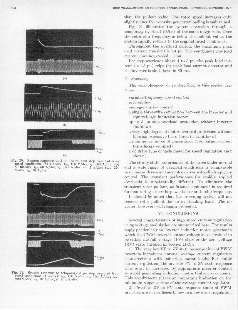
3) Overloading: In Fig. 20, system operation is demon-strated for a 3 pu (60 c/s) step overload at rated condi-tions. The motor immediately pulls out and deceleratesto near zero speed in 1 s. The frequency automaticallyramps down, and 4.5 s later the rotor slip frequency is less
523
IEEE TRANSACTIONS ON INDUSTRY APPLICATIONS, SEPTEMBER/OCTBOER 1975
- O,Vdc
I- 0,iP
(a)
-o,ip
(b)0 ,"Vpw
18A,iar
(C)
Fig. 20. System response to 3 pu (at 60 c/s) step overload fromrated conditions. (a) 1 s/div: vdc, 100 V/div; i,, 100 A/div. (b)50 ms/div: id., 50 A/div; i4, 100 A/div. (c) I s/div: ve,,1, 220V/div; tar, 18 A/div.
-cO,Vdc
_o p~~~~~~~~~~~~~~,i
0,
-vpwI
f iar
Fig. 21. System response to temporary 3 pu step overload fromrated conditions (I s/div): vde, 100 V/div; ip, 100 A/div; v,,,,220 V/div; i,,, 18 A/div; fi, 43 c/s/div.
than the pullout value. The rotor speed increases onlyslightly since the excessive generator loading is maintained.
Fig. 21 illustrates the system operation through atemporary overload (0.5 s) of the same magnitude. Oncethe rotor slip frequency is below the pullout value, thesystem rapidly returns to the original rated conditions.Throughout the overload period, the maximum peak
load current transient is 1.4 pu. The continuous rms loadcurrent does not exceed 1.1 pu.
For step overloads above 4 to 5 pu, the peak load cur-rent ( > 1.5 pu) trips the peak load current detector andthe inverter is shut down in 80 ms.
C. Summary
The variable-speed drive described in this section fea-tures
variable-frequency speed controlreversibilitynonregenerative controla single three-wire connection between the inverter and
squirrel-cage induction motorup to 3 pu step overload protection without invertershutdown
a very high degree of motor overload protection withoutblowing expensive fuses (inverter shutdown)
a minimum number of transducers (two output currenttransducers required)
a de drive type of tachometer for speed regulation (notshown).
The steady state performance of the drive under normaland a wide range of overload conditions is comparableto dc motor drives and ac motor drives with slip frequencycontrol. The transient performance for rapidly appliedoverloads is substantially different. To eliminate thetransient rotor pullout, additional equipment is requiredfor monitoring either the power factor or the slip frequency.
It should be noted that the preceding system will notrecover rotor pullout due to overhauling loads. The in-verter, however, will remain protected.
VI. CONCLUSIONS
Several characteristics of high speed current regulationusing voltage modulation are summarized here. The resultsapply particularly to inverter-induction motor systems inwhich the PWM inverter output voltage is constrained tobe either the full voltage (FV) state or the zero voltage(ZV) state (defined in Section Il-A).
1) The very low FV to ZV state response time of PWMinverters introduces unusual average current regulationcharacteristics with induction motor loads. For stablecurrent regulation, the inverter FV to ZV state responsetime must be increased by appropriate inverter controlto avoid generating inductioin motor fault-type currents.This requirement places an important limitation on theminimum response time of the average current regulator.
2) Practical ZV to FV state response times of PWMinverters are not sufficiently low to allow direct regulation
524

PORSYTHE AND DEWAN: OUTPUT CURRENT REGULATION
of the peak output current for induction motor loads. Therequired high component switching frequencies result inlow efficiency and excessive component ratings.
3) The average current regulator described in SectionIV demonstrates that for load torque step changes of 3 pu,a maximum peak load current of 1.4 pu is readily achieved.Consequently, the 15-hp PWM inverter-induction motorsystem can be designed with a commutation capabilityof approximately 1.6 pu for load torque step changes ofup to 3 pu without causing inverter shutdown or expend-ing fuses.
4) For very large and rapid load torque increases, theaverage current loop allows peak load currents in excessof the inverter commutation capability. By detecting thepeak allowable load current and then ramping the motorvoltage to zero over a period approximately twice the in-duction motor short circuit time constant, the system isshut down without expending fuses.With average current regulation, the PWM inverter has
a soft current source characteristic. This characteristicminimizes the disadvantages of 1) a stiff current source,which develops output voltage spikes with inductive load-ing, and 2) a stiff voltage source, which supplies high peakcurrents during transient loading.
Results 1) and 3) indicate that the minimum averagecurrent regulator response time is limited and related tothe short circuit time constant of the 'induction motor.Although this time constant is relatively low (30-50 msfor 15-30-hp motors), it is in excess of 100 ms for largerhorsepower induction motors. Further work is requiredto confirm the implication that for a given per unit stepoverload, the per unit PWM inverter commutation cap-ability must increase with the induction motor horsepowerrating if inverter shutdown is to be avoided.
REFERENCES[1] C. E. Graf, E. A. Skogsholm, and W. K. Volkmann, "Practical
design considerations for inverter drives," in Conf. Rec. IEEEInt. Semiconductor Power Converter Conf. May 1972, pp. 3.5.1-3.5.9c.
[2] K. P. Phillips, "Current source converter for ac motor drives,"in Conf. Rec. 1971 6th Annu. Meet. IEEE Ind. Gen. Appl. Soc.,pp. 385-392.
[31 R. B. Magg, "Characteristics and application of current source/slip regulated ac induction motor drives," in Conf. Rec 19716th Annu. Meet. IEEE Ind. Gen. Appl. Soc., pp. 411-416.
[41 D. A. Bradley, C. D. Clarke, R. M. Davis, and D. A. Jones,"Adjustable-frequency inverters and their application to vari-able speed drives," Proc. IEE, vol. 111, no. 11, pp. 1833-1846,Nov. 1964.
[5] I. D. Landau, "Wide-range speed control of three-phase squirrel-cage induction motors using static frequency converters,"IEEE Trans. Ind. Gen. Appi. vol. IGA-5, pp. 53-60, Jan. /Feb.1969.
[6] B. Mokrytzki, "Pulse width modulated inverters for ac motordrives," IEEE Trans Ind. Gen. Appl., vol. IGA-3, pp. 493-503,Nov./Dec. 1967.
[71 J. J. Pollack, "Advanced pulsewidth modulated inverter tech-niques," IEEE Trans. Ind. Appl. vol. IA-8, pp. 145-154,Mar./Apr. 1972.
[81 A. C. Betke, J. F. Billings and K. P. Phillips, "Special-purposeac converter systems for constant horsepower applications,"IEEE Trans. Ind. Appl. vol. IA-8, pp. 126-135, Mar./Apr. 1972.
19] G. Moltgen, "State of the art in ac to dc converter systems inthe Federal Republic of Germany," in Conf. Rec. IEEE In-ternational Semiconductor Power Converter Conf., May 1972,pp. 2.9.1-2.9.12.
[101 S. B. Dewan and J. B. Forsythe, "Harmonic analysis of asynchronized pulse width modulated three phase inverter,"in Conf. Rec. IEEE Ind. Gen. Appl. Soc., pp. 327-332.
[111 J. B. Forsythe, "Design considerations for a pulse width mod-ulated inverter-induction motor drive," Ph.D. dissertation,University of Toronto, Toronto, Ont., Canada, 1971.
[12] B.D. Bedford and R. G. Hoft, Principles of Inverter Circuits.New York: Wiley, 1964, pp. 190-207.
[131 A. E. Fitzgerald and C. Kingsley, Jr.. Electric Machinery, 2nded. New York: McGraw-Hill, 1961, pp. 303-309.
[14] W. P. Wagner, "Short circuit contribution of large inductionmotors," Proc. IEE, vol. 116, no. 6, pp. 985-990, June 1969.
James B. Forsythe (M'71) was born inToronto, Ont., Canada, on December 27,1940. He recieved the B.A.Sc. (Honors),M.A.Sc., and Ph.D. degrees from Universityof Toronto, Toronto, in 1965, 1967, and 1971,respectively.From 1965 to 1966 he was employed by
Computing Devices of Canada Ltd., Ottawa,Ont., developing servo subsystems for navalfire control systems, aircraft range andvelocity systemns, and aircraft constant-
frequency power supplies. From 1968 to 1971 he worked as a part-time Consultant with Marathon Electrical Research Ltd., Oakville,Ont., developing PWM inverter technology and with Carriere Tech-nical Industries, developing automotive electronics. From 1971 to1972 he continued his solid-state drive studies as a Post-DoctoralFellow at the University of Toronto. He is the author of severalpapers on variable-frequency ac motor drives. In 1973 he joinedthe Garrett Corporation, AiResearch Division, Torrance, Calif.,where he is currently a Senior Systems Engineer in the GroundTransportation Department.
Dr. Forsythe is a member of the Association of Professional Engi-neers of the Province of Ontario.
S. B. Dewan (M'67) was born in Jampur,India on April 16, 1941. He received theM.A.Sc. and Ph.D. degrees from the Uni-versity of Toronto, Toronto, Ont., Canada,in 1964 and 1966, respectively.For one year he worked as Electronic
Development Engineer for DeHavillandAircraft Company to design an airborne
ii:S SCR power supply. In 1967, he joined thestaff of the Electrical Engineering Depart-ment at the University of Toronto where he
currently is Associate Professor. He holds more than ten patentsand has over 50 publications in the general area of solid-state powerconversion. His current research and consulting activities are in thearea of application of solid-state power devices to induction heating,ac motor control, and ground transportation. He has also co-authoreda textbook on power semiconductor circuits.
Dr. Dewan is currently Chairman of the Toronto IAS Chapter anda member of the Professional Engineers of Ontario.