
Performance Evaluation of Sub-Multilevel Cell Cascaded Multilevel Inverter Using Different PWM...
16
International Journal of Applied Engineering Research ISSN 0973-4562 Volume 9, Number 8 (2014) pp. 961-975 © Research India Publications http://www.ripublication.com Performance Evaluation of Sub-Multilevel Cell Cascaded Multilevel Inverter Using Different PWM Techniques 1 K.Anish and 2 P.Ramprakash 1 PG scholor, SASTRA University, Thanjavur, Tamilnadu-613401, India. 2 Assistant Professor, Department of EEE, SASTRA University, Tamilnadu-613401, India. 1 [email protected] 2 [email protected] Abstract The multilevel inverters have important place in the modern high voltage applications because of their high quality output in all load conditions. Number of Power electronic switches and DC voltage sources are the important factors of the inverter which define output levels and quality. Cascaded multilevel inverters are mostly capable of handling more power in the output side thus these inverters are preferred for industrial applications. This paper presents a modified cascaded multilevel inverter with lessened number of power semiconductor switches compared with conventional cascaded multilevel inverter and also it presents various multicarrier pulse width modulation (MCPWM) techniques based on modified cascaded multilevel Inverter. These techniques will reduce the harmonic distortions present in the output voltage waveform. The proposed multilevel inverter produces thirteen-level using symmetrical sub-multilevel cells. This paper focus on to improve the ac output voltage with lower harmonic distortion and reduce the total harmonic distortion (THD). The proposed circuit have been simulated with help of MATLAB/SIMULINK. Keywords- Symmetric topology, sub-multilevel cells, Multicarrier PWM, Total harmonic distortion (THD). INTRODUCTION The Multilevel inverters are used in flexible power applications because of their high
Transcript of Performance Evaluation of Sub-Multilevel Cell Cascaded Multilevel Inverter Using Different PWM...

International Journal of Applied Engineering Research ISSN 0973-4562 Volume 9, Number 8 (2014) pp. 961-975 © Research India Publications http://www.ripublication.com
Performance Evaluation of Sub-Multilevel Cell Cascaded Multilevel Inverter Using Different PWM Techniques
1K.Anish and 2P.Ramprakash
1PG scholor, SASTRA University, Thanjavur, Tamilnadu-613401, India. 2Assistant Professor, Department of EEE, SASTRA University,
Tamilnadu-613401, India. 1 [email protected] [email protected]
Abstract
The multilevel inverters have important place in the modern high voltage applications because of their high quality output in all load conditions. Number of Power electronic switches and DC voltage sources are the important factors of the inverter which define output levels and quality. Cascaded multilevel inverters are mostly capable of handling more power in the output side thus these inverters are preferred for industrial applications. This paper presents a modified cascaded multilevel inverter with lessened number of power semiconductor switches compared with conventional cascaded multilevel inverter and also it presents various multicarrier pulse width modulation (MCPWM) techniques based on modified cascaded multilevel Inverter. These techniques will reduce the harmonic distortions present in the output voltage waveform. The proposed multilevel inverter produces thirteen-level using symmetrical sub-multilevel cells. This paper focus on to improve the ac output voltage with lower harmonic distortion and reduce the total harmonic distortion (THD). The proposed circuit have been simulated with help of MATLAB/SIMULINK. Keywords- Symmetric topology, sub-multilevel cells, Multicarrier PWM, Total harmonic distortion (THD).
INTRODUCTION The Multilevel inverters are used in flexible power applications because of their high

962 K.Anish and P.Ramprakash
quality output voltage. The first neutral point clamped multilevel inverter (NPCMLI) was introduced by Nabae in 1981 [2].The inverter was applied to an ac motor system, due to more harmonics in the motor, the losses are increased and produced lesser ac output power. The multilevel inverters have some advantages as enhanced output voltage level and it can be generating a close to ac sinusoidal stepped wave output voltage. The standard of ac voltage is resultant from amount of ac output voltage levels of MLI. The inverters are essentially classified in to voltage source inverter and current source inverter [3]. The voltage source inverter (VSI) has DC input source voltage has small resistance. The inverter output current and output voltage is depends on load. The two level voltage source inverters generate an output voltage through levels like 0 or +Vdc or –Vdc. To get a quality output voltage among a less amount of harmonic content, this requires fast-switching frequency with different pulse-width modulation (PWM) techniques. In high-power and high-voltage applications, the normal full bridge inverters contain various limitations in operating at fast frequency mostly due to an switching losses and voltage ratings [4]. The multilevel inverters produce step by step output voltage wave which consequences in high output voltage wave and lesser harmonic distortion. This type of inverters used for higher and medium power application. Mostly the power electronic switches like IGBT, MOSFETs, GTO, MCT, and Power BJTs used for inverters. Because of the switching frequency of the semiconductor devices are high, inverter output voltage can also be adjusted by exercising a control within the inverter itself [3]. There are two possible ways of doing multilevel inverter. They are Series inverter control and Pulse-width modulation control. In The first method voltage control involve making use of two or more inverters connected in series. The second one is the most efficient method of scheming output voltage is to include pulse width modulation (PWM) control within the inverters. The drawback of multilevel inverters is quantities of switches are increased with the increment in output voltage levels. Another drawback of these inverters is requirement of number of DC voltage sources. To produce N level output voltage, N-1 DC voltage sources are required. A multilevel inverter is able to remove the required number of step-up transformers and reduce the ripples produced in semiconductor devices used in inverter. Also the multilevel inverter design was firstly introduced for reducing ripple content in the output AC voltage waveform. The interesting feature of multilevel inverter (MLI) design is able to increase the kilovolt-ampere (kVA) rating and also improve the harmonic performance. The most general applications of multilevel inverters are reactive power compensation and variable speed drives.

Performance Evaluation of Sub-Multilevel Cell Cascaded Multilevel Inverter 963
MULTILEVEL INVERTER TOPOLOGIES The multilevel inverters (MLI) are widely used in power industries. They are suitable for reactive power compensation. These are simple methods for using high power and high voltage rating applications because of the switching losses are minimized. The number of output levels increased based on the structure and switching devices [3]. The multilevel inverters (MLIs) are having high output voltage with little amount of harmonics without need of transformers. Since the quantity of voltage levels are increased, then the harmonic content of the output AC voltage waveform reduces drastically. They have higher efficiency because of the devices can be switched at a low frequency. The power factor is close to unity for multilevel inverters used as rectifiers to convert AC to DC. The electromagnetic interference (EMI) does not affect on multilevel inverters [2, 5].By introducing multilevel inverters the switching losses are decreased in comparison with 2-level inverters. So for that development of multilevel inverters classified as three types such as Neutral point clamped (NPC) MLI, Flying Capacitor NPCMLI and Cascaded H-Bridge (CHB) MLI. The normal cascaded H-bridge Inverter consists of a series connection of H-bridges contain four switches in each cell. The universal function of this multilevel inverter (MLI) is to combine a required voltage from several input dc sources [7]. The input DC sources are connected to an each converter cell. The output ac voltages of different levels of the multilevel inverters are connected in series. It does not require any clamping diodes or flying capacitors. The response voltage of inverter is nearly sinusoidal, this inverter has fewer amount of harmonics and reduced total harmonic distortion (THD) with each of H-bridges switching only at fundamental frequency. The series connected multilevel inverters can be separated into two types based on the input voltage sources used in multilevel inverters. The voltage of every input DC source is equal value called the symmetrical type otherwise that is known as asymmetrical type. In the symmetrical cascaded H-bridge (CHB) multilevel inverters is added quantity of output voltage for a certain quantity of switching devices.
964 K.Anish and P.Ramprakash
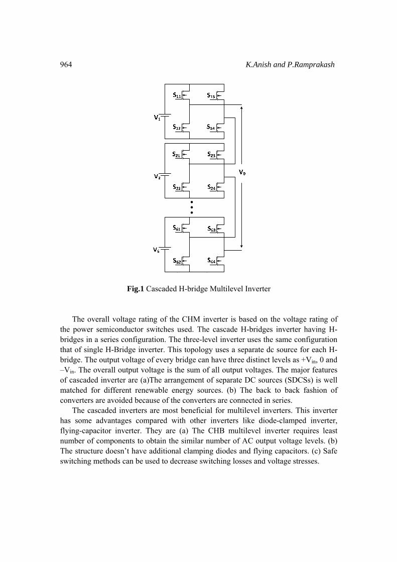
Fig.1 Cascaded H-bridge Multilevel Inverter
The overall voltage rating of the CHM inverter is based on the voltage rating of the power semiconductor switches used. The cascade H-bridges inverter having H-bridges in a series configuration. The three-level inverter uses the same configuration that of single H-Bridge inverter. This topology uses a separate dc source for each H-bridge. The output voltage of every bridge can have three distinct levels as +Vin, 0 and –Vin. The overall output voltage is the sum of all output voltages. The major features of cascaded inverter are (a)The arrangement of separate DC sources (SDCSs) is well matched for different renewable energy sources. (b) The back to back fashion of converters are avoided because of the converters are connected in series. The cascaded inverters are most beneficial for multilevel inverters. This inverter has some advantages compared with other inverters like diode-clamped inverter, flying-capacitor inverter. They are (a) The CHB multilevel inverter requires least number of components to obtain the similar number of AC output voltage levels. (b) The structure doesn’t have additional clamping diodes and flying capacitors. (c) Safe switching methods can be used to decrease switching losses and voltage stresses.

Performance Evaluation of Sub-Multilevel Cell Cascaded Multilevel Inverter 965
MODIFIED CASCADED MULTILEVEL INVERTER WITH SUB-MULTILEVEL CELLS The block diagram of modified cascaded multilevel inverter is shown in fig 2.This multilevel inverter has equal DC voltage values [1]. The Single cell topology of modified converter is shown in fig.3. It consists of only sixteen power MOSFET switches and feedback Power Diodes. The switching losses due to the power semiconductor switches are reduced and the complicity of circuit is minimized. The switching circuit for this inverter is also simple. The cost of the inverter is reduced and the simulation time is also reduced due to less number of switches. The modified series connected sub-multilevel cells be capable of be extended to several number of output voltage levels, switches T1–T4 have to endure voltage identical to total input DC voltage. The presented topology proposes the cascaded sub-multi cells.
Fig.2. Block diagram of Modified multilevel inverter
Fig. 3: Single cell of the modified multilevel inverter
The proposed multilevel inverter contains of n equal number of input dc voltage sources which are used to combine a multilevel ac output voltage waveform through a

966 K.Anish and P.Ramprakash
power electronic switching devices. Switching devices are use in this circuit be two types (i)The switches are bidirectional. (ii)The switching devices are unidirectional. The Modified series connected multilevel inverter has following equations Vdc1 =Vdc2 = ····· =Vdck = ····· =Vdcl =Vd Total AC output voltage levels=2ln+1 Number of switches =2l(n+1) Total AC output voltage =l*n*Vd n is the quantity of input DC voltage sources l is the quantity of sub cells Vdc is the value of input DC voltage sources Vd is DC voltage source
Fig.4: Thirteen-level cascaded MLI In conventional cascaded multilevel inverter requires 24 switches for 13-level, but the proposed topology needs only 16 switches. The comparison of switches as given in Table 1 compares the switching devices for conventional cascaded multilevel inverter and modified cascaded H-bridge multilevel inverter.

Performance Evaluation of Sub-Multilevel Cell Cascaded Multilevel Inverter 967
Table 1: Comparison of switches
Levels Switches required Cascaded H-Bridge Inverter Modified Cascaded Multilevel Inverter
7 12 8 9 16 10 13 24 16
Table 2: Switching States
Duration ON Switches Voltage levels
Positive Half Cycle S1, S3, S5, S7 0 D1(S1), T1, D2(P2), P1, T4, D3(S3) +Vdc
S2, T1, D2(P2), P1, T4, D3(S3) +2Vdc S2, T1, D2(P2), P1, T4, S4 +3Vdc
S2, T1, P4, D7(S7), D5(S5), P1, T4, S4 +4Vdc S2, T1, P4, D7(S7), S6, P1, T4, S4 +5Vdc
S2, T1, P4, S8, S6, P1, T4, S4 +6Vdc Negative Half Cycle S1, S3, S5, S7 0
D1(S1), T2, D1(P1), P2, T3, D3 -Vdc S2, T2, D1(P1), P2, T3, D3(S3) -2Vdc
S2, T2, D1(P1), P2, T3, S4 -3Vdc S2, T2, P3, D7(S7), D5(S5), P2, T3, S4 -4Vdc
S2, T2, P3, D7(S7), S6, P2, T3, S4 -5Vdc S2, T2, P3, S8, P2, T3, S4 -6Vdc
OPERATION OF PROPOSED MLI The thirteen-level multilevel inverter consists of sixteen switches along with three dc voltage sources on each cell. The circuit diagram for Modified thirteen Level Inverter is given in Fig 4. The thirteen level output voltages are +Vdc, +2Vdc, +3Vdc, +4Vdc, +5Vdc, +6Vdc, 0, -Vdc, -2Vdc, -3Vdc, -4Vdc, -5Vdc, -6Vdc. The operation of the conducting switches for thirteen-level inverter is shown in Table 2. For getting 0th level the switches S1, S3, S5, and S7 are ON. The switching table describes modified Cascaded Multilevel inverter using sub-multilevel cells. PULSE WIDTH MODULATION (PWM) METHODS In these methods, reference (sine wave) is compared with the carrier (triangular wave) results the square output voltage level. Basically the PWM methods are used to reduce

968 K.Anish and P.Ramprakash
the harmonics and increase ac output voltage. For X-level converter minimum X-1 carrier signals are needed. Each carrier signal has appropriate pair of switches. Multiple carrier signals are used in multilevel inverters. These are two types like constant frequency and variable frequency. Multicarrier based PWM strategies have multiple carrier waves compared with the only one reference wave. The various multicarrier PWM techniques are Phase Opposition Disposition (POD), Alternative Phase Opposition Disposition (APOD), Phase Disposition (PD) and Variable frequency (VF) technique [11, 12]. Modulation index (MI) is defines the ratio of carrier voltage with respect to reference voltage.
Where Vc is the sum of number of carrier waveform amplitudes. Phase Opposition Disposition (POD) PWM
Fig 5: POD PWM The PODPWM shown in fig 5, consists of the constant frequency and same amplitude for all the carrier waves, except all carriers on top of zero level are same within phase and under the zero level carriers also within phase but they are 180 degree phase shift with respect to on top of reference. The reference signal having same frequency of output waveform in all cases.

Performance Evaluation of Sub-Multilevel Cell Cascaded Multilevel Inverter 969
Alternative Phase Opposition Disposition (APOD) PWM
Fig 6: APOD PWM In the APODPWM shown in fig 6, every carrier wave is shifted by 180° since the next level carrier triangular waveforms. All the carriers have constant frequency and amplitude. Phase Disposition (PD) PWM
Fig 7: PD PWM In phase deposition PWM technique shown in fig 7, all the carriers are in phase. All the carriers have unchanged frequency and amplitude, however every carrier on top and under the reference are same in phase.

970 K.Anish and P.Ramprakash
Variable Frequency (VF) PWM
Fig 8: VF PWM In VF PWM technique shown in fig 8, all the carrier wave forms have different frequencies and each carrier waveform have double than successive carrier wave form. And all the carriers are in phase. Since all the remaining methods use same frequency carrier signals, this method uses different frequency carriers. This increases the complexity of the PWM pulse generation circuit. In all these PWM techniques, the amplitude modulation index which is used to decide the total harmonic distortion is only based on the amplitude of the carrier waveforms only. By keeping the modulation index constant, the THD value has been controlled based on newton raphson method. SIMULATION In order to verify that the proposed inverter with various PWM techniques, the simulation for the proposed configuration is done by using MATLAB/SIMULINK software which is shown in fig.9..The load used in the simulation is resistive load with the value of 100Ω. Each input DC supply has the value of 40V. The frequency of carrier waveforms is maintained as 1.5 KHz except variable frequency method.

Performance Evaluation of Sub-Multilevel Cell Cascaded Multilevel Inverter 971
Fig 9: Simulation of Modified Cascaded MLI APOD PWM Technique
Fig 10: By using APOD PWM (a) Output voltage (b) Harmonic Analysis
The output voltage waveform and FFT analysis for corresponding THD value for thirteen- level using APOD PWM technique is given in the figure 10.

972 K.Anish and P.Ramprakash
POD PWM Technique The output voltage waveform and FFT analysis for corresponding THD value for thirteen- level using POD PWM technique is given in the figure 11.
Fig 11: By using POD PWM (a) output voltage (b) Harmonic Analysis PD PWM Technique
Fig 12: By using PD PWM (a) output voltage (b) Harmonic Analysis The output voltage waveform and FFT analysis for corresponding THD value for thirteen- level using PD PWM technique is given in the figure 12.

Performance Evaluation of Sub-Multilevel Cell Cascaded Multilevel Inverter 973
VF PWM Technique
Fig 13: By using VF PWM (a) output voltage (b) Harmonic Analysis The output voltage waveform and FFT analysis for corresponding THD value for thirteen- level using VF PWM technique is given in the figure 13. Table 3 compares the percentage of THD with respect to modulation index for modified cascaded multi-level inverter using different multi-carrier PWM techniques. The input voltage is 240V.
Table 3 Comparison of THD values
PWM Technique Modulation index %THD
APOD PWM
1.0 10.28 0.9 10.01 0.8 13.37 0.7 15.39
POD PWM
1.0 9.51 0.9 8.60 0.8 11.41 0.7 15.93
PD PWM
1.0 9.42 0.9 9.23 0.8 11.66 0.7 15.16
VF PWM
1.0 9.18 0.9 8.34 0.8 10.91 0.7 14.73

974 K.Anish and P.Ramprakash
Fig 13: comparison of THD values for (a) APOD PWM (b) POD PWM (c) PD PWM (d) VF PWM CONCLUSION A cascaded H-bridge multilevel inverter with sub multilevel cell has presented in this paper. This circuit is designed to reduce the harmonics. The analysis of the project shows better output in symmetrical type when compared to usual series connected H-Bridge multilevel inverter. The simulations results are obtained in a thirteen-level multilevel inverter using present topology. The Multicarrier PWM (MCPWM) technique helps to reduce switching losses. This structure also requires a reduced quantity of switches compared to conventional series connected multilevel inverter and it requires few carrier signals so the complexity in pulse generation was reduced. By using this cascaded multilevel Inverter using Sub multilevel cells, total harmonic distortion is reduced. The presented circuit with all PWM methods is compared at all ranges of modulation index values. The lowest harmonic values are obtained at the modulation index of 0.9 in all cases. Since the number of switches required are same in all compared cases, the PWM method will be selected based on the complexity of the PWM pulse generation circuit.

Performance Evaluation of Sub-Multilevel Cell Cascaded Multilevel Inverter 975
References
[1] E.Babaei, et.al., Cascaded multilevel inverter using sub-multilevel cells, journal of electric power system research, 2012, pp.101-110.
[2] Nabae, I. Takahashi, H. Akagi, “A New Neutral-Point-Clamped PWM Inverter, ” IEEE Transactions on Industry Applications, vol. 17. No. 5, pp.518-523, Sept. 1981.
[3] M D Singh, K B Khanchandani, “Power Electronics” TATA McGRAW HILL Publishers, New Delhi, Second Edition, pp.535-537, Eleventh print 2011.
[4] Muhammad H. Rashid, “Power Electronics Circuits, Devices, and Applications” PEARSON Education Publishers, India, Third Edition, pp.406-419.
[5] P.M. Bhagwat and V.R.Stefanovic, “Generalized structure of a multilevel PWM inverter, ” IEEE Transactions on industry Applications, Vol. 19, No. 6, November/December 1983, pp. 1057-1069.
[6] E.Babaei, et.al., Symmetric and asymmetric multilevel inverter topologies with reduced switching devices, journal of electric power system research, 2012, pp.122-130.
[7] Dr. P. S. Bimbra, “Power Electronics, ” KHANNA Publishers, New Delhi, Fourth Edition, pp. 414-416.
[8] L.M. Tolbert, F.Z. Peng, and T.G. Habetler, “multilevel converters for large electric drives, ” IEEE Transactions on industry Applications, Vol.15, No. 1, January/ February 1999, pp. 36-44.
[9] M. Malinowski, K. Gopakumar, J. Rodriguez, M. Perez, A survey on cascaded multilevel inverters, IEEE Transactions on Industrial Electronics 57 (7) (2010) 2197–2206.
[10] Rufer, M. Veenstra, K. Gopakumar, Asymmetric multilevel converter for high resolution voltage phasor generation, in: Proceedings of EPE, 1999.
[11] E. Babaei, A cascade multilevel converter topology with reduced number of switches, IEEE Transactions on Power Electronics 23 (6) (2008) 2657–2664.
[12] A. Radan, A. H. Shahirinia, M. Falahi, “Evaluation of Carrier-Based PWM Methods for Multi-level Inverters”1-4244-0755-9/07/$20.00 '2007 IEEE.
[13] B.P.McGrath and Holmes, “Multicarrier PWM strategies for multilevel inverter, ” IEEE Trans.Ind-Electron., vol.49, no.4, Aug.2002 pp.858, 867.

976 K.Anish and P.Ramprakash