
DESIGN AND SIMULATION OF CASCADED SEVEN LEVEL H-BRIDGE MULTILEVEL INVERTER BASED DSTATCOM FOR POWER...
10
1 [Pawar, 2(2): February 2015] ISSN 2348 – 8034 GLOBAL JOURNAL OF ENGINEERING SCIENCE AND RESEARCHES DESIGN AND SIMULATION OF CASCADED SEVEN LEVEL H-BRIDGE MULTILEVEL INVERTER BASED DSTATCOM FOR POWER QYALITY IMPROVEMENT Prof. Suryakant H. Pawar *1 and Chetan A. Jambhulkar 2 *1 Associate Professor, Department of Electrical Engineering, Government College of Engineering, Karad, Maharashtra, India 2 P. G. Student, Department of Electrical Engineering, Government College of Engineering, Karad, Maharashtra, India ABSTRACT In this paper the design of a DSTATCOM employing a Seven–Level Cascaded H-Bridge Multilevel Inverter (CHBMLI) in medium voltage distribution power system is presented. The DSTATCOM helps to improve sending end & receiving end voltage and current drawn from a Non Linear Load (NLL). The control strategy based on Synchronous Reference Frame (SRF) theory is designed so that the voltage injected by active filter is able to mitigate the voltage sag, imbalance in the source voltage and reduce the harmonic content. The Level Shifted PWM (LSPWM) techniques are adopted to investigate the performance of CHB inverter. The performance of the proposed DSTATCOM is validated through simulation using MATLAB software with its SIMULINK and Power System block set tool and also performance of the system without DSTATCOM and with DSTATCOM is evaluated. Keywords— DSTATCOM, Level Shifted Pulse Width Modulation (LSPWM), Cascaded H-Bridge Multilevel Inverter (CHBMLI), MOSFET. I. INTRODUCTION In recent years Electrical Power Quality had obtained more attention in power engineering. In present day’s power distribution systems is suffering from severe power quality problems. These power quality problems include high reactive power burden, harmonics currents, load unbalance, excessive neutral current etc. The measure of power quality depends upon the needs of the equipment that is being supplied. Usually the term power quality refers to maintaining a sinusoidal waveform of bus voltages at rated voltage and frequency [1]. The waveform of electric power at generation stage is purely sinusoidal and free from any distortion. Many of the Power conversion and consumption equipment are also designed to function under pure sinusoidal voltage waveforms. However, there are many devices that distort the waveform. These distortions may propagate all over the electrical network. In recent years, there has been an increased use of non- linear loads which has resulted in an increased fraction of non-sinusoidal currents and voltages in Electric Network. The wave shape phenomena associated with power quality may be characterized into synchronous and non synchronous phenomena. Synchronous phenomena refer to those in synchronism with A.C waveform at power frequency [10], [13]. (C) Global Journal Of Engineering Science And Researches
-
Upload
independent -
Category
Documents
-
view
0 -
download
0
Transcript of DESIGN AND SIMULATION OF CASCADED SEVEN LEVEL H-BRIDGE MULTILEVEL INVERTER BASED DSTATCOM FOR POWER...

1
[Pawar, 2(2): February 2015] ISSN 2348 – 8034
GLOBAL JOURNAL OF ENGINEERING SCIENCE AND RESEARCHESDESIGN AND SIMULATION OF CASCADED SEVEN LEVEL H-BRIDGE MULTILEVEL INVERTER
BASED DSTATCOM FOR POWER QYALITY IMPROVEMENTProf. Suryakant H. Pawar*1 and Chetan A. Jambhulkar2
*1Associate Professor, Department of Electrical Engineering, Government College ofEngineering, Karad, Maharashtra, India
2P. G. Student, Department of Electrical Engineering, Government College ofEngineering, Karad, Maharashtra, India
ABSTRACTIn this paper the design of a DSTATCOM employing a Seven–Level Cascaded H-BridgeMultilevel Inverter (CHBMLI) in medium voltage distribution power system is presented.The DSTATCOM helps to improve sending end & receiving end voltage and current drawn froma Non Linear Load (NLL). The control strategy based on Synchronous Reference Frame (SRF)theory is designed so that the voltage injected by active filter is able to mitigate thevoltage sag, imbalance in the source voltage and reduce the harmonic content. The LevelShifted PWM (LSPWM) techniques are adopted to investigate the performance of CHBinverter. The performance of the proposed DSTATCOM is validated through simulation usingMATLAB software with its SIMULINK and Power System block set tool and also performance ofthe system without DSTATCOM and with DSTATCOM is evaluated.
Keywords— DSTATCOM, Level Shifted Pulse Width Modulation (LSPWM), Cascaded H-Bridge Multilevel Inverter (CHBMLI),MOSFET.
I. INTRODUCTION
In recent years Electrical Power Quality had obtained more attention in powerengineering. In present day’s power distribution systems is suffering from severe powerquality problems. These power quality problems include high reactive power burden,harmonics currents, load unbalance, excessive neutral current etc. The measure of powerquality depends upon the needs of the equipment that is being supplied. Usually the termpower quality refers to maintaining a sinusoidal waveform of bus voltages at ratedvoltage and frequency [1]. The waveform of electric power at generation stage is purelysinusoidal and free from any distortion. Many of the Power conversion and consumptionequipment are also designed to function under pure sinusoidal voltage waveforms. However,there are many devices that distort the waveform. These distortions may propagate allover the electrical network. In recent years, there has been an increased use of non-linear loads which has resulted in an increased fraction of non-sinusoidal currents andvoltages in Electric Network. The wave shape phenomena associated with power quality maybe characterized into synchronous and non synchronous phenomena. Synchronous phenomenarefer to those in synchronism with A.C waveform at power frequency [10], [13].
(C) Global Journal Of Engineering Science And Researches

2
[Pawar, 2(2): February 2015] ISSN 2348 – 8034
A group of controllers together called Custom Power Devices (CPD), which includethe DSTATCOM (distribution static compensator), The DSTATCOM, is a shunt-connecteddevice, which takes care of the power quality problems in the currents it consists of adc capacitor, three-phase inverter (IGBT, MOSFET) module, ac filter, coupling transformerand a control strategy. The basic electronic block of the D-STATCOM is the voltage-sourced inverter that converts an input dc voltage into a three-phase output voltage atfundamental frequency. The D-STACOM employs an inverter to convert the DC link voltageVdc on the capacitor to a voltage source of adjustable magnitude and phase. Therefore theD-STATCOM can be treated as a voltage controlled source. The D-STATCOM can also be seenas a current-controlled source. The DSTATCOM is based on the instantaneous real-powertheory; it provides good compensation characteristics in steady state as well astransient states [9]. The instantaneous real-power theory generates the referencecurrents required to compensate the distorted line current harmonics and reactive power.It also tries to maintain the dc-bus voltage across the capacitor constant.
A multilevel inverter can reduce the device voltage and the output harmonics byincreasing the number of output voltage levels. There are several types of multilevelinverters: cascaded H-bridge (CHB), neutral point clamped, flying capacitor [5], [6],[8], [11]. In particular, among these topologies, CHB inverters are being widely usedbecause of their modularity and simplicity. Various modulation methods can be applied toCHB inverters. CHB inverters can also increase the number of output voltage levels easilyby increasing the number of H-bridges. This paper presents a DSTATCOM with a proportionalintegral controller based CHB multilevel (seven level) inverter for the harmonics andreactive power mitigation of the nonlinear loads. This type of arrangements have beenwidely used for PQ applications due to increase in the number of voltage levels, lowswitching losses, low electromagnetic compatibility for hybrid filters and higher orderharmonic elimination.
II.DISTRIBUTED STATIC SYNCHRONOUS COMPENSATOR (DSTATCOM) A. Basic Configuration of DSTATCOM
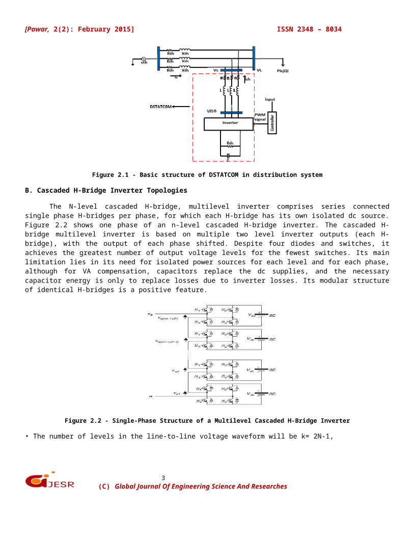
The DSTATCOM is a voltage or current source inverter based custom power device connectedin shunt with the power system. It is connected near the load at the distribution systems[12], [14]. The basic structure of DSTATCOM is presented in Figure 2.1 As shown in Figure2.1; DSTATCOM consists of an inverter, dc link capacitance C that providing the dc voltagefor inverter, coupling inductance L used for current filter and reactive power exchangebetween DSTATCOM and power system and a control unit to generate PWM signals for theswitches of inverter. In Figure 4, and R respectively represent switching losses ininverter and winding resistance of coupling inductance [6].
(C) Global Journal Of Engineering Science And Researches
3
[Pawar, 2(2): February 2015] ISSN 2348 – 8034
Figure 2.1 - Basic structure of DSTATCOM in distribution system
B. Cascaded H-Bridge Inverter Topologies
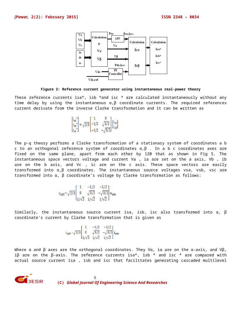
The N-level cascaded H-bridge, multilevel inverter comprises series connectedsingle phase H-bridges per phase, for which each H-bridge has its own isolated dc source.Figure 2.2 shows one phase of an n-level cascaded H-bridge inverter. The cascaded H-bridge multilevel inverter is based on multiple two level inverter outputs (each H-bridge), with the output of each phase shifted. Despite four diodes and switches, itachieves the greatest number of output voltage levels for the fewest switches. Its mainlimitation lies in its need for isolated power sources for each level and for each phase,although for VA compensation, capacitors replace the dc supplies, and the necessarycapacitor energy is only to replace losses due to inverter losses. Its modular structureof identical H-bridges is a positive feature.
Figure 2.2 - Single-Phase Structure of a Multilevel Cascaded H-Bridge Inverter
• The number of levels in the line-to-line voltage waveform will be k= 2N-1,
(C) Global Journal Of Engineering Science And Researches

4
[Pawar, 2(2): February 2015] ISSN 2348 – 8034
• While the number of levels in the line to neutral of a star (wye) load will be p = 2k−1
• The number of capacitors or isolated supplies required per phase is Ncap = ½(N −1)
• The number of possible switch states is nstates = N phases
• The number of switches in each leg is Sn = 2(N −1)
Figure 2.3 shows the seven level multilevel inverter and. Here even though we havetwelve switches at any switching state only two switches are on/off at a voltage level ofVdc/3, so switching losses are reduced. In three level inverter dv/dt is Vdc, but in fivelevel inverter dv/dt is Vdc/2 and in seven level inverter dv/dt is Vdc/3. As dv/dtreduces, the stress on switches reduces and EMI also reduces.
Figure 2.3 - Block diagram of 7-level CHB inverter model
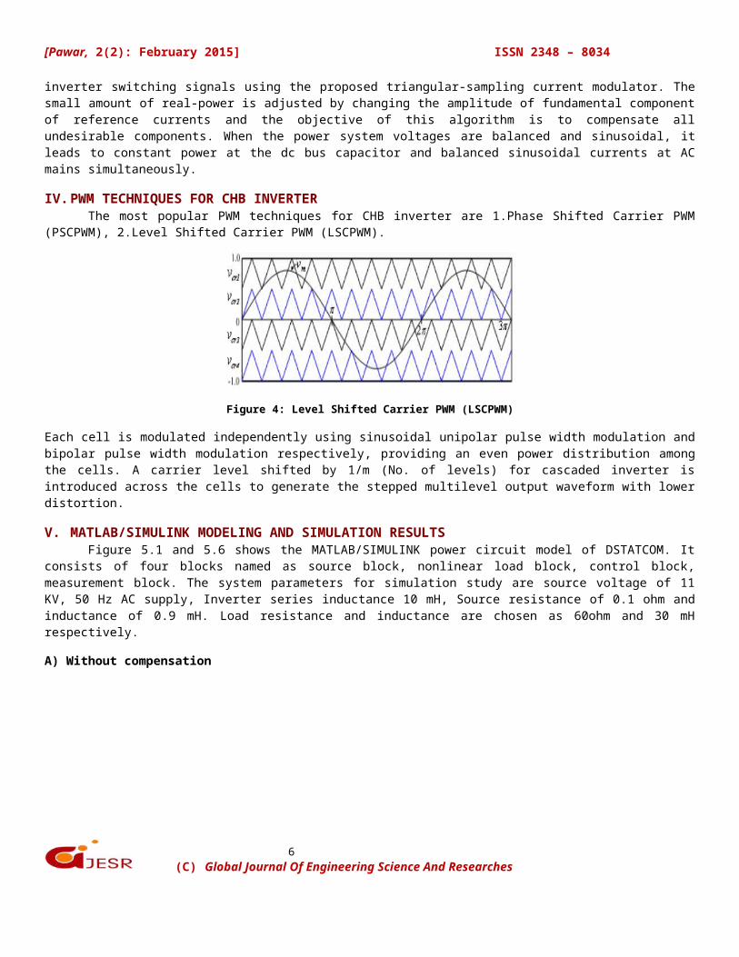
III. REFERENCE CURRENT CONTROL STRATEGYThe control scheme of the shunt active power filter must calculate the current referencesignals from each phase of the inverter using instantaneous real-power compensator. Theblock diagram as shown in Figure 3, that control scheme generates the reference currentrequired to compensate the load current harmonics and reactive power. The PI controlleris tried to maintain the dc-bus voltage across the capacitor constant of the cascadedinverter. This instantaneous real- power compensator with PI-controller is used toextracts reference value of current to be compensated.
(C) Global Journal Of Engineering Science And Researches
5
[Pawar, 2(2): February 2015] ISSN 2348 – 8034
Figure 3: Reference current generator using instantaneous real-power theory
These reference currents isa*, isb *and isc * are calculated instantaneously without anytime delay by using the instantaneous α,β coordinate currents. The required referencescurrent derivate from the inverse Clarke transformation and it can be written as
The p-q theory performs a Clarke transformation of a stationary system of coordinates a bc to an orthogonal reference system of coordinates α,β . In a b c coordinates axes arefixed on the same plane, apart from each other by 120 that as shown in Fig 5. Theinstantaneous space vectors voltage and current Va , ia are set on the a axis, Vb , ibare on the b axis, and Vc , ic are on the c axis. These space vectors are easilytransformed into α,β coordinates. The instantaneous source voltages vsa, vsb, vsc aretransformed into α, β coordinate’s voltage by Clarke transformation as follows:
Similarly, the instantaneous source current isa, isb, isc also transformed into α, βcoordinate’s current by Clarke transformation that is given as
Where α and β axes are the orthogonal coordinates. They Vα, iα are on the α-axis, and Vβ,iβ are on the β-axis. The reference currents isa*, isb * and isc * are compared withactual source current isa , isb and isc that facilitates generating cascaded multilevel
(C) Global Journal Of Engineering Science And Researches
6
[Pawar, 2(2): February 2015] ISSN 2348 – 8034
inverter switching signals using the proposed triangular-sampling current modulator. Thesmall amount of real-power is adjusted by changing the amplitude of fundamental componentof reference currents and the objective of this algorithm is to compensate allundesirable components. When the power system voltages are balanced and sinusoidal, itleads to constant power at the dc bus capacitor and balanced sinusoidal currents at ACmains simultaneously.
IV.PWM TECHNIQUES FOR CHB INVERTERThe most popular PWM techniques for CHB inverter are 1.Phase Shifted Carrier PWM
(PSCPWM), 2.Level Shifted Carrier PWM (LSCPWM).
Figure 4: Level Shifted Carrier PWM (LSCPWM)
Each cell is modulated independently using sinusoidal unipolar pulse width modulation andbipolar pulse width modulation respectively, providing an even power distribution amongthe cells. A carrier level shifted by 1/m (No. of levels) for cascaded inverter isintroduced across the cells to generate the stepped multilevel output waveform with lowerdistortion.
V. MATLAB/SIMULINK MODELING AND SIMULATION RESULTSFigure 5.1 and 5.6 shows the MATLAB/SIMULINK power circuit model of DSTATCOM. It
consists of four blocks named as source block, nonlinear load block, control block,measurement block. The system parameters for simulation study are source voltage of 11KV, 50 Hz AC supply, Inverter series inductance 10 mH, Source resistance of 0.1 ohm andinductance of 0.9 mH. Load resistance and inductance are chosen as 60ohm and 30 mHrespectively.
A) Without compensation
(C) Global Journal Of Engineering Science And Researches
7
[Pawar, 2(2): February 2015] ISSN 2348 – 8034
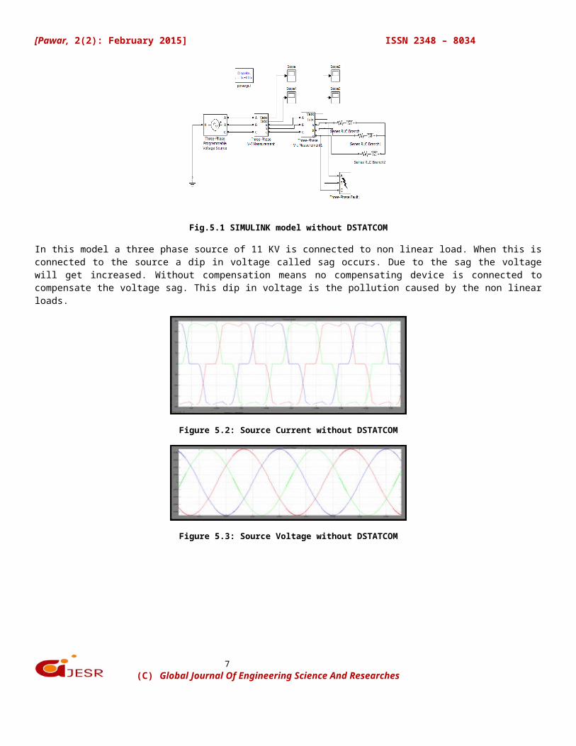
Fig.5.1 SIMULINK model without DSTATCOM
In this model a three phase source of 11 KV is connected to non linear load. When this isconnected to the source a dip in voltage called sag occurs. Due to the sag the voltagewill get increased. Without compensation means no compensating device is connected tocompensate the voltage sag. This dip in voltage is the pollution caused by the non linearloads.
Figure 5.2: Source Current without DSTATCOM
Figure 5.3: Source Voltage without DSTATCOM
(C) Global Journal Of Engineering Science And Researches

8
[Pawar, 2(2): February 2015] ISSN 2348 – 8034
Figure 5.4: Load Current without DSTATCOM
Figure 5.5: Load Current without DSTATCOM
B) With compensation
Fig.5.6 SIMULINK model with DSTATCOM
(C) Global Journal Of Engineering Science And Researches
9
[Pawar, 2(2): February 2015] ISSN 2348 – 8034
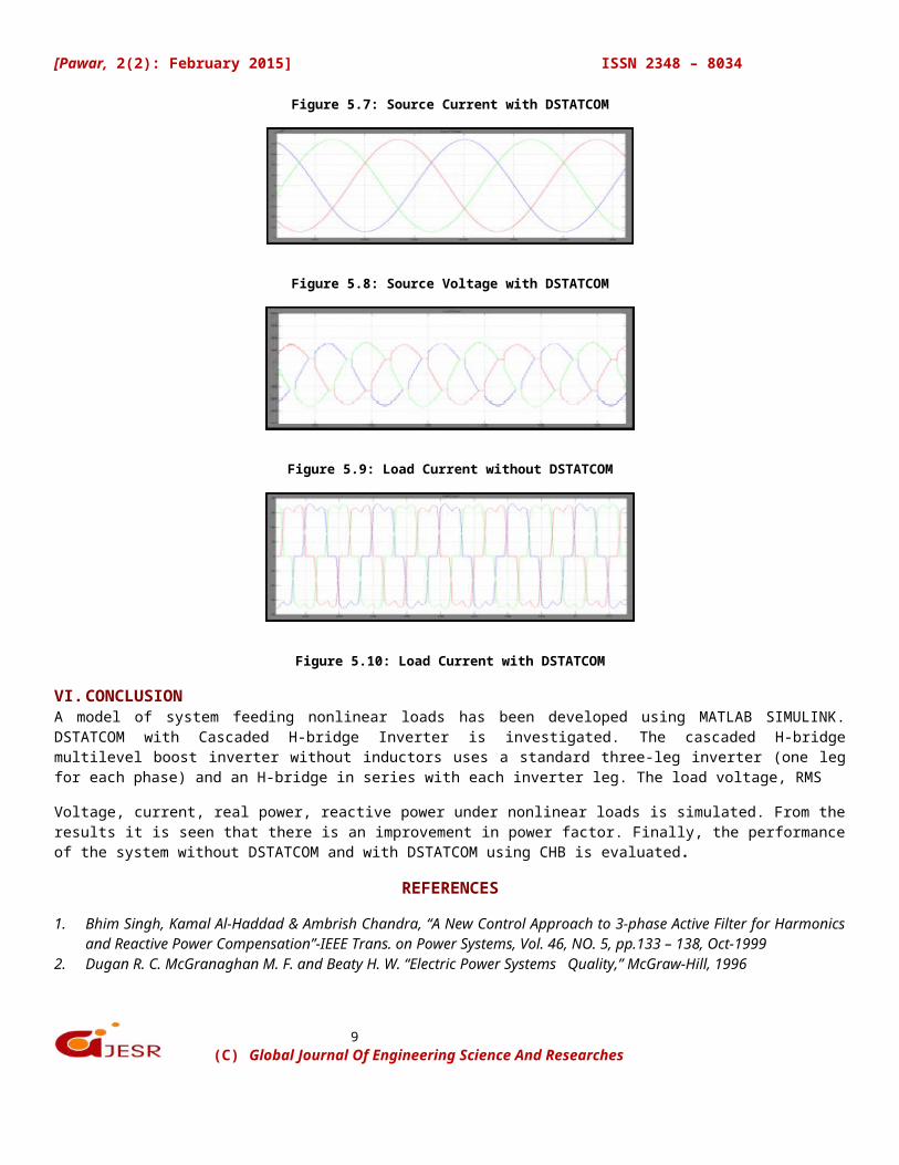
Figure 5.7: Source Current with DSTATCOM
Figure 5.8: Source Voltage with DSTATCOM
Figure 5.9: Load Current without DSTATCOM
Figure 5.10: Load Current with DSTATCOM
VI.CONCLUSIONA model of system feeding nonlinear loads has been developed using MATLAB SIMULINK.DSTATCOM with Cascaded H-bridge Inverter is investigated. The cascaded H-bridgemultilevel boost inverter without inductors uses a standard three-leg inverter (one legfor each phase) and an H-bridge in series with each inverter leg. The load voltage, RMS
Voltage, current, real power, reactive power under nonlinear loads is simulated. From theresults it is seen that there is an improvement in power factor. Finally, the performanceof the system without DSTATCOM and with DSTATCOM using CHB is evaluated.
REFERENCES
1. Bhim Singh, Kamal Al-Haddad & Ambrish Chandra, “A New Control Approach to 3-phase Active Filter for Harmonicsand Reactive Power Compensation”-IEEE Trans. on Power Systems, Vol. 46, NO. 5, pp.133 – 138, Oct-1999
2. Dugan R. C. McGranaghan M. F. and Beaty H. W. “Electric Power Systems Quality,” McGraw-Hill, 1996
(C) Global Journal Of Engineering Science And Researches
10
[Pawar, 2(2): February 2015] ISSN 2348 – 8034
3. G.F. Reed, M. Takeda, and I. lyoda, ―Improved power quality solution using advanced solid-slate switching andstatic compensation technologies,‖ IEEE Power Engineering Sociery winter Meeting, New York, NY, USA, vol. 2, pp.1132-1137, 1999.
4. J. Ganesh Prasad Reddy, K. Ramesh Reddy, “Design and Simulation of Cascaded H-Bridge Multilevel Inverter BasedDSTATCOM for Compensation of Reactive Power and Harmonics”, IEEE 1ST International Conference on RecentAdvances in Information Technology [RAIT]-2012.
5. J. Rodriguez, J. S. Lai, and F. Z. Peng, “Multilevel inverters: a survey of topologies, controls, and applications,” IEEETrans. on Industrial Electronics, vol. 49, no. 4, pp. 724-738,2002.
6. J. S. Lai and F. Z. Peng, “Multilevel converters- a new breed of power converters,” IEEE Trans. on Industry Applications,vol. 32, no. 3, pp. 509-517, 1996.
7. Karuppanan P and Kamala Kanta Mahapatra “Shunt Active Power Line Conditioners for Compensating Harmonicsand Reactive Power”-Proceedings of the International Conference on Environment and Electrical Engineering (EEEIC),pp.277 – 280, May 2010
8. Keith Corzine, Yakov Familiant, “A new cascaded multilevel H-bridge drive” IEEE Transactions on Power Electronics,Vol. 17, No. 1, January 2002.
9. Leszek S. Czarnecki “Instantaneous Reactive Power p-q Theory and Power Properties of Three-Phase Systems”- IEEETrans on Power, VOL. 21, NO. 1, pp 362-367, 2006
10. N. G. Hingorani and L. Gyugyi, Understanding FACTS, IEEE Press, 2000.11. P. Giroux and G. Sybille, “Modelling & Simulation of a Distribution STATCOM using Simulink Power System Blocksets,”
27 annual conf. of IEEE Ind. Electron. Soc., vol. 2, no. 2, pp.990-994, April 2001. 12. S. Iyer, A. Ghosh and A. Joshi, “Inverter Topologies for DSTATCOM applications-A Simulation Study,” Elect. Power Syst.
Res., vol. 75, no.2/3, pp. 161-170, Aug. 2005. 13. S. P. Gawande ,S.Khan, M. R. Ramteke, “Voltage Sag Mitigation Using Multilevel Inverter based Distribution Static
Compensator (DSTATCOM) in Low Voltage Distribution System” Power Electronics (IICPE), 2012 IEEE 5th IndiaInternational Conference.
14. W. K. Chang, W. M. Grady, Austin, M. J. Samotyj “Meeting IEEE- 519 Harmonic Voltage and Voltage DistortionConstraints with an Active Power Line Conditioner”- IEEE Trans on Power Delivery, Vol.9, No.3, pp.1531-1537, 1994
15. Wei-Neng Chang, Jing-Huan Liau, “Development of a Cascaded Multilevel DSTATCOM for Real-Time Load PowerFactor Correction”, IEEE 2010 International Power Electronics Conference.
(C) Global Journal Of Engineering Science And Researches