Development of Improved Diode Clamped Multilevel Inverter Using Optimized Selective Harmonic...
12
Emerging Trends in Electrical, Electronics & Instrumentation Engineering: An international Journal (EEIEJ), Vol. 1, No. 3, August 2014 17 Development of Improved Diode Clamped Multilevel Inverter Using Optimized Selective Harmonic Elimination Technique Tariq Kamal, Syed Zulqadar Hassan, Syeda Zahra Naqvi, Imranullah Department of Electronics Engineering University of Engineering & Technology Peshawar, Abbottabad Campus,Pakistan ABSTRACT In this paper the role of Selective Harmonic Elimination (SHE) is presented for diode clamped twelve-level multilevel inverter (DCMLI) based on dog leg optimization algorithm. Non-linear equations has been solved to eliminate specific low order harmonics, using the developed DOP algorithm, while at the same time the fundamental component is retained efficiently. The non-linear nature of transcendental equation provide multiple or even no solution for a particular modulation index. The proposed optimization method solving the nonlinear transcendental equations providing all possible solutions. The paper also showing the comparison between different modulation techniques including the proposed method. The entire system has been simulated using MATLAB/Simulink. Simulation results confirm the effectiveness with negligible THD. KEYWORDS DCMLI,SHEPWM, Switching Angles, DOP, THD I. INTRODUTION In power electronics, the development of multilevel inverter provide a new and alternative option in high power applications. The high voltage sharing ability, low electromagnetic interference (EMI), lower harmonics, made multilevel inverter a very hot area in today’s power system and large motor drives. It is not difficult to develop high voltage inverters with multilevel structure in which voltage are controlled, but the main problem is the harmonic distortion in the output waveform. Recently many modulation techniques such as SPWM, SVPWM, SHEPWM, etc [1] have been used to address this problem. SHEPWM technique can lower the harmonic content of the output current as well as resonant harmonic. In the same manner different types of multilevel are used for the purpose of reduction in harmonics and improvement in power quality [2] . Cascaded five level multilevel inverter using DSTATCOM implemented for power improvement [3] .Chopper with flying capacitor used in DCMLI for the reduction of stress and produces AC voltage [4] . The paper [5] presents voltage sharing for high power factor loads based on DCMLI(4-levels). SVPWM based [6] 3-level diode clamped multilevel level inverter is presented for leakage current in PV system. 3-level DCMLI with ANPC, ZCT used for sustainable energy [7] .Building H-Bridge for AC to DC conversion with the use of capacitors and
Transcript of Development of Improved Diode Clamped Multilevel Inverter Using Optimized Selective Harmonic...

Emerging Trends in Electrical, Electronics & Instrumentation Engineering: An international Journal (EEIEJ), Vol. 1, No. 3, August 2014
17
Development of Improved Diode Clamped
Multilevel Inverter Using Optimized Selective
Harmonic Elimination Technique
Tariq Kamal, Syed Zulqadar Hassan, Syeda Zahra Naqvi, Imranullah
Department of Electronics Engineering
University of Engineering & Technology Peshawar, Abbottabad Campus,Pakistan
ABSTRACT
In this paper the role of Selective Harmonic Elimination (SHE) is presented for diode clamped twelve-level
multilevel inverter (DCMLI) based on dog leg optimization algorithm. Non-linear equations has been
solved to eliminate specific low order harmonics, using the developed DOP algorithm, while at the same
time the fundamental component is retained efficiently. The non-linear nature of transcendental equation
provide multiple or even no solution for a particular modulation index. The proposed optimization method
solving the nonlinear transcendental equations providing all possible solutions. The paper also showing
the comparison between different modulation techniques including the proposed method. The entire system
has been simulated using MATLAB/Simulink. Simulation results confirm the effectiveness with negligible
THD.
KEYWORDS
DCMLI,SHEPWM, Switching Angles, DOP, THD
I. INTRODUTION In power electronics, the development of multilevel inverter provide a new and alternative option
in high power applications. The high voltage sharing ability, low electromagnetic interference
(EMI), lower harmonics, made multilevel inverter a very hot area in today’s power system and
large motor drives. It is not difficult to develop high voltage inverters with multilevel structure in
which voltage are controlled, but the main problem is the harmonic distortion in the output
waveform. Recently many modulation techniques such as SPWM, SVPWM, SHEPWM, etc[1]
have been used to address this problem. SHEPWM technique can lower the harmonic content of
the output current as well as resonant harmonic. In the same manner different types of multilevel
are used for the purpose of reduction in harmonics and improvement in power quality[2]
.
Cascaded five level multilevel inverter using DSTATCOM implemented for power
improvement[3]
.Chopper with flying capacitor used in DCMLI for the reduction of stress and
produces AC voltage[4]
. The paper[5]
presents voltage sharing for high power factor loads based
on DCMLI(4-levels). SVPWM based[6]
3-level diode clamped multilevel level inverter is
presented for leakage current in PV system. 3-level DCMLI with ANPC, ZCT used for
sustainable energy[7]
.Building H-Bridge for AC to DC conversion with the use of capacitors and

Emerging Trends in Electrical, Electronics & Instrumentation Engineering: An international Journal (EEIEJ), Vol. 1, No. 3, August 2014
18
single DC source with less harmonics[8]
. Using different voltage balancing equations and
techniques to form a flying capacitor H-Bridge multilevel inverter[9]
.Cascaded inverters with
particle swarm optimization technique to improve power quality and reduce total
harmonics[10]
.Cascaded inverter using SVPWM to minimize harmonics and switching
frequency[11]
.Many multi -level inverters are used but diode clamped multi-level inverter
(DCMLI) is employed for many applications like power drives & utility system [12]
.
In this proposed method diode clamped 12 level inverter is implemented using selective
harmonic elimination pulse width modulation technique (SHEPWM) to reduce the total harmonic
distortion of the output wave form and improve quality of power. Optimization technique dog leg
is used for switching angles of IGBTs employed in the system and the switching angles are
solved by non-linear transcendental equations which contain trigonometric terms. Newton-
Repshan is used to solve thesetranscendental equations.
II. WORKING PRINCIPLE
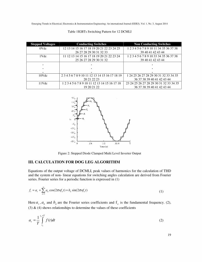
The basic working principle block diagram of SHE was shown in Figure 1. Table 1 showsthe
number of on and off switches for different levels of output voltage in a half cycle (0to90o) for
12levels DCMLI’s. At any level number of on switches = (m/2)-1 while each switch is turned on
once at a time.
DC SupplyThree Phase
VSILoad
Sinusoidal
PWM
Techniques
Selective
Harmonic
Elimination
Figure 1 Block Diagram of Selective Harmonic Elimination
The output of DCMLI is a stepped waveforms shown in Figure 2 for each step IGBT is switched
at an angle such that the total harmonic distortion is reduced. To get a desired value of
fundamental component of voltage and reduced THD, Selective harmonic elimination PWM
method is used. Selective Harmonic elimination (SHEPWM) is used for low switching frequency
and removing lower order odd harmonics such as 3rd
, 5th, 7th, 11
th and 13
th. This method further
uses of iterative optimization technique ‘trust region dogleg’ algorithms to compute switching
angles (α).
Emerging Trends in Electrical, Electronics & Instrumentation Engineering: An international Journal (EEIEJ), Vol. 1, No. 3, August 2014
Table
Stepped Voltages
0Vdc 12 13 14 15
26 27 28 29 30 31 32 33
1Vdc 11 12 13 14 15 16 17 18 19 20 21 22 23 24
25 26 27 28 29 30 31 32
.
.
.
10Vdc 2 3 4 5 6 7 8 9 10 11 12 13 14 15 16 17 18 19
11Vdc 1 2 3 4 5 6 7 8 9 10 11 12 13 14 15 16 17 18
Figure 2: Stepped Diode Clamped Multi Level Inverter Output
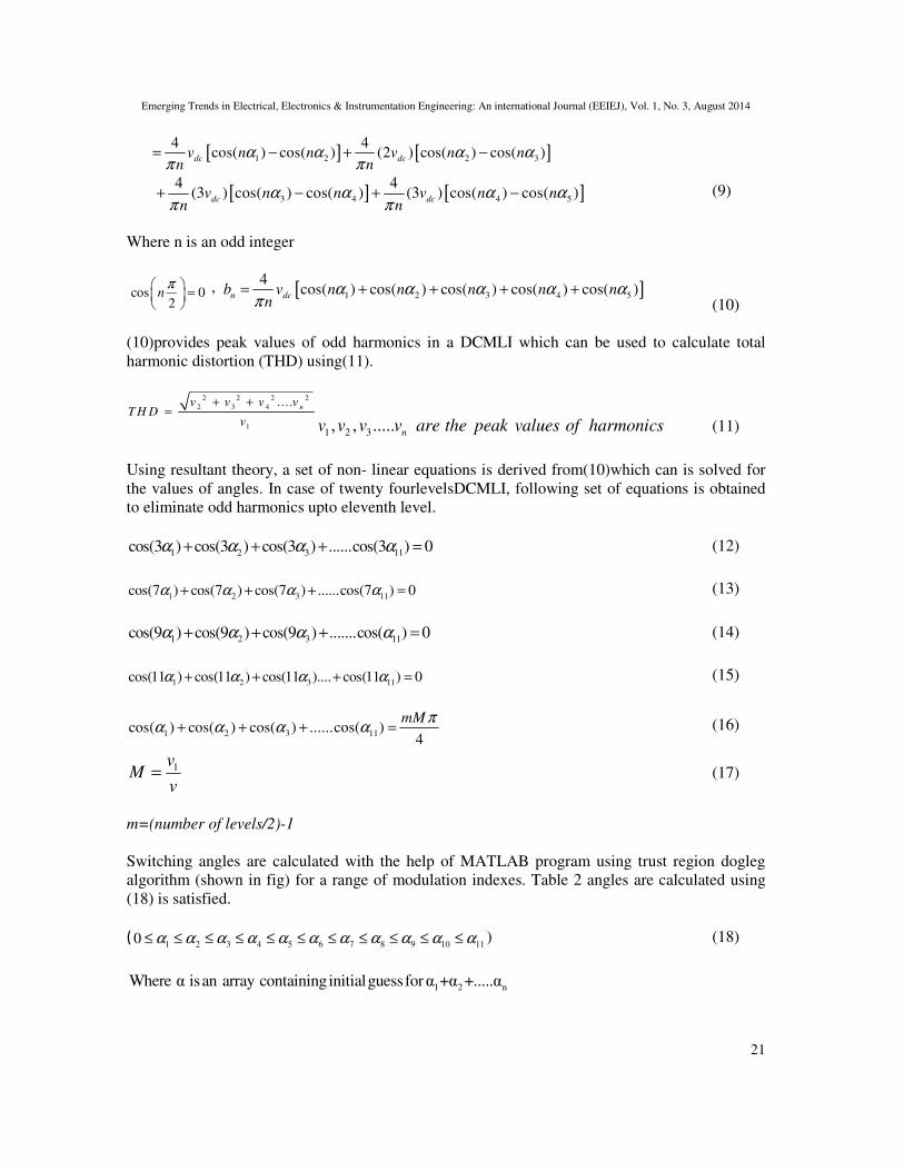
III. CALCULATION FOR DOG LEG ALGORITHM
Equations of the output voltage of DCMLI, peak values of harmonics for the calculation of THD
and the system of non- linear equations for switching angles calculation are derived from Fourier
series. Fourier series for a periodic
1
cos(2 ) sin(2 )t v n o n o
n
f a a nf t b nf tπ π∞
=
= + +∑
Here va , n
a and nb are the Fourier series coefficients and
(3) & (4) shows relationships to determine the values of these coefficients
1( )
o
o
t T
v
t
a f t dtT
+
= ∫
Electrical, Electronics & Instrumentation Engineering: An international Journal (EEIEJ), Vol. 1, No. 3, August 2014
Table 1IGBTs Switching Pattern for 12 DCMLI
Conducting Switches Non Conducting Switches
12 13 14 15 16 17 18 19 20 21 22 23 24 25
26 27 28 29 30 31 32 33
1 2 3 4 5 6 7 8 9 10 11 34 35 36 37 38
39 40 41 42 43 44
11 12 13 14 15 16 17 18 19 20 21 22 23 24
25 26 27 28 29 30 31 32
1 2 3 4 5 6 7 8 9 10 33 34 35 36 37 38
39 40 41 42 43 44
.
.
.
2 3 4 5 6 7 8 9 10 11 12 13 14 15 16 17 18 19
20 21 22 23
1 24 25 26 27 28 29 30 31 32 33 34 35
36 37 38 39 40 41 42 43 44
1 2 3 4 5 6 7 8 9 10 11 12 13 14 15 16 17 18
19 20 21 22
23 24 25 26 27 28 29 30 31 32 33 34 35
36 37 38 39 40 41 42
: Stepped Diode Clamped Multi Level Inverter Output
CALCULATION FOR DOG LEG ALGORITHM
voltage of DCMLI, peak values of harmonics for the calculation of THD
linear equations for switching angles calculation are derived from Fourier
series. Fourier series for a periodic function is expressed in (1)
cos(2 ) sin(2 )t v n o n of a a nf t b nf tπ π
urier series coefficients and fo
is the fundamental frequency.
determine the values of these coefficients
Electrical, Electronics & Instrumentation Engineering: An international Journal (EEIEJ), Vol. 1, No. 3, August 2014
19
Non Conducting Switches
1 2 3 4 5 6 7 8 9 10 11 34 35 36 37 38
39 40 41 42 43 44
1 2 3 4 5 6 7 8 9 10 33 34 35 36 37 38
39 40 41 42 43 44
.
.
.
1 24 25 26 27 28 29 30 31 32 33 34 35
36 37 38 39 40 41 42 43 44
23 24 25 26 27 28 29 30 31 32 33 34 35
36 37 38 39 40 41 42 43 44
voltage of DCMLI, peak values of harmonics for the calculation of THD
linear equations for switching angles calculation are derived from Fourier
(1)
frequency. (2),
(2)

Emerging Trends in Electrical, Electronics & Instrumentation Engineering: An international Journal (EEIEJ), Vol. 1, No. 3, August 2014
20
2( )cos(2 )
o
o
t T
n o
t
a f t nf t dtT
π
+
= ∫ (3)
2( )sin(2 )
o
o
t T
n o
t
b f t nf t dtT
π
+
= ∫ (4)
Where ot = Chosen time reference, T = Fundamental period.
For a signal having odd quarter wave Symmetry, Fourier series coefficients are given as
0v
a = 0n
a for all n= 0n
b for n even=
And
4
0
8( )sin(2 )
T
n ob f t nf t dt for odd nT
π= ∫ (5)
The Multilevel inverter has odd quarter wave symmetry. Using Fourier coefficient equations of a
quarter waves, Fourier coefficients for a DCMLI output are derived in terms of switching angles.
Five angles are considered here only for mathematical calculations.
2
0
4( )sin( ) ( )2
n
o
tb f n t d t for n odd
f
π
ωω ω
π π= ∫ (6)
3 52 4
1 2 43
5
2
4 4 4 4( )sin( ) ( ) (2 )sin( ) ( ) (3 )sin( ) ( ) (4 )sin( ) ( )
4(5 )sin( ) ( ) (7)
n dc dc dc dc
dc
b v n t d t v n t d t v n t d t v n t d t
v n t d t
α αα α
α α α α
π
α
ω ω ω ω ω ω ω ωπ π π π
ω ωπ
= + + +
+
∫ ∫ ∫ ∫
∫
1 2 3 4 5where α ,α ,α ,α and α are the switching angles
Solving Integration results
2
0
4( )sin( ) ( )2
n
o
tb f n t d t for n odd
f
π
ωω ω
π π= ∫
[ ] [ ] 32
1 2
4 4cos( ) (2 ) cos( )
n dc dcb v n t v n t
n n
αα
α αω ωπ π
= − −
[ ] [ ] 54
3 4
4 4(3 ) cos( ) (4 ) cos( )dc dcv n t v n t
n n
αα
α αω ωπ π
− −
[ ] [ ]2 2
1 5
4 4(5 ) cos( ) (2 ) cos( )
dc dcv n t v n t
n n
παα
α αω ω
π π− − (8)
Emerging Trends in Electrical, Electronics & Instrumentation Engineering: An international Journal (EEIEJ), Vol. 1, No. 3, August 2014
21
[ ] [ ]1 2 2 3
4 4cos( ) cos( ) (2 ) cos( ) cos( )dc dcv n n v n n
n nα α α α
π π= − + −
[ ] [ ]3 4 4 5
4 4(3 ) cos( ) cos( ) (3 ) cos( ) cos( )
dc dcv n n v n n
n nα α α α
π π+ − + − (9)
Where n is an odd integer
cos 02
nπ
=
, [ ]1 2 3 4 5
4cos( ) cos( ) cos( ) cos( ) cos( )
n dcb v n n n n n
nα α α α α
π= + + + +
(10)
(10)provides peak values of odd harmonics in a DCMLI which can be used to calculate total
harmonic distortion (THD) using(11).
1 2 3, , ..... nv v v v are the peak values of harmonics (11)
Using resultant theory, a set of non- linear equations is derived from(10)which can is solved for
the values of angles. In case of twenty fourlevelsDCMLI, following set of equations is obtained
to eliminate odd harmonics upto eleventh level.
1 2 3 11cos(3 ) cos(3 ) cos(3 ) ......cos(3 ) 0α α α α+ + + = (12)
1 2 3 11cos(7 ) cos(7 ) cos(7 ) ......cos(7 ) 0α α α α+ + + = (13)
1 2 3 11cos(9 ) cos(9 ) cos(9 ) .......cos( ) 0α α α α+ + + = (14)
1 2 3 11cos(11 ) cos(11 ) cos(11 ).... cos(11 ) 0α α α α+ + + = (15)
1 2 3 11cos( ) cos( ) cos( ) ......cos( )4
mMπα α α α+ + + = (16)
1vM
v= (17)
m=(number of levels/2)-1
Switching angles are calculated with the help of MATLAB program using trust region dogleg
algorithm (shown in fig) for a range of modulation indexes. Table 2 angles are calculated using
(18) is satisfied.
(1 2 3 4 5 6 7 8 9 10 110 α α α α α α α α α α α≤ ≤ ≤ ≤ ≤ ≤ ≤ ≤ ≤ ≤ ≤ ) (18)
1 2 nWhere α isan array containinginitialguessforα +α +.....α
2 2 2 2
2 3 4
1
....n
v v v vT H D
v
+ +=

Emerging Trends in Electrical, Electronics & Instrumentation Engineering: An international Journal (EEIEJ), Vol. 1, No. 3, August 2014
22
Initial Guess α
Evaluate Fi(α )
Calculate S from Newton & Steepest
Decent method such that ||S||≤ r
Calculate Fi(α+S)
& revise r
Fi(α+S) < F(S)
α is replaced by α+S
Yes
No
Figure 3: Proposed Dog Leg Algorithm
2
1
( ) [ ( )]n
i
i
F Fα α=
=∑ (19)
S is correction step and r is radius of trust region. Figure 4 shows the proposed flow chart of trust
region dogleg method for computing 1 2 ..... nα α α+ + from set of functions
1 2 3, , .....n
f f f f
In first step, a correction step is calculated which is added to the initial guess. Dogleg utilizes
Newton and steepest descent methods. The combination of these two methods ensures a fast
convergence and a solution of function in the steepest descent direction. The second step involves
finding the value of trust region radius to estimate length of step for the current iteration such that
the following condition is obeyed.
( ) ( )F s Fα α+ < (20)
Third step performs a check the new values of function. Has the function minimized.
Emerging Trends in Electrical, Electronics & Instrumentation Engineering: An international Journal (EEIEJ), Vol. 1, No. 3, August 2014
23
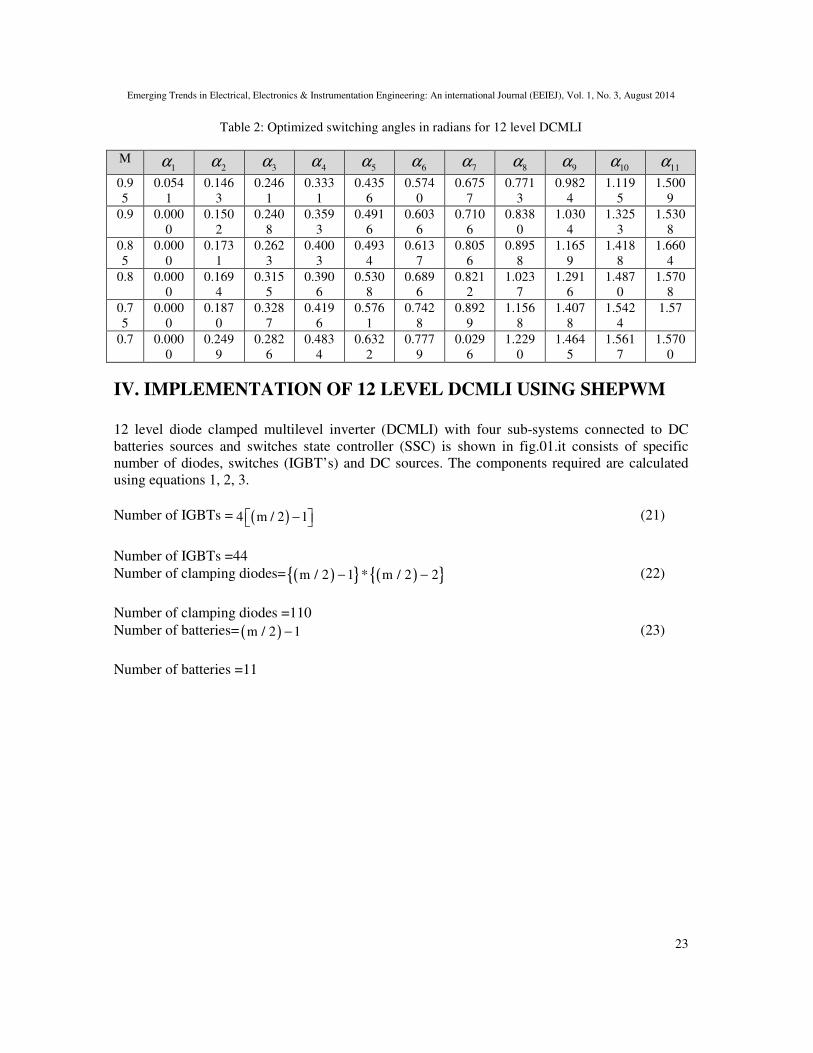
Table 2: Optimized switching angles in radians for 12 level DCMLI
M 1α 2α 3α 4α 5α 6α 7α 8α 9α 10α 11α
0.9
5
0.054
1
0.146
3
0.246
1
0.333
1
0.435
6
0.574
0
0.675
7
0.771
3
0.982
4
1.119
5
1.500
9
0.9 0.000
0
0.150
2
0.240
8
0.359
3
0.491
6
0.603
6
0.710
6
0.838
0
1.030
4
1.325
3
1.530
8
0.8
5
0.000
0
0.173
1
0.262
3
0.400
3
0.493
4
0.613
7
0.805
6
0.895
8
1.165
9
1.418
8
1.660
4
0.8 0.000
0
0.169
4
0.315
5
0.390
6
0.530
8
0.689
6
0.821
2
1.023
7
1.291
6
1.487
0
1.570
8
0.7
5
0.000
0
0.187
0
0.328
7
0.419
6
0.576
1
0.742
8
0.892
9
1.156
8
1.407
8
1.542
4
1.57
0.7 0.000
0
0.249
9
0.282
6
0.483
4
0.632
2
0.777
9
0.029
6
1.229
0
1.464
5
1.561
7
1.570
0
IV. IMPLEMENTATION OF 12 LEVEL DCMLI USING SHEPWM
12 level diode clamped multilevel inverter (DCMLI) with four sub-systems connected to DC
batteries sources and switches state controller (SSC) is shown in fig.01.it consists of specific
number of diodes, switches (IGBT’s) and DC sources. The components required are calculated
using equations 1, 2, 3.
Number of IGBTs = ( ) 4 m / 2 1− (21)
Number of IGBTs =44
Number of clamping diodes= ( ){ } ( ){ }m / 2 1 * m / 2 2 − − (22)
Number of clamping diodes =110
Number of batteries= ( )m / 2 1− (23)
Number of batteries =11

Emerging Trends in Electrical, Electronics & Instrumentation Engineering: An international Journal (EEIEJ), Vol. 1, No. 3, August 2014
Figure 4 shows the overall system of DCMLI. In figure,1 & 3 shows the first leg of positive
terminal of output DC similarly 2 &
generates the control signals to legs and 6 contains the number of capacitors for multilevel
arrangement. Figure5 shows Leg 1a
to complete first leg as there are two legs in this system. Second leg is similar
first and second legs are connected to form a full H
V. SIMULATION RESULTS
Experimental results are obtained
non-optimized IGBTs switching angles. Experimental results
Electrical, Electronics & Instrumentation Engineering: An international Journal (EEIEJ), Vol. 1, No. 3, August 2014
Figure 4: 12 Levels DCMLI
shows the overall system of DCMLI. In figure,1 & 3 shows the first leg of positive
terminal of output DC similarly 2 & 4 shows the 2nd
leg of negative terminal of output DC. 5
generates the control signals to legs and 6 contains the number of capacitors for multilevel
Leg 1a of 12 levels DCMLI which is connected in series with leg1b
first leg as there are two legs in this system. Second leg is similar to first leg. B
first and second legs are connected to form a full H-Bridge DCMLI.
V. SIMULATION RESULTS
obtained for optimized switching angles using dog leg method and
switching angles. Experimental results include shows
Electrical, Electronics & Instrumentation Engineering: An international Journal (EEIEJ), Vol. 1, No. 3, August 2014
24
shows the overall system of DCMLI. In figure,1 & 3 shows the first leg of positive
leg of negative terminal of output DC. 5
generates the control signals to legs and 6 contains the number of capacitors for multilevel
of 12 levels DCMLI which is connected in series with leg1b
to first leg. Both
method and for
Emerging Trends in Electrical, Electronics & Instrumentation Engineering: An international Journal (EEIEJ), Vol. 1, No. 3, August 2014
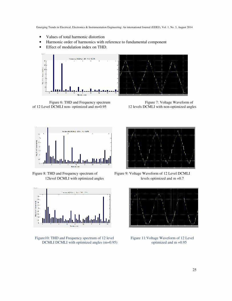
• Values of total harmonic distortion
• Harmonic order of harmonics with reference to fundamental component
• Effect of modulation index on THD.
Figure 6: THD and Frequency spectrum
of 12 Level DCMLI non- optimized and m=0.95
Figure 8: THD and Frequency spectrum of
12level DCMLI with optimized angles
Figure10: THD and Frequency spectrum of
DCMLI DCMLI with optimized angles (m=0.95)
Electrical, Electronics & Instrumentation Engineering: An international Journal (EEIEJ), Vol. 1, No. 3, August 2014
Values of total harmonic distortion
Harmonic order of harmonics with reference to fundamental component
modulation index on THD.
: THD and Frequency spectrum Figure 7: Voltage Waveform of
optimized and m=0.95 12 levels DCMLI with non-optimized angles
: THD and Frequency spectrum of Figure 9: Voltage Waveform of 12 Level DCMLI
DCMLI with optimized angles levels optimized and m =0.7
: THD and Frequency spectrum of 12 level Figure 11:Voltage Waveform of 12 Level
with optimized angles (m=0.95) optimized and m =0.95
Electrical, Electronics & Instrumentation Engineering: An international Journal (EEIEJ), Vol. 1, No. 3, August 2014
25
: Voltage Waveform of
optimized angles
Voltage Waveform of 12 Level DCMLI
optimized and m =0.7
Voltage Waveform of 12 Level
optimized and m =0.95
Emerging Trends in Electrical, Electronics & Instrumentation Engineering: An international Journal (EEIEJ), Vol. 1, No. 3, August 2014
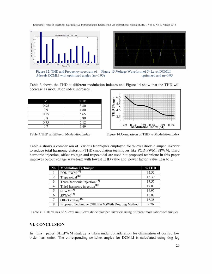
Figure 12: THD and Frequency spectrum of Fig
5-levels DCMLI with optimized angles (m=0.95)
Table 3 shows the THD at different modulation indexes and Figure 1
decrease as modulation index increases.
Table 3:THD at different Modulation index
Table 4 shows a comparison of various techniques employed for 5
to reduce total harmonic distortion(THD).modulation techniques like POD
harmonic injection, offset voltage and trapezoidal are
improves output voltage waveform with lowest THD value and power factor value near to 1.
No. Modulation Technique
1 POD-PWM[12]
2 Trapezoidal[13]
3 Three harmonic
4 Third harmonic injection
5 SPWM[13]
6 SPWM[15]
7 Offset voltage
8 Proposed Technique (SHEPWM)With Dog Leg Method
Table 4: THD values of 5-level multilevel diode clamped i
VI. CONCLUSION
In this paper, SHEPWM strategy is taken under consideration for elimination of desired low
order harmonics. The corresponding switches angles for DCMLI is calculated using dog leg
M THD
0.95
0.9
0.85
0.8
0.75
0.7
Electrical, Electronics & Instrumentation Engineering: An international Journal (EEIEJ), Vol. 1, No. 3, August 2014
: THD and Frequency spectrum of Figure 13:Voltage Waveform of 5- Level DCMLI
levels DCMLI with optimized angles (m=0.95) optimized and m=0.95
Table 3 shows the THD at different modulation indexes and Figure 14 show that the THD will
decrease as modulation index increases.
fferent Modulation index Figure 14:Comparison of THD vs Modulation Index
shows a comparison of various techniques employed for 5-level diode clamped inverter
to reduce total harmonic distortion(THD).modulation techniques like POD-PWM, SPWM, Third
harmonic injection, offset voltage and trapezoidal are used but proposed technique in this paper
improves output voltage waveform with lowest THD value and power factor value near to 1.
Modulation Technique %THD [12]
32.32 [13]
18.39
Three harmonic Injection[14]
17.57
Third harmonic injection[13]
17.03
16.97
16.82
Offset voltage[13]
16.38
Proposed Technique (SHEPWM)With Dog Leg Method 9.76
multilevel diode clamped inverters using different modulations techniques
, SHEPWM strategy is taken under consideration for elimination of desired low
order harmonics. The corresponding switches angles for DCMLI is calculated using dog leg
THD
3.80
4.80
5.65
5.80
6.12
6.49
33.5
44.5
55.5
66.5
7
0.69 0.74 0.79 0.84
TH
D (
%a
ge)
Modulation Index (M)
Electrical, Electronics & Instrumentation Engineering: An international Journal (EEIEJ), Vol. 1, No. 3, August 2014
26
Level DCMLI
optimized and m=0.95
show that the THD will
Modulation Index
level diode clamped inverter
PWM, SPWM, Third
used but proposed technique in this paper
improves output voltage waveform with lowest THD value and power factor value near to 1.
using different modulations techniques
, SHEPWM strategy is taken under consideration for elimination of desired low
order harmonics. The corresponding switches angles for DCMLI is calculated using dog leg
0.89 0.94Modulation Index (M)
Emerging Trends in Electrical, Electronics & Instrumentation Engineering: An international Journal (EEIEJ), Vol. 1, No. 3, August 2014
27
optimization algorithm. Undesired harmonics are eliminated to possible maximum limits and the
fundamental voltage is maintained at desired level, thus resulting the minimum THD. The
proposed technique can be applied to any multilevel inverter configurations and we can
generalize this method to any higher order inverters.
REFERENCES
[1] Peddapeli.S.K, (2014) “Recent Advances in Pulse Width Modulation Techniques andMultilevel
Inverters”International Journal of Electrical, Electronic Science and EngineeringVol 8 No 3, pp-568-
576.
[2] Hussein. H, (2014) “Harmonics Elimination PWM (HEPWM)” International Journal of Engineering
Research and General Science Vol 2, No 2, pp-172-181.
[3] Satyanarayana, G. V. R., & Ganesh, S. N. V, (April 2010)“Cascaded 5-level inverter
typeDSTATCOM for power quality improvement”InStudents' Technology Symposium (TechSym),
2010 IEEE (pp. 166-170).
[4] Shukla, A., Ghosh, A., & Joshi, A, (2010) “Flying-capacitor-based chopper circuit for dc capacitor
voltage balancing in diode-clamped multilevel inverter” Industrial Electronics, IEEE Transactions on,
57(7), pp2249-2261.
[5] Boora, A. A., Nami, A., Zare, F., Ghosh, A., &Blaabjerg, F, (2010) “Voltage-sharing converter to
supply single-phase asymmetrical four-level diode-clamped inverter with high power factor
loads”Power Electronics, IEEE Transactions on, 25(10), pp2507-2520.
[6] Cavalcanti, M. C., Farias, A. M., Oliveira, K. C., Neves, F. A., &Afonso, J. L, (2012)“Eliminating
leakage currents in neutral point clamped inverters for photovoltaic systems” Industrial Electronics,
IEEE Transactions on, 59(1), pp435-443.
[7] Li, J., Liu, J., Boroyevich, D., Mattavelli, P., &Xue, Y, (May, 2011) “Comparative analysis of three-
level diode neural-point-clamped and active neural-point-clamped zero-current-transition inverters”
In Power Electronics and ECCE Asia (ICPE & ECCE), 2011 IEEE 8th International Conference (pp.
2290-2295)
[8] Du, Z., Tolbert, L. M., Ozpineci, B., &Chiasson, J. N, (2009) “Fundamental frequency switching
strategies of a seven-level hybrid cascaded H-bridge multilevel inverter” Power Electronics, IEEE
Transactions on, 24(1), pp25-33.
[9] Khazraei, M., Sepahvand, H., Corzine, K. A., &Ferdowsi, M, (2012) “Active capacitor voltage
balancing in single-phase flying-capacitor multilevel power converters”.Industrial Electronics, IEEE
Transactions on, 59(2), pp769-778.
[10] Rodriguez, J. C., & P Moran, L, (2001) “A vector control technique for medium voltage multilevel
inverters” Applied Power Electronics Conference and Exposition, 2001.APEC 2001.
[11] J. Rodriguez, J. S. Lai, and F. Z. Peng, (2002) “Multilevel inverters: A survey of topologies, controls,
and applications” IEEE Trans. Ind. Electron., Vol.49, no. 4, pp. 724–738.
[12] Chaturvedi. R,(2014) “A Single Phase Diode Clamped Multilevel Inverter and its Switching
Function”. Journal of Innovative trends in Science, Pharmacy & Technology. Vol-1(1),pp.63-66.
[13] Haskar Reddy, V. N.,Babu, C. S. & Suresh, K, (2011) “Advanced Modulating Techniques for Diode
Clamped Multilevel Inverter Fed Induction Motor”Vol. 6, No 1,pp. 90-99.
[14] Zheng, X., Song, L., & Hongying, P, “Study of Five-level diodes-clamped Inverter Modulation
Technology Based on Three-harmonic Injection Method” 2nd International Conference on Electronic
& Mechanical Engineering and Information Technology 2012.
[15] Kedareswar.M., (2013) “Reduction of THD in Diode Clamped Multilevel Inverter employing SPWM
technique”International Journal of Scientific and Research Publications, Vol 3, No 6, pp.1-4.

Emerging Trends in Electrical, Electronics & Instrumentation Engineering: An international Journal (EEIEJ), Vol. 1, No. 3, August 2014
28
AUTHORS
Tariq Kamal, received his BSc degree in Electronic Engineering from University of
Engineering and Technology (UET) Peshawar, Pakistan in 2012.He is currently in Comsats
institute of information Technology Abbottabad Campus pursuing his Master degree in
Electrical Power and Control Engineering and acting as a Lecturer in University of
Engineering and Technology (UET) Abbottabad Campus. His main research is in the area
of power system stability, application of adaptive intelligent controls, power electronics and
electrical Machine drives.
Syed Zulqadar Hassan, has received his B.Sc. (Electronics Engineering) from University
of Engineering and Technology, Peshawar in 2012 with securing a Gold Medal and also
got award from Governor of KPK. Currently his M.Sc. (Electrical Engineering Power &
Control) is likely to be completed from Comsats Institute of Information Technology,
Abbottabad Campus and recently also performing the duties of Lecturer in University of
Engineering and Technology (UET) Abbottabad Campus. His main research focuses on the area of Fuzzy
Based Controller Design and Power Electronics Control.
Syeda Zahra Naqvi, received her B.Sc. (Electronics Engineering) from University of Engineering and
Technology, Peshawar in 2013. Currently she is engaged in doing M.Sc. (Electrical Engineering Power &
Control) form Comsats Institute of Information Technology, Abbottabad Campus. Her main research is in
the area of Power System and Power Electronics Control.
Imranullah, received his BSc degree in Electronic Engineering from University of
Engineering and Technology (UET) Peshawar, Pakistan in 2012.He is currently in
University of Engineering & Technology Taxila pursuing his Master degree in Control
Engineering. His main research is in the area of Control stability, Power electronic Control
system.