A Single Leg Switched PWM Method - UPCommons
6
A Single Leg Switched PWM Method for Three-phase H-Bridge Voltage Source Converters Osman S. Senturk, Student Member, IEEE Stig Munk-Nielsen, Member, IEEE Remus Teodorescu, Senior Member, IEEE Aalborg University Department of Energy Technology Pontoppidanstraede 101 Aalborg, 9220, Denmark [email protected], [email protected], [email protected] Lars Helle Vestas Wind Systems Pontoppidanstraede 101 Aalborg, 9220, Denmark [email protected] Pedro Rodriguez Member, IEEE Technical University of Catalonia Dept. of Electrical Engineering C. Colom 1 Terrassa, 08222, Spain [email protected] Abstract -- This paper proposes a single leg switched or a hybrid PWM (HPWM) method for three-phase three-level H- Bridge Voltage Source Converters (3L-HB-VSCs). By means of the proposed modulation, a 3L-HB-VSC can generate the same output as a three-level neutral point clamped (3L-NPC) VSC with phase disposition (PD) PWM provided that the outputs of 3L-HB- VSC are isolated by transformers or connected to open winding machines. Thus, the proposed method is called PD-HPWM. Moreover, it is emphasized that 3L-HB-VSC with HPWM utilizes its switches similar to 3L-NPC-VSC. Compared to 3L-NPC-VSCs, 3L-HB-VSCs (without neutral point clamping diodes) have simpler, more modular, and more reliable 2L circuit structure. Therefore, this method encourages the use of 3L-HB-VSCs in the applications utilizing transformers such as grid-side converters of multi-MW wind turbines. The proposed PWM method’s performance is demonstrated by the simulations of a 6MW wind turbine’s grid connection and experimentally verified via a small- scale prototype. Index Terms-- H-Bridge, hybrid modulation, neutral point clamped, multilevel converters, wind energy I. INTRODUCTION H-bridge (HB) voltage source converters (VSCs) have been mostly utilized in DC/DC converter systems [1] and single- phase AC applications [2]. In three-phase applications, with AC side isolation transformers as shown in Fig. 1, HB-VSCs have been utilized in Series Active Filter (SAF) [3], Dynamic Voltage Restorer (DVR) [4], and STATCOM [5] applications. Moreover, the three-phase HB-VSC topology or its close variants have been used to drive open winding induction machines [6]-[9] and dual three-phase induction machines [10]. Note that in these induction machine drive systems, these converters are considered as two 2L three-phase VSCs. In addition to these studies, the cascaded connections of H-bridge (CHB) VSCs have been investigated in medium voltage motor drive applications [11], [12]. The modulation of single-phase HB-VSC has been thoroughly studied in the literature [1], [11]. In most applications, three-level (3L) modulation, which is called unipolar pulse width modulation (UPWM), is preferred to the two-level (2L) modulation, which is also called bipolar PWM (BPWM), because UPWM ensures the half of the dv/dt output voltage stress that BPWM results in. As well as UPWM, single phase-leg switched modulation or hybrid PWM (HPWM) generates 3L output voltage [11], [13]. Nevertheless, these PWM methods have not been studied for three-phase HB- VSCs elaborately. For the aforementioned ‘two 2L VSCs’ variants of the three-phase HB-VSC, there are PWM studies which aim at control of dual three-phase induction machines [10], common mode voltage elimination of an open winding induction machine [7], and balancing the power drawn from two isolated DC sources in an open winding induction machine drive system [8]. In [9], it has been demonstrated that by means of a space vector based PWM method a ‘cascaded 2L converter’ is able to generate the same converter performance as 3L neutral-point-clamped (NPC) VSC (Fig. 2), which has been thoroughly studied in the literature since it was introduced in 1981 [14]. Nonetheless, the correlation between the three-phase HB-VSC (or so-called 3L-HB-VSC hereafter in this paper) with HPWM and 3L-NPC-VSC has not been studied in the literature. Fig. 1. 3L-HB-VSC with a transformer for grid connection Fig. 2. 3L-NPC-VSC with a transformer for grid connection 3137 978-1-4244-2893-9/09/$25.00 ©2009 IEEE
-
Upload
khangminh22 -
Category
Documents
-
view
3 -
download
0
Transcript of A Single Leg Switched PWM Method - UPCommons

A Single Leg Switched PWM Method for Three-phase H-Bridge Voltage Source Converters
Osman S. Senturk, Student Member, IEEE Stig Munk-Nielsen, Member, IEEE
Remus Teodorescu, Senior Member, IEEE Aalborg University
Department of Energy Technology Pontoppidanstraede 101 Aalborg, 9220, Denmark
[email protected], [email protected], [email protected]
Lars Helle Vestas Wind Systems
Pontoppidanstraede 101 Aalborg, 9220, Denmark
Pedro Rodriguez Member, IEEE
Technical University of Catalonia Dept. of Electrical Engineering
C. Colom 1 Terrassa, 08222, Spain [email protected]
Abstract -- This paper proposes a single leg switched or a
hybrid PWM (HPWM) method for three-phase three-level H-Bridge Voltage Source Converters (3L-HB-VSCs). By means of the proposed modulation, a 3L-HB-VSC can generate the same output as a three-level neutral point clamped (3L-NPC) VSC with phase disposition (PD) PWM provided that the outputs of 3L-HB-VSC are isolated by transformers or connected to open winding machines. Thus, the proposed method is called PD-HPWM. Moreover, it is emphasized that 3L-HB-VSC with HPWM utilizes its switches similar to 3L-NPC-VSC. Compared to 3L-NPC-VSCs, 3L-HB-VSCs (without neutral point clamping diodes) have simpler, more modular, and more reliable 2L circuit structure. Therefore, this method encourages the use of 3L-HB-VSCs in the applications utilizing transformers such as grid-side converters of multi-MW wind turbines. The proposed PWM method’s performance is demonstrated by the simulations of a 6MW wind turbine’s grid connection and experimentally verified via a small-scale prototype.
Index Terms-- H-Bridge, hybrid modulation, neutral point
clamped, multilevel converters, wind energy
I. INTRODUCTION H-bridge (HB) voltage source converters (VSCs) have been
mostly utilized in DC/DC converter systems [1] and single-phase AC applications [2]. In three-phase applications, with AC side isolation transformers as shown in Fig. 1, HB-VSCs have been utilized in Series Active Filter (SAF) [3], Dynamic Voltage Restorer (DVR) [4], and STATCOM [5] applications. Moreover, the three-phase HB-VSC topology or its close variants have been used to drive open winding induction machines [6]-[9] and dual three-phase induction machines [10]. Note that in these induction machine drive systems, these converters are considered as two 2L three-phase VSCs. In addition to these studies, the cascaded connections of H-bridge (CHB) VSCs have been investigated in medium voltage motor drive applications [11], [12].
The modulation of single-phase HB-VSC has been thoroughly studied in the literature [1], [11]. In most applications, three-level (3L) modulation, which is called unipolar pulse width modulation (UPWM), is preferred to the two-level (2L) modulation, which is also called bipolar PWM (BPWM), because UPWM ensures the half of the dv/dt output voltage stress that BPWM results in. As well as UPWM, single phase-leg switched modulation or hybrid PWM (HPWM)
generates 3L output voltage [11], [13]. Nevertheless, these PWM methods have not been studied for three-phase HB-VSCs elaborately. For the aforementioned ‘two 2L VSCs’ variants of the three-phase HB-VSC, there are PWM studies which aim at control of dual three-phase induction machines [10], common mode voltage elimination of an open winding induction machine [7], and balancing the power drawn from two isolated DC sources in an open winding induction machine drive system [8]. In [9], it has been demonstrated that by means of a space vector based PWM method a ‘cascaded 2L converter’ is able to generate the same converter performance as 3L neutral-point-clamped (NPC) VSC (Fig. 2), which has been thoroughly studied in the literature since it was introduced in 1981 [14]. Nonetheless, the correlation between the three-phase HB-VSC (or so-called 3L-HB-VSC hereafter in this paper) with HPWM and 3L-NPC-VSC has not been studied in the literature.
Fig. 1. 3L-HB-VSC with a transformer for grid connection
Fig. 2. 3L-NPC-VSC with a transformer for grid connection
3137978-1-4244-2893-9/09/$25.00 ©2009 IEEE

This study demonstrates that a 3L-HB-VSC with HPWM generates the same output voltage as an 3L-NPC-VSC with phase opposition disposition PWM (POD-PWM), and then it proposes a carrier-based HPWM in order 3L-HB-VSC to generate the same output voltage as 3L-NPC-VSC with phase disposition PWM (PD-PWM) (or its space vector equivalent of Nearest Triangle Vector (NTV) PWM when zero-sequence triangular voltage is added to three-phase reference voltages). Thus, the former HPWM method will be called POD-HPWM and the proposed method will be called PD-HPWM hereafter in this paper. It should be noted that in a three-phase three-wire system, PD type PWM results in less harmonic distortion than POD type PWM due to the elimination of the common mode harmonic terms in line-to-line voltages [11]; therefore, the existence of the proposed PD-HPWM carries more significance than POD-HPWM particularly for low switching frequency applications where this elimination makes significant difference in harmonic spectrum. Also, this study emphasizes on the capability of 3L-HB-VSC with HPWM to utilize its switches similarly to 3L-NPC-VSC.
In this paper, first, POD-PWM, PD-PWM, and POD-HPWM are described. Then, PD-HPWM is proposed via a carrier based realization. By means of the simulations of a 6MW wind turbine medium voltage grid-side converter as 3L-NPC-VSC and 3L-HB-VSC, the equivalency between these POD methods and the equivalency between these PD methods are demonstrated via output voltage/current waveforms. Also, the switch current waveforms illustrates the similarity of the switch utilizations in the two VSCs . Next, experimental results of a 1.5kW prototype validate the performance of the proposed PD-HPWM. Finally, the advantages and disadvantages of 3L-HB-VSC with PD-HPWM compared to 3L-NPC-VSC are discussed and its possible application fields are addressed.
II. THREE-LEVEL PWM METHODS For 3L-NPC-VSCs, there are two types of triangular carrier
based PWM methods: POD-PWM and PD-PWM (Fig. 3 and 4 for phase-a). Both methods compare the reference voltage v*
a with the upper triangle vtri+ and the lower triangle vtri- signals where vtri+ and vtri-’s absolute peak values are scaled with the half of the total DC bus voltage of the converter, VDC. Illustrated in Fig. 5, the difference between the two methods is that vtri+ and vtri- for PD-PWM are in-phase while they have 180° phase shift for POD-PWM [11]. These two methods results in similar output voltage and current in single-phase applications; however, the elimination of common mode harmonic (zero sequence) components in the line-to-line output voltage in three-phase systems makes the output difference favoring PD-PWM [11].
In 3L-HB-VSCs, the single leg switched or hybrid PWM method (Fig. 6) modulates the leg of SA1&SA2 with the switching frequency fS while the other leg of SA3&SA4 with the electrical frequency fe [11], [13]. Hence, the switches are utilized similarly to those of the NPC for PF≈1. Also, the resulting output current waveform is theoretically identical to
the one with POD-PWM because the comparison of the absolute value of the reference voltage |v*
a| with the triangular carrier signal vtri works similarly to POD-PWM. Thus, this method will be called POD-HPWM hereafter in this paper. Nonetheless, the existence of the PD counterpart of POD-HPWM would carry more importance due to its favorable output performance in three-phase applications. Hence, PD-HPWM (Fig. 7) is proposed as follows. The modulation algorithm compares the positive part of v*
a with vtri+ for v*a>0
and the negative part of v*a with vtri- for v*
a<0 in order to modulate the leg with the switches SA1&SA2 of the HB while the polarity of v*
a is used for the switching decision of the leg with SA3&SA4. The signals employed in the hybrid PWM methods are illustrated in Fig. 8.
Fig. 3. POD-PWM algorithm for phase-a of 3L-NPC-VSC
Fig. 4. PD-PWM algorithm for phase-a of 3L-NPC-VSC
Fig. 5. The waveforms of POD-PWM and PD-PWM employing third-harmonic added reference voltage v*
a (black), vtri+ (red), vtri- for PD-PWM (green), and vtri- for PD-PWM (blue)
3138

Fig. 6. POD-HPWM algorithm for phase-a of 3L-HB-VSC
Fig. 7. PD-HPWM algorithm for phase-a of 3L-HB-VSC
Fig. 8. The waveforms of POD-HPWM and PD-HPWM employing third-harmonic added reference voltage v*
a (black), |v*a| (blue), vtri and vtri+ (red), and
vtri- (green).
III. SIMULATION RESULTS The simulations are conducted by employing ideal
component models built in Ansoft/Simplorer for the medium voltage 3L-HB-VSC and 3L-NPC-VSC shown in Fig. 1 and 2 for a grid connection of 6MW wind turbine via a three-phase transformer with open primary windings. The simulation parameters are given in Table I. In implementation of PWM algorithms, asymmetrical double-edge regular sampling is used [11]. Fig. 9 demonstrates that the output current is significantly less distorted for PD-PWM than POD-PWM in 3L-NPC-VSC. The line-to-line voltage waveforms shown in Fig. 10 explain the performance difference such that PD-PWM results only in the voltage steps of VDC while POD-PWM results in both VDC and 2VDC. For 3L-HB-VSC, Fig. 11 demonstrates the equivalencies between POD-PWM and POD-HPWM and between PD-PWM and PD-HPWM. Table II summarizes the
output current Total Harmonic Distortion THDI values for each case. Demonstrated in Fig. 12, there is a correlation between the switch utilizations of 3L-NPC-VSC and 3L-HB-VSC with the hybrid PWM methods. Given in Table III, for PF≈1, there is one-to-oneness for IGBT utilization while the antiparallel diodes DA2&DA1 of the HB converter are utilized similarly to the clamping diodes DA5&DA6, respectively.
TABLE I
SIMULATION PARAMETERS Grid line-to-line voltage 10kVrms (50Hz)Filter inductor, L 450µH (10%)Transformer turns-ratio, N (Ninv/Ngrid) 0.3 (1:3.33)Output power, P 6MWPower factor, PF 1 DC bus voltage, VDC 2500VSwitching frequency, fS 1050Hz
Fig. 9. The reference voltage v*a (black), output phase voltage va (green),
and output current ia (blue) waveforms of phase-a for POD-PWM (upper) and PD-PWM (lower) in 3L-NPC-VSC
Fig. 10. The output line-to-line voltage vab (red) and output current ia (blue) waveforms for POD-PWM (upper) and PD-PWM (lower) in 3L-NPC-VSC
TABLE II
THDI RESULTS IN SIMULATIONS VSC NPC HB
Modulation POD-PWM
PD-PWM
POD- HPWM
PD-HPWM
THDI (%) 19.63 8.88 19.58 8.78
3139
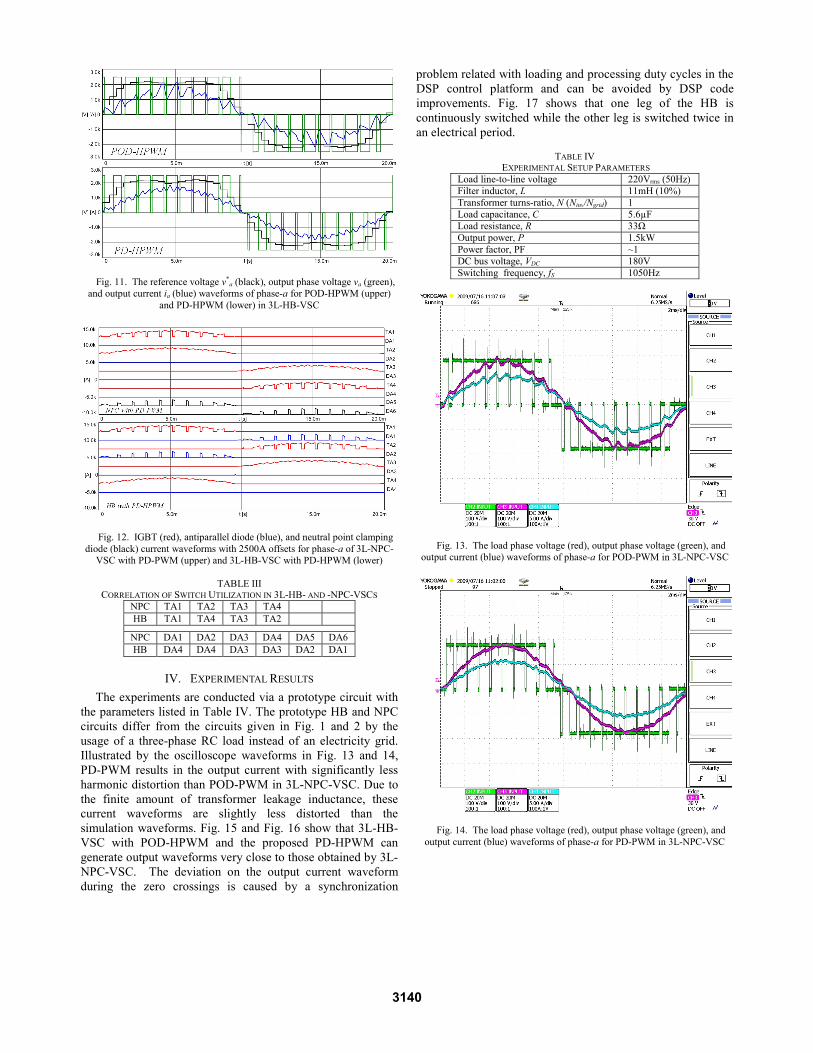
Fig. 11. The reference voltage v*a (black), output phase voltage va (green),
and output current ia (blue) waveforms of phase-a for POD-HPWM (upper) and PD-HPWM (lower) in 3L-HB-VSC
Fig. 12. IGBT (red), antiparallel diode (blue), and neutral point clamping diode (black) current waveforms with 2500A offsets for phase-a of 3L-NPC-
VSC with PD-PWM (upper) and 3L-HB-VSC with PD-HPWM (lower)
TABLE III CORRELATION OF SWITCH UTILIZATION IN 3L-HB- AND -NPC-VSCS
NPC TA1 TA2 TA3 TA4 HB TA1 TA4 TA3 TA2
NPC DA1 DA2 DA3 DA4 DA5 DA6HB DA4 DA4 DA3 DA3 DA2 DA1
IV. EXPERIMENTAL RESULTS The experiments are conducted via a prototype circuit with
the parameters listed in Table IV. The prototype HB and NPC circuits differ from the circuits given in Fig. 1 and 2 by the usage of a three-phase RC load instead of an electricity grid. Illustrated by the oscilloscope waveforms in Fig. 13 and 14, PD-PWM results in the output current with significantly less harmonic distortion than POD-PWM in 3L-NPC-VSC. Due to the finite amount of transformer leakage inductance, these current waveforms are slightly less distorted than the simulation waveforms. Fig. 15 and Fig. 16 show that 3L-HB-VSC with POD-HPWM and the proposed PD-HPWM can generate output waveforms very close to those obtained by 3L-NPC-VSC. The deviation on the output current waveform during the zero crossings is caused by a synchronization
problem related with loading and processing duty cycles in the DSP control platform and can be avoided by DSP code improvements. Fig. 17 shows that one leg of the HB is continuously switched while the other leg is switched twice in an electrical period.
TABLE IV
EXPERIMENTAL SETUP PARAMETERS Load line-to-line voltage 220Vrms (50Hz)Filter inductor, L 11mH (10%)Transformer turns-ratio, N (Ninv/Ngrid) 1 Load capacitance, C 5.6µFLoad resistance, R 33Ω Output power, P 1.5kWPower factor, PF ~1 DC bus voltage, VDC 180VSwitching frequency, fS 1050Hz
Fig. 13. The load phase voltage (red), output phase voltage (green), and output current (blue) waveforms of phase-a for POD-PWM in 3L-NPC-VSC
Fig. 14. The load phase voltage (red), output phase voltage (green), and output current (blue) waveforms of phase-a for PD-PWM in 3L-NPC-VSC
3140

Fig. 15. The load phase voltage (red), output phase voltage (green), and output current (blue) waveforms of phase-a for POD-HPWM in 3L-HB-VSC
Fig. 16. The load phase voltage (red), output phase voltage (green), and output current (blue) waveforms of phase-a for PD-HPWM in 3L-HB-VSC
V. DISCUSSION The proposed PD-HPWM carries importance due to its
equivalent performance and similar switch utilization to 3L-NPC-VSC, which is dominantly used converter topology especially for medium voltage converters with low switching frequency (fS<2kHz). Hence, for medium voltage grid converter applications requiring transformers or for open winding machine converter applications, 3L-HB-VSC can be considered as an alternative to 3L-NPC-VSC because the former has simpler, more modular, and more reliable 2L structure than the 3L structure. Also, the clamping diodes and neutral point variation problem of the NPC are eliminated in the HB. Considering switch utilization, the duty of the clamping diodes in the NPC is performed by the antiparallel diodes in the HB. However, for the applications where IGBTs and diodes are packaged together, the elimination of the clamping diodes increases the power loss stress on the IGBT-diode packages forming the switched HB legs and becomes a
disadvantage. On the other hand, for medium voltage applications where these two semiconductors are packaged separately, this elimination is an advantage of reducing semiconductor cost and more efficient utilization of the switches. Moreover, several control and design strategies can be developed by means of hybrid modulation of 3L-HB-VSCs as follows.
Fig. 17. With respect to the negative rail of the DC bus, the switched leg’s voltage (green) and the other leg’s voltage (red), and output current (blue)
waveforms of phase-a for PD-HPWM in 3L-HB-VSC
The switched leg and the other leg can be interchanged cyclically. Hence, better utilization of the switches over the NPC can be achieved and better lifetime for each switch can be attained. Also, as proposed in [9], different type of switches can be used for the two legs. For example, the switches with low switching loss for the switched leg and the switches with low conduction loss for the other leg can be chosen in order to optimize the efficiency.
For the grid applications requiring capacitive switching ripple filters, the implementation of these filters at the grid side of the transformer does not influence the output performance equivalency of the two converters. However, if a capacitive filter is directly applied to the inverter side of a 3L-HB-VSC, then the elimination of the common mode terms in three-phase system does no longer exist and the converter output current deteriorates significantly with the harmonics around the switching frequency. In order to solve this problem, common mode inductors in series with the filter inductors can be applied to 3L-HB-VSC.
VI. CONCLUSION The 3L-HB-VSC with the proposed PD-HPWM produces
the same output performance as the 3L-NPC-VSC with PD-PWM or space vector NTV. Moreover, the PD-HPWM enables the former VSC to utilize its switches similarly to those of the latter. The performance of the proposed method has been validated by the simulations and experiments. Thus, the former VSC can be considered as an alternative to the latter for medium voltage grid-connected converter with transformer
3141

or open winding motor drive applications in regards to design simplicity and switch utilization flexibility. Only disadvantage, which can be avoided by the hardware solutions discussed, is the limitation of capacitive switching ripple filter employment for grid-connected applications.
ACKNOWLEDGMENT This work was supported by Aalborg University-Vestas
Wind Systems partnership under Vestas Power Program. Any opinions, findings, and conclusions or recommendations expressed in this material are those of the authors and do not necessarily reflect those of Vestas Wind Systems.
The authors gratefully acknowledge the contributions of M. Swierczynski, A. Adamczyk, and T. Kerekes for their work on the experimental test setup.
REFERENCES [1] N. Mohan, T. M. Undeland, W. P. Robbins, Power Electronics
Converters, Applications, and Design, 4th Edition, NJ: John Wiley & Sons, 2003.
[2] S. B. Kjaer, J. K. Pedersen, F. Blaabjerg, “A review of single-phase grid-connected inverters for photovoltaic modules,” IEEE Trans. on Ind. Applicat., Vol. 41, No. 5, pp.1292-1306, Sept./Oct. 2005.
[3] F. Z. Peng, H. Akagi, A. Nabae, “A new approach to harmonic compensation in power systems - a combined system of shunt passive and series active filters,” IEEE Trans. on Ind. Applicat., Vol. 26, No. 6, pp. 983-990, Nov.r/Dec. 1990.
[4] H. Kim, S. K. Sul, “Compensation voltage control in dynamic voltage restorers by use of feed forward and state feedback scheme,” IEEE Trans. on Power Electron., Vol. 20, No. 5, pp. 1169-1177, Sept. 2005.
[5] S. Ponnaluri, J. K. Steinke, P. Steimer, S. Reichert, B. Buchmann, “Design comparison and control of medium voltage STATCOM with novel twin convertert topology,” in Proc. 2004 IEEE PESC.
[6] K. Gopakumar, V. T. Ranganathan, S. R. Bhat, “Split-phase induction motor operation from PWM voltage source inverter,” IEEE Trans. on Ind. Applicat., Vol. 29, No. 5, pp. 927-932, Sept./Oct. 1993.
[7] M. R. Baiju, K. K. Mohapatra, R. S. Kanchan, K. Gopakumar, “A dual two-level inverter scheme with common mode voltage elimination for an induction motor drive,” IEEE Trans. on Power Electron., Vol. 19, No. 3, pp. 794-805, May 2004.
[8] D. Casadei, G. Grandi, A. Lega, C. Rossi, “Multilevel operation and input power balancing for a dual two-level inverter with insulated DC sources,” IEEE Trans. on Ind. Applicat., Vol. 44, No. 6, pp. 1815-1824, Nov./Dec. 2008.
[9] K. A. Corzine, S. D. Sudhoff, C. A. Whitcomb, “Performance characteristics of a cascaded two-level converter,” IEEE Trans. on Energy Conversion, Vol. 14, No. 3, pp. 433-439, Sept. 1999.
[10] Y. Zhao, T. A. Lipo, “Space vector PWM control of dual three-phase induction machine using vector space decomposition,” IEEE Trans. on Ind. Applicat., Vol. 31, No. 5, pp. 1100-1109, Sept./Oct. 1995.
[11] D. G. Holmes, T. A. Lipo, Pulse Width Modulation for Power Converters, Piscataway, NJ: IEEE-Wiley, 2003.
[12] B. Wu, High-Power Converters and AC Drives, Piscataway, NJ: IEEE Press, 2006.
[13] R. S. Lai and K. D. T. Ngo, “A PWM method for reduction of switching loss in a full-bridge inverter,” IEEE Trans. on Power Electron., Vol. 10, No. 3, pp. 326-332, May 1995.
[14] A. Nabae, I. Takahashi, H. Akagi, “A new neutral-point-clamped PWM inverter,” IEEE Trans. on Ind. Applicat., Vol. IA-17, No.5, pp. 518-523, Sept./Oct. 1981.
3142