Comparison of different modulation strategies applied to PMSM drives under inverter fault conditions
8
Comparison of Different Modulation Strategies Applied to PMSM Drives Under Inverter Fault Conditions Jorge O. Estima and A. J. Marques Cardoso University of Coimbra, FCTUC/IT, Department of Electrical and Computer Engineering, Pólo II – Pinhal de Marrocos, P - 3030-290, Coimbra, Portugal Phone/Fax: +351 239 796 232/247 jestima@ieee, [email protected] Abstract. This paper presents a comparative study of two distinct modulation strategies applied to a permanent magnet synchronous motor drive, under inverter faulty operating conditions. A rotor field oriented control is used and a performance evaluation is conducted by comparing a hysteresis current control with a space vector modulation technique. Three different operating conditions are considered: normal situation, a single power switch open-circuit fault and a single-phase open-circuit fault. In order to compare the drive performance under these conditions, global results are presented concerning the analysis of some key parameters such as motor efficiency, power factor, electromagnetic torque and currents rms and distortion values. Keywords: Permanent magnet synchronous motor, hysteresis current control, space vector modulation, inverter open-circuit faults. 1 Introduction Permanent magnet synchronous motors (PMSM) employed in AC drive systems are usually fed by six-switch three-phase voltage source inverters. Due to their complexity, it is known that these devices are very susceptible to the occurrence of failures, either in the power stage or in the control subsystem. These can be broadly classified as short-circuit faults and open-circuit faults. Short-circuits represent the most serious class of faults. In case of a single power device short-circuit, the second switch in the same inverter leg has to be turned off immediately to avoid a dangerous shoot-through inverter failure. Open-circuit failures may occur when, for any reason, the semiconductor is disconnected, damaged or due to a problem in the gate control signal. Some studies can be found in the literature concerning the analysis of PMSM drives under different faulty operating conditions. In [1], the effects on currents, voltages and torque of different drive failures such as switch-on failures, single-phase open-circuit, switch-off and DC supply failures, are investigated. The steady state and dynamic response of a PMSM drive to a single-phase open-circuit fault is investigated in [2], and in [3] symmetrical and asymmetrical short-circuit faults are considered.
-
Upload
independent -
Category
Documents
-
view
5 -
download
0
Transcript of Comparison of different modulation strategies applied to PMSM drives under inverter fault conditions

Comparison of Different Modulation Strategies Applied
to PMSM Drives Under Inverter Fault Conditions
Jorge O. Estima and A. J. Marques Cardoso
University of Coimbra, FCTUC/IT,
Department of Electrical and Computer Engineering,
Pólo II – Pinhal de Marrocos, P − 3030-290, Coimbra, Portugal
Phone/Fax: +351 239 796 232/247 jestima@ieee, [email protected]
Abstract. This paper presents a comparative study of two distinct modulation
strategies applied to a permanent magnet synchronous motor drive, under
inverter faulty operating conditions. A rotor field oriented control is used and a
performance evaluation is conducted by comparing a hysteresis current control
with a space vector modulation technique. Three different operating conditions
are considered: normal situation, a single power switch open-circuit fault and a
single-phase open-circuit fault. In order to compare the drive performance
under these conditions, global results are presented concerning the analysis of
some key parameters such as motor efficiency, power factor, electromagnetic
torque and currents rms and distortion values.
Keywords: Permanent magnet synchronous motor, hysteresis current control,
space vector modulation, inverter open-circuit faults.
1 Introduction
Permanent magnet synchronous motors (PMSM) employed in AC drive systems
are usually fed by six-switch three-phase voltage source inverters. Due to their
complexity, it is known that these devices are very susceptible to the occurrence of
failures, either in the power stage or in the control subsystem. These can be broadly
classified as short-circuit faults and open-circuit faults. Short-circuits represent the
most serious class of faults. In case of a single power device short-circuit, the second
switch in the same inverter leg has to be turned off immediately to avoid a dangerous
shoot-through inverter failure. Open-circuit failures may occur when, for any reason,
the semiconductor is disconnected, damaged or due to a problem in the gate control
signal.
Some studies can be found in the literature concerning the analysis of PMSM
drives under different faulty operating conditions. In [1], the effects on currents,
voltages and torque of different drive failures such as switch-on failures, single-phase
open-circuit, switch-off and DC supply failures, are investigated. The steady state and
dynamic response of a PMSM drive to a single-phase open-circuit fault is investigated
in [2], and in [3] symmetrical and asymmetrical short-circuit faults are considered.

Major potential faults that can occur in PMSM drives are discussed and simulated
in [4]. Single-phase open-circuit and short-circuit faults, three-phase short-circuit
faults and single switch-on failures are considered.
Several performance analysis of a PMSM drive under a single power switch and
single-phase open-circuit faults in the inverter are reported in [5]-[7]. Through the
evaluation of some key parameters, it was concluded that a single-phase open-circuit
fault has a greater negative impact on the PMSM performance than a single power
switch open-circuit failure.
This paper intends to present a comparative analysis between two different PWM
strategies applied to PMSMs control, namely, a rotor field oriented control with
hysteresis current controllers and with space vector PWM (SV-PWM), under inverter
faulty operating conditions. Three distinct operating conditions are considered –
normal behavior, a single power switch open-circuit fault and a single-phase open-
circuit fault in the inverter. A typical three-phase diode bridge rectifier, a VSI and a
PMSM are used, as shown in Fig. 1.
T1 T3 T5
T2 T4 T6
PMSM
ia
ib
ic
Fig. 1. Structure of the PMSM drive.
The PMSM performance evaluation for both control strategies is based on the
analysis of some key parameters such as motor efficiency, power factor,
electromagnetic torque and currents rms and harmonic distortion values.
2 Contribution to Technological Innovation for Sustainability
Due to the arising concerns about global warming and energy resources constraints,
there is nowadays an increasing demand for high-efficient energy conversion systems.
Therefore, and considering also the large impact of electric motor drives energy
consumption in the worldwide industry, the subject discussed in this work can
contribute to the technological innovation for sustainability since, among other things,
a comparison of efficiency levels is performed.
3 PMSM Dynamic Model Equations
Typical PMSM mathematical models found in the literature do not take iron losses
into account. For this reason, in order to obtain a more accurate modeling, especially
for the iron losses, a dedicated parameter has been considered aimed at accounting for
the iron losses in the stator core, specifically the eddy current losses. These are
modeled by a resistor which is inserted in parallel with the magnetizing branch, so
that the power losses depend on the air-gap flux linkage [6]. Therefore, assuming that

the saturation is neglected, the electromotive force is sinusoidal and a cageless rotor,
the stator dq equations in the rotor reference frame are:
(1)
(2)
where and are the dq axes voltage components, the stator winding resistance,
and the dq axes supply currents, and the dq axes inductances, and
the dq axes magnetizing currents, the fundamental frequency and the flux
linkage due to the rotor magnets.
The PMSM electromagnetic torque equation is given by:
(3)
being the machine pole pairs number.
4 Results
The modeling and simulation of the drive was carried out using the Matlab/Simulink
environment, in association with the Power System Blockset software toolbox. A
rotor field oriented control strategy was implemented for a PMSM employing a
hysteresis current control, in the abc reference frame, and a space vector PWM (SV-
PWM). The value of the hysteresis band was defined to 0.3 A and the SV-PWM
switching frequency was chosen to be 8 kHz. Three different operating conditions are
considered: normal situation, an inverter single power switch open-circuit fault (IGBT
T1) and a single-phase open-circuit failure (double fault in IGBTs T1 and T2).
The PMSM phase currents are analyzed by the calculation of their rms and
distortion values using the Total Waveform Distortion (TWD) defined as:
(4)
being the waveform rms value and its respective fundamental component.
In order to study the electromagnetic torque developed by the PMSM for the
considered cases, a Total Waveform Oscillation (TWO) parameter is also introduced,
which is given by:
(5)
where and stand for the electromagnetic torque rms and average values,
respectively.

Finally, for all the considered operating conditions, a constant load torque
equivalent to 28% of the PMSM rated torque is assumed, together with a reference
speed of 1200 revolutions per minute.
4.1 Normal Operating Conditions
Fig. 2 presents the time-domain waveforms of the motor phase currents obtained for a
hysteresis current control and for a space vector PWM technique under normal
operating conditions. Fig. 3 presents their corresponding rms and distortion values.
As expected, under healthy operating conditions, the PMSM phase currents are
practically sinusoidal, containing a well-defined fundamental component and low
amplitude high-frequency noise. However, in spite of their rms values are the same
for both modulation strategies (Fig. 3(a)), it can be seen that with a SV-PWM
technique, it is possible to achieve lower distortion values (Fig. 3(b)).
Fig. 4(a) and Fig. 4(b) present the spectrograms of the electromagnetic torque and
their corresponding time-domain waveforms for a hysteresis current control and for a
SV-PWM, respectively. Under normal operating conditions, there are no appreciable
differences between both cases, leading to a similar TWO value.
Regarding the PMSM power factor, the results in Fig. 5(a) show that with a
hysteresis current control, the obtained power factor value is considerably lower than
with a SV-PWM strategy. This is justified by the larger rms values of the supplying
voltage generated by the hysteresis controllers, which lead to the increasing of the
apparent power and the subsequent decrease of the machine power factor.
Fig. 5(b) presents the PMSM efficiency values for both the considered modulation
strategies. Once more, the use of SV-PWM allows to achieve higher efficiency values
since, as previously mentioned, with a hysteresis current control, larger voltage rms
values are applied to the machine, contributing considerably to the increase of the
PMSM iron losses.
Fig. 2. Time-domain waveforms of the
PMSM phase currents under normal operating
conditions: (a) hysteresis current control; (b)
SV-PWM.
Fig. 3. PMSM phase currents rms (a) and
TWD values (b) under normal operating
conditions.

4.2 Single Power Switch Open-Circuit Fault
Fig. 6 presents the time-domain waveforms of the motor phase currents obtained for a
hysteresis current control and for a space vector PWM technique with a single power
switch open-circuit fault in transistor T1. Fig. 7 presents their corresponding rms and
distortion values. It can be clearly seen that, under these conditions, the motor phase
currents do not have a sinusoidal shape anymore. This unbalanced inverter topology
also influences the currents rms values, where the affected phase (phase a) will have
the lowest value, increasing the remaining values of the healthy inverter legs.
Comparing with normal operating conditions, the TWD values increase significantly,
particularly for the faulty phase. However, comparing both modulation strategies, the
SV-PWM has a better behavior since it generates less harmonic distortion on the two
healthy phases.
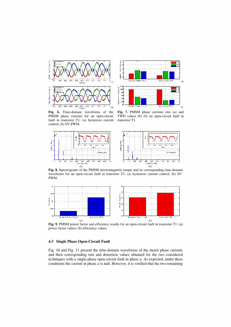
The results presented in Fig. 8 show that the PMSM electromagnetic torque is no
longer constant, containing harmonics multiple of the fundamental currents
frequency. The main pulsating component is less significant for the SV-PWM control,
which contributes to a lower TWO value and a smoother torque.
Fig. 9 presents the results concerning the PMSM power factor and efficiency.
Comparing with the healthy operating conditions, although all values are negatively
affected by the fault, the SV-PWM technique has a better performance since it allows
to achieve higher power factor and efficiency values.
(a)
(b)
Fig. 4. Spectrograms of the PMSM electromagnetic torque and its corresponding time-domain
waveforms under normal operating conditions: (a) hysteresis current control; (b) SV-PWM.
(a)
(b)
Fig. 5. PMSM power factor and efficiency results under normal operating conditions: (a) power
factor values; (b) efficiency values.
4.3 Single Phase Open-Circuit Fault
Fig. 10 and Fig. 11 present the time-domain waveforms of the motor phase currents
and their corresponding rms and distortion values obtained for the two considered
techniques with a single-phase open-circuit fault in phase a. As expected, under these
conditions the current in phase a is null. However, it is verified that the two remaining
Fig. 6. Time-domain waveforms of the
PMSM phase currents for an open-circuit
fault in transistor T1: (a) hysteresis current
control; (b) SV-PWM.
Fig. 7. PMSM phase currents rms (a) and
TWD values (b) for an open-circuit fault in
transistor T1.
(a)
(b)
Fig. 8. Spectrograms of the PMSM electromagnetic torque and its corresponding time-domain
waveforms for an open-circuit fault in transistor T1: (a) hysteresis current control; (b) SV-
PWM.
(a)
(b)
Fig. 9. PMSM power factor and efficiency results for an open-circuit fault in transistor T1: (a)
power factor values; (b) efficiency values.

currents amplitude is larger for a hysteresis current control, which contributes to a
greater thermal stress imposed on the stator windings insulation. Furthermore, the
TWD results show that the SV-PWM has a better behavior since it generates much
less harmonic distortion than the hysteresis current control.
The time-domain waveforms of the electromagnetic torque developed by the
PMSM (Fig. 12) confirm its very pulsating nature. Comparing both modulation
strategies, the SV-PWM leads to the creation of a less pulsating torque, which means
that as far as the motor is concerned, the produced mechanical stresses are reduced,
Fig. 10. Time-domain waveforms of the
PMSM phase currents for a single-phase
open-circuit fault in phase a: (a) hysteresis
current control; (b) SV-PWM.
Fig. 11. PMSM phase currents rms (a) and
TWD values (b) for a single-phase open-
circuit fault in phase a.
(a)
(b)
Fig. 12. Spectrograms of the PMSM electromagnetic torque and its corresponding time-domain
waveforms for a single-phase open-circuit fault in phase a: (a) hysteresis current control; (b)
SV-PWM.
(a)
(b)
Fig. 13. PMSM power factor and efficiency results for a single-phase open-circuit fault in phase
a: (a) power factor values; (b) efficiency values.

comparing with a hysteresis current control.
Regarding the power factor results presented in Fig. 13(a), despite the noticeable
increase of the PMSM power factor with a hysteresis current control, a higher value is
obtained with a SV-PWM technique.
Fig. 13(b) presents the PMSM efficiency results for the two considered strategies.
Due to the larger motor phase currents rms values, the efficiency values are severely
affected by this fault type, when comparing to the normal operating conditions.
Nevertheless, with a SV-PWM technique it is possible to obtain a higher efficiency
value than with a hysteresis current control.
5 Conclusions
The results presented in this paper allow to conclude that with a SV-PWM technique
applied to a PMSM drive, it is possible to achieve a better performance than with a
hysteresis current control. Under both normal and faulty operating conditions, by
using the SV-PWM technique it is possible to obtain lower rms and distortion values
in the motor phase currents, a less pulsating electromagnetic torque and higher power
factor and efficiency values, as compared to the use of the hysteresis current control.
Acknowledgments. The authors gratefully acknowledge the financial support of the
Portuguese Foundation for Science and Technology (FCT) under Project No.
SFRH/BD/40286/2007 and Project No. PTDC/EEA-ELC/105282/2008.
References
1. N. Bianchi, S. Bolognani and M. Zigliotto, “Analysis of PM synchronous motor drive
failures during flux weakening operation”, 27th Annual IEEE Power Electronics Specialists
Conference, Baveno, Italy, vol. 2, pp. 1542-1548, June 23-27, 1996.
2. B. A. Welchko, T. M. Jahns and S. Hiti, “IPM synchronous machine drive response to a
single-phase open circuit fault”, IEEE Transactions on Power Electronics, vol. 17, no. 5, pp.
764-771, September, 2002.
3. B. A. Welchko, T. M. Jahns, W. L. Soong and J. M. Nagashima, “IPM synchronous
machine drive response to symmetrical and asymmetrical short circuit faults”, IEEE
Transactions on Energy Conversion, vol. 18, no. 2, pp. 291-298, June, 2003.
4. T. Sun, S. H. Lee and J. P. Hong, “Faults analysis and simulation for interior permanent
magnet synchronous motor using Simulink@MATLAB”, International Conference on
Electrical Machines and Systems, Seul, South Korea, pp. 900-905, 8-11 October, 2007.
5. J. O. Estima and A. J. M. Cardoso, “Performance evaluation of permanent magnet
synchronous motor drives under inverter fault conditions”, XVIII International Conference
on Electrical Machines, Vilamoura, Portugal, CD-ROM, 6 pp., September 6-9, 2008.
6. J. O. Estima and A. J. M. Cardoso “Performance evaluation of DTC-SVM permanent
magnet synchronous motor drives under inverter fault conditions”, 35th Annual Conference
of IEEE Industrial Electronics Society, Porto, Portugal, 6 pp., 3-5 November, 2009.
7. J. O. Estima and A. J. M. Cardoso “Impact of Inverter Faults in the Overall Performance of
Permanent Magnet Synchronous Motor Drives”, IEEE International Electric Machines and
Drives Conference, Miami, USA, pp. 1319-1325, May, 2009.