MCUXpresso SDK 3-Phase PMSM Control (LPC)
48
MCUXpresso SDK 3-Phase PMSM Control (LPC) NXP Semiconductors Document identifier: 3PPMSMCLPCUG User's Guide Rev. 0, 02/2020
-
Upload
khangminh22 -
Category
Documents
-
view
0 -
download
0
Transcript of MCUXpresso SDK 3-Phase PMSM Control (LPC)

MCUXpresso SDK 3-Phase PMSM Control(LPC)
NXP Semiconductors Document identifier: 3PPMSMCLPCUGUser's Guide Rev. 0, 02/2020

ContentsChapter 1 Introduction........................................................................................... 3
Chapter 2 Hardware setup.....................................................................................4
Chapter 3 LPC5500 series features and peripheral settings................................. 9
Chapter 4 Project file and IDE workspace structure............................................ 14
Chapter 5 Tools................................................................................................... 16
Chapter 6 Motor-control peripheral initialization.................................................. 17
Chapter 7 User interface......................................................................................19
Chapter 8 Remote control using FreeMASTER...................................................20
Chapter 9 Identifying parameters of user motor using MCAT..............................27
Chapter 10 Conclusion........................................................................................ 43
Chapter 11 Acronyms and abbreviations.............................................................44
Chapter 12 References........................................................................................45
Chapter 13 Useful links........................................................................................46
Contents
MCUXpresso SDK 3-Phase PMSM Control (LPC), Rev. 0, 02/20202 NXP Semiconductors

Chapter 1IntroductionThis user's guide describes the implementation of the sensorless Motor Control software for the 3-phase Permanent MagnetSynchronous Motor (PMSM), including the motor parameters identification algorithm, on the NXP LPC55S6x MCU based onthe Arm® Cortex®-M33 architecture. The sensorless control software and PMSM control theory in general are described inSensorless PMSM Field-Oriented Control (documentDRM148). The NXP Freedom board (FRDM-MC-LVPMSM) is used ashardware platform for the PMSM control reference solution. The hardware-dependent part of the sensorless control software,including a detailed peripheral setup and the Motor Control (MC) peripheral drivers, is addressed as well. The motor parametersidentification theory and algorithms are described in this document. The last part of the document introduces and explains theuser interface represented by the Motor Control Application Tuning (MCAT) page based on the FreeMASTER run-time debuggingtool. These tools present a simple and user-friendly way for motor parameter identification, algorithm tuning, software control,debugging, and diagnostics.
This document provides instructions for running and controlling the PMSM project using the LPCXpresso55S69 developmentboard with the Freedom development board. The software provides the sensorless field-oriented speed, torque, and scalarcontrol. You can control the application using the board buttons or the FreeMASTER application. The motor identification andapplication tuning is done using the MCAT tool integrated in the FreeMASTER page. The required software, hardware setup,jumper settings, project arrangement, and user interface is described in the following sections. For more information, visit www.nxp.com/motorcontrol_pmsm.
MCUXpresso SDK 3-Phase PMSM Control (LPC), Rev. 0, 02/2020NXP Semiconductors 3

Chapter 2Hardware setupThe PMSM Field-Oriented Control (FOC) application runs on the FRDM-MC-LVPMSM development platform with the LPC55S69-EVK development tool, in combination with the Linix 45ZWN24-40 permanent magnet synchronous motors.
2.1 FRDM-MC-LVPMSMThis evaluation board, in a shield form factor, effectively turns a NXP Freedom development board into a complete motor controlreference design, compatible with existing NXP Freedom development boards. Freedom motor control headers are compatiblewith Arduino ™ R3 pin layout.
The FRDM-MC-LVPMSM low-voltage, 3-phase Permanent Magnet Synchronous Motor (PMSM) Freedom development platformboard has the power supply input voltage of 24-48 VDC with a reverse polarity protection circuitry. The auxiliary power supply of5.5 VDC is created to supply the FRDM MCU boards. The output current is up to 5 A RMS. The inverter itself is realized by a 3-phase bridge inverter (six MOSFETs) and a 3-phase MOSFET gate driver. The analog quantities (such as the 3-phase motorcurrents, DC-bus voltage, and DC-bus current) are sensed on this board. There is also an interface for speed and position sensors(encoder, hall). The block diagram of a complete NXP Freedom motor-control development kit is shown below.
Figure 1. Motor-control development platform block diagram
Hardware setup
MCUXpresso SDK 3-Phase PMSM Control (LPC), Rev. 0, 02/20204 NXP Semiconductors

Figure 2. FRDM-MC-LVPMSM
The FRDM-MC-LVPMSM does not require any complicated setup. For more information about Freedom development platformsee nxp.com.
2.2 Linix 45ZWN24-40 motorThe Linix 45ZWN24-40 motor is a low-voltage 3-phase permanent-magnet motor with hall sensor used in PMSM applications.The motor parameters are listed in Table below.
Table 1. Linix 45ZWN24-40 motor parameters
Characteristic Symbol Value Units
Rated Voltage Vt 24 V
Rated speed - 4000 RPM
Rated torque T 0.0924 Nm
Rated power P 40 W
Continuous current Ics 2.34 A
Number of pole-pairs pp 2 -
Linix 45ZWN24-40 motor
MCUXpresso SDK 3-Phase PMSM Control (LPC), Rev. 0, 02/2020NXP Semiconductors 5

Figure 3. Linix 45ZWN24-40 permanent magnet synchronous motor
The motor has two types of connectors (cables). The first cable has three wires and is designated to power the motor. The secondcable has five wires and is designated for the hall sensors’ signal sensing. For the PMSM sensorless application, only the powerinput wires are needed.
2.3 LPC55S69-EVKThe LPCXpresso55S69 development board is an ideal platform for evaluation and development with the LPC55S6x MCU basedon the Arm Cortex-M33 architecture. The Arm Cortex-M33 core operates at up to 150 MHz. The board includes the high-performance on-board debug probe, audio subsystem, and accelerometer, with a possibility to add off-the-shelf add-on boardsfor networking, sensors, displays, and other interfaces. Configure the jumper settings according to Table 2 for the motor-controlapplication to work properly.
Table 2. LPC55S69-EVK jumper settings
Jumper Setting Jumper Setting Jumper Setting
J3 1-2 J7 1-2 P1 open
J4 open J12 open P4 3.3V
J6 FS - - - -
Hardware setup
MCUXpresso SDK 3-Phase PMSM Control (LPC), Rev. 0, 02/20206 NXP Semiconductors

Figure 4. LPC55S69-EVK board with highlighted jumper settings
Hardware assembling
1. Wire the FRDM-MC-LVPMSM power stage to the LPC55S69-EVK board according to the pin assignment (Table 3) andthe interconnection diagram (Figure 5).
2. Connect the 3-phase motor wires to the screw terminals (J7) on the Freedom PMSM power stage.
3. Plug the USB cable from the USB host to the USB connector (Debug Link - P6) on the EVK board.
4. Plug the 24-V DC power supply to the DC power connector on the Freedom PMSM power stage.
Table 3. LPC55S69-EVK pin assignment
FRDM-MC-LVPMSM Connection LPC55S69-EVK
PWM_AT J3, 15 <-> P18, 5 LEDR/PWM_ARD PIO1_4
PWM_AB J3, 13 <-> P18, 20 PIO0_18_GPIO_ARD PIO0_18
PWM_BT J3, 11 <-> P18, 6 PLU_CLKIN/GPIO/SD1_D0 PIO1_25
PWM_BB J3, 9 <-> P18, 3 PIO1_10_GPIO_ARD PIO1_10
PWM_CT J3, 7 <-> P18, 19 SD1_CARD_DET PIO1_17
PWM_CB J3, 5 <-> P17, 13 LSPI_HS_MOSI PIO0_26
3V3 J3, 4 <-> P16, 12 VDD_TARGET -
GND J3, 14 <-> P16, 16 GND -
CUR_A J2, 1 <->P19, 2 ADC0_N PIO0_16
Table continues on the next page...
LPC55S69-EVK
MCUXpresso SDK 3-Phase PMSM Control (LPC), Rev. 0, 02/2020NXP Semiconductors 7

Table 3. LPC55S69-EVK pin assignment (continued)
FRDM-MC-LVPMSM Connection LPC55S69-EVK
CUR_B J2, 3 <-> P19, 4 ADC0_P PIO0_23
CUR_C J2, 5 <->P18, 11 PIO0_15_GPIO_ARD PIO0_15
VOLT_DCB J2, 7 <->P17, 19 PIO1_8_GPIO_ARD PIO1_8
CUR_DCB J2, 9 <-> P19, 6 COMPARATOR PIO0_0
Figure 5. LPC55S69-EVK interconnection diagram
Hardware setup
MCUXpresso SDK 3-Phase PMSM Control (LPC), Rev. 0, 02/20208 NXP Semiconductors

Chapter 3LPC5500 series features and peripheral settingsThis section describes the peripheral settings and application timing. The LPC5500 MCU series contains Arm's newest Cortex-M33 technology. It combines significant product architecture enhancements and greater integration over previous generationswith dramatic power consumption improvements and advanced security features, including the SRAM PUF-based root of trustand provisioning, real-time execution from encrypted images (internal flash), and asset protection with Arm TrustZone-M. Inaddition, the LPC5500 MCU series features seven scalable families with broad package and memory options, as well as thecomprehensive MCUXpresso software and tools ecosystem and low-cost development boards.
3.1 LPC-55S6xThe LPC55S6x MCU family is built upon the world’s first general-purpose Cortex-M33-based MCU introduced with the LPC5500series. This high-efficiency family leverages the new Armv8-M architecture to introduce new levels of performance and advancedsecurity capabilities, including TrustZone-M and co-processor extensions. The LPC55S6x family enables these co-processorsextensions and leverages them to bring significant signal processing efficiency gains from a proprietary DSP accelerator offeringa 10x clock cycle reduction. An optional second Cortex-M33 core offers flexibility to balance high performance and powerefficiency.
In addition, the LPC55S6x MCU family provides benefits, such as the 40-nm NVM-based process technology cost advantages,broad scalable packages, and memory options, as well as a robust enablement including the MCUXpresso Software and Toolsecosystem and low-cost development boards.
Figure 6. LPC55S6x block diagram
LPC-55S6x
MCUXpresso SDK 3-Phase PMSM Control (LPC), Rev. 0, 02/2020NXP Semiconductors 9

3.1.1 LPC55S69 hardware timing and synchronizationCorrect and precise timing is crucial for motor-control applications. Therefore, the motor-control-dedicated peripherals take careof the timing and synchronization on the hardware layer. In addition, it is possible to set the PWM frequency as a multiple of theADC interrupt (ADC ISR) frequency where the FOC algorithm is calculated. In this case, the PWM frequency is equal to the FOCfrequency. The timing diagram is shown in Figure 7.
Figure 7. Hardware timing and synchronization on LPC55S69
• The top signal shows the SCT counter (SCT0 counter). The dead time is emphasized at the PWM top and PWM bottomsignals.
• The sct0_output[9] generates a trigger for the ADC with a short delay. This delay ensures correct current sampling at dutycycles close to 100 %.
• When the ADC conversion is completed, the ADC ISR (ADC interrupt) is entered. The FOC calculation is done in this interrupt.
3.1.2 LPC55S69 peripheral settingsThis section describes the peripherals used for the motor control. On LPC55S69, the SCTimer is used for 6-channel PWMgeneration. The 16-bit ADC is used for the phase currents and DC-bus voltage measurement. The SCTimer and ADC aresynchronized via a trigger from "SCTimer sct0_output[9]". The following settings are in the mcdrv_lpcexpresso55s69.c andboard.c files and in their header files.
Clock select and control (SYSCON)The clock source for the registers and memories is derived from the main clock. The main clock is selected from the FROhigh-speed output (fro_hf) of the 96-MHz internal oscillator.
LPC5500 series features and peripheral settings
MCUXpresso SDK 3-Phase PMSM Control (LPC), Rev. 0, 02/202010 NXP Semiconductors

Figure 8. LPC55S69 clock source for motor-control peripherals
The clock sources for the peripherals used for the motor control are listed in Table 4.
Table 4. LPC55S69 clock source for motor-control peripherals
Clock source Clock div Clock root frequency
SCTimer main_clk SCTCLKDIV 96 MHz
CTimer main_clk - 96 MHz
ADC main_clk ADCCLKDIV 24 MHz
For more details, see the LPC55S6x User Manual (document UM11126).
PWM generation - SCT0
• The SCT0 is clocked from "main_clk" (96 MHz).
• SDK initialization structures are used for the SCT0 initiallization.
• SCTIMER_Out_0 - SCTIMER_Out_5 are used for the 3-phase PWM generation.
• kSCTIMER_Out_9 is used for the ADC generation trigger.
• Dead time is inserted using the "ui16DeadTimePWM in g_sM1Pwm3ph" structure.
Analog sensing - ADC
• The clock frequency of the ADC is 24 MHz. It is taken from "main_clk" and divided by four.
• The ADCs operate as 10-bit with the single-ended conversion and hardware trigger selected. The ADCs are triggeredfrom "sct0_output[9]".
LPC-55S6x
MCUXpresso SDK 3-Phase PMSM Control (LPC), Rev. 0, 02/2020NXP Semiconductors 11

• The watermark interrupt is enabled and serves the FOC fast loop algorithm generated after the last scan is completed.
Slow loop interrupt generation - CTIMER2The standard timer 2 is used to generate the slow-loop interrupt.
• The CTIMER2 is clocked from the "main_clk" divided with a clock frequency of 96 MHz.
• The slow loop is usually ten times slower than the fast loop. Therefore, the interrupt is generated after the counter countsto CTIMER_CLK_FREQ / g_sClockSetup.ui16M1SpeedLoopFreq. The speed loop frequency is set in theM1_SPEED_LOOP_FREQ macro and equals 1000 Hz.
• An interrupt (which serves the slow-loop period) is enabled and generated at the reload event.
Analog comparator - ACMP0
• The analog comparator is used for the over-current detection.
• SDK initialization structures are used for the SCT0 initiallization.
• Channel 1 is used as the positive input.
• Channel 0 is used as the negative input.
3.2 CPU load and memory usageThe following information apply to the application built using the MCUXpresso IDE in the Debug and Release configurations. Table 5 shows the memory usage and CPU load. The memory usage is calculated from the .map linker file, including the 4-KBFreeMASTER recorder buffer allocated in RAM. The CPU load is measured using the SysTick timer. The CPU load is dependenton the fast-loop (FOC calculation) and slow-loop (speed loop) frequencies. In this case, it applies to the fast-loop frequency of10 KHz and the slow-loop frequency of 1 KHz. The total CPU load is calculated using these equations:
Where:
CPUfast - the CPU load taken by the fast loop.
cyclesfast - the number of cycles consumed by the fast loop.
ffast - the frequency of the fast-loop calculation (10 KHz).
fCPU - CPU frequency.
CPUslow - the CPU load taken by the slow loop.
cyclesslow - the number of cycles consumed by the slow loop.
fslow - the frequency of the slow-loop calculation (1 KHz).
CPUtotal - the total CPU load consumed by the motor control.
Table 5. LPC-55S69 CPU load and memory usage
Debug configuration Release configuration
Program flash 76 136 B 41 048 B
Table continues on the next page...
LPC5500 series features and peripheral settings
MCUXpresso SDK 3-Phase PMSM Control (LPC), Rev. 0, 02/202012 NXP Semiconductors

Table 5. LPC-55S69 CPU load and memory usage (continued)
Debug configuration Release configuration
SRAM 19 864 B 19 800 B
Maximum CPU load (core 0) 44.8 % 44.8 %
CPU load and memory usage
MCUXpresso SDK 3-Phase PMSM Control (LPC), Rev. 0, 02/2020NXP Semiconductors 13

Chapter 4Project file and IDE workspace structureAll the necessary files are included in one package, which simplifies the distribution and decreases the size of the final package.The directory structure of this package is simple, easy to use, and organized in a logical manner. The folder structure used in theIDE is different from the structure of the PMSM package installation, but it uses the same files. The different organization is chosendue to a better manipulation with folders and files in workplaces and due to the possibility to add or remove files and directories.The “pack_motor_board“ project includes the available functions and routines, MID functions, scalar and vector control of themotor, FOC control, and FreeMASTER MCAT project. This project serves for development and testing purposes.
4.1 PMSM project structureThe directory tree of the PMSM project is shown in Figure 9.
Figure 9. Directory tree
The main project folder pack_motor_lpcxx\boards\lpcxpressoxx\demo_apps\mc_pmsm\pmsm_snsless\cm33_corex contains thefollowing folders:
• iar—for the IAR Embedded Workbench IDE.
• armgcc—for the GNU Arm IDE.
Project file and IDE workspace structure
MCUXpresso SDK 3-Phase PMSM Control (LPC), Rev. 0, 02/202014 NXP Semiconductors

• mdk—for the uVision Keil IDE.
The folder contains also the following files:
• m1_pmsm_appconfig.h—contains the definitions of constants for the application control processes, parameters of themotor and regulators, and the constants for other vector control-related algorithms. When you tailor the application for adifferent motor using the Motor Control Application Tuning (MCAT) tool, the tool generates this file at the end of the tuningprocess.
• main.c—contains the basic application initialization (enabling interrupts), subroutines for accessing the MCU peripherals,and interrupt service routines. The FreeMASTER communication is performed in the background infinite loop.
• board.c—contains the functions for the UART, GPIO, and SysTick initialization.
• board.h—contains the definitions of the board LEDs, buttons, UART instance used for FreeMASTER, and so on.
• clock_config—contains the CPU clock setup functions. These files are going to be generated by the clock tool in thefuture.
• mcdrv.h—this file ensures the abstraction of the mcdrv_lpcxpressoxx.h file inclusion.
• mcdrv_lpcxpressoxx.c—contains the motor-control driver peripherals initialization functions that are specific for the boardand MCU used.
• mcdrv_lpcxpressoxx.h—header file for mcdrv_lpcxpressoxx.c. This file contains the macros for changing the PWM periodand the ADC channels assigned to the phase currents and board voltage.
• freemaster_cfg.h—the FreeMASTER configuration file containing the FreeMASTER communication and features setup.
• pin_mux—port configuration files. It is recommended to generate these files in the pin tool.
The pack_motor_lpcxx\boards\lpcxpressoxx\demo_apps\mc_pmsm\pmsm_snsless folder contains the FreeMASTER project filepmsm_float.pmp. Open this file in the FreeMASTER tool and use it to control the application.
The pack_motor_lpcxx\middleware\motor_control\freemaster\pmsm_float folder contains the auxiliary files for the MCAT tool.
The pack_motor_lpcxx\middleware\motor_control\pmsm\pmsm_float folder contains the following subfolders common to theother motor-control projects:
• mc_algorithms—contains the main control algorithms used to control the FOC and speed control loop.
• mc_drivers—contains the source and header files used to initialize and run motor-control applications.
• mc_identification—contains the source code for the automated parameter-identification routines of the motor.
• mc_state_machine—contains the software routines that are executed when the application is in a particular state or statetransition.
• state_machine—contains the state machine functions for the FAULT, INITIALIZATION, STOP, and RUN states.
PMSM project structure
MCUXpresso SDK 3-Phase PMSM Control (LPC), Rev. 0, 02/2020NXP Semiconductors 15

Chapter 5ToolsInstall the FreeMASTER Run-Time Debugging Tool 3.0 and one of the following IDEs on your PC to run and control the PMSMapplication properly:
• IAR Embedded Workbench IDE v8.40.2 or higher.
• MCUXpresso v11.1.0.
• ARM-MDK - Keil μVision version 5.25.2.
• FreeMASTER Run-Time Debugging Tool 3.0.
5.1 Compiler warningsWarnings are diagnostic messages that report constructions that are not inherently erroneous and warn about potential runtime,logic, and performance errors. In some cases, warnings can be suspended and these warnings do not show during the compilingprocess. One of such special cases is the “unused function” warning, where the function is implemented in the source code withits body, but this function is not used. This case occurs in situations where you implement the function as a supporting functionfor better usability, but you do not use the function for any special purposes for a while.
The IAR Embedded Workbench IDE suppresses these warnings:
• Pa082—undefined behavior; the order of volatile accesses is not defined in this statement.
• Ta022—possible ROM access (<ptr>) from within a __ramfunc function.
• Ta023—call to a non __ramfunc function (somefunction) from within a __ramfunc function.
The Arm-MDK Keil μVision IDE suppresses these warnings:
• 66—the enumeration value is out of the “int” range.
• 1035—a single-precision operand is implicitly converted to a double-precision operand.
• 1296—the extended constant initializer is used.
By default, there are no other warnings shown during the compiling process.
Tools
MCUXpresso SDK 3-Phase PMSM Control (LPC), Rev. 0, 02/202016 NXP Semiconductors

Chapter 6Motor-control peripheral initializationThe motor-control peripherals are initialized by calling the MCDRV_Init_M1() function during the MCU startup and before theperipherals are used. All initialization functions are in the mcdrv_lpcxx.c source file and the mcdrv_lpcxx.h header file. Thedefinitions specified by the user are also in these files. The features provided by the functions are the 3-phase PWM generationand 3-phase current measurement, as well as the DC-bus voltage and auxiliary quantity measurement. The principles of boththe 3-phase current measurement and the PWM generation using the Space Vector Modulation (SVM) technique are describedin Sensorless PMSM Field-Oriented Control (document DRM148).
The mcdrv_lpcxx.h header file provides several macros that can be defined by the user:
• M1_MCDRV_ADC—this macro specifies which ADC periphery is used. If you select an unsupported periphery, apreprocessor error is issued.
• M1_MCDRV_PWM3PH—this macro specifies which PWM periphery is used. If you select an unsupported periphery, apreprocessor error is issued.
• M1_PWM_FREQ—the value of this definition sets the PWM frequency.
• M1_FOC_FREQ_VS_PWM_FREQ—enables you to call the fast loop interrupt at every first, second, third, or nth PWM reload.This is convenient when the PWM frequency must be higher than the maximal fast-loop interrupt.
• M1_SPEED_LOOP_FREQ—the value of this definition sets the speed-loop frequency.
• M1_PWM_DEADTIME—the value of the PWM dead time in nanoseconds.
• M1_PWM_PAIR_PH[A..C]—these macros enable a simple assignment of the physical motor phases to the PWM peripherychannels (or submodules). Change the order of the motor phases this way.
• M1_ADC[1,2]_PH_[A..C]—these macros are used to assign the ADC channels for the phase current measurement. Thegeneral rule is that at least one of the phase currents must be measurable on both ADC converters and the two remainingphase currents must be measurable on different ADC converters. The reason for this is that the selection of the phase currentpair to measure depends on the current SVM sector. If this rule is broken, a preprocessor error is issued. For more informationabout the 3-phase current measurement, see Sensorless PMSM Field-Oriented Control (document DRM148).
• M1_ADC[1,2]_UDCB—this define is used to select the ADC channel for the measurement of the DC-bus voltage.
In the motor-control software, these API-serving ADC and PWM peripherals are available:
• The available APIs for the ADC are:
— mcdrv_adc_t—MCDRV ADC structure data type.
— bool_t M1_MCDRV_ADC_PERIPH_INIT()—this function is by default called during the ADC peripheral initializationprocedure invoked by the MCDRV_Init_M1() function and should not be called again after the peripheral initializationis done.
— bool_t M1_MCDRV_CURR_3PH_CHAN_ASSIGN(mcdrv_adc_t*)—calling this function assigns proper ADC channelsfor the next 3-phase current measurement based on the SVM sector. The function always returns true.
— bool_t M1_MCDRV_CURR_3PH_CALIB_INIT(mcdrv_adc_t*)—this function initializes the phase-current channel-offsetmeasurement. This function always returns true.
— bool_t M1_MCDRV_CURR_3PH_CALIB(mcdrv_adc_t*)—this function reads the current information from theunpowered phases of a stand-still motor and filters them using moving average filters. The goal is to obtain the valueof the measurement offset. The length of the window for moving the average filters is set to eight samples by default.This function always returns true.
— bool_t M1_MCDRV_CURR_3PH_CALIB_SET(mcdrv_adc_t*)—this function asserts the phase-current measurementoffset values to the internal registers. Call this function after a sufficient number of M1_MCDRV_CURR_3PH_CALIB()calls. This function always returns true.
MCUXpresso SDK 3-Phase PMSM Control (LPC), Rev. 0, 02/2020NXP Semiconductors 17

— bool_t M1_MCDRV_ADC_GET(mcdrv_adc_t*)—this function reads and calculates the actual values of the 3-phasecurrents, DC-bus voltage, and auxiliary quantity. This function always returns true.
• The available APIs for the PWM are:
— mcdrv_pwma_pwm3ph_t—MCDRV PWM structure data type.
— bool_t M1_MCDRV_PWM_PERIPH_INIT()—this function is by default called during the PWM periphery initializationprocedure invoked by the MCDRV_Init_M1() function.
— bool_t M1_MCDRV_PWM3PH_SET(mcdrv_pwma_pwm3ph_t*)—this function updates the PWM phase duty cycles.This function always returns true.
— bool_t M1_MCDRV_PWM3PH_EN(mcdrv_pwma_pwm3ph_t*)—calling this function enables all PWM channels. Thisfunction always returns true.
— bool_t M1_MCDRV_PWM3PH_DIS (mcdrv_pwma_pwm3ph_t*)—calling this function disables all PWM channels. Thisfunction always returns true.
— bool_t M1_MCDRV_PWM3PH_FLT_GET(mcdrv_pwma_pwm3ph_t*)—this function returns the state of the over-current fault flags and automatically clears the flags (if set). This function returns true when an over-current event occurs.Otherwise, it returns false.
Motor-control peripheral initialization
MCUXpresso SDK 3-Phase PMSM Control (LPC), Rev. 0, 02/202018 NXP Semiconductors

Chapter 7User interfaceThe application contains the demo mode to demonstrate motor rotation. You can operate it using FreeMASTER. TheFreeMASTER application consists of two parts: the PC application used for variable visualization and the set of software driversrunning in the embedded application. Data is transferred between the PC and the embedded application via the serial interface.This interface is provided by the debugger included in the boards.
The application can be remotely controlled using FreeMASTER:
• Using the Motor Control Application Tuning (MCAT) interface in the “Control Structure” tab or the “Application control” tab(controlling the demo mode).
• Setting a variable in the FreeMASTER Variable Watch.
If you are using your own motor (different from the default motors), make sure to identify all motor parameters. The automatedparameter identification is described in the following sections.
MCUXpresso SDK 3-Phase PMSM Control (LPC), Rev. 0, 02/2020NXP Semiconductors 19

Chapter 8Remote control using FreeMASTERThis section provides information about the tools and recommended procedures to control the sensorless PMSM Field-OrientedControl (FOC) application using FreeMASTER. The application contains the embedded-side driver of the FreeMASTER real-timedebug monitor and data visualization tool for communication with the PC. It supports non-intrusive monitoring, as well as themodification of target variables in real time, which is very useful for the algorithm tuning. Besides the target-side driver, theFreeMASTER tool requires the installation of the PC application as well. You can download FreeMASTER 3.0 at www.nxp.com/freemaster. To run the FreeMASTER application including the MCAT tool, double-click the pmsm_float.pmp file located in thepack_motor_lpcxx\boards\lpcxpressoxx\demo_apps\mc_pmsm\pmsm_snsless folder. The FreeMASTER application starts andthe environment is created automatically, as defined in the *.pmp file.
8.1 Establishing FreeMASTER communicationThe remote operation is provided by FreeMASTER via the USB interface. Perform these steps to control a PMSM motor usingFreeMASTER:
1. Download the project from your chosen IDE to the MCU and run it.
2. Open the FreeMASTER file pmsm_x.pmp. The PMSM project uses the TSA by default, so it is not necessary to select asymbol file for FreeMASTER.
3. Click the communication button (the red “STOP” button in the top left-hand corner) to establish the communication.
Figure 10. Red “STOP” button placed in top left-hand corner
4. If the communication is established successfully, the FreeMASTER communication status in the bottom right-hand cornerchanges from “Not connected” to “RS232 UART Communication; COMxx; speed=115200”. Otherwise, the FreeMASTERwarning popup window appears.
Figure 11. FreeMASTER—communication is established successfully
5. Press F5 to reload the MCAT html page and check the App ID.
6. Control the PMSM motor using the MCAT “Control structure” tab, the MCAT “Application demo control” tab, or by directlywriting to a variable in a variable watch.
7. If you rebuild and download the new code to the target, turn the FreeMASTER application off and on.
If the communication is not established successfully, perform these steps:
1. Go to the “Project -> Options -> Comm” tab and make sure that “SDA” is set in the “Port” option and the communicationspeed is set to 115200 bps.
Remote control using FreeMASTER
MCUXpresso SDK 3-Phase PMSM Control (LPC), Rev. 0, 02/202020 NXP Semiconductors

Figure 12. FreeMASTER communication setup window
2. If “OpenSDA-CDC Serial Port” is not printed out in the message box next to the “Port” drop-down menu, unplug and thenplug in the USB cable and reopen the FreeMASTER project.
Make sure to supply your development board from a sufficient energy source. Sometimes the PC USB port is not sufficient tosupply the development board.
8.2 MCAT FreeMASTER interface (Motor Control ApplicationTuning)
The PMSM sensor/sensorless FOC application can be easily controlled and tuned using the Motor Control Application Tuning(MCAT) plug-in for PMSM. The MCAT for PMSM is a user-friendly modular page, which runs within FreeMASTER. The toolconsists of the tab menu, tuning mode selector, and workspace shown in Figure 13. Each tab from the tab menu represents onesub-module which enables you to tune or control different aspects of the application. Besides the MCAT page for PMSM, severalscopes, recorders, and variables in the project tree are predefined in the FreeMASTER project file to further simplify the motorparameter tuning and debugging. When the FreeMASTER is not connected to the target, the “App ID” line shows “offline”. Whenthe communication with the target MCU is established using a correct software, the “App ID” line displays the board name“pmsm_used_board” and all stored parameters for the given MCU are loaded. If the connection is established and the board IDis not shown, press F5 to reload the MCAT html page.
MCAT FreeMASTER interface (Motor Control Application Tuning)
MCUXpresso SDK 3-Phase PMSM Control (LPC), Rev. 0, 02/2020NXP Semiconductors 21

Figure 13. MCAT layout
In the default configuration, these tabs are available:
• “Introduction”—welcome page with the PMSM sensor/sensorless FOC diagram and a short description of the application.
• “Motor Identif”—PMSM semi-automated parameter measurement control page. The PMSM parameter identification is moreclosely described further on in this document.
• “Parameters”—this page enables you to modify the motor parameters, specification of hardware and application scales,alignment, and fault limits.
• “Current Loop”—current loop PI controller gains and output limits.
• “Speed & Pos”—this tab contains fields for the specification of the speed controller proportional and integral gains, as wellas the output limits and parameters of the speed ramp. The position proportional controller constant is also set here.
• “Sensors”—this page contains the encoder parameters and position observer parameters.
• “Sensorless”—this page enables you to tune the parameters of the BEMF observer, tracking observer, and open-loop startup.
• “Control Struc”—this application control page enables you to select and control the PMSM using different techniques (scalar—Volt/Hertz control, voltage FOC, current FOC, speed FOC, and position FOC). The application state is also shown in thistab.
• “Output file”—this tab shows all the calculated constants that are required by the PMSM sensor/sensorless FOC application.It is also possible to generate the m1_acim_appconfig.h file, which is then used to preset all application parameterspermanently at the project rebuild.
• “App page”—this tab contains the graphical elements like the speed gauge, DC-bus voltage measurement bar, and varietyof switches which enable a simple, quick, and user-friendly application control. The fault clearing and the demo mode (whichsets various predefined required speeds and positions over time) can be also controlled from here.
Most tabs offer the possibility to immediately load the parameters specified in the MCAT into the target using the “Update target”button and save (or restore) them from the hard drive file using the “Reload Data” and “Store Data” buttons.
The following sections provide simple instructions on how to identify the parameters of a connected PMSM motor and how toappropriately tune the application.
Remote control using FreeMASTER
MCUXpresso SDK 3-Phase PMSM Control (LPC), Rev. 0, 02/202022 NXP Semiconductors

Control structure—“Control Struc” tab
The application can be controlled through the “Control Struc” tab, which is shown in Figure 14. The state control area on the leftside of the screen shows the current application state and enables you to turn the main application switch on or off (turning arunning application off disables all PWM outputs). The “Cascade Control Structure” area is placed in the right-hand side of thescreen. Here you can choose between the scalar control and the FOC control using the appropriate buttons. The selected partsof the FOC cascade structure can be enabled by selecting “Voltage FOC”, “Current FOC”, and “Speed FOC” (sensor/sensorless).This is useful for application tuning and debugging.
Figure 14. MCAT for PMSM control page
The scalar control diagram is shown in Figure 15. It is the simplest type of motor-control techniques. The ratio between themagnitude of the stator voltage and the frequency must be kept at the nominal value. Hence, the control method is sometimescalled Volt per Hertz (or V/Hz). The position estimation BEMF observer and tracking observer algorithms (see Sensorless PMSMField-Oriented Control (document DRM148) for more information) run in the background, even if the estimated positioninformation is not directly used. This is useful for the BEMF observer tuning.
MCAT FreeMASTER interface (Motor Control Application Tuning)
MCUXpresso SDK 3-Phase PMSM Control (LPC), Rev. 0, 02/2020NXP Semiconductors 23

Figure 15. Scalar control mode
The block diagram of the voltage FOC is in Figure 16. Unlike the scalar control, the position feedback is closed using the BEMFobserver and the stator voltage magnitude is not dependent on the motor speed. Both the d-axis and q-axis stator voltages canbe specified in the “Ud_req” and “Uq_req” fields. This control method is useful for the BEMF observer functionality check.
Figure 16. Voltage FOC control mode
The current FOC (or torque) control requires the rotor position feedback and the currents transformed into a d-q reference frame.There are two reference variables (“Id_req” and “Iq_req”) available for the motor control, as shown in the block diagram in Figure17. The d-axis current component isd_req is responsible for the rotor flux control. The q-axis current component of the currentisq_req generates torque and, by its application, the motor starts running. By changing the polarity of the current isq_req, themotor changes the direction of rotation. Supposing that the BEMF observer is tuned correctly, the current PI controllers can betuned using the current FOC control structure.
Remote control using FreeMASTER
MCUXpresso SDK 3-Phase PMSM Control (LPC), Rev. 0, 02/202024 NXP Semiconductors
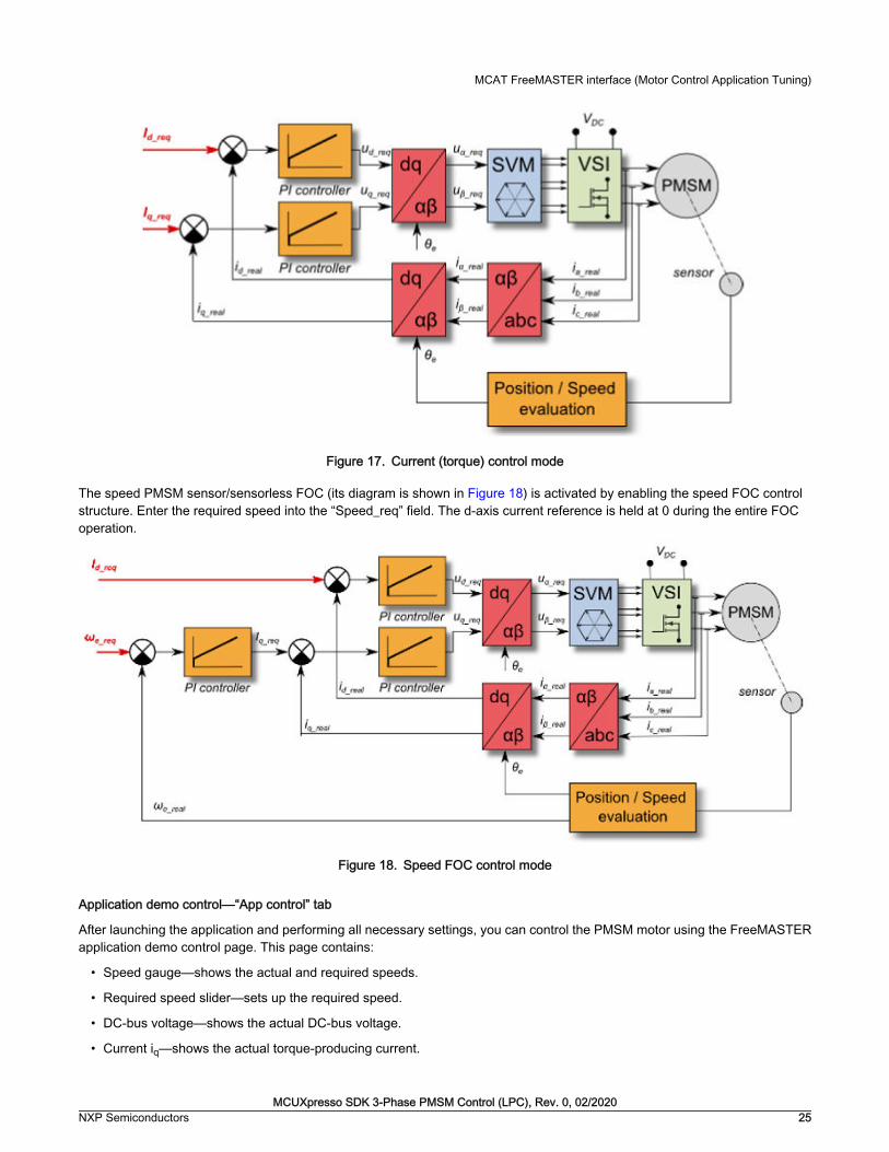
Figure 17. Current (torque) control mode
The speed PMSM sensor/sensorless FOC (its diagram is shown in Figure 18) is activated by enabling the speed FOC controlstructure. Enter the required speed into the “Speed_req” field. The d-axis current reference is held at 0 during the entire FOCoperation.
Figure 18. Speed FOC control mode
Application demo control—“App control” tab
After launching the application and performing all necessary settings, you can control the PMSM motor using the FreeMASTERapplication demo control page. This page contains:
• Speed gauge—shows the actual and required speeds.
• Required speed slider—sets up the required speed.
• DC-bus voltage—shows the actual DC-bus voltage.
• Current iq—shows the actual torque-producing current.
MCAT FreeMASTER interface (Motor Control Application Tuning)
MCUXpresso SDK 3-Phase PMSM Control (LPC), Rev. 0, 02/2020NXP Semiconductors 25

• Current limitation—sets up the torque-producing current limit.
• Demo mode on/off button—turns the demonstration mode on/off.
• RUN/STOP PWM button—runs/stops the whole application (sets the PWM on and off).
• Notification—shows the notification about the actual application state (or faults).
Figure 19. FreeMASTER control page
These are the basic instructions for controlling a motor:
• To start the motor, set the required speed using the speed slider.
• In case of a fault, click on the fault notification to clear the fault.
• Click the “Demo Mode On/Off” button to turn the demonstration mode on/off.
• Click the “RUN/STOP” button to stop the motor.
Remote control using FreeMASTER
MCUXpresso SDK 3-Phase PMSM Control (LPC), Rev. 0, 02/202026 NXP Semiconductors

Chapter 9Identifying parameters of user motor using MCATThis section provides a guide on how to run your own motor or tune the default motor in several steps. It is highly recommendedto go through all the steps carefully to eliminate any possible issues during the tuning process. The state diagram in Figure 20shows a typical PMSM sensor/sensorless control tuning process.
Because the model-based control methods of the PMSM drives are the most effective and usable, obtaining an accurate modelof a motor is an important part of the drive design and control. For the implemented FOC algorithms, it is necessary to know thevalue of the stator resistance Rs, direct inductance Ld, quadrature inductance Lq, and BEMF constant Ke. If your connectedPMSM motor is not the default Teknic or Linix motor described in the previous sections, identify the parameters of your motorfirst. Each tuning phase is described in more detail in the following sections.
Figure 20. Running a new PMSM
Power stage characterization
Each inverter introduces the total error voltage Uerror, which is caused by the dead time, current clamping effect, and transistorvoltage drop. The total error voltage Uerror depends on the phase current is and this dependency is measured during the power
MCUXpresso SDK 3-Phase PMSM Control (LPC), Rev. 0, 02/2020NXP Semiconductors 27

stage characterization process. An example of the inverter error characteristic is shown in Figure 21. The power stagecharacterization is a part of the MCAT and it can be controlled from the “Motor Identif” tab. To perform the characterization,connect the motor with a known stator resistance Rs and enter this value into the “Calib Rs” field. Then specify the “CalibrationRange”, which is the range of the stator current is, in which the measurement of Uerror is performed. Start the characterization bypressing the “Calibrate” button. The characterization gradually performs 65 isd current steps (from is = -Is,calib to is = Is,calib) witheach taking 300 ms, so be aware that the process takes about 20 seconds and the motor must withstand this load. The acquiredcharacterization data is saved to a file and used later for the phase voltage correction during the Rs measurement process. Thefollowing Rs measurement can be done with the Is,calib maximum current. It is recommended to use a motor with a low Rs forcharacterization purposes.
Figure 21. Example power stage characteristic
The power stage characterization is necessary only for the user hardware board. When the NXP power stages (TWR, FRDM, orHVP) are used with the application, the characterization process can be omitted. The acquired characterization data is savedinto a file, so it is necessary to do it only once for a given hardware.
Stator resistance measurement
The stator resistance Rs is measured using the DC current IphN value, which is applied to the motor for 1200 ms. The DC voltageUDC is held using current controllers. Their parameters are selected conservatively to ensure stability. The stator resistance Rsis calculated using the Ohm’s law as:
Stator inductance
For the stator inductance (Ls) identification purposes, a sinusoidal measurement voltage is applied to the motor. During the LSmeasurement, the voltage control is enabled. The frequency and amplitude of the sinusoidal voltage are obtained before theactual measurement, during the tuning process. The tuning process begins with a 0-V amplitude and the F start frequency, whichare applied to the motor. The amplitude is gradually increased by Ud inc up to a half of the DC-bus voltage (DCbus/2), until Idampl is reached. If Id ampl is not reached even with the DCbus/2 and F start, the frequency of the measuring signal is graduallydecreased by F dec down to F min again, until Id ampl is reached. If Id ampl is still not reached, the measurement continues withDCbus/2 and F min. The tuning process is shown in Figure 22.
Identifying parameters of user motor using MCAT
MCUXpresso SDK 3-Phase PMSM Control (LPC), Rev. 0, 02/202028 NXP Semiconductors
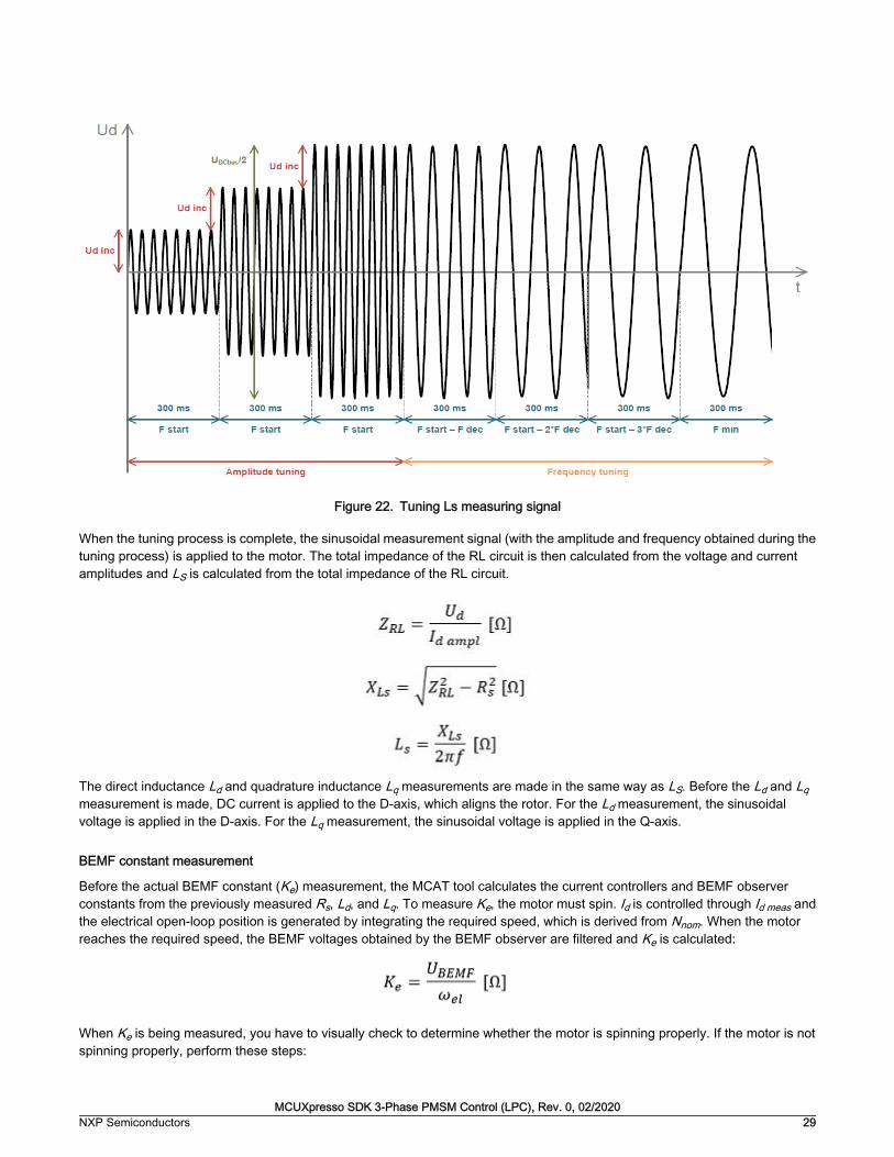
Figure 22. Tuning Ls measuring signal
When the tuning process is complete, the sinusoidal measurement signal (with the amplitude and frequency obtained during thetuning process) is applied to the motor. The total impedance of the RL circuit is then calculated from the voltage and currentamplitudes and LS is calculated from the total impedance of the RL circuit.
The direct inductance Ld and quadrature inductance Lq measurements are made in the same way as LS. Before the Ld and Lqmeasurement is made, DC current is applied to the D-axis, which aligns the rotor. For the Ld measurement, the sinusoidalvoltage is applied in the D-axis. For the Lq measurement, the sinusoidal voltage is applied in the Q-axis.
BEMF constant measurement
Before the actual BEMF constant (Ke) measurement, the MCAT tool calculates the current controllers and BEMF observerconstants from the previously measured Rs, Ld, and Lq. To measure Ke, the motor must spin. Id is controlled through Id meas andthe electrical open-loop position is generated by integrating the required speed, which is derived from Nnom. When the motorreaches the required speed, the BEMF voltages obtained by the BEMF observer are filtered and Ke is calculated:
When Ke is being measured, you have to visually check to determine whether the motor is spinning properly. If the motor is notspinning properly, perform these steps:
MCUXpresso SDK 3-Phase PMSM Control (LPC), Rev. 0, 02/2020NXP Semiconductors 29

• Ensure that the number of pp is correct. The required speed for the Ke measurement is also calculated from pp.Therefore, inaccuracy in pp causes inaccuracy in the resulting Ke.
• Increase Id meas to produce higher torque when spinning during the open loop.
• Decrease Nnom to decrease the required speed for the Ke measurement.
Number of pole-pair assistant
The number of pole-pairs cannot be measured without a position sensor. However, there is a simple assistant to determine thenumber of pole-pairs (pp). The number of the pp assistant performs one electrical revolution, stops for a few seconds, and thenrepeats it. Because the pp value is the ratio between the electrical and mechanical speeds, it can be determined as the numberof stops per one mechanical revolution. It is recommended not to count the stops during the first mechanical revolution becausethe alignment occurs during the first revolution and affects the number of stops. During the pp measurement, the current loop isenabled and the Id current is controlled to Id meas. The electrical position is generated by integrating the open-loop speed. If therotor does not move after the start of the number of pp assistant, stop the assistant, increase Id meas, and restart the assistant.
Mechanical parameters measurementThe moment of inertia J and the viscous friction B can be identified using a test with the known generated torque T and theloading torque Tload.
The ωm character in the equation is the mechanical speed. The mechanical parameter identification software uses the torqueprofile. The loading torque is (for simplicity reasons) said to be 0 during the whole measurement. Only the friction and themotor-generated torque are considered. During the first phase of measurement, the constant torque Tmeas is applied and themotor accelerates to 50 % of its nominal speed in time t1. These integrals are calculated during the period from t0 (the speedestimation is accurate enough) to t1:
During the second phase, the rotor decelerates freely with no generated torque, only by friction. This enables you to simplymeasure the mechanical time constant τm=J/B as the time in which the rotor decelerates from its original value by 63 %.
The final mechanical parameter estimation can be calculated by integrating:
Te moment of inertia is:
The viscous friction is then derived from the relation between the mechanical time constant and the moment of inertia. To usethe mechanical parameters measurement, the current control loop bandwidth f0,Current, the speed control loop bandwidth f0,Speed,and the mechanical parameters measurement torque Trqm must be set.
Identifying parameters of user motor using MCAT
MCUXpresso SDK 3-Phase PMSM Control (LPC), Rev. 0, 02/202030 NXP Semiconductors

Figure 23. PMSM identification tab
9.1 PMSM electrical and mechanical parameters measurementprocess
The motor identification process can be controlled and set up in the MCAT “Motor Identif” tab, which is shown in Figure 24. Tomeasure your own motor, follow these steps:
• Select your hardware board. Choose between the standard NXP hardware or use your own. If you use your ownhardware, specify its scales (“I max” and “U DCB max” in the “Parameters” menu tab).
• If you don’t know the number of motor’s pole-pairs, use the number of pole-pair assistant and compute the number ofmotor rotor stops in one turn.
• If you use your own hardware for the first time, perform the power stage characterization.
• Enter the motor measurement parameters and start the measurement by pressing the “Measure electrical” or “Measuremechanical” buttons. You can observe which parameter is being measured in the “Status” bar.
PMSM electrical and mechanical parameters measurement process
MCUXpresso SDK 3-Phase PMSM Control (LPC), Rev. 0, 02/2020NXP Semiconductors 31

Figure 24. PMSM identification tab
Identifying parameters of user motor using MCAT
MCUXpresso SDK 3-Phase PMSM Control (LPC), Rev. 0, 02/202032 NXP Semiconductors

Figure 25. Measurement process diagram
During the measurement, faults and warnings may occur. Do not confuse these faults for the application faults, such asovercurrent, undervoltage, and so on. The list of these faults with their description and possible troubleshooting is shown in Table6.
Table 6. Measurement faults and warnings
Fault no. Fault description Fault reason Troubleshooting
1 Motor not connected Id > 50 mA cannot bereached with the available
DC-bus voltage.
Check that the motor isconnected.
2 Rs too high for calibration The calibration cannot bereached with the available
DC-bus voltage.
Use a motor with a lower Rsfor the power stage
characterization.
3 Current measurement Is DCnot reached
The user-defined Is DC wasnot reached, so the
measurement was taken witha lower Is DC.
Raise the DC-bus voltage toreach the Is DC or lower theIs DC to avoid this warning.
4 Current amplitudemeasurement Is AC not
reached
The user-defined Is AC wasnot reached, so the
measurement was taken witha lower Is AC.
Raise the DC-bus voltage orlower the Fmin to reach the Is
AC or lower the Is AC toavoid this warning.
5 Wrong characteristic data The characteristic data, whichis used for the voltagecorrection, does not
correspond to the actualpower stage.
Select the user hardware andperform the calibration.
Table continues on the next page...
PMSM electrical and mechanical parameters measurement process
MCUXpresso SDK 3-Phase PMSM Control (LPC), Rev. 0, 02/2020NXP Semiconductors 33

Table 6. Measurement faults and warnings (continued)
Fault no. Fault description Fault reason Troubleshooting
6 Mechanical measurementtimeout
The mechanicalmeasurement takes too long.
Repeat the measurementprocess with a different
setup.
9.2 Initial configuration setting and update1. Open the PMSM control application FreeMASTER project containing the dedicated MCAT plug-in module.
2. Select the “Parameters” tab.
3. Leave the measured motor parameters or specify the parameters manually. The motor parameters can be obtained fromthe motor data sheet or using the PMSM parameters measurement procedure described in PMSM Electrical ParametersMeasurement (document AN4680). All parameters provided in Table 7 are accessible. The motor inertia J expresses theoverall system inertia and can be obtained using a mechanical measurement. The J parameter is used to calculate thespeed controller constant. However, the manual controller tuning can also be used to calculate this constant.
Table 7. MCAT motor parameters
Parameter Units Description Typical range
pp [-] Motor pole pairs 1-10
Rs [Ω] 1-phase stator resistance 0.3-50
Ld [H] 1-phase direct inductance 0.00001-0.1
Lq [H] 1-phase quadratureinductance
0.00001-0.1
Ke [V.sec/rad] BEMF constant 0.001-1
J [kg.m2] System inertia 0.00001-0.1
Iph nom [A] Motor nominal phase current 0.5-8
Uph nom [V] Motor nominal phase voltage 10-300
N nom [rpm] Motor nominal speed 1000-2000
4. Set the hardware scales—the modification of these two fields is not required when a reference to the standard power stageboard is used. These scales express the maximum measurable current and voltage analog quantities.
5. Check the fault limits—these fields are not accessible in the “Basic” mode and are calculated using the motor parametersand hardware scales (see Table 8).
Table 8. Fault limits
Parameter Units Description Typical range
U DCB trip [V] Voltage value at which theexternal braking resistorswitch turns on
U DCB Over ~ U DCB max
U DCB under [V] Trigger value at which theundervoltage fault is detected
0 ~ U DCB Over
U DCB over [V] Trigger value at which theovervoltage fault is detected
U DCB Under ~ U max
Table continues on the next page...
Identifying parameters of user motor using MCAT
MCUXpresso SDK 3-Phase PMSM Control (LPC), Rev. 0, 02/202034 NXP Semiconductors

Table 8. Fault limits (continued)
Parameter Units Description Typical range
N over [rpm] Trigger value at which theoverspeed fault is detected
N nom ~ N max
N min [rpm] Minimal actual speed value forthe sensorless control
(0.05~0.2) *N max
6. Check the application scales—these fields are not accessible in the “Basic” mode and are calculated using the motorparameters and hardware scales.
Table 9. Application scales
Parameter Units Description Typical range
N max [rpm] Speed scale >1.1 * N nom
E max [V] BEMF scale ke* Nmax
kt [Nm/A] Motor torque constant -
7. Check the alignment parameters—these fields are not accessible in the “Basic” mode and they are calculated using themotor parameters and hardware scales. The parameters express the required voltage value applied to the motor duringthe rotor alignment and its duration.
8. Click the “Store Data” button to save the modified parameters into the inner file.
9.3 Control structure modes1. Select the scalar control by clicking the “DISABLED” button in the “Scalar Control” section. The button color changes to
red and the text changes to “ENABLED”.
2. Turn the application switch on. The application state changes to “RUN”.
3. Set the required frequency value in the “Freq_req” field; for example, 15 Hz in the “Scalar Control” section. The motorstarts running (Figure 26).
Figure 26. MCAT scalar control
Control structure modes
MCUXpresso SDK 3-Phase PMSM Control (LPC), Rev. 0, 02/2020NXP Semiconductors 35

4. Select the “Phase Currents” recorder from the “Scalar & Voltage Control” FreeMASTER project tree.
5. The optimal ratio for the V/Hz profile can be found by changing the V/Hz factor directly or using the “UP/DOWN” buttons.The shape of the motor currents should be close to a sinusoidal shape (Figure 27).
Figure 27. Phase currents
6. Select the “Position” recorder to check the observer functionality. The difference between the “Position Electrical Scalar”and the “Position Estimated” should be minimal (see Figure 28) for the Back-EMF position and speed observer to workproperly. The position difference depends on the motor load. The higher the load, the bigger the difference between thepositions due to the load angle.
Figure 28. Generated and estimated positions
7. If an opposite speed direction is required, set a negative speed value into the “Freq_req” field.
8. The proper observer functionality and the measurement of analog quantities is expected at this step.
9. Enable the voltage FOC mode by clicking the “DISABLED” button in the “Voltage FOC” section while the main applicationswitch is turned off.
10. Switch the main application switch on and set a non-zero value in the “Uq_req” field. The FOC algorithm uses the estimatedposition to run the motor.
Identifying parameters of user motor using MCAT
MCUXpresso SDK 3-Phase PMSM Control (LPC), Rev. 0, 02/202036 NXP Semiconductors

9.4 Alignment tuningFor the alignment parameters, navigate to the “Tab” menu and select “Parameters”. The alignment procedure sets the rotor toan accurate initial position and enables you to apply full start-up torque to the motor. The rotor-alignment parameters are availablefor editing in the “Expert” mode. A correct initial position is needed mainly for high start-up loads (compressors, washers, and soon). The aim of the alignment is to have the rotor in a stable position, without any oscillations before the startup.
1. The alignment voltage is the value applied to the d-axis during the alignment. Increase this value for a higher shaft load.
2. The alignment duration expresses the time when the alignment routine is called. Tune this parameter to eliminate rotoroscillations or movement at the end of the alignment process.
9.5 Current loop tuningThe parameters for the current D, Q, and PI controllers are fully calculated in the “Basic” mode using the motor parameters andno action is required in this mode. If the calculated loop parameters do not correspond to the required response, the bandwidthand attenuation parameters can be tuned.
1. Lock the motor shaft.
2. Set the required loop bandwidth and attenuation and click the “Update Target” button in the “Current Loop” tab. The tuningloop bandwidth parameter defines how fast the loop response is whilst the tuning loop attenuation parameter defines theactual quantity overshoot magnitude.
3. Select the “Current Controller Id” recorder.
4. Select the “Control Structure” tab, switch to “Current FOC”, set the “Iq_req” field to a very low value (for example 0.01),and set the required step in “Id_req”. The control loop response is shown in the recorder.
5. Tune the loop bandwidth and attenuation until you achieve the required response. The example waveforms show thecorrect and incorrect settings of the current loop parameters:
• The loop bandwidth is low (110 Hz) and the settling time of the Id current is long (Figure 29).
Figure 29. Slow step response of the Id current controller
• The loop bandwidth (400 Hz) is optimal and the response time of the Id current is sufficient (see Figure 30).
Alignment tuning
MCUXpresso SDK 3-Phase PMSM Control (LPC), Rev. 0, 02/2020NXP Semiconductors 37

Figure 30. Optimal step response of the Id current controller
• The loop bandwidth is high (700 Hz) and the response time of the Id current is very fast, but with oscillation andovershoot (see Figure 31).
Figure 31. Fast step response of the Id current controller
9.6 Speed ramp tuning1. The speed command is applied to the speed controller through a speed ramp. The ramp function contains two increments
(up and down) which express the motor acceleration and deceleration per second. If the increments are very high, theycan cause an overcurrent fault during acceleration and an overvoltage fault during deceleration. In the “Speed” scope, youcan see whether the “Speed Actual Filtered” waveform shape equals the “Speed Ramp” profile.
2. The increments are common for the scalar and speed control. The increment fields are in the “Speed & Pos” tab andaccessible in both tuning modes. Clicking the “Update Target” button applies the changes to the MCU. An example speedprofile is shown in Figure 32. The ramp increment down is set to 500 rpm/sec and the increment up is set to 3000 rpm/sec.
3. The start-up ramp increment is in the “Sensorless” tab and its value is usually higher than that of the speed loop ramp.
Identifying parameters of user motor using MCAT
MCUXpresso SDK 3-Phase PMSM Control (LPC), Rev. 0, 02/202038 NXP Semiconductors

Figure 32. Speed profile
9.7 Open loop startup1. The start-up process can be tuned by a set of parameters located in the “Sensorless” tab. Two of them (ramp increment
and current) are accessible in both tuning modes. The start-up tuning can be processed in all control modes besides thescalar control. Setting the optimal values results in a proper motor startup. An example start-up state of low-dynamic drives(fans, pumps) is shown in Figure 33.
2. Select the “Startup” recorder from the FreeMASTER project tree.
3. Set the start-up ramp increment typically to a higher value than the speed-loop ramp increment.
4. Set the start-up current according to the required start-up torque. For drives such as fans or pumps, the start-up torque isnot very high and can be set to 15 % of the nominal current.
5. Set the required merging speed—when the open-loop and estimated position merging starts, the threshold is mostly setin the range of 5 % ~ 10 % of the nominal speed.
6. Set the merging coefficient—in the position merging process duration, 100 % corresponds to a half of an electricalrevolution. The higher the value, the faster the merge. Values close to 1 % are set for the drives where a high start-uptorque and smooth transitions between the open loop and the closed loop are required.
7. Click the “Update Target” button to apply the changes to the MCU.
8. Switch to the “Control Structure” tab, and enable the “Speed FOC”.
9. Set the required speed higher than the merging speed.
10. Check the start-up response in the recorder.
11. Tune the start-up parameters until you achieve an optimal response.
12. If the rotor does not start running, increase the start-up current.
13. If the merging process fails (the rotor is stuck or stopped), decrease the start-up ramp increment, increase the mergingspeed, and set the merging coefficient to 5 %.
Open loop startup
MCUXpresso SDK 3-Phase PMSM Control (LPC), Rev. 0, 02/2020NXP Semiconductors 39

Figure 33. Motor startup
9.8 BEMF observer tuning1. In the “Basic” mode, the parameters of the BEMF observer and the tracking observer are fully calculated using the motor
parameters and no action is required. If the calculated loop parameters do not correspond to the optimal response, thebandwidth and attenuation parameters can be tuned.
2. Select the “Observer” recorder from the FreeMASTER project tree.
3. Set the required bandwidth and attenuation of the BEMF observer—the bandwidth is typically set to a value close to thecurrent loop bandwidth.
4. Set the required bandwidth and attenuation of the tracking observer—the bandwidth is typically set in the range of 10 – 20Hz for most low-dynamic drives (fans, pumps).
5. Click the “Update Target” button to apply the changes to the MCU.
6. Check the observer response in the recorder.
9.9 Speed PI controller tuningThe motor speed control loop is a first-order function with a mechanical time constant that depends on the motor inertia andfriction. If the mechanical constant is available, the PI controller constants can be tuned using the loop bandwidth and attenuation.Otherwise, the manual tuning of the P and I portions of the speed controllers is available to obtain the required speed response(see the example response in Figure 34). There are dozens of approaches to tune the PI controller constants. The following stepsprovide an approach to set and tune the speed PI controller for a PM synchronous motor:
1. Select the “Speed Controller” option from the FreeMASTER project tree.
2. Select the “Speed & Pos” tab.
3. Check the “Manual Constant Tuning” option—that is, the “Bandwidth” and “Attenuation” fields are disabled and the“SL_Kp” and “SL_Ki” fields are enabled.
4. Tune the proportional gain:
• Set the “SL_Ki” integral gain to 0.
• Set the speed ramp to 1000 rpm/sec (or higher).
• Switch to the “Control Structure” tab and run the motor at a convenient speed (about 30 % of the nominal speed).
Identifying parameters of user motor using MCAT
MCUXpresso SDK 3-Phase PMSM Control (LPC), Rev. 0, 02/202040 NXP Semiconductors

• Set a step in the required speed to 40 % of Nnom.
• Switch back to the “Speed loop” tab.
• Adjust the proportional gain “SL_Kp” until the system responds to the required value properly and without anyoscillations or excessive overshoot:
— If the “SL_Kp” field is set low, the system response is slow.
— If the “SL_Kp” field is set high, the system response is tighter.
— When the “SL_Ki” field is 0, the system most probably does not achieve the required speed.
— Click the “Update Target” button to apply the changes to the MCU.
5. Tune the integral gain:
• Increase the “SL_Ki” field slowly to minimize the difference between the required and actual speeds to 0.
• Adjust the “SL_Ki” field such that you do not see any oscillation or large overshoot of the actual speed value whilethe required speed step is applied.
• Click the “Update Target” button to apply the changes to the MCU.
6. Tune the loop bandwidth and attenuation until the required response is received. The example waveforms with thecorrect and incorrect settings of the speed loop parameters are shown in the following figures:
• The “SL_Ki” value is low and the “Speed Actual Filtered” does not achieve the “Speed Ramp” (see Figure 34).
Figure 34. Speed controller response—SL_Ki value is low, Speed Ramp is not achieved
• The “SL_Kp” value is low, the “Speed Actual Filtered” greatly overshoots, and the long settling time is unwanted(see Figure 35).
Speed PI controller tuning
MCUXpresso SDK 3-Phase PMSM Control (LPC), Rev. 0, 02/2020NXP Semiconductors 41

Figure 35. Speed controller response—SL_Kp value is low, Speed Actual Filtered greatly overshoots
• The speed loop response has a small overshoot and the “Speed Actual Filtered” settling time is sufficient. Suchresponse can be considered optimal (see Figure 36).
Figure 36. Speed controller response—speed loop response with a small overshoot
Identifying parameters of user motor using MCAT
MCUXpresso SDK 3-Phase PMSM Control (LPC), Rev. 0, 02/202042 NXP Semiconductors

Chapter 10ConclusionThis application note describes the implementation of the sensor and sensorless Field-Oriented Control of a 3-phase PMSM onthe NXP LPC55S69 with the FRDM-MC-LVPMSM NXP Freedom Development Platform. The hardware-dependent part of thecontrol software is described in Hardware setup. The motor-control application timing is described in LPC55S69 hardware timingand synchronization and the peripheral initialization is described in Motor-control peripheral initialization. The motor user interfaceand remote control using FreeMASTER are as follows. The motor parameters identification theory and the identification algorithmsare described in Identifying parameters of user motor using MCAT.
MCUXpresso SDK 3-Phase PMSM Control (LPC), Rev. 0, 02/2020NXP Semiconductors 43

Chapter 11Acronyms and abbreviations
Table 10.
Acronym Meaning
ADC Analog-to-Digital Converter
ACIM Asynchronous Induction Motor
ADC_ETC ADC External Trigger Control
AN Application Note
BLDC Brushless DC motor
CCM Clock Controller Module
CPU Central Processing Unit
DC Direct Current
DRM Design Reference Manual
ENC Encoder
FOC Field-Oriented Control
GPIO General-Purpose Input/Output
LPUART Low Power Universal Asynchronous Receiver/Transmitter
MCAT Motor Control Application Tuning tool
MCDRV Motor Control Peripheral Drivers
MCU Microcontroller
PI Proportional Integral controller
PLL Phase-Locked Loop
PMSM Permanent Magnet Synchronous Machine
PWM Pulse-Width Modulation
QD Quadrature Decoder
TMR Quad Timer
USB Universal Serial Bus
XBAR Inter-Peripheral Crossbar Switch
Acronyms and abbreviations
MCUXpresso SDK 3-Phase PMSM Control (LPC), Rev. 0, 02/202044 NXP Semiconductors

Chapter 12ReferencesThese references are available on www.nxp.com:
1. Sensorless PMSM Field-Oriented Control (document DRM148).
2. Motor Control Application Tuning (MCAT) Tool for 3-Phase PMSM (document AN4642).
MCUXpresso SDK 3-Phase PMSM Control (LPC), Rev. 0, 02/2020NXP Semiconductors 45

Chapter 13Useful links
1. PMSM Control Reference Design www.nxp.com/motorcontrol_pmsm
2. BLDC Control Reference Design www.nxp.com/motorcontrol_bldc
3. ACIM Control Reference Design www.nxp.com/motorcontrol_acim
4. LPC55S69-EVK
5. FRDM-MC-PMSM Freedome Development Platform
6. Get Started with the LPC55S69-EVK
7. SCTimer/PWM Cookbook (document AN11538)
8. MCUXpresso IDE - Importing MCUXpresso SDK
9. MCUXpresso SDK Builder (SDK examples in several IDEs) https://mcuxpresso.nxp.com/en/welcome
Useful links
MCUXpresso SDK 3-Phase PMSM Control (LPC), Rev. 0, 02/202046 NXP Semiconductors


How To Reach Us
Home Page:
nxp.com
Web Support:
nxp.com/support
Information in this document is provided solely to enable system and software implementers touse NXP products. There are no express or implied copyright licenses granted hereunder todesign or fabricate any integrated circuits based on the information in this document. NXPreserves the right to make changes without further notice to any products herein.
NXP makes no warranty, representation, or guarantee regarding the suitability of its products forany particular purpose, nor does NXP assume any liability arising out of the application or useof any product or circuit, and specifically disclaims any and all liability, including without limitationconsequential or incidental damages. “Typical” parameters that may be provided in NXP datasheets and/or specifications can and do vary in different applications, and actual performancemay vary over time. All operating parameters, including “typicals,” must be validated for eachcustomer application by customer's technical experts. NXP does not convey any license underits patent rights nor the rights of others. NXP sells products pursuant to standard terms andconditions of sale, which can be found at the following address: nxp.com/SalesTermsandConditions.
While NXP has implemented advanced security features, all products may be subject tounidentified vulnerabilities. Customers are responsible for the design and operation of theirapplications and products to reduce the effect of these vulnerabilities on customer’s applicationsand products, and NXP accepts no liability for any vulnerability that is discovered. Customersshould implement appropriate design and operating safeguards to minimize the risks associatedwith their applications and products.
NXP, the NXP logo, NXP SECURE CONNECTIONS FOR A SMARTER WORLD, COOLFLUX,EMBRACE, GREENCHIP, HITAG, I2C BUS, ICODE, JCOP, LIFE VIBES, MIFARE, MIFARECLASSIC, MIFARE DESFire, MIFARE PLUS, MIFARE FLEX, MANTIS, MIFARE ULTRALIGHT,MIFARE4MOBILE, MIGLO, NTAG, ROADLINK, SMARTLX, SMARTMX, STARPLUG, TOPFET,TRENCHMOS, UCODE, Freescale, the Freescale logo, AltiVec, C‑5, CodeTEST, CodeWarrior,ColdFire, ColdFire+, C‑Ware, the Energy Efficient Solutions logo, Kinetis, Layerscape, MagniV,mobileGT, PEG, PowerQUICC, Processor Expert, QorIQ, QorIQ Qonverge, Ready Play,SafeAssure, the SafeAssure logo, StarCore, Symphony, VortiQa, Vybrid, Airfast, BeeKit,BeeStack, CoreNet, Flexis, MXC, Platform in a Package, QUICC Engine, SMARTMOS, Tower,TurboLink, UMEMS, EdgeScale, EdgeLock, eIQ, and Immersive3D are trademarks of NXP B.V.All other product or service names are the property of their respective owners. AMBA, Arm,Arm7, Arm7TDMI, Arm9, Arm11, Artisan, big.LITTLE, Cordio, CoreLink, CoreSight, Cortex,DesignStart, DynamIQ, Jazelle, Keil, Mali, Mbed, Mbed Enabled, NEON, POP, RealView,SecurCore, Socrates, Thumb, TrustZone, ULINK, ULINK2, ULINK-ME, ULINK-PLUS, ULINKpro,µVision, Versatile are trademarks or registered trademarks of Arm Limited (or its subsidiaries) inthe US and/or elsewhere. The related technology may be protected by any or all of patents,copyrights, designs and trade secrets. All rights reserved. Oracle and Java are registeredtrademarks of Oracle and/or its affiliates. The Power Architecture and Power.org word marksand the Power and Power.org logos and related marks are trademarks and service markslicensed by Power.org.
© NXP B.V. 2020. All rights reserved.
For more information, please visit: http://www.nxp.comFor sales office addresses, please send an email to: [email protected]
Date of release: 02/2020Document identifier: 3PPMSMCLPCUG