FM0+ Low Voltage, 3-Phase BLDC/PMSM Motor Control ...
23
THIS SPEC IS OBSOLETE Spec No: 002-04391 Spec Title: AN204391 - FM0+ Low Voltage, 3-Phase BLDC/PMSM Motor Control Replaced by: 002-02483
-
Upload
khangminh22 -
Category
Documents
-
view
1 -
download
0
Transcript of FM0+ Low Voltage, 3-Phase BLDC/PMSM Motor Control ...

THIS SPEC IS OBSOLETE Spec No: 002-04391 Spec Title: AN204391 - FM0+ Low Voltage, 3-Phase
BLDC/PMSM Motor Control Replaced by: 002-02483
www.cypress.com Document No. 002-04391Rev.*A 1
AN204391
FM0+ Low Voltage, 3-Phase BLDC/PMSM Motor Control
This document describes low voltage 3-phase BLDC/PMSM control on S6E1A1 MCU, including whole system scope,
hardware design, software design and test result.
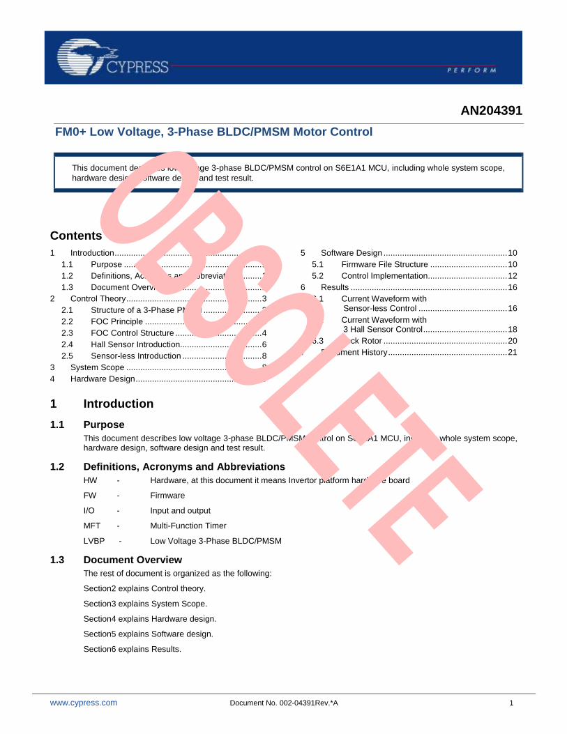
Contents
1 Introduction ............................................................... 1 1.1 Purpose ........................................................... 1 1.2 Definitions, Acronyms and Abbreviations ........ 1 1.3 Document Overview ........................................ 1
2 Control Theory .......................................................... 3 2.1 Structure of a 3-Phase PMSM ......................... 3 2.2 FOC Principle .................................................. 3 2.3 FOC Control Structure ..................................... 4 2.4 Hall Sensor Introduction................................... 6 2.5 Sensor-less Introduction .................................. 8
3 System Scope .......................................................... 8 4 Hardware Design ...................................................... 9
5 Software Design ..................................................... 10 5.1 Firmware File Structure ................................. 10 5.2 Control Implementation .................................. 12
6 Results ................................................................... 16 6.1 Current Waveform with
Sensor-less Control ...................................... 16 6.2 Current Waveform with
3 Hall Sensor Control .................................... 18 6.3 Lock Rotor ..................................................... 20
7 Document History ................................................... 21
1 Introduction
1.1 Purpose
This document describes low voltage 3-phase BLDC/PMSM control on S6E1A1 MCU, including whole system scope, hardware design, software design and test result.
1.2 Definitions, Acronyms and Abbreviations
HW - Hardware, at this document it means Invertor platform hardware board
FW - Firmware
I/O - Input and output
MFT - Multi-Function Timer
LVBP - Low Voltage 3-Phase BLDC/PMSM
1.3 Document Overview
The rest of document is organized as the following:
Section2 explains Control theory.
Section3 explains System Scope.
Section4 explains Hardware design.
Section5 explains Software design.
Section6 explains Results.
FM0+ Low Voltage, 3-Phase BLDC/PMSM Motor Control
www.cypress.com Document No. 002-04391Rev.*A 2
FM0+ Low Voltage, 3-Phase BLDC/PMSM Motor Control
www.cypress.com Document No. 002-04391Rev.*A 3
2 Control Theory
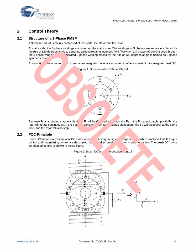
2.1 Structure of a 3-Phase PMSM
A 3-phase PMSM is mainly composed of two parts: the stator and the rotor.
At stator side, the 3-phase windings are coiled on the stator core. The windings of 3 phases are separately placed by the rule of 120 degrees angle to generate a round rotating magnetic field (Fs) when a 3-phase AC current goes through the 3 phase windings. The separated 3-phase winding placed by the rule of 120 degrees angle is named as 3-phase symmetric winding.
At rotor side, one or more pairs of permanent magnetic poles are mounted to offer a constant rotor magnetic field (Fr).
Figure 1. Structure of a 3-Phase PMSM
Because Fs is a rotating magnetic field, the Fr will be dragged and follow the Fs. If the Fr cannot catch up with Fs, the rotor will rotate continuously. If the 3-phase current in 3-phase windings disappears, the Fs will disappear at the same time, and the rotor will also stop.
2.2 FOC Principle
Brush DC motor is a conventional DC motor with a long history. A big advantage of the brush DC motor is that its torque control and magnetizing control are decoupled, which makes brush DC motor is easy to control. The brush DC motor de-coupled control is shown in below figure.
Figure 2. Brush DC Motor De-coupled Control
FM0+ Low Voltage, 3-Phase BLDC/PMSM Motor Control
www.cypress.com Document No. 002-04391Rev.*A 4
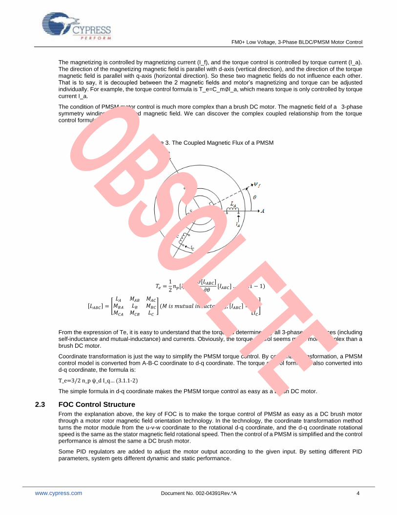
The magnetizing is controlled by magnetizing current (I_f), and the torque control is controlled by torque current (I_a). The direction of the magnetizing magnetic field is parallel with d-axis (vertical direction), and the direction of the torque magnetic field is parallel with q-axis (horizontal direction). So these two magnetic fields do not influence each other. That is to say, it is decoupled between the 2 magnetic fields and motor’s magnetizing and torque can be adjusted individually. For example, the torque control formula is T_e=C_m∅I_a, which means torque is only controlled by torque
current I_a.
The condition of PMSM motor control is much more complex than a brush DC motor. The magnetic field of a 3-phase symmetry winding is a coupled magnetic field. We can discover the complex coupled relationship from the torque control formula.
Figure 3. The Coupled Magnetic Flux of a PMSM
𝑇𝑒 =1
2𝑛𝑝[𝐼𝐴𝐵𝐶]
𝑇𝜕[𝐿𝐴𝐵𝐶]
𝜕𝜃[𝐼𝐴𝐵𝐶] … (3.1.1 − 1)
[𝐿𝐴𝐵𝐶] = [
𝐿𝐴 𝑀𝐴𝐵 𝑀𝐴𝐶𝑀𝐵𝐴 𝐿𝐵 𝑀𝐵𝐶𝑀𝐶𝐴 𝑀𝐶𝐵 𝐿𝐶
] (𝑀 𝑖𝑠 𝑚𝑢𝑡𝑢𝑎𝑙 𝑖𝑛𝑑𝑢𝑐𝑡𝑎𝑛𝑐𝑒), [𝐼𝐴𝐵𝐶] = [
𝐼𝐴𝐼𝐵𝐼𝐶
]
From the expression of Te, it is easy to understand that the torque is determined by all 3-phase inductances (including self-inductance and mutual-inductance) and currents. Obviously, the torque control seems much more complex than a brush DC motor.
Coordinate transformation is just the way to simplify the PMSM torque control. By coordinate transformation, a PMSM control model is converted from A-B-C coordinate to d-q coordinate. The torque control formula is also converted into d-q coordinate, the formula is:
T_e=3/2 n_p ψ_d I_q… (3.1.1-2)
The simple formula in d-q coordinate makes the PMSM torque control as easy as a brush DC motor.
2.3 FOC Control Structure
From the explanation above, the key of FOC is to make the torque control of PMSM as easy as a DC brush motor through a motor rotor magnetic field orientation technology. In the technology, the coordinate transformation method turns the motor module from the u-v-w coordinate to the rotational d-q coordinate, and the d-q coordinate rotational speed is the same as the stator magnetic field rotational speed. Then the control of a PMSM is simplified and the control performance is almost the same a DC brush motor.
Some PID regulators are added to adjust the motor output according to the given input. By setting different PID parameters, system gets different dynamic and static performance.
FM0+ Low Voltage, 3-Phase BLDC/PMSM Motor Control
www.cypress.com Document No. 002-04391Rev.*A 5
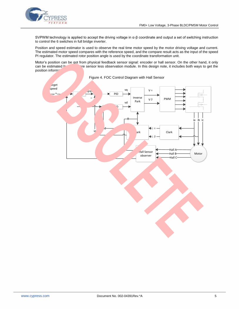
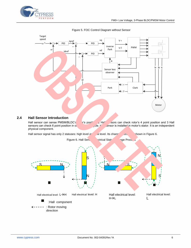
SVPWM technology is applied to accept the driving voltage in α-β coordinate and output a set of switching instruction to control the 6 switches in full bridge inverter.
Position and speed estimator is used to observe the real time motor speed by the motor driving voltage and current. The estimated motor speed compares with the reference speed, and the compare result acts as the input of the speed PI regulator. The estimated rotor position angle is used by the coordinate transformation unit.
Motor’s position can be got from physical feedback sensor signal: encoder or hall sensor. On the other hand, it only can be estimated by a firmware sensor less observation module. In this design note, it includes both ways to get the position information.
Figure 4. FOC Control Diagram with Hall Sensor
Motor
PWMinverse Park
Hall Sensor observer
ClarkPark
PID
PID
PID
Target speed
ia ib ic
Hall A
Hall BHall C
iα
iβ
id
*
θ
Idref
Iqref
_
_
iq
vd
vq Vα
Vβ
FM0+ Low Voltage, 3-Phase BLDC/PMSM Motor Control
www.cypress.com Document No. 002-04391Rev.*A 6
Figure 5. FOC Control Diagram without Sensor
Motor
PWMinverse Park
ClarkPark
PID
PID
PID
Target speed
ia ib ic
iα
iβ
id
*
Idref
Iqref
_
_
iq
vd
vq Vα
Vβ
Sensor less observer
ɵ
2.4 Hall Sensor Introduction
Hall sensor can sense PMSM/BLDC’s rotor’s position. 2 Hall sensors can check rotor’s 4 point position and 3 Hall sensors can check 6 point position in one electrical cycle. Hall sensor is installed in motor’s stator. It is an independent physical component.
Hall sensor signal has only 2 statuses: high level and low level. Its change process is shown in Figure 6.
Figure 6. Hall Sensor Electrical Status Change Process
N S
:Hall component
Hall electrical level: HL
N S
Hall electrical level: LH Hall electrical level: H
N
Hall electrical level: L
N S
S
: Rotor moving direction
FM0+ Low Voltage, 3-Phase BLDC/PMSM Motor Control
www.cypress.com Document No. 002-04391Rev.*A 7
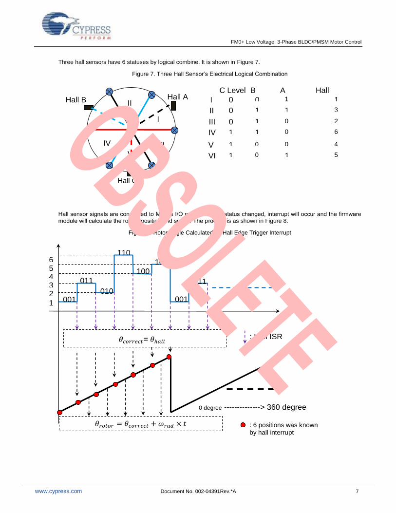
Three hall sensors have 6 statuses by logical combine. It is shown in Figure 7.
Figure 7. Three Hall Sensor’s Electrical Logical Combination
Hall sensor signals are connected to MCU’s I/O port. Once the status changed, interrupt will occur and the firmware module will calculate the rotor’s position and speed. The process is as shown in Figure 8.
Figure 8. Rotor Angle Calculated by Hall Edge Trigger Interrupt
Hall A Hall B
I
II
C Level B level I
II
III IV
0
0
0
0
1
1
1
1
Hall Statues 1
3
2
6
V 1 0 4
VI 1 0 5
A level 1
1
0
0
0
1
III
IV
V VI
Hall C
001
011
010
110
100
101
001
011
𝜃𝑐𝑜𝑟𝑟𝑒𝑐𝑡= 𝜃ℎ𝑎𝑙𝑙 : Hall ISR trigger
1
2 3 4 5 6
0 degree --------------> 360 degree
𝜃𝑟𝑜𝑡𝑜𝑟 = 𝜃𝑐𝑜𝑟𝑟𝑒𝑐𝑡 + 𝑟𝑎𝑑 × 𝑡 : 6 positions was known by hall interrupt
FM0+ Low Voltage, 3-Phase BLDC/PMSM Motor Control
www.cypress.com Document No. 002-04391Rev.*A 8
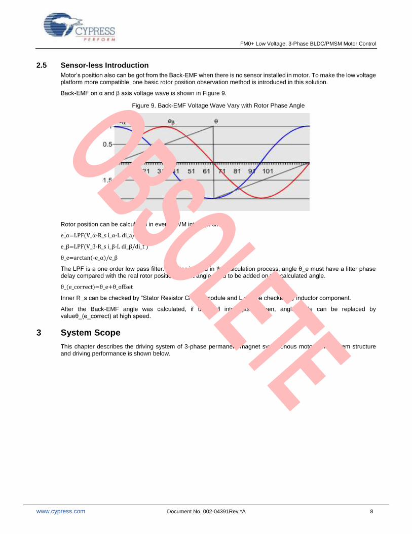
2.5 Sensor-less Introduction Motor’s position also can be got from the Back-EMF when there is no sensor installed in motor. To make the low voltage platform more compatible, one basic rotor position observation method is introduced in this solution.
Back-EMF on α and β axis voltage wave is shown in Figure 9.
Figure 9. Back-EMF Voltage Wave Vary with Rotor Phase Angle
Rotor position can be calculated in every PWM interrupt time:
e_α=LPF(V_α-R_s i_α-L di_a/di_t )
e_β=LPF(V_β-R_s i_β-L di_β/di_t )
θ_e=arctan(-e_α)/e_β
The LPF is a one order low pass filter. As filter is used in the calculation process, angle θ_e must have a litter phase delay compared with the real rotor position. Offset angle need to be added on the calculated angle.
θ_(e_correct)=θ_e+θ_offset
Inner R_s can be checked by “Stator Resistor Check” module and L can be checked by inductor component.
After the Back-EMF angle was calculated, if the hall interrupts happen, angle table can be replaced by valueθ_(e_correct) at high speed.
3 System Scope
This chapter describes the driving system of 3-phase permanent magnet synchronous motor. The system structure and driving performance is shown below.

FM0+ Low Voltage, 3-Phase BLDC/PMSM Motor Control
www.cypress.com Document No. 002-04391Rev.*A 9
Figure 10. System Whole Structure
S6E1A1is the target controller with configured 40MHZ main clock
Motor can work with hall sensor or sensor-less ways.
The followings are the whole system specification
Auto hall sensor phase angle detect.
Wide speed range: 360rpm ~ 4000rpm.
Input voltage range from 24V to 48V. Max current: 3A.
Carrier wave frequency can be changed on line.
All protect function implementation.
Rapid speed acceleration up to 2000rpm/s
Field-weaken do not implement in this system.
Accurate speed controlling with less than1% target error.
Firmware development environment
Windows XP or later
IAR 7.3
4 Hardware Design
For documents about hardware, please refer to hardware design application note.
Here gives some specification about hardware.
DC-DC power supply
Three-shunt current sample
Support J-LINK connection
Combine hall sensor interface (HA , HB, HC, 5V, GND)
IPM for motor drive
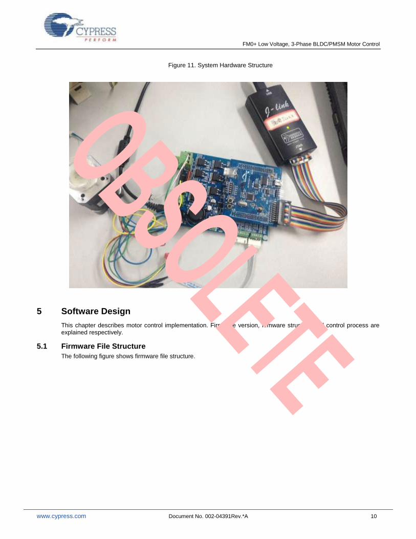
Hardware system connection is shown as Figure 11.
Jlink
Jlink interface
Ta
rge
t Bo
ard
U V W
M
Current sense
FM0+ Low Voltage, 3-Phase BLDC/PMSM Motor Control
www.cypress.com Document No. 002-04391Rev.*A 10
Figure 11. System Hardware Structure
5 Software Design
This chapter describes motor control implementation. Firmware version, firmware structure and control process are explained respectively.
5.1 Firmware File Structure
The following figure shows firmware file structure.
FM0+ Low Voltage, 3-Phase BLDC/PMSM Motor Control
www.cypress.com Document No. 002-04391Rev.*A 11
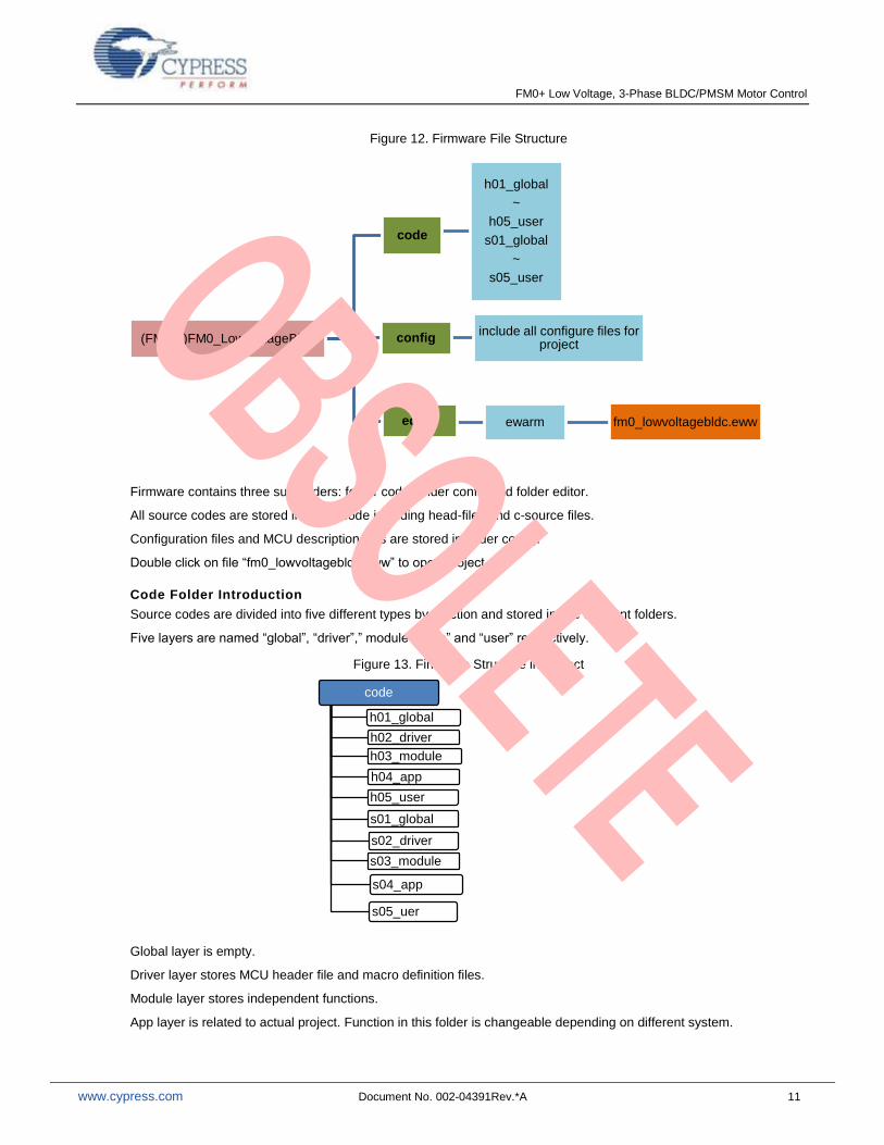
Figure 12. Firmware File Structure
Firmware contains three sub-folders: folder code, folder config and folder editor.
All source codes are stored in folder code including head-files and c-source files.
Configuration files and MCU description files are stored in folder config.
Double click on file “fm0_lowvoltagebldc.eww” to open project.
Code Folder Introduction
Source codes are divided into five different types by function and stored in five different folders.
Five layers are named “global”, “driver”,” module”, “app” and “user” respectively.
Figure 13. Firmware Structure in Project
Global layer is empty.
Driver layer stores MCU header file and macro definition files.
Module layer stores independent functions.
App layer is related to actual project. Function in this folder is changeable depending on different system.
(FMLIB)FM0_LowVoltageBldc
code
h01_global
~
h05_user
s01_global
~
s05_user
configinclude all configure files for
project
editor ewarm fm0_lowvoltagebldc.eww
code
h01_global
h02_driver
h03_module
h04_app
h05_user
s01_global
s02_driver
s03_module
s04_app
s05_uer

FM0+ Low Voltage, 3-Phase BLDC/PMSM Motor Control
www.cypress.com Document No. 002-04391Rev.*A 12
User layer is open to customer for configuration and debugging.
5.2 Control Implementation
This chapter explains peripherals and interrupts used in firmware firstly, and then control process flow.
5.2.1 Peripherals in Fi rmware
All peripherals used in firmware are configured in “init_mcu.c” stored in folder “s05_user”.
Details on peripheral initialization can refer to MCU datasheets.
Table 1. Peripherals Used in Firmware
Peripherals Function in firmware
clock Configure system main clock and bus clock
NVIC Enable or disable interrupts, configure priorities
base timer Measure the width of hall signal to calculate motor current speed
Adc Be used to sample phase current, ADC unit 0 is being used.
Multi-function timer(MFT)
Generate PWM signals to control 3 half-bridge to drive motor running. MFT unit 0 is being used.
Watch dog Reset MCU when program goes wrong
Clock setting
SCM_CTL: System clock mode control.
BSC_PSR: Base clock mode control.
APBC0_PSR: APB0 prescaler register.
APBC1_PSR: APB1 prescaler register.
APBC2_PSR: APB2 prescaler register.
NVIC setting
NVIC_SetPriority(IRQn, x):priority setting
NVIC_EnableIRQ(IRQn): enable priority
IRQn: irq number
X: indicate priority number
Base timer setting
PWC function is selected in this firmware.
TMCR:Timer control register
STC:Status control register
DTBF: Data Buffer control
Adc setting
Scan interrupt is enabled is this firmware, priority mode interrupt is not used.
ADCR: AD control registers.
ADSR: AD status registers.
SCCR: Scan conversion control.
MFT setting
FRT, OCU, WFG and ADCMP is used in this firmware.
Configuration details can refer to MCU datasheet.
FRT selects up and down count mode. Complementary output of WFG with dead-time is selected.

FM0+ Low Voltage, 3-Phase BLDC/PMSM Motor Control
www.cypress.com Document No. 002-04391Rev.*A 13
Watch dog setting
WdogControl: Software watchdog timer control registers.
WDG_CTL: Hardware watchdog timer control registers.
5.2.2 Interrupts in Fi rmware
The following table shows interrupts being used in system. Function “InitMcu_Nvic()” in “init_mcu.c” is for interrupt control.
More details about interrupt control can refer to document“Cotex-M0Technical Reference Manual”
Table 2. Interrupt Function Used in Firmware
Interrupt type Function in firmware
Multi-function timer zero match interrupt
FOC algorithm is executing in this interrupt.
ADC scan interrupt It is for DC voltage and three-phase current sampling. Triggered by MFT zero matching.
Multi-function timer DTIF interrupt
It is for hardware over-current protection.
Software watch dog interrupt
When software watch overflow, motor stops running.
Base timer hall capture interrupt
It is for capture hall sensor signal edge change.
For priority setting, the less the digit is, the higher the priority is.
NVIC_SetPriority(ADC0_IRQn,1)
NVIC_SetPriority(FRT0_ZERO_IRQn,2)
ADC0_IRQn priority is higher than FRT_ZERO_IRQn through above setting.
MFT and ADC interrupt execution illustration is shown below, MFT and ADC interrupt includes all functions about motor controlling.
MFT and ADC interrupts is triggered every PWM cycle.
Base timer interrupt is triggered by hall sensor edge change.
FM0+ Low Voltage, 3-Phase BLDC/PMSM Motor Control
www.cypress.com Document No. 002-04391Rev.*A 14
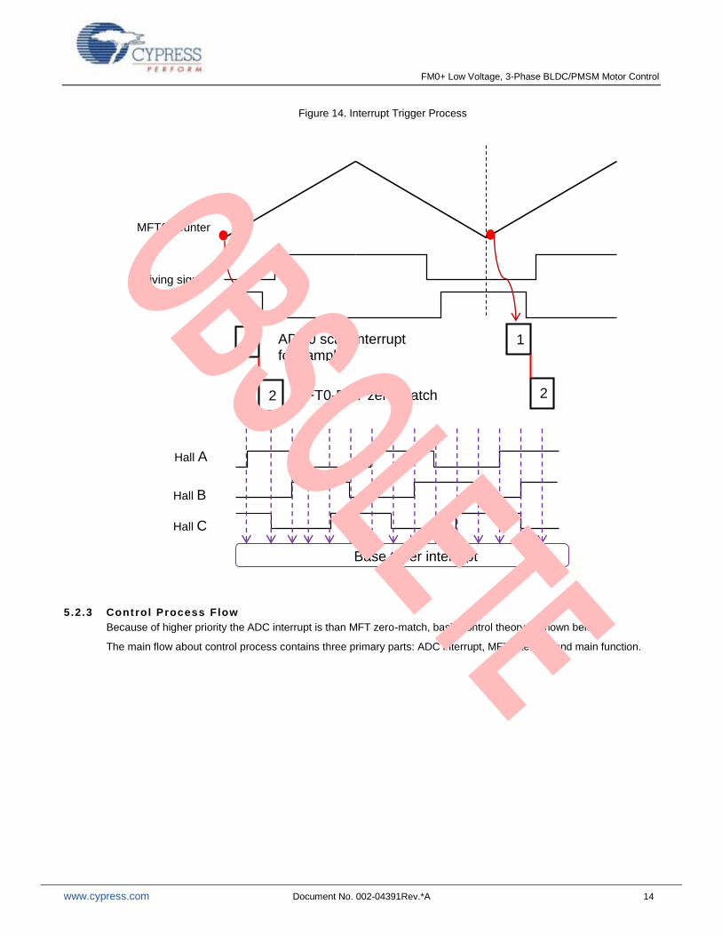
Figure 14. Interrupt Trigger Process
5.2.3 Control Process Flow
Because of higher priority the ADC interrupt is than MFT zero-match, basic control theory is shown below.
The main flow about control process contains three primary parts: ADC interrupt, MFT interrupt and main function.
MFT0 counter
Driving signal
1
2
ADC0 scan interrupt for sample current and DC
MFT0-FRT zero match interrupt
1
2
Hall A
Hall B
Hall C
Base timer interrupt trigger
FM0+ Low Voltage, 3-Phase BLDC/PMSM Motor Control
www.cypress.com Document No. 002-04391Rev.*A 15
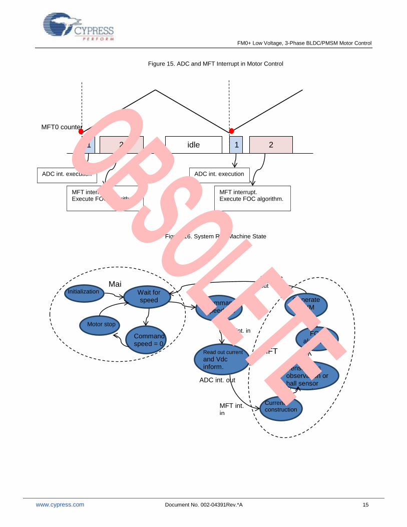
Figure 15. ADC and MFT Interrupt in Motor Control
Figure 16. System Run Machine State
MFT0 counter
1 2 1 2
ADC int. execution
MFT interrupt. Execute FOC algorithm.
MFT interrupt. Execute FOC algorithm.
ADC int. execution
idle
Initialization Wait for speed
command
Read out current
and Vdc inform.
Command speed > 0
Current construction
FOC algorithm
Generate PWM
ADC int. in
ADC int. out
MFT int. in
MFT int. out
Motor stop
Command speed = 0
Main
MFT interrupt
Sensor less observation or hall sensor observation
FM0+ Low Voltage, 3-Phase BLDC/PMSM Motor Control
www.cypress.com Document No. 002-04391Rev.*A 16
6 Results
All results are based on a BLDC motor. Control system will run it with sensor and sensor-less mode.
Motor parameters are listed on table below
Table 3. Motor Parameter in the Test Platform
Motor parameters max units
Phase current(peak) 2 A
Speed range 360~4000 rpm
Ld 0.65 mh
Lq 0.85 mh
Rs 0.5 Ω
Ke 2.8 Vrms/krpm
Pole pairs 2 N/A
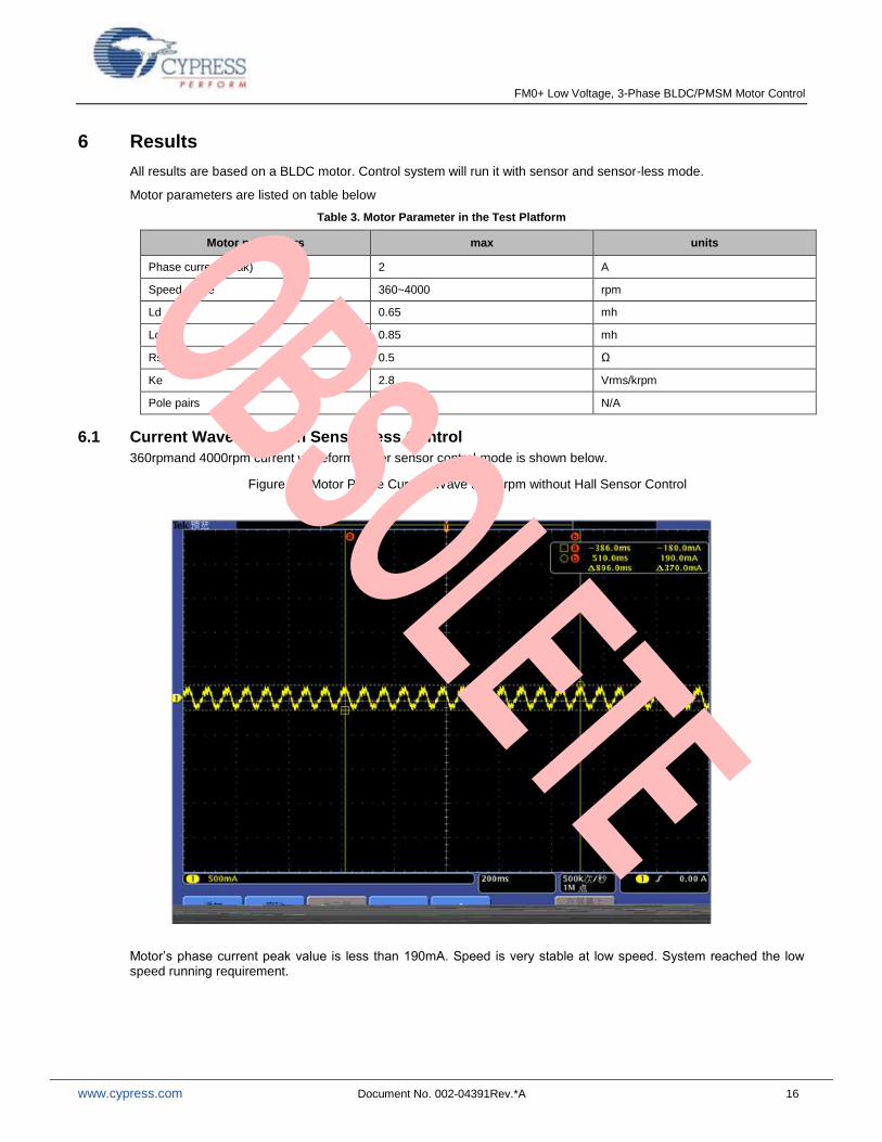
6.1 Current Waveform with Sensor-less Control
360rpmand 4000rpm current waveform under sensor control mode is shown below.
Figure 17. Motor Phase Current Wave at360rpm without Hall Sensor Control
Motor’s phase current peak value is less than 190mA. Speed is very stable at low speed. System reached the low speed running requirement.

FM0+ Low Voltage, 3-Phase BLDC/PMSM Motor Control
www.cypress.com Document No. 002-04391Rev.*A 17
Figure 18. Motor phase current in 4000rpm without sensor control
From the test wave, it can be seen that the motor run at the max speed is very stable and current enveloping is much smooth. Actually, it also can reflect the noise is also much low indirectly.
FM0+ Low Voltage, 3-Phase BLDC/PMSM Motor Control
www.cypress.com Document No. 002-04391Rev.*A 18
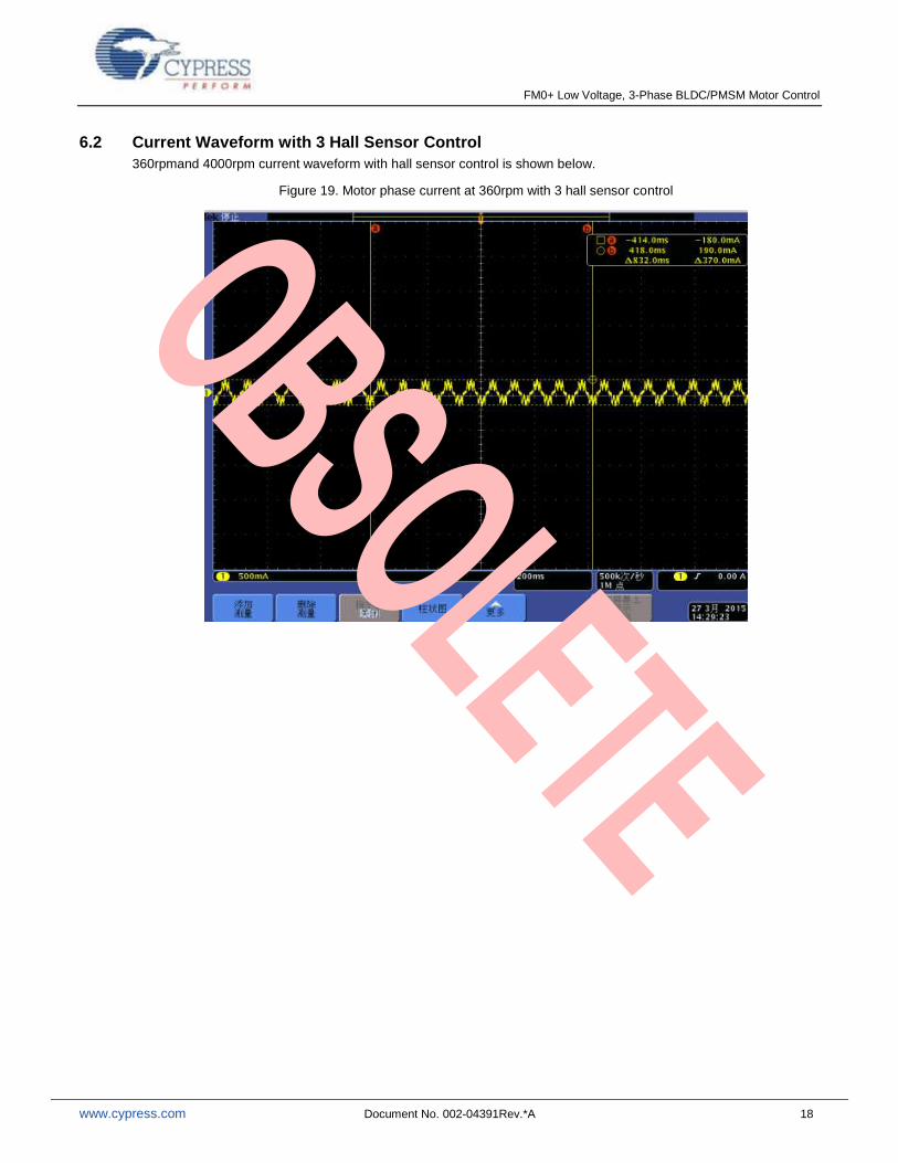
6.2 Current Waveform with 3 Hall Sensor Control
360rpmand 4000rpm current waveform with hall sensor control is shown below.
Figure 19. Motor phase current at 360rpm with 3 hall sensor control
FM0+ Low Voltage, 3-Phase BLDC/PMSM Motor Control
www.cypress.com Document No. 002-04391Rev.*A 19
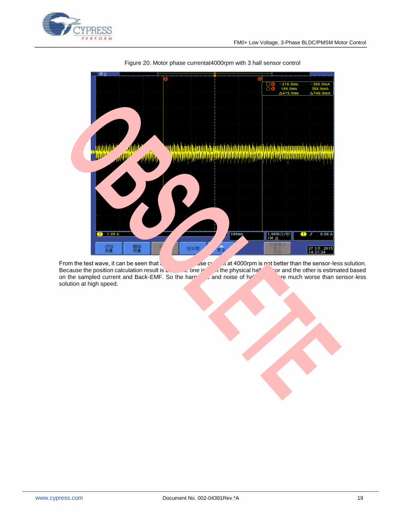
Figure 20. Motor phase currentat4000rpm with 3 hall sensor control
From the test wave, it can be seen that the motor’s phase current at 4000rpm is not better than the sensor-less solution. Because the position calculation result is different: one is from the physical hall sensor and the other is estimated based on the sampled current and Back-EMF. So the harmonic and noise of hall sensor are much worse than sensor-less solution at high speed.
FM0+ Low Voltage, 3-Phase BLDC/PMSM Motor Control
www.cypress.com Document No. 002-04391Rev.*A 20
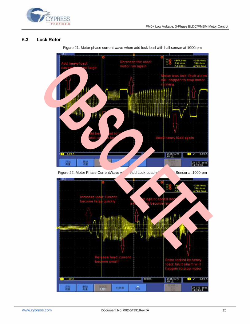
6.3 Lock Rotor
Figure 21. Motor phase current wave when add lock load with hall sensor at 1000rpm
Figure 22. Motor Phase CurrentWave when Add Lock Load without Hall Sensor at 1000rpm
FM0+ Low Voltage, 3-Phase BLDC/PMSM Motor Control
www.cypress.com Document No. 002-04391Rev.*A 21
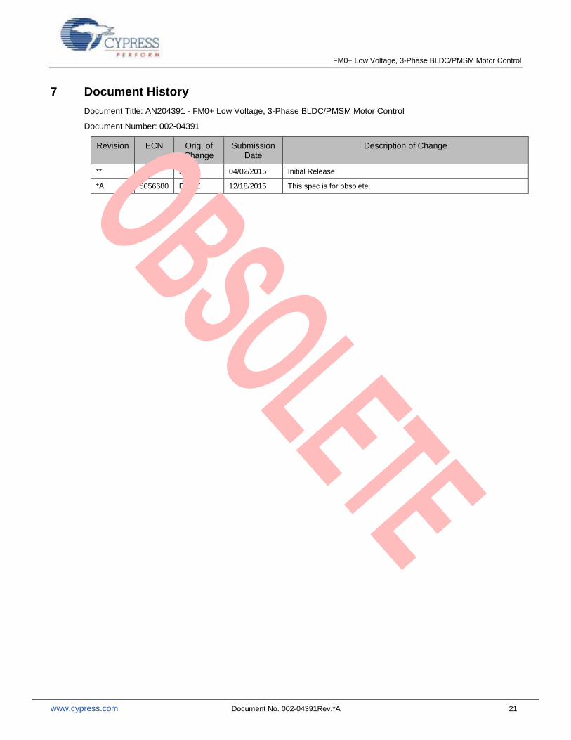
7 Document History
Document Title: AN204391 - FM0+ Low Voltage, 3-Phase BLDC/PMSM Motor Control
Document Number: 002-04391
Revision ECN Orig. of Change
Submission Date
Description of Change
** - DOHE 04/02/2015 Initial Release
*A 5056680 DOHE 12/18/2015 This spec is for obsolete.

FM0+ Low Voltage, 3-Phase BLDC/PMSM Motor Control
www.cypress.com Document No. 002-04391Rev.*A 22
Worldwide Sales and Design Support
Cypress maintains a worldwide network of offices, solution centers, manufacturer’s representatives, and distributors. To find the office closest to you, visit us at Cypress Locations.
Products
Automotive cypress.com/go/automotive
Clocks & Buffers cypress.com/go/clocks
Interface cypress.com/go/interface
Lighting & Power Control cypress.com/go/powerpsoc
Memory cypress.com/go/memory
PSoC cypress.com/go/psoc
Touch Sensing cypress.com/go/touch
USB Controllers cypress.com/go/usb
Wireless/RF cypress.com/go/wireless
Spansion Products spansion.com/products
PSoC® Solutions
psoc.cypress.com/solutions
PSoC 1 | PSoC 3 | PSoC 4 | PSoC 5LP
Cypress Developer Community
Community | Forums |Blogs | Video |Training
Technical Support
cypress.com/go/support
All other trademarks or registered trademarks referenced herein are the property of their respective owners.
Cypress Semiconductor 198 Champion Court San Jose, CA 95134-1709
Phone : 408-943-2600 Fax : 408-943-4730 Website : www.cypress.com
© Cypress Semiconductor Corporation, 2015. The information contained herein is subject to change without notice. Cypress Semiconductor Corporation assumes no responsibility for the use of any circuitry other than circuitry embodied in a Cypress product. Nor does it convey or imply any license under patent or other rights. Cypress products are not warranted nor intended to be used for medical, life support, life saving, critical control or safety applications, unless pursuant to an express written agreement with Cypress. Furthermore, Cypress does not authorize its products for use as critical components in life-support systems where a malfunction or failure may reasonably be expected to result in significant injury to the user. The inclusion of Cypress products in life-support systems application implies that the manufacturer assumes all risk of such use and in doing so indemnifies Cypress against all charges. This Source Code (software and/or firmware) is owned by Cypress Semiconductor Corporation (Cypress) and is protected by and subject to worldwide patent protection (United States and foreign), United States copyright laws and international treaty provisions. Cypress hereby grants to licensee a personal, non-exclusive, non-transferable license to copy, use, modify, create derivative works of, and compile the Cypress Source Code and derivative works for the sole purpose of creating custom software and or firmware in support of licensee product to be used only in conjunction with a Cypress integrated circuit as specified in the applicable agreement. Any reproduction, modification, translation, compilation, or representation of this Source Code except as specified above is prohibited without the express written permission of Cypress. Disclaimer: CYPRESS MAKES NO WARRANTY OF ANY KIND, EXPRESS OR IMPLIED, WITH REGARD TO THIS MATERIAL, INCLUDING, BUT NOT LIMITED TO, THE IMPLIED WARRANTIES OF MERCHANTABILITY AND FITNESS FOR A PARTICULAR PURPOSE. Cypress reserves the right to make changes without further notice to the materials described herein. Cypress does not assume any liability arising out of the application or use of any product or circuit described herein. Cypress does not authorize its products for use as critical components in life-support systems where a malfunction or failure may reasonably be expected to result in significant injury to the user. The inclusion of Cypress’ product in a life-support systems application implies that the manufacturer assumes all risk of such use and in doing so indemnifies Cypress against all charges. Use may be limited by and subject to the applicable Cypress software license agreement.