BLDC MOTOR PID CONTROLER - Theseus
44
Minh Nguyen BLDC MOTOR PID CONTROLER Technology and Communication 2021
-
Upload
khangminh22 -
Category
Documents
-
view
1 -
download
0
Transcript of BLDC MOTOR PID CONTROLER - Theseus

Minh Nguyen
BLDC MOTOR PID CONTROLER
Technology and Communication 2021
2
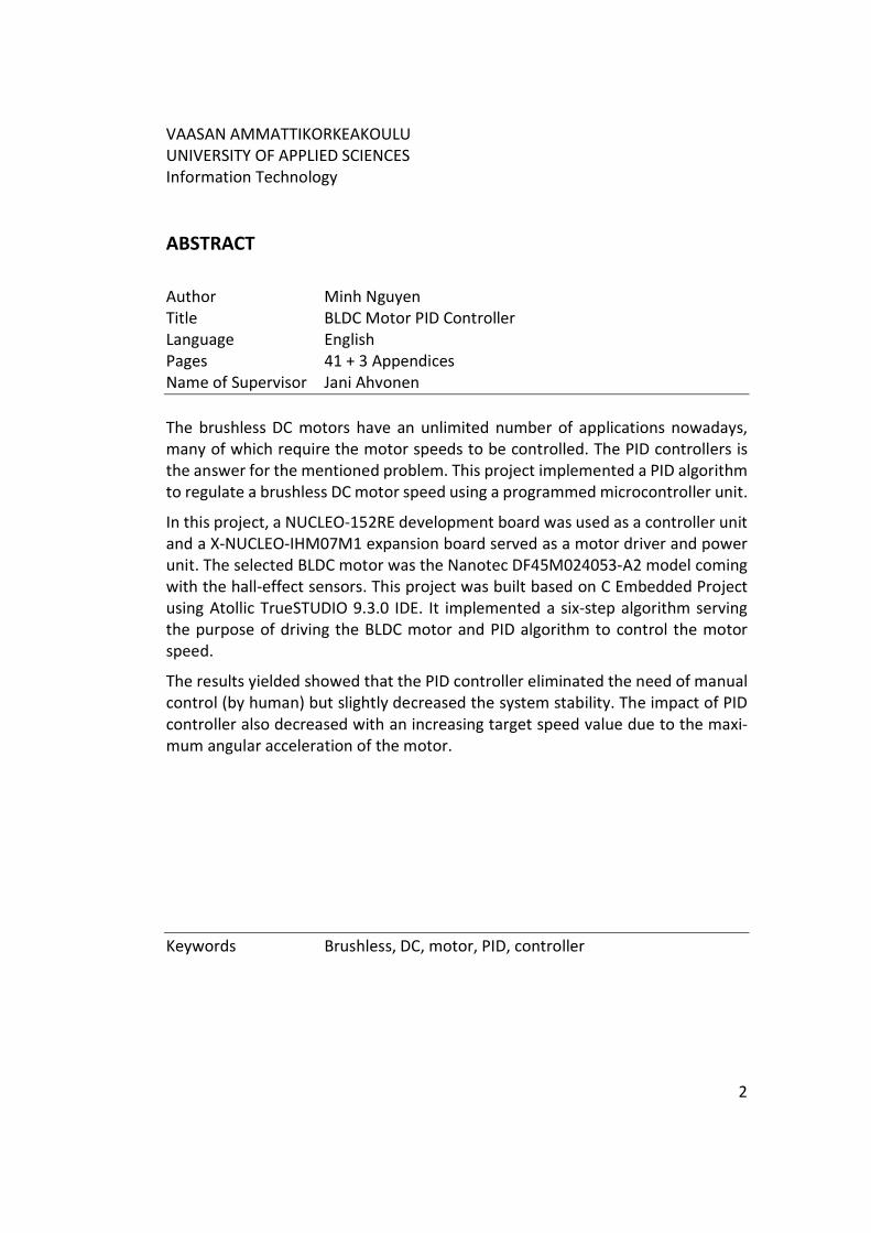
VAASAN AMMATTIKORKEAKOULU UNIVERSITY OF APPLIED SCIENCES Information Technology ABSTRACT
Author Minh Nguyen Title BLDC Motor PID Controller Language English Pages 41 + 3 Appendices Name of Supervisor Jani Ahvonen The brushless DC motors have an unlimited number of applications nowadays, many of which require the motor speeds to be controlled. The PID controllers is the answer for the mentioned problem. This project implemented a PID algorithm to regulate a brushless DC motor speed using a programmed microcontroller unit.
In this project, a NUCLEO-152RE development board was used as a controller unit and a X-NUCLEO-IHM07M1 expansion board served as a motor driver and power unit. The selected BLDC motor was the Nanotec DF45M024053-A2 model coming with the hall-effect sensors. This project was built based on C Embedded Project using Atollic TrueSTUDIO 9.3.0 IDE. It implemented a six-step algorithm serving the purpose of driving the BLDC motor and PID algorithm to control the motor speed.
The results yielded showed that the PID controller eliminated the need of manual control (by human) but slightly decreased the system stability. The impact of PID controller also decreased with an increasing target speed value due to the maxi-mum angular acceleration of the motor.
Keywords Brushless, DC, motor, PID, controller

3
TABLE OF CONTENTS
ABSTRACT
1 INTRODUCTION ................................................................................................. 8
2 LITERARY REVIEW .............................................................................................. 9
2.1 DC Motor ................................................................................................... 9
2.1.1 Brushed DC Motor....................................................................... 10
2.1.2 Brushless DC Motor ..................................................................... 11
2.1.3 Six-step Algorithm ....................................................................... 12
2.2 PID Controller .......................................................................................... 13
2.2.1 Proportional Term ....................................................................... 14
2.2.2 Integral Term ............................................................................... 15
2.2.3 Derivative Term ........................................................................... 16
2.2.4 Tuning .......................................................................................... 17
3 METHODS ........................................................................................................ 18
3.1 Resources ................................................................................................ 18
3.1.1 Hardware ..................................................................................... 18
3.1.2 Software ...................................................................................... 19
3.2 System Building ....................................................................................... 19
3.3 Programming .......................................................................................... 21
3.3.1 Baremetal Files ............................................................................ 23
3.3.2 Device-specific Files .................................................................... 23
3.3.3 Six-step Algorithm ....................................................................... 24
3.3.4 PID Controller .............................................................................. 25
3.3.5 Main Software ............................................................................. 26
3.4 Measuring ............................................................................................... 27
3.4.1 Motor Driving Operation............................................................. 27
3.4.2 The Impact of PID controller ....................................................... 29
4 CONCLUSIONS ................................................................................................. 40
REFERENCES ........................................................................................................... 41

4
LIST OF ABBREVIATIONS
BLDC Brushless Direct Current
CD Compact Disk
CMSIS Cortex Microcontroller Software Interface Standard
DC Direct Current
GPIO General Pin Input/Output
IDE Integrated Development Environment
LED Light-Emitting Diode
PID Proportional-Integral-Derivative
PV Process Variable
PWM Pulse-Width Modulation
RCC Reset and Clock Control
SP Setpoint

5
LIST OF FIGURES AND TABLES
Figure 1. The working principle behind the rotation of DC motor 9
Figure 2. Working principle of brushed DC motor 10
Figure 3. Physical structure and working principle of brushless DC motor 11
Figure 4. Six combinations in six-step algorithm 12
Figure 5. The working principle of PID controller 13
Figure 6. System responses with different value of 𝐾𝑝 15
Figure 7. System responses with different value of 𝐾𝑖 16
Figure 8. System responses with different value of 𝐾𝑑 17
Figure 9. The hardware structure of the project 18
Figure 10. System hardware 21
Figure 11. Program logic flow diagram 22
Figure 11. Program layer structure 23
Figure 12. Pseudocode for PID algorithm 25
Figure 13. Implementation block diagram 26
Figure 14. Hall sensor and PWM signals in six-step algorithm 28
Figure 15. Steady-state error with 𝐾𝑝 alone 31
Figure 16. Long settling time with small 𝐾𝑖 31
Figure 17. Overshoot happened with larger value of 𝐾𝑖 32
Figure 18. Perfect system response with 𝐾𝑖 being optimal to current 𝐾𝑝 32
Figure 19. System rise time without PID at target speed of 1850 RPM 33
Figure 20. System settling time without PID at target speed 1850 RPM 33
Figure 21. System rise time with PID at target speed 1850 RPM 34
6
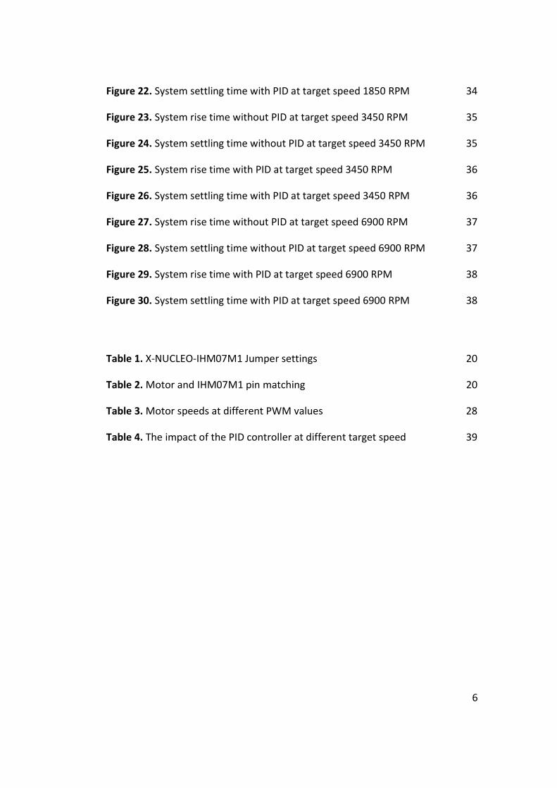
Figure 22. System settling time with PID at target speed 1850 RPM 34
Figure 23. System rise time without PID at target speed 3450 RPM 35
Figure 24. System settling time without PID at target speed 3450 RPM 35
Figure 25. System rise time with PID at target speed 3450 RPM 36
Figure 26. System settling time with PID at target speed 3450 RPM 36
Figure 27. System rise time without PID at target speed 6900 RPM 37
Figure 28. System settling time without PID at target speed 6900 RPM 37
Figure 29. System rise time with PID at target speed 6900 RPM 38
Figure 30. System settling time with PID at target speed 6900 RPM 38
Table 1. X-NUCLEO-IHM07M1 Jumper settings 20
Table 2. Motor and IHM07M1 pin matching 20
Table 3. Motor speeds at different PWM values 28
Table 4. The impact of the PID controller at different target speed 39

7
LIST OF APPENDICES
APPENDIX 1. Motor Speed Result Table
APPENDIX 2. D6230 Three-phase BLDC Motor Driver Schematic
APPENDIX 3. Hall Sensor Schematic

8
1 INTRODUCTION
In today’s world, brushless direct current (BLDC) motors can be found in many
applications ranging from big propulsion systems in an electric aircraft to a small
compact disk (CD) drive. For some cases, it is critical for the motor speed to be
controlled which leads to the need of motor controllers.
The proportional-integral-derivative controllers (PID controllers) apply a control
mechanism using proportional, integral and derivative terms to calculate optimal
outputs from the differences between the measured values and the target value
/3/. The PID concept is the most used control algorithm in industrial control sys-
tems because of its superior precision and accuracy.
The PID controller is a solution to the mentioned problem. This project aimed to
implement the PID controller algorithm on an ARM microcontroller to regulate a
BLDC motor speed.
9
2 LITERARY REVIEW
In this section of the thesis, the theoretical ideas behind the project are explained.
There are two fundamental theory parts that are the DC motor and the PID con-
troller.
2.1 DC Motor
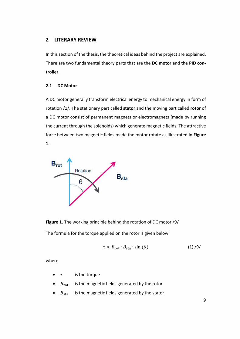
A DC motor generally transform electrical energy to mechanical energy in form of
rotation /1/. The stationary part called stator and the moving part called rotor of
a DC motor consist of permanent magnets or electromagnets (made by running
the current through the solenoids) which generate magnetic fields. The attractive
force between two magnetic fields made the motor rotate as illustrated in Figure
1.
Figure 1. The working principle behind the rotation of DC motor /9/
The formula for the torque applied on the rotor is given below.
𝜏 ∝ 𝐵 ∙ 𝐵 ∙ sin (𝜃) (1) /9/
where
𝜏 is the torque
𝐵 is the magnetic fields generated by the rotor
𝐵 is the magnetic fields generated by the stator

10
𝜃 is load angle (the angle between two vectors 𝐵 ⃗ and 𝐵 ⃗)
Deduced from the formula, the maximum output torque is archived with the load
angle 𝜃 being 90°.
There are two common types of DC motor which are brushed and brushless ones.
2.1.1 Brushed DC Motor
In a brushed DC motor, the rotor is composed of pairs of solenoids and the stator
consists of permanent magnets. The stator electromagnetic field remains fixed
while the rotor electromagnetic field is constantly changing during the rotation.
The load angle is kept close to 90° by constantly charging the next pair of solenoids
when they come to a specific position (as in Figure 2).
Figure 2. Working principle of brushed DC motor /20/
The connectors between the circuit and solenoids are called brushes, thus the
name of brushed DC motor. Changing the current the direction will make the mo-
tor to rotate in the opposite direction.

11
2.1.2 Brushless DC Motor
A brushless DC motor has the rotor containing a permanent magnet and its stator
consists of three solenoids connected in a star topology and positioned 120° from
each other. The rotor electromagnetic field changes with the rotation so that in
order to keep the load angle as close to 90° as possible, the stator electromagnetic
field is constantly changed according to the position of the rotor. Figure 3 below
show the structure and working principle of a brushless DC motor.
Figure 3. Physical structure and working principle of brushless DC motor /11/
Even though brushed DC motors have a low initial cost and simple control of motor
speed, the high maintenance of the brushes makes the brushless counterpart su-
perior in terms of durability and reliability. However, operating a brushless DC mo-
tors is more complex.
Brushless motors can be constructed in several different physical configurations:
In the 'conventional' (also known as inrunner) configuration, the permanent mag-
12
nets are part of the rotor. Three stator windings surround the rotor. In the outrun-
ner (or external-rotor) configuration, the radial-relationship between the coils and
magnets is reversed; the stator coils form the centre (core) of the motor, while the
permanent magnets spin within an overhanging rotor which surrounds the core.
/2/
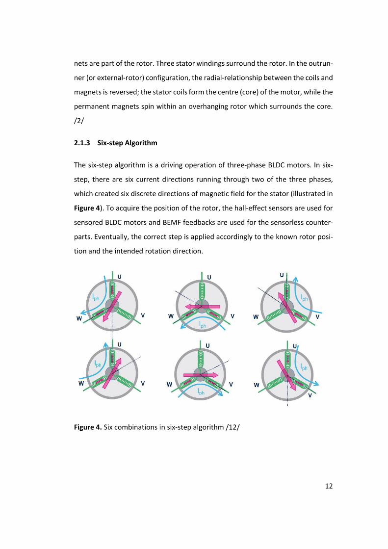
2.1.3 Six-step Algorithm
The six-step algorithm is a driving operation of three-phase BLDC motors. In six-
step, there are six current directions running through two of the three phases,
which created six discrete directions of magnetic field for the stator (illustrated in
Figure 4). To acquire the position of the rotor, the hall-effect sensors are used for
sensored BLDC motors and BEMF feedbacks are used for the sensorless counter-
parts. Eventually, the correct step is applied accordingly to the known rotor posi-
tion and the intended rotation direction.
Figure 4. Six combinations in six-step algorithm /12/

13
2.2 PID Controller
A proportional-integral-derivative controller (also known as a PID controller or
three-term controller) is a closed loop control mechanism that is widely used in
industrial control systems. It uses the three control terms of proportional, integral
and derivative to calculate the output from the error value, which is the difference
between the designated target value called a setpoint (SP) and the measured feed-
back value called a process variable (PV). /3/
Figure 5. The working principle of PID controller /3/
The mathematical formula of overall control function of PID controller is
𝑢(𝑡) = 𝐾 ∙ 𝑒(𝑡) + 𝐾 ∙ 𝑒(𝜏)𝑑𝜏 + 𝐾 ∙
𝑑𝑒(𝑡)
𝑑𝑡
(2) /3/
where
𝑡 is running time
𝜏 is integral time
𝑟(𝑡) is setpoint
𝑒(𝑡) is error
𝑢(𝑡) is control variable
𝑦(𝑡) is process variable
𝐾 is proportional gain
𝐾 is integral gain
𝐾 is derivative gain

14
From the block diagram in Figure 5, the error value 𝑒(𝑡) as a difference between
setpoint 𝑟(𝑡) and process variable 𝑦(𝑡) is continuously measured then the output
control variable 𝑢(𝑡) is calculated based on proportional, integral and derivative
terms to minimize the error over time. /3/
Even though the PID controller has three control terms, some applications may
not need all of them to have appropriate control. In those cases, the selective use
of the control terms can be achieved by setting the coefficients (𝐾 , 𝐾 or 𝐾 ) of
unnecessary terms to 0 so that they have no impact on the output. /3/
2.2.1 Proportional Term
The proportional term produces an output value that is proportional to the error
value. The P term takes the formula
𝑃 = 𝐾 ∙ 𝑒(𝑡) (3) /3/
By changing the coefficient 𝐾 (also known as proportional gain), the response of
output based on P term can be adjusted. If the proportional gain is too large, the
system overreacts with the error value and the process variable oscillates around
the setpoint, which increases the settling time and decreases the stability. Mean-
while, with small proportional gain, the system becomes less responsive, and the
rise time is increased. /3/
Figure 6 below shows the graph of process variable responses with different val-
ues of 𝐾 .
The proportional term alone cannot correct the system of steady-state error,
which is the difference between the desired final output and the actual one. /3/

15
Figure 6. System responses with different value of 𝐾 /3/
2.2.2 Integral Term
The integral term considers both the error and the duration of the error when
calculating an output /3/. In fact, the mathematical formula for I term comes with
the integral, which is the sum of instantaneous errors over time.
𝐼 = 𝐾 ∙ 𝑒(𝜏)𝑑𝜏
(4) /3/
Increasing the 𝐾 gain to, thus increasing the impact of I term, will help to eliminate
the steady-state error but in exchange it increases the overshoot, settling time and
decreasing system stability /3/. The graph in Figure 7 illustrates how I term affects
the system respond.
16
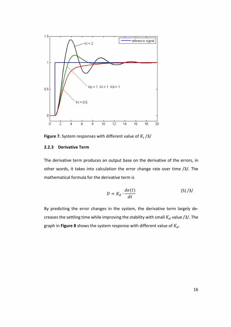
Figure 7. System responses with different value of 𝐾 /3/
2.2.3 Derivative Term
The derivative term produces an output base on the derivative of the errors, in
other words, it takes into calculation the error change rate over time /3/. The
mathematical formula for the derivative term is
𝐷 = 𝐾 ∙
𝑑𝑒(𝑡)
𝑑𝑡
(5) /3/
By predicting the error changes in the system, the derivative term largely de-
creases the settling time while improving the stability with small 𝐾 value /3/. The
graph in Figure 8 shows the system response with different value of 𝐾 .

17
Figure 8. System responses with different value of 𝐾 /3/
2.2.4 Tuning
Different control systems have different control parameter values that lead to
their desired control responses and the work of finding those optimal values is
called tuning. The system requirements may include the rise time, settling time,
overshoot allowance but the basic one is stability /3/. There are various tuning
methods with different levels of sophistication but in this project, manual tuning
method was used.
Manual tuning requires understanding the impact on the system of control terms
and adjusting them one by one (firstly 𝐾 , then 𝐾 and finally 𝐾 ) until the system
response meets the requirements.

18
3 METHODS
In this section, the resources used for the project are listed and the conducting method, as well as the measuring results, are interpreted.
3.1 Resources
The resource consumed, apart from working hours and materials, can be divided
into two parts: hardware and software.
3.1.1 Hardware
The hardware selected for the project consisted of a NUCLEO-L152RE develop-
ment board serving as a controller, a X-NUCLEO-IHM07M1 expansion board serv-
ing as a power block and a Nanotec DF45M024053-A2 sensored BLDC motor. The
Figure 9 below shows the theoretical layer structure of the hardware.
Figure 9. The hardware structure of the project /7/
The NUCLEO-L152RE belongs to the STM32 Nucleo-64 board family which is pro-
duced by STMicroelectronics. It features the STM32 microcontrollers with the 32-
bit ARM processor core which are widely used in real-life embedded system appli-
cations. This development board is also an affordable and flexible device to study,
try out new concepts and build prototypes, thus, it suited for this project /4/.

19
The X-NUCLEO-IHM07M1 is a three-phase brushless DC motor driver expansion
board based on the L6230 for STM32 Nucleo. It is produced by the same manufac-
turer, STMicroelectronics, to provide an affordable and easy-to-use solution for
driving a three-phase brushless DC motor /5/.
The brushless DC motor model DF45M024053-A2 is produced by Nanotec Elec-
tronic GmbH & Co. KG. It is a 12N16P outrunner type which contains 16 poles of
permanent magnet in the outer rotor and 12 coils connected to 3 current phases,
serving as stator electromagnets.
Apart of the main hardware, an oscilloscope was used to measure motor speed
changes.
3.1.2 Software
Atollic TrueSTUDIO 9.3.0 was used during the coding part of this project. Atollic
TrueSTUDIO is an Eclipse based IDE that is commercially enhanced by STMicroe-
lectronics. It provides extension, features and utilities that support devices pro-
duced by the same manufacturer, thus, are highly suitable to work with NUCLEO-
L152RE /6/.
The project was based on the C Embedded Project template provided by TrueSTU-
DIO, which contains Cortex Microcontroller Software Interface Standard library
(CMSIS) serving as a foundation of the project software.
3.2 System Building
The X-NUCLEO-IHM07M1 was connected to the NUCLEO-L152RE development
board through an ST-morpho connector, and its jumper configuration was left de-
fault as in Table 1. The motor was connected to the expansion board following
Table 2 below. The external DC voltage is connected to J1 section of the board.

20
The circuit diagrams of the D6230 three-phase BLDC motor driver and hall/en-
coder sensors are displayed in APPENDIX 2 and 3. Figure 10 below shows the com-
plete configuration of the system hardware.
Table 1. X-NUCLEO-IHM07M1 Jumper settings /8/
Jumper Permitted configurations Default condition
JP1 Selection for pull-up insertion (BIAS) in current sensing circuit OPEN
JP2 Selection for op amp gain modification in current sens-ing circuit OPEN
JP3 Selection for pull-up enabling in Hall/Encoder detec-tion circuit CLOSED
J9 Selection to supply the STM32 Nucleo board through the X-NUCLEOIHM07M OPEN
J5 Selection for single/three shunt configuration. Set to single shunt by default 2-3 CLOSED
J6 Selection for single/three shunt configuration. Set to single shunt by default 2-3 CLOSED
J7 Debug connector for DAC. Available for probe connec-tion OPEN
Table 2. Motor and IHM07M1 pin matching
X-NUCLEO-IHM07M1 DF45M024053-A2
J3
GND GND
5V VCC
A+ H1
B+ H2
Z+ H3
J2
OUT3 PHW
OUT1 PHU
OUT2 PHV

21
Figure 10. System hardware
3.3 Programming
The program starts with the initialisation of PID controller by setting PID parame-
ters and a target speed which will remain constant during the runtime. It then cal-
culates an optimal value for PWM duty cycle using the PID algorithm and the error
between the target speed and the motor speed. In the next steps, the program
reads the motor position (or current step in six-step algorithm), enables and gen-
erates PWM to the correct channels, which will then make the motor run. These
steps will run indefinitely if there is no external interrupt caused by a hall sensor
signal. If an interrupt is triggered, marking one eighth of revolution was done, the
motor value would be calculated based on the timer value. Finally, a new PWM
duty cycle value is calculated using the newly measured motor speed and the pro-
gram continues. The main logic of the program is illustrated by the flow diagram
in Figure 11.

22
Figure 11. Program logic flow diagram
The project was built based on a C Embedded Project template that is specifically
designed for NUCLEO-L152RE and provided by Atollic TrueSTUDIO IDE. The project
was given the name BLDC_Motor_PID_Controller. The Figure 12 below illustrates
the structure of the program.

23
Figure 12. Program layer structure
In the program structure, the bottom layer called CMSIS was provided by the pro-
ject template, serving as the foundation of the program. The remaining parts were
developed by the author of this project in separated C source code and header
files.
3.3.1 Baremetal Files
“Baremetal” files were the first to be written which contain functions executing
bit operations directly to registers and can be called in upper layers to do basic
specific tasks. These files are independent from each other to ensure their modu-
larity and reusability. In this project, the following sections had baremetal files:
Reset and clock control (RCC)
General-purpose input/output (GPIO)
Timers (TIM)
3.3.2 Device-specific Files
Files “x-nucleo-ihm07m1.c” and “x-nucleo-ihm07m1.h” served as a driver for the
X-NUCLEO-IHM07M1 expansion board, which contained functions to use the
D6230 three-phase motor driver, the hall-effect sensor encoder and the debug
LED.

24
For the same purpose, “nucleo-l152re.c” and “nucleo-l152re.h” were created spe-
cifically for the NUCLEO-L152RE board and they contained only functions to con-
trol the user LED.
3.3.3 Six-step Algorithm
The six-step algorithm was implemented in “SixStep.c” and “SixStep.h”. These files
contained functions to execute the specific tasks which are
Generating pulse-width modulation (PWM) to 3 channels of the D6230
three-phase motor driver.
Reading the hall-effect sensor to determine at which step the motor is.
Measuring the motor speed based on the time between different consec-
utive steps.
The “SixStep” files were created specifically for the X-NUCLEO-IHM07M1 board
and the Nanotec DF45M024053-A2 sensored motor. They were not written as a
general six-step driver and cannot used for other hardware because of the follow-
ing reasons
Functions in X-NUCLEO-IHM07M1 driver were called directly in SixStep
functions.
Six-step table were based on the hall-effect sensor reading function and
wiring diagram in the DF45M024053-A2 datasheet.
Because of its specific target, it is unnecessary to write functions that implement
the six-step algorithm based on BEMF feedbacks, thus, there are no option for a
sensorless motor.
25
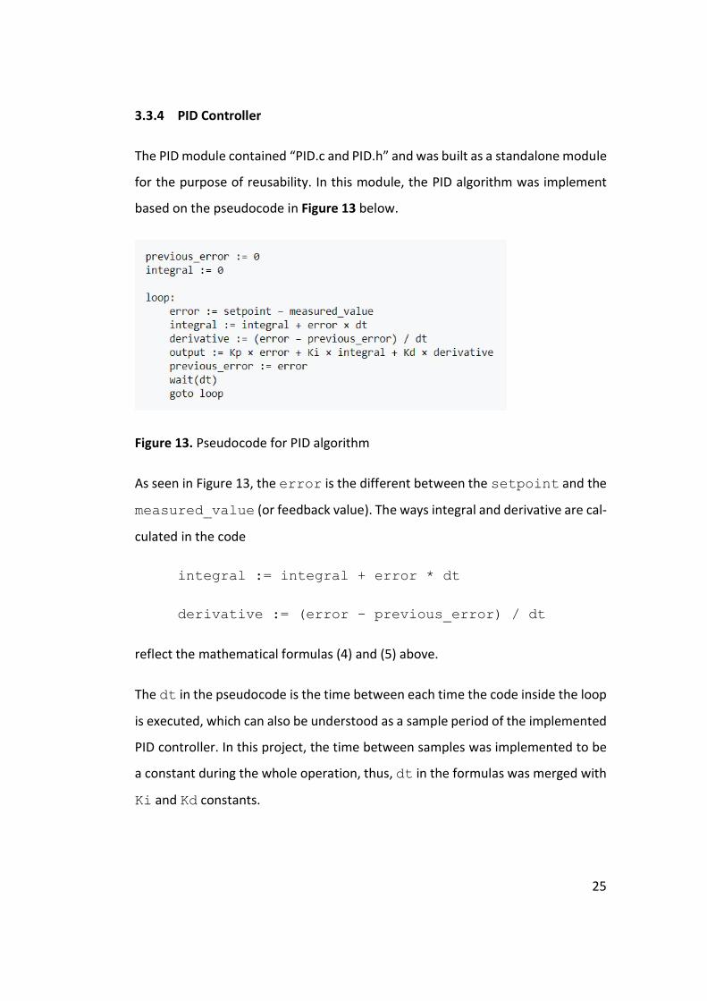
3.3.4 PID Controller
The PID module contained “PID.c and PID.h” and was built as a standalone module
for the purpose of reusability. In this module, the PID algorithm was implement
based on the pseudocode in Figure 13 below.
Figure 13. Pseudocode for PID algorithm
As seen in Figure 13, the error is the different between the setpoint and the
measured_value (or feedback value). The ways integral and derivative are cal-
culated in the code
integral := integral + error * dt
derivative := (error – previous_error) / dt
reflect the mathematical formulas (4) and (5) above.
The dt in the pseudocode is the time between each time the code inside the loop
is executed, which can also be understood as a sample period of the implemented
PID controller. In this project, the time between samples was implemented to be
a constant during the whole operation, thus, dt in the formulas was merged with
Ki and Kd constants.
26
3.3.5 Main Software
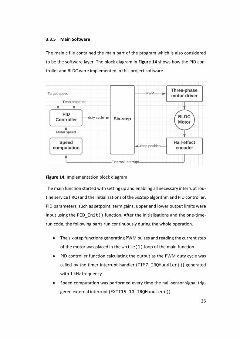
The main.c file contained the main part of the program which is also considered
to be the software layer. The block diagram in Figure 14 shows how the PID con-
troller and BLDC were implemented in this project software.
Figure 14. Implementation block diagram
The main function started with setting up and enabling all necessary interrupt rou-
tine service (IRQ) and the initialisations of the SixStep algorithm and PID controller.
PID parameters, such as setpoint, term gains, upper and lower output limits were
input using the PID_Init() function. After the initialisations and the one-time-
run code, the following parts run continuously during the whole operation.
The six-step functions generating PWM pulses and reading the current step
of the motor was placed in the while(1) loop of the main function.
PID controller function calculating the output as the PWM duty cycle was
called by the timer interrupt handler (TIM7_IRQHandler()) generated
with 1 kHz frequency.
Speed computation was performed every time the hall-sensor signal trig-
gered external interrupt (EXTI15_10_IRQHandler()).

27
3.4 Measuring
After success in compiling and downloading the source code to the microcontrol-
ler, multiple measurements were performed to reveal the internal operation of
the system in various situations, with and without PID controller.
3.4.1 Motor Driving Operation
The first test runs were performed to see how the system worked during the six-
step algorithm, in which the hall sensor signal (A+/H1, B+/H2 and Z+/H3 in APPEN-
DIX 3) and PWM signals (IN1, IN2 and IN3 in APPENDIX 2) were captured using the
digital probe of the oscilloscope. The PID controller was not initialised during these
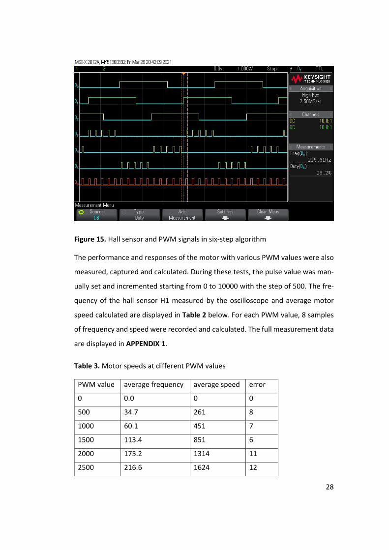
tests. Figure 14 below shows the measurement at PWM value equal 2500, in which
D0 measured Encoder A/Hall H1 at PA15
D1 measured Encoder B/Hall H2 at PB3
D2 measured Encoder Z/Hall H3 at PB10
D3 measured UH_PWM at PA8
D4 measured VH_PWM at PA9
D5 measured WH_PWM at PA10
The motor speed could be calculated using the frequency of any hall signal and
the formula below:
motor_speed = 𝑓
8× 60 =
218.61
8× 60 ≈ 1640 RPM
28
Figure 15. Hall sensor and PWM signals in six-step algorithm
The performance and responses of the motor with various PWM values were also
measured, captured and calculated. During these tests, the pulse value was man-
ually set and incremented starting from 0 to 10000 with the step of 500. The fre-
quency of the hall sensor H1 measured by the oscilloscope and average motor
speed calculated are displayed in Table 2 below. For each PWM value, 8 samples
of frequency and speed were recorded and calculated. The full measurement data
are displayed in APPENDIX 1.
Table 3. Motor speeds at different PWM values
PWM value average frequency average speed error
0 0.0 0 0
500 34.7 261 8
1000 60.1 451 7
1500 113.4 851 6
2000 175.2 1314 11
2500 216.6 1624 12

29
3000 254.1 1905 12
3500 291.1 2183 11
4000 345.0 2587 21
4500 394.1 2956 17
5000 457.7 3433 18
5500 484.8 3636 24
6000 532.4 3993 33
6500 589.5 4422 21
7000 627.4 4705 30
7500 672.1 5041 37
8000 710.3 5327 35
8500 750.4 5628 32
9000 799.3 5995 27
9500 877.3 6580 37
10000 915.5 6866 33
3.4.2 The Impact of PID controller
In these measurements, test runs were performed to tune the parameters of the
PID controller. The control terms proportional and integral were selected, and de-
rivative term was disabled as in most real-life control systems. The PI controller
was manually tuned by the following steps:
Setting a small 𝐾 value (preferably
) and 𝐾 equal 0.
Adding small 𝐾 (preferably
) so that the system can correct
the steady-state error.
Manually increasing 𝐾 to the maximum value that did not cause an over-
shoot.
Increasing 𝐾 so that the rise time was improved.
30
Repeat the two previous steps until the rise time and settling time im-
provement was minor.
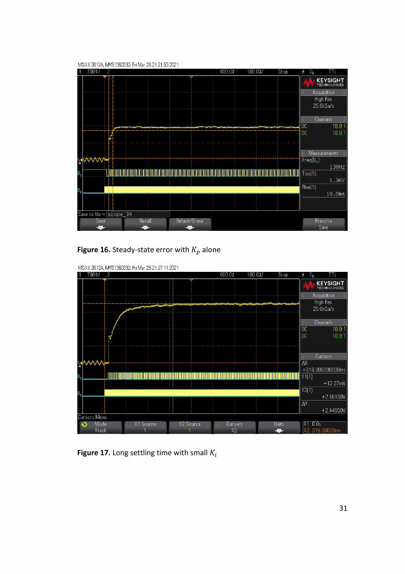
Figures 15, 16, 17 and 18 below show the system responses with different value
of 𝐾 during tuning. The motor speed changes were the analog output of DAC mod-
ule channel 1, pin PA4 and were captured with probe 1 of the oscilloscope.
After tuning the PID controller, three target speed values were selected to test
how effective it was at different speed ranges. The oscilloscope pictures (from Fig-
ure 19 to Figure 30) with the measurements displayed in the order to show the
system rise time then settling time, with the PID, then without the PID and from
small to large target speed values. The measurement results are also displayed in
Table 4 below.
31
Figure 16. Steady-state error with 𝐾 alone
Figure 17. Long settling time with small 𝐾

32
Figure 18. Overshoot happened with larger value of 𝐾
Figure 19. Perfect system response with 𝐾 being optimal to current 𝐾

33
Figure 20. System rise time without PID at target speed of 1850 RPM
Figure 21. System settling time without PID at target speed 1850 RPM

34
Figure 22. System rise time with PID at target speed 1850 RPM
Figure 23. System settling time with PID at target speed 1850 RPM
35
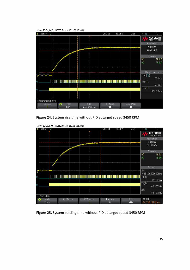
Figure 24. System rise time without PID at target speed 3450 RPM
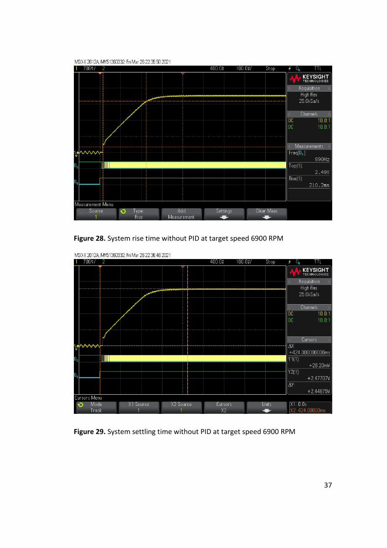
Figure 25. System settling time without PID at target speed 3450 RPM

36
Figure 26. System rise time with PID at target speed 3450 RPM
Figure 27. System settling time with PID at target speed 3450 RPM
37
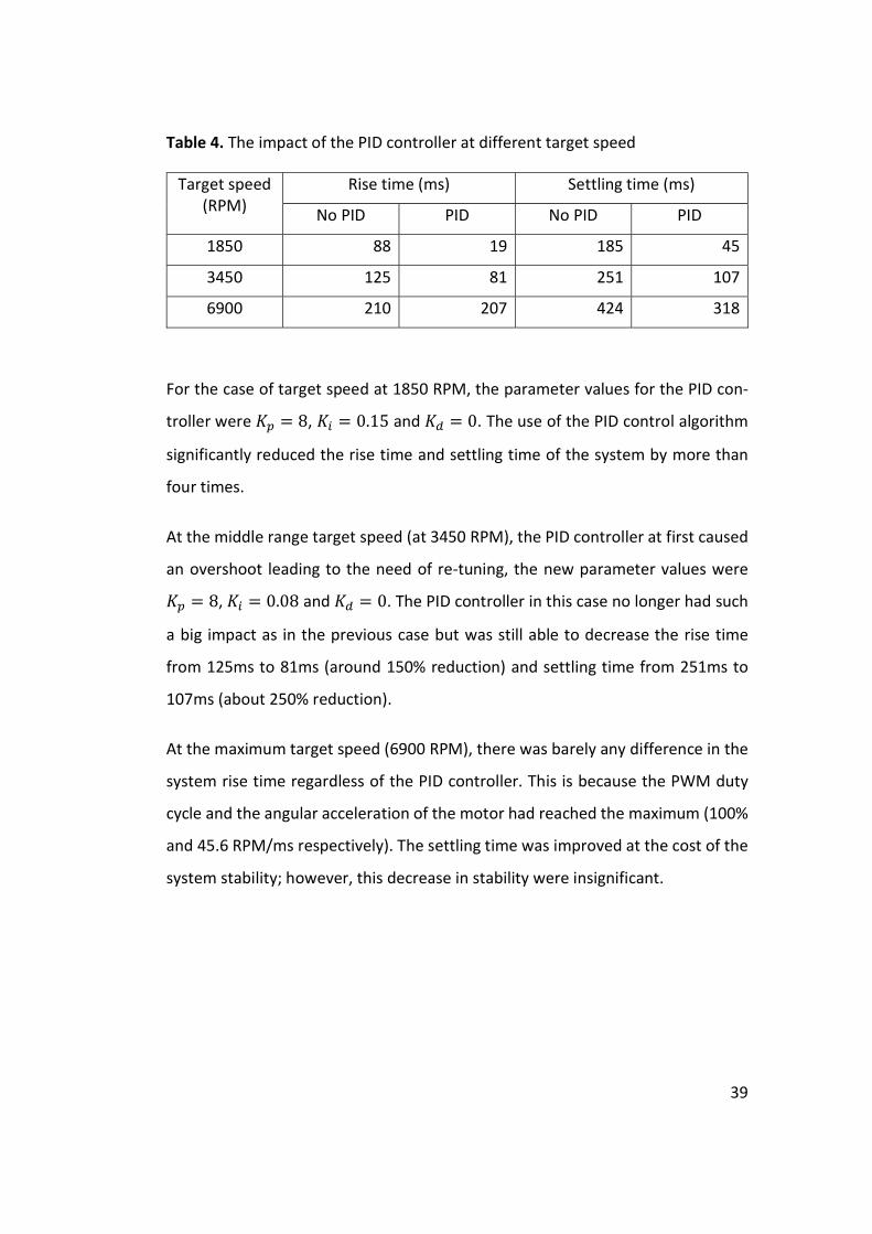
Figure 28. System rise time without PID at target speed 6900 RPM
Figure 29. System settling time without PID at target speed 6900 RPM

38
Figure 30. System rise time with PID at target speed 6900 RPM
Figure 31. System settling time with PID at target speed 6900 RPM
39
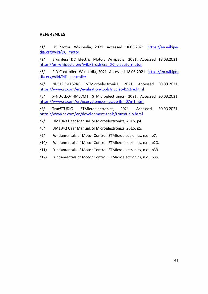
Table 4. The impact of the PID controller at different target speed
Target speed (RPM)
Rise time (ms) Settling time (ms)
No PID PID No PID PID
1850 88 19 185 45
3450 125 81 251 107
6900 210 207 424 318
For the case of target speed at 1850 RPM, the parameter values for the PID con-
troller were 𝐾 = 8, 𝐾 = 0.15 and 𝐾 = 0. The use of the PID control algorithm
significantly reduced the rise time and settling time of the system by more than
four times.
At the middle range target speed (at 3450 RPM), the PID controller at first caused
an overshoot leading to the need of re-tuning, the new parameter values were
𝐾 = 8, 𝐾 = 0.08 and 𝐾 = 0. The PID controller in this case no longer had such
a big impact as in the previous case but was still able to decrease the rise time
from 125ms to 81ms (around 150% reduction) and settling time from 251ms to
107ms (about 250% reduction).
At the maximum target speed (6900 RPM), there was barely any difference in the
system rise time regardless of the PID controller. This is because the PWM duty
cycle and the angular acceleration of the motor had reached the maximum (100%
and 45.6 RPM/ms respectively). The settling time was improved at the cost of the
system stability; however, this decrease in stability were insignificant.

40
4 CONCLUSIONS
From measuring results yielded, these following statements were drawn as the
conclusion:
The six-step algorithm was operational as expected.
The motor speed increased linearly but fluctuated more with increasing
PWM values.
The PID controller eliminated the need of manual control but slightly de-
creased the system stability.
Manual tuning method in this project proved to be effective.
Each range of target speed had a different optimal tuning value for PID pa-
rameters.
The PID controller significantly reduced the motor speed rise time and set-
tling time at a low target speed but had little impact at a high target speed.
In the future, this thesis work can be developed by improving the reusability of six-
step module so that it can be used by other microcontrollers and BLDC motors. In
addition to that, new software tuning methods are encouraged to be developed
to eliminate the need of manual tuning.
41
REFERENCES
/1/ DC Motor. Wikipedia, 2021. Accessed 18.03.2021. https://en.wikipe-dia.org/wiki/DC_motor
/2/ Brushless DC Electric Motor. Wikipedia, 2021. Accessed 18.03.2021. https://en.wikipedia.org/wiki/Brushless_DC_electric_motor
/3/ PID Controller. Wikipedia, 2021. Accessed 18.03.2021. https://en.wikipe-dia.org/wiki/PID_controller
/4/ NUCLEO-L152RE. STMicroelectronics, 2021. Accessed 30.03.2021. https://www.st.com/en/evaluation-tools/nucleo-l152re.html
/5/ X-NUCLEO-IHM07M1. STMicroelectronics, 2021. Accessed 30.03.2021. https://www.st.com/en/ecosystems/x-nucleo-ihm07m1.html
/6/ TrueSTUDIO. STMicroelectronics, 2021. Accessed 30.03.2021. https://www.st.com/en/development-tools/truestudio.html
/7/ UM1943 User Manual. STMicroelectronics, 2015, p4.
/8/ UM1943 User Manual. STMicroelectronics, 2015, p5.
/9/ Fundamentals of Motor Control. STMicroelectronics, n.d., p7.
/10/ Fundamentals of Motor Control. STMicroelectronics, n.d., p20.
/11/ Fundamentals of Motor Control. STMicroelectronics, n.d., p33.
/12/ Fundamentals of Motor Control. STMicroelectronics, n.d., p35.

42
APPENDIX 1
Motor Speed Result Table Average values Sample 1 Sample 2 Sample 3 Sample 4 Sample 5 Sample 6 Sample 7 Sample 8 PWM val avg freq avg speed error freq speed freq speed freq speed freq speed freq speed freq speed freq speed freq speed
0 0.0 0 0 0.0 0 0.0 0 0.0 0 0.0 0 0.0 0 0.0 0 0.0 0 0.0 0 500 34.7 261 8 35.4 265 33.7 252 35.1 263 35.5 266 34.5 259 33.8 254 35.1 264 34.9 262
1000 60.1 451 7 60.2 452 59.2 444 60.1 451 60.4 453 60.3 452 60.3 452 60.2 452 60.1 450 1500 113.4 851 6 113.4 851 113.6 852 113.6 852 113.4 850 112.6 844 113.5 851 113.1 848 114.0 855 2000 175.2 1314 11 174.8 1311 176.0 1320 176.6 1325 174.8 1311 174.2 1307 173.9 1304 175.6 1317 175.9 1319 2500 216.6 1624 12 216.3 1622 215.2 1614 215.5 1616 216.3 1622 217.0 1628 217.4 1631 218.2 1637 216.6 1625 3000 254.1 1905 12 253.6 1902 253.9 1904 253.3 1900 255.6 1917 254.1 1906 254.3 1907 254.2 1907 253.4 1901 3500 291.1 2183 11 290.5 2179 292.1 2191 291.6 2187 292.6 2195 290.4 2178 290.2 2177 290.2 2177 291.0 2183 4000 345.0 2587 21 344.6 2585 346.1 2596 342.9 2572 343.0 2573 344.6 2585 347.8 2609 345.3 2590 345.3 2590 4500 394.1 2956 17 394.6 2960 395.3 2965 395.7 2968 394.6 2960 392.2 2942 393.6 2952 391.9 2939 395.1 2963 5000 457.7 3433 18 457.9 3434 457.0 3428 455.4 3416 457.5 3431 456.2 3422 459.6 3447 458.7 3440 459.6 3447 5500 484.8 3636 24 483.0 3623 485.0 3638 484.0 3630 482.0 3615 485.0 3638 485.0 3638 486.0 3645 488.0 3660 6000 532.4 3993 33 530.2 3977 534.2 4007 534.8 4011 534.8 4011 534.8 4011 530.8 3981 528.0 3960 531.9 3989 6500 589.5 4422 21 591.7 4438 586.9 4402 591.7 4438 586.9 4402 588.2 4412 588.2 4412 592.4 4443 590.3 4427 7000 627.4 4705 30 630.0 4725 627.5 4706 628.8 4716 628.5 4714 625.9 4694 623.4 4676 628.1 4711 626.9 4702 7500 672.1 5041 37 672.0 5040 670.6 5030 672.0 5040 673.1 5048 677.1 5078 671.0 5033 672.0 5040 669.2 5019 8000 710.3 5327 35 705.6 5292 713.4 5351 708.5 5314 713.1 5348 711.8 5339 712.8 5346 706.5 5299 710.8 5331 8500 750.4 5628 32 751.0 5633 749.2 5619 754.6 5660 750.8 5631 746.1 5596 748.7 5615 749.2 5619 753.5 5651 9000 799.3 5995 27 801.5 6011 799.7 5998 800.8 6006 801.3 6010 799.2 5994 795.7 5968 799.5 5996 796.9 5977 9500 877.3 6580 37 874.4 6558 879.7 6598 877.8 6584 878.7 6590 880.0 6600 877.5 6581 872.3 6542 877.8 6584
10000 915.5 6866 33 915.8 6869 917.8 6884 917.8 6884 915.1 6863 911.1 6833 915.8 6869 912.4 6843 918.4 6888

43
APPENDIX 2
D6230 Three-phase BLDC Motor Driver Schematic

44
APPENDIX 3
Hall Sensor Schematic