Bachelor's Thesis - Theseus
58
Degree Program in Information Technology Telecommunication Engineering Bachelor’s Thesis Shock Sensor Detection and Transmission of a Forklift Le Ma Accepted___.___.___ ________________
-
Upload
khangminh22 -
Category
Documents
-
view
0 -
download
0
Transcript of Bachelor's Thesis - Theseus

Degree Program in Information Technology
Telecommunication Engineering
Bachelor’s Thesis
Shock Sensor Detection and Transmission of a Forklift
Le Ma
Accepted___.___.___ ________________

ABSTRACT
SAVONIA UNIVERSITY OF APPLIED SCIENCES Degree Programme
Information Technology
Author(s)
Le Ma
Title of study
Shock Sensor Detection and Transmission of a Forklift
Type of project
Final project
Date
18 March 2011
Pages
57
Supervisor(s) of study
Mr Mikko Pääkkönen and Arto Toppinen
Executive organisation
AP-TRUKIT OY
Abstract
Nowadays, In the highly developed modern industry, based on the development of IC electronic and
computer technology, the sensing technology has made big development and brought so much
convenient for our lives.
The aim of this thesis was to create a remote mobile monitoring device for a forklift shock situation
for AP-TRUKIT OY using an EZ-10 device .The main objectives were to find a suitable shock
sensor, and to create a workable python code. The program uses a SMS message to inform the
shock time to the service person.
Th Different kinds of shock sensors were looked for. Their operating principle were studied, to
understand how they work. A suitable one was chosen for the thesis. Knowledge and technologies
related to GSM, python language and AT commands were studied in detail.
The remote test was done in Savonia’s wireless lab at Technopolis Kuopio. The result of the thesis
is a working shock sensor.
Keywords
EZ-10, python shock sensor, AT command, GSM
Note
Public

TIIVISTELMÄ
SAVONIA AMMATTIKORKEAKOULU Information Technology koulutusohjelma
Tekijä
Le Ma
Työn nimi
Shock Sensor Detection and Transmission of a Forklift
Päättötyö
Pvm
18 March 2011
Sivut
57
Työn ohjaajat
Mikko Pääkkönen ja Arto Toppinen
Työn tilaaja
AP-TRUKIT OY
Tiivistelmä
Nykyisin, kehittyneessä modernissa teollisuudessa, joka perustuu IC-piirien ja tietokoneiden
kehittymiselle, sensoritekniikassa on tehty suuria edistysaskeleita ja se on tuonut mukavuuksia
elämäämme.
Tämän työn tarkoituksena oli toteuttaa mobiili shokkisensorointi AP-trukit Oy:n toimittamiin
trukkeihin käyttäen GSM modeemia. Päätavoitteina oli löytää sopiva shokkisensori ja tehdä Python
koodilla sopiva ohjelma. Ohjelma käyttää tekstiviestiä sensoritiedon lähetykseen huoltomiehen
puhelimeen.
Työssä vertailtiin erilaisia shokkisensoreita. Niiden toimintaperiaatteet tutkittiin ja testattiin. Eräs
shokkisensori valittiin lopulta toteutukseen. GSM tekniikat, Python kieli ja AT-komennot tutkittiin
ja opeteltiin yksityiskohtaisesti.
Shokkisensorin testit ja kehitys tehtiin Savonian Wireless laboratoriossa. Tuloksena saatiin mobiili
shokkisensorin prototyyppi.
Avainsanat
EZ-10, python shock sensor, AT command, GSM
Julkinen

4
ACKONWLEDGEMENTS
Firstly, I want to give my sincerest appreciation to Mr Arto Toppinen. I am grateful
for this topic he provided me. It was a good opportunity to learn more and improve
my skills. Arto Toppinen is such a kind teacher.
Secondly, I want to thank Jarno Ruutinen and Mikko Pääkkonen very much: thanks
for all the help , suggestions and guidance on the project. I would like to thank all the
teachers during study period in Kuopio, not only for the knowledge they taught me,
but also the skills they trained on me.
Moreover, i am grateful for my family. Thanks for their great love and support. Their
encouragement gives me so much power. Thanks to my friends who gave me
understanding and encouragement during the study period in Kuopio.
Le Ma
March 18, 2011
Kuopio, Finland

5
ABBREVIATIONS
IC Integrated circuit
IP Internet protocol
PZT piezoelectric zirconate titanate
GSM global system mobile communication
SMS short message service
AT Attention
SIM Subscriber Identity module
MO mobile originated
MT mobile terminated
CPU central process unit
PDU protocol data unit
GPRS general packet radio service
ADC analog to digital converter
MEMS micro electrical mechanical system
CDMA code division multiple access
HSDPA high speed downlink packet access
UMTS universal mobile telecommunication system
GPS general position system
PDN packet data network

6
PDP packet data protocol
EDGE enhanced data for GSM evolution
TCP transport control protocol

7
Table of Contents
1.INTRODUCTION…………………………………………………………………………………9
2. SHOCK SENSORS AND APPLICATION…………. ………………………………………….10
2.1 What is Sensor Technology…………………………………………………………………..10
2.1.1 MEMS-Based Sensor Technology……………………………………………………….10
2.1.2 MEMS application………………………………………………………………………..11
2.2 Application Field of Sensors………………………………………………………………….12
2.3 Application Field of Shock Sensors………………………...…………………………………14
2.3.1Remote Control via SMS on Shock situation for a forklift………………………………..15
2.4 Different Kinds of Shock Sensor………………………………………………………………16
2.4.1 Piezoelectric Ceramic Characteristic……………………….………………………….16
2.4.2 Piezoelectric Shock Sensor………..……………..………………………………………17
2.4.3 Specifications…………………………………...………………………………………..19
3.GSM MODEM……………………………………………………………………………………21
3.1 Wireless Modem………………………………………………………………………………21
3.2 What is GSM Modem ………………………………………………………………………….21
3.3What is GPRS Modem…………………………...…………………………………………….22
3.4 EZ-10 GPS……………………………………………………………………………………..22
3.4.1 Interface Description ……………………………………………………………………..25
3.4.2 Power Supply………………………………………………………………………………25
3.4.3 Switch on via Automatic Power Supply Unit……………………………………...………26
3.4.4 GPIO Interface for RJ11 (AUX) Connector………………………………………………26
3.4.5 GPIO Interface specification……………………………………………………………..27
3.5Telit GM862-GPS Modem……………………………………………………………………28
4.PYTHON INTERPRETER…………………………...…………………………………………..30
4.1 introduction to Python................................................................................ 30
4.2 Execution of Python Script………………………………………………….……………35

8
5. AT COMMAND………………………………………………...………………………………..37
5.1 A Brief Description about AT Commands…………………………...…………………….37
5.2 AT commands that were used………………………………………………………………..38
6. LM555 MONOSTABLE CIRCUI………………………………………………………………40
7. TEST AND ANALYSIS ……………………………………………………………………...43
7.1 Test for Shock Sensor…………………………………………………………………...43
7.2 Test for sending SMS through GSM modem……………………………………..…...43
7.3 Analysis……………………………………………………………………………….……….46
8. VARIOUS APPLICATIONS ON GSM VIA SMS………………………. … …………………47
9. CONCLUSION………………………………………………………………………………49
REFERENCES…………….................................................................................... 50
Appendices…………………………………………………………………….....................52
Appendix 1 Installing of PYTHON.…………………………………………………………….53
Appendix 2 python implementation description………………………………………………..54
Appendix 3 software python code in this final work…………………………………………....55

9
1. INTRODUCTION
Nowadays, with the development of sensoring technology, the shock sensor as one kind of sensors
can be found in a wide variety of applications. Such as alarm and security systems, remote control,
object traceability and so on. There are different types of shock sensor like electric, mechanical,
wireless and piezoelectric.
The AP-Trukit company needs to remote monitor the forklift shock situations, it is possible to use
the shock sensoring technology and mobile communication technology to achieve the remote
control.
The aim of this thesis is to create a remote mobile monitoring device for a forklift shock situation.
Firstly, different possible shock sensors are looked for and understand how they work. Then a
suitable one will be selected for this thesis. Secondly, software for Telit (python language) will be
created to read the sensor (digital input) and send the SMS message through the GSM mobile
communication technology.

10
2. SHOCK SENSOR AND APPLICATION
2.1 What is Sensor Technology?
A sensor is a detection device, it could feel the information to be measured and converted to a
available signal which can be read by an observer or by an instrument. During the past two decades,
there has been an unprecedented growth in the number of products and services, which utilize
information gained by monitoring and measuring using different types of sensors. [1] Sensor
technology was seen as an integral element in the overall development of products and services. In
fact it emerged as the key technology to support a wide variety of research and industrial
applications.
Sensors are normally components of some larger electronic system such as a computer control and
measurement system. Analog sensors most often produce a voltage proportional to the measured
quantity. The signal must be converted to digital form with a ADC before the CPU can process it.
Digital sensors most often use serial communication to return information directly to the controller
or computer through a serial port.
2.1.1 MEMS Based Sensor Technology
Micro electromechanical systems (MEMS) are devices that can sense, think, act and communicate.
Fig.1 shows the MEMS based technology. MEMS redirect light, pump and mix fluids, and detect
the presence of molecules, heat, pressure or motion (all of which have been done for years in a
macro scale). Through the miniaturization of these macro-sized devices and the ability to fabricate
micro-sized devices in large numbers, the costs of manufacturing have decreased. [2]

11
Figure 1 MEMS based technology [2]
A MEMS's small size allows it to be incorporated into a vast array of products. It can be included as
a component of an integrated circuit or embedded into materials during manufacturing. Such
characteristics permit the construction of more complicated systems and expand the potential
applications of MEMS.
2.1.2 MEMS Applications
Freescale's MEMS-based sensors are a class of devices that builds very small electrical and
mechanical components on a single chip. MEMS-based sensors are a crucial component in
automotive electronics, medical equipment, hard disk drives, computer peripherals, wireless devices
and smart portable electronics such as cell phones and PDAs. These sensors began in the
automotive industry especially for crash detection in airbag systems. Throughout the 1990s to today,
the airbag sensor market has proved to be a huge success using MEMS technology. MEMS-based
sensors are now becoming pervasive in everything from inkjet cartridges to cell phones. Every
major market has now embraced the technology. The benefits of MEMS include: low Cost, low
Power, miniaturization, high Performance and Integration.[3]
Applications for MEMS are being realized every day. MEMS are built as sub millimeter devices as
needed for medical applications and in the millimeter range for miniature robots. Single MEMS can
12
consist of a few components to millions of components. Because of this versatility, MEMS
applications are practically unlimited.
There are still challenges in the fabrication of MEMS for applications such as RF (radio frequency)
devices, optical and chemical devices, and fluidics. However, due to the development of new
processes, materials, and equipment, these challenges are being addressed.
2.2 Application Field of Sensor
Sensors are used in everyday objects such as touch-sensitive elevator buttons and lamps which dim
or brighten by touching the base. There are also innumerable applications for sensors of which most
people are never aware of. Application field include cars, machines, aerospace, medicine,
manufacturing and robotics. [1]
In professional words, sensor applications involve machinery manufacturing, industrial process
control, automotive electronics, telecommunication electronics, consumer electronics and special
equipment. Nowadays, the fastest-growing sensors market demand for the car industry market,
good prospects for the telecommunications market.
As we seen from Fig. 2, there are various sensors, like shock sensors, humidity sensors, alcohol
sensors, temperature sensor, air pressure sensors, humidity module, ultrasonic transducers, gas
sensors, atmospheric pressure sensors.

13
Item Picture Name Applications
shock sensor
Alarm, Electric Lock & other shock detector
Tilt sensor
Nun Mercury type For tilt switch,
angle switch, others.
Close type Ultrasonic
Transducer
Distance measurement, Back meter,
others...
Gas sensor
For detecting: Smoke,
Gas, Alcohol, CO, Air pollution...etc
Atmospheric
pressure sensor
For air pressure
detecting.
Humidity
sensor
Humidity (30-90%RH)
Stable quality
Shock sensor
for window
Alarm, security and other
shock detecting
Password
shock detector
Alarm, security and shock
detecting.
Figure 2 Some example sensor products. [4]
For example, in a modern Luxury Car, the key of the electronic control system is the number and
level of use of sensors, Today an ordinary family cars are about to install only tens to hundreds of
sensors, while the number sensors in luxury cars on the sensor up to two hundred only, species is
usually more than 30 species, as many as over 100 kinds. Nowadays, new MEMS sensor
technology not only to achieve miniaturization, but also have the functions like detection and
control ,can be intelligent.[5] Fig.3 shows an MEMS sensor’s application to Auto key parts.

14
Figure 3.MEMS sensor’s application to Auto key parts. [5]
2.3 Application Field of Shock Sensor
A shock sensor is designed to trigger an alarm on light or heavy impacts and vibrations (standard
sensor included with most alarms) the shock sensors are used very often. Applications can be found
in various fields.
As we seen from Fig.4, car alarm system with electronic shock sensor. Besides, collision sensoring
system in vehicles, a remote tire pressure monitoring system (a tire monitor for mounting to a
vehicle as part of a remote tire monitoring system includes a tire condition sensor to produce a tire

15
condition signal, a controller coupled to the tire condition sensor to control operation of the tire
monitor, and a radio circuit coupled to the controller).
Figure 4. The shock sensor in car alarm system [6]
It is also possible to find shock sensor in laptop. It is used to protect the hard disk in case of sudden
impact to the laptop. The shock sensor is designed to decrease the risk of damage to the computer’s
hard disk drive in the event of excessive impact of vibration. [7]
Additionally, the shock sensor utility can also be used to improve the security of the computer by
automatically locking the computer with a password when it is carried. Acceleration shock sensor is
also popular.
2.3.1 Remote Control via SMS on Shock situation for a forklift
In the final project, shock sensor, one mini PC with Windows 7 operating system with GSM modem
and a mobile phone are used in the laboratory work as shown in Fig.5.

16
(GSM network)
(SMS)
Figure 5 The components in the implementation of this thesis.
2.4 Different kinds of Shock Sensor
Nowadays, it is possible to find different types of shock sensor like electric, mechanical, wireless
and piezoelectric (mechanical-to-electrical transducers).
2.4.1 Piezoelectric Ceramic Characteristics
Piezoelectric ceramics have the property of developing an electric charge when mechanical stress is
exerted on them. In these materials, an applied electric field produces a proportional strain. The
electrical response to mechanical stimulation is called the direct piezoelectric effect, and the
mechanical response to electrical stimulation is called the converse piezoelectric effect. [8]

17
The most commonly produced piezoelectric ceramics are lead zirconate titanate (PZT). Ceramic
materials have several advantages over single crystals, especially the ease of fabrication into a
variety of shapes and sizes. In contrast, single crystals must be cut along certain crystallographic
directions, limiting the possible geometric shapes. [8]
Piezoelectric ceramics may be used to produce e.g.:
• Actuators
• Sensors
• Generators
• Transducers
2.4.2 Piezoelectric Ceramic Shock Sensor
The piezoelectric effect causes a crystal to produce an electrical potential. It has the advantage of
high electromechanical transformation efficiency and high machinability. [9]
Piezoelectric ceramic chip as a vibration detection device. Because of the high resonant frequency
of PZT, so some gravity springs were welded. Not only reduced the resonant frequency, but also
enhanced the effect of vibration.
In this final thesis, the ZD-1 high sensitivity vibration sensor (piezoelectric ceramic shock sensor
shown in Fig 6) will be used. The internal components are shown in Fig 7.
Figure 6. ZD-1 high sensitivity vibration sensor

18
Figure 7.The internal components in a shock sensor.
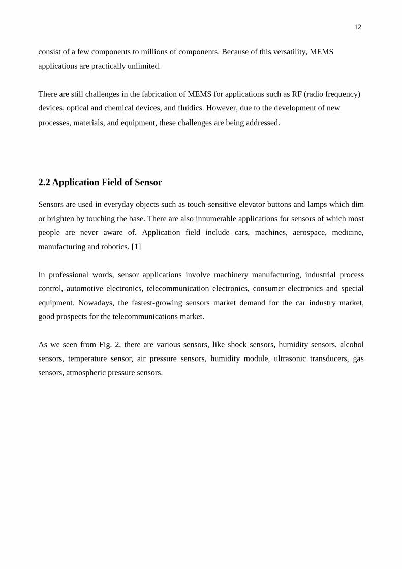
Fig. 8 shows that this kind of sensor is an open collector output transistor drive mode. D1 is the
single chip system interface. When the sensor detects vibration signal Q1 turns on, the voltage in
point will be down to 0.1V and D1 line will also be down to 0.8V. Then the output could detect
changes and get the shock signal.
19
Figure 8. The internal circuit in the shock sensor
2.4.3 Specifications
The following list presents some advantages and specifications in this ZD-1 high sensitivity
piezoelectric ceramic shock sensor.
1. Green line:5 to 12V power supply
2. Black line: earth
3. Red line: signal output (output 1 second low power signal after detecting one shock) single
chip interface.
4. Size: 50×30×20mm
5. Work temperature: -10℃~+50℃
6. Work current: 10mA
7. Advantages: omni-directional detection, sensitivity adjustable, the structure simple, low

20
cost, high sensitivity, and continuously adjustable.
8. Sensitivity: there is a adjustment button, clockwise to increase sensitivity, anticlockwise to
decrease sensitivity. When the detected vibration is greater than a certain level, the red
indicator lights ON.
3 GSM Modem

21
3.1 Wireless Modem
Wireless Modems are the Modem devices that generate, transmit or decode data from a cellular
network, for establishing communication between the cellular network and the computer. These are
manufactured for specific cellular network (GSM/UMTS/CDMA) or specific cellular data standard
(GSM/UMTS/GPRS/EDGE/HSDPA) or technology (GPS/SIM). Wireless Modems like other
Modem devices use serial communication to interface with and need Hayes compatible AT
commands for communication with the computer (any microprocessor or microcontroller system).
[20] .Fig 9 shows the wireless network, data standard and technology.
Figure 9 The wireless network, data standard and technology
3.2 What is a GSM Modem?
The information is composed of digital signals by using "0" and "1" in the computer, but there are
only analog signal in the telephone line. Thus when data is transmission through the telephone line,
it needs a device for the digital-analog conversion (DAC). The DAC is called the Modem.
A GSM modem is a wireless modem that makes it possible to connect a computer to a GSM
network. Like a GSM mobile phone, a GSM modem requires a SIM card from a wireless carrier in

22
order to operate. An external GSM modem is connected to a computer through a serial cable or a
USB cable. It is possible to make and receive phone calls and send text messages. The main
difference is that instead of a cell phone keypad and display, a computer keyboard and monitor are
used. A GSM modem is connected to the computer. Communicate with the modem by typing AT
commands in the command prompt of the software that came with the modem. [10]
3.3 What is a GPRS Modem?
A GPRS modem is a GSM modem that additionally supports the GPRS technology for data
transmission. GPRS stands for General Packet Radio Service. It is a packet-switched technology
that is an extension of GSM. (GSM is a circuit-switched technology.) A key advantage of GPRS
over GSM is that GPRS has a higher data transmission speed.
GPRS can be used as the bearer of SMS. If SMS over GPRS is used, an SMS transmission speed of
about 30 SMS messages per minute may be achieved. This is much faster than using the ordinary
SMS over GSM, whose SMS transmission speed is about 6 to 10 SMS messages per minute. A
GPRS modem is needed to send and receive SMS over GPRS. Note that some wireless carriers do
not support the sending and receiving of SMS over GPRS. [11]
If you need to send or receive MMS messages, a GPRS modem is typically needed.
3.4 EZ10 GPS
The EZ10 GPS is the GSM modem device used in this final year project. EZ10 GPS is based on
GM862 GPS module. The Telit EZ10-GPS GSM terminal is the complete GPS capable GSM
modem solution for wireless m2m and mobile applications.
Based on Telit's impressive GM-862-GPS module it inherits the reliability and large feature set of
this module including quad band GSM 850/900/1800/1900 reception, 20 channel SiRFStarIII GPS
and integrated Python scripts interpreter.

23
The integrated Python interpreter offers the ability for the customer to run custom programs inside
the modem, making it a complete self-contained unit for a variety of applications. Programmable
GPIO ports and the IIC-Bus can be used to detect external signals, connect sensors, and to switch
external devices. [12]
The EZ10-GPS can also be used as a standard GSM modem connected to a PC via RS-232 serial.
Key Features of the EZ10 GPS PY Terminal are shown in Table 1. and Fig.10.
Table 1. Key Features of the EZ10 GPS PY Terminal [12]
Feature implementation
General
Incorporates GM862 GPS
module
The Telit GM862 GPS PY module
handles all processing for audio,
signal and data within the EZ10
GPS PY Terminal
Frequency bands Quad band: GSM
850/900/1800/1900MHz
Power supply Single supply voltage 5V to 30V
Operating temperature -20°C to +70°C ambient
temperature
Physical Dimensions: 107mm x 64m x 33m
Weight: 160g
Figure 10 EZ10 GPS PY Terminal Telit Cellular GPS Engine [12].
The GSM feature is used in this final year project. The implementation on SMS has following

24
points.
• Point-to-point MT and MO
• Text and PDU mode
• Storage: SIM card plus 20 SMS locations in mobile equipment
• Transmission of SMS alternatively over CSD or GPRS.
Preferred mode can be user defined.
Table 2 shows some software in EZ10 GPS PY Terminal.
Table 2. Software in EZ10 GPS PY Terminal [12].
Feature implementation
software
AT commands AT-Hayes GSM 07.05 and 07.07
TCP/IP Stack TCP/IP stack Access by AT
commands
Firmware update Upgradeable via serial interface
PYTHON platform Major benefits: seamless
integration into PTYHON
applications, no need
for application microcontroller,
extremely cost-efficient hardware
and software design – ideal
platform for industrial GSM
applications.
The memory space available for
PYTHON programs is 3.0 MB
flash file
system and 1.5 MB RAM.
Application code and data share the
space in
the flash file system and in RAM.
3.4.1 Interface Description

25
EZ10 GPS PY Terminal provides the following lists are connectors for power supply, interface and
antennas, see the Fig. 11 [12]
1. SMA connector (female) for GSM antenna.
2. Led's GSM and Power indicators.
3. 9-pole (female) SUB-D plug for RS-232 serial interface.
4. SMA connector (female) for GPS antenna.
5. 4-pole 3mm Micro Mate-N-LOK connector for power supply and GPIO3.
6. SIM card holder.
7. 6-pole RJ11 plug (female) for 4 GPIOs or option audio, such as a Microphone and Speaker.
Optional Audio Hand free card 3w, optional Relay card for GPIO5.
Figure 11 EZ10 GPS PY Terminal side A and B view.[12]
3.4.2 Power Supply
In Fig.12, that is the pin assignment for power supply. The DC power supply must be connected to
the POWER input:
• Input voltage range: 12 - 24V DC
• Nominal Voltage 12V DC
Pin description:
• GND = Ground reference (1x POWER, 1x Signal)
• Input Power = 12 - 24VDC
• GPIO3 input CMOS 2.8 (voltage range allowed on)

26
this pin: 0-3,6VDC vs. GND)
Figure 12 Male 4-pole plug for power supply [13]
3.4.3 Supply voltage requirements
The DC power supply must be connected to the POWER input:
• Input voltage range 5 - 30V DC
• Nominal Voltage 12V DC
• Power Supply current rating: min. 1,2A @12V
• Power Supply ripple: max. 120mV
• Input current in idle mode: 20mA @ 12V
• Input average current in communication mode: 100mA @ 12V
3.4.4 GPIO Interface for RJ11 (AUX) connector
The EZ10 GPS PY Terminal provides four GPIO pins at the 6 pins interface connector.
Each GPIO line is ESD protected and a serial resistor of 100 Ohm is added. This avoids short
circuits. The signal direction (input/output) of the GPIO lines is selectable with AT commands. We
could see the GPIO number for RJ11 (AUX) connector in Fig.13 [13]

27
Figure 13 Audio RJ11 plug (6/4-pole female)[13]
Table 3 shows the position of the GPIO pins on the IO interface connector. When the EZ10 GPS PY
Terminal starts up.
Table 3 Input / output Lines on the RJ11 GPIO interface [13]
3.4.5 GPIO Interface Specification
All General Purpose input / output lines on the RJ11 GPIO interface have a 100 pF bypass capacitor
to ground and are connected to the related pins of the Telit module over a 100 Ohms series resistor.
Table 4 shows the logic level specifications in the Telit EZ10-QUAD-PY terminal interface circuits.

28
Table 4 Logic level specifications in the Telit EZ10-QUAD-PY terminal interface
3.5 Telit GM862-GPS Modem
The Telit GM862 module is a small, lightweight and low power consumption device that allows
digital communication services wherever there is a GSM 900 and DCS 1800 network. [14]
Telit GM862-GPS provides all the features of the GM862-QUAD version such as voice, circuit
switched, Data transfer, phonebook, SMS four bands GSM capability. Moreover, the GM862-GPS
integrate the “EASY SCRIPT” functionality. With the EASY SCRIPT feature the GM862-GPS
become a finite product, they just need your script to be run. We could see the picture Telit GM62-
GPS Modem in Fig.14. [14]

29
Figure 14 Telit GM862-GPS module [14]
In Telit GM862-GPS modem, the core Engine is the GM862-QUAD.
Telit GM862-GPS main characteristics are as follow:
Core engine GM862-PY.
MMCX connectors for GSM.
GPS antenna connection.
Indoor tracking capability.
EASY SCRIPT python Interpreter.
Footprint compatible to GM862-Family.

30
4. Python interpreter
4.1 Introduction to python
In this final year project, PYTHON program runs on the Telit GM862-GPS quad-band modem.
Setup is done by AT command.
It was possible to use the Python programming language to read the shock digital signal and send
SMS messages.
Python is a dynamic object oriented programming language that can be used for many kinds of
software development. The python interpreter is aimed for the application usually done by a small
microcontroller that managed some I/O pins and the module through the AT command interface. [13]
Fig 15 shows the schematic of such configuration.
Figure 15 The schematic of Easy script extension.[15]

31
In order to eliminate this external controller, and further simplify the programming of the sequence
of operations, inside the GM862-PYTHON it is included:
- Python script interpreter engine v. 1.5.2+
- Around 3MB of Non Volatile Memory room for the user scripts and data
- 1.5 MB RAM reserved for Python engine usage.
A schematic of this approach is in Fig. 16.
Figure 16 A schematic of this approach [16]
The MDM built-in module is the interface between python and the module AT command parser
engine. It was used to send AT commands and data from python script to the network and receive
responses and data from the network during connections.
The SER built-in module is the interface that allows python script to read from and write to the real
physical serial port ASCO that is usually used to send the AT commands to the module.

32
The MOD built-in module is the interface between python and module miscellaneous functions.
You need to use MOD built-in module if there is a need to generate timers in Python script, stop
python execution, manage the power saving mode from your python script, etc. It is a collection of
useful functions.
If the purpose is to use the MOD built-in module you need to import first:
Import MOD, then you could use MOD method like MOD.sleep(15) this blocks python script
execution for 1.5s.
The GPIO built-in module is the interface between the python core and module internal general
purpose input output direct handling. If you want to set GPIO values from python script and to read
GPIO values from python script. You need the GPIO built-in module.
For example:
MDM.send("AT+CREG?\r") <--- that gives the command
res = MDM.receive(20) <--- that reads the response.
SER = for serial traffic (rs223, the connection to the PC)
... to send text to PC: SER.send("hi there\r")
The following are examples about the send SMS in python code.
import MDM
import SER
import MOD
file = open('log.txt', 'wb')
file.write('sendSMS.py LOKI AUKI\r\n')
SER.set_speed('115200')
SER.send('sendSMS.py\r\n\r\n')
num = "" # enter the phone number (+358466440535)
message = "" # enter the message
SER.send('phone number: ' + num + '\r\n')
SER.send('message: ' + message + '\r\n\r\n')
file.write('phone number: ' + num + '\r\n')

33
file.write('message: ' + message + '\r\n\r\n')
timer = MOD.secCounter() + 200
SER.send('Searching for operator...\r\n\r\n')
file.write('Searching for operator...\r\n\r\n')
res = MDM.send('AT+CREG?\r',0)
res = MDM.receive(5)
while ((res.find('+CREG: 0,1') == -1) and (res.find('+CREG: 0,5') == -1) and
MOD.secCounter() < timer):
res = MDM.send('AT+CREG?\r',0)
res = MDM.receive(5)
SER.send('AT+CREG: OK\r\n\r\n')
file.write('AT+CREG: OK\r\n\r\n')
SER.send('Changing the SMS format to text\r\n\r\n')
file.write('Changing the SMS format to text\r\n\r\n')
res = MDM.send('AT+CMGF=1\r',0)
res = MDM.receive(20)
while(res.find('OK') == -1 and res.find('ERROR') == -1):
res = MDM.receive(5)
if(res.find('ERROR') != -1):
SER.send('ERROR')
file.write('ERROR setting message format')
else:
SER.send('Sending the message...\r\n\r\n')
file.write('Sending the message...\r\n\r\n')
# initialize the message
res = MDM.send('AT+CMGS=' + num + ';\r', 0)
# wait for answer
res = MDM.receive(5)
# if the > character is found, the module is ready to receive the
message
if (res.find('>') != -1):
# enter the message
res = MDM.send(message, 0)

34
# end the message
ret = MDM.sendbyte(0x1A, 0)
ok = MDM.receive(5)
while(ok.find('+CMGS:') == -1 and ok.find('ERROR') == -1):
res = MDM.receive(5)
ok = ok+ res
if(ok.find('+CMGS:') != -1):
SER.send('Message sent\r\n\r\n')
file.write('Message sent\r\n\r\n')
if(ok.find('ERROR') != -1):
SER.send('ERROR\r\n\r\n')
file.write('ERROR sending message\r\n\r\n')
else:
if(res.find('ERROR') != -1):
SER.send('ERROR\r\n\r\n')
file.write('ERROR initializing message\r\n\r\n')
else:
SER.send('The module is not responding\r\n\r\n')
file.write('The module is not responding\r\n\r\n')
Telit has several custom libraries that make things a lot easier:
MDM
MDM2
SER
SER2
GPIO
MOD
SPI
IIC
GPS
The most used libraries are the MDM interfaces. These are used to send commands to and from the
module. MDM and MDM2 use different AT instances. The device can be controlled from either one.
For my project, it came in handy to multitask a bit by using MDM to send Telnet packets directly to
the SER interface while reading the connection status on the MDM2 interface.
35
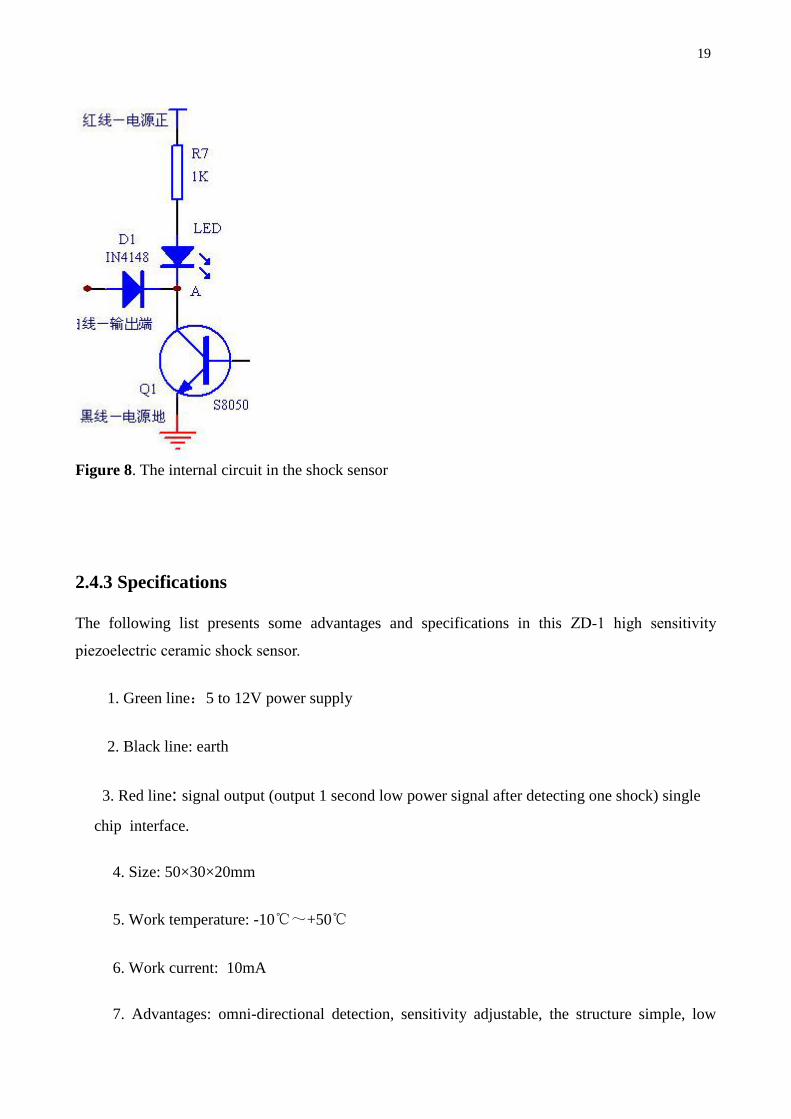
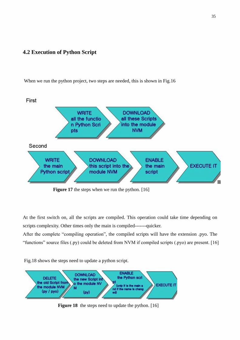
4.2 Execution of Python Script
When we run the python project, two steps are needed, this is shown in Fig.16
Figure 17 the steps when we run the python. [16]
At the first switch on, all the scripts are compiled. This operation could take time depending on
scripts complexity. Other times only the main is compiled-------quicker.
After the complete “compiling operation”, the compiled scripts will have the extension .pyo. The
“functions” source files (.py) could be deleted from NVM if compiled scripts (.pyo) are present. [16]
Fig.18 shows the steps need to update a python script.
Figure 18 the steps need to update the python. [16]

36
The following are automatic run code:
import shocksens
if __name__ == '__main__':
shocksens.main()

37
5. AT Command
5.1 A Brief Description about AT Commands
AT is the abbreviation for Attention. AT commands are instructions used to control a modem, it is an
essential part of this work. Because that’s the way how to communicate with the modem from code
(python program). The Telit wireless module family can be driven via the serial interface using the
standard AT command. Fig 19 shows the execution of AT commands.
Figure 19 the execution of AT commands. [16]

38
There are two types of AT commands:
1. Basic commands are AT commands that do not start with a "+". For example, D (Dial), A
(Answer), H (Hook control), and O (Return to online data state) are the basic commands.
2. Extended commands are AT commands that start with a "+". All GSM AT commands are
extended commands. For example, +CMGS (Send SMS message), +CMGL (List SMS
messages), and +CMGR (Read SMS messages) are extended commands. [17]
When starting to work with AT commands to setup and check the status of the GSM modem, it can
be done like this:
AT Returns a "OK" to confirm that modem is working
AT+CPIN="xxxx"
To enter the PIN for your SIM ( if enabled )
AT+CREG? A "0,1" reply confirms your modem is connected to GSM network
AT+CSQ Indicates the signal strength, 31.99 is maximum.
5.2 the AT Commands be used
The following are some AT commands that were used in my experiments.
AT+CGMR // returns the software version information
AT+CGMM// returns the Telit module identification.
Examples
Checking the software version
AT+CGMR
07.02.604-A014
OK
Checking the module identification
AT+CGMM
GM862-QUAD
39
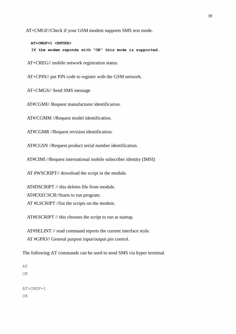
AT+CMGF//Check if your GSM modem supports SMS text mode.
AT+CMGF=1 <ENTER>
If the modem reponds with "OK" this mode is supported.
AT+CREG// mobile network registration status.
AT+CPIN// put PIN code to register with the GSM network.
AT+CMGS// Send SMS message
AT#CGMI// Request manufacturer identification.
AT#/CGMM //Request model identification.
AT#CGMR //Request revision identification.
AT#CGSN //Request product serial number identification.
AT#CIMI //Request international mobile subscriber identity (IMSI)
AT #WSCRIPT// download the script in the module.
AT#DSCRIPT // this deletes file from module.
AT#EXECSCR//Starts to run program.
AT #LSCRIPT //list the scripts on the modem.
AT#ESCRIPT // this chooses the script to run at startup.
AT#SELINT // read command reports the current interface style.
AT #GPIO// Genreal purpost input/output pin control.
The following AT commands can be used to send SMS via hyper terminal.
AT
OK
AT+CMGF=1
OK

40
AT+CSCA="number of message centre"
OK
AT+CMGW="Mobile number"
> A simple demo of SMS text messaging. (When finished, press Ctrl+z of
the keyboard.)
+CMGW: 1 (note this number)
OK
AT+CMSS=1 (the number is from returned value of CMGW)
+CMSS: 20
OK
If an OK is received then the SMS was sent successfully.
The default behavior is to always send SMS using the CS domain but it is possible to send SMS
over PS domain. This is sometimes used by data cards that have not implemented the complete
functionality of CS domain. To send SMS over PS domain, the following AT command is required.
AT+cgsms=0
where
0 = PS Domain
1 = CS Domain
2 = PS Domain preferred (else use CS Domain if GPRS not available)
3 = CS Domain preferred (else use PS Domain if CS is not available)
If you use AT+cgsms=0 and if the SGSN is not configured for SMS then the sending of SMS will
fail and the UE will resend the SMS automatically using CS Domain.

41
6. LM555 Monostable Circuits
In the actual experiments, a LM555 monostable timer circuit and Schmitt trigger were needed.
LM555 produces one pulse of a set length (time period T). Fig 20 shows the LM555 Timer Internal
circuit block diagram.
Figure 20 LM555 Timer Internal Circuit Block Diagram
In order to get the time period T=10S, It is essential to design a circuit. The circuit diagram of 555
monostable circuit is given in Fig 21. The resistor value R and the capacitor value C are unspecified.
The values of these components determine the length of time.

42
Figure 21. 555 monostable Circuit given in my experiment

43
7. Test and Analysis
7.1 Test for Shock Sensor
When shock has happened, after connected with LM555 Monostable circuit and Schmitt trigger
circuit, it is possible to read the signal in oscilloscope (shows in Fig 22).
Figure 22. Shock signal in oscilloscope
7.2 Test for Sending SMS through GSM modem
In general, there are two ways to send SMS messages from a computer to a mobile phone:
1. Connect a mobile phone or GSM/GPRS modem to a computer. Then use the computer and
AT commands to instruct GSM/GPRS modem to send SMS messages.
2. Connect the computer to the SMS center (SMSC) or SMS gateway of a wireless carrier or
SMS service provider. Then send SMS messages using a protocol / interface supported by
the SMSC or SMS gateway.

44
As we seen in Fig 23, it possible to do port settings which will be the same as you did in the hyper
terminal and then click the OK button. If the modem is connected successfully, a message box will
appear with the message “Modem is connected”.
Figure 23. port setting in SMS application
Type "AT" in the main window. A response "OK" should be returned from the GSM
modem.
If “OK” returns, it means your modem is connected successfully.
After successful connection with PC, It could run this application. Download the attached project
and run the application. Table 5 lists the AT commands that are related to the receiving and reading
of SMS messages.
Now comes the hard part. When connecting to the device that is running Python code, it is possible
to see in Fig 24. It is also needed to give it time to startup and begin running.

45
Figure 24. GSM modem is running python code
Table 5 commands that are related to the receiving and reading of SMS
AT command Meaning
+CNMI New message indications
+CMGL List messages
+CMGR Read messages
+CNMA New message acknowledgement
Below shows a simple example that demonstrates how to use AT commands and the
HyperTerminal program of Microsoft Windows to read SMS text messages received by a GSM
modem. The lines in bold type are the command lines that should be entered in HyperTerminal. The
other lines are responses returned from the GSM modem.

46
AT
OK
AT+CMGF=1
OK
AT+CMGL="ALL"
+CMGL: 1,"REC READ"," +358466440535 ",,"10/1/11,00:30:29+32"
+CMGL: 2,"REC READ"," +358466440535 ",,"10/1/11,00:32:20+32"
OK
Line 3: The AT command +CMGF is used to instruct the GSM modem to operate in SMS text
mode. The result code "OK" is indicates the command line "AT+CMGF=1" has been executed
successfully. If the result code "ERROR" is returned, it is likely that the GSM modem does not
support the SMS text mode. To confirm, type "AT+CMGF=?" in the HyperTerminal program. If
the response is "+CMGF: (0,1)" (0=PDU mode and 1=text mode), then SMS text mode is supported.
If the response is "+CMGF: (0)", then SMS text mode is not supported.
7.3 Analysis
In this actual experiment, a lot of actual practice difficulties were solved. Like interfaces between
EZ10 and Shock sensor, power supply for different devices, sensitivity of the python language,
designing the timer circuit and so on.
Firstly, I choose some possible shock sensors and understand how they work. And then, choose
piezoelectric ceramic one for this experiment. The shock signal is too short so the EZ10 modem
cannot read the digital signal. It is essential to design a timer circuit. I connected with LM555
Monostable circuit and Schmitt trigger circuit, then it is possible to get the suitable shock signal.
The shock sensor is working.
Secondly, it is the software python code. The python code for this final year project has two parts,
the first part is to read the signal and the other part is to send SMS, there are some errors in python
code of the reading part, the sending SMS part is working. Due to the actual practice ability and
time, this experiment is half finished. This experiment still needs some modifications to be done in

47
the python code. If this experiments continue to be done some deep research. This remote shock
monitoring device could be put into use in the future. Besides, the remote control together with GPS
is very popular.
During the last few months, I read materials and the knowledge related on sensor technology, shock
sensor, piezoelectric ceramic characterics and applications, GSM modem and so on. This will be
very helpful for my future study.
48
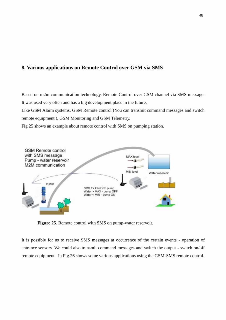
8. Various applications on Remote Control over GSM via SMS
Based on m2m communication technology. Remote Control over GSM channel via SMS message.
It was used very often and has a big development place in the future.
Like GSM Alarm systems, GSM Remote control (You can transmit command messages and switch
remote equipment ), GSM Monitoring and GSM Telemetry.
Fig 25 shows an example about remote control with SMS on pumping station.
Figure 25. Remote control with SMS on pump-water reservoir.
It is possible for us to receive SMS messages at occurrence of the certain events - operation of
entrance sensors. We could also transmit command messages and switch the output - switch on/off
remote equipment. In Fig.26 shows some various applications using the GSM-SMS remote control.

49
Figure 26. Some various applications about GSM-SMS remote control.

50
9. Conclusion
I spent several months on this final year work, a lot of knowledge and skills to understand. I studied
things about different kinds of shock sensor technologies, piezoelectric ceramic characterics, python
programming and AT commands. I made a half-finished python code for reading the sensor (digital
input) and sending the SMS message through GSM mobile communication technology. The code
needs some modifications and if that is done, it could be put into use in the future. If have a chance,
I will continue to study in this field.
Being an undergraduate of Information Technology, this project provided me a good opportunity to
study and improve my professional knowledge. It made me understand more about remote alarm,
remote monitor system and know more ways about mobile technology applications. This will be
very helpful for my future study and job career.

51
REFERENCES
[1] What is Sensor Technology? December 2010[on-line]
http://en.wikipedia.org/wiki/Sensor
[2] MEMS application overview. March 2011 [on-line pdf]
http://www.scme-nm.org/ scme_2009/MEMS_Application_LM_PG_.pdf
http://w
[3] MEMS based sensor technology. December 2010[on-line]
http://www.freescale.com/webapp/sps/site/overview.jsp?code=SNSMEMSOVERVIEW
[4] Application Field of Sensor Technology. December 2010[on-line]
http://www.sensorelement.com/shock-sensor.htm
[5] MEMS sensors application to Auto key parts in China. December 2010[on-line]
http://www.researchinchina.com/Report/ShowReport.aspx?id=5717&date=2009
[6] The Shock Sensor in car alarm system. March 2011[on-line]
http://caralarmexpres.com/
[7] The Application Field of Shock Sensors. March 2011[on-line]
http://www.faultwire.com/solutions-application/Shock-Sensor-Utility-Settings-*4630.html
[8] Piezoelectric Ceramic shock sensors. December 2010[on-line pdf]
http://www.symmetron.ru/suppliers/murata/sensors/p19e6.pdf
[9] Piezoelectric Ceramic characteristics. January 2011[on-line pdf]
http://www.noliac.com/Files/Billeder/02%20Standard/Ceramics _datasheet.pdf
[10] What is GSM Modem, January 2011 [on-line]
http://www.ehow.com/how_7226225_send-messages-via-gsm-modem.html
[11] What is GPRS Modem. Januray 2011[on-line]
http://www.developershome.com/sms/GSMModemIntro.asp

52
[12] Telit EZ-10 GPS GSM Terminal. January 2011[on-line]
http://www.trademe.co.nz/Electronics-photography/Other-electronics/Other/auction-297419404.htm
[13] EZ-10 GPS PY Terminal. January [online PDF]
http://www.gatetel.com/PDF/EZ10GPS/HWEZ10GPS.pdf
[14] GM862 Quad PY GPS product description, [online PDF]
http://www.m2m-platforms.com/data/Telit_GM862-QUAD-PY-GPS_Product_Description_r7.pdf
[15] Telit Easy script in python interpreter. January 2011[online PDF]
http://www.m2m-platforms.com/Python/Telit_Easy_script_Python_80000ST10020a_r1.pdf
[16] Telit Easy Script python -M2M Platform. January 2011[online-PDF]
http://www.m2m-platforms.com/seminars/2007seminar_material
[17] Telit AT commands Reference Guide. January [online PDF]
http://www.m2m-platforms.com/data/Telit_AT_Commands_Reference_Guide_r5.pdf
[18] How to send an SMS by GSM modem. January 2011[online HTML]
http://www.ehow.com/how_7226342_send-sms-gsm-modem.html
[19] Application about Remote Control over GSM via SMS. February 2011 [on-line]
http://www.bieneelectronics.com/products/br_application2.htm
[20] Wireless Modem. March 2011 [on-line]
http://www.engineersgarage.com/articles/gsm-gprs-modules

53
APPENDICES
A.1 Installing of python
Download and get the python Win package 1.5.2+ with the latest version Telit PY
1.5.2+_V3.0.exe.The installation conditions the Python compiler package. The Telit Python
package is placed in the folder C:\programme files\python\.The correct path in the windows
Environmental variables will be set up automatically.

54
A.2 python implementation description
Python scripts are text files stored in NVM inside the Telit module. There is a file system inside the
module that allows writing and reading files with different names on one single level.
It is possible to run only one python script at the time. The python script is executed in a task inside
the Telit module at the lowest priority, making sure this does not interfere with GSM/GPRS normal
operations. This allows serial ports, protocol stack, etc. to run independently from the python script.
The python script interacts with the Telit module functionality through four build-in interfaces
Note: Antenna GPS, GPS receiver and GPS library are available exclusively for GPS modules
GM862-GPS and GM863-GPS. Moreover SER2 library cannot be used by the GPS modules since
their TRACE port is not available.
55
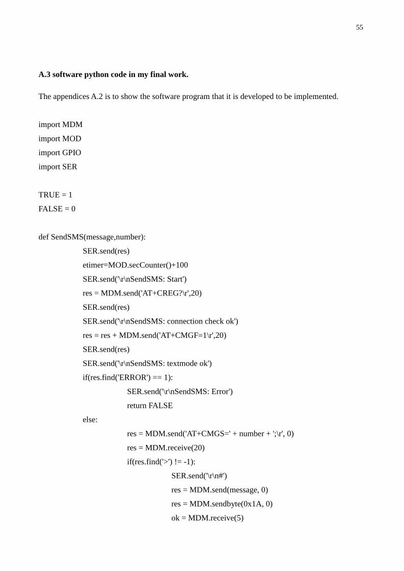
A.3 software python code in my final work.
The appendices A.2 is to show the software program that it is developed to be implemented.
import MDM
import MOD
import GPIO
import SER
TRUE = 1
FALSE = 0
def SendSMS(message,number):
SER.send(res)
etimer=MOD.secCounter()+100
SER.send('\r\nSendSMS: Start')
res = MDM.send('AT+CREG?\r',20)
SER.send(res)
SER.send('\r\nSendSMS: connection check ok')
res = res + MDM.send('AT+CMGF=1\r',20)
SER.send(res)
SER.send('\r\nSendSMS: textmode ok')
if(res.find('ERROR') == 1):
SER.send('\r\nSendSMS: Error')
return FALSE
else:
res = MDM.send('AT+CMGS=' + number + ';\r', 0)
res = MDM.receive(20)
if(res.find('>') != -1):
SER.send('\r\n#')
res = MDM.send(message, 0)
res = MDM.sendbyte(0x1A, 0)
ok = MDM.receive(5)

56
while((ok.find('+CMGS:') == -1 and ok.find('ERROR') ==
-1) and (MOD.secCounter() < etimer)):
res = MDM.receive(5)
ok = ok + res
SER.send('#')
if(ok.find('+CMGS:') != -1):
SER.send('\r\nSendSMS: OK')
return TRUE
elif(ok.find('ERROR') != -1):
SER.send('\r\nSendSMS: Error 2')
return FALSE
else:
SER.send('\r\nSendSMS: Error?')
return FALSE
else:
SER.send('\r\nSendSMS: Error 3')
return FALSE
return FALSE
def main():
SER.set_speed('115200')
SSstate = FALSE;
ShockAlarm = FALSE;
ShockAlarmSent = FALSE;
SER.send('\r\nSER connection initialized!\r\n')
while 1 == 1:
SER.send('\r\nMAIN-LOOP!')
SER.send('\r\nBEFORE SLEEP!')
MOD.sleep(100)
#sleep for 10s
SER.send('\r\nafter SLEEP!')
#SSstate = GPIO.getIOvalue(5) # read state of
GPIO 5
SSstate = TRUE
SER.send('\r\nafter gpio getvalue')

57
SSstate = int(SSstate) #
convert to integger
SER.send('\r\nafter gpio value conversion to int')
if ((SSstate == TRUE) | (ShockAlarm == TRUE)): #i
(shockSensorState OR ShockAlarm)
ShockAlarm == TRUE #
sets ShockAlarm to true
SER.send('\r\nSHOCK\r\n') #
prints text SHOCK to terminal
ShockAlarmSent=SendSMS('my message is
something...','0466440535') #sends text message to masternumber
if ShockAlarmSent == TRUE: # if ShockAlarm
was sent..
ShockAlarm == FALSE # reset
ShockAlarm to false

58