Master's Thesis Simulation Aided Product Software ... - Theseus
64
Tampere University of Applied Sciences Degree Programme in Information Technology, Master’s Degree Jani Hyvönen B.Sc Master’s Thesis Simulation Aided Product Software Development Supervisor Senior Lecturer, Software Engineering, M.Sc. ( Eng. ), Jari Mikkolainen Commissioned by Senior Manager, Member of the CEO Technology Council, PhD (Computing), Tero Rissa Tampere 4/2010
-
Upload
khangminh22 -
Category
Documents
-
view
0 -
download
0
Transcript of Master's Thesis Simulation Aided Product Software ... - Theseus

Tampere University of Applied Sciences Degree Programme in Information Technology, Master’s Degree Jani Hyvönen B.Sc Master’s Thesis Simulation Aided Product Software Development Supervisor Senior Lecturer, Software Engineering, M.Sc. ( Eng. ), Jari
Mikkolainen Commissioned by Senior Manager, Member of the CEO Technology Council,
PhD (Computing), Tero Rissa Tampere 4/2010
Tampere University of Applied Sciences Degree Programme in Information Technology, Master’s Degree Author(s) Jani Hyvönen Name of the report Simulation Aided Product Software Development Number of pages Graduation time Thesis supervisor Mikkolainen Jari Commissioned by Rissa Tero, Nokia Oyj ABSTRACT This work is a study of simulation environments as tools for product software development from architecture definition phase to testing the actual end product software code. The purpose of the work was to find a feasible way to utilize simulation environments for improving product time to market. The work was initiated to renew the existing simulation methods to correspond the demands of the present-day process of developing products. Work effort mainly consisted of studying the existing environments, understanding the lessons learnt, finding a proper architectural approach for a new design and implementing it to the system as proof of concept. Work context is Symbian OS even though most of the findings can be used in other operating system contexts as well. The main outcome of the work introduces a three-phase method for developing product software by utilizing simulation environments. Based on the outcome, a MCP (Major Contribution Proposal) for developing SHAI SDK (Symbian Hardware Abstraction Interface Software Development Kit) was issued to Symbian Foundation. Another concrete outcome of the work was an internal software development environment for client company using QEMU based simulation environment. Simulation environment abstraction level study and related proof of concept implementation using QEMU can be regarded as outcomes of this work as well. The results of the work can be used in the future simulation aided software development by the client company. In the short term, the results of this work will be visible in Symbian Foundation SHAI SDK tool. The following effort to continue this work is to implement the proposed approach, to verify the implementation and make the possible changes found necessary to create a working simulation based software development environment. Keywords Simulation, software development, QEMU, SHAI SDK

Tampereen Ammattikorkeakoulu Degree Programme in Information Technology, Master’s Degree Kirjoittaja Jani Hyvönen Työn nimi Simulation Aided Product Software Development Sivujen lukumäärä Valmistumisajankohta Työn valvoja Mikkolainen Jari Toimeksiantaja Rissa Tero, Nokia Oyj TIIVISTELMÄ Tämä työ tutki simuloitujen ympäristöjen käyttöä apuna tuoteohjelmistokoodin kehitysprosessissa. Soveltuvuus ohjelmistokehitystyökaluksi tutkittiin koko kehitysprosessin alueelta, arkkitehtuurin määrittelyvaiheesta toteutuksen testaamiseen. Työn tarkoitus oli löytää toteuttamiskelpoinen keino hyödyntää simuloituja ympäristöjä tuotekehityksessä päätavoitteina tuotteen ohjelmistokoodin kehitystyön aikaistaminen, tehostaminen ja kehitystyöhön käytetyn ajan lyhentäminen mahdollistamalla useampien työvaiheiden rinnakkaisuus. Tämä tutkimus tarvittiin nykyisellään käytettävien simulointimenetelmien uudistamiseksi vastaamaan nykypäivän tuoteohjelmistokoodin kehitysprosessien vaatimuksiin. Työ koostui suurilta osin nykyisiin simulaatioympäristöihin tutustumisesta, nykyisissä simulaatioympäristöissä tehtyjen virheiden ja oivalluksien ymmärtämisestä, uuden toteuttamiskelpoisen arkkitehtuurin määrittämisestä ja sen toteuttamiskelpoisuuden tarkistamisesta esimerkkitoteutuksin. Työ keskittyy Symbian käyttöjärjestelmään. Suuri osa oivalluksista voidaan käyttää hyödyksi myös muiden ohjelmistoympäristöjen kehityksessä. Työn tärkein tulos esittelee simuloitujen ympäristöjen avulla toteutettavan kolmivaiheisen menetelmän tuoteohjelmistokoodin kehitykseen. Edellämainittuun menetelmään perustuva MCP (Major Contribution Proposal) SHAI SDKn (Symbian Hardware Abstraction Interface Software Development Kit) kehittämiseksi esitettiin Symbian Foundation yhteisölle. Lisäksi työn sivutuotteena työn tilaajalle valmistui QEMU simulaatiotyökaluun perustuva ohjelmistokehitysympäristö. Lisäksi työn tuloksina voidaan mainita simulaatioympäristöjen abstraktiotasoihin liittyvä tutkielma, sekä tutkielmaan perustuvan arkkitehtuurin toteuttamiskelpoisuuden tarkistamisen yhteydessä tehdyt esimerkkitoteutukset. Työn tuloksia voidaan käyttää simulaatioympäristöjen, sekä simulaatioympäristöjen avulla tehtävän tuoteohjelmistokoodin kehitykseen tulevaisuudessa. Lyhyellä aikavälillä työn tulokset ovat nähtävissä Symbian Foundation SHAI SDK työkalussa. Tämän työn jälkeen tapahtuva jatkokehitys sisältää seuraavat pääkohdat: Ehdotetun menetelmän toteuttaminen, toteutuksen soveltuvuuden testaaminen ja testauksessa huomattujen puutteiden ja epäkohtien korjaaminen alkuperäiseen ehdotettuun menetelmään käyttökelpoisen simulaatioavusteisen ohjelmistokehitysympäristön ja prosessin aikaansaamiseksi. Avainsanat Simulation, software development, QEMU, SHAI SDK

Foreword
The topic of this work commissioned is to consider simulation model abstraction levels in general in different phases of product software development while creating a high level technical description of a simulation based software development environment. The work itself contained a lot of documentation and communication effort by its nature. The study work related to simulation model abstraction contained a lot of communication with professionals of different areas (simulation, software development, software integration, etc.). Explaining problems was easier by creating a figure which illustrated the problem in question. Most of the figures and the text in this document are created during this kind of communication work. Most of the text created and the models implemented in the scope of the work are being used by Nokia and by Symbian Foundation while finalizing this report. This thesis now gathers together the bits and pieces I have documented and implemented in the context of the thesis during the second half of 2009 and the first quarter of 2010. I thank the representative of commissioning company (Nokia Oyj), Tero Rissa, for sharing his thoughts in the field of simulation and for the inspiring discussions on the topic “where should this red dotted line reside in our simulated system”. The “red dotted line” is the layer of abstraction the reader will get familiar with later on in this document. I thank the Nokia Oyj virtual platform team members I am still working with while writing this document. I also want to thank all the other people I have worked with in the scope of creation work of this thesis. Tampere April 2010 Jani Hyvönen

TAMK University of Applied Sciences Degree Programme in Information Technology, Master’s Degree
Table of Contents 1 Introduction...................................................................................................................8
2 The Concept of Simulation Abstraction ........................................................................9 2.1 Virtualization Abstraction Layer (VAL) .................................................................................9 2.2 Virtual System Model (VSM)................................................................................................9
2.2.1 Determining VAL for VSM...........................................................................................9 2.2.2 Determining the functional completeness for VSM...................................................12
2.3 Abstraction perspective to model qualifiers .......................................................................13 2.3.1 Model usability ..........................................................................................................13 2.3.2 Model reusability.......................................................................................................14 2.3.3 Model expandability ..................................................................................................16 2.3.4 Model maintainability ................................................................................................16 2.3.5 Model accuracy.........................................................................................................16 2.3.6 Model availability ......................................................................................................19
2.4 An Evaluation example of two VSMs having different VAL approaches ...........................19
3 Simulation based software development in phases ...................................................24 3.1 Development environment design work.............................................................................24 3.2 Phase 1 – Creating a feature.............................................................................................25 3.3 Phase 2 – Implementing hardware abstraction .................................................................25 3.4 Phase 3 – Validation on hardware.....................................................................................27
4 Simulation model approach for developing peripheral device drivers ........................28 4.1 SHAI SDK ..........................................................................................................................29
4.1.1 SHAI SDK in brief .....................................................................................................29 4.1.2 SHAI SDK necessity .................................................................................................29
4.2 Device Driver environment.................................................................................................29 4.3 A proposal for the simulation approach .............................................................................33
4.3.1 Virtual system model in brief.....................................................................................36 4.4 Features needed to establish a device driver development environment .........................39
4.4.1 General features .......................................................................................................40 4.4.2 Software environment features.................................................................................40 4.4.3 Simulator features.....................................................................................................43 4.4.4 Tools and documentation .........................................................................................44
5 Summary ....................................................................................................................46
References ....................................................................................................................47
Appendices....................................................................................................................48 Appendix 1: SHAI SDK requirements ........................................................................................1
List of abbreviations and terms
API Application Programming Interface
ARM Advanced RISC Machine
CCI Camera Control Interface
CPU Central Processing Unit
DMA Direct Memory Access
GPIO General Purpose Input Output
GPS Global Positioning System
HAI Hardware Abstraction Interface
HDL Hardware Description Language
HPV Hardware Programmers View
HW Hardware
I2C Inter-Integrated Circuit
I2S Integrated Interchip Sound
IDE Integrated Development Environment
IPR Intellectual Property Right
L2 Cache Layer 2 cache
MHA Modular Hardware Abstraction
MIPI Mobile Industry Processor Interface
MW Middleware
OS Operating System
OST Open System Trace
PDK Platform Development Kit (What are the kits? 2010)
PV Programmers View
QEMU Open source processor emulator (Fabrice Bellard 2010, QEMU)
QEMU Syborg Symbian virtual board model based on QEMU (Syborg & QEMU
2010)
Qt A cross-platform application and UI framework
RISC Reduced Instruction Set Computer
RTC Real Time Clock
SHAI SDK Symbian Hardware Abstraction Interface Software Development Kit
SLIMbus Serial Low-power Inter-chip Media Bus
SMP Symmetric MultiProcessing
SPI Serial Peripheral Interface bus
SW Software

UniPro Unified Protocol
USB Universal Serial Bus
VAL Virtualization Abstraction Layer
VP Virtual Platform / Virtual Prototype
VSM Virtual System Model
WRT Web Runtime

1 Introduction
The aim of this work is to provide an approach to a simulation model based software
development process as well as to define rules on how to select the suitable simulation
model architecture for the purpose.
The first section of this document considers the concept of abstraction of simulation
environments used in the scope of this document. It is important for the reader to
familiarize himself with the first section before entering the rest of the document.
The second section of this document introduces the reader to a three-phase approach of
embedded system software development. It shows in rough level how software
development of a system feature can be divided to phases starting from the architecture
definition and ending to validation on real hardware.
The third section of this document uses the three-phase approach in practise and defines
a simulation model based software development environment for developing hardware
abstraction layer specific software.
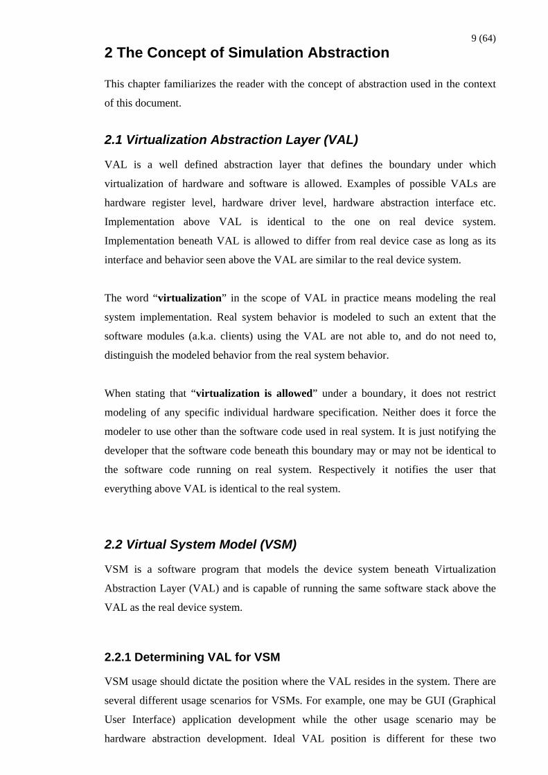
9 (64) 2 The Concept of Simulation Abstraction
This chapter familiarizes the reader with the concept of abstraction used in the context
of this document.
2.1 Virtualization Abstraction Layer (VAL)
VAL is a well defined abstraction layer that defines the boundary under which
virtualization of hardware and software is allowed. Examples of possible VALs are
hardware register level, hardware driver level, hardware abstraction interface etc.
Implementation above VAL is identical to the one on real device system.
Implementation beneath VAL is allowed to differ from real device case as long as its
interface and behavior seen above the VAL are similar to the real device system.
The word “virtualization” in the scope of VAL in practice means modeling the real
system implementation. Real system behavior is modeled to such an extent that the
software modules (a.k.a. clients) using the VAL are not able to, and do not need to,
distinguish the modeled behavior from the real system behavior.
When stating that “virtualization is allowed” under a boundary, it does not restrict
modeling of any specific individual hardware specification. Neither does it force the
modeler to use other than the software code used in real system. It is just notifying the
developer that the software code beneath this boundary may or may not be identical to
the software code running on real system. Respectively it notifies the user that
everything above VAL is identical to the real system.
2.2 Virtual System Model (VSM)
VSM is a software program that models the device system beneath Virtualization
Abstraction Layer (VAL) and is capable of running the same software stack above the
VAL as the real device system.
2.2.1 Determining VAL for VSM
VSM usage should dictate the position where the VAL resides in the system. There are
several different usage scenarios for VSMs. For example, one may be GUI (Graphical
User Interface) application development while the other usage scenario may be
hardware abstraction development. Ideal VAL position is different for these two

10 (64) example use cases. The process of selecting the right VAL for a VSM should always be
initiated by determining the VSM usage scenario, and by listing the features needed by
the VSM users.
Application software code is usually allowed to access only relatively high level APIs
(Applications 1, 2, 3 and 4 in the Figure 1). Application developers are interested in
using the system services abstracted with high level APIs and providing services to
device end-user in human understandable and easy to use form. As users of VSM the
application developers are interested in having the same level of system services
available as there will be in forthcoming hardware device. Application developers want
to have those services executed on the model with speed not slower than a real hardware
would provide. When the target of the VSM is to enable development for applications
(Applications 2 and 3 in the Figure 1) which are using a cross-platform programming
framework such as Qt (Qt 2010), WRT (Web Runtime (WRT) Quick Start 2010) and
Java, it is the API (or layer) provided by the programming framework and seen by the
applications which should be chosen as VAL. While providing cross-platform APIs this
type of VSM does not need to provide instruction set emulation but instead the client
applications can be compiled to and run on host computer instruction set.
MW (Middleware) and OS layer software code provide the application developers with
high abstraction APIs of the system services. If the application to be developed is using
APIs provided by MW and OS (Applications 1, 4 and cross platform programming
framework in the Figure 1) it is in most of the cases most straightforward to include the
generic part of the OS software code to model and specify the VAL interface to be the
same as hardware abstraction interface. While having the OS running on VSM, it
becomes as obvious solution to run the VSM on virtual machine which implements the
required processor and instruction set emulation.
MW and OS (Figure 1) developers need to have the hardware abstraction APIs and
accurate enough processor and instruction set model available to implement and run
their software code. Hardware abstraction software code, for example hardware drivers,
accesses hardware and abstracts the hardware complexity from MW and OS.
Hardware adaptation developers are interested in mapping the hardware adaptation API
calls to hardware register and system service accesses. The modeled system in which
the VAL is defined to be at hardware register level is a special case of VSM. This type
of VSM is often called as PV (Programmers View) type of a Virtual Platform (or of a

11 (64) Virtual Prototype). This type of a VSM is mainly used in hardware adaptation, such as
hardware drivers, development. If the model is planned to be used only for developing
hardware adaptation software code for specific hardware it make sense to choose
hardware – software boundary as VAL i.e. modeling the hardware register interface and
the functionality beneath according to a hardware specification.
Figure 1: A high level architectural view to a system for which there is a need to
develop software by means of VSM.
Sometimes the same VSM should act as a “jack of all trades” enabling as efficient
software development as possible at each layer of the software stack including OS layer.
For this type of VSM the VAL should probably reside somewhere within the software
stack where the generic, platform independent, code is turning into platform specific i.e.
hardware abstraction interface.
Having VAL higher than software – hardware boundary does not prevent from using
the same VSM in hardware specific software development. To enable hardware specific
software development one just needs to replace the modeled functionality below VAL
with the services available in real system. Such services include, for example, accurate

12 (64) enough hardware register level model, generic (for example OS specific) software
layers and the interfaces the hardware specific software is using.
A system often consists of several vertical subsystems (Figure 2). Vertical subsystem
consists of software and hardware layers which together form a complete functionality,
for example camera functionality could consist of camera application, camera
middleware, camera driver and the camera related hardware. When modeled, each of
these vertical subsystems will have a VAL. It is not mandatory to have the VAL at the
same layer of architecture, for example, hardware abstraction layer (subsystem 4 and 5
in Figure 2) for each subsystem. One approach would be to consider the position of the
VAL for each subsystem separately by taking into account the expected use cases,
dependencies to and from other subsystems (subsystem 3 hardware adaptation has
dependency to subsystem 4 OS & MW in Figure 2), expected work load for
implementation and maintenance, model life cycle, etc. VAL is selected for each
subsystem in a way the models based on the selection implements satisfactory level of
usability, reusability, expandability, maintainability, accuracy and availability.
2.2.2 Determining the functional completeness for VSM
Virtualized implementation beneath VAL should serve the planned development of
software layers above VAL at least as efficiently as an exact system model would serve.
Exact system model in this scope would be a complete software stack, identical to the
one eventually running on real hardware, running on accurate hardware model.
It is to be decided case by case how detailed the virtualized functionality should be. For
an example of very simple functionality, the model beneath VAL may just return a
value known to make the client software happy (subsystem 1 in Figure 2) without
processing the possible client input (for example function call parameters) and without
checking the current state of the rest of the system. As an example of very detailed
model functionality, the model may mimic the complete functionality described in a
hardware specification (subsystem 3 in Figure 2).
The modeled (virtualized) functionality may take advantage of host system services. For
example graphics acceleration, Bluetooth and WLAN client applications are calling
APIs as they would when running on real system, but beneath VAL these calls are
translated into host system service calls (subsystem 2 in Figure 2). It is to be noticed
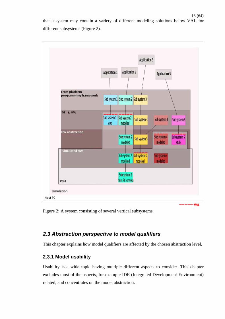
13 (64) that a system may contain a variety of different modeling solutions below VAL for
different subsystems (Figure 2).
Figure 2: A system consisting of several vertical subsystems.
2.3 Abstraction perspective to model qualifiers
This chapter explains how model qualifiers are affected by the chosen abstraction level.
2.3.1 Model usability
Usability is a wide topic having multiple different aspects to consider. This chapter
excludes most of the aspects, for example IDE (Integrated Development Environment)
related, and concentrates on the model abstraction.

14 (64) Execution speed is often considered as a synonym for usability among software
developers. Increase in execution time increases the time consumed in one development
cycle: write code – compile - run the code – debug – write code. By making the right
modeling decisions one can gain best possible execution speed while still providing the
APIs and the behavior developers need in their work. Choosing the right VAL and
using the host system services efficiently are in key role what comes to speed. The more
complicated and accurate model the slower the execution speed tends to be.
Efficient model debugging methods are essential when developers are trying to
determine what went wrong with their software. A feature where the model is able to
notify the user in informative way about illegal usage is desirable. The worst case is that
the model is ignoring an illegal usage and possibly causing erroneous behavior of the
system. It is sometimes hard to track down root causes later on for this kind of
erroneous behavior. In abstraction point of view gaining a usable debugging capability
requires that the protocol how the VAL should be used can not be abstracted. A good
example is the power management framework of a system when writing low level
software. If peripherals can be used without calling the power management to switch on
the peripheral under use the code will most probably not work on real hardware target.
A better rule for model designers is to enable the software developers, the users of the
model, to concentrate on the essential i.e. the software development. This is more about
out of the box design, templates, etc. In abstraction perspective this simply means that
the VAL and the surrounding implementation of the model should be set up in a way
the software development can start running their implementation on the model without
any additional tuning of the model.
2.3.2 Model reusability
One important aspect to take into account in modeling work is reusability. Actually
reusability is important aspect in all development work.
Model design should be modular in a way the functionalities of the model, let us call
them sub-modules, are atomic pieces of functionality with minimized dependencies to
other functionalities. These sub-modules, libraries for instance, can be individually
replaced or used in some other context. Models should be written with a widely
supported programming language. For example module written in ANSI C can be easily
adopted by most of the simulation tools in market. It can be wrapped by a layer of

15 (64) SystemC, VRE, Lisa, Python or whatever language the simulation tool happens to
support. The benefit in having this approach is to bring the model available for various
entities which may need it in some phase of the product development cycle. This aspect
is explained more in chapter 3 “Simulation based software development in three
phases”.
Choosing the right VAL is an essential factor of reusability if thinking the models life
cycle. For example, a hardware register level model makes sense when developing
hardware adaptation software. The approach of modeling at hardware register interface
level decreases the level of model reusability. VAL at register level does not necessarily
make the VSM completely useless in the reusability point of view, but the main usage
of the VSM should be carefully considered before selecting this option. If the main
target is to develop something above hardware adaptation interface the hardware
register level model does not make sense. Problems emerge when the hardware needs to
be updated to a new revision. Even more problems emerge if there is need to use
completely different hardware, such as in many cases when changing the ASIC vendor.
In addition complex hardware register level model requires a complex, and often error
prone, hardware adaptation software on top of it. Having the VAL specified as high
level as feasible i.e. to a level each development use case can be fulfilled will make the
model life cycle much longer. Hardware keeps changing under the hardware abstraction
interface but the OS features do not change that often. New OS features are introduced
but they are rarely affecting to the existing APIs. Cross platform programming
frameworks are the same case, new APIs are introduced but old ones remain long.
Backwards compatibility breaks are something not in favor of software developers.
Even the entities developing hardware register level models and related adaptation
software would probably benefit from having a VSM with VAL specified at hardware
abstraction interface level as starting point. They would be enabled running OS on top
of the model right from the beginning. It would be possible to add hardware register
level models and their adaptation software one at a time. It is always better to add small
functionality at a time rather than having the “big bang” integration effort with all the
related debugging when all the sub-modules are ready.

16 (64) 2.3.3 Model expandability
One may have a well-defined idea in the beginning what kind of usage there will be for
a model under development. It is highly probable though that the use cases of the model
will change or increase while the time goes by.
It is often the case that there becomes a need to expand the VSM. For example when
moving from a hardware generation to new one the existing sub-module functionality
may need to be expanded or totally new sub-modules may need to be added. The design
of the VSM is not expandable if there is major rework to existing content needed when
VSM is expanded, i.e. new functionality is added. The design is expandable when a
sub-module can be changed to a new revision or a totally new sub-module can be added
without the need to change and re-compile the existing content.
2.3.4 Model maintainability
Reusability and expandability together form the basis for maintainability. Well
documented, well structured and modular code is a key to gain maintainability.
2.3.5 Model accuracy
Accuracy is the magnitude which gives a level how far away from the real system case
the modeled solution is. When designing the level of accuracy for the model the
question “what kind of development are you going to use the model for?” should be
asked first.
From the definition of VAL one can conclude that hardware register level is the lowest
possible VAL. The level of accuracy can reach almost 100% of actual hardware when
using, as an example, simulation model generated from the same HDL as which is used
in hardware synthesis. Models generated form HDL are typically used in verifying the
hardware design before the hardware synthesis. This chapter is dealing with models
which are implemented before there is HDL or corresponding formal hardware
description available i.e. models are based on modelers interpretation of the
specifications.
Implementing hardware adaptation, such as device driver, requires a certain level of
accuracy from the model. Minimum accuracy requirements are that VAL needs to
reside at hardware – software boundary and the behavior of the model seen by the

17 (64) software is the same as the real hardware will have. Increasing accuracy from the
minimum requirements means bringing the behavior closer to real hardware behavior in
terms of items that are not specified by the hardware modules behavioral description.
Such items can be, for example, the way how hardware module is connected to and
interacting with its environment. The hardware module may, for example, have shared
DMA channel with some other hardware modules. This means in practice that there
may not be a DMA channel available immediately when adaptation software requests
the DMA channel. In another example it may take long time while a hardware module
completes its reset routines after enabling the power for the module. If model indicates
ready signal immediately after power enable the adaptation software developer may
forget to check the signal status before proceeding to use the hardware module. This
kind of situations needs to be handled properly by the adaptation software and it would
bring benefit to be able to simulate this kind of situations to implement and verify the
correct behavior of the adaptation software.
An example of an accuracy item which is affecting to the whole software stack
indirectly is L2 (Layer 2) cache. A L2 cache model implemented in a way it is just
enough to make the OS cache handling implementation happy would provide the cache
related registers interface but not more. OS believes it is using L2 cache while all the
memory reads and writes are issued straight to main memory. With this level of model
accuracy the L2 cache impact would not be seen by the software developer. For
example omitting cache flush operations in conjunction with DMA transfers would not
have the impact of possible memory corruption. As well with this level of accuracy it
would be impossible to measure the software implementation cache efficiency for
software optimization purpose.
The more accurate the model is the more mature the software will be, assuming that
modeled behavior is error free. Or in better words, the more different possible run time
scenarios the model is able to provide for the software developers the more mature the
software will be.
Increasing the number of details the model contains i.e. bringing the behavior closer to
real hardware increases the probability of errors in the modeled behavior. This is
derived from the fact that there will be more code involved in more accurate model. It is
also to be remembered that the more accurate the model is, the slower the simulation
will be.
18 (64) One issue of model accuracy at hardware register level is the possible usage of the
model after hardware arrival. It is often the case that hardware will have some delta to
the hardware specification. There can be several different causes for such a delta.
Erroneous interpretation of the specification, an error in hardware description code and
a missing implementation are examples of typical causes of the delta. hardware errors
lead to a situation where software written for model does not run correctly on hardware
and the model needs to either be changed to have the same erroneous behavior as
hardware does or there needs to be separate software branches for the model and for the
hardware. It is to be noted here that having a software implementation ready and
running on simulation may help in spotting hardware errors. In order to spot the
hardware errors it is important to inspect carefully the cases where hardware fails to run
the same software that runs correctly on simulation.
It would be safer to assume right from the beginning that the register level model will
never correspond 100% to the actual hardware but enables creating mature enough
reference implementation before hardware availability.
When specifying the VAL of the model to reside at higher level within the software
stack the accuracy rules apply as well. It is obvious that getting rid of the complexity of
hardware and its adaptation reduces the model accuracy. This approach clearly makes it
mandatory to treat the model as yet another reference platform without correspondence
to any specific hardware. As stated before, it is not forbidden to have subsystems with
several different VAL approaches in the system. For example a processor subsystem
could have VAL on the register interface level and accuracy making it possible to run
operating system which is configured and compiled for some specific processor
architecture version and instruction set. The rest of the subsystems could have VAL at
hardware abstraction interface level. This combination would enable processor specific
OS kernel implementation as well as generic software implementation for software
layers above the hardware abstraction interfaces. By adding more accuracy with, for
example, an accurate enough cache model to the combination will enable developing
more mature software. Mature in this case indicates that when having a cache modeled
the software developers are enabled to check the correct and efficient cache related
behavior of their implementation by running their software on top of the model and
studying how the cache behaves.
It is important to remember that when modeling something, the first level of accuracy
should be the fastest level that is just enough to make the software running on top of the
19 (64) model happy. Later on when increasing accuracy, the model should be made
configurable in a way user of the model can always, preferably just by for example
changing a configuration parameter before running the simulation, turn the accuracy
back to the fastest level.
2.3.6 Model availability
The intended audience for the model i.e. the entities expected to use the model for
software development should have unrestricted access to the model. If there is, for
example, hardware specific IPR which prevents delivering the hardware specific model
for each entity that is planned to develop software, it should be considered to create a
model which abstracts the hardware specific IPR. The high abstraction model can be
replaced with hardware specific model only for the entities which are creating hardware
specific software.
Model should be ready for use in time. As an example, a model may be needed for
creating future applications before there is any hardware specification available for such
a feature. In this case it should be possible to add a high abstraction model of the feature
to a VSM which provides all the needed interfaces and behavior for application
development.
2.4 An Evaluation example of two VSMs having different VAL approaches
The following chapter shows an exemplary comparison of two optional choices of
VSMs for Symbian having different VAL approaches. Pros and cons are listed for both
of the options.
The current VSM implementation proven to be outdated for current development tasks
is compared to both of the options as a reference.
The high level requirements for the new VSM are: Enable application development,
enable OS and MW development, enable hardware abstraction architecture
development, is available before ASIC specification availability and is able to run
binaries compiled for real hardware target processor architecture.

20 (64) Both of the new options implement hardware specification to an extent that makes it
possible to run the same compilation of software stack above the VAL as the real
hardware does. In practice this means modeling of processor architecture and
instruction set. Processor architecture specific details needs to be at the minimum
modeled just enough to make the processor architecture specific software happy.
Models processor emulation makes it possible to run the same instructions on model as
on real hardware.
To take advantage of existing simulation technologies and tools both of the options
implements hardware – software boundary. Details are given in following paragraphs.
First option for VAL for each subsystem is the hardware programmers view a.k.a.
hardware register level a.k.a. software – hardware boundary (Option 1 VAL in Figure
3). VSM based on this level represents a complete hardware specification including
processor architecture and ASIC specifications. Model looks and behaves as real
hardware does in software point of view. Software accesses the model as it accesses real
ASIC through memory mapped IO register address space. Registers layout and behavior
is implemented as stated by the ASIC specification. The basic idea of this VSM is to
enable running a complete and same software image on top of both the model and the
real hardware target. From now on in this document the first option is called as HPV
(Hardware Programmers View) model.
Second option for VAL for most of the subsystems is HAI (Hardware Abstraction
Interface) (Option 2 VAL in Figure 3). Note that in Symbian the term Hardware
Abstraction Layer HAL corresponds rather a communication method (among other
communication methods) of user mode and kernel mode code than a hardware
abstraction as it is commonly understood. Symbian specific HAI is referred as SHAI
(Symbian Hardware Abstraction Interface) (SHAI, 2010). VSM based on HAI level
does not represent complete hardware specification. Model emulates the processor
architecture and instruction set in a way the same compilation of the software above
VAL can be run on both the model and the real hardware target. Model does not
implement any individual ASIC specification (For example interrupt controller, DMA
controllers, bus controllers and various peripheral controllers are not following any
ASIC specification). By hiding the ASIC specific details the model can be regarded as
just another hardware platform hidden by the hardware abstraction interface. Software
accesses the model as it accesses the hardware abstraction interface on real hardware.
Hardware – software boundary is hidden by the hardware adaptation layer of software.
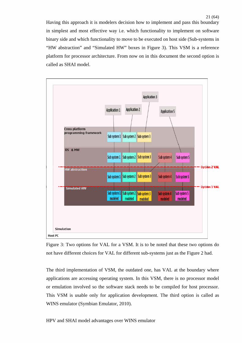
21 (64) Having this approach it is modelers decision how to implement and pass this boundary
in simplest and most effective way i.e. which functionality to implement on software
binary side and which functionality to move to be executed on host side (Sub-systems in
“HW abstraction” and “Simulated HW” boxes in Figure 3). This VSM is a reference
platform for processor architecture. From now on in this document the second option is
called as SHAI model.
Figure 3: Two options for VAL for a VSM. It is to be noted that these two options do
not have different choices for VAL for different sub-systems just as the Figure 2 had.
The third implementation of VSM, the outdated one, has VAL at the boundary where
applications are accessing operating system. In this VSM, there is no processor model
or emulation involved so the software stack needs to be compiled for host processor.
This VSM is usable only for application development. The third option is called as
WINS emulator (Symbian Emulator, 2010).
HPV and SHAI model advantages over WINS emulator

22 (64) • Enable to run binary which is compiled for real hardware target system, arm
architecture version 5 as an example.
• No need to maintain two set of binaries. One for PC x86 instruction set and
another for real hardware target system, for example ARM architecture version
5.
• No need for WINS specific software code maintenance.
• Enable OS and MW development.
• Enable hardware abstraction architecture development.
SHAI model pros over HPV model
• New features can be simulated much before there is hardware (ASIC)
specification available including the new feature. In fact, the model can be used
in specification work for new features.
• Enable modeler to find fastest (in performance and development effort vice)
possible combination of simulated functionality on host computer side and
SHAI implementation on Symbian OS side, still keeping the promises of SHAI
specification.
• New processor architecture (for example SMP) and instruction set can be tested
before there is hardware design available which includes the new architecture
and instruction set.
SHAI model cons
• Simulation model specific SHAI implementation involves additional effort to
implement and maintain.
HPV model pros over SHAI model
• Exactly the same image can be run on both the simulation model and the real
hardware target.
• Smaller probability to run into trouble when running the binary on real hardware
which is based on the same specification as the simulation model does. Taking
into consideration the fact that the implementation above SHAI should not have
timing related assumptions in optimal world this pro is not valid.
• Common adaptation software for both the simulation model and the actual
hardware. No need to maintain simulation specific adaptation.
HPV model cons
• Modeling can not be started before there is hardware specification available.
23 (64) o If it is OEM creating the model the vendor hardware specification may
not be available early enough to create a mature and accurate enough
simulation to gain benefit before hardware availability.
o Is it guaranteed that a vendor will provide usable enough simulation
model and the related SHAI implementation in time for all the parties
needing the simulation model?
• ASIC specific model require pretty complicated adaptation. This combination
tends to eat performance. It would be hard to gain a simulation speed level
suitable for all the stakeholders using simulation model.
• When the hardware become available there may be errors. There is a need to
model the same error to the simulation model in order to run the same SHAI
implementation or branch the simulation model specific SHAI implementation.

24 (64) 3 Simulation based software development in phases
This chapter introduces a phased approach to use simulation models in software
development. The approach is explained in form of an example (Figure 4). The example
is derived from the actual VSM design work made during creation of this document. It
is to be noted that the VAL position chosen for this environment is not the only possible
solution. As well it is to be noted that there can be several sub-phases within main
phases explained in this chapter.
3.1 Development environment design work
Before the first simulation based software development phase can be initiated there
needs to be development environment available including VSM as software execution
environment.
First step of design work for development environment is to gather a list of
requirements the development environment needs to fulfill. First high level sketch of
the requirements of the example in Figure 4 can be found from the chapter 4.4 “Features
needed to establish a device driver development environment”. The first set of actual
requirements formed from the high level sketch and gathered in the scope of the
example are sketched and listed in appendix 1.
The second step is to map the suitability of the possible existing development
environments to the new requirements. In the Figure 4 one can notice that there is a lot
of implementation ready in first phase VSM (the green area). In this example it was the
case that there was an existing simulation environment (Syborg & QEMU 2010) which
could be reused and expanded to fulfill the new requirements.
The first and the second steps described above need to be done only once when a
development environment is created. After the new development environment and basic
set of VSM features are created, for example, when creating an abstraction interface for
a new system feature, most of the environment already exists and there is only need to
expand the environment to cover the new features (red portions of phase 1 VSM in
Figure 4).

25 (64) 3.2 Phase 1 – Creating a feature
Phase 1 VAL in the example is set to hardware abstraction interface. The starting point
in the example is that a development environment is ready and a new feature is to be
introduced to the system. The hardware abstraction level of VSM enables developing a
suitable hardware abstraction interface for the new feature with all the functionalities
included. In practice, instead of developing a compliancy test suite for the new
hardware abstraction interface first (recommended way), it is often the case that upper
software layers are being developed hand in hand with the hardware abstraction
interface and the functionality below it. The test suite is often developed when there is
the first implementation ready for the abstraction interface. Let us use the recommended
way and as a first step create a design document for the hardware abstraction interface.
The second step is to create compliancy test for the interface. Compliancy test calls all
the possible combinations of the interface and checks the correct behavior of the
system. It is valuable also to call the interface methods in illegal way as well and check
that interface triggers to illegal calls correctly. While having the VAL at hardware
abstraction interface level it is possible and recommended at least in performance wise
to implement most of the feature functionality on host side (VSM host side in Figure 4).
The main idea of phase 1 is to enable software development for the whole software
chain up from the UI applications down to the phase 1 VAL. A feature can be
implemented for which there is only a high level sketch available. Moreover phase 1
type of VSM enables specifying and developing the features themselves. Phase 1
implementation above VAL including the abstraction interface test suite and actual
product software implementation together form the set of rules according to which the
phase 2 (or phase 3) implementation is done. In other words, when the phase 2 (or 3)
implementation works correctly and has the same behavior as phase 1 implementation
the implementation work for a feature implementation is completed. The phase 1
implementation below VAL can be regarded as behavioral specification for a feature.
3.3 Phase 2 – Implementing hardware abstraction
When phase 2 is initiated to implement a new feature the software layers above phase 1
VAL as well as compliancy test suite are available. For the software layers above phase
1 VAL the phase 2 is only a validation task, in the example for finding hardware
specific code leakage above phase 1 VAL. In the example the phase 2 requires an
accurate model of the forthcoming hardware which implements the new feature (HW

26 (64) model in Figure 4). In practice this means that VAL is set to software-hardware
boundary. In the example eventually the whole product software stack for the new
feature can be run on phase 2 VSM.
Model reusability plays a great role in phase 2. Let us assume the models created during
phase 1 are highly portable. For example, the core behavior of each model is created as
a standalone library that can be loaded and run on host operating system. A thin
simulation tool specific wrapper can be created for each model to adopt the model core
behavior (the library) to the system. By doing this the silicon vendors may use their
favorite simulation tool and still take full advantage of phase 1. By using the models
from phase 1 silicon vendors are enabled to run the whole software stack on their
simulation environment on early phase of their work. This is much before they have
implemented all the actual hardware models, and respective hardware abstraction
software, that they need in order to boot up the whole software stack. Integration gets
easier since vendor may replace phase 1 models and its hardware abstraction
implementation one by one with model representation of their actual hardware
specification and its abstraction implementation.
A proof of concept implementation for model reusability was created in the context of
the thesis work. During this implementation work a couple of stand alone libraries that
can be loaded and run on host operating system were adopted to a new simulation tool.
The libraries were created in context of another simulation tool environment. Libraries
represented Khronos OpenVG and EGL core behavior (QEMU Graphics Integration,
2010, Phase 3 – Step 1 – Basic enablers).
The main idea of the phase 2 is to enable software development up from the phase 1
VAL down to the phase 2 VAL by using the outcome of the phase 1. In the Figure 4
example the phase 2 is used for developing hardware abstraction implementation when
the hardware model for the new feature becomes available. When the behavior of the
phase 2 system corresponds to the behavior implemented in phase 1 a feature
implementation has completed. Phase 2 is mainly carried out by the silicon vendors who
are creating hardware abstraction implementation for their chipset. Phase 2 is optional
since all the tasks implemented during this phase can be carried out during phase 3 as
well. Carrying out phase 2 has some advantages just as earlier start for the hardware
abstraction implementation and as described above, if phase 1 models are efficiently
reused, easier adaption to a new chipset.
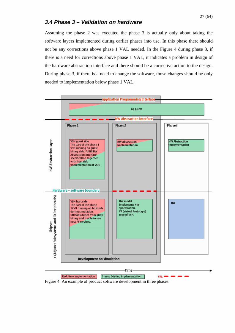
27 (64) 3.4 Phase 3 – Validation on hardware
Assuming the phase 2 was executed the phase 3 is actually only about taking the
software layers implemented during earlier phases into use. In this phase there should
not be any corrections above phase 1 VAL needed. In the Figure 4 during phase 3, if
there is a need for corrections above phase 1 VAL, it indicates a problem in design of
the hardware abstraction interface and there should be a corrective action to the design.
During phase 3, if there is a need to change the software, those changes should be only
needed to implementation below phase 1 VAL.
Figure 4: An example of product software development in three phases.

28 (64) 4 Simulation model approach for developing peripheral
device drivers
The development environment for which this chapter is originally written is briefly
introduced in “SHAI SDK” chapter. In chapter “Device Driver environment” the reader
is familiarized with an environment a device driver is running in. Chapter “A proposal
for the simulation approach” proposes a simulation approach for developing device
drivers. Chapter “Features needed to establish a device driver development
environment” considers device driver development environment features.
In the scope of this chapter when referring to “real system” it is the system(s) where the
device driver is targeted to be used after it is ready.
The chapter focuses on peripheral device driver development. Despite of this the
approach can also be used for the devices integrated in ASIC. The reason for focusing
on peripheral device development is the fact that ASIC vendors usually have their own
hardware accurate model prepared for hardware specific software development for the
devices residing in the ASIC. The ASIC vendors may, for example, want to use the
approach for developing their devices functionality and device drivers before there is a
complete enough ASIC simulation model available.
Simulation model in the context of this chapter is an executable model of a system
consisting of hardware and software. Executable in a sense that device driver software
can run in the simulated system as it runs in the real system. Simulation model may
have peripheral device hardware and models connected to it.
Device driver in the context of this chapter is the software module abstracting the
hardware specific details of one or more hardware items. Such hardware items are
peripherals, controllers, busses, clocks etc. There can be items just as camera, GPS
receiver, display, interrupt controller, DMA controller, I2C bus, RTC as an example.
The hardware items may reside in ASIC or they can be discrete components. Discrete
components or peripherals are either controlled with a bus or a controller in ASIC.
This chapter is written as generic as possible but still in context of Symbian OS.
Specific details, just as which simulation tool to use, are not listed by this chapter.

29 (64)
4.1 SHAI SDK
Symbian Hardware Abstraction Interface Software Development Kit in brief.
4.1.1 SHAI SDK in brief
“SHAI SDK is a development environment for creating SHAI compliant hardware. It
aims to provide Symbian HW ecosystem developers with straightforward and
productive PC -based toolset to achieve SHAI compliancy for wide selection of various
HW technologies. It enables the developers to run, test and debug a SHAI
implementation in an environment which looks like- and behaves similarly as in the
targeted HW environment.” (Hyvönen 2010, 3).
4.1.2 SHAI SDK necessity
“SHAI SDK enables validation of SHAI implementation and creation of SHAI
implementation prior to hardware platform availability. SHAI SDK can also be used for
purposes like SHAI API and SHAI compliancy test development.” (Hyvönen 2010, 3).
4.2 Device Driver environment
The device driver and its environment illustrated with highly simplified architectural
diagrams and their descriptions. The environment in which the device driver is running
is described. Device driver development environment should provide all the
compilation- and runtime services seen and used by the driver.
Environment consists of the software and the hardware system surrounding the device
driver. Device driver uses the surrounding system through the systems programming
interfaces. As well the device driver is used by the surrounding system through its own
programming interface.
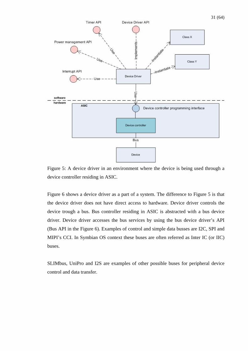
Figure 5 shows a device driver as a part of a system. The device driver is commonly
using several APIs that are provided by the surrounding system. APIs can be public
class methods which device driver is using by first instantiating the class and using the
services provided by the class via the instance (object of class X and Y in Figure 5).
Used APIs can as well be static methods provided by a class or exported methods from
a neighbouring binary (a DLL for example). Device drivers are often using services just
as interrupt framework (Interrupt API) for receiving interrupts from the device

30 (64) controller they are driving, power management framework (Power management API)
for requesting clock and power for their device, timer services (Timer API) for creating
timed events, and many more. The amount of APIs needed and used by the device
driver depends on how the device is integrated to the system.
Device Driver API in Figure 5 is specified well before implementing the device driver.
In Symbian OS context such an API is referred as SHAI (Symbian Hardware
Abstraction Interface) API. One important intention of the SHAI is to enable changing
the device and the driver without a need to change the software above the API.
The device controller programming interface in Figure 5 describes the interface through
which the device driver is accessing the hardware. A scenario in which the device driver
needs to access the hardware device’s memory mapped IO address space is the case
when there is a controller available in ASIC for controlling the device. Another scenario
would be that device itself is integrated in ASIC in addition to the controller.
The software space above the dotted line in Figure 5 presents kernel space. The API’s
and other services used by the device driver are referred as “kernel space services” in
the context of this chapter.
The hardware implementation below the device controller programming interface is
explained later in this document when dealing issues like how to connect a peripheral
device to simulation model.
31 (64)
Figure 5: A device driver in an environment where the device is being used through a
device controller residing in ASIC.
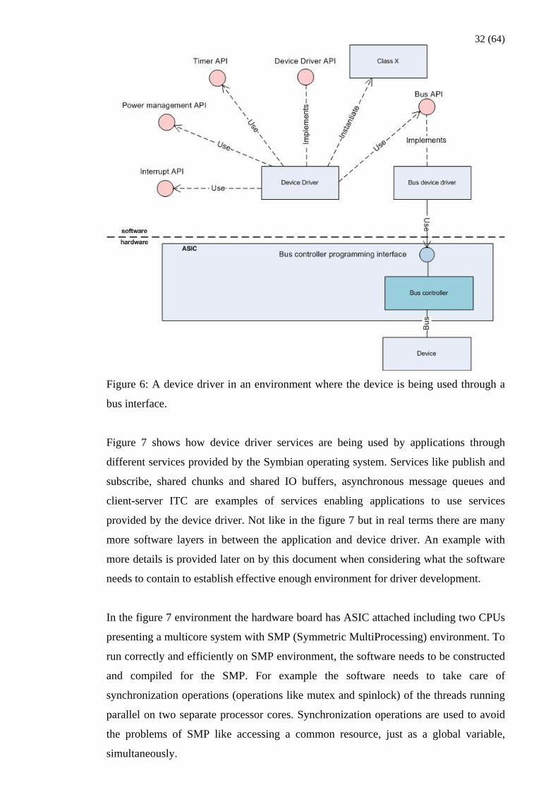
Figure 6 shows a device driver as a part of a system. The difference to Figure 5 is that
the device driver does not have direct access to hardware. Device driver controls the
device trough a bus. Bus controller residing in ASIC is abstracted with a bus device
driver. Device driver accesses the bus services by using the bus device driver’s API
(Bus API in the Figure 6). Examples of control and simple data busses are I2C, SPI and
MIPI’s CCI. In Symbian OS context these buses are often referred as Inter IC (or IIC)
buses.
SLIMbus, UniPro and I2S are examples of other possible buses for peripheral device
control and data transfer.
32 (64)
Figure 6: A device driver in an environment where the device is being used through a
bus interface.
Figure 7 shows how device driver services are being used by applications through
different services provided by the Symbian operating system. Services like publish and
subscribe, shared chunks and shared IO buffers, asynchronous message queues and
client-server ITC are examples of services enabling applications to use services
provided by the device driver. Not like in the figure 7 but in real terms there are many
more software layers in between the application and device driver. An example with
more details is provided later on by this document when considering what the software
needs to contain to establish effective enough environment for driver development.
In the figure 7 environment the hardware board has ASIC attached including two CPUs
presenting a multicore system with SMP (Symmetric MultiProcessing) environment. To
run correctly and efficiently on SMP environment, the software needs to be constructed
and compiled for the SMP. For example the software needs to take care of
synchronization operations (operations like mutex and spinlock) of the threads running
parallel on two separate processor cores. Synchronization operations are used to avoid
the problems of SMP like accessing a common resource, just as a global variable,
simultaneously.

33 (64)
Figure 7: A device driver as a part of the whole system
4.3 A proposal for the simulation approach
Simulation approach basic idea is to “make things earlier”.
Conventional approach for peripheral device driver development requires availability of
real system including the hardware board with ASIC and the peripheral integrated in it
as well as the device driver software environment running on top of the hardware.
Simulating the hardware makes it possible to start the device driver development before
the hardware availability.
Conventional hardware simulation model approach takes the complete hardware
specification as input and creates a hardware model based on the specification. Model
consists of the hardware programming interface and the behaviour beneath the interface.
ASIC specification needs to be available before the modelling work can be started.
After the model is ready the peripheral device driver software environment (ASIC
hardware adaptation) needs to be built up. When the hardware is ready it is likely that

34 (64) there is a need to change the model to mimic the hardware implementation
(specification interpretation, errors) to be able to run the same software on top of
hardware and model.
The proposal does not exclude the above mentioned conventional methods but includes
one more step to the picture. Approach target is to “make things earlier”. Approach
introduces a VSM (Virtual System Model). VSM implements the hardware
functionality, but does not depend on complete hardware specification. VSM introduces
a concept named VAL (Virtualization Abstraction Layer). VAL is well defined
abstraction layer that defines the boundary under which virtualization (of hardware and
software) is allowed. Refer to the chapter 2 “Concept of Simulation Abstraction” for
more information about VSM and VAL. The VSM approach chooses an API (a VAL)
from the system being modelled and implements the services specified for the chosen
API. The software above the chosen API which is executed on VSM can be exactly the
same as it will be on real system. With this approach there is no need to have complete
hardware target specification available before the model can be created. The system
specification is required at VAL level to create device driver environment. As stated,
VSM does not depend on any individual complete ASIC specification, but requires
processor architecture and instruction set specifications to emulate the real hardware
target processor system. The real hardware target processor and the peripheral hardware
specification (for which the device driver is to be developed) are the only hardware
specifications needed. As an exception will be mentioned the case where the real system
ASIC includes the controller for the peripheral for which the driver is being developed.
In this case there needs to be specification available for the controllers programming
interface and behaviour. In the case where the peripheral device is controlled via a
generic bus interface there is no need for ASIC peripheral controller specification.
A possible existing simulation model can be used as a basis for implementing the
additional VSM step. It should be considered carefully which one to choose from the
possible existing options. Chapter 4.4 “Features needed to establish a device driver
development environment” lists device driver development environment features that
should be taken into account when selecting a possible existing simulation environment
to be used as a basis for the VSM. Models developed to mimic hardware contain
complicated hardware programming interface and block behaviour that require
complicated hardware adaptation software on top of it. When the approach is to abstract
from as high level APIs as feasible, it does not make sense to have complicated ASIC
specific block modelled below the virtualisation abstraction. The target should be that
35 (64) under the selected VAL it is modeller decision to make the implementation that is
easiest (and performance-wise fastest) possible to implement the services specified for
the API. In device driver development case the highest possible APIs selected for
virtualisation abstraction are the APIs seen and used by the device driver. The generic
software layer behind the API the device driver is using should be kept intact. This rule
is to keep the surrounding system as close as possible to the real system.
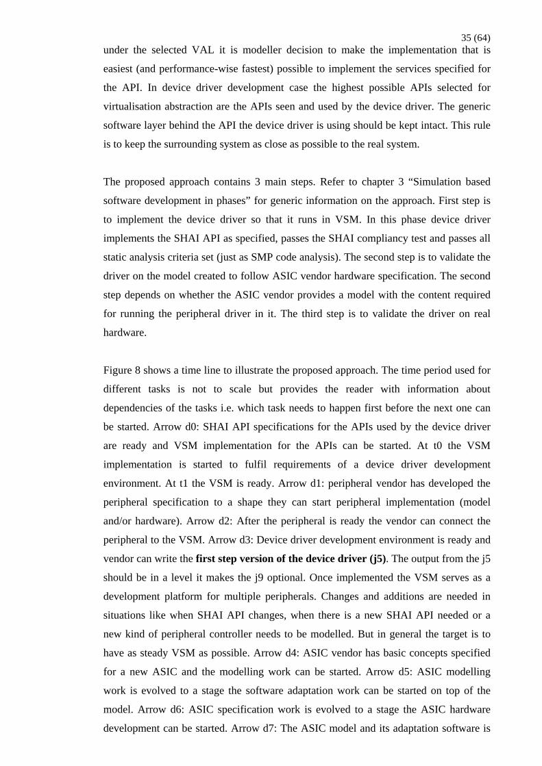
The proposed approach contains 3 main steps. Refer to chapter 3 “Simulation based
software development in phases” for generic information on the approach. First step is
to implement the device driver so that it runs in VSM. In this phase device driver
implements the SHAI API as specified, passes the SHAI compliancy test and passes all
static analysis criteria set (just as SMP code analysis). The second step is to validate the
driver on the model created to follow ASIC vendor hardware specification. The second
step depends on whether the ASIC vendor provides a model with the content required
for running the peripheral driver in it. The third step is to validate the driver on real
hardware.
Figure 8 shows a time line to illustrate the proposed approach. The time period used for
different tasks is not to scale but provides the reader with information about
dependencies of the tasks i.e. which task needs to happen first before the next one can
be started. Arrow d0: SHAI API specifications for the APIs used by the device driver
are ready and VSM implementation for the APIs can be started. At t0 the VSM
implementation is started to fulfil requirements of a device driver development
environment. At t1 the VSM is ready. Arrow d1: peripheral vendor has developed the
peripheral specification to a shape they can start peripheral implementation (model
and/or hardware). Arrow d2: After the peripheral is ready the vendor can connect the
peripheral to the VSM. Arrow d3: Device driver development environment is ready and
vendor can write the first step version of the device driver (j5). The output from the j5
should be in a level it makes the j9 optional. Once implemented the VSM serves as a
development platform for multiple peripherals. Changes and additions are needed in
situations like when SHAI API changes, when there is a new SHAI API needed or a
new kind of peripheral controller needs to be modelled. But in general the target is to
have as steady VSM as possible. Arrow d4: ASIC vendor has basic concepts specified
for a new ASIC and the modelling work can be started. Arrow d5: ASIC modelling
work is evolved to a stage the software adaptation work can be started on top of the
model. Arrow d6: ASIC specification work is evolved to a stage the ASIC hardware
development can be started. Arrow d7: The ASIC model and its adaptation software is
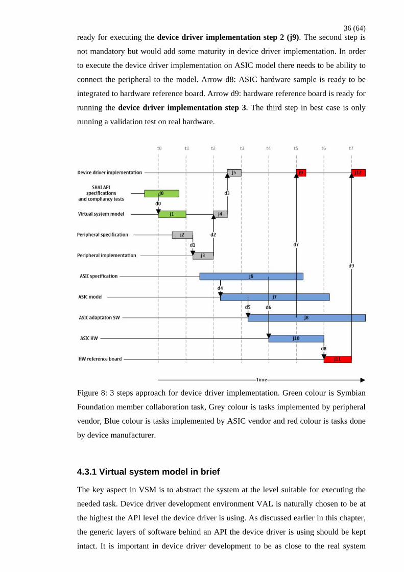
36 (64) ready for executing the device driver implementation step 2 (j9). The second step is
not mandatory but would add some maturity in device driver implementation. In order
to execute the device driver implementation on ASIC model there needs to be ability to
connect the peripheral to the model. Arrow d8: ASIC hardware sample is ready to be
integrated to hardware reference board. Arrow d9: hardware reference board is ready for
running the device driver implementation step 3. The third step in best case is only
running a validation test on real hardware.
Figure 8: 3 steps approach for device driver implementation. Green colour is Symbian
Foundation member collaboration task, Grey colour is tasks implemented by peripheral
vendor, Blue colour is tasks implemented by ASIC vendor and red colour is tasks done
by device manufacturer.
4.3.1 Virtual system model in brief
The key aspect in VSM is to abstract the system at the level suitable for executing the
needed task. Device driver development environment VAL is naturally chosen to be at
the highest the API level the device driver is using. As discussed earlier in this chapter,
the generic layers of software behind an API the device driver is using should be kept
intact. It is important in device driver development to be as close to the real system
37 (64) environment as possible. Good rule of thumb for modeller could be to make the
virtualization abstraction at SHAI API level when ever possible.
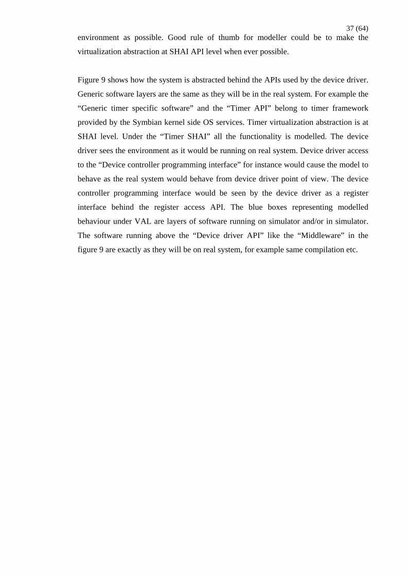
Figure 9 shows how the system is abstracted behind the APIs used by the device driver.
Generic software layers are the same as they will be in the real system. For example the
“Generic timer specific software” and the “Timer API” belong to timer framework
provided by the Symbian kernel side OS services. Timer virtualization abstraction is at
SHAI level. Under the “Timer SHAI” all the functionality is modelled. The device
driver sees the environment as it would be running on real system. Device driver access
to the “Device controller programming interface” for instance would cause the model to
behave as the real system would behave from device driver point of view. The device
controller programming interface would be seen by the device driver as a register
interface behind the register access API. The blue boxes representing modelled
behaviour under VAL are layers of software running on simulator and/or in simulator.
The software running above the “Device driver API” like the “Middleware” in the
figure 9 are exactly as they will be on real system, for example same compilation etc.

38 (64)
Figure 9: Device driver environment from Figure 5 turned into VSM.
Figure 10 shows a scenario where a real hardware peripheral is connected to VSM. The
system in figure 10 differs from the system in figure 9 in two ways. The first difference
is that peripheral is controlled through a bus. Second difference is that a real peripheral
hardware is connected instead of a peripheral model. Again the generic layer of
software implementing the “Bus API” is maintained as it is. Virtualisation abstraction is
done at “Bus SHAI” level. “Peripheral connector” represents the behaviour of the
adaptation software implementing the bus SHAI. Additionally, peripheral connector
duty in this case is to receive and transmit bus signalling to and from “Bus signal
carrier”. “Bus signal carrier” may be for example USB form PC to a board the
peripheral hardware is connected to (“Peripheral board”). The “Peripheral board” duty
is to receive and transmit bus signalling to and from “Bus signal carrier” and convey the
signals to and from “Peripheral hardware”. The bus signalling may be packed into
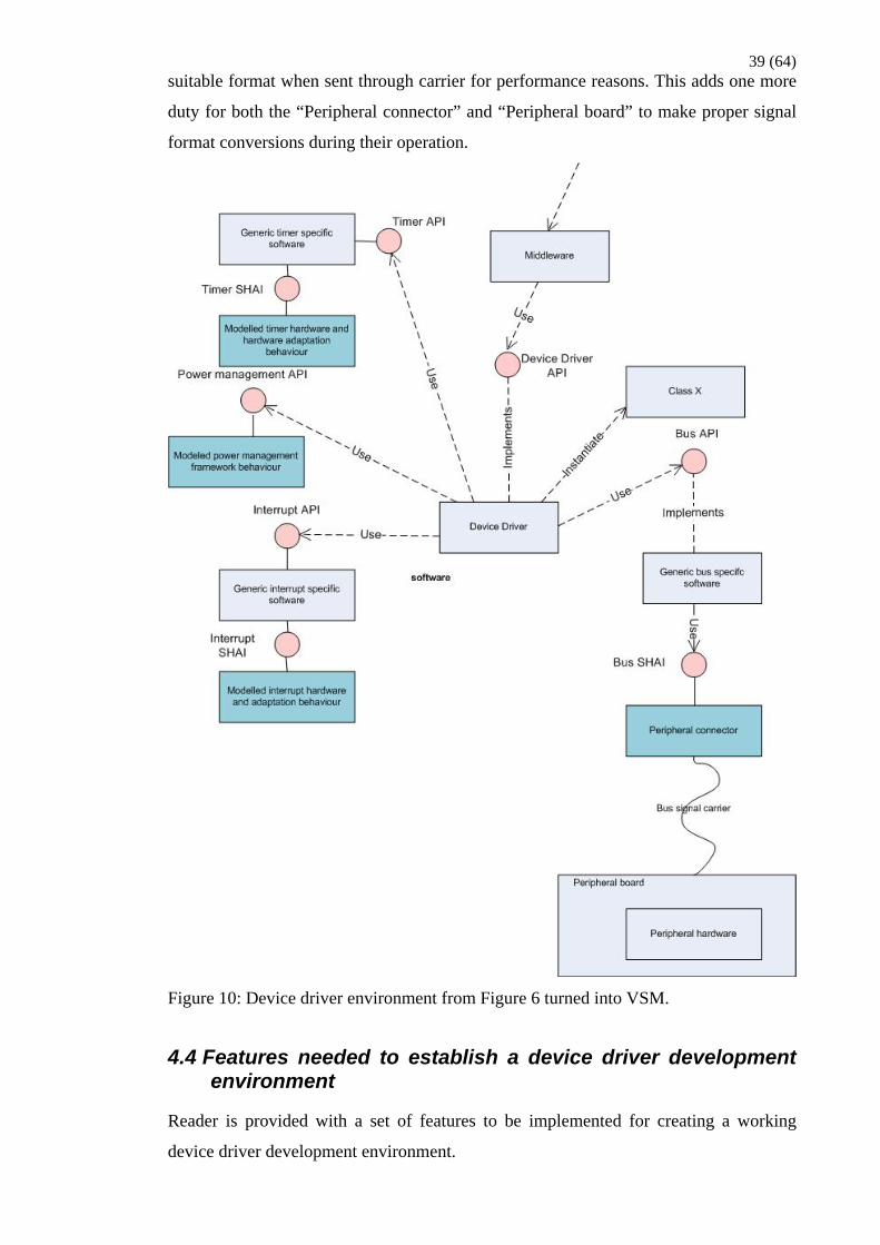
39 (64) suitable format when sent through carrier for performance reasons. This adds one more
duty for both the “Peripheral connector” and “Peripheral board” to make proper signal
format conversions during their operation.
Figure 10: Device driver environment from Figure 6 turned into VSM.
4.4 Features needed to establish a device driver development environment
Reader is provided with a set of features to be implemented for creating a working
device driver development environment.

40 (64) 4.4.1 General features
To follow Symbian Foundation open source approach the development environment
and the tools related to it should exist as free open source downloadable in internet. This
feature should be implemented in a way one can download the items, add a peripheral
and start creating SHAI compliant device driver for the peripheral with neither extra
tool nor payment needed. To ease up adoption, there should be pre-built version of the
environment available for downloading.
It would be beneficial if the environment would support most common operating
systems just as Windows, OS-X and Linux. Having this feature, development
environment usage would not be restricted to, for example, only Windows users.
4.4.2 Software environment features
Software environment needs to fulfil certain requirements to work as development
environment for device drivers. Device driver developer needs to be able to compile and
add the driver to the environment. Running and debugging ability for the driver and the
surrounding system is needed. Device driver has to run in the development environment
as it will run in the real system. Refer to chapter “Device driver environment” for
information on what kind of environments device drivers may be running in.
Software environment should take into account possible differences of compiler
outputs. Environment should support compiling the device driver just as it will be
compiled for the real system. Compiling for a correct ARM instruction set version as an
example. To enable this feature, it would be mandatory to have the same compiler
version available for both the device driver development environment and the real
system.
It would be desirable target to enable device driver developer to download only the
mandatory parts of software environment to build up an image with minimal content to
support device driver development. Like for example an environment which builds up
to the Symbian textual UI (eshell) image containing SHAI API compliancy test for the
device driver under development. In this way there would be no need to download a full
PDK including whole software environment if not desired. Then again a useful feature
would also be to build GUI image to enable running the whole software chain on device
driver development environment up from the GUI application down to the device driver
itself containing all the middleware layers in between. Environment should enable the

41 (64) driver developers to create their own additional applications to the environment for
testing the features that SHAI compliancy test does not necessarily cover or for showing
a demo GUI application that is using their peripheral. Images need to (of course) be
executable on the simulation model provided with the driver development environment.
An approach where the software environment for device driver development is a subset
of a full software environment would avoid having duplicate copies and double
maintenance effort for common parts of the software. PDK and SHAI SDK specific
parts of the software environment would then be delivered depending on which
environment the end user whish to download.
The environment should support the driver developer in creating the device driver and
adding the driver binary to the software image. SHAI compliant APIs used by device
driver as well as the SHAI compliant API to be implemented by device driver are
needed. The initial distribution of the software environment probably needs to contain
the SHAI compliant services commonly used by almost all device driver
implementations. Commonly used services include items like timers, interrupt, DMA,
power management, GPIO, I2C, SPI and register access. Common service SHAI APIs
are often regarded as Modular Hardware Abstraction (MHA) APIs. The list of SHAI
APIs needed by the driver naturally depends on the device to be controlled. There
should be templates and proper documentation to cover the difficulties in creating the
first draft of the device driver and configuring the image content to contain the driver.
Tools and tool support of the environment should have the initial default configuration
set up in a way the actual work can be immediately started. In this way the developer
can concentrate on the device driver creation instead of fighting to get the environment
working in proper way. After enabling an easy start for the developer the environment
should take into account the development cycle for the device driver. Development
cycle being a compile – build – run – debug – write code – compile type of cycle the
developer executes frequently while implementing the driver. Attention should be paid
to speed when making decisions for how to update the driver to system, boot up the
system, setting up a debug session, etc.
Tools for debugging the device driver and the surrounding software environment are an
essential part of the device driver development environment. Who has written a piece of
code containing no bugs at one go? Stop mode debug and software tracing features will
be needed in finding out problems from the device driver implementation and from its
connection to surrounding software environment. Stop mode debug is the feature where
the developer is allowed to halt the execution of CPU, step the code line by line,

42 (64) examine the memory and register content, etc. Software tracing referred in this context
is Symbian tracing systems just as BTrace and Open System Trace (OST) where
software is instrumented with informative trace output. Enabling effective stop mode
debug and tracing for the system sets some requirements for the software environment,
like for example, there needs to be symbols and trace instrumentation available for the
items to be debugged. The more the developer is allowed to debug the surrounding
system the less there will be support requests coming towards the entity responsible for
the environment maintenance. When thinking a bit further the developer should be
provided with possibility to make changes to the software environment source code.
This would encourage the environment users to contribute to the environment
development by finding bug solution proposals and other improvement proposals for
the environment.
To support a test driven approach for device driver development there should be SHAI
compliancy test available for the SHAI API the device driver is implementing. In
practise this may well be that when the first SHAI API compatible driver is written the
test is written in parallel. Later on, once created, the first implementation of the test
code will be available for the implementations to follow. The same may well apply to
the SHAI APIs itself. The first (probably at least the first three) different hardware
abstraction layer implementations will fine tune the SHAI API to a one that does not
need to change anymore when a new hardware needs to be adapted to. When using
already fine-tuned and possibly standardized APIs as SHAI APIs the fine tuning may
not be needed.
When considering development environment behaviour, it is essential that calling a
SHAI API causes the system to behave as specified. Just as, for example, calling the
power management API to enable clocks for a peripheral enables the use of the
peripheral and correspondingly disabling clocks should disable the peripheral
functionality. This may sound as self-explanatory but it is still worth paying attention
to. Let’s take an example of enabling devices voltage supply. A platform may be
implemented in a way that the input signal to enable devices voltage supply is
connected to a reset signal. This setup enables the voltage supply at platform boot up. In
this platform it does not matter whether or not the user of the peripheral calls the power
management to enable the voltage supply. A software developer now forgets to call the
enable and is still able to use the device services. Another platform may be
implemented in a way that device voltage supply is controllable by software and enable
needs to be called in order to power up the device. Now software written for previous
43 (64) platform does not call the enable and system has a bug in it because the device is not
turned on before its services are used.
4.4.3 Simulator features
Just as the software environment as well the simulator needs to fulfil certain
requirements to work as effective development environment for device drivers.
Simulator should be able to execute the same device driver binary as will eventually be
run on real hardware. To enable this simulator, for example, needs to be easily
modifiable to support things like the real hardware processor instruction set and whether
the real system is single or multicore SMP architecture.
Peripheral vendors should be able to connect their peripheral model or hardware to the
simulator. Connecting a peripheral should be possible without a need to re-compile the
simulator together with the peripheral device specific source. Easy connection just as
this enables device driver developer to hand over only a binary of the peripheral device
model for their customers use. Connection should be again done in a way there are
templates and extensive documentation available to connect the peripheral so that the
actual device driver development can be started quickly without a need to study the
underlying system specific details. The amount of peripheral devices that can be
connected to system should not be limited. There will probably be a case where a set of
peripherals and their drivers needs to be tested together if there is a need for example to
measure the traffic they are causing or a need to develop middleware or application
which is using a combination of peripheral services. Enabling run time analysis
capabilities for the system like measuring the traffic or system load will for sure be
designer interest and should not be forgotten.
When using simulator approach for software development it enables some features
which are not possible in current hardware solutions. Simulator can work as run time
development guide. It can be implemented in a way that illegal use of the environment
causes the system to provide device driver developer with informative failure message.
Examples: Trying to use a peripheral device without the clocks or power enabled for the
peripheral, accessing a peripheral device controller register which is specified to have
undetermined behaviour in current state, Etc. Simulator can be implemented to be
configurable to stop the execution with failure message or continue with the failure
message when illegal use takes place.
44 (64)
In addition to software debugging it is important to have possibility to debug and trace
the simulator. Certainly in some cases the device driver developer ends up in a situation
where debugging of the device, device connection or other simulator content would
help solve a problem. Developer should have access to simulator symbols for stop mode
debugging and should be enabled to switch on simulator traces in order to connect the
peripheral device correctly and find possible bugs from the connection in environment
side. Again the more visibility to the system the less support requests towards the entity
responsible for the environment maintenance. Possibility for studying the simulator
code and making changes to it could encourage the environment users to contribute to
the simulator development by finding bug solution proposals and other improvement
proposals for the environment.
4.4.4 Tools and documentation
The same development tools such as compilers and other building tools should be used
for both the application and the device driver development environment as far as they
apply. Certain additional tool features that are not necessarily a part of the application
development environment are needed to enable efficient device driver development.
It is often the case with existing development environments that the user of the
environment needs to spend a lot of time in setting up the environment before the actual
work on top of the environment can be started. Instead of this approach, the user of the
environment should be enabled to concentrate on the software development. The
details, not relevant to the task the user is concentrating on, should be hidden as far as
possible. As an example, if user does not want to make all the needed tool installations
manually there should be a system available for making the needed installations
automatically. Eclipse P2 and pulsar mentioned here as examples of systems for
controlling kit installations.
Things just as making the IDE to support creating device driver and peripheral
connection templates for different SHAI APIs with informative comments included are
important. As stated earlier the template should contain all the needed files for starting
driver development (code and header files, project and configuration files etc.). IDE
should support debugging both the software environment and the simulator.
In addition to run time analysis feature mentioned before there is probably needed some
static analysis tool for example for SMP related code analysis. Passing a defined set of

45 (64) static analysis could be part of the criteria for a device driver to gain the SHAI
compliancy.
Documentation should cover all the SHAI API specifications for the SHAI APIs
available in the environment. The documentation should provide the reader with a guide
for a whole project starting from fetching the development environment to releasing
their driver. The guide should contain variety of examples and references to all
available how-to guides. How-to guides would need to cover all the device driver
development environment features. Guides like getting the development environment,
connecting peripheral to the simulator, creating device driver with development
environment, running the SHAI compliancy test, debugging, etc are needed.

46 (64) 5 Summary
The goal for defining a simulation based approach for product software development
which correspond present-day needs of the commissioning company was achieved. The
conclusion above is derived form the fact that the SHAI SDK major contribution
proposal which based on the results of this work is approved by the SHAI working
group and FRC (Feature and Roadmap Council) of Symbian Foundation.
There are still Symbian Foundation councils though which will need to review and
approve the SHAI SDK before the proposal will officially proceed into implementation
phase. Overall feedback about the proposal has been positive.
The proof of concept implementation related to this work has been continuing for
almost a year now. A lot of basic enablers for creating SHAI SDK have already been
implemented including a working simulation environment with debugging capabilities
and PC accelerated graphics solution.
There is still much to do before SHAI SDK implementation fulfil the requirements
specified during this work. Currently the largest effort is made to transfer from the old
Symbian baseport to new SHAI approach. Most subsystems will have their hardware
abstraction part of the software at least slightly changed. SHAI SDK would be a great
method in aiding this transformation. While aiding the current transformation the SHAI
SDK implementation itself would get finalized for future use.
Future will show how SHAI SDK will be adopted by the community and how well the
product software development approach introduced by this document will work in
practise.

47 (64) References
Fabrice Bellard 2010. QEMU. [online] [referred to 9.4.2010]. http://wiki.qemu.org/Main_Page
Hyvönen, Jani 2010. Major Contribution Proposal: SHAI Software Development Kit. [online] Revision 1.2. http://developer.symbian.org/wiki/images/b/b2/Major_contribution_proposal_SHAI_SDK_v1.2.doc
Proposals pipeline. Symbian developer. Symbian Foundation 2010. [online] [referred to 14.4.2010]. http://developer.symbian.org/wiki/index.php/Proposals_pipeline#Proposals_pipeline_overview
QEMU Graphics Integration. Symbian developer. Symbian Foundation 2010. [online] [referred to 9.4.2010]. http://developer.symbian.org/wiki/index.php/QEMU_Graphics_Integration
Qt. Nokia Oyj 2010. [online] [referred to 14.4.2010]. http://qt.nokia.com/products
SHAI. Symbian developer. Symbian Foundation 2010. [online] [referred to 9.4.2010]. http://developer.symbian.org/wiki/index.php/Category:SHAI
Syborg & QEMU. Symbian developer. Symbian Foundation 2010. [online] [referred to 9.4.2010]. http://developer.symbian.org/wiki/index.php/SYBORG/QEMU
Symbian Emulator. Symbian developer. Symbian Foundation 2010. [online] [referred to 9.4.2010]. http://developer.symbian.org/wiki/index.php/Symbian_Emulator
Web Runtime (WRT) Quick Start. Symbian developer. Symbian Foundation 2010. [online] [referred to 14.4.2010]. http://developer.symbian.org/wiki/index.php/Web_Runtime_%28WRT%29_Quick_Start
What are the kits? Symbian developer. Symbian Foundation 2010. [online] [referred to 13.4.2010]. http://developer.symbian.org/wiki/index.php/What_are_the_Kits%3F

48 (64) Appendices
1 (64)
Appendix 1: SHAI SDK requirements
Numerical order of the requirements is not continuous. This is due to a reason of
rejected and combined requirements still maintaining the requirement number –
requirement title relation unchanged thus easing up communication in between entities
having different revision of the requirements in hand.
DDKREQ001
Title:
General - Development environment and related tools will exist as free downloadable in
internet.
Description:
The development environment and the tools related to it will exist as free open source
downloadable in internet. This feature should be implemented in a way one can
download the items, add a peripheral and start creating SHAI compliant device driver
for the peripheral with neither extra tool nor payment needed.
To ease up adoption there should be pre-built version of the environment available for
downloading.
It is not forbidden to create development environment plugins which are not free. If one
is not willing to purchase a non free plugin it will not prevent the basic usage of the
development environment.
Justification:
To follow Symbian Foundation open source approach.
DDKREQ002
Title:
General - Fast development cycle.
Description:
Development cycle for the device driver will be fast. Answer to the question "how fast
should it be" could be found by studying other existing development environments
(WINS, Google Android) and make this a bit faster. Development cycle being a
compile – build – run – debug – write code – compile type of cycle the developer
executes frequently while implementing the driver. Environment should support the
fastest possible way to update the driver to the system. It should be paid attention to

2 (64) speed when making decisions for how to boot up the system, set up a debug session,
etc.
Justification:
Development cycle is executed frequently by a developer while implementing the
driver. Time should be reserved for the actual work (writing and correcting code,
debugging) instead of consuming the time on waiting the image to be created or setting
up a debug session.
DDKREQ003
Title:
General - Calling the SHAI API will cause the system to behave as specified.
Description:
When considering development environment behaviour it is essential that calling a
SHAI API causes the system to behave as specified. For example calling the power
management API to enable clocks for a peripheral enables the use of the peripheral and
correspondingly disabling clocks should disable the peripheral functionality.
Implementing this feature probably require features to both the software environment
and the simulation model.
Justification:
Let’s take an example of enabling devices voltage supply. A platform may be
implemented in a way that the input signal to enable devices voltage supply is
connected to a reset signal. This setup enables the voltage supply at platform boot up. In
this platform it does not matter whether or not the user of the peripheral calls the power
management to enable the voltage supply. A software developer now forgets to call the
enable and is still able to use the device services. Another platform may be
implemented in a way that device voltage supply is controllable by software and enable
needs to be called in order to power up the device. Now software written for previous
platform does not call the enable and system has a bug in it because the device is not
turned on before its services are used.
DDKREQ004
Title:
General - Performance budgeting
Description:
This is a high level requirement for performance budgeting. This requirement needs to
be split into sub requirements which are to be implemented in priority order.

3 (64) Users of the development environment should be provided with ability to measure the
load caused by the software. Such a load items can be, for example, CPU load,
concurrent DMA transfers, concurrent non-volatile and volatile memory accesses etc.
Justification:
Enabling different run time analysis capabilities for the system like measuring the
traffic or system load will increase the environment usability. One can, already with
high abstraction model, measure the load caused by the software system. Based on these
measurements system designers can proactively react when early hardware system
design does not seem copes with the load caused by the software.
DDKREQ005
Title:
General - Fast environment adoption
Description:
User of the development environment should be enabled with fast adoption of the
development environment. To implement this approach the environment adoption
should be automated as far as possible. Downloading all the needed content and tools,
installations, basic setup etc. should be automated in a way user can escape the details
not relevant to the task the user is concentrating on.
Justification:
It is often the case with existing development environments that the user of the
environment needs to spend a lot of time in setting up the environment before the actual
work on top of the environment can be started. Due to this, a lot of man hours are
wasted by having several users investigating same environment setup problems in
parallel.
DDKREQ006
Title:
General - SMP code development
Description:
Device driver kit will enable SMP code development. It will be possible to run the same
SMP binary on both the device driver kit and the real system.
Device driver kit can provide means to analyze the written SMP code in certain level so
that some SMP related problems can be found. It is to be remembered though that there
is not yet a simulation model available which would expose SMP problems to same
extent that real hardware environment does.
Justification:
4 (64) SMP related problems are timing dependent i.e. problems may never become visible
during run time testing. In worst case it is the end user who finds the SMP problem by,
for example, installing a new application which is using the system (and slightly
changing the system timings) in a way the test did not cover. This problem applies for
both the simulated environment and hardware environment. By having an extensive set
of different SMP code analysis methods (both static and run time) the error leakage can
be minimized.
DDKREQ007
Title:
General – SHAI compliancy testing
Description:
The SHAI SDK will possess a complete service for SHAI compliancy testing.
Service will include items just as creating tests, building test image, running tests,
providing the test results to developer with informative failure messages, creating a test
report, etc. This feature will affect to at least SHAI SDK software environment and
IDE.
Justification:
Key features of the SHAI SDK.
DDKREQ101
Title:
Software environment - Compiler
Description:
It will be possible to compile the device driver like it will be compiled for the real
system. Compiling for a correct ARM instruction set version as an example. To enable
this feature it would be mandatory to have the same compiler version available for both
the device driver development environment and the real system.
Justification:
Software environment should take into account possible differences of compiler
outputs.
DDKREQ102
Title:
Software environment - Image build environment
Description:
5 (64) Device driver developer will be enabled to download only the mandatory parts of
software environment to build up an image with minimal content to support device
driver development. It will be possible to build SHAI compliancy test images, GUI
images and the textual UI (eshell) images containing the device driver under
development. Images will be runnable on the simulator provided with the environment.
Justification:
It would be a desirable target to enable device driver developer to download only the
mandatory parts of software environment to build up an image with minimal content to
support device driver development. For example an environment which builds up to a
textual UI (eshell) image containing SHAI API compliancy test for the device driver
under development. This way there would be no need to download the entire software
environment including whole PDK if not desired. Then again a useful feature would be
to build also GUI image to enable running the whole software chain on device driver
development environment up from the GUI application down to the device driver itself
containing all the middleware layers in between.
DDKREQ103
Title:
Software environment - Driver creation support
Description:
The environment will support the driver developer in creating the device driver and
adding the driver binary to the software image. There should be templates and proper
documentation to cover the difficulties in creating the first draft of the device driver and
configuring the image content to contain the driver.
Justification:
Actual implementation work can be started immediately.
DDKREQ105
Title:
Software environment - SHAI compliant APIs used by device drivers will be available
in the environment.
Description:
SHAI compliant APIs (and the behaviour beneath the API) used by device drivers will
be available in the environment. The initial distribution of the software environment
will contain the SHAI compliant services commonly used by almost all device driver
implementations. Commonly used services include items like timers, interrupt, DMA,
power management, GPIO, I2C, SPI and register access. Common service SHAI APIs

6 (64) are often regarded as Modular Hardware Abstraction (MHA) APIs. The list of SHAI
APIs needed by the driver naturally depends on the device to be controlled.
Justification:
SHAI APIs provide the driver with an environment corresponding to the real system
where the driver is going to be used.
DDKREQ106
Title:
Software environment - SHAI compliant API to be implemented by device driver will
be available in the environment.
Description:
SHAI API header files (either ratified APIs or API candidates depending on the status)
and source templates containing at least the API functions will be provided for the
driver developers.
Justification:
Actual implementation work can be started immediately.
DDKREQ107
Title:
Software environment - SHAI compliancy test will be available for the SHAI API the
device driver is implementing.
DDKREQ108
Title:
Software environment - Adding image content
Description:
It will be possible for the driver developer to easily create their own
additional applications to the environment. Additional applications may be needed, for
example, to test the features that SHAI compliancy test do not necessarily cover or to
show a demo of peripheral services.
Justification:
Environment should not set constrains for creating and proposing new functionality to
the existing content.
DDKREQ110
Title:
Software environment - Stop mode debug
7 (64) Description:
Stop mode debug feature will be available for the device driver as well as for the
surrounding software system. Surrounding system being the APIs the device driver is
using as well as the whole service chain from SHAI compliancy test down to the SHAI
API the device driver is implementing. To effectively debug the system, there will be
symbols available for the items to be debugged.
Debug feature will provide OS awareness.
Justification:
Tools for debugging the device driver and the surrounding software environment are
essential part of the device driver development environment. Who has written a piece of
code containing no bugs at one go? Stop mode debug and software tracing features will
be needed in finding out problems from the device driver implementation and from its
connection to surrounding software environment. Stop mode debug is the feature where
developer is allowed to halt the execution of CPU, step the code line by line, examine
the memory and register content, etc.
DDKREQ111
Title:
Software environment - Tracing method
Description:
Device driver developer will be provided with a feature to trace the device driver under
implementation. It will also be possible to switch on the traces from the surrounding
software system. Software tracing referred in this context is systems like BTrace and
Open System Trace (OST) where software is instrumented with informative trace
output.
Justification:
Tools for debugging the device driver and the surrounding software environment are an
essential part of the device driver development environment. Who has written a piece of
code containing no bugs at one go? Stop mode debug and software tracing features will
be needed in finding out problems from the device driver implementation and from its
connection to surrounding software environment. Software tracing referred in this
context is systems like BTrace and Open System Trace (OST) where software is
instrumented with informative trace output.
DDKREQ112
Title:
Software environment - Studying and modifying the environment

8 (64) Description:
Developer should be provided with a possibility to study the environment code and
make changes to it. In addition to generic layers of software there should be access to
software layers below SHAIs.
Justification:
Opening up the software environment source code will help developers to understand
the environment surrounding the piece of software they are developing. This will
encourage the environment users to contribute to the environment development by
finding bug solution proposals and other improvement proposals for the environment.
DDKREQ114
Title:
Software environment - Usage of common code
Description:
Generic layers of SHAI SDK software environment should be common with Symbian
Foundation code repositories. The Software environment generic layers may consist of
parts from MCL (Master Code Line) as well as parts from FCL (Feature Code Line).
Software layers below SHAI i.e. the hardware adaptation layer should be common with
– where possible – the application development kit hardware adaptation layer.
Justification:
The approach of using common code where possible minimizes amount of duplicate
copies. Having one copy minimizes the maintenance and problem solving effort i.e. one
needs to find a problem and correct in only once. Having several copy of the same
software leads to a risk of changes and corrections not propagating to each copy –
which again causes several developers to debug a problem that may have been already
found and corrected.
DDKREQ115
Title:
Software environment – SHAI stub implementation
Description:
There will be stub implementation available for each SHAI function. Stub
implementation will contain code for substituting the behaviour beneath the SHAI. At
minimum the stub implementation will return a value for the caller which is indicating
that the operation was successfully completed and enabling the caller to continue
operation.
Justification:

9 (64) Stub implementation makes it possible to build and run an image having dependency to
a SHAI for which there is not yet actual implementation available. This approach
reduces the dependencies in between different entities creating SHAI implementations.
DDKREQ116
Title:
Software environment – SHAI configurability
Description:
There will be on/off type configuration available for each SHAI and the software
depending on them. When configured off a SHAI and the functionality depending on
the SHAI is not included to the image being build.
Justification:
Configurability makes it possible to build and run partial images having only a defined
set of functionality available. This approach reduces the dependencies in between
different entities creating device functionality. In addition, this approach makes it
possible to create devices with limited functionality available.
DDKREQ201
Title:
Simulation model - Support for processor architectures
Description:
Simulator will be easily modifiable to support the real system instruction set i.e. to
change the simulator instruction interpretation, or translation, to emulate instructions
sets of different processors and processor architecture versions.
Simulator will be easily modifiable to support single and multicore architectures.
Developer will be enabled to run either single or SMP software on the simulator.
Like the items above simulator will be easily modifiable to emulate different MMUs
(Memory Management Unit), TLBs (Translation Lookaside Buffer), Interrupt handling,
etc.
Justification:
No need to have several simulator copies with different setups.
DDKREQ203
Title:
10 (64) Simulation model - Connecting peripheral device model to simulator
Description:
It will be possible for the device driver developer to easily connect a peripheral device
model to the existing simulation model content. Environment will support different
peripheral control schemes like a controller residing in ASIC or a control buses like I2C
or SlimBus.
Justification:
Key features of the SHAI SDK.
DDKREQ204
Title:
Simulation model - Connecting peripheral device hardware
Description:
It will be possible for the device driver developer to easily connect peripheral device
hardware to the existing simulation model content. Environment will support different
peripheral control schemes like a controller residing in ASIC or a control buses like I2C
or SlimBus.
Justification:
Key features of the SHAI SDK.
DDKREQ205
Title:
Simulation model - Connecting multiple peripheral devices
Description:
It will be possible to easily connect multiple peripheral devices to the existing simulator
content. Peripheral devices may be either models or hardware. Peripheral devices may
be controlled with different peripheral control schemes like a controller residing in
ASIC or a control buses like I2C or SlimBus.
Justification:
Peripherals and their drivers needs to be tested together for, as an example, measuring
the traffic they are causing or for developing middleware or application which is using a
combination of peripheral services.
DDKREQ206
Title:
Simulation model - Easy connection of a peripheral
Description:

11 (64) It should be possible to add peripheral device model to the simulator content without a
need to re-compile the simulator with the peripheral device specific source.
Justification:
Enable peripheral device driver developers to use the simulator environment without a
need to compile the simulator. Enable device driver developer to hand over only a
binary of the peripheral device model for their customers use. Enable downloading only
the mandatory binaries of simulator environment if there is no specific need to have the
whole simulator compilation environment.
DDKREQ207
Title:
Simulation model - Run time development guide
Description:
Illegal use of the environment will cause the system to provide device driver developer
with informative failure message. Examples: Trying to use a peripheral device without
the clocks or power enabled for the peripheral, Accessing a peripheral device controller
register which is specified to have undetermined behavior in current state, Etc.
Environment will be configurable to stop the execution with failure message or continue
with the failure message when illegal use happens.
Justification:
Simulation model offers an advantage of providing visibility to “hardware”. Developer
is guided by the simulation model to create correct behaviour for the driver. It is often
time consuming work to search through hardware reference manuals for trying to find
what configurations are missing from the driver implementation. Now the “hardware”
itself can tell the developer what needs to be done to get the missing configurations
implemented.
DDKREQ208
Title:
Simulation model - Peripheral device model debugging
Description:
It will be possible for the device driver developer to trace and stop mode debug the
peripheral device model while it is running as a part of the simulator.
Justification:
Enable SHAI SDK usage in device model development work.

12 (64) DDKREQ209
Title:
Simulation model - debugging
Description:
It will be possible for the device driver developer to debug the peripheral device
connection to simulation model i.e. developer should be provided with enough visibility
to the simulation model in order to connect the peripheral device correctly and find
possible bugs from the connection in environment side.
Debug feature will have at least the following items supported: stop mode debug, signal
analysis and tracing.
Stop mode debugging feature provides the developer with ability to connect a debugger
to simulation model, set breakpoints, step the simulation model code, dumb the
simulation model memory, etc.
Signal analysis provides the developer with ability to log the signal traffic in between a
peripheral device and the simulation model. Signal traffic log can then be analyzed later
on with, for example, a tool showing the signal traffic in graphical logic analyzer type
of form.
Tracing provides the developer with ability to switch on simulation model trace
logging. Simulation models peripheral connection framework will be instrumented with
informative traces to guide the developer to connect the peripheral in right way.
Justification:
Debugging ability is an essential feature to enable a developer - independently from
SHAI SDK support team - to attach the peripheral (model or hardware) to the
simulation model.
DDKREQ211
Title:
Simulation model - Changing the model
Description:
It should be possible to study the simulator code and make changes to it. Justification:

13 (64) Access to simulation model source will encourage the environment users to contribute
to the simulator development by finding bug solution proposals and other improvement
proposals for the environment.
DDKREQ212
Title:
Simulation model – Reusing the solution for different kits
Description:
The same simulator and simulation model should be used for application development
and device driver development where applicable. In practice the SHAI SDK and PDK
can share the same core parts of the simulation model.
This requirement does not apply to the simulation models which are trying to accurately
model the hardware programming interface. But - if it is found feasible to use a VSM (a
high abstraction simulator) for SHAI SDK first phase simulation model - this
requirement may apply.
Justification:
Having one solution (where applicable) minimizes the development, maintenance and
problem solving effort.
DDKREQ214
Title:
Simulation model – Instruction tracing
Description:
Simulation model will provide the developers with ability to generate (ETM like)
instruction trace log from the execution of the software.
Justification:
Instruction trace log from the software execution enable profiling of the software with
profiling tools such as Fine Tooth Comp.
DDKREQ301
Title:
Tools – Software environment – Software tools
Description:
Compilers, linkers, static analysis tools, documentation tools, image builders and other
software tools should be available for simulation model development.
14 (64) Software tools will be common with PDK as far as they apply.
In addition SHAI SDK may require special software development tools. Like new
compiler features which do not yet belong to standard PDK tool delivery.
DDKREQ303
Title:
Tools – IDE for SHAI SDK
Description:
SHAI SDK will have an IDE (Integrated Development Environment). IDE will provide
user interface for all the SHAI SDK features. IDE will provide the developer with
means to manage the software environment as well as the simulation model. Creating
driver projects, compiling, creating target images, running the software environment,
starting up debug session and debugging are examples of essential features of SHAI
SDK IDE.
IDE basis will be the same as the application development environment IDE. Device
driver and application development environment features will be the same as far as
apply.
SHAI SDK IDE will be easily maintainable and extendable. For example, SHAI SDK
features can be individually supported as Eclipse (and Carbide C++) plugins.
Justification:
Provide developers with a logical view and user interface to SHAI SDK features.
DDKREQ304
Title:
Tools – SHAI SDK IDE features – Driver project templates
Description:
The used development environment (IDE) will support creating device driver project
template for different SHAI APIs. Device driver project template will include all the
needed files for starting driver development (code and header files, project and
configuration files etc.) – in a way the template as is can be compiled and added to the
software environment. Template files will have informative comments on where to add
functionality.
Justification:

15 (64) Developer can concentrate on the device driver behaviour development instead of
fighting to get the software environment set up in proper way.
DDKREQ305
Title:
Tools – SHAI SDK IDE features – Peripheral connection templates
Description:
The used development environment (IDE) will support creating a project template for
peripheral connection to the simulator. Different connection schemes will be
covered. Peripheral device project template will include all the needed files for
connecting a peripheral device to the simulation model – in a way the template as is can
be run as a part of simulation model. Template files will have informative comments on
where to add functionality.
Justification:
The actual device driver development can be started quickly without a need to study the
underlying system specific details for connecting a peripheral model or hardware to the
simulation model.
DDKREQ306
Title:
Tools – SHAI SDK IDE features – Debugging software environment
Description:
IDE will provide the developer with graphical user interface to debug the software
under development.
At least the following features will be provided: Stop mode debug, Software traces
presented in interpreted human readable form.
DDKREQ307
Title:
Tools – SHAI SDK IDE features – Debugging simulation model
Description:
IDE will provide the developer with graphical user interface to debug the simulation
model.
At least the following features will be provided: Stop mode debug, Simulation model
traces presented in interpreted form.
Justification:

16 (64) Make simulation model traces visible to the developer (see the requirement
DDKREQ207). Enable the developer to independently solve problems in peripheral
connections.
DDKREQ401
Title:
Documentation - SHAI SDK feature guides
Description:
There will be guide document available for all the device driver development
environment features. Features like getting the development environment, connecting
peripheral to the simulator, creating device driver with development environment,
running the SHAI compliancy test, debugging, etc. will be provided with a guide
document.
Justification:
Enable the developer to independently study the environment features.
DDKREQ402
Title:
Documentation – Device driver project guide
Description:
The documentation will provide the reader with a guide for a whole device driver
project starting from getting the environment to releasing their driver. Project guide will
contain extensive examples and references to all available feature guide documents.
Justification:
DDKREQ403
Title:
Documentation - SHAI API specifications
Description:
SHAI compliant APIs used by device driver as well as the SHAI compliant API to be
implemented by device driver will be available in the development kit.