AIDED MANUFACTURING - SMU
17
RESEARCH CENTER FOR ADVANCED MANUFACTURING & CENTER FOR LASER- AIDED MANUFACTURING Research Development Technology Transfer Education Physical address: RCAM -SMU; 3101 Dyer St., Dallas, Texas 75205, USA E-mail: [email protected] Mailing address: RCAM -SMU; PO Box 0337, Dallas, Texas 75205, USA Web: lyle.smu.edu/rcam Tel: (214) 768-4865; Fax: (214) 768-0812 lyle.smu.edu/clam
-
Upload
khangminh22 -
Category
Documents
-
view
1 -
download
0
Transcript of AIDED MANUFACTURING - SMU

RESEARCH CENTER FOR ADVANCED
MANUFACTURING & CENTER FOR LASER-AIDED MANUFACTURING
Research
Development Technology Transfer
Education
Physical address: RCAM -SMU; 3101 Dyer St., Dallas, Texas 75205, USA E-mail: [email protected] Mailing address: RCAM -SMU; PO Box 0337, Dallas, Texas 75205, USA Web: lyle.smu.edu/rcam Tel: (214) 768-4865; Fax: (214) 768-0812 lyle.smu.edu/clam

Physical address: RCAM -SMU; 3101 Dyer St., Dallas, Texas 75205, USA E-mail: [email protected] Mailing address: RCAM -SMU; PO Box 0337, Dallas, Texas 75205, USA Web: lyle.smu.edu/rcam Tel: (214) 768-4865; Fax: (214) 768-0812 lyle.smu.edu/clam
R&D AREAS
Rapid Manufacturing/Repair by Laser Cladding
Electron Beam Direct Metal Deposition
Friction Stir Welding
High Power Lasers in Materials Processing
Abrasive Water Jet Materials Processing
Development of Lead-free Solders
Paint Striping by Lasers
Materials Characterization
Process Automation
Micromachining by Lasers
Fusion Welding
CAD/CAM/CAE
Research Center for Advanced Manufacturing (RCAM) and Center for Laser Aided Manufacturing (CLAM) at Southern Methodist University
MISSION
To provide and apply university led R&D work, education, and training in advanced manufacturing.
RCAM
In order to respond to the industry's needs and to provide the conditions to educate undergraduate and graduate students in the area of manufacturing engineering, the Department of Mechanical Engineering and the School of Engineering established the Research Center for Advanced Manufacturing (RCAM) in September of 1999.
CLAM
In August of 2005, the National Science Foundation awarded SMU a grant to establish the Industry/University Cooperative Research Center (I/UCRC) for Lasers and Plasmas for Advanced Manufacturing. SMU is the fourth university site in the multi-institutional I/UCRC for Lasers and Plasmas for Advanced Manufacturing together with the University of Michigan, the University of Virginia and the University of Illinois at Urbana-Champaign.
EQUIPMENT
TRUMPF 10 kW disk laser
IPG fiber laser of 4 kW in power
COHERENT direct diode laser of 8kW in power
Spectra-Physics HIPPO Q-switched laser system with four harmonics wavelengths (1064, 532, 355,
and 266 nm)
NUVONYX direct diode laser of 2 kW in power
NUVONYX fiber coupled diode laser of 1 kW in power
LUMONIX Nd:YAG laser of 1 kW in power
3-axis CNC vertical machining center adapted for friction stir welding
5-axis CNC vertical machining center adapted for multi-fabrication process (combined additive and
subtractive operations at the same setup for rapid manufacturing/repair)
5-axis CNC vertical machining center VF-4 adapted for high-speed machining
6-axis KUKA robot
Two 6-axis MOTOMAN robots
Two high-accuracy 4-axis CNC positioning systems for micro-machining
Z Corp 3D color printer for rapid prototype
Axila-portable coordinate measuring arm
Abrasive waterjet cutting machine
Well equipped Laboratories for R&D in welding, materials characterization, monitoring and
control, and reverse engineering
Well equipped machine shop

Physical address: RCAM -SMU; 3101 Dyer St., Dallas, Texas 75205, USA E-mail: [email protected]
Mailing address: RCAM -SMU; PO Box 0337, Dallas, Texas 75205, USA Web: lyle.smu.edu/rcam
Tel: (214) 768-4865; Fax: (214) 768-0812 lyle.smu.edu/clam
LYLE SCHOOL OF ENGINEERING
PROCESS DESCRIPTIONThe SMU RCAM has developed an integrated platform for demonstrating/ expanding the concept ofmulti-fabrication (MultiFab) where additive operations based on laser cladding and the micro-plasma powder cladding are combined with high-speed multi-axis machining via integrated softwareto control the CNC based system. The MultiFab platform can be additionally configured withdimensional scan capability for reverse engineering, as well as for in-process and post-processinspection. Different engineering materials in the form of powders are used to manufacturecomponents with variable compositions of Ni-alloys, tool steels, Ti-alloys, and metal-ceramiccomposites.
Rapid Manufacturing/RepairMultiFab Platform
ADVANTAGES• Repairing high-value components such as dies or molds minimizing cost and production
downtime• Manufacturing spare parts for legacy equipment “on-demand” from CAD files
eliminating expensive inventory stock• Producing components with Functionally Graded Material (FGM) compositions with
properties unattainable by current manufacturing processes• Create custom orthopedic implants or scaffolds using patient’s image scans• Improve surface resistance to heat, abrasion, corrosion, and erosion via laser cladding• Synthesizing materials to achieve specific mechanical and physical properties
RECENT PATENTS• “System and Method for Controlling Welding Parameters in Welding-based
Deposition Process”,US Patent No. 6,940,037, issued on Sept. 6, 2005.
• “System and Method for Controlling the Size of the Molten Pool in Laser-based Additive
Manufacturing”, US Patent No. 6,995,334, issued on February 7, 2006.
• “System and Method for Fabrication or Repairing Part”, US Patent No. 7,020,539, issued
on March 28, 2006.
• “Powder Delivery System and Method”,US Patent No. 7,045,738,
issued on May 16, 2006.
CAD model…
Different structure due to using different powder
Micro-Plasma Powder deposition
Functionally Graded
Material (FGM) part
Multi-Fab Integrated Platform
Actual Multifab part

Physical address: RCAM -SMU; 3101 Dyer St., Dallas, Texas 75205, USA E-mail: [email protected]
Mailing address: RCAM -SMU; PO Box 0337, Dallas, Texas 75205, USA Web: lyle.smu.edu/rcam
Tel: (214) 768-4865; Fax: (214) 768-0812 lyle.smu.edu/clam
LYLE SCHOOL OF ENGINEERING
Industrial Applications• Oil and gas • Automotive • Transportation • Mining • Energy sector
DESCRIPTIONIn October 2011, a Joint Application Lab for High-power Direct DiodeLasers has been established at CLAM as a joined effort among SMU,Coherent, Inc., the Army Research Laboratory and KUKA Robotics.Coherent equipped this Laboratory with its newest HighLight 8000Dlaser, with output power of 8 kW. This is the most powerful, energy-efficient industrial direct diode laser system currently available withfree-space beam delivery. This type of laser is specifically developed toprovide industry and research community with a cost-effective andcontrollable power source for heat treatment, cladding and welding inconduction mode.
CHARACTERISTICS AND BENEFITS• Low laser system cost• Outstanding system electrical efficiency
(~40% wall plug efficiency)• Enhanced system thermal efficiency
(high material absorption (975 nm wavelength),low dilution (4-7%), high quench rates)
• Metallurgical bond with very low porosity and low distortion
• Mobile and remote laser placement, (easy to integrate with a 6-axis robot)
• Specially designed co-axial cladding nozzlewith a deposition rate of over 20 lb/hr andpowder capture efficiency up to 93%
• Closed-loop control of heat input• Variable line beam shapes from 1x3 mm to 1x36 mm
and with beam width expansion from 1 mm to 12 mm• High reliability, diode array MTBF – typically 20,000 hours• Coating thickness from 0.4 mm (thin layer) to 4 mm (thick
layer) at a scanning speed of 18 mm/s and 7 mm/s, respectively
• Ability to coat wide variety of materials including composite materials
Super stainless steel (Hoganas) coating on low alloy steel at a laser power of 4000 W, scanning speed of 7.5 mm/s and powder flow rate of 1.8 g/s (a) single-pass with a beam size of 12 mm 3 mm (b) single-pass with a beam size of 24 mm 3 mm (c) multi-pass with a beam size of 24 mm 3 mm
Joint Application Lab for High-Power Direct Diode Lasers
Control unitPowder feeding nozzle
Laser head
Chiller
Powder feeder
Coherent HighLight 8000D HPDL laser with 6-axis Kuka robot(a)
(b)
(c)
Nickel (Ni) powder Tungsten carbide(WC) powder
Ni-55%WC composite coating (0.5 mm thick) on AISI 4140 steel at laser power = 3000 W , scanning speed =18 mm/s and powder flow rate = 0.66 g/s at preheating temperature =500oC
Ni-55%WC (3 mm thick) on AISI 4140 steel at laser power = 3360 W, scanning speed =5 mm/s and powder flow rate = 0.74 g/s

Physical address: RCAM -SMU; 3101 Dyer St., Dallas, Texas 75205, USA E-mail: [email protected]
Mailing address: RCAM -SMU; PO Box 0337, Dallas, Texas 75205, USA Web: lyle.smu.edu/rcam
Tel: (214) 768-4865; Fax: (214) 768-0812 lyle.smu.edu/clam
LYLE SCHOOL OF ENGINEERING
Hybrid Laser/ Arc Welding
PROCESS DESCRIPTION
SMU’s Center for Laser Aided Manufacturing (CLAM) has been developing a hybridlaser/arc technology which consists of a 4-kW fiber laser, a 6-axis KUKA robot, andone of the traditional GTAW, GMAW or micro-plasma welding systems. Thistechnology leverages the individual strengths of the laser and arc welding processesin one platform.
Hybrid laser/GTA welding system at CLAM
ADVANTAGES
Deep penetration, high speed, narrow weld bead and HAZ,high quality welds, suppression of humping, reduction ofporosities in the weld, possibility to add filler materials, goodtolerance to joint fit-up
INDUSTRIAL APPLICATIONS•Automotive industry•Shipyard and marine industries•Aerospace and aircraft Industries•Heavy industries
Robot arm
Laser head
GMAW torch
CCD camera
CLAM CAPABILITIES
•Welding of galvanized dual phase steel at gap-free overlap joint configuration• Welding of mild steel, aluminum alloys, titanium alloys, stainless steels, andhigh strength steels• Heat treatment via direct diode laser to restore mechanical properties ofwelded joint in high strength steels• Monitoring of the welding process using acoustic emission, airborne sound,and machine vision systems•Metallurgical analysis and mechanical testing of welded materials•Numerical modeling of the welding process and heat treatment by diode laser
RECENT PUBLICATIONS•F. Kong, J. Ma, R. Kovacevic. Numerical andexperimental study of thermally induced residualstresses in the hybrid laser-GMA welding process. TheJournal of Materials Processing Technology. 2011, 211(6): 1102-1111.
Hybrid laser/GMA welding system at CLAM
Green laser
Laser weld Hybrid laser-GMA weld
Comparison of experimental and numerical results of cross-sectional weld in Laser-GMA hybrid welding
Laser with wire feeding
•W. Huang, R. Kovacevic. Development of a real-time laser-based machine vision system to monitor and control welding process, theInternational Journal of Advanced Manufacturing Technology, DOI:10.10071S00170-012-3902-0,2012.•W. Huang, R. Kovacevic. A neutral network and multiple regression method for the characterization of the depth of weld penetration in laserwelding based on acoustic signature, the Journal of Intelligent Manufacturing, 2011, 22 (2): 131-143.

Physical address: RCAM -SMU; 3101 Dyer St., Dallas, Texas 75205, USA E-mail: [email protected]
Mailing address: RCAM -SMU; PO Box 0337, Dallas, Texas 75205, USA Web: lyle.smu.edu/rcam
Tel: (214) 768-4865; Fax: (214) 768-0812 lyle.smu.edu/clam
LYLE SCHOOL OF ENGINEERING
Hybrid Laser/Arc Welding of Dissimilar Materials
PROCESS DESCRIPTION
SMU’s Center for Laser Aided Manufacturing (CLAM) has been developing combined welding techniques to join dissimilarmaterials. Based on the current state-of-the-art, it could be concluded that the welding of Advanced High Strength Steel (AHSS)to different aluminum alloys could be achieved only by using the Fe/Al structural transition inserts obtained by explosivecladding. Dynamic Materials Corp., Boulder, Co., provided one research team with TRICLAD® composite material that consist ofASTM 516 Grade 55/Aluminum 1050A/ Aluminum 5086 with thicknesses 19+9.5+6 mm, respectively. The shear strength of theTRICLAD® is typically 96 MPa and the tensile strength is typically 126 MPa. In order to provide a satisfactory load bearingstructure and a large enough volume of heat sink a rule of “1:4” has been applied. The mechanical property of the explosivelyformed clad decreases substantially at the temperature above 300 °C. One of the ways to keep the temperature at theinterface of the TRICLAD® composite material below 300°C is the application of hybrid laser/arc welding (HLAW) process wherethe control of heat is possible by designing the welding procedure.
CURRENT TOPICS OF RESEARCH
• Numerical investigation of hybrid laser arc welding of advanced high strength
steels .
• Experimental and numerical analysis of the hybrid laser/arc welding of
dissimilar materials using the TRICLAD in a T-joint configuration.
• Study of the laser welding of dissimilar materials assisted with a hot-wire and
cold wire.
• On-line monitoring of the hybrid laser/arc welding of dissimilar alloys in
different grooves configurations.
RECENT PUBLICATIONS
•M. Mazar Atabaki, M. Nikodinovski, P. Chenier, J. Ma, M. Harooni, R. Kovacevic, Welding of aluminum alloys to steels: an overview, J. Manufacturing Science and Production(2014), 14(2): 59-78.
• M. Mazar Atabaki, M. Nikodinovski, P. Chenier, J. Ma, W. Liu, R. Kovacevic, Experimental and numerical investigations of hybrid laser arc welding of aluminum alloys in the thickT- joint configuration, J. Optics & Laser Technology (2014), 59 (7): 68-92.
•M. Mazar Atabaki, J. Ma, G. Yang, R. Kovacevic, Hybrid laser/arc welding of advanced high strength steel in different butt joint configurations, J. Materials & Design, 64 (2014),573-587.
•W. Liu, J. Ma, G. Yang, R. Kovacevic, Hybrid laser-arc welding of advanced high-strength steel, Journal of Materials Processing and Technology, 214 (12), 2823–2833 (2014).
(a) Finite element model and meshing of T-joint, (b)
temperature distribution at the steel side
The mechanism of HLAW of
aluminum alloys
Experimental setup of the HLAWThe process parameters influencing
the final properties of the HLAW of
AHSS.
An image from the welded coupon

Physical address: RCAM -SMU; 3101 Dyer St., Dallas, Texas 75205, USA E-mail: [email protected]
Mailing address: RCAM -SMU; PO Box 0337, Dallas, Texas 75205, USA Web: lyle.smu.edu/rcam
Tel: (214) 768-4865; Fax: (214) 768-0812 lyle.smu.edu/clam
LYLE SCHOOL OF ENGINEERING
Laser Welding of Galvanized Steels
PROCESS DESCRIPTION
SMU’s Center for Laser Aided Manufacturing (CLAM) has been indevelopment and evaluation of a hybrid laser/arc technology whichconsists of a 4-kW fiber laser, a 6-axis KUKA robot, a CNC and a pressurewheel systems. This technology can successfully weld galvanized steels in azero gap lap joint configuration.
Laser welding with pressure wheel system at CLAM
ADVANTAGESSound lap-jointed galvanized steel, deep penetration, highspeed, narrow weld bead and HAZ, high mechanical propertiesof welds, suppression of humping, reduction in porosity
INDUSTRIAL APPLICATIONS• Automotive industry
Blowhole Pores
Common defects in laser welding of galvanized steel in lap-joint configuration
High quality galvanized steel joint achieved by laser welding with controlled compressive load
CLAM CAPABILITIES• Mitigation of zinc vapor in welding of galvanized high-strength dual-phase steels in a zero gap lap joint configuration by applying:
• low power low speed laser welding• two-pass laser beam welding• a controlled compressive load at the interface• hybrid laser/GTAW
• Monitoring of the welding process using acoustic emission, airborne sound, spectroscopy and machine vision system• Metallurgical analysis and mechanical testing of welds• Numerical modeling of the welding process
RECENT PRESENTATIONS•J. Ma, F.Kong, R. Kovacevic, Finite-Element Thermal Analysis of Laser Welding of Galvanized High-Strength Steel in a Zero-gap Lap Joint Configuration and its Experimental Verification, Materials and Design (2012) Volume: 36, Pages 348–358• S. Yang, B. Carlson, and R. Kovacevic, Laser Welding of High-Strength Galvanized Steels in a Gap-Free Lap Joint Configuration under Different Shielding Conditions, Welding Journal (2011) Volume: 90, Pages 8-18
Laser head
Machine visionGreen laser
Top view
Top view
Bottom view
Bottom view
Numerical simulation of vaporized zinc area at the overlapped interface during laser welding of galvanized steels
Roller
Pressure controller
Force sensors
Laser head

Physical address: RCAM -SMU; 3101 Dyer St., Dallas, Texas 75205, USA E-mail: [email protected]
Mailing address: RCAM -SMU; PO Box 0337, Dallas, Texas 75205, USA Web: lyle.smu.edu/rcam
Tel: (214) 768-4865; Fax: (214) 768-0812 lyle.smu.edu/clam
LYLE SCHOOL OF ENGINEERING
Numerical Simulation of Heat-Based Processes
PROCESS DESCRIPTION
SMU’s Center for Laser Aided Manufacturing (CLAM) has been developing numerical simulation of heat and mass transfer indifferent material processing techniques (cladding, heat treatment and welding), as well as of the erosion of surface impacted bysolid particles mixed with liquid. These simulation techniques provide the end-user with the optimized process parameterwindows using only a limited number of experiments.
CURRENT TOPICS OF RESEARCH
• Modeling of heat transfer and fluid flow in laser-based manufacturing processes:welding, hybrid laser/arc welding, heat treatment, cladding, paint stripping, surfacetexturing, micro-welding, micro-drilling, micro-cutting•Modeling of microstructure evolution in laser-based manufacturing processes• Prediction of residual stresses and the level of distortion in laser-based manufacturingprocesses•Dynamic analysis of adhesively boned joints under impact load•Fatigue life prediction of laser welds• Thermal implicit-to-explicit modeling of roller hemming of aluminum sheets with laserpreheating•Explicit modeling of erosion process of surface impacted by solid particles• Numerical simulation of heat transfer and the level of residual stresses in thesubmerged arc welding
RECENT PUBLICATIONS•Fanrong Kong, Radovan Kovacevic. Modeling of heat transfer and fluid flow in the laser multilayered cladding process. Metallurgical andMaterials Transactions B, 2010, 41(6): 1310-1320.•S. Santhanakrishnan, Fanrong Kong, and Radovan Kovacevic. An experimentally-based thermo-kinetic hardening model for high power directdiode laser cladding. Journal of Materials Processing Technology. 2011, 211 (7): 1247-1259.
Temperature distribution (left) and fluid flow (right) in the molten pool of laser multilayered cladding
Development of a user friendly interface for parameters optimization in the erosion process
Temperature (left) and liquid fraction (right) distribution in the weld pool obtained by hybrid laser-GTA welding with 2 mm stand-off distance from laser to arc
FE modeling of residual stresses at the top surface of a lap joint obtained by laser welding
Comparison of the cross-section profiles of weld beads obtained by simulation
and by hybrid laser-GTA welding
Experimental and numerical results of the microstructure in the HAZ in direct diode laser heat treatment of DP980 steel
Temperature field of submerged arc welding predicted by FE model for different joint configurations
Deformation of roller hemmed aluminum
sheet predicted by using LS-DYNA
The contours of equivalent stress of adhesively bonded joint under solid particle impact
Sequential contours of equivalent stress distribution at the eroded surface impacted by continuous solid particles mixed with liquid
x
y
z
Mapping area
Transverse stress Sx
Longitudinal stress Sz
Normal stress Sy
Equivalent stress Se
Experiment Grain size Martensite

Physical address: RCAM -SMU; 3101 Dyer St., Dallas, Texas 75205, USA E-mail: [email protected]
Mailing address: RCAM -SMU; PO Box 0337, Dallas, Texas 75205, USA Web: lyle.smu.edu/rcam
Tel: (214) 768-4865; Fax: (214) 768-0812 lyle.smu.edu/clam
LYLE SCHOOL OF ENGINEERING
Modeling of Laser Cladding
PROCESS DESCRIPTION
SMU’s Center for Laser Aided Manufacturing (CLAM) has been developing numerical simulation models for heat and masstransfer processes in the laser material processing, cladding, heat treatment and welding, as well as the erosion model of coatedsurface impacted by solid particles. These simulation techniques provide the end-user with the optimized process parameterwindows using only a limited number of experiments.
CLAM CAPABILITIES
•Heat management of laser cladding as well as laser direct deposition manufacturing•Fluid flow and surface evolution track of the molten pool in the laser cladding process•Solute diffusion due to the convection of liquid phase in the molten pool in the laser cladding of surface coating•Residual stress prediction and metallurgical analysis of clad materials•Grain growth prediction in the solidified clad zone by using Finite Element-Monte Carlo (FE-MC) model•Erosion model of surface coatings by solid particles impact• Development of user friendly interface for parameters optimization in laser cladding and for simulating the erosionprocess by impacting the laser coated surface
RECENT PUBLICATIONS•Fanrong Kong, Radovan Kovacevic. Modeling of heat transfer and fluid flow in the laser multilayered cladding process. Metallurgical andMaterials Transactions B, 2010, 41(6): 1310-1320.•S. Santhanakrishnan, Fanrong Kong, and Radovan Kovacevic. An experimentally-based thermo-kinetic hardening model for high power directdiode laser cladding. Journal of Materials Processing Technology. 2011, 211 (7): 1247-1259.
Temperature distribution of laser claddingFluid flow in the molten pool of laser cladding
Simulation of erosion process of surface coatings by solid particle impact
Development of a user friendly interface for parameters optimization in the erosion process

Physical address: RCAM -SMU; 3101 Dyer St., Dallas, Texas 75205, USA E-mail: [email protected]
Mailing address: RCAM -SMU; PO Box 0337, Dallas, Texas 75205, USA Web: lyle.smu.edu/rcam
Tel: (214) 768-4865; Fax: (214) 768-0812 lyle.smu.edu/clam
LYLE SCHOOL OF ENGINEERING
PROCESS DESCRIPTION• Rapid manufacturing/repair techniques have been under development at SMU’s RCAM using Variable Polarity Plasma Arc
Welding (VPGPAW) for depositing layer by layer of aluminum alloys. The controllable shape and duration of the current pulse guarantees low dilution and high quality buildup formation.
• The system components consist of a precision five-axis CNC, the VPGTAW power source, sensing control units, wire feeder and a host computer with a custom software interface to coordinate communications.
Rapid Manufacturing/Repair
of Aluminum Alloy Parts
INDUSTRIAL APPLICATIONS• Rapid manufacturing of high-quality functional parts made of
aluminum alloys.• Repair of aluminum parts (e.g. undersized cast and machined
parts) with low dilution.
FSW Facilities in RCAM
Variable Polarity Plasma Arc Welding Machine incorporated with a multi-axis CNC positioning system
RCAM’s CAPABILITIES• Rapid Manufacturing of functional aluminum parts.• Cladding on wrought and cast aluminum alloys with excellent
metallurgical bonding, low depth of penetration, and good mechanical properties.
• Characterization of material properties.• In-line sensing and monitoring of the process by spectroscopy, acoustic
emission, and machine vision.• Numerical simulations of material flow, heat transfer, and residual
stress.
SELECTED PUBLICATIONS• H. Wang and R. Kovacevic, “Rapid Prototyping Based on Variable Polarity Gas Tungsten Arc Welding for Aluminum Alloys”,
Proc. Inst. Mech. Engrs., Part B: Journal of Engineering Manufacture, Vol.215, 2001, pp.1519-1527• J. Ouyang, H.Wang, R. Kovacevic, “Rapid Prototyping of 5356-Aluminum Alloy Based on Variable Polarity Gas Tungsten Arc
Welding”, Journal of Materials and Manufacturing processes, 17(1), 2002, pp. 103-124
5356 Aluminum part made by VP PAW
Cladding of 4043 on Al 6061
alloy
Low depth of penetration of the clad

Physical address: RCAM -SMU; 3101 Dyer St., Dallas, Texas 75205, USA E-mail: [email protected]
Mailing address: RCAM -SMU; PO Box 0337, Dallas, Texas 75205, USA Web: lyle.smu.edu/rcam
Tel: (214) 768-4865; Fax: (214) 768-0812 lyle.smu.edu/clam
LYLE SCHOOL OF ENGINEERING
PROCESS DESCRIPTIONFriction stir welding (FSW) is a solid-state joining process invented by TWI, UK in 1991. In this process:
• A rotating tool is inserted in the material which traverses along the joint.• The rotary motion of the tool generates heat which creates a soft and plasticized
region around the pin and the shoulders.• A durable weld is produced by extrusion and forging of the plasticized material from
the leading side to the trailing side of the moving.
Friction Stir Welding
CURRENT INDUSTRIAL APPLICATIONS• Automotive (Ford, Mazda, Audi, BMW, …) for engine and chassis cradles, wheel
rims, truck bodies, fuel tanks, and motorcycle frames• Aerospace (NASA, Eclipse Aviation, Lockheed Martin, …) for wings, cryogenics
fuel tanks for space vehicles, aviation fuel tanks, external throw away tanks in military applications
• Ship building and marine industries for welding panels in docks, sides and floors, helicopter landing platforms, and marine structures
• Railway industry for welding tankers and wagons
RCAM’s R&D ACTIVITIES• FSW of similar and dissimilar aluminum alloys (1xxx to 7xxx series)• FSW of dissimilar materials (Steel-Al, Cu-Al, Al-Ti, and other materials)• FSW in different joint designs (Butt, edge-butt, and Lap) • FSW in rapid manufacturing (e.g. abrasive water-jet cutting, FSW, and machining to
produce complex products)• Designing and manufacturing of the FSW tools for wear-resistive applications using
laser-based direct metal deposition (LBDMD )• Weld microstructural analysis and mechanical tests• Sensing and monitoring of the process using load cells, thermo-couples, and
acoustic emission sensors• Numerical simulations (material flow, structural, and heat transfer analysis)
SELECTED PUBLICATIONS• Chen, C. M., and Kovacevic, R., Joining of Al 6061 alloy to AISI 1018 steel by
combined effects of fusion and solid state welding, International Journal of Machine Tools & Manufacture, Vol. 44(11), 2004, pp. 1205-1214.
FSW of 1018 St to 6061 Al
FSW Facilities in RCAM
Hybrid manufacturing of complex parts
Heat transfer simulation
• Soundararajan, V., Atharifar, H., and Kovacevic, R., Monitoring and processing the acoustic emission signals from the friction-stir-welding process, Journal of Engineering Manufacture, Vol. 220(10), 2006, pp. 1673-1685.
• Atharifar, H., Lin, D. and Kovacevic, R.,“Numerical Simulation and Experimental Investigations on the Loads Carried by the Tool During Friction Stir Welding”, the Journal of Materials Engineering and Performance, Vol. 18(4), June 2009, pp. 339 -350.
• Chen, C.M. and Kovacevic, R., “Parameteric Finite Element Analysis of Stress Evolution during Friction Stir Welding”, the Proceedings of the Institution of Mechanical Engineers, Part B, Journal of Engineering Manufacture, Vol. 220, (2006) pp. 1359-1371.

Physical address: RCAM -SMU; 3101 Dyer St., Dallas, Texas 75205, USA E-mail: [email protected]
Mailing address: RCAM -SMU; PO Box 0337, Dallas, Texas 75205, USA Web: lyle.smu.edu/rcam
Tel: (214) 768-4865; Fax: (214) 768-0812 lyle.smu.edu/clam
LYLE SCHOOL OF ENGINEERING
PROCESS DESCRIPTIONAs a subsidiary process for FSW, friction stir spot welding (FSSW) is an alternative
process to resistive spot welding (RSW) where the fusion of materials is replaced by solid-state joining. SMU-RCAM invented a new device for FSSW (see the patent app. below) characterized with the following functions:
• The FSSW welding head is placed above the area to be welded (position A). • Rotation of the tool is initiated, and the welding head is brought into contact with
the workpiece (position B). • The tool with multiple pin is then pressed into the workpiece while the welding
head is held in place (position C). • The tool is then retracted (position D), and finally the welding head is moved away
from the workpiece (position E). • RCAM’s invented welding head is capable to generate one weld-per-second.
Friction Stir Spot Welding
INDUSTRIAL APPLICATIONS• Automotive (Ford, Mazda, Audi, BMW, …)• Aerospace (NASA, Eclipse Aviation, …)• Ship building and marine industries• Railway industry
R&D AREAS• FSSW of similar and dissimilar
aluminum alloys (1xxx to 7xxx series)• FSSW of dissimilar materials (Steel-Al,
Cu-Al, Al-Ti, and other materials)• Weld microstructural analysis and mechanical tests• Sensing and monitoring of the process using load cells,
temperature, and acoustic emission sensors• Numerical simulations (material flow, structural, and heat transfer
analysis)
Sequence of operations in FSSW
RCAM FSSW welding head
A B C D E
PIN AND SHOULDER TOOL
WELDING HEAD
Ultimate Load vs. RPM
For FSSW 10mm Spot, AA6022-T4, 1.9mm Thick (X2), 75mm/min
0
1
2
3
4
5
6
7
8
400 800 1200 1600 2000 2400 2800 3200 3600 4000
RPM
Ult
imate
Lo
ad
(kN
)
RCAM FSSW
Conventional FSSW
Multiple-pin tool
Typical FSSW weld with developed tool
Weld from conventional tool Weld from multiple-pin tool
PUBLICATIONS• Valant, M., Yarrapareddy, E., and Kovacevic, R., A novel tool design for friction
stir spot welding, ASM 7th International Conference on Trends in Welding Research, Pine Mountain, GA., 2005.
• Valant, M., and Kovacevic, R., System and method for friction stir spot welding, US Patent Application No. 11/279,908, April 17, 2006.
Comparison indicates a greater volume of plastic flow around the proposed tool as compared to the conventional tool, as well as the absence of “pull -up” defects near the
faying surfaces
Ultimate Load vs. RPM
For FSSW 10mm Spot, AA6022-T4, 1.9mm Thick (X2), 75mm/min
0
1
2
3
4
5
6
7
8
400 800 1200 1600 2000 2400 2800 3200 3600 4000
RPM
Ult
imate
Lo
ad
(kN
)
RCAM FSSW
Conventional FSSW
Ultimate Load vs. RPM
For FSSW 10mm Spot, AA6022-T4, 1.9mm Thick (X2), 75mm/min
0
1
2
3
4
5
6
7
8
400 800 1200 1600 2000 2400 2800 3200 3600 4000
RPM
Ult
ima
te L
oa
d (
kN
)
RCAM FSSW
Conventional FSSW
Ultimate Load vs. RPM
For FSSW 10mm Spot, AA6022-T4, 1.9mm Thick (X2), 75mm/min
0
1
2
3
4
5
6
7
8
400 800 1200 1600 2000 2400 2800 3200 3600 4000
RPM
Ult
ima
te L
oa
d (
kN
)
RCAM FSSW
Conventional FSSW

Physical address: RCAM -SMU; 3101 Dyer St., Dallas, Texas 75205, USA E-mail: [email protected]
Mailing address: RCAM -SMU; PO Box 0337, Dallas, Texas 75205, USA Web: lyle.smu.edu/rcam
Tel: (214) 768-4865; Fax: (214) 768-0812 lyle.smu.edu/clam
LYLE SCHOOL OF ENGINEERING
Laser Curing of Powder
Coating with Closed Loop
Control of Heat Input
PROCESS DESCRIPTIONSMU’s Center for Laser Aided Manufacturing (CLAM) in cooperation with Photo Fusion Technologies from
Arlington, TX has been working on the closed-loop control system of localized laser curing of heat curable powder
coatings. The objective of this research is to optimize the process parameters necessary for uniform curing of powder coatings over various substrates. The approach involves a closed loop control system of the heat input and
modeling of heat transfer during powder coating as a function of the substrate heat sink conditions.
INDUSTRIAL APPLICATIONS• Aerospace
• Aircraft (commercial and military)
• Pipeline system
• Shipyard and marine equipment
• Pulp and paper equipment
• Chemical storages
ADVANTAGES• Locally curing in-situ small patches
• Environmentally friendly
• Accurate control of heat input
• High efficiency and no limitations of
workpiece dimensions
• Portable system
CLAM’s CAPABILITIES• Two robotized stations in operation, one equipped with a fiber
coupled diode laser of 1 kW in power and the other one equipped
with a direct diode laser of 2 kW in power.
• Microstructural and surface quality analysis with mechanical
testing of coatings
• Real-time process monitoring via temperature and spectral
analysis.
• Numerical simulations (heat transfer analysis).
Laser curing facilities at CLAM
Defocused spot of direct Diode laser
in curing thermoplastic powder
burned
Open loop
Closed loop
Laser cured coupons
without and with closed
loop control of heat input
Numerical simulation of heat transfer for powder curing on
the substrate with different volumes of heat sinks

Physical address: RCAM -SMU; 3101 Dyer St., Dallas, Texas 75205, USA E-mail: [email protected]
Mailing address: RCAM -SMU; PO Box 0337, Dallas, Texas 75205, USA Web: lyle.smu.edu/rcam
Tel: (214) 768-4865; Fax: (214) 768-0812 lyle.smu.edu/clam
LYLE SCHOOL OF ENGINEERING
Appearance of paint
surface immediately
after laser ablation
Appearance of the same
surface after debris removal
FSW Facilities in RCAM
Removal of white polyurethane paint
from primer surface
Laser head
Robotically driven Direct Diode Laser platform
PROCESS DESCRIPTIONSMU’s Center for Laser Aided Manufacturing (CLAM) has been studying the issues surrounding selective top coat
paint removal via “on-the-fly” laser ablation. The objective of the research is to control removal of the surface layer
by a heat input management while maintaining the functionality and original thickness of the underlying primer. This non-pyrolytic ablation technology has been successfully demonstrated on aluminum substrates. Carbon composite
aircraft surfaces will also be studied as this minimally intrusive removal technique may prove an optimal solution.
INDUSTRIAL APPLICATIONS• Aerospace – Aircraft (commercial and military)
• Nuclear industry paint removal on contaminated surfaces
• Shipyard and marine industries
• Salvaged automotive parts
• Graffiti removal
ADVANTAGES• Environmentally friendly
• Selective layer removal without
damaging of primer
• Compatible with composite substrates
(low heat input)
• Easily automated
RCAM’s CAPABILITIES• Two robotic paint removal stations in operation, one equipped
with a fiber coupled diode laser of 1 kW in power and the second
one with a direct diode laser of 2 kW in power.
• Microstructural analysis and mechanical testing of materials
• Real-time process monitoring via temperature, acoustic emission
and spectral analysis.
• Numerical simulations (heat transfer analysis).
Paint Removal via Direct
Diode Laser Ablation

Physical address: RCAM -SMU; 3101 Dyer St., Dallas, Texas 75205, USA E-mail: [email protected]
Mailing address: RCAM -SMU; PO Box 0337, Dallas, Texas 75205, USA Web: lyle.smu.edu/rcam
Tel: (214) 768-4865; Fax: (214) 768-0812 lyle.smu.edu/clam
LYLE SCHOOL OF ENGINEERING
Development of Lead-free Composite Solders Reinforced by Nanoparticles
INTRODUCTION OF NEW COMPOSITE SOLDERS
SMU’s Research Center for Advanced Manufacturing (RCAM) has developed improvedcomposite lead-free solders derived from Sn-Ag and Sn-Ag-Cu systems and enhanced/reinforced with nanoparticles of various materials as well as a technique to mitigate the tinwhiskers growth. Investigation has shown that copper nanoparticles will reinforce the solderitself, but they fail to strengthen the interface between the solder and substrate. Nickelnanoparticles in solders will significantly improve the solder structure and strengthen boththe solder and the solder/substrate interface. It is known that the multiple layering of Ni andSn could prolong the appearance of tin whiskers.
RECENT PUBLICATIONS•D.C. Lin, R. Kovacevic, et. al. (2007), An Investigation of the Influence of Nanoparticle Reinforcements on Microstructural
Development in Lead Free Tin-Silver Solder. International Journal of Nanomanufacturing, Vol. 1, No. 3, 357-369.•D.C. Lin, R. Kovacevic, et. al. (2006), Microstructural Development of a Rapidly Cooled Eutectic Sn-3.5% Ag Solder Reinforced
with Copper Powder, Powder Technology. Vol.166, pp38-46.•Dimitrovska, A. and Kovacevic, R., ”Mitigation of Tin Whiskers Growth by Applying Multiple Ni/Sn Plating Prior to the Final SnFinish”, the Journal of Electronic Materials, Vol.38, No. 12, 2009, pp. 2516 –2524.
•Dimitrovska, A. and Kovacevic, R., ”The Effect of Micro-alloying of Tin Plating on Mitigation of TinWhiskers Growth”, IEEE, the Journal of Electronic Materials, Vol. 38, No. 12, 2008, pp. 2726-2734.
AVANTAGES•High strength and longer fatigue life• Improved thermal reliability•Mitigate the growth of tin whiskers
INDUSTRIAL APPLICATIONS•Electronics packaging•Surface mount technology•Any critical electronic assembly
Cracks along interface of
Solder and substrate
RCAM’s composite
solder enhanced with
nanoparticles
No cracks
Substrate
Commercially available
Lead-free Solder “bumped”
Ag3Sn needle
Uniform interface
Substrate
Tin whiskers
Needle-like interfaceOUR CAPABILITIES
•Development of lead-free solders•Modeling and testing solder systems•Controlling the growth of tin whiskers
Substrate
Substrate
Substrate
Substrate
Substrate
Physical address: RCAM -SMU; 3101 Dyer St., Dallas, Texas 75205, USA E-mail: [email protected]
Mailing address: RCAM -SMU; PO Box 0337, Dallas, Texas 75205, USA Web: lyle.smu.edu/rcam
Tel: (214) 768-4865; Fax: (214) 768-0812 lyle.smu.edu/clam
LYLE SCHOOL OF ENGINEERING
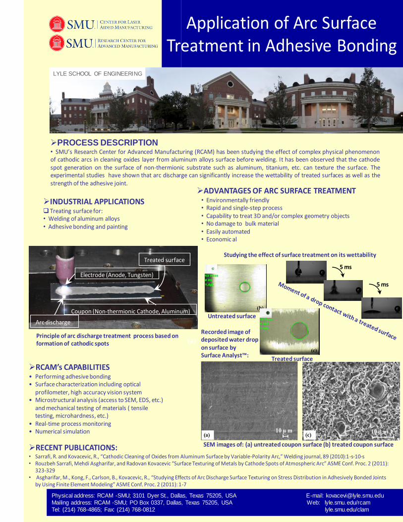
Application of Arc Surface Treatment in Adhesive Bonding
INDUSTRIAL APPLICATIONS Treating surface for:• Welding of aluminum alloys• Adhesive bonding and painting
PROCESS DESCRIPTION• SMU’s Research Center for Advanced Manufacturing (RCAM) has been studying the effect of complex physical phenomenonof cathodic arcs in cleaning oxides layer from aluminum alloys surface before welding. It has been observed that the cathodespot generation on the surface of non-thermionic substrate such as aluminum, titanium, etc. can texture the surface. Theexperimental studies have shown that arc discharge can significantly increase the wettability of treated surfaces as well as thestrength of the adhesive joint.
ADVANTAGES OF ARC SURFACE TREATMENT• Environmentally friendly• Rapid and single-step process• Capability to treat 3D and/or complex geometry objects• No damage to bulk material• Easily automated• Economic al
RCAM’s CAPABILITIES• Performing adhesive bonding• Surface characterization including optical
profilometer, high accuracy vision system• Microstructural analysis (access to SEM, EDS, etc.)
and mechanical testing of materials ( tensile testing, microhardness, etc.)
• Real-time process monitoring • Numerical simulation
Coupon (Non-thermionic Cathode, Aluminum)
Arc discharge
Electrode (Anode, Tungsten)
Treated surface
(a)Principle of arc discharge treatment process based on formation of cathodic spots
Untreated surface
Recorded image of deposited water drop on surface by Surface Analyst™:
Treated surface
5 ms
5 ms
SEM images of: (a) untreated coupon surface (b) treated coupon surface RECENT PUBLICATIONS:• Sarrafi, R. and Kovacevic, R., “Cathodic Cleaning of Oxides from Aluminum Surface by Variable-Polarity Arc,” Welding journal, 89 (2010):1-s-10-s• Rouzbeh Sarrafi, Mehdi Asgharifar, and Radovan Kovacevic “Surface Texturing of Metals by Cathode Spots of Atmospheric Arc” ASME Conf. Proc. 2 (2011):
323-329• Asgharifar, M., Kong, F., Carlson, B., Kovacevic, R., “Studying Effects of Arc Discharge Surface Texturing on Stress Distribution in Adhesively Bonded Joints
by Using Finite Element Modeling” ASME Conf. Proc. 2 (2011): 1-7
Studying the effect of surface treatment on its wettability

486609
Physical address: RCAM -SMU; 3101 Dyer St., Dallas, Texas 75205, USA E-mail: [email protected] Mailing address: RCAM -SMU; PO Box 0337, Dallas, Texas 75205, USA Web: lyle.smu.edu/rcam Tel: (214) 768-4865; Fax: (214) 768-0812 lyle.smu.edu/clam
Since August 1997, Dr. Radovan Kovacevic has been a Herman Brown Chair in Engineering and a
Professor of the Mechanical Engineering at SMU. He has also been a founder and Director of the
Research Center for Advanced Manufacturing since 1999 and a Director of the NSF Industry/University
Cooperative Research Center for Lasers and Plasmas for Advanced Manufacturing (SMU’s site) since
2005. Prior to joining SMU, Dr. Kovacevic was a faculty member at the University of Montenegro,
former Yugoslavia, for fifteen years, at Syracuse University for four years, and at the University of
Kentucky for six and a half years. His research interest is in materials processing by high-power lasers,
abrasive water jet, and electron beam; hybrid laser/arc welding; friction stir welding; numerical
simulation of heat transfer in fluid flow in different manufacturing processes; monitoring and control
of different manufacturing processes; micro-machining by short-pulsed lasers; rapid manufacturing
with reverse engineering; and design and manufacturing of bio-medical implants. Dr. Kovacevic is a
Fellow of three prominent engineering societies: the American Welding Society (AWS); the American
Society of Mechanical Engineers (ASME); and the Society of Manufacturing Engineers (SME). He was
awarded the 2000 Taylor Research Medal by the Society of Manufacturing Engineers for his
accomplishments in education and research related to manufacturing engineering. Additionally, he
was a recipient of the Alexander von Humboldt Scholarship (Germany) for two years, Carl Duisberg
Scholarship (Germany) for one year and the Fulbright Foundation Scholarship for one year. His work
has been presented to the engineering community in over 580 technical papers, six books, seven U.S.
patents and over 20 invention disclosures. Since 1987, his research activities have been financially
supported by a number of state and federal agencies and the industry in excess of $20 million. Over
200 graduate students, visiting scholars, undergraduate interns, and high school teachers have worked
in his laboratories since 1987. He graduated 32 Ph.D. candidates and his publications have been cited
over 5700 times with the citation index h=38. More information on his research activities is available
at www.lyle.smu.edu/rcam and www.lyle.smu.edu/clam.
The following statements are excellent testimonials of Dr. Kovacevic’s accomplishments as a teacher, adviser, and researcher.
Dr. Hosein Atharifar, an Assistant Professor at the Department of Industry and Technology of Millersville University of
Pennsylvania, a former doctoral student of Dr. Kovacevic who graduated in May of 2008, wrote to Dr. Kovacevic the following
note:
On February 28, 2009, Dr. Jianming Qu, a Professor and Associate Chair in the School of Mechanical Engineering at Georgia
Institute of Technology sent a thank you note to Dr. Kovacevic after his visit to SMU with the following content:
“Dear Radovan,
It was a great pleasure meeting you last week. I am extremely impressed by the quality and quantity of your research
operation there. It is amazing that you single handedly developed such a large-scale research program within such a
short period of time. I have visited many universities and met a lot of people in the manufacturing area. I rarely see
an individual who has carried that much research.
Thank you again and best wishes, Jianmin”
Dr. Geoffrey Orsak, Dean of Lyle School of Engineering made the following statement in the article “SMU Graduate School
Specializes in Green and Joining Technology”, published in the Welding Journal, June 2010:
“The RCAM and CLAM have brought a great deal of international visibility to the SMU Lyle School of Engineering. The quality and impact of the work conducted in these two aligned centers is simple spectacular”.
Radovan Kovacevic
PhD
Herman Brown Chair in Engineering
Professor of Mechanical Engineering
Director of Research Center for Advanced Manufacturing and Center for Laser-aided Manufacturing