
Lapland UAS thesis template - Theseus
89
Investigation of Low Force Stereolithography Using Selected Applications and Recommendations for a Better Workflow Sieberer Markus Bachelor’s Thesis Lapland University of Applied Sciences Mechanical Engineering Bachelor of Engineering 2021
-
Upload
khangminh22 -
Category
Documents
-
view
2 -
download
0
Transcript of Lapland UAS thesis template - Theseus

Investigation of Low Force Stereolithography Using Selected Applications and Recommendations for a Better
Workflow
Sieberer Markus
Bachelor’s Thesis Lapland University of Applied Sciences
Mechanical Engineering Bachelor of Engineering
2021

Lapland University of Applied Sciences Mechanical Engineering Bachelor
Abstract of Thesis
Author Markus Sieberer Year 2021 Supervisor Ari Pikkarainen, M.Sc. (tech.) Commissioned by Lapland UAS, Mechanical Engineering Title of Thesis Investigation of Low Force Stereolithography Using
Selected Applications and Recommendations for a Better Workflow
Number of pages 84 + 5
Since additive manufacturing in general, and also low force stereolithography technology, faces a knowledge gap that is one of the biggest limiting factors for its general adoption, this thesis aimed to close this information gap by investigating some selected advanced applications. In this respect, various scientific questions were addressed regarding the effects of different part orientations, the feasibility and requirements of manufacturing metric internal and external threads, and the approach of printing objects on top of each other. Moreover, stereolithography requires working with toxic substances, which makes safety and cleanliness important aspects. Therefore, the second objective of this thesis was to improve the workflow for the 3D printing laboratory at Lapland University of Applied Sciences. Firstly, to investigate the effects of different part orientations, two different objects were produced at different angles to analyse the effects on material consumption, print time and overall visual quality. Secondly, by producing different-sized metric internal and external threads, the feasibility and necessary scaling factors were determined and thirdly, the possibility and effects of stacked printed objects were investigated by using two different methods and object types. All practical printing tests were carried out using Formlabs' Form 3 printer. Furthermore, all workflow recommendations were developed based on own experience within this thesis. The wide-ranging results of this thesis imply that part orientation has a substantial effect on earlier mentioned parameters and is best when the object surface area facing the build platform is kept to a minimum. Furthermore, M12 to M4 threaded screws and nuts are possible to print when considering investigated scaling factors and printing objects on top of each other was found as feasible but not as economic. Regarding workflow improvements, some setup upgrades and a contamination concept was introduced, and the complete improved workflow was re-defined. Key words additive manufacturing, low force stereolithography, workflow, orientation, threads, stacking
CONTENTS
1 INTRODUCTION ............................................................................................ 7
1.1 Problem and motivation ......................................................................... 8
1.2 Objectives and significance ................................................................. 10
1.3 Methodology ........................................................................................ 11
2 ADDITIVE MANUFACTURING ..................................................................... 13
2.1 Generic AM process ............................................................................ 15
2.2 Usage and benefits of AM .................................................................... 16
2.3 Overview on AM categories and technologies ..................................... 17
3 VAT PHOTOPOLYMERIZATION (SLA & LFS) ............................................ 20
3.1 Functionality of stereolithography ........................................................ 20
3.2 Advantages, disadvantages, and fields of application ......................... 22
3.3 General design considerations and characteristics .............................. 23
3.4 Review of different materials ................................................................ 27
3.5 Low force stereolithography and comparison to generic SLA .............. 30
4 WORKING IN A FORMLABS ENVIRONMENT ............................................ 35
4.1 Formlabs workflow ............................................................................... 35
4.2 Risks, prevention measures and toxicity .............................................. 38
4.3 Setup description of 3D printing laboratory .......................................... 41
5 METHODOLOGY ......................................................................................... 44
5.1 Evaluation of effects of different printing orientations .......................... 44
5.2 Printing of different-sized iso metric threads ........................................ 47
5.3 Attempt of printing objects on top of each other ................................... 50
5.4 Development of own workflow recommendations ................................ 53
6 RESULTS AND ANALYSES ......................................................................... 54
6.1 Investigated effects of different printing orientations ............................ 54
6.2 Printed different-sized iso metric threads ............................................. 58
6.3 Printed objects on top of each other .................................................... 62
6.4 Own workflow recommendations and improvement ideas ................... 66
7 CONCLUSIONS & DISCUSSION ................................................................. 72
7.1 Part orientation .................................................................................... 72
7.2 Metric threaded screws and nuts ......................................................... 73
7.3 Stacked objects ................................................................................... 74
7.4 Workflow improvements ....................................................................... 75

7.5 Future studies ...................................................................................... 75
BIBLIOGRAPHY ............................................................................................... 77
LIST OF FIGURES ........................................................................................... 82
LIST OF TABLES .............................................................................................. 84
APPENDIX ........................................................................................................ 85

5
FOREWORD
I would like to thank Ari Pikkarainen, Sanna Moisanen, Peter Franz and Johanna
Wachter for making the first ever double degree programme between Vienna
(UAS Technikum Wien) and Kemi (Lapland UAS) possible. A big thank you to Ari
for the support and good cooperation during the whole academic year in Kemi
and to Sanna who was like our host mother and helped us with everything. Also,
I could not have survived a whole year in Lapland without the support of all our
international student tutors, especially Julianna and Amir, and all the Kemi
exchange students in 2020/21. It was a great year with ups and downs, but
through the inspiration of Dr. Dave I always found my motivation. In addition, one
of the most essential things for this thesis was the daily lunch buffet at the Kosmos
campus and all the tools from Jouko's workshop. Special thanks also to Henna,
who was always smiling and taught me some Finnish words while shopping.
Last but not least, I would like to thank my family and friends who made it possible
for me to study abroad for a whole year and told me to just do it. My sister always
supported me with her music and my friends were always able to slow me down
when I was too stressed. So, many thanks to Jessi, Manuel and co. Finally, a
thank you to my three double degree colleagues and flatmates, Nicole, Hansi and
Markus, because all this was only possible together.

6
SYMBOLS AND ABBREVIATIONS
3D Three-Dimensional
AM Additive Manufacturing
ASTM American Society for Testing and Materials
BJ Binder Jetting
CAD Computer Aided Design
CNC Computerized Numerical Control
DIY Do It Yourself
DLP Digital Light Processing
FDM Fused Deposition Modelling
FFF Fused Filament Fabrication
IPA Isopropyl Alcohol
ISO International Standards Organization
LENS Laser Engineered Net Shaping
LFS Low-Force Stereolithography
LOM Laminated Object Manufacturing
LPU Light Processing Unit
MJ Material Jetting
MIT Massachusetts Institute of Technology
PPE Personal Protection Equipment
R&D Research and Development
RP Rapid Prototyping
SDS Safety Data Sheet
SL Stereolithography
SLA Stereolithography Apparatus
SLS Selective Laser Sintering
STL Standard Triangle Language
UAS University of Applied Sciences
UV Ultraviolet
VP Vat Photopolymerization

7
1 INTRODUCTION
Additive manufacturing (AM) saw its earliest approaches and concepts at the end
of the 19th century, and early 20th century. Back then, the first applications for AM
were the manufacturing of layer-based topographical maps to represent terrain
three dimensional. However, modern AM, was introduced in the mid-20th century
as the first patent in that field was registered. Nowadays, this patent is considered
as the starting signal of modern stereolithography (SL) technique. Despite this
publication, AM became not commercially before 1986, when Chuck Hull
published another patent regarding SL. Two years later, he has found the start-
up “3D Systems” that released the first commercially available stereolithography
apparatus (SLA) machine. Therefore, SL is considered as the very first
commercially available AM technology which today is considered as part of the
vat photopolymerization family when it comes to the classification of different AM
technologies. (Diegel, Nordin & Motte 2019, 1, 3; Gibson, Rosen, Stucker &
Khorasani 2021, 78.) However, the starting signal for AM to be spread globally
on the international market was between 2009 and 2014 when most patents,
considering SL and other AM technologies, expired. During this period, many
modern start-ups, such as Formlabs were found that is one of the biggest SLA
manufacturers today and is also the developer of low-force stereolithography
(LFS), the newer and better version of SL (3dsourced 2020; Formlabs 2019a.)
Since this time, also the number of scientific publications regarding AM in general
started to increase exponentially (see Figure 1).

8
Figure 1. Trend in scientific papers published over two decades from 2000 to
2019 on 3D printing (Vahabi, Laoutid, Mehrpouya, Saeb & Dubois 2021, 2)
As shown in Figure 1, the number of scientific reports about AM and the more
common keyword in media, 3D printing, has increased exponentially especially
within the last decade (2010 – 2019). The number of publications in 2019 is
already above 5,000 whereas it was at about 200 in 2010. This shows the
extraordinary effect of the expiration of most patents in AM (SL involved).
Furthermore, not only the number of scientific publications has seen a
skyrocketing trend but also the number of AM machines sold is increasing
exponentially, as stated in the Wohlers report, which is published annually.
According to the Wohlers report 2015, the number of AM machines sold
worldwide per year under 5,000 $ has doubled every year since 2012 and
reached more than 528,000 in 2016 whereas it was below 6,000 in 2010. (McCue
2018; Redwood 2021a.)
1.1 Problem and motivation
Because of those mentioned trends of rising numbers of scientific publications
and sold AM machines, the penetration level of all different AM technologies has
changed during the last decade. Nowadays however, SL is the third most

9
common AM technology used in industry after fused deposition modelling (FDM,
material extrusion) and selective laser sintering (SLS, powder bed fusion).
Considering private households, SL is even the second most common AM
technology after FDM. (Statista 2020.) In addition, the use of AM and also
specifically of SL in educational and research and development (R&D) institutions
increased steadily over the last few years. Despite these trends, in SL, toxic
resins are used for the manufacturing process of parts, whereby it is crucial to
follow certain steps and general safety measures when handling such materials
in order to prevent critical health issues (Diegel et al. 2019, 30; Formlabs 2021j).
Therefore, the most important safety measures and guidelines for handling these
resins, as well as information on a safe workflow in SL, must be known to the
users of such AM machines, regardless of whether they are used in industry or
privately in households. Especially private users of SL should be familiarised with
safety measures, as they rather tend to not obtain certain rules or neglect to wear
suitable personal protection equipment (PPE). Furthermore, besides those earlier
mentioned increasing trends in AM, there are still some limiting factors for the
adoption of AM (see Figure 2).
Figure 2. Limiting factors for the adoption of AM (Sculpteo 2020, 11)
Figure 2 shows part of the results of a survey about the state of AM, carried out
by Sculpteo, a French AM company, in 2020. In this survey, more than 1,600
individuals all around the world were asked about limiting factors for the adoption
of AM. As can be seen, the three most common limiting factors are cost of entry,
lack of knowledge, and operating costs. Since more and more AM machines are
being sold each year, as already mentioned earlier, it can be assumed, that the

10
prices and cost of entry will decline soon (McCue 2018). However, by raising
awareness by publishing scientific reports, the limiting factor of lacking
knowledge can be reduced. Regarding the high operating costs of AM machines,
it is important to gain knowledge about the respective selected process which
involves information on how to orientate parts properly on the build platform of
the AM machine in order to keep the running costs to a minimum. By orientating
parts correctly it could be possible to reach shorter manufacturing times or to
reduce the number of attempts to reach the desired quality and accuracy.
(Chitubox 2020; Ghazy & Hossam 2015, 4, 6.) Furthermore, SL is generally
known and considered for parts with exceptional visual quality and smooth
surface finish rather than functional parts for assemblies such as threaded screws
and nuts. However, such applications could be tested in order to broaden the field
of applications of SL. (Diegel et al. 2019, 32.)
1.2 Objectives and significance
The aim of this thesis is to provide a summarized view of the AM technology SL
and in particular LFS, in order to contribute a scientific report that helps against
the limiting factor of the mentioned knowledge gap for the adoption of AM. That
involves information about the AM process of SL and LFS as well as instructions
regarding a safe workflow and handling the resins properly. Furthermore, various
scientific questions listed below regarding selected applications for LFS shall be
answered during practical printing tests in this thesis to investigate the feasibility
of specific use cases for LFS. The most important questions to be answered are
following ones:
- How does part orientation effect the result in terms of print time, material
consumption, support structure, and overall quality?
- Which sizes of iso-metric threaded screws and nuts are possible to
manufacture with ensured fitting and which scaling factors may have to be
considered?
- Is it possible to print objects on top of each other to use more of the build
volume? What conditions must be met and what effects occur?

11
Last but not least, another aim of this thesis is to develop own recommendations
for improving the LFS workflow and safety in the 3D printing laboratory of Lapland
University of Applied Sciences (Lapland UAS).
1.3 Methodology
This thesis is divided into two general sections first being a broad literature
research part and second a development part including various practical printing
tests with LFS and workflow improvements for the 3D printing laboratory of
Lapland UAS (see Figure 3). The research part of this thesis is intended to be the
basis for the development part which means that in the research part, the theory
is presented in connection with the later practical tests.
Figure 3. Overview of the methodology of this thesis
As can be seen in Figure 3, all relevant findings of the literature research will be
summarised and presented in the research part of this thesis. In this part, SL and
LFS will be investigated in more detail by researching the technology itself and
the general manufacturing process and differences. In addition, various types of
resins, the Formlabs workflow and the main aspects of occupational safety and
handling of the resins will be presented. Furthermore, in the development part of
this thesis, all methodologies for the practical printing tests are defined and
carried out in order to subsequently analyse all results obtained. Thus, several
printing tests with Formlabs Form 3 LFS machine will be carried out to find

12
answers to the earlier mentioned scientific questions, regarding different selected
applications for LFS. During these practical tests, the effect of part orientation of
different objects on the final result in terms of print time, material consumption,
support structure, and overall quality will be investigated to find suitable
orientations for different use cases. Another selected application for the practical
tests is the manufacturing of threaded screws and nuts to test feasibility,
accuracy, and fitting. Furthermore, it will be tested if printing objects on top of
each other is generally possible to find out what conditions need to be fulfilled
and finally own recommendations and improvement ideas for a better workflow
in the 3D printing laboratory of Lapland UAS will be developed and presented. At
the end, all findings obtained during the development part of this thesis will be
concluded and discussed.
13
2 ADDITIVE MANUFACTURING
AM is a widely used term including a variety of different technologies to
manufacture physical objects layer by layer from digital 3D models (Diegel et al.
2019, 1). The term additive manufacturing therefore implies that material is added
to form a new object or to change or improve an already existing object (Kumar
2020, 1). According to the Finnish Standards Association, additive manufacturing
is a ”process of joining materials to make parts from 3D model data, usually layer
upon layer” (ISO/ASTM 52900:2017, 28). In the past, additive manufacturing was
called rapid prototyping (RP) (Gibson et al. 2021, 1). Today, rapid prototyping is
defined as one of many applications of additive manufacturing to produce
prototypes rapidly in a short period of time (ISO/ASTM 52900:2017, 37).
Therefore, additive manufacturing is not only commonly used to faster create a
physical representation of a product before its final release or commercialization
but also to manufacture real parts with a close link to the final product (Gibson et
al. 2021, 1). Furthermore, the term 3D printing was first used by researchers at
MIT but it is the most commonly term to describe AM technologies today as the
process starts with nothing and creates the object layer by layer by printing each
layer upon the other until the desired part is finalised (Diegel et al. 2019, 1, 8).
However, creating physical objects by adding material is the main aspect of
additive manufacturing. Thus, additive manufacturing differs from other
manufacturing approaches such as subtractive or formative manufacturing.
Subtractive processes like CNC machining, drilling, or cutting do not add material
but remove material to form the desired object and deforming processes such as
bending deforms the material. Especially when comparing additive manufacturing
with subtractive manufacturing, there are two different approaches: top-down and
bottom-up (see Figure 4). (Kumar 2020, 1.)

14
Figure 4. Top-down approach in subtractive manufacturing and bottom-up
approach in additive manufacturing (modified after Kumar 2020, 7)
Figure 4 shows the main difference between the two approaches of subtractive
manufacturing and AM. The upper row of the figure shows the top-down approach
that is commonly used in machining such as CNC machining. This approach can
also be called a big-small approach as it starts with a big block of material and
ends with the smaller desired object. The machining tool cuts material away
(subtractive manufacturing) and therefore starts usually at the top of the material
block and ends at the bottom. The second row of the figure represents the
bottom-up approach that is used in additive manufacturing. The manufacturing
process starts with the first layer at the bottom and ends with the last layer at the
top. In other words, this approach can also be considered as the small-big
approach as small blocks (layers) at the beginning form a complete object at the
end. These two approaches are the fundamentals of each manufacturing class
and they are independent from the object orientation. If the 3D model of the object
would be rotated for 180°, then the process is still the same. It starts with the first
layer (bottom) and ends with the last layer (top) in additive manufacturing. The
generation of waste is not avoidable in subtractive manufacturing whereas it is
not necessary in AM. Figure 4 shows a nozzle for the additive manufacturing
process even though this does not account for all AM technologies. However, all
AM technologies use the same bottom-up approach. The figure only simplifies
the schematic by using a nozzle for showing that approach. Technologies that do
not use an AM nozzle also build the desired object by starting with the first bottom
layer and ending the last top layer. (Kumar 2020, 7-8.)

15
2.1 Generic AM process
While general manufacturing processes (e.g., subtractive manufacturing) acquire
detailed and sometimes elaborate planning of how the desired physical object
can be produced in terms of orientation, tool usage and order as well as which
features can be realised, in AM there is no need for thoughtful process planning.
In AM, even complex objects can be produced directly from a 3D computer aided
design (CAD) which remarkably simplifies the whole manufacturing process
chain. (Gibson et al. 2021, 2.) The actual steps in the process chain of AM depend
on the stage of a product and can therefore vary in order and extent. For example,
early stages focus more on the visualization of digital models where rough
surfaces are tolerated, while the later stages of a product focus more on
functionality and visual appearance, where post-processing might be required.
However, the main aspects of the process chain remain the same. (Gibson et al.
2021, 3-4.) This chapter summarises the AM process chain and briefly describes
each step of how a desired object is manufactured (see Figure 5).
Figure 5. The AM process chain (a-d) (modified after Diegel et al. 2019, 6)
In the first step, all AM objects start with a virtual 3D CAD model that completely
describes the external surfaces and geometries (see Figure 5.a). For this, any
adequate CAD software can be used. The only requirement is that the model is
a solid or a fully representation of the surface of the model. If there are gaps or
missing surfaces, it would mean that there is an infinitely thin layer that cannot be
manufactured later in the process. Second, after modelling the CAD object, the
CAD file is converted into a STL file (standard triangle language, standard
tessellation language or stereolithography). This file format can be understood by
basically all AM machines (commonly called 3D printer) and it describes the

16
whole surface of the digital model with connected triangles (see Figure 5.b).
Dependent on the pre-set resolution, the triangle net matches more or less with
the actual model boundaries. The higher the resolution of the STL file the higher
the quality of the model as it contains more and smaller triangles across the
model’s surface. (Diegel et al. 2019, 4-5; Gibson et al. 2021, 5.) In the next step,
the STL file is loaded into a suitable slicing software that is compatible with the
AM machine. The model is then placed on the virtual build platform for adjusting
the build orientation of the model and adding support material if necessary (critical
design features will be discussed later in this thesis). The slicing software slices
the model into thin layers (see Figure 5.c), generating the g-code for the AM
machine and usually allowing to define certain AM machine parameters such as
the layer height, building speed and infill settings. The resultant g-code is a set of
commands that controls the AM machine to manufacture the desired physical
object. It includes information about how the AM machine must use its tool (e.g.
nozzle) to build the object layer-by-layer. (Brown & Beer 2013, 4-5; Diegel et al.
2019, 5; Kumar 2020, 4-5; Manoj Prabhakar et al. 2020, 3-4.) Once the AM
machine is setup and the g-code loaded to its internal memory, the building (more
commonly called printing) process starts by converting the virtual layers into
physical layers (see Figure 5.d) with the help of the g-code commands. The exact
building process depends on the technology used by the AM machine and is
discussed later in this thesis. The process itself however, is a mainly automated
process and does not require a strict supervision. (Gibson et al. 2021, 5.) Finally,
the manufactured (printed) physical object is removed from the build platform.
Dependent on the AM technology, this step may require special safety measures
when for example handling with resin or powder. After removal, the object may
require additional cleaning or post-processing to achieve the desired surface
finish, mechanical strength or other properties than cannot be provided by the
AM machine itself. (Diegel et al. 2019, 6; Gibson et al. 2021, 5-6.)
2.2 Usage and benefits of AM
According to Diegel et. al (2019, 7) the 2018 Wohlers Report (annual state of the
industry report) stated that 43.9 % of AM applications are in the field of rapid
prototyping which includes functional representations of models with suitable
assembly and fit. However, 56 % use AM for real direct or indirect part production

17
and Wohlers expects this number to rise steadily over the next few years as more
and more companies and industries invest in AM for their production and
manufacturing processes. Not only the share of part production is spreading but
also the number of different industry sectors using AM show increasing trends.
AM is mostly used by sectors such as motor vehicles, aerospace, industrial
engineering, electronics, and healthcare. Furthermore, AM machines like desktop
3D printers are getting cheaper and affordable by more and more people which
leads to growing do-it-yourself (DIY) communities in the field of AM. (Diegel et al.
2019, 7-8.) That means AM is not only used for prototyping with reduced costs
and shorter process chains but also for replacing parts made from generic
manufacturing processes as AM fulfil the “3F-Formula” that is form, fit and
function. That is also one of the reasons why the term rapid prototyping evolved
to additive manufacturing. (Gibson et al. 2021, 3.)
All these remarkably trends are based on various benefits, AM comes along with.
To only mention a few advantages, AM outperforms other technologies in many
respects. For example, when it comes to part complexity, AM is better the more
complex a part is compared to subtractive manufacturing where essential limits
are present and sometimes cannot even be produced. (Diegel et al. 2019, 8-9.)
This can result in part consolidation where several simpler parts can be replaced
by a single more complex AM part. In addition, AM offers designers a greater
degree of freedom when designing a part, and thanks to well-developed AM
technologies, mass customization and on-demand manufacturing have never
been easier. (Diegel et al. 2019, 13-16.)
2.3 Overview on AM categories and technologies
AM offers a variety of different AM machines that are based on several
technologies. Each technology offers its own specific approach on how to transfer
the virtual layers from the g-code file into physical layers and finally into the
desired physical object. However, AM is a fast changing and developing
manufacturing sector and AM technologies are continuously being developed or
upgraded. Also, some technologies have different variants within the same
category. The aim of this chapter is not to describe all existing AM technologies
and variants but to give a broad overview on each category of AM technologies

18
and to briefly mention their definition and fundamental functionality. In this
chapter, as well as throughout the thesis, an attempt is made to align the
terminology with the defined ASTM (American Society for Testing and Materials)
terminology for AM technologies. According to this standard, AM technologies
are distinguished mainly by the way the material is consolidated to achieve part
production. (Diegel et al. 2019, 19; ISO/ASTM 52900:2017, 26, 29.) Table 1
summarises the seven AM categories and provides examples for AM
technologies as well as for the main materials each group can print with.
Table 1. Classification of AM processes with given examples of AM technologies
and materials (3D Hubs 2021a, 16; ISO/ASTM 52900:2017, 29)
Process category Example Process Main Material
1 Binder Jetting BJ Gypsum, Sand, Metal
2 Directed Energy Deposition LENS Metal
3 Material Extrusion FFF Composite, Plastic
4 Material Jetting MJ Plastic, Metal
5 Powder Bed Fusion SLS Plastic
6 Sheet Lamination LOM Composite, Paper
7 Vat Photopolymerization SLA, DLP Plastic
The classification of the ISO/ASTM 52900 is the newest and mostly used
categorisation of AM technologies. All different types of AM technologies are
under one of these seven groups (see Table 1) (3D Hubs 2021a, 16). In the
following, all seven groups are shortly described with their definition according to
the mentioned ASTM standard. In binder jetting (BJ), a liquid bonding agent is
selectively deposited to join powder materials (ISO/ASTM 52900:2017, 29). A
small proportion of the would-be part material is extruded trough a print head,
most of the part material is comprised of powder in the powder bed (Gibson et al.
2021, 237). Directed energy deposition uses thermal energy (high-energy
source) to fuse materials by melting as it is deposited. (ISO/ASTM 52900:2017,
29; 3D Hubs 2021a, 16). An example process for that is laser engineered net
shaping (LENS) where a heat source in form of a laser melts powder and
substrate using a coaxial nozzle to manufacture parts (Kelly, Elmer, Ryerson, Lee
& Haslam 2021, 1). The third AM process category according to Table 1 is

19
material extrusion. Here, a material is dispensed through a nozzle or orifice like
how icing is applied to cakes. The plastic material is in a semisolid state and is
being extruded in a specific flow rate under a specific pressure while the nozzle
is moving at a certain speed. (ISO/ASTM 52900:2017, 29; Gibson et al. 2021,
171.) When choosing a process in this category, fused filament fabrication (FFF),
also known under the trademark fused deposition modelling (FDM) is the most
known and used process (Li, McGuan, Isaac, Kavehpour & Candler 2021, 1). In
the next AM process category, material jetting (MJ), droplets of material are
selectively deposited and cured (3D Hubs 2021a, 16; ISO/ASTM 52900:2017,
29). Powder bed fusion is another one of the seven classes of AM technologies
where the process of selective laser sintering (SLS) is often used when polymers
are the build material (Chatham, Long & Williams 2019, 1). In this process,
thermal energy (high-energy source) fuses regions of a powder bed (ISO/ASTM
52900:2017, 29). A thin layer of powder is spread on a platform which represents
the layer of the model that is fused with further powder layers (Kumar 2020, 41).
Based on the process category of sheet lamination is the technology of laminated
object manufacturing (LOM). In LOM, material sheets are bonded and formed
together (ISO/ASTM 52900:2017, 29). Each sheet represents a cross-sectional
layer of the desired part, bonded together in different ways. Excessive material is
cut by using a CO2 laser (Gibson et al. 2021, 253). The last process category is
vat photopolymerization (VP) that includes the two common processes of
stereolithography apparatus (SLA) and digital light processing (DLP). Both
processes are based on the same approach as liquid photopolymer in a vat is
selectively cured by light-activated polymerization (photopolymerization).
(ISO/ASTM 52900:2017, 29.) Radiation curable resins are used to undergo a
chemical chain reaction to become solid (Gibson et al. 2021, 77). In SLA, a single
laser beam is used that traverses the entire cross-sectional plane of the model
slice along a predefined path (Varotsis 2021a). In DLP however, a digital light
projector screen flashes the whole layer of the model at once. This leads to faster
manufacturing times compared to SLA but due to the limited projector screen
resolution, SLA can be finer and more detailed than DLP. (Redwood 2021b.)

20
3 VAT PHOTOPOLYMERIZATION (SLA & LFS)
Stereolithography (SLA) is an AM process that belongs to the AM category of vat
photopolymerization (VP) as shown in Table 1 in chapter 2.3. The term
stereolithography was formed by Chuck Hull who created the first-ever 3D printed
part and patented this AM technology in 1984. Later he founded the worldwide
first 3D printing company “3D Systems” to commercialise it. (3D Systems 2017;
Chartrain, Williams & Whittington 2018, 97; Formlabs 2019a, 6.) In this chapter,
the SLA fabrication process is explained and compared to low force
stereolithography (LFS), the newer version of this AM process (Formlabs 2019a,
7). Furthermore, the most important design rules will be summarised and popular
print materials with their properties and fields of applications will be presented.
3.1 Functionality of stereolithography
In VP, a beam of ultraviolet (UV) laser light selectively cures liquid photopolymers
(polymer resin) by triggering a chemical chain reaction, the so called
photopolymerization. The beam of UV light therefore scans the surface of the
resin for each layer of the STL model and hardens the resin layer-by-layer. After
each layer, the build platform of the AM machine moves exactly one layer height
and the UV laser light scans and hardens the next layer of resin. (Diegel et al.
2019, 30; Varotsis 2021a.) In Stereolithography there are two basic approaches
for curing the resin and building up the part. For industrial applications, the top-
down approach is usually more popular (see Figure 6 left). Top-down SLA
machines have the light source above the build platform and the resin tank. The
build platform moves downwards after each layer so that the next layer of liquid
resin can be cured. (Varotsis 2021a; Zakeri, Vippola & Levänen 2020, 2-3.)
Figure 6. Schematic of a top-down (left) and bottom-up (right) SLA machine
(modified after Varotsis 2021a)

21
The more common approach for desktop applications is the bottom-up approach,
where the light source is under the resin tank and the part is built facing upside
down (see Figure 6 right). The bottom of the resin tank is light transparent to allow
the laser to cure the resin in it and the build platform moves upwards after each
layer. That means, that the freshly cured resin is detached from the bottom of the
tank (so called shearing process). For this reason, the transparent tank bottom is
coated with silicone to prevent cured resin from sticking to it. The principle of
curing the resin is in both approaches the same. (Varotsis 2021a; Zakeri et al.
2020, 2-3.) However, in this thesis, the focus is set to desktop bottom-up SLA
machines, whose schematic is shown in Figure 7.
Figure 7. Representation of the basic mechanics of a bottom-up SLA machine
(modified after Formlabs 2019a, 4)
Figure 7 shows a schematic of the main components of a bottom-up SLA machine
developed by Formlabs. As can be seen, the resin tank is filled with liquid resin
that gets solidified by a laser that is under the tank. The resin is usually dispensed
through a resin cartridge that is inserted into the SLA machine before the
manufacturing process. The SLA fabrication process of bottom-up SLA machines
usually consists out of three main steps:
1: Build Platform
2: Resin Cartridge
3: Resin Tank
4: Printed Part
5: Laser
6: Galvanometers
7: Mirror
8: Laser Beam
9: Wiper
10: Photopolymer Resin

22
1. The build platform is positioned in the liquid resin one layer-height above
the bottom of the resin tank.
2. A UV laser creates a layer by curing and solidifying the liquid resin. The
laser traverses the entire cross-sectional plane along a predefined path
by adjusting the mirror and the galvanometers (see Figure 7).
3. After one layer is complete, the build platform rises to a safe height and
the sweeper swipes once across the bottom of the tank to coat it evenly
with new resin. These three steps then repeat until the desired part is
finished. (Varotsis 2021a.)
After the manufacturing process is completed, SLA printed parts always require
further post-processing steps that among other things mainly include washing
and curing as the part is in a no-fully-cured state (also called “green state”)
(Varotsis 2021a). Those steps will be explained later in this thesis.
3.2 Advantages, disadvantages, and fields of application
The AM technologies within the VP family and especially SLA are typically known
for their excellent surface quality and surface finish. As mentioned in the last
chapter, SLA machines usually offer high accuracies which is beneficial for parts
that require tight tolerances and well-defined textures. Therefore, SLA printed
parts are suitable and usually used for form and fit applications and visual
prototypes for example in the cosmetic industry. These advantages are mainly
due to the nature of the printing material used, i.e., resin or, more precisely,
thermoset as it is better suited for applications where aesthetics is important.
Generally, thermosets are quite brittle but come along with great stiffness and
they are available in many different kinds for certain applications such as in the
field of engineering, cosmetics, aerospace but also for dental or medical purposes
as well as in the educational sector. Additionally, different kinds of resins offer
different kinds of special material properties such as clearance or flexibility.
(Diegel et al. 2019, 32; Gibson et al. 2021, 117; Pazhamannil & Govindan 2021,
5-6; Varotsis 2021b.) The different types of resins with their properties are
described in detail later in this thesis. Furthermore, another main advantage is
the high isotropy of SLA printed parts. Regarding other AM families such as
material extrusion, parts have different strengths in X, Y and Z direction

23
dependent on the printing orientation due to layer-to-layer differences and are
therefore considered as quite anisotropic. With SLA, on the other hand, the nature
of the curing resins results in highly isotropic parts, as each printed layer remains
in what is known as a “green state” (not fully cured state), in which polymerizable
groups form that generates cross-layer bonds. This ability results in great
watertightness as SLA parts are continuous and allows for example to control air
and fluid flows for engineering applications. (Cosmi & Dal Maso 2020, 194-195;
Formlabs 2019a, 9-10.)
On the other hand, SLA performs not perfectly in all aspects. It can be a good
choice if the scope is on the advantage side, but there are some facts that are
more considered as disadvantages and that are better in other AM processes
than in the family of VP. Regarding material properties, resins tend to change
their properties over time which means that minimal shrinkage could be a fact. In
addition, photopolymers degrade when they are getting older, especially when
SLA printed parts are exposed to direct sunlight or UV rays, which means that
their visual appearance and mechanical properties in terms of brittleness
decrease. That is why, the AM process SLA is not commonly used for functional
outdoor applications. Also, important to mention is that SLA always requires
support material that needs to be removed after the manufacturing process which
usually leaves tiny visual marks. Removing these support marks can be quite
time intensive and is not always easy when considering small and complex parts.
Furthermore, resins are messy and can be harmful or irritating when getting in
touch with it. Therefore, special safety measures are required. More information
about support material and safety instructions is given later in this thesis. (Diegel
et al. 2019, 32; Gibson et al. 2021, 117; Varotsis 2021b.)
3.3 General design considerations and characteristics
After it was decided that AM in general and VP regarding SLA is the right
approach for manufacturing a part, the designer must consider several aspects.
Before a part can be manufactured by an AM machine, the 3D CAD model must
be designed or prepared. For this, the designer must follow not only general
design considerations for AM, but also certain process dependent design rules
and he/she must familiarise with the characteristics of the AM process and the

24
AM machine itself. Regarding general AM design considerations, there are
various aspects that are equal to all AM processes. Some of them are listed
below: (Diegel et al. 2019, 43-47.)
- There are no 100 % exact values for certain design features. It always
depends on the AM process and machine.
- Part complexity is one of the biggest benefits of AM and should be
applied to a part’s design to fully use the potentials of AM.
- When designing a part, large masses of material and support material
should be minimized.
- The building orientation of parts affects the isotropy, surface quality,
material consumption, support structure and many other aspects in
almost all AM processes. Therefore, it should be considered. (Diegel et
al. 2019, 43-47.)
However, as mentioned above, it is crucial to consider all AM process specific
accuracies and limitations to ensure a successful and qualitative manufacturing
result. Therefore, specific thresholds for each design feature must be adhered to.
For the AM process SLA, the most important design rules are shown in Figure 8.

25
Figure 8. General design rules for the AM process SLA (modified after 3D Hubs
2021b)
As can be seen in Figure 8, there are eleven design rules that are considered as
the most important and critical design features. One of the most important
aspects when manufacturing parts with SLA is that support material is always
required due to the nature of the manufacturing process itself. That is why,
classical bridging without support material is not possible in this AM process (see
Figure 8). In SLA, support structures are built with the same material as the part
and must be removed after the building process. The orientation of the part is a
decisive factor for the amount of support material needed and also determines
the location of it. Therefore, locations where a high degree of visual quality is

26
expected should be free from support during the building process as support
marks could remain after removal. However, the most crucial criterion is to
orientate the part so that the cross-sectional area of each layer is always at a
minimum (see Figure 9). This orientation sometimes requires more support
structure but due to the shearing process after each layer where the build platform
moves upwards (at bottom-up machines), the whole part could get detached from
the build platform if the shearing forces are too high. Minimizing the cross-
sectional area therefore results in lower shearing forces and leads to better
manufacturing qualities and safer building processes.
Figure 9. Example for orientation for minimizing support (left) versus orientation
for minimizing the cross-sectional area and shearing forces (right) (Varotsis
2021a)
Figure 9 shows how to orientate an example part for minimizing support material
(left) and minimizing cross-sectional areas and shearing forces (right). The left
approach can be successful in top-down SLA machines as there are no shearing
forces. In bottom-up machines it is necessary to follow the right approach to
prevent building processes from failing. (Varotsis 2021a.)
Another important design guideline when manufacturing with SLA is to hollow out
parts to safe a significant amount of resin and time at each building process (see
Figure 10). This can be made with simple software applications such as
Meshmixer. However, when hollowing out a model it is important to think about
the reduction of strength and wall thickness but also to generate vent holes at the
bottom of the model that resin can escape. (Formlabs 2021a).

27
Figure 10. Example for hollowing out models and adding vent holes (Formlabs
2021b)
When letting the model shown in Figure 10 fully solid, it would take about 15.5 h
and consume about 246 ml of resin. The hollow model only needs less than 8
hours in manufacturing with a resin consumption of about 77 ml. (Formlabs
2021b.) The vent holes should be around 4 mm (see Figure 8) and the minimum
wall thickness for hollow models should be around 2 mm. Drain holes are also
important to prevent the so called cupping effect i.e. when trapped resin in a
hollow section creates pressure imbalances. This could lead to small cracks until
complete building fails if no vent holes for hollow models are placed. (Armstrong
2021.)
3.4 Review of different materials
In SLA (and LFS), a wide variety of different materials is available that usually
can be used by the same SLA machine (compatibility with different resins). This
wide variety meets a wide range of designer requirements and makes SLA an
increasingly attractive manufacturing process as new materials with improved
properties are constantly being developed. Nowadays, needs such as high-
elongation, transparency, mechanical and high-temperature resistance and even
biocompatibility can already be met with commercially available resins. Designers
therefore tend more and more to use SLA not only for prototyping but for
manufacturing end-use parts. That is why, it is important to know different resins

28
and their properties when selecting SLA as the suitable AM process. (Cosmi &
Dal Maso 2020, 195.) In this chapter, standard and different kinds of engineering
resins are presented and briefly summarised with their areas of application and
advantages and disadvantages.
Considering Formlabs standard resins, these are available in different variants
such as clear, white, grey, and black but also in a more colourful colour kit. The
clear resin can be polished in post-processing steps to reach full transparency
and thus can be used in combination with light applications. The coloured resins
are opaque and offer parts with matte surfaces which is good for large, smooth
surfaces and for showing fine details. Standard resins are most commonly used
for generic manufacturing purposes without any special requirements on material
properties. Designers choose these kinds of resins for manufacturing high
detailed parts with layer heights usually between 25 µm and 100 µm. Standard
resins are quite brittle and have a low impact strength and heat deflection
temperature (see Figure 11). (Armstrong 2021; Formlabs 2020, 3; Latouche
2021.)
Figure 11. Overview of material properties of Formlabs standard resins (clear
resin) (modified after Formlabs 2021c)

29
As shown in Figure 11, standard resins, more precisely, standard clear resins
have good tensile strengths but do not show any other special properties whereas
they are not suitable for functional applications (Armstrong 2021). For rapid
prototyping, Formlabs draft resin can be taken under consideration as it prints up
to four times faster with layer heights up to 300 µm (Formlabs 2020, 3, 8).
When considering engineering resins for functional applications or for
requirements on certain material properties, a variety of different resins is
available. To mention a few, rigid, tough, durable, flexible, and elastic as well as
high temperature resins are regarded as engineering resins which are generally
suitable for layer heights from 50 µm to 100 µm. In the following, a few of these
types of resins will be briefly summarised. Formlabs elastic resin is primarily
made for cushioning and damping purposes and is applied everywhere where
silicone-like flexibility is needed. Some applications could be handles and grips
but mainly seals, gaskets, and masks. Elastic resin is generally suitable for
making parts normally made with silicone and it allows parts to bend, compress
and stretch in a repeatable manner. Further, durable resins offer the possibility to
print polyethylene-like squeezable prototypes with low-friction and non-degrading
surfaces. It is one of the most pliable, impact resistant and lubricious materials
for SLA manufacturing with great material properties regarding impact strength
and elongation (see Figure 12). Especially for snap fits, ball joints and in general
low-friction parts, durable resin is the right choice. Another worth mentioning
engineering resin is Formlabs high temperature resin that is usually used for
applications where heat-resistant fixtures are necessary. It is usable for
prototyping moulds and low-pressure fluidics applications as well as for
environmental testing. High temperature resins show moderate material
properties regarding tensile strength but are the best when it comes to heat
resistance (see Figure 12). When high stiffness and significant load resistance
for industrial parts is needed, Formlabs rigid 4000 and rigid 10k resins are
suitable. These resin types offer smooth surfaces and are highly resistant to
chemicals and heat. Due to its high stiffness, parts with thin wall thicknesses are
possible to manufacture. Rigid resin is made for applications like fixtures and
tooling and is commonly used for electrical casings and automotive housings but
also fan blades and small prototype turbines can be manufactured with high

30
details. Regarding material properties, especially rigid 10k offers significantly high
values in tensile and flexural modulus as well as in tensile strength (see Figure
12). (Armstrong 2021; Formlabs 2020, 3, 13, 15, 21, 25, 27; Latouche 2021.)
Figure 12. Overview of material properties of Formlabs durable (light green), high
temperature (orange) and rigid 10k (dark grey) resin (Formlabs 2021c)
Figure 12 presents an overview of the earlier mentioned Formlabs resin types
(durable, high temperature, rigid 10k). As can be seen, each resin type has its
own specific strengths and weaknesses. There is no resin that has significantly
high material properties in all categories. Therefore, it is important to know what
type of application is being targeted to choose the right material.
3.5 Low force stereolithography and comparison to generic SLA
The technology of low force stereolithography (LFS) is a significant improvement
towards generic stereolithography (SLA). This technology was first developed by
the manufacturer Formlabs and was firstly released with the Formlabs Form 3
LFS printer. In this chapter, the key features of LFS and main benefits towards
generic SLA (Formlabs Form 2 printer) will be analysed and summarised.
(Formlabs 2019, 7.) The generic bottom-up SLA process introduces shearing

31
forces to the printed part after each layer when it gets separated from the surface
of the tank (see chapter 3.1). Therefore, LFS (the advanced form of SLA)
reduces these forces exerted on parts during the print process which allows light-
touch support and accounts for better print results with smoother surface finish.
Basically, two main components, the flexible resin tank, and the light processing
unit (LPU), ensure the upgrade from generic SLA to LFS (see Figure 13). (Adey
2019a; Formlabs 2019a, 7; Sheikh & Damiano 2021.)
Figure 13. Schematic of the Formlabs Form 3 LFS printer (Formlabs 2019, 8)
Figure 13 shows a schematic of the core of the Formlabs Form 3 LFS printer.
Apart from the flexible tank and LPU, the main components remain the same as
for a generic SLA machine (see chapter 3.1). As can be seen, the base of the
resin tank is not a rigid panel anymore (like it is in generic SLA, e.g., Formlabs
Form 2 printer) but a flexible film that is the key feature for the reduction of the
shearing forces. The second key component, the LPU, sits beneath the flexible
tank and ensures the curing of the liquid resin by generating a focused laser
beam. Although, the main building process of LFS is like SLA (bottom-up
approach), there are some minor differences due to the new two key components.
In the first step, the build platform with the part lowers into the liquid resin (see
Figure 13) and stays just above the flexible bottom of the tank. Second, the LPU
moves beneath the tank from one side to the other and squeezes the resin out
from under the part with rollers to generate a thin, even layer of resin (see Figure
14 left). During the squeezing process, the resin layer is cured by the LPU and
the flexible film of the bottom of the tank adheres to the cured material. In the next
step, the LPU moves to the left side again and the build platform moves upwards
a: Build Platform
b: Tank
c: Liquid Resin
d: Printed Part
e: Flexible Film
f: LPU

32
and gently pulls the part away from the flexible film (see Figure 14 right). Then,
the film relaxes and is ready for the next layer, starting at step one again. (Adey
2019a; Formlabs 2019a, 7-8; Sheikh & Damiano 2021.)
Figure 14. Squeezing process (left) and lifting process (right) (Formlabs 2019, 8)
Figure 14 shows the squeezing (left) and lifting process (right). Due to the flexible
film at the bottom of the tank, the shearing forces are reduced significantly in
contrast to the generic SLA building process. For curing the resin, the LPU
generates a precise laser beam and therefore accounts for linear high-quality
illumination (see Figure 15). It is a compact user-replaceable component which
offers a good print quality throughout the whole build platform area. (Adey 2019a;
Formlabs 2019a, 7; Sheikh & Damiano 2021.)
Figure 15. Formlabs Form 3 Light Processing Unit (modified after Adey 2019a)
The LPU of the Formlabs Form 3 printer with its components is shown in Figure
15. As can be seen, a galvanometer controls the direction of the laser and guides
it to the fold mirror at the top of the LPU. The fold mirror connects the
1: Laser
2: Galvanometer
3: Fold Mirror
4: Parabolic Mirror
5: Perpendicular Laser Beam

33
galvanometer with the parabolic mirror where the laser beam is reflected
perpendicular to the print plane. With this setup, the laser beam can be adjusted
in one axis and is always perpendicular to the build platform. To adjust the laser
beam in the second two-dimensional axis of the build platform, a precise stepper
motor moves the whole LPU. Furthermore, spatial filters eliminate any stray light
from the laser beam and ensures that the beam is crisp and clear. In that way, a
pinpoint precision for high accuracies and smooth surfaces is guaranteed. In
addition, Formlabs Form 3 LFS printer is equipped with a variety of different
sensors to make the whole workflow easier and to enable nonstop printing. For
example, there are resin level, cartridge, and optical sensors to ensure that there
is always enough resin and that no dust or cured particles disturb the building
process. As already mentioned earlier, LFS allows light touch support that results
in less and thinner support marks on the final part (see Figure 16). (Adey 2019a;
Adey 2019b; Sheikh & Damiano 2021.)
Figure 16. Support marks from a Form 3 (LFS) and Form 2 (SLA) (Adey 2019b)
When comparing left support marks between parts from LFS and parts from SLA,
like it is in Figure 16, one of the main differences between these two technologies
can be seen. In LFS, not only the number of support marks is reduced (and
therefore the amount of support material needed), but also their size is smaller.
Light touch support in LFS therefore does not affect the surface of a part as much
as support material does in generic SLA which results in smoother surfaces when
manufacturing with LFS. Additionally, less time for post-processing is needed as
the surface quality offered by the Formlabs Form 3 LFS printer is already quite
good. Furthermore, no visible layers are present because of lower shearing

34
forces which results in much clearer parts in contrast to parts, printed from a
generic SLA machine (see Figure 17). (Adey 2019a; Adey 2019b; Sheikh &
Damiano 2021.)
Figure 17. Clarity comparison of a Form 3 (LFS) and Form 2 (SLA) (Adey 2019b)
As can be seen in Figure 17, the LFS printed part is much clearer and offers more
and accurate details in structure and surface. In direct comparison, the effect of
lower shearing forces during the building process is remarkable, as the internal
structure in the SLA part is hardly visible.

35
4 WORKING IN A FORMLABS ENVIRONMENT
In this chapter, the most important facts and explanations about working in a
Formlabs environment will be presented. Aspects regarding the Formlabs
workflow and safety measures when handling resins will be discussed. Since
Formlabs offers not only AM machines but also post-processing devices, the
whole process chain of AM is simplified and customized to make the workflow
smooth and efficient. Basically, the main Formlabs setup consists of a Form 3
LFS machine, a Form Wash, and a Form Cure (detailed setup description later in
chapter 4.3). Furthermore, the generic AM process is described in chapter 2.1
and will not be mentioned in detail here. In addition, the setup of the 3D printing
laboratory of Lapland UAS will be presented to provide a good and summarised
overview of the working environment.
4.1 Formlabs workflow
The whole Formlabs workflow can be divided into three main steps that is design,
print, and post-process. First, a 3D CAD model needs to be designed (see
chapter 3.3 for general design rules) and exported to the slicing software in a
manufacturable file format, that is STL. Formlabs slicing software PreForm offers
a variety of features including many automatic settings but also more advanced
manual settings regarding adding support manually or adjusting the printing
orientation, layer height and many other parameters (see Figure 18). After
selecting the right printer and material, the model can be sliced into layers and
the setup is completed. That means that the sliced model can be sent to the
printer via a cable or wireless connection. (Formlabs 2019a, 5; Formlabs 2021d.)

36
Figure 18. Formlabs slicing software Preform with an example part
Figure 18 shows Formlabs slicing software PreForm with an already orientated
and supported example part in the middle. On the left side, several settings
regarding part size, orientation, position, and support material can be adjusted.
On the right side, the most important information about the building process is
displayed which helps finding a suitable solution that consumes less time and
material. Also, the printability is shown on the right side that gives information on
missing support material or cupping effects that could lead to print failures. The
second step is the printing process itself (Formlabs 2019a, 5). Therefore, two
basic approaches are possible. One variant is to start the print manually via the
touchscreen of the Formlabs Form 3 printer after the model was sent from the
PreForm software. Another variant is to first prime the printer via the touchscreen
and then send the model to the printer to start the print automatically once the
model is received by the printer. (Formlabs 2021e.) During the building process,
the printer can be left unattended (e.g., overnight) as the material is refilled
automatically by the cartridge system of Formlabs’ Form 3 printer (Formlabs
2019a, 5). After the building process, the build platform with the completed
manufactured part can be removed. The last main step of the Formlabs workflow
is post-processing which involves both post-washing and post-curing of the

37
manufactured parts. After the print is completed, it is necessary that the parts are
rinsed in isopropyl alcohol (IPA) to remove any uncured resin. (Formlabs 2019a,
5.) For this, Formlabs Form Wash can be used that is an additional device that
properly post-washes printed parts by soaking and moving them in a solvent.
Important to note is, that each resin type has its own recommended washing
times that can be selected and should be checked in information sheets of the
manufacturer. For most Formlabs standard resins, the recommended post-
washing time is 15 minutes but for engineering resins it can be more or even less.
(Formlabs 2021f.) Alternatively, it is also possible to manually wash fresh printed
parts with the finish kit that is included in every printer package. After the washing
process, the part can be removed from the build platform, or it can remain on it
until the next step is completed. The same applies to the removal of support
material. However, the part should fully dry before proceeding with further post-
processing steps after washing. When using IPA for washing, the part should dry
for at least 30 minutes. (Formlabs 2021g.) The next post-processing step is post-
curing (Formlabs 2019a, 5). Formlabs Form Cure provides a suitable solution for
each type of resin. By post-curing manufactured parts, the material’s final
mechanical properties can be reached as the part remains in a so-called green
state after the building process where it is not fully cured yet. Formlabs Form
Cure exposures heat with a certain temperature and light with a wavelength of
405 nm to the part’s surface to increase stability and strength. (Formlabs 2021h.)
Similar to the post-washing process, each resin type has its own recommended
curing time and temperature that should be considered for the best outcome. For
example, for standard grey resin the recommended curing time is 30 minutes at
a temperature of 60 °C (see Figure 19). (Formlabs 2021i.)
38
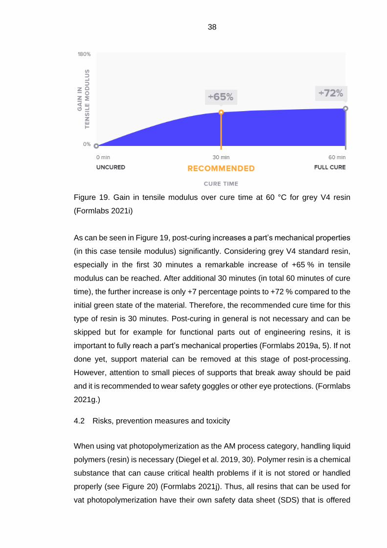
Figure 19. Gain in tensile modulus over cure time at 60 °C for grey V4 resin
(Formlabs 2021i)
As can be seen in Figure 19, post-curing increases a part’s mechanical properties
(in this case tensile modulus) significantly. Considering grey V4 standard resin,
especially in the first 30 minutes a remarkable increase of +65 % in tensile
modulus can be reached. After additional 30 minutes (in total 60 minutes of cure
time), the further increase is only +7 percentage points to +72 % compared to the
initial green state of the material. Therefore, the recommended cure time for this
type of resin is 30 minutes. Post-curing in general is not necessary and can be
skipped but for example for functional parts out of engineering resins, it is
important to fully reach a part’s mechanical properties (Formlabs 2019a, 5). If not
done yet, support material can be removed at this stage of post-processing.
However, attention to small pieces of supports that break away should be paid
and it is recommended to wear safety goggles or other eye protections. (Formlabs
2021g.)
4.2 Risks, prevention measures and toxicity
When using vat photopolymerization as the AM process category, handling liquid
polymers (resin) is necessary (Diegel et al. 2019, 30). Polymer resin is a chemical
substance that can cause critical health problems if it is not stored or handled
properly (see Figure 20) (Formlabs 2021j). Thus, all resins that can be used for
vat photopolymerization have their own safety data sheet (SDS) that is offered

39
by the resin manufacturer and is available for free. An SDS contains information
about the properties of the chemical substance and about possible health and
physical risks that can be caused. Furthermore, an SDS provides advice on how
to handle and store the involved chemical substance. (Finnish Safety and
Chemicals Agency 2021.) This chapter presents possible risks and advice on
how to avoid them when handling resins, based on the SDS of Formlabs'
standard grey resin.
Figure 20. Label elements for hazards identification on Formlabs grey resin
(Formlabs 2019b, 1)
Figure 20 shows the presented label elements for hazard identification on
Formlabs grey resin. The left label represents general health hazards that will be
explained in detail later in this chapter. The right label indicates that resin is
hazardous to the environment and especially to aquatic life with long lasting
effects. (European Chemicals Agency 2021.) Considering possible health
hazards that can be caused by resin, serious eye irritation and allergic skin
reaction are the main risks that are stated in the SDS of Formlabs’ grey resin.
Therefore, the SDS strongly recommends avoiding heavy breathing of resin
fumes and contact with eyes, skin, and clothing. Thus, safety goggles or face
shields, impervious clothing e.g., a laboratory coat and chemical resistant gloves
out of nitrile or neoprene (not latex) should be worn. Moreover, an effective
ventilation in all process areas should be installed or in case of insufficient
ventilation, respiratory protection should be worn. (Formlabs 2021j; Formlabs
2019b, 1, 4.) In case of contamination with resin, the worn clothing should be
taken off and affected body areas should be washed. Additionally, the SDS of the
used resin must be read and medical attention or advice should be sought. After
handling resins, it is advisable to wash hands and face. Considering
environmental hazards, resins should never enter drains and discharging into the
environment must be avoided. A proper disposal should match with local

40
regulations. When it comes to storage, resin should be kept in a dry, well
ventilated and cool place where it cannot be in touch with heat sources or
incompatible materials that are listed in the resin’s SDS. (Formlabs 2019b, 2-4.)
As mentioned in the previous chapter, post-processing of SLA or LFS
manufactured parts involves post-washing where isopropyl alcohol (IPA, also
called isopropanol or 2-propanol) is needed to remove uncured resin. It is a highly
flammable and irritating substance that can cause serious eye damage, skin
irritation but also drowsiness or dizziness when breathed. When handling IPA,
the respective SDS should be read before and it is strongly recommended to
wear safety goggles, chemical proof gloves and suitable clothing. Also, it should
only be handled and stored at well ventilated places and away from any sources
of ignition. In case of insufficient ventilation, respiratory protection is
recommended and in case of accidents, medical advice or attention should be
sought. (LabChem 2020, 1-10.)
Since liquid resins are highly toxic as mentioned earlier, the question arises if it
is safe to touch after the building process and post-processing steps. Especially
after the publication of the scientific paper “Assessing and Reducing the Toxicity
of 3D-Printed Parts” from Oskui et al. in 2016, more research was done in the
field of toxicity. In this work, zebrafish embryos were exposed to SLA- and FFF-
manufactured parts of different process steps (post-printed and post-cured parts)
and observed for their survivability. It was found that the zebrafish embryos
exposed to the FFF-manufactured parts had good survival rates. Embryos
exposed to SLA-manufactured parts, on the other hand, died within seven days.
However, post-curing of the parts fabricated with SLA significantly improved the
survival rate of the zebrafish embryos. (Oskui et al. 2015, 1-6.) Some years later,
another paper analysed the toxicity of urethane dimethacrylate (UDMA) resin, the
same kind of resin as Formlabs’ standard resins. Here, it was found that post-
cured SLA-manufactured parts out of the named resin type can be considered as
nontoxic to humans. In general, toxic unreacted monomers (liquid resin) could
leach out and cause harmful effects. However, this was not found on the reason
that the spaces between the cured polymer chains are small enough to prevent
leaching out of the monomers after post-curing. Therefore, it is suspected that

41
post-curing causes deformations of the resin matrix which makes parts nontoxic.
(Formlabs 2019b, 2; Lin, Lin, Lai & Lee 2020, 351-353.)
4.3 Setup description of 3D printing laboratory
The 3D printing laboratory of Lapland UAS is located at the Kosmos campus in
Kemi and provides a student learning environment. It offers a variety of different
AM technologies that can be learned and practiced by students during laboratory
classes or independent projects. Besides LFS, also FFF and SLS AM machines
are available in the 3D printing laboratory. In this chapter, only the setup and
working environment of LFS will be described, as other AM technologies do not
have any relevance for this thesis. The basic LFS setup consists of a Formlabs
Form 3 LFS printer, a Formlabs Form Wash, and a Formlabs Form Cure (see
Figure 21). Thus, the 3D printing laboratory of Lapland UAS offers a full Formlabs
working environment. Furthermore, also a fume cupboard is present where post-
processing such as washing, and support removal can be done (see Figure 22).
In the following, all devices will be briefly described and some of their main
specifications will be listed.
Figure 21. Formlabs working environment, Form 3, Form Wash and Form Cure
(from left to right)
Figure 21 shows the LFS Formlabs working environment of the 3D printing
laboratory of Lapland UAS. All three devices are placed in a fume casing, which
was designed and built by students, and it is responsible for discharging exhaust
air and fumes from resins and IPA. Therefore, the fume casing is directly

42
connected to the main ventilation system of the Kosmos campus of Lapland UAS.
The Formlabs Form 3 LFS printer offers a maximum build volume of
14.5 * 14.5 * 18.5 cm with a built-in 250 mW laser. The laser spot size is 85 µm
with a wavelength of 405 nm and the XY-resolution of the Form 3 is 25 µm.
Possible layer thicknesses that can be selected in the Preform slicer software are
between 25 µm and 300 µm. Furthermore, Form 3 offers one resin cartridge slot
with an automated resin fill system. During the building process, the air-heated
build chamber reaches a temperature of 35 °C. (Formlabs 2021k.) Regarding,
the maximum part size of the Form Wash and Form Cure, both fit manufactured
parts from the Formlabs Form 3. However, since the maximum supported part
height of the Form Wash is 1 cm lower than from the Form 3 printer, it can be
necessary to remove the manufactured part from the building platform before
inserting it to the Form Wash. But usually, the part can be left on the build
platform. The IPA bucket volume of the Form Wash is 8.6 l and should not fall
below a certain marked threshold. The Form Cure has a built-in rotating platform
with a diameter of 19.3 cm and curing temperatures up to 80 °C can be reached.
The curing process itself is done with 13 LEDs, that have a wavelength of 405 nm.
(Formlabs 2021l.)
Figure 22. Formlabs working environment and fume cupboard
In Figure 22, the area of the LFS working environment within the 3D printing
laboratory of Lapland UAS can be seen. As can be seen, the three Formlabs
devices are inside the earlier mentioned fume casing. The fume cupboard is

43
placed in the corner of the room and is directly connected to the ventilation
system of the building. In the fume cupboard, post-processing steps can be
performed. On the shelf in the middle of the photo, there is a finish kit for removing
parts from the build platform and tools for support removal and other post-
processing tasks. On the other side of the 3D printing laboratory, there is a
fireproof cabinet where all the resins, resin tanks and IPA are stored.
Furthermore, safety goggles, gloves and laboratory coats are available in other
cabinets of the laboratory.

44
5 METHODOLOGY
In this chapter, the methodology of each practical printing test and of the
development for workflow recommendations is presented and described. In that
way, it can be understood, how the subsequent results of this thesis could be
gained. In total, there are three different practical printing tests, namely firstly
evaluating the effects of different printing orientations on the result, secondly
printing isometric screw and nut threads and thirdly printing objects on top of each
other along the z-axis of the build volume. Furthermore, it is described how the
subsequent recommendations for a better workflow were developed.
5.1 Evaluation of effects of different printing orientations
As mentioned earlier in this thesis, support material is always necessary in SLA
and is not only dependent on the model itself but also on its printing orientation.
In this test, different objects were printed in various angles and analysed to
investigate the effects of different printing orientations. Therefore, the importance
of correct printing orientation can be shown, and knowledge can be gained to
save time and material or to reach a good visual result with less deformation or
support marks. For this purpose, the two input parameters, the rotation around
the x-axis and around the y-axis, were varied in different predetermined steps,
i.e., 0°, 45° and 90° orientation (see Table 2). With two axis and three orientation
steps on each axis, a total number of 32 (= 9) variations is possible. However, not
all variations were selected to be analysed for each selected object as some
variants are redundant. Furthermore, the orientation around the z-axis was not
carried out as this has no effect on the angle between the printed object and the
build platform. To investigate the effects on the results of that orientation
variation, several output parameters were defined to be analysed (see Table 3).
Print time and material consumption are factual output values that could be
directly gathered from Formlabs slicing software PreForm. To rate the impacts of
different printing orientations on non-factual output parameters such as the
overall printing quality, objective evaluation criteria were defined in order to
prevent subjective judgements. Those defined evaluation criteria are the total
number of supported object sides, the total number of support touchpoints, and
a ranking of all variants based on deformation and surface quality.

45
Table 2. Variants of different printing orientations with variation in x- and y-axis in
degrees for two different objects
Variant X [°] Y [°] Plate Cylinder
1
0
0
2
0
45
3
0
90
4
45
0
Redundant to
Variant 2
5
45
45
6 45 90 Redundant to Variant 3 Redundant to Variant 3
7
90
0
Redundant to
Variant 3
8
90
45
Redundant to
Variant 3
9 90 90 Redundant to Variant 3 Redundant to Variant 3
Table 2 shows the variation of the two input parameters, that is orientation in x-
axis and y-axis in three steps from 0° to 90°. As described earlier and shown in
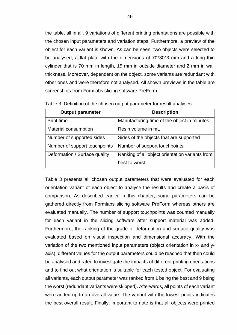
46
the table, all in all, 9 variations of different printing orientations are possible with
the chosen input parameters and variation steps. Furthermore, a preview of the
object for each variant is shown. As can be seen, two objects were selected to
be analysed, a flat plate with the dimensions of 70*30*3 mm and a long thin
cylinder that is 70 mm in length, 15 mm in outside diameter and 2 mm in wall
thickness. Moreover, dependent on the object, some variants are redundant with
other ones and were therefore not analysed. All shown previews in the table are
screenshots from Formlabs slicing software PreForm.
Table 3. Definition of the chosen output parameter for result analyses
Output parameter Description
Print time Manufacturing time of the object in minutes
Material consumption Resin volume in mL
Number of supported sides Sides of the objects that are supported
Number of support touchpoints Number of support touchpoints
Deformation / Surface quality Ranking of all object orientation variants from
best to worst
Table 3 presents all chosen output parameters that were evaluated for each
orientation variant of each object to analyse the results and create a basis of
comparison. As described earlier in this chapter, some parameters can be
gathered directly from Formlabs slicing software PreForm whereas others are
evaluated manually. The number of support touchpoints was counted manually
for each variant in the slicing software after support material was added.
Furthermore, the ranking of the grade of deformation and surface quality was
evaluated based on visual inspection and dimensional accuracy. With the
variation of the two mentioned input parameters (object orientation in x- and y-
axis), different values for the output parameters could be reached that then could
be analysed and rated to investigate the impacts of different printing orientations
and to find out what orientation is suitable for each tested object. For evaluating
all variants, each output parameter was ranked from 1 being the best and 9 being
the worst (redundant variants were skipped). Afterwards, all points of each variant
were added up to an overall value. The variant with the lowest points indicates
the best overall result. Finally, important to note is that all objects were printed

47
with the same material and slicing settings to ensure a better base of comparison
of each variant of one object. The selected material was Formlabs standard resin
“White V4” and all objects were printed with a layer thickness of 0.05 mm and
default print and support settings. Additionally, support material was always
added by using the auto-generated support feature offered by PreForm. After the
print process, all objects were pre-washed in IPA and then washed with Formlabs
Form Wash for 10 minutes. Finally, all support structures were removed, the parts
were air-dried and then cured in Formlabs Form Cure for 30 minutes at 60 °C.
5.2 Printing of different-sized iso metric threads
As SLA (and LFS) is known for manufacturing objects with high accuracies, small
details and extraordinary good surface finishes, it is commonly used for
applications, where a high grade of detail is necessary and tight tolerances are
needed (see chapter 3.2). For testing those mentioned aspects of Formlabs Form
3 LFS printer, the application of printing internal threads (nuts) and external
threads (screws) was selected. This test investigates whether printing different-
sized nuts and screws is generally possible and, if so, what kind of up or down
scaling is necessary to take tolerances into account and ensure a good fitting. In
this practical test, various ISO metric threaded screws and nuts were printed and
analysed to test their fitting on real screws and nuts, and on each other.
Furthermore, each thread size was printed in different scaling factors to involve
print tolerances and improve fitting. That means, that up or down scaling in x- and
y-axis (with vertical printing orientation of nut and screw) was carried out to vary
the major and minor diameter of the screws and nuts printed (see Figure 23).
Different scaling factors along the z-axis were not made as this would have
affected the pitch of the thread itself. Moreover, also the dimensional deviation
between the theoretical and printed diameter of the screws and nuts was
determined by using a calliper. In general, for this test, the experimental method
of “trial and error” was chosen to investigate step by step what scaling factors for
what sizes of screws and nuts are necessary to imply. The selected screw and
nut sizes with its thread dimensions are presented in Table 4.

48
Figure 23. Basic concept of terminology for nominal screw and nut dimensions
(Bossard 2019, 81)
Figure 23 shows a schematic of a fitting nut and bolt / screw with the terminology
and definition of different dimensions of each component. In order to measure the
accuracy of the printed screws and nuts, only measurable dimensions were
selected for comparisons with literature values. For screws, the major diameter,
also considered as the nominal size of the thread was selected and for nuts, the
minor diameter was selected as it is the inner diameter and can be measured
with a calliper. By adjusting the scale in x- and y- axis (at vertical printing
orientation of nut and screw), the major diameter of the screw and minor diameter
of the nut can be varied which has a direct effect on the fitting of these
components. As mentioned earlier, no scaling variation along the z-axis was
carried out as this would affect the pitch of the thread. As shown on the figure,
the pitch of the screw and nut must be equal to ensure a good fitting, whereby
different scaling factors of screw and nut in z-direction would negatively affect the
fitting. All screws and nuts with their dimensions that were printed and analysed
during this test, are shown in Table 4.

49
Table 4. Selected screws and nuts that were printed (Bossard 2019, 82)
Thread size Thread
pitch [mm]
Thread
length [mm]
Major / minor
diameter [mm]
M12 screw 1.75 25 11.701 – 11.966
M12 nut 1.75 10 10.106 – 10.441
M8 screw 1.25 25 7.76 – 7.972
M8 nut 1.25 6.5 6.647 – 6.912
M6 screw 1 20 5.794 – 5.974
M6 nut 1 5 4.917 – 5.153
M4 screw 0.7 20 3.838 – 3.978
M4 nut 0.7 3.2 3.242 – 3.422
M3 screw 0.5 15 2.874 – 2.98
M3 nut 0.5 2.4 2.459 – 2.599
As can be seen in Table 4, five different thread sizes ranging from M12 to M3
were selected to be printed and tested to find out the right scaling factors for a
good fitting and investigate if it is generally possible to print those different internal
and external thread sizes. The respective thread pitch to each thread size is
based on the ISO 262 standard and the major and minor diameters of the screws
and nuts are related to the ISO 965 standard. Furthermore, to print those shown
screws and nuts, exact 3D CAD models were needed (see Figure 24). Therefore,
the CAD software Fusion 360 was used as it offers an easy possibility to import
real CAD models of all kinds of screws and nuts. After downloading and importing
the desired components, they were saved as STL files in order to print them.
Figure 24. Imported M12 screw in Fusion 360 (left) and printing orientation of
screw and nut in PreForm (right)

50
Figure 24 shows an imported M12 screw in Fusion 360 (left) and a screenshot of
Formlabs slicing software PreForm that shows the desired print orientation for all
screws and nuts. Furthermore, the non-uniform scaling in x- and y-direction of all
screws and nuts was carried out in Fusion 360. As can be seen in the figure and
as already mentioned earlier in this chapter, all screws and nuts were printed
vertically. Furthermore, no support material was added as it was not necessary
and would have affected the quality of the threads in a negative way. As coming
to the print settings, some screws and nuts were printed with Formlabs standard
resin “White V4” with a layer height of 0.05 mm and some were printed with “Grey
V4” and a layer height of 0.025 mm. The reason for choosing the grey resin with
a lower layer height was to reach a better quality for smaller thread sizes. Which
screws were printed with which resin is indicated later in the result section. After
all objects were printed, they were pre-washed in IPA, and washed with Formlabs
Form Wash station for 10 minutes. Afterwards, all objects were cured with
Formlabs Form Cure station for 30 minutes at 60 °C.
5.3 Attempt of printing objects on top of each other
In AM, all parts to be manufactured must be attached to the build platform of the
AM machine. However, the build platform is limited by its geometries, which in
the case of the Formlabs Form 3 LFS printer are 14.5 * 14.5 cm. To take
maximum advantage of this limitation, objects could be stacked to also use the
full height of the build volume of 18.5 cm. As there is little literature on printing
objects on top of each other, this practical test investigated the feasibility, the
conditions to be fulfilled and the effects on the result of stacked printed objects.
Furthermore, Formlabs slicing software PreForm does not offer the feature of
stacking up objects (STL files) whereas other ways had to be found. For this
purpose, two different objects with the use of two different methods for stacking
were selected to be printed and analysed. The first analysis was carried out on
stacked up hollow cubes with a side length of 40 mm and a wall thickness of
2 mm (see Figure 25). Both cubes were designed already hollow with the CAD
software Inventor 2021 from Autodesk and were then exported together as one
single STL file. The reason for hollowing out the cubes was to save resin (see
chapter 3.3). In addition, each cube has a vent hole with a diameter of 4 mm to

51
allow uncured resin to escape from the hollow body during and after the printing
process.
Figure 25. Hollow cubes, stacked up versus generic print arrangement
Figure 25 shows a screenshot of Formlabs slicing software PreForm where two
STL files are placed on the virtual build platform. One STL file contains the two
stacked cubes that have already been stacked during the design process in the
CAD software, and the other STL file contains only one cube arranged for a
generic, non-stacked print. Important to note is that for the left STL file (stacked
cubes), internal support structure needs to be activated in the support settings to
reach that support material is added between both cubes within the STL file. For
the right cube, no internal support material was necessary as it is supported from
the build platform. The reason for printing both STL files, stacked cubes, and
unstacked cube was to compare and analyse different parameters to evaluate
the effects of printing objects on top of each other compared to generic flat
printing. The parameters that were considered were, print time, material
consumption, and dimensional accuracy of all three cubes. Moreover, some
scenarios were analysed directly in the slicing software. To investigate the
efficiency of stacking objects, the printing time and material consumption for
producing different numbers of parts with both stacked and non-stacked
approaches were noted.

52
The second analysis, looking at feasibility and impact on the outcome, was
carried out on two stacked towers that were not designed but whose STL files
were already available. Since it is not possible to stack two STL files in PreForm,
as already mentioned, another method had to be found. One possibility is to
merge the two STL files to create only one STL file that contains both already
stacked towers. For this purpose, an additional software was needed. Autodesk’s
software Meshmixer offers good possibilities to edit and transform STL files (see
Figure 26).
Figure 26. Stacking up two STL files in Autodesk Meshmixer
As can be seen in Figure 26, both STL files were imported in Meshmixer and
stacked up. After the STL files were imported, both models could be moved and
placed on top of each other after they were selected with the object browser (right
side of Figure 26). Meshmixer not only offers possibilities to move and replace
models, but also to resize and scale them as well as hollowing out solid STL
models. However, once both towers were stacked up, as shown on Figure 26,
they could be exported as one single STL file. Important to note is that the STL
file must be exported in ASCII format, not in binary format, as Formlabs slicing
software PreForm cannot read binary formatted STL files exported from
Meshmixer. When importing the new merged STL file into PreForm, internal

53
support structure needs to be activated for the same reason as already
mentioned earlier. Since both towers are not connected but part of one single
STL file, support material must be added within the STL model. As coming to the
print process of both object groups (stacked cubes and towers), all parts from this
chapter were printed with the same slicing and printing settings. The used resin
was Formlabs standard resin “White V4” with a layer height of 0.1 mm. After the
printing process, all parts were pre-washed manually in IPA and then washed in
Formlabs Form Wash station for 10 minutes. Afterwards, the parts were air-dried
and cured in Formlabs Form Cure for 30 minutes at 60 °C.
5.4 Development of own workflow recommendations
One aim of this thesis is to improve the workflow around the whole SLA printing
process in the 3D printing laboratory of Lapland UAS. As only the general
Formlabs workflow was summarised in the research part of this thesis (see 4.1),
concrete suggestions for improvement and guidelines for handling the resin and
the printed objects were developed in the development part of this thesis. In that
way, working in the 3D printing laboratory of Lapland UAS regarding the SLA
workflow can be improved to be not only more efficient but also safer and cleaner
in the future. With those recommendations, also the ergonomics and logistics of
the complete SLA process in the 3D printing laboratory can be improved and
further developed in the future. As coming to the methodology of the development
of recommendations and guidelines for workflow improvements, it is to say that
the biggest part is based on own experiences and ideas. As the technology and
the whole process and workflow of SLA was investigated in detail during this
thesis, a lot of knowledge could be gained. Therefore, all developed
recommendations and improvement ideas are not only based on knowledge that
was gained during the research part of this thesis but also on own experiences
and ideas that were gained during all practical printing tests. During those
practical printing tests of this thesis, the current state of the whole workflow and
logistics of the 3D printing laboratory could be investigated and analysed in detail
(also see 4.3). Therefore, based on gained knowledge and experiences, own
ideas for the improvement of the SLA workflow for the 3D printing laboratory of
Lapland UAS could be developed and are presented in the result section of this
thesis.

54
6 RESULTS AND ANALYSES
In this chapter, all results obtained with the defined and previously described
methods are presented and analysed. The results are presented on the
investigated effects of different print orientations, the printing of isometric threads
of different sizes and the printing of stacked objects. In addition, the developed
own workflow recommendations are described.
6.1 Investigated effects of different printing orientations
After the methodology was defined, carried out and all parts were printed, various
results could be generated due to the parameter variation shown in Table 2. Both
objects, the plate and the cylinder were analysed independently from each other.
In the following, all results are presented and analysed. The results for the plate
are shown in Table 5. As described earlier, for each variant (V), all defined output
parameters were evaluated and ranked from the best to the worst to see which
variant is best in each output value category. Additionally, all rankings within one
variant were added up which led to the final ranking based on the total points of
each variant. Furthermore, variant six was not analysed as it is a redundant
orientation (see Table 2).
Table 5. Output values of the plate (with individual parameter ranking) and total
points based on ranking for each variant (V)
V Print
time [min]
Material
con. [mL]
Supp.
sides
Supp.
points
Visual
quality
Total
points
Final
ranking
1 100 (1) 13.77 (7) 1 (1) 148 (7) 7 23 6
2 330 (5) 10.72 (4) 2 (2) 34 (4) 6 21 5
3 328 (4) 8.5 (2) 3 (3) 17 (1) 2 12 2
4 170 (2) 10.98 (5) 2 (2) 67 (6) 5 20 4
5 365 (7) 11 (6) 3 (3) 48 (5) 4 25 7
7 175 (3) 8.36 (1) 1 (1) 29 (2) 1 8 1
8 333 (6) 9.71 (3) 2 (2) 30 (3) 3 17 3
As can be seen in Table 5, variant seven has the best final ranking with only 8
points, followed by variant three with 12 points and variant eight with 17 points.

55
When viewing Table 2, it can be noticed, that all those three mentioned best
variants have one similarity. In each of those variants, the plate is placed with the
smaller area facing the build platform. The variants where the bigger area of the
plate is facing the build platform have generally reached a worse final ranking as
can be seen when viewing Table 5 and Table 2. The reason for that can be found
when analysing the ranking of the output parameters. It is clear to see that the
best three variants (regarding the final ranking) have quite good rankings in most
of the output parameters. Considering visual quality and material consumption,
the ranking in these output parameter categories is equal to the final ranking and
the number of support touchpoints is least on variant three, seven and eight. This
effect can also be seen when viewing at the preview screenshots in Table 2. In
general, there is an interesting correlation to note: The higher the material
consumption the more touchpoints are present. This seems to be logical as the
plate itself has the same size in all variants. Due to different orientations, more or
less support material is necessary which impacts material consumption and
number of touchpoints. In variants where the smaller area of the plate is facing
the build platform, less area is available that can be supported, which leads to
less material consumption, less support touchpoints, and therefore a better visual
surface quality. That is why, those variants have reached a better final ranking
than the variants where the bigger area is facing the build platform such as in
variant one. In this case, the area that is facing the build platform is largest (see
screenshot Table 2), and material consumption and number of support
touchpoints is highest which led to the worst visual quality and therefore a bad
final ranking. However, print time is the shortest in variant one, as the number of
layers that need to be cured is the smallest. Regarding print time, this output
value is higher the higher the object is in relation to the build platform but is also
connected with material consumption that is impacted by support material and
finally by print orientation. Considering the visual quality of all variants, the print
results can be seen in Figure 27.
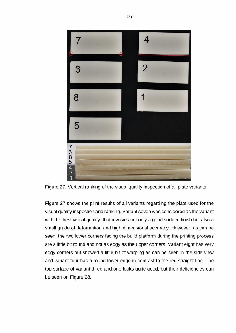
56
Figure 27. Vertical ranking of the visual quality inspection of all plate variants
Figure 27 shows the print results of all variants regarding the plate used for the
visual quality inspection and ranking. Variant seven was considered as the variant
with the best visual quality, that involves not only a good surface finish but also a
small grade of deformation and high dimensional accuracy. However, as can be
seen, the two lower corners facing the build platform during the printing process
are a little bit round and not as edgy as the upper corners. Variant eight has very
edgy corners but showed a little bit of warping as can be seen in the side view
and variant four has a round lower edge in contrast to the red straight line. The
top surface of variant three and one looks quite good, but their deficiencies can
be seen on Figure 28.

57
Figure 28. Backside of variant 1 (top) and left side of variant 3 (bottom)
As shown in Figure 28, the backside of variant one has many irregularities and
bumps due to the support structure and high shearing forces and it even got
destroyed when the support material was removed. Variant three was considered
as the second-best variant because of its sharp edges and high accuracies.
However, the left side where the object was supported is quite uneven and wavy.
As coming to the analysis of the cylinder, the reached results are presented in
Table 6. As the structure is the same as in Table 5, it will not be described again
and because five out of nine variants are redundant (see Table 2), only four
variants were analysed for the cylinder.
Table 6. Output values of the cylinder (with individual parameter ranking) and
total points based on ranking for each variant (V)
V Print
time [min]
Material
con. [mL]
Supp.
sides
Supp.
points
Visual
quality
Total
points
Final
ranking
1 323 (4) 6,69 (1) 1 (1) 11 (1) 1 8 1
2 308 (3) 9,28 (2) 3 (3) 38 (2) 3 13 2
3 150 (1) 9,42 (3) 2 (2) 80 (4) 4 14 3
5 264 (2) 10,04 (4) 2 (2) 50 (3) 2 13 2
As can be seen in Table 6, variant one has the best final ranking with a total of 8
points. The remaining variants two, three and five are worse and have a similar

58
number of total points. It is clear to see that variant one is the best in most output
parameter categories but is the worst in print time as the build height in variant
one is highest compared to the other variants. Similar to the correlation
considering the plate described earlier, variant three shows the fastest print time
as the object’s height is lowest. However, variant three has the worst visual
quality ranking (see Figure 29).
Figure 29. Visual quality inspection of cylinder variant 3
Figure 29 shows variant three of the cylinders, which was classified as the worst
variant after the visual inspection. Considering the results shown in Table 6,
variant one has the best ranking as it has the fewest support touchpoints.
Furthermore, due to its vertical orientation, variant one is the only one where no
support material is present on the cylindrical surface of the cylinder. Due to the
angled orientation of variants two, three and five, support material had to be
added on the cylindrical surface. Moreover, variant three has the worst ranking in
terms of visual quality. Due to its flat orientation, it can be assumed that high
shearing forces occurred during the printing process. This assumption is based
on the fact that variant three shows clearly visible wrinkles (see Figure 29).
Because of the wrinkles, this variant was considered as the worst one.
6.2 Printed different-sized iso metric threads
In the course of this practical print test, all in all, 20 screws and 22 nuts in different
sizes (M12-M3) and different scaling factors in x and y direction were printed. As
the chosen method was based on a “trial and error” approach, the number of
iterative prints for each screw and nut size could be reduced after analysing each
thread size, as knowledge about tolerances and deviations could be gained
during the tests. Each single printed screw and nut was measured, analysed, and
checked for accuracy of fit. In that way, a big number of results could be

59
generated as every print attempt was documented. Thus, all gained results are
placed in the appendix of this thesis and are shown in Table 11 - Table 20.
However, the most crucial and especially successful results (regarding to
successful fitting) are presented and analysed in this chapter and are shown in
Table 7. As mentioned earlier in the methodology chapter regarding this print test
(see chapter 5.2), each screw and nut was printed vertically with a 90° angle to
the build platform without the use of support material. Furthermore, each screw
and nut were differently scaled in x and y direction to investigate the suitable up-
or down-scaling factor for each thread type (internal or external) and thread size
(M12-M3). In addition, all printed parts were measured with a calliper to compare
the actual printed major diameter of screws and the minor diameter of nuts with
nominal literature values. In this way, assumptions could be made about accuracy
and printing tolerances. To check the actual fit of each printed screw and nut, real
screws, and nuts, but also the respective printed counterpart, were used to
evaluate the fit with a simple yes or no answer.
Table 7. Summary of the best reached results regarding best fit with suitable
scaling factors for different thread types and sizes
Thread
size
XY-
scale
[%]
Maj./ min.
diameter*
[mm]
Measured
diameter
[mm]
Diameter
deviation
[mm]
Diameter
deviation
[%]
M12 screw 97 11.64 11.66 0.02 0.17
M12 nut 104 10.12 10.11 -0.01 -0.10
M8 screw 96 7.68 7.65 -0.03 -0.39
M8 nut 106 6.76 6.75 -0.01 -0.15
M6 screw 92 5.52 5.53 0.01 0.18
M6 nut 114 5.37 5.36 -0.01 -0.19
M4 screw 91 3.64 3.61 -0.03 -0.82
M4 nut 116 3.59 3.54 -0.05 -1.39
M3 screw 90 2.70 2.68 -0.02 -0.74
M3 nut 116 2.71 Not measured - -
Average value based on the above column values -0.019 -0.38
*Calculated nominal diameter according to the 100 % sized CAD model with
respective XY-scale factors, details are shown in the appendix of this thesis

60
Table 7 shows the selection of the best results regarding best fit that were gained
during this practical print test. As mentioned earlier, the complete results are
presented in the appendix of this thesis. In Table 7, it can be seen that there are
two different background colours. The white background colour indicates that
Formlabs standard resins “White V4” with a layer height of 0.05 mm was used
whereas the grey background colour represents the usage of Formlabs standard
resin “Grey V4” with a layer height of only 0.025 mm. When viewing at the
selected results in the table, it can be noticed that the best fit for all thread sizes
was reached with downscaled screws and upscaled nuts. As screws are the male
component of the fitting, they tend to be too big for the nut fitting which means
that downscaling was necessary to compensate print inaccuracies. On the other
side, nuts need to fit the screw and had to be upscaled that a suitable fit could be
reached. Furthermore, it can also be seen that the smaller the thread size, the
greater the difference between the actual scaling factor and 100 %. The reason
for this is that the absolute values become smaller and smaller with smaller thread
sizes, while the absolute tolerances of the printer remain the same. Regarding
absolute values, it was found that the major diameter of a threaded screw must
be on average 0.17 mm smaller than the nominal major diameter according to
the original screw model in order to achieve successful fitting after printing. This
value was calculated by considering the differences between the smaller value of
the nominal major diameters (shown in Table 4) and the actual measured major
diameters (shown in Table 7) of each thread size.
In terms of printing tolerances, the largest deviation between the desired
theoretical diameter and the actual printed diameter is -0.05 mm for the M4 nut.
However, the average deviation between the desired and the actual result is -
0.019 mm which represents in this case a deviation of -0.38 %. Regarding the
M3 nut, no nut diameter was measured, as the nut was too small to ensure an
accurate measurement. Moreover, it was not possible to reach a good quality for
the M3 nut which means that the printed nut could not fit a real M3 screw (see
Table 8). Considering the fitting of all screws and nuts presented in Table 7, all
three cases (printed screw with printed nut, printed screw with real nut, real screw
with printed nut) are shown in Table 8.

61
Table 8. Printed screws and nuts with best fit in all three cases
Thread
Size
Printed screw
Printed nut
Printed screw
Real nut
Real screw
Printed nut
M12
M8
M6
M4
M3
No proper fit could be
reached
Table 8 shows all screws and nuts presented in Table 7 with evidence of fitting in
all three cases. Furthermore, it can be seen, that M12 and M8 screws and nuts
were printed with white resin and the other ones with grey resin as already
mentioned earlier. In general, it can be said that the achieved quality and fitting
accuracy of all printed parts with their already presented respective upscaling and
downscaling factors can be described as extraordinarily good. However, it could
be noticed that the general thread quality decreased with smaller thread sizes
that is why, grey resin with a lower layer height of 0.025 mm (instead of 0.05 mm
for the white parts) was selected for smaller thread sizes. With the respective
upscaling and downscaling factors of screw and nut found by trial and error for
each thread size, a good fit for M12-M4 could be achieved for all three cases
shown in Table 8. For M3, the printed nut does not fit a real screw because the
nut is a little deformed and very brittle due to its small size, which could be a sign
of the limitations of Formlabs Form 3 LFS printer.

62
6.3 Printed objects on top of each other
After the two selected object types were printed to test the feasibility of stacked
printing, the results could be analysed to investigate the conditions that must be
met and the effects that occurred. In general, it can be clearly said that both object
types, that is stacked hollow cubes and towers, were printed successfully, which
means that no failures during the printing processes occurred. Analysing first the
stacked print of the hollow cubes, the printing result can be seen on Figure 30.
Figure 30. Successful stacked print of hollow cubes
As can be seen in Figure 30 and already mentioned, the stacked print of the two
hollow cubes was successful. Therefore, it can be said that the method of printing
stacked objects by designing and exporting them as a single STL file works and
it is feasible if internal support material is activated in the slicing software.
However, as can be seen, the grade of support material is quite high whereby
post-processing was quite extensive. Furthermore, all three cubes were
measured for dimensional accuracy with a calliper. The result of this analysis was
that the generic flat printed cube (right cube on Figure 30) showed the best
dimensional accuracy compared to the designed dimensions of 40*40*40 mm.
The two cubes that were printed by using the stacked approach showed little
dimensional deviations which means that almost all side lengths were a little bit

63
longer than 40 mm. The reason for that could be higher shearing forces that
occurred during the printing process due to the higher weight of the objects
compared to the single cube. It can be assumed that especially the lower cube of
the stacked group was exposed to high shear forces, not only due to the printing
process of this cube itself, but also due to the attached support material for the
cube above. These shear forces could therefore be the reason why the side
lengths have diverged somewhat. Moreover, considering visual quality of all three
cubes, the single generic printed cube and the upper cube of the stacked group
showed good surface qualities. The lower cube of the stacked group showed the
worst surface quality as much support material from all sides was attached to its
surfaces.
Coming to the scenario analysis where efficiency regarding print time and
material consumption of stacked printing compared to generic flat printing was
investigated, different numbers of parts were selected. Important to note is that
this analysis was only carried out by using the pre-showed parameter values of
the slicing software PreForm. Those objects were not printed as visual quality or
dimensional accuracy was not part of this analysis whereby actual prints of the
objects were not necessary as one stacked cube group was already printed
during this test. The result of this analysis is shown Table 9.
Table 9. Parameter comparison between the two approaches of generic flat
printing and stacked printing for different numbers (N) of hollow cubes
N
[-]
Approach Print
time
[h]
+ time for
stacking
[%]
Material
con.
[mL]
+ material for
stacking [%]
N of build
platforms
[-]
2 Flat 6.9 - 59.7 - 1
2 Stacking 11.1 + 61.5 75.8 + 26.9 1
4 Flat 12.2 - 119.5 - 1
4 Stacking 18.3 + 50 151.7 + 26.9 1
8 Flat 24.4 - 239 - 2
8 Stacking 32.3 + 32.4 303.3 + 26.9 1
As shown in Table 9, the comparison between the two approaches of generic flat
printing and stacked printing was carried out for the part numbers (N) two, four

64
and eight. It is clear to see that the stacked printing approach always requires
more print time and material than the flat printing approach for the same number
of parts. The reason for the higher material consumption is that two stacked
cubes require more support material in total than two flat printed cubes. In
addition, the stacked cubes had to have internal support material activated, which
means that support material was also printed inside the hollow cubes, which is
not the case for the single cube without activated internal support material.
Moreover, higher material consumption leads to longer printing times because
more resin has to be cured during the printing process. However, it can be seen
that material consumption is increasing linear whereas print time is increasing
less with each increase of part numbers. This can be noticed when looking at the
percentage values for additional print time and material consumption for stacked
printing compared to the flat printing approach. As can be seen, the stacked
printing approach always requires 26.9 % more material than if the same number
of parts were printed using the flat printing process. When looking at the
additional printing time, it can be seen that the more parts are printed by stacking,
the lower the additional printing time, as the percentage values decrease steadily.
Furthermore, the maximum number of cubes that can be printed with one build
platform with generic flat printing is 4 whereas it is 8 when stacking up. This
means that less user attention is required when printing a high number of parts,
as fewer printing processes are needed. Moving on to the second stacked print
that was carried out during this practical test, the stacked printing of the towers,
the results can be seen in Figure 31.

65
Figure 31. Stacked print of two towers
As already mentioned earlier in this chapter, and as can be seen, this stacked
print was also carried out successfully. This means that the second method,
namely stacking two STL models with Autodesk's software Meshmixer and
exporting them as a single STL file, is also possible and works if internal support
material is activated in the slicing software. After the printing process, both towers
were inspected to proof visual quality whereby it was found that both towers
showed great surface qualities. However, as can be seen, support material had
to be added up to the top of the lower tower, leaving visual support marks.
Furthermore, another crucial effect of activating internal support structure was
found. Activating this setting is necessary to add support material between the
two towers, otherwise the upper tower would not be sufficiently supported,
making stacked printing impossible. However, during the result analysis, it was
found that this setting also generates and prints support material within the
towers, as can be seen on the right of Figure 31. As the towers are quite small
and narrow, it was not possible to reach these internal support structures to
remove them, which means that both towers are filled with internal support
material, although this would not have been necessary as these towers are
usually printed without any support material. Therefore, unwanted internal

66
support points should have been removed manually in the slicing software before
starting the print.
6.4 Own workflow recommendations and improvement ideas
After all practical printing tests for this thesis had been carried out, it was possible
to write down all own ideas collected during the practical work in the 3D printing
laboratory at Lapland UAS. All improvement ideas and recommendations are
based on a total number of 15 prints that were carried out during this thesis.
Those suggestions are presented in this chapter in an ordered structure and can
help students and teachers to improve the laboratory working environment and
make the whole LFS workflow safer. First, a few words regarding the current
situation of the LFS laboratory environment are mentioned to point out and rate
some aspects and measures that are already quite good. Second, own ideas and
recommendations for further improvements are presented which involve following
three aspects:
- Setup improvements
- Personal protection equipment and safety precautions
- Complete improved workflow presented as a flow chart
As described earlier in chapter 4.3 of this thesis, the three main devices, that are
Formlabs Form 3, Formlabs Form Wash, and Formlabs Form Cure are placed in
a fume casing that is connected to the central ventilation system of the campus
and is responsible for discharging exhaust air and fumes from resins and IPA.
This fume casing is quite new and was installed at the same time as all practical
printing tests of this thesis were carried out. Therefore, no evaluation of the
functionality of this fume casing is available yet whereby it is rated in this chapter.
Because of all the prints that were carried out during this thesis, it is possible to
rate and comment on the mentioned fume casing. Regarding odour intensity,
significant improvements could be reached with the installation of that fume
casing. As the used resins needed for printing and especially IPA are quite smelly
and evaporative (see chapter 4.2), the air quality of the whole 3D printing
laboratory was negatively affected during LFS prints. With the implementation of
the fume casing, no pungent odours caused by resin or IPA were noticed

67
anymore, as all fumes are directly extracted by the ventilation system attached to
the fume casing. Therefore, the functionality of the fume casing can be
considered as particularly good, and it definitely improved air quality and well-
being. Another existing aspect that is part of the current LFS workflow is the pre-
wash station, which is placed in the fume cupboard next to the Formlabs working
environment (see chapter 4.3). The pre-washing station is used for manually pre-
washing freshly printed parts with IPA before they are washed with Formlabs
Form Wash station. In that way, the IPA in the Form Wash is kept fresh and clean
longer and can be used for more cycles. Thus, the idea and use of this pre-
washing station can be considered as exceptionally effective whereby it should
stay part of the future improved LFS workflow.
Coming to the second part of this chapter, the self-developed recommendations,
and ideas for an improved workflow, first some setup improvements regarding
additional and better placed equipment are pointed out. Most of these setup
improvement ideas relate to the workplace at the fume cupboard. When working
on the fume cupboard to remove parts of the build platform, pre-washing and
removing support material, it is necessary to work with gloves and paper or cloth
towels. Gloves and suitable towels are generally available in the 3D printing
laboratory but are placed far away from the place where they are needed most.
Thus, especially paper and cloth towels should be placed directly next to the fume
cupboard so that it can be reached while working with IPA and resin. Another
suggestion would be a small waste bin that is either open or can be opened by a
foot pedal and that is also placed right next to the fume cupboard. Both of these
suggestions would make working at the fume cupboard cleaner and safer, as
cleaning cloths are within reach and resin-contaminated gloves and cloths can
be disposed of more quickly. In addition, the fume cupboard's working surface is
currently only protected by a cardboard sheet, which quickly soaks up liquids
such as IPA or uncured resin and thus becomes soft, making work more difficult
and less clean. This aspect could be significantly improved by replacing that
cardboard by a cheap tablecloth out of plastic as that does not soak up liquid, is
easier to clean and thus can be used longer and makes working on the fume
cupboard generally cleaner and easier. Last but not least, as the 3D printer and
the fume cupboard are placed in a distance of a few meters, it is necessary to

68
carry the build platform with the freshly printed parts on it to the fume cupboard
after each print. Thus, there is always a risk that uncured resin can drip on the
floor. For preventing that, a small rigid food tray where the build platform can be
placed to carry it to the fume cupboard can be used (see Figure 32).
Figure 32. Example for a rigid food tray to transport the build platform
A small rigid food tray, as shown in Figure 32, can be used for placing and
transporting the build platform from the 3D printer to the fume cupboard for further
post-processing steps. With the use of such a food tray, no uncured resin can
drip on the floor and working on the fume cupboard can be even cleaner as also
the earlier mentioned plastic tablecloth would be protected. Also, such a food tray
can be cleaned easily with IPA and paper or cloth towels after each usage.
The second aspect, mentioned earlier in the introduction of this chapter, involves
improvement ideas and recommendations related to general safety precautions
and personal protection equipment. As mentioned earlier in this thesis, uncured
resin in liquid form and IPA is highly toxic whereby personal safety equipment
should be worn whenever handling these chemical substances (see chapter 4.2).
Recommended personal safety equipment are proper masks, nitrile gloves,
safety glasses and laboratory coats. Gloves should never be worn twice and
should always be disposed after each use as it is a consumable item which is
always in direct contact with toxic resin and IPA. Thus, it is necessary to consume
more than only one pair of gloves when carrying out a complete print (workflow
details are described later). As IPA is a highly evaporative liquid, toxic fumes can

69
be inhaled easily whereby wearing a suitable mask is recommended.
Furthermore, when starting with the post-processing steps after a print is
completed, handling resin-covered parts and IPA cannot be prevented. For that,
a concept of resin and IPA contaminated, and non-contaminated items is strongly
advisable and helps making the whole workflow cleaner and safer (see Table 10).
Table 10. General list of resin and IPA contaminated and non-contaminated items
Contaminated items Non-contaminated items
Build platform 3D printer
Metal scraper / other part removal
tools
Form Wash and Form Cure
Plastic tablecloth of the fume
cupboard and food tray
Handles of the fume casing and fume
cupboard
Pre-wash station and IPA spray bottle Everything else in the laboratory
Table 10 presents some of the most relevant resin and IPA contaminated and
non-contaminated items when post-processing parts after a completed print.
When both gloves are contaminated with resin, do not touch everything and
especially not items that are listed as non-contaminated items that are then also
contaminated. Select items that can be contaminated and items that are always
kept clean. This concept makes the workflow cleaner and safer and also reduces
the effort of cleaning after post-processing is completed as only specific items are
contaminated with resin and IPA. Furthermore, a more extensive level of this
concept could be that one hand is always kept clean whereas the other one is
contaminated with resin and IPA. However, sometimes, both hands are needed
when washing off resin or removing support material from complex parts whereby
this idea cannot always be implemented. Finally, before starting with post-
processing and removing the build platform after a print is completed, everything
should be prepared in advance to make sure that there is no need to contaminate
items that are considered as clean items. That means, all tools and items needed
for part removal and pre-washing should be clean and placed where they are
needed.

70
Regarding the last part of this chapter, the presentation of the complete improved
workflow for the 3D printing laboratory at Lapland UAS, it must be said that this
is only one possible version of an improved workflow based on own ideas (see
Figure 33). In fact, many steps can be carried out differently and so depend on
specific situations and use cases. However, the most important aspect is, to keep
the workflow as simple as possible. If a process is getting too difficult, people tend
to skip steps whereas safety cannot be ensured. Thus, the improved workflow
should not be more complicated than the existing workflow but should still aim for
more safety and cleanliness.
Figure 33. Complete SLA workflow based on own experiences

71
As can be seen in Figure 33, the complete improved workflow for the 3D printing
laboratory of Lapland UAS is shown in the form of a flowchart with a specific
colour coding. The colour yellow represents safe or low-risk tasks, while red
represents high-risk tasks, as these tasks involve working with resin and IPA.
Furthermore, the blue coloured fields highlight when it is time to wear personal
protection equipment that is just before low- or high-risk tasks and green indicates
when special care is no longer required. In addition, grey tasks are processes
which do not require user attention and can be therefore left unattended. As
already mentioned earlier in this thesis, parts need to be air-dried for at least
30 minutes after the washing process with IPA is completed (see chapter 4.1).
For reducing this waiting time, ventilators can be used to accelerate the drying
process (see Figure 34).
Figure 34. Accelerated drying process of freshly washed parts with ventilators
Figure 34 shows a small setup that was used for accelerating the air-drying
process after the parts (in this case screws and nuts from chapter 5.2) were
washed in Formlabs Form Wash station with IPA. By using ventilators, IPA
evaporates quicker whereas the waiting time of 30 minutes can be reduced to
about only 10 minutes. Afterwards, it can be directly proceeded with the curing
process with Formlabs Form Cure station. In general, all printing tests in this
thesis were always carried out according to the previously presented workflow,
which means that the process chain can be considered as effective, safe, and
clean. All recommendations and the workflow could be implemented by Lapland
UAS students in the future.

72
7 CONCLUSIONS & DISCUSSION
During all three practical printing tests that were carried out in the course of this
thesis and the development of own workflow recommendations, the AM
technology of low force stereolithography could be investigated in detail.
Therefore, valuable, and scientific results were obtained after completion of all
methodologies. Thus, this thesis provides a broad overview of SLA and LFS and
could contribute to the fight against the present knowledge gap for the adoption
of AM that was mentioned in the introduction and was the main motivation of this
thesis. Furthermore, this thesis could help Lapland UAS students, to learn more
about advanced applications for LFS. Based on all gained results and its
analyses, conclusions can be drawn from all the findings of this thesis and results
discussed in this chapter. For a better overview, each printing test and the
workflow recommendations are concluded and discussed in separated sub-
chapters.
7.1 Part orientation
Beginning with the first practical printing test of this thesis, the investigation of
effects of different printing orientations, several conclusions based on the results
shown in chapter 6.1 can be drawn. Considering both objects analysed (flat plate
and cylinder), it was found out, that in both cases, the best results were reached
with print orientations where the area of the objects facing the build platform was
kept small or to a complete minimum. That means, with orientations where
smaller object areas are facing the build platform, better overall results in terms
of number of support touchpoints, material consumption, and printing time were
reached. Because less area is available that can be attached to the build platform
through support material, less touchpoints are generated resulting in less material
consumption and a better visual quality with smoother surface finish. Considering
visual quality and grade of deformation, a similar correlation was found as the
worst result was reached where the biggest object area was facing the build
platform, that was variant one for the plate and variant three for the cylinder.
However, in those mentioned variants, the shortest print time was reached as a
flat orientation towards the build platform leads to a smaller number of layers that
needs to be cured during the printing process. Therefore, the flatter the

73
orientation, the lower the object will be above the build platform and the shorter
the print times. Furthermore, besides all mentioned correlations, different
orientations can be better for different objects. Since part orientation has a direct
influence on the position of support material, resulting in reduced surface quality
at these points, part areas where a high surface quality is desired should always
face away from the build platform. Summarising all conclusions, it can be said,
that it is difficult to make a generally valid statement about the best part
orientation as many factors are involved. If a short print time is most important,
then a flat orientation is recommended and if a good surface finish is important,
areas facing the build platform should be kept to a minimum whereas small details
should always face away from the build platform to prevent support points at
those spots. In addition, the developer of a free available slicing software,
Chitubox, published two articles regarding part orientation for generic SLA on its
website. In general, similar results and correlations were found which confirms
the reliability of this practical printing test with its obtained results. (Chitubox
2020a; Chitubox 2020b.)
7.2 Metric threaded screws and nuts
In the second practical printing test, different-sized iso metric threaded screws
and nuts were printed to test feasibility and fitting, and to investigate possible
scaling factors. As presented in the result section of this thesis (see chapter 6.2),
all thread sizes from M12 to M3 were successfully printed with only one
exception, the M3 nut, which could not fit a real M3 screw. However, regarding
the scientific question stated in the introduction of this thesis, it can be clearly
said, that all analysed screw and nut sizes (except M3 nut) are possible to print
with ensured fitting and sufficient quality. Concluding the obtained results, screws
always had to be scaled down whereas nuts had to be scaled up and, the smaller
the thread size the bigger the relative up- or downscaling factor. Regarding
absolute values for screws, an average downscaling of 0.17 mm dependent on
the thread size was necessary to reach a proper fit on nuts in contrast to the real
screw geometry. In general, smaller threaded screws had to be downscaled more
than screws with bigger thread sizes. According to Formlabs’ paper “Adding
Screw Threads to 3D Printed Parts”, an absolute downscaling value of 0.1 mm is
suggested for proper fits (Formlabs 2021m). Therefore, the investigated

74
downscaling results for screws obtained in this test are slightly bigger than
according to Formlabs. Nevertheless, screw sizes up to M3 and nut sizes up to
M4 are good to print. Important to note is, that smaller thread sizes should be
printed with the smallest possible layer height of 0.025 mm to make use of the
full resolution of Formlabs Form 3 LFS printer. Furthermore, during this test, also
printing tolerances were investigated through comparing the theoretical desired
screw and nut diameters with the actual measured diameters of the printed parts.
It was found that the average deviation of the desired dimension to the printed
dimension of all screws and nuts is -0.019 mm which is within the print resolution
of 0.025 mm that is promised by Formlabs. Therefore, printing iso metric threaded
screws and nuts is generally possible if certain obtained scaling factors are
considered. With those scaling factors, print tolerances can be compensated and
fitting can be improved. Moreover, Formlabs’ Form 3 LFS printer offers sufficient
resolutions and small layer heights for printing highly detailed threads whereas it
can be used for manufacturing functional parts that can be assembled with either
real or printed screws and nuts.
7.3 Stacked objects
Based on the results gained by printing stacked objects, it can be concluded, that
printing objects on top of each other is generally possible. That statement
includes both tested methods, that is designing already stacked models and
stacking up STL models with Autodesk’s Meshmixer. Therefore, in contrast to the
scientific question, asked in the introduction of this thesis, printing objects on top
of each other is possible even though Formlabs slicing software PreForm does
not offer such features. However, internal support material has to be activated in
the slicing software which can lead to visual destruction if unwanted support
touchpoints are not removed manually before starting the print. In the case of the
stacked towers, support material was printed visibly inside both towers whereby
it was not possible to remove it afterwards. Furthermore, printing objects on top
of each other always require more time and material as support structure is more
extensive and also printed within hollow models. Therefore, it can be concluded,
that stacking up objects is not economic as it is connected with higher material
costs and longer post-processing. However, if print time and material
consumption are lower prioritised, stacking up objects can save space and allows

75
printing more parts at the same time whereby less user attention needs to be
paid. Additionally, if objects are printed on top of each other, surface quality will
automatically decrease as more support material and touchpoints are attached
to the models, especially to the lower model of the stacked group. Generic flat
printing is therefore, faster, consumes less material and offers better surface
finishes. Stacking up objects is only senseful if less user attention is desired or if
a large number of objects should be printed within one printing process.
7.4 Workflow improvements
Concluding all developed and presented workflow recommendations regarding
setup improvements, general safety precaution concepts and the workflow itself,
it can be said, that this should be a good approach to improve efficiency and
safety when working with LFS in the 3D printing laboratory of Lapland UAS. The
mentioned setup improvements make working on the fume cupboard cleaner as
less resin and IPA can be spilled and occurring impurities can be removed easier.
Considering wearing recommended safety equipment and implementing the
introduced concept of with resin and IPA contaminated and non-contaminated
items, these measures will increase safety while handling toxic chemical
substances. Moreover, the whole workflow was re-defined with certain steps and
different levels of risks, and it is clearly stated when gloves should be disposed
and use new ones. Those recommendations aim for more cleanliness, safety and
efficiency and could be implemented and validated in the future.
7.5 Future studies
After all thesis findings were analysed, concluded, and discussed, suggestions
for future studies can be drawn as each of the three practical printing tests of this
thesis allows further investigation possibilities. Regarding the analysis of effects
of different orientated parts, more angle variations could be carried out. In this
thesis, only three angles (0°, 45°, and 90°) were analysed in two axes. Future
investigations on this topic could therefore analyse the best printing angle for
different kinds of objects by varying the orientation angle in finer steps.
Furthermore, more, and different objects, also with more complex shapes and
geometries could be analysed. In addition, the Formlabs slicing software

76
PreForm offers the possibility to add, remove, and edit support structures
manually. This feature could be investigated in combination with different object
orientations to further analyse the effects and also whether material can be
saved, or quality improved by manually editing support material. Considering the
printing of iso metric threaded screws and nuts, future projects could aim for
printing different kinds of threads to further investigate the possibilities and
accuracy with Formlabs’ Form 3 LFS printer. Also, strength tests of those printed
screws and nuts could be carried out to analyse if such parts could be used as
real functional parts and in assemblies. Finally, as coming to the last practical test
of this thesis, the printing of stacked objects, some more detailed tests could be
carried out since mainly the feasibility and basic requirements were investigated
in this thesis. Focusing more on this selected advanced application of LFS, larger
objects with more complex shapes could be printed on top of each other to see if
small details and other critical design features can also be printed using the
stacked printing approach. Furthermore, tests regarding dimensional accuracy
could be carried out in more detail to find out if inaccuracy increases the higher
the object is placed above the build platform. Last but not least, all developed and
presented recommendations and workflow improvements could be implemented
in the future to test efficiency, safety, and cleanliness aspects. With those
evaluations, further improvements and changes could be introduced if certain
workflow steps need to be re-defined.

77
BIBLIOGRAPHY
3D Hubs 2021a. What is 3D printing? The definitive guide. Accessed 7 February 2021 https://www.3dhubs.com/get/3d-printing-guide/.
3D Hubs 2021b. 3D printing design rules poster. Accessed 9 February 2021 https://www.3dhubs.com/get/3d-printing-design-rules/.
3D Systems 2017. Our Story. Accessed 8 February 2021 https://www.3dsystems.com/our-story.
3dsourced 2020. The Complete History of 3D Printing: From 1980 to 2021. Accessed 12 March 2021 https://www.3dsourced.com/guides/history-of-3d-printing/.
Adey, L. 2019a. Formlabs Releases New 3D Printers using LFS Technology. Accessed 15 February 2021 https://eacpds.com/formlabs-releases-new-3d-printers-using-lfs-technology/.
Adey, L. 2019b. Form 2 vs Form 3: Formlabs SLA 3D printer comparison. Accessed 16 February 2021 https://eacpds.com/form-2-vs-form-3-formlabs-sla-3d-printer-comparison/.
Armstrong, C. How to design parts for SLA 3D printing. Accessed 10 February 2021 https://www.3dhubs.com/knowledge-base/how-design-parts-sla-3d-printing/.
Bossard. 2019. Metric ISO threads. Accessed 29 March 2021 https://media.bossard.com/kr-en/-/media/bossard-group/website/documents/technical-resources/en/f_079_en.pdf%20ISO965%20calculated%20from%20average%20nominal%20minor%20diameter%20of%20a%20M12%20nut.
Brown, A.C. & Beer, D. 2013. Development of a stereolithography (STL) slicing and G-code generation algorithm for an entry level 3-D printer. 2013 Africon. Accessed 3 February 2021. DOI: 10.1109/AFRCON.2013.6757836.
Chartrain, N.A., Williams, C.B. & Whittington, A.R. 2018. A review on fabricating tissue scaffolds using vat photopolymerization. Acta Biomaterialia Vol. 74, 90–111. Accessed 12 February 2021. DOI: 10.1016/j.actbio.2018.05.010.
Chatham, C.A., Long, T.E. & Williams, C.B. 2019. A review of the process physics and material screening methods for polymer powder bed fusion additive manufacturing. Progress in Polymer Science, Vol. 93, 68–95. Accessed 17 February 2021. DOI: 10.1016/j.progpolymsci.2019.03.003.
Chitubox 2020a. Effects of Part Orientation for SLA/DLP/LCD 3D Printing. Accessed 12 March 2021 https://www.chitubox.com/en/article/support/howto/chitubox-free/editing/45.

78
Chitubox 2020b. Improve Surface Quality in 3D Printing by Opimizing Part Orientation. Accessed 10 April 2021 https://www.chitubox.com/en/article/support/howto/chitubox-free/editing/25
Cosmi, F. & Dal Maso, A. 2020. A mechanical characterization of SLA 3D-printed specimens for low-budget applications. Materials Today: Proceedings Vol. 32, No 2, 194-201. Accessed 11 February 2021. https://doi.org/10.1016/j.matpr.2020.04.602.
Diegel, O., Nordin, A. & Motte, D. 2019. A Practical Guide to Design for Additive Manufacturing. Singapore: Springer Singapore
European Chemicals Agency 2021. CLP Pictograms - ECHA. Accessed 18 February 2021 https://echa.europa.eu/regulations/clp/clp-pictograms.
Finnish Safety and Chemicals Agency (Tukes) 2021. Accessed 18 February 2021 https://tukes.fi/en/chemicals/reach/safety-data-sheet.
Formlabs 2019a. Intro to Stereolithography 3D Printing. Accessed 8 February 2021 https://3d.formlabs.com/rs/060-UIG-504/images/Formlabs-3D-Printing-Intoduction-to-SLA.pdf?mkt_tok=eyJpIjoiT1dOaU1qRXpZV0UxTkRJMiIsInQiOiI5WFJqQWRFdVNnZjdXMmhzZlhpTmI5K1FSS1duVGdMK2FOR2FmenQ1bHBzQUVVcjl3NzlzMW1rN3Zta042bDdpdnVjekxpSGJDV0RZdFphemErWFhXZWRjamxLXC9sRzVpTTJ2MTIrVnFaUlwvckNDZXZMRU5jMHRYOXZDMEZUUnZlIn0%3D
Formlabs 2019b. Safety Data Sheet. Accessed 18 February 2021 https://formlabs-media.formlabs.com/datasheets/1801046-SDS-ENUS-0.pdf.
Formlabs 2020. Materials Library. Accessed 11 February 2021 https://formlabs-media.formlabs.com/datasheets/1901266-TDS-ENUS-0.pdf.
Formlabs 2021a. 10 Tips to Reduce the Costs and Lead Time of Rapid Prototyping and 3D Printing. Accessed 10 February 2021 https://formlabs.com/blog/rapid-prototyping-tips/.
Formlabs 2021b. How to Hollow Out 3D Models with Meshmixer to Save Material and Time. Accessed 10 February 2021 https://formlabs.com/blog/how-to-hollow-out-3d-models/.
Formlabs 2021c. 3D Printing Materials: Engineering Resins. Accessed 11 February 2021 https://formlabs.com/materials/engineering/.
Formlabs 2021d. Starting a print (SLA). Accessed 18 February 2021 https://support.formlabs.com/s/article/Set-Up-Your-Print?language=en_US.
Formlabs 2021e. Starting a print job on the printer touchscreen. Accessed 18 February 2021 https://support.formlabs.com/s/article/Starting-a-print-job-on-the-printer-touchscreen?language=en_US.
Formlabs 2021f. Form Wash time settings. Accessed 18 February 2021 https://support.formlabs.com/s/article/Form-Wash-Time-Settings?language=en_US.

79
Formlabs 2021g. SLA basic finishing steps. Accessed 19 February 2021 https://support.formlabs.com/s/article/Form-2-Basic-Finishing-Steps?language=en_US
Formlabs 2021h. An Introduction to Post-Curing SLA 3D Prints. Accessed 18 February 2021 https://formlabs.com/blog/introduction-post-curing-sla-3d-prints/.
Formlabs 2021i. Form Cure time and temperature settings. Accessed 18 February 2021 https://support.formlabs.com/s/article/Form-Cure-Time-and-Temperature-Settings?language=en_US.
Formlabs 2021j. Resin care. Accessed 18 February 2021 https://support.formlabs.com/s/article/Resin-Care?language=en_US.
Formlabs 2021k. Compare Formlabs SLA 3D Printers Tech Specs. Accessed 22 February 2021 https://formlabs.com/3d-printers/form-3/tech-specs/.
Formlabs 2021l. Form Wash and Form Cure Tech Specs. Accessed 22 February 2021 https://formlabs.com/post-processing/wash-cure/tech-specs/.
Formlabs 2021m. Adding Screw Threads to 3D Printed Parts. Accessed 10 April 2021 https://cimquest-inc.com/wp/wp-content/uploads/2017/12/Screw-Threads-EN.pdf.
Ghazy, M. & Hossam, M. 2015. Effect of SLA Process Parameters on Part Build-Time. ResearchGate. Accessed 12 March 2021 https://www.researchgate.net/profile/Mootaz-Ghazy/publication/283430704_Effect_of_SLA_Process_Parameters_on_Part_Build-Time/links/570cdc0608aec783ddcd8c70/Effect-of-SLA-Process-Parameters-on-Part-Build-Time.pdf.
Gibson, I., Rosen, D., Stucker, B. & Khorasani, M. 2021. Additive Manufacturing Technologies. Cham: Springer International Publishing
ISO/ASTM 52900. 2017. Additive manufacturing Terminology.
Kelly, J.P., Elmer, J.W., Ryerson, F.J., Lee, J.R.I. & Haslam, J.J. 2021. Directed energy deposition additive manufacturing of functionally graded Al-W composites. Additive Manufacturing Vol. 39. Accessed 17 February 2021. DOI: 10.1016/j.addma.2021.101845.
Kumar, S. 2020. Additive Manufacturing Processes. Cham: Springer International Publishing
LabChem 2020. Safety Data Sheet, Isopropyl Alcohol. Accessed 19 February 2021 http://www.labchem.com/tools/msds/msds/LC15750.pdf.
Latouche, M. 2021. SLA 3D printing materials compared. Accessed 11 February 2021 https://www.3dhubs.com/knowledge-base/sla-3d-printing-materials-compared/.

80
Li, L., McGuan, R., Isaac, R., Kavehpour, P. & Candler, R. 2021. Improving precision of material extrusion 3D printing by in-situ monitoring & predicting 3D geometric deviation using conditional adversarial networks. Additive Manufacturing Vol. 38. Accessed 17 February 2021. DOI: 10.1016/j.addma.2020.101695.
Lin, C.-H., Lin, Y.-M., Lai, Y.-L. & Lee, S.-Y. 2020. Mechanical properties, accuracy, and cytotoxicity of UV-polymerized 3D printing resins composed of Bis-EMA, UDMA, and TEGDMA. The Journal of Prosthetic Dentistry Vol. 123, No 2, 349–354. Accessed 19 February 2021. DOI: 10.1016/j.prosdent.2019.05.002
Manoj Prabhakar, M., Saravanan, A.K., Haiter Lenin, A., Jerin leno, I., Mayandi, K. & Sethu Ramalingam, P. 2020. A short review on 3D printing methods, process parameters and materials. Materials Today: Proceedings. Accessed 21 January 2021. DOI: 10.1016/j.matpr.2020.10.225
McCue, T.J. 2018. Wohlers Report 2018: 3D Printer Industry Tops $7 Billion. Accessed 12 March https://www.forbes.com/sites/tjmccue/2018/06/04/wohlers-report-2018-3d-printer-industry-rises-21-percent-to-over-7-billion/.
Oskui, S.M., Diamante, G., Liao, C., Shi, W., Gan, J., Schlenk, D. & Grover, W.H. 2015. Assessing and Reducing the Toxicity of 3D-Printed Parts. Environmental Science & Technology Letters Vol. 3, No 1, 1–6. Accessed 19 February 2021.DOI: 10.1021/acs.estlett.5b00249.
Pazhamannil, R.V. & Govindan, P. 2021. Current state and future scope of additive manufacturing technologies via vat photopolymerization. Materials Today: Proceedings. Accessed 11 February 2021. DOI: 10.1016/j.matpr.2020.11.225
Redwood, B. 2021a. The advantages of 3D printing. Accessed 12 March 2021 https://www.3dhubs.com/knowledge-base/advantages-3d-printing/.
Redwood, B. 2021b. Additive manufacturing technologies: An overview. Accessed 17 February 2021 https://www.3dhubs.com/knowledge-base/additive-manufacturing-technologies-overview/.
Sculpteo 2020, The State of 3D Printing. Accessed 12 February 2021 https://info.sculpteo.com/hubfs/downloads/The%20State%20of%203D%20Printing_2020%20edition.pdf?__hstc=136347695.5155219f5bca2c98e0dce793a9ba012c.1613131078701.1613131078701.1613131078701.1&__hssc=136347695.1.1613131078702&__hsfp=3495902012
Sheikh, F. & Damiano, A. 2021. Form 3 Product Demo. Accessed 16 February 2021 https://3d.formlabs.com/webinar-form-3-product-demo-evergreen/.
Statista 2020. Most used 3D printing technologies 2020. Accessed 12 March 2021 https://www.statista.com/statistics/560304/worldwide-survey-3d-printing-top-technologies/.

81
Vahabi, H., Laoutid, F., Mehrpouya, M., Saeb, M.R. & Dubois, P. 2021. Flame retardant polymer materials: An update and the future for 3D printing developments. Materials Science and Engineering Vol. 144, No 100604. Accessed 21 January 2021. DOI: 10.1016/j.mser.2020.100604
Varotsis, A.B. 2021a. Introduction to SLA 3D printing. Accessed 8 February 2021 https://www.3dhubs.com/knowledge-base/introduction-sla-3d-printing/.
Varotsis, A.B. 2021b. Selecting the right 3D printing process. Accessed 9 February 2021 https://www.3dhubs.com/knowledge-base/selecting-right-3d-printing-process/.
Zakeri, S., Vippola, M. & Levänen, E. 2020. A comprehensive review of the photopolymerization of ceramic resins used in stereolithography. Additive Manufacturing Vol 35. Accessed 12 February 2021. DOI: 10.1016/j.addma.2020.101177

82
LIST OF FIGURES
Figure 1. Trend in scientific papers published over two decades from 2000 to
2019 on 3D printing (Vahabi, Laoutid, Mehrpouya, Saeb & Dubois 2021, 2) ...... 8
Figure 2. Limiting factors for the adoption of AM (Sculpteo 2020, 11) ................ 9
Figure 3. Overview of the methodology of this thesis ........................................ 11
Figure 4. Top-down approach in subtractive manufacturing and bottom-up
approach in additive manufacturing (modified after Kumar 2020, 7) ................. 14
Figure 5. The AM process chain (a-d) (modified after Diegel et al. 2019, 6) ..... 15
Figure 6. Schematic of a top-down (left) and bottom-up (right) SLA machine
(modified after Varotsis 2021a) ......................................................................... 20
Figure 7. Representation of the basic mechanics of a bottom-up SLA machine
(modified after Formlabs 2019a, 4) ................................................................... 21
Figure 8. General design rules for the AM process SLA (modified after 3D Hubs
2021b) ............................................................................................................... 25
Figure 9. Example for orientation for minimizing support (left) versus orientation
for minimizing the cross-sectional area and shearing forces (right) (Varotsis
2021a) ............................................................................................................... 26
Figure 10. Example for hollowing out models and adding vent holes (Formlabs
2021b) ............................................................................................................... 27
Figure 11. Overview of material properties of Formlabs standard resins (clear
resin) (modified after Formlabs 2021c) ............................................................. 28
Figure 12. Overview of material properties of Formlabs durable (light green), high
temperature (orange) and rigid 10k (dark grey) resin (Formlabs 2021c) ........... 30
Figure 13. Schematic of the Formlabs Form 3 LFS printer (Formlabs 2019, 8) 31
Figure 14. Squeezing process (left) and lifting process (right) (Formlabs 2019, 8)
.......................................................................................................................... 32
Figure 15. Formlabs Form 3 Light Processing Unit (modified after Adey 2019a)
.......................................................................................................................... 32
Figure 16. Support marks from a Form 3 (LFS) and Form 2 (SLA) (Adey 2019b)
.......................................................................................................................... 33
Figure 17. Clarity comparison of a Form 3 (LFS) and Form 2 (SLA) (Adey 2019b)
.......................................................................................................................... 34
Figure 18. Formlabs slicing software Preform with an example part ................. 36

83
Figure 19. Gain in tensile modulus over cure time at 60 °C for grey V4 resin
(Formlabs 2021i) ............................................................................................... 38
Figure 20. Label elements for hazards identification on Formlabs grey resin
(Formlabs 2019b, 1) .......................................................................................... 39
Figure 21. Formlabs working environment, Form 3, Form Wash and Form Cure
(from left to right) ............................................................................................... 41
Figure 22. Formlabs working environment and fume cupboard ........................ 42
Figure 23. Basic concept of terminology for nominal screw and nut dimensions
(Bossard 2019, 81) ........................................................................................... 48
Figure 24. Imported M12 screw in Fusion 360 (left) and printing orientation of
screw and nut in PreForm (right) ....................................................................... 49
Figure 25. Hollow cubes, stacked up versus generic print arrangement ........... 51
Figure 26. Stacking up two STL files in Autodesk Meshmixer .......................... 52
Figure 27. Vertical ranking of the visual quality inspection of all plate variants . 56
Figure 28. Backside of variant 1 (top) and left side of variant 3 (bottom) .......... 57
Figure 29. Visual quality inspection of cylinder variant 3 ................................... 58
Figure 30. Successful stacked print of hollow cubes ......................................... 62
Figure 31. Stacked print of two towers .............................................................. 65
Figure 32. Example for a rigid food tray to transport the build platform ............. 68
Figure 33. Complete SLA workflow based on own experiences ....................... 70
Figure 34. Accelerated drying process of freshly washed parts with ventilators71

84
LIST OF TABLES
Table 1. Classification of AM processes with given examples of AM technologies
and materials (3D Hubs 2021a, 16; ISO/ASTM 52900:2017, 29) ..................... 18
Table 2. Variants of different printing orientations with variation in x- and y-axis in
degrees for two different objects ....................................................................... 45
Table 3. Definition of the chosen output parameter for result analyses ............ 46
Table 4. Selected screws and nuts that were printed (Bossard 2019, 82) ........ 49
Table 5. Output values of the plate (with individual parameter ranking) and total
points based on ranking for each variant (V) .................................................... 54
Table 6. Output values of the cylinder (with individual parameter ranking) and
total points based on ranking for each variant (V) ............................................. 57
Table 7. Summary of the best reached results regarding best fit with suitable
scaling factors for different thread types and sizes ........................................... 59
Table 8. Printed screws and nuts with best fit in all three cases ....................... 61
Table 9. Parameter comparison between the two approaches of generic flat
printing and stacked printing for different numbers (N) of hollow cubes ............ 63
Table 10. General list of resin and IPA contaminated and non-contaminated items
.......................................................................................................................... 69
Table 11. Practical print tests of M12 screw ..................................................... 85
Table 12. Practical print tests of M12 nut .......................................................... 85
Table 13. Practical print tests of M8 screw ....................................................... 86
Table 14. Practical print tests of M8 nut ............................................................ 86
Table 15. Practical print tests of M6 screw ....................................................... 87
Table 16. Practical print tests of M6 nut ............................................................ 87
Table 17. Practical print tests of M4 screw ....................................................... 88
Table 18. Practical print tests of M4 nut ............................................................ 88
Table 19. Practical print tests of M3 screw ....................................................... 89
Table 20. Practical print tests of M3 nut ............................................................ 89

85
APPENDIX
Appendix 1. 1(5) – Results of printing different-sized iso metric screws and nuts
Table 11. Practical print tests of M12 screw
M12 Screw Pitch 1.75 mm Length 25 mm
Scale [%] Major diam. [mm] Meas. diam. [mm] Fit on M12 nut?
Real screw 11.701 – 11.966 11.81 Yes
100 12 11.98 No
99 11.88 11.88 No
98 11.76 11.79 Yes, with high force
97 11.64 11.66 Yes
(Bossard 2019, 82)
Measured at used CAD screw model
Table 12. Practical print tests of M12 nut
M12 Nut Pitch 1,75 mm
Scale [%] Minor diam. [mm] Meas. diam. [mm] Fit on M12 screw?
Real nut 10.106 – 10,441 10.35 Yes
100 9.73 9.75 No
101 9.82 9.8 No
102 9.92 9.9 Yes, with high force
103 10.02 10.01 Yes. with low force
104 10.12 10.11 Yes
(Bossard 2019, 82)
Measured at used CAD nut model

86
Appendix 1. 2(5) – Results of printing different-sized iso metric screws and nuts
Table 13. Practical print tests of M8 screw
M8 Screw Pitch 1.25 mm Length 25 mm
Scale [%] Major diam. [mm] Meas. diam. [mm] Fit on M8 nut?
Real screw 7.76 – 7.972 7.86 Yes
100 8 8 No
98 7.84 7.83 Yes. with high force
97 7.76 7.79 Yes. with low force
96 7.68 7.65 Yes
(Bossard 2019, 82)
Measured at used CAD screw model
Table 14. Practical print tests of M8 nut
M8 Nut Pitch 1.25 mm
Scale [%] Minor diam. [mm] Meas. diam. [mm] Fit on M8 screw?
Real nut 6.647 – 6.912 6.79 Yes
100 6.38 6.4 No
102 6.51 6.49 No
104 6.64 6.65 Yes. with high force
106 6.76 6.75 Yes
(Bossard 2019, 82)
Measured at used CAD nut model

87
Appendix 1. 3(5) – Results of printing different-sized iso metric screws and nuts
Table 15. Practical print tests of M6 screw
M6 Screw Pitch 1 mm Length 20 mm
Scale [%] Major diam. [mm] Meas. diam. [mm] Fit on M6 nut?
Real screw 5.794 – 5.974 5.86 Yes
100 6 Not printed Not printed
96 5.76 5.75 no
94 5.64 5.63 Yes. with low force
92 5.52 5.53 Yes
(Bossard 2019, 82)
Measured at used CAD screw model
Printed with standard resin Grey V4 with 0.025 mm layer height
Table 16. Practical print tests of M6 nut
M6 Nut Pitch 1 mm
Scale [%] Minor diam. [mm] Meas. diam. [mm] Fit on M6 screw?
Real nut 4.917 – 5.153 5.11 Yes
100 4.71 Not printed Not printed
106 4.99 4.95 No
108 5.09 5.01 No
114 5.37 5.36 Yes
(Bossard 2019, 82)
Measured at used CAD nut model
Printed with standard resin Grey V4 with 0.025 mm layer height

88
Appendix 1. 4(5) – Results of printing different-sized iso metric screws and nuts
Table 17. Practical print tests of M4 screw
M4 Screw Pitch 0.7 mm Length 20 mm
Scale [%] Major diam. [mm] Meas. diam. [mm] Fit on M4 nut?
Real screw 3.838 – 3.978 3.88 Yes
100 4 Not printed Not printed
96 3.84 3.79 No
95 3.8 3.76 No
93 3.72 3.73 Yes. with high force
91 3.64 3.61 Yes
90 3.6 3.57 Yes
(Bossard 2019, 82)
Measured at used CAD screw model
Printed with standard resin Grey V4 with 0.025 mm layer height
Table 18. Practical print tests of M4 nut
M4 Nut Pitch 0.7 mm
Scale [%] Minor diam. [mm] Meas. diam. [mm] Fit on M4 screw?
Real nut 3.242 – 3.422 3.34 Yes
100 3.1 Not printed Not printed
106 3.28 3.24 No
108 3.34 3.28 No
110 3.4 3.31 No
112 3.47 3.39 No
114 3.53 3.41 No
116 3.59 3.54 Yes. with low force
(Bossard 2019, 82)
Measured at used CAD nut model
Printed with standard resin Grey V4 with 0.025 mm layer height

89
Appendix 1. 5(5) – Results of printing different-sized iso metric screws and nuts
Table 19. Practical print tests of M3 screw
M3 Screw Pitch 0.5 mm Length 15 mm
Scale [%] Major diam. [mm] Meas. diam. [mm] Fit on M3 nut?
Real screw 2.874 – 2.98 2.88 Yes
100 3 Not printed Not printed
93 2.79 2.77 No
92 2.76 2.75 Yes. with low force
90 2.7 2.68 Yes
(Bossard 2019, 82)
Measured at used CAD screw model
Printed with standard resin Grey V4 with 0.025 mm layer height
Table 20. Practical print tests of M3 nut
M3 Nut Pitch 0.5 mm
Scale [%] Minor diam. [mm] Meas. diam. [mm] Fit on M3 screw?
Real nut 2.459 – 2.599 2.5 Yes
100 2.34 Not printed Not printed
108 2.53 Not measured No
110 2.57 Not measured No
112 2.62 Not measured No
114 2.67 Not measured No
116 2.71 Not measured No
(Bossard 2019, 82)
Measured at used CAD nut model
Printed with standard resin Grey V4 with 0.025 mm layer height


![Filsafat Ilmu [UTS & UAS 2014]](https://static.fdokumen.com/doc/165x107/63330dd01a52294ec2035886/filsafat-ilmu-uts-uas-2014.jpg)