
The Energetic Playground - Theseus
93
The Energetic Playground A feasibility study applying energy sources on a Playground: Green Energy alternatives Daniel Rey Sisó ‘In times of crisis, only imagination is more important than knowledge.’ Albert Einstein Degree Thesis for Bachelor of Engineering Degree Programme in Energy and Environmental Engineering Vaasa, Finland 2016
-
Upload
khangminh22 -
Category
Documents
-
view
0 -
download
0
Transcript of The Energetic Playground - Theseus
The Energetic Playground
A feasibility study applying energy sources on a
Playground: Green Energy alternatives
Daniel Rey Sisó
‘In times of crisis, only imagination is more important than knowledge.’
Albert Einstein
Degree Thesis for Bachelor of Engineering
Degree Programme in Energy and Environmental Engineering
Vaasa, Finland 2016
BACHELOR’S THESIS
Author: Daniel Rey Sisó
Degree Program: Energy and Environmental Engineering
Specialization: Mechanical Engineering (University of Lleida, Spain)
Supervisors: Charlotta Risku
Title: The Energetic Playground
______________________________________________________________________
Date: 22/04/2016 Number of pages: 93
______________________________________________________________________
Abstract
This thesis aims to study the feasibility of using energy generated by the physical activity
of children playing in playgrounds. More particular, the goal is to generate clean energy
by playing games and showing them the effort about how energy is produced.
The ease of turning on lights or using electrical appliance by simply pushing one button
causes unawareness of the actual effort and negative impacts of the generation,
transmission and distribution behind energy sourcing. The idea of this study arises from
the concern of the damage that has already been caused to the environment by the
excessive use of the main energy resources. The different prototypes presented in the
following document are based on the mechanical swing operation, merry-go-round and
the piezoelectric tiles; energy sources that are not typically utilized on this matter. The
intention is the usage of human mechanical force, in this case the physical activity of
children, to generate electric current, which would be stored, sent to the grid or used
directly in parks at night or in surrounding houses.
The main idea behind this project is to change the view on energy generation in order to
avoid further environmental damage. To ensure long-term success children must be well
educated e.g.: by designing an educational municipal or local playground, where they can
gain first-hand insights of the process of energy production while they are playing, losing
weight and feeling good with themselves.
______________________________________________________________________
Language: English / Key words: Environmental, sustainable, mechanical, new alternatives.
______________________________________________________________________
PREFACE
The presented thesis has been carried out to obtain the Double Degree title in
Environmental Engineering and Mechanical Engineering. The main topic is based on a
feasibility study of to generate clean electricity with energy derived from the physical
activity of children in playgrounds in parks or schools.
This project showed a good way to pair both bachelor programs. On the one side, this
project used previously acquired mechanical knowledge such as calculations and physics
theories, and software’s like SolidWorks 3D CAD and AutoCAD. On the other side, in the
field of Environmental and Renewable Energies are the concepts about renewable
resources as well as several concepts that have been applied to ensure a cleaner and more
efficient way of energy production. Furthermore, it shows a ‘green vision’ to generate
electricity for the population.
This thesis has been divided into two parts.
The First Part contains General Introduction collected in three chapters.
Chapter 1 introduces the main concept of Energy and Energy as a Resource.
In Chapter 2 and 3 the main topics of this project are developed, as which mechanisms
are going to use in the designs.
The Second Part contains the main objectives of this project and three more chapters that
collect the Research work.
Chapter 4 shows the first mechanism of entertainment for children: The electrical
generator Swing which the design of it is explained.
The Chapter 5 is about the mechanism known as: Merry-Go-Round that explains the
function of the design of the mechanism, which collects electrical Energy to use directly
or to store it.
Chapter 6 looks on a different way to gain energy from the habitants such as when they
are walking.
Finally, the final conclusions are listed of the investigation project and the appendixes.
‘The Earth provides enough to satisfy every man's need but not for every man's greed.’
Mahatma Gandhi
Table of contents
1. INTRODUCTION.............................................................................................................................. 1
2. PROBLEM STATEMENT ............................................................................................................... 3
3. ENERGY ............................................................................................................................................ 5
3.1. ENERGY AS A RESOURCE .................................................................................................................. 5
3.2. HOW IS ELECTRICITY GENERATED? .................................................................................................. 6
4. MECHANISM FOR ENERGY CONVERSION ............................................................................ 7
4.1. SPEED MULTIPLIER ........................................................................................................................... 7
4.2. DRIVESHAFT OR PROPELLER SHAFT .................................................................................................. 8
4.2.1. Loads on the driveshaft ...................................................................................................... 9
4.3. ROLLER BEARING ............................................................................................................................. 9
4.4. DRAWN CUP ROLLER CLUTCHES .................................................................................................... 12
4.5. GEARS ............................................................................................................................................ 12
4.5.1. Synchronous generators ................................................................................................... 14
5. ENERGY-GENERATOR SWING ................................................................................................. 15
5.1. INTRODUCTION TO THE ENERGY-GENERATOR SWING ..................................................................... 16
5.2. THEORETICAL BASES ..................................................................................................................... 18
5.2.1. Conservative forces .......................................................................................................... 18 5.2.2. Potential energy due to the gravitational field ................................................................. 19
5.3. DESIGN OF THE ELECTRICAL GENERATOR SWING ........................................................................... 20
5.4. FIRST STEP: ENERGY BALANCE ...................................................................................................... 20
5.5. SECOND STEP: REACTIONS ON THE COGWHEEL .............................................................................. 22
5.6. THIRD STEP: DESIGN OF THE DRIVESHAFT ...................................................................................... 23
5.6.1. Calculation of the roller bearings .................................................................................... 24 5.6.2. Study and calculation of the driveshaft ............................................................................ 29 5.6.3. Calculation of the fatigue resistance on the driveshaft .................................................... 33
5.7. REMODELING AND SELECTION OF THE COMPONENTS ..................................................................... 35
5.8. ESTIMATION OF THE POWER OUTPUT .............................................................................................. 37
5.9. CONCLUSIONS ................................................................................................................................ 38
6. MERRY-GO-ROUND MECHANISM .......................................................................................... 39
6.1. INTRODUCTION TO MERRY-GO-ROUND ......................................................................................... 39
6.2. DESIGN .......................................................................................................................................... 40
6.2.1. Level 1 Block diagram...................................................................................................... 40 6.2.2. Level 2 Block diagram...................................................................................................... 40
6.3. ELECTRIC CIRCUIT ESTIMATIONS .................................................................................................... 41
6.4. FINANCIAL STUDY .......................................................................................................................... 43
6.5. HARDWARE .................................................................................................................................... 44
6.6. MATERIAL AND ELECTRONIC EQUIPMENT ..................................................................................... 44
6.6.1. Ac Dynamo Generator ..................................................................................................... 44 6.6.2. AC-DC Rectifier ............................................................................................................... 45 6.6.3. Boost Convert Module ...................................................................................................... 47
6.6.4. Buck Converter module .................................................................................................... 48
6.7. CONCLUSIONS AND RECOMMENDATIONS ....................................................................................... 50
7. OTHER WAYS OF CAPTURING HUMAN KINETIC ENERGY ............................................ 51
7.1. INTRODUCTION .............................................................................................................................. 51
7.2. ANTECEDENTS ............................................................................................................................... 51
7.3. PIEZOELECTRICITY ......................................................................................................................... 54
7.4. INTRODUCTION TO THE PIEZOELECTRIC PHENOMENON .................................................................. 54
7.5. PIEZOELECTRIC MATERIALS PROPERTIES ........................................................................................ 54
7.6. PIEZO GENERATORS ....................................................................................................................... 55
7.6.1. One layer piezo generators .............................................................................................. 55 7.6.2. Multi layers Piezo Generators ......................................................................................... 55
7.7. USE THE PIEZOELECTRIC TILES TO HARVEST ENERGY ..................................................................... 56
7.7.1. Introduction ...................................................................................................................... 56 7.7.2. Principle of the operation of the piezoelectric tiles .......................................................... 56
7.8. DESCRIPTION OF A PIEZOELECTRIC TILE POWERLEAP .................................................................... 57
8. RESULTS AND CONCLUSIONS ................................................................................................. 58
APPENDIX 1 ............................................................................................................................................. II
1.1 LOW-TECH SYSTEM. PROJECT SWING / MORADAVAGA ................................................................... II
1.2 CALCULATION OF THE DIMENSIONING ON REQUEST DYNAMIC OF ROLLER BEARINGS. ...................... III
1.3 CALCULATION OF THE DIMENSIONING ON REQUEST DYNAMIC OF ROLLER CLUTCHES. ...................... III
1.4 DIMENSIONING THE DIAMETER OF THE DRIVESHAFT AT POINT B. .................................................... IV
1.5 CALCULATIONS IN EXCEL AT POINT B ............................................................................................ VII
1.6 DIMENSIONING THE DIAMETER OF THE DRIVESHAFT AT POINT C. .................................................... IX
1.7 CALCULATIONS IN EXCEL AT POINT C ............................................................................................ XII
1.8 MATERIALS SELECTED ................................................................................................................... XIV
APPENDIX 2 ..................................................................................................................................... XVIII
2.1 MATERIALS SELECTED ................................................................................................................. XVIII
T h e E n e r g e t i c p l a y g r o u n d : G r e e n E n e r g y
a l t e r n a t i v e | 1
N o v i a U . A . S
First part. General Introduction
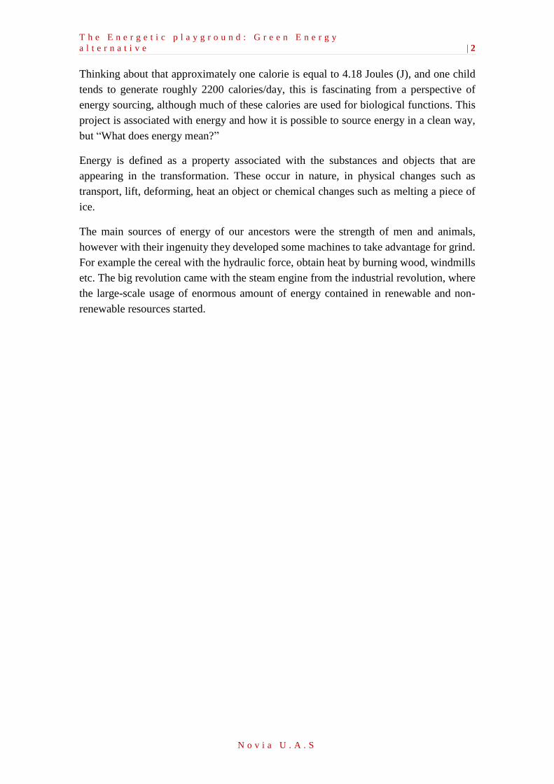
1. Introduction
Generating clean electricity is constantly developing through multiple projects and new
mechanism operating around the world. Despite this, the use of these mechanisms is still
in process. Gradually, these mechanisms are more frequently developed in more and more
countries. The majority of these projects are still in the design stage, but it can be seen
that these have already been applied in underdeveloped countries, for example in Africa.
It is generally known that children have unlimited energy. This energy could be used in a
different way than just having a good time or running. We have often heard that children
never get tired of playing and adults usually demand them to sit still and not to disturb,
however what would happen if the energy that children use playing is harnessed to
generate electricity? The idea is to use children’s playgrounds outdoors or in local
elementary schools to produce energy in form of electricity.
First of all, a study to design a model of a traditional swing which could generate either
electricity in alternate current (AC) or continues current (DC), depending on the use that
is wanted, like for example the main purpose, illuminate the parks (AC) has to be made.
Next, there is the design of a traditional merry-go-round that can produce electricity in
both ways. There are many projects related to this children game, many of them in
underdeveloped countries. Nowadays it is still built in Africa, to provide electricity for
flashlights enabling children to study at night.
Nevertheless, this project about the merry-go-round focuses on trying to generate
electricity either in DC to charge mobiles, tablets, etc. or in AC to help to illuminate the
municipal or school playground. Finally, a more recent technology is in continuous
development for many companies, piezoelectric tiles are studied. A design with these
piezoelectric plates is presented, covering the entire playground floor to generate
electricity.
Furthermore, it has a positive influence on the children’s live by designing an educational
municipal or local playground where they can feel involved in the process of producing
energy while they are playing, losing weight and feel good with themselves.
Constantly, media says that children are the future. This thesis takes advantage of these
words making this project to increase the general motivation of the people. Here,
producing energy in a useful mode while keeping the users enjoying their time.
T h e E n e r g e t i c p l a y g r o u n d : G r e e n E n e r g y
a l t e r n a t i v e | 2
N o v i a U . A . S
Thinking about that approximately one calorie is equal to 4.18 Joules (J), and one child
tends to generate roughly 2200 calories/day, this is fascinating from a perspective of
energy sourcing, although much of these calories are used for biological functions. This
project is associated with energy and how it is possible to source energy in a clean way,
but “What does energy mean?”
Energy is defined as a property associated with the substances and objects that are
appearing in the transformation. These occur in nature, in physical changes such as
transport, lift, deforming, heat an object or chemical changes such as melting a piece of
ice.
The main sources of energy of our ancestors were the strength of men and animals,
however with their ingenuity they developed some machines to take advantage for grind.
For example the cereal with the hydraulic force, obtain heat by burning wood, windmills
etc. The big revolution came with the steam engine from the industrial revolution, where
the large-scale usage of enormous amount of energy contained in renewable and non-
renewable resources started.
T h e E n e r g e t i c p l a y g r o u n d : G r e e n E n e r g y
a l t e r n a t i v e | 3
N o v i a U . A . S
2. Problem Statement
Actually the human requires energy to survive, manage their environment and produce
goods1. For some time now, the world is watching all the energetic problems due to the
depletion of the world oil reserves, which are used as a direct source of energy (engines
of automobiles or others) or to generate other energy as electric. This phenomenon has
been termed as 'energy crisis'.
The reasons are various: the consumption of electrical energy due to the constant growth
of the industrial and the residential sector. These have the highest amount of energy
demand and exploit natural resources most. To face this crisis the necessity to take
advantage in the best way has emerged. The available energy resources currently generate
new ways of making better use of available natural resources to transform into energy.
It is known that almost all types of energy comes indirectly from the sun. For example,
wind energy is caused by energy kinetics of solar radiation which produces a difference
pressure between the differences temperature of the air masses. Fossil fuels or
hydrocarbons come from energy transmitted by the sun and the decomposition process in
the absence of oxygen of plant species, which inhabited the earth millions of years ago.
There are two large groups of energy sources, which are renewable and nonrenewable.
The non-renewable energies (petrol, coal, natural gas or uranium principally) are from
sources that are depleted, such as uranium, gas fields, coal and oil. Once out they cannot
regenerate or take too long to do so. Renewable energies are those that are non-exhausted,
such as the sun's energy, wind energy, the energy produced by the gravitational pull of
the moon (tidal power), the energy of the earth (geothermal energy), etc.
After the industrial revolution, humans turned largely to the use of fossil fuels (natural
gas, coal and oil), which have been used in high amounts because of its high efficiency
considering its energy transformation.
However, many of these fuels pose serious environmental problems, as they emit toxic or
polluting gases into the Earth's atmosphere harming life. Additionally, as fuel fossils
begin to dwindle in the future, these will rise in price according to offer and demand.
Many countries have tried to reduce their dependence on fossil fuels through research
into sources of "green" or renewable energy to reduce the heavy pollution that exists
today. Hence, todays’ fossil fuels are the prime energy source on the planet.
1 Roman L, (2006).

T h e E n e r g e t i c p l a y g r o u n d : G r e e n E n e r g y
a l t e r n a t i v e | 4
N o v i a U . A . S
Globally, all these fuels: oil, coal and natural gas, represent 78% of the total consumption.
Approximately one third of the primary energy is used to produce electricity. Also 40%
of the electricity comes from coal, while oil and nuclear energy only cover between 12%
and 15% each. In terms of energy consumption, electricity accounts for 12% of the total
consumption equally the industrial and residential sectors.
A quarter of the world population consumes three quarters of the total primary energy in
the world. These inequalities are more significant, considering electricity consumption.
Poor countries (characterized by a dispersed habitat) exhibit large gaps in rural
electrification. Nowadays, we have a huge population that demands large amounts of
energy. Consequently, there is the necessity to make certain changes which generate
development, but these in turn are hand in hand with the sustainability of the planet.
The proposal of this thesis aims to deepen the issue of power generation by the mechanical
energy that people can produce, in which has been working in recent years on other
projects.
These sources of cleaner energy than fossil fuels have the advantage that they are not
exhausted, as this energy is produced by our own efforts. For this reason the awareness
of the people could be improved by offering opportunities to learn the fundamentals of
energy, e.g.: through the mechanisms in the playground it can be showed how the work
performed by a human is harvested, stored and used.
The green technology could be the biggest opportunity in the 21th century
John Doerr
T h e E n e r g e t i c p l a y g r o u n d : G r e e n E n e r g y
a l t e r n a t i v e | 5
N o v i a U . A . S
3. Energy
Energy is a property of the matter which is the ability to perform work or produce
transformations. Any material body passing from one state to another, produces physical
phenomena that are nothing more than manifestations of this property. Therefore, it can
be in various forms to be transformed from one energy state to another.
Energy can manifest itself in different forms: gravitational, kinetic, chemical, electrical,
magnetic, nuclear, calorific, etc., with the possibility of transforming each other with
respect of the principle of conservation of energy.
The principle of energy conservation: Energy can neither be created nor destroyed; rather,
it transforms from one form to another.2 Practically all the energy has come from the sun.
The sun produces wind, surface water evaporation, cloud formation, rainfall, etc. Its heat
and light are the basis of many chemical reactions for the development of plants and
animals, whose remains over centuries originate to fossil fuels such as coal, oil and natural
gas.
3.1. Energy as a resource
Energy sources are existing resources from nature, which humanity can derive usable
energy from. The origin of almost all types of energy is the sun.
Energy sources that regenerate naturally and bring the idea of being "clean" are called
renewable energy sources or alternatives. These can become non-renewable sources if the
level of consumption is higher than their regeneration capacity. Some sources of this type
are:
o Hydro power
o Geothermal
o Bioenergy
o Solar
o Wind
In contrast, it is understood by non-renewable sources, those involving the consumption
of exhaustible resources and energy contaminants. Some examples are:
o Petroleum
o Coal
o Nuclear fission Generation
2 Conservation of Energy. McGraw-Hill Dictionary of Scientific & Technical Terms, 6E, Copyright ©
2003 by the McGraw-Hill Companies, Inc.
T h e E n e r g e t i c p l a y g r o u n d : G r e e n E n e r g y
a l t e r n a t i v e | 6
N o v i a U . A . S
Energy availability of renewable energy is higher than of non-renewable energy, but its
use is limited. The development of technology, increasing social demand, lower
installation costs and fast amortization are driving greater use of sources of energy from
renewable sources in recent years.
3.2. How is electricity generated?
Currently, most of the electricity is produced by burning fossil fuels like oil, coal, natural
gas, etc. Part of the energy comes from the nuclear power plants and big dams. To
understand why clean energy is needed to replace fossil fuels and nuclear power plants,
it should be understood how electricity is produced from renewable sources or from
polluting sources.
Most of the electricity produced by fossil fuels is produced when the energy source heats
water to produce steam and this steam turns the big turbines to produce electricity,
different from the big hydroelectric dams which are not fossil fuels. The hydro power is
used in a different way to produce energy: the waterfalls spin the turbines to produce
electricity. All these techniques of energy production result in toxic pollution, destruction
of communities (dams) and many serious health problems. None of these options are
healthy or sustainable, especially when used in a large scale.
The fossils fuels become scarcer every day and more difficult to find. They are not
renewable which means that once used, they will be exhausted. At the same time, the
danger of the climate change and pollution from burning fossil fuels has become a higher
environmental health problem.
If the clean energy is used, it is possible to reduce the damage that the fossil fuels and
other pollutant technologies for the non-renewable energy production cause to the human
health and the environment. Clean energy renewable sources can provide electricity
without causing damage.
T h e E n e r g e t i c p l a y g r o u n d : G r e e n E n e r g y
a l t e r n a t i v e | 7
N o v i a U . A . S
4. Mechanism for Energy conversion
_____________________________________________________
In this chapter the following mechanisms can be applied to the prototypes that will be
explained in the second part of this project. This mechanisms are explained considering
that in the prototypes are going to be use to get electricity from mechanical energy by
the children.
_____________________________________________________
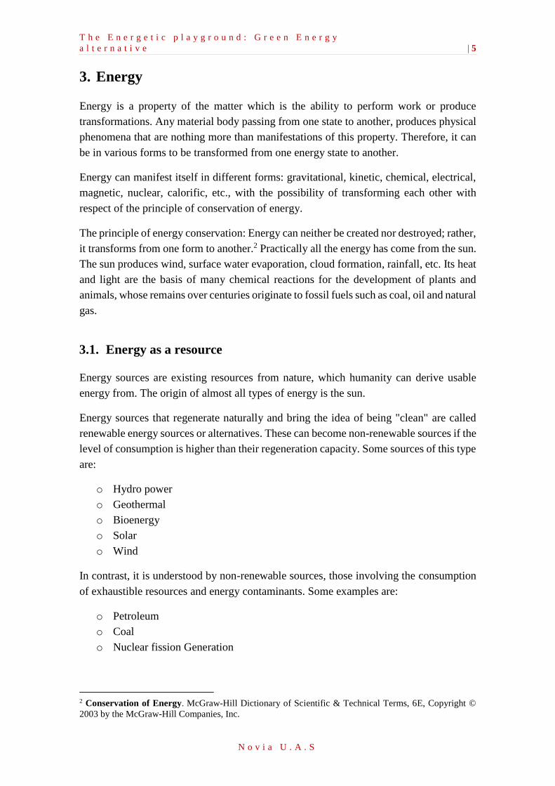
4.1. Speed multiplier
This gear uses the mechanism to transmit mechanical power between different parts of a
device. It serves to transmit circular movements by sprockets in contact. One of the most
important applications is the transmission of motion from the shaft of a power source, to
another shaft located at some distance that still has to perform work.
Figure 1. Speed multiplier.3
A speed multiplier is a transmission system formed by gears. It characterizes that the
output speed is higher than the input. It is an opposite system to the speed reducer, because
in most cases the speed of the motors spin is more than adequate for the work in machines.
It is similar than a speed reducer but with the difference in the input shaft and the output.
The efficiency of this device can reach from 90% to 97%.
If we look the figure 7, the Ni (number of the teeth) and Di, with i = 1, 2, 3, 4, the angular
velocities and the diameters for the gears 1, 2, 3 and 4. Then it holds that:
𝐷1𝑁1 = 𝐷2𝑁2 (Equation 3.1)
𝐷3𝑁3 = 𝐷4𝑁4 (Equation 3.2)
3 Source. http://iet-journals.org/archive/2014/april_vol_4_no_4/8213113821526.pdf
T h e E n e r g e t i c p l a y g r o u n d : G r e e n E n e r g y
a l t e r n a t i v e | 8
N o v i a U . A . S
𝑁2 = 𝑁3 (Equation 3.3)
𝑁1 =𝐷2𝐷4
𝐷1𝐷3𝑁4 = 𝑘𝑁4 (Equation 3.1)
To conclude, if the factor k is greater than 1, the gear arrangement represents a speed
multiplier in case the input to the system is given at the gear shaft n°4.
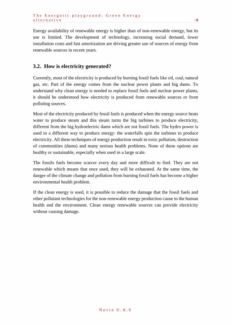
4.2. Driveshaft or propeller shaft
A driveshaft is a shaft that transmits a driving force and it is subjected to some torque
effort because of the transmission of couple of forces, as it might be subject to other types
of mechanical stresses at the same time.
Figure 2. Driveshaft or propeller shaft. 4
A propeller shaft is a rotating member that is used to transmit the rotatory movement and
power between coaxial transmission elements, such as flywheels, gears, pulley, etc. The
driveshaft also transmit around the rotating members such as crank. Generally, it has a
revolution form and a section in the diameter smaller than its length.
4 Source. Teoría de Mecanismes - Arbre de transmissió. University of Lleida (UDL)
T h e E n e r g e t i c p l a y g r o u n d : G r e e n E n e r g y
a l t e r n a t i v e | 9
N o v i a U . A . S
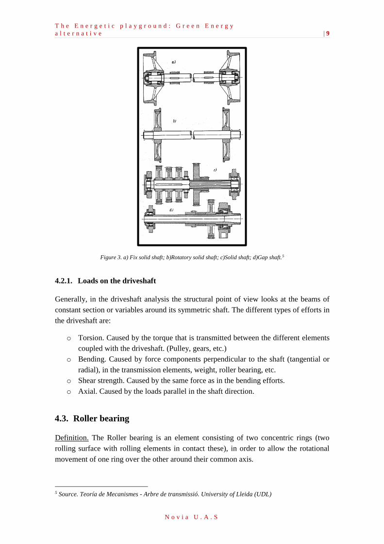
Figure 3. a) Fix solid shaft; b)Rotatory solid shaft; c)Solid shaft; d)Gap shaft.5
4.2.1. Loads on the driveshaft
Generally, in the driveshaft analysis the structural point of view looks at the beams of
constant section or variables around its symmetric shaft. The different types of efforts in
the driveshaft are:
o Torsion. Caused by the torque that is transmitted between the different elements
coupled with the driveshaft. (Pulley, gears, etc.)
o Bending. Caused by force components perpendicular to the shaft (tangential or
radial), in the transmission elements, weight, roller bearing, etc.
o Shear strength. Caused by the same force as in the bending efforts.
o Axial. Caused by the loads parallel in the shaft direction.
4.3. Roller bearing
Definition. The Roller bearing is an element consisting of two concentric rings (two
rolling surface with rolling elements in contact these), in order to allow the rotational
movement of one ring over the other around their common axis.
5 Source. Teoría de Mecanismes - Arbre de transmissió. University of Lleida (UDL)
T h e E n e r g e t i c p l a y g r o u n d : G r e e n E n e r g y
a l t e r n a t i v e | 10
N o v i a U . A . S
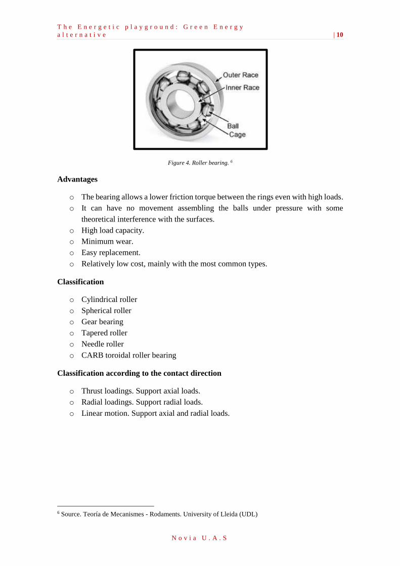
Figure 4. Roller bearing. 6
Advantages
o The bearing allows a lower friction torque between the rings even with high loads.
o It can have no movement assembling the balls under pressure with some
theoretical interference with the surfaces.
o High load capacity.
o Minimum wear.
o Easy replacement.
o Relatively low cost, mainly with the most common types.
Classification
o Cylindrical roller
o Spherical roller
o Gear bearing
o Tapered roller
o Needle roller
o CARB toroidal roller bearing
Classification according to the contact direction
o Thrust loadings. Support axial loads.
o Radial loadings. Support radial loads.
o Linear motion. Support axial and radial loads.
6 Source. Teoría de Mecanismes - Rodaments. University of Lleida (UDL)
T h e E n e r g e t i c p l a y g r o u n d : G r e e n E n e r g y
a l t e r n a t i v e | 11
N o v i a U . A . S
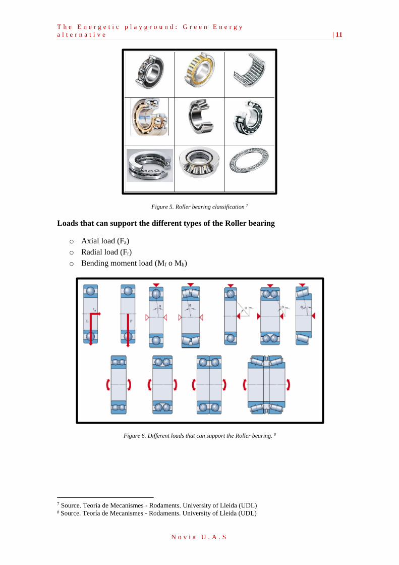
Figure 5. Roller bearing classification 7
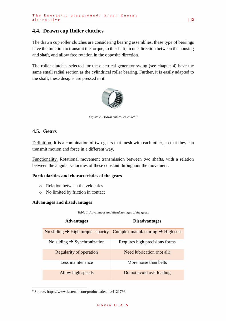
Loads that can support the different types of the Roller bearing
o Axial load (Fa)
o Radial load (Fr)
o Bending moment load (Mf o Mb)
Figure 6. Different loads that can support the Roller bearing. 8
7 Source. Teoría de Mecanismes - Rodaments. University of Lleida (UDL) 8 Source. Teoría de Mecanismes - Rodaments. University of Lleida (UDL)
T h e E n e r g e t i c p l a y g r o u n d : G r e e n E n e r g y
a l t e r n a t i v e | 12
N o v i a U . A . S
4.4. Drawn cup Roller clutches
The drawn cup roller clutches are considering bearing assemblies, these type of bearings
have the function to transmit the torque, to the shaft, in one direction between the housing
and shaft, and allow free rotation in the opposite direction.
The roller clutches selected for the electrical generator swing (see chapter 4) have the
same small radial section as the cylindrical roller bearing. Further, it is easily adapted to
the shaft; these designs are pressed in it.
Figure 7. Drawn cup roller clutch.9
4.5. Gears
Definition. It is a combination of two gears that mesh with each other, so that they can
transmit motion and force in a different way.
Functionality. Rotational movement transmission between two shafts, with a relation
between the angular velocities of these constant throughout the movement.
Particularities and characteristics of the gears
o Relation between the velocities
o No limited by friction in contact
Advantages and disadvantages
Table 1. Advantages and disadvantages of the gears
Advantages Disadvantages
No sliding High torque capacity Complex manufacturing High cost
No sliding Synchronization Requires high precisions forms
Regularity of operation Need lubrication (not all)
Less maintenance More noise than belts
Allow high speeds Do not avoid overloading
9 Source. https://www.fastenal.com/products/details/4121798
T h e E n e r g e t i c p l a y g r o u n d : G r e e n E n e r g y
a l t e r n a t i v e | 13
N o v i a U . A . S
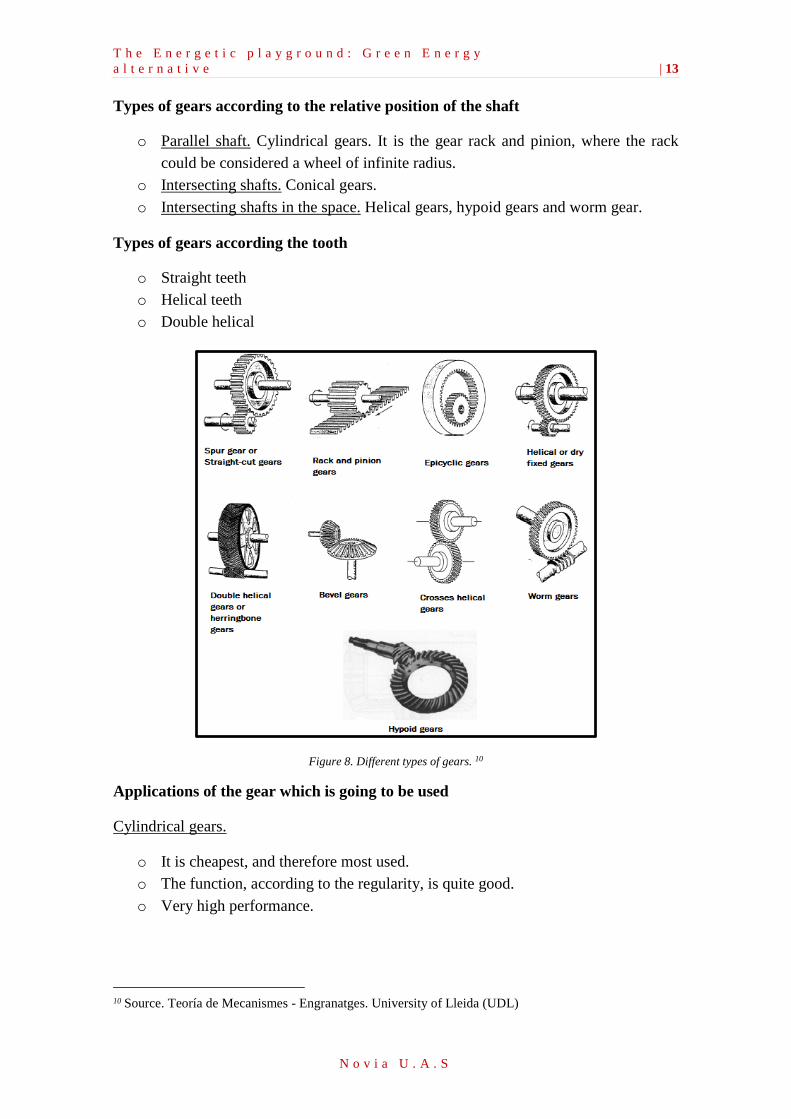
Types of gears according to the relative position of the shaft
o Parallel shaft. Cylindrical gears. It is the gear rack and pinion, where the rack
could be considered a wheel of infinite radius.
o Intersecting shafts. Conical gears.
o Intersecting shafts in the space. Helical gears, hypoid gears and worm gear.
Types of gears according the tooth
o Straight teeth
o Helical teeth
o Double helical
Figure 8. Different types of gears. 10
Applications of the gear which is going to be used
Cylindrical gears.
o It is cheapest, and therefore most used.
o The function, according to the regularity, is quite good.
o Very high performance.
10 Source. Teoría de Mecanismes - Engranatges. University of Lleida (UDL)
T h e E n e r g e t i c p l a y g r o u n d : G r e e n E n e r g y
a l t e r n a t i v e | 14
N o v i a U . A . S
Table 2. Efficiency of the gears. 11
Quality and lubrication of the gears Efficiency
Dirty teeth without machined 0.9 … 0.92
Machined flanks of the teeth and lubricated 0.94
Machined flanks of the teeth with precision and lubricated 0.96
Figure 9. Representation of a cylindrical gear with straight teeth. 12
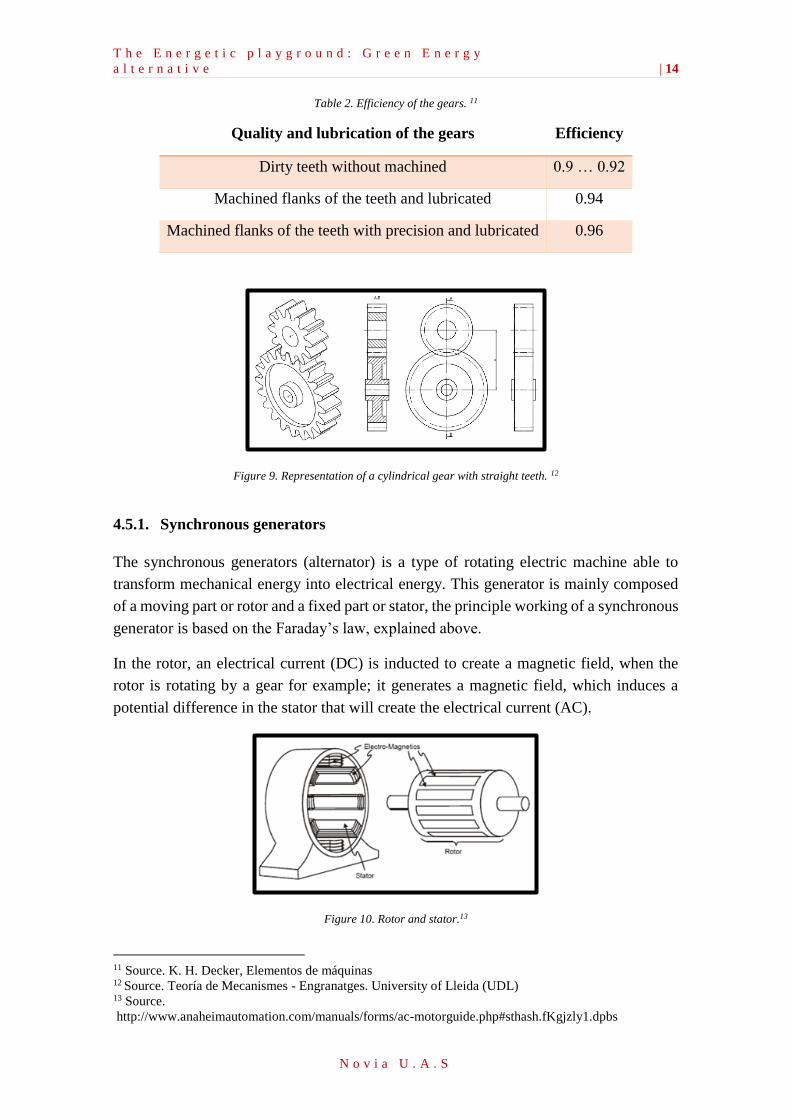
4.5.1. Synchronous generators
The synchronous generators (alternator) is a type of rotating electric machine able to
transform mechanical energy into electrical energy. This generator is mainly composed
of a moving part or rotor and a fixed part or stator, the principle working of a synchronous
generator is based on the Faraday’s law, explained above.
In the rotor, an electrical current (DC) is inducted to create a magnetic field, when the
rotor is rotating by a gear for example; it generates a magnetic field, which induces a
potential difference in the stator that will create the electrical current (AC).
Figure 10. Rotor and stator.13
11 Source. K. H. Decker, Elementos de máquinas 12 Source. Teoría de Mecanismes - Engranatges. University of Lleida (UDL) 13 Source.
http://www.anaheimautomation.com/manuals/forms/ac-motorguide.php#sthash.fKgjzly1.dpbs

T h e E n e r g e t i c p l a y g r o u n d : G r e e n E n e r g y
a l t e r n a t i v e | 15
N o v i a U . A . S
Second part. Research work
5. Energy-generator swing
__________________________________________
The main idea of this project arises from the concern of the damage we have already
caused to the environment by over usage of the main energy sources. The prototype
presented in the following document is based on taking advantage of the mechanical
energy that is provided by children’s movement for electricity production and how it
can be stored for later use (such as in parks overnight, schools, nearby residential, etc.)
or send directly to the grid if it can be sourced.
T h e E n e r g e t i c p l a y g r o u n d : G r e e n E n e r g y
a l t e r n a t i v e | 16
N o v i a U . A . S
5.1. Introduction to the energy-generator swing
The main idea to build this energy-generator swing is that children have the opportunity
to have a playful installation in the one hand and on the other hand interact with the
production process of electricity. It is intended to build a driveshaft with a one-gear
assembly coupled with an alternator on the swing to derive the energy of the children.
Thanks to the project built by Moradavaga14, “for the Pop up Culture competition”,
promoted by Guimaraes, Portugal in November of 2012 the first swing was introduced.
This project has served as a support and motivation. The function is quite simple.
Basically, there is a bicycle chain attached to the swing with a counterweight in the back
to spin the bicycle wheel. At the wheel a common bicycle dynamo is fixed to produce
electricity for a hidden light bulb underneath the floor. (See appendix 1. Low-tech system.
Project SWING / Moradavaga.)
This study tries to find out an efficient mechanism because usually young people try to
touch all the visible things and at the same time destroy it. Due to the complex mechanism
in the swing such as gears, generators, etc. it is perhaps better to hide these so children
will not get hurt and at the same time they can play without their families to worry.
The goal of this project would be to invent a small-scale alternative to replace the
traditional energy generation by fossil fuel by using structures in a playground (like
elementary school or Childcare Center). There is hope that this initiative could create
educational playgrounds where children feel involved in the production of energy while
playing, feeling good and get fit at the same time. When the public gets more involved in
the process of clean energy, they will contribute more to ensure the wellbeing of our
planet.
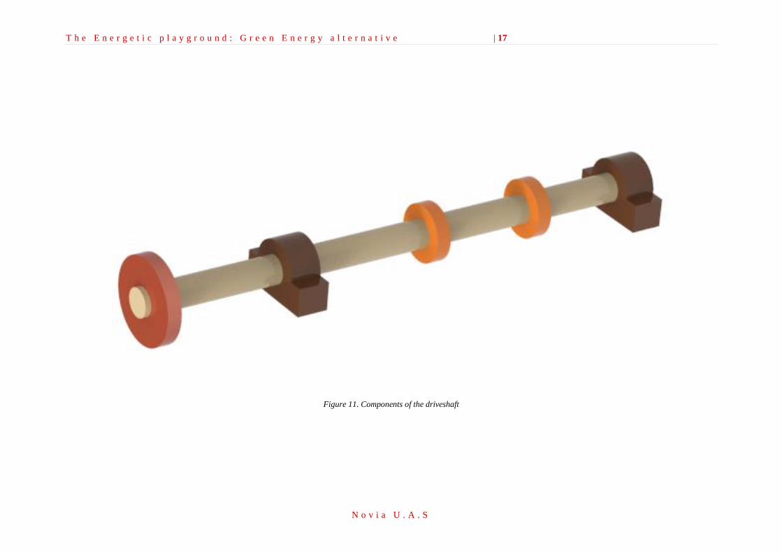
The driveshaft of the electrical generator swing is composed of one cogwheel, two roller
bearings, two drawn cup roller clutches, and one generator. In addition, the Roller
bearings shall be mounted on the driveshaft at the point where the two bars supporting
the swing meet the driveshaft. Moreover, the two roller clutches are situated at the points
where the strings of the swing are coupled to the driveshaft. The cogwheel is situated in
one of the extremes of the driveshaft, this cogwheel is connected to a smaller gear which
is driving the alternator.
14 Source. http://moradavaga.com/SWING
T h e E n e r g e t i c p l a y g r o u n d : G r e e n E n e r g y a l t e r n a t i v e | 17
N o v i a U . A . S
Figure 11. Components of the driveshaft
T h e E n e r g e t i c p l a y g r o u n d : G r e e n E n e r g y
a l t e r n a t i v e | 18
N o v i a U . A . S
5.2. Theoretical Bases
5.2.1. Conservative forces
Conservative forces, if applied to a particle follow a closed path, with the same start and
end point, no work done. As a result, the work done by a conservative force between
certain start and end points is independent of the route followed by the point of application
of force.
Note: For the study of mechanisms two types of conservative forces must be considered:
the weight due to the gravitational attraction and the power made by a spring.
Given this property that the work done by conservative forces is independent of the path
followed and only depends on the starting and ending points of the route: you can define
the potential energy of a system, as energy that is in a certain position within a field of
conservative forces. Then, the increase of potential energy is the absolute value of the
work done by a conservative force to move the system from one position to another.
∆𝐸𝑝 = −(𝑊𝑐)1→2 = −∫ 𝐹𝑐⃗⃗ ⃗ · 𝑑𝑟⃗⃗⃗⃗ 2
1
Said in another way, the difference in potential energy is consumed to perform
conservative force, a work between the start and end positions.
Replacing the expression of energy theorem and separating the not conservative work and
conservative:
𝑊1→2 = 𝐸𝑘2 − 𝐸𝑘1
(𝑊𝑛𝑐)1→2 + (𝑊𝑐)1→2 = ∆𝐸𝑘
(𝑊𝑛𝑐)1→2 = ∆𝐸𝑘 − (𝑊𝑐)1→2 = ∆𝐸𝑘 + ∆𝐸𝑝
Mechanical energy is defined as the sum of kinetic energy and potential energy. Then:
(𝑊𝑛𝑐)1→2 = ∆𝐸𝑚
A particular case, which frequently occurs in is when you have a system in which the
work done by non-conservative forces is zero. Then the mechanical energy is maintained
and in any case that can happen is that there is an exchange between kinetic and potential
energies.
T h e E n e r g e t i c p l a y g r o u n d : G r e e n E n e r g y
a l t e r n a t i v e | 19
N o v i a U . A . S
𝑊𝑛𝑐 = 0 → 𝐸𝑚 = 𝐸𝑘 + 𝐸𝑝 = 𝑐𝑜𝑛𝑠𝑡𝑎𝑛𝑡
(Principle of conservation of mechanical energy: If the work done on a system that the
forces not conservative is zero, then the mechanical energy system remains constant.)
5.2.2. Potential energy due to the gravitational field
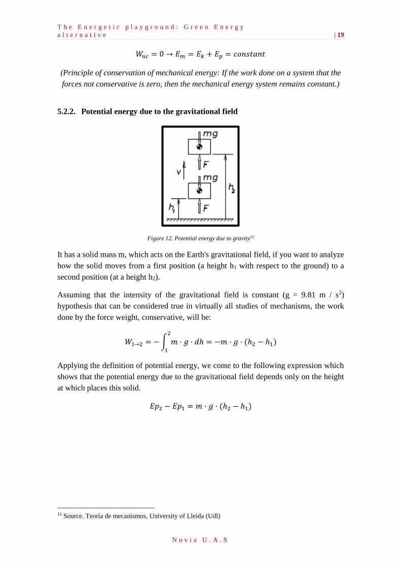
Figure 12. Potential energy due to gravity15
It has a solid mass m, which acts on the Earth's gravitational field, if you want to analyze
how the solid moves from a first position (a height h1 with respect to the ground) to a
second position (at a height h2).
Assuming that the intensity of the gravitational field is constant (g = 9.81 m / s2)
hypothesis that can be considered true in virtually all studies of mechanisms, the work
done by the force weight, conservative, will be:
𝑊1→2 = −∫ 𝑚 · 𝑔 · 𝑑ℎ2
1
= −𝑚 · 𝑔 · (ℎ2 − ℎ1)
Applying the definition of potential energy, we come to the following expression which
shows that the potential energy due to the gravitational field depends only on the height
at which places this solid.
𝐸𝑝2 − 𝐸𝑝1 = 𝑚 · 𝑔 · (ℎ2 − ℎ1)
15 Source. Teoría de mecanismos, University of Lleida (Udl)
T h e E n e r g e t i c p l a y g r o u n d : G r e e n E n e r g y
a l t e r n a t i v e | 20
N o v i a U . A . S
5.3. Design of the electrical generator swing
The design of the electrical generator swing, has been dived into three steps. In the first
step, the energy balance is calculated from the initial position of the swing (0º), until the
supposed maximum position (70º), which can be reached, to find the maximum velocity
that the swing can have. Afterwards, the point with the force of the string that the system
can support and also the maximum torque on the shaft that the children can do is
determined.
In the second step, the reactions on the first cogwheel are calculated on the roller
bearings. Finally, in the third step, the driveshaft is studied and calculated, including the
fatigue resistance of it. Finally, the driveshaft is recalculated to adapt all the components.
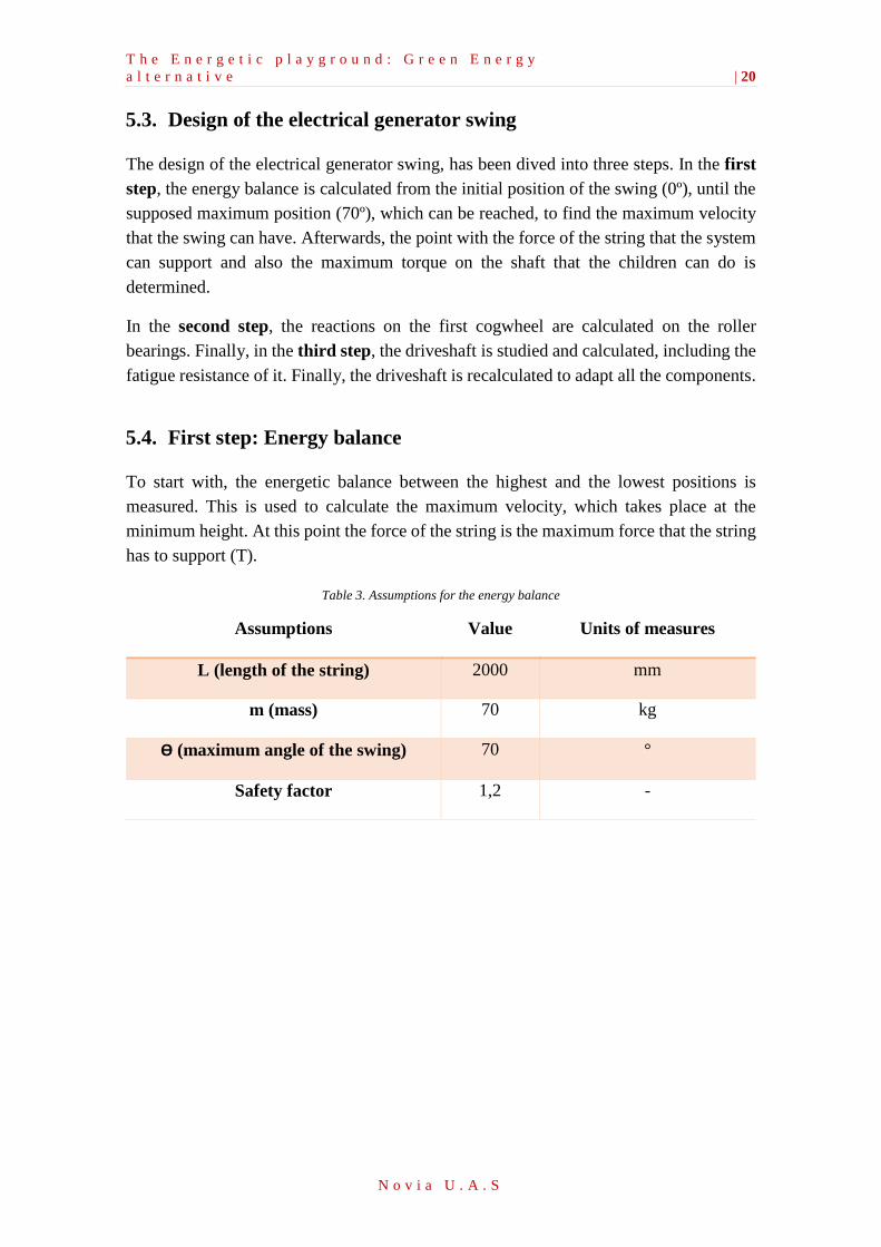
5.4. First step: Energy balance
To start with, the energetic balance between the highest and the lowest positions is
measured. This is used to calculate the maximum velocity, which takes place at the
minimum height. At this point the force of the string is the maximum force that the string
has to support (T).
Table 3. Assumptions for the energy balance
Assumptions Value Units of measures
L (length of the string) 2000 mm
m (mass) 70 kg
ϴ (maximum angle of the swing) 70 °
Safety factor 1,2 -
T h e E n e r g e t i c p l a y g r o u n d : G r e e n E n e r g y
a l t e r n a t i v e | 21
N o v i a U . A . S
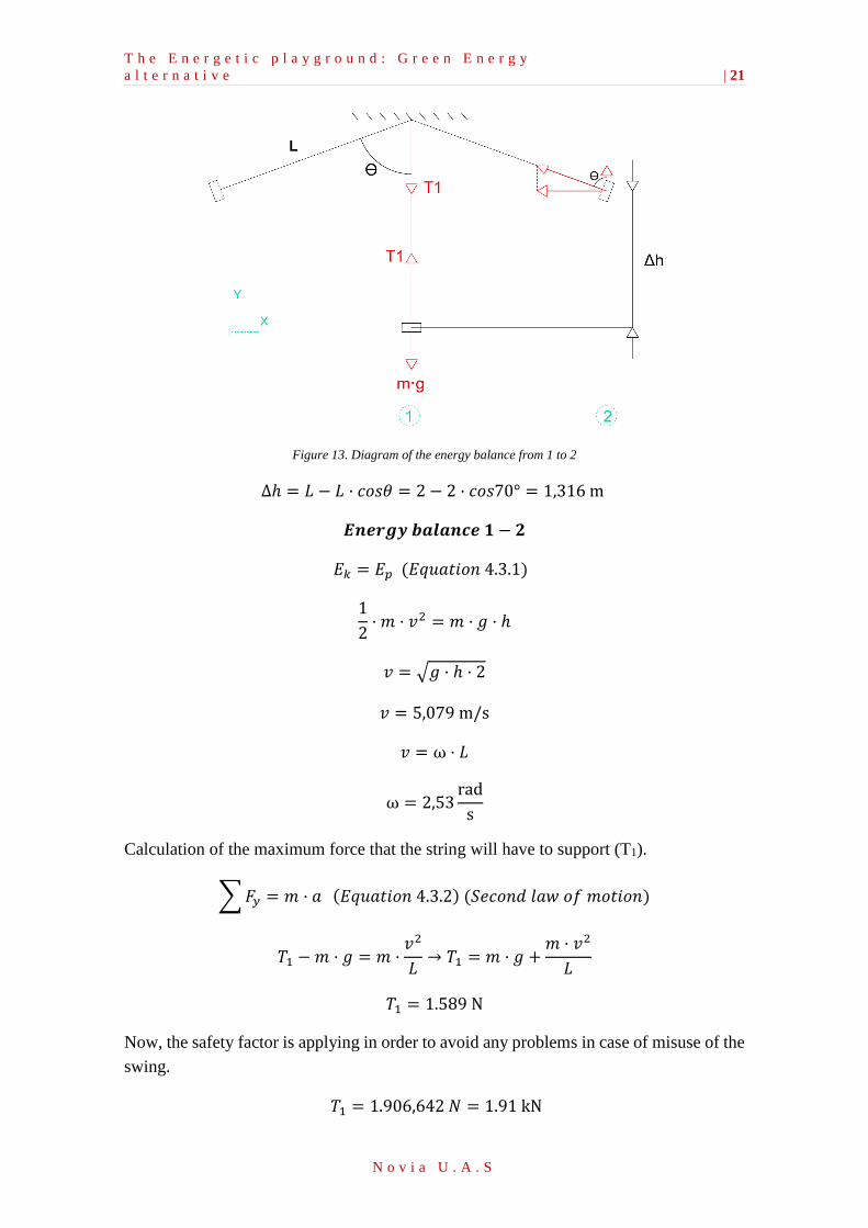
Figure 13. Diagram of the energy balance from 1 to 2
∆ℎ = 𝐿 − 𝐿 · 𝑐𝑜𝑠𝜃 = 2 − 2 · 𝑐𝑜𝑠70° = 1,316 m
𝑬𝒏𝒆𝒓𝒈𝒚 𝒃𝒂𝒍𝒂𝒏𝒄𝒆 𝟏 − 𝟐
𝐸𝑘 = 𝐸𝑝 (𝐸𝑞𝑢𝑎𝑡𝑖𝑜𝑛 4.3.1)
1
2· 𝑚 · 𝑣2 = 𝑚 · 𝑔 · ℎ
𝑣 = √𝑔 · ℎ · 2
𝑣 = 5,079 m/s
𝑣 = ⍵ · 𝐿
⍵ = 2,53rad
s
Calculation of the maximum force that the string will have to support (T1).
∑𝐹𝑦 = 𝑚 · 𝑎 (𝐸𝑞𝑢𝑎𝑡𝑖𝑜𝑛 4.3.2) (𝑆𝑒𝑐𝑜𝑛𝑑 𝑙𝑎𝑤 𝑜𝑓 𝑚𝑜𝑡𝑖𝑜𝑛)
𝑇1 − 𝑚 · 𝑔 = 𝑚 ·𝑣2
𝐿→ 𝑇1 = 𝑚 · 𝑔 +
𝑚 · 𝑣2
𝐿
𝑇1 = 1.589 N
Now, the safety factor is applying in order to avoid any problems in case of misuse of the
swing.
𝑇1 = 1.906,642 𝑁 = 1.91 kN
T h e E n e r g e t i c p l a y g r o u n d : G r e e n E n e r g y
a l t e r n a t i v e | 22
N o v i a U . A . S
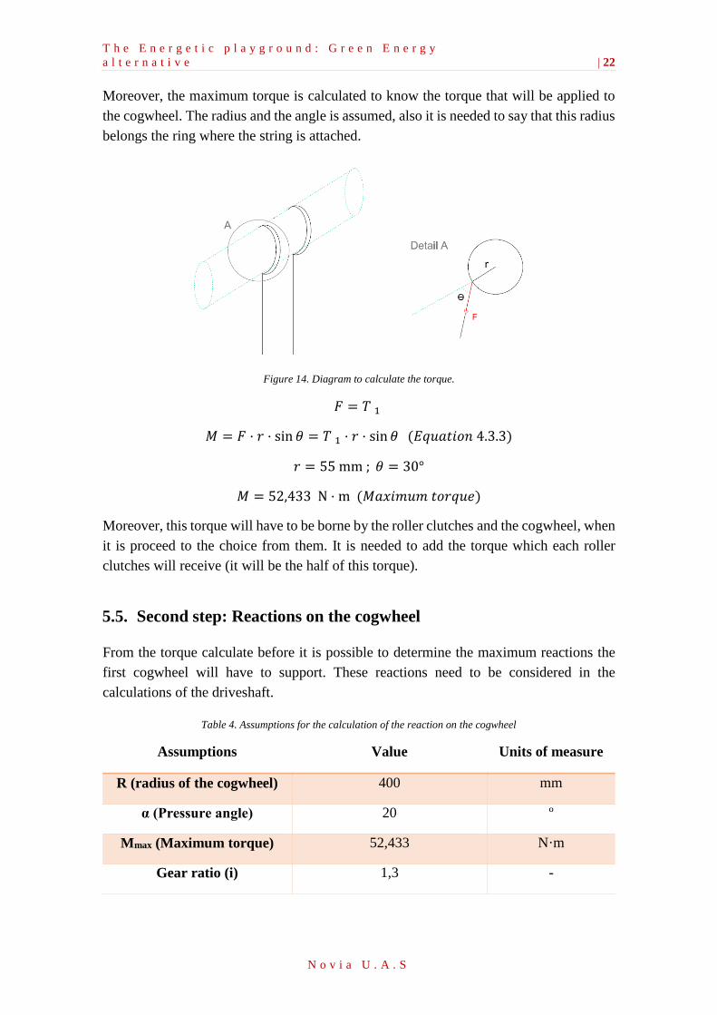
Moreover, the maximum torque is calculated to know the torque that will be applied to
the cogwheel. The radius and the angle is assumed, also it is needed to say that this radius
belongs the ring where the string is attached.
Figure 14. Diagram to calculate the torque.
𝐹 = 𝑇 1
𝑀 = 𝐹 · 𝑟 · sin 𝜃 = 𝑇 1 · 𝑟 · sin 𝜃 (𝐸𝑞𝑢𝑎𝑡𝑖𝑜𝑛 4.3.3)
𝑟 = 55 mm ; 𝜃 = 30°
𝑀 = 52,433 N · m (𝑀𝑎𝑥𝑖𝑚𝑢𝑚 𝑡𝑜𝑟𝑞𝑢𝑒)
Moreover, this torque will have to be borne by the roller clutches and the cogwheel, when
it is proceed to the choice from them. It is needed to add the torque which each roller
clutches will receive (it will be the half of this torque).
5.5. Second step: Reactions on the cogwheel
From the torque calculate before it is possible to determine the maximum reactions the
first cogwheel will have to support. These reactions need to be considered in the
calculations of the driveshaft.
Table 4. Assumptions for the calculation of the reaction on the cogwheel
Assumptions Value Units of measure
R (radius of the cogwheel) 400 mm
α (Pressure angle) 20 º
Mmax (Maximum torque) 52,433 N·m
Gear ratio (i) 1,3 -
T h e E n e r g e t i c p l a y g r o u n d : G r e e n E n e r g y
a l t e r n a t i v e | 23
N o v i a U . A . S
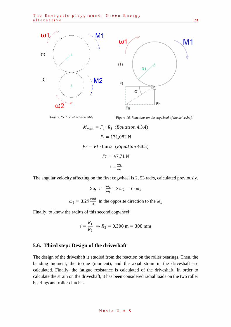
Figure 15. Cogwheel assembly
Figure 16. Reactions on the cogwheel of the driveshaft
𝑀𝑚𝑎𝑥 = 𝐹𝑡 · 𝑅1 (𝐸𝑞𝑢𝑎𝑡𝑖𝑜𝑛 4.3.4)
𝐹𝑡 = 131,082 N
𝐹𝑟 = 𝐹𝑡 · tan𝛼 (𝐸𝑞𝑢𝑎𝑡𝑖𝑜𝑛 4.3.5)
𝐹𝑟 = 47,71 N
𝑖 =𝜔2
𝜔1
The angular velocity affecting on the first cogwheel is 2, 53 rad/s, calculated previously.
So, 𝑖 =𝜔2
𝜔1 ⇒ 𝜔2 = 𝑖 · 𝜔1
𝜔2 = 3,29𝑟𝑎𝑑
𝑠 In the opposite direction to the 𝜔1
Finally, to know the radius of this second cogwheel:
𝑖 =𝑅1
𝑅2 ⇒ 𝑅2 = 0,308 m = 308 mm
5.6. Third step: Design of the driveshaft
The design of the driveshaft is studied from the reaction on the roller bearings. Then, the
bending moment, the torque (moment), and the axial strain in the driveshaft are
calculated. Finally, the fatigue resistance is calculated of the driveshaft. In order to
calculate the strain on the driveshaft, it has been considered radial loads on the two roller
bearings and roller clutches.
T h e E n e r g e t i c p l a y g r o u n d : G r e e n E n e r g y
a l t e r n a t i v e | 24
N o v i a U . A . S
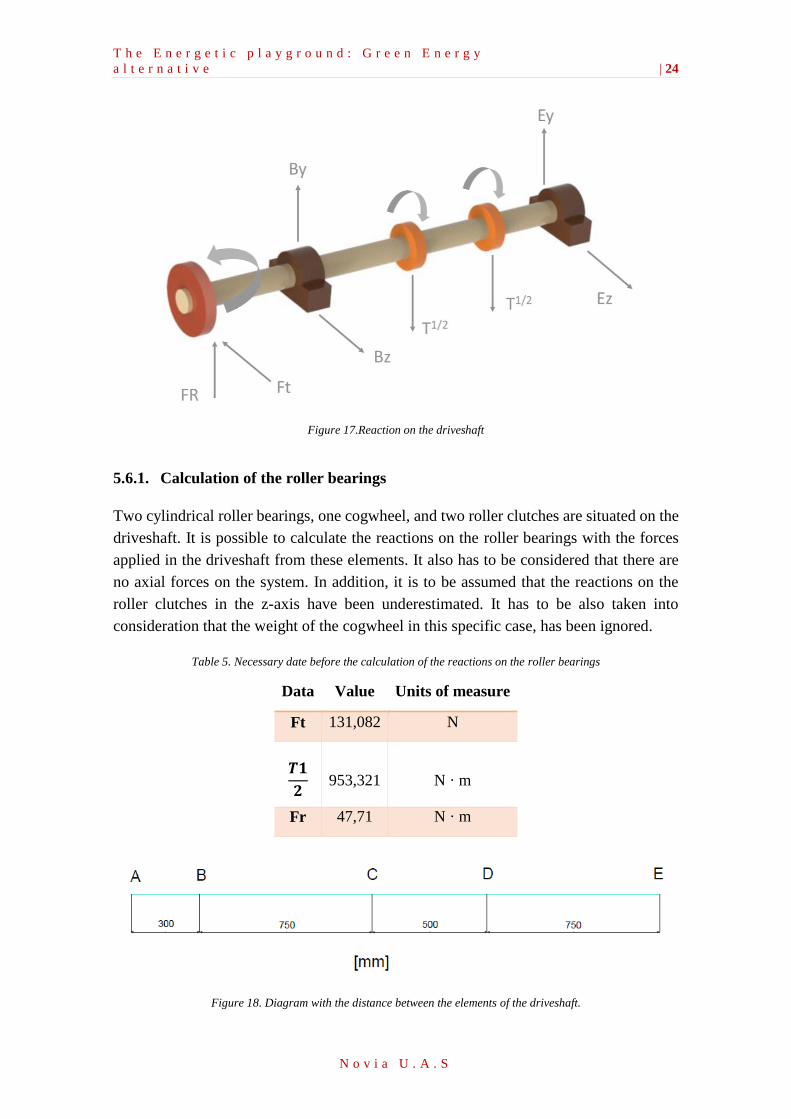
Figure 17.Reaction on the driveshaft
5.6.1. Calculation of the roller bearings
Two cylindrical roller bearings, one cogwheel, and two roller clutches are situated on the
driveshaft. It is possible to calculate the reactions on the roller bearings with the forces
applied in the driveshaft from these elements. It also has to be considered that there are
no axial forces on the system. In addition, it is to be assumed that the reactions on the
roller clutches in the z-axis have been underestimated. It has to be also taken into
consideration that the weight of the cogwheel in this specific case, has been ignored.
Table 5. Necessary date before the calculation of the reactions on the roller bearings
Data Value Units of measure
Ft 131,082 N
𝑻𝟏
𝟐
953,321
N · m
Fr 47,71 N · m
Figure 18. Diagram with the distance between the elements of the driveshaft.
T h e E n e r g e t i c p l a y g r o u n d : G r e e n E n e r g y
a l t e r n a t i v e | 25
N o v i a U . A . S
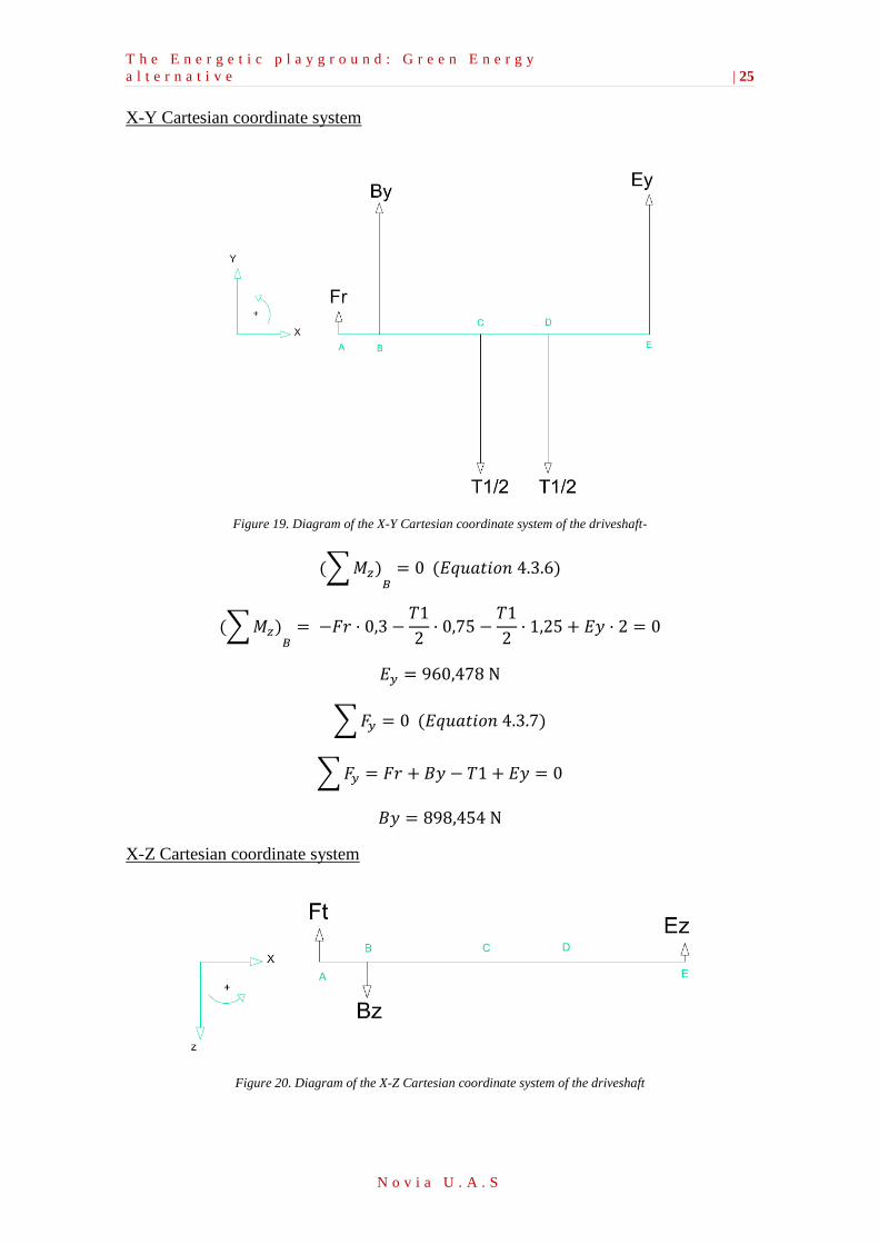
X-Y Cartesian coordinate system
Figure 19. Diagram of the X-Y Cartesian coordinate system of the driveshaft-
(∑𝑀𝑧)𝐵
= 0 (𝐸𝑞𝑢𝑎𝑡𝑖𝑜𝑛 4.3.6)
(∑𝑀𝑧)𝐵
= −𝐹𝑟 · 0,3 −𝑇1
2· 0,75 −
𝑇1
2· 1,25 + 𝐸𝑦 · 2 = 0
𝐸𝑦 = 960,478 N
∑𝐹𝑦 = 0 (𝐸𝑞𝑢𝑎𝑡𝑖𝑜𝑛 4.3.7)
∑𝐹𝑦 = 𝐹𝑟 + 𝐵𝑦 − 𝑇1 + 𝐸𝑦 = 0
𝐵𝑦 = 898,454 N
X-Z Cartesian coordinate system
Figure 20. Diagram of the X-Z Cartesian coordinate system of the driveshaft
T h e E n e r g e t i c p l a y g r o u n d : G r e e n E n e r g y
a l t e r n a t i v e | 26
N o v i a U . A . S
(∑𝑀𝑦)𝐸
= 0 (𝐸𝑞𝑢𝑎𝑡𝑖𝑜𝑛 4.3.8)
(∑𝑀𝑦)𝐸
= −𝐹𝑡 · 2,3 + 𝐵𝑧 · 2 = 0
𝐵𝑧 = 150,744 N
∑𝐹𝑧 = 0 (𝐸𝑞𝑢𝑎𝑡𝑖𝑜𝑛 4.3.9)
∑𝐹𝑧 = −𝐹𝑡 + 𝐵𝑧 − 𝐸𝑧 = 0
𝐸𝑧 = 19,622 N
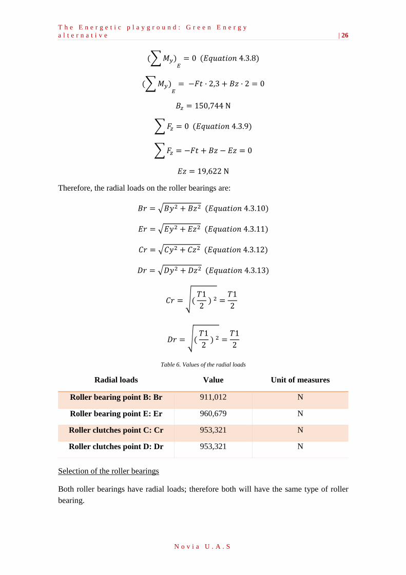
Therefore, the radial loads on the roller bearings are:
𝐵𝑟 = √𝐵𝑦2 + 𝐵𝑧2 (𝐸𝑞𝑢𝑎𝑡𝑖𝑜𝑛 4.3.10)
𝐸𝑟 = √𝐸𝑦2 + 𝐸𝑧2 (𝐸𝑞𝑢𝑎𝑡𝑖𝑜𝑛 4.3.11)
𝐶𝑟 = √𝐶𝑦2 + 𝐶𝑧2 (𝐸𝑞𝑢𝑎𝑡𝑖𝑜𝑛 4.3.12)
𝐷𝑟 = √𝐷𝑦2 + 𝐷𝑧2 (𝐸𝑞𝑢𝑎𝑡𝑖𝑜𝑛 4.3.13)
𝐶𝑟 = √( 𝑇1
2 ) 2 =
𝑇1
2
𝐷𝑟 = √( 𝑇1
2 ) 2 =
𝑇1
2
Table 6. Values of the radial loads
Radial loads Value Unit of measures
Roller bearing point B: Br 911,012 N
Roller bearing point E: Er 960,679 N
Roller clutches point C: Cr 953,321 N
Roller clutches point D: Dr 953,321 N
Selection of the roller bearings
Both roller bearings have radial loads; therefore both will have the same type of roller
bearing.
T h e E n e r g e t i c p l a y g r o u n d : G r e e n E n e r g y
a l t e r n a t i v e | 27
N o v i a U . A . S
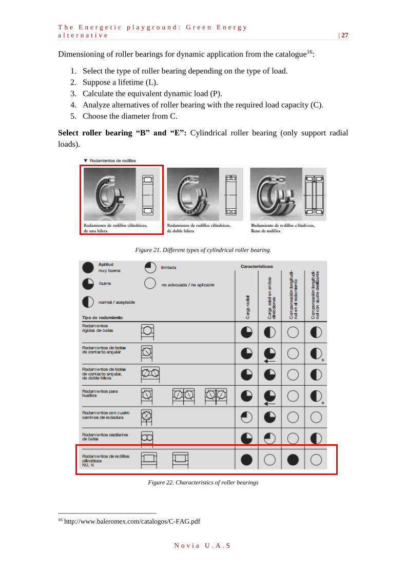
Dimensioning of roller bearings for dynamic application from the catalogue16:
1. Select the type of roller bearing depending on the type of load.
2. Suppose a lifetime (L).
3. Calculate the equivalent dynamic load (P).
4. Analyze alternatives of roller bearing with the required load capacity (C).
5. Choose the diameter from C.
Select roller bearing “B” and “E”: Cylindrical roller bearing (only support radial
loads).
Figure 21. Different types of cylindrical roller bearing.
Figure 22. Characteristics of roller bearings
16 http://www.baleromex.com/catalogos/C-FAG.pdf
T h e E n e r g e t i c p l a y g r o u n d : G r e e n E n e r g y
a l t e r n a t i v e | 28
N o v i a U . A . S
The lifetime for both roller bearings that is assumed is:
(15 𝑎𝑛𝑦𝑠 ·288 𝑑𝑖𝑒𝑠
1 𝑎𝑛𝑦·
4 ℎ
1 𝑑𝑖𝑎·60 𝑚𝑖𝑛
1 ℎ·20 𝑟𝑒𝑣
1 𝑚𝑖𝑛= 20,7 · 106 𝑟𝑒𝑣) (𝐸𝑞𝑢𝑎𝑡𝑖𝑜𝑛 4.3.14)
Roller bearings “B” and “E”: Cylindrical roller bearings
Following the steps of the catalogue “Rodamientos FAG” the previous inner diameter is:
∅𝐵 = ∅𝐸 = 15 𝑚𝑚
To see how it has been calculated the diameters above see Appendix 1. (1.2 Calculation
of the dimensioning on request dynamic of roller bearings.)
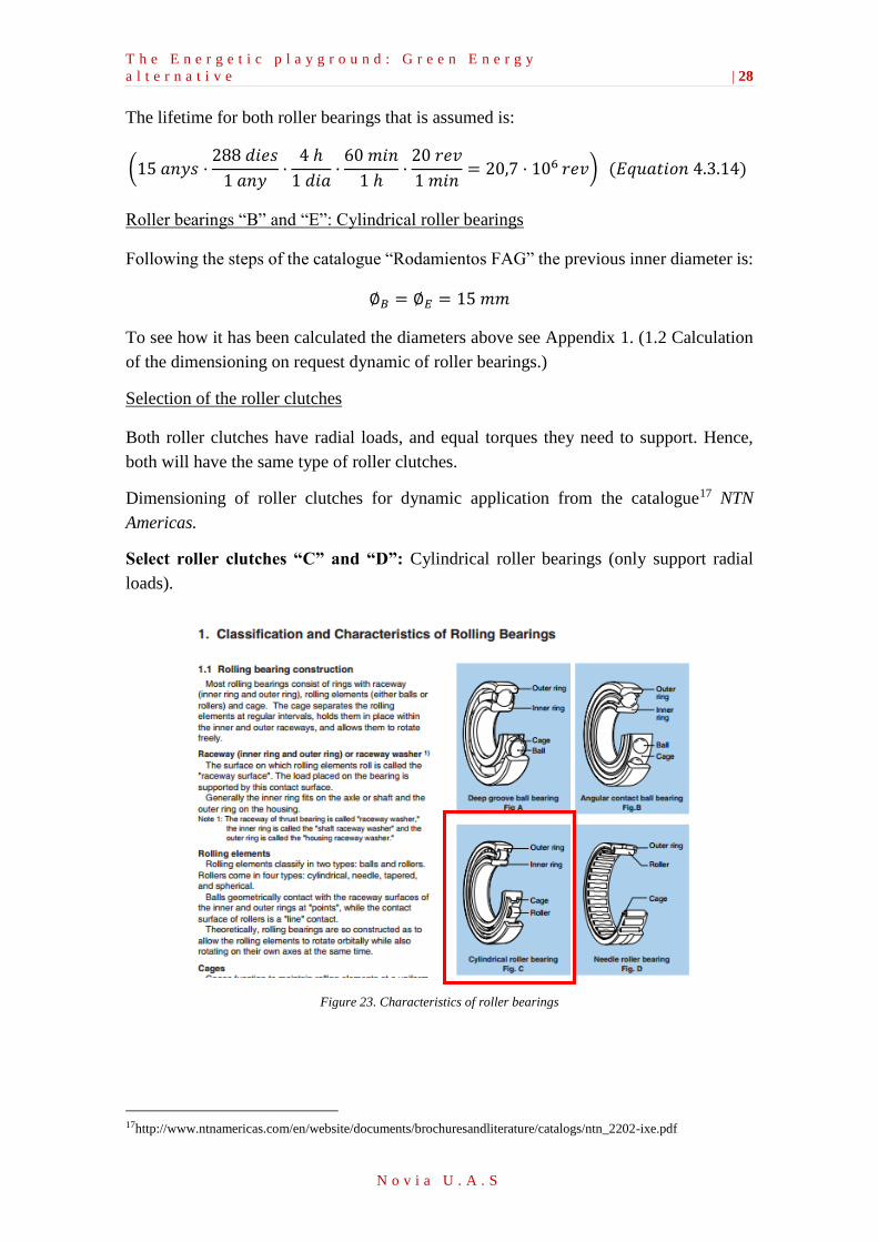
Selection of the roller clutches
Both roller clutches have radial loads, and equal torques they need to support. Hence,
both will have the same type of roller clutches.
Dimensioning of roller clutches for dynamic application from the catalogue17 NTN
Americas.
Select roller clutches “C” and “D”: Cylindrical roller bearings (only support radial
loads).
Figure 23. Characteristics of roller bearings
17http://www.ntnamericas.com/en/website/documents/brochuresandliterature/catalogs/ntn_2202-ixe.pdf
T h e E n e r g e t i c p l a y g r o u n d : G r e e n E n e r g y
a l t e r n a t i v e | 29
N o v i a U . A . S
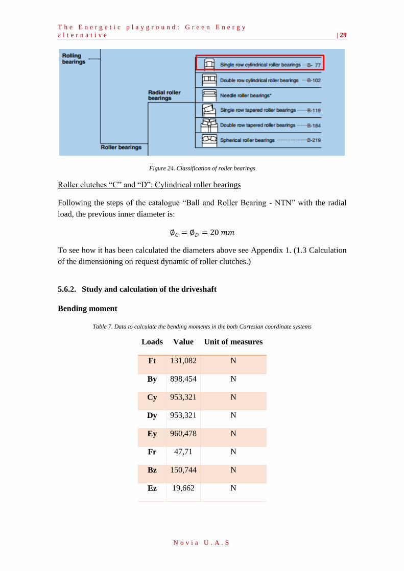
Figure 24. Classification of roller bearings
Roller clutches “C” and “D”: Cylindrical roller bearings
Following the steps of the catalogue “Ball and Roller Bearing - NTN” with the radial
load, the previous inner diameter is:
∅𝐶 = ∅𝐷 = 20 𝑚𝑚
To see how it has been calculated the diameters above see Appendix 1. (1.3 Calculation
of the dimensioning on request dynamic of roller clutches.)
5.6.2. Study and calculation of the driveshaft
Bending moment
Table 7. Data to calculate the bending moments in the both Cartesian coordinate systems
Loads Value Unit of measures
Ft 131,082 N
By 898,454 N
Cy 953,321 N
Dy 953,321 N
Ey 960,478 N
Fr 47,71 N
Bz 150,744 N
Ez 19,662 N
T h e E n e r g e t i c p l a y g r o u n d : G r e e n E n e r g y
a l t e r n a t i v e | 30
N o v i a U . A . S
Sign criteria to follow:
∑𝑀 = 0 (𝐸𝑞𝑢𝑎𝑡𝑖𝑜𝑛 4.3.15)
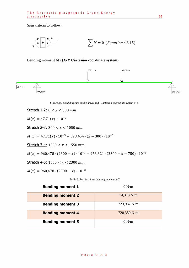
Bending moment Mz (X-Y Cartesian coordinate system)
Figure 25. Load diagram on the driveshaft (Cartesian coordinate system Y-Z)
Stretch 1-2: 0 < 𝑥 < 300 𝑚𝑚
𝑀(𝑥) = 47,71(𝑥) · 10−3
Stretch 2-3: 300 < 𝑥 < 1050 𝑚𝑚
𝑀(𝑥) = 47,71(𝑥) · 10−3 + 898,454 · (𝑥 − 300) · 10−3
Stretch 3-4: 1050 < 𝑥 < 1550 𝑚𝑚
𝑀(𝑥) = 960,478 · (2300 − 𝑥) · 10−3 − 953,321 · (2300 − 𝑥 − 750) · 10−3
Stretch 4-5: 1550 < 𝑥 < 2300 𝑚𝑚
𝑀(𝑥) = 960,478 · (2300 − 𝑥) · 10−3
Table 8. Results of the bending moment X-Y
Bending moment 1 0 N·m
Bending moment 2 14,313 N·m
Bending moment 3 723,937 N·m
Bending moment 4 720,359 N·m
Bending moment 5 0 N·m
T h e E n e r g e t i c p l a y g r o u n d : G r e e n E n e r g y
a l t e r n a t i v e | 31
N o v i a U . A . S
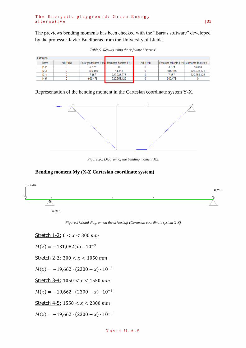
The previews bending moments has been cheeked with the “Barras software” developed
by the professor Javier Bradineras from the University of Lleida.
Table 9. Results using the software "Barras"
Representation of the bending moment in the Cartesian coordinate system Y-X.
Figure 26. Diagram of the bending moment Mz.
Bending moment My (X-Z Cartesian coordinate system)
Figure 27.Load diagram on the driveshaft (Cartesian coordinate system X-Z)
Stretch 1-2: 0 < 𝑥 < 300 𝑚𝑚
𝑀(𝑥) = −131,082(𝑥) · 10−3
Stretch 2-3: 300 < 𝑥 < 1050 𝑚𝑚
𝑀(𝑥) = −19,662 · (2300 − 𝑥) · 10−3
Stretch 3-4: 1050 < 𝑥 < 1550 𝑚𝑚
𝑀(𝑥) = −19,662 · (2300 − 𝑥) · 10−3
Stretch 4-5: 1550 < 𝑥 < 2300 𝑚𝑚
𝑀(𝑥) = −19,662 · (2300 − 𝑥) · 10−3
T h e E n e r g e t i c p l a y g r o u n d : G r e e n E n e r g y
a l t e r n a t i v e | 32
N o v i a U . A . S
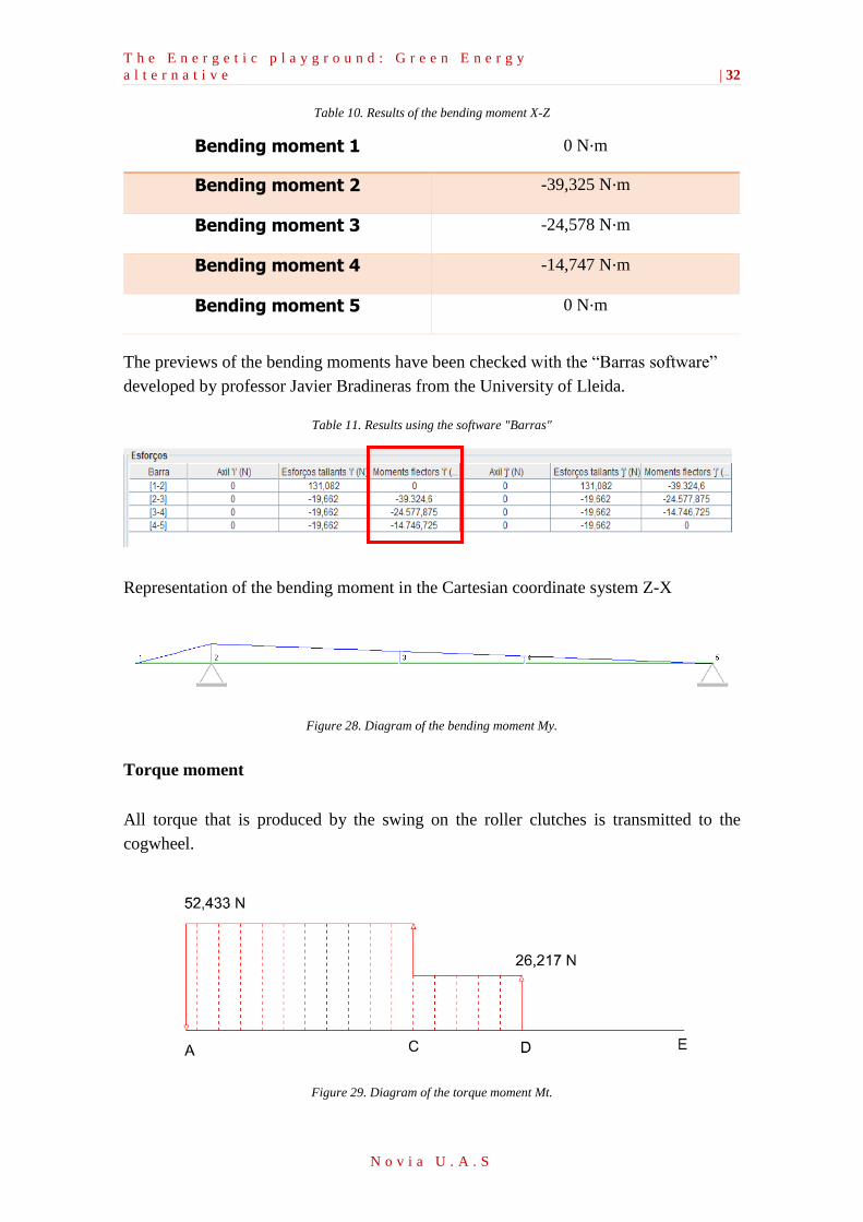
Table 10. Results of the bending moment X-Z
Bending moment 1 0 N·m
Bending moment 2 -39,325 N·m
Bending moment 3 -24,578 N·m
Bending moment 4 -14,747 N·m
Bending moment 5 0 N·m
The previews of the bending moments have been checked with the “Barras software”
developed by professor Javier Bradineras from the University of Lleida.
Table 11. Results using the software "Barras"
Representation of the bending moment in the Cartesian coordinate system Z-X
Figure 28. Diagram of the bending moment My.
Torque moment
All torque that is produced by the swing on the roller clutches is transmitted to the
cogwheel.
Figure 29. Diagram of the torque moment Mt.
T h e E n e r g e t i c p l a y g r o u n d : G r e e n E n e r g y
a l t e r n a t i v e | 33
N o v i a U . A . S
5.6.3. Calculation of the fatigue resistance on the driveshaft
Based on the DECKER, K.H. “Elementos de maquinas” bibliography, the diameter of the
driveshaft is calculated by the worst-case scenario from bending moments and torque
moments, obtained previously.
It is expected, that point C (roller clutches) will be in the worst section. However, it is
also calculated at the point B (cylindrical roller bearing).
To ensure that the diameter of the tree can withstand the strains mentioned above, it will
have to achieve: 𝜎𝑎𝑑𝑚 ≥ 𝜎𝑣, where 𝜎𝑎𝑑𝑚 =𝜎𝐺
𝐶𝑠 and 𝜎𝑣 is the equivalent tensile stress.
The fatigue resistance in the considered section is: 𝜎𝐺 =𝜎𝑊·𝑏0
𝛽𝑘𝑏·(1−𝑅) , where 𝜎𝑊 is the
traction and compressive fatigue resistance, that considers a steel with the traction
resistance, 𝜎𝐵 = 450𝑁
𝑚𝑚2→ 𝜎𝑊 = 210
𝑁
𝑚.
The other values which are needed to calculate 𝜎𝐺 are found it in the appendix 1. (1.4.
Dimensioning the diameter of the driveshaft).
The equivalent tensile stress is calculated as: 𝜎𝑣 = √𝜎02 + (3𝛼0
2)𝜏𝑡2, where 𝜎0 is the value
composed of the stress (produced by the axil and bending stresses, in this case there are
no axial stresses in the system), that are in the studied section.
𝛼0 is the fatigue factor, in this case the torque and bending moments diagram are
considered pulsating, by the DECKER, K.H. “Elementos de maquinas” bibliography it is
obtained that 𝛼0 = 1; 𝜏𝑡 is the torque stress.
The composite stress is calculated as, 𝜎0 =𝑀𝑏
𝑊𝑏+
𝑁
𝜋𝑑2
4
where 𝑀𝑏 is the bending moment
(vector sum of bending moments obtained in each Cartesian coordinate system), in the
studied section, 𝑊𝑏 is the moment resistance, that considered a smooth shaft, 𝑊𝑏 ≈ 0,1 ·
𝑑3. N is the value of the axial stress that in this design there is no axial stress.
The torque stress in the studied section is, 𝜏𝑡 =𝑀𝑡
𝑊𝑡 where 𝑀𝑡 and 𝑊𝑡 are the torque
moment and the resistant moment, that considered a smooth shaft, 𝑤𝑡 = 0,2 · 𝑑3.
Study to point B (cylindrical roller bearing):
For a diameter 𝑑 = 20 𝑚𝑚 , the results of the stresses are:
𝜎𝐺 = 227,74 𝑁/𝑚𝑚2 , and considering a correction factor of 𝐶𝑠 = 1,3, 𝜎𝑎𝑑𝑚 =227,74
1,3=
175,19 𝑁/𝑚𝑚2 . 𝜎𝑣 = 77,19 𝑁/𝑚𝑚2 .
As 175,19 𝑁/𝑚𝑚2 ≥ 77,19 𝑁/𝑚𝑚2, this diameter can withstand the loads in point B.
T h e E n e r g e t i c p l a y g r o u n d : G r e e n E n e r g y
a l t e r n a t i v e | 34
N o v i a U . A . S
For more information about the previous results of the study in point B, see Appendix 1.
(1.4 – 1.5. Dimensioning the diameter of the driveshaft at point B).
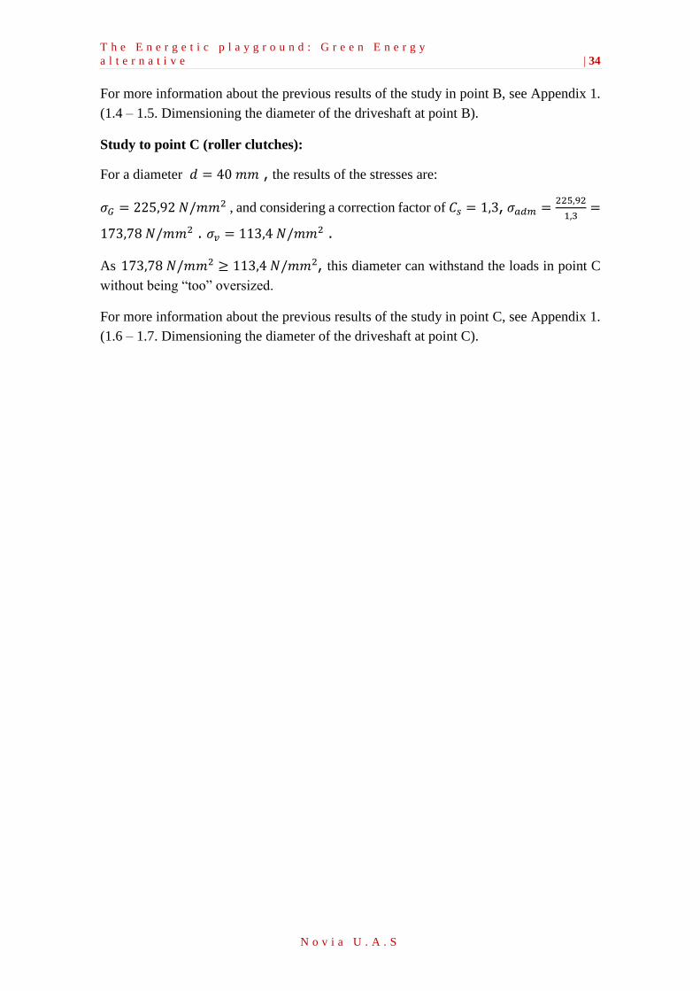
Study to point C (roller clutches):
For a diameter 𝑑 = 40 𝑚𝑚 , the results of the stresses are:
𝜎𝐺 = 225,92 𝑁/𝑚𝑚2 , and considering a correction factor of 𝐶𝑠 = 1,3, 𝜎𝑎𝑑𝑚 =225,92
1,3=
173,78 𝑁/𝑚𝑚2 . 𝜎𝑣 = 113,4 𝑁/𝑚𝑚2 .
As 173,78 𝑁/𝑚𝑚2 ≥ 113,4 𝑁/𝑚𝑚2, this diameter can withstand the loads in point C
without being “too” oversized.
For more information about the previous results of the study in point C, see Appendix 1.
(1.6 – 1.7. Dimensioning the diameter of the driveshaft at point C).
T h e E n e r g e t i c p l a y g r o u n d : G r e e n E n e r g y
a l t e r n a t i v e | 35
N o v i a U . A . S
5.7. Remodeling and selection of the components
To determinate the final dimensions of the driveshaft, the elements have to be decided to
permit affix union on the cogwheel and roller bearings. Furthermore, it has to be kept in
mind that the assembly of these elements has to be possible. The dimensions found in the
first part are:
Inner diameter cylindrical roller bearing = 15mm
Inner diameter drawn cup roller clutches = 20mm
Outside diameter shaft = 50mm
Inner diameter shaft = 40mm
In order to affix all the elements on the drive shaft, the outside diameter of the driveshaft
is considered, based on the study of point C (the worst section), so the two roller clutches
need a large inner diameter to attach on the shaft. To be noted, with this alteration the
roller clutches will be able to support more loads than the loads calculated.
Moreover, with the roller bearings at the same level the new inner diameter will be 50mm,
since the inner diameter for the shaft has been calculated with 50 mm.
The finals dimensions of the driveshaft will be:
Inner diameter cylindrical roller bearing = 40mm
Inner diameter drawn cup roller clutches = 50mm
Outside diameter shaft = 50mm
Inner diameter shaft = 40mm
Inner diameter cogwheel = 25mm
See appendix 1 (1.8) to know how these elements have been selected.
E n e r g e t i c p l a y g r o u n d : G r e e n E n e r g y a l t e r n a t i v e | 36
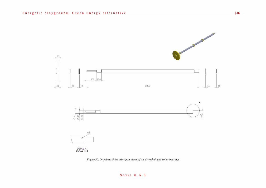
N o v i a U . A . S
Figure 30. Drawings of the principals views of the driveshaft and roller bearings
E n e r g e t i c p l a y g r o u n d : G r e e n E n e r g y
a l t e r n a t i v e | 37
N o v i a U . A . S
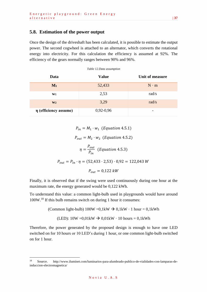
5.8. Estimation of the power output
Once the design of the driveshaft has been calculated, it is possible to estimate the output
power. The second cogwheel is attached to an alternator, which converts the rotational
energy into electricity. For this calculation the efficiency is assumed at 92%. The
efficiency of the gears normally ranges between 90% and 96%.
Table 12.Data assumption
Data Value Unit of measure
M1 52,433 N · m
w1 2,53 rad/s
w2 3,29 rad/s
η (efficiency assume) 0,92-0,96 -
𝑃𝑖𝑛 = 𝑀1 · 𝑤1 (𝐸𝑞𝑢𝑎𝑡𝑖𝑜𝑛 4.5.1)
𝑃𝑜𝑢𝑡 = 𝑀2 · 𝑤2 (𝐸𝑞𝑢𝑎𝑡𝑖𝑜𝑛 4.5.2)
𝜂 =𝑃𝑜𝑢𝑡
𝑃𝑖𝑛 (𝐸𝑞𝑢𝑎𝑡𝑖𝑜𝑛 4.5.3)
𝑃𝑜𝑢𝑡 = 𝑃𝑖𝑛 · 𝜂 = (52,433 · 2,53) · 0,92 = 122,043 𝑊
𝑃𝑜𝑢𝑡 = 0,122 𝑘𝑊
Finally, it is observed that if the swing were used continuously during one hour at the
maximum rate, the energy generated would be 0,122 kWh.
To understand this value: a common light-bulb used in playgrounds would have around
100W.18 If this bulb remains switch on during 1 hour it consumes:
(Common light-bulb) 100W =0,1kW 0,1kW · 1 hour = 0,1kWh
(LED): 10W =0,01kW 0,01kW · 10 hours = 0,1kWh
Therefore, the power generated by the proposed design is enough to have one LED
switched on for 10 hours or 10 LED’s during 1 hour, or one common light-bulb switched
on for 1 hour.
18 Source. http://www.iluminet.com/luminarios-para-alumbrado-publico-de-vialidades-con-lamparas-de-
induccion-electromagnetica/

E n e r g e t i c p l a y g r o u n d : G r e e n E n e r g y
a l t e r n a t i v e | 38
N o v i a U . A . S
5.9. Conclusions
In the completion of this work many concepts have been acquired and consolidated, such
as: designing transmission gears and the design of a driveshaft and roller bearings
selection according to the type of forces they are subjected to, especially roller clutches.
The design part of the driveshaft has needed much attention due to the high amounts of
calculations to find out the forces, which the driveshaft is subjected to, plus it was needed
to work in three dimensions and work with calculations unlikely to a bachelor level. It
would have been better go more in depth on the study of this element; however due to
lack of time and knowledge acquired to calculate the dimensions of pins for example it
has not been possible.
From the negative point of view, it can be say that if is probably that the kids need to do
more force than with one conventional swing, because of the alternator is required to
rotate at one speed to produce electricity. Also this can produce that it would be not very
fun to play with it if the kids cannot go very fast, but on the other hand, it could teach the
children to learn the difficulty of producing electrical energy in a clean way, without non-
renewable sources.
In conclusion, the design outcome is positive being that it is possible to produce electricity
in a small scale. It was possible to make a re-design of a swing. Furthermore, it was
possible to use prior gained knowledge from the past study years to select and design a
piece that is useful for everyday life.
E n e r g e t i c p l a y g r o u n d : G r e e n E n e r g y
a l t e r n a t i v e | 39
N o v i a U . A . S
6. Merry-Go-Round Mechanism
______________________________________________________________________
How to get electricity in a clean way using our own energy? This project tries to pair
providing energy and at the same time supports children to play, have fun, do exercise
and learn how to produce energy in a non-polluting way. Thanks to generators in
children play-parks this might be possible. This project intends to redesign the well-
known merry-go-round. Using human power to produce mechanical energy and
transform it into electrical one.
__________________________________________
6.1. Introduction to Merry-Go-Round
As known, the field of the renewable energy is rapidly growing. In the last 10 years this
field had the highest increased and thus, investments rose. Moreover, it is expected that
in 2030 the government investment around the world will be 2 or 3 times more than is
now. This increase can be explain as the nowadays way of energy production is not
sustainable because of the high use of non-renewable energy such as fossils. The need of
electricity will never end; therefore finding new ways to source is crucial.
In the world, the most common human power generator is the bicycle or the hand cranked
generator. The way they work is attaching a bike tire to convert the rotation into electricity
or using a hand-cranked apparatus. The last one is used to power small devices such as a
light or a mobile charger. We have to bear in mind that this type of technology has been
around for decades, now we are only improving it but without changing the basic way of
function. One example of this improvement is the exercise machine to produce electricity.
Thanks of this machine; people get fit while producing no pollutant electricity. So, what
about the use of this energy production in parks where children play? The main idea is
using a marry-go-round to produce electricity to illuminate parks or to charge any electric
device with an USB port.
The merry-go-round generator will operate by turning the human mechanical work to
electricity that it could supply to DC house. The children will be the ones providing the
work without knowing that they are helping to produce electricity for the house. Further,
the merry-go-round is a small part of a bigger project, as we can apply this basic to another
way in energy production using the play actions of children in the playgrounds.
E n e r g e t i c p l a y g r o u n d : G r e e n E n e r g y
a l t e r n a t i v e | 40
N o v i a U . A . S
6.2. Design
As it has been mentioned before, the merry-go-round is going to be an energy generator
to take advantage of the human mechanical energy to produce DC voltage in a clean way.
Now the design is going to be analyzed level by level. From the most general to the most
detailed one.
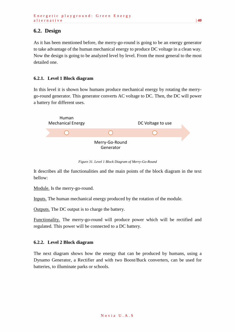
6.2.1. Level 1 Block diagram
In this level it is shown how humans produce mechanical energy by rotating the merry-
go-round generator. This generator converts AC voltage to DC. Then, the DC will power
a battery for different uses.
Figure 31. Level 1 Block Diagram of Merry-Go-Round
It describes all the functionalities and the main points of the block diagram in the text
bellow:
Module. Is the merry-go-round.
Inputs. The human mechanical energy produced by the rotation of the module.
Outputs. The DC output is to charge the battery.
Functionality. The merry-go-round will produce power which will be rectified and
regulated. This power will be connected to a DC battery.
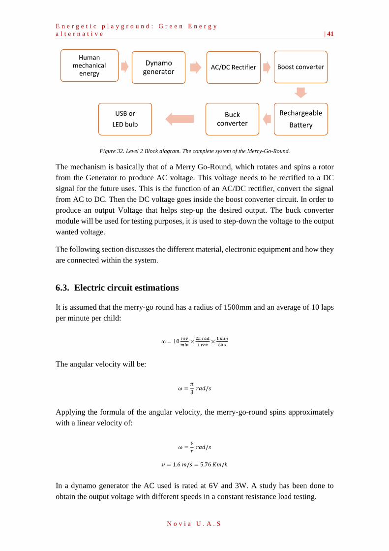
6.2.2. Level 2 Block diagram
The next diagram shows how the energy that can be produced by humans, using a
Dynamo Generator, a Rectifier and with two Boost/Buck converters, can be used for
batteries, to illuminate parks or schools.
Human Mechanical Energy
Merry-Go-Round Generator
DC Voltage to use
E n e r g e t i c p l a y g r o u n d : G r e e n E n e r g y
a l t e r n a t i v e | 41
N o v i a U . A . S
Figure 32. Level 2 Block diagram. The complete system of the Merry-Go-Round.
The mechanism is basically that of a Merry Go-Round, which rotates and spins a rotor
from the Generator to produce AC voltage. This voltage needs to be rectified to a DC
signal for the future uses. This is the function of an AC/DC rectifier, convert the signal
from AC to DC. Then the DC voltage goes inside the boost converter circuit. In order to
produce an output Voltage that helps step-up the desired output. The buck converter
module will be used for testing purposes, it is used to step-down the voltage to the output
wanted voltage.
The following section discusses the different material, electronic equipment and how they
are connected within the system.
6.3. Electric circuit estimations
It is assumed that the merry-go round has a radius of 1500mm and an average of 10 laps
per minute per child:
ω = 10𝑟𝑒𝑣
𝑚𝑖𝑛×
2𝜋 𝑟𝑎𝑑
1 𝑟𝑒𝑣×
1 𝑚𝑖𝑛
60 𝑠
The angular velocity will be:
𝜔 =𝜋
3 𝑟𝑎𝑑/𝑠
Applying the formula of the angular velocity, the merry-go-round spins approximately
with a linear velocity of:
𝜔 =𝑣
𝑟 𝑟𝑎𝑑/𝑠
𝑣 = 1.6 𝑚/𝑠 = 5.76 𝐾𝑚/ℎ
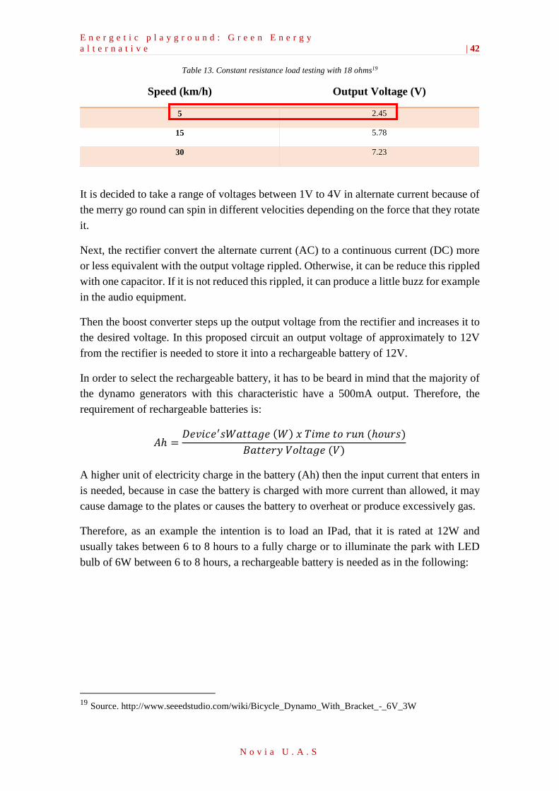
In a dynamo generator the AC used is rated at 6V and 3W. A study has been done to
obtain the output voltage with different speeds in a constant resistance load testing.
Human mechanical
energy
Dynamo generator
AC/DC Rectifier Boost converter
Rechargeable
Battery
Buck converter
USB or
LED bulb
E n e r g e t i c p l a y g r o u n d : G r e e n E n e r g y
a l t e r n a t i v e | 42
N o v i a U . A . S
Table 13. Constant resistance load testing with 18 ohms19
Speed (km/h) Output Voltage (V)
5 2.45
15 5.78
30 7.23
It is decided to take a range of voltages between 1V to 4V in alternate current because of
the merry go round can spin in different velocities depending on the force that they rotate
it.
Next, the rectifier convert the alternate current (AC) to a continuous current (DC) more
or less equivalent with the output voltage rippled. Otherwise, it can be reduce this rippled
with one capacitor. If it is not reduced this rippled, it can produce a little buzz for example
in the audio equipment.
Then the boost converter steps up the output voltage from the rectifier and increases it to
the desired voltage. In this proposed circuit an output voltage of approximately to 12V
from the rectifier is needed to store it into a rechargeable battery of 12V.
In order to select the rechargeable battery, it has to be beard in mind that the majority of
the dynamo generators with this characteristic have a 500mA output. Therefore, the
requirement of rechargeable batteries is:
𝐴ℎ =𝐷𝑒𝑣𝑖𝑐𝑒′𝑠𝑊𝑎𝑡𝑡𝑎𝑔𝑒 (𝑊) 𝑥 𝑇𝑖𝑚𝑒 𝑡𝑜 𝑟𝑢𝑛 (ℎ𝑜𝑢𝑟𝑠)
𝐵𝑎𝑡𝑡𝑒𝑟𝑦 𝑉𝑜𝑙𝑡𝑎𝑔𝑒 (𝑉)
A higher unit of electricity charge in the battery (Ah) then the input current that enters in
is needed, because in case the battery is charged with more current than allowed, it may
cause damage to the plates or causes the battery to overheat or produce excessively gas.
Therefore, as an example the intention is to load an IPad, that it is rated at 12W and
usually takes between 6 to 8 hours to a fully charge or to illuminate the park with LED
bulb of 6W between 6 to 8 hours, a rechargeable battery is needed as in the following:
19 Source. http://www.seeedstudio.com/wiki/Bicycle_Dynamo_With_Bracket_-_6V_3W
E n e r g e t i c p l a y g r o u n d : G r e e n E n e r g y
a l t e r n a t i v e | 43
N o v i a U . A . S
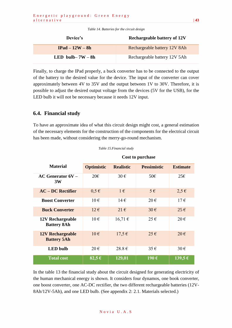
Table 14. Batteries for the circuit design
Device’s Rechargeable battery of 12V
IPad – 12W – 8h Rechargeable battery 12V 8Ah
LED bulb– 7W – 8h Rechargeable battery 12V 5Ah
Finally, to charge the IPad properly, a buck converter has to be connected to the output
of the battery to the desired value for the device. The input of the converter can cover
approximately between 4V to 35V and the output between 1V to 30V. Therefore, it is
possible to adjust the desired output voltage from the devices (5V for the USB), for the
LED bulb it will not be necessary because it needs 12V input.
6.4. Financial study
To have an approximate idea of what this circuit design might cost, a general estimation
of the necessary elements for the construction of the components for the electrical circuit
has been made, without considering the merry-go-round mechanism.
Table 15.Financial study
Material
Cost to purchase
Optimistic Realistic Pessimistic Estimate
AC Generator 6V –
3W
20€ 30 € 50€ 25€
AC – DC Rectifier 0,5 € 1 € 5 € 2,5 €
Boost Converter 10 € 14 € 20 € 17 €
Buck Converter 12 € 21 € 30 € 25 €
12V Rechargeable
Battery 8Ah
10 € 16,71 € 25 € 20 €
12V Rechargeable
Battery 5Ah
10 € 17,5 € 25 € 20 €
LED bulb 20 € 28.8 € 35 € 30 €
Total cost 82,5 € 129,01 190 € 139,5 €
In the table 13 the financial study about the circuit designed for generating electricity of
the human mechanical energy is shown. It considers four dynamos, one book converter,
one boost converter, one AC-DC rectifier, the two different rechargeable batteries (12V-
8Ah/12V-5Ah), and one LED bulb. (See appendix 2: 2.1. Materials selected.)
E n e r g e t i c p l a y g r o u n d : G r e e n E n e r g y
a l t e r n a t i v e | 44
N o v i a U . A . S
6.5. Hardware
6.6. Material and Electronic Equipment
In this section all the different materials and equipment that are used in this system and
how they are connected are discussed.
6.6.1. Ac Dynamo Generator
The dynamo consists of a stationary structure that provided a constant magnetic field and
a set of rotating windings spinning beside the field. In small machines, the magnetic field
was delivered by one or more permanent magnets; in larger machines it is driven by
electromagnets.
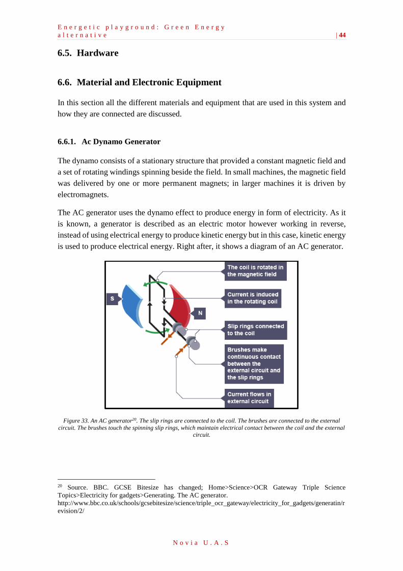
The AC generator uses the dynamo effect to produce energy in form of electricity. As it
is known, a generator is described as an electric motor however working in reverse,
instead of using electrical energy to produce kinetic energy but in this case, kinetic energy
is used to produce electrical energy. Right after, it shows a diagram of an AC generator.
Figure 33. An AC generator20. The slip rings are connected to the coil. The brushes are connected to the external
circuit. The brushes touch the spinning slip rings, which maintain electrical contact between the coil and the external
circuit.
20 Source. BBC. GCSE Bitesize has changed; Home>Science>OCR Gateway Triple Science
Topics>Electricity for gadgets>Generating. The AC generator.
http://www.bbc.co.uk/schools/gcsebitesize/science/triple_ocr_gateway/electricity_for_gadgets/generatin/r
evision/2/
E n e r g e t i c p l a y g r o u n d : G r e e n E n e r g y
a l t e r n a t i v e | 45
N o v i a U . A . S
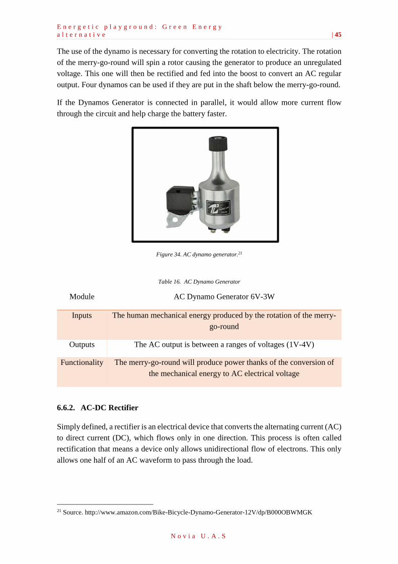
The use of the dynamo is necessary for converting the rotation to electricity. The rotation
of the merry-go-round will spin a rotor causing the generator to produce an unregulated
voltage. This one will then be rectified and fed into the boost to convert an AC regular
output. Four dynamos can be used if they are put in the shaft below the merry-go-round.
If the Dynamos Generator is connected in parallel, it would allow more current flow
through the circuit and help charge the battery faster.
Figure 34. AC dynamo generator.21
Table 16. AC Dynamo Generator
Module AC Dynamo Generator 6V-3W
Inputs The human mechanical energy produced by the rotation of the merry-
go-round
Outputs The AC output is between a ranges of voltages (1V-4V)
Functionality The merry-go-round will produce power thanks of the conversion of
the mechanical energy to AC electrical voltage
6.6.2. AC-DC Rectifier
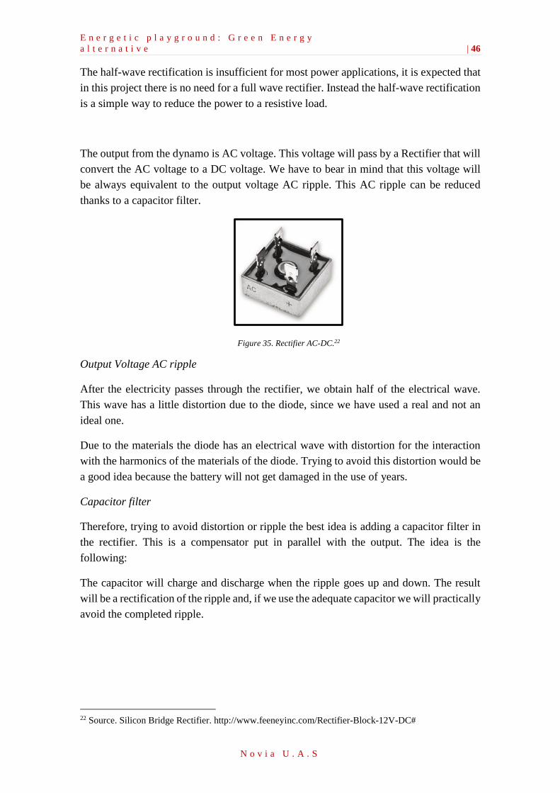
Simply defined, a rectifier is an electrical device that converts the alternating current (AC)
to direct current (DC), which flows only in one direction. This process is often called
rectification that means a device only allows unidirectional flow of electrons. This only
allows one half of an AC waveform to pass through the load.
21 Source. http://www.amazon.com/Bike-Bicycle-Dynamo-Generator-12V/dp/B000OBWMGK
E n e r g e t i c p l a y g r o u n d : G r e e n E n e r g y
a l t e r n a t i v e | 46
N o v i a U . A . S
The half-wave rectification is insufficient for most power applications, it is expected that
in this project there is no need for a full wave rectifier. Instead the half-wave rectification
is a simple way to reduce the power to a resistive load.
The output from the dynamo is AC voltage. This voltage will pass by a Rectifier that will
convert the AC voltage to a DC voltage. We have to bear in mind that this voltage will
be always equivalent to the output voltage AC ripple. This AC ripple can be reduced
thanks to a capacitor filter.
Figure 35. Rectifier AC-DC.22
Output Voltage AC ripple
After the electricity passes through the rectifier, we obtain half of the electrical wave.
This wave has a little distortion due to the diode, since we have used a real and not an
ideal one.
Due to the materials the diode has an electrical wave with distortion for the interaction
with the harmonics of the materials of the diode. Trying to avoid this distortion would be
a good idea because the battery will not get damaged in the use of years.
Capacitor filter
Therefore, trying to avoid distortion or ripple the best idea is adding a capacitor filter in
the rectifier. This is a compensator put in parallel with the output. The idea is the
following:
The capacitor will charge and discharge when the ripple goes up and down. The result
will be a rectification of the ripple and, if we use the adequate capacitor we will practically
avoid the completed ripple.
22 Source. Silicon Bridge Rectifier. http://www.feeneyinc.com/Rectifier-Block-12V-DC#
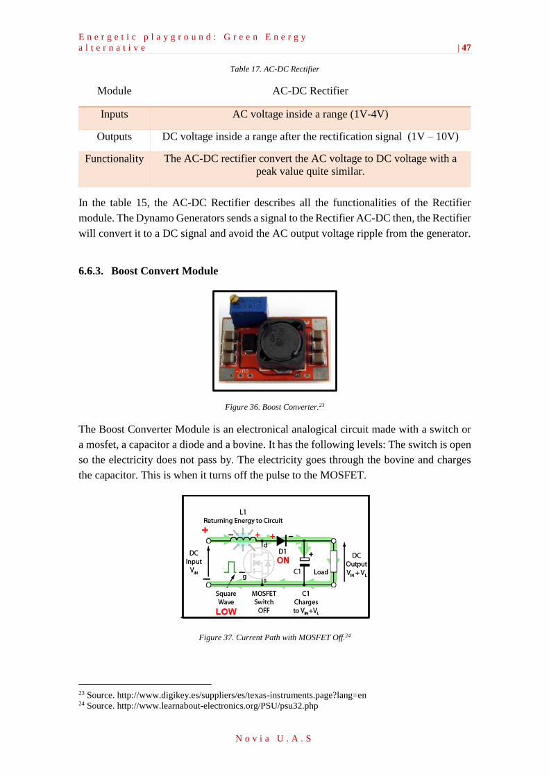
E n e r g e t i c p l a y g r o u n d : G r e e n E n e r g y
a l t e r n a t i v e | 47
N o v i a U . A . S
Table 17. AC-DC Rectifier
In the table 15, the AC-DC Rectifier describes all the functionalities of the Rectifier
module. The Dynamo Generators sends a signal to the Rectifier AC-DC then, the Rectifier
will convert it to a DC signal and avoid the AC output voltage ripple from the generator.
6.6.3. Boost Convert Module
Figure 36. Boost Converter.23
The Boost Converter Module is an electronical analogical circuit made with a switch or
a mosfet, a capacitor a diode and a bovine. It has the following levels: The switch is open
so the electricity does not pass by. The electricity goes through the bovine and charges
the capacitor. This is when it turns off the pulse to the MOSFET.
.
Figure 37. Current Path with MOSFET Off.24
23 Source. http://www.digikey.es/suppliers/es/texas-instruments.page?lang=en 24 Source. http://www.learnabout-electronics.org/PSU/psu32.php
Module AC-DC Rectifier
Inputs AC voltage inside a range (1V-4V)
Outputs DC voltage inside a range after the rectification signal (1V – 10V)
Functionality The AC-DC rectifier convert the AC voltage to DC voltage with a
peak value quite similar.
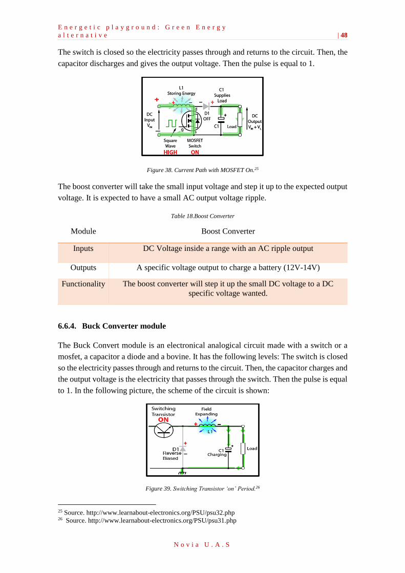
E n e r g e t i c p l a y g r o u n d : G r e e n E n e r g y
a l t e r n a t i v e | 48
N o v i a U . A . S
The switch is closed so the electricity passes through and returns to the circuit. Then, the
capacitor discharges and gives the output voltage. Then the pulse is equal to 1.
Figure 38. Current Path with MOSFET On.25
The boost converter will take the small input voltage and step it up to the expected output
voltage. It is expected to have a small AC output voltage ripple.
Table 18.Boost Converter
Module Boost Converter
Inputs DC Voltage inside a range with an AC ripple output
Outputs A specific voltage output to charge a battery (12V-14V)
Functionality The boost converter will step it up the small DC voltage to a DC
specific voltage wanted.
6.6.4. Buck Converter module
The Buck Convert module is an electronical analogical circuit made with a switch or a
mosfet, a capacitor a diode and a bovine. It has the following levels: The switch is closed
so the electricity passes through and returns to the circuit. Then, the capacitor charges and
the output voltage is the electricity that passes through the switch. Then the pulse is equal
to 1. In the following picture, the scheme of the circuit is shown:
Figure 39. Switching Transistor ‘on’ Period.26
25 Source. http://www.learnabout-electronics.org/PSU/psu32.php 26 Source. http://www.learnabout-electronics.org/PSU/psu31.php
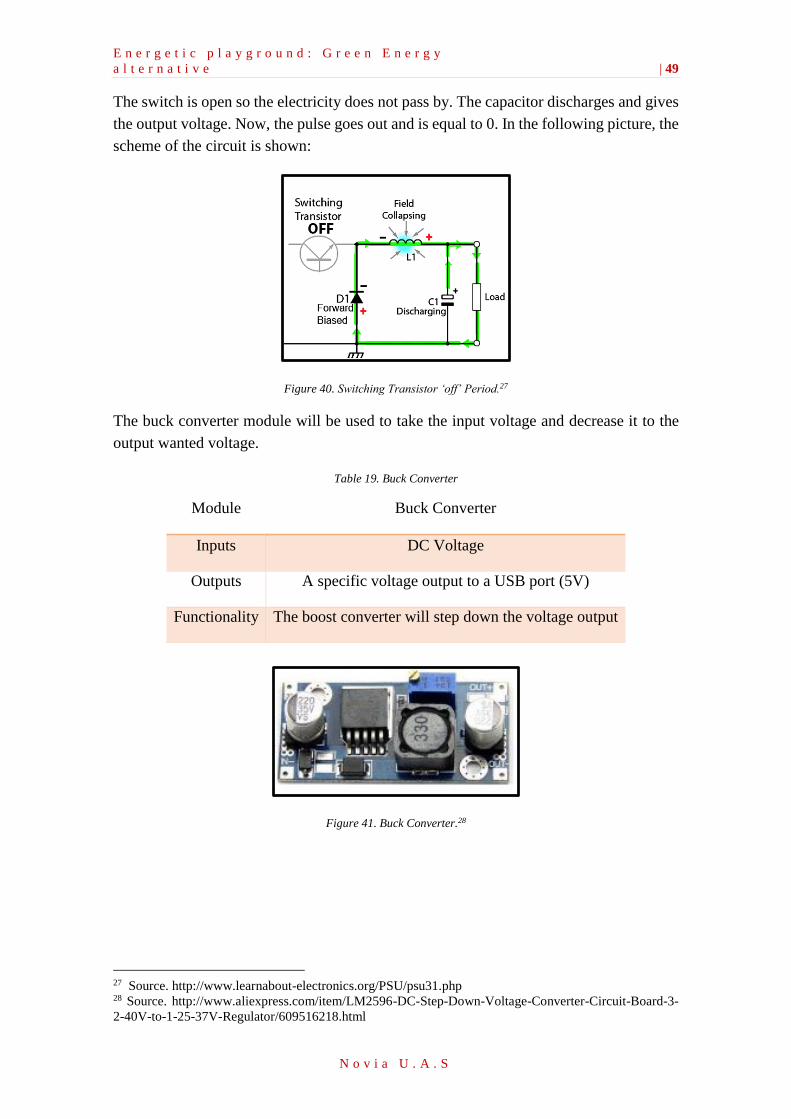
E n e r g e t i c p l a y g r o u n d : G r e e n E n e r g y
a l t e r n a t i v e | 49
N o v i a U . A . S
The switch is open so the electricity does not pass by. The capacitor discharges and gives
the output voltage. Now, the pulse goes out and is equal to 0. In the following picture, the
scheme of the circuit is shown:
Figure 40. Switching Transistor ‘off’ Period.27
The buck converter module will be used to take the input voltage and decrease it to the
output wanted voltage.
Table 19. Buck Converter
Module Buck Converter
Inputs DC Voltage
Outputs A specific voltage output to a USB port (5V)
Functionality The boost converter will step down the voltage output
Figure 41. Buck Converter.28
27 Source. http://www.learnabout-electronics.org/PSU/psu31.php 28 Source. http://www.aliexpress.com/item/LM2596-DC-Step-Down-Voltage-Converter-Circuit-Board-3-
2-40V-to-1-25-37V-Regulator/609516218.html
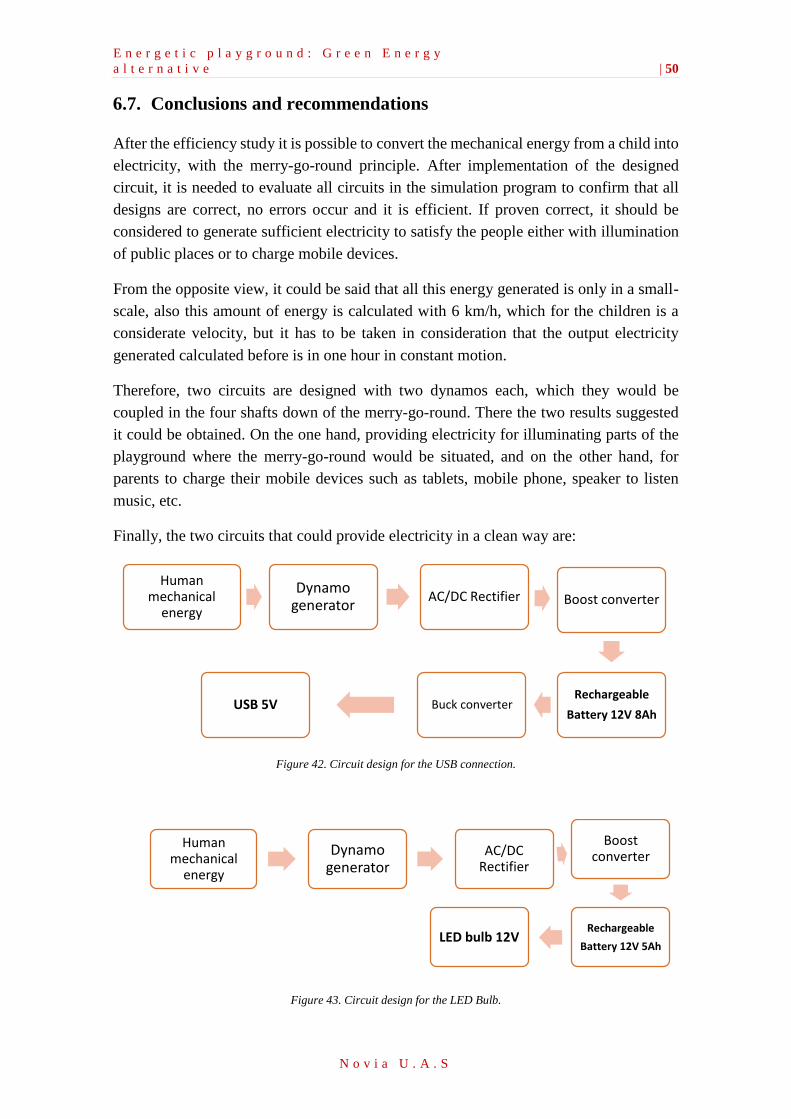
E n e r g e t i c p l a y g r o u n d : G r e e n E n e r g y
a l t e r n a t i v e | 50
N o v i a U . A . S
6.7. Conclusions and recommendations
After the efficiency study it is possible to convert the mechanical energy from a child into
electricity, with the merry-go-round principle. After implementation of the designed
circuit, it is needed to evaluate all circuits in the simulation program to confirm that all
designs are correct, no errors occur and it is efficient. If proven correct, it should be
considered to generate sufficient electricity to satisfy the people either with illumination
of public places or to charge mobile devices.
From the opposite view, it could be said that all this energy generated is only in a small-
scale, also this amount of energy is calculated with 6 km/h, which for the children is a
considerate velocity, but it has to be taken in consideration that the output electricity
generated calculated before is in one hour in constant motion.
Therefore, two circuits are designed with two dynamos each, which they would be
coupled in the four shafts down of the merry-go-round. There the two results suggested
it could be obtained. On the one hand, providing electricity for illuminating parts of the
playground where the merry-go-round would be situated, and on the other hand, for
parents to charge their mobile devices such as tablets, mobile phone, speaker to listen
music, etc.
Finally, the two circuits that could provide electricity in a clean way are:
Figure 42. Circuit design for the USB connection.
Figure 43. Circuit design for the LED Bulb.
Human mechanical
energy
Dynamo generator
AC/DC Rectifier Boost converter
Rechargeable
Battery 12V 8AhBuck converterUSB 5V
Human mechanical
energy
Dynamo generator
AC/DC Rectifier
Boost converter
Rechargeable
Battery 12V 5AhLED bulb 12V
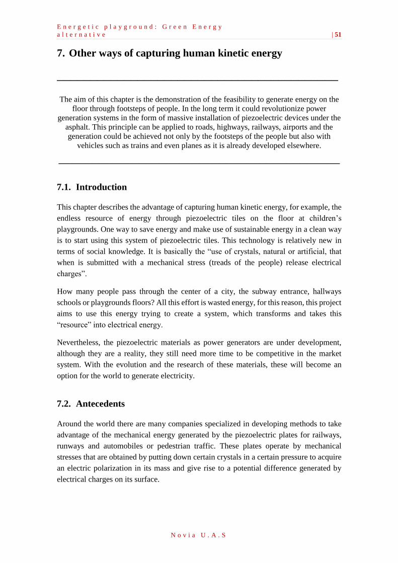
E n e r g e t i c p l a y g r o u n d : G r e e n E n e r g y
a l t e r n a t i v e | 51
N o v i a U . A . S
7. Other ways of capturing human kinetic energy
__________________________________________ The aim of this chapter is the demonstration of the feasibility to generate energy on the
floor through footsteps of people. In the long term it could revolutionize power
generation systems in the form of massive installation of piezoelectric devices under the
asphalt. This principle can be applied to roads, highways, railways, airports and the
generation could be achieved not only by the footsteps of the people but also with
vehicles such as trains and even planes as it is already developed elsewhere.
__________________________________________
7.1. Introduction
This chapter describes the advantage of capturing human kinetic energy, for example, the
endless resource of energy through piezoelectric tiles on the floor at children’s
playgrounds. One way to save energy and make use of sustainable energy in a clean way
is to start using this system of piezoelectric tiles. This technology is relatively new in
terms of social knowledge. It is basically the “use of crystals, natural or artificial, that
when is submitted with a mechanical stress (treads of the people) release electrical
charges”.
How many people pass through the center of a city, the subway entrance, hallways
schools or playgrounds floors? All this effort is wasted energy, for this reason, this project
aims to use this energy trying to create a system, which transforms and takes this
“resource” into electrical energy.
Nevertheless, the piezoelectric materials as power generators are under development,
although they are a reality, they still need more time to be competitive in the market
system. With the evolution and the research of these materials, these will become an
option for the world to generate electricity.
7.2. Antecedents
Around the world there are many companies specialized in developing methods to take
advantage of the mechanical energy generated by the piezoelectric plates for railways,
runways and automobiles or pedestrian traffic. These plates operate by mechanical
stresses that are obtained by putting down certain crystals in a certain pressure to acquire
an electric polarization in its mass and give rise to a potential difference generated by
electrical charges on its surface.
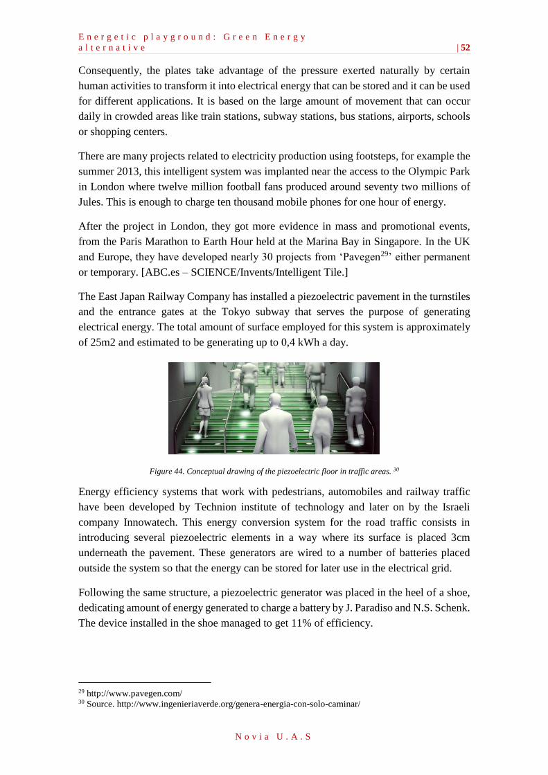
E n e r g e t i c p l a y g r o u n d : G r e e n E n e r g y
a l t e r n a t i v e | 52
N o v i a U . A . S
Consequently, the plates take advantage of the pressure exerted naturally by certain
human activities to transform it into electrical energy that can be stored and it can be used
for different applications. It is based on the large amount of movement that can occur
daily in crowded areas like train stations, subway stations, bus stations, airports, schools
or shopping centers.
There are many projects related to electricity production using footsteps, for example the
summer 2013, this intelligent system was implanted near the access to the Olympic Park
in London where twelve million football fans produced around seventy two millions of
Jules. This is enough to charge ten thousand mobile phones for one hour of energy.
After the project in London, they got more evidence in mass and promotional events,
from the Paris Marathon to Earth Hour held at the Marina Bay in Singapore. In the UK
and Europe, they have developed nearly 30 projects from ‘Pavegen29’ either permanent
or temporary. [ABC.es – SCIENCE/Invents/Intelligent Tile.]
The East Japan Railway Company has installed a piezoelectric pavement in the turnstiles
and the entrance gates at the Tokyo subway that serves the purpose of generating
electrical energy. The total amount of surface employed for this system is approximately
of 25m2 and estimated to be generating up to 0,4 kWh a day.
Figure 44. Conceptual drawing of the piezoelectric floor in traffic areas. 30
Energy efficiency systems that work with pedestrians, automobiles and railway traffic
have been developed by Technion institute of technology and later on by the Israeli
company Innowatech. This energy conversion system for the road traffic consists in
introducing several piezoelectric elements in a way where its surface is placed 3cm
underneath the pavement. These generators are wired to a number of batteries placed
outside the system so that the energy can be stored for later use in the electrical grid.
Following the same structure, a piezoelectric generator was placed in the heel of a shoe,
dedicating amount of energy generated to charge a battery by J. Paradiso and N.S. Schenk.
The device installed in the shoe managed to get 11% of efficiency.
29 http://www.pavegen.com/ 30 Source. http://www.ingenieriaverde.org/genera-energia-con-solo-caminar/

E n e r g e t i c p l a y g r o u n d : G r e e n E n e r g y
a l t e r n a t i v e | 53
N o v i a U . A . S
Another application for this kind of technology can be found in what is known as WATT
club, based in the model of the Sustainable Dance Club, which franchises ecological
clubs. This is a project where piezoelectric materials form the dance floor of nightclubs
so that the energy from each step can be stored and later be used for the basic utilities of
the local municipality and save up to 10% of the energy consumption.
E n e r g e t i c p l a y g r o u n d : G r e e n E n e r g y
a l t e r n a t i v e | 54
N o v i a U . A . S
7.3. Piezoelectricity
What is a piezoelectric material?
A piezoelectric material is a crystalline element which by submitting an effort mechanical
acquires an electrical polarization and a difference potential appears which produces
electrical energy.
7.4. Introduction to the piezoelectric phenomenon
Piezoelectric materials have an induced polarization by an external electric field, the
polarization is also produced under the influence of the mechanical stress. When a
piezoelectric material is deformed, it is produced a displacement of the charged particles,
resulting in a dipolar moment in the material and influence on opposite charges facing
surfaces thereof.
In addition, the crystals are given the reverse piezoelectric effect resulting of a material
deformation by applying an electrical voltage. When the material is subjected to an
electric field an internal forces on the loads that constitute the crystal appears, and the
loads will change their position, producing a mechanical deformation of the crystal.
7.5. Piezoelectric materials properties
The materials that present piezoelectric properties are divided into two groups: those with
present properties in the natural way and those that need to be polarized (which are the
piezoelectric ceramic). The first have a very small piezoelectric effect. For that reason a
second alternative with a greater effect was developed.
In the industry, titanate barium (BaOTiO2) and the combination of zicronate lead
(PbZrO3) and titanate lead (PbTiO3) are most used. This combination is called PZT
(zicronate titanate of lead) and are manufactured by powder compression at high
temperature, molded and baked in an oven.
The PZT
The PZT has an advantage over the other ceramics as it can be manufactured at a very
low price, is physically strong and chemically inert. Further, it has shown to be more
sensitive than other piezoelectric ceramics.
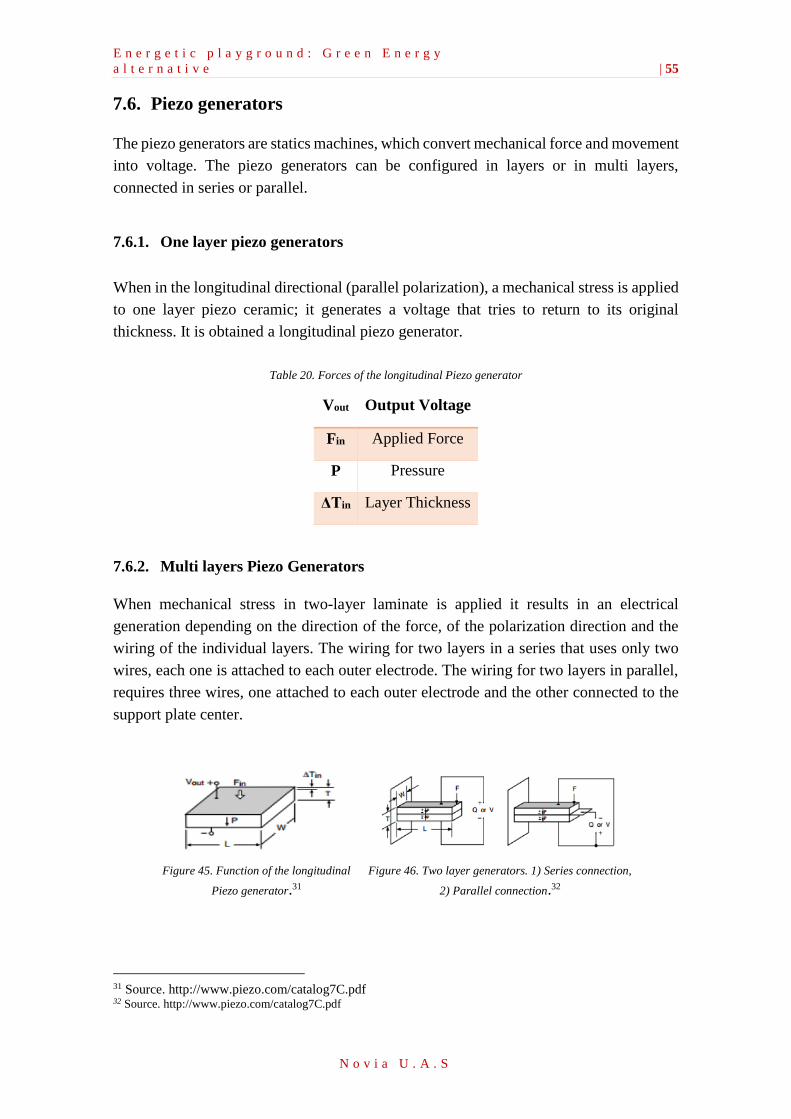
E n e r g e t i c p l a y g r o u n d : G r e e n E n e r g y
a l t e r n a t i v e | 55
N o v i a U . A . S
7.6. Piezo generators
The piezo generators are statics machines, which convert mechanical force and movement
into voltage. The piezo generators can be configured in layers or in multi layers,
connected in series or parallel.
7.6.1. One layer piezo generators
When in the longitudinal directional (parallel polarization), a mechanical stress is applied
to one layer piezo ceramic; it generates a voltage that tries to return to its original
thickness. It is obtained a longitudinal piezo generator.
Table 20. Forces of the longitudinal Piezo generator
Vout Output Voltage
Fin Applied Force
P Pressure
ΔTin Layer Thickness
7.6.2. Multi layers Piezo Generators
When mechanical stress in two-layer laminate is applied it results in an electrical
generation depending on the direction of the force, of the polarization direction and the
wiring of the individual layers. The wiring for two layers in a series that uses only two
wires, each one is attached to each outer electrode. The wiring for two layers in parallel,
requires three wires, one attached to each outer electrode and the other connected to the
support plate center.
Figure 45. Function of the longitudinal
Piezo generator.31
Figure 46. Two layer generators. 1) Series connection,
2) Parallel connection.32
31 Source. http://www.piezo.com/catalog7C.pdf 32 Source. http://www.piezo.com/catalog7C.pdf
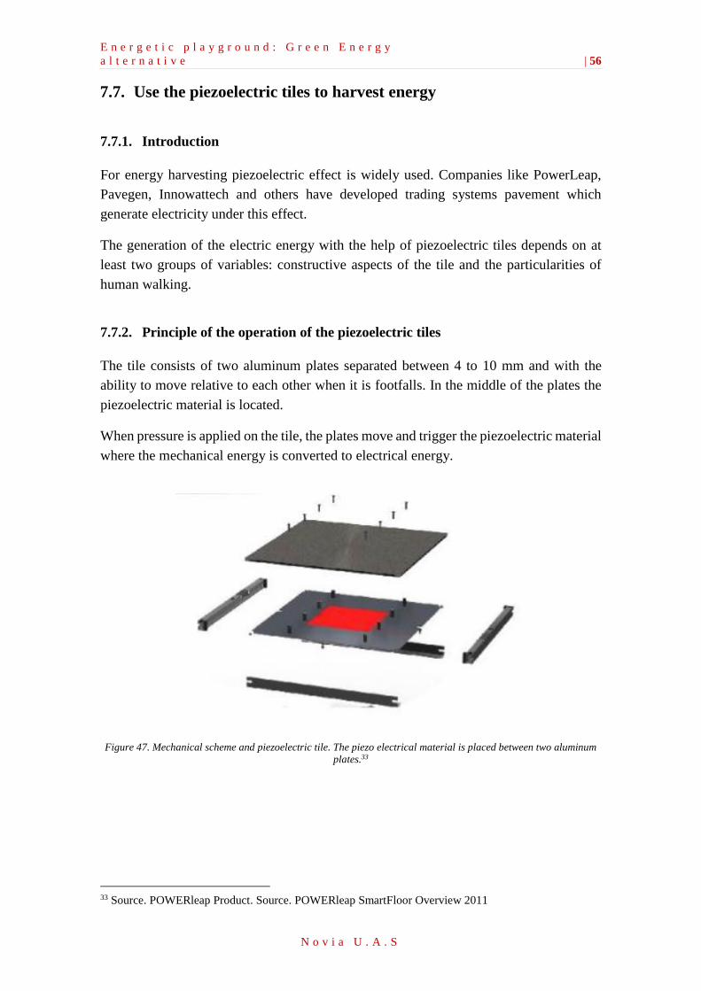
E n e r g e t i c p l a y g r o u n d : G r e e n E n e r g y
a l t e r n a t i v e | 56
N o v i a U . A . S
7.7. Use the piezoelectric tiles to harvest energy
7.7.1. Introduction
For energy harvesting piezoelectric effect is widely used. Companies like PowerLeap,
Pavegen, Innowattech and others have developed trading systems pavement which
generate electricity under this effect.
The generation of the electric energy with the help of piezoelectric tiles depends on at
least two groups of variables: constructive aspects of the tile and the particularities of
human walking.
7.7.2. Principle of the operation of the piezoelectric tiles
The tile consists of two aluminum plates separated between 4 to 10 mm and with the
ability to move relative to each other when it is footfalls. In the middle of the plates the
piezoelectric material is located.
When pressure is applied on the tile, the plates move and trigger the piezoelectric material
where the mechanical energy is converted to electrical energy.
Figure 47. Mechanical scheme and piezoelectric tile. The piezo electrical material is placed between two aluminum
plates.33
33 Source. POWERleap Product. Source. POWERleap SmartFloor Overview 2011
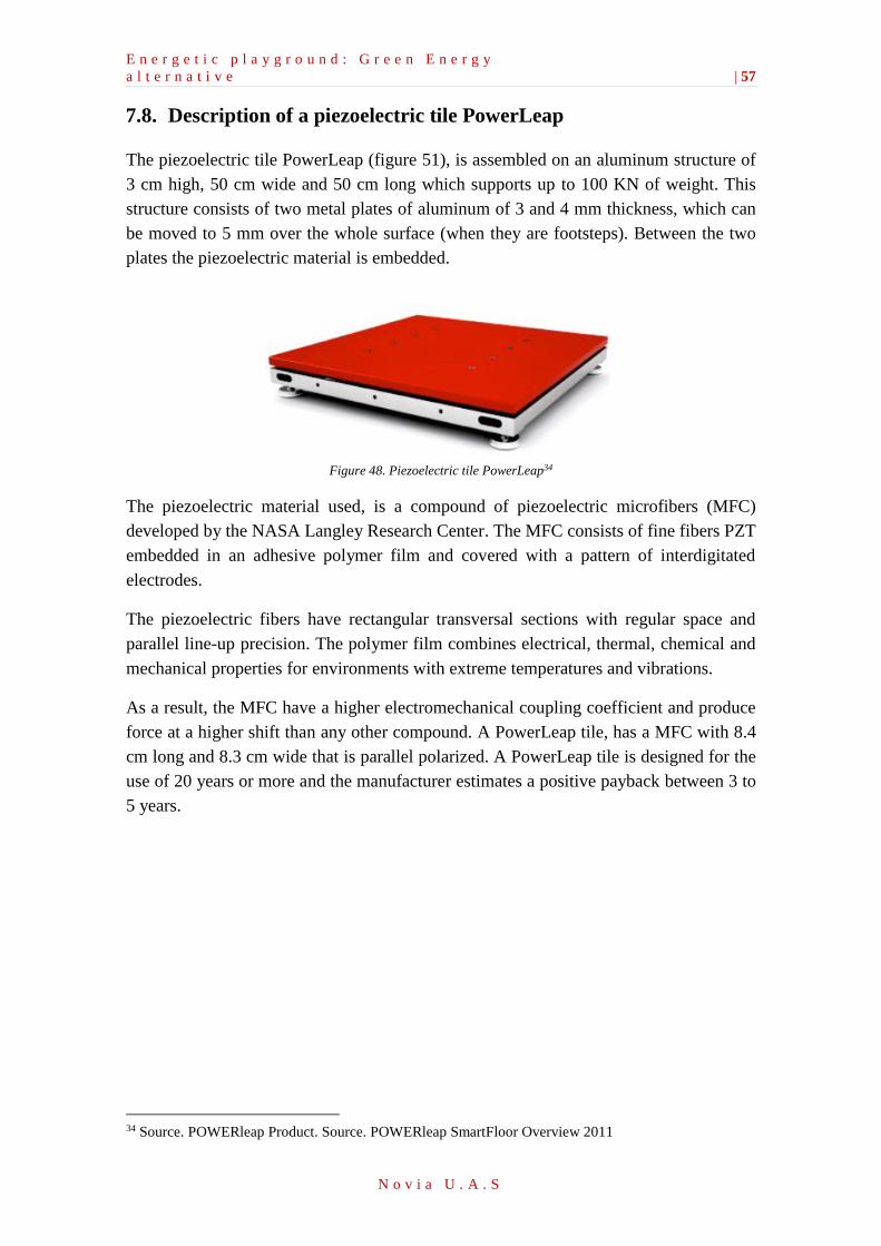
E n e r g e t i c p l a y g r o u n d : G r e e n E n e r g y
a l t e r n a t i v e | 57
N o v i a U . A . S
7.8. Description of a piezoelectric tile PowerLeap
The piezoelectric tile PowerLeap (figure 51), is assembled on an aluminum structure of
3 cm high, 50 cm wide and 50 cm long which supports up to 100 KN of weight. This
structure consists of two metal plates of aluminum of 3 and 4 mm thickness, which can
be moved to 5 mm over the whole surface (when they are footsteps). Between the two
plates the piezoelectric material is embedded.
Figure 48. Piezoelectric tile PowerLeap34
The piezoelectric material used, is a compound of piezoelectric microfibers (MFC)
developed by the NASA Langley Research Center. The MFC consists of fine fibers PZT
embedded in an adhesive polymer film and covered with a pattern of interdigitated
electrodes.
The piezoelectric fibers have rectangular transversal sections with regular space and
parallel line-up precision. The polymer film combines electrical, thermal, chemical and
mechanical properties for environments with extreme temperatures and vibrations.
As a result, the MFC have a higher electromechanical coupling coefficient and produce
force at a higher shift than any other compound. A PowerLeap tile, has a MFC with 8.4
cm long and 8.3 cm wide that is parallel polarized. A PowerLeap tile is designed for the
use of 20 years or more and the manufacturer estimates a positive payback between 3 to
5 years.
34 Source. POWERleap Product. Source. POWERleap SmartFloor Overview 2011
E n e r g e t i c p l a y g r o u n d : G r e e n E n e r g y
a l t e r n a t i v e | 58
N o v i a U . A . S
Results and general Conclusions
8. Results and conclusions
From the mechanical point of view, it is possible to design a playground where the
mechanical energy is obtained to illuminate the park or to charge different types of
devices. This study has not taken into account the economical aspect, except in the case
of the merry-go-round. In this case, the feasibility of the system has shown to be relatively
high, since the elements used are inexpensive.
Nevertheless, throughout the study different assumptions have been made in order to
simplify the calculations of the systems. In the case that the project would be carried out
by a group of experienced engineers in this sector the assumptions might be argued. In
addition, the uses of sensors and other measurement devices would make the study more
realistic.
Moreover, if the project was going to be carried out, it would be necessary to perform
both an economical study and a safety study. Regarding the economical study it is
obviously important to know the prior investment amount needed and the exact payback
period. Regarding the safety study, it must be ensured that the structure of the swing will
not break or fall. Otherwise, the engineer in charge of the project would be held
responsible for any accident. Furthermore, before building or commercializing this
technology at a large scale, it is necessary to study the behavior of a prototype of each
design.
From an environmental point of view, it can be said that the main goals of creating a
sustainable playground have been achieved. In addition, it has been only possible to study
the swing and the merry-go-round; however, there are still many other designs to develop
for other kind of games. Nonetheless, this project could be largely developed in order to
find new alternatives to generate electricity.
Moreover, this initiative would hopefully have a positive impact on growing up children.
Nowadays, the global awareness on environmental impacts and economic cost of
generating electricity increases steadily. This attempt shows a greener vision of energy
generation.
Furthermore, the results that have been obtained do seem to be fairly realistic. In the
merry-go-round, a system to charge electronic devices has been established. Besides,
some of this energy would be stored in small batteries to use to illuminate the playground.
The results from the swing have shown to be fairly good; with only 1 hour working at the
highest rate it is possible to illuminate the park from 10 hours onwards.
E n e r g e t i c p l a y g r o u n d : G r e e n E n e r g y
a l t e r n a t i v e | 59
N o v i a U . A . S
Literature references
Cabrera Pérez, D., Díaz Torres, M., García Déniz, R., Hernández Rodríguez, C.,
Martel Rodríguez, Gilberto., Pardilla Fariña, J., Pernavieja Izquierdo, G.,
Schallenberg Rodríguez, J.C., Subiela Ortin, V. (2008). Énergías renovables y
eficiencia energética. Instituto Tecnológico de Canarias, S.A.
CFF Conserve Energy Future. Non-renewable energy source.
http://www.conserve-energy-fu ture.com/NonRenewableEnergySources.php
(Retrieved: 1.4.2016)
Chapman, Stephen J (2000). Máquinas Eléctricas. Colombia: Mc Graw Hill.
CO.EXIST. (2012, Jun., 25). 6 future Playgrounds.
http://www.fastcoexist.com/1680066/6-future-playgrounds-that-harness-kids-energy-
while-they-play/1 (Retrieved 5.3.2016)
Conservation of Energy (2003). McGraw-Hill Dictionary of Scientific & Technical
Terms, Copyright ©. McGraw-Hill Companies, Inc.
Energy Floors. Sustainable dance club, energy floors.
http://www.sustainabledanceclub.com/ (Retrieved 18.3.2016)
Empower, Playgrounds, Inc. Merry-Go-Round.
http://www.empowerplaygrounds.org/mgr/ (Retrieved 5.3.2016)
Foulled García, J. (1994). Acumuladores electroquímicos. s.l.: McGraw-Hill.
Interempresas, metalmecanica. Un Sistema de almacenamiento avanzado.
http://www.interempresas.net/MetalMecanica/Articulos/33346-Un-sistema-de-
almacenamiento-avanzado-de-energia-cinetica.html
(Retrieved 18.3.2014)
Johnson Matthey, Piezo Product. (2008). Energy Harvesting.
Learning about Electronics. Filter Capacitor.
http://www.learningaboutelectronics.com/Articles/Filter-capacitor.php.
(Retrieved 15.3.2016)
Lloyd J. (2004). Electrical Properties of Macro-Fiber Composite Actuators and Sensors.
Masters of Science in Mechanical Engineering. Virginia Polytechnic Institute.
Blacksburg, Virginia.
E n e r g e t i c p l a y g r o u n d : G r e e n E n e r g y
a l t e r n a t i v e | 60
N o v i a U . A . S
Losty, H.H.W & Lewis, D.L. (1973). Philosophical Transactions for the Royal Society
of London. Homopolar Machines. Mathematical and Physical Sciences.
Mellado, A. (2013, May, 27). Baldosas inteligentes generadoras de electricidad,
SCIENCE/Invents/Intelligent Tile. ABC
O’callaghan, J. (2014, Sep., 11). MailOnline. Kinetic football field.
http://www.dailymail.co.uk/sciencetech/article-2752022/Pitch-black-start-playing-
Kinetic-football-field-harnesses-players-energy-power-night-time-lights.html
(Retrieved 5.3.2016)
Pavegen. Company which harvest kinetic energy from the footsteps.
http://www.pavegen.com/. (Retrieved 29.3.2016)
Pérez Bello, A., Sainz Ruiz, J.A., Vilá Verdaguer, J., Zumárraga Lizundia, R. (1998).
Piezoelectric, Energy-harvesting. Escuela Técnica Superior de Ingeniería (ICAI-Instituto
Católico de Artes e Industria). Universidad Pontificia Comillas de Madrid.
Planeta Vital, (2003, Oct, 18). La energía de los niños genera electricidad.
http://tuplanetavital.org/actualidad-planetaria/la-energia-de-los-ninos-genera-
electricidad-luciernagas-de-ghana/ (Retrieved 2.3.2016)
Redmond, E., Powerleap. (2011). Fully integrated Energy Harvesting & Data Tracking
Floor systems. Product Design and Development Overview.
Romaní Martínez, L.F., Domarco Álvarez, G. (2008). Acumuladores de energía
mediante discos magnéticos superconductores. OTRI, Universidad de Vigo.
Schellen, H., Nathaniel S.K., (1884). Dynamo-Electric Machines and Magneto-Electric,
Vol. 1, translated from German by Nathaniel Keith.
Alquimia. (2011, Jun., 01)). Selected Science News. Harvesting energy from passin
trailn.
http://www.scitech-news.com/2011/01/harvesting-energy-from-passing-train.html
(Retrieved 5.3.2016)
Shingley, J. E. & Mischke, C. R. (2002). Diseño ingeniería mecánica. Mc Graw hill.
Sodano H., Park G, Inman D. Investigation into the performance of microfiber
composites.
http://www.me.mtu.edu/~hsodano/Publications/MSSP%202003%20MFC%20Applicati
ons.pdf. (Retrieved 1.4.2016)
Swanson, S. (2007, Oct., 15). Harvesting Pedestrian Power. MIT, Technology Review.
https://www.technologyreview.com/s/408860/harvesting-pedestrian-power/ (Retrieved
13.3.2016)

E n e r g e t i c p l a y g r o u n d : G r e e n E n e r g y
a l t e r n a t i v e | 61
N o v i a U . A . S
SWING, moradavaga (SWING). Guimaraes 2012 – European Capital of Culture.
http://moradavaga.com/SWING (Retrieved 5.3.2016)
UFF ECOLOGIA. (2016, Jan., 26). Columpio generador de energia, alimenta bomba de
agua.
http://www.uffmag.com/columpio-generador-de-energia-alimenta-bomba-de-agua/
(Retrieved 1.3.2016)

E n e r g e t i c p l a y g r o u n d : G r e e n E n e r g y
a l t e r n a t i v e | 62
N o v i a U . A . S
Tables
Table 1. Advantages and disadvantages of the gears ________________________________________ 12
Table 2. Efficiency of the gears. _________________________________________________________ 14
Table 3. Assumptions for the energy balance _______________________________________________ 20
Table 4. Assumptions for the calculation of the reaction on the cogwheel ________________________ 22
Table 5. Necessary date before the calculation of the reactions on the roller bearings ______________ 24
Table 6. Values of the radial loads _______________________________________________________ 26
Table 7. Data to calculate the bending moments in the both Cartesian coordinate systems __________ 29
Table 8. Results of the bending moment X-Y _______________________________________________ 30
Table 9. Results using the software "Barras" _______________________________________________ 31
Table 10. Results of the bending moment X-Z ______________________________________________ 32
Table 11. Results using the software "Barras" ______________________________________________ 32
Table 12.Data assumption ______________________________________________________________ 37
Table 13. Constant resistance load testing with 18 ohms _____________________________________ 42
Table 14. Batteries for the circuit design __________________________________________________ 43
Table 15.Financial study _______________________________________________________________ 43
Table 16. AC Dynamo Generator ________________________________________________________ 45
Table 17. AC-DC Rectifier _______________________________________________________________ 47
Table 18.Boost Converter ______________________________________________________________ 48
Table 19. Buck Converter _______________________________________________________________ 49
Table 20. Forces of the longitudinal Piezo generator _________________________________________ 55
Table 21. Resistance fatigue _____________________________________________________________ iv
Table 22. Types of shaft _________________________________________________________________ vi
Table 23. Resistance fatigue _____________________________________________________________ ix
Table 24. Types of shaft _________________________________________________________________ xi
Figures
Figure 1. Speed multiplier. _______________________________________________________________ 7
Figure 2. Driveshaft or propeller shaft. ____________________________________________________ 8
Figure 3. a) Fix solid shaft; b)Rotatory solid shaft; c)Solid shaft; d)Gap shaft. ______________________ 9
Figure 4. Roller bearing. _______________________________________________________________ 10
Figure 5. Roller bearing classification _____________________________________________________ 11
Figure 6. Different loads that can support the Roller bearing. _________________________________ 11
Figure 7. Drawn cup roller clutch. ________________________________________________________ 12
Figure 8. Different types of gears. _______________________________________________________ 13
Figure 9. Representation of a cylindrical gear with straight teeth. ______________________________ 14
Figure 10. Rotor and stator. ____________________________________________________________ 14
Figure 11. Components of the driveshaft __________________________________________________ 17
Figure 12. Potential energy due to gravity _________________________________________________ 19
Figure 13. Diagram of the energy balance from 1 to 2________________________________________ 21
Figure 14. Diagram to calculate the torque. ________________________________________________ 22
Figure 15. Cogwheel assembly __________________________________________________________ 23
Figure 16. Reactions on the cogwheel of the driveshaft _______________________________________ 23
Figure 17.Reaction on the driveshaft _____________________________________________________ 24
Figure 18. Diagram with the distance between the elements of the driveshaft. ____________________ 24
E n e r g e t i c p l a y g r o u n d : G r e e n E n e r g y
a l t e r n a t i v e | 63
N o v i a U . A . S
Figure 19. Diagram of the X-Y Cartesian coordinate system of the driveshaft- _____________________ 25
Figure 20. Diagram of the X-Z Cartesian coordinate system of the driveshaft _____________________ 25
Figure 21. Different types of cylindrical roller bearing. _______________________________________ 27
Figure 22. Characteristics of roller bearings ________________________________________________ 27
Figure 23. Characteristics of roller bearings ________________________________________________ 28
Figure 24. Classification of roller bearings _________________________________________________ 29
Figure 25. Load diagram on the driveshaft (Cartesian coordinate system Y-Z) _____________________ 30
Figure 26. Diagram of the bending moment Mz. ____________________________________________ 31
Figure 27.Load diagram on the driveshaft (Cartesian coordinate system X-Z) _____________________ 31
Figure 28. Diagram of the bending moment My. ____________________________________________ 32
Figure 29. Diagram of the torque moment Mt. _____________________________________________ 32
Figure 30. Drawings of the principals views of the driveshaft and roller bearings __________________ 36
Figure 31. Level 1 Block Diagram of Merry-Go-Round ________________________________________ 40
Figure 32. Level 2 Block diagram. The complete system of the Merry-Go-Round. __________________ 41
Figure 33. An AC generator. The slip rings are connected to the coil. The brushes are connected to the
external circuit. The brushes touch the spinning slip rings, which maintain electrical contact between the
coil and the external circuit. ____________________________________________________________ 44
Figure 34. AC dynamo generator. ________________________________________________________ 45
Figure 35. Rectifier AC-DC. ______________________________________________________________ 46
Figure 36. Boost Converter. _____________________________________________________________ 47
Figure 37. Current Path with MOSFET Off. _________________________________________________ 47
Figure 38. Current Path with MOSFET On. _________________________________________________ 48
Figure 39. Switching Transistor ‘on’ Period. ________________________________________________ 48
Figure 40. Switching Transistor ‘off’ Period. ________________________________________________ 49
Figure 41. Buck Converter. ______________________________________________________________ 49
Figure 42. Circuit design for the USB connection. ____________________________________________ 50
Figure 43. Circuit design for the LED Bulb. _________________________________________________ 50
Figure 44. Conceptual drawing of the piezoelectric floor in traffic areas. ________________________ 52
Figure 45. Function of the longitudinal Piezo generator. ______________________________________ 55
Figure 46. Two layer generators. 1) Series connection, 2) Parallel connection. ____________________ 55
Figure 47. Mechanical scheme and piezoelectric tile. The piezo electrical material is placed between two
aluminum plates. _____________________________________________________________________ 56
Figure 48. Piezoelectric tile PowerLeap ____________________________________________________ 57
Figure 49. Low-Tech system ______________________________________________________________ ii
Figure 50. Catalogue Roller bearings ______________________________________________________ iii
Figure 51.Performance comparision of roller bearings ________________________________________ iv
Figure 52. Boundary dimension of roller bearings (roller cltuches) _______________________________ iv
Figure 53. Influence factor b0 in the relation with the fatigue resistance __________________________ v
Figure 54. Coefficient α0 ________________________________________________________________ v
Figure 55. Influence factor b0 in the relation with the fatigue resistance __________________________ ix
Figure 56. Coefficient α0 ________________________________________________________________ ix

i
N o v i a U . A . S
Appendixes
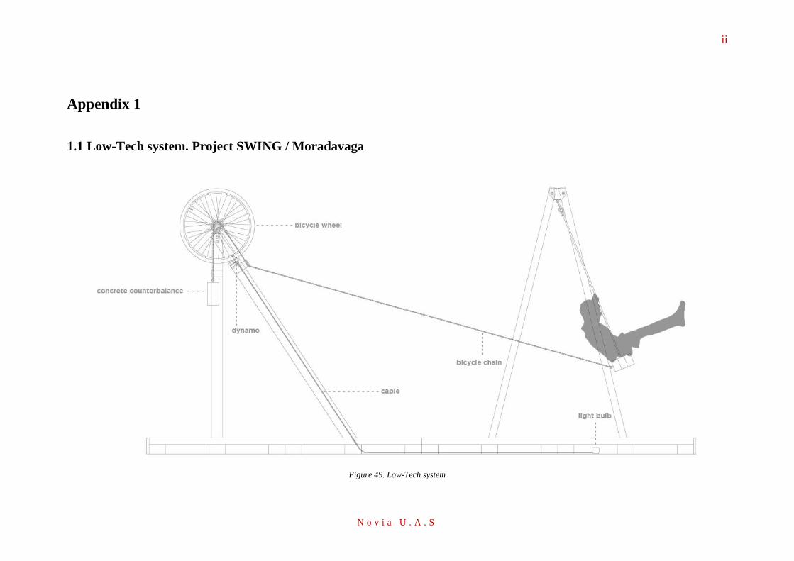
ii
N o v i a U . A . S
Appendix 1
1.1 Low-Tech system. Project SWING / Moradavaga
Figure 49. Low-Tech system
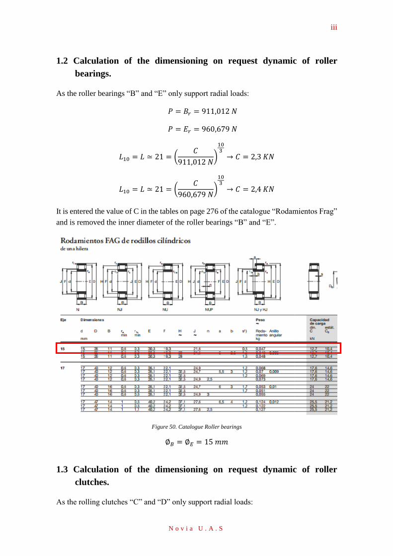
iii
N o v i a U . A . S
1.2 Calculation of the dimensioning on request dynamic of roller
bearings.
As the roller bearings “B” and “E” only support radial loads:
𝑃 = 𝐵𝑟 = 911,012 𝑁
𝑃 = 𝐸𝑟 = 960,679 𝑁
𝐿10 = 𝐿 ≃ 21 = (𝐶
911,012 𝑁)
103
→ 𝐶 = 2,3 𝐾𝑁
𝐿10 = 𝐿 ≃ 21 = (𝐶
960,679 𝑁)
103
→ 𝐶 = 2,4 𝐾𝑁
It is entered the value of C in the tables on page 276 of the catalogue “Rodamientos Frag”
and is removed the inner diameter of the roller bearings “B” and “E”.
Figure 50. Catalogue Roller bearings
∅𝐵 = ∅𝐸 = 15 𝑚𝑚
1.3 Calculation of the dimensioning on request dynamic of roller
clutches.
As the rolling clutches “C” and “D” only support radial loads:
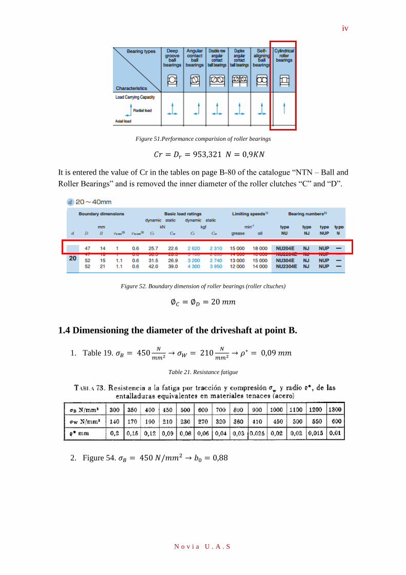
iv
N o v i a U . A . S
Figure 51.Performance comparision of roller bearings
𝐶𝑟 = 𝐷𝑟 = 953,321 𝑁 = 0,9𝐾𝑁
It is entered the value of Cr in the tables on page B-80 of the catalogue “NTN – Ball and
Roller Bearings” and is removed the inner diameter of the roller clutches “C” and “D”.
Figure 52. Boundary dimension of roller bearings (roller cltuches)
∅𝐶 = ∅𝐷 = 20 𝑚𝑚
1.4 Dimensioning the diameter of the driveshaft at point B.
1. Table 19. 𝜎𝐵 = 450𝑁
𝑚𝑚2 → 𝜎𝑊 = 210𝑁
𝑚𝑚2 → 𝜌∗ = 0,09 𝑚𝑚
Table 21. Resistance fatigue
2. Figure 54. 𝜎𝐵 = 450 𝑁/𝑚𝑚2 → 𝑏0 = 0,88
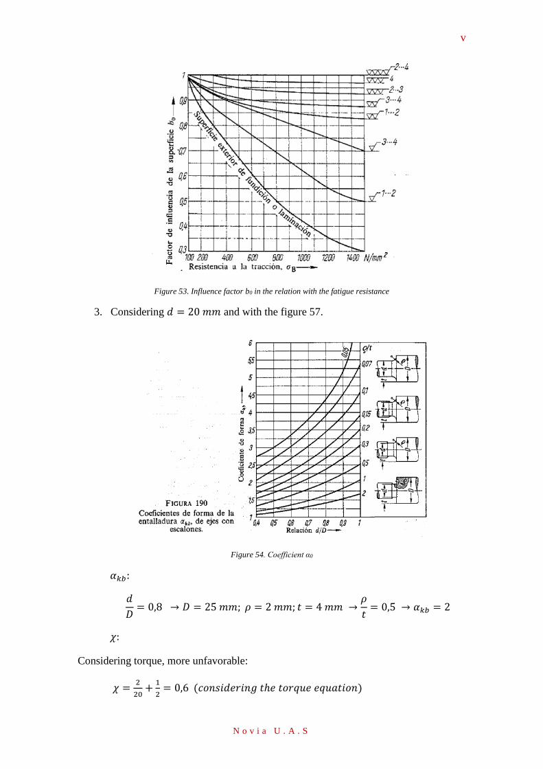
v
N o v i a U . A . S
Figure 53. Influence factor b0 in the relation with the fatigue resistance
3. Considering 𝑑 = 20 𝑚𝑚 and with the figure 57.
Figure 54. Coefficient α0
𝛼𝑘𝑏:
𝑑
𝐷= 0,8 → 𝐷 = 25 𝑚𝑚; 𝜌 = 2 𝑚𝑚; 𝑡 = 4 𝑚𝑚 →
𝜌
𝑡= 0,5 → 𝛼𝑘𝑏 = 2
𝜒:
Considering torque, more unfavorable:
𝜒 =2
20+
1
2= 0,6 (𝑐𝑜𝑛𝑠𝑖𝑑𝑒𝑟𝑖𝑛𝑔 𝑡ℎ𝑒 𝑡𝑜𝑟𝑞𝑢𝑒 𝑒𝑞𝑢𝑎𝑡𝑖𝑜𝑛)
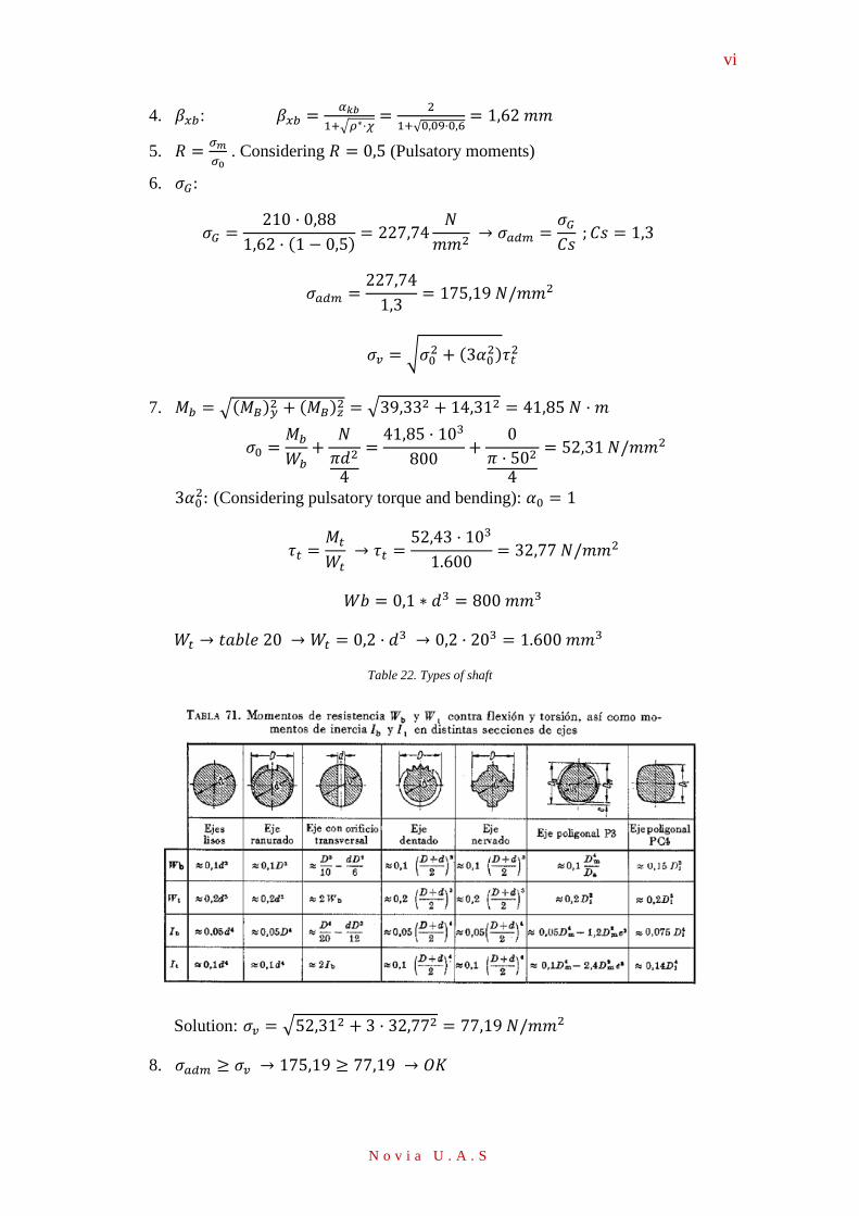
vi
N o v i a U . A . S
4. 𝛽𝑥𝑏: 𝛽𝑥𝑏 =𝛼𝑘𝑏
1+√𝜌∗·𝜒=
2
1+√0,09·0,6= 1,62 𝑚𝑚
5. 𝑅 =𝜎𝑚
𝜎0 . Considering 𝑅 = 0,5 (Pulsatory moments)
6. 𝜎𝐺:
𝜎𝐺 =210 · 0,88
1,62 · (1 − 0,5)= 227,74
𝑁
𝑚𝑚2 → 𝜎𝑎𝑑𝑚 =
𝜎𝐺
𝐶𝑠 ; 𝐶𝑠 = 1,3
𝜎𝑎𝑑𝑚 =227,74
1,3= 175,19 𝑁/𝑚𝑚2
𝜎𝑣 = √𝜎02 + (3𝛼0
2)𝜏𝑡2
7. 𝑀𝑏 = √(𝑀𝐵)𝑦2 + (𝑀𝐵)𝑧
2 = √39,332 + 14,312 = 41,85 𝑁 · 𝑚
𝜎0 =𝑀𝑏
𝑊𝑏+
𝑁
𝜋𝑑2
4
=41,85 · 103
800+
0
𝜋 · 502
4
= 52,31 𝑁/𝑚𝑚2
3𝛼02: (Considering pulsatory torque and bending): 𝛼0 = 1
𝜏𝑡 =𝑀𝑡
𝑊𝑡 → 𝜏𝑡 =
52,43 · 103
1.600= 32,77 𝑁/𝑚𝑚2
𝑊𝑏 = 0,1 ∗ 𝑑3 = 800 𝑚𝑚3
𝑊𝑡 → 𝑡𝑎𝑏𝑙𝑒 20 → 𝑊𝑡 = 0,2 · 𝑑3 → 0,2 · 203 = 1.600 𝑚𝑚3
Table 22. Types of shaft
Solution: 𝜎𝑣 = √52,312 + 3 · 32,772 = 77,19 𝑁/𝑚𝑚2
8. 𝜎𝑎𝑑𝑚 ≥ 𝜎𝑣 → 175,19 ≥ 77,19 → 𝑂𝐾
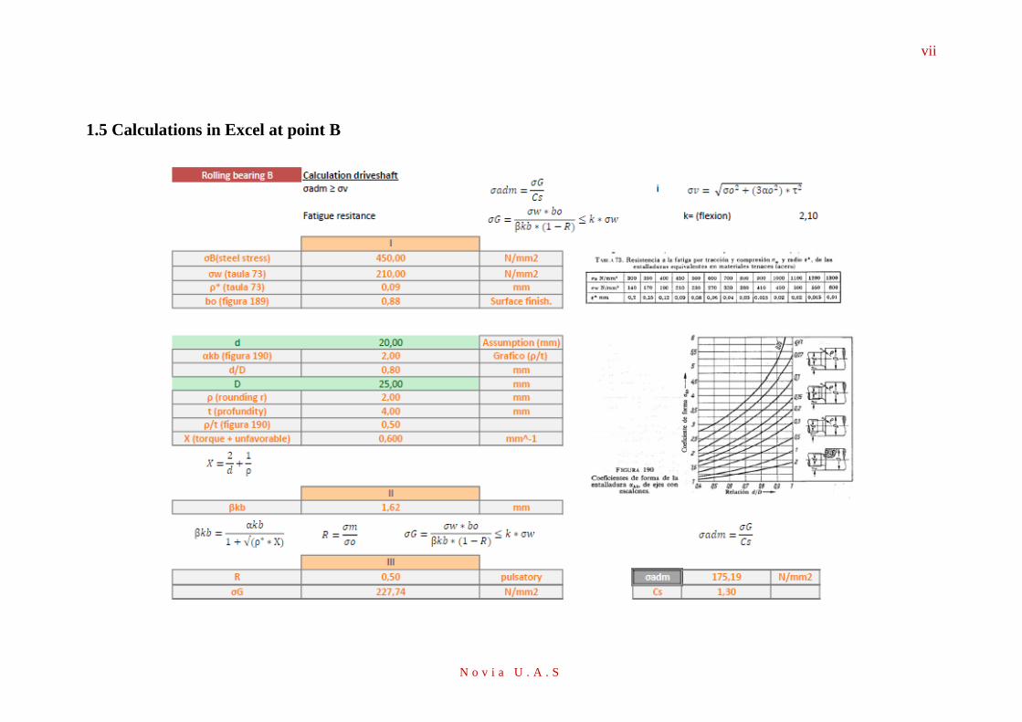
vii
N o v i a U . A . S
1.5 Calculations in Excel at point B
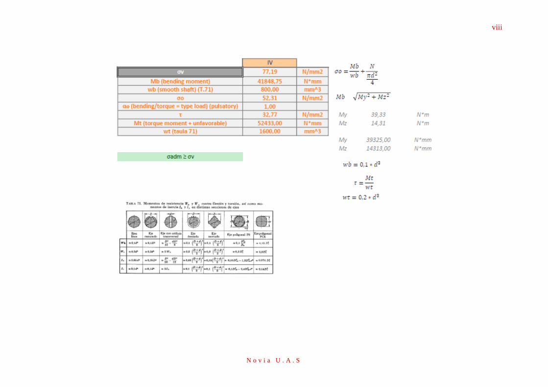
viii
N o v i a U . A . S
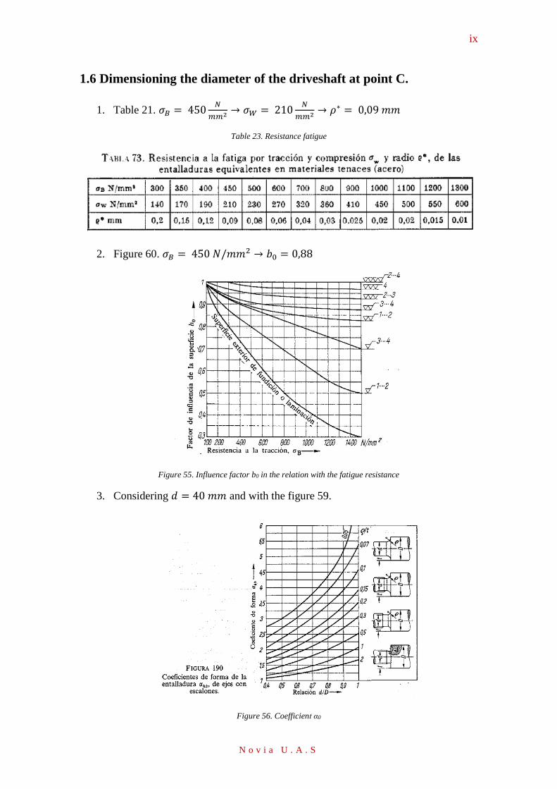
ix
N o v i a U . A . S
1.6 Dimensioning the diameter of the driveshaft at point C.
1. Table 21. 𝜎𝐵 = 450𝑁
𝑚𝑚2 → 𝜎𝑊 = 210𝑁
𝑚𝑚2 → 𝜌∗ = 0,09 𝑚𝑚
Table 23. Resistance fatigue
2. Figure 60. 𝜎𝐵 = 450 𝑁/𝑚𝑚2 → 𝑏0 = 0,88
Figure 55. Influence factor b0 in the relation with the fatigue resistance
3. Considering 𝑑 = 40 𝑚𝑚 and with the figure 59.
Figure 56. Coefficient α0
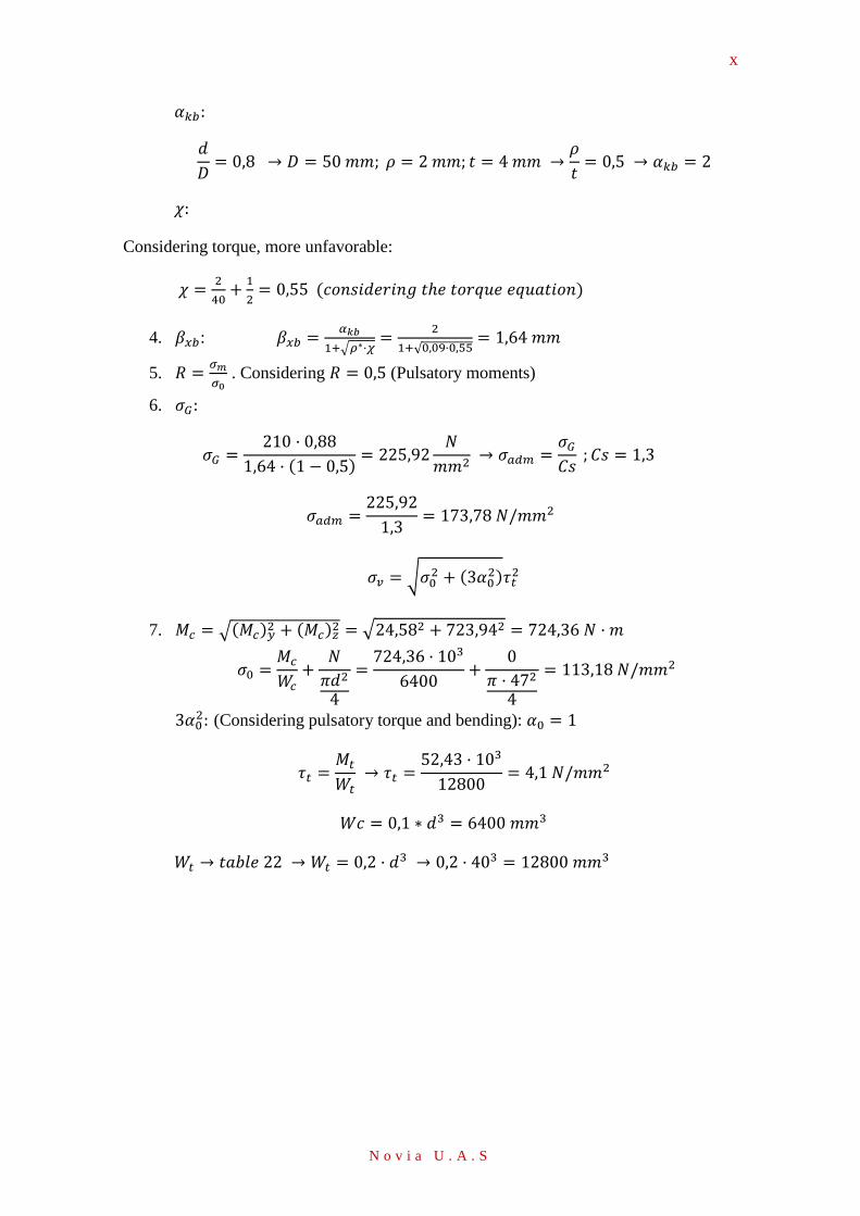
x
N o v i a U . A . S
𝛼𝑘𝑏:
𝑑
𝐷= 0,8 → 𝐷 = 50 𝑚𝑚; 𝜌 = 2 𝑚𝑚; 𝑡 = 4 𝑚𝑚 →
𝜌
𝑡= 0,5 → 𝛼𝑘𝑏 = 2
𝜒:
Considering torque, more unfavorable:
𝜒 =2
40+
1
2= 0,55 (𝑐𝑜𝑛𝑠𝑖𝑑𝑒𝑟𝑖𝑛𝑔 𝑡ℎ𝑒 𝑡𝑜𝑟𝑞𝑢𝑒 𝑒𝑞𝑢𝑎𝑡𝑖𝑜𝑛)
4. 𝛽𝑥𝑏: 𝛽𝑥𝑏 =𝛼𝑘𝑏
1+√𝜌∗·𝜒=
2
1+√0,09·0,55= 1,64 𝑚𝑚
5. 𝑅 =𝜎𝑚
𝜎0 . Considering 𝑅 = 0,5 (Pulsatory moments)
6. 𝜎𝐺:
𝜎𝐺 =210 · 0,88
1,64 · (1 − 0,5)= 225,92
𝑁
𝑚𝑚2 → 𝜎𝑎𝑑𝑚 =
𝜎𝐺
𝐶𝑠 ; 𝐶𝑠 = 1,3
𝜎𝑎𝑑𝑚 =225,92
1,3= 173,78 𝑁/𝑚𝑚2
𝜎𝑣 = √𝜎02 + (3𝛼0
2)𝜏𝑡2
7. 𝑀𝑐 = √(𝑀𝑐)𝑦2 + (𝑀𝑐)𝑧
2 = √24,582 + 723,942 = 724,36 𝑁 · 𝑚
𝜎0 =𝑀𝑐
𝑊𝑐+
𝑁
𝜋𝑑2
4
=724,36 · 103
6400+
0
𝜋 · 472
4
= 113,18 𝑁/𝑚𝑚2
3𝛼02: (Considering pulsatory torque and bending): 𝛼0 = 1
𝜏𝑡 =𝑀𝑡
𝑊𝑡 → 𝜏𝑡 =
52,43 · 103
12800= 4,1 𝑁/𝑚𝑚2
𝑊𝑐 = 0,1 ∗ 𝑑3 = 6400 𝑚𝑚3
𝑊𝑡 → 𝑡𝑎𝑏𝑙𝑒 22 → 𝑊𝑡 = 0,2 · 𝑑3 → 0,2 · 403 = 12800 𝑚𝑚3
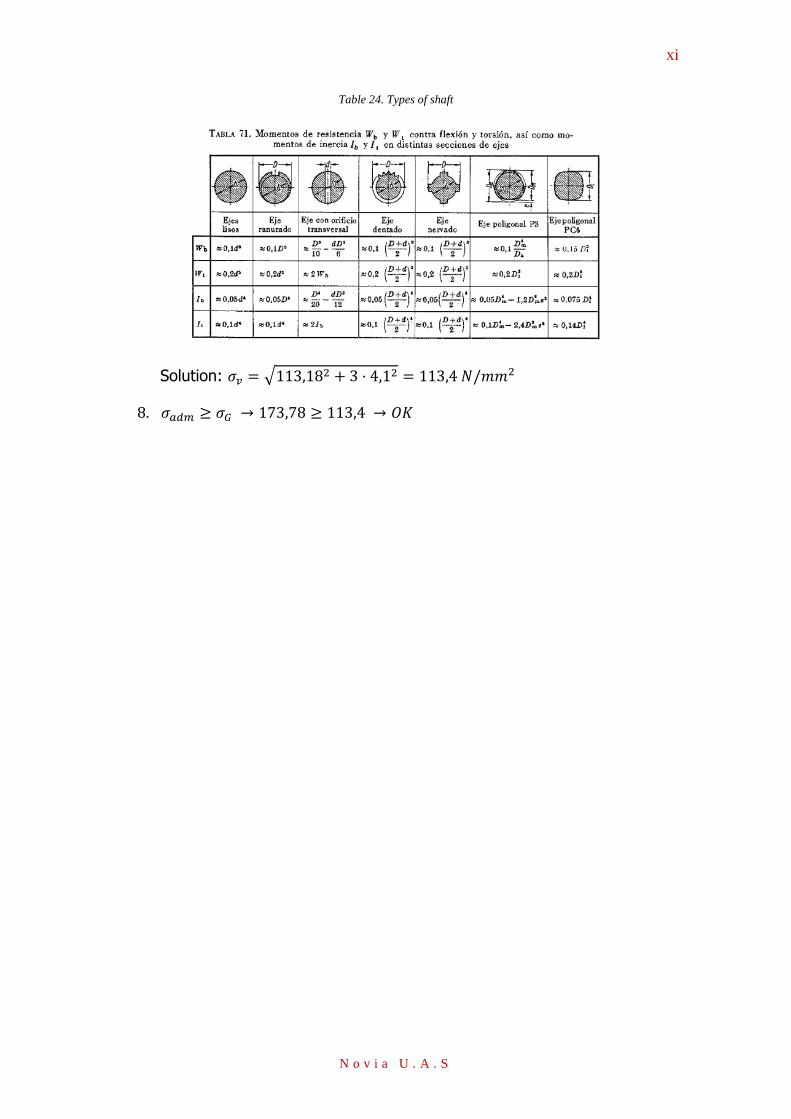
xi
N o v i a U . A . S
Table 24. Types of shaft
Solution: 𝜎𝑣 = √113,182 + 3 · 4,12 = 113,4 𝑁/𝑚𝑚2
8. 𝜎𝑎𝑑𝑚 ≥ 𝜎𝐺 → 173,78 ≥ 113,4 → 𝑂𝐾
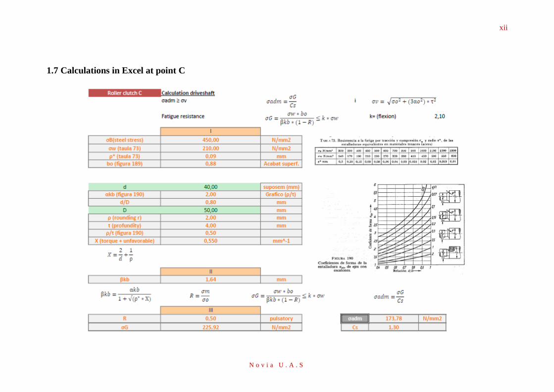
xii
N o v i a U . A . S
1.7 Calculations in Excel at point C
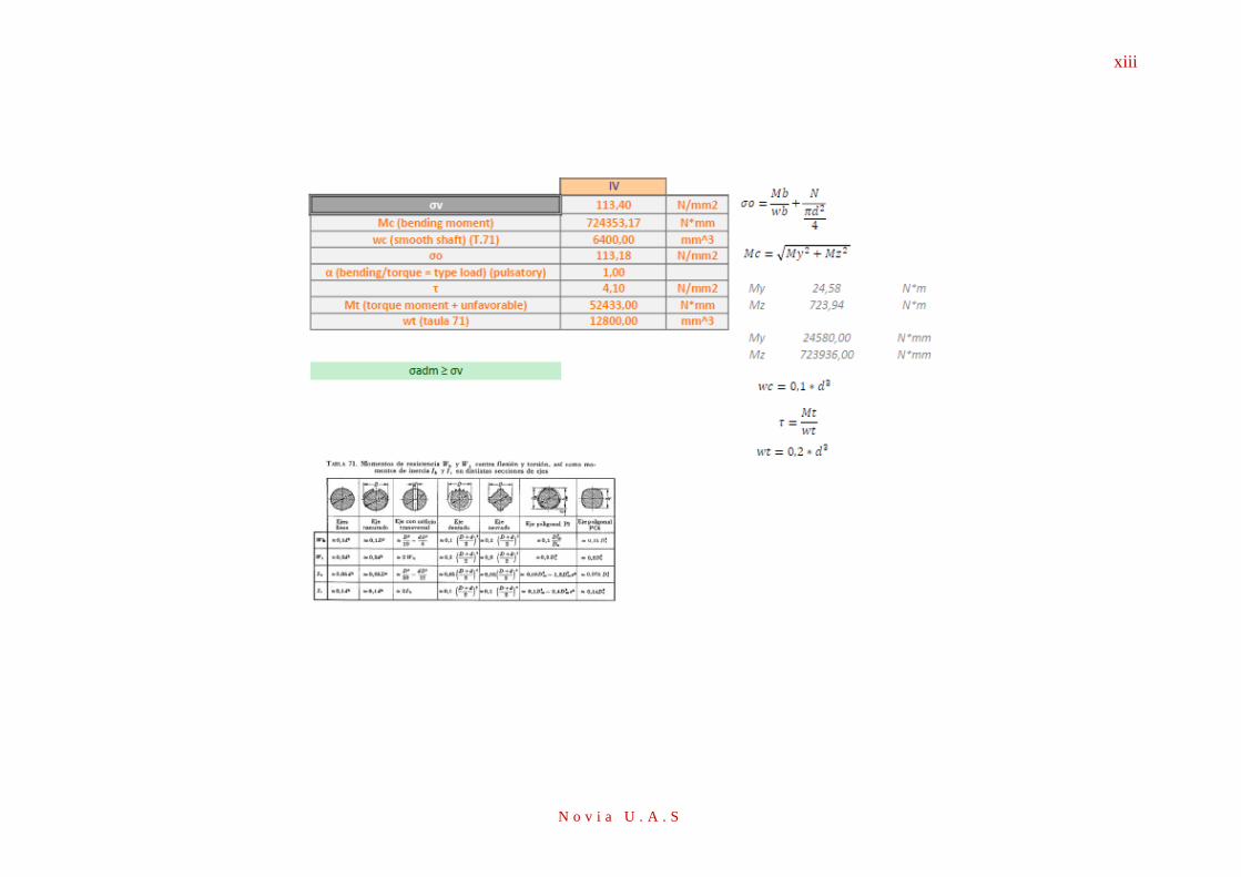
xiii
N o v i a U . A . S
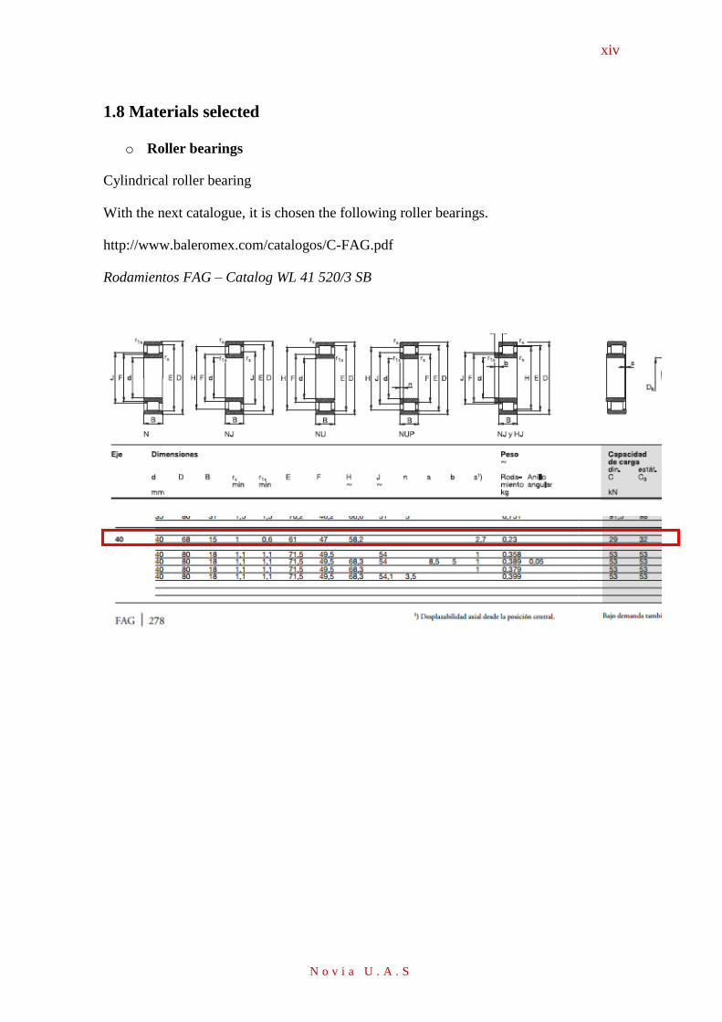
xiv
N o v i a U . A . S
1.8 Materials selected
o Roller bearings
Cylindrical roller bearing
With the next catalogue, it is chosen the following roller bearings.
http://www.baleromex.com/catalogos/C-FAG.pdf
Rodamientos FAG – Catalog WL 41 520/3 SB
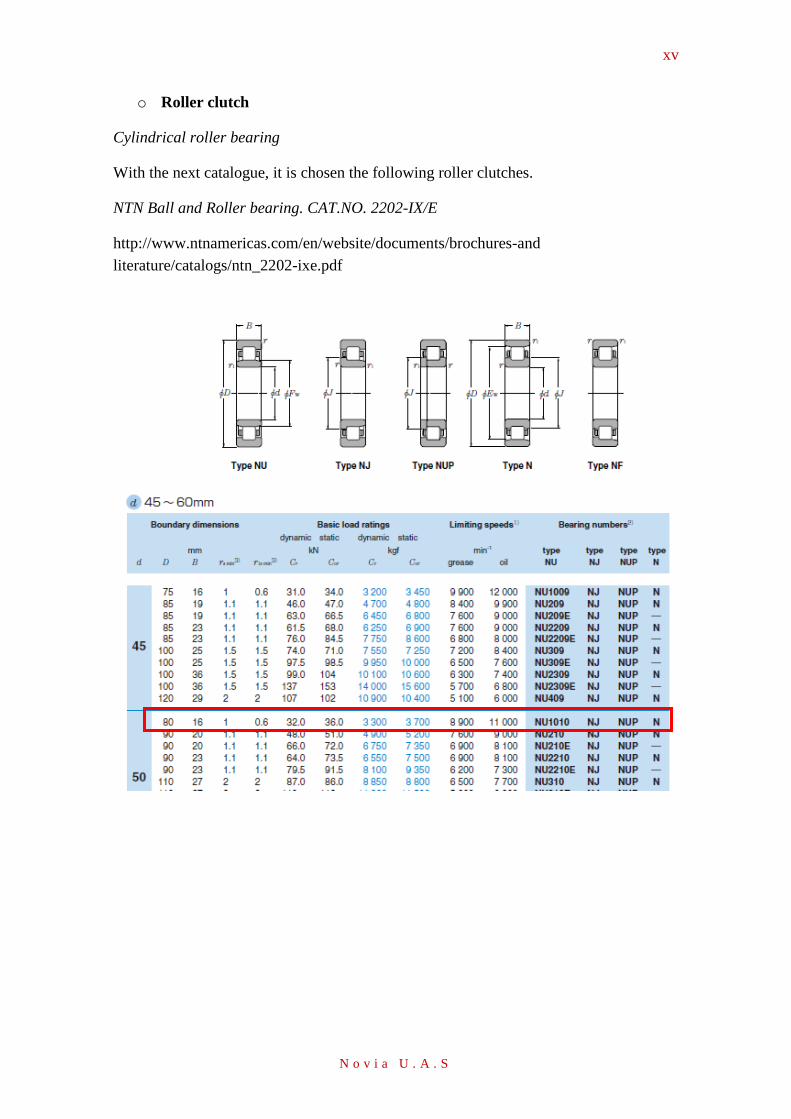
xv
N o v i a U . A . S
o Roller clutch
Cylindrical roller bearing
With the next catalogue, it is chosen the following roller clutches.
NTN Ball and Roller bearing. CAT.NO. 2202-IX/E
http://www.ntnamericas.com/en/website/documents/brochures-and
literature/catalogs/ntn_2202-ixe.pdf
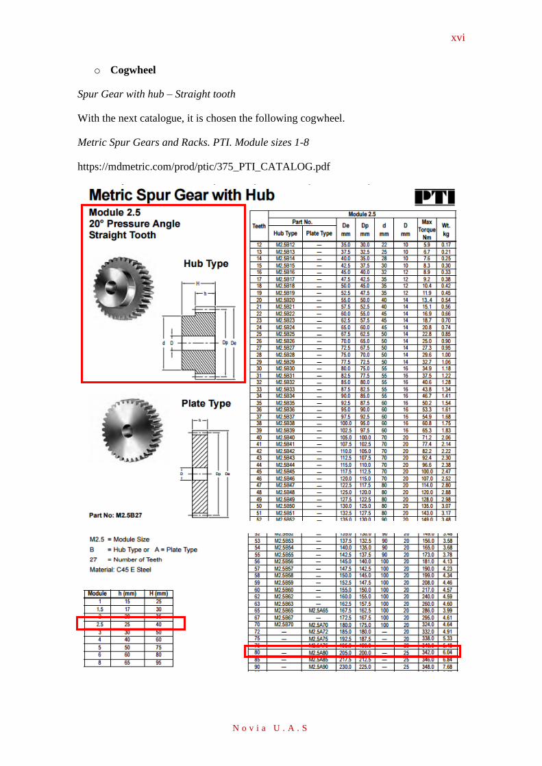
xvi
N o v i a U . A . S
o Cogwheel
Spur Gear with hub – Straight tooth
With the next catalogue, it is chosen the following cogwheel.
Metric Spur Gears and Racks. PTI. Module sizes 1-8
https://mdmetric.com/prod/ptic/375_PTI_CATALOG.pdf
xvii
N o v i a U . A . S
o Alternator
Harmonic alternator / Monophasic / Industrial / Lighting application.
With the next catalogue, it is chosen the following alternator.
Fujian Mindong Electric Co., Ltd.
http://www.directindustry.es/prod/fujian-mindong-electric-co-ltd/product-126201-
1571100.html

xviii
N o v i a U . A . S
Appendix 2
2.1 Materials selected
o AC Dynamo generator 6V-3W
With the next catalogue, it is chosen the following dynamo for the circuit designed.
http://www.bumm.de/fileadmin/user_upload/Katalog/B_M__Catalogue_2014_15__Eng
lish.pdf
Then, the estimated prize is chosen through the amazon company:
http://www.amazon.co.uk/BUSCH-MÜLLER-Dymotec-6-Dynamo/dp/B00F8HWZEE
Date. 16/04/2016
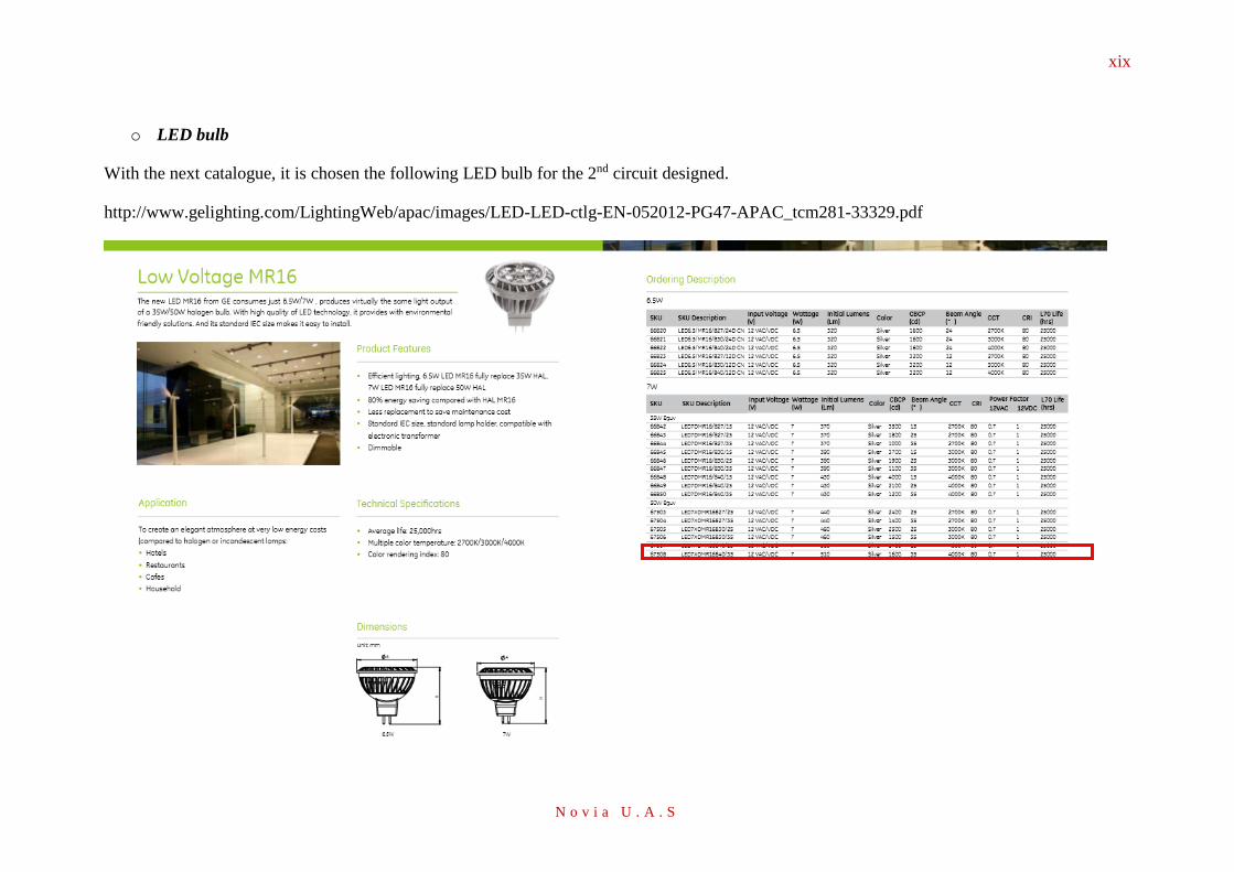
xix
N o v i a U . A . S
o LED bulb
With the next catalogue, it is chosen the following LED bulb for the 2nd circuit designed.
http://www.gelighting.com/LightingWeb/apac/images/LED-LED-ctlg-EN-052012-PG47-APAC_tcm281-33329.pdf

xx
N o v i a U . A . S
Then, the estimated prize is chosen through the ADL (All Day Light) company:
https://www.alldaylighting.com/shop/led-light-bulbs/ge-67844-led7dmr1684025/
Date 16/04/2016

xxi
N o v i a U . A . S
o Rechargeable battery 8Ah
With the next catalogue, it is chosen the following battery bulb for the 1st circuit designed.
http://www.elkproducts.com/product-catalog/elk-1280
Then, the estimated prize is chosen through the Amazon Company:
https://www.alldaylighting.com/shop/led-light-bulbs/ge-67844-led7dmr1684025/
Date (16/04/2016)

xxii
N o v i a U . A . S
o Rechargeable battery 5Ah
With the next catalogue, it is chosen the following battery bulb for the 2nd circuit designed.
http://www.communica.co.za/catalog/Details/P2647837992
Then, the estimated prize is chosen through the Amazon Company:
http://www.amazon.com/12V-5AH-SLA-187-FASTON/dp/B000BPCUXO
Date (16/04/2016)
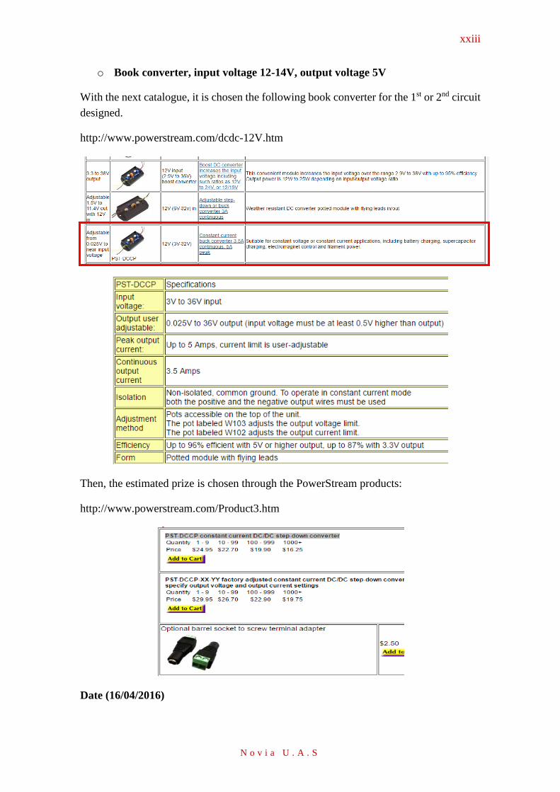
xxiii
N o v i a U . A . S
o Book converter, input voltage 12-14V, output voltage 5V
With the next catalogue, it is chosen the following book converter for the 1st or 2nd circuit
designed.
http://www.powerstream.com/dcdc-12V.htm
Then, the estimated prize is chosen through the PowerStream products:
http://www.powerstream.com/Product3.htm
Date (16/04/2016)

xxiv
N o v i a U . A . S
o Boost converter, input voltage 1V-10V, output voltage 12V-14V
With the next catalogue, it is chosen the following boost converter for the 1st or 2nd circuit
designed.
http://www.ti.com/tool/tps6734evm#descriptionArea
Then, the estimated prize is chosen through the Amazon products:
http://www.amazon.com/gp/product/B00DWX8PM2/ref=pd_lpo_sbs_dp_ss_2?pf_rd_p=1944687502&pf_rd_s=lpo-top-stripe-
1&pf_rd_t=201&pf_rd_i=B00J03PBW0&pf_rd_m=ATVPDKIKX0DER&pf_rd_r=11CNKP9SAPBD436VR1JA
Date (16/04/2016)

xxv
N o v i a U . A . S
o Rectifier AC-DC, input voltage 1V min, output voltage 12V max
With the next catalogue, it is chosen the following Rectifier AC-DC for the 1st or 2nd
circuit designed. Then, the estimated prize is chosen through the Alibaba products:
http://www.alibaba.com/product-detail/the-best-selling-international-market-
AC_60304474644.html?spm=a2700.7724857.29.117.cDEc12
Date (16/04/2016)