IMPROVED POWER QUALITY FEATURES USING FUZZY BASED UPQC TOPOLOGY FOR BLDC DRIVE APPLICATIONS
14
www.tjprc.org [email protected] IMPROVED POWER QUALITY FEATURES USING FUZZY BASED UPQC TOPOLOGY FOR BLDC DRIVE APPLICATIONS K. DHILLESWARAMMA 1 , K. B. MADHU SAHU 2 & CH. KRISHNA RAO 3 1 Department of EEE, AITAM Engineering College, Andhra Pradesh, India 2 Professor & Principal, Department of EEE, AITAM Engineering College, Andhra Pradesh, India 3 Associate Professor, Department of EEE, AITAM Engineering College, Andhra Pradesh, India ABSTRACT Implementation of the fuzzy logic controller by using voltage as feedback for significantly improving the dynamic performance of proposed UPQC module. Power quality is normally degree of any deviation from the nominal values of the voltage magnitude and frequency. Power quality problem manifested in voltage, current (or) frequency deviations. That causes power failure (or) disoperation of customer of equipment. Mostly power quality problems mitigate by UPQC. This UPQC contain combination of the the series and shunt active filters and series active filter mitigate the voltage related harmonics in power supply side and shunt active filters are mitigate the current related harmonics of non linear loads. And UPQC mitigate the harmonics and other harmonic sensitive loads. APF(active power filters),passive filters, UPFC (Unified Power Flow Converter ) etc are mitigate the other power quality problems. Among from them unified power quality conditioner was widely studied by different controllers and we applied to BLDC motor for updating of load characteristics that improve the power quality in distribution side. KEYWORDS: Series Active Power Filter, Shunt Active Power Filter, Three-Phase Four Wire Systems (3P4W), Instantaneous Active Reactive Power (P-Q) Theory INTRODUCTION The electric power quality mostly effected by voltage and current flickering due to arc in arc furnaces, harmonic contamination, due to non-linear loads Such as large thyristor power converters, rectifiers, and also sags and swells due to the switching of the loads etc. These above many factors effects the electric power quality. This deals mainly like issues of maintaining fixed voltage at point of common coupling (PCC) for various distribution voltage levels irrespective of voltage fluctuations, and maintaining near unit power factor drawn from electric power supply, Blocking Unbalanced Voltage and current from passive upwards from various distribution levels, voltage and current harmonics reductions in system [1]. In the distribution system from the perspective of sensitive non-linear loads, must needs power quality. In the electric power system as PQ varies due to various types of sources of generations. So in this UPQC are recommended. Hence, suitable power conditioning interfaces are suggested for sensitive load, three phase loads, and several single phase loads and non- linear loads. These type of loads primarily include production industries like paper mills, automotive plants, semi conductor, manufacturing plants, chemical and pharmaceutical industries, etc. and critical services providers like air ports, broad casting centers, medical centers, etc. International Journal of Electrical and Electronics Engineering Research (IJEEER) ISSN(P): 2250-155X; ISSN(E): 2278-943X Vol. 5, Issue 1, Feb 2015, 45-58 © TJPRC Pvt. Ltd.
-
Upload
independent -
Category
Documents
-
view
2 -
download
0
Transcript of IMPROVED POWER QUALITY FEATURES USING FUZZY BASED UPQC TOPOLOGY FOR BLDC DRIVE APPLICATIONS
www.tjprc.org [email protected]
IMPROVED POWER QUALITY FEATURES USING FUZZY BASED U PQC
TOPOLOGY FOR BLDC DRIVE APPLICATIONS
K. DHILLESWARAMMA 1, K. B. MADHU SAHU 2 & CH. KRISHNA RAO 3
1Department of EEE, AITAM Engineering College, Andhra Pradesh, India 2Professor & Principal, Department of EEE, AITAM Engineering College, Andhra Pradesh, India
3Associate Professor, Department of EEE, AITAM Engineering College, Andhra Pradesh, India
ABSTRACT
Implementation of the fuzzy logic controller by using voltage as feedback for significantly improving the dynamic
performance of proposed UPQC module. Power quality is normally degree of any deviation from the nominal values of the
voltage magnitude and frequency. Power quality problem manifested in voltage, current (or) frequency deviations.
That causes power failure (or) disoperation of customer of equipment. Mostly power quality problems mitigate by UPQC.
This UPQC contain combination of the the series and shunt active filters and series active filter mitigate the voltage related
harmonics in power supply side and shunt active filters are mitigate the current related harmonics of non linear loads.
And UPQC mitigate the harmonics and other harmonic sensitive loads. APF(active power filters),passive filters,
UPFC (Unified Power Flow Converter ) etc are mitigate the other power quality problems. Among from them unified
power quality conditioner was widely studied by different controllers and we applied to BLDC motor for updating of load
characteristics that improve the power quality in distribution side.
KEYWORDS: Series Active Power Filter, Shunt Active Power Filter, Three-Phase Four Wire Systems (3P4W),
Instantaneous Active Reactive Power (P-Q) Theory
INTRODUCTION
The electric power quality mostly effected by voltage and current flickering due to arc in arc furnaces, harmonic
contamination, due to non-linear loads Such as large thyristor power converters, rectifiers, and also sags and swells due to
the switching of the loads etc. These above many factors effects the electric power quality. This deals mainly like issues of
maintaining fixed voltage at point of common coupling (PCC) for various distribution voltage levels irrespective of voltage
fluctuations, and maintaining near unit power factor drawn from electric power supply, Blocking Unbalanced Voltage and
current from passive upwards from various distribution levels, voltage and current harmonics reductions in system [1].
In the distribution system from the perspective of sensitive non-linear loads, must needs power quality. In the electric
power system as PQ varies due to various types of sources of generations. So in this UPQC are recommended.
Hence, suitable power conditioning interfaces are suggested for sensitive load, three phase loads, and several single phase
loads and non- linear loads. These type of loads primarily include production industries like paper mills, automotive plants,
semi conductor, manufacturing plants, chemical and pharmaceutical industries, etc. and critical services providers like air
ports, broad casting centers, medical centers, etc.
International Journal of Electrical and Electronics Engineering Research (IJEEER) ISSN(P): 2250-155X; ISSN(E): 2278-943X Vol. 5, Issue 1, Feb 2015, 45-58 © TJPRC Pvt. Ltd.

46 K. Dhilleswaramma, K. B. Madhu Sahu & CH. Krishna Rao
Impact Factor (JCC): 5.9638 Index Copernicus Value (ICV): 3.0
Active power filters used for power quality improvement typical grid integration problems associate with voltage
and frequency compatibility and requirement of reactive and active power. [2] UPQC most widely used for comprehensive
power conditioning equipment. It mitigates both voltage and current power quality problems [3]. And functionally UPQC
is a combination of series active filter and shunt active filter and from incoming voltage and current the UPQC maintained
desired power quality. The series active power filter is connected via transformer in series with the AC line shunt active
power filter cancels current- based distortions. It compensate reactive current of the non linear nodes and as well as at the
same time it improve power factor The shunt bi directional converter is connect the connected in the parallel with the load
terminals.
Figure 1: Block Diagram of UPQC
Thus the transformer neural part can be maintained at the virtual zero potential [4]. The unbalanced three-phase
four wire distribution system can be reduced by injecting the currents using shunt active filters [4]-[6]. The configuration
shown in figure 1.
UNIFIED POWER QUALITY CONDITIONER (UPQC)
UPQC is combination of 2 types of active power filters with a common self supporting DC bus. So UPQC mainly
use to compensate for issues of supply voltage power quality, such as, sags, swells, voltage regulation, Unbalance flickers,
harmonics, and for current power quality problems, those are harmonics, unbalance, reactive current, & neural currents. By
the electric power utilities the general UPQC will be installed at various sub stations.
The main purpose of series active filter and Shunt Active Power Filter shown in the below table:
Table 1
Series Active Power Filter Shunt Active Power Filter In this series active filter harmonic isolation between a sub transmission system and harmonic isolation between a sub transmission distribution.
In this Shunt Active Power Filter to observe current harmonic.
In this series active filter the capacity of voltage flicker/ imbalance compensation.
In this Shunt Active Power filter compensation reactive power.
In this series active filter voltage regulation and harmonic compensation at the utility consumer of the Point Of Common Coupling (PCC).
In this Shunt Active Power filter negative- sequences current and regulate dc- link voltage in between both active filters [7].

Improved Power Quality Features Using Fuzzy Based UPQC Topology for BLDC Drive Applications 47
www.tjprc.org [email protected]
The key components of system: as follows below are:
The UPQC used in power distribution system at substation. and UPQC simentanously operates series & shunt
compensation [8]. the UPQC contain the Lsh, Cdc LC Filter and isolation Transformer and series and shunt inverters.
In UPQC(Unified Power Flow Converter has
• Two Inverters: In which the both series APF and shunt APF s were connected back to back with a common dc
reactor as shown in figure 3.
• Lsh(shunt coupling inductor) is uses as to interface the shunt inverter to the network, it works for the smoothing
the current wave Shape. isolation transformer is utilized sometimes electrically isolate the inverter from the
network. Common dc link formed by using inductor (or) capacitor.
• Cdc: This UPQC configuration dc link formed by a capacitor and it inter connects the two series and shunt
inverters. It provides constant self- supporting dc bus voltage across it.
• An LC Filters serves as a passive low –pass Filter (LPF), and It mitigate high frequency switching ripples on the
output voltage of generated
• Series injection transformer used: It connect the series inverter inverter in the networks. It turns ratio is chosen
suitable only then to reduction series inverter current & voltage rating.. In basic UPQC (Unified Power Quality
Converter) maintain the followings are :
The basic Shunt inverter inject a current is governed by following Equation: )(I)()(I LSh wttIwt s −= ∗ ω
(1)
Where )(ISh wt = shunt inverter current
)( tI s ω∗ = reference source current )(I L wt = load current respectively
The basic Series inverters inject a voltage is governed by following equation: )(V)()(V SSr wttVt Lc −= ∗ ω
(2)
Where )(VSr t = series inverter voltage injected voltage, )( tVLc ω∗ =reference load voltage, )(VS wt = actual source
voltage, respectively
In this paper developed from 3P4W VSI based UPQC using Different Load conditions using p-q theory (active
and reactive power (or) three phase pq theory) control technique
3P4W DISTRIBUTION SYSTEM REALIZED WITH UPQC
3p4w distribution system available for two ways:
• From generation station one is providing a neural conductor along with three power conductors. From figure 1
neural conductor provided from generation station itself.
• By utilizing 3-phase delta- star transformer at distribution level.
The main advantage of 3p4w UPQC in the area of plant site is
• To restrict any entry of from load side toward utility.
• Installed to protect a sensitive load. According to plant under construction & to installation of single – phase
loads, the distribution transformer upgrade from 3P3W to 3P4W system. With any involvement of major cost,
utility provide the neural conductor from transformer. This is costlier, because of it not suitable in close

48 K. Dhilleswaramma, K. B. Madhu Sahu & CH. Krishna Rao
Impact Factor (JCC): 5.9638 Index Copernicus Value (ICV): 3.0
vicinity[6]
In this paper current flowing towards the transformer neural point is compensated by Four – Leg VSI Topology
[8] And 4- leg VSI is get from existing UPQC(Unified Power Quality Converter ) with three phase four wire (3P4W).
So transformer neural point will be at virtual zero potential.
Figure 2: 3ph4w Distribution System: Neutral Provided from ∆–Y Transformer
The desired structure 3P4W system realize from 3p3w system at distribution load end. So 3P3W to 3P4W
explanation of results are easier. And we introduce a new control strategy is under unbalanced load consideration
conditions this generate balanced reference source currents. That results explained in detail next section [9].
Figure 3: UPQC Structure with Nonlinear Load
FUZZY LOGIC CONTROLLER
In 1965 first paper published by on Fuzzy set theory by L A Zadeh. For some power system applications most
widely use this Fuzzy set theory [10]-[12]. Fuzzy controller logically formed and since then, a new Fuzzy language
improved to explain the Fuzzy properties of reality, which are sometimes difficult and even impossible to described using
method of conventional. Fuzzy set rules built a group of up rules that based on the expert experience (or) knowledge data
base. From the Mat lab / simulink model of Fuzzy logic controller with the three phase four wire UPQC structure obtained
the dynamic behavior of converter. In linear control technique, furthermore, Fuzzy logic control design is not possible
when at same time. Dynamic performance of desirable both small & large signal by Fuzzy logic controller furthermore,
Improved Power Quality Features Using Fuzzy Based UPQC Topology for
www.tjprc.org
in linear control technique it is impossible. Fuzzy logic controller table shown in figure 4.
converter. It ‘s technique has been potential ability.
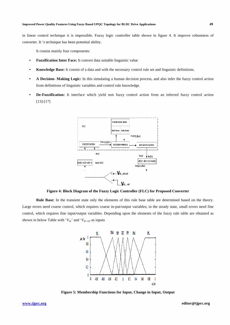
It consist mainly four components:
• Fuzzification Inter Face: It convert data suitable linguistic value
• Knowledge Base: It consist of a data
• A Decision- Making Logic: In
from definitions of linguistic variables and
• De-Fuzzification: It interface which yield non fuzzy control action from an inferred fuzzy control action
[13]-[17]
Figure 4: Block Diagram
Rule Base: In the transient state only the elements of this rule base table are determined based on the theory.
Large errors need coarse control, which requires coarse in
control, which requires fine input/output variables.
shown in below Table with ‘Vdc’ and ‘V
Figure 5: Membership
Improved Power Quality Features Using Fuzzy Based UPQC Topology for BLDC Drive Applications
in linear control technique it is impossible. Fuzzy logic controller table shown in figure 4.
has been potential ability.
components:
convert data suitable linguistic value
consist of a data and with the necessary control rule set and linguistic definitions.
In this simulating a human decision process, and also infer the fuzzy control action
definitions of linguistic variables and control rule knowledge.
interface which yield non fuzzy control action from an inferred fuzzy control action
Diagram of the Fuzzy Logic Controller (FLC) for Proposed Converter
In the transient state only the elements of this rule base table are determined based on the theory.
errors need coarse control, which requires coarse in-put/output variables; in the steady state, small errors need fine
control, which requires fine input/output variables. Depending upon the elements of the fuzzy rule table are obtained as
Vdc-ref’ as inputs
Membership Functions for Input, Change in Input, Output
49
in linear control technique it is impossible. Fuzzy logic controller table shown in figure 4. It improve robustness of
and linguistic definitions.
and also infer the fuzzy control action
interface which yield non fuzzy control action from an inferred fuzzy control action
Proposed Converter
In the transient state only the elements of this rule base table are determined based on the theory.
variables; in the steady state, small errors need fine
fuzzy rule table are obtained as
, Output

50 K. Dhilleswaramma, K. B. Madhu Sahu & CH. Krishna Rao
Impact Factor (JCC): 5.9638 Index Copernicus Value (ICV): 3.0
Fuzzy controller control strategy is from linguistic into automatic strategy. And it convert these the numerical
variables into linguistic variables. The table explained the following 7 fuzzy levels as: NB (negative big), NM (negative
medium), NS (negative small), ZE (zero), PS (positive small), PM (positive medium), and PB (positive big) as shown in
the below table.
Table 2
MATLAB/SIMULINK RESULTS
Here the simulation is carried out in several cases, in that 1). UPQC with PI Controller, 2). UPQC with Fuzzy
Controller, 3) UPQC with Fuzzy Controller with BLDC Drive.
Case 1: UPQC with PI Controller
Figure 6: Mat Lab/Simulink Model of 3P4W UPQC with PI Controller
Figure 6 shows the Mat lab/Simulink Model of Proposed UPQC Methodology with PI Controller using mat
lab/Simulink environment
Test-I : This Figure 7 shows the Source Voltage, Load Voltage, Compensation Voltage of UPQC with PI
Controller

Improved Power Quality Features Using Fuzzy Based UPQC Topology for BLDC Drive Applications 51
www.tjprc.org [email protected]
Figure 7: Source Voltage, Load Voltage, Compensation Voltage
Test-II : This figure 8 shows the Source Current, Load Current, Compensation Current of UPQC with PI
Controller
Figure 8: Source Current, Load Current, Compensation Current
Test III : This figure 9 shows the DC Link Voltage & Source Neutral Current of UPQC with PI Controller
Figure 9: DC Link Voltage &Source Neutral Current
Test-IV: This figure 10 shows the Load Neutral Current & Compensator Neutral Current of UPQC with PI
Controller

52 K. Dhilleswaramma, K. B. Madhu Sahu & CH. Krishna Rao
Impact Factor (JCC): 5.9638 Index Copernicus Value (ICV): 3.0
Figure 10: Load Neutral Current & Compensator Neutral Current
Test V: The figure 11 is shows the FFT Analysis of Source Current of UPQC with PI Controller, attain 2.30%
Figure 11: FFT Analysis of Source Current
Case 2: UPQC with Fuzzy Controller
Test-I: This figure 12. Shows Source Voltage, Load Voltage, and Compensation Voltage of UPQC with Fuzzy
Controller
Figure 12: Source Voltage, Load Voltage, Compensation Voltage
Test-II : This figure.12 shows the Source Current, Load Current, and Compensation Current of UPQC with Fuzzy
Controller

Improved Power Quality Features Using Fuzzy Based UPQC Topology for BLDC Drive Applications 53
www.tjprc.org [email protected]
Figure 13: Source Current, Load Current, Compensation Current
Test-III : This. Figure 14 shows the DC Link Voltage & Source Neutral Current of UPQC with Fuzzy Controller
Figure 14: DC Link Voltage & Source Neutral Current
Test-IV: This figure 15 shows the Load Neutral Current & Compensator Neutral Current of UPQC with Fuzzy
Controller.
Figure 15: Load Neutral Current & Compensator Neutral Current
Test-V: This figure 16 shows the FFT Analysis of Source Current of UPQC with PI Controller, attain 1.00% as
shown in figure 16. With the help of fuzzy controller attain low THD compared to PI controller and get fast response with
low steady state error values, that’s why used in many industrial applications.

54 K. Dhilleswaramma, K. B. Madhu Sahu & CH. Krishna Rao
Impact Factor (JCC): 5.9638 Index Copernicus Value (ICV): 3.0
Figure 16: FFT Analysis of Source Current
Table 3
PI Controller Fuzzy Controller THD=2.30% THD=1.00%
In This above table has presented a novel control of an existing UPQC within the source side. In the shunt
controller (i) with PI controller & (ii)Fuzzy logic controller to improve the quality of power at PCC for a 3-phase 4-wire
UPQC system. By using PI controller we get THD value is 2.30%, but using the Fuzzy logic controller THD value is
1.00%. and. The simulation results show that the performance of converter system has been found to be satisfactory for
improving the power quality at the consumer premises.
Case 3: UPQC with Fuzzy Controller with BLDC Drive
Figure 17: Matlab/Simulink Model of Proposed UPQC Methodology with Fuzzy Controller with BLDC Drive
Figure 17 shows the Matlab/Simulink Model of Proposed UPQC Methodology with Fuzzy Controller with BLDC
Drive using Matlab/Simulink platform
Test –I: This figure 18 shows the Stator Current & Back EMF of UPQC with Fuzzy Controller with BLDC Drive

Improved Power Quality Features Using Fuzzy Based UPQC Topology for BLDC Drive Applications 55
www.tjprc.org [email protected]
Figure 18: Stator Current & Back EMF
Test- II: This Figure figure 19 shows the Stator Current & Back EMF of UPQC with Fuzzy Controller with
BLDC Drive.
Figure 19: Speed & Electromagnetic Torque
Figure 19: shows the Speed & Electromagnetic Torque of Proposed UPQC Methodology with Fuzzy Controller
with BLDC Drive. And BLDC motor Low Power Applications (Consumer electronics, Medical field etc.) and High Power
Applications (Industrial Machines Vehicles, aero planes) and For Compressor(air conditioner, refrigerator) and For
Appliances (refrigerator, vaccum cleaner, food processor) and For Automotive (fuel & water pumps, cooling fan, climate
control).
CONCLUSIONS
The BLDC (Brush Less Dc Motor ) motors are have numerous advantages over brushed dc motor & in dc motor
brush performance also limits the transient response & one of the electrical drives that rapidly gaining popularity, due to
their high frequency, low maintenance, it obsence mechanical commutators which allow high speed, good dynamic
response and also widely used in motor applications developing high torque with good speed response, reduce audible
noise & electromagnetic torque. BLDC is easier to dissipate heat because BLDC source of heating is stator while dc motor
is rotor. In this paper presented design of a simulation model of 3- PHASE 4 WIRE UPQC with fuzzy controlled BLDC
drive. Simulation model results shows, from the utility side the distorted and unbalanced load currents free from distortion
& are act as perfectly balanced source currents. and such modeling is very useful to studying drive system. & predict the
behavior of the actual system. The THD analysis is also done as per IEEE standards & from simulations observed that
there will be reduction in THD (UPQC with PI controller THD=2.30% & UPQC with fuzzy controller THD=1.00%)and

56 K. Dhilleswaramma, K. B. Madhu Sahu & CH. Krishna Rao
Impact Factor (JCC): 5.9638 Index Copernicus Value (ICV): 3.0
improve the power quality under sag and swell conditions and also for linear unbalanced conditions. By using advanced
control strategy neural current eradication is possible in this paper. Results are used to determine the range of parameters of
controller while designing the system. This paper demonstrated for compensation of reactive power, voltage sag & swell,
neutral currents (FOR 3-PHASE 4 WIRE SYSTEM), unbalanced for voltage and currents (FOR 3-PHASE SYSTEM),
and elimination of current harmonics and voltage regulation & correction of power factor. Rotor movement regulated by
speed controller & by varying frequency of the pulse based on feedback from the hall sensors. The application of this thesis
is on the basis of simulation results carried out. Can be to select the proper motor specifications. To match the load
requirements.
REFERENCES
1. V. Khadkikar, P. Agarwal, A. Chandra, A. Barry, and T. Nguyen, “Simple new control technique for unified
power quality conditioner (UPQC),”inProc.11thInt. Conf. Harmonics Quality Power, Sep. 12–15, 2004,
pp. 289–293.
2. B. Singh, K. Al-Haddad, and A. Chandra, “A review of active power filters for power quality improvement,”
IEEE Trans. Ind. Electron, vol. 45,no. 5, pp. 960–971, Oct. 1999..
3. H. Akagi, Y. Kanazawa, and A. Nabae,“ Instantaneous reactive power compensators comprising switching
devices without energy storage components, ”IEEE Trans. Ind. Appl, vol. IA-20, no. 3, pp. 625–630,May/Jun.
1984.
4. Hideaki Fujita, Member, IEEE, and Hirofumi Akagi, Fellow, IEEE, “The Unified Power Quality Conditioner: The
Integration of Series- and Shunt-Active Filters,” IEEE Trans. On Power Electronics, Vol. 13, no. 2, March 1998.
5. Yash Pal, A. Swarup, BhimSingh, “A Novel Control Strategy of Three-phase, Four-wire UPQC for Power Quality
Improvement,” Journal of Electrical Engineering & Technology Vol. 7, No. 1, pp. 1~8, 2012.
6. VinodKhadkikar, Member, IEEE, and Ambrish Chandra, Senior Member, IEEE, “A Novel Structure for Three-
Phase Four-Wire Distribution System Utilizing Unified Power Quality Conditioner (UPQC)” IEEE Trans. On
Industry Applications,Vol.45, no. 5, Sept/Oct 2009
7. Vinod Khadkikar, Member, IEEE, “Enhancing Electric Power Quality Using UPQC: A Comprehensive
Overview,” IEEE Trans. On Power Electronics, vol.27, no. 5, May 2012.
8. J. M. Mendel, Fuzzy Logic systems for engineering: A tutorial,Proceedings of the IEEE, 83 3, 1995, pp. 345–377.
9. R Jager, Fuzzy logic in control, PhD Thesis, Delft university, Holland, 1995.
10. G. C. Sousa, B. K. Bose, J. G. Cleland, Fuzzy logic based on-line efficiency optimisation control of an indirect
vector controlled induction motor drive, IEEE, Trans. On industrial electronics 42 (2) (1995) 192–198.
11. J. Fonseca, J. L. Afonso, J. S. Matins, C. Couto, Evaluation of neural networks and fuzzy logic techniques applied
to the control of electrical machines, Proceedings of the 5th UK mechatronics forum international conference,
Portugal, 2, 1996, pp. 15–20.
12. J. L. Afonso, J. Fonseca, J. S. Martins, C. Couto, Fuzzy logic techniques applied to the control of a three-phase
induction motor, ISIE’97- IEEE International symposium on Industrial Electronics, Guimara˜es, Portugal, July 7-
Improved Power Quality Features Using Fuzzy Based UPQC Topology for BLDC Drive Applications 57
www.tjprc.org [email protected]
11, 1997, IEEE Catalog number: 97TH8280, ISBN: 07803-3936-3, pp. 1179–1184.
13. J. H. Holland, Adaption in natural and artificial systems, Univ. of Michigan press, Ann Arbor, MI, 1975.
14. C. Couto, J. S. Martins, Control of a voltage source inverter fed induction motor with on-line efficiency
optimisation, IEEE ICIT’94, Guangzhou, China, 1994, pp. 528–532.
15. J. S. Martins, Controlo de Velocidade do motor de InduC¸ a˜o Trifa´sico, PhD Thesis, University of Minho,
Portugal, 1993.
16. W. Leonard, Control of electrical drives, Springer-Verlag, Berlin Heidelberg, New York, 1985.
17. A. Cavallo, R. Setola, F. Vasca, Using Matlab, Simulink and control system toolbox: A practical approach,
Prentice Hall, Europe, UK, 1996.
AUTHORS DETAILS
Ms. K. Dhilleswaramma received the B.Tech Degree in Electrical & Electronics Engineering from Aditya
Institute of Technology & Management,Tekkali, Srikakulam,India in 2012. Currently persuing M. Tech in Aditya Institute
of Technology & Management,Tekkali, Srikakulam,India. Her research interests include power quality, power systems,
Power electronics and Drives.
Dr. K. B. Madhu sahu received the B. E. Degree in Electrical Engineering from college of Engineering. Gandhi
Institute of Technology & Management, Visakhapatnam, India in 1985 and the M. E Degree in power systems from
college of Engineering, Andhra University and Visakhapatnam in 1998. He obtained his Ph. D from Jawaharlal Nehru
Technological University. Hyderabad. He has 26 years of Experience. Currently he is working as a professor & Principal in
the Department of Electrical & Electronics Engineering, AITAM, Tekkali, and Srikakulam. Dt. Andhra Pradesh.
His research interests include gas insulated substations, high voltage engineering and power systems. He has published
research papers in national and conferences.

58 K. Dhilleswaramma, K. B. Madhu Sahu & CH. Krishna Rao
Impact Factor (JCC): 5.9638 Index Copernicus Value (ICV): 3.0
Sri. CH. Krishna Rao obtained B. Tech Degree in Electrical and Electronics Engineering from College of
Engineering, GMRIT Rajam and Srikakulam Dt. He also obtained M. Tech in Power Electronics and Electric Drives from
ASTIET Garividi, Vizayanagaram. He has 12 Years of Teaching Experience. Presently he is working as associate
professor in the Department of Electrical & Electronics Engineering, A. I. T. A. M, Tekkali, and Srikakulam (Dt) Andhra
Pradesh. He has published number of papers in journals, national and international conferences. His main areas of interest
are power electronics, switched mode power supplies, electrical drives and renewable energy sources.