DRM027, 3-Phase Sensorless BLDC Motor Control with ... - NXP
Upload
khangminh22Category
view
1download
0
38 Page 38-47 © MANTECH PUBLICATIONS 2020. All Rights Reserved
International Journal of Research in Electrical, Electronics and Communication
Engineering
Volume 5 Issue 1
Speed Control System for BLDC motor without Position Sensor
using MSP430 Controller and back EMF Method
Mahesh Dattatraya Bhambure
Assistant Professor
Department of Electronics and Telecommunication
Adarsh Institute of Technology and Research Center, vita
Dr. Babasaheb Ambedkar Technical University, Lonere, Maharastra, India
Corresponding Author’s email id: [email protected]
DOI:- http://doi.org/10.5281/zenodo.3766074
Abstract
Use of BLDC Motors are huge in human life for industrial applications, in
medical field, in home appliances etc., Speed control of BLDC motors require
for this applications. BLDC motor speed control using position sensor to
identify rotor position makes configuration more complex and costly. In this
paper we are using Back E.M.F. zero crossing detection method and
electronic commutation circuitry to identify rotor position and speed control
of BLDC Motors, this helps to reduce cost and make controlling BLDC motor
flexible with more simplicity.
Keywords: - Brushless DC motor, Back EMF, sensor less control, electronic
commutation, Zero crossing detection
INTRODUCTION
The most important feature of Brushless
DC motor is the mechanical commutation
configuration constituted by commutator
and brushes are replaced by electronic
commutation circuitry. It solves drawbacks
caused by mechanical commutation.
BLDC motors have less maintenance due
to absence of brushes, enables operation at
all speeds with rated load. Provide high
efficiency, reduced size, and reduced
maintenance and gives higher speed range;
hence BLDC motors are use for large
number of applications such as in medical
field, fans, drones, transportation field,
Electric vehicles, Electric ship,
39 Page 38-47 © MANTECH PUBLICATIONS 2020. All Rights Reserved
International Journal of Research in Electrical, Electronics and Communication
Engineering
Volume 5 Issue 1
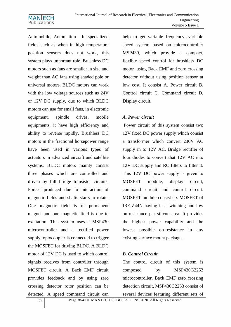
Automobile, Automation. In specialized
fields such as when in high temperature
position sensors does not work, this
system plays important role. Brushless DC
motors such as fans are smaller in size and
weight than AC fans using shaded pole or
universal motors. BLDC motors can work
with the low voltage sources such as 24V
or 12V DC supply, due to which BLDC
motors can use for small fans, in electronic
equipment, spindle drives, mobile
equipments, it have high efficiency and
ability to reverse rapidly. Brushless DC
motors in the fractional horsepower range
have been used in various types of
actuators in advanced aircraft and satellite
systems. BLDC motors mainly consist
three phases which are controlled and
driven by full bridge transistor circuits.
Forces produced due to interaction of
magnetic fields and shafts starts to rotate.
One magnetic field is of permanent
magnet and one magnetic field is due to
excitation. This system uses a MSP430
microcontroller and a rectified power
supply, optocoupler is connected to trigger
the MOSFET for driving BLDC. A BLDC
motor of 12V DC is used to which control
signals receives from controller through
MOSFET circuit. A Back EMF circuit
provides feedback and by using zero
crossing detector rotor position can be
detected. A speed command circuit can
help to get variable frequency, variable
speed system based on microcontroller
MSP430, which provide a compact,
flexible speed control for brushless DC
motor using Back EMF and zero crossing
detector without using position sensor at
low cost. It consist A. Power circuit B.
Control circuit C. Command circuit D.
Display circuit.
A. Power circuit
Power circuit of this system consist two
12V fixed DC power supply which consist
a transformer which convert 230V AC
supply in to 12V AC, Bridge rectifier of
four diodes to convert that 12V AC into
12V DC supply and RC filters to filter it.
This 12V DC power supply is given to
MOSFET module, display circuit,
command circuit and control circuit.
MOSFET module consist six MOSFET of
IRF Z44N having fast switching and low
on-resistance per silicon area. It provides
the highest power capability and the
lowest possible on-resistance in any
existing surface mount package.
B. Control Circuit
The control circuit of this system is
composed by MSP430G2253
microcontroller, Back EMF zero crossing
detection circuit, MSP430G2253 consist of
several devices featuring different sets of
40 Page 38-47 © MANTECH PUBLICATIONS 2020. All Rights Reserved
International Journal of Research in Electrical, Electronics and Communication
Engineering
Volume 5 Issue 1
peripherals targeted for various
applications. It contains 16 RISC CPU, 16
bit registers and constant generator,
digitally controlled oscillator(DCO),
which change microcontroller from low
power modes to active mode, 16 bit timers.
These microcontrollers have 24 I/O
capacitive touch enabled pins, a versatile
analog comparator and built in
communication capacity using the
universal serial communication interface,
10 bit analog to digital convertor. This
microcontroller works on 1.8V to 3.6V,
having ultra low power consumption.
Controller operates with its software
“Energia” which is based on c language.
Controlled Signals to 12V BLDC motor
getting from microcontroller. Controlled
Signals are in pulse width modulated form.
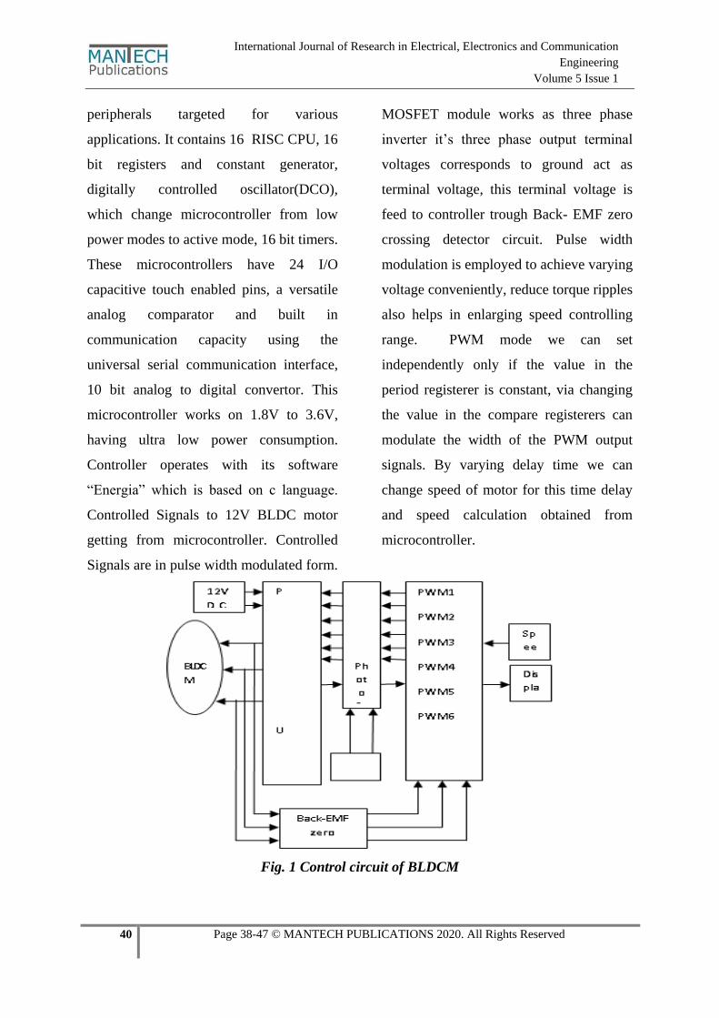
MOSFET module works as three phase
inverter it’s three phase output terminal
voltages corresponds to ground act as
terminal voltage, this terminal voltage is
feed to controller trough Back- EMF zero
crossing detector circuit. Pulse width
modulation is employed to achieve varying
voltage conveniently, reduce torque ripples
also helps in enlarging speed controlling
range. PWM mode we can set
independently only if the value in the
period registerer is constant, via changing
the value in the compare registerers can
modulate the width of the PWM output
signals. By varying delay time we can
change speed of motor for this time delay
and speed calculation obtained from
microcontroller.
Fig. 1 Control circuit of BLDCM

41 Page 38-47 © MANTECH PUBLICATIONS 2020. All Rights Reserved
International Journal of Research in Electrical, Electronics and Communication
Engineering
Volume 5 Issue 1
BI. Three Phase Inverter
The BLDC motor control consists of
generating DC currents in the motor
phases. This control is subdivided into two
independent operations: first, stator flux
synchronization, then control through the
three phase inverter in the following
scheme. The flux synchronization is
derived from sensorless techniques, that is
by back E.M.F. and zero crossing
detection the position of stator and rotor
identifies, from position of stator and rotor
the controller defines the appropriate pair
of transistors which must be driven.
BII. Design Control Strategy without
Position Sensor
MSP430 controller generates six
independent PWM signals through opto-
isolated signals acting on control terminals
of three phase inverter circuit. In three
phase inverter circuit phase shift of 120
degree are used to drive the BLDCM via
changing each phase output average
voltage amplitude, variable frequency and
variable speed of motor is attained.
The inverters three phase output terminal
voltages related to negative pole are sent to
three capture ports of MSP430 controller
through Back-EMF zero crossing detection
circuit. According to that six MOSFETS in
inverter circuit conduct PWM used for
inverter control. A terminal voltage varies
with control torque ripples. The inverters
three phase output terminal sent to
controller through Back EMF zero
crossing circuit.
There are only two phase conducting at
time, each phase winding continues
conduction for the full 120 degree angle
whether in negative or positive direction,
the Back-EMF in each phase stator
winding has two zero crossing points, each
leads its phase commutation instant 30
degree angle, so via detecting the Back-
EMF zero crossing point rotor and stator
position can identify and according to that,
three phase inverter generates motor
terminal voltage and according to that
motor operates.
This terminal voltages detect by zero
crossing detection point that can obtained
indirectly through dealing with the signals
and the conducting instants of the power
devices in the inverter are attained at the
same time.
42 Page 38-47 © MANTECH PUBLICATIONS 2020. All Rights Reserved
International Journal of Research in Electrical, Electronics and Communication
Engineering
Volume 5 Issue 1
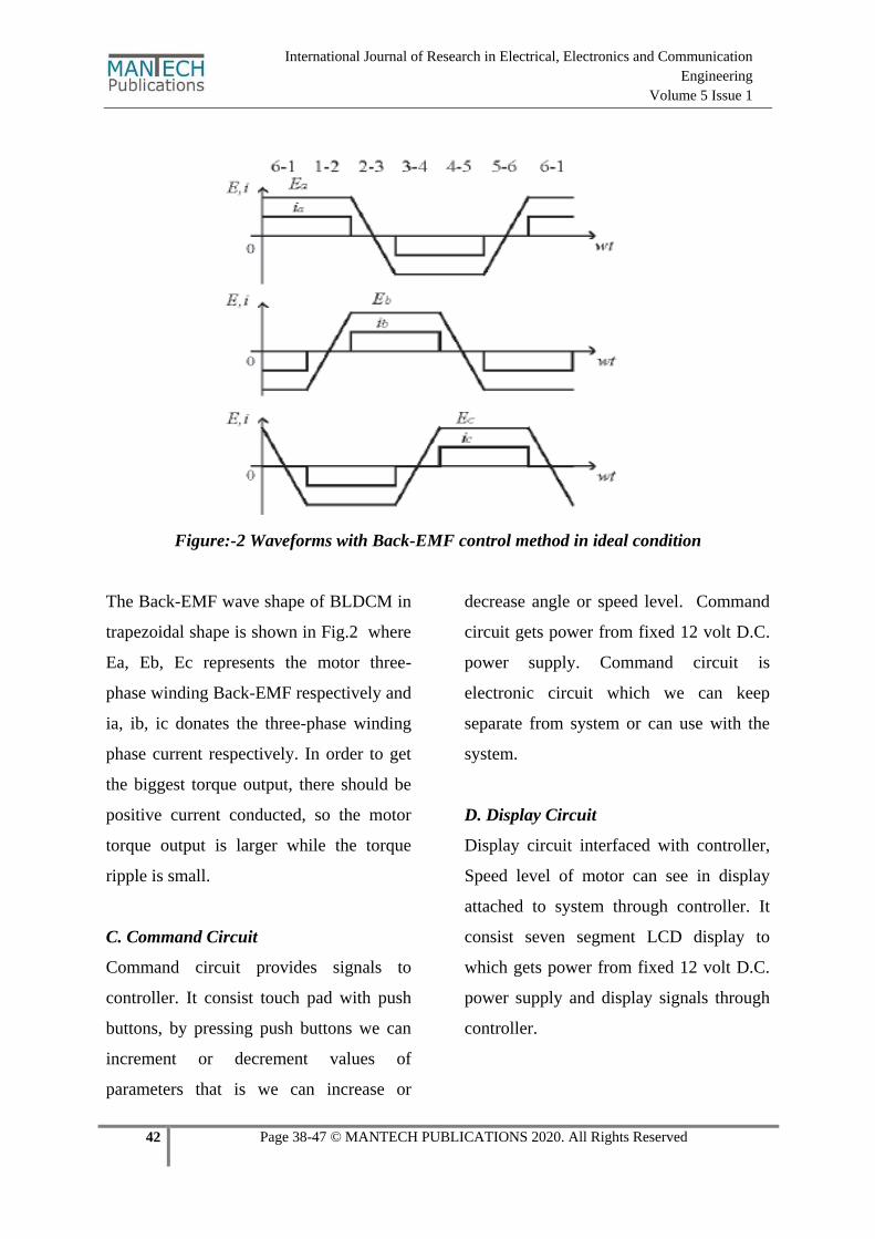
Figure:-2 Waveforms with Back-EMF control method in ideal condition
The Back-EMF wave shape of BLDCM in
trapezoidal shape is shown in Fig.2 where
Ea, Eb, Ec represents the motor three-
phase winding Back-EMF respectively and
ia, ib, ic donates the three-phase winding
phase current respectively. In order to get
the biggest torque output, there should be
positive current conducted, so the motor
torque output is larger while the torque
ripple is small.
C. Command Circuit
Command circuit provides signals to
controller. It consist touch pad with push
buttons, by pressing push buttons we can
increment or decrement values of
parameters that is we can increase or
decrease angle or speed level. Command
circuit gets power from fixed 12 volt D.C.
power supply. Command circuit is
electronic circuit which we can keep
separate from system or can use with the
system.
D. Display Circuit
Display circuit interfaced with controller,
Speed level of motor can see in display
attached to system through controller. It
consist seven segment LCD display to
which gets power from fixed 12 volt D.C.
power supply and display signals through
controller.
43 Page 38-47 © MANTECH PUBLICATIONS 2020. All Rights Reserved
International Journal of Research in Electrical, Electronics and Communication
Engineering
Volume 5 Issue 1
SOFTWARE DESIGN
The whole control system software is
composed by the main program and the
interrupt service subsystem, while the
main program is composed by system
initialize program, motor start program.
The A/D conversion to the speed
command is finished in the main program.
Capture interrupt subprogram and timer
compare interrupt service subprogram are
the main composed parts of the interrupt
service subprogram. The main function of
capture interrupt is to get three-phase
Back-EMF zero-crossing instants and read
the time interval between twice capture, so
to calculate timer internal corresponding to
the 30° angle. While the compare interrupt
of the timer is used to set commutation
instant and send value to the three compare
registers, the value is got from the
calculated pulse width corresponding to
speed command.
TIME DELAY AND ROTATE SPEED
CALCULATION
In the control system, time delay and
rotating speed calculation are both
obtained indirectly from the capture ports
of MSP430 microcontroller. The capture
port can be used to measure the time T
consumed by rotor for rotating 180° angle.
If divided by 6, the relating average time
to 30° angle can be obtained. The average
time is used as the time delay between the
lower half period zero-crossing point and
the related commutation point, then the
real speed of the motor can be calculated
from n = 30 / T.
MOTOR START SCHEME
Motor start scheme is important in this
speed control system of brushless DC
motor without Back-EMF and position
sensor because the Back-EMF is zero or
very little when the BLDCM operates at
static or lower speed state, it is useless to
estimate the rotor position at these times.
Therefore, Back-EMF scheme requires
special start technology. The usual way
employed is to accelerate the motor from
static state to sufficient speed using
separate-controlled motor, and then
converts to DC brushless operation mode.
In this mode contains three states, rotor
position dictated, accelerating and
switching stages. Rotor position dictated is
to give current to two of the three phases
while closing the other phase. Till the rotor
magnetic pole rotates to the direction of
stator integrated magnetic motive force,
then the rotor initial position can be
dictated. In accelerating stage, according
to motor rotating direction commutation
sequence, the corresponding winding is
conducted by control program to start the
motor. Switching process is that the open-
44 Page 38-47 © MANTECH PUBLICATIONS 2020. All Rights Reserved
International Journal of Research in Electrical, Electronics and Communication
Engineering
Volume 5 Issue 1
loop commutation process lasts after one
commutation period, the motor speed and
the amplitude of Back-EMF have achieved
some extent, and when the Back-EMF can
be measured via detecting circuit, program
can jump out of open-loop commutation
program and enters into the self-control
operation state controlled by Back-EMF
detecting signal.
RESULT
In proper condition, for proper inputs
motor runs properly and get good motor
speed control. Gives efficiency of 95% for
a 20 Watt input overall cost of the
hardware is less than other BLDC motor
control.
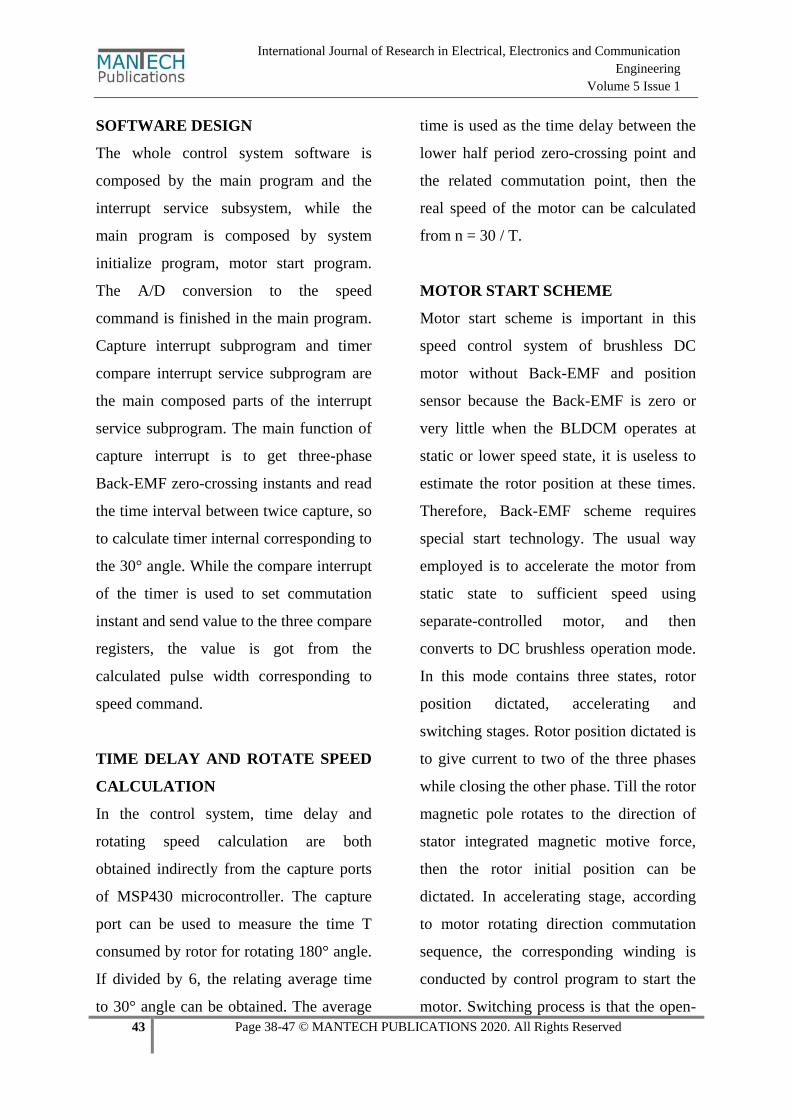
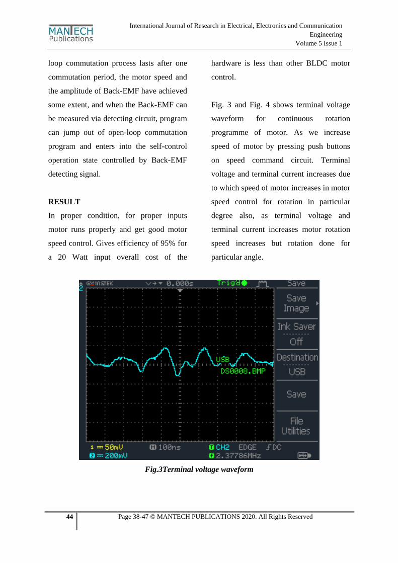
Fig. 3 and Fig. 4 shows terminal voltage
waveform for continuous rotation
programme of motor. As we increase
speed of motor by pressing push buttons
on speed command circuit. Terminal
voltage and terminal current increases due
to which speed of motor increases in motor
speed control for rotation in particular
degree also, as terminal voltage and
terminal current increases motor rotation
speed increases but rotation done for
particular angle.
Fig.3Terminal voltage waveform
45 Page 38-47 © MANTECH PUBLICATIONS 2020. All Rights Reserved
International Journal of Research in Electrical, Electronics and Communication
Engineering
Volume 5 Issue 1
Fig.4Terminal voltage waveform
SCOPE OF THE STUDY
Due to sensor less configuration system
can use in high temperature area. By
adding extra digital hardware we can
monitor motor current, voltage. By using
SCADA, we can control many motors at a
time. In future this system will help in
transportation field, for electric bikes and
cars. In automation and robotics this
system can help for fast and accurate
motors speed control.
OBJECTIVES OF STUDY
The main objective of this study is to
provide fast and accurate speed control
to permanent magnet D.C. motors.
To increase performance of BLDC
motors so that they can use for large
applications.
To reduce cost and make controlling of
BLDC motors flexible with more
simplicity.
CONCLUSIONS
This is variable speed, variable frequency
control system of non-position sensor
brushless DC Motor. This system is based
on intelligent power module and
microcontroller. Non-position sensor
configuration makes whole system
configuration compact and gives flexible
control capable of regulating speed
without observer. System failure chances
46 Page 38-47 © MANTECH PUBLICATIONS 2020. All Rights Reserved
International Journal of Research in Electrical, Electronics and Communication
Engineering
Volume 5 Issue 1
are less due to Non –position sensor
configuration.
REFERENCES
I. Huang Qingxin, Liang Hui, “DSP
Control System of Brushless DC
Motor without Position Sensor”
IEEE POWER ELECTR, 2007,
15(6), pp. 942-950.
II. Hanamoto T, Hara H, Tanaka Y,
"Sensor less control of BLDCM
applying the modified induced
voltage observer", ELECTR END
JPN, 1999, 129(2), pp. 87-89
III. M. Tawadros, J. Rizk, and M.
Nagrial, “Brushless DC Motor
control using PLC”, School of
Engineering, University of Western
Sydney (Australia) Locked Bag
1797 Penrith South DC NSW
1797.
IV. Electric drives for pump, fan, and
compressor loads in automotive
applications McCleer, P.J.,
Industrial Electronics, 1995. ISIE
’95, Proceedings of the IEEE
International symposium on,
Volume: 1, 10-14 Jul1995 Page(s):
80 -85 vol.1.
V. Jung DH, Ha IJ, "Low-cost sensor
less control of brushless DC
motors using a frequency-
independent phase shifter", IEEE
POWER ELECTR, 2000, 15(4),
pp. 744-752.
VI. Yedamale, P., 2005. AN970 Using
the PIC18F2431 for sensor less
BLDC Motor Control. Microchip.
VII. AN885 Brushless DC (BLDC)
Motor Fundamentals Microchip
Technology Inc. Manual.
VIII. AN905 Brushed DC Motor
Fundamentals Microchip
Technology Inc. manual
IX. Fully integrated BLDC motor
control ATMEL Application Note -
804.
X. Carreira. Chen H.C., Liaw C.M.,
"Sensor less Control via Intelligent
Commutation Tuning For
Brushless DC Motor”, Electric
Power Applications 1999, 146(6),
pp. 678-684.
XI. Tulin, Jiang ShanLin, Zou JiBin,
Zhang Hong Liang, Shang Jing, “A
Novel method of detecting for rotor
47 Page 38-47 © MANTECH PUBLICATIONS 2020. All Rights Reserved
International Journal of Research in Electrical, Electronics and Communication
Engineering
Volume 5 Issue 1
Position of a sensor less brushless
DC motor”, proceeding of
International Conference on
Electrical Machines and Systems,
pp. 797-800, Oct. 2007.
XII. Yeo H G, Hong C S, Yoo J Y.
Sensor less drive for permanent
magnet brushless DC motor.
XIII. IEEE International Electrical
Machine and Drives Conference
Record, 1997 TD1/3.1~TD1/3.3.
XIV. Ogasawara S, and Akagi H. “An
approach to position sensor less
drive for brushless DC motor”,
IEEE Transactions, 1991
XV. C. J. X. Shen, K. J. Tseng,
“Analyses and Compensation of
Rotor Position Detection Error in
Sensor less PM Brushless DC
Motor Drives”, IEEE Trans.
Energy Conversion, vol. 18, no. 1,
pp. 87-93, March 2003.
XVI. J. C. Moreira, “Indirect sensing for
rotor flux position of permanent
magnet AC motors operating over
a wide speed range”, IEEE Trans.
Industry Applications, vol. 32, no.
6, pp.1394-1401, Nov. 1996
XVII. XVI. D. H. Deitz, I. E. Hark, and
H. Gesund. Physical properties of
glass fiber reinforcedpolymer
rebars in compression. Journal of
Composites for Construction 7 (4):
363–366 (2003).
XVIII. Lubliner, J., Oliver, J., Oller, S.
and Onate, E. (1989). “A Plastic-
Damage Model for Concrete.”
InternationalJournal of Solids and
Structures, 25 (3), 229-326.
XIX. XVIII. Begum. M.,Robert G.
Driver.,Alaa E. Elwi., (2007)
Finite-Element Modeling of
PartiallyEncased
CompositeColumns Using the
Dynamic Explicit Method
Cite this Article as
Mahesh Dattatraya Bhambure (2020)
“Speed Control System for BLDC
motor without Position Sensor using
MSP430 Controller and back EMF
Method” International Journal of
Research in Electrical, Electronics and
Communication Engineering, 5 (1), 38- 47
http://doi.org/10.5281/zenodo.3766074
Copyright © 2022 FDOKUMEN