
A NEW PROPOSAL FOR POWER QUALITY AND CUSTOM POWER IMPROVEMENT OPEN UPQC
116
A NEW PROPOSAL FOR POWER QUALITY AND CUSTOM POWER IMPROVEMENT OPEN UPQC ABSTRACT Power quality (PQ) is very important to certain customers. For this reason, many utilities could sell electrical energy at different prices to their customers, depending on the quality of the delivered electric power. Since most end users are connected to secondary. Currently, the quality of supplied power is important to several customers. Power quality (PQ) is a service and many customers are ready to pay for it. In the future, distribution system operators could decide, or could be obliged by authorities, to supply their customers with different PQ levels and at different prices. A new device that can fulfill this role is the OPEN unified power quality conditioner (UPQC), composed of a power-electronic series main unit installed in the medium-voltage/low-voltage (LV) substation, along with several power-electronic shunt units connected close to the end users. The series and parallel units do not have a common dc link, so their control strategies are different than traditional UPQC control techniques. This device can achieve general improvement in PQ, reducing the most common disturbances for all customers that are supplied by the mains (PQ) by using only the series unit. Additional increments in PQ (i.e., mains power interruptions), can be provided to the customers who need it
-
Upload
independent -
Category
Documents
-
view
1 -
download
0
Transcript of A NEW PROPOSAL FOR POWER QUALITY AND CUSTOM POWER IMPROVEMENT OPEN UPQC

A NEW PROPOSAL FOR POWER QUALITY AND CUSTOM
POWER IMPROVEMENT OPEN UPQC
ABSTRACT
Power quality (PQ) is very important to certain customers.
For this reason, many utilities could sell electrical energy at
different prices to their customers, depending on the quality of
the delivered electric power. Since most end users are connected
to secondary. Currently, the quality of supplied power is
important to several customers. Power quality (PQ) is a service
and many customers are ready to pay for it. In the future,
distribution system operators could decide, or could be obliged
by authorities, to supply their customers with different PQ
levels and at different prices. A new device that can fulfill
this role is the OPEN unified power quality conditioner (UPQC),
composed of a power-electronic series main unit installed in the
medium-voltage/low-voltage (LV) substation, along with several
power-electronic shunt units connected close to the end users.
The series and parallel units do not have a common dc link,
so their control strategies are different than traditional UPQC
control techniques. This device can achieve general improvement
in PQ, reducing the most common disturbances for all customers
that are supplied by the mains (PQ) by using only the series
unit. Additional increments in PQ (i.e., mains power
interruptions), can be provided to the customers who need it
(custom power) by the shunt units. Therefore, this new solution
combines an improvement in PQ for all end users, with a cost
reduction for those that need high quality power. The proposed
solution has been analyzed and described, and a model of a 400-
kVA LV grid is considered a test network to evaluate the steady-
state performance and functioning limits. The results obtained
under steady-state conditions justify the configuration chosen
and good device performance.
The OPEN UPQC apparatus is a good compensation system if
wide installation of shunt units is needed. An increase in the
percentage of the protected load enhances the voltage
stabilization interval over which the OPEN UPQC can significantly
improve the power quality, especially if the load power factor
takes a high value.
If the power factor of load is less than one, the power
factor in section increases, to avoid nonnative power absorption
from the mains. For low values of the parameter, the OPEN UPQC
becomes expensive if there are few shunt units. In this case, it
is better to install other compensation device typologies (as
UPS, UPQC, etc.) near the sensitive loads, and a non active
compensator system near the nonsensitive loads if necessary. It
is possible to conclude that installation of the series unit is a
cost-effective way for distributors to improve the power quality
level in the distribution networks in order to achieve the
standards imposed by the authorities. Compensation improvement

for the sensitive end users can be achieved by installing a shunt
unit near them, instead of the more expensive UPS device. The
OPEN UPQC working conditions are reported.
I. INTRODUCTION

Power quality (PQ) is very important to certain customers.
For this reason, many utilities could sell electrical energy at
different prices to their customers, depending on the quality of
the delivered electric power. Since most end users are connected
to secondary distribution networks, at low voltage (LV), it could
be important to monitor and compensate the main disturbances on
the LV grid. Specifically, it has been reported in a survey that,
in the Southeastern region of the U.S., most monitored industrial
customers and main end users did not suffer long outages. Rather,
they experienced numerous short duration voltage sags and
momentary interruptions. Therefore, local utility companies had
to re-configure their systems to keep their most important
customers on-line.
Fig. Chronology of voltage sags occurring in the Southeastern
states of the
U.S. on December 4 and 5, 2002.
Fig. shows the chronology of voltage sags occurring in the
Southeastern states of the U.S. on December 4 and 5, 2002. As can
be seen, most sags take place around the 10%–20% level. Various
solutions are available to compensate for these disturbances. One
solution involves increasing the short circuit level of the
distribution network, i.e., revamping all the LV distribution
cables or raising the power of the MV/LV substation transformer,
thus increasing the power quality for all end users. In this way,
an incoming disturbance from a load (i.e., harmonics) or from a
fault in a line is reduced at the point of common coupling (PCC).
Therefore, this solution effectively reduces the depth of the
voltage variations, but does not protect the loads against
transients and short interruptions.
A second solution that can compensate any kind of
disturbance, including interruptions, is installation of on-line,
off-line, line interactive and hybrid UPS systems. In all of
these cases, only the end users that decide to install them are
protected, while all of the other costumers do not receive any
improvement in PQ. Often, these solutions cannot be adopted by
the local utility companies or by the end users, because they are
too expensive relative to the increase in power quality that they
produce. However, many cheaper solutions are available. In
particular, several electronic devices have been developed,
studied and proposed to the international scientific community
with the goal of improving supplied power quality. Different
connection topologies (series or shunt types) are used to realize
these devices.

The series devices are connected upstream of the protected
lines, while the shunt devices are connected in parallel to the
sensitive loads. In general, both types of conditioning devices
increase the power quality level at the loads. Other studies have
been carried out to consider combinations of the previous single
apparatus solutions (as UPS, UPLC, UPQC, etc.). The unified power
quality conditioner (UPQC) compensator seems to be a particularly
promising power conditioner device. This apparatus is constituted
of a series and a shunt unit, with a common dc section through
which power can be exchanged. Its function is to improve the
quality levels of the current absorbed at the mains and the load
supply voltage.
However, these devices do not allow local distributors to
guarantee different quality demand levels to the final customers,
because they improve power quality for all the supplied end
users. The installation investments are also quite high relative
to the power quality level obtained. A solution that has similar
performances and advantages, but also makes cost reduction
possible, is the proposed OPEN UPQC. This new solution, analyzed
in, starts from the UPQC configuration, removes the common dc
connection and splits the shunt unit into several shunted
devices.
Therefore, the control strategy is different than the
traditional combined series and shunt converters, but the
improvements to load voltage and network current quality are
quite similar. Above all, the OPEN UPQC can stabilize load
voltage, increase the network power factor, leading to keep load
voltage and network current sinusoidal and balanced as well.
The series main unit is installed in the MV/LV substation.
In a grid connected configuration, it can stabilize load voltage
at the LV bus bar (PCC) as the series devices analyzed. The shunt
units do not affect the dynamic behavior of the series unit,
because their dynamic responses are very slow under these
operating conditions. The transient behavior of a single dynamic
voltage restorer) device was analyzed and simulated, and its
working limits were determined. In particular, the device
behavior in the presence of voltage sags (i.e. 10%–20%) is
described.
The several shunt units are connected near the end users
that need high power quality. If a storage system is present,
they can exchange active power and nonnative power with the
electrical system. Especially in a grid-connected configuration,
no active power can be exchanged with the mains in order to
enhance the series unit performance and extend its working
limits. Otherwise, the users can disconnect themselves when the
PCC voltage is out of the operating limits, and the load will be
supplied in back-up mode.
II. POWER SYSEM AND POWER QUALITY
POWER QUALITY
The contemporary container crane industry, like many other
industry segments, is often enamored by the bells and whistles,
colorful diagnostic displays, high speed performance, and levels
of automation that can be achieved. Although these features and
their indirectly related computer based enhancements are key
issues to an efficient terminal operation, we must not forget the
foundation upon which we are building. Power quality is the

mortar which bonds the foundation blocks. Power quality also
affects terminal operating economics, crane reliability, our
environment, and initial investment in power distribution systems
to support new crane installations.
To quote the utility company newsletter which accompanied
the last monthly issue of my home utility billing: ‘Using
electricity wisely is a good environmental and business practice
which saves you money, reduces emissions from generating plants,
and conserves our natural resources.’ As we are all aware,
container crane performance requirements continue to increase at
an astounding rate. Next generation container cranes, already in
the bidding process, will require average power demands of 1500
to 2000 kW – almost double the total average demand three years
ago. The rapid increase in power demand levels, an increase in
container crane population, SCR converter crane drive retrofits
and the large AC and DC drives needed to power and control these
cranes will increase awareness of the power quality issue in the
very near future.
POWER QUALITY PROBLEMS
For the purpose of this article, we shall define power
quality problems as: ‘Any power problem that results in failure
or misoperation of customer equipment, manifests itself as an
economic burden to the user, or produces negative impacts on the
environment.’
When applied to the container crane industry, the power
issues which degrade power quality include:
• Power Factor
• Harmonic Distortion
• Voltage Transients
• Voltage Sags or Dips
• Voltage Swells
The AC and DC variable speed drives utilized on board
container cranes are significant contributors to total harmonic
current and voltage distortion. Whereas SCR phase control creates
the desirable average power factor, DC SCR drives operate at less
than this. In addition, line notching occurs when SCR’s
commutate, creating transient peak recovery voltages that can be
3 to 4 times the nominal line voltage depending upon the system
impedance and the size of the drives. The frequency and severity
of these power system disturbances varies with the speed of the
drive. Harmonic current injection by AC and DC drives will be
highest when the drives are operating at slow speeds. Power
factor will be lowest when DC drives are operating at slow speeds
or during initial acceleration and deceleration periods,
increasing to its maximum value when the SCR’s are phased on to
produce rated or base speed.

Above base speed, the power factor essentially remains
constant. Unfortunately, container cranes can spend considerable
time at low speeds as the operator attempts to spot and land
containers. Poor power factor places a greater kVA demand burden
on the utility or engine-alternator power source. Low power
factor loads can also affect the voltage stability which can
ultimately result in detrimental effects on the
life of sensitive electronic equipment or even intermittent
malfunction. Voltage transients created by DC drive SCR line
notching, AC drive voltage chopping, and high frequency harmonic
voltages and currents are all significant sources of noise and
disturbance to sensitive electronic equipment
It has been our experience that end users often do not
associate power quality problems with Container cranes, either
because they are totally unaware of such issues or there was no
economic Consequence if power quality was not addressed. Before
the advent of solid-state power supplies, Power factor was
reasonable, and harmonic current injection was minimal.
Not until the crane Population multiplied, power demands
per crane increased, and static power conversion became the way
of life, did power quality issues begin to emerge. Even as
harmonic distortion and power Factor issues surfaced, no one was
really prepared. Even today, crane builders and electrical drive
System vendors avoid the issue during competitive bidding for new
cranes. Rather than focus on Awareness and understanding of the
potential issues, the power quality issue is intentionally or
unintentionally ignored. Power quality problem solutions are
available. Although the solutions are not free, in most cases,
they do represent a good return on investment. However, if power
quality is not specified, it most likely will not be delivered.
Power quality can be improved through:
• Power factor correction,
• Harmonic filtering,
• Special line notch filtering,
• Transient voltage surge suppression,
• Proper earthing systems.
In most cases, the person specifying and/or buying a
container crane may not be fully aware of the potential power
quality issues. If this article accomplishes nothing else, we
would hope to provide that awareness.
In many cases, those involved with specification and
procurement of container cranes may not be cognizant of such
issues, do not pay the utility billings, or consider it someone
else’s concern. As a result, container crane specifications may
not include definitive power quality criteria such as power
factor correction and/or harmonic filtering. Also, many of those
specifications which do require power quality equipment do not
properly define the criteria. Early in the process of preparing
the crane specification:
• Consult with the utility company to determine regulatory
or contract requirements that must be satisfied, if any.
• Consult with the electrical drive suppliers and determine
the power quality profiles that can be expected based on the
drive sizes and technologies proposed for the specific project.
• Evaluate the economics of power quality correction not
only on the present situation, but consider the impact of future
utility deregulation and the future development plans for the
terminal.
THE BENEFITS OF POWER QUALITY
Power quality in the container terminal environment impacts
the economics of the terminal operation, affects reliability of
the terminal equipment, and affects other consumers served by the
same utility service. Each of these concerns is explored in the
following paragraphs.
1. ECONOMIC IMPACT
The economic impact of power quality is the foremost
incentive to container terminal operators. Economic impact can be
significant and manifest itself in several ways:
A. POWER FACTOR PENALTIES
Many utility companies invoke penalties for low power factor
on monthly billings. There is no industry standard followed by
utility companies. Methods of metering and calculating power
factor penalties vary from one utility company to the next. Some
utility companies actually meter kVAR usage and establish a fixed
rate times the number of kVAR-hours consumed. Other utility
companies monitor kVAR demands and calculate power factor. If the
power factor falls below a fixed limit value over a demand
period, a penalty is billed in the form of an adjustment to the
peak demand charges. A number of utility companies servicing
container terminal equipment do not yet invoke power factor
penalties.
However, their service contract with the Port may still
require that a minimum power factor over a defined demand period
be met. The utility company may not continuously monitor power
factor or kVAR usage and reflect them in the monthly utility
billings; however, they do reserve the right to monitor the Port
service at any time. If the power factor criteria set forth in
the service contract are not met, the user may be penalized, or
required to take corrective actions at the user’s expense.
One utility company, which supplies power service to several
east coast container terminals in the USA, does not reflect power
factor penalties in their monthly billings, however, their
service contract with the terminal reads as follows:
‘The average power factor under operating conditions of
customer’s load at the point where service is metered shall be
not less than 85%. If below 85%, the customer may be required to
furnish, install and maintain at its expense corrective apparatus
which will increase the Power factor of the entire installation
to not less than 85%. The customer shall ensure that no excessive
harmonics or transients are introduced on to the [utility]
system. This may require special power conditioning equipment or
filters.
The Port or terminal operations personnel, who are
responsible for maintaining container cranes, or specifying new
container crane equipment, should be aware of these requirements.
Utility deregulation will most likely force utilities to enforce
requirements such as the example above.
Terminal operators who do not deal with penalty issues today
may be faced with some rather severe penalties in the future. A
sound, future terminal growth plan should include contingencies
for addressing the possible economic impact of utility
deregulation.
B. SYSTEM LOSSES
Harmonic currents and low power factor created by nonlinear
loads, not only result in possible power factor penalties, but
also increase the power losses in the distribution system. These
losses are not visible as a separate item on your monthly utility
billing, but you pay for them each month.
Container cranes are significant contributors to harmonic
currents and low power factor. Based on the typical demands of
today’s high speed container cranes, correction of power factor
alone on a typical state of the art quay crane can result in a

reduction of system losses that converts to a 6 to 10% reduction
in the monthly utility billing. For most of the larger terminals,
this is a significant annual saving in the cost of operation.
C. POWER SERVICE INITIAL CAPITAL INVESTMENTS
The power distribution system design and installation for
new terminals, as well as modification of systems for terminal
capacity upgrades, involves high cost, specialized, high and
medium voltage equipment. Transformers, switchgear, feeder
cables, cable reel trailing cables, collector bars, etc. must be
sized based on the kVA demand. Thus cost of the equipment is
directly related to the total kVA demand.
As the relationship above indicates, kVA demand is inversely
proportional to the overall power factor, i.e. a lower power
factor demands higher kVA for the same kW load. Container cranes
are one of the most significant users of power in the terminal.
Since container cranes with DC, 6 pulse, SCR drives operate at
relatively low power factor, the total kVA demand is
significantly larger than would be the case if power factor
correction equipment were supplied on board each crane or at some
common bus location in the terminal. In the absence of power
quality corrective equipment, transformers are larger, switchgear
current ratings must be higher, feeder cable copper sizes are
larger, collector system and cable reel cables must be larger,
etc. Consequently, the cost of the initial power distribution
system equipment for a system which does not address power
quality will most likely be higher than the same system which
includes power quality equipment.
2. EQUIPMENT RELIABILITY
Poor power quality can affect machine or equipment
reliability and reduce the life of components. Harmonics, voltage
transients, and voltage system sags and swells are all power
quality problems and are all interdependent. Harmonics affect
power factor, voltage transients can induce harmonics, the same
phenomena which create harmonic current injection in DC SCR
variable speed drives are responsible for poor power factor, and
dynamically varying power factor of the same drives can create
voltage sags and swells. The effects of harmonic distortion,
harmonic currents, and line notch ringing can be mitigated using
specially designed filters.
3. POWER SYSTEM ADEQUACY
When considering the installation of additional cranes to an
existing power distribution system, a power system analysis
should be completed to determine the adequacy of the system to
support additional crane loads.
Power quality corrective actions may be dictated due to
inadequacy of existing power distribution systems to which new or
relocated cranes are to be connected. In other words, addition of

power quality equipment may render a workable scenario on an
existing power distribution system, which would otherwise be
inadequate to support additional cranes without high risk of
problems.
4. ENVIRONMENT
No issue might be as important as the effect of power
quality on our environment. Reduction in system losses and lower
demands equate to a reduction in the consumption of our natural
nm resources and reduction in power plant emissions. It is our
responsibility as occupants of this planet to encourage
conservation of our natural resources and support measures which
improve our air quality.

FACTS
Flexible AC Transmission Systems, called FACTS, got in the
recent years a well known term for higher controllability in
power systems by means of power electronic devices. Several
FACTS-devices have been introduced for various applications
worldwide. A number of new types of devices are in the stage of
being introduced in practice.
In most of the applications the controllability is used to
avoid cost intensive or landscape requiring extensions of power
systems, for instance like upgrades or additions of substations
and power lines. FACTS-devices provide a better adaptation to
varying operational conditions and improve the usage of existing
installations. The basic applications of FACTS-devices are:
• Power flow control,
• Increase of transmission capability,
• Voltage control,
• Reactive power compensation,
• Stability improvement,
• Power quality improvement,
• Power conditioning,
• Flicker mitigation,
• Interconnection of renewable and distributed generation
and storages.
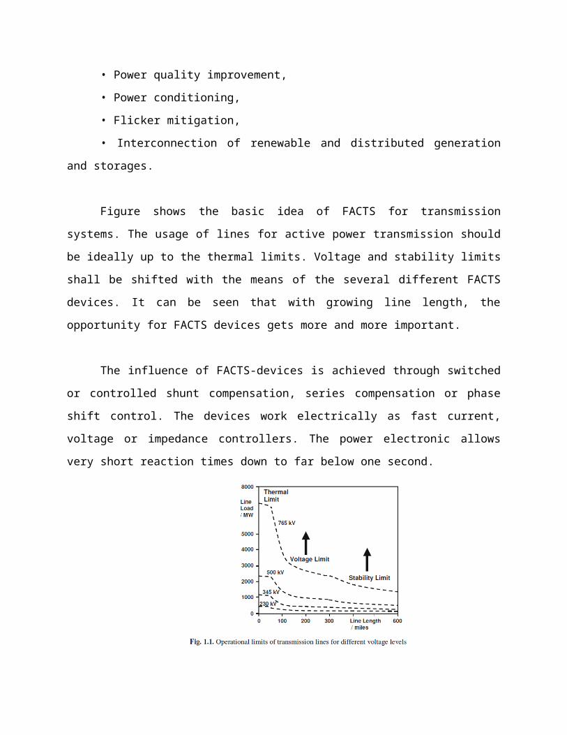
Figure shows the basic idea of FACTS for transmission
systems. The usage of lines for active power transmission should
be ideally up to the thermal limits. Voltage and stability limits
shall be shifted with the means of the several different FACTS
devices. It can be seen that with growing line length, the
opportunity for FACTS devices gets more and more important.
The influence of FACTS-devices is achieved through switched
or controlled shunt compensation, series compensation or phase
shift control. The devices work electrically as fast current,
voltage or impedance controllers. The power electronic allows
very short reaction times down to far below one second.
The development of FACTS-devices has started with the
growing capabilities of power electronic components. Devices for
high power levels have been made available in converters for high
and even highest voltage levels. The overall starting points are
network elements influencing the reactive power or the impedance
of a part of the power system. Figure 1.2 shows a number of basic
devices separated into the conventional ones and the FACTS-
devices.
For the FACTS side the taxonomy in terms of 'dynamic' and
'static' needs some explanation. The term 'dynamic' is used to
express the fast controllability of FACTS-devices provided by the
power electronics. This is one of the main differentiation
factors from the conventional devices. The term 'static' means
that the devices have no moving parts like mechanical switches to
perform the dynamic controllability. Therefore most of the FACTS-
devices can equally be static and dynamic.
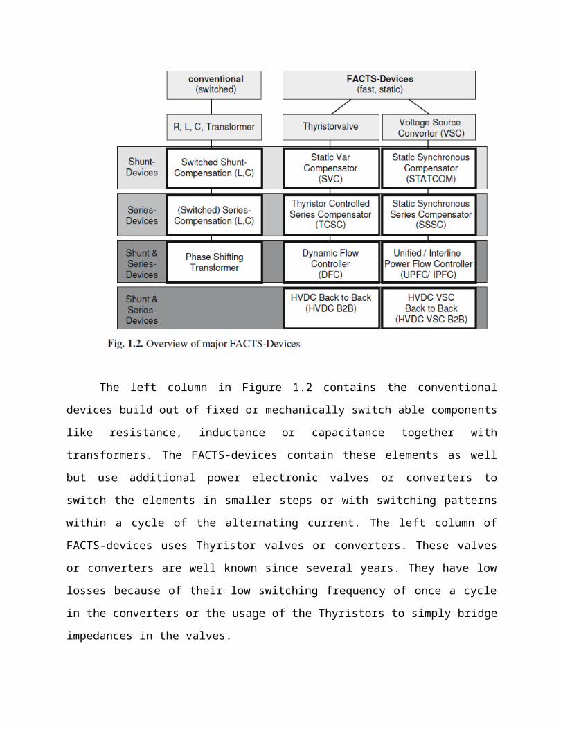
The left column in Figure 1.2 contains the conventional
devices build out of fixed or mechanically switch able components
like resistance, inductance or capacitance together with
transformers. The FACTS-devices contain these elements as well
but use additional power electronic valves or converters to
switch the elements in smaller steps or with switching patterns
within a cycle of the alternating current. The left column of
FACTS-devices uses Thyristor valves or converters. These valves
or converters are well known since several years. They have low
losses because of their low switching frequency of once a cycle
in the converters or the usage of the Thyristors to simply bridge
impedances in the valves.
The right column of FACTS-devices contains more advanced
technology of voltage source converters based today mainly on
Insulated Gate Bipolar Transistors (IGBT) or Insulated Gate
Commutated Thyristors (IGCT). Voltage Source Converters provide a
free controllable voltage in magnitude and phase due to a pulse
width modulation of the IGBTs or IGCTs. High modulation
frequencies allow to get low harmonics in the output signal and
even to compensate disturbances coming from the network.
The disadvantage is that with an increasing switching
frequency, the losses are increasing as well. Therefore special
designs of the converters are required to compensate this.
CONFIGURATIONS OF FACTS-DEVICES:
SHUNT DEVICES:
The most used FACTS-device is the SVC or the version with
Voltage Source Converter called STATCOM. These shunt devices are
operating as reactive power compensators. The main applications
in transmission, distribution and industrial networks are:
• Reduction of unwanted reactive power flows and therefore
reduced network losses.
• Keeping of contractual power exchanges with balanced reactive
power.
• Compensation of consumers and improvement of power quality
especially with huge demand fluctuations like industrial
machines, metal melting plants, railway or underground train
systems.
• Compensation of Thyristor converters e.g. in conventional HVDC
lines.
• Improvement of static or transient stability.
Almost half of the SVC and more than half of the STATCOMs
are used for industrial applications. Industry as well as
commercial and domestic groups of users require power quality.
Flickering lamps are no longer accepted, nor are interruptions of
industrial processes due to insufficient power quality. Railway
or underground systems with huge load variations require SVCs or
STATCOMs.
SVC:
Electrical loads both generate and absorb reactive power.
Since the transmitted load varies considerably from one hour to
another, the reactive power balance in a grid varies as well. The
result can be unacceptable voltage amplitude variations or even a
voltage depression, at the extreme a voltage collapse.
A rapidly operating Static Var Compensator (SVC) can
continuously provide the reactive power required to control
dynamic voltage oscillations under various system conditions and
thereby improve the power system transmission and distribution
stability.
Applications of the SVC systems in transmission systems:
a. To increase active power transfer capacity and transient
stability margin
b. To damp power oscillations
c. To achieve effective voltage control
In addition, SVCs are also used
1. in transmission systems
a. To reduce temporary over voltages
b. To damp sub synchronous resonances
c. To damp power oscillations in interconnected power
systems
2. in traction systems
a. To balance loads
b. To improve power factor
c. To improve voltage regulation
3. In HVDC systems
a. To provide reactive power to ac–dc converters
4. In arc furnaces
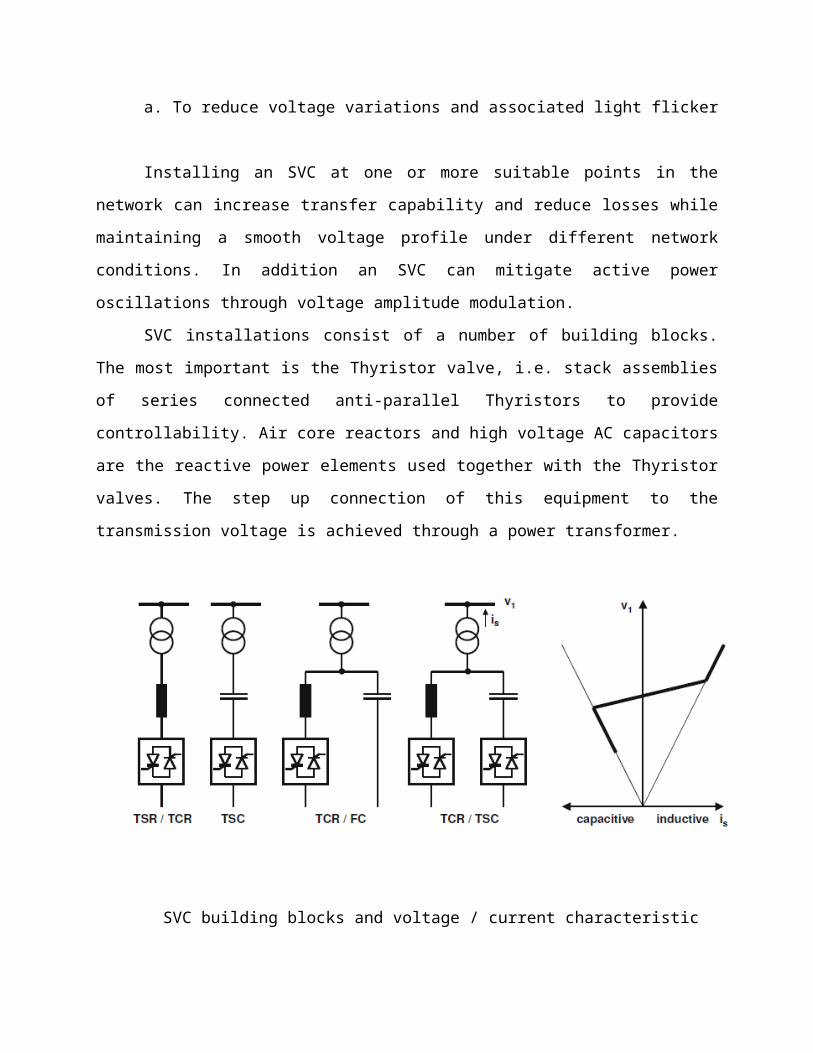
a. To reduce voltage variations and associated light flicker
Installing an SVC at one or more suitable points in the
network can increase transfer capability and reduce losses while
maintaining a smooth voltage profile under different network
conditions. In addition an SVC can mitigate active power
oscillations through voltage amplitude modulation.
SVC installations consist of a number of building blocks.
The most important is the Thyristor valve, i.e. stack assemblies
of series connected anti-parallel Thyristors to provide
controllability. Air core reactors and high voltage AC capacitors
are the reactive power elements used together with the Thyristor
valves. The step up connection of this equipment to the
transmission voltage is achieved through a power transformer.
SVC building blocks and voltage / current characteristic

In principle the SVC consists of Thyristor Switched
Capacitors (TSC) and Thyristor Switched or Controlled Reactors
(TSR / TCR). The coordinated control of a combination of these
branches varies the reactive power as shown in Figure. The first
commercial SVC was installed in 1972 for an electric arc furnace.
On transmission level the first SVC was used in 1979. Since then
it is widely used and the most accepted FACTS-device.
SVC
SVC USING A TCR AND AN FC:
In this arrangement, two or more FC (fixed capacitor) banks
are connected to a TCR (thyristor controlled reactor) through a
step-down transformer. The rating of the reactor is chosen larger
than the rating of the capacitor by an amount to provide the
maximum lagging vars that have to be absorbed from the system.
By changing the firing angle of the thyristor controlling
the reactor from 90° to 180°, the reactive power can be varied
over the entire range from maximum lagging vars to leading vars
that can be absorbed from the system by this compensator.
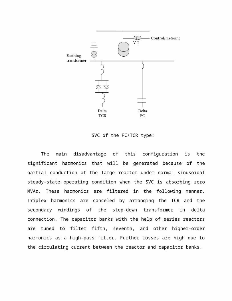
SVC of the FC/TCR type:
The main disadvantage of this configuration is the
significant harmonics that will be generated because of the
partial conduction of the large reactor under normal sinusoidal
steady-state operating condition when the SVC is absorbing zero
MVAr. These harmonics are filtered in the following manner.
Triplex harmonics are canceled by arranging the TCR and the
secondary windings of the step-down transformer in delta
connection. The capacitor banks with the help of series reactors
are tuned to filter fifth, seventh, and other higher-order
harmonics as a high-pass filter. Further losses are high due to
the circulating current between the reactor and capacitor banks.
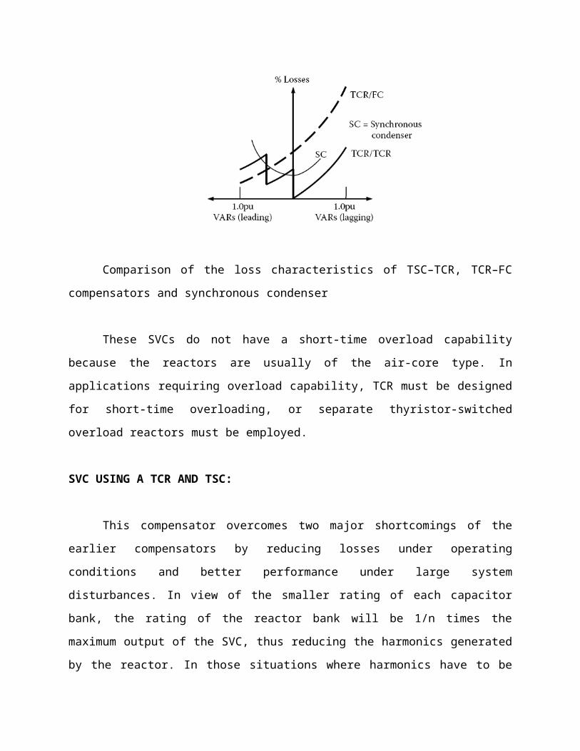
Comparison of the loss characteristics of TSC–TCR, TCR–FC
compensators and synchronous condenser
These SVCs do not have a short-time overload capability
because the reactors are usually of the air-core type. In
applications requiring overload capability, TCR must be designed
for short-time overloading, or separate thyristor-switched
overload reactors must be employed.
SVC USING A TCR AND TSC:
This compensator overcomes two major shortcomings of the
earlier compensators by reducing losses under operating
conditions and better performance under large system
disturbances. In view of the smaller rating of each capacitor
bank, the rating of the reactor bank will be 1/n times the
maximum output of the SVC, thus reducing the harmonics generated
by the reactor. In those situations where harmonics have to be

reduced further, a small amount of FCs tuned as filters may be
connected in parallel with the TCR.
SVC of combined TSC and TCR type
When large disturbances occur in a power system due to load
rejection, there is a possibility for large voltage transients
because of oscillatory interaction between system and the SVC
capacitor bank or the parallel. The LC circuit of the SVC in the
FC compensator. In the TSC–TCR scheme, due to the flexibility of
rapid switching of capacitor banks without appreciable
disturbance to the power system, oscillations can be avoided, and
hence the transients in the system can also be avoided. The
capital cost of this SVC is higher than that of the earlier one
due to the increased number of capacitor switches and increased
control complexity.
STATCOM:
In 1999 the first SVC with Voltage Source Converter called
STATCOM (STATic COMpensator) went into operation. The STATCOM has
a characteristic similar to the synchronous condenser, but as an
electronic device it has no inertia and is superior to the
synchronous condenser in several ways, such as better dynamics, a
lower investment cost and lower operating and maintenance costs.
A STATCOM is build with Thyristors with turn-off capability
like GTO or today IGCT or with more and more IGBTs. The static
line between the current limitations has a certain steepness
determining the control characteristic for the voltage.
The advantage of a STATCOM is that the reactive power
provision is independent from the actual voltage on the
connection point. This can be seen in the diagram for the maximum
currents being independent of the voltage in comparison to the
SVC. This means, that even during most severe contingencies, the
STATCOM keeps its full capability.
In the distributed energy sector the usage of Voltage Source
Converters for grid interconnection is common practice today. The
next step in STATCOM development is the combination with energy
storages on the DC-side. The performance for power quality and
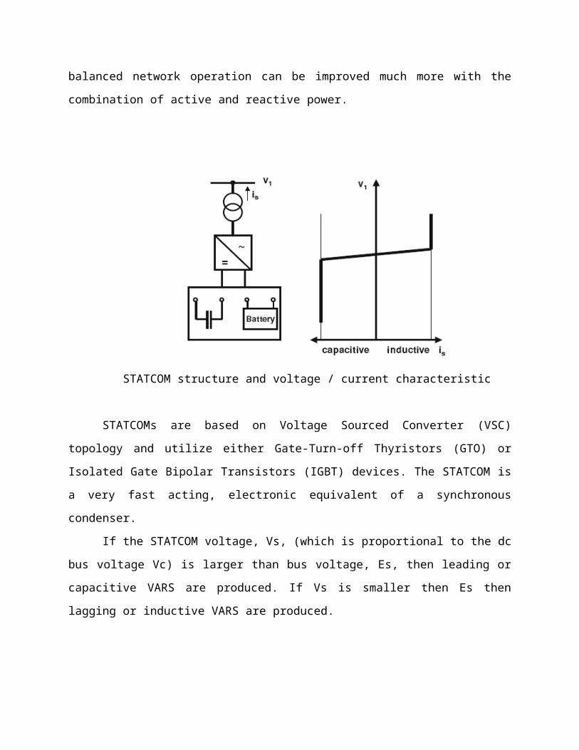
balanced network operation can be improved much more with the
combination of active and reactive power.
STATCOM structure and voltage / current characteristic
STATCOMs are based on Voltage Sourced Converter (VSC)
topology and utilize either Gate-Turn-off Thyristors (GTO) or
Isolated Gate Bipolar Transistors (IGBT) devices. The STATCOM is
a very fast acting, electronic equivalent of a synchronous
condenser.
If the STATCOM voltage, Vs, (which is proportional to the dc
bus voltage Vc) is larger than bus voltage, Es, then leading or
capacitive VARS are produced. If Vs is smaller then Es then
lagging or inductive VARS are produced.
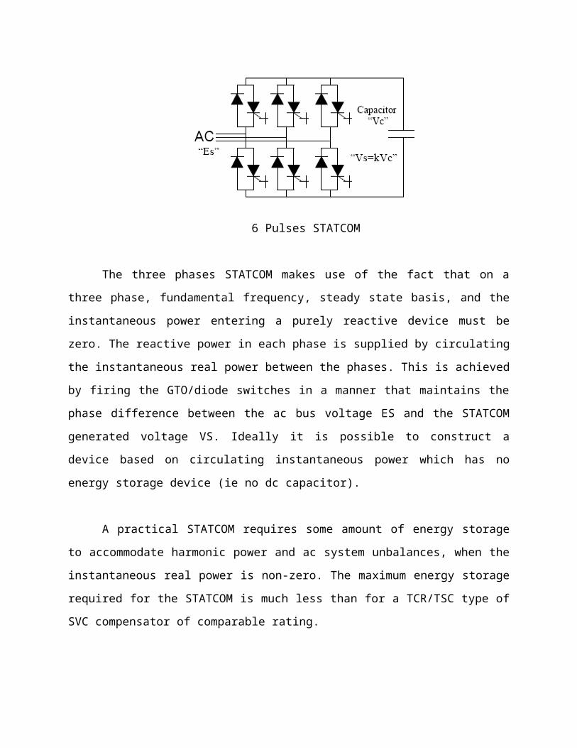
6 Pulses STATCOM
The three phases STATCOM makes use of the fact that on a
three phase, fundamental frequency, steady state basis, and the
instantaneous power entering a purely reactive device must be
zero. The reactive power in each phase is supplied by circulating
the instantaneous real power between the phases. This is achieved
by firing the GTO/diode switches in a manner that maintains the
phase difference between the ac bus voltage ES and the STATCOM
generated voltage VS. Ideally it is possible to construct a
device based on circulating instantaneous power which has no
energy storage device (ie no dc capacitor).
A practical STATCOM requires some amount of energy storage
to accommodate harmonic power and ac system unbalances, when the
instantaneous real power is non-zero. The maximum energy storage
required for the STATCOM is much less than for a TCR/TSC type of
SVC compensator of comparable rating.
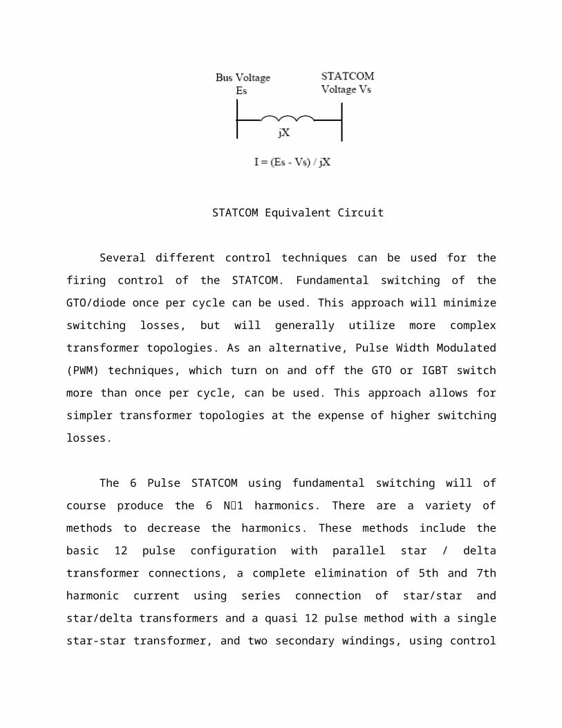
STATCOM Equivalent Circuit
Several different control techniques can be used for the
firing control of the STATCOM. Fundamental switching of the
GTO/diode once per cycle can be used. This approach will minimize
switching losses, but will generally utilize more complex
transformer topologies. As an alternative, Pulse Width Modulated
(PWM) techniques, which turn on and off the GTO or IGBT switch
more than once per cycle, can be used. This approach allows for
simpler transformer topologies at the expense of higher switching
losses.
The 6 Pulse STATCOM using fundamental switching will of
course produce the 6 N1 harmonics. There are a variety of
methods to decrease the harmonics. These methods include the
basic 12 pulse configuration with parallel star / delta
transformer connections, a complete elimination of 5th and 7th
harmonic current using series connection of star/star and
star/delta transformers and a quasi 12 pulse method with a single
star-star transformer, and two secondary windings, using control
of firing angle to produce a 30phase shift between the two 6
pulse bridges.
This method can be extended to produce a 24 pulse and a 48
pulse STATCOM, thus eliminating harmonics even further. Another
possible approach for harmonic cancellation is a multi-level
configuration which allows for more than one switching element
per level and therefore more than one switching in each bridge
arm. The ac voltage derived has a staircase effect, dependent on
the number of levels. This staircase voltage can be controlled to
eliminate harmonics.
SERIES DEVICES:
Series devices have been further developed from fixed or
mechanically switched compensations to the Thyristor Controlled
Series Compensation (TCSC) or even Voltage Source Converter based
devices.
The main applications are:
• Reduction of series voltage decline in magnitude and angle
over a power line,
• Reduction of voltage fluctuations within defined limits
during changing power transmissions,
• Improvement of system damping resp. damping of
oscillations,
• Limitation of short circuit currents in networks or
substations,
• Avoidance of loop flows resp. power flow adjustments.
TCSC:
Thyristor Controlled Series Capacitors (TCSC) address
specific dynamical problems in transmission systems. Firstly it
increases damping when large electrical systems are
interconnected. Secondly it can overcome the problem of Sub
Synchronous Resonance (SSR), a phenomenon that involves an
interaction between large thermal generating units and series
compensated transmission systems.
The TCSC's high speed switching capability provides a
mechanism for controlling line power flow, which permits
increased loading of existing transmission lines, and allows for
rapid readjustment of line power flow in response to various
contingencies. The TCSC also can regulate steady-state power flow
within its rating limits.
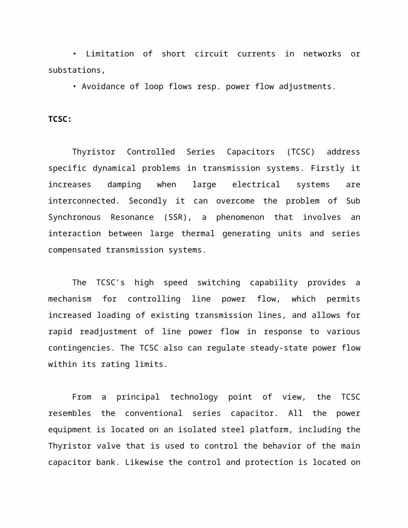
From a principal technology point of view, the TCSC
resembles the conventional series capacitor. All the power
equipment is located on an isolated steel platform, including the
Thyristor valve that is used to control the behavior of the main
capacitor bank. Likewise the control and protection is located on
ground potential together with other auxiliary systems. Figure
shows the principle setup of a TCSC and its operational diagram.
The firing angle and the thermal limits of the Thyristors
determine the boundaries of the operational diagram.
ADVANTAGES
Continuous control of desired compensation level
Direct smooth control of power flow within the network
Improved capacitor bank protection
Local mitigation of sub synchronous resonance (SSR). This
permits higher levels of compensation in networks where
interactions with turbine-generator torsional vibrations or
with other control or measuring systems are of concern.
Damping of electromechanical (0.5-2 Hz) power oscillations
which often arise between areas in a large interconnected
power network. These oscillations are due to the dynamics of
inter area power transfer and often exhibit poor damping
when the aggregate power tranfer over a corridor is high
relative to the transmission strength.
SHUNT AND SERIES DEVICES
DYNAMIC POWER FLOW CONTROLLER
A new device in the area of power flow control is the
Dynamic Power Flow Controller (DFC). The DFC is a hybrid device
between a Phase Shifting Transformer (PST) and switched series
compensation.
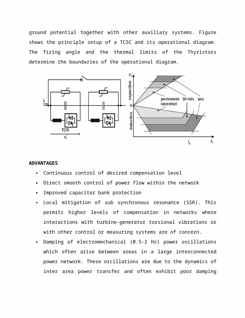
A functional single line diagram of the Dynamic Flow
Controller is shown in Figure 1.19. The Dynamic Flow Controller
consists of the following components:
• a standard phase shifting transformer with tap-changer
(PST)
• series-connected Thyristor Switched Capacitors and
Reactors (TSC / TSR)
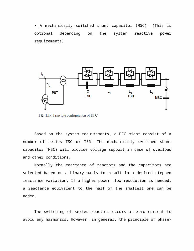
• A mechanically switched shunt capacitor (MSC). (This is
optional depending on the system reactive power
requirements)
Based on the system requirements, a DFC might consist of a
number of series TSC or TSR. The mechanically switched shunt
capacitor (MSC) will provide voltage support in case of overload
and other conditions.
Normally the reactance of reactors and the capacitors are
selected based on a binary basis to result in a desired stepped
reactance variation. If a higher power flow resolution is needed,
a reactance equivalent to the half of the smallest one can be
added.
The switching of series reactors occurs at zero current to
avoid any harmonics. However, in general, the principle of phase-
angle control used in TCSC can be applied for a continuous
control as well. The operation of a DFC is based on the following
rules:
• TSC / TSR are switched when a fast response is required.
• The relieve of overload and work in stressed situations is
handled by the TSC / TSR.
• The switching of the PST tap-changer should be minimized
particularly for the currents higher than normal loading.
• The total reactive power consumption of the device can be
optimized by the operation of the MSC, tap changer and the
switched capacities and reactors.
In order to visualize the steady state operating range of
the DFC, we assume an inductance in parallel representing
parallel transmission paths. The overall control objective in
steady state would be to control the distribution of power flow
between the branch with the DFC and the parallel path. This
control is accomplished by control of the injected series
voltage.
The PST (assuming a quadrature booster) will inject a
voltage in quadrature with the node voltage. The controllable
reactance will inject a voltage in quadrature with the throughput
current. Assuming that the power flow has a load factor close to
one, the two parts of the series voltage will be close to

collinear. However, in terms of speed of control, influence on
reactive power balance and effectiveness at high/low loading the
two parts of the series voltage has quite different
characteristics. The steady state control range for loadings up
to rated current is illustrated in Figure 1.20, where the x-axis
corresponds to the throughput current and the y-axis corresponds
to the injected series voltage.
Fig. Operational diagram of a DFC
Operation in the first and third quadrants corresponds to
reduction of power through the DFC, whereas operation in the
second and fourth quadrants corresponds to increasing the power
flow through the DFC. The slope of the line passing through the
origin (at which the tap is at zero and TSC / TSR are bypassed)
depends on the short circuit reactance of the PST.

Starting at rated current (2 kA) the short circuit reactance
by itself provides an injected voltage (approximately 20 kV in
this case). If more inductance is switched in and/or the tap is
increased, the series voltage increases and the current through
the DFC decreases (and the flow on parallel branches increases).
The operating point moves along lines parallel to the arrows in
the figure. The slope of these arrows depends on the size of the
parallel reactance. The maximum series voltage in the first
quadrant is obtained when all inductive steps are switched in and
the tap is at its maximum.
Now, assuming maximum tap and inductance, if the throughput
current decreases (due e.g. to changing loading of the system)
the series voltage will decrease. At zero current, it will not
matter whether the TSC / TSR steps are in or out, they will not
contribute to the series voltage.
Consequently, the series voltage at zero current corresponds
to rated PST series voltage. Next, moving into the second
quadrant, the operating range will be limited by the line
corresponding to maximum tap and the capacitive step being
switched in (and the inductive steps by-passed). In this case,
the capacitive step is approximately as large as the short
circuit reactance of the PST, giving an almost constant maximum
voltage in the second quadrant.
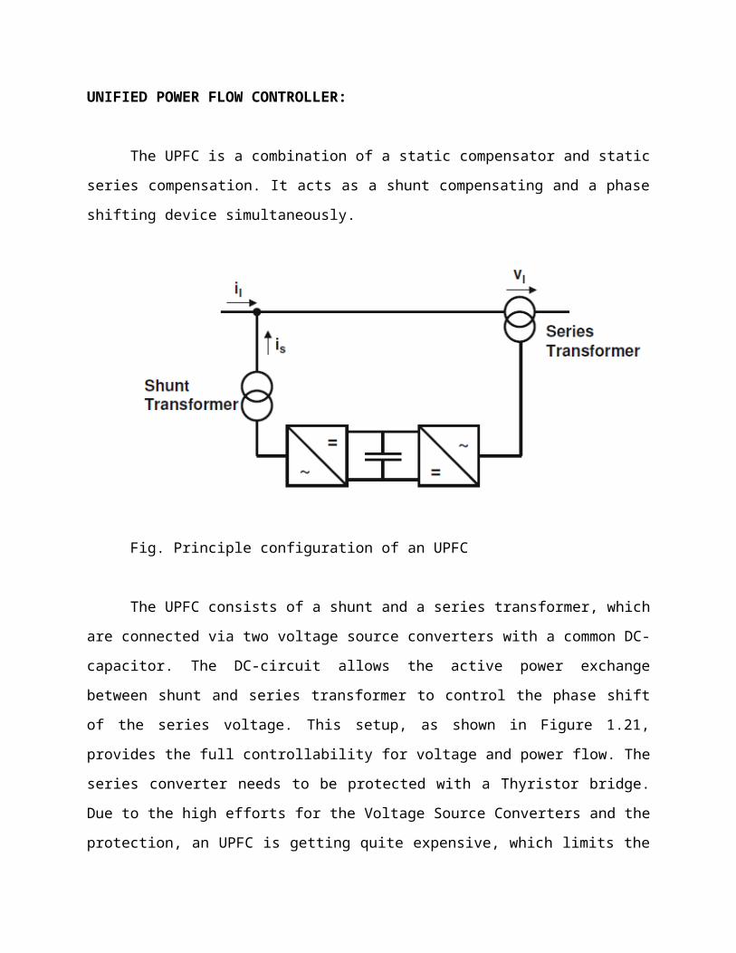
UNIFIED POWER FLOW CONTROLLER:
The UPFC is a combination of a static compensator and static
series compensation. It acts as a shunt compensating and a phase
shifting device simultaneously.
Fig. Principle configuration of an UPFC
The UPFC consists of a shunt and a series transformer, which
are connected via two voltage source converters with a common DC-
capacitor. The DC-circuit allows the active power exchange
between shunt and series transformer to control the phase shift
of the series voltage. This setup, as shown in Figure 1.21,
provides the full controllability for voltage and power flow. The
series converter needs to be protected with a Thyristor bridge.
Due to the high efforts for the Voltage Source Converters and the
protection, an UPFC is getting quite expensive, which limits the

practical applications where the voltage and power flow control
is required simultaneously.
OPERATING PRINCIPLE OF UPFC
The basic components of the UPFC are two voltage source
inverters (VSIs) sharing a common dc storage capacitor, and
connected to the power system through coupling transformers. One
VSI is connected to in shunt to the transmission system via a
shunt transformer, while the other one is connected in series
through a series transformer.
A basic UPFC functional scheme is shown in fig.1
The series inverter is controlled to inject a symmetrical
three phase voltage system (Vse), of controllable magnitude and
phase angle in series with the line to control active and
reactive power flows on the transmission line. So, this inverter
will exchange active and reactive power with the line. The
reactive power is electronically provided by the series inverter,
and the active power is transmitted to the dc terminals. The
shunt inverter is operated in such a way as to demand this dc
terminal power (positive or negative) from the line keeping the
voltage across the storage capacitor Vdc constant. So, the net
real power absorbed from the line by the UPFC is equal only to
the losses of the inverters and their transformers.
The remaining capacity of the shunt inverter can be used to
exchange reactive power with the line so to provide a voltage
regulation at the connection point.
The two VSI’s can work independently of each other by
separating the dc side. So in that case, the shunt inverter is
operating as a STATCOM that generates or absorbs reactive power
to regulate the voltage magnitude at the connection point.
Instead, the series inverter is operating as SSSC that generates
or absorbs reactive power to regulate the current flow, and hence
the power low on the transmission line.
The UPFC has many possible operating modes. In particular,
the shunt inverter is operating in such a way to inject a
controllable current, ish into the transmission line. The shunt
inverter can be controlled in two different modes:
VAR Control Mode: The reference input is an inductive or
capacitive VAR request. The shunt inverter control translates the
var reference into a corresponding shunt current request and
adjusts gating of the inverter to establish the desired current.
For this mode of control a feedback signal representing the dc
bus voltage, Vdc, is also required.
Automatic Voltage Control Mode: The shunt inverter reactive
current is automatically regulated to maintain the transmission
line voltage at the point of connection to a reference value. For
this mode of control, voltage feedback signals are obtained from
the sending end bus feeding the shunt coupling transformer.
The series inverter controls the magnitude and angle of the
voltage injected in series with the line to influence the power
flow on the line. The actual value of the injected voltage can be
obtained in several ways.
Direct Voltage Injection Mode: The reference inputs are
directly the magnitude and phase angle of the series voltage.
Phase Angle Shifter Emulation mode: The reference input is
phase displacement between the sending end voltage and the
receiving end voltage. Line Impedance Emulation mode: The
reference input is an impedance value to insert in series with
the line impedance
Automatic Power Flow Control Mode: The reference inputs are
values of P and Q to maintain on the transmission line despite
system changes.
ACTIVE POWER CONDITIONER
A power conditioner (also known as a line conditioner or
power line conditioner) is a device intended to improve the
quality of the power that is delivered to electrical load
equipment. While there is no official definition of a power
conditioner, the term most often refers to a device that acts in
one or more ways to deliver a voltage of the proper level and
characteristics to enable load equipment to function properly. In
some usages, power conditioner refers to a voltage regulator with
at least one other function to improve power quality (e.g. noise
suppression, transient impulse protection, etc.).
The terms "power conditioning" and "power conditioner" can
be misleading, as the word "power" refers to the electricity
generally rather than the more technical electric power.
Conditioners specifically work to smooth the voltage of the
electricity they supply.
Power conditioners can vary greatly in specific
functionality and size, with both parameters generally determined
by the application. Some power conditioners provide only minimal
voltage regulation while others provide protection from half a
dozen or more power quality problems, such as harmonics, reactive
power, power line flicker and resonance. Units may be small
enough to mount on a printed circuit board or large enough to
protect an entire factory. Small power conditioners are rated in
volt-amperes (V·A) while larger units are rated in kilovolt-
amperes (kV·A).
While no single power conditioner can correct all power
quality problems, many can correct a variety of them.
It is common to find audio power conditioners that only
include an electronic filter and a surge protector with no
voltage regulating capability
PULSE WIDTH MODULATION
Pulse Width Modulation (PWM) is the most effective means to
achieve constant voltage battery charging by switching the solar
system controller’s power devices. When in PWM regulation, the
current from the solar array tapers according to the battery’s

condition and recharging needs consider a waveform such as this:
it is a voltage switching between 0v and 12v. It is fairly
obvious that, since the voltage is at 12v for exactly as long as
it is at 0v, then a 'suitable device' connected to its output
will see the average voltage and think it is being fed 6v -
exactly half of 12v. So by varying the width of the positive
pulse - we can vary the 'average' voltage.
Similarly, if the switches keep the voltage at 12 for 3
times as long as at 0v, the average will be 3/4 of 12v - or 9v,
as shown below
and if the output pulse of 12v lasts only 25% of the overall
time, then the average is
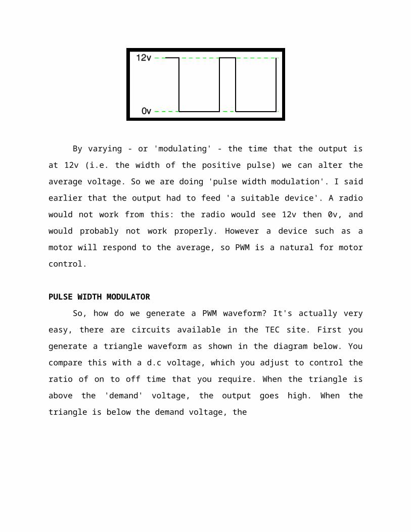
By varying - or 'modulating' - the time that the output is
at 12v (i.e. the width of the positive pulse) we can alter the
average voltage. So we are doing 'pulse width modulation'. I said
earlier that the output had to feed 'a suitable device'. A radio
would not work from this: the radio would see 12v then 0v, and
would probably not work properly. However a device such as a
motor will respond to the average, so PWM is a natural for motor
control.
PULSE WIDTH MODULATOR
So, how do we generate a PWM waveform? It's actually very
easy, there are circuits available in the TEC site. First you
generate a triangle waveform as shown in the diagram below. You
compare this with a d.c voltage, which you adjust to control the
ratio of on to off time that you require. When the triangle is
above the 'demand' voltage, the output goes high. When the
triangle is below the demand voltage, the

When the demand speed it in the middle (A) you get a 50:50
output, as in black. Half the time the output is high and half
the time it is low. Fortunately, there is an IC (Integrated
circuit) called a comparator: these come usually 4 sections in a
single package. One can be used as the oscillator to produce the
triangular waveform and another to do the comparing, so a
complete oscillator and modulator can be done with half an IC and
maybe 7 other bits.
The triangle waveform, which has approximately equal rise
and fall slopes, is one of the commonest used, but you can use a
saw tooth (where the voltage falls quickly and rinses slowly).
You could use other waveforms and the exact linearity (how good
the rise and fall are) is not too important.
Traditional solenoid driver electronics rely on linear
control, which is the application of a constant voltage across a
resistance to produce an output current that is directly
proportional to the voltage. Feedback can be used to achieve an
output that matches exactly the control signal. However, this
scheme dissipates a lot of power as heat, and it is therefore
very inefficient.
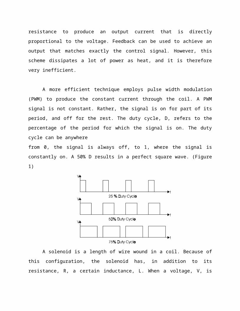
A more efficient technique employs pulse width modulation
(PWM) to produce the constant current through the coil. A PWM
signal is not constant. Rather, the signal is on for part of its
period, and off for the rest. The duty cycle, D, refers to the
percentage of the period for which the signal is on. The duty
cycle can be anywhere
from 0, the signal is always off, to 1, where the signal is
constantly on. A 50% D results in a perfect square wave. (Figure
1)
A solenoid is a length of wire wound in a coil. Because of
this configuration, the solenoid has, in addition to its
resistance, R, a certain inductance, L. When a voltage, V, is

applied across an inductive element, the current, I, produced in
that element does not jump up to its constant value, but
gradually rises to its maximum over a period of time called the
rise time (Figure 2). Conversely, I does not disappear
instantaneously, even if V is removed abruptly, but decreases
back to zero in the same amount of time as the rise time.
Therefore, when a low frequency PWM voltage is applied
across a solenoid, the current through it will be increasing and
decreasing as V turns on and off. If D is shorter than the rise
time, I will never achieve its maximum value, and will be
discontinuous since it will go back to zero during V’s off period
(Figure 3).* In contrast, if D is larger than the rise time, I
will never fall back to zero, so it will be continuous, and have
a DC average value. The current will not be constant, however,
but will have a ripple.
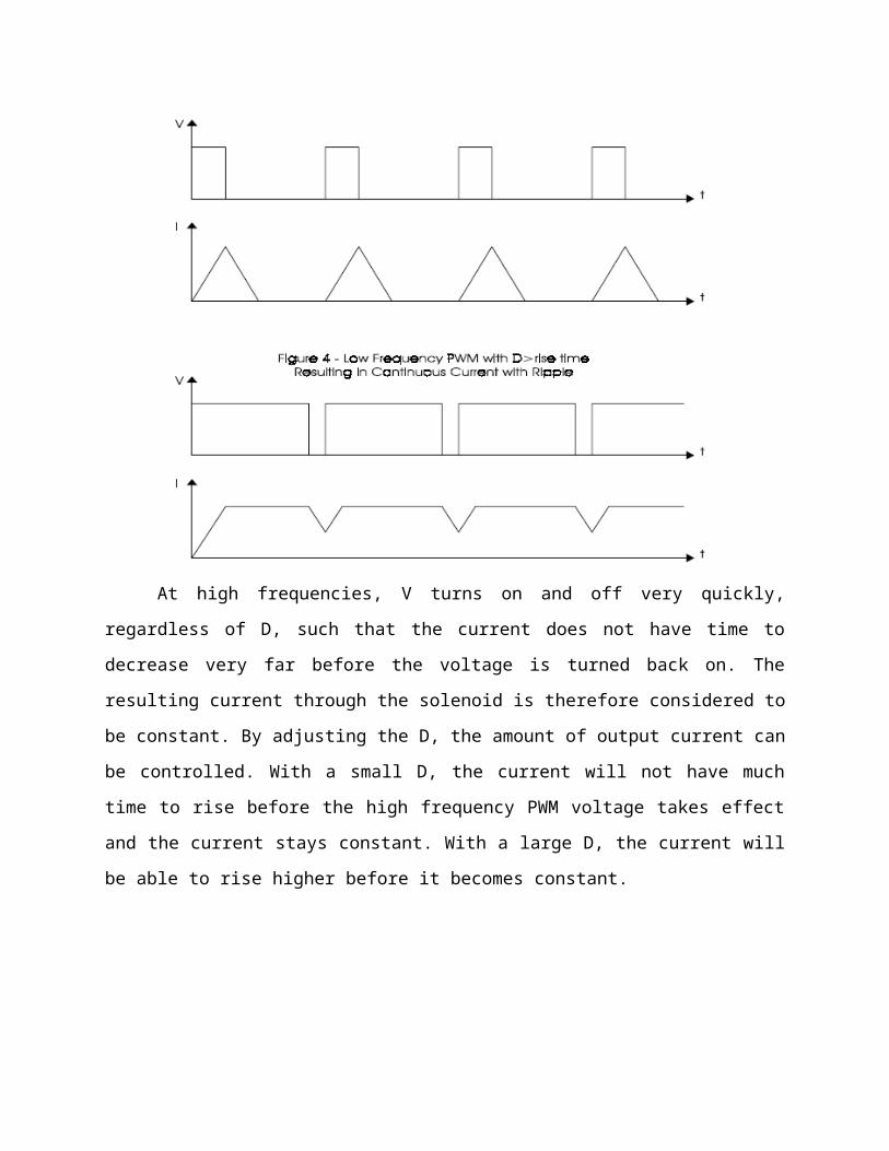
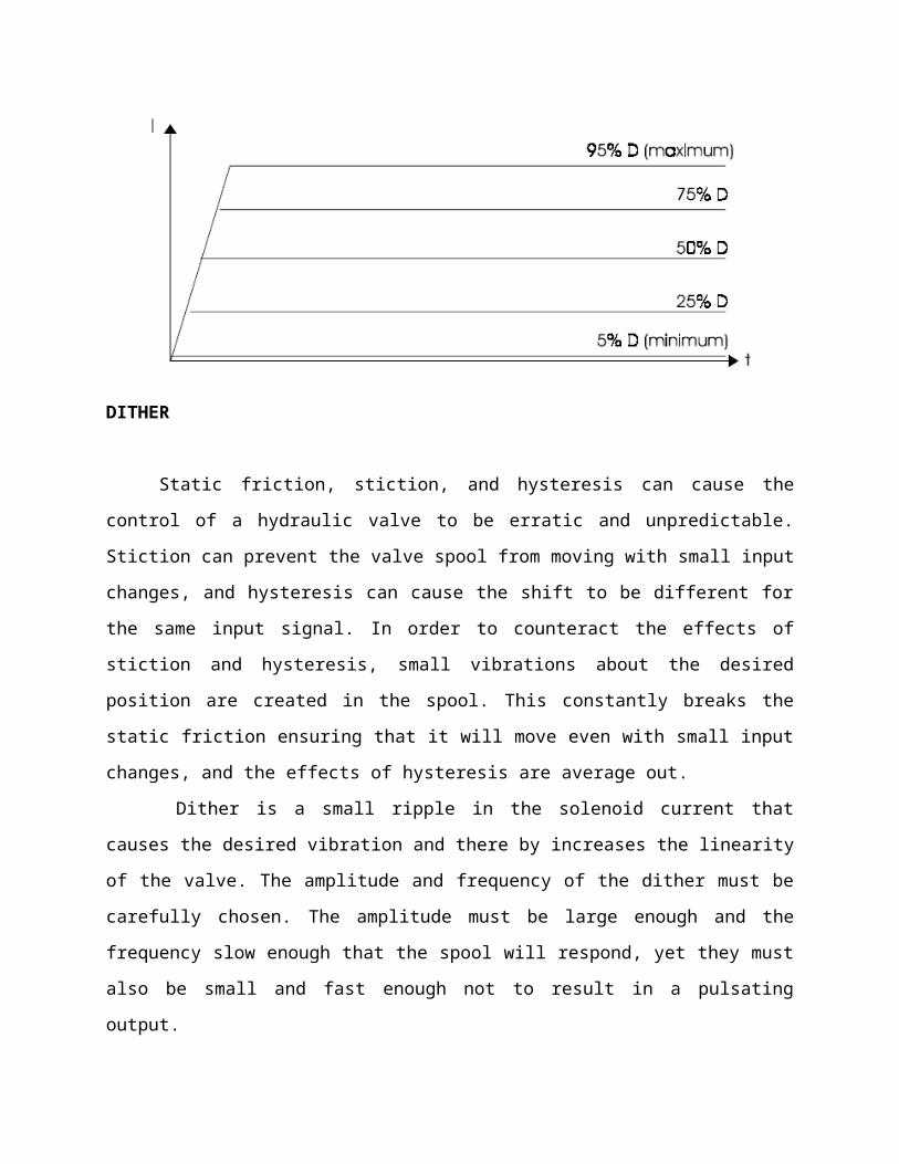
At high frequencies, V turns on and off very quickly,
regardless of D, such that the current does not have time to
decrease very far before the voltage is turned back on. The
resulting current through the solenoid is therefore considered to
be constant. By adjusting the D, the amount of output current can
be controlled. With a small D, the current will not have much
time to rise before the high frequency PWM voltage takes effect
and the current stays constant. With a large D, the current will
be able to rise higher before it becomes constant.
DITHER
Static friction, stiction, and hysteresis can cause the
control of a hydraulic valve to be erratic and unpredictable.
Stiction can prevent the valve spool from moving with small input
changes, and hysteresis can cause the shift to be different for
the same input signal. In order to counteract the effects of
stiction and hysteresis, small vibrations about the desired
position are created in the spool. This constantly breaks the
static friction ensuring that it will move even with small input
changes, and the effects of hysteresis are average out.
Dither is a small ripple in the solenoid current that
causes the desired vibration and there by increases the linearity
of the valve. The amplitude and frequency of the dither must be
carefully chosen. The amplitude must be large enough and the
frequency slow enough that the spool will respond, yet they must
also be small and fast enough not to result in a pulsating
output.
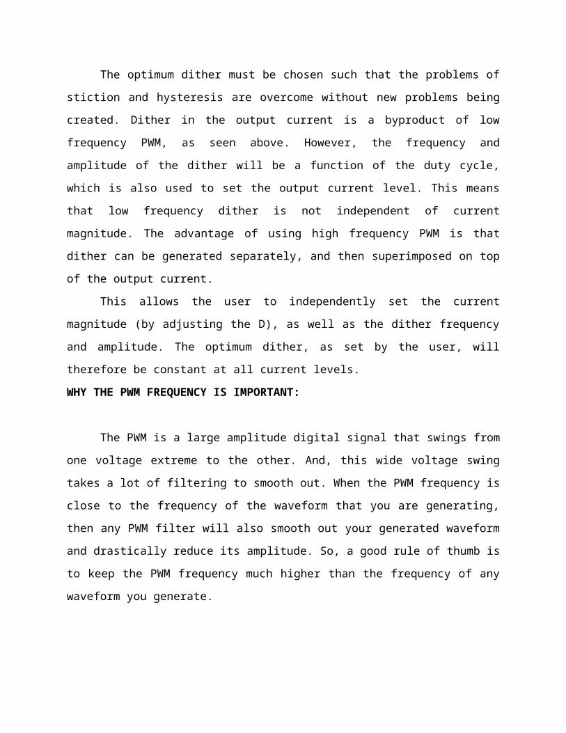
The optimum dither must be chosen such that the problems of
stiction and hysteresis are overcome without new problems being
created. Dither in the output current is a byproduct of low
frequency PWM, as seen above. However, the frequency and
amplitude of the dither will be a function of the duty cycle,
which is also used to set the output current level. This means
that low frequency dither is not independent of current
magnitude. The advantage of using high frequency PWM is that
dither can be generated separately, and then superimposed on top
of the output current.
This allows the user to independently set the current
magnitude (by adjusting the D), as well as the dither frequency
and amplitude. The optimum dither, as set by the user, will
therefore be constant at all current levels.
WHY THE PWM FREQUENCY IS IMPORTANT:
The PWM is a large amplitude digital signal that swings from
one voltage extreme to the other. And, this wide voltage swing
takes a lot of filtering to smooth out. When the PWM frequency is
close to the frequency of the waveform that you are generating,
then any PWM filter will also smooth out your generated waveform
and drastically reduce its amplitude. So, a good rule of thumb is
to keep the PWM frequency much higher than the frequency of any
waveform you generate.

Finally, filtering pulses is not just about the pulse
frequency but about the duty cycle and how much energy is in the
pulse. The same filter will do better on a low or high duty cycle
pulse compared to a 50% duty cycle pulse. Because the wider pulse
has more time to integrate to a stable filter voltage and the
smaller pulse has less time to disturb it the inspiration was a
request to control the speed of a large positive displacement
fuel pump. The pump was sized to allow full power of a boosted
engine in excess of 600 Hp.
At idle or highway cruise, this same engine needs far less
fuel yet the pump still normally supplies the same amount of
fuel. As a result the fuel gets recycled back to the fuel tank,
unnecessarily heating the fuel. This PWM controller circuit is
intended to run the pump at a low speed setting during low power
and allow full pump speed when needed at high engine power
levels.
MOTOR SPEED CONTROL (POWER CONTROL)
Typically when most of us think about controlling the speed
of a DC motor we think of varying the voltage to the motor. This
is normally done with a variable resistor and provides a limited
useful range of operation. The operational range is limited for
most applications primarily because torque drops off faster than
the voltage drops.
Most DC motors cannot effectively operate with a very low
voltage. This method also causes overheating of the coils and
eventual failure of the motor if operated too slowly. Of course,
DC motors have had speed controllers based on varying voltage for
years, but the range of low speed operation had to stay above the
failure zone described above.
Additionally, the controlling resistors are large and
dissipate a large percentage of energy in the form of heat. With
the advent of solid state electronics in the 1950’s and 1960’s
and this technology becoming very affordable in the 1970’s & 80’s
the use of pulse width modulation (PWM) became much more
practical. The basic concept is to keep the voltage at the full
value and simply vary the amount of time the voltage is applied
to the motor windings. Most PWM circuits use large transistors to
simply allow power On & Off, like a very fast switch.
This sends a steady frequency of pulses into the motor
windings. When full power is needed one pulse ends just as the
next pulse begins, 100% modulation. At lower power settings the
pulses are of shorter duration. When the pulse is On as long as
it is Off, the motor is operating at 50% modulation. Several
advantages of PWM are efficiency, wider operational range and
longer lived motors. All of these advantages result from keeping
the voltage at full scale resulting in current being limited to a
safe limit for the windings.
PWM allows a very linear response in motor torque even down
to low PWM% without causing damage to the motor. Most motor
manufacturers recommend PWM control rather than the older voltage
control method. PWM controllers can be operated at a wide range
of frequencies. In theory very high frequencies (greater than 20
kHz) will be less efficient than lower frequencies (as low as 100
Hz) because of switching losses.
The large transistors used for this On/Off activity have
resistance when flowing current, a loss that exists at any
frequency. These transistors also have a loss every time they
“turn on” and every time they “turn off”. So at very high
frequencies, the “turn on/off” losses become much more
significant. For our purposes the circuit as designed is running
at 526 Hz. Somewhat of an arbitrary frequency, it works fine.
Depending on the motor used, there can be a hum from the
motor at lower PWM%. If objectionable the frequency can be
changed to a much higher frequency above our normal hearing level
(>20,000Hz).
PWM CONTROLLER FEATURES:
This controller offers a basic “Hi Speed” and “Low Speed”
setting and has the option to use a “Progressive” increase
between Low and Hi speed. Low Speed is set with a trim pot inside
the controller box. Normally when installing the controller, this
speed will be set depending on the minimum speed/load needed for
the motor. Normally the controller keeps the motor at this Lo
Speed except when Progressive is used and when Hi Speed is
commanded (see below). Low Speed can vary anywhere from 0% PWM to
100%.
Progressive control is commanded by a 0-5 volt input signal.
This starts to increase PWM% from the low speed setting as the 0-
5 volt signal climbs. This signal can be generated from a
throttle position sensor, a Mass Air Flow sensor, a Manifold
Absolute Pressure sensor or any other way the user wants to
create a 0-5 volt signal. This function could be set to increase
fuel pump power as turbo boost starts to climb (MAP sensor). Or,
if controlling a water injection pump, Low Speed could be set at
zero PWM% and as the TPS signal climbs it could increase PWM%,
effectively increasing water flow to the engine as engine load
increases. This controller could even be used as a secondary
injector driver (several injectors could be driven in a batch
mode, hi impedance only), with Progressive control (0-100%) you
could control their output for fuel or water with the 0-5 volt
signal.
Progressive control adds enormous flexibility to the use of
this controller. Hi Speed is that same as hard wiring the motor
to a steady 12 volt DC source. The controller is providing 100%
PWM, steady 12 volt DC power. Hi Speed is selected three
different ways on this controller: 1) Hi Speed is automatically
selected for about one second when power goes on. This gives the
motor full torque at the start. If needed this time can be
increased ( the value of C1 would need to be increased). 2) High
Speed can also be selected by applying 12 volts to the High Speed
signal wire. This gives Hi Speed regardless of the Progressive
signal.
When the Progressive signal gets to approximately 4.5 volts,
the circuit achieves 100% PWM – Hi Speed.
HOW DOES THIS TECHNOLOGY HELP?
The benefits noted above are technology driven. The more
important question is how the PWM technology Jumping from a
1970’s technology into the new millennium offers:
• LONGER BATTERY LIFE:
– reducing the costs of the solar system
– reducing battery disposal problems
• MORE BATTERY RESERVE CAPACITY:
– increasing the reliability of the solar system
– reducing load disconnects
– Opportunity to reduce battery size to lower the system cost

• GREATER USER SATISFACTION:
– get more power when you need it for less money
ELECTRICAL SUBSTATION

An electrical substation is a subsidiary station of an
electricity generation, transmission and distribution system
where voltage is transformed from high to low or the reverse
using transformers. Electric power may flow through several
substations between generating plant and consumer, and may be
changed in voltage in several steps.
A substation that has a step-up transformer increases the
voltage while decreasing the current, while a step-down
transformer decreases the voltage while increasing the current
for domestic and commercial distribution. The word substation
comes from the days before the distribution system became a grid.
The first substations were connected to only one power station
where the generator was housed, and were subsidiaries of that
power station.
ELEMENTS OF A SUBSTATION
Substations generally have switching, protection and control
equipment and one or more transformers. In a large substation,
circuit breakers are used to interrupt any short-circuits or
overload currents that may occur on the network. Smaller
distribution stations may use recloser circuit breakers or fuses
for protection of distribution circuits. Substations do not
usually have generators, although a power plant may have a
substation nearby. Other devices such as capacitors and voltage
regulators may also be located at a substation.
Substations may be on the surface in fenced enclosures,
underground, or located in special-purpose buildings. High-rise
buildings may have several indoor substations. Indoor substations
are usually found in urban areas to reduce the noise from the
transformers, for reasons of appearance, or to protect switchgear
from extreme climate or pollution conditions.
Where a substation has a metallic fence, it must be properly
grounded (UK: earthed) to protect people from high voltages that
may occur during a fault in the network. Earth faults at a
substation can cause a ground potential rise. Currents flowing in
the Earth's surface during a fault can cause metal objects to
have a significantly different voltage than the ground under a
person's feet; this touch potential presents a hazard of
electrocution.
TRANSMISSION SUBSTATION
A transmission substation connects two or more transmission
lines. The simplest case is where all transmission lines have the
same voltage. In such cases, the substation contains high-voltage
switches that allow lines to be connected or isolated for fault
clearance or maintenance. A transmission station may have
transformers to convert between two transmission voltages,
voltage control/power factor correction devices such as
capacitors, reactors or static VAr compensators and equipment

such as phase shifting transformers to control power flow between
two adjacent power systems.
Transmission substations can range from simple to complex. A
small "switching station" may be little more than a bus plus some
circuit breakers. The largest transmission substations can cover
a large area (several acres/hectares) with multiple voltage
levels, many circuit breakers and a large amount of protection
and control equipment (voltage and current transformers, relays
and SCADA systems). Modern substations may be implemented using
International Standards such as IEC61850.
DISTRIBUTION SUBSTATION
A distribution substation in Scarborough, Ontario, Canada
disguised as a house, complete with a driveway, front walk and a
mown lawn and shrubs in the front yard. A warning notice can be
clearly seen on the "front door".
A distribution substation transfers power from the
transmission system to the distribution system of an area. It is
uneconomical to directly connect electricity consumers to the
high-voltage main transmission network, unless they use large
amounts of power, so the distribution station reduces voltage to
a value suitable for local distribution.
The input for a distribution substation is typically at
least two transmission or sub transmission lines. Input voltage
may be, for example, 115 kV, or whatever is common in the area.
The output is a number of feeders. Distribution voltages are
typically medium voltage, between 2.4 and 33 kV depending on the
size of the area served and the practices of the local utility.
The feeders will then run overhead, along streets (or under
streets, in a city) and eventually power the distribution
transformers at or near the customer premises.
Besides changing the voltage, the job of the distribution
substation is to isolate faults in either the transmission or
distribution systems. Distribution substations may also be the
points of voltage regulation, although on long distribution
circuits (several km/miles), voltage regulation equipment may
also be installed along the line.
Complicated distribution substations can be found in the
downtown areas of large cities, with high-voltage switching, and
switching and backup systems on the low-voltage side. More
typical distribution substations have a switch, one transformer,
and minimal facilities on the low-voltage side.
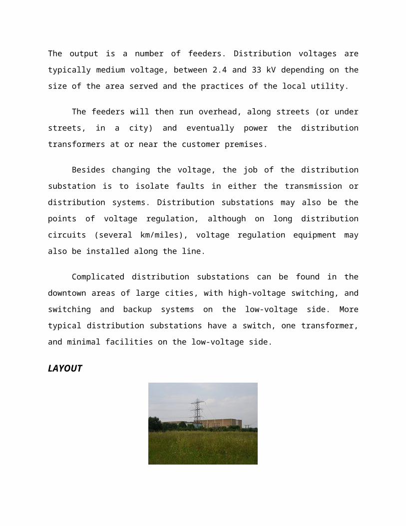
LAYOUT
Tottenham Substation, set in wild parkland in North London,
United Kingdom
The first step in planning a substation layout is the
preparation of a one-line diagram which shows in simplified form
the switching and protection arrangement required, as well as the
incoming supply lines and outgoing feeders or transmission lines.
It is a usual practice by many electrical utilities to prepare
one-line diagrams with principal elements (lines, switches,
circuit breakers, and transformers) arranged on the page
similarly to the way the apparatus would be laid out in the
actual station.
Incoming lines will almost always have a disconnect switch
and a circuit breaker. In some cases, the lines will not have
both; with either a switch or a circuit breaker being all that is
considered necessary.
A disconnect switch is used to provide isolation, since it
cannot interrupt load current. A circuit breaker is used as a
protection device to interrupt fault currents automatically, and
may be used to switch loads on and off. When a large fault
current flows through the circuit breaker, this may be detected
through the use of current transformers. The magnitude of the
current transformer outputs may be used to 'trip' the circuit
breaker resulting in a disconnection of the load supplied by the
circuit break from the feeding point. This seeks to isolate the
fault point from the rest of the system, and allow the rest of
the system to continue operating with minimal impact. Both
switches and circuit breakers may be operated locally (within the
substation) or remotely from a supervisory control center.
Once past the switching components, the lines of a given
voltage connect to one or more buses. These are sets of bus bars,
usually in multiples of three, since three-phase electrical power
distribution is largely universal around the world.
The arrangement of switches, circuit breakers and buses used
affects the cost and reliability of the substation. For important
substations a ring bus, double bus, or so-called "breaker and a
half" setup can be used, so that the failure of any one circuit
breaker does not interrupt power to branch circuits for more than
a brief time, and so that parts of the substation may be de-
energized for maintenance and repairs. Substations feeding only a
single industrial load may have minimal switching provisions,
especially for small installations.
Once having established buses for the various voltage
levels, transformers may be connected between the voltage levels.
These will again have a circuit breaker, much like transmission
lines, in case a transformer has a fault (commonly called a
'short circuit').
Along with this, a substation always has control circuitry
needed to command the various breakers to open in case of the
failure of some component.
SWITCHING FUNCTION
An important function performed by a substation is
switching, which is the connecting and disconnecting of
transmission lines or other components to and from the system.
Switching events may be "planned" or "unplanned".
A transmission line or other component may need to be de
energized for maintenance or for new construction; for example,
adding or removing a transmission line or a transformer.
To maintain reliability of supply, no company ever brings
down its whole system for maintenance. All work to be performed,
from routine testing to adding entirely new substations, must be
done while keeping the whole system running.
Perhaps more importantly, a fault may develop in a
transmission line or any other component. Some examples of this:
a line is hit by lightning and develops an arc, or a tower is
blown down by a high wind. The function of the substation is to
isolate the faulted portion of the system in the shortest
possible time.
There are two main reasons: a fault tends to cause equipment
damage; and it tends to destabilize the whole system. For
example, a transmission line left in a faulted condition will
eventually burn down, and similarly, a transformer left in a
faulted condition will eventually blow up. While these are
happening, the power drain makes the system more unstable.
Disconnecting the faulted component, quickly, tends to minimize
both of these problems.
III. UNIFIED POWER QUALITY CONDITIONER
The provision of both DSTATCOM and DVR can control the power
quality of the source current and the load bus voltage. In
addition, if the DVR and STATCOM are connected on the DC side,
the DC bus voltage can be regulated by the shunt connected
DSTATCOM while the DVR supplies the required energy to the load
in case of the transient disturbances in source voltage. The
configuration of such a device (termed as Unified Power Quality

Conditioner (UPQC)) is shown in Fig. 14.15. This is a versatile
device similar to a UPFC. However, the control objectives of a
UPQC are quite different from that of a UPFC.
CONTROL OBJECTIVES OF UPQC
The shunt connected converter has the following control
objectives
1. To balance the source currents by injecting negative and zero
sequence components required by the load
2. The compensate for the harmonics in the load current by
injecting the required harmonic currents
3. To control the power factor by injecting the required reactive
current (at fundamental frequency)
4. To regulate the DC bus voltage.
The series connected converter has the following control
objectives

1. To balance the voltages at the load bus by injecting negative
and zero sequence voltages to compensate for those present in the
source.
2. To isolate the load bus from harmonics present in the source
voltages, by injecting the harmonic voltages
3. To regulate the magnitude of the load bus voltage by injecting
the required active and reactive components (at fundamental
frequency) depending on the power factor on the source side
4. To control the power factor at the input port of the UPQC
(where the source is connected. Note that the power factor at the
output port of the UPQC (connected to the load) is controlled by
the shunt converter.
OPERATION OF UPQC
The operation of a UPQC can be explained from the analysis
of the idealized equivalent circuit shown in Fig. 14.16. Here,
the series converter is represented by a voltage source VC and
the shunt converter is represented by a current source IC. Note
that all the currents and voltages are 3 dimensional vectors with
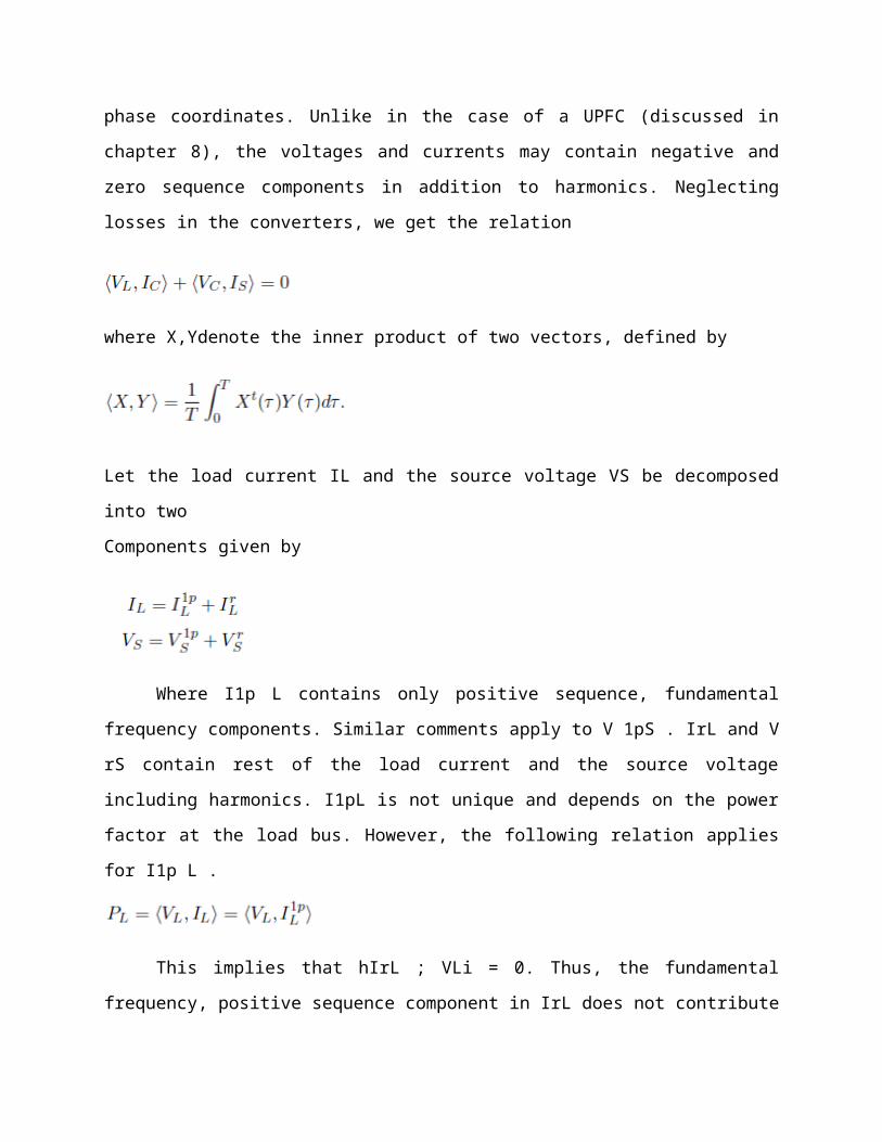
phase coordinates. Unlike in the case of a UPFC (discussed in
chapter 8), the voltages and currents may contain negative and
zero sequence components in addition to harmonics. Neglecting
losses in the converters, we get the relation
where X,Ydenote the inner product of two vectors, defined by
Let the load current IL and the source voltage VS be decomposed
into two
Components given by
Where I1p L contains only positive sequence, fundamental
frequency components. Similar comments apply to V 1pS . IrL and V
rS contain rest of the load current and the source voltage
including harmonics. I1pL is not unique and depends on the power
factor at the load bus. However, the following relation applies
for I1p L .
This implies that hIrL ; VLi = 0. Thus, the fundamental
frequency, positive sequence component in IrL does not contribute
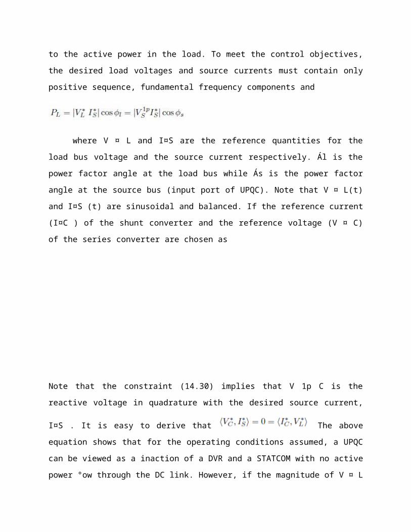
to the active power in the load. To meet the control objectives,
the desired load voltages and source currents must contain only
positive sequence, fundamental frequency components and
where V ¤ L and I¤S are the reference quantities for the
load bus voltage and the source current respectively. Ál is the
power factor angle at the load bus while Ás is the power factor
angle at the source bus (input port of UPQC). Note that V ¤ L(t)
and I¤S (t) are sinusoidal and balanced. If the reference current
(I¤C ) of the shunt converter and the reference voltage (V ¤ C)
of the series converter are chosen as
Note that the constraint (14.30) implies that V 1p C is the
reactive voltage in quadrature with the desired source current,
I¤S . It is easy to derive that The above
equation shows that for the operating conditions assumed, a UPQC
can be viewed as a inaction of a DVR and a STATCOM with no active
power °ow through the DC link. However, if the magnitude of V ¤ L
is to be controlled, it may not be feasible to achieve this by
injecting only
reactive voltage. The situation gets complicated if V 1p S is not
constant, but changes due to system disturbances or fault. To
ensure the regulation of the load bus voltage it may be necessary
to inject variable active voltage (in phase with the source
current). If we express
This implies that both ¢VC and ¢IC are perturbations involving
positive sequence, fundamental frequency quantities (say,
resulting from symmetric voltage sags). the power balance on the
DC side of the shunt and series converter. The perturbation in VC
is initiated to ensure that
Thus, the objective of the voltage regulation at the load bus may
require exchange of power between the shunt and series
converters.
REMARKS
1. The unbalance and harmonics in the source voltage can arise
due to uncompensated nonlinear and unbalanced loads in the
upstream of the UPQC.
2. The injection of capacitive reactive voltage by the series
converter has the advantage of raising the source voltage
magnitude.
IV. MODELLING OF CASE STUDY
THE OPEN UPQC
Most end user disturbances are characterized by short
duration and small amplitude, though they can still cause
interruptions in production processes. Most voltage sags have
small depth and short durations. More than 95% of voltage sags
can be compensated by injecting a voltage of up to 60% of the
nominal voltage, with a maximum duration of 30 cycles. This
information is primarily used to evaluate a suitable size for the
OPEN UPQC.
The series unit of the OPEN UPQC, sized to supply 60% of the
LV network power and equipped with a small storage system, can
compensate for most of the voltage disturbances.

Fig.. Example of distribution of voltage disturbances reported in the
EPRI event coordination chart
Fig. 3. Multiwire power diagram of the new proposed solution.
Each shunt unit is sized in relation to the supplied load
power, and can protect its sensitive load against interruptions.
The shunt unit’s function is similar to that of the UPS output
stage, but is less expensive because it only has one conversion
stage and involves less power loss. The series unit consists of a
coupling transformer (TR), with the primary circuit connected in
series with the mains line and a secondary one supplying the
reversible ac/dc power converter. The output stage of the pulse
width modulation (PWM) voltage controlled converter contains
passive RC shunt filters, to compensate for the harmonic currents
at switching and multiple frequencies. Neglecting the active
power to compensate the converter losses, the series unit is
controlled to act as a purely reactive inductor when the supply
voltage is within its operation limits. This fact is of
fundamental importance, because in this range the loads must be
supplied by the mains 95% of the time, as established by the IEEE
Std 1159 “IEEE Recommended Practice for Monitoring Electric Power
Quality” and European EN50160; therefore, the storage system must
not discharge itself. Outside of this range, active power can be
used to compensate the disturbances, in the same way as the usual
series compensation devices, when a storage system is present.
The shunt units consist of an ac/dc power converter, similar
to the one used in the series unit, connected to an energy
storage system and a set of static switches (SS). The shunt unit,
depending on the state of the network voltage, can supply either
the entire load, or a part of the load. There are two different
modes of OPEN UPQC operation:
COMPENSATOR: when the PCC voltage is within its operation
limits, the SS are closed, the series unit works as a three
phase voltage generator and the shunt units work as current
generators.
BACK-UP: when the PCC voltage is outside of its operation
limits, the SS are open, decoupling the network and the
load-compensator system. Each sensitive load is supplied by
its shunt unit, which acts as a sinusoidal voltage
generator, using the energy stored in the storage system as
an energy source.
OPEN UPQC PERFORMANCEThis section is focused on understanding the OPEN UPQC
compensation limits. The analysis will be carried out under
steady state conditions, to evaluate the compensation capacity of
the device in normal operation mode . It is
important to remember that the power absorbed by the loads and
the shunt units influences the performance of the series unit,
and therefore of the whole OPENS UPQC.
Therefore, when considering a particular set of load
conditions, it is possible to find operating conditions for the
shunt units that increase the compensating limits of the series
unit. Depending on whether or not storage systems are present,
the series and shunt units can exchange only non active power or
both non active power and active power with the mains. In the
latter case, as will be shown in the following, the OPEN UPQC can
better compensate for short duration disturbances.
In the following cases, all of the solutions will be
analyzed under the assumption that the voltages are sinusoidal
and are constituted of only the positive sequence component in
the different network buses. It is important to emphasize that
suitably coordinating the various units of the OPEN UPQC allows
for a wide compensation range, comparable with the UPS, but more
economical.
This coordination requires a communication system (i.e.,
based on the carrier waves) between the series unit and the shunt
units, but this system cannot be very fast. Moreover, in
transient analysis, the communication between the series unit and
the shunt units cannot be included (the communication could be
slow, could be out of order, etc.). Therefore, each unit
necessarily works alone.
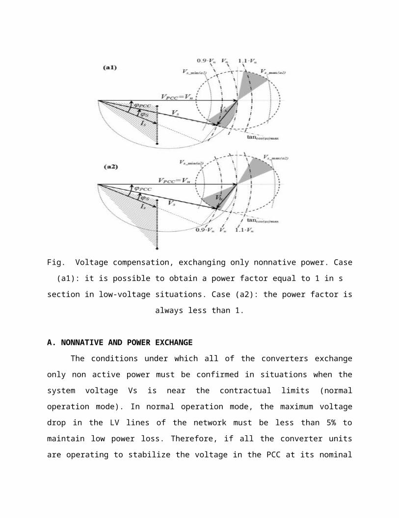
Fig. Voltage compensation, exchanging only nonnative power. Case
(a1): it is possible to obtain a power factor equal to 1 in s
section in low-voltage situations. Case (a2): the power factor is
always less than 1.
A. NONNATIVE AND POWER EXCHANGE
The conditions under which all of the converters exchange
only non active power must be confirmed in situations when the
system voltage Vs is near the contractual limits (normal
operation mode). In normal operation mode, the maximum voltage
drop in the LV lines of the network must be less than 5% to
maintain low power loss. Therefore, if all the converter units
are operating to stabilize the voltage in the PCC at its nominal
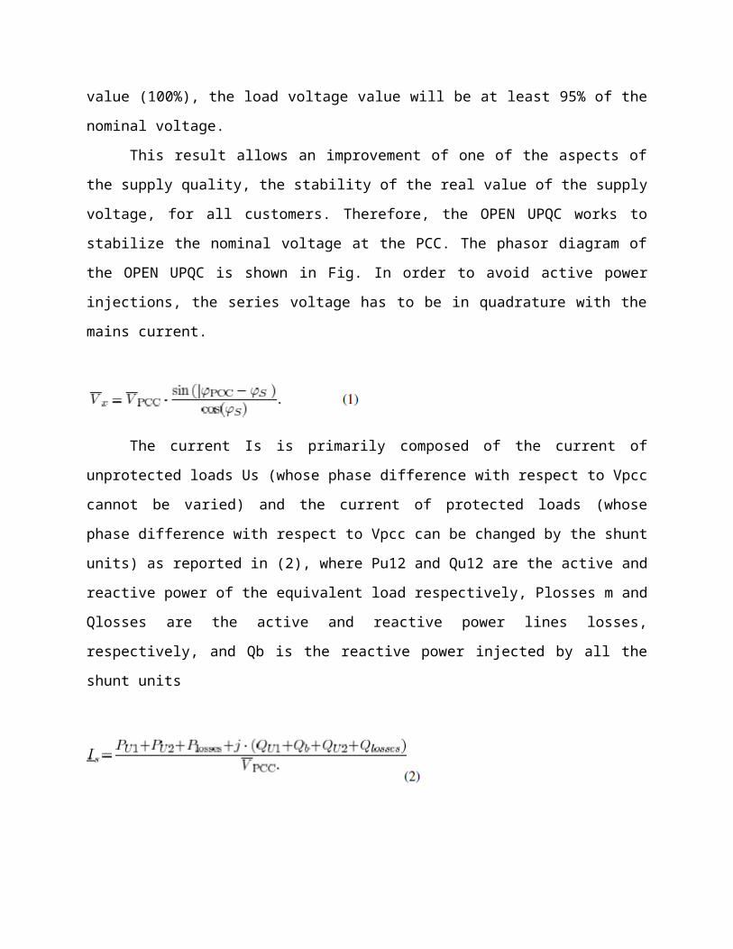
value (100%), the load voltage value will be at least 95% of the
nominal voltage.
This result allows an improvement of one of the aspects of
the supply quality, the stability of the real value of the supply
voltage, for all customers. Therefore, the OPEN UPQC works to
stabilize the nominal voltage at the PCC. The phasor diagram of
the OPEN UPQC is shown in Fig. In order to avoid active power
injections, the series voltage has to be in quadrature with the
mains current.
The current Is is primarily composed of the current of
unprotected loads Us (whose phase difference with respect to Vpcc
cannot be varied) and the current of protected loads (whose
phase difference with respect to Vpcc can be changed by the shunt
units) as reported in (2), where Pu12 and Qu12 are the active and
reactive power of the equivalent load respectively, Plosses m and
Qlosses are the active and reactive power lines losses,
respectively, and Qb is the reactive power injected by all the
shunt units

Therefore, the angle can oscillate between the upper
and lower limits , obtained
when and respectively, in the area highlighted in Fig. 4. The
angle can be calculated by the equation shown at the bottom of
the page.
The current phasor Ia can move along the black dotted line,
varying the reactive power of the shunt units. In case (a1) in
particular, it is possible to obtain a power factor equal to 1 in
the section in low voltage situations, because the line
intercepts the black dotted line. In case (a2), the power factor
is always less than 1. The quantities can be
obtained with (4) and (5), as shown at the bottom of the page.
Assuming that , the range
the range amplitude can be obtained with
It can be seen that the compensating range amplitude
depends on the value that the series unit can
inject, and on the non active power. The non active power is
susceptible to exchanges by the shunt units (length of the black
dotted line, proportional to the loads apparent power) and to
the power factors of the equivalent loads and .

In normal operation mode, the compensation strategy can be
implemented in various ways. For example, power factor
maximization in the s section (corresponding to minimization of
the current Is) is a compensation strategy that can be
implemented by coordinating the series unit and the shunt ones.
Therefore, communication between all the units is required. The
simplest solution is to employ a slow communication system that
allows the OPEN UPQC to stabilize the voltage at the PCC,
maximizing the power factor in normal operation conditions and
increasing its compensation limits outside of normal operation.
Obviously, in the case of large disturbances in that the series
unit cannot compensate, each shunt unit can supply the load in
back-up mode.
B. NONNATIVE Qb AND Qx AND ACTIVE Px POWER EXCHANGE
In this case, the series converter produces only non active
power, but the shunt units can exchange active and non active
power with the mains. This condition could be represented as an
active network into which dispersed generations are inserted.
Fig. 5 depicts the new phasor diagram of the OPEN UPQC under the
above operating conditions.
In order to avoid active power injections by the series
unit, the voltage Vx and the mains current Is have to be in
quadrature with each other. In Fig. 5, the light grey areas
indicate the field in which Vx can lay without active power
exchanges by the shunt units, and the dark gray areas indicate
the possible values of with active power exchanges by shunt
units. In this case, the compensating range amplitude
is greater than without active power exchanges, but it is
important to note that the difference is small. The phasor
current can move inside of the gray dotted circle, varying the
active and non active power of the shunt units (movement on the
black dotted line regards only non active power exchange).

C. NONCCTIVE Qb AND Qx AND ACTIVE Px POWER EXCHANGE
In order to exchange active power with the mains, a storage
system connected to the dc section of the series unit is needed.
The storage system size does not need to be very large, because
little energy is required to compensate most of the disturbances
For example, to compensate most of the voltage variations
reported in Fig. 2 (voltage sag 60% deep for 30 cycle) for a 400-
kW load, an energy equal to 120 kJ is needed, corresponding to a
battery capacity of about 0.4 Ah at 96 V or a capacitor or super
capacitor bank of about 1.5 F at 400 V. Given a storage system
with twice the abovementioned capacity, in order to allow

bidirectional energy exchange with the mains, it is possible to
compensate voltage disturbances in that are outside of the
contractual limits.
In the case of mains interruptions lasting longer than 30
cycles, the SS of the shunt units switch off, and the loads are
supplied in back-up mode Considering compensation of transient
disturbances, such as voltage sags, swells, etc., various
compensation strategies are available for the OPEN UPQC,
including minimizing the energy required by the storage system of
the series unit. The new phasor diagram of the OPEN UPQC
operation is shown in Fig. 6. In the light gray areas, the series
voltage and the mains current have to be in quadrature with each
other, because active power exchanges by the series unit are not
allowed.
In these areas, the behavior of the OPEN UPQC is the same
as that of the cases described previously. In the case of
transient disturbances, the series unit can compensate the
voltage over a very large range (the compensating range amplitude
is ) compared with all the cases previously
analyzed. Indeed, the series unit can exchange active power with
the mains in the dark gray areas, but this is only possible for
transient disturbances due to the small size of the series unit
storage system.
CONTROL STRATEGYThe following describes a control strategy that can be
employed in normal operation mode , under

steady state conditions, and elucidates the device performance.
The dynamic response during transient events has not been
considered in this work, because it is described in detail in.
For example, considering the dynamic behavior of the series unit,
it can be seen that the series unit cannot be affected by the
shunt units during a transient event. This is due to the fact
that the communication system between them is slow, and does not
allow a fast coordinated control strategy.
In order to compensate for the voltages in normal
operation, the strategy that maximizes the power factor
(corresponding to the current minimization) can be chosen. With
this choice, it is possible to minimize the apparent power
required by the mains. The mains current Is is reported in (2),
and the compensated voltage Vpcc is
Neglecting power losses and considering that the voltage has
to be in quadrature with the current , it is possible to write
the following relation:
Where is the equivalent reactance of the series unit, giving
a voltage proportional to . Solving (7) and (8) is not
mathematically easy due to the nonlinearity of the problem, and
implementing them into a controller is not useful. It is more
convenient to implement two PI controllers: one to evaluate the
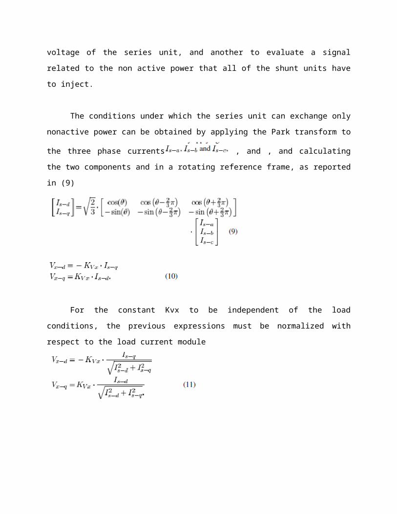
voltage of the series unit, and another to evaluate a signal
related to the non active power that all of the shunt units have
to inject.
The conditions under which the series unit can exchange only
nonactive power can be obtained by applying the Park transform to
the three phase currents , and , and calculating
the two components and in a rotating reference frame, as reported
in (9)
For the constant Kvx to be independent of the load
conditions, the previous expressions must be normalized with
respect to the load current module
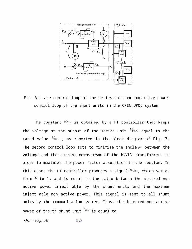
Fig. Voltage control loop of the series unit and nonactive power
control loop of the shunt units in the OPEN UPQC system
The constant is obtained by a PI controller that keeps
the voltage at the output of the series unit equal to the
rated value , as reported in the block diagram of Fig. 7.
The second control loop acts to minimize the angle between the
voltage and the current downstream of the MV/LV transformer, in
order to maximize the power factor absorption in the section. In
this case, the PI controller produces a signal , which varies
from 0 to 1, and is equal to the ratio between the desired non
active power inject able by the shunt units and the maximum
inject able non active power. This signal is sent to all shunt
units by the communication system. Thus, the injected non active
power of the th shunt unit is equal to
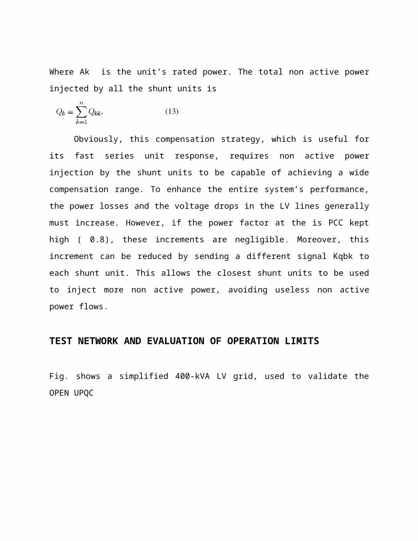
Where Ak is the unit’s rated power. The total non active power
injected by all the shunt units is
Obviously, this compensation strategy, which is useful for
its fast series unit response, requires non active power
injection by the shunt units to be capable of achieving a wide
compensation range. To enhance the entire system’s performance,
the power losses and the voltage drops in the LV lines generally
must increase. However, if the power factor at the is PCC kept
high ( 0.8), these increments are negligible. Moreover, this
increment can be reduced by sending a different signal Kqbk to
each shunt unit. This allows the closest shunt units to be used
to inject more non active power, avoiding useless non active
power flows.
TEST NETWORK AND EVALUATION OF OPERATION LIMITS
Fig. shows a simplified 400-kVA LV grid, used to validate the
OPEN UPQC

System compensation structure
The protected loads are grouped into the equivalent load ,
so all of the shunt units are represented by means of an
equivalent unit. In the same way, all of the unprotected loads
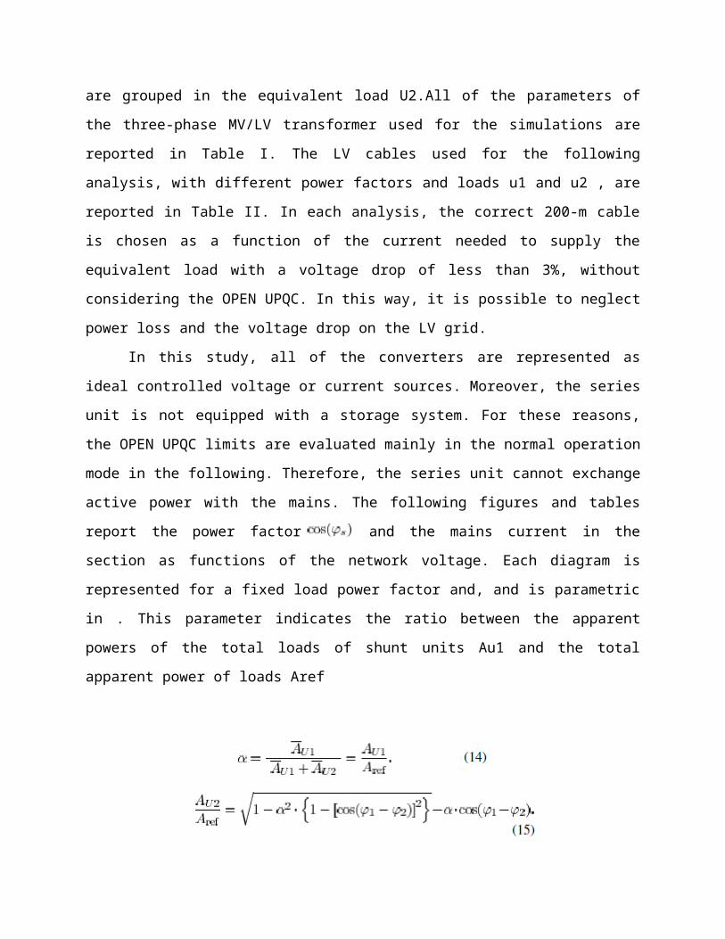
are grouped in the equivalent load U2.All of the parameters of
the three-phase MV/LV transformer used for the simulations are
reported in Table I. The LV cables used for the following
analysis, with different power factors and loads u1 and u2 , are
reported in Table II. In each analysis, the correct 200-m cable
is chosen as a function of the current needed to supply the
equivalent load with a voltage drop of less than 3%, without
considering the OPEN UPQC. In this way, it is possible to neglect
power loss and the voltage drop on the LV grid.
In this study, all of the converters are represented as
ideal controlled voltage or current sources. Moreover, the series
unit is not equipped with a storage system. For these reasons,
the OPEN UPQC limits are evaluated mainly in the normal operation
mode in the following. Therefore, the series unit cannot exchange
active power with the mains. The following figures and tables
report the power factor and the mains current in the
section as functions of the network voltage. Each diagram is
represented for a fixed load power factor and, and is parametric
in . This parameter indicates the ratio between the apparent
powers of the total loads of shunt units Au1 and the total
apparent power of loads Aref
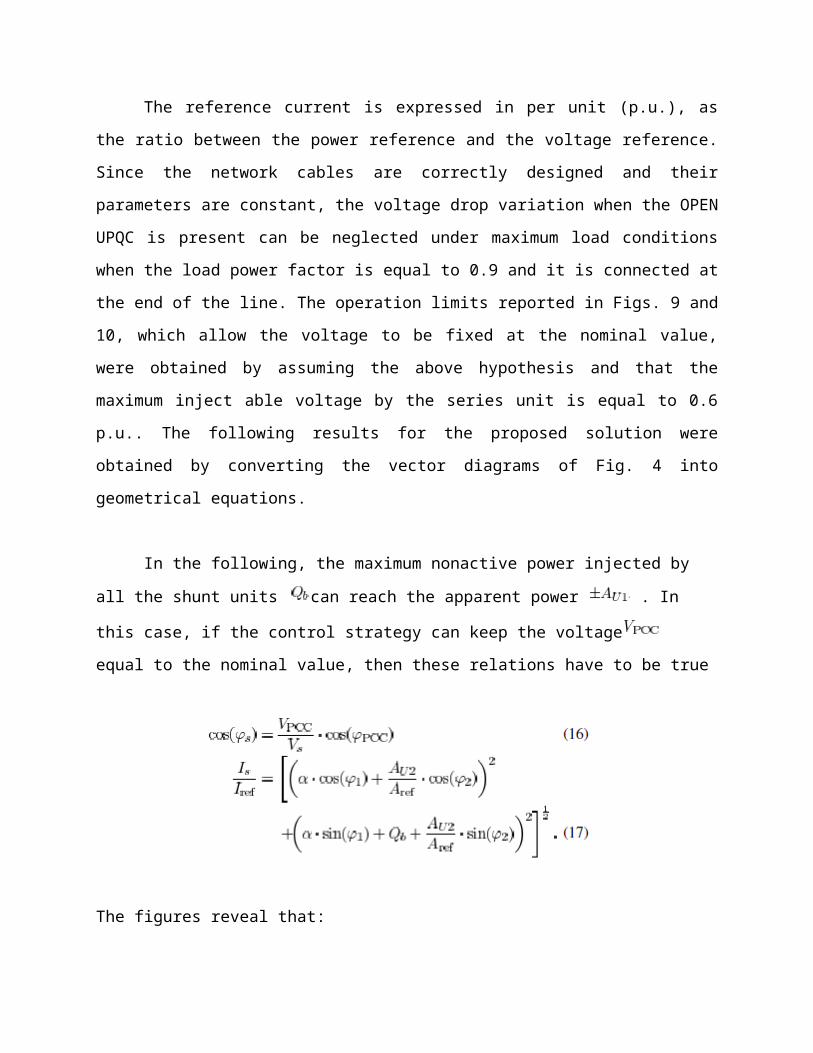
The reference current is expressed in per unit (p.u.), as
the ratio between the power reference and the voltage reference.
Since the network cables are correctly designed and their
parameters are constant, the voltage drop variation when the OPEN
UPQC is present can be neglected under maximum load conditions
when the load power factor is equal to 0.9 and it is connected at
the end of the line. The operation limits reported in Figs. 9 and
10, which allow the voltage to be fixed at the nominal value,
were obtained by assuming the above hypothesis and that the
maximum inject able voltage by the series unit is equal to 0.6
p.u.. The following results for the proposed solution were
obtained by converting the vector diagrams of Fig. 4 into
geometrical equations.
In the following, the maximum nonactive power injected by
all the shunt units can reach the apparent power . In
this case, if the control strategy can keep the voltage
equal to the nominal value, then these relations have to be true
The figures reveal that:
1) the OPEN UPQC is well-adapted when the power factor of
the load is low. Fig. 9 shows the interval that can be
compensated by exchanging only nonactive power when the power
factor of the load is equal to 0.8. In this case, the OPEN UPQC
produces excellent voltage stabilization, especially when the
parameter is greater than 0.4.
2) The OPEN UPQC is not well-adapted when the power factor
of the load is high. Fig. 10 shows the interval that can be
compensated by exchanging only nonactive power when the power
factor of the load is equal to 1. In this case, the OPEN UPQC
does not produce good voltage stabilization, because it is too
limited. It is possible to obtain voltage stabilization in normal
operation mode range (between 0.9 p.u. and 1.1 p.u.) only with a
high value.
TABLE III MAXIMUM AND MINIMUM MAINS VOLTAGE RANGE VARIATION THAT THE SYSTEM CAN COMPENSATE, AS A FUNCTION OF THE
MAXIMUM NONACTIVE POWER THAT THE SHUNT UNIT CAN INJECT, WITHOUT CONSIDERING THE MAINS POWER FACTOR
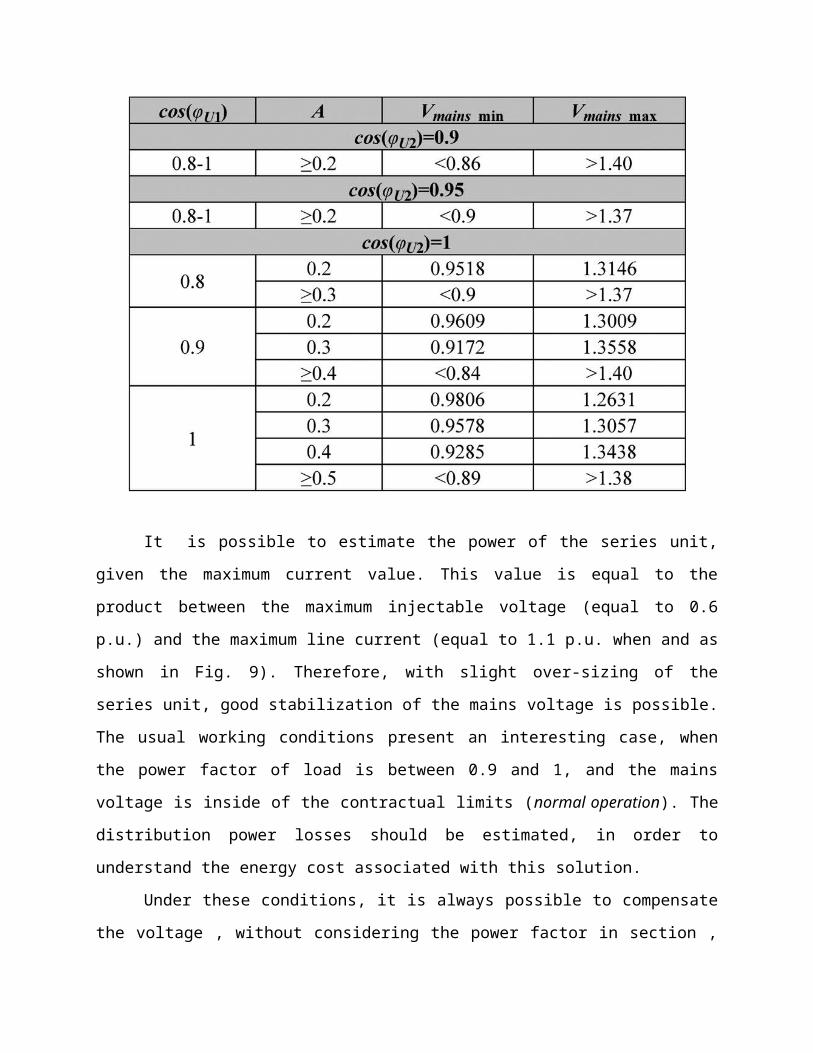
It is possible to estimate the power of the series unit,
given the maximum current value. This value is equal to the
product between the maximum injectable voltage (equal to 0.6
p.u.) and the maximum line current (equal to 1.1 p.u. when and as
shown in Fig. 9). Therefore, with slight over-sizing of the
series unit, good stabilization of the mains voltage is possible.
The usual working conditions present an interesting case, when
the power factor of load is between 0.9 and 1, and the mains
voltage is inside of the contractual limits (normal operation). The
distribution power losses should be estimated, in order to
understand the energy cost associated with this solution.
Under these conditions, it is always possible to compensate
the voltage , without considering the power factor in section ,
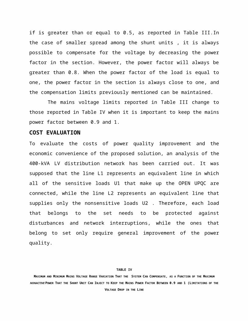
if is greater than or equal to 0.5, as reported in Table III.In
the case of smaller spread among the shunt units , it is always
possible to compensate for the voltage by decreasing the power
factor in the section. However, the power factor will always be
greater than 0.8. When the power factor of the load is equal to
one, the power factor in the section is always close to one, and
the compensation limits previously mentioned can be maintained.
The mains voltage limits reported in Table III change to
those reported in Table IV when it is important to keep the mains
power factor between 0.9 and 1.
COST EVALUATIONTo evaluate the costs of power quality improvement and the
economic convenience of the proposed solution, an analysis of the
400-kVA LV distribution network has been carried out. It was
supposed that the line L1 represents an equivalent line in which
all of the sensitive loads U1 that make up the OPEN UPQC are
connected, while the line L2 represents an equivalent line that
supplies only the nonsensitive loads U2 . Therefore, each load
that belongs to the set needs to be protected against
disturbances and network interruptions, while the ones that
belong to set only require general improvement of the power
quality.
TABLE IV
MAXIMUM AND MINIMUM MAINS VOLTAGE RANGE VARIATION THAT THE SYSTEM CAN COMPENSATE, AS A FUNCTION OF THE MAXIMUM
NONACTIVE POWER THAT THE SHUNT UNIT CAN INJECT TO KEEP THE MAINS POWER FACTOR BETWEEN 0.9 AND 1 (LIMITATIONS OF THE
VOLTAGE DROP IN THE LINE
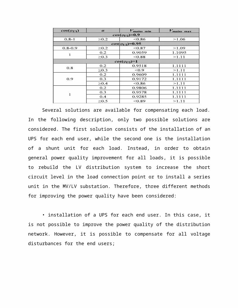
Several solutions are available for compensating each load.
In the following description, only two possible solutions are
considered. The first solution consists of the installation of an
UPS for each end user, while the second one is the installation
of a shunt unit for each load. Instead, in order to obtain
general power quality improvement for all loads, it is possible
to rebuild the LV distribution system to increase the short
circuit level in the load connection point or to install a series
unit in the MV/LV substation. Therefore, three different methods
for improving the power quality have been considered:
• installation of a UPS for each end user. In this case, it
is not possible to improve the power quality of the distribution
network. However, it is possible to compensate for all voltage
disturbances for the end users;
• revamping of all of the LV distribution cables. In this
case, it is not possible to compensate for all voltage
disturbances;
• installation of an OPEN UPQC. In this case, it is possible
to compensate for most of the voltage disturbances. The last
solution consists of the installation of a series unit sized for
66% of the total power loads supplied (264 kVA), while each shunt
unit has an assumed size of 5 kVA. Moreover, each UPS is assumed
to have the same power, and the input stage of each UPS is
composed of PFC rectifiers. It is important to clarify that the
storage systems cost for UPS and OPEN UPQC solutions in this
analysis is not considered, because it primarily depends on the
technologies and autonomies required. The revamping cost
considered here can be found in the economical analysis carried
out.
The total cost for each solution is reported in Fig. 11.
They include only the devices and various materials; the
installation cost is assumed to be 50% of the device cost. Fig.
11 shows that to compensate for most of the disturbances in the
whole network, installing the series unit only is a better
solution than revamping all of the LV distribution system. To
compensate for the loads , it is necessary to install a UPS or a
shunt unit close to them, which increases the total cost as a
function of their power. Referring to Fig. 11, it can be seen
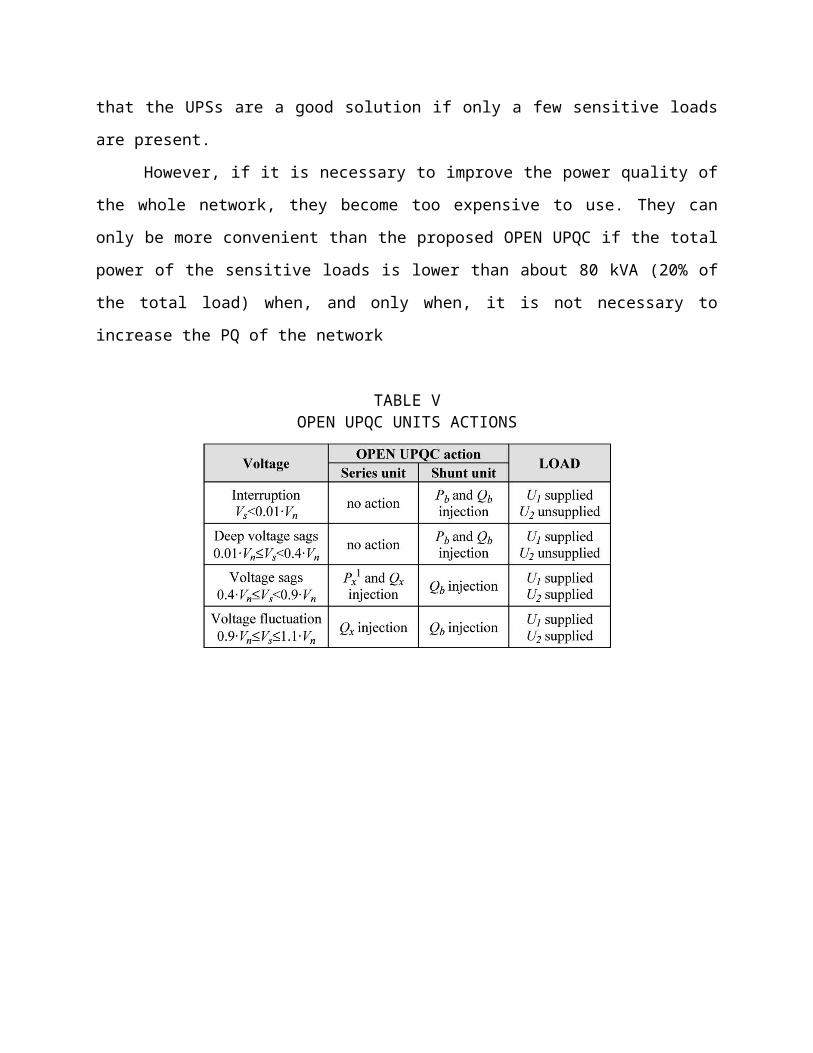
that the UPSs are a good solution if only a few sensitive loads
are present.
However, if it is necessary to improve the power quality of
the whole network, they become too expensive to use. They can
only be more convenient than the proposed OPEN UPQC if the total
power of the sensitive loads is lower than about 80 kVA (20% of
the total load) when, and only when, it is not necessary to
increase the PQ of the network
TABLE VOPEN UPQC UNITS ACTIONS
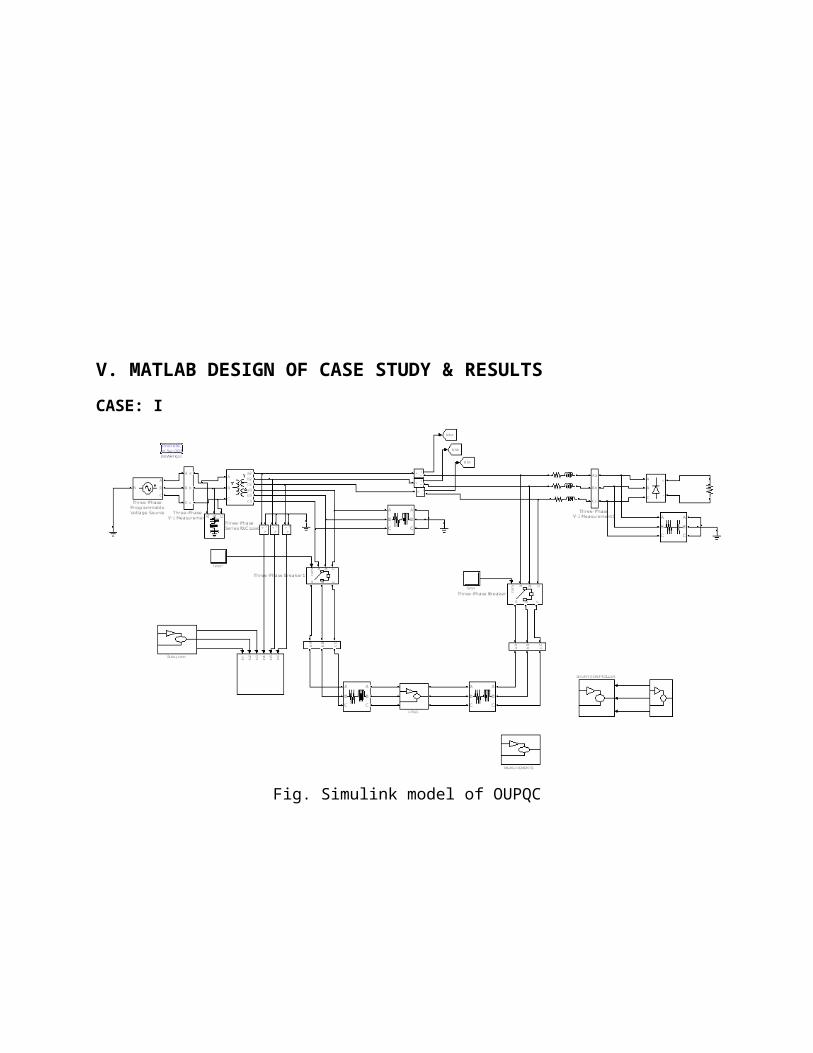
V. MATLAB DESIGN OF CASE STUDY & RESULTSCASE: I
Fig. Simulink model of OUPQC
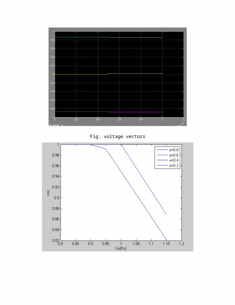
Fig. voltage vectors
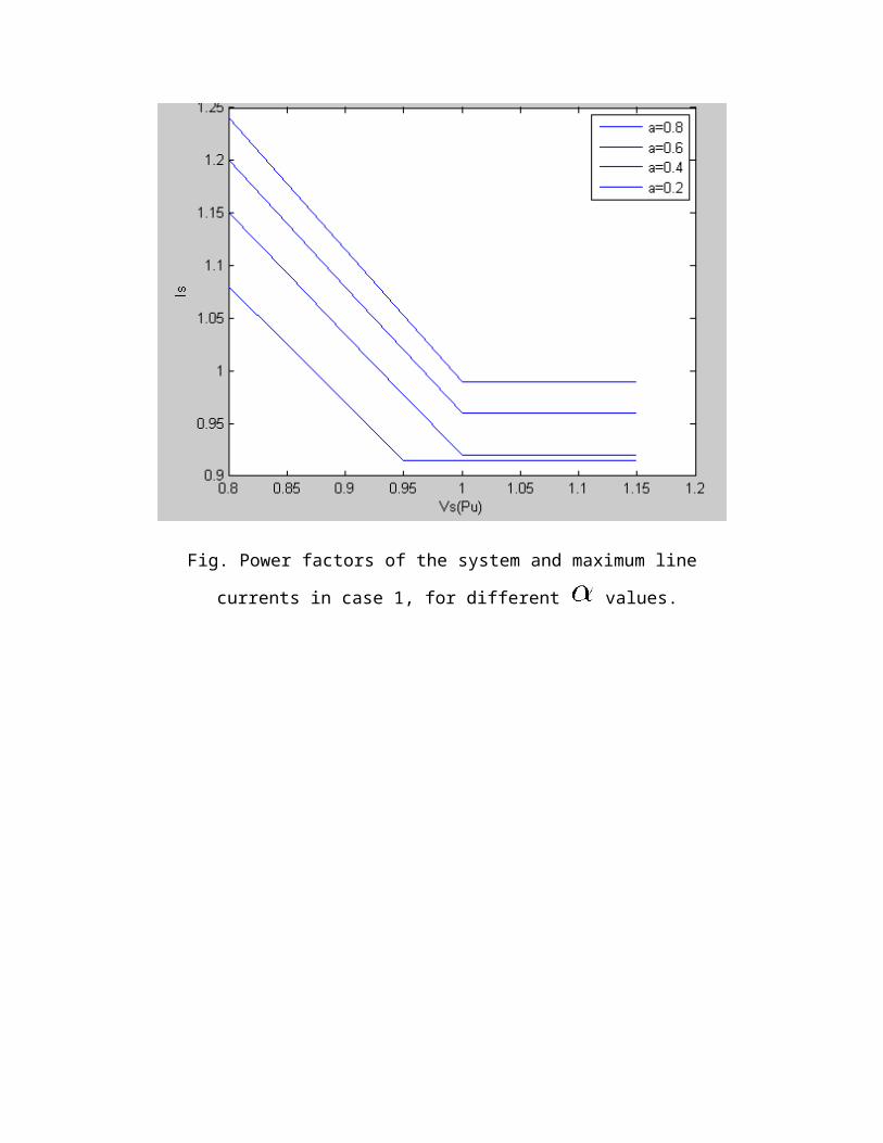
Fig. Power factors of the system and maximum line
currents in case 1, for different values.
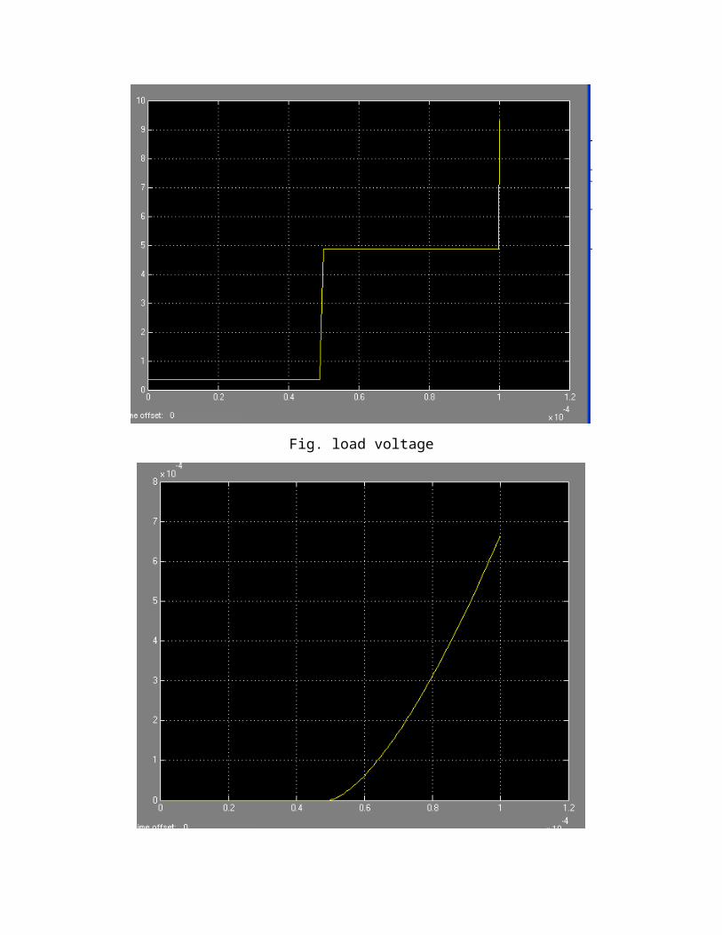
Fig. load voltage
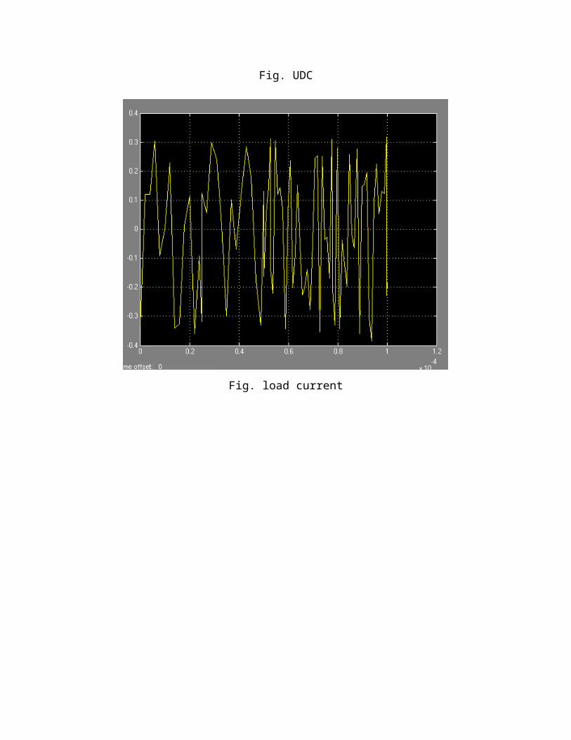
Fig. UDC
Fig. load current
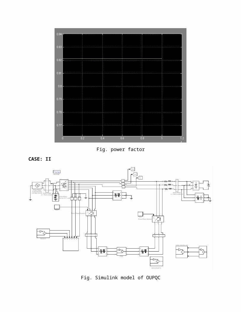
Fig. power factor
CASE: II
Fig. Simulink model of OUPQC
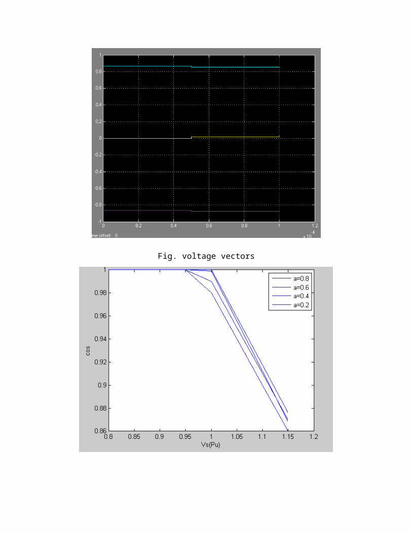
Fig. voltage vectors
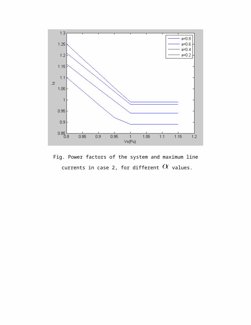
Fig. Power factors of the system and maximum line
currents in case 2, for different values.
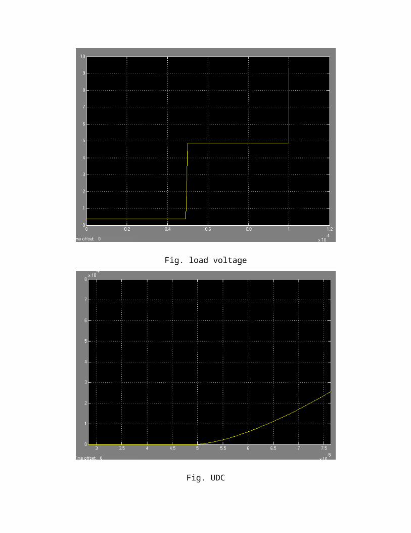
Fig. load voltage
Fig. UDC
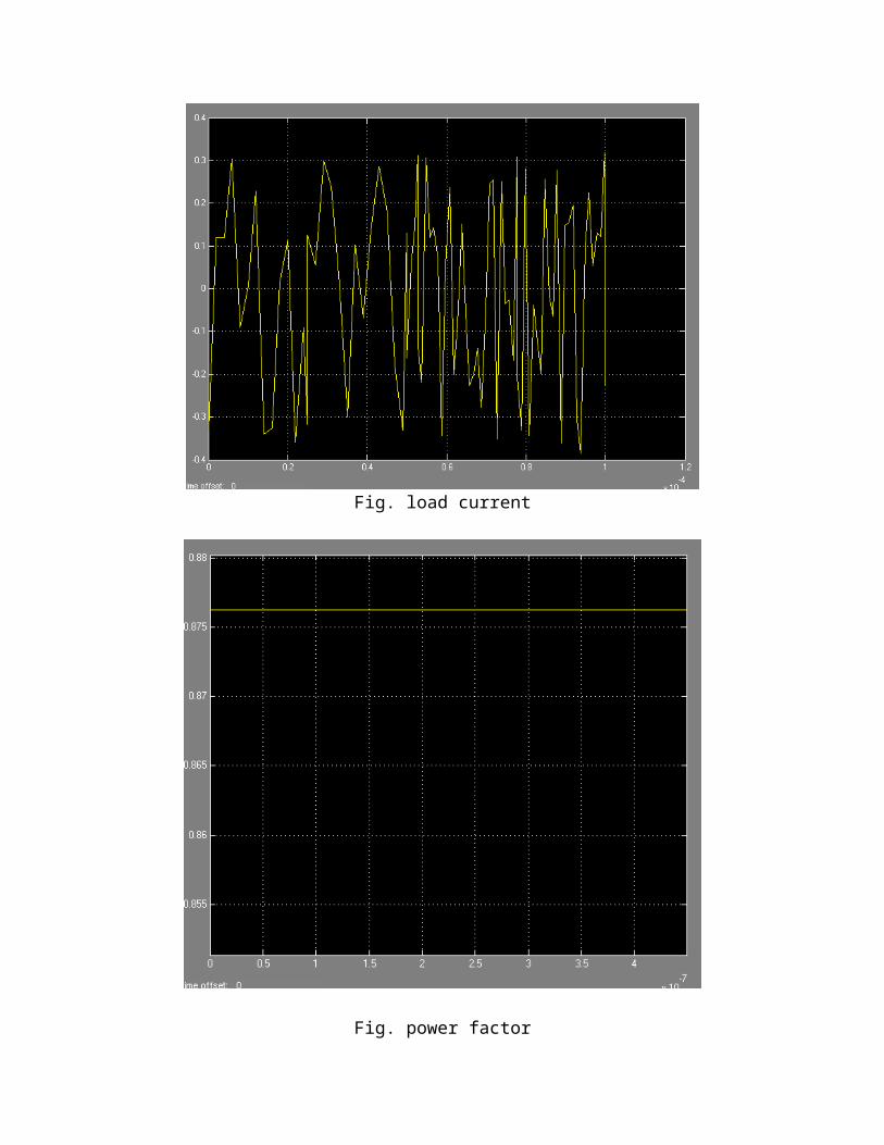
Fig. load current
Fig. power factor
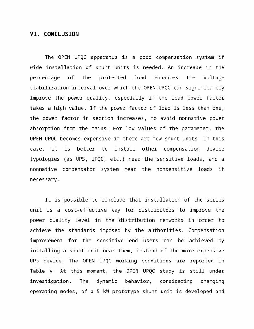
VI. CONCLUSION
The OPEN UPQC apparatus is a good compensation system if
wide installation of shunt units is needed. An increase in the
percentage of the protected load enhances the voltage
stabilization interval over which the OPEN UPQC can significantly
improve the power quality, especially if the load power factor
takes a high value. If the power factor of load is less than one,
the power factor in section increases, to avoid nonnative power
absorption from the mains. For low values of the parameter, the
OPEN UPQC becomes expensive if there are few shunt units. In this
case, it is better to install other compensation device
typologies (as UPS, UPQC, etc.) near the sensitive loads, and a
nonnative compensator system near the nonsensitive loads if
necessary.
It is possible to conclude that installation of the series
unit is a cost-effective way for distributors to improve the
power quality level in the distribution networks in order to
achieve the standards imposed by the authorities. Compensation
improvement for the sensitive end users can be achieved by
installing a shunt unit near them, instead of the more expensive
UPS device. The OPEN UPQC working conditions are reported in
Table V. At this moment, the OPEN UPQC study is still under
investigation. The dynamic behavior, considering changing
operating modes, of a 5 kW prototype shunt unit is developed and
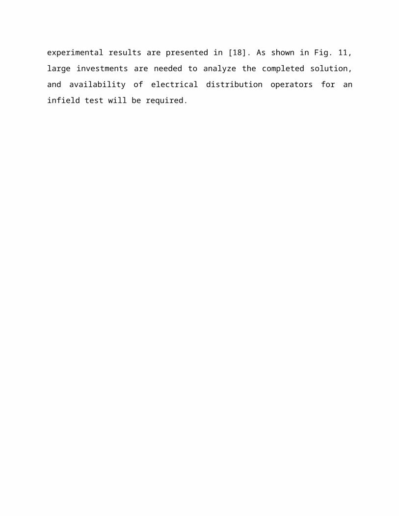
experimental results are presented in [18]. As shown in Fig. 11,
large investments are needed to analyze the completed solution,
and availability of electrical distribution operators for an
infield test will be required.
VII. REFERENCES
[1] D. M. Divan, W. E. Brumsickle, G. A. Luckjiff, J. W.
Freeborg, and R. L. Hayes, “Realizing a nation-wide power quality
and reliability monitoring system,” 2003. [Online]. Available:
http://www.softswitch. com/docs/Realizing%20a%20Nationwide
%20System%202003.pdf.
[2] J. M. Guerrero, L. Garcia de Vicuna, and J. Uceda,
“Uninterruptible power supply systems provide protection,” IEEE
Ind. Electron. Mag., vol. 1, no. 1, pp. 28–38, Spring, 2007.
[3] B.Wang, G. Venkataramanan, and M. Illindala, “Operation and
control of a dynamic voltage restorer using transformer coupled
H-bridge converters,” IEEE Trans. Power. Electron., vol. 21, no.
4, pp. 1053–1061, Jul. 2006.
[4] D. M. Vilathgamuwa, H. M. Wijekoon, and S. S. Choi, “A novel
technique to compensate voltage sags in multiline distribution
system—The interline dynamic voltage restorer,” IEEE Trans. Ind.
Electron., vol. 53, no. 5, pp. 1603–1611, Oct. 2006.]
[5] C. N. M. Ho and H. S. H. Chung, “Fast transient control of
singlephase Dynamic Voltage Restorer (DVR) without external DC
source,” in Proc. 37th IEEE Power Electronics Specialists Conf.,
Jeju, Korea, Jun. 18–22, 2006, pp. 2105–2111.
[6] M. R. Banaei, S. H. Hosseini, and M. D. Khajee, “Mitigation
of voltage sag using adaptive neural network with dynamic voltage
restorer,” in Proc. 5th Int. CES/IEEE Power Electronics and
Motion Control Conf., Shanghai, China, Aug. 14–16, 2006, vol. 2,
pp. 1–5.
[7] A. Ghosh and G. Ledwich, “Compensation of distribution system
voltage using DVR,” IEEE Trans. Power Del., vol. 17, no. 4, pp.
1030–1036, Oct. 2002.
[8] M. K. Mishra, K. Karthikeyan, and P. K. Linash, “A
development and implementation of DSP based DSTATCOM to
compensate unbalanced nonlinear loads,” presented at the IEEE
Power India Conf., New Delhi, India, Apr. 10–12, 2006.
[9] B. Singh, A. Adya, A. P. Mittal, and J. R. P. Gupta,
“Analysis, simulation and control of DSTATCOM in three-phase,
four-wire isolated distribution systems,” presented at the IEEE
Power India Conf., New Delhi, India, Apr. 10–12, 2006., Jun. 18–
22, 2006.