Biosensor signal improvement using current mirror topology ...
17
Biosensor signal improvement using current mirror topology for dissolved oxygen measurement Lazuardi Umar, Yanuar Hamzah and Rahmondia N. Setiadi Department of Physics, Faculty of Mathematics and Natural Sciences, University of Riau, Pekanbaru 28293, Indonesia E-mail: [email protected] Abstract. A biosensor system for dissolved oxygen level detection based on current mirror method has been designed and characterized. Most biosensor systems implement a transimpedance circuit to convert the flowing current on the sensor to an output voltage signal. These systems are voracious and susceptible to instability and noise due to the configuration of circuit used, impractical on power supply due to bipolar polarity need, and consumes more power, since it uses more active devices in the op-amp. These disadvantages need to be overcome when the special requirements are needed such as low noise measurement in the dissolved oxygen level detection, battery powered and low power device for in- situ and remote area measurement. Different to the transimpedance, the current mirror circuits convert the flowing current to the output voltage by copying the current with a ground-referenced input and output, and use fewer active devices. The proposed current mirror circuit is aimed to diminish the noise of output and minimize the power consumption through reducing used active devices. The results show some significant signal quality improvements when using current mirror circuit, where the noise response of the current mirror circuits is 10 times lower than the transimpedance circuit. Keywords : Biosensor, current-mirror, dissolved oxygen, oxygen electrode, tran- simpedance amplifier 1. Introduction The dissolved oxygen (DO) level measurement in a solution is very important to determine the quality of water for living things. The oxygen level contained in the water can be an indicator of the quality of water. It could degrade by the pollutants that mixed with the water such as H 2 S, NO 2 , NH + 4 , and organic matter [1], which can affect the life of living organisms in the water. Therefore, the living organisms in the water can be used as an indicator of the health of water environment [2]. Pollutants in industrial wastewater are specifically characterized and indicated by the color, chemical oxygen demand (COD), and biological oxygen demand (BOD) [3]. The rate of dissolved oxygen produced by the living organisms in the water is influenced by the activity of photosynthesis of the organism such as algae. Therefore, the quality of the water can be determined by measuring the rate of dissolved oxygen level. The advantages of involving living things i.e. biological impact can be determined, pollutants effect can be monitored, and can replace human beings [2]. There are several methods can be used for oxygen detection by utilizing these bio- indicator. The presence of bio-indicator can be observed through light, temperature, Page 1 of 17 AUTHOR SUBMITTED MANUSCRIPT - MST-107994.R1 1 2 3 4 5 6 7 8 9 10 11 12 13 14 15 16 17 18 19 20 21 22 23 24 25 26 27 28 29 30 31 32 33 34 35 36 37 38 39 40 41 42 43 44 45 46 47 48 49 50 51 52 53 54 55 56 57 58 59 60 Accepted Manuscript
-
Upload
khangminh22 -
Category
Documents
-
view
5 -
download
0
Transcript of Biosensor signal improvement using current mirror topology ...
Biosensor signal improvement using current mirrortopology for dissolved oxygen measurement
Lazuardi Umar, Yanuar Hamzah and Rahmondia N. SetiadiDepartment of Physics, Faculty of Mathematics and Natural Sciences,University of Riau, Pekanbaru 28293, Indonesia
E-mail: [email protected]
Abstract. A biosensor system for dissolved oxygen level detection based oncurrent mirror method has been designed and characterized. Most biosensorsystems implement a transimpedance circuit to convert the flowing current on thesensor to an output voltage signal. These systems are voracious and susceptibleto instability and noise due to the configuration of circuit used, impractical onpower supply due to bipolar polarity need, and consumes more power, since ituses more active devices in the op-amp. These disadvantages need to be overcomewhen the special requirements are needed such as low noise measurement in thedissolved oxygen level detection, battery powered and low power device for in-situ and remote area measurement. Different to the transimpedance, the currentmirror circuits convert the flowing current to the output voltage by copying thecurrent with a ground-referenced input and output, and use fewer active devices.The proposed current mirror circuit is aimed to diminish the noise of outputand minimize the power consumption through reducing used active devices. Theresults show some significant signal quality improvements when using currentmirror circuit, where the noise response of the current mirror circuits is 10 timeslower than the transimpedance circuit.
Keywords: Biosensor, current-mirror, dissolved oxygen, oxygen electrode, tran-simpedance amplifier
1. Introduction
The dissolved oxygen (DO) level measurement in a solution is very important todetermine the quality of water for living things. The oxygen level contained in thewater can be an indicator of the quality of water. It could degrade by the pollutantsthat mixed with the water such as H2S, NO2, NH+
4 , and organic matter [1], which canaffect the life of living organisms in the water. Therefore, the living organisms in thewater can be used as an indicator of the health of water environment [2].
Pollutants in industrial wastewater are specifically characterized and indicatedby the color, chemical oxygen demand (COD), and biological oxygen demand (BOD)[3]. The rate of dissolved oxygen produced by the living organisms in the water isinfluenced by the activity of photosynthesis of the organism such as algae. Therefore,the quality of the water can be determined by measuring the rate of dissolvedoxygen level. The advantages of involving living things i.e. biological impact canbe determined, pollutants effect can be monitored, and can replace human beings [2].There are several methods can be used for oxygen detection by utilizing these bio-indicator. The presence of bio-indicator can be observed through light, temperature,
Page 1 of 17 AUTHOR SUBMITTED MANUSCRIPT - MST-107994.R1
123456789101112131415161718192021222324252627282930313233343536373839404142434445464748495051525354555657585960
Acc
epte
d M
anus
crip
t
Biosensor signal improvement using current mirror topology 2
suspended solids. The other method is the electrochemical using an amperometriccircuit, which is based on the electrical conductivity measurement in the solution.Several circuits using the amperometric method are already described in [4]. Theydiscussed about the advantages and disadvantages of those circuits, but did not discussabout the output performance such as stability and noise.
The amperometric method is commonly used in the electronics circuit of abiosensor system to detect the algae photosynthesis activity as the living organism.When using this method, a current with constant voltage is injected into the solutionthrough three electrodes, then the generated current determined by the ions in thesolution is measured. The dissolved oxygen level in the solution can be measured, sinceit can create ions and affect the conductivity of the solution. Some previous worksfrom [5, 6] have implemented this method using a transimpedance circuit to detect thedissolved oxygen produced by the algae. The algae photosynthesis can be detectedvery well. Although it succeeded with a good response of algae photosynthesis process,the output voltage signal from the circuit is rather not stable and noisy. Therefore, inorder to increase the stability and reduce the noise, the electronics circuit performanceneeds to be improved, so that the dissolved oxygen measurement reading can be moreaccurate, precise, and reliable. In this experiment, the stability and noise performanceof the electronics circuit are improved using a proposed circuit. We present a simplecurrent mirror circuit to improve the signal quality of the output voltage. With thisimprovement, the small changes in the dissolved oxygen level from the algae can bedetected and observed with good stability and small noise of the output voltage signal.Here, we analyze the noise theory and validate the noise response analysis with theexperiments.
2. Biosensor for Dissolved Oxygen Measurement
2.1. Clark Sensor
Clark-type oxygen sensor is the most widely used among the known oxygen sensorand has been applied in clinical analysis, fermentation monitoring, and biosensordevelopment [7]. The sensor element consists of three electrodes i.e. Auxiliary (AE),Reference (RE), and Work (WE), which works with oxygen-electrode-based principle.The AE electrode is functioned as the current source for the solution. The RE electrodekeeps the potential of the sensor constant for any conductivity of the solution, whilethe WE electrode collects the flowing current in the solution. The electrodes are madeof Pt and AgCl, and the WE electrode potential should be brought to 0.6 - 0.8 V lowerthan the RE electrode to ensure oxygen-electrode-based principle to take place [4]. Inthis experiment, we set up the voltage between the RE and WE electrodes to 0.7 V.
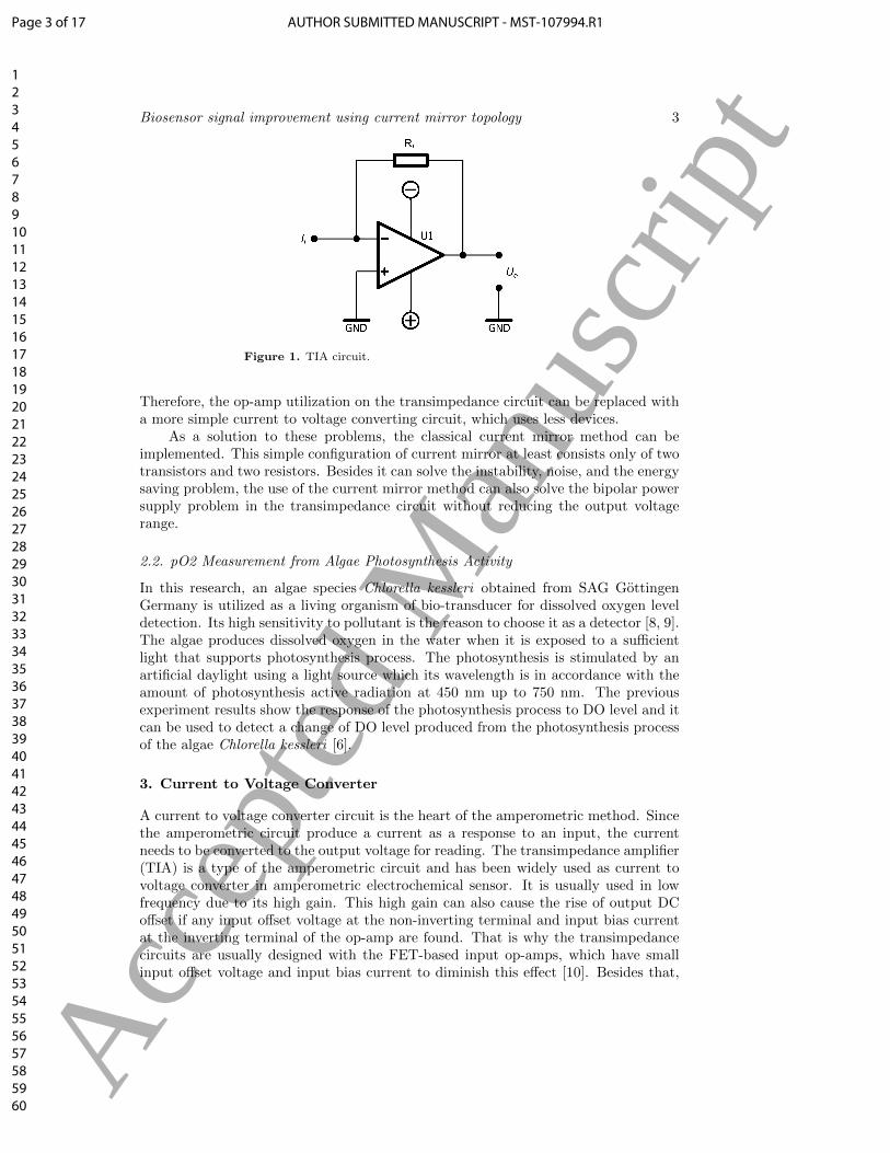
The conventional biosensor measurement systems utilize a transimpedance circuitto convert the current from the sensor to the output voltage. The basic transimpedancecircuit consists of an op-amp and a feedback resistance as shown in figure 1. Thisconfiguration introduces the instability and noise due to virtual ground at the invertinginput of the op-amp and large feedback resistance. Besides that, this configuration alsoneeds a bipolar power supply to accommodate a negative output voltage. Althoughthis problem can be solved by shifting the non-inverting input voltage to 1/2 Vcc, it isstill impractical, since the output range will be narrower and it is not ground-referencedcircuit. In case of the purpose of a biosensor system for in-situ measurement, whichis placed far away from an electrical grid source, energy saving should be considered.
Page 2 of 17AUTHOR SUBMITTED MANUSCRIPT - MST-107994.R1
123456789101112131415161718192021222324252627282930313233343536373839404142434445464748495051525354555657585960
Acc
epte
d M
anus
crip
t
Biosensor signal improvement using current mirror topology 3
Figure 1. TIA circuit.
Therefore, the op-amp utilization on the transimpedance circuit can be replaced witha more simple current to voltage converting circuit, which uses less devices.
As a solution to these problems, the classical current mirror method can beimplemented. This simple configuration of current mirror at least consists only of twotransistors and two resistors. Besides it can solve the instability, noise, and the energysaving problem, the use of the current mirror method can also solve the bipolar powersupply problem in the transimpedance circuit without reducing the output voltagerange.
2.2. pO2 Measurement from Algae Photosynthesis Activity
In this research, an algae species Chlorella kessleri obtained from SAG GottingenGermany is utilized as a living organism of bio-transducer for dissolved oxygen leveldetection. Its high sensitivity to pollutant is the reason to choose it as a detector [8, 9].The algae produces dissolved oxygen in the water when it is exposed to a sufficientlight that supports photosynthesis process. The photosynthesis is stimulated by anartificial daylight using a light source which its wavelength is in accordance with theamount of photosynthesis active radiation at 450 nm up to 750 nm. The previousexperiment results show the response of the photosynthesis process to DO level and itcan be used to detect a change of DO level produced from the photosynthesis processof the algae Chlorella kessleri [6].
3. Current to Voltage Converter
A current to voltage converter circuit is the heart of the amperometric method. Sincethe amperometric circuit produce a current as a response to an input, the currentneeds to be converted to the output voltage for reading. The transimpedance amplifier(TIA) is a type of the amperometric circuit and has been widely used as current tovoltage converter in amperometric electrochemical sensor. It is usually used in lowfrequency due to its high gain. This high gain can also cause the rise of output DCoffset if any input offset voltage at the non-inverting terminal and input bias currentat the inverting terminal of the op-amp are found. That is why the transimpedancecircuits are usually designed with the FET-based input op-amps, which have smallinput offset voltage and input bias current to diminish this effect [10]. Besides that,
Page 3 of 17 AUTHOR SUBMITTED MANUSCRIPT - MST-107994.R1
123456789101112131415161718192021222324252627282930313233343536373839404142434445464748495051525354555657585960
Acc
epte
d M
anus
crip
t
Biosensor signal improvement using current mirror topology 4
due to the nonlinearity and finite gain in the op-amp, the virtual ground in the circuitis not perfect, it is causing distortion currents that lead to instability [11]. A feedbackcapacitor is often used to increase the stability of the output, but in contrary it canreduce the responsivity of the amplifier.
As an alternative, a classical current mirror (CM) circuit comes with its simplicity,which consists of less devices and offering the solution of the problems faced when usingthe transimpedance circuit. The noise performance of both circuits needs furtheranalysis, but from the topologies we know that the current mirror uses less power andthe output voltage is ground-referenced. The comparisons of the transimpedanceand current mirror topology have been described by [4]. However, they did notevaluate the output stability and noise characteristics. Therefore, we propose to usethe classical current mirror as the current to voltage converter for biosensor system forDO level measurement. Both stability and noise properties are analyzed theoreticallyand experimentally in this paper.
3.1. Transimpedance Amplifier
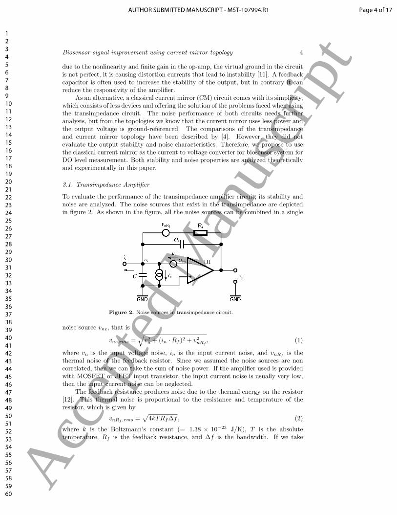
To evaluate the performance of the transimpedance amplifier circuit, its stability andnoise are analyzed. The noise sources that exist in the transimpedance are depictedin figure 2. As shown in the figure, all the noise sources can be combined in a single
Figure 2. Noise sources in transimpedance circuit.
noise source vne, that is
vne,rms =√v2n + (in ·Rf )2 + v2nRf
, (1)
where vn is the input voltage noise, in is the input current noise, and vnRfis the
thermal noise of the feedback resistor. Since we assumed the noise sources are noncorrelated, then we can take the sum of noise power. If the amplifier used is providedwith MOSFET or JFET input transistor, the input current noise is usually very low,then the input current noise can be neglected.
The feedback resistance produces noise due to the thermal energy on the resistor[12]. This thermal noise is proportional to the resistance and temperature of theresistor, which is given by
vnRf ,rms =√
4kTRf∆f, (2)
where k is the Boltzmann’s constant (= 1.38 × 10⁻²³ J/K), T is the absolutetemperature, Rf is the feedback resistance, and ∆f is the bandwidth. If we take
Page 4 of 17AUTHOR SUBMITTED MANUSCRIPT - MST-107994.R1
123456789101112131415161718192021222324252627282930313233343536373839404142434445464748495051525354555657585960
Acc
epte
d M
anus
crip
t
Biosensor signal improvement using current mirror topology 5
the absolute temperature of 300 K and the feedback resistance of 1 MΩ, the noise offeedback resistance becomes 128.7 nV/
√Hz.
The system noise gain is obtained by comparing the noise at output responseto the noise source at the inverting input terminal vinv. By analyzing the gain ofinverting amplifier, we are given [13]
vinv = − voA(s)
= −vo(s+ ω0)
A0ω0, (3)
where vo is the output voltage, ω0 is the open loop pole, and A0 is the open loop gain.By summing the current at node vi, we obtain the noise gain expression as
vovne
=1 + s(Ci + Cf )Rf
1 + sCfRf +s+ ω0
A0ω0[1 + s(Ci + Cf )Rf ]
. (4)
Ci is the input capacitance and Cf is the feedback capacitance. This expression is afunction of frequency. Since Cf is not used and the value of Ci and operation frequencyin this experiment are low, this leaves the noise gain (An) to unity. Therefore, thetotal system noise (vns) can be written as
vns = An · vne = vne. (5)
From (5), it is obviously seen that no noise gain is applied. So that, the total systemnoise is the same with vne. In this case, the thermal noise from feedback resistancedominates the total noise at low frequency. A FET-based input op-amp of TLC2272is used for the transimpedance with the input voltage noise of 9 nV/
√Hz @ 1 kHz,
the input current noise of 0.6 fA/√Hz, and the input capacitance of 8 pF. As the
reference resistance, a metal film resistor of 10 MΩ with 1% tolerance is used. Withthese values, the total system noise is 407.1 nV/
√Hz.
3.2. Current Mirror
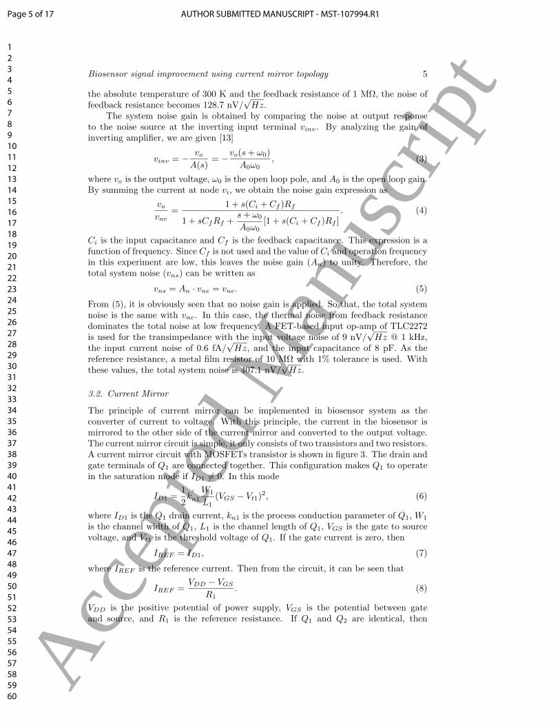
The principle of current mirror can be implemented in biosensor system as theconverter of current to voltage. With this principle, the current in the biosensor ismirrored to the other side of the current mirror and converted to the output voltage.The current mirror circuit is simple, it only consists of two transistors and two resistors.A current mirror circuit with MOSFETs transistor is shown in figure 3. The drain andgate terminals of Q1 are connected together. This configuration makes Q1 to operatein the saturation mode if ID1 6= 0. In this mode
ID1 =1
2k
′
n1
W1
L1(VGS − Vt1)2, (6)
where ID1 is the Q1 drain current, kn1 is the process conduction parameter of Q1, W1
is the channel width of Q1, L1 is the channel length of Q1, VGS is the gate to sourcevoltage, and Vt1 is the threshold voltage of Q1. If the gate current is zero, then
IREF = ID1, (7)
where IREF is the reference current. Then from the circuit, it can be seen that
IREF =VDD − VGS
R1. (8)
VDD is the positive potential of power supply, VGS is the potential between gateand source, and R1 is the reference resistance. If Q1 and Q2 are identical, then
Page 5 of 17 AUTHOR SUBMITTED MANUSCRIPT - MST-107994.R1
123456789101112131415161718192021222324252627282930313233343536373839404142434445464748495051525354555657585960
Acc
epte
d M
anus
crip
t
Biosensor signal improvement using current mirror topology 6
Figure 3. Current mirror circuit with MOSFET.
these MOSFETs have the same VGS . Consequently, the drain current in the secondtransistor is
ID2 =1
2k
′
n2
W2
L2(VGS − Vt2)2, (9)
where ID2 is the Q2 drain current, kn2 is the process conduction parameter of Q2, W2
is the channel width of Q2, L2 is the channel length of Q1, and Vt2 is the thresholdvoltage of Q2. If these MOSFETs are perfectly match fabricated, then k
′
n1 = k′
n2,W1 = W2, L1 = L2, and Vt1 = Vt2. So that from (6), (7) and (9)
ID2 = IREF . (10)
This equation becomes the basic principle of current mirror circuit.
3.3. Current Mirror Noise
The current mirror is a current-mode circuit, which possesses a small input and a largeoutput impedance. The current transfer function is given by [14]
Io(s)
Ii(s)=
As
ωb+ 1
, (11)
where A =gm2
gm1, and
ωb =gm1
Cgs1 + Cgs2 + Cgd2. (12)
Cgs1 is the gate to source capacitance of Q1, Cgs2 is the gate to source capacitanceof Q2, and Cgd2 is the gate to drain capacitance of Q2. In the case of Q1 and Q2
match and low frequency application, these bring to gm1 = gm2 ands
ωb 1. As the
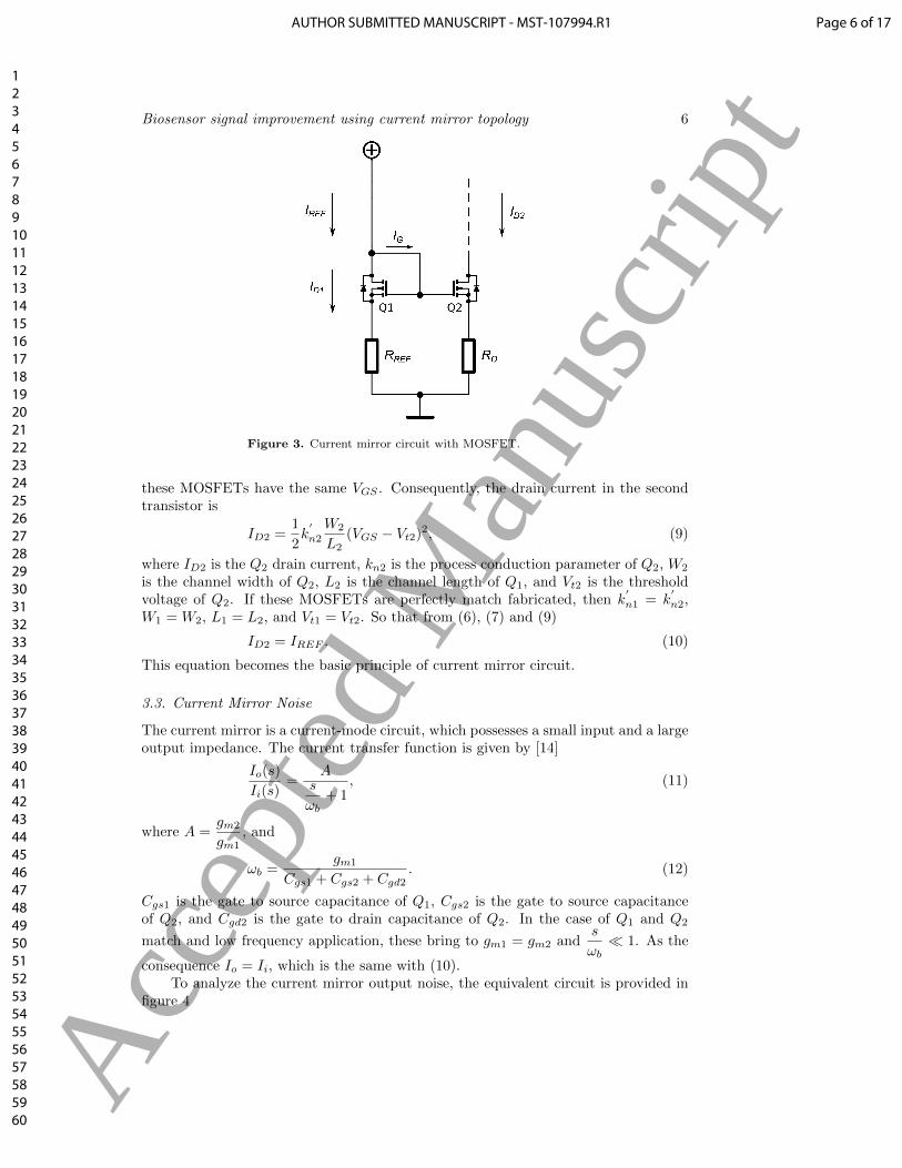
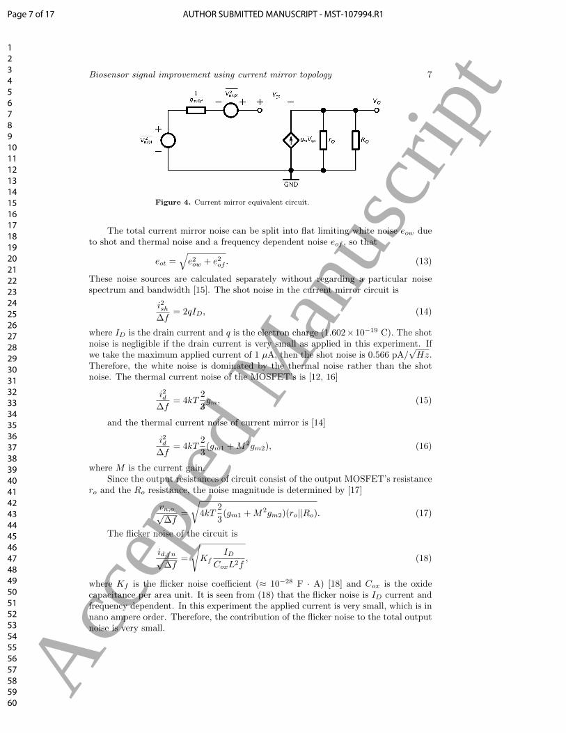
consequence Io = Ii, which is the same with (10).To analyze the current mirror output noise, the equivalent circuit is provided in
figure 4
Page 6 of 17AUTHOR SUBMITTED MANUSCRIPT - MST-107994.R1
123456789101112131415161718192021222324252627282930313233343536373839404142434445464748495051525354555657585960
Acc
epte
d M
anus
crip
t
Biosensor signal improvement using current mirror topology 7
Figure 4. Current mirror equivalent circuit.
The total current mirror noise can be split into flat limiting white noise eow dueto shot and thermal noise and a frequency dependent noise eof , so that
eot =√e2ow + e2of . (13)
These noise sources are calculated separately without regarding a particular noisespectrum and bandwidth [15]. The shot noise in the current mirror circuit is
i2sh∆f
= 2qID, (14)
where ID is the drain current and q is the electron charge (1.602×10⁻¹⁹ C). The shotnoise is negligible if the drain current is very small as applied in this experiment. Ifwe take the maximum applied current of 1 µA, then the shot noise is 0.566 pA/
√Hz.
Therefore, the white noise is dominated by the thermal noise rather than the shotnoise. The thermal current noise of the MOSFET’s is [12, 16]
i2d∆f
= 4kT2
3gm, (15)
and the thermal current noise of current mirror is [14]
i2d∆f
= 4kT2
3(gm1 +M2gm2), (16)
where M is the current gain.Since the output resistances of circuit consist of the output MOSFET’s resistance
ro and the Ro resistance, the noise magnitude is determined by [17]
vn,o√∆f
=
√4kT
2
3(gm1 +M2gm2)(ro||Ro). (17)
The flicker noise of the circuit is
id,fn√∆f
=
√Kf
IDCoxL2f
, (18)
where Kf is the flicker noise coefficient (≈ 10−28 F · A) [18] and Cox is the oxidecapacitance per area unit. It is seen from (18) that the flicker noise is ID current andfrequency dependent. In this experiment the applied current is very small, which is innano ampere order. Therefore, the contribution of the flicker noise to the total outputnoise is very small.
Page 7 of 17 AUTHOR SUBMITTED MANUSCRIPT - MST-107994.R1
123456789101112131415161718192021222324252627282930313233343536373839404142434445464748495051525354555657585960
Acc
epte
d M
anus
crip
t
Biosensor signal improvement using current mirror topology 8
So that, the total noise of current mirror is
vn√∆f
=
√v2n,Q1 + v2n,Q2 +
(vn,o√∆f
)2
+
(id,fn√
∆f
)2
. (19)
The total noise is dominated by the thermal resistance of the output resistance,because the vn,Q1, vn,Q2, ID and Kf are very small. Therefore, the total noise isdepending only on the output resistance
vn√∆f
=
√4kT
2
3(gm1 +M2gm2)(ro||Ro). (20)
In this current mirror design, the thermal noise is dominated by the outputresistance. The channel resistance ro is determined by the channel-length modulationparameter (λ) and the dc or quiescent drain current (IDQ). Since the λ value is around0.02 V−1 [19] and the IDQ value in this experiment is very small (∼ 1 nA), the internaloutput resistance can be much larger and the output resistance is equal to externaloutput resistance Ro (= 10 MΩ). By using (20), we can approximate that the noiseof current mirror circuit. With the value of gm around 10 mA/V [19] and M is 1 dueto current mirror, then the noise of the current mirror circuit is
vn√∆f
=
√4
3· 10−24kTRo. (21)
From (21), we can prove that the noise of the current mirror circuit is lower about 10times than the transimpedance circuit described previously in (2).
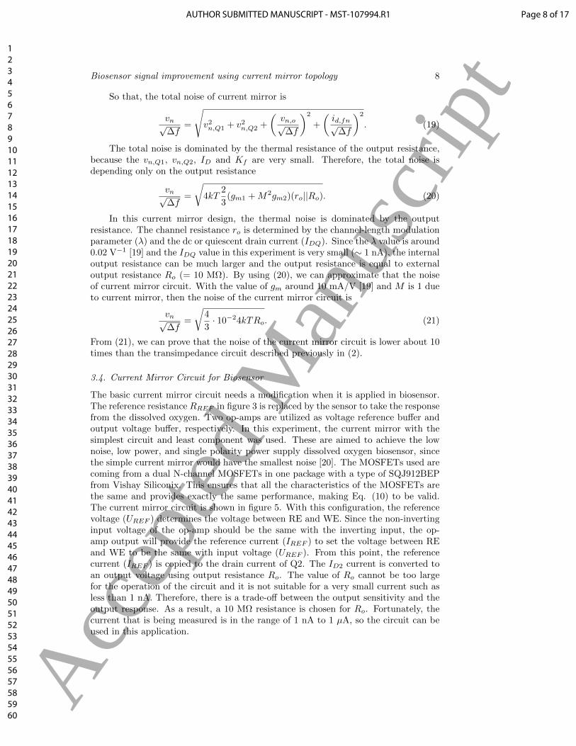
3.4. Current Mirror Circuit for Biosensor
The basic current mirror circuit needs a modification when it is applied in biosensor.The reference resistance RREF in figure 3 is replaced by the sensor to take the responsefrom the dissolved oxygen. Two op-amps are utilized as voltage reference buffer andoutput voltage buffer, respectively. In this experiment, the current mirror with thesimplest circuit and least component was used. These are aimed to achieve the lownoise, low power, and single polarity power supply dissolved oxygen biosensor, sincethe simple current mirror would have the smallest noise [20]. The MOSFETs used arecoming from a dual N-channel MOSFETs in one package with a type of SQJ912BEPfrom Vishay Siliconix. This ensures that all the characteristics of the MOSFETs arethe same and provides exactly the same performance, making Eq. (10) to be valid.The current mirror circuit is shown in figure 5. With this configuration, the referencevoltage (UREF ) determines the voltage between RE and WE. Since the non-invertinginput voltage of the op-amp should be the same with the inverting input, the op-amp output will provide the reference current (IREF ) to set the voltage between REand WE to be the same with input voltage (UREF ). From this point, the referencecurrent (IREF ) is copied to the drain current of Q2. The ID2 current is converted toan output voltage using output resistance Ro. The value of Ro cannot be too largefor the operation of the circuit and it is not suitable for a very small current such asless than 1 nA. Therefore, there is a trade-off between the output sensitivity and theoutput response. As a result, a 10 MΩ resistance is chosen for Ro. Fortunately, thecurrent that is being measured is in the range of 1 nA to 1 µA, so the circuit can beused in this application.
Page 8 of 17AUTHOR SUBMITTED MANUSCRIPT - MST-107994.R1
123456789101112131415161718192021222324252627282930313233343536373839404142434445464748495051525354555657585960
Acc
epte
d M
anus
crip
t
Biosensor signal improvement using current mirror topology 9
Figure 5. Current mirror circuit for biosensor.
The output voltage can be calculated by
UOUT = IREF ·Ro. (22)
In the application, the biosensor replaces the reference resistance in figure 3, sothe resistance of the solution is determined by the O2 concentration and controls thereference current (IREF ). Therefore, the output voltage (UOUT ) can be read as theeffect of O2 concentration.
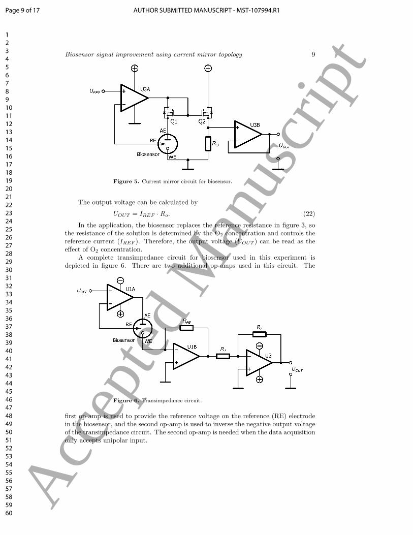
A complete transimpedance circuit for biosensor used in this experiment isdepicted in figure 6. There are two additional op-amps used in this circuit. The
Figure 6. Transimpedance circuit.
first op-amp is used to provide the reference voltage on the reference (RE) electrodein the biosensor, and the second op-amp is used to inverse the negative output voltageof the transimpedance circuit. The second op-amp is needed when the data acquisitiononly accepts unipolar input.
Page 9 of 17 AUTHOR SUBMITTED MANUSCRIPT - MST-107994.R1
123456789101112131415161718192021222324252627282930313233343536373839404142434445464748495051525354555657585960
Acc
epte
d M
anus
crip
t
Biosensor signal improvement using current mirror topology 10
4. Measurement
4.1. Current to Voltage Conversion Characteristics
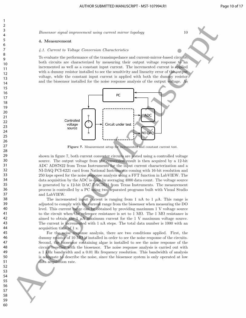
To evaluate the performance of the transimpedance and current-mirror-based circuits,both circuits are characterized by measuring their output voltage response to anincremented as well as a constant input current. The incremented current is appliedwith a dummy resistor installed to see the sensitivity and linearity error of the outputvoltage, while the constant input current is applied with both the dummy resistorand the biosensor installed for the noise response analysis of the output voltage. As
Figure 7. Measurement setup for incremented and constant current test.
shown in figure 7, both current converter circuits are tested using a controlled voltagesource. The output voltage from the conversion result is then acquired by a 12-bitADC ADS7822 from Texas Instruments for the input current characterization and aNI-DAQ PCI-6221 card from National Instruments coming with 16-bit resolution and250 ksps speed for the noise response analysis using a FFT function in LabVIEW. Thedata acquisition by the ADC is done by averaging 4000 data count. The voltage sourceis generated by a 12-bit DAC DAC7611 from Texas Instruments. The measurementprocess is controlled by a PC using two separated programs built with Visual Studioand LabVIEW.
The incremented input current is ranging from 1 nA to 1 µA. This range isadjusted to comply with the current range from the biosensor when measuring the DOlevel. This current range can be obtained by providing maximum 1 V voltage sourceto the circuit when the reference resistance is set to 1 MΩ. The 1 MΩ resistance isaimed to obtain the 1 µA maximum current for the 1 V maximum voltage source.The current is incremented with 1 nA steps. The total data number is 1000 with anacquisition time of 1 s.
For the noise response analysis, there are two conditions applied. First, thedummy resistor of 10 MΩ is installed in order to see the noise response of the circuits.Second, the biosensor containing algae is installed to see the noise response of thecircuit together with the biosensor. The noise response analysis is carried out witha 1 kHz bandwidth and a 0.01 Hz frequency resolution. This bandwidth of analysisis adequate to describe the noise, since the biosensor system is only operated at lowdata acquisition rate.
Page 10 of 17AUTHOR SUBMITTED MANUSCRIPT - MST-107994.R1
123456789101112131415161718192021222324252627282930313233343536373839404142434445464748495051525354555657585960
Acc
epte
d M
anus
crip
t
Biosensor signal improvement using current mirror topology 11
4.2. Dissolved Oxygen Measurements
The dissolved oxygen measurement is aimed to evaluate the circuits when they aredirectly applied to the biosensor system for measuring dissolved oxygen in the solution.The measurement utilizes algae as the oxygen producer in the water. The dissolvedoxygen level is varied to see the response of the biosensor system. The dissolvedoxygen can be varied either by varying the amount of inserted algae in the water orby applying the artificial light to stimulated a photosynthesis. The first way is ratherdifficult to be done. The easy way is by using the second one. The measurement iscarried out by turning on and off the light source to see the oxygen production activityby the algae.
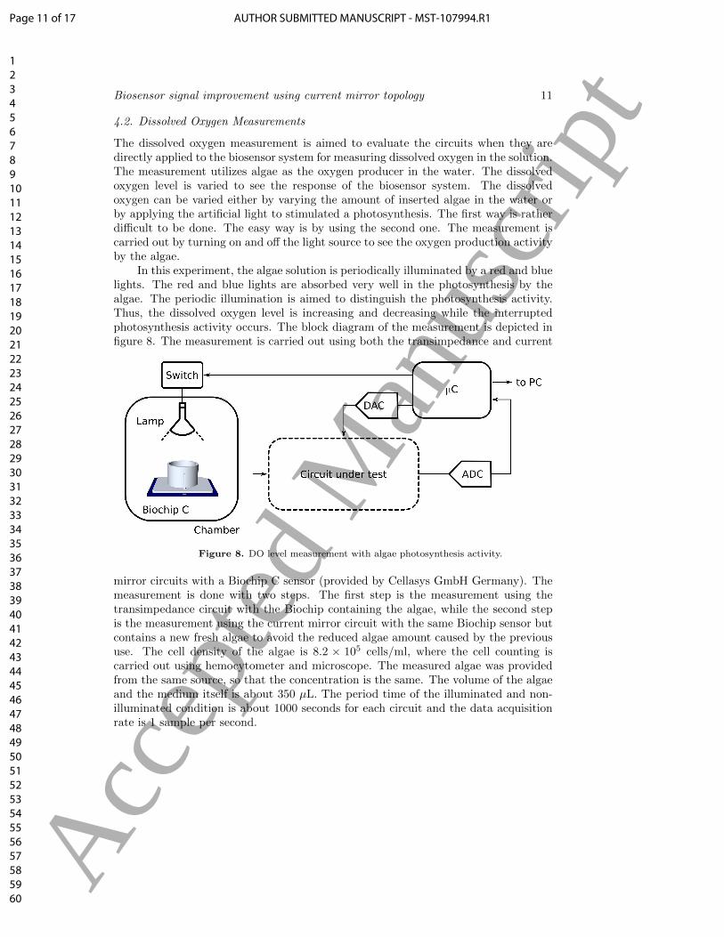
In this experiment, the algae solution is periodically illuminated by a red and bluelights. The red and blue lights are absorbed very well in the photosynthesis by thealgae. The periodic illumination is aimed to distinguish the photosynthesis activity.Thus, the dissolved oxygen level is increasing and decreasing while the interruptedphotosynthesis activity occurs. The block diagram of the measurement is depicted infigure 8. The measurement is carried out using both the transimpedance and current
Figure 8. DO level measurement with algae photosynthesis activity.
mirror circuits with a Biochip C sensor (provided by Cellasys GmbH Germany). Themeasurement is done with two steps. The first step is the measurement using thetransimpedance circuit with the Biochip containing the algae, while the second stepis the measurement using the current mirror circuit with the same Biochip sensor butcontains a new fresh algae to avoid the reduced algae amount caused by the previoususe. The cell density of the algae is 8.2 × 10⁵ cells/ml, where the cell counting iscarried out using hemocytometer and microscope. The measured algae was providedfrom the same source, so that the concentration is the same. The volume of the algaeand the medium itself is about 350 µL. The period time of the illuminated and non-illuminated condition is about 1000 seconds for each circuit and the data acquisitionrate is 1 sample per second.
Page 11 of 17 AUTHOR SUBMITTED MANUSCRIPT - MST-107994.R1
123456789101112131415161718192021222324252627282930313233343536373839404142434445464748495051525354555657585960
Acc
epte
d M
anus
crip
t
Biosensor signal improvement using current mirror topology 12
5. Results and Discussion
5.1. Current to Voltage Conversion Characteristics
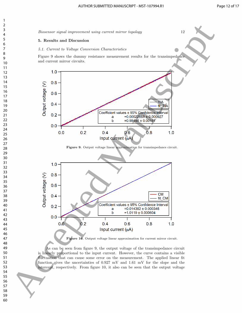
Figure 9 shows the dummy resistance measurement results for the transimpedanceand current mirror circuits.
Figure 9. Output voltage linear approximation for transimpedance circuit.
Figure 10. Output voltage linear approximation for current mirror circuit.
As can be seen from figure 9, the output voltage of the transimpedance circuitis linearly proportional to the input current. However, the curve contains a visiblefluctuation that can cause some error on the measurement. The applied linear fitfunction gives the uncertainties of 0.927 mV and 1.61 mV for the slope and theintercept, respectively. From figure 10, it also can be seen that the output voltage
Page 12 of 17AUTHOR SUBMITTED MANUSCRIPT - MST-107994.R1
123456789101112131415161718192021222324252627282930313233343536373839404142434445464748495051525354555657585960
Acc
epte
d M
anus
crip
t
Biosensor signal improvement using current mirror topology 13
of the current mirror circuit is linearly proportional to the incremented input current.Contrast with the transimpedance, it is seen almost no visible fluctuation of the outputvoltage of the current mirror circuit. The obtained uncertainties of the transimpedancecircuit are larger than the uncertainties of the current mirror circuit which are 0.348mV and 0.604 mV for the slope and the intercept, respectively.
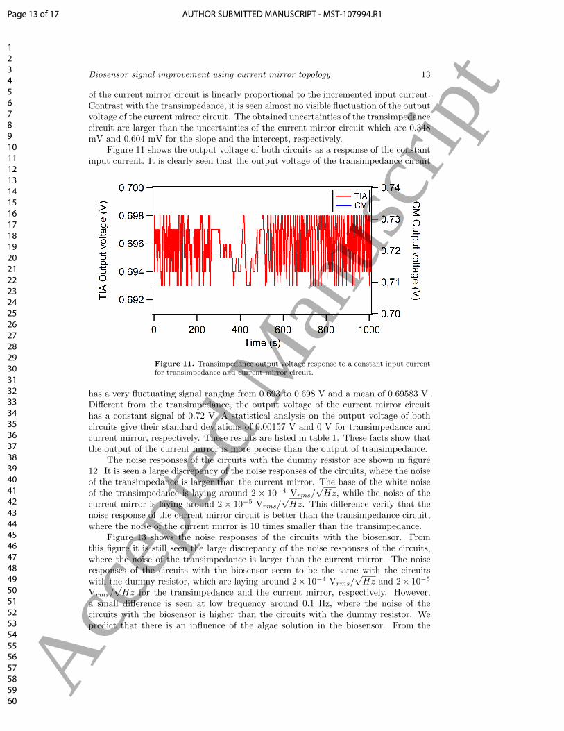
Figure 11 shows the output voltage of both circuits as a response of the constantinput current. It is clearly seen that the output voltage of the transimpedance circuit
Figure 11. Transimpedance output voltage response to a constant input currentfor transimpedance and current mirror circuit.
has a very fluctuating signal ranging from 0.693 to 0.698 V and a mean of 0.69583 V.Different from the transimpedance, the output voltage of the current mirror circuithas a constant signal of 0.72 V. A statistical analysis on the output voltage of bothcircuits give their standard deviations of 0.00157 V and 0 V for transimpedance andcurrent mirror, respectively. These results are listed in table 1. These facts show thatthe output of the current mirror is more precise than the output of transimpedance.
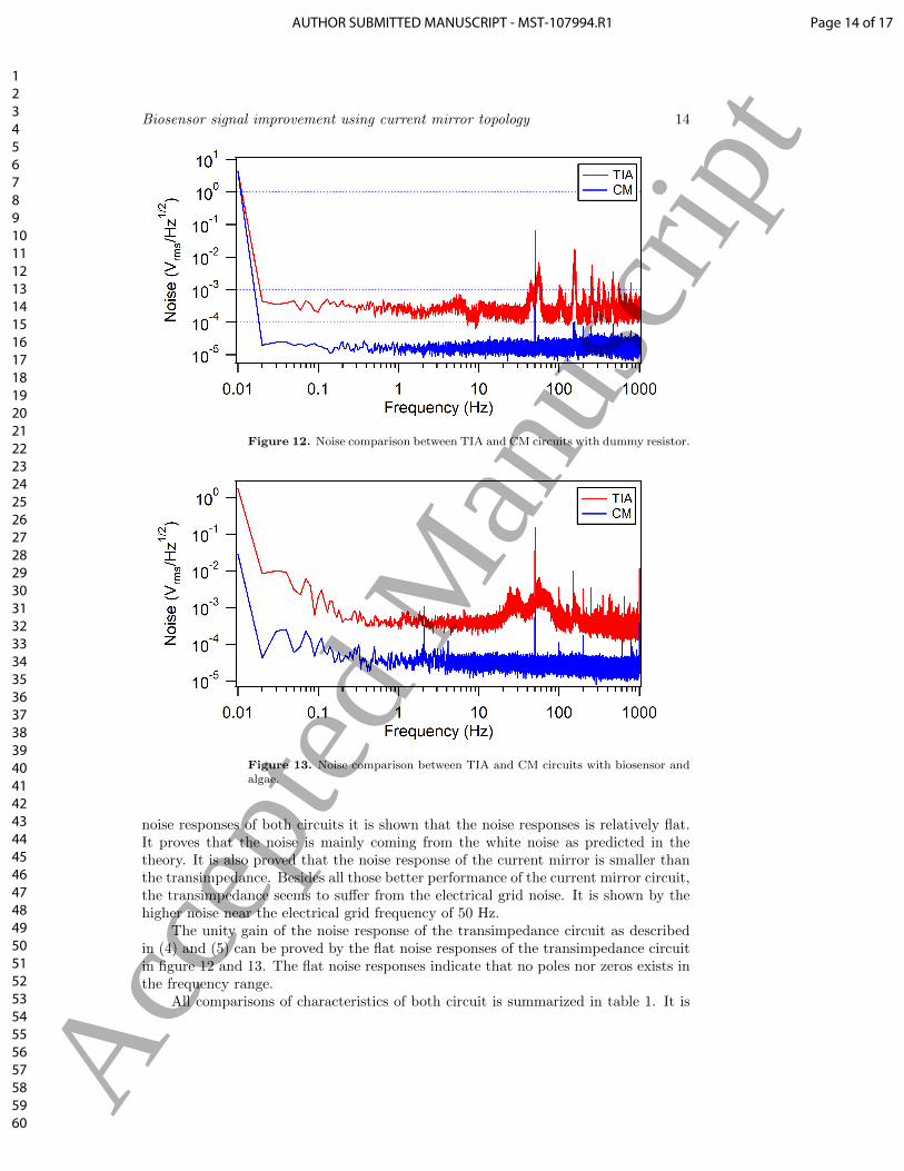
The noise responses of the circuits with the dummy resistor are shown in figure12. It is seen a large discrepancy of the noise responses of the circuits, where the noiseof the transimpedance is larger than the current mirror. The base of the white noiseof the transimpedance is laying around 2 × 10⁻⁴ Vrms/
√Hz, while the noise of the
current mirror is laying around 2 × 10⁻⁵ Vrms/√Hz. This difference verify that the
noise response of the current mirror circuit is better than the transimpedance circuit,where the noise of the current mirror is 10 times smaller than the transimpedance.
Figure 13 shows the noise responses of the circuits with the biosensor. Fromthis figure it is still seen the large discrepancy of the noise responses of the circuits,where the noise of the transimpedance is larger than the current mirror. The noiseresponses of the circuits with the biosensor seem to be the same with the circuitswith the dummy resistor, which are laying around 2× 10⁻⁴ Vrms/
√Hz and 2× 10⁻⁵
Vrms/√Hz for the transimpedance and the current mirror, respectively. However,
a small difference is seen at low frequency around 0.1 Hz, where the noise of thecircuits with the biosensor is higher than the circuits with the dummy resistor. Wepredict that there is an influence of the algae solution in the biosensor. From the
Page 13 of 17 AUTHOR SUBMITTED MANUSCRIPT - MST-107994.R1
123456789101112131415161718192021222324252627282930313233343536373839404142434445464748495051525354555657585960
Acc
epte
d M
anus
crip
t
Biosensor signal improvement using current mirror topology 14
Figure 12. Noise comparison between TIA and CM circuits with dummy resistor.
Figure 13. Noise comparison between TIA and CM circuits with biosensor andalgae.
noise responses of both circuits it is shown that the noise responses is relatively flat.It proves that the noise is mainly coming from the white noise as predicted in thetheory. It is also proved that the noise response of the current mirror is smaller thanthe transimpedance. Besides all those better performance of the current mirror circuit,the transimpedance seems to suffer from the electrical grid noise. It is shown by thehigher noise near the electrical grid frequency of 50 Hz.
The unity gain of the noise response of the transimpedance circuit as describedin (4) and (5) can be proved by the flat noise responses of the transimpedance circuitin figure 12 and 13. The flat noise responses indicate that no poles nor zeros exists inthe frequency range.
All comparisons of characteristics of both circuit is summarized in table 1. It is
Page 14 of 17AUTHOR SUBMITTED MANUSCRIPT - MST-107994.R1
123456789101112131415161718192021222324252627282930313233343536373839404142434445464748495051525354555657585960
Acc
epte
d M
anus
crip
t

Biosensor signal improvement using current mirror topology 15
Table 1. Comparison of the characteristic of the transimpedance and currentmirror circuits.
Lin. fit uncertainty Const. Inp. current Noise (Vrms/√Hz)Circuit
Slope Intercept Mean Std. dev. Resistor BiosensorTIA 0.00161 0.000927 0.69583 0.00157 2× 10⁻⁴ 3× 10⁻⁴
CM 0.000604 0.000348 0.72 0 2× 10⁻⁵ 3× 10⁻⁵
seen from the table that the comparisons of all parameters give some proofs that thecurrent mirror circuit is better than the transimpedance circuit.
5.2. Dissolved Oxygen Measurements
From figure 14, it can be seen the responses of both circuits to the algae photosynthesisactivity. It is seen that the output voltage of both circuits is increasing and decreasingwhen the algae is illuminated and not illuminated by the light. The increasingphase is the condition where the photosynthesis occurs and the decreasing phaseis the condition where the photosynthesis does not occur. The increasing anddecreasing periods are consistent with the periods of illumination and non-illuminationphases. The difference of the noise response of the circuits is obviously seen in this
Figure 14. Zoomed transimpedance and current mirror output voltage responsewith algae photosynthesis experiment.
measurement results. The output from the transimpedance circuit is thicker than theoutput of current mirror circuit. As the consequence, the measurement resolution ofthe transimpedance circuit might be larger than the current mirror. Therefore, theability of the transimpedance circuit to detect the DO level is not as good as thecurrent mirror circuit.
6. Conclusion
The theory of the noise sources of the transimpedance and current mirror circuitsand the characteristics of the circuits for increment and constant input current have
Page 15 of 17 AUTHOR SUBMITTED MANUSCRIPT - MST-107994.R1
123456789101112131415161718192021222324252627282930313233343536373839404142434445464748495051525354555657585960
Acc
epte
d M
anus
crip
t
Biosensor signal improvement using current mirror topology 16
been presented and discussed. It has also been performed the dissolved oxygenmeasurement on the photosynthesis activity of the algae. From the provided theory,it can be concluded that the noise response of the current mirror circuit is lowerthan the transimpedance circuit. It is then can be agreed by the experiments of theincremented and constant input current, which show the good results for the currentmirror circuit. The noise response of the current mirror circuit is 10 times lower thanthe transimpedance circuit. Besides that, the theory prediction of the domination ofthe white noise in the system has also been verified. The last experiment, which iscarried out using the algae as the dissolved oxygen producer, also shows the advantagesof using the current mirror circuit as the biosensor system. The notable excellences ofusing the current mirror circuit are proof against Biochip sensor properties and alsoexhibits low noise.
Acknowledgments
The authors gratefully acknowledge the Directorate of Research and CommunityService, General Directorate of Research Strengthening and Development, Ministryof Research, Technology, and Higher Education of Indonesia for the research fundingwith the contract number: 086/SP2H/LT/DRPM/2018.
References
[1] Li F, Wei Y, Chen Y, Li D and Zhang X 2015 Sensors 15 30913–30926[2] Parmar T K, Rawtani D and Agrawal Y K 2016 Frontiers in Life Science 9 110–118 URL
https://doi.org/10.1080/21553769.2016.1162753
[3] Chong S S, Aziz A R A and Harun S W 2013 Sensors 13 8640–8668[4] Ahmadi M M and Jullien G A 2009 IEEE Transactions on Circuits and Systems I: Regular
Papers 56 1339–1348[5] Umar L, Alexander F A and Wiest J 2015 Application of algae-biosensor for en-
vironmental monitoring 2015 37th Annual International Conference of the IEEEEngineering in Medicine and Biology Society (EMBC) pp 7099–7102 URLhttps://ieeexplore.ieee.org/document/7320028
[6] Umar L, Setiadi R N, Hamzah Y and Linda T M 2017 InternationalJournal on Smart Sensing and Intelligent Systems 10 955–975 URLhttp://s2is.org/Issues/v10/n4/papers/paper10.pdf
[7] Wu C C, Yasukawa T, Shiku H and Matsue T 2005 Sensors and Actuators B 110 342–349 URLhttp://www.sciencedirect.com/science/article/pii/S0925400505001942
[8] Stadthagen T 2007 Enwicklung eines online Gewssermonitorings-systems mittles Biosensorchipszum Nachweis ausgewhlter Xenobiotika PhD dissertation TU Muenchen
[9] Belaidi F S, Tsopela A, Salvagnac L, Ventalon V, Bedel-Pereira E, Bardinal V, Seguy I, Temple-Boyer P, Juneau P, Izquierdo R and Launay J 2016 Lab-on-chip with microalgal basedbiosensor for water assessment 2016 IEEE Nanotechnology Materials and Devices Conference(NMDC) pp 1–2 URL https://ieeexplore.ieee.org/document/7777103
[10] Razavi B 2000 A 622 mb/s 4.5 pA/√Hz cmos transimpedance amplifier 2000 IEEE
International Solid-State Circuits Conference. Digest of Technical Papers pp 162–163 URLhttps://ieeexplore.ieee.org/document/839732
[11] Mahrof D H, Klumperink E A M, Ru Z, Alink M S O and Nauta B 2014 IEEE Journal ofSolid-State Circuits 49 1112–1124 URL https://ieeexplore.ieee.org/document/6708481
[12] Leach W M 1994 Proceedings of the IEEE 82 1515–1538[13] Uhrmann H, Gaberl W and Zimmermann H 2008 Advance in Radio Science 6 213–217 URL
https://www.adv-radio-sci.net/6/213/2008/
[14] Yuan F 2007 Design Techniques for Current-Mode Circuits (Boston, MA: Springer US) pp 13–48ISBN 978-0-387-29758-3 URL https://doi.org/10.1007/978-0-387-47691-9 2
[15] Bilotti A and Mariani E 1975 IEEE Journal of Solid-state Circuits SC-10 516–524[16] Haque S, Frost R, Dion F, Groulx R, Holland S, Karcher A, Kolbe W et al.
2012 Design of low-noise output amplifiers for p-channel charge-coupled de-
Page 16 of 17AUTHOR SUBMITTED MANUSCRIPT - MST-107994.R1
123456789101112131415161718192021222324252627282930313233343536373839404142434445464748495051525354555657585960
Acc
epte
d M
anus
crip
t
Biosensor signal improvement using current mirror topology 17
vices fabricated on high-resistivity silicon online; September 28, 2018 URLhttps://digital.library.unt.edu/ark:/67531/metadc842724/
[17] Khatib M and Perenzoni M 2018 Sensors 18 1–18 URLhttp://www.mdpi.com/1424-8220/18/6/1867
[18] Allen P E and Holberg D R 2002 CMOS analog circuit design (2nd ed.) (New York: Oxford:Oxford University Press) ISBN 978-0199937424
[19] Neamen D A 2010 Microelectronics: Circuit Analysis and Design (New York, NY: The McGraw-Hill Companies, Inc.) ISBN 9780073380643
[20] Alves L N and Aguiar R L 2002 9th International Conference on Electronics, Circuits andSystems 1 277–280 URL https://ieeexplore.ieee.org/document/1045387/
Page 17 of 17 AUTHOR SUBMITTED MANUSCRIPT - MST-107994.R1
123456789101112131415161718192021222324252627282930313233343536373839404142434445464748495051525354555657585960
Acc
epte
d M
anus
crip
t