Chapter 4 AC Voltage Regulators
14
Chapter 4 AC Voltage Regulators 1. Introduction A power electronic ac/ac converter, in generic form, accepts electric power from one system and converts it for delivery to another ac system with waveforms of different amplitude frequency, and phase. They may be single- or three - phase types depending on their power ratings. The ac/ac converters employed to vary the rms voltage across the load at constant frequency are known as AC voltage controllers, AC regulators or AC chopper. The voltage control is accomplished either by: (i) Phase control under natural commutation using pairs of silicon-controlled rectifiers (SCRs) or Triacs. (ii) On-off control under forced commutation using fully controlled self- commutated switches such as Gate Turn-off Thyristors (GTOs), power transistors, Insulated Gate Bipolar Transistors (IGBTs), MOS-controlled Thyristors (MCTs), etc. The most common applications of AC voltage controllers are: industrial heating, on-load transformer tap changer, light control, induction heating of metals, speed control of polyphase induction motors, electric welding, and primary transformer control for electro-chemical processes and AC magnet controls. Figure 1 shows the configurations of AC voltage controller. The basic power circuit of a single-phase ac-ac voltage controller, as shown in Fig. 1a, is composed of a pair of SCRs connected back-to-back (also known as inverse-parallel or anti-parallel) between the ac supply and the load. This connection provides a bidirectional full-wave symmetrical control and the SCR pair can be replaced by Triac (Fig. 1b) for low-power applications. Alternate arrangements are as shown in Fig. 1c with two diodes and two SCRs to provide a common cathode connection for simplifying the gating circuit without needing
-
Upload
khangminh22 -
Category
Documents
-
view
0 -
download
0
Transcript of Chapter 4 AC Voltage Regulators

Chapter 4 AC Voltage Regulators
1. Introduction
A power electronic ac/ac converter, in generic form, accepts electric power
from one system and converts it for delivery to another ac system with waveforms
of different amplitude frequency, and phase. They may be single- or three - phase
types depending on their power ratings. The ac/ac converters employed to vary
the rms voltage across the load at constant frequency are known as AC voltage
controllers, AC regulators or AC chopper.
The voltage control is accomplished either by:
(i) Phase control under natural commutation using pairs of silicon-controlled rectifiers (SCRs) or Triacs.
(ii) On-off control under forced commutation using fully controlled self-commutated switches such as Gate Turn-off Thyristors (GTOs), power transistors, Insulated Gate Bipolar Transistors (IGBTs), MOS-controlled Thyristors (MCTs), etc.
The most common applications of AC voltage controllers are: industrial
heating, on-load transformer tap changer, light control, induction heating of
metals, speed control of polyphase induction motors, electric welding, and
primary transformer control for electro-chemical processes and AC magnet
controls. Figure 1 shows the configurations of AC voltage controller.
The basic power circuit of a single-phase ac-ac voltage controller, as shown in
Fig. 1a, is composed of a pair of SCRs connected back-to-back (also known as
inverse-parallel or anti-parallel) between the ac supply and the load. This
connection provides a bidirectional full-wave symmetrical control and the SCR
pair can be replaced by Triac (Fig. 1b) for low-power applications. Alternate
arrangements are as shown in Fig. 1c with two diodes and two SCRs to provide a
common cathode connection for simplifying the gating circuit without needing

isolation, and in Fig. 1d with one SCR and four diodes to reduce the device cost
but with increased device conduction loss. An SCR and diode combination,
known as a thyrode controller, as shown in Fig. 1e, provides a unidirectional half-
wave asymmetrical voltage control with device economy but introduces a dc
component and more harmonics and thus is not very practical to use except for a
very low power heating load.
This chapter shows the operation of AC Chopper, for single phase R load, R-L
load, L-Vb load and the parallel operation of two single phase AC Choppers.
Methods of control:
For power transfer, two methods of control are used:
a. On-off control (Integral-Cycle Control):
The bidirectional AC switch is employed to connect the load circuit to
source for a few cycles (or half cycle) of the source voltage and disconnect it for a
comparable period as shown in Fig. 2
The thyristor switch connects the AC supply to load for a time tn; the switch
is turned off by a gate pulse inhibiting for time to. The on-time, tn, usually consists
of an integral number of cycles. The thyristors are turned on at the zero voltage
crossing of AC input voltage for resistive loads.
This type of control is applied in application, which have a high mechanical
inertia and high time constant such as temperature control, industrial heating and
speed control of motors,
Due to zero voltage switching of the thyristors, the harmonics generated by
switching actions are reduced, with low electrical noise.

Figure 1 Single-phase ac voltage controllers: (a) full-wave, two SCRs in inverse parallel; (b) full-wave with Triac; (c) full wave with two SCRs and two diodes; (d) full wave with
four diodes and one SCR
Figure 1 half-controlled with one SCR and diode in antiparallel.
Figure 2 On-off control (Integral-Cycle Control).
For a sinusoidal input voltage:
)sin()sin(2 tVtVv ms
If the input voltage is connected to load (pure resistance) for n cycles and is disconnected for m cycles, the rms output voltage is given by:

mn
ncycledutyk
kVmn
nV
tdtVmn
nV
ss
s
21
2
0
20 )sin(2(
)(2
Poav= average load power=Vs2K/R
kfactorpower
Example 4.1
A single phase AC voltage regulator has a resistive load of R=10 and the rms input voltage is 120V, 60Hz. The thyristors is On for n=25 Cycles and is Off for m=75 Cycles. Determine: a. rms output voltage. b. input power factor. c. average and rms current of thyristors. Solution: R=10, Vs=120V, n=25, m=75.
25.02575
25
nm
ncycledutyk
a. VkVV s 6025.01200 = rms load voltage.
AR
VI 6
10
6000 =rms load current.
b. wattRIP 360)10(62200 =output power
wattIVP si 7206*1200 =input voltage ampere
laggingmn
nk
P
PPf
i
5.0
5.0720
3600
c. AR
VII s
tppeakthy
97.1610
)120(22
Ak
Imn
nItdtI
mn
nI tptptp
avthy35.1
25.0)97.16(
)().sin(
)(20
Amn
nItdtI
mn
nI
tp
tprmsthy
24.425.02
97.16
)(2].)]sin([
)(2[
0
2/12

b. Phase control method:
The bidirectional AC switch is employed to connect the load circuit to the
source for a chosen portion of each half cycle of the source voltage.
The power flow to the load is controlled by delaying the firing angle of
thyristors T1 and T2 as shown in Fig. 3. This method of control is the must
common used method.
1. Phase control AC Chopper connected to R load:
Figure 4 shows the typical voltage and current waveforms for the single-phase
bidirectional phase-controlled ac voltage controller of Figure 1.a with resistive
load. The output voltage and current waveforms have half-wave symmetry and
thus no dc component.
Figure 3 Phase control method.
If suitable gating pulses are applied to the thyristors T1, T2 while their
respective anode voltages are positive conduction is initiated, the conduction
angle depends on the firing angle (also known as triggering angle) measured from
anode- voltage zero. The effective load voltage vo can be varied from zero,

corresponding to extinction of both thyristors, to almost full supply voltage,
corresponding to full of both thyristors. A set of theoretical wave forms for
sinusoidal supply voltage with an arbitrary triggering angle is given in the
Figure 5.
)sin(2,1 tVvvvv sTo
12 TT vv
,
,01
2,
,
)sin*2
)sin(2
tVvv
tVvRiv
sT
soo
From the viewpoint of power transfer, the electrical parameters of interest are the
rms load voltage Vo and rms current Io.
R
Vtd
R
vI oo
o
2/122
02
1
i.e. for 2 tandt
where varies form 0 to
. then Io varies from Vs/R to 0
and Vo varies from Vs to 0
The rms value the thyristor voltage is
2
2sin
2
12/12
0
211
sTT VtdvV
It is assumed that the supply voltage remain sinusoidal in the presence of
the nonsinusoidal current drawn through the supply impedance.
The Fourier spectrum of the load voltage ant of the load current contains
only odd harmonics.
The time-average value of the load voltage is zero over any complete
2
2sin1
2
12/12
0
2
s
oo
V
tdvV

number of cycles. Half cycle average values of the load voltage Vav and thyristor
voltage VTav are given by
0
cos121 s
oavo
VtdvV
0
cos121 s
TTav
VtdvV
Power is correctly defined as the time rate of energy transfer. The instantaneous
power at the load terminals Pi.
tR
VivP s
ooi 22
sin2
For t ; + t 2
The double supply frequency pulsation is positive for all time regardless of
triggering angle. Average lower P into the circuit with resistive load is given by
the time-average of voio product.
2
2sin1sin
21
2
1 22
0
22
R
Vttd
R
VtdivP s
oo
RIR
Vo
o 22

An alternative viewpoint is to consider that average power is dissipated
only by combination of in phase voltage and current components of the same
frequencies. Since the terminal voltage is sinusoidal and of supply
frequency, average power is related to the supply voltage in combination
with in-phase component of fundamental current Io1.
11 cosos IVP
Where 1 is the phase angle of fundamental component of load current Io1.
Irrespective of waveform, the power factor of a circuit is the factor by which
the apparent power must be multiplied in order to give the average power.
Power factor (pf)=Average Power/Apparent Volt-Ampers= P/Vs/Io.
The factor cos 1 is given the special name "Displacement factor"
The power factor of a nonsinusoidal system is often significantly different
from the displacement factor and this has led to the use of the term distortion
factor.
Distortion factor = Power factor/displacement factor
Power factor 1111 cos
cos
o
o
os
os
os I
I
IV
IV
IV
P
Power factor =
2
2sin1
so
oo
VI
VI
The fundamental component Io1 lags the supply voltage by angle 1. It is
known that a fundamental lagging component of current usually associated
with energy storage in a magnetic field. But in the circuit with resistive load,
shown in this section no storage of energy is possible. For this reason the
pulsations of instantaneous power is always positive. Since the load is not
capable of storing energy, no return of energy can occur from the load to the
supply and the instantaneous power cannot go negative.

Figure 5 Waveforms for single-phase ac full-wave voltage controller with R-load.
2. AC Chopper connected to R-L load
Figure 6 shows the voltage and current waveforms for the controller in
Figure 1.a with R-L load. This type of AC depends on the load impedance
angle, therefore,
a. Let’s take the first α≥ where is the load impedance angle.
Due to the inductance, the current carried by the T1 may not fall to zero
at ωt = π when the input voltage goes negative and may continue until
ωt= β (the extinction angle) as shown.
The conduction angle is:
The conduction angle of the SCR depends on the firing delay angle (α) and the load impedance angle ( ),

There some cases can take in considerations that depend on the firing angle and the power impedance and such as:
Figure 6 Typical wave forms of single-phase ac voltage controller with an RL-load.
1. Where [ ], that produces discontinuous AC output (AC
Chopper) as shown in figure 6.
2. For [α= ] that produces continuous output (Vorms = Vs).
3. Finally for [ ] that represent single phase half wave rectifier
and the output is a discontinuous DC. That is discussed in the single-phase half wave controlled rectifier.
4. State what happing if the gate pulse is sustain?

For The expression for the load current io (ωt) when conducting from
α to β can be derived in the same way as that used for a phase-controlled
rectifier in a discontinuous mode.
By solving the relevant Kirchhoff voltage equation:
)sin(2 tV
dt
diLRi
vv so
This equation of the first order has the solution of:
t
Aez
tVti
)sin(2
)(
Where R
LandLRz
R
L
221 )(,tan
From initial condition at t=α, the load current (io) equal to zero
e
z
VAAe
z
V )0sin(2)0sin(20
The load current equation is given by:
])sin()[sin(2
)( tan/)( tetZ
Vti
This equation valid from t
The angle β, when the current io falls to zero, can be determined from the
following transcendental equation obtained by putting io (ωt = β) = 0 in the
above equation.
tan/)()sin()sin( e
From the above Equation. One can obtain a relationship between γ and α for
given value of Φ, it is obtained that as α is increased the conduction angle γ
decreases and the rms value of the current decreases. The rms output voltage
2/12/122]
2
2sin
2
2sin[])(sin2
1[
VsttdVV so
Vo can be evaluated for two possible extreme values of Φ=0 when β= π and
Φ= π/2 when β=2π- α.
The rms SCR current:
])(2
1[ 2
)(
tdiI rmsSCR
The rms load current
)(2 rmsSCRo II
The average value of SCR current
)(
2
1)( tdiI oavSCR
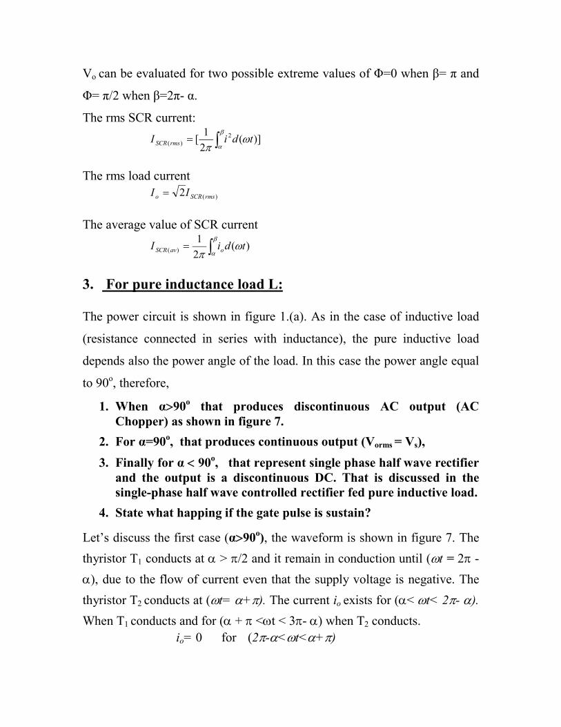
3. For pure inductance load L: The power circuit is shown in figure 1.(a). As in the case of inductive load
(resistance connected in series with inductance), the pure inductive load
depends also the power angle of the load. In this case the power angle equal
to 90o, therefore,
1. When α90o that produces discontinuous AC output (AC Chopper) as shown in figure 7.
2. For α=90o, that produces continuous output (Vorms = Vs),
3. Finally for α 90o, that represent single phase half wave rectifier and the output is a discontinuous DC. That is discussed in the single-phase half wave controlled rectifier fed pure inductive load.
4. State what happing if the gate pulse is sustain?
Let’s discuss the first case (α90o), the waveform is shown in figure 7. The
thyristor T1 conducts at > /2 and it remain in conduction until (t = 2 -
), due to the flow of current even that the supply voltage is negative. The
thyristor T2 conducts at (t= +). The current io exists for (< t< 2- ).
When T1 conducts and for ( + <t < 3- ) when T2 conducts.
io= 0 for (2-<t<+)

It is noticed that there is asymmetrical operation for the circuit shown.
If the firing pulse are of short time and /2; the current io cease to
conduct later than the firing pulse received by T2; and no current can start in
the opposite direction.
Figure 7. waveforms of pure inductive load when α90o.
4. Parallel operation of phase angle controlled load: For resistive load: Figure 8 shows the parallel operation with phase angle controlled load and
its waveform. The supply voltage and current are given by:
bcss iiitVv sin2
c = firing angle for T1, b = firing angle of T3 with two phase angle
tL
Vi
ttdVL
i
dt
diLv
tVv
so
t
so
o
s
coscos2
sin21
sin2

controllers connected in parallel, a power is delivered into
independently adjustable resistance loads.
For c < b
tfortIi
tfortIi
tfortIi
tfortIi
bcbs
bccs
bbb
ccc
sin2
sin2
sin2
sin2
tdt
IItd
II
b
c b
bccs
22
22
2 sin)(2
sin)2(
Figure 8. The circuit and the wave form
of the parallel operation of AC Chopper