Analytical expression of pulsating torque harmonics due to PWM drives
8
Analytical Expression of Pulsating Torque Harmonics due to PWM Drives Joseph Song-Manguelle, Gabriel Ekemb, Stefan Schröder, Tobias Geyer, Jean-Maurice Nyobe-Yome, Rene Wamkeue Abstract—This paper proposes an analytical approach to reconstruct the air gap torque waveform of an electrical motor from its stator voltages and currents. This approach is consistent with practical implementation requirements of large variable frequency drives, where a direct measurement of the air gap torque is generally not possible. The method is based on an analytical reconstruction of the air gap torque in stationary and orthogonal coordinates. The proposed approach can be used as a design tool to accurately predict the frequencies of torque harmonics along with their magnitudes and phases. The results can be used to predict the shaft’s torsional behavior and they can help assessing shear stresses of the shaft, thus providing a better understanding of the shaft’s design life time. Moreover, the proposed approach is a tool for root cause analysis of drive failures. By reconstructing the air gap torque one can accurately prove whether or not one of the shaft’s eigenmodes was excited. The proposed technique is applied to a 35 MW drive system based on the parallel connection of four back-to-back neutral point clamped converters. Through simulations, the pulse-width modulated voltage source inverters are analyzed for different switching frequencies and over a wide operating range. The results confirm the accuracy of the proposed method. Index Terms—Medium-voltage drive, megawatt drive, multi- level converter, liquefied natural gas, oil and gas, voltage source inverter, pulse width modulation, pulsating torque, torsional vibration. I. I NTRODUCTION A rotating mechanical system is shown in Fig. 1. The shaft system is a combination of different energy storage elements such as inertia and stiffness constants. It has at least one natural frequency [1]. These eigenmodes can be excited, if an oscillatory external torque component is applied to the shaft system, with a frequency located at or near one of the shaft’s natural frequencies. As a result, the magnitude of the corresponding shaft oscillation increases linearly with time— it is only limited by the damping elements of the system [1]. Depending on the torque magnitude and the duration of the stimulus torque, the shear stress on the shaft may be increased, leading to accelerated fatigue, life time reduction, and possibly eventually to system failure or shutdown. Large rotating machines involving electric motors are sub- ject to diverse disturbances. These disturbances can result in torque oscillations and may initiate twisting oscillations of the J. Song-Manguelle is with ExxonMobil Development, Houston, TX, USA, [email protected] G. Ekemb is with the University of Chicoutimi, Chicoutimi, QC, Canada. S. Schröder is with GE Global Research, Munich, Germany. T. Geyer is with ABB Corporate Research, Baden-Dättwil, Switzerland. J.M. Nyobe-Yome is with ENSET, the University of Douala, Cameroon. Prof. R. Wamkeue is with the University of Quebec in Abiti- Temiscamingue, Rouyn-Noranda, QC, Canada. Fig. 1. General representation of a rotating shaft system with a VFD rotating shaft. Among these disturbances, the motor’s air gap torque components are one of the electromagnetic stimulus sources that can create such undesired phenomena. Elec- tromagnetic stimulus forces are created by electromagnetic phenomena such as radial magnetic attraction between the stator, rotor and magneto-motive forces (MMFs) in the motor air gap [2]. These forces are influenced by the construction of the machine (slot construction in the stator or rotor, winding coefficients and air gap correction). MMFs are created by the voltage applied at the machine terminals. For rotating shafts driven by variable speed drive systems, the voltage applied at the machine terminals is supplied by the variable frequency drive (VFD). VFDs create distorted voltages, which generate flux in the stator and produce current flows in the stator windings. It is the combination of flux and current that generates electromagnetic torque components in the motor’s air gap. Previous investigations have shown how to predict the frequencies of torque harmonics [4]–[6]. However, these re- lationships were not analytically demonstrated and torque magnitudes and phases were not calculated. This paper covers these limitations for pulse width modulated voltage source inverters and provides analytical expressions of the air gap torque components based on measured three-phase stator voltages and currents only. Simulations of a 35 MW PWM voltage source inverter (VSI) system confirm the accuracy of the results. 2813 978-1-4799-0336-8/13/$31.00 ©2013 IEEE
Transcript of Analytical expression of pulsating torque harmonics due to PWM drives

Analytical Expression of Pulsating TorqueHarmonics due to PWM Drives
Joseph Song-Manguelle, Gabriel Ekemb, Stefan Schröder,Tobias Geyer, Jean-Maurice Nyobe-Yome, Rene Wamkeue
Abstract—This paper proposes an analytical approach toreconstruct the air gap torque waveform of an electrical motorfrom its stator voltages and currents. This approach is consistentwith practical implementation requirements of large variablefrequency drives, where a direct measurement of the air gaptorque is generally not possible.
The method is based on an analytical reconstruction of theair gap torque in stationary and orthogonal coordinates. Theproposed approach can be used as a design tool to accuratelypredict the frequencies of torque harmonics along with theirmagnitudes and phases. The results can be used to predict theshaft’s torsional behavior and they can help assessing shearstresses of the shaft, thus providing a better understanding ofthe shaft’s design life time. Moreover, the proposed approach isa tool for root cause analysis of drive failures. By reconstructingthe air gap torque one can accurately prove whether or not oneof the shaft’s eigenmodes was excited.
The proposed technique is applied to a 35 MW drive systembased on the parallel connection of four back-to-back neutralpoint clamped converters. Through simulations, the pulse-widthmodulated voltage source inverters are analyzed for differentswitching frequencies and over a wide operating range. Theresults confirm the accuracy of the proposed method.
Index Terms—Medium-voltage drive, megawatt drive, multi-level converter, liquefied natural gas, oil and gas, voltage sourceinverter, pulse width modulation, pulsating torque, torsionalvibration.
I. INTRODUCTION
A rotating mechanical system is shown in Fig. 1. The shaftsystem is a combination of different energy storage elementssuch as inertia and stiffness constants. It has at least onenatural frequency [1]. These eigenmodes can be excited, ifan oscillatory external torque component is applied to theshaft system, with a frequency located at or near one of theshaft’s natural frequencies. As a result, the magnitude of thecorresponding shaft oscillation increases linearly with time—it is only limited by the damping elements of the system [1].Depending on the torque magnitude and the duration of thestimulus torque, the shear stress on the shaft may be increased,leading to accelerated fatigue, life time reduction, and possiblyeventually to system failure or shutdown.
Large rotating machines involving electric motors are sub-ject to diverse disturbances. These disturbances can result intorque oscillations and may initiate twisting oscillations of the
J. Song-Manguelle is with ExxonMobil Development, Houston, TX, USA,[email protected]
G. Ekemb is with the University of Chicoutimi, Chicoutimi, QC, Canada.S. Schröder is with GE Global Research, Munich, Germany.T. Geyer is with ABB Corporate Research, Baden-Dättwil, Switzerland.J.M. Nyobe-Yome is with ENSET, the University of Douala, Cameroon.Prof. R. Wamkeue is with the University of Quebec in Abiti-
Temiscamingue, Rouyn-Noranda, QC, Canada.
Fig. 1. General representation of a rotating shaft system with a VFD
rotating shaft. Among these disturbances, the motor’s air gaptorque components are one of the electromagnetic stimulussources that can create such undesired phenomena. Elec-tromagnetic stimulus forces are created by electromagneticphenomena such as radial magnetic attraction between thestator, rotor and magneto-motive forces (MMFs) in the motorair gap [2]. These forces are influenced by the construction ofthe machine (slot construction in the stator or rotor, windingcoefficients and air gap correction). MMFs are created by thevoltage applied at the machine terminals.
For rotating shafts driven by variable speed drive systems,the voltage applied at the machine terminals is supplied bythe variable frequency drive (VFD). VFDs create distortedvoltages, which generate flux in the stator and produce currentflows in the stator windings. It is the combination of flux andcurrent that generates electromagnetic torque components inthe motor’s air gap.
Previous investigations have shown how to predict thefrequencies of torque harmonics [4]–[6]. However, these re-lationships were not analytically demonstrated and torquemagnitudes and phases were not calculated. This paper coversthese limitations for pulse width modulated voltage sourceinverters and provides analytical expressions of the air gaptorque components based on measured three-phase statorvoltages and currents only. Simulations of a 35 MW PWMvoltage source inverter (VSI) system confirm the accuracy ofthe results.
2813978-1-4799-0336-8/13/$31.00 ©2013 IEEE

Fig. 2. Equivalent electrical circuit of a generalized shaft system
II. TORSIONAL RESONANCE EXCITATION DUE TO VFDS
A. Modeling and Excitation of the Rotating Shaft System
Previous investigations have shown that a rotating me-chanical system as shown in Fig. 1 with multiple iner-tias 𝐽1, . . . , 𝐽𝑀 coupled by shaft elements with stiffnessconstants 𝑘12, . . . , 𝑘(𝑀−1)𝑀 and with damping coefficients𝑑12, . . . , 𝑑(𝑀−1)𝑀 and 𝑑10, . . . , 𝑑𝑀0 behaves in a similar wayas a multiple branch electrical circuit as shown in Fig. 2.From a phenomenological point of view, moments of in-ertia are equivalent to inductances, damping coefficients toresistances, and inverse stiffness constants to capacitances.Angular velocities can be seen as currents, and torques areequivalent to potential differences measured against a commonreference [4]–[7].
In Fig. 2, 𝐽𝑀 is the rotor inertia of the electric motorand 𝑡𝑒𝑥𝑡 is the set of electromagnetic torque components inthe motor’s air gap. These torque components are createdby a combination of stator flux and current harmonics. Thestator flux can be approximated as the time integral of thevoltage applied to the stator windings. The stator voltages aresupplied to the motor by the VFD. The switching inherentto power electronics introduces nonlinearities on the voltagesgenerated by the VFD [3]. As a consequence, distorted voltagewaveforms with non-fundamental frequency harmonics arefed to the stator windings. The voltage harmonics are notonly converted to current harmonics through the machineimpedance, but they also create a flux in the machine wind-ings [5]. The combination of the stator flux harmonics and thecurrent harmonics leads to torque harmonics in the motor’s airgap1. The motor air gap torque components are applied to themotor’s rotor inertia as the externally applied torque 𝑡𝑒𝑥𝑡.
If one of the external torque components has a frequency lo-cated at or near one of the shaft’s natural frequencies, then theshaft’s eigenmodes may be excited. This leads to an angularoscillation of the shaft with a magnitude linearly increasingwith time. Consequently, this may lead to torque increasesalong the shaft resulting in accelerated fatigue and possibly inshaft-system failure. Fig. 3 summarizes the mechanism of theexcitation of the shaft’s natural frequencies. The shaft behavesin a similar way as an RLC circuit with multiple branches.The natural frequencies 𝑓𝑛𝑎𝑡0 , . . . , 𝑓𝑛𝑎𝑡𝑛 can be calculatedas the roots of the characteristic equation of the circuit [8].The air gap torque components generated by the motor aredecomposed into a DC component 𝑇𝐷𝐶 and into multipleharmonics, which are applied to the inertia of the rotor. If at
1It has been assumed that the machine is designed with winding coefficientsto produce a sinusoidal magneto-motive force. Therefore, flux distortions dueto the machine design are neglected.
Fig. 3. Mechanism of the torsional excitation of a rotating shaft system bya VFD
least one of the torque harmonics has a frequency 𝑓𝑡𝑒ℎ locatednear one of the shaft natural frequencies,
[𝑓𝑛𝑎𝑡0 , ..., 𝑓𝑛𝑎𝑡𝑛 ] ≈ [𝑓𝑡𝑒1, 𝑓𝑡𝑒2, ..., 𝑓𝑡𝑒𝑚] (1)
the resulting torque along the shaft increases linearly withtime [1].
B. Origin of the Motor Air Gap Torque Components
Regardless of the type of AC motor (synchronous or induc-tion) used with the VFD, the torque developed in the motor’sair gap is dependent on the applied voltage and the statorcurrent. The relationship between the generated torque, thevoltage and current is similar in both types of machines.
Consider the set of balanced three-phase voltages 𝑣𝑠𝑎𝑏𝑐 tobe applied to the stator winding with different frequencies andmagnitudes. The corresponding stator current is denoted by𝑖𝑠𝑎𝑏𝑐. The motor’s air gap torque is denoted by 𝑡𝑒(𝑡) whenusing SI quantities and is given by [5] as:
𝑡𝑒 (𝑡) =3
2
𝑃
2(𝜓𝑠𝛼𝑖𝑠𝛽 − 𝜓𝑠𝛽𝑖𝑠𝛼) , (2)
where the factor 3/2 stems from the peak invariant trans-formation and 𝑃 denotes the number of poles. Adoptingthe stationary orthogonal coordinate system 𝛼𝛽, 𝜓𝑠𝛼 and𝜓𝑠𝛽 denote the stator flux components in the 𝛼 and 𝛽-axis,respectively, and 𝑖𝑠𝛼 and 𝑖𝑠𝛽 refer accordingly to the statorcurrents in 𝛼𝛽.
Consider an electrical quantity 𝑋𝑎𝑏𝑐 (such as a voltage,current, flux, etc.) in the three-phase system with the phases 𝑎,𝑏 and 𝑐. Using the Park transformation [5], the 𝑋𝑎𝑏𝑐 quantitycan be transformed to the 𝛼𝛽0 stationary reference frameaccording to
𝑋𝛼𝛽0 = 𝑀𝑋𝑎𝑏𝑐 (3a)
𝑀 =2
3
⎛⎜⎝
1 −1/2 −1/2
0√3/2 −√
3/2
1/2 1/2 1/2
⎞⎟⎠ (3b)
2814

For a balanced three-phase system, (3a) can be simplifiedto
𝑋𝛼 = 𝑋𝑎 (4a)
𝑋𝛽 = (𝑋𝑏 −𝑋𝑐) /√3. (4b)
The flux 𝜓𝑠 in (2) can be determined by taking into account thestator resistance 𝑅𝑠, the supplied voltage and the stator current.In the high power operating regime, the resistive losses of thestator can be neglected; the stator flux is then only dependenton the stator voltage:
𝜓𝑠𝑎𝑏𝑐 =
∫(𝑢𝑠𝑎𝑏𝑐 −𝑅𝑠𝑖𝑠𝑎𝑏𝑐) 𝑑𝑡 ∼=
∫𝑢𝑠𝑎𝑏𝑐𝑑𝑡. (5)
Finally, the torque harmonic in (2) can be estimated basedonly on the voltage harmonics:
∙ The voltage harmonics applied to the stator windings areknown based on the type of VFD and its control and/ormodulation strategy. Therefore, the flux harmonics can beestimated.
∙ The stator current harmonics are located at the samefrequencies as the voltage harmonics that created them,with their magnitude being dependent on the machine’stotal leakage impedance.
Neglecting the stator resistance simplifies the derivation. Amore complete analysis can be done that includes the voltagedrop due to the stator resistance. However, as simulation andtests results have shown for a 35 MW PWM VSI system [7],this assumption is valid for all operating points of this partic-ular machine, because the stator flux due to the voltage dropon the stator resistance has a negligible magnitude, leading toa negligible error in the induced air gap torque components.
III. BASIC ANALYTICAL EXPRESSIONS OF THE TORQUE
A. Effect of Voltages Without Harmonics
Assume that the voltage applied to the stator is a symmet-rical three-phase system without harmonics. The three-phasestator voltage and current sets can be written as
𝑣𝑠𝑎 = 𝑉1 cos (𝜔𝑡)
𝑣𝑠𝑏 = 𝑉1 cos(𝜔𝑡− 2𝜋
3
)𝑣𝑠𝑐 = 𝑉1 cos
(𝜔𝑡+ 2𝜋
3
) ;
𝑖𝑠𝑎 = 𝐼1 cos (𝜔𝑡− 𝜙1)
𝑖𝑠𝑏 = 𝐼1 cos(𝜔𝑡− 2𝜋
3 − 𝜙1
)𝑖𝑠𝑐 = 𝐼1 cos
(𝜔𝑡+ 2𝜋
3 − 𝜙1
)(6)
Equivalently, in the orthogonal coordinate system, using thepeak-invariant transformation, these quantities can be writtenas follows
𝑣𝑠𝛼 = 𝑉1 cos (𝜔𝑡)
𝑣𝑠𝛽 = 𝑉1 sin (𝜔𝑡);𝑖𝑠𝛼 = 𝐼1 cos (𝜔𝑡− 𝜙1)
𝑖𝑠𝛽 = 𝐼1 sin (𝜔𝑡− 𝜙1)(7)
and the stator flux components are given by
𝜓𝑠𝛼∼=
∫𝑣𝑠𝛼𝑑𝑡 =
𝑉1
𝜔sin (𝜔𝑡)
𝜓𝑠𝛽∼=
∫𝑣𝑠𝛽𝑑𝑡 = −𝑉1
𝜔cos (𝜔𝑡)
(8)
Transforming the stator current and flux to the 𝛼𝛽 referenceframe as shown in (7)–(8) and substituting them in the torqueequation (2) yields
𝑡𝑒 =3
2
𝑃
2
𝑉1𝐼1𝜔
cos (𝜙1) (9)
The result shows that if a symmetrical three-phase voltagesystem is applied to the stator windings, regardless of itsfrequency, a constant DC torque component (zero frequency)is created in the motor air gap. This DC torque component isthe one that drives the motor.
B. Effect of Voltages with Negative Sequence Harmonics
Assume that the voltage applied to the stator windings is asymmetrical voltage with a fundamental component and oneharmonic component located at five times the fundamentalfrequency:
𝑣𝑠𝑎 = 𝑉1 cos (𝜔𝑡) + 𝑉5 cos (5𝜔𝑡)
𝑣𝑠𝑏 = 𝑉1 cos
(𝜔𝑡− 2𝜋
3
)+ 𝑉5 cos
(5𝜔𝑡− 5
2𝜋
3
)
𝑣𝑠𝑐 = 𝑉1 cos
(𝜔𝑡+
2𝜋
3
)+ 𝑉5 cos
(5𝜔𝑡+ 5
2𝜋
3
) (10)
Following a similar approach as in the previous subsection,the 5𝑡ℎ harmonic component of the current has the phase angle𝜙5 and the flux is taken approximately as the time integral ofthe voltage. Using the Park transformation to transform thestator voltages and currents from the 𝑎𝑏𝑐 system to the 𝛼𝛽reference frame, computing the stator flux similar to (8) andinserting the results into the torque equation (2) results in thefollowing air gap torque:
𝑡𝑒(𝑡) = 𝑇𝐷𝐶 + 𝑇6𝑁𝑒𝑔 cos (6𝜔𝑡+ 𝜙5) (11a)
𝑇𝐷𝐶 =3
2
𝑃
2
(𝑉1𝐼1𝜔
cos (𝜙1)− 𝑉5𝐼55𝜔
cos (𝜙5)
)(11b)
𝑇6𝑁𝑒𝑔 =3
2
𝑃
2
(𝑉1𝐼5𝜔
− 𝑉5𝐼15𝜔
)(11c)
The resulting torque is composed of two components:i) An DC component, which is solely created by the inter-
action of voltages and currents located at the same fre-quency with their respective phases. The DC componentrepresents the active power absorbed by the machine.
ii) A 6𝑡ℎ harmonic component created by the interaction ofthe fundamental component of the voltage and the 5𝑡ℎ
harmonic component of the current, as well as the fun-damental component of the current and the 5𝑡ℎ harmoniccomponent of the voltage.
C. Effect of Voltages with Positive Sequence Harmonics
Following a similar approach as in the previous subsection,it is assumed that the voltage applied at the stator windings isa symmetrical voltage with a fundamental component and aharmonic component located at seven times the fundamental,creating the 7𝑡ℎ harmonic component of the current with thephase angle 𝜙7. As previously, the resulting torque consists oftwo components, as shown in (12):
i) An DC component, which is solely created by the in-teraction of voltages and currents located at the samefrequency with their respective phases.
ii) A 6𝑡ℎ harmonic component created by the interaction ofthe fundamental component of the voltage and the 7𝑡ℎ
harmonic component of the current, as well as the fun-damental component of the current and the 7𝑡ℎ harmoniccomponent of the voltage.
2815

𝑡𝑒(𝑡) = 𝑇𝐷𝐶 + 𝑇6𝑃𝑜𝑠 cos (6𝜔𝑡+ 𝜙7) (12a)
𝑇𝐷𝐶 =3
2
𝑃
2
(𝑉1𝐼1𝜔
cos (𝜙1) +𝑉7𝐼77𝜔
cos (𝜙7)
)(12b)
𝑇6𝑃𝑜𝑠 =3
2
𝑃
2
(𝑉1𝐼7𝜔
+𝑉7𝐼17𝜔
)(12c)
D. A Generic Formulation of the Basic Campbell Diagram
1) Preliminary Considerations: It is beneficial to under-stand the phase sequences of the harmonics in electricalsystems and how they behave in the stationary reference frame.This will allow us to provide insight into the way torqueharmonics are created and to easily correlate the location ofvoltage and current harmonics and their corresponding torqueharmonic components in the frequency domain. The rank ofall harmonics can be represented in a generic form as
𝑛𝑝𝑜𝑠 = 6𝑙 + 1
𝑛𝑛𝑒𝑔 = 6𝑙 − 1
𝑛𝑧𝑒𝑟𝑜 = 3𝑙
∀𝑙 = 0, 1, 2, 3, ...
(13)
where 𝑛𝑝𝑜𝑠, 𝑛𝑛𝑒𝑔 and 𝑛𝑧𝑒𝑟𝑜 respectively represent the rankof positive, negative and zero sequence harmonic componentswith respect to the fundamental 𝑛 = 1. Harmonic ranksincluding the fundamental can be written in compact formas
𝑛 ∈ {𝑛𝑧𝑒𝑟𝑜, 𝑛𝑛𝑒𝑔, 𝑛𝑝𝑜𝑠} . (14)
It may be beneficial to note that:∙ All zero sequence harmonics such as the 3𝑟𝑑 harmonic
and all integer multiple of 3 (i.e. 6𝑡ℎ, 9𝑡ℎ, 12𝑡ℎ, etc.)are all in phase with each other, regardless of the factthat their respective fundamentals are 120 degrees out ofphase. Their phase is not affected by the transformationinto stationary coordinates.
∙ All positive sequence harmonics such as the 7𝑡ℎ, 13𝑡ℎ,19𝑡ℎ and so on are rotating in the same direction as thefundamental component in stationary coordinates. Theyboth have non-zero 𝛼 and 𝛽-components and their overallvector rotation is in the same direction as the fundamentalwhen they are transformed into stationary coordinates.
∙ All negative sequence harmonics such as the 5𝑡ℎ, 11𝑡ℎ,17𝑡ℎ and so on are rotating in the opposite directionof the fundamental component in stationary coordinates.When they are transformed into stationary coordinates,they both have non-zero 𝛼 and 𝛽-components, with the𝛽-component having a negative sign, and the overallvector rotation being in the opposite direction of thefundamental.
2) Formulation of the Campbell Diagram: Based on (11)and (12), the following statements can be formulated:
i) The air gap torque created by a symmetrical three-phasesystem with a (𝑛𝑛𝑒𝑔)
𝑡ℎ negative sequence harmonic hasa DC component with a magnitude dependent on thephase angle of that negative sequence component, anda harmonic torque pulsating at (𝑛𝑛𝑒𝑔 + 1) times thefundamental frequency.
ii) The air gap torque created by a symmetrical three-phasesystem with a (𝑛𝑝𝑜𝑠)
𝑡ℎ positive sequence harmonic has a
Fig. 4. Transformation of electrical negative and positive sequence harmonicsto an air gap torque harmonic
Fig. 5. Basic Campbell diagram of the air gap torque due to a VFD
DC component with a magnitude dependent on the phaseangle of that positive component, and a harmonic torquepulsating at (𝑛𝑝𝑜𝑠 − 1) times the fundamental frequency.
iii) A positive voltage harmonic component 𝑛𝑝𝑜𝑠 and a nega-tive harmonic component 𝑛𝑛𝑒𝑔 create a torque harmoniccomponent of order 𝑛𝑡𝑒 = 0.5(𝑛𝑛𝑒𝑔 + 𝑛𝑝𝑜𝑠).
Therefore, the 5𝑡ℎ and 7𝑡ℎ voltage or current harmonicscreate a torque harmonic at 6 times the fundamental frequency.Similarly, the 11𝑡ℎ and 13𝑡ℎ create a torque harmonic at the12𝑡ℎ, the 17𝑡ℎ and 19𝑡ℎ create a torque harmonic at the 18𝑡ℎ,and so on. Fig. 4 summarizes these results and Fig. 5 showsa basic Campbell diagram of the air gap torque due to aVFD. In this figure, 𝑓𝑛𝑎𝑡1 and 𝑓𝑛𝑎𝑡2 correspond to two naturalfrequencies of a given shaft. The solution of (1) is illustrated asred dots in the figure and corresponds to intersections betweenair gap torque frequencies and natural frequencies of the shaft.In the vicinity of those operating points the rotating shaft maybe excited by the VFD.
IV. ANALYTICAL EXPRESSIONS OF THE AIR GAP TORQUE
HARMONICS DUE TO PWM VSIS
A. Preliminary Considerations
Voltage spectra of pulse-width-modulated VSI were ana-lytically calculated by Holmes, McGrath and Lipo [9]–[10].Using the double Fourier transformation, the authors haveanalytically calculated the voltage spectrum of different PWMstrategies, such as naturally sampled, regularly sampled, thirdharmonic reference injection (which is similar to space-vectormodulation), discontinuous PWM, etc. for a wide range ofVSI topologies, such as two-level, three-level and multi-level topologies, including the neutral point clamped (NPC)topology and series connected H-bridges. The results show thatthe voltage harmonic spectrum of a VSI is clearly dependent
2816
on the selected topology as well as on the type of PWM usedto modulate the VFD.
The importance of the aforementioned authors’ results fordrive-motor-load integration is emphasized in this section. Thevoltage harmonic spectrum of PWM VSI is characterized bythe carrier frequency 𝑓𝑐, the fundamental frequency 𝑓0 andtheir integer multiples 𝑚 and 𝑛, with 𝑚 referring to the integermultiples of the carrier frequency and 𝑛 to multiples of thefundamental frequency. Each voltage harmonic ℎ𝑚𝑛 can bewritten as
ℎ𝑚𝑛 (𝑡) = 𝐶𝑚𝑛 cos (𝑚 (𝜔𝑐𝑡+ 𝜃𝑐) + 𝑛 (𝜔0𝑡+ 𝜃0) + 𝜃𝑚𝑛) ,(15)
where 𝜔𝑐 = 2𝜋𝑓𝑐 and 𝜔0 = 2𝜋𝑓0; 𝜃𝑐 and 𝜃0 are respectivelythe phases of the carrier and the fundamental; 𝐶𝑚𝑛 and 𝜃𝑚𝑛
are expressions dependent on the modulation scheme.For PWM VSI, the following statements can be made.i) Even values of 𝑚 are paired with odd values of 𝑛:
𝑚 = 2𝑖, ∀𝑖 = 0, 1, 2, 3, ...
𝑛 = 2𝑗 + 1, ∀𝑗 = 0,±1,±2,±3, ...(16)
In (16) 𝑗 should be chosen such that all triplen harmonicsare excluded. If 𝑛 is an integer multiple of 3, the corre-sponding harmonic is of zero sequence. Since no zerosequence current can flow into a three-phase machine(whose star point is not connected), these harmonicscan be excluded. Therefore, the positive and negativesequence harmonics can be written as
𝑛𝑝𝑜𝑠 = 6𝑙 + 1, ∀𝑙 = 0,±1, ± 2, ± 3, ...
𝑛𝑛𝑒𝑔 = 6𝑙 − 1.(17)
ii) Odd values of 𝑚 are paired with even values of 𝑛, i.e.
𝑚 = 2𝑖+ 1, ∀𝑖 = 0, 1, 2, 3, ...
𝑛 = 2𝑗, ∀𝑗 = 0, ± 1, ± 2, ± 3, ...(18)
In this case, the positive and negative sequence harmonicscan be written as follows:
𝑛𝑝𝑜𝑠 = 6𝑙 − 2, ∀𝑙 = 0,±1, ± 2, ± 3, ...
𝑛𝑛𝑒𝑔 = 6𝑙 + 2.(19)
iii) All other combinations yield zero amplitudes of thecorresponding harmonic.
It is important to note that the definition of the harmonicsequences is mainly linked to the phase-shift 𝜃0 of the fun-damental component. Therefore the analytical development ofthe torque (2) can be adapted based on the previous approach,and the torque harmonic frequencies can be extracted byfollowing the same principle. Phase sequences are then definedaccording to harmonic positions with respect to 𝑓0, i.e. withthe value of 𝑛. The torque can be expressed as a product ofthe stator flux and stator currents in orthogonal coordinates.
B. General Formulation
Assume that a voltage harmonic is given by (20), and acurrent harmonic is given by (21):
𝑣𝑚𝑣𝑛𝑛(𝑡) = 𝑉𝑚𝑣𝑛𝑣
cos (𝑚𝑣𝜔𝑐𝑡+ 𝑛𝑣𝜔0𝑡+ 𝜃𝑚𝑣𝑛𝑣) (20)
𝑖𝑚𝑖𝑛𝑖(𝑡) = 𝐼𝑚𝑖𝑛𝑖
cos (𝑚𝑖𝜔𝑐𝑡+ 𝑛𝑖𝜔0𝑡+ 𝜃𝑚𝑖𝑛𝑖) (21)
The parameters 𝑚𝑣, 𝑛𝑣 and 𝑚𝑖, 𝑛𝑖 are integer constants.Following the principle described in the previous subsections,the harmonic stator current and flux in the 𝛼𝛽 reference framecan be written as follows:
𝑖𝑠𝛼𝑚𝑖𝑛𝑖= 𝐼𝑚𝑖𝑛𝑖
cos (𝑚𝑖𝜔𝑐𝑡+ 𝑛𝑖𝜔0𝑡+ 𝜃𝑚𝑖𝑛𝑖) (22a)
𝑖𝑠𝛽𝑚𝑖𝑛𝑖= 𝜀𝑖𝐼𝑚𝑖𝑛𝑖
sin (𝑚𝑖𝜔𝑐𝑡+ 𝑛𝑖𝜔0𝑡+ 𝜃𝑚𝑖𝑛𝑖) (22b)
𝜓𝑠𝛼𝑚𝑣𝑛𝑣= Ψ𝑚𝑣𝑛𝑣
sin (𝑚𝑣𝜔𝑐𝑡+ 𝑛𝑣𝜔0𝑡+ 𝜃𝑚𝑣𝑛𝑣) (22c)
𝜓𝑠𝛽𝑚𝑣𝑛𝑣= −𝜀𝑣Ψ𝑚𝑣𝑛𝑣
cos (𝑚𝑣𝜔𝑐𝑡+ 𝑛𝑣𝜔0𝑡+ 𝜃𝑚𝑣𝑛𝑣) ,(22d)
where the flux magnitude Ψ𝑚𝑣𝑛𝑣is given by
Ψ𝑚𝑣𝑛𝑣=
𝑉𝑚𝑣𝑛𝑣
𝑚𝑣𝜔𝑐 + 𝑛𝑣𝜔0(23)
and the coefficients 𝜀𝑛𝑣and 𝜀𝑛𝑣
are ∈ (−1, 1). Triplenharmonics are not considered, i.e. for 𝑛𝑣, 𝑛𝑖 ∕= 0, 3, 6, 9, ...
𝜀𝑛𝑣=
2√3sin
(𝑛𝑣
2𝜋
3
), 𝜀𝑛𝑖
=2√3sin
(𝑛𝑖
2𝜋
3
). (24)
The interaction between the flux harmonic (created by thevoltage harmonic 𝑣𝑚𝑣𝑛𝑣
(𝑡)) and the current harmonic 𝑖𝑚𝑖𝑛𝑖(𝑡)
produces the torque harmonic
𝑡𝑒ℎ (𝑡) = 𝑇𝑒ℎ cos (𝜔ℎ𝑡+ 𝜃ℎ) (25)
with the magnitude, frequency and phase given by
𝑇𝑒ℎ = 𝜀𝑛𝑣
3
2
𝑃
2
𝑉𝑚𝑣𝑛𝑣
𝑚𝑣𝜔𝑐 + 𝑛𝑣𝜔0𝐼𝑚𝑖𝑛𝑖
(26a)
𝜔ℎ =
(𝑚𝑖 − 𝜀𝑛𝑖
𝜀𝑛𝑣
𝑚𝑣
)𝜔𝑐 +
(𝑛𝑖 − 𝜀𝑛𝑖
𝜀𝑛𝑣
𝑛𝑣
)𝜔0 (26b)
𝜃ℎ = 𝜃𝑚𝑖𝑛𝑖− 𝜀𝑛𝑖
𝜀𝑛𝑣
𝜃𝑚𝑣𝑛𝑣. (26c)
The relationships given in (25) and (26) correspond to theharmonic components of the air gap torque in induction andsynchronous motors, when supplied by a voltage with harmon-ics, such as in variable speed drive applications. Depending onthe inverter, the carrier frequency 𝜔𝑐 needs to be adapted, aswell as the specific values of the parameters 2 𝑚𝑣, 𝑛𝑣,𝑚𝑖 and𝑛𝑖. These relationships can also be extended to asynchronousand synchronous generators, where the voltage correspondsto the voltage generated by the machine. Using the notion ofsuperposition, they can be used as the external torque 𝑡𝑒𝑥𝑡 inthe electromechanical model of the rotating shaft shown inFig. 2.
C. Relevant Torque Harmonics in PWM VSIs
Based on the previous relationships, the following state-ments can now be formulated:
i) In PWM drives 𝜔𝑐 ≫ 𝜔0 usually holds. Then, accordingto (26a), the torque harmonic has a small magnitude𝑇𝑒ℎ if 𝑚𝑣 ∕= 0. In fact, this harmonic is of a relevantmagnitude only when it is due to voltage basebandfrequencies, i.e when 𝑚𝑣 = 0.
2For load-commutated inverters, 𝜔𝑐 represents the grid frequency and𝑚𝑣 ,𝑚𝑖, 𝑛𝑣 and 𝑛𝑖 are defined according to the pulse numbers for the gridand the motor side, respectively [6].
2817

Fig. 6. Simplified representation of the 35 MW validation system
ii) The magnitude 𝑇𝑒ℎ is larger when the voltage or currentharmonic is a fundamental component, because 𝑉01 and𝐼01 are always the largest components compared to otherharmonics.
iii) All other combinations yield negligible torque magni-tudes in the motor’s air gap.
1) A Note on the DC Torque Component: Eq. (26) showsthat only interactions between a current harmonic and a fluxharmonic (created by a voltage harmonic) located at the samefrequency as the current harmonic generate a DC torquecomponent:
𝑚𝑖 =𝜀𝑛𝑖
𝜀𝑛𝑣
𝑚𝑣, 𝑛𝑖 =𝜀𝑛𝑖
𝜀𝑛𝑣
𝑛𝑣. (27)
According to item (i) above, a torque with significant magni-tude will be generated for 𝑚𝑣 = 0, i.e 𝑚𝑖 = 0. Therefore, aDC torque component 𝑇𝐷𝐶 will be generated only when thereis an interaction between a current and a flux harmonic locatedat the same frequency, i.e. 𝑛𝑣 = 𝑛𝑖 = 𝑛. The notation of thecurrent and voltage harmonics can be simplified as 𝐼0𝑛 = 𝐼𝑛and 𝑉0𝑛 = 𝑉𝑛, and 𝑇𝐷𝐶 can be written as
𝑇𝐷𝐶 =2√3sin
(𝑛2𝜋
3
)3
2
𝑃
2
𝑉𝑛𝐼𝑛𝑛𝜔0
cos (𝜃𝑣𝑛 − 𝜃𝑖𝑣) , (28)
where 𝜃𝑣𝑛 and 𝜃𝑖𝑣 correspond to the phase angle of the voltageand current harmonic, respectively.
2) Effects of Voltage Harmonics: According to (26), themagnitude of torque components has a relevant value only for𝑚𝑣 = 0. That means only baseband harmonics of the voltagewill remain and will mainly interact with the fundamentalcomponent of the current.
In (26), the parameters are set to 𝑚𝑣 = 0, 𝑚𝑖 = 0 and𝑛𝑖 = 1, leading to the frequency of the torque harmonic
𝜔ℎ = (1− 𝜀𝑛𝑣𝑛𝑣)𝜔0. (29)
Note that 𝑛𝑣 can be a negative or a positive sequence compo-nent with respect to the fundamental:
𝑛𝑣,𝑛𝑒𝑔 = 6𝑙 − 1 ⇒ 𝑇𝑒ℎ = −3
2
𝑃
2
𝑉6𝑙−1
(6𝑙 − 1)𝜔0𝐼1
𝑛𝑣,𝑝𝑜𝑠 = 6𝑙 + 1 ⇒ 𝑇𝑒ℎ =3
2
𝑃
2
𝑉6𝑙+1
(6𝑙 + 1)𝜔0𝐼1
𝜔ℎ = (6𝑙)𝜔0 ∀𝑙 = 0,±1,±2,±3...
(30)
This result explains why baseband harmonics at multiplesof six times the fundamental frequency are present in theCampbell diagram of a machine supplied by a PWM VSI [7].
3) Effects of Current Harmonics: According to (26) andfollowing the derivations in the previous subsection, currentharmonics generate torque harmonics with relevant magni-tudes when they interact with the fundamental component ofthe voltage. This corresponds to 𝑚𝑣 = 0 and 𝑛𝑣 = 1 (implying𝜀𝑛𝑣
= 1) and arbitrary 𝑚𝑖 and 𝑛𝑖. Omitting the phase, (26)becomes:
𝑇𝑒ℎ =3
2
𝑃
2
𝑉1
𝜔0𝐼𝑚𝑖𝑛𝑖
(31a)
𝜔ℎ = 𝑚𝑖𝜔𝑐 + (𝑛𝑖 − 𝜀𝑛𝑖)𝜔0 (31b)
∙ For sidebands around even multiples of the carrier fre-quency, 𝑚𝑖 and 𝑛𝑖 are given according to (17). Takinginto account the fundamental, negative and positive se-quence components yields:
𝑇𝑒ℎ,𝑛𝑒𝑔 =3
2
𝑃
2
𝑉1
𝜔0𝐼2𝑖,6𝑙−1
𝜔ℎ,𝑛𝑒𝑔 = 2𝑖𝜔𝑐 + 6𝑙𝜔0
(32)
𝑇𝑒ℎ,𝑝𝑜𝑠 =3
2
𝑃
2
𝑉1
𝜔0𝐼2𝑖,6𝑙+1
𝜔ℎ,𝑝𝑜𝑠 = 2𝑖𝜔𝑐 + 6𝑙𝜔0
(33)
2818
50 55 60 65 70 75 80−2
−1
0
1
2
Vo
ltag
e [k
V]
Time [ms]
50 55 60 65 70 75 80
−5
0
5
Time [ms]
Cu
rren
t [k
A]
(a) Three-phase stator voltages and currents
50 55 60 65 70 75 80
60
65
70
75
80
Time [ms]
To
rqu
e [k
Nm
]
Simul TorqueCalculated Torque
0 fc 2fc 3fc 4fc 5fc
10−2
10−1
Frequency (Hz)
Har
mo
nic
Mag
nit
ud
e −
T e/T0
(b) Simulated and reconstructed torque in the time and frequencydomains
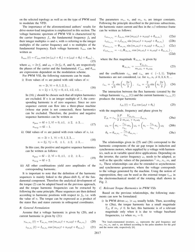
Fig. 7. Simulation results for the carrier frequency 𝑓𝑐 = 625 Hz and the fundamental frequency 𝑓0 = 65 Hz
∙ For sidebands around odd multiples of the carrier fre-quency, 𝑚𝑖 and 𝑛𝑖 are given according to (19). Takinginto account negative and positive sequence componentsyields:
𝑇𝑒ℎ,𝑛𝑒𝑔 =3
2
𝑃
2
𝑉1
𝜔0𝐼2𝑖+1,6𝑙+2
𝜔ℎ,𝑛𝑒𝑔 = (2𝑖+ 1)𝜔𝑐 + [(6𝑙 + 2) + 1]𝜔0
= (2𝑖+ 1)𝜔𝑐 + 3 (2𝑙 + 1)𝜔0
(34)
𝑇𝑒ℎ,𝑝𝑜𝑠 =3
2
𝑃
2
𝑉1
𝜔0𝐼2𝑖+1,6𝑙−2
𝜔ℎ,𝑝𝑜𝑠 = (2𝑖+ 1)𝜔𝑐 + [(6𝑙 − 2)− 1]𝜔0
= (2𝑖+ 1)𝜔𝑐 + 3 (2𝑙 − 1)𝜔0
(35)
The relationships provided in (30)–(35) justify the location oftorque harmonic frequencies as given in [7] and complementthe torque expressions with their magnitudes. For a given cur-rent or voltage harmonic, the positive and negative sequenceharmonics generate a torque component at the same frequency.The phases of the torque components are given in (26c).
V. VALIDATION
A. Principle of Validation
A compressor test bed rated at 35 MW and based on aparallel connection of PWM VSI systems with four back-to-back three-level neutral point clamped (NPC) inverters wasused for validation purposes. The overall system is shownin Fig. 6. The validation procedure included computer sim-ulations in Saber and Matlab, a scaled-down drive systemas software evaluation platform and a full-scale system testfacility. The design procedure and its detailed implementationwere provided in [17]. Experimental test results as well asother design aspects of the system were discussed in [4].Using Saber, selected simulation results that correlate currentand voltage harmonics with torque harmonics in the frequencydomain were presented in [7].
For the specific validation of the analytical expressions ofthe torque harmonics presented in this paper, post-processedresults of simulations of the full-scale system are discussed
in this section. The results show a good correlation betweencalculations and simulations.
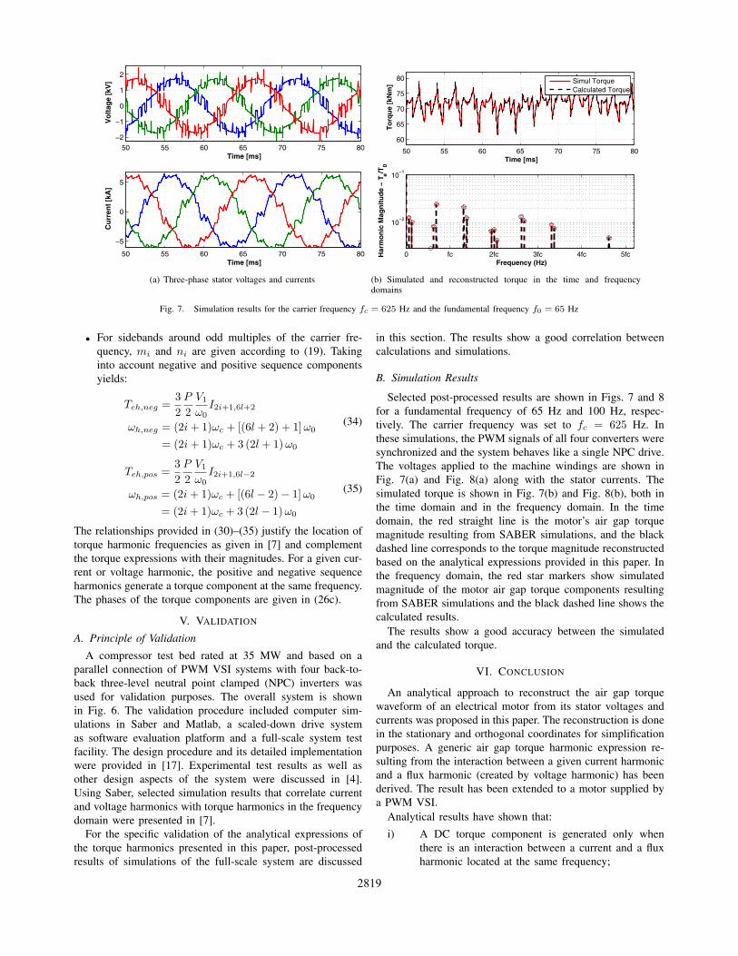
B. Simulation Results
Selected post-processed results are shown in Figs. 7 and 8for a fundamental frequency of 65 Hz and 100 Hz, respec-tively. The carrier frequency was set to 𝑓𝑐 = 625 Hz. Inthese simulations, the PWM signals of all four converters weresynchronized and the system behaves like a single NPC drive.The voltages applied to the machine windings are shown inFig. 7(a) and Fig. 8(a) along with the stator currents. Thesimulated torque is shown in Fig. 7(b) and Fig. 8(b), both inthe time domain and in the frequency domain. In the timedomain, the red straight line is the motor’s air gap torquemagnitude resulting from SABER simulations, and the blackdashed line corresponds to the torque magnitude reconstructedbased on the analytical expressions provided in this paper. Inthe frequency domain, the red star markers show simulatedmagnitude of the motor air gap torque components resultingfrom SABER simulations and the black dashed line shows thecalculated results.
The results show a good accuracy between the simulatedand the calculated torque.
VI. CONCLUSION
An analytical approach to reconstruct the air gap torquewaveform of an electrical motor from its stator voltages andcurrents was proposed in this paper. The reconstruction is donein the stationary and orthogonal coordinates for simplificationpurposes. A generic air gap torque harmonic expression re-sulting from the interaction between a given current harmonicand a flux harmonic (created by voltage harmonic) has beenderived. The result has been extended to a motor supplied bya PWM VSI.
Analytical results have shown that:
i) A DC torque component is generated only whenthere is an interaction between a current and a fluxharmonic located at the same frequency;
2819

50 55 60 65 70 75 80
−2
0
2
Vo
ltag
e [k
V]
Time [ms]
50 55 60 65 70 75 80
−5
0
5
10
Time [ms]
Cu
rren
t [k
A]
(a) Three-phase stator voltages and currents
50 55 60 65 70 75 80
90
95
100
105
110
115
Time [ms]
To
rqu
e [k
Nm
]
0 fc 2fc 3fc 4fc 5fc
10−2
10−1
Frequency (Hz)
Har
mo
nic
Mag
nit
ud
e −
T e/T0
Simulated TorqueCalculated Torque
(b) Simulated and reconstructed torque in the time and frequencydomains
Fig. 8. Simulation results for the carrier frequency 𝑓𝑐 = 625 Hz and the fundamental frequency 𝑓0 = 100 Hz
ii) Baseband torque harmonics multiple of six timesthe fundamental frequency are created due to theinteraction between voltage baseband harmonics andthe fundamental component of the current. Therefore,positive and negative sequence voltage harmonicscreate the same torque component.
iii) Sideband torque harmonics are created due to theinteraction between sideband current harmonics andthe fundamental component of the voltage.
The proposed analytical expressions can be used for abetter prediction of fatigue life of rotating machinery [11]or, as a tool to improve practical design against torsionalvibrations [12]-[15]. Finally, they can also be extended toLCIs [16], with appropriate parameters (𝑚𝑣, 𝑛𝑣) and (𝑚𝑖, 𝑛𝑖),depending on the number of pulses on the rectifier or on theinverter sides. Specifically for LCIs, motor’s air gap torquecomponents are mainly created due to the interaction betweencurrent harmonics resulting from the LCI and the flux createdby the fundamental component of the back electromotive forceof a synchronous motor.
REFERENCES
[1] J. Song-Manguelle, C. Sihler, J. M. Nyobe-Yome, Modeling of torsionalresonances for multi-megawatt drives design, IEEE IAS 43rd AnnualMeeting, Oct. 2008, Edmonton, Canada.
[2] D. Walker, Torsional vibration of turbomachinery, McGraw-Hill, 2004.[3] B. Wu, High-power converters and AC drives, IEEE Press, 2006.[4] S. Schröder, P. Tenca, T. Geyer, P. Soldi, L. Garces, R. Zhang, T. Toma
and P. Bordignon, Modular high-power shunt-interleaved drive system:A realization up to 35 MW for oil & gas applications, IEEE Trans. onIndustry Appl., vol. 46, no. 2, pp. 821-830, Mar./Apr. 2010.
[5] P. C. Krause, O. Wasynczuk, S. D. Sudhoff, Analysis of Electric Machin-ery and Drive Systems, 2nd. ed., IEEE Press, Wiley Interscience, 2002.
[6] J. Song-Manguelle, J. M. Nyobe-Yome, G. Ekemb, Pulsating Torquesin PWM Multi-megawatt Drives for Torsional Analysis of Large Shafts,IEEE Trans. on Industry Appl., vol. 46, no. 1, pp. 130-138, Jan./Feb.2010.
[7] J. Song-Manguelle, S. Schröder, T. Geyer, G. Ekemb, J. M. Nyobe-Yome, Prediction of Mechanical Shaft Failures due to Variable FrequencyDrives, IEEE Trans. on Industry Appl., vol. 25, no. 4, pp. 130-138,Jan./Feb. 2010.
[8] C. Mung-Ong, Dynamic Simulation of Electric Machinery using Mat-lab/Simulink, Prentice Hall, Purdue, 1999.
[9] D. G. Holmes, B. P. McGrath, Opportunities for Harmonic Cancellationwith Carrier-based PWM for Two-Level and Multilevel Cascaded Invert-ers, IEEE Trans. on Industry Appl., vol. 37, no. 2, pp. 574-582, Mar./Apr.2001.
[10] D. G. Holmes, T. A. Lipo, Pulse Width Modulation for Power Convert-ers: Principle and Practice, IEEE Press, Series on Power Eng., WileyInterscience, 2003.
[11] Xu Han, A. B. Palazzolo VFD Machinery Vibration Fatigue Life andMulti-level Inverter Effect , IEEE IAS 47rd Annual Meeting, Oct. 2012,Las Vegas, NV, USA.
[12] M. A. Corbo, S. B. Malanoski Practical Design against TorsionalVibration, Proceedings of the 25th Turbomachinery Symposium, Turbo-machinery Laboratory, Texas A&M University, College Station, Texas,pp. 189-222, 1996.
[13] T. F. Kaiser, R. H. Osman, R. O. Dickau Analysis Guide for VariableFrequency Drive Operated Centrifugal Pump, Proceedings of the 24thInternational pump Users Symposium, Texas A&M University, CollegeStation, Texas, pp. 81-106, 2008.
[14] J. A. Kocur, J. Corcoran VFD Induced Coupling Failure, Case Studyno. 9, The 37th Turbomachinery Symposium, Texas A&M University,College Station, Texas, 2008.
[15] H. McArthur, M. Falk, M. Bertel, VFD Induced Coupling TorquePulsations: Cause of Mine Exhaust Fan Coupling failures, The 14thU.S./North American Mine Ventiilation Symposium Salt Lake City, Utah,2012.
[16] V. Hütten, R. M. Zurowski, M. Hilsher, Torsional Interharmonic Inter-action Study of 75 MW Direct-Driven VSDS Motor Compressor Trainsfor LNG Duty, Proceedings of the 37th Turbomachinery Symposium,Turbomachinery Laboratory, Texas A&M University, College Station,Texas, pp. 57-66, 2008.
[17] R. Baccani, R. Zhang, et al., Electric System for High Power CompressorTrains in Oil and Gas Applications - System Design, Validation Approachand Performance, Proc. 36th Turbomach. Symp., Texas A&M Univ.,College Station, TX, 2007.
2820