High precision grinding Steady Rests Grinding diameter Ø 3
12
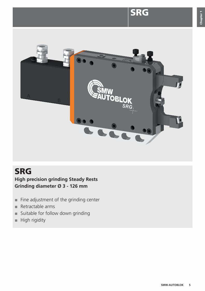
SMW-AUTOBLOK 5 SRG High precision grinding Steady Rests Grinding diameter Ø 3 - 126 mm ■ Fine adjustment of the grinding center ■ Retractable arms ■ Suitable for follow down grinding ■ High rigidity Chapter 1 SRG
-
Upload
khangminh22 -
Category
Documents
-
view
0 -
download
0
Transcript of High precision grinding Steady Rests Grinding diameter Ø 3
SMW-AUTOBLOK 5
SRGHigh precision grinding Steady RestsGrinding diameter Ø 3 - 126 mm
■ Fine adjustment of the grinding center■ Retractable arms■ Suitable for follow down grinding■ High rigidity
Ch
ap
ter
1SRG

6 SMW-AUTOBLOK
1
3
5
4
2
1. Horizontal fi ne adjustment of the grinding center2. Vertical fi ne adjustment of the grinding center3. Retractable Steady Rest arms4. Port for compressed air against dust and coolant5. Monitoring of end positions with proximity switches (switches
not included)
Application / customer benefi ts• Support of shaft type workpieces on grinding machines• Particularly suitable for the machining of crankshafts and camshafts• Rapid set up of the Steady Rest to the grinding center with the fi ne adjustment• Suitable for Follow down grinding
Standard equipment• Basic Grinding Steady Rest SRG• Delivery in transport box
(Padholder for the middle piece, Clamping Kit and Pad Kits are not scope of delivery. See therefor the overview for the confi gurations below.)
Technical Features
Overview Confi guration
• Consisting of padholder middle piece (incl. mounting material)
• 3 versions available:0 degree, ± 5 degree, ± 7 degree
• Can be rotated by 180 degrees
• Consisting of 2 nests for the arms and 1 padholder for the middle piece (incl. mounting material)
• The different clamping ranges can be covered by different clamping kits
• Consisting of 3 pads incl. 3 mounting screws
• Standard for clamping range as shown on the Steady Rest
• Special for shifting of the clamping range -5 mm
Padholder for the middle piece (*) Clamping Kit for the arms (**) Pad Kit (***)
* Consisting of padholder for the middle piece incl. mounting material** Consisting of padholder for the middle piece and the nests for the arms incl. mounting material*** Consisting of 3 pads and 3 mounting bolts
Application / customer benefi ts
Select padholder for the middle piece (SRG 1 / 1 S / 2)
Select clamping kit(SRG 2 F / 4 F / 5.1 FS; SRG-B 4 F / 5 F)
Select Pad Kit

SMW-AUTOBLOK 7
SRG/ SRG-B
SRG 0.8223250
SRG 1221175
SRG 1 S223060
SRG 2221871
3-18 20-35 20-35 30-60
- 203977 205191 203985
- 203978 205196 203986
- 203979 205197 203987
205439 203976 204161 203976
- 203939 - 203939
20-50 15-30 20-50 15-30
SRG 2 F222260
SRG 4 F221930
SRG 5.1 FS222665
12-60 22-100 96-126
I II III I II III IV V VI I II III IV V
12-28 28-44 44-60 22-35 35-48 48-61 61-74 74-87 87-100 96-102 102-108 108-114 114-120 120-126
204383 204382 204381 205000 205001 205002 205003 205004 205005 - - - - -
- - - 205006 205007 205008 205009 205010 205011 - - - - -
- - - - - - - - - 205200 205201 205202 205203 205204
206349 206348 206347 - - - - - - - - - - -
206346 206345 206344 - - - - - - - - - - -
203976 204161 204161
203939 - -
15-30 7-25 7-25
SRG-B 4 F223140
SRG-B 5 F222530
22-100 48-136
I II III IV V VI I II III IV
22-35 35-48 48-61 61-74 74-87 87-100 48-70 70-92 92-114 114-136
205000 205001 205002 205003 205004 205005 - - - -
205006 205007 205008 205009 205010 205011 205018 205019 205020 205021
- - - - - - - - - -
204161 204161
- -
10-30 10-30
Grinding Steady Rests Ordering review
SMW-AUTOBLOK TypeBasic Steady RestClamping range mm
Padholder 0 degree* Id. No.
Padholder ± 5 degree* Id. No.
Padholder ± 7 degree* Id. No.
Pad Kit Standard Id. No.
Pad Kit Special *** Id. No.
Working pressure bar
Follow down grinding Yes Yes Yes Yes
SMW-AUTOBLOK TypeBasic Steady RestClamping range mm
Clamping kit
Clamping range mm
Clamping kit 0 degree** Id. No.
Clamping kit -2 degree** Id. No.
Clamping kit -3 degree** Id. No.
Clamping kit -5 degree** Id. No.
Clamping kit -7 degree** Id. No.
Pad Kit Standard Id. No.
Pad Kit Special*** Id. No.
Working pressure bar
Follow down grinding Yes Yes Yes
SMW-AUTOBLOK TypeBasic Steady RestClamping range mm
Clamping kit
Clamping range mm
Clamping kit 0 degree** Id. No.
Clamping kit -2 degree** Id. No.
Clamping kit -3 degree** Id. No.
Pad Kit Standard Id. No.
Pad Kit Special*** Id. No.
Working pressure bar
Follow down grinding Yes Yes
* Consisting of padholder for the middle piece incl. mounting material** Consisting of padholder for the middle piece and the nests for the arms incl. mounting material*** Clamping range -5 mmSRG-B Side mounted cylinder

8 SMW-AUTOBLOK
SRG 0.8
S1 VS2
F1F2
A
O1 O2
P1P2
U1
U2
U3
D4 D3 D2 D1 C
E1
XY
T K G
A B
U4/
U5
SRG 0.8223250
U1 3U2 18U3 58U4 58U5 58
± 0.05± 0.05
A 249.5C 45D1 25D2 25D3 25D4 25E1 60F1 70F2 50G 30K 10
O1 4O2 83.5P1 35P2 35S1 9 (4x)S2 13.46 (1x)T 30V 30X 10Y 10
433.1450
20-50±0.001
4.3
Englisch
Grinding Steady RestsDimensions and technical data
Subjected to technical changes.For more detailed information please ask our customer service.
Cylinder portG 1/8“ close
Cylinder portG 1/8“ open
For prox. switches Ø 8 mm
G1/8“ Port forcompressed air
Drain
Vertical fine adjustmentHorizontal fine adjustment
G 1/8“ Port forcentralized lubrication
SMW-AUTOBLOK TypeId. No.Minimum clamping diameter mmMaximum clamping diameter mmMax. loading diameter (vertical, steady open) mmMax. axial clearance diameter (steady open) mmMax. swing diameter mmHorizontal adjustment range mmVertical adjustment range mm
mmmmmmmmmmmmmmmmmmmmmmmmmmmmmmmmmmmmmmmmmm
Cylinder stroke mmPiston area cm²Operating pressure max. barWorking pressure barRepeatability accuracy mmMass kg

SMW-AUTOBLOK 9
SRG 1
V
J
S1S2
O2O1
P2P1
A
R C1E
F1F2
U1
U2
U3
CD1D2D3D4D5
E3E1E2
T GK
Y X
I
H
A B
U4
/ U5
SRG 1221175
U1 20U2 35U3 72U4 72U5 72
± 0.20± 0.10
A 306.8C 55.9
C1 67.5D1 22.8D2 22.7D3 22.7D4 22.7D5 22.6E 111.1E1 76.2E2 85.7E3 20.65F1 95.2F2 63.5G 39H 5I 13J 121K 16.1
O1 4.5O2 104.3P1 41P2 35R 82.8S1 11 (5x)S2 13.46 (1x)T 39V 37X 19.5Y 19.5
73.47.0745
15-30±0.001
8.5
Englisch
Grinding Steady Rests Dimensions and technical data
SMW-AUTOBLOK TypeId. No.Minimum clamping diameter mmMaximum clamping diameter mmMax. loading diameter (vertical, steady open) mmMax. axial clearance diameter (steady open) mmMax. swing diameter mmHorizontal adjustment range mmVertical adjustment range mm
mmmmmmmmmmmmmmmmmmmmmmmmmmmmmmmmmmmmmmmmmmmmmmmmmmmmmmmmmmmm
Cylinder stroke mmPiston area cm²Operating pressure max. barWorking pressure barRepeatability accuracy mmMass kg
Subjected to technical changes.For more detailed information please ask our customer service.
Cylinder portG 1/4“ close
For prox. switsches Ø 12 mm
G1/8“ Port forcompressed air
Cylinder portG 1/4“ open
Drain
Vertical fine adjustmentLift thread M8
Horizontal fine adjustment
G 1/8“ Port centralized lubrication

10 SMW-AUTOBLOK
SRG 1 S
V
F1F2
A
P1P2
S2
O2O1
S1
U1
U2
D5 D4 D3 D2 D1 C
E2E1
YX
K GT
A B
U4/
U5
U3
SRG 1 S223060
U1 20U2 35U3 62U4 72U5 72
± 0.20± 0.10
A 280C 55.8D1 22.7D2 22.7D3 22.7D4 22.7D5 22.7E1 85.7E2 76.2F1 95.25F2 63.5G 25K 10
O1 4.5O2 93.5P1 35P2 35S1 9 (5x)S2 13.46 (1x)T 25V 36.7X 7.5Y 10
532.0150
20-50±0.001
4.8
Englisch
Grinding Steady RestsDimensions and technical data
Subjected to technical changes.For more detailed information please ask our customer service.
Cylinder portG 1/8“ close
For prox. switches Ø 12 mm
G1/8“ Port forcompressed air
Cylinder portG 1/8“ open
Drain
Vertical fine adjustmentHorizontal fine adjustment
SMW-AUTOBLOK TypeId. No.Minimum clamping diameter mmMaximum clamping diameter mmMax. loading diameter (vertical, steady open) mmMax. axial clearance diameter (steady open) mmMax. swing diameter mmHorizontal adjustment range mmVertical adjustment range mm
mmmmmmmmmmmmmmmmmmmmmmmmmmmmmmmmmmmmmmmmmmmmmm
Cylinder stroke mmPiston area cm²Operating pressure max. barWorking pressure barRepeatability accuracy mmMass kg
G 1/8“ Port forcentralized lubrication
SMW-AUTOBLOK 11
SRG 2
V
J
E
F1F2
P2P1
O1 O2
AR C1
S
U1
U2
D4 D3 D2 D1 C
E1E2
X Y H
I
T K G
A B
U4/
U5
U3
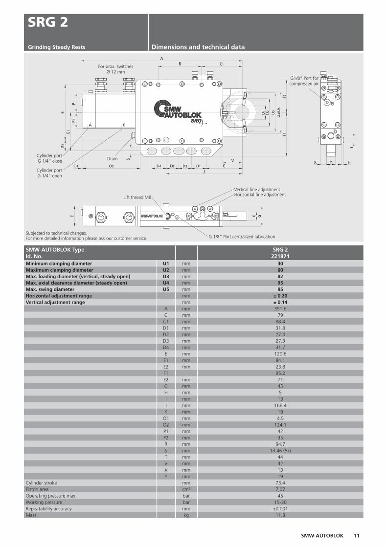
SRG 2221871
U1 30U2 60U3 82U4 95U5 95
± 0.20± 0.14
A 351.6C 79C1 88.4D1 31.8D2 27.4D3 27.3D4 31.7E 120.6
E1 84.1E2 23.8F1 95.2F2 71G 45H 5I 13J 166.4K 19
O1 4.5O2 124.1P1 42P2 35R 94.7S 13.46 (5x)T 44V 42X 13Y 19
73.47,0745
15-30±0.001
11.8
Englisch
Grinding Steady Rests Dimensions and technical data
SMW-AUTOBLOK TypeId. No.Minimum clamping diameter mmMaximum clamping diameter mmMax. loading diameter (vertical, steady open) mmMax. axial clearance diameter (steady open) mmMax. swing diameter mmHorizontal adjustment range mmVertical adjustment range mm
mmmmmmmmmmmmmmmmmmmm
mmmmmmmmmmmmmmmmmmmmmmmmmmmmmmmm
Cylinder stroke mmPiston area cm²Operating pressure max. barWorking pressure barRepeatability accuracy mmMass kg
Subjected to technical changes.For more detailed information please ask our customer service.
Cylinder portG 1/4“ close
Cylinder portG 1/4“ open
For prox. switches Ø 12 mm
G1/8“ Port forcompressed air
Drain
Vertical fine adjustment
Lift thread M8Horizontal fine adjustment
G 1/8“ Port centralized lubrication

12 SMW-AUTOBLOK
SRG 2 F
SRG 2 F222260
I II IIIU1 12 28 44U2 28 44 60U3 82 82 82U4 94 94 94U5 94
± 0.20± 0.14
A 351.1C 79C1 88.4D1 31.8D2 27.3D3 27.4D4 31.7E 120.6
E1 84.1E2 23.8F1 95.2F2 71G 45H 5I 13J 166.4K 19
O1 4.5O2 124.1P1 42P2 35R 94.7S 13.46 (5x)T 44V 42X 13Y 19
66.47.0745
15-30±0.001
11.2
V
JO2O1
S
P2P1
A
ER C1
F2F1
U3
U2
U1
CD1D2D3D4
E1E2
X Y
I
H
K GT
A B
U5
U4
Englisch
Grinding Steady RestsDimensions and technical data
Subjected to technical changes.For more detailed information please ask our customer service.
Cylinder portG 1/4“ close
Cylinder portG 1/4“ open
For prox. switches Ø 12 mm G1/8“ Port for
compressed air
Drain
Vertical fine adjustmentLift thread M8 Horizontal fine adjustment
G 1/8“ Port centralized lubrication
SMW-AUTOBLOK TypeId. No.Clamping kitMinimum clamping diameter mmMaximum clamping diameter mmMax. loading diameter (vertical, steady open) mmMax. axial clearance diameter (steady open) mmMax. swing diameter mmHorizontal adjustment range mmVertical adjustment range mm
mmmmmmmmmmmmmmmmmmmmmmmmmmmmmmmmmmmmmmmmmmmmmmmmmmmmmm
Cylinder stroke mmPiston area cm²Operating pressure max. barWorking pressure barRepeatability accuracy mmMass kg

SMW-AUTOBLOK 13
SRG 4 F
U3
VCD1D2O2O1
P1P2
EE1
JA
F1F2
U5
U2
U1
K GT
H
I
A B
S
U4
U3
SRG 4 F221930
I II III IV V VIU1 22 35 48 61 74 87U2 35 48 61 74 87 100U3 206 204 200 196 194 190U4 218 219 219 220 222 224U5 228
± 0.20± 0.14
A 557.6C 170.2D1 160.3D2 28.3E 190.5
E1 95.25F1 108F2 108G 55H 6I 16J 230.4K 18.2
O1 4.5O2 145.1P1 48P2 43S M12 (6x)T 54.5V 106
127.212.56
307-25
±0.00130
Englisch
Grinding Steady Rests Dimensions and technical data
Subjected to technical changes.For more detailed information please ask our customer service.
G1/8“ Port forcompressed airFor prox. switches
Ø 12 mm
Cylinder portG 1/4“ close
Cylinder portG 1/4“ open
Drain
Lift thread M10
Vertical fi ne adjustment
Horizontal fi ne adjustment
G 1/8“ Port centralized lubrication
SMW-AUTOBLOK TypeId. No.Clamping kitMinimum clamping diameter mmMaximum clamping diameter mmMax. loading diameter (vertical, steady open) mmMax. axial clearance diameter (steady open) mmMax. swing diameter mmHorizontal adjustment range mmVertical adjustment range mm
mmmmmmmmmmmmmmmmmmmmmmmmmmmmmmmmmmmmmmmm
Cylinder stroke mmPiston area cm²Operating pressure max. barWorking pressure barRepeatability accuracy mmMass kg
14 SMW-AUTOBLOK
SRG-B 4 F
U3
F1F2
JE1
E
P1P2
O2
A
D2 D1 C
V
S
U1
U2
U5
V1
K1
K G
T
O
H
I
U3
U4
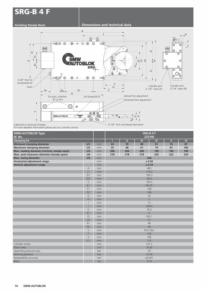
SRG-B 4 F223140
I II III IV V VIU1 22 35 48 61 74 87U2 35 48 61 74 87 100U3 206 204 200 196 194 190U4 218 218 218 220 222 224U5 228
± 0.20± 0.14
A 465C 170.2D1 160.3D2 28.3E 190.5
E1 95.25F1 108F2 108G 55H 5I 13J 230.4K 18.2
K1 9O 350.1
O2 57P1 48P2 43S M12 (6x)T 106V 106
V1 115127.210.02
3510-30±0.001
37.8
Englisch
Grinding Steady Rests Dimensions and technical data
SMW-AUTOBLOK TypeId. No.Clamping kitMinimum clamping diameter mmMaximum clamping diameter mmMax. loading diameter (vertical, steady open) mmMax. axial clearance diameter (steady open) mmMax. swing diameter mmHorizontal adjustment range mmVertical adjustment range mm
mmmmmmmmmmmmmmmmmmmmmmmmmmmmmmmmmmmmmmmmmmmm
Cylinder stroke mmPiston area cm²Operating pressure max. barWorking pressure barRepeatability accuracy mmMass kg
Subjected to technical changes.For more detailed information please ask our customer service.
G1/8“ Port forcompressed air
For prox. switches Ø 12 mm
Cylinder portG 1/4“ close (A)
Cylinder portG 1/4“ open (B)
Drain
Lift thread M10 Vertical fi ne adjustment
Horizontal fi ne adjustment
G 1/8“ Port centralized lubrication

SMW-AUTOBLOK 15
SRG-B 5 F
U3
F2F1
V
V1
CD1D2
JA
C1D3E1
P1P2
E
O2
S
U5
U2
U1
H
I
K
K1
G
T
O
U3
U4
SRG-B 5 F222530
I II III IVU1 48 70 92 114U2 70 92 114 136U3 273 267 263 257U4 298 298 298 299U5 310
± 0.20± 0.14
A 624C 235.9
C1 243.7D1 138.5D2 71D3 201.7E 263.4
E1 131.7F1 149F2 149G 65.3H 9I 24J 348.7K 22.9
K1 11.1O 468
O2 29P1 45P2 45S M16 (5x)T 129.5V 154V1 156
17916.49
3510-30±0.002
76.4
Englisch
Grinding Steady RestsDimensions and technical data
Subjected to technical changes.For more detailed information please ask our customer service.
G1/8“ Port forcompressed air
For prox. switches Ø 12 mm
Cylinder portG 1/4“ close (A)
Cylinder portG 1/4“ open (B)
Drain
Lift thread M10
Vertical fi ne adjustmentHorizontal fi ne adjustment
G 1/8“ Port centralizedlubrication
SMW-AUTOBLOK TypeId. No.Clamping kitMinimum clamping diameter mmMaximum clamping diameter mmMax. loading diameter (vertical, steady open) mmMax. axial clearance diameter (steady open) mmMax. swing diameter mmHorizontal adjustment range mmVertical adjustment range mm
mmmmmmmmmmmmmmmmmmmmmmmmmmmmmmmmmmmmmmmmmmmmmmmm
Cylinder stroke mmPiston area cm²Operating pressure max. barWorking pressure barRepeatability accuracy mmMass kg
G1/8“ Port forcompressed air

16 SMW-AUTOBLOK
SRG 5.1 FS
SRG 5.1 FS222665
I II III IV VU1 96 102 108 114 120U2 102 108 114 120 126U3 236 234 232 229 228U4 272 272 272 272 272U5 320
± 0.22± 0.17
A 676.6C 190D1 30.7D2 162.2E 247.6
E1 123.8F1 139.7F2 139.7G 64.3H 6I 16J 331.2K 20.25
K1 10O2 124.6P1 48P2 47S 17 (5x)T 64V 139.5
167.119.63
238-18.5±0.002
54.8
F2F1
D1D2O2
E
P1P2
E1
JC
V
A
S
U5
U2
U1
H
I
K GT
K1
A B
U3
U4
Englisch
Grinding Steady RestsDimensions and technical data
G1/8“ Port for compressed air
For prox. switchesØ12mm
Cylinder portG 1/4“ close
Cylinder portG 1/4“ open
Drain
Lift thread M10Vertical fi ne adjustment
Horizontal fi ne adjustment
Subjected to technical changes.For more detailed information please ask our customer service.
G 1/8“ Port centralized lubrication
SMW-AUTOBLOK TypeId. No.Clamping kitMinimum clamping diameter mmMaximum clamping diameter mmMax. loading diameter (vertical, steady open) mmMax. axial clearance diameter (steady open) mmMax. swing diameter mmHorizontal adjustment range mmVertical adjustment range mm
mmmmmmmmmmmmmmmmmmmmmmmmmmmmmmmmmmmmmmmm
Cylinder stroke mmPiston area cm²Operating pressure max. barWorking pressure barRepeatability accuracy mmMass kg