Product Data WeatherMaker® Packaged Rooftop Units
120
© Carrier Corporation 2019 Form 48/50A-19PD Product Data WeatherMaker ® Packaged Rooftop Units 20 to 60 Nominal Tons 48/50A020-060 Single-Package Gas Heating/Electric Cooling Rooftop Units and Electric Cooling Rooftop Units with Optional Electric Heat with ComfortLink Controls and Puron ® Refrigerant (R-410A)
-
Upload
khangminh22 -
Category
Documents
-
view
1 -
download
0
Transcript of Product Data WeatherMaker® Packaged Rooftop Units
© Carrier Corporation 2019 Form 48/50A-19PD
Product Data
WeatherMaker®
Packaged Rooftop Units20 to 60 Nominal Tons
48/50A020-060Single-Package Gas Heating/Electric CoolingRooftop Units and Electric CoolingRooftop Units with Optional Electric Heat with ComfortLink Controlsand Puron® Refrigerant (R-410A)
2
Carrier’s 48/50A commercial packaged unit offers design flexibility, quality, reliability, and ComfortLink controls.Carrier’s 48/50A Series commercialpackaged rooftops offer:• Non-ozone depleting Puron refriger-
ant (R-410A)• Novation® heat exchanger technol-
ogy with microchannel coil• An easy-to-use, plain English lan-
guage display on the ComfortLinkcontrols
• Ratings that meet ASHRAE (Ameri-can Society of Heating, Refrigerating,and Air-Conditioning Engineers) Stan-dard 90.1-2016 and IECC (Interna-tional Energy Conservation Code)IECC-2015 minimum energy effi-ciency requirements when equippedwith the SAV™ (staged air volume)option
• Meets ASHRAE Standard 62• Constant, staged, or variable air
volume• Communicating controls• Accurately match building loads
with up to 5 steps of capacity• Variable capacity compressor
option
• Humidi-MiZer® adaptive dehumidifi-cation option
• Variable frequency drive on all vari-able air volume and SAV™ units
• Mechanical cooling operation atoutdoor ambient temperatures aslow as 32°F (–20°F with optionallow ambient control)
Design flexibilityDedicated vertical supply/return units(A2, A3, A6, A7) are ideal for newconstruction or retrofit to existinginstallations. The low unit profile ismaintained when the unit is installedon the accessory roof curb. The ducts are attached directly to theroof curb to allow all ductwork to becompleted before the unit is positioned.Dedicated horizontal units (A4, A5,A8, A9) are ideal for replacement orapplications such as through-the-wallwhere sound must be attenuated beforethe duct penetrates the roof. Ductsconnect directly to the unit. Horizontalunits may be curb or slab mounted.The unit cabinet may be provided withoptional double wall construction forindoor air quality sensitive applications.
ComfortLink controlsFactory-installed ComfortLink con-trols provide the capability for free-standing operation or may be linkedwith a more extensive system. Factory-installed and programmed BACnet1communication capability providessimple integration with the buildingHVAC system (e.g., terminal devices),an i-Vu® Open Control System, or aBACnet building automation system.The ComfortLink controls also havethe capability to communicate with theCarrier Comfort Network® (CCN) sys-tem. This communication flexibilityallows simple system integration, aswell as data collection, trending, moni-toring, and alarm displays.The 48/50A Series may also be con-figured to communicate via Modbus2 orLonWorks3 protocols, if required bythe application.The ComfortLink controls are yourlink to a world of simple and easy-to-use rooftop units that offer outstandingperformance and value. When usedwith a space temperature sensor, theComfortLink controls maintain controlover the economizer and condenserfans and help optimize the perfor-mance of the multiple refrigeration cir-cuits as conditions change, resulting inthe following features:• higher part load efficiency• better control of temperature and
humidity• superior reliability• redundant refrigeration systems• high ambient cooling operation at
115°F• low ambient cooling operation at
32°F as standard (optional Green-speed® control for operation downto –20°F)
The ComfortLink scrolling marqueedisplay is very easy to use. Messagesare displayed in easy to understandEnglish. No decoding is required. Ascrolling readout provides detailedexplanations of control information.Only 4, large, easy-to-use buttons arerequired to maneuver through theentire menu. The readout is designed
1. BACnet is a registered trademark of ASHRAE (American Society of Heating, Re-frigerating, and Air-Conditioning Engineers).
2. Modbus is a registered trademark of Schnei-der Electric.
3. LonWorks is a registered trademark of Ech-elon Corporation.
Features/Benefits
Table of contentsPage
Features/Benefits . . . . . . . . . . . . . . . . . . . . . . . . . . . . . . . . . . . . . . . . . . 2Model Number Nomenclature . . . . . . . . . . . . . . . . . . . . . . . . . . . . . . . . . . 6Ratings and Capacities . . . . . . . . . . . . . . . . . . . . . . . . . . . . . . . . . . . . . . . 8Physical Data . . . . . . . . . . . . . . . . . . . . . . . . . . . . . . . . . . . . . . . . . . . . 11Options and Accessories . . . . . . . . . . . . . . . . . . . . . . . . . . . . . . . . . . . . 19Base Unit Dimensions . . . . . . . . . . . . . . . . . . . . . . . . . . . . . . . . . . . . . . 21Accessory Dimensions . . . . . . . . . . . . . . . . . . . . . . . . . . . . . . . . . . . . . . 39Selection Procedure. . . . . . . . . . . . . . . . . . . . . . . . . . . . . . . . . . . . . . . . 44Performance Data . . . . . . . . . . . . . . . . . . . . . . . . . . . . . . . . . . . . . . . . . 45Controls . . . . . . . . . . . . . . . . . . . . . . . . . . . . . . . . . . . . . . . . . . . . . . . . .84Application Data . . . . . . . . . . . . . . . . . . . . . . . . . . . . . . . . . . . . . . . . . . .98Typical Wiring Schematics . . . . . . . . . . . . . . . . . . . . . . . . . . . . . . . . . . .100Guide Specifications . . . . . . . . . . . . . . . . . . . . . . . . . . . . . . . . . . . . . . .108

3
to be visible even in the brightest sun-light. A hand-held Navigator™ acces-sory can be used for added serviceflexibility.The ComfortLink controls provideunparalleled service diagnostic infor-mation. Temperature and pressure canbe read from the display with no needfor separate gages. Other data, such ascompressor cycles, unit run time hours,and current alarms can also beaccessed. A history of alarms is alsoavailable for viewing.A service run test can be very helpfulwhen troubleshooting. The user canrun test major components to helpdetermine the root cause of a problem.The unit can be run-tested before aninstallation is complete to support asatisfactory start-up.To further support reliability, the Com-fortLink controls prevent reverse com-pressor rotation.No laptop computers are required forstart-up. Time schedules are built inand the scrolling marquee display pro-vides easy access to set points.The ComfortLink controller acceptsinput from a CO2 sensor and a smokedetector. Both are available as factory-installed options or as field-installedaccessories.The unit-mounted terminal strip allowscontrol of the unit with a standard ther-mostat. Expensive interface devices arenot required.Environmentally balancedMaking an environmentally responsibledecision is possible when using Carrier’sPuron® refrigerant (R-410A). Puronrefrigerant (R-410A) is an HFC refriger-ant that does not contain chlorine that isdamaging to the ozone layer. Thisrefrigerant is a safe, efficient, and envi-ronmentally balanced refrigerant.Quality and reliabilityExcellent full and part load efficienciesare achieved by using multiple scrollcompressors and indoor coils withintertwined dual refrigerant circuits.The compressors are equipped withcrankcase heaters and protected byelectronic sensors and logic to controlminimum on and off times and reverserotation. The refrigerant circuits areboth electrically and mechanically inde-pendent, to provide standby capability,should one circuit require service.
Totally enclosed outdoor-fan motorsare designed for many years of trouble-free operation.Positive-locking bearings for the indoorfan reduce vibration of the supply fanassembly and remain locked during thelife of the bearing.Unit capacity controlThe units have up to 5 stages of capac-ity control to match the load require-ments of the conditioned space. Unitoperation will closely match the loadand maintain comfort in the mostenergy-efficient manner.Variable capacity scroll com-pressorIn air conditioning applications, theload may vary significantly, requiring ameans to vary the system capacity foroptimal performance and control.The A Series large rooftop units withoptional variable capacity scroll com-pression provide a highly efficientmeans of capacity control using scrollcompressors. The digital compressortechnology provides smooth, vibration-free operation by axially unloading thecompliant scrolls.By varying the amount of time that thescrolls are unloaded, the A Series unitis able to precisely match the systemcapacity to the space load. This featurecan reduce energy consumption, pro-vide better dehumidification, reducecompressor cycling, and improve com-fort in the space.Humidi-MiZer® adaptive dehu-midification systemCarrier's Humidi-MiZer adaptive dehu-midification system is an all-inclusivefactory-installed option that can beordered with WeatherMaker® 48/50Arooftop unit. This system expands theenvelope of operation of the A Seriesrooftop to provide unprecedented flexi-bility that will meet year-round comfortconditions.The Humidi-MiZer adaptive dehumidi-fication system has the industry's onlydual dehumidification mode setting.The WeatherMaker rooftop, coupledwith the Humidi-MiZer adaptive dehu-midification system, is capable of mod-ulating between normal design coolingmode, subcooling mode, and hot gasreheat mode. Normal design cooling mode will oper-ate under the normal sequence of
operation. Subcooling mode will oper-ate to satisfy part load type conditions.Hot Gas Reheat mode will operatewhen outdoor temperatures diminishand the need for latent capacity isrequired for sole humidity control. HotGas Reheat mode will provide neutralair for maximum dehumidificationoperation.The WeatherMaker A Series genera-tion version of Carrier's Humidi-MiZersystem includes refrigerant modulatingvalves that provide variable flow bypassaround the condenser. This innovativefeature ensures exact control of thesupply-air temperature as the unit low-ers the evaporator temperature toincrease latent capacity.Additionally, when the space requiresdehumidification only, the Humidi-MiZersystem can increase hot discharge gasbypass to the Humidi-MiZer coil in orderto heat the air to the exact neutral staterequired—no overcooling or overheat-ing with latent capacity similar to thatprovided in the full subcooling mode.Variable frequency drive (VFD) Variable air volume (VAV) units usestate of the art variable frequency drive(VFD) to control duct static pressure foroptimum supply fan energy savings.VAV features include:• control of cooling and heating (if
equipped with heat) in both occu-pied and unoccupied mode
• support of optional space tempera-ture sensor
• control of modulating economizer toprovide free cooling when outdoorconditions are suitable
• support of IAQ (indoor air quality)sensor
• support linkage to ComfortID™VAV systems
Staged air volume units use the VFD toallow for a configurable high and low fanspeed. In this way, during times of partload or low demand, indoor fan motorpower consumption can be reduced.Greenspeed® Intelligence provides lowambient temperature head pressurecontrol that permits operation of the48/50A units to –20°F (–29°C) out-door ambient temperature. The optionoffers increased efficiency and low out-door acoustic performance. It featuresa quiet AeroAcoustic™ fan system,compressor sound blankets, and VFDdriven condenser fan motors.

4
Factory-installed economizerAn optional integrated economizerpermits cooling by using an outdoor airsensor. The economizer uses ultra-lowleak blades for tight sealing and arobust drive design for long life.The economizer operates in conjunc-tion with mechanical cooling, whenrequired, and is factory installed foreither vertical or horizontal operation.The factory-supplied and field-installedrain hood/filter assembly is designed toprevent moisture or objects from enter-ing the unit.Exhaust air relief is available for allunits:• barometric relief (CV [constant vol-
ume] or VAV)• power exhaust• modulating power exhaust• high capacity power exhaustField-adjustable set points on modulatingpower exhaust prevent space pressuriza-tion problems. Factory-installed reliefoptions are unit mounted on downflowunits. Accessories must be duct mountedfor horizontal applications.Novation® heat exchanger technologyThe Novation heat exchanger designwith microchannel condenser coil is arobust, cost-effective alternative totraditional coil design for standardapplications. Microchannel coils arealso sturdier than other coil types, mak-ing them easier to clean without caus-ing damage to the coil.Due to the compact, all-aluminumdesign, microchannel coils reduce over-all unit operating weight. The stream-lined microchannel coil also reducesrefrigerant charge by up to 40%.Microchannel coils are not recom-mended by Carrier for marine,coastal, or industrial environments,unless Carrier-approved coating isapplied.Gas heating unitsIntegrated gas unit controller(IGC) (gas heating units only) All ignition components are contained inthe compact IGC, which is easily accessi-ble for servicing. The IGC control board,designed and manufactured exclusivelyfor Carrier rooftop units, provides built-indiagnostic capability. An LED (light-emit-ting diode) simplifies troubleshooting by
providing visual fault notification and sys-tem status confirmation.The IGC also contains an anti-cycleprotection for gas heat operation.After 4 continuous cycles on the unithigh-temperature limit switch, the gasheat operation is disabled and an errorcode is issued. This feature greatlyimproves reliability of the rooftop unit.The IGC also contains burner controllogic for accurate and dependable gasignition. This LED fault-notificationsystem reduces service person trouble-shooting time and minimizes servicecosts. The IGC can also increase heat-ing efficiency by controlling evapora-tor fan on and off delays.Efficient, dependable operationTubular, dimpled gas heat exchangersoptimize heat transfer for improved effi-ciency. The tubular design permits hotgases to make multiple passes across thepath of the supply air. The dimpleddesign creates a turbulent gas flow toincrease heating efficiency. The extrathick Alumagard™ heat exchanger coat-ing provides corrosion resistance tolengthen coil life. An optional stainlesssteel heat exchanger is also available.The unsightly appearance of flue stacksis eliminated and the effects of wind onheating operations are diminished bythe induced draft combustion system.The inducer fan draws hot combustiongas through the heat exchanger at theoptimum rate for the most effective heattransfer. Induced draft heating systemsare safer than positive pressure, forceddraft heating systems. With the induceddraft heating system, the heatexchanger operates under negativepressure, preventing flue gas leakageinto the indoor supply air.During the heating mode, the evapora-tor-fan relay automatically starts theevaporator fan after the heatexchanger warms up to a suitable tem-perature. To increase efficiency andcomfort, the 30-second fan delay pre-vents cold air from entering the supplyduct system when the conditionedspace is calling for heat.The direct-spark ignition system savesoperating expense when compared topilot ignition systems. No crossovertube is required; therefore, no sootingor pilot-fouling problems can occur.
All 48A standard units are designed fornatural gas. An accessory LP (liquidpropane) conversion kit is available.Safety is built inAll 48A units have a flame rectificationsensor to quickly sense the burner flameand ignite burners almost immediately.The controls are designed to shut downthe unit during any flame outage or cir-cuit failure. The flame sensor reactsquickly to these events. In the event of ashutdown, an error code is issued at theIGC board.The heating safety controls will shutdown the unit if they detect a problem.If excessive temperatures develop, limitswitches shut off the gas valve. After 4continuous short cycles of the high-temperature limit switch, the IGCboard locks out the gas heat cycle toprevent any further short cycles. Therollout switch also de-energizes the gasvalve in the event of a flame rollout.Support of fire and smoke control isincluded with an optional ComfortLinkcontrols expansion module (CEM).Staged gas unit heatingThe staged gas control option adds thecapability to control the rooftop unit’sgas heating system to a specified sup-ply air temperature set point for pur-poses of tempering a cool mixed-aircondition, or for reheat when themechanical cooling is being used fordehumidification. The gas heating sys-tem employs multiple heating sec-tions. Each section is equipped with atwo-stage gas valve. The gas valves aresequenced by a factory-installed stagedgas controller (SGC), as required, tomaintain the user-specified supply airset point. Up to 11 stages of heatingcontrol are available, based on quantityand heating capacity sizes of the indi-vidual heat exchanger sections pro-vided in the base unit. In addition toproviding system control for temper-ing and reheat operation, the SGC alsoprovides Demand Heating control forthe first stage (W1 or low-heat) heatingmode. The heating capacity will alwaysgo to 100% for second stage (W2 orhigh-heat) operation.Tempering supply air is desirable whenrooftop units are operating in ventila-tion mode (economizer only opera-tion) at low outdoor temperatures. Atlow outdoor temperatures, the mixed-air temperature (combination of return-
Features/Benefits (cont)
5
from-space temperature and outdoor/ventilation air temperature) maybecome too low for the comfort of theoccupants or for the terminal reheatsystems. The tempering function addsincremental steps of heat capacity toraise the temperature of the mixed airup to levels suitable for direct admis-sion into the occupied space or to lev-els consistent with reheat capabilities ofthe space terminals.Installation/serviceabilityDedicated design (vertical or horizontal)requires no alteration time to convertin the field. Single point electrical con-nections are standard on all units. Elec-
trical service access can be madethrough roof curb or side of unit.All units are equipped with the Com-fortLink control system as standard.The ComfortLink control system has afully alphanumeric display and keypad.The display has expandable text mes-sages that eliminate the need to lookup coded display information. The unitalso supports use of the enhanced mul-tiple line display that can be connectedthrough a phone jack connection ateither end of the unit. The standardmicroprocessor controls replace theneed for field-installed anti-short cycletimers. The controls are compatiblewith either a room sensor or conven-
tional thermostat with no need toinstall an accessory interface. In addi-tion, no special tools are required torun the unit through its operationalsteps. The unit can be run-testedbefore an installation is complete toensure satisfactory start-up.Hinged access panels are located foreasy access to standard serviceablecomponents for maintenance.No fasteners need to be removed, whichreduces servicing time and helps preventroof leaks caused by discarded screws.Color-coded wiring permits easy tracingand diagnostics.

6
48A UNITS
Control Options– – No FeaturesA – Controls Expansion Module with Phase MonitorB – CO2 SensorC – Smoke Detector D – CO2 Sensor and Smoke DetectorE – Plugged Filter Indicator and Lube Lines
Unit Size - Nominal Tons
027 – 27030 – 30035 – 35040 – 40
48 – Cooling Unit with Gas Heat
Configuration
Voltage1 – 575-3-605 – 208/230-3-606 – 460-3-60
Heat OptionsD – Low Gas HeatE – High Gas Heat
M – Low Gas Heat StainlessN – High Gas Heat StainlessS – Staged Low Gas Heat StainlessT – Staged High Gas Heat Stainless
Packaging/Communication1 – Domestic3 – Export
Motor OptionsNo
VFD VFDA – 5 HP L – 5 HPC – 10 HP N – 10 HPD – 15 HP P – 15 HPE – 20 HP Q – 20 HPF – 25 HP R – 25 HPG – 30 HP S – 30 HPH – 40 HP T – 40 HP
Design Series4 – A Series
48 A2 D 050 F E G 6 4 1 GN
Coil Options– – Al/Cu Cond, Al/Cu Evap
C – Cu/Cu Cond, Al/Cu Evap
E – Al/Cu Cond Precoat, Al/Cu EvapF – E-coated Al/Cu, Al/Cu Evap
Q – Al/Cu Cond, Al/Cu Evap with Hot Gas BypassR – Cu/Cu Cond, Al/Cu Evap with Hot Gas BypassS – Al/Cu Cond Precoat, Al/Cu Evap with Hot Gas BypassT – E-coated Al/Cu, Al/Cu Evap with Hot Gas Bypass
Factory-Installed OptionsRefer to price pages foravailable option codes.
050 – 50060 – 60
VFDBJ – 5 HP1 – 10 HP2 – 15 HP3 – 20 HP4 – 25 HP5 – 30 HP6 – 40 HP
G – MCHX Cond, Al/Cu Evap
V – MCHX Cond, Al/Cu Evap with Hot Gas Bypass (No Humidimizer)
025 – 25020 – 20
A – Domestic with BACnet Communication OptionC – Export with BACnet Communication Option
W –
X – MCHX Cond with Coil Grilles, Al/Cu Evap with Hot Gas Bypass (No Humidimizer)
Y – E-coated MCHX Cond with Coil Grilles, Al/Cu Evap with Hot Gas Bypass (No Humidimizer)
E-coated MCHX Cond, Al/Cu Evap with Hot Gas Bypass (No Humidimizer)
H –J – MCHX Cond with Coil Grilles, Al/Cu EvapK – E-coated MCHX Cond with Coil Grilles, Al/Cu Evap
E-coated MCHX Cond, Al/Cu Evap
A – Al/Cu Cond, Al/Cu Evap with Digital CompressorB – Cu/Cu Cond, Al/Cu Evap with Digital Compressor
D – Al/Cu Cond Precoat, Al/Cu Evap with Digital Compressor
L – E-coated Al/Cu Cond, Al/Cu Evap with Digital Compressor M – MCHX Cond, Al/Cu Evap with Digital Compressor N – E-coated MCHX Cond, Al/Cu Evap with Digital CompressorP – MCHX Cond with Coil Grilles, Al/Cu Evap with
Digital Compressor
Z – E-coated MCHX Cond with Coil Grilles, Al/Cu Evap with Digital Compressor
F – Low Gas Heat with Humidi-MiZerG – High Gas Heat with Humidi-MiZer
V – Staged Low Gas Heat Stainless with Humidi-MiZerW – Staged High Gas Heat Stainless with Humidi-MiZer
F – Plugged Filter Indicator, Lube Lines and CO2 Sensor G – Plugged Filter Indicator, Lube Lines and Smoke Detector H – Plugged Filter Indicator, Lube Lines, CO2 Sensor and Smoke Detector J – CO2 Sensor with Controls Expansion Module and Phase MonitorK – Smoke Detector with Controls Expansion Module and Phase MonitorL – CO2 Sensor and Smoke Detector with Controls Expansion Module and
Phase MonitorM – Plugged Filter Indicator and Lube Lines with Controls Expansion Module
and Phase Monitor N – Plugged Filter Indicator, Lube Lines and CO2 Sensor with Controls
Expansion Module and Phase Monitor P – Plugged Filter Indicator, Lube Lines and Smoke Detector with
Controls Expansion Module and Phase Monitor Q – Plugged Filter Indicator, Lube Lines, CO2 Sensor and Smoke Detector
with Controls Expansion Module and Phase Monitor
2 – E-coated Al/Cu Cond, Al/Cu E-Coat Evap3 – E-coated MCHX Cond, Al/Cu E-Coat Evap4 – E-coated MCHX Cond with Coil Grilles, Al/Cu E-Coat Evap5 – E-coated Al/Cu Cond, Al/Cu E-Coat Evap with Digital Compressor6 – E-coated MCHX Cond, Al/Cu E-Coat Evap with Digital Compressor7 – E-coated MCHX Cond with Coil Grilles, Al/Cu E-Coat Evap with
Digital Compressor
A2 – CV/SAV VerticalA3 – VAV VerticalA4 – CV/SAV Horizontal A5 – VAV Horizontal A6 – CV/SAV Vertical with Greenspeed IntelligenceA7 – VAV Vertical with Greenspeed IntelligenceA8 – CV/SAV Horizontal with Greenspeed IntelligenceA9 – VAV Horizontal with Greenspeed Intelligence
NOTES:1. VAV and SAV models are equipped with a supply fan motor variable
frequency drive (VFD).2. All indoor fan motors meet the minimum efficiency requirements as
established by the Energy Independence and Security Act (EISA)2007.
Quality AssuranceISO 9001:2008-certified processes
LEGENDAl — AluminumCu — CopperCV — Constant VolumeMCHX — Microchannel Heat ExchangerSAV — Staged Air VolumeVAV — Variable Air VolumeVFDB — Variable Frequency Drive Bypass
Model number nomenclature

7
50A UNITS
Control Options
Unit Size - Nominal Tons
027 – 27030 – 30035 – 35040 – 40
50 – Cooling Unit
Configuration
Voltage1 – 575-3-60
5 – 208/230-3-606 – 460-3-60
Heat Options- – No heatB – 36/27 kWC – 72/54 kWD – 54/42 kWE – 108/81 kW
Packaging/Communication1 – Domestic3 – Export
Design Series4 – A Series
50 A2 E 050 F E G 6 4 1 GN
Factory-Installed OptionsRefer to price pages foravailable option codes.
050 – 50060 – 60
Motor OptionsNo
VFD VFD
A – 5 HP L – 5 HPC – 10 HP N – 10 HPD – 15 HP P – 15 HPE – 20 HP Q – 20 HPF – 25 HP R – 25 HPG – 30 HP S – 30 HPH – 40 HP T – 40 HP
VFDBJ – 5 HP1 – 10 HP2 – 15 HP3 – 20 HP4 – 25 HP5 – 30 HP6 – 40 HP
025 – 25020 – 20
2 – 380-3-60
A – Domestic with BACnet Communication OptionC – Export with BACnet Communication Option
Coil Options
F – No heat with Humidi-MiZerG – 36/27 kW with Humidi-MiZerH – 72/54 kW with Humidi-MiZerJ – 54/42 kW with Humidi-MiZerK – 108/81 kW with Humidi-MiZer
– – Al/Cu Cond, Al/Cu Evap
C – Cu/Cu Cond, Al/Cu Evap
E – Al/Cu Cond Precoat, Al/Cu EvapF – E-coated Al/Cu, Al/Cu Evap
Q – Al/Cu Cond, Al/Cu Evap with Hot Gas BypassR – Cu/Cu Cond, Al/Cu Evap with Hot Gas BypassS – Al/Cu Cond Precoat, Al/Cu Evap with Hot Gas BypassT – E-coated Al/Cu, Al/Cu Evap with Hot Gas Bypass
G – MCHX Cond, Al/Cu Evap
V – MCHX Cond, Al/Cu Evap with Hot Gas Bypass (No Humidimizer)W –
X – MCHX Cond with Coil Grilles, Al/Cu Evap with Hot Gas Bypass (No Humidimizer)
Y – E-coated MCHX Cond with Coil Grilles, Al/Cu Evap with Hot Gas Bypass (No Humidimizer)
E-coated MCHX Cond, Al/Cu Evap with Hot Gas Bypass (No Humidimizer)
H –J – MCHX Cond with Coil Grilles, Al/Cu EvapK – E-coated MCHX Cond with Coil Grilles, Al/Cu Evap
E-coated MCHX Cond, Al/Cu Evap
A – Al/Cu Cond, Al/Cu Evap with Digital CompressorB – Cu/Cu Cond, Al/Cu Evap with Digital Compressor
D – Al/Cu Cond Precoat, Al/Cu Evap with Digital Compressor
L – E-coated Al/Cu Cond, Al/Cu Evap with Digital Compressor M – MCHX Cond, Al/Cu Evap with Digital Compressor N – E-coated MCHX Cond, Al/Cu Evap with Digital CompressorP – MCHX Cond with Coil Grilles, Al/Cu Evap with
Digital Compressor
Z – E-coated MCHX Cond with Coil Grilles, Al/Cu Evap with Digital Compressor
2 – E-coated Al/Cu Cond, Al/Cu E-Coat Evap3 – E-coated MCHX Cond, Al/Cu E-Coat Evap4 – E-coated MCHX Cond with Coil Grilles, Al/Cu E-Coat Evap5 – E-coated Al/Cu Cond, Al/Cu E-Coat Evap with Digital Compressor6 – E-coated MCHX Cond, Al/Cu E-Coat Evap with Digital Compressor7 – E-coated MCHX Cond with Coil Grilles, Al/Cu E-Coat Evap with
Digital Compressor
– – No FeaturesA – Controls Expansion Module with Phase MonitorB – CO2 Sensor without Controls Expansion ModuleC – Smoke DetectorD – CO2 Sensor and Smoke DetectorE – Plugged Filter Indicator and Lube Lines F – Plugged Filter Indicator, Lube Lines and CO2 Sensor G – Plugged Filter Indicator, Lube Lines and Smoke Detector H – Plugged Filter Indicator, Lube Lines, CO2 Sensor and Smoke Detector J – CO2 Sensor with Controls Expansion Module and Phase MonitorK – Smoke Detector with Controls Expansion Module and Phase MonitorL – CO2 Sensor and Smoke Detector with Controls Expansion Module and
Phase MonitorM – Plugged Filter Indicator and Lube Lines with Controls Expansion Module
and Phase MonitorN – Plugged Filter Indicator, Lube Lines and CO2 Sensor with Controls
Expansion Module and Phase Monitor P – Plugged Filter Indicator, Lube Lines and Smoke Detector with
Controls Expansion Module and Phase Monitor Q – Plugged Filter Indicator, Lube Lines, CO2 Sensor and Smoke Detector
with Controls Expansion Module and Phase Monitor
A2 – CV/SAV VerticalA3 – VAV VerticalA4 – CV/SAV Horizontal A5 – VAV Horizontal A6 – CV/SAV Vertical with Greenspeed IntelligenceA7 – VAV Vertical with Greenspeed IntelligenceA8 – CV/SAV Horizontal with Greenspeed IntelligenceA9 – VAV Horizontal with Greenspeed Intelligence
LEGENDAl — AluminumCu — CopperCV — Constant VolumeMCHX — Microchannel Heat ExchangerSAV — Staged Air VolumeVAV — Variable Air VolumeVFDB — Variable Frequency Drive Bypass
NOTES:1. VAV and SAV models are equipped with a supply fan motor variable
frequency drive (VFD).2. All indoor fan motors meet the minimum efficiency requirements as
established by the Energy Independence and Security Act (EISA)2007.
Quality AssuranceISO 9001:2008-certified processes
8
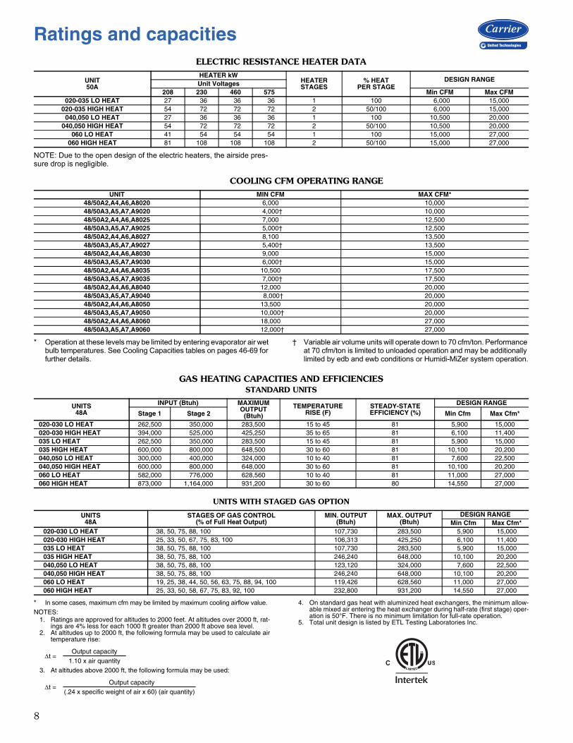
ELECTRIC RESISTANCE HEATER DATA
NOTE: Due to the open design of the electric heaters, the airside pres-sure drop is negligible.
COOLING CFM OPERATING RANGE
* Operation at these levels may be limited by entering evaporator air wet bulb temperatures. See Cooling Capacities tables on pages 46-69 for further details.
† Variable air volume units will operate down to 70 cfm/ton. Performance at 70 cfm/ton is limited to unloaded operation and may be additionally limited by edb and ewb conditions or Humidi-MiZer system operation.
GAS HEATING CAPACITIES AND EFFICIENCIESSTANDARD UNITS
UNITS WITH STAGED GAS OPTION
* In some cases, maximum cfm may be limited by maximum cooling airflow value.
NOTES:1. Ratings are approved for altitudes to 2000 feet. At altitudes over 2000 ft, rat-
ings are 4% less for each 1000 ft greater than 2000 ft above sea level.2. At altitudes up to 2000 ft, the following formula may be used to calculate air
temperature rise:
3. At altitudes above 2000 ft, the following formula may be used:
4. On standard gas heat with aluminized heat exchangers, the minimum allow-able mixed air entering the heat exchanger during half-rate (first stage) oper-ation is 50°F. There is no minimum limitation for full-rate operation.
5. Total unit design is listed by ETL Testing Laboratories Inc.
UNIT50A
HEATER kWHEATERSTAGES
% HEATPER STAGE
DESIGN RANGEUnit Voltages
208 230 460 575 Min CFM Max CFM020-035 LO HEAT 27 36 36 36 1 100 6,000 15,000
020-035 HIGH HEAT 54 72 72 72 2 50/100 6,000 15,000040,050 LO HEAT 27 36 36 36 1 100 10,500 20,000
040,050 HIGH HEAT 54 72 72 72 2 50/100 10,500 20,000060 LO HEAT 41 54 54 54 1 100 15,000 27,000
060 HIGH HEAT 81 108 108 108 2 50/100 15,000 27,000
UNIT MIN CFM MAX CFM*48/50A2,A4,A6,A8020 6,000 10,00048/50A3,A5,A7,A9020 4,000† 10,00048/50A2,A4,A6,A8025 7,000 12,50048/50A3,A5,A7,A9025 5,000† 12,50048/50A2,A4,A6,A8027 8,100 13,50048/50A3,A5,A7,A9027 5,400† 13,50048/50A2,A4,A6,A8030 9,000 15,00048/50A3,A5,A7,A9030 6,000† 15,00048/50A2,A4,A6,A8035 10,500 17,50048/50A3,A5,A7,A9035 7,000† 17,50048/50A2,A4,A6,A8040 12,000 20,00048/50A3,A5,A7,A9040 8,000† 20,00048/50A2,A4,A6,A8050 13,500 20,00048/50A3,A5,A7,A9050 10,000† 20,00048/50A2,A4,A6,A8060 18,000 27,00048/50A3,A5,A7,A9060 12,000† 27,000
UNITS48A
INPUT (Btuh) MAXIMUMOUTPUT
(Btuh)
TEMPERATURERISE (F)
STEADY-STATEEFFICIENCY (%)
DESIGN RANGE
Stage 1 Stage 2 Min Cfm Max Cfm*
020-030 LO HEAT 262,500 350,000 283,500 15 to 45 81 5,900 15,000020-030 HIGH HEAT 394,000 525,000 425,250 35 to 65 81 6,100 11,400035 LO HEAT 262,500 350,000 283,500 15 to 45 81 5,900 15,000035 HIGH HEAT 600,000 800,000 648,500 30 to 60 81 10,100 20,200040,050 LO HEAT 300,000 400,000 324,000 10 to 40 81 7,600 22,500040,050 HIGH HEAT 600,000 800,000 648,000 30 to 60 81 10,100 20,200060 LO HEAT 582,000 776,000 628,560 10 to 40 81 11,000 27,000060 HIGH HEAT 873,000 1,164,000 931,200 30 to 60 80 14,550 27,000
UNITS48A
STAGES OF GAS CONTROL(% of Full Heat Output)
MIN. OUTPUT(Btuh)
MAX. OUTPUT(Btuh)
DESIGN RANGEMin Cfm Max Cfm*
020-030 LO HEAT 38, 50, 75, 88, 100 107,730 283,500 5,900 15,000020-030 HIGH HEAT 25, 33, 50, 67, 75, 83, 100 106,313 425,250 6,100 11,400035 LO HEAT 38, 50, 75, 88, 100 107,730 283,500 5,900 15,000035 HIGH HEAT 38, 50, 75, 88, 100 246,240 648,000 10,100 20,200040,050 LO HEAT 38, 50, 75, 88, 100 123,120 324,000 7,600 22,500040,050 HIGH HEAT 38, 50, 75, 88, 100 246,240 648,000 10,100 20,200060 LO HEAT 19, 25, 38, 44, 50, 56, 63, 75, 88, 94, 100 119,426 628,560 11,000 27,000060 HIGH HEAT 25, 33, 50, 58, 67, 75, 83, 92, 100 232,800 931,200 14,550 27,000
t =Output capacity
1.10 x air quantity
t =Output capacity
(.24 x specific weight of air x 60) (air quantity)
Ratings and capacities

9
CAPACITY CONTROL STAGING OPTIONS
LEGEND
CAPACITY CONTROL STAGING OPTIONS TABLE A48/50A020-027 UNITS VAV AND ADAPTIVE CV/SAV STAGING SEQUENCE WITHOUT HOT GAS BYPASS
CAPACITY CONTROL STAGING OPTIONS TABLE B48/50A020-027 UNIT VAV AND ADAPTIVE CV STAGING SEQUENCE WITH HOT GAS BYPASS
*Hot gas bypass activated.
CAPACITY CONTROL STAGING OPTIONS TABLE C48/50A020-027 UNITS VAV AND ADAPTIVE CV/SAV STAGING SEQUENCE WITH VARIABLE CAPACITY COMPRESSOR
*On units with optional digital scroll compressor, compressor B1 modulates fromminimum to maximum capacity to provide increased stages.
APPLICATION UNIT DEMANDSOURCE
COOLINGCONTROL METHOD
COMPRESSOR SEQUENCESIZE 020-027 UNITS SIZE 030-060 UNITS
WITHOUT HOT GAS BYPASS
WITH HOT GAS BYPASS
WITH VARIABLE CAPACITY
COMPRESSOR
WITHOUT HOT GAS BYPASS
WITH HOT GAS BYPASS
WITH VARIABLE CAPACITY
COMPRESSOR
VAV 48/50A3,A5, A7,A9
RAT Multiple Stage EDT Table A Table B Table C Table D Table E Table FSPT Multiple Stage EDT Table A Table B Table C Table D Table E Table F
SAV/CV Sensor 48/50A2,A4,
A6,A8
SPT Multiple Adaptive Demand Table A Table B Table C Table D Table E Table F
SAV/CV, Mech Thermostat Y1,Y2 Multiple Adaptive
Demand Table A Table B Table C Table D Table E Table F
CV — Constant VolumeEDT — Evaporator Discharge TemperatureRAT — Return Air TemperatureSAV — Staged Air VolumeSPT — Space TemperatureVAV — Variable Air Volume
STAGESEQUENCE 1 SEQUENCE 2
0 1 2 3 0 1 2 3COMP Compressor Status Compressor Status
A1 OFF ON OFF ON OFF OFF ON ONA2 OFF OFF ON ON OFF ON OFF ONB1 OFF OFF ON ON OFF OFF ON ON
UNIT Capacity 48/50A Capacity 48/50A020 0% 30% 70% 100% 0% 30% 70% 100%025 0% 33% 67% 100% 0% 33% 67% 100%027 0% 33% 67% 100% 0% 33% 67% 100%
STAGESEQUENCE 1 SEQUENCE 2
0 1 2 3 4 0 1 2 3 4COMP Compressor Status Compressor Status
A1 OFF ON* ON OFF ON OFF OFF OFF ON ONA2 OFF OFF OFF ON ON OFF ON* ON OFF ONB1 OFF OFF OFF ON ON OFF OFF OFF ON ON
UNIT Capacity 48/50A Capacity 48/50A020 0% 10% 30% 70% 100% 0% 10% 30% 70% 100%025 0% 17% 33% 67% 100% 0% 17% 33% 67% 100%027 0% 17% 33% 67% 100% 0% 17% 33% 67% 100%
STAGE0 1 2 3
COMP Compressor StatusA1 OFF OFF ON ONA2 OFF OFF OFF ONB1* OFF ON ON ON
UNIT Capacity 48/50A020 0% 20% to 40% 50% to 70% 80% to 100%025 0% 17% to 33% 50% to 66% 83% to 100%027 0% 17% to 33% 50% to 66% 83% to 100%
10
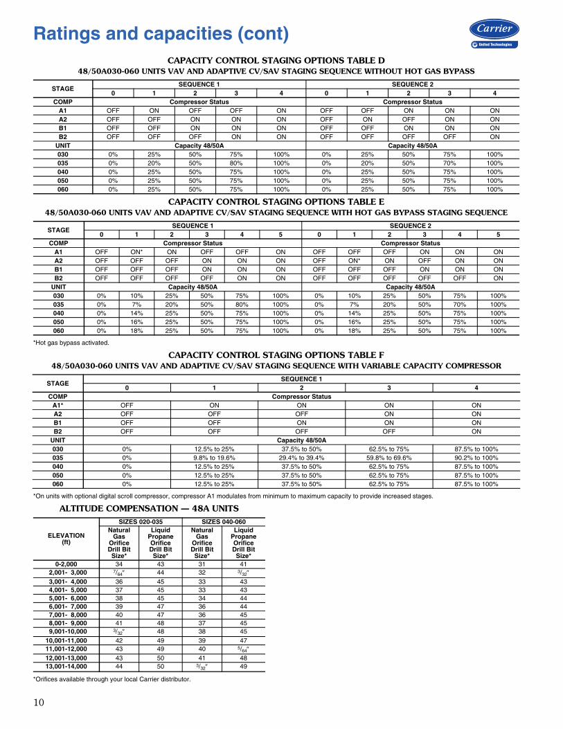
CAPACITY CONTROL STAGING OPTIONS TABLE D48/50A030-060 UNITS VAV AND ADAPTIVE CV/SAV STAGING SEQUENCE WITHOUT HOT GAS BYPASS
CAPACITY CONTROL STAGING OPTIONS TABLE E48/50A030-060 UNITS VAV AND ADAPTIVE CV/SAV STAGING SEQUENCE WITH HOT GAS BYPASS STAGING SEQUENCE
*Hot gas bypass activated.
CAPACITY CONTROL STAGING OPTIONS TABLE F48/50A030-060 UNITS VAV AND ADAPTIVE CV/SAV STAGING SEQUENCE WITH VARIABLE CAPACITY COMPRESSOR
*On units with optional digital scroll compressor, compressor A1 modulates from minimum to maximum capacity to provide increased stages.
ALTITUDE COMPENSATION — 48A UNITS
*Orifices available through your local Carrier distributor.
STAGESEQUENCE 1 SEQUENCE 2
0 1 2 3 4 0 1 2 3 4COMP Compressor Status Compressor Status
A1 OFF ON OFF OFF ON OFF OFF ON ON ONA2 OFF OFF ON ON ON OFF ON OFF ON ONB1 OFF OFF ON ON ON OFF OFF ON ON ONB2 OFF OFF OFF ON ON OFF OFF OFF OFF ON
UNIT Capacity 48/50A Capacity 48/50A030 0% 25% 50% 75% 100% 0% 25% 50% 75% 100%035 0% 20% 50% 80% 100% 0% 20% 50% 70% 100%040 0% 25% 50% 75% 100% 0% 25% 50% 75% 100%050 0% 25% 50% 75% 100% 0% 25% 50% 75% 100%060 0% 25% 50% 75% 100% 0% 25% 50% 75% 100%
STAGESEQUENCE 1 SEQUENCE 2
0 1 2 3 4 5 0 1 2 3 4 5COMP Compressor Status Compressor Status
A1 OFF ON* ON OFF OFF ON OFF OFF OFF ON ON ONA2 OFF OFF OFF ON ON ON OFF ON* ON OFF ON ONB1 OFF OFF OFF ON ON ON OFF OFF OFF ON ON ONB2 OFF OFF OFF OFF ON ON OFF OFF OFF OFF OFF ON
UNIT Capacity 48/50A Capacity 48/50A030 0% 10% 25% 50% 75% 100% 0% 10% 25% 50% 75% 100%035 0% 7% 20% 50% 80% 100% 0% 7% 20% 50% 70% 100%040 0% 14% 25% 50% 75% 100% 0% 14% 25% 50% 75% 100%050 0% 16% 25% 50% 75% 100% 0% 16% 25% 50% 75% 100%060 0% 18% 25% 50% 75% 100% 0% 18% 25% 50% 75% 100%
STAGESEQUENCE 1
0 1 2 3 4COMP Compressor Status
A1* OFF ON ON ON ONA2 OFF OFF OFF ON ONB1 OFF OFF ON ON ONB2 OFF OFF OFF OFF ON
UNIT Capacity 48/50A030 0% 12.5% to 25% 37.5% to 50% 62.5% to 75% 87.5% to 100%035 0% 9.8% to 19.6% 29.4% to 39.4% 59.8% to 69.6% 90.2% to 100%040 0% 12.5% to 25% 37.5% to 50% 62.5% to 75% 87.5% to 100%050 0% 12.5% to 25% 37.5% to 50% 62.5% to 75% 87.5% to 100%060 0% 12.5% to 25% 37.5% to 50% 62.5% to 75% 87.5% to 100%
ELEVATION(ft)
SIZES 020-035 SIZES 040-060Natural
GasOrificeDrill Bit
Size*
LiquidPropaneOrificeDrill Bit
Size*
NaturalGas
OrificeDrill Bit
Size*
LiquidPropaneOrificeDrill Bit
Size*0-2,000 34 43 31 41
2,001- 3,000 7/64 44 32 3/323,001- 4,000 36 45 33 434,001- 5,000 37 45 33 435,001- 6,000 38 45 34 446,001- 7,000 39 47 36 447,001- 8,000 40 47 36 458,001- 9,000 41 48 37 459,001-10,000 3/32 48 38 45
10,001-11,000 42 49 39 4711,001-12,000 43 49 40 5/6412,001-13,000 43 50 41 4813,001-14,000 44 50 3/32 49
Ratings and capacities (cont)

11
LEGEND* Sizes 020 to 027: Circuit 1 uses the lower portion of condenser coil, Circuit 2 uses
the upper portion. Sizes 030 and 035: Circuit 1 uses the upper portion of condens-er coil, Circuit 2 uses the lower portion. Sizes 040 and 050: Circuit 1 uses the left condenser coil, Circuit 2 the right. Size 060: Circuit A uses the two MCHX coils near the bulkhead, Circuit B uses the two MCHX coils near the control box.
† Rollout switch is manual reset.
UNIT 48A 020 025 027 030NOMINAL CAPACITY (tons) 20 25 27 30
BASE UNIT See Unit Weights TableOPERATING WEIGHT (lb)COMPRESSOR Quantity ... Type (Ckt 1/Ckt 2) 2 ... ZP67/1…ZP91 2 ... ZP91/1…ZP91 2 ... ZP91/1…ZP91 2…ZP72, 2…ZP72 Number of Refrigerant Circuits 2 2 2 2 Oil Precharged Precharged Precharged Precharged
REFRIGERANT R-410A Operating Charge (lb), Ckt 1/Ckt 2 RTPF Coils 26.2/18.8 30.2/15.2 32.8/16.5 30.5/34.3 MCHX Coils 14.9/11.8 16.5/11.0 16.5/11.0 15.1/15.3 MCHX Coils with Humidi-MiZer 22.1/11.8 23.7/11.0 23.7/11.0 15.1/22.5
MCHX CONDENSER* Quantity 1 1 1 1 Total Face Area (sq ft) 32.9 32.9 32.9 32.9
RTPF CONDENSER Quantity 1 1 1 1 Rows...Fins/in. 2...15 3...15 3...15 4...15 Total Face Area (sq ft) 33.3 33.3 33.3 33.3
CONDENSER FAN Propeller Type Nominal Cfm 19,500 19,500 19,500 19,500 Quantity... Diameter (in.) 2 ... 30 2 ... 30 2 ... 30 2 ... 30 Motor Hp 1 1 1 1
EVAPORATOR COIL Cross-Hatched Copper Tubes, Aluminum Plate Fins with Intertwined Circuits Tube Size (in.) 3/8 3/8 3/8 3/8 Rows ... Fins/in. 3 ... 15 4 ... 14 4 ... 15 4 ... 15 Total Face Area (sq ft) 31.7 31.7 31.7 31.7
HUMIDI-MIZER COIL Coil Construction E-Coated Aluminum Novation® Heat Exchanger with Microchannel Coil Technology Quantity 1 1 1 1 Face Area (sq ft) 14.4 14.4 14.4 14.4
EVAPORATOR FAN Centrifugal Type Quantity ... Size (in.) 2 ... 20 X 15 2 ... 20 X 15 2 ... 20 X 15 2 ... 20 X 15 Type Drive Belt Belt Belt Belt Nominal Cfm 8,000 10,000 11,000 12,000 Motor Hp 5 10 15 5 10 15 10 15 20 10 15 20 Motor Frame Size 184T 215T 254T 184T 215T 254T 215T 254T 256T 215T 254T 256T Motor Bearing Type Ball Ball Ball Ball Maximum Allowable Rpm 1200 1200 1200 1200 Motor Pulley Pitch Diameter 4.8 4.4 5.7 5.2 6.1 5.5 4.4 4.9 5.9 4.4 5.7 5.9 Nominal Motor Shaft Diameter (in.) 11/8 13/8 15/8 11/8 13/8 15/8 13/8 15/8 15/8 13/8 15/8 15/8 Fan Pulley Pitch Diameter (in.) 12.4 8.6 9.1 12.4 11.1 8.7 9.4 8.1 8.7 9.0 9.1 8.7 Nominal Fan Shaft Diameter (in.) 115/16 115/16 115/16 115/16 Belt Quantity 1 2 2 1 1 2 2 2 2 2 2 2 Belt Type BX56 BX50 5VX530 BX56 5VX570 5VX530 BX50 5VX500 5VX530 BX50 5VX530 5VX530 Belt Length (in.) 56 63 53 56 57 53 50 50 53 50 53 53 Pulley Center Line Distance (in.) 16.0-
18.715.6-18.4
15.0-17.9 15.6-18.4 15.6-18.4 15.0-17.9 15.6-18.4 15.0-
17.915.0-17.9
15.6-18.4
15.0-17.9
15.0-17.9
Factory Speed Setting (rpm) 717 924 1096 773 962 1106 848 1059 1187 856 1096 1187
FURNACE SECTION Supply Line Pressure Range 5.0-in. wg min/13.5-in. wg max. Rollout Switch Cutout Temp (F)† 225 225 225 225 Burner Orifice Diameter (in. ...drill size) Natural Gas Std .111 ... 34 .111 ... 34 .111 ... 34 .111 ... 34 Liquid Propane Alt .089 ... 43 .089 ... 43 .089 ... 43 .089 ... 43 Thermostat Heat Anticipator Setting Stage 1 (amps) 0.1 0.1 0.1 0.1 Stage 2 (amps) 0.1 0.1 0.1 0.1 Gas Input (Btuh) Stage 1 (Low Heat/High Heat) 262,500/394,000 262,500/394,000 262,500/394,000 262,500/394,000
Stage 2 (Low Heat/High Heat) 350,000/525,000 350,000/525,000 350,000/525,000 350,000/525,000
Efficiency (Steady State) (%) 81 81 81 81 Temperature Rise Range 15-45/35-65 15-45/35-65 15-45/35-65 15-45/35-65 Manifold Pressure (in. wg) Natural Gas Std 3.5 3.5 3.5 3.5 Liquid Propane Alt 3.5 3.5 3.5 3.5 Gas Valve Quantity 2 2 2 2
HIGH-PRESSURE SWITCH (psig) Cutout 650 650 650 650 Reset (Auto.) 500 500 500 500
MIXED-AIR FILTERS Quantity ... Size (in.) Standard 10 ... 20 x 24 x 2 10 ... 20 x 24 x 2 10 ... 20 x 24 x 2 10 ... 20 x 24 x 2 Pleated 5 ... 20 x 20 x 4
5 ... 20 x 24 x 45 ... 20 x 20 x 45 ... 20 x 24 x 4
5 ... 20 x 20 x 45 ... 20 x 24 x 4
5 ... 20 x 20 x 45 ... 20 x 24 x 4
OUTDOOR-AIR FILTERS Quantity...Size (in.) 8...16 x 25 x 2
4...20 x 25 x 2
POWER EXHAUST Direct Drive, Single-Phase Motors (Factory-Wired for High Speed Operation), Forward-Curved Fan Wheelswith Backdraft Dampers on Each Fan Housing
Motor, Quantity...Hp 4...1 Fan, Diameter...Width (in.) 11 x 10
Al — AluminumCu — CopperMCHX — Microchannel Heat ExchangerRTPF — Round Tube Plate Fin
Physical data — 48A units
12
LEGEND * Sizes 020 to 027: Circuit 1 uses the lower portion of condenser coil, Circuit 2 uses the upper portion. Sizes 030 and 035: Circuit 1 uses the upper portion of condens-er coil, Circuit 2 uses the lower portion. Sizes 040 and 050: Circuit 1 uses the left condenser coil, Circuit 2 the right. Size 060: Circuit A uses the two MCHX coils near the bulkhead, Circuit B uses the two MCHX coils near the control box.
† Rollout switch is manual reset.
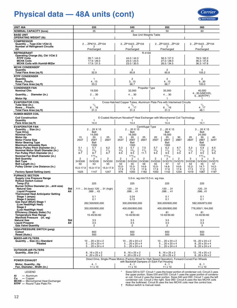
UNIT 48A 035 040 050 060NOMINAL CAPACITY (tons) 35 40 50 60
BASE UNIT See Unit Weights TableOPERATING WEIGHT (lb)COMPRESSOR Quantity ... Type (Ckt 1/Ckt 2) 2 ... ZP67/2...ZP104 2...ZP104/2...ZP104 2…ZP122/2…ZP122 2…ZP154/2…ZP154 Number of Refrigerant Circuits 2 2 2 2 Oil Precharged Precharged Precharged Precharged
REFRIGERANT R-410A Operating Charge (lb), Ckt 1/Ckt 2 RTPF Coils 28.7 / 44.0 44.0 / 44.0 56.3 / 57.3 78.5 / 82.0 MCHX Coils 17.9 / 26.0 23.0 / 23.5 27.0 / 28.0 36.3 / 37.8 MCHX Coils with Humidi-MiZer 17.9 / 31.5 23.0 / 30.5 26.5 / 34.5 36.3 / 47.6
MCHX CONDENSER* Quantity 1 2 2 4 Total Face Area (sq ft) 32.9 65.8 65.8 105.2
RTPF CONDENSER Quantity 1 2 2 2 Rows...Fins/in. 4...15 3...15 4...15 6...30 Total Face Area (sq ft) 33.3 66.7 66.7 100.0
CONDENSER FAN Propeller Type Nominal Cfm 19,500 32,000 35,000 40,000
Quantity... Diameter (in.) 2 ... 30 4 ... 30 4 ... 30 4...30.5(MCHX), 6...30(RTPF)
Motor Hp 1 1 1 1
EVAPORATOR COIL Cross-Hatched Copper Tubes, Aluminum Plate Fins with Intertwined Circuits Tube Size (in.) 1/2 1/2 1/2 1/2 Rows ... Fins/in. 6 ... 16 4 ... 17 6 ... 16 4...17 Total Face Area (sq ft) 31.3 31.3 31.3 48.1
HUMIDI-MIZER COIL Coil Construction E-Coated Aluminum Novation® Heat Exchanger with Microchannel Coil Technology Quantity 1 1 1 1 Face Area (sq ft) 14.4 14.4 14.4 14.1
EVAPORATOR FAN Centrifugal Type Quantity ... Size (in.) 2 ... 20 X 15 2 ... 20 X 15 2 ... 20 X 15 3 ... 20 X 15 Type Drive Belt Belt Belt Belt Nominal Cfm 14,000 16,000 18,000 24,000 Motor Hp 15 20 25 15 20 25 20 25 30 25 30 40 Motor Frame Size 254T 256T 284T 254T 256T 284T 256T 284T 286T 284T 286T 324T Motor Bearing Type Ball Ball Ball Ball Maximum Allowable Rpm 1300 1300 1300 1200 Motor Pulley Pitch Diameter (in.) 5.1 5.7 6.2 5.3 5.7 7.5 5.7 6.2 6.7 5.3 5.9 6.5 Nominal Motor Shaft Diameter (in.) 15/8 15/8 17/8 15/8 15/8 17/8 15/8 17/8 17/8 17/8 17/8 21/8 Fan Pulley Pitch Diameter (in.) 8.7 8.7 8.7 9.5 9.5 11.1 9.5 9.5 9.5 9.1 9.5 9.5 Nominal Fan Shaft Diameter (in.) 115/16 115/16 115/16 115/16 Belt Quantity 2 2 2 2 2 2 2 2 2 3 3 3 Belt Type 5VX500 5VX530 5VX550 5VX530 5VX550 5VX590 5VX550 5VX570 5VX570 5VX530 5VX550 5VX570 Belt Length (in.) 50 53 55 53 55 59 55 57 57 53 55 57 Pulley Center Line Distance (in.) 15.0-17.9 15.0-17.9 15.0-17.9 15.0-
17.915.0-17.9
14.6-17.6
15.0-17.9
14.6-17.6
14.6-17.6
15.2-17.5
14.7-17.2
14.2-17.0
Factory Speed Setting (rpm) 1025 1147 1247 976 1050 1182 1050 1142 1234 1019 1087 1197
FURNACE SECTION Supply Line Pressure Range 5.0-in. wg min/13.5-in. wg max. Rollout Switch Cutout Temp (F)† 225 225 225 225 Burner Orifice Diameter (in ...drill size) Natural Gas Std .111 ... 34 (low)/.120 ... 31 (high) .120 ... 31 .120 ... 31 .120...31 Liquid Propane Alt .089 ... 43 .096 ... 41 .096 ... 41 .096...41 Thermostat Heat Anticipator Setting Stage 1 (amps) 0.1 0.24 0.1 0.1 Stage 2 (amps) 0.1 0.13 0.1 0.1 Gas Input (Btuh) Stage 1 (Low Heat/High Heat) 262,500/600,000 300,000/600,000 300,000/600,000 582,000/873,000
Stage 2 (Low Heat/High Heat) 350,000/800,000 400,000/800,000 400,000/800,000 776,000/1,164,000
Efficiency (Steady State) (%) 81 81 81 81 Temperature Rise Range 15-45/30-60 10-40/30-60 10-40/30-60 10-40/30-60 Manifold Pressure (in. wg) Natural Gas Std 3.5 3.5 3.5 3.3 Liquid Propane Alt 3.5 3.5 3.5 3.3 Gas Valve Quantity 2 2 2 3
HIGH-PRESSURE SWITCH (psig) Cutout 650 650 650 650 Reset (Auto.) 500 500 500 500
MIXED-AIR FILTERS Quantity ... Size (in.) Standard 10 ... 20 x 24 x 2 10 ... 20 x 24 x 2 10 ... 20 x 24 x 2 16...20 x 24 x 2
8...20 x 20 x 48...20 x 24 x 4
Pleated 5 ... 20 x 20 x 45 ... 20 x 24 x 4
5 ... 20 x 20 x 45 ... 20 x 24 x 4
5 ... 20 x 20 x 45 ... 20 x 24 x 4
OUTDOOR-AIR FILTERS Quantity...Size (in.) 8...16 x 25 x 2
4...20 x 25 x 28...16 x 25 x 24...20 x 25 x 2
8...16 x 25 x 24...20 x 25 x 2
12...16 x 25 x 26...20 x 25 x 2
POWER EXHAUST Direct Drive, Single-Phase Motors (Factory-Wired for High Speed Operation), Forward-Curved Fan Wheelswith Backdraft Dampers on Each Fan Housing
Motor, Quantity...Hp 4...111 x 10
4...111 x 10
4...111 x 10
6...111 x 10 Fan, Diameter...Width (in.)
Al — AluminumCu — CopperMCHX — Microchannel Heat ExchangerRTPF — Round Tube Plate Fin
Physical data — 48A units (cont)

13
LEGEND * Sizes 020 to 027: Circuit 1 uses the lower portion of condenser coil, Circuit 2 uses the upper portion. Sizes 030 and 035: Circuit 1 uses the upper portion of condens-er coil, Circuit 2 uses the lower portion. Sizes 040 and 050: Circuit 1 uses the left condenser coil, Circuit 2 the right. Size 060: Circuit A uses the two MCHX coils near the bulkhead, Circuit B uses the two MCHX coils near the control box.
† Rollout switch is manual reset.
UNIT 50A 020 025 027 030NOMINAL CAPACITY (tons) 20 25 27 30
BASE UNIT See Unit Weights TableOPERATING WEIGHT (lb)COMPRESSOR Quantity ... Type (Ckt 1/Ckt 2) 2 ... ZP67/1…ZP91 2 ... ZP91/1…ZP91 2 ... ZP91/1…ZP91 2…ZP72, 2…ZP72 Number of Refrigerant Circuits 2 2 2 2 Oil Precharged Precharged Precharged Precharged
REFRIGERANT R-410A Operating Charge (lb), Ckt 1/Ckt 2 RTPF Coils 26.2/18.8 30.2/15.2 32.8/16.5 30.5/34.3 MCHX Coils 14.9/11.8 16.5/11.0 16.5/11.0 15.1/15.3 MCHX Coils with Humidi-MiZer 22.1/11.8 23.7/11.0 23.7/11.0 15.1/22.5
MCHX CONDENSER* Quantity 1 1 1 1 Total Face Area (sq ft) 32.9 32.9 32.9 32.9
RTPF CONDENSER Quantity 1 1 1 1 Rows...Fins/in. 2...15 3...15 3...15 4...15 Total Face Area (sq ft) 33.3 33.3 33.3 33.3
CONDENSER FAN Propeller Type Nominal Cfm 19,500 19,500 19,500 19,500 Quantity... Diameter (in.) 2 ... 30 2 ... 30 2 ... 30 2 ... 30 Motor Hp 1 1 1 1
EVAPORATOR COIL Cross-Hatched Copper Tubes, Aluminum Plate Fins with Intertwined Circuits Tube Size (in.) 3/8 3/8 3/8 3/8 Rows ... Fins/in. 3 ... 15 4 ... 14 4 ... 15 4 ... 15 Total Face Area (sq ft) 31.7 31.7 31.7 31.7
HUMIDI-MIZER COIL Coil Construction E-Coated Aluminum Novation® Heat Exchanger with Microchannel Coil Technology Quantity 1 1 1 1 Face Area (sq ft) 14.4 14.4 14.4 14.4
EVAPORATOR FAN Centrifugal Type Quantity ... Size (in.) 2 ... 20 X 15 2 ... 20 X 15 2 ... 20 X 15 2 ... 20 X 15 Type Drive Belt Belt Belt Belt Nominal Cfm 8,000 10,000 11,000 12,000 Motor Hp 5 10 15 5 10 15 10 15 20 10 15 20 Motor Frame Size 184T 215T 254T 184T 215T 254T 215T 254T 256T 215T 254T 256T Motor Bearing Type Ball Ball Ball Ball Maximum Allowable Rpm 1200 1200 1200 1200 Motor Pulley Pitch Diameter 4.8 4.4 5.7 5.2 6.1 5.5 4.4 4.9 5.9 4.4 5.7 5.9 Nominal Motor Shaft Diameter (in.) 11/8 13/8 15/8 11/8 13/8 15/8 13/8 15/8 15/8 13/8 15/8 15/8 Fan Pulley Pitch Diameter (in.) 12.4 8.6 9.1 12.4 11.1 8.7 9.4 8.1 8.7 9.0 9.1 8.7 Nominal Fan Shaft Diameter (in.) 115/16 115/16 115/16 115/16 Belt Quantity 1 2 2 1 1 2 2 2 2 2 2 2 Belt Type BX56 BX50 5VX530 BX56 5VX570 5VX530 BX50 5VX500 5VX530 BX50 5VX530 5VX530 Belt Length (in.) 56 63 53 56 57 53 50 50 53 50 53 53 Pulley Center Line Distance (in.) 16.0-
18.715.6-18.4
15.0-17.9 15.6-18.4 15.6-18.4 15.0-17.9 15.6-18.4 15.0-
17.915.0-17.9
15.6-18.4
15.0-17.9
15.0-17.9
Factory Speed Setting (rpm) 717 924 1096 773 962 1106 848 1059 1187 856 1096 1187
HIGH-PRESSURE SWITCH (psig) Cutout 650 650 650 650 Reset (Auto.) 500 500 500 500
MIXED-AIR FILTERS Quantity ... Size (in.) Standard 10 ... 20 x 24 x 2 10 ... 20 x 24 x 2 10 ... 20 x 24 x 2 10 ... 20 x 24 x 2 Pleated 5 ... 20 x 20 x 4
5 ... 20 x 24 x 45 ... 20 x 20 x 45 ... 20 x 24 x 4
5 ... 20 x 20 x 45 ... 20 x 24 x 4
5 ... 20 x 20 x 45 ... 20 x 24 x 4
OUTDOOR-AIR FILTERS Quantity...Size (in.) 8...16 x 25 x 2
4...20 x 25 x 2
POWER EXHAUST Direct Drive, Single-Phase Motors (Factory-Wired for High Speed Operation), Forward-Curved Fan Wheels with Backdraft Damperson Each Fan Housing
Motor, Quantity...Hp 4...1 Fan, Diameter...Width (in.) 11 x 10
Al — AluminumCu — CopperMCHX — Microchannel Heat ExchangerRTPF — Round Tube Plate Fin
Physical data — 50A units

14
LEGEND * Sizes 020 to 027: Circuit 1 uses the lower portion of condenser coil, Circuit 2 uses the upper portion. Sizes 030 and 035: Circuit 1 uses the upper portion of condens-er coil, Circuit 2 uses the lower portion. Sizes 040 and 050: Circuit 1 uses the left condenser coil, Circuit 2 the right. Size 060: Circuit A uses the two MCHX coils near the bulkhead, Circuit B uses the two MCHX coils near the control box.
† Rollout switch is manual reset.
UNIT 50A 035 040 050 060NOMINAL CAPACITY (tons) 35 40 50 60
BASE UNIT See Unit Weights TableOPERATING WEIGHT (lb)COMPRESSOR Quantity ... Type (Ckt 1/Ckt 2) 2 ... ZP67/2…ZP104 2…ZP104/2…ZP104 2…ZP122/2…ZP122 2…ZP154/2…ZP154 Number of Refrigerant Circuits 2 2 2 2 Oil Precharged Precharged Precharged Precharged
REFRIGERANT R-410A Operating Charge (lb), Ckt 1/Ckt 2 RTPF Coils 28.7 / 44.0 44.0 / 44.0 56.3 / 57.3 78.5 / 82.0 MCHX Coils 17.9 / 26.0 23.0 / 23.5 27.0 / 28.0 36.3 / 37.8 MCHX Coils with Humidi-MiZer 17.9 / 31.5 23.0 / 30.5 26.5 / 34.5 36.3 / 47.6
MCHX CONDENSER* Quantity 1 2 2 4 Total Face Area (sq ft) 32.9 65.8 65.8 105.2
RTPF CONDENSER Quantity 1 2 2 2 Rows...Fins/in 4...15 3...15 4...15 6...30 Total Face Area (sq ft) 33.3 66.7 66.7 100.0
CONDENSER FAN Propeller Type Nominal Cfm 19,500 32,000 35,000 40,000
Quantity... Diameter (in.) 2 ... 30 4 ... 30 4 ... 30 4...30.5(MCHX), 6...30(RTPF)
Motor Hp 1 1 1 1
EVAPORATOR COIL Cross-Hatched Copper Tubes, Aluminum Plate Fins with Intertwined Circuits Tube Size (in.) 1/2 1/2 1/2 1/2 Rows ... Fins/in. 6 ... 16 4 ... 17 6 ... 16 4...17 Total Face Area (sq ft) 31.3 31.3 31.3 48.1
HUMIDI-MIZER COIL Coil Construction E-Coated Aluminum Novation® Heat Exchanger with Microchannel Coil Technology Quantity 1 1 1 1 Face Area (sq ft) 14.4 14.4 14.4 14.4
EVAPORATOR FAN Centrifugal Type Quantity ... Size (in.) 2 ... 20 X 15 2 ... 20 X 15 2 ... 20 X 15 3 ... 20 X 15 Type Drive Belt Belt Belt Belt Nominal Cfm 14,000 16,000 18,000 24,000 Motor Hp 15 20 25 15 20 25 20 25 30 25 30 40 Motor Frame Size 254T 256T 284T 254T 256T 284T 256T 284T 286T 284T 286T 324T Motor Bearing Type Ball Ball Ball Ball Maximum Allowable Rpm 1300 1300 1300 1200 Motor Pulley Pitch Diameter 5.1 5.7 6.2 5.3 5.7 7.5 5.7 6.2 6.7 5.3 5.9 6.5 Nominal Motor Shaft Diameter (in.) 15/8 15/8 17/8 15/8 15/8 17/8 15/8 17/8 17/8 17/8 17/8 21/8 Fan Pulley Pitch Diameter (in.) 8.7 8.7 8.7 9.5 9.5 11.1 9.5 9.5 9.5 9.1 9.5 9.5 Nominal Fan Shaft Diameter (in.) 115/16 115/16 115/16 115/16 Belt Quantity 2 2 2 2 2 2 2 2 2 3 3 3 Belt Type 5VX500 5VX530 5VX550 5VX530 5VX550 5VX590 5VX550 5VX570 5VX570 5VX530 5VX550 5VX570 Belt Length (in.) 50 53 55 53 55 59 55 57 57 53 55 57 Pulley Center Line Distance (in.) 15.0-
17.915.0-17.9
15.0-17.9
15.0-17.9
15.0-17.9
14.6-17.6
15.0-17.9
14.6-17.6
14.6-17.6
15.2-17.5
14.7-17.2
14.2-17.0
Factory Speed Setting (rpm) 1025 1147 1247 976 1050 1182 1050 1142 1234 1019 1087 1197
HIGH-PRESSURE SWITCH (psig) Cutout 650 650 650 650 Reset (Auto.) 500 500 500 500
MIXED-AIR FILTERS Quantity ... Size (in.) Standard 10 ... 20 x 24 x 2 10 ... 20 x 24 x 2 10 ... 20 x 24 x 2 16...20 x 24 x 2
8...20 x 20 x 48...20 x 24 x 4
Pleated 5 ... 20 x 20 x 45 ... 20 x 24 x 4
5 ... 20 x 20 x 45 ... 20 x 24 x 4
5 ... 20 x 20 x 45 ... 20 x 24 x 4
OUTDOOR-AIR FILTERS Quantity...Size (in.) 8...16 x 25 x 2
4...20 x 25 x 28...16 x 25 x 24...20 x 25 x 2
8...16 x 25 x 24...20 x 25 x 2
12...16 x 25 x 26...20 x 25 x 2
POWER EXHAUST Direct Drive, Single-Phase Motors (Factory-Wired for High Speed Operation), Forward-Curved Fan Wheelswith Backdraft Dampers on Each Fan Housing
Motor, Quantity...Hp 4...111 x 10
4...111 x 10
4...111 x 10
6...111 x 10 Fan, Diameter...Width (in.)
Al — AluminumCu — CopperMCHX — Microchannel Heat ExchangerRTPF — Round Tube Plate Fin
Physical data — 50A units (cont)
15
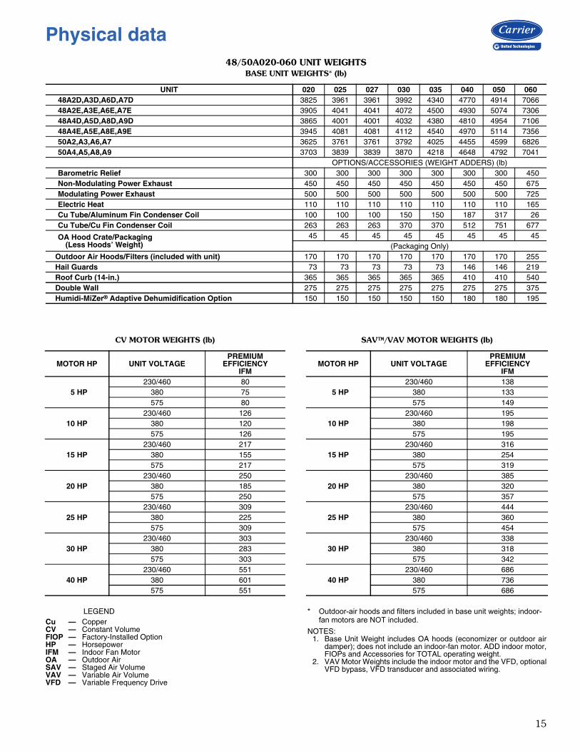
48/50A020-060 UNIT WEIGHTSBASE UNIT WEIGHTS* (lb)
CV MOTOR WEIGHTS (lb) SAV™/VAV MOTOR WEIGHTS (lb)
LEGEND * Outdoor-air hoods and filters included in base unit weights; indoor-fan motors are NOT included.
NOTES:1. Base Unit Weight includes OA hoods (economizer or outdoor air
damper); does not include an indoor-fan motor. ADD indoor motor,FIOPs and Accessories for TOTAL operating weight.
2. VAV Motor Weights include the indoor motor and the VFD, optionalVFD bypass, VFD transducer and associated wiring.
UNIT 020 025 027 030 035 040 050 06048A2D,A3D,A6D,A7D 3825 3961 3961 3992 4340 4770 4914 706648A2E,A3E,A6E,A7E 3905 4041 4041 4072 4500 4930 5074 730648A4D,A5D,A8D,A9D 3865 4001 4001 4032 4380 4810 4954 710648A4E,A5E,A8E,A9E 3945 4081 4081 4112 4540 4970 5114 735650A2,A3,A6,A7 3625 3761 3761 3792 4025 4455 4599 682650A4,A5,A8,A9 3703 3839 3839 3870 4218 4648 4792 7041
OPTIONS/ACCESSORIES (WEIGHT ADDERS) (lb)Barometric Relief 300 300 300 300 300 300 300 450Non-Modulating Power Exhaust 450 450 450 450 450 450 450 675Modulating Power Exhaust 500 500 500 500 500 500 500 725Electric Heat 110 110 110 110 110 110 110 165Cu Tube/Aluminum Fin Condenser Coil 100 100 100 150 150 187 317 26Cu Tube/Cu Fin Condenser Coil 263 263 263 370 370 512 751 677
OA Hood Crate/Packaging(Less Hoods’ Weight)
45 45 45 45 45 45 45 45(Packaging Only)
Outdoor Air Hoods/Filters (included with unit) 170 170 170 170 170 170 170 255Hail Guards 73 73 73 73 73 146 146 219Roof Curb (14-in.) 365 365 365 365 365 410 410 540Double Wall 275 275 275 275 275 275 275 375Humidi-MiZer® Adaptive Dehumidification Option 150 150 150 150 150 180 180 195
MOTOR HP UNIT VOLTAGEPREMIUM
EFFICIENCYIFM
5 HP230/460 80
380 75575 80
10 HP230/460 126
380 120575 126
15 HP230/460 217
380 155575 217
20 HP230/460 250
380 185575 250
25 HP230/460 309
380 225575 309
30 HP230/460 303
380 283575 303
40 HP230/460 551
380 601575 551
MOTOR HP UNIT VOLTAGEPREMIUM
EFFICIENCYIFM
5 HP230/460 138
380 133575 149
10 HP230/460 195
380 198575 195
15 HP230/460 316
380 254575 319
20 HP230/460 385
380 320575 357
25 HP230/460 444
380 360575 454
30 HP230/460 338
380 318575 342
40 HP230/460 686
380 736575 686
Cu — CopperCV — Constant VolumeFIOP — Factory-Installed OptionHP — HorsepowerIFM — Indoor Fan MotorOA — Outdoor AirSAV — Staged Air VolumeVAV — Variable Air VolumeVFD — Variable Frequency Drive
Physical data
16
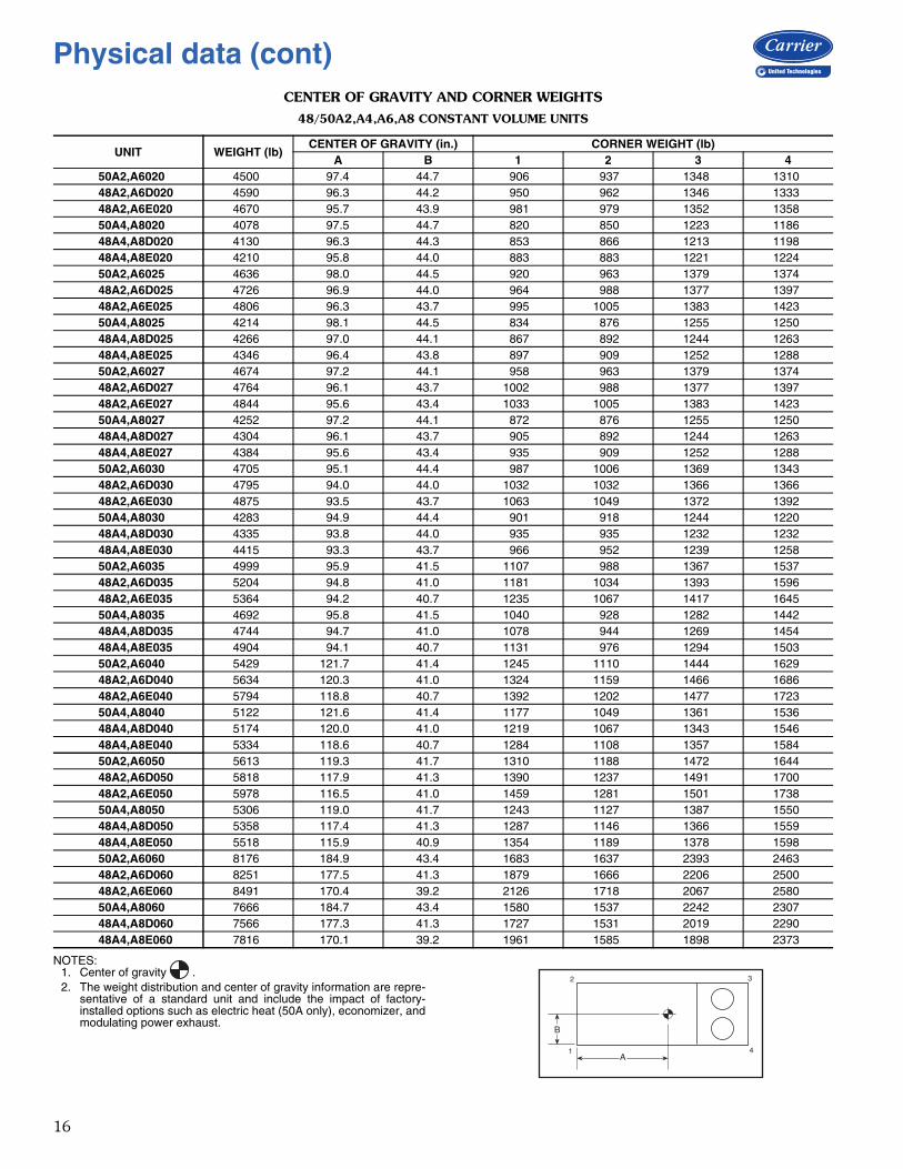
CENTER OF GRAVITY AND CORNER WEIGHTS
48/50A2,A4,A6,A8 CONSTANT VOLUME UNITS
NOTES:1. Center of gravity .2. The weight distribution and center of gravity information are repre-
sentative of a standard unit and include the impact of factory-installed options such as electric heat (50A only), economizer, andmodulating power exhaust.
UNIT WEIGHT (lb)CENTER OF GRAVITY (in.) CORNER WEIGHT (lb)
A B 1 2 3 450A2,A6020 4500 97.4 44.7 906 937 1348 131048A2,A6D020 4590 96.3 44.2 950 962 1346 133348A2,A6E020 4670 95.7 43.9 981 979 1352 135850A4,A8020 4078 97.5 44.7 820 850 1223 118648A4,A8D020 4130 96.3 44.3 853 866 1213 119848A4,A8E020 4210 95.8 44.0 883 883 1221 122450A2,A6025 4636 98.0 44.5 920 963 1379 137448A2,A6D025 4726 96.9 44.0 964 988 1377 139748A2,A6E025 4806 96.3 43.7 995 1005 1383 142350A4,A8025 4214 98.1 44.5 834 876 1255 125048A4,A8D025 4266 97.0 44.1 867 892 1244 126348A4,A8E025 4346 96.4 43.8 897 909 1252 128850A2,A6027 4674 97.2 44.1 958 963 1379 137448A2,A6D027 4764 96.1 43.7 1002 988 1377 139748A2,A6E027 4844 95.6 43.4 1033 1005 1383 142350A4,A8027 4252 97.2 44.1 872 876 1255 125048A4,A8D027 4304 96.1 43.7 905 892 1244 126348A4,A8E027 4384 95.6 43.4 935 909 1252 128850A2,A6030 4705 95.1 44.4 987 1006 1369 134348A2,A6D030 4795 94.0 44.0 1032 1032 1366 136648A2,A6E030 4875 93.5 43.7 1063 1049 1372 139250A4,A8030 4283 94.9 44.4 901 918 1244 122048A4,A8D030 4335 93.8 44.0 935 935 1232 123248A4,A8E030 4415 93.3 43.7 966 952 1239 125850A2,A6035 4999 95.9 41.5 1107 988 1367 153748A2,A6D035 5204 94.8 41.0 1181 1034 1393 159648A2,A6E035 5364 94.2 40.7 1235 1067 1417 164550A4,A8035 4692 95.8 41.5 1040 928 1282 144248A4,A8D035 4744 94.7 41.0 1078 944 1269 145448A4,A8E035 4904 94.1 40.7 1131 976 1294 150350A2,A6040 5429 121.7 41.4 1245 1110 1444 162948A2,A6D040 5634 120.3 41.0 1324 1159 1466 168648A2,A6E040 5794 118.8 40.7 1392 1202 1477 172350A4,A8040 5122 121.6 41.4 1177 1049 1361 153648A4,A8D040 5174 120.0 41.0 1219 1067 1343 154648A4,A8E040 5334 118.6 40.7 1284 1108 1357 158450A2,A6050 5613 119.3 41.7 1310 1188 1472 164448A2,A6D050 5818 117.9 41.3 1390 1237 1491 170048A2,A6E050 5978 116.5 41.0 1459 1281 1501 173850A4,A8050 5306 119.0 41.7 1243 1127 1387 155048A4,A8D050 5358 117.4 41.3 1287 1146 1366 155948A4,A8E050 5518 115.9 40.9 1354 1189 1378 159850A2,A6060 8176 184.9 43.4 1683 1637 2393 246348A2,A6D060 8251 177.5 41.3 1879 1666 2206 250048A2,A6E060 8491 170.4 39.2 2126 1718 2067 258050A4,A8060 7666 184.7 43.4 1580 1537 2242 230748A4,A8D060 7566 177.3 41.3 1727 1531 2019 229048A4,A8E060 7816 170.1 39.2 1961 1585 1898 2373
B
A
2
1 4
3
Physical data (cont)

17
CENTER OF GRAVITY AND CORNER WEIGHTS (cont)48/50A3,A5,A7,A9 VARIABLE AIR VOLUME UNITS
NOTES:1. Center of gravity .2. The weight distribution and center of gravity information are repre-
sentative of a standard unit and include the impact of factory-installed options such as electric heat (50A only), economizer, andmodulating power exhaust.
UNIT WEIGHT (lb)CENTER OF GRAVITY (in.) CORNER WEIGHT (lb)
A B 1 2 3 450A3,A7020 4599 98.0 44.9 905 963 1385 134748A3,A7D020 4689 96.8 44.5 949 989 1382 137048A3,A7E020 4769 96.3 44.2 980 1006 1388 139650A5,A9020 4177 98.1 45.0 818 876 1261 122348A5,A9D020 4229 96.9 44.6 852 893 1249 123548A5,A9E020 4309 96.4 44.2 882 910 1257 126150A3,A7025 4735 98.5 44.7 918 989 1416 141148A3,A7D025 4825 97.4 44.3 963 1015 1414 143448A3,A7E025 4905 96.9 44.0 994 1032 1419 146050A5,A9025 4313 98.7 44.8 832 902 1292 128748A5,A9D025 4365 97.5 44.3 866 919 1281 130048A5,A9E025 4445 97.0 44.0 896 936 1288 132550A3,A7027 4801 97.2 44.1 984 989 1416 141148A3,A7D027 4891 96.1 43.7 1029 1015 1414 143448A3,A7E027 4971 95.6 43.4 1060 1032 1419 146050A5,A9027 4379 97.2 44.1 898 902 1292 128748A5,A9D027 4431 96.1 43.7 932 919 1281 130048A5,A9E027 4511 95.6 43.4 962 936 1288 132550A3,A7030 4832 95.2 44.4 1013 1032 1407 138048A3,A7D030 4922 94.1 44.0 1058 1058 1403 140348A3,A7E030 5002 93.6 43.7 1090 1075 1408 142850A5,A9030 4410 95.0 44.4 927 944 1282 125748A5,A9D030 4462 93.9 44.0 962 962 1269 126948A5,A9E030 4542 93.4 43.7 993 979 1276 129550A3,A7035 5134 95.9 41.5 1137 1014 1405 157948A3,A7D035 5339 94.8 41.0 1211 1061 1430 163748A3,A7E035 5499 94.2 40.7 1266 1093 1453 168750A5,A9035 4827 95.8 41.5 1070 954 1320 148448A5,A9D035 4879 94.7 41.0 1108 970 1305 149548A5,A9E035 5039 94.1 40.7 1161 1003 1330 154550A3,A7040 5564 121.8 41.4 1276 1137 1481 167148A3,A7D040 5769 120.3 41.0 1355 1186 1502 172748A3,A7E040 5929 118.8 40.7 1423 1229 1513 176450A5,A9040 5257 121.6 41.4 1207 1076 1398 157748A5,A9D040 5309 120.1 41.0 1250 1094 1379 158748A5,A9E040 5469 118.6 40.7 1316 1136 1393 162550A3,A7050 5744 119.5 41.7 1338 1214 1509 168448A3,A7D050 5949 118.1 41.3 1419 1264 1527 174048A3,A7E050 6109 116.6 41.0 1489 1308 1536 177750A5,A9050 5437 119.1 41.7 1271 1153 1423 159048A5,A9D050 5489 117.5 41.3 1316 1172 1402 159948A5,A9E050 5649 116.1 40.9 1384 1215 1413 163850A3,A7060 8311 184.9 43.4 1710 1663 2433 250448A3,A7D060 8386 177.6 41.3 1909 1693 2243 254148A3,A7E060 8626 170.4 39.2 2159 1745 2100 262250A5,A9060 7801 184.8 43.4 1608 1564 2282 234948A5,A9D060 7701 177.3 41.3 1757 1558 2056 233148A5,A9E060 7951 170.1 39.2 1994 1611 1932 2414
B
A
2
1 4
3

18
FIOP AND ACCESSORY CORNER WEIGHT ADJUSTMENTS
UNIT WEIGHT (lb)CORNER WEIGHTS (lb)
1 2 3 448/50A 020-027
Barometric Relief 300 2 185 111 1Non Mod. Power Exhaust 450 3 278 167 2Mod. Power Exhaust 500 4 309 186 2Electric Heat 110 59 10 6 35
Al/Cu Cond Coil 100 1 1 49 49Cu/Cu Cond Coil 263 2 2 129 129Hail Guards 73 0 0 36 36
Humidi-MiZer Coil 150 26 41 51 3248/50A 030,035
Barometric Relief 300 2 185 111 1Non Mod. Power Exhaust 450 3 278 167 2Mod. Power Exhaust 500 4 309 186 2Electric Heat 110 59 10 6 35
Al/Cu Cond coil 150 1 1 74 74Cu/Cu Cond Coil 370 3 3 182 182Hail Guards 73 0 0 36 36
Humidi-MiZer Coil 150 26 41 51 3248/50A 040
Barometric Relief 300 2 211 86 1Non Mod. Power Exhaust 450 4 317 128 1Mod. Power Exhaust 500 4 352 143 2Electric Heat 110 67 12 5 27
Al/Cu Cond Coil 187 2 2 92 92Cu/Cu Cond Coil 512 5 5 252 252Hail Guards 146 0 0 73 73
Humidi-MiZer Coil 180 32 50 60 3848/50A 050
Barometric Relief 300 2 211 86 1Non Mod. Power Exhaust 450 4 317 128 1Mod. Power Exhaust 500 4 352 143 2Electric Heat 110 67 12 5 27
Al/Cu Cond Coil 317 34 34 124 124Cu/Cu Cond Coil 751 80 80 295 295Hail Guards 146 0 0 73 73
Humidi-MiZer Coil 180 32 50 60 3848/50A 060
Barometric Relief 450 4 319 126 1Non Mod. Power Exhaust 675 6 479 189 2Mod. Power Exhaust 725 6 514 203 2Electric Heat 165 101 17 7 40
Al/Cu Cond Coil 26 0 0 13 13Cu/Cu Cond Coil 677 72 72 266 266Hail Guards 219 0 0 109 109
Humidi-MiZer Coil 195 37 58 62 39
B
A
2
1 4
3
Physical data (cont)
19
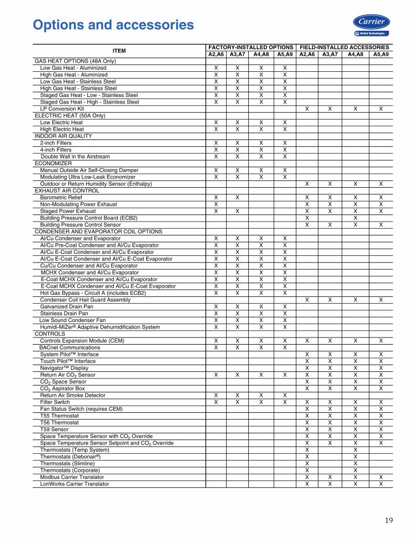
ITEMFACTORY-INSTALLED OPTIONS FIELD-INSTALLED ACCESSORIESA2,A6 A3,A7 A4,A8 A5,A9 A2,A6 A3,A7 A4,A8 A5,A9
GAS HEAT OPTIONS (48A Only)Low Gas Heat - Aluminized X X X XHigh Gas Heat - Aluminized X X X XLow Gas Heat - Stainless Steel X X X XHigh Gas Heat - Stainless Steel X X X XStaged Gas Heat - Low - Stainless Steel X X X XStaged Gas Heat - High - Stainless Steel X X X XLP Conversion Kit X X X X
ELECTRIC HEAT (50A Only)Low Electric Heat X X X XHigh Electric Heat X X X X
INDOOR AIR QUALITY2-inch Filters X X X X4-inch Filters X X X X
Double Wall in the Airstream X X X XECONOMIZER
Manual Outside Air Self-Closing Damper X X X XModulating Ultra Low-Leak Economizer X X X XOutdoor or Return Humidity Sensor (Enthalpy) X X X X
EXHAUST AIR CONTROLBarometric Relief X X X X X XNon-Modulating Power Exhaust X X X X XStaged Power Exhaust X X X X X XBuilding Pressure Control Board (ECB2) X XBuilding Pressure Control Sensor X X X X
CONDENSER AND EVAPORATOR COIL OPTIONSAl/Cu Condenser and Evaporator X X X XAl/Cu Pre-Coat Condenser and Al/Cu Evaporator X X X XAl/Cu E-Coat Condenser and Al/Cu Evaporator X X X XAl/Cu E-Coat Condenser and Al/Cu E-Coat Evaporator X X X XCu/Cu Condenser and Al/Cu Evaporator X X X X
MCHX Condenser and Al/Cu Evaporator X X X X E-Coat MCHX Condenser and Al/Cu Evaporator X X X X E-Coat MCHX Condenser and Al/Cu E-Coat Evaporator X X X X
Hot Gas Bypass - Circuit A (includes ECB2) X X X XCondenser Coil Hail Guard Assembly X X X XGalvanized Drain Pan X X X XStainless Drain Pan X X X X
Low Sound Condenser Fan X X X XHumidi-MiZer® Adaptive Dehumidification System X X X X
CONTROLSControls Expansion Module (CEM) X X X X X X X X
BACnet Communications X X X XSystem Pilot™ Interface X X X XTouch Pilot™ Interface X X X XNavigator™ Display X X X XReturn Air CO2 Sensor X X X X X X X XCO2 Space Sensor X X X XCO2 Aspirator Box X X X XReturn Air Smoke Detector X X X XFilter Switch X X X X X X X XFan Status Switch (requires CEM) X X X XT55 Thermostat X X X XT56 Thermostat X X X XT59 Sensor X X X XSpace Temperature Sensor with CO2 Override X X X XSpace Temperature Sensor Setpoint and CO2 Override X X X XThermostats (Temp System) X XThermostats (Debonair®) X XThermostats (Slimline) X XThermostats (Corporate) X XModbus Carrier Translator X X X XLonWorks Carrier Translator X X X X
Options and accessories
20
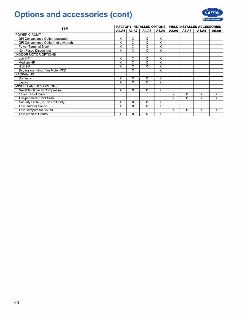
POWER CIRCUITGFI Convenience Outlet (powered) X X X XGFI Convenience Outlet (not powered) X X X XPower Terminal Block X X X XNon-Fused Disconnect X X X X
INDOOR MOTOR OPTIONSLow HP X X X XMedium HP X X X XHigh HP X X X X
Bypass on Indoor Fan Motor VFD X XPACKAGING
Domestic X X X XExport X X X X
MISCELLANEOUS OPTIONSVariable Capacity Compressor X X X X14-inch Roof Curb X X X XFull-perimeter Roof Curb X X X XSecurity Grille (60 Ton Unit Only) X X X XLow Outdoor Sound X X X XLow Compressor Sound X X X XLow Ambient Control X X X X
ITEMFACTORY-INSTALLED OPTIONS FIELD-INSTALLED ACCESSORIESA2,A6 A3,A7 A4,A8 A5,A9 A2,A6 A3,A7 A4,A8 A5,A9
Options and accessories (cont)

21
48A
2/A
3/A
6/A
7
48A
2/A
3/A
6/A
7
48A
2/A
3/A
6/A
748A
2/A
3/A
6/A
7
48A
2/A
3/A
6/A
7
48A
2/A
3/A
6/A
7
48A
2/A
3/A
6/A
7
48A
2/A
3/A
6/A
7
48A
2/A
3/A
6/A
7
48A
2/A
3/A
6/A
7
48A
2/A
3/A
6/A
7
48A
2/A
3/A
6/A
7
48A
2/A
3/A
6/A
7
48A
2/A
3/A
6/A
7
48A
2/A
3/A
6/A
7
48A
2/A
3/A
6/A
7
48A
2/A
3/A
6/A
7
48A
2/A
3/A
6/A
7
48A
2/A
3/A
6/A
7
48A
2/A
3/A
6/A
7
7. D
IMEN
SION
S AR
E IN
INCH
ES [M
M].
Base unit dimensions 48A2,A3,A6,A7020-035

22
A48-8689NO
TE
S:
1.W
eigh
ts in
clud
e ec
onom
izer
.2.
c
ente
r of g
ravi
ty.
3.U
nit c
lear
ance
s:
Top
of u
nits
: no
over
hang
C
onde
nser
coi
l: 4’
- 0”
[121
9]
Eco
nom
izer
sid
e: 6
’ - 0
” [1
829]
H
eat s
ide:
4’ -
0” [
1219
]
Filt
er a
cces
s si
de: 1
0’ -
0” [3
048]
(for
r
emov
al o
f eva
pora
tor c
oil)
4.B
otto
m d
ucts
are
des
igne
d to
be
atta
ched
toac
cess
ory
roof
cur
b. I
f un
it is
mou
nted
on
dunn
age,
it
is r
ecom
men
ded
that
the
duc
tsbe
sup
port
ed b
y cr
oss
brac
es a
s do
ne o
nac
cess
ory
roof
cur
b.5.
Dim
ensi
ons
in [
] are
in m
illim
eter
s. A
ll ot
her
dim
ensi
ons
are
in in
ches
.
*Ope
ratin
g w
eigh
t inc
lude
s la
rges
t ind
oor
fan
mot
or, m
icro
-ch
anne
l he
at e
xcha
nger
, m
odul
atin
g po
wer
exh
aust
(va
ri-ab
le
air
volu
me
units
),
and
varia
ble
freq
uenc
y dr
ive
(var
iabl
e ai
r vo
lum
e un
its).
48A2
/A3/A6
/A748
A2/A3
/A6/A7
48A2
/A3/A6
/A748
A2/A3
/A6/A7
48A2
/A3/A6
/A748
A2/A3
/A6/A7
48A2
/A3/A6
/A748
A2/A3
/A6/A7
A48-8689
Base unit dimensions 48A2,A3,A6,A7040,050

23
31
1.2
8[7
90
6.6
]
85
.09
[21
61
]1
61
.66
[41
06
]
13
3.6
9[3
39
6]
42.5
6[1
08
1]
65.9
1[1
67
4]
45.0
6[1
14
5]
41.7
2[1
06
0]
20.1
8[5
13]
2.1
0[5
3]
82.0
2[2
08
3]
2.9
9[7
6]
7/8
" D
IA [22]
LO
W V
OLT
AG
E
78.6
0[1
99
7]
94
.00
[23
88
]
91
.50
[23
24
]
88
.00
[22
35
]
49
.53
[12
58
]3
0.1
2[7
65
]
22
.72
[57
7]
88
.24
[22
41
]T
OP
CO
VE
RS
10
.49
[26
6]
50
.00
[12
70
]5
0.0
0[1
27
0]
50
.00
[12
70
]
2.5
7[6
5]
2.5
7[6
5]
1"[
25
]N
PT
DR
AIN
CO
NN
1.3
75 D
IA [35]
34.4
6[8
75]
70.0
5[1
77
9]
29.4
0[7
47]
24.4
0[6
20]
8.0
5[2
04]
44.2
8[1
12
5]
9.5
6[2
43]
13.8
8[3
53]
0.7
5 N
PT
LO
W V
OLT
AG
E[1
9]
3.5
0 N
PT
FIE
LD
PO
WE
R[8
9]
24
[61
3]
24
[61
3]
15
.53
[39
5]
15
.93
[40
5]
8.6
0[2
18
]1
62
.90
[41
38
]
17.4
7[4
44]
43
.43
[1
10
3]
92
.63
[2
3.5
3]
14
1.8
6 [3
6.0
3]
7.5
0[1
90
]
19
.06
[48
4]
17.9
1[4
55]
42.3
1[1
07
5]
18.2
5[4
64]
45.4
4[1
15
4]
OP
EN
ING
31.2
5[7
95]
OP
EN
ING
HO
OD
RE
MO
VE
DD
AM
PE
R O
PE
NIN
G
WIT
H H
OO
D
WIT
H P
AN
EL
PA
NE
L R
EM
OV
ED
VIE
W A
-AN
O P
OW
ER
EX
HA
US
T O
R B
AR
OM
ET
RIC
RE
LIE
F
IND
OO
R B
LO
WE
RA
CC
ES
S P
AN
EL
HE
AT
SE
CT
ION
AC
CE
SS
PA
NE
L
MC
HX
CO
ILS
V F D
OV
ER
ALL L
IFT
ING
SH
IPP
ING
DIM
LIF
TIN
G P
OS
ITIO
N
BA
SE
FR
AM
E
TY
P 4
PL
AC
ES
EC
ON
OM
IZE
R H
OO
DS
(HO
OD
S F
IELD
IN
ST
ALLE
D)
(IN
CLU
DE
D W
ITH
UN
IT)
3 R
EQ
'D
IND
OO
R M
OT
OR
AC
CE
SS
DO
OR
(H
ING
ED
)
FIL
TE
R/A
UX
CO
NT
RO
L B
OX
AC
CE
SS
DO
OR
(H
ING
ED
)
SU
PP
LY
AIR
EC
ON
AIR A
UX
ILIA
RY
CO
NT
RO
LB
OX
EX
HA
US
TA
IR
PO
WE
R E
XH
AU
ST
OR
BA
RO
ME
TR
ICR
ELIE
F H
OO
DS
OP
TIO
N3 R
EQ
'D
2.5
0 [6
4] N
PT
GA
S IN
LE
T H
OLE
MA
IN C
ON
TR
OL B
OX
V F D
AA
RE
TU
RN
SU
PP
LY
AC
CE
SS
DO
OR
S (
HIN
GE
D)
CO
NT
RO
L B
OX
/ C
OM
PR
ES
SO
R
INS
IDE
BA
SE
RA
ILS
RE
TU
RN
AIR
3"
DIA
[76]
FIE
LD
WIR
ING
(2)
LIF
TIN
G L
UG
HO
LE
IN
WIN
D C
AP
(FIE
LD
INS
TA
LL
ED
)
FO
R
CE
NT
ER
S
OF
G
RA
VIT
Y,
OP
ER
AT
ING
A
ND
C
OR
NE
RW
EIG
HT
S, S
EE
PA
GE
29.
Base unit dimensions 48A2,A3,A6,A7060 MCHX

24
85
.09
[21
61
]
31
1.2
8[7
90
6.6
]
88
.24
TO
P C
OV
ER
S[2
24
1]
10
.49
[26
6]
50
.00
[12
70
] 2.5
7[6
5]
50
.00
[12
70
]
2.5
7[6
5]
50
.00
[12
70
]
16
1.6
6 [
41
06
]
9.5
6 [
24
3]
13
.88
[3
53
]
44
.28
[1
12
5]
78
.60
[1
99
7]
42
.31
[10
75
]
18
.25
[46
4]
31
.25
[79
5]
OP
EN
ING
45
.44
[11
54
]O
PE
NIN
G
94
.00
[23
88
]
91
.50
[23
24
]
88
.00
[22
35
]
49
.53
[12
58
]3
0.1
2[7
65
]
22
.72
[57
7]
1"[
25
]N
PT
DR
AIN
CO
NN
13
3.6
9[3
39
6]
42
.56
[10
81
]
65
.91
[16
74
]
45
.06
[11
45
]
41
.72
[10
60
]
20
.18
[51
3]
2.1
0[5
3]
82
.02
[20
83
]2
.99
[76
]
7/8
" D
IA [
22
]LO
W V
OLT
AG
E
78
.60
[19
97
]
1.3
75
DIA
[3
5]
34
.46
[87
5]
70
.05
[17
79
]
29
.40
[74
7]
24
.40
[62
0]
8.0
5[2
04
]
17
.47
[44
4]
16
2.9
0[4
13
8]
8.6
0[2
18
]
15
.93
[40
5]
24
[61
3]
15
.53
[39
5]
24
[61
3]
HE
AT
SE
CT
ION
AC
CE
SS
PA
NE
LIN
DO
OR
BL
OW
ER
AC
CE
SS
PA
NE
L
CO
ND
EN
SE
R C
OIL
BO
TH
SID
ES
MA
IN C
ON
TR
OL
BO
X
V F D V F D
AA
3.5
0 [8
9] N
PT
FIE
LD
PO
WE
R
.75
[1
9] N
PT
LO
W V
OL
TA
GE
LO
W S
OU
ND
OU
TD
OO
R F
AN
OP
TIO
N O
NL
Y(A
LL
FA
N P
OS
ITIO
NS
)
ST
AN
DA
RD
OU
TD
OO
R F
AN
HO
OD
RE
MO
VE
DD
AM
PE
R O
PE
NIN
G
WIT
H H
OO
D
WIT
H P
AN
EL
PA
NE
L R
EM
OV
ED
VIE
W A
-AN
O P
OW
ER
EX
HA
US
T O
R B
AR
OM
ET
RIC
RE
LIE
F
OV
ER
ALL L
IFT
ING
SH
IPP
ING
DIM
LIF
TIN
G P
OS
ITIO
N
BA
SE
FR
AM
E
TY
P 4
PL
AC
ES
EC
ON
OM
IZE
R H
OO
DS
(HO
OD
S F
IEL
D IN
ST
AL
LE
D)
(IN
CL
UD
ED
WIT
H U
NIT
)3
RE
Q'D
IND
OO
R M
OT
OR
AC
CE
SS
DO
OR
(H
ING
ED
)
FIL
TE
R/A
UX
CO
NT
RO
L B
OX
AC
CE
SS
DO
OR
(H
ING
ED
)
RE
TU
RN
AIR
SU
PP
LY
AIR
EC
ON
AIR
AU
XIL
IAR
YC
ON
TR
OL
BO
X
EX
HA
US
TA
IR
PO
WE
R E
XH
AU
ST
OR
BA
RO
ME
TR
ICR
EL
IEF
HO
OD
SO
PT
ION
3 R
EQ
'D
AC
CE
SS
DO
OR
S (
HIN
GE
D)
CO
NT
RO
L B
OX
/ C
OM
PR
ES
SO
R
INS
IDE
BA
SE
RA
ILS
3"
DIA
[7
6]
FIE
LD
WIR
ING
(2
)L
IFT
ING
LU
GH
OL
E IN
RE
TU
RN
SU
PP
LY
FO
R
CE
NT
ER
S
OF
G
RA
VIT
Y,
OP
ER
AT
ING
A
ND
C
OR
NE
RW
EIG
HT
S, S
EE
PA
GE
29.
Base unit dimensions 48A2,A3,A6,A7060 RTPF

25
6. D
IMEN
SION
S AR
E IN
INCH
ES [M
M].
Base unit dimensions 48A4,A5,A8,A9020-035

26
*Ope
ratin
g w
eigh
t inc
lude
s la
rges
t ind
oor f
an m
otor
, mic
ro-
chan
nel h
eat
exch
ange
r, m
odul
atin
g po
wer
exh
aust
(va
ri-ab
le
air
volu
me
units
),
and
varia
ble
freq
uenc
y dr
ive
(var
iabl
e ai
r vo
lum
e un
its).
NO
TE
S:
2. c
ente
r of g
ravi
ty3.
Uni
t cle
aran
ces:
T
op o
f uni
ts: n
o ov
erha
ng4.
C
onde
nser
coi
l: 4 ’
- 0”
[121
9]
Eco
nom
izer
sid
e: 6
’ - 0
” [18
29]
H
eat s
ide:
4’ -
0” [
1219
]
Filt
er a
cces
s si
de: 1
0’ -
0” [3
048]
(for
r
emov
al o
f eva
pora
tor c
oil)
5.F
or s
mal
ler
serv
ice
and
oper
atio
nal
clea
r-an
ces,
con
tact
Car
rier
appl
icat
ion
engi
neer
-in
g de
partm
ent.
6.B
otto
m d
ucts
are
des
igne
d to
be
atta
ched
toac
cess
ory
roof
cur
b. I
f un
it is
mou
nted
on
dunn
age,
it
is r
ecom
men
ded
that
the
duc
tsbe
sup
porte
d by
cro
ss b
race
s as
don
e on
acce
ssor
y ro
of c
urb.
7.D
imen
sion
s in
[ ] a
re in
mill
imet
ers.
All
othe
rdi
men
sion
s ar
e in
inch
es.
1.W
eigh
ts in
clud
e ec
onom
izer
.
Base unit dimensions 48A4,A5,A8,A9040,050

27
31
1.2
8[7
90
6.6
]
85
.09
[21
61
]1
61
.66
[41
06
]
13
3.6
9[3
39
6]
42
.56
[10
81
]
65
.91
[16
74
]
45
.06
[11
45
]
41
.72
[10
60
]
20
.18
[51
3] 2.1
0[5
3]
82
.02
[20
83
]2
.99
[76
]
7/8
" D
IA [2
2]
LO
W V
OL
TA
GE
78
.60
[19
97
]
94
.00
[23
88
]
91
.50
[23
24
]
88
.00
[22
35
]
49
.53
[12
58
]
30
.12
[76
5]
22
.72
[57
7]
88
.24
[22
41
]T
OP
CO
VE
RS
10
.49
[26
6]
50
.00
[12
70
]5
0.0
0[1
27
0]
50
.00
[12
70
]
2.5
7[6
5]
2.5
7[6
5]
1"[
25
]N
PT
DR
AIN
CO
NN
1.3
75
DIA
[3
5]
34
.46
[87
5]
70
.05
[17
79
]
29
.40
[74
7]
24
.40
[62
0]
8.0
5[2
04
]
44
.28
[11
25
]
9.5
6[2
43
]
13
.88
[35
3]
0.7
5 N
PT
LO
W V
OL
TA
GE
[19
]3
.50
NP
T F
IEL
D P
OW
ER
[89
]
6.9
7[1
77
.0]
13
.20
[33
5.3
]
5.1
2[1
30
.0]
12
.93
[32
8.3
]1
50
.47
[3
82
2.0
]
12
.63
[32
0.8
]
43
.43
[1
10
3]
92
.63
[2
3.5
3]
14
1.8
6 [
36
.03
]
7.5
0[1
90
]
19
.06
[48
4]
17
.91
[45
5]
VIE
W A
-A
IND
OO
R B
LO
WE
RA
CC
ES
S P
AN
EL
HE
AT
SE
CT
ION
AC
CE
SS
PA
NE
L
MC
HX
CO
ILS
V F D
OV
ER
AL
L L
IFT
ING
SH
IPP
ING
DIM
LIF
TIN
G P
OS
ITIO
N
BA
SE
FR
AM
E
TY
P 4
PL
AC
ES
EC
ON
OM
IZE
R H
OO
DS
(HO
OD
S F
IEL
D IN
ST
AL
LE
D)
(IN
CL
UD
ED
WIT
H U
NIT
)3
RE
Q'D
IND
OO
R M
OT
OR
AC
CE
SS
DO
OR
(H
ING
ED
)
FIL
TE
R/A
UX
CO
NT
RO
L B
OX
AC
CE
SS
DO
OR
(H
ING
ED
)
RE
TU
RN
AIR
SU
PP
LY
AIR
EC
ON
AIR
AU
XIL
IAR
YC
ON
TR
OL
BO
X
2.5
0 [
64
] N
PT
GA
S IN
LE
T H
OL
E
MA
IN C
ON
TR
OL
BO
X
V F D
AA
AC
CE
SS
DO
OR
S (
HIN
GE
D)
CO
NT
RO
L B
OX
/ C
OM
PR
ES
SO
R
INS
IDE
BA
SE
RA
ILS
3"
DIA
[7
6]
FIE
LD
WIR
ING
(2
)
LIF
TIN
G L
UG
HO
LE
IN
WIN
D C
AP
(FIE
LD
INS
TA
LL
ED
)
FO
R
CE
NT
ER
S
OF
G
RA
VIT
Y,
OP
ER
AT
ING
A
ND
C
OR
NE
RW
EIG
HT
S, S
EE
PA
GE
29.
Base unit dimensions 48A4,A5,A8,A9060 MCHX
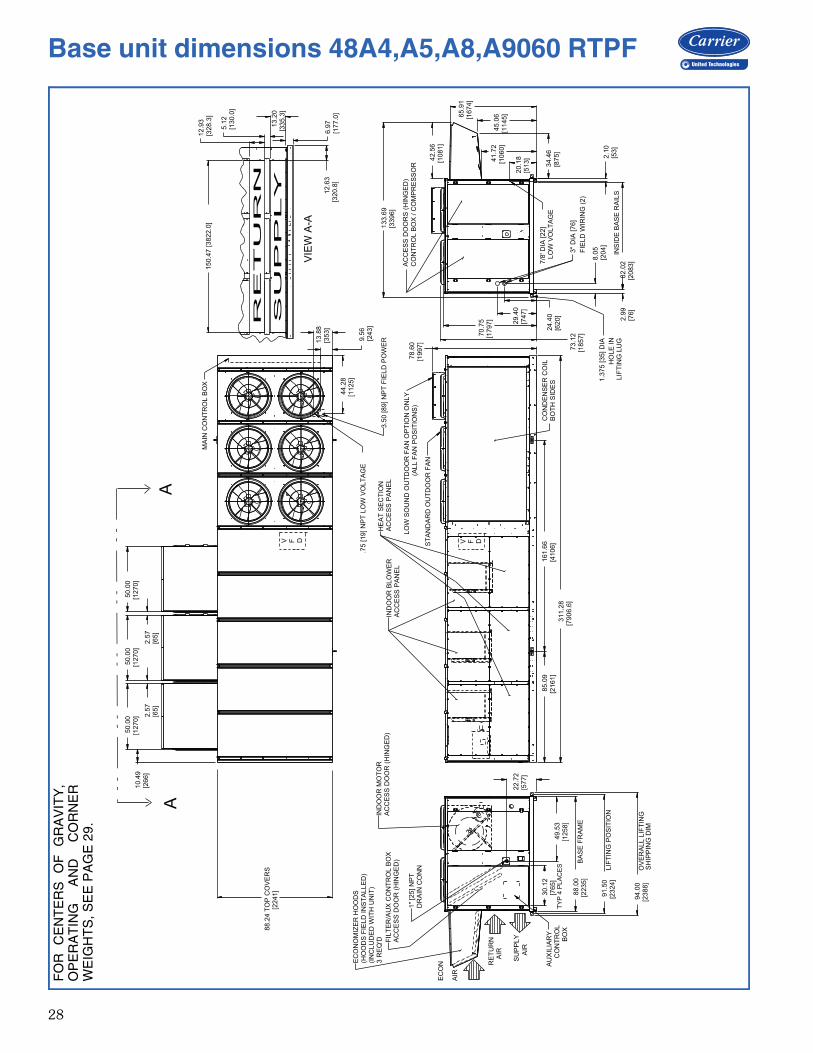
28
a48-8688
70
.75
[17
97
]
65
.91
[16
74
]
45
.06
[11
45
]
41
.72
[10
60
]
34
.46
[87
5]
30
.12
[76
5]
78
.60
[1
99
7]
TY
P 4
PL
AC
ES
AU
XIL
IAR
YC
ON
TR
OL
BO
X
EC
ON
OM
IZE
R H
OO
DS
(HO
OD
S F
IEL
D IN
ST
AL
LE
D)
(IN
CL
UD
ED
WIT
H U
NIT
)3
RE
Q'D
AC
CE
SS
DO
OR
S (
HIN
GE
D)
CO
NT
RO
L B
OX
/ C
OM
PR
ES
SO
R
IND
OO
R M
OT
OR
AC
CE
SS
DO
OR
(H
ING
ED
)F
ILT
ER
/AU
X C
ON
TR
OL
BO
XA
CC
ES
S D
OO
R (
HIN
GE
D)
HE
AT
SE
CT
ION
AC
CE
SS
PA
NE
LIN
DO
OR
BL
OW
ER
AC
CE
SS
PA
NE
L
CO
ND
EN
SE
R C
OIL
BO
TH
SID
ES
3"
DIA
[7
6]
FIE
LD
WIR
ING
(2
)
7/8
' D
IA [2
2]
LO
W V
OL
TA
GE
EC
ON
AIR
RE
TU
RN
AIR
1"
[25
] N
PT
DR
AIN
CO
NN
BA
SE
FR
AM
E
LIF
TIN
G P
OS
ITIO
N
OV
ER
AL
L L
IFT
ING
SH
IPP
ING
DIM
MA
IN C
ON
TR
OL
BO
X
INS
IDE
BA
SE
RA
ILS
1.3
75
[3
5] D
IA
HO
LE
IN
L
IFT
ING
LU
G
V F D V F D
VIE
W A
-A
AA
3.5
0 [8
9] N
PT
FIE
LD
PO
WE
R
SU
PP
LY
AIR
.75
[1
9] N
PT
LO
W V
OL
TA
GE
73
.12
[18
57
]
42
.56
[10
81
]
20
.18
[51
3] 2
.10
[53
]
82
.02
[20
83
]2
.99
[76
]
8.0
5[2
04
]
24
.40
[62
0]
29
.40
[74
7]
85
.09
[21
61
]
31
1.2
8[7
90
6.6
]
22
.72
[57
7]
94
.00
[23
88
]
91
.50
[23
24
]
88
.00
[22
35
]
49
.53
[12
58
]
13
3.6
9[3
39
6]
88
.24
TO
P C
OV
ER
S[2
24
1]
10
.49
[26
6]
50
.00
[12
70
] 2.5
7[6
5]
50
.00
[12
70
]
2.5
7[6
5]
50
.00
[12
70
]
16
1.6
6 [4
10
6]
6.9
7[1
77
.0]
13
.20
[33
5.3
]
5.1
2[1
30
.0]
12
.93
[32
8.3
]1
50
.47
[3
82
2.0
]
12
.63
[32
0.8
]
9.5
6 [2
43
]
13
.88
[3
53
]
44
.28
[1
12
5]
LO
W S
OU
ND
OU
TD
OO
R F
AN
OP
TIO
N O
NL
Y(A
LL
FA
N P
OS
ITIO
NS
)
ST
AN
DA
RD
OU
TD
OO
R F
AN
FO
R
CE
NT
ER
S
OF
G
RA
VIT
Y,
OP
ER
AT
ING
A
ND
C
OR
NE
RW
EIG
HT
S, S
EE
PA
GE
29.
Base unit dimensions 48A4,A5,A8,A9060 RTPF

29
A
B
NO
TE
S:
1. W
EIG
HT
S IN
CLU
DE
EC
ON
OM
IZE
R O
R O
UT
DO
OR
AIR
DA
MP
ER
. 2.
CE
NT
ER
OF
GR
AV
ITY
. 3. F
OR
MU
LT
IPLE
UN
IT A
PP
LIC
AT
ION
S S
EE
LIT
ER
AT
UR
E.
4. U
NIT
CLE
AR
AN
CE
S:
T
OP
OF
UN
ITS
: N
O O
VE
RH
AN
G C
U T
UB
E C
ON
DE
NS
ER
CO
IL: 4'-0"
[1219]
H
EA
T S
IDE
: 4'-0"
[1219]
F
ILT
ER
AC
CE
SS
SID
E: 15'-0"
[4572]
(F
OR
RE
MO
VA
L O
F E
VA
PO
RA
TO
R C
OIL
) E
CO
NO
MIZ
ER
SID
E: 6'-0"
[1829] (F
OR
TU
BE
CO
ND
EN
SE
R C
OIL
S)
8
'-0"
[2438] (F
OR
RE
MO
VA
L O
F M
CH
X
C
ON
DE
NS
ER
CO
ILS
) 5. F
OR
SM
ALLE
R S
ER
VIC
E A
ND
OP
ER
AT
ION
AL
C
LE
AR
AN
CE
S, C
ON
TA
CT
CA
RR
IER
AP
PLIC
AT
ION
E
NG
INE
ER
ING
DE
PA
RT
ME
NT
. 6. B
OT
TO
M D
UC
TS
DE
SIG
NE
D T
O B
E A
TT
AC
HE
D T
O A
CC
ES
SO
RY
RO
OF
CU
RB
. IF
UN
IT IS
MO
UN
TE
D O
N D
UN
NA
GE
, IT
IS
RE
CO
MM
EN
DE
D T
HE
DU
CT
S M
US
T B
E S
UP
PO
RT
ED
BY
CR
OS
S B
RA
CE
S A
S D
ON
E O
N A
CC
ES
SO
RY
RO
OF
CU
RB
. 7. B
AS
E U
NIT
WE
IGH
TS
IN
CLU
DE
OU
TD
OO
R A
IR H
OO
DS
, A
ND
FIL
TE
RS
(IN
DO
OR
FA
N M
OT
OR
IS
NO
T IN
CLU
DE
D).
A
DD
IN
DO
OR
MO
TO
R, F
IOP
S A
ND
AC
CE
SS
OR
IES
FO
R T
OT
AL O
PE
RA
TIN
G W
EIG
HT
. 8. V
AV
MO
TO
R W
EIG
HT
S IN
CLU
DE
IN
DO
OR
MO
TO
R, V
FD
, V
FD
TR
AN
SD
UC
ER
AN
D A
SS
OC
IAT
ED
WIR
ING
. 9. D
IME
NS
ION
S IN
[ ] A
RE
IN
MIL
LIM
ET
ER
S, K
ILO
GR
AM
S,
O
R K
ILO
WA
TT
S.
10. F
OR
SID
E-S
UP
PLY
/RE
TU
RN
AP
PLIC
AT
ION
S, A
SIN
GLE
R
ET
UR
N A
ND
SU
PP
LY
DU
CT
WO
RK
CO
NN
EC
TIO
N IS
R
EC
OM
ME
ND
ED
FO
R C
OV
ER
ING
ALL T
HR
EE
RE
TU
RN
AN
D A
LL T
HR
EE
SU
PP
LY
OP
EN
ING
S. T
HE
EN
TIR
E A
RE
A A
RO
UN
D T
HE
DU
CT
OP
EN
ING
S IS
AV
AIL
AB
LE
FO
R A
1
.5"
DU
CT
FLA
NG
E A
TT
AC
HM
EN
T.
UN
IT S
IZE
OP
ER
AT
ING
WE
IGH
T
CE
NT
ER
OF
GR
AV
ITY
C
OR
NE
R W
EIG
HT
(LB
) A
B
LB
SF
T/IN
FT
/IN
12
34
48
A2
/A3/A
6/A
7 (
D,M
,S)
06
08
38
61
4 -
9 5
/8"
3 -
5 1
/4"
19
09
16
93
22
43
25
41
48
A2
/A3/A
6/A
7 (
E,N
,T)
06
08
62
61
4 -
2 3
/8"
3 -
3 1
/4"
21
59
17
45
21
00
26
22
48
A4
/A/A
6/A
7 (
D,M
,S)
06
08
42
61
4 -
1 5
/8"
3 -
9 1
/4"
17
63
20
72
22
59
23
33
48
A4
/A/A
6/A
7 (
E,N
,T)
06
08
67
61
3 -
7 1
/4"
3 -
7 1
/4"
20
00
21
26
21
34
24
17
50
A2
/A3/A
6/A
7 0
60
83
11
15
- 5
"3
- 7
3/8
"1
71
01
66
32
43
32
50
4
50
A4
/A/A
6/A
7 0
60
85
26
14
- 8
1/2
"3
- 1
1 1
/8"
16
13
20
78
24
84
23
51
BA
SE
UN
IT W
EIG
HT
S (
SE
E N
OT
E 7
)LB
(K
g)
060
48A
2D
/A3D
/A6D
/A7D
7066 (
3205)
48A
2E
/A3E
/A6E
/A7E
7306 (
3314)
48A
4D
/A5D
/A8D
/A9D
7106 (
3223)
48A
4E
/A5E
/A8E
/A9E
7356 (
3337)
50A
2/A
3/A
6/A
76826 (
3096)
50A
4/A
5/A
8/A
97041 (
3194)
OP
TIO
NS
/ A
CC
ES
SO
RIE
S (
SE
E N
OT
E 7
)
BA
RO
ME
TR
IC R
ELIE
F450 (
204)
NO
N M
OD
. P
OW
ER
EX
HA
US
T675 (
306)
MO
D. P
OW
ER
EX
HA
US
T725 (
329)
ELE
CT
RIC
HE
AT
165 (
75)
CU
TU
/AL F
IN C
ON
D C
OIL
26 (
12)
CU
TU
/CU
FIN
CO
ND
CO
IL677 (
307)
CV
MO
TO
R W
EIG
HT
SLB
(K
g)
VA
V M
OT
OR
WE
IGH
TS
LB
(K
g)
(SE
E N
OT
E 8
)
HIG
HE
FF
C'Y
IF
MP
RE
MIU
ME
FF
C'Y
IF
MH
IGH
EF
FC
'Y IF
MP
RE
MIU
ME
FF
C'Y
IF
M
25 H
P(1
8.6
5 k
W)
230/4
60
240 (
109)
309 (
140)
375 (
170)
444 (
201)
575
240 (
109)
319 (
145)
375 (
170)
454 (
206)
30 H
P(2
2.3
8 k
W)
230/4
60
283 (
128)
355 (
161)
418 (
190)
490 (
222)
575
283 (
128)
359 (
163)
418 (
190)
494 (
224)
40 H
P(2
9.8
4 k
W)
230/4
60
372 (
169)
415 (
188)
507 (
230)
550 (
249)
575
372 (
169)
410 (
186)
507 (
230)
545 (
247)
UN
IT S
IZE
OP
ER
AT
ING
WE
IGH
T
CE
NT
ER
OF
GR
AV
ITY
CO
RN
ER
WE
IGH
T (
kg)
AB
KG
MM
MM
12
34
48
A2
/A3/A
6/A
7 (
D,M
,S)
06
03
80
44
51
11
04
98
66
76
81
01
71
15
3
48
A2
/A3/A
6/A
7 (
E,N
,T)
06
03
91
34
32
99
96
97
97
92
95
31
18
9
48
A4
/A/A
6/A
7 (
D,M
,S)
06
03
82
24
30
91
14
98
00
94
01
02
41
05
8
48
A4
/A/A
6/A
7 (
E,N
,T)
06
03
93
64
14
71
09
79
07
96
49
68
10
96
50
A2
/A3/A
6/A
7 0
60
37
70
46
98
11
02
77
67
55
11
04
11
36
50
A4
/A/A
6/A
7 0
60
38
68
44
84
11
96
73
29
42
11
27
10
66
12
43
OF
M#
4O
FM
#2
OF
M#
3O
FM
#1
CEN
TER
OF
GR
AV
ITY
AN
D W
EIG
HTS —
48A
060
Base unit dimensions 48A 060
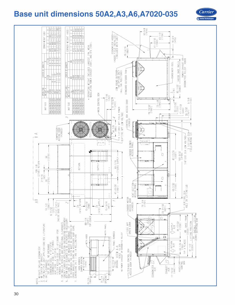
30
Base unit dimensions 50A2,A3,A6,A7020-035

31
*Ope
ratin
g w
eigh
t inc
lude
s la
rges
t ind
oor f
an m
otor
, mic
ro-
chan
nel h
eat
exch
ange
r, m
odul
atin
g po
wer
exh
aust
(va
ri-ab
le
air
volu
me
units
),
and
varia
ble
freq
uenc
y dr
ive
(var
iabl
e ai
r vo
lum
e un
its).
NO
TE
S:
1.W
eigh
ts in
clud
e ec
onom
izer
.2.
cen
ter o
f gra
vity
.3.
Uni
t cle
aran
ces:
T
op o
f uni
ts: n
o ov
erha
ng
Con
dens
er c
oil:
4’ -
0” [1
219]
E
cono
miz
er s
ide:
6’ -
0” [
1829
]
Hea
t sid
e: 4
’ - 0
” [12
19]
F
ilter
acc
ess
side
: 10’
- 0”
[304
8] (f
or
rem
oval
of e
vapo
rato
r coi
l)4.
For
sm
alle
r se
rvic
e an
d op
erat
iona
l cl
ear-
ance
s, c
onta
ct C
arrie
r ap
plic
atio
n en
gine
er-
ing
depa
rtmen
t.5.
Bot
tom
duc
ts a
re d
esig
ned
to b
e at
tach
ed to
acce
ssor
y ro
of c
urb.
If
unit
is m
ount
ed o
ndu
nnag
e, i
t is
rec
omm
ende
d th
at t
he d
ucts
be s
uppo
rted
by c
ross
bra
ces
as d
one
onac
cess
ory
roof
cur
b.6.
Dim
ensi
ons
in [
] are
in m
illim
eter
s. A
ll ot
her
dim
ensi
ons
are
in in
ches
.
Base unit dimensions 50A2,A3,A6,A7040,050
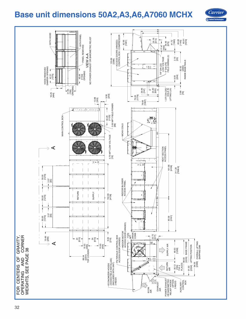
32
31
1.2
8[7
90
6.6
]
85
.09
[21
61
]1
61
.66
[41
06
]
13
3.6
9[3
39
6]
42
.56
[10
81
]
65
.91
[16
74
]
45
.06
[11
45
]
41
.72
[10
60
]
20
.18
[51
3]
2.1
0[5
3]
82
.02
[20
83
]2
.99
[76
]
7/8
" D
IA [2
2]
LO
W V
OLT
AG
E
78
.60
[19
97
]
94
.00
[23
88
]
91
.50
[23
24
]
88
.00
[22
35
]
49
.53
[12
58
]3
0.1
2[7
65
]
22
.72
[57
7]
88
.24
[22
41
]T
OP
CO
VE
RS
10
.49
[26
6]
50
.00
[12
70
]5
0.0
0[1
27
0]
50
.00
[12
70
]
2.5
7[6
5]
2.5
7[6
5]
1"[
25
]N
PT
DR
AIN
CO
NN
1.3
75
DIA
[3
5]
34
.46
[87
5]
70
.05
[17
79
]
29
.40
[74
7]
24
.40
[62
0]
8.0
5[2
04
]
44
.28
[11
25
]
9.5
6[2
43
]
13
.88
[35
3]
0.7
5 N
PT
LO
W V
OL
TA
GE
[19
]3
.50
NP
T F
IEL
D P
OW
ER
[89
]
24
[61
3]
24
[61
3]
15
.53
[39
5]
15
.93
[40
5]
8.6
0[2
18
]1
62
.90
[41
38
]
17
.47
[44
4]
42
.31
[10
75
]1
8.2
5[4
64
] 31
.25
[79
5]
OP
EN
ING
45
.44
[11
54
]O
PE
NIN
G
HO
OD
RE
MO
VE
DD
AM
PE
R O
PE
NIN
G
WIT
H H
OO
D
WIT
H P
AN
EL
PA
NE
L R
EM
OV
ED
VIE
W A
-AN
O P
OW
ER
EX
HA
US
T O
R B
AR
OM
ET
RIC
RE
LIE
F
IND
OO
R B
LO
WE
RA
CC
ES
S P
AN
EL
HE
AT
SE
CT
ION
AC
CE
SS
PA
NE
L
MC
HX
CO
ILS
V F D
OV
ER
AL
L L
IFT
ING
SH
IPP
ING
DIM
LIF
TIN
G P
OS
ITIO
N
BA
SE
FR
AM
E
TY
P 4
PL
AC
ES
EC
ON
OM
IZE
R H
OO
DS
(HO
OD
S F
IEL
D IN
ST
AL
LE
D)
(IN
CL
UD
ED
WIT
H U
NIT
)3
RE
Q'D
IND
OO
R M
OT
OR
AC
CE
SS
DO
OR
(H
ING
ED
)
FIL
TE
R/A
UX
CO
NT
RO
L B
OX
AC
CE
SS
DO
OR
(H
ING
ED
)
RE
TU
RN
AIR
SU
PP
LY
AIR
EC
ON
AIR AU
XIL
IAR
YC
ON
TR
OL
BO
X
EX
HA
US
TA
IR
PO
WE
R E
XH
AU
ST
OR
BA
RO
ME
TR
ICR
EL
IEF
HO
OD
SO
PT
ION
3 R
EQ
'D
MA
IN C
ON
TR
OL
BO
X
V F D
AA
RE
TU
RN
SU
PP
LY
AC
CE
SS
DO
OR
S (
HIN
GE
D)
CO
NT
RO
L B
OX
/ C
OM
PR
ES
SO
R
INS
IDE
BA
SE
RA
ILS
3"
DIA
[7
6]
FIE
LD
WIR
ING
(2
)LIF
TIN
G L
UG
HO
LE
IN
FO
R
CE
NT
ER
S
OF
G
RA
VIT
Y,
OP
ER
AT
ING
A
ND
C
OR
NE
RW
EIG
HT
S, S
EE
PA
GE
38
Base unit dimensions 50A2,A3,A6,A7060 MCHX
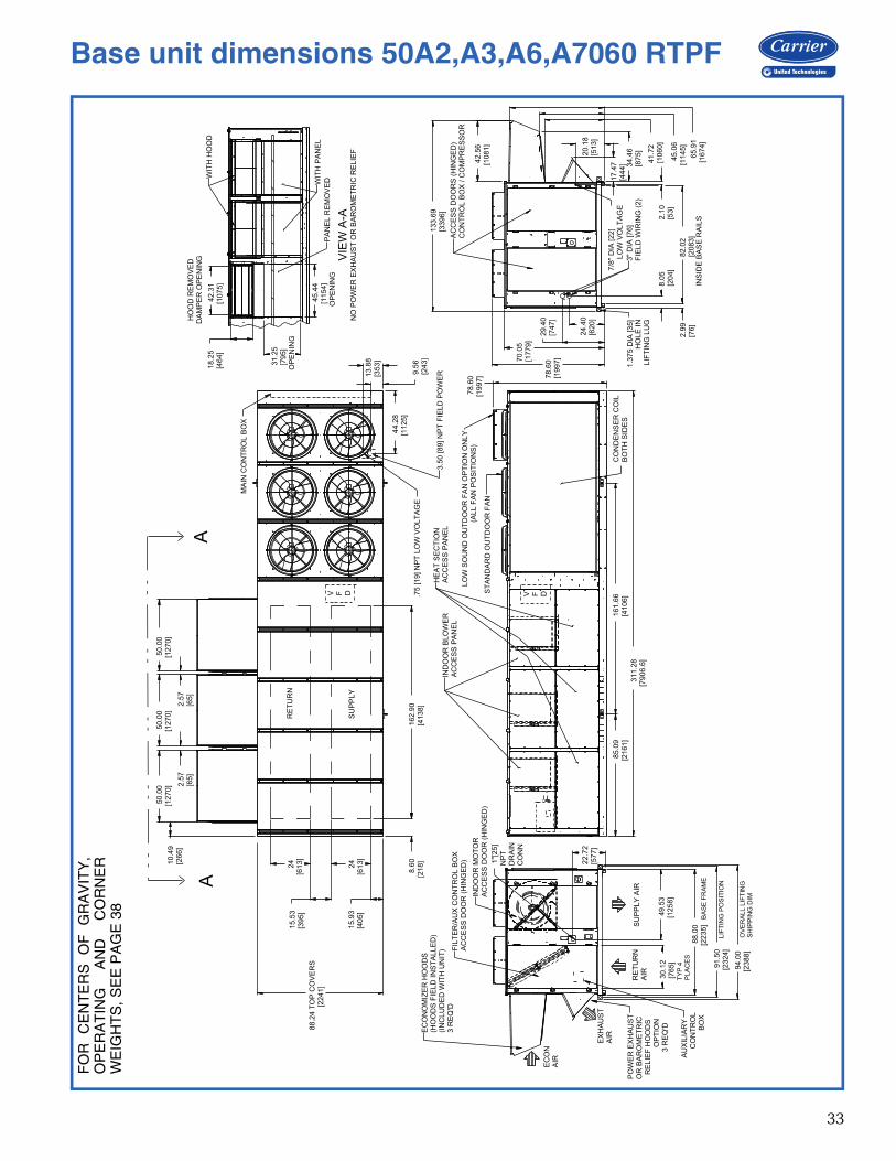
33
85
.09
[21
61
]
31
1.2
8[7
90
6.6
]
88.2
4 T
OP
CO
VE
RS
[22
41
]
10
.49
[26
6]
50
.00
[12
70
] 2.5
7[6
5]
50
.00
[12
70
]
2.5
7[6
5]
50
.00
[12
70
]
16
1.6
6 [4
10
6]
9.5
6 [2
43
]
13
.88
[3
53
]
44
.28
[1
12
5]
78
.60
[1
99
7]
42
.31
[10
75
]
18
.25
[46
4]
31
.25
[79
5]
OP
EN
ING
45
.44
[11
54
]O
PE
NIN
G
94
.00
[23
88
]
91
.50
[23
24
]
88
.00
[22
35
]
49
.53
[12
58
]3
0.1
2[7
65
]
22
.72
[57
7]
1"[
25]
NP
TD
RA
INC
ON
N
13
3.6
9[3
39
6]
42
.56
[10
81
]
65
.91
[16
74
]
45
.06
[11
45
]
41
.72
[10
60
]
20
.18
[51
3]
2.1
0[5
3]
82
.02
[20
83
]2
.99
[76
]
7/8
" D
IA [2
2]
LO
W V
OLT
AG
E
78
.60
[19
97
]
1.3
75
DIA
[3
5]
34
.46
[87
5]
70
.05
[17
79
]
29
.40
[74
7]
24
.40
[62
0]
8.0
5[2
04
]
17
.47
[44
4]
16
2.9
0[4
13
8]
8.6
0[2
18
]
15
.93
[40
5]
24
[61
3]
15
.53
[39
5]
24
[61
3]
HE
AT
SE
CT
ION
AC
CE
SS
PA
NE
LIN
DO
OR
BLO
WE
RA
CC
ES
S P
AN
EL
CO
ND
EN
SE
R C
OIL
BO
TH
SID
ES
MA
IN C
ON
TR
OL B
OX
V F D V F D
AA
3.5
0 [89] N
PT
FIE
LD
PO
WE
R
.75 [19] N
PT
LO
W V
OLT
AG
E
LO
W S
OU
ND
OU
TD
OO
R F
AN
OP
TIO
N O
NLY
(ALL F
AN
PO
SIT
ION
S)
ST
AN
DA
RD
OU
TD
OO
R F
AN
HO
OD
RE
MO
VE
DD
AM
PE
R O
PE
NIN
G
WIT
H H
OO
D
WIT
H P
AN
EL
PA
NE
L R
EM
OV
ED
VIE
W A
-AN
O P
OW
ER
EX
HA
US
T O
R B
AR
OM
ET
RIC
RE
LIE
F
OV
ER
AL
L L
IFT
ING
SH
IPP
ING
DIM
LIF
TIN
G P
OS
ITIO
N
BA
SE
FR
AM
E
TY
P 4
PL
AC
ES
EC
ON
OM
IZE
R H
OO
DS
(HO
OD
S F
IELD
IN
ST
ALLE
D)
(IN
CLU
DE
D W
ITH
UN
IT)
3 R
EQ
'D
IND
OO
R M
OT
OR
AC
CE
SS
DO
OR
(H
ING
ED
)
FIL
TE
R/A
UX
CO
NT
RO
L B
OX
AC
CE
SS
DO
OR
(H
ING
ED
)
RE
TU
RN
AIR
SU
PP
LY
AIR
EC
ON
AIR
AU
XIL
IAR
YC
ON
TR
OL
BO
X
EX
HA
US
TA
IR
PO
WE
R E
XH
AU
ST
OR
BA
RO
ME
TR
ICR
ELIE
F H
OO
DS
OP
TIO
N3 R
EQ
'D
AC
CE
SS
DO
OR
S (
HIN
GE
D)
CO
NT
RO
L B
OX
/ C
OM
PR
ES
SO
R
INS
IDE
BA
SE
RA
ILS
3"
DIA
[7
6]
FIE
LD
WIR
ING
(2)
LIF
TIN
G L
UG
HO
LE
IN
RE
TU
RN
SU
PP
LY
FO
R
CE
NT
ER
S
OF
G
RA
VIT
Y,
OP
ER
AT
ING
A
ND
C
OR
NE
RW
EIG
HT
S, S
EE
PA
GE
38
Base unit dimensions 50A2,A3,A6,A7060 RTPF

34
Base unit dimensions 50A4,A5,A8,A9020,035
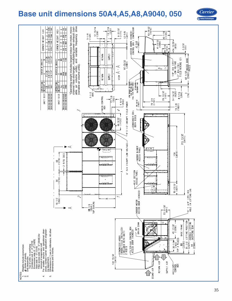
35
a50-8837
*Ope
ratin
g w
eigh
t inc
lude
s la
rges
t ind
oor
fan
mot
or, m
icro
-ch
anne
l hea
t ex
chan
ger,
mod
ulat
ing
pow
er e
xhau
st (
vari-
able
ai
r vo
lum
e un
its),
an
d va
riabl
e fr
eque
ncy
driv
e(v
aria
ble
air
volu
me
units
).
NO
TE
S:
1.W
eigh
ts in
clud
e ec
onom
izer
.2.
cen
ter o
f gra
vity
.3.
Uni
t cle
aran
ces:
T
op o
f uni
ts: n
o ov
erha
ng
Con
dens
er c
oil:
4’ -
0” [1
219]
E
cono
miz
er s
ide:
6’ -
0” [
1829
]
Hea
t sid
e: 4
’ - 0
” [12
19]
F
ilter
acc
ess
side
: 10’
- 0”
[304
8] (f
or
rem
oval
of e
vapo
rato
r coi
l)4.
For
sm
alle
r se
rvic
e an
d op
erat
iona
l cl
ear-
ance
s, c
onta
ct C
arrie
r ap
plic
atio
n en
gine
er-
ing
depa
rtmen
t.5.
Dim
ensi
ons
in [
] are
in m
illim
eter
s. A
ll ot
her
dim
ensi
ons
are
in in
ches
.
Base unit dimensions 50A4,A5,A8,A9040, 050
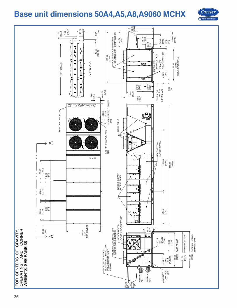
36
FO
R
CE
NT
ER
S
OF
G
RA
VIT
Y,
OP
ER
AT
ING
A
ND
C
OR
NE
RW
EIG
HT
S, S
EE
PA
GE
38
31
1.2
8[7
90
6.6
]
85
.09
[21
61
]1
61
.66
[41
06
]
13
3.6
9[3
39
6]
42
.56
[10
81
]
65
.91
[16
74
]
45
.06
[11
45
]
41
.72
[10
60
]
20
.18
[51
3] 2.1
0[5
3]
82
.02
[20
83
]
2.9
9[7
6]
7/8
" D
IA [2
2]
LO
W V
OLT
AG
E
78
.60
[19
97
]
94
.00
[23
88
]
91
.50
[23
24
]
88
.00
[22
35
]
49
.53
[12
58
]
30
.12
[76
5]
22
.72
[57
7]
88
.24
[22
41
]T
OP
CO
VE
RS
10
.49
[26
6]
50
.00
[12
70
]5
0.0
0[1
27
0]
50
.00
[12
70
]
2.5
7[6
5]
2.5
7[6
5]
1"[
25
]N
PT
DR
AIN
CO
NN
1.3
75
DIA
[3
5]
34
.46
[87
5]
70
.05
[17
79
]
29
.40
[74
7]
24
.40
[62
0]
8.0
5[2
04
]
44
.28
[11
25
]
9.5
6[2
43
]
13
.88
[35
3]
0.7
5 N
PT
LO
W V
OL
TA
GE
[19
]3
.50
NP
T F
IEL
D P
OW
ER
[89
]
6.9
7[1
77
.0]
13
.20
[33
5.3
]
5.1
2[1
30
.0]
12
.93
[32
8.3
]1
50
.47
[3
82
2.0
]
12
.63
[32
0.8
]
VIE
W A
-A
IND
OO
R B
LO
WE
RA
CC
ES
S P
AN
EL
HE
AT
SE
CT
ION
AC
CE
SS
PA
NE
L
MC
HX
CO
ILS
V F D
OV
ER
AL
L L
IFT
ING
SH
IPP
ING
DIM
LIF
TIN
G P
OS
ITIO
N
BA
SE
FR
AM
E
TY
P 4
PL
AC
ES
EC
ON
OM
IZE
R H
OO
DS
(HO
OD
S F
IEL
D IN
ST
AL
LE
D)
(IN
CL
UD
ED
WIT
H U
NIT
)3
RE
Q'D
IND
OO
R M
OT
OR
AC
CE
SS
DO
OR
(H
ING
ED
)
FIL
TE
R/A
UX
CO
NT
RO
L B
OX
AC
CE
SS
DO
OR
(H
ING
ED
)
RE
TU
RN
AIR
SU
PP
LY
AIR
EC
ON
AIR
AU
XIL
IAR
YC
ON
TR
OL
BO
X
MA
IN C
ON
TR
OL
BO
X
V F D
AA
AC
CE
SS
DO
OR
S (
HIN
GE
D)
CO
NT
RO
L B
OX
/ C
OM
PR
ES
SO
R
INS
IDE
BA
SE
RA
ILS
3"
DIA
[7
6]
FIE
LD
WIR
ING
(2
)LIF
TIN
G L
UG
HO
LE
IN
Base unit dimensions 50A4,A5,A8,A9060 MCHX
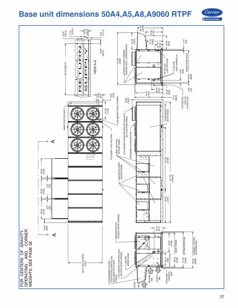
37
70
.75
[17
97
]
65
.91
[16
74
]
45
.06
[11
45
]
41
.72
[10
60
]
34
.46
[87
5]
30.1
2[7
65]
78.6
0 [1997]
TY
P 4
PL
AC
ES
AU
XIL
IAR
YC
ON
TR
OL
BO
X
EC
ON
OM
IZE
R H
OO
DS
(HO
OD
S F
IELD
IN
ST
ALLE
D)
(IN
CL
UD
ED
WIT
H U
NIT
)3 R
EQ
'D
AC
CE
SS
DO
OR
S (
HIN
GE
D)
CO
NT
RO
L B
OX
/ C
OM
PR
ES
SO
R
IND
OO
R M
OT
OR
AC
CE
SS
DO
OR
(H
ING
ED
)F
ILT
ER
/AU
X C
ON
TR
OL B
OX
AC
CE
SS
DO
OR
(H
ING
ED
)
HE
AT
SE
CT
ION
AC
CE
SS
PA
NE
LIN
DO
OR
BLO
WE
RA
CC
ES
S P
AN
EL
CO
ND
EN
SE
R C
OIL
BO
TH
SID
ES
3"
DIA
[76]
FIE
LD
WIR
ING
(2)
7/8
' D
IA [22]
LO
W V
OLT
AG
E
EC
ON
AIR
RE
TU
RN
AIR
1"
[25] N
PT
DR
AIN
CO
NN
BA
SE
FR
AM
E
LIF
TIN
G P
OS
ITIO
N
OV
ER
ALL L
IFT
ING
SH
IPP
ING
DIM
MA
IN C
ON
TR
OL B
OX
INS
IDE
BA
SE
RA
ILS
1.3
75 [35] D
IA
HO
LE
IN
LIF
TIN
G L
UG
V F D V F D
VIE
W A
-A
AA
3.5
0 [89] N
PT
FIE
LD
PO
WE
R
SU
PP
LY
AIR
.75 [19] N
PT
LO
W V
OLT
AG
E
73
.12
[18
57
]
42
.56
[10
81
]
20
.18
[51
3] 2
.10
[53
]
82
.02
[20
83
]2
.99
[76
]
8.0
5[2
04
]
24
.40
[62
0]
29
.40
[74
7]
85.0
9[2
16
1]
31
1.2
8[7
906.6
]
22.7
2[5
77]
94.0
0[2
38
8]
91.5
0[2
32
4]
88.0
0[2
23
5]
49.5
3[1
25
8]
13
3.6
9[3
39
6]
88.2
4 T
OP
CO
VE
RS
[22
41
]
10.4
9[2
66]
50.0
0[1
27
0] 2
.57
[65]
50.0
0[1
27
0]
2.5
7[6
5]
50
.00
[12
70
]
161.6
6 [4106]
6.9
7[1
77.0
]
13
.20
[335.3
]
5.1
2[1
30.0
]
12
.93
[328.3
]1
50
.47
[3
82
2.0
]
12
.63
[320.8
]
9.5
6 [243]
13.8
8 [353]
44.2
8 [1125]
LO
W S
OU
ND
OU
TD
OO
R F
AN
OP
TIO
N O
NLY
(ALL F
AN
PO
SIT
ION
S)
ST
AN
DA
RD
OU
TD
OO
R F
AN
FO
R
CE
NT
ER
S
OF
G
RA
VIT
Y,
OP
ER
AT
ING
A
ND
C
OR
NE
RW
EIG
HT
S, S
EE
PA
GE
38
Base unit dimensions 50A4,A5,A8,A9060 RTPF
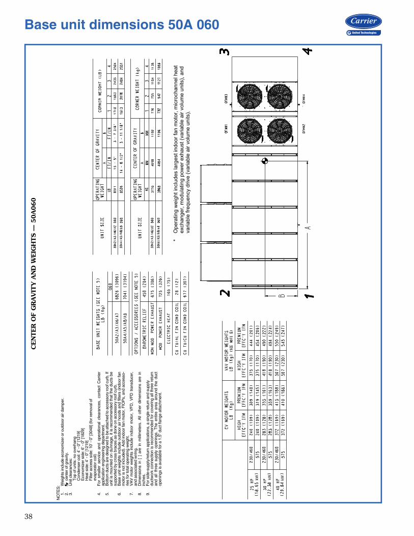
38
kW kW kW
CEN
TER
OF
GR
AV
ITY
AN
D W
EIG
HTS —
50A
060
NO
TE
S:
1.W
eigh
ts in
clud
e ec
onom
izer
or o
utdo
or a
ir da
mpe
r.2.
c
ente
r of g
ravi
ty.
3.U
nit c
lear
ance
s:
Top
of u
nits
: no
over
hang
C
onde
nser
coi
l: 4’
- 0”
[121
9]
Eco
nom
izer
sid
e: 6
’ - 0
” [18
29]
H
eat s
ide:
4’ -
0” [
1219
]
Filt
er a
cces
s si
de: 1
0’ -
0” [3
048]
(for
rem
oval
of
e
vapo
rato
r coi
l)4.
For
sm
alle
r se
rvic
e an
d op
erat
iona
l cl
eara
nces
, co
ntac
t C
arrie
rap
plic
atio
n en
gine
erin
g de
partm
ent.
5.B
otto
m d
ucts
are
des
igne
d to
be
atta
ched
to a
cces
sory
roof
cur
b. If
unit
is m
ount
ed o
n du
nnag
e, it
is r
ecom
men
ded
that
the
duct
s be
supp
orte
d by
cro
ss b
race
s as
don
e on
acc
esso
ry ro
of c
urb.
6.B
ase
unit
wei
ghts
incl
ude
outd
oor
air
hood
s an
d fil
ters
(in
door
fan
mot
or is
not
incl
uded
). A
dd in
door
fan
mot
or, F
IOP
s, a
nd a
cces
so-
ries
for t
otal
ope
ratin
g w
eigh
t.7.
VA
V m
otor
wei
ghts
inc
lude
ind
oor
mot
or,
VF
D,
VF
D t
rans
duce
r,an
d as
soci
ated
wiri
ng.
8.D
imen
sion
s in
[ ]
are
in
mill
imet
ers.
All
othe
r di
men
sion
s ar
e in
inch
es.
9.F
or s
ide-
supp
ly/re
turn
app
licat
ions
, a s
ingl
e re
turn
and
sup
ply
duct
wor
k co
nnec
tion
is r
ecom
men
ded
for
cove
ring
all t
hree
ret
urn
and
all
thre
e su
pply
ope
ning
s. T
he e
ntire
are
a ar
ound
the
duc
top
enin
gs is
ava
ilabl
e fo
r a 1
.5”
duct
flan
ge a
ttach
men
t.
*O
per
atin
g w
eigh
t inc
lud
es la
rges
t ind
oor
fan
mot
or, m
icro
chan
nel h
eat
exch
ang
er, m
odul
atin
g po
wer
exh
aust
(va
riabl
e a
ir v
olum
e un
its),
and
va
riabl
e fr
eque
ncy
driv
e (v
aria
ble
air
volu
me
units
).
Base unit dimensions 50A 060

39
RO
OF
CU
RB
SIZ
ES 0
20-0
35
NO
TE
S:
1.U
nles
s ot
herw
ise
spec
ified
, all
dim
ensi
ons
are
to o
utsi
de o
f par
t.2.
Roo
f cur
b ac
cess
ory
CR
RF
CU
RB
005A
00 is
shi
pped
dis
asse
mbl
ed.
3.A
ll ro
of c
urb
parts
are
to b
e 14
ga.
gal
vani
zed
stee
l.4.
Uni
ts w
ith e
lect
ric h
eat m
ust b
e in
stal
led
with
a 9
0° e
lbow
on
the
supp
ly d
uct p
rior t
o an
y su
pply
take
offs
or b
ranc
hes.
5.D
imen
sion
s in
[ ] a
re in
mill
imet
ers.
All
othe
r dim
ensi
ons
are
in in
ches
.
Accessory dimensions
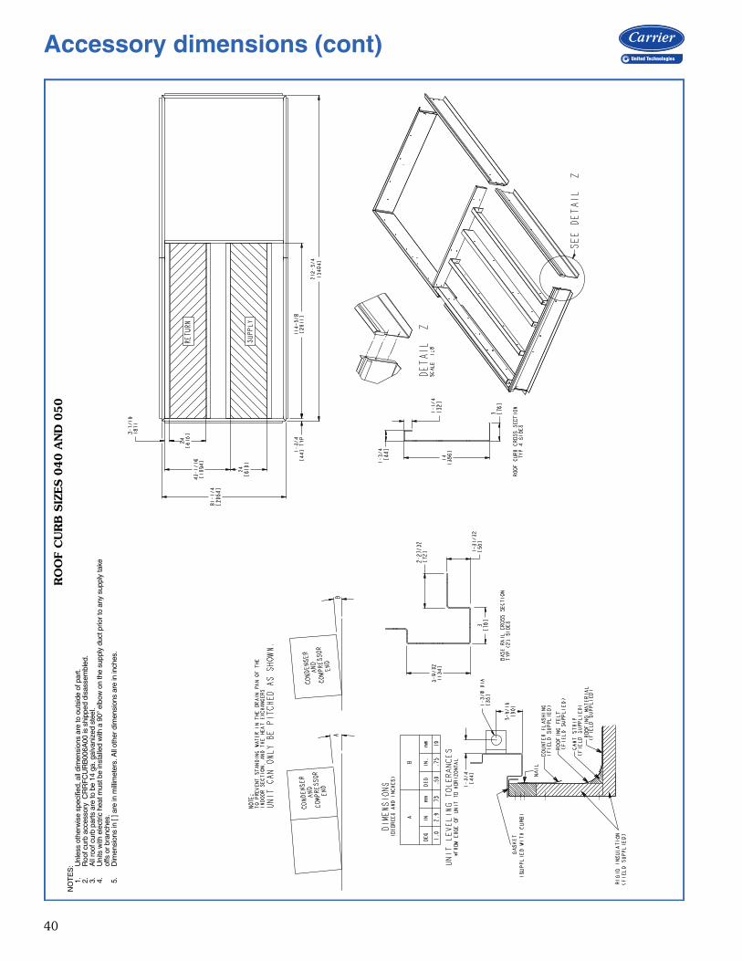
40
RO
OF
CU
RB
SIZ
ES 0
40 A
ND
050
NO
TE
S:
1.U
nles
s ot
herw
ise
spec
ified
, all
dim
ensi
ons
are
to o
utsi
de o
f par
t.2.
Roo
f cur
b ac
cess
ory
CR
RF
CU
RB
006A
00 is
shi
pped
dis
asse
mbl
ed.
3.A
ll ro
of c
urb
parts
are
to b
e 14
ga.
gal
vani
zed
stee
l.4.
Uni
ts w
ith e
lect
ric h
eat m
ust b
e in
stal
led
with
a 9
0° e
lbow
on
the
supp
ly d
uct p
rior t
o an
y su
pply
take
offs
or b
ranc
hes.
5.D
imen
sion
s in
[ ] a
re in
mill
imet
ers.
All
othe
r dim
ensi
ons
are
in in
ches
.
Accessory dimensions (cont)

41
RO
OF
CU
RB
48A
2,A
3,A
6,A
7060
, 50A
2,A
3,A
6,A
7060 W
ITH
OU
T E
LEC
TR
IC H
EA
T/U
NIT
SU
PPO
RT 4
8/5
0A
4,A
5,A
8,A
9060
NO
TE
S:
1.U
nles
s ot
herw
ise
spec
ified
, all
dim
ensi
ons
are
to o
utsi
de o
f par
t.2.
Roo
f cur
b ac
cess
ory
CR
RF
CU
RB
014A
00 is
shi
pped
dis
asse
mbl
ed.
3.A
ll ro
of c
urb
parts
are
to b
e 14
ga.
gal
vani
zed
stee
l.4.
Dim
ensi
ons
in [
] are
in m
illim
eter
s. A
ll ot
her d
imen
sion
s ar
e in
inch
es.
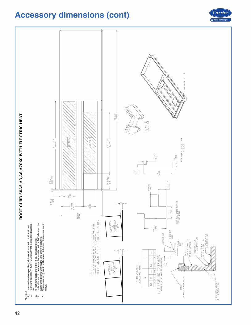
42
RO
OF
CU
RB
50A
2,A
3,A
6,A
7060 W
ITH
ELE
CTR
IC H
EA
TN
OT
ES
:1.
Unl
ess
othe
rwis
e sp
ecifi
ed, a
ll di
men
sion
s ar
e to
out
side
of p
art.
2.R
oof
curb
acc
esso
ry
CR
RF
CU
RB
009A
00 is
shi
pped
dis
asse
m-
bled
.3.
All
roof
cur
b pa
rts a
re to
be
14 g
a. g
alva
nize
d st
eel.
4.U
nits
with
ele
ctric
hea
t m
ust
be in
stal
led
with
a 9
0° e
lbow
on
the
supp
ly d
uct p
rior t
o an
y su
pply
take
offs
or b
ranc
hes.
5.D
imen
sion
s in
[ ]
are
in
mill
imet
ers.
All
othe
r di
men
sion
s ar
e in
inch
es.
Accessory dimensions (cont)
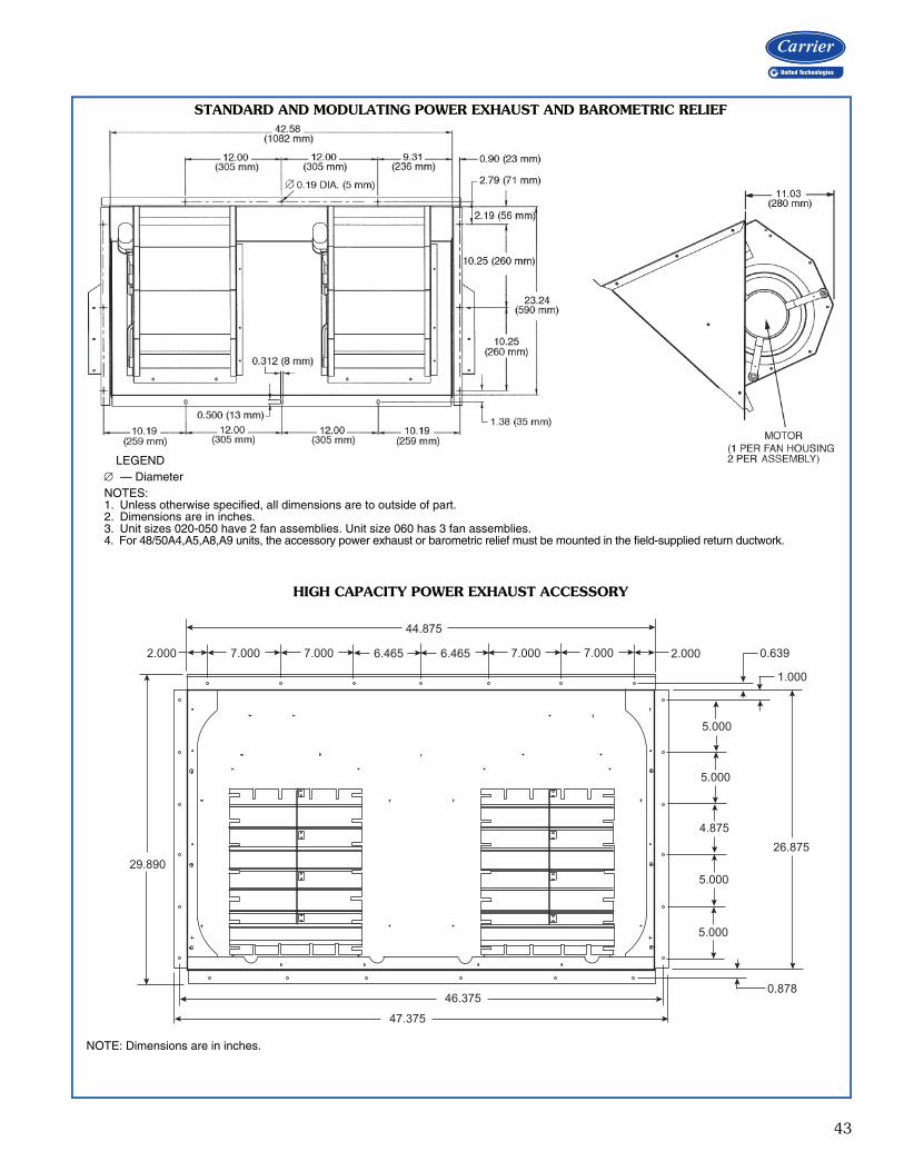
43
7.000 7.000 7.0007.0006.4656.465
44.875
2.000 0.639
1.000
5.000
5.000
5.000
5.000
4.875
26.875
0.87846.375
47.375
29.890
2.000
STANDARD AND MODULATING POWER EXHAUST AND BAROMETRIC RELIEF
a48-4172
NOTE: Dimensions are in inches.
HIGH CAPACITY POWER EXHAUST ACCESSORY
LEGEND — DiameterNOTES:1. Unless otherwise specified, all dimensions are to outside of part.2. Dimensions are in inches.3. Unit sizes 020-050 have 2 fan assemblies. Unit size 060 has 3 fan assemblies.4. For 48/50A4,A5,A8,A9 units, the accessory power exhaust or barometric relief must be mounted in the field-supplied return ductwork.

44
I Determine cooling and heat requirements atdesign conditions.Given:Type Application ......................................... VAVRequired Cooling Capacity (TC) .......480,000 BtuhSensible Heat Capacity (SHC) ..........338,000 BtuhRequired Heating Capacity ..............300,000 BtuhDesign Outdoor Air db Temperature.............. 95°FDesign Outdoor Air wb Temperature ............. 67°FClimate Type (as per ASHRAE 90.1 Table D) .... DryIndoor-Air Temperature.......... 80°F edb, 67°F ewbEvaporator Air Quantity...................... 16,000 cfmExternal Static Pressure .........................1.4 in. wgElectrical Characteristics (V-Ph-Hz) ..........460-3-60Unit Type ............. Gas Heating Vertical Discharge
II Select the unit based on required coolingcapacity.Entering Cooling Capacity table at air condenserentering temperature of 95°F. Unit 48A3D040 at16,000 cfm and 67°F ewb will provide the totalcapacity of 485,000 Btuh and a SHC of 380,000Btuh. Calculate SHC correction, if required, usingnotes under cooling capacity table.
III Select heat capacity of unit to provide designcondition requirements.In the Gas Heating Capacities and Efficiencies table,note that unit 48A3D040 will provide 324,000Btuh with an input of 400,000 Btuh.
IV Select supply fan to provide design conditionrequirements.Tabulated fan performance includes 2-in. throw-away filters, wet evaporator coil, economizer, cabi-net losses, and roof curb. Find fan rpm and bhp at1.4 in. wg and 16,000 cfm on 48A3D040 Fan Per-formance table for vertical applications. Find thatthe fan speed is 1063 rpm and the power requiredis 19.06 bhp. Refer to the Motor Limitations tablewhich shows the 20 hp motor is required.
V Select unit that corresponds to the powersource available.The model number nomenclature shows that a460-3-60 unit is available.
VI Select the options and accessories.As per the ASHRAE 90.1 requirements, this unit islocated in a dry climate and therefore is required tohave an economizer. As this is a dry climate, eitherdifferential dry bulb changeover, outdoor air change-over or differential enthalpy should be used. Outsideair enthalpy cannot be used.Select the options and model number using theoptions summary and model number charts in theprice pages.Note, as an alternative, a computerized selectionprogram, RTUBuilder, is available for use in select-ing and optimizing the unit for your application.
Selection procedure (with example)

45
Humidi-MiZer® performance dataCarrier's Humidi-MiZer adaptive dehumidification system isan all-inclusive factory-installed option that can be orderedwith WeatherMaker® 48/50A rooftop units. This system expands the envelope of operation of the ASeries rooftop to provide unprecedented flexibility that willmeet year-round comfort conditions. The Humidi-MiZer adaptive dehumidification system hasthe industry's only dual dehumidification mode setting. TheWeatherMaker rooftop, coupled with the Humidi-MiZeradaptive dehumidification system, is capable of modulatingbetween normal design cooling mode, subcooling mode,and hot gas reheat mode. Normal design cooling mode will operate under the normalsequence of operation. Subcooling mode will operate tosatisfy part load type conditions. Hot Gas Reheat mode willoperate when outdoor temperatures diminish and the need
for latent capacity is required for sole humidity control. HotGas Reheat mode will provide neutral air for maximumdehumidification operation. The WeatherMaker A Series next generation version ofCarrier's Humidi-MiZer system includes refrigerant modu-lating valves that provide variable flow bypass around thecondenser. This innovative feature ensures exact control ofthe supply-air temperature as the unit lowers the evapora-tor temperature to increase latent capacity. Additionally, when the space requires dehumidificationonly, the Humidi-MiZer system can increase hot dischargegas bypass to the Humidi-MiZer coil in order to heat the airto the exact neutral state required—no overcooling oroverheating with latent capacity similar to that provided inthe full subcooling mode.
In this example, unit SHR can rangefrom 0.00 to 0.60 between Reheat andSubcooling Modes depending onspace requirements. Refrigerant flowto the Humidi-MiZer coil will bemodulated to meet the SHR requiredin normal cooling mode, the unitwould operate at 0.66 SHR.
Sensible
Latent
80°F db/67°F wb Ent Air, 95°F Outdoor, Constant Volume CFM
Cap
acit
y (T
ons)
Variable Sensible Heat Ratio (SHR) Example
0.66 SHR
0.60 SHR
0.00 SHR
60
50
40
30
20
10
0
100% Reheat 100% Subcool Normal
Performance data

46
COOLING CAPACITIES
See legend on page 58.
48/50A020 (20 TONS) — STANDARD MODE
Temp (F)Air EnteringCondenser
(Edb)
Evaporator Air Quantity — Cfm4,000 5,000 6,000 7,000
Evaporator Air — Ewb (F)75 72 67 62 57 75 72 67 62 57 75 72 67 62 57 75 72 67 62 57
75TC 268 258 236 214 195 284 272 250 228 208 294 282 260 239 224 302 289 268 246 232SHC 109 119 141 161 179 113 128 155 180 201 116 136 168 197 224 121 144 180 213 232kW 14.1 14.0 13.8 13.7 13.6 14.3 14.2 14.0 13.8 13.7 14.5 14.3 14.1 13.9 13.8 14.6 14.4 14.1 13.9 13.8BF 0.00 0.00 0.09 0.15 0.14 0.00 0.00 0.19 0.16 0.17 0.00 0.27 0.18 0.17 0.24 0.00 0.23 0.19 0.17 0.28
85TC 261 250 228 207 188 276 264 242 221 200 286 273 252 230 218 293 280 259 238 226SHC 106 115 138 158 176 110 125 152 176 194 112 133 164 193 218 118 141 176 210 226kW 16.0 16.0 15.8 15.7 15.5 16.2 16.1 15.9 15.8 15.6 16.4 16.2 16.0 15.8 15.8 16.5 16.3 16.1 15.9 15.8BF 0.02 0.00 0.21 0.15 0.13 0.00 0.14 0.18 0.15 0.17 0.00 0.24 0.18 0.16 0.26 0.15 0.22 0.18 0.17 0.30
95TC 253 242 220 200 181 267 254 233 212 198 277 264 242 221 207 283 271 249 228 218SHC 102 112 134 154 172 106 122 148 172 198 109 130 161 190 207 115 137 173 206 218kW 18.2 18.2 18.0 17.9 17.9 18.4 18.3 18.2 18.0 17.9 18.5 18.4 18.2 18.1 18.0 18.6 18.5 18.3 18.1 18.0BF 0.00 0.00 0.18 0.14 0.13 0.00 0.12 0.17 0.15 0.20 0.00 0.22 0.17 0.16 0.25 0.13 0.21 0.18 0.17 0.32
105TC 244 232 211 191 174 257 244 223 203 187 266 253 232 211 200 272 260 238 218 211SHC 97 109 130 150 168 101 118 144 168 187 106 126 156 185 200 112 134 168 201 211kW 20.7 20.6 20.6 20.7 20.8 20.8 20.8 20.6 20.6 20.8 20.9 20.8 20.7 20.6 20.7 21.0 20.9 20.7 20.6 20.6BF 0.00 0.00 0.17 0.13 0.13 0.00 0.25 0.16 0.14 0.19 0.00 0.20 0.16 0.15 0.28 0.28 0.20 0.17 0.17 0.35
115TC 234 222 201 182 166 246 233 212 193 180 254 241 220 201 192 260 247 227 207 202SHC 93 105 126 146 162 97 114 139 164 180 103 122 152 180 192 108 129 164 195 202kW 23.4 23.4 23.6 23.9 24.3 23.5 23.4 23.5 23.7 24.0 23.6 23.5 23.5 23.7 23.8 23.7 23.6 23.5 23.7 23.7BF 0.00 0.00 0.15 0.13 0.15 0.00 0.21 0.15 0.14 0.22 0.13 0.19 0.16 0.15 0.31 0.24 0.19 0.17 0.18 0.38
120TC 228 216 196 178 161 240 227 207 188 175 247 235 215 195 188 253 241 220 201 198SHC 91 103 124 143 159 95 112 137 161 175 101 120 150 178 188 106 127 162 192 198kW 24.9 25.1 25.4 25.7 26.3 24.9 25.0 25.2 25.5 25.8 25.0 25.0 25.1 25.4 25.6 25.1 25.0 25.1 25.3 25.4BF 0.00 0.12 0.14 0.12 0.15 0.00 0.20 0.15 0.14 0.24 0.29 0.18 0.16 0.15 0.32 0.23 0.18 0.17 0.18 0.39
48/50A020 (20 TONS) — STANDARD MODE (cont)
Temp (F)Air EnteringCondenser
(Edb)
Evaporator Air Quantity — Cfm8,000 9,000 10,000
Evaporator Air — Ewb (F)75 72 67 62 57 75 72 67 62 57 75 72 67 62 57
75TC 308 295 274 252 243 313 299 278 257 251 317 303 282 262 259SHC 126 151 191 228 243 130 158 202 242 251 135 164 212 251 259kW 14.7 14.5 14.2 14.0 13.9 14.8 14.5 14.3 14.0 14.0 14.8 14.6 14.3 14.1 14.1BF 0.34 0.22 0.19 0.19 0.34 0.28 0.22 0.20 0.21 0.40 0.26 0.23 0.21 0.25 0.44
85TC 298 286 265 243 236 302 290 269 248 244 306 294 273 253 251SHC 123 148 188 224 236 127 155 199 236 244 131 161 209 247 251kW 16.6 16.4 16.1 16.0 15.9 16.6 16.4 16.2 16.0 16.0 16.7 16.5 16.2 16.1 16.0BF 0.29 0.21 0.19 0.19 0.36 0.26 0.22 0.20 0.22 0.41 0.25 0.22 0.21 0.25 0.46
95TC 288 276 255 234 228 293 280 259 239 236 296 284 262 245 243SHC 120 145 184 219 228 124 151 195 230 236 129 158 205 239 243kW 18.7 18.5 18.3 18.2 18.1 18.7 18.6 18.4 18.2 18.2 18.8 18.6 18.4 18.2 18.3BF 0.27 0.21 0.18 0.19 0.38 0.25 0.21 0.19 0.23 0.43 0.24 0.22 0.20 0.28 0.47
105TC 277 265 243 223 220 281 269 248 229 227 284 272 251 235 234SHC 116 141 180 213 220 121 148 191 223 227 125 154 201 232 234kW 21.1 20.9 20.8 20.6 20.6 21.1 21.0 20.8 20.6 20.6 21.2 21.0 20.8 20.7 20.7BF 0.24 0.20 0.18 0.21 0.41 0.23 0.20 0.19 0.25 0.45 0.23 0.21 0.20 0.29 0.49
115TC 264 252 231 213 211 268 256 235 219 218 271 258 238 225 224SHC 113 137 175 206 211 117 144 186 216 218 121 150 197 221 224kW 23.7 23.6 23.5 23.6 23.6 23.8 23.7 23.5 23.5 23.6 23.8 23.7 23.5 23.5 23.5BF 0.22 0.19 0.18 0.22 0.43 0.22 0.20 0.19 0.26 0.48 0.22 0.21 0.20 0.32 0.52
120TC 257 245 225 207 206 261 248 229 215 213 263 251 232 219 219SHC 110 134 173 202 206 115 141 184 215 213 119 148 194 219 219kW 25.1 25.1 25.1 25.2 25.3 25.2 25.1 25.0 25.2 25.2 25.3 25.1 25.0 25.1 25.1BF 0.22 0.19 0.18 0.23 0.44 0.22 0.20 0.19 0.29 0.49 0.22 0.21 0.20 0.32 0.53
Performance data (cont)

47
COOLING CAPACITIES (cont)
See legend on page 58.
48/50A020 (20 TONS) — SUBCOOLING MODE
Temp (F)Air EnteringCondenser
(Edb)
Evaporator Air Quantity – SCFM4,000 5,000 6,000 7,000
Evaporator Air Ewb (F)75 72 67 62 57 75 72 67 62 57 75 72 67 62 57 75 72 67 62 57
75
TC 265 249 223 204 184 285 269 239 220 199 293 277 251 232 212 303 286 260 236 222SHC 96 109 126 147 166 107 121 140 168 191 109 126 153 186 209 115 134 166 197 222kW 14.0 13.8 13.6 13.5 13.4 14.1 14.0 13.7 13.6 13.5 14.2 14.0 13.8 13.7 13.6 14.3 14.1 13.9 13.7 13.6BF 0.00 0.02 0.09 0.10 0.10 0.00 0.08 0.11 0.12 0.12 0.03 0.11 0.13 0.14 0.19 0.08 0.14 0.15 0.15 0.25
85
TC 249 234 201 193 173 265 250 219 207 187 277 262 240 214 199 286 270 248 226 212SHC 83 96 106 139 157 91 105 123 157 179 97 114 145 170 197 102 122 157 191 212kW 15.5 15.4 15.1 15.1 15.0 15.7 15.5 15.2 15.2 15.1 15.8 15.6 15.4 15.2 15.1 15.9 15.7 15.5 15.3 15.3BF 0.00 0.03 0.09 0.10 0.10 0.01 0.09 0.12 0.12 0.14 0.05 0.12 0.13 0.14 0.20 0.10 0.14 0.15 0.15 0.26
95
TC 235 222 201 177 162 251 237 214 192 177 262 247 223 204 188 270 255 231 210 199SHC 72 87 108 125 148 80 95 121 145 170 86 103 132 163 188 90 110 144 179 199kW 17.3 17.2 17.0 16.8 16.7 17.5 17.3 17.1 16.9 16.9 17.6 17.4 17.2 17.0 17.0 17.7 17.5 17.3 17.1 17.0BF 0.00 0.05 0.10 0.10 0.10 0.02 0.10 0.12 0.12 0.16 0.07 0.12 0.13 0.14 0.20 0.10 0.14 0.15 0.16 0.28
105
TC 221 207 186 167 150 226 220 199 176 163 246 231 209 189 176 214 238 215 196 181SHC 61 75 97 118 138 58 82 109 132 158 72 90 121 151 176 38 97 131 168 181kW 19.3 19.2 19.0 18.9 18.8 19.3 19.3 19.2 18.9 18.9 19.6 19.4 19.2 19.1 19.0 19.0 19.5 19.3 19.1 19.0BF 0.00 0.07 0.10 0.10 0.11 0.03 0.10 0.12 0.12 0.17 0.08 0.12 0.14 0.14 0.22 0.11 0.14 0.15 0.16 0.30
115
TC 205 191 170 150 136 219 205 184 165 151 199 215 192 173 157 222 200 198 178 168SHC 50 63 84 104 126 55 71 97 124 147 31 78 108 140 157 50 63 119 153 168kW 21.6 21.5 21.3 21.1 21.1 21.7 21.6 21.4 21.3 21.2 21.4 21.7 21.5 21.4 21.2 21.6 21.4 21.5 21.4 21.3BF 0.00 0.08 0.10 0.10 0.11 0.04 0.11 0.12 0.12 0.18 0.09 0.13 0.14 0.14 0.24 0.12 0.14 0.15 0.16 0.32
48/50A020 (20 TONS) — SUBCOOLING MODE (cont)
Temp (F)Air EnteringCondenser
(Edb)
Evaporator Air Quantity – SCFM8,000 9,000 10,000
Evaporator Air Ewb (F)75 72 67 62 57 75 72 67 62 57 75 72 67 62 57
75
TC 317 299 267 242 235 317 300 273 248 243 322 305 280 258 251SHC 126 147 177 213 235 126 149 188 227 243 130 156 202 246 251kW 14.4 14.3 13.9 13.7 13.7 14.4 14.2 14.0 13.8 13.8 14.4 14.3 14.1 13.9 13.8BF 0.12 0.16 0.17 0.17 0.32 0.14 0.18 0.18 0.19 0.37 0.17 0.19 0.20 0.21 0.42
85
TC 294 277 252 232 222 299 284 260 238 231 307 290 264 238 234SHC 108 129 166 205 222 112 138 180 220 231 120 146 190 225 234kW 15.9 15.8 15.5 15.4 15.3 16.0 15.8 15.6 15.5 15.4 16.1 15.9 15.7 15.4 15.4BF 0.13 0.16 0.17 0.17 0.33 0.15 0.18 0.18 0.20 0.38 0.17 0.19 0.20 0.24 0.43
95
TC 277 262 236 217 209 282 267 241 221 216 287 270 246 226 223SHC 95 118 153 194 209 99 124 165 206 216 104 130 176 214 223kW 17.7 17.6 17.3 17.2 17.1 17.8 17.6 17.4 17.2 17.2 17.8 17.7 17.4 17.3 17.2BF 0.13 0.16 0.17 0.18 0.34 0.15 0.18 0.18 0.20 0.40 0.17 0.19 0.20 0.25 0.44
105
TC 248 224 221 198 195 230 240 225 186 199 256 217 229 213 207SHC 70 84 142 178 195 51 101 153 171 199 77 83 163 203 207kW 19.6 19.3 19.3 19.1 19.2 19.3 19.5 19.4 18.9 19.2 19.7 19.2 19.4 19.3 19.2BF 0.14 0.16 0.17 0.18 0.36 0.16 0.18 0.18 0.22 0.41 0.18 0.19 0.20 0.26 0.45
115
TC 186 182 204 185 178 237 185 208 189 186 205 187 195 195 192SHC 14 46 130 166 178 63 51 140 175 186 31 56 133 187 192kW 21.1 21.1 21.6 21.5 21.4 21.7 21.2 21.6 21.5 21.5 21.3 21.2 21.4 21.5 21.5BF 0.14 0.16 0.17 0.20 0.38 0.16 0.18 0.18 0.24 0.43 0.18 0.19 0.19 0.27 0.47
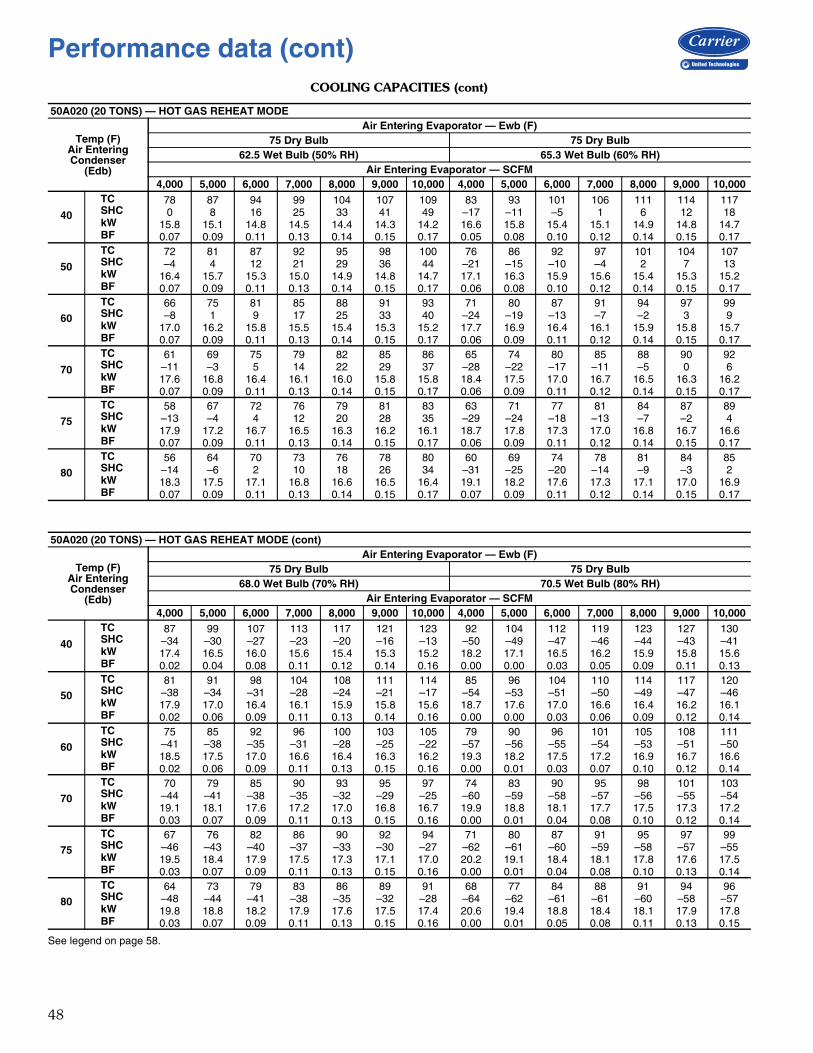
48
COOLING CAPACITIES (cont)
See legend on page 58.
50A020 (20 TONS) — HOT GAS REHEAT MODE
Temp (F)Air EnteringCondenser
(Edb)
Air Entering Evaporator — Ewb (F)75 Dry Bulb 75 Dry Bulb
62.5 Wet Bulb (50% RH) 65.3 Wet Bulb (60% RH)Air Entering Evaporator — SCFM
4,000 5,000 6,000 7,000 8,000 9,000 10,000 4,000 5,000 6,000 7,000 8,000 9,000 10,000
40
TC 78 87 94 99 104 107 109 83 93 101 106 111 114 117SHC 0 8 16 25 33 41 49 –17 –11 –5 1 6 12 18kW 15.8 15.1 14.8 14.5 14.4 14.3 14.2 16.6 15.8 15.4 15.1 14.9 14.8 14.7BF 0.07 0.09 0.11 0.13 0.14 0.15 0.17 0.05 0.08 0.10 0.12 0.14 0.15 0.17
50
TC 72 81 87 92 95 98 100 76 86 92 97 101 104 107SHC –4 4 12 21 29 36 44 –21 –15 –10 –4 2 7 13kW 16.4 15.7 15.3 15.0 14.9 14.8 14.7 17.1 16.3 15.9 15.6 15.4 15.3 15.2BF 0.07 0.09 0.11 0.13 0.14 0.15 0.17 0.06 0.08 0.10 0.12 0.14 0.15 0.17
60
TC 66 75 81 85 88 91 93 71 80 87 91 94 97 99SHC –8 1 9 17 25 33 40 –24 –19 –13 –7 –2 3 9kW 17.0 16.2 15.8 15.5 15.4 15.3 15.2 17.7 16.9 16.4 16.1 15.9 15.8 15.7BF 0.07 0.09 0.11 0.13 0.14 0.15 0.17 0.06 0.09 0.11 0.12 0.14 0.15 0.17
70
TC 61 69 75 79 82 85 86 65 74 80 85 88 90 92SHC –11 –3 5 14 22 29 37 –28 –22 –17 –11 –5 0 6kW 17.6 16.8 16.4 16.1 16.0 15.8 15.8 18.4 17.5 17.0 16.7 16.5 16.3 16.2BF 0.07 0.09 0.11 0.13 0.14 0.15 0.17 0.06 0.09 0.11 0.12 0.14 0.15 0.17
75
TC 58 67 72 76 79 81 83 63 71 77 81 84 87 89SHC –13 –4 4 12 20 28 35 –29 –24 –18 –13 –7 –2 4kW 17.9 17.2 16.7 16.5 16.3 16.2 16.1 18.7 17.8 17.3 17.0 16.8 16.7 16.6BF 0.07 0.09 0.11 0.13 0.14 0.15 0.17 0.06 0.09 0.11 0.12 0.14 0.15 0.17
80
TC 56 64 70 73 76 78 80 60 69 74 78 81 84 85SHC –14 –6 2 10 18 26 34 –31 –25 –20 –14 –9 –3 2kW 18.3 17.5 17.1 16.8 16.6 16.5 16.4 19.1 18.2 17.6 17.3 17.1 17.0 16.9BF 0.07 0.09 0.11 0.13 0.14 0.15 0.17 0.07 0.09 0.11 0.12 0.14 0.15 0.17
50A020 (20 TONS) — HOT GAS REHEAT MODE (cont)
Temp (F)Air EnteringCondenser
(Edb)
Air Entering Evaporator — Ewb (F)75 Dry Bulb 75 Dry Bulb
68.0 Wet Bulb (70% RH) 70.5 Wet Bulb (80% RH)Air Entering Evaporator — SCFM
4,000 5,000 6,000 7,000 8,000 9,000 10,000 4,000 5,000 6,000 7,000 8,000 9,000 10,000
40
TC 87 99 107 113 117 121 123 92 104 112 119 123 127 130SHC –34 –30 –27 –23 –20 –16 –13 –50 –49 –47 –46 –44 –43 –41kW 17.4 16.5 16.0 15.6 15.4 15.3 15.2 18.2 17.1 16.5 16.2 15.9 15.8 15.6BF 0.02 0.04 0.08 0.11 0.12 0.14 0.16 0.00 0.00 0.03 0.05 0.09 0.11 0.13
50
TC 81 91 98 104 108 111 114 85 96 104 110 114 117 120SHC –38 –34 –31 –28 –24 –21 –17 –54 –53 –51 –50 –49 –47 –46kW 17.9 17.0 16.4 16.1 15.9 15.8 15.6 18.7 17.6 17.0 16.6 16.4 16.2 16.1BF 0.02 0.06 0.09 0.11 0.13 0.14 0.16 0.00 0.00 0.03 0.06 0.09 0.12 0.14
60
TC 75 85 92 96 100 103 105 79 90 96 101 105 108 111SHC –41 –38 –35 –31 –28 –25 –22 –57 –56 –55 –54 –53 –51 –50kW 18.5 17.5 17.0 16.6 16.4 16.3 16.2 19.3 18.2 17.5 17.2 16.9 16.7 16.6BF 0.02 0.06 0.09 0.11 0.13 0.15 0.16 0.00 0.01 0.03 0.07 0.10 0.12 0.14
70
TC 70 79 85 90 93 95 97 74 83 90 95 98 101 103SHC –44 –41 –38 –35 –32 –29 –25 –60 –59 –58 –57 –56 –55 –54kW 19.1 18.1 17.6 17.2 17.0 16.8 16.7 19.9 18.8 18.1 17.7 17.5 17.3 17.2BF 0.03 0.07 0.09 0.11 0.13 0.15 0.16 0.00 0.01 0.04 0.08 0.10 0.12 0.14
75
TC 67 76 82 86 90 92 94 71 80 87 91 95 97 99SHC –46 –43 –40 –37 –33 –30 –27 –62 –61 –60 –59 –58 –57 –55kW 19.5 18.4 17.9 17.5 17.3 17.1 17.0 20.2 19.1 18.4 18.1 17.8 17.6 17.5BF 0.03 0.07 0.09 0.11 0.13 0.15 0.16 0.00 0.01 0.04 0.08 0.10 0.13 0.14
80
TC 64 73 79 83 86 89 91 68 77 84 88 91 94 96SHC –48 –44 –41 –38 –35 –32 –28 –64 –62 –61 –61 –60 –58 –57kW 19.8 18.8 18.2 17.9 17.6 17.5 17.4 20.6 19.4 18.8 18.4 18.1 17.9 17.8BF 0.03 0.07 0.09 0.11 0.13 0.15 0.16 0.00 0.01 0.05 0.08 0.11 0.13 0.15
Performance data (cont)
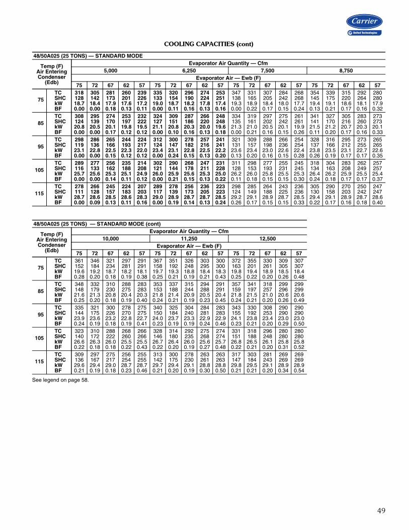
49
COOLING CAPACITIES (cont)
See legend on page 58.
48/50A025 (25 TONS) — STANDARD MODE
Temp (F)Air EnteringCondenser
(Edb)
Evaporator Air Quantity — Cfm5,000 6,250 7,500 8,750
Evaporator Air — Ewb (F)75 72 67 62 57 75 72 67 62 57 75 72 67 62 57 75 72 67 62 57
75TC 318 305 281 260 239 335 320 296 274 253 347 331 307 284 268 354 339 315 292 280SHC 128 142 173 201 226 133 154 190 224 251 138 165 205 242 268 145 175 220 264 280kW 18.7 18.4 17.9 17.6 17.2 19.0 18.7 18.2 17.8 17.4 19.3 18.9 18.4 18.0 17.7 19.4 19.1 18.6 18.1 17.9BF 0.00 0.00 0.18 0.13 0.11 0.00 0.11 0.16 0.13 0.16 0.00 0.22 0.17 0.15 0.24 0.13 0.21 0.17 0.16 0.32
85TC 308 295 274 253 232 324 309 287 266 248 334 319 297 275 261 341 327 305 283 273SHC 124 139 170 197 222 127 151 186 220 248 135 161 202 242 261 141 170 216 260 273kW 20.8 20.5 20.1 19.8 19.5 21.1 20.8 20.3 20.0 19.6 21.3 21.0 20.5 20.1 19.9 21.5 21.2 20.7 20.3 20.1BF 0.00 0.00 0.17 0.12 0.12 0.00 0.10 0.16 0.13 0.18 0.00 0.21 0.16 0.15 0.26 0.11 0.20 0.17 0.16 0.33
95TC 298 286 265 244 224 312 300 278 257 241 321 309 288 266 254 328 316 295 273 265SHC 119 136 166 193 217 124 147 182 216 241 131 157 198 236 254 137 166 212 255 265kW 23.1 22.8 22.5 22.3 22.0 23.4 23.1 22.8 22.5 22.2 23.6 23.4 23.0 22.6 22.4 23.8 23.5 23.1 22.7 22.6BF 0.00 0.00 0.15 0.12 0.12 0.00 0.24 0.15 0.13 0.20 0.13 0.20 0.16 0.15 0.28 0.26 0.19 0.17 0.17 0.35
105TC 289 277 256 235 214 302 290 268 247 231 311 298 277 255 245 318 304 283 262 257SHC 116 133 162 188 208 121 144 178 211 228 128 153 193 231 245 134 163 208 249 257kW 25.7 25.6 25.3 25.1 24.9 26.0 25.9 25.6 25.3 25.0 26.2 26.0 25.8 25.5 25.3 26.4 26.2 25.9 25.5 25.4BF 0.00 0.00 0.14 0.11 0.12 0.00 0.21 0.15 0.13 0.22 0.11 0.18 0.15 0.15 0.30 0.24 0.18 0.17 0.17 0.37
115TC 278 266 245 224 207 289 278 256 236 223 298 285 264 243 236 305 290 270 250 247SHC 111 128 157 183 203 117 139 173 205 223 124 149 188 225 236 130 158 203 242 247kW 28.7 28.6 28.5 28.6 28.3 29.0 28.9 28.7 28.7 28.5 29.2 29.1 28.9 28.7 28.5 29.4 29.1 28.9 28.7 28.6BF 0.00 0.09 0.13 0.11 0.16 0.00 0.19 0.14 0.13 0.24 0.26 0.17 0.15 0.15 0.33 0.22 0.17 0.16 0.18 0.40
48/50A025 (25 TONS) — STANDARD MODE (cont)
Temp (F)Air EnteringCondenser
(Edb)
Evaporator Air Quantity — Cfm10,000 11,250 12,500
Evaporator Air — Ewb (F)75 72 67 62 57 75 72 67 62 57 75 72 67 62 57
75TC 361 346 321 297 291 367 351 326 303 300 372 355 330 309 307SHC 152 184 234 281 291 158 192 248 295 300 163 201 261 305 307kW 19.6 19.2 18.7 18.2 18.1 19.7 19.3 18.8 18.4 18.3 19.8 19.4 18.9 18.5 18.4BF 0.28 0.20 0.18 0.19 0.38 0.25 0.21 0.19 0.21 0.43 0.25 0.22 0.20 0.26 0.48
85TC 348 332 310 288 283 353 337 315 294 291 357 341 318 299 299SHC 148 179 230 275 283 153 188 244 288 291 159 197 257 296 299kW 21.6 21.3 20.8 20.4 20.3 21.8 21.4 20.9 20.5 20.4 21.8 21.5 21.0 20.6 20.6BF 0.25 0.20 0.18 0.19 0.40 0.24 0.21 0.19 0.23 0.45 0.24 0.21 0.20 0.26 0.49
95TC 335 321 300 278 275 340 325 304 284 283 343 330 308 290 290SHC 144 175 226 270 275 150 184 240 281 283 155 192 253 290 290kW 23.9 23.6 23.2 22.8 22.7 24.0 23.7 23.3 22.9 22.9 24.1 23.8 23.4 23.0 23.0BF 0.24 0.19 0.18 0.19 0.41 0.23 0.19 0.19 0.24 0.46 0.23 0.21 0.20 0.29 0.50
105TC 323 310 288 268 266 328 314 292 275 274 331 318 296 280 280SHC 140 172 222 260 266 146 180 235 268 274 151 188 248 280 280kW 26.6 26.3 26.0 25.5 25.5 26.7 26.4 26.0 25.6 25.7 26.8 26.5 26.1 25.8 25.8BF 0.22 0.18 0.18 0.22 0.43 0.22 0.20 0.19 0.27 0.48 0.22 0.21 0.20 0.31 0.52
115TC 309 297 275 256 255 313 300 278 263 263 317 303 281 269 269SHC 136 167 217 254 255 142 175 230 261 263 147 184 243 269 269kW 29.6 29.4 29.0 28.7 28.7 29.7 29.4 29.1 28.8 28.8 29.8 29.5 29.1 28.9 28.9BF 0.21 0.19 0.18 0.23 0.46 0.21 0.20 0.19 0.30 0.50 0.21 0.21 0.20 0.34 0.54
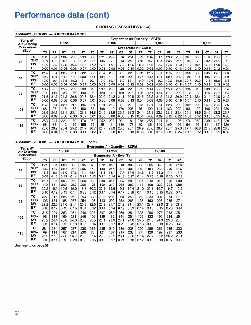
50
COOLING CAPACITIES (cont)
See legend on page 58.
48/50A025 (25 TONS) — SUBCOOLING MODE
Temp (F)Air EnteringCondenser
(Edb)
Evaporator Air Quantity – SCFM5,000 6,250 7,500 8,750
Evaporator Air Ewb (F)75 72 67 62 57 75 72 67 62 57 75 72 67 62 57 75 72 67 62 57
75
TC 331 298 284 253 233 338 321 292 276 251 359 334 317 290 267 367 358 316 288 271SHC 118 121 162 183 212 115 136 170 213 242 130 147 198 236 267 134 170 202 246 271kW 18.0 17.2 17.2 16.5 16.4 17.9 17.6 17.1 17.0 16.6 18.2 17.8 17.7 17.3 17.0 18.2 18.4 17.5 17.0 16.8BF 0.00 0.01 0.05 0.06 0.07 0.00 0.05 0.08 0.08 0.10 0.02 0.08 0.09 0.10 0.16 0.06 0.10 0.11 0.12 0.24
85
TC 314 294 265 231 222 330 314 283 261 229 332 315 288 274 252 356 337 305 272 260SHC 105 120 145 163 203 111 134 163 200 220 107 132 173 223 252 128 154 195 233 260kW 19.9 19.4 18.8 18.2 18.4 20.1 19.9 19.1 18.9 18.1 19.9 19.6 19.2 19.2 18.8 20.7 20.3 19.5 18.9 18.6BF 0.00 0.02 0.06 0.06 0.07 0.00 0.05 0.08 0.08 0.12 0.03 0.08 0.09 0.10 0.18 0.07 0.10 0.11 0.12 0.26
95
TC 285 281 255 232 208 312 297 265 248 226 325 309 271 258 239 336 318 280 256 254SHC 79 110 138 166 190 98 120 149 189 218 105 129 159 211 239 112 139 174 219 254kW 21.5 21.7 21.2 20.8 20.3 22.4 22.0 21.2 21.1 20.8 22.6 22.2 21.3 21.2 20.9 22.9 22.4 21.4 21.0 21.2BF 0.00 0.02 0.06 0.06 0.07 0.01 0.06 0.08 0.08 0.13 0.04 0.08 0.09 0.10 0.19 0.07 0.10 0.11 0.12 0.27
105
TC 267 264 229 217 196 294 279 253 231 212 293 278 254 228 222 309 293 267 235 236SHC 66 97 115 153 180 83 106 140 176 205 76 102 145 183 222 93 120 166 201 236kW 23.9 24.1 23.1 23.1 22.8 24.8 24.5 23.9 23.4 23.2 24.4 24.1 23.6 23.1 23.4 25.1 24.6 24.0 23.2 23.7BF 0.00 0.02 0.06 0.06 0.07 0.01 0.06 0.08 0.08 0.15 0.04 0.08 0.09 0.12 0.22 0.09 0.12 0.13 0.15 0.30
115
TC 253 245 221 189 170 259 252 223 201 184 268 255 244 211 196 276 262 239 218 220SHC 58 83 112 129 155 55 85 114 149 178 60 86 140 169 196 64 93 141 187 220kW 26.6 26.9 26.4 25.2 24.7 26.7 26.7 25.9 25.5 25.1 26.9 26.6 26.7 25.7 25.3 27.1 26.8 26.3 25.8 26.3BF 0.00 0.04 0.07 0.08 0.11 0.02 0.08 0.10 0.10 0.18 0.06 0.10 0.12 0.12 0.24 0.10 0.12 0.13 0.15 0.32
48/50A025 (25 TONS) — SUBCOOLING MODE (cont)
Temp (F)Air EnteringCondenser
(Edb)
Evaporator Air Quantity – SCFM10,000 11,250 12,500
Evaporator Air Ewb (F)75 72 67 62 57 75 72 67 62 57 75 72 67 62 57
75
TC 371 353 336 306 295 378 372 342 313 306 383 365 348 309 316SHC 136 166 229 276 295 142 189 244 294 306 148 184 258 299 316kW 18.4 18.1 18.0 17.6 17.4 18.4 18.6 18.1 17.7 17.6 18.6 18.3 18.2 17.4 17.7BF 0.09 0.12 0.13 0.14 0.31 0.12 0.14 0.14 0.16 0.37 0.14 0.15 0.16 0.20 0.42
85
TC 349 332 305 279 269 355 338 311 285 289 374 343 316 303 288SHC 119 151 203 252 269 125 159 217 268 289 144 168 230 294 288kW 20.2 19.9 19.5 19.0 18.8 20.3 20.1 19.6 19.1 19.4 21.0 20.1 19.7 19.7 19.2BF 0.10 0.12 0.13 0.14 0.33 0.12 0.14 0.14 0.17 0.38 0.14 0.15 0.15 0.22 0.43
95
TC 327 312 286 262 254 333 317 291 268 263 352 333 304 274 271SHC 103 135 188 237 254 108 143 202 252 263 128 163 223 265 271kW 22.2 22.0 21.6 21.1 20.9 22.5 22.2 21.7 21.2 21.1 23.1 22.7 22.0 21.3 21.3BF 0.10 0.12 0.13 0.15 0.34 0.12 0.14 0.14 0.19 0.39 0.14 0.15 0.15 0.23 0.44
105
TC 315 290 263 254 246 323 307 269 260 254 325 296 273 253 251SHC 98 119 169 231 246 106 139 182 244 254 109 132 195 244 251kW 25.2 24.4 23.8 24.0 23.8 25.5 25.1 23.9 24.1 24.0 25.5 24.5 24.0 23.6 23.5BF 0.12 0.14 0.15 0.18 0.36 0.14 0.16 0.17 0.23 0.42 0.16 0.18 0.18 0.26 0.46
115
TC 281 281 257 237 230 286 285 249 230 238 290 289 266 235 233SHC 69 114 167 214 230 73 121 167 215 238 77 129 192 227 233kW 27.2 27.5 27.0 26.7 26.5 27.4 27.6 26.5 26.1 26.6 27.4 27.7 27.2 26.2 26.1BF 0.12 0.14 0.15 0.20 0.38 0.15 0.16 0.17 0.24 0.43 0.17 0.18 0.18 0.27 0.47
Performance data (cont)
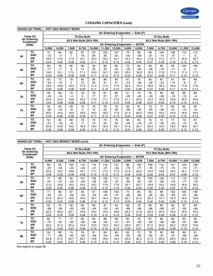
51
COOLING CAPACITIES (cont)
See legend on page 58.
50A025 (25 TONS) — HOT GAS REHEAT MODE
Temp (F)Air EnteringCondenser
(Edb)
Air Entering Evaporator — Ewb (F)75 Dry Bulb 75 Dry Bulb
62.5 Wet Bulb (50% RH) 65.3 Wet Bulb (60% RH)Air Entering Evaporator — SCFM
5,000 6,250 7,500 8,750 10,000 11,250 12,500 5,000 6,250 7,500 8,750 10,000 11,250 12,500
40
TC 75 84 92 97 101 105 107 79 90 98 104 108 112 115SHC –13 –3 7 18 29 39 50 –35 –28 –21 –14 –6 1 9kW 18.5 17.6 17.0 16.7 16.4 16.2 16.1 19.4 18.4 17.8 17.4 17.1 16.9 16.7BF 0.04 0.06 0.08 0.09 0.11 0.12 0.13 0.03 0.05 0.07 0.09 0.10 0.12 0.13
50
TC 69 78 85 90 94 96 99 73 83 90 95 99 103 105SHC –17 –7 3 14 25 35 45 –39 –32 –26 –18 –11 –4 4kW 19.0 18.1 17.5 17.1 16.9 16.7 16.5 20.0 18.9 18.3 17.8 17.5 17.3 17.1BF 0.04 0.06 0.08 0.09 0.11 0.12 0.13 0.03 0.06 0.07 0.09 0.11 0.12 0.13
60
TC 63 72 78 82 85 88 90 67 76 83 87 91 94 96SHC –20 –10 0 10 20 31 41 –43 –36 –30 –23 –15 –8 0kW 19.5 18.6 18.0 17.6 17.4 17.2 17.0 20.5 19.4 18.8 18.3 18.0 17.8 17.6BF 0.04 0.06 0.08 0.09 0.11 0.12 0.13 0.04 0.06 0.07 0.09 0.11 0.12 0.13
70
TC 58 66 72 76 79 81 82 61 70 76 80 83 86 88SHC –24 –14 –4 6 17 27 37 –46 –40 –33 –26 –19 –12 –4kW 20.2 19.2 18.6 18.2 17.9 17.7 17.6 21.1 20.0 19.3 18.9 18.6 18.3 18.2BF 0.04 0.06 0.08 0.09 0.11 0.12 0.13 0.04 0.06 0.07 0.09 0.10 0.12 0.13
75
TC 55 63 69 73 76 78 79 58 67 73 77 80 82 84SHC –26 –16 –6 5 15 25 35 –48 –42 –35 –28 –21 –14 –6kW 20.5 19.5 18.9 18.5 18.2 18.0 17.8 21.5 20.3 19.6 19.2 18.9 18.6 18.4BF 0.04 0.06 0.08 0.09 0.11 0.12 0.13 0.04 0.06 0.07 0.09 0.10 0.12 0.13
80
TC 52 60 66 70 72 74 76 56 64 70 74 77 79 81SHC –27 –18 –8 3 13 24 34 –49 –43 –37 –30 –23 –15 –8kW 20.8 19.8 19.2 18.8 18.5 18.3 18.1 21.8 20.7 20.0 19.5 19.2 18.9 18.7BF 0.05 0.06 0.08 0.09 0.10 0.12 0.13 0.04 0.06 0.07 0.09 0.10 0.12 0.13
50A025 (25 TONS) — HOT GAS REHEAT MODE (cont)
Temp (F)Air EnteringCondenser
(Edb)
Air Entering Evaporator — Ewb (F)75 Dry Bulb 75 Dry Bulb
68.0 Wet Bulb (70% RH) 70.5 Wet Bulb (80% RH)Air Entering Evaporator — SCFM
5,000 6,250 7,500 8,750 10,000 11,250 12,500 5,000 6,250 7,500 8,750 10,000 11,250 12,500
40
TC 83 95 104 110 115 118 121 88 100 109 116 121 124 128SHC –57 –53 –49 –46 –41 –37 –33 –78 –77 –76 –75 –74 –73 –71kW 20.5 19.3 18.6 18.1 17.7 17.5 17.3 21.6 20.2 19.3 18.8 18.4 18.1 17.9BF 0.02 0.03 0.06 0.08 0.10 0.12 0.13 0.00 0.00 0.02 0.04 0.07 0.09 0.12
50
TC 77 88 95 101 105 109 111 80 92 100 106 111 115 118SHC –61 –57 –54 –50 –46 –42 –37 –82 –81 –81 –80 –79 –77 –76kW 21.0 19.8 19.0 18.5 18.2 17.9 17.8 22.1 20.7 19.8 19.2 18.9 18.6 18.3BF 0.02 0.04 0.06 0.08 0.10 0.12 0.13 0.00 0.00 0.02 0.05 0.07 0.10 0.12
60
TC 71 80 87 93 97 100 102 74 85 92 98 102 105 108SHC –64 –61 –58 –54 –50 –46 –41 –86 –85 –85 –84 –83 –81 –80kW 21.6 20.3 19.6 19.0 18.7 18.4 18.2 22.7 21.2 20.3 19.7 19.3 19.0 18.8BF 0.02 0.04 0.06 0.08 0.10 0.12 0.13 0.00 0.00 0.02 0.05 0.08 0.10 0.12
70
TC 65 74 80 85 89 91 94 68 78 85 90 94 97 99SHC –68 –65 –62 –58 –54 –50 –45 –89 –89 –88 –88 –87 –85 –84kW 22.2 20.9 20.1 19.6 19.2 19.0 18.8 23.3 21.8 20.9 20.3 19.9 19.6 19.3BF 0.02 0.04 0.06 0.08 0.10 0.12 0.13 0.00 0.00 0.03 0.06 0.08 0.10 0.12
75
TC 62 71 77 82 85 88 90 65 75 81 86 90 93 95SHC –70 –67 –63 –60 –56 –52 –47 –91 –90 –90 –90 –89 –87 –86kW 22.5 21.2 20.4 19.9 19.5 19.3 19.0 23.6 22.1 21.2 20.6 20.2 19.9 19.6BF 0.02 0.04 0.07 0.08 0.10 0.12 0.13 0.00 0.01 0.03 0.06 0.08 0.10 0.12
80
TC 59 68 74 78 81 84 86 62 72 78 82 86 89 91SHC –71 –68 –65 –62 –58 –54 –49 –92 –92 –92 –91 –91 –89 –88kW 22.8 21.5 20.7 20.2 19.8 19.6 19.4 23.9 22.4 21.5 20.9 20.5 20.2 19.9BF 0.02 0.04 0.07 0.08 0.10 0.12 0.13 0.00 0.01 0.03 0.06 0.08 0.10 0.12

52
COOLING CAPACITIES (cont)
See legend on page 58.
48/50A027 (27 TONS) — STANDARD MODE
Temp (F)Air EnteringCondenser
(Edb)
Evaporator Air Quantity — Cfm5,500 6,875 8,250 9,625
Evaporator Air — Ewb (F)75 72 67 62 57 75 72 67 62 57 75 72 67 62 57 75 72 67 62 57
75TC 339 324 297 273 251 356 340 312 288 268 368 351 323 298 283 377 359 331 305 296SHC 138 154 186 215 242 145 168 204 240 265 153 180 222 263 283 161 190 238 284 296kW 19.0 18.7 18.3 17.9 17.6 19.4 19.0 18.5 18.1 17.8 19.6 19.3 18.7 18.3 18.1 19.8 19.4 18.9 18.5 18.3BF 0.00 0.00 0.15 0.11 0.11 0.00 0.07 0.14 0.12 0.19 0.11 0.19 0.15 0.13 0.26 0.27 0.18 0.16 0.15 0.34
85TC 329 313 289 265 243 344 329 303 279 262 355 339 313 289 276 364 346 321 295 288SHC 134 151 182 211 237 141 164 201 236 262 149 175 218 262 276 156 186 234 279 288kW 21.1 20.8 20.4 20.1 19.8 21.5 21.2 20.7 20.4 20.1 21.7 21.4 20.9 20.5 20.3 21.9 21.5 21.1 20.6 20.5BF 0.00 0.09 0.13 0.11 0.11 0.00 0.21 0.14 0.12 0.20 0.09 0.18 0.14 0.14 0.28 0.24 0.17 0.15 0.16 0.36
95TC 319 305 280 256 235 333 319 293 270 254 344 328 303 278 268 352 335 309 285 280SHC 130 148 178 207 230 137 160 196 234 254 145 172 214 254 268 153 182 230 273 280kW 23.5 23.3 23.0 22.7 22.4 23.8 23.6 23.3 23.0 22.6 24.1 23.8 23.4 23.1 22.9 24.3 24.0 23.6 23.1 23.1BF 0.00 0.08 0.13 0.10 0.13 0.13 0.19 0.13 0.12 0.22 0.08 0.17 0.14 0.13 0.30 0.23 0.17 0.15 0.16 0.37
105TC 309 294 269 246 228 322 307 282 258 244 332 316 290 266 258 339 323 297 274 270SHC 125 144 173 202 226 133 156 192 226 244 142 168 209 248 258 149 178 225 264 270kW 26.3 26.1 25.9 25.7 25.4 26.6 26.4 26.2 25.9 25.7 26.9 26.7 26.3 26.0 25.8 27.0 26.8 26.4 26.0 26.0BF 0.00 0.07 0.12 0.10 0.16 0.10 0.17 0.13 0.12 0.24 0.25 0.16 0.14 0.14 0.33 0.20 0.16 0.15 0.18 0.40
115TC 296 281 257 235 220 309 293 269 246 235 317 302 277 254 249 324 308 282 262 259SHC 120 139 168 196 218 129 151 186 221 235 137 162 203 242 249 144 172 219 254 259kW 29.3 29.3 29.4 29.5 29.3 29.7 29.6 29.5 29.5 29.4 30.0 29.8 29.6 29.5 29.4 30.2 29.9 29.7 29.4 29.4BF 0.00 0.20 0.12 0.10 0.19 0.08 0.15 0.12 0.12 0.27 0.21 0.15 0.13 0.14 0.35 0.19 0.16 0.15 0.20 0.42
48/50A027 (27 TONS) — STANDARD MODE (cont)
Temp (F)Air EnteringCondenser
(Edb)
Evaporator Air Quantity — Cfm11,000 12,375 13,750
Evaporator Air — Ewb (F)75 72 67 62 57 75 72 67 62 57 75 72 67 62 57
75TC 384 365 337 311 307 389 371 342 319 316 394 375 346 324 324SHC 168 201 254 301 307 174 210 269 309 316 181 219 284 324 324kW 19.9 19.6 19.0 18.6 18.5 20.0 19.7 19.1 18.7 18.7 20.1 19.8 19.2 18.8 18.8BF 0.23 0.18 0.17 0.18 0.40 0.22 0.19 0.18 0.24 0.45 0.22 0.20 0.19 0.27 0.49
85TC 370 353 326 302 299 375 358 331 309 307 380 362 334 315 315SHC 163 196 250 294 299 170 206 265 301 307 176 215 279 315 315kW 22.0 21.7 21.2 20.8 20.7 22.1 21.8 21.3 20.9 20.8 22.2 21.9 21.3 21.0 21.0BF 0.22 0.18 0.17 0.19 0.41 0.21 0.19 0.18 0.26 0.46 0.21 0.20 0.19 0.29 0.51
95TC 358 342 315 292 290 363 346 319 299 298 368 350 322 306 305SHC 160 192 245 284 290 166 202 260 295 298 173 211 275 306 305kW 24.4 24.1 23.7 23.3 23.2 24.5 24.2 23.8 23.4 23.4 24.7 24.3 23.8 23.5 23.5BF 0.21 0.18 0.16 0.22 0.43 0.20 0.19 0.18 0.27 0.48 0.21 0.19 0.19 0.31 0.52
105TC 345 328 301 281 280 350 332 305 288 288 353 336 308 295 295SHC 155 188 240 275 280 162 197 255 285 288 168 206 269 295 295kW 27.2 26.9 26.5 26.1 26.1 27.4 27.1 26.6 26.2 26.3 27.5 27.1 26.6 26.4 26.4BF 0.20 0.17 0.16 0.24 0.45 0.20 0.18 0.18 0.28 0.50 0.20 0.20 0.19 0.35 0.54
115TC 329 312 287 268 268 333 316 290 276 276 336 320 293 283 282SHC 151 183 235 268 268 157 192 250 276 276 163 201 263 283 282kW 30.4 30.0 29.7 29.5 29.5 30.6 30.2 29.7 29.5 29.5 30.7 30.3 29.8 29.6 29.6BF 0.19 0.16 0.16 0.23 0.47 0.19 0.18 0.17 0.31 0.52 0.19 0.19 0.19 0.37 0.56
Performance data (cont)
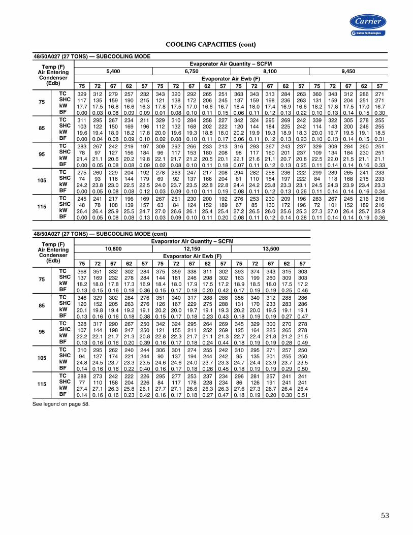
53
COOLING CAPACITIES (cont)
See legend on page 58.
48/50A027 (27 TONS) — SUBCOOLING MODE
Temp (F)Air EnteringCondenser
(Edb)
Evaporator Air Quantity – SCFM5,400 6,750 8,100 9,450
Evaporator Air Ewb (F)75 72 67 62 57 75 72 67 62 57 75 72 67 62 57 75 72 67 62 57
75
TC 329 312 279 257 232 343 320 292 265 251 363 343 313 284 263 360 343 312 286 271SHC 117 135 159 190 215 121 138 172 206 245 137 159 198 236 263 131 159 204 251 271kW 17.7 17.5 16.8 16.6 16.3 17.8 17.5 17.0 16.6 16.7 18.4 18.0 17.4 16.9 16.6 18.2 17.8 17.5 17.0 16.7BF 0.00 0.03 0.08 0.09 0.09 0.01 0.08 0.10 0.11 0.15 0.06 0.11 0.12 0.13 0.22 0.10 0.13 0.14 0.15 0.30
85
TC 311 295 267 234 211 329 310 284 258 227 342 324 295 269 242 339 322 305 278 255SHC 103 122 150 169 196 112 132 168 202 222 120 144 184 225 242 114 143 200 246 255kW 19.6 19.4 18.9 18.2 17.8 20.0 19.6 19.3 18.8 18.0 20.2 19.9 19.3 18.9 18.3 20.0 19.7 19.5 19.1 18.5BF 0.00 0.04 0.08 0.09 0.10 0.02 0.08 0.10 0.11 0.17 0.06 0.11 0.12 0.13 0.23 0.10 0.13 0.14 0.15 0.31
95
TC 283 267 242 219 197 309 292 266 233 213 316 293 267 243 237 329 309 284 260 251SHC 78 97 127 156 184 96 117 153 180 208 98 117 160 201 237 109 134 184 230 251kW 21.4 21.1 20.6 20.2 19.8 22.1 21.7 21.2 20.5 20.1 22.1 21.6 21.1 20.7 20.8 22.5 22.0 21.5 21.1 21.1BF 0.00 0.05 0.08 0.08 0.09 0.02 0.08 0.10 0.11 0.18 0.07 0.11 0.12 0.13 0.25 0.11 0.14 0.14 0.16 0.33
105
TC 275 260 229 204 192 278 263 247 217 208 294 282 258 236 222 299 289 265 241 233SHC 74 93 116 144 179 69 92 137 166 204 81 110 154 197 222 84 118 168 215 233kW 24.2 23.8 23.0 22.5 22.5 24.0 23.7 23.5 22.8 22.8 24.4 24.2 23.8 23.3 23.1 24.5 24.3 23.9 23.4 23.3BF 0.00 0.05 0.08 0.08 0.12 0.03 0.09 0.10 0.11 0.19 0.08 0.11 0.12 0.13 0.26 0.11 0.14 0.14 0.16 0.34
115
TC 245 241 217 196 169 267 251 230 200 192 276 253 230 209 196 283 267 245 216 216SHC 48 78 108 139 157 63 84 124 152 189 67 85 130 172 196 72 101 152 189 216kW 26.4 26.4 25.9 25.5 24.7 27.0 26.6 26.1 25.4 25.4 27.2 26.5 26.0 25.6 25.3 27.3 27.0 26.4 25.7 25.9BF 0.00 0.05 0.08 0.08 0.13 0.03 0.09 0.10 0.11 0.20 0.08 0.11 0.12 0.14 0.28 0.11 0.14 0.14 0.19 0.36
48/50A027 (27 TONS) — SUBCOOLING MODE (cont)
Temp (F)Air EnteringCondenser
(Edb)
Evaporator Air Quantity – SCFM10,800 12,150 13,500
Evaporator Air Ewb (F)75 72 67 62 57 75 72 67 62 57 75 72 67 62 57
75
TC 368 351 332 302 284 375 359 338 311 302 393 374 343 315 303SHC 137 169 232 278 284 144 181 246 298 302 163 199 260 309 303kW 18.2 18.0 17.8 17.3 16.9 18.4 18.0 17.9 17.5 17.2 18.9 18.5 18.0 17.5 17.2BF 0.13 0.15 0.16 0.18 0.36 0.15 0.17 0.18 0.20 0.42 0.17 0.19 0.19 0.25 0.46
85
TC 346 329 302 284 276 351 340 317 288 288 356 340 312 288 286SHC 120 152 205 263 276 126 167 229 275 288 131 170 233 283 286kW 20.1 19.8 19.4 19.2 19.1 20.2 20.0 19.7 19.1 19.3 20.2 20.0 19.5 19.1 19.1BF 0.13 0.16 0.16 0.18 0.38 0.15 0.17 0.18 0.23 0.43 0.18 0.19 0.19 0.27 0.47
95
TC 328 317 290 267 250 342 324 295 264 269 345 329 300 270 278SHC 107 144 198 247 250 121 155 211 252 269 125 164 225 265 278kW 22.2 22.1 21.7 21.3 20.8 22.8 22.3 21.7 21.1 21.3 22.7 22.4 21.8 21.2 21.5BF 0.13 0.16 0.16 0.20 0.39 0.16 0.17 0.18 0.24 0.44 0.18 0.19 0.19 0.28 0.49
105
TC 310 295 262 240 244 306 301 274 255 242 310 295 271 257 250SHC 94 127 174 221 244 90 137 194 244 242 95 135 201 255 250kW 24.8 24.5 23.7 23.3 23.5 24.6 24.6 24.0 23.7 23.3 24.7 24.4 23.9 23.7 23.5BF 0.14 0.16 0.16 0.22 0.40 0.16 0.17 0.18 0.26 0.45 0.18 0.19 0.19 0.29 0.50
115
TC 288 273 242 222 226 295 277 253 237 234 296 281 257 241 241SHC 77 110 158 204 226 84 117 178 228 234 86 126 191 241 241kW 27.4 27.1 26.3 25.8 26.1 27.7 27.1 26.6 26.3 26.3 27.6 27.3 26.7 26.4 26.4BF 0.14 0.16 0.16 0.23 0.42 0.16 0.17 0.18 0.27 0.47 0.18 0.19 0.20 0.30 0.51

54
COOLING CAPACITIES (cont)
See legend on page 58.
50A027 (27 TONS) — HOT GAS REHEAT MODE
Temp (F)Air EnteringCondenser
(Edb)
Air Entering Evaporator — Ewb (F)75 Dry Bulb 75 Dry Bulb
62.5 Wet Bulb (50% RH) 65.3 Wet Bulb (60% RH)Air Entering Evaporator — SCFM
5,400 6,750 8,100 9,450 10,800 12,150 13,500 5,400 6,750 8,100 9,450 10,800 12,150 13,500
40
TC 73 84 91 97 101 104 106 77 89 97 103 107 110 113SHC –18 –6 7 18 29 41 51 –42 –33 –25 –16 –9 –1 8kW 18.8 17.7 17.0 16.7 16.4 16.3 16.1 19.9 18.6 17.8 17.4 17.1 16.9 16.7BF 0.05 0.07 0.08 0.10 0.11 0.13 0.14 0.04 0.06 0.08 0.10 0.11 0.13 0.14
50
TC 67 77 84 89 92 95 97 71 82 89 94 98 101 104SHC –22 –9 2 14 25 36 47 –46 –37 –29 –21 –13 –5 3kW 19.3 18.2 17.5 17.2 16.9 16.7 16.6 20.4 19.1 18.3 17.9 17.6 17.3 17.2BF 0.05 0.07 0.08 0.10 0.11 0.13 0.14 0.04 0.06 0.08 0.10 0.11 0.13 0.14
60
TC 62 72 78 82 85 87 89 66 76 82 87 90 93 95SHC –25 –13 –1 10 21 32 43 –49 –41 –33 –25 –17 –9 –1kW 19.9 18.7 18.0 17.7 17.4 17.2 17.1 20.9 19.6 18.8 18.4 18.1 17.8 17.7BF 0.05 0.07 0.08 0.10 0.11 0.13 0.14 0.04 0.06 0.08 0.10 0.11 0.13 0.14
70
TC 57 66 71 75 78 80 81 60 69 75 79 82 85 87SHC –28 –16 –5 6 17 28 39 –53 –44 –36 –28 –21 –13 –5kW 20.5 19.3 18.6 18.2 18.0 17.8 17.6 21.6 20.2 19.4 18.9 18.6 18.4 18.2BF 0.05 0.07 0.08 0.10 0.11 0.13 0.14 0.04 0.06 0.08 0.10 0.11 0.13 0.14
75
TC 54 63 69 72 75 77 79 57 67 73 77 79 82 83SHC –30 –18 –6 5 16 27 37 –54 –46 –38 –30 –22 –15 –7kW 20.9 19.6 18.9 18.5 18.3 18.1 17.9 21.9 20.5 19.7 19.2 18.9 18.7 18.5BF 0.05 0.07 0.08 0.10 0.11 0.13 0.14 0.04 0.06 0.08 0.10 0.11 0.13 0.14
80
TC 52 61 66 70 72 74 76 55 64 70 74 77 79 80SHC –31 –19 –8 3 14 25 36 –55 –47 –39 –31 –24 –16 –8kW 21.2 20.0 19.3 18.9 18.6 18.4 18.2 22.2 20.8 20.0 19.6 19.2 19.0 18.8BF 0.05 0.07 0.08 0.10 0.11 0.13 0.14 0.04 0.06 0.08 0.10 0.11 0.13 0.14
50A027 (27 TONS) — HOT GAS REHEAT MODE (cont)
Temp (F)Air EnteringCondenser
(Edb)
Air Entering Evaporator — Ewb (F)75 Dry Bulb 75 Dry Bulb
68.0 Wet Bulb (70% RH) 70.5 Wet Bulb (80% RH)Air Entering Evaporator — SCFM
5,400 6,750 8,100 9,450 10,800 12,150 13,500 5,400 6,750 8,100 9,450 10,800 12,150 13,500
40
TC 81 94 103 109 113 117 120 85 99 108 114 119 123 126SHC –66 –61 –56 –51 –46 –41 –36 –89 –87 –85 –83 –81 –79 –77kW 21.0 19.5 18.7 18.1 17.8 17.5 17.3 22.2 20.5 19.5 18.9 18.5 18.2 17.9BF 0.02 0.04 0.07 0.09 0.11 0.12 0.14 0.00 0.01 0.03 0.06 0.08 0.11 0.13
50
TC 75 86 94 100 104 108 110 78 91 99 105 110 113 116SHC –70 –65 –60 –55 –50 –45 –40 –93 –91 –89 –87 –86 –83 –81kW 21.6 20.0 19.1 18.6 18.2 18.0 17.8 22.7 21.0 20.0 19.4 18.9 18.6 18.4BF 0.02 0.05 0.07 0.09 0.11 0.12 0.14 0.00 0.01 0.03 0.06 0.09 0.11 0.13
60
TC 69 79 87 92 96 99 101 72 84 92 97 101 105 107SHC –73 –69 –64 –59 –54 –49 –44 –97 –95 –93 –91 –89 –87 –85kW 22.1 20.6 19.7 19.1 18.7 18.5 18.3 23.3 21.5 20.5 19.9 19.4 19.1 18.9BF 0.02 0.05 0.07 0.09 0.11 0.13 0.14 0.00 0.01 0.03 0.07 0.09 0.11 0.13
70
TC 63 73 79 84 88 91 93 66 77 84 90 94 97 99SHC –76 –72 –67 –63 –58 –53 –48 –99 –98 –97 –95 –93 –91 –89kW 22.7 21.1 20.2 19.7 19.3 19.0 18.8 23.9 22.1 21.1 20.4 20.0 19.7 19.4BF 0.02 0.05 0.07 0.09 0.11 0.13 0.14 0.00 0.01 0.04 0.07 0.09 0.11 0.13
75
TC 60 70 77 81 84 87 89 63 74 80 85 89 92 94SHC –78 –73 –69 –64 –60 –55 –50 –101 –100 –98 –97 –95 –93 –91kW 23.0 21.4 20.5 20.0 19.6 19.3 19.1 24.2 22.4 21.4 20.7 20.3 20.0 19.7BF 0.02 0.05 0.07 0.09 0.11 0.13 0.14 0.00 0.01 0.04 0.07 0.09 0.11 0.13
80
TC 58 68 74 78 81 83 85 60 71 78 82 86 88 91SHC –80 –75 –70 –66 –61 –56 –52 –103 –101 –100 –98 –97 –95 –93kW 23.4 21.8 20.9 20.3 19.9 19.6 19.4 24.6 22.8 21.7 21.0 20.6 20.3 20.0BF 0.02 0.05 0.07 0.09 0.11 0.13 0.14 0.00 0.01 0.04 0.07 0.09 0.12 0.13
Performance data (cont)
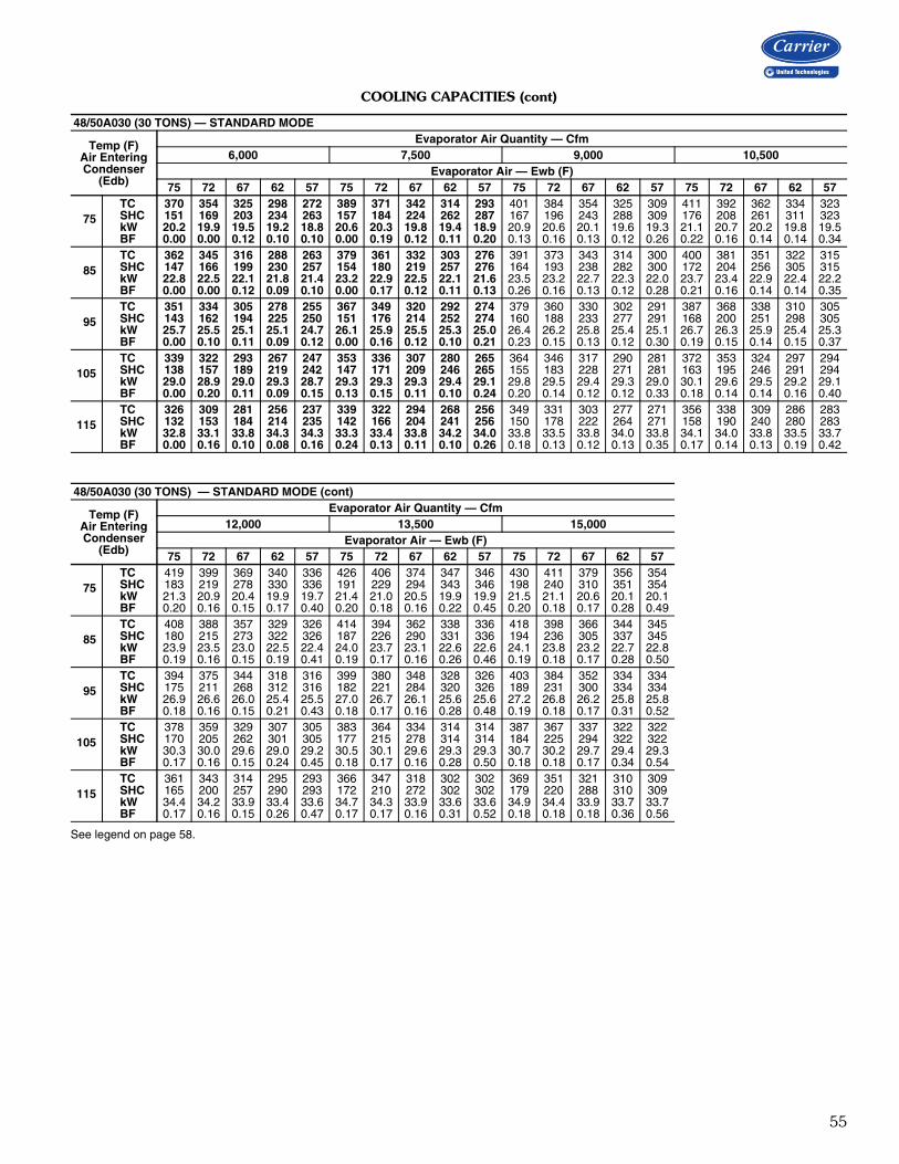
55
COOLING CAPACITIES (cont)
See legend on page 58.
48/50A030 (30 TONS) — STANDARD MODE
Temp (F)Air EnteringCondenser
(Edb)
Evaporator Air Quantity — Cfm6,000 7,500 9,000 10,500
Evaporator Air — Ewb (F)75 72 67 62 57 75 72 67 62 57 75 72 67 62 57 75 72 67 62 57
75TC 370 354 325 298 272 389 371 342 314 293 401 384 354 325 309 411 392 362 334 323SHC 151 169 203 234 263 157 184 224 262 287 167 196 243 288 309 176 208 261 311 323kW 20.2 19.9 19.5 19.2 18.8 20.6 20.3 19.8 19.4 18.9 20.9 20.6 20.1 19.6 19.3 21.1 20.7 20.2 19.8 19.5BF 0.00 0.00 0.12 0.10 0.10 0.00 0.19 0.12 0.11 0.20 0.13 0.16 0.13 0.12 0.26 0.22 0.16 0.14 0.14 0.34
85TC 362 345 316 288 263 379 361 332 303 276 391 373 343 314 300 400 381 351 322 315SHC 147 166 199 230 257 154 180 219 257 276 164 193 238 282 300 172 204 256 305 315kW 22.8 22.5 22.1 21.8 21.4 23.2 22.9 22.5 22.1 21.6 23.5 23.2 22.7 22.3 22.0 23.7 23.4 22.9 22.4 22.2BF 0.00 0.00 0.12 0.09 0.10 0.00 0.17 0.12 0.11 0.13 0.26 0.16 0.13 0.12 0.28 0.21 0.16 0.14 0.14 0.35
95TC 351 334 305 278 255 367 349 320 292 274 379 360 330 302 291 387 368 338 310 305SHC 143 162 194 225 250 151 176 214 252 274 160 188 233 277 291 168 200 251 298 305kW 25.7 25.5 25.1 25.1 24.7 26.1 25.9 25.5 25.3 25.0 26.4 26.2 25.8 25.4 25.1 26.7 26.3 25.9 25.4 25.3BF 0.00 0.10 0.11 0.09 0.12 0.00 0.16 0.12 0.10 0.21 0.23 0.15 0.13 0.12 0.30 0.19 0.15 0.14 0.15 0.37
105TC 339 322 293 267 247 353 336 307 280 265 364 346 317 290 281 372 353 324 297 294SHC 138 157 189 219 242 147 171 209 246 265 155 183 228 271 281 163 195 246 291 294kW 29.0 28.9 29.0 29.3 28.7 29.3 29.3 29.3 29.4 29.1 29.8 29.5 29.4 29.3 29.0 30.1 29.6 29.5 29.2 29.1BF 0.00 0.20 0.11 0.09 0.15 0.13 0.15 0.11 0.10 0.24 0.20 0.14 0.12 0.12 0.33 0.18 0.14 0.14 0.16 0.40
115TC 326 309 281 256 237 339 322 294 268 256 349 331 303 277 271 356 338 309 286 283SHC 132 153 184 214 235 142 166 204 241 256 150 178 222 264 271 158 190 240 280 283kW 32.8 33.1 33.8 34.3 34.3 33.3 33.4 33.8 34.2 34.0 33.8 33.5 33.8 34.0 33.8 34.1 34.0 33.8 33.5 33.7BF 0.00 0.16 0.10 0.08 0.16 0.24 0.13 0.11 0.10 0.26 0.18 0.13 0.12 0.13 0.35 0.17 0.14 0.13 0.19 0.42
48/50A030 (30 TONS) — STANDARD MODE (cont)
Temp (F)Air EnteringCondenser
(Edb)
Evaporator Air Quantity — Cfm12,000 13,500 15,000
Evaporator Air — Ewb (F)75 72 67 62 57 75 72 67 62 57 75 72 67 62 57
75TC 419 399 369 340 336 426 406 374 347 346 430 411 379 356 354SHC 183 219 278 330 336 191 229 294 343 346 198 240 310 351 354kW 21.3 20.9 20.4 19.9 19.7 21.4 21.0 20.5 19.9 19.9 21.5 21.1 20.6 20.1 20.1BF 0.20 0.16 0.15 0.17 0.40 0.20 0.18 0.16 0.22 0.45 0.20 0.18 0.17 0.28 0.49
85TC 408 388 357 329 326 414 394 362 338 336 418 398 366 344 345SHC 180 215 273 322 326 187 226 290 331 336 194 236 305 337 345kW 23.9 23.5 23.0 22.5 22.4 24.0 23.7 23.1 22.6 22.6 24.1 23.8 23.2 22.7 22.8BF 0.19 0.16 0.15 0.19 0.41 0.19 0.17 0.16 0.26 0.46 0.19 0.18 0.17 0.28 0.50
95TC 394 375 344 318 316 399 380 348 328 326 403 384 352 334 334SHC 175 211 268 312 316 182 221 284 320 326 189 231 300 334 334kW 26.9 26.6 26.0 25.4 25.5 27.0 26.7 26.1 25.6 25.6 27.2 26.8 26.2 25.8 25.8BF 0.18 0.16 0.15 0.21 0.43 0.18 0.17 0.16 0.28 0.48 0.19 0.18 0.17 0.31 0.52
105TC 378 359 329 307 305 383 364 334 314 314 387 367 337 322 322SHC 170 205 262 301 305 177 215 278 314 314 184 225 294 322 322kW 30.3 30.0 29.6 29.0 29.2 30.5 30.1 29.6 29.3 29.3 30.7 30.2 29.7 29.4 29.3BF 0.17 0.16 0.15 0.24 0.45 0.18 0.17 0.16 0.28 0.50 0.18 0.18 0.17 0.34 0.54
115TC 361 343 314 295 293 366 347 318 302 302 369 351 321 310 309SHC 165 200 257 290 293 172 210 272 302 302 179 220 288 310 309kW 34.4 34.2 33.9 33.4 33.6 34.7 34.3 33.9 33.6 33.6 34.9 34.4 33.9 33.7 33.7BF 0.17 0.16 0.15 0.26 0.47 0.17 0.17 0.16 0.31 0.52 0.18 0.18 0.18 0.36 0.56

56
COOLING CAPACITIES (cont)
See legend on page 58.
48/50A030 (30 TONS) — SUBCOOLING MODE
Temp (F)Air EnteringCondenser
(Edb)
Evaporator Air Quantity – SCFM6,000 7,500 9,000 10,500
Evaporator Air Ewb (F)75 72 67 62 57 75 72 67 62 57 75 72 67 62 57 75 72 67 62 57
75
TC 347 329 302 276 248 360 342 314 292 265 373 355 329 304 285 387 367 337 313 298SHC 126 146 178 208 234 132 155 193 235 260 140 167 215 260 285 152 181 231 282 298kW 19.8 19.4 18.9 18.5 18.1 20.1 19.7 19.2 18.8 18.3 20.3 20.0 19.4 19.0 18.7 20.6 20.2 19.6 19.1 18.9BF 0.00 0.05 0.09 0.10 0.11 0.02 0.09 0.11 0.12 0.17 0.08 0.12 0.14 0.14 0.25 0.12 0.15 0.16 0.17 0.33
85
TC 326 309 285 262 239 345 322 301 277 251 354 337 311 287 271 365 347 318 295 285SHC 109 130 164 197 226 121 139 183 223 247 126 153 200 246 271 135 165 215 267 285kW 22.0 21.6 21.2 20.8 20.5 22.3 21.9 21.4 21.0 20.6 22.5 22.2 21.6 21.2 21.0 22.7 22.4 21.8 21.3 21.2BF 0.00 0.05 0.09 0.09 0.11 0.03 0.10 0.11 0.12 0.18 0.08 0.12 0.14 0.14 0.27 0.12 0.15 0.16 0.17 0.34
95
TC 309 294 267 243 224 325 308 282 259 242 335 319 293 270 252 343 327 300 276 269SHC 97 118 149 182 214 105 129 168 209 239 112 140 186 232 252 119 150 202 251 269kW 24.6 24.2 23.8 23.4 23.1 24.9 24.5 24.0 23.6 23.4 25.1 24.7 24.2 23.8 23.5 25.3 24.9 24.3 23.9 23.8BF 0.00 0.06 0.09 0.09 0.11 0.04 0.10 0.11 0.12 0.19 0.09 0.13 0.14 0.14 0.28 0.12 0.15 0.16 0.17 0.35
105
TC 295 257 236 228 210 305 278 264 242 227 315 295 274 252 241 323 307 284 259 253SHC 87 86 122 170 201 90 103 155 195 225 97 121 172 219 241 104 135 191 239 253kW 27.6 26.9 26.5 26.4 26.3 27.8 27.3 27.0 26.6 26.4 28.0 27.6 27.2 26.8 26.6 28.2 27.8 27.3 26.9 26.8BF 0.00 0.06 0.09 0.09 0.13 0.04 0.10 0.11 0.12 0.21 0.09 0.13 0.14 0.15 0.29 0.13 0.15 0.16 0.17 0.37
115
TC 271 254 233 212 196 274 268 246 223 207 293 279 256 233 224 287 286 262 241 235SHC 69 88 124 157 187 66 99 141 180 207 81 111 159 203 224 73 120 174 220 235kW 30.9 30.6 30.3 30.0 29.9 31.0 30.8 30.4 30.1 29.9 31.4 31.0 30.5 30.2 30.1 31.2 31.1 30.6 30.2 30.2BF 0.01 0.07 0.09 0.09 0.15 0.05 0.10 0.11 0.12 0.21 0.10 0.13 0.14 0.15 0.31 0.13 0.15 0.16 0.20 0.38
48/50A030 (30 TONS) — SUBCOOLING MODE (cont)
Temp (F)Air EnteringCondenser
(Edb)
Evaporator Air Quantity – SCFM12,000 13,500 15,000
Evaporator Air Ewb (F)75 72 67 62 57 75 72 67 62 57 75 72 67 62 57
75
TC 395 375 346 320 313 396 381 348 321 322 401 387 355 328 326SHC 159 192 248 301 313 160 202 260 311 322 166 211 277 324 326kW 20.8 20.4 19.8 19.3 19.1 20.8 20.5 19.8 19.3 19.3 20.9 20.6 19.9 19.4 19.4BF 0.14 0.17 0.18 0.20 0.39 0.17 0.19 0.19 0.24 0.45 0.19 0.21 0.21 0.28 0.49
85
TC 369 352 324 298 296 378 357 330 309 306 379 362 334 315 312SHC 139 174 231 284 296 149 183 246 300 306 151 192 261 314 312kW 22.9 22.5 21.9 21.4 21.4 23.0 22.6 22.0 21.6 21.5 23.1 22.7 22.1 21.7 21.6BF 0.15 0.17 0.18 0.19 0.40 0.17 0.19 0.19 0.25 0.45 0.19 0.21 0.21 0.28 0.50
95
TC 350 333 307 285 280 354 338 311 289 286 359 342 315 294 296SHC 125 159 218 270 280 130 169 233 280 286 137 178 247 294 296kW 25.4 25.0 24.5 24.0 24.0 25.5 25.1 24.6 24.1 24.1 25.6 25.2 24.6 24.2 24.2BF 0.15 0.17 0.18 0.21 0.41 0.17 0.19 0.19 0.26 0.46 0.19 0.21 0.21 0.29 0.51
105
TC 331 315 273 266 260 337 301 294 274 271 341 321 296 278 277SHC 112 147 189 252 260 119 137 221 267 271 124 162 233 278 277kW 28.4 28.0 27.2 27.0 26.9 28.5 27.8 27.5 27.1 27.1 28.6 28.1 27.5 27.2 27.2BF 0.15 0.17 0.18 0.23 0.43 0.17 0.19 0.19 0.27 0.48 0.19 0.21 0.21 0.31 0.52
115
TC 307 291 268 248 243 311 295 271 254 251 313 299 274 258 258SHC 94 129 190 235 243 99 138 203 248 251 104 147 217 258 258kW 31.7 31.3 30.7 30.3 30.3 31.8 31.4 30.8 30.4 30.4 31.9 31.4 30.8 30.5 30.5BF 0.15 0.17 0.17 0.24 0.44 0.18 0.19 0.19 0.28 0.49 0.20 0.21 0.21 0.32 0.53
Performance data (cont)

57
COOLING CAPACITIES (cont)
See legend on page 58.
50A030 (30 TONS) — HOT GAS REHEAT MODE
Temp (F)Air EnteringCondenser
(Edb)
Air Entering Evaporator — Ewb (F)75 Dry Bulb 75 Dry Bulb
62.5 Wet Bulb (50% RH) 65.3 Wet Bulb (60% RH)Air Entering Evaporator — SCFM
6,000 7,500 9,000 10,500 12,000 13,500 15,000 6,000 7,500 9,000 10,500 12,000 13,500 15,000
40
TC 138 148 154 159 164 167 169 145 155 162 168 172 176 179SHC 35 48 61 73 86 99 111 10 19 28 38 47 56 66kW 17.0 16.7 16.6 16.5 16.5 16.5 16.5 17.8 17.4 17.3 17.2 17.1 17.1 17.1BF 0.07 0.09 0.11 0.12 0.14 0.16 0.17 0.06 0.08 0.10 0.12 0.14 0.16 0.17
50
TC 133 142 149 153 157 159 161 139 149 156 161 165 168 170SHC 31 44 57 70 83 95 107 7 16 25 34 43 52 62kW 17.9 17.5 17.4 17.3 17.3 17.3 17.3 18.7 18.2 18.1 18.0 17.9 17.9 17.9BF 0.07 0.09 0.11 0.12 0.14 0.16 0.17 0.06 0.08 0.10 0.12 0.14 0.16 0.17
60
TC 127 136 142 147 150 153 155 133 143 150 154 158 161 163SHC 28 41 54 67 79 92 104 3 12 21 30 40 49 58kW 18.8 18.5 18.3 18.2 18.2 18.2 18.1 19.6 19.2 19.0 18.8 18.8 18.7 18.7BF 0.07 0.09 0.11 0.12 0.14 0.16 0.17 0.06 0.08 0.10 0.12 0.14 0.16 0.17
70
TC 120 129 135 140 143 145 147 127 136 143 147 151 153 155SHC 24 37 50 63 75 88 100 0 9 18 27 36 45 54kW 19.9 19.5 19.3 19.2 19.2 19.1 19.1 20.7 20.2 20.0 19.8 19.8 19.7 19.7BF 0.07 0.09 0.11 0.12 0.14 0.16 0.17 0.06 0.08 0.10 0.12 0.14 0.16 0.17
75
TC 117 126 132 136 139 142 143 124 133 139 143 147 149 151SHC 22 35 48 61 74 86 98 –2 7 16 25 34 43 52kW 20.5 20.1 19.9 19.8 19.7 19.7 19.7 21.3 20.8 20.5 20.4 20.3 20.2 20.2BF 0.07 0.09 0.11 0.12 0.14 0.16 0.17 0.06 0.08 0.10 0.12 0.14 0.16 0.17
80
TC 114 123 128 133 136 138 139 120 129 135 140 143 145 147SHC 20 33 46 59 72 84 96 –4 5 14 23 32 41 51kW 21.1 20.7 20.5 20.4 20.3 20.3 20.2 21.9 21.4 21.1 21.0 20.9 20.8 20.8BF 0.07 0.09 0.11 0.12 0.14 0.16 0.17 0.06 0.08 0.10 0.12 0.14 0.16 0.17
50A030 (30 TONS) — HOT GAS REHEAT MODE (cont)
Temp (F)Air EnteringCondenser
(Edb)
Air Entering Evaporator — Ewb (F)75 Dry Bulb 75 Dry Bulb
68.0 Wet Bulb (70% RH) 70.5 Wet Bulb (80% RH)Air Entering Evaporator — SCFM
6,000 7,500 9,000 10,500 12,000 13,500 15,000 6,000 7,500 9,000 10,500 12,000 13,500 15,000
40
TC 151 162 170 176 181 185 188 158 170 178 184 189 193 196SHC –14 –9 –3 2 8 14 20 –38 –35 –33 –31 –28 –25 –22kW 18.6 18.2 18.0 17.8 17.8 17.7 17.7 19.5 19.0 18.7 18.5 18.4 18.3 18.3BF 0.02 0.06 0.09 0.12 0.14 0.16 0.17 0.00 0.00 0.04 0.08 0.11 0.14 0.16
50
TC 146 156 163 169 173 176 179 152 163 171 176 181 184 187SHC –17 –12 –7 –1 4 10 16 –41 –39 –37 –34 –32 –29 –26kW 19.5 19.0 18.7 18.6 18.5 18.5 18.4 20.4 19.8 19.4 19.3 19.2 19.1 19.0BF 0.02 0.06 0.09 0.12 0.14 0.16 0.17 0.00 0.00 0.05 0.09 0.11 0.14 0.16
60
TC 140 150 157 162 166 169 171 146 156 164 169 173 176 179SHC –21 –16 –10 –5 1 7 13 –44 –42 –40 –38 –35 –33 –30kW 20.4 19.9 19.6 19.5 19.4 19.3 19.3 21.3 20.7 20.3 20.1 20.0 19.9 19.9BF 0.03 0.07 0.09 0.12 0.14 0.16 0.17 0.00 0.00 0.05 0.09 0.12 0.14 0.16
70
TC 133 143 150 155 158 161 163 139 150 157 162 166 169 171SHC –24 –19 –14 –8 –3 3 9 –48 –45 –44 –41 –39 –36 –33kW 21.5 20.9 20.6 20.5 20.4 20.3 20.2 22.3 21.7 21.3 21.1 21.0 20.9 20.8BF 0.03 0.07 0.09 0.12 0.14 0.16 0.17 0.00 0.01 0.06 0.09 0.12 0.14 0.16
75
TC 130 140 146 151 154 157 159 136 146 153 158 162 165 167SHC –26 –21 –16 –10 –5 1 7 –49 –47 –45 –43 –41 –38 –35kW 22.1 21.5 21.2 21.0 20.9 20.8 20.8 22.9 22.2 21.9 21.6 21.5 21.4 21.4BF 0.04 0.07 0.09 0.12 0.14 0.16 0.17 0.00 0.01 0.06 0.09 0.12 0.14 0.16
80
TC 127 136 142 147 150 153 155 132 142 149 154 158 161 163SHC –28 –23 –18 –12 –6 –1 5 –51 –49 –47 –45 –43 –40 –37kW 22.7 22.1 21.8 21.6 21.5 21.4 21.4 23.5 22.8 22.4 22.2 22.1 22.0 21.9BF 0.04 0.07 0.10 0.12 0.14 0.16 0.17 0.00 0.02 0.06 0.09 0.12 0.14 0.16
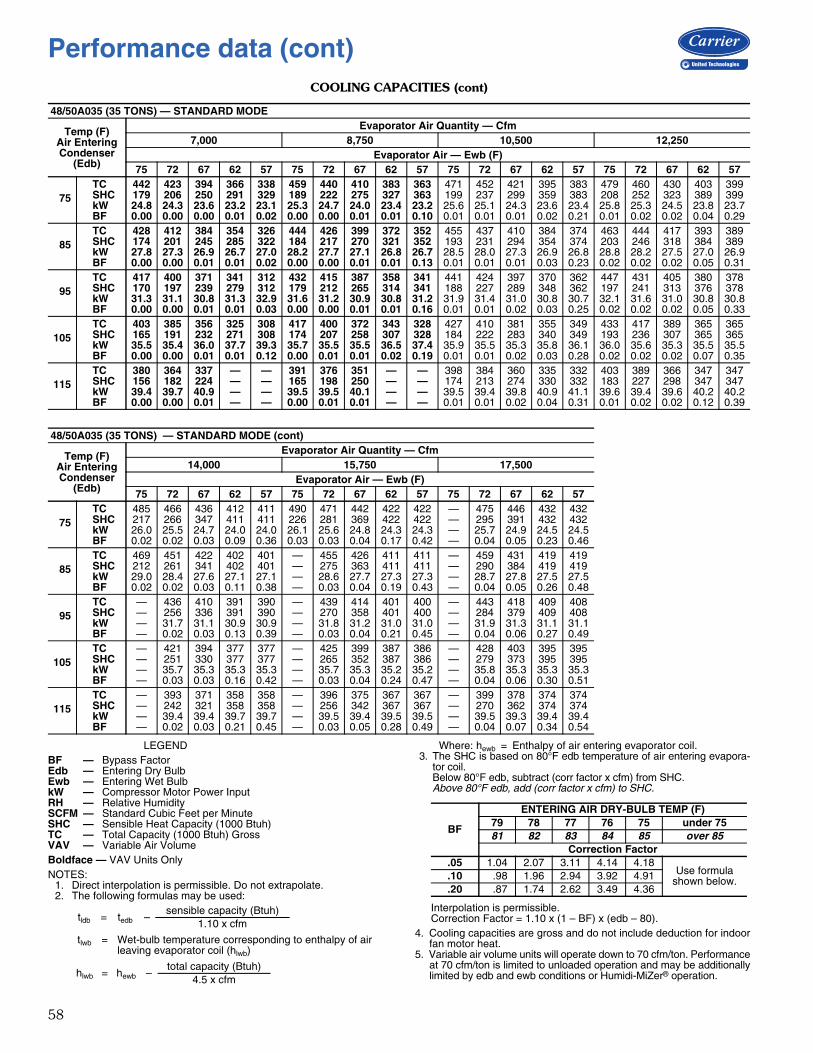
58
COOLING CAPACITIES (cont)
LEGEND
Boldface — VAV Units OnlyNOTES:
1. Direct interpolation is permissible. Do not extrapolate.2. The following formulas may be used:
Where: hewb = Enthalpy of air entering evaporator coil.3. The SHC is based on 80°F edb temperature of air entering evapora-
tor coil.Below 80°F edb, subtract (corr factor x cfm) from SHC.Above 80°F edb, add (corr factor x cfm) to SHC.
Interpolation is permissible.Correction Factor = 1.10 x (1 – BF) x (edb – 80).
4. Cooling capacities are gross and do not include deduction for indoorfan motor heat.
5. Variable air volume units will operate down to 70 cfm/ton. Performanceat 70 cfm/ton is limited to unloaded operation and may be additionallylimited by edb and ewb conditions or Humidi-MiZer® operation.
48/50A035 (35 TONS) — STANDARD MODE
Temp (F)Air EnteringCondenser
(Edb)
Evaporator Air Quantity — Cfm7,000 8,750 10,500 12,250
Evaporator Air — Ewb (F)75 72 67 62 57 75 72 67 62 57 75 72 67 62 57 75 72 67 62 57
75TC 442 423 394 366 338 459 440 410 383 363 471 452 421 395 383 479 460 430 403 399SHC 179 206 250 291 329 189 222 275 327 363 199 237 299 359 383 208 252 323 389 399kW 24.8 24.3 23.6 23.2 23.1 25.3 24.7 24.0 23.4 23.2 25.6 25.1 24.3 23.6 23.4 25.8 25.3 24.5 23.8 23.7BF 0.00 0.00 0.00 0.01 0.02 0.00 0.00 0.01 0.01 0.10 0.01 0.01 0.01 0.02 0.21 0.01 0.02 0.02 0.04 0.29
85TC 428 412 384 354 326 444 426 399 372 352 455 437 410 384 374 463 444 417 393 389SHC 174 201 245 285 322 184 217 270 321 352 193 231 294 354 374 203 246 318 384 389kW 27.8 27.3 26.9 26.7 27.0 28.2 27.7 27.1 26.8 26.7 28.5 28.0 27.3 26.9 26.8 28.8 28.2 27.5 27.0 26.9BF 0.00 0.00 0.01 0.01 0.02 0.00 0.00 0.01 0.01 0.13 0.01 0.01 0.01 0.03 0.23 0.02 0.02 0.02 0.05 0.31
95TC 417 400 371 341 312 432 415 387 358 341 441 424 397 370 362 447 431 405 380 378SHC 170 197 239 279 312 179 212 265 314 341 188 227 289 348 362 197 241 313 376 378kW 31.3 31.1 30.8 31.3 32.9 31.6 31.2 30.9 30.8 31.2 31.9 31.4 31.0 30.8 30.7 32.1 31.6 31.0 30.8 30.8BF 0.00 0.00 0.01 0.01 0.03 0.00 0.00 0.01 0.01 0.16 0.01 0.01 0.02 0.03 0.25 0.02 0.02 0.02 0.05 0.33
105TC 403 385 356 325 308 417 400 372 343 328 427 410 381 355 349 433 417 389 365 365SHC 165 191 232 271 308 174 207 258 307 328 184 222 283 340 349 193 236 307 365 365kW 35.5 35.4 36.0 37.7 39.3 35.7 35.5 35.5 36.5 37.4 35.9 35.5 35.3 35.8 36.1 36.0 35.6 35.3 35.5 35.5BF 0.00 0.00 0.01 0.01 0.12 0.00 0.01 0.01 0.02 0.19 0.01 0.01 0.02 0.03 0.28 0.02 0.02 0.02 0.07 0.35
115TC 380 364 337 — — 391 376 351 — — 398 384 360 335 332 403 389 366 347 347SHC 156 182 224 — — 165 198 250 — — 174 213 274 330 332 183 227 298 347 347kW 39.4 39.7 40.9 — — 39.5 39.5 40.1 — — 39.5 39.4 39.8 40.9 41.1 39.6 39.4 39.6 40.2 40.2BF 0.00 0.00 0.01 — — 0.00 0.01 0.01 — — 0.01 0.01 0.02 0.04 0.31 0.01 0.02 0.02 0.12 0.39
48/50A035 (35 TONS) — STANDARD MODE (cont)
Temp (F)Air EnteringCondenser
(Edb)
Evaporator Air Quantity — Cfm14,000 15,750 17,500
Evaporator Air — Ewb (F)75 72 67 62 57 75 72 67 62 57 75 72 67 62 57
75TC 485 466 436 412 411 490 471 442 422 422 — 475 446 432 432SHC 217 266 347 411 411 226 281 369 422 422 — 295 391 432 432kW 26.0 25.5 24.7 24.0 24.0 26.1 25.6 24.8 24.3 24.3 — 25.7 24.9 24.5 24.5BF 0.02 0.02 0.03 0.09 0.36 0.03 0.03 0.04 0.17 0.42 — 0.04 0.05 0.23 0.46
85TC 469 451 422 402 401 — 455 426 411 411 — 459 431 419 419SHC 212 261 341 402 401 — 275 363 411 411 — 290 384 419 419kW 29.0 28.4 27.6 27.1 27.1 — 28.6 27.7 27.3 27.3 — 28.7 27.8 27.5 27.5BF 0.02 0.02 0.03 0.11 0.38 — 0.03 0.04 0.19 0.43 — 0.04 0.05 0.26 0.48
95TC — 436 410 391 390 — 439 414 401 400 — 443 418 409 408SHC — 256 336 391 390 — 270 358 401 400 — 284 379 409 408kW — 31.7 31.1 30.9 30.9 — 31.8 31.2 31.0 31.0 — 31.9 31.3 31.1 31.1BF — 0.02 0.03 0.13 0.39 — 0.03 0.04 0.21 0.45 — 0.04 0.06 0.27 0.49
105TC — 421 394 377 377 — 425 399 387 386 — 428 403 395 395SHC — 251 330 377 377 — 265 352 387 386 — 279 373 395 395kW — 35.7 35.3 35.3 35.3 — 35.7 35.3 35.2 35.2 — 35.8 35.3 35.3 35.3BF — 0.03 0.03 0.16 0.42 — 0.03 0.04 0.24 0.47 — 0.04 0.06 0.30 0.51
115TC — 393 371 358 358 — 396 375 367 367 — 399 378 374 374SHC — 242 321 358 358 — 256 342 367 367 — 270 362 374 374kW — 39.4 39.4 39.7 39.7 — 39.5 39.4 39.5 39.5 — 39.5 39.3 39.4 39.4BF — 0.02 0.03 0.21 0.45 — 0.03 0.05 0.28 0.49 — 0.04 0.07 0.34 0.54
BF — Bypass FactorEdb — Entering Dry BulbEwb — Entering Wet BulbkW — Compressor Motor Power InputRH — Relative HumiditySCFM — Standard Cubic Feet per MinuteSHC — Sensible Heat Capacity (1000 Btuh)TC — Total Capacity (1000 Btuh) GrossVAV — Variable Air Volume
tldb = tedb –sensible capacity (Btuh)
1.10 x cfm
tlwb = Wet-bulb temperature corresponding to enthalpy of air leaving evaporator coil (hlwb)
hlwb = hewb –total capacity (Btuh)
4.5 x cfm
BF
ENTERING AIR DRY-BULB TEMP (F)79 78 77 76 75 under 7581 82 83 84 85 over 85
Correction Factor.05 1.04 2.07 3.11 4.14 4.18
Use formulashown below..10 .98 1.96 2.94 3.92 4.91
.20 .87 1.74 2.62 3.49 4.36
Performance data (cont)

59
COOLING CAPACITIES (cont)
See legend on page 58.
48/50A035 (35 TONS) — SUBCOOLING MODE
Temp (F)Air EnteringCondenser
(Edb)
Evaporator Air Quantity – SCFM7,000 8,750 10,500 12,250
Evaporator Air Ewb (F)75 72 67 62 57 75 72 67 62 57 75 72 67 62 57 75 72 67 62 57
75
TC 413 378 346 305 268 417 409 369 329 286 450 404 385 346 318 460 433 389 360 345SHC 132 145 188 220 249 125 171 216 259 282 153 166 242 294 318 161 199 260 327 345kW 23.6 23.0 22.8 22.3 22.0 23.7 23.5 23.0 22.6 21.7 24.1 23.4 23.2 22.7 22.2 24.3 23.9 23.2 22.9 22.8BF 0.00 0.00 0.02 0.02 0.03 0.00 0.02 0.02 0.03 0.09 0.02 0.03 0.03 0.04 0.18 0.04 0.04 0.04 0.06 0.27
85
TC 373 356 316 277 240 397 353 337 288 257 393 386 351 314 291 402 377 343 327 304SHC 96 126 161 194 224 109 119 187 221 254 101 152 212 265 291 107 146 217 297 304kW 25.9 25.8 25.3 25.0 24.7 26.3 25.6 25.5 24.7 24.2 26.3 26.1 25.7 25.2 24.9 26.5 26.0 25.5 25.4 24.9BF 0.00 0.01 0.02 0.02 0.03 0.00 0.02 0.02 0.03 0.10 0.02 0.03 0.03 0.04 0.19 0.04 0.04 0.04 0.07 0.28
95
TC 347 324 285 246 200 344 320 303 267 222 355 329 297 280 263 361 337 303 292 272SHC 75 98 134 167 184 61 90 158 203 220 67 100 162 235 263 72 112 181 265 272kW 29.0 28.7 28.2 27.9 26.8 28.9 28.5 28.4 28.0 27.2 29.1 28.6 28.2 28.1 28.0 29.3 28.8 28.2 28.2 27.8BF 0.00 0.01 0.02 0.02 0.05 0.01 0.02 0.02 0.03 0.11 0.02 0.03 0.03 0.05 0.21 0.04 0.04 0.04 0.07 0.29
105
TC 306 281 253 214 182 307 278 269 234 206 314 313 249 247 231 319 296 284 259 250SHC 38 60 106 139 168 30 53 129 174 206 31 89 119 206 231 35 75 167 233 250kW 32.1 31.7 31.6 31.3 31.2 32.1 31.5 31.7 31.4 31.2 32.3 32.3 31.1 31.5 31.4 32.4 31.9 31.8 31.6 31.5BF 0.00 0.01 0.02 0.02 0.07 0.01 0.02 0.02 0.03 0.13 0.02 0.03 0.03 0.05 0.23 0.04 0.04 0.04 0.09 0.31
115
TC 281 249 221 173 143 291 242 226 201 165 272 251 219 213 172 275 253 247 223 204SHC 20 34 79 102 130 19 23 91 146 165 –4 33 95 175 172 –3 39 136 199 204kW 36.5 35.7 35.7 34.8 34.6 36.5 35.3 35.2 35.5 34.6 36.0 35.4 34.9 35.5 34.4 36.1 35.5 35.5 35.4 34.9BF 0.00 0.01 0.02 0.02 0.09 0.01 0.02 0.02 0.03 0.15 0.02 0.03 0.03 0.06 0.24 0.04 0.04 0.04 0.11 0.32
48/50A035 (35 TONS) — SUBCOOLING MODE (cont)
Temp (F)Air EnteringCondenser
(Edb)
Evaporator Air Quantity – SCFM14,000 15,750 17,500
Evaporator Air Ewb (F)75 72 67 62 57 75 72 67 62 57 75 72 67 62 57
75
TC 452 443 399 372 365 460 434 410 383 381 465 438 414 384 394SHC 154 214 284 356 365 163 213 311 379 381 171 225 330 384 394kW 24.2 24.0 23.4 23.1 23.0 24.4 24.0 23.5 23.2 23.2 24.5 24.1 23.6 23.1 23.4BF 0.05 0.05 0.05 0.10 0.34 0.06 0.06 0.07 0.14 0.39 0.08 0.07 0.08 0.20 0.44
85
TC 409 384 351 338 333 415 391 371 349 337 420 394 378 350 358SHC 115 159 240 323 333 123 175 276 345 337 131 185 299 350 358kW 26.6 26.2 25.7 25.5 25.5 26.8 26.3 25.9 25.7 25.4 26.9 26.4 26.1 25.6 25.9BF 0.05 0.05 0.05 0.11 0.35 0.06 0.06 0.07 0.15 0.40 0.08 0.07 0.08 0.21 0.45
95
TC 367 342 299 304 299 371 347 313 304 303 374 351 318 316 323SHC 78 122 193 290 299 84 135 221 301 303 91 147 242 316 323kW 29.4 28.9 28.1 28.4 28.3 29.5 29.0 28.4 28.3 28.2 29.6 29.1 28.5 28.4 28.6BF 0.05 0.05 0.05 0.12 0.36 0.06 0.06 0.07 0.17 0.41 0.08 0.07 0.08 0.22 0.46
105
TC 320 299 291 260 254 325 302 268 278 275 328 305 262 287 281SHC 37 85 189 247 254 44 95 182 276 275 50 107 191 287 281kW 32.5 32.0 31.9 31.4 31.3 32.7 32.0 31.4 31.8 31.7 32.8 32.1 31.3 31.9 31.7BF 0.05 0.05 0.06 0.13 0.37 0.07 0.06 0.07 0.18 0.42 0.08 0.07 0.08 0.24 0.47
115
TC 277 256 227 234 229 279 257 268 238 240 278 256 270 243 249SHC 0 48 130 222 229 4 57 188 238 240 7 64 205 243 249kW 36.2 35.5 34.9 35.5 35.5 36.4 35.6 36.1 35.5 35.5 36.5 35.6 36.0 35.4 35.6BF 0.05 0.05 0.06 0.15 0.38 0.07 0.06 0.07 0.19 0.44 0.08 0.07 0.09 0.26 0.48

60
COOLING CAPACITIES (cont)
See legend on page 58.
50A035 (35 TONS) — HOT GAS REHEAT MODE
Temp (F)Air EnteringCondenser
(Edb)
Air Entering Evaporator — Ewb (F)75 Dry Bulb 75 Dry Bulb
62.5 Wet Bulb (50% RH) 65.3 Wet Bulb (60% RH)Air Entering Evaporator — SCFM
7,000 8,750 10,500 12,250 14,000 15,750 17,500 7,000 8,750 10,500 12,250 14,000 15,750 17,500
40
TC 162 170 176 180 184 186 189 173 182 188 193 197 200 202SHC 46 61 77 94 111 128 144 18 27 37 48 60 71 83kW 23.4 23.0 22.8 22.7 22.6 22.5 22.4 24.6 24.2 23.9 23.7 23.6 23.5 23.4BF 0.00 0.01 0.01 0.02 0.03 0.04 0.05 0.00 0.01 0.01 0.02 0.03 0.04 0.05
50
TC 143 151 156 160 163 165 167 155 163 169 173 177 179 181SHC 31 45 61 78 95 111 128 3 12 22 32 44 55 67kW 24.1 23.8 23.6 23.4 23.3 23.2 23.2 25.4 24.9 24.7 24.5 24.3 24.3 24.2BF 0.00 0.01 0.01 0.02 0.03 0.04 0.05 0.00 0.01 0.01 0.02 0.03 0.04 0.05
60
TC 125 132 137 140 142 144 146 137 144 150 153 156 158 160SHC 15 29 45 62 78 95 111 –12 –4 6 16 28 39 51kW 24.9 24.6 24.4 24.2 24.1 24.1 24.0 26.2 25.8 25.5 25.3 25.2 25.1 25.0BF 0.00 0.01 0.01 0.02 0.03 0.04 0.05 0.00 0.01 0.01 0.02 0.03 0.04 0.05
70
TC 108 114 118 121 123 125 126 118 125 129 132 135 137 139SHC –1 14 29 46 62 79 95 –27 –20 –10 0 11 23 35kW 24.8 25.5 25.3 25.1 25.0 25.0 24.9 27.2 26.7 26.4 26.2 26.1 26.0 25.9BF 0.01 0.01 0.01 0.02 0.03 0.04 0.05 0.00 0.01 0.01 0.02 0.03 0.04 0.05
75
TC 99 105 108 111 113 114 116 109 115 119 122 125 127 128SHC –7 6 21 38 54 71 87 –35 –27 –18 –8 4 15 27kW 26.4 26.0 25.8 25.6 25.5 25.4 25.4 27.7 27.2 26.9 26.7 26.6 26.5 26.4BF 0.00 0.01 0.01 0.02 0.03 0.04 0.05 0.00 0.01 0.01 0.02 0.03 0.04 0.05
80
TC 90 96 99 101 103 104 106 100 106 110 112 115 117 118SHC –15 –1 14 30 46 63 78 –43 –35 –26 –16 –4 7 19kW 26.9 26.5 26.3 26.2 26.0 26.0 25.9 28.2 27.7 27.4 27.2 27.1 27.0 26.9BF 0.00 0.01 0.01 0.02 0.03 0.04 0.05 0.00 0.01 0.01 0.02 0.03 0.04 0.05
50A035 (35 TONS) — HOT GAS REHEAT MODE (cont)
Temp (F)Air EnteringCondenser
(Edb)
Air Entering Evaporator — Ewb (F)75 Dry Bulb 75 Dry Bulb
68.0 Wet Bulb (70% RH) 70.5 Wet Bulb (80% RH)Air Entering Evaporator — SCFM
7,000 8,750 10,500 12,250 14,000 15,750 17,500 7,000 8,750 10,500 12,250 14,000 15,750 17,500
40
TC 184 193 200 205 209 212 215 193 204 211 215 220 222 223SHC –10 –8 –4 1 7 13 19 –39 –42 –44 –44 –42 –40 –38kW 26.2 25.6 25.4 25.2 25.2 25.1 25.2 28.1 27.7 27.5 27.6 27.8 28.1 28.6BF 0.00 0.01 0.02 0.03 0.04 0.06 0.07 0.00 0.00 0.01 0.03 0.05 0.07 0.09
50
TC 165 175 181 185 189 192 195 175 184 191 196 201 203 204SHC –25 –23 –20 –15 –9 –3 4 –54 –58 –60 –59 –58 –56 –54kW 26.9 26.4 26.1 26.0 25.9 25.9 25.9 28.8 28.4 28.2 28.3 28.5 28.8 29.2BF 0.00 0.01 0.02 0.03 0.04 0.05 0.07 0.00 0.00 0.01 0.03 0.05 0.07 0.09
60
TC 147 155 161 165 169 172 175 157 165 172 177 181 183 184SHC –41 –39 –35 –31 –25 –19 –12 –69 –73 –75 –75 –73 –72 –70kW 27.8 27.2 26.9 26.8 26.7 26.7 26.7 29.7 29.2 29.0 29.1 29.3 29.6 30.0BF 0.00 0.01 0.02 0.03 0.04 0.05 0.07 0.00 0.00 0.01 0.03 0.05 0.07 0.09
70
TC 129 136 141 145 149 152 154 138 146 152 157 160 162 162SHC –56 –55 –51 –46 –41 –35 –28 –84 –89 –90 –90 –89 –88 –86kW 28.7 28.2 27.8 27.7 27.6 27.6 27.7 30.6 30.1 29.9 30.0 30.2 30.5 30.9BF 0.00 0.01 0.02 0.03 0.04 0.05 0.07 0.00 0.00 0.01 0.03 0.05 0.07 0.09
75
TC 119 126 131 135 139 141 143 129 137 142 147 150 151 152SHC –64 –62 –59 –54 –49 –43 –36 –92 –96 –98 –98 –97 –96 –94kW 29.2 28.7 28.3 28.2 28.1 28.1 28.1 31.1 30.6 30.4 30.5 30.7 31.0 31.3BF 0.00 0.01 0.02 0.03 0.04 0.05 0.07 0.00 0.00 0.01 0.03 0.05 0.07 0.09
80
TC 110 117 122 125 128 131 133 119 127 133 137 139 141 141SHC –71 –70 –67 –62 –57 –51 –44 –99 –104 –106 –106 –105 –104 –102kW 29.7 29.2 28.9 28.7 28.6 28.6 28.7 31.6 31.1 30.9 31.0 31.2 31.5 31.8BF 0.00 0.01 0.02 0.03 0.04 0.05 0.07 0.00 0.00 0.01 0.03 0.05 0.07 0.09
Performance data (cont)
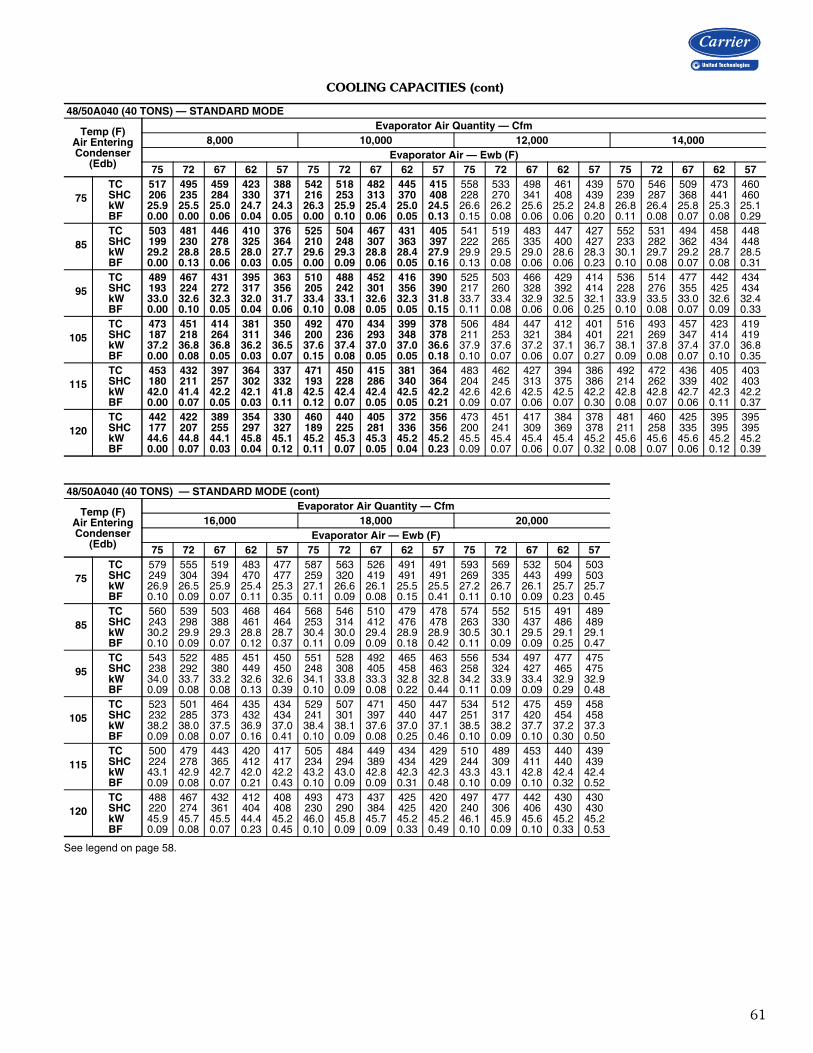
61
COOLING CAPACITIES (cont)
See legend on page 58.
48/50A040 (40 TONS) — STANDARD MODE
Temp (F)Air EnteringCondenser
(Edb)
Evaporator Air Quantity — Cfm8,000 10,000 12,000 14,000
Evaporator Air — Ewb (F)75 72 67 62 57 75 72 67 62 57 75 72 67 62 57 75 72 67 62 57
75TC 517 495 459 423 388 542 518 482 445 415 558 533 498 461 439 570 546 509 473 460SHC 206 235 284 330 371 216 253 313 370 408 228 270 341 408 439 239 287 368 441 460kW 25.9 25.5 25.0 24.7 24.3 26.3 25.9 25.4 25.0 24.5 26.6 26.2 25.6 25.2 24.8 26.8 26.4 25.8 25.3 25.1BF 0.00 0.00 0.06 0.04 0.05 0.00 0.10 0.06 0.05 0.13 0.15 0.08 0.06 0.06 0.20 0.11 0.08 0.07 0.08 0.29
85TC 503 481 446 410 376 525 504 467 431 405 541 519 483 447 427 552 531 494 458 448SHC 199 230 278 325 364 210 248 307 363 397 222 265 335 400 427 233 282 362 434 448kW 29.2 28.8 28.5 28.0 27.7 29.6 29.3 28.8 28.4 27.9 29.9 29.5 29.0 28.6 28.3 30.1 29.7 29.2 28.7 28.5BF 0.00 0.13 0.06 0.03 0.05 0.00 0.09 0.06 0.05 0.16 0.13 0.08 0.06 0.06 0.23 0.10 0.08 0.07 0.08 0.31
95TC 489 467 431 395 363 510 488 452 416 390 525 503 466 429 414 536 514 477 442 434SHC 193 224 272 317 356 205 242 301 356 390 217 260 328 392 414 228 276 355 425 434kW 33.0 32.6 32.3 32.0 31.7 33.4 33.1 32.6 32.3 31.8 33.7 33.4 32.9 32.5 32.1 33.9 33.5 33.0 32.6 32.4BF 0.00 0.10 0.05 0.04 0.06 0.10 0.08 0.05 0.05 0.15 0.11 0.08 0.06 0.06 0.25 0.10 0.08 0.07 0.09 0.33
105TC 473 451 414 381 350 492 470 434 399 378 506 484 447 412 401 516 493 457 423 419SHC 187 218 264 311 346 200 236 293 348 378 211 253 321 384 401 221 269 347 414 419kW 37.2 36.8 36.8 36.2 36.5 37.6 37.4 37.0 37.0 36.6 37.9 37.6 37.2 37.1 36.7 38.1 37.8 37.4 37.0 36.8BF 0.00 0.08 0.05 0.03 0.07 0.15 0.08 0.05 0.05 0.18 0.10 0.07 0.06 0.07 0.27 0.09 0.08 0.07 0.10 0.35
115TC 453 432 397 364 337 471 450 415 381 364 483 462 427 394 386 492 472 436 405 403SHC 180 211 257 302 332 193 228 286 340 364 204 245 313 375 386 214 262 339 402 403kW 42.0 41.4 42.2 42.1 41.8 42.5 42.4 42.4 42.5 42.2 42.6 42.6 42.5 42.5 42.2 42.8 42.8 42.7 42.3 42.2BF 0.00 0.07 0.05 0.03 0.11 0.12 0.07 0.05 0.05 0.21 0.09 0.07 0.06 0.07 0.30 0.08 0.07 0.06 0.11 0.37
120TC 442 422 389 354 330 460 440 405 372 356 473 451 417 384 378 481 460 425 395 395SHC 177 207 255 297 327 189 225 281 336 356 200 241 309 369 378 211 258 335 395 395kW 44.6 44.8 44.1 45.8 45.1 45.2 45.3 45.3 45.2 45.2 45.5 45.4 45.4 45.4 45.2 45.6 45.6 45.6 45.2 45.2BF 0.00 0.07 0.03 0.04 0.12 0.11 0.07 0.05 0.04 0.23 0.09 0.07 0.06 0.07 0.32 0.08 0.07 0.06 0.12 0.39
48/50A040 (40 TONS) — STANDARD MODE (cont)
Temp (F)Air EnteringCondenser
(Edb)
Evaporator Air Quantity — Cfm16,000 18,000 20,000
Evaporator Air — Ewb (F)75 72 67 62 57 75 72 67 62 57 75 72 67 62 57
75TC 579 555 519 483 477 587 563 526 491 491 593 569 532 504 503SHC 249 304 394 470 477 259 320 419 491 491 269 335 443 499 503kW 26.9 26.5 25.9 25.4 25.3 27.1 26.6 26.1 25.5 25.5 27.2 26.7 26.1 25.7 25.7BF 0.10 0.09 0.07 0.11 0.35 0.11 0.09 0.08 0.15 0.41 0.11 0.10 0.09 0.23 0.45
85TC 560 539 503 468 464 568 546 510 479 478 574 552 515 491 489SHC 243 298 388 461 464 253 314 412 476 478 263 330 437 486 489kW 30.2 29.9 29.3 28.8 28.7 30.4 30.0 29.4 28.9 28.9 30.5 30.1 29.5 29.1 29.1BF 0.10 0.09 0.07 0.12 0.37 0.11 0.09 0.09 0.18 0.42 0.11 0.09 0.09 0.25 0.47
95TC 543 522 485 451 450 551 528 492 465 463 556 534 497 477 475SHC 238 292 380 449 450 248 308 405 458 463 258 324 427 465 475kW 34.0 33.7 33.2 32.6 32.6 34.1 33.8 33.3 32.8 32.8 34.2 33.9 33.4 32.9 32.9BF 0.09 0.08 0.08 0.13 0.39 0.10 0.09 0.08 0.22 0.44 0.11 0.09 0.09 0.29 0.48
105TC 523 501 464 435 434 529 507 471 450 447 534 512 475 459 458SHC 232 285 373 432 434 241 301 397 440 447 251 317 420 454 458kW 38.2 38.0 37.5 36.9 37.0 38.4 38.1 37.6 37.0 37.1 38.5 38.2 37.7 37.2 37.3BF 0.09 0.08 0.07 0.16 0.41 0.10 0.09 0.08 0.25 0.46 0.10 0.09 0.10 0.30 0.50
115TC 500 479 443 420 417 505 484 449 434 429 510 489 453 440 439SHC 224 278 365 412 417 234 294 389 434 429 244 309 411 440 439kW 43.1 42.9 42.7 42.0 42.2 43.2 43.0 42.8 42.3 42.3 43.3 43.1 42.8 42.4 42.4BF 0.09 0.08 0.07 0.21 0.43 0.10 0.09 0.09 0.31 0.48 0.10 0.09 0.10 0.32 0.52
120TC 488 467 432 412 408 493 473 437 425 420 497 477 442 430 430SHC 220 274 361 404 408 230 290 384 425 420 240 306 406 430 430kW 45.9 45.7 45.5 44.4 45.2 46.0 45.8 45.7 45.2 45.2 46.1 45.9 45.6 45.2 45.2BF 0.09 0.08 0.07 0.23 0.45 0.10 0.09 0.09 0.33 0.49 0.10 0.09 0.10 0.33 0.53

62
COOLING CAPACITIES (cont)
See legend on page 58.
48/50A040 (40 TONS) — SUBCOOLING MODE
Temp (F)Air EnteringCondenser
(Edb)
Evaporator Air Quantity – SCFM8,000 10,000 12,000 14,000
Evaporator Air Ewb (F)75 72 67 62 57 75 72 67 62 57 75 72 67 62 57 75 72 67 62 57
75
TC 501 473 429 379 352 528 499 455 403 374 549 519 474 420 387 562 534 488 446 408SHC 189 214 253 281 327 202 231 281 319 368 214 249 307 352 387 224 265 331 395 408kW 26.5 26.1 25.7 24.9 25.0 26.8 26.4 25.9 25.2 25.1 27.1 26.7 26.2 25.4 25.0 27.3 26.9 26.3 26.0 25.3BF 0.00 0.07 0.09 0.09 0.10 0.07 0.10 0.11 0.11 0.14 0.10 0.12 0.12 0.13 0.22 0.12 0.13 0.14 0.15 0.30
85
TC 478 444 410 369 330 497 477 422 382 344 523 492 440 397 363 527 498 462 424 383SHC 172 190 239 276 309 177 215 253 302 338 195 229 279 334 363 196 236 311 378 383kW 29.4 28.9 28.9 28.4 27.9 29.5 29.4 28.6 28.2 27.9 30.0 29.6 28.9 28.4 28.1 30.1 29.7 29.2 29.1 28.2BF 0.00 0.07 0.09 0.09 0.11 0.07 0.10 0.11 0.11 0.16 0.10 0.12 0.12 0.13 0.24 0.12 0.13 0.14 0.16 0.32
95
TC 442 416 375 348 310 476 451 398 358 332 484 457 426 386 344 506 480 437 395 363SHC 142 168 209 259 292 164 196 235 284 326 164 201 271 328 344 184 226 293 354 363kW 32.6 32.3 31.9 31.9 31.6 33.1 32.9 32.1 31.7 31.7 33.1 32.8 32.6 32.3 31.7 33.5 33.2 32.7 32.3 31.8BF 0.02 0.07 0.09 0.09 0.11 0.08 0.10 0.11 0.11 0.18 0.11 0.12 0.12 0.13 0.25 0.13 0.13 0.14 0.16 0.33
105
TC 415 402 363 314 288 438 413 384 347 316 464 439 400 361 325 467 449 410 374 342SHC 122 160 203 231 275 133 165 227 278 311 153 190 252 309 325 153 202 274 338 342kW 36.6 36.7 36.4 35.9 35.9 36.8 36.6 36.5 36.4 36.2 37.2 37.0 36.7 36.4 36.0 37.2 37.1 36.8 36.5 36.1BF 0.03 0.08 0.09 0.09 0.11 0.08 0.10 0.11 0.11 0.19 0.11 0.12 0.12 0.14 0.27 0.13 0.13 0.14 0.16 0.34
115
TC 388 376 339 304 273 410 394 356 311 295 433 410 371 324 303 445 421 383 334 330SHC 103 141 184 226 260 113 154 207 247 291 130 169 231 277 303 140 183 254 303 330kW 41.2 41.5 41.4 41.4 41.5 41.4 41.5 41.4 40.9 41.3 41.8 41.6 41.4 41.0 40.9 41.9 41.7 41.6 41.0 41.4BF 0.03 0.08 0.09 0.09 0.13 0.08 0.10 0.10 0.11 0.21 0.11 0.12 0.12 0.14 0.29 0.13 0.13 0.14 0.17 0.36
48/50A040 (40 TONS) — SUBCOOLING MODE (cont)
Temp (F)Air EnteringCondenser
(Edb)
Evaporator Air Quantity – SCFM16,000 18,000 20,000
Evaporator Air Ewb (F)75 72 67 62 57 75 72 67 62 57 75 72 67 62 57
75
TC 568 537 490 445 416 583 553 509 465 452 591 554 516 469 464SHC 228 272 345 410 416 243 293 377 445 452 252 300 400 465 464kW 27.4 26.9 26.3 25.7 25.4 27.6 27.2 26.6 26.1 25.9 27.7 27.2 26.8 26.0 26.0BF 0.14 0.15 0.15 0.18 0.37 0.15 0.16 0.17 0.21 0.42 0.17 0.18 0.18 0.24 0.47
85
TC 539 509 463 421 405 553 519 469 439 433 561 531 478 46 444SHC 206 251 325 391 405 222 266 345 422 433 231 285 368 45 444kW 30.2 29.8 29.2 28.7 28.5 30.5 29.9 29.2 29.2 29.1 30.6 30.1 29.4 29.2 29.2BF 0.14 0.15 0.15 0.18 0.38 0.16 0.16 0.17 0.22 0.43 0.17 0.18 0.18 0.25 0.48
95
TC 515 489 448 409 394 517 488 455 404 409 525 495 449 424 425SHC 192 239 317 384 394 194 244 338 394 409 204 257 347 423 425kW 33.6 33.3 32.9 32.6 32.4 33.7 33.2 32.9 32.2 32.5 33.8 33.3 32.7 32.7 32.9BF 0.14 0.15 0.15 0.19 0.39 0.16 0.16 0.17 0.22 0.44 0.17 0.18 0.18 0.26 0.49
105
TC 484 460 420 369 359 488 464 426 384 385 491 471 431 399 396SHC 169 218 297 351 359 175 229 318 374 385 179 243 337 399 396kW 37.5 37.2 36.9 36.2 36.1 37.5 37.2 37.0 36.4 36.6 37.5 37.3 37.0 36.8 36.7BF 0.14 0.15 0.15 0.19 0.41 0.16 0.16 0.17 0.24 0.46 0.17 0.18 0.18 0.28 0.50
115
TC 445 429 390 357 335 458 435 397 365 355 464 432 401 375 366SHC 139 195 275 339 335 153 208 296 356 355 161 212 314 375 366kW 41.8 41.8 41.6 41.5 40.9 42.0 41.8 41.6 41.5 41.4 42.1 41.7 41.7 41.6 41.4BF 0.14 0.15 0.15 0.21 0.42 0.16 0.16 0.17 0.26 0.47 0.17 0.18 0.19 0.29 0.51
Performance data (cont)
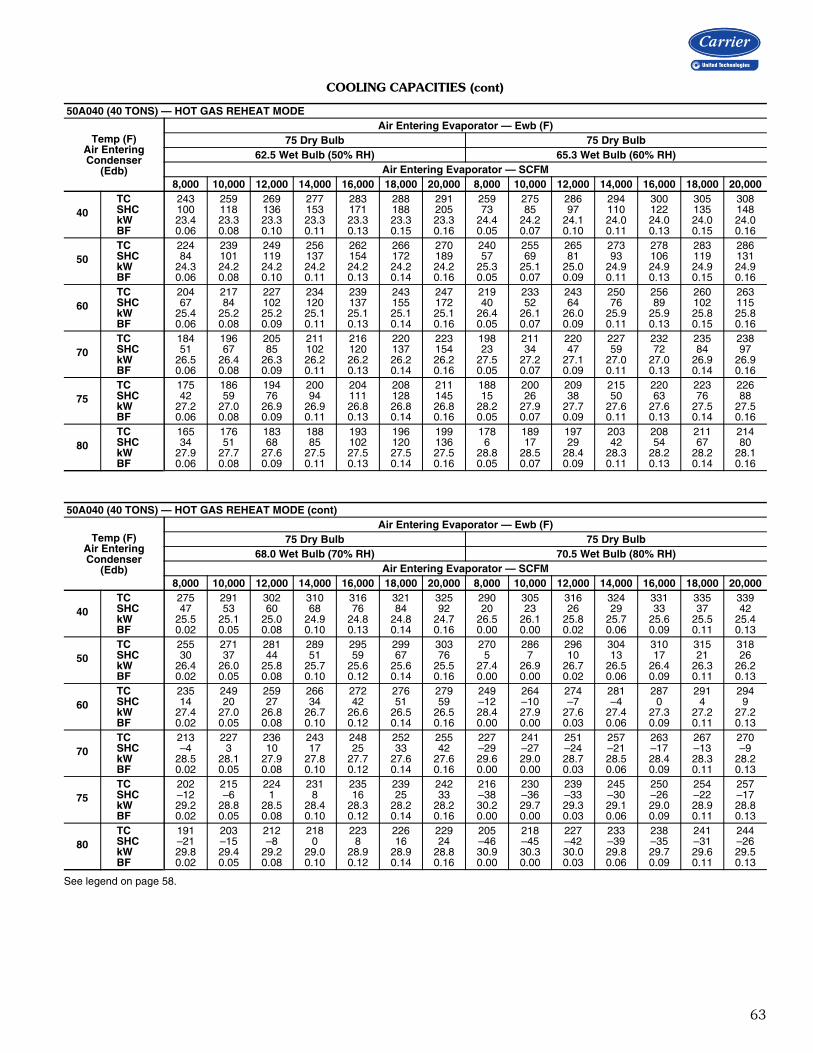
63
COOLING CAPACITIES (cont)
See legend on page 58.
50A040 (40 TONS) — HOT GAS REHEAT MODE
Temp (F)Air EnteringCondenser
(Edb)
Air Entering Evaporator — Ewb (F)75 Dry Bulb 75 Dry Bulb
62.5 Wet Bulb (50% RH) 65.3 Wet Bulb (60% RH)Air Entering Evaporator — SCFM
8,000 10,000 12,000 14,000 16,000 18,000 20,000 8,000 10,000 12,000 14,000 16,000 18,000 20,000
40TC 243 259 269 277 283 288 291 259 275 286 294 300 305 308SHC 100 118 136 153 171 188 205 73 85 97 110 122 135 148kW 23.4 23.3 23.3 23.3 23.3 23.3 23.3 24.4 24.2 24.1 24.0 24.0 24.0 24.0BF 0.06 0.08 0.10 0.11 0.13 0.15 0.16 0.05 0.07 0.10 0.11 0.13 0.15 0.16
50TC 224 239 249 256 262 266 270 240 255 265 273 278 283 286SHC 84 101 119 137 154 172 189 57 69 81 93 106 119 131kW 24.3 24.2 24.2 24.2 24.2 24.2 24.2 25.3 25.1 25.0 24.9 24.9 24.9 24.9BF 0.06 0.08 0.10 0.11 0.13 0.14 0.16 0.05 0.07 0.09 0.11 0.13 0.15 0.16
60TC 204 217 227 234 239 243 247 219 233 243 250 256 260 263SHC 67 84 102 120 137 155 172 40 52 64 76 89 102 115kW 25.4 25.2 25.2 25.1 25.1 25.1 25.1 26.4 26.1 26.0 25.9 25.9 25.8 25.8BF 0.06 0.08 0.09 0.11 0.13 0.14 0.16 0.05 0.07 0.09 0.11 0.13 0.15 0.16
70TC 184 196 205 211 216 220 223 198 211 220 227 232 235 238SHC 51 67 85 102 120 137 154 23 34 47 59 72 84 97kW 26.5 26.4 26.3 26.2 26.2 26.2 26.2 27.5 27.2 27.1 27.0 27.0 26.9 26.9BF 0.06 0.08 0.09 0.11 0.13 0.14 0.16 0.05 0.07 0.09 0.11 0.13 0.14 0.16
75TC 175 186 194 200 204 208 211 188 200 209 215 220 223 226SHC 42 59 76 94 111 128 145 15 26 38 50 63 76 88kW 27.2 27.0 26.9 26.9 26.8 26.8 26.8 28.2 27.9 27.7 27.6 27.6 27.5 27.5BF 0.06 0.08 0.09 0.11 0.13 0.14 0.16 0.05 0.07 0.09 0.11 0.13 0.14 0.16
80TC 165 176 183 188 193 196 199 178 189 197 203 208 211 214SHC 34 51 68 85 102 120 136 6 17 29 42 54 67 80kW 27.9 27.7 27.6 27.5 27.5 27.5 27.5 28.8 28.5 28.4 28.3 28.2 28.2 28.1BF 0.06 0.08 0.09 0.11 0.13 0.14 0.16 0.05 0.07 0.09 0.11 0.13 0.14 0.16
50A040 (40 TONS) — HOT GAS REHEAT MODE (cont)
Temp (F)Air EnteringCondenser
(Edb)
Air Entering Evaporator — Ewb (F)75 Dry Bulb 75 Dry Bulb
68.0 Wet Bulb (70% RH) 70.5 Wet Bulb (80% RH)Air Entering Evaporator — SCFM
8,000 10,000 12,000 14,000 16,000 18,000 20,000 8,000 10,000 12,000 14,000 16,000 18,000 20,000
40TC 275 291 302 310 316 321 325 290 305 316 324 331 335 339SHC 47 53 60 68 76 84 92 20 23 26 29 33 37 42kW 25.5 25.1 25.0 24.9 24.8 24.8 24.7 26.5 26.1 25.8 25.7 25.6 25.5 25.4BF 0.02 0.05 0.08 0.10 0.13 0.14 0.16 0.00 0.00 0.02 0.06 0.09 0.11 0.13
50TC 255 271 281 289 295 299 303 270 286 296 304 310 315 318SHC 30 37 44 51 59 67 76 5 7 10 13 17 21 26kW 26.4 26.0 25.8 25.7 25.6 25.6 25.5 27.4 26.9 26.7 26.5 26.4 26.3 26.2BF 0.02 0.05 0.08 0.10 0.12 0.14 0.16 0.00 0.00 0.02 0.06 0.09 0.11 0.13
60TC 235 249 259 266 272 276 279 249 264 274 281 287 291 294SHC 14 20 27 34 42 51 59 –12 –10 –7 –4 0 4 9kW 27.4 27.0 26.8 26.7 26.6 26.5 26.5 28.4 27.9 27.6 27.4 27.3 27.2 27.2BF 0.02 0.05 0.08 0.10 0.12 0.14 0.16 0.00 0.00 0.03 0.06 0.09 0.11 0.13
70TC 213 227 236 243 248 252 255 227 241 251 257 263 267 270SHC –4 3 10 17 25 33 42 –29 –27 –24 –21 –17 –13 –9kW 28.5 28.1 27.9 27.8 27.7 27.6 27.6 29.6 29.0 28.7 28.5 28.4 28.3 28.2BF 0.02 0.05 0.08 0.10 0.12 0.14 0.16 0.00 0.00 0.03 0.06 0.09 0.11 0.13
75TC 202 215 224 231 235 239 242 216 230 239 245 250 254 257SHC –12 –6 1 8 16 25 33 –38 –36 –33 –30 –26 –22 –17kW 29.2 28.8 28.5 28.4 28.3 28.2 28.2 30.2 29.7 29.3 29.1 29.0 28.9 28.8BF 0.02 0.05 0.08 0.10 0.12 0.14 0.16 0.00 0.00 0.03 0.06 0.09 0.11 0.13
80TC 191 203 212 218 223 226 229 205 218 227 233 238 241 244SHC –21 –15 –8 0 8 16 24 –46 –45 –42 –39 –35 –31 –26kW 29.8 29.4 29.2 29.0 28.9 28.9 28.8 30.9 30.3 30.0 29.8 29.7 29.6 29.5BF 0.02 0.05 0.08 0.10 0.12 0.14 0.16 0.00 0.00 0.03 0.06 0.09 0.11 0.13

64
COOLING CAPACITIES (cont)
See legend on page 58.
48/50A050 (50 TONS) — STANDARD MODE
Temp (F)Air EnteringCondenser
(Edb)
Evaporator Air Quantity — Cfm10,000 12,500 15,000
Evaporator Air — Ewb (F)75 72 67 62 57 75 72 67 62 57 75 72 67 62 57
75
TC 636 602 545 495 450 669 633 575 525 489 692 658 602 550 523SHC 255 287 340 391 438 271 314 379 443 482 289 338 418 493 523kW 31.3 30.7 29.9 29.2 28.5 31.8 31.2 30.3 29.6 29.0 32.2 31.6 30.8 30.1 29.6BF 0.00 0.07 0.06 0.04 0.05 0.00 0.10 0.06 0.05 0.16 0.18 0.09 0.06 0.06 0.23
85
TC 611 574 524 476 432 639 605 553 504 471 662 628 576 525 503SHC 237 270 322 371 413 253 293 357 417 450 266 312 387 456 481kW 34.6 33.9 33.3 32.8 32.2 35.0 34.5 33.8 33.2 32.6 35.4 34.9 34.2 33.6 33.1BF 0.00 0.17 0.06 0.04 0.06 0.00 0.09 0.05 0.05 0.17 0.15 0.08 0.06 0.06 0.25
95
TC 584 553 502 454 411 613 581 530 480 450 633 601 549 499 482SHC 227 261 315 365 408 246 287 354 416 450 263 311 390 463 482kW 38.4 38.0 37.5 37.4 36.8 38.9 38.5 38.1 37.9 37.2 39.3 38.9 38.5 38.1 37.6BF 0.00 0.13 0.05 0.04 0.07 0.08 0.08 0.05 0.05 0.18 0.13 0.08 0.06 0.06 0.28
105
TC 559 527 477 429 393 585 553 502 453 429 603 572 519 471 459SHC 213 248 301 351 387 233 274 339 401 429 249 297 375 447 459kW 43.0 42.9 42.9 43.5 42.4 43.8 43.5 43.5 43.8 43.0 44.1 43.9 43.9 43.7 43.2BF 0.00 0.10 0.05 0.04 0.11 0.20 0.08 0.05 0.05 0.21 0.12 0.07 0.06 0.07 0.30
115
TC 529 498 449 402 368 554 523 472 425 406 572 540 489 442 435SHC 201 234 286 335 367 219 259 324 385 406 235 283 360 428 435kW 49.0 49.3 50.0 51.1 50.1 49.8 49.9 50.6 51.2 50.4 50.2 50.3 51.0 50.8 50.4BF 0.00 0.09 0.04 0.04 0.13 0.15 0.07 0.05 0.05 0.24 0.11 0.07 0.05 0.08 0.33
120
TC 514 484 435 386 357 538 507 457 409 393 555 524 472 427 421SHC 194 227 278 326 357 212 252 316 376 393 228 275 351 418 421kW 52.5 53.0 54.3 55.3 54.6 53.3 53.7 54.7 55.5 54.2 53.8 54.1 55.3 54.7 54.1BF 0.00 0.08 0.04 0.04 0.15 0.13 0.07 0.05 0.05 0.26 0.10 0.07 0.05 0.08 0.35
48/50A050 (50 TONS) — STANDARD MODE (cont)
Temp (F)Air EnteringCondenser
(Edb)
Evaporator Air Quantity — Cfm17,500 20,000
Evaporator Air — Ewb (F)75 72 67 62 57 75 72 67 62 57
75
TC 709 674 618 566 550 740 685 629 577 573SHC 305 361 453 537 550 326 383 486 570 573kW 32.4 31.9 31.0 30.3 30.0 32.6 32.1 31.2 30.4 30.3BF 0.13 0.08 0.06 0.08 0.31 0.12 0.08 0.07 0.12 0.37
85
TC 678 645 591 540 529 691 656 600 552 550SHC 276 328 413 488 499 284 341 435 504 510kW 35.7 35.3 34.4 33.7 33.5 35.9 35.4 34.6 33.8 33.8BF 0.12 0.08 0.06 0.09 0.33 0.11 0.08 0.07 0.15 0.39
95
TC 648 616 563 512 506 658 625 572 530 527SHC 278 334 425 501 506 292 355 457 522 527kW 39.6 39.2 38.8 37.9 37.9 39.8 39.3 38.9 38.0 38.1BF 0.11 0.08 0.06 0.10 0.35 0.10 0.08 0.07 0.18 0.41
105
TC 617 585 532 487 483 628 595 542 506 503SHC 264 320 409 481 483 279 341 442 499 503kW 44.4 44.2 44.3 43.2 43.4 44.6 44.4 44.5 43.3 43.5BF 0.10 0.07 0.06 0.12 0.37 0.10 0.08 0.07 0.20 0.43
115
TC 584 553 500 463 458 594 562 508 476 474SHC 250 305 394 451 458 265 327 425 476 474kW 50.6 50.7 51.4 50.1 50.4 50.8 50.9 51.7 50.4 50.2BF 0.10 0.07 0.06 0.17 0.40 0.09 0.07 0.07 0.22 0.46
120
TC 567 535 482 447 444 577 545 492 465 462SHC 243 297 385 440 444 257 319 417 459 462kW 54.1 54.4 55.3 53.6 54.3 54.3 54.7 56.0 53.8 54.2BF 0.09 0.07 0.06 0.18 0.41 0.09 0.07 0.07 0.25 0.47
Performance data (cont)

65
COOLING CAPACITIES (cont)
See legend on page 58.
48/50A050 (50 TONS) — SUBCOOLING MODE
Temp (F)Air EnteringCondenser
(Edb)
Evaporator Air Quantity – SCFM10,000 12,500 15,000 17,500
Evaporator Air Ewb (F)75 72 67 62 57 75 72 67 62 57 75 72 67 62 57 75 72 67 62 57
75
TC 601 568 523 479 438 624 596 547 507 471 643 608 567 521 494 651 604 582 542 524SHC 218 251 311 367 418 229 274 342 416 468 241 287 377 455 494 247 289 410 501 524kW 31.4 30.8 30.1 29.5 28.9 31.9 31.4 30.5 29.9 29.4 32.5 31.8 30.9 30.1 29.7 32.6 31.7 31.2 30.4 30.1BF 0.00 0.02 0.03 0.03 0.05 0.01 0.04 0.04 0.05 0.12 0.04 0.05 0.06 0.07 0.21 0.06 0.07 0.07 0.09 0.30
85
TC 567 541 498 455 417 596 570 522 481 449 620 586 540 495 472 610 599 554 510 496SHC 192 230 291 348 399 209 254 324 396 446 429 272 356 434 472 428 426 414 474 496kW 34.6 34.2 33.5 32.8 32.3 35.2 34.7 33.9 33.2 32.8 35.8 35.0 34.2 33.4 33.1 35.6 35.5 34.5 33.7 33.4BF 0.00 0.02 0.03 0.03 0.06 0.02 0.04 0.04 0.05 0.14 0.04 0.05 0.06 0.07 0.23 0.06 0.07 0.07 0.10 0.31
95
TC 540 513 469 428 395 565 497 495 454 426 565 555 512 470 452 591 568 524 482 477SHC 172 209 268 326 380 185 189 304 375 426 180 250 336 415 452 205 269 367 451 477kW 38.6 38.1 37.3 36.7 36.4 39.1 38.0 37.8 37.1 36.7 39.2 38.9 38.1 37.3 37.0 39.7 39.0 38.3 37.6 37.5BF 0.00 0.02 0.03 0.03 0.07 0.02 0.04 0.04 0.05 0.14 0.05 0.05 0.06 0.07 0.24 0.06 0.07 0.07 0.10 0.32
105
TC 512 484 444 405 378 533 506 465 424 400 548 523 482 440 423 524 535 494 455 445SHC 153 189 250 309 364 163 207 281 352 400 174 227 315 392 423 149 246 346 430 445kW 43.2 42.7 42.1 41.6 41.5 43.6 43.0 42.4 41.8 41.5 43.9 43.3 42.6 42.0 41.7 43.6 43.6 42.8 42.2 42.0BF 0.00 0.02 0.03 0.03 0.08 0.02 0.04 0.04 0.05 0.16 0.05 0.05 0.06 0.08 0.26 0.07 0.07 0.07 0.11 0.34
115
TC 477 454 421 385 350 500 474 432 398 377 515 489 450 413 401 533 502 459 427 421SHC 127 167 236 296 337 139 184 257 332 377 150 203 292 372 401 168 223 320 404 421kW 48.5 48.1 47.8 47.5 47.2 48.9 48.4 47.8 47.5 47.3 49.2 48.7 48.0 47.6 47.4 49.5 48.9 48.1 47.7 47.6BF 0.00 0.02 0.03 0.04 0.10 0.03 0.04 0.04 0.05 0.18 0.05 0.05 0.06 0.08 0.28 0.07 0.07 0.07 0.13 0.35
48/50A050 (50 TONS) — SUBCOOLING MODE (cont)
Temp (F)Air EnteringCondenser
(Edb)
Evaporator Air Quantity – SCFM20,000 22,500 25,000
Evaporator Air Ewb (F)75 72 67 62 57 75 72 67 62 57 75 72 67 62 57
75
TC 657 628 564 549 544 666 640 592 561 559 671 646 604 575 574SHC 255 320 412 530 544 267 343 460 557 559 276 360 493 575 574kW 32.7 32.2 31.0 30.6 30.5 32.9 32.4 31.5 30.8 30.7 33.0 32.5 31.8 31.0 31.0BF 0.08 0.08 0.08 0.13 0.36 0.10 0.10 0.10 0.18 0.42 0.11 0.11 0.11 0.23 0.46
85
TC 613 586 527 523 517 641 614 573 536 532 630 620 568 553 552SHC 428 422 409 407 406 437 430 418 409 409 433 430 416 553 552kW 35.7 35.2 34.1 33.9 33.8 36.4 35.8 34.8 34.1 34.1 36.1 35.8 34.7 34.4 34.4BF 0.08 0.08 0.08 0.13 0.37 0.10 0.10 0.10 0.19 0.43 0.11 0.11 0.12 0.25 0.47
95
TC 608 579 534 499 494 615 588 535 508 506 599 598 549 520 524SHC 224 289 397 486 494 236 309 419 505 506 222 329 454 520 524kW 39.9 39.3 38.5 37.8 37.7 40.0 39.5 38.5 38.0 38.0 39.9 39.7 38.8 38.2 38.2BF 0.08 0.08 0.09 0.15 0.39 0.10 0.10 0.10 0.20 0.44 0.11 0.11 0.12 0.26 0.48
105
TC 568 517 501 473 462 579 553 509 478 476 562 548 516 494 494SHC 194 237 374 461 462 210 284 402 478 476 198 292 430 494 494kW 44.3 43.3 42.9 42.4 42.2 44.5 43.9 43.0 42.5 42.5 44.3 43.9 43.2 42.7 42.7BF 0.08 0.08 0.09 0.16 0.40 0.10 0.10 0.10 0.21 0.45 0.11 0.11 0.12 0.28 0.49
115
TC 496 481 469 443 439 514 490 476 452 452 533 506 482 461 462SHC 134 211 350 432 439 155 204 378 452 452 179 231 404 461 462kW 49.0 48.5 48.2 47.8 47.7 49.3 48.7 48.3 47.9 47.9 49.5 48.9 48.4 48.0 48.1BF 0.08 0.08 0.09 0.18 0.41 0.10 0.10 0.11 0.23 0.46 0.11 0.11 0.13 0.29 0.51
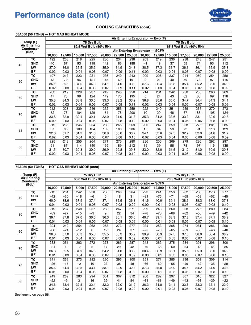
66
COOLING CAPACITIES (cont)
See legend on page 58.
50A050 (50 TONS) — HOT GAS REHEAT MODE
Temp (F)Air EnteringCondenser
(Edb)
Air Entering Evaporator — Ewb (F)75 Dry Bulb 75 Dry Bulb
62.5 Wet Bulb (50% RH) 65.3 Wet Bulb (60% RH)Air Entering Evaporator — SCFM
10,000 12,500 15,000 17,500 20,000 22,500 25,000 10,000 12,500 15,000 17,500 20,000 22,500 25,000
40
TC 192 208 218 225 230 234 238 203 219 230 238 243 247 251SHC 40 67 93 118 142 166 188 –1 18 37 55 74 93 112kW 37.0 36.0 35.5 35.2 35.0 34.9 34.8 38.5 37.3 36.7 36.3 36.1 35.9 35.8BF 0.02 0.03 0.04 0.06 0.07 0.09 0.11 0.02 0.03 0.04 0.05 0.07 0.08 0.09
50
TC 197 213 223 231 236 240 243 209 226 237 244 250 254 258SHC 43 70 96 121 145 169 191 2 21 40 59 78 97 115kW 36.1 35.1 34.6 34.3 34.1 34.0 33.9 37.6 36.4 35.8 35.4 35.2 35.0 34.9BF 0.02 0.03 0.04 0.06 0.07 0.09 0.11 0.02 0.03 0.04 0.05 0.07 0.08 0.09
60
TC 203 219 229 237 242 246 250 214 231 242 250 255 260 263SHC 47 73 99 124 149 173 195 5 24 43 62 80 99 118kW 35.3 34.3 33.8 33.5 33.3 33.2 33.2 36.8 35.6 35.0 34.7 34.4 34.3 34.1BF 0.02 0.03 0.04 0.06 0.07 0.09 0.11 0.02 0.03 0.04 0.05 0.07 0.08 0.09
70
TC 212 228 239 246 252 256 259 222 240 251 259 265 270 273SHC 52 78 104 129 154 178 200 10 29 48 67 86 105 124kW 33.8 32.9 32.4 32.1 32.0 31.9 31.8 35.3 34.2 33.6 33.3 33.1 32.9 32.8BF 0.02 0.03 0.04 0.05 0.07 0.08 0.10 0.02 0.03 0.04 0.05 0.06 0.08 0.09
75
TC 219 235 246 254 260 265 269 230 247 259 268 275 281 285SHC 57 83 109 134 159 183 206 15 34 53 72 91 110 129kW 32.6 31.7 31.2 31.0 30.8 30.8 30.7 34.1 33.0 32.5 32.2 32.0 31.8 31.7BF 0.02 0.03 0.04 0.05 0.07 0.08 0.10 0.02 0.03 0.04 0.05 0.06 0.08 0.09
80
TC 225 243 255 264 271 276 280 236 256 269 279 286 292 297SHC 61 87 114 140 165 189 212 19 39 58 78 97 116 135kW 31.5 30.7 30.3 30.0 29.9 29.8 29.8 33.0 32.0 31.5 31.2 31.0 30.9 30.8BF 0.02 0.03 0.04 0.05 0.07 0.08 0.10 0.02 0.03 0.04 0.05 0.06 0.08 0.09
50A050 (50 TONS) — HOT GAS REHEAT MODE (cont)
Temp (F)Air EnteringCondenser
(Edb)
Air Entering Evaporator — Ewb (F)75 Dry Bulb 75 Dry Bulb
68.0 Wet Bulb (70% RH) 70.5 Wet Bulb (80% RH)Air Entering Evaporator — SCFM
10,000 12,500 15,000 17,500 20,000 22,500 25,000 10,000 12,500 15,000 17,500 20,000 22,500 25,000
40
TC 213 231 242 250 256 260 264 223 241 253 262 268 273 277SHC –42 –30 –18 –6 6 18 31 –81 –76 –71 –65 –59 –52 –45kW 40.0 38.6 37.9 37.4 37.1 36.9 36.8 41.6 40.0 39.1 38.6 38.2 38.0 37.8BF 0.01 0.03 0.04 0.05 0.07 0.08 0.09 0.00 0.01 0.03 0.05 0.07 0.08 0.10
50
TC 219 237 248 257 263 267 271 229 248 260 268 275 280 284SHC –39 –27 –15 –3 9 22 34 –78 –73 –68 –62 –56 –49 –42kW 39.1 37.8 37.0 36.6 36.3 36.1 36.0 40.7 39.1 38.3 37.8 37.4 37.1 36.9BF 0.01 0.03 0.04 0.05 0.07 0.08 0.09 0.00 0.01 0.03 0.05 0.07 0.08 0.10
60
TC 224 242 254 262 268 273 277 234 253 265 274 281 286 290SHC –36 –24 –12 0 12 24 37 –75 –70 –65 –59 –53 –46 –40kW 38.3 37.0 36.3 35.8 35.5 35.3 35.2 39.9 38.3 37.5 37.0 36.6 36.4 36.2BF 0.01 0.03 0.04 0.05 0.07 0.08 0.09 0.00 0.01 0.03 0.05 0.07 0.08 0.10
70
TC 233 251 263 272 278 283 287 243 262 275 284 291 296 300SHC –31 –19 –7 5 17 29 42 –70 –65 –60 –54 –48 –41 –35kW 36.8 35.5 34.9 34.5 34.2 34.0 33.9 38.4 36.9 36.1 35.6 35.3 35.0 34.9BF 0.01 0.03 0.04 0.05 0.07 0.08 0.09 0.00 0.01 0.03 0.05 0.07 0.08 0.10
75
TC 241 259 273 282 290 295 300 251 271 285 296 303 309 314SHC –26 –15 –2 10 23 35 48 –66 –60 –55 –49 –42 –35 –28kW 35.6 34.4 33.8 33.4 33.1 32.9 32.8 37.3 35.8 35.0 34.5 34.2 34.0 33.8BF 0.01 0.03 0.04 0.05 0.07 0.08 0.09 0.00 0.01 0.03 0.05 0.07 0.08 0.10
80
TC 249 269 283 294 301 307 312 260 282 297 307 316 322 327SHC –22 –9 3 16 29 41 54 –61 –55 –49 –43 –36 –29 –22kW 34.6 33.4 32.8 32.4 32.2 32.0 31.9 36.3 34.8 34.1 33.6 33.3 33.1 32.9BF 0.01 0.03 0.04 0.05 0.07 0.08 0.09 0.00 0.01 0.03 0.05 0.07 0.08 0.10
Performance data (cont)
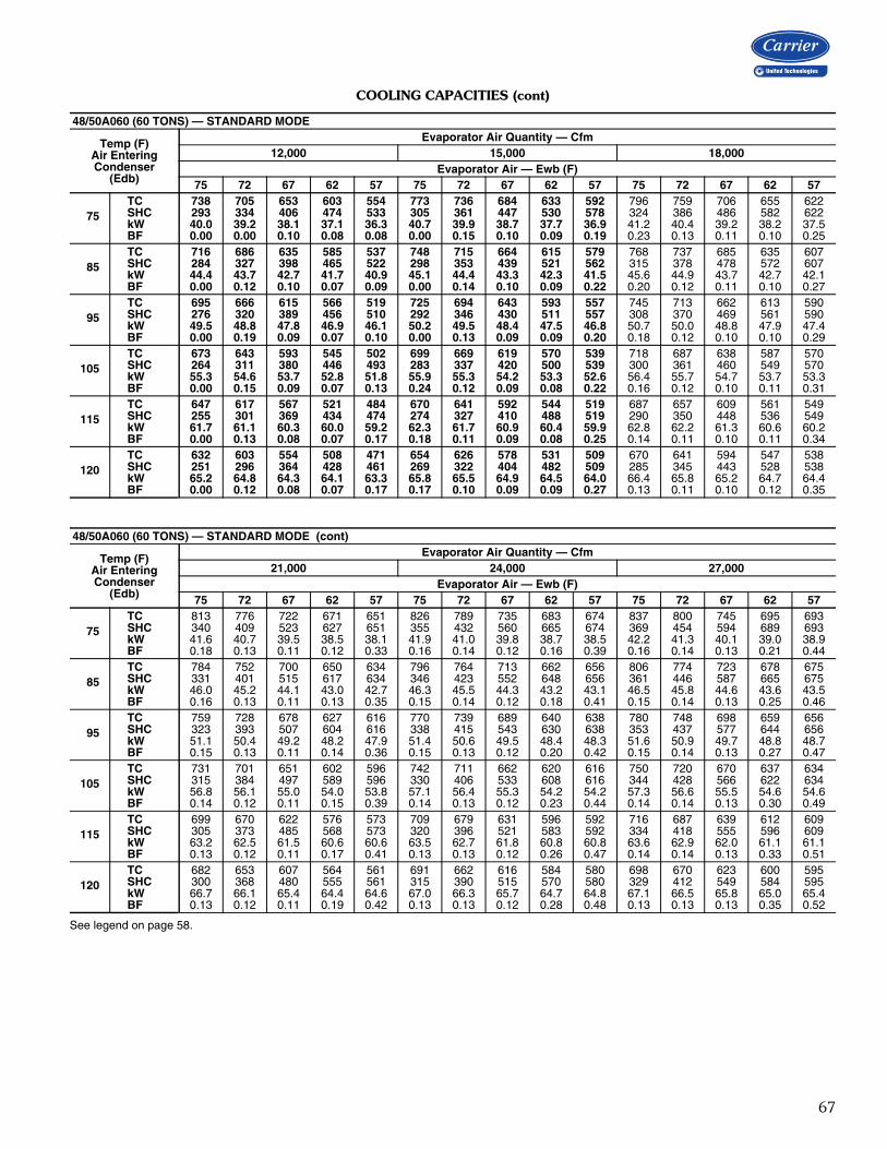
67
COOLING CAPACITIES (cont)
See legend on page 58.
48/50A060 (60 TONS) — STANDARD MODE
Temp (F)Air EnteringCondenser
(Edb)
Evaporator Air Quantity — Cfm12,000 15,000 18,000
Evaporator Air — Ewb (F)75 72 67 62 57 75 72 67 62 57 75 72 67 62 57
75TC 738 705 653 603 554 773 736 684 633 592 796 759 706 655 622SHC 293 334 406 474 533 305 361 447 530 578 324 386 486 582 622kW 40.0 39.2 38.1 37.1 36.3 40.7 39.9 38.7 37.7 36.9 41.2 40.4 39.2 38.2 37.5BF 0.00 0.00 0.10 0.08 0.08 0.00 0.15 0.10 0.09 0.19 0.23 0.13 0.11 0.10 0.25
85TC 716 686 635 585 537 748 715 664 615 579 768 737 685 635 607SHC 284 327 398 465 522 298 353 439 521 562 315 378 478 572 607kW 44.4 43.7 42.7 41.7 40.9 45.1 44.4 43.3 42.3 41.5 45.6 44.9 43.7 42.7 42.1BF 0.00 0.12 0.10 0.07 0.09 0.00 0.14 0.10 0.09 0.22 0.20 0.12 0.11 0.10 0.27
95TC 695 666 615 566 519 725 694 643 593 557 745 713 662 613 590SHC 276 320 389 456 510 292 346 430 511 557 308 370 469 561 590kW 49.5 48.8 47.8 46.9 46.1 50.2 49.5 48.4 47.5 46.8 50.7 50.0 48.8 47.9 47.4BF 0.00 0.19 0.09 0.07 0.10 0.00 0.13 0.09 0.09 0.20 0.18 0.12 0.10 0.10 0.29
105TC 673 643 593 545 502 699 669 619 570 539 718 687 638 587 570SHC 264 311 380 446 493 283 337 420 500 539 300 361 460 549 570kW 55.3 54.6 53.7 52.8 51.8 55.9 55.3 54.2 53.3 52.6 56.4 55.7 54.7 53.7 53.3BF 0.00 0.15 0.09 0.07 0.13 0.24 0.12 0.09 0.08 0.22 0.16 0.12 0.10 0.11 0.31
115TC 647 617 567 521 484 670 641 592 544 519 687 657 609 561 549SHC 255 301 369 434 474 274 327 410 488 519 290 350 448 536 549kW 61.7 61.1 60.3 60.0 59.2 62.3 61.7 60.9 60.4 59.9 62.8 62.2 61.3 60.6 60.2BF 0.00 0.13 0.08 0.07 0.17 0.18 0.11 0.09 0.08 0.25 0.14 0.11 0.10 0.11 0.34
120TC 632 603 554 508 471 654 626 578 531 509 670 641 594 547 538SHC 251 296 364 428 461 269 322 404 482 509 285 345 443 528 538kW 65.2 64.8 64.3 64.1 63.3 65.8 65.5 64.9 64.5 64.0 66.4 65.8 65.2 64.7 64.4BF 0.00 0.12 0.08 0.07 0.17 0.17 0.10 0.09 0.09 0.27 0.13 0.11 0.10 0.12 0.35
48/50A060 (60 TONS) — STANDARD MODE (cont)
Temp (F)Air EnteringCondenser
(Edb)
Evaporator Air Quantity — Cfm21,000 24,000 27,000
Evaporator Air — Ewb (F)75 72 67 62 57 75 72 67 62 57 75 72 67 62 57
75TC 813 776 722 671 651 826 789 735 683 674 837 800 745 695 693SHC 340 409 523 627 651 355 432 560 665 674 369 454 594 689 693kW 41.6 40.7 39.5 38.5 38.1 41.9 41.0 39.8 38.7 38.5 42.2 41.3 40.1 39.0 38.9BF 0.18 0.13 0.11 0.12 0.33 0.16 0.14 0.12 0.16 0.39 0.16 0.14 0.13 0.21 0.44
85TC 784 752 700 650 634 796 764 713 662 656 806 774 723 678 675SHC 331 401 515 617 634 346 423 552 648 656 361 446 587 665 675kW 46.0 45.2 44.1 43.0 42.7 46.3 45.5 44.3 43.2 43.1 46.5 45.8 44.6 43.6 43.5BF 0.16 0.13 0.11 0.13 0.35 0.15 0.14 0.12 0.18 0.41 0.15 0.14 0.13 0.25 0.46
95TC 759 728 678 627 616 770 739 689 640 638 780 748 698 659 656SHC 323 393 507 604 616 338 415 543 630 638 353 437 577 644 656kW 51.1 50.4 49.2 48.2 47.9 51.4 50.6 49.5 48.4 48.3 51.6 50.9 49.7 48.8 48.7BF 0.15 0.13 0.11 0.14 0.36 0.15 0.13 0.12 0.20 0.42 0.15 0.14 0.13 0.27 0.47
105TC 731 701 651 602 596 742 711 662 620 616 750 720 670 637 634SHC 315 384 497 589 596 330 406 533 608 616 344 428 566 622 634kW 56.8 56.1 55.0 54.0 53.8 57.1 56.4 55.3 54.2 54.2 57.3 56.6 55.5 54.6 54.6BF 0.14 0.12 0.11 0.15 0.39 0.14 0.13 0.12 0.23 0.44 0.14 0.14 0.13 0.30 0.49
115TC 699 670 622 576 573 709 679 631 596 592 716 687 639 612 609SHC 305 373 485 568 573 320 396 521 583 592 334 418 555 596 609kW 63.2 62.5 61.5 60.6 60.6 63.5 62.7 61.8 60.8 60.8 63.6 62.9 62.0 61.1 61.1BF 0.13 0.12 0.11 0.17 0.41 0.13 0.13 0.12 0.26 0.47 0.14 0.14 0.13 0.33 0.51
120TC 682 653 607 564 561 691 662 616 584 580 698 670 623 600 595SHC 300 368 480 555 561 315 390 515 570 580 329 412 549 584 595kW 66.7 66.1 65.4 64.4 64.6 67.0 66.3 65.7 64.7 64.8 67.1 66.5 65.8 65.0 65.4BF 0.13 0.12 0.11 0.19 0.42 0.13 0.13 0.12 0.28 0.48 0.13 0.13 0.13 0.35 0.52

68
COOLING CAPACITIES (cont)
See legend on page 58.
48/50A060 (60 TONS) — SUBCOOLING MODE
Temp (F)Air EnteringCondenser
(Edb)
Evaporator Air Quantity – SCFM12,000 15,000 18,000 21,000
Evaporator Air Ewb (F)75 72 67 62 57 75 72 67 62 57 75 72 67 62 57 75 72 67 62 57
75
TC 708 671 616 563 513 742 706 649 596 549 767 732 675 620 583 787 751 693 639 613SHC 253 294 361 425 483 271 320 400 481 542 288 346 441 531 583 303 368 477 578 613kW 39.7 39.0 38.0 37.1 36.2 40.4 39.7 38.6 37.7 36.9 40.8 40.2 39.1 38.0 37.4 41.2 40.5 39.4 38.4 38.0BF 0.00 0.03 0.06 0.07 0.08 0.01 0.07 0.08 0.09 0.15 0.05 0.09 0.10 0.11 0.23 0.08 0.11 0.12 0.14 0.31
85
TC 676 642 588 539 492 709 675 620 568 525 730 697 643 590 556 748 714 660 607 585SHC 229 272 340 406 466 247 297 379 459 519 260 320 416 508 556 275 341 452 552 585kW 43.8 43.1 42.1 41.2 40.4 44.4 43.7 42.7 41.7 41.0 44.9 44.2 43.1 42.1 41.5 45.2 44.5 43.5 42.4 42.0BF 0.00 0.04 0.06 0.07 0.09 0.02 0.07 0.08 0.09 0.16 0.06 0.09 0.10 0.11 0.24 0.09 0.11 0.12 0.14 0.32
95
TC 643 608 559 511 464 674 641 589 539 500 695 663 610 560 531 711 679 626 576 556SHC 205 245 317 384 445 220 271 356 437 494 235 294 392 485 531 249 316 427 528 556kW 48.4 47.7 46.7 45.8 45.0 49.0 48.3 47.3 46.3 45.6 49.5 48.8 47.7 46.7 46.2 49.8 49.1 48.0 47.0 46.6BF 0.00 0.04 0.06 0.07 0.08 0.02 0.07 0.08 0.09 0.17 0.06 0.09 0.10 0.11 0.26 0.09 0.11 0.12 0.14 0.33
105
TC 609 574 528 481 439 636 606 556 508 473 654 625 575 527 501 671 640 590 543 526SHC 179 220 294 362 420 193 245 331 413 469 205 267 366 459 501 219 288 401 501 526kW 53.6 52.8 51.9 51.0 50.2 54.2 53.5 52.5 51.5 50.8 54.6 54.0 52.9 51.9 51.4 55.0 54.3 53.2 52.2 51.9BF 0.00 0.04 0.06 0.07 0.10 0.03 0.07 0.08 0.09 0.18 0.07 0.09 0.10 0.11 0.27 0.09 0.11 0.11 0.15 0.35
115
TC 571 538 494 450 413 594 566 519 474 443 614 585 538 492 470 628 599 551 506 494SHC 153 193 268 338 395 162 217 304 387 443 177 238 339 433 470 189 259 373 472 494kW 59.4 58.7 57.8 56.9 56.1 59.9 59.3 58.3 57.4 56.7 60.4 59.7 58.7 57.7 57.3 60.7 60.0 59.0 58.0 57.8BF 0.01 0.05 0.06 0.07 0.12 0.04 0.07 0.08 0.09 0.19 0.07 0.09 0.10 0.12 0.29 0.09 0.11 0.11 0.15 0.36
48/50A060 (60 TONS) — SUBCOOLING MODE (cont)
Temp (F)Air EnteringCondenser
(Edb)
Evaporator Air Quantity – SCFM24,000 27,000 30,000
Evaporator Air Ewb (F)75 72 67 62 57 75 72 67 62 57 75 72 67 62 57
75
TC 804 768 708 654 637 814 779 720 665 657 825 789 729 678 674SHC 320 392 512 618 637 332 413 546 652 657 346 434 578 678 674kW 41.5 40.9 39.7 38.7 38.4 41.8 41.1 39.9 38.9 38.8 42.0 41.3 40.1 39.2 39.1BF 0.11 0.13 0.13 0.17 0.38 0.12 0.14 0.15 0.20 0.43 0.14 0.16 0.16 0.24 0.47
85
TC 761 729 674 621 607 772 740 684 634 627 783 749 693 647 646SHC 289 364 487 591 607 302 385 520 621 627 317 406 552 647 646kW 45.5 44.8 43.7 42.7 42.5 45.7 45.1 43.9 43.0 42.8 46.0 45.3 44.1 43.2 43.2BF 0.11 0.13 0.13 0.17 0.39 0.13 0.14 0.15 0.21 0.44 0.14 0.16 0.16 0.26 0.48
95
TC 722 691 639 589 578 734 702 647 599 597 742 709 656 612 613SHC 260 337 461 565 578 275 358 492 588 597 287 377 524 612 613kW 50.1 49.4 48.3 47.3 47.1 50.3 49.6 48.5 47.5 47.4 50.5 49.8 48.6 47.7 47.8BF 0.11 0.13 0.13 0.17 0.40 0.13 0.14 0.15 0.23 0.45 0.14 0.15 0.16 0.27 0.49
105
TC 682 651 601 556 547 692 661 608 569 565 700 669 618 582 580SHC 232 308 434 533 547 245 328 464 559 565 258 349 496 582 580kW 55.3 54.5 53.4 52.5 52.3 55.5 54.8 53.6 52.7 52.7 55.7 54.9 53.8 53.0 53.0BF 0.11 0.12 0.13 0.19 0.41 0.13 0.14 0.15 0.24 0.46 0.14 0.15 0.16 0.29 0.50
115
TC 639 610 562 521 514 647 618 570 535 531 655 625 575 546 545SHC 202 279 406 501 514 214 299 437 527 531 226 318 464 546 545kW 61.0 60.3 59.2 58.3 58.2 61.2 60.5 59.4 58.6 58.5 61.4 60.7 59.5 58.8 58.8BF 0.11 0.12 0.13 0.21 0.42 0.13 0.14 0.15 0.25 0.47 0.14 0.15 0.17 0.30 0.51
Performance data (cont)

69
COOLING CAPACITIES (cont)
See legend on page 58.
50A060 (60 TONS) — HOT GAS REHEAT MODE
Temp (F)Air EnteringCondenser
(Edb)
Air Entering Evaporator — Ewb (F)75 Dry Bulb 75 Dry Bulb
62.5 Wet Bulb (50% RH) 65.3 Wet Bulb (60% RH)Air Entering Evaporator — SCFM
12,000 15,000 18,000 21,000 24,000 27,000 30,000 12,000 15,000 18,000 21,000 24,000 27,000 30,000
40
TC 298 322 339 352 362 369 375 314 339 357 370 380 388 395SHC 80 111 141 171 201 230 258 30 52 74 97 119 141 163kW 36.2 36.0 36.0 36.1 36.1 36.2 36.3 37.8 37.5 37.4 37.4 37.4 37.5 37.5BF 0.04 0.06 0.07 0.08 0.09 0.11 0.12 0.03 0.05 0.07 0.08 0.09 0.10 0.12
50
TC 287 308 324 336 345 351 357 301 325 341 353 363 370 376SHC 74 104 134 164 194 223 250 24 46 68 90 112 134 156kW 37.7 37.5 37.4 37.4 37.5 37.5 37.6 39.3 38.9 38.8 38.8 38.8 38.8 38.8BF 0.04 0.06 0.07 0.08 0.09 0.11 0.12 0.04 0.05 0.07 0.08 0.09 0.10 0.12
60
TC 277 297 311 320 328 335 340 291 311 326 337 346 352 358SHC 70 99 128 157 187 216 243 19 40 61 83 105 127 149kW 39.4 39.1 39.0 39.0 39.0 39.0 39.1 40.9 40.5 40.3 40.3 40.3 40.3 40.3BF 0.04 0.06 0.07 0.08 0.09 0.11 0.12 0.04 0.05 0.07 0.08 0.09 0.10 0.11
70
TC 267 287 299 309 316 321 325 280 300 314 324 331 336 341SHC 65 94 123 153 182 210 237 15 35 56 78 100 121 143kW 41.2 40.9 40.8 40.7 40.7 40.7 40.8 42.7 42.3 42.1 42.0 42.0 42.0 42.0BF 0.04 0.06 0.07 0.08 0.09 0.11 0.12 0.04 0.05 0.07 0.08 0.09 0.10 0.11
75
TC 262 281 294 303 309 314 319 275 295 308 317 324 330 334SHC 62 92 121 150 180 207 234 12 33 54 75 97 119 141kW 42.2 41.9 41.7 41.7 41.7 41.7 41.7 43.7 43.3 43.1 43.0 43.0 42.9 42.9BF 0.04 0.06 0.07 0.08 0.09 0.11 0.13 0.04 0.05 0.07 0.08 0.09 0.10 0.11
80
TC 257 275 288 296 303 308 312 270 289 302 311 318 323 327SHC 60 89 118 148 177 205 232 10 30 51 73 95 116 138kW 43.3 42.9 42.8 42.7 42.7 42.7 42.7 44.8 44.3 44.1 44.0 44.0 44.0 43.9BF 0.04 0.06 0.07 0.08 0.09 0.11 0.13 0.04 0.05 0.07 0.08 0.09 0.10 0.11
50A060 (60 TONS) — HOT GAS REHEAT MODE (cont)
Temp (F)Air EnteringCondenser
(Edb)
Air Entering Evaporator — Ewb (F)75 Dry Bulb 75 Dry Bulb
68.0 Wet Bulb (70% RH) 70.5 Wet Bulb (80% RH)Air Entering Evaporator — SCFM
12,000 15,000 18,000 21,000 24,000 27,000 30,000 12,000 15,000 18,000 21,000 24,000 27,000 30,000
40
TC 330 357 375 389 400 408 414 345 373 393 407 418 426 433SHC –19 –5 10 24 39 54 69 –65 –58 –51 –43 –35 –27 –18kW 39.4 39.0 38.8 38.8 38.8 38.7 38.8 41.0 40.4 40.2 40.0 40.0 39.9 39.9BF 0.02 0.04 0.06 0.07 0.09 0.10 0.11 0.00 0.01 0.03 0.05 0.07 0.09 0.10
50
TC 316 341 359 372 381 389 395 331 358 376 389 399 407 413SHC –25 –11 3 18 32 48 63 –72 –64 –57 –50 –42 –33 –25kW 40.9 40.4 40.2 40.1 40.1 40.1 40.1 42.5 41.8 41.5 41.4 41.3 41.2 41.2BF 0.02 0.04 0.06 0.07 0.09 0.10 0.11 0.00 0.01 0.03 0.05 0.07 0.09 0.10
60
TC 304 326 342 354 363 370 376 318 342 358 371 380 387 393SHC –30 –17 –3 11 26 41 56 –77 –71 –64 –56 –48 –40 –31kW 42.5 42.0 41.7 41.6 41.6 41.5 41.5 44.1 43.4 43.1 42.9 42.8 42.7 42.6BF 0.02 0.04 0.06 0.07 0.09 0.10 0.11 0.00 0.01 0.03 0.05 0.07 0.09 0.10
70
TC 294 315 329 339 347 353 357 307 329 343 354 363 369 374SHC –35 –22 –9 5 20 35 49 –82 –75 –69 –62 –54 –46 –37kW 44.3 43.8 43.5 43.3 43.3 43.2 43.2 45.9 45.2 44.8 44.6 44.5 44.4 44.3BF 0.02 0.04 0.06 0.07 0.09 0.10 0.11 0.00 0.01 0.03 0.05 0.07 0.09 0.10
75
TC 288 309 323 332 340 346 350 301 323 337 348 356 362 367SHC –37 –24 –11 3 18 32 47 –84 –78 –71 –64 –56 –48 –40kW 45.3 44.7 44.5 44.3 44.2 44.2 44.1 46.9 46.1 45.7 45.5 45.4 45.3 45.3BF 0.02 0.04 0.06 0.07 0.09 0.10 0.11 0.00 0.01 0.03 0.05 0.07 0.09 0.10
80
TC 283 303 316 326 333 339 343 295 316 330 341 348 355 360SHC –39 –27 –13 1 15 30 44 –86 –80 –74 –67 –59 –50 –42kW 46.4 45.8 45.5 45.3 45.2 45.2 45.1 47.9 47.2 46.8 46.6 46.4 46.3 46.3BF 0.02 0.04 0.06 0.07 0.09 0.10 0.11 0.00 0.01 0.03 0.05 0.07 0.09 0.10
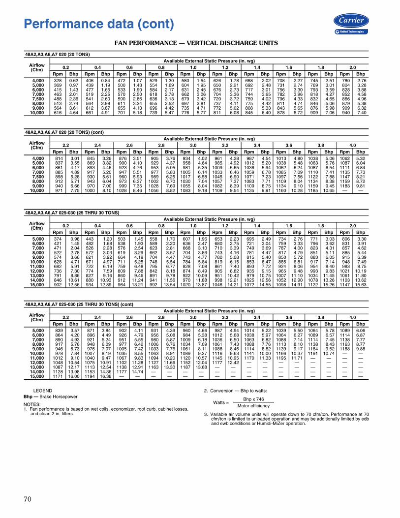
70
FAN PERFORMANCE — VERTICAL DISCHARGE UNITS
LEGENDBhp — Brake Horsepower
NOTES:1. Fan performance is based on wet coils, economizer, roof curb, cabinet losses,
and clean 2-in. filters.
2. Conversion — Bhp to watts:
3. Variable air volume units will operate down to 70 cfm/ton. Performance at 70cfm/ton is limited to unloaded operation and may be additionally limited by edband ewb conditions or Humidi-MiZer operation.
48A2,A3,A6,A7 020 (20 TONS)
Airflow(Cfm)
Available External Static Pressure (in. wg)0.2 0.4 0.6 0.8 1.0 1.2 1.4 1.6 1.8 2.0
Rpm Bhp Rpm Bhp Rpm Bhp Rpm Bhp Rpm Bhp Rpm Bhp Rpm Bhp Rpm Bhp Rpm Bhp Rpm Bhp 4,000 328 0.62 406 0.84 472 1.07 529 1.30 580 1.54 626 1.78 668 2.02 708 2.27 745 2.51 780 2.76 5,000 369 0.97 439 1.19 500 1.43 554 1.69 604 1.95 650 2.21 692 2.48 731 2.74 769 3.01 804 3.28 6,000 415 1.43 477 1.65 533 1.90 584 2.17 631 2.45 676 2.73 717 3.01 756 3.30 793 3.59 828 3.88 7,000 463 2.01 519 2.25 570 2.50 618 2.78 662 3.06 704 3.36 744 3.65 782 3.96 818 4.27 852 4.58 7,500 488 2.36 541 2.60 590 2.86 636 3.13 679 3.42 720 3.72 759 4.02 796 4.33 832 4.65 866 4.96 8,000 513 2.74 564 2.98 611 3.24 655 3.52 697 3.81 737 4.11 775 4.42 811 4.74 846 5.06 879 5.38 9,000 564 3.61 612 3.87 655 4.13 696 4.42 735 4.71 772 5.02 808 5.33 843 5.65 876 5.98 909 6.3210,000 616 4.64 661 4.91 701 5.18 739 5.47 776 5.77 811 6.08 845 6.40 878 6.72 909 7.06 940 7.40
48A2,A3,A6,A7 020 (20 TONS) (cont)
Airflow(Cfm)
Available External Static Pressure (in. wg)2.2 2.4 2.6 2.8 3.0 3.2 3.4 3.6 3.8 4.0
Rpm Bhp Rpm Bhp Rpm Bhp Rpm Bhp Rpm Bhp Rpm Bhp Rpm Bhp Rpm Bhp Rpm Bhp Rpm Bhp 4,000 814 3.01 845 3.26 876 3.51 905 3.76 934 4.02 961 4.28 987 4.54 1013 4.80 1038 5.06 1062 5.32 5,000 837 3.55 869 3.82 900 4.10 929 4.37 958 4.64 985 4.92 1012 5.20 1038 5.48 1063 5.76 1087 6.04 6,000 861 4.17 893 4.46 923 4.76 953 5.05 981 5.35 1009 5.65 1036 5.94 1062 6.24 1087 6.54 1111 6.84 7,000 885 4.89 917 5.20 947 5.51 977 5.83 1005 6.14 1033 6.46 1059 6.78 1085 7.09 1110 7.41 1135 7.73 7,500 898 5.28 930 5.61 960 5.93 989 6.25 1017 6.58 1045 6.90 1071 7.23 1097 7.56 1122 7.88 1147 8.21 8,000 912 5.71 943 6.04 973 6.37 1002 6.70 1030 7.04 1057 7.37 1083 7.71 1109 8.04 1134 8.38 1159 8.72 9,000 940 6.66 970 7.00 999 7.35 1028 7.69 1055 8.04 1082 8.39 1109 8.75 1134 9.10 1159 9.45 1183 9.8110,000 971 7.75 1000 8.10 1028 8.46 1056 8.82 1083 9.18 1109 9.54 1135 9.91 1160 10.28 1185 10.65 — —
48A2,A3,A6,A7 025-030 (25 THRU 30 TONS)
Airflow(Cfm)
Available External Static Pressure (in. wg)0.2 0.4 0.6 0.8 1.0 1.2 1.4 1.6 1.8 2.0
Rpm Bhp Rpm Bhp Rpm Bhp Rpm Bhp Rpm Bhp Rpm Bhp Rpm Bhp Rpm Bhp Rpm Bhp Rpm Bhp 5,000 374 0.98 443 1.20 503 1.45 558 1.70 607 1.96 653 2.23 695 2.49 734 2.76 771 3.03 806 3.30 6,000 421 1.45 482 1.68 538 1.93 589 2.20 636 2.47 680 2.75 721 3.04 759 3.33 796 3.62 831 3.91 7,000 471 2.04 526 2.28 576 2.54 623 2.81 668 3.10 710 3.39 749 3.69 787 4.00 823 4.31 857 4.62 8,000 522 2.78 572 3.03 619 3.29 662 3.57 704 3.86 743 4.16 781 4.47 817 4.79 851 5.11 885 5.44 9,000 574 3.66 621 3.92 664 4.19 704 4.47 743 4.77 780 5.08 815 5.40 850 5.72 883 6.05 915 6.3910,000 628 4.71 671 4.97 711 5.25 748 5.54 784 5.84 819 6.15 853 6.47 885 6.81 917 7.14 948 7.4911,000 682 5.91 722 6.19 759 6.48 795 6.77 828 7.08 861 7.40 893 7.72 924 8.06 954 8.40 983 8.7512,000 736 7.30 774 7.59 809 7.88 842 8.18 874 8.49 905 8.82 935 9.15 965 9.48 993 9.83 1021 10.1913,000 791 8.86 827 9.16 860 9.46 891 9.78 922 10.09 951 10.42 979 10.75 1007 11.10 1034 11.45 1061 11.8014,000 846 10.61 880 10.93 912 11.24 941 11.56 970 11.88 998 12.21 1025 12.56 1052 12.90 1078 13.26 1103 13.6215,000 902 12.56 934 12.89 964 13.21 992 13.54 1020 13.87 1046 14.21 1072 14.55 1098 14.91 1122 15.26 1147 15.63
48A2,A3,A6,A7 025-030 (25 THRU 30 TONS) (cont)
Airflow(Cfm)
Available External Static Pressure (in. wg)2.2 2.4 2.6 2.8 3.0 3.2 3.4 3.6 3.8 4.0
Rpm Bhp Rpm Bhp Rpm Bhp Rpm Bhp Rpm Bhp Rpm Bhp Rpm Bhp Rpm Bhp Rpm Bhp Rpm Bhp 5,000 839 3.57 871 3.84 902 4.11 931 4.39 960 4.66 987 4.94 1014 5.22 1039 5.50 1064 5.78 1089 6.06 6,000 864 4.20 896 4.49 926 4.79 956 5.08 984 5.38 1012 5.68 1038 5.97 1064 6.27 1089 6.57 1114 6.87 7,000 890 4.93 921 5.24 951 5.55 980 5.87 1009 6.18 1036 6.50 1063 6.82 1088 7.14 1114 7.45 1138 7.77 8,000 917 5.76 948 6.09 977 6.42 1006 6.76 1034 7.09 1061 7.43 1088 7.76 1113 8.10 1138 8.43 1163 8.77 9,000 946 6.73 976 7.07 1005 7.42 1033 7.76 1061 8.11 1088 8.46 1114 8.82 1139 9.17 1164 9.52 1188 9.8810,000 978 7.84 1007 8.19 1035 8.55 1063 8.91 1089 9.27 1116 9.63 1141 10.00 1166 10.37 1191 10.74 — —11,000 1012 9.10 1040 9.47 1067 9.83 1094 10.20 1120 10.57 1145 10.95 1170 11.33 1195 11.71 — — — —12,000 1048 10.54 1075 10.91 1102 11.28 1127 11.66 1152 12.04 1177 12.42 — — — — — — — —13,000 1087 12.17 1113 12.54 1138 12.91 1163 13.30 1187 13.68 — — — — — — — — — —14,000 1128 13.98 1153 14.36 1177 14.74 — — — — — — — — — — — — — —15,000 1171 16.00 1194 16.38 — — — — — — — — — — — — — — — —
Watts =Bhp x 746
Motor efficiency
Performance data (cont)
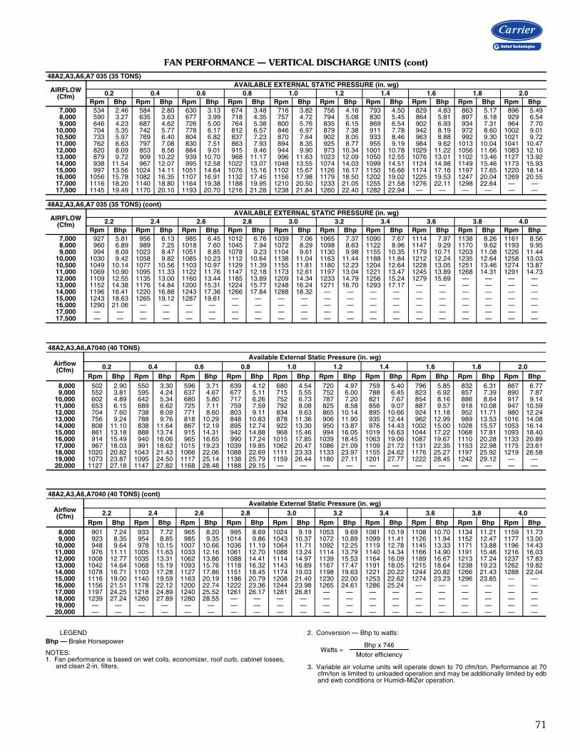
71
FAN PERFORMANCE — VERTICAL DISCHARGE UNITS (cont)
LEGENDBhp — Brake Horsepower
NOTES:1. Fan performance is based on wet coils, economizer, roof curb, cabinet losses,
and clean 2-in. filters.
2. Conversion — Bhp to watts:
3. Variable air volume units will operate down to 70 cfm/ton. Performance at 70cfm/ton is limited to unloaded operation and may be additionally limited by edband ewb conditions or Humidi-MiZer operation.
48A2,A3,A6,A7 035 (35 TONS)
AIRFLOW(Cfm)
AVAILABLE EXTERNAL STATIC PRESSURE (in. wg)0.2 0.4 0.6 0.8 1.0 1.2 1.4 1.6 1.8 2.0
Rpm Bhp Rpm Bhp Rpm Bhp Rpm Bhp Rpm Bhp Rpm Bhp Rpm Bhp Rpm Bhp Rpm Bhp Rpm Bhp7,000 534 2.46 584 2.80 630 3.13 674 3.48 716 3.82 756 4.16 793 4.50 829 4.83 863 5.17 896 5.498,000 590 3.27 635 3.63 677 3.99 718 4.35 757 4.72 794 5.08 830 5.45 864 5.81 897 6.18 929 6.549,000 646 4.23 687 4.62 726 5.00 764 5.38 800 5.76 835 6.15 869 6.54 902 6.93 934 7.31 964 7.70
10,000 704 5.35 742 5.77 778 6.17 812 6.57 846 6.97 879 7.38 911 7.78 942 8.19 972 8.60 1002 9.0110,500 733 5.97 769 6.40 804 6.82 837 7.23 870 7.64 902 8.05 933 8.46 963 8.88 992 9.30 1021 9.7211,000 762 6.63 797 7.08 830 7.51 863 7.93 894 8.35 925 8.77 955 9.19 984 9.62 1013 10.04 1041 10.4712,000 820 8.09 853 8.56 884 9.01 915 9.46 944 9.90 973 10.34 1001 10.78 1029 11.22 1056 11.66 1083 12.1013,000 879 9.72 909 10.22 939 10.70 968 11.17 996 11.63 1023 12.09 1050 12.55 1076 13.01 1102 13.46 1127 13.9214,000 938 11.54 967 12.07 995 12.58 1022 13.07 1048 13.55 1074 14.03 1099 14.51 1124 14.98 1149 15.46 1173 15.9315,000 997 13.56 1024 14.11 1051 14.64 1076 15.16 1102 15.67 1126 16.17 1150 16.66 1174 17.16 1197 17.65 1220 18.1416,000 1056 15.78 1082 16.35 1107 16.91 1132 17.45 1156 17.98 1179 18.50 1202 19.02 1225 19.53 1247 20.04 1269 20.5517,000 1116 18.20 1140 18.80 1164 19.38 1188 19.95 1210 20.50 1233 21.05 1255 21.58 1276 22.11 1298 22.64 — —17,500 1145 19.49 1170 20.10 1193 20.70 1216 21.28 1238 21.84 1260 22.40 1282 22.94 — — — — — —
48A2,A3,A6,A7 035 (35 TONS) (cont)
AIRFLOW(Cfm)
AVAILABLE EXTERNAL STATIC PRESSURE (in. wg)2.2 2.4 2.6 2.8 3.0 3.2 3.4 3.6 3.8 4.0
Rpm Bhp Rpm Bhp Rpm Bhp Rpm Bhp Rpm Bhp Rpm Bhp Rpm Bhp Rpm Bhp Rpm Bhp Rpm Bhp7,000 927 5.81 956 6.13 985 6.45 1012 6.76 1039 7.06 1065 7.37 1090 7.67 1114 7.97 1138 8.26 1161 8.568,000 960 6.89 989 7.25 1018 7.60 1045 7.94 1072 8.29 1098 8.63 1122 8.96 1147 9.29 1170 9.62 1193 9.959,000 994 8.09 1023 8.47 1051 8.85 1078 9.23 1104 9.61 1130 9.98 1155 10.35 1179 10.71 1203 11.08 1226 11.44
10,000 1030 9.42 1058 9.82 1085 10.23 1112 10.64 1138 11.04 1163 11.44 1188 11.84 1212 12.24 1235 12.64 1258 13.0310,500 1049 10.14 1077 10.56 1103 10.97 1129 11.39 1155 11.81 1180 12.23 1204 12.64 1228 13.05 1251 13.46 1274 13.8711,000 1069 10.90 1095 11.33 1122 11.76 1147 12.18 1173 12.61 1197 13.04 1221 13.47 1245 13.89 1268 14.31 1291 14.7312,000 1109 12.55 1135 13.00 1160 13.44 1185 13.89 1209 14.34 1233 14.79 1256 15.24 1279 15.69 — — — —13,000 1152 14.38 1176 14.84 1200 15.31 1224 15.77 1248 16.24 1271 16.70 1293 17.17 — — — — — —14,000 1196 16.41 1220 16.88 1243 17.36 1266 17.84 1288 18.32 — — — — — — — — — —15,000 1243 18.63 1265 19.12 1287 19.61 — — — — — — — — — — — — — —16,000 1290 21.06 — — — — — — — — — — — — — — — — — —17,000 — — — — — — — — — — — — — — — — — — — —17,500 — — — — — — — — — — — — — — — — — — — —
48A2,A3,A6,A7040 (40 TONS)
Airflow(Cfm)
Available External Static Pressure (in. wg)0.2 0.4 0.6 0.8 1.0 1.2 1.4 1.6 1.8 2.0
Rpm Bhp Rpm Bhp Rpm Bhp Rpm Bhp Rpm Bhp Rpm Bhp Rpm Bhp Rpm Bhp Rpm Bhp Rpm Bhp8,000 502 2.90 550 3.30 596 3.71 639 4.12 680 4.54 720 4.97 759 5.40 796 5.85 832 6.31 867 6.779,000 552 3.81 595 4.24 637 4.67 677 5.11 715 5.55 752 6.00 788 6.45 823 6.92 857 7.39 890 7.87
10,000 602 4.89 642 5.34 680 5.80 717 6.26 752 6.73 787 7.20 821 7.67 854 8.16 886 8.64 917 9.1411,000 653 6.15 689 6.62 725 7.11 759 7.59 792 8.08 825 8.58 856 9.07 887 9.57 918 10.08 947 10.5912,000 704 7.60 738 8.09 771 8.60 803 9.11 834 9.63 865 10.14 895 10.66 924 11.18 952 11.71 980 12.2413,000 756 9.24 788 9.76 818 10.29 848 10.83 878 11.36 906 11.90 935 12.44 962 12.99 989 13.53 1016 14.0814,000 808 11.10 838 11.64 867 12.19 895 12.74 922 13.30 950 13.87 976 14.43 1002 15.00 1028 15.57 1053 16.1415,000 861 13.18 888 13.74 915 14.31 942 14.88 968 15.46 994 16.05 1019 16.63 1044 17.22 1068 17.81 1093 18.4016,000 914 15.49 940 16.06 965 16.65 990 17.24 1015 17.85 1039 18.45 1063 19.06 1087 19.67 1110 20.28 1133 20.8917,000 967 18.03 991 18.62 1015 19.23 1039 19.85 1062 20.47 1086 21.09 1109 21.72 1131 22.35 1153 22.98 1175 23.6118,000 1020 20.82 1043 21.43 1066 22.06 1088 22.69 1111 23.33 1133 23.97 1155 24.62 1176 25.27 1197 25.92 1219 26.5819,000 1073 23.87 1095 24.50 1117 25.14 1138 25.79 1159 26.44 1180 27.11 1201 27.77 1222 28.45 1242 29.12 — —20,000 1127 27.18 1147 27.82 1168 28.48 1188 29.15 — — — — — — — — — — — —
48A2,A3,A6,A7040 (40 TONS) (cont)
Airflow(Cfm)
Available External Static Pressure (in. wg)2.2 2.4 2.6 2.8 3.0 3.2 3.4 3.6 3.8 4.0
Rpm Bhp Rpm Bhp Rpm Bhp Rpm Bhp Rpm Bhp Rpm Bhp Rpm Bhp Rpm Bhp Rpm Bhp Rpm Bhp8,000 901 7.24 933 7.72 965 8.20 995 8.69 1024 9.19 1053 9.69 1081 10.19 1108 10.70 1134 11.21 1159 11.739,000 923 8.35 954 8.85 985 9.35 1014 9.86 1043 10.37 1072 10.89 1099 11.41 1126 11.94 1152 12.47 1177 13.00
10,000 948 9.64 978 10.15 1007 10.66 1036 11.19 1064 11.71 1092 12.25 1119 12.78 1145 13.33 1171 13.88 1196 14.4311,000 976 11.11 1005 11.63 1033 12.16 1061 12.70 1088 13.24 1114 13.79 1140 14.34 1166 14.90 1191 15.46 1216 16.0312,000 1008 12.77 1035 13.31 1062 13.86 1088 14.41 1114 14.97 1139 15.53 1164 16.09 1189 16.67 1213 17.24 1237 17.8313,000 1042 14.64 1068 15.19 1093 15.76 1118 16.32 1143 16.89 1167 17.47 1191 18.05 1215 18.64 1238 19.23 1262 19.8214,000 1078 16.71 1103 17.28 1127 17.86 1151 18.45 1174 19.03 1198 19.63 1221 20.22 1244 20.82 1266 21.43 1288 22.0415,000 1116 19.00 1140 19.59 1163 20.19 1186 20.79 1208 21.40 1230 22.00 1253 22.62 1274 23.23 1296 23.85 — —16,000 1156 21.51 1178 22.12 1200 22.74 1222 23.36 1244 23.98 1265 24.61 1286 25.24 — — — — — —17,000 1197 24.25 1218 24.89 1240 25.52 1261 26.17 1281 26.81 — — — — — — — — — —18,000 1239 27.24 1260 27.89 1280 28.55 — — — — — — — — — — — — — —19,000 — — — — — — — — — — — — — — — — — — — —20,000 — — — — — — — — — — — — — — — — — — — —
Watts =Bhp x 746
Motor efficiency
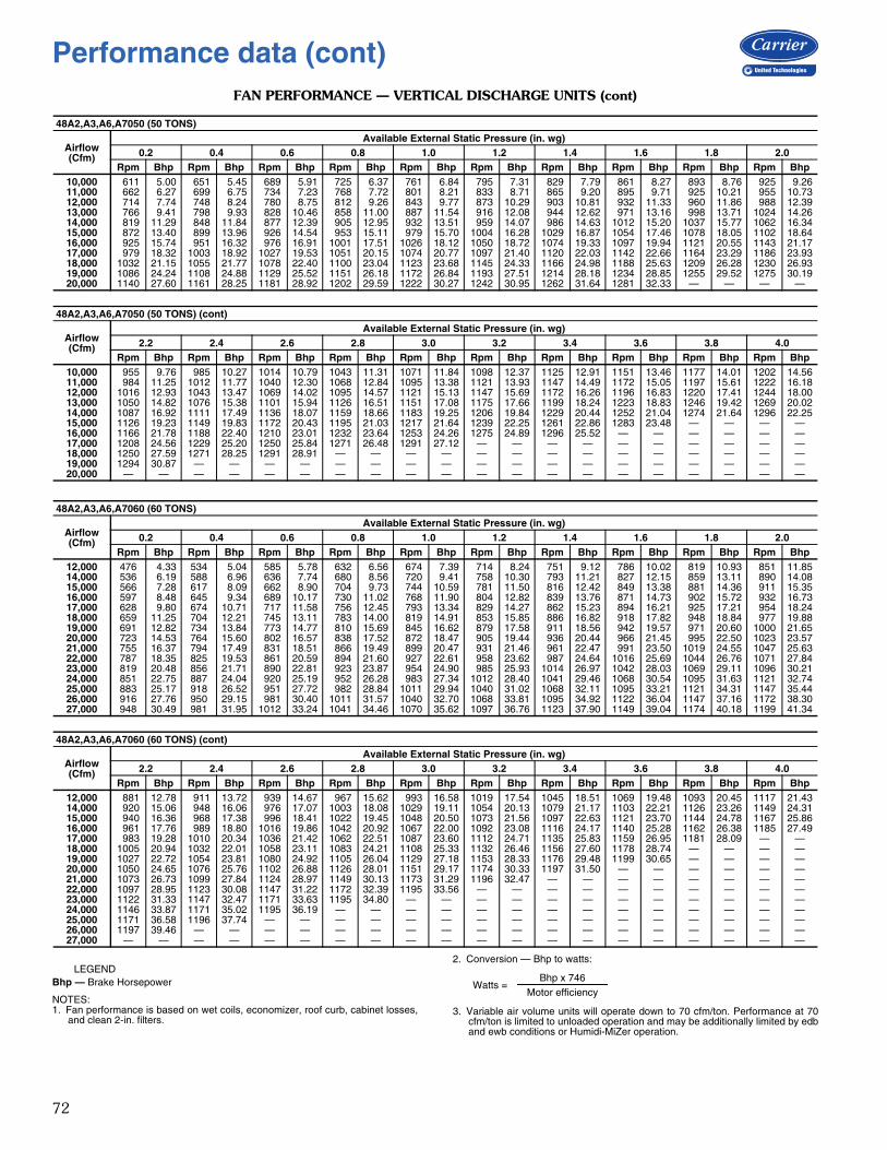
72
FAN PERFORMANCE — VERTICAL DISCHARGE UNITS (cont)
LEGENDBhp — Brake Horsepower
NOTES:1. Fan performance is based on wet coils, economizer, roof curb, cabinet losses,
and clean 2-in. filters.
2. Conversion — Bhp to watts:
3. Variable air volume units will operate down to 70 cfm/ton. Performance at 70cfm/ton is limited to unloaded operation and may be additionally limited by edband ewb conditions or Humidi-MiZer operation.
48A2,A3,A6,A7050 (50 TONS)
Airflow(Cfm)
Available External Static Pressure (in. wg)0.2 0.4 0.6 0.8 1.0 1.2 1.4 1.6 1.8 2.0
Rpm Bhp Rpm Bhp Rpm Bhp Rpm Bhp Rpm Bhp Rpm Bhp Rpm Bhp Rpm Bhp Rpm Bhp Rpm Bhp10,000 611 5.00 651 5.45 689 5.91 725 6.37 761 6.84 795 7.31 829 7.79 861 8.27 893 8.76 925 9.2611,000 662 6.27 699 6.75 734 7.23 768 7.72 801 8.21 833 8.71 865 9.20 895 9.71 925 10.21 955 10.7312,000 714 7.74 748 8.24 780 8.75 812 9.26 843 9.77 873 10.29 903 10.81 932 11.33 960 11.86 988 12.3913,000 766 9.41 798 9.93 828 10.46 858 11.00 887 11.54 916 12.08 944 12.62 971 13.16 998 13.71 1024 14.2614,000 819 11.29 848 11.84 877 12.39 905 12.95 932 13.51 959 14.07 986 14.63 1012 15.20 1037 15.77 1062 16.3415,000 872 13.40 899 13.96 926 14.54 953 15.11 979 15.70 1004 16.28 1029 16.87 1054 17.46 1078 18.05 1102 18.6416,000 925 15.74 951 16.32 976 16.91 1001 17.51 1026 18.12 1050 18.72 1074 19.33 1097 19.94 1121 20.55 1143 21.1717,000 979 18.32 1003 18.92 1027 19.53 1051 20.15 1074 20.77 1097 21.40 1120 22.03 1142 22.66 1164 23.29 1186 23.9318,000 1032 21.15 1055 21.77 1078 22.40 1100 23.04 1123 23.68 1145 24.33 1166 24.98 1188 25.63 1209 26.28 1230 26.9319,000 1086 24.24 1108 24.88 1129 25.52 1151 26.18 1172 26.84 1193 27.51 1214 28.18 1234 28.85 1255 29.52 1275 30.1920,000 1140 27.60 1161 28.25 1181 28.92 1202 29.59 1222 30.27 1242 30.95 1262 31.64 1281 32.33 — — — —
48A2,A3,A6,A7050 (50 TONS) (cont)
Airflow(Cfm)
Available External Static Pressure (in. wg)2.2 2.4 2.6 2.8 3.0 3.2 3.4 3.6 3.8 4.0
Rpm Bhp Rpm Bhp Rpm Bhp Rpm Bhp Rpm Bhp Rpm Bhp Rpm Bhp Rpm Bhp Rpm Bhp Rpm Bhp10,000 955 9.76 985 10.27 1014 10.79 1043 11.31 1071 11.84 1098 12.37 1125 12.91 1151 13.46 1177 14.01 1202 14.5611,000 984 11.25 1012 11.77 1040 12.30 1068 12.84 1095 13.38 1121 13.93 1147 14.49 1172 15.05 1197 15.61 1222 16.1812,000 1016 12.93 1043 13.47 1069 14.02 1095 14.57 1121 15.13 1147 15.69 1172 16.26 1196 16.83 1220 17.41 1244 18.0013,000 1050 14.82 1076 15.38 1101 15.94 1126 16.51 1151 17.08 1175 17.66 1199 18.24 1223 18.83 1246 19.42 1269 20.0214,000 1087 16.92 1111 17.49 1136 18.07 1159 18.66 1183 19.25 1206 19.84 1229 20.44 1252 21.04 1274 21.64 1296 22.2515,000 1126 19.23 1149 19.83 1172 20.43 1195 21.03 1217 21.64 1239 22.25 1261 22.86 1283 23.48 — — — —16,000 1166 21.78 1188 22.40 1210 23.01 1232 23.64 1253 24.26 1275 24.89 1296 25.52 — — — — — —17,000 1208 24.56 1229 25.20 1250 25.84 1271 26.48 1291 27.12 — — — — — — — — — —18,000 1250 27.59 1271 28.25 1291 28.91 — — — — — — — — — — — — — —19,000 1294 30.87 — — — — — — — — — — — — — — — — — —20,000 — — — — — — — — — — — — — — — — — — — —
48A2,A3,A6,A7060 (60 TONS)
Airflow(Cfm)
Available External Static Pressure (in. wg)0.2 0.4 0.6 0.8 1.0 1.2 1.4 1.6 1.8 2.0
Rpm Bhp Rpm Bhp Rpm Bhp Rpm Bhp Rpm Bhp Rpm Bhp Rpm Bhp Rpm Bhp Rpm Bhp Rpm Bhp12,000 476 4.33 534 5.04 585 5.78 632 6.56 674 7.39 714 8.24 751 9.12 786 10.02 819 10.93 851 11.8514,000 536 6.19 588 6.96 636 7.74 680 8.56 720 9.41 758 10.30 793 11.21 827 12.15 859 13.11 890 14.0815,000 566 7.28 617 8.09 662 8.90 704 9.73 744 10.59 781 11.50 816 12.42 849 13.38 881 14.36 911 15.3516,000 597 8.48 645 9.34 689 10.17 730 11.02 768 11.90 804 12.82 839 13.76 871 14.73 902 15.72 932 16.7317,000 628 9.80 674 10.71 717 11.58 756 12.45 793 13.34 829 14.27 862 15.23 894 16.21 925 17.21 954 18.2418,000 659 11.25 704 12.21 745 13.11 783 14.00 819 14.91 853 15.85 886 16.82 918 17.82 948 18.84 977 19.8819,000 691 12.82 734 13.84 773 14.77 810 15.69 845 16.62 879 17.58 911 18.56 942 19.57 971 20.60 1000 21.6520,000 723 14.53 764 15.60 802 16.57 838 17.52 872 18.47 905 19.44 936 20.44 966 21.45 995 22.50 1023 23.5721,000 755 16.37 794 17.49 831 18.51 866 19.49 899 20.47 931 21.46 961 22.47 991 23.50 1019 24.55 1047 25.6322,000 787 18.35 825 19.53 861 20.59 894 21.60 927 22.61 958 23.62 987 24.64 1016 25.69 1044 26.76 1071 27.8423,000 819 20.48 856 21.71 890 22.81 923 23.87 954 24.90 985 25.93 1014 26.97 1042 28.03 1069 29.11 1096 30.2124,000 851 22.75 887 24.04 920 25.19 952 26.28 983 27.34 1012 28.40 1041 29.46 1068 30.54 1095 31.63 1121 32.7425,000 883 25.17 918 26.52 951 27.72 982 28.84 1011 29.94 1040 31.02 1068 32.11 1095 33.21 1121 34.31 1147 35.4426,000 916 27.76 950 29.15 981 30.40 1011 31.57 1040 32.70 1068 33.81 1095 34.92 1122 36.04 1147 37.16 1172 38.3027,000 948 30.49 981 31.95 1012 33.24 1041 34.46 1070 35.62 1097 36.76 1123 37.90 1149 39.04 1174 40.18 1199 41.34
48A2,A3,A6,A7060 (60 TONS) (cont)
Airflow(Cfm)
Available External Static Pressure (in. wg)2.2 2.4 2.6 2.8 3.0 3.2 3.4 3.6 3.8 4.0
Rpm Bhp Rpm Bhp Rpm Bhp Rpm Bhp Rpm Bhp Rpm Bhp Rpm Bhp Rpm Bhp Rpm Bhp Rpm Bhp12,000 881 12.78 911 13.72 939 14.67 967 15.62 993 16.58 1019 17.54 1045 18.51 1069 19.48 1093 20.45 1117 21.4314,000 920 15.06 948 16.06 976 17.07 1003 18.08 1029 19.11 1054 20.13 1079 21.17 1103 22.21 1126 23.26 1149 24.3115,000 940 16.36 968 17.38 996 18.41 1022 19.45 1048 20.50 1073 21.56 1097 22.63 1121 23.70 1144 24.78 1167 25.8616,000 961 17.76 989 18.80 1016 19.86 1042 20.92 1067 22.00 1092 23.08 1116 24.17 1140 25.28 1162 26.38 1185 27.4917,000 983 19.28 1010 20.34 1036 21.42 1062 22.51 1087 23.60 1112 24.71 1135 25.83 1159 26.95 1181 28.09 — —18,000 1005 20.94 1032 22.01 1058 23.11 1083 24.21 1108 25.33 1132 26.46 1156 27.60 1178 28.74 — — — —19,000 1027 22.72 1054 23.81 1080 24.92 1105 26.04 1129 27.18 1153 28.33 1176 29.48 1199 30.65 — — — —20,000 1050 24.65 1076 25.76 1102 26.88 1126 28.01 1151 29.17 1174 30.33 1197 31.50 — — — — — —21,000 1073 26.73 1099 27.84 1124 28.97 1149 30.13 1173 31.29 1196 32.47 — — — — — — — —22,000 1097 28.95 1123 30.08 1147 31.22 1172 32.39 1195 33.56 — — — — — — — — — —23,000 1122 31.33 1147 32.47 1171 33.63 1195 34.80 — — — — — — — — — — — —24,000 1146 33.87 1171 35.02 1195 36.19 — — — — — — — — — — — — — —25,000 1171 36.58 1196 37.74 — — — — — — — — — — — — — — — —26,000 1197 39.46 — — — — — — — — — — — — — — — — — —27,000 — — — — — — — — — — — — — — — — — — — —
Watts =Bhp x 746
Motor efficiency
Performance data (cont)
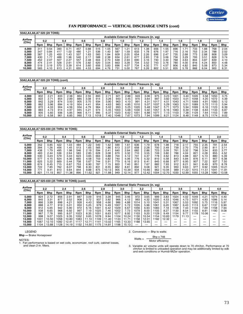
73
FAN PERFORMANCE — VERTICAL DISCHARGE UNITS (cont)
LEGENDBhp — Brake Horsepower
NOTES:1. Fan performance is based on wet coils, economizer, roof curb, cabinet losses,
and clean 2-in. filters.
2. Conversion — Bhp to watts:
3. Variable air volume units will operate down to 70 cfm/ton. Performance at 70cfm/ton is limited to unloaded operation and may be additionally limited by edband ewb conditions or Humidi-MiZer operation.
50A2,A3,A6,A7 020 (20 TONS)
Airflow(Cfm)
Available External Static Pressure (in. wg)0.2 0.4 0.6 0.8 1.0 1.2 1.4 1.6 1.8 2.0
Rpm Bhp Rpm Bhp Rpm Bhp Rpm Bhp Rpm Bhp Rpm Bhp Rpm Bhp Rpm Bhp Rpm Bhp Rpm Bhp 4,000 311 0.54 390 0.71 457 0.88 515 1.05 567 1.21 613 1.38 656 1.55 696 1.71 733 1.88 768 2.04 5,000 347 0.84 417 1.02 480 1.21 536 1.40 587 1.59 633 1.78 676 1.97 716 2.16 753 2.34 788 2.52 6,000 387 1.25 450 1.43 507 1.63 560 1.84 609 2.05 654 2.26 696 2.47 735 2.68 773 2.88 808 3.09 7,000 430 1.77 488 1.96 540 2.17 588 2.38 634 2.61 677 2.83 718 3.06 756 3.29 793 3.51 828 3.74 7,500 452 2.07 507 2.27 557 2.48 604 2.70 648 2.93 690 3.16 730 3.40 768 3.63 804 3.87 839 4.10 8,000 474 2.41 528 2.61 576 2.82 620 3.04 663 3.28 704 3.52 743 3.76 780 4.00 816 4.24 850 4.48 9,000 519 3.19 570 3.39 614 3.60 656 3.83 696 4.07 734 4.32 771 4.57 806 4.82 840 5.08 873 5.3410,000 565 4.10 613 4.31 655 4.53 694 4.76 731 5.00 767 5.26 802 5.51 835 5.78 868 6.04 900 6.31
50A2,A3,A6,A7 020 (20 TONS) (cont)
Airflow(Cfm)
Available External Static Pressure (in. wg)2.2 2.4 2.6 2.8 3.0 3.2 3.4 3.6 3.8 4.0
Rpm Bhp Rpm Bhp Rpm Bhp Rpm Bhp Rpm Bhp Rpm Bhp Rpm Bhp Rpm Bhp Rpm Bhp Rpm Bhp 4,000 802 2.21 833 2.38 864 2.55 893 2.71 921 2.88 949 3.06 975 3.23 1001 3.40 1026 3.58 1050 3.75 5,000 822 2.71 854 2.89 885 3.08 914 3.26 943 3.45 970 3.64 997 3.82 1023 4.01 1048 4.20 1072 4.39 6,000 842 3.29 874 3.50 905 3.70 934 3.90 963 4.10 991 4.31 1017 4.51 1043 4.71 1069 4.91 1093 5.12 7,000 862 3.96 894 4.19 924 4.41 954 4.63 983 4.85 1010 5.07 1037 5.29 1063 5.51 1089 5.72 1113 5.94 7,500 872 4.33 904 4.56 934 4.79 964 5.02 993 5.25 1020 5.48 1047 5.71 1073 5.94 1099 6.16 1123 6.39 8,000 883 4.73 914 4.97 945 5.21 974 5.45 1003 5.68 1030 5.92 1057 6.16 1083 6.39 1108 6.63 1133 6.87 9,000 905 5.60 936 5.85 966 6.11 995 6.37 1023 6.62 1051 6.88 1077 7.13 1103 7.38 1129 7.64 1153 7.8910,000 931 6.58 961 6.85 990 7.13 1018 7.40 1046 7.67 1073 7.94 1099 8.21 1124 8.48 1149 8.75 1174 9.02
50A2,A3,A6,A7 025-030 (25 THRU 30 TONS)
Airflow(Cfm)
Available External Static Pressure (in. wg)0.2 0.4 0.6 0.8 1.0 1.2 1.4 1.6 1.8 2.0
Rpm Bhp Rpm Bhp Rpm Bhp Rpm Bhp Rpm Bhp Rpm Bhp Rpm Bhp Rpm Bhp Rpm Bhp Rpm Bhp 5,000 352 0.85 422 1.03 484 1.22 540 1.42 590 1.61 636 1.79 678 1.98 718 2.17 755 2.35 791 2.54 6,000 394 1.26 456 1.45 513 1.65 565 1.86 613 2.07 658 2.28 700 2.49 739 2.70 776 2.90 811 3.11 7,000 438 1.79 495 1.98 546 2.19 594 2.41 640 2.64 682 2.86 723 3.09 761 3.32 798 3.54 833 3.77 8,000 483 2.44 536 2.64 583 2.85 628 3.08 670 3.32 710 3.55 749 3.80 786 4.04 821 4.28 855 4.52 9,000 530 3.23 579 3.43 623 3.65 664 3.88 704 4.12 741 4.37 778 4.62 813 4.88 847 5.13 880 5.3910,000 577 4.15 624 4.36 665 4.58 703 4.82 740 5.06 776 5.32 810 5.58 843 5.84 876 6.11 907 6.3811,000 625 5.22 669 5.44 708 5.67 744 5.91 779 6.16 813 6.41 845 6.68 877 6.95 907 7.22 937 7.5012,000 674 6.45 715 6.67 753 6.90 787 7.15 820 7.40 851 7.67 882 7.93 912 8.21 941 8.49 970 8.7813,000 722 7.85 762 8.07 798 8.30 831 8.55 862 8.81 892 9.08 921 9.35 950 9.63 977 9.92 1005 10.2114,000 771 9.41 810 9.64 844 9.88 875 10.13 905 10.39 934 10.66 962 10.94 989 11.22 1015 11.51 1041 11.8115,000 821 11.15 857 11.38 890 11.62 921 11.88 949 12.14 977 12.42 1004 12.70 1030 12.99 1055 13.28 1080 13.58
50A2,A3,A6,A7 025-030 (25 THRU 30 TONS) (cont)
Airflow(Cfm)
Available External Static Pressure (in. wg)2.2 2.4 2.6 2.8 3.0 3.2 3.4 3.6 3.8 4.0
Rpm Bhp Rpm Bhp Rpm Bhp Rpm Bhp Rpm Bhp Rpm Bhp Rpm Bhp Rpm Bhp Rpm Bhp Rpm Bhp 5,000 824 2.72 856 2.91 887 3.09 916 3.28 945 3.46 972 3.65 999 3.83 1024 4.02 1049 4.21 1074 4.40 6,000 845 3.31 877 3.52 908 3.72 937 3.92 966 4.12 993 4.32 1020 4.53 1046 4.73 1071 4.93 1096 5.14 7,000 866 3.99 898 4.21 928 4.43 958 4.66 986 4.88 1014 5.10 1041 5.31 1067 5.53 1092 5.75 1116 5.97 8,000 888 4.77 919 5.01 950 5.25 979 5.49 1007 5.72 1035 5.96 1061 6.20 1087 6.43 1113 6.67 1137 6.90 9,000 912 5.65 942 5.90 972 6.16 1001 6.42 1029 6.67 1056 6.93 1083 7.18 1108 7.43 1134 7.69 1158 7.9410,000 938 6.65 968 6.92 997 7.19 1025 7.46 1052 7.73 1079 8.00 1105 8.27 1130 8.54 1155 8.81 1180 9.0811,000 967 7.78 995 8.07 1023 8.35 1051 8.63 1077 8.92 1103 9.20 1129 9.49 1154 9.77 1178 10.06 — —12,000 998 9.07 1025 9.35 1052 9.65 1078 9.94 1104 10.24 1130 10.54 1154 10.83 1179 11.13 — — — —13,000 1031 10.50 1058 10.80 1083 11.10 1109 11.40 1133 11.71 1158 12.01 1182 12.32 — — — — — —14,000 1067 12.10 1092 12.41 1117 12.71 1141 13.02 1165 13.33 1188 13.65 — — — — — — — —15,000 1104 13.88 1128 14.19 1152 14.50 1175 14.81 1198 15.13 — — — — — — — — — —
Watts =Bhp x 746
Motor efficiency
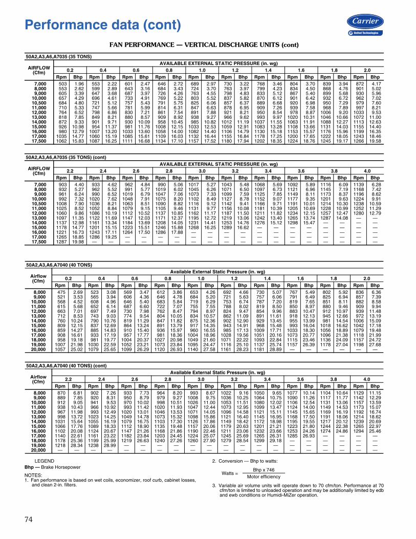
74
FAN PERFORMANCE — VERTICAL DISCHARGE UNITS (cont)
LEGENDBhp — Brake Horsepower
NOTES:1. Fan performance is based on wet coils, economizer, roof curb, cabinet losses,
and clean 2-in. filters.
2. Conversion — Bhp to watts:
3. Variable air volume units will operate down to 70 cfm/ton. Performance at 70cfm/ton is limited to unloaded operation and may be additionally limited by edband ewb conditions or Humidi-MiZer operation.
50A2,A3,A6,A7035 (35 TONS)
AIRFLOW(Cfm)
AVAILABLE EXTERNAL STATIC PRESSURE (in. wg)0.2 0.4 0.6 0.8 1.0 1.2 1.4 1.6 1.8 2.0
Rpm Bhp Rpm Bhp Rpm Bhp Rpm Bhp Rpm Bhp Rpm Bhp Rpm Bhp Rpm Bhp Rpm Bhp Rpm Bhp7,000 503 1.96 553 2.22 601 2.47 646 2.72 689 2.97 730 3.22 768 3.46 804 3.70 839 3.94 872 4.178,000 553 2.62 599 2.89 643 3.16 684 3.43 724 3.70 763 3.97 799 4.23 834 4.50 868 4.76 901 5.029,000 605 3.39 647 3.68 687 3.97 726 4.26 763 4.55 798 4.83 833 5.12 867 5.40 899 5.68 930 5.96
10,000 657 4.29 696 4.61 733 4.91 769 5.22 803 5.52 837 5.82 870 6.12 901 6.42 932 6.72 962 7.0210,500 684 4.80 721 5.12 757 5.43 791 5.75 825 6.06 857 6.37 889 6.68 920 6.98 950 7.29 979 7.6011,000 710 5.33 747 5.66 781 5.99 814 6.31 847 6.63 878 6.95 909 7.26 939 7.58 968 7.89 997 8.2112,000 764 6.52 798 6.86 830 7.21 861 7.54 891 7.88 921 8.21 950 8.54 978 8.87 1006 9.20 1033 9.5313,000 818 7.85 849 8.21 880 8.57 909 8.92 938 9.27 966 9.62 993 9.97 1020 10.31 1046 10.66 1072 11.0014,000 872 9.33 901 9.71 930 10.09 958 10.45 985 10.82 1012 11.19 1037 11.55 1063 11.91 1088 12.27 1113 12.6315,000 926 10.98 954 11.37 981 11.76 1008 12.15 1033 12.53 1059 12.91 1083 13.28 1108 13.66 1131 14.03 1155 14.4016,000 980 12.79 1007 13.20 1033 13.60 1058 14.00 1082 14.40 1106 14.79 1130 15.18 1153 15.57 1176 15.96 1199 16.3517,000 1035 14.77 1060 15.19 1085 15.61 1109 16.03 1132 16.44 1155 16.84 1178 17.25 1200 17.65 1222 18.05 1243 18.4617,500 1062 15.83 1087 16.25 1111 16.68 1134 17.10 1157 17.52 1180 17.94 1202 18.35 1224 18.76 1245 19.17 1266 19.58
50A2,A3,A6,A7035 (35 TONS) (cont)
AIRFLOW(Cfm)
AVAILABLE EXTERNAL STATIC PRESSURE (in. wg)2.2 2.4 2.6 2.8 3.0 3.2 3.4 3.6 3.8 4.0
Rpm Bhp Rpm Bhp Rpm Bhp Rpm Bhp Rpm Bhp Rpm Bhp Rpm Bhp Rpm Bhp Rpm Bhp Rpm Bhp7,000 903 4.40 933 4.62 962 4.84 990 5.06 1017 5.27 1043 5.48 1068 5.69 1092 5.89 1116 6.09 1139 6.288,000 932 5.27 962 5.52 991 5.77 1019 6.02 1045 6.26 1071 6.50 1097 6.73 1121 6.96 1145 7.19 1168 7.429,000 961 6.24 990 6.52 1019 6.79 1047 7.06 1073 7.33 1099 7.59 1125 7.85 1149 8.11 1173 8.37 1196 8.62
10,000 992 7.32 1020 7.62 1048 7.91 1075 8.20 1102 8.49 1127 8.78 1152 9.07 1177 9.35 1201 9.63 1224 9.9110,500 1008 7.90 1036 8.21 1063 8.51 1090 8.82 1116 9.12 1142 9.41 1166 9.71 1191 10.01 1214 10.30 1238 10.5911,000 1025 8.52 1052 8.84 1079 9.15 1105 9.46 1131 9.77 1156 10.08 1181 10.39 1205 10.69 1228 10.99 1252 11.2912,000 1060 9.86 1086 10.19 1112 10.52 1137 10.85 1162 11.17 1187 11.50 1211 11.82 1234 12.15 1257 12.47 1280 12.7913,000 1097 11.35 1122 11.69 1147 12.03 1171 12.37 1195 12.72 1219 13.06 1242 13.40 1265 13.74 1287 14.08 — —14,000 1137 12.98 1161 13.34 1184 13.69 1208 14.05 1231 14.41 1253 14.76 1276 15.12 1298 15.47 — — — —15,000 1178 14.77 1201 15.15 1223 15.51 1246 15.88 1268 16.25 1289 16.62 — — — — — — — —16,000 1221 16.73 1243 17.11 1264 17.50 1286 17.88 — — — — — — — — — — — —17,000 1265 18.85 1286 19.25 — — — — — — — — — — — — — — — —17,500 1287 19.98 — — — — — — — — — — — — — — — — — —
50A2,A3,A6,A7040 (40 TONS)
Airflow(Cfm)
Available External Static Pressure (in. wg)0.2 0.4 0.6 0.8 1.0 1.2 1.4 1.6 1.8 2.0
Rpm Bhp Rpm Bhp Rpm Bhp Rpm Bhp Rpm Bhp Rpm Bhp Rpm Bhp Rpm Bhp Rpm Bhp Rpm Bhp8,000 475 2.69 523 3.08 569 3.47 612 3.86 653 4.26 692 4.66 730 5.07 767 5.49 802 5.92 836 6.369,000 521 3.53 565 3.94 606 4.36 646 4.78 684 5.20 721 5.63 757 6.06 791 6.49 825 6.94 857 7.39
10,000 568 4.52 608 4.96 646 5.40 683 5.84 719 6.29 753 6.74 787 7.20 819 7.65 851 8.11 882 8.5811,000 615 5.68 652 6.14 687 6.60 722 7.07 755 7.55 788 8.02 819 8.50 850 8.97 880 9.46 909 9.9412,000 663 7.01 697 7.49 730 7.98 762 8.47 794 8.97 824 9.47 854 9.96 883 10.47 912 10.97 939 11.4813,000 712 8.53 743 9.03 774 9.54 804 10.05 834 10.57 862 11.09 891 11.61 918 12.13 945 12.66 972 13.1914,000 760 10.24 790 10.76 819 11.29 847 11.82 875 12.36 902 12.90 929 13.45 955 13.99 981 14.54 1006 15.0915,000 809 12.15 837 12.69 864 13.24 891 13.79 917 14.35 943 14.91 968 15.48 993 16.04 1018 16.62 1042 17.1816,000 859 14.27 885 14.83 910 15.40 936 15.97 960 16.55 985 17.13 1009 17.71 1033 18.30 1056 18.89 1079 19.4817,000 908 16.61 933 17.19 957 17.77 981 18.36 1004 18.96 1028 19.56 1051 20.16 1073 20.77 1096 21.38 1118 21.9918,000 958 19.18 981 19.77 1004 20.37 1027 20.98 1049 21.60 1071 22.22 1093 22.84 1115 23.46 1136 24.09 1157 24.7219,000 1007 21.98 1030 22.59 1052 23.21 1073 23.84 1095 24.47 1116 25.10 1137 25.74 1157 26.39 1178 27.04 1198 27.6820,000 1057 25.02 1079 25.65 1099 26.29 1120 26.93 1140 27.58 1161 28.23 1181 28.89 — — — — — —
50A2,A3,A6,A7040 (40 TONS) (cont)
Airflow(Cfm)
Available External Static Pressure (in. wg)2.2 2.4 2.6 2.8 3.0 3.2 3.4 3.6 3.8 4.0
Rpm Bhp Rpm Bhp Rpm Bhp Rpm Bhp Rpm Bhp Rpm Bhp Rpm Bhp Rpm Bhp Rpm Bhp Rpm Bhp8,000 870 6.81 902 7.26 933 7.73 964 8.20 993 8.67 1022 9.16 1050 9.65 1077 10.14 1104 10.64 1129 11.159,000 889 7.85 920 8.31 950 8.79 979 9.27 1008 9.75 1036 10.25 1064 10.75 1090 11.26 1117 11.77 1142 12.29
10,000 912 9.05 941 9.53 970 10.02 998 10.51 1026 11.00 1053 11.51 1080 12.02 1106 12.54 1131 13.06 1157 13.5911,000 938 10.43 966 10.92 993 11.42 1020 11.93 1047 12.44 1073 12.95 1099 13.47 1124 14.00 1149 14.53 1173 15.0712,000 967 11.98 993 12.49 1020 13.01 1046 13.53 1071 14.05 1096 14.58 1121 15.11 1145 15.65 1169 16.19 1192 16.7413,000 998 13.72 1023 14.25 1049 14.78 1073 15.32 1098 15.86 1121 16.40 1145 16.95 1168 17.50 1191 18.06 1214 18.6214,000 1031 15.64 1055 16.19 1079 16.75 1103 17.30 1126 17.86 1149 18.42 1172 18.98 1195 19.55 1217 20.12 1239 20.6915,000 1066 17.76 1089 18.33 1112 18.90 1135 19.48 1157 20.06 1179 20.63 1201 21.21 1223 21.80 1244 22.38 1265 22.9716,000 1102 20.08 1124 20.67 1147 21.26 1168 21.86 1190 22.46 1211 23.06 1232 23.66 1253 24.26 1274 24.86 1294 25.4617,000 1140 22.61 1161 23.22 1182 23.84 1203 24.45 1224 25.07 1245 25.69 1265 26.31 1285 26.93 — — — —18,000 1178 25.36 1199 25.99 1219 26.63 1240 27.26 1260 27.90 1279 28.54 1299 29.18 — — — — — —19,000 1218 28.34 1238 28.99 — — — — — — — — — — — — — — — —20,000 — — — — — — — — — — — — — — — — — — — —
Watts =Bhp x 746
Motor efficiency
Performance data (cont)

75
FAN PERFORMANCE — VERTICAL DISCHARGE UNITS (cont)
LEGENDBhp — Brake Horsepower
NOTES:1. Fan performance is based on wet coils, economizer, roof curb, cabinet losses,
and clean 2-in. filters.
2. Conversion — Bhp to watts:
3. Variable air volume units will operate down to 70 cfm/ton. Performance at 70cfm/ton is limited to unloaded operation and may be additionally limited by edband ewb conditions or Humidi-MiZer operation.
50A2,A3,A6,A7050 (50 TONS)
Airflow(Cfm)
Available External Static Pressure (in. wg)0.2 0.4 0.6 0.8 1.0 1.2 1.4 1.6 1.8 2.0
Rpm Bhp Rpm Bhp Rpm Bhp Rpm Bhp Rpm Bhp Rpm Bhp Rpm Bhp Rpm Bhp Rpm Bhp Rpm Bhp10,000 577 4.62 617 5.06 655 5.50 692 5.95 727 6.40 761 6.85 794 7.30 827 7.76 858 8.22 889 8.6911,000 625 5.80 661 6.26 697 6.73 731 7.20 764 7.67 796 8.14 827 8.62 858 9.10 888 9.58 917 10.0712,000 673 7.15 707 7.63 740 8.12 772 8.62 803 9.11 833 9.61 863 10.11 891 10.61 920 11.12 947 11.6213,000 722 8.69 753 9.19 784 9.70 814 10.22 843 10.74 872 11.26 900 11.78 927 12.31 954 12.83 980 13.3614,000 771 10.43 800 10.95 829 11.48 857 12.01 885 12.55 912 13.10 938 13.64 964 14.19 990 14.74 1015 15.2915,000 821 12.37 848 12.91 875 13.46 901 14.01 928 14.57 953 15.14 978 15.70 1003 16.27 1028 16.84 1052 17.4116,000 870 14.52 896 15.08 922 15.65 947 16.22 971 16.80 996 17.39 1020 17.97 1043 18.56 1066 19.15 1089 19.7517,000 920 16.89 945 17.48 969 18.06 993 18.65 1016 19.25 1039 19.86 1062 20.46 1084 21.07 1107 21.68 1129 22.3018,000 971 19.50 994 20.10 1017 20.71 1039 21.32 1061 21.93 1083 22.55 1105 23.18 1126 23.80 1148 24.44 1169 25.0719,000 1021 22.35 1043 22.96 1065 23.59 1086 24.21 1107 24.85 1128 25.49 1149 26.13 1170 26.78 1190 27.42 1210 28.0820,000 1071 25.43 1092 26.07 1113 26.71 1133 27.36 1154 28.01 1174 28.66 1194 29.33 1213 29.99 1233 30.65 1252 31.33
50A2,A3,A6,A7050 (50 TONS) (cont)
Airflow(Cfm)
Available External Static Pressure (in. wg)2.2 2.4 2.6 2.8 3.0 3.2 3.4 3.6 3.8 4.0
Rpm Bhp Rpm Bhp Rpm Bhp Rpm Bhp Rpm Bhp Rpm Bhp Rpm Bhp Rpm Bhp Rpm Bhp Rpm Bhp10,000 919 9.17 948 9.64 977 10.13 1005 10.62 1032 11.12 1059 11.63 1086 12.14 1112 12.66 1137 13.18 1162 13.7111,000 945 10.56 973 11.05 1001 11.55 1027 12.06 1054 12.57 1080 13.09 1105 13.61 1130 14.14 1155 14.67 1179 15.2112,000 975 12.13 1001 12.64 1027 13.16 1053 13.68 1078 14.21 1103 14.74 1128 15.27 1152 15.81 1176 16.35 1199 16.9013,000 1006 13.89 1032 14.42 1057 14.96 1081 15.49 1105 16.03 1129 16.58 1153 17.12 1176 17.68 1199 18.23 1221 18.8014,000 1040 15.84 1064 16.39 1088 16.94 1112 17.50 1135 18.06 1158 18.62 1180 19.18 1203 19.75 1225 20.32 1246 20.9015,000 1075 17.99 1098 18.56 1121 19.13 1144 19.71 1166 20.29 1188 20.86 1210 21.45 1231 22.03 1253 22.62 1274 23.2116,000 1112 20.34 1134 20.93 1156 21.53 1178 22.12 1199 22.72 1221 23.32 1241 23.92 1262 24.52 1283 25.13 — —17,000 1150 22.91 1172 23.52 1193 24.14 1214 24.76 1234 25.37 1255 25.99 1275 26.61 1295 27.23 — — — —18,000 1190 25.70 1210 26.34 1230 26.97 1250 27.61 1270 28.25 1290 28.89 — — — — — — — —19,000 1230 28.73 1250 29.38 1269 30.04 1289 30.70 — — — — — — — — — — — —20,000 1271 31.99 1290 32.67 — — — — — — — — — — — — — — — —
50A2,A3,A6,A7060 (60 TONS)
Airflow(Cfm)
Available External Static Pressure (in. wg)0.2 0.4 0.6 0.8 1.0 1.2 1.4 1.6 1.8 2.0
Rpm Bhp Rpm Bhp Rpm Bhp Rpm Bhp Rpm Bhp Rpm Bhp Rpm Bhp Rpm Bhp Rpm Bhp Rpm Bhp12,000 450 4.02 509 4.71 560 5.41 605 6.12 647 6.86 686 7.62 723 8.40 757 9.21 790 10.04 821 10.8914,000 505 5.74 558 6.49 606 7.24 649 8.01 689 8.79 727 9.59 762 10.40 795 11.24 827 12.09 857 12.9615,000 533 6.75 584 7.53 630 8.32 672 9.11 711 9.91 748 10.73 782 11.56 815 12.41 846 13.28 876 14.1716,000 561 7.88 610 8.68 655 9.50 696 10.32 734 11.14 770 11.98 803 12.84 836 13.71 866 14.59 896 15.4917,000 590 9.12 637 9.95 680 10.79 720 11.64 757 12.49 792 13.35 825 14.23 857 15.12 887 16.02 916 16.9418,000 619 10.48 664 11.33 706 12.20 744 13.07 781 13.96 815 14.84 847 15.74 878 16.65 908 17.57 937 18.5019,000 648 11.96 692 12.84 732 13.74 769 14.64 805 15.54 838 16.45 870 17.37 900 18.30 930 19.24 958 20.1920,000 678 13.57 719 14.47 758 15.40 795 16.32 829 17.25 862 18.19 893 19.13 923 20.08 952 21.04 979 22.0121,000 707 15.30 748 16.24 785 17.19 821 18.14 854 19.09 886 20.05 917 21.02 946 22.00 974 22.98 1001 23.9722,000 737 17.18 776 18.14 812 19.11 847 20.09 879 21.07 911 22.06 940 23.05 969 24.04 997 25.05 1024 26.0623,000 767 19.20 804 20.18 840 21.17 873 22.17 905 23.18 935 24.19 965 25.21 993 26.23 1020 27.25 1046 28.2824,000 797 21.35 833 22.36 867 23.38 900 24.40 931 25.43 961 26.47 989 27.51 1017 28.55 1044 29.60 1070 30.6525,000 827 23.66 862 24.68 895 25.72 927 26.78 957 27.83 986 28.89 1014 29.95 1041 31.02 1068 32.09 1093 33.1726,000 857 26.11 891 27.16 923 28.23 954 29.30 984 30.38 1012 31.46 1040 32.55 1066 33.64 1092 34.73 1117 35.8327,000 888 28.72 920 29.79 952 30.88 982 31.97 1011 33.08 1038 34.19 1065 35.29 1091 36.40 1117 37.52 1141 38.64
50A2,A3,A6,A7060 (60 TONS) (cont)
Airflow(Cfm)
Available External Static Pressure (in. wg)2.2 2.4 2.6 2.8 3.0 3.2 3.4 3.6 3.8 4.0
Rpm Bhp Rpm Bhp Rpm Bhp Rpm Bhp Rpm Bhp Rpm Bhp Rpm Bhp Rpm Bhp Rpm Bhp Rpm Bhp12,000 851 11.75 880 12.63 907 13.53 934 14.45 960 15.38 985 16.32 1010 17.28 1033 18.24 1057 19.22 1079 20.2214,000 886 13.85 915 14.76 942 15.68 968 16.62 993 17.57 1018 18.54 1042 19.52 1066 20.51 1088 21.52 1111 22.5315,000 905 15.07 933 15.99 960 16.92 986 17.87 1011 18.83 1035 19.81 1059 20.81 1082 21.81 1105 22.82 1127 23.8516,000 924 16.41 952 17.34 978 18.28 1004 19.25 1029 20.22 1053 21.21 1077 22.21 1100 23.22 1122 24.25 1144 25.2917,000 944 17.86 971 18.81 997 19.77 1023 20.74 1047 21.73 1071 22.73 1095 23.74 1117 24.76 1140 25.80 1161 26.8518,000 964 19.45 991 20.41 1017 21.38 1042 22.36 1066 23.36 1090 24.37 1113 25.40 1136 26.43 1158 27.48 1179 28.5419,000 985 21.15 1011 22.13 1037 23.12 1061 24.11 1085 25.13 1109 26.15 1132 27.19 1154 28.24 1176 29.29 1197 30.3620,000 1006 22.99 1032 23.98 1057 24.99 1081 26.00 1105 27.03 1128 28.06 1151 29.11 1173 30.17 1195 31.24 — —21,000 1028 24.97 1053 25.97 1078 26.99 1102 28.02 1126 29.06 1148 30.11 1171 31.17 1193 32.25 — — — —22,000 1050 27.08 1075 28.10 1099 29.14 1123 30.18 1146 31.24 1169 32.30 1191 33.38 — — — — — —23,000 1072 29.32 1097 30.37 1121 31.42 1144 32.48 1167 33.55 1190 34.64 — — — — — — — —24,000 1095 31.71 1119 32.78 1143 33.85 1166 34.93 1189 36.02 — — — — — — — — — —25,000 1118 34.25 1142 35.33 1165 36.42 1188 37.52 — — — — — — — — — — — —26,000 1141 36.93 1165 38.04 1188 39.15 — — — — — — — — — — — — — —27,000 1165 39.76 1188 40.89 — — — — — — — — — — — — — — — —
Watts =Bhp x 746
Motor efficiency

76
FAN PERFORMANCE — HORIZONTAL DISCHARGE UNITS
LEGENDBhp — Brake Horsepower
NOTES:1. Fan performance is based on wet coils, economizer, roof curb, cabinet losses,
and clean 2-in. filters.
2. Conversion — Bhp to watts:
3. Variable air volume units will operate down to 70 cfm/ton. Performance at 70cfm/ton is limited to unloaded operation and may be additionally limited by edband ewb conditions or Humidi-MiZer operation.
48A4,A5,A8,A9 020 (20 TONS)
Airflow(Cfm)
Available External Static Pressure (in. wg)0.2 0.4 0.6 0.8 1.0 1.2 1.4 1.6 1.8 2.0
Rpm Bhp Rpm Bhp Rpm Bhp Rpm Bhp Rpm Bhp Rpm Bhp Rpm Bhp Rpm Bhp Rpm Bhp Rpm Bhp 4,000 339 0.71 414 0.97 478 1.25 534 1.54 585 1.84 631 2.14 674 2.44 714 2.75 751 3.06 787 3.37 5,000 384 1.10 452 1.37 510 1.66 563 1.96 611 2.28 656 2.60 698 2.93 738 3.27 775 3.60 811 3.94 6,000 433 1.61 494 1.89 548 2.19 597 2.51 643 2.84 686 3.18 726 3.52 764 3.88 800 4.23 835 4.60 7,000 484 2.27 540 2.56 590 2.87 636 3.19 679 3.53 719 3.88 757 4.24 794 4.61 829 4.98 863 5.36 7,500 511 2.66 563 2.95 612 3.26 656 3.59 698 3.94 737 4.29 775 4.66 810 5.03 845 5.41 877 5.79 8,000 538 3.09 588 3.38 634 3.70 678 4.03 718 4.38 756 4.74 793 5.11 827 5.49 861 5.87 893 6.26 9,000 593 4.07 639 4.37 682 4.69 722 5.03 760 5.39 796 5.76 831 6.13 864 6.52 896 6.91 927 7.3210,000 649 5.23 691 5.54 731 5.87 769 6.21 805 6.58 839 6.95 872 7.34 904 7.73 934 8.13 964 8.54
48A4,A5,A8,A9 020 (20 TONS) (cont)
Airflow(Cfm)
Available External Static Pressure (in. wg)2.2 2.4 2.6 2.8 3.0 3.2 3.4 3.6 3.8 4.0
Rpm Bhp Rpm Bhp Rpm Bhp Rpm Bhp Rpm Bhp Rpm Bhp Rpm Bhp Rpm Bhp Rpm Bhp Rpm Bhp 4,000 820 3.68 852 3.99 883 4.30 912 4.62 940 4.93 967 5.25 993 5.57 1019 5.89 1043 6.21 1067 6.53 5,000 844 4.28 877 4.63 907 4.97 937 5.31 966 5.66 993 6.01 1020 6.35 1046 6.70 1071 7.05 1095 7.40 6,000 869 4.96 901 5.33 931 5.70 961 6.07 990 6.44 1017 6.81 1044 7.19 1070 7.57 1096 7.94 1121 8.32 7,000 895 5.74 926 6.13 956 6.52 986 6.91 1014 7.30 1042 7.70 1068 8.10 1094 8.50 1120 8.90 1145 9.30 7,500 909 6.18 940 6.57 970 6.97 999 7.37 1027 7.78 1054 8.18 1081 8.59 1107 9.00 1132 9.41 1157 9.82 8,000 925 6.66 955 7.06 984 7.46 1013 7.87 1040 8.28 1067 8.69 1094 9.11 1119 9.53 1144 9.95 1169 10.37 9,000 957 7.72 986 8.13 1015 8.55 1042 8.97 1069 9.39 1096 9.82 1121 10.25 1146 10.69 1171 11.12 1195 11.5610,000 993 8.96 1021 9.38 1048 9.80 1075 10.23 1101 10.67 1126 11.11 1151 11.55 1176 12.00 1200 12.45 — —
48A4,A5,A8,A9 025-030 (25 THRU 30 TONS)
Airflow(Cfm)
Available External Static Pressure (in. wg)0.2 0.4 0.6 0.8 1.0 1.2 1.4 1.6 1.8 2.0
Rpm Bhp Rpm Bhp Rpm Bhp Rpm Bhp Rpm Bhp Rpm Bhp Rpm Bhp Rpm Bhp Rpm Bhp Rpm Bhp 5,000 389 1.11 456 1.38 514 1.68 566 1.98 614 2.30 659 2.62 701 2.95 740 3.29 777 3.62 813 3.96 6,000 439 1.64 499 1.92 553 2.22 602 2.54 647 2.87 689 3.21 730 3.56 768 3.91 804 4.27 838 4.63 7,000 492 2.31 546 2.60 596 2.91 641 3.24 684 3.58 724 3.93 762 4.29 798 4.66 833 5.03 867 5.41 8,000 546 3.14 596 3.43 642 3.75 684 4.09 724 4.44 762 4.80 798 5.17 833 5.55 866 5.93 898 6.32 9,000 602 4.13 647 4.43 690 4.76 730 5.10 768 5.46 803 5.83 838 6.21 871 6.60 903 7.00 933 7.4010,000 659 5.31 701 5.62 740 5.95 777 6.30 813 6.67 847 7.04 880 7.43 911 7.83 942 8.23 971 8.6411,000 717 6.67 755 6.99 792 7.33 827 7.68 860 8.06 893 8.44 924 8.83 954 9.24 983 9.65 1011 10.0712,000 775 8.23 811 8.56 845 8.90 878 9.27 909 9.64 940 10.03 970 10.43 999 10.84 1026 11.26 1054 11.6913,000 834 9.99 867 10.33 899 10.68 930 11.05 960 11.44 989 11.83 1017 12.24 1045 12.65 1072 13.08 1098 13.5114,000 893 11.97 924 12.32 954 12.68 983 13.06 1012 13.44 1039 13.85 1066 14.26 1093 14.68 1118 15.11 1143 15.5415,000 953 14.17 982 14.53 1010 14.90 1037 15.28 1064 15.68 1091 16.08 1116 16.50 1142 16.93 1166 17.36 1190 17.80
48A4,A5,A8,A9 025-030 (25 THRU 30 TONS) (cont)
Airflow(Cfm)
Available External Static Pressure (in. wg)2.2 2.4 2.6 2.8 3.0 3.2 3.4 3.6 3.8 4.0
Rpm Bhp Rpm Bhp Rpm Bhp Rpm Bhp Rpm Bhp Rpm Bhp Rpm Bhp Rpm Bhp Rpm Bhp Rpm Bhp 5,000 846 4.31 879 4.65 909 4.99 939 5.34 968 5.68 995 6.03 1022 6.38 1048 6.73 1073 7.08 1097 7.43 6,000 872 5.00 903 5.36 934 5.73 964 6.10 992 6.48 1020 6.85 1047 7.22 1073 7.60 1098 7.98 1123 8.36 7,000 899 5.79 930 6.18 960 6.57 989 6.96 1018 7.36 1045 7.75 1072 8.15 1098 8.55 1123 8.95 1148 9.35 8,000 930 6.72 960 7.12 989 7.53 1017 7.94 1045 8.35 1072 8.76 1098 9.18 1124 9.60 1148 10.02 1173 10.44 9,000 963 7.80 992 8.22 1020 8.63 1048 9.06 1075 9.48 1101 9.91 1126 10.34 1151 10.78 1176 11.21 1200 11.6510,000 1000 9.06 1028 9.48 1055 9.91 1081 10.34 1107 10.77 1133 11.22 1157 11.66 1182 12.11 — — — —11,000 1039 10.49 1066 10.92 1092 11.36 1117 11.80 1142 12.24 1167 12.69 1191 13.15 — — — — — —12,000 1080 12.12 1106 12.56 1131 13.00 1156 13.45 1180 13.90 — — — — — — — — — —13,000 1123 13.95 1148 14.39 1172 14.84 1196 15.30 — — — — — — — — — — — —14,000 1168 15.99 1192 16.44 — — — — — — — — — — — — — — — —15,000 — — — — — — — — — — — — — — — — — — — —
Watts =Bhp x 746
Motor efficiency
Performance data (cont)

77
FAN PERFORMANCE — HORIZONTAL DISCHARGE UNITS (cont)
LEGENDBhp — Brake Horsepower
NOTES:1. Fan performance is based on wet coils, economizer, roof curb, cabinet losses,
and clean 2-in. filters.
2. Conversion — Bhp to watts:
3. Variable air volume units will operate down to 70 cfm/ton. Performance at 70cfm/ton is limited to unloaded operation and may be additionally limited by edband ewb conditions or Humidi-MiZer operation.
48A4,A5,A8,A9 035 (35 TONS)
AIRFLOW(Cfm)
AVAILABLE EXTERNAL STATIC PRESSURE (in. wg)0.2 0.4 0.6 0.8 1.0 1.2 1.4 1.6 1.8 2.0
Rpm Bhp Rpm Bhp Rpm Bhp Rpm Bhp Rpm Bhp Rpm Bhp Rpm Bhp Rpm Bhp Rpm Bhp Rpm Bhp7,000 553 2.59 602 2.92 648 3.26 691 3.61 732 3.95 770 4.29 807 4.63 842 4.96 875 5.29 907 5.628,000 612 3.45 656 3.81 698 4.17 738 4.53 776 4.90 812 5.27 847 5.63 881 6.00 913 6.36 944 6.729,000 672 4.47 712 4.86 750 5.24 787 5.62 823 6.01 857 6.39 890 6.78 922 7.17 953 7.56 983 7.95
10,000 733 5.67 769 6.08 805 6.48 839 6.88 872 7.28 904 7.69 935 8.10 966 8.51 995 8.92 1024 9.3310,500 763 6.33 798 6.75 832 7.17 865 7.58 897 7.99 929 8.40 959 8.82 989 9.24 1017 9.66 1046 10.0811,000 794 7.04 828 7.47 861 7.90 892 8.32 923 8.74 954 9.16 983 9.59 1012 10.01 1040 10.44 1067 10.8712,000 855 8.60 887 9.06 918 9.51 948 9.95 977 10.39 1005 10.83 1033 11.27 1060 11.71 1087 12.16 1113 12.6013,000 917 10.36 947 10.84 976 11.31 1004 11.77 1031 12.23 1058 12.69 1084 13.14 1110 13.60 1135 14.06 1160 14.5214,000 980 12.32 1008 12.82 1035 13.31 1061 13.79 1087 14.27 1112 14.75 1137 15.22 1161 15.70 1185 16.17 1209 16.6515,000 1042 14.49 1069 15.01 1094 15.52 1119 16.03 1143 16.53 1167 17.02 1191 17.51 1214 18.01 1237 18.50 1260 18.9916,000 1105 16.88 1130 17.42 1154 17.96 1178 18.48 1201 19.00 1224 19.51 1246 20.02 1268 20.53 1290 21.04 — —17,000 1168 19.49 1191 20.06 1214 20.61 1237 21.16 1259 21.69 1281 22.23 — — — — — — — —17,500 1200 20.88 1222 21.46 1245 22.03 1267 22.58 1288 23.13 — — — — — — — — — —
48A4,A5,A8,A9 035 (35 TONS) (cont)
AIRFLOW(Cfm)
AVAILABLE EXTERNAL STATIC PRESSURE (in. wg)2.2 2.4 2.6 2.8 3.0 3.2 3.4 3.6 3.8 4.0
Rpm Bhp Rpm Bhp Rpm Bhp Rpm Bhp Rpm Bhp Rpm Bhp Rpm Bhp Rpm Bhp Rpm Bhp Rpm Bhp7,000 937 5.94 967 6.26 995 6.57 1022 6.87 1048 7.18 1073 7.48 1098 7.78 1122 8.07 1145 8.36 1168 8.668,000 974 7.08 1003 7.43 1031 7.77 1058 8.12 1084 8.46 1109 8.79 1134 9.13 1158 9.46 1181 9.78 1204 10.119,000 1012 8.33 1041 8.72 1068 9.10 1094 9.47 1120 9.85 1145 10.22 1169 10.58 1193 10.95 1216 11.31 1239 11.66
10,000 1052 9.74 1080 10.15 1106 10.55 1132 10.96 1157 11.36 1182 11.76 1206 12.16 1229 12.55 1252 12.95 1275 13.3410,500 1073 10.50 1100 10.92 1126 11.34 1151 11.75 1176 12.17 1201 12.59 1224 13.00 1248 13.41 1271 13.82 1293 14.2211,000 1094 11.30 1120 11.73 1146 12.16 1171 12.59 1196 13.02 1220 13.45 1243 13.87 1266 14.30 1289 14.72 — —12,000 1138 13.05 1163 13.50 1188 13.95 1212 14.40 1236 14.84 1259 15.30 1282 15.74 — — — — — —13,000 1184 14.99 1208 15.45 1232 15.92 1255 16.39 1278 16.85 — — — — — — — — — —14,000 1232 17.13 1255 17.61 1278 18.09 — — — — — — — — — — — — — —15,000 1282 19.48 — — — — — — — — — — — — — — — — — —16,000 — — — — — — — — — — — — — — — — — — — —17,000 — — — — — — — — — — — — — — — — — — — —17,500 — — — — — — — — — — — — — — — — — — — —
48A4,A5,A8,A9 040 (40 TONS)
Airflow(Cfm)
Available External Static Pressure (in. wg)0.2 0.4 0.6 0.8 1.0 1.2 1.4 1.6 1.8 2.0
Rpm Bhp Rpm Bhp Rpm Bhp Rpm Bhp Rpm Bhp Rpm Bhp Rpm Bhp Rpm Bhp Rpm Bhp Rpm Bhp8,000 526 3.10 573 3.50 617 3.91 660 4.33 700 4.75 740 5.18 778 5.62 814 6.07 850 6.53 884 7.009,000 579 4.08 621 4.51 662 4.95 701 5.39 738 5.83 775 6.28 810 6.74 845 7.21 878 7.69 911 8.17
10,000 633 5.24 671 5.70 709 6.16 744 6.62 779 7.09 813 7.57 846 8.05 879 8.53 910 9.03 941 9.5311,000 687 6.59 723 7.07 757 7.56 790 8.05 823 8.54 854 9.04 885 9.54 916 10.05 945 10.56 974 11.0812,000 742 8.15 775 8.65 807 9.17 838 9.68 868 10.20 898 10.72 927 11.24 955 11.77 983 12.30 1011 12.8413,000 797 9.92 827 10.45 857 10.98 887 11.52 915 12.07 943 12.61 970 13.15 997 13.70 1024 14.25 1050 14.8114,000 852 11.92 881 12.47 909 13.03 936 13.59 963 14.15 990 14.72 1016 15.29 1041 15.86 1066 16.43 1091 17.0115,000 908 14.15 935 14.72 961 15.31 987 15.89 1013 16.48 1038 17.06 1062 17.65 1086 18.25 1110 18.84 1134 19.4416,000 964 16.63 989 17.23 1014 17.83 1039 18.43 1063 19.04 1086 19.65 1110 20.26 1133 20.88 1156 21.49 1178 22.1117,000 1021 19.37 1044 19.98 1068 20.60 1091 21.23 1114 21.86 1136 22.49 1158 23.12 1180 23.76 1202 24.39 1223 25.0318,000 1077 22.37 1099 23.01 1122 23.64 1144 24.29 1165 24.94 1187 25.59 1208 26.25 1229 26.90 1250 27.56 1270 28.2219,000 1133 25.65 1155 26.30 1176 26.96 1197 27.62 1217 28.29 1238 28.96 — — — — — — — —20,000 1190 29.21 — — — — — — — — — — — — — — — — — —
48A4,A5,A8,A9 040 (40 TONS) (cont)
Airflow(Cfm)
Available External Static Pressure (in. wg)2.2 2.4 2.6 2.8 3.0 3.2 3.4 3.6 3.8 4.0
Rpm Bhp Rpm Bhp Rpm Bhp Rpm Bhp Rpm Bhp Rpm Bhp Rpm Bhp Rpm Bhp Rpm Bhp Rpm Bhp8,000 917 7.48 949 7.96 980 8.44 1010 8.94 1039 9.43 1067 9.93 1094 10.44 1121 10.95 1147 11.46 1172 11.989,000 942 8.66 973 9.16 1003 9.66 1033 10.17 1061 10.69 1089 11.21 1116 11.73 1142 12.26 1168 12.80 1193 13.33
10,000 971 10.03 1001 10.55 1030 11.06 1058 11.59 1086 12.12 1113 12.66 1139 13.20 1165 13.75 1190 14.30 1215 14.8611,000 1003 11.60 1031 12.13 1059 12.67 1086 13.21 1112 13.75 1139 14.31 1164 14.86 1189 15.43 1214 15.99 1238 16.5612,000 1038 13.38 1065 13.92 1091 14.47 1117 15.03 1142 15.59 1167 16.16 1192 16.73 1216 17.31 1240 17.89 1264 18.4813,000 1075 15.37 1101 15.93 1126 16.50 1150 17.07 1175 17.65 1199 18.23 1222 18.82 1246 19.41 1269 20.00 1291 20.6114,000 1115 17.59 1139 18.17 1163 18.75 1186 19.34 1210 19.94 1232 20.53 1255 21.14 1277 21.74 1300 22.35 — —15,000 1157 20.04 1180 20.64 1202 21.24 1225 21.85 1247 22.46 1269 23.07 1290 23.69 — — — — — —16,000 1200 22.73 1222 23.35 1243 23.97 1265 24.60 1286 25.23 — — — — — — — — — —17,000 1245 25.67 1266 26.32 1286 26.96 — — — — — — — — — — — — — —18,000 1290 28.88 — — — — — — — — — — — — — — — — — —19,000 — — — — — — — — — — — — — — — — — — — —20,000 — — — — — — — — — — — — — — — — — — — —
Watts =Bhp x 746
Motor efficiency

78
FAN PERFORMANCE — HORIZONTAL DISCHARGE UNITS (cont)
LEGENDBhp — Brake Horsepower
NOTES:1. Fan performance is based on wet coils, economizer, roof curb, cabinet losses,
and clean 2-in. filters.
2. Conversion — Bhp to watts:
3. Variable air volume units will operate down to 70 cfm/ton. Performance at 70cfm/ton is limited to unloaded operation and may be additionally limited by edband ewb conditions or Humidi-MiZer operation.
48A4,A5,A8,A9 050 (50 TONS)
Airflow(Cfm)
Available External Static Pressure (in. wg)0.2 0.4 0.6 0.8 1.0 1.2 1.4 1.6 1.8 2.0
Rpm Bhp Rpm Bhp Rpm Bhp Rpm Bhp Rpm Bhp Rpm Bhp Rpm Bhp Rpm Bhp Rpm Bhp Rpm Bhp10,000 642 5.35 680 5.80 717 6.27 753 6.73 787 7.20 821 7.68 854 8.16 886 8.65 917 9.14 948 9.6511,000 696 6.72 732 7.20 766 7.69 799 8.18 831 8.67 863 9.17 893 9.68 923 10.18 953 10.70 982 11.2112,000 751 8.29 784 8.80 816 9.32 847 9.83 877 10.35 906 10.87 935 11.40 964 11.92 991 12.46 1019 12.9913,000 807 10.09 837 10.62 867 11.16 896 11.70 924 12.24 952 12.78 979 13.33 1006 13.88 1032 14.43 1058 14.9914,000 863 12.12 891 12.67 919 13.23 946 13.79 973 14.36 999 14.92 1025 15.49 1050 16.06 1075 16.64 1100 17.2115,000 919 14.38 946 14.96 972 15.54 997 16.12 1023 16.71 1047 17.30 1072 17.89 1096 18.48 1120 19.08 1143 19.6816,000 975 16.90 1000 17.49 1025 18.09 1049 18.70 1073 19.31 1097 19.92 1120 20.53 1143 21.15 1165 21.76 1188 22.3817,000 1032 19.67 1056 20.29 1079 20.91 1102 21.54 1125 22.17 1147 22.80 1169 23.44 1191 24.07 1213 24.71 1234 25.3518,000 1089 22.71 1111 23.35 1134 23.99 1155 24.64 1177 25.29 1198 25.95 1219 26.60 1240 27.26 1261 27.92 1281 28.5819,000 1146 26.04 1167 26.69 1188 27.35 1209 28.02 1230 28.69 1250 29.37 1270 30.04 1290 30.72 — — — —20,000 1203 29.65 1224 30.32 1244 31.00 1263 31.69 1283 32.38 — — — — — — — — — —
48A4,A5,A8,A9 050 (50 TONS) (cont)
Airflow(Cfm)
Available External Static Pressure (in. wg)2.2 2.4 2.6 2.8 3.0 3.2 3.4 3.6 3.8 4.0
Rpm Bhp Rpm Bhp Rpm Bhp Rpm Bhp Rpm Bhp Rpm Bhp Rpm Bhp Rpm Bhp Rpm Bhp Rpm Bhp10,000 978 10.15 1008 10.67 1036 11.19 1064 11.72 1092 12.25 1119 12.79 1145 13.33 1171 13.88 1196 14.43 1221 14.9911,000 1010 11.74 1038 12.27 1066 12.81 1093 13.35 1119 13.90 1145 14.45 1171 15.01 1196 15.57 1220 16.14 1245 16.7212,000 1046 13.53 1072 14.08 1098 14.63 1124 15.19 1149 15.76 1174 16.32 1199 16.90 1223 17.48 1247 18.06 1270 18.6513,000 1084 15.55 1109 16.11 1134 16.68 1158 17.26 1182 17.84 1206 18.42 1230 19.01 1253 19.60 1276 20.20 1299 20.8014,000 1124 17.79 1148 18.38 1171 18.97 1195 19.55 1218 20.15 1241 20.75 1263 21.35 1285 21.96 — — — —15,000 1166 20.27 1189 20.88 1211 21.49 1234 22.09 1256 22.71 1277 23.32 1299 23.94 — — — — — —16,000 1210 23.00 1231 23.62 1253 24.25 1274 24.88 1295 25.51 — — — — — — — — — —17,000 1255 25.99 1276 26.63 1296 27.27 — — — — — — — — — — — — — —18,000 — — — — — — — — — — — — — — — — — — — —19,000 — — — — — — — — — — — — — — — — — — — —20,000 — — — — — — — — — — — — — — — — — — — —
48A4,A5,A8,A9 060 (60 TONS)
Airflow(Cfm)
Available External Static Pressure (in. wg)0.2 0.4 0.6 0.8 1.0 1.2 1.4 1.6 1.8 2.0
Rpm Bhp Rpm Bhp Rpm Bhp Rpm Bhp Rpm Bhp Rpm Bhp Rpm Bhp Rpm Bhp Rpm Bhp Rpm Bhp12,000 516 4.81 569 5.54 617 6.30 660 7.10 701 7.93 739 8.79 774 9.68 808 10.59 841 11.52 872 12.4614,000 584 6.90 632 7.69 676 8.50 716 9.33 754 10.20 790 11.10 824 12.02 857 12.97 888 13.94 917 14.9215,000 619 8.13 664 8.96 706 9.79 745 10.65 782 11.53 817 12.44 850 13.38 882 14.35 912 15.33 941 16.3416,000 654 9.49 697 10.36 737 11.22 775 12.10 811 13.00 845 13.93 877 14.88 908 15.86 938 16.86 966 17.8817,000 689 10.99 730 11.90 769 12.79 806 13.69 840 14.61 873 15.56 904 16.53 935 17.52 964 18.54 992 19.5818,000 725 12.64 764 13.58 801 14.51 837 15.43 870 16.38 902 17.34 933 18.32 962 19.33 990 20.36 1018 21.4119,000 760 14.43 798 15.41 834 16.37 868 17.32 900 18.29 932 19.27 961 20.27 990 21.29 1018 22.34 1045 23.4020,000 796 16.37 833 17.39 867 18.39 900 19.37 931 20.36 962 21.36 991 22.38 1019 23.42 1046 24.48 1072 25.5621,000 832 18.47 867 19.54 901 20.56 932 21.57 963 22.59 992 23.61 1020 24.65 1048 25.71 1074 26.78 1100 27.8722,000 869 20.74 902 21.84 934 22.90 965 23.94 995 24.98 1023 26.03 1051 27.09 1077 28.17 1103 29.26 1129 30.3623,000 905 23.17 937 24.31 968 25.40 998 26.48 1027 27.55 1055 28.62 1081 29.70 1107 30.79 1133 31.90 1157 33.0224,000 942 25.78 973 26.95 1003 28.08 1032 29.18 1059 30.28 1086 31.38 1113 32.48 1138 33.59 1163 34.72 1187 35.8625,000 978 28.56 1008 29.77 1037 30.93 1065 32.07 1092 33.20 1119 34.32 1144 35.44 1169 36.58 1193 37.72 — —26,000 1015 31.52 1044 32.76 1072 33.96 1099 35.13 1125 36.29 1151 37.44 1176 38.59 — — — — — —27,000 1052 34.66 1080 35.94 1107 37.18 1133 38.38 1159 39.57 1184 40.75 — — — — — — — —
48A4,A5,A8,A9 060 (60 TONS) (cont)
Airflow(Cfm)
Available External Static Pressure (in. wg)2.2 2.4 2.6 2.8 3.0 3.2 3.4 3.6 3.8 4.0
Rpm Bhp Rpm Bhp Rpm Bhp Rpm Bhp Rpm Bhp Rpm Bhp Rpm Bhp Rpm Bhp Rpm Bhp Rpm Bhp12,000 901 13.42 930 14.38 958 15.36 985 16.34 1011 17.33 1036 18.33 1061 19.33 1085 20.34 1108 21.35 1131 22.3614,000 946 15.92 974 16.94 1001 17.97 1027 19.01 1052 20.06 1077 21.12 1101 22.18 1125 23.25 1148 24.33 1170 25.4215,000 970 17.36 997 18.40 1024 19.45 1049 20.51 1074 21.58 1099 22.67 1122 23.76 1146 24.86 1168 25.97 1191 27.0816,000 994 18.93 1021 19.98 1047 21.05 1072 22.14 1097 23.23 1121 24.34 1144 25.45 1167 26.58 1190 27.71 — —17,000 1019 20.63 1045 21.70 1071 22.79 1096 23.89 1120 25.01 1144 26.13 1167 27.27 1190 28.42 — — — —18,000 1045 22.48 1070 23.57 1096 24.67 1120 25.79 1144 26.93 1167 28.07 1190 29.23 — — — — — —19,000 1071 24.49 1096 25.59 1121 26.71 1145 27.84 1169 28.99 1192 30.16 — — — — — — — —20,000 1098 26.66 1123 27.77 1147 28.90 1171 30.05 1194 31.21 — — — — — — — — — —21,000 1125 28.99 1150 30.12 1173 31.26 1197 32.42 — — — — — — — — — — — —22,000 1153 31.49 1177 32.63 — — — — — — — — — — — — — — — —23,000 1181 34.16 — — — — — — — — — — — — — — — — — —24,000 — — — — — — — — — — — — — — — — — — — —25,000 — — — — — — — — — — — — — — — — — — — —26,000 — — — — — — — — — — — — — — — — — — — —27,000 — — — — — — — — — — — — — — — — — — — —
Watts =Bhp x 746
Motor efficiency
Performance data (cont)
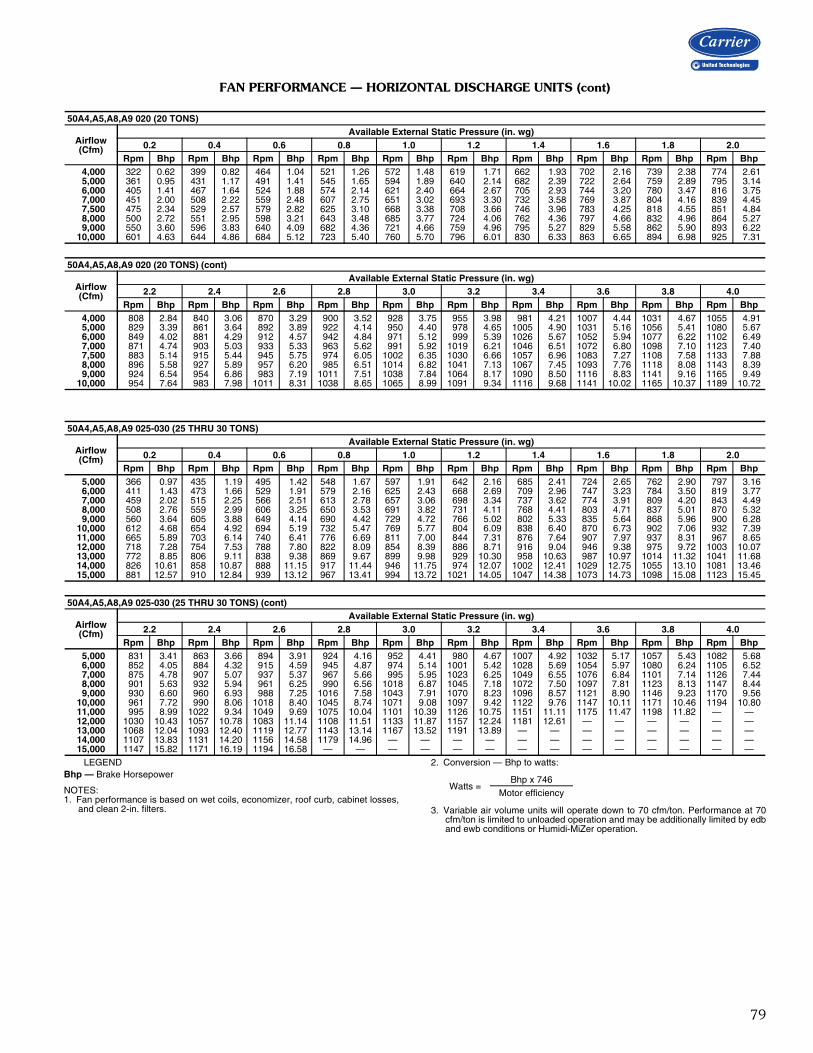
79
FAN PERFORMANCE — HORIZONTAL DISCHARGE UNITS (cont)
LEGENDBhp — Brake Horsepower
NOTES:1. Fan performance is based on wet coils, economizer, roof curb, cabinet losses,
and clean 2-in. filters.
2. Conversion — Bhp to watts:
3. Variable air volume units will operate down to 70 cfm/ton. Performance at 70cfm/ton is limited to unloaded operation and may be additionally limited by edband ewb conditions or Humidi-MiZer operation.
50A4,A5,A8,A9 020 (20 TONS)
Airflow(Cfm)
Available External Static Pressure (in. wg)0.2 0.4 0.6 0.8 1.0 1.2 1.4 1.6 1.8 2.0
Rpm Bhp Rpm Bhp Rpm Bhp Rpm Bhp Rpm Bhp Rpm Bhp Rpm Bhp Rpm Bhp Rpm Bhp Rpm Bhp 4,000 322 0.62 399 0.82 464 1.04 521 1.26 572 1.48 619 1.71 662 1.93 702 2.16 739 2.38 774 2.61 5,000 361 0.95 431 1.17 491 1.41 545 1.65 594 1.89 640 2.14 682 2.39 722 2.64 759 2.89 795 3.14 6,000 405 1.41 467 1.64 524 1.88 574 2.14 621 2.40 664 2.67 705 2.93 744 3.20 780 3.47 816 3.75 7,000 451 2.00 508 2.22 559 2.48 607 2.75 651 3.02 693 3.30 732 3.58 769 3.87 804 4.16 839 4.45 7,500 475 2.34 529 2.57 579 2.82 625 3.10 668 3.38 708 3.66 746 3.96 783 4.25 818 4.55 851 4.84 8,000 500 2.72 551 2.95 598 3.21 643 3.48 685 3.77 724 4.06 762 4.36 797 4.66 832 4.96 864 5.27 9,000 550 3.60 596 3.83 640 4.09 682 4.36 721 4.66 759 4.96 795 5.27 829 5.58 862 5.90 893 6.2210,000 601 4.63 644 4.86 684 5.12 723 5.40 760 5.70 796 6.01 830 6.33 863 6.65 894 6.98 925 7.31
50A4,A5,A8,A9 020 (20 TONS) (cont)
Airflow(Cfm)
Available External Static Pressure (in. wg)2.2 2.4 2.6 2.8 3.0 3.2 3.4 3.6 3.8 4.0
Rpm Bhp Rpm Bhp Rpm Bhp Rpm Bhp Rpm Bhp Rpm Bhp Rpm Bhp Rpm Bhp Rpm Bhp Rpm Bhp 4,000 808 2.84 840 3.06 870 3.29 900 3.52 928 3.75 955 3.98 981 4.21 1007 4.44 1031 4.67 1055 4.91 5,000 829 3.39 861 3.64 892 3.89 922 4.14 950 4.40 978 4.65 1005 4.90 1031 5.16 1056 5.41 1080 5.67 6,000 849 4.02 881 4.29 912 4.57 942 4.84 971 5.12 999 5.39 1026 5.67 1052 5.94 1077 6.22 1102 6.49 7,000 871 4.74 903 5.03 933 5.33 963 5.62 991 5.92 1019 6.21 1046 6.51 1072 6.80 1098 7.10 1123 7.40 7,500 883 5.14 915 5.44 945 5.75 974 6.05 1002 6.35 1030 6.66 1057 6.96 1083 7.27 1108 7.58 1133 7.88 8,000 896 5.58 927 5.89 957 6.20 985 6.51 1014 6.82 1041 7.13 1067 7.45 1093 7.76 1118 8.08 1143 8.39 9,000 924 6.54 954 6.86 983 7.19 1011 7.51 1038 7.84 1064 8.17 1090 8.50 1116 8.83 1141 9.16 1165 9.4910,000 954 7.64 983 7.98 1011 8.31 1038 8.65 1065 8.99 1091 9.34 1116 9.68 1141 10.02 1165 10.37 1189 10.72
50A4,A5,A8,A9 025-030 (25 THRU 30 TONS)
Airflow(Cfm)
Available External Static Pressure (in. wg)0.2 0.4 0.6 0.8 1.0 1.2 1.4 1.6 1.8 2.0
Rpm Bhp Rpm Bhp Rpm Bhp Rpm Bhp Rpm Bhp Rpm Bhp Rpm Bhp Rpm Bhp Rpm Bhp Rpm Bhp 5,000 366 0.97 435 1.19 495 1.42 548 1.67 597 1.91 642 2.16 685 2.41 724 2.65 762 2.90 797 3.16 6,000 411 1.43 473 1.66 529 1.91 579 2.16 625 2.43 668 2.69 709 2.96 747 3.23 784 3.50 819 3.77 7,000 459 2.02 515 2.25 566 2.51 613 2.78 657 3.06 698 3.34 737 3.62 774 3.91 809 4.20 843 4.49 8,000 508 2.76 559 2.99 606 3.25 650 3.53 691 3.82 731 4.11 768 4.41 803 4.71 837 5.01 870 5.32 9,000 560 3.64 605 3.88 649 4.14 690 4.42 729 4.72 766 5.02 802 5.33 835 5.64 868 5.96 900 6.2810,000 612 4.68 654 4.92 694 5.19 732 5.47 769 5.77 804 6.09 838 6.40 870 6.73 902 7.06 932 7.3911,000 665 5.89 703 6.14 740 6.41 776 6.69 811 7.00 844 7.31 876 7.64 907 7.97 937 8.31 967 8.6512,000 718 7.28 754 7.53 788 7.80 822 8.09 854 8.39 886 8.71 916 9.04 946 9.38 975 9.72 1003 10.0713,000 772 8.85 806 9.11 838 9.38 869 9.67 899 9.98 929 10.30 958 10.63 987 10.97 1014 11.32 1041 11.6814,000 826 10.61 858 10.87 888 11.15 917 11.44 946 11.75 974 12.07 1002 12.41 1029 12.75 1055 13.10 1081 13.4615,000 881 12.57 910 12.84 939 13.12 967 13.41 994 13.72 1021 14.05 1047 14.38 1073 14.73 1098 15.08 1123 15.45
50A4,A5,A8,A9 025-030 (25 THRU 30 TONS) (cont)
Airflow(Cfm)
Available External Static Pressure (in. wg)2.2 2.4 2.6 2.8 3.0 3.2 3.4 3.6 3.8 4.0
Rpm Bhp Rpm Bhp Rpm Bhp Rpm Bhp Rpm Bhp Rpm Bhp Rpm Bhp Rpm Bhp Rpm Bhp Rpm Bhp 5,000 831 3.41 863 3.66 894 3.91 924 4.16 952 4.41 980 4.67 1007 4.92 1032 5.17 1057 5.43 1082 5.68 6,000 852 4.05 884 4.32 915 4.59 945 4.87 974 5.14 1001 5.42 1028 5.69 1054 5.97 1080 6.24 1105 6.52 7,000 875 4.78 907 5.07 937 5.37 967 5.66 995 5.95 1023 6.25 1049 6.55 1076 6.84 1101 7.14 1126 7.44 8,000 901 5.63 932 5.94 961 6.25 990 6.56 1018 6.87 1045 7.18 1072 7.50 1097 7.81 1123 8.13 1147 8.44 9,000 930 6.60 960 6.93 988 7.25 1016 7.58 1043 7.91 1070 8.23 1096 8.57 1121 8.90 1146 9.23 1170 9.5610,000 961 7.72 990 8.06 1018 8.40 1045 8.74 1071 9.08 1097 9.42 1122 9.76 1147 10.11 1171 10.46 1194 10.8011,000 995 8.99 1022 9.34 1049 9.69 1075 10.04 1101 10.39 1126 10.75 1151 11.11 1175 11.47 1198 11.82 — —12,000 1030 10.43 1057 10.78 1083 11.14 1108 11.51 1133 11.87 1157 12.24 1181 12.61 — — — — — —13,000 1068 12.04 1093 12.40 1119 12.77 1143 13.14 1167 13.52 1191 13.89 — — — — — — — —14,000 1107 13.83 1131 14.20 1156 14.58 1179 14.96 — — — — — — — — — — — —15,000 1147 15.82 1171 16.19 1194 16.58 — — — — — — — — — — — — — —
Watts =Bhp x 746
Motor efficiency
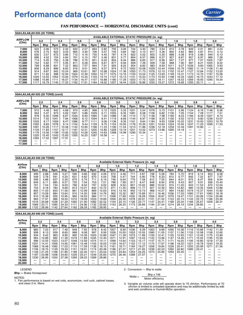
80
FAN PERFORMANCE — HORIZONTAL DISCHARGE UNITS (cont)
LEGENDBhp — Brake Horsepower
NOTES:1. Fan performance is based on wet coils, economizer, roof curb, cabinet losses,
and clean 2-in. filters.
2. Conversion — Bhp to watts:
3. Variable air volume units will operate down to 70 cfm/ton. Performance at 70cfm/ton is limited to unloaded operation and may be additionally limited by edband ewb conditions or Humidi-MiZer operation.
50A4,A5,A8,A9 035 (35 TONS)
AIRFLOW(Cfm)
AVAILABLE EXTERNAL STATIC PRESSURE (in. wg)0.2 0.4 0.6 0.8 1.0 1.2 1.4 1.6 1.8 2.0
Rpm Bhp Rpm Bhp Rpm Bhp Rpm Bhp Rpm Bhp Rpm Bhp Rpm Bhp Rpm Bhp Rpm Bhp Rpm Bhp7,000 522 2.06 573 2.32 620 2.57 664 2.82 705 3.06 744 3.30 780 3.54 815 3.78 849 4.01 881 4.248,000 576 2.75 622 3.03 665 3.30 706 3.57 745 3.84 782 4.10 817 4.36 850 4.62 883 4.87 914 5.129,000 630 3.57 672 3.86 712 4.16 750 4.45 787 4.74 822 5.02 855 5.30 888 5.58 919 5.86 949 6.13
10,000 686 4.52 724 4.84 761 5.15 797 5.46 831 5.77 864 6.07 896 6.37 927 6.67 957 6.97 986 7.2610,500 714 5.05 750 5.38 786 5.70 821 6.02 854 6.34 886 6.65 917 6.96 947 7.27 977 7.57 1005 7.8711,000 742 5.62 777 5.95 811 6.28 845 6.61 877 6.94 909 7.26 939 7.58 968 7.90 997 8.21 1025 8.5212,000 799 6.88 831 7.22 863 7.57 894 7.91 925 8.25 954 8.60 983 8.93 1011 9.27 1039 9.60 1065 9.9313,000 856 8.29 886 8.65 916 9.01 945 9.37 974 9.72 1002 10.08 1029 10.44 1056 10.79 1082 11.14 1108 11.4914,000 914 9.87 942 10.24 969 10.61 997 10.98 1024 11.36 1050 11.73 1076 12.10 1102 12.47 1127 12.84 1152 13.2015,000 971 11.62 998 12.00 1024 12.39 1050 12.77 1075 13.16 1100 13.54 1125 13.93 1149 14.31 1173 14.70 1197 15.0816,000 1029 13.55 1054 13.94 1079 14.34 1103 14.74 1127 15.13 1151 15.53 1174 15.93 1198 16.33 1220 16.73 1243 17.1217,000 1088 15.66 1111 16.07 1134 16.47 1157 16.88 1180 17.29 1203 17.70 1225 18.11 1247 18.53 1269 18.93 1290 19.3417,500 1117 16.79 1140 17.20 1162 17.61 1184 18.02 1207 18.44 1229 18.86 1250 19.27 1272 19.69 1293 20.11 — —
50A4,A5,A8,A9 035 (35 TONS) (cont)
AIRFLOW(Cfm)
AVAILABLE EXTERNAL STATIC PRESSURE (in. wg)2.2 2.4 2.6 2.8 3.0 3.2 3.4 3.6 3.8 4.0
Rpm Bhp Rpm Bhp Rpm Bhp Rpm Bhp Rpm Bhp Rpm Bhp Rpm Bhp Rpm Bhp Rpm Bhp Rpm Bhp7,000 912 4.46 942 4.68 970 4.90 998 5.12 1025 5.33 1051 5.54 1076 5.75 1101 5.96 1124 6.16 1148 6.368,000 944 5.37 973 5.62 1001 5.86 1029 6.11 1055 6.35 1081 6.58 1106 6.82 1130 7.05 1154 7.28 1177 7.519,000 978 6.40 1006 6.67 1034 6.93 1060 7.20 1086 7.46 1112 7.72 1136 7.98 1160 8.23 1184 8.49 1207 8.74
10,000 1014 7.55 1041 7.84 1068 8.12 1094 8.41 1119 8.69 1144 8.97 1168 9.25 1192 9.52 1215 9.80 1238 10.0710,500 1033 8.17 1059 8.47 1086 8.77 1111 9.06 1136 9.35 1161 9.64 1184 9.93 1208 10.22 1231 10.50 1253 10.7911,000 1052 8.83 1078 9.14 1104 9.44 1129 9.75 1154 10.05 1178 10.35 1201 10.64 1224 10.94 1247 11.23 1269 11.5312,000 1091 10.26 1117 10.58 1142 10.90 1166 11.23 1190 11.54 1213 11.86 1236 12.18 1259 12.49 1281 12.80 — —13,000 1133 11.83 1157 12.17 1181 12.51 1205 12.85 1228 13.19 1251 13.52 1273 13.86 1295 14.19 — — — —14,000 1176 13.56 1199 13.92 1222 14.28 1245 14.63 1268 14.99 1290 15.34 — — — — — — — —15,000 1220 15.45 1243 15.83 1265 16.20 1287 16.58 — — — — — — — — — — — —16,000 1265 17.52 1287 17.91 — — — — — — — — — — — — — — — —17,000 — — — — — — — — — — — — — — — — — — — —17,500 — — — — — — — — — — — — — — — — — — — —
50A4,A5,A8,A9 040 (40 TONS)
Airflow(Cfm)
Available External Static Pressure (in. wg)0.2 0.4 0.6 0.8 1.0 1.2 1.4 1.6 1.8 2.0
Rpm Bhp Rpm Bhp Rpm Bhp Rpm Bhp Rpm Bhp Rpm Bhp Rpm Bhp Rpm Bhp Rpm Bhp Rpm Bhp8,000 499 2.88 546 3.27 590 3.66 632 4.06 672 4.46 711 4.87 748 5.28 784 5.70 819 6.14 853 6.589,000 548 3.78 591 4.20 631 4.62 670 5.04 708 5.47 744 5.90 778 6.33 812 6.77 845 7.22 877 7.67
10,000 599 4.86 637 5.30 675 5.74 711 6.19 746 6.64 779 7.09 812 7.55 844 8.01 875 8.47 905 8.9411,000 649 6.11 685 6.57 720 7.04 753 7.51 786 7.99 817 8.47 848 8.94 878 9.43 907 9.91 936 10.4012,000 701 7.54 734 8.03 766 8.52 797 9.02 828 9.52 857 10.02 886 10.52 915 11.03 943 11.53 970 12.0413,000 753 9.18 783 9.69 813 10.21 842 10.72 871 11.25 899 11.77 927 12.30 953 12.82 980 13.35 1006 13.8814,000 805 11.03 833 11.56 861 12.09 889 12.63 916 13.18 942 13.73 968 14.27 994 14.82 1019 15.37 1044 15.9215,000 857 13.09 884 13.64 910 14.20 936 14.76 962 15.32 987 15.89 1011 16.46 1036 17.03 1060 17.61 1083 18.1816,000 910 15.38 935 15.95 960 16.53 984 17.11 1008 17.69 1032 18.28 1056 18.87 1079 19.47 1101 20.06 1124 20.6617,000 963 17.91 986 18.50 1010 19.09 1033 19.69 1056 20.30 1078 20.91 1101 21.52 1123 22.13 1145 22.75 1166 23.3618,000 1016 20.68 1038 21.29 1060 21.90 1082 22.52 1104 23.15 1126 23.77 1147 24.41 1168 25.04 1189 25.67 1209 26.3119,000 1069 23.71 1090 24.33 1111 24.96 1132 25.60 1153 26.25 1173 26.89 1194 27.54 1214 28.19 1234 28.85 — —20,000 1122 26.99 1142 27.64 1162 28.29 1182 28.95 — — — — — — — — — — — —
50A4,A5,A8,A9 040 (40 TONS) (cont)
Airflow(Cfm)
Available External Static Pressure (in. wg)2.2 2.4 2.6 2.8 3.0 3.2 3.4 3.6 3.8 4.0
Rpm Bhp Rpm Bhp Rpm Bhp Rpm Bhp Rpm Bhp Rpm Bhp Rpm Bhp Rpm Bhp Rpm Bhp Rpm Bhp8,000 885 7.03 917 7.48 948 7.95 978 8.42 1007 8.90 1036 9.39 1063 9.88 1090 10.38 1116 10.88 1142 11.399,000 908 8.13 939 8.60 968 9.08 997 9.56 1026 10.05 1053 10.55 1080 11.05 1107 11.56 1133 12.08 1158 12.60
10,000 934 9.42 963 9.90 992 10.39 1020 10.89 1047 11.39 1073 11.89 1100 12.41 1125 12.93 1151 13.45 1175 13.9911,000 964 10.89 992 11.39 1019 11.89 1045 12.40 1071 12.91 1097 13.43 1122 13.96 1147 14.49 1171 15.02 1195 15.5612,000 996 12.55 1023 13.07 1048 13.59 1074 14.11 1099 14.64 1123 15.17 1147 15.71 1171 16.25 1195 16.80 1218 17.3513,000 1031 14.41 1056 14.95 1081 15.48 1105 16.03 1129 16.57 1152 17.12 1175 17.67 1198 18.22 1221 18.78 1243 19.3514,000 1068 16.48 1092 17.03 1115 17.59 1138 18.15 1161 18.71 1184 19.27 1206 19.84 1228 20.41 1250 20.99 1271 21.5615,000 1106 18.75 1129 19.33 1151 19.91 1174 20.48 1196 21.07 1217 21.65 1239 22.23 1260 22.82 1280 23.41 — —16,000 1146 21.25 1168 21.85 1189 22.45 1211 23.04 1232 23.64 1253 24.25 1273 24.85 1293 25.45 — — — —17,000 1187 23.98 1208 24.60 1229 25.21 1249 25.83 1270 26.46 1289 27.07 — — — — — — — —18,000 1230 26.95 1250 27.58 1269 28.22 1289 28.86 — — — — — — — — — — — —19,000 — — — — — — — — — — — — — — — — — — — —20,000 — — — — — — — — — — — — — — — — — — — —
Watts =Bhp x 746
Motor efficiency
Performance data (cont)
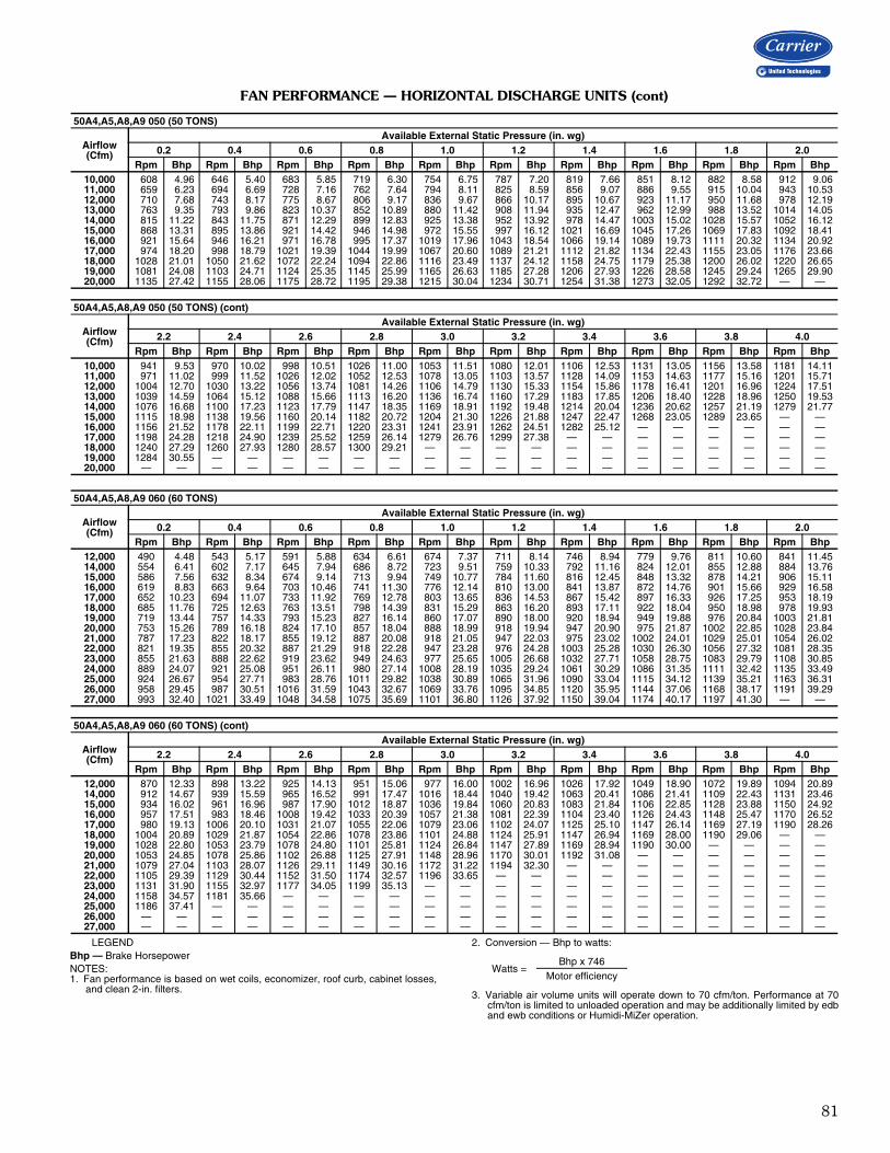
81
FAN PERFORMANCE — HORIZONTAL DISCHARGE UNITS (cont)
LEGENDBhp — Brake HorsepowerNOTES:1. Fan performance is based on wet coils, economizer, roof curb, cabinet losses,
and clean 2-in. filters.
2. Conversion — Bhp to watts:
3. Variable air volume units will operate down to 70 cfm/ton. Performance at 70cfm/ton is limited to unloaded operation and may be additionally limited by edband ewb conditions or Humidi-MiZer operation.
50A4,A5,A8,A9 050 (50 TONS)
Airflow(Cfm)
Available External Static Pressure (in. wg)0.2 0.4 0.6 0.8 1.0 1.2 1.4 1.6 1.8 2.0
Rpm Bhp Rpm Bhp Rpm Bhp Rpm Bhp Rpm Bhp Rpm Bhp Rpm Bhp Rpm Bhp Rpm Bhp Rpm Bhp10,000 608 4.96 646 5.40 683 5.85 719 6.30 754 6.75 787 7.20 819 7.66 851 8.12 882 8.58 912 9.0611,000 659 6.23 694 6.69 728 7.16 762 7.64 794 8.11 825 8.59 856 9.07 886 9.55 915 10.04 943 10.5312,000 710 7.68 743 8.17 775 8.67 806 9.17 836 9.67 866 10.17 895 10.67 923 11.17 950 11.68 978 12.1913,000 763 9.35 793 9.86 823 10.37 852 10.89 880 11.42 908 11.94 935 12.47 962 12.99 988 13.52 1014 14.0514,000 815 11.22 843 11.75 871 12.29 899 12.83 925 13.38 952 13.92 978 14.47 1003 15.02 1028 15.57 1052 16.1215,000 868 13.31 895 13.86 921 14.42 946 14.98 972 15.55 997 16.12 1021 16.69 1045 17.26 1069 17.83 1092 18.4116,000 921 15.64 946 16.21 971 16.78 995 17.37 1019 17.96 1043 18.54 1066 19.14 1089 19.73 1111 20.32 1134 20.9217,000 974 18.20 998 18.79 1021 19.39 1044 19.99 1067 20.60 1089 21.21 1112 21.82 1134 22.43 1155 23.05 1176 23.6618,000 1028 21.01 1050 21.62 1072 22.24 1094 22.86 1116 23.49 1137 24.12 1158 24.75 1179 25.38 1200 26.02 1220 26.6519,000 1081 24.08 1103 24.71 1124 25.35 1145 25.99 1165 26.63 1185 27.28 1206 27.93 1226 28.58 1245 29.24 1265 29.9020,000 1135 27.42 1155 28.06 1175 28.72 1195 29.38 1215 30.04 1234 30.71 1254 31.38 1273 32.05 1292 32.72 — —
50A4,A5,A8,A9 050 (50 TONS) (cont)
Airflow(Cfm)
Available External Static Pressure (in. wg)2.2 2.4 2.6 2.8 3.0 3.2 3.4 3.6 3.8 4.0
Rpm Bhp Rpm Bhp Rpm Bhp Rpm Bhp Rpm Bhp Rpm Bhp Rpm Bhp Rpm Bhp Rpm Bhp Rpm Bhp10,000 941 9.53 970 10.02 998 10.51 1026 11.00 1053 11.51 1080 12.01 1106 12.53 1131 13.05 1156 13.58 1181 14.1111,000 971 11.02 999 11.52 1026 12.02 1052 12.53 1078 13.05 1103 13.57 1128 14.09 1153 14.63 1177 15.16 1201 15.7112,000 1004 12.70 1030 13.22 1056 13.74 1081 14.26 1106 14.79 1130 15.33 1154 15.86 1178 16.41 1201 16.96 1224 17.5113,000 1039 14.59 1064 15.12 1088 15.66 1113 16.20 1136 16.74 1160 17.29 1183 17.85 1206 18.40 1228 18.96 1250 19.5314,000 1076 16.68 1100 17.23 1123 17.79 1147 18.35 1169 18.91 1192 19.48 1214 20.04 1236 20.62 1257 21.19 1279 21.7715,000 1115 18.98 1138 19.56 1160 20.14 1182 20.72 1204 21.30 1226 21.88 1247 22.47 1268 23.05 1289 23.65 — —16,000 1156 21.52 1178 22.11 1199 22.71 1220 23.31 1241 23.91 1262 24.51 1282 25.12 — — — — — —17,000 1198 24.28 1218 24.90 1239 25.52 1259 26.14 1279 26.76 1299 27.38 — — — — — — — —18,000 1240 27.29 1260 27.93 1280 28.57 1300 29.21 — — — — — — — — — — — —19,000 1284 30.55 — — — — — — — — — — — — — — — — — —20,000 — — — — — — — — — — — — — — — — — — — —
50A4,A5,A8,A9 060 (60 TONS)
Airflow(Cfm)
Available External Static Pressure (in. wg)0.2 0.4 0.6 0.8 1.0 1.2 1.4 1.6 1.8 2.0
Rpm Bhp Rpm Bhp Rpm Bhp Rpm Bhp Rpm Bhp Rpm Bhp Rpm Bhp Rpm Bhp Rpm Bhp Rpm Bhp12,000 490 4.48 543 5.17 591 5.88 634 6.61 674 7.37 711 8.14 746 8.94 779 9.76 811 10.60 841 11.4514,000 554 6.41 602 7.17 645 7.94 686 8.72 723 9.51 759 10.33 792 11.16 824 12.01 855 12.88 884 13.7615,000 586 7.56 632 8.34 674 9.14 713 9.94 749 10.77 784 11.60 816 12.45 848 13.32 878 14.21 906 15.1116,000 619 8.83 663 9.64 703 10.46 741 11.30 776 12.14 810 13.00 841 13.87 872 14.76 901 15.66 929 16.5817,000 652 10.23 694 11.07 733 11.92 769 12.78 803 13.65 836 14.53 867 15.42 897 16.33 926 17.25 953 18.1918,000 685 11.76 725 12.63 763 13.51 798 14.39 831 15.29 863 16.20 893 17.11 922 18.04 950 18.98 978 19.9319,000 719 13.44 757 14.33 793 15.23 827 16.14 860 17.07 890 18.00 920 18.94 949 19.88 976 20.84 1003 21.8120,000 753 15.26 789 16.18 824 17.10 857 18.04 888 18.99 918 19.94 947 20.90 975 21.87 1002 22.85 1028 23.8421,000 787 17.23 822 18.17 855 19.12 887 20.08 918 21.05 947 22.03 975 23.02 1002 24.01 1029 25.01 1054 26.0222,000 821 19.35 855 20.32 887 21.29 918 22.28 947 23.28 976 24.28 1003 25.28 1030 26.30 1056 27.32 1081 28.3523,000 855 21.63 888 22.62 919 23.62 949 24.63 977 25.65 1005 26.68 1032 27.71 1058 28.75 1083 29.79 1108 30.8524,000 889 24.07 921 25.08 951 26.11 980 27.14 1008 28.19 1035 29.24 1061 30.29 1086 31.35 1111 32.42 1135 33.4925,000 924 26.67 954 27.71 983 28.76 1011 29.82 1038 30.89 1065 31.96 1090 33.04 1115 34.12 1139 35.21 1163 36.3126,000 958 29.45 987 30.51 1016 31.59 1043 32.67 1069 33.76 1095 34.85 1120 35.95 1144 37.06 1168 38.17 1191 39.2927,000 993 32.40 1021 33.49 1048 34.58 1075 35.69 1101 36.80 1126 37.92 1150 39.04 1174 40.17 1197 41.30 — —
50A4,A5,A8,A9 060 (60 TONS) (cont)
Airflow(Cfm)
Available External Static Pressure (in. wg)2.2 2.4 2.6 2.8 3.0 3.2 3.4 3.6 3.8 4.0
Rpm Bhp Rpm Bhp Rpm Bhp Rpm Bhp Rpm Bhp Rpm Bhp Rpm Bhp Rpm Bhp Rpm Bhp Rpm Bhp12,000 870 12.33 898 13.22 925 14.13 951 15.06 977 16.00 1002 16.96 1026 17.92 1049 18.90 1072 19.89 1094 20.8914,000 912 14.67 939 15.59 965 16.52 991 17.47 1016 18.44 1040 19.42 1063 20.41 1086 21.41 1109 22.43 1131 23.4615,000 934 16.02 961 16.96 987 17.90 1012 18.87 1036 19.84 1060 20.83 1083 21.84 1106 22.85 1128 23.88 1150 24.9216,000 957 17.51 983 18.46 1008 19.42 1033 20.39 1057 21.38 1081 22.39 1104 23.40 1126 24.43 1148 25.47 1170 26.5217,000 980 19.13 1006 20.10 1031 21.07 1055 22.06 1079 23.06 1102 24.07 1125 25.10 1147 26.14 1169 27.19 1190 28.2618,000 1004 20.89 1029 21.87 1054 22.86 1078 23.86 1101 24.88 1124 25.91 1147 26.94 1169 28.00 1190 29.06 — —19,000 1028 22.80 1053 23.79 1078 24.80 1101 25.81 1124 26.84 1147 27.89 1169 28.94 1190 30.00 — — — —20,000 1053 24.85 1078 25.86 1102 26.88 1125 27.91 1148 28.96 1170 30.01 1192 31.08 — — — — — —21,000 1079 27.04 1103 28.07 1126 29.11 1149 30.16 1172 31.22 1194 32.30 — — — — — — — —22,000 1105 29.39 1129 30.44 1152 31.50 1174 32.57 1196 33.65 — — — — — — — — — —23,000 1131 31.90 1155 32.97 1177 34.05 1199 35.13 — — — — — — — — — — — —24,000 1158 34.57 1181 35.66 — — — — — — — — — — — — — — — —25,000 1186 37.41 — — — — — — — — — — — — — — — — — —26,000 — — — — — — — — — — — — — — — — — — — —27,000 — — — — — — — — — — — — — — — — — — — —
Watts =Bhp x 746
Motor efficiency

82
FAN PERFORMANCE — STANDARD AND MODULATING POWER EXHAUST
LEGEND LEGEND
HIGH CAPACITY POWER EXHAUST ACCESSORY
HUMIDI-MIZER® SYSTEM COMPONENT PRESSURE DROPS (in. wg)SIZE 020-035 UNITS
HUMIDI-MIZER SYSTEM COMPONENT PRESSURE DROPS (in. wg)SIZE 040,050 UNITS
HUMIDI-MIZER SYSTEM COMPONENT PRESSURE DROPS (in. wg)SIZE 060 UNITS
48/50A020-050 (20 to 50 Tons)
Airflow(Cfm)
208 V 230, 460, 575 VESP Bhp Watts ESP Bhp Watts
7,700 0.60 3.69 4140 0.73 3.98 44607,900 0.56 3.74 4190 0.69 4.02 45108,100 0.51 3.78 4240 0.65 4.07 45608,500 0.41 3.83 4290 0.56 4.12 46208,900 0.31 3.93 4410 0.47 4.23 47409,300 0.20 4.07 4560 0.37 4.37 49009,700 0.11 4.17 4670 0.30 4.47 5010
10,100 0.04 4.25 4770 0.23 4.56 511010,500 — — — 0.17 4.66 522010,900 — — — 0.12 4.75 533011,300 — — — 0.07 4.80 538011,700 — — — 0.04 4.83 5420
Bhp — Brake HorsepowerESP — External Static Pressure (in. wg)Watts — Input Watts to Motor
48/50A060 (60 Tons)
Airflow(Cfm)
208 V 230, 460, 575 VESP Bhp Watts ESP Bhp Watts
11,550 0.60 5.54 6210 0.73 5.97 669011,850 0.56 5.61 6285 0.69 6.03 676512,150 0.51 5.67 6360 0.65 6.10 684012,750 0.41 5.74 6435 0.56 6.18 693013,350 0.31 5.90 6615 0.47 6.34 711013,950 0.20 6.10 6840 0.37 6.56 735014,550 0.11 6.25 7005 0.30 6.70 751515,150 0.04 6.38 7155 0.23 6.84 766515,750 — — — 0.17 6.98 783016,350 — — — 0.12 7.13 799516,950 — — — 0.07 7.20 807017,550 — — — 0.04 7.25 8130
Bhp — Brake HorsepowerESP — External Static Pressure (in. wg)Watts — Input Watts to Motor
PART NO. VOLTAGECFM PERFORMANCE VS. STATIC PRESSURE TOTAL
AMPSNOISE (dB)
1/4 in. 3/8 in. 1/2 in. 5/8 in. at 1 foot at 10 footSingle Module
CRPWREXH071A00 230V/3PH9,817 9,631 9,591 8,964
12.888 77CRPWREXH072A00 460V/3PH 6.4
CRPWREXH073A00 575V/3PH 4.8Two Module
CRPWREXH074A00 230V/3PH19,634 19,262 19,182 17,928
25.688 77CRPWREXH075A00 460V/3PH 12.8
CRPWREXH076A00 575V/3PH 9.6Three Module
CRPWREXH077A00 230V/3PH29,451 28,893 28,773 26,892
38.488 77CRPWREXH078A00 460V/3PH 19.2
CRPWREXH079A00 575V/3PH 14.4
COMPONENTAIRFLOW (cfm)
4,000 6,000 8,000 10,000 12,000 14,000HUMIDI-MIZER 0.012 0.022 0.035 0.050 0.068 0.089
COMPONENTAIRFLOW (cfm)
8,000 10,000 12,000 14,000 16,000 18,000 20,000HUMIDI-MIZER 0.035 0.050 0.068 0.089 0.112 0.137 0.165
COMPONENTAIRFLOW (cfm)
12,000 14,000 16,000 18,000 20,000 22,000 24,000HUMIDI-MIZER 0.002 0.004 0.010 0.023 0.044 0.077 0.125
Performance data (cont)
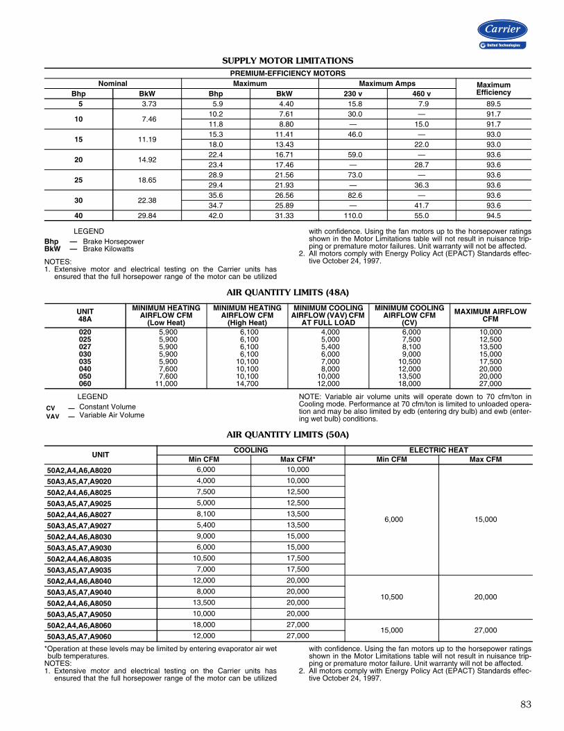
83
SUPPLY MOTOR LIMITATIONS
LEGEND
NOTES:1. Extensive motor and electrical testing on the Carrier units has
ensured that the full horsepower range of the motor can be utilized
with confidence. Using the fan motors up to the horsepower ratingsshown in the Motor Limitations table will not result in nuisance trip-ping or premature motor failures. Unit warranty will not be affected.
2. All motors comply with Energy Policy Act (EPACT) Standards effec-tive October 24, 1997.
AIR QUANTITY LIMITS (48A)
LEGEND NOTE: Variable air volume units will operate down to 70 cfm/ton inCooling mode. Performance at 70 cfm/ton is limited to unloaded opera-tion and may be also limited by edb (entering dry bulb) and ewb (enter-ing wet bulb) conditions.
AIR QUANTITY LIMITS (50A)
*Operation at these levels may be limited by entering evaporator air wetbulb temperatures.
NOTES:1. Extensive motor and electrical testing on the Carrier units has
ensured that the full horsepower range of the motor can be utilized
with confidence. Using the fan motors up to the horsepower ratingsshown in the Motor Limitations table will not result in nuisance trip-ping or premature motor failure. Unit warranty will not be affected.
2. All motors comply with Energy Policy Act (EPACT) Standards effec-tive October 24, 1997.
PREMIUM-EFFICIENCY MOTORSNominal Maximum Maximum Amps Maximum
EfficiencyBhp BkW Bhp BkW 230 v 460 v5 3.73 5.9 4.40 15.8 7.9 89.5
10 7.4610.2 7.61 30.0 — 91.711.8 8.80 — 15.0 91.7
15 11.1915.3 11.41 46.0 — 93.018.0 13.43 22.0 93.0
20 14.9222.4 16.71 59.0 — 93.623.4 17.46 — 28.7 93.6
25 18.6528.9 21.56 73.0 — 93.629.4 21.93 — 36.3 93.6
30 22.3835.6 26.56 82.6 — 93.634.7 25.89 — 41.7 93.6
40 29.84 42.0 31.33 110.0 55.0 94.5
Bhp — Brake HorsepowerBkW — Brake Kilowatts
UNIT48A
MINIMUM HEATINGAIRFLOW CFM
(Low Heat)
MINIMUM HEATINGAIRFLOW CFM
(High Heat)
MINIMUM COOLINGAIRFLOW (VAV) CFM
AT FULL LOAD
MINIMUM COOLINGAIRFLOW CFM
(CV)
MAXIMUM AIRFLOWCFM
020 5,900 6,100 4,000 6,000 10,000025 5,900 6,100 5,000 7,500 12,500027 5,900 6,100 5,400 8,100 13,500030 5,900 6,100 6,000 9,000 15,000035 5,900 10,100 7,000 10,500 17,500040 7,600 10,100 8,000 12,000 20,000050 7,600 10,100 10,000 13,500 20,000060 11,000 14,700 12,000 18,000 27,000
CV — Constant VolumeVAV — Variable Air Volume
UNITCOOLING ELECTRIC HEAT
Min CFM Max CFM* Min CFM Max CFM
50A2,A4,A6,A8020 6,000 10,000
6,000 15,000
50A3,A5,A7,A9020 4,000 10,000
50A2,A4,A6,A8025 7,500 12,500
50A3,A5,A7,A9025 5,000 12,500
50A2,A4,A6,A8027 8,100 13,500
50A3,A5,A7,A9027 5,400 13,500
50A2,A4,A6,A8030 9,000 15,000
50A3,A5,A7,A9030 6,000 15,000
50A2,A4,A6,A8035 10,500 17,500
50A3,A5,A7,A9035 7,000 17,500
50A2,A4,A6,A8040 12,000 20,000
10,500 20,00050A3,A5,A7,A9040 8,000 20,000
50A2,A4,A6,A8050 13,500 20,000
50A3,A5,A7,A9050 10,000 20,000
50A2,A4,A6,A8060 18,000 27,00015,000 27,000
50A3,A5,A7,A9060 12,000 27,000

84
ControlsControl componentsThe 48/50A Series rooftops use the ComfortLink controlsystem that has been developed for use in Carrier Com-mercial equipment. The control system monitors all oper-ating conditions in the rooftop unit, as well as controllingthe compressors, economizers, fans, heat, and otherdevices. It also has the capability of communicating withthe Carrier Comfort Network® devices using the CCN pro-tocol and other popular protocols including BACnet,MODBUS, LonWorks, etc.The system uses a microprocessor and a series of boards,each with inputs and outputs. A local network communica-tions bus (LEN) ties all the boards together into a systemand enables the boards to communicate.For the 48/50A Series, the control consists of the follow-ing key components:Main base board (MBB)The MBB is the center of the ComfortLink control system.It contains the major portion of the operating software andcontrols the operation of the unit. The MBB continuouslymonitors inputs and outputs as well as data from the LENand CCN communications channels. The MBB also con-trols 11 output relays. A complete list of the MBB and sys-tem I/O are contained in the table on page 85. The boardis located in the main control box.Economizer control board (ECB1)The ECB1 controls the economizer actuator. The ECB1controls the economizer motor using a digital communica-tions signal that also provides operation and diagnosticdata on the economizer motor. The ECB1 also controls theoperation of the power exhaust motors and provides up to6 stages of digitally sequenced power exhaust. Exhaustsequencing can be based on either the economizer motorposition or the building pressure. On the A Series unit, theECB1 board is located in an auxiliary box located at theend of the unit near the economizer motor. The board alsocontains a second LEN port that can be used with thehandheld Navigator™ display.Supply and building pressure control board (ECB2or RXB)The board, which is the same hardware as the ECB1, isused to control the supply fan inverter on the VAV units. Itsends a 4 to 20 mA signal to the inverter based on a supplyduct pressure sensor connected to the board. The boardalso accepts a signal from another pressure sensor thatmonitors building pressure and controls the operation ofthe optional modulating power exhaust system.On units equipped with the variable capacity compressorand/or Humidi-MiZer system, this board is called the RXB.The RXB performs the same functions as the ECB2 andhas additional inputs and outputs to control the variablecapacity compressor as well as the Humidi-MiZer adaptive
dehumidification system. The ECB2/RXB is located in theauxiliary control box.Staged gas heat board (SCB)When the optional staged gas heat is used, the SCB boardwill be installed and will control the operation of the gasvalves. It also provides additional sensors for monitoringthe supply air temperature. This board is located in the gasheat section of the unit.Integrated gas controller (IGC)One IGC is provided with each bank of gas heat exchang-ers. It controls the direct spark ignition system and moni-tors the rollout switch, limit switches, and induced-draftmotor Hall Effect sensor. It is equipped with an LED fordiagnostics.Controls expansion module (CEM)The optional expansion module is used to provide inputsfor demand limiting, remote set point, and other optionalinputs. It is located in the main control box.Compressor protection Cycle-LOC™ board (CS)This board monitors the status of the compressor by sens-ing the current flow to the compressors; it then providesdigital status signal to the MBB.Expansion valve control board (EXV)The optional EXV board controls both the condenser andbypass modulation valves of the humidimizer. This boardalso receives inputs to sense the evaporative dischargetemperature if the unit has the humidimizer option. Thisboard is located in the auxiliary control box.Scrolling marquee displayThis device is the keypad interface used to access the controlinformation, read sensor values, test the unit, and monitoralarm status. The marquee display is a 4-key, 4-character, 16-segment LED (light-emitting diode) display. The display is veryeasy to operate using 4 buttons and a group of 11 LEDs thatindicate the following menu structures:
Through the display, inputs and outputs can be checkedfor their value or status. Because the unit is equipped withsuction pressure transducers and discharge saturation tem-perature sensors, it can also display pressures typicallyobtained from gages. The control includes a full alarm his-tory which can be accessed from the display. Through thedisplay, a built-in test routine can be used at start-up com-mission and during maintenance inspections to help diag-nose operational problems with the unit.
• Run Status • Outputs• Service Test • Configuration• Temperatures • Timeclock• Pressures • Operating Modes• Set Points • Alarms• Inputs
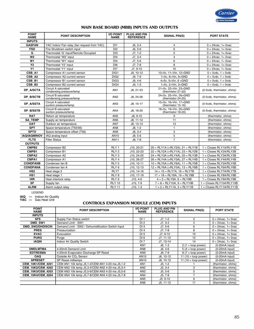
85
MAIN BASE BOARD (MBB) INPUTS AND OUTPUTS
LEGEND
CONTROLS EXPANSION MODULE (CEM) INPUTS
POINT NAME POINT DESCRIPTION I/O POINT
NAMEPLUG AND PIN REFERENCE SIGNAL PIN(S) PORT STATE
INPUTSGASFAN YAC Indoor Fan relay (fan request from YAC) DI1 J6, 3-4 4 0 = 24vac, 1= 0vac
FSD Fire Shutdown switch input DI2 J6, 5-6 6 0 = 24vac, 1= 0vacG Thermostat ‘G’ input/Remote Occupied DI3 J7, 1-2 2 0 = 24vac, 1= 0vac
W2 Thermostat ‘W2’ input DI4 J7, 3-4 4 0 = 24vac, 1= 0vacW1 Thermostat ‘W1’ input DI5 J7, 5-6 6 0 = 24vac, 1= 0vacY2 Thermostat ‘Y2’ input DI6 J7, 7-8 8 0 = 24vac, 1= 0vacY1 Thermostat ‘Y1’ input DI7 J7, 9-10 10 0 = 24vac, 1= 0vac
CSB_A1 Compressor A1 current sensor DIG1 J9, 10-12 10=5v, 11=Vin, 12=GND 0 = 5vdc, 1 = 0vdcCSB_A2 Compressor A2 current sensor DIG2 J9, 7-9 7=5v, 8=Vin, 9=GND 0 = 5vdc, 1 = 0vdcCSB_B1 Compressor B1 current sensor DIG3 J9, 4-6 4=5v, 5=Vin, 6 =GND 0 = 5vdc, 1 = 0vdcCSB_B2 Compressor B2 current sensor DIG4 J9, 1-3 1=5v, 2=Vin, 3=GND 0 = 5vdc, 1 = 0vdc
DP_A/SCTA Circuit A saturated condensing pressure/temp AN1 J8, 21-23 21=5v, 22=Vin, 23=GND
(thermistor 21-22) (0-5vdc, thermistor, ohms)
DP_B/SCTB Circuit B saturated condensing pressure/temp AN2 J8, 24-26 24=5v, 25=Vin, 26=GND
(thermistor 24-25) (0-5vdc, thermistor, ohms)
SP_A/SSTA Circuit A saturated suction pressure/temp AN3 J8, 15-17 15=5v, 16=Vin, 17=GND
(thermistor 15-16) (0-5vdc, thermistor, ohms)
SP_B/SSTB Circuit B saturated suction pressure/temp AN4 J8, 18-20 18=5v, 19=Vin, 20=GND
(thermistor 18-20) (0-5vdc, thermistor, ohms)
RAT Return air temperature AN5 J8, 9-10 9 (thermistor, ohms)SA_TEMP Supply air temperature AN6 J8, 11-12 11 (thermistor, ohms)
OAT Outdoor air temperature AN7 J8, 13-14 13 (thermistor, ohms)SPT Space temperature (T55/56) AN8 J8, 1-2 1 (thermistor, ohms)
SPTO Space temperature offset (T56) AN9 J8, 3-4 3 (thermistor, ohms)IAQ/IAQMINOV IAQ analog input AN10 J8, 5-6 5 (thermistor, ohms)
FLTS Filter Status AN11 J8, 7-8 7 (thermistor, ohms)OUTPUTS
CMPB2 Compressor B2 RLY 1 J10, 20-21 20 = RLY1A (=RLY2A), 21 = RLY1B 1 = Closes RLY1A/RLY1BCMPB1 Compressor B1 RLY 2 J10, 22-23 22 = RLY2A (=RLY1A), 23 = RLY2B 1 = Closes RLY2A/RLY2BCMPA2 Compressor A2 RLY 3 J10, 24-25 24 = RLY3A (=RLY4A), 25 = RLY3B 1 = Closes RLY3A/RLY3BCMPA1 Compressor A1 RLY 4 J10, 26-27 26 = RLY4A (=RLY3A), 27 = RLY4B 1 = Closes RLY4A/RLY4B
CONDFANB Condenser fan B RLY 5 J10, 10-11 10 = RLY5A (=RLY6A), 11 = RLY5B 1 = Closes RLY5A/RLY5BCONDFANA Condenser fan A RLY 6 J10, 12-13 12 = RLY6A (=RLY5A), 13 = RLY6B 1 = Closes RLY6A/RLY6B
HS2 Heat stage 2 RLY7 J10, 14-16 14 = 15 = RLY7A, 16 = RLY7B 1 = Closes RLY7A/RLY7BHS1 Heat stage 1 RLY 8 J10, 17-19 17 = 18 = RLY8A, 19 = RLY8B 1 = Closes RLY8A/RLY8BHIR Heat interlock relay RLY 9 J10, 4-6 4 = 5 = RLY9A, 6 = RLY9B 1 = Closes RLY9A/RLY9BSF Supply fan RLY 10 J10, 7-9 7 = 8 = RLY10A, 9 = RLY10B 1 = Closes RLY10A/RLY10B
ALRM Alarm output relay RLY 11 J10, 1-3 1 = 2 = RLY11A, 3 = RLY11B 1 = Closes RLY11A/RLY11B
IAQ — Indoor-Air QualityYAC — Gas Heat Unit
POINT NAME POINT DESCRIPTION I/O POINT
NAMEPLUG AND PIN REFERENCE SIGNAL PIN(S) PORT STATE
INPUTSSFS Supply Fan Status switch DI 1 J7, 1-2 2 0 = 24vac, 1= 0vac
DMD_SW1 Demand Limit - SW1 DI 2 J7, 3-4 4 0 = 24vac, 1= 0vacDMD_SW2/DHDISCIN Demand Limit - SW2 / Dehumidification Switch Input DI 3 J7, 5-6 6 0 = 24vac, 1= 0vac
PRES Pressurization DI 4 J7, 7-8 8 0 = 24vac, 1= 0vacEVAC Evacuation DI 5 J7, 9-10 10 0 = 24vac, 1= 0vacPURG Purge DI 6 J7, 11-12 12 0 = 24vac, 1= 0vacIAQIN Indoor Air Quality Switch DI 7 J7, 13-14 14 0 = 24vac, 1= 0vac
AN7 J6, 1-3 2 (1 = loop power) (0-20mA input)DMDLMTMA 4-20mA Demand Limit AN8 J6, 4-6 5 (4 = loop power) (0-20mA input)EDTRESMA 4-20mA Evaporator Discharge SP Reset AN9 J6, 7-9 8 (7 = loop power) (0-20mA input)
OAQ Outside Air CO2 Sensor AN10 J6, 10-12 11 (10 = loop power) (0-20mA input)SPRESET SP Reset milliamps AN10 J6, 10-12 11 (10 = loop power) (0-20mA input)
CEM_10K1/CEM_4201 CEM AN1 10k temp J5,1-2/CEM AN1 4-20 ma J5,1-2 AN1 J5, 1-2 1 (thermistor, ohms)CEM_10K2/CEM_4202 CEM AN2 10k temp J5,3-4/CEM AN2 4-20 ma J5,3-4 AN2 J5, 3-4 3 (thermistor, ohms)CEM_10K3/CEM_4203 CEM AN3 10k temp J5,5-6/CEM AN3 4-20 ma J5,5-6 AN3 J5, 5-6 5 (thermistor, ohms)CEM_10K4/CEM_4204 CEM AN4 10k temp J5,7-8/CEM AN4 4-20 ma J5,7-8 AN4 J5, 7-8 7 (thermistor, ohms)
AN5 J5, 9-10 9 (thermistor, ohms) AN6 J5, 11-12 11 (thermistor, ohms)

86
Controls (cont)ECONOMIZER CONTROL BOARD (ECB1) INPUTS AND OUTPUTS
RXB CONTROL BOARD (ECB2) INPUTS AND OUTPUTS
NOTE: RXB is required for Digital Scroll or Humidi-MiZer option.
POINT NAME POINT DESCRIPTION I/O POINT
NAMEPLUG AND PIN REFERENCE SIGNAL PIN(S) PORT STATE
INPUTSRMTIN Remote occupancy DI1 J4, 1-2 2 24VAC = 1, 0VAC = 0
ECONENBL, ECOORIDE Economizer enable DI2 J4, 3-4 4 24VAC = 1, 0VAC = 0
RARH Return air relative humidity AN1 J5, 1-3 1=24VDC, 2=0-20mA in, 3=GND 0-20mAOARH Outdoor air relative humidity AN2 J5, 4-6 4=24VDC, 5=0-20mA in, 6=GND 0-20mA
OUTPUTSECB1_AO1 ECB1, analog output 1 AO1 J9, 1-2 1=0-20mA, 2=GND 0-20mA OUT
ECONOCMD Economizer actuator (digital control) PP/MP J7, 1-3 1=PP/MP Data, 2=24VAC, 3=GND Belimo PP/MP Protocol
PE_A Power Exhaust stage A RLY1 J8, 1-3 1 = 2 = RLY1A, 3 = RLY1B 1 = Closes RLY1A/RLY1BPE_B Power Exhaust stage B RLY 2 J8, 4-6 4 =5 = RLY2A, 6 = RLY2B 1 = Closes RLY2A/RLY2BPE_C Power Exhaust stage C RLY 3 J8, 7-9 7 = 8 = RLY3A, 9 = RLY3B 1 = Closes RLY3A/RLY3B
ECON_PWR Economizer Power RLY 6 J8, 16-18 16 = 17 = RLY6A, 18 = RLY6B 1 = Closes RLY6A/RLY6B
POINT NAME POINT DESCRIPTION I/O POINT
NAMEPLUG AND PIN REFERENCE SIGNAL PIN(S) PORT STATE
INPUTS DI1 J4, 1-2 2=Vin, 1=24VAC 24VAC = 1, 0VAC = 0
DI2 J4, 3-4 4=Vin, 3=24vac 24VAC = 1, 0VAC = 0DI3 J4, 5-6 6=Vin, 5=24vacDI4 J4, 7-8 8=Vin, 7=24vacDI5 J4, 9-10 10=Vin, 9=24vacDI6 J4, 11-12 12=Vin, 11=24vac
BP Building static pressure AN1 J5, 1-3 1=24VDC, 2=0-20mA in, 3=GND 0-20mASP Supply Duct static pressure AN2 J5, 4-6 4=24VDC, 5=0-20mA in, 6=GND 0-20mA
CCT Air Temp Lvg Evap Coil AN3 J6, 1-2 1=Vin, 2=GND (thermistor, ohms)DSDT DS Discharge Temperature AN4 J6, 3-4 3=Vin, 4=GND (thermistor, ohms)
AN5 J6, 5-6 5=Vin, 6=GND (thermistor, ohms)AN6 J6, 7-8 7=Vin, 8=GND (thermistor, ohms)
OUTPUTSSFAN_VFD Supply Fan Inverter speed AO1 J9, 1-2 1=0-20mA, 2=GND 0-20mA OUTCMPDSCAP Digital Scroll Solenoid PP/MP J7, 1-3 1=PP/MP Data, 2=24VAC, 3=GND Belimo PP/MP Protocol
RLY1 J8, 1-3 1 = 2 = RLY1A, 3 = RLY1B 1 = Closes RLY1A / RLY1BRLY2 J8, 4-6 4 = 5 = RLY2A, 6 = RLY2B 1 = Closes RLY2A / RLY2B
HUM3WVAL Humidimizer 3 Way Valve RLY3 J8, 7-9 7 = 8 = RLY3A, 9 = RLY3B 1 = Closes RLY3A / RLY3BRLY4 J8, 10-12 10 = 11 = RLY4A, 12 = RLY4B 1 = Closes RLY4A / RLY4BRLY5 J8, 13-15 13 = 14 = RLY5A, 15 = RLY5B 1 = Closes RLY5A / RLY5B
MLV Minimum load valve RLY 6 J8, 16-18 16 = 17 = RLY6A, 18 = RLY6B 1 = Closes RLY6A / RLY6B
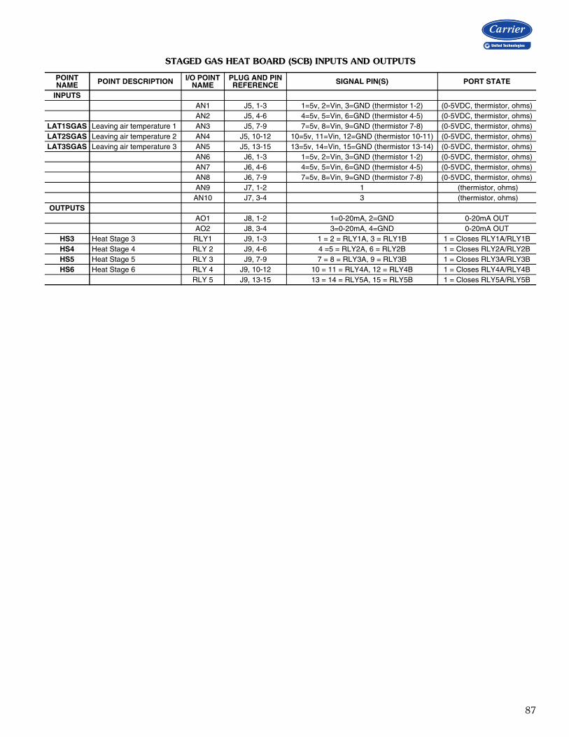
87
STAGED GAS HEAT BOARD (SCB) INPUTS AND OUTPUTS
POINT NAME POINT DESCRIPTION I/O POINT
NAMEPLUG AND PIN REFERENCE SIGNAL PIN(S) PORT STATE
INPUTS AN1 J5, 1-3 1=5v, 2=Vin, 3=GND (thermistor 1-2) (0-5VDC, thermistor, ohms) AN2 J5, 4-6 4=5v, 5=Vin, 6=GND (thermistor 4-5) (0-5VDC, thermistor, ohms)
LAT1SGAS Leaving air temperature 1 AN3 J5, 7-9 7=5v, 8=Vin, 9=GND (thermistor 7-8) (0-5VDC, thermistor, ohms)LAT2SGAS Leaving air temperature 2 AN4 J5, 10-12 10=5v, 11=Vin, 12=GND (thermistor 10-11) (0-5VDC, thermistor, ohms)LAT3SGAS Leaving air temperature 3 AN5 J5, 13-15 13=5v, 14=Vin, 15=GND (thermistor 13-14) (0-5VDC, thermistor, ohms)
AN6 J6, 1-3 1=5v, 2=Vin, 3=GND (thermistor 1-2) (0-5VDC, thermistor, ohms) AN7 J6, 4-6 4=5v, 5=Vin, 6=GND (thermistor 4-5) (0-5VDC, thermistor, ohms) AN8 J6, 7-9 7=5v, 8=Vin, 9=GND (thermistor 7-8) (0-5VDC, thermistor, ohms) AN9 J7, 1-2 1 (thermistor, ohms) AN10 J7, 3-4 3 (thermistor, ohms)
OUTPUTS AO1 J8, 1-2 1=0-20mA, 2=GND 0-20mA OUT AO2 J8, 3-4 3=0-20mA, 4=GND 0-20mA OUT
HS3 Heat Stage 3 RLY1 J9, 1-3 1 = 2 = RLY1A, 3 = RLY1B 1 = Closes RLY1A/RLY1BHS4 Heat Stage 4 RLY 2 J9, 4-6 4 =5 = RLY2A, 6 = RLY2B 1 = Closes RLY2A/RLY2BHS5 Heat Stage 5 RLY 3 J9, 7-9 7 = 8 = RLY3A, 9 = RLY3B 1 = Closes RLY3A/RLY3BHS6 Heat Stage 6 RLY 4 J9, 10-12 10 = 11 = RLY4A, 12 = RLY4B 1 = Closes RLY4A/RLY4B
RLY 5 J9, 13-15 13 = 14 = RLY5A, 15 = RLY5B 1 = Closes RLY5A/RLY5B

88
Controls (cont)HUMIDI-MIZER CONTROL BOARD (EXV) INPUTS AND OUTPUTS
POINT NAME POINT DESCRIPTION I/O POINT
NAMEPLUG AND PIN REFERENCE SIGNAL PIN(S) PORT STATE
INPUTSCCT Air Temp Lvg Evap Coil AN1 J5, 5-6 5=Vin, 6=GND (Thermistor, ohms)
AN2 J5, 7-8 7=Vin,8 =GND (Thermistor, ohms)AN3 J5, 9-10 9=Vin, 10=GND (Thermistor, ohms)AN4 J5, 11-12 11=Vin, 12=GND (Thermistor, ohms)AN5 J5, 1-2 1=Vin, 2=GND 0-20mA INPUTAN6 J5, 3-4 3=Vin, 4=GND 0-20mA INPUT
OUTPUTSCOND_EXV Condenser EXV Position OUTA
Coil1A J6,1 1
HI Z when P5.7 and P5.6 = 0+12 vdc when P5.7 = 1 and P5.6 = 0
0 vdc when P5.7 = 0 and P5.6 = 1PROHIBITED when P5.7 = 1 and P5.6 = 1
Coil2A J6,2 2
HI Z when P5.5 and P5.4 = 0 +12 vdc when P5.5 = 1 and P5.4 = 0
0 vdc when P5.5 = 0 and P5.4 = 1PROHIBITED when P5.5 = 1 and P5.4 = 1
12VDC J6, 3 3 Power Output
Coil3A J6,4 4
HI Z when P5.3 and P5.2 = 0+12 vdc when P5.3 = 1 and P5.2 = 0 0 vdc when P5.3 = 0 and P5.2 = 1
PROHIBITED when P5.3 = 1 and P5.2 = 1
Coil4A J6,5 5
HI Z when P5.1 and P5.0 = 0 +12 vdc when P5.1 = 1 and P5.0 = 0
0 vdc when P5.1 = 0 and P5.0 = 1PROHIBITED when P5.1 = 1 and P5.0 = 1
COND_EXV Bypass EXV Position OUTB
Coil1B J7,1 1
HI Z when P8.7 and P8.6 = 0+12 vdc when P8.7 = 1 and P8.6 = 0
0 vdc when P8.7 = 0 and P8.6 = 1PROHIBITED when P8.7 = 1 and P8.6 = 1
Coil2B J7,2 2HI Z when P8.5 and P8.4 = 0
+12 vdc when P8.5 = 1 and P8.4 = 0PROHIBITED when P8.5 = 1 and P8.4 = 1
12VDC J7,3 3 Power Output
Coil3B J7,4 4
HI Z when P8.3 and P8.2 = 0 +12 vdc when P8.3 = 1 and P8.2 = 0
0 vdc when P8.3 = 0 and P8.2 = 1PROHIBITED when P8.3 = 1 and P8.2 = 1
Coil4B J7,5 5
HI Z when P8.1 and P8.0 = 0 +12 vdc when P8.1 = 1 and P8.0 = 0
0 vdc when P8.1 = 0 and P8.0 = 1PROHIBITED when P8.1 = 1 and P8.0 = 1

89
INPUT/OUTPUT CHANNEL DESIGNATIONS — FIELD CONNECTION TERMINAL STRIPS
* Requires optional Controls Expansion Module (CEM).
TERMINALBOARD
TERMINALNO. DESCRIPTION TYPE
TB-1 - POWER CONNECTION OR DISCONNECT (in Main Control Box)
TB111 L1 power supply 208-230/460/575/380/-3-6012 L2 power supply 208-230/460/575/380/-3-6013 L3 power supply 208-230/460/575/380/-3-60
TB-2 - GROUND (in Main Control Box)TB2 1 Neutral Power
TB-3 - CCN COMMUNICATIONS (HY84HA096) (in Main Control Box)
TB3
1 LEN + 5 VDC, logic2 LEN C 5 VDC, logic3 LEN – 5 VDC, logic4 24 VAC 24 VAC5 CCN + 5 VDC, logic6 CCN C 5 VDC, logic7 CCN – 5 VDC, logic8 Grd ground
TB-4 - THEROMSTAT CONNECTIONS (HY84HA090) (in Main Control Box)
TB4
1 Thermostat R 24 VAC Power2 Thermostat Y1 24 VAC Input3 Thermostat Y2 24 VAC Input4 Thermostat W1 24 VAC Input5 Thermostat W2 24 VAC Input6 Thermostat G 24 VAC Input7 Thermostat C 24 VAC Common8 Thermostat X (Alarm Contact) 24 VAC Output
TB-5 - FIELD CONNECTIONS (HY84HA101) (in Main Control Box)
TB5
1 VAV Heater Interlock Relay, Ground Dry Contact, Max 1 Amp2 VAV Heater Interlock Relay, 24 VAC Dry Contact, Max 1 Amp3 T55/T56 10 K Thermistor Thermistor Input4 T55/T56 10 K Thermistor Thermistor Input5 T56 Set Point Adjustment (100,000 ohm) Thermistor Input6 Indoor Air IAQ Remote Sensor/Remote Pot/Remote 4-20 mA 4-20 mA, ext. powered w/res or 0-5 VDC, +7 Indoor Air IAQ Remote Sensor/Remote Pot/Remote 4-20 mA 4-20 mA, ext. powered w/res or 0-5 VDC, –8 Smoke Detector Remote Alarm external contacts9 Smoke Detector Remote Alarm external contacts
10 Fire Shutdown 24 VAC Power11 Fire Shutdown 24 VAC Input12 Fire Control* 24 VAC Power13 Fire Pressurization* 24 VAC Input14 Fire Evacuation* 24 VAC Input15 Fire Smoke Purge* 24 VAC Input16 Not Used —
TB-6 - FIELD CONNECTIONS (HY84HA101) (in Main Control Box)
TB6
1 Remote Occupied/Economizer Enable 24 VAC 24 VAC Power2 Remote Economizer Contact 24 VAC Input3 Remote Occupied Contact 24 VAC Input4 Demand Limit Contacts Common* 24 VAC Power5 Demand Limit SW1* 24 VAC Input6 Demand Limit SW2 / Dehumidification Switch* 24 VAC Input7 Demand Limit 4-20 mA* externally powered 4-20 mA8 Demand Limit 4-20 mA* externally powered 4-20 mA9 Remote Supply Air Setpoint 4-20 mA* externally powered 4-20 mA
10 Remote Supply Air Setpoint 4-20 mA* externally powered 4-20 mA11 Outdoor Air IAQ 4-20 mA* externally powered 4-20 mA12 Outdoor Air IAQ 4-20 mA* externally powered 4-20 mA13 IAQ Remote Switch* 24 VAC Power14 IAQ Remote Switch* 24 VAC Input15 Supply Fan Status Switch* 24 VAC Power16 Supply Fan Status Switch* 24 VAC Input
TB-7 - ELECTRIC HEAT POWER BLOCK (in Electric Heat section)
TB71 L1 Power Supply 208-230/460/575/380/-3-60, 400-3-502 L2 Power Supply 208-230/460/575/380/-3-60, 400-3-503 L3 Power Supply 208-230/460/575/380/-3-60, 400-3-50

90
Cooling control optionsWhen mechanical cooling is required, the A Series Com-fortLink controls have the capability to control the stagingof the compressors in several different ways:• 3 compressor stages on 020-027 units.• 4 compressor stages on 030-060 units.• Optional variable capacity scroll compressor.• Optional minimum load hot gas bypass valve (MLV)The control also integrates the use of an economizer with theuse of mechanical cooling to allow for the greatest use of freecooling. When both mechanical cooling and the economizerare being used, the control will use the economizer to providebetter temperature control and limit the cycling of the com-pressors. The control also ensures safety limits are notexceeded and the compressors are reliably operated. The A Series ComfortLink controls offer two basic controlapproaches to mechanical cooling: • constant volume/staged air volume• VAVBoth approaches utilize multiple stages of cooling. In addi-tion, the A Series ComfortLink controls offer the ability torun multiple stages of cooling in constant volume/stagedair volume operation by controlling the unit to either a lowor high cool supply air set point based on either a spacetemperature sensor or 2-stage thermostat input.
Control typeThe control type determines the selection of the type ofcooling control as well as the technique for selecting a cool-ing mode. The control types are:VAV-RAT and VAV-SPTBoth of these configurations refer to standard VAV opera-tion. If the control is occupied, the supply fan is run contin-uously and return-air temperature will be used in thedetermination of the cooling mode. VAV-SPT differs fromVAV-RAT only in that during the unoccupied period, spacetemperature will be used instead of return-air temperatureto start the fan for ten minutes before the return-air tem-perature is allowed to call out any mode.CV/SAV TSTAT-Multiple StageThis configuration will force the control to monitor thethermostat inputs (Y1,Y2) to make a determination ofmode. Unlike traditional 2-stage thermostat control, theunit is allowed to use multiple stages of cooling control andperform VAV-style capacity control. CV/SAV SPT-Multiple StageThis configuration will force the control to monitor a spacetemperature sensor to make a determination of mode. Theunit is allowed to use multiple stages of cooling control andperform VAV-style capacity control.
Cooling control methodTwo different cooling control methods are used to stepthrough the available stages of capacity. Depending on theunit size, cooling control method, and presence of an MLV,this may range from 2 up to 5 stages of capacity control.These methods are:VAV Supply Air Temperature (SAT) ControlThe capacity of the economizer and compressors are con-trolled based on the evaporator air discharge temperatureand supply air temperature set point. This control methoduses an adaptive PID (proportional, integral, derivative)algorithm (referred to as SumZ) to calculate the estimatedchange in supply-air temperature before engaging or dis-engaging the next stage of cooling. The algorithm com-pensates for varying conditions, including changing flowrates across the evaporator coil, to provide better overallcontrol of compressor staging.Multiple Adaptive DemandThis control method will base the capacity of the econo-mizer and compressors on the evaporator air dischargetemperature and one of two supply air temperature setpoints. The control will be able to call out a LOW COOL ora HIGH COOL mode and maintain a low or high cool sup-ply air set point. The unit will either use the input from aconventional thermostat to turn the Y1, Y2 signals into ahigh and low demand signal, or with a space temperaturesensor use a differential from set point to determine themode. Once the mode has been established, the controluses the same algorithm as with VAV control.Integrated economizerFor each of the above modes of operation, all mechanicalcooling will first be delayed while the unit attempts to usethe economizer for free cooling. Once the economizer is atfull capacity, the control will then supplement the free cool-ing with as much mechanical cooling as required. To pre-vent any rapid changes in cooling, the control will also usethe economizer to trim the cooling supplied.Heating control optionsWhen heating is required, the A Series units can be providedwith 2-stage electric heat, 2-stage gas heat, or multiple-stagegas heat. Depending on unit size and heating capacity, themultiple-stage option may have between 5 and 11 stages ofheating capacity control. The A Series ComfortLink controlshave the capability to control the heating capacity based oninput from a 2-stage mechanical thermostat, a space tem-perature sensor, or on VAV units by the return air tempera-ture sensor. With CV/SAV units the heating mode (off, low orhigh) will be enabled based on W1 and W2 thermostat inputs,or when using a space temperature sensor the differentialfrom heating set point will be used. Heating with VAV unitswill be enabled based on the return-air temperature or thespace temperature, but once enabled, control will be based onthe return-air temperature. Variable air volume terminals willbe commanded open to the heating cfm through linkage orthe heat interlock relay. The A Series ComfortLink controls will use one of the fol-lowing control methods:
CONTROL TYPECOOLING CONTROL
METHODUnit Application Demand Source
A3,A5,A7,A9 VAV RAT orSPT
VAV Supply Air Temperature (SAT) Control
A2,A4,A6,A8 CV/SAV SPT orT-STAT Multiple Adaptive Demand
Controls (cont)

91
Two-stage controlThe unit will operate in LOW HEAT or HIGH HEAT modeas determined by the demand inputs. In the LOW HEATmode if the temperature sensed by the evaporator dis-charge temperature sensor is below 50°F, the unit willautomatically go into a HIGH HEAT mode.Multiple-stage controlWhen the unit is in a LOW HEAT mode, the algorithm cal-culates the desired heat capacity based on set point andsupply-air temperature. The staged gas control logic willstage the heating capacity to match the calculated demand.When the unit is in a HIGH HEAT mode, all stages of heatwill be activated. Staged gas heat can also be used in aTEMPERING mode. Tempering controlWhen a unit is equipped with multiple staged gas heat,tempering allows the unit to provide a neutral supply airtemperature in winter climates. This mode is enabledduring a VENTILATION, LOW COOL, or HIGH COOLmode when the economizer dampers are at their minimumventilation position and the mixed-air temperature is belowthe supply air set point. Tempering can also be used duringa preoccupancy purge to prevent low temperature air frombeing delivered to the space. Economizer and IAQ optionsThe controls have been designed to support the require-ments of indoor air quality control through the use of out-side air. Units can be equipped either with an adjustable,self-closing outdoor air damper or with a fully modulatingeconomizer with ultra-low leak dampers. The economizercan be configured for a full modulation mode or 3-positionmode of operation. The control includes logic for a mini-mum ventilation position and different set points for occu-pied and unoccupied minimum position set points. Thiscontrol also has logic built in to calibrate the economizerposition to the actual percentage of outside air introduced.During periods when the compressors are not being used,the control will use the RAT, SAT and OAT to calibrate theeconomizer. This will allow for setting the outside air actualpercentage, not just the percent damper position.The use of the economizer will depend on the mode ofchange selected. This control integrates the changeoverdirectly into the control. Five types of changeover are avail-able:• Outdoor air dry bulb• Differential dry bulb• Outdoor air enthalpy• Differential enthalpy• Outdoor air dew pointThe units are provided with an outdoor air and return airtemperature sensor so the first two changeover methodsare available as standard. To use the enthalpy changeoveroptions, the control supports the addition of highly reliableelectronic humidity or enthalpy sensors. The humidity sen-sor input is then used with the dry bulb sensors to calculatethe enthalpy. For outdoor enthalpy changeover the controlalso has the ASHRAE 90.1 A, B, C, D economizerchangeover curves built into the software.
Building pressure control — When operating with out-side air economizers, large amounts of air can be intro-duced into the building and a means must be provided forbuilding pressure relief. The 48/50A Series control sup-ports the following three types of building pressure control:• Relief Dampers — Can be used on low return duct
static applications• Non-Modulating Two-Stage Power Exhaust — The unit
can be equipped with multiple power exhaust fans—4on sizes 020-050 and 6 on size 060. The software con-trols the power exhaust stages based on the economizerposition (percent open).
• Modulating Power Exhaust — Both the VAV and CV/SAVunits can be equipped with power exhaust fans that arecontrolled by a building pressure sensor that is connectedto the ComfortLink controller. The fans are in groupswhich allow for 4 stages on sizes 020-050 and 6 stages onsize 060.
• High Capacity Power Exhaust (field-installed) — Boththe VAV and CV/SAV units can be equipped with thefield-installed high capacity power exhaust. Thesemotors are modulated via VFDs which are controlled bya building pressure sensor that is connected to theComfortLink controller. The VFDs provide full modula-tion and precise building pressure control.
The units are capable of using either 2-in. or optional 4-in.pleated filters and can have an optional filter pressure dropswitch to warn of dirty filter conditions.The indoor air quality (IAQ) function provides a demand-based control for ventilation air quantity, by providing amodulating outside air damper position that is proportionalto the space CO2 level. The ventilation damper position isvaried between a minimum ventilation level (based on inter-nal sources of contaminants and CO2 levels other than theeffect of people) and the maximum design ventilation level(determined at maximum populated status in the building).During a less-than-fully populated space period, the CO2level will be lower than that at full-load design conditionand will require less ventilation air. Reduced quantities ofventilation air will result in reduced operating costs. SpaceCO2 levels are monitored and compared to user-configuredset points. Accessory CO2 sensor for space (or return ductmounting) is required. The IAQ routine can be enhancedby also installing a sensor for outdoor air (CEM required).During the occupied period, in the absence of a demand forcooling using outside air, if CO2 levels are below the set pointfor the minimum ventilation level, the outside-air damper willopen to the minimum ventilation level damper position setpoint. The minimum damper position will be maintained aslong as the CO2 level remains below the set point.When the space CO2 level exceeds set point for the mini-mum ventilation level condition, the ComfortLink controlswill begin to open the outside air damper position to admitmore ventilation air and remove the additional contami-nants. As the space CO2 level approaches the set point formaximum design ventilation level condition, the outside airdamper position will reach the maximum ventilation leveldamper position set point limit. Damper position will bemodulated in a directly proportional relationship between
92
these two CO2 set point limits and their correspondingdamper position limits.In most applications a fixed reference value can be set forthe outdoor air quality level, but the control also supports(with optional CEM) the addition of an outdoor air qualitysensor that will be compared to the indoor or return IAQsensor. If an OAQ (outdoor air quality) sensor is connected,the demand set point levels will be adjusted automaticallyas the outdoor CO2 levels vary. Also, if the outdoor CO2level exceeds a user-configured maximum limit value, thenoutside air damper position will be limited to the minimumventilation damper set point value. The control can alsoreceive these signals through the CCN system.The IAQ and OAQ measurement levels are displayed bythe ComfortLink scrolling marquee in parts per million(ppm).Fire and smoke controls interfaceThe unit can be equipped with an optional return air smokedetector. The smoke detector is wired to stop the unit andsend a message to a remote alarm system if a fault conditionis detected. If the controls expansion module (CEM) is add-ed, the control will support smoke control modes includingevacuation, smoke purge, and pressurization.Demand limiting The control supports demand limiting using one or twofixed capacity limits initiated by discrete input switches or avariable capacity limit function based on an analog inputsignal. On CCN systems this can be done through the net-work, or for non-CCN network jobs this can be done byadding the controls expansion module.DiagnosticsThe ComfortLink controls have fully integrated all controlsand sensors into a common control system. The controlmonitors these inputs as well as many of the routines toprovide advanced diagnostics and prognostics. These in-clude adaptive logic to allow the unit to continue to operatein a reduced output mode and automatic resets where ap-plicable. The last 10 alarms and alerts are stored in memo-ry and can be accessed through the display. The alarmscan also be monitored through the Carrier Comfort Net-work® connection or building automation system. The unitalso supports the use of the hand-held Navigator™ displaywhich can be plugged in at the main control box and auxil-iary control box at the opposite end of the unit.Some of the diagnostics that are included are:• Monitoring of all sensors• Suction pressure transducers to provide compressor
protection and coil freeze protection• Monitoring of the economizer actuator via digital com-
munication• Monitoring of compressor status using compressor pro-
tection boards• Adaptive logic for low supply-air temperatures• Compressor lockout at low ambient conditions• Storage of compressor run hours and starts• Low refrigerant charge protection• Compressor reverse rotation protection
Control interfaceThe ComfortLink controller can interface with the i-Vu®
Open Control System, a BACnet building automationsystem, or Carrier Comfort Network® devices. This willallow for the use of all system control programs. Theseinclude:• Network Service Tool• System Pilot™ device• Touch Pilot™ device• i-Vu® Open Control System software• ComfortView™ software• CCN Web software• ComfortID™ systemContact Carrier Controls Marketing for more information.The control can also provide interface with other energymanagement systems with the addition of either the BAC-net communication option, the MODBUS Carrier transla-tor, or the LonWorks Carrier translator.Several contact connection points have been provided inthe main control box for interface to external controls andfor easy third party control. These are summarized in theInterface Connections table on page 93. External controlsuse the following interface points:• Start/Stop (On/Off) — Start/Stop is accomplished with
a contact closure between terminals 1 and 3 on TB6.• Remote Economizer Enable — Enabling and disabling
of the economizer can be done by connecting a contactclosure to terminals 1 and 2 on TB6. The economizercan be configured for a switch closure changeover for3-position operation.
• VAV Heating Interlock — Interface with non-linkageterminals can be done through TB5 terminal 1 and 2.
• Remote IAQ Inputs — External IAQ demand inputs canbe connected through terminals 6 and 7 on TB5.
• Smoke Detectors Alarm Output — Remote detectoralarm outputs can be connected through terminals 8and 9 on TB5.
• Fire Shutdown — A remote fire shutdown signal can beconnected to 10 and 11 on TB5. The software can beconfigured to shut the unit down on an open or closedsignal.
• Fire Pressurization — For a remote control of pressur-ization a contact closer can be connected to terminals12 and 13 on TB5. In this mode the economizerdamper will be fully opened and the supply fan turnedon to pressurize the space.
• Fire Evacuation — For this mode a remote contact clo-sure can be connected to terminal 12 and 14 on TB5.For remote evacuation of a space the outside-air damp-ers will be opened and the power exhaust fans turnedon to evacuate the space of smoke.
• Fire Purge — For this mode external contacts can beconnected to terminals 12 and 15 on TB5. In this modethe supply fan and return fans will be turned on with theeconomizer at a full open position.
• Demand Limiting — For demand limiting the controlsexpansion module (CEM) must be used. Connectionsare provided on TB6 for switch input demand limitingand for 4 to 20 mA demand limit signals.
Controls (cont)
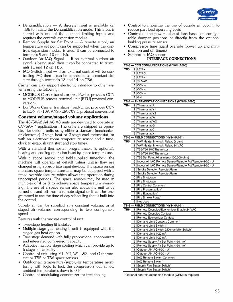
93
• Dehumidification — A discrete input is available onTB6 to initiate the Dehumidification mode. This input isshared with one of the demand limiting inputs andrequires the controls expansion module.
• Remote Supply Air Set Point — A remote supply airtemperature set point can be supported when the con-trols expansion module is used. It can be connected toterminals 9 and 10 on TB6.
• Outdoor Air IAQ Signal — If an external outdoor airsignal is being used then it can be connected to termi-nals 11 and 12 on TB6.
• IAQ Switch Input — If an external control will be con-trolling IAQ then it can be connected as a contact clo-sure through terminals 13 and 14 on TB6.
Carrier can also support electronic interface to other sys-tems using the following;• MODBUS Carrier translator (read/write, provides CCN
to MODBUS remote terminal unit [RTU] protocol con-version)
• LonWorks Carrier translator (read/write, provides CCNto LON FT-10A ANSI/EIA-709.1 protocol conversion)
Constant volume/staged volume applicationsThe 48/50A2,A4,A6,A8 units are designed to operate inCV/SAV™ applications. The units are shipped as opera-ble, stand-alone units using either a standard (mechanicalor electronic) 2-stage heat or 2-stage cool thermostat, orwith an electronic room temperature sensor and a time-clock to establish unit start and stop times. With a standard thermostat (programmable is optional),heating and cooling operation is set by space temperature. With a space sensor and field-supplied timeclock, themachine will operate at default values unless they arechanged using appropriate input devices. The space sensormonitors space temperature and may be equipped with atimed override feature, which allows unit operation duringunoccupied periods. The space sensors may be used inmultiples of 4 or 9 to achieve space temperature averag-ing. The use of a space sensor also allows the unit to beturned on and off from a remote signal or it can be pro-grammed to use the time of day scheduling that is built intothe control. Supply air can be supplied at a constant volume, or atstaged air volumes corresponding to two configurablespeeds.Features with thermostat control of unit• Two-stage heating (if installed)• Multiple stage gas heating if unit is equipped with the
staged gas heat option• Two-stage demand with fully proportional economizers
and integrated compressor capacity• Adaptive multiple stage cooling which can provide up to
5 stages of capacity• Control of unit using Y1, Y2, W1, W2, and G thermo-
stat or T55 or T56 space sensors• Outdoor-air temperature/supply-air temperature moni-
toring with logic to lock the compressors out at lowambient temperatures down to 0°F
• Control of modulating economizer for free cooling
• Control to maximize the use of outside air cooling toreduce part load operating costs
• Control of the power exhaust fans based on configu-rable damper positions or directly from the optionalbuilding pressure sensor
• Compressor time guard override (power up and mini-mum on and off timers)
• Support of IAQ sensorINTERFACE CONNECTIONS
* Optional controls expansion module (CEM) is required.
TB-3 — CCN COMMUNICATIONS (HY84HA096)TB3 1 LEN +
2 LEN C3 LEN –4 24 VAC5 CCN +6 CCN c7 CCN –8 Grd
TB-4 — THERMOSTAT CONNECTIONS (HY84HA090)TB4 1 Thermostat R
2 Thermostat Y13 Thermostat Y24 Thermostat W15 Thermostat W26 Thermostat G7 Thermostat C8 Thermostat X
TB-5 — FIELD CONNECTIONS (HY84HA101)TB5 1 VAV Heater Interlock Relay, Ground
2 VAV Heater Interlock Relay, 24 VAC3 T55/T56 10K Thermistor4 T55/T56 10K Thermistor5 T56 Set Point Adjustment (100,000 ohm)6 Indoor Air IAQ Remote Sensor/Remote Pot/Remote 4-20 mA7 Indoor Air IAQ Remote Sensor/Remote Pot/Remote 4-20 mA8 Smoke Detector Remote Alarm9 Smoke Detector Remote Alarm
10 Fire Shutdown11 Fire Shutdown12 Fire Control Common*13 Fire Pressurization*14 Fire Evacuation*15 Fire Smoke Purge*16 Not Used
TB-6 — FIELD CONNECTIONS (HY84HA101)TB6 1 Remote Occupied/Economizer Enable 24 VAC
2 Remote Occupied Contact3 Remote Economizer Contact4 Demand Limit Contacts Common*5 Demand Limit Switch 1*6 Demand Limit Switch 2/Dehumidify Switch*7 Demand Limit 4-20 mA*8 Demand Limit 4-20 mA*9 Remote Supply Air Set Point 4-20 mA*
10 Remote Supply Air Set Point 4-20 mA*11 Outdoor Air IAQ 4-20 mA*12 Outdoor Air IAQ 4-20 mA*13 IAQ Remote Switch Common*14 IAQ Remote Switch*15 Supply Fan Status Switch*16 Supply Fan Status Switch*
94
Features with sensor control of unit There are 2 sensor options available:• T55 sensor will monitor room temperature and provide
unoccupied override capability (1 to 4 hours).• T56 sensor will monitor room temperature, provide
unoccupied override capability (1 to 4 hours), and pro-vide a temperature offset of 5°F maximum.
Standard features are:• Support of remote occupied/unoccupied input to start
and stop the unit• Two-stage economizer demand with fully proportional
economizers and integrated compressor capacity• Variable capacity control with variable capacity com-
pressor option• Cooling capacity with adaptive control, with up to 5
stages of mechanical refrigeration capacity• Occupied or unoccupied set point• Enable heating (if installed) or cooling during unoccu-
pied periods as required to maintain space temperaturewithin the unoccupied set points
• Adjustment of space temperature set points of ± 5°Fwhen using a T56 sensor
• Support of IAQ sensor• 365-day timeclock with backup (supports minute, hour,
and day of week, date, month, and year access). Thetimeclock includes the following features:— Daylight savings time function— Occupancy control with 8 periods for unit operation— Holiday table containing up to 18 holiday schedules— Ability to initiate timed override from T55 or T56
sensors (for a timed period of 1 to 4 hours)— Temperature-compensated start to calculate early
start times before occupancy— For units connected into a CCN network, the time-
clock can be integrated into the overall building ener-gy management system and be updated remotely
• For units connected to the CCN network the user canalso display all the unit information including I/O valuesMaintenance, Configuration, Service, and Set Pointdata tables
Variable air volume (VAV) applicationsThe 48/50A3,A5,A7,A9 units are designed to operate inVAV applications. As standard they include a supply fan in-verter (VFD) to control the supply fan speed and duct pres-sure. They are designed to control the leaving-air temperaturein cooling to a configurable set point. The changes in mode ofoperation from Heating to Vent to Cooling mode can be con-trolled either from the return air temperature sensor or froman accessory space temperature sensor. Some of the featuresfor VAV units in a stand-alone application are:• The units are shipped as operable, stand-alone units
with the addition of a field-supplied timeclock to estab-lish unit start and stop times or they can use Com-fortLink time of day scheduling routine
• Provides cooling and heating control (if equipped withheat) in both occupied and unoccupied modes
• Supports an optional space temperature sensor formode control and supply air temperature reset
• If space sensor is equipped with an override feature, thesensor will allow operation during the unoccupiedperiod for a fixed length of time
• Base unit control supports a heat interlock relay (fieldsupplied) to signal the VAV terminal devices to fullyopen during heating operation
• Control board diagnostics• Control of modulating economizer for free cooling• Control to maximize the use of outside air cooling to
reduce part load operating costs• Support of remote occupied/unoccupied input to start• Controls the operation of the supply fan inverter to
maintain a configurable supply duct static pressure setpoint. Inverter is configured and controlled directly byComfortLink controls
• Support of IAQ sensor• Support a field test for field check out• Support linkage to ComfortID™ systems• Cooling capacity control of up to 5 stages plus economizer• Control of heat to maintain return-air temperature• Control of heat interlock relay• Compressor time delays to prevent rapid cycling of
compressors• Automatic lead-lag control of compressors to reduce the
number of compressor cycles• With the addition of a remote start/stop switch, heating
or cooling is enabled during unoccupied periods asrequired to maintain space temperature to within unoc-cupied set points
• With the addition of the controls expansion board, theComfortLink controls will also support demand limitingand remote set point control
When the unit is connected to a CCN (Carrier ComfortNetwork®) system, additional features can be used:• Interface of the unit clock with the CCN network clock
and allow for remote configuration of the schedules• CCN demand limit participation• Interface with ComfortID™ control systems through
linkageSequence of operationCooling, constant volume (CV)/staged air volume(SAV™) units On power up, the initialization software will determine theunit configuration and also initialize any controls loops andinput/output devices. All alarms and configurations aresaved in memory and maintained during power outages.All alarms will be maintained in memory and must becleared through the display.On SAV units equipped with a supply fan VFD, the fan iscontrolled at discrete speeds based on the operation modeof the unit. Fan will operate in Low speed when:• Cooling capacity is less than 50%• In ventilation mode• Heating is less than 75% capacityFan will operate in High speed when:• Cooling capacity is greater than 50%• Heating capacity is greater than 75% capacity
Controls (cont)

95
Constant volume/staged air volume conventionalthermostat controlIf the unit is equipped with a conventional thermostat withY1, Y2, W1, W2, and G connections, then the control willperform the following sequence. When G is closed the indoor fan will turn on. G must beclosed for heating or cooling to occur. If Y1 is closed, then the control will first check the ability touse the economizer. If the economizer can be used, thecontrol will modulate the damper open to maintain the lowload economizer leaving air temperature set point. If Y2 closes, then the control will lower the leaving air tem-perature set point to the configured set point. If the econo-mizer cannot satisfy the load, then compressors will besequenced on to maintain either the low or high load tem-perature set points. If the economizer cannot be used orthe enable control disables the economizer, then the con-trol will sequence the compressors based on the Y1 andY2 signals. If two-stage control has been selected, then the control willmap the compressors to the Y1 and Y2 inputs as definedin the loading sequence. If Adaptive mode has been selected, then the control willadd and remove compressor stages to maintain the lowand high demand leaving air set points. If Y1 is closed, atleast one compressor stage will be turned on.Heating — If W1 closes, then it will indicate that the unitsshould be in the Heating mode. The economizer will beclosed to the minimum position, and if the unit is equippedwith gas or electric heat then the first stage of heat will beenergized. If W2 closes, then the control will turn on thesecond stage of heat. If the unit is equipped with a stagedgas heat control option, then the W1 signal will be used tocontrol the gas heat to the configurable low heat load leav-ing air temperature set point. When W2 is energized, theunit will fire all stages of heat capacity. If the unit isequipped with gas heat, then the IGC board will control theoperation of the gas heat. See the 48 Series Gas Heatunits section for the IGC board sequence of operation.Constant volume/staged air volume space tempera-ture sensor controlIf the space temperature operation has been selected usinga T55, T56, or T59 sensor, then the following logic will beused to control the operation of the unit. If a space tem-perature is used, then a wire jumper must be addedbetween R, W1, and W2. If a remote occupancy controlmethod has been selected, then the input must first beclosed for the unit to go into Heat, Vent or Cooling mode. If the internal timeclock is used, the control module deter-mines the occupancy state based on the system timeschedules. If Temperature Compensated Start is active, the unit willbe controlled as in the occupied mode and will start a timeas determined by prior operation to have the space at setpoint by the occupied time. If the unit has been configured for a preoccupancy purge,then the control will start the unit in Vent mode prior to theoccupancy time to vent the space. If an IAQ sensor is being
used and the low IAQ set point is satisfied, then the occu-pancy purge mode will be terminated. The set points forheat and cooling are configurable through the display. If aT56 sensor is being used, then the set point can be shiftedby as much as 5 degrees. Cooling — If the space temperature goes above the cool-ing set point, then the unit will go into Cooling mode. If theeconomizer can be used, the control will first try to controlto the leaving air temperature set point. The set point willdepend on the space temperature. If the temperature isabove the low demand set point, then the low economizerload discharge air temperature set point will be used. If thetemperature is above the high load space temperature setpoint, then the high load leaving air temperature set pointwill be used. If the economizer cannot satisfy the load, thencompressors will be sequenced on to maintain either thelow or high load temperature set points. If the economizer cannot be used or the enable control dis-ables the economizer, then the control will sequence thecompressors based on the low and high load space tem-perature variables. If two-stage control has been selected,then the control will map the compressors to the low andhigh loads as defined in the loading sequence. If Adaptivemode has been selected, then the control will add andremove compressor stages to maintain the high and lowdemand leaving air set points.Heating — If the space temperature goes below the heat-ing space temperature set points, then it will indicate thatthe units should be in the Heating mode. The economizerwill be closed to the minimum position and if the unit isequipped with gas or electric heat then the first stage ofheat will be energized. If the space temperature goes belowthe high load space temperature set point, then the controlwill turn on the second stage of heat. If the unit is equippedwith a staged gas heat control option, then the low loaddemand signal will turn on heating stages to maintain theleaving air temperature set point. A high demand signalwill energize all stages of heat.Unoccupied Mode — If the unit is configured for unoccu-pied free cooling, mechanical cooling, or heating, and thetemperature goes beyond the unoccupied configuration setpoints, then the control will turn on free cooling, mechani-cal cooling, or heat as needed to get within the unoccupiedset points. When in this mode, the economizer damperswill be maintained fully closed or to the minimum unoccu-pied ventilation set point.Variable air volume controlOn power up, the initialization software will determine theunit configuration and also initialize any controls loops andinput/output devices. All alarms and configurations aresaved in memory and maintained during power outages.All alarms will be maintained in memory and must becleared through the display.The unit will first determine the mode of operation. If theunit has been configured for space temperature demand,then the control will determine, based on the configurableset points, if the unit should be in heat mode, vent mode,or cooling mode. If the unit is configured for return air tem-perature control, then it will start the fan and monitor the
96
return air temperature vs. the configurable set point todetermine if the unit should be in cooling, vent, or heatingmode.If the control is connected to a ComfortID™ system, theroom terminals are equipped with microprocessor controlsthat give commands to the base module. If linkage is active,the control module will replace local ComfortLink setpoints and occupancy data with linkage-supplied data.If temperature compensated start is active, then advancepre-cool or heat of the space is enabled. If the unit is con-figured to use a pre-purge cycle, then the ComfortLinkcontrols will start the unit in Vent mode based on a pre-start time interval. If an IAQ sensor is being used and thelow IAQ control point is satisfied, then the mode will beterminated.Cooling — If Cooling mode is required, then the con-trolling set point will be the leaving air temperature setpoint. If an economizer is present and the changeover con-trol allows the economizer to be used, then it will firstattempt to control the leaving-air temperature using freecooling. If this cannot satisfy the load, then additional com-pressor stages will be turned on to maintain the leaving-airtemperature. When both compressors and economizersare being used, the control will use the economizer damp-ers to maintain better control of the leaving air and to helpprevent high compressor cycling. If the economizer cannotbe used, then it will be set to the minimum vent position.When using compressors, the leaving-air temperature willsequence to compressors on and off using a PID controlloop. If the unit is equipped with an optional hot gas bypassvalve, the control will use the hot gas as an additional stageof capacity. When the first stage of cooling is required thecontrol will turn on a circuit “A” compressor and the hotgas bypass valve. When additional cooling is called for itwill turn off the hot gas bypass valve. The valve will also beused for additional freeze protection of the coils when lowevaporator refrigerant temperatures are detected using thesuction pressure transducers.When operating in cooling mode, the control will alsomonitor the supply duct pressure and send a 4 to 20 mAsignal to the factory-supplied inverter to control the speedof the fan and the delivered cfm. If on a linkage system, thecontrol will also support static pressure reset based on theneeds of the zones.Heating — If the unit has been enabled for occupied heatand the space temperature sensor (SPT), return air tempera-ture sensor (RAT), or linkage demand calls for heat, the con-trol will energize the electric heat or gas heat (if present) towarm the space. In this mode the control will energize theheat interlock relay which will signal the terminals to open tothe heating position. Note that for the linkage systems theinterlock relay connection is not required. Once the Heatmode is enabled, the heat capacity will be controlled by thereturn air temperature set point. Heating will continue untilthe return temperature set point is satisfied. If the unit isconfigured for morning warm-up and the heating demand isbelow the set point during the first 10 minutes of operation,the control will energize full heating capacity until the returnair temperature set point is satisfied.
If the space temperature sensor (SPT), return air tempera-ture sensor (RAT), or linkage demand requires that the unitbe in heating, then the control will energize the electric heator gas heat (if present) to warm the space. In this mode thecontrol will energize the heat interlock relay which should beconnected to the terminals to indicate that they should opento the heating position. The interlock relay connection is notrequired for the linkage systems. Heating will continue untilthe mode selection sensor is satisfied.Dehumidification mode A Dehumidification mode can be initiated by either a dis-crete input on TB6 or by a direct measurement of humiditylevels with an optional space or return air humidity sensor.When the Dehumidification mode is active, the evaporatorcoil leaving air temperature will be controlled to the Dehu-midify Cool set point, which is typically colder than thenormal cool mode leaving air set points.In this mode, comfort condition set points, which are basedon dry bulb temperature, will be overridden. If a source ofreheat is available, then the leaving-air temperature can beraised to a more desirable temperature. Available methodsof reheat are internal gas heat if the unit is equipped withthe staged gas heating option or an external heat sourcethat can be controlled by an auxiliary alarm relay switch.Humidi-MiZer® operationThe design of the Humidi-MiZer adaptive dehumidificationsystem allows for two humidity control modes of operationof the rooftop unit, utilizing a common subcooling/reheatdehumidification coil located downstream of the standardevaporator coil.This unique and innovative design provides the capabilityfor the rooftop unit to operate in both a subcooling modeand a hot gas reheat mode for maximum system flexibility.The Humidi-MiZer package is factory installed and willoperate whenever there is a dehumidification requirement.The Humidi-MiZer system is initiated based on input froma factory-installed return air humidity sensor to the largerooftop unit controller. Additionally, the unit controller mayreceive an input from a field-installed space humidity sen-sor, a discrete input from a mechanical humidistat, or inputfrom a third-party controller.A unit equipped with a Humidi-MiZer system can operatein the following modes:Conventional Cooling modeConventional operation of the A series large rooftop unit al-lows the unit to cycle up to six compressors to maintain com-fort conditions, with expanded cycling operation offered bythe optional digital compressor. This mode is the convention-al DX (direct expansion) cooling method used on Carrier'sstandard large rooftops and provides equivalent capacity to anon-Humid-MiZer equipped unit. It is used when there is a callfor cooling only, such as at design AHRI (Air-Conditioning,Heating, and Refrigeration Institute) cooling conditions of95°F ambient and 80°F/67°F db/wb entering air conditions.The SHR (sensible heat ratio) for equipment in this scenario istypically 0.7 or higher.
Controls (cont)

97
Subcooling modeThis modulating mode will operate to satisfy part load typeconditions when there is a space call for cooling and dehu-midification. Although the temperature (sensible) may havedropped and decreased the sensible load in the space, theoutdoor and/or space humidity levels may have risen. A typical scenario might be when the outside air is 85°Fand 70 to 80% relative humidity (RH). Desired SHR forequipment in this scenario is typically 0.4 to 0.7. Carrier'sA Series Humidi-MiZer adaptive dehumidification systemwill increase subcooling entering the evaporator and cycleon enough compressors to meet the latent load require-ment, while simultaneously adjusting refrigerant flow to theHumidi-MiZer coil to reheat the air to the required supplyair set point. This will allow the unit to provide variableSHR to meet space requirements.Conversely, a standard unit might overcool the space orstage down to meet set point, sacrificing latent capacitycontrol. The Humidi-MiZer unit will initiate subcoolingmode when the space temperature and humidity are bothabove the temperature and humidity set points, andattempt to meet both requirements. Once the humidityrequirement is met, the unit can continue to operate innormal cooling mode to meet any remaining sensiblecapacity load. Alternatively, if the sensible load is met andhumidity levels remain high, the unit can switch to Hot GasReheat mode to provide neutral, dehumidified air.Hot Gas Reheat modeThis modulating mode is used when dehumidification is re-quired without a need for cooling, such as when the outsideair is at a neutral temperature (70 to 75°F) but high humid-ity exists. This situation requires the equipment to operateat a SHR of 0.0 to 0.2.With no cooling requirement and a call for dehumidifica-tion, the A Series Humidi-MiZer adaptive dehumidificationsystem will cycle on enough compressors to meet the la-tent load requirement, while simultaneously modulating re-frigerant flow to the Humidi-MiZer® coil to reheat the air tothe desired neutral air set point.The A-Series Humid-MiZer system controls allow for thedischarge air to be reheated either to the return-air tem-perature minus a configurable offset or to a configurableReheat set point (default 70°F). The Hot Gas Reheat modewill be initiated when only the humidity is above the humid-ity set point, without a demand for cooling.Mode controlThe essential difference between the Subcooling mode andthe Hot Gas Reheat mode is in the supply air set point. InSubcooling mode, the supply air set point is the temperaturerequired to provide cooling to the space. In Reheat mode,the supply air set point is the temperature required to pro-vide neutral air to the space. In both cases, the unit will de-crease the evaporator discharge temperature to meet the la-tent load and reheat the air to the required cooling or reheatset point (i.e., 50, 60, 70°F, etc.).48 series gas heat unitsThe gas heat units incorporate 2 (3 on size 060) separatesystems to provide gas heat. Each system incorporates itsown induced-draft motor, integrated gas control (IGC)
board, 2-stage gas valve, manifold, and safeties. For 2-stage heat control, the systems are operated in parallel.For example, when there is a call for first stage heat, bothinduced-draft motors operate, both gas valves are ener-gized, and both IGC boards initiate spark. With the staged gas control, the systems are operated inde-pendently to allow for a greater range of capacity control.All of the gas heating control is performed through theIGC boards (located in the heating section). The MBBmodule board serves only to initiate and terminate heatingoperation and monitor the status of the requirements forindoor fan operation. The fan will be controlled directly by the MBB board. Thebase module board is powered by 24 vac. When the ther-mostat or room sensor calls for heating, the MBB boardwill close heating relays and send power to W on each ofthe IGC boards. An LED on the IGC board will be on during normal opera-tion. A check is made to ensure that the rollout switchesand limit switches are closed and the induced-draft motorsare not running. After the induced-draft motors are ener-gized and speed is proven with the Hall Effect sensor onthe motor, the ignition activation period begins. The burn-ers will ignite within 5 seconds. When ignition occurs, the IGC board will continue to monitorthe condition of the rollout and limit switches, the Hall Effectsensor, and the flame sensor. If the unit is controlled through aroom thermostat set for fan auto, 45 seconds after ignitionoccurs the indoor-fan motor will be energized and the out-door-air dampers will open to their minimum position. If the overtemperature limit opens prior to the start of theindoor fan blower, on the next attempt the 45-seconddelay will be shortened to 5 seconds less than the timefrom initiation of heat to when the limit tripped. Gas willnot be interrupted to the burners and heating will continue.Once modified, the fan on delay will not change back to 45seconds unless power is reset to the control. If the unit is controlled through a room sensor, the indoorfan will be operating in the occupied mode and the out-door-air dampers will be in the minimum position. If theunit is controlled with a room sensor in the unoccupiedmode, the indoor fan will be energized through the IGCboard with a 45-second delay and the outside-air damperswill move to the minimum unoccupied set point. When additional heat is required, the second stage MBBoutput relay closes and initiates power to the second stage ofall main gas valves in all sections. When the demand is satis-fied, MBB heat output relays will open and the gas valvesclose, interrupting the flow of gas to the main burners. If thecall for stage 1 heat lasts less than 1 minute, the heatingcycle will not terminate until 1 minute after W1 becameactive. If the unit is configured for intermittent fan, theindoor-fan motor will continue to operate for an additional45 seconds, then stop, and the outdoor-air dampers willclose. If the overtemperature limit opens after the indoormotor is stopped within 10 minutes of W1 becoming inac-tive, on the next cycle the time will be extended by 15 sec-onds. The maximum delay is 3 minutes. Once modified, thefan off delay will not change back to 45 seconds unlesspower is reset to the control.

98
Ductwork — Secure vertical discharge ductwork to roofcurb. Interior installation may proceed before unit is set inplace on roof. For horizontal discharge applications, attachductwork to unit, or field-supplied flanges can be attached tohorizontal discharge openings and all ductwork attached toflanges. Units equipped with electric heat require a 90-degreeelbow below the unit supply duct connection.Thru-the-curb service connections — Roof curb con-nections allow field power wires and control wires to enterthrough the roof curb opening.Thermostat (CV only) — Use of a thermistor-type roomsensor is recommended on all CCN installations. A therm-istor-type room sensor or a 2-stage heating/cooling ther-mostat may be used for all other units.Heating-to-cooling changeover — All units are automaticchangeover from heating to cooling when automatic change-over thermostat and subbase or a thermistor-type room sen-sor are used.Airflow — Units are draw-thru on cooling and blow-thru onheating.Maximum airflow — To minimize the possibility of con-densate blow-off from evaporator, airflow through unitsshould not exceed values shown in Cooling Cfm OperatingRange table and Cooling Capacities tables.Minimum airflow — The minimum airflow for cooling is300 cfm/ton for constant volume units and 70 cfm/ton forVAV (variable air volume) units. Performance at 70 cfm/tonis limited to unloaded operation and may be additionally lim-ited by entering-air temperatures or Humidi-MiZer opera-tion. Refer to Gas Heating Capacities and Efficiencies tableon page 8 for minimum airflow cfm for heating.Minimum ambient cooling operation temperature —All units are equipped with factory economizers to allow free
cooling at any outdoor ambient. If mechanical cooling isrequired, the units are designed to operate at outdoor tem-peratures down to 32°F. Greenspeed® control units canoperate at outdoor temperatures down to –20°F.Carrier recommends the installation of field-fabricatedwind baffles on all vertically oriented condenser coil sur-faces when operating in environments with prevailingwinds of more than 5 mph and where temperatures dropbelow 32°F.Maximum operating outdoor-air temperature — Themaximum operating outdoor-air temperature is 115°F. Somemodels will operate up to 125°F depending on model and op-erating conditions.High altitude (gas heat units only) — A change to thegas orifice may be required at high altitudes. Refer to Alti-tude Compensation table on page 10.Minimum temperature — Minimum allowable tempera-ture of mixed air entering the heat exchanger during halfrate (first stage) operation is 50°F. There is no minimummixture temperature during full-rate operation. Comfortconditioning may be compromised at temperatures below50°F. Below 50°F entering-air temperature (EAT) bothstages of heat are engaged. Internal unit design — Due to Carrier’s internal unit de-sign (draw-thru over the motor), air path, and specially de-signed motors, the full horsepower listed in the PhysicalData table and Motor Limitations table can be used withextreme confidence. Using Carrier motors with the valueslisted in the Physical Data and Motor Limitations tables willnot result in nuisance tripping or premature motor failure.The unit warranty will not be affected.Electric heat — A field-supplied 90-degree elbow must beinstalled in the supply ductwork below the unit discharge.
Application data

99
Application data (cont)Acoustical considerationsIn order to minimize sound transmitted to the space, pleaseconform to the following recommendations:Location• Avoid locating the unit above sound-sensitive areas.
Instead, locate the unit above restrooms, storage areas,corridors, or other noise-tolerant areas.
• Avoid mounting the unit in the middle of large roofexpanses between vertical supports. This will minimizethe phenomenon known as roof bounce.
• Install the units close to vertical roof supports (columnsor load bearing walls).
• Locate the units at least 25 feet away from criticalareas. If this is not possible, the ductwork and ceilingstructure should be acoustically treated.
• Consider the use of vibration isolators or an acoustic curb.Ductwork• Use flexible connectors between the unit and the supply
and return ducts. • Supply and return air main trunk ducts should be
located over hallways and/or public areas. • Provide trailing edge turning vanes in ductwork elbows
and tees to reduce air turbulence.• Make the ductwork as stiff as possible.• Use round duct wherever possible because it is less
noisy.
• Seal all penetrations around ductwork entering thespace.
• Make sure that ceiling and wall contractors do notattach hangers or supports to ductwork.
• Provide as smooth and gradual transition as possiblewhen connecting the rooftop unit discharge to the sup-ply duct.
• If a ceiling plenum return is used, provide a returnelbow or tee to eliminate line-of-sight noise to thespace. Face the entrance of the return duct away fromother adjacent units.
Acoustic insulation• Provide acoustic interior lining for first 20 feet of supply
and return duct or until the first elbow is encountered.The elbow prevents line-of-sight transmission in thesupply and return ducts.
• Install a double layer of 2-in. low density quilted fiberglassacoustical pad with a 1/8-in. barium-loaded vinyl facing ontop of the roof deck before building insulation and roofinginstallation occur. Place the material inside the curb and for4 to 8 ft beyond the unit perimeter, dependent upon unitsize (larger units require a wider apron outside the curb).Openings in the pad should only be large enough for thesupply and return ducts. An alternate approach is to usetwo layers of gypsum board with staggered seams in addi-tion to the acoustical pad.
FLEXIBLECONNECTORSSUPPLY ANDRETURN
VIBRATIONISOLATORSIN ROOFCURB
INTAKEPLENUM
SUPPLYFAN
DISCHARGEPLENUM
COMPRESSOR/CONDENSINGSECTION ALL ROOF
PENETRATIONSSHOULD BESEALEDAIR TIGHT
ROUND DUCT CONTROLSRUMBLE BEST
SUPPLY AND RETURNDUCTS LINED WITHACOUSTICAL DUCT LINER
ACOUSTICAL CONSIDERATIONS

100
E
F
G
A
B
C
D
MULTIPLE UNIT APPLICATION SPACING
a48-8343
MINIMUM SPACING (FT)
* Required for coil removal. Can reduce to 6 ft if coil removed from top.
UNIT A B C D E* F G* UNIT A B C D E* F G*
48A020 15 8 4 4 10 8 10 50A020 8 8 4 4 10 8 10
48A025 15 8 4 4 10 8 10 50A025 8 8 4 4 10 8 10
48A027 15 8 4 4 10 8 10 50A027 8 8 4 4 10 8 10
48A030 15 8 4 4 10 8 10 50A030 8 8 4 4 10 8 10
48A035 15 8 4 4 10 8 10 50A035 8 8 4 4 10 8 10
48A040 15 8 4 8 10 4 10 50A040 8 8 4 8 10 4 10
48A050 15 8 4 8 10 4 10 50A050 8 8 4 8 10 4 10
48A060 15 8 4 8 15 4 15 50A060 8 8 4 8 15 4 15
Application data (cont)
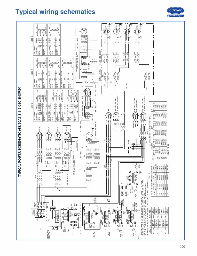
101
Typical wiring schematicsTY
PIC
AL
PO
WER
SC
HEM
ATIC
(48/5
0A
2,3
,4,5
040 S
HO
WN
)
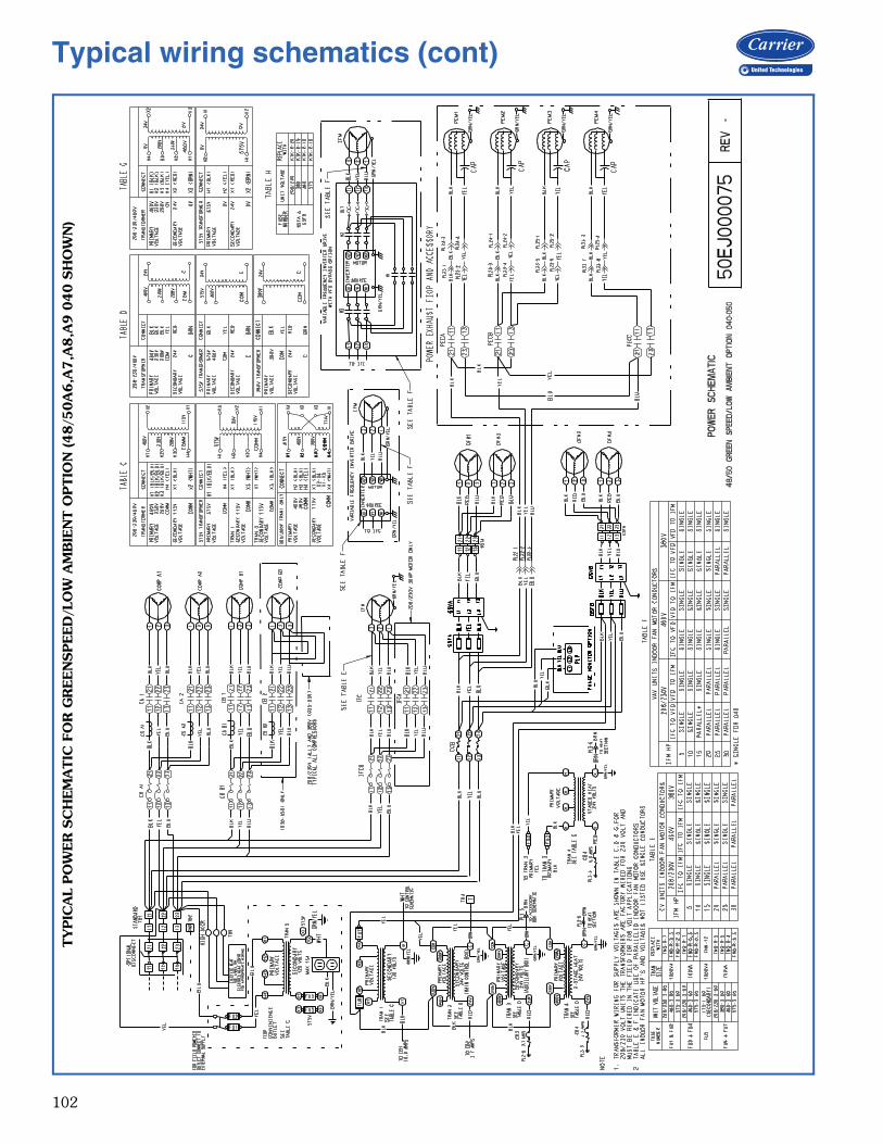
102
TY
PIC
AL
PO
WER
SC
HEM
ATIC
FO
R G
REEN
SPEED
/LO
W A
MB
IEN
T O
PTIO
N (48/5
0A
6,A
7,A
8,A
9 0
40 S
HO
WN
)Typical wiring schematics (cont)

103
MA
IN B
OX
CO
NTR
OL
SC
HEM
ATIC
48/5
0A
020-0
60

104
AU
XIL
IAR
Y C
ON
TR
OL
BO
X S
CH
EM
ATIC
48/5
0A
020-0
60
Typical wiring schematics (cont)
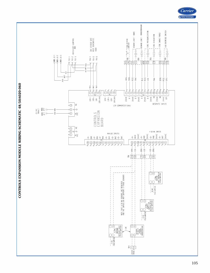
105
SW
1
SW
2/D
EH
UM
CO
NTR
OLS
EX
PA
NSIO
N M
OD
ULE
WIR
ING
SC
HEM
ATIC
48/5
0A
020-0
60
a48-8347

106
GA
S H
EA
T C
ON
TR
OL
SC
HEM
ATIC
(TW
O-S
TA
GE H
EA
T) 48A
2,A
3,A
6,A
7020-0
60
Typical wiring schematics (cont)
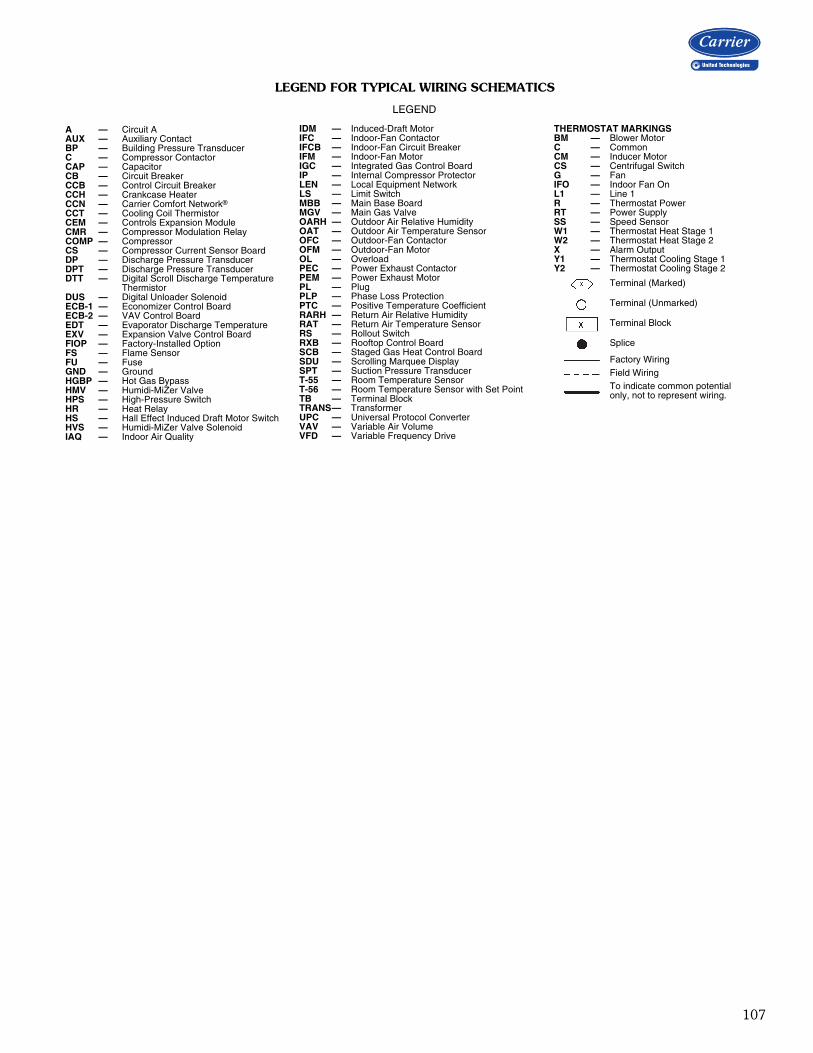
107
LEGEND FOR TYPICAL WIRING SCHEMATICS
LEGEND
A — Circuit AAUX — Auxiliary ContactBP — Building Pressure TransducerC — Compressor ContactorCAP — CapacitorCB — Circuit BreakerCCB — Control Circuit BreakerCCH — Crankcase HeaterCCN — Carrier Comfort Network®
CCT — Cooling Coil ThermistorCEM — Controls Expansion ModuleCMR — Compressor Modulation RelayCOMP — CompressorCS — Compressor Current Sensor BoardDP — Discharge Pressure TransducerDPT — Discharge Pressure TransducerDTT — Digital Scroll Discharge Temperature
ThermistorDUS — Digital Unloader SolenoidECB-1 — Economizer Control BoardECB-2 — VAV Control BoardEDT — Evaporator Discharge TemperatureEXV — Expansion Valve Control BoardFIOP — Factory-Installed OptionFS — Flame SensorFU — FuseGND — GroundHGBP — Hot Gas BypassHMV — Humidi-MiZer ValveHPS — High-Pressure SwitchHR — Heat RelayHS — Hall Effect Induced Draft Motor SwitchHVS — Humidi-MiZer Valve SolenoidIAQ — Indoor Air Quality
IDM — Induced-Draft MotorIFC — Indoor-Fan ContactorIFCB — Indoor-Fan Circuit BreakerIFM — Indoor-Fan MotorIGC — Integrated Gas Control BoardIP — Internal Compressor ProtectorLEN — Local Equipment NetworkLS — Limit SwitchMBB — Main Base BoardMGV — Main Gas ValveOARH — Outdoor Air Relative HumidityOAT — Outdoor Air Temperature SensorOFC — Outdoor-Fan ContactorOFM — Outdoor-Fan MotorOL — OverloadPEC — Power Exhaust ContactorPEM — Power Exhaust MotorPL — PlugPLP — Phase Loss ProtectionPTC — Positive Temperature CoefficientRARH — Return Air Relative HumidityRAT — Return Air Temperature SensorRS — Rollout SwitchRXB — Rooftop Control BoardSCB — Staged Gas Heat Control BoardSDU — Scrolling Marquee DisplaySPT — Suction Pressure TransducerT-55 — Room Temperature SensorT-56 — Room Temperature Sensor with Set PointTB — Terminal BlockTRANS— TransformerUPC — Universal Protocol ConverterVAV — Variable Air VolumeVFD — Variable Frequency Drive
THERMOSTAT MARKINGSBM — Blower MotorC — CommonCM — Inducer MotorCS — Centrifugal SwitchG — FanIFO — Indoor Fan OnL1 — Line 1R — Thermostat PowerRT — Power SupplySS — Speed SensorW1 — Thermostat Heat Stage 1W2 — Thermostat Heat Stage 2X — Alarm OutputY1 — Thermostat Cooling Stage 1Y2 — Thermostat Cooling Stage 2
Terminal (Marked)
Terminal (Unmarked)
Terminal Block
Splice
Factory WiringField WiringTo indicate common potentialonly, not to represent wiring.

108
Packaged Rooftop Cooling Unit and Packaged Rooftop Cooling Unit with Gas Heat — Constant Volume or Staged Air Volume ApplicationHVAC Guide Specifications — Section 48/50A2,A4,A6,A8Size Range: 20 to 60 Tons, Nominal (Cooling)Carrier Model Number: 48A2, 48A4, 48A6, 48A8, 50A2, 50A4, 50A6, 50A8Part 1 — General1.01 SYSTEM DESCRIPTION
Outdoor roof curb or slab mounted, electronicallycontrolled heating and cooling unit utilizing hermeticscroll compressors with crankcase heaters for coolingduty and with optional gas heat or electric heat. Unitsshall discharge supply and return air vertically or hori-zontally as shown on contract drawings. EER (EnergyEfficiency Ratio) shall meet requirements of ASHRAE(American Society of Heating, Refrigeration and Air-Conditioning Engineers) Standard 90.1-2013.
1.02 QUALITY ASSURANCEA. Unit shall be rated in accordance with AHRI (Air-
Conditioning, Heating, and Refrigeration Institute)Standard 340/360, latest edition.
B. Unit shall be designed to conform to ANSI (Ameri-can National Standards Institute)/ASHRAE 15,ASHRAE 62, and UL (Underwriters Laboratories)Standard 1995.
C. Unit shall be listed by ETL and ETL, Canada as atotal package.
D. The 48A2,A4,A6,A8 units shall be designed to con-form with ANSI Standard Z21.47 (U.S.A.) / CSA(Canadian Standards Association) Standard 2.3(Canada), Gas-Fired Central Furnaces.
E. Roof curb shall be designed to NRCA (NationalRoofing Contractors Association) criteria per Bulle-tin B-1986.
F. Insulation and adhesive shall meet NFPA (NationalFire Protection Association) 90A requirements forflame spread and smoke generation.
G. The management system governing the manufac-ture of this product is ISO (International Organiza-tion for Standardization) 9001:2008 certified.
1.03 DELIVERY, STORAGE AND HANDLINGUnit shall be stored and handled per manufacturer’srecommendations. All exposed coils shall have pro-tective shipping covers.
Part 2 — Products2.01 EQUIPMENT
A. General:Factory-assembled, single-piece heating and coolingunit. Contained within the unit enclosure shall be allfactory wiring, piping, refrigerant charge (R-410A),operating oil charge, dual refrigerant circuits,microprocessor based control system and associated
hardware, and all special features required prior tofield start-up.
B. Unit Cabinet:1. Constructed of galvanized steel, bonderized and
precoated with a baked enamel finish.a. Top cover shall be 18-gage sheet metal
with 0.75-in. thick, 1.5-lb density, fiber-glass insulation.
b. Access panels and doors shall be 20-gagesheet metal with 0.5-in. thick, 1.5-lb density,fiberglass insulation.
c. Corner and center posts shall be 16-gagegalvanized steel.
d. Basepans in the heating and return air sec-tions shall be 16-gage galvanized steel.
e. Basepans in the condenser section shall be16-gage galvanized steel.
f. Compressor rail shall be 12-gage galvanizedsteel.
g. Condensate pan shall be 16-gage aluminizedsteel.
h. Air baffles shall be 18-gage galvanized steelwith 0.5-in. thick, 1.5-lb density, fiberglassinsulation.
i. Base rail shall be 14-gage galvanized steel.j. Fan deck (indoor and outdoor section) shall
be 16-gage galvanized steel.2. Unit casing shall be capable of withstanding
500-hour salt spray exposure per ASTM(American Society for Testing and Materials)B117 (scribed specimen).
3. Sides shall have person-sized insulated hingedaccess doors for easy access to the control boxand other areas requiring servicing. Each doorshall seal against a rubber gasket to help pre-vent air and water leakage and be equipped topermit ease and safety during servicing.
4. Interior cabinet surfaces shall be sheet metallined or insulated with flexible fire-retardantmaterial, coated on the air side.
5. Unit shall have a factory-installed sloped con-densate drain connection made from an alumi-nized steel or optional stainless steel.
6. Equipped with lifting lugs to facilitate overheadrigging.
7. Filters shall be accessible through a hingedaccess panel without requiring any special tools.
C. Fans:1. Indoor Evaporator Fans:
a. Double-width/double-inlet, centrifugal, beltdriven, forward-curved type with single out-let discharge.
b. Fan shaft bearings shall be of the pillow-block type with positive locking collar andlubrication provisions.
Guide specifications — 48/50A2,A4,A6,A8
109
c. Statically and dynamically balanced.d. Evaporator fan shaft bearings shall have a
life of 200,000 hours at design operatingconditions in accordance with ANSI B3.15.
e. Solid fan shaft construction for size 020-050units and two-piece solid fan shaft construc-tion on the size 060 unit.
2. Condenser Fans:a. Fans shall be direct-driven propeller type
only, with corrosion-resistant blades rivetedto corrosion resistant steel supports for allsize 020-050 units and the size 060 unitwith optional condenser coil. Size 060 unitswith the microchannel condenser coil shallhave a direct driven, 9-blade airfoil cross sec-tion, reinforced polymer construction, andshrouded-axial type fans with inherent corro-sion resistance.
b. Fans discharge air vertically upward and areprotected by PVC coated steel wire safetyguards.
c. Statically and dynamically balanced.3. Fan Drive for SAV™ (Staged Air Volume) Units:
Staged air volume units shall be equipped withvariable frequency drive (VFD) inverter. TheVFD shall control motor speed to user-configu-rable speeds. High speed shall be a percentageof 60 Hz, and shall be user configurable. Therange of adjustment for high speed shall bebetween 50 and 100% of 60 Hz. Low speedshall be a percentage of 60 Hz, and shall beuser configurable. The range of adjustment forlow speed shall be between 33 and 67% of60 Hz. The control shall allow user-configurablefan speeds for cooling and heating modes. TheVFD shall be factory-mounted, wired, andtested. The variable speed drive shall includethe following features.a. Full digital control with direct control from
the unit ComfortLink controls.b. Insulated gate bi-polar transistors (IGBT)
used to produce the output pulse width mod-ulated (PWM) waveform, allowing for quietmotor operation.
c. Inverters capable of operation at a frequencyof 8 kHz so no acoustic noise shall be pro-duced by the motor.
d. Critical frequency avoidance.e. Self diagnostics.f. On-board storage of unit manufacturer’s cus-
tomer user settings, retrievable from the key-pad.
g. RS485 communications capability.h. Electronic thermal overload protection.i. 5% swinging chokes for harmonic reduction
and improved power factor.
j. All printed circuit boards shall be conformalcoated.
k. Shall, through ABB, qualify for a 24-monthwarranty from date of commissioning or 30months from date of sale, whichever comesfirst.
D. Compressors:1. Fully hermetic, scroll type compressors with
overload protection and short cycle protectionwith minimum on and off timers.
2. Factory rubber-in-shear mounted for vibrationisolation.
3. Reverse rotation protection capability.4. Crankcase heaters shall only be activated during
compressor off mode.E. Coils:
1. Standard evaporator coil shall have aluminumplate fins mechanically bonded to seamlessinternally grooved copper tubes with all jointsbrazed.
2. Standard condenser coil shall be microchanneldesign. The coil shall have a series of flat tubescontaining a series of multiple, parallel flowmicrochannels layered between the refrigerantmanifolds. Microchannel coils shall consist of atwo-pass arrangement. Coil construction shallconsist of aluminum alloys for the fins, tubes,and manifolds.
3. Coils shall be leak tested at 150 psig and pres-sure tested at 650 psig.
4. Optional condenser coil shall have aluminumplate fins mechanically bonded to seamlessinternally grooved copper tubes with all jointsbrazed.
5. Optional pre-coated aluminum-fin coils shallhave a durable epoxy-phenolic coating to pro-vide protection in mildly corrosive coastal envi-ronments. Coating shall be applied to thealuminum fin stock prior to the fin stampingprocess to create an inert barrier between thealuminum fin and copper tube. Epoxy-phenolicbarrier shall minimize galvanic action betweendissimilar metals.
6. Copper-fin coils shall be constructed of copperfins mechanically bonded to copper tubes andcopper tube sheets. Galvanized steel tubesheets shall not be acceptable. A polymer stripshall prevent coil assembly from contacting thesheet metal coil pan to minimize potential forgalvanic corrosion between coil and pan. Allcopper construction shall provide protection inmoderate coastal environments.
7. E-coated coils shall have a flexible epoxy poly-mer coating uniformly applied to all coil sur-face areas without material bridging betweenfins. Coating process shall ensure completecoil encapsulation. Color shall be high glossblack with gloss — 60 deg of 65 to 90% per

110
ASTM D523-89. Uniform dry film thicknessfrom 0.8 to 1.2 mil on all surface areas includ-ing fin edges. Superior hardness characteris-tics of 2H per ASTM D3363-92A and cross-hatch adhesion of 4B-5B per ASTM D3359-93. Impact resistance shall be up to 160 in./lb(ASTM D2794-93). Humidity and waterimmersion resistance shall be up to minimum1000 and 250 hours respectively (ASTMD2247-92 and ASTM D870-92). Corrosiondurability shall be confirmed through testing tobe no less than 6000 hours salt spray perASTM B117-90. Coil construction shall bealuminum fins mechanically bonded to coppertubes.
F. Gas Heating Section (48 Series Only):1. Induced-draft combustion type with energy-sav-
ing direct spark ignition systems and redundantmain gas valves.
2. The heat exchanger shall be of the tubular sec-tion type constructed of a minimum of 20-gagesteel coated with a nominal 1.2 mil aluminum-sil-icone alloy for corrosion resistance. Optionalstainless steel heat exchangers shall be available.
3. Burners shall be of the in-shot type constructedof aluminum coated steel.
4. All gas piping shall enter the unit cabinet at asingle location.
5. Induced Draft Fans:a. Direct-driven, single inlet, forward-curved
centrifugal type.b. Statically and dynamically balanced.c. Made from steel with a corrosion-resistant
finish.6. High-corrosion areas such as flue gas collection
and exhaust areas shall be lined with corrosionresistant material.
G. Refrigerant Components:Unit shall be equipped with dual refrigerant circuits,each containing:
1. Solid core filter drier.2. Thermostatic expansion valve.3. Fusible plug.
H. Filter Section:Standard filter section shall be supplied with 2-in.thick disposable fiberglass filters.
I. Controls and Safeties:1. Unit ComfortLink Controls:
a. Scrolling marquee display.b. CCN (Carrier Comfort Network®) capable.c. Unit control with standard suction pressure
and condensing pressure transducers.d. Shall provide a minimum 5°F temperature dif-
ference between cooling and heating set pointsto meet ASHRAE 90.1 energy standard.
e. Shall provide and display a current alarm listand an alarm history list.
f. Automatic compressor lead/lag control.g. Service run test capability.h. Shall accept input from a CO2 sensor (both
indoor and outdoor).i. Configurable alarm light shall be provided
which activates when certain types of alarmsoccur.
j. Compressor minimum run time (3 min-utes) and minimum off time (3 minutes) areprovided.
k. Service diagnostic mode.l. Optional integrated economizer control or
two-position self-closing adjustable outsideair damper.
m. Minimum of 3 capacity stages of mechanicalcapacity control (excluding hot gas bypass)controlled by the following method:A control algorithm to maintain either high-cool or low-cool supply air temperature setpoint. Cooling mode (off, low, or high) to bedetermined from space temperature sensoror standard 2-stage mechanical thermostatinput.
n. Optional minimum load valve for additionalcapacity stage.
o. Unit shall be complete with self-containedlow voltage control circuit.
p. Control of evaporator leaving air tempera-ture through compressor and economizercontrol.
2. Safeties:a. Unit shall incorporate a solid-state compres-
sor lockout which provides optional resetcapability at the space thermostat shouldany of the following safety devices trip andshut off compressor:1.) Compressor lockout protection provided
for either internal or external overload.2.) Low-pressure protection.3.) Freeze protection (evaporator coil).4.) High-pressure protection (high pressure
switch or internal).5.) Compressor reverse rotation protection.6.) Loss-of-charge protection.7.) Welded contactor protection.
b. Supply-air sensor shall be located in the unitand should be used for economizer controland compressor stage control.
c. Induced draft heating section (48 Series)shall be provided with the following mini-mum protections:1.) High-temperature limit switch.2.) Induced-draft motor speed sensor.3.) Flame rollout switch.4.) Flame proving controls.
Guide specifications — 48/50A2,A4,A6,A8 (cont)

111
5.) Redundant gas valve.J. Operating Characteristics:
1. Unit shall be capable of starting and running at115°F ambient outdoor temperature per maxi-mum load criteria of AHRI Standard 340/360.
2. Unit with standard controls will operate in cool-ing down to an outdoor ambient temperature of32°F.
3. Unit shall be provided with fan time delay tohelp prevent cold air delivery.
K. Electrical Requirements:All unit power wiring shall enter unit cabinet at a sin-gle location.
L. Motors:1. Compressor motors shall be cooled by refrigerant
gas passing through motor windings and shallhave either internal line break thermal and currentoverload protection or external current overloadmodules with compressor temperature sensors.
2. All condenser-fan motors shall be totallyenclosed 3-phase type with permanently lubri-cated ball bearings, class F insulation and inter-nal, automatic-reset thermal overload protectionor manual reset calibrated circuit breakers.
3. All indoor fan and power exhaust motors 5 hpand larger shall meet the minimum efficiencyrequirements as established by the Energy Inde-pendence and Security Act (EISA) of 2007.
M. Special Features:Certain features are not applicable when the featuresdesignated * are specified. For assistance in amendingthe specifications, contact your local Carrier SalesOffice.
1. Variable Capacity Compressor:A variable capacity compressor shall be avail-able for constant volume, staged air volume,and variable air volume configurations. TheComfortLink control system shall be capable ofunloading this compressor in an infinite numberof steps from 100% of compressor capacitydown to 50% of compressor capacity.
2. Humidi-MiZer® Adaptive Dehumidification:The Humidi-MiZer dehumidification systemshall be factory installed with an e-coated reheatcoil and shall provide greater dehumidificationof the occupied space by using two modes ofdehumidification instead of the normal designcooling mode of the unit:a. Subcooling mode shall further subcool the
hot liquid refrigerant leaving the condensercoil when both temperature and humidity inthe space are not satisfied.
b. Hot gas reheat mode shall mix a portion ofthe hot gas from the discharge of the com-pressor with the hot liquid refrigerant leavingthe condenser coil to create a two-phase
heat transfer in the system, resulting in aneutral leaving-air temperature.
c. The system shall be equipped with modulat-ing control valves to provide precise leaving-air temperature control. On-off, cycling typecontrol shall not be acceptable.
3. Integrated Ultra Low Leak Economizer:a. Economizer shall meet the requirements of
ASHRAE 90.1 (latest revision) and Califor-nia Energy Commission Title 24.
b. Economizer shall be furnished and installedcomplete with recirculated air dampers, out-door air dampers, and controls.
c. All dampers shall be ultra-low leakage typewith blade and edge seals. Dampers shall be1A certified and exhibit a maximum leakagerate of 3 cfm per square foot of area at 1 in.wg pressure differential when tested perAMCA (Air Movement and Control Associa-tion) Std 511.
d. Dampers shall continue to operate asintended after 100,000 cycles when testedin accordance with Section 8, UL (Under-writers Laboratories) standard 555S.
e. Actuator shall have a spring return featurewhich closes the outdoor air dampers upona power interruption or unit shutdown. Actu-ators shall be of the communicating type andcapable of internal diagnostics.
f. Economizer shall be capable of introducingup to 100% outdoor air for ventilation orfree cooling.
g. Economizer outdoor air hoods shall be con-structed of pre-painted steel.
4. Barometric Relief Damper Package:a. Package shall include damper, seals, hard-
ware, and hoods to relieve excess internalpressure.
b. Damper shall close due to gravity upon unitshutdown.
5. Power Exhaust:Package shall include a multiple exhaust fan(centrifugal style) fan, 1 Hp 208-230, 460 vdirect-drive motor, and damper for vertical flowunits with economizer to control over-pressurization of building. Control shall bethrough ComfortLink controls based on damperposition or through an optional building pressuresensor. On size 020-050 units, 4 stages ofcontrol shall be available. On size 060 units, 6stages of control shall be available.
6. Thermostats and Subbases:To provide staged heating and cooling in addi-tion to automatic (or manual) changeover andfan control.

112
7. Electronic Programmable Thermostat:Capable of using deluxe full-featured electronicthermostat.
8. Liquefied Propane Conversion Kit (48 Series):Kit shall contain all the necessary hardware andinstructions to convert a standard natural gasunit for use with liquefied propane gas.
9. Convenience Outlet:Shall be factory installed and internally mountedwith an externally accessible 115-v, 15 amp.GFI (Ground Fault Interrupter), female recepta-cle with hinged cover. A step-down transformerand overload protection shall be included so noadditional wiring is necessary unless the field-wired outlet has been requested. When appliedwith a unit-mounted disconnect, the outlet shallbe wired to the load side of the disconnect sothe outlet will shut off with the disconnect.
10. Non-Fused Disconnect Switch:Shall be factory installed, internally mounted,and UL approved. Non-fused switch shall pro-vide unit power shutoff. Shall be accessiblefrom outside the unit and shall provide power-off lockout capability.
11. Electric Heater (50 Series Units Only):Electric resistance heaters shall be factoryinstalled, nichrome element type, open wirecoils with 0.29 in. inside diameter, insulatedwith ceramic bushings, and shall include operat-ing and safety controls. Coil ends are stakedand welded to terminal screw slots.
12. Hail Guard, Condenser Coil Grille:Shall protect the condenser coil from hail, flyingdebris, and damage by large objects withoutincreasing unit clearances.
13. CO2 Sensor:The CO2 sensor shall have the ability to moni-tor CO2 levels and relay information to the con-troller. The controller will use CO2 levelinformation to modulate the economizer andprovide demand controlled ventilation. The sen-sor shall be available as a field-installed or fac-tory-installed return air sensor or a remotespace sensor.
14. Return Air Smoke Detector:The smoke detector shall send input to the con-troller to shut down the unit in case smoke isdetected. The smoke detector shall be factoryinstalled in the return air section or shall beavailable as a field-installed accessory.
15. Filter Status:The filter status switch shall be a pressure differ-ential switch and will indicate a dirty filter. Theswitch shall be available as field or factoryinstalled.
16. Humidity Sensor:A humidity sensor will allow for outside airenthalpy changeover control using the standardoutside air dry bulb sensor and the accessoryhumidity sensor. When both an outside andreturn air humidity sensor are used, differentialenthalpy changeover can be supported.
17. Two-Position Damper:A two-position damper shall admit up to 25%outdoor air during fan operation and shall closewhen the fan is off. The damper position shallbe mechanically adjustable.
18. 4-Inch Filters:Optional filter section shall be supplied with 4-in.thick MERV (Minimum Efficiency ReportingValue) 7 pleated fiberglass filters.
19. Control Expansion Module (CEM):Shall provide the following additional optionalfeatures:a. Remote set pointb. Demand limit controlc. Remote economizer positiond. Fire and smoke control override controle. Remote sensor monitoringf. Fan status switch monitoring
20. Staged Gas Heat (48A2,A4 only):The control shall have the option for control ofthe gas heat to a discharge air temperature bysequencing on the gas cells to provide up to 11stages of capacity. The control shall be inte-grated directly into the main unit controls andshall include leaving air temperature sensors toensure that high temperatures do not occurduring the operation of the staged gas heat.
21. Navigator™ Display Module:The Navigator display module shall be a porta-ble hand-held display module with a minimumof 4 lines and 20 characters per line, of clearEnglish, Spanish, Portuguese, or French lan-guage. Display menus shall provide clear lan-guage descriptions of all menu items, operatingmodes, configuration points, and alarm diag-nostics. Reference to factory codes shall not beaccepted. An industrial grade coiled extensioncord shall allow the display module to be movedaround the chiller. Magnets shall hold the dis-play module to any sheet metal panel to allowhands-free operation. Display module shallhave NEMA (National Electrical ManufacturersAssociation) 4x housing suitable for use in out-door environments. Display shall have backlight and contrast adjustment for easy viewingin bright sunlight or night conditions. The dis-play module shall have raised surface buttonswith positive tactile response.
Guide specifications — 48/50A2,A4,A6,A8 (cont)

113
22. BACnet1 Communication Option:Shall provide factory-installed communicationcapability with a BACnet MS/TP network.Allows integration with i-Vu® Open ControlSystem or a BACnet Building Automation Sys-tem.
23. Modbus2 Protocol Translator:A controller-based accessory module shall pro-vide CCN to MODBUS Remote Terminal Unit(RTU) protocol conversion.
24. LonWorks3 Protocol Translator:A controller-based accessory module shall pro-vide CCN to LON FT-10A ANSI/EIA-709.1protocol conversion.
25. Full Perimeter Roof Curbs (Horizontal andVertical):Shall be formed of 14-gage galvanized steelwith wood nailer strip and shall be capable ofsupporting entire unit weight.
26. Security Grille (48/50A060 Unit with MCHX[microchannel heat exchanger] Only):Factory-installed grille shall limit access to com-pressor and condenser coil area to authorizedpersonnel only.
27. Double Wall Option:Unit cabinet shall have double wall constructionfeaturing flexible fire retardant fiberglass insula-tion sandwiched between pre-painted exteriorpanels and galvanized steel inner panels.
28. Low Outdoor Sound Accessory:Field-installed accessory, consisting of compres-sor sound blankets which are used to mitigatethe level of outdoor sound. Available in bothsingle and tandem arrangements.
29. Low Outdoor Sound Condenser Fans:Low sound condenser fan system shall be pro-vided to reduce outdoor sound levels.
30. Low Ambient Greenspeed® Control Option;a. This factory-installed option shall regulate
outdoor fan motor speeds in response tothe saturated condensing temperature ofthe refrigeration circuits and local ambientconditions.
b. The control shall be capable of operatingthe rooftop unit with outdoor temperatureat –20°F.
c. Fans shall be direct-driven shrouded-axial pro-peller type fans only, with 9-blade Aero-Acoustic™ airfoil cross section, reinforcedpolymer construction blades bolted to corro-sion resistant steel supports for all size 020-050 units and the size 060 unit with optionalcondenser coil.
d. Fans discharge air vertically upward and areprotected by PVC coated steel wire safetyguards.
e. Fans are statically and dynamically balanced.f. The condenser fan motors will be VFD
driven.g. Compressor blankets will be applied to miti-
gate the level of outdoor sound on all refrig-erant compressors. They shall be weatherresistant are applied in both single and tan-dem arrangements.
h. Unit efficiency is maximized by monitoringthe refrigerant system and ambient conditionsand controlling condenser fan performance.
31. Phase Loss Protection:If the phases of the electric supply are out ofsequence, or if one phase is missing, the con-tacts will never close. If a phase is lost while thephase monitor is energized, the contacts willopen immediately and will remain open untilthe error is corrected.
1. BACnet is a registered trademark of ASHRAE (American Society of Heating, Refrigerating, and Air-Conditioning Engineers).
2. Modbus is a registered trademark of Schneider Electric.3. LonWorks is a registered trademark of Echelon Corporation.
114
Packaged Rooftop Cooling Unit and Packaged Rooftop Cooling Unit with Gas Heat — Variable Air Volume ApplicationHVAC Guide Specifications — Section 48/50A3,A5,A7,A9Size Range: 20 to 60 Tons, Nominal (Cooling)Carrier Model Number: 48A3, 48A5, 48A7, 48A9, 50A3, 50A5, 50A7, 50A9Part 1 — General1.01 SYSTEM DESCRIPTION
Outdoor roof curb or slab mounted, electronicallycontrolled heating and cooling unit utilizing hermeticscroll compressors with crankcase heaters for cool-ing duty and gas heat or electric heat. Units shall dis-charge supply and return air vertically orhorizontally as shown on contract drawings. EERs(Energy Efficiency Ratios) shall meet requirements ofASHRAE (American Society of Heating, Refrigera-tion, and Air-Conditioning Engineers) Standard90.1-2013.
1.02 QUALITY ASSURANCEA. Unit shall be rated in accordance with AHRI (Air-
Conditioning, Heating, and Refrigeration Institute)Standard 340/360, latest edition.
B. Unit shall be designed to conform to ANSI/ASHRAE 15 (latest edition), ASHRAE 62, and UL(Underwriters Laboratories) Standard 1995.
C. Unit shall be listed by ETL and ETL, Canada as atotal package.
D. The 48A3,A5,A7,A9 units shall be designed to con-form with ANSI (American National Standards Insti-tute) Standard Z21.47 (U.S.A.) / CSA (CanadianStandards Association) Standard 2.3, Gas-FiredCentral Furnaces.
E. Roof curb shall be designed to NRCA (NationalRoofing Contractors Association) criteria per Bulle-tin B-1986.
F. Insulation and adhesive shall meet NFPA (NationalFire Protection Association) 90A requirements forflame spread and smoke generation.
G. The management system governing the manufac-ture of this product is ISO (International Organiza-tion for Standardization) 9001:2008 certified.
1.03 DELIVERY, STORAGE AND HANDLINGUnit shall be stored and handled per manufacturer’srecommendations.
Part 2 — Products2.01 EQUIPMENT
A. General:Factory-assembled, single-piece heating and coolingunit. Contained within the unit enclosure shall be allfactory wiring, piping, refrigerant charge (R-410A),operating oil charge, dual refrigerant circuits, micro-processor-based control system and associated
hardware, and all special features required prior tofield start-up.
B. Unit Cabinet:1. Constructed of galvanized steel, bonderized and
precoated with a baked enamel finish.a. Top cover shall be 18-gage sheet metal with
0.75-in. thick, 1.5-lb density, fiberglass insu-lation.
b. Access panels and doors shall be 20-gagesheet metal with 0.5-in. thick, 1.5-lb density,fiberglass insulation.
c. Corner and center posts shall be 16-gagegalvanized steel.
d. Basepans in the heating and return air sec-tions shall be 16-gage galvanized steel.
e. Basepans in the condenser section shall be16-gage galvanized steel.
f. Compressor rail shall be 12-gage galvanizedsteel.
g. Condensate pan shall be 16-gage aluminizedsteel.
h. Air baffles shall be 18-gage galvanized steelwith 0.5-in. thick, 1.5-lb density, fiberglassinsulation.
i. Base rail shall be 14-gage galvanized steel.j. Fan deck (indoor and outdoor section) shall
be 16-gage galvanized steel.2. Unit casing shall be capable of withstanding
500-hour salt spray exposure per ASTM(American Society for Testing and Materials)B117 (scribed specimen).
3. Sides shall have person-sized insulated hingedaccess doors for easy access to the control boxand other areas requiring servicing. Each doorshall seal against a rubber gasket to help pre-vent air and water leakage and be equipped topermit ease and safety during servicing.
4. Interior cabinet surfaces shall be sheet metallined or insulated with flexible fire-retardantmaterial, coated on the air side.
5. Unit shall have a factory-installed sloped con-densate drain connection made from an alumi-nized steel or optional stainless steel.
6. Equipped with lifting lugs to facilitate overheadrigging.
7. Filters shall be accessible through a hingedaccess panel without requiring any special tools.
C. Fans:1. Indoor Evaporator Fans:
a. Double-width/double-inlet, centrifugal, beltdriven, forward-curved type with single out-let discharge.
b. Fan shaft bearings shall be of the pillow-block type with positive locking collar andlubrication provisions.
Guide specifications — 48/50A3,A5,A7,A9
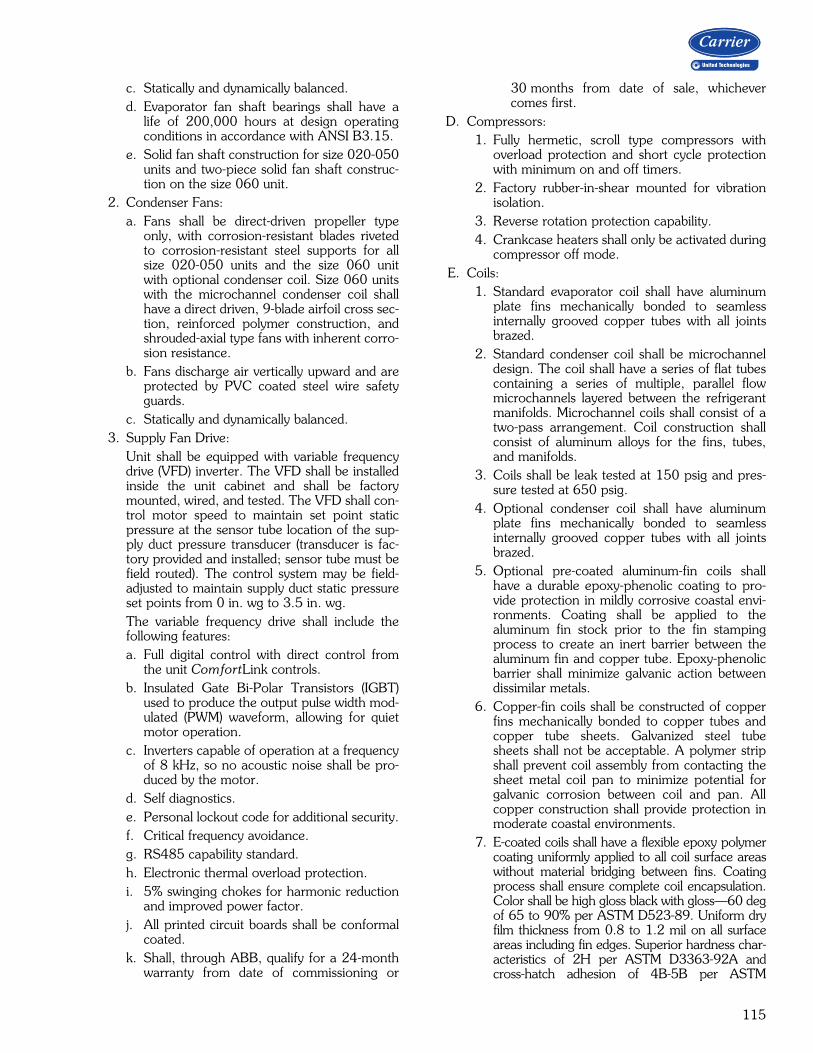
115
c. Statically and dynamically balanced.d. Evaporator fan shaft bearings shall have a
life of 200,000 hours at design operatingconditions in accordance with ANSI B3.15.
e. Solid fan shaft construction for size 020-050units and two-piece solid fan shaft construc-tion on the size 060 unit.
2. Condenser Fans:a. Fans shall be direct-driven propeller type
only, with corrosion-resistant blades rivetedto corrosion-resistant steel supports for allsize 020-050 units and the size 060 unitwith optional condenser coil. Size 060 unitswith the microchannel condenser coil shallhave a direct driven, 9-blade airfoil cross sec-tion, reinforced polymer construction, andshrouded-axial type fans with inherent corro-sion resistance.
b. Fans discharge air vertically upward and areprotected by PVC coated steel wire safetyguards.
c. Statically and dynamically balanced.3. Supply Fan Drive:
Unit shall be equipped with variable frequencydrive (VFD) inverter. The VFD shall be installedinside the unit cabinet and shall be factorymounted, wired, and tested. The VFD shall con-trol motor speed to maintain set point staticpressure at the sensor tube location of the sup-ply duct pressure transducer (transducer is fac-tory provided and installed; sensor tube must befield routed). The control system may be field-adjusted to maintain supply duct static pressureset points from 0 in. wg to 3.5 in. wg.The variable frequency drive shall include thefollowing features:a. Full digital control with direct control from
the unit ComfortLink controls.b. Insulated Gate Bi-Polar Transistors (IGBT)
used to produce the output pulse width mod-ulated (PWM) waveform, allowing for quietmotor operation.
c. Inverters capable of operation at a frequencyof 8 kHz, so no acoustic noise shall be pro-duced by the motor.
d. Self diagnostics.e. Personal lockout code for additional security.f. Critical frequency avoidance.g. RS485 capability standard.h. Electronic thermal overload protection.i. 5% swinging chokes for harmonic reduction
and improved power factor.j. All printed circuit boards shall be conformal
coated.k. Shall, through ABB, qualify for a 24-month
warranty from date of commissioning or
30 months from date of sale, whichevercomes first.
D. Compressors:1. Fully hermetic, scroll type compressors with
overload protection and short cycle protectionwith minimum on and off timers.
2. Factory rubber-in-shear mounted for vibrationisolation.
3. Reverse rotation protection capability.4. Crankcase heaters shall only be activated during
compressor off mode.E. Coils:
1. Standard evaporator coil shall have aluminumplate fins mechanically bonded to seamlessinternally grooved copper tubes with all jointsbrazed.
2. Standard condenser coil shall be microchanneldesign. The coil shall have a series of flat tubescontaining a series of multiple, parallel flowmicrochannels layered between the refrigerantmanifolds. Microchannel coils shall consist of atwo-pass arrangement. Coil construction shallconsist of aluminum alloys for the fins, tubes,and manifolds.
3. Coils shall be leak tested at 150 psig and pres-sure tested at 650 psig.
4. Optional condenser coil shall have aluminumplate fins mechanically bonded to seamlessinternally grooved copper tubes with all jointsbrazed.
5. Optional pre-coated aluminum-fin coils shallhave a durable epoxy-phenolic coating to pro-vide protection in mildly corrosive coastal envi-ronments. Coating shall be applied to thealuminum fin stock prior to the fin stampingprocess to create an inert barrier between thealuminum fin and copper tube. Epoxy-phenolicbarrier shall minimize galvanic action betweendissimilar metals.
6. Copper-fin coils shall be constructed of copperfins mechanically bonded to copper tubes andcopper tube sheets. Galvanized steel tubesheets shall not be acceptable. A polymer stripshall prevent coil assembly from contacting thesheet metal coil pan to minimize potential forgalvanic corrosion between coil and pan. Allcopper construction shall provide protection inmoderate coastal environments.
7. E-coated coils shall have a flexible epoxy polymercoating uniformly applied to all coil surface areaswithout material bridging between fins. Coatingprocess shall ensure complete coil encapsulation.Color shall be high gloss black with gloss—60 degof 65 to 90% per ASTM D523-89. Uniform dryfilm thickness from 0.8 to 1.2 mil on all surfaceareas including fin edges. Superior hardness char-acteristics of 2H per ASTM D3363-92A andcross-hatch adhesion of 4B-5B per ASTM
116
D3359-93. Impact resistance shall be up to 160in./lb (ASTM D2794-93). Humidity and waterimmersion resistance shall be up to minimum1000 and 250 hours respectively (ASTM D2247-92 and ASTM D870-92). Corrosion durabilityshall be confirmed through testing to be no lessthan 6000 hours salt spray per ASTM B117-90.Coil construction shall be aluminum fins mechani-cally bonded to copper tubes.
F. Gas Heating Section (48 Series Only):1. Induced-draft combustion type with energy-saving
direct spark ignition systems and redundant maingas valves.
2. The heat exchanger shall be of the tubular sec-tion type constructed of a minimum of 20-gagesteel coated with a nominal 1.2 mil aluminum-silicone alloy for corrosion resistance. Optionalstainless steel heat exchangers shall be avail-able.
3. Burners shall be of the in-shot type constructedof aluminum coated steel.
4. All gas piping shall enter the unit cabinet at asingle location.
5. Induced Draft Fans:a. Direct-driven, single inlet, forward-curved
centrifugal type.b. Statically and dynamically balanced.c. Made from steel with a corrosion-resistant
finish.6. High-corrosion areas such as flue gas collection
and exhaust areas shall be lined with corrosionresistant material.
G. Refrigerant Components:Unit shall be equipped with dual refrigerant circuitseach containing:
1. Solid core filter drier.2. Thermostatic expansion valve.3. Fusible plug.
H. Filter Section:Standard filter section shall be supplied with 2-in.thick disposable fiberglass filters.
I. Controls and Safeties:1. Unit ComfortLink Controls:
a. Scrolling marquee display.b. CCN (Carrier Comfort Network®) capable.c. Unit control with standard suction pressure
and condensing pressure transducers.d. Shall provide a 5°F temperature difference
between cooling and heating set points tomeet ASHRAE 90.1, energy standard.
e. Shall provide and display a current alarm listand an alarm history list.
f. Automatic compressor redundancy.
g. Service run test capability.h. Shall accept input from a CO2 sensor (both
indoor and outdoor).i. Configurable alarm light shall be provided
which activates when certain types of alarmsoccur.
j. Compressor minimum run time (3 minutes)and minimum off time (3 minutes) areprovided.
k. Service diagnostic mode.l. Optional integrated economizer control or
two-position self-closing adjustable outside-air damper.
m. Minimum of 3 capacity stages of mechanicalcapacity control (excluding hot gas bypass)controlled with logic to maintain supply airtemperature set point.
n. Optional minimum load valve for additionalcapacity stage.
o. Unit shall be complete with self-containedlow voltage control circuit.
2. Safeties:a. Unit shall incorporate a solid-state compres-
sor lockout which provides optional resetcapability at the space thermostat shouldany of the following safety devices trip andshut off compressor:1.) Compressor lockout protection provided
for either internal or external overload.2.) Low-pressure protection.3.) Freeze protection (evaporator coil).4.) High-pressure protection (high pressure
switch or internal).5.) Compressor reverse rotation protection.6.) Loss of charge protection.7.) Welded contactor protection.
b. Supply-air sensor shall be located in the unitand should be used for economizer controland compressor stage control.
c. Induced draft heating section (48 Series)shall be provided with the following mini-mum protections:1.) High-temperature limit switch.2.) Induced-draft motor speed sensor.3.) Flame rollout switch.4.) Flame proving controls.5.) Redundant gas valve.
J. Operating Characteristics:1. Unit shall be capable of starting and running at
115°F ambient outdoor temperature per maxi-mum load criteria of AHRI Standard 340/360.
2. Unit with standard controls will operate in cool-ing down to an outdoor ambient temperature of32°F.
3. Unit shall be provided with fan time delay toprevent cold air delivery.
Guide specifications — 48/50A3,A5,A7,A9 (cont)

117
K. Electrical Requirements:All unit power wiring shall enter unit cabinet at a sin-gle location.
L. Motors:1. Compressor motors shall be cooled by refriger-
ant gas passing through motor windings andshall have either internal line break thermal andcurrent overload protection or external currentoverload modules with compressor temperaturesensors.
2. All condenser-fan motors shall be totallyenclosed 3-phase type with permanently lubri-cated ball bearings, class F insulation and inter-nal, automatic-reset thermal overload protectionor manual reset calibrated circuit breakers.
3. All indoor fan and power exhaust motors 5 hpand larger shall meet the minimum efficiencyrequirements as established by the Energy Inde-pendence and Security Act (EISA) of 2007.
M. Special Features:Certain features are not applicable when thefeatures designated * are specified. For assistance inamending the specifications, contact your localCarrier Sales Office.
1. Variable Capacity Compressor:A variable capacity compressor shall be avail-able for constant volume, staged air volume,and variable air volume configurations. TheComfortLink control system shall be capable ofunloading this compressor in an infinite numberof steps from 100% of compressor capacitydown to 50% of compressor capacity.
2. Humidi-MiZer® Adaptive Dehumidification:The Humidi-MiZer dehumidification systemshall be factory installed with an e-coated reheatcoil and shall provide greater dehumidificationof the occupied space by using two modes ofdehumidification instead of the normal designcooling mode of the unit:a. Subcooling mode shall further subcool the
hot liquid refrigerant leaving the condensercoil when both temperature and humidity inthe space are not satisfied.
b. Hot gas reheat mode shall mix a portion ofthe hot gas from the discharge of the com-pressor with the hot liquid refrigerant leavingthe condenser coil to create a two-phaseheat transfer in the system, resulting in aneutral leaving-air temperature.
c. The system shall be equipped with modulat-ing control valves to provide precise leavingair temperature control. On-off, cycling typecontrol shall not be acceptable.
3. Ultra Low Leak Economizer:Dry bulb, differential dry bulb temperature,optional enthalpy, or optional differentialenthalpy controlled integrated type consisting
of dampers, actuator, and linkages in conjunc-tion with control system to provide primarycooling using outdoor air, conditionspermitting, supplemented with mechanicalcooling when necessary.a. Economizer shall meet the requirements of
the California Energy Commission Title 24economizer requirements.
b. Dampers shall be a gear-driven ultra lowleakage type with blade and edge seals.Dampers shall exhibit a maximum leakagerate of 3 cfm per square foot of area at 1 in.wg pressure differential when tested inaccordance with AMCA (Air Movement andControl Association) Standard 500.
4. Barometric Relief Damper Package:a. Package shall include damper, seals, hard-
ware, and hoods to relieve excess internalpressure.
b. Damper shall close due to gravity upon unitshutdown.
5. Power Exhaust:Package shall include a multiple exhaust fan(centrifugal style) fan, 1 Hp 208-230, 460 vdirect-drive motor, and damper for vertical flowunits with economizer to control over-pressur-ization of building. Control shall be throughComfortLink controls based on optional build-ing pressure sensor. On size 020-050 units, 4stages of control shall be available. On size 060units, 6 stages of control shall be available.
6. Liquefied Propane Conversion Kit (48 Series):Kit shall contain all the necessary hardware andinstructions to convert a standard natural gasunit for use with liquefied propane gas.
7. Convenience Outlet:Shall be factory installed and internally mountedwith an externally accessible 115-v, 15 ampGFI (ground fault interrupter), female receptaclewith hinged cover. A step-down transformerand overload protection shall be included so noadditional wiring is necessary unless the field-wired outlet has been requested. When appliedwith a unit-mounted disconnect, the outlet shallbe wired to the load side of the disconnect sothe outlet will shut off with the disconnect.
8. Non-Fused Disconnect Switch:Shall be factory installed, internally mounted,and UL approved. Non-fused switch shall pro-vide unit power shutoff. Shall be accessiblefrom outside the unit and shall provide poweroff lockout capability.
9. Electric Heater (50 Series Units Only):Electric resistance heaters shall be factory-installed, nichrome element type, open wirecoils with 0.29 in. inside diameter, insulatedwith ceramic bushings, and include operating

118
and safety controls. Coil ends are staked andwelded to terminal screw slots.
10. Hail Guard, Condenser Coil Grille:Shall protect the condenser coil from hail, flyingdebris, and damage by large objects withoutincreasing unit clearances.
11. CO2 Sensor:The CO2 sensor shall have the ability to moni-tor CO2 levels and relay information to the con-troller. The controller will use CO2 levelinformation to modulate the economizer andprovide demand controlled ventilation. The sen-sor shall be available as a field-installed or fac-tory-installed return air sensor or a remotespace sensor.
12. Return Air Smoke Detector:The smoke detector shall send input to the con-troller to shut down the unit in case smoke isdetected. The smoke detector shall be factoryinstalled in the return air section or shall beavailable as a field-installed accessory.
13. Filter Status:The filter status switch shall be a pressure differ-ential switch and will indicate a dirty filter. Theswitch shall be available as field or factoryinstalled.
14. Humidity Sensor:A humidity sensor will allow for outside airenthalpy changeover control using the standardoutside air dry bulb sensor and the accessoryhumidity sensor. When both an outside andreturn air humidity sensor are used, differentialenthalpy changeover can be supported.
15. Two-Position Damper:A two-position damper shall admit up to 25%outdoor air during fan operation and shall closewhen the fan is off. The damper position shallbe mechanically adjustable.
16. 4-Inch Filters:Optional filter section shall be supplied with 4-in. thick MERV (Minimum Efficiency ReportingValue) 7 pleated fiberglass filters.
17. Control Expansion Module (CEM):Shall provide the following additional optionalfeatures:a. Remote set point.b. Demand limit control.c. Remote economizer position.d. Fire and smoke control override control.e. Remote sensor monitoring.f. Fan status switch monitoring.
18. Bypass for Supply Fan VFD (Variable Fre-quency Drive):Units may be equipped with an optional manualbypass switch which allows the supply fan VFDto be electrically bypassed.
19. BACnet1 Communication Option:Shall provide factory-installed communicationcapability with a BACnet MS/TP network.Allows integration with i-Vu® Open ControlSystem or a BACnet Building AutomationSystem.
20. Modbus2 Protocol Translator:A controller-based module shall provide CCN toMODBUS Remote Terminal Unit (RTU) proto-col conversion.
21. LonWorks3 Protocol Translator:A controller-based module shall provide CCN toLON FT-10A ANSI/EIA-709.1 protocol con-version.
22. Navigator™ Display Module:The Navigator display module shall be a porta-ble hand-held display module with a minimumof 4 lines and 20 characters per line, of clearEnglish, Spanish, Portuguese, or French lan-guage. Display menus shall provide clear lan-guage descriptions of all menu items, operatingmodes, configuration points and alarm diagnos-tics. Reference to factory codes shall not beaccepted. An industrial grade coiled extensioncord shall allow the display module to be movedaround the chiller. Magnets shall hold the dis-play module to any sheet metal panel to allowhands-free operation. Display module shallhave NEMA (National Electrical ManufacturersAssociation) 4x housing suitable for use in out-door environments. Display shall have backlight and contrast adjustment for easy viewingin bright sunlight or night conditions. The dis-play module shall have raised surface buttonswith positive tactile response.
23. Staged Gas Heat (48A3,A5 only):The control shall have the option for control ofthe gas heat to a discharge air temperature bysequencing on the gas cells to provide up to 11stages of capacity. The control shall be inte-grated directly into the main unit controls andshall include leaving air temperature sensors toensure that high temperatures do not occurduring the operation of the staged gas heat.
1. BACnet is a registered trademark of ASHRAE (American Society of Heating, Refrigerating, and Air-Conditioning Engineers).
2. Modbus is a registered trademark of Schneider Electric.3. LonWorks is a registered trademark of Echelon Corporation.
Guide specifications — 48/50A3,A5,A7,A9 (cont)

119
24. Full Perimeter Roof Curbs (Horizontal andVertical):Shall be formed of 14-gage galvanized steelwith wood nailer strip and shall be capable ofsupporting entire unit weight.
25. Security Grille (48/50A060 Unit with MCHX[microchannel heat exchanger] Only):Factory-installed grille shall limit access to com-pressor and condenser coil area to authorizedpersonnel only.
26. Double Wall Option:Unit cabinet shall have double wall constructionfeaturing flexible fire retardant fiberglass insula-tion sandwiched between pre-painted exteriorpanels and galvanized steel inner panels.
27. Low Outdoor Sound Accessory:Field-installed accessory, consisting of compres-sor sound blankets which are used to mitigatethe level of outdoor sound. Available in bothsingle and tandem arrangements.
28. Low Outdoor Sound Condenser Fans:Low sound condenser fan system shall be pro-vided to reduce outdoor sound levels.
29. Low Ambient Greenspeed® Control Option;a. This factory-installed option shall regulate
outdoor fan motor speeds in response tothe saturated condensing temperature ofthe refrigeration circuits and local ambientconditions.
b. The control shall be capable of operatingthe rooftop unit with outdoor temperatureat –20°F.
c. Fans shall be direct-driven shrouded-axial pro-peller type fans only, with 9-blade Aero-Acoustic™ airfoil cross section, reinforcedpolymer construction blades bolted to corro-sion resistant steel supports for all size 020-050 units and the size 060 unit with optionalcondenser coil.
d. Fans discharge air vertically upward and areprotected by PVC coated steel wire safetyguards.
e. Fans are statically and dynamically balanced.f. The condenser fan motors will be VFD
driven.g. Compressor blankets will be applied to miti-
gate the level of outdoor sound on all refrig-erant compressors. They shall be weatherresistant are applied in both single and tan-dem arrangements.
h. Unit efficiency is maximized by monitoringthe refrigerant system and ambient conditionsand controlling condenser fan performance.
30. Phase Loss Protection:If the phases of the electric supply are out ofsequence, or if one phase is missing, the con-tacts will never close. If a phase is lost while thephase monitor is energized, the contacts willopen immediately and will remain open untilthe error is corrected.

Manufacturer reserves the right to discontinue, or change at any time, specifications or designs without notice and without incurring obligations.Pg 120 Catalog No. 04-52480061-01 Printed in U.S.A. Form 48/50A-19PD
Replaces: 48/50A-18PD
Carrier Corporation • Syracuse, New York 13221 4-19