Service Handbook
403
7th AIR CONDITIONER 2017 Service Handbook PURY-P72, P96, P120, P144T(Y)KMU-A, P144YSKMU-A PURY-P168, P192, P216, P240, P264, P288T(Y)SKMU-A PURY-P72, P96, P120, P144T(Y)KMU-U, P144YSKMU-U PURY-P168, P192, P216, P240, P264, P288T(Y)SKMU-U Model
-
Upload
khangminh22 -
Category
Documents
-
view
0 -
download
0
Transcript of Service Handbook

7th
AIR CONDITIONER 2017
Service HandbookPURY-P72, P96, P120, P144T(Y)KMU-A, P144YSKMU-A
PURY-P168, P192, P216, P240, P264, P288T(Y)SKMU-A
PURY-P72, P96, P120, P144T(Y)KMU-U, P144YSKMU-U
PURY-P168, P192, P216, P240, P264, P288T(Y)SKMU-U
Model

ii
HWE1116F GB
Safety PrecautionsBefore installing the unit, thoroughly read the following safety precautions.Observe these safety precautions for your safety.
WARNINGThis symbol is intended to alert the user to the presence of important instructions that must be followed to avoid the risk of serious injury or death.
CAUTIONThis symbol is intended to alert the user to the presence of important instructions that must be followed to avoid the risk of serious injury or damage to the unit.
After reading this manual, give it to the user to retain for future reference.Keep this manual for easy reference. When the unit is moved or repaired, give this manual to those who provide these services. When the user changes, make sure that the new user receives this manual.
WARNING
Do not use refrigerant other than the type indicated in the manuals provided with the unit and on the name-plate.
Doing so may cause the unit or pipes to burst, or result in explosion or fire during use, during repair, or at the time of disposal of the unit.It may also be in violation of applicable laws. MITSUBISHI ELECTRIC CORPORATION cannot be held responsible for malfunctions or accidents resulting from the use of the wrong type of refrigerant.
Ask your dealer or a qualified technician to install the unit.
Improper installation by the user may result in water leak-age, electric shock, smoke, and/or fire.
Properly install the unit on a surface that can with-stand the weight of the unit.
Unit installed on an unstable surface may fall and cause in-jury.
Only use specified cables. Securely connect each ca-ble so that the terminals do not carry the weight of the cable.
Improperly connected or fixed cables may produce heat and start a fire.
Take appropriate safety measures against strong winds and earthquakes to prevent the unit from falling.
If the unit is not installed properly, the unit may fall and cause serious injury to the person or damage to the unit.
Do not make any modifications or alterations to the unit. Consult your dealer for repair.
Improper repair may result in water leakage, electric shock, smoke, and/or fire.
Do not touch the heat exchanger fins.
The fins are sharp and dangerous.
In the event of a refrigerant leak, thoroughly ventilate the room.
If refrigerant gas leaks and comes in contact with an open flame, poisonous gases will be produced.
When installing the All-Fresh type units, take it into consideration that the outside air may be discharged directly into the room when the thermo is turned off.
Direct exposure to outdoor air may have an adverse effect on health. It may also result in food spoilage.
Properly install the unit according to the instructions in the installation manual.
Improper installation may result in water leakage, electric shock, smoke, and/or fire.
Have all electrical work performed by an authorized electrician according to the local regulations and in-structions in this manual, and a dedicated circuit must be used.
Insufficient capacity of the power supply circuit or improper installation may result in malfunctions of the unit, electric shock, smoke, and/or fire.

iiHWE1116F GB
WARNING
Securely attach the terminal block cover (panel) to the unit.
If the terminal block cover (panel) is not installed properly, dust and/or water may infiltrate and pose a risk of electric shock, smoke, and/or fire.
Only use the type of refrigerant that is indicated on the unit when installing or reinstalling the unit.
Infiltration of any other type of refrigerant or air into the unit may adversely affect the refrigerant cycle and may cause the pipes to burst or explode.
When installing the unit in a small room, exercise cau-tion and take measures against leaked refrigerant reaching the limiting concentration.
Consult your dealer with any questions regarding limiting concentrations and for precautionary measures before in-stalling the unit. Leaked refrigerant gas exceeding the lim-iting concentration causes oxygen deficiency.
Consult your dealer or a specialist when moving or re-installing the unit.
Improper installation may result in water leakage, electric shock, and/or fire.
To reduce the risk of burns, do not touch electrical parts during or directly after operation.
After completing the service work, check for a gas leak.
If leaked refrigerant is exposed to a heat source, such as a fan heater, stove, or electric grill, poisonous gases may be produced.
Do not try to defeat the safety features of the unit.
Forced operation of the pressure switch or the temperature switch by defeating the safety features of these devices, or the use of accessories other than the ones that are recom-mended by MITSUBISHI may result in smoke, fire, and/or explosion.
Only use accessories recommended by MITSUBISHI.
Ask a qualified technician to install the unit. Improper instal-lation by the user may result in water leakage, electric shock, smoke, and/or fire.
Control box houses high-voltage parts.
When opening or closing the front panel of the control box, do not let it come into contact with any of the internal com-ponents. Before inspecting the inside of the control box, turn off the power, keep the unit off for at least 10 minutes, and confirm that the voltage across the terminals of the in-verter circuit main capacitor has dropped to DC20V or less. (It takes about 10 minutes to discharge electricity after the power supply is turned off.)

iiiiii
HWE1116F GB
Precautions for handling units for use with R410A
CAUTION
Do not use the existing refrigerant piping.
A large amount of chlorine that may be contained in the re-sidual refrigerant and refrigerating machine oil in the exist-ing piping may cause the refrigerating machine oil in the new unit to deteriorate.R410A is a high-pressure refrigerant and can cause the existing pipes to burst.
Use refrigerant pipes made of phosphorus deoxidized copper. Keep the inner and outer surfaces of the pipes clean and free of such contaminants as sulfur, oxides, dust, dirt, shaving particles, oil, and water.
These types of contaminants inside the refrigerant pipes may cause the refrigerant oil to deteriorate.
Store the pipes to be installed indoors, and keep both ends of the pipes sealed until immediately before braz-ing. (Keep elbows and other joints wrapped in plastic.)
Infiltration of dust, dirt, or water into the refrigerant system may cause the refrigerating machine oil to deteriorate or cause the unit to malfunction.
Use a small amount of ester oil, ether oil, or alkylben-zene to coat flares and flanges.
Infiltration of a large amount of mineral oil may cause the re-frigerating machine oil to deteriorate.
Charge liquid refrigerant (as opposed to gaseous re-frigerant) into the system.
If gaseous refrigerant is charged into the system, the com-position of the refrigerant in the cylinder will change and may result in performance loss.
Use a vacuum pump with a reverse-flow check valve.
If a vacuum pump that is not equipped with a reverse-flow check valve is used, the vacuum pump oil may flow into the refrigerant cycle and cause the refrigerating machine oil to deteriorate.
Prepare tools for exclusive use with R410A. Do not use the following tools if they have been used with the con-ventional refrigerant (gauge manifold, charging hose, gas leak detector, reverse-flow check valve, refrigerant charge base, vacuum gauge, and refrigerant recovery equipment.).
If the refrigerant or the refrigerating machine oil left on these tools are mixed in with R410A, it may cause the re-frigerating machine oil to deteriorate.Infiltration of water may cause the refrigerating machine oil to deteriorate.Gas leak detectors for conventional refrigerants will not detect an R410A leak because R410A is free of chlorine.
Do not use a charging cylinder.
If a charging cylinder is used, the composition of the refrig-erant will change, and the unit may experience power loss.
Exercise special care when handling the tools for use with R410A.
Infiltration of dust, dirt, or water into the refrigerant system may cause the refrigerating machine oil to deteriorate.

ivHWE1116F GB
Before installing the unit
WARNING
Do not install the unit where a gas leak may occur.
If gaseous refrigerant leaks and piles up around the unit, it may be ignited.
Do not use the unit to keep food items, animals, plants, artifacts, or for other special purposes.
The unit is not designed to preserve food products.
Do not use the unit in an unusual environment.
Do not install the unit where a large amount of oil or steam is present or where acidic or alkaline solutions or chemical sprays are used frequently. Doing so may lead to a re-markable drop in performance, electric shock, malfunc-tions, smoke, and/or fire.The presence of organic solvents or corrosive gas (i.e. ammonia, sulfur compounds, and acid) may cause gas leakage or water leakage.
When installing the unit in a hospital, take appropriate measures to reduce noise interference.
High-frequency medical equipment may interfere with the normal operation of the air conditioner or vice versa.The product may affect communication equipment. Visual inter-ruption to video images and noise may occur.
Do not install the unit on or over things that cannot get wet.
When the humidity level exceeds 80% or if the drainage system is clogged, the indoor unit may drip water. Drain wa-ter is also discharged from the outdoor unit. Install a central-ized drainage system if necessary.

vv
HWE1116F GB
Before installing the unit (moving and reinstalling the unit) and performing electrical work
CAUTION
Properly ground the unit.
Do not connect the grounding wire to a gas pipe, water pipe, lightning rod, or grounding wire from a telephone pole. Im-proper grounding may result in electric shock, smoke, fire, and/or malfunction due to noise interference.
Do not put tension on the power supply wires.
If tension is put on the wires, they may break and result in excessive heat, smoke, and/or fire.
Install an earth leakage breaker for the inverter circuit to avoid the risk of electric shock.
Failure to install an earth leakage breaker for the inverter circuit may result in electric shock, smoke, and/or fire.
Use the kind of power supply wires that are specified in the installation manual.
The use of wrong kind of power supply wires may result in current leak, electric shock, and/or fire.
Use breakers and fuses (current breaker, remote switch <switch + Type-B fuse>, moulded case circuit breaker) with the proper current capacity.
The use of wrong capacity fuses, steel wires, or copper wires may result in malfunctions, smoke, and/or fire.
Do not spray water on the air conditioner or immerse the air conditioner in water.
Otherwise, electric shock and/or fire may result.
When handling units, always wear protective gloves to protect your hands from metal parts and high-tempera-ture parts.
To reduce the risk of burns, do not touch electrical parts during or directly after operation.
Periodically check the installation base for damage.
If the unit is left on a damaged platform, it may fall and cause injury.
Properly install the drain pipes according to the in-structions in the installation manual. Keep them insu-lated to avoid dew condensation.
Improper plumbing work may result in water leakage and damage to the furnishings.
Exercise caution when transporting products.
Products weighing more than 20 kg should not be carried alone.Do not carry the product by the PP bands that are used on some products.Do not touch the heat exchanger fins. They are sharp and dangerous.When lifting the unit with a crane, secure all four corners to prevent the unit from falling.
Properly dispose of the packing materials.
Nails and wood pieces in the package may pose a risk of injury.Plastic bags may pose a risk of choking hazard to chil-dren. Tear plastic bags into pieces before disposing of them.

viHWE1116F GB
Before the test run
CAUTION
Turn on the unit at least 12 hours before the test run.
Keep the unit turned on throughout the season. If the unit is turned off in the middle of a season, it may result in malfunc-tions.
To avoid the risk of electric shock or malfunction of the unit, do not operate switches with wet hands.
Do not touch the refrigerant pipes with bare hands dur-ing and immediately after operation.
During or immediately after operation, certain parts of the unit such as pipes and compressor may be either very cold or hot, depending on the state of the refrigerant in the unit at the time. To reduce the risk of frost bites and burns, do not touch these parts with bare hands.
Do not operate the unit without panels and safety guards.
Rotating, high-temperature, or high-voltage parts on the unit pose a risk of burns and/or electric shock.
Do not turn off the power immediately after stopping the operation.
Keep the unit on for at least five minutes before turning off the power to prevent water leakage or malfunction.
Do not operate the unit without the air filter.
Dust particles may build up in the system and cause mal-functions.

CONTENTS
HWE1116F GB
I Read Before Servicing[1] Read Before Servicing.............................................................................................................. 3[2] Necessary Tools and Materials ................................................................................................ 4[3] Piping Materials ........................................................................................................................ 5[4] Storage of Piping ...................................................................................................................... 7[5] Pipe Processing........................................................................................................................ 7[6] Brazing...................................................................................................................................... 8[7] Air Tightness Test..................................................................................................................... 9[8] Vacuum Drying (Evacuation) .................................................................................................. 10[9] Refrigerant Charging .............................................................................................................. 12[10] Remedies to be taken in case of a Refrigerant Leak............................................................ 12[11] Characteristics of the Conventional and the New Refrigerants ............................................ 13[12] Notes on Refrigerating Machine Oil ...................................................................................... 14
II Restrictions[1] System configuration .............................................................................................................. 17[2] Types and Maximum allowable Length of Cables .................................................................. 18[3] Switch Settings and Address Settings .................................................................................... 19[4] Sample System Connection ................................................................................................... 26[5] An Example of a System to which an MA Remote Controller is connected ........................... 28[6] An Example of a System to which an ME Remote Controller is connected ........................... 42[7] An Example of a System to which both MA Remote Controller and ME Remote Controller are con-
nected..................................................................................................................................... 44[8] Restrictions on Pipe Length.................................................................................................... 47
III Outdoor Unit Components[1] Outdoor Unit Components and Refrigerant Circuit ................................................................. 61[2] Control Box of the Outdoor Unit.............................................................................................. 65[3] Outdoor Unit Circuit Board...................................................................................................... 70[4] BC Controller Components..................................................................................................... 81[5] Control Box of the BC Controller ............................................................................................ 84[6] BC Controller Circuit Board .................................................................................................... 85
IV Remote Controller[1] Functions and Specifications of MA and ME Remote Controllers .......................................... 89[2] Group Settings and Interlock Settings via the ME Remote Controller .................................... 90[3] Interlock Settings via the MA Remote Controller .................................................................... 94[4] Using the built-in Temperature Sensor on the Remote Controller.......................................... 95
V Electrical Wiring Diagram[1] Electrical Wiring Diagram of the Outdoor Unit ........................................................................ 99[2] Electrical Wiring Diagram of the BC Controller ..................................................................... 104[3] Electrical Wiring Diagram of Transmission Booster.............................................................. 114
VI Refrigerant Circuit[1] Refrigerant Circuit Diagram .................................................................................................. 117[2] Principal Parts and Functions ............................................................................................... 125
VII Control[1] Functions and Factory Settings of the Dipswitches .............................................................. 137[2] Controlling the Outdoor Unit ................................................................................................. 144[3] Controlling BC Controller ...................................................................................................... 158[4] Operation Flow Chart............................................................................................................ 159
VIII Test Run Mode[1] Items to be checked before a Test Run................................................................................ 167[2] Test Run Method .................................................................................................................. 168[3] Operating Characteristic and Refrigerant Amount................................................................ 169[4] Adjusting the Refrigerant Amount......................................................................................... 169[5] Refrigerant Amount Adjust Mode.......................................................................................... 172[6] The following symptoms are normal. .................................................................................... 174[7] Standard Operation Data (Reference Data) ......................................................................... 175
IX Troubleshooting[1] Error Code Lists.................................................................................................................... 195[2] Responding to Error Display on the Remote Controller........................................................ 199[3] Investigation of Transmission Wave Shape/Noise ............................................................... 286[4] Troubleshooting Principal Parts............................................................................................ 289[5] Refrigerant Leak ................................................................................................................... 338[6] Compressor Replacement Instructions................................................................................. 340

HWE1116F GB
[7] Servicing the BC controller ................................................................................................... 350[8] Troubleshooting Using the Outdoor Unit LED Error Display................................................. 353[9] Cleaning the outdoor unit heat exchanger............................................................................ 353
X LED Monitor Display on the Outdoor Unit Board[1] How to Read the LED on the Service Monitor ...................................................................... 357

- 1 -HWE1116F GB
I Read Before Servicing
[1] Read Before Servicing.......................................................................................................3
[2] Necessary Tools and Materials..........................................................................................4
[3] Piping Materials .................................................................................................................5
[4] Storage of Piping ...............................................................................................................7
[5] Pipe Processing.................................................................................................................7
[6] Brazing...............................................................................................................................8
[7] Air Tightness Test ..............................................................................................................9
[8] Vacuum Drying (Evacuation) ...........................................................................................10
[9] Refrigerant Charging........................................................................................................12
[10] Remedies to be taken in case of a Refrigerant Leak .......................................................12
[11] Characteristics of the Conventional and the New Refrigerants .......................................13
[12] Notes on Refrigerating Machine Oil .................................................................................14

- 2 -HWE1116F GB

[ I Read Before Servicing ]
- 3 -HWE1116F GB
I Read Before Servicing
[1] Read Before Servicing
1. Check the type of refrigerant used in the system to be serviced.Refrigerant TypeMulti air conditioner for building application CITY MULTI R2 TKMU, YKMU series R410A
2. Check the symptoms exhibited by the unit to be serviced.Refer to this service handbook for symptoms relating to the refrigerant cycle.
3. Thoroughly read the safety precautions at the beginning of this manual.
4. Preparing necessary tools: Prepare a set of tools to be used exclusively with each type of refrigerant.Refer to "Necessary Tools and Materials" for information on the use of tools.(page 4)
5. Verification of the connecting pipes: Verify the type of refrigerant used for the unit to be moved or replaced.Use refrigerant pipes made of phosphorus deoxidized copper. Keep the inner and outer surfaces of the pipes clean and free of such contaminants as sulfur, oxides, dust, dirt, shaving particles, oil, and water.These types of contaminants inside the refrigerant pipes may cause the refrigerant oil to deteriorate.
6. If there is a leak of gaseous refrigerant and the remaining refrigerant is exposed to an open flame, a poisonous gas hydrofluoric acid may form. Keep workplace well ventilated.
CAUTIONInstall new pipes immediately after removing old ones to keep moisture out of the refrigerant circuit.The use of refrigerant that contains chloride, such as R22, will cause the refrigerating machine oil to deteriorate.

[ I Read Before Servicing ]
- 4 -HWE1116F GB
[2] Necessary Tools and Materials
Prepare the following tools and materials necessary for installing and servicing the unit.
Tools for use with R410A (Adaptability of tools that are for use with R22 or R407C)1. To be used exclusively with R410A (not to be used if used with R22 or R407C)
2. Tools and materials that may be used with R410A with some restrictions
3. Tools and materials that are used with R22 or R407C that may also be used with R410A
4. Tools and materials that must not be used with R410A
Tools for R410A must be handled with special care to keep moisture and dust from infiltrating the cycle.
Tools/Materials Use Notes
Gauge Manifold Evacuation and refrigerant charging Higher than 5.09MPa[738psi] on the high-pressure side
Charging Hose Evacuation and refrigerant charging The hose diameter is larger than the conventional model.
Refrigerant Recovery Cylinder Refrigerant recovery
Refrigerant Cylinder Refrigerant charging The refrigerant type is indicated. The cylinder is pink.
Charging Port on the Refrigerant Cylinder Refrigerant charging The charge port diameter is larger than that of the current port.
Flare Nut Connection of the unit with the pipes Use Type-2 Flare nuts.
Tools/Materials Use Notes
Gas Leak Detector Gas leak detection The ones for use with HFC refrigerant may be used.
Vacuum Pump Vacuum drying May be used if a check valve adapter is attached.
Flare Tool Flare processing Flare processing dimensions for the piping in the system using the new re-frigerant differ from those of R22. Re-fer to I [3] Piping Materials.
Refrigerant Recovery Equipment Refrigerant recovery May be used if compatible with R410A.
Tools/Materials Use Notes
Vacuum Pump with a Check Valve Vacuum drying
Bender Bending pipes
Torque Wrench Tightening flare nuts Only the flare processing dimensions for pipes that have a diameter of ø12.70 (1/2") and ø15.88 (5/8") have been changed.
Pipe Cutter Cutting pipes
Welder and Nitrogen Cylinder Welding pipes
Refrigerant Charging Meter Refrigerant charging
Vacuum Gauge Vacuum level check
Tools/Materials Use Notes
Charging Cylinder Refrigerant charging Prohibited to use

[ I Read Before Servicing ]
- 5 -HWE1116F GB
[3] Piping Materials
1. Copper pipe materials
The distinction between Annealed and Drawn is made based on the strength of the pipes themselves.Annealed can easily be bent with hands. Drawn are considerably stronger than Annealed at the same thickness.
2. Types of copper pipes
3. Piping materials/Radial thicknessSelect piping materials that meet the requirements set forth in ASTM B280.
Annealed Soft copper pipes (annealed copper pipes). They can easily be bent with hands.
Drawn Hard copper pipes (straight pipes). They are stronger than the Annealed at the same radial thickness.
Maximum working pressure Refrigerant type
3.45 MPa [500psi] R22, R407C etc.
4.30 MPa [624psi] R410A etc.
Do not use the existing piping!

[ I Read Before Servicing ]
- 6 -HWE1116F GB
4. Thickness and refrigerant type indicated on the piping materialsAsk the pipe manufacturer for the symbols indicated on the piping material for new refrigerant (R410A).
5. Flare processingSelect piping materials that meet the requirements set forth in ASTM.
6. Flare nutSelect piping materials that meet the requirements set forth in ASTM.

[ I Read Before Servicing ]
- 7 -HWE1116F GB
[4] Storage of Piping
1. Storage location
Store the pipes to be used indoors. (Warehouse at site or owner's warehouse) If they are left outdoors, dust, dirt, or moisture may infiltrate and contaminate the pipe.
2. Sealing the pipe ends
Both ends of the pipes should be sealed until just before brazing.Keep elbow pipes and T-joints in plastic bags.
The new refrigerator oil is 10 times as hygroscopic as the conventional refrigerating machine oil (such as Suniso) and, if not handled with care, could easily introduce moisture into the system. Keep moisture out of the pipes, for it will cause the oil to deteriorate and cause a compressor failure.
[5] Pipe Processing
Use a small amount of ester oil, ether oil, or alkylbenzene to coat flares and flanges.
Use a minimum amount of oil. Use only ester oil, ether oil, and alkylbenzene.

[ I Read Before Servicing ]
- 8 -HWE1116F GB
[6] Brazing
No changes have been made in the brazing procedures. Perform brazing with special care to keep foreign objects (such as oxide scale, water, and dust) out of the refrigerant system.
Example: Inside the brazed connection
1. Items to be strictly observedDo not conduct refrigerant piping work outdoors if raining.Use inert gas during brazing.Use a brazing material (BCuP-3) that requires no flux when brazing between copper pipes or between a copper pipe and copper coupling.If installed refrigerant pipes are not immediately connected to the equipment, then braze and seal both ends.
2. ReasonsThe new refrigerating machine oil is 10 times as hygroscopic as the conventional oil and is more likely to cause unit failure if water infiltrates into the system.Flux generally contains chloride. Residual flux in the refrigerant circuit will cause sludge to form.
3. NotesDo not use commercially available antioxidants because they may cause the pipes to corrode or refrigerating machine oil to deteriorate.
Use of no inert gas during brazing Use of inert gas during brazing

[ I Read Before Servicing ]
- 9 -HWE1116F GB
[7] Air Tightness Test
No changes have been made in the detection method. Note that a refrigerant leak detector for R22 will not detect an R410A leak.
1. Items to be strictly observedPressurize the equipment with nitrogen up to the design pressure (4.15MPa[601psi]), and then judge the equipment's air tight-ness, taking temperature variations into account.Refrigerant R410A must be charged in its liquid state (vs. gaseous state).
2. ReasonsOxygen, if used for an air tightness test, poses a risk of explosion. (Only use nitrogen to check air tightness.)Refrigerant R410A must be charged in its liquid state. If gaseous refrigerant in the cylinder is drawn out first, the composition of the remaining refrigerant in the cylinder will change and become unsuitable for use.
3. NotesProcure a leak detector that is specifically designed to detect an HFC leak. A leak detector for R22 will not detect an HFC(R410A) leak.
Halide torch R22 leakage detector

[ I Read Before Servicing ]
- 10 -HWE1116F GB
[8] Vacuum Drying (Evacuation)
1. Vacuum pump with a reverse-flow check valve (Photo1)To prevent the vacuum pump oil from flowing into the refrigerant circuit during power OFF or power failure, use a vacuum pump with a reverse-flow check valve.A reverse-flow check valve may also be added to the vacuum pump currently in use.
2. Standard of vacuum degree (Photo 2)Use a vacuum pump that attains 0.5Torr(65Pa) or lower degree of vacuum after 5 minutes of operation, and connect it directly to the vacuum gauge. Use a pump well-maintained with an appropriate lubricant. A poorly maintained vacuum pump may not be able to attain the desired degree of vacuum.
3. Required precision of vacuum gaugeUse a vacuum gauge that registers a vacuum degree of 5Torr(650Pa) and measures at intervals of 1Torr(130Pa). (A recom-mended vacuum gauge is shown in Photo2.)Do not use a commonly used gauge manifold because it cannot register a vacuum degree of 5Torr(650Pa).
4. Evacuation timeAfter the degree of vacuum has reached 5Torr(650Pa), evacuate for an additional 1 hour. (A thorough vacuum drying re-moves moisture in the pipes.)Verify that the vacuum degree has not risen by more than 1Torr(130Pa) 1hour after evacuation. A rise by less than 1Torr(130Pa) is acceptable.If the vacuum is lost by more than 1Torr(130Pa), conduct evacuation, following the instructions in section 6. Special vacuum drying.
5. Procedures for stopping vacuum pumpTo prevent the reverse flow of vacuum pump oil, open the relief valve on the vacuum pump side, or draw in air by loosening the charge hose, and then stop the operation.The same procedures should be followed when stopping a vacuum pump with a reverse-flow check valve.
6. Special vacuum dryingWhen 5Torr(650Pa) or lower degree of vacuum cannot be attained after 3 hours of evacuation, it is likely that water has pen-etrated the system or that there is a leak.If water infiltrates the system, break the vacuum with nitrogen. Pressurize the system with nitrogen gas to 0.5kgf/cm2G(0.05MPa) and evacuate again. Repeat this cycle of pressurizing and evacuation either until the degree of vac-uum below 5Torr(650Pa) is attained or until the pressure stops rising.Only use nitrogen gas for vacuum breaking. (The use of oxygen may result in an explosion.)
(Photo1) 15010H (Photo2) 14010
Recommended vacuum gauge: ROBINAIR 14010 Thermistor Vacuum Gauge

[ I Read Before Servicing ]
- 11 -HWE1116F GB
7. Triple EvacuationThe method below can also be used to evacuate the system.Evacuate the system to 4,000 microns from both service valves. System manifold gauges must not be used to measure vac-uum. A micron gauge must be used at all times. Break the vacuum with Nitrogen (N2) into the discharge service valve to 0 PSIG.Evacuate the system to 1,500 microns from the suction service valve. Break the vacuum with Nitrogen (N2) into the discharge service valve to 0 PSIG.Evacuate the system to 500 microns. System must hold the vacuum at 500 microns for a minimum of 1 hour.Conduct a rise test for a minimum of 30 minutes
8. NotesTo evacuate air from the entire systemApplying a vacuum through the check joints at the refrigerant service valve on the high and low pressure sides (BV1 and 2) is not enough to attain the desired vacuum pressure.Be sure to apply a vacuum through the check joints at the refrigerant service valve on the high and low pressure sides (BV1 and 2) and also through the check joints on the high and low pressure sides (CJ1 and 2).To evacuate air only from the outdoor unitsApply a vacuum through the check joints on the high and low pressure sides (CJ1, and 2). To evacuate air from the indoor units and extension pipes Apply a vacuum through the check joints at the refrigerant service valve on the high and low pressure sides (BV1 and 2).

[ I Read Before Servicing ]
- 12 -HWE1116F GB
[9] Refrigerant Charging
1. ReasonsR410A is a pseudo-azeotropic HFC blend (boiling point R32=-52°C[-62°F], R125=-49°C[-52°F]) and can almost be handled the same way as a single refrigerant, such as R22. To be safe, however, draw out the refrigerant from the cylinder in the liquid phase. If the refrigerant in the gaseous phase is drawn out, the composition of the remaining refrigerant will change and be-come unsuitable for use.
2. NotesWhen using a cylinder with a siphon, refrigerant is charged in the liquid state without the need for turning it upside down. Check the type of the cylinder on the label before use.
[10] Remedies to be taken in case of a Refrigerant Leak
If the refrigerant leaks out, it may be replenished. The entire refrigerant does not need to be replaced. (Charge refrigerant in the liquid state.)Refer to "IX [5] Refrigerant Leak."(page 338)
Cylinder with a siphon
Cylinder color R410A is pink. Refrigerant charging in the liquid state
Cylin-der
liquid
Valve Valve
liquid
Cylin-der
Cylinder without a siphon

[ I Read Before Servicing ]
- 13 -HWE1116F GB
[11] Characteristics of the Conventional and the New Refrigerants
1. Chemical propertyAs with R22, the new refrigerant (R410A) is low in toxicity and chemically stable nonflammable refrigerant.However, because the specific gravity of vapor refrigerant is greater than that of air, leaked refrigerant in a closed room will accumulate at the bottom of the room and may cause hypoxia.If exposed to an open flame, refrigerant will generate poisonous gases. Do not perform installation or service work in a con-fined area.
*1 When CFC11 is used as a reference*2 When CO2 is used as a reference
2. Refrigerant compositionR410A is a pseudo-azeotropic HFC blend and can almost be handled the same way as a single refrigerant, such as R22. To be safe, however, draw out the refrigerant from the cylinder in the liquid phase. If the refrigerant in the gaseous phase is drawn out, the composition of the remaining refrigerant will change and become unsuitable for use.If the refrigerant leaks out, it may be replenished. The entire refrigerant does not need to be replaced.
3. Pressure characteristicsThe pressure in the system using R410A is 1.6 times as great as that in the system using R22.
New Refrigerant (HFC type) Conventional Refriger-ant (HCFC type)
R410A R407C R22
R32/R125 R32/R125/R134a R22
Composition (wt%) (50/50) (23/25/52) (100)
Type of Refrigerant Pseudo-azeotropic Refrigerant
Non-azeotropic Refrigerant
Single Refrigerant
Chloride Not included Not included Included
Safety Class A1/A1 A1/A1 A1
Molecular Weight 72.6 86.2 86.5
Boiling Point (°C/°F) -51.4/-60.5 -43.6/-46.4 -40.8/-41.4
Steam Pressure(25°C,MPa/77°F,psi) (gauge)
1.557/226 0.9177/133 0.94/136
Saturated Steam Density(25°C,kg/m3/77°F,psi)
64.0 42.5 44.4
Flammability Nonflammable Nonflammable Nonflammable
Ozone Depletion Coefficient (ODP)*1 0 0 0.055
Global Warming Coefficient (GWP)*2 1730 1530 1700
Refrigerant Charging Method Refrigerant charging in the liquid state
Refrigerant charging in the liquid state
Refrigerant charging in the gaseous state
Replenishment of Refrigerant after a Refrigerant Leak
Available Available Available
Temperature (°C/°F)
Pressure (gauge)
R410A R407C R22
MPa/psi MPa/psi MPa/psi
-20/-4 0.30/44 0.18/26 0.14/20
0/32 0.70/102 0.47/68 0.40/58
20/68 1.34/194 0.94/136 0.81/117
40/104 2.31/335 1.44/209 1.44/209
60/140 3.73/541 2.44/354 2.33/338
65/149 4.17/605 2.75/399 2.60/377

[ I Read Before Servicing ]
- 14 -HWE1116F GB
[12] Notes on Refrigerating Machine Oil
1. Refrigerating machine oil in the HFC refrigerant system
HFC type refrigerants use a refrigerating machine oil different from that used in the R22 system.Note that the ester oil used in the system has properties that are different from commercially available ester oil.
2. Effects of contaminants*1
Refrigerating machine oil used in the HFC system must be handled with special care to keep contaminants out.The table below shows the effect of contaminants in the refrigerating machine oil on the refrigeration cycle.
3. The effects of contaminants in the refrigerating machine oil on the refrigeration cycle.
Refrigerant Refrigerating machine oil
R22 Mineral oil
R407C Ester oil
R410A Ester oil
*1. Contaminants is defined as moisture, air, processing oil, dust/dirt, wrong types of refrigerant, and refrigerating machine oil.
Cause Symptoms Effects on the refrigerant cycle
Water infiltration Frozen expansion valve and capillary tubes
Clogged expansion valve and capillary tubesPoor cooling performanceCompressor overheatMotor insulation failureBurnt motorCoppering of the orbiting scrollLockBurn-in on the orbiting scroll
HydrolysisSludge formation and ad-hesionAcid generationOxidizationOil degradation
Air infiltration Oxidization
Infiltration of contaminants
Dust, dirt
Adhesion to expansion valve and capillary tubes
Clogged expansion valve, capillary tubes, and drierPoor cooling performanceCompressor overheat
Infiltration of contaminants into the com-pressor
Burn-in on the orbiting scroll
Mineral oil etc.
Sludge formation and adhesion Clogged expansion valve and capillary tubesPoor cooling performanceCompressor overheat
Oil degradation Burn-in on the orbiting scroll

- 15 -HWE1116F GB
II Restrictions
[1] System configuration .......................................................................................................17
[2] Types and Maximum allowable Length of Cables ...........................................................18
[3] Switch Settings and Address Settings .............................................................................19
[4] Sample System Connection.............................................................................................26
[5] An Example of a System to which an MA Remote Controller is connected.....................28
[6] An Example of a System to which an ME Remote Controller is connected.....................42
[7] An Example of a System to which both MA Remote Controller and ME Remote
Controller are connected..................................................................................................44
[8] Restrictions on Pipe Length .............................................................................................47

- 16 -HWE1116F GB

[ II Restrictions ]
- 17 -HWE1116F GB
II Restrictions
[1] System configuration
1. Table of compatible indoor unitsThe table below summarizes the types of indoor units that are compatible with different types of outdoor units.
1) "Maximum total capacity of connectable indoor units" refers to the sum of the numeric values in the indoor unit model names.2) If the total capacity of the indoor units that are connected to a given outdoor unit exceeds the capacity of the outdoor unit, the
indoor units will not be able to perform at the rated capacity when they are operated simultaneously. Select a combination of units so that the total capacity of the connected indoor units is at or below the capacity of the outdoor unit whenever possible.
3) There is no P144 that consists of two P72 units in the TKMU series.
Outdoor units
Composing units Maximum total capacity of connectable indoor
units
Maximum number of connectable in-
door units
Types of connectable in-door units
72 - - 36 - 108 18 P06 - P96 modelsR410A series indoor units
96 - - 48 - 144 24
120 - - 60 - 180 30
144 - - 72 - 216 36
144 72 72 72 - 216 36
168 96 72 84 - 252 42
192 96 96 96 - 288 48
216 120 96 108 - 324 50
240 120 120 120 - 360 50
264 144 120 132 - 396 50
288 144 144 144 - 432 50

[ II Restrictions ]
- 18 -HWE1116F GB
[2] Types and Maximum allowable Length of Cables
1. Wiring work (1) Notes
1) Have all electrical work performed by an authorized electrician according to the local regulations and instructions in this man-ual.
2) Install external transmission cables at least 5cm [1-31/32"] away from the power supply cable to avoid noise interference.(Do not put the control cable and power supply cable in the same conduit tube.)
3) Provide grounding for the outdoor unit as required.4) Run the cable from the electric box of the indoor or outdoor unit in such way that the box is accessible for servicing.5) Do not connect power supply wiring to the terminal block for transmission line. Doing so will damage the electronic compo-
nents on the terminal block.6) Use 2-core shielded cables as transmission cables.
Use a separate 2-core control cable for each refrigerant system. Do not use a single multiple-core cable to connect indoor units that belong to different refrigerant systems. The use of a multiple-core cable may result in signal transmission errors and malfunctions.
7) When extending the transmission cable, be sure to extend the shield wire.
(2) Control wiring
Different types of control wiring are used for different systems. Refer to section "[5] An Example of a System to which an MA Remote Controller is connected - [7] An Example of a System to which both MA Remote Controller and ME Remote Controller are connected" before performing wiring work.
Types and maximum allowable length of cablesControl lines are categorized into 2 types: transmission line and remote controller line. Use the appropriate type of cables and observe the maximum allowable length specified for a given system. If a given system has a long transmission line or if a noise source is located near the unit, place the unit away from the noise source to reduce noise interference.
1) M-NET transmission line
Cable type
Facility type All facility types
Type Shielded cable CVVS, CPEVS, MVVS
Number of cores 2-core cable
Cable size Larger than 1.25mm2 [AWG16]
Maximum transmission line distance between the outdoor unit and the far-thest indoor unit
200 m [656ft] max.
Maximum transmission line distance for central-ized control and Indoor/outdoor transmission line(Maximum line distance via outdoor unit)
500 m [1640ft] max.*The maximum overall line length from the power supply unit on the transmission lines for centralized control to each outdoor unit or to the system controller is 200m [656ft] max.
TB3
TB7
TB3
TB7
TB3
TB7
TB3
TB7
TB3
TB7
TB3
TB7
TB3
TB7
TB3
TB7
TB3: Terminal block for indoor-outdoor transmission line TB7: Terminal block for centralized control
multiple-core cable
BC Controller Indoor unit
Remote ControllerRemote Controller
2-core shielded cable
2-core shielded cable
Outdoor unit
BC Controller Indoor unit
Outdoor unit

[ II Restrictions ]
- 19 -HWE1116F GB
2) Remote controller wiring
*1 MA remote controller refers to MA remote controller (PAR-20MAU, PAR-21MAAU, PAR-30MAAU), Simple MA Re-mote Controller, and wireless remote controller.
*2 The use of cables that are smaller than 0.75mm2 (AWG18) is recommended for easy handling.*3 When connected to the terminal block on the Simple remote controller, use cables that meet the cable size specifi-
cations shown in the parenthesis.*4 When connecting PAR-30MAAU, use a 0.3mm2 sheathed cable.*5 ME remote controller refers to ME remote controller and Simple ME Remote Controller.
[3] Switch Settings and Address Settings
1. Switch settingRefer to section "[5] An Example of a System to which an MA Remote Controller is connected - [7] An Example of a System to which both MA Remote Controller and ME Remote Controller are connected" before performing wiring work.Set the switches while the power is turned off.If the switch settings are changed while the unit is being powered, those changes will not take effect, and the unit will not function properly.
*1. Applicable when LOSSNAY units are connected to the indoor-outdoor transmission line.*2. The outdoor units in the same refrigerant circuit are automatically designated as OC and OS in the order of capacity
from large to small (if two or more units have the same capacity, in the order of address from small to large).*3. Turn off the power to all the outdoor units in the same refrigerant circuit.*4. When a PAR-30MAAU is connected to a group, no other MA remote controllers can be connected to the same group.*5. When setting the switch SW4 of the control board, set it with the outdoor unit power on. (Refer to VII [1] -1- (1).)
MA remote controller*1 ME remote controller*5
Cable type
Type CVV CVV
Number of cores 2-core cable 2-core cable
Cable size
0.3 to 1.25mm2 *2 *4 [AWG22 to 16] (0.75 to 1.25mm2 ) *3 [AWG18 to 16]
0.3 to 1.25mm2 *2 [AWG22 to 16] (0.75 to 1.25mm2 ) *3 [AWG18 to 16]
Maximum overall line length 200 m [656ft] max.
The section of the cable that exceeds 10m [32ft] must be included in the maximum in-door-outdoor transmission line distance.
Units on which to set the switches Symbol Units to which the power must be shut off
CITY MULTI indoor unit Main/sub unit IC Outdoor units *3 and Indoor units
LOSSNAY, OA processing unit *1 LC Outdoor units *3 and LOSSNAY
ME remote controller Main/sub remote controller
RC Outdoor units *3
MA remote controller *4 Main/sub remote controller
MA Indoor units
CITY MULTI outdoor unit*2 OC,OS Outdoor units *3
BC controller Main BC Outdoor units *3 and BC controller
Sub1, 2 BS1, BS2 Outdoor units *3 *5 and BC controller

[ II Restrictions ]
- 20 -HWE1116F GB
2. M-NET Address settings(1) Address settings table
The need for address settings and the range of address setting depend on the configuration of the system.
*1. If a given address overlaps any of the addresses that are assigned to other units, use a different, unused address within the setting range.
*2. To set the outdoor unit address or the auxiliary outdoor unit address to "100," set the rotary switches to "50."*3. To set the ME remote controller address to "200," set the rotary switches to "00."*4. Some models of indoor units have two or three control boards.
Assign an address to the No.1, No. 2, and No. 3 control boards so that the No. 2 control board address equals the No. 1 control board address plus 1, and that the No. 3 control board address equals the No. 1 control board address plus 2.
*5. The outdoor units in the same refrigerant circuit are automatically designated as OC, and OS. They are designated as OC, and OS in the descending order of capacity (ascending order of address if the capacities are the same).
*6. No address settings are required for units in a system with a single outdoor unit (with some exceptions). Address setting is required if a sub BC controller is connected.
*7. When a PAR-30MAAU is connected to a group, no other MA remote controllers can be connected to the same group.
Unit or controller Sym-bol
Address setting range
Setting method Factory address setting
CITY MULTI indoor unit
Main/sub unit IC 0, 01 to 50*1 *4 *6
Assign the smallest address to the main indoor unit in the group, and assign sequential address numbers to the rest of the indoor units in the same group. In an R2 system with a sub BC controller, make the set-tings for the indoor units in the following order. (i) Indoor unit to be connected to the main BC controller(ii) Indoor unit to be connected to sub BC controller 1(iii) Indoor unit to be connected to sub BC controller 2Make the settings for the indoor units in the way that the formula "(i) < (ii) < (iii)" is true.
00
M-NET adapter
M-NET con-trol interface
Free Plan adapter
LOSSNAY, OA processing unit LC 0, 01 to 50*1 *4 *6
Assign an arbitrary but unique address to each of these units after assigning an address to all indoor units.
00
ME remote controller
Main remote controller
RC 101 to 150
Add 100 to the smallest address of all the indoor units in the same group.
101
Sub remote controller
RC 151 to 200*3
Add 150 to the smallest address of all the indoor units in the same group.
MA remote controller MA No address settings required. (The main/sub setting must be made if 2 remote controllers are connected to the system.) *7
Main
CITY MULTI outdoor unit OCOS
0, 51 to 100*1 *2 *6
Assign an address that equals the lowest address of the indoor units in the same refrigerant circuit plus 50.Assign sequential addresses to the outdoor units in the same re-
frigerant circuit. The outdoor units in the same refrigerant circuit are automatically designated as OC and OS. *5
00
Auxiliary outdoor unit
BC controller(main)
BC 0, 51 to 100*1 *2 *6
Assign an address that equals the address of the outdoor unit in the same refrigerant system plus 1.If a given address overlaps any of the addresses that are
assigned to the outdoor units or to the sub BC controller, use a different, unused address within the setting range.
00
BC controller(sub1, 2)
BS1BS2
51 to 100 *2
Assign an address to both the sub BC controller 1 and 2 that equals the lowest address of the indoor units that are connected to each of them plus 50.If a sub BC controller is connected, the automatic startup
function is not available.

[ II Restrictions ]
- 21 -HWE1116F GB
Unit or controller Sym-bol
Address setting range
Setting method Factory address setting
System controller
Group remote con-troller
GRSC
201 to 250
Assign an address that equals the sum of the smallest group number of the group to be controlled and 200.
201
System remote con-troller
SRSC
Assign an arbitrary but unique address within the range listed on the left to each unit.
ON/OFF remote con-troller
ANSC
Assign an address that equals the sum of the smallest group number of the group to be controlled and 200.
Schedule timer (com-patible with M-NET)
STSC
Assign an arbitrary but unique address within the range listed on the left to each unit.
202
Central controllerAG-150A G(B)-50A GB-24A
TRSC
000201 to 250
Assign an arbitrary but unique address within the range listed on the left to each unit. The address must be set to "000" to control the K-control unit.
000
Expansion controller PAC-YG50ECA
TR 000 201 to 250
Assign an arbitrary but unique address within the range listed on the left to each unit. The address must be set to "000" to control the K-control unit.
000
BM adapter BAC-HD150
SC 000 201 to 250
Assign an arbitrary but unique address within the range listed on the left to each unit. The address must be set to "000" to control the K-control unit.
000
LM adapter LMAP03U
SC 201 to 250
Assign an arbitrary but unique address within the range listed on the left to each unit.
247

[ II Restrictions ]
- 22 -HWE1116F GB
(2) Power supply switch connector connection on the outdoor unit(Factory setting: The male power supply switch connector is connected to CN41.)
There are limitations on the total number of units that are connectable to each refrigerant system. Refer to the System Design Manual for details.
*1 The need for a power supply unit for transmission lines depends on the system configuration.*2 The replacement of the power jumper connector from CN41 to CN40 must be performed on only one outdoor unit in the
system. (3) Settings for the centralized control switch for the outdoor unit (Factory setting: SW5-1 is set to OFF.)
*1. Set SW5-1 on all outdoor units in the same refrigerant circuit to the same setting.*2. When only the LM adapter is connected, leave SW5-1 to OFF (as it is).
(4) Selecting the position of temperature detection for the indoor unit (Factory setting: SW1-1 set to "OFF".)
To stop the fan during heating Thermo-OFF (SW1-7 and 1-8 on the indoor units to be set to ON), use the built-in thermistor on the remote controller or an optional thermistor.
1) To use the built-in sensor on the remote controller, set the SW1-1 to ON.
Some models of remote controllers are not equipped with a built-in temperature sensor. Use the built-in temperature sensor on the indoor unit instead.When using the built-in sensor on the remote controller, install the remote controller where room temperature can be detected.(Note) Factory setting for SW1-1 on the indoor unit of the All-Fresh Models is ON.
2) When an optional temperature sensor is used, set SW1-1 to OFF, and set SW3-8 to ON.
When using an optional temperature sensor, install it where room temperature can be detected.(5) Various start-stop controls (Indoor unit settings)
Each indoor unit (or group of indoor units) can be controlled individually by setting SW 1-9 and 1-10.
*1. Do not cut off power to the outdoor unit. Cutting off the power supply to the outdoor unit will cut off the power supply to the belt heater and may cause the compressor to malfunction when the unit is put back into operation.
*2. Not applicable to units with a built-in drain pump or humidifier.*3. Models with a built-in drain pump cannot be turned on/off by the plug individually. All the units in the same refrigerant cir-
cuits will be turned on or off by the plug.*4. Requires that the dipswitch settings for all the units in the group be made.*5. To control the external input to and output from the air conditioners with the PLC software for general equipment via the
G(B)-50A, set SW1-9 and SW1-10 to ON. With these settings made, the power start-stop function becomes disabled. To use the auto recovery function after power failure while these settings are made, set SW1-5 to ON.
System configura-tion
Connection to the system con-troller
Power supply unit for transmission lines
Group operation of units in a sys-tem with multiple outdoor units
Power supply switch connector connection
System with one outdoor unit
_ _ _ Leave CN41 as it is (Factory setting)
System with multi-ple outdoor units
Not connected _ Not grouped
Grouped Disconnect the male connector from the fe-male power supply switch connector (CN41) and connect it to the female power supply switch connector (CN40) on only one of the outdoor units.*2
*Connect the S (shielded) terminal on the terminal block (TB7) on the outdoor unit whose CN41 was replaced with CN40 to the ground terminal ( ) on the electric box.
With connection to the indoor unit system
Not required Grouped/not grouped
With connection to the central-ized control sys-tem
Not required*1 (Powered from the outdoor unit)
Grouped/not grouped
Required *1 Grouped/not grouped
Leave CN41 as it is (Factory setting)
System configuration Centralized control switch settings *1
Connection to the system controller Not connected Leave it to OFF. (Factory setting)
Connection to the system controller Connected *2 ON
FunctionOperation of the indoor unit when the operation is resumed after the unit
was stopped
Setting (SW1)*4 *5
9 10
Power ON/OFF by the plug*1,*2,*3
Indoor unit will go into operation regardless of its operation status before power off (power failure). (In approx. 5 minutes)
OFF ON
Automatic restoration after power failure
Indoor unit will go into operation if it was in operation when the power was turned off (or cut off due to power failure). (In approx. 5 minutes)
ON OFF
Indoor unit will remain stopped regardless of its operation status before power off (power failure).
OFF OFF

[ II Restrictions ]
- 23 -HWE1116F GB
(6) Miscellaneous settings
Cooling-only setting for the indoor unit: Cooling only model (Factory setting: SW3-1 "OFF.")When using indoor unit as a cooling-only unit, set SW3-1 to ON.
(7) Various types of control using input-output signal connector on the outdoor unit (various connection options)
*4. By setting Dip SW6-7, the Low-noise mode can be switched between the Capacity priority mode and the Low-noise pri-ority mode.When SW6-7 is set to ON: The low-noise mode always remains effective.When SW6-7 is set to OFF: The low noise mode is cancelled when certain outside temperature or pressure criteria are met, and the unit goes into normal operation (capacity priority mode).
*5. Each outdoor unit in the system with multiple outdoor units requires the signal input/output setting to be made.*6. Take out signals from the outdoor unit (OC) if multiple outdoor units exist in a single system.
CAUTION1) Wiring should be covered by insulation tube with supplementary insulation.2) Use relays or switches with IEC or equivalent standard.3) The electric strength between accessible parts and control circuit should have 2750V or more.
Type Usage FunctionTerminal
to be used*1
*1. For detailed drawing, refer to "Example of wiring connection".
Option
Input Prohibiting cooling/heating operation (thermo OFF) by an external input to the outdoor unit.
DEMAND (level) CN3D*2
*2. For details, refer to section (4) on the next page, and section (8) Demand control for further details.
Adapter for external input(PAC-SC36NA-E)Performs a low level noise operation of the outdoor unit by an ex-
ternal input to the outdoor unit. * It can be used as the silent operation device for each refrigerant system.
Low-noise mode (level)*3 *4
*3. Low-noise mode is valid when Dip SW6-8 on the outdoor unit is set to OFF. When DIP SW6-8 is set to ON, 4 levels of on-DEMAND are possible, using different configurations of low-noise mode input and DEMAND input settings. When 2 or more outdoor units exist in one refrigerant circuit system, 8 levels of on-DEMAND are possible.
Forces the outdoor unit to perform a fan operation by receiving sig-nals from the snow sensor. *5
Snow sensor signal input (level)
CN3S
Cooling/heating operation can be changed by an external input to the outdoor unit.
Auto-changeover CN3N
Out-put
How to extract signals from the outdoor unit *It can be used as an operation status display device.*It can be used for an interlock operation with external devices.
Operation status of the compressor *5
CN51 Adapter for external out-put(PAC-SC37SA-E)
Error status*6
Low-noise mod is effective. Capacity priority mode becomes effective.
Cooling Heating Cooling Heating
TH7<30°C[86°F] and 63HS1<32kg/cm2
TH7>3°C[37°F] and 63LS>4.6kg/cm2
TH7>35°C[95°F] or 63HS1>35kg/cm2
TH7<0°C[32°F] or 63LS<3.9kg/cm2

[ II Restrictions ]
- 24 -HWE1116F GB
Example of wiring connection
(1) CN51 (2) CN3S
CN51
X
Y
L1
L2
ecruos rewop pmaL
Distant control board Relay circuit Adapter 1 Outdoor unit
control board
Preparationsin the field Maximum cable
length is 10m
543
X Y
L1 : Outdoor unit error display lampL2 : Compressor operation lamp (compressor running state)X, Y : Relay (coil =<0.9W : DC12V)
1. Optional part : PAC-SC37SA-E or field supply.2. Optional part : PAC-SC36NA-E or field supply.
X : Relay
Snow sensor : The outdoor fan runs when X is closed in stop mode or thermostat mode.
XCN3S
Preparationsin the field
Maximum cable length is 10m
Adapter 2Outdoor unitcontrol board
2
3
1
Contact rating voltage >= DC15VContact rating current >= 0.1AMinimum applicable load =< 1mA at DC
Relay circuit
(3) CN3N
2. Optional part : PAC-SC36NA-E or field supply.
Preparationsin the field
OFF
Cooling
ON
Heating
NormalY OFF
ON
X
Contact rating voltage >= DC15VContact rating current >= 0.1AMinimum applicable load =< 1mA at DC
X : Cooling / HeatingY : Validity / Invalidity of XX,Y : Relay
CN3NX
Y
Relay circuit Adapter 2 Outdoor unitcontrol board
Maximum cable length is 10m
12
3
(4) CN3D
2. Optional part : PAC-SC36NA-E or field supply.
X : Low-noise modeX : Low-noise mode
Y : Compressor ON/OFFX,Y : Relay Contact rating voltage >= DC15V
Contact rating current >= 0.1AMinimum appicable load =< 1mA at DC
Y
XCN3D
Preparationsin the field
Maximum cable length is 10m
Adapter 2Outdoor unitcontrol board
3
21
Relay circuit
2. Optional part : PAC-SC36NA-E or field supply.
XCN3D
Preparationsin the field
Maximum cable length is 10m
Adapter 2Outdoor unitcontrol board
2
3
1
X : Relay
fan frequency and maximum compressor frequency.
Contact rating voltage >= DC15VContact rating current >= 0.1AMinimum applicable load =< 1mA at DC
Low-noise mode : The noise level is reduced by controlling the maximum
Relay circuit

[ II Restrictions ]
- 25 -HWE1116F GB
(8) Demand control
1) General outline of control
Demand control is performed by using the external signal input to the 1-2 and 1-3 pins of CN3D on the outdoor units (OC and OS).Between 2 and 8 steps of demand control is possible by setting Dip SW6-8 on the outdoor units (OC and OS).
*1 Available demand functionsP72-P144T(Y)KMU models (single-outdoor-unit system) : 2 and 4 steps shown in the rows 1 and 2 in the table above only.P144-P288T(Y)SKMU models (two-outdoor-unit system OC+OS) : 2-8 steps shown in the rows 1, 2, 3, and 4 in the table above only.
*2 Signal is input to CN3D on the outdoor unit whose SW6-8 is set to ON. When SW6-8 is set to OFF on all outdoor units, the signal is input to the CN3D on the OC.Outdoor units whose SW6-8 is set to ON are selectable in a single refrigerant system.
*3 If wrong sequence of steps are taken, the units may go into the Thermo-OFF (compressor stop) mode.Ex) When switching from 100% to 50%(Incorrect) 100%→0%→50% The units may go into the Thermo-OFF mode.(Correct) 100%→75%→50%
*4 The percentage of the demand listed in the table above is an approximate value based on the compressor volume and does not necessarily correspond with the actual capacity.
*5 Notes on using demand control in combination with the low-noise mode To enable the low-noise mode, it is necessary to short-circuit 1-2 pin of CN3D on the outdoor unit whose SW6-8 is set to OFF. When SW6-8 is set to ON on all outdoor units, the following operations cannot be performed. Performing 4-step demand in combination with the low-noise operation in a single-outdoor-unit system.Performing 8-step demand in combination with the low-noise operation in a two-outdoor-unit system.
2) Contact input and control content2-step demand control
The same control as the Thermo-OFF is performed by closing 1-3 pin of CN3D.
4-step demand control (When SW6-8 is set to ON on an outdoor unit)Demand capacity is shown below.
8-step demand control (When SW6-8 is set to ON on two outdoor units)Demand capacity is shown below.
*1. The outdoor units whose SW6-8 is set to ON are designated as No. 1 and No. 2 in the order of address from small to large.Ex) When outdoor units whose SW6-8 is set to ON are designated as OC and OS, OC=No. 1 and OS=No. 2.
No Demand control switchDip SW6-8
Input to CN3D*2
OC OS
1 2 steps (0-100%) OFF OFF OC
24 steps (0-50-75-100%)
ON OFF OC
3 OFF ON OS
4 8 steps (0-25-38-50-63-75-88-100%)
ON ON OC and OS
CN3D
1-3
Open 100%
Close 0%
CN3D 1-2P
1-3P Open Close
Open 100% 75%
Close 0% 50%
8-step demand No.2 CN3D
1-2P Open Close
No.1 CN3D 1-2P 1-3P Open Close Open Close
Open Open 100% 50% 88% 75%
Close 50% 0% 38% 25%
Close Open 88% 38% 75% 63%
Close 75% 25% 63% 50%

[ II Restrictions ]
- 26 -HWE1116F GB
[4] Sample System Connection
Examples of typical system connection are shown on pages [5] to [7]. Refer to the Installation Manual that came with each device or controller for details.
(1) An example of a system to which an MA remote controller is connected
(2) An example of a system to which an ME remote controller is connected
(3) An example of a system to which both MA remote controller and ME remote controller are connected
System configuration
Connection to the system controller Address start up for in-door and outdoor units
Notes
1 System with one out-door unit NO Automatic
address setup
2System with one out-
door unit NOManual
address setup
Connection of multiple LOSS-NAY units
3Grouping of units in a system with multiple
outdoor unitsNO Manual
address setup
4 System with one out-door unit
With connection to transmission line for centralized control
Manual address setup
5System with one out-
door unitWith connection to indoor-outdoor
transmission lineManual
address setup
6 System with one out-door unit
With connection to transmission line for centralized control
Manual address setup
Connection of multiple LOSS-NAY units
System configuration Connection to the system controller Address start up for indoor
and outdoor units Notes
1 System with one out-door unit
With connection to transmission line for centralized control
Manual address setup
System configuration
Connection to the system controller Address start up for in-door and outdoor units
Notes
1 System with one out-door unit
With connection to transmission line for centralized control
Manual address setup
*MA remote controller and ME remote controller cannot both be connected to the same group.

[ II Restrictions ]
- 27 -HWE1116F GB

- 28 -
[ II Restrictions ]
GBHWE1116F
[5] An Example of a System to which an MA Remote Controller is connected
1. System with one outdoor unit (automatic address setup for both indoor and outdoor units)(1) Sample control wiring
(2) Cautions
1) ME remote controller and MA remote controller cannot both be connected to the same group of indoor units.
2) No more than 2 MA remote controllers can be connected to a group of indoor units. It is not possible to connect a pair of PAR-30MAAU.
3) When the number of the connected indoor units is as shown in the table below, one or more transmission boosters (sold separately) are required.To connect two transmission boosters, connect them in par-allel. (Observe the maximum number of connectable indoor units that are listed in the specifications for each outdoor unit.)
The table above shows the number of transmission boost-ers that is required by the system with three BC controllers. For each BC controller that is subtracted from the above-mentioned system, two additional indoor units can be con-nected.
4) Automatic address setup is not available if start-stop in-put(CN32, CN51, CN41) is used for a group operation of in-door units. Refer to "[5] 2. Manual address setup for both indoor and outdoor units"(page 30)
5) To connect more than 2 LOSSNAY units to indoor units in the same system, refer to "[5] 2. An example of a system with one outdoor unit to which 2 or more LOSSNAY units are connected".(page 30)
(3) Maximum allowable length
1) Indoor/outdoor transmission line
Maximum distance (1.25mm2 [AWG16] or larger)L1 +L2+L3+L4+L5 200m[656ft]L1 +L2+L3+L11+L12+L13 200m[656ft]
2) Transmission line for centralized control
No connection is required.3) MA remote controller wiring
Maximum overall line length (0.3 to 1.25mm2 [AWG22 to 16])m1 200m [656ft]m2+m3 200m [656ft]m4+m5 200m [656ft]*When connected to the terminal block on the Simple re-mote controller, use cables that meet the following cable size specifications: 0.75 - 1.25 mm2 [AWG18-14]. *When connecting PAR-30MAAU, use a 0.3 mm2 sheathed cable.
IC
TB5M1M2 M1M2 M1M2
M1M2M1M2M1M2
STB151 2
00
IC
TB5S
TB151 2
00
A1 B2
MA
A1 B2
MA
A1 B2
RC
LC
TB5S
00
IC
TB5S 1 2
TB15
IC
TB5S
TB151 2
0000
IC
TB5S
TB151 2
00
A1 B2
MA
A1 B2
MA
A1 B2
MA
GroupGroup
GroupGroup
A1 B2
MA
m1
L11
m2
L4 L5
L12 L13
m3
m5
m4
Interlock operation withthe ventilation unit
*1. When BS is connected to the system, automatic address setup is not available.
BC
00
OC
00TB7
M1 M2 STB3
OS
00TB7
M1 M2 M1 M2 M1 M2STB3 TB02
M1 M2 S
*1
BS
TB02
00
SM1M2
L3L1 L2Leave the maleconnector onCN41 as it is.SW5-1 OFF
Leave the maleconnector onCN41 as it is.SW5-1 OFF
Number of transmission booster (sold separately) re-quired
1 unit 2 units
When the P72 and P96 models are not included in the connect-ed indoor units
27 - 50 units -
When the P72 and P96 models are included in the connected indoor units
21 - 39 units 40 - 50 units

[ II Restrictions ]
29- 29 -HWE1116F GB
(4) Wiring method
1) Indoor/outdoor transmission line
Daisy-chain terminals M1 and M2 of the terminal block for indoor-outdoor transmission line (TB3) on the outdoor units (OC and OS), of the terminal block for indoor-out-door transmission line (TB02) on the main BC controller (BC), and of the terminal block for indoor-outdoor trans-mission line (TB5) on each indoor unit (IC). (Non-polar-ized two-wire)Only use shielded cables.
The outdoor units in the same refrigerant circuit are au-tomatically designated as OC and OS in the order of ca-pacity from large to small (if two or more units have the same capacity, in the order of address from small to large).Shielded cable connectionDaisy-chain the ground terminal ( ) on the outdoor units (OC and OS), the S terminal of the terminal block (TB02) on the BC controller (BC), and the S terminal of the terminal block (TB5) on the indoor unit (IC) with the shield of the shielded cable.
2) Transmission line for centralized control
No connection is required.3) MA remote controller wiring
Connect terminals 1 and 2 on the terminal block for MA remote controller line (TB15) on the indoor unit (IC) to the terminal block on the MA remote controller (MA). (Non-polarized two-wire)When 2 remote controllers are connected to the sys-temWhen 2 remote controllers are connected to the system, connect terminals 1 and 2 of the terminal block (TB15) on the indoor unit (IC) to the terminal block on the two MA remote controllers.
Set one of the MA remote controllers as a sub controller. (Refer to the Instruction Manual for the MA remote con-troller for the setting method.)Group operation of indoor unitsTo perform a group operation of indoor units (IC), daisy-chain terminals 1 and 2 on the terminal block (TB15) on all indoor units (IC) in the same group, and then connect terminals 1 and 2 on the terminal block (TB15) on the in-door unit on one end to the terminal block on the MA re-motecontroller. (Non-polarized two-wire)When performing a group operation of indoor units that have different functions, "Automatic indoor/outdoor ad-dresssetup" is not available.
4) LOSSNAY connection
Connect terminals M1 and M2 on the terminal block(TB5) on the indoor unit (IC) to the appropriate ter-minals on the terminal block (TB5) on LOSSNAY (LC). (Non-polarized two-wire)Interlock operation setting with all the indoor units in the same system will automatically be made. (It is required that the Lossnay unit be turned on before the outdoo-runit.)When performing an interlocked operation of part of the indoor units in the system with a LOSSNAY unit, using a LOSSNAY unit alone without interlocking it with any units, performing an interlock operation of more than 16 indoor units with a LOSSNAY unit, or connecting two or more LOSSNAY units to the same refrigerant system, the automatic IC/OC address setup function is not available.(page 30)
5) Switch setting
No address settings required.
(5) Address setting method
The outdoor units in the same refrigerant circuit are automatically designated as OC and OS.They are designated as OC and OS in the descending order of capacity (ascending order of address if the capacities are the same).
Proce-dures Unit or controller Address set-
ting range Setting method Notes Factory setting
1 Indoor unit Main unit IC No settings required.
- Port number setting is re-quiredTo perform a group opera-tion of indoor units that fea-ture different functions, the automatic IC/OC address setup function is not avail-able.
00
Sub unit IC
2 LOSSNAY LC No settings required.
- 00
3 MA remote con-troller
Main remote con-troller
MA No settings required.
- It is not possible to connect a pair of PAR-30MAAU.
Main
Sub remote con-troller
MA Sub remote con-troller
Settings to be made with the Sub/Main switch
4 Outdoor unit OCOS
No settings required.
- 00
5 Auxiliary outdoor unit
BC controller
BC No settings required.
- 00

- 30 -
[ II Restrictions ]
GBHWE1116F
2. An example of a system with one outdoor unit to which 2 or more LOSSNAY units are connected (manual address setup for both indoor and outdoor units)
(1) Sample control wiring
(2) Cautions1) ME remote controller and MA remote controller cannot both be
connected to the same group of indoor units.2) No more than 2 MA remote controllers can be connected to a
group of indoor units. It is not possible to connect a pair of PAR-30MAAU.
3) When the number of the connected indoor units is as shown in the table below, one or more transmission boosters (sold sepa-rately) are required.To connect two transmission boosters, connect them in parallel. (Observe the maximum number of connectable indoor units that are listed in the specifications for each outdoor unit.)
The table above shows the number of transmission boost-ers that is required by the system with three BC controllers. For each BC controller that is subtracted from the above-mentioned system, two additional indoor units can be con-nected.Refer to the DATABOOK for further information about how many booster units are required for a given system.
(3) Maximum allowable length
1) Indoor/outdoor transmission line
Same as [5] 1.2) Transmission line for centralized control
No connection is required.3) MA remote controller wiring
Same as [5] 1.
L3
BC
53
OC
51TB7
STB3 TB02
S
IC
TB5S
TB151 2
01
IC
TB5S
TB151 2
02
A1 B2
MA
A1 B2
MA
LC
TB5S
05
IC
TB5S 1 2
TB15
IC
TB5S
TB151 2
0403
LC
TB5S
06
A1 B2
MA
* If the BC address overlaps any of the addresses that are assigned to either the OC, OS, or BS, use a different, unused address. OC, OS, and BS addresses (lowest indoor unit address in the group plus +50) have higher priority than the BS address.
IC
TB5S 1 2
TB15
IC
TB5S
TB151 2
0807
A1 B2
MA
A1 B2
MA
M1M2M1M2
L11
L4 L5
L12 L13
OS
52TB7
M1 M2 M1 M2M1 M2 M1 M2 M1 M2M1M2 M1M2 M1M2
M1M2M1M2M1M2
STB3
M1 M2TB02
S
57
BS
L1 L2GroupGroup
Group
Interlock operation with the ventilation unit
Leave the maleconnector onCN41 as it is.SW5-1 OFF
Leave the maleconnector onCN41 as it is.SW5-1 OFF
m1
m2
m3
Number of transmission booster (sold separately) required
1 unit 2 units
When the P72 and P96 models are not in-cluded in the connected indoor units
27 - 50 units -
When the P72 and P96 models are includ-ed in the connected indoor units
21 - 39 units
40 - 50 units

[ II Restrictions ]
31- 31 -HWE1116F GB
(4) Wiring method
1) Indoor/outdoor transmission line
Daisy-chain terminals M1 and M2 of the terminal block for indoor-outdoor transmission line (TB3) on the outdoor units (OC and OS), of the terminal block for indoor-out-door transmission line (TB02) on the main and sub BC controllers (BC and BS), and of the terminal block for in-door-outdoor transmission line (TB5) on each indoor unit (IC). (Non-polarized two-wire)Only use shielded cables.
The outdoor units in the same refrigerant circuit are au-tomatically designated as OC and OS in the order of ca-pacity from large to small (if two or more units have the same capacity, in the order of address from small to large).Shielded cable connectionDaisy-chain the ground terminal ( ) on the outdoor units (OC and OS), the S terminal of the terminal block (TB02) on BC and BS, and the S terminal of the terminal block (TB5) on the indoor unit (IC) with the shield of the shielded cable.
2) Transmission line for centralized control
No connection is required.
3) MA remote controller wiring
Same as [5] 1.When 2 remote controllers are connected to the sys-temSame as [5] 1.Group operation of indoor unitsSame as [5] 1.
4) LOSSNAY connection
Connect terminals M1 and M2 on the terminal block (TB5) on the indoor unit (IC) to the appropriate terminals on the terminal block (TB5) on LOSSNAY (LC). (Non-po-larized two-wire)Interlock setting between the indoor units and LOSS-NAY units must be entered on the remote controller. (Re-fer to "IV [3] Interlock Settings via the MA Remote Controller(page 94)" or the installation manual for the MA remote controller for the setting method.)
5) Switch setting
Address setting is required as follows.
(5) Address setting method
The outdoor units in the same refrigerant circuit are automatically designated as OC and OS.They are designated as OC and OS in the descending order of capacity (ascending order of address if the capacities are the same).
Proce-dures
Unit or controllerAddress setting range
Setting method Notes
Fac-tory set-ting
1 Indoor unit
Main unit IC 01 to 50 Assign the smallest address to the main unit in the group.In a system with a sub BC controller,
make the settings for the indoor units in the following order.
(i) Indoor unit to be connected to the main BC controller
(ii) Indoor unit to be connected to sub BC controller 1
(iii) Indoor unit to be connected to sub BC controller 2
Make the settings for the indoor units in the way that the formula "(i) < (ii) < (iii)" is true.
Port number setting is requiredTo perform a group op-
eration of indoor units that feature different functions, designate the indoor unit in the group with the greatest number of functions as the main unit.
00
Sub unit Assign sequential numbers starting with the address of the main unit in the same group +1. (Main unit address +1, main unit address +2, main unit address +3, etc.)
2 LOSSNAY LC 01 to 50 Assign an arbitrary but unique address to each of these units after assigning an ad-dress to all indoor units.
None of these addresses may overlap any of the indoor unit addresses.
00
3 MA remote controller
Main remote controller
MA No set-tings re-quired.
- It is not possible to con-nect a pair of PAR-30MAAU.
Main
Sub remote controller
MA Sub remote controller
Settings to be made with the Sub/Main switch
4 Outdoor unit OCOS
51 to 100 Assign sequential address to the outdoor units in the same refrigerant circuit. The outdoor units are automatically des-
ignated as OC and OS.(Note)
To set the address to 100, set the rotary switches to 50.If the addresses that is as-
signed to the main BC con-troller overlaps any of the addresses that are assigned to the outdoor units or to the sub BC controller, use a dif-ferent, unused address with-in the setting range.The use of a sub BC control-
ler requires the connection of a main BC controller.
00
5 Auxiliary outdoor unit
BCcon-troller (Sub)
BS 51 to 100 Assign an address that equals the sum of the smallest address of the indoor units that are connected to the sub BC controller and 50.
BC control-ler (Main)
BC OC (or OS if it exists) +1

- 32 -
[ II Restrictions ]
GBHWE1116F
3. Group operation of units in a system with multiple outdoor units(1) Sample control wiring
(2) Cautions
1) ME remote controller and MA remote controller cannot both be connected to the same group of indoor units.
2) No more than 2 MA remote controllers can be connected to a group of indoor units. It is not possible to connect a pair of PAR-30MAAU.
3) Do not connect the terminal blocks (TB5) on the indoor units that are connected to different outdoor units with each other.
4) Replacement of male power jumper connector (CN41) must be performed only on one of the outdoor units.
5) Provide grounding to S terminal on the terminal block for transmission line for centralized control (TB7) on only one of the outdoor units.
6) When the number of the connected indoor units is as shown in the table below, one or more transmission boosters (sold separately) are required.To connect two transmission boosters, connect them in par-allel. (Observe the maximum number of connectable indoor units that are listed in the specifications for each outdoor unit.)
The left table shows the number of transmission boost-
ers that is required by the system with three BC control-lers. For each BC controller that is subtracted from the above-mentioned system, two additional indoor units can be connected.Refer to the DATABOOK for further information about how many booster units are required for a given system.
(3) Maximum allowable length
1) Indoor/outdoor transmission line
Maximum distance (1.25mm2 [AWG16] or larger)L11+L12 200m [656ft]L21+L22 200m [656ft]
2) Transmission line for centralized control
L31+L21 200m [656ft]3) MA remote controller wiring
Same as [5] 1.4) Maximum line distance via outdoor unit
(1.25mm2 [AWG16] or larger)
L12(L11)+L31+L22(L21) 500m [1640ft]
IC
TB5S
TB151 2
01
IC
TB5S
TB151 2
03
A1 B2
MA
A1 B2
MA
LC
TB5S
07
IC
TB5S 1 2
TB15
IC
TB5S
TB151 2 1 2
0402
IC
TB5 TB15S
05
A1 B2
MA
Group
IC
TB5S
TB151 2
06
A1 B2
MA
GroupGroup
Group
To be leftunconnected
m2
m3
Interlock operation withthe ventilation unitL12
L22
L11
L21
OC
Move the male connector from CN41 to CN40.SW5-1 OFF
Leave the maleconnector onCN41 as it is.SW5-1 OFF
Leave the maleconnector onCN41 as it is.SW5-1 OFF
Leave the maleconnector onCN41 as it is.SW5-1 OFF
TB3
TB7S
51
OS
TB3
TB7
M1 M2
M1 M2
M1 M2
M1 M2
M1 M2 M1 M2 M1 M2 M1 M2 M1 M2
M1 M2M1 M2M1 M2M1 M2M1 M2M1 M2
M1 M2 M1 M2
S
52
OC
TB3
TB7S
55
OS
TB3
TB7S
56
L31
To be leftunconnected
S
S
BC
TB02
53
BC
TB02
57
To be leftunconnected
To be connected
m1
m4
m5
Number of transmission boost-er (sold separately) required
1 unit 2 units
When the P72 and P96 mod-els are not included in the con-nected indoor units
27 - 50 units -
When the P72 and P96 mod-els are included in the con-nected indoor units
21 - 39 units 40 - 50 units

[ II Restrictions ]
33- 33 -HWE1116F GB
(4) Wiring method
1) Indoor/outdoor transmission line
Same as [5] 2.Shielded cable connectionSame as [5] 2.
2) Transmission line for centralized control
Daisy-chain terminals M1 and M2 on the terminal block for transmission line for centralized control (TB7) on the out-door units (OC) in different refrigerant circuits and on the OC and OS (Note a) in the same refrigerant circuit.If a power supply unit is not connected to the transmission line for centralized control, replace the power jumper con-nector on the control board from CN41 to CN40 on only one of the outdoor units.
a) The outdoor units in the same refrigerant circuit are automat-ically designated as OC and OS in the order of capacity from large to small (if two or more units have the same capacity, in the order of address from small to large).
b) If TB7's on the outdoor units in the same refrigerant circuit are not daisy-chained, connect the transmission line for the central control system to TB7 of the OC. (Note a).To main-tain the central control even during an OC failure or a power failure, connect TB7 on OC and OS together. (If there is a problem with the outdoor unit whose power jumper was
moved from CN41 to CN40, central control is not possible, even if TB7's are daisy-chained.)
c) When connecting TB7, only commence after checking that the voltage is below 20 VDC.Only use shielded cables.Shielded cable connectionDaisy-chain the S terminal on the terminal block (TB7) on the outdoor units (OC, OS) with the shield wire of the shield-ed cable. Short-circuit the earth terminal ( ) and the S ter-minal on the terminal block (TB7) on the outdoor unit whose power jumper connector is mated with CN40.
3) MA remote controller wiring
Same as [5] 1.When 2 remote controllers are connected to the systemSame as [5] 1.Group operation of indoor unitsSame as [5] 1.
4) LOSSNAY connection
Same as [5] 2.5) Switch setting
Address setting is required as follows.
(5) Address setting method
The outdoor units in the same refrigerant circuit are automatically designated as OC and OS.They are designated as OC and OS in the descending order of capacity (ascending order of address if the capacities are the same).
Proce-dures Unit or controller
Address setting range
Setting method Notes
Fac-tory set-ting
1 Indoor unit
Main unit IC 01 to 50 Assign the smallest address to the main unit in the group.In a system with a sub BC controller,
make the settings for the indoor units in the following order.
(i) Indoor unit to be connected to the main BC controller
(ii) Indoor unit to be connected to sub BC controller 1
(iii) Indoor unit to be connected to sub BC controller 2
Make the settings for the indoor units in the way that the formula "(i) < (ii) < (iii)" is true.
Port number setting is requiredTo perform a group op-
eration of indoor units that feature different functions, designate the indoor unit in the group with the greatest number of functions as the main unit.
00
Sub unit Assign sequential numbers starting with the address of the main unit in the same group +1. (Main unit address +1, main unit address +2, main unit address +3, etc.)
2 LOSSNAY LC 01 to 50 Assign an arbitrary but unique address to each of these units after assigning an ad-dress to all indoor units.
None of these addresses may overlap any of the indoor unit addresses.
00
3 MA remote controller
Main remote controller
MA No set-tings re-quired.
- It is not possible to con-nect a pair of PAR-30MAAU.
Main
Sub remote controller
MA Sub remote controller
Settings to be made with the Sub/Main switch
4 Outdoor unit OCOS
51 to 100 Assign sequential address to the outdoor units in the same refrigerant circuit. The outdoor units are automatically des-
ignated as OC and OS.(Note)
To set the address to 100, set the rotary switches to 50.If the addresses that is as-
signed to the main BC con-troller overlaps any of the addresses that are assigned to the outdoor units or to the sub BC controller, use a dif-ferent, unused address with-in the setting range.The use of a sub BC control-
ler requires the connection of a main BC controller.
00
5 Auxiliary outdoor unit
BCcon-troller (Sub)
BS 51 to 100 Assign an address that equals the sum of the smallest address of the indoor units that are connected to the sub BC controller and 50.
BC control-ler (Main)
BC OC (or OS if it exists) +1

- 34 -
[ II Restrictions ]
GBHWE1116F
4. A system in which a system controller is connected to the transmission line for centralized control and which is pow-ered from an outdoor unit
(1) Sample control wiring
(2) Cautions1) ME remote controller and MA remote controller cannot both be connect-
ed to the same group of indoor units.2) No more than 2 MA remote controllers can be connected to a group of
indoor units. It is not possible to connect a pair of PAR-30MAAU.3) Do not connect the terminal blocks (TB5) on the indoor units that are con-
nected to different outdoor units with each other.4) Replacement of male power jumper connector (CN41) must be per-
formed only on one of the outdoor units.5) When the System controller is connected TB7 side and TKMU outdoor
unit model is used, connect a PAC-SC51KUA to TB7 side. If a PAC-SC51KUA cannnot be used, connect the System controller to TB3 side. When YKMU outdoor unit model is used, the male power supply connec-tor can be connected to CN40, and the System controller can be connect-ed to TB7 side.
6) Short-circuit the shield terminal (S terminal) and the earth terminal ( ) on the terminal block for transmission line for centralized control (TB7) on the outdoor unit whose power jumper connector is mated with CN40.
7) When the number of the connected indoor units is as shown in the table below, one or more transmission boosters (sold separately) are required.To connect two transmission boosters, connect them in parallel. (Observe the maximum number of connectable indoor units that are listed in the specifications for each outdoor unit.)
The left table shows the number of transmission boosters that is required by the system with three BC controllers. For each BC controller that is subtracted from the above-men-tioned system, two additional indoor units can be connected.Refer to the DATABOOK for further information about how many booster units are required for a given system.
8) When a power supply unit is connected to the transmission line for centralized control, leave the power jumper connec-tor on CN41 as it is (factory setting).
(3) Maximum allowable length
1) Indoor/outdoor transmission line
Same as [5] 3.2) Transmission line for centralized control
L31+L32(L21) 200m [656ft]3) MA remote controller wiring
Same as [5] 1.4) Maximum line distance via outdoor unit
(1.25mm2 [AWG16] or larger)
L32+L31+L12(L11) 500m [1640ft]L32+L22(L21) 500m [1640ft]L12(L11)+L31+L22(L21) 500m[1640ft]
IC
TB5S
TB151 2
01
IC
TB5S
TB151 2
02
A1
B2
MA
A1
B2
MA
LC
TB5S
07
IC
TB5S 1 2
TB15
IC
TB5S
TB151 2
0504
LC
TB5S
08
IC
TB5S
TB151 2
03
A1
B2
MA
IC
TB5S
TB151 2
06
A1
B2
MA
A1
B2
MAm3
L31
System controller
A B S
Note1
L32
OC
To be connected
m2
m1
Note1 When only the LM adapter is connected, leave SW5-1 to OFF (as it is).Note2 LM adapters require the power supply capacity of single-phase AC 208 - 230V.
TB3
TB7S
51
OS
TB3
TB7
M1 M2 M1 M2
M1 M2M1 M2
M1 M2 M1 M2 M1 M2 M1 M2 M1 M2
M1 M2M1 M2M1 M2M1 M2M1 M2M1 M2M1 M2
M1 M2 M1 M2
S
52
OC
TB3
TB7S
55
OS
TB3
TB7S
56
Group
Group Group
Group Group
Interlock operation withthe ventilation unit
Move the male connectorfrom CN41 to CN40.SW5-1 OFF
Leave the maleconnector onCN41 as it is.SW5-1 OFF
Leave the maleconnector onCN41 as it is.SW5-1 OFF
Leave the maleconnector onCN41 as it is.SW5-1 OFF
To be left unconnected
To be left unconnected
To be left unconnected
S
BC
TB02
53
S
BC
TB02
57
L22L21
L12L11
Number of transmission booster (sold separately) required
1 unit 2 units
When the P72 and P96 models are not included in the connected in-door units
27 - 50 units -
When the P72 and P96 models are included in the connected indoor units
21 - 39 units 40 - 50 units

[ II Restrictions ]
35- 35 -HWE1116F GB
(4) Wiring method
1) Indoor/outdoor transmission line
Same as [5] 2.Only use shielded cables.Shielded cable connectionSame as [5] 2.
2) Transmission line for centralized control
Daisy-chain terminals A and B on the system controller, ter-minals M1 and M2 on the terminal block for transmission line for centralized control (TB7) on the outdoor units (OC) in dif-ferent refrigerant circuits and on the outdoor units (OC and OS) in the same refrigerant circuit. (Note b)If a power supply unit is not connected to the transmission line for centralized control, replace the power jumper con-nector on the control board from CN41 to CN40 on only one of the outdoor units.If a system controller is connected, set the central control switch (SW5-1) on the control board of all outdoor units to "ON."
a) The outdoor units in the same refrigerant circuit are automat-ically designated as OC and OS in the order of capacity from large to small (if two or more units have the same capacity, in the order of address from small to large).
b) If TB7's on the outdoor units in the same refrigerant circuit are not daisy-chained, connect the transmission line for the central control system to TB7 of the OC. (Note a).To main-tain the central control even during an OC failure or a power failure, connect TB7 on OC and OS together. (If there is a problem with the outdoor unit whose power jumper was
moved from CN41 to CN40, central control is not possible, even if TB7's are daisy-chained.)
c) When connecting TB7, only commence after checking that the voltage is below 20 VDC.Only use shielded cables.Shielded cable connectionDaisy-chain the S terminal of the terminal block (TB7) on the system controller, OC, and OS with the shield of the shield-ed cable. Short-circuit the earth terminal ( ) and the S ter-minal on the terminal block (TB7) on the outdoor unit whose power jumper connector is mated with CN40.
3) MA remote controller wiring
Same as [5] 1.When 2 remote controllers are connected to the systemSame as [5] 1.Group operation of indoor unitsSame as [5] 1.
4) LOSSNAY connection
Connect terminals M1 and M2 on the terminal block (TB5) on the indoor unit (IC) to the appropriate terminals on the terminal block for indoor-outdoor transmission line (TB5) on LOSSNAY (LC). (Non-polarized two-wire)Indoor units must be interlocked with the LOSSNAY unit us-ing the system controller. (Refer to the operation manual for the system controller for the setting method.) Interlock set-ting from the remote controller is required if the ON/OFF re-mote controller alone or the LM adapter alone is connected.
5) Switch setting
Address setting is required as follows.
(5) Address setting method
The outdoor units in the same refrigerant circuit are automatically designated as OC and OS.They are designated as OC and OS in the descending order of capacity (ascending order of address if the capacities are the same).
Proce-dures Unit or controller
Ad-dress setting range
Setting method Notes
Fac-tory set-ting
1 Indoor unit
Main unit IC 01 to 50
Assign the smallest address to the main unit in the group.In a system with a sub BC controller, make
the settings for the indoor units in the fol-lowing order.
(i) Indoor unit to be connected to the main BC controller
(ii) Indoor unit to be connected to sub BC controller 1
(iii) Indoor unit to be connected to sub BC controller 2
Make the settings for the indoor units in the way that the formula "(i) < (ii) < (iii)" is true.
Port number setting is re-quiredTo perform a group opera-
tion of indoor units that fea-ture different functions, designate the indoor unit in the group with the greatest number of functions as the main unit.
00
Sub unit Assign sequential numbers starting with the address of the main unit in the same group +1. (Main unit address +1, main unit address +2, main unit address +3, etc.)
2 LOSSNAY LC 01 to 50
Assign an arbitrary but unique address to each of these units after assigning an address to all indoor units.
None of these addresses may over-lap any of the indoor unit addresses.
00
3 MA remote controller
Main remote con-troller
MA No set-tings re-quired.
- Make the same indoor unit group settings with the system controller as the ones that were made with the MA remote controller. It is not possi-ble to connect a pair of PAR-30MAAU.
Main
Sub remote con-troller
MA Sub remote controller
Settings to be made with the Sub/Main switch
4 Outdoor unit (Note) OCOS
51 to 100 Assign sequential address to the outdoor units in the same refrigerant circuit. The outdoor units are automatically desig-
nated as OC and OS.(Note)
To set the address to 100, set the rotary switches to 50.If the addresses that is assigned to
the main BC controller overlaps any of the addresses that are as-signed to the outdoor units or to the sub BC controller, use a differ-ent, unused address within the setting range.The use of a sub BC controller re-
quires the connection of a main BC controller.
00
5 Auxiliary outdoor unit
BCcon-troller (Sub)
BS 51 to 100 Assign an address that equals the sum of the smallest address of the indoor units that are connected to the sub BC controller and 50.
BC control-ler (Main)
BC OC (or OS if it exists) +1

- 36 -
[ II Restrictions ]
GBHWE1116F
5. An example of a system in which a system controller is connected to the indoor-outdoor transmission line (except LM adapter)
(1) Sample control wiring
(2) Cautions1) ME remote controller and MA remote controller cannot both be con-
nected to the same group of indoor units.2) No more than 2 MA remote controllers can be connected to a group
of indoor units. It is not possible to connect a pair of PAR-30MAAU.3) Do not connect the terminal blocks (TB5) on the indoor units that are
connected to different outdoor units with each other.4) Replacement of male power jumper connector (CN41) must be per-
formed only on one of the outdoor units.5) Provide grounding to S terminal on the terminal block for transmis-
sion line for centralized control (TB7) on only one of the outdoor units.
6) A maximum of 3 system controllers can be connected to the indoor-outdoor transmission line, with the exception that only one G(B)-50A may be connected.
7) When the total number of indoor units exceeds 20 (12 if one or more indoor units of the 72 model or above is connected), it may not be possible to connect a system controller to the indoor-outdoor trans-mission line.
8) When the number of the connected indoor units is as shown in the table below, one or more transmission boosters (sold separately) are required.To connect two transmission boosters, connect them in parallel. (Observe the maximum number of connectable indoor units that are listed in the specifications for each outdoor unit.)
The table above shows the number of transmission boosters that is required by the system with three BC controllers. For each BC con-troller that is subtracted from the above-mentioned system, two ad-ditional indoor units can be connected.Refer to the DATABOOK for further information about how many booster units are required for a given system.
(3) Maximum allowable length
1) Indoor/outdoor transmission line
Maximum distance (1.25mm2 [AWG16] or larger)L11+L12 200m [656ft]L21+L22 200m [656ft]L25 200m [656ft]
2) Transmission line for centralized control
L31+L21 200m [656ft]3) MA remote controller wiring
Same as [5] 1.4) Maximum line distance via outdoor unit
(1.25mm2 [AWG16] or larger)L25+L31+L12(L11) 500m [1640ft]L12(L11)+L31+L22(L21) 500m [1640ft]
IC
TB5S
TB151 2
01
IC
TB5S
TB151 2
02
A1
B2
MA
A1
B2
MA
LC
TB5S
07
IC
TB5S 1 2
TB15
IC
TB5S
TB151 2
0504
LC
TB5S
08
IC
TB5S
TB151 2
03
A1
B2
MA
IC
TB5S
TB151 2
06
A1
B2
MA
A1
B2
MA
GroupGroupGroup
Group Group
m3
Interlock operation withthe ventilation unit
OC
Connect
m2
m1
Note1 LM adapters cannot be connected to the indoor-outdoor transmission line.
TB3
TB7S
51
OS
TB3
TB7S
52
OC
TB3
TB7S
55
OS
TB3
TB7S
56
L31
A B S
L25
M2M1 M2M1
M2M1 M2M1
M2M1 M2M1 M2M1 M2M1 M2M1
M2M1M2M1M2M1M2M1M2M1M2M1
M2M1M2M1
M2M1
NotConnect
NotConnect
NotConnect
CN41 CN40 ReplaceSW5-1 OFF ON
SW5-1 OFF ON
Leave the maleconnector onCN41 as it is.
SW5-1 OFF ON
Leave the maleconnector onCN41 as it is.
SW5-1 OFF ON
Leave the maleconnector onCN41 as it is.
System controller
Note1
S
BC
TB02
53
S
BC
TB02
57
L22L21
L12L11
Number of transmission boost-er (sold separately) required
1 unit 2 units
When the P72 and P96 models are not included in the connected indoor units 27 - 50 units -
When the P72 and P96 models are in-cluded in the connected indoor units 21 - 39 units 40 - 50 units

[ II Restrictions ]
37- 37 -HWE1116F GB
(4) Wiring method
1) Indoor/outdoor transmission lineDaisy-chain terminals M1 and M2 of the terminal block for indoor-outdoor transmission line (TB3) on the outdoor units (OC and OS) (Note a), of the terminal block for indoor-outdoor transmission line (TB02) on the main and sub BC controllers (BC and BS), of the ter-minal block for indoor-outdoor transmission line (TB5) on each in-door unit (IC), and the S terminal of the system controller.(Non-polarized two-wire)Only use shielded cables.
a) The outdoor units in the same refrigerant circuit are automatically designated as OC and OS in the order of capacity from large to small (if two or more units have the same capacity, in the order of address from small to large).Shielded cable connectionDaisy-chain the ground terminal ( ) on the outdoor units (OC and OS), the S terminal of the terminal block (TB02) on the BC and BS, and the S terminal of the terminal block (TB5) on the indoor unit (IC) with the shield of the shielded cable.
2) Transmission line for centralized controlDaisy-chain terminals M1 and M2 on the terminal block for transmis-sion line for centralized control (TB7) on the outdoor units (OC) in different refrigerant circuits and on the OC and OS in the same re-frigerant circuit. (Note b)If a power supply unit is not connected to the transmission line for centralized control, replace the power jumper connector on the con-trol board from CN41 to CN40 on only one of the outdoor units.Set the central control switch (SW5-1) on the control board of all out-door units to "ON."
b) If TB7's on the outdoor units in the same refrigerant circuit are not
daisy-chained, connect the transmission line for the central control system to TB7 of the OC. (Note a).To maintain the central control even during an OC failure or a power failure, connect TB7 on OC and OS together. (If there is a problem with the outdoor unit whose power jumper was moved from CN41 to CN40, central control is not possible, even if TB7's are daisy-chained.)
c) When connecting TB7, only commence after checking that the volt-age is below 20 VDC.Only use shielded cables.Shielded cable connectionDaisy-chain the S terminal on the terminal block (TB7) on the out-door units (OC, OS) with the shield wire of the shielded cable. Short-circuit the earth terminal ( ) and the S terminal on the terminal block (TB7) on the outdoor unit whose power jumper connector is mated with CN40.
3) MA remote controller wiringSame as [5] 1.When 2 remote controllers are connected to the systemSame as [5] 1.Group operation of indoor unitsSame as [5] 1.
4) LOSSNAY connectionConnect terminals M1 and M2 on the terminal block (TB5) on the in-door units (IC) to the appropriate terminals on the terminal block for indoor-outdoor transmission line (TB5) on LOSSNAY (LC). (Non-po-larized two-wire)Indoor units must be interlocked with the LOSSNAY unit using the system controller. (Refer to the operation manual for the system controller for the setting method.) Interlock setting from the remote controller is required if the ON/OFF remote controller alone is con-nected.
5) Switch settingAddress setting is required as follows.
(5) Address setting method
The outdoor units in the same refrigerant circuit are automatically designated as OC and OS.They are designated as OC and OS in the descending order of capacity (ascending order of address if the capacities are the same).
Proce-dures Unit or controller
Address setting range
Setting method NotesFacto-ry set-
ting
1 Indoor unit
Main unit IC 01 to 50
Assign the smallest address to the main unit in the group.In a system with a sub BC controller, make
the settings for the indoor units in the fol-lowing order.
(i) Indoor unit to be connected to the main BC controller
(ii) Indoor unit to be connected to sub BC controller 1
(iii) Indoor unit to be connected to sub BC controller 2
Make the settings for the indoor units in the way that the formula "(i) < (ii) < (iii)" is true.
Port number setting is requiredTo perform a group op-
eration of indoor units that feature different functions, designate the indoor unit in the group with the greatest number of functions as the main unit.
00
Sub unit Assign sequential numbers starting with the address of the main unit in the same group +1. (Main unit address +1, main unit address +2, main unit address +3, etc.)
2 LOSSNAY LC 01 to 50
Assign an arbitrary but unique address to each of these units after assigning an address to all indoor units.
None of these addresses may overlap any of the indoor unit addresses.
00
3 MA remote controller
Main remote con-troller
MA No set-tings re-quired.
- Make the same indoor unit group settings with the system controller as the ones that were made with the MA remote controller.It is not possible to connect a pair of PAR-30MAAU.
Main
Sub remote con-troller
MA Sub remote controller
Settings to be made with the Sub/Main switch
4 Outdoor unit OCOS
51 to 100 Assign sequential address to the outdoor units in the same refrigerant circuit. The outdoor units are automatically desig-
nated as OC and OS.(Note)
To set the address to 100, set the rotary switches to 50.If the addresses that is as-
signed to the main BC con-troller overlaps any of the addresses that are assigned to the outdoor units or to the sub BC controller, use a dif-ferent, unused address with-in the setting range.The use of a sub BC control-
ler requires the connection of a main BC controller.
00
5 Auxiliary outdoor unit
BCcon-troller (Sub)
BS 51 to 100 Assign an address that equals the sum of the smallest address of the indoor units that are connected to the sub BC controller and 50.
BC control-ler (Main)
BC OC (or OS if it exists) +1

- 38 -
[ II Restrictions ]
GBHWE1116F
6. A system with multiple BC controller connections (with a system controller connected to the centralized control line)(1) Sample control wiring
(2) Cautions1) ME remote controller and MA remote controller cannot both be con-
nected to the same group of indoor units.2) No more than 2 MA remote controllers can be connected to a group
of indoor units. It is not possible to connect a pair of PAR-30MAAU.3) Do not connect the terminal blocks (TB5) on the indoor units that are
connected to different outdoor units with each other.4) Replacement of male power jumper connector (CN41) must be per-
formed only on one of the outdoor units.5) Short-circuit the S (shield) terminal of the terminal block for the cen-
tral control unit (TB7) and the ground terminal ( ) on the outdoor unit whose power jumper was moved from CN41 to CN40.
6) When the number of the connected indoor units is as shown in the table below, one or more transmission boosters (sold separately) are required. To connect two transmission boosters, connect them in parallel. (Observe the maximum number of connectable indoor units that are listed in the specifications for each outdoor unit.)
The table above shows the number of transmission boost-ers that is required by the system with three BC controllers. For each BC controller that is subtracted from the above-mentioned system, two additional indoor units can be con-nected.Refer to the DATABOOK for further information about how many booster units are required for a given system.
7) When a power supply unit is connected to the transmission line for centralized control, leave the power jumper connec-tor on CN41 as it is (factory setting).
(3) Maximum allowable length
1) Indoor/outdoor transmission line
Maximum distance (1.25mm2 [AWG16] or larger)L11+L12 200m [656ft]L21+L22 200m [656ft]
2) Transmission line for centralized control
L31+L32(L21) 200m [656ft]3) MA remote controller wiring
Maximum overall line length (0.3 to 1.25mm2 [AWG22 to 16])m1 200m [656ft]m2+m3 200m [656ft]
4) Maximum line distance via outdoor unit(1.25mm2 [AWG16] or larger)
L32+L31+L12(L11) 500m [1640ft]L32+L22(L21) 500m [1640ft]L12(L11)+L31+L22(L21) 500m[1640ft]
L11
L21
OC
TB3
TB7S
51
L31
A B S
L32
OS
TB3
TB7
M1M2
S
52
OC
TB3
TB7S
54
OS
TB3
TB7S
55
SW5-1 OFF ON
Move the male connector from CN41 to CN40
Group
Group Group Group
Group Group Group
To be left unconnected
To be left unconnected
To be left unconnected
To be connected
M1M2
M1M2 M1M2
M1M2
M1M2
M1M2 M1M2
M1M2
*1 When only the LM adapter is connected, leave SW5-1 to OFF (as it is).*2 LM adapters require the power supply capacity of single-phase AC 208 - 230V.
IC
TB5S
TB151 2
01
IC
TB5S
TB151 2
02
IC
TB5S
TB151 2
04
IC
TB5S
TB151 2
06
A1 B2
MA
A1 B2
MA
A1 B2
MA
IC
TB5S 1 2
TB15
IC
TB5S
TB151 2
0503
L12
L22
IC
TB5S
TB151 2
07
IC
TB5S
TB151 2
08
A1 B2
MA
IC
TB5S
TB151 2
09
IC
TB5S
TB151 2
10
A1 B2
MA
A1 B2
MA
BC
BC
TB02S
53 57
TB02M1M2 S
BS
TB02S
BS
TB02S
1 1 2 1 222 12
57
1 1 2 1 1
LC
TB5S
14323 1
Numbers in the square indicate port numbers.Connection to BC controllers
56 59
Interlock operation with the ventilation unit
IC
TB5S
TB151 2
11
IC
TB5S
TB151 2
12
A1 B2
MA
61
BS
TB02S
1 2
LC
TB5S
1312
m2
m3
m1
SW5-1 OFF ON
Leave the maleconnector onCN41 as it is.
SW5-1 OFF ON
Leave the maleconnector onCN41 as it is.
SW5-1 OFF ON
Leave the maleconnector onCN41 as it is.
System controller
Note1
M1M2 M1M2 M1M2 M1M2 M1M2 M1M2 M1M2 M1M2 M1M2 M1M2
M1M2 M1M2 M1M2 M1M2 M1M2 M1M2M1M2
Number of transmission booster (sold separately) required
1 unit 2 units
When the P72 and P96 models are not in-cluded in the connected indoor units
27 - 50 units -
When the P72 and P96 models are includ-ed in the connected indoor units
21 - 39 units
40 - 50 units

[ II Restrictions ]
39- 39 -HWE1116F GB
(4) Wiring method
1) Indoor/outdoor transmission line
Daisy-chain terminals M1 and M2 of the terminal block for indoor-outdoor transmission line (TB3) on the outdoor units (OC and OS) (Note a), of the terminal block for in-door-outdoor transmission line (TB02) on the main and sub BC controllers (BC and BS), and of the terminal block for indoor-outdoor transmission line (TB5) on each indoor unit (IC). (Non-polarized two-wire)Only use shielded cables.
a) The outdoor units in the same refrigerant circuit are auto-matically designated as OC and OS in the order of ca-pacity from large to small (if two or more units have the same capacity, in the order of address from small to large).Shielded cable connectionDaisy-chain the ground terminal ( ) on the outdoor units (OC and OS), the S terminal of the terminal block (TB02) on the BC and BS, and the S terminal of the terminal block (TB5) on the indoor unit (IC) with the shield of the shielded cable.
2) Transmission line for centralized control
Daisy-chain terminals A and B of the system controller, M1 and M2 terminals of TB7 (terminal block for central-ized control system connection) on the outdoor units (OC) in different refrigerant systems, and M1 and M2 ter-minals of TB7 (terminal block for centralized control sys-tem connection) on the outdoor units (OC and OS ) in the same refrigerant circuit. (Note b)If a power supply unit is not connected to the transmis-sion line for centralized control, replace the power jump-er connector on the control board from CN41 to CN40 on only one of the outdoor units.When connecting a system controller, set the centralized control switch (SW5-1) on the control board of all indoor units to "ON."
b) If TB7's on the outdoor units in the same refrigerant cir-
cuit are not daisy-chained, connect the transmission line for the central control system to TB7 of the OC. (Note a).To maintain the central control even during an OC fail-ure or a power failure, connect TB7 on OC and OS to-gether. (If there is a problem with the outdoor unit whose power jumper was moved from CN41 to CN40, central control is not possible, even if TB7's are daisy-chained.)
c) When connecting TB7, only commence after checking that the voltage is below 20 VDC.Only use shielded cables.Shielded cable connectionDaisy-chain the S terminal of the terminal block (TB7) on the system controller, OC, and OS with the shield of the shielded cable. Short-circuit the earth terminal ( ) and the S terminal on the terminal block (TB7) on the outdoor unit whose power jumper connector is mated with CN40.
3) MA remote controller wiring
Same as [5] 1.When 2 remote controllers are connected to the sys-temSame as [5] 1.Group operation of indoor unitsSame as [5] 1.
4) LOSSNAY connection
Connect terminals M1 and M2 on the terminal block (TB5) on the indoor unit (IC) to the appropriate terminals on the terminal block for indoor-outdoor transmission line (TB5) on LOSSNAY (LC). (Non-polarized two-wire)Indoor units must be interlocked with the LOSSNAY unit using the system controller. (Refer to the operation man-ual for the system controller for the setting method.) In-terlock setting from the remote controller is required if the ON/OFF remote controller alone or the LM adapter alone is connected.
5) Switch setting
Address setting is required as follows.

- 40 -
[ II Restrictions ]
GBHWE1116F
(5) Address setting method
The outdoor units in the same refrigerant circuit are automatically designated as OC and OS.They are designated as OC and OS in the descending order of capacity (ascending order of address if the capacities are the same).
Pro-ce-dures
Unit or controllerAddress setting range
Setting method Notes
Fac-tory set-ting
1 Indoor unit
Main unit IC 01 to 50 Assign the smallest address to the main unit in the group.In a system with a sub BC controller, make the set-
tings for the indoor units in the following order.(i) Indoor unit to be connected to the main BC control-
ler(ii) Indoor unit to be connected to sub BC controller 1(iii) Indoor unit to be connected to sub BC controller 2
Make the settings for the indoor units in the way that the formula "(i) < (ii) < (iii)" is true.
Port number setting is re-quiredTo perform a group opera-
tion of indoor units that feature different functions, designate the indoor unit in the group with the greatest number of func-tions as the main unit.
00
Sub unit Assign sequential numbers starting with the address of the main unit in the same group +1. (Main unit address +1, main unit address +2, main unit address +3, etc.)
2 LOSSNAY LC 01 to 50 Assign an arbitrary but unique address to each of these units after assigning an address to all indoor units.
None of these addresses may overlap any of the indoor unit ad-dresses.
00
3 MA remote control-ler
Main re-mote controller
MA No set-tings re-quired.
- Make the same indoor unit group settings with the system controller as the ones that were made with the MA remote controller.It is not possible to connect a pair of PAR-30MAAU.
Main
Sub re-mote con-troller
MA Sub re-mote controller
Settings to be made with the Sub/Main switch
4 Outdoor unit OCOS
51 to 100 The sum of the smallest address of the indoor units in the same system and 50.Assign sequential address to the outdoor units in the
same refrigerant circuit. The outdoor units are automatically designated as
OC and OS.(Note)
To set the address to 100, set the rotary switches to 50.
00
5 Auxilia-ry out-door unit
BCcontroller (Sub)
BS 51 to 100 Assign an address that equals the sum of the smallest address of the indoor units that are connected to the sub BC controller and 50.
To set the address to 100, set the rotary switches to 50.If the addresses that is assigned
to the main BC controller over-laps any of the addresses that are assigned to the outdoor units or to the sub BC control-ler, use a different, unused ad-dress within the setting range.The use of a sub BC controller
requires the connection of a main BC controller.
00
BC con-troller (Main)
BC 51 to 100
OC (or OS if it exists) +1

[ II Restrictions ]
41- 41 -HWE1116F GB
- 42 -
[ II Restrictions ]
GBHWE1116F
[6] An Example of a System to which an ME Remote Controller is connected
(1) Sample control wiring
(2) Cautions
1) ME remote controller and MA remote controller cannot both be connected to the same group of indoor units.
2) No more than 2 ME remote controllers can be connected to a group of indoor units.
3) Do not connect the terminal blocks (TB5) on the indoor units that are connected to different outdoor units with each other.
4) Replace the power jumper connector of the control board from CN41 to CN40 on only one of the outdoor units.
5) Provide an electrical path to ground for the S terminal on the terminal block for centralized control on only one of the out-door units.
6) When the number of the connected indoor units is as shown in the table below, one or more transmission boosters (sold separately) are required.To connect two transmission boosters, connect them in par-allel. (Observe the maximum number of connectable indoor units that are listed in the specifications for each outdoor unit.)
The left table shows the number of transmission boosters
that is required by the system with three BC controllers. For each BC controller that is subtracted from the above-men-tioned system, two additional indoor units can be connected.Refer to the DATABOOK for further information about how many booster units are required for a given system.
7) When a power supply unit is connected to the transmission line for centralized control, leave the power jumper connec-tor on CN41 as it is (factory setting).
(3) Maximum allowable length
1) Indoor/outdoor transmission line
Same as [5] 3.2) Transmission line for centralized control
Same as [5] 4.3) ME remote controller wiring
Maximum overall line length (0.3 to 1.25mm2 [AWG22 to 16])m1 10m [32ft]m2+m3 10m [32ft]If the standard-supplied cable must be extended, use a cable with a diameter of 1.25mm2 [AWG16]. The section of the cable that exceeds 10m [32ft] must be included in the maximum indoor-outdoor transmission line distance described in (1).When connected to the terminal block on the Simple re-mote controller, use cables that meet the following cable size specifications: 0.75 - 1.25 mm2 [AWG18-16].
4) Maximum line distance via outdoor unit(1.25 mm2 [AWG16] or large)
Same as [5] 4.
IC
TB5S
TB151 2
01
IC
TB5S
TB151 2
02
LC
TB5S
07
IC
TB5S 1 2
TB15
IC
TB5S
TB151 2
0504
LC
TB5S
08
IC
TB5S
TB151 2
03
IC
TB5S
TB151 2
06
A1 B2
RC101
A1 B2
RC102
A1 B2
RC103
Group
Group Group
Group Group
To be connected
M1M2 M1M2M1M2
M1M2 M1M2 M1M2 M1M2
L31
A B S
L32
OC
m1
TB3
TB7M1 M2S
51
OS
TB3
TB7M1M2
M1M2 M1M2
S
52
OC
TB3
TB7S
55
OS
TB3
TB7S
56
To be left unconnected
Interlock operation with the ventilation unit
*1 When only the LM adapter is connected, leave SW5-1 to OFF (as it is).*2 LM adapters require the power supply capacity of single-phase AC 208 - 230V.
System controller
Note1
SW5-1 OFF ON
Leave the maleconnector onCN41 as it is.
SW5-1 OFF ON
Leave the maleconnector onCN41 as it is.
SW5-1 OFF ON
Move the male connector from CN41 to CN40.
SW5-1 OFF ON
Leave the maleconnector onCN41 as it is.
M1M2
M1M2 M1M2
M1M2 M1M2To be left unconnected
To be left unconnected
104
A1 B2
RC154
A1 B2
RC
m3
106
A1 B2
RC
m2
S
BC
TB02
53
S
BC
TB02
57
L12L11
L22L21
M1M2
M1M2
Number of transmission booster (sold separately) required
1 unit 2 units 3 units
When the P72 and P96 models are not included in the connected indoor units
15 - 34 units
35 - 50 units -
When the P72 and P96 models are in-cluded in the connected indoor units
11 - 26 units
27 - 42 units
43 - 50 units

[ II Restrictions ]
43- 43 -HWE1116F GB
(4) Wiring method
1) Indoor/outdoor transmission line
Same as [5] 2.Shielded cable connectionSame as [5] 2.
2) Transmission line for centralized control
Same as [5] 4.Shielded cable connectionSame as [5] 4.
3) ME remote controller wiring
ME remote controller is connectable anywhere on the in-door-outdoor transmission line.
When 2 remote controllers are connected to the sys-temRefer to the section on Switch Setting.Performing a group operation (including the group operation of units in different refrigerant circuits).Refer to the section on Switch Setting.
4) LOSSNAY connection
Same as [5] 4.5) Switch setting
Address setting is required as follows.
(5) Address setting method
The outdoor units in the same refrigerant circuit are automatically designated as OC and OS.They are designated as OC and OS in the descending order of capacity (ascending order of address if the capacities are the same).
Proce-dures Unit or controller
Ad-dress setting range
Setting method Notes
Fac-tory set-ting
1 Indoor unit
Main unit IC 01 to 50
Assign the smallest address to the main unit in the group.In a system with a sub BC controller, make
the settings for the indoor units in the fol-lowing order.
(i) Indoor unit to be connected to the main BC controller
(ii) Indoor unit to be connected to sub BC controller 1
(iii) Indoor unit to be connected to sub BC controller 2
Make the settings for the indoor units in the way that the formula "(i) < (ii) < (iii)" is true.
Port number setting is requiredTo perform a group op-
eration of indoor units that have different func-tions, set the indoor unit in the group with the greatest number of functions as the main unit.
00
Sub unit Assign sequential numbers starting with the address of the main unit in the same group +1. (Main unit address +1, main unit address +2, main unit address +3, etc.)
2 LOSSNAY LC 01 to 50
Assign an arbitrary but unique address to each of these units after assigning an address to all indoor units.
None of these addresses may overlap any of the indoor unit addresses.
00
3 ME remote controller
Main remote con-troller
RC 101 to 150
Add 100 to the main unit address in the group
It is not necessary to set the 100s digit.To set the address to 200,
set the rotary switches to 00.
101
Sub remote con-troller
RC 151 to 200
Add 150 to the main unit address in the group
4 Outdoor unit OCOS
51 to 100 Assign sequential address to the outdoor units in the same refrigerant circuit. The outdoor units are automatically desig-
nated as OC and OS.(Note)
To set the address to 100, set the rotary switches to 50.If the addresses that is as-
signed to the main BC con-troller overlaps any of the addresses that are assigned to the outdoor units or to the sub BC controller, use a dif-ferent, unused address with-in the setting range.The use of a sub BC control-
ler requires the connection of a main BC controller.
00
5 Auxiliary outdoor unit
BCcon-troller (Sub)
BS 51 to 100 Assign an address that equals the sum of the smallest address of the indoor units that are connected to the sub BC controller and 50.
BC control-ler (Main)
BC OC (or OS if it exists) +1

- 44 -
[ II Restrictions ]
GBHWE1116F
[7] An Example of a System to which both MA Remote Controller and ME Remote Controller are connected
(1) Sample control wiring
(2) Cautions1) Be sure to connect a system controller.2) ME remote controller and MA remote controller cannot both be con-
nected to the same group of indoor units.3) Assign to the indoor units connected to the MA remote controller ad-
dresses that are smaller than those of the indoor units that are con-nected to the ME remote controller.
4) No more than 2 ME remote controllers can be connected to a group of indoor units.
5) No more than 2 MA remote controllers can be connected to a group of indoor units. It is not possible to connect a pair of PAR-30MAAU.
6) Do not connect the terminal blocks (TB5) on the indoor units that are connected to different outdoor units with each other.
7) Replace the power jumper connector of the control board from CN41 to CN40 on only one of the outdoor units.
8) Provide an electrical path to ground for the S terminal on the terminal block for centralized control on only one of the outdoor units.
9) When the number of the connected indoor units is as shown in the table below, one or more transmission boosters (sold separately) are required.To connect two transmission boosters, connect them in parallel. (Observe the maximum number of connectable indoor units that are listed in the specifications for each outdoor unit.)
The left table shows the number of transmission boost-ers that is required by the system with three BC control-lers. For each BC controller that is subtracted from the above-mentioned system, two additional indoor units can be connected.Refer to the DATABOOK for further information about how many booster units are required for a given system.
10) When a power supply unit is connected to the transmis-sion line for centralized control, leave the power jumper connector on CN41 as it is (factory setting).
IC
TB5S
TB151 2
01
IC
TB5S
TB151 2
02
IC
TB5S
TB151 2
06
106
IC
TB5S
TB151 2
05
A1 B2
MA
A1 B2
RC
A1 B2
MA
IC
TB5S 1 2
TB15
IC
TB5S
TB151 2
0403
104A1 B2
RC
OC
TB3
TB7S
51
OS
TB3
TB7S
52
OC
TB3
TB7S
54
OS
TB3
TB7S
55
L31
A B S
L32
SW5-1 OFF ON
Leave the maleconnector onCN41 as it is.
SW5-1 OFF ON
Leave the maleconnector onCN41 as it is.
To be left unconnected
To be left unconnected
To be left unconnected
To be connected
System controller
Note1
*1 When only the LM adapter is connected, leave SW5-1 to OFF (as it is).*2 LM adapters require the power supply capacity of single-phase AC 208 - 230V.
M1M2
M1M2
M1M2
M1M2
M1M2 M1M2 M1M2
M1M2M1M2M1M2M1 M2M1 M2M1 M2
M1 M2M1 M2
S
BC
TB02
53
S
BC
TB02
56
L22L21
L12L11
SW5-1 OFF ON
Leave the maleconnector onCN41 as it is. SW5-1 OFF ON
Move the male connector from CN41 to CN40. Group Group
GroupGroup
M1M2
Number of transmission booster (sold separately) required
1 unit 2 units 3 units
When the P72 and P96 models are not included in the connected indoor units
15 - 34 units
35 - 50 units -
When the P72and P96 models are included in the connected in-door units
11 - 26 units
27 - 42 units
43 - 50 units

[ II Restrictions ]
45- 45 -HWE1116F GB
(3) Maximum allowable length
1) Indoor/outdoor transmission line
Same as [5] 3.2) Transmission line for centralized control
Same as [5] 4.3) MA remote controller wiring
Same as [5] 1.4) ME remote controller wiring
Same as [6]5) Maximum line distance via outdoor unit
(1.25 mm2 [AWG16] or larger)
Same as [5] 4.(4) Wiring method
1) Indoor/outdoor transmission line
Same as [5] 2.
Shielded cable connectionSame as [5] 2.
2) Transmission line for centralized control
Same as [5] 4.Shielded cable connectionSame as [5] 4.
3) MA remote controller wiring
When 2 remote controllers are connected to the sys-temGroup operation of indoor unitsSame as [5] 1.
4) ME remote controller wiring
When 2 remote controllers are connected to the sys-temGroup operation of indoor unitsSame as [6]
5) LOSSNAY connection
Same as [5] 4.6) Switch setting
Address setting is required as follows.

- 46 -
[ II Restrictions ]
GBHWE1116F
(5) Address setting method
The outdoor units in the same refrigerant circuit are automatically designated as OC and OS. They are designated as OC and OS in the descending order of capacity (ascending order of address if the capacities are the same).
Pro-ce-
dures
Unit or controller
Ad-dress set-ting
range
Setting method NotesFacto-ry set-
ting
1 Opera-tion with the MA re-mote controller
In-door unit
Main unit
IC 01 to 50
Assign the smallest address to the main unit in the group.In a system with a sub BC con-
troller, make the settings for the indoor units in the following or-der.
(i) Indoor unit to be connected to the main BC controller
(ii) Indoor unit to be connected to sub BC controller 1
(iii) Indoor unit to be connected to sub BC controller 2
Make the settings for the indoor units in the way that the formula "(i) < (ii) < (iii)" is true.
Assign an address smaller than that of the indoor unit that is connected to the ME remote controller.Enter the same indoor unit group set-
tings on the system controller as the ones that were entered on the MA re-mote controller.To perform a group operation of indoor
units that have different functions, des-ignate the indoor unit in the group with the greatest number of functions as the main unit.Port number setting is required.
00
Sub unit
IC 01 to 50
Assign sequential numbers start-ing with the address of the main unit in the same group +1. (Main unit address +1, main unit address +2, main unit address +3, etc.)
MA re-mote con-troller
Main re-mote control-ler
MA No set-tings re-quired.
- It is not possible to connect a pair of PAR-30MAAU.
Main
Sub remote control-ler
MA Sub remote control-ler
Settings to be made according to the remote controller func-tion selection
2 Opera-tion with the ME re-mote controller
In-door unit
Main unit
IC 01 to 50
Assign the smallest address to the main unit in the group.
Assign an address higher than those of the indoor units that are connected to the MA remote controller.Make the initial settings for the indoor
unit group settings via the system con-troller.To perform a group operation of indoor
units that have different functions, des-ignate the indoor unit in the group with the greatest number of functions as the main unit.Port number setting is required. Addresses that are assigned to the in-
door units that are connected to the sub BC controller should be higher than the addresses that are assigned to the in-door units that are connected to the main BC controller.
00
Sub unit
IC 01 to 50
Assign sequential numbers starting with the address of the main unit in the same group +1. (Main unit address +1, main unit address +2, main unit address +3, etc.)
ME re-mote con-troller
Main re-mote control-ler
RC 101 to 150
Add 100 to the main unit ad-dress in the group.
It is not necessary to set the 100s digit.To set the address to 200, set it to
00.
101
Sub remote control-ler
RC 151 to 200
Add 150 to the main unit ad-dress in the group.
3 LOSSNAY LC 01 to 50
Assign an arbitrary but unique address to each of these units after assigning an address to all indoor units.
None of these addresses may over-lap any of the indoor unit addresses.
00
4 Outdoor unit OCOS
51 to 100
Assign sequential address to the outdoor units in the same refrig-erant circuit. The outdoor units are automati-
cally designated as OC and OS.(Note)
To set the address to 100, set it to 50.If the addresses that is assigned to the
main BC controller overlaps any of the addresses that are assigned to the out-door units or to the sub BC controller, use a different, unused address within the setting range.The use of a sub BC controller requires
the connection of a main BC controller.
00
5 Auxiliary outdoor unit
BCcontroller (Sub) BS 51 to 100
Assign an address that equals the sum of the smallest address of the indoor units that are connected to the sub BC controller and 50.
BC controller (Main)
BC OC (or OS if it exists) +1

[ II Restrictions ]
- 47 -HWE1116F GB
[8] Restrictions on Pipe Length
(1) System that requires 16 BC controller ports or fewer <System with only the main BC controller or standard BC con-troller>
1) To connect the P72 through P96 models of indoor units, use an optional twinning pipe kit (Model: CMY-R160-J) and merge the two ports before connecting them.
2) Do not connect the P72 or P96 models of indoor units and other models of indoor units at the same port.3) Note the following when connecting multiple indoor units to a single port.
Those indoor units connected to the same port must be installed in the same room.Set the indoor temperature via the connected remote controller, and when connecting multiple remote controllers, configure these controllers as a group by making appropriate settings. These indoor units can only be operated in the same mode.
a b
H H'
h1
A
h2
Outdoor unit
BC controller
Reducer (P06 - P18 models)(Supplied with the BC Controller)
B
d
cJunction pipe(CMY-R160-J)
*Use a main BC controller when connecting the outdoor units of P144 model or above.
Branch joint(CMY-Y102S-G2)
Indoor Indoor Indoor
Indoor
(P06 - P54 models) (P72 - P96 models) Maximum of 3 units per portTotal capacity of P54 or below
Unit: m [ft]
Operation Pipe sections Allowable length of pipes
Length Total pipe length A+B+a+b+c+d Refer to the restrictions on the total piping length in the graph on the next page.
Total pipe length from the outdoor unit to the farthest indoor unit
A+B+d 165 [541] or less (Equivalent length 190 [623] or less)
Between outdoor unit and BC control-ler
A 110 [360] or less
Between BC controller and indoor unit B+d 40 [131] or less*1
Height difference Between indoor
and outdoor units
Outdoor unit above indoor unit
H 50 [164] or less
Outdoor unit be-low indoor unit
H' 40 [131] or less
Between indoor unit and BC controller h1 15[49](10[32]) or less*2
Between indoor units h2 15[49](10[32]) or less *2
*1. When the overall pipe length between the BC controller and the farthest indoor unit exceeds 40m [131ft], observe the restrictions in the figure titled "Restrictions on pipe length" below. (Except the P96 models)
*2. When the capacity of the connected indoor units is P72 or above, use the figures in the parentheses as a reference.

[ II Restrictions ]
- 48 -HWE1116F GB
0
10
20
30
40
50
60
70
0 5 10 15
Pipe
leng
th b
etwe
en m
ain B
Cco
ntro
ller a
nd fa
rthes
t indo
or u
nit (m
[ft])
Height difference between main BC controller and farthest indoor unit (m[ft])
The height difference and the pipe length between BC controller and indoor unitsRestrictions on pipe length [PURY-P72, P96TKMU, PURY-P72, P96YKMU]
1000
900
800
700
600
500
400
300
20010 20 30 40 50 60 70 80 90 100 110
Agg
rega
te le
ngth
of a
ll pi
pes(
m[ft
])
Pipe length between outdoor unit and BC controller (m[ft])[32] [64] [98] [131] [164] [196] [229] [262] [295] [328] [360]
[3280]
[2952]
[2624]
[2296]
[1968]
[1640]
[1312]
[984]
[656]
[32]
[16] [32] [49]
[64]
[98]
[131]
[164]
[196]
[229]
[ II Restrictions ]
- 49 -HWE1116F GB
(2) System that requires more than 16 BC controller ports or with multiple BC controllers <Outdoor unit P144 model or below.>
Unit: m [ft]
Operation Pipe sections Allowable length of pipes
Length Total pipe length A+B+C+D+E+a+b+c+d+e+f Refer to the restrictions on the total pip-ing length in the graphon the next page.
Total pipe length from the out-door unit to the farthest indoor unit
A+C+E+f 165 [541] or less (Equivalent length 190 [623] or less)
Between outdoor unit and BC controller
A 110 [360] or less
Between BC controller and in-door unit
B+d or C+D+eor C+E+f
40 [131] or less*1
*1. When the overall pipe length between the BC controller and the farthest indoor unit exceeds 40m [131ft], observe the restrictions in the figure titled "Restrictions on pipe length" below. (Except the P96 models)
Height differ-ence Between indoor
and outdoor units
Outdoor unit above in-door unit
H 50 [164] or less
Outdoor unit below in-door unit
H' 40 [131] or less
Between indoor unit and BC controller
h1 15 [49](10[32]) or less*2
*2. When the capacity of the connected indoor units is P72 or above, use the figures in the parentheses as a reference.
Between indoor units h2 15 [49](10[32]) or less *2
Between the BC controller (main or sub) and the sub BC controller
h3 15 [49] or less
Branch joint(CMY-Y202-G2)(CMY-Y102L-G2)(CMY-Y102S-G2)
Branch joint(CMY-Y102S-G2)
a
C
b
H H'
h1h1
Bc d f
h3
D
E
A e h1
h2
Outdoor unit
BC controller (main)
BC controller (sub)
BC controller (sub)
Indoor Indoor Indoor Indoor
Indoor
Indoor
Reducer (P06 - P18 models)(Supplied with the BC Controller)
(P06 - P54 models) (P72 - P96 models) Maximum of 3 units per portTotal capacity of P54 or below
Junction pipe(CMY-R160-J)

[ II Restrictions ]
- 50 -HWE1116F GB
1) A system that requires more than 16 BC controller ports requires two or three BC controllers (main and sub), and three pipes will be used between the main and the sub BC controllers.
2) When connecting two sub BC controllers, observe the maximum allowable length in the table above. 3) When connecting two sub BC controllers, install them in parallel.4) To connect the P72 through P96 models of indoor units, use an optional twinning pipe kit (Model: CMY-R160-J) and merge
the two ports before connecting them.5) Do not connect the P72 or P96 models of indoor units and other models of indoor units at the same port.6) Note the following when connecting multiple indoor units to a single port.
Those indoor units connected to the same port must be installed in the same room.Set the indoor temperature via the connected remote controller, and when connecting multiple remote controllers, configure these controllers as a group by making appropriate settings. These indoor units can only be operated in the same mode.
7) The maximum capacity of the indoor units that is connectable to the CMB-P-NU-GB types of sub BC controllers is P126 or below (when two GB type controllers are connected P126 or below for both combined). The maximum total capacity of indoor units that is connectable to the sub BC controller CMB-P1016NU-HB is P126 or below. If at least one CMB-P1016NU-HB unit is connected, the maximum total capacity of connectable indoor units to a system with two sub controllers is P168 or below.
0
10
20
30
40
50
60
70
0 5 10 15
1000
900
800
700
600
500
400
300
20010 20 30 40 50 60 70 80 90 100 110
Pipe
leng
th b
etwe
en m
ain B
Cco
ntro
ller a
nd fa
rthes
t indo
or u
nit (m
[ft])
Height difference between main BC controller and farthest indoor unit (m[ft])
The height difference and the pipe length between BC controller and indoor unitsRestrictions on pipe length [PURY-P120, P144TKMU, PURY-P120, P144Y(S)KMU]
Agg
rega
te le
ngth
of a
ll pi
pes(
m[ft
])
Pipe length between outdoor unit and BC controller (m[ft])
[32] [64] [98] [131] [164] [196] [229] [262] [295] [328] [360]
[3280]
[2952]
[2624]
[2296]
[1968]
[1640]
[1312]
[984]
[656]
[32]
[16] [32] [49]
[64]
[98]
[131]
[164]
[196]
[229]

[ II Restrictions ]
- 51 -HWE1116F GB
(3) System that requires more than 16 BC controller ports or with multiple BC controllers <Outdoor unit P168 model or above.>
Unit: m [ft]
Operation Pipe sections Allowable length of pipes
Length Total pipe length F+G+A+B+C+D+E+a+b+c+d+e+f
Refer to the restrictions on the total pip-ing length in the graph on the next page.
Total pipe length from the out-door unit to the farthest indoor unit
F(G)+A+C+E+f 165 [541] or less (Equivalent length 190 [623] or less)
Between outdoor unit and BC controller
F(G)+A 110 [360] or less
Between BC controller and in-door unit
B+d or C+D+eor C+E+f
40 [131] or less*1
*1. When the overall pipe length between the BC controller and the farthest indoor unit exceeds 40m [131ft], observe the restrictions in the figure titled "Restrictions on pipe length" below. (Except the P96 models)
Between indoor units F+G 5 [16] or less
Height differ-ence Between indoor
and outdoor units
Outdoor unit above in-door unit
H 50 [164] or less
Outdoor unit below in-door unit
H' 40 [131] or less
Between indoor unit and BC controller
h1 15 [49](10[32]) or less*2
*2. When the capacity of the connected indoor units is P72 or above, use the figures in the parentheses as a reference.
Between indoor units h2 15 [49](10[32]) or less *2
Between the BC controller (main or sub) and the sub BC controller
h3 15 [49] or less
Between outdoor units h4 0.1 [0.3] or less
h1
h3
h1
h2
f
D
E
e
Branch joint (CMY-R100VBK)The distributor on the low-pressure side must be placed in the outdoor unit that has a larger capacityindex of the two, regardless of the relative positions of the outdoor units or their addresses.If the distributor is placed in the outdoor unit that has a smaller capacity, refrigerant will not be properlydistributed and compressor failure may result.(If outdoor units that have the same capacity are used in combination, the distributor can be placed ineither outdoor unit.)
a
C
bB
c d
AGF
h4
Outdoor unit 1Outdoor unit 2
H H'
h1
BC controller (main)
Indoor Indoor Indoor Indoor
Indoor
Indoor
BC controller (sub)
BC controller (sub)
Branch joint(CMY-Y202-G2)(CMY-Y102L-G2)(CMY-Y102S-G2)
Branch joint(CMY-Y102S-G2)
(P06 - P54 models) (P72 - P96 models) Maximum of 3 units per portTotal capacity of P54 or below
Reducer (P06 - P18 models)(Supplied with the BC Controller)
Junction pipe(CMY-R160-J)

[ II Restrictions ]
- 52 -HWE1116F GB
1) A system that requires more than 16 BC controller ports requires two or three BC controllers (main and sub), and three pipes will be used between the main and the sub BC controllers.
2) When connecting two sub BC controllers, observe the maximum allowable length in the table above. 3) When connecting two sub BC controllers, install them in parallel.4) To connect the P72 through P96 models of indoor units, use an optional twinning pipe kit (Model: CMY-R160-J) and merge
the two ports before connecting them.5) Do not connect the P72 or P96 models of indoor units and other models of indoor units at the same port.6) Note the following when connecting multiple indoor units to a single port.
Those indoor units connected to the same port must be installed in the same room.Set the indoor temperature via the connected remote controller, and when connecting multiple remote controllers, configure these controllers as a group by making appropriate settings. These indoor units can only be operated in the same mode.
7) The maximum capacity of the indoor units that is connectable to the CMB-P-NU-GB types of sub BC controllers is P126 or below (when two GB type controllers are connected P126 or below for both combined) . The maximum total capacity of indoor units that is connectable to the sub BC controller CMB-P1016NU-HB is P126 or below. If at least one CMB-P1016NU-HB unit is connected, the maximum total capacity of connectable indoor units to a system with two sub controllers is P168 or below.
0
10
20
30
40
50
60
70
0 5 10 15
[PURY-P168TSKMU][PURY-P168YSKMU]
[PURY-P192TSKMU][PURY-P192YSKMU]
[PURY-P264, P288TSKMU][PURY-P264, P288YSKMU]
10 20 30 40 50 60 70 80 90 100 110[32] [64] [98] [131] [164] [196] [229] [262] [295] [328] [360]
1000
900
800
700
600
500
400
300
200
[3280]
[2952]
[2624]
[2296]
[1968]
[1640]
[1312]
[984]
[656]
[PURY-P216, P240TSKMU][PURY-P216, P240YSKMU]
The height difference and the pipe length between BC controller and indoor units
Restrictions on pipe length
Agg
rega
te le
ngth
of a
ll pi
pes(
m[ft
])
Agg
rega
te le
ngth
of a
ll pi
pes(
m[ft
])A
ggre
gate
leng
th o
f all
pipe
s(m
[ft])
Agg
rega
te le
ngth
of a
ll pi
pes(
m[ft
])Pi
pe le
ngth
bet
ween
main
BC
cont
rolle
r and
farth
est in
door
unit
(m[ft
])
Height difference between main BC controller and farthest indoor unit (m[ft])
[32]
[16] [32] [49]
[64]
[98]
[131]
[164]
[196]
[229]
110
1000
900
800
700
600
500
400
300
20010 20 30 40 50 60 70 80 90 100
Pipe length between outdoor unit and BC controller (m[ft])[32] [64] [98] [131] [164] [196] [229] [262] [295] [328] [360]
[3280]
[2952]
[2624]
[2296]
[1968]
[1640]
[1312]
[984]
[656] 110
1000
900
800
700
600
500
400
300
20010 20 30 40 50 60 70 80 90 100
Pipe length between outdoor unit and BC controller (m[ft])[32] [64] [98] [131] [164] [196] [229] [262] [295] [328] [360]
[3280]
[2952]
[2624]
[2296]
[1968]
[1640]
[1312]
[984]
[656]
110
1000
900
800
700
600
500
400
300
20010 20 30 40 50 60 70 80 90 100
Pipe length between outdoor unit and BC controller (m[ft]) Pipe length between outdoor unit and BC controller (m[ft])[32] [64] [98] [131] [164] [196] [229] [262] [295] [328] [360]
[3280]
[2952]
[2624]
[2296]
[1968]
[1640]
[1312]
[984]
[656]

[ II Restrictions ]
- 53 -HWE1116F GB
1. Refrigerant pipe size(1) Between outdoor unit and the first twinning pipe (Part A)
(2) Between BC controller and indoor unit (Sections a, b, c, d, e, and f )
(3) Between the main and sub BC controllers (Section C)
Select the proper size pipes for the main unit based on the total capacity of the indoor units that are connected to both sub BC controllers. Select the proper size pipes for the sub controller side based on the total capacity of the indoor units that are connected to the sub controller.
Unit : mm [inch]
Outdoor unitsRefrigerant pipe size Connection to outdoor unit and BC controller
Low-pressure pipe High-pressure pipe Low-pressure pipe High-pressure pipe
72 ø19.05 [3/4"] ø15.88 [5/8"] ø19.05 [3/4"] ø15.88 [5/8"]
96 ø22.2 [7/8"]ø19.05 [3/4"]
ø22.2 [7/8"]ø19.05 [3/4"]
120
ø28.58 [1-1/8"]ø28.58 [1-1/8"]
144
ø22.2[7/8"] ø22.2 [7/8"]168
192
216
ø28.58 [1-1/8"] ø28.58 [1-1/8"]240
ø34.93 [1-3/8"]264ø34.93 [1-3/8"]
288
Unit : mm [inch]
Indoor unit
Refrigerant pipe size Indoor unit connection (Flare connection for all models)
Liquid pipe Gas pipe Liquid pipe Gas pipe
P06, P08, P12, P15, P18 ø6.35 [1/4"] ø12.7 [1/2"] ø6.35 [1/4"] ø12.7 [1/2"]
P24, P27, P30ø9.52 [3/8"] ø15.88 [5/8"] ø9.52 [3/8"] ø15.88 [5/8"]
P36, P48, P54
P72
ø12.7 [1/2"]
ø19.05 [3/4"]
ø12.7 [1/2"]
ø19.05 [3/4"]
P96 ø22.2[7/8"]
ø22.2[7/8"]
Unit : mm [inch]
Indoor unitRefrigerant pipe size (Brazed connection on all models )
Liquid pipe High-pressure gas pipe Low-pressure gas pipe
- P72ø9.52 [3/8"]
ø15.88 [5/8"] ø19.05 [3/4"]
P73 - P108ø19.05 [3/4"]
ø22.2 [7/8"]
P109 - P126ø12.7 [1/2"]
ø28.58 [1-1/8"]P127 - P144ø22.2 [7/8"]
P145 - P168 ø15.88 [5/8"]

[ II Restrictions ]
- 54 -HWE1116F GB
2. Connecting the BC controller(1) Size of the pipe that fits the standard BC controller ports
P72 - P120 models
* BC controllers can only be connected to P72 - P120 models of outdoor units.
Unit : mm [inch]
OperationPipe sections
High-pressure side (gas) Low-pressure side (gas)
Outdoor unit side PURY-P72TKMUPURY-P72YKMU
ø15.88 [5/8"] (Brazed connection)
ø19.05 [3/4"] (Brazed connection)
PURY-P96TKMUPURY-P96YKMU ø19.05 [3/4"]
(Brazed connection)
ø22.2 [7/8"] (Brazed connection)
PURY-P120TKMUPURY-P120YKMU
ø28.58 [1-1/8"] (Brazed connection)
Indoor unit side ø9.52 [3/8"] (Flare connection) ø15.88 [5/8"] (Flare connection)
IndoorIndoorIndoorIndoorIndoorIndoor
BC controller
Maximum of 3 units per portTotal capacity of P54 or below(All units connected to the same port must be in the same operating mode.)
Branch joint (Model name:CMY-Y102S-G2) (Optional accessory)
*2Junction pipe kit
(Model name: CMY-R160-J)(Optional accessory)
P18 model or below P24 - P54 models P72 - P96 models
The ports of the BC controller accommodates the pipes on P24 - P54 models of indoor units.To connect other types of indoor units, follow the procedure below.
3*
A B
*1Reducer(Standard supplied parts)
To outdoor unit
Connection: Brazed connection

[ II Restrictions ]
- 55 -HWE1116F GB
1) To connect P06 - P18 models of indoor units use the reducer that is supplied with the BC controller.
2) To connect P72 - P96 models of indoor units (or when the total capacity of indoor units exceeds P55), use a junction pipe kit and merge the two nozzles.
3) To connect multiple indoor units to a port (or to a junction pipe)Maximum total capacity of connected indoor units: P54 or below (in a system with a junction pipe: P96 or below)Maximum number of connectable indoor units: 3 unitsBranch joint: Use CMY-Y102S-G2 (optional accessory).Refrigerant pipe selection (size of the pipes A and B in the previous page) : Select the proper size pipes based on the total capacity of the downstream indoor units, using the table below as a reference.
Unit : mm [inch]
Total capacity of indoor units Liquid pipe Gas pipe
P54 or below ø9.52 [3/8"] ø15.88 [5/8"]
P55 - P72 ø9.52 [3/8"] ø19.05 [3/4"]
P73 - P96 ø9.52 [3/8"] ø22.2 [7/8"]
Liquid pipe side: 6.35[1/4"]IDGas pipe side: 12.7[1/2"]ID
Liquid pipe side:3/8F(Flare connection)Gas pipe side:5/8F(Flare connection)
Note) Use the flare nut that is supplied with the BC controller.
50 [1-31/32"]
Liquid pipe side: 9.52[3/8”]IDGas pipe side: 19.05[3/4”]ID(*1)
234 [9-7/32"]
Supplied with a thermal insulation cover
Liquid pipe side:3/8F(Flare connection)Gas pipe side:5/8F(Flare connection)

[ II Restrictions ]
- 56 -HWE1116F GB
(2) Size of the pipe that fits the main BC controller ports
P72 - P288 models
The ports of the BC controller accommodates the pipes on P24 - P54 models of indoor units. To connect other types of indoor units, follow the procedure below.
1) To connect P06 - P18 models of indoor units use the reducer that is supplied with the BC controller.2) To connect the P72 through P96 models of indoor units (or when the total capacity of indoor units is P55 or above), use
an optional twinning pipe kit (Model: CMY-R160-J) to merge two ports before connecting them.3) To connect multiple indoor units to a port (or to a junction pipe)Maximum total capacity of connected indoor units: P54 or below (in a system with a junction pipe: P96 or below)Maximum number of connectable indoor units: 3 unitsBranch joint: Use CMY-Y102S-G2 (optional accessory).Refrigerant pipe selection (size of the pipes in sections A and B in the figure above): Select the proper based on the total
capacity of the downstream indoor units, using the table below as a reference.
Unit : mm [inch]
Total capacity of indoor units Liquid pipe Gas pipe
P54 or below ø9.52 [3/8"] ø15.88 [5/8"]
P55 - P72 ø9.52 [3/8"] ø19.05 [3/4"]
P73 - P96 ø9.52 [3/8"] ø22.2 [7/8"]
Unit : mm [inch]
OperationPipe sections
High pressure side (Liquid) Low-pressure side (Gas)
Outdoor unit side
PURY-P72TKMUPURY-P72YKMU
ø15.88 [5/8"] (Brazed connection)
ø19.05 [3/4"] (Brazed connection)
PURY-P96TKMUPURY-P96YKMU ø19.05 [3/4"]
(Brazed connection)
ø22.2 [7/8"] (Brazed connection)
PURY-P120TKMUPURY-P120YKMU
ø28.58 [1-1/8"] (Brazed connection)
PURY-P144TKMUPURY-P144Y(S)KMU
ø22.2 [7/8"] (Brazed connection)
PURY-P168TSKMUPURY-P168YSKMU
PURY-P192TSKMUPURY-P192YSKMU
PURY-P216TSKMUPURY-P216YSKMU
ø28.58 [1-1/8"] (Brazed connection)
PURY-P240TSKMUPURY-P240YSKMU
ø34.93 [1-3/8"] (Brazed connection)
PURY-P264TSKMUPURY-P264YSKMU
PURY-P288TSKMUPURY-P288YSKMU
Indoor unit side ø9.52 [3/8"] (Flare connection) ø15.88 [5/8"] (Flare connection)
A B
Indoor Indoor IndoorP18 model or below P24 - P54 models P72 - P96 models
*2Junction pipe kit(Model name:CMY-R160-J)(Optional accessory)
BC controller (main)To outdoor unit Connection: Brazed connection
*1Reducer(Standard supplied parts)
Maximum of 3 units per portTotal capacity of P54 or below(All units connected to the same port must be in the same operating mode.)
3*
Indoor Indoor Indoor
Branch joint (Model name:CMY-Y102S-G2) (Optional accessory)

[ II Restrictions ]
- 57 -HWE1116F GB
(3) Size of the pipe that fits the sub BC controller ports
The ports of the BC controller accommodates the pipes on P24 - P54 models of indoor units. To connect other types of indoor units, follow the procedure below.
1) To connect P06 - P18 models of indoor units use the reducer that is supplied with the BC controller.2) To connect the P72 through P96 models of indoor units (or when the total capacity of indoor units is P55 or above), use
an optional twinning pipe kit (Model: CMY-R160-J) to merge two ports before connecting them.3) To connect multiple indoor units to a port (or to a junction pipe)Maximum total capacity of connected indoor units: P54 or below (in a system with a junction pipe: P96 or below)Maximum number of connectable indoor units: 3 unitsBranch joint: Use CMY-Y102S-G2 (optional accessory).Refrigerant pipe selection (size of the pipes in sections A and B in the figure above): Select the proper based on the total
capacity of the downstream indoor units, using the table below as a reference.
Unit : mm [inch]
Total capacity of indoor units Liquid pipe Gas pipe
P54 or below ø9.52 [3/8"] ø15.88 [5/8"]
P55 - P72 ø9.52 [3/8"] ø19.05 [3/4"]
P73 - P96 ø9.52 [3/8"] ø22.2 [7/8"]
Unit : mm [inch]
Operation Pipe sections
High-pressure side (liquid)
Low-pressure side (gas)
Liquid pipe side
Total capacity of the in-door units that are con-nected to the BC controller
On the BC controller side P72 model or below ø15.88 [5/8"]
(Brazed connection)ø19.05 [3/4"]
(Brazed connection) ø9.52 [3/8"](Brazed connection)
P73 - P108 ø19.05 [3/4"] (Brazed connection)
ø22.2 [7/8"] (Brazed connection)
P109 - P126
ø28.58 [1-1/8"] (Brazed connection)
ø12.7 [1/2"](Brazed connection)P127 - P144
ø22.2 [7/8"] (Brazed connection)P145 - P168 ø15.88 [5/8"]
(Brazed connection)
A B
Indoor Indoor IndoorP18 model or below P24 - P54 models P72 - P96 models
*2Junction pipe kit(Model name: CMY-R160-J)(Optional accessory)
BC controller (sub)To Main BC controller
Connection: Brazed connection
*1Reducer(Standard supplied parts)
Maximum of 3 units per portTotal capacity of P54 or below(All units connected to the same port must be in the same operating mode.)
3*
Indoor Indoor Indoor
Branch joint (Model name:CMY-Y102S-G2) (Optional accessory)

[ II Restrictions ]
- 58 -HWE1116F GB

- 59 -HWE1116F GB
III Outdoor Unit Components
[1] Outdoor Unit Components and Refrigerant Circuit ..........................................................61
[2] Control Box of the Outdoor Unit.......................................................................................65
[3] Outdoor Unit Circuit Board...............................................................................................70
[4] BC Controller Components ..............................................................................................81
[5] Control Box of the BC Controller......................................................................................84
[6] BC Controller Circuit Board..............................................................................................85

- 60 -HWE1116F GB

[ III Outdoor Unit Components ]
- 61 -HWE1116F GB
III Outdoor Unit Components
[1] Outdoor Unit Components and Refrigerant Circuit
1. Front view of a outdoor unit(1) PURY-P72, P96TKMU
PURY-P72, P96YKMU
Fan guardFan guard
FanFan
Control boxControl box
Heat exchangerHeat exchanger
Front panelsFront panels
Fin guardFin guard
Side panelsSide panels
Transformer box (YKMU only)Transformer box (YKMU only)

[ III Outdoor Unit Components ]
- 62 -HWE1116F GB
(2) PURY-P120, P144TKMUPURY-P120, P144YKMU
Fan guardsFan guards
FansFans
Control boxControl box
Fan boxFan box
Heat exchangerHeat exchanger
Transformer box(YKMU only)
Transformer box(YKMU only)
Front panelsFront panels
Fin guardFin guardSide panelSide panel
Side panelSide panel

[ III Outdoor Unit Components ]
- 63 -HWE1116F GB
2. Refrigerant circuit(1) PURY-P72, P96TKMU
PURY-P72, P96YKMU
Check valve (CV7a)
Check valve (CV5a)
Check valve (CV3a)
Check valve (CV9a)
Check valve (CV2a)
Check valve (CV6a)Check valve (CV4a)
Check valve (CV8a)
4-way valve (21S4a)
Solenoid valve (SV9)
Solenoid valve (SV5b)
Solenoid valve (SV1a)
Low-pressure sensor(63LS)
High-pressure switch(63H1) High-pressure sensor (63HS1)
Accumulator
Transformer box (YKMU only)Transformer box (YKMU only)
Compressorcover
Compressor
Oil separator
High-pressure check joint
Low-pressure check joint
Linear expansionvalve (LEV5a)
Solenoid valve block (SV4d, SV4b, SV4a)
Refrigerant service valve on the low pressure side
Refrigerant service valve on the high pressure side

[ III Outdoor Unit Components ]
- 64 -HWE1116F GB
(2) PURY-P120, P144TKMUPURY-P120, P144YKMU
The YKMU model has a transformer box.
Check valve (CV7a)
Check valve (CV5b)
Check valve (CV3a)
Check valve (CV2b)
Check valve (CV2a)
Check valve (CV6a)
Check valve (CV4a)
Check valve (CV8a)
4-way valve (21S4a)
4-way valve (21S4b)
Bidirectional solenoid valve (SV4c)
Solenoid valve (SV9)
Solenoid valve (SV1a)
Solenoid valve (SV5b)
Check valve (CV7b)
Check valve (CV6b)
Check valve (CV4b)
Check valve (CV5a)
Low-pressure sensor(63LS)
High-pressure switch(63H1)
High-pressure sensor (63HS1)
Accumulator
Compressor cover
CompressorOil separator
High-pressure check joint
Low-pressure check joint
Linear expansionvalve (LEV5a)
Linear expansionvalve (LEV5b)
Solenoid valve block (SV4d, SV4b, SV4a)
Refrigerant service valve on the low pressure side
Refrigerant service valve on the high pressure side

[ III Outdoor Unit Components ]
- 65 -HWE1116F GB
[2] Control Box of the Outdoor Unit
1. PURY-P72TKMU
1) Exercise caution not to damage the bottom and the front panel of the control box. Damage to these parts affect the water-proof and dust proof properties of the control box and may result in damage to its internal components.
2) Faston terminals have a locking function. Make sure the cable heads are securely locked in place. Press the tab on the ter-minals to remove them.
3) Control box houses high temperature parts. Be well careful even after turning off the power source.4) Perform the service after disconnecting the fan board connector (CNINV) and the inverter board connector (CN1 or
CNFAN). To plug or unplugconnectors, check that the outdoor unit fan is not rotating and that the voltage of capac-itor in the main circuit is 20 VDC or below. The capacitor may collect a charge and cause an electric shock when the outdoor unit fan rotates in windy conditions. Refer to the wiring nameplate for details.
5) To connect wiring to TB7, check that the voltage is 20 VDC or below.6) Reconnect the connector (CNINV) back to the fan board and reconnect the connector (CN1 or CNFAN) back to the inverter
board after servicing.7) When opening or closing the front panel of the control box, do not let it come into contact with any of the internal components.
Before inspecting the inside of the control box, turn off the power, keep the unit off for at least 10 minutes, and confirm that the capacitor voltage (inverter main circuit) has dropped to 20 VDC or less. It takes about 10 minutes to discharge electricity after the power supply is turned off.
8) When the power is turned on, the compressor is energized even while it is not operating. Before turning on the power, discon-nect all power supply wires from the compressor terminal block, and measure the insulation resistance of the compressor. Check the compressor for a graound fault. If the insulation resistance is 1.0 MΩ or below, connect all power supply wires to the compressor and turn on the power to the outdoor unit. The liquid refrigerant in the compressor will evaporate by energizing the compressor.
<HIGH VOLTAGE WARNING>Control box houses high-voltage parts.When opening or closing the front panel of the control box, do not let it come into contact with any of the internal components.Before inspecting the inside of the control box, turn off the power, keep the unit off for at least 10 minutes, and check that the the voltage of the electrolytic capacitor (Inverter main circuit) is 20VDC or below.(It takes about 10 minutes to discharge electricity after the power supply is turned off.)
FAN INV board
M-NET board
INV board
Noise filter
(R1) Note 2
DC reactor(DCL)
Rush currentprotection resistor
Terminal block for power supply (TB1)
Note 1Ground terminal
Electromagneticrelay (72C)
Terminal block fortransmission line(TB3, TB7)
Control board

[ III Outdoor Unit Components ]
- 66 -HWE1116F GB
2. PURY-P96, P120, P144TKMU
1) Exercise caution not to damage the bottom and the front panel of the control box. Damage to these parts affect the water-proof and dust proof properties of the control box and may result in damage to its internal components.
2) Faston terminals have a locking function. Make sure the cable heads are securely locked in place. Press the tab on the ter-minals to remove them.
3) Control box houses high temperature parts. Be well careful even after turning off the power source.4) Perform the service after disconnecting the fan board connector (CNINV) and the inverter board connector (CN1 or
CNFAN). To plug or unplugconnectors, check that the outdoor unit fan is not rotating and that the voltage of capac-itor in the main circuit is 20 VDC or below. The capacitor may collect a charge and cause an electric shock when the outdoor unit fan rotates in windy conditions. Refer to the wiring nameplate for details.
5) To connect wiring to TB7, check that the voltage is 20 VDC or below.6) Reconnect the connector (CNINV) back to the fan board and reconnect the connector (CN1 or CNFAN) back to the inverter
board after servicing.7) When opening or closing the front panel of the control box, do not let it come into contact with any of the internal components.
Before inspecting the inside of the control box, turn off the power, keep the unit off for at least 10 minutes, and confirm that the capacitor voltage (inverter main circuit) has dropped to 20 VDC or less. It takes about 10 minutes to discharge electricity after the power supply is turned off.
8) When the power is turned on, the compressor is energized even while it is not operating. Before turning on the power, discon-nect all power supply wires from the compressor terminal block, and measure the insulation resistance of the compressor. Check the compressor for a graound fault. If the insulation resistance is 1.0 MΩ or below, connect all power supply wires to the compressor and turn on the power to the outdoor unit. The liquid refrigerant in the compressor will evaporate by energizing the compressor.
FAN INV board Control board
M-NET board
IPM
Note 2
Noise filter
Rush current protection resistor(R1) Note 2
DC reactor(DCL)
INV board
Current sensor(ACCT1)
Current sensor(DCCT1)
Current sensor(ACCT2)
Diode stack
Electromagneticcontactor (72C)
Ground terminal
Note 1
Smoothing capacitor (C1)
Terminal block fortransmission line(TB3, TB7)
Terminal blockfor power supply (TB1)

[ III Outdoor Unit Components ]
- 67 -HWE1116F GB
3. PURY-P72, P96, P120, P144YKMU
1) Exercise caution not to damage the bottom and the front panel of the control box. Damage to these parts affect the water-proof and dust proof properties of the control box and may result in damage to its internal components.
2) Faston terminals have a locking function. Make sure the cable heads are securely locked in place. Press the tab on the ter-minals to remove them.
3) Control box houses high temperature parts. Be well careful even after turning off the power source.4) Perform the service after disconnecting the fan board connector (CNINV) and the inverter board connector (CN1 or
CNFAN). To plug or unplugconnectors, check that the outdoor unit fan is not rotating and that the voltage of capac-itor in the main circuit is 20 VDC or below. The capacitor may collect a charge and cause an electric shock when the outdoor unit fan rotates in windy conditions. Refer to the wiring nameplate for details.
5) To connect wiring to TB7, check that the voltage is 20VDC or below.6) Reconnect the connector (CNINV) back to the fan board and reconnect the connector (CN1 or CNFAN) back to the inverter
board after servicing.7) When opening or closing the front panel of the control box, do not let it come into contact with any of the internal components.
Before inspecting the inside of the control box, turn off the power, keep the unit off for at least 10 minutes, and confirm that the capacitor voltage (inverter main circuit) has dropped to 20 V DC or less. It takes about 10 minutes to discharge electricity after the power supply is turned off.
8) When the power is turned on, the compressor is energized even while it is not operating. Before turning on the power, discon-nect all power supply wires from the compressor terminal block, and measure the insulation resistance of the compressor. Check the compressor for a graound fault. If the insulation resistance is 1.0 MΩ or below, connect all power supply wires to the compressor and turn on the power to the outdoor unit. The liquid refrigerant in the compressor will evaporate by energizing the compressor.
INV board
Noise filter
DC reactor(DCL)
(72C)Capacitor(C100)
FAN INV board Control board
Electromagnetic relay
Note 2
Rush current protection resistor(R1, R5) Note 2
M-NET board
Note 1
Ground terminalFuse (F5)
Fuse (F4)
Terminal block for power supply (TB1)
Terminal block for transmission line (TB3, TB7)

[ III Outdoor Unit Components ]
- 68 -HWE1116F GB
4. Transformer Box (PURY-P72, P96, P120, P144YKMU)
Transformer(T03)
Transformer(T02)

[ III Outdoor Unit Components ]
- 69 -HWE1116F GB
5. Fan Box (PURY-P120, P144TKMU)
(PURY-P120, P144YKMU)
1) Handle the fan box with care. If the front or the bottom panel becomes damaged, water or dust may enter the fan box, dam-aging its internal parts.
2) Perform the service after disconnecting the fan board connector (CNINV) and the connect board connector (CN103). To plug or unplugconnectors, check that the outdoor unit fan is not rotating and that the voltage of capacitor in the main circuit is 20 VDC or below. The capacitor may collect a charge and cause an electric shock when the outdoor unit fan rotates in windy conditions.
3) Reconnect the connector (CNINV) back to the fan board and reconnect the connector (CN103) back to the connect board after servicing.
FAN INV board
Connector board
Note 1

[ III Outdoor Unit Components ]
- 70 -HWE1116F GB
[3] Outdoor Unit Circuit Board
1. Outdoor unit control board
For information about the display of SW4 function settings, refer to sectionVII [1] Functions and Factory Settings of the Dipswitches(page 137)
(208/230 VAC)

[ III Outdoor Unit Components ]
- 71 -HWE1116F GB
2. M-NET board
Power supply output for centralized control system (30VDC) Indoor/outdoor transmission line input/output (30VDC)
CN102 CNS2Transmission line input/output for centralized control system (30VDC)
CNIT 12VDC Input GND 5VDC Input Power supply detection output Power supply ON/OFF signal input
LED1Power supply for indoor transmission line
TP1,2Check pins for indoor/outdoortransmission line
TB7Terminal block for centralized controltransmission line
TB3Indoor/outdoor transmission block
Ground terminal for transmission line
GroundingGrounding
CN04Bus voltage input P N Grounding

[ III Outdoor Unit Components ]
- 72 -HWE1116F GB
3. INV board(1) PURY-P72TKMU
1) When opening or closing the front panel of the control box, do not let it come into contact with any of the internal components. Before inspecting the inside of the control box, turn off the power, keep the unit off for at least 10 minutes, and confirm that the electrolytic capacitor voltage (inverter main circuit) has dropped to 20 VDC or less. It takes about 10 minutes to discharge electricity after the power supply is turned off.
2) Control box houses high temperature parts. Be well careful even after turning off the power source.3) Perform the service after disconnecting the fan board connector (CNINV) and the inverter board connector (CN1 or
CNFAN). To plug or unplug connectors, check that the outdoor unit fan is not rotating and that the voltage of capac-itor in the main circuit is 20 VDC or below. The capacitor may collect a charge and cause an electric shock when the outdoor unit fan rotates in windy conditions. Refer to the wiring nameplate for details.
4) To connect wiring to TB7, check that the voltage is 20 VDC or below.5) Reconnect the connector (CNINV) back to the fan board and reconnect the connector (CN1 or CNFAN) back to the inverter
board after servicing.6) When the power is turned on, the compressor is energized even while it is not operating. Before turning on the power, discon-
nect all power supply wires from the compressor terminal block, and measure the insulation resistance of the compressor. Check the compressor for a ground fault. If the insulation resistance is 1.0 MΩ or below, connect all power supply wires to the compressor and turn on the power to the outdoor unit. The liquid refrigerant in the compressor will evaporate by energizing the compressor.
ON: No-load operation settingOFF: Normal operation setting
GND (FAN INV board)Serial communication signal input
SC-P1Diode rectifieroutput (P)
SC-P2Bus voltage input (P)
TB-N (Note 1)Bus voltagecheck terminal (N)
SC-TInput (L3)
SC-SInput (L2)
SC-RInput (L1)
SC-UInverter output (U)
SC-VInverter output (V)
SC-WInverter output (W)
F001Fuse250 VAC 3.15A
CNVDCBus voltage output
IGBTBack
C011 - C016Smoothing capacitor
TB-P (Note 1)Bus voltagecheck terminal (P)
CT11Current sensor (U)
CT12Current sensor (W)
PSH01 - 03Overcurrentdetectionresistor
SW001
Set to OFF
CN4
CN2Serial signal outputGND17VDC input17VDC output
CNFANBus voltage output N P LED1
Inverter in normal operation (Lit)/Error (blinking)
LED4Lit during normalCPU operation
PPNN

[ III Outdoor Unit Components ]
- 73 -HWE1116F GB
(2) PURY-P96, P120, P144TKMU
1) Faston terminals have a locking function. Make sure the cable heads are securely locked in place. Press the tab on the ter-minals to remove them.
2) When opening or closing the front panel of the control box, do not let it come into contact with any of the internal components. Before inspecting the inside of the control box, turn off the power, keep the unit off for at least 10 minutes, and confirm that the capacitor voltage (inverter main circuit) has dropped to 20 VDC or less. It takes about 10 minutes to discharge electricity after the power supply is turned off.
3) Control box houses high temperature parts. Be well careful even after turning off the power source.4) Perform the service after disconnecting the fan board connector (CNINV) and the inverter board connector (CN1 or
CNFAN). To plug or unplug connectors, check that the outdoor unit fan is not rotating and that the voltage of capac-itor in the main circuit is 20 VDC or below. The capacitor may collect a charge and cause an electric shock when the outdoor unit fan rotates in windy conditions. Refer to the wiring nameplate for details.
5) To connect wiring to TB7, check that the voltage is 20 VDC or below.6) Reconnect the connector (CNINV) back to the fan board and reconnect the connector (CN1 or CNFAN) back to the inverter
board after servicing.7) When the power is turned on, the compressor is energized even while it is not operating. Before turning on the power, discon-
nect all power supply wires from the compressor terminal block, and measure the insulation resistance of the compressor. Check the compressor for a ground fault. If the insulation resistance is 1.0 MΩ or below, connect all power supply wires to the compressor and turn on the power to the outdoor unit. The liquid refrigerant in the compressor will evaporate by energizing the compressor.
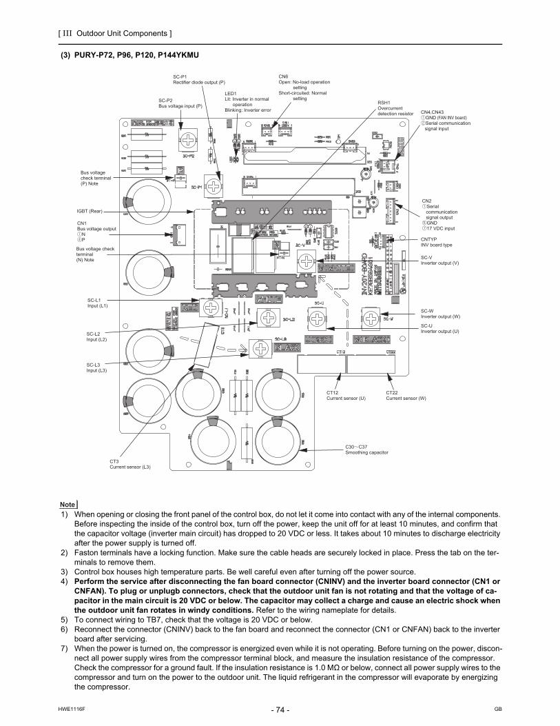
[ III Outdoor Unit Components ]
- 74 -HWE1116F GB
(3) PURY-P72, P96, P120, P144YKMU
1) When opening or closing the front panel of the control box, do not let it come into contact with any of the internal components. Before inspecting the inside of the control box, turn off the power, keep the unit off for at least 10 minutes, and confirm that the capacitor voltage (inverter main circuit) has dropped to 20 VDC or less. It takes about 10 minutes to discharge electricity after the power supply is turned off.
2) Faston terminals have a locking function. Make sure the cable heads are securely locked in place. Press the tab on the ter-minals to remove them.
3) Control box houses high temperature parts. Be well careful even after turning off the power source.4) Perform the service after disconnecting the fan board connector (CNINV) and the inverter board connector (CN1 or
CNFAN). To plug or unplugb connectors, check that the outdoor unit fan is not rotating and that the voltage of ca-pacitor in the main circuit is 20 VDC or below. The capacitor may collect a charge and cause an electric shock when the outdoor unit fan rotates in windy conditions. Refer to the wiring nameplate for details.
5) To connect wiring to TB7, check that the voltage is 20 VDC or below.6) Reconnect the connector (CNINV) back to the fan board and reconnect the connector (CN1 or CNFAN) back to the inverter
board after servicing.7) When the power is turned on, the compressor is energized even while it is not operating. Before turning on the power, discon-
nect all power supply wires from the compressor terminal block, and measure the insulation resistance of the compressor. Check the compressor for a ground fault. If the insulation resistance is 1.0 MΩ or below, connect all power supply wires to the compressor and turn on the power to the outdoor unit. The liquid refrigerant in the compressor will evaporate by energizing the compressor.

[ III Outdoor Unit Components ]
- 75 -HWE1116F GB
4. Fan board(1) PURY-P72, P96, P120, P144TKMU
1) When opening or closing the front panel of the control box, do not let it come into contact with any of the internal components. Before inspecting the inside of the control box, turn off the power, keep the unit off for at least 10 minutes, and confirm that the capacitor voltage (inverter main circuit) has dropped to 20 VDC or less. It takes about 10 minutes to discharge electricity after the power supply is turned off.
2) Control box houses high temperature parts. Be well careful even after turning off the power source.3) Perform the service after disconnecting the fan board connector (CNINV) and the inverter board connector (CN1 or
CNFAN). To plug or unplugconnectors, check that the outdoor unit fan is not rotating and that the voltage of capac-itor in the main circuit is 20 VDC or below. The capacitor may collect a charge and cause an electric shock when the outdoor unit fan rotates in windy conditions. Refer to the wiring nameplate for details.
4) To connect wiring to TB7, check that the voltage is 20 VDC or below.5) Reconnect the connector (CNINV) back to the fan board and reconnect the connector (CN1 or CNFAN) back to the inverter
board after servicing.
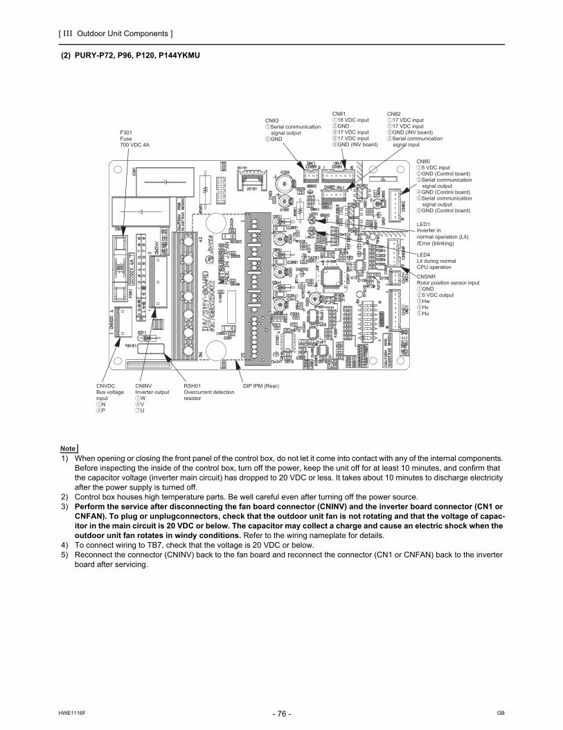
[ III Outdoor Unit Components ]
- 76 -HWE1116F GB
(2) PURY-P72, P96, P120, P144YKMU
1) When opening or closing the front panel of the control box, do not let it come into contact with any of the internal components. Before inspecting the inside of the control box, turn off the power, keep the unit off for at least 10 minutes, and confirm that the capacitor voltage (inverter main circuit) has dropped to 20 VDC or less. It takes about 10 minutes to discharge electricity after the power supply is turned off.
2) Control box houses high temperature parts. Be well careful even after turning off the power source.3) Perform the service after disconnecting the fan board connector (CNINV) and the inverter board connector (CN1 or
CNFAN). To plug or unplugconnectors, check that the outdoor unit fan is not rotating and that the voltage of capac-itor in the main circuit is 20 VDC or below. The capacitor may collect a charge and cause an electric shock when the outdoor unit fan rotates in windy conditions. Refer to the wiring nameplate for details.
4) To connect wiring to TB7, check that the voltage is 20 VDC or below.5) Reconnect the connector (CNINV) back to the fan board and reconnect the connector (CN1 or CNFAN) back to the inverter
board after servicing.

[ III Outdoor Unit Components ]
- 77 -HWE1116F GB
5. Noise Filter(1) PURY-P72TKMU
Ground
Ground
TB32Bus voltage input (P)CN110
Power supply detectionsignal output
CN012Output
CN001Input
CNR1Rush currentprotection resistor (R1) connection
TB21Input/output (L1)
TB22Input/output (L2)
TB23Input/output (L3)
F002Fuse250 VAC 6.3A T
F001Fuse250 VAC 6.3A T
TB31Bus voltage output (P)
X001Electromagneticrelay (72C)
CN72C72C drive signal input
L3L2L1
L2L1

[ III Outdoor Unit Components ]
- 78 -HWE1116F GB
(2) PURY-P96, P120, P144TKMU
Ground
Ground
TB31Bus voltage output (P)
CN110Power supply detectionsignal output
CN012Output
CN001Input
CNR1Rush currentprotection registor(R1) connection
TB21Input (L1)
TB22Input (L2)
TB23Input (L3)
F002Fuse250 VAC 6.3A T
F001Fuse250 VAC 6.3A T
TB42Bus voltage output (N)
X001Electromagnetic relay (72C)
CN72C72C drive input
F003Fuse250 VAC 6.3A T
Diode stackRectifier voltage input (Diode stack output)
Output (Diode stack input)
L3L2L1
L2L1

[ III Outdoor Unit Components ]
- 79 -HWE1116F GB
(3) PURY-P72, P96, P120, P144YKMU
CN4Output(Rectified L2-L3 current) P N
CN5Output(Rectified L2-L3 current) P N
TB21Input/output(L1)
TB22Input/output(L2)
TB23Input/output(L3)
CN1BInput L3 L2
CN1AInput L1
Grounding
F1,F2,F3,F4Fuse250VAC 6.3A
CN6Input L2 L3
Grounding
CN2 Surge absorber circuit Surge absorber circuit Short circuit Short circuit

[ III Outdoor Unit Components ]
- 80 -HWE1116F GB
6. Connect board
1) When opening or closing the front panel of the control box, do not let it come into contact with any of the internal components. Before inspecting the inside of the control box, turn off the power, keep the unit off for at least 10 minutes, and confirm that the capacitor voltage (inverter main circuit) has dropped to 20 VDC or less. It takes about 10 minutes to discharge electricity after the power supply is turned off.
2) Control box houses high temperature parts. Be well careful even after turning off the power source.3) Perform the service after disconnecting the fan board connector (CNINV) and the connector board connector
(CN103). To plug or unplugconnectors, check that the outdoor unit fan is not rotating and that the voltage of capac-itor in the main circuit is 20 VDC or below. The capacitor may collect a charge and cause an electric shock when the outdoor unit fan rotates in windy conditions. Refer to the wiring nameplate for details.
4) To connect wiring to TB7, check that the voltage is 20 VDC or below.5) Reconnect the connector (CNINV) back to the fan board and reconnect the connector (CN103) back to the connector board
after servicing.
1

[ III Outdoor Unit Components ]
- 81 -HWE1116F GB
[4] BC Controller Components
1. CMB-P NU-G, GA, HA(1) Front
(2) Rear view <G type>
Liquid pipe (Indoor unit side)
Gas pipe (Indoor unit side)
TH12
TH15
TH16
TH11
SVM1
LEV1LEV3
PS1
PS3
Tube in tube heat exchanger
Gas/Liquid separator

[ III Outdoor Unit Components ]
- 82 -HWE1116F GB
(3) Rear view <GA type>
(4) Rear view <HA type>
TH12 TH15
TH16
TH11
SVM2
SVM1
LEV1
LEV3
LEV2 PS1PS3
Tube in tube heat exchanger
Gas/Liquid separator
Gas/Liquid separator
LEV3
LEV1LEV2
SVM2
SVM2b
SVM1bSVM1
TH16TH15TH12
TH11
PS1
PS3
Tube in tube heat exchanger

[ III Outdoor Unit Components ]
- 83 -HWE1116F GB
2. CMB-P NU-GB, HB(1) Front
(2) Rear view
Liquid pipe (Indoor unit side)
Gas pipe (Indoor unit side)
TH15
TH12
LEV3

[ III Outdoor Unit Components ]
- 84 -HWE1116F GB
[5] Control Box of the BC Controller
1. CMB-P1016NU-G, GA, HA
Relay board
Transformer
Terminal block fortransmission line
BC controller board
Terminal block forpower supply

[ III Outdoor Unit Components ]
- 85 -HWE1116F GB
[6] BC Controller Circuit Board
1. BC controller circuit board (BC board)
SW1SW2SW5 SW6SW4

[ III Outdoor Unit Components ]
- 86 -HWE1116F GB
2. RELAY BOARD (RELAY 4 board)
3. RELAY BOARD (RELAY 10 board)

- 87 -HWE1116F GB
IV Remote Controller
[1] Functions and Specifications of MA and ME Remote Controllers ...................................89
[2] Group Settings and Interlock Settings via the ME Remote Controller .............................90
[3] Interlock Settings via the MA Remote Controller .............................................................94
[4] Using the built-in Temperature Sensor on the Remote Controller ...................................95

- 88 -HWE1116F GB

[ IV Remote Controller ]
- 89 -HWE1116F GB
IV Remote Controller
[1] Functions and Specifications of MA and ME Remote Controllers
There are two types of remote controllers: ME remote controller, which is connected on the indoor-outdoor transmission line, and MA remote controller, which is connected to each indoor unit.
1. Comparison of functions and specifications between MA and ME remote controllers
2. Remote controller selection criteriaMA remote controller and ME remote controller have different functions and characteristics. Choose the one that better suits the requirements of a given system. Use the following criteria as a reference.
Functions/specifications MA remote controller*1*2
*1. MA remote controller refers to MA remote controller (PAR-20MAU, PAR-21MAAU, PAR-30MAAU), Simple MA Remote Controller, and wireless remote controller.
*2. Either the MA remote controller or the ME remote controller can be connected when a group operation of units in a sys-tem with multiple outdoor units is conducted or when a system controller is connected.
ME remote controller*2*3
*3. ME remote controller refers to ME remote controller and Simple ME Remote Controller.
Remote controller address settings Not required Required
Indoor/outdoor unit address set-tings
Not required (required only by a system with one outdoor unit)*4
*4. Depending on the system configuration, some systems with one outdoor unit may require address settings.
Required
Wiring method Non-polarized 2-core cableTo perform a group operation, daisy-
chain the indoor units using non-polar-ized 2-core cables.
Non-polarized 2-core cable
Remote controller connection Connectable to any indoor unit in the group
Connectable anywhere on the indoor-out-door transmission line
Interlock with the ventilation unit Each indoor unit can individually be in-terlocked with a ventilation unit. (Set up via remote controller in the group.)
Each indoor unit can individually be inter-locked with a ventilation unit. (Set up via remote controller.)
Changes to be made upon group-ing change
MA remote controller wiring between in-door units requires rewiring.
Either the indoor unit address and remote controller address must both be changed, or the registration information must be changed via MELANS.
MA remote controller*1*2 ME remote controller*1*2
There is little likelihood of system expansion and group-ing changes.Grouping (floor plan) has been set at the time of instal-lation.
There is a likelihood of centralized installation of remote controllers, system expansion, and grouping changes.Grouping (floor plan) has not been set at the time of in-stallation.To connect the remote controller directly to the OA pro-cessing unit.
*1. ME remote controller and MA remote controller cannot both be connected to the same group of indoor units.
*2. A system controller must be connected to a system to which both MA remote controller and ME remote controller are con-nected.
<System with MA remote controller> <System with ME remote controllers>
MA remote controller
Outdoor unit
Indoor unitBC controller
M-NET transmission line(indoor/outdoor transmission line)
groupgroup
ME remote controller
Outdoor unit
Indoor unitBC controller
M-NET transmission line(indoor/outdoor transmission line)
groupgroup

[ IV Remote Controller ]
- 90 -HWE1116F GB
[2] Group Settings and Interlock Settings via the ME Remote Controller
1. Group settings/interlock settings
<Deletion error>
[Normal display]
(B) Interlock Settings (A) Group Settings
Indoor unit address display window Indoor unit address display window
Interlocked unit address display window
Make the following settings to perform a group operation of units that are connected to different outdoor units or to manually set up the indoor/outdoor unit address. (A) Group settings...........Registration of the indoor units to be controlled with the remote controller, and search and deletion of registered information. (B) Interlock settings........Registration of LOSSNAY units to be interlocked with the indoor units, and search and deletion of registered information
[Operation Procedures](1) Address settings Register the indoor unit to be controlled with the remote controller. Bring up either one of the following displays on the remote controller: The blinking display of HO, which appears when the power is turned on, or the normal display, which appears when the unit is stopped. The display window must look like one of the two figures below to proceed to the next step.
1
2 Bring up the Group Setting window. -Press and hold buttons [FILTER] and [LOUVER] simultaneously for 2 seconds to bring up the display as shown below.
3
A
C
D
B
Select the unit address. - Select the address of the indoor unit to be registered by pressing button [SET TEMP. ( ) or ( )] to advance or go back through the addresses. Register the indoor unit whose address appears on the display. - Press button [TEST] to register the indoor unit address whose address appears on the display. - If registration is successfully completed, unit type will appear on the display as shown in the figure below. - If the selected address does not have a corresponding indoor unit, an error message will appear on the display. Check the address, and try again.
5
<Successful completion of registration>
Unit type (Indoor unit in this case)
blinks to indicate a registration error.(Indicates that selected address does not have a corresponding unit.)
4
To register the addresses for multiple indoor units, repeat steps and above.3 4
To search for an address, go to section (2) Address Search.
Next page.
To search for an address, go to section (2) Address Search.
Bring up the Interlock Setting window. -Press button [MODE] to bring up the following display. Press again to go back to the Group Setting window as shown under step .
6G
2
Both the indoor unit address and interlocked unit address will be displayed together.
Bring up the address of the indoor unit and the address of the LOSSNAY to be interlocked on the display.- Select the address of the indoor unit to be registered by pressing button [SET TEMP. ( ) or ( )] to advance or go back through the addresses. - Select the address of the LOSSNAY unit to be interlocked by pressing button [TIMER SET ( ) or ( )] to advance or go back through the interlocked unit addresses.
7
8
C
H
Make the settings to interlock LOSSNAY units with indoor units.- Press button [TEST] while both the indoor unit address and the address of the LOSSNAY units to be interlocked are displayed to enter the interlock setting.- Interlock setting can also be made by bringing up the LOSSNAY address in the indoor unit address display window and the indoor unit address in the interlocked unit address display window.
D
(Displayed alternately)
If registration is successfully completed, the two displays as shown on the left will appear alternately.If the registration fails, will blink on the display.(Indicates that the selected address does not have a corresponding unit.)
NOTE : Interlock all the indoor units in the group with the LOSSNAY units; otherwise, the LOSSNAY units will not operate.
[Blinking display of HO ]
ON/OFF SET TEMP.
PAR-F27MEA-US
FILTER
CHECK TEST
CLOCK ON OFFMODE TIMER FAN SPEED
LOUVER VENTILATION
AIR DIRECTION
TIMER SET
AF
D
BH
G
C
E

[ IV Remote Controller ]
- 91 -HWE1116F GB
<Entry found>
<No entries found>
(C) To return to the normal displayWhen all the group settings and interlock settings are made, take the following step to go back to the normal display. Press and hold buttons [FILTER] and [LOUVER] simultaneously for 2 seconds to go back to the window as shown in step .
(2) Address search To search for the address of indoor units that have been entered into the remote controller, follow steps and .
(A) To search group settings
Unit type(Indoor unit in this case)
- When only one unit address is registered, the same address will remain on the display regardless of how many times the button is pressed.- When the address of multiple units are registered (i.e. 011, 012, 013 ), they will be displayed one at a time in an ascending order with each pressing of button [TIMER ] .
To delete an address, go to section (3) Address Deletion.
To go back to the normal display, follow step
(Displayed alternately)
To delete an address, go to section (3) Address Deletion .
Bring up the address of another registered unit on the display.- After completing step , a subsequent pressing of button [TIMER] will bring up the address of another registered unit. (The display method is the same as the one in step .)
Address of an interlocked LOSSNAY unit
Address of another interlocked unit
Bring up on the display the address of the LOSSNAY unit that was interlocked with the indoor unit in step . - With each pressing of button [TIMER], the address of the LOSSNAY and indoor unit that is interlocked with it will be displayed alternately.
LOSSNAY can be searched in the same manner by bringing up the LOSSNAY address in the Interlocked unit address display window.
(B) Interlock setting search
After performing step , proceed as follows:
Bring up the address of the indoor unit to be searched on the display.- Select the address of the indoor unit to be searched by pressing button [TIMER SET ( ) or ( )] to advance or go back through the interlocked addresses.
Repeat steps and in the previous page to interlock all the indoor units in a group with the LOSSNAY unit.
7 8
To go back to the normal display, follow step
To search for an address, go to section (2) Address Search.
(3) Address deletion
(Displayed alternately)
10 A B
1
Bring up the Group Setting window.- Each pressing of button [TIMER ] will bring up the address of a registered indoor unit and its unit type on the display.
11E
1 2
E
10
E
13
13
13
12
14
12
6
E
H
9
10
The addresses of the indoor units that have been entered into the remote controller can be deleted by deleting the group settings.The interlock settings between units can be deleted by deleting the interlock settings.Follow the steps in section (2) Address Search to find the address to be deleted and perform deletion with the address being displayed in the display window. To delete an address, the address must first be bought up on the display.
Delete the registered indoor unit address or the interlock setting between units. - Press button [CLOCK ON OFF] twice while either the indoor unit address or the address of the interlocked unit is displayed on the display to delete the interlock setting.
F
15

[ IV Remote Controller ]
- 92 -HWE1116F GB
2. Remote controller function selection via the ME remote controller
(A) To delete group settings (B) To delete interlock settings
<Successful completion of deletion>
will be displayed in the room temperature display window.
- If a transmission error occurs, the selected setting will not be deleted, and the display will appear as shown below. In this case, repeat the steps above.
(Displayed alternately)
<Deletion error>
will be displayed in the room temperature display window.
(4) Making (A) Group settings and (B) Interlock settings of a group from any arbitrary remote controller
(A) Group settings and (B) Interlock settings of a group can be made from any arbitrary remote controller.Refer to (B) Interlock Settings under section 1 Group Settings/Interlock Settings for operation procedures.Set the address as shown below.
(A) To make group settings Interlocked unit address display window...Remote controller address Indoor unit address display window...........The address of the indoor unit to be controlled with the remote controller
(B) To make interlock settings Interlocked unit address display window...LOSSNAY address Indoor unit address display window..........The address of the indoor unit to be interlocked with the LOSSNAY
If deletion is successfully completed, will appear in the unit type display window.If the deletion fails, will appear in the unit type display window. In this case, repeat the steps above.
- -
To go back to the normal display, follow step .10
PAR-F27MEA-US
ON/OFF
FILTERFUN SPEED
LOUVER VENTILATION
AIR DIRECTION
CHECK TEST
TIMER SET
MODE TIMER CLOCK ON OFF
SET TEMP.
COOL
AUTO
HEAT
FANSPEED
1
3
2
4
In the remote controller function selection mode, the settings for three types of functions can be made or changed as necessary.
3) Narrowed preset temperature range mode The default temperature ranges are 67°F to 87°F in the cooling/dry mode and 63°F to 83°F in the heating mode. By changing these ranges (raising the lower limit for the cooling/dry mode and lowering the upper limit for the heating mode), energy can be saved. *The settable range varies depending on the unit to be connected.
On the PAR-F27MEA-US model, automatic operation mode cannot be selected while the unit is in the narrowed preset temperature range mode.Only the lower limit can be set for cooling/dry mode, and upper limit for heating mode.
NOTE
[Function selection mode sequence on the remote controller]
Normal Display (Stopped unit)
1 1
3 2
3 2
3 2
32
[Normal display]
Operation mode display selection mode
Room temperature display selection mode
Narrowed preset temperature range mode (cooling/dry mode)
Narrowed preset temperature range mode (heating mode)
CENTRALLY CONTROLLEDDAILY
AUTO OFF
DRY
FANREMAINDER
ERROR CODE
CLOCKSET TEMP.
AUTOON
AUTOOFF FAN
SPEED
CHECK MODEFILTER
SENSORINSIDE
TEST RUN
LIMIT TEMP.
1Hr.
NOT AVAILABLE
VENTILATIONSTAND BY DEFROST
TIMER
CHECK
1
32
: Press and hold the [CHECK] and [MODE] buttons simultaneously for two seconds.: [SET TEMP. ( ) ] button: [SET TEMP. ( ) ] button
2) Room temperature display selection mode (Display or non-display of room temperature) Although the suction temperature is normally displayed on the remote controller, the setting can be changed so that it will not appear on the remote controller.
1) Operation mode display selection mode (Display or non-display of COOL/HEAT during automatic operation mode) When the automatic operation mode is selected, the indoor unit will automatically perform a cooling or heating operation based on the room temperature. In this case, AUTO COOL or AUTO HEAT will appear on the remote controller display. This setting can be changed so that only AUTO will appear on the display.
Remote controller function selection mode

[ IV Remote Controller ]
- 93 -HWE1116F GB
1Hr.
NOT AVAILABLE
VENTILATIONSTAND BY DEFROST
TIMER
CHECK
[Operation Procedures]1. Press the [ON/OFF] button on the remote controller to bring the unit to a stop. The display will appear as shown in the previous page (Normal display).2. Press buttons [CHECK] and [MODE] simultaneously for 2 seconds to go into the operation mode display selection mode under the remote controller function selection mode. Press button [SET TEMP. ( )] or [SET TEMP. ( )] to go into the other three modes under the remote controller function selection mode.
2 3
Operation mode display selection mode (Display or non-display of room temperature on the remote controller.)
AUTO COOL/HEAT will blink, and either ON or OFF will light up. Press button [TIMER SET ( ) or ( )] in this state to switch between ON and OFF.
When it is set to ON, AUTO and COOL or AUTO and HEAT will appear on the display during automatic operation mode.When it is set to OFF, only AUTO will appear on the display during automatic operation mode.
Room temperature display selection mode (Display or non-display of room temperature)
Narrowed preset temperature range mode (The range of preset temperature can be changed.)
When it is set to ON, the room temperature will stay in the operation display window during operation.When it is set to OFF, the room temperature will not appear in the operation display window during operation.
88 F will blink in the room temperature display window, and either ON or OFF will light up. Press button [TIMER SET ( ) or ( )] in this state to switch between ON and OFF.
1) Temperature range setting for the cooling/dry mode
COOL/DRY and LIMIT TEMP. will light up in the display window, and the temperature range for the cooling/dry mode will appear on the display.The lower limit temperature will be blinking in the preset temperature display window. While it is blinking, the temperature setting can be changed.[Selection range for the lower limit temperature] : 67 F 87 F (Medium temperature range indoor unit 57 F 87 F) (The upper limit temperature is fixed at 87 F. Only the lower limit temperature is changeable.)
HEAT and LIMIT TEMP will light up, and the temperature range for the heating mode will appear on the screen.The upper limit temperature can be changed with button [TIMER SET ( ) or ( )]. [Selection range for the upper limit temperature] : 63 F 83 F (Medium temperature range indoor unit 63 F 83 F) (The lower limit temperature is fixed at 63 F. Only the upper limit temperature is changeable.)
[When the temperature range for the cooling or dry mode is set to 67 F to 87 F]
[When the temperature range is changed to 75 F - 87 F]
2) Press button [TIMER SET ( ) or ( )] to set the lower limit temperature to the desired temperature.
3) After completing the step above, press button [SET TEMP. ( )] to go into the temperature range setting mode to set the temperature range for the heating operation.
3. When all the necessary settings have been made, exit the remote controller function selection mode and go back to the Normal display by pressing and holding buttons [CHECK] and [MODE] simultaneously for 2 seconds.
1
CENTRALLY CONTROLLEDDAILY
AUTO OFF
DRY COOL
AUTO FAN
HEATREMAINDER
ERROR CODE
CLOCKSET TEMP.
AUTOON
AUTOOFF FAN
SPEED
CHECK MODEFILTER
SENSAORINSIDE
TEST RUN
LIMIT TEMP.
1Hr.
NOT AVAILABLE
VENTILATIONSTAND BY DEFROST
TIMER
CHECK
CENTRALLY CONTROLLEDDAILY
AUTO OFF
DRY COOL
AUTO FAN
HEATREMAINDER
ERROR CODE
CLOCKSET TEMP.
AUTOON
AUTOOFF FAN
SPEED
CHECK MODEFILTER
SENSAORINSIDE
TEST RUN
LIMIT TEMP.
1Hr.
NOT AVAILABLE
VENTILATIONSTAND BY DEFROST
TIMER
CHECK
CENTRALLY CONTROLLEDDAILY
AUTO OFF
DRY COOL
AUTO FAN
HEATREMAINDER
ERROR CODE
CLOCKSET TEMP.
AUTOON
AUTOOFF FAN
SPEED
CHECK MODEFILTER
SENSAORINSIDE
TEST RUN
LIMIT TEMP.
1Hr.
NOT AVAILABLE
VENTILATIONSTAND BY DEFROST
TIMER
CHECK
CENTRALLY CONTROLLEDDAILY
AUTO OFF
DRY COOL
AUTO FAN
HEATREMAINDER
ERROR CODE
CLOCKSET TEMP.
AUTOON
AUTOOFF FAN
SPEED
CHECK MODEFILTER
SENSAORINSIDE
TEST RUN
LIMIT TEMP.
1Hr.
NOT AVAILABLE
VENTILATIONSTAND BY DEFROST
TIMER
CHECK
CENTRALLY CONTROLLEDDAILY
AUTO OFF
DRY COOL
AUTO FAN
HEATREMAINDER
ERROR CODE
CLOCKSET TEMP.
AUTOON
AUTOOFF FAN
SPEED
CHECK MODEFILTER
SENSAORINSIDE
TEST RUN
LIMIT TEMP.
1Hr.
NOT AVAILABLE
VENTILATIONSTAND BY DEFROST
TIMER
CHECK
[TIMER SET ( ) (( ))] button
[TIMER SET ( ) (( ))] button
4
4
4
4
2
1

[ IV Remote Controller ]
- 94 -HWE1116F GB
[3] Interlock Settings via the MA Remote Controller
1. LOSSNAY interlock setting (Make this setting only when necessary.)(1) MA Remote Controller (PAR-21MAAU)
[Operation Procedures]
<Indoor unit address and indoor unit> <LOSSNAY address and LOSSNAY> - Without interlocked LOSSNAY settings
Search result - The indoor unit address and the interlocked LOSSNAY address will appear alternately.
Press the [ON/OFF] button on the remote controller to bring the unit to a stop. The display window on the remote controller must look like the figure below to proceed to step .
NOTE: When using LOSSNAY units in conjunction, interlock the addresses of all indoor units within the group and address of LOSSNAY units.
Perform this operation to enter the interlock setting between the LOSSNAY and the indoor units to which the remote controller is connected, or to search and delete registered information.
* When the upper controller is connected, make the setting using the upper controller.
In the following example, the address of the indoor unit is 05 and the address of the LOSSNAY unit is 30.
2
< 1. Registration Procedures >
Indoor unit address LOSSNAY address
Press the [TEST] button to register the address of the selected indoor unit and the interlocked LOSSNAY unit. - Registration completed The registered indoor unit address and IC, and the interlocked LOSSNAY address and LC will appear alternately.
- Registration error If the registration fails, the indoor unit address and the LOSSNAY address will be displayed alternately.
Registration cannot be completed: The selected unit address does not have a corresponding indoor unit or a LOSSNAY unit. Registration cannot be completed: Another LOSSNAY has already been interlocked with the selected indoor unit.
1
3
2 Press and hold the [FILTER] and [ ] buttons simultaneously for two seconds to perform a search for the LOSSNAY that is interlocked with the indoor unit to which the remote controller is connected.
If no settings are necessary, exit the window by pressing and holding the [FILTER] and [ ] buttons simultaneously for 2 seconds. Go to step 1. Registration Procedures to make the interlock settings with LOSSNAY units, or go to step 2. Search Procedures to search for a particular LOSSNAY unit. Go to step 3. Deletion Procedures to delete any LOSSNAY settings.
To interlock an indoor unit with a LOSSNAY unit, press the [ TEMP. ( ) or ( )] button on the remote controller that is connected to the indoor unit, and select its address (01 to 50). Press the [ CLOCK ( ) or ( )] button to select the address of the LOSSNAY to be interlocked (01 to 50).
5
4
7
6

[ IV Remote Controller ]
- 95 -HWE1116F GB
[4] Using the built-in Temperature Sensor on the Remote Controller
1. Selecting the position of temperature detection (Factory setting: SW1-1 on the controller board on the indoor unit is set to OFF.)To use the built-in sensor on the remote controller, set the SW1-1 on the controller board on the indoor unit to ON.Some models of remote controllers are not equipped with a built-in temperature sensor. Use the built-in temperature sensor on the indoor unit instead.When using the built-in sensor on the remote controller, install the remote controller where room temperature can be detected.
<Indoor unit address>
- Search completed (No interlocked settings with a LOSSNAY exist.)
- The selected address does not have a corresponding indoor unit.
< 2. Search Procedures >
< 3. Deletion Procedures >
Press the [ MENU] button to search for the address of the LOSSNAY unit that is interlocked with the selected indoor unit.- Search completed (With a LOSSNAY connection) The indoor unit address and IC, and the interlocked LOSSNAY address and LC will appear alternately.
Take the following steps to delete the interlock setting between a LOSSNAY unit and the interlocked indoor unit from the remote controller that is connected to the indoor unit.Find the address of the LOSSNAY to be deleted (See section 2. Search Procedures. ), and bring up the result of the search for both the indoor unit and LOSSNAY on the display.
Press the [ ON/OFF] button twice to delete the address of the LOSSNAY unit that is interlocked with the selected indoor unit.- Registration completed The indoor unit address and , and the interlocked LOSSNAY address and will appear alternately.
-Deletion error If the deletion fails
8
9
10
11
To search for the LOSSNAY unit that is interlocked with a particular indoor unit, enter the address of the indoor unit into the remote controller that is connected to it.

[ IV Remote Controller ]
- 96 -HWE1116F GB

- 97 -HWE1116F GB
V Electrical Wiring Diagram
[1] Electrical Wiring Diagram of the Outdoor Unit .................................................................99
[2] Electrical Wiring Diagram of the BC Controller ..............................................................104
[3] Electrical Wiring Diagram of Transmission Booster.......................................................114

- 98 -HWE1116F GB

[ V Electrical Wiring Diagram ]
- 99 -HWE1116F GB
V Electrical Wiring Diagram
[1] Electrical Wiring Diagram of the Outdoor Unit
(1) PURY-P72TKMU
*3
*4
*3
*5
12
red
CNPS
1 321 TP
1TP
2
TB3
23
TB7
M1
M2
M1
M2
S
1
512
34
12
t°
For o
peni
ng/c
losi
ng th
e by
pass
circ
uit
Term
inal
bloc
kC
entra
l con
trol t
rans
mis
sion
cabl
e
Pow
er s
uppl
y
Func
tion
setti
ng c
onne
ctor
IPM
tem
pera
ture
OA
tem
pera
ture
AC
C in
let p
ipe
tem
pera
ture
Dis
char
ge p
ipe
tem
pera
ture
Ther
mis
tor
SV
9
TB1
TB3
TB7
TH3
TH4
TH5
TH6
TH7
THH
SZ2
4,25
1
DC
reac
tor
Cur
rent
sen
sor(
AC
)
Low
pre
ssur
eD
isch
arge
pre
ssur
e
Hig
h pr
essu
re p
rote
ctio
n fo
r the
outd
oor u
nit
Pre
ssur
esw
itch
Pre
ssur
ese
nsor
Exp
lana
tion
Exp
lana
tion
4-w
ay v
alve
(Coo
ling/
Hea
ting
switc
hing
)
For o
peni
ng/c
losi
ng th
e by
pass
circ
uit u
nder
the
O/S
Sol
enoi
dva
lve
Sol
enoi
dva
lve
DC
L
LEV
5a
2
CT1
1,12
63LS
63H
S1
63H
1
<Sym
bol e
xpla
natio
n>S
ymbo
lS
ymbo
l21
S4a
132
3456
1 2 2
CN82
blue
13 4CN
83bl
ack
31
Fan
mot
or(H
eat e
xcha
nger
)W V U
CNIN
V
6 14
5
CN4
blac
k
1
21
231
t°
SW00
1
CN2
red
12
1
3
31
432
23
1
1
CNSN
R
TH4
t°
4
1
1
CN21
1gr
een
23
123
32
1
3
12345
32
23
123
CN11
0bl
ack
2
1
1CN
72C
red
12
21
t°
2
X12
SV
1a
16 3CN
508
blue
yello
wCN
POW
red
t°
654
X10
ON
X08
Unit
addr
ess
setti
ng
CT11
6
3 16
RSH0
1
12
34
3gr
een
CN62
CN99
0gr
een
CNTY
P4gr
een
CN20
1
Z25
1
TH5
2
SWU2
LED1
SW6
10
Cont
rol B
oard
TH3
CN40
63HS
1
CN41
TH7
15
543
1
SW4
LED3
2
LEV5
a
3
SE
T U
P(S
W6-
10)
SC-V
CT12
SC-U
V
CN72
C re
d
M
OFF t
CN50
6 re
d
yello
w C
N3K
Com
pres
sor O
N/O
FF o
utpu
tEr
ror d
etec
tion
outp
ut
TB21
DC12
VCN
51
SV
5b
U
blue
CN3N
1 3
3
4
TB1
CN00
1
TB7
Powe
rse
lect
ing
conn
ecto
r
IPM
5
1
DCL
blac
k
X001
white
26
ON
OFF
M-N
ET p
ower
supp
ly cir
cuit
12
M-N
ET B
oard
Pow
er fa
ilure
dete
ctio
n ci
rcui
t
Indo
or/O
utdo
ortra
nsm
issio
nca
ble
INV
Boar
d
red
TB23
ON1'
sdi
git
THHS
CN10
2
14
1
W
10's
digi
t
OFF
LED
2:N
orm
al o
pera
tion(
Lit)
/
Err
or(B
link)
CNS
2ye
llow
CNDC
red
MS 3~
2
TH6
U
LED
1:P
ower
sup
ply
to
Indo
or/O
utdo
or
tran
smis
sion
line
ZNR4
00
Cent
ral c
ontro
ltra
nsm
issio
nca
ble
SC-T
ONOF
F
TB-N
Mot
or(C
ompr
esso
r)
red
CN3S
1
CN04
red
CN4
yello
w
CN61
gree
n
CN20
2 re
d
8
red
LED
1:N
orm
al o
pera
tion(
Lit)
/
Err
or(B
link)
SC-W
2
P
63H1
4
1
SW5
10
5
CN3D
1
CP
U p
ower
supp
ly c
ircui
t
blac
kCN
AC2
1ON
OFF
10
SWU1
For i
nrus
h cu
rren
t pre
vent
ion
CN21
2 re
d
6
SV
5b
R1
CN80
F301
AC25
0V15
A T
CNTY
P5gr
een
Out
door
uni
t hea
t exc
hang
erca
paci
ty c
ontro
l
LED
4:C
PU
in o
pera
tion
LED
1:N
orm
al o
pera
tion(
Lit)
/
Err
or(B
link)
CN80
1 re
d
°IP
M
SC-P
1
Pip
e te
mpe
ratu
re
TB-P
C011
~C01
6
TB22
SWP0
1
RSH0
1~RS
H03
FAN
Boar
d
63LS
L
Noise
Filte
r
Z24
2
CN50
7bl
ack
36
4
CN21
3gr
een
CN01
2
SV
9Fu
nctio
nse
tting
LED
1D
ispl
ayse
tting
/Fu
nctio
nse
tting
Noi
se fi
lter
white
21
red
3
red
Surg
eab
sorb
er
1
12
1
CNLV
A
1
R1
F01
AC25
0V3.
15A
T
MS 3~
white
blac
k
12
6
CNIT
red
L1L2
L3
4
CNVD
C
Sub
cool
ed li
quid
refri
gera
ntte
mpe
ratu
re
*1. S
ingl
e-do
tted
lines
indi
cate
wiri
ng n
ot
supp
lied
with
the
unit.
*2. D
ot-d
ash
lines
indi
cate
the
cont
rol b
ox
boun
darie
s.*3
. Ref
er to
the
Dat
a bo
ok fo
r con
nect
ing
in
put/o
utpu
t sig
nal c
onne
ctor
s.*4
. Dai
sy-c
hain
term
inal
s (T
B3) o
n th
e ou
tdoo
r
units
in th
e sa
me
refri
gera
nt s
yste
m to
geth
er.
*5. F
asto
n te
rmin
als
have
a lo
ckin
g fu
nctio
n.
Mak
e su
re th
e te
rmin
als
are
secu
rely
lock
ed
in p
lace
afte
r ins
ertio
n. P
ress
the
tab
on
the
term
inal
s to
rem
oved
them
.*6
. Con
trol b
ox h
ouse
s hi
gh-v
olta
ge p
arts
.
Befo
re in
spec
ting
the
insi
de o
f the
con
trol
bo
x,tu
rn o
ff th
e po
wer
,kee
p th
e un
it of
f for
at
leas
t 10
min
utes
, and
con
firm
that
the
vo
ltage
bet
wee
n TB
-P a
nd T
B-N
on
INV
Boar
d
has
drop
ped
to D
C20
V or
less
.
3
Powe
r Sou
rce
3~
60H
z 2
08/2
30VL3
L2L1
F001
AC25
0V6.
3A T
CNFG
2
X001
5CN
110
13
36CN
R1re
d1 3 TB
31
TB32
red
X05
X06
35 16
CN50
5
13
red
white
+
LED
4:C
PU
in o
pera
tion
blac
k
blac
k
red
F001
AC25
0V3.
15A
Tred
SC-P
2
CNFA
N1
3 4CN
VDC
15
2
SC-R
SC-S
(INV
Boa
rd)
Hea
t exc
hang
er c
apac
ity c
ontro
l
Line
ar e
xpan
sion
val
ve (F
or th
e co
ntro
l of
evap
orat
ing
tem
pera
ture
)
4
LC
hoke
coi
l (fo
r hig
h fre
quen
cy n
oise
redu
ctio
n)
X14
X13
156 3
Mag
netic
rela
y (in
verte
r mai
n ci
rcui
t)72C
Cap
acito
r (in
verte
r mai
n ci
rcui
t)C
011~
C01
6X
001
CN50
9S
V4a
SV
4b
F002
AC25
0V6.
3A T
SV
4d
CNAC
CN81
gree
n
12
5134
RS
H01
~RS
H03
For c
urre
nt d
etec
tion
4
4CN
2
C310
,C31
1
SV
4a,b
,d
SV
1a
black
white
21S
4a
Indo
or/O
utdo
or tr
ansm
issi
on c
able
2
Res
isto
rFo
r cur
rent
det
ectio
n
Pow
er fa
ilure
dete
ctio
n ci
rcui
t
RSH0
1(FA
N Bo
ard)
Gro
und

[ V Electrical Wiring Diagram ]
- 100 -HWE1116F GB
(2) PURY-P96TKMU
*3
*4
*3
*5
*5
X14
X13
6 13CN
509
5
12
red
CNPS
1 321 TP
1TP
2
TB3
23
TB7
M1
M2
M1
M2
S
512
34
12
t°
For o
peni
ng/c
losi
ng th
e by
pass
circ
uit
Term
inal
bloc
kC
entra
l con
trol t
rans
mis
sion
cabl
e
Pow
er s
uppl
y
Func
tion
setti
ng c
onne
ctor
IPM
tem
pera
ture
OA
tem
pera
ture
AC
C in
let p
ipe
tem
pera
ture
Dis
char
ge p
ipe
tem
pera
ture
Ther
mis
tor
SV
9
TB1
TB3
TB7
TH3
TH4
TH5
TH6
TH7
THH
SZ2
4,25
,26
1
DC
reac
tor
Cur
rent
sen
sor(
AC
)
Low
pre
ssur
eD
isch
arge
pre
ssur
e
Hig
h pr
essu
re p
rote
ctio
n fo
r the
outd
oor u
nit
Pre
ssur
esw
itch
Pre
ssur
ese
nsor
Exp
lana
tion
Exp
lana
tion
4-w
ay v
alve
(Coo
ling/
Hea
ting
switc
hing
)
For o
peni
ng/c
losi
ng th
e by
pass
circ
uit u
nder
the
O/S
Sol
enoi
dva
lve
Sol
enoi
dva
lve
DC
L
LEV
5a
2
AC
CT1
,2
63LS
63H
S1
63H
1
<Sym
bol e
xpla
natio
n>S
ymbo
lS
ymbo
l21
S4a
132
3456
1 2 2
CN82
blue
13 4CN
83bl
ack
31
6
X12
13CN
508
blue
CN4
blac
k231
t°
SW00
1
13
CN2
red
7
12
1
3
31
432
23
1
1
TH4
t°
4
1
1
CN21
1gr
een
23
123
32
1
6
C1
CNSN
R5 4 3 2 1
UVWFa
n m
otor
(Hea
t exc
hang
er)
MS 3~
4 16
CNIN
V2
SW1
1 6OFF
ON
DC
CT1
32
23
Pow
er fa
ilure
de
tect
ion
circ
uit
red
1
Surg
eab
sorb
er
23
1
L1L2
L3
TB1
L3L2
L1
21
INV
Boar
d
t°
2
SV
1a
L
yello
wCN
POW
t°
654
5CN
VDC
4
CNDC2 1
+
ACCT
2
F02
AC25
0V3.
15A
T
C1
IPM
4
X10
ON
X08
Unit
addr
ess
setti
ng
LED
3:C
harg
e
6
3 16
F001
AC25
0V6.
3A T
F002
AC25
0V6.
3A T
RSH0
1
CN00
15
31
TB22
TB23
TB21Di
ode
stac
k ~~
~
12
34
3gr
een
CN62
CN99
0gr
een
CNTY
P4gr
een
CN20
1
Z25
1
TH5
2
SWU2
LED1
SW6
10
Cont
rol B
oard
TH3
CN40
63HS
1
CN41
TH7
15
543
1
SW4
LED3
2
LEV5
a
3
SE
T U
P(S
W6-
10)
V
M
OFF
CN50
6 re
d
yello
w C
N3K
Com
pres
sor O
N/O
FF o
utpu
tEr
ror d
etec
tion
outp
ut
DC12
VCN
51
SV
5b
W
blue
CN3N
1 3
3
4
TB7
Powe
rse
lect
ing
conn
ecto
r
CNVD
C
IPM
5
1
26
ON
OFF
M-N
ET p
ower
supp
ly cir
cuit
12
M-N
ET B
oard
Pow
er fa
ilure
dete
ctio
n ci
rcui
t
Indo
or/O
utdo
ortra
nsm
issio
nca
ble
ON1'
sdi
git
CN10
2
14
1
U
10's
digi
t
OFF
LED
2:N
orm
al o
pera
tion(
Lit)
/
Err
or(B
link)
CNS
2ye
llow
CNDC
red
MS 3~
2
TH6
U
LED
1:P
ower
sup
ply
to
Indo
or/O
utdo
or
tran
smis
sion
line
ZNR4
00
Cent
ral c
ontro
ltra
nsm
issio
nca
ble
ONOF
F
Mot
or(C
ompr
esso
r)
red
CN3S
1
CN04
red
CN4
3ye
llow
CN61
gree
n
CN20
2 re
d
8
LED
1:N
orm
al o
pera
tion(
Lit)
/
Err
or(B
link)
2
P63H1
4
1
SW5
10
5
CN3D
1
CP
U p
ower
supp
ly c
ircui
t
black
CNAC
2
1ON
OFF
10
SWU1
N
CN21
2 re
d
WU
P
6
CNDC
1
SV
5b
1 4
V
1
CN80
25
F301
AC25
0V15
A T
CNIP
M
CNTY
P5gr
een
Out
door
uni
t hea
t exc
hang
erca
paci
ty c
ontro
l
LED
4:C
PU
in o
pera
tion
FT-N
LED
1:N
orm
al o
pera
tion(
Lit)
/
Err
or(B
link)
CN80
1 re
d
Pip
e te
mpe
ratu
re
SWP0
1
CN01
21 3
FAN
Boar
d
63LS
U
ZNR0
05
Z24
2
CN50
7bl
ack
3
F003
AC25
0V6.
3A T
TB42
+
6
4
-
X001
CN21
3gr
een
blac
k
SV
9
Func
tion
setti
ng
LED
1D
ispl
ayse
tting
/Fu
nctio
nse
tting
red
LED
4:C
PU
in o
pera
tion
51
SC-P1
DCL
blac
k
SV
4a,b
,d
CN72
C re
d
3
1DCCT
1
121
4
1
CNLV
A
1
CNR1
red
black
F01
AC25
0V3.
15A
T
TB31
R1
white
red
CNIT
red
X001
12
Sub
cool
ed li
quid
refri
gera
ntte
mpe
ratu
re
*1. S
ingl
e-do
tted
lines
indi
cate
wiri
ng n
ot
supp
lied
with
the
unit.
*2. D
ot-d
ash
lines
indi
cate
the
cont
rol b
ox
boun
darie
s.*3
. Ref
er to
the
Dat
a bo
ok fo
r con
nect
ing
in
put/o
utpu
t sig
nal c
onne
ctor
s.*4
. Dai
sy-c
hain
term
inal
s (T
B3)
on
the
outd
oor
un
its in
the
sam
e re
frige
rant
sys
tem
toge
ther
.*5
. Fas
ton
term
inal
s ha
ve a
lock
ing
func
tion.
M
ake
sure
the
term
inal
s ar
e se
cure
ly lo
cked
in
pla
ce a
fter i
nser
tion.
Pre
ss th
e ta
b on
th
e te
rmin
als
to re
mov
ed th
em.
*6. C
ontro
l box
hou
ses
high
-vol
tage
par
ts.
B
efor
e in
spec
ting
the
insi
de o
f the
con
trol b
ox,
tu
rn o
ff th
e po
wer
,kee
p th
e un
it of
f for
at
le
ast 1
0 m
inut
es, a
nd c
onfir
m th
at th
e vo
ltage
at
bot
h en
ds o
f the
mai
n ca
paci
tor (
C1)
has
dr
oppe
d to
DC
20V
or l
ess.
Powe
r Sou
rce
3~
60H
z 2
08/2
30V
CNCT
X00
1
red
white
ACCT
1
56
CN11
0 Noi
se fi
lter
316
41
2
IPM
pow
er
supp
ly c
ircui
t
CNFG
2
Noise
Filte
r
blac
k
4321
CNCT
2bl
ue 4321
X05
X06
35 16
CN50
5
13
12
CNFG
blue 12
black
red
white
blac
k
red
THHS
° t
Z26
CNTY
P2 CN
THgr
een
21
CN11
0bl
ack
2 1CN
72C
red
12
1
For i
nrus
h cu
rren
t pre
vent
ion
R1
Cho
ke c
oil (
for h
igh
frequ
ency
noi
se re
duct
ion)
L
CNAC
CN81
gree
n
12
5134
Indo
or/O
utdo
or tr
ansm
issi
on c
able
Mag
netic
rela
y (in
verte
r mai
n ci
rcui
t)72C
Hea
t exc
hang
er c
apac
ity c
ontro
l
4
SV
4a
4CN
2
C310
,C31
1
SV
4d
SV
1a
Line
ar e
xpan
sion
val
ve (f
or th
e co
ntro
l of
evap
orat
ing
tem
pera
ture
)
SV
4b
21S
4a
Res
isto
rFo
r cur
rent
det
ectio
nR
SH
01
Cap
acito
r (in
verte
r mai
n ci
rcui
t)C
urre
nt s
enso
r(D
C)
Gro
und

[ V Electrical Wiring Diagram ]
- 101 -HWE1116F GB
(3) PURY-P120, P144TKMU
Gro
und
*3
*4
*3
*5
*5
12
X13
X14
CN50
936 5 1
SV4b
red
CNPS
1 321 TP
1TP
2
TB3
23
TB7
M1
M2
M1
M2
S
512
34
12
t°
LEV5
b
M
12346
For o
peni
ng/c
losi
ng th
e by
pass
circ
uit
Term
inal
bloc
kP
ower
sup
ply
Func
tion
setti
ng c
onne
ctor
IPM
tem
pera
ture
OA
tem
pera
ture
AC
C in
let p
ipe
tem
pera
ture
Dis
char
ge p
ipe
tem
pera
ture
Ther
mis
tor
SV
9
TB1
TB3
TB7
TH3
TH4
TH5
TH6
TH7
THH
SZ2
4,25
,26
1
DC
reac
tor
Cur
rent
sen
sor(
AC
)
Low
pre
ssur
eD
isch
arge
pre
ssur
e
Hig
h pr
essu
re p
rote
ctio
n fo
r the
outd
oor u
nit
Pre
ssur
esw
itch
Coo
ling/
Hea
ting
switc
hing
Pre
ssur
ese
nsor
Exp
lana
tion
Exp
lana
tion
4-w
ay v
alve
Hea
t exc
hang
er c
apac
ity c
ontro
lFo
r ope
ning
/clo
sing
the
bypa
ssci
rcui
t und
er th
e O
/SS
olen
oid
valv
e
DC
L
LEV
5a,b
2
AC
CT1
,2
21S
4b
63LS
63H
S1
63H
1
<Sym
bol e
xpla
natio
n>S
ymbo
lS
ymbo
l21
S4a
3456
1 2 2
CN82
blue
13 4CN
83bl
ack
1
CN4A
blac
k
41
31
23
32
41
CN4
blac
kCN
23
CN81
gree
n
1 2
CN2A
32
6
1
Fan
mot
or(H
eat e
xcha
nger
)UVWM
S 3~
3CN
FAN
t°
LED1
:Nor
mal
ope
ratio
n(Li
t)
/
Erro
r(Blin
k)LE
D4:C
PU in
ope
ratio
n
F301
AC25
0V15
A T
SW00
1
IPM
CNVD
CRS
H01
13
CN80
SW00
1
2
1 2 3 4 5 61 8OF
FON
3 1
C310
,C31
1
2
CN2
red
7
CNIN
V
6 1412345CN
SNR
12
1
3
31
432
23
1
1
1
TH4
t°
4
1
1
CN21
1gr
een
23
123
32
1
6
C1
CNSN
R5 4 3 2 1
U
blac
kCN
103
VW1
Fan
mot
or(H
eat e
xcha
nger
)
MS 3~
44 16
CNIN
V2
SW1
1 6OFF
ON
CN20
1bl
ue
14
CN10
43
CN20
2gr
een
FT2-
NFT
2-P
C102
R104
~R10
6R1
01~R
103
C101CO
NNEC
T Bo
ard
F101
DC70
0V4A
T
1
3 1
DC
CT1
32
23
Pow
er fa
ilure
de
tect
ion
circ
uit
red
1
Surg
eab
sorb
er
23
1
L1L2
L3
TB1
L3L2
L1
21
Sub
cool
ed li
quid
refri
gera
nt te
mpe
ratu
re
INV
Boar
d
t°
2
SV
1a
L
yello
wCN
POW
t°
654
5CN
VDC
4
FAN
Boar
d
CNDC2 1
+
ACCT
2
F02
AC25
0V3.
15A
T
C1
IPM
4
X10
ON
X08
X07
Uni
t add
ress
setti
ng
LED3
:Cha
rge
6
35 16
F001
AC25
0V6.
3A T
F002
AC25
0V6.
3A T
RSH0
1
CN00
15
31
TB22
TB23
TB21Di
ode
stac
k ~~
~12
34
3gr
een
CN62
CN99
0gr
een
CNTY
P4gr
een
CN20
1
Z25
1
TH5
2
2
SWU2
LED1
1CN
332
blue
SW6
10
Cont
rol B
oard
TH3
CN40
63HS
1
CN41
TH7
15
543
1
SW4
LED3
2
LEV5
a
3
SE
T U
P(S
W6-
10)
V
M
OFF
CN50
6 re
d
yello
w C
N3K
Com
pres
sor O
N/O
FF o
utpu
tEr
ror d
etec
tion
outp
ut
DC12
VCN
51
SV5b
W
blue
CN3N
1 3
3
21S4
b
4
TB7
Powe
rse
lect
ing
conn
ecto
r
CNVD
CIP
M
5
1
26
ON
OFF
M-N
ET p
ower
supp
ly cir
cuit
12
M-N
ET B
oard
Pow
er fa
ilure
dete
ctio
n ci
rcui
t
Indo
or/O
utdo
ortra
nsm
issio
nca
ble
ON1'
sdi
git
CN10
2
14
1
U
10's
digi
t
OFF
LED
2:N
orm
al o
pera
tion(
Lit)
/
Err
or(B
link)
CNS
2ye
llow
CNDC
red
MS 3~
2
TH6
U
LED
1:P
ower
sup
ply
to
Indo
or/O
utdo
or
tran
smis
sion
line
ZNR4
00
Cent
ral c
ontro
ltra
nsm
issio
nca
ble
ONOF
F
Mot
or(C
ompr
esso
r)
red
CN3S
1
CN04
red
CN4
3ye
llow
CN61
gree
n
CN20
2 re
d
8
LED1
:Nor
mal
ope
ratio
n(Li
t)
/
Erro
r(Blin
k)
2
P
63H1
4
1
SW5
10
5
CN3D
1
CPU
powe
rsu
pply
circu
it
black
CNAC
2
1ON
OFF
10
SWU1
N
CN21
2 re
d
WU
P
6
CNDC
1
SV
5b
1 4
V
1
CN80
25
F301
AC25
0V15
A T
CNIP
M
CNTY
P5gr
een
Out
door
uni
t hea
t exc
hang
erca
paci
ty c
ontro
l
LED4
:CPU
in o
pera
tion
FT-N
LED1
:Nor
mal
oper
ation
(Lit)
/ Er
ror(B
link)
CN80
1 re
d
Pip
e te
mpe
ratu
re
SWP0
1
CN01
21 3
FAN
Boar
d
63LS
U
ZNR0
05
Z24
2
CN50
7bl
ack
3
F003
AC25
0V6.
3A T
TB42
+
6
4
-
X001
CN21
3gr
een
Indo
or/O
utdo
or tr
ansm
issi
on c
able
blac
k
SV9
Func
tion
setti
ngLE
D1
Dis
play
setti
ng/
Func
tion
setti
ng
red
LED4
:CPU
in o
pera
tion
51
SC-P1
DCL
blac
k
SV
4a,b
,c,d
CN72
C re
d
3
1DCCT
1
121
4
1
CNLV
A
CNLV
B re
d
1
CNR1
red
black
F01
AC25
0V3.
15A
T
TB31
R1
white
red
CNIT
red
X001
12
Powe
r Sou
rce
3~
60H
z 2
08/2
30V
CNCT
X00
1
red
white
ACCT
1
56
CN11
0 Noi
se fi
lter
316
41
2
IPM
pow
er
supp
ly c
ircui
t
CNFG
2
Noise
Filte
r
blac
k
4321
CNCT
2bl
ue
4321
X05
X06
35 16
CN50
5
13
12
CNFG
blue 12
black
red
white
blac
k
red
THHS
° t
Z26
CNTY
P2 CN
THgr
een
21
CN11
0bl
ack
2 1CN
72C
red
12
SV4d
*1. S
ingl
e-do
tted
lines
indi
cate
wiri
ng n
ot
supp
lied
with
the
unit.
*2. D
ot-d
ash
lines
indi
cate
the
cont
rol b
ox
boun
darie
s.*3
. Ref
er to
the
Dat
a bo
ok fo
r con
nect
ing
in
put/o
utpu
t sig
nal c
onne
ctor
s.*4
. Dai
sy-c
hain
term
inal
s (T
B3)
on
the
outd
oor
un
its in
the
sam
e re
frige
rant
sys
tem
toge
ther
.*5
. Fas
ton
term
inal
s ha
ve a
lock
ing
func
tion.
M
ake
sure
the
term
inal
s ar
e se
cure
ly lo
cked
in
pla
ce a
fter i
nser
tion.
Pre
ss th
e ta
b on
th
e te
rmin
als
to re
mov
ed th
em.
*6. C
ontro
l box
hou
ses
high
-vol
tage
par
ts.
B
efor
e in
spec
ting
the
insi
de o
f the
con
trol
bo
x, tu
rn o
ff th
e po
wer
,kee
p th
e un
it of
f
for a
t lea
st 1
0 m
inut
es, a
nd c
onfir
m th
at
the
volta
ge a
t bot
h en
ds o
f the
mai
n
capa
cito
r (C
1) h
as d
ropp
ed to
DC
20V
or l
ess.
1
For i
nrus
h cu
rren
t pre
vent
ion
R1
X12
X11
Cho
ke c
oil (
for h
igh
frequ
ency
noi
se re
duct
ion)
L
156 3CN
508
blue
CNAC
CN81
gree
n
12
Line
ar e
xpan
sion
val
ve (f
or th
e co
ntro
l of
evap
orat
ing
tem
pera
ture
)
51
SV4c
34
Mag
netic
rela
y (in
verte
r mai
n ci
rcui
t)72C
Cen
tral c
ontro
l tra
nsm
issi
on c
able
SV4a
4
C310
,C31
1
SV1a
21S4
a
Res
isto
rFo
r cur
rent
det
ectio
nR
SH
01
Cap
acito
r (in
verte
r mai
n ci
rcui
t)
Hea
t exc
hang
er c
apac
ity c
ontro
l
Cur
rent
sen
sor(
DC
)
++

[ V Electrical Wiring Diagram ]
- 102 -HWE1116F GB
(4) PURY-P72, P96YKMU
*3
*5
*6
*4
*3 12
L3
red
CNPS
1 321 TP
1TP
2
TB3
23
TB7
M1
M2
M1
M2
S
1
512
34
12
t°
For o
peni
ng/c
losi
ng th
e by
pass
circ
uit
Term
inal
bloc
k
Cen
tral c
ontro
l tra
nsm
issi
onca
ble
Indo
or/O
utdo
or tr
ansm
issi
onca
ble
Pow
er s
uppl
y
Func
tion
setti
ng c
onne
ctor
IPM
tem
pera
ture
OA
tem
pera
ture
AC
C in
let p
ipe
tem
pera
ture
Dis
char
ge p
ipe
tem
pera
ture
Ther
mis
tor
SV
9
TB1
TB3
TB7
TH3
TH4
TH5
TH6
TH7
THH
SZ2
4,25
1
DC
reac
tor
Cur
rent
sen
sor(
AC
)
Mag
netic
rela
y(in
verte
r mai
n ci
rcui
t)Lo
w p
ress
ure
Dis
char
ge p
ress
ure
Hig
h pr
essu
re p
rote
ctio
n fo
r the
outd
oor u
nit
Pre
ssur
esw
itch
Pre
ssur
ese
nsor
Exp
lana
tion
4-w
ay v
alve
(Coo
ling/
Hea
ting
switc
hing
)
For o
peni
ng/c
losi
ng th
e by
pass
circ
uit u
nder
the
O/S
Sol
enoi
dva
lve
DC
L
LEV
5a
2
CT1
2,22
,3
72C
63LS
63H
S1
63H
1
<Sym
bol e
xpla
natio
n>S
ymbo
l21
S4a
132
3456
36
1
53
1
2 2
CN82
blue
13 4CN
83bl
ack
L1L2
31
Fan
mot
or(H
eat e
xcha
nger
)
UV W
CNIN
V
7 14
34
CN4
blac
k
1
13
231
t°3
SW00
1
14
CN2
1
12
1
3
31
432
23
1
1
CNSN
R
TH4
t°
4
1
1
1
CN21
1gr
een
23
123
32
1
U
5
Tran
sfor
mer
Box
CNTR
3
34
CNTR
2
T
02(T
rans
form
er)
2 234
T
03(T
rans
form
er)
1 1
2
54321
1
32
1
23
123
1
CN6
21
t°
2
SV
1a
yello
wCN
POW
t°
1
654
X10
ON
X08
Uni
t add
ress
setti
ng
CT12
CN5
red
D1R4
-Z5
1
3 16
CNTR
11
2
L1L2
L23
L345
67
8
RSH0
1
white
Gro
und
12
34
3
white
red
blac
k
blac
kwh
itere
d
F4 AC60
0V3A
T
F5 AC60
0V3A
T
gree
nCN
62
CN99
0gr
een
CNTY
P4gr
een
F4 AC25
0V6.
3A T
R5
CN20
1
Z25
1
TH5
2
SWU2
LED1
SW6
10
Con
trol B
oard
TH3
CN40
63HS
1
CN41
TH7
15
234
1
SW4
LED3
5
LEV5
a
3
3
SET
UP(S
W6-
10)
SC-V
CT22
SC-U
V
CN4
blue
red
M
OFF
t°
blac
k
CN50
6 re
d
CNTY
P2bl
ack
6
yello
w C
N3K
Com
pres
sor O
N/O
FF o
utpu
tEr
ror d
etec
tion
outp
ut
TB21
DC12
VCN
51
SV
5b
CN1A
U
CN2
blue
CN3N
1 3
+
3
4
TB1
CN1B
TB7
Powe
rse
lect
ing
conn
ecto
r
CNVD
C
1
IPM
2
5
6
L3
DCL
blac
k
72C
white
red
26
ON
OFF
M-N
ET p
ower
supp
ly cir
cuit
12
M-N
ET B
oard
Pow
er fa
ilure
dete
ctio
n ci
rcui
t
Indo
or/O
utdo
ortra
nsm
issio
nca
ble
INV
Boar
dre
dTB
23
L2L1
ON1'
sdi
git
THHS
CN10
2
C31,
C33,
C35,
C37
14
1
W
10's
digi
t
OFF
LED2
:Nor
mal
ope
ratio
n(Li
t)
/ Er
ror(B
link)
CNS
2ye
llow
CNDC
red
red
MS 3~
2
C100
TH6
U
LED
1:P
ower
sup
ply
to
Indo
or/O
utdo
or
tran
smis
sion
line
ZNR4
00
blac
k
Cent
ral c
ontro
ltra
nsm
issio
nca
ble
SC-L
1
ONOF
F
FT-N
R30,
R32,
R34
Mot
or(C
ompr
esso
r)
red
CN3S
1
CN04
red
CN43
1
SC-P
2
P
CN61
gree
n
CN20
2 re
d
C30,
C32,
C34,
C36
8
N
CN1
LED1
:Nor
mal
ope
ratio
n(Li
t)
/ E
rror(B
link)
SC-W
SC-L
3
2
CN72
P63H1
4
1
SW5
10
5
CN3D
1
CP
U p
ower
supp
ly c
ircui
t
blac
kCN
AC2
1ON
OFF
10
SWU1
white
CN21
2 re
d
SC-L
2
6
2
SV
5b
CN80
F301
DC70
0V4A
T
CNTY
P5gr
een
Out
door
uni
t hea
t exc
hang
erca
paci
ty c
ontro
l
LED
4:C
PU
in o
pera
tion
LED
1:N
orm
al o
pera
tion(
Lit)
/
Err
or(B
link)
CN80
1 re
d5
IPM4
SC-P
1
Pip
e te
mpe
ratu
re
FT-P
blac
kre
d
DB1
CT3
C1
CNTY
Pbl
ack
blac
k
TB22
SWP0
1
RSH1
R6
C11
FAN
Boar
d
63LS
ZNR1
U
L
Noise
Filte
r
Z24
2
CN50
7bl
ack
3
3
6
4
CN21
3gr
een
CN6
yello
w
SV
9
Func
tion
setti
ngLE
D1
Dis
play
setti
ng/
Func
tion
setti
ng
72C
Noi
se fi
lter
Noi
se fi
lter
67
red
Surg
eab
sorb
er
12
1
CNLV
A
1
F01
AC25
0V3.
15A
T
MS 3~
white
blac
k
1
CNIT
red
L1L2
L3
R31,
R33,
R35
Sub
cool
ed li
quid
refri
gera
ntte
mpe
ratu
re
*1. S
ingl
e-do
tted
lines
indi
cate
wiri
ng n
ot s
uppl
ied
w
ith th
e un
it.*2
. Dot
-das
h lin
es in
dica
te th
e co
ntro
l box
bou
ndar
ies.
*3. R
efer
to th
e D
ata
book
for c
onne
ctin
g in
put/o
utpu
t
sign
al c
onne
ctor
s.*4
. Dai
sy-c
hain
term
inal
s (T
B3)
on
the
outd
oor u
nits
in th
e
sam
e re
frige
rant
sys
tem
toge
ther
.*5
. Fas
ton
term
inal
s ha
ve a
lock
ing
func
tion.
M
ake
sure
the
term
inal
s ar
e se
cure
ly lo
cked
in p
lace
af
ter i
nser
tion.
Pre
ss th
e ta
b on
the
term
inal
s to
re
mov
ed th
em.
*6. C
ontro
l box
hou
ses
high
-vol
tage
par
ts.
B
efor
e in
spec
ting
the
insi
de o
f the
con
trol b
ox,tu
rn o
ff
the
pow
er,k
eep
the
unit
off f
or a
t lea
st 1
0 m
inut
es, a
nd
conf
irm th
at th
e vo
ltage
bet
wee
n FT
-P a
nd F
T-N
on
IN
V B
oard
has
dro
pped
to D
C20
V o
r les
s.
3
4 1
R1,R
5
X05
X06
35 16
CN50
5
13
For i
nrus
h cu
rren
t pre
vent
ion
Res
isto
rR
1,5
X13
Hea
t exc
hang
er c
apac
ity c
ontro
l
SV
4d
X14
X12
16 3CN
508
blue
SV
4a,b
,d
Cho
ke c
oil (
for h
igh
frequ
ency
noi
se re
duct
ion)
L
16 3
CNAC
CN81
gree
n
CN50
9
12
5134
Cap
acito
r (in
verte
r mai
n ci
rcui
t)
SV
4a
SV
4b
4
4CN
2
C310
,C31
1
SV
1a
C30
~C37
21S
4a
5
For c
urre
nt d
etec
tion
RSH0
1,RSH
1
Powe
r Sou
rce
3~
60H
z 4
60V
Line
ar e
xpan
sion
val
ve (f
or th
e co
ntro
l of
evap
orat
ing
tem
pera
ture
)
+
+
+
PURY-P72,96YKMU-A(-BS)
yello
w

[ V Electrical Wiring Diagram ]
- 103 -HWE1116F GB
(5) PURY-P120, P144YKMU
*3
*3
*5
*6
*4
CONN
ECT
Boar
d
X12
X11
156 3CN
508
blue
543
C101
R101
~R10
3R1
04~R
106
C102
21
1
F101
DC70
0V4A
T
12
3CN
2A1
23
CN2
FT2-
PFT
2-N
M2
CPU
powe
rsu
pply
circu
it
M1
CN33
2bl
ue
12
12
WVU
Fan
mot
or(H
eat e
xcha
nger
)
FAN
Boar
d
CN4
blac
k
LED1
:Nor
mal
ope
ratio
n(Li
t)
/ Er
ror(B
link)
LED4
:CPU
in o
pera
tion
F301
DC70
0V4A
T
3
IPM
CNVD
CRS
H01
1
CN81
gree
n
CN80
SW00
1
42
L3
23
6 5 4 3 2 1 211 8OF
FON
4 1 4 17
CNIN
V
14
red
CNPS
1 321
TP1
TP2
TB3
23
CN20
1bl
ue
CN4A
blac
k
TB7
S
1
512
34
543
T
03(T
rans
form
er)
4
1
12
t°
LEV5
b
M
1
3
2
2
346
For o
peni
ng/c
losi
ng th
e by
pass
circ
uit
Term
inal
bloc
kP
ower
sup
ply
Func
tion
setti
ng c
onne
ctor
IPM
tem
pera
ture
OA
tem
pera
ture
AC
C in
let p
ipe
tem
pera
ture
Dis
char
ge p
ipe
tem
pera
ture
Ther
mis
tor
SV
9
TB1
TB3
TB7
TH3
TH4
TH5
TH6
TH7
THH
SZ2
4,25
1
DC
reac
tor
Cur
rent
sen
sor(
AC
)
Mag
netic
rela
y(in
verte
r mai
n ci
rcui
t)Lo
w p
ress
ure
Dis
char
ge p
ress
ure
Hig
h pr
essu
re p
rote
ctio
n fo
r the
outd
oor u
nit
Pre
ssur
esw
itch
Coo
ling/
Hea
ting
switc
hing
Pre
ssur
ese
nsor
Exp
lana
tion
4-w
ay v
alve
Hea
t exc
hang
er c
apac
ity c
ontro
l
For o
peni
ng/c
losi
ng th
e by
pass
circ
uit u
nder
the
O/S
Sol
enoi
dva
lve
DC
L
LEV
5a,b
2
CT1
2,22
,3
21S
4b
72C
63LS
63H
S1
63H
1
<Sym
bol e
xpla
natio
n>S
ymbo
l21
S4a
341 2
56
1
36 53
1CN20
2gr
een3
41
L1L2
T
02(T
rans
form
er)
CNTR
2
4 3
CNTR
3
31
3 4bl
ack
CN10
1
Fan
mot
or(H
eat e
xcha
nger
)
UV W
CNIN
V
7 14
34
1
13
t°
3
SW00
1
14
CN2
11
12
1
3
31
432
23
1
1
CNSN
R
M2
TH4
t°
4
1
1
1
CN21
1gr
een
23
123
32
1
U
5
X13
X14
CN50
936 5 1
2
CN10
24
1
SV4b
1
32No
ise fi
lter
Hea
t exc
hang
er c
apac
ity c
ontro
l
1
23
Surg
eab
sorb
er
red
1
blac
k
MS 3~
2
123
1
CN6
1
21
MS 3~
3
t°
2
SV
1a
CN82
blue
yello
wCN
POW
t°
Cho
ke c
oil (
for h
igh
frequ
ency
noi
se re
duct
ion)
L
1
654
X10
ON
X08
X07
Uni
t add
ress
setti
ng
CT12
C31,
C33,
C35,
C37
CN5
red
D1R4
-Z5
1
35 16
CNTR
11
2
L1L2
L23
L345
67
8
RSH0
1
white
Gro
und
12
34
3
white
red
blac
k
blac
kwh
itere
d
F4 AC60
0V3A
T
F5 AC60
0V3A
T
gree
nCN
62
SE
T U
P(S
W6-
10)
LED
1D
ispl
ayse
tting
/Fu
nctio
nse
tting
CN51
DC12
V
Func
tion
setti
ngCN
990
gree
n
CNTY
P4gr
een
F4 AC25
0V6.
3A T
R5
Com
pres
sor O
N/O
FF o
utpu
tEr
ror d
etec
tion
outp
utCN
201
Z25
1
TH5
2
SWU2
LED1
R31,
R33,
R35
R30,
R32,
R34
SW6
10
Cont
rol B
oard
TH3
CN40
63HS
1
CN41
TH7
15
234
1
SW4
LED3
5
LEV5
a
33
SC-V
CT22
SC-U
V
CN4
blue
red
MOF
F
t
blac
k
CN50
6 re
d
CNTY
P2bl
ack
6
yello
w C
N3K
TB21
SV
5b
CN1A
U
CN2
blue
CN3N
+
3
21S
4b
TB1
CN1B
TB7
Powe
rse
lect
ing
conn
ecto
r
CNVD
C
1
IPM
2
6
L3
DCL
blac
k
72C
white
red
26
ON
OFF
Cap
acito
r (in
verte
r mai
n ci
rcui
t)
M-N
ET p
ower
supp
ly cir
cuit
12
M-N
ET B
oard
Powe
r fai
lure
dete
ctio
n cir
cuit
Indo
or/O
utdo
ortra
nsm
issio
nca
ble
INV
Boar
dre
dTB
23
L2L1
ON1'
sdi
git
THHS
CN10
2
C30
~C37
14
1
W
10's
digi
t
OFF
LED
2:N
orm
al o
pera
tion(
Lit)
/
Err
or(B
link)
CNS
2ye
llow
CNDC
red
red
MS 3~
2
C100
TH6
U
LED
1:P
ower
sup
ply
to
Indo
or/O
utdo
or
tran
smis
sion
line
ZNR4
00
6
blac
k
Cent
ral c
ontro
ltra
nsm
issio
nca
ble
SC-L
1
ONOF
F
FT-N
Mot
or(C
ompr
esso
r)
red
CN3S
1
CN04
red
CN43
1
SC-P
2
P
CN61
gree
n
CN20
2 re
d
8
N
CN1
1 2
LED1
:Nor
mal
ope
ratio
n(Li
t)
/
Erro
r(Blin
k)
SC-W
SC-L
3
2
CN72
P
63H1
4
1
SW5
10
5
CN3D
1
black
CNAC
2
1ON
OFF
10
SWU1
white
CN21
2 re
d
SC-L
2
3
6
2
SV
5b
CN80
4
C310
,C31
1
F301
DC70
0V4A
T
CNTY
P5gr
een
Out
door
uni
t hea
t exc
hang
erca
paci
ty c
ontro
l
LED
4:C
PU in
ope
ratio
n
LED
1:N
orm
al o
pera
tion(
Lit)
/
Erro
r(Blin
k)
5
CN80
1 re
d
CNSN
R
5
°IP
M4
SC-P
1
Pip
e te
mpe
ratu
re
FT-P
blac
k
C30,
C32,
C34,
C36
red
DB1
CT3
C1
CNTY
Pbl
ack
R1,R
5bl
ack
TB22
SWP0
1
RSH1
R6
C11
FAN
Boar
d
63LS
ZNR1
U
L
Noise
Filte
r
Z24
2
CN50
7bl
ack
3
3
6
4
CN21
3gr
een
CN6
yello
w
SV
9
Noise
filte
r
72C
67
red
SV
4a,b
,c,d
12
1
CNLV
A
CNLV
B re
d
1
F01
AC25
0V3.
15A
T
white
blac
k
1
CNIT
red
L1L2
L3
Tran
sfor
mer
Box
Sub
cool
ed li
quid
refri
gera
ntte
mpe
ratu
re
*1. S
ingl
e-do
tted
lines
indi
cate
wiri
ng n
ot s
uppl
ied
w
ith th
e un
it.*2
. Dot
-das
h lin
es in
dica
te th
e co
ntro
l box
bou
ndar
ies.
*3. R
efer
to th
e D
ata
book
for c
onne
ctin
g in
put/o
utpu
t
sign
al c
onne
ctor
s.*4
. Dai
sy-c
hain
term
inal
s (T
B3)
on
the
outd
oor u
nits
in
the
sam
e re
frige
rant
sys
tem
toge
ther
.*5
. Fas
ton
term
inal
s ha
ve a
lock
ing
func
tion.
M
ake
sure
the
term
inal
s ar
e se
cure
ly lo
cked
in p
lace
af
ter i
nser
tion.
Pre
ss th
e ta
b on
the
term
inal
s to
re
mov
ed th
em.
*6. C
ontro
l box
hou
ses
high
-vol
tage
par
ts.
B
efor
e in
spec
ting
the
insi
de o
f the
con
trol b
ox,tu
rn
off t
he p
ower
,kee
p th
e un
it of
f for
at l
east
10
min
utes
,
and
conf
irm th
at th
e vo
ltage
bet
wee
n FT
-P a
nd F
T-N
on
IN
V B
oard
has
dro
pped
to D
C20
V o
r les
s.
Cen
tral c
ontro
l tra
nsm
issi
on c
able
Line
ar e
xpan
sion
val
ve (f
or th
e co
ntro
l of
evap
orat
ing
tem
pera
ture
)
3
4 1
C310
,C31
1
X05
X06
35 16
CN50
5
13
M1
Indo
or/O
utdo
or tr
ansm
issi
on c
able
For c
urre
nt d
etec
tion
CNAC
CN81
gree
n
12
51
SV4a
34
RSH0
1,RS
H1
4
SV
1a
For i
nrus
h cu
rren
t pre
vent
ion
Res
isto
rR
1,5
CN83
blac
k
21S
4a
2
SV
4d
SV
4c
Powe
r Sou
rce
3~
60H
z 4
60V
++
++
+
PURY-P120,144YKMU-A(-BS)
yello
w

[ V Electrical Wiring Diagram ]
- 104 -HWE1116F GB
[2] Electrical Wiring Diagram of the BC Controller
(1) CMB-P104NU-G model
(Red)
CN
TR
ZNR
02ZN
R01
L2
X2
1C
N3
6(G
ree
n)
31
321
321
SV
M1
CN
29
(Gre
en
)
X3
3
X7
X8
1 3 5 7
1
4321
14 1615
SV
4A
SV
4C
SV
4B
11 12 13 14 15 16
11 12 13432
11
11
CN
28
(Blu
e)
CN
27
(Re
d)
X3
2
X5
X6
X3
1
X3
X4
X3
0
X1
X2
1 3 5 7 1 3 5 7 1 3 5 7
SV
1B
SV
1A
SV
1C
5 6 7 8 9
432 4321 4321
2 3 4 65 7
3 42
SV
2A
SV
2C
SV
3C
SV
2B
SV
3B
SV
3A
3 41 2
1032 4
8 9 104321
L1
M1
M2
S(S
HIE
LD
)
LEV
3
TB
01
LEV
1
12
34
56
PS
3
PS
1
TH
16
TH
15
TH
12
TH
11
CN
07
CN
11
CN
10
CN
13
CN
03
12
32
1
1 2 3 4876543211 2
CN
P3
321
CN
P13
CN
02
21
CO
NT.
B
12
34
56
CN
05
35
1
CN
12
1 3
CN
26
TB
02
TR
SV
M1
So
len
oid
va
lve
Fu
se A
C2
50
V 6
.3A
FF
01
Term
ina
lT
1~
4
Term
ina
l blo
ck(f
or
Tra
nsm
issi
on
)T
B0
2
Term
ina
l blo
ck(f
or
po
we
r so
urc
e)
TB
01
So
len
oid
va
lve
SV
1~
4A
,B,C
Exp
an
sio
n v
alv
eT
he
rmis
tor
sen
sor
Tra
nsf
orm
er
Na
me
Sym
bo
lT
R
T
H11
,12
,15
,16
L
EV
1,3
PS
1,3
P
ress
ure
se
nso
r
CO
NT.
B
No
te:1
.TB
02
is t
ran
smis
sio
n
te
rmin
al b
lock
.
Ne
ver
con
ne
ct p
ow
er
li
ne
to
it.
2.T
he
initi
al s
et
valu
es
o
f sw
itch
on
CO
NT.
B
are
as
follo
ws.
S
W1
:0
SW
2:0
Indoor/
outd
oor
(heat so
urc
e)
Tra
nsm
issi
on L
ine
~208V
-230V
60H
zP
OW
ER
SU
PP
LY
BR
EA
KE
R(1
5A
)
FU
SE
(15A
)
PU
LL
BO
X
TO
NE
XT
IN
DO
OR
UN
IT
G
T4
T1
T3
T2
1313
G
22
8
1
ON
SW
4
8
OF
F
SW
5
1
OF
F
ON
DS
A
(Yello
w)
(Red)
(Yello
w)
(Red)
(Bla
ck)
F0
125
0VAC
6.3
A F
10
1
SW
1S
W2
Circu
itb
oa
rd
(Sym
bol e
xpla
natio
n)
BC
co
ntr
olle
r
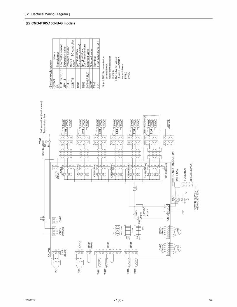
[ V Electrical Wiring Diagram ]
- 105 -HWE1116F GB
(2) CMB-P105,106NU-G models
CN
36
(Gre
en
)
L2L1
ZN
R02
CN
29
(Gre
en
)
CN
28
(Blu
e)
CN
27
(Re
d)
ZN
R01
CN
05
CN
07
S(S
HIE
LD
)
M1
M2T
B02
X21
1 3
SV
M1
321
2 31
TR
CN
26
3C
NT
R1
CN
12
15
36
54
32
1
CO
NT.
B 1 2
CN
02
3
CN
P1 1 2 3
CN
P3
21 1 2 3 4 5 6 7 8 4321
12
32
1
CN
03
CN
13
CN
10
CN
11
TH
11
TH
12
TH
15
TH
16
PS
1
PS
3
65
43
21
TB
01
LEV
3LE
V1
1 2 3 41098
42 3 10
21 43
SV
3A
SV
3B
SV
2B
SV
3C
SV
2C
SV
2A
2 43
75 6432
1 2 3 41 2 3 42 3 4
98765
SV
1C
SV
1A
SV
1B
753175317531X
2
X1
X30
X4
X3
X31
X6
X5
X32
11
11
2 3 4131211
161514131211
SV
5A
SV
5C
SV
4B
SV
5B
SV
4C
SV
4A
15 1614 1 2
1 42 3
434321
4321
SV
6C
SV
6A
SV
6B
1 2 3 41 2 3 4
1 2 3 41
53175317531X
8
X7
X33
X10
X9
X34
X12
X11
X35
CN
30
(Bla
ck)
CN
31
(Ye
llow
)
So
len
oid
va
lve
SV
M1
CO
NT.
B
Pre
ssu
re s
en
sor
TR
TH
11,1
2,1
5,1
6
LE
V1
,3P
S1
,3
Sym
bo
lN
am
eT
ran
sfo
rme
rT
he
rmis
tor
sen
sor
Exp
an
sio
n v
alv
e
SV
1~
6A
,B,C
So
len
oid
va
lve
TB
01
Term
ina
l blo
ck(f
or
po
we
r so
urc
e)
TB
02
Term
ina
l blo
ck(f
or
Tra
nsm
issi
on
)
T1
~6
Term
ina
lF
01
Fu
se A
C2
50
V 6
.3A
F
No
te:1
.TB
02
is t
ran
smis
sio
n
te
rmin
al b
lock
.
Ne
ver
con
ne
ct p
ow
er
li
ne
to
it.
2.T
he
initi
al s
et
valu
es
o
f sw
itch
on
CO
NT.
B
are
as
follo
ws.
S
W1
:0
SW
2:0
TO
NE
XT
IN
DO
OR
UN
IT
PU
LL
BO
X
FU
SE
(15A
)
BR
EA
KE
R(1
5A
)
PO
WE
R S
UP
PLY
~208V
-230V
60H
z
GG
Indoor/
outd
oor
(heat so
urc
e)
Tra
nsm
issi
on li
ne
2 23 1 3 1T
2
T3T1
T6
T4
T5
ON
OF
F
1
SW
5
OF
F
8
SW
4
ON
1
8
(Yello
w)
(Red)
DSA
(Red)
(Yello
w)
(Red)
(Bla
ck)
SW
2S
W1
11
0
CMB-
P106
NU-G
ONL
YF
01
250V
AC
6.3
A F
BC
co
ntr
olle
r
(Sym
bol e
xpla
natio
n)
Circu
itb
oa
rd

[ V Electrical Wiring Diagram ]
- 106 -HWE1116F GB
(3) CMB-P108,1010NU-G models
2.T
he
initi
al s
et
valu
es
o
f sw
itch
on
CO
NT.
B
are
as
follo
ws.
S
W1
:0
SW
2:0
Pre
ssure
senso
r
TR
TH
11,1
2,1
5,1
6
LE
V1,3
PS
1,3
SV
1~
10A
,B,C
Sym
bol
Nam
eT
ransf
orm
er
Therm
isto
r se
nso
rE
xpansi
on v
alv
e
Sole
noid
valv
e
TB
01
Term
inal b
lock
(for
pow
er
sourc
e)
TB
02
Term
inal b
lock
(for
Tra
nsm
issi
on)
CO
NT.
B
T1~
10
Term
inal
Fuse
AC
250V
6.3
A F
F01
Sole
noid
valv
eS
VM
1
CN51
CN
53
65
43
211
23
45
6
65
43
21
(Red
)
ZN
R0
1Z
NR
02
L1TB
01
L2
CN
31
(Ye
llow
)
CN
30
(Bla
ck)
CN
29
(Gre
en
)
CN
28
(Blu
e)
CN
27
(Re
d)
CN
05
CN
07
CN
13
CN
P1
M1
M2T
B02
S(S
HIE
LD
)
X21
31
CN
36(G
reen)
CN
12
33
31
57
13
57
13
57
13
75
X20
X19
X39
X38
X17
X18
X16
X15
X37
X36
X13
X14
CN34(Black)
CN33(Red)
CN32
CN35(Blue)
16
16
13
14
15
910
1112
56
78
4 45
68
79
12
1110
15
14
13
SV10C
SV9C
SV8C
SV7C
SV10A
SV9A
SV8A
SV7A
SV10B
SV9B
SV8B
SV7B
43
21
43
21
43
21
43
21
43
21
43
21
43
21
43
21
X30
X1
X2
1 3 54321
SV
1B
SV
1A
SV
1C
1 2 3 432 41
32 41
X35
X11
X12
X34
X9
X10
X33
X7
X8
X32
X5
X6
X31
X3
X4
7 1 3 5 7 1 3 5 7 1 3 5 7 1 3 5 7 1 3 5 7
1 11 4324324321432
SV
2C
SV
2A
SV
2B
SV
3C
SV
3A
SV
3B
SV
4C
SV
4A
SV
4B
SV
5B
SV
5A
SV
5C
1111 2222 3333 4444
11 12 138 9 105 6 7 14 15 16
8 9 10 11 12 135 6 7 14 15 16 1 2
1 2 33
4321
4321
SV
6C
SV
6A
SV
6B
76
54
32
1
CN
39 3 1
CN
52
CO
NT.
B
65
43
21
65
43
21
LE
V3
LE
V1
1 2 3 1 2 3C
NP
3
21 1 2 3 4 5 6 7 8 4321
12
32
1
CN
03
CN
02
CN
10
CN
11
TH
11
TH
12
TH
15
TH
16
TR
PS
1
PS
3
CN
50
76
54
32
112
34
56
7
13
5
13
CN
38
CN
2631
CN
TR
12
3
12
3
SVM1
RE
L.B
No
te:1
.TB
02
is t
ran
smis
sio
n
te
rmin
al b
lock
.
Ne
ver
con
ne
ct p
ow
er
li
ne
to
it.
GGTO
NE
XT
IN
DO
OR
UN
IT
PU
LL
BO
X
FU
SE
(15A
)B
RE
AK
ER
(15A
)PO
WE
R S
UP
PLY
~208V
-230V
60H
z
Indoor/
outd
oor
(heat so
urc
e)
Tra
nsm
issi
on li
ne
T10
T9T8
T7
T1
T5
T4
T3
T2 T6
1323 1 2
18
ON
OF
F
SW
5
SW
4
ON
OF
F
18
(Sym
bo
l exp
lan
atio
n)
Circu
itboard
BC
contr
olle
rR
EL.B
Rela
y
CM
B-P
1010
NU
-G O
NLY
(Yello
w)
DS
A
(Red)
(Yello
w)
(Red)
(Bla
ck)
F01
250V
AC6.
3A F
CM
B-P
10
10
NU
-G O
NLY
10
1
SW
1S
W2

[ V Electrical Wiring Diagram ]
- 107 -HWE1116F GB
(4) CMB-P1013,1016NU-G models
ZN
R0
1Z
NR
02
L1 L2TB
01
M1
M2T
B02
S(S
HIE
LD)
CN32
CN33(Red)
CN34(Black)
CN35(Blue)
CN
36
(Gre
en
)
CN
31
(Ye
llow
)
CN
30
(Bla
ck)
CN
29
(Gre
en
)
CN
28
(Blu
e)
CN
27
(Re
d)
(Red
)
(Blu
e)
(Yello
w)
CN
07
CN
05
CN
13
LE
V1
LE
V3
X2
1
31
21
CN
VC
C1
3
CN
VC
C2
31
2
CO
NT.
B
CN3913
13
5
CN
12
CN
OU
T3
CN
OU
T1
13
1 2 387654321 4
CN
OU
T2
CN
OU
T4
65
43
21
65
43
21
1 2 3
CN
P1 1 2 3C
NP
3
21 1 2 3 4 5 6 7 8 4321
12
32
1
CN
03
CN
02
CN
10
CN
11
TH
11
TH
12
TH
15
TH
16
TR
CN
38
CN
2631
CNTR
41 2 3 4 5 6 7 8 321
PS
1
PS
3
CN
44(Y
ello
w)
CN
45(G
reen
)
CN
41(G
reen
)
CN
43
(Re
d)
(Ye
llow
)
SV
1B
SV
1A
SV
1C
5 6 7 8 9 10 11 12 13 14 15 1632 4
8 9 10 11 12 1332 4 5 6 7 14 15 16
432
SV
2C
SV
2A
SV
2B
SV
3C
SV
3A
SV
3B
SV
4C
SV
4A
SV
4B
SV
5B
SV
5A
SV
5C
4321 4321 4321 4321
432 4321 4321 4321 4321
SV
6B
SV
6A
SV
6C
1 2 3 4
1 2 3 43
321
21
X3
5
X11
X1
2
X3
4
X9
X1
0
X3
3
X7
X8
X3
2
X5
X6
X3
1
X3
X4
X3
0
X1
X2
531753175317531753175311
11
1
SV7A
SV7B
SV7C
SV8B
SV8A
SV8C
SV9B
SV9A
SV9C
SV10B
SV10A
SV10C
16
16
13
14
15
91
011
12
56
78
4 45
68
79
12
111
01
51
41
3
12
34
12
34
12
34
12
34
12
34
12
34
12
34
12
34
75
31
33
X14
X13
X36
X37
X15
X16
X38
X39
X17
X19
X18
X20
75
31
75
31
75
31
CN
40
SV
M1
2
321
31
RE
L.B
4 5 6 8 97 10 1211 13 1514 16 3 421
SV
11B
SV
11A
SV
11C
1 32
8 9 10 11 12 1332 41 5 6 7 14 15 16
4321
SV
12C
SV
12A
SV
12B
SV
13C
SV
13A
SV
13B
SV
14C
SV
14A
SV
14B
SV
15B
SV
15A
SV
15C
4321 4321 4321 4321
4321 4321 4321 4321 4321
SV
16B
SV
16A
SV
16C
1 2 3 4
1 2 3 43 421
X51
X55
X56
X52
X53
X57
X54
7 7531 7531
X45
X42
X43
X40
X44
X48
X47
X46
X50
X49
CN
42
5 7 7531 7531 5313X
41
1
So
len
oid
va
lve
SV
M1
CO
NT.
B
Term
ina
l blo
ck(f
or
Tra
nsm
issi
on
)T
B0
2
Term
ina
l blo
ck(f
or
po
we
r so
urc
e)
TB
01
So
len
oid
va
lve
Exp
an
sio
n v
alv
eT
he
rmis
tor
sen
sor
Tra
nsf
orm
er
Na
me
Sym
bo
l
SV
1~
16
A,B
,C
TR
TH
11,1
2,1
5,1
6
LE
V1
,3P
S1
,3
Pre
ssu
re s
en
sor
Term
ina
lT
1~
16
F0
1F
use
AC
25
0V
6.3
A F
No
te:1
.TB
02
is t
ran
smis
sio
n
te
rmin
al b
lock
.
Ne
ver
con
ne
ct p
ow
er
li
ne
to
it.
2.T
he
initi
al s
et
valu
es
o
f sw
itch
on
CO
NT.
B
are
as
follo
ws.
S
W1
:0
SW
2:0
IND
OO
R U
NIT
GG
PU
LL
BO
X
FUSE
(15A
)BR
EAKE
R(1
5A)
POW
ER S
UPP
LY~2
08V-
230V
60H
z
TO N
EXT
Indoor/
outd
oor
(heat so
urc
e)
Tra
nsm
issi
on li
ne
2 213 13
T1
T5
T4
T3
T2 T6
T10
T9T8
T7
T11
T15
T14
T13
T12
T16
1
ON
SW
4
8
OF
F
SW
5
OF
F
ON
81
DS
A
(Blu
e)
(Yello
w)
(Red)
(Red)
(Bla
ck)
10
1
SW
1S
W2
F0
12
50
VA
C6
.3A
F
CMB-
P101
6NU-
G ON
LY
Re
lay
RE
L.B
BC
co
ntr
olle
rC
ircu
itb
oa
rd
(Sym
bol e
xpla
natio
n)

[ V Electrical Wiring Diagram ]
- 108 -HWE1116F GB
(5) CMB-P108,1010NU-GA models
No
te:1
.TB
02
is t
ran
smis
sio
n
te
rmin
al b
lock
.
Ne
ver
con
ne
ct p
ow
er
li
ne
to
it.
2.T
he
initi
al s
et
valu
es
o
f sw
itch
on
CO
NT.
B
are
as
follo
ws.
S
W1
:0
SW
2:0
F0
1F
use
AC
25
0V
6.3
A F
T1
~1
0Te
rmin
al
So
len
oid
va
lve
SV
M1
,2
CO
NT.
B
Term
ina
l blo
ck(f
or
Tra
nsm
issi
on
)T
B0
2
Term
ina
l blo
ck(f
or
po
we
r so
urc
e)
TB
01
So
len
oid
va
lve
Exp
an
sio
n v
alv
eT
he
rmis
tor
sen
sor
Tra
nsf
orm
er
Na
me
Sym
bo
l
SV
1~
10
A,B
,C
TR
TH
11,1
2,1
5,1
6
LE
V1
~3
PS
1,3
P
ress
ure
se
nso
r
65
43
21
CN
53
65
43
211
23
45
6
CN
51
(Yello
w)
CN
03
TB
01
L2L1
CN
36(G
reen)
CN
30(B
lack
)
CN
31(Y
ello
w)
CN
29(G
reen)
CN
28(B
lue)
CN
27(R
ed)
(Red
)C
NTR
ZNR
01ZN
R02
M1
M2T
B02
S(S
HIE
LD)
CN
06
CN
05
CN
07
CN
13
CN
P1
LE
V2
12
34
56
1 3
CN
26
CN
383
1
CN
12
53
1
76
54
32
112
34
56
7
CN
50
PS
3
PS
1
TR
TH
16
TH
15
TH
12
TH
11
CN
11
CN
10
CN
021
23
21
1 2 3 4876543211 2
CN
P3
321321
LE
V1
LE
V3
12
34
56
12
34
56
CO
NT.
B
SV
6B
SV
6A
SV
6C
1 2 3 4
1 2 3 43
321
21161514765 1312111098
161514765 1098 131211
4 4 4 43 3 3 32 2 2 21 1 1 1
SV
5C
SV
5A
SV
5B
SV
4B
SV
4A
SV
4C
SV
3B
SV
3A
SV
3C
SV
2B
SV
2A
SV
2C
2 3 4 1 2 3 4 2 3 4 2 3 41 11
753175317531753175317
X4
X3
X31
X6
X5
X32
X8
X7
X33
X10
X9
X34
X12
X11
X35
1 42 3
1 42 34321
SV
1C
SV
1A
SV
1B
1 2 3 4531
X2
X1
X30
X60
X21
CN
46(Y
ello
w)
3131
3 1
CN33(Red)
CN34(Black)
CN35(Blue)
CN
39
RE
L.B
CN
52
12
34
56
7
12
34
12
34
12
34
12
34
12
34
12
34
12
34
12
34
SV7B
SV8B
SV9B
SV10B
SV7A
SV8A
SV9A
SV10A
SV7C
SV8C
SV9C
SV10C
13
14
15
10
1112
97
86
544
87
65
12
1110
915
14
13
16
16
CN32
X14
X13
X36
X37
X15
X16
X18
X17
X38
X39
X19
X20
57
17
51
75
31
75
13
33
12
34 4
12
3
12
3
12
3
SVM1
SVM2
60Hz
~208
V-23
0VPO
WER
SUP
PLY
BR
EA
KE
R(1
5A)
PU
LL
BO
X
FUS
E(1
5A)
TO
NE
XT
IN
DO
OR
UN
IT
GG
Indoor/
outd
oor
(heat so
urc
e)
Tra
nsm
issi
on li
ne
213 2 3 1
T6
T2
T3
T4
T5T1
T7T8
T9T1
0
81
OF
F
ON
SW
4
SW
5
OF
F
ON
81
Re
lay
RE
L.B
BC
co
ntr
olle
rC
ircu
itb
oa
rd
(Sym
bol e
xpla
natio
n)
CM
B-P
1010N
U-G
A O
NLY
DS
A
(Blu
e)
(Red)
(Yello
w)
(Red)
(Bla
ck)
SW
2S
W1
110
F01
250V
AC
6.3
A F
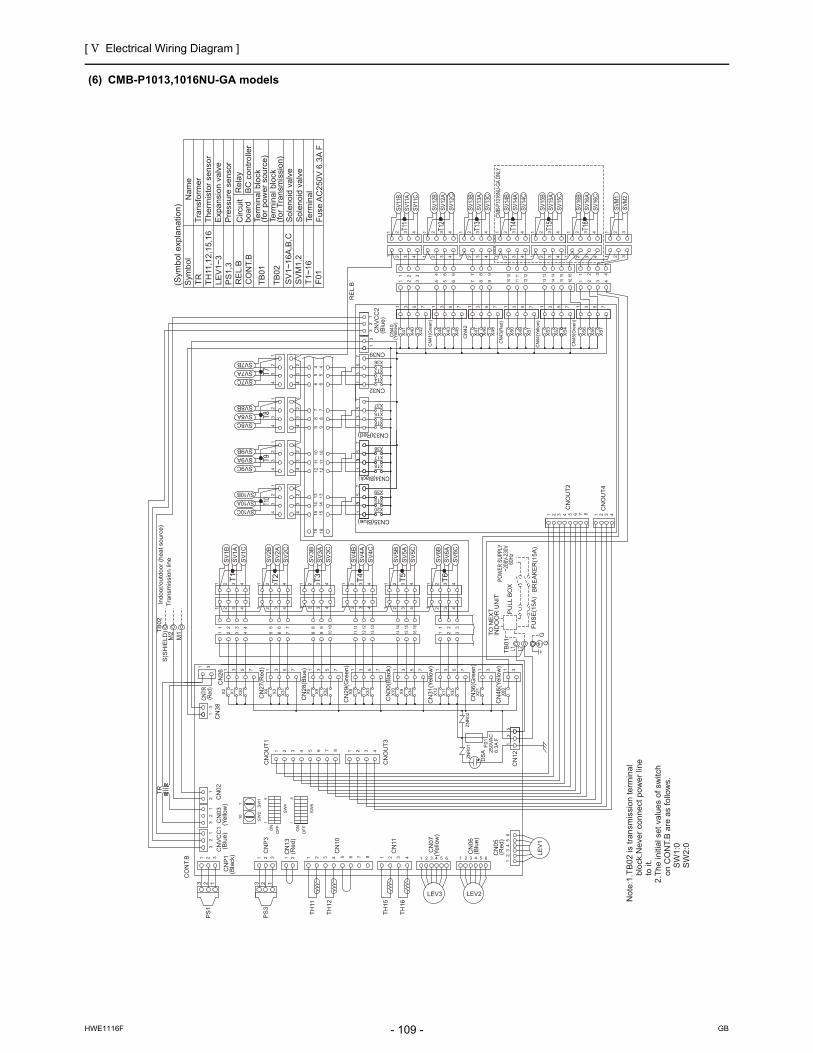
[ V Electrical Wiring Diagram ]
- 109 -HWE1116F GB
(6) CMB-P1013,1016NU-GA models
CN
TR(R
ed)
CN
41(G
reen
)
CN
40
(Yello
w)
CN34(Black)
CN33(Red)
CN35(Blue)
ZN
R01
ZN
R02
CN
06
54321
LEV2
CN
07
CN
13
CN
P1
(Blu
e)
CN
VC
C1
(Ye
llow
)C
N0
3
M1
M2T
B0
2S
(SH
IEL
D)
654321
LEV3
21
3
CN
VC
C2
31
2
CO
NT.
B
CN39
13
CN
OU
T3
CN
OU
T1
13
1 2 3 1 2 3C
NP
3
21 1 2 3 4 5 6 7 8 4321
12
32
1
CN
02
CN
10
CN
11
TH
11
TH
12
TH
15
TH
16
TR
CN
38
CN
26
31
41 2 3 4 5 6 7 8 321
PS
1
PS
3
X45
X42
X43
X40
X44
X47
X46
CN
42
X41
SV
1B
SV
1A
SV
1C
5 6 7 8 9 10 11 12 13 14 15 1632 4
8 9 10 11 12 1332 4 5 6 7 14 15 16
432
SV
2C
SV
2A
SV
2B
SV
3C
SV
3A
SV
3B
SV
4C
SV
4A
SV
4B
SV
5B
SV
5A
SV
5C
4321 4321 4321 4321
432 4321 4321 4321 4321
SV
6B
SV
6A
SV
6C
1 2 3 4
1 2 3 43
321
21
CN
31
(Ye
llow
)
CN
30
(Bla
ck)
CN
29
(Gre
en
)
CN
28
(Blu
e)
CN
27
(Re
d)
X3
5
X11
X1
2
X3
4
X9
X1
0
X3
3
X7
X8
X3
2
X5
X6
X3
1
X3
X4
X3
0
X1
X2
7531753175317531753175311
11
1
SV7A
SV7B
SV7C
SV8B
SV8A
SV8C
SV9B
SV9A
SV9C
SV10B
SV10A
SV10C
16
16
13
14
15
91
011
12
56
78
4 45
68
79
12
111
01
51
41
3
12
34
12
34
12
34
12
34
12
34
12
34
12
34
12
34
CN32
75
31
33
X14
X13
X36
X37
X15
X16
X38
X39
X17
X19
X18
X20
75
31
75
31
75
31
1C
N3
6(G
ree
n)
X2
1
CN
45(G
reen
)
CN
44(Y
ello
w)
CN
43(R
ed)
RE
L.B
4 5 6 8 97 10 1211 13 1514 16 3 421
SV
11B
SV
11A
SV
11C
1 32
8 9 10 11 12 1332 41 5 6 7 14 15 16
4321
SV
12C
SV
12A
SV
12B
SV
13C
SV
13A
SV
13B
SV
14C
SV
14A
SV
14B
SV
15B
SV
15A
SV
15C
4321 4321 4321 4321
4321 4321 4321 4321 4321
SV
16B
SV
16A
SV
16C
1 2 3 4
1 3 43 421
X51
X55
X56
X52
X53
X57
X54
7 7531 7531
X48
X50
X49
5 7 7531 7531 53131
SV
M2
SV
M1
322 3
11
2
CN
05
65
43
21
LE
V1
L2L1TB
01
13
5
CN
12
1 2 387654321 4
CN
OU
T2
CN
OU
T4
3 31C
N4
6(Y
ello
w)
X6
0
CO
NT.
B
Term
ina
l blo
ck(f
or
Tra
nsm
issi
on
)T
B0
2
Term
ina
l blo
ck(f
or
po
we
r so
urc
e)
TB
01
So
len
oid
va
lve
Exp
an
sio
n v
alv
eT
he
rmis
tor
sen
sor
Tra
nsf
orm
er
Na
me
Sym
bo
l
SV
1~
16
A,B
,C
TR
TH
11,1
2,1
5,1
6
LE
V1
~3
PS
1,3
P
ress
ure
se
nso
r
SV
M1
,2T
1~
16
Term
ina
lS
ole
no
id v
alv
e
F0
1F
use
AC
25
0V
6.3
A F
No
te:1
.TB
02
is t
ran
smis
sio
n t
erm
ina
l
blo
ck.N
eve
r co
nn
ect
po
we
r lin
e
to
it.
2.T
he
initi
al s
et
valu
es
of
switc
h
on
CO
NT.
B a
re a
s fo
llow
s.
SW
1:0
S
W2
:0
6
In
do
or/
ou
tdo
or
(he
at
sou
rce
)T
ran
smis
sio
n li
ne
2 213 13
T1
T5
T4
T3
T2 T6
T10
T9T8
T7
T11
T15
T14
T13
T12
T16
PU
LL
BO
X
FU
SE
(15
A)
BR
EA
KE
R(1
5A
)
IND
OO
R U
NIT
TO
NE
XT
POW
ER S
UPPL
Y~2
08V-
230V
60Hz
GG
1
ON
SW
4
8
OF
F
SW
5
OF
F
ON
81
(Blu
e)
DS
A(B
lue
)
(Ye
llow
)
(Re
d)
(Bla
ck)
10
1
SW
1S
W2
CMB-
P101
6NU-
GA O
NLY
(Re
d)
F0
12
50
VA
C6
.3A
F
Re
lay
RE
L.B
BC
co
ntr
olle
rC
ircu
itb
oa
rd
(Sym
bo
l exp
lan
atio
n)

[ V Electrical Wiring Diagram ]
- 110 -HWE1116F GB
(7) CMB-P104NU-GB model
ZN
R02
ZN
R01
CN
29(G
reen)
CN
28(B
lue)
CN
27(R
ed)
CN
TR
(Red)
CN
07
L1 L2TB
01
CN
13
CN
03
M1
M2
S(S
HIE
LD
)TB
02
X33
X7
X8
1 3 5 7
1
4321
14 1615
SV
4A
SV
4C
SV
4B
11 12 13 14 15 16
11 12 13432
11
11
X32
X5
X6
X31
X3
X4
X30
X1
X2
1 3 5 7 1 3 5 7 1 3 5 7
SV
1B
SV
1A
SV
1C
5 6 7 8 9
432 4321 4321
2 3 4 65 7
3 42
SV
2A
SV
2C
SV
3C
SV
2B
SV
3B
SV
3A
3 41 2
1032 4
8 9 104321
LE
V3
12
34
56
TH
15
TH
12
CN
11
CN
10
12
32
1
1 2 3 4876543211 2
CN
02
CO
NT.
B
35
1
CN
12
1 3
CN
26
TR
Fuse
AC
250V
6.3
A F
F01
Term
inal
T1~
4
Term
inal b
lock
(for
Tra
nsm
issi
on)
TB
02
Term
inal b
lock
(for
pow
er
sourc
e)
TB
01
Sole
noid
valv
eS
V1~
4A
,B,C
Exp
ansi
on v
alv
eT
herm
isto
r se
nso
rT
ransf
orm
er
Nam
eS
ymbol
TR
TH
12,1
5
LE
V3
CO
NT.
B
No
te:1
.TB
02
is t
ran
smis
sio
n
te
rmin
al b
lock
.
Ne
ver
con
ne
ct p
ow
er
li
ne
to
it.
2.T
he
initi
al s
et
valu
es
o
f sw
itch
on
CO
NT.
B
are
as
follo
ws.
S
W1
:0
SW
2:0
GG
FU
SE
(15A
)
BR
EA
KE
R(1
5A
)
PO
WE
R S
UP
PLY
~208V
-230V
60H
z
TO
NE
XT
IN
DO
OR
UN
IT
PU
LL
BO
X
Indoor/
outd
oor
(heat so
urc
e)
Tra
nsm
issi
on L
ine
T4T1
T3T2
8
1
ON
SW
4
8
OF
F
SW
5
1
OF
F
ON
DS
A
(Yello
w)
(Red)
(Yello
w)
F01
250V
AC6.
3A F
10
1
SW
1S
W2
Circu
itboard
(Sym
bo
l exp
lan
atio
n)
BC
contr
olle
r

[ V Electrical Wiring Diagram ]
- 111 -HWE1116F GB
(8) CMB-P108NU-GB model
CN
31
(Ye
llow
)
CN33(Red)
CN34(Black)
CN35(Blue)
CN
30
(Bla
ck)
CN
29
(Gre
en
)
CN
28
(Blu
e)
CN
27
(Re
d)
TB
01
L1
L2
ZN
R02
ZN
R01
CN
07
CN
13
(Red
)
M1
M2
S(SH
IELD
)TB
02
CN
12
31
57
13
57
13
57
13
75
X20
X19
X39
X38
X17
X18
X16
X15
X37
X36
X13
X14
CN32
16
16
13
14
15
910
1112
56
78
4 45
68
79
12
1110
15
14
13
SV8C
SV7C
SV8A
SV7A
SV8B
SV7B
43
21
43
21
43
21
43
21
X30
X1
X2
1 3 54321
SV
1B
SV
1A
SV
1C
1 2 3 432 41
32 41
X35
X11
X12
X34
X9
X10
X33
X7
X8
X32
X5
X6
X31
X3
X4
7 1 3 5 7 1 3 5 7 1 3 5 7 1 3 5 7 1 3 5 7
1 11 4324324321432
SV
2C
SV
2A
SV
2B
SV
3C
SV
3A
SV
3B
SV
4C
SV
4A
SV
4B
SV
5B
SV
5A
SV
5C
1111 2222 3333 4444
11 12 138 9 105 6 7 14 15 16
8 9 10 11 12 135 6 7 14 15 16 1 2
1 2 33
4321
4321
SV
6C
SV
6A
SV
6B
76
54
32
1C
N393 1
CN
52
CO
NT.
B
65
43
21
LE
V3
21 1 2 3 4 5 6 7 8 4321
12
32
1
CN
03
CN
02
CN
10
CN
11
TH
12
TH
15
TR
CN
50
76
54
32
1
13
5
13
CN
38
CN
2631
CN
TR
RE
L.B
F0
1F
use
AC
25
0V
6.3
A F
Term
ina
lT
1~
8
CO
NT.
B
Term
ina
l blo
ck(f
or
Tra
nsm
issi
on
)T
B0
2
Term
ina
l blo
ck(f
or
po
we
r so
urc
e)
TB
01
So
len
oid
va
lve
Exp
an
sio
n v
alv
eT
he
rmis
tor
sen
sor
Tra
nsf
orm
er
Na
me
Sym
bo
l
SV
1~
8A
,B,C
TR
TH
12
,15
L
EV
3
No
te:1
.TB
02
is t
ran
smis
sio
n
te
rmin
al b
lock
.
Ne
ver
con
ne
ct p
ow
er
li
ne
to
it.
2.T
he
initi
al s
et
valu
es
o
f sw
itch
on
CO
NT.
B
are
as
follo
ws.
S
W1
:0
SW
2:0
G 60H
z~
208V
-230V
PO
WE
R S
UP
PLY
BR
EA
KE
R(1
5A
)F
US
E(1
5A
)
PU
LL
BO
X
TO
NE
XT
IN
DO
OR
UN
IT
G
Indoor/
outd
oor
(heat so
urc
e)
Tra
nsm
issi
on li
ne
T8T7
T1
T5
T4
T3
T2
T6
18
ON
OF
F
SW
5
SW
4
ON
OF
F
18
F01
250V
AC6.
3A F
DS
A
(Yello
w)
(Red)
Re
lay
RE
L.B
BC
co
ntr
olle
rC
ircu
itb
oa
rd
(Sym
bol e
xpla
natio
n)
10
1
SW
1S
W2

[ V Electrical Wiring Diagram ]
- 112 -HWE1116F GB
(9) CMB-P1016NU-HA model
L1 L2
GG
(Blue
)CN
VCC1
(Yell
ow)
CN03
CN02
22
32
31
11
321
(Blac
k)CN
P1
123
TR
CN38
13
CNTR
(Red
)31
CN26
X02
X01 X30
7531
CN27
(Red
)1 3 5 7
X31
X03
X04
CN28
(Blue
)
X06
X05 X32
1 3 5 7
CN29
(Gre
en)
X08
X07 X33
531 7
CN30
(Blac
k)
X10
1 3 5 7X
34
X09
CN31
(Yell
ow)
X12
1 3X
11
X35
5 7
CN36
(Gre
en)
X21
1 3
CN46
(Yell
ow)
X60
1 3
CN47
X62
X61
1 3 655
31
CN12
ZNR0
2ZN
R01 F0
125
0VAC
6.3A
F
CNOU
T3
2 3 4187654321
CNOU
T1
110 SW
2S
W1
18
OFFO
N
81
SW
4
OFFO
N
SW
5
81
SW
6O
FFON
87654CN
10
32
CN13
(Red
)2
CNP3
32 1113 2 1
PS
3
PS
1
TH11
TH12
CN11
4321TH
15
TH16
4 5 6321
(Yell
ow)
CN07
CN05
(Red
)4 5 63214 5 6321
(Blue
)CN
06
Indo
or/o
utdo
orTr
ansm
issio
n lin
e TB
02S(
SHIE
LD) 16151476542 3 1312111098
42 3 1615141312111098765
11
1 2
1 2 33
~208
V-23
0VPO
WER
SUP
PLY
60H
z
BREA
KER(
16A)
FUSE
(16A
)
PULL
BOX
INDO
OR U
NIT
TO N
EXT
1 2 3 44321 1 2 3 4
4321 1 2 3 44321
1 2 3 44321 4321
1 2 3 4
1 2 3 44321
CNOU
T4
CNOU
T2
41 2 3 4 5 6 7 8 321
43
21 1
23
4
43
21 1
23
4
43
21 1
23
41
23
443
21
1314
1510
1112
97
86
87
612
1110
915
1413
16165
445
CN35(Blue)
X20
X19
X39
75
31
CN34(Black)
X18
X17
X38
75
31
CN33(Red)
X16
X15
X37
75
31
CN39
CN32
13
57
X36
X13
X14
CNVC
C23
21
3 (Blue
)
1
(Yell
ow)
CN40 X
41
X40
X42
1 3 5 7CN
41(G
reen
)
X44
X43
X45
CN42 X47
X46
X48
CN43
(Red
)
X50
X49
X51
CN44
(Yell
ow)
X53
X52
3 5175317531 3 5 76542 3
2 3 654
7 12111098
11 12107 98
11
2 3 41 2
X54
CN45
(Gre
en)
X56
X55
X57
75317151413
1 2 431614 1513 5 6 87
16
543211 2 3 4 5
85 6 71 2 434321
1 2 3 443211 2 3 42 31
21 3 441 2 3 4
43 11 2 3 4
432
2 3 4Fuse
AC
250V
6.3
A F
F01
SV
M1,
2,1b
,2b
Sol
enoi
d va
lve
Sol
enoi
d va
lve
SV
1~16
A,B
,C
TB02
Term
inal
blo
ck(fo
r Tra
nsm
issi
on)
Term
inal
blo
ck(fo
r pow
er s
ourc
e)TB
01
CO
NT.
BR
EL.
B
TR
TH
11,1
2,15
,16
LE
V1~
3P
S1,
3
Sym
bol
Nam
e(S
ymbo
l exp
lana
tion)
Tran
sfor
mer
Ther
mis
ter s
enso
rE
xpan
sion
val
veP
ress
ure
sens
orC
ircui
tbo
ard
Rel
ayBC
con
trolle
r
66
CO
NT.
B
RE
L.B
M2
M1
SV
1B
SV
1A
SV
1C
SV
2C
SV
2A
SV
2B
SV
3C
SV
3A
SV
3B
SV
4C
SV
4A
SV
4B
SV
5C
SV
5A
SV
5B
SV
6C
SV
6A
SV
6B
SV10C
SV10A
SV10B
SV9C
SV9A
SV9B
SV8C
SV8A
SV8B
SV7C
SV7A
SV7B
SV
11C
SV
11A
SV
11B
SV
12C
SV
12A
SV
12B
SV
13C
SV
13A
SV
13B
SV
14C
SV
14A
SV
14B
SV
15C
SV
15A
SV
15B
SV
16C
SV
16A
SV
16B
SV
M2b
SV
M2
SV
M1
SV
M1b
TB01
T1 T2 T3 T4 T5 T6
T7T8
T9T1
0
T11
T12
T13
T14
T15
T16
T1~1
6Te
rmin
al
MLE
V1
LEV
2
M
LEV
3
M
LD
1:C
PU
in
ope
ratio
n
UU
DSA
1
1 3 5 7
3

[ V Electrical Wiring Diagram ]
- 113 -HWE1116F GB
(10) CMB-P1016NU-HB model
L2L1
GG
Note
:1.T
B02 is
tra
nsm
issi
on term
inal
blo
ck.N
eve
r co
nnect
pow
er
line
to it
.
2.T
he in
itial s
et va
lues
of sw
ithon C
ON
T.B
are
as
follo
ws.
SW
1:0
SW
2:0
TB
01
SV
16B
SV
16A
SV
16C
SV
15B
SV
15A
SV
15C
SV
14B
SV
14A
SV
14C
SV
13B
SV
13A
SV
13C
SV
12B
SV
12A
SV
12C
SV
11B
SV
11A
SV
11C
SV7B
SV7A
SV7C
SV8B
SV8A
SV8C
SV9B
SV9A
SV9C
SV10B
SV10A
SV10C
SV
6B
SV
6A
SV
6C
SV
5B
SV
5A
SV
5C
SV
4B
SV
4A
SV
4C
SV
3B
SV
3A
SV
3C
SV
2B
SV
2A
SV
2C
SV
1C
SV
1A
SV
1B
M1
M2
RE
L.B
CO
NT.
B
4321
2 3 44321
13 44321 4
431 2
1 32 43211 2 3 4 4321
1 2 3 43 42116
13 1514 16 3 421
13 14 157 1 3 5 7
X5
7
X5
5
X5
6
CN
45(G
reen
)
X5
4
214321
11
8 97 10 1211
8 9 10 11 127
4 5 632
32 4 5 67531 3 5 7 1 3 5 7 1 53
X5
2
X5
3
CN
44(Y
ello
w)
X5
1
X4
9
X5
0
CN
43(R
ed)
X4
8
X4
6
X4
7
CN
42X4
5
X4
3
X4
4
CN
41(G
reen
)
7531
X4
2
X4
0
X4
1
CN
40
(Yello
w)
1
(Blu
e)
31
23
CN
VC
C2
X14
X13
X36
75
31
CN32
CN39
13
57
X37
X15
X16
CN33(Red)
13
57
X38
X17
X18
CN34(Black)
13
57
X39
X19
X20
CN35(Blue)
54 4
516
16
13
14
15
910
1112
67
86
87
912
1110
15
14
13
12
34 4
32
14
32
112
34
43
211
23
4
43
211
23
4 1 2 387654321 4
CN
OU
T2
CN
OU
T4
1 2 3 44321
43211 2 3 41 2 3 4
4321
1 2 3 443211 2 3 4
43211 2 3 44321
TO
NE
XT
IND
OO
R U
NIT
PU
LL
BO
X
FU
SE
(15
A)
BR
EA
KE
R(1
5A
)
PO
WE
R S
UP
PLY
~2
08
V-2
30
V
3321
21
11
5 6 7 8 9 10 11 12 13 14 15 1632 4
8 9 10 11 12 1332 4 5 6 7 14 15 16
S(S
HIE
LD)T
B0
2 I
nd
oo
r/o
utd
oo
rT
ran
smis
sio
n li
ne
CN
07
(Ye
llow
)
1 2 3 654
TH
15
1 2 3 4
CN
11
TH
12
1 12(R
ed
)C
N1
3
2 3
CN
10
4 5 6 7 8
SW
6
18
SW
5
SW
4
18
ON
OF
F
ON
OF
F
ON
OF
F
81
SW
1S
W2
10
1
CN
OU
T1
1 2 3 4 5 6 7 8 1 432
CN
OU
T3 F0
12
50
VA
C6
.3A
F
ZN
R01
ZN
R02
CN
12
13
5
75
X35
X11
31
X12
CN
31(Y
ello
w)
X09
X34
7531
X10
CN
30(B
lack
)
71 3 5
X33
X07
X08
CN
29(G
reen
)
7531
X32
X05
X06
CN
28(B
lue)
X04
X03
X31
7531C
N27
(Red
)
1 3 5 7X
30
X01
X02C
N2
6
1 3
CN
TR
(Re
d)
31
CN
38
TR
11
13
23
22 CN
02
CN
03
(Ye
llow
)C
NV
CC
1(B
lue
)
Term
ina
lT
1~
T16
Sole
noid
valv
eS
V1~
16A
,B,C
TB
02
Term
ina
l blo
ck(f
or T
rans
mis
sion
)
Term
ina
l blo
ck(f
or p
ower
sou
rce)
TB
01
CO
NT.
BR
EL
.B
TR
TH
12,1
5L
EV
3
Sym
bo
lN
am
eT
ran
sfo
rme
rT
herm
iste
r se
nsor
Exp
ansi
on v
alv
eC
ircu
itboard
Rela
yB
C c
ontro
ller
(Sym
bo
l exp
lan
atio
n)
T1 T2 T3 T4 T5 T6
T11
T12
T13
T14
T15
T16
T10
T9
T8
T7
Fuse
AC
250V
6.3
A F
F01
t° t°
DS
A
UU
LD
1:C
PU
in o
pera
tion
ML
EV
3
33
7531
1

[ V Electrical Wiring Diagram ]
- 114 -HWE1116F GB
[3] Electrical Wiring Diagram of Transmission Booster
AC208V/230V
L Red Red Red
White
Green
250V 2A
Grounding
RedRed
Red
U
U
White
White White
White
White
White BlueRedRed
DSA
White
White
Blue
Red
Red
Red
Red
Varistor
Varistor
Noise filter
Stabilized power supply
4
3
2
1
1
2
3
CN2CN1
Black
Black
Black
Black
Green/Yellow
1
2
3
E
4
Choke coil
1 2
CN3
1 2 1 2
CN4
CN2
12
CN1Electronic control board
Black
White
Red
Red
Black
S
B
A
S
B
A
Terminal block 2 for transmission line (TB3)Expanded (indoor unit) side
Terminal block 1 for transmission line (TB2)Expanded (outdoor unit) side
Terminal block for power supply(TB1)

- 115 -HWE1116F GB
VI Refrigerant Circuit
[1] Refrigerant Circuit Diagram ...........................................................................................117
[2] Principal Parts and Functions ........................................................................................125

- 116 -HWE1116F GB

[ VI Refrigerant Circuit ]
- 117 -HWE1116F GB
VI Refrigerant Circuit
[1] Refrigerant Circuit Diagram
1. Outdoor unit(1) PURY-P72, P96 models
O/S
TH4
CJ2
BV2
COMP
21S4a
ST1
63LS
BV1
CV8a
CV6a
TH7
TH3
SV4a SV4b
SV4d
Solenoid valve block
ACC
ST6ST7
ST17
TH5
TH6
CV9a
SV9
CV4a
CV2a
CV7a
CV3a CV5a
CJ1
SV5b
HEX
63HS163H1
ST3
CP1
SV1a
LEV5a
*1
*1
CP3CP2

[ VI Refrigerant Circuit ]
- 118 -HWE1116F GB
(2) PURY-P120, P144 models
O/S
TH4
BV2
COMP
21S4a
21S4b
ST1BV1
CV8a
CV5a
CV4a
CV3aCV2a
CV6a
CV7a
TH3
SV4a SV4b
SV4cCV7b
CV5bCV4b
CV6b
Solenoid valve block
ACC
ST6ST7
CJ2
63LS
TH5
ST1763HS1
63H1
SV9 CP2
SV4d
CV2b
TH7
TH6
HEX
HEX
ST3
CP1
SV1a
LEV5a
LEV5b
*1
*1
CP3
SV5b
CJ1

[ VI Refrigerant Circuit ]
- 119 -HWE1116F GB
(3) PURY-P144, P168, P192 models
Low-pressure side distributor
High-pressure side junction pipe
O/S
TH4
CJ2
BV2
COMP
21S4a
ST1
63LS
BV1
CV8a
CV6a
TH7
TH3
SV4a SV4b
SV4d
Solenoid valve block
ACC
ST6ST7
ST17
TH5
TH6
CV9a
SV9
CV4a
CV2a
CV7a
CV3a CV5a
CJ1
SV5b
HEX
63HS163H1
ST3
CP1
SV1a
LEV5a
*1
*1
CP3CP2
O/S
TH4
CJ2
BV2
COMP
21S4a
ST1
63LS
BV1
CV8a
CV6a
TH7
TH3
SV4a SV4b
SV4d
Solenoid valve block
ACC
ST6ST7
ST17
TH5
TH6
CV9a
SV9
CV4a
CV2a
CV7a
CV3a CV5a
CJ1
SV5b
HEX
63HS163H1
ST3
CP1
SV1a
LEV5a
*1
*1
CP3CP2

[ VI Refrigerant Circuit ]
- 120 -HWE1116F GB
(4) PURY-P216 model
O/S
TH4
CJ2
BV2
COMP
21S4a
ST1
63LS
BV1
CV8a
CV6a
TH7
TH3
SV4a SV4b
SV4d
Solenoid valve block
ACC
ST6ST7
ST17
TH5
TH6
CV9a
SV9
CV4a
CV2a
CV7a
CV3a CV5a
CJ1
SV5b
HEX
63HS163H1
ST3
CP1
SV1a
LEV5a
*1
*1
CP3CP2
O/S
TH4
BV2
COMP
21S4a
21S4b
ST1 BV1
CV8a
CV5a
CV4a
CV3aCV2a
CV6a
CV7a
TH3
SV4a SV4b
SV4cCV7b
CV5bCV4bCV6b
Solenoid valve block
ACC
ST6ST7
CJ2
63LS
TH5
ST1763HS1
63H1
SV9 CP2
SV4d
CV2b
TH7
TH6
HEX
HEX
ST3
CP1
SV1a
LEV5a
LEV5b
*1
*1
CP3
SV5b
CJ1
Low-pressure side distributor
High-pressure side junction pipe

[ VI Refrigerant Circuit ]
- 121 -HWE1116F GB
(5) PURY-P240, P264, P288 models
O/S
TH4
BV2
COMP
21S4a
21S4b
ST1BV1
CV8a
CV5a
CV4a
CV3aCV2a
CV6a
CV7a
TH3
SV4a SV4b
SV4cCV7b
CV5bCV4bCV6b
Solenoid valve block
ACC
ST6ST7
CJ2
63LS
TH5
ST1763HS1
63H1
SV9 CP2
SV4d
CV2b
TH7
TH6
HEX
HEX
ST3
CP1
SV1a
LEV5a
LEV5b
*1
*1
CP3
SV5b
CJ1
O/S
TH4
BV2
COMP
21S4a
21S4b
ST1BV1
CV8a
CV5a
CV4a
CV3aCV2a
CV6a
CV7a
TH3
SV4a SV4b
SV4cCV7b
CV5bCV4bCV6b
Solenoid valve block
ACC
ST6ST7
CJ2
63LS
TH5
ST1763HS1
63H1
SV9 CP2
SV4d
CV2b
TH7
TH6
HEX
HEX
ST3
CP1
SV1a
LEV5a
LEV5b
*1
*1
CP3
SV5b
CJ1
Low-pressure side distributor
High-pressure side junction pipe

[ VI Refrigerant Circuit ]
- 122 -HWE1116F GB
2. BC controller(1) CMB-P104 - P1016NU-G
TH15
TH12
LEV3
LEV1 TH16
PS3PS1
TH11
SVM1
Gas/Liquid separator
Check valve block
Solenoid valve block

[ VI Refrigerant Circuit ]
- 123 -HWE1116F GB
(2) CMB-P108, P1010, P1013, P1016NU-GA (main)
(3) CMB-P104, P108NU-GB (sub)
TH15
TH12
LEV3SVM2
LEV1
LEV2
TH16
PS3PS1
TH11
SVM1
Gas/Liquid separator
Check valve block
Solenoid valve block
TH15
TH12
HIC-C
CP
LEV3
Check valve block
Solenoid valve block

[ VI Refrigerant Circuit ]
- 124 -HWE1116F GB
(4) CMB-P1016V-HA (main)
(5) CMB-P1016NU-HB (sub)
TH15
TH12
Gas/Liquid separator LEV3
LEV1 TH16
PS1 PS3
TH11
SVA,SVB,SVC
SVM1
SVM2
HIC-A
HIC-B
LEV2
SVM1b
SVM2b
TH15
TH12
HIC-C
CP
LEV3
Check valve block
Solenoid valve block

[ VI Refrigerant Circuit ]
- 125 -HWE1116F GB
[2] Principal Parts and Functions
1. Outdoor unit
Part name
Symbols (functions) Notes Usage Specifications Check method
Com-pressor
MC1(Comp1)
Adjusts the amount of circulating refrigerant by adjusting the operat-ing frequency based on the oper-ating pressure data
P72 modelLow-pressure shell scroll compressorWirewound resistance20°C[68°F] : 0.20ohm (TKMU)0.72ohm (YKMU)P96, P120, P144 modelsLow-pressure shell scroll compressorWirewound resistance20°C[68°F] : 0.092ohm (TKMU)0.323ohm (YKMU)
High pressure sensor
63HS1 1) Detects high pressure2) Regulates frequency and pro-
vides high-pressure protec-tion
Low pressure sensor
63LS 1) Detects low pressure2) Provides low-pressure pro-
tection
Pres-sure switch
63H1 1) Detects high pressure2) Provides high-pressure pro-
tection
4.15MPa[601psi] OFF set-ting
Power supply trans-former
Trans former YKMU only
Decreases the power supply volt-age (460V) supplied to the circuit board
Primary rated voltage:460V, 50/60HzSecondary rated voltage:229V(No-load voltage)
Thermis-tor
TH4(Discharge)
1) Detects discharge air temper-ature
2) Provides high-pressure pro-tection
Degrees Celsius Resistance check
0°C[32°F] :698kohm 10°C[50°F] :413kohm 20°C[68°F] :250kohm 30°C[86°F] :160kohm 40°C[104°F] :104kohm 50°C[122°F] : 70kohm 60°C[140°F] : 48kohm 70°C[158°F] : 34kohm 80°C[176°F] : 24kohm 90°C[194°F] :17.5kohm100°C[212°F] :13.0kohm110°C[230°F] : 9.8kohm
Pressure0~4.15 MPa [601psi]Vout 0.5~3.5V0.071V/0.098 MPa [14psi]Pressure [MPa]=1.38 x Vout [V]-0.69Pressure [psi]=(1.38 x Vout [V] - 0.69) x 145
GND (Black)Vout (White)Vcc (DC5V) (Red)
Con-nector
63HS1
1
1 2 3
23
Pressure0~1.7 MPa [247psi]Vout 0.5~3.5V0.173V/0.098 MPa [14psi]Pressure [MPa]=0.566 x Vout [V] - 0.283Pressure [psi]=(0.566 x Vout [V] - 0.283) x 145
GND (Black)Vout (White)Vcc (DC5V) (Red)
Con-nector
63LS
1
1 2 3
23
R = 7.465k120
R = 4057R =7.465
25/120
t
4057 273 t1
3931exp

[ VI Refrigerant Circuit ]
- 126 -HWE1116F GB
Thermis-tor
TH3(Pipe temperature)
Controls defrosting during heating operation
Degrees Celsius
0°C[32°F] :15kohm10°C[50°F] :9.7kohm20°C[68°F] :6.4kohm25°C[77°F] :5.3kohm30°C[86°F] :4.3kohm40°C[104°F] :3.1kohm
Resistance check
TH7(Outdoor tem-perature)
1) Detects outdoor air tempera-ture
2) Controls fan operation
TH5 Fan operated on the 63LS and TH5 values.
TH6 Controls defrosting during heating operation
THHSInverter heat sink tem-perature
Controls inverter cooling fan based on THHS temperature
Degrees Celsius
0°C[32°F] :161kohm10°C[50°F] :97kohm20°C[68°F] :60kohm25°C[77°F] :48kohm30°C[86°F] :39kohm40°C[104°F] :25kohm
THBOXControl box internal tem-perature de-tection
Solenoid valve
SV1aDischarge-suction bypass
1) High/low pressure bypass at start-up and stopping, and capacity control during low-load operation
2) High-pressure-rise preven-tion
AC208 - 230VOpen while being powered/closed while not being pow-ered
Continuity check with a tester
SV4a - SV4dHeat exchanger capacity con-trol
Controls outdoor unit heat ex-changer capacity
SV5b Heat exchanger capacity con-trol
Prevents high-pressure-riseControls defrost cycle
AC208 - 230VClosed while being powered/open while not being pow-ered
SV9 High-pressure-rise prevention AC208 - 230VOpen while being powered/closed while not being pow-ered
LEV LEV5a,b LEV5b is only on the P120 and P144 models.
Evaporating temperature control DC12VOpening of stepping motor driving valve 0-3000 pulses
Refer to the section "Continuity Test with a Tester". Continuity between white and orange.Continuity between yellow, brown, and blue.
4-way valve
21S4a Changeover between heating and cooling
AC208-230VDead: cooling cycle Live: heating cycle
Continuity check with a tester
21S4b P120 and P144 only
Part name
Symbols (functions) Notes Usage Specifications Check method
R = 15k0
R = 3460R = 15
0/80
t 3460 273 t1
2731exp
R = 17k 50
R = 4016 R = 17
25/120
t 4016 273 t 1
323 1exp
OrangeBlueYellow
Red
WhiteM

[ VI Refrigerant Circuit ]
- 127 -HWE1116F GB
Fan mo-tor
FAN motor 1,2
FAN mo-tor 2 is only on the P120 and P144 models.
Regulates the heat exchanger ca-pacity by adjusting the operating frequency and operating the pro-peller fan based on the operating pressure.
(TKMU) AC200-230V, 920W(YKMU) AC380-460V, 920W
Part name
Symbols (functions) Notes Usage Specifications Check method

[ VI Refrigerant Circuit ]
- 128 -HWE1116F GB
2. Indoor Unit
Part Name
Symbol (functions) Notes Usage Specification Check method
Linear expan-sion valve
LEV 1) Adjusts superheat at the indoor heat exchanger outlet during cooling
2) Adjusts subcool at the heat exchanger outlet of the indoor unit during cooling
DC12VOpening of stepping motordriving valve 0-(1800) puls-es
Refer to the section "Continuity Test with a Tester". Continuity between white, red, and or-ange.Continuity between yellow, brown, and blue.
Thermis-tor
TH1 (Suction air temperature)
Indoor unit control (Thermo)
0°C [32°F]:15kohm 10°C [50°F] :9.7kohm 20°C [68°F]:6.4kohm 25°C [77°F] :5.3kohm 30°C [86°F] :4.3kohm 40°C [104°F] :3.1kohm
Resistance check
TH2 (Pipe temper-ature)
1) Indoor unit control (Frost prevention, Hot adjust)
2) LEV control during heat-ing operation (subcool detection).
TH3 (Gas pipe temperature)
LEV control during cooling op-eration (superheat detection)
TH4 Outdoor air temperature)
Indoor unit control (Thermo)
Temperature sensor (In-door air tem-perature)
Indoor unit control (Thermo)
Yellow
White
Red
Orange Brown Blue
M
1
273+t
R0=15k R0/80=3460Rt =15exp3460( - )
1
273

[ VI Refrigerant Circuit ]
- 129 -HWE1116F GB
3. BC controller(1) G type
Part nameSymbols
(functions)Part code Usage Specifications Check method
Pressure sensor
PS1 (High pres-sure side)
1) Detects high pressure2) LEV control
PS3(Intermedi-ate pres-sure)
1) Detects intermediate pressure
2) LEV control
Thermistor TH11(Liquid inlet tempera-ture)
LEV control(Liquid level control)
0°C[32°F] : 15kohm 10°C[50°F] :9.7kohm 20°C[68°F] :6.4kohm 25°C[77°F] :5.3kohm 30°C[86°F] :4.3kohm 40°C[104°F] :3.1kohm
TH12(Bypass outlet tem-perature)
LEV control (Superheat)
TH15(Bypass in-let tempera-ture)
LEV control (Superheat)
TH16 (Liquid re-frigerant tempera-ture)
LEV control (Subcool)
Solenoid valve
SVM1 Opens during cooling and de-frost modes
AC208-230VOpen while being powered/closed while not being pow-ered
Continuity check with a tester
SV A Provides refrigerant to indoor unit in cooling operation
SV B Provides refrigerant to indoor unit in heating operation
SV C Provides refrigerant to indoor unit in cooling operation
LEV LEV1 1) Liquid level control2) Pressure differential con-
trol
DC12VOpening of a valve driven by a stepping motor 0-2000 pulses
Same as indoor LEV
LEV3
Pressure0~4.15 MPa [601psi]Vout 0.5~3.5V0.071V/0.098 MPa [14psi]Pressure [MPa]=1.38 x Vout [V]-0.69Pressure [psi]=(1.38 x Vout [V] - 0.69) x 145
GND (Black)Vout (White)Vcc (DC5V) (Red)
Con-nector
PS1
1
1 2 3
23
R = 15k0
R = 3460R = 15
0/80
t 3460 273 t1
2731exp

[ VI Refrigerant Circuit ]
- 130 -HWE1116F GB
(2) GA type
Part nameSymbols
(functions)Part code Usage Specifications Check method
Pressure sensor
PS1 (High pres-sure side)
1) Detects high pressure2) LEV control
PS3(Intermedi-ate pres-sure)
1) Detects intermediate pressure
2) LEV control
Thermistor TH11(Liquid inlet tempera-ture)
LEV control(Liquid level control)
0°C[32°F] : 15kohm 10°C[50°F] :9.7kohm 20°C[68°F] :6.4kohm 25°C[77°F] :5.3kohm 30°C[86°F] :4.3kohm 40°C[104°F] :3.1kohm
TH12(Bypass outlet tem-perature)
LEV control (Superheat)
TH15(Bypass in-let tempera-ture)
LEV control (Superheat)
TH16 (Liquid re-frigerant tempera-ture)
LEV control (Subcool)
Solenoid valve
SVM1 Opens during cooling and de-frost modes
AC208-230VOpen while being powered/closed while not being pow-ered
Continuity check with a tester
SVM2 Pressure differential control
SV A Provides refrigerant to indoor unit in cooling operation
SV B Provides refrigerant to indoor unit in heating operation
SV C Provides refrigerant to indoor unit in cooling operation
LEV LEV1LEV2
1) Liquid level control2) Pressure differential con-
trol
DC12VOpening of a valve driven by a stepping motor 0-2000 pulses
Same as indoor LEV
LEV3 Subcool control
Pressure0~4.15 MPa [601psi]Vout 0.5~3.5V0.071V/0.098 MPa [14psi]Pressure [MPa]=1.38 x Vout [V]-0.69Pressure [psi]=(1.38 x Vout [V] - 0.69) x 145
GND (Black)Vout (White)Vcc (DC5V) (Red)
Con-nector
PS1
1
1 2 3
23
R = 15k0
R = 3460R = 15
0/80
t 3460 273 t1
2731exp

[ VI Refrigerant Circuit ]
- 131 -HWE1116F GB
(3) GB type
Part nameSymbols
(functions)Part code Usage Specifications Check method
Thermistor TH12(Bypass outlet tem-perature)
LEV control (Superheat)
0°C[32°F] : 15kohm 10°C[50°F] :9.7kohm 20°C[68°F] :6.4kohm 25°C[77°F] :5.3kohm 30°C[86°F] :4.3kohm 40°C[104°F] :3.1kohm
TH15(Bypass in-let tempera-ture)
LEV control (Superheat)
Solenoid valve
SV A Provides refrigerant to indoor unit in cooling operation
AC208-230VOpen while being powered/closed while not being pow-ered
Continuity check with a tester
SV B Provides refrigerant to indoor unit in heating operation
SV C Provides refrigerant to indoor unit in cooling operation
LEV LEV3 Pressure differential control DC12VOpening of a valve driven by a stepping motor 0-2000 pulses
Same as indoor LEV
R = 15k0
R = 3460R = 15
0/80
t 3460 273 t1
2731exp

[ VI Refrigerant Circuit ]
- 132 -HWE1116F GB
(4) HA type
Part nameSymbols
(functions)Part code Usage Specifications Check method
Pressure sensor
PS1 (High pres-sure side)
1) Detects high pressure2) LEV control
PS3(Intermedi-ate pres-sure)
1) Detects intermediate pressure
2) LEV control
Thermistor TH11(Liquid inlet tempera-ture)
LEV control(Liquid level control)
0°C[32°F] : 15kohm 10°C[50°F] :9.7kohm 20°C[68°F] :6.4kohm 25°C[77°F] :5.3kohm 30°C[86°F] :4.3kohm 40°C[104°F] :3.1kohm
TH12(Bypass outlet tem-perature)
LEV control (Superheat)
TH15(Bypass in-let tempera-ture)
LEV control (Superheat)
TH16 (Liquid re-frigerant tempera-ture)
LEV control (Subcool)
Solenoid valve
SVM1 Opens during cooling and de-frost modes
AC208-230VOpen while being powered/closed while not being pow-ered
Continuity check with a tester
SVM1b Opens during cooling and de-frost modes
SVM2 Pressure differential control
SVM2b Pressure differential control
SV A Provides refrigerant to indoor unit in cooling operation
SV B Provides refrigerant to indoor unit in heating operation
SV C Provides refrigerant to indoor unit in cooling operation
LEV LEV1LEV2
1) Liquid level control2) Pressure differential con-
trol
DC12VOpening of a valve driven by a stepping motor 0-2000 pulses
Same as indoor LEV
LEV3 Subcool control
Pressure0~4.15 MPa [601psi]Vout 0.5~3.5V0.071V/0.098 MPa [14psi]Pressure [MPa]=1.38 x Vout [V]-0.69Pressure [psi]=(1.38 x Vout [V] - 0.69) x 145
GND (Black)Vout (White)Vcc (DC5V) (Red)
Con-nector
PS1
1
1 2 3
23
R = 15k0
R = 3460R = 15
0/80
t 3460 273 t1
2731exp

[ VI Refrigerant Circuit ]
- 133 -HWE1116F GB
(5) HB type
Part nameSymbols
(functions)Part code Usage Specifications Check method
Thermistor TH12(Bypass outlet tem-perature)
LEV control (Superheat)
0°C[32°F] : 15kohm 10°C[50°F] :9.7kohm 20°C[68°F] :6.4kohm 25°C[77°F] :5.3kohm 30°C[86°F] :4.3kohm 40°C[104°F] :3.1kohm
TH15(Bypass in-let tempera-ture)
LEV control (Superheat)
Solenoid valve
SV A Provides refrigerant to indoor unit in cooling operation
AC208-230VOpen while being powered/closed while not being pow-ered
Continuity check with a tester
SV B Provides refrigerant to indoor unit in heating operation
SV C Provides refrigerant to indoor unit in cooling operation
LEV LEV3 Pressure differential control DC12VOpening of a valve driven by a stepping motor 0-2000 pulses
Same as indoor LEV
R = 15k0
R = 3460R = 15
0/80
t 3460 273 t1
2731exp

[ VI Refrigerant Circuit ]
- 134 -HWE1116F GB

- 135 -HWE1116F GB
VII Control
[1] Functions and Factory Settings of the Dipswitches .......................................................137
[2] Controlling the Outdoor Unit ..........................................................................................144
[3] Controlling BC Controller ...............................................................................................158
[4] Operation Flow Chart.....................................................................................................159

- 136 -HWE1116F GB

[ VII Control ]
- 137 -HWE1116F GB
VII Control
[1] Functions and Factory Settings of the Dipswitches
1. Outdoor unit(1) Control board
1) Unless otherwise specified, leave the switch to OFF where indicated by "-" or where the cells are blank, which may be set to OFF for a reason.
2) A: Only the switch on OC needs to be set for the setting to be effective.B: The switches on both the OC and OS need to be set to the same seeing for the setting to be effective.C: The switches on both the OC and OS need to be set.
3) When set to the performance-priority mode, the low-noise mode will be terminated, and the units will operate in the normal mode.Cooling: Ambient temperature or the high pressure is high.Heating: Ambient temperature or the low pressure is low. (page 23)
4) Operation noise is reduced by controlling the compressor frequencies and the rotation speed of the outdoor unit fans.Requires CN3D to be set.(page 25)
Switch FunctionFunction according to switch setting
Switch setting timingUnits that require
switch setting (Note 2)OFF ON
SWU 1-2 Unit address set-ting Set to 00 or 51-100 with the dial switch Before power on C
SW5
1 Centralized control switch
Without connec-tion to the central-ized controller
With connection to the centralized con-troller
Before power onB
2 Deletion of connec-tion information
Normal control Deletion Before power on A
3 -
Preset before shipment
-
4 - -
5 - -
6 - -
7 - -
SW6
4Model setting (out-door unit/high static pressure setting)
Normal static pres-sure
High static pres-sure Before power on
C
5Model setting (out-door unit/high static pressure setting)
High (60 Pa) High (30 Pa) Before power onC
7Performance-prior-ity/low-noise mode setting
Performance-pri-ority mode (Note 3)
Quiet-priority mode Anytime after power on
A
8Low-noise mode/step demand switching
Low-noise mode (Note 4)
Step demand mode Before power onC
10Self-diagnosis/function setting No. display setting
Self-diagnosis monitor display
Function setting No. display
Anytime after power on
C

[ VII Control ]
- 138 -HWE1116F GB
1) To change the settings, set SW6-10 to ON, set SW4, and press and hold SWP01 for 2 seconds or longer (OFF→ON).LED3 will light up when the switch setting is ON, and lights off when OFF.Use the LED3 display to confirm that the settings are properly made.The settings will need to be set again when the control board is replaced. Write down the settings on the electrical wiring drawing label.
2) A: OC: Only the switch on OC needs to be set for the setting to be effective.B: OC: The switches on both the OC and OS need to be set to the same seeing for the setting to be effective.C: OC: The switches on both the OC and OS need to be set. D: OC: The switch on either the OC or OS needs to be set.
3) Refer to section -7- Defrost Operation control under [2] Controlling the Outdoor Unit for details. (page 147)4) Target evaporating temperature will change as shown in the table below each time SW4(982) is turned ON and OFF.
5) Unless otherwise specified, leave the switch to OFF where indicated by "-" or where the cells are blank, which may be set to OFF for a reason.6) The settings that are configured with SW4 (SW6-10: ON) will automatically be stored on the indoor units that support the new function*. The stored
settings will automatically be restored when the outdoor unit control board is replaced.
If none of the connected indoor units supports the new function, no configuration information will be saved. If this is the case, manually record the settings configuration on the control box panel.*The new function is supported on most units that are manufactured in April of 2012 and later. Depending on the model, this function may be added
on later date. Ask your dealer for further details.
Switch Function
Function according to switch setting
Switch setting timing
Units that require switch setting
(Note 2)OFF (LED3 Unlit) ON (LED3 Lit)
SW4SW6-10: OFF
1-10 Self-diagnosis/operation monitor
Refer to the LED monitor display on the out-door unit outdoor unit board. Anytime after power on C
SW41-10 [0:OFF, 1:ON](Note 1)SW6-10:ON
No.769 1000000011 Test run mode: ON/OFF Stops all ICs Sends a test-run sig-nal to all IC Anytime after power on A
No.832 0000001011 Cumulative compressor operation time deletion Retained Cleared Anytime after power on (OFF→ON) C
No.896 0000000111 Clearance of error history
OC Retained (IC/OC) Deleted (IC/OC)Anytime after power on (OFF→ON) C
OS Retained (OS) Deleted (OS)
No.897 1000000111 High sensible heat opera-tion setting Normal control High sensible heat
operation mode Before power on A
No.912 0000100111 Pump down function Normal control Pump down opera-tion
After being energized and while the com-pressor is stopped A
No.913 1000100111 Forced defrost (Note 3) Normal control Forced defrost starts10 minutes after the completion of de-frost operation (OFF→ON) or 10 minutes after compressor start-up (OFF→ON)
D
No.915 1100100111 Defrost start temperature (Note 3)
P72, P96: -10°C [14°F]P120, P144: -8°C [18°F]
-5°C [23°F] Anytime after power on B
No.916 0010100111 Defrost end temperature (Note 3) 7°C [45°F] 12°C [54°F] Anytime after power on B
No.921 1001100111 Temperature unit display °C °F Anytime after power on C
No.922 0101100111 Refrigerant amount adjust-ment Normal control Refrigerant amount
adjust mode
Anytime after power on (except during initial startup/becomes ineffective 60 minutes after compressor started up.
A
No.932 0010010111 Heating backup Disabled Enabled Anytime after power on A
No.935 1110010111 High heating power (at low outside temperature) Ineffective Effective Anytime after power on A
No.972 0011001111Automatic cooling/heating mode (IC with the smallest address)
Normal control Automatic cooling/heating mode Before power on A
No.982 0110101111 Target evaporation tem-perature setting Refer to Note 4) Anytime after power on A
SW4(982) OFF → ON → OFF → ON → OFF → ON
Target evaporatingtemperature
0 [32 ] [32 ] [32 ][25 ]
-2[28 ]
0 0-4[21 ]-6

[ VII Control ]
- 139 -HWE1116F GB
(2) INV board
1) PURY-P72, P96, P120, P144YKMU
Functions are switched with the following connector.
CN6 short-circuit connector is mated with the mating connector. Leave the short-circuit connector on the mating connector during normal operation to enable error detection and protect the equipment from damage.
2) PURY-P72, P96, P120, P144TKMU
All are set to OFF at factory shipment. Unless otherwise specified, set the switch to OFF where indicated by "-," which may be set to a certain setting for a reason.Leave SW1-1 to OFF during normal operation. If it is set to ON, errors cannot be detected and the unit may be damaged.
Connector Function
Function according to connec-tor Setting timing
Enabled Disabled
CN6 short-circuit con-
nector
Enabling/disabling the following error detection functions;ACCT sensor failure(5301 Detail No. 115)ACCT sensor circuit failure(5301 Detail No.117)IPM open/ACCT erroneous wiring(5301 Detail No. 119)Detection of ACCT erroneous wiring(5301 Detail No.120)
Error detec-tion enabled
Error detec-tion disable(No load op-eration is pos-sible.)
Anytime after power on
Switch Function
Function according to switch setting Switch setting timing
OFF ON
SW1 1 Enabling/disabling the following error detection functions;ACCT/DCCT sensor failure(5301 Detail No. 115, 116)ACCT/DCCT sensor circuit failure(5301 Detail No.117,118)IPM open/Disconnected CNCT2(5301 Detail No. 119)Detection of erroneous wiring(5301 Detail No.120)
Error detec-tion enabled
Error detec-tion disable(No load op-eration is pos-sible.)
Anytime after power on
2 - - - - -
3 - - - - -
4 - - - - -
5 - - - - -
6 - - - - -

[ VII Control ]
- 140 -HWE1116F GB
(3) Fan INV board (Control box side, Fan box side)
Only the addresses are preset before shipment (All other switches are set to OFF.) Unless otherwise specified, leave the switch to OFF where indicated by "-," which may be set to OFF for a reason.Set SW1-5 on the fan-box-side fan inverter board to ON (address = 5). Set SW1-6 on the fan-box-side fan inverter board to ON (address = 6).Leave SW1-1 to OFF during normal operation. Setting this switch to ON will disable the error detection function and may result in equipment damage.
Switch Function
Function according to switch setting Switch setting timing
OFF ON
SW1 1 Enabling/Disabling no-load opera-tionNo-load operation will continue for approximately 30 seconds, and then the unit will come to an ab-normal stop. Refer to the section on "Inverter" for details.(page 314)(page 325)
No-load oper-ation disabled
No-load oper-ation enabled
Anytime after power on
2 - - - -
3 - - - -
4 - - - -
5 Address setting (Control box side) 0 5 Before power on
6 Address setting (Fan box side) 0 6 Before power on

[ VII Control ]
- 141 -HWE1116F GB
2. Function of the switch (Indoor unit)(1) Dipswitches
1) SW1,3
The switch setting may vary depending on the indoor unit's type. Refer to relevant Service Handbook for details.
(2) Address switch
Actual indoor unit address setting varies in different systems. Refer to the installation manual for the outdoor unit for details on how to make the address setting.Each address is set with a combination of the settings for the 10's digit and 1's digit.(Example)When setting the address to "3", set the 1's digit to 3, and the 10's digit to 0.When setting the address to "25", set the 1's digit to 5, and the 10's digit to 2.
SW3-1
OFF
OFFOFF
ON
ON
ON
OFF
ON
OFFONOFFONOFFON
Very LowLowPreset speed
Preset speed
Preset speed
Stop
StopStopStop
Switch settingSW1-7 SW1-8 Heating Cooling Cooling-only/heat pump
Heat pump
Cooling-only
Heat pump
Fan speed during Thermo-OFF
Note 2. If both SW1-7 and SW1-8 are set to ON, the fan remains stopped during heating Thermo-OFF. To prevent incorrect temperature detection due to a build-up of warm air around the indoor unit, use the built-in temperature sensor on the remote controller (SW1-1) instead of the one on the indoor unit inlet thermistor.Note 3. By setting SW3-1, SW1-7, and SW1-8 to a certain configuration, the fan can be set to remain stopped during cooling Thermo-OFF. See the table below for details.
Note 4. The settings that are configured from the remote controller will automatically be stored on the outdoor unit. The stored settings will automatically be restored when the indoor unit control board is replaced.
Switch Function Function according to switch setting
OFF ON
Switch setting timingNotes
SW1
SW3
1
2
3
45
6
7
8
9
10
9
10
12
3
45
6
7
8
Room temperature detection position
Clogged filter detection
Filter check reminder time setting
Outside air intakeRemote display option
Humidifier control
Self-recovery after power failure
Fan speed setting for Heating Thermo-OFF
Power source start-stop
Unit model selectionLouver
Vane
Vane swing function-
Vane angle limit setting for cooling operation
Initial vane position
Heating 4°C [7.2°F] up
Automatic LEV value conversion function
Indoor unit inlet
100h
DisabledFan output
2500h
EnabledThermo-ON signal
Built-in sensor on the remote controller
Available
During heating operation
According to the SW1-7 setting
Heat pump
Always on while in the heating modeFan speed setting for Heating Thermo-OFF Very Low Low
Preset speed
Cooling only
Enabled
Enabled
Disabled
Disabled Enabled
Enabled
Not available Available
Not available Available
Not available
Not available
AvailableNot available
Available
Not available Available
- -
- - -
Downblow B,C Horizontal
While the unit is stopped (Remote controller OFF)
Always set to OFF on PKFY-AM model units
Set to ON (built-in sensor on the remote controller) on All Fresh (PEFY-VMH-F) model units
Applicable to All Fresh model units(PEFY-VMH-F) only
Applicable to All Fresh model units(PEFY-VMH-F) only
Always set to OFF on PKFY-VAM model units
PLFY-VLMD model only
Set to ON on floor-standing (PFFY) type units
Note 1. Settings in the shaded areas are factory settings.(Refer to the table below for the factory setting of the switches whose factory settings are not indicated by the shaded cells.)
Always set to Downblow B or C on PKFY-VAM model units
Disabled
SHm setting 2°C [3.6°F]
10°C [18°F]
5°C [9°F]
15°C [27°F]
The setting depends on the model and type.The setting depends on the model and type.SCm setting
Disabled
Forced heating operation at OA temp of 5 C or below
---

[ VII Control ]
- 142 -HWE1116F GB
3. Function of the switch <Remote controller>(1) MA remote controller (PAR-20MAU)
The SW is located at the bottom of the remote controller under the cover. Operate the switches to perform the remote con-troller main/sub setting or other function settings. Normally, do not change the settings of switches other than the SW1 (main/sub switching switch). (All the switches are set to "ON" at factory setting.)
The MA remote controller (PAR-21MAAU,PAR-30MAAU) does not have the switches listed above. Refer to the installation manual for the function setting.
Remote controllerSwitching switch
1
ON
2 3 4
Switch
2
1
Function
Remote controller main/sub setting
At power on of the remote controller
Normal startup
Timer mode startup
3 Cooling/heating display set by automatic setting
Displayed Not displayed
4 Suction temperature display (discharge temperature display) Displayed Not displayed
Operation by switch settings Switch setting timingON OFF
Main Sub
Before power on
Before power on
Before power on
Before power onWhen two remote controllers are connected to one group, set either of the remote controllers to "Sub".
When the program timer (only few stockproducts are available) is connected, set to "Timer mode startup" to resume the operation with timer mode after power is restored.
When the automatic mode is set and the "Cooling"/"Heating" display is not necessary, set to "Not displayed".
When the suction temperature (discharge temperature) display is not necessary, set to "Not displayed".

[ VII Control ]
- 143 -HWE1116F GB
(2) ME remote controller (PAR-F27MEA-US)
Set the address of the remote controller with the rotary switch.
To set addresses, use a precision slotted screw driver [2.0 mm [0.08 in] (w)], and do not apply than 19.6N. The use of any other tool or applying too much load may damage the switch.
4. Switch functions <BC controller> (Control board)
0123456789 0123456789
012345678901234567
8 9
10's digit 1's digit(left) (right)
Remote controller unit
Rotary switch
Example: In case of address 108
Address setting range Setting method
Main remote controller 101-150 Add 100 to the smallest address of all the indoor units in the same group.
Sub remote controller 151-200 Add 150 to the smallest address of all the indoor units in the same group.
Setting of rotary switch Address No.
01-99*1 101-199 with the 100's digit automatically being set to 1*2
00 200
*1. At factory shipment, the rotary switch is set to 01.
*2. The address range that can be set with the ME remote controller is between 101 and 200. When the dials are set to a number between 01 and 99, the 100's digit is automatically set to [1]. When the dials are set to 00, the 100's digit is automatically set to [2].
Switch FunctionFunction according to switch setting
Switch setting timingOFF ON
SW4
1 Model setting R410A - Always leave this switch to OFF.
2 - 5 - - - -
6 No. of ports 1 2 Before being energized
7, 8 - - - -
SW5
1 - 6 - - - -
7 - - - -
8 - - - -

[ VII Control ]
- 144 -HWE1116F GB
[2] Controlling the Outdoor UnitOutline of Control Method
-1- Outline of Control Method
The outdoor units are designated as OC and OS in the order of capacity from large to small (if two or more units have the same capacity, in the order of address from small to large).The setting of outdoor unit can be verified by using the self-diagnosis switch (SW4).
The OC determines the operation mode and the control mode, and it also communicates with the indoor units.The OS exercises autonomous distributed control (over defrost, error detection, and actuator control etc.) according to the operation/control mode signals that are sent from the OC.
Startup sequence rotation
-2- Startup sequence rotation
At the initial startup, outdoor units start up in the order of "OC and OS." When the cumulative operation time of the OC reaches two hours, the OS will start up before the OC at the next start up.Startup sequence rotation is performed while all the indoor units are stopped. (Even after two hours of operation, startup se-quence rotation is not performed while the compressor is in operation.)In a system with multiple outdoor units (OC and OS), when the integrated operation time of the unit in operation (either OC or OS) reaches one hour during a cooling operation at low outside temperature, that unit will stop and the other unit will go into operation.Refer to [-11-Control at Initial Start-up] for the initial startup.(page 150)Performing startup sequence rotation does not change the basic operation of OC and OS. Only startup sequence is changed.Startup sequence of the outdoor units can be checked with the self-diagnosis switch (SW4) on the OC.
Initial Control
-3- Initial Control
When the power is turned on, the initial processing of the microcomputer is given top priority.During the initial processing, control processing of the operation signal is suspended. (The control processing is resumed after the initial processing is completed. Initial processing involves data processing in the microcomputer and initial setting of each of the LEV opening. This process will take up to 5 minutes.)During the initial processing, the LED monitor on the outdoor unit's control board displays S/W version -> refrigerant type -> heat pump -> cooling only and capacity -> and communication address in turn every second.
Control at Start-up
-4- Control at Start-up
The upper limit of frequency during the first 3 minutes of the operation is 50 Hz.When the power is turned on, normal operation will start after the initial start-up mode (to be described later) has been com-pleted (with a restriction on the frequency).
SW4 (SW6-10:OFF) Display
The unit is designated as the OC: "oc" appears on the display.The unit is designated as OS: "oS" appears on the display.
SW4 (SW6-10:OFF) Display
OC→OS: "oc" and the "OC" address appear alternately on the display.OS→OC: "oS" and the "OS" address appear alternately on the display.
ON1 2 3 54 6 7 8 9 10
ON1 2 3 54 6 7 8 9 10

[ VII Control ]
- 145 -HWE1116F GB
Bypass Control
-5- Bypass Control
Bypass solenoid valves (SV1a), which bypass the high- and low- pressure sides, perform the following functions.
(1) Bypass solenoid valve (SV1a) (ON [energized] = Open)
(2) Bypass solenoid valve (SV9) (ON [energized] = Open)
(3) Bypass solenoid valve (SV5b) (ON [energized] = Closed)
OperationSV1a
ON OFF
When starting-up the compressor of each outdoor unit
ON for 4 minutes.
After the restoration of thermo or 3 minutes after restart
ON for 4 minutes.
During cooling or heating operation with the compressor stopped
Always ON. Exception: OFF when 63HS1-63LS is 0.2MPa[29psi] or less
After the operation has stopped ON for 3 minutes. Exception: OFF when 63HS1-63LS is 0.2MPa[29psi] or less
During defrost operation ON
While the compressor is operating at the minimum frequency and when the low pres-sure (63LS) drops (3 or more minutes after compressor startup)
When low pressure (63LS) drops below 0.23MPa[33psi].
When low pressure (63LS) ex-ceeds 0.38MPa[55psi].
When high pressure (63HS1) rises When 63HS1 exceeds 3.62MPa[525psi]
When 63HS1 is or below 3.43MPa[497psi] and 30 seconds have passed
OperationSV9
ON OFF
When high pressure (63HS1) rises during the heating operation
When 63HS1 exceeds 3.50MPa [507psi]
When SV5b is ON and the pressure is 2.70MPa[391psi]or below
Others Always OFF
OperationSV5b
ON (Closed) OFF (Open)
When high pressure (63HS1) rises during the heating operation
When the pressure is 2.70MPa [391psi] or below
When SV9 is ON and the pressure is 3.50MPa [507psi] or more
At startup ON (Closed)
During defrost cycle ON (Closed)
When returning to normal operation after completion of the defrost cycle
OFF (Open) for 5 minutes and goes ON (Closed)
Others Always ON (Closed)
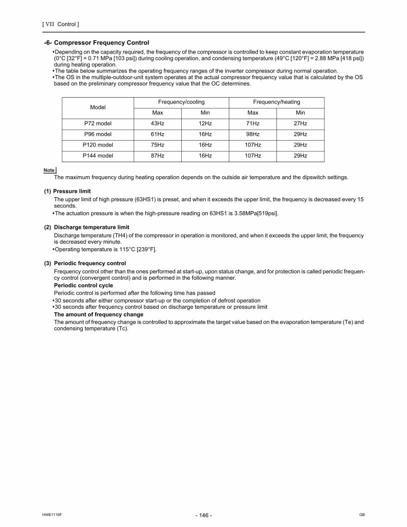
[ VII Control ]
- 146 -HWE1116F GB
Compressor Frequency Control
-6- Compressor Frequency Control
Depending on the capacity required, the frequency of the compressor is controlled to keep constant evaporation temperature (0°C [32°F] = 0.71 MPa [103 psi]) during cooling operation, and condensing temperature (49°C [120°F] = 2.88 MPa [418 psi]) during heating operation. The table below summarizes the operating frequency ranges of the inverter compressor during normal operation.The OS in the multiple-outdoor-unit system operates at the actual compressor frequency value that is calculated by the OS based on the preliminary compressor frequency value that the OC determines.
The maximum frequency during heating operation depends on the outside air temperature and the dipswitch settings.
(1) Pressure limit
The upper limit of high pressure (63HS1) is preset, and when it exceeds the upper limit, the frequency is decreased every 15 seconds.The actuation pressure is when the high-pressure reading on 63HS1 is 3.58MPa[519psi].
(2) Discharge temperature limit
Discharge temperature (TH4) of the compressor in operation is monitored, and when it exceeds the upper limit, the frequency is decreased every minute.Operating temperature is 115°C [239°F].
(3) Periodic frequency control
Frequency control other than the ones performed at start-up, upon status change, and for protection is called periodic frequen-cy control (convergent control) and is performed in the following manner.Periodic control cyclePeriodic control is performed after the following time has passed30 seconds after either compressor start-up or the completion of defrost operation30 seconds after frequency control based on discharge temperature or pressure limitThe amount of frequency changeThe amount of frequency change is controlled to approximate the target value based on the evaporation temperature (Te) and condensing temperature (Tc).
ModelFrequency/cooling Frequency/heating
Max Min Max Min
P72 model 43Hz 12Hz 71Hz 27Hz
P96 model 61Hz 16Hz 98Hz 29Hz
P120 model 75Hz 16Hz 107Hz 29Hz
P144 model 87Hz 16Hz 107Hz 29Hz

[ VII Control ]
- 147 -HWE1116F GB
Defrost Operation Control
-7- Defrost Operation Control
(1) Starting the defrost operation
The defrost cycle will start when all of the three conditions (outside temperature, cumulative compressor operation time, and pipe temperature) under <Condition 1>, <Condition 2>, or <Condition 3> are met.
1) Pipe temperature(TH6)
The defrost cycle will not start if other outdoor units are in the defrost cycle or until a minimum of 10 minutes have passed since the completion of the last defrost cycle.If 10 minutes have passed since compressor startup or since the completion of a defrost cycle, a forced defrost cycle can be started by setting DIP SW4 (913) to ON. Even if the defrost-prohibit timer is set to 90 minutes (or 150 minutes for "Condition 3" to be met), the actual defrost-prohibit time for the next defrost cycle is 50 minutes if the last defrost cycle took 12 minutes. All units in the heating mode will simultaneously go into the defrost cycle in a system with multiple units. The units that are not in operation may or may not go into the defrost cycle, depending on the cumulative operation time of their compressors.
Condition 1 Condition 2 Condition 3
Outside temperature (TH7)
-5ºC [23ºF] or above -5ºC [23ºF] or below
Cumulative compressor operation time
50 minutes or more 90 minutes or more if the defrost prohibit timer is set to 90.
250 minutes or more
Pipe temperature(TH6)
The pipe temperature has stayed below the temperatures in the table below (Note1) for three minutes.
The pipe temperature has stayed below the value ob-tained from the formula "Out-side temperature (TH7) - 5ºC [ 9ºF] " for three minutes, or the 63LS (kg/cm2G) has met for three minutes.63LS ≤ 1.5 + 0.02 x (20+TH7)
The pipe temperature has stayed below the temperatures in the table below (Note1) for three minutes
P72 P96 P120 P144
SW4 (915) OFF -10ºC -10ºC -8ºC -8ºC
SW4 (915) ON -5ºC -5ºC -5ºC -5ºC

[ VII Control ]
- 148 -HWE1116F GB
(2) Defrost operation
(3) Stopping the defrost operation
The defrost cycle ends when 12 minutes have passed since the beginning of the cycle, or when the pipe temperatures (TH3 and TH6) have been continuously detected for 4 minutes (when SW4 (916) is set to OFF) or 2 minutes (when SW4 (916) is set to ON) that exceeds the values in the table below.The defrost cycle will not end for two minutes once started unless one of the following conditions is met : Pipe temperature reaches 25°C [77°F] and SW4 (916) is set to OFF OR =25+TH7°C [77°F+TH7] and SW4 (916) is set to ON.*1 (5°C [41°F] 25°C [77°F]).In the multiple-outdoor-unit system, defrosting is stopped on all units at the same time.
(4) Problems during defrost operation
If a problem is detected during defrost operation, the operation will be stopped, and the defrost prohibition time based on the integrated compressor operation time will be set to 20 minutes.
(5) Change in the number of operating indoor units during defrost operation
Even when there is a change in the number of operating indoor units during defrost operation, the operation will continue, and an adjustment will be made after the completion of the defrost operation.Defrost operation will be continued, even if the indoor units stop or under the Thermo-OFF conditions until it has run its course.
Outdoou unit Compressor frequency Model Compressor frequency
P72 model 79Hz
P96 model 107Hz
P120, P144 models 107Hz
Outdoor unit fan Stopped
SV1a ON (open)
SV5b ON (closed)
21S4a, 21S4b OFF
SV9 OFF (closed)
BC controller LEV1 G type: 4000, GA type: 6000, HA type: 8000
LEV3 G type: 1000, GA type: 2000, HA type: 2000GB, HB type: 60 (full closed)
SVM1 ON
SVM2 OFF
SVM1b ON
SVM2b OFF
SV B OFF
SV A Ports that are connected to the indoor units in cooling Thermo-ON Other ports : OFF
ModelTH3 and TH6
SW4 (916) OFF SW4 (916) ON
72 model 7°C [45°F] 12°C [54°F]
96 model 7°C [45°F] 12°C [54°F]
120 model 7°C [45°F] 12°C [54°F]
144 model 7°C [45°F] 12°C [54°F]

[ VII Control ]
- 149 -HWE1116F GB
Refrigerant Recovery Control
-8- Refrigerant Recovery Control
Refrigerant recovery is performed for each BC port during heating operation to prevent the refrigerant from accumulating in-side the units that are stopped (in the fan mode), in the cooling mode, or in the heating Thermo-OFF mode.It is also performed during cooling operation to prevent an excessive amount of refrigerant from accumulating in the outdoor heat exchanger.
Starting criteria for the refrigerant recovery cycle (during Cooling-only, Cooling-main, Heating-only, or Heating-main mode)The refrigerant recovery mode starts when all of the following conditions are met:
1) When 5 minutes have passed in the Heating-only or Heating-main mode or 30 seconds have passed in the Cooling-only or Cooling-main mode since the completion of the previous refrigerant recovery cycle AND the when following conditions are met. TH4 > 105°C [221°F]
2) When the port is not in the 4-minute restart delay mode
Starting criteria for the refrigerant recovery cycle (during Cooling-only, Cooling-main, Heating-only, or Heating-main mode)
1) When the port is in the cooling Thermo-OFF, fan, or stop mode SV C at the port turns on for 30 seconds. ( indicates port No.)
2) The opening of LEV1 and LEV3 is increased.
Capacity Control of Outdoor Fan
-9- Capacity Control of Outdoor Fan and Heat Exchanger
(1) Control method
Depending on the capacity required, the rotation speed of the outdoor unit fan is controlled by the inverter to keep a constant condensing temperature of (outside temperature +10°C [18°F]) during cooling operation and a constant evaporation temper-ature of (0°C [32°F] =0.71 MPa [103psi]) during heating operation.The OS in the multiple-outdoor-unit system operates at the actual outdoor unit fan control value that is calculated by the OS based on the preliminary outdoor unit fan control value that the OC determines.
(2) Control
Outdoor unit fan stops while the compressor is stopped (except in the presence of input from snow sensor).The fan operates at full speed for 5 seconds after start-up.(Only when TH7<0°C [32°F])The outdoor unit fan stops during defrost operation.On the P120 and P144 models of outdoor units, before the second fan goes into operation, the capacity of the first fan is
reduced to 50%.
(3) Outdoor unit heat exchanger capacity control patterns
*Solenoid valves SV4 a, b, c, and d open when energized and close when de-energized.
Model Operation mode Operation patterns
Solenoid valve FAN
SV4a SV4b SV4c SV4d FAN1 FAN2
P72, P96 models Cooling-onlyCooling-main
1 OFF ON - ON ON -
2 OFF ON - OFF ON -
3 ON ON - OFF ON -
Heating-only 1 ON ON - OFF ON -
Heating-main 1 ON ON - ON ON -
2 ON ON - OFF ON -
Defrost 1 ON ON - OFF OFF -
P120, P144 models Cooling-onlyCooling-main
1 OFF ON OFF ON ON OFF
2 OFF ON OFF OFF ON OFF
3 ON ON OFF OFF ON OFF
4 ON ON OFF OFF ON ON
5 ON ON ON OFF ON ON
Heating-only 1 ON ON ON OFF ON ON
Heating-main 1 ON ON ON ON ON ON
2 ON ON ON OFF ON ON
Defrost 1 ON ON ON OFF OFF OFF

[ VII Control ]
- 150 -HWE1116F GB
Evaporting control (Linear expansion valve <LEV5a, b>)
-10- Evaporting temperature control (Linear expansion valve <LEV5a, b>)
(1) LEV5 control will begin when all of the following conditions are met.
Units are operated in the Heating-Main mode.15 minutes have passed after the compressor started up.TH7<5°C [41°F]63LS<0.69MPa [99psi]TH15<4°C [39°F]
(2) LEV5 control will end when one or more of the following conditions are met.
Units are operated in the mode other than Heating-Main or Heating-Only.TH7>10°C [50°F]63LS>0.98MPa [142psi]
The LEV is controlled every 30 seconds to maintain constant the bypass inlet temperature (TH15 = 4~5°C [39~41°F]) of the BC controller during heatingmain mode or heating mode. When LEV5 is being controlled, SV4a, b, c, and d will all be turned off. The LEV operates at 300 pulse while the compressor is stopped. The LEV opens to a specified position in response to chang-es in heat exchanger capacity control patterns during cooling only or cooling main mode.
Control at Initial Start-up
-11- Control at Initial Start-up
When started up for the first time before 12 hours have elapsed after power on, the unit goes into the initial startup mode.At the completion of the initial operation mode on the OC and OS, they will go into the normal control mode.
1. Flowchart of initial operation(1) P72, P96, P120, P144 models
50 F 60Hz
or F < 50Hz
Initial startup mode starts.
Completed in the integrated operation time of 35 minutes.
Initial startup mode complete
or the discharge superheat (TH4 - Tc) is detected (within 5 minutes of startup) that remains above approximately 25 degrees for one minute .
Completed in the integrated operation time of 90 minutes.

[ VII Control ]
- 151 -HWE1116F GB
(2) P144, P168, P192, P216, P240, P264, P288 models (As for P144, only the YKMU series is applicable.)
1 Qj:Total capacity (models) codeRefer to the VII [1] 2. (1) Dipswitches for the capacity code. (page 141)
The compressor on the OC starts up.
The total operating load of the indoor unit after 5 minutes of operation is P96 or above.
(*1 Qj 50)
Initial startup mode starts.
F 60Hz
Yes
No
or F < 50Hz (both OC and OS)Completed in the integrated operation time of 90 minutes.
The compressor on the OC remains in operation, and the compressor on the OS starts up.
or F < 50Hz (OC)Completed in the integrated operation time of 90 minutes.
The compressor on the OC starts up.
Both the OC and OS stop.The startup sequence of the OC and OS is rotated.
or F < 50Hz (OS)Completed in the integrated operation time of 90 minutes.
The compressor on the OS starts up.
*2
*3
*2The air conditioning load is too small for both the OC and the OS tosimultaneously stay in operation.*3The air conditioning load is high enough for both OC and OS tosimultaneously stay in operation.
Initial startup mode complete
or the discharge superheat (TH4 - Tc) is detected (within 5 minutes of startup) that remains above approximately 25 degrees for one minute .
or the discharge superheat (TH4 - Tc) is detected (within 5 minutes of startup) that remains above approximately 25 degrees for one minute .
or the discharge superheat (TH4 - Tc) is detected (within 5 minutes of startup) that remains above approximately 25 degrees for one minute .
50 F 60Hz (both OC and OS)Completed in the integrated operation time of 35 minutes.
50 F 60Hz (OC)Completed in the integrated operation time of 35 minutes.
50 F 60Hz (OS)Completed in the integrated operation time of 35 minutes.

[ VII Control ]
- 152 -HWE1116F GB
Emergency Operation Mode
-12- Emergency Operation Mode
1. Problems with the outdoor unitThe P144 through P240 models of unit have a mode that allows the outdoor unit to perform an emergency operation when the other outdoor unit in the system malfunctions. (As for the P144 model, only the YKMU series is applicable.)This mode can be started by performing an error reset via the remote controller.
(1) Starting the emergency operation
1) When an error occurs, the error source and the error code will be displayed on the display on the remote controller.2) The error is reset using the remote controller.3) If an error code appears that permits an emergency operation in step 1) above, (See the table below.), the retry operation
starts.4) If the same error is detected during the retry operation (step 3 above), an emergency operation can be started by resetting
the error via the remote controller.Error codes that permit an emergency operation (Applicable to both OC and OS)
Emergency operation pattern (2 outdoor units)
1) If an attempt is made to put into operation a group of indoor units whose total capacity exceeds the maximum allowable ca-pacity, some of the indoor units will go into the same condition as Thermo-OFF.
Trouble source Error codes that permit an emergency operation
Error code description
CompressorFan motorInverter
0403 Serial communication error
4220,4225,4226 Bus voltage drop
4230,4235 Heatsink overheat protection
4240,4245 Overload protection
4250,4255,4256 Overcurrent relay trip
5110 Heatsink temperature sensor failure (THHS)
5301 Current sensor/circuit failure
5305,5306 Position error
Thermistor TH2 5102 Subcool heat exchanger bypass outlet temperature sensor failure
TH3 5103 Pipe temperature sensor failure
TH4 5104 Discharge temperature sensor failure
TH5 5105 Accumulator inlet temperature sensor failure
TH6 5106 Subcool heat exchanger liquid outlet sensor failure
TH7 5107 Outside air temperature sensor failure
Power 4102 Open phase
4115 Power supply sync signal abnormality
OC
OC failure pattern Trouble Normal Permitted Permitted Permitted Permitted
60%
Cooling Heating
Normal Trouble
OS failure pattern
OS Emergency operation
Maximum total capacity of indoor units (Note 1)

[ VII Control ]
- 153 -HWE1116F GB
(2) Ending the emergency operation
1) End conditions
When one of the following conditions is met, emergency operation stops, and the unit makes an error stop.When the integrated operation time of compressor in cooling mode has reached four hours.When the integrated operation time of compressor in heating mode has reached two hours.When an error is detected that does not permit the unit to perform an emergency operation.
2) Control at or after the completion of emergency operation
At or after the completion of emergency operation, the compressor stops, and the error code reappears on the remote con-troller.If another error reset is performed at the completion of an emergency mode, the unit repeats the procedures in section (1) above.To stop the emergency mode and perform a current-carrying operation after correcting the error, perform a power reset.
2. Communication circuit failure or when some of the outdoor units are turned offThis is a temporary operation mode in which the outdoor unit that is not in trouble operates when communication circuit failure occurs or when some of the outdoor units are turned off.
(1) Starting the emergency operation (When the OC is in trouble)
1) When an error occurs, the error source and the error code appear on the display on the remote controller.2) Reset the error via the remote controller to start an emergency operation.
Precautions before servicing the unitWhen the OC is in trouble, the OS temporarily takes over the OC's function and performs an emergency operation. When this happens, the indoor unit connection information are changed.In a system that has a billing function, a message indicating that the billing system information has an error may appear on the TG-2000A. Even if this message appears, do not change (or set) the refrigerant system information on the TG-2000A. After the completion of an emergency operation, the correct connection information will be restored.
(2) Starting the emergency operation (When the OS is in trouble)
1) A communication error occurs. -> An emergency operation starts in approximately six minutes.
Error codes that permit an emergency operation (Applicable to both OC and OS)
Emergency operation pattern (2 outdoor units)
1) If an attempt is made to put into operation a group of indoor units whose total capacity exceeds the maximum allowable ca-pacity, some of the indoor units will go into the same condition as Thermo-OFF.
(3) Ending the emergency operation
When communication is restored, the emergency mode is cancelled, and the units go into the normal operation mode.
Trouble source
Circuit board failure or the power to the outdoor units is off
6607 6608
No acknowledgement error No response error
Error codes that permit an emergency operation Error code description
OC
Cooling Heating
OC failure pattern Trouble Normal Permitted Permitted Permitted Permitted
Normal Trouble
OS failure pattern
OS Emergency operation
Maximum total capacity of indoor units (Note 1)
Capacity that matches the total capacity of the operable outdoor units

[ VII Control ]
- 154 -HWE1116F GB
Control Method
-13- Control Method
The control system configuration for the PURY models is shown in the chart below.
Con
trol
met
hod
Data signal exchange between system equipment
Calculation, processing
System control Adjustment of refrigerant flow rate Adjustment of rotation speed of compressor or fan
Non-polar 2-wireserial communication method
16-bit CPUmicrocomputer operation processing
Autonomous distributed control system (F2-VPM control)
Rotation speed control of compressor or fan depending on the refrigerant pressure value and the changing speed
Self-contained capacity control depending on the load
Refrigerant distribution control depending on the operation mode
Outdoor unit
Daisy-chained non-polar 2-wiretransmission line
Indoor unit
BC controller
*
Autonomous distributed control system : A system that consists of three independent sub control systems,instead of a single centralized control system, that work togetherto maintain the overall control of the entire system.

[ VII Control ]
- 155 -HWE1116F GB
Cooling/heating Circuit Control and General Function of System Equipment
-14- Cooling/heating Circuit Control and General Function of System Equipment
Hig
h-pr
essu
re g
asH
igh-
pres
sure
gas
Hea
t exc
hang
er
High-pressureliquid
Fan
4-way valve Check valve Selector valve
Low-pressure two-phase
Low-pressure two-phase
Low-pressure
two- phase
High-pressure liquid
Low-pressure
two- phase
Low-pressure
two- phase
Heat exchanger
High-pressureliquid
High-pressureliquid
High-pressureliquid
High-pressureliquid
High-pressure liquid
Cooling
Cooling
Cooling
Heating
Cooling
Heating
Heating
Heating
Low-pressure
pipe
High-pressure
pipe
High-pressure
gas
High-pressure
gas
High-pressure
gas
High-pressure two-phase
Low-pressuregas
Low-pressuregas
Low
-pre
ssur
e ga
sLo
w-p
ress
ure
gas
Low-pressure
gas
Gas-liquidseparator
Outdoor unit BC controller
Indoor unit
LEV
LEV
M
M L
M L
M
L
M
L
A
O
ML
ML
ML
ML
A
O
B
CD
I
J
J
E
F
F
N
N
N
K
M L
M L
M
L
G H
A
O
L
J G I
K H
D C F E B
N
A
M O
JG
I
K H
D
C
FE
BA
M
L
F
MA
O
M
LA
O
M
A
I
E
K
B C D
B C D
B C D
FGH
Gas-liquid mixture
Pressure
Liquid
Gas
Enthalpy(energy)
Schematic diagram of refrigerant circuitGasTwo-phaseLiquid
Schematic diagram of refrigerating cycle
Coolingonly
Operationstatus
Coolingmain
Heatingonly
Heatingmain

[ VII Control ]
- 156 -HWE1116F GB
Operation Mode
-15- Operation Mode
(1) Indoor unit operation mode
The operation mode can be selected from the following 6 modes using the remote controller.
(2) Outdoor unit operation mode
When units in cooing and heating coexist, the operation mode (cooling main mode or heating main mode) will be determined, based on the refrigerant pressure in the R2 refrigerant circuit and speed variation data.
(3) Operation pattern for automatic cooling/heating mode
When the automatic cooling/heating mode is selected from remote controller functions, the indoor temperature will be detect-ed in pattern as shown in the figure below, and the operation mode (cooling or heating) will automatically be selected.
(4) Relationship between the operation mode and the load capacity (kW) (within a system)
1 Cooling mode
2 Heating mode
3 Dry mode
4 Automatic cooling/heating mode
5 Fan mode
6 Stopping mode
1 Cooling only mode All indoor units in operation are in cooling mode.
2 Heating only mode All indoor units in operation are in heating mode.
3 Cooling main mode Coexistence of units in cooling and heating modes.
4 Heating main mode Coexistence of units in cooling and heating modes.
5 Stopping mode All indoor units are in fan mode or stopping mode.
CoolingFan
Heating
Switches to cooling mode
Cooling operation under Thermo-ON conditionsSet temperature (Variable between 19 C and 28 C [ 67 F and 83 F])Heating operation under Thermo-ON conditionsSwitches to heating mode
Fan
Tem
pera
ture
rise
1.5 C [3 F]
1.5 C [3 F]
1 C [2 F]
1 C [2 F]
Cooling load capacity
Heating load capacity+Cooling load
capacity
Heating load capacity
Heating load capacity+Cooling load
capacity
100(%)
Cooling onlymode
Cooling mainmode
Heating mainmode
Total heat recovery mode
Heating onlymode
100(%)
Heating load (%)
Heating load
X100 = Cooling load (%)
=
Cooling load
X 100
0
0

[ VII Control ]
- 157 -HWE1116F GB
DEMAND Control
-16- DEMAND Control
Cooling/heating operation can be prohibited (Thermo-OFF) by an external input to the indoor units.
When DIP SW6-8 is set to ON, the 4-step DEMAND control is enabled. Eight-step demand control is possible in the system with two outdoor units.
Refer to Chapter II [3] 2. (7) "Various types of control using input-output signal connector on the outdoor unit (various connec-tion options)" for details.(page 23)

[ VII Control ]
- 158 -HWE1116F GB
[3] Controlling BC Controller
1. Control of SV A, SV B, and SV CSV A, SV B, and SV C turn on or off depending on the operation mode of the branch.
2. Control of SVM1, SVM1bSVM turns on or off depending on the operation mode.
3. Control of LEVLEV opening (sj) is controlled as follows depending on the operation mode.
4. Control of SVM2, SVM2b
Mode
Cooling Heating Stopped Defrost
Port
SV A ON OFF OFF OFF
SV B OFF ON OFF OFF
SV C ON OFF OFF OFF
Operation mode Cooling only Cooling main Heating only Heating main Defrost Stopped
SVM1,1b ONPressure dif-ferential con-trol*1
*1. Pressure differential control: The detected differential pressure (PS1 and PS3) is controlle every minute so as to be within a certain range.
OFF OFF ON OFF
Operation mode Cooling only Cooling main Heating only Heating
main Defrost Stopped
G,GA,HAtype
LEV1
2000 Liquid level control*1dif-ferential control*2
*1. Liquid level control: The liquid level detected by the liquid inlet temperature (TH11 sensor) is controlled so as to be within a certain range.
*2. Pressure differential control: The detected differential pressure (PS1 and PS3) is controlle every minute so as to be within a certain range.
110 110*3
*3. Can be 110 or more due to pressure rise on the liquid side (PS1).
2000 1200LEV2(only GA,HA type)
LEV3 Superheat control*4
*4. Superheat control: The amound of superheat that is calculated on the bypass inlet and outlet temperature (G, GA,HA:TH12,TH15, GB, HB: TH12, TH15) is controlled every minute so as to be within a certain range.
Pressure dif-ferential con-trol*2
Pressure dif-ferential con-trol*2
G:1000GA,HA:2000 60
GB,HBtype LEV3 Superheat
control*4Superheat control*4 60 60 60 60
Operation mode Cooling only Cooling main Heating only Heating main Defrost Stopped
SVM2,2b OFF OFF Pressure differ-ential control*1
*1. Pressure differential control: The detected differential pressure (PS1 and PS3) is controlled every minute so as to be within a certain range.
Pressure differ-ential control*1 OFF OFF

[ VII Control ]
- 159 -HWE1116F GB
[4] Operation Flow Chart
1. Mode determination flowchart(1) Indoor unit (cooling, heating, dry, fan mode)
Start
Remote controller display lit off Error mode
Error stop
Error display
Self-holding of protection function
Error command to outdoor unit
Indoor unit LEV fully closed.
Refer to 2-(1) for cooling operation.
Refer to 2-(2) for heating operation.
Refer to 2-(3) for dry operation.
ProhibitionProhibitionProhibition
Dry displayHeating displayCooling display
Dry modeHeating mode Fan mode
Fan display
Fan operations
Operation mode
Cooling mode
Prohibition"Blinking display on the remote controller"
FAN stop
Breaker turned on
Operation SW turned on
Auxiliary heaterON
Drain pumpON
3-minute drain pump ON
NO
NO
NO
NO
NO NO NO NO NO
*Note 1
*Note 1
*Note 2
*Note 3 *Note 3 *Note 3
1. Protection function self-holding cancelled.2. Indoor unit LEV fully closed.
1. Auxiliary heater OFF2. Low fan speed for 1 minute
YES
YES
YES
YESYES YES YES
YES
Normal operation
Error
Stop
1
Prohibition
Auto COOL/HEAT display
Automatic cooling/heating mode
*Note 3YES
Auto cooling/heating mode
11
*Note 1. Indoor unit LEV fully closed : Opening 41.*Note 2. The system may go into the error mode on either the indoor unit side or the BC controller or outdoor unit side. If some of the indoor units are experiencing a problem, only those indoor units that are experiencing the problem will stop. If the BC controller or the outdoor unit is experiencing a problem, all the connected units will stop.
*Note 3. If multiple indoor units are connected to a port and there is a discrepancy in the operation mode between the indoor unit and the port, the operation will be prohibited. (Operation mode blinks on the remote controller, the Fan stops, indoor unit LEV becomes fully closed.)

[ VII Control ]
- 160 -HWE1116F GB
(2) Outdoor unit (cooling only, heating only, cooling main and heating main modes)
Start
Breaker turned on
Operation command
Error stop
Error display on the outdoor unit LED
Self-holding of protection function
Operation command to the BC controller
Operation mode
Error mode
52C1 ON
*Note 1
*Note 2
*Note 3
*Note 4
YES
YES
YES
YES
NO
NO
NO
fan
NO
"HO" / "PLEASE WAIT" blinks on the remote controller
Operation command to the BC controller
Cooling only, Heating onlyMixture of units in cooling and heating
Mixture of units in cooling and heating
Protection function self-holding cancelled.
Normal operation
1. 52C1 4-way valve OFF
2. Inverter output 0Hz
3. Fan stop
4. All solenoid valves OFF
Cooling Only Heating Only
2
2
Cooling Main
Operation mode
Operation mode
*Note 1. For about 3 minutes after power on, search for the indoor unit address, for the remote controller address, and for the group information will start. During this, "HO"/ "PLEASE WAIT" blinks on the display of the remote controller. When the indoor unit to be controlled by the remote controller is missing, "HO"/ "PLEASE WAIT" keeps blinking on the display of the remote controller even after 3 or more minutes after power on.
*Note 3. The units will follow the operation mode commands from the BC controller
*Note 4. When the operation mode commands from the BC controllers are mixed (both cooling and heating), the actual operation mode is determined by the outdoor unit.
*Note 2. The system may go into the error mode on either the indoor unit or the outdoor unit side. The outdoor stops only when all of the connected indoor units are experiencing problems. The operation of even a single indoor unit will keep the outdoor unit running. The error will be indicated on the LED display.
Heating Main
Indoor units registered to the remote controller
Error
Unit in the stopped state

[ VII Control ]
- 161 -HWE1116F GB
(3) BC controller (cooling only, heating only, cooling main and heating main modes)
Start
Breaker turned on
Operation command
Error command to outdoor unit
Error stop
Self-holding of protection function
Error command to indoor unit
Error mode
*Note 1
YES
YES
YES
NO
NO
Fan
NO
All units in the same mode
Solenoid valves OFFLEV Fully closed
1. Determination of operation mode (Cooling only, Heating only, Mixture of units in cooling and heating)2. Transmitted to the outdoor unit
3
3
Operation mode
Note 1. The system may go into the error mode on either the indoor unit side or the BC controller or outdoor unit side. If some of the indoor units are experiencing a problem, only those indoor units that are experiencing the problem will stop. If the BC controller or the outdoor unit is experiencing a problem, all the connected units will stop.
Operation mode
Operation mode
Cooling Only Heating Only Cooling Main Heating Main
Mixture of units in cooling and heating
Reception of operation mode command from the outdoor unit
Protection function self-holding cancelled.
Normal operation
Error
Unit in the stopped state

[ VII Control ]
- 162 -HWE1116F GB
2. Operations in each mode(1) Cooling operation
Cooling operation
Test run mode ON
Thermostat ON
3-minute restart prevention
*Note 1
YES
YES
YES
NO
NO
NO
4-way valve OFF
1. Inverter frequency control2. Indoor unit LEV, Oil returnLEV control3. Solenoid valve control4. Outdoor unit fan control5. BC controller solenoid valve control6. BC controller control
Normal operation
During test run mode
Indoor unit fan operation
1. Inverter output 0Hz2. Indoor unit LEV, Oil return LEV fully closed3. Solenoid valves OFF4. Outdoor unit fan stop5. BC controller solenoid valves OFF6. BC controller LEV fully closed
Unit in the stopped state
2 3
*Note 1. The indoor fan operates at the set notch under cooling mode regardless of the ON/OFF state of the thermostat.

[ VII Control ]
- 163 -HWE1116F GB
(2) Heating operation
*Note 1. When the outdoor unit goes into the defrost mode, defrost command is sent to the BC controller and indoor units.Upon reception of the command, the indoor units will go into the defrost mode. When defrosting is completed and upon receiving the signal that indicates the completion of defrosting, indoor units will resume the heating operation.
*Note 2. Defrost end condition: 10 or more minutes must pass after defrost operation.or Outdoor unit piping temperature : refer to "-7- Defrost operation control" of [2] Controlling the Outdoor Unit. (page 147)
Heating operation
Test run mode ON
Thermostat ON
Defrost operation
3-minute restart prevention
*Note 1,2
*Note 1,2
YES
YES
YES
YES
NO
NO
NO
NO
NO
1. Indoor/outdoor unit fan control2. Inverter frequency control3. Indoor unit LEV fully open4. Solenoid valve control5. BC controller solenoid valve control6. BC controller LEV control
Normal operation
Defrost operation
4-way valve ON
During test run mode
1. Indoor unit fan operation at Very Low speed2. Inverter output 0Hz3. Indoor unit LEV fully open4. Solenoid valve OFF5. Outdoor unit fan stop6. BC controller solenoid valve control7. BC controller LEV control
Stopping the defrost operation
1. Indoor unit fan stop2. Inverter defrost frequency control3. Indoor unit LEV fully open4. Solenoid valve control5. Outdoor unit fan stop6. BC controller solenoid valve control7. BC controller LEV control
4-way valve OFF
1 3
Stopping the defrost operation
Unit in the stopped state

[ VII Control ]
- 164 -HWE1116F GB
(3) Dry operation
Dry operation
*Note 1
*Note 2
YES
YES
NO
NO
4-way valve OFF
1. Outdoor unit (compressor) intermittent operation2. Indoor unit fan intermittent operations (Synchronized with the compressor: low speed, OFF operations)
Normal operation
Thermostat ON
Thermostat ON
1. Indoor unit fan stop2. Inverter output 0Hz3. Indoor unit LEV fully closed.4. Solenoid valve OFF5. Outdoor unit fan stop6. BC controller Solenoid valve OFF7. BC controller LEV fully closed
2 3
*Note 1.When the indoor unit inlet temperature exceeds 18 C [64 F], the outdoor unit (compressor) and the indoor unit fan start the intermittent operation simultaneously. When the indoor unit inlet temperature becomes 18 C [64 F],or less, the fan always runs (at low speed). The outdoor unit, the indoor unit, and the solenoid valve operate in the same way as they do in the cooling operation when the compressor is turned on.
*Note 2.Thermostat is always kept on during test run mode, and indoor and outdoor unit intermittent operation (ON) time is a little longer than that of normal operation.
Test run mode ON
Suction temperature 18 C[64 F]
Unit in the stopped state

- 165 -HWE1116F GB
VIII Test Run Mode
[1] Items to be checked before a Test Run.........................................................................167
[2] Test Run Method ...........................................................................................................168
[3] Operating Characteristic and Refrigerant Amount .........................................................169
[4] Adjusting the Refrigerant Amount ..................................................................................169
[5] Refrigerant Amount Adjust Mode...................................................................................172
[6] The following symptoms are normal. .............................................................................174
[7] Standard Operation Data (Reference Data) ..................................................................175

- 166 -HWE1116F GB

[ VIII Test Run Mode ]
- 167 -HWE1116F GB
VIII Test Run Mode
[1] Items to be checked before a Test Run
(1) Check for refrigerant leak and loose cables and connectors.
(2) When opening or closing the front panel of the control box, do not let it come into contact with any of the internal components.
Before inspecting the inside of the control box, turn off the power, keep the unit off for at least 10 minutes, and confirm that the capacitor voltage (inverter main circuit) has dropped to 20 VDC or less. (It takes about 10 minutes to discharge electricity after the power supply is turned off.)Control box houses high temperature parts. Be well careful even after turning off the power source.Perform the service after disconnecting the fan board connector (CNINV) and the inverter board connector (CN1 or CNFAN). (To plug or unplugconnectors, check that the outdoor unit fan is not rotating and that the voltage of capacitor in the main circuit is 20 VDC or below. The capacitor may collect a charge and cause an electric shock when the outdoor unit fan rotates in windy conditions. Refer to the wiring nameplate for details.) To connect wiring to TB7, check that the voltage is 20 VDC or below.Reconnect the connector (CNINV) back to the fan board and reconnect the connector (CN1 or CNFAN) back to the inverter board after servicing.
(3) Measure the insulation resistance between the power supply terminal block and the ground with a 500V megger and make sure it reads at least 1.0Mohm.
Do not operate the unit if the insulation resistance is below 1.0Mohm.Do not apply megger voltage to the terminal block for transmission line. Doing so will damage the controller board.The insulation resistance between the power supply terminal block and the ground could go down to close to 1Mohm imme-diately after installation or when the power is kept off for an extended period of time because of the accumulation of refrigerant in the compressor.If insulation resistance reads at least 1 MΩ, by turning on the main power and keeping it on for at least 12 hours, the refrigerant in the compressor will evaporate and the insulation resistance will go up.Do not measure the insulation resistance of the terminal block for transmission line for the unit remote controller.
(4) When the power is turned on, the compressor is energized even while it is not operating.
Before turning on the power, disconnect all power supply wires from the compressor terminal block, and measure the insula-tion resistance of the compressor.Check the compressor for a ground fault. If the insulation resistance is 1.0 MΩ or below, connect all power supply wires to the compressor and turn on the power to the outdoor unit. (The liquid refrigerant in the compressor will evaporate by energiz-ing the compressor.)
(5) Check that the valve on the gas pipe and liquid pipe are fully open.
Securely tighten the cap.
(6) Check the phase sequence and the voltage of the power supply.
When the voltage is out of the ±10% range, or when the phase voltage difference is more than 2%, please discuss the coun-termeasure with the customer.
(7) [When a transmission booster is connected]Turn on the transmission booster before turning on the outdoor units.
If the outdoor units are turned on first, the connection information for the refrigerant circuit may not be properly recognized.In case the outdoor units are turned on before the transmission booster is turned on, perform a power reset on the outdoor units after turning on the power booster.
(8) Turn on the main power at least 12 hours before test run.
Insufficient powering time may result in compressor damage.
(9) When a power supply unit is connected to the transmission line for centralized control(*), perform a test run with the power supply unit being energized. Leave the power jumper connector on CN41 as it is (factory setting).
*Includes the cases where power is supplied to the transmission line from a system controller with a power-supply function

[ VIII Test Run Mode ]
- 168 -HWE1116F GB
[2] Test Run Method
The figure shows an MA remote controller (PAR-21MAAU).
PAR-21MAAU
ON/OFF
FILTER
CHECK
OPERATION CLEAR
TEST
TEMP.
MENU
BACK DAYMONITOR/SET
CLOCK
ON/OFF
Set Temperature buttons
Down
Up
Operation Mode button
ON/OFF button
Fan Speed button
Test Run button
Vertical Air Direction buttonLouver button( Operation button)
To precedingoperation number.
Ventilation button( Operation button)
To next operation number.
F CF C
ERROR CODEAFTERTIMERTIME SUN MON TUE WED THU FRI SAT
ONOFF
HrAFTER
FILTERFUNCTION
ONLY1Hr.
WEEKLYSIMPLE
AUTO OFF
Operation procedures Turn on the main power. "PLEASE WAIT" appears on the LCD for up to five minutes. Leave
the power on for 12 hours. (Energize the belt heater.)
Press the Test button twice. Operation mode display "TEST RUN" and OPERATION MODE are displayed alternately.
Press the Operation Mode button.
Make sure that cold (or warm) air blows out. On the same refrigerant system, make the operation mode the same.
Make sure that the air is blowing out.
Switch to cooling (or heating) operation by pressing the Operation Mode button.
Press the Fan Speed button.
Change the air flow direction by pressing the Vertical Air Direction button or the Louver button.
Confirm the operation of outdoor unit fan.
Confirm the operation of all interlocked equipment, such as ventilation equipment.
Note 1: Refer to the following pages if an error code appears on the remote controller or when the unit malfunctions. 2: The OFF timer will automatically stop the test run after 2 hours. 3: The remaining time for the test run will be displayed in the time display during test run. 4: The temperature of the liquid pipe on the indoor unit will be displayed in the room temperature display window on the remote controller during test run. 5: On some models, "NOT AVAILABLE" may appear on the display when the Vane Control button is pressed. This is normal. 6: If an external input is connected, perform a test run using the external input signal. 7: Test run all systems for at least 15 minutes to detect possible system errors.
Make sure that the fan speed changes with each pressing of the button.
Stop
Make sure that the air flow direction changes with each pressing of the button.
Cancel the test run by pressing the ON/OFF button.

[ VIII Test Run Mode ]
- 169 -HWE1116F GB
[3] Operating Characteristic and Refrigerant Amount
It is important to have a clear understanding of the characteristics of refrigerant and the operating characteristics of air conditioners before attempting to adjust the refrigerant amount in a given system.
1. Operating characteristic and refrigerant amountThe following table shows items of particular importance.
1) During cooling operation, the amount of refrigerant in the accumulator is the smallest when all indoor units are in operation.2) During heating operation, the amount of refrigerant in the accumulator is the largest when all indoor units are in operation.3) General tendency of discharge temperature
Discharge temperature tends to rise when the system is short on refrigerant.Changing the amount of refrigerant in the system while there is refrigerant in the accumulator has little effect on the discharge temperature.The higher the pressure, the more likely it is for the discharge temperature to rise.The lower the pressure, the more likely it is for the discharge temperature to rise.
4) When the amount of refrigerant in the system is adequate, the compressor shell temperature is 10 to 60°C [18 to 108°F] higher than the low pressure saturation temperature (Te).
-> If the temperature difference between the compressor shell temperature and low pressure saturation temperature (Te) is smaller than 5°C [9°F], an overcharging of refrigerant is suspected.
[4] Adjusting the Refrigerant Amount
1. SymptomsOvercharging or undercharging of refrigerant can cause the following symptoms: Before attempting to adjust the amount of refrigerant in the system, thoroughly check the operating conditions of the system. Then, adjust the refrigerant amount by running the unit in the refrigerant amount adjust mode.
2. Amount of refrigerant(1) To be checked during operation
Operate all indoor units in either cooling-only or heating-only mode, and check such items as discharge temperature, subcool-ing, low pressure, suction temperature, and shell bottom temperature to estimate the amount of refrigerant in the system.
The system comes to an abnormal stop, displaying 1500 (overcharged refrigerant) on the controller.
Overcharged refrigerant
The operating frequency does not reach the set frequency, and there is a problem with performance.
Insufficient refrigerant amount
The system comes to an abnormal stop, displaying 1102 (abnormal discharge temper-ature) on the controller.
Symptoms Conclusion
Discharge temperature is high. (Normal discharge temperature is below 95°C [203°F].) Slightly under-charged refrigerant
Low pressure is unusually low.
Suction superheat is large. (Normal suction superheat is less than 20°C [36°F].)
Compressor shell bottom temperature is high. (The difference between the compressor shell bottom temperature and low pressure saturation temperature (Te) is greater than 60°C [108°F].)
Discharge superheat is small. (Normal discharge superheat is greater than 10°C [18°F].) Slightly overcharged refrigerant
Compressor shell bottom temperature is low. (The difference between the compressor shell bot-tom temperature and low pressure saturation temperature (Te) is less than 5°C [9°F].)

[ VIII Test Run Mode ]
- 170 -HWE1116F GB
3. Amount of refrigerant to be addedThe amount of refrigerant that is shown in the table below is factory-charged to the outdoor units.The amount necessary for extended pipe (field piping) is not included and must be added on site.
(1) Calculation formula
The amount of refrigerant to be added depends on the size and the length of field piping. (unit in m[ft])When the piping length from the outdoor unit to the farthest indoor unit is 30.5m (100ft) or shorter.
When the piping length from the outdoor unit to the farthest indoor unit is longer than 30.5m (100ft).
Round up the calculation result to the nearest 0.1kg. (Example: 18.04kg to 18.1kg)Round up the calculation result in increments of 4oz (0.1kg) or round it up to the nearest 1oz. (Example: 78.21oz to 79oz)
Outdoor unit model P72 P96 P120 P144
Amount of pre-charged refrigerant in the outdoor unit (kg) 11.8 11.8 11.8 11.8
Amount of pre-charged refrigerant in the outdoor unit [lbs-oz] 26-1 26-1 26-1 26-1
Amount of added refrigerant (kg) = (0.36 x L1) + (0.23 x L2) + (0.16 x L3) + (0.11 x L4)+ (0.2 x L5) + (0.12 x L6) + (0.06 x L7) + (0.024 x L8) + α1 + α2 + α3 + α4 + β
Amount of added refrigerant (oz) = (3.88 x L1' ) + (2.48 x L2' ) + (1.73 x L3' ) + (1.19 x L4' )+ (2.16 x L5' ) + (1.30 x L6' ) + (0.65 x L7' ) + (0.26 x L8' ) + α1' + α2' +α3' + α4'+ β'
Amount of added refrigerant (kg) = (0.33 x L1) + (0.21 x L2) + (0.14 x L3) + (0.1 x L4)+ (0.18 x L5) + (0.11 x L6) + (0.054 x L7) + (0.021 x L8) + α1 + α2 + α3 + α4 + β
Amount of added refrigerant (oz) = (3.54 x L1' ) + (2.26 x L2' ) + (1.51 x L3' ) + (1.08 x L4' )+ (1.94 x L5' ) + (1.19 x L6' ) + (0.59 x L7' ) + (0.23 x L8' ) + α1' + α2' +α3' + α4'+ β'
L1 : Length of ø28.58[1-1/8"] high pressure pipe (m) L2 : Length of ø22.2[7/8"] high pressure pipe (m) L3 : Length of ø19.05[3/4"] high pressure pipe (m) L4 : Length of ø15.88[5/8"] high pressure pipe (m) L5 : Length of ø15.88[5/8"] liquid pipe (m) L6 : Length of ø12.7[1/2"] liquid pipe (m) L7 : Length of ø9.52[3/8"] liquid pipe (m) L8 : Length of ø6.35[1/4"] liquid pipe (m)α1, α2, α3, α4, α1' , α2' , α3' , α4' : Refer to the table below.
L1' : Length of ø28.58[1-1/8"] high pressure pipe [ft] L2' : Length of ø22.2[7/8"] high pressure pipe [ft] L3' : Length of ø19.05[3/4"] high pressure pipe [ft] L4' : Length of ø15.88[5/8"] high pressure pipe [ft] L5' : Length of ø15.88[5/8"] liquid pipe [ft] L6' : Length of ø12.7[1/2"] liquid pipe [ft] L7' : Length of ø9.52[3/8"] liquid pipe [ft] L8' : Length of ø6.35[1/4"] liquid pipe [ft]β, β' : Refer to the table below.
Outdoor unit total index
Amount for the BC con-trollers (standard/main)
BC controller (main) Total capacity of connected indoor
units
Amount for the Indoor unit
α1(kg) α1' (oz) α4(kg) α4' (oz)
P72 model 3.0 106 HA type α2(kg) α2' (oz) - 27 2.0 71
P96 model4.5 160
1 2.0 71 28 - 54 2.5 89
P120 model 55 - 126 3.0 106
P144 model
6.0 212
BC controller (sub) 127 - 144 3.5 124
P168 model 145 - 180 4.5 159
P192 model Total number of BC α3(kg) α3' (oz) 181 - 234 5.0 177
P216 model 1 1.0 36 235 - 273 6.0 212
P240 model 2 2.0 71 274 - 307 8.0 283
P264 model 308 - 342 9.0 318
P288 model 343 - 411 10.0 353
412 - 12.0 424
Outdoor unit total index
Charged amount for Out-door Unit(s)
Outdoor unit total index
Charged amount for Out-door Unit(s)
β (kg) β' (oz) β (kg) β' (oz)
Single
P72 model 0.0 0
Combination
P144 model 0.0 0
P96 model 1.0 36 P168 model 1.0 36
P120 model 5.5 195 P192 model 2.0 71
P144 model 5.5 195 P216 model 6.5 230
P240 model 11.0 389
P264 model 11.0 389
P288 model 11.0 389

[ VIII Test Run Mode ]
- 171 -HWE1116F GB
1) Maximum refrigerant charge
There is a limit to the amount of refrigerant that can be charged into a unit. Regardless of the amount yielded by the formula above, observe the maximum refrigerant charge in the table below.
*1 Maximum refrigerant charge: the amount of factory-charged refrigerant and the amount of refrigerant to be added on site.
(2) Example
(3) Sample calculation
Total index of the outdoor units P72 P96 P120 P144 P168 P192 P216
Maximum refrigerant charge *1 (kg) 39.0 47.3 52.8 58.5 73.0 86.3 99.0
Maximum refrigerant charge *1 [lbs-oz] 86-0 104-3 116-5 129-0 161-0 190-3 218-4
Total index of the outdoor units P240 P264 P288
Maximum refrigerant charge *1 (kg) 99.0 99.0 99.0
Maximum refrigerant charge *1 [lbs-oz] 218-4 218-4 218-4
BC controller(GA)
BC controller(HB)
BC controller(HB)
Indoor
a
C
b
H H′
h1h1
(P06 - P54)
Junction pipe kit(CMY-R160-J)(Optional accessory)
Branch joint(CMY-Y102S-G2)
Bc d f
h3
D
E
Branch joint(CMY-Y202-G2)(CMY-Y102L-G2)(CMY-Y102S-G2)
A e h1
F
h4
Branch joint kit
Outdoor unit 1Outdoor unit 2
Reducer (Supplied with the BC Controller)
G
h2
Indoor
Indoor
Maximum of 3 units per portTotal capacity of P54 or below
Indoor IndoorIndoor2
6
5
3 41
(P72 - P96)
Outdoor unit 1 : 96 modelOutdoor unit 2 : 72 modelIndoor unit 1 : 30 modelIndoor unit 2 : 96 modelIndoor unit 3 : 12 modelIndoor unit 4 : 15 modelIndoor unit 5 : 12 modelIndoor unit 6 : 24 model
A : 22.2B : 9.52C : 9.52D : 9.52E : 9.52F : 19.05G : 15.88
40m 10m 20m
5m 5m 3m 1m
[7/8"][3/8"][3/8"][3/8"][3/8"][3/4"][5/8"]
[3/8"][3/8"][1/4"][1/4"][1/4"][3/8"]
[131ft][32ft][65ft][16ft][16ft][9ft][3ft]
[32ft][16ft][16ft][32ft][16ft][16ft]
a : 9.52b : 9.52c : 6.35d : 6.35e : 6.35f : 9.52
10m 5m 5m
10m 5m 5m
22.2 A = 40m [131ft] 19.05 F = 3m [9ft] 15.88 G = 1m [3ft] 9.52 B+C+D+E+a+b+f = 60m [196ft] 6.35 c+d+e = 20m [65ft]
The aggregate length of each liquid pipe type.
The final result will be as follows:Amount of refrigerant to be charged [kg] = 40×0.23+3×0.16+1×0.11+60×0.06+20×0.024+6.0+2+5+1.0
= 27.9 kgAmount of refrigerant to be charged [oz] = 131×2.48+9×1.73+3×1.19+196×0.65+65×0.26+212+71+177+36
= 985 oz
When

[ VIII Test Run Mode ]
- 172 -HWE1116F GB
[5] Refrigerant Amount Adjust Mode
1. Procedures Follow the procedures below to add or extract refrigerant as necessary depending on the operation mode.
When the function switch (SW4 (922)) on the main board on the outdoor unit (OC only) is turned to ON, the unit goes into the refrigerant amount adjust mode, and the following sequence is followed.
The unit will not go into the refrigerant amount adjust mode when the switch on the OS is set to ON.
OperationWhen the unit is in the refrigerant amount adjust mode, the LEV on the indoor unit does not open as fully as it nor-mally does during cooling operation to secure subcooling.
1) Adjust the refrigerant amount based on the values of TH4, SC11, SC16, and Tc, following the flowchart below. The TH4, SC11, SC16, and Tc values can be displayed by using the self-diagnosis switch (SW4 (SW6-10: OFF)) on the control board of the OC or OS.
2) There may be cases when the refrigerant amount may seem adequate for a short while after starting the unit in the refrigerant amount adjust mode but turn out to be inadequate later on (when the refrigerant system stabilizes).
When the amount of refrigerant is truly adequate.Subcool (SC11 and SC16) of the BC controller is 5°C [9°F] or above and SH on the indoor unit is between 5 and 15°C [9 and 27°F].The refrigerant amount may seem adequate at the moment, but may turn out to be inadequate later on.Subcool (SC11 and SC16) of the BC controller is 5°C [9°F] or less and SH on the indoor unit is 5°C [9°F] or less. Wait until the Subcool (SC11 and SC16) of the BC controller reaches 5°C [9°F] or above and the SH of the indoor unit is be-tween 5 and 15°C [9 and 27°F] to determine that the refrigerant amount is adequate.SC11: Subcool of liquid refrigerant at BC controller inlet; SC16: Subcool of liquid refrigerant at BC controller outlet
3) High pressure must be at least 2.0MPa [290psi] to enable a proper adjustment of refrigerant amount to be made. 4) Refrigerant amount adjust mode automatically ends 90 minutes after beginning. When this happens, by turning off the SW4
(922) and turning them back on, the unit will go back into the refrigerant amount adjust mode.
Self-diagnosis swithes on TH4
Self-diagnosis swithes on SC16
Use these switches to check the TH4, SC11, and SC16.
Self-diagnosis swithes on SC11
ON ON1 2 3 4 5 6 7 8 9 10 1 2 3 4 5 6 7 8 9 10
1 2 3 4 5 6 7 8 9 10ON

[ VIII Test Run Mode ]
- 173 -HWE1116F GB
YES
YES
YES
YES
YES
YES
YES
YES YES
YES
NO
NO
NO
NO
NO
NO
NO
NO
NO
Start
Put all indoor units in the test run mode and run the units in cooling mode.
Has it been at least 30 minutes since
start up?
5°C[9°F]≤SH on all indoor units.
Has the LEV opening been stabilizedon all indoor units ?
NODoes the following hold true? SC11 < 5°C[9°F]
YES
NODoes the following hold true ?5°C[9°F]≤SC11≤15°C[27°F]
(on the BC)
Gradually add refrigerant from the service port on the low- pressure side.
Keep the unit running for 5 minutes after adjusting the refrigerant amount to determine its adequacy.
Keep the unit running for 5 minutes after adjusting the refrigerant amount to determine its adequacy.
Turn on SW4 (922) on the OC.
Adjustment completeTurn off SW4 (922) on the OC.
Has the initial start-upmode been completed?
Gradually add refrigerant from the service port on the low -pressure side.
Gradually add refrigerant from the service port on the low -pressure side.
Keep the unit running for 5 minutes after adjusting the refrigerant amout to determine its adequacy.
Gradually add refrigerant from the service port on the low- pressure side.
Gradually draw out refrigerant from the service port on the low pressure side.
Is the TH4 value of the OC and OSat or below 100°C [212°F]?
Has the operating frequency of the compressor on the OC and OS
become stable?
Does the following hold true ?TH4≤95°C[203°F] on the OC and OS
Does the following hold true ?15°C[27°F]≤SC16 (on the BC)
Operation of the Refrigerant Amount Adjust Mode
When the unit is the refrigerant amount adjust mode, the LEV on the indoor unit does not open as fully as it normally does during cooling operation to secure subcooling.
Note
1) SW4-3 on the OS is invalid, and the unit will not go into the refrigerant amount adjust mode.
2) There may be cases when the refrigerant amount may seem adequate for a short while after starting the unit in the refrigerant amount adjust mode but turn out to be inadequate later on (when the refrigerant system stabilizes).
3) High pressure must be at least 2.0MPa[290psi] to enable a proper adjustment of refrigerant amount to be made.
4) Refrigerant amount adjust mode automatically ends 90 minutes after beginning.
When this happens, by turning off the SW4-3 and turning them back on, the unit will go back into the refrigerant amount adjust mode.
CAUTIONDo not release the extracted refrigerant into the air.
CAUTIONCharge liquid refrigerant (as opposed to gaseous refrigerant) into the system.If gaseous refrigerant is charged into the system, the composition of the refrigerant in the cylinder will change and may result in performance loss.

[ VIII Test Run Mode ]
- 174 -HWE1116F GB
[6] The following symptoms are normal.
Symptoms Remote controller display Cause
The indoor unit does not start after starting cooling (heating) operation.
"Cooling (heating)" icon blinks on the
display.
The unit cannot perform a heating (cooling) operation when other indoor units on the same refrigerant system, are performing a cooling (heating) operation.
The auto vane adjusts its posi-tion by itself.
Normal display
After an hour of cooling operation with the auto vane in the vertical posi-tion, the vane may automatically move into the horizontal position. Louver blades will automatically move into the horizontal position while the unit is in the defrost mode, pre-heating stand-by mode, or when the thermostat triggers unit off.
The fan speed changes dur-ing heating. Normal display Very Low fan speed when "Thermo-OFF.' Changes from Very Low to pre-
set fan speed when "Thermo-ON" depending on pipe temperature.
The fan stops during heating operation. Defrost The fan remains stopped during defrost operation.
The fan keeps running after the unit has stopped. Unlit When the auxiliary heater is turned on, the fan operates for one minute
after stopping to dissipate heat.
The fan speed does not reach the set speed when operation switch is turned on. STAND BY
The fan operates at extra low speed for 5 minutes after it is turned on or until the pipe temperature reaches 35°C[95°F], then it operates at low speed for 2 minutes, and finally it operates at the set speed. (Pre-heating stand-by)
When the main power is turned on, the display shown on the right appears on the in-door unit remote controller for 5 minutes.
"HO" or "PLEASE WAIT" icons blink
on the display.
The system is starting up. Wait until the blinking display of "HO" or "PLEASE WAIT" go off.
The drain pump keeps run-ning after the unit has stopped.
UnlitThe drain pump stays in operation for three minutes after the unit in the cooling mode is stopped.
The drain pump is running while the unit is stopped. Unlit When drain water is detected, the drain pump goes into operation even
while the unit is stopped.
Indoor unit and BC controller make noise during cooling/heating changeover.
Normal displayThis noise is made when the refrigerant circuit is reversed and is normal.
Sound of the refrigerant flow is heard from the indoor unit im-mediately after starting opera-tion.
Normal display
This is caused by the transient instability of the refrigerant flow and is nor-mal.
Warm air sometimes comes out of the indoor units that are not in the heating mode. Normal display
This is due to the fact that the LEVs on some of the indoor units are kept slightly open to prevent the refrigerant in the indoor units that are not op-erating in the heating mode from liquefying and accumulating in the com-pressor. It is part of a normal operation.
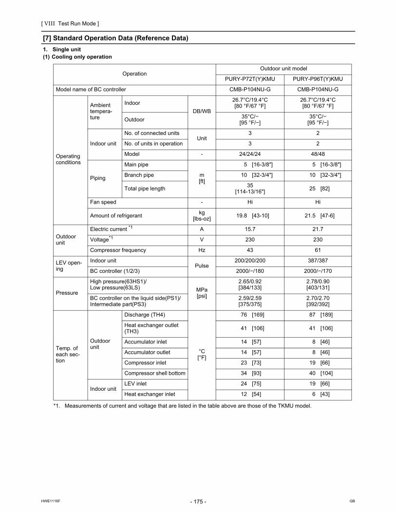
[ VIII Test Run Mode ]
- 175 -HWE1116F GB
[7] Standard Operation Data (Reference Data)
1. Single unit(1) Cooling only operation
OperationOutdoor unit model
PURY-P72T(Y)KMU PURY-P96T(Y)KMU
Model name of BC controller CMB-P104NU-G CMB-P104NU-G
Operating conditions
Ambient tempera-ture
Indoor
DB/WB
26.7°C/19.4°C[80 °F/67 °F]
26.7°C/19.4°C[80 °F/67 °F]
Outdoor 35°C/−[95 °F/−]
35°C/−[95 °F/−]
Indoor unit
No. of connected unitsUnit
3 2
No. of units in operation 3 2
Model - 24/24/24 48/48
Piping
Main pipe
m[ft]
5 [16-3/8"] 5 [16-3/8"]
Branch pipe 10 [32-3/4"] 10 [32-3/4"]
Total pipe length 35[114-13/16"] 25 [82]
Fan speed - Hi Hi
Amount of refrigerant kg[lbs-oz] 19.8 [43-10] 21.5 [47-6]
Outdoor unit
Electric current *1
*1. Measurements of current and voltage that are listed in the table above are those of the TKMU model.
A 15.7 21.7
Voltage*1 V 230 230
Compressor frequency Hz 43 61
LEV open-ing
Indoor unitPulse
200/200/200 387/387
BC controller (1/2/3) 2000/−/180 2000/−/170
Pressure
High pressure(63HS1)/Low pressure(63LS) MPa
[psi]
2.65/0.92[384/133]
2.78/0.90[403/131]
BC controller on the liquid side(PS1)/Intermediate part(PS3)
2.59/2.59[375/375]
2.70/2.70[392/392]
Temp. of each sec-tion
Outdoor unit
Discharge (TH4)
°C[°F]
76 [169] 87 [189]
Heat exchanger outlet (TH3)
41 [106] 41 [106]
Accumulator inlet 14 [57] 8 [46]
Accumulator outlet 14 [57] 8 [46]
Compressor inlet 23 [73] 19 [66]
Compressor shell bottom 34 [93] 40 [104]
Indoor unitLEV inlet 24 [75] 19 [66]
Heat exchanger inlet 12 [54] 6 [43]

[ VIII Test Run Mode ]
- 176 -HWE1116F GB
OperationOutdoor unit model
PURY-P120T(Y)KMU PURY-P144T(Y)KMU
Model name of BC controller CMB-P104NU-G CMB-P108NU-GA
Operating conditions
Ambient tempera-ture
Indoor
DB/WB
26.7°C/19.4°C[80 °F/67 °F]
26.7°C/19.4°C[80 °F/67 °F]
Outdoor35°C/−
[95 °F/−]35°C/−
[95 °F/−]
Indoor unit
No. of connected unitsUnit
4 4
No. of units in operation 4 4
Model - 30/30/30/30 36/36/36/36
Piping
Main pipe
m[ft]
5 [16-3/8"] 5 [16-3/8"]
Branch pipe 10 [32-3/4"] 10 [32-3/4"]
Total pipe length 45[147-5/8"]
45[147-5/8"]
Fan speed - Hi Hi
Amount of refrigerant kg[lbs-oz] 28.1 [61-15] 30.8 [67-14]
Outdoor unit
Electric current *1
*1. Measurements of current and voltage that are listed in the table above are those of the TKMU model.
A 27.8 34.6
Voltage*1 V 230 230
Compressor frequency Hz 75 87
LEV open-ing
Indoor unitPulse
230/230/230/230 275/275/275/275
BC controller (1/2/3) 2000/−/210 2000/2000/250
Pressure
High pressure(63HS1)/Low pressure(63LS) MPa
[psi]
2.82/0.94[409/136]
2.87/0.96[416/139]
BC controller on the liquid side(PS1)/Intermediate part(PS3)
2.73/2.72[395/394]
2.80/2.80[406/406]
Temp. of each sec-tion
Outdoor unit
Discharge (TH4)
°C[°F]
82 [180] 83 [181]
Heat exchanger outlet (TH3) 43 [109] 44 [111]
Accumulator inlet 10 [50] 10 [50]
Accumulator outlet 10 [50] 10 [50]
Compressor inlet 22 [72] 22 [72]
Compressor shell bottom 44 [111] 44 [111]
Indoor unitLEV inlet 22 [72] 22 [72]
Heat exchanger inlet 13 [55] 13 [55]

[ VIII Test Run Mode ]
- 177 -HWE1116F GB
(2) Heating only operation
OperationOutdoor unit model
PURY-P72T(Y)KMU PURY-P96T(Y)KMU
Model name of BC controller CMB-P104NU-G CMB-P104NU-G
Operating conditions
Ambient tempera-ture
Indoor
DB/WB
21.1°C/−[70 °F/-]
21.1°C/−[70 °F/-]
Outdoor8.3°C/6.1°C[47 °F/43 °F]
8.3°C/6.1°C[47 °F/43 °F]
Indoor unit
No. of connected unitsUnit
3 2
No. of units in operation 3 2
Model - 24/24/24 48/48
Piping
Main pipe
m[ft]
5 [16-3/8"] 5 [16-3/8"]
Branch pipe 10 [32-3/4"] 10 [32-3/4"]
Total pipe length 35[114-13/16"] 25 [82]
Fan speed - Hi Hi
Amount of refrigerant kg[lbs-oz] 19.8 [43-10] 21.5 [47-6]
Outdoor unit
Electric current *1
*1. Measurements of current and voltage that are listed in the table above are those of the TKMU model.
A 17.1 24.1
Voltage*1 V 230 230
Compressor frequency Hz 57 76
LEV open-ing
Indoor unitPulse
203/203/203 406/406
BC controller (1/2/3) 110/−/520 110/−/590
Pressure
High pressure(63HS1)/Low pressure(63LS) MPa
[psi]
2.52/0.7[365/102]
2.52/0.63[365/91]
BC controller on the liquid side(PS1)/Intermediate part(PS3)
2.45/2.13[355/309]
2.48/2.27[360/329]
Temp. of each sec-tion
Outdoor unit
Discharge (TH4)
°C[°F]
68 [154] 78 [172]
Heat exchanger inlet (TH6) 2 [36] 0 [32]
Accumulator inlet 1 [34] -2 [28]
Accumulator outlet 1 [34] -3 [27]
Compressor inlet 1 [34] -3 [27]
Compressor shell bottom 40 [104] 40 [104]
Indoor unitLEV inlet 30 [86] 36 [97]
Heat exchanger inlet 62 [144] 68 [154]

[ VIII Test Run Mode ]
- 178 -HWE1116F GB
OperationOutdoor unit model
PURY-P120T(Y)KMU PURY-P144T(Y)KMU
Model name of BC controller CMB-P104NU-G CMB-P108NU-GA
Operating conditions
Ambient tempera-ture
Indoor
DB/WB
21.1°C/−[70 °F/−]
21.1°C/−[70 °F/−]
Outdoor8.3°C/6.1°C[47 °F/43 °F]
8.3°C/6.1°C[47 °F/43 °F]
Indoor unit
No. of connected unitsUnit
4 4
No. of units in operation 4 4
Model - 30/30/30/30 36/36/36/36
Piping
Main pipe
m[ft]
5 [16-3/8"] 5 [16-3/8"]
Branch pipe 10 [32-3/4"] 10 [32-3/4"]
Total pipe length 45[147-5/8"]
45[147-5/8"]
Fan speed - Hi Hi
Amount of refrigerant kg[lbs-oz] 28.1 [61-15] 30.8 [67-14]
Outdoor unit
Electric current *1
*1. Measurements of current and voltage that are listed in the table above are those of the TKMU model.
A 30.7 36.8
Voltage*1 V 230 230
Compressor frequency Hz 86 107
LEV open-ing
Indoor unitPulse
295/295/295/295 350/350/350/350
BC controller (1/2/3) 110/−/660 110/110/870
Pressure
High pressure(63HS1)/Low pressure(63LS) MPa
[psi]
2.57/0.64[372/92]
2.52/0.63[365/91]
BC controller on the liquid side(PS1)/Intermediate part(PS3)
2.54/2.22[368/321]
2.45/2.13[355/309]
Temp. of each sec-tion
Outdoor unit
Discharge (TH4)
°C[°F]
73 [163] 73 [163]
Heat exchanger inlet (TH6) 2 [36] 2 [36]
Accumulator inlet -1 [30] -1 [30]
Accumulator outlet -1 [30] -1 [30]
Compressor inlet -1 [30] -1 [30]
Compressor shell bottom 40 [104] 40 [104]
Indoor unitLEV inlet 28 [82] 28 [82]
Heat exchanger inlet 67 [153] 67 [153]

[ VIII Test Run Mode ]
- 179 -HWE1116F GB
2. 2-unit combination(1) Cooling only operation
Operation
Outdoor unit model
PURY-P144YSKMU
PURY-P72YKMU PURY-P72YKMU
Model name of BC controller CMB-P108NU-GA
Operating conditions
Ambient tempera-ture
IndoorDB/WB
26.7°C/19.4°C [80 °F/67 °F]
Outdoor 35°C/− [95 °F/−]
Indoor unit
No. of connected unitsUnit
4
No. of units in operation 4
Model - 36/36/36/36
Piping
Main pipem[ft]
5 [16-3/8"]
Branch pipe 10 [32-3/4"]
Total pipe length 45 [147-5/8"]
Fan speed - Hi
Amount of refrigerant kg[lbs-oz]
36.6 [80-11]
Outdoor unit
Electric current A 15.7
Voltage V 460
Compressor frequency Hz 43 43
LEV open-ing
Indoor unitPulse
275/275/275/275
BC controller (1/2/3) 2000/2000/250
Pressure
High pressure(63HS1)/Low pressure(63LS) MPa
[psi]
2.65/0.91[384/131]
2.65/0.91[384/131]
BC controller on the liquid side(PS1)/Intermediate part(PS3)
2.59/2.59[375/375]
Temp. of each sec-tion
Outdoor unit
Discharge (TH4)
°C[°F]
76 [169] 76 [169]
Heat exchanger outlet (TH3) 41 [106] 41 [106]
Accumulator inlet 14 [57] 14 [57]
Accumulator outlet 14 [57] 14 [57]
Compressor inlet 23 [73] 23 [73]
Compressor shell bottom 34 [93] 34 [93]
Indoor unitLEV inlet 22 [72]
Heat exchanger inlet 13 [55]

[ VIII Test Run Mode ]
- 180 -HWE1116F GB
Operation
Outdoor unit model
PURY-P168T(Y)SKMU
PURY-P96T(Y)KMU PURY-P72T(Y)KMU
Model name of BC controller CMB-P108NU-GA
Operating conditions
Ambient tempera-ture
IndoorDB/WB
26.7°C/19.4°C [80 °F/67 °F]
Outdoor 35°C/− [95 °F/−]
Indoor unit
No. of connected unitsUnit
5
No. of units in operation 5
Model - 30/30/36/36/36
Piping
Main pipem[ft]
5 [16-3/8"]
Branch pipe 10 [32-3/4"]
Total pipe length 55 [180-1/8"]
Fan speed - Hi
Amount of refrigerant kg[lbs-oz]
37.9 [83-9]
Outdoor unit
Electric current *1
*1. Measurements of current and voltage that are listed in the table above are those of the TKMU model.
A 38.6
Voltage*1 V 230
Compressor frequency Hz 61 43
LEV open-ing
Indoor unitPulse
230/230/275/275/275
BC controller (1/2/3) 2000/2000/260
Pressure
High pressure(63HS1)/Low pressure(63LS) MPa
[psi]
2.78/0.91[403/131]
2.65/0.91[384/131]
BC controller on the liquid side(PS1)/Intermediate part(PS3)
2.65/2.65[384/384]
Temp. of each sec-tion
Outdoor unit
Discharge (TH4)
°C[°F]
87 [189] 76 [169]
Heat exchanger outlet (TH3) 41 [106] 41 [106]
Accumulator inlet 8 [46] 14 [57]
Accumulator outlet 8 [46] 14 [57]
Compressor inlet 19 [66] 23 [73]
Compressor shell bottom 40 [104] 34 [93]
Indoor unitLEV inlet 22 [72]
Heat exchanger inlet 9 [48]

[ VIII Test Run Mode ]
- 181 -HWE1116F GB
Operation
Outdoor unit model
PURY-P192T(Y)SKMU
PURY-P96T(Y)KMU PURY-P96T(Y)KMU
Model name of BC controller CMB-P108NU-GA
Operating conditions
Ambient tempera-ture
IndoorDB/WB
26.7°C/19.4°C [80 °F/67 °F]
Outdoor 35°C/− [95 °F/−]
Indoor unit
No. of connected unitsUnit
6
No. of units in operation 6
Model - 30/30/30/30/36/36
Piping
Main pipem[ft]
5 [16-3/8"]
Branch pipe 10 [32-3/4"]
Total pipe length 65 [213-1/4"]
Fan speed - Hi
Amount of refrigerant kg[lbs-oz]
38.7 [85-5]
Outdoor unit
Electric current *1
*1. Measurements of current and voltage that are listed in the table above are those of the TKMU model.
A 44.8
Voltage*1 V 230
Compressor frequency Hz 61 61
LEV open-ing
Indoor unitPulse
230/230/230/230/275/275
BC controller (1/2/3) 2000/2000/270
Pressure
High pressure(63HS1)/Low pressure(63LS) MPa
[psi]
2.78/0.90[403/131]
2.78/0.90[403/131]
BC controller on the liquid side(PS1)/Intermediate part(PS3)
2.70/2.70[392/392]
Temp. of each sec-tion
Outdoor unit
Discharge (TH4)
°C[°F]
87 [189] 87 [189]
Heat exchanger outlet (TH3) 41 [106] 41 [106]
Accumulator inlet 8 [46] 8 [46]
Accumulator outlet 8 [46] 8 [46]
Compressor inlet 19 [66] 19 [66]
Compressor shell bottom 42 [108] 40 [104]
Indoor unitLEV inlet 19 [66]
Heat exchanger inlet 6 [43]

[ VIII Test Run Mode ]
- 182 -HWE1116F GB
Operation
Outdoor unit model
PURY-P216T(Y)SKMU
PURY-P120T(Y)KMU PURY-P96T(Y)KMU
Model name of BC controller CMB-P1013NU-GA
Operating conditions
Ambient tempera-ture
IndoorDB/WB
26.7°C/19.4°C [80 °F/67 °F]
Outdoor 35°C/− [95 °F/−]
Indoor unit
No. of connected unitsUnit
6
No. of units in operation 6
Model - 36/36/36/36/36/36
Piping
Main pipem[ft]
5 [16-3/8"]
Branch pipe 10 [32-3/4"]
Total pipe length 65 [213-1/4"]
Fan speed - Hi
Amount of refrigerant kg[lbs-oz]
46.0 [101-7]
Outdoor unit
Electric current *1
*1. Measurements of current and voltage that are listed in the table above are those of the TKMU model.
A 51.0
Voltage*1 V 230
Compressor frequency Hz 75 61
LEV open-ing
Indoor unitPulse
275/275/275/275/275/275
BC controller (1/2/3) 2000/2000/280
Pressure
High pressure(63HS1)/Low pressure(63LS) MPa
[psi]
2.82/0.92[409/133]
2.78/0.92[403/133]
BC controller on the liquid side(PS1)/Intermediate part(PS3)
2.73/2.72[395/394]
Temp. of each sec-tion
Outdoor unit
Discharge (TH4)
°C[°F]
82 [180] 82 [180]
Heat exchanger outlet (TH3) 43 [109] 39 [102]
Accumulator inlet 8 [46] 8 [46]
Accumulator outlet 8 [46] 8 [46]
Compressor inlet 20 [68] 19 [66]
Compressor shell bottom 42 [108] 40 [104]
Indoor unitLEV inlet 22 [72]
Heat exchanger inlet 9 [48]

[ VIII Test Run Mode ]
- 183 -HWE1116F GB
Operation
Outdoor unit model
PURY-P240T(Y)SKMU
PURY-P120T(Y)KMU PURY-P120T(Y)KMU
Model name of BC controller CMB-P1013NU-GA
Operating conditions
Ambient tempera-ture
IndoorDB/WB
26.7°C/19.4°C [80 °F/67 °F]
Outdoor 35°C/− [95 °F/−]
Indoor unit
No. of connected unitsUnit
7
No. of units in operation 7
Model - 24/36/36/36/36/36/36
Piping
Main pipem[ft]
5 [16-3/8"]
Branch pipe 10 [32-3/4"]
Total pipe length 75 [229-5/8"]
Fan speed - Hi
Amount of refrigerant kg[lbs-oz]
53.3 [117-8]
Outdoor unit
Electric current *1
*1. Measurements of current and voltage that are listed in the table above are those of the TKMU model.
A 57.4
Voltage*1 V 230
Compressor frequency Hz 75 75
LEV open-ing
Indoor unitPulse
200/275/275/275/275/275/275
BC controller (1/2/3) 2000/2000/290
Pressure
High pressure(63HS1)/Low pressure(63LS) MPa
[psi]
2.82/0.94[409/136]
2.82/0.94[409/136]
BC controller on the liquid side(PS1)/Intermediate part(PS3)
2.73/2.73[395/395]
Temp. of each sec-tion
Outdoor unit
Discharge (TH4)
°C[°F]
82 [180] 82 [180]
Heat exchanger outlet (TH3) 43 [109] 43 [109]
Accumulator inlet 10 [50] 10 [50]
Accumulator outlet 10 [50] 10 [50]
Compressor inlet 22 [72] 22 [72]
Compressor shell bottom 44 [111] 44 [111]
Indoor unitLEV inlet 22 [72]
Heat exchanger inlet 13 [55]

[ VIII Test Run Mode ]
- 184 -HWE1116F GB
Operation
Outdoor unit model
PURY-P264T(Y)SKMU
PURY-P144T(Y)KMU PURY-P120T(Y)KMU
Model name of BC controller CMB-P1016NU-HA
Operating conditions
Ambient tempera-ture
IndoorDB/WB
26.7°C/19.4°C [80 °F/67 °F]
Outdoor 35°C/− [95 °F/−]
Indoor unit
No. of connected unitsUnit
8
No. of units in operation 8
Model - 24/24/36/36/36/36/36/36
Piping
Main pipem[ft]
5 [16-3/8"]
Branch pipe 10 [32-3/4"]
Total pipe length 75 [229-5/8"]
Fan speed - Hi
Amount of refrigerant kg[lbs-oz]
53.6 [118-3]
Outdoor unit
Electric current *1
*1. Measurements of current and voltage that are listed in the table above are those of the TKMU model.
A 64.4
Voltage*1 V 230
Compressor frequency Hz 87 75
LEV open-ing
Indoor unitPulse
200/200/275/275/275/275/275/275
BC controller (1/2/3) 2000/2000/290
Pressure
High pressure(63HS1)/Low pressure(63LS) MPa
[psi]
2.87/0.95[416/138]
2.82/0.95[409/138]
BC controller on the liquid side(PS1)/Intermediate part(PS3)
2.75/2.75[399/399]
Temp. of each sec-tion
Outdoor unit
Discharge (TH4)
°C[°F]
82 [180] 82 [180]
Heat exchanger outlet (TH3) 43 [109] 43 [109]
Accumulator inlet 10 [50] 10 [50]
Accumulator outlet 10 [50] 10 [50]
Compressor inlet 22 [72] 22 [72]
Compressor shell bottom 44 [111] 44 [111]
Indoor unitLEV inlet 22 [72]
Heat exchanger inlet 13 [55]

[ VIII Test Run Mode ]
- 185 -HWE1116F GB
Operation
Outdoor unit model
PURY-P288T(Y)SKMU
PURY-P144T(Y)KMU PURY-P144T(Y)KMU
Model name of BC controller CMB-P1016NU-HA
Operating conditions
Ambient tempera-ture
IndoorDB/WB
26.7°C/19.4°C [80 °F/67 °F]
Outdoor 35°C/− [95 °F/−]
Indoor unit
No. of connected unitsUnit
8
No. of units in operation 8
Model - 36/36/36/36/36/36/36/36
Piping
Main pipem[ft]
5 [16-3/8"]
Branch pipe 10 [32-3/4"]
Total pipe length 75 [229-5/8"]
Fan speed - Hi
Amount of refrigerant kg[lbs-oz]
55.6 [122-9]
Outdoor unit
Electric current *1
*1. Measurements of current and voltage that are listed in the table above are those of the TKMU model.
A 71.4
Voltage*1 V 230
Compressor frequency Hz 87 87
LEV open-ing
Indoor unitPulse
275/275/275/275/275/275/275/275
BC controller (1/2/3) 2000/2000/290
Pressure
High pressure(63HS1)/Low pressure(63LS) MPa
[psi]
2.87/0.96[416/139]
2.87/0.96[416/139]
BC controller on the liquid side(PS1)/Intermediate part(PS3)
2.80/2.80[406/406]
Temp. of each sec-tion
Outdoor unit
Discharge (TH4)
°C[°F]
83 [181] 83 [181]
Heat exchanger outlet (TH3) 44 [111] 44 [111]
Accumulator inlet 10 [50] 10 [50]
Accumulator outlet 10 [50] 10 [50]
Compressor inlet 22 [72] 22 [72]
Compressor shell bottom 44 [111] 44 [111]
Indoor unitLEV inlet 22 [72]
Heat exchanger inlet 13 [55]

[ VIII Test Run Mode ]
- 186 -HWE1116F GB
(2) Heating only operation
Operation
Outdoor unit model
PURY-P144YSKMU
PURY-P72YKMU PURY-P72YKMU
Model name of BC controller CMB-P108NU-GA
Operating conditions
Ambient tempera-ture
IndoorDB/WB
21.1°C/− [70 °F/−]
Outdoor 8.3°C/6.1°C [47°F/43°F]
Indoor unit
No. of connected unitsUnit
4
No. of units in operation 4
Model - 36/36/36/36
Piping
Main pipem[ft]
5 [16-3/18"]
Branch pipe 10 [32-3/4"]
Total pipe length 45 [147-5/8"]
Fan speed - Hi
Amount of refrigerant kg[lbs-oz]
36.6 [80-11]
Outdoor unit
Electric current A 17.1
Voltage V 460
Compressor frequency Hz 57 57
LEV open-ing
Indoor unitPulse
350/350/350/350
BC controller (1/2/3) 110/110/870
Pressure
High pressure(63HS1)/Low pressure(63LS) MPa
[psi]
2.52/0.70[365/102]
2.52/0.70[365/102]
BC controller on the liquid side(PS1)/Intermediate part(PS3)
2.45/2.13[355/309]
Temp. of each sec-tion
Outdoor unit
Discharge (TH4)
°C[°F]
68 [154] 68 [154]
Heat exchanger inlet (TH6) 2 [36] 2 [36]
Accumulator inlet 1 [34] 1 [34]
Accumulator outlet 1 [34] 1 [34]
Compressor inlet 1 [34] 1 [34]
Compressor shell bottom 40 [104] 40 [104]
Indoor unitLEV inlet 28 [82]
Heat exchanger inlet 67 [153]

[ VIII Test Run Mode ]
- 187 -HWE1116F GB
Operation
Outdoor unit model
PURY-P168T(Y)SKMU
PURY-P96T(Y)KMU PURY-P72T(Y)KMU
Model name of BC controller CMB-P108NU-GA
Operating conditions
Ambient tempera-ture
IndoorDB/WB
21.1°C/− [70 °F/−]
Outdoor 8.3°C/6.1°C [47°F/43°F]
Indoor unit
No. of connected unitsUnit
5
No. of units in operation 5
Model - 30/30/36/36/36
Piping
Main pipem[ft]
5 [16-3/18"]
Branch pipe 10 [32-3/4"]
Total pipe length 55 [180-1/8"]
Fan speed - Hi
Amount of refrigerant kg[lbs-oz]
37.9 [83-9]
Outdoor unit
Electric current *1
*1. Measurements of current and voltage that are listed in the table above are those of the TKMU model.
A 42.5
Voltage*1 V 230
Compressor frequency Hz 76 57
LEV open-ing
Indoor unitPulse
295/295/350/350/350
BC controller (1/2/3) 110/110/980
Pressure
High pressure(63HS1)/Low pressure(63LS) MPa
[psi]
2.52/0.63[365/91]
2.52/0.70[365/102]
BC controller on the liquid side(PS1)/Intermediate part(PS3)
2.46/2.20[357/319]
Temp. of each sec-tion
Outdoor unit
Discharge (TH4)
°C[°F]
78 [172] 68 [154]
Heat exchanger inlet (TH6) 0 [32] 2 [36]
Accumulator inlet -2 [28] 1 [34]
Accumulator outlet -3 [27] 1 [34]
Compressor inlet -3 [27] 1 [34]
Compressor shell bottom 40 [104] 40 [104]
Indoor unitLEV inlet 34 [93]
Heat exchanger inlet 65 [149]

[ VIII Test Run Mode ]
- 188 -HWE1116F GB
Operation
Outdoor unit model
PURY-P192T(Y)SKMU
PURY-P96T(Y)KMU PURY-P96T(Y)KMU
Model name of BC controller CMB-P108NU-GA
Operating conditions
Ambient tempera-ture
IndoorDB/WB
21.1°C/− [70 °F/−]
Outdoor 8.3°C/6.1°C [47°F/43°F]
Indoor unit
No. of connected unitsUnit
6
No. of units in operation 6
Model - 30/30/30/30/36/36
Piping
Main pipem[ft]
5 [16-3/18"]
Branch pipe 10 [32-3/4"]
Total pipe length 65 [213-1/4"]
Fan speed - Hi
Amount of refrigerant kg[lbs-oz]
38.7 [85-5]
Outdoor unit
Electric current *1
*1. Measurements of current and voltage that are listed in the table above are those of the TKMU model.
A 49.7
Voltage*1 V 230
Compressor frequency Hz 76 76
LEV open-ing
Indoor unitPulse
295/295/295/295/350/350
BC controller (1/2/3) 110/110/1050
Pressure
High pressure(63HS1)/Low pressure(63LS) MPa
[psi]
2.52/0.63[365/91]
2.52/0.63[365/91]
BC controller on the liquid side(PS1)/Intermediate part(PS3)
2.48/2.27[360/329]
Temp. of each sec-tion
Outdoor unit
Discharge (TH4)
°C[°F]
78 [172] 78 [172]
Heat exchanger inlet (TH6) 0 [32] 0 [32]
Accumulator inlet -2 [28] -2 [28]
Accumulator outlet -3 [27] -3 [27]
Compressor inlet -3 [27] -3 [27]
Compressor shell bottom 40 [104] 40 [104]
Indoor unitLEV inlet 36 [97]
Heat exchanger inlet 68 [154]

[ VIII Test Run Mode ]
- 189 -HWE1116F GB
Operation
Outdoor unit model
PURY-P216T(Y)SKMU
PURY-P120T(Y)KMU PURY-P96T(Y)KMU
Model name of BC controller CMB-P1013NU-GA
Operating conditions
Ambient tempera-ture
IndoorDB/WB
21.1°C/− [70 °F/−]
Outdoor 8.3°C/6.1°C [47°F/43°F]
Indoor unit
No. of connected unitsUnit
6
No. of units in operation 6
Model - 36/36/36/36/36/36
Piping
Main pipem[ft]
5 [16-3/18"]
Branch pipe 10 [32-3/4"]
Total pipe length 65 [213-1/4"]
Fan speed - Hi
Amount of refrigerant kg[lbs-oz]
46.0 [101-7]
Outdoor unit
Electric current *1
*1. Measurements of current and voltage that are listed in the table above are those of the TKMU model.
A 56.7
Voltage*1 V 230
Compressor frequency Hz 86 76
LEV open-ing
Indoor unitPulse
350/350/350/350/350/350
BC controller (1/2/3) 110/110/1120
Pressure
High pressure(63HS1)/Low pressure(63LS) MPa
[psi]
2.54/0.64[368/92]
2.54/0.63[368/91]
BC controller on the liquid side(PS1)/Intermediate part(PS3)
2.50/2.17[363/315]
Temp. of each sec-tion
Outdoor unit
Discharge (TH4)
°C[°F]
69 [154] 69 [154]
Heat exchanger inlet (TH6) 2 [36] 0 [32]
Accumulator inlet -1 [30] -2 [28]
Accumulator outlet -1 [30] -3 [27]
Compressor inlet -1 [30] -3 [27]
Compressor shell bottom 40 [104] 40 [104]
Indoor unitLEV inlet 33 [91]
Heat exchanger inlet 68 [154]
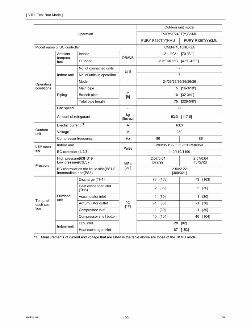
[ VIII Test Run Mode ]
- 190 -HWE1116F GB
Operation
Outdoor unit model
PURY-P240T(Y)SKMU
PURY-P120T(Y)KMU PURY-P120T(Y)KMU
Model name of BC controller CMB-P1013NU-GA
Operating conditions
Ambient tempera-ture
IndoorDB/WB
21.1°C/− [70 °F/−]
Outdoor 8.3°C/6.1°C [47°F/43°F]
Indoor unit
No. of connected unitsUnit
7
No. of units in operation 7
Model - 24/36/36/36/36/36/36
Piping
Main pipem[ft]
5 [16-3/18"]
Branch pipe 10 [32-3/4"]
Total pipe length 75 [229-5/8"]
Fan speed - Hi
Amount of refrigerant kg[lbs-oz]
53.3 [117-8]
Outdoor unit
Electric current *1
*1. Measurements of current and voltage that are listed in the table above are those of the TKMU model.
A 63.3
Voltage*1 V 230
Compressor frequency Hz 86 86
LEV open-ing
Indoor unitPulse
203/350/350/350/350/350/350
BC controller (1/2/3) 110/110/1190
Pressure
High pressure(63HS1)/Low pressure(63LS) MPa
[psi]
2.57/0.64[372/92]
2.57/0.64[372/92]
BC controller on the liquid side(PS1)/Intermediate part(PS3)
2.54/2.22[368/321]
Temp. of each sec-tion
Outdoor unit
Discharge (TH4)
°C[°F]
73 [163] 73 [163]
Heat exchanger inlet (TH6) 2 [36] 2 [36]
Accumulator inlet -1 [30] -1 [30]
Accumulator outlet -1 [30] -1 [30]
Compressor inlet -1 [30] -1 [30]
Compressor shell bottom 40 [104] 40 [104]
Indoor unitLEV inlet 28 [82]
Heat exchanger inlet 67 [153]

[ VIII Test Run Mode ]
- 191 -HWE1116F GB
Operation
Outdoor unit model
PURY-P264T(Y)SKMU
PURY-P144T(Y)KMU PURY-P120T(Y)KMU
Model name of BC controller CMB-P1016NU-HA
Operating conditions
Ambient tempera-ture
IndoorDB/WB
21.1°C/− [70 °F/−]
Outdoor 8.3°C/6.1°C [47°F/43°F]
Indoor unit
No. of connected unitsUnit
8
No. of units in operation 8
Model - 24/24/36/36/36/36/36/36
Piping
Main pipem[ft]
5 [16-3/18"]
Branch pipe 10 [32-3/4"]
Total pipe length 75 [229-5/8"]
Fan speed - Hi
Amount of refrigerant kg[lbs-oz]
53.6 [118-3]
Outdoor unit
Electric current *1
*1. Measurements of current and voltage that are listed in the table above are those of the TKMU model.
A 69.5
Voltage*1 V 230
Compressor frequency Hz 107 86
LEV open-ing
Indoor unitPulse
203/203/350/350/350/350/350/350
BC controller (1/2/3) 110/110/1190
Pressure
High pressure(63HS1)/Low pressure(63LS) MPa
[psi]
2.55/0.63[370/91]
2.55/0.64[370/92]
BC controller on the liquid side(PS1)/Intermediate part(PS3)
2.52/2.20[365/319]
Temp. of each sec-tion
Outdoor unit
Discharge (TH4)
°C[°F]
73 [163] 73 [163]
Heat exchanger inlet (TH6) 2 [36] 2 [36]
Accumulator inlet -1 [30] -1 [30]
Accumulator outlet -1 [30] -1 [30]
Compressor inlet -1 [30] -1 [30]
Compressor shell bottom 40 [104] 40 [104]
Indoor unitLEV inlet 28 [82]
Heat exchanger inlet 67 [153]

[ VIII Test Run Mode ]
- 192 -HWE1116F GB
Operation
Outdoor unit model
PURY-P288T(Y)SKMU
PURY-P144T(Y)KMU PURY-P144T(Y)KMU
Model name of BC controller CMB-P1016NU-HA
Operating conditions
Ambient tempera-ture
IndoorDB/WB
21.1°C/− [70 °F/−]
Outdoor 8.3°C/6.1°C [47°F/43°F]
Indoor unit
No. of connected unitsUnit
8
No. of units in operation 8
Model - 36/36/36/36/36/36/36/36
Piping
Main pipem[ft]
5 [16-3/18"]
Branch pipe 10 [32-3/4"]
Total pipe length 75 [229-5/8"]
Fan speed - Hi
Amount of refrigerant kg[lbs-oz]
55.6 [122-9]
Outdoor unit
Electric current *1
*1. Measurements of current and voltage that are listed in the table above are those of the TKMU model.
A 75.8
Voltage*1 V 230
Compressor frequency Hz 107 107
LEV open-ing
Indoor unitPulse
350/350/350/350/350/350/350/350
BC controller (1/2/3) 110/110/1190
Pressure
High pressure(63HS1)/Low pressure(63LS) MPa
[psi]
2.52/0.63[365/91]
2.52/0.63[365/91]
BC controller on the liquid side(PS1)/Intermediate part(PS3)
2.45/2.13[355/309]
Temp. of each sec-tion
Outdoor unit
Discharge (TH4)
°C[°F]
73 [163] 73 [163]
Heat exchanger inlet (TH6) 2 [36] 2 [36]
Accumulator inlet -1 [30] -1 [30]
Accumulator outlet -1 [30] -1 [30]
Compressor inlet -1 [30] -1 [30]
Compressor shell bottom 40 [104] 40 [104]
Indoor unitLEV inlet 28 [82]
Heat exchanger inlet 67 [153]

- 193 -HWE1116F GB
IX Troubleshooting
[1] Error Code Lists .............................................................................................................195
[2] Responding to Error Display on the Remote Controller.................................................199
[3] Investigation of Transmission Wave Shape/Noise.........................................................286
[4] Troubleshooting Principal Parts .....................................................................................289
[5] Refrigerant Leak ............................................................................................................338
[6] Compressor Replacement Instructions..........................................................................340
[7] Servicing the BC controller ............................................................................................350
[8] Troubleshooting Using the Outdoor Unit LED Error Display..........................................353
[9] Cleaning the outdoor unit heat exchanger .....................................................................353

- 194 -HWE1116F GB

[ IX Troubleshooting ]
- 195 -HWE1116F GB
IX Troubleshooting
[1] Error Code Lists
Error Code
Prelimi-nary error code
Error (prelim-inary) detail code
Error code definition
Searched unit
Notes
0403430043054306
156
(Note)
Serial communication error/Panel communication error O O
1102 1202 - Discharge temperature fault O
1301 - - Low pressure fault O
1302 1402 - High pressure fault O
1500 1600 - Refrigerant overcharge O
- 1605 - Preliminary suction pressure fault O
2500 - - Drain sensor submergence O
2502 - - Drain pump fault O O
2503 - - Drain sensor (Thd) fault O O
2600 - - Water leakage O
2601 - - Water supply cutoff O
3121 - - Out-of-range outside air temperature O
4102 4152 - Open phase O
4106 - - Transmission power supply fault O
4109 - - Fan operation status detection error O
4115 - - Power supply signal sync error O
4116 - - RPM error/Motor error O O
4121 4171 − Function setting error O
422042254226(Note)
432043254326
(Note)
[0] Backup operation O
[108] Abnormal bus voltage drop O
[109] Abnormal bus voltage rise O
[111] Logic error O
[131] Low bus voltage at startup O
4230 4330 - Heatsink overheat protection O
4240 4340 - Overload protection O
425042554256(Note)
435043554356
(Note)
[0] Backup operation O
[101] IPM error O
[103] DCCT overcurrent (H/W detection) O
[104] Short-circuited IPM/Ground fault O
[105] Overcurrent error due to short-circuited motor O
[106] Instantaneous overcurrent (S/W detection) O
[107] Overcurrent (effective value)(S/W detection) O
4260 - - Heatsink overheat protection at startup O
Out
door
uni
t
Indo
or u
nit
BC
con
trol
ler
LOS
SN
AY
Rem
ote
cont
rolle
r

[ IX Troubleshooting ]
- 196 -HWE1116F GB
5101 1202 - Temperature sensor fault
Return air temperature (TH21) O
OA processing unit inlet temperature (TH4) O
5102 1217 - Temperature sensor fault
Indoor unit pipe tempera-ture (TH22) O
OA processing unit pipe temperature (TH2) O
5103 1205 00 Temperature sensor fault
Indoor unit gas-side pipe temperature (TH23) O
OA processing unit gas-side pipe temperature (TH3)
O
Pipe temperature at heat exchanger outlet (TH3) O
5104 1202 - Temperature sensor fault
OA processing unit intake air temperature (TH1) O
Outside temperature (TH24) O
Detectable only by the All-Fresh type in-door units
Outdoor unit discharge temperature (TH4) O
5105 1204 - Temperature sensor fault
Accumulator inlet tempera-ture (TH5) O
5106 1216 - Temperature sensor fault
Heat exchanger inlet tem-perature (TH6) O
5107 1221 - Temperature sensor fault
Outside temperature (TH7) O
5110 1214
[0] Backup operation O
01 Temperature sensor fault
Heatsink temperature (THHS) O
5111 - -
Temperature sensor fault(BC controller)
Liquid inlet temperature (TH11) O
5112 - - Bypass outlet temperature (TH12) O
5115 - -LEV3 outlet temperature (TH15) O
5116 - - LEV3 inlet temperature (TH16) O
5201 - - High-pressure sensor fault (63HS1) O
5201 1402 - High-pressure sensor fault (Outdoor unit HPS/BC controller PS1) O O
5203 - - Intermediate pressure sensor fault (BC controller PS3) O
Error Code
Prelimi-nary error code
Error (prelim-inary) detail code
Error code definition
Searched unit
Notes
Out
door
uni
t
Indo
or u
nit
BC
con
trol
ler
LOS
SN
AY
Rem
ote
cont
rolle
r
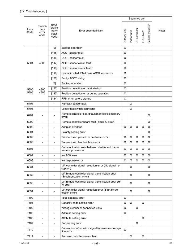
[ IX Troubleshooting ]
- 197 -HWE1116F GB
5301 4300
[0] Backup operation O
[115] ACCT sensor fault O
[116] DCCT sensor fault O
[117] ACCT sensor circuit fault O
[118] DCCT sensor circuit fault O
[119] Open-circuited IPM/Loose ACCT connector O
[120] Faulty ACCT wiring O
53055306
43054306
[0] Backup operation O
[132] Position detection error at startup O
[133] Position detection error during operation O
[134] RPM error before startup O
5401 - - Humidity sensor fault O
5701 - - Loose float switch connector O
6201 - - Remote controller board fault (nonvolatile memory error)
O
6202 - - Remote controller board fault (clock IC error) O
6600 - - Address overlaps O O O O O
6601 - - Polarity setting error O
6602 - - Transmission processor hardware error O O O O O
6603 - - Transmission line bus busy error O O O O O
6606 - - Communication error between device and trans-mission processors O O O O O
6607 - - No ACK error O O O O O
6608 - - No response error O O O O O
6831 - - MA controller signal reception error (No signal re-ception) O O
6832 - - MA remote controller signal transmission error (Synchronization error) O O
6833 - - MA remote controller signal transmission error (H/W error) O O
6834 - - MA controller signal reception error (Start bit de-tection error) O O
7100 - - Total capacity error O
7101 - - Capacity code setting error O O O
7102 - - Wrong number of connected units O O
7105 - - Address setting error O
7106 - - Attribute setting error O
7107 - - Port setting error O
7110 - - Connection information signal transmission/recep-tion error O
7111 - - Remote controller sensor fault O O
Error Code
Prelimi-nary error code
Error (prelim-inary) detail code
Error code definition
Searched unit
Notes
Out
door
uni
t
Indo
or u
nit
BC
con
trol
ler
LOS
SN
AY
Rem
ote
cont
rolle
r

[ IX Troubleshooting ]
- 198 -HWE1116F GB
The last digit in the check error codes in the 4000's and 5000's and two-digit detail codes indicate if the codes apply to inverter on fan inverter.ExampleCode 4225 (detail code 108): Bus voltage drop in the fan inverter systemCode 4230 : Heatsink overheat protection in the inverter system
7113 - - Function setting error (improper connection of CN-TYP) O
7117 - - Model setting error O
7130 - - Incompatible unit combination O
The last digit Inverter system
0 or 1 Compressor inverter system
5 or 6 Fan inverter system
Error Code
Prelimi-nary error code
Error (prelim-inary) detail code
Error code definition
Searched unit
Notes
Out
door
uni
t
Indo
or u
nit
BC
con
trol
ler
LOS
SN
AY
Rem
ote
cont
rolle
r

[ IX Troubleshooting ]
- 199 -HWE1116F GB
[2] Responding to Error Display on the Remote Controller0403
1. Error Code
Serial communication error
2. Error definition and error detection methodSerial communication error between the control board and the INV board on the compressor, and between the control board and the Fan boardDetail code 1: Between the control board and the INV board Detail code 5, 6: Between the control board and the Fan board
3. Cause, check method and remedy(1) Faulty wiring
Check the following wiring connections.1) Between Control board and Fan board
2) Between Fan board and INV board
(2) INV board failure, Fan board failure and Control board failure
Replace the INV board or the Fan board or control board when the power turns on automatically, even if the power source is reset.
1. Error code
Panel communication error
2. Error definition and detection methodThis error is detected when indoor units cannot successfully receive the signals from the Auto filter cleaning unit for one min-ute.
3. Cause, check method and remedy
Refer to section -7- "Inverter" under part [4] Troubleshooting Principal Parts for error codes related to the inverter.(page 310)(page 321)
0403
Control board FAN board
CN2,CN2A CN80
CN4,CN4A CN80
FAN board INV board
CN82 CN2
CN83 CN43
0403 (Indoor unit)
Cause Check method and remedy
(1) Incorrect switch setting on the indoor unit cir-cuit board
Check SW3-3 on the indoor unit circuit board Set SW3-3 to ON only when connecting an auto filter cleaning unit.
(2) Power wire that connects the circuit board on the indoor unit and the circuit board on the cleaning unit is loose.
Check the LED1 (cleaning unit circuit board (microcomputer power)). Lit: Power is supplied properly. Unlit: Check for loose or disconnected power wire between the indoor unit circuit board (CNAC) and the cleaning unit circuit board (CN3A).
(3) Communication wire that connects the circuit board on the indoor unit and the circuit board on the cleaning unit is loose.
Check the LED4 (cleaning unit circuit board (communication)).Blinking: Normal communication Unlit: Check for loose or disconnected communication wire be-tween the indoor unit circuit board (CN3G) and the cleaning unit circuit board (CN3G). If the LED blinks at irregular intervals (normally blinks at 0.5-sec-ond intervals), electrical interference is suspected. Check the items above, turn the power off, and turn the power back on. If the error persists, replace either the cleaning unit cir-cuit board or the indoor unit circuit board.
(4) Panel transceiver circuit fault (cleaning unit)
(5) Panel transceiver circuit fault (indoor unit)
(6) Electrical interference on the cleaning unit's communication cable

[ IX Troubleshooting ]
- 200 -HWE1116F GB
1102
1. Error Code
Discharge temperature fault
2. Error definition and error detection method1) If the discharge temperature of 120 °C [248°F] or more is detected during the above operation (the first detection), the outdoor
unit stops once, turns to anti-restart mode for 3 minutes, and restarts after 3 minutes automatically.2) If the discharge temperature of 120° C [248°F] or more is detected again (the second detection) within 30 minutes after the
second stop of the outdoor unit described above, the mode will be changed to 3 - minute restart mode, then the outdoor unit will restart in 3 minutes.
3) If the discharge temperature of 120°C [248°F] or more is detected (the third detection) within 30 minutes after the stop of the outdoor unit described above (regardless of the first or the second stop), the outdoor unit will make an error stop, and the error code "1102" will be displayed.
4) If the discharge temperature of 120°C [248°F] or more is detected more than 30 minutes after the previous stop of the outdoor unit, the detection is regarded as the first detection, and the operation described in step 1 above will start.
5) For 30 minutes after the stop (the first stop or the second stop) of the outdoor unit, preliminary errors will be displayed on the LED display.
3. Cause, check method and remedy
1102
Cause Check method and remedy
(1) Gas leak, gas shortage Refer to the page on refrigerant amount evaluation.(page 169)
(2) Overload operation Check operating conditions and operation status of indoor/outdoor units.
(3) LEV failure on the indoor unit Perform a heating operation and check the operation.Cooling: LEV on the indoor unit LEV1,2,3 SVM1,2 SVA,CHeating: LEV on the indoor unit LEV3 SVB SV4a - 4dRefer to the page on troubleshooting LEV.(page 296)
(4) BC controller LEV malfunctionCooling only : LEV3Cooling main : LEV1,2,3Heating only or heatingmain : LEV3Defrost : LEV3
(5) BC controller SVM1 and 2 malfunction-> Cooling only or defrost
(6) BC controller SVA malfunction-> Cooling only or cooling main
(7) BC controller SVB malfunction-> Heating only or heating main
(8) Solenoid valve SV malfunction (4a-4c (P72 model) ,4a-4d (P96, P120, P144 models)):heating only, heating main
(9) Port address setting error. Confirm the port address of the indoor unit.
(10) Closed ball valve Confirm that the ball valve is fully open.
(11) Outdoor fan (including fan parts) failure, mo-tor failure, or fan controller malfunctionRise in discharge temp. by low pressure drawing for (3) - (11).
Check the fan on the outdoor unit. Refer to the section on troubleshooting the outdoor unit fan.(page 295)
(12) Gas leak between low and high pressures(4-way valve failure, Compressor failure, So-lenoid valve (SV1a) failure)
Perform a cooling or heating operation and check the opera-tion.
(13) Thermistor failure(TH4)
Check the thermistor resistor.(page 234)
(14) Input circuit failure on the controller board thermistor
Check the inlet air temperature on the LED monitor.

[ IX Troubleshooting ]
- 201 -HWE1116F GB
1301
1. Error Code
Low pressure fault
2. Error definition and error detection methodWhen starting the compressor from Stop Mode for the first time if low pressure reads 0.098MPa [14psi] immediately before start-up, the operation immediately stops.
3. Cause, check method and remedy
1301
Cause Check method and remedy
(1) Inner pressure drop due to a leakage. Refer to the section on troubleshooting the low pressure sensor.(page 290)
(2) Low pressure sensor failure
(3) Short-circuited pressure sensor cable due to torn outer rubber
(4) A pin on the male connector is missing.
(5) Disconnected wire
(6) Failure of the low pressure input circuit on the controller board

[ IX Troubleshooting ]
- 202 -HWE1116F GB
1302
1. Error Code
High pressure fault 1 (Outdoor unit)2. Error definition and error detection method1) If the pressure of 3.78MPa [548psi] or higher is detected by the pressure sensor during operation (the first detection), the out-
door stops once, turns to antirestart mode for 3 minutes, and restarts after 3 minutes automatically.2) If the pressure of 3.78MPa [548psi] or higher is detected by the pressure sensor again (the second detection) within 30 min-
utes after the first stop of the outdoor unit, the outdoor unit stops once, turns to anti-restart mode for 3 minutes, and restarts after 3 minutes automatically.
3) If the pressure of 3.87MPa [561psi] or higher is detected by the pressure sensor (the third detection) within 30 minutes of the second stop of the outdoor unit, the outdoor unit will make an error stop, and the error code "1302" will be displayed.
4) If the pressure of 3.78MPa [548psi] or higher is detected more than 30 minutes after the stop of the outdoor unit, the detection is regarded as the first detection, and the operation described in step 1 above will start.
5) For 30 minutes after the stop of the outdoor unit, preliminary errors will be displayed on the LED display.6) The outdoor unit makes an error stop immediately when not only the pressure sensor but also the pressure switch detects
4.15+0,-0.15 MPa [601+0,-22 psi]7) Open phase due to unstable power supply voltage may cause the pressure switch to malfunction or cause the units to come
to an abnormal stop.
3. Cause, check method and remedy
1302
Cause Check method and remedy
(1) Indoor unit LEV actuation failure Perform a heating operation and check the op-eration.Cooling: LEV on the indoor unit LEV1,2,3 SVM1,1b,2,2b SVAHeating: LEV on the indoor unit LEV3 SVM2,2b SVB,SV4a - 4dRefer to the page on troubleshooting for LEV and solenoid valve.(page 296)
(2) BC controller LEV malfunction Heating only or heating main : Indoor LEV 3Defrost : LEV3
(3) BC controller SVM1 and 2 malfunction->Cooling only or defrost
(4) BC controller SVA and SVC malfunction->Cooling only or cooling main
(5) BC controller SVB malfunction ->Heating only or heating mainSolenoid valve SV malfunction(4a-4c (P72 model) ,4a-4d(P96, P120, P144 models)) ->Cooling only or cooling main
(6) Port address setting error. Confirm the port address of the indoor unit.
(7) Refrigerant service valve actuation failure Confirm that the refrigerant service valve is fully
(8) Short cycle on the indoor unit side Check the indoor units for problems and correct them, if any.(9) Clogged filter on the indoor unit
(10) Reduced air flow due to dirty fan on the indoor unit fan
(11) Dirty heat exchanger of the indoor unit
(12) Indoor fan (including fan parts) failure or motor failureItems (7) through (12) above reduce the condensing capability of the unit, resulting in high-pressure rise during heating operation.
(13) Short cycle on the outdoor unit Check the outdoor units for problems and cor-rect them, if any.(14) Dirty heat exchanger of the outdoor unit
(15) Outdoor fan (including fan parts) failure, motor failure, or fan con-troller malfunctionItems (13) through (15) above reduce the condensing capability of the unit, resulting in high-pressure rise during cooling operation.
Check the fan on the outdoor unit.Refer to the section on troubleshooting the out-door unit fan.(page 295)
(16) Solenoid valve (SV1a) malfunction The by-pass valve (SV1a) can not control rise in high pressure.
Refer to the section on troubleshooting the sole-noid valve.(page 291)
(17) Thermistor failure (TH3, TH7) Check the thermistor resistor.(page 234)
(18) Pressure sensor failure Refer to the page on the troubleshooting of the high pressure sensor. (page 289)
(19) Failure of the thermistor input circuit and pressure sensor input circuit on the controller board
Check the sensor temperature/pressure on the LED monitor.
(20) Thermistor mounting problem (TH3, TH7) Check the sensor temperature/pressure on the LED monitor. (21) Disconnected male connector on the pressure switch (63H1) or
disconnected wire
(22) Voltage drop caused by unstable power supply voltage Check the input voltage at the power supply ter-minal block (TB1).

[ IX Troubleshooting ]
- 203 -HWE1116F GB
1. Error Code
High pressure fault 2 (Outdoor unit)
2. Error definition and error detection methodIf the pressure of 0.098MPa [14psi] or lower is registered on the pressure sensor immediately before start-up, it will trigger an abnormal stop, and error code "1302" will be displayed.
3. Cause, check method and remedy
1500
1. Error Code
Refrigerant overcharge
2. Error definition and error detection methodAn error can be detected by the discharge temperature superheat.
1) If the formula "TdSH 10°C [18°F]" is satisfied during operation (first detection), the outdoor unit stops, goes into the 3-minute restart mode, and starts up in three minutes.
2) If the formula "TdSH 10°C [18°F]" is satisfied again within 30 minutes of the first stoppage of the outdoor unit (second de-tection), the unit comes to an abnormal stop, and the error code "1500" appears.
3) If the formula "TdSH 10°C [18°F]" is satisfied 30 minutes or more after the first stoppage of the outdoor unit, the same se-quence as Item "1 above (first detection) is followed.
4) For 30 minutes after the stop of the outdoor unit, preliminary errors will be displayed on the LED display.
3. Cause, check method and remedy
1302
Cause Check method and remedy
(1) Inner pressure drop due to a leakage. Refer to the page on the troubleshooting of the high pressure sensor.(page 289)
(2) Pressure sensor failure
(3) Shorted-circuited pressure sensor cable due to torn outer rubber
(4) A pin on the male connector on the pressure sensor is missing or contact failure
(5) Disconnected pressure sensor cable
(6) Failure of the pressure sensor input circuit on the controller board
1500
Cause Check method and remedy
(1) Overcharged refrigerant Refer to the page on refrigerant amount evaluation.(page 169)
(2) Thermistor input circuit failure on the control board Check the temperature and pressure readings on the sen-sor that are displayed on the LED monitor.
(3) Faulty mounting of thermistor (TH4) Check the temperature and pressure readings on the thermistor that are displayed on the LED monitor.

[ IX Troubleshooting ]
- 204 -HWE1116F GB
2500
1. Error Code
Drain sensor submergence (Models with a drain sensor)
2. Error definition and error detection method1) If an immersion of the drain sensor in the water is detected while the unit is in any mode other than the Cool/Dry mode and
when the drain pump goes from OFF to ON, this condition is considered preliminary water leakage. While this error is being detected, humidifier output cannot be turned on.(Applicable to the units manufactured in or after October 1996)
2) If the immersion of the sensor in the water is detected four consecutive times at an hour interval, this is considered water leak-age, and "2500" appears on the monitor.
3) Detection of water leakage is also performed while the unit is stopped.4) Preliminary water leakage is cancelled when the following conditions are met:
One hour after the preliminary water leakage was detected, it is not detected that the drain pump goes from OFF to ON.The operation mode is changed to Cool/Dry.Liquid pipe temperature - inlet temperature -10°C[ -18°F]
3. Cause, check method and remedy
2500
Cause Check method and remedy
(1) Drain water drainage problemClogged drain pumpClogged drain pipingBackflow of drain water from other units
Check for proper drainage.
(2) Adhesion of water drops to the drain sensorTrickling of water along the lead wireRippling of drain water caused by filter clogging
1) Check for proper lead wire installation.
2) Check for clogged filter.
(3) Failure of the relay circuit for the solenoid valve Replace the relay.
(4) Indoor unit control board failureDrain sensor circuit failure
If the above item checks out OK, replace the indoor unit control board.

[ IX Troubleshooting ]
- 205 -HWE1116F GB
1. Error Code
Drain sensor submergence (Models with a float switch)
2. Error definition and error detection method1) If an immersion of the float switch in the water is detected while the unit is in any mode other than the Cool/Dry mode and
when the drain pump goes from OFF to ON, this condition is considered preliminary water leakage. While this error is being detected, humidifier output cannot be turned on.
2) If the drain pump turns on within one hour after preliminary water leakage is detected and the above-mentioned condition is detected two consecutive times, water leakage error water leakage is detected, and "2500" appears on the monitor.
3) Detection of water leakage is also performed while the unit is stopped.4) Preliminary water leakage is cancelled when the following conditions are met:
One hour after the preliminary water leakage was detected, it is not detected that the drain pump goes from OFF to ON.The operation mode is changed to Cool/Dry.Liquid pipe temperature - inlet temperature - 10°C[-18°F]
3. Cause, check method and remedy
<Reference>
2500
Cause Check method and remedy
(1) Drain water drainage problemClogged drain pumpClogged drain pipingBackflow of drain water from other units
Check for proper drainage.
(2) Stuck float switchCheck for slime in the moving parts of the float switch.
Check for normal operation of the float switch.
(3) Float switch failure Check the resistance with the float switch turned on and turned off.
6 minutes 6 minutes
15 seconds
15 seconds 15
seconds 15
seconds 15
seconds
ON
OFF
ON
OFF
Drain pump operation triggered by a submergence of the liquid level sensor (except during the Cooing/Dry mode)
Drain pump output
Float switch input
Submergence of the sensor
Submergence of the sensor Preliminary water leakage
Submergence of the sensor Water leakage
Sensor in the air Sensor in the air
Within 1-hour period Within 1-hour period

[ IX Troubleshooting ]
- 206 -HWE1116F GB
2502
1. Error Code
Drain pump fault (Models with a drain sensor)
2. Error definition and error detection method1) Make the drain sensor thermistor self-heat. If the temperature rise is small, it is interpreted that the sensor is immersed in
water. This condition is considered to be a preliminary error, and the unit goes into the 3-minute restart delay mode.2) If another episode of the above condition is detected during the preliminary error, this is considered a drain pump error, and
"2502" appears on the monitor.3) This error is always detected while the drain pump is in operation.4) The following criteria are met when the criteria for the forced stoppage of outdoor unit (system stoppage) are met.
"Liquid pipe temperature - inlet temperature - 10 °C [ -18°F] " has been detected for 30 minutes.The immersion of drain sensor is detected 10 consecutive times.The conditions that are listed under items 1) through 3) above are always met before the criteria for the forced stoppage
of the outdoor unit.5) The indoor unit that detected the conditions that are listed in item 4) above brings the outdoor unit in the same refrigerant
circuit to an error stop (compressor operation prohibited), and the outdoor unit brings all the indoor units in the same refrigerant circuit that are in any mode other than Fan or Stop to an error stop. "2502" appears on the monitor of the units that came to an error stop.
6) Forced stoppage of the outdoor unitDetection timing: The error is detected whether the unit is in operation or stopped.
7) Ending criteria for the forced stoppage of outdoor unitPower reset the indoor unit that was identified as the error source and the outdoor unit that is connected to the same refrig-erant circuit.Forced stoppage of the outdoor unit cannot be cancelled by stopping the unit via the remote controller.(Note) Items 1) - 3) and 4) - 7) are detected independently from each other.
The address and attribute that appear on the remote controller are those of the indoor unit (or OA processing unit) that caused the error.
3. Cause, check method and remedy
2502
Cause Check method and remedy
(1) Drain pump failure Check for proper functioning of the drain pump.
(2) Drain water drainage problemClogged drain pumpClogged drain piping
Check for proper drainage.
(3) Adhesion of water drops to the drain sensorTrickling of water along the lead wireRippling of drain water caused by filter clogging
1) Check for proper lead wire installation.
2) Check for clogged filter.
(4) Indoor unit control board failureDrain pump drive circuit failureDrain heater output circuit failure
If the above item checks out OK, replace the indoor unit control board.
(5) Items (1) through (4) above and an indoor unit elec-tronic valve closure failure (leaky valve) occurred si-multaneously.
Check the solenoid valves on the indoor unit for leaks.

[ IX Troubleshooting ]
- 207 -HWE1116F GB
1. Error Code
Drain pump fault (Models with a float switch)
2. Error definition and error detection method1) The immersion of sensor tip in water is detected by the ON/OFF signal from the float switch.
Submergence of the sensor When it is detected that the float switch has been ON for 15 seconds, it is interpreted that the sensor tip is immersed in water.
Sensor in the airWhen it is detected that the float switch has been OFF for 15 seconds, it is interpreted that the sensor tip is not immersed in water.
2) If it is detected that the float switch has been ON for 3 minutes after the immersion of the sensor tip was detected, this is con-sidered a drain pump failure, and "2502" appears on the monitor.
The total time it takes for this error to be detected is 3 minutes and 15 seconds, including the time it takes for the first im-mersion of the sensor tip to be detected.
3) Detection of drain pump failure is performed while the unit is stopped.4) The following criteria are met when the criteria for the forced stoppage of outdoor unit (system stoppage) are met.
"Liquid pipe temperature - inlet temperature - 10°C [ -18°F] " has been detected for 30 minutes.It is detected by the float switch that the sensor tip has been immersed in water for 15 minutes or more.The conditions that are listed under items 1) through 3) above are always met before the criteria for the forced stoppage
of the outdoor unit.5) The indoor unit that detected the conditions that are listed in item 4) above brings the outdoor unit in the same refrigerant
circuit to an error stop (compressor operation prohibited), and the outdoor unit brings all the indoor units in the same refrigerant circuit that are in any mode other than Fan or Stop to an error stop.
6) Forced stoppage of the outdoor unitDetection timing: The error is detected whether the unit is in operation or stopped.This error is detected whether the unit is in operation or stopped.
7) Ending criteria for the forced stoppage of outdoor unitPower reset the indoor unit that was identified as the error source and the outdoor unit that is connected to the same refrig-erant circuit.Forced stoppage of the outdoor unit cannot be cancelled by stopping the unit via the remote controller.(Note) Items 1) - 3) and 4) - 7) are detected independently from each other.
The address and attribute that appear on the remote controller are those of the indoor unit (or OA processing unit) that caused the error.
3. Cause, check method and remedy
2502
Cause Check method and remedy
(1) Drain pump failure Check for proper functioning of the drain pump mechanism
(2) Drain water drainage problemClogged drain pumpClogged drain piping
Check for proper drainage.
(3) Stuck float switchCheck for slime in the moving parts of the float switch.
Check for normal operation of the float switch.
(4) Float switch failure Check the resistance with the float switch turned on and turned off.
(5) Indoor unit control board failureDrain pump drive circuit failureFloat switch input circuit failure
Replace indoor unit control board.
(6) Items (1) through (5) above and an indoor unit electronic valve closure failure (leaky valve) occurred simultane-ously.
Check the solenoid valves on the indoor unit for leaks.

[ IX Troubleshooting ]
- 208 -HWE1116F GB
2503
1. Error Code
Drain sensor (Thd) fault
2. Error definition and error detection methodIf the open or short circuit of the thermistor has been detected for 30 seconds, this condition is considered to be a preliminary error, and the unit goes into the 3-minute restart delay mode.If another episode of the above condition is detected during the preliminary error, this is considered a drain sensor error.(If the short or open circuit of the thermistor is no longer detected, normal operation will be restored in 3 minutes.)This error is detected when one of the following conditions are met.
During Cool/Dry operationLiquid pipe temperature minus inlet temperature is equal to or smaller than - 10°C[ -18°F] (except during the defrost cycle)When the liquid temperature thermistor or suction temperature thermistor or short or open circuited.Drain pump is in operation.One hour has elapsed since the drain sensor went off.
Short: 90 °C [194 °F] or aboveOpen: - 20 °C [-4 °F] or below
3. Cause, check method and remedy
2503
Cause Check method and remedy
(1) Faulty connector (CN31) insertion. 1) Check for connector connection failure.Reinsert the connector, restart the operation, and check for proper operation.
(2) Broken or semi-broken thermistor wire 2) Check for a broken thermistor wire.
(3) Thermistor failure 3) Check the resistance of the thermistor.0°C[32 °F]:6.0k 10°C[50 °F]:3.9k 20°C[68°F]:2.6k 30°C[86°F]:1.8k 40°C[104 °F]:1.3k
(4) Indoor unit control board (error detection circuit) failure
4) Replace the indoor unit control board if the problem recurs when the unit is operated with the No.-1 and No.-2 pins on the drain sensor connector (CN31) being short-circuited.If the above item checks out OK, there are no problems with the drain sensor.Turn off the power and turn it back on.

[ IX Troubleshooting ]
- 209 -HWE1116F GB
2600
1. Error Code
Water leakage
2. Cause, check method and remedyCheck that water does not leak from the pipes in such as the humidifier.
2601
1. Error Code
Water supply cutoff
2. Cause, check method and remedy
2600
2601
Cause Check method and remedy
(1) The water tank of the humidifier is empty. Check the amount of supply water. Check for the solenoid valve and for the connection.
(2) The solenoid valve for humidification is OFF. Check the connector.
(3) Disconnected float switch Check the connecting part.
(4) Poor operation of float switch Check for the float switch.
(5) Frozen water tank Turn off the power source of the water tank to defrost, and turn it on again.

[ IX Troubleshooting ]
- 210 -HWE1116F GB
3121
1. Error Code
Out-of-range outside air temperature
2. Error definition and error detection methodWhen the thermistor temperature of -28°C[-18°F] or below has continuously been detected for 3 minutes during heating op-eration (during compressor operation), the unit makes an error stop and "3121" appears on the display. (Use the OC therm-istor temperature to determine when two outdoor units are in operation.)The compressor restarts when the thermistor temperature is -26°C[-15°F] or above (both OC and OS) during error stop. (The error display needs to be canceled by setting the remote controller.)Outdoor temperature error is canceled if the units stop during error stop. (The error display needs to be canceled by setting the remote controller.)
3. Cause, check method and remedyCheck the following factors if an error is detected, without drop in the outdoor temperature.
<Reference>
3121
Cause Check method and remedy
(1) Thermistor failure Check thermistor resistance.
(2) Pinched lead wire Check for pinched lead wire.
(3) Torn wire coating Check for wire coating.
(4) A pin on the male connector is missing or contact failure
Check connector.
(5) Disconnected wire Check for wire.
(6) Thermistor input circuit failure on the control board
Check the intake temperature of the sensor with the LED monitor.When the temperature is far different from the actual temper-ature, replace the control board.
TH7Open detection
-40 C [ -40 F ] and below (130 k )Short detection
110 C [230 F ] and above (0.4 k )

[ IX Troubleshooting ]
- 211 -HWE1116F GB
4102
1. Error Code
Open phase
2. Error definition and error detection methodAn open phase of the power supply was detected at power on.
The open phase of the power supply may not always be detected if a power voltage from another circuit is applied.
3. Cause, check method and remedy
4102 (TKMU)
Cause Check method and remedy
(1) Power supply problemOpen phase voltage of the power supplyPower supply voltage drop
Check the input voltage to the power supply terminal block TB1.
(2) Noise filter problemCoil problemCircuit board failure
Check the coil connections.Check for coil burnout.Confirm that the voltage at the CN001 connector is 188 V or
above.
(3) Wiring failure Check Noise filter CN110, relay connector CNFG2, and control board CN110 connector for damage to wire or for incomplete connection. Check Noise filter CN012 and control board CNAC connector.
(4) Blown fuse Check F01 on the control board, F4, and F5 for a blown fuse. ->If a blown fuse is found, check for a short-circuiting or earth fault of the actuator.
(5) Control board failure Replace the control board if none of the above is causing the problem.

[ IX Troubleshooting ]
- 212 -HWE1116F GB
1. Error Code
Open phase
2. Error definition and error detection methodAn open phase of the power supply (L1 phase, L2 phase) was detected at power on. The L3 phase current is outside of the specified range.
The open phase of the power supply may not always be detected if a power voltage from another circuit is applied.
3. Cause, check method and remedy
4102 (YKMU)
Cause Check method and remedy
(1) Power supply problemOpen phase voltage of the power supplyPower supply voltage drop
Check the input voltage to the power supply terminal block TB1.
(2) Noise filter problemCoil problemCircuit board failure
Check the coil connections.Check for coil burnout.Check that the voltage across TB21 and TB22 on the noise filter
board is 414V or above.
(3) Wiring failure Confirm that the voltage at the control board connector CNAC is 190 V or above.If the voltage is below 190, check the wiring between noise filter CN6, noise filter CN2, transformer box, and control board CNAC. Confirm that the wiring between noise filter TB23 and INV board SC-L3 is put through CT3.
(4) Blown fuse Check F01 on the control board, F4, and F5 for a blown fuse.->If a blown fuse is found, check for a short-circuiting or earth fault of the actuator.
(5) CT3 failure Replace the inverter if this problem is detected after the compres-sor has gone into operation.
(6) Control board failure Replace the control board if none of the above is causing the problem.

[ IX Troubleshooting ]
- 213 -HWE1116F GB
4106
1. Error Code
<Transmission power supply fault Error detail code FF (Outdoor unit)>2. Error definition and error detection method
Transmission power output failure
3. Cause 1) Wiring failure2) Transmission power supply cannot output voltage because overcurrent was detected.3) Voltage cannot be output due to transmission power supply problem. 4) Transmission voltage detection circuit failure
4. Check method and remedyCheck the items in IX [4] -8- (2) Troubleshooting transmission power circuit of outdoor unit on all outdoor units in the same refrigerant circuit.(page 333)(page 337)
<Transmission power supply fault other than error detail code FF (Outdoor unit)>2. Error definition and error detection method
Transmission power reception failure
3. CauseOne of the outdoor units stopped supplying power, but no other outdoor units start supplying power.
4. Check method and remedyCheck the items in IX [4] -8- (2) Troubleshooting transmission power circuit of outdoor unit on all outdoor units in the same refrigerant circuit.(page 333)(page 337)
4106

[ IX Troubleshooting ]
- 214 -HWE1116F GB
4109
1. Error Code
Indoor unit fan operation error
2. Error definition and error detection method1) During operation, it has been continuously detected for 100 seconds that the auxiliary relay (X13) for fan fault detection is not
excited.
3. Cause, check method and remedy
4109
Cause Check method and remedy
(1) Auxiliary relay (X13) fault Coil failure, disconnected coil
(2) Connector (CN28) is disconnected. Check the connector for proper connection.
(3) Blown fuse Check the fuse on the control circuit board.
(4) Motor error (thermistor error inside the motor) Check the unit fan for proper operation in the test run mode. If no problems are found with items 1 through 3 above and the fan does not operate, replace the motor.

[ IX Troubleshooting ]
- 215 -HWE1116F GB
4115
1. Error Code
Power supply signal sync error
2. Error definition and error detection methodThe frequency cannot be determined when the power is switched on.
3. Cause, check method and remedy
1. Error Code
Power supply signal sync error
2. Error definition and error detection methodThe frequency cannot be determined when the power is switched on.
3. Cause, check method and remedy
4115 (TKMU)
Cause Check method and remedy
(1) Power supply error Check the voltage of the power supply terminal block (TB1).
(2) Noise filter problemCoil problemCircuit board failure
Check the coil connections.Check for coil burnout.Confirm that the voltage at the CN012 connector is
188 V or above.
(3) Faulty wiring Check fuse F01 on the control board.
(4) Wiring failureBetween noise filter board CN012 and control board CNAC
Confirm that the voltage at the control board con-nector CNAC is 188 V or above.
(5) Control board failure If none of the items described above is applicable, and if the trouble reappears even after the power is switched on again, replace the control board.
4115 (YKMU)
Cause Check method and remedy
(1) Power supply error Check the voltage of the power supply terminal block (TB1).
(2) Noise filter problemCoil problemCircuit board failure
Check the coil connections.Check for coil burnout.Check that the voltage across TB21 and TB22 on
the noise filter board is 414V or above.
(3) Faulty wiring Check F01 on the control board, F4, and F5 for a blown fuse.
(4) Wiring failureBetween noise filter CN6, noise filter CN2, transformer box, and control board CNAC
Confirm that the voltage at the control board con-nector CNAC is 190 V or above.
(5) Control board failure If none of the items described above is applicable, and if the trouble reappears even after the power is switched on again, replace the control board.

[ IX Troubleshooting ]
- 216 -HWE1116F GB
4116
1. Error Code
RPM error/Motor error
2. Error definition and error detection methodLOSSNAY
The motor keep running even if the power is OFF.The thermal overload relay is ON. (Only for the three-phase model)
Indoor unitIf detected less than 180rpm or more than 2000rpm, the indoor unit will restart and keep running for 3 minutes.If detected again, the display will appear.
3. Cause, check method and remedy
4121
1. Error Code
Function setting error
2. Error source, cause, check method and remedy
4116
Cause Check method and remedy
(1) Board failure Replace the board.
(2) Motor malfunction Check for the motor and the solenoid switch.
(3) Solenoid switch malfunction
4121
Error source Cause Check method and remedy
Outdoor unit (1) Dip switch setting error on the control board Check the SW6-1 setting on the control board
(2) Connector connection error on the control board
Check that nothing is connected to the connector CNAF on the control board.
(3) Control board failure Replace the control board if no problems are found with the two items above.
[ IX Troubleshooting ]
- 217 -HWE1116F GB
4220?4225
1. Error Code
Abnormal bus voltage drop (Detail code 108)
2. Error definition and error detection methodIf Vdc 160V or less is detected during Inverter operation. (S/W detection)
3. Cause, check method and remedy(1) Power supply environment
Find out if there was a (momentary) power failure.Check whether the power voltage is 188V or less across all phases.
(2) Voltage drop detected
4220P72 modelCheck the voltage between the tab terminal TB-P and TB-N on the INV board while the inverter is stopped. -> Check the fol-lowing items if it is 253V or above.
1) Confirm on the LED monitor that the bus voltage is above 160 V. Replace the INV board if it is below 160 V.
2) Check the voltage at CN72C on the control board. ->Go to (3).3) Check the coil connections (L1 - L3) and for coil burnout.4) Check the wiring connections between the following sections
Between the noise filter board and INV board. Between the INV board and DCL. Replace the noise filter board if no problems are found.-> Check the following items if the voltage is below 253V.
1) Check the coil connections (L1 - L3) and for coil burnout.2) Check the wiring between the noise filter board and INV board.3) Check the connection to SC-P1 and SC-P2 on the INV board.4) Check the in-rush current resistor value. Replace the INV board if no problems are found.
P96, P120, P144 modelsCheck the voltage between SC-P1 and IPM N terminals on the INV board while the inverter is stopped. -> Check the following items if it is 253V or above.
1) Confirm on the LED monitor that the bus voltage is above 160 V. Replace the INV board if it is below 160 V.
2) Check the voltage at CN72C on the control board. ->Go to (3). 3) Check the coil connections (L1 - L3) and coil burnout.4) Check the resistance of the diode stack. ->Refer to IX [4] -7- (7).(page 319)5) Check the wiring connections between the following sections:
Between the noise filter board and INV board. Between the INV board and C1. Replace the noise filter board if no problems are found.-> Check the following items if the voltage is below 253 V.
1) Check the connection to SC-P1 and IPM N on the INV board. 2) Check the wiring between the noise filter board and INV board. 3) Check the resistance of the diode stack. ->Refer to IX [4] -7- (7).(page 319)4) Check the in-rush current resistor value. ->Refer to IX [4] -7- (5).(page 317)5) Replace the noise filter board.
4225 Check the voltage at CNVDC on the Fan board while the inverter is stopped.->Check the following items if it is 253 V or above.
1) Check the voltage at CN72C on the control board. ->Go to 3). 2) Check the coil connections (L1 - L3) and for coil burnout.3) Check the wiring connections between noise filter board, inverter board, and fan board.
Replace the noise filter board, if no problems are found. If the problem recurs after replacing the noise filter, replace the Fan board. -> Check the following items if the voltage is below 253V.
4) Check the CNVDC connector connection.
422042254226
(TKMU)

[ IX Troubleshooting ]
- 218 -HWE1116F GB
For 4226 (For P120-P144 the fan board is applicable.)When the inverter is stopped, check the fan board ( CNVDC ) → If above 253V, then check as below.
1) Check CN72C voltage → Go to (3).2) Check coil (L1 - L3) connection condition and for connection failure3) Check wire connections, noise filter, inverter board, connector board, fan board. If there are no problems, change
the noise filter board. Replace the noise filter board, if no problems are found. If the problem recurs after replacing the noise filter, replace the Fan board. -> Check the following items if the voltage is below 253V.
4) Check the CNVDC connector connection.
(3) Control board failure
Confirm that a voltage of 12 VDC is applied to the connector CN72C on the control board during inverter operation. ->If voltage is absent, check the fuse F01. If no problems are found, replace the control board.
Refer to section -7- "Inverter (TKMU)" under part [4] Troubleshooting Principal Parts for error codes related to the inverter.(page 310)

[ IX Troubleshooting ]
- 219 -HWE1116F GB
1. Error Code
Abnormal bus voltage drop (Detail code 108)
2. Error definition and error detection methodIf Vdc 289V or less is detected during Inverter operation. (S/W detection)
3. Cause, check method and remedy(1) Power supply environment
Find out if there was a (momentary) power failure.Check whether the power voltage (Between L1 and L2, L2 and L3, and L1 and L3) is 414V or less across all phases.
(2) Voltage drop detected
4220Check the voltage between the FT-P and FT-N terminals on the INV board while the inverter is stopped and if it is 420 V or above, check the following items.
1) Confirm on the LED monitor that the bus voltage is above 289V.
Replace the INV board if it is below 289 V. 2) Check the voltage at CN72 on the control board. ->Go to (3).3) Check the noise filter coil connections and for coil burnout.4) Check the wiring connections between the following sections
Between the noise filter board and INV board. Between the INV board and DCL.Replace 72C if no problems are found.
5) Check the IGBT module resistance on the INV board (Refer to the Trouble shooting for IGBT module).
Check the voltage between the FT-P and FT-N terminals on the INV board while the inverter is stopped and if it is less than 420 V, check the following items.
1) Check the coil connections and for coil burnout on the noise filter.2) Check the wiring between the noise filter board and INV board.3) Check the connection to SCP1 and SC-P2 on the INV board. 4) Check the in-rush current resistor value.5) Check the 72C resistance value.6) Check the DCL resistance value.
Replace the INV board if no problems are found.
4225Check the voltage at CNVDC on the Fan board while the inverter is stopped and if it is 420 V or above, check the following items.
1) Check the voltage at CN72 on the control board. ->Go to 3). 2) Check the noise filter coil connections and for coil burnout.3) Check the wiring connections between the following sections
Between the noise filter board INV board and the Fan board.4) Check contents 4220
Replace the Fan board if no problems are found.Check the voltage at CNVDC on the Fan board while the inverter is stopped and if it is less than 420 V, check the following items.
1) Check the state of the wiring connections between the INV board and the Fan board.2) Check contents 4220
Replace the Fan board if no problems are found.
422042254226
(YKMU)

[ IX Troubleshooting ]
- 220 -HWE1116F GB
In case of 4226 (For P120 and P144 type units, the fan box's fan board is applicable)Check the voltage at CNVDC on the Fan board while the inverter is stopped and if it is 420 V or above, check the following items.
1) Check the voltage at CN72 on the control board. ->Go to 3). 2) Check the noise filter coil connections and for coil burnout.3) Check the wiring connections between the following sections
Between the noise filter board INV board and the Fan board.4) Check contents 4220
Replace the Fan board if no problems are found.Check the voltage at CNVDC on the Fan board while the inverter is stopped and if it is less than 420 V, check the following items.
1) Check between noise filter board, inverter board, connector board, and fan board.2) Check contents 4220
Replace the Fan board if no problems are found.
(3) Control board failure
Check that 12VDC is applied to connector CN72 on the control board while the inverter is operating. If voltage is absent or the wrong voltage is applied, check the fuse F01. Replace the control board if no problems are found with the fuse.
Refer to section -7- "Inverter (YKMU)" under part [4] Troubleshooting Principal Parts for error codes related to the inverter.(page 321)
[ IX Troubleshooting ]
- 221 -HWE1116F GB
1. Error Code
Abnormal bus voltage rise (Detail code 109)
2. Error definition and error detection methodIf Vdc 400V is detected during inverter operation.
3. Cause, check method and remedy(1) Different voltage connection
Check the power supply voltage on the power supply terminal block (TB1).(2) INV board failure
If the problem recurs, replace the INV board or fan board.In the case of 4220: INV boardIn the case of 4225: Fan boardIn the case of 4226: Fan board (Fan box side)
Refer to section -7- "Inverter (TKMU)" under part [4] Troubleshooting Principal Parts for error codes related to the inverter.(page 310)
1. Error Code
Abnormal bus voltage rise (Detail code 109)
2. Error definition and error detection methodIf Vdc 830V is detected during inverter operation.
3. Cause, check method and remedy(1) Different voltage connection
Check the power supply voltage on the power supply terminal block (TB1).(2) INV board failure
If the problem recurs, replace the INV board or fan board.In the case of 4220: INV boardIn the case of 4225: Fan boardIn the case of 4226: Fan board (Fan box side)
Refer to section -7- "Inverter (YKMU)" under part [4] Troubleshooting Principal Parts for error codes related to the inverter.(page 321)
422042254226
(TKMU)
422042254226
(YKMU)

[ IX Troubleshooting ]
- 222 -HWE1116F GB
1. Error Code
VDC error (Detail code 110)
2. Error definition and error detection methodBus voltage abnormality If Vdc 400V or Vdc 160V is detected. (H/W detection)
3. Cause, check method and remedy
Same as detail code No.108 and 109 of 4220 error
Refer to section -7- "Inverter (TKMU)" under part [4] Troubleshooting Principal Parts for error codes related to the inverter.(page 310)
1. Error Code
Logic error (Detail code 111)
2. Error definition and error detection methodH/W errorIf only the H/W error logic circuit operates, and no identifiable error is detected.
3. Cause, Check method and remedyIn the case of 4220
In the case of 4225 and 4226
Refer to section -7- "Inverter (TKMU)" under part [4] Troubleshooting Principal Parts for error codes related to the inverter.(page 310)
422042254226
(TKMU)
422042254226
(TKMU)
Cause Check method and remedy
(1) External noise
(2) INV board failure Refer to IX [4] -7- (2) [1].(page 312)
(3) IPM failure (P96, P120, P144 models only) Replace the IPM.
(4) DCCT failure (P96, P120, P144 models only) Replace the DCCT.
Cause Check method and remedy
(1) External noise
(2) Fan board failure Refer to IX [4] -7- (2) [6], [7], [8].(page 314)

[ IX Troubleshooting ]
- 223 -HWE1116F GB
1. Error Code
Logic error (Detail code 111)
2. Error definition and error detection methodH/W errorIf only the H/W error logic circuit operates, and no identifiable error is detected.
3. Cause, Check method and remedyIn the case of 4220
In the case of 4225 and 4226
Refer to section -7- "Inverter (YKMU)" under part [4] Troubleshooting Principal Parts for error codes related to the inverter.(page 321)
1. Error Code
Low bus voltage at startup (Detail code 131)
2. Error definition and error detection methodWhen Vdc 160 V is detected just before the inverter operation.
3. Cause, check method and remedy(1) Inverter main circuit failure
Same as detail code 108 of 4220 error
Refer to section -7- "Inverter" under part [4] Troubleshooting Principal Parts for error codes related to the inverter.(page 310)(page 321)
422042254226
(YKMU)
Cause Check method and remedy
(1) External noise
(2) INV board failure Refer to IX [4] -7- (2) [1].(page 323)
Cause Check method and remedy
(1) External noise
(2) Fan board failure Refer to IX [4] -7- (2) [6], [7], [8].(page 325)
422042254226

[ IX Troubleshooting ]
- 224 -HWE1116F GB
4230
1. Error Code
Heatsink overheat protection
2. Error definition and error detection methodWhen the heat sink temperature (THHS) remains at or above TOH is detected.
3. Cause, check method and remedy
Refer to section -7- "Inverter (TKMU)" under part [4] Troubleshooting Principal Parts for error codes related to the inverter.(page 310)
4230 (TKMU)
Model TOH
P72 model 100°C [212°F]
P96, P120, P144 models 90°C [194°F]
Cause Check method and remedy
(1) Fan board failure Refer to IX [4] -7- (2) [6], [7], [8].(page 314)
(2) Outdoor unit fan failure Check the outdoor unit fan operation. If any problem is found with the fan operation, check the fan motor. ->Refer to IX [4] -7- (2) [5].(page 314)
(3) Air passage blockage Check that the heat sink cooling air passage is not blocked
(4) THHS failure P72 model
1) Check for proper installation of the INV board IGBT. (Check for proper instal-lation of the IGBT heatsink.)
2) Check for proper installation of the INV board IGBT. ->If an abnormal value appears, replace the INV board.
P96, P120, P144 models
3) Check the THHS sensor reading on the LED monitor.->If an abnormal value appears, check the sensor resistance, and replace the sensor as necessary.

[ IX Troubleshooting ]
- 225 -HWE1116F GB
1. Error Code
Heatsink overheat protection
2. Error definition and error detection methodWhen the heat sink temperature (THHS) remains at or above 100°C [212°F] is detected.
3. Cause, check method and remedy
Refer to section -7- "Inverter (YKMU)" under part [4] Troubleshooting Principal Parts for error codes related to the inverter.(page 321)
4230 (YKMU)
Cause Check method and remedy
(1) Fan board failure Refer to IX [4] -7- (2) [6], [7], [8].(page 314)
(2) Outdoor unit fan failure Check the outdoor unit fan operation. If any problem is found with the fan operation, check the fan motor. ->Refer to IX [4] -7- (2) [5].(page 314)
(3) Air passage blockage Check that the heat sink cooling air passage is not blocked
(4) THHS failure 1) Check for proper installation of the INV board IGBT. (Check for proper instal-lation of the IGBT heatsink.)
2) Check the THHS sensor reading on the LED monitor.->If an abnormal value appears, replace the INV board.

[ IX Troubleshooting ]
- 226 -HWE1116F GB
4240
1. Error Code
Overload protection
2. Error definition and error detection methodIf the output current of "(Iac) >Imax (Arms)" or "THHS > TOL" is continuously detected for 10 minutes or more during inverter operation.
3. Cause, check method and remedy
Refer to section -7- "Inverter (TKMU)" under part [4] Troubleshooting Principal Parts for error codes related to the inverter.(page 310)
4240 (TKMU)
Model Imax(Arms)
P72 model 28
P96, P120, P144 models 50
Model TOL
P72 model 95°C [203°F]
P96, P120, P144 models 80°C [175°F]
Cause Check method and remedy
(1) Air passage blockage Check that the heat sink cooling air passage is not blocked
(2) Power supply environment Power supply voltage is 188 V or above.
(3) Inverter failure Refer to IX [4] -7-.(page 310)
(4) Current sensor (ACCT) failure Refer to IX [4] -7- (5).(page 317)
(5) Compressor failure Check that the compressor has not overheated during operation.-> Check the refrigerant circuit (oil return section).Refer to IX [4] -7- (2) [2].(page 312)

[ IX Troubleshooting ]
- 227 -HWE1116F GB
1. Error Code
Overload protection
2. Error definition and error detection methodIf the output current of "(Iac) >Imax (Arms)" or "THHS > 95°C [203°F] " is continuously detected for 10 minutes or more during inverter operation.
3. Cause, check method and remedy
Refer to section -7- "Inverter (YKMU)" under part [4] Troubleshooting Principal Parts for error codes related to the inverter.(page 321)
4240 (YKMU)
Model Imax(Arms)
P72 model 15
P96, P120, P144 models 27
Cause Check method and remedy
(1) Air passage blockage Check that the heat sink cooling air passage is not blocked
(2) Power supply environment Power supply voltage is 414 V or above.
(3) Inverter failure Refer to IX [4] -7-.(page 321)
(4) Compressor failure Check that the compressor has not overheated during operation.-> Check the refrigerant circuit (oil return section).Refer to IX [4] -7- (2) [2].(page 323)
[ IX Troubleshooting ]
- 228 -HWE1116F GB
4250?4250 4255
1. Error Code
IPM error (Detail code 101)
2. Error definition and error detection methodIn the case of 4250P72 modelOvercurrent is detected by the overcurrent detection resistor (RSH) on the INVboard.P96, P120, P144 modelsIPM error signal is detected.In the case of 4255 and 4256IPM error signal is detected.
3. Cause, check method and remedyIn the case of 4250P72 model
P96, P120, P144 models
In the case of 4255 and 4256
Refer to section -7- "Inverter (TKMU)" under part [4] Troubleshooting Principal Parts for error codes related to the inverter.(page 310)
425042554256
(TKMU)
Cause Check method and remedy
(1) Inverter output related Refer to IX [4] -7- (2) [1] - [4], [9].(page 312)
Cause Check method and remedy
(1) Inverter output related Refer to IX [4] -7- (2) [1] - [4], [9].(page 312)
(2) Same as 4230 error Same as 4230 error
Cause Check method and remedy
(1) Fan motor abnormality Refer to IX [4] -7- (2) [5].(page 314)
(2) Fan board failure Refer to IX [4] -7- (2) [6], [7], [8].(page 314)
[ IX Troubleshooting ]
- 229 -HWE1116F GB
1. Error Code
IPM error (Detail code 101)
2. Error definition and error detection methodIn the case of 4250Overcurrent is detected by the overcurrent detection resistor (RSH) on the INV board. In the case of 4255 and 4256IPM error signal is detected.
3. Cause, check method and remedyIn the case of 4250
In the case of 4255 and 4256
Refer to section -7- "Inverter (YKMU)" under part [4] Troubleshooting Principal Parts for error codes related to the inverter.(page 321)
425042554256
(YKMU)
Cause Check method and remedy
(1) Inverter output related Refer to IX [4] -7- (2) [1] - [4], [9].(page 323)
Check the IGBT module resistance value of the INV board, if no problems are found. (Refer to the Trouble shooting for IGBT module)(page 328)
Cause Check method and remedy
(1) Fan motor abnormality Refer to IX [4] -7- (2) [5].(page 325)
(2) Fan board failure Refer to IX [4] -7- (2) [6], [7], [8].(page 325)

[ IX Troubleshooting ]
- 230 -HWE1116F GB
1. Error Code
DCCT overcurrent (H/W detection) (Detail code 103)Instantaneous overcurrent (Detail code 106)Overcurrent (effective value) (Detail code 107)
2. Error definition and error detection methodP72 modelOvercurrent 71 Apeak or 34 Arms and above is detected by the current sensor.P96, P120, P144 modelsOvercurrent 106 Apeak or 64 Arms and above is detected by the current sensor.
3. Cause, check method and remedy
Refer to section -7- "Inverter (TKMU)" under part [4] Troubleshooting Principal Parts for error codes related to the inverter.(page 310)
4250 (TKMU)
Cause Check method and remedy
(1) Inverter output related Refer to IX [4] -7- (2) [1] - [4], [9].(page 312)
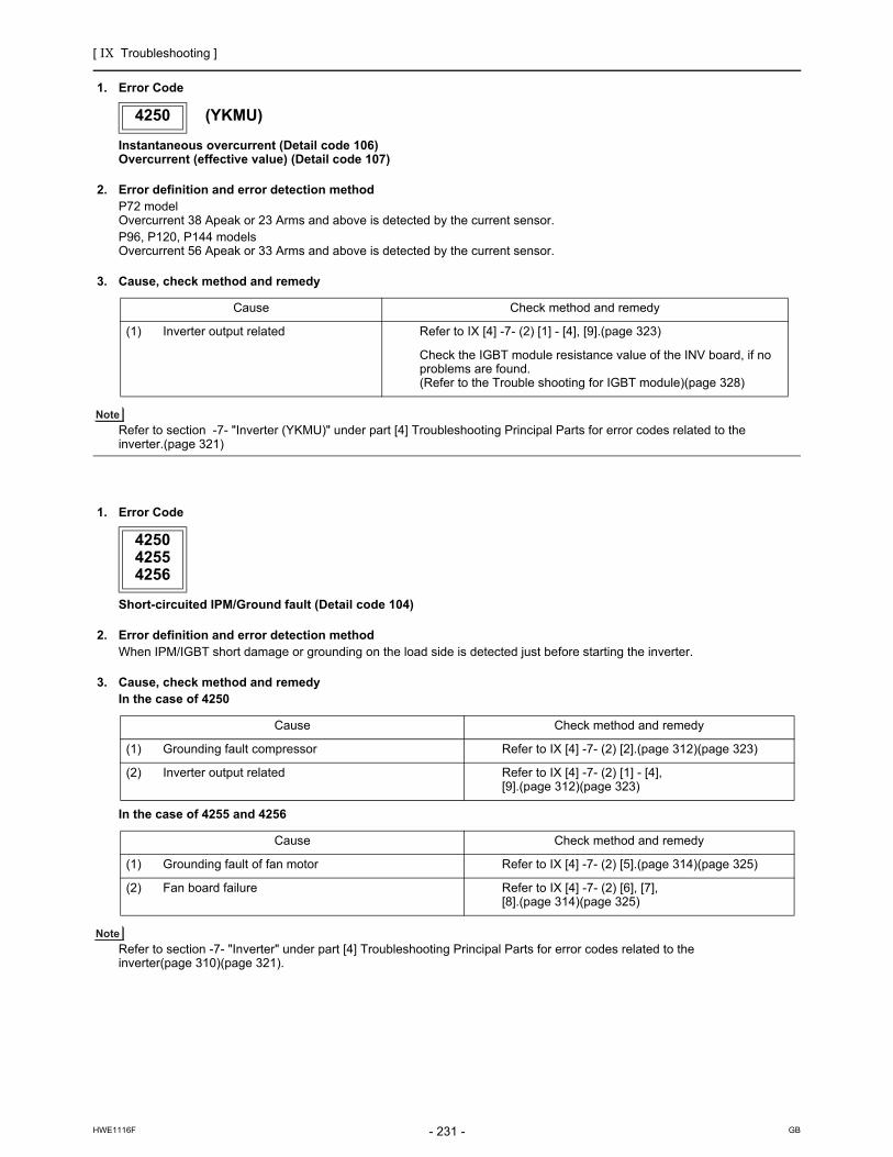
[ IX Troubleshooting ]
- 231 -HWE1116F GB
1. Error Code
Instantaneous overcurrent (Detail code 106)Overcurrent (effective value) (Detail code 107)
2. Error definition and error detection methodP72 modelOvercurrent 38 Apeak or 23 Arms and above is detected by the current sensor.P96, P120, P144 modelsOvercurrent 56 Apeak or 33 Arms and above is detected by the current sensor.
3. Cause, check method and remedy
Refer to section -7- "Inverter (YKMU)" under part [4] Troubleshooting Principal Parts for error codes related to the inverter.(page 321)
1. Error Code
Short-circuited IPM/Ground fault (Detail code 104)
2. Error definition and error detection methodWhen IPM/IGBT short damage or grounding on the load side is detected just before starting the inverter.
3. Cause, check method and remedyIn the case of 4250
In the case of 4255 and 4256
Refer to section -7- "Inverter" under part [4] Troubleshooting Principal Parts for error codes related to the inverter(page 310)(page 321).
4250 (YKMU)
Cause Check method and remedy
(1) Inverter output related Refer to IX [4] -7- (2) [1] - [4], [9].(page 323)
Check the IGBT module resistance value of the INV board, if no problems are found. (Refer to the Trouble shooting for IGBT module)(page 328)
425042554256
Cause Check method and remedy
(1) Grounding fault compressor Refer to IX [4] -7- (2) [2].(page 312)(page 323)
(2) Inverter output related Refer to IX [4] -7- (2) [1] - [4], [9].(page 312)(page 323)
Cause Check method and remedy
(1) Grounding fault of fan motor Refer to IX [4] -7- (2) [5].(page 314)(page 325)
(2) Fan board failure Refer to IX [4] -7- (2) [6], [7], [8].(page 314)(page 325)

[ IX Troubleshooting ]
- 232 -HWE1116F GB
1. Error Code
Overcurrent error due to short-circuited motor (Detail code 105)
2. Error definition and error detection methodWhen a short is detected on the load side just before starting the inverter operation.
3. Cause, Check method and remedyIn the case of 4250
In the case of 4255 and 4256
Refer to section -7- "Inverter" under part [4] Troubleshooting Principal Parts for error codes related to the inverter.(page 310)(page 321)
4260
1. Error Code
Heatsink overheat protection at startup
2. Error definition and error detection methodThe heatsink temperature (THHS) remains at or above TOH for 10 minutes or more at inverter startup.
3. Cause, check method and remedySame as 4230 error
1. Error Code
Heatsink overheat protection at startup
2. Error definition and error detection methodThe heatsink temperature (THHS) remains at or above 100°C [212°F] for 10 minutes or more at inverter startup.
3. Cause, check method and remedySame as 4230 error
425042554256
Cause Check method and remedy
(1) Short - circuited compressor Refer to IX [4] -7- (2) [2].(page 312)(page 323)
(2) Output wiring Check for a short circuit.
Cause Check method and remedy
(1) Short - circuited fan motor Refer to IX [4] -7- (2) [5].(page 314)(page 325)
(2) Output wiring Check for a short circuit.
4260 (TKMU)
Model TOH
P72 model 100°C [212°F]
P96, P120, P144 models 90°C [194°F]
4260 (YKMU)

[ IX Troubleshooting ]
- 233 -HWE1116F GB
5101,5102,5103,5104
1. Error Code
Return air temperature sensor (TH21) fault (Indoor unit)Return air temperature sensor (TH4) fault (OA processing unit)
Pipe temperature sensor (TH22) fault (Indoor unit) Pipe temperature sensor (TH2) fault (OA processing unit)
Gas-side pipe temperature sensor (TH23) fault (Indoor unit)Gas-side pipe temperature sensor (TH3) fault (OA processing unit)
Intake air temperature sensor (TH1) fault (OA processing unit)Intake air temperature sensor (TH24) fault (All-fresh (100% outdoor air) type indoor unit)
2. Error definition and error detection methodIf a short or an open is detected during thermostat ON, the outdoor unit turns to anti-restart mode for 3 minutes. When the error is not restored after 3 minutes (if restored, the outdoor unit runs normally), the outdoor unit makes an error stop.Short: detectable at 90°C [194°F] or higherOpen: detectable at -40°C [-40°F] or lowerSensor error at gas-side cannot be detected under the following conditions.
During heating operationDuring cooling operation for 3 minutes after the compressor turns on.
3. Cause, check method and remedy
5101
5102
5103
5104
Cause Check method and remedy
(1) Thermistor failure Check the thermistor resistor.0°C [32°F]: 15 kohm10°C [50°F]: 9.7 kohm20°C [68°F] : 6.4 kohm30°C [86°F] : 4.3 kohm40°C [104°F] : 3.1 kohm
(2) Connector contact failure
(3) Disconnected wire or partial disconnected thermistor wire
(4) Unattached thermistor or contact failure
(5) Indoor board (detection circuit) failure Check the connector contact.When no fault is found, the indoor board is a failure.

[ IX Troubleshooting ]
- 234 -HWE1116F GB
5102,5103,5104,5105,5106,5107?5103,5104,5105,5106,5107
1. Error Code
Heat exchanger outlet temperature sensor (TH3) fault (Outdoor unit)
Discharge temperature sensor (TH4) fault (Outdoor unit)
Accumulator inlet temperature sensor (TH5) fault (Outdoor unit)
Heat exchanger inlet temperature sensor (TH6) fault (Outdoor unit)
Outside temperature sensor (TH7) fault (Outdoor unit)
2. Error definition and error detection methodWhen a short (high temperature intake) or an open (low temperature intake) of the thermistor is detected (the first detection), the outdoor unit stops, turns to anti-restart mode for 3 minutes, and restarts when the detected temperature of the thermistor.When a short or an open is detected again (the second detection) after the first restart of the outdoor unit, the outdoor unit stops, turns to anti-restart mode for 3 minutes, and restarts in 3 minutes when the detected temperature is within the normal range.When a short or an open is detected again (the third detection) after the previous restart of the outdoor unit, the outdoor unit makes an error stop.When a short or an open of the thermistor is detected just before the restart of the outdoor unit, the outdoor unit makes an error stop, and the error code "5102", "5103", 5104", "5105", "5106"or "5107" will appear.During 3-minute antirestart mode, preliminary errors will be displayed on the LED display.A short or an open described above is not detected for 10 minutes after the compressor start, during defrost mode, or for 3 minutes after defrost mode.
3. Cause, check method and remedy
<Reference>
5103
5104
5105
5106
5107
Cause Check method and remedy
(1) Thermistor failure Check thermistor resistance.
(2) Pinched lead wire Check for pinched lead wire.
(3) Torn wire coating Check for wire coating.
(4) A pin on the male connector is missing or contact failure
Check connector.
(5) Disconnected wire Check for wire.
(6) Thermistor input circuit failure on the control board
Check the intake temperature of the sensor with the LED monitor.When the temperature is far different from the actual temper-ature, replace the control board.
TH3TH4TH5TH6TH7
Open detection
-40 C [ -40 F ] and below (130 k and above ) 0 C [ 32 F ] and below (698 k and above)-40 C [ -40 F ] and below (130 k and above)-40 C [ -40 F ] and below (130 k and above)-40 °C [ -40 °F ] and below (130 k and above )
Short detection 110 C [230 F ] and above (0.4 k and below )240 C [464 F ] and above (0.57 k and below ) 70 C [158 F ] and above (0.4 k and below ) 70 C [158 F ] and above (1.14 k and below )110 °C [230 °F ] and above (0.4 k and below )

[ IX Troubleshooting ]
- 235 -HWE1116F GB
5110
1. Error Code
Heatsink temperature sensor (THHS) fault (Detail code 01)
2. Error definition and error detection methodWhen a short or an open of THHS is detected just before or during the inverter operation.
3. Cause, check method and remedyP72 model
P96, P120, P144 models
Refer to section -7- "Inverter (TKMU)" under part [4] Troubleshooting Principal Parts for error codes related to the inverter.(page 310)
1. Error Code
Heatsink temperature sensor (THHS) fault (Detail code 01)
2. Error definition and error detection methodWhen a short or an open of THHS is detected just before or during the inverter operation.
3. Cause, check method and remedy
Refer to section -7- "Inverter (YKMU)" under part [4] Troubleshooting Principal Parts for error codes related to the inverter.(page 321)
5110 (TKMU)
Cause Check method and remedy
(1) INV board failure If the problem recurs when the unit is put into operation, replace the INV board.
Cause Check method and remedy
(1) THHS sensor failure Check the THHS sensor reading on the LED monitor.Replace the sensor if it reads below - 30°C[ -22°F] or above 150°C[302°F].
(2) Contact failure Check the connector connection (CNTH) on the INV board.
5110 (YKMU)
Cause Check method and remedy
(1) INV board failure If the problem recurs when the unit is put into operation, replace the INV board.

[ IX Troubleshooting ]
- 236 -HWE1116F GB
5111,5112,5115,5116
1. Error Code
Liquid inlet temperature sensor (TH11) fault (BC controller)
Bypass outlet temperature sensor (TH12) fault (BC controller)
LEV3 outlet temperature sensor (TH15) fault (BC controller)
LEV3 inlet temperature sensor (TH16) fault (BC controller)
2. Error definition and error detection methodIf a shorted (high temperature intake) or open (low temperature intake) thermistor (TH11, TH12, TH15, or TH16) is detected during operation, the unit makes an error stop, and an error code "5111," "5112," "5115," or "5116" appears on the display. Detection of a short- or open-circuit as described above is suspended during the defrost cycle and for 3 minutes after the operation mode is changed.
3. Cause, check method and remedy
<Reference>
5111
5112
5115
5116
Cause Check method and remedy
(1) Thermistor failure Check thermistor resistance.
(2) Pinched lead wire Check for pinched lead wire.
(3) Torn wire coating Check for wire coating.
(4) A pin on the male connector is missing or contact failure
Check connector.
(5) Disconnected wire Check for wire.
(6) Thermistor input circuit failure on the control board
Check the intake temperature of the sensor with the LED monitor.When the temperature is far different from the actual temperature, replace the control board.
TH11TH12TH15TH16
Open detection-40 C [ -40 F ] and below (130 k )-40 C [ -40 F ] and below (130 k )-40 C [ -40 F ] and below (130 k )-40 C [ -40 F ] and below (130 k )
Short detection110 C [230 F ] and above (0.4 k )110 C [230 F ] and above (0.4 k ) 70 C [158 F ] and above (0.4 k )110 C [230 F ] and above (0.4 k )

[ IX Troubleshooting ]
- 237 -HWE1116F GB
5201
1. Error Code
High-pressure sensor fault (63HS1)
2. Error definition and error detection methodIf the high pressure sensor detects 0.098MPa [14psi] or less during the operation, the outdoor unit stops once, turns to anti-restart mode for 3 minutes, and restarts after 3 minutes when the detected high pressure sensor is 0.098MPa [14psi] or more.If the high pressure sensor detects 0.098MPa [14psi] or less just before the restart, the outdoor unit makes an error stop, and the error code "5201" will appear.During 3-minute antirestart mode, preliminary errors will be displayed on the LED display.A error is not detected for 3 minutes after the compressor start, during defrost operation, or 3 minutes after defrost operation.
3. Cause, check method and remedy
5201
Cause Check method and remedy
(1) High pressure sensor failure Refer to the page on the troubleshooting of the high pressure sensor. (IX [4] -1-) (page 289)
(2) Pressure drop due to refrigerant leak
(3) Torn wire coating
(4) A pin on the male connector is missing or contact failure
(5) Disconnected wire
(6) High pressure sensor input circuit failure on the control board

[ IX Troubleshooting ]
- 238 -HWE1116F GB
1. Error Code
High-pressure sensor fault (Outdoor unit HPS/BC controller PS1)
Intermediate pressure sensor fault (BC controller PS3)
2. Error definition and error detection methodWhen a pressure sensor reading of 4.06 MPa [589 psi] or above is detected, error codes "5201" and "5203" will appear.The unit will continue its operation by using other sensors as a backup.
3. Cause, check method and remedy
5201
5203
Cause Check method and remedy
(1) High pressure sensor failure Refer to the page on the troubleshooting of the high pressure sensor. (IX [4] -1-)
(2) Pressure drop due to refrigerant leak
(3) Torn wire coating
(4) A pin on the male connector is missing or contact failure
(5) Disconnected wire
(6) High pressure sensor input circuit failure on the control board

[ IX Troubleshooting ]
- 239 -HWE1116F GB
5301
1. Error Code
ACCT sensor fault (Detail code 115)
2. Error definition and error detection methodWhen the formula "output current < 2 Arms" remains satisfied for 10 seconds while the inverter is in operation.
3. Cause, check method and remedyP72 model
P96, P120, P144 models
Refer to section -7-"Inverter (TKMU)" under part [4] Troubleshooting Principal Parts for error codes related to the inverter.(page 310)
1. Error Code
ACCT sensor fault (Detail code 115)
2. Error definition and error detection methodWhen the formula "output current < 1.5 Arms" remains satisfied for 10 seconds while the inverter is in operation.
3. Cause, check method and remedy
Refer to section -7-"Inverter (YKMU)" under part [4] Troubleshooting Principal Parts for error codes related to the inverter.(page 321)
5301 (TKMU)
Cause Check method and remedy
(1) Inverter open output phase Check the output wiring connections.
(2) Compressor failure Refer to IX [4] -7- (2) [2].(page 312)
(3) INV board failure Refer to IX [4] -7- (2) [1], [3], [4].(page 312)
Cause Check method and remedy
(1) Inverter open output phase Check the output wiring connections.
(2) Compressor failure Refer to IX [4] -7- (2) [2].(page 312)
(3) INV board failure Refer to IX [4] -7- (2) [1], [3], [4].(page 312)
(4) Contact failure Check the connection of the connector (CNCT2) on the INV board-INV board.
(5) ACCT sensor failure Refer to IX [4] -7- (5).(page 317)
5301 (YKMU)
Cause Check method and remedy
(1) Inverter open output phase Check the output wiring connections.
(2) Compressor failure Refer to IX [4] -7- (2) [2].(page 323)
(3) INV board failure Refer to IX [4] -7- (2) [1], [3], [4].(page 323)

[ IX Troubleshooting ]
- 240 -HWE1116F GB
1. Error Code
DCCT sensor fault (Detail code116)
2. Error definition and error detection methodWhen the bus current less than 18 Apeak is detected at startup (6Hz)
3. Cause, check method and remedy
Refer to section -7-"Inverter (TKMU)" under part [4] Troubleshooting Principal Parts for error codes related to the inverter.(page 310)
1. Error Code
ACCT sensor circuit fault (Detail code 117)
2. Error definition and error detection methodWhen an error value is detected with the ACCT detection circuit just before the inverter starts
3. Cause, check method and remedy
Refer to section -7-"Inverter" under part [4] Troubleshooting Principal Parts for error codes related to the inverter.(page 310)(page 321)
5301 (TKMU) (P96, P120, P144 models only)
Cause Check method and remedy
(1) Contact failure Check the contact of the connector (CNCT) on the INV board, and the contact the connector on DCCT side.
(2) Misorientation Check the installation direction of DCCT.
(3) DCCT sensor failure Replace the DCCT sensor.
(4) INV board failure Replace the INV board.
5301
Cause Check method and remedy
(1) INV board failure Refer to IX [4] -7- (2) [1], [3], [4].(page 312)(page 323)
(2) Compressor failure Refer to IX [4] -7- (2) [2].(page 312)(page 323)

[ IX Troubleshooting ]
- 241 -HWE1116F GB
1. Error Code
DCCT sensor circuit fault (Detail code118)
2. Error definition and error detection methodWhen an error value is detected with the DCCT detection circuit just before the inverter starts
3. Cause, check method and remedy
Refer to section -7- "Inverter (TKMU)" under part [4] Troubleshooting Principal Parts for error codes related to the inverter.(page 310)
5301 (TKMU) (P96, P120, P144 models only)
Cause Check method and remedy
(1) Contact failure Check for good contact of the INV board connector CNCT and the connec-tor on the DCCT side.
(2) INV board failure Refer to IX [4] -7- (2) [1], [3], [4].(page 312)
(3) DCCT sensor failure Replace the DCCT sensor.
(4) Compressor failure Refer to IX [4] -7- (2) [2].(page 312)
(5) Inverter failure Refer to IX [4] -7-.(page 310)

[ IX Troubleshooting ]
- 242 -HWE1116F GB
1. Error Code
Open-circuited IPM/Loose ACCT connector (Detail code 119)
2. Error definition and error detection methodPresence of enough current cannot be detected during the self-diagnostic operation immediately before inverter startup.
3. Cause, check method and remedyP72 model
P96, P120, P144 models
Refer to section -7- "Inverter (TKMU)" under part [4] Troubleshooting Principal Parts for error codes related to the inverter.(page 310)
1. Error Code
Open-circuited IPM/Loose ACCT connector (Detail code 119)
2. Error definition and error detection methodPresence of enough current cannot be detected during the self-diagnostic operation immediately before inverter startup.
3. Cause, check method and remedy
Refer to section -7- "Inverter (YKMU)" under part [4] Troubleshooting Principal Parts for error codes related to the inverter.(page 321)
5301 (TKMU)
Cause Check method and remedy
(1) Inverter output wiring problem Check output wiring connections.Confirm that the U- and W-phase output cables are put through CT11 and CT12 on the INV board respectively.
(2) Inverter failure Refer to IX [4] -7- (2) [3], [4].(page 313)
(3) Compressor failure Refer to IX [4] -7- (2) [2].(page 312)
Cause Check method and remedy
(1) ACCT sensor disconnection Check the connection of the connector (CNCT2) on the INV board.Check for proper mounting of ACCT.
(2) ACCT sensor failure Refer to IX [4] -7- (5).(page 317)
(3) Inverter failure Refer to IX [4] -7- (2) [3], [4].(page 313)
(4) Compressor failure Refer to IX [4] -7- (2) [2].(page 312)
5301 (YKMU)
Cause Check method and remedy
(1) Inverter output wiring problem Check output wiring connections.Confirm that the U- and W-phase output cables are put through CT12 and CT22 on the INV board respectively.
(2) Inverter failure Refer to IX [4] -7- (2) [3], [4].(page 323)
(3) Compressor failure Refer to IX [4] -7- (2) [2].(page 323)

[ IX Troubleshooting ]
- 243 -HWE1116F GB
1. Error Code
Faulty ACCT wiring (Detail code 120)
2. Error definition and error detection methodPresence of target current cannot be detected during the self-diagnostic operation immediately before startup. (Detection of improperly mounted ACCT sensor)
3. Cause, check method and remedy P72 model
P96, P120, P144 models
Refer to section -7- "Inverter (TKMU)" under part [4] Troubleshooting Principal Parts for error codes related to the inverter.(page 310)
1. Error Code
Faulty ACCT wiring (Detail code 120)
2. Error definition and error detection methodPresence of target current cannot be detected during the self-diagnostic operation immediately before startup.
3. Cause, check method and remedy
Refer to section -7- "Inverter (YKMU)" under part [4] Troubleshooting Principal Parts for error codes related to the inverter.(page 321)
5301 (TKMU)
Cause Check method and remedy
(1) Inverter output wiring problem Check output wiring connections.Confirm that the U- and W-phase output cables are put through CT11 and CT12 on the INV board respectively.
(2) Inverter failure Refer to IX [4] -7- (2) [3], [4].(page 313)
(3) Compressor failure Refer to IX [4] -7- (2) [2].(page 312)
(4) INV board failure Replace the INV board.
Cause Check method and remedy
(1) Wrongly mounted ACCT sensor Check for proper mounting of ACCT.Refer to IX [4] -7- (5).(page 317)
(2) ACCT sensor failure Refer to IX [4] -7- (5).(page 317)
(3) Inverter failure Refer to IX [4] -7- (2) [3], [4].(page 313)
(4) Compressor failure Refer to IX [4] -7- (2) [2].(page 312)
5301 (YKMU)
Cause Check method and remedy
(1) Inverter output wiring problem Check output wiring connections.Confirm that the U- and W-phase output cables are put through CT12 and CT22 on the INV board respectively.
(2) Inverter failure Refer to IX [4] -7- (2) [3], [4].(page 323)
(3) Compressor failure Refer to IX [4] -7- (2) [2].(page 323)

[ IX Troubleshooting ]
- 244 -HWE1116F GB
5305,5306
1. Error Code
Position detection error at startup (Detail code 132)
2. Error definition and error detection methodWhen a motor sensor has detected an error within 10 seconds after the fan motor has gone into operation.
3. Cause, check method and remedy
Refer to section -7- "Inverter" under part [4] Troubleshooting Principal Parts for error codes related to the inverter.(page 310)(page 321)
1. Error Code
Position detection error during operation (Detail code 133)
2. Error definition and error detection methodAn error from a motor sensor is detected during fan moter operation.
3. Cause, check method and remedy
Refer to section -7- "Inverter" under part [4] Troubleshooting Principal Parts for error codes related to the inverter.(page 310)(page 321)
53055306
Cause Check method and remedy
(1) Contact failure and faulty fan motor wiring
Check the fan board connector CNINV and CNSNR for proper con-tacts.Check the wirign betweem the fan motor and fan board.
(2) Fan board failure Refer to IX [4] -7- (2) [8] (page 315)(page 326)
(3) Fan motor error Refer to IX [4] -7- (2) [5] (page 314)(page 325)
53055306
Cause Check method and remedy
(1) Outdoor factors Check that there is no wind (gust or strong wind).
(2) Contact failure and faulty fan motor wiring
Check the fan board connector CNINV and CNSNR for proper con-tacts.Check the wirign betweem the fan motor and fan board.
(3) Fan board failure Refer to IX [4] -7- (2) [7], [8] (page 314)(page 325)
(4) Fan motor error Refer to IX [4] -7- (2) [5] (page 314)(page 325)

[ IX Troubleshooting ]
- 245 -HWE1116F GB
1. Error Code
RPM error before start up (Detail code 134)
2. Error definition and error detection methodThe fan RPM will not drop to the set RPM.
3. Cause, check method and remedy
Refer to section -7- "Inverter" under part [4] Troubleshooting Principal Parts for error codes related to the inverter.(page 310)(page 321)
5401
1. Error Code
Humidity sensor fault
2. Error definition and error detection methodA short-circuit or an open-circuit of the humidity sensor is detected during operation.
3. Cause, check method and remedy
53055306
Cause Check method and remedy
(1) Outdoor factors Check that there is no wind (gust or strong wind).
(2) Fan board failure Refer to IX [4] -7- (2) [7], [8] (page 314)(page 325)
(3) Fan motor error Refer to IX [4] -7- (2) [5] (page 314)(page 325)
5401
Cause Check method and remedy
(1) Connector contact failure (CN30) (Loose con-nector)
1) Check the connector for proper contact. Reconnect the connector, and operate the unit to check for proper operation.
(2) Broken or partially broken humidity sensor wire 2) Check for broken humidity sensor wire.
(3) Humidity sensor fault 3) Check the output voltage across No. 1 and No. 3 pins of connector CN30 with the connector being connected to the indoor unit control board. 30% : 1.25V 40% : 1.52V 50% : 1.88V 60% : 2.19V 70% : 2.48V 80% : 2.79V
(4) Indoor unit control board (detection circuit) fault 4) If the above items check out okay, replace the indoor unit control board.
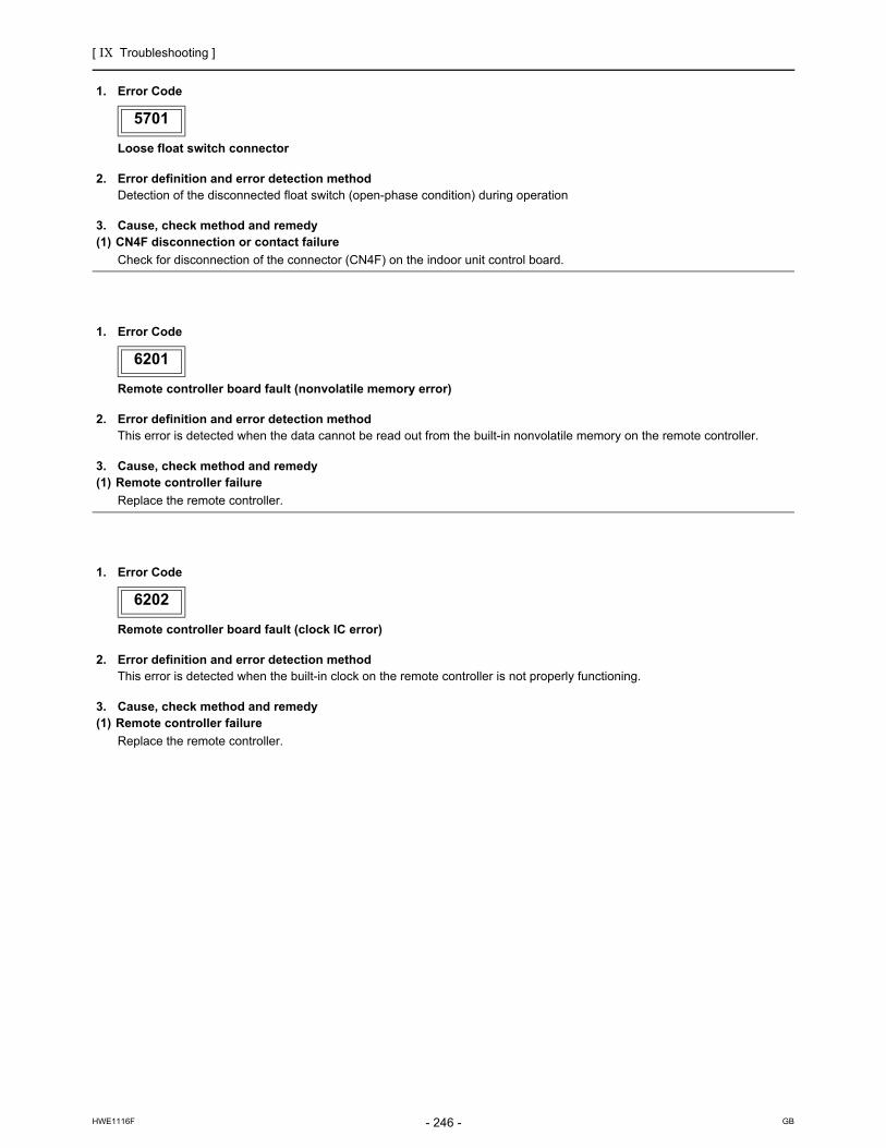
[ IX Troubleshooting ]
- 246 -HWE1116F GB
5701
1. Error Code
Loose float switch connector
2. Error definition and error detection methodDetection of the disconnected float switch (open-phase condition) during operation
3. Cause, check method and remedy(1) CN4F disconnection or contact failure
Check for disconnection of the connector (CN4F) on the indoor unit control board.
6201
1. Error Code
Remote controller board fault (nonvolatile memory error)
2. Error definition and error detection methodThis error is detected when the data cannot be read out from the built-in nonvolatile memory on the remote controller.
3. Cause, check method and remedy(1) Remote controller failure
Replace the remote controller.
6202
1. Error Code
Remote controller board fault (clock IC error)
2. Error definition and error detection methodThis error is detected when the built-in clock on the remote controller is not properly functioning.
3. Cause, check method and remedy(1) Remote controller failure
Replace the remote controller.
5701
6201
6202

[ IX Troubleshooting ]
- 247 -HWE1116F GB
6600
1. Error Code
Address overlaps
2. Error definition and error detection methodAn error in which signals from more than one indoor units with the same address are received
The address and attribute that appear on the remote controller indicate the controller that detected the error.
3. Cause, check method and remedy
6601
1. Error Code
Polarity setting error
2. Error definition and error detection methodThe error detected when transmission processor cannot distinguish the polarities of the M-NET transmission line.
3. Cause, check method and remedy
6600
Cause Check method and remedy
(1) Two or more of the following have the same address: Outdoor units, BC controller, indoor units, LOSSNAY units, controllers such as ME remote controllers. <Example>6600 "01" appears on the remote controllerUnit #01 detected the error. Two or more units in the system have 01 as their ad-dress.
Find the unit that has the same address as that of the error source. Once the unit is found, correct the address. Then, turn off the outdoor units, indoor units, BC controller, and LOSSNAY units, keep them all turned off for at least five minutes, and turn them back on. When air conditioning units are operating normally despite the address overlap errorCheck the transmission wave shape and noise on the transmission line.See the section "Investigation of Transmission Wave Shape/Noise."
(2) Electrical noise on the transmission wire distorted the transmission signals.
6601
Cause Check method and remedy
(1) No voltage is applied to the M-NET transmission line that AG-150A/GB-50ADA/GB-24A, PAC-YG50ECA, BAC-HD150 is connected to.
Check if power is supplied to the M-NET transmission line of the AG-150A/GB-50ADA/GB-24A, PAC-YG50ECA, BAC-HD150, and correct any problem found.
(2) M-NET transmission line to which AG-150A/GB-50ADA/GB-24A, PAC-YG50ECA, BAC-HD150 is connected is short-circuited.

[ IX Troubleshooting ]
- 248 -HWE1116F GB
6602
1. Error Code
Transmission processor hardware error
2. Error definition and error detection methodAlthough "0" was surely transmitted by the transmission processor, "1" is displayed on the transmission line.
The address/attribute appeared on the display on the remote controller indicates the controller where an error oc-curred.
3. Cause1) When the wiring work of or the polarity of either the indoor or outdoor transmission line is performed or is changed while the
power is on, the transmitted data will collide, the wave shape will be changed, and an error will be detected.2) Grounding fault of the transmission line3) When grouping the indoor units that are connected to different outdoor units, the male power supply connectors on the multiple
outdoor units are connected to the female power supply switch connector (CN40).4) When the power supply unit for transmission lines is used in the system connected with MELANS, the male power supply
connector is connected to the female power supply switch connector (CN40) on the outdoor unit.5) Controller failure of the source of the error6) When the transmission data is changed due to the noise on the transmission line7) Voltage is not applied on the transmission line for centralized control (in case of grouped indoor units connected to different
outdoor units or in case of the system connected with MELANS)
4. Check method and remedy
6602
NO Tightly reconnect the male power supply connector to the female power supply switch connector (CN40).
YES
YES
YES
YES
YES
YES
NO
NO
NO
NO
Is the transmission line work performed while the power is on?
Check the power source of the indoor unit.
188 / 253V?
Check the transmission line work is performed and the shielded wire is treated properly.
Grounding fault or does the shielded wire contact with the transmission line?
System ?
Faulty power source work
Improper transmission line work
Turn off the power source of outdoor/indoor units, and turn them on again.
NO
Investigation into the transmission line noise
Noise exist?
Controller failure of the source of the error
*For the investigation method, follow <Investigation method of transmission wave shape/noise>
Investigation into the cause of the noise
Correct the error.
System with the power supply unit for transmission lines
Is the male power supply connector connected to the female power supply switch connector (CN40) on only one of the outdoor unit?
Is the male power supply connector connected to the female power supply switch connector (CN40) ?
Confirm that the power supply connector on the outdoor unit is not plugged into CN40.
Confirm that the power supply connector on the outdoor unit is not plugged into CN40.
Disconnect the male power supply on CN40 and connect it to CN41
Single-outdoor-unit system Multiple-outdoor-unit system

[ IX Troubleshooting ]
- 249 -HWE1116F GB
6603
1. Error Code
Transmission line bus busy error
2. Error definition and error detection methodGenerated error when the command cannot be transmitted for 4-10 minutes in a row due to bus-busyGenerated error when the command cannot be transmitted to the transmission line for 4-10 minutes in a row due to noise
The address/attribute appeared on the display on the remote controller indicates the controller where an error oc-curred.
3. Cause, check method and remedy
6606
1. Error Code
Communication error between device and transmission processors
2. Error definition and error detection methodCommunication error between the main microcomputer on the indoor unit board and the microcomputer for transmission
The address/attribute appeared on the display on the remote controller indicates the controller where an error oc-curred.
3. Cause, check method and remedy
6603
Cause Check method and remedy
(1) The transmission processor cannot be transmit-ted as the short-wavelength voltage like noise ex-ists consecutively on the transmission line.
Check the transmission wave shape and noise on the transmission line.See the section "Investigation of Transmission Wave Shape/Noise."-> No noise indicates that the error source controller is a
failure.-> If noise exists, investigate the noise.
(2) Error source controller failure
6606
Cause Check method and remedy
(1) Data is not properly transmitted due to accidental erroneous operation of the controller of the error source.
Turn off the power source of the outdoor and the indoor units.(When the power source is turned off separately, the microcomputer will not be reset, and the error will not be corrected.)-> If the same error occurs, the error source controller is
a failure.
(2) Error source controller failure

[ IX Troubleshooting ]
- 250 -HWE1116F GB
6607
1. Error Code
No ACK error
2. Error definition and error detection methodThe error is detected when no acknowledgement (ACK signal) is received after the transmission. (eg. When the data is trans-mitted six times in a row with 30 seconds interval, the error is detected on the transmission side.)
The address/attribute appeared on the display on the remote controller indicates the controller which did not provide the response (ACK).
3. System configuration(1) System with one outdoor unit
6607
Error source address
Error dis-play
Detection method Cause Check method and remedy
Outdoor unit (OC)
ME re-mote con-troller (RC)MA re-mote con-troller (MA)
No ac-knowl-edgement (ACK) at IC trans-mission to OC
(1) Contact failure of transmission line of OC or IC Turn off the power source of the outdoor unit, and turn it on again.If the error is accidental, it will run normally. If not, check the causes (1) - (4).
(2) Decrease of transmission line voltage/signal by ex-ceeding acceptable range of transmission wiring.Farthest:200 m [656ft] or lessRemote controller wiring:10m [32ft] or less
(3) Erroneous sizing of transmission line (Not within the range below). Wire diameter:1.25mm2 [AWG16] or more
(4) Indoor unit control board failure
BC con-troller (BC)
ME re-mote con-troller (RC)MA re-mote con-troller (MA)
No ac-knowl-edgement (ACK) at IC trans-mission to BC
(1) When BC controller address is changed or modified during operation.
Turn off the outdoor/in-door units for 5 or more minutes, and turn them on again. If the error is accidental, they will run normally. If not, check the causes (1) - (4).
(2) Faulty or disconnected transmission wiring of BC controller
(3) Disconnected connector of BC controller (CN02)
(4) Faulty control board of BC controller
Indoor unit (IC)
ME re-mote con-troller (RC)MA re-mote con-troller (MA)
No ac-knowl-edgement (ACK) at RC trans-mission to IC
(1) When IC unit address is changed or modified during operation.
Turn off the outdoor/in-door units for 5 or more minutes, and turn them on again.If the error is accidental, they will run normally. If not, check the causes (1) - (5).
(2) Faulty or disconnected IC transmission wiring
(3) Disconnected IC connector(CN2M)
(4) Indoor unit controller failure
(5) ME remote controller failure
LOSS-NAY (LC)
ME re-mote con-troller (RC)MA re-mote con-troller (MA)
No ac-knowl-edgement (ACK) at IC trans-mission to LC
(1) The power source of LOSSNAY has been shut off. Turn off the power source of LOSSNAY and turn it on again.If the error is accidental, it will run normally.If not, check the causes (1) - (5).
(2) When the address of LOSSNAY is changed in the middle of the operation
(3) Faulty or disconnected transmission wiring of LOSSNAY
(4) Disconnected connector (CN1) on LOSSNAY
(5) Controller failure of LOSSNAY
ME re-mote control-ler (RC)
ME re-mote con-troller (RC)MA re-mote con-troller (MA)
No ac-knowl-edgement (ACK) at IC trans-mission to RC
(1) Faulty transmission wiring at IC unit side. Turn off the power source of the outdoor unit for 5 minutes or more, and turn it on again.If the error is accidental, it will run normally.If not, check the causes (1) - (4).
(2) Faulty wiring of the transmission line for ME remote controller
(3) When the address of ME remote controller is changed in the middle of the operation
(4) ME remote controller failure

[ IX Troubleshooting ]
- 251 -HWE1116F GB
1. Error Code
No ACK error
2. Error definition and error detection methodThe error is detected when no acknowledgement (ACK signal) is received after the transmission. (eg. When the data is trans-mitted six times in a row with 30 seconds interval, the error is detected on the transmission side.)
The address/attribute appeared on the display on the remote controller indicates the controller which did not provide the response (ACK).
3. System configuration(2) Grouping of units in a system with multiple outdoor units
6607
Error source
addressError display
Detection method Cause Check method and remedy
Outdoor unit(OC)
ME remote controller (RC)MA remote controller (MA)
No acknowl-edgement (ACK) at IC transmission to OC
Same cause as that for system with one outdoor unit
Same remedy as that for sys-tem with one outdoor unit
BC con-troller(BC)
ME remote controller(RC)MA remote controller(MA)
No acknowl-edgement (ACK) at IC transmission to BC
Same cause as that for system with one outdoor unit
Same remedy as that for sys-tem with one outdoor unit
Indoor unit(IC)
ME remote controller (RC)MA remote controller (MA)
No acknowl-edgement (ACK) at RC transmission to IC
(1) Same causes as (1) - (5) for sys-tem with one outdoor unit
1) Turn off the power sources of the outdoor and indoor units for 5 or more minutes, and turn them on again. If the error is accidental, the will run normal-ly.If not, check the cause 2).
(2) Disconnection or short circuit of the transmission line for the out-door unit on the terminal block for centralized control line connection (TB7)
2) Check the causes of (1) - (5). If the cause is found, correct it. If no cause is found, check 3).
(3) When multiple outdoor units are connected and the power source of one of the outdoor units has been shut off.
3) Check the LED displays for troubleshooting on other re-mote controllers whether an error occurs.
(4) The male power supply connector of the outdoor unit is not connect-ed to the female power supply switch connector (CN40).
If an error is found,-> If an error is found, check the check code definition, and correct the error.If no error is found,-> Indoor unit board failure(5) The male power supply connec-
tors on 2 or more outdoor units are connected to the female pow-er supply switch connector (CN40) for centralized control.
If an error occurs, after the unit runs normally once, the following causes may be considered.Total capacity error (7100)Capacity code error (7101)Error in the number of con-nected units (7102)Address setting error (7105)

[ IX Troubleshooting ]
- 252 -HWE1116F GB
1. Error Code
No ACK error
2. Error definition and error detection methodThe error is detected when no acknowledgement (ACK signal) is received after the transmission. (eg. When the data is trans-mitted six times in a row with 30 seconds interval, the error is detected on the transmission side.)
The address/attribute appeared on the display on the remote controller indicates the controller which did not provide the response (ACK).
3. System configuration(2) Grouping of units in a system with multiple outdoor units
6607
Error source address
Error displayDetection method Cause Check method and remedy
LOSS-NAY(LC)
ME remote controller (RC)MA remote controller (MA)
No acknowl-edgement (ACK) at IC transmission to LC
(1) Factors (1) through (5) in the "Factors in system with one outdoor unit" (When perform-ing an interlocked operation of the LOSSNAY unit and the indoor units that are connect-ed to different outdoor units.)
1) Turn off the power source of LOSSNAY for 5 or more min-utes, and turn it on again. If the error is accidental, it will run normally.If not, check the cause 2).
(2) Disconnection or short circuit of the transmission line for the outdoor unit on the termi-nal block for centralized con-trol line connection (TB7)
2) Check the causes of (1) - (5). If the cause is found, correct it. If no cause is found, check 3).
(3) When multiple outdoor units are connected and the power source of one of the outdoor units has been shut off.
3) Same cause as that for indoor unit described in 3)
(4) The male power supply con-nector of the outdoor unit is not connected to the female power supply switch connec-tor (CN40).
(5) The male power supply con-nectors on 2 or more outdoor units are connected to the fe-male power supply switch connector (CN40) for central-ized control.
If an error occurs, after the unit runs normally once, the following causes may be con-sidered.Total capacity error (7100)Capacity code error (7101)Error in the number of connected units (7102)Address setting error (7105)

[ IX Troubleshooting ]
- 253 -HWE1116F GB
1. Error Code
No ACK error
2. Error definition and error detection methodThe error is detected when no acknowledgement (ACK signal) is received after the transmission. (eg. When the data is trans-mitted six times in a row with 30 seconds interval, the error is detected on the transmission side.)
The address/attribute appeared on the display on the remote controller indicates the controller which did not provide the response (ACK).
3. System configuration(2) Grouping of units in a system with multiple outdoor units
6607
Error source address
Error displayDetection method Cause Check method and remedy
ME re-mote con-troller (RC)
ME remote controller (RC)MA remote controller (MA)
No acknowl-edgement (ACK) at IC transmission to RC
(1) Same causes as (1) - (4) for system with one outdoor unit
1) Turn off the power source of LOSSNAY for 5 or more min-utes, and turn it on again. If the error is accidental, it will run normally.If not, check the cause 2).
(2) Disconnection or short circuit of the transmission line for the outdoor unit on the termi-nal block for centralized con-trol line connection (TB7)
2) Check the causes of (1) - (5). If the cause is found, correct it. If no cause is found, check 3).
(3) When multiple outdoor units are connected and the power source of one of the outdoor units has been shut off.
3) Same cause as that for indoor unit described in 3)
(4) The male power supply con-nector of the outdoor unit is not connected to the female power supply switch connec-tor (CN40).
(5) The male power supply con-nectors on 2 or more outdoor units are connected to the fe-male power supply switch connector (CN40) for central-ized control.
If the problem recurs after normal operation is restored, the problem is caused by one of the following factors: Total capacity error (7100)Capacity code setting error (7101)Error in the number of connected units (7102)Address setting error (7105)

[ IX Troubleshooting ]
- 254 -HWE1116F GB
1. Error Code
No ACK error
2. Error definition and error detection methodThe error is detected when no acknowledgement (ACK signal) is received after the transmission. (eg. When the data is trans-mitted six times in a row with 30 seconds interval, the error is detected on the transmission side.)
The address/attribute appeared on the display on the remote controller indicates the controller which did not provide the response (ACK).
3. System configuration(3) System connected to the system controllers (MELANS)
6607
Error source address
Error displayDetection method Cause Check method and remedy
Out-door unit(OC)
ME remote controller (RC)System control-ler (SC)MA remote controller (MA)
No acknowl-edgement (ACK) at IC transmis-sion to OC
Same cause as that for system with one outdoor unit
Same remedy as that for system with one outdoor unit
BC con-troller(BC)
ME remote controller (RC)system control-ler (SC)MA remote controller (MA)
No acknowl-edgement (ACK) at IC transmis-sion to BC
Same cause as that for system with one outdoor unit
Same remedy as that for system with one outdoor unit

[ IX Troubleshooting ]
- 255 -HWE1116F GB
1. Error Code
No ACK error
2. Error definition and error detection methodThe error is detected when no acknowledgement (ACK signal) is received after the transmission. (eg. When the data is trans-mitted six times in a row with 30 seconds interval, the error is detected on the transmission side.)
The address/attribute appeared on the display on the remote controller indicates the controller which did not provide the response (ACK).
3. System configuration(3) System connected to the system controllers (MELANS)
6607
Error source address
Error displayDetection method Cause Check method and remedy
Indoor unit(IC)
ME remote controller (RC)MA remote controller (MA)
No acknowl-edgement (ACK) at RC transmis-sion to IC
Same as grouping of units in a system with multiple outdoor units
Same remedy as that for grouping of units in a sys-tem with multiple outdoor units
System control-ler (SC)
No acknowl-edgement (ACK) at SC transmis-sion to IC
1. Error occurrence on some IC Same remedy as that for system with one outdoor unit(1) Same cause as that for system with one
outdoor unit
2. Error occurrence on all IC in the system with one outdoor unit
1) Check the LED display for troubleshooting on the outdoor unit.
(1) Total capacity error (7100) If an error is found, check the check code definition, and correct the error.If no error is found,
check 2).
(2) Capacity code error (7101)
(3) Error in the number of connected units (7102)
(4) Address setting error (7105)
(5) Disconnection or short circuit of the trans-mission line for the outdoor unit on the ter-minal block for centralized control line connection (TB7)
2) Check (5) - (7) on the left.
(6) Turn off the power source of the outdoor unit
(7) Malfunction of electrical system for the outdoor unit
3. Error occurrence on all IC 1) Check voltage of the transmission line for cen-tralized control.20V or more: Check (1)
and (2) on the left.Less than 20V: Check
(3) on the left.
(1) Same causes as (1) - (7) described in 2.
(2) The male power supply connectors on 2 or more outdoor units are connected to the female power supply switch connector (CN40) for the transmission line for cen-tralized control.
(3) Disconnection or shutdown of the power source of the power supply unit for trans-mission line
2) When the male power supply connector is connected from TKMU outdoor unit to CN40, the power supplied to TB7 side even when the main power of the TKMU outdoor unit is switched off, and the System controller may store an error in the error history and emit an alarm signal.
(4) System controller (MELANS) malfunction
(5) The TKMU outdoor unit's central control connector (CN40) is inserted.

[ IX Troubleshooting ]
- 256 -HWE1116F GB
1. Error Code
No ACK error
2. Error definition and error detection methodThe error is detected when no acknowledgement (ACK signal) is received after the transmission. (eg. When the data is trans-mitted six times in a row with 30 seconds interval, the error is detected on the transmission side.)
The address/attribute appeared on the display on the remote controller indicates the controller which did not provide the response (ACK).
3. System configuration(3) System connected to the system controllers (MELANS)
6607
Error source address
Error displayDetection method Cause Check method and remedy
ME re-mote con-troller(RC)
ME remote controller (RC)System con-troller (SC)MA remote controller (MA)
No acknowl-edgement (ACK) at IC transmission to RC
Same as grouping of units in a sys-tem with multiple outdoor units
Same remedy as that for grouping of units in a sys-tem with multiple outdoor units
System con-troller(SC)
No acknowl-edgement (ACK) at MELANS transmission to RC
1. Error occurrence on some IC Same remedy as that for system with one outdoor unit(1) Same cause as that for system with
one outdoor unit
2. Error occurrence on all IC in the sys-tem with one outdoor unit
1) Check the LED display for troubleshooting on the out-door unit.
(1) An error is found by the outdoor unit.Total capacity error (7100)Capacity code error (7101)Error in the number of connected units (7102)Address setting error (7105)
If an error is found, check the check code definition, and correct the error.If no error is found, check
the cause 2).
(2) Disconnection or short circuit of the transmission line for the outdoor unit on the terminal block for centralized control line connection (TB7)
2) Check (2) - (4) on the left.
(3) Turn off the power source of the out-door unit
(4) Malfunction of electrical system for the outdoor unit
3. Error occurrence on all IC 1) Check (1) - (4) on the left.
(1) Same causes as (1) - (4) described in 2.
(2) When the power supply unit for transmis-sion lines is used and the male power supply connector is connected to the fe-male power supply switch connector (CN40) for the transmission line for cen-tralized control
(3) Disconnection or shutdown of the power source of the power supply unit for transmission line
2) When the male power supply connector is connected from TKMU outdoor unit to CN40, the power supplied to TB7 side even when the main power of the TKMU outdoor unit is switched off, and the System controller may store an error in the error history and emit an alarm signal.
(4) System controller (MELANS) mal-function
(5) The TKMU outdoor unit's central control connector (CN40) is inserted.

[ IX Troubleshooting ]
- 257 -HWE1116F GB
1. Error Code
No ACK error
2. Error definition and error detection methodThe error is detected when no acknowledgement (ACK signal) is received after the transmission. (eg. When the data is trans-mitted six times in a row with 30 seconds interval, the error is detected on the transmission side.)
The address/attribute appeared on the display on the remote controller indicates the controller which did not provide the response (ACK).
3. System configuration(3) System connected to the system controllers (MELANS)
6607
Error source address
Error displayDetection method Cause Check method and remedy
System controller(SC)
ME remote controller(RC)MA remote controller(MA)
No acknowl-edgement (ACK) at IC transmission to SC
1. Error display on some displays on ME remote controllers
Check (1) - (3) on the left.
(1) Faulty wiring of the transmission line for ME remote controller
(2) Disconnection or contact failure of the transmission connector for ME remote controller
(3) ME remote controller failure
2. Error occurrence on all IC in the system with one outdoor unit
1) Check the LED display for troubleshooting on the out-door unit.
(1) An error is found by the outdoor unit.Total capacity error (7100)Capacity code error (7101)Error in the number of connected units (7102)Address setting error (7105)
If an error is found, check the check code definition, and correct the error.If no error is found, check
the cause 2)
(2) Disconnection or short circuit of the transmission line for the outdoor unit on the terminal block for cen-tralized control line connection (TB7)
2) Check (2) - (4) on the left.
(3) Turn off the power source of the outdoor unit
(4) Malfunction of electrical system for the outdoor unit
3. Error display on all displays on ME remote controllers
Check (1) - (4) on the left
(1) Same causes as (1) - (4) described in 2.
(2) When the power supply unit for transmission lines is used and the male power supply connector is connected to the female power sup-ply switch connector (CN40) for the transmission line for centralized control
(3) Disconnection or shutdown of the power source of the power supply unit for transmission line
(4) System controller (MELANS) mal-function

[ IX Troubleshooting ]
- 258 -HWE1116F GB
1. Error Code
No ACK error
2. Error definition and error detection methodThe error is detected when no acknowledgement (ACK signal) is received after the transmission. (eg. When the data is trans-mitted six times in a row with 30 seconds interval, the error is detected on the transmission side.)
The address/attribute appeared on the display on the remote controller indicates the controller which did not provide the response (ACK).
3. System configuration(4) Errors that are not limited to a particular system
6607
Error source ad-
dress
Error dis-play
Detection method Cause Check method and remedy
Address which should not be existed
- - (1) Although the address of ME remote controller has been changed after the group is set using ME remote controller, the indoor unit is keeping the memory of the previous ad-dress. The same symptom will appear for the registration with SC.
Delete unnecessary informa-tion of non-existing address which some indoor units have.Use either of the following two methods for deletion.
(2) Although the address of LOSSNAY has been changed after the interlock registration of LOSSNAY is made using ME remote controller, the in-door unit is keeping the mem-ory of the previous address.
1) Address deletion by ME remote controllerDelete unnecessary address in-formation using the manual set-ting function of ME remote controller. Refer to this service handbook "IV. [2]. Group Set-tings and Interlock Settings via the ME Remote Controller 1. (3) Address deletion".(page 91)
2) Deletion of connection informa-tion of the outdoor unit by the deleting switch
Note that the above method will delete all the group set-tings set via the ME remote controller and all the inter-lock settings between LOSS-NAY units and indoor units.Turn off the power source of
the outdoor unit, and wait for 5 minutes.Turn on the dip switch (SW2-
2) on the outdoor unit control board. Turn on the power source of
the outdoor unit, and wait for 5 minutes.Turn off the power source of
the outdoor unit, and wait for 5 minutes.Turn off the dip switch (SW2-
2) on the outdoor unit control board. Turn on the power source of
the outdoor unit.
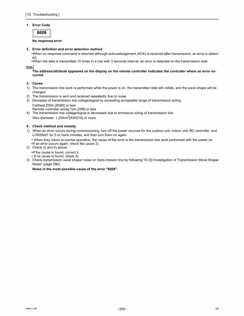
[ IX Troubleshooting ]
- 259 -HWE1116F GB
6608
1. Error Code
No response error
2. Error definition and error detection methodWhen no response command is returned although acknowledgement (ACK) is received after transmission, an error is detect-ed.When the data is transmitted 10 times in a row with 3 seconds interval, an error is detected on the transmission side.
The address/attribute appeared on the display on the remote controller indicates the controller where an error oc-curred.
3. Cause1) The transmission line work is performed while the power is on, the transmitted data will collide, and the wave shape will be
changed.2) The transmission is sent and received repeatedly due to noise.3) Decrease of transmission line voltage/signal by exceeding acceptable range of transmission wiring.
Farthest:200m [656ft] or lessRemote controller wiring:12m [39ft] or less
4) The transmission line voltage/signal is decreased due to erroneous sizing of transmission line.
Wire diameter: 1.25mm2[AWG16] or more
4. Check method and remedy1) When an error occurs during commissioning, turn off the power sources for the outdoor unit, indoor unit, BC controller, and
LOSSNAY for 5 or more minutes, and then turn them on again.
When they return to normal operation, the cause of the error is the transmission line work performed with the power on.If an error occurs again, check the cause 2).
2) Check 3) and 4) above.
If the cause is found, correct it. If no cause is found, check 3).
3) Check transmission wave shape/ noise on trans-mission line by following "IX [3] Investigation of Transmission Wave Shape/Noise" (page 286).
Noise is the most possible cause of the error "6608".
6608

[ IX Troubleshooting ]
- 260 -HWE1116F GB
6831
1. Error Code
MA controller signal reception error (No signal reception)
2. Error definition and error detection methodCommunication between the MA remote controller and the indoor unit is not done properly. No proper data has been received for 3 minutes.
3. Cause1) Contact failure of the remote controller lines of MA remote controller or the indoor unit.2) All the remote controllers are set to SUB.3) Failure to meet wiring regulations
Wire lengthWire sizeNumber of remote controllersNumber of indoor units
4) The remote controller is removed after the installation without turning the power source off.5) Noise interference on the remote controller transmission lines6) Faulty circuit that is on the indoor board and performs transmission/ reception of the signal from the remote controller7) Problems with the circuit on the remote controller that sends or receives the signals from the remote controller
4. Check method and remedy1) Check for disconnected or loose transmission lines for the indoor units or MA remote controllers.2) Confirm that the power is supplied to the main power source and the remote controller line.3) Confirm that MA remote controller's capacity limit is not exceeded.4) Check the sub/main setting of the MA remote controllers.One of them must be set to MAIN.5) Diagnose the remote controller (described in the remote controller installation manual).
[OK]: no problems with the remote controller (check the wiring regulations)[NG]: Replace the MA remote controller.[6832, 6833, ERC]: Due to noise interference <Go to 6)>
6) Check wave shape/noise on MA remote controller line by following "IX [3] Investigation of Transmission Wave Shape/Noise".(page 286)
7) When no problems are found with items 1) through 6), replace the indoor unit board or the MA remote controller.The following status can be confirmed on LED1 and 2 on the indoor unit board.
If LED1 is lit, the main power source of the indoor unit is turned on.If LED2 is lit, the MA remote controller line is being powered.
6831

[ IX Troubleshooting ]
- 261 -HWE1116F GB
6832
1. Error Code
MA remote controller signal transmission error (Synchronization error)
2. Error definition and error detection methodMA remote controller and the indoor unit is not done properly.Failure to detect opening in the transmission path and unable to send signals
Indoor unit : 3 minutesRemote controller : 6 seconds
3. Cause1) Contact failure of the remote controller lines of MA remote controller or the indoor unit2) 2 or more remote controllers are set to MAIN3) Overlapped indoor unit address4) Noise interference on the remote controller lines5) Failure to meet wiring regulations
Wire lengthWire sizeNumber of remote controllersNumber of indoor units
6) Problems with the circuit on the remote controller that sends or receives the signals from the remote controller
4. Check method and remedy1) Check for disconnected or loose transmission lines for the indoor units or MA remote controllers.2) Confirm that the power is supplied to the main power source and the remote controller line.3) Confirm that MA remote controller's capacity limit is not exceeded.4) Check the sub/main setting of the MA remote controllers.One of them must be set to MAIN.5) Diagnose the remote controller (described in the remote controller installation manual).
[OK]: no problems with the remote controller (check the wiring regulations)[NG]: Replace the MA remote controller.[6832, 6833, ERC]: Due to noise interference <Go to 6)>
6) Check wave shape/noise on MA remote controller line by following "IX [3] Investigation of Transmission Wave Shape/Noise".(page 286)
7) When no problems are found with items 1) through 6), replace the indoor unit board or the MA remote controller.The following status can be confirmed on LED1 and 2 on the indoor unit board.
If LED1 is lit, the main power source of the indoor unit is turned on.If LED2 is lit, the MA remote controller line is being powered.
6832

[ IX Troubleshooting ]
- 262 -HWE1116F GB
6833
1. Error Code
MA remote controller signal transmission error (Hardware error)
2. Error definition and error detection methodCommunication between the MA remote controller and the indoor unit is not done properly.An error occurs when the transmitted data and the received data differ for 30 times in a row.
3. Cause1) Contact failure of the remote controller lines of MA remote controller or the indoor unit2) 2 or more remote controllers are set to MAIN3) Overlapped indoor unit address4) Noise interference on the remote controller lines5) Failure to meet wiring regulations
Wire lengthWire sizeNumber of remote controllersNumber of indoor units
6) Problems with the circuit on the remote controller that sends or receives the signals from the remote controller
4. Check method and remedy1) Check for disconnected or loose transmission lines for the indoor units or MA remote controllers.2) Confirm that the power is supplied to the main power source and the remote controller line.3) Confirm that MA remote controller's capacity limit is not exceeded.4) Check the sub/main setting of the MA remote controllers.One of them must be set to MAIN.5) Diagnose the remote controller (described in the remote controller installation manual).
[OK]: no problems with the remote controller (check the wiring regulations)[NG]: Replace the MA remote controller.[6832, 6833, ERC]: Due to noise interference <Go to 6)>
6) Check wave shape/noise on MA remote controller line by following "IX [3] Investigation of Transmission Wave Shape/Noise".(page 286)
7) When no problems are found with items 1) through 6), replace the indoor unit board or the MA remote controller.The following status can be confirmed on LED1 and 2 on the indoor unit board.
If LED1 is lit, the main power source of the indoor unit is turned on.If LED2 is lit, the MA remote controller line is being powered.
6833

[ IX Troubleshooting ]
- 263 -HWE1116F GB
6834
1. Error Code
MA controller signal reception error (Start bit detection error)
2. Error definition and error detection methodCommunication between the MA remote controller and the indoor unit is not done properly.No proper data has been received for 2 minutes.
3. Cause1) Contact failure of the remote controller lines of MA remote controller or the indoor unit.2) All the remote controllers are set to SUB.3) Failure to meet wiring regulations
Wire lengthWire sizeNumber of remote controllersNumber of indoor units
4) The remote controller is removed after the installation without turning the power source off.5) Noise interference on the remote controller transmission lines6) Faulty circuit that is on the indoor board and performs transmission/ reception of the signal from the remote controller7) Problems with the circuit on the remote controller that sends or receives the signals from the remote controller
4. Check method and remedy1) Check for disconnected or loose transmission lines for the indoor units or MA remote controllers.2) Confirm that the power is supplied to the main power source and the remote controller line.3) Confirm that MA remote controller's capacity limit is not exceeded.4) Check the sub/main setting of the MA remote controllers.One of them must be set to MAIN.5) Diagnose the remote controller (described in the remote controller installation manual).
[OK]: no problems with the remote controller (check the wiring regulations)[NG]: Replace the MA remote controller.[6832, 6833, ERC]: Due to noise interference <Go to 6)>
6) Check wave shape/noise on MA remote controller line by following "IX [3] Investigation of Transmission Wave Shape/Noise".(page 286)
7) When no problems are found with items 1) through 6), replace the indoor unit board or the MA remote controller.The following status can be confirmed on LED1 and 2 on the indoor unit board.
If LED1 is lit, the main power source of the indoor unit is turned onIf LED2 is lit, the MA remote controller line is being powered.
6834

[ IX Troubleshooting ]
- 264 -HWE1116F GB
7100
1. Error Code
Total capacity error
2. Error definition and error detection methodThe model total of indoor units in the system with one outdoor unit exceeds limitations.
3. Error source, cause, check method and remedy,
7100
Error source Cause Check method and remedy
Outdoor unit (1) The model total of indoor units in the sys-tem with one outdoor unit exceeds the fol-lowing table.
1) Check the model total (capacity code total) of in-door units connected.
2) Check the model name (capacity code) of the connected indoor unit set by the switch (SW2 on indoor unit board).
When the model name set by the switch is differ-ent from that of the unit connected, turn off the power source of the outdoor and the indoor units, and change the setting of the model name (ca-pacity code).
(2) The model selection switches (SW5-3 - 5-6) on the outdoor unit are set incorrectly.
Check the setting for the model selection switch on the outdoor unit (Dipswitches SW5-3 - 5-6 on the outdoor unit control board).
(3) The outdoor unit and the auxiliary unit (OS) that is connected to the same system are not properly connected.
Confirm that the TB3 on the OC and OS are properly connected.
P72 modelP96 model
P120 modelP144 modelP168 modelP192 modelP216 modelP240 modelP264 modelP288 model
108144180216252288324360396432
Model Capacity total
Model
72 model96 model
120 model144 model
SW5
OFF ON OFF OFFON ON
ON ON
OFF OFFOFF OFF ON
ONOFFOFF
3 4 5 6

[ IX Troubleshooting ]
- 265 -HWE1116F GB
7101
1. Error Code
Capacity code setting error
2. Error definition and error detection method Connection of incompatible (wrong capacity code) indoor unit or outdoor unit
3. Error source, cause, check method and remedy
7101
Error source Cause Check method and remedy
Outdoor unitIndoor unit
(1) The model name (capacity code) set by the switch (SW2) is wrong.
1) Check the model name (capacity code) of the in-door unit which has the error source address set by the switch (SW2 on indoor unit board).When the model name set by the switch is different from that of the unit connected, turn off the power source of the outdoor and the indoor units, and change the setting of the capacity code.
*The capacity of the indoor unit can be confirmed by the self-diagnosis function (SW1 operation) of the outdoor unit.
Outdoor unit (2) The model selection switches (SW5-3 - 5-6) on the outdoor unit are set incor-rectly.
Check the setting for the model selection switch on the outdoor unit (Dipswitches SW5-3 - 5-6 on the outdoor unit control board).
Model
72 model96 model120 model144 model
SW5
OFF ON OFF OFFON ON
ON ON
OFF OFFOFF OFF ON
ONOFFOFF
3 4 5 6

[ IX Troubleshooting ]
- 266 -HWE1116F GB
7102
1. Error Code
Wrong number of connected units
2. Error definition and error detection method The number of connected indoor units is "0" or exceeds the allowable value.
3. Error source, cause, check method and remedy
7102
Error source Cause Check method and remedy
Outdoor unit (1) Number of indoor units connected to the outdoor terminal block (TB3) for indoor/ outdoor transmis-sion lines exceeds limitations described below.
1) Check whether the number of units con-nected to the outdoor terminal block (TB3) for indoor/ outdoor transmission lines does not exceed the limitation. (See (1) and (2) on the left.)
2) Check (2) - (3) on the left.
3) Check whether the transmission line for the terminal block for centralized control (TB7) is not connected to the terminal block for the indoor/outdoor transmission line (TB3).
4) Check the setting for the model selection switch on the outdoor unit (Dipswitches SW5-7 on the outdoor unit control board).
(2) Disconnected transmission line from the outdoor unit or BC controller
(3) Short-circuited transmission lineWhen (2) and (3) apply, the following display will appear.
ME remote controllerNothing appears on the remote controller be-cause it is not powered.MA remote controller
"HO" or "PLEASE WAIT" blinks.
(4) The model selection switch (SW5-7) on the out-door unit is set to OFF. (Normally set to ON)
(5) Outdoor unit address setting error The outdoor units in the same refrigerant circuit do not have sequential address numbers.
(6) A BC controller other than the GA or HA type is connected to a system that consists of P168 or larger models of units OR a BC controller other than the HA type is used as the main controller in a system that consists of P264 or larger models of units.
Restriction on the number of unitsNumber of units
0 or 1
0 or 1
1(P72- P144 models only)
0,1 or 2
1 - 18 : P72 model1 - 24 : P96 model1 - 30 : P120 model1 - 36 : P144 model1 - 42 : P168 model1 - 48 : P192 model2 - 50 : P216 model2 - 50 : P240 model2 - 50 : P264 model2 - 50 : P288 model
1 : P72 - P144 models2 : P168 - P288 models
Total number of indoor units
Total number of LOSSNAY units (During auto address start-up only)
Number of Sub BC controllers
Number of Main BC controllers
Number of BC controllers
Total number of outdoor units

[ IX Troubleshooting ]
- 267 -HWE1116F GB
7105
1. Error Code
Address setting error
2. Error definition and error detection methodErroneous setting of OC unit addressErroneous setting of BC controller address
3. Cause, check method and remedy
7106
1. Error Code
Attribute setting error
2. Error definition and error detection method
7105
Error source Cause Check method and remedy
Outdoor unitBC controller
Erroneous setting of OC unit address The address of outdoor unit is not being set to 51 - 100.The address of BC controller is not set to 51 - 100.
Check that the outdoor unit and BC controller addresses are set to 00 or a number between 51 and 100.If the outdoor unit address is out of the valid range, reset the address with the power to the outdoor unit turned off.If the BC controller address is out of the valid range, reset the address with the power to both the outdoor unit and BC controller turned off.
7106
Error source Cause Check method and remedy
- A remote controller for use with indoor units, such as the MA remote controller, is connected to the OA processing unit whose attribute is FU.
To operate the OA processing unit directly via a re-mote controller for use with indoor units, such as the MA remote controller, set the DIP SW 3-1 on the OA processing unit to ON.
SW3-1
OFF
ON
Interlocked operation with the indoor unit
Operation Method
Direct operation via the MA remote controller

[ IX Troubleshooting ]
- 268 -HWE1116F GB
7107
1. Error Code
Port setting error
2. Error definition and error detection methodThe port with wrong number is connected to the indoor unit.The model total connected to the port is greater than the specifi-cation.
3. Cause, check method and remedy
7107
Error source Cause Check method and remedy
BC controller (1) Model total of indoor units per each port or per each port merge is greater than the specification.
Before resetting the port number using the port number setting switch or the model using the model (capacity code) setting switch, turn off the power of the outdoor unit, the BC controller and the indoor unit.
(2) 4 or more indoor units are connected to the same port.
(3) When two ports are used, the port with the smaller number is not connected to the indoor unit.
(4) For the address of the BC controller (Sub 1 or 2), 50 is not added to the smallest indoor unit address, which is connected to the BC controller (Sub1 or 2).
(5) In the system to which multiple BC controllers are connected, the indoor unit address connected to the BC controller is not set as shown below.(i) The indoor unit address which is connected to
the BC controller (main)(ii) The indoor unit address which is connected to
the BC controller (Sub1)(iii) he indoor unit address which is connected to
the BC controller (Sub2)Address setting
(i)<(ii)<(iii)*(ii) and (iii) can be reversed.
Model totalTotal port numberSingle branching
2 branches merge5496
Change the port No.
Is there a BC controller (Sub)?
Are 4 or more indoor units connected to the same port?
Is the model total of indoor units connected to the same port
greater than the item (1)?
When two ports are used, is the port with the smallest number
connected to the indoor unit?
YES
YES
NO
YES
YES
NO
For the address of the BC controller (Sub), is 50 added to
the smallest indoor unit address, which is connected to the
BC controller (Sub)?
Is the address of the indoor unit, which is connected to the the BC controller (Main) ,smaller than
that of the indoor, which is connected to the BC controller
(Sub 1 or 2)?
YES
YES
Is the address of the indoor unit, which is connected to the the BC controller (Main), smaller than
that of the indoor, which is connected to the BC controller
(Sub 1 or 2)?
YES
NO
NO
NO
NO
NO
Change the port No.
NO Change the BC controller (Sub) address.
NO
NO
Change the indoor unit address or change the BC controller address
YESChange the port No.
YES Change the set indoor unit model (capacity code).
Port No. setting error?
Port No. setting error?
The wrong model (capacity code) is set.
Adjust the piping connection to the port.
Adjust the piping connection to the port.

[ IX Troubleshooting ]
- 269 -HWE1116F GB
7110
1. Error Code
Connection information signal transmission/reception error
2. Error definition and error detection methodThe given indoor unit is inoperable because it is not properly connected to the outdoor unit in the same system.
3. Error source, cause, check method and remedy
7111
1. Error Code
Remote controller sensor fault
2. Error definition and error detection methodThis error occurs when the temperature data is not sent although the remote controller sensor is specified.
3. Error source, cause, check method and remedy
7110
Error source Cause Check method and remedy
Outdoor unit (1) Power to the transmission booster is cut off. 1) Confirm that the power to the transmission booster is not cut off by the booster being connected to the switch on the indoor unit. (The unit will not function properly unless the transmission booster is turned on.)
(2) Power resetting of the transmission booster and outdoor unit.
->Reset the power to the outdoor unit.
(3) Wiring failure between OC and OS 2) Confirm that the TB3 on the OC and OS are properly connected.
(4) Broken wire between OC and OS. 3) Check the model selection switch on the out-door unit (Dipswitch SW5-7 on the control board.). (5) The model selection switch (SW5-7) on the
outdoor unit is set to OFF. (Normally set to ON)
7111
Error source Cause Check method and remedy
Indoor unit OA process-ing unit
The remote controller without the temperature sensor (the wireless remote controller or the ME compact remote controller (mounted type)) is used and the remote controller sen-sor for the indoor unit is specified. (SW1-1 is ON.)
Replace the remote controller with the one with built-in temperature sensor.

[ IX Troubleshooting ]
- 270 -HWE1116F GB
7113
1. Error Code
Function setting error (improper connection of CNTYP)
2. Error source, cause, check method and remedy
7113
Error source Cause Check method and remedy
Outdoor unit (1) Wiring fault (Detail code 15)
(2) Loose connectors, short-circuit, con-tact failure
1) Check the connector CNTYP5 on the control board for proper connection.
(Detail code 14)
(3) Incompatible control board and INV board (replacement with a wrong cir-cuit board)
1) Check the connector CNTYP4 on the control board for proper connection.
2) Check the connector CNTYP5 on the control board for proper connection.
(4) DIP SW setting error on the control board
3) Check the settings of SW5-3 through SW5-6 on the control board.
(Detail code 12)
1) Check the connector CNTYP2 on the control board for proper connection.
2) Check the connector CNTYP5 on the control board for proper connection.
3) Check the connector CNTYP4 on the control board for proper connection.
4) Check the settings of SW5-3 through SW5-6 on the control board.
(Detail code 16)
1) Check the connector CNTYP on the INV board for proper connection.
2) Check the connector CNTYP5 on the control board for proper connection.
3) Check the connector CNTYP4 on the control board for proper connection.
4) Check the settings of SW5-3 through SW5-6 on the control board.
5) Check the wiring between the control board and INV board. (Refer to the section on Error code 0403.) (page 199)
(Detail code 0, 1, 5, 6)
1) Check the wiring between the control board and INV board. (Refer to the section on Error code 0403.) (page 199)
2) Check the settings of SW5-3 through SW5-6 on the control board.
3) Check the connector CNTYP5 on the control board for proper connection.
4) Check the connector CNTYP4 on the control board for proper connection.
(Detail code Miscellaneous)
*If a set-model-name identification error occurs, check the detail code on the unit on which the error occurred. The detail code that appears on other units will be dif-ferent from the ones shown above.
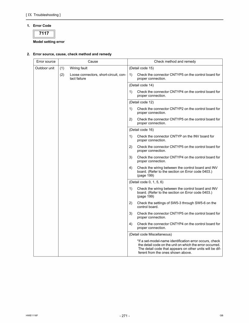
[ IX Troubleshooting ]
- 271 -HWE1116F GB
7117
1. Error Code
Model setting error
2. Error source, cause, check method and remedy
7117
Error source Cause Check method and remedy
Outdoor unit (1) Wiring fault (Detail code 15)
(2) Loose connectors, short-circuit, con-tact failure
1) Check the connector CNTYP5 on the control board for proper connection.
(Detail code 14)
1) Check the connector CNTYP4 on the control board for proper connection.
(Detail code 12)
1) Check the connector CNTYP2 on the control board for proper connection.
2) Check the connector CNTYP5 on the control board for proper connection.
(Detail code 16)
1) Check the connector CNTYP on the INV board for proper connection.
2) Check the connector CNTYP5 on the control board for proper connection.
3) Check the connector CNTYP4 on the control board for proper connection.
4) Check the wiring between the control board and INV board. (Refer to the section on Error code 0403.) (page 199)
(Detail code 0, 1, 5, 6)
1) Check the wiring between the control board and INV board. (Refer to the section on Error code 0403.) (page 199)
2) Check the settings of SW5-3 through SW5-6 on the control board.
3) Check the connector CNTYP5 on the control board for proper connection.
4) Check the connector CNTYP4 on the control board for proper connection.
(Detail code Miscellaneous)
*If a set-model-name identification error occurs, check the detail code on the unit on which the error occurred. The detail code that appears on other units will be dif-ferent from the ones shown above.
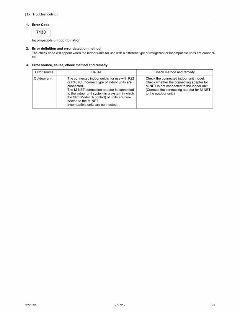
[ IX Troubleshooting ]
- 272 -HWE1116F GB
7130
1. Error Code
Incompatible unit combination
2. Error definition and error detection methodThe check code will appear when the indoor units for use with a different type of refrigerant or incompatible units are connect-ed.
3. Error source, cause, check method and remedy
7130
Error source Cause Check method and remedy
Outdoor unit The connected indoor unit is for use with R22 or R407C. Incorrect type of indoor units are connected. The M-NET connection adapter is connected to the indoor unit system in a system in which the Slim Model (A control) of units are con-nected to the M-NET. Incompatible units are connected.
Check the connected indoor unit model.Check whether the connecting adapter for M-NET is not connected to the indoor unit.(Connect the connecting adapter for M-NET to the outdoor unit.)

[ IX Troubleshooting ]
- 273 -HWE1116F GB
Troubleshooting according to the remote controller malfunction or the external input error
In the case of MA remote controller
-1- Troubleshooting according to the remote controller malfunction or the external input error
In the case of MA remote controller
1. PhenomenaEven if the operation button on the remote controller is pressed, the display remains unlit and the unit does not start run-ning.(Power indicator does not appear on the screen.)
(1) Cause
1) The power is not supplied to the indoor unit.
The main power of the indoor unit is not on.The connector on the indoor unit board has come off.The fuse on the indoor unit board has melted.Transformer failure and disconnected wire of the indoor unit.
2) Incorrect wiring for the MA remote controller
Disconnected wire for the MA remote controller or disconnected line to the terminal block.Short-circuited MA remote controller wiringIncorrect wiring of the MA remote controller cablesIncorrect connection of the MA remote wiring to the terminal block for transmission line (TB5) on the indoor unitWiring mixup between the MA remote controller cable and power supply cableReversed connection of the wire for the MA remote controller and the M-NET transmission line on the indoor unit
3) The number of the MA remote controllers that are connected to an indoor unit exceeds the allowable range (2 units).4) The length or the diameter of the wire for the MA remote controller are out of specification.5) Short circuit of the wire for the remote display output of the outdoor unit or reversed polarity connection of the relay.6) The indoor unit board failure7) MA remote controller failure
(2) Check method and remedy
1) Measure voltages of the MA remote controller terminal (among 1 to 3).
If the voltage is between DC 9 and 12V, the remote controller is a failure.If no voltage is applied, check the causes 1) and 3) and if the cause is found, correct it.If no cause is found, refer to 2).
2) Remove the wire for the remote controller from the terminal block (TB15) on the MA remote controller for the indoor unit, and check voltage among 1 to 3.
If the voltage is between DC 9 and 12 V, check the causes 2) and 4) and if the cause is found, correct it.If no voltage is applied, check the cause 1) and if the cause is found, correct it.If no cause is found, check the wire for the remote display output (relay polarity).If no further cause is found, replace the indoor unit board.

[ IX Troubleshooting ]
- 274 -HWE1116F GB
In the case of MA remote controller
2. PhenomenaWhen the remote controller operation SW is turned on, the operation status briefly appears on the display, then it goes off, and the display lights out immediately, and the unit stops.
(1) Cause
1) The power for the M-NET transmission line is not supplied from the outdoor unit.2) Short circuit of the transmission line.3) Incorrect wiring of the M-NETtransmission line on the outdoorunit.
Disconnected wire for the MA remote controller or disconnected line to the terminal block.The indoor transmission line is connected incorrectly to the transmission terminal block for centralized controller (TB7).The male power supply connectors on the multiple outdoor units are connected to the female power supply switch connector (CN40).In the system to which the power supply unit for transmission lines is connected, the male power supply connector is connect-ed to the female power supply switch connector (CN40) on the outdoor unit.
4) Disconnected M-NET transmission line on the indoor unit side.5) Disconnected wire between the terminal block for M-NET line (TB5) of the indoor unit and the indoor unit board (CN2M) or
disconnected connector.
(2) Check method and remedy
1) When 2) and 3) above apply, check code 7102 will be displayed on the self-diagnosis LED.
Refer to section IX [4] -8- (2) Troubleshooting transmission power circuit of outdoor unit for how to check the first item in the flowchart above.(page 333)(page 337)
YES
YES
YES
YES
NO
NO
NO
NO
Same symptom for all units in a system with one outdoor unit?
Check the self-diagnosis LED
Check 1).
Check for 2) and 3).
Check 4).
Measure voltages of the terminal block for transmission line (TB5) on the indoor unit.
17 - 30V?
Check 5).
Error found?
Indoor unit board or MA remote controller failure
Correct the error.
Correct the error.
Is the error code 7102 displayed?

[ IX Troubleshooting ]
- 275 -HWE1116F GB
In the case of MA remote controller
3. Phenomena"HO" or "PLEASE WAIT" display on the remote controller does not disappear, and no operation is performed even if the button is pressed. ("HO" or "PLEASE WAIT" display will normally turn off 5 minutes later after the power on.)
(1) Cause
1) The power for the M-NET transmission line is not supplied from the outdoor unit.2) Short-circuited transmission line3) Incorrect wiring of the M-NET transmission line on the outdoor unit.
Disconnected wire for the MA remote controller or disconnected line to the terminal block.The indoor transmission line is connected incorrectly to the transmission terminal block for centralized controller (TB7).The male power supply connectors on the multiple outdoor units are connected to the female power supply switch connector (CN40).In the system to which the power supply unit for transmission lines is connected, the male power supply connector is connect-ed to the female power supply switch connector (CN40) on the outdoor unit
4) Disconnected M-NET transmission line on the indoor unit.5) Disconnected wire between the terminal block for M-NET line (TB5) of the indoor unit and the indoor unit board (CN2M) or
disconnected connector.6) Incorrect wiring for the MA remote controller
Short-circuited wire for the MA remote controllerDisconnected wire for the MA remote controller (No.2) and disconnected line to the terminal block.Reversed daisy-chain connection between groupsIncorrect wiring for the MA remote controller to the terminal block for transmission line connection (TB5) on the indoor unitThe M-NET transmission line is connected incorrectly to the terminal block (TB15) for the MA remote controller.
7) The sub/main setting of the MA remote controller is set to sub.8) 2 or more main MA remote controllers are connected.9) Indoor unit board failure (MA remote controller communication circuit)10) Remote controller failure11) Outdoor unit failure (Refer to IX [8] Troubleshooting Using the Outdoor Unit LED Error Display.)(page 353)
(2) Check method and remedy
1) When 2) and 3) above apply, check code 7102 will be displayed on the self-diagnosis LED.
Refer to section IX [4] -8- (2) Troubleshooting transmission power circuit of outdoor unit for how to check the first item in the flowchart above.(page 333)(page 337)
YES
YES
YES
NO
NO
YES
YES
NO
NO
NO
Check the self-diagnosis LED
Error found?
Error found?
Replace the ME remote controller with the MA remote controller
Check for 5) and 6).
17 - 30V?
Same symptom for all units in a system with one outdoor unit?
Check 1).
Check 2) and 3).
Check 4).
Correct the error.
Correct the error.
Measure voltages of the terminal block for transmission line (TB5) on the indoor unit.
Is the error code 7102 displayed?
Indoor unit board or MA remote controller failure

[ IX Troubleshooting ]
- 276 -HWE1116F GB
Flow chartEven if the operation button on the remote controller is pressed, the indoor and the outdoor units do not start running.
YE
SB
linki
ng?
Is "
" dis
playe
d on
th
e re
mot
e co
ntro
ller?
NO
NO
NO
YE
S
YE
S
Whe
n al
l wire
s us
ed fo
r gr
oupi
ng a
re d
isco
nnec
ted,
is a
t le
ast o
ne o
f the
LE
D2
on th
e gr
oupe
d in
door
uni
ts li
t?
YE
S
Rep
lace
the
MA
rem
ote
cont
rolle
r.
Is th
ere
an in
door
unit
on
which
LED
2 is
turn
ed o
ff?
If ope
rated
after
ward
s, er
ror 6
602 o
r 66
07 oc
curs.
Chec
k the
volta
ge be
twee
n the
MA
remo
te co
ntroll
er
termi
nals
(A an
d B).
9-13
VDC
if the
volta
ge is
appli
ed
and 0
V if n
o volt
age i
s app
lied.
Is L
ED1
on th
e in
door
uni
t co
ntro
l boa
rd lit
?(B
links
for 2
or 3
sec
onds
ap
prox
imat
ely
ever
y 20
sec
onds
)
Does
the n
umbe
r of th
e MA
remo
te co
ntroll
ers t
hat a
re
conn
ected
to an
indo
or
unit e
xcee
d the
allow
able
rang
e (2 u
nits)?
Blink
ing?
(Tur
ns on
mom
entar
ily
appr
oxim
ately
ever
y 20
seco
nds)
In th
e ca
se o
f rem
ote
cont
rolle
r,to
“1.p
heno
men
a”*A
fter c
orre
ctin
g th
e er
ror,
daisy
-cha
in
the
wire
for t
he M
A re
mot
e co
ntro
ller a
gain
.
In th
e ca
se o
fM
A re
mot
e co
ntro
ller
to “1
.phe
nom
ena”
In th
e ca
se o
fM
A re
mot
e co
ntro
ller
to “1
.phe
nom
ena”
and
“2.p
heno
men
a”
In th
e ca
se o
fM
A re
mot
e co
ntro
ller
to “3
.phe
nom
ena”
In th
e ca
se o
fM
A re
mot
e co
ntro
ller
to “2
.phe
nom
ena”
No.
1 R
efrig
eran
t circ
uit c
heck
In th
e ca
se o
fM
A re
mot
e co
ntro
ller
to “2
.phe
nom
ena”
Che
ck th
e m
alfu
nctio
ning
re
frige
rant
circ
uit.
Che
ck fo
r the
M-N
ET
trans
mis
sion
line
.
Rep
lace
the
indo
or u
nit c
ontro
l boa
rd.
Con
nect
2 re
mot
e co
ntro
llers
or l
ess.
Che
ck w
heth
er th
e sc
rew
on
the
wire
is n
ot lo
ose.
Is L
ED2
on th
e in
door
uni
t co
ntro
l boa
rd b
linkin
g?
Whe
n the
unit i
s ope
rated
with
the
remo
te co
ntroll
er, w
ill "O
N"
appe
ar on
the d
isplay
?
Is "C
entra
lized
" di
spla
yed?
"HO"
/"PLE
ASE
WAI
T" ke
eps
blink
ing on
the M
A re
mote
contr
oller.
Is on
ly the
powe
r sou
rce of
the
indoo
r unit
turn
turn
ed on
again
?DE
MAN
D by
MEL
ANS?
Exte
rnal
ther
mo
inpu
t set
ting?
(SW
3-3=
ON)
Does
an
erro
r occ
ur w
hen
the
powe
r is
rese
t?
Does
the u
nit w
ork p
rope
rly
when
the w
ire fo
r the
MA
remo
te co
ntroll
er is
da
isy-ch
ained
again
?
Is L
ED
1 on
the
indo
or
unit
cont
rol b
oard
lit?
Does
the M
A re
mote
contr
oller
wo
rk pr
oper
ly wh
en it
is co
nnec
ted
to the
spec
ified i
ndoo
r unit
?
Does
an
erro
r occ
ur w
hen
the
powe
r is r
eset
?
Runn
ing g
roup
ope
ratio
n wi
th
the
MA
rem
ote
cont
rolle
r?
Is th
e un
it gr
oupe
d wi
th th
e eq
uipm
ent p
acka
ge
indo
or u
nit?
No fa
ult w
ith th
e eq
uipm
ent
pack
age
indo
or u
nit?
Does
an
erro
r occ
ur w
hen
the
powe
r is r
eset
?
Chec
k tha
t no e
rror o
ccurs
in ot
her in
door
units
.
Che
ck th
e in
door
uni
t on
whi
ch L
ED
2 is
lit.
All t
he in
door
uni
t po
wer f
ailu
re?
All t
he in
door
uni
t p
ower
failu
re?
Erro
r disp
lay?
Erro
r disp
lay?
Ther
mo
is O
FF?
Is o
pera
tion
poss
ible
?
Shor
t circ
uit o
f the
re
mot
e co
ntro
ller?
After t
urning
the po
wer on
, check
wheth
er "HO
"/"PL
EASE
WAIT"
is dis
played
on the
remote
contro
ller.
Afte
r mor
e th
an 2
0 se
cond
s si
nce
turn
ing
the
pow
er o
n, is
LE
D2
chec
k of
the
indo
or c
ontro
l boa
rd s
till
disp
laye
d?
Is th
e op
erat
ion b
y MEL
ANS
forb
idden
or t
he in
put f
rom
exte
rnal
cont
rol
equip
men
t allo
wed
(SW
C=ON
)?
Is th
e co
mpu
lsor
y th
erm
o O
FF (S
WA
) sw
itch
set t
o "2
" or "
3"?
Alth
ough
No.
1 re
frige
rant
circ
uit
is no
rmal,
No.
2 or
No.
3 re
frige
rant
circ
uit re
main
stop
ped.
Runn
ing gr
oup o
pera
tion w
ith
the M
A re
mote
contr
oller
?
Does
the i
ndoo
r unit
mak
e an
insta
ntane
ous s
top?
Powe
r sup
ply
volta
geAC
188~
253V
?
NO
YE
S
NO
NO
NO
NO
NO
NO
NO
NOWhe
n no
err
or o
ccur
s
NO
NO
NO
Kee
p di
spla
ying
fo
r 5 o
r mor
e m
inut
es.
NO
NO
NO
NO
NO
NO
NO
NO
NO
NO
NO
NO
Che
ck th
e po
wer
sup
ply.
Che
ck th
e w
ire fo
r th
e re
mot
e co
ntro
ller.NO
Rep
lace
the
indo
or u
nit c
ontro
l boa
rd.
NO
NO
NO
NO
NO
Rep
lace
the
MA
rem
ote
cont
rolle
r.
NO
Repl
ace
the
rem
ote
cont
rolle
r or
the
indo
or c
ontro
l boa
rd.
YE
S
Rep
lace
the
indo
or u
nit c
ontro
l bo
ard
whe
re a
n er
ror o
ccur
s.
Kee
p th
e op
erat
ion.
NO
NO
NO
NO
Kee
p th
e op
erat
ion.
YE
S
YE
S
YE
S
YE
S
Pow
er o
n
YE
S
Ref
er to
the
self-
diag
nosi
s lis
t fo
r the
dis
play
ed e
rror
cod
e.
YE
S
Nor
mal
Turn
s of
f with
in a
ppro
xim
atel
y 5
min
utes
.A
fter t
he m
ain
pow
er o
n, s
tart
the
MA
rem
ote
cont
rolle
r. "H
O" d
ispl
ay w
ill a
ppea
r. YE
S
Nor
mal
"C
entra
lized
" is
disp
laye
d.
YE
S Ref
er to
the
erro
r cod
e lis
t.
YE
S
YE
SY
ES
Nor
mal
YE
S
Nor
mal
(Is th
e th
erm
o O
FF
sign
al in
put?
)
YE
S
Set
the
SW
A to
"1".
YE
S
Ref
er to
the
self-
diag
nosi
s lis
t for
th
e di
spla
yed
erro
r cod
e.
YE
S
YE
S
YE
S
YE
S
Chec
k th
e eq
uipm
ent
pack
age
indo
or u
nit.
YE
S Rep
lace
the
rem
ote
cont
rolle
r or
the
indo
or c
ontro
l boa
rd.
Rep
lace
the
indo
or u
nit c
ontro
l boa
rd.
YE
S
YE
S
YE
S
Rep
lace
the
rem
ote
cont
rolle
r or
the
indo
or c
ontro
l boa
rd.
Nor
mal
(O
pera
te th
e un
it w
ith
exte
rnal
con
trol e
quip
men
t)
YE
S
YE
S Rep
lace
the
indo
or
unit
cont
rol b
oard
.
Che
ck th
e po
wer
sup
ply.
YE
S
YE
S
YE
S
YE
S
Chec
k the
volta
ge be
twee
n the
MA
remo
te co
ntroll
er
termi
nal b
locks
(TB1
5) (A
and B
).9-
13VD
C if t
he vo
ltage
is
appli
ed an
d 0V
if no v
oltag
e is
appli
ed.
NO
Disc
onne
cted
wire
for
the
rem
ote
cont
rolle
r?Di
scon
nect
ed w
ire to
th
e te
rmin
al b
lock
?Di
scon
necte
d rela
y con
necto
r?
NO
Are t
he le
ngth
or th
e diam
eter
of the
wire
for M
A re
mote
contr
oller
ou
t of s
pecif
icatio
n?
NO
YE
S
YE
S Use
the
wire
that
mee
ts th
e sp
ecifi
catio
n.
Rep
lace
the
wire
for t
he M
A re
mot
e co
ntro
ller.
YE
S
Che
ck fo
r the
wire
for
the
rem
ote
cont
rolle
r.
Kee
p th
e op
erat
ion.
YE
S
Rep
lace
the
indo
or
unit
cont
rol b
oard
.
YE
S
YE
S
YE
S
Pow
er o
n

[ IX Troubleshooting ]
- 277 -HWE1116F GB
Troubleshooting according to the remote controller malfunction or the external input error
In case of ME remote controller
In case of ME remote controller
1. PhenomenaEven if the operation button on the remote controller is pressed, the display remains unlit and the unit does not start running.(Power indicator does not appear on the screen.)
(1) Cause
1) The power for the M-NET transmission line is not supplied from the outdoor unit.2) Short circuit of the transmission line.3) Incorrect wiring of the M-NET transmission line on the outdoor unit.
Disconnected wire for the MA remote controller or disconnected line to the terminal block.The indoor transmission line is connected incorrectly to the transmission terminal block for centralized controller (TB7).
4) Disconnected transmission line on the remote controller.5) Remote controller failure6) Outdoor unit failure (Refer to IX [8] Troubleshooting Using the Outdoor Unit LED Error Display.)(page 353)
(2) Check method and remedy
1) Check voltage of the transmission terminal block for of the ME remote controller.
If voltage between is 17V and 30V -> ME remote controller failure When voltage is 17V or less -> Refer to IX [4] -8- (2).(page 333)(page 337)
2) When 2) and 3) above apply, check code 7102 will be displayed on the self-diagnosis LED.

[ IX Troubleshooting ]
- 278 -HWE1116F GB
In case of ME remote controller
2. PhenomenaWhen the remote controller operation SW is turned on, a temporary operation display is indicated, and the display lights out immediately.
(1) Cause
1) The power is not supplied to the indoor unit.
The main power of the indoor unit (AC208/230V) is not on.The connector on the indoor unit board has come off.The fuse on the indoor unit board has melted.Transformer failure and disconnected wire of the indoor unitThe indoor unit board failure
2) The outdoor control board failure
As the indoor unit does not interact with the outdoor unit, the outdoor unit model cannot be recognized.
(2) Check method and remedy
YES
YES
YES
YES
YES
NO
NO
NO
NO
NO
NO
YES
*1 *1
Check LED1 on the indoor unit control board.
Is it lit?
When it is lit When it is off or cannot be checked
Check for the change of LED display by operating dip switch for self-diagnosis.
Check voltage of the power supply terminal on the indoor unit.
AC208/230V?
Check the fuse on the circuit board.
Melted? Check 200V circuit for short circuit and ground fault
Check the connection of the connector.
Check the main power of the power supply wire Turn on the
power again.
Connector contact failure Disconnected?
Check the resistance value of the transformer
Within specification? Check the cause of the disconnected transformer. Ground fault on the circuit board Ground fault of the sensor and the LEV
Check self-diagnosis function of outdoor unit
Changed?
Changed?
Outdoor unit board failure
Check self-diagnosis function of outdoor unit after the power on.
Accidental error
Indoor unit control board failure
Correct the error.
*1. Refer to the parts catalog “transformer check”.

[ IX Troubleshooting ]
- 279 -HWE1116F GB
In case of ME remote controller
3. Phenomena"HO" display on the remote controller does not disappear, and no operation is performed even if the button is pressed.
(1) Cause
Without using MELANS1) Outdoor unit address is set to "00"2) A wrong address is set.
The address of the indoor unit that is connected to the remote controller is incorrect. (It should equal the ME remote controller address plus 100.)A wrong address is set to the ME remote controller. (100 must be added to the address of the indoor unit.)
3) Faulty wiring of the terminal block for transmission line (TB5) of the indoor unit in the same group with the remote controller.4) The centralized control switch (SW5-1) on the outdoor unit is set to ON.5) Disconnection or faulty wiring of indoor unit transmission line.6) Disconnection between the terminal block for M-NET line connection (TB5) of the indoor unit and the male connector (CN2M)7) The male power supply connectors on 2 or more outdoor units are connected to the female power supply switch connector
(CN40) for the transmission line for centralized control.8) Outdoor unit control board failure9) Outdoor unit control board failure10) Remote controller failure
Interlocking control with MELANS1) No group registration is made using MELANS. (The indoor unit and the ME remote controller are not grouped.)2) Disconnected transmission line for centralized control (TB7) of the outdoor unit3) The male power supply connector is connected to CN40 on more than one outdoor unit, or the connector is connected to CN40
on the outdoor unit in the system to which a power supply unit for transmission line is connected.Using MELANS1) When MELANS is used, "HO" display on the remote controller will disappear when the indoor unit and the local remote con-
troller (ME remote controller) are grouped.If "HO" does not disappear after the registration, check the causes (2) 1) - 3).
(2) Check method and remedy
YES
YES
YES
YES
YES
YES
YES
NO
NO *1
*1. When the indoor unit address is set to 1 - 50, the address will be forcibly set to 100.
NO
NO
NO
NO
NO
Without using MELANS
Are all the units in the system experiencing the same problem?
Check the address of the outdoor unit.
51 - 100?
Check the centralized centralizedswitch (SW5-1) on the outdoor unit.
ON?
Indoor unit control board failure
A wrong address is set to the outdoor unit.
Wrong switch setting Change it from ON to OFF.
A wrong address is set to the ME remote controller.
A wrong address is set to the indoor unit.
Wrong wiring of the M-NET transmission line of the indoor unit
Disconnected connector (CN2M)
Correct the error.
Disconnected?
17 - 30V?
ME remote controller- 100?
Check the address of the indoor unit to be coupled.
Indoor unit + 100?
Check the address of the ME remote controller on which "HO" is displayed.
Check connection between indoor M-NET transmission terminal block (TB5) and the male connector (CN2M)
Measure voltages of the terminal block for M-NET transmission line on the indoor unit.
Indoor unit board or remote controller failure

[ IX Troubleshooting ]
- 280 -HWE1116F GB
In case of ME remote controller
4. Phenomena"88" appears on the remote controller when the address is registered or confirmed.
(1) Cause, check method and remedy
Cause Check method and remedy
An error occurs when the address is registered or con-firmed. (common)
1. A wrong address is set to the unit to be coupled. (1) Confirm the address of unit to be coupled.
2. The transmission line of the unit to be coupled is dis-connected or is not connected.
(2) Check the connection of transmission line.
3. Circuit board failure of the unit to be coupled (3) Check voltage of the terminal block for transmission line of the unit to be coupled.
1) Normal if voltage is between DC17 and 30V.
4. Improper transmission line work 2) Check (4) in case other than 1).
Generates at interlocking registration between LOSS-NAY and the indoor unit
5. The power of LOSSNAY is OFF. (4) Check for the main power of LOSSNAY.
Generates at confirmation of controllers used in the system in which the indoor units connected to differ-ent outdoor units are grouped
6. The power of the outdoor unit to be confirmed has been cut off.
(5) Check the power supply of the outdoor unit which is coupled with the unit to be confirmed.
7. Transmission line is disconnected from the terminal block for central control system connection (TB7) on the outdoor unit.
(6) Check that the transmission line for centralized control (TB7) of the outdoor unit is not disconnect-ed.
8. When the indoor units connected to different outdoor units are grouped without MELANS, the male power supply connector is not connected to the female power supply switch connector (CN40) for the trans-mission line for centralized control.
(7) Check voltage of the transmission line for central-ized control.
9. The male power supply connectors on 2 or more out-door units are connected to the female power supply switch connector (CN40) for the transmission line for centralized control.
1) Normal when voltage is between 10V and 30V
10. In the system to which MELANS is connected, the male power supply connector is connected to the fe-male power supply switch connector (CN40) for the transmission line for centralized control.
2) Check 8 - 11 described on the left in case other than 1).
11. Short circuit of the transmission line for centralized control

[ IX Troubleshooting ]
- 281 -HWE1116F GB
Troubleshooting according to the remote controller malfunction or the external input error
Both for MA remote controller and ME remote controller
Both for MA remote controller and ME remote controller
1. PhenomenaAlthough cooling operation starts with the normal remote controller display, the capacity is not enough
(1) Cause, check method and remedy
Cause Check method and remedy
1. Compressor frequency does not rise sufficiently.Faulty detection of pressure sensor.Protection works and compressor frequency does
not rise due to high discharge temperatureProtection works and compressor frequency does
not rise due to high pressurePressure drops excessively.
(1) Check pressure difference between the detected pressure by the pressure sensor and the actual pressure with self-diagnosis LED. -> If the accurate pressure is not detected, check the pressure sensor. (Refer to the page on Trouble-shooting of Pressure Sensor)(page 289)
Note: Lower inlet pressure by the low pressure sensor than the actual pressure causes insufficient capac-ity.SW4 setting (SW6-10: OFF)
(2) Check temperature difference between the evapo-rating temperature (Te) and the target evaporating temperature (Tem) with self-diagnosis LED.
Note: Higher Te than Tem causes insufficient capacity.SW4 setting (SW6-10: OFF)
Note: Protection works and compressor frequency does not rise even at higher Te than Tem due to high dis-charge temperature and high pressure.At high discharge temperature:Refer to 1102.(page 200) At high pressure:Refer to 1302.(page 202)
2. Indoor unit LEV malfunction Refer to the page of LEV troubleshooting ([4] -5-).(page 296)
Insufficient refrigerant flows due to LEV malfunc-tion (not enough opening) or protection works and compressor frequency does not rise due to pres-sure drop.Refrigerant leak from LEV on the stopping unit
causes refrigerant shortage on the running unit.
3. RPM error of the outdoor unit FAN Refer to the page on troubleshooting of the outdoor unit fan.Refer to 5107.(page 234) Refer to 1302.(page 202)
Motor failure or board failure, or airflow rate de-crease due to clogging of the heat exchangerThe fan is not properly controlled as the outdoor
temperature cannot be precisely detected by the temperature sensor.The fan is not properly controlled as the pressure
cannot be precisely detected by the pressure sen-sor.
High pressure sensor
Low pressure sensor
ON 1 2 3 4 5 6 7 8 9 10
ON 1 2 3 4 5 6 7 8 9 10
SW4
SW4
1 2 3 4 5 6 7 8 9 10
Evaporating temperature Te
Target evaporating temperature Tem
ON 1 2 3 4 5 6 7 8 9 10
ON
SW4
SW4

[ IX Troubleshooting ]
- 282 -HWE1116F GB
Cause Check method and remedy
4. Long piping lengthThe cooling capacity varies greatly depending on the pressure loss. (When the pressure loss is large, the cooling capacity drops.)
Check the piping length to determine if it is contrib-uting to performance loss.Piping pressure loss can be estimated from the temperature difference between the indoor unit heat exchanger outlet temperature and the satura-tion temperature (Te) of 63LS. ->Correct the piping.5. Piping size is not proper (thin)
6. Insufficient refrigerant amountProtection works and compressor frequency does not rise due to high discharge temperature.
Refer to 1-1. (Compressor frequency does not rise sufficiently.)(page 281) Refer to the page on refrigerant amount adjustment(page 169)
7. Clogging by foreign object Check the temperature difference between in front of and behind the place where the foreign object is clogging the pipe (upstream side and downstream side). When the temperature drops significantly, the foreign object may clog the pipe.-> Remove the foreign object inside the pipe.
8. The indoor unit inlet temperature is excessively. (Less than 15°C [59°F] WB)
Check the inlet air temperature and for short cy-cling. Change the environment where the indoor unit is used.
9. Compressor failureThe amount of circulating refrigerant decreases due to refrigerant leak in the compressor.
Check the discharge temperature to determine if the refrigerant leaks, as it rises if there is a leak.
10. LEV3 malfunctionSufficient liquid refrigerant is not be supplied to the indoor unit as sufficient sub cool cannot be secured due to LEV3 malfunction.
Refer to the page of LEV troubleshooting ( [4] -5- ).(page 296) It most likely happens when there is little difference or no difference between TH12 and TH15.
11. TH12, TH15 and 63HS1 sensor failure or faulty wir-ingLEV3 is not controlled normally.
Check the thermistor.Check wiring.

[ IX Troubleshooting ]
- 283 -HWE1116F GB
2. PhenomenaAlthough heating operation starts with the normal remote controller display, the capacity is not enough.
(1) Cause, check method and remedy
Cause Check method and remedy
1. Compressor frequency does not rise sufficiently.Faulty detection of pressure sensor.Protection works and compressor frequency does
not rise due to high discharge temperatureProtection works and compressor frequency does
not rise due to high pressure.
(1) Check pressure difference between the detected pressure by the pressure sensor and the actual pressure with self-diagnosis LED. -> If the accurate pressure is not detected, check the pressure sensor.(Refer to the page on Trouble-shooting of Pressure Sensor)(page 289)
Note: Higher inlet pressure by the high pressure sensor than the actual pressure causes insufficient capac-ity.SW4 setting (SW6-10: OFF)
(2) Check the difference between the condensing tem-perature (Tc) and the target condensing tempera-ture (Tcm) with self-diagnosis LED.
Note: Higher Tc than Tcm causes insufficient capacity.SW4 setting (SW6-10: OFF)
Note: Protection works and compressor frequency does not rise even at lower Tc than Tcm due to high dis-charge temperature and high pressure.At high discharge temperature:Refer to 1102.(page 200) At high pressure:Refer to 1302.(page 202)
High pressure sensor
Low pressure sensor
ON 1 2 3 4 5 6 7 8 9 10
ON 1 2 3 4 5 6 7 8 9 10
SW4
SW4
Condensing temperature Tc
Target condensing temperature Tcm
ON
ON 1 2 3 4 5 6 7 8 9 10
1 2 3 4 5 6 7 8 9 10
SW4
SW4

[ IX Troubleshooting ]
- 284 -HWE1116F GB
Cause Check method and remedy
2. Indoor unit LEV malfunctionInsufficient refrigerant flows due to LEV malfunction (not enough opening).
Refer to the page of LEV troubleshooting ([4] -5-).(page 296)
3. Temperature reading error on the indoor unit piping temperature sensor If the temperature reading on the sensor is higher than the actual temperature, it makes the subcool seem smaller than it is, and the LEV opening de-creases too much.
Check the thermistor.
4 RPM error of the outdoor unit FAN Refer to the page on outdoor unit fan ([4] -4-).(page 295)
Motor failure or board failure, or airflow rate de-crease, pressure drop due to clogging of the heat exchanger leading to high discharge temperatureThe fan is not properly controlled as the tempera-
ture cannot be precisely detected with the piping sensor.
5. Insulation failure of the refrigerant piping
6. Long piping lengthExcessively long piping on the high pressure side causes pressure loss leading to increase in the high pressure.
Confirm that the characteristic of capacity drop due to piping length.-> Change the pipe
7. Piping size is not proper (thin)
8. Clogging by foreign object Check the temperature difference between the up-stream and the downstream of the pipe section that is blocked. Since blockage in the extended section is difficult to locate, operate the unit in the cooling cycle, and follow the same procedures that are used to locate the blockage of pipe during cooling operation.->Remove the blockage in the pipe.
9. The indoor unit inlet temperature is excessively high.(exceeding 28°C [82°F])
Check the inlet air temperature and for short cy-cling. Change the environment where the indoor unit is used.
10. Insufficient refrigerant amountProtection works and compressor frequency does not rise due to low discharge temperatureRefrigerant recovery operation is likely to start.
Refer to 2 - 1. (Compressor frequency does not rise sufficiently.)(page 283) Refer to the page on refrigerant amount adjustment.(page 169)
11. Compressor failure (same as in case of cooling) Check the discharge temperature.
12. LEV3 actuation failureA drop in the low pressure that is caused either by a blockage of liquid pipe or by a pressure loss and the resultant slowing of refrigerant flow causes a tenden-cy for the discharge temperature to rise.
Refer to the page on troubleshooting the LEV ([4] -5-).(page 296)

[ IX Troubleshooting ]
- 285 -HWE1116F GB
3. PhenomenaOutdoor unit stops at times during operation.
(1) Cause, check method and remedy
Cause Check method and remedy
The first stop is not considered as an error, as the unit turns to anti-restart mode for 3 minutes as a pre-liminary error.
(1) Check the mode operated in the past by displaying preliminary error history on LED display with SW4.
Error mode
1) Abnormal high pressure (2) Reoperate the unit to find the mode that stops the unit by displaying preliminary error history on LED display with SW4.2) Abnormal discharge air temperature
3) Heatsink thermistor failure
4) Thermistor failure Refer to the reference page for each error mode.*Display the indoor piping temperature table with SW4 to check whether the freeze proof operation runs properly, and check the temperature.
5) Pressure sensor failure
6) Over-current break
7) Refrigerant overcharge
Note1: Frost prevention tripping only under cooling mode may be considered in addition to the above. (Freeze protection is detected by one or all indoor units.)
Note2: Even the second stop is not considered as an error when some specified errors occur. (eg. The third stop is considered as an error when the thermistor error occurs.)

[ IX Troubleshooting ]
- 286 -HWE1116F GB
[3] Investigation of Transmission Wave Shape/Noise
1. M-NET transmissionControl is performed by exchanging signals between the outdoor unit and the indoor unit (ME remote controller) through M-NET transmission. Noise interference on the transmission line will interrupt the normal transmission, leading to erroneous op-eration.
(1) Symptoms caused by noise interference on the transmission line
(2) Wave shape check
Wave shape checkCheck the wave pattern of the transmission line with an oscilloscope. The following conditions must be met.
1) Small wave pattern (noise) must not exist on the transmission signal. (Minute noise (approximately 1V) can be generated by DC-DC converter or the inverter operation; however, such noise is not a problem when the shield of the transmission line is grounded.)
2) The sectional voltage level of transmission signal should be as follows.
Cause Erroneous operation Error code Error code definition
Noise interference on the transmission line
Signal is transformed and will be misjudged as the signal of another address.
6600 Address overlap
Transmission wave pattern is transformed due to the noise creating a new signal
6602 Transmission pro-cessor hardware er-ror
Transmission wave pattern is transformed due to the noise, and will not be received normally leading to no acknowledgement (ACK).
6607 No ACK error
Transmission cannot be performed due to the fine noise.
6603 Transmission line bus busy error
Transmission is successful; however, the acknowl-edgement (ACK) or the response cannot be re-ceived normally due to the noise.
66076608
No ACK errorNo response error
Logic Voltage level of the transmission line
0 VHL = 2.5V or higher
1 VBN = 1.3V or below
[With transmission]
[Without transmission]
No fine noise allowed
No fine noise allowed
52 52 52 52 52
VBN
VHL
Logic "0" Logic "1"

[ IX Troubleshooting ]
- 287 -HWE1116F GB
(3) Check method and remedy
1) Measures against noiseCheck the followings when noise exists on the wave or the errors described in (1) occur.
2) Check the followings when the error "6607" occurs, or "HO" appears on the display on the remote controller.
Error code definition Remedy
Check that the wiring work is performed ac-cording to wiring specifications.
1. The transmission line and the power line are not wired too closely.
Isolate the transmission line from the power line (5cm [1-31/32"] or more). Do not insert them in the same conduit.
2. The transmission line is not bundled with that for another systems.
The transmission line must be isolated from another transmission line.When they are bundled, erroneous operation may be caused.
3. The specified wire is used for the transmission line.
Use the specified transmission line.Type: Shielded wire CVVS/CPEVS/MVVS (For ME remote control-ler)Diameter: 1.25mm2 [AWG16] or more (Remote controller wire: 0.3 - 1.25mm2 [AWG22-16])
4. When the transmission line is daisy-chained on the indoor unit terminals, are the shields daisy-chained on the terminals, too?
The transmission is two-wire daisy-chained. The shielded wire must be also daisy-chained.When the shielded cable is not daisy-chained, the noise cannot be reduced enough.
Check that the grounding work is performed according to grounding specifi-cations.
5. Is the shield of the indoor-outdoor transmission ca-ble grounded to the earth terminal on the outdoor unit?
Connect the shield of the indoor-outdoor transmission cable to the earth terminal ( ) on the outdoor unit.If no grounding is provided, the noise on the transmission line can-not escape leading to change of the transmission signal.
6. Check the treatment meth-od of the shield of the transmission line (for cen-tralized control).
The transmission cable for centralized control is less subject to noise interference if it is grounded to the outdoor unit whose power jumper cable was moved from CN41 to CN40 or to the power sup-ply unit.The environment against noise varies depending on the distance of the transmission lines, the number of the connected units, the type of the controllers to be connected, or the environment of the installation site. Therefore, the transmission line work for central-ized control must be performed as follows.
1. When no grounding is provided: Ground the shield of the transmission cable by connecting to the outdoor unit whose power jumper connector was moved from CN41 to CN40 or to the power supply unit.
2. When an error occurs even though one point grounding is provided: Ground the shield on all outdoor units.
Error code definition Remedy
7. The farthest distance of transmission line is 200m [656ft] or longer.
Check that the farthest distance from the outdoor unit to the indoor unit and to the remote controller is within 200m [656ft].
8. The types of transmission lines are different. Use the specified transmission line.Type: Shielded wire CVVS/CPEVS/MVVS (For ME remote control-ler)Diameter: 1.25mm2 [AWG16] or more (Remote controller wire: 0.3-1.25mm2 [AWG22-16])
9. Outdoor unit circuit board failure Replace the outdoor unit control board or the power supply board for the transmission line.
10. Indoor unit circuit board failure or remote con-troller failure
Replace the indoor unit circuit board or the remote controller.
11. The MA remote controller is connected to the M-NET transmission line.
Connect the MA remote controller to the terminal block for MA re-mote controller (TB15).

[ IX Troubleshooting ]
- 288 -HWE1116F GB
2. MA remote controller transmissionThe communication between the MA remote controller and the indoor unit is performed with current tone burst.
(1) Symptoms caused by noise interference on the transmission line
If noise is generated on the transmission line, and the communication between the MA remote controller and the indoor unit is interrupted for 3 minutes in a row, MA transmission error (6831) will occur.
(2) Confirmation of transmission specifications and wave pattern
A, B : No polarity Across terminal No. 1-2 : Power supply (9V to 12VDC) Satisfies the formula 12 msec/bit 5% Voltage among terminals must be between DC9 and 12 V.
TB15
A B
1 2
MA remote controller
Transmission waveform (Across terminal No.1 - 2)
DC9~12V
Logic 1 Logic 0 Logic 1 Logic 1
12msec 12msec 12msec 12msec
Indoor unit

[ IX Troubleshooting ]
- 289 -HWE1116F GB
[4] Troubleshooting Principal PartsHigh-Pressure Sensor
-1- High-Pressure Sensor (63HS1, PS1, PS3)
1. Compare the pressure that is detected by the high pressure sensor, and the high-pressure gauge pressure to check for failure.By configuring the digital display setting switch (SW4 (when SW6-10 is set to OFF)) as shown in the figure below, the pressure as measured by the high-pressure sensor appears on the LED1 on the control board.
(1) While the sensor is stopped, compare the gauge pressure and the pressure displayed on self-diagnosis LED1.
1) When the gauge pressure is between 0 and 0.098MPa [14psi], internal pressure is caused due to gas leak. 2) When the pressure displayed on self-diagnosis LED1 is between 0 and 0.098MPa [14psi], the connector may be defective or
be disconnected. Check the connector and go to (4). 3) When the pressure displayed on self-diagnosis LED1 exceeds 4.15MPa [601psi], go to (3).4) If other than 1), 2) or 3), compare the pressures while the sensor is running. Go to (2).
(2) Compare the gauge pressure and the pressure displayed on self-diagnosis LED1 while the sensor is running. (Com-pare them by MPa [psi] unit.)
1) When the difference between both pressures is within 0.098MPa [14psi], both the high pressure sensor and the control board are normal.
2) When the difference between both pressures exceeds 0.098MPa [14psi], the high pressure sensor has a problem. (perfor-mance deterioration)
3) When the pressure displayed on self-diagnosis LED1 does not change, the high pressure sensor has a problem.
(3) Remove the high pressure sensor from the control board to check the pressure on the self-diagnosis LED1.
1) When the pressure displayed on self-diagnosis LED1 is between 0 and 0.098MPa [14psi], the high pressure sensor has a problem.
2) When the pressure displayed on self-diagnosis LED1 is approximately 4.15MPa [601psi], the control board has a problem.
(4) Remove the high pressure sensor from the control board, and short-circuit between the No.2 and 3 connectors (63HS1, PS1, PS3) to check the pressure with self-diagnosis LED1.
1) When the pressure displayed on the self-diagnosis LED1 exceeds 4.15MPa [601psi], the high pressure sensor has a problem.2) If other than 1), the control board has a problem.
2. Pressure sensor configurationThe high pressure sensor consists of the circuit shown in the figure below. If DC 5V is applied between the red and the black wires, voltage corresponding to the pressure between the white and the black wires will be output, and the value of this voltage will be converted by the microcomputer. The output voltage is 0.071V per 0.098MPa [14psi].
The pressure sensor on the body side is designed to connect to the connector. The connector pin number on the body side is different from that on the control board side.
Body side Control board side
Vcc Pin 1 Pin 3
Vout Pin 2 Pin 2
GND Pin 3 Pin 1
1 2 3 4 5 6 7 8 9 10 ON
SW4
0
0.5 [73]
1.0 [145]
1.5 [218]
2.0 [290]
2.5 [363]
3.0 [435]
3.5 [508]
4.0 [580]
4.5 [653]
0 0.5 1 1.5 2 2.5 3 3.5
Output voltage (V)
Pr
essu
re (M
Pa
[psi
])
Connector
63HS11 2 3
1 2
3
GND (Black)
Vout (White)
Vcc (DC 5 V)(Red)
Pressure 0 ~ 4.15 MPa [601psi] Vout 0.5 ~ 3.5 V 0.071 V / 0.098 MPa [14 psi]

[ IX Troubleshooting ]
- 290 -HWE1116F GB
Low-Pressure Sensor
-2- Low-Pressure Sensor (63LS)
1. Compare the pressure that is detected by the low pressure sensor, and the low pressure gauge pressure to check for failure.By configuring the digital display setting switch (SW4 (when SW6-10 is set to OFF)) as shown in the figure below, the pressure as measured by the low-pressure sensor appears on the LED1 on the control board.
(1) While the sensor is stopped, compare the gauge pressure and the pressure displayed on self-diagnosis LED1.
1) When the gauge pressure is between 0 and 0.098MPa [14psi], internal pressure is caused due to gas leak. 2) When the pressure displayed on self-diagnosis LED1 is between 0 and 0.098MPa [14psi], the connector may be defective or
be disconnected. Check the connector and go to (4). 3) When the pressure displayed on self-diagnosis LED1 exceeds 1.7MPa [247psi], go to (3).4) If other than 1), 2) or 3), compare the pressures while the sensor is running. Go to (2).
(2) Compare the gauge pressure and the pressure displayed on self-diagnosis LED1 while the sensor is running.(Com-pare them by MPa [psi] unit.)
1) When the difference between both pressures is within 0.03MPa [4psi], both the low pressure sensor and the control board are normal.
2) When the difference between both pressures exceeds 0.03MPa [4psi], the low pressure sensor has a problem. (performance deterioration)
3) When the pressure displayed on the self-diagnosis LED1 does not change, the low pressure sensor has a problem.
(3) Remove the low pressure sensor from the control board to check the pressure with the self-diagnosis LED1 display.
1) When the pressure displayed on the self-diagnosis LED1 is between 0 and 0.098MPa [14psi], the low pressure sensor has a problem.
2) When the pressure displayed on self-diagnosis LED1 is approximately 1.7MPa [247psi], the control board has a problem.
When the outdoor temperature is 30°C [86°F] or less, the control board has a problem. When the outdoor temperature exceeds 30°C [86°F], go to (5).
(4) Remove the low pressure sensor from the control board, and short-circuit between the No.2 and 3 connectors (63LS:CN202) to check the pressure with the self-diagnosis LED1.
1) When the pressure displayed on the self-diagnosis LED1 exceeds 1.7MPa [247psi], the low pressure sensor has a problem. 2) If other than 1), the control board has a problem.
(5) Remove the high pressure sensor (63HS1) from the control board, and insert it into the connector for the low pres-sure sensor (63LS) to check the pressure with the self-diagnosis LED1.
1) When the pressure displayed on the self-diagnosis LED1 exceeds 1.7MPa [247psi], the control board has a problem. 2) If other than 1), the control board has a problem.
2. Low-pressure sensor configurationThe low pressure sensor consists of the circuit shown in the figure below. If DC5V is applied between the red and the black wires, voltage corresponding to the pressure between the white and the black wires will be output, and the value of this voltage will be converted by the microcomputer. The output voltage is 0.173V per 0.098MPa [14psi].
The pressure sensor on the body side is designed to connect to the connector. The connector pin number on the body side is different from that on the control board side.
Body side Control board side
Vcc Pin 1 Pin 3
Vout Pin 2 Pin 2
GND Pin 3 Pin 1
1 2 3 4 5 6 7 8 9 10 ON
SW4
0
0.2 [29]
0.4 [58]
0.6 [87]
0.8 [116]
1.0 [145]
1.2 [174]
1.4 [203]
1.6 [232]
1.8 [261]
0 0.5 1 1.5 2 2.5 3 3.5 Output voltage (V)
Pr
essu
re (M
Pa
[psi
])
Connector
63LS 1 2 3
1 2
3
GND (Black)
Vout (White)
Vcc (DC 5 V)(Red)
Pressure 0 ~ 1.7 MPa [247psi] Vout 0.5 ~ 3.5 V 0.173 V / 0.098 MPa [14 psi]

[ IX Troubleshooting ]
- 291 -HWE1116F GB
Solenoid Valve
-3- Solenoid Valve
Check whether the output signal from the control board and the operation of the solenoid valve match.Setting the self-diagnosis switch (SW4) as shown in the figure below causes the ON signal of each relay to be output to the LED's.Each LED shows whether the relays for the following parts are ON or OFF. LEDs light up when relays are on.
The circuits on some parts are closed when the relays are ON. Refer to the following instructions.
When a valve malfunctions, check if the wrong solenoid valve coil is not attached the lead wire of the coil is not disconnected, the connector on the board is not inserted wrongly, or the wire for the connector is not disconnected.
(1) In case of 21S4a, 21S4b (4-way switching valve)
About this 4-way valveWhen not powered: Conducts electricity between the oil separator outlet and heat exchanger AND the gas ball valve (BV1) and the accumulator to com-plete the circuit for the cooling cycle. When powered: The electricity runs between the oil separator and the gas ball valve, and between the heat exchanger and the accumulator. This circulation is for heating.
Check the LED display and the intake and the discharge temperature for the 4-way valve to check whether the valve has no faults and the electricity runs between where and where.Do not touch the pipe when checking the temperature, as the pipe on the oil sep-arator side will be hot.
Do not give an impact from outside, as the outer hull will be deformed leading to the malfunction of the inner valve.
(2) In case of SV1a (Bypass valve)
This solenoid valve opens when powered (Relay ON).1) At compressor start-up, the SV1a turns on for 4 minutes, and the operation can be checked by the self-diagnosis LED display
and the closing sound.2) To check whether the valve is open or closed, check the change of the SV1a downstream piping temperature while the valve
is being powered.Even when the valve is closed, high-temperature refrigerant flows inside the capillary next to the valve. (Therefore, temperature of the downstream piping will not be low with the valve closed.)
(3) SV4a, 4b and 4d (P72, P96 models), SV4a - 4d (P120, P144 models)(Controls heat exchanger capacity)
1) Depending on the conditions during Cooling-only operation, at least one of the solenoid valves among SV4a through 4d turns on. Check for proper operation on the LED and by listening for the operation sound of the solenoid valve.
2) During Heating-only operation, SV4a through 4d all turn on. Check for proper operation on the LED and by listening for the operation sound of the solenoid valves.
3) Depending on the conditions during Cooling-main or Heating-main operation, at least one of the solenoid valves among SV4a through 4d turns on. Check for proper operation on the LED and by listening for the operation sound of the solenoid valve.
4) The diagram on the next page shows the refrigerant flow. This diagram shows the flow of the high-temperature (high-pressure) gas refrigerant in the Cooling-only and Cooling-main modes and the flow of the low-temperature gas/liquid refrigerant in the Heating-only and Heating-main modes. Refer to the refrigerant circuit diagram. Solenoid valves turns on and off according to such factors as the capacity of the indoor units in operation and outside temperature. Check the LED. Remove the SV coil, open the lid, and check the plunger. The type of pin face wrench that is listed in the service parts list is required to perform this task.
SW4 (SW6-10:OFF)Display
LD1 LD2 LD3 LD4 LD5 LD6 LD7 LD8
Upper 21S4a SV1a
Lower 21S4b SV5b
Upper SV4a SV4b SV4c SV4d SV9
Lower
1 2 3 4 5 6 7 8 9 10 ON
SW4
ON
SW4
1 2 3 4 5 6 7 8 9 10

[ IX Troubleshooting ]
- 292 -HWE1116F GB
Solenoid valve block
Refrigerant Circuit diagram (P72 model)
12
3
45
1
23
4
5
Solenoid valve block (three compartments)
SV4d SV4b SV4a SV4d SV4b SV4a
BV2
ST1BV1
CV8a
CV6a
TH7
TH3
SV4a SV4b
SV4d
TH6
CV9a
CV4a
CV2a
CV7a
CV3a CV5a
SV5b
HEX
LEV5aCP3

[ IX Troubleshooting ]
- 293 -HWE1116F GB
12
3
4
5
2
3
4
5
Refrigerant Circuit diagram (P120, P144 models)
Solenoid valve block(three compartments)
1 is located behind 3
BV2
ST1BV1
CV8a
CV5a
CV4a
CV3aCV2a
CV6a
CV7a
TH3
SV4a SV4b
SV4cCV7b
CV5bCV4bCV6b
SV4d
CV2b
TH7
TH6
HEX
HEX
LEV5a
LEV5bCP3
SV5b
SV4d
SV4bSV4a
SV4dSV4b
SV4a
Solenoid valve block

[ IX Troubleshooting ]
- 294 -HWE1116F GB
(4) In the case of SV5b (Bypass valve)
This solenoid valve closes when energized (when the relay is on).This valve turns off for five minutes after the completion of the defrost cycle, or when SV9 is on turned ON and the value of 63HS1 is greater than 3.5 MPa [507psi] during Heating-only or Heating-main operation at the minimum frequency. The valve position can be determined by measuring and monitoring the changes in the pipe temperature on the downstream of SV5b while the unit is de-energized. When the valve is open, high-temperature gas refrigerant passes through the pipe. Do not at-tempt to check the pipe temperature by touching the pipe.
(5) In the case of SV9 (Bypass valve)
This solenoid valve opens when energized (when the relay is on)This valve turns on when the value of 63HS1 is greater than 3.5 MPa [507psi] during Heating-only or Heating-main operation at the minimum frequency. The valve position can be determined by measuring and monitoring the changes in the pipe tem-perature on the downstream of SV9 while the unit is energized. When the valve is open, high-temperature gas refrigerant passes through the pipe. Do not attempt to check the pipe temperature by touching the pipe.

[ IX Troubleshooting ]
- 295 -HWE1116F GB
Outdoor Unit Fan
-4- Outdoor Unit Fan
(1) Fan motor
To check the revolution of the fan, check the inverter output state on the self-diagnosis LED, as the inverter on the outdoor fan controls the revolutions of the fan.The revolution of the fan is approximately 680rpm(P72 model),790rpm(P96 model), 630rpm (P120 model), 750rpm (P144 model) at full speed.When starting the fan, the fan runs at full speed for 5 seconds.When setting the DIP SW4 (when SW6-10 is set to OFF) as shown in the figure below, the inverter output [%] will appear. 100% indicates the full speed and 0% indicates the stopping. (Fan 2 is only on the P120 through 144 models.)
As the revolution of the fan changes under control, at the interphase or when the indoor unit operation capacity is low, the revolution of the fan may change.If the fan does not move or it vibrates, fan inverter board problem or fan motor problem is suspected. Refer to IX [4] -7- (2) [5] "Check the fan motor ground fault or the winding." (page 314)(page 325) and IX [4] -7- (2) [6], [7], [8] "Check the FAN board failure." (page 314)(page 325)
987654321 10 987654321 10ON ON
SW4
Fan 1 Fan 2
SW4

[ IX Troubleshooting ]
- 296 -HWE1116F GB
LEV
-5- LEV
LEV operationLEV are stepping-motor-driven valves that operate by receiving the pulse signals from the indoor and outdoor unit control boards.
(1) Outdoor LEV (LEV5a,b), Indoor LEV and BC controller LEV
The valve opening changes according to the number of pulses.1) Control boards (indoor unit and BC controller) and LEV (indoor unit LEV, and BC controller LEV1 (G1 type only) and LEV3)
2) Control boards (indoor unit and BC controller), LEV (BC controller LEV1 (applicable only to the GA1 and HA1 types), and the outdoor unit LEV (LEV5a and 5b))
3) Pulse signal output and valve operation
Note. The connector numbers on the intermediate connector and the connector on the control board differ. Check the color of the lead wire to judge the number.
Outdoor control board
Drive circuit
LEV
M
5
5
2
2
1
1
3
3 4
4
6
6
DC12V
Red
Intermediate connector
Brown
Blue
Orange
Yellow
White Red Orange White
Brown
Blue
Yellow
6
5
4 4
3
2
1
3
2
1
4
3
2
1
ø4
ø3
ø2
ø1
ø4
ø3
ø2
ø1
Control board
Drive circuit
LEV
M
52
13
4
6
DC12V
Red
Blue
Orange
Yellow
WhiteOrangeWhite
Blue
Yellow
Red
6
5
4
3
2
1
Output stateOutput (phase) number 1 2 3 4
1 ON OFF OFF ON2 ON ON OFF OFF3 OFF ON ON OFF
4 OFF OFF ON ON
Output pulses change in the following orders when the Valve is closed; 1 2 3 4 1 Valve is open; 4 3 2 1 4
*1. When the LEV opening angle does not change, all the output phases will be off.*2. When the output is open phase or remains ON, the motor cannot run smoothly, and rattles and vibrates.

[ IX Troubleshooting ]
- 297 -HWE1116F GB
4) LEV valve closing and opening operation
(2) Judgment methods and possible failure mode
*When the power is turned on, the valve closing signal of 2200 pulses will be output from the indoor board to LEV to fix the valve position. It must be fixed at point A .
When the valve operates smoothly, no sound from LEV or no vibration occurs, however, when the pulses change from E to A in the chart or the valve is locked, a big sound occurs.
*Whether a sound is generated or not can be determined by holding a screwdriver against it, then placing your ear against the handle.
Val
ve o
peni
ng (
refr
iger
ant f
low
rat
e)Valve closed
Valve open
E
B80 - 100 pulses
Pulses
Fully open: 1400 pulsesA
CD
Malfunction mode
Judgment method Remedy LEV
Microcomput-er driver circuit failure
Disconnect the control board connector and connect the check LED as shown in the figure below.
resistance : 0.25W 1kLED : DC15V 20mA or moreWhen the main power is turned on, the indoor unit circuit board out-puts pulse signals to the indoor unit LEV for 10 seconds. If any of the LED remains lit or unlit, the drive circuit is faulty.
When the drive circuit has a problem, replace the control board.
Indoor unit, Outdoor unit and BC control-ler
LEV mecha-nism is locked
If the LEV is locked, the drive motor runs idle, and makes a small clicking sound.When the valve makes a closing and opening sound, the valve has a problem.
Replace the LEV. Indoor unit, Outdoor unit and BC control-ler
Disconnected or short-circuit-ed LEV motor coil
Measure resistance between the coils (red - white, red -orange, red - yellow, red - blue) using a tester. They are normal if resistance is 100Ω ± 10%.
Replace the LEV coils. Outdoor unit (LEV5a,5b) and BC control-ler(LEV3, LEV1(G1 type)
Measure resistance between the coils (red - white, red -orange, brown - yellow, brown - blue) using a tester. They are normal if re-sistance is 150Ω ± 3%.
Replace the LEV coils. Indoor unit and BC control-ler(LEV1(GA1,HA1 type)
Incomple seal-ing (leak from the valve)
When checking the refrigerant leak from the indoor LEV, run the target indoor unit in the fan mode, and the other indoor units in the cooling mode. Then, check the liquid temperature (TH22) with the self-diagno-sis LED. When the unit is running in the fan mode, the LEV is fully closed, and the temperature detected by the thermistor is not low. If there is a leak, however, the temperature will be low. If the temperature is extremely low compared with the inlet temperature displayed on the remote controller, the LEV is not properly sealed, however, if there is a little leak, it is not necessary to replace the LEV when there are no ef-fects to other parts.
If there is a large amount of leakage, re-place the LEV.
Indoor unit
Faulty wire connections in the connector or faulty con-tact
1. Check for loose pins on the connector and check the colors of the lead wires visually
Check the continuity at the points where an er-ror occurs.
Indoor unit, Outdoor unit and BC control-ler2. Disconnect the control board's connector and conduct a con-
tinuity check using a tester.
6
5
4
3
2
11 k LED
Thermistor(liquid piping temperature detection)
Linear Expansion Valve

[ IX Troubleshooting ]
- 298 -HWE1116F GB
(3) Removal procedure of outdoor unit LEV5a,b coils
1) Components
The outdoor unit LEV consists of a coil and a valve body that can be separated from each other.
2) Removing the coil
Securely hold the LEV at the bottom (as indicated by A in the figure), and turn the coil. After checking that the stopper is re-moved, pull up and out the coil.When removing the coil, hold the LEV body securely to prevent undue force from being placed on the pipe and bending the pipe.
3) Installing the coil
Securely hold the bottom of the LEV (section A in the figure), insert the coil from above, and turn the coil until the coil stopper is properly installed on the LEV body.When removing the coil, hold the LEV body securely to prevent undue force from being placed on the pipe and bending the pipe.
Stopper
Lead wire
CoilBody
Part A
Stopper
Stopper
Part A

[ IX Troubleshooting ]
- 299 -HWE1116F GB
Troubleshooting Principal Parts of BC Controller
-6- Troubleshooting Principal Parts of BC Controller
1. Pressure sensorTroubleshooting flow chart for pressure sensor
Check whether the pressure sensor or the connectors of P1 and P3 are connected, properly
All the compressors of the outdoor units to which the BC controller is connected are stopped.
Check P1 and P3 on the self-diagnosis LED, and check that the detected pressure is 0.098MPa [14psi] or less.
On the self-diagnosis monitor, measure Outdoor high-pressure 63HS1 Outdoor low-pressure 63LS BC controller pressure P1 (liquid side) and P3 (intermediate part)Check whether the result is63HS1 P1 P3 63LS
START
Repair the fault.
Fix the relation between the refrigerant piping and the transmission line.
Fix the relation between the refrigerant piping and the transmission line.
Replace the pressure sensor. Replace the board.
Restore contact failure.
Check whether the contact of the pressure sensor connector in trouble is not faulty.
OK?
OK?
Check that the difference between each detected pressure is 0.098MPa [14psi] or less.
OK?
Both the board and the pressure sensor are normal.
OK? Is Pd P1 P3 Ps? Remove the pressure sensor connector from the board, and check the pressure.
OK?
OK?
Check whether the refrigerant pipe and the transmission line are connected correctly between the indoor unit and the BC controller.
OK?
Operating at the moment?
Check whether the refrigerant pipe and the transmission line are connected correctly between the indoor unit and the BC controller.
OK?
YES Note 2
Note 1
NO
YES
YES
YES
Note 3
Note 4
NO
NO
NO
NO
YES
NO
NO
YES
YES
YES
NO
NO
YES
NO
YES
NO
NO
Replace the pressure sensor, which detects less than 6MPa [870psi] pressure, with the pressure sensor, which detects 6MPa [870psi] or more pressure, check the pressure, and check whether the detected pressure is displayed normally.
10 minutes or longer after the operation stops?
Pressure 0MPa [0psi]
6MPa [870psi] pressure or more is displayed.
Short-circuit between connecter pins #2 and #3 on the circuit board, and check the pressure.

[ IX Troubleshooting ]
- 300 -HWE1116F GB
1) BC controller: Phenomena when the pressure sensor is connected wrongly (reverse connection of P1 and P3) to the board.
2) Check the self-diagnosis switch (Outdoor control board SW4 (SW6-10:OFF)).
3) Check whether CNP1 (liquid side) connector on the BC controller control board and the connector CNP2 (intermediate part) are not disconnected or not loose.
4) Check the pressure value on the self-diagnosis switch (same as note 2) with the connector of the applied pressure sensor is disconnected from the board.
Cooling-only Heating only
Heating main
Non-cooling Indoor heating SC small Heating indoor Thermo ON Especially noise is large.
Indoor heating SC smallHeating indoor Thermo ON Especially noise is large.
Cooling-main
Symptoms
SC11 large SC16 small PHM large
SC11 large SC16 small PHM large
Non-cooling Normal SC11 largeSC16 small PHM large
Measurement data SW4 setting value
Outdoor high pressure
Outdoor low pressure
BC controller pressure (liquid side)
BC controller pressure (intermediate part)
Symbol
63HS1
PS1
63LS
PS3
1 2 3 4 5 6 7 8 9 10ON
1 2 3 4 5 6 7 8 9 10ON
1 2 3 4 5 6 7 8 9 10ON
1 2 3 4 5 6 7 8 9 10ON

[ IX Troubleshooting ]
- 301 -HWE1116F GB
2. Temperature sensor
Pull out the thermistor connector in trouble from the board.
Measure the temperature of the thermistor in trouble. (actual measurement value)
Check the thermistor resistor.
Compare the temperature corresponding to the resistance measured by the thermistor and the temperature measured by a commercially available thermometer, and check whether there is no difference between them.
Insert the connector of the thermistor in trouble into the board, check the sensor inlet temperature on the LED monitor, and check the temperature difference.
START
Normal
Troubleshooting instructions for thermistor
Replace the thermistorTemperature difference
Temperature difference Check for contact failure.
Replace the control board.
Note 1
Note 2
Note 2
Note 3
YES
NO
YES
NO

[ IX Troubleshooting ]
- 302 -HWE1116F GB
1) For the connectors on the board, TH11 and TH12 are connected to CN10, and TH15 and TH16 are connected to CN11. Dis-connect the connector in trouble, and check the sensor of each number.
2)
Pull out the sensor connector from the I/O board, Do not pull the sensor by holding the lead wire.Measure the resistance with such as a tester.Compare the measured value with that of shown in the figure below. When the result is 10%, it is normal.
3) Check the self-diagnosis switch (Outdoor control board SW1).
1 2 3 4 5 6 7 8 9 10ON
1 2 3 4 5 6 7 8 9 10ON
1 2 3 4 5 6 7 8 9 10ON
1 2 3 4 5 6 7 8 9 10ON
1 2 3 4 5 6 7 8 9 10ON
1 2 3 4 5 6 7 8 9 10ON
1 2 3 4 5 6 7 8 9 10ON
1 2 3 4 5 6 7 8 9 10ON
TH12
TH15
TH12
TH15
Liquid inlet temperature
Bypass outlet temperature
Bypass outlet temperature
Bypass outlet temperature
TH11
TH12
Bypass inlet temperature
Bypass inlet temperature
Bypass inlet temperature
Bypass inlet temperature
TH15
TH16
Measurement data SW4 setting value Symbol
G, GA, HA(Standard / main)
GB, HB(Sub 1)
GB, HB(Sub 2)

[ IX Troubleshooting ]
- 303 -HWE1116F GB
3. Troubleshooting flow chart for LEV Solenoid valve(1) LEV
Check whether the electric expansion valve and the solenoid valve connector are not disconnected or not loose.
Run the cooling operation or the heating operation in the system in trouble (only in one system).
No cooling capacityNo heating capacity
Repair the fault.Fault is found.
Note 1
NO
Check that LEV1 is fully open. Check that LEV1 is fully open.
Check that SVA and SVC are ON. Check that SVA and SVC are OFF.
Cooling or heating operation
Note 2
Heating operation
Check whether LEV3 is controlling superheat.
Check LEV1.
Check LEV3.
Check SVA and SVC.
Check SVB.
LEV1 is fully open.
Check whether LEV 3 is controlled by the value of the differential pressure.
LEV1 is fully open.
Note 3
Note 2
Note 3YES
NO
Cooling operation
Superheat control OK Differential pressure OK
YES
NO
Check that SVB is OFF. Check that SVB is ON.
SVA, SVC ON SVA, SVC OFF
YES
YES
NO
Completed
SVB OFF SVB ON
YES
YES
YES
YES
NO
NO
NO
NO
NO

[ IX Troubleshooting ]
- 304 -HWE1116F GB
1) BC controller: Phenomena when LEV is connected wrongly (reverse connection of LEV1 and LEV3) to the board.
2) Check method of fully open state or fully closed state of LEV
Check LEV opening (pulse) on the self-diagnosis LED (Outdoor control board SW1).Full open: 2000 pulsesFully closed: 110 pulses (In the case of heating-only mode, however, the pulse may become 110 or more.)When LEV is fully open, measure the temperature at the upstream and downstream pipes of LEV, and make sure that there is no temperature difference.When LEV is fully closed, check that there is no refrigerant flowing sound.
3) Refer to the chart below to judge LEV opening controlled by the values of the differential pressure and of the superheat. (BC controller LEV basic operation characteristic)
Phenomena
Cooling-only Cooling-main Heating only Heating main
Non-coolingSH12 small, SC11 smallSC16 small, branch pipe SC smallBC controller sound
Non-cooling and non-heatingSH12 small, SC11 smallSC16 large, but branch pipe SC smallBC controller sound PHM large
Indoor heating SC small PHM large
Non-coolingIndoor heating SC small PHM large
Part Malfunction mode
Operation mode Content Standards of judgment on
unit stable operation
G, GA, HA type
LEV1
Inclined to close Heating only
Heating-main
Cooling-main
Difference between high pressure (P1) and interme-diate pressure (P3) is large.
0.3 to 0.4MPa[44 to 58psi]
Inclined to open
Difference between high pressure (P1) and interme-diate pressure (P3) is small.
LEV3
Inclined to close
Cooling-onlyCooling-
mainSH12 is large. SH12 < 20°C [36°F]
Heating onlyHeating-
main
Difference between high pressure (P1) and interme-diate pressure (P3) is small.
0.3 to 0.4MPa[44 to 58psi]
Inclined to open
Cooling-onlyCooling-
mainSC16 and SH12 are small.
SC16 > 3°C [5.4°F]SH12 > 3°C [5.4°F]
Heating onlyHeating-
main
Difference between high pressure (P1) and interme-diate pressure (P3) is large.
0.3 to 0.4MPa[44 to 58psi]
GB, HB type) LEV3
Inclined to close
Cooling-onlyCooling-
mainSH22 is large. SH22 < 20°C [36°F]
Inclined to open
Cooling-onlyCooling-
mainSH22 is small. SH22 > 3°C [5.4°F]

[ IX Troubleshooting ]
- 305 -HWE1116F GB
Self-diagnosis LED
1 2 3 4 5 6 7 8 9 10ON
1 2 3 4 5 6 7 8 9 10ON
1 2 3 4 5 6 7 8 9 10ON
1 2 3 4 5 6 7 8 9 10ON
1 2 3 4 5 6 7 8 9 10ON
1 2 3 4 5 6 7 8 9 10ON
1 2 3 4 5 6 7 8 9 10ON
1 2 3 4 5 6 7 8 9 10ON
LEV1 opening
LEV3 opening
LEV3 opening
BC controller bypass outlet superheat
BC controller intermediate part subcool
SH12
LEV2 opening
LEV3 opening
SC16
BC controller liquid-side subcool SC11
Measurement data SW4 setting value Symbol
G, GA, HA(Standard / main)
GB, HB(Sub 1)
GB, HB(Sub 2)

[ IX Troubleshooting ]
- 306 -HWE1116F GB
Troubleshooting flow chart for LEV
6
6
54321
54321
251346
ToLEV
LED10 k
Start
BrownRedBlue
OrangeYellowWhite
BrownRedBlue
OrangeYellowWhite
OK?NO
YES
OK?NO
YES
Repair the fault.
Repair the fault.
OK?NO
YES
OK?NO
YES Replace LEV.
OK?NO
YES Replace LEV.
Replace LEV.
OK?NO
YESReplace the board in trouble.
Completed
Check for pins not fully inserted on the connectorand check the colors of the lead wires visually.
Intermediate connector Control board
Check that no refrigerant leaks from LEV.
Pull out the connector from the board, and check that the electricity runs with a tester.The wiring side of CN05 and 07: Among 1, 3 and 5, and among 2, 4 and 6
Check the resistance between each coil with a tester (between red and white, red and orange, brown and yellow and brown and blue), and check that the resistance is 150 (100 ) within 10%.
Connect the LED for check, which is as shown in the right figure, to the board connector, and check that the LED keeps lighting for 10 seconds.
When LEV is fully closed : tick soundWhen LEV is fully open : no soundCheck the above.

[ IX Troubleshooting ]
- 307 -HWE1116F GB
(2) Solenoid valve (SVA, SVB, SVC)
Stop the operation of the applied BC remote controller system.
Faulty judgment of solenoid valve
Faulty judgment of solenoid valve Solenoid valve failure
Replace the control board. Replace the solenoid valve coil.
Repair the fault.
Replace the control board.
Stop the operation
Note 1
Check whether the wire to the solenoid valve is not connected wrongly, or the connector is not loose.
No fault
Check the operation sound of the solenoid valve to be magnetized at the time of turning on the remote controller.
Makes a tick sound.
Check the relay output with the self-diagnosis LED, and check whether the operation corresponds with the operation mode.
Corresponds
Measure the temperature at the upstream and downstream pipes of the solenoid valve.When the solenoid valve is ON : There is no temperature difference.When the solenoid valve is OFF : There is a temperature difference.
OK
Remove the solenoid valve coil, and check that there is a suction force.
There is a suction force.
Note 2
Note 2
Note 2
Measure the temperature at the upstream and downstream pipes of the solenoid valve, and compare them.There is no temperature difference. : OKThere is a temperature difference. : NO
OK
Run the cooling or heating operation of the refrigerant system of the solenoid valve in trouble.
NO
NO
NO
Stop the unit with the remote controller.
Remove the solenoid valve connector, and check that the electricity runs through the solenoid valve coil.
The electricity runs.
Output 200V
NO
NO NO
NO
YES
YES
YES
YES
YES
YES
YES
YES
YES
Turn on the remote controller with the connector of the solenoid valve in troubledisconnected, and check that the control board outputs 200V.
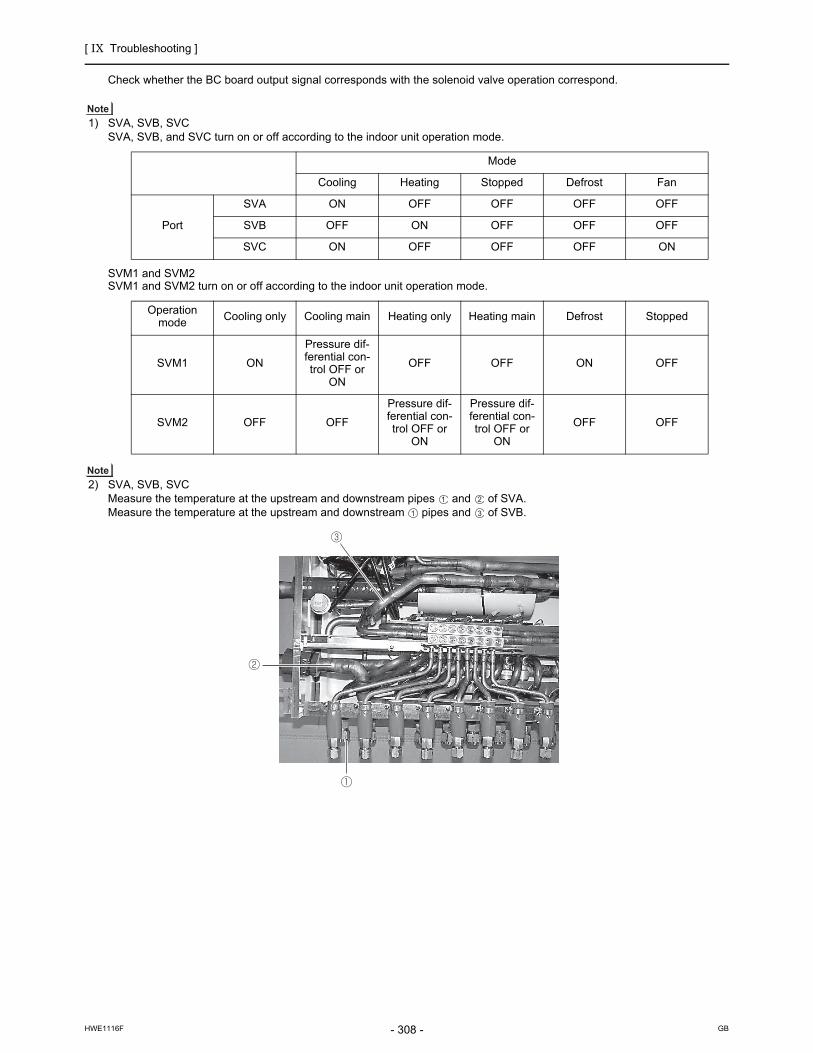
[ IX Troubleshooting ]
- 308 -HWE1116F GB
Check whether the BC board output signal corresponds with the solenoid valve operation correspond.
1) SVA, SVB, SVCSVA, SVB, and SVC turn on or off according to the indoor unit operation mode.
SVM1 and SVM2SVM1 and SVM2 turn on or off according to the indoor unit operation mode.
2) SVA, SVB, SVCMeasure the temperature at the upstream and downstream pipes and of SVA.Measure the temperature at the upstream and downstream pipes and of SVB.
Mode
Cooling Heating Stopped Defrost Fan
Port
SVA ON OFF OFF OFF OFF
SVB OFF ON OFF OFF OFF
SVC ON OFF OFF OFF ON
Operation mode Cooling only Cooling main Heating only Heating main Defrost Stopped
SVM1 ON
Pressure dif-ferential con-trol OFF or
ON
OFF OFF ON OFF
SVM2 OFF OFF
Pressure dif-ferential con-trol OFF or
ON
Pressure dif-ferential con-trol OFF or
ON
OFF OFF

[ IX Troubleshooting ]
- 309 -HWE1116F GB
4. BC controller transformer
* Before measuring the resistance, pull out the connector.
Normal Abnormal
CNTR(1)-(3) about 58 ohm.Open-phase or shorting
CN03(1)-(3) about 1.6 ohm.
CNTR CN03
BC controller control board
Red White Red Red

[ IX Troubleshooting ]
- 310 -HWE1116F GB
Inverter (TKMU)
-7- Inverter (TKMU)
Replace only the compressor if only the compressor is found to be defective. (Overcurrent will flow through the inverter if the compressor is damaged, however, the power supply is automatically cut when overcurrent is detected, protecting the inverter from damage.)Replace only the fan motor if only the fan motor is found to be defective. (Overcurrent will flow through the inverter if the fan motor is damaged, however, the power supply is automatically cut when overcurrrent is detected, protecting the inverter from damage.)Replace the defective components if the inverter is found to be defective.If both the compressor and the inverter are found to be defective, replace the defective component(s) of both devices.
(1) Inverter-related problems: Troubleshooting and remedies
1) The INV board has a large-capacity electrolytic capacitor, in which residual voltage remains even after the main power is turned off, posing a risk of electric shock. Before inspecting the inverter-related items, turn off the main power, wait for 5 to 10 minutes, and confirm that the voltage at both ends of the electrolytic capacitor has dropped to a sufficiently low level.
2) Perform the service after disconnecting the fan board connector (CNINV) and the inverter board connector (CN1 or CNFAN). (To plug or unplugconnectors, check that the outdoor unit fan is not rotating and that the voltage of capacitor in the main circuit is 20 VDC or below. The capacitor may collect a charge and cause an electric shock when the outdoor unit fan rotates in windy conditions. Refer to the wiring nameplate for details.)
3) To connect wiring to TB7, check that the voltage is 20 VDC or below.4) Reconnect the connector (CNINV) back to the fan board and reconnect the connector (CN1 or CNFAN) back to the inverter
board after servicing.5) The IPM on the inverter becomes damaged if there are loose screws are connectors. If a problem occurs after replacing some
of the parts, mixed up wiring is often the cause of the problem. Check for proper connection of the wiring, screws, connectors, and Faston terminals.
6) To avoid damage to the circuit board, do not connect or disconnect the inverter-related connectors with the main power turned on.
7) Current sensors become damaged if electricity is passed through without them being connected to the circuit board.Connect the current sensor to the appropriate connectors on the circuit board before operating the inverter.
8) Faston terminals have a locking function. Make sure the terminals are securely locked in place after insertion.
9) When the IPM, diode stack, or IGBT is replaced, apply a thin layer of heat radiation grease that is supplied evenly to these parts. Wipe off any grease that may get on the wiring terminal to avoid terminal contact failure.
10) Faulty wiring to the compressor damages the compressor. Connect the wiring in the correct phase sequence.11) When the power is turned on, the compressor is energized even while it is not operating. Before turning on the power, dis-
connect all power supply wires from the compressor terminal block, and measure the insulation resistance of the compressor. Check the compressor for a graound fault. If the insulation resistance is 1.0 MΩ or below, connect all power supply wires to the compressor and turn on the power to the outdoor unit. (The liquid refrigerant in the compressor will evaporate by energiz-ing the compressor.)
Press the tab on the terminals to remove them.
[TKMU]

[ IX Troubleshooting ]
- 311 -HWE1116F GB
Error display/failure condition Measure/inspection item
[1] Inverter related errors4250, 4255, 4256, 4220, 4225, 4226, 4230, 4240, 4260, 5301, 5305, 5306, 0403
Check the details of the inverter error in the error log at X LED Monitor Display on the Outdoor Unit Board.Take appropriate measures to the error code and the error details in ac-cordance with IX [2] Responding to Error Display on the Remote Con-troller.
[2] Main power breaker trip <1> Check the breaker capacity.
<2> Check whether the electrical system is short-circuited or ground-faulted.
<3> If items cause is not <1>or <2> are not the causes of the problem, see (3)-[1].(page 316)
[3] Main power earth leakage breaker trip <1> Check the earth leakage breaker capacity and the sensitivity cur-rent.
<2> Meg failure for electrical system other than the inverter
<3> If the cause is not <1>or <2>, see (3)-[1](page 316)
[4] Only the compressor does not operate. Check the inverter frequency on the LED monitor and proceed to (2) - [4] if the compressor is in operation.(page 313)
[5] The compressor vibrates violently at all times or makes an abnor-mal sound.
See (2)-[4].(page 313)
[6] Only the fan motor does not operate. Check the inverter frequency on the LED monitor and proceed to (2)-[6], [7], [8] if the fan motor is in operation.(page 314)
[7] The fan motor shakes violently at all times or makes an abnormal sound.
Check the inverter frequency on the LED monitor and proceed to (2)-[6], [7], [8] if the fan motor is in operation.(page 314)
[8] Noise is picked up by the peripheral device <1> Check that power supply wiring of the peripheral device does not run close to the power supply wiring of the outdoor unit.
<2> Check that the inverter output wiring is not in close contact with the power supply wiring and the transmission lines.
<3> Check that the shielded wire is used as the transmission line when it is required, and check that the grounding work is performed prop-erly on the shielded wire.
<4> Meg failure for electrical system other than the inverter
<5> Attach a ferrite core to the inverter output wiring. (Contact the fac-tory for details of the service part settings.)
<6> Provide separate power supply to the air conditioner and other electric appliances.
<7> If the error occurred suddenly, a ground fault of the inverter output can be considered. See (2)-[4].(page 313)
*Contact the factory for cases other than those listed above.
[9] Sudden malfunction (as a result of external noise.) <1> Check that the grounding work is performed properly.
<2>Check that the shielded wire is used as the transmission line when it is required, and check that the grounding work is performed prop-erly on the shielded wire.
<3>Check that neither the transmission line nor the external connec-tion wiring does not run close to another power supply system or does not run through the same conduit pipe.
* Contact the factory for cases other than those listed above.
[TKMU]

[ IX Troubleshooting ]
- 312 -HWE1116F GB
(2) Inverter output related troubles
Items to be checked Phenomena Remedy
[1]Check the INV board error detection cir-cuit.
<P72 model> 1) IPM/overcurrent breaker tripError code: 4250Detail code: No. 101, 104, 105, 106, and 107
Replace the INV board.
(1) Remove power sup-ply.
(2) Disconnect the invert-er output wire from the terminals of the INV board (SC-U, SC-V, SC-W).
2) Logic errorError code: 4220Detail code: No. 111
Replace the INV board.
(3) Apply power supply. 3) ACCT sensor circuit failure Error code: 5301Detail code: No.117
Replace the INV board.
(4) Put the outdoor unit into operation.
4) IPM open Error code: 5301Detail code: No.119
Normal
<P96, P120, P144 models>
1) IPM/overcurrent breaker tripError code: 4250Detail code: No. 101, 103, 104, 105, 106, and 107
See the section "Troubleshooting the IPM" ( Refer toIX [4] -7- (6)).Replace the IPM, and put the out-door unit back into operation.If the problem persists, replace the INV board.
(1) Remove power sup-ply.
(2) Disconnect the invert-er output wire from the output terminals (U, V, W) of the IPM.
2) Logic errorError code: 4220Detail code: No. 111
See the section "Troubleshooting the IPM" ( Refer to IX [4] -7- (6)).Replace the IPM, and put the out-door unit back into operation.If the problem persists, replace the INV board.Replace the INV board, and put the outdoor unit back into opera-tion.If the problem persists, replace the DCCT.
(3) Apply power supply. 3) ACCT sensor circuit failure Error code: 5301Detail code: No.117
Replace the INV board.
(4) Put the outdoor unit into operation.
4) DCCT sensor circuit failure Error code: 5301Detail code: No.118
Replace the DCCT board.Replace the DCCT, and put the outdoor unit back into operation.If the problem persists, replace the INV board.
5) IPM open Error code: 5301Detail code: No.119
Normal
[2]Check for compressor ground fault or coil error.
Disconnect the compres-sor wiring, and check the compressor Meg, and coil resistance.
1) Compressor Meg failureError if less than 1 Mohm.When no liquid refrigerant in the compressor
Replace the compressorCheck that no liquid refrigerant in the compressor.
2) Compressor coil resistance failureCoil resistance value of 0.20 ohm (20°C [68°F]) : P72 modelCoil resistance value of 0.092 ohm (20°C [68°F]) : P96 - P144 models
[TKMU]

[ IX Troubleshooting ]
- 313 -HWE1116F GB
Items to be checked Phenomena Remedy
[3]Check whether the inverter is damaged.(No load)
<P72 model> 1) Inverter-related prob-lems are detected.
Turn off SW1-1 and go to [1]
(1) Remove power supply. 2) Inverter voltage is not output.
Replace the INV board.
(2) Disconnect the inverter output wire from the ter-minals of the INV board (SC-U, SC-V, SC-W).
3) There is an voltage im-balance between the wires. Greater than 5% imbal-ance or 5V
Replace the INV board.
(3) Turn on SW1-1 on the INV board.
(4) Apply power supply. 4) There is no voltage im-balance between the wires.
Normal*Turn off SW1-1.
(5) Put the outdoor unit into operation.Check the inverter output voltage after the inverter output frequency has sta-bilized.
<P96, P120, P144 models> 1) Inverter-related prob-lems are detected.
Turn off SW1-1 and go to [1]
(1) Remove power supply. 2) Inverter voltage is not output.
Check the connection between the IPM and the CNIPM on the INV board.Replace the IPM.If the problem persists, replace the INV board.
(2) Disconnect the inverter out-put wire from the output ter-minals (U, V, W) of the IPM.
3) There is an voltage im-balance between the wires. Greater than 5% imbal-ance or 5V
Replace the IPM.If the problem persists, replace the INV board.
(3) Turn on SW1-1 on the INV board.
(4) Apply power supply. 4) There is no voltage im-balance between the wires.
Normal*Turn off SW1-1
(5) Put the outdoor unit into operation.
[4]Check whether the inverter is damaged.(During com-pressor oper-ation)
Put the outdoor unit into oper-ation.Check the inverter output volt-age after the inverter output frequency has stabilized.
1) Overcurrent-related problems occur immedi-ately after compressor startup.(4250 Details : No.101, 102, 103, 106, 107)
a. Check items [1] throught [3] for prob-lems.
b. Check that high and low pressures are bal-anced.
c. Check that no liquid refrigerant is present in the compressor.→Go to "d." when the problem persists after compressor startup was repeated several times.If normal operation is restored, check the belt heater for problems.
d. Check that there is a pressure difference be-tween high and low pressures after compres-sor startup.→Check the high pressure with LED monitor for changes.Replace the compressor if there is no pressure difference. (the compressor may be locked.)
2) There is a voltage im-balance between the wires after the inverter output voltage is stabi-lized. Greater than the larger of the following values: imbalance of 5% or 5V
If there is a voltage imbalance<P72 model>Replace the INV board.<P96, P120, P144 models>Replace the IPM.If the problem persists, replace the INV board.If the problem persists after replacing the above parts, go to section [2].Check the belt heater for problems if there is no voltage imbalance.→When the error occurred, liquid refriger-ant may have been present in the compres-sor.
[TKMU]

[ IX Troubleshooting ]
- 314 -HWE1116F GB
Check list Phenomenon Resolution
[5]Fan motor earth, coil error check.
Remove fan motor winding. Check insulation resistance and coil resistance.
1) Fan motor insulation failure.If < 1 MΩ, Defect.
Change fan motor.
2) Fan motor wire failure.Normal coil resistance is a few ohms.(Changes with temperature)
Change fan motor.
[6]Fan inverter board error de-tection circuit check.(No load)
(1) Turn off breaker.*Turn power off without fail.
1) Electrical current over load er-ror.Check code: 4255, 4256 Detail code: 101, 104
Change fan inverter board.
(2) Remove fan inverter board CNINV and CNSNR connectors.
2) Logic error Check code: 4255, 42566Detail code:111
Change fan inverter board.
(3) Turn on breaker. 3) Position error on start up Check code: 5305, 5306Detail code: 132
Normal*After checking, return con-nector CNINV & CNSNR.(4) Operate unit.
[7]Fan inverter check failure check. (No load)
(1) Turn off breaker.*Turn power off without fail.
1) Within 30 seconds from the start of operation, an error oth-er than a position error (5305, 5306) (detail code 132) is de-tected.
Change fan inverter board.
(2) Disconnect the connec-tor CNINV from the fan inverter board.
2) Less than 5V unbalance in the wiring.
Change fan inverter board.
(3) Set fan inverter board switch SW1-1 to ON.
3) No unbalanced voltage in the wiring.After 30 second, detail code 132 is produced and the sys-tem stops.
Normal*After checking, return SW1&CNINV.
(4) Turn on breaker.
(5) Operate unit.After about 30 seconds under no load with con-stant voltage output, the code below will be dis-played indicating a posi-tion error (5305, 5306).Detail code: 132Also, running with no load produces constant voltage of about 160V.
[TKMU]

[ IX Troubleshooting ]
- 315 -HWE1116F GB
Check list Phenomenon Resolution
[8]Check for fan in-verter failure. (with load)
(1) Turn off breaker. 1) After operation, electrical over-load error or position detection er-ror and unit stops within 10 seconds.Check code: 4255, 4256, 5305, 5306Detail code: 101, 132
Check for fan motor lock.→If locked, change for fan motor.If the same error is still present after changing fan motor, change INV board. →If not locked, refer to 3) & 4).
(2) Turn on breaker. 2) RPM error before stat-up Check code: 5305, 5306Detail code: 134
Change fan inverter board if the same error occurs after restart.
(3) Operate unit. 3) Electrical current overload error during operation Check code: 4255, 4256Detail code: 101
a. Check for gusts or windy con-ditions.
b. Go to [5] if not windy.c. After checking [5] , and there
is no problem, change fan in-verter board.
d. If replacing Fan INV board doesn't resolve issue, change fan motor.
4) Sensor error during operation Check code: 5305, 5306Detail code: 132, 133
a. Check for gusts or windy con-ditions.
b. If no issues with wind, but the error is still present, change Fan inverter board.
c. Change fan motor if Fan INV board change doesn't resolve issue.
5) Voltage overload error Check code: 4225, 4226Detail code: 109
a. Check for gusts or windy con-ditions.
b. Change fan inverter board if it is not windy.
6) Load short circuit Check code: 4255, 4256.Detail code: 105
a. Check [6] and [7]. If no prob-lem, then check wiring for short circuit.
b. If there is no problem with item a. above, change fan motor.
c. If same error after motor change, change Fan inverter board.
7) After RPM has stabilized, voltage unbalance of 5%, or 5V.
a. If voltage is unbalanced, go to [5]
b. If no problem change , change Fan INV board.
c. If Fan INV board change doesn't resolve issue, change fan motor.
[9]Check installa-tion condition.
(1) Check refrigerant charge.
Overcharge of refrigerant Return to correct refrigerant charge.
(2) Check outdoor unit branch installation.
The branch approach <500 mm. Make branch approach >500mm
Is the branch angle < ±15° to hor-izontal?
Make branch angle < ±15°
[TKMU]

[ IX Troubleshooting ]
- 316 -HWE1116F GB
(3) Trouble treatment when the main power breaker is tripped.
(4) Trouble treatment when the main power earth leakage breaker is tripped
The insulation resistance could go down to close to 1MΩ after installation or when the power is kept off for an extended period of time because of the accumulation of refrigerant in the compressor. If the earth leakage breaker is triggered, please use the following procedure to take care of this.Disconnect the wires from the compressor's terminal block.If the resistance is less than 1 MΩ, switch on the power for the outdoor unit with the wires still disconnected.Leave the power on for at least 12 hours.Check that the resistance has recovered to 1 MΩ or greater.
Earth leakage current measurement methodFor easy on-site measurement of the earth leakage current, enable the filter with a measurement instrument that has filter functions as below, clamp all the power supply wires, and measure.Recommended measurement instrument: CLAMP ON LEAK HiTESTER 3283 made by HIOKI E.E. CORPORATIONWhen measuring one device alone, measure near the device's power supply terminal block.
Items to be checked Phenomena Remedy
[1] Perform Meg check between the terminals on the power terminal block TB1.
Zero to several ohm, or Meg failure a. Check each part in the main inverter circuit.*Refer to "(5) Simple checking pro-cedure for individual components of main inverter circuit".(page 317)Diode stackIPMIGBT moduleRush current protection resistorElectromagnetic relayDC reactor
[2] Turn on the power again and check again.
1) Main power breaker trip
2) No remote control display
[3] Turn on the outdoor unit and check that it operates normally.
1) Operates normally without tripping the main breaker.
a) The wiring may have been short-circuited. Search for the wire that short-circuited, and repair it.
b) If item a) above is not the cause of the problem, the compressor may have a problem.
2) Main power breaker trip A compressor ground fault can be con-sidered. Go to (2)-[2].
Items to be checked Phenomena Remedy
[1] Check the earth leakage breaker capacity and the sensitivity cur-rent.
Use of a non-specified earth leakage breaker
Replace with a regulation earth leakage breaker.
[2] Check the resistance at the power supply terminal block (TB1) with a megger.
Failure resistance value Check each part and wiring.*Refer to (5) "Simple checking procedure for individual components of main inverter circuit".(page 317)IPMIGBT moduleRush current protection resistorElectromagnetic relayDC reactor
[3] Disconnect the compressor wir-ings and check the resistance of the compressor with a megger.
Failure compressor if the insu-lating resistance value is not in specified range.Failure when the insulating re-sistance value is 1 MΩ or less.
Check that there is no liquid refrigerant in the compressor. If there is none, replace the compressor.
[4] Disconnect the fan motor wirings and check the resistance of the fan motor with a megger.
Failure fan motor if the insulat-ing resistance value is not in specified range.Failure when the insulating re-sistance value is 1 MΩ or less.
Replace the fan motor.
[TKMU]

[ IX Troubleshooting ]
- 317 -HWE1116F GB
(5) Simple checking procedure for individual components of main inverter circuit
Turn off the power of the unit and leave it turned off for 10 minutes. Check that the voltage of the electrolytic capacitor (inverter main circuit) is 20 VDC or below. Then, remove the relevant parts from the control box. Before checking, turn the power off and remove the parts to be checked from the control box.
Part name Judgment method
IGBT module See "Troubleshooting for IGBT Module ".(IX [4] -7- (8))(page 319)
Diode stack Refer to "Diode stack" (IX [4] -7- (7))(page 319)
IPM (Intelligent power module)
Refer to "Intelligent power module (IPM)" (IX [4] -7- (6))(page 318)
Rush current protection resis-torR1(R2)
<P72 model>Measure the resistance between terminals: 22 Ω±10%<P96, P120, P144 models>Measure the resistance between the + terminal on the diode stack and terminal TB31. (*Can be mea-sured without the need to remove the noise filter board): 22 Ω±10%
Electromagnetic relay72C
This electromagnetic relay is rated at 200VAC and is driven by a coil. The resistance between the coils in row A cannot be measured with a tester.Check only for shorting.
DC reactor DCL Measure the resistance between terminals: 1 Ω or lower (almost 0 Ω)Measure the resistance between terminals and the chassis:
Current sensor ACCT
<P96, P120, P144 models>Disconnect the CNCT2 connector and measure the resistance between terminals: 280 Ω± 30 Ω1 - 2 PIN (U-phase),3 - 4 PIN (W-phase)
Check point
Row A Not to be short-circuited
Row B to Row E
Installation direction
Test button
Row A
Row B
Row C
Row D
Row E
A2 44 34 24 14
43 33 23 13 A1
<P72 model>
Coil
Contact
Check point
Not to be short-circuited
<P96, P120, P144 models>
Coil
Contact
Checking criteria
Checking criteria Between No. 1 pin and
No. 3 pin of the CN03 on the noise filter board
+ terminal on the diode stack and terminal TB31 on the noise filter
With the test button turned off : With the test button turned on : 0
With the test button turned on : 0
With the test button turned off :
U
U V IPM
*Check the ACCT connection phase and the direction of the connection
W ACCT-W
W
ACCT-U
[TKMU]

[ IX Troubleshooting ]
- 318 -HWE1116F GB
(6) Intelligent power module (P96, P120, P144 models)
Measure resistances between each pair of terminals on the IPM with a tester, and use the results for troubleshooting.
1) Notes on measurement
Check the polarity before measuring. (On the tester, black normally indicates plus.)Check that the resistance is not open ( Ω) or not shorted (to 0 Ω).The values are for reference, and the margin of errors is allowed.The result that is more than double or half of the result that is measured at the same measurement point is not allowed.
2) Tester restriction
Use the tester whose internal electrical power source is 1.5V or greaterUse the dry-battery-powered tester.
(The accurate diode-specific resistance cannot be measured with the button-battery-powered card tester, as the applied volt-age is low.)Use a low-range tester if possible. A more accurate resistance can be measured.
Judgment value (reference)
Black ( + )
P N U V W
Red (-)
P - - 5 - 200 Ω 5 - 200 Ω 5 - 200 Ω
N - -
U 5 - 200 Ω - - -
V 5 - 200 Ω - - -
W 5 - 200 Ω - - -
External view Internal circuit diagram
1 4 7 10 16
W V U
B
P
N V
U
P
W
N
B
3
2
1
6
5
4
9
8
7
11
13
10
14
15
12
16
Drive circuit
Drive circuit
Drive circuit
Drive circuit
Drive circuit
Drive circuit
Overheating -protection circuit
Temperature sensor
[TKMU]

[ IX Troubleshooting ]
- 319 -HWE1116F GB
(7) Diode stack (P96, P120, P144 models)
Measure resistances between each pair of terminals on the diode stack with a tester, and use the results for troubleshoot-ing.Refer to (6) " Intelligent power module (IPM) " for notes on measurement and tester selection.
(8) Troubleshooting for IGBT Module (P72 model)
Measure the resistances between each pair of terminals on the IGBT with a tester, and use the results for troubleshooting.The terminals on the INV board are used for the measurement.
1) Notes on measurement
Check the polarity before measuring. (On the tester, black normally indicates plus.)Check that the resistance is not open ( Ω) or not shorted (to 0 Ω).The values are for reference, and the margin of errors is allowed.The result that is more than double or half of the result that is measured at the same measurement point is not allowed.Disconnect all the wiring connected the INV board, and make the measurement.
2) Tester restriction
Use the tester whose internal electrical power source is 1.5V or greaterUse the dry-battery-powered tester.
(The accurate diode-specific resistance cannot be measured with the button-battery-powered card tester, as the applied volt-age is low.)Use a low-range tester if possible. A more accurate resistance can be measured.
Judgment value (reference)
Black ( + ) External view
+ (P) - (N) to (L1) to (L2) to (L3)
Red (-)
+ (P) - - 5 - 200Ω
5 - 200 Ω
5 - 200 Ω
- (N) - -
to (L1) 5 - 200Ω
- - -Internal circuit diagram
to (L2) 5 - 200Ω
- - -
to (L3) 5 - 200Ω
- - -
L1 L2 L3
+
-
L1
L2
L3
[TKMU]

[ IX Troubleshooting ]
- 320 -HWE1116F GB
INV board external diagram
Judgment value (reference)
Black ( + )
SC-P1 TB-N SC-R SC-S SC-T
Red (-)
SC-P1 - - 5 - 200 Ω 5 - 200 Ω 5 - 200 Ω
TB-N - -
SC-R 5 - 200 Ω - - -
SC-S 5 - 200 Ω - - -
SC-T 5 - 200 Ω - - -
Black ( + )
SC-P2 TB-N SC-U SC-V SC-W
Red (-)
SC-P2 - - 5 - 200 Ω 5 - 200 Ω 5 - 200 Ω
TB-N - -
SC-U 5 - 200 Ω - - -
SC-V 5 - 200 Ω - - -
SC-W 5 - 200 Ω - - -
SC-P1
SC-P2
TB-NSC-T SC-S SC-R
SC-U
SC-V
SC-W
TB-P
[TKMU]

[ IX Troubleshooting ]
- 321 -HWE1116F GB
Inverter (YKMU)
-7- Inverter (YKMU)Replace only the compressor if only the compressor is found to be defective. (Overcurrent will flow through the inverter if the compressor is damaged, however, the power supply is automatically cut when overcurrent is detected, protecting the inverter from damage.)Replace only the fan motor if only the fan motor is found to be defective. (Overcurrent will flow through the inverter if the fan motor is damaged, however, the power supply is automatically cut when overcurrrent is detected, protecting the inverter from damage.)Replace the defective components if the inverter is found to be defective.If both the compressor and the inverter are found to be defective, replace the defective component(s) of both devices.
(1) Inverter-related problems: Troubleshooting and remedies
1) The INV board has a large-capacity electrolytic capacitor, in which residual voltage remains even after the main power is turned off, posing a risk of electric shock. Turn off the unit, leave it turned off for at least 10 minutes, and check that the voltage across FT-P and FT-N terminals on the INV board or the terminals at both ends of the electrolytic capacitor is 20V or below before checking inside the control box.(It takes about 10 minutes to discharge electricity after the power supply is turn off.)
2) Perform the service after disconnecting the fan board connector (CNINV) and the inverter board connector (CN1 or CNFAN). (To plug or unplugconnectors, check that the outdoor unit fan is not rotating and that the voltage of capacitor in the main circuit is 20 VDC or below. The capacitor may collect a charge and cause an electric shock when the outdoor unit fan rotates in windy conditions. Refer to the wiring nameplate for details.)
3) To connect wiring to TB7, check that the voltage is 20 VDC or below.4) Reconnect the connector (CNINV) back to the fan board and reconnect the connector (CN1 or CNFAN) back to the inverter
board after servicing.5) The IPM on the inverter becomes damaged if there are loose screws are connectors. If a problem occurs after replacing some
of the parts, mixed up wiring is often the cause of the problem. Check for proper connection of the wiring, screws, connectors, and Faston terminals.
6) To avoid damage to the circuit board, do not connect or disconnect the inverter-related connectors with the main power turned on.
7) Faston terminals have a locking function. Make sure the terminals are securely locked in place after insertion.
8) When the IPM or IGBT is replaced, apply a thin layer of heat radiation grease that is supplied evenly to these parts. Wipe off any grease that may get on the wiring terminal to avoid terminal contact failure.
9) Faulty wiring to the compressor damages the compressor. Connect the wiring in the correct phase sequence.10) When the power is turned on, the compressor is energized even while it is not operating. Before turning on the power, dis-
connect all power supply wires from the compressor terminal block, and measure the insulation resistance of the compressor. Check the compressor for a graound fault. If the insulation resistance is 1.0 MΩ or below, connect all power supply wires to the compressor and turn on the power to the outdoor unit. (The liquid refrigerant in the compressor will evaporate by energiz-ing the compressor.)
Press the tab on the terminals to remove them.
[YKMU]

[ IX Troubleshooting ]
- 322 -HWE1116F GB
Error display/failure condition Measure/inspection item
[1] Inverter related errors4250, 4255, 4256, 4220, 4225, 4226, 4230, 4240, 4260, 5301, 5305, 5306, 0403
Check the details of the inverter error in the error log at X LED Monitor Display on the Outdoor Unit Board. Take appropriate measures to the error code and the error details in ac-cordance with IX [2] Responding to Error Display on the Remote Con-troller.
[2] Main power breaker trip Refer to "(3) Trouble treatment when the main power breaker is tripped".(page 327)
[3] Main power earth leakage breaker trip Refer to "(4) Trouble treatment when the main power earth leakage breaker is tripped".(page 327)
[4] Only the compressor does not operate. Check the inverter frequency on the LED monitor and proceed to (2) - [4] if the compressor is in operation.(page 324)
[5] The compressor vibrates violently at all times or makes an abnor-mal sound.
See (2)-[4].(page 324)
[6] Only the fan motor does not operate. Check the inverter frequency on the LED monitor and proceed to (2)-[6], [7], [8] if the fan motor is in operation.(page 325)
[7] The fan motor shakes violently at all times or makes an abnormal sound.
Check the inverter frequency on the LED monitor and proceed to (2)-[6], [7], [8] if the fan motor is in operation.(page 325)
[8] Noise is picked up by the peripheral device <1> Check that power supply wiring of the peripheral device does not run close to the power supply wiring of the outdoor unit.
<2> Check if the inverter output wiring is not running parallel to the power supply wiring and the transmission lines.
<3> Check that the shielded wire is used as the transmission line when it is required, and check that the grounding work is performed prop-erly on the shielded wire.
<4> Meg failure for electrical system other than the inverter
<5> Attach a ferrite core to the inverter output wiring. (Contact the fac-tory for details of the service part settings.)
<6> Provide separate power supply to the air conditioner and other electric appliances.
<7> If the error occurred suddenly, a ground fault of the inverter output can be considered. See (2)-[4].(page 324)
*Contact the factory for cases other than those listed above.
[9] Sudden malfunction (as a result of external noise.) <1> Check that the grounding work is performed properly.
<2>Check that the shielded wire is used as the transmission line when it is required, and check that the grounding work is performed prop-erly on the shielded wire.
<3>Check that neither the transmission line nor the external connec-tion wiring does not run close to another power supply system or does not run through the same conduit pipe.
* Contact the factory for cases other than those listed above.
[YKMU]

[ IX Troubleshooting ]
- 323 -HWE1116F GB
(2) Inverter output related troubles
Items to be checked Phenomena Remedy
[1]Check the INV board er-ror detection circuit.
(1) Remove power sup-ply.
1) Overcurrent error Error code: 4250Detail code: No. 101, 104, 105, 106, and 107
Replace the INV board.
(2) Disconnect the invert-er output wire from the terminals of the INV board (SC-U, SC-V, SC-W).
2) Logic errorError code: 4220Detail code: No. 111
Replace the INV board.
(3) Apply power supply. 3) ACCT sensor circuit failure Error code: 5301Detail code: No.117
Replace the INV board.
(4) Put the outdoor unit into operation.
4) IPM open Error code: 5301Detail code: No.119
Normal
[2]Check for compressor ground fault or coil error.
Disconnect the compressor wiring, and check the com-pressor Meg, and coil resis-tance.
1) Compressor Meg failureError if less than 1 Mohm.
Check that there is no liquid re-frigerant in the compressor. If there is none, replace the com-pressor.
2) Compressor coil resistance failureCoil resistance value of 0.71 ohm (20°C [68°F]): P72 modelCoil resistance value of 0.32 ohm(20°C [68°F]): P96 - P144 models
Replace the compressor.
[3]Check wheth-er the inverter is damaged.(No load)
(1) Remove power sup-ply.
1) Inverter-related problems are de-tected.
Connect the short-circuit connec-tor to CN6, and go to section [1].
(2) Disconnect the invert-er output wire from the terminals of the INV board (SC-U, SC-V, SC-W).
2) Inverter voltage is not output at the terminals (SC-U, SC-V, and SC-W)
Replace the INV board.
(3) Disconnect the short-circuit connector from CN6 on the INV board.
3) There is an voltage imbalance be-tween the wires. Greater than 5% imbalance or 5V
Replace the INV board.
(4) Apply power supply.
(5) Put the outdoor unit into operation.Check the inverter output voltage after the inverter output frequency has stabi-lized.
4) There is no voltage imbalance be-tween the wires.
Normal*Reconnect the short-circuit con-nector to CN6 after checking the voltage.
[YKMU]

[ IX Troubleshooting ]
- 324 -HWE1116F GB
Items to be checked Phenomena Remedy
[4]Check whether the inverter is damaged.(During com-pressor opera-tion)
Put the outdoor unit into oper-ation.Check the inverter output volt-age after the inverter output frequency has stabilized.
1) Overcurrent-related problems oc-cur immediately after compressor startup.Error code : 4250Detail code : 101, 102, 106, 107
a. Check items [1] through [3] for problems.
b. Check that high and low pressures are balanced.
c. Check that no liquid refrig-erant is present in the compressor.→Go to "d." when the problem persists after compressor startup was repeated several times.If normal operation is re-stored, check the belt heater for problems.
d. Check that there is a pres-sure difference between high and low pressures af-ter compressor startup.→Check the high pressure with LED monitor for changes.Replace the compressor if there is no pressure differ-ence. (the compressor may be locked.)
2) There is a voltage imbalance be-tween the wires after the inverter output voltage is stabilized. Greater than the larger of the fol-lowing values: imbalance of 5% or 5V
Replace the INV board if there is a voltage imbalance.Check the belt heater for prob-lems if there is no voltage im-balance.→When the error occurred, liquid refrigerant may have been present in the compres-sor.
[YKMU]

[ IX Troubleshooting ]
- 325 -HWE1116F GB
Check list Phenomenon Resolution
[5]Fan motor earth, coil error check.
Remove fan motor winding. Check insulation resistance and coil resistance.
1) Fan motor insulation failure.If < 1 MΩ, Defect.
Change fan motor.
2) Fan motor wire failure.Normal coil resistance is a few ohms.(Changes with temperature)
Change fan motor.
[6]Fan inverter board error de-tection circuit check.(No load)
(1) Turn off breaker.*Turn power off without fail.
1) Electrical current over load er-ror.Check code: 4255, 4256 Detail code: 101, 104
Change fan inverter board.
(2) Remove fan inverter board CNINV and CNSNR connectors.
2) Logic error Check code: 4255, 42566Detail code:111
Change fan inverter board.
(3) Turn on breaker. 3) Position error on start up Check code: 5305, 5306Detail code: 132
Normal*After checking, return con-nector CNINV & CNSNR.(4) Operate unit.
[7]Fan inverter check failure check. (No load)
(1) Turn off breaker.*Turn power off without fail.
1) Within 30 seconds from the start of operation, an error oth-er than a position error (5305, 5306) (detail code 132) is de-tected.
Change fan inverter board.
(2) Disconnect the connec-tor CNINV from the fan inverter board.
2) Less than 5V unbalance in the wiring.
Change fan inverter board.
(3) Set fan inverter board switch SW1-1 to ON.
3) No unbalanced voltage in the wiring.After 30 second, detail code 132 is produced and the sys-tem stops.
Normal*After checking, return SW1&CNINV.
(4) Turn on breaker.
(5) Operate unit.After about 30 seconds under no load with con-stant voltage output, the code below will be dis-played indicating a posi-tion error (5305, 5306).Detail code: 132Also, running with no load produces constant voltage of about 160V.
[YKMU]

[ IX Troubleshooting ]
- 326 -HWE1116F GB
Check list Phenomenon Resolution
[8]Check for fan in-verter failure. (with load)
(1) Turn off breaker. 1) After operation, electrical over-load error or position detection er-ror and unit stops within 10 seconds.Check code: 4255, 4256, 5305, 5306Detail code: 101, 132
Check for fan motor lock.→If locked, change for fan motor.If the same error is still present after changing fan motor, change INV board. →If not locked, refer to 3) & 4).
(2) Turn on breaker. 2) RPM error before stat-up Check code: 5305, 5306Detail code: 134
Change fan inverter board if the same error occurs after restart.
(3) Operate unit. 3) Electrical current overload error during operation Check code: 4255, 4256Detail code: 101
a. Check for gusts or windy con-ditions.
b. Go to [5] if not windy.c. After checking [5] , and there
is no problem, change fan in-verter board.
d. If replacing Fan INV board doesn't resolve issue, change fan motor.
4) Sensor error during operation Check code: 5305, 5306Detail code: 132, 133
a. Check for gusts or windy con-ditions.
b. If no issues with wind, but the error is still present, change Fan inverter board.
c. Change fan motor if Fan INV board change doesn't resolve issue.
5) Voltage overload error Check code: 4225, 4226Detail code: 109
a. Check for gusts or windy con-ditions.
b. Change fan inverter board if it is not windy.
6) Load short circuit Check code: 4255, 4256.Detail code: 105
a. Check [6] and [7]. If no prob-lem, then check wiring for short circuit.
b. If there is no problem with item a. above, change fan motor.
c. If same error after motor change, change Fan inverter board.
7) After RPM has stabilized, voltage unbalance of 5%, or 5V.
a. If voltage is unbalanced, go to [5]
b. If no problem change , change Fan INV board.
c. If Fan INV board change doesn't resolve issue, change fan motor.
[9]Check installa-tion condition.
(1) Check refrigerant charge.
Overcharge of refrigerant Return to correct refrigerant charge.
(2) Check outdoor unit branch installation.
The branch approach <500 mm. Make branch approach >500mm
Is the branch angle < ±15° to hor-izontal?
Make branch angle < ±15°
[YKMU]

[ IX Troubleshooting ]
- 327 -HWE1116F GB
(3) Trouble treatment when the main power breaker is tripped
(4) Trouble treatment when the main power earth leakage breaker is tripped
The insulation resistance could go down to close to 1 MΩ after installation or when the power is kept off for an extended period of time because of the accumulation of refrigerant in the compressor. If the earth leakage breaker is triggered, please use the following procedure to take care of this.Disconnect the wires from the compressor's terminal block.If the resistance is less than 1 MΩ, switch on the power for the outdoor unit with the wires still disconnected.Leave the power on for at least 12 hours.Check that the resistance has recovered to 1 MΩ or greater.
Earth leakage current measurement methodFor easy on-site measurement of the earth leakage current, enable the filter with a measurement instrument that has filter functions as below, clamp all the power supply wires, and measure.Recommended measurement instrument: CLAMP ON LEAK HiTESTER 3283 made by HIOKI E.E. CORPORATIONWhen measuring one device alone, measure near the device's power supply terminal block.
Items to be checked Phenomena Remedy
[1] Check the breaker capacity. Use of a non-specified break-er
Replace it with a specified breaker.
[2] Perform Meg check between the terminals on the power terminal block TB1.
Zero to several ohm, or Meg failure
Check each part and wiring.*Refer to (5) "Simple checking procedure for individual components of main inverter circuit".(page 328)IGBT moduleRush current protection resistorElectromagnetic relayDC reactor
[3] Turn on the power again and check again.
1) Main power breaker trip
2) No remote control display
[4] Turn on the outdoor unit and check that it operates normally.
1) Operates normally without tripping the main breaker.
a) The wiring may have been short-circuit-ed. Search for the wire that short-circuit-ed, and repair it.
b) If item a) above is not the cause of the problem, refer to (2)-[1]-[6].
2) Main power breaker trip
Items to be checked Phenomena Remedy
[1] Check the earth leakage breaker capacity and the sensitivity cur-rent.
Use of a non-specified earth leakage breaker
Replace with a regulation earth leakage breaker.
[2] Check the resistance at the power supply terminal block with a meg-ger.
Failure resistance value Check each part and wiring.*Refer to (5) "Simple checking procedure for individual components of main inverter circuit".(page 328)IGBT moduleRush current protection resistorElectromagnetic relayDC reactor
[3] Disconnect the compressor wir-ings and check the resistance of the compressor with a megger.
Failure compressor if the insu-lating resistance value is not in specified range.Failure when the insulating re-sistance value is 1 MΩ or less.
Check that there is no liquid refrigerant in the compressor. If there is none, replace the compressor.
[4] Disconnect the fan motor wirings and check the resistance of the fan motor with a megger.
Failure fan motor if the insulat-ing resistance value is not in specified range.Failure when the insulating re-sistance value is 1 MΩ or less.
Replace the fan motor.
[YKMU]

[ IX Troubleshooting ]
- 328 -HWE1116F GB
(5) Simple checking procedure for individual components of main inverter circuit
Before inspecting the inside of the control box, turn off the power, keep the unit off for at least 10 minutes, and confirm that the voltage between FT-P and FT-N on INV Board has dropped to DC20V or less.
(6) Troubleshooting for IGBT Module
Measure the resistances between each pair of terminals on the IGBT with a tester, and use the results for troubleshooting.The terminals on the INV board are used for the measurement.
1) Notes on measurement
Check the polarity before measuring. (On the tester, black normally indicates plus.)Check that the resistance is not open ( Ω) or not shorted (to 0 Ω).The values are for reference, and the margin of errors is allowed.The result that is more than double or half of the result that is measured at the same measurement point is not allowed.Disconnect all the wiring connected the INV board, and make the measurement.
2) Tester restriction
Use the tester whose internal electrical power source is 1.5V or greaterUse the dry-battery-powered tester.
(The accurate diode-specific resistance cannot be measured with the button-battery-powered card tester, as the applied volt-age is low.)Use a low-range tester if possible. A more accurate resistance can be measured.
Part name Judgment method
IGBT module See "Troubleshooting for IGBT Module ". (IX [4] -7- (6))(page 328)
Rush current pro-tection resistorR1, R5
Measure the resistance between terminals R1 and R5: 22 Ω±10%
Electromagnetic relay72C
This electromagnetic relay is rated at DC12V and is driven by a coil. Check the resistance between terminals
DC reactor DCL Measure the resistance between terminals: 1Ω or lower (almost 0 Ω)Measure the resistance between terminals and the chassis:
1
6 5
2 3 4Upper
Installation direction
Check point Checking criteria( )W
Between Terminals 5 and 6
Between Terminals 1 and 2Between Terminals 3 and 4
Not to be short-circuited(Center value 75 ohm)Coil
Contact
[YKMU]

[ IX Troubleshooting ]
- 329 -HWE1116F GB
INV board external diagram
Judgment value (reference)
Black ( + )
SC-P1 FT-N SC-L1 SC-L2 SC-L3
Red (-)
SC-P1 - - 5 - 200 Ω 5 - 200 Ω 5 - 200 Ω
FT-N - -
SC-L1 5 - 200 Ω - - -
SC-L2 5 - 200 Ω - - -
SC-L3 5 - 200 Ω - - -
Black ( + )
SC-P2 FT-N SC-U SC-V SC-W
Red (-)
SC-P2 - - 5 - 200 Ω 5 - 200 Ω 5 - 200 Ω
FT-N - -
SC-U 5 - 200 Ω - - -
SC-V 5 - 200 Ω - - -
SC-W 5 - 200 Ω - - -
SC-U
SC-W
SC-V
FT-N
SC-P1SC-P2
SC-L1SC-L2
SC-L3
[YKMU]

[ IX Troubleshooting ]
- 330 -HWE1116F GB
Control Circuit (TKMU)
-8- Control Circuit (TKMU)
(1) Control power source function block
1) PURY-P72TKMU
Out
door
uni
t
Power source system (AC 208 / 230 V)Control system (DC 5 ~ 30 V)
* MA remote controllers and ME remote controllers cannot be used together.(Both the ME and MA remote controller can be connected to a system with a system controller.)
A, B
A, B
M-NET transmission line (Non-polar 2 wire)
AC 208 / 230 V AC Power source
To next unit (Indoor unit)
MA
rem
ote
cont
rolle
r wiri
ng
(Non
-pol
ar 2
wire
)
DC 17 ~ 30 V
DC 9 ~ 12 V
ME remote controller
MA remote controller
Indoor unit
TB2
TB15
Terminal block for power source
TB5 Terminal block for MA remote controller
Terminal block for transmission line connection DC 17 ~ 30 V
AC 208 / 230 V Terminal block for power source
TB1
Noise filter Noise filter
Fuse
Fuse
Fuse
LEV
Fuse
Surge protection
INV board
Control board Fan board
63H1
72C
DC / DC converter
Detection circuit for the power supply to the transmission line
M-NET board
DC / DC converter
Microcomputer
Microcomputer
Microcomputer 5 V Power supply
16 V Power supply
12V Power supply
30 V Power supply
Relay drive circuit
Relay
5 V Power supply
5 V Power supply
17V Power supply
Smoothing capacitor Inverter
Inverter
Inverter drive circuit
Inverter drive circuit
Inverter reset circuit
Rectifier Compressor
Heat exchanger
fan
Relay, LEV Drive circuit
72CSolenoid valve4-way valve
CN40 Terminal block for transmission line for centralized control (DC 24 ~ 30 V)
TB7
Indoor/outdoor transmission block (DC 24 ~ 30 V)
TB3
DCL
[TKMU]

[ IX Troubleshooting ]
- 331 -HWE1116F GB
2) PURY-P96TKMU
* MA remote controllers and ME remote controllers cannot be used together.(Both the ME and MA remote controller can be connected to a system with a system controller.)
TB2
TB15
Terminal block for power source
TB5 Terminal block for MA remote controller
Terminal block for transmission line connection DC 17 ~ 30 V
CN40
A, B
A, B
MA
rem
ote
cont
rolle
r wiri
ng
(Non
-pol
ar 2
wire
)
DC 17 ~ 30 V
DC 9 ~ 12 V
ME remote controller
MA remote controller
AC 208 / 230 V Terminal block for power source
TB1
Noise filter Noise filter
Fuse
Surge protection
INV board
72C DCL Rectifier Smoothing capacitor
15V Power supply Inverter drive circuit
Microcomputer
5 V Power supply 12 V Power supply
DC / DC converter
Fuse
Inverter Compressor
Heat exchanger
fan Fuse
Fan board
Microcomputer 5 V Power supply
Inverter
Inverter drive circuit
Out
door
uni
t
Power source system (AC 208 / 230 V) Control system (DC 5 ~ 30 V)
63H1 Inverter reset circuit
DC / DC converter
Microcomputer
5 V Power supply
16 V Power supply
Fuse Detection circuit for the power supply to the transmission line
M-NET board
DC / DC converter
30 V Power supply
Relay drive circuit
Relay
Indoor unit
LEV
72CSolenoid valve4-way valve
Fuse
Control board
12V Power supply
Relay, LEV Drive circuit
AC 208 / 230 V AC Power source
To next unit (Indoor unit)
Terminal block for transmission line for centralized control (DC 24 ~ 30 V)
TB7
Indoor/outdoor transmission block (DC 24 ~ 30 V)
TB3
[TKMU]

[ IX Troubleshooting ]
- 332 -HWE1116F GB
3) PURY-P120, P144TKMU
* MA remote controllers and ME remote controllers cannot be used together.(Both the ME and MA remote controller can be connected to a system with a system controller.)
TB2
TB15
Terminal block for power source
TB5 Terminal block for MA remote controller
Terminal block for transmission line connection DC 17 ~ 30 V
CN40
A, B
A, B
MA
rem
ote
cont
rolle
r wiri
ng
(Non
-pol
ar 2
wire
)
DC 17 ~ 30 V
DC 9 ~ 12 V
ME remote controller
MA remote controller
AC 208 / 230 V Terminal block for power source
TB1
Noise filter Noise filter
Fuse
Surge protection
INV board
72C DCL Rectifier Smoothing capacitor
15V Power supply Inverter drive circuit
Microcomputer
5 V Power supply 12 V Power supply
DC / DC converter
Fuse
Inverter Compressor
Heat exchanger
fan 1Fuse
Fan board
Microcomputer 5 V Power supply
Inverter
Inverter drive circuit
Out
door
uni
t
Power source system (AC 208 / 230 V) Control system (DC 5 ~ 30 V)
63H1 Inverter reset circuit
DC / DC converter
Microcomputer
5 V Power supply
16 V Power supply
Fuse Detection circuit for the power supply to the transmission line
M-NET board
DC / DC converter
30 V Power supply
Relay drive circuit
Relay
Indoor unit
LEV
72CSolenoid valve4-way valve
Fuse
Control board
12V Power supply
Relay, LEV Drive circuit
AC 208 / 230 V AC Power source
To next unit (Indoor unit)
Terminal block for transmission line for centralized control (DC 24 ~ 30 V)
TB7
Indoor/outdoor transmission block (DC 24 ~ 30 V)
TB3
Connect board
Heat exchanger
fan 2
Fuse
Fan board
Microcomputer5 V Power supply
16 V Power supply
Inverter
Inverter drive circuit
Smoothing capacitor
[TKMU]

[ IX Troubleshooting ]
- 333 -HWE1116F GB
(2) Troubleshooting transmission power circuit of outdoor unit
1) PURY-P72TKMU
Check the voltage between No.1 and No.2 pins of the CN62 on the control board.
Check the wiring between the control board and power supply board for the transmission line (CN62, CNPS, CN102 and CNIT), and check for proper connection of connectors.
Check the wiring between the control board and power supply board for the transmission line (CN62, CNPS, CN102 and CNIT), and check for proper connection of connectors.
Is there a wiring error or a connector
disconnection?
Check the voltage between No.5 and No.2 pins of the CNPS on the control board.
Is the voltage measurement between
4.5 and 5.2 VDC?
Is there a connector disconnection? Fix the connector disconnection.
Replace the M-NET board
Replace the M-NET board
Replace the inrush current limiting resistor.
Replace the INV board.
Replace the INV board.
Check the wiring between the noise filter and the INV board as well as screw tightness, and fix any problems found.
Replace the noise filter.
Check and fix any power supply wiring and main power supply problems found.
Check the inrush current resistance (R1).
Fix the wiring and connector disconnection.
Check for shorted transmission line for centralized control.
Replace the control board.
Check the voltage between No.1 and No.2 pins of the CN62 on the power supply board for the transmission line.
Check the voltage between No.1 and No.3 pins of the CNDC on the INV board.
Check the voltage between SC-P1 and TB-N on the INV board.
Check the voltages among SC-R, SC-S, and SC-T on the INV board.
Check the voltages among TB21, TB22, and TB23 on the noise filter.
Check the voltage at the power supply terminal block TB1.
DC24 ~ 30V
DC24 ~ 30V
DC24 ~ 30V
DC265 ~ 357V
DC265 ~ 357V
AC188 ~ 253V
AC188 ~ 253V
AC188 ~ 253V
DC24 ~ 30V
Turn on the power again.
YES
YES
YES
YES
YES
YES
YES
YES
YES
YES
YES
YES
YES
YES
YES
YES
NO NO
NO
NO
NO
NO
NO
NO
NO
NO
NO
NO
NO
NO
NO
NO
22 10%
Check the voltage at the indoor/outdoor transmission terminal block (TB3) of outdoor unit.
DC 24 ~ 30 V
DC 24 ~ 30 V
Check the voltage at TB3 after removing transmission line from TB3.
Check whether the male connector is connected to the female power supply connector (CN40).
Connected
Check voltage of terminal block for centralized control (TB7).
Check voltage of TB7 by removing transmission line from TB7.
Check if the indoor/outdoor transmission line is not short-circuited, and repair the problem.
Check whether the transmission line is disconnected, check for contact failure, and repair the problem.
[TKMU]

[ IX Troubleshooting ]
- 334 -HWE1116F GB
2) PURY-P96, P120, P144TKMU
DC24 ~ 30V
YES
NO
NO
NO
NO
Check the voltage at the indoor/outdoor transmission terminal block (TB3) of outdoor unit.
DC 24 ~ 30 V
DC 24 ~ 30 V
Check the voltage at TB3 after removing transmission line from TB3.
Check whether the male connector is connected to the female power supply connector (CN40).
Connected
Check voltage of terminal block for centralized control (TB7).
YES
YES
YES
Check if the indoor/outdoor transmission line is not short-circuited, and repair the problem.
Check whether the transmission line is disconnected, check for contact failure, and repair the problem.
Check the voltage between No.1 and No.2 pins of the CN62 on the control board.
Check the voltage between No.1 and No.2 pins of the CN62 on the power supply board for the transmission line.
DC24 ~ 30V
DC24 ~ 30V
DC24 ~ 30V
NO
NO
Check voltage of TB7 by removing transmission line from TB7.
YES
YES
YES
NO
Check the wiring between the control board and power supply board for the transmission line (CN62, CNPS, CN102 and CNIT), and check for proper connection of connectors.
Fix the wiring and connector disconnection.
Check for shorted transmission line for centralized control.
YES Is there a wiring error or a connector
disconnection?
Replace the control board.
Check the wiring between the control board and power supply board for the transmission line (CN62, CNPS, CN102 and CNIT), and check for proper connection of connectors.
Check the voltage between No.5 and No.2 pins of the CNPS on the control board.
Is the voltage measurement between
4.5 and 5.2 VDC?
Is there a connector disconnection? Fix the connector disconnection.
Replace the M-NET board
Replace the M-NET board
YES
YES
YES
YES
YES
YES
YES
NO
NO
Replace the INV board.
Replace the noise filter.
Replace the noise filter.
Replace the diode stack.
Check and fix any power supply wiring and main power supply problems found.
Turn on the power again.
Check the voltage between No.1 and No.3 pins of the CNDC3 on the INV board.
Check the voltage between TB31 and TB42 on the noise filter.
Check the voltage between the + and – terminals on the diode stack.
DC265 ~ 357V
DC265 ~ 357V
DC265 ~ 357V
NO
NO
NO
Check the voltages among TB21, TB22, and TB23 on the noise filter.
Check the voltage at the power supply terminal block TB1.
AC188 ~ 253V
AC188 ~ 253V NO
NO
NO
[TKMU]

[ IX Troubleshooting ]
- 335 -HWE1116F GB
Control Circuit (YKMU)
- 8 - Control Circuit (YKMU)(1) Control power source function block
1) PURY-P72, P96YKMU
Out
door
uni
t
Power source system (AC 230 / 460 V)Control system (DC 5 ~ 30 V)
* MA remote controllers and ME remote controllers cannot be used together.(Both the ME and MA remote controller can be connected to a system with a system controller.)
A, B
A, B
M-NET transmission line (Non-polar 2 wire)
AC 220 / 240 VAC Power source
To next unit (Indoor unit)
MA
rem
ote
cont
rolle
r wiri
ng
(Non
-pol
ar 2
wire
)
DC 17 ~ 30 V
DC 9 ~ 12 V
TB2
TB15
Terminal block for power source
TB5 Terminal block for MA remote controller
Terminal block for transmission line connection DC 17 ~ 30 V
AC 460VTerminal block for power source
TB1
Noise filterNoise filter
Fuse
Fuse
Fuse
72C, LEV
Fuse
Surge protection
INV board
Control boardFan board
63H1
72C DCL
DC / DC converter
Detection circuit for the power supply to the transmission line
M-NET board
DC / DC converter
Microcomputer
Microcomputer
Microcomputer5 V Power supply
16 V Power supply
12V Power supply
30 V Power supply
Relay drive circuit
Relay
5 V Power supply
5 V Power supply
17V Power supply
Smoothing capacitor Inverter
Inverter
Inverter drive circuit
Inverter drive circuit
Inverter resetcircuit
Rectifier Compressor
Heat exchanger
fan
Relay, LEVDrive circuit
Solenoid valve4-way valve
CN40
Terminal block for transmission line for centralized control (DC 24 ~ 30 V)
TB7
Indoor/outdoor transmission block (DC 24 ~ 30 V)
TB3
Rectifier
Trans Box
ME remote controller
MA remote controller
Indoor unit
Oud
oor u
nit
[YKMU]

[ IX Troubleshooting ]
- 336 -HWE1116F GB
2) PURY-P120, P144YKMU
Out
door
uni
t
Power source system (AC 230 / 460 V)Control system (DC 5 ~ 30 V)
* MA remote controllers and ME remote controllers cannot be used together.(Both the ME and MA remote controller can be connected to a system with a system controller.)
A, B
A, B
M-NET transmission line (Non-polar 2 wire)
AC 220 / 240 VAC Power source
To next unit (Indoor unit)
MA
rem
ote
cont
rolle
r wiri
ng
(Non
-pol
ar 2
wire
)
DC 17 ~ 30 V
DC 9 ~ 12 V
TB2
TB15
Terminal block for power source
TB5 Terminal block for MA remote controller
Terminal block for transmission line connection DC 17 ~ 30 V
AC 460VTerminal block for power source
TB1
Noise filterNoise filter
Fuse
Fuse
Fuse
72C, LEV
Fuse
Surge protection
INV board
Control boardFan board
63H1
72C DCL
DC / DC converter
Detection circuit for the power supply to the transmission line
M-NET board
DC / DC converter
Microcomputer
Microcomputer
Microcomputer5 V Power supply
16 V Power supply
12V Power supply
30 V Power supply
Relay drive circuit
Relay
5 V Power supply
5 V Power supply
17V Power supply
Smoothing capacitor Inverter
Inverter
Inverter drive circuit
Inverter drive circuit
Inverter resetcircuit
Rectifier Compressor
Heat exchanger
fan 1
Heat exchanger
fan 2
Relay, LEVDrive circuit
Solenoid valve4-way valve
CN40
Terminal block for transmission line for centralized control (DC 24 ~ 30 V)
TB7
Indoor/outdoor transmission block (DC 24 ~ 30 V)
TB3
Rectifier
Trans Box
ME remote controller
MA remote controller
Indoor unit
Oud
oor u
nit
Fuse
Fan boardConnect board
Microcomputer5 V Power supply
5 V Power supply
Inverter
Inverter drive circuit
Smoothing capacitor
[YKMU]

[ IX Troubleshooting ]
- 337 -HWE1116F GB
(2) Troubleshooting transmission power circuit of outdoor unit
1) PURY-P72, P96, P120, P144YKMU
YES
YES
YES
YES
YES
YES
NO
NO
NO
NO
NO
NO
DC270 ~ 356V
AC414 ~ 506V
Fuse F4 on the noise filter board is blown.
AC414 ~ 506V
YES
YES
YES
YES
YES
NO
NO
NO
NO
NO
NO
YES
NO
YES
YES
NO
NO
NO
YES
YES
YES
NO
NO
NO
YES
NO
YES
Check the voltage between L2 and L3 at the power supply terminal block TB1.
Check the voltages among TB22 and TB23 on the noise filter
Fuse F5 is blown.
Fuse F5 is blown.
Fuse F5 is blown.
Check fuse F5.
Pull out CN4 and CN5 on the noise filter, replace fuse F5, and turn on the power.
YES
Check the voltage at the indoor/outdoor transmission terminal block (TB3) of outdoor unit.
DC 24 ~ 30 V
Check the voltage at TB3 after removing transmission line from TB3.
DC 24 ~ 30 V
DC 24 ~ 30 V
DC 24 ~ 30 V
DC 24 ~ 30 V
DC 24 ~ 30 V
Check whether the male connector is connected to the female power supply connector (CN40).
Connected
Check voltage of terminal block for centralized control (TB7).
Check voltage of TB7 by removing transmission line from TB7.
Check the voltage between No.1 and No.2 pins of the CNS2 on the control board.
Check the voltage between No.1 and No.3 pins of the noise filter CN4.
DC270 ~ 356V
Check the voltage between No.1 and No.3 pins of the noise filter CN5.
Check the noise filter fuse F4 .
Turn on the power again.
Check and fix any power supply wiring and main power supply problems found.
Replace the noise filter.
Replace the noise filter.
Replace the M-NET board
Connect the noise filter CN4, and then turn the power on.
Replace the control board.
Replace the noise filter.
Replace the noise filter.
Replace the control board.
Fuse F4 on the noise filter board is blown.
Fuse F4 on the noise filter board is blown.
Disconnect the noise filters CN4 and CN5, and then replace fuse F4 on the noise filterboard, then turn the power on.
Connect the noise filter CN4, and then turn the power on.
Replace the M-NET board
Replace the M-NET board
Replace the control board.
Is the voltage measurement between
4.5 and 5.2 VDC?Replace the M-NET board
Check the voltage between No.5 and No.2 pins of the CNPS on the control board.
Is there a connector disconnection?
Fix the connector disconnection.
Check whether the transmission line is disconnected, check for contact failure, and repair the problem.
Check if the indoor/outdoor transmission line is notshort-circuited, and repair the problem.
Check the wiring between the control board and power supply board for the transmission line (CN62, CNPS, CN102 and CNIT), and check for proper connection of connectors.
Check the wiring between the control board and power supply board for the transmission line (CN62, CNPS, CN102 and CNIT), and check for proper connection of connectors.
Fix the wiring and connector disconnection.
Check for shorted transmission line or power feed collision for centralized control.
Replace the control board.
Is there a wiring error or a connector
disconnection?
Check the voltage between No.1 and No.2 pins of the CN102 on the power supply board for the transmission line.
[YKMU]

[ IX Troubleshooting ]
- 338 -HWE1116F GB
[5] Refrigerant Leak
1. Leak spot: In the case of extension pipe for indoor unit (Cooling season)1) Mount a pressure gauge on the service check joint (CJ2) on the low-pressure side.2) Stop all the indoor units, and close the high-pressure side refrigerant service valve (BV2) on the outdoor unit while the com-
pressor is being stopped.3) Stop all the indoor units; turn on SW4 (912) on the outdoor unit control board while the compressor is being stopped. (Pump
down mode will start, and all the indoor units will run in cooling test run mode.)4) In the pump down mode (SW4 (912)), all the indoor units and compressors will automatically stop when the low pressure
(63LS) reaches 0.383MPa [55psi] or less or 15 minutes have passed after the pump mode started. Stop all the indoor units and compressors when the pressure indicated by the pressure gauge, which is on the check joint (CJ2) for low-pressure ser-vice, reaches 0.383MPa [55psi] or 20 minutes pass after the pump down operation is started.
5) Close the service ball valve (BV1) on the low-pressure pipe on the outdoor unit. 6) Collect the refrigerant that remains in the extended pipe for the indoor unit. Do not discharge refrigerant into the atmosphere
when it is collected.7) Repair the leak.8) After repairing the leak, vacuum*1 the extension pipe and the indoor unit.9) To adjust refrigerant amount, open the ball valves (BV1 and BV2) inside the outdoor unit, and turn off SW4 (912).
2. Leak spot: In the case of outdoor unit (Cooling season)(1) Run all the indoor units in the cooling test run mode.
1) To run the indoor unit in test run mode, turn SW4 (769) on the outdoor unit control board to ON.2) Change the setting of the remote controller for all the indoor units to the cooling mode.3) Check that all the indoor units are performing a cooling operation.
(2) Check the SC16 value.(This value can be displayed on the LED by setting the self-diagnosis switch SW4 (SW6-10: OFF) on the outdoor unit control board.)
1) When SC16 is 10°C [18°F] or above: Go to the next item (3).2) When the SC16 value is below 10°C [18°F] : After the compressor has stopped, extract the refrigerant in the system, repair
the leak, evacuate the air from the system *1, and charge the system with refrigerant. (If the leak is in the outdoor unit, follow the same procedure as listed under "heating season.")
(3) Stop all the indoor units, and stop the compressor.
1) To stop all the indoor units and the compressors, turn SW4 (769) on the outdoor control board from ON to OFF.2) Check that all the indoor units are being stopped.
(4) Close the ball valves (BV1 and BV2).
(5) Collect the refrigerant that remains inside the outdoor unit.Do not discharge refrigerant into air into the atmosphere when it is collected.
(6) Repair the leak.
(7) After repairing the leak, perform evacuation *1 inside the outdoor unit.
(8) To adjust refrigerant amount, open the ball valves (BV1 and BV2) inside the outdoor unit.
*1. Refer to Chapter I [8] Vacuum Drying (Evacuation) for detailed procedure.(page 10)
SC16 self-diagnosis switch
1 2 3 4 5 6 7 8 10 9ON

[ IX Troubleshooting ]
- 339 -HWE1116F GB
3. Leak spot: In the case of extension pipe for indoor unit (Heating season)(1) Run all the indoor units in heating test run mode.
1) To run the indoor unit in test run mode, set SW4 (769) on the outdoor unit control board to ON.2) Change the setting of the remote controller for all the indoor units to the heating mode.3) Check that all the indoor units are performing a heating operation.
(2) Stop all the indoor units, and stop the compressor.
1) To stop all the indoor units and the compressors, turn SW4 (769) on the outdoor control board from ON to OFF.2) Check that all the indoor units are stopped.
(3) Close the ball valves (BV1 and BV2).
(4) Collect the refrigerant that remains inside the indoor unit. Do not discharge refrigerant into air into the atmosphere when it is collected.
(5) Repair the leak.
(6) After repairing the leak, perform evacuation of the extension pipe*1 for the indoor unit, and open the ball valves (BV1 and BV2) to adjust refrigerant.
4. Leak spot: In the case of outdoor unit (Heating season)1) Collect the refrigerant in the entire system (outdoor unit, extended pipe and indoor unit).Do not discharge refrigerant into the
atmosphere when it is collected.2) Repair the leak.3) Repair the leak, and evacuate the air from the entire system *1 . Then, calculate the proper amount of refrigerant to be added
(outdoor unit + extension pipe + indoor unit), and charge the system with that amount. Refer to Chapter VIII [4] 3. for the proper amount of refrigerant charge.(page 170)
*1. Refer to Chapter I [8] Vacuum Drying (Evacuation) for detailed procedure.(page 10)

[ IX Troubleshooting ]
- 340 -HWE1116F GB
[6] Compressor Replacement Instructions
1. Compressor Replacement Instructions
Follow the procedures below (Steps 1 through 6) to remove the compressor components and replace the compressor. Reassemble them in the reverse order after replacing the compressor.
[Compressor replacement procedures]
1. Remove both the top and bottom service panels (front panels).
3. Remove the wires that are secured to the frame, and remove the frame.
Electric wiring
Frame
Service panel
Control box
Compressor cover (front)
2. Remove the control box and the compressor cover (front).

[ IX Troubleshooting ]
- 341 -HWE1116F GB
5. Remove the compressor wires, compressor cover, and the right.
Compressor cover (top)
4. Remove the compressor cover (top).
Compressor cover (right)
Protection for the sealing material
Suction piping
Protection for the compressor cover
6. Place protective materials on the insulation lining of the compressor cover and on the sealing material on the compressor suction pipe to protect them from the torch flame, debraze the pipe, and replace the compressor.

[ IX Troubleshooting ]
- 342 -HWE1116F GB
NO. Parts to be serviced
1 Solenoid valve block ASSY (SV4a, SV4b, SV4d)
2 Check valve (CV4a, CV6a)
Check valve (CV6a)
4
3
Check valve (CV9a)
2. R410A CITY MULTI R2 Solenoid valve block ASSY (SV4a, SV4b, SV4d), Check valve (CV4a, CV6a, CV8a, CV9a) replacement instructions
* Following instructions show procedures for replacing service parts for Solenoid valve block ASSY (SV4a, SV4b, SV4d), Check valve (CV4a, CV6a, CV8a, CV9a). Replace them properly according to the procedures.
1. Applicable models • PURY-P72, 96TKMU (-BS), PURY-P72, 96YKMU (-BS)
2. Parts to be serviced, Set-contentFollowing instructions are applicable to 1-4 service parts on the table below.
Things required for replacingItem Code
Solenoid valve block service parts set [Set-content] • Replacement instructions • Solenoid valve block ASSY
KB00S879G13
WT06632X01KB00N305G01
Service parts replacement instructions [Set-content] • Replacement instructions • Check valveService parts replacement instructions [Set-content] • Replacement instructions • Check valveService parts replacement instructions [Set-content] • Replacement instructions • Check valve
Numbers1
11
KB00S879G14
WT06632X01P639183X01
1
11
KB00S879G15
WT06632X01P633133X01
1
11
KB00S879G16
WT06632X01P639180X01
1
11
3. Procedures
* Precautions for starting replacement • Check that the main power supply is OFF. • Check that no refrigerant is in the outdoor unit.
Remove each part according to the 1)-3) procedures on the figure above right before replacing service parts.Mount the removed parts back in place in a reversed procedure of 1)-3) on the figure next page after replacing service parts.
(1) Solenoid valve block ASSY (SV4a, SV4b, SV4d) replacement procedures
• To remove Solenoid valve block ASSY
Remove the Solenoid valve block coil cover, Solenoid valve coil, and peripheral cables.Remove the screw (M5) that fixes the supporting plate for Solenoid valve block and the unit base.Debraze A-F parts (total 6 places).Do not damage heat exchanger fins and peripheral piping devices when removing the Solenoid valve block ASSY.Remove the screw (M5) that fixes the Solenoid valve block and the supporting plate for Solenoid valve block.
• To install Solenoid valve block ASSYFix the Solenoid valve block ASSY and the supporting plate with the fixing screw (M5).Mount the Solenoid valve block ASSY replacement to the unit with care not to damage heat exchanger fins and peripheral piping devices. Fix the supporting plate for Solenoid valve block and the unit base with the fixing screw (M5).Braze A-F parts (total 6 places).Mount the Solenoid valve block coil cover, Solenoid valve coil, and peripheral cables back in place.
* Precautions for replacing Solenoid valve block ASSY • Be sure to perform no-oxidation brazing when brazing. • Place a wet towel on the Solenoid valve block when heating pipes to keep the temperature of the valve
from exceeding 120ºC. • After brazing, check the condition around the brazing. After confirming no leakage, evacuate the air inside. • Perform brazing with care of the flame direction so that it does not burn cables and plates etc. in the unit. • Remove the brazing part protecting heat exchanger fins from burning, and replace the service parts.
2
1
3
4
5
6
7
8
9
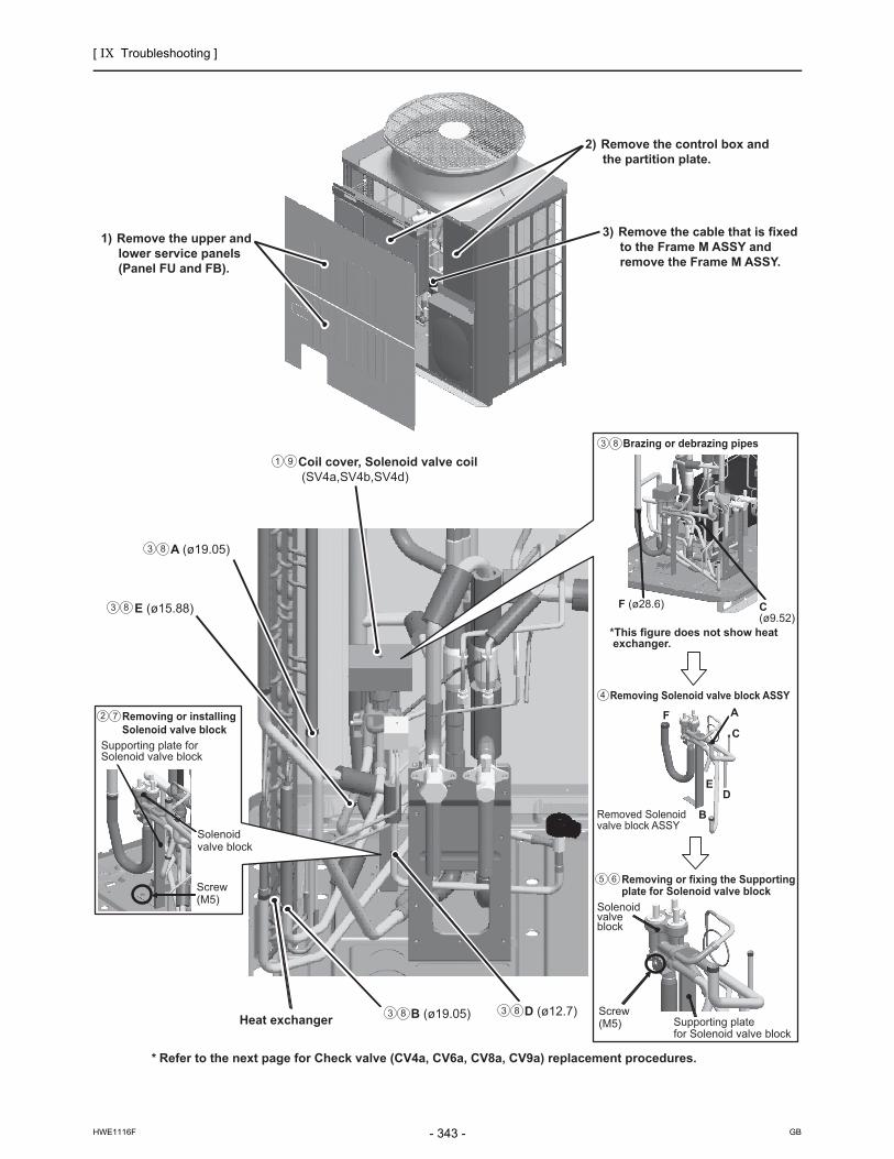
[ IX Troubleshooting ]
- 343 -HWE1116F GB
1) Remove the upper and lower service panels (Panel FU and FB).
2) Remove the control box and the partition plate.
3) Remove the cable that is fixed to the Frame M ASSY and remove the Frame M ASSY.
Screw (M5)
F (ø28.6)
FC
A
D
B
E
C (ø9.52)
Solenoidvalve block
Supporting plate for Solenoid valve block
Removing or installingSolenoid valve block
Brazing or debrazing pipes
Removing or fixing the Supportingplate for Solenoid valve block
Removing Solenoid valve block ASSY
*This figure does not show heat exchanger.
Removed Solenoidvalve block ASSY
Screw (M5) Supporting plate
for Solenoid valve block
Solenoid valve block
* Refer to the next page for Check valve (CV4a, CV6a, CV8a, CV9a) replacement procedures.
Heat exchanger
2
4
5 6
7
A (ø19.05)3 8
3 8
B (ø19.05)3 8 D (ø12.7)3 8
E (ø15.88)3 8
Coil cover, Solenoid valve coil (SV4a,SV4b,SV4d)
1 9

[ IX Troubleshooting ]
- 344 -HWE1116F GB
(2) Check valve (CV4a, CV6a, CV8a, CV9a) replacement proceduresRemove the Solenoid valve block ASSY following "(1) Solenoid valve block ASSY (SV4a, SV4b, SV4d) replacement procedures" on the front page.Debraze G-J parts (total 4 places), and remove the Check valve ASSY.Replace the Check valve (CV4a, CV6a, CV8a, CV9a) to be serviced while it is removed from the unit.Braze the pipes as they were according to the angle of the pipes on the figure below right (Figure as viewed from point K).Mount the Solenoid valve block ASSY, coil cover, and peripheral cables back in place according to "(1) Solenoid valve block ASSY (SV4a, SV4b, SV4d) replacement procedures" on the front page.
* Precautions for replacing Check valve • Be sure to perform no-oxidation brazing when brazing. • Place a wet towel on the Check valve when heating pipes to keep the temperature of the valve from exceed-
ing 120ºC. • After brazing, check the condition around the brazing. After confirming no leakage, evacuate the air inside. • Perform carefully with the flame direction so that it does not burn cables and plates etc. in the unit. • Remove the brazing part protecting heat exchanger fins not to be burn, and replace the service parts.
* After removing Solenoid valve block ASSY
Part A (Refer to the next page.)
2
1
3
I (ø19.05)2 3
J (ø15.88)2 3
4

[ IX Troubleshooting ]
- 345 -HWE1116F GB
6 4
Detailed View of Part A
CV6aCV4a
1 (ø28.6)2 (ø15.88)
5 (ø22.2)3 (ø28.6)
4 (ø28.6)
6 (ø22.2)
CV9a
*This figure does not show heat exchanger.
CV8a
Check valve ASSY
J
K
I
G
H
When replacing CV4a:Remove the brazing 1.
When replacing CV6a:Remove the brazing 2.
When replacing CV8a:Remove the brazing 3and 4.
When replacing CV9a:Remove the brazing 5and 6.
Brazing or debrazing pipes2 3
H (ø15.88)2 3 G (ø28.6)2 3
Check valve replacement3
Angle of the pipes when replacing CV8a,CV9a (Figure as viewed from point K)
3
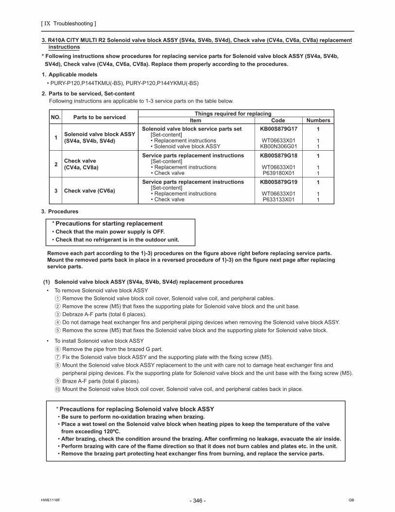
[ IX Troubleshooting ]
- 346 -HWE1116F GB
3. Procedures
* Precautions for starting replacement • Check that the main power supply is OFF. • Check that no refrigerant is in the outdoor unit.
Remove each part according to the 1)-3) procedures on the figure above right before replacing service parts.Mount the removed parts back in place in a reversed procedure of 1)-3) on the figure next page after replacing service parts.
(1) Solenoid valve block ASSY (SV4a, SV4b, SV4d) replacement procedures • To remove Solenoid valve block ASSY
Remove the Solenoid valve block coil cover, Solenoid valve coil, and peripheral cables.Remove the screw (M5) that fixes the supporting plate for Solenoid valve block and the unit base.Debraze A-F parts (total 6 places).Do not damage heat exchanger fins and peripheral piping devices when removing the Solenoid valve block ASSY.Remove the screw (M5) that fixes the Solenoid valve block and the supporting plate for Solenoid valve block.
• To install Solenoid valve block ASSYRemove the pipe from the brazed G part.Fix the Solenoid valve block ASSY and the supporting plate with the fixing screw (M5).Mount the Solenoid valve block ASSY replacement to the unit with care not to damage heat exchanger fins and peripheral piping devices. Fix the supporting plate for Solenoid valve block and the unit base with the fixing screw (M5).Braze A-F parts (total 6 places).Mount the Solenoid valve block coil cover, Solenoid valve coil, and peripheral cables back in place.
3. R410A CITY MULTI R2 Solenoid valve block ASSY (SV4a, SV4b, SV4d), Check valve (CV4a, CV6a, CV8a) replacement instructions
* Following instructions show procedures for replacing service parts for Solenoid valve block ASSY (SV4a, SV4b, SV4d), Check valve (CV4a, CV6a, CV8a). Replace them properly according to the procedures.
1. Applicable models • PURY-P120,P144TKMU(-BS), PURY-P120,P144YKMU(-BS)
2. Parts to be serviced, Set-contentFollowing instructions are applicable to 1-3 service parts on the table below.
NO. Parts to be serviced
1 Solenoid valve block ASSY (SV4a, SV4b, SV4d)
2 Check valve (CV4a, CV8a)
Check valve (CV6a)3
Things required for replacingItem Code
Solenoid valve block service parts set [Set-content] • Replacement instructions • Solenoid valve block ASSY
KB00S879G17
WT06633X01KB00N306G01
Service parts replacement instructions [Set-content] • Replacement instructions • Check valveService parts replacement instructions [Set-content] • Replacement instructions • Check valve
Numbers1
11
KB00S879G18
WT06633X01P639180X01
1
11
KB00S879G19
WT06633X01P633133X01
1
11
* Precautions for replacing Solenoid valve block ASSY • Be sure to perform no-oxidation brazing when brazing. • Place a wet towel on the Solenoid valve block when heating pipes to keep the temperature of the valve
from exceeding 120ºC. • After brazing, check the condition around the brazing. After confirming no leakage, evacuate the air inside. • Perform brazing with care of the flame direction so that it does not burn cables and plates etc. in the unit. • Remove the brazing part protecting heat exchanger fins from burning, and replace the service parts.
2
1
3
4
5
6
7
8
9
10

[ IX Troubleshooting ]
- 347 -HWE1116F GB
C A
Heat exchanger
Coil cover, Solenoid valve coil(SV4a,SV4b,SV4d)
Screw (M5)
Supporting plate for Solenoid valve block
Solenoidvalve block
Removing or installingSolenoid valve block
D
Removed Solenoid valve block ASSY
FB
E
C
A
Screw (M5)
Supporting plate for Solenoid valve block
Solenoid valve block
Debrazing pipe
Removing or fixing the Supportingplate for Solenoid valve block
G(ø15.88)
E (ø15.88)
F(ø28.6)
(ø9.52) (ø19.05)
Remove the pipefrom the brazed G.
3) Remove the cable that is fixed to the Frame M ASSYand remove the Frame M ASSY.
*This figure does not show heat exchanger.
2) Remove the control box.
1) Remove the upper and lower service panels (Panel FU and FB).
6
1 10
2 8
D (ø12.7)93 B (ø19.05)93
93 93
75
Brazing or debrazing pipes93
Removing Solenoid valve block ASSY
4
* Refer to the next page for Check valve (CV4a, CV6a, CV8a) replacement procedures.

[ IX Troubleshooting ]
- 348 -HWE1116F GB
H (ø22.2)2 3
J (ø22.2)2 3
(2) Check valve (CV4a, CV6a, CV8a) replacement proceduresRemove the Solenoid valve block ASSY following "(1) Solenoid valve block ASSY (SV4a, SV4b, SV4d) replacement procedures" on the front page.Debraze H-K parts (total 4 places), and remove the Check valve ASSY.Replace the Check valve (CV4a, CV6a, CV8a) to be serviced while it is removed from the unit.Mount the Solenoid valve block ASSY, coil cover, and peripheral cables back in place according to "(1) Solenoid valve block ASSY (SV4a, SV4b, SV4d) replacement procedures" on the front page.
Part A (Refer to the next page.)
* After removing Solenoid valve block ASSY
* Precautions for replacing Check valve • Be sure to perform no-oxidation brazing when brazing. • Place a wet towel on the Check valve when heating pipes to keep the temperature of the valve from
exceeding 120ºC. • After brazing, check the condition around the brazing. After confirming no leakage, evacuate the air inside. • Perform carefully with the flame direction so that it does not burn cables and plates etc. in the unit. • Remove the brazing part protecting heat exchanger fins not to be burn, and replace the service parts.
2
1
3
4

[ IX Troubleshooting ]
- 349 -HWE1116F GB
Detailed View of Part A
CV4a
CV8a
CV6a
2
1
HI
J
K
When replacing CV4a: Remove the brazing 1.
When replacing CV6a:Remove the brazing 2.
When replacing CV8a: Remove the brazing 3.
*This figure does not show heat exchanger.
(ø22.2)
3(ø22.2)
(ø15.88)
Check valve replacement3
Brazing or debrazing pipes32
32 K (ø15.88)
32 I (ø15.88)

[ IX Troubleshooting ]
- 350 -HWE1116F GB
[7] Servicing the BC controller
1. Service panel
2. Control box
*Special care must be taken when replacing heavy parts.
Work procedure Explanatory figure
1) Remove the two lock nuts on the control box, loosen the other two, and remove the control box.
2) Remove the three fixing screws on the service panel, and remove the service panel.
3) Remove the nine machine screws on the ceiling panel, and remove the ceiling panel.
Work procedure Explanatory figure
(1) To check the inside of the control box, remove the two lock nuts on the control box cover.
1) Check the terminal connection of the power wire or of the transmission line.
2) Check the transformer.3) Check the address switch.
(2) When the control board is replaced, the followings must be noted.
(1) Check that the board type is G,GA(HA), or GB(HB).
(2) Check that the wire and the connector are properly con-nected.
It is not required to remove the two fixing screws on the control box when checking the inside.
Loosen Service panel
Control Box
Ceiling panel
CMB-1016NU-G, GA, HA

[ IX Troubleshooting ]
- 351 -HWE1116F GB
3. Thermistor (liquid pipe/gas pipe temperature detection)
4. Pressure sensor
*Special care must be taken when replacing heavy parts.
Work procedure Explanatory figure
(1) Remove the service panel.
1) For TH11, TH12, and TH15, refer to 1. 1) - 2).2) For TH16, refer to 1. 1) - 3) (GA type only)
(2) Remove the lead wire of the piping sensor from the control board.
1) TH11,TH12 (CN10)2) TH15,TH16 (CN11)
(3) Pull out the temperature sensor from the tempera-ture sensor housing, and replace the temperature sensor with the new one.
(4) Connect the lead wire of the temperature sensor se-curely on the control board.
Work procedure Explanatory figure
(1) Remove the service panel.
1) For the pressure sensors PS1 and PS3, refer to 1. 1) - 2)
(2) Remove the pressure sensor connector in trouble from the control board, and insulate the connector.
1) Liquid-side pressure sensor (CNP1)2) Intermediate-part pressure sensor (CNP3)
(3) Attach a new pressure sensor to the place which is shown in the figure, and insert the connector to the control board.
When gas leaks from the pressure sensor, repair the leak, and follow the instructions above if required.
CMB-1016NU-GA
TH16
TH11
TH15TH12
SVM1
PS1
PS3

[ IX Troubleshooting ]
- 352 -HWE1116F GB
5. LEV
6. Solenoid valve
Work procedure Explanatory figure
(1) Remove the service panel.(Refer to 1. 1) - 3)
(2) Replace the LEV in trouble.
Secure enough service space in the ceiling for welding operation, and conduct the work carefully.If required, dismount the unit from the ceiling, and conduct the work.
*Special care must be taken when replacing heavy parts.
Work procedure Explanatory figure
(1) Remove the service panel.(Refer to 1. 1) - 3)
(2) Remove the connector of the solenoid valve in trou-ble.
(3) Remove the solenoid valve coil.
1) The coils on the solenoid valves SVA, SVB, SVM1b, SVM2 and SVM2b can be serviced through the inspec-tion door. SVC is accessible for replacement by remov-ing the four mounting screws on the rear panel and removing the panel (if enough space is available on the back). (SVM1 is present only on the G and GA and HA types, SVM2 on the GA and HA types, SVM1b and SVM2b is present only on the HA type units.)
LEV3
LEV1LEV2
SVM2
SVM2b
CMB-1016NU-G
Double-pipe heat exchanger
CMB-1016NU-GA
Solenoid valve

[ IX Troubleshooting ]
- 353 -HWE1116F GB
[8] Troubleshooting Using the Outdoor Unit LED Error Display
If the LED error display appear as follows while all the SW4 switches and SW6-10 are set to OFF, check the items under the ap-plicable item numbers below.1. Error code appears on the LED display.
Refer to IX [2] Responding to Error Display on the Remote Controller.(page 199)
2. LED is blank.Take the following troubleshooting steps.
(1) If the voltage between pins 1 and 3 of CNDC on the control board is outside the range between 220 VDC and 380 VDC, refer to IX [4] -8- (2) Troubleshooting transmission power circuit of outdoor unit. (page 333)(page 337)
(2) If the LED error display becomes lit when the power is turned on with all the connectors on the control board except CNDC disconnected, there is a problem with the wiring to those connectors or with the connectors themselves.
(3) If nothing appears on the display under item (2) above AND the voltage between pins 1 and 3 of CNDC is within the range between 220 VDC and 380 VDC, control board failure is suspected.
3. Only the software version appears on the LED display.(1) Only the software version appears while the transmission cables to TB3 and TB7 are disconnected.
1) Wiring failure between the control board and the transmission line power supply board.(CN62, CNPS, CNIT, CNS2, CN102)2) If item 1) checks out OK, the transmission line power supply board failure is suspected.3) If items 1) and 2) check out OK, control board failure is suspected.
(2) If the LED display appears as noted in "X [1] 2. LED display at Initial setting"(page 357) while the transmission cables to TB3 and TB7 are disconnected, failure with the transmission cable or the connected equipment is suspected.
[9] Cleaning the outdoor unit heat exchanger
Clean the outdoor unit heat exchanger with water once or twice a year.

[ IX Troubleshooting ]
- 354 -HWE1116F GB

- 355 -HWE1116F GB
X LED Monitor Display on the Outdoor Unit Board
[1] How to Read the LED on the Service Monitor ...............................................................357

- 356 -HWE1116F GB

[ X LED Monitor Display on the Outdoor Unit Board ]
- 357 -HWE1116F GB
X LED Monitor Display on the Outdoor Unit Board
[1] How to Read the LED on the Service Monitor
1. How to read the LEDBy setting the DIP SW 4-1 through 4-10 (Set SW6-10 to OFF.)(Switch number 10 is represented by 0), the operating condition of the unit can be monitored on the service monitor. (Refer to the table on the following pages for DIP SW settings.) The service monitor uses 4-digit 7-segment LED to display numerical values and other types of information.
Pressure and temperature are examples of numerical values, and operating conditions and the on-off status of solenoid valve are examples of flag display.
2. LED display at initial settingFrom power on until the completion of initial settings, the following information will be displayed on the monitor screen.(Displays No. 1 through No. 4 in order repeatedly.)
After the initial settings have been completed, the information on these items can be checked by making the switch setting that corresponds to No. 517 in the LED display table.
Only item No. 1 "Software Version" appears on the display if there is a wiring failure between the control board and the trans-mission line power supply board or if the circuit board has failed.
1) Display of numerical values
Example: When the pressure data sensor reads 18.8kg/cm2 (Item No. 58)The unit of pressure is in kg/cm2
Use the following conversion formula to convert the displayed value into a value in SI unit. Value in SI unit (MPa) = Displayed value (kg/cm2) x 0.098
2) Flag display
Example: When 21S4a, 21S4b, SV1a are ON. (Item No. 3)
Example: 3-minutes restart mode (Item No. 14)
No Item Display Remarks
1
Software version
[0103] : Version 1.03
2
Refrigerant type
[ 410] : R410A
3
Model and capacity [H-20] : Cooling/Heating 20 HPFor the first few minutes after power on, the capacity of each outdoor unit is displayed. Thereafter, the com-bined capacity is displayed.
4
Communication address
[ 51] : Address 51
SW4
ON 1 2 3 4 5 6 7 8
SW4-10 is represented as “0” in the table.
9 10
7SEG LED
LD1 LD2 LD3 LD4 LD5 LD6 LD7 LD8
Upper
Lower
LD1 LD2 LD3 LD4 LD5 LD6 LD7 LD8

[ X LED Monitor Display on the Outdoor Unit Board ]
- 358 -HWE1116F GB
3. Time data storage function
The outdoor unit has a simple clock function that enables the unit to calculate the current time with an internal timer by receiv-ing the time set by the system controller, such as AG-150A.If an error (including a preliminary error) occurs, the error history data and the error detection time are stored into the service memory.The error detection time stored in the service memory and the current time can be seen on the service LED.
1) Use the time displayed on the service LED as a reference.2) The date and the time are set to "00" by default. If a system controller that sets the time, such as AG-150A is not connected,
the elapsed time and days since the first power on will be displayed.If the time set on a system controller is received, the count will start from the set date and the time.
3) The time is not updated while the power of the indoor unit is turned off. When the power is turned off and then on again, the count will resume from the time before the power was turned off. Thus, the time that differs the actual time will be displayed. (This also applies when a power failure occurs.)The system controller, such as AG-150A, adjusts the time once a day. When the system controller is connected, the time will be automatically updated to the correct current time after the time set by the system controller is received. (The data stored into the memory before the set time is received will not be updated.)
(1) Reading the time data:
1) Time display
Example: 12 past 9
2) Date display
When the main controller that can set the time is connectedExample: May 10, 2003
When the main controller that can set the time is not connectedExample: 52 days after power was turned on
* Disappears if the time data is deviated due to a power failure, or if a system controller that sets the time is not connected.
Alternate display
Alternate display of year and month, and date
* Appears between the year and the month, and nothing appears when the date is displayed.
Alternate display
Day count
* Appears between the year and the month, and nothing appears when the date is displayed.

[ X LED Monitor Display on the Outdoor Unit Board ]
- 359 -HWE1116F
ILE
D M
onito
r D
ispl
ay
on
the
Out
doo
r U
nit
Bo
ard
LE
D m
on
ito
r d
isp
lay
Cu
rren
t d
ata
No
.
SW
4 (W
he
n S
W6
- 1
0 is
se
t t
o O
FF
)It
em
Dis
play
Un
it(A
, B)
*1R
em
ark
s
12
34
56
78
90
LD
1L
D2
LD
3L
D4
LD
5L
D6
LD
7L
D8
OC
OS
00
00
00
00
00
0
Re
lay
ou
tpu
t d
isp
lay
1
Ligh
ting
Co
mp
in o
p-
era
tion
72
CO
CC
PU
in o
pe
r-a
tion
AA
Ch
eck
(e
rro
r) d
isp
lay
1
OC
/OS
err
or
00
00
to
99
99
(A
dd
ress
an
d e
rro
r co
de
s h
igh
ligh
ted
)B
B
11
00
00
00
00
0
Ch
eck
(e
rro
r) d
isp
lay
2
OC
/OS
err
or
00
00
to
99
99
(A
dd
ress
an
d e
rro
r co
de
s h
igh
ligh
ted
)A
A
Dis
pla
y o
f th
e la
test
pre
-lim
ina
ry e
rro
rIf
no
pre
limin
ary
err
ors
a
re d
ete
cte
d,
"---
-" a
p-
pe
ars
on
th
e d
isp
lay.
20
10
00
00
00
0C
he
ck (
err
or)
dis
pla
y 3
(I
ncl
ud
ing
IC
an
d B
C)
00
00
to
99
99
(A
dd
ress
an
d e
rro
r co
de
s h
igh
ligh
ted
)B
If n
o e
rro
rs a
re d
ete
cte
d,
"---
-" a
pp
ea
rs o
n t
he d
is-
play
.
31
10
00
00
00
0R
ela
y o
ut-
pu
t dis
pla
y 2
To
p2
1S4
aS
V1
aA
AB
ott
om
21
S4
bS
V5
b
40
01
00
00
00
0
Re
lay
ou
t-p
ut d
isp
lay
3
Top
SV
4a
SV
4bS
V4
cS
V4
dS
V9
Pow
er s
up-
ply
for i
nd
oo
r tr
ansm
is-
sio
n li
ne
AA
Bo
tto
m
71
11
00
00
00
0
Sp
eci
al c
on
tro
l
Re
try
op
era
-tio
nE
me
rge
ncy
o
pe
ratio
n
Co
mm
un
ica
-tio
n e
rro
r b
e-
twe
en
th
e
OC
an
d O
S
Co
mm
un
ica
-tio
n e
rro
r3
-min
ute
re
-st
art
de
lay
mo
de
BB
91
00
10
00
00
0C
om
mu
nic
atio
n d
e-
ma
nd
ca
pa
city
00
00
to
99
99
BB
If n
ot
de
ma
nd
ed
co
n-
trol
led,
"-
---"
[ %
] a
p-p
ea
rs o
n t
he
dis
pla
y.
10
01
01
00
00
00
Co
nta
ct p
oin
t d
em
an
d
cap
aci
ty0
00
0 t
o 9
99
9B
If n
ot
de
ma
nd
ed
co
n-
trol
led,
"-
---"
[ %
] a
p-p
ea
rs o
n t
he
dis
pla
y.
11
11
01
00
00
00
Ext
ern
al s
ign
al
(Op
en
inp
ut c
on
tact
po
int)
Co
nta
ct
po
int
de
-m
an
d
Lo
w-n
ois
e
mo
de
(Ca
pa
city
pr
iorit
y )
Sn
ow
se
nso
r
Co
olin
g-
he
atin
g
cha
ng
eo
ver
(Co
olin
g)
Co
olin
g-
he
atin
g
chan
ge
ove
r(H
ea
ting
)
AA
*1 A
: T
he
co
nditi
on
of
eith
er
OC
or
OS
is d
isp
laye
d in
div
idua
lly.
B:
Th
e c
on
diti
on
of
the
en
tire
re
frig
eran
t sy
stem
is d
ispl
aye
d.

[ X LED Monitor Display on the Outdoor Unit Board ]
- 360 -HWE1116F
12
00
11
00
00
00
Ext
ern
al s
ign
al
(Op
en
inp
ut c
on
tact
po
int)
Low
-noi
se
mo
de
(Q
uie
t pri
ori
-ty
)
AA
13
10
11
00
00
00
14
01
11
00
00
00
Ou
tdo
or
un
it o
pe
ratio
n
sta
tus
BC
op
era
-tio
n s
ign
al
Wa
rm-u
p
mo
de
3-m
inu
tes
rest
art
mo
de
Co
mp
ress
or
in o
pe
ratio
nP
relim
ina
ry
err
or
Err
or
3-m
inu
tes
rest
art
aft
er
inst
an
ta-
ne
ou
s p
ow
er
failu
re
Pre
limin
ary
lo
w p
res-
sure
err
or
AA
15
11
11
00
00
00
OC
/OS
ide
ntif
ica
tion
OC
/OS
AA
16
00
00
10
00
00
Ind
oor
un
it ch
eck
To
pU
nit
No
. 1
Un
it N
o.
2U
nit
No
. 3
Un
it N
o.
4U
nit
No
. 5
Un
it N
o.
6U
nit
No
. 7U
nit
No
. 8
BT
he
lam
p t
ha
t co
rre
-sp
on
ds
to t
he
un
it th
at
cam
e to
an
ab
no
rma
l sto
p
ligh
ts.
Th
e la
mp
go
es
off
wh
en
th
e e
rro
r is
re
set.
Eac
h un
it th
at c
om
es t
o a
n a
bn
orm
al u
nit
will
be
g
ive
n a
se
que
ntia
l nu
m-
be
r in
asc
en
din
g o
rde
r st
art
ing
with
1.
Bo
tto
mU
nit
No
. 9
Un
it N
o.
10
Un
it N
o.
11
Un
it N
o.
12
Un
it N
o.
13
Un
it N
o.
14
Un
it N
o.
15U
nit
No
. 1
6
17
10
00
10
00
00
To
pU
nit
No
. 1
7U
nit
No
. 1
8U
nit
No
. 1
9U
nit
No
. 2
0U
nit
No
. 2
1U
nit
No
. 2
2U
nit
No
. 23
Un
it N
o.
24
Bo
tto
mU
nit
No
. 2
5U
nit
No
. 2
6U
nit
No
. 2
7U
nit
No
. 2
8U
nit
No
. 2
9U
nit
No
. 3
0U
nit
No
. 31
Un
it N
o.
32
18
01
00
10
00
00
To
pU
nit
No
. 3
3U
nit
No
. 3
4U
nit
No
. 3
5U
nit
No
. 3
6U
nit
No
. 3
7U
nit
No
. 3
8U
nit
No
. 39
Un
it N
o.
40
Bo
tto
mU
nit
No
. 4
1U
nit
No
. 4
2U
nit
No
.43
Un
it N
o.
44
Un
it N
o.
45
Un
it N
o.
46
Un
it N
o.
47U
nit
No
. 4
8
19
11
00
10
00
00
To
pU
nit
No
. 4
9U
nit
No
. 5
0
Bo
tto
m
20
00
10
10
00
00
Ind
oor
un
it O
pe
ratio
n
mo
de
To
pU
nit
No
. 1
Un
it N
o.
2U
nit
No
. 3
Un
it N
o.
4U
nit
No
. 5
Un
it N
o.
6U
nit
No
. 7U
nit
No
. 8
BL
it d
uri
ng
co
olin
g
Blin
kin
g d
uri
ng
he
atin
g
Unl
it w
hile
th
e u
nit
is
sto
pp
ed
or
in t
he
fan
m
od
e
Bo
tto
mU
nit
No
. 9
Un
it N
o.
10
Un
it N
o.
11
Un
it N
o.
12
Un
it N
o.
13
Un
it N
o.
14
Un
it N
o.
15U
nit
No
. 1
6
21
10
10
10
00
00
To
pU
nit
No
. 1
7U
nit
No
. 1
8U
nit
No
. 1
9U
nit
No
. 2
0U
nit
No
. 2
1U
nit
No
. 2
2U
nit
No
. 23
Un
it N
o.
24
Bo
tto
mU
nit
No
. 2
5U
nit
No
. 2
6U
nit
No
. 2
7U
nit
No
. 2
8U
nit
No
. 2
9U
nit
No
. 3
0U
nit
No
. 31
Un
it N
o.
32
22
01
10
10
00
00
To
pU
nit
No
. 3
3U
nit
No
. 3
4U
nit
No
. 3
5U
nit
No
. 3
6U
nit
No
. 3
7U
nit
No
. 3
8U
nit
No
. 39
Un
it N
o.
40
Bo
tto
mU
nit
No
. 4
1U
nit
No
. 4
2U
nit
No
.43
Un
it N
o.
44
Un
it N
o.
45
Un
it N
o.
46
Un
it N
o.
47U
nit
No
. 4
8
23
11
10
10
00
00
To
pU
nit
No
. 4
9U
nit
No
. 5
0
Bo
tto
m
Cu
rren
t d
ata
No
.
SW
4 (W
he
n S
W6
- 1
0 is
se
t t
o O
FF
)It
em
Dis
play
Un
it(A
, B)
*1R
em
ark
s
12
34
56
78
90
LD
1L
D2
LD
3L
D4
LD
5L
D6
LD
7L
D8
OC
OS
*1 A
: T
he
co
nditi
on
of
eith
er
OC
or
OS
is d
isp
laye
d in
div
idua
lly.
B:
Th
e c
on
diti
on
of
the
en
tire
re
frig
eran
t sy
stem
is d
ispl
aye
d.

[ X LED Monitor Display on the Outdoor Unit Board ]
- 361 -HWE1116F
24
00
01
10
00
00
Ind
oor
un
it th
erm
o-
sta
t
To
pU
nit
No
. 1
Un
it N
o.
2U
nit
No
. 3
Un
it N
o.
4U
nit
No
. 5
Un
it N
o.
6U
nit
No
. 7U
nit
No
. 8
BL
it w
he
n t
he
rmo
sta
t is
on
Unl
it w
he
n t
her
mo
sta
t is
o
ffB
ott
om
Un
it N
o.
9U
nit
No
. 1
0U
nit
No
. 1
1U
nit
No
. 1
2U
nit
No
. 1
3U
nit
No
. 1
4U
nit
No
. 15
Un
it N
o.
16
25
10
01
10
00
00
To
pU
nit
No
. 1
7U
nit
No
. 1
8U
nit
No
. 1
9U
nit
No
. 2
0U
nit
No
. 2
1U
nit
No
. 2
2U
nit
No
. 23
Un
it N
o.
24
Bo
tto
mU
nit
No
. 2
5U
nit
No
. 2
6U
nit
No
. 2
7U
nit
No
. 2
8U
nit
No
. 2
9U
nit
No
. 3
0U
nit
No
. 31
Un
it N
o.
32
26
01
01
10
00
00
To
pU
nit
No
. 3
3U
nit
No
. 3
4U
nit
No
. 3
5U
nit
No
. 3
6U
nit
No
. 3
7U
nit
No
. 3
8U
nit
No
. 39
Un
it N
o.
40
Bo
tto
mU
nit
No
. 4
1U
nit
No
. 4
2U
nit
No
.43
Un
it N
o.
44
Un
it N
o.
45
Un
it N
o.
46
Un
it N
o.
47U
nit
No
. 4
8
27
11
01
10
00
00
To
pU
nit
No
. 4
9U
nit
No
. 5
0
Bo
tto
m
37
10
10
01
00
00
BC
op
era
tion
mo
de
Co
olin
g-o
nly
O
NC
oo
ling
-on
ly
OF
FH
ea
ting-
on
ly
ON
He
atin
g-o
nly
O
FF
Mix
ed
-mo
de
ON
Mix
ed
-mo
de
O
FF
Fan
Sto
pB
39
11
10
01
00
00
Ou
tdo
or
un
it O
pe
ratio
n
mo
de
Per
mis
sibl
e st
op
Sta
nd
by
Co
olin
gC
oo
ling
-m
ain
He
atin
gH
ea
ting
-m
ain
AA
42
01
01
01
00
00
Out
door
uni
t co
ntro
l m
od
eS
top
Th
erm
o O
FF
Ab
no
rma
l st
op
Sch
ed
ule
d
con
tro
lIn
itial
sta
rt
up
De
fro
stO
il b
ala
nce
Lo
w f
re-
quen
cy o
il re
cove
ryA
A
43
11
01
01
00
00
Wa
rm-u
p
mod
eR
efr
ige
ran
t re
cove
ryA
A
45
10
11
01
00
00
TH
4-9
9.9
to
99
9.9
AA
Th
e u
nit
is [
°C]
46
01
11
01
00
00
TH
3-9
9.9
to
99
9.9
AA
47
11
11
01
00
00
TH
7-9
9.9
to
99
9.9
AA
48
00
00
11
00
00
TH
6-9
9.9
to
99
9.9
AA
50
01
00
11
00
00
TH
5-9
9.9
to
99
9.9
AA
56
00
01
11
00
00
TH
HS
1-9
9.9
to
99
9.9
AA
Th
e u
nit
is [
°C]
58
01
01
11
00
00
Hig
h-p
ress
ure
se
nso
r d
ata
-99
.9 t
o 9
99
.9A
AT
he u
nit
is [
kgf/
cm2 ]
59
11
01
11
00
00
Lo
w-p
ress
ure
se
nso
r d
ata
-99
.9 t
o 9
99
.9A
A
78
01
11
00
10
00
Qj
00
00
to
99
99
BB
79
11
11
00
10
00
Qjc
00
00
to
99
99
BB
80
00
00
10
10
00
Qjh
00
00
to
99
99
BB
Cu
rren
t d
ata
No
.
SW
4 (W
he
n S
W6
- 1
0 is
se
t t
o O
FF
)It
em
Dis
play
Un
it(A
, B)
*1R
em
ark
s
12
34
56
78
90
LD
1L
D2
LD
3L
D4
LD
5L
D6
LD
7L
D8
OC
OS
*1 A
: T
he
co
nditi
on
of
eith
er
OC
or
OS
is d
isp
laye
d in
div
idua
lly.
B:
Th
e c
on
diti
on
of
the
en
tire
re
frig
eran
t sy
stem
is d
ispl
aye
d.

[ X LED Monitor Display on the Outdoor Unit Board ]
- 362 -HWE1116F
81
10
00
10
10
00
Ta
rge
t Tc
-99
.9 t
o 9
99
.9B
Th
e u
nit
is [
°C]
82
01
00
10
10
00
Ta
rge
t Te
-99
.9 t
o 9
99
.9B
83
11
00
10
10
00
Tc
-99
.9 t
o 9
99
.9A
A
84
00
10
10
10
00
Te
-99
.9 t
o 9
99
.9A
A
86
01
10
10
10
00
Tot
al f
requ
enci
es
(OC
+O
S)
00
00
to
99
99
BC
ontr
ol d
ata
[ H
z ]
87
11
10
10
10
00
Tot
al fr
eque
ncy
of e
ach
unit
00
00
to
99
99
AA
88
00
01
10
10
00
CO
MP
fre
qu
en
cy0
00
0 t
o 9
99
9A
A
91
11
01
10
10
00
CO
MP
op
era
ting
fre
-q
ue
ncy
00
00
to
99
99
AA
Th
e u
nit
is [
rps]
Ou
tpu
t fr
eq
ue
ncy
of
the
inve
rte
r d
ep
en
ds
on
th
e t
ype
of
com
pre
sso
r a
nd
eq
ua
ls
the
inte
ge
r m
ulti
ple
s (x
1,
x2 e
tc.)
of
the
op
era
ting
fr
eq
ue
ncy
of
the
co
m-
pre
sso
r.
92
00
11
10
10
00
Nu
mb
er
of
times
err
or
occ
urr
ed
du
rin
g c
rank
-ca
se h
ea
ting
by
com
-p
ress
or
mo
tor
00
00
to
99
99
AA
Num
be
r o
f tim
es
INV
er-
ror
occ
urr
ed
du
rin
g I
H
cra
nkc
ase
he
atin
g b
y co
mp
ress
or
mo
tor
93
10
11
10
10
00
All
AK
(O
C+
OS
)0
00
0 t
o 9
99
9B
94
01
11
10
10
00
AK
00
00
to
99
99
AA
95
11
11
10
10
00
FA
N1
00
00
to
99
99
AA
Fa
n o
utp
ut
[ %
]
96
00
00
01
10
00
Fa
n in
vert
er o
utp
ut r
pm
(F
AN
1)
00
00
to
99
99
AA
[rp
m]
97
10
00
01
10
00
FA
N2
00
00
to
99
99
AA
Fa
n o
utp
ut
[ %
]
98
01
00
01
10
00
Fa
n in
vert
er o
utp
ut r
pm
(F
AN
2)
00
00
to
99
99
AA
[rp
m]
10
11
01
00
11
00
0L
EV
5a
00
00
to
99
99
AA
10
71
10
10
11
00
0L
EV
5b
00
00
to
99
99
AA
10
80
01
10
11
00
0C
OM
P o
pe
ratin
g c
ur-
ren
t (D
C)
00
.0 t
o 9
99
.9A
AP
ea
k va
lue
[A]
Cu
rren
t d
ata
No
.
SW
4 (W
he
n S
W6
- 1
0 is
se
t t
o O
FF
)It
em
Dis
play
Un
it(A
, B)
*1R
em
ark
s
12
34
56
78
90
LD
1L
D2
LD
3L
D4
LD
5L
D6
LD
7L
D8
OC
OS
*1 A
: T
he
co
nditi
on
of
eith
er
OC
or
OS
is d
isp
laye
d in
div
idua
lly.
B:
Th
e c
on
diti
on
of
the
en
tire
re
frig
eran
t sy
stem
is d
ispl
aye
d.

[ X LED Monitor Display on the Outdoor Unit Board ]
- 363 -HWE1116F
11
11
11
10
11
00
0C
OM
P b
us v
olta
ge0
0.0
to
99
9.9
AA
Th
e u
nit
is[
V ]
11
60
01
01
11
00
0
Nu
mb
er
of
times
th
e
un
it w
en
t in
to th
e m
od
e
to r
em
ed
y w
et
vap
or
suct
ion
00
00
to
99
99
B
11
71
01
01
11
00
0C
OM
P O
pe
ratio
n t
ime
Up
per
4 d
igits
00
00
to
99
99
AA
Th
e u
nit
is[
h ]
11
80
11
01
11
00
0C
OM
P O
pe
ratio
n t
ime
Low
er 4
dig
its0
00
0 t
o 9
99
9A
A
12
11
00
11
11
00
0B
ack
up
mo
de
Ab
no
rma
l pr
essu
re r
ise
Hig
h-p
res-
sure
dro
pL
ow
-pre
s-su
re d
rop
Abn
orm
al T
d
rise
Hig
h-p
res-
sure
du
rin
g
defr
ost
cyc
le
Co
ntr
ol b
ox
tem
pe
ratu
re
rise
AA
Sta
ys li
t fo
r 9
0 se
con
ds
aft
er
the
co
mp
letio
n o
f ba
ckup
con
tro
l
12
31
10
11
11
00
0C
OM
P n
um
be
r o
f st
art
-st
op
eve
nts
Up
per
4 d
igits
00
00
to
99
99
AA
Cou
nt-
up
at
sta
rt-u
pT
he
un
it is
[T
ime
]
12
40
01
11
11
00
0C
OM
P n
um
be
r o
f st
art
-st
op
eve
nts
Low
er 4
dig
its0
00
0 t
o 9
99
9A
A
12
91
00
00
00
10
0In
tegr
ate
d o
pe
ratio
n
time
of c
om
pre
sso
r (f
or
rota
tion
pu
rpo
se)
00
00
to
99
99
BT
he
un
it is
[ h
]
13
20
01
00
00
10
0R
ela
y o
ut-
pu
t dis
pla
y B
C(M
ain
)
To
pS
VM
1S
VM
2S
VM
1b
SV
M2
bB
Bo
tto
m
13
31
01
00
00
10
0T
op
SV
A1
SV
B1
SV
C1
SV
A2
SV
B2
SV
C2
BB
ott
om
SV
A3
SV
B3
SV
C3
SV
A4
SV
B4
SV
C4
13
40
11
00
00
10
0T
op
SV
A5
SV
B5
SV
C5
SV
A6
SV
B6
SV
C6
BB
ott
om
SV
A7
SV
B7
SV
C7
SV
A8
SV
B8
SV
C8
13
51
11
00
00
10
0T
op
SV
A9
SV
B9
SV
C9
SV
A1
0S
VB
10
SV
C1
0B
Bo
tto
mS
VA
11
SV
B1
1S
VC
11
SV
A1
2S
VB
12
SV
C1
2
13
60
00
10
00
10
0T
op
SV
A1
3S
VB
13
SV
C1
3S
VA
14
SV
B1
4S
VC
14
BB
ott
om
SV
A1
5S
VB
15
SV
C1
5S
VA
16
SV
B1
6S
VC
16
Cu
rren
t d
ata
No
.
SW
4 (W
he
n S
W6
- 1
0 is
se
t t
o O
FF
)It
em
Dis
play
Un
it(A
, B)
*1R
em
ark
s
12
34
56
78
90
LD
1L
D2
LD
3L
D4
LD
5L
D6
LD
7L
D8
OC
OS
*1 A
: T
he
co
nditi
on
of
eith
er
OC
or
OS
is d
isp
laye
d in
div
idua
lly.
B:
Th
e c
on
diti
on
of
the
en
tire
re
frig
eran
t sy
stem
is d
ispl
aye
d.

[ X LED Monitor Display on the Outdoor Unit Board ]
- 364 -HWE1116F
13
80
10
10
00
10
0R
ela
y o
ut-
pu
t dis
pla
y B
C(S
ub
1)
To
pS
VA
1S
VB
1S
VC
1S
VA
2S
VB
2S
VC
2B
Bo
tto
mS
VA
3S
VB
3S
VC
3S
VA
4S
VB
4S
VC
4
13
91
10
10
00
10
0T
op
SV
A5
SV
B5
SV
C5
SV
A6
SV
B6
SV
C6
BB
ott
om
SV
A7
SV
B7
SV
C7
SV
A8
SV
B8
SV
C8
14
00
01
10
00
10
0T
op
SV
A9
SV
B9
SV
C9
SV
A1
0S
VB
10
SV
C1
0B
Bo
tto
mS
VA
11
SV
B1
1S
VC
11
SV
A1
2S
VB
12
SV
C1
2
14
11
01
10
00
10
0T
op
SV
A1
3S
VB
13
SV
C1
3S
VA
14
SV
B1
4S
VC
14
BB
ott
om
SV
A1
5S
VB
15
SV
C1
5S
VA
16
SV
B1
6S
VC
16
14
31
11
10
00
10
0R
ela
y o
ut-
pu
t dis
pla
y B
C(S
ub
2)
To
pS
VA
1S
VB
1S
VC
1S
VA
2S
VB
2S
VC
2B
Bo
tto
mS
VA
3S
VB
3S
VC
3S
VA
4S
VB
4S
VC
4
14
40
00
01
00
10
0T
op
SV
A5
SV
B5
SV
C5
SV
A6
SV
B6
SV
C6
BB
ott
om
SV
A7
SV
B7
SV
C7
SV
A8
SV
B8
SV
C8
14
51
00
01
00
10
0T
op
SV
A9
SV
B9
SV
C9
SV
A1
0S
VB
10
SV
C1
0B
Bo
tto
mS
VA
11
SV
B1
1S
VC
11
SV
A1
2S
VB
12
SV
C1
2
14
60
10
01
00
10
0T
op
SV
A1
3S
VB
13
SV
C1
3S
VA
14
SV
B1
4S
VC
14
BB
ott
om
SV
A1
5S
VB
15
SV
C1
5S
VA
16
SV
B1
6S
VC
16
14
91
01
01
00
10
0B
C(M
ain
or
sta
nd
ard
)T
H11
-99
.9 t
o 9
99
.9B
15
00
11
01
00
10
0 B
C(M
ain
)TH
12
-99
.9 t
o 9
99
.9B
15
11
11
01
00
10
0 B
C(M
ain
)TH
15
-99
.9 t
o 9
99
.9B
15
20
00
11
00
10
0 B
C(M
ain
)TH
16
-99
.9 t
o 9
99
.9B
15
31
00
11
00
10
0 B
C(M
ain
)63
HS
1-9
9.9
to
99
9.9
B
15
40
10
11
00
10
0 B
C(M
ain
)63
HS
3-9
9.9
to
99
9.9
B
15
51
10
11
00
10
0 B
C(M
ain
)SC
11
-99
.9 t
o 9
99
.9B
15
60
01
11
00
10
0 B
C(M
ain
)SH
12
-99
.9 t
o 9
99
.9B
15
71
01
11
00
10
0 B
C(M
ain
)SH
13
-99
.9 t
o 9
99
.9B
15
80
11
11
00
10
0 B
C(M
ain
)SC
16
-99
.9 t
o 9
99
.9B
Cu
rren
t d
ata
No
.
SW
4 (W
he
n S
W6
- 1
0 is
se
t t
o O
FF
)It
em
Dis
play
Un
it(A
, B)
*1R
em
ark
s
12
34
56
78
90
LD
1L
D2
LD
3L
D4
LD
5L
D6
LD
7L
D8
OC
OS
*1 A
: T
he
co
nditi
on
of
eith
er
OC
or
OS
is d
isp
laye
d in
div
idua
lly.
B:
Th
e c
on
diti
on
of
the
en
tire
re
frig
eran
t sy
stem
is d
ispl
aye
d.

[ X LED Monitor Display on the Outdoor Unit Board ]
- 365 -HWE1116F
15
91
11
11
00
10
0 B
C(M
ain
)LE
V1
00
00
to
20
00
BL
EV
1 o
pe
nin
g(F
ully
ope
n:20
00)
16
00
00
00
10
10
0 B
C(M
ain
)LE
V3
00
00
to
20
00
BL
EV
3 o
pe
nin
g(F
ully
ope
n:20
00)
16
11
00
00
10
10
0 B
C(S
ub
1)T
H1
2-9
9.9
to
99
9.9
B
16
20
10
00
10
10
0 B
C(S
ub
1)T
H1
5-9
9.9
to
99
9.9
B
16
31
10
00
10
10
0 B
C(S
ub
1)L
EV
30
00
0 t
o 2
00
0B
LE
V3
op
en
ing
(Ful
ly o
pen:
2000
)
16
40
01
00
10
10
0 B
C(S
ub
2)T
H1
2-9
9.9
to
99
9.9
B
16
51
01
00
10
10
0 B
C(S
ub
2)T
H1
5-9
9.9
to
99
9.9
B
16
60
11
00
10
10
0 B
C(S
ub
2)L
EV
30
00
0 t
o 2
00
0B
LE
V3
a o
pe
nin
g(F
ully
ope
n:20
00)
16
71
11
00
10
10
0 B
C(M
ain
)LE
V2
00
00
to
20
00
BL
EV
2 o
pe
nin
g(F
ully
ope
n:20
00)
Cu
rren
t d
ata
No
.
SW
4 (W
he
n S
W6
- 1
0 is
se
t t
o O
FF
)It
em
Dis
play
Un
it(A
, B)
*1R
em
ark
s
12
34
56
78
90
LD
1L
D2
LD
3L
D4
LD
5L
D6
LD
7L
D8
OC
OS
*1 A
: T
he
co
nditi
on
of
eith
er
OC
or
OS
is d
isp
laye
d in
div
idua
lly.
B:
Th
e c
on
diti
on
of
the
en
tire
re
frig
eran
t sy
stem
is d
ispl
aye
d.

[ X LED Monitor Display on the Outdoor Unit Board ]
- 366 -HWE1116F
17
80
10
01
10
10
0E
rro
r h
isto
ry 1
00
00
to
99
99
BB
Ad
dre
ss a
nd
err
or
cod
es
hig
hlig
hte
dIf
no
err
ors
are
de
tect
ed
, "-
---
" a
pp
ea
rs o
n t
he d
is-
play
.P
relim
ina
ry e
rro
r in
form
a-
tion
of
the
OS
do
es
no
t a
pp
ea
r o
n t
he
OC
.N
eith
er
pre
limin
ary
err
or
info
rma
tion
of t
he
OC
no
r e
rro
r in
form
atio
n o
f th
e IC
a
pp
ea
rs o
n t
he
OS
.
17
91
10
01
10
10
0 E
rro
r d
eta
ils o
f in
vert
er
Err
or
de
tails
of
inve
rte
r (0
00
1-0
12
0)
AA
18
00
01
01
10
10
0 E
rro
r h
isto
ry 2
00
00
to
99
99
BB
18
11
01
01
10
10
0 E
rro
r d
eta
ils o
f in
vert
er
Err
or
de
tails
of
inve
rte
r (0
00
1-0
12
0)
AA
18
20
11
01
10
10
0 E
rro
r h
isto
ry 3
00
00
to
99
99
BB
18
31
11
01
10
10
0 E
rro
r d
eta
ils o
f in
vert
er
Err
or
de
tails
of
inve
rte
r (0
00
1-0
12
0)
AA
18
40
00
11
10
10
0 E
rro
r h
isto
ry 4
00
00
to
99
99
BB
18
51
00
11
10
10
0 E
rro
r d
eta
ils o
f in
vert
er
Err
or
de
tails
of
inve
rte
r (0
00
1-0
12
0)
AA
18
60
10
11
10
10
0 E
rro
r h
isto
ry 5
00
00
to
99
99
BB
18
71
10
11
10
10
0 E
rro
r d
eta
ils o
f in
vert
er
Err
or
de
tails
of
inve
rte
r (0
00
1-0
12
0)
AA
18
80
01
11
10
10
0 E
rro
r h
isto
ry 6
00
00
to
99
99
BB
18
91
01
11
10
10
0 E
rro
r d
eta
ils o
f in
vert
er
Err
or
de
tails
of
inve
rte
r (0
00
1-0
12
0)
AA
19
00
11
11
10
10
0 E
rro
r h
isto
ry 7
00
00
to
99
99
BB
19
11
11
11
10
10
0 E
rro
r d
eta
ils o
f in
vert
er
Err
or
de
tails
of
inve
rte
r (0
00
1-0
12
0)
AA
19
20
00
00
01
10
0 E
rro
r h
isto
ry 8
00
00
to
99
99
BB
19
31
00
00
01
10
0 E
rro
r d
eta
ils o
f in
vert
er
Err
or
de
tails
of
inve
rte
r (0
00
1-0
12
0)
AA
19
40
10
00
01
10
0 E
rro
r h
isto
ry 9
00
00
to
99
99
BB
19
51
10
00
01
10
0 E
rro
r d
eta
ils o
f in
vert
er
Err
or
de
tails
of
inve
rte
r (0
00
1-0
12
0)
AA
19
60
01
00
01
10
0 E
rro
r h
isto
ry 1
00
00
0 t
o 9
99
9B
B
19
71
01
00
01
10
0 E
rro
r d
eta
ils o
f in
vert
er
Err
or
de
tails
of
inve
rte
r (0
00
1-0
12
0)
AA
19
80
11
00
01
10
0E
rro
r h
isto
ry o
f in
vert
er(A
t th
e ti
me
of l
ast
da
ta
ba
cku
p b
efo
re e
rro
r)0
00
0 t
o 9
99
9B
B
19
91
11
00
01
10
0E
rro
r d
eta
ils o
f in
vert
er
Err
or
de
tails
of
inve
rte
r (0
00
1-0
12
0)
AA
Cu
rren
t d
ata
No
.
SW
4 (W
he
n S
W6
- 1
0 is
se
t t
o O
FF
)It
em
Dis
play
Un
it(A
, B)
*1R
em
ark
s
12
34
56
78
90
LD
1L
D2
LD
3L
D4
LD
5L
D6
LD
7L
D8
OC
OS
*1 A
: T
he
co
nditi
on
of
eith
er
OC
or
OS
is d
isp
laye
d in
div
idua
lly.
B:
Th
e c
on
diti
on
of
the
en
tire
re
frig
eran
t sy
stem
is d
ispl
aye
d.

[ X LED Monitor Display on the Outdoor Unit Board ]
- 367 -HWE1116F
Da
ta b
efo
re e
rro
r
No
.
SW
4 (W
he
n S
W6
- 1
0 is
se
t t
o O
FF
)It
em
Dis
play
Un
it(A
, B)
*1R
em
ark
s
12
34
56
78
90
LD
1L
D2
LD
3L
D4
LD
5L
D6
LD
7L
D8
OC
OS
20
11
00
10
01
10
0
Ou
tdo
or
un
it o
pe
ratio
n
sta
tus
BC
op
era
-tio
n s
ign
al
Wa
rm-u
p
mo
de
3-m
inu
tes
rest
art
mo
de
Co
mp
ress
or
in o
pe
ratio
nP
relim
ina
ry
err
or
Err
or
3-m
inu
tes
rest
art
aft
er
inst
an
ta-
ne
ou
s p
ow
er
failu
re
Pre
limin
ary
lo
w p
res-
sure
err
or
AA
20
20
10
10
01
10
0O
C/O
S id
en
tific
atio
nO
C/O
SA
A
20
31
10
10
01
10
0B
C o
pe
ratio
n m
od
eC
oo
ling
-on
ly
ON
Co
olin
g-o
nly
O
FF
He
atin
g-o
nly
O
NH
ea
ting
-on
ly
OF
FM
ixe
d-m
od
e O
NM
ixe
d-m
od
e
OF
FF
anS
top
AA
20
51
01
10
01
10
0O
utd
oo
r u
nit
Op
era
tion
m
od
eP
erm
issi
ble
sto
pS
tan
db
yC
oo
ling
Co
olin
g-
ma
inH
ea
ting
He
atin
g-
ma
inA
A
20
80
00
01
01
10
0O
utdo
or u
nit
cont
rol
mo
de
Sto
pT
he
rmo
OF
FA
bn
orm
al
sto
pS
che
du
led
co
ntr
ol
Initi
al s
tart
u
pD
efr
ost
Oil
ba
lan
ceL
ow
fre
-qu
ency
oil
reco
very
AA
20
91
00
01
01
10
0R
efr
ige
ran
t re
cove
ryA
A
21
11
10
01
01
10
0R
ela
y o
utp
ut
dis
pla
y 1
Ligh
ting
Co
mp
in o
p-
era
tion
72C
OC
Alw
ays
litA
A
21
20
01
01
01
10
0
Re
lay
ou
t-p
ut d
isp
lay
2 Ligh
ting
To
p2
1S4
aS
V1
a
AA
Bo
tto
m2
1S
4b
SV
5b
21
31
01
01
01
10
0
Re
lay
ou
t-p
ut d
isp
lay
3 Ligh
ting
Top
SV
4a
SV
4bS
V4
cS
V4
dS
V9
Lit
wh
ile
po
we
r to
the
in
do
or
un
its
is b
ein
g s
up
-pl
ied
AA
Bo
tto
m
21
60
00
11
01
10
0T
H4
-99
.9 t
o 9
99
.9A
AT
he
un
it is
[°C
]
21
71
00
11
01
10
0T
H3
-99
.9 t
o 9
99
.9A
A
21
80
10
11
01
10
0T
H7
-99
.9 t
o 9
99
.9A
A
21
91
10
11
01
10
0T
H6
-99
.9 t
o 9
99
.9A
A
22
11
01
11
01
10
0T
H5
-99
.9 t
o 9
99
.9A
A
22
71
10
00
11
10
0T
HH
S1
-99
.9 t
o 9
99
.9A
AT
he
un
it is
[°C
]
*1
A:
Th
e c
ond
itio
n o
f e
ithe
r O
C o
r O
S is
dis
pla
yed
ind
ivid
ua
lly.
B:
Th
e c
on
diti
on
of
the
en
tire
re
frig
era
nt
syst
em
is d
isp
laye
d.

[ X LED Monitor Display on the Outdoor Unit Board ]
- 368 -HWE1116F
22
91
01
00
11
10
0H
igh
-pre
ssu
re s
en
sor
da
ta-9
9.9
to
99
9.9
AA
The
uni
t is
[kg
f/cm
2 ]
23
00
11
00
11
10
0L
ow
-pre
ssu
re s
en
sor
da
ta-9
9.9
to
99
9.9
AA
24
91
00
11
11
10
0 Q
j 0
00
0 t
o 9
99
9B
B
25
00
10
11
11
10
0 Q
jc0
00
0 t
o 9
99
9B
B
25
11
10
11
11
10
0 Q
jh0
00
0 t
o 9
99
9B
B
25
20
01
11
11
10
0T
arg
et T
c-9
9.9
to
99
9.9
BT
he
un
it is
[°C
]
25
31
01
11
11
10
0T
arg
et T
e-9
9.9
to
99
9.9
B
25
40
11
11
11
10
0T
c-9
9.9
to
99
9.9
AA
Th
e u
nit
is [
°C]
25
51
11
11
11
10
0T
e-9
9.9
to
99
9.9
AA
25
71
00
00
00
01
0T
otal
fre
quen
cies
(O
C+
OS
)0
00
0 t
o 9
99
9B
Con
tro
l da
ta[
Hz
]
25
80
10
00
00
01
0T
otal
freq
uen
cy o
f eac
h
unit
00
00
to
99
99
AA
25
91
10
00
00
01
0C
OM
P f
req
ue
ncy
00
00
to
99
99
AA
26
40
00
10
00
01
0A
ll A
K (
OC
+O
S)
00
00
to
99
99
B
26
51
00
10
00
01
0A
K0
00
0 t
o 9
99
9A
A
26
60
10
10
00
01
0F
AN
10
00
0 t
o 9
99
9A
AF
an
inve
rte
r o
utp
ut [
% ]
26
71
10
10
00
01
0F
an
inve
rte
r ou
tpu
t rp
m
(FA
N1
)0
00
0 t
o 9
99
9A
A[r
pm
]
26
80
01
10
00
01
0F
AN
20
00
0 t
o 9
99
9A
AF
an
inve
rte
r o
utp
ut [
% ]
26
91
01
10
00
01
0F
an
inve
rte
r ou
tpu
t rp
m
(FA
N2
)0
00
0 t
o 9
99
9A
A[r
pm
]
27
20
00
01
00
01
0L
EV
5a
00
00
to
99
99
AA
27
80
11
01
00
01
0L
EV
5b
00
00
to
99
99
AA
27
91
11
01
00
01
0C
OM
P o
pe
ratin
g c
ur-
ren
t (D
C)
00
.0 t
o 9
99
.9A
AP
ea
k va
lue
[A]
28
20
10
11
00
01
0C
OM
P b
us
volta
ge
00
.0 t
o 9
99
.9A
AT
he
un
it is
[ V
]
Da
ta b
efo
re e
rro
r
No
.
SW
4 (W
he
n S
W6
- 1
0 is
se
t t
o O
FF
)It
em
Dis
play
Un
it(A
, B)
*1R
em
ark
s
12
34
56
78
90
LD
1L
D2
LD
3L
D4
LD
5L
D6
LD
7L
D8
OC
OS
*1
A:
Th
e c
ond
itio
n o
f e
ithe
r O
C o
r O
S is
dis
pla
yed
ind
ivid
ua
lly.
B:
Th
e c
on
diti
on
of
the
en
tire
re
frig
era
nt
syst
em
is d
isp
laye
d.

[ X LED Monitor Display on the Outdoor Unit Board ]
- 369 -HWE1116F
28
80
00
00
10
01
0C
OM
P O
pe
ratio
n t
ime
Upp
er
4 di
gits
00
00
to
99
99
AA
Th
e u
nit
is [
h ]
28
91
00
00
10
01
0C
OM
P O
pe
ratio
n t
ime
Low
er 4
dig
its0
00
0 t
o 9
99
9A
A
29
40
11
00
10
01
0C
OM
P n
um
be
r o
f st
art
-st
op
eve
nts
Up
per
4 d
igits
00
00
to
99
99
AA
Cou
nt-
up
at
sta
rt-u
pT
he
un
it is
[T
ime
]
29
51
11
00
10
01
0C
OM
P n
um
be
r o
f st
art
-st
op
eve
nts
Low
er 4
dig
its0
00
0 t
o 9
99
9A
A
30
00
01
10
10
01
0In
tegr
ate
d o
pe
ratio
n
time
of c
om
pre
sso
r (f
or
rota
tion
pu
rpo
se)
00
00
to
99
99
BT
he
un
it is
[ h
]
Da
ta b
efo
re e
rro
r
No
.
SW
4 (W
he
n S
W6
- 1
0 is
se
t t
o O
FF
)It
em
Dis
play
Un
it(A
, B)
*1R
em
ark
s
12
34
56
78
90
LD
1L
D2
LD
3L
D4
LD
5L
D6
LD
7L
D8
OC
OS
*1
A:
Th
e c
ond
itio
n o
f e
ithe
r O
C o
r O
S is
dis
pla
yed
ind
ivid
ua
lly.
B:
Th
e c
on
diti
on
of
the
en
tire
re
frig
era
nt
syst
em
is d
isp
laye
d.

[ X LED Monitor Display on the Outdoor Unit Board ]
- 370 -HWE1116F
Da
ta b
efo
re e
rro
r
No
.
SW
4 (W
he
n S
W6
- 1
0 is
se
t t
o O
FF
)It
em
Dis
play
Un
it(A
, B
)*1R
em
ark
s
12
34
56
78
90
LD
1L
D2
LD
3L
D4
LD
5L
D6
LD
7L
D8
OC
OS
30
11
01
10
10
01
0P
ow
er
sup
ply
un
itO
C/O
S <
-> A
dd
ress
B
30
20
11
10
10
01
0S
tart
-up
un
itO
C/O
S <
-> A
dd
ress
B
32
00
00
00
01
01
0 B
C(M
ain
)TH
11
-99
.9 t
o 9
99
.9B
32
11
00
00
01
01
0 B
C(M
ain
)TH
12
-99
.9 t
o 9
99
.9B
32
20
10
00
01
01
0 B
C(M
ain
)TH
15
-99
.9 t
o 9
99
.9B
32
31
10
00
01
01
0 B
C(M
ain
)TH
16
-99
.9 t
o 9
99
.9B
32
40
01
00
01
01
0 B
C(M
ain
)PS
1-9
9.9
to
99
9.9
B
32
51
01
00
01
01
0 B
C(M
ain
)PS
3-9
9.9
to
99
9.9
B
33
00
10
10
01
01
0 B
C(M
ain
)LE
V1
00
00
to
20
00
B
33
11
10
10
01
01
0 B
C(M
ain
)LE
V3
00
00
to
20
00
B
33
20
01
10
01
01
0 B
C(S
ub
1)T
H1
2-9
9.9
to
99
9.9
B
33
31
01
10
01
01
0 B
C(S
ub
1)T
H1
5-9
9.9
to
99
9.9
B
33
40
11
10
01
01
0 B
C(S
ub
1)L
EV
30
00
0 t
o 2
00
0B
33
51
11
10
01
01
0 B
C(S
ub
2)T
H1
2-9
9.9
to
99
9.9
B
33
60
00
01
01
01
0 B
C(S
ub
2)T
H1
5-9
9.9
to
99
9.9
B
33
71
00
01
01
01
0 B
C(S
ub
2)L
EV
30
00
0 t
o 2
00
0B
33
80
10
01
01
01
0 B
C(M
ain
)LE
V2
00
00
to
20
00
B
*1
A:
Th
e c
ond
itio
n o
f e
ithe
r O
C o
r O
S is
dis
pla
yed
ind
ivid
ua
lly.
B:
Th
e c
on
diti
on
of
the
en
tire
re
frig
era
nt
syst
em
is d
isp
laye
d.

[ X LED Monitor Display on the Outdoor Unit Board ]
- 371 -HWE1116F
Da
ta o
n in
do
or
un
it s
yste
m
No
.
SW
4 (W
he
n S
W6
- 1
0 is
se
t t
o O
FF
)It
em
Dis
pla
yU
nit
(A,
B)
*1R
em
ark
s
12
34
56
78
90
LD
1L
D2
LD
3L
D4
LD
5L
D6
LD
7L
D8
OC
OS
35
11
11
11
01
01
0 IC
1 A
dd
ress
/ca
pa
city
co
de
00
00
to
99
99
00
00
to
99
99
BD
isp
laye
d a
ltern
ate
ly e
v-e
ry 5
se
con
ds
35
20
00
00
11
01
0IC
2 A
dd
ress
/ca
pa
city
co
de
00
00
to
99
99
00
00
to
99
99
35
31
00
00
11
01
0IC
3 A
dd
ress
/ca
pa
city
co
de
00
00
to
99
99
00
00
to
99
99
35
40
10
00
11
01
0IC
4 A
dd
ress
/ca
pa
city
co
de
00
00
to
99
99
00
00
to
99
99
35
51
10
00
11
01
0IC
5 A
dd
ress
/ca
pa
city
co
de
00
00
to
99
99
00
00
to
99
99
35
60
01
00
11
01
0IC
6 A
dd
ress
/ca
pa
city
co
de
00
00
to
99
99
00
00
to
99
99
35
71
01
00
11
01
0IC
7 A
dd
ress
/ca
pa
city
co
de
00
00
to
99
99
00
00
to
99
99
35
80
11
00
11
01
0IC
8 A
dd
ress
/ca
pa
city
co
de
00
00
to
99
99
00
00
to
99
99
35
91
11
00
11
01
0IC
9 A
dd
ress
/ca
pa
city
co
de
00
00
to
99
99
00
00
to
99
99
36
00
00
10
11
01
0IC
10
Ad
dre
ss/c
ap
acity
co
de
00
00
to
99
99
00
00
to
99
99
36
11
00
10
11
01
0IC
11
Ad
dre
ss/c
ap
acity
co
de
00
00
to
99
99
00
00
to
99
99
36
20
10
10
11
01
0IC
12
Ad
dre
ss/c
ap
acity
co
de
00
00
to
99
99
00
00
to
99
99
36
31
10
10
11
01
0IC
13
Ad
dre
ss/c
ap
acity
co
de
00
00
to
99
99
00
00
to
99
99
36
40
01
10
11
01
0IC
14
Ad
dre
ss/c
ap
acity
co
de
00
00
to
99
99
00
00
to
99
99
36
51
01
10
11
01
0IC
15
Ad
dre
ss/c
ap
acity
co
de
00
00
to
99
99
00
00
to
99
99
36
60
11
10
11
01
0IC
16
Ad
dre
ss/c
ap
acity
co
de
00
00
to
99
99
00
00
to
99
99
36
71
11
10
11
01
0IC
17
Ad
dre
ss/c
ap
acity
co
de
00
00
to
99
99
00
00
to
99
99
*1
A:
Th
e c
ond
itio
n o
f e
ithe
r O
C o
r O
S is
dis
pla
yed
ind
ivid
ua
lly.
B:
Th
e c
on
diti
on
of
the
en
tire
re
frig
era
nt
syst
em
is d
isp
laye
d.

[ X LED Monitor Display on the Outdoor Unit Board ]
- 372 -HWE1116F
36
80
00
01
11
01
0IC
18
Ad
dre
ss/c
ap
acity
co
de
00
00
to
99
99
00
00
to
99
99
BD
isp
laye
d a
ltern
ate
ly e
v-e
ry 5
se
con
ds
36
91
00
01
11
01
0IC
19
Ad
dre
ss/c
ap
acity
co
de
00
00
to
99
99
00
00
to
99
99
37
00
10
01
11
01
0IC
20
Ad
dre
ss/c
ap
acity
co
de
00
00
to
99
99
00
00
to
99
99
37
11
10
01
11
01
0IC
21
Ad
dre
ss/c
ap
acity
co
de
00
00
to
99
99
00
00
to
99
99
37
20
01
01
11
01
0IC
22
Ad
dre
ss/c
ap
acity
co
de
00
00
to
99
99
00
00
to
99
99
37
31
01
01
11
01
0IC
23
Ad
dre
ss/c
ap
acity
co
de
00
00
to
99
99
00
00
to
99
99
37
40
11
01
11
01
0IC
24
Ad
dre
ss/c
ap
acity
co
de
00
00
to
99
99
00
00
to
99
99
37
51
11
01
11
01
0IC
25
Ad
dre
ss/c
ap
acity
co
de
00
00
to
99
99
00
00
to
99
99
37
60
00
11
11
01
0IC
26
Ad
dre
ss/c
ap
acity
co
de
00
00
to
99
99
00
00
to
99
99
37
71
00
11
11
01
0IC
27
Ad
dre
ss/c
ap
acity
co
de
00
00
to
99
99
00
00
to
99
99
37
80
10
11
11
01
0IC
28
Ad
dre
ss/c
ap
acity
co
de
00
00
to
99
99
00
00
to
99
99
37
91
10
11
11
01
0IC
29
Ad
dre
ss/c
ap
acity
co
de
00
00
to
99
99
00
00
to
99
99
38
00
01
11
11
01
0IC
30
Ad
dre
ss/c
ap
acity
co
de
00
00
to
99
99
00
00
to
99
99
38
11
01
11
11
01
0IC
31
Ad
dre
ss/c
ap
acity
co
de
00
00
to
99
99
00
00
to
99
99
38
20
11
11
11
01
0IC
32
Ad
dre
ss/c
ap
acity
co
de
00
00
to
99
99
00
00
to
99
99
38
31
11
11
11
01
0IC
33
Ad
dre
ss/c
ap
acity
co
de
00
00
to
99
99
00
00
to
99
99
38
40
00
00
00
11
0IC
34
Ad
dre
ss/c
ap
acity
co
de
00
00
to
99
99
00
00
to
99
99
38
51
00
00
00
11
0IC
35
Ad
dre
ss/c
ap
acity
co
de
00
00
to
99
99
00
00
to
99
99
38
60
10
00
00
11
0IC
36
Ad
dre
ss/c
ap
acity
co
de
00
00
to
99
99
00
00
to
99
99
38
71
10
00
00
11
0IC
37
Ad
dre
ss/c
ap
acity
co
de
00
00
to
99
99
00
00
to
99
99
38
80
01
00
00
11
0IC
38
Ad
dre
ss/c
ap
acity
co
de
00
00
to
99
99
00
00
to
99
99
38
91
01
00
00
11
0IC
39
Ad
dre
ss/c
ap
acity
co
de
00
00
to
99
99
00
00
to
99
99
39
00
11
00
00
11
0IC
40
Ad
dre
ss/c
ap
acity
co
de
00
00
to
99
99
00
00
to
99
99
39
11
11
00
00
11
0IC
41
Ad
dre
ss/c
ap
acity
co
de
00
00
to
99
99
00
00
to
99
99
39
20
00
10
00
11
0IC
42
Ad
dre
ss/c
ap
acity
co
de
00
00
to
99
99
00
00
to
99
99
39
31
00
10
00
11
0IC
43
Ad
dre
ss/c
ap
acity
co
de
00
00
to
99
99
00
00
to
99
99
39
40
10
10
00
11
0IC
44
Ad
dre
ss/c
ap
acity
co
de
00
00
to
99
99
00
00
to
99
99
39
51
10
10
00
11
0IC
45
Ad
dre
ss/c
ap
acity
co
de
00
00
to
99
99
00
00
to
99
99
Da
ta o
n in
do
or
un
it s
yste
m
No
.
SW
4 (W
he
n S
W6
- 1
0 is
se
t t
o O
FF
)It
em
Dis
pla
yU
nit
(A,
B)
*1R
em
ark
s
12
34
56
78
90
LD
1L
D2
LD
3L
D4
LD
5L
D6
LD
7L
D8
OC
OS
*1
A:
Th
e c
ond
itio
n o
f e
ithe
r O
C o
r O
S is
dis
pla
yed
ind
ivid
ua
lly.
B:
Th
e c
on
diti
on
of
the
en
tire
re
frig
era
nt
syst
em
is d
isp
laye
d.
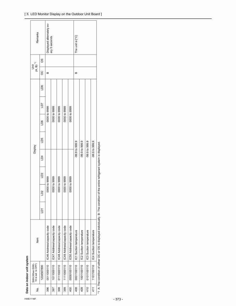
[ X LED Monitor Display on the Outdoor Unit Board ]
- 373 -HWE1116F
39
60
01
10
00
11
0IC
46
Ad
dre
ss/c
ap
acity
co
de
00
00
to
99
99
00
00
to
99
99
BD
isp
laye
d a
ltern
ate
ly e
v-e
ry 5
se
con
ds
39
71
01
10
00
11
0IC
47
Ad
dre
ss/c
ap
acity
co
de
00
00
to
99
99
00
00
to
99
99
39
80
11
10
00
11
0IC
48
Ad
dre
ss/c
ap
acity
co
de
00
00
to
99
99
00
00
to
99
99
39
91
11
10
00
11
0IC
49
Ad
dre
ss/c
ap
acity
co
de
00
00
to
99
99
00
00
to
99
99
40
00
00
01
00
11
0IC
50
Ad
dre
ss/c
ap
acity
co
de
00
00
to
99
99
00
00
to
99
99
40
80
00
11
00
11
0IC
1 S
uct
ion
te
mp
era
ture
-99
.9 t
o 9
99
.9B
Th
e u
nit
is [
°C]
40
91
00
11
00
11
0IC
2 S
uct
ion
te
mp
era
ture
-99
.9 t
o 9
99
.9
41
00
10
11
00
11
0IC
3 S
uct
ion
te
mp
era
ture
-99
.9 t
o 9
99
.9
41
11
10
11
00
11
0IC
4 S
uct
ion
te
mp
era
ture
-99
.9 t
o 9
99
.9
Da
ta o
n in
do
or
un
it s
yste
m
No
.
SW
4 (W
he
n S
W6
- 1
0 is
se
t t
o O
FF
)It
em
Dis
pla
yU
nit
(A,
B)
*1R
em
ark
s
12
34
56
78
90
LD
1L
D2
LD
3L
D4
LD
5L
D6
LD
7L
D8
OC
OS
*1
A:
Th
e c
ond
itio
n o
f e
ithe
r O
C o
r O
S is
dis
pla
yed
ind
ivid
ua
lly.
B:
Th
e c
on
diti
on
of
the
en
tire
re
frig
era
nt
syst
em
is d
isp
laye
d.

[ X LED Monitor Display on the Outdoor Unit Board ]
- 374 -HWE1116F
41
20
01
11
00
11
0IC
5 S
uct
ion
te
mp
era
ture
-99
.9 t
o 9
99
.9B
Th
e u
nit
is [
°C]
41
31
01
11
00
11
0IC
6 S
uct
ion
te
mp
era
ture
-99
.9 t
o 9
99
.9
41
40
11
11
00
11
0IC
7 S
uct
ion
te
mp
era
ture
-99
.9 t
o 9
99
.9
41
51
11
11
00
11
0IC
8 S
uct
ion
te
mp
era
ture
-99
.9 t
o 9
99
.9
41
60
00
00
10
11
0IC
9 S
uct
ion
te
mp
era
ture
-99
.9 t
o 9
99
.9
41
71
00
00
10
11
0IC
10
Su
ctio
n t
em
per
atu
re-9
9.9
to
99
9.9
41
80
10
00
10
11
0IC
11
Su
ctio
n t
em
per
atu
re-9
9.9
to
99
9.9
41
91
10
00
10
11
0IC
12
Su
ctio
n t
em
per
atu
re-9
9.9
to
99
9.9
42
00
01
00
10
11
0IC
13
Su
ctio
n t
em
per
atu
re-9
9.9
to
99
9.9
42
11
01
00
10
11
0IC
14
Su
ctio
n t
em
per
atu
re-9
9.9
to
99
9.9
42
20
11
00
10
11
0IC
15
Su
ctio
n t
em
per
atu
re-9
9.9
to
99
9.9
42
31
11
00
10
11
0IC
16
Su
ctio
n t
em
per
atu
re-9
9.9
to
99
9.9
42
40
00
10
10
11
0IC
17
Su
ctio
n t
em
per
atu
re-9
9.9
to
99
9.9
42
51
00
10
10
11
0IC
18
Su
ctio
n t
em
per
atu
re-9
9.9
to
99
9.9
42
60
10
10
10
11
0IC
19
Su
ctio
n t
em
per
atu
re-9
9.9
to
99
9.9
42
71
10
10
10
11
0IC
20
Su
ctio
n t
em
per
atu
re-9
9.9
to
99
9.9
42
80
01
10
10
11
0IC
21
Su
ctio
n t
em
per
atu
re-9
9.9
to
99
9.9
42
91
01
10
10
11
0IC
22
Su
ctio
n t
em
per
atu
re-9
9.9
to
99
9.9
43
00
11
10
10
11
0IC
23
Su
ctio
n t
em
per
atu
re-9
9.9
to
99
9.9
43
11
11
10
10
11
0IC
24
Su
ctio
n t
em
per
atu
re-9
9.9
to
99
9.9
43
20
00
01
10
11
0IC
25
Su
ctio
n t
em
per
atu
re-9
9.9
to
99
9.9
43
31
00
01
10
11
0IC
26
Su
ctio
n t
em
per
atu
re-9
9.9
to
99
9.9
43
40
10
01
10
11
0IC
27
Su
ctio
n t
em
per
atu
re-9
9.9
to
99
9.9
43
51
10
01
10
11
0IC
28
Su
ctio
n t
em
per
atu
re-9
9.9
to
99
9.9
Da
ta o
n in
do
or
un
it s
yste
m
No
.
SW
4 (W
he
n S
W6
- 1
0 is
se
t t
o O
FF
)It
em
Dis
pla
yU
nit
(A,
B)
*1R
em
ark
s
12
34
56
78
90
LD
1L
D2
LD
3L
D4
LD
5L
D6
LD
7L
D8
OC
OS
*1
A:
Th
e c
ond
itio
n o
f e
ithe
r O
C o
r O
S is
dis
pla
yed
ind
ivid
ua
lly.
B:
Th
e c
on
diti
on
of
the
en
tire
re
frig
era
nt
syst
em
is d
isp
laye
d.

[ X LED Monitor Display on the Outdoor Unit Board ]
- 375 -HWE1116F
43
60
01
01
10
11
0IC
29
Su
ctio
n t
em
per
atu
re-9
9.9
to
99
9.9
BT
he
un
it is
[°C
]
43
71
01
01
10
11
0IC
30
Su
ctio
n t
em
per
atu
re-9
9.9
to
99
9.9
43
80
11
01
10
11
0IC
31
Su
ctio
n t
em
per
atu
re-9
9.9
to
99
9.9
43
91
11
01
10
11
0IC
32
Su
ctio
n t
em
per
atu
re-9
9.9
to
99
9.9
44
00
00
11
10
11
0IC
33
Su
ctio
n t
em
per
atu
re-9
9.9
to
99
9.9
44
11
00
11
10
11
0IC
34
Su
ctio
n t
em
per
atu
re-9
9.9
to
99
9.9
44
20
10
11
10
11
0IC
35
Su
ctio
n t
em
per
atu
re-9
9.9
to
99
9.9
44
31
10
11
10
11
0IC
36
Su
ctio
n t
em
per
atu
re-9
9.9
to
99
9.9
44
40
01
11
10
11
0IC
37
Su
ctio
n t
em
per
atu
re-9
9.9
to
99
9.9
44
51
01
11
10
11
0IC
38
Su
ctio
n t
em
per
atu
re-9
9.9
to
99
9.9
44
60
11
11
10
11
0IC
39
Su
ctio
n t
em
per
atu
re-9
9.9
to
99
9.9
44
71
11
11
10
11
0IC
40
Su
ctio
n t
em
per
atu
re-9
9.9
to
99
9.9
44
80
00
00
01
11
0IC
41
Su
ctio
n t
em
per
atu
re-9
9.9
to
99
9.9
44
91
00
00
01
11
0IC
42
Su
ctio
n t
em
per
atu
re-9
9.9
to
99
9.9
45
00
10
00
01
11
0IC
43
Su
ctio
n t
em
per
atu
re-9
9.9
to
99
9.9
45
11
10
00
01
11
0IC
44
Su
ctio
n t
em
per
atu
re-9
9.9
to
99
9.9
45
20
01
00
01
11
0IC
45
Su
ctio
n t
em
per
atu
re-9
9.9
to
99
9.9
45
31
01
00
01
11
0IC
46
Su
ctio
n t
em
per
atu
re-9
9.9
to
99
9.9
45
40
11
00
01
11
0IC
47
Su
ctio
n t
em
per
atu
re-9
9.9
to
99
9.9
45
51
11
00
01
11
0IC
48
Su
ctio
n t
em
per
atu
re-9
9.9
to
99
9.9
45
60
00
10
01
11
0IC
49
Su
ctio
n t
em
per
atu
re-9
9.9
to
99
9.9
45
71
00
10
01
11
0IC
50
Su
ctio
n t
em
per
atu
re-9
9.9
to
99
9.9
45
80
10
10
01
11
0IC
1 L
iqu
id p
ipe
te
mp
era
ture
-99
.9 t
o 9
99
.9B
Th
e u
nit
is [
°C]
45
91
10
10
01
11
0IC
2 L
iqu
id p
ipe
te
mp
era
ture
-99
.9 t
o 9
99
.9
46
00
01
10
01
11
0IC
3 L
iqu
id p
ipe
te
mp
era
ture
-99
.9 t
o 9
99
.9
46
11
01
10
01
11
0IC
4 L
iqu
id p
ipe
te
mp
era
ture
-99
.9 t
o 9
99
.9
46
20
11
10
01
11
0IC
5 L
iqu
id p
ipe
te
mp
era
ture
-99
.9 t
o 9
99
.9
46
31
11
10
01
11
0IC
6 L
iqu
id p
ipe
te
mp
era
ture
-99
.9 t
o 9
99
.9
Da
ta o
n in
do
or
un
it s
yste
m
No
.
SW
4 (W
he
n S
W6
- 1
0 is
se
t t
o O
FF
)It
em
Dis
pla
yU
nit
(A,
B)
*1R
em
ark
s
12
34
56
78
90
LD
1L
D2
LD
3L
D4
LD
5L
D6
LD
7L
D8
OC
OS
*1
A:
Th
e c
ond
itio
n o
f e
ithe
r O
C o
r O
S is
dis
pla
yed
ind
ivid
ua
lly.
B:
Th
e c
on
diti
on
of
the
en
tire
re
frig
era
nt
syst
em
is d
isp
laye
d.

[ X LED Monitor Display on the Outdoor Unit Board ]
- 376 -HWE1116F
46
40
00
01
01
11
0IC
7 L
iqu
id p
ipe
te
mp
era
ture
-99
.9 t
o 9
99
.9B
Th
e u
nit
is [
°C]
46
51
00
01
01
11
0IC
8 L
iqu
id p
ipe
te
mp
era
ture
-99
.9 t
o 9
99
.9
46
60
10
01
01
11
0IC
9 L
iqu
id p
ipe
te
mp
era
ture
-99
.9 t
o 9
99
.9
46
71
10
01
01
11
0IC
10
Liq
uid
pip
e t
em
pe
ratu
re-9
9.9
to
99
9.9
46
80
01
01
01
11
0IC
11
Liq
uid
pip
e t
em
pe
ratu
re-9
9.9
to
99
9.9
46
91
01
01
01
11
0IC
12
Liq
uid
pip
e t
em
pe
ratu
re-9
9.9
to
99
9.9
47
00
11
01
01
11
0IC
13
Liq
uid
pip
e t
em
pe
ratu
re-9
9.9
to
99
9.9
47
11
11
01
01
11
0IC
14
Liq
uid
pip
e t
em
pe
ratu
re-9
9.9
to
99
9.9
47
20
00
11
01
11
0IC
15
Liq
uid
pip
e t
em
pe
ratu
re-9
9.9
to
99
9.9
47
31
00
11
01
11
0IC
16
Liq
uid
pip
e t
em
pe
ratu
re-9
9.9
to
99
9.9
47
40
10
11
01
11
0IC
17
Liq
uid
pip
e t
em
pe
ratu
re-9
9.9
to
99
9.9
47
51
10
11
01
11
0IC
18
Liq
uid
pip
e t
em
pe
ratu
re-9
9.9
to
99
9.9
47
60
01
11
01
11
0IC
19
Liq
uid
pip
e t
em
pe
ratu
re-9
9.9
to
99
9.9
47
71
01
11
01
11
0IC
20
Liq
uid
pip
e t
em
pe
ratu
re-9
9.9
to
99
9.9
47
80
11
11
01
11
0IC
21
Liq
uid
pip
e t
em
pe
ratu
re-9
9.9
to
99
9.9
47
91
11
11
01
11
0IC
22
Liq
uid
pip
e t
em
pe
ratu
re-9
9.9
to
99
9.9
48
00
00
00
11
11
0IC
23
Liq
uid
pip
e t
em
pe
ratu
re-9
9.9
to
99
9.9
48
11
00
00
11
11
0IC
24
Liq
uid
pip
e t
em
pe
ratu
re-9
9.9
to
99
9.9
48
20
10
00
11
11
0IC
25
Liq
uid
pip
e t
em
pe
ratu
re-9
9.9
to
99
9.9
48
31
10
00
11
11
0IC
26
Liq
uid
pip
e t
em
pe
ratu
re-9
9.9
to
99
9.9
48
40
01
00
11
11
0IC
27
Liq
uid
pip
e t
em
pe
ratu
re-9
9.9
to
99
9.9
48
51
01
00
11
11
0IC
28
Liq
uid
pip
e t
em
pe
ratu
re-9
9.9
to
99
9.9
48
60
11
00
11
11
0IC
29
Liq
uid
pip
e t
em
pe
ratu
re-9
9.9
to
99
9.9
48
71
11
00
11
11
0IC
30
Liq
uid
pip
e t
em
pe
ratu
re-9
9.9
to
99
9.9
48
80
00
10
11
11
0IC
31
Liq
uid
pip
e t
em
pe
ratu
re-9
9.9
to
99
9.9
48
91
00
10
11
11
0IC
32
Liq
uid
pip
e t
em
pe
ratu
re-9
9.9
to
99
9.9
49
00
10
10
11
11
0IC
33
Liq
uid
pip
e t
em
pe
ratu
re-9
9.9
to
99
9.9
49
11
10
10
11
11
0IC
34
Liq
uid
pip
e t
em
pe
ratu
re-9
9.9
to
99
9.9
Da
ta o
n in
do
or
un
it s
yste
m
No
.
SW
4 (W
he
n S
W6
- 1
0 is
se
t t
o O
FF
)It
em
Dis
pla
yU
nit
(A,
B)
*1R
em
ark
s
12
34
56
78
90
LD
1L
D2
LD
3L
D4
LD
5L
D6
LD
7L
D8
OC
OS
*1
A:
Th
e c
ond
itio
n o
f e
ithe
r O
C o
r O
S is
dis
pla
yed
ind
ivid
ua
lly.
B:
Th
e c
on
diti
on
of
the
en
tire
re
frig
era
nt
syst
em
is d
isp
laye
d.

[ X LED Monitor Display on the Outdoor Unit Board ]
- 377 -HWE1116F
49
20
01
10
11
11
0IC
35
Liq
uid
pip
e t
em
pe
ratu
re-9
9.9
to
99
9.9
BT
he
un
it is
[°C
]
49
31
01
10
11
11
0IC
36
Liq
uid
pip
e t
em
pe
ratu
re-9
9.9
to
99
9.9
49
40
11
10
11
11
0IC
37
Liq
uid
pip
e t
em
pe
ratu
re-9
9.9
to
99
9.9
49
51
11
10
11
11
0IC
38
Liq
uid
pip
e t
em
pe
ratu
re-9
9.9
to
99
9.9
49
60
00
01
11
11
0IC
39
Liq
uid
pip
e t
em
pe
ratu
re-9
9.9
to
99
9.9
49
71
00
01
11
11
0IC
40
Liq
uid
pip
e t
em
pe
ratu
re-9
9.9
to
99
9.9
49
80
10
01
11
11
0IC
41
Liq
uid
pip
e t
em
pe
ratu
re-9
9.9
to
99
9.9
49
91
10
01
11
11
0IC
42
Liq
uid
pip
e t
em
pe
ratu
re-9
9.9
to
99
9.9
50
00
01
01
11
11
0IC
43
Liq
uid
pip
e t
em
pe
ratu
re-9
9.9
to
99
9.9
50
11
01
01
11
11
0IC
44
Liq
uid
pip
e t
em
pe
ratu
re-9
9.9
to
99
9.9
50
20
11
01
11
11
0IC
45
Liq
uid
pip
e t
em
pe
ratu
re-9
9.9
to
99
9.9
50
31
11
01
11
11
0IC
46
Liq
uid
pip
e t
em
pe
ratu
re-9
9.9
to
99
9.9
50
40
00
11
11
11
0IC
47
Liq
uid
pip
e t
em
pe
ratu
re-9
9.9
to
99
9.9
50
51
00
11
11
11
0IC
48
Liq
uid
pip
e t
em
pe
ratu
re-9
9.9
to
99
9.9
50
60
10
11
11
11
0IC
49
Liq
uid
pip
e t
em
pe
ratu
re-9
9.9
to
99
9.9
50
71
10
11
11
11
0IC
50
Liq
uid
pip
e t
em
pe
ratu
re-9
9.9
to
99
9.9
Da
ta o
n in
do
or
un
it s
yste
m
No
.
SW
4 (W
he
n S
W6
- 1
0 is
se
t t
o O
FF
)It
em
Dis
pla
yU
nit
(A,
B)
*1R
em
ark
s
12
34
56
78
90
LD
1L
D2
LD
3L
D4
LD
5L
D6
LD
7L
D8
OC
OS
*1
A:
Th
e c
ond
itio
n o
f e
ithe
r O
C o
r O
S is
dis
pla
yed
ind
ivid
ua
lly.
B:
Th
e c
on
diti
on
of
the
en
tire
re
frig
era
nt
syst
em
is d
isp
laye
d.

[ X LED Monitor Display on the Outdoor Unit Board ]
- 378 -HWE1116F
Se
ttin
g d
ata
No
.
SW
4 (W
he
n S
W6
- 1
0 is
se
t t
o O
FF
)It
em
Dis
play
Un
it(A
, B
)*1R
em
ark
s
12
34
56
78
90
LD
1L
D2
LD
3L
D4
LD
5L
D6
LD
7L
D8
OC
OS
51
20
00
00
00
00
1S
elf-
add
ress
Alte
rna
te d
isp
lay
of
self
ad
dre
ss a
nd
un
it m
od
el
AA
51
31
00
00
00
00
1IC
/FU
ad
dre
ssC
ou
nt-
up
dis
pla
y o
f n
umb
er
of
con
ne
cte
d u
nits
B
51
40
10
00
00
00
1R
C a
dd
ress
Co
un
t-u
p d
isp
lay
of
num
be
r o
f co
nn
ect
ed
un
itsB
51
51
10
00
00
00
1B
C/B
S/T
U a
dd
ress
Co
un
t-u
p d
isp
lay
of
num
be
r o
f co
nn
ect
ed
un
its
51
60
01
00
00
00
1O
S a
dd
ress
Co
un
t-u
p d
isp
lay
of
num
be
r o
f co
nn
ect
ed
un
itsB
51
71
01
00
00
00
1V
ers
ion
/Ca
pa
city
S/W
ve
rsio
n →
Re
frig
era
nt
typ
e →
Mo
de
l an
d c
ap
aci
ty →
Co
mm
un
ica
tion
ad
dre
ssA
A
51
80
11
00
00
00
1O
C a
ddr
ess
OC
ad
dre
ss d
isp
lay
B
*1
A:
Th
e c
ond
itio
n o
f e
ithe
r O
C o
r O
S is
dis
pla
yed
ind
ivid
ua
lly.
B:
Th
e c
on
diti
on
of
the
en
tire
re
frig
era
nt
syst
em
is d
isp
laye
d.

[ X LED Monitor Display on the Outdoor Unit Board ]
- 379 -HWE1116F
Dat
a o
n in
do
or
un
it s
yste
m
No.
SW
4 (W
he
n S
W6
- 1
0 is
se
t t
o O
FF
)It
em
Dis
pla
yU
nit
(A,
B)
*1R
em
ark
s
12
34
56
78
90L
D1
LD
2L
D3
LD
4L
D5
LD
6L
D7
LD
8O
CO
S
52
31
10
10
00
001
IC1
Ga
s p
ipe
te
mp
era
ture
-99
.9 t
o 9
99
.9B
Th
e u
nit
is [
°C]
52
40
01
10
00
001
IC2
Ga
s p
ipe
te
mp
era
ture
-99
.9 t
o 9
99
.9
52
51
01
10
00
001
IC3
Ga
s p
ipe
te
mp
era
ture
-99
.9 t
o 9
99
.9
52
60
11
10
00
001
IC4
Ga
s p
ipe
te
mp
era
ture
-99
.9 t
o 9
99
.9
52
71
11
10
00
001
IC5
Ga
s p
ipe
te
mp
era
ture
-99
.9 t
o 9
99
.9
52
80
00
01
00
001
IC
6 G
as
pip
e t
em
pe
ratu
re-9
9.9
to
99
9.9
52
91
00
01
00
001
IC
7 G
as
pip
e t
em
pe
ratu
re-9
9.9
to
99
9.9
53
00
10
01
00
001
IC
8 G
as
pip
e t
em
pe
ratu
re-9
9.9
to
99
9.9
53
11
10
01
00
001
IC
9 G
as
pip
e t
em
pe
ratu
re-9
9.9
to
99
9.9
53
20
01
01
00
001
IC
10
Ga
s p
ipe
te
mp
era
ture
-99
.9 t
o 9
99
.9
53
31
01
01
00
001
IC
11
Ga
s p
ipe
te
mp
era
ture
-99
.9 t
o 9
99
.9
53
40
11
01
00
001
IC
12
Ga
s p
ipe
te
mp
era
ture
-99
.9 t
o 9
99
.9
53
51
11
01
00
001
IC
13
Ga
s p
ipe
te
mp
era
ture
-99
.9 t
o 9
99
.9
53
60
00
11
00
001
IC
14
Ga
s p
ipe
te
mp
era
ture
-99
.9 t
o 9
99
.9
53
71
00
11
00
001
IC
15
Ga
s p
ipe
te
mp
era
ture
-99
.9 t
o 9
99
.9
53
80
10
11
00
001
IC
16
Ga
s p
ipe
te
mp
era
ture
-99
.9 t
o 9
99
.9
53
91
10
11
00
001
IC
17
Ga
s p
ipe
te
mp
era
ture
-99
.9 t
o 9
99
.9
54
00
01
11
00
001
IC
18
Ga
s p
ipe
te
mp
era
ture
-99
.9 t
o 9
99
.9
54
11
01
11
00
001
IC
19
Ga
s p
ipe
te
mp
era
ture
-99
.9 t
o 9
99
.9
54
20
11
11
00
001
IC
20
Ga
s p
ipe
te
mp
era
ture
-99
.9 t
o 9
99
.9
54
31
11
11
00
001
IC
21
Ga
s p
ipe
te
mp
era
ture
-99
.9 t
o 9
99
.9
54
40
00
00
10
001
IC
22
Ga
s p
ipe
te
mp
era
ture
-99
.9 t
o 9
99
.9
54
51
00
00
10
001
IC
23
Ga
s p
ipe
te
mp
era
ture
-99
.9 t
o 9
99
.9
54
60
10
00
10
001
IC
24
Ga
s p
ipe
te
mp
era
ture
-99
.9 t
o 9
99
.9
54
71
10
00
10
001
IC
25
Ga
s p
ipe
te
mp
era
ture
-99
.9 t
o 9
99
.9
54
80
01
00
10
001
IC
26
Ga
s p
ipe
te
mp
era
ture
-99
.9 t
o 9
99
.9
54
91
01
00
10
001
IC
27
Ga
s p
ipe
te
mp
era
ture
-99
.9 t
o 9
99
.9
*1
A:
Th
e c
ond
itio
n o
f e
ithe
r O
C o
r O
S is
dis
pla
yed
ind
ivid
ua
lly.
B:
Th
e co
nd
itio
n o
f th
e e
ntir
e r
efr
ige
ran
t sy
ste
m is
dis
pla
yed
.

[ X LED Monitor Display on the Outdoor Unit Board ]
- 380 -HWE1116F
Dat
a o
n in
do
or
un
it s
yste
m
No.
SW
4 (W
he
n S
W6
- 1
0 is
se
t t
o O
FF
)It
em
Dis
pla
yU
nit
(A,
B)
*1R
em
ark
s
12
34
56
78
90L
D1
LD
2L
D3
LD
4L
D5
LD
6L
D7
LD
8O
CO
S
55
00
11
00
10
001
IC
28
Ga
s p
ipe
te
mp
era
ture
-99
.9 t
o 9
99
.9B
Th
e u
nit
is [
°C]
55
11
11
00
10
001
IC
29
Ga
s p
ipe
te
mp
era
ture
-99
.9 t
o 9
99
.9
55
20
00
10
10
001
IC
30
Ga
s p
ipe
te
mp
era
ture
-99
.9 t
o 9
99
.9
55
31
00
10
10
001
IC
31
Ga
s p
ipe
te
mp
era
ture
-99
.9 t
o 9
99
.9
55
40
10
10
10
001
IC
32
Ga
s p
ipe
te
mp
era
ture
-99
.9 t
o 9
99
.9
55
51
10
10
10
001
IC
33
Ga
s p
ipe
te
mp
era
ture
-99
.9 t
o 9
99
.9
55
60
01
10
10
001
IC
34
Ga
s p
ipe
te
mp
era
ture
-99
.9 t
o 9
99
.9
55
71
01
10
10
001
IC
35
Ga
s p
ipe
te
mp
era
ture
-99
.9 t
o 9
99
.9
55
80
11
10
10
001
IC
36
Ga
s p
ipe
te
mp
era
ture
-99
.9 t
o 9
99
.9
55
91
11
10
10
001
IC
37
Ga
s p
ipe
te
mp
era
ture
-99
.9 t
o 9
99
.9
56
00
00
01
10
001
IC
38
Ga
s p
ipe
te
mp
era
ture
-99
.9 t
o 9
99
.9
56
11
00
01
10
001
IC
39
Ga
s p
ipe
te
mp
era
ture
-99
.9 t
o 9
99
.9
56
20
10
01
10
001
IC
40
Ga
s p
ipe
te
mp
era
ture
-99
.9 t
o 9
99
.9
56
31
10
01
10
001
IC
41
Ga
s p
ipe
te
mp
era
ture
-99
.9 t
o 9
99
.9
56
40
01
01
10
001
IC
42
Ga
s p
ipe
te
mp
era
ture
-99
.9 t
o 9
99
.9
56
51
01
01
10
001
IC
43
Ga
s p
ipe
te
mp
era
ture
-99
.9 t
o 9
99
.9
56
60
11
01
10
001
IC
44
Ga
s p
ipe
te
mp
era
ture
-99
.9 t
o 9
99
.9
56
71
11
01
10
001
IC4
5 G
as
pip
e t
em
pe
ratu
re-9
9.9
to
99
9.9
56
80
00
11
10
001
IC4
6 G
as
pip
e t
em
pe
ratu
re-9
9.9
to
99
9.9
56
91
00
11
10
001
IC4
7 G
as
pip
e t
em
pe
ratu
re-9
9.9
to
99
9.9
57
00
10
11
10
001
IC4
8 G
as
pip
e t
em
pe
ratu
re-9
9.9
to
99
9.9
57
11
10
11
10
001
IC4
9 G
as
pip
e t
em
pe
ratu
re-9
9.9
to
99
9.9
57
20
01
11
10
001
IC5
0 G
as
pip
e t
em
pe
ratu
re-9
9.9
to
99
9.9
*1
A:
Th
e c
ond
itio
n o
f e
ithe
r O
C o
r O
S is
dis
pla
yed
ind
ivid
ua
lly.
B:
Th
e co
nd
itio
n o
f th
e e
ntir
e r
efr
ige
ran
t sy
ste
m is
dis
pla
yed
.

[ X LED Monitor Display on the Outdoor Unit Board ]
- 381 -HWE1116F
Da
ta o
n in
do
or
un
it s
yste
m
No
.
SW
4 (W
he
n S
W6
- 1
0 is
se
t t
o O
FF
)It
em
Dis
play
Un
it(A
, B
)*1R
em
ark
s
12
34
56
78
90
LD
1L
D2
LD
3L
D4
LD
5L
D6
LD
7L
D8
OC
OS
57
31
01
11
10
00
1IC
1S
H-9
9.9
to
99
9.9
BT
he
un
it is
[ °
C ]
57
40
11
11
10
00
1IC
2S
H-9
9.9
to
99
9.9
57
51
11
11
10
00
1IC
3S
H-9
9.9
to
99
9.9
57
60
00
00
01
00
1IC
4S
H-9
9.9
to
99
9.9
57
71
00
00
01
00
1IC
5S
H-9
9.9
to
99
9.9
57
80
10
00
01
00
1IC
6S
H-9
9.9
to
99
9.9
57
91
10
00
01
00
1IC
7S
H-9
9.9
to
99
9.9
58
00
01
00
01
00
1IC
8S
H-9
9.9
to
99
9.9
58
11
01
00
01
00
1IC
9S
H-9
9.9
to
99
9.9
58
20
11
00
01
00
1IC
10
SH
-99
.9 t
o 9
99
.9
58
31
11
00
01
00
1IC
11
SH
-99
.9 t
o 9
99
.9
58
40
00
10
01
00
1IC
12
SH
-99
.9 t
o 9
99
.9
58
51
00
10
01
00
1IC
13
SH
-99
.9 t
o 9
99
.9
58
60
10
10
01
00
1IC
14
SH
-99
.9 t
o 9
99
.9
58
71
10
10
01
00
1IC
15
SH
-99
.9 t
o 9
99
.9
58
80
01
10
01
00
1IC
16
SH
-99
.9 t
o 9
99
.9
58
91
01
10
01
00
1IC
17
SH
-99
.9 t
o 9
99
.9
59
00
11
10
01
00
1IC
18
SH
-99
.9 t
o 9
99
.9
59
11
11
10
01
00
1IC
19
SH
-99
.9 t
o 9
99
.9
59
20
00
01
01
00
1IC
20
SH
-99
.9 t
o 9
99
.9
59
31
00
01
01
00
1IC
21
SH
-99
.9 t
o 9
99
.9
59
40
10
01
01
00
1IC
22
SH
-99
.9 t
o 9
99
.9
59
51
10
01
01
00
1IC
23
SH
-99
.9 t
o 9
99
.9
59
60
01
01
01
00
1IC
24
SH
-99
.9 t
o 9
99
.9
59
71
01
01
01
00
1IC
25
SH
-99
.9 t
o 9
99
.9
59
80
11
01
01
00
1IC
26
SH
-99
.9 t
o 9
99
.9
59
91
11
01
01
00
1IC
27
SH
-99
.9 t
o 9
99
.9
*1
A:
Th
e c
ond
itio
n o
f e
ithe
r O
C o
r O
S is
dis
pla
yed
ind
ivid
ua
lly.
B:
Th
e c
on
diti
on
of
the
en
tire
re
frig
era
nt
syst
em
is d
isp
laye
d.

[ X LED Monitor Display on the Outdoor Unit Board ]
- 382 -HWE1116F
60
00
00
11
01
00
1IC
28
SH
-99
.9 t
o 9
99
.9B
Th
e u
nit
is [
°C
]
60
11
00
11
01
00
1IC
29
SH
-99
.9 t
o 9
99
.9
60
20
10
11
01
00
1IC
30
SH
-99
.9 t
o 9
99
.9
60
31
10
11
01
00
1IC
31
SH
-99
.9 t
o 9
99
.9
60
40
01
11
01
00
1IC
32
SH
-99
.9 t
o 9
99
.9
60
51
01
11
01
00
1IC
33
SH
-99
.9 t
o 9
99
.9
60
60
11
11
01
00
1IC
34
SH
-99
.9 t
o 9
99
.9
60
71
11
11
01
00
1IC
35
SH
-99
.9 t
o 9
99
.9
60
80
00
00
11
00
1IC
36
SH
-99
.9 t
o 9
99
.9
60
91
00
00
11
00
1IC
37
SH
-99
.9 t
o 9
99
.9
61
00
10
00
11
00
1IC
38
SH
-99
.9 t
o 9
99
.9
61
11
10
00
11
00
1 IC
39
SH
-99
.9 t
o 9
99
.9
61
20
01
00
11
00
1 IC
40
SH
-99
.9 t
o 9
99
.9
61
31
01
00
11
00
1 IC
41
SH
-99
.9 t
o 9
99
.9
61
40
11
00
11
00
1 IC
42
SH
-99
.9 t
o 9
99
.9
61
51
11
00
11
00
1 IC
43
SH
-99
.9 t
o 9
99
.9
61
60
00
10
11
00
1 IC
44
SH
-99
.9 t
o 9
99
.9
61
71
00
10
11
00
1 IC
45
SH
-99
.9 t
o 9
99
.9
61
80
10
10
11
00
1 IC
46
SH
-99
.9 t
o 9
99
.9
61
91
10
10
11
00
1 IC
47
SH
-99
.9 t
o 9
99
.9
62
00
01
10
11
00
1 IC
48
SH
-99
.9 t
o 9
99
.9
62
11
01
10
11
00
1 IC
49
SH
-99
.9 t
o 9
99
.9
62
20
11
10
11
00
1 IC
50
SH
-99
.9 t
o 9
99
.9
Da
ta o
n in
do
or
un
it s
yste
m
No
.
SW
4 (W
he
n S
W6
- 1
0 is
se
t t
o O
FF
)It
em
Dis
play
Un
it(A
, B
)*1R
em
ark
s
12
34
56
78
90
LD
1L
D2
LD
3L
D4
LD
5L
D6
LD
7L
D8
OC
OS
*1
A:
Th
e c
ond
itio
n o
f e
ithe
r O
C o
r O
S is
dis
pla
yed
ind
ivid
ua
lly.
B:
Th
e c
on
diti
on
of
the
en
tire
re
frig
era
nt
syst
em
is d
isp
laye
d.

[ X LED Monitor Display on the Outdoor Unit Board ]
- 383 -HWE1116F
Da
ta o
n in
do
or
un
it s
yste
m
No
.
SW
4 (W
he
n S
W6
- 1
0 is
se
t t
o O
FF
)It
em
Dis
play
Un
it(A
, B
)*1R
em
ark
s
12
34
56
78
90
LD
1L
D2
LD
3L
D4
LD
5L
D6
LD
7L
D8
OC
OS
62
31
11
10
11
00
1 IC
1S
C-9
9.9
to
99
9.9
BT
he
un
it is
[ °
C ]
62
40
00
01
11
00
1 IC
2S
C-9
9.9
to
99
9.9
62
51
00
01
11
00
1 IC
3S
C-9
9.9
to
99
9.9
62
60
10
01
11
00
1 IC
4S
C-9
9.9
to
99
9.9
62
71
10
01
11
00
1 IC
5S
C-9
9.9
to
99
9.9
62
80
01
01
11
00
1 IC
6S
C-9
9.9
to
99
9.9
62
91
01
01
11
00
1 IC
7S
C-9
9.9
to
99
9.9
63
00
11
01
11
00
1 IC
8S
C-9
9.9
to
99
9.9
63
11
11
01
11
00
1 IC
9S
C-9
9.9
to
99
9.9
63
20
00
11
11
00
1 IC
10
SC
-99
.9 t
o 9
99
.9
63
31
00
11
11
00
1 IC
11
SC
-99
.9 t
o 9
99
.9
63
40
10
11
11
00
1 IC
12
SC
-99
.9 t
o 9
99
.9
63
51
10
11
11
00
1 IC
13
SC
-99
.9 t
o 9
99
.9
63
60
01
11
11
00
1 IC
14
SC
-99
.9 t
o 9
99
.9
63
71
01
11
11
00
1 IC
15
SC
-99
.9 t
o 9
99
.9
63
80
11
11
11
00
1 IC
16
SC
-99
.9 t
o 9
99
.9
63
91
11
11
11
00
1 IC
17
SC
-99
.9 t
o 9
99
.9
64
00
00
00
00
10
1 IC
18
SC
-99
.9 t
o 9
99
.9
64
11
00
00
00
10
1 IC
19
SC
-99
.9 t
o 9
99
.9
64
20
10
00
00
10
1 IC
20
SC
-99
.9 t
o 9
99
.9
64
31
10
00
00
10
1 IC
21
SC
-99
.9 t
o 9
99
.9
64
40
01
00
00
10
1 IC
22
SC
-99
.9 t
o 9
99
.9
64
51
01
00
00
10
1 IC
23
SC
-99
.9 t
o 9
99
.9
64
60
11
00
00
10
1 IC
24
SC
-99
.9 t
o 9
99
.9
64
71
11
00
00
10
1 IC
25
SC
-99
.9 t
o 9
99
.9
64
80
00
10
00
10
1 IC
26
SC
-99
.9 t
o 9
99
.9
64
91
00
10
00
10
1 IC
27
SC
-99
.9 t
o 9
99
.9
*1 A
: T
he
co
nditi
on
of
eith
er
OC
or
OS
is d
isp
laye
d in
div
idua
lly.
B:
Th
e c
on
diti
on
of
the
en
tire
re
frig
eran
t sy
stem
is d
ispl
aye
d.

[ X LED Monitor Display on the Outdoor Unit Board ]
- 384 -HWE1116F
65
00
10
10
00
10
1 IC
28
SC
-99
.9 t
o 9
99
.9B
Th
e u
nit
is [
°C
]
65
11
10
10
00
10
1 IC
29
SC
-99
.9 t
o 9
99
.9
65
20
01
10
00
10
1 IC
30
SC
-99
.9 t
o 9
99
.9
65
31
01
10
00
10
1IC
31
SC
-99
.9 t
o 9
99
.9
65
40
11
10
00
10
1 IC
32
SC
-99
.9 t
o 9
99
.9
65
51
11
10
00
10
1 IC
33
SC
-99
.9 t
o 9
99
.9
65
60
00
01
00
10
1 IC
34
SC
-99
.9 t
o 9
99
.9
65
71
00
01
00
10
1 IC
35
SC
-99
.9 t
o 9
99
.9
65
80
10
01
00
10
1 IC
36
SC
-99
.9 t
o 9
99
.9
65
91
10
01
00
10
1 IC
37
SC
-99
.9 t
o 9
99
.9
66
00
01
01
00
10
1 IC
38
SC
-99
.9 t
o 9
99
.9
66
11
01
01
00
10
1 IC
39
SC
-99
.9 t
o 9
99
.9
66
20
11
01
00
10
1 IC
40
SC
-99
.9 t
o 9
99
.9
66
31
11
01
00
10
1 IC
41
SC
-99
.9 t
o 9
99
.9
66
40
00
11
00
10
1 IC
42
SC
-99
.9 t
o 9
99
.9
66
51
00
11
00
10
1 IC
43
SC
-99
.9 t
o 9
99
.9
66
60
10
11
00
10
1 IC
44
SC
-99
.9 t
o 9
99
.9
66
71
10
11
00
10
1 IC
45
SC
-99
.9 t
o 9
99
.9
66
80
01
11
00
10
1 IC
46
SC
-99
.9 t
o 9
99
.9
66
91
01
11
00
10
1 IC
47
SC
-99
.9 t
o 9
99
.9
67
00
11
11
00
10
1 IC
48
SC
-99
.9 t
o 9
99
.9
67
11
11
11
00
10
1 IC
49
SC
-99
.9 t
o 9
99
.9
67
20
00
00
10
10
1 IC
50
SC
-99
.9 t
o 9
99
.9
Da
ta o
n in
do
or
un
it s
yste
m
No
.
SW
4 (W
he
n S
W6
- 1
0 is
se
t t
o O
FF
)It
em
Dis
play
Un
it(A
, B
)*1R
em
ark
s
12
34
56
78
90
LD
1L
D2
LD
3L
D4
LD
5L
D6
LD
7L
D8
OC
OS
*1 A
: T
he
co
nditi
on
of
eith
er
OC
or
OS
is d
isp
laye
d in
div
idua
lly.
B:
Th
e c
on
diti
on
of
the
en
tire
re
frig
eran
t sy
stem
is d
ispl
aye
d.

[ X LED Monitor Display on the Outdoor Unit Board ]
- 385 -HWE1116F
Se
ttin
g d
ata
No
.
SW
4 (W
he
n S
W6
- 1
0 is
se
t t
o O
FF
)It
em
Dis
pla
yU
nit
(A,
B)*
1R
em
ark
s
12
34
56
78
90
LD
1L
D2
LD
3L
D4
LD
5L
D6
LD
7L
D8
OC
OS
67
60
01
00
10
10
1 IN
V b
oa
rd S
/W v
ers
ion
0.0
0 t
o 9
9.9
9A
A
67
91
11
00
10
10
1 F
an
IN
V b
oa
rd (
ad
dre
ss 5
) S
/W v
ersi
on0
.00
to
99
.99
AA
68
00
00
10
10
10
1 F
an
IN
V b
oa
rd (
ad
dre
ss 6
) S
/W v
ersi
on0
.00
to
99
.99
AA
68
80
00
01
10
10
1 C
urr
en
t tim
e0
0:0
0 t
o 2
3:5
9A
AH
ou
r: m
inu
te
68
91
00
01
10
10
1 C
urr
en
t tim
e -
20
0.0
0 t
o 9
9.1
2/1
to
31
Ye
ar a
nd
mo
nth
, an
d d
ate
a
ltern
ate
dis
pla
y
69
00
10
01
10
10
1 T
ime
of
err
or
det
ect
ion
10
0:0
0 t
o 2
3:5
9H
ou
r: m
inu
te
69
11
10
01
10
10
1 T
ime
of
err
or
det
ect
ion
1-2
00
.00
to
99
.12
/1 t
o 3
1Y
ea
r an
d m
on
th, a
nd
da
te
alte
rna
te d
isp
lay
69
20
01
01
10
10
1 T
ime
of
err
or
det
ect
ion
20
0:0
0 t
o 2
3:5
9H
ou
r: m
inu
te
69
31
01
01
10
10
1 T
ime
of
err
or
det
ect
ion
2-2
00
.00
to
99
.12
/1 t
o 3
1Y
ea
r an
d m
on
th, a
nd
da
te
alte
rna
te d
isp
lay
69
40
11
01
10
10
1 T
ime
of
err
or
det
ect
ion
30
0:0
0 t
o 2
3:5
9H
ou
r: m
inu
te
69
51
11
01
10
10
1T
ime
of
err
or
det
ect
ion
3-2
00
.00
to
99
.12
/1 t
o 3
1Y
ea
r an
d m
on
th, a
nd
da
te
alte
rna
te d
isp
lay
69
60
00
11
10
10
1 T
ime
of
err
or
det
ect
ion
40
0:0
0 t
o 2
3:5
9H
ou
r: m
inu
te
69
71
00
11
10
10
1 T
ime
of
err
or
det
ect
ion
4-2
00
.00
to
99
.12
/1 t
o 3
1Y
ea
r an
d m
on
th, a
nd
da
te
alte
rna
te d
isp
lay
69
80
10
11
10
10
1 T
ime
of
err
or
det
ect
ion
50
0:0
0 t
o 2
3:5
9H
ou
r: m
inu
te
69
91
10
11
10
10
1 T
ime
of
err
or
det
ect
ion
5-2
00
.00
to
99
.12
/1 t
o 3
1Y
ea
r an
d m
on
th, a
nd
da
te
alte
rna
te d
isp
lay
70
00
01
11
10
10
1 T
ime
of
err
or
det
ect
ion
60
0:0
0 t
o 2
3:5
9H
ou
r: m
inu
te
70
11
01
11
10
10
1 T
ime
of
err
or
det
ect
ion
6-2
00
.00
to
99
.12
/1 t
o 3
1Y
ea
r an
d m
on
th, a
nd
da
te
alte
rna
te d
isp
lay
*1
A:
Th
e c
ond
itio
n o
f e
ithe
r O
C o
r O
S is
dis
pla
yed
ind
ivid
ua
lly.
B:
Th
e c
on
diti
on
of
the
en
tire
re
frig
era
nt
syst
em
is d
isp
laye
d.

[ X LED Monitor Display on the Outdoor Unit Board ]
- 386 -HWE1116F
70
20
11
11
10
10
1 T
ime
of
err
or
det
ect
ion
70
0:0
0 t
o 2
3:5
9A
AH
ou
r: m
inu
te
70
31
11
11
10
10
1 T
ime
of
err
or
det
ect
ion
7-2
00
.00
to
99
.12
/1 t
o 3
1Y
ea
r an
d m
on
th, a
nd
da
te
alte
rna
te d
isp
lay
70
40
00
00
01
10
1 T
ime
of
err
or
det
ect
ion
80
0:0
0 t
o 2
3:5
9H
ou
r: m
inu
te
70
51
00
00
01
10
1 T
ime
of
err
or
det
ect
ion
8-2
00
.00
to
99
.12
/1 t
o 3
1Y
ea
r an
d m
on
th, a
nd
da
te
alte
rna
te d
isp
lay
70
60
10
00
01
10
1 T
ime
of
err
or
det
ect
ion
90
0:0
0 t
o 2
3:5
9H
ou
r: m
inu
te
70
71
10
00
01
10
1 T
ime
of
err
or
det
ect
ion
9-2
00
.00
to
99
.12
/1 t
o 3
1Y
ea
r an
d m
on
th, a
nd
da
te
alte
rna
te d
isp
lay
70
80
01
00
01
10
1 T
ime
of
err
or
det
ect
ion
10
00
:00
to
23
:59
Ho
ur:
min
ute
70
91
01
00
01
10
1 T
ime
of
err
or
det
ect
ion
10
-20
0.0
0 t
o 9
9.1
2/1
to
31
Ye
ar a
nd
mo
nth
, an
d d
ate
a
ltern
ate
dis
pla
y
71
00
11
00
01
10
1 T
ime
of
last
da
ta b
acku
p b
e-
fore
err
or
00
:00
to
23
:59
Ho
ur:
min
ute
71
11
11
00
01
10
1 T
ime
of
last
da
ta b
acku
p b
e-
fore
err
or
-20
0.0
0 t
o 9
9.1
2/1
to
31
Ye
ar a
nd
mo
nth
, an
d d
ate
a
ltern
ate
dis
pla
y
Se
ttin
g d
ata
No
.
SW
4 (W
he
n S
W6
- 1
0 is
se
t t
o O
FF
)It
em
Dis
pla
yU
nit
(A,
B)*
1R
em
ark
s
12
34
56
78
90
LD
1L
D2
LD
3L
D4
LD
5L
D6
LD
7L
D8
OC
OS
*1
A:
Th
e c
ond
itio
n o
f e
ithe
r O
C o
r O
S is
dis
pla
yed
ind
ivid
ua
lly.
B:
Th
e c
on
diti
on
of
the
en
tire
re
frig
era
nt
syst
em
is d
isp
laye
d.

[ X LED Monitor Display on the Outdoor Unit Board ]
- 387 -HWE1116F
Da
ta o
n in
do
or
un
it s
yste
m
No
.
SW
4 (W
he
n S
W6
- 1
0 is
se
t t
o O
FF
)It
em
Dis
play
Un
it(A
, B
)* 1
Re
ma
rks
12
34
56
78
90
LD
1L
D2
LD
3L
D4
LD
5L
D6
LD
7L
D8
OC
OS
71
40
10
10
01
10
1 IC
1 L
EV
op
en
ing
00
00
to
99
99
BF
ully
op
en
: 2
00
0
71
51
10
10
01
10
1 IC
2 L
EV
op
en
ing
00
00
to
99
99
71
60
01
10
01
10
1 IC
3 L
EV
op
en
ing
00
00
to
99
99
71
71
01
10
01
10
1 IC
4 L
EV
op
en
ing
00
00
to
99
99
71
80
11
10
01
10
1 IC
5 L
EV
op
en
ing
00
00
to
99
99
71
91
11
10
01
10
1 IC
6 L
EV
op
en
ing
00
00
to
99
99
72
00
00
01
01
10
1 IC
7 L
EV
op
en
ing
00
00
to
99
99
72
11
00
01
01
10
1 IC
8 L
EV
op
en
ing
00
00
to
99
99
72
20
10
01
01
10
1 IC
9 L
EV
op
en
ing
00
00
to
99
99
72
31
10
01
01
10
1 IC
10
LE
V o
pe
nin
g0
00
0 t
o 9
99
9
72
40
01
01
01
10
1 IC
11
LE
V o
pe
nin
g0
00
0 t
o 9
99
9
72
51
01
01
01
10
1 IC
12
LE
V o
pe
nin
g0
00
0 t
o 9
99
9
72
60
11
01
01
10
1 IC
13
LE
V o
pe
nin
g0
00
0 t
o 9
99
9
72
71
11
01
01
10
1 IC
14
LE
V o
pe
nin
g0
00
0 t
o 9
99
9
72
80
00
11
01
10
1 IC
15
LE
V o
pe
nin
g0
00
0 t
o 9
99
9
72
91
00
11
01
10
1 IC
16
LE
V o
pe
nin
g0
00
0 t
o 9
99
9
73
00
10
11
01
10
1 IC
17
LE
V o
pe
nin
g0
00
0 t
o 9
99
9
73
11
10
11
01
10
1 IC
18
LE
V o
pe
nin
g0
00
0 t
o 9
99
9
73
20
01
11
01
10
1 IC
19
LE
V o
pe
nin
g0
00
0 t
o 9
99
9
73
31
01
11
01
10
1 IC
20
LE
V o
pe
nin
g0
00
0 t
o 9
99
9
73
40
11
11
01
10
1 IC
21
LE
V o
pe
nin
g0
00
0 t
o 9
99
9
73
51
11
11
01
10
1 IC
22
LE
V o
pe
nin
g0
00
0 t
o 9
99
9
73
60
00
00
11
10
1 IC
23
LE
V o
pe
nin
g0
00
0 t
o 9
99
9
73
71
00
00
11
10
1 IC
24
LE
V o
pe
nin
g0
00
0 t
o 9
99
9
73
80
10
00
11
10
1 IC
25
LE
V o
pe
nin
g0
00
0 t
o 9
99
9
73
91
10
00
11
10
1 IC
26
LE
V o
pe
nin
g0
00
0 t
o 9
99
9
74
00
01
00
11
10
1 IC
27
LE
V o
pe
nin
g0
00
0 t
o 9
99
9
*1
A:
Th
e c
ond
itio
n o
f e
ithe
r O
C o
r O
S is
dis
pla
yed
ind
ivid
ua
lly.
B:
Th
e c
on
diti
on
of
the
en
tire
re
frig
era
nt
syst
em
is d
isp
laye
d.

[ X LED Monitor Display on the Outdoor Unit Board ]
- 388 -HWE1116F
74
11
01
00
11
10
1 IC
28
LE
V o
pe
nin
g0
00
0 t
o 9
99
9B
Fu
lly o
pe
n:
20
00
74
20
11
00
11
10
1 IC
29
LE
V o
pe
nin
g0
00
0 t
o 9
99
9
74
31
11
00
11
10
1 IC
30
LE
V o
pe
nin
g0
00
0 t
o 9
99
9
74
40
00
10
11
10
1 IC
31
LE
V o
pe
nin
g0
00
0 t
o 9
99
9
74
51
00
10
11
10
1 IC
32
LE
V o
pe
nin
g0
00
0 t
o 9
99
9
74
60
10
10
11
10
1 IC
33
LE
V o
pe
nin
g0
00
0 t
o 9
99
9
74
71
10
10
11
10
1 IC
34
LE
V o
pe
nin
g0
00
0 t
o 9
99
9
74
80
01
10
11
10
1 IC
35
LE
V o
pe
nin
g0
00
0 t
o 9
99
9
74
91
01
10
11
10
1 IC
36
LE
V o
pe
nin
g0
00
0 t
o 9
99
9
75
00
11
10
11
10
1 IC
37
LE
V o
pe
nin
g0
00
0 t
o 9
99
9
75
11
11
10
11
10
1 IC
38
LE
V o
pe
nin
g0
00
0 t
o 9
99
9
75
20
00
01
11
10
1 IC
39
LE
V o
pe
nin
g0
00
0 t
o 9
99
9
75
31
00
01
11
10
1 IC
40
LE
V o
pe
nin
g0
00
0 t
o 9
99
9
75
40
10
01
11
10
1 IC
41
LE
V o
pe
nin
g0
00
0 t
o 9
99
9
75
51
10
01
11
10
1 IC
42
LE
V o
pe
nin
g0
00
0 t
o 9
99
9
75
60
01
01
11
10
1 IC
43
LE
V o
pe
nin
g0
00
0 t
o 9
99
9
75
71
01
01
11
10
1 IC
44
LE
V o
pe
nin
g0
00
0 t
o 9
99
9
75
80
11
01
11
10
1 IC
45
LE
V o
pe
nin
g0
00
0 t
o 9
99
9
75
91
11
01
11
10
1 IC
46
LE
V o
pe
nin
g0
00
0 t
o 9
99
9
76
00
00
11
11
10
1 IC
47
LE
V o
pe
nin
g0
00
0 t
o 9
99
9
76
11
00
11
11
10
1 IC
48
LE
V o
pe
nin
g0
00
0 t
o 9
99
9
76
20
10
11
11
10
1 IC
49
LE
V o
pe
nin
g0
00
0 t
o 9
99
9
76
31
10
11
11
10
1 IC
50
LE
V o
pe
nin
g0
00
0 t
o 9
99
9
76
40
01
11
11
10
1 IC
1 O
pera
tion
mo
de
000
0 :
Sto
p
00
01
: V
en
tila
tion
0
00
2 :
Co
olin
g
00
03
: H
ea
ting
0
00
4 :
Dry
B
76
51
01
11
11
10
1 IC
2 O
pera
tion
mo
de
76
60
11
11
11
10
1 IC
3O
per
atio
n m
od
e
76
71
11
11
11
10
1 IC
4 O
pera
tion
mo
de
76
80
00
00
00
01
1 IC
5 O
pera
tion
mo
de
Da
ta o
n in
do
or
un
it s
yste
m
No
.
SW
4 (W
he
n S
W6
- 1
0 is
se
t t
o O
FF
)It
em
Dis
play
Un
it(A
, B
)* 1
Re
ma
rks
12
34
56
78
90
LD
1L
D2
LD
3L
D4
LD
5L
D6
LD
7L
D8
OC
OS
*1
A:
Th
e c
ond
itio
n o
f e
ithe
r O
C o
r O
S is
dis
pla
yed
ind
ivid
ua
lly.
B:
Th
e c
on
diti
on
of
the
en
tire
re
frig
era
nt
syst
em
is d
isp
laye
d.

[ X LED Monitor Display on the Outdoor Unit Board ]
- 389 -HWE1116F
76
91
00
00
00
01
1 IC
6 O
pera
tion
mo
de
000
0 :
Sto
p
00
01
: V
en
tila
tion
0
00
2 :
Co
olin
g
00
03
: H
ea
ting
0
00
4 :
Dry
B
77
00
10
00
00
01
1 IC
7 O
pera
tion
mo
de
77
11
10
00
00
01
1 IC
8 O
pera
tion
mo
de
77
20
01
00
00
01
1 IC
9 O
pera
tion
mo
de
77
31
01
00
00
01
1 IC
10
Op
era
tion
mo
de
77
40
11
00
00
01
1 IC
11
Op
era
tion
mo
de
77
51
11
00
00
01
1 IC
12
Op
era
tion
mo
de
77
60
00
10
00
01
1 IC
13
Op
era
tion
mo
de
77
71
00
10
00
01
1 IC
14
Op
era
tion
mo
de
77
80
10
10
00
01
1 IC
15
Op
era
tion
mo
de
77
91
10
10
00
01
1 IC
16
Op
era
tion
mo
de
78
00
01
10
00
01
1 IC
17
Op
era
tion
mo
de
78
11
01
10
00
01
1 IC
18
Op
era
tion
mo
de
78
20
11
10
00
01
1 IC
19
Op
era
tion
mo
de
78
31
11
10
00
01
1 IC
20
Op
era
tion
mo
de
78
40
00
01
00
01
1 IC
21
Op
era
tion
mo
de
78
51
00
01
00
01
1 IC
22
Op
era
tion
mo
de
78
60
10
01
00
01
1 IC
23
Op
era
tion
mo
de
78
71
10
01
00
01
1 IC
24
Op
era
tion
mo
de
78
80
01
01
00
01
1 IC
25
Op
era
tion
mo
de
78
91
01
01
00
01
1 IC
26
Op
era
tion
mo
de
79
00
11
01
00
01
1 IC
27
Op
era
tion
mo
de
79
11
11
01
00
01
1 IC
28
Op
era
tion
mo
de
79
20
00
11
00
01
1 IC
29
Op
era
tion
mo
de
79
31
00
11
00
01
1 IC
30
Op
era
tion
mo
de
79
40
10
11
00
01
1 IC
31
Op
era
tion
mo
de
79
51
10
11
00
01
1 IC
32
Op
era
tion
mo
de
79
60
01
11
00
01
1 IC
33
Op
era
tion
mo
de
Da
ta o
n in
do
or
un
it s
yste
m
No
.
SW
4 (W
he
n S
W6
- 1
0 is
se
t t
o O
FF
)It
em
Dis
play
Un
it(A
, B
)* 1
Re
ma
rks
12
34
56
78
90
LD
1L
D2
LD
3L
D4
LD
5L
D6
LD
7L
D8
OC
OS
*1
A:
Th
e c
ond
itio
n o
f e
ithe
r O
C o
r O
S is
dis
pla
yed
ind
ivid
ua
lly.
B:
Th
e c
on
diti
on
of
the
en
tire
re
frig
era
nt
syst
em
is d
isp
laye
d.

[ X LED Monitor Display on the Outdoor Unit Board ]
- 390 -HWE1116F
79
71
01
11
00
01
1 IC
34
Op
era
tion
mo
de
000
0 :
Sto
p
00
01
: V
en
tila
tion
0
00
2 :
Co
olin
g
00
03
: H
ea
ting
0
00
4 :
Dry
B
79
80
11
11
00
01
1 IC
35
Op
era
tion
mo
de
79
91
11
11
00
01
1 IC
36
Op
era
tion
mo
de
80
00
00
00
10
01
1 IC
37
Op
era
tion
mo
de
80
11
00
00
10
01
1 IC
38
Op
era
tion
mo
de
80
20
10
00
10
01
1 IC
39
Op
era
tion
mo
de
80
31
10
00
10
01
1 IC
40
Op
era
tion
mo
de
80
40
01
00
10
01
1 IC
41
Op
era
tion
mo
de
80
51
01
00
10
01
1 IC
42
Op
era
tion
mo
de
80
60
11
00
10
01
1 IC
43
Op
era
tion
mo
de
80
71
11
00
10
01
1 IC
44
Op
era
tion
mo
de
80
80
00
10
10
01
1 IC
45
Op
era
tion
mo
de
80
91
00
10
10
01
1 IC
46
Op
era
tion
mo
de
81
00
10
10
10
01
1 IC
47
Op
era
tion
mo
de
81
11
10
10
10
01
1 IC
48
Op
era
tion
mo
de
81
20
01
10
10
01
1 IC
49
Op
era
tion
mo
de
81
31
01
10
10
01
1 IC
50
Op
era
tion
mo
de
81
40
11
10
10
01
1 IC
1 f
ilte
r0
00
0 t
o 9
99
9B
Hou
rs s
ince
last
ma
inte
-n
an
ce
[ h
]8
15
11
11
01
00
11
IC2
filt
er
00
00
to
99
99
81
60
00
01
10
01
1IC
3 f
ilte
r0
00
0 t
o 9
99
9
81
71
00
01
10
01
1IC
4 f
ilte
r0
00
0 t
o 9
99
9
81
80
10
01
10
01
1IC
5 f
ilte
r0
00
0 t
o 9
99
9
81
91
10
01
10
01
1IC
6 f
ilte
r0
00
0 t
o 9
99
9
82
00
01
01
10
01
1IC
7 f
ilte
r0
00
0 t
o 9
99
9
82
11
01
01
10
01
1IC
8 f
ilte
r0
00
0 t
o 9
99
9
82
20
11
01
10
01
1IC
9 f
ilte
r0
00
0 t
o 9
99
9
82
31
11
01
10
01
1IC
10
filt
er
00
00
to
99
99
82
40
00
11
10
01
1IC
11
filt
er
00
00
to
99
99
Da
ta o
n in
do
or
un
it s
yste
m
No
.
SW
4 (W
he
n S
W6
- 1
0 is
se
t t
o O
FF
)It
em
Dis
play
Un
it(A
, B
)* 1
Re
ma
rks
12
34
56
78
90
LD
1L
D2
LD
3L
D4
LD
5L
D6
LD
7L
D8
OC
OS
*1
A:
Th
e c
ond
itio
n o
f e
ithe
r O
C o
r O
S is
dis
pla
yed
ind
ivid
ua
lly.
B:
Th
e c
on
diti
on
of
the
en
tire
re
frig
era
nt
syst
em
is d
isp
laye
d.

[ X LED Monitor Display on the Outdoor Unit Board ]
- 391 -HWE1116F
82
51
00
11
10
01
1IC
12
filt
er
00
00
to
99
99
BH
ours
sin
ce la
st m
ain
te-
na
nce
[
h ]
82
60
10
11
10
01
1IC
13
filt
er
00
00
to
99
99
82
71
10
11
10
01
1IC
14
filt
er
00
00
to
99
99
82
80
01
11
10
01
1IC
15
filt
er
00
00
to
99
99
82
91
01
11
10
01
1IC
16
filt
er
00
00
to
99
99
83
00
11
11
10
01
1IC
17
filt
er
00
00
to
99
99
83
11
11
11
10
01
1IC
18
filt
er
00
00
to
99
99
83
20
00
00
01
01
1IC
19
filt
er
00
00
to
99
99
83
31
00
00
01
01
1IC
20
filt
er
00
00
to
99
99
83
40
10
00
01
01
1IC
21
filt
er
00
00
to
99
99
83
51
10
00
01
01
1IC
22
filt
er
00
00
to
99
99
83
60
01
00
01
01
1IC
23
filt
er
00
00
to
99
99
83
71
01
00
01
01
1IC
24
filt
er
00
00
to
99
99
83
80
11
00
01
01
1IC
25
filt
er
00
00
to
99
99
83
91
11
00
01
01
1IC
26
filt
er
00
00
to
99
99
84
00
00
10
01
01
1IC
27
filt
er
00
00
to
99
99
84
11
00
10
01
01
1IC
28
filt
er
00
00
to
99
99
84
20
10
10
01
01
1IC
29
filt
er
00
00
to
99
99
84
31
10
10
01
01
1IC
30
filt
er
00
00
to
99
99
84
40
01
10
01
01
1IC
31
filt
er
00
00
to
99
99
84
51
01
10
01
01
1IC
32
filt
er
00
00
to
99
99
84
60
11
10
01
00
1 IC
33
filt
er
00
00
to
99
99
84
71
11
10
01
01
1 IC
34
filt
er
00
00
to
99
99
84
80
00
01
01
01
1 IC
35
filt
er
00
00
to
99
99
84
91
00
01
01
01
1 IC
36
filt
er
00
00
to
99
99
85
00
10
01
01
01
1 IC
37
filt
er
00
00
to
99
99
85
11
10
01
01
01
1 IC
38
filt
er
00
00
to
99
99
85
20
01
01
01
01
1 IC
39
filt
er
00
00
to
99
99
Da
ta o
n in
do
or
un
it s
yste
m
No
.
SW
4 (W
he
n S
W6
- 1
0 is
se
t t
o O
FF
)It
em
Dis
play
Un
it(A
, B
)* 1
Re
ma
rks
12
34
56
78
90
LD
1L
D2
LD
3L
D4
LD
5L
D6
LD
7L
D8
OC
OS
*1
A:
Th
e c
ond
itio
n o
f e
ithe
r O
C o
r O
S is
dis
pla
yed
ind
ivid
ua
lly.
B:
Th
e c
on
diti
on
of
the
en
tire
re
frig
era
nt
syst
em
is d
isp
laye
d.

[ X LED Monitor Display on the Outdoor Unit Board ]
- 392 -HWE1116F
85
31
01
01
01
01
1 IC
40
filt
er
00
00
to
99
99
BH
ours
sin
ce la
st m
ain
te-
na
nce
[
h ]
85
40
11
01
01
01
1 IC
41
filt
er
00
00
to
99
99
85
51
11
01
01
01
1 IC
42
filt
er
00
00
to
99
99
85
60
00
11
01
01
1 IC
43
filt
er
00
00
to
99
99
85
71
00
11
01
01
1 IC
44
filt
er
00
00
to
99
99
85
80
10
11
01
01
1 IC
45
filt
er
00
00
to
99
99
85
91
10
11
01
01
1 IC
46
filt
er
00
00
to
99
99
86
00
01
11
01
01
1 IC
47
filt
er
00
00
to
99
99
86
11
01
11
01
01
1 IC
48
filt
er
00
00
to
99
99
86
20
11
11
01
01
1 IC
49
filt
er
00
00
to
99
99
86
31
11
11
01
01
1 IC
50
filt
er
00
00
to
99
99
Da
ta o
n in
do
or
un
it s
yste
m
No
.
SW
4 (W
he
n S
W6
- 1
0 is
se
t t
o O
FF
)It
em
Dis
play
Un
it(A
, B
)* 1
Re
ma
rks
12
34
56
78
90
LD
1L
D2
LD
3L
D4
LD
5L
D6
LD
7L
D8
OC
OS
*1
A:
Th
e c
ond
itio
n o
f e
ithe
r O
C o
r O
S is
dis
pla
yed
ind
ivid
ua
lly.
B:
Th
e c
on
diti
on
of
the
en
tire
re
frig
era
nt
syst
em
is d
isp
laye
d.

[ X LED Monitor Display on the Outdoor Unit Board ]
- 393 -HWE1116F
Oth
er t
ype
s o
f d
ata
No.
SW
4 (W
he
n S
W6
- 1
0 is
se
t t
o O
FF
)It
em
Dis
pla
yU
nit
(A,
B) *
1R
em
ark
s
12
34
56
78
90L
D1
LD
2L
D3
LD
4L
D5
LD6
LD
7L
D8
OC
OS
87
11
11
00
11
011
U
-ph
ase
cu
rre
nt
eff
ec-
tive
val
ue
1-9
9.9
to
99
9.9
AA
Th
e u
nit
is [
A ]
87
20
00
10
11
011
W
-ph
ase
cu
rren
t e
ffe
c-tiv
e v
alu
e 1
-99
.9 t
o 9
99
.9A
A
87
31
00
10
11
011
P
ow
er
fact
or
ph
ase
an-
gle
1-9
9.9
to
99
9.9
AA
Th
e u
nit
is [
de
g ]
88
00
00
01
11
011
C
on
tro
l bo
ard
Re
set c
ou
nte
r0
to 2
54
AA
Th
e u
nit
is [
tim
e ]
88
11
00
01
11
011
IN
V b
oa
rdR
ese
t co
un
ter
0 to
25
4A
A
88
40
01
01
11
011
F
an
INV
bo
ard
(a
dd
ress
5
) re
set
cou
nte
r0
to 2
54
AA
Th
e u
nit
is [
tim
e ]
88
51
01
01
11
011
F
an
INV
bo
ard
(a
dd
ress
6
) re
set
cou
nte
r0
to 2
54
AA
*1
A:
Th
e c
ond
itio
n o
f e
ithe
r O
C o
r O
S is
dis
pla
yed
ind
ivid
ua
lly.
B:
Th
e co
nd
itio
n o
f th
e e
ntir
e r
efr
ige
ran
t sy
ste
m is
dis
pla
yed
.

www.MitsubishiElectric.com
HWE1116F
New publication effective Mar. 2017Specifications subject to change without notice
Service Handbook
PURY-P72, P96, P120, P144T(Y)KMU-A, P144YSKMU-APURY-P168, P192, P216, P240, P264, P288T(Y)SKMU-APURY-P72, P96, P120, P144T(Y)KMU-U, P144YSKMU-UPURY-P168, P192, P216, P240, P264, P288T(Y)SKMU-U
Model