Prism: Private Verifiable Set Computation over Multi-Owner ...
Upload
khangminh22Category
view
4download
0
Owner Handbook
The data contained in this publication is intended merely as a guide. Lancia reserves the right to modify the models and versions described in this booklet at any time for technical
and commercial reasons. If you have any further questions please consult your Lancia dealer. Printed in recycled paper without chlorine.
ENGLISH

We really know your car because we invented, designed and built it: we really know every single detail. At
Lancia Service authorised workshops you can find technicians directly trained by us, offering quality and
professionalism for all service operations. Lancia workshops are always close to you for the regular servicing operations, season checks and
practical recommendations by our experts.With Genuine Parts you keep the reliability,
comfort and performance features of your new car unchanged in time: that’s why you bought it for.Always ask for Genuine Parts for the components
used on our cars; we recommend them because they come from our steady commitment in research and
development of highly innovative technologies.For all these reasons: rely on Genuine Parts, because
they are the only ones designed for your car.
WHY CHOOSING GENUINE PARTS

HOW TO RECOGNISE
GENUINE PARTS
All Genuine Parts undergo strict controls, both during design and
manufacturing stages, by specialists using vanguard materials, to test
the component reliability.
This to guarantee performance and safety for you and your passengers on
board, for a long time. Always ask for and make sure a Genuine Part has
been used.
Dear Customer,
We would like to congratulate and thank you for choosing LANCIA.
We have written this handbook to help you get to know all the features of your car and use it in the best possible way.
You are recommended to read it right through before taking to the road for the first time.
It contains important information, advice and instructions for the use of the car which will help you get the very best out ofyour LANCIA. This booklet also provides a description of special features, essential information for the correct care andmaintenance of your LANCIA as well as safe driving tips.
The enclosed Warranty Booklet lists the services that LANCIA offers to its Customers:
• the Warranty Certificate with terms and conditions for maintaining its validity;
• the range of additional services available to LANCIA Customers.
We are sure that these will help you get in touch with your new car and further appreciate it and the care provided by thepeople at LANCIA.
Enjoy reading. Happy motoring!
This Owner Handbook describes all the versions of the LANCIA Thema. As a consequence, you should only
consider the information which is related to the trim level, engine and version that you have purchased.
All data contained in this publication are purely indicative. Fiat Group Automobiles can modify the specifi-
cations of the vehicle model described in this publication at any time, for technical or marketing purposes.
For further information, contact a Lancia Dealership.


TABLE OF CONTENTS
1 INTRODUCTION . . . . . . . . . . . . . . . . . . . . . . . . . . . . . . . . . . . . . . . . . . . . . . . . . . . . . . . . . . . . . . . . . . 3
2 THINGS TO KNOW BEFORE STARTING YOUR VEHICLE . . . . . . . . . . . . . . . . . . . . . . . . . . . . . . . . . . . 9
3 UNDERSTANDING THE FEATURES OF YOUR VEHICLE . . . . . . . . . . . . . . . . . . . . . . . . . . . . . . . . . . 55
4 UNDERSTANDING YOUR INSTRUMENT PANEL . . . . . . . . . . . . . . . . . . . . . . . . . . . . . . . . . . . . . . . 149
5 STARTING AND OPERATING . . . . . . . . . . . . . . . . . . . . . . . . . . . . . . . . . . . . . . . . . . . . . . . . . . . . . . 187
6 WHAT TO DO IN EMERGENCIES . . . . . . . . . . . . . . . . . . . . . . . . . . . . . . . . . . . . . . . . . . . . . . . . . . . 239
7 MAINTAINING YOUR VEHICLE . . . . . . . . . . . . . . . . . . . . . . . . . . . . . . . . . . . . . . . . . . . . . . . . . . . . 253
8 MAINTENANCE SCHEDULES . . . . . . . . . . . . . . . . . . . . . . . . . . . . . . . . . . . . . . . . . . . . . . . . . . . . . . 289
9 INDEX . . . . . . . . . . . . . . . . . . . . . . . . . . . . . . . . . . . . . . . . . . . . . . . . . . . . . . . . . . . . . . . . . . . . . . . 297
1

2
1
INTRODUCTION• INTRODUCTION . . . . . . . . . . . . . . . . . . . . . . . . . . 4
• IMPORTANT NOTICE . . . . . . . . . . . . . . . . . . . . . . 4
• HOW TO USE THIS MANUAL . . . . . . . . . . . . . . . . 5
• WARNINGS AND CAUTIONS . . . . . . . . . . . . . . . . . 7
• VEHICLE IDENTIFICATION NUMBER . . . . . . . . . 7
• VEHICLE MODIFICATIONS/ALTERATIONS . . . . . 7
3
INTRODUCTIONCongratulations on selecting yournew LANCIA vehicle. Be assured thatit represents precision workmanship,distinctive styling, and high quality -all essentials that are traditional toour vehicles.
Before you start to drive this vehicle,read this Owner's Manual and all thesupplements. Be sure you are familiarwith all vehicle controls, particularlythose used for braking, steering, andtransmission shifting. Learn how yourvehicle handles on different road sur-faces. Your driving skills will improvewith experience, but as in driving anyvehicle, take it easy as you begin. Al-ways observe local laws wherever youdrive.
NOTE:
After reviewing the owner infor-mation, it should be stored in thevehicle for convenient referencingand remain with the vehicle whensold.
Failure to operate this vehicle cor-rectly may result in loss of control or acollision.
Operating this vehicle at excessivespeeds or while intoxicated may resultin loss of control, collision with othervehicles or objects, going off the road,or overturning; any of which may leadto serious injury or death. Also, failureto use seat belts subjects the driverand passengers to a greater risk ofinjury or death.
To keep your vehicle running at itsbest, have your vehicle serviced atrecommended intervals by an autho-rized dealer who has the qualified per-sonnel, special tools, and equipmentto perform all service.
The manufacturer and its distributorsare vitally interested in your completesatisfaction with this vehicle. If youencounter a service or warranty prob-lem, which is not resolved to yoursatisfaction, discuss the matter withyour dealer's management.
Your authorized dealer will be happyto assist you with any questions aboutyour vehicle.
IMPORTANT NOTICEALL MATERIAL CONTAINED INTHIS PUBLICATION IS BASED ONTHE LATEST INFORMATIONAVAILABLE AT TIME OF PUBLI-CATION APPROVAL. THE RIGHTIS RESERVED TO PUBLISH REVI-SIONS AT ANY TIME.
This Owner's Manual has been pre-pared with the assistance of serviceand engineering specialists to ac-quaint you with the operation andmaintenance of your new vehicle. It issupplemented by a Warranty Infor-mation Booklet and variouscustomer-oriented documents. Youare urged to read these publicationscarefully. Following the instructionsand recommendations in this Owner'sManual will help assure safe and en-joyable operation of your vehicle.
After you have read the Owner’sManual, it should be stored in thevehicle for convenient reference andremain with the vehicle when sold.
The manufacturer reserves the rightto make changes in design and speci-fications, and/or to make additions to
4
or improvements in its products with-out imposing any obligations upon it-self to install them on products previ-ously manufactured.
The Owner's Manual illustrates anddescribes the features that are stan-dard or available as extra cost op-tions. Therefore, some of the equip-ment and accessories in thispublication may not appear on yourvehicle.
NOTE:
Be sure to read the Owner'sManual first before driving yourvehicle and before attaching or in-stalling parts/accessories or mak-ing other modifications to the ve-hicle.
In view of the many replacement partsand accessories from various manu-facturers available on the market, themanufacturer cannot be certain thatthe driving safety of your vehicle willnot be impaired by the attachment orinstallation of such parts. Even if suchparts are officially-approved (for ex-ample, by a general operating permitfor the part or by constructing the
part in an officially approved design),or if an individual operating permitwas issued for the vehicle after theattachment or installation of suchparts, it cannot be implicitly assumedthat the driving safety of your vehicleis unimpaired. Therefore, neither ex-perts nor official agencies are liable.The manufacturer only assumes re-sponsibility when parts, which are ex-pressly authorized or recommendedby the manufacturer, are attached orinstalled at an authorized dealer. Thesame applies when modifications tothe original condition are subse-quently made on the manufacturer'svehicles.
Your warranties do not cover any partthat the manufacturer did not supply.Nor do they cover the cost of anyrepairs or adjustments that might becaused or needed because of the in-stallation or use of non-manufacturerparts, components, equipment, mate-rials, or additives. Nor do your war-ranties cover the costs of repairingdamage or conditions caused by any
changes to your vehicle that do notcomply with the manufacturers speci-fications.
Original parts and accessories andother products approved by themanufacturer, including qualified ad-vice, are available at your authorizeddealer.
When it comes to service, rememberthat your authorized dealer knowsyour vehicle best, has the factory-trained technicians and genuineparts, and is interested in your satis-faction.
Copyright © 2012 FIAT Group Auto-mobiles S.p.A.
HOW TO USE THISMANUALConsult the Table of Contents to de-termine which section contains the in-formation you desire.
Since the specification of your vehicledepends on the items of equipmentordered, certain descriptions and il-lustrations may differ from your vehi-cle's equipment.
5
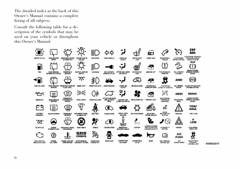
The detailed index at the back of thisOwner's Manual contains a completelisting of all subjects.
Consult the following table for a de-scription of the symbols that may beused on your vehicle or throughoutthis Owner's Manual:
6
WARNINGS ANDCAUTIONSThis Owner's Manual containsWARNINGS against operating proce-dures that could result in a collision orbodily injury. It also contains CAU-TIONS against procedures that couldresult in damage to your vehicle. Ifyou do not read this entire manual,you may miss important information.Observe all Warnings and Cautions.
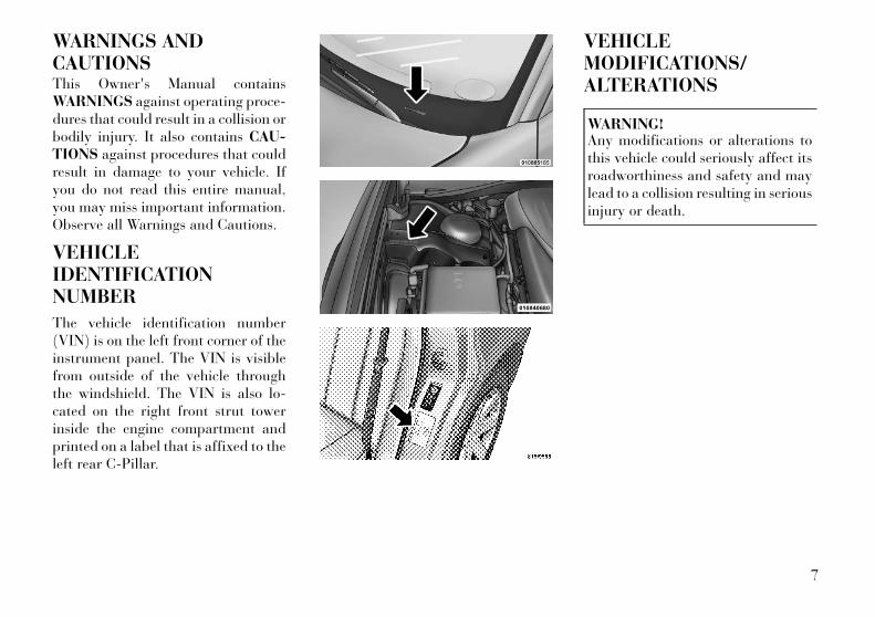
VEHICLEIDENTIFICATIONNUMBER
The vehicle identification number(VIN) is on the left front corner of theinstrument panel. The VIN is visiblefrom outside of the vehicle throughthe windshield. The VIN is also lo-cated on the right front strut towerinside the engine compartment andprinted on a label that is affixed to theleft rear C-Pillar.
VEHICLEMODIFICATIONS/ALTERATIONS
WARNING!Any modifications or alterations tothis vehicle could seriously affect itsroadworthiness and safety and maylead to a collision resulting in seriousinjury or death.
7

8
2
THINGS TO KNOW BEFORE STARTINGYOUR VEHICLE• A WORD ABOUT YOUR KEYS . . . . . . . . . . . . . . . 12
• KEYLESS IGNITION NODE (KIN) . . . . . . . . . . 12
• KEY FOB . . . . . . . . . . . . . . . . . . . . . . . . . . . . . 12
• IGNITION OR ACCESSORY ON MESSAGE . . . . 13
• SENTRY KEY® . . . . . . . . . . . . . . . . . . . . . . . . . . 13
• REPLACEMENT KEYS . . . . . . . . . . . . . . . . . . 14
• CUSTOMER KEY PROGRAMMING . . . . . . . . . 14
• GENERAL INFORMATION . . . . . . . . . . . . . . . . 14
• VEHICLE SECURITY ALARM (forversions/markets, where provided) . . . . . . . . . . . 15
• REARMING OF THE SYSTEM . . . . . . . . . . . . . 15
• TO ARM THE SYSTEM . . . . . . . . . . . . . . . . . . 15
• TO DISARM THE SYSTEM . . . . . . . . . . . . . . . 15
• ILLUMINATED ENTRY (for versions/markets,where provided) . . . . . . . . . . . . . . . . . . . . . . . . . . 16
• REMOTE KEYLESS ENTRY (RKE) . . . . . . . . . . . 16
• TO UNLOCK THE DOORS . . . . . . . . . . . . . . . . 16
• TO LOCK THE DOORS . . . . . . . . . . . . . . . . . . 17
• TO UNLATCH THE TRUNK . . . . . . . . . . . . . . . 17
• PROGRAMMING ADDITIONALTRANSMITTERS . . . . . . . . . . . . . . . . . . . . . . . 17
9
• TRANSMITTER BATTERY REPLACEMENT . . . 17
• GENERAL INFORMATION . . . . . . . . . . . . . . . . 18
• DOOR LOCKS . . . . . . . . . . . . . . . . . . . . . . . . . . . 18
• MANUAL DOOR LOCKS . . . . . . . . . . . . . . . . . 18
• POWER DOOR LOCKS . . . . . . . . . . . . . . . . . . 19
• CHILD-PROTECTION DOOR LOCKSYSTEM — REAR DOORS . . . . . . . . . . . . . . . . 20
• KEYLESS ENTER-N-GO . . . . . . . . . . . . . . . . . . . 20
• WINDOWS . . . . . . . . . . . . . . . . . . . . . . . . . . . . . . 22
• POWER WINDOWS . . . . . . . . . . . . . . . . . . . . . 22
• WIND BUFFETING . . . . . . . . . . . . . . . . . . . . . 24
• TRUNK LOCK AND RELEASE . . . . . . . . . . . . . . . 24
• TRUNK SAFETY WARNING . . . . . . . . . . . . . . . . . 25
• TRUNK EMERGENCY RELEASE . . . . . . . . . . . 25
• OCCUPANT RESTRAINTS . . . . . . . . . . . . . . . . . . 25
• LAP/SHOULDER BELTS . . . . . . . . . . . . . . . . . 26
• LAP/SHOULDER BELT UNTWISTINGPROCEDURE . . . . . . . . . . . . . . . . . . . . . . . . . . 29
• SEAT BELTS IN PASSENGER SEATINGPOSITIONS . . . . . . . . . . . . . . . . . . . . . . . . . . . 29
• AUTOMATIC LOCKING RETRACTOR MODE(ALR) . . . . . . . . . . . . . . . . . . . . . . . . . . . . . . . . 30
• SEAT BELT PRETENSIONERS . . . . . . . . . . . . . 30
• ACTIVE HOOD SYSTEM (for versions/markets, where provided) . . . . . . . . . . . . . . . . 30
10
• ENHANCED SEAT BELT USE REMINDERSYSTEM (BeltAlert®) . . . . . . . . . . . . . . . . . . . . 32
• SEAT BELTS AND PREGNANT WOMEN . . . . . 33
• SUPPLEMENTAL RESTRAINT SYSTEM(SRS) — AIR BAGS . . . . . . . . . . . . . . . . . . . . . 33
• AIR BAG DEPLOYMENT SENSORS ANDCONTROLS . . . . . . . . . . . . . . . . . . . . . . . . . . . 37
• EVENT DATA RECORDER (EDR) . . . . . . . . . . . 41
• CHILD RESTRAINTS . . . . . . . . . . . . . . . . . . . . 42
• ENGINE BREAK-IN RECOMMENDATIONS . . . . . 50
• Additional Requirements For Diesel Engine(for versions/markets, where provided) . . . . . . 50
• SAFETY TIPS . . . . . . . . . . . . . . . . . . . . . . . . . . . 50
• Transporting Passengers . . . . . . . . . . . . . . . . . 50
• Exhaust Gas . . . . . . . . . . . . . . . . . . . . . . . . . . . 51
• Safety Checks You Should Make Inside TheVehicle . . . . . . . . . . . . . . . . . . . . . . . . . . . . . . . 51
• Periodic Safety Checks You Should MakeOutside The Vehicle . . . . . . . . . . . . . . . . . . . . . 53
11
A WORD ABOUT YOURKEYSYour vehicle uses a keyless ignitionsystem. This system consists of a KeyFob with Remote Keyless Entry(RKE) transmitter and a Keyless Ig-nition Node (KIN).
Keyless Enter-N-Go FeatureThis vehicle is equipped with the Key-less Enter-N-Go feature, refer to“Starting Procedure” in “StartingAnd Operating” for further informa-tion.
KEYLESS IGNITION NODE(KIN)This feature allows the driver to oper-ate the ignition switch with the pushof a button, as long as the RemoteKeyless Entry (RKE) transmitter is inthe passenger compartment.
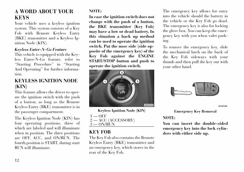
The Keyless Ignition Node (KIN) hasfour operating positions, three ofwhich are labeled and will illuminatewhen in position. The three positionsare OFF, ACC, and ON/RUN. Thefourth position is START, during startRUN will illuminate.
NOTE:
In case the ignition switch does notchange with the push of a button,the RKE transmitter (Key Fob)may have a low or dead battery. Inthis situation a back up methodcan be used to operate the ignitionswitch. Put the nose side (side op-posite of the emergency key) of theKey Fob against the ENGINESTART/STOP button and push tooperate the ignition switch.
KEY FOBThe Key Fob also contains the RemoteKeyless Entry (RKE) transmitter andan emergency key, which stores in therear of the Key Fob.
The emergency key allows for entryinto the vehicle should the battery inthe vehicle or the Key Fob go dead.The emergency key is also for lockingthe glove box. You can keep the emer-gency key with you when valet park-ing.
To remove the emergency key, slidethe mechanical latch on the back ofthe Key Fob sideways with yourthumb and then pull the key out withyour other hand.
NOTE:
You can insert the double-sidedemergency key into the lock cylin-ders with either side up.
Keyless Ignition Node (KIN)
1 — OFF2 — ACC (ACCESSORY)3 — ON/RUN
Emergency Key Removal
12
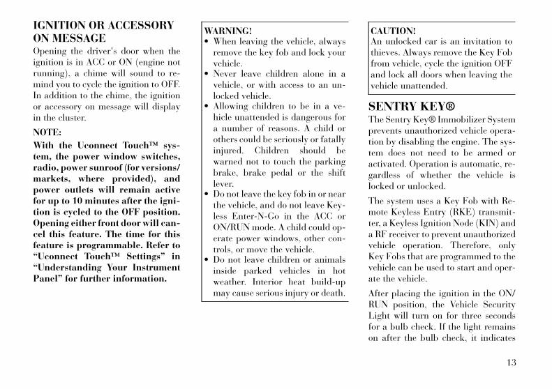
IGNITION OR ACCESSORYON MESSAGEOpening the driver's door when theignition is in ACC or ON (engine notrunning), a chime will sound to re-mind you to cycle the ignition to OFF.In addition to the chime, the ignitionor accessory on message will displayin the cluster.
NOTE:
With the Uconnect Touch™ sys-tem, the power window switches,radio, power sunroof (for versions/markets, where provided), andpower outlets will remain activefor up to 10 minutes after the igni-tion is cycled to the OFF position.Opening either front door will can-cel this feature. The time for thisfeature is programmable. Refer to“Uconnect Touch™ Settings” in“Understanding Your InstrumentPanel” for further information.
WARNING!• When leaving the vehicle, always
remove the key fob and lock yourvehicle.
• Never leave children alone in avehicle, or with access to an un-locked vehicle.
• Allowing children to be in a ve-hicle unattended is dangerous fora number of reasons. A child orothers could be seriously or fatallyinjured. Children should bewarned not to touch the parkingbrake, brake pedal or the shiftlever.
• Do not leave the key fob in or nearthe vehicle, and do not leave Key-less Enter-N-Go in the ACC orON/RUN mode. A child could op-erate power windows, other con-trols, or move the vehicle.
• Do not leave children or animalsinside parked vehicles in hotweather. Interior heat build-upmay cause serious injury or death.
CAUTION!An unlocked car is an invitation tothieves. Always remove the Key Fobfrom vehicle, cycle the ignition OFFand lock all doors when leaving thevehicle unattended.
SENTRY KEY®The Sentry Key® Immobilizer Systemprevents unauthorized vehicle opera-tion by disabling the engine. The sys-tem does not need to be armed oractivated. Operation is automatic, re-gardless of whether the vehicle islocked or unlocked.
The system uses a Key Fob with Re-mote Keyless Entry (RKE) transmit-ter, a Keyless Ignition Node (KIN) anda RF receiver to prevent unauthorizedvehicle operation. Therefore, onlyKey Fobs that are programmed to thevehicle can be used to start and oper-ate the vehicle.
After placing the ignition in the ON/RUN position, the Vehicle SecurityLight will turn on for three secondsfor a bulb check. If the light remainson after the bulb check, it indicates
13

that there is a problem with the elec-tronics. This condition will result inthe engine being shut off after twoseconds.
If the Vehicle Security Light turns onduring normal vehicle operation (ve-hicle running for longer than 10 sec-onds), it indicates that there is a faultin the electronics. Should this occur,have the vehicle serviced as soon aspossible by an authorized dealer.
CAUTION!The Sentry Key® Immobilizer sys-tem is not compatible with someafter-market remote starting sys-tems. Use of these systems may re-sult in vehicle starting problems andloss of security protection.
All of the Key Fobs provided withyour new vehicle have been pro-grammed to the vehicle electronics.
REPLACEMENT KEYS
NOTE:
Only Key Fobs that are pro-grammed to the vehicle electronicscan be used to start and operatethe vehicle. Once a Key Fob is pro-
grammed to a vehicle, it cannot beprogrammed to any other vehicle.
CAUTION!• Always remove the Key Fobs from
the vehicle and lock all doorswhen leaving the vehicle unat-tended.
• For vehicles equipped with Key-less Enter-N-Go, always remem-ber to place the ignition in OFF.
At the time of purchase, the originalowner is provided with a four-digitPersonal Identification Number(PIN). Keep the PIN in a secure loca-tion. This number is required for au-thorized dealer replacement of KeyFobs. Duplication of Key Fobs may beperformed at an authorized dealer,this procedure consists of program-ming a blank Key Fob to the vehicleelectronics. A blank Key Fob is onethat has never been programmed.
NOTE:
When having the Sentry Key® Im-mobilizer System serviced, bringall vehicle Key Fobs with you to theauthorized dealer.
CUSTOMER KEYPROGRAMMINGProgramming Key Fobs or RKEtransmitters may be performed at anauthorized dealer.
GENERAL INFORMATIONThe Sentry Key® operates on a car-rier frequency of 433.92 MHz. TheSentry Key® Immobilizer system willbe used in the following Europeancountries, which apply Directive1999/5/EC: Austria, Belgium, CzechRepublic, Denmark, Finland, France,Germany, Greece, Hungary, Ireland,Italy, Luxembourg, Netherlands, Nor-way, Poland, Portugal, Romania,Russian Federation, Slovenia, Spain,Sweden, Switzerland, Yugoslavia,and United Kingdom.
Operation is subject to the followingconditions:
• This device may not cause harmfulinterference.
• This device must accept any inter-ference that may be received, in-cluding interference that may causeundesired operation.
14

VEHICLE SECURITYALARM (forversions/markets, whereprovided)The Vehicle Security Alarm monitorsthe vehicle doors, hood and trunk forunauthorized entry and the KeylessEnter-N-Go Start/Stop button for un-authorized operation. While the Ve-hicle Security Alarm is armed, inte-rior switches for door locks anddecklid release are disabled. If some-thing triggers the alarm, the VehicleSecurity Alarm will provide the fol-lowing audible and visible signals: thehorn will pulse, the park lampsand/or turn signals will flash, and theVehicle Security Light in the instru-ment cluster will flash.
REARMING OF THESYSTEMIf something triggers the alarm, andno action is taken to disarm it, theVehicle Security Alarm will turn offthe horn after 29 seconds, and turn offall of the visual signals after an addi-tional 31 seconds, then the VehicleSecurity Alarm will rearm itself.
TO ARM THE SYSTEMFollow these steps to arm the VehicleSecurity Alarm:
1. Make sure the vehicle ignition sys-tem is "OFF". (refer to "Starting Pro-cedures" in "Starting And Operating"for further information).
2. Perform one of the followingmethods to lock the vehicle:
•Press LOCK on the interior powerdoor lock switch with the driverand/or passenger door open.
•Press the LOCK button on the exte-rior Passive Entry Door Handle with avalid Key Fob available in the sameexterior zone (refer to "Keyless Enter-N-Go" in "Things To Know BeforeStarting Your Vehicle" for further in-formation).
• Press the LOCK button on the Re-mote Keyless Entry (RKE) transmit-ter.
3. If any doors are open, close them.
TO DISARM THE SYSTEMThe Vehicle Security Alarm can bedisarmed using any of the followingmethods:
• Press the UNLOCK button on theRemote Keyless Entry (RKE)transmitter.
• Grasp the Passive Entry UnlockDoor Handle (refer to "KeylessEnter-N-Go" in "Things To KnowBefore Starting Your Vehicle" forfurther information).
• Cycle the vehicle ignition systemout of the OFF position.
• Press the Keyless Enter-N-GoStart/Stop button (requires atleast one valid Key Fob in thevehicle).
NOTE:
• The driver's door key cylinderand the trunk button on the RKEtransmitter cannot arm or dis-arm the Vehicle Security Alarm.
• When the Vehicle SecurityAlarm is armed, the interiorpower door lock switches willnot unlock the doors.
The Vehicle Security Alarm is de-signed to protect your vehicle; how-ever, you can create conditions wherethe system will give you a false alarm.
15

If one of the previously describedarming sequences has occurred, theVehicle Security Alarm will arm re-gardless of whether you are in thevehicle or not. If you remain in thevehicle and open a door, the alarmwill sound. If this occurs, disarm theVehicle Security Alarm.
If the Vehicle Security Alarm is armedand the battery becomes discon-nected, the Vehicle Security Alarmwill remain armed when the battery isreconnected; the exterior lights willflash, the horn will sound. If this oc-curs, disarm the Vehicle SecurityAlarm.
ILLUMINATED ENTRY(for versions/markets,where provided)The courtesy lights will turn on whenyou use the Remote Keyless Entry(RKE) transmitter to unlock thedoors or open any door.
This feature also turns on the ap-proach lighting in the outside mirrors(for versions/markets, where pro-vided). Refer to “Mirrors” in “Under-
standing The Features Of Your Ve-hicle” for further information.
The lights will fade to off after ap-proximately 30 seconds or they willimmediately fade to off once the igni-tion is cycled to the ON/RUN positionfrom the OFF position.
NOTE:
• The front courtesy overheadconsole and door courtesy lightswill turn on if the dimmer con-trol is in the "Dome ON" position(extreme top position).
• The Illuminated Entry systemwill not operate if the dimmercontrol is in the “Dome defeat”position (extreme bottom posi-tion).
REMOTE KEYLESSENTRY (RKE)The RKE system allows you to lock orunlock the doors, open the trunk, oractivate the Panic Alarm from dis-tances up to approximately 10 m us-ing a hand-held Key Fob with RKEtransmitter. The RKE transmitter
does not need to be pointed at thevehicle to activate the system.
NOTE:
Driving at speeds 8 km/h andabove disables the system from re-sponding to all RKE transmitterbuttons for all RKE transmitters.
TO UNLOCK THE DOORSPress and release the UNLOCK but-ton on the RKE transmitter once tounlock the driver's door or twicewithin five seconds to unlock alldoors. The turn signal lights will flashto acknowledge the unlock signal.The illuminated entry system will alsoturn on.
If the vehicle is equipped with PassiveEntry, refer to “Keyless Enter-N-Go”
Key Fob With RKE Transmitter
16
under “Things To Know Before Start-ing Your Vehicle” for further informa-tion.
Remote Key Unlock, DriverDoor/All Doors 1st PressThis feature lets you program the sys-tem to unlock either the driver's dooror all doors on the first press of theUNLOCK button on the RKE trans-mitter. To change the current setting,refer to “Uconnect Touch™ Settings”in “Understanding Your InstrumentPanel” for further information.
Flash Lights With LockThis feature will cause the turn signallights to flash when the doors arelocked or unlocked with the RKEtransmitter. This feature can beturned on or turned off. To change thecurrent setting, refer to “UconnectTouch™ Settings” in “UnderstandingYour Instrument Panel” for furtherinformation.
Turn Headlights On With RemoteKey UnlockThis feature activates the headlightsfor up to 90 seconds when the doorsare unlocked with the RKE transmit-
ter. The time for this feature is pro-grammable on vehicles equippedthrough Uconnect Touch™. Tochange the current setting, refer to“Uconnect Touch™ Settings” in “Un-derstanding Your Instrument Panel”for further information.
TO LOCK THE DOORSPress and release the LOCK button onthe RKE transmitter to lock all doors.The turn signal lights will flash toacknowledge the signal.
If the vehicle is equipped with PassiveEntry, refer to “Keyless Enter-N-Go”under “Things To Know Before Start-ing Your Vehicle” for further informa-tion.
TO UNLATCH THE TRUNKPress the TRUNK button on the RKEtransmitter two times within five sec-onds to unlatch the trunk.
If the vehicle is equipped with PassiveEntry, refer to “Keyless Enter-N-Go”under “Things To Know Before Start-ing Your Vehicle” for further informa-tion.
PROGRAMMINGADDITIONALTRANSMITTERSProgramming Key Fobs or RKEtransmitters may be performed at anauthorized dealer.
TRANSMITTER BATTERYREPLACEMENTThe recommended replacement bat-tery is one CR2032 battery.
NOTE:
• Perchlorate Material — specialhandling may apply. Batteriescould contain dangerous mate-rials. Please dispose of them ac-cording to respect for environ-ment and local laws.
• Do not touch the battery termi-nals that are on the back hous-ing or the printed circuit board.
1. Remove the emergency key bysliding the mechanical latch on theback of the RKE transmitter sidewayswith your thumb and then pull thekey out with your other hand.
2. Insert the tip of the emergency keyor a #2 flat blade screwdriver into the
17
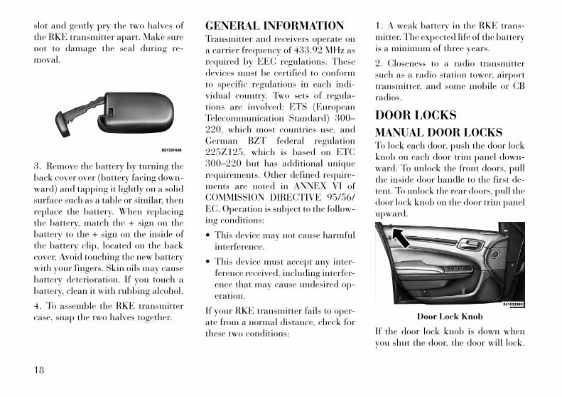
slot and gently pry the two halves ofthe RKE transmitter apart. Make surenot to damage the seal during re-moval.
3. Remove the battery by turning theback cover over (battery facing down-ward) and tapping it lightly on a solidsurface such as a table or similar, thenreplace the battery. When replacingthe battery, match the + sign on thebattery to the + sign on the inside ofthe battery clip, located on the backcover. Avoid touching the new batterywith your fingers. Skin oils may causebattery deterioration. If you touch abattery, clean it with rubbing alcohol.
4. To assemble the RKE transmittercase, snap the two halves together.
GENERAL INFORMATIONTransmitter and receivers operate ona carrier frequency of 433.92 MHz asrequired by EEC regulations. Thesedevices must be certified to conformto specific regulations in each indi-vidual country. Two sets of regula-tions are involved: ETS (EuropeanTelecommunication Standard) 300–220, which most countries use, andGerman BZT federal regulation225Z125, which is based on ETC300–220 but has additional uniquerequirements. Other defined require-ments are noted in ANNEX VI ofCOMMISSION DIRECTIVE 95/56/EC. Operation is subject to the follow-ing conditions:
• This device may not cause harmfulinterference.
• This device must accept any inter-ference received, including interfer-ence that may cause undesired op-eration.
If your RKE transmitter fails to oper-ate from a normal distance, check forthese two conditions:
1. A weak battery in the RKE trans-mitter. The expected life of the batteryis a minimum of three years.
2. Closeness to a radio transmittersuch as a radio station tower, airporttransmitter, and some mobile or CBradios.
DOOR LOCKS
MANUAL DOOR LOCKSTo lock each door, push the door lockknob on each door trim panel down-ward. To unlock the front doors, pullthe inside door handle to the first de-tent. To unlock the rear doors, pull thedoor lock knob on the door trim panelupward.
If the door lock knob is down whenyou shut the door, the door will lock.
Door Lock Knob
18

Therefore, make sure the Key Fob isnot inside the vehicle before closingthe door.
WARNING!• For personal security and safety
in the event of an accident, lockthe vehicle doors before you driveas well as when you park andleave the vehicle.
• When leaving the vehicle, alwaysremove the key fob and lock yourvehicle.
• Never leave children alone in avehicle, or with access to an un-locked vehicle.
• Allowing children to be in a vehicleunattended is dangerous for anumber of reasons. A child or oth-ers could be seriously or fatally in-jured. Children should be warnednot to touch the parking brake,brake pedal or the shift lever.
• Do not leave the key fob in or nearthe vehicle, and do not leave Key-less Enter-N-Go in the ACC orON/RUN mode. A child could op-erate power windows, other con-trols, or move the vehicle.
POWER DOOR LOCKSA power door lock switch is on eachfront door trim panel. Use this switchto lock or unlock the doors.
The doors can also be locked and un-locked with the Keyless Enter-N-Go(Passive Entry) system. For furtherinformation, refer to “Keyless Enter-N-Go” in “Things To Know BeforeStarting Your Vehicle”.
If you press the power door lockswitch while the ignition is in the ACCor ON/RUN position, and any frontdoor is open, the power locks will notoperate. This prevents you from acci-dentally locking the Key Fob in thevehicle. Cycling the ignition to theOFF position or closing the door willallow the locks to operate. If a door isopen, and the ignition is in the ACC or
ON/RUN position, a chime will soundas a reminder to remove the Key Fob.
Automatic Door Locks (forversions/markets, whereprovided)When enabled, the door locks willlock automatically when the vehicle'sspeed exceeds 24 km/h. The autodoor lock feature can be enabled ordisabled by your authorized dealerper written request of the customer.Please see your authorized dealer forservice.
Automatic Unlock Doors On ExitThe doors will unlock automaticallyon vehicles with power door locks if:
1. The Automatic Unlock Doors OnExit feature is enabled.
2. The transmission was in gear andthe vehicle speed returned to 0 km/h.
3. The transmission is in NEUTRALor PARK.
4. The driver door is opened.
5. The doors were not previously un-locked.
6. The vehicle speed is 0 km/h.
Power Door Lock Switch
19

Automatic Unlock Doors On ExitProgrammingTo change the current setting, refer to“Uconnect Touch™ Settings” in “Un-derstanding Your Instrument Panel”for further information.
NOTE:
Use the Automatic Unlock DoorsOn Exit feature in accordance withlocal laws.
CHILD-PROTECTIONDOOR LOCK SYSTEM —REAR DOORSTo provide a safer environment forsmall children riding in the rear seats,the rear doors are equipped withChild-Protection Door Lock system.
To Engage Or Disengage TheChild-Protection Door LockSystem
1. Open the rear door.
2. Insert the tip of the emergency keyinto the lock and rotate to the LOCKor UNLOCK position.
3. Repeat steps 1 and 2 for the oppo-site rear door.
WARNING!Avoid trapping anyone in a vehiclein a collision. Remember that therear doors can only be opened fromthe outside when the Child-Protection locks are engaged(locked).
NOTE:
For emergency exit from the rearseats when the Child-ProtectionDoor Lock System is engaged,manually raise the door lock knobto the unlocked position, roll downthe window, and open the door us-ing the outside door handle.
KEYLESS ENTER-N-GOThe Passive Entry system is an en-hancement to the vehicle’s Remote
Keyless Entry (RKE) system and afeature of Keyless Enter-N-Go. Thisfeature allows you to lock and unlockthe vehicle’s door(s) without havingto press the RKE transmitter lock orunlock buttons.
NOTE:
• Passive Entry may be pro-grammed ON/OFF; refer to“Uconnect Touch™ Settings” in“Understanding Your Instru-ment Panel” for further infor-mation.
• If wearing gloves on your hands,or if it has been raining on thePassive Entry door handle, theunlock sensitivity can be af-fected, resulting in a slower re-sponse time.
• If the vehicle is unlocked by theRKE transmitter or Passive En-try and no door goes ajar within60 seconds, the vehicle will re-lock and for versions/markets,where provided will arm thetheft alarm.
Child-Protection Door Lock Function
20
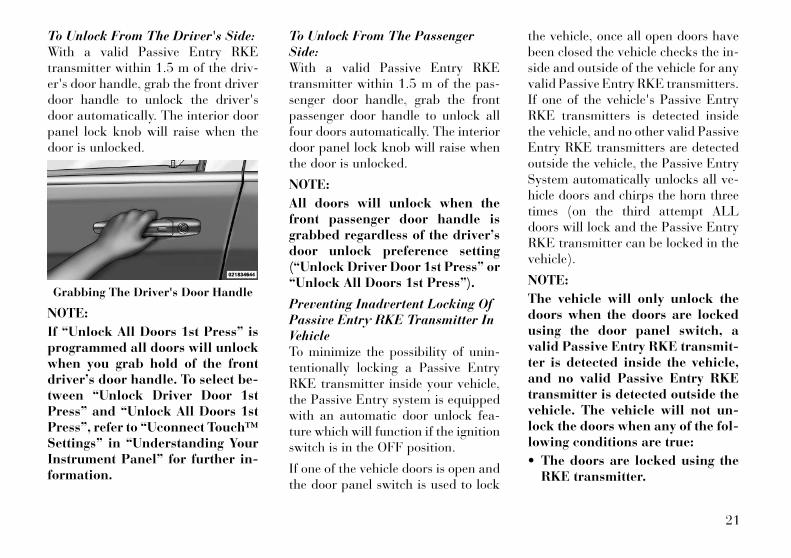
To Unlock From The Driver's Side:With a valid Passive Entry RKEtransmitter within 1.5 m of the driv-er's door handle, grab the front driverdoor handle to unlock the driver'sdoor automatically. The interior doorpanel lock knob will raise when thedoor is unlocked.
NOTE:
If “Unlock All Doors 1st Press” isprogrammed all doors will unlockwhen you grab hold of the frontdriver’s door handle. To select be-tween “Unlock Driver Door 1stPress” and “Unlock All Doors 1stPress”, refer to “Uconnect Touch™Settings” in “Understanding YourInstrument Panel” for further in-formation.
To Unlock From The PassengerSide:With a valid Passive Entry RKEtransmitter within 1.5 m of the pas-senger door handle, grab the frontpassenger door handle to unlock allfour doors automatically. The interiordoor panel lock knob will raise whenthe door is unlocked.
NOTE:
All doors will unlock when thefront passenger door handle isgrabbed regardless of the driver’sdoor unlock preference setting(“Unlock Driver Door 1st Press” or“Unlock All Doors 1st Press”).
Preventing Inadvertent Locking OfPassive Entry RKE Transmitter InVehicleTo minimize the possibility of unin-tentionally locking a Passive EntryRKE transmitter inside your vehicle,the Passive Entry system is equippedwith an automatic door unlock fea-ture which will function if the ignitionswitch is in the OFF position.
If one of the vehicle doors is open andthe door panel switch is used to lock
the vehicle, once all open doors havebeen closed the vehicle checks the in-side and outside of the vehicle for anyvalid Passive Entry RKE transmitters.If one of the vehicle's Passive EntryRKE transmitters is detected insidethe vehicle, and no other valid PassiveEntry RKE transmitters are detectedoutside the vehicle, the Passive EntrySystem automatically unlocks all ve-hicle doors and chirps the horn threetimes (on the third attempt ALLdoors will lock and the Passive EntryRKE transmitter can be locked in thevehicle).
NOTE:
The vehicle will only unlock thedoors when the doors are lockedusing the door panel switch, avalid Passive Entry RKE transmit-ter is detected inside the vehicle,and no valid Passive Entry RKEtransmitter is detected outside thevehicle. The vehicle will not un-lock the doors when any of the fol-lowing conditions are true:
• The doors are locked using theRKE transmitter.
Grabbing The Driver's Door Handle
21
• The doors are locked using theLOCK button on the Passive En-try door handles.
• The doors are manually lockedusing the door lock knobs.
• There is a valid Passive EntryRKE transmitter outside the ve-hicle and within 1.5 m of eitherPassive Entry door handle.
• Three attempts are made to lockthe doors using the door panelswitch and then close the doors.
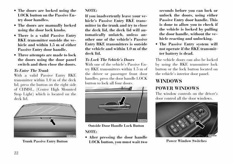
To Enter The TrunkWith a valid Passive Entry RKEtransmitter within 1.0 m of the decklid, press the button on the right sideof CHMSL, (Center High MountedStop Light) which is located on thedeck lid.
NOTE:
If you inadvertently leave your ve-hicle's Passive Entry RKE trans-mitter in the trunk and try to closethe deck lid, the deck lid will au-tomatically unlatch, unless an-other one of the vehicle’s PassiveEntry RKE transmitters is outsidethe vehicle and within 1.0 m of thedeck lid.
To Lock The Vehicle’s DoorsWith one of the vehicle’s Passive En-try RKE transmitters within 1.5 m ofthe driver or passenger front doorhandles, press the door handle LOCKbutton to lock all four doors.
NOTE:
• After pressing the door handleLOCK button, you must wait two
seconds before you can lock orunlock the doors, using eitherPassive Entry door handle. Thisis done to allow you to check ifthe vehicle is locked by pullingthe door handle, without the ve-hicle reacting and unlocking.
• The Passive Entry system willnot operate if the RKE transmit-ter battery is dead.
The vehicle doors can also be lockedby using the RKE transmitter lockbutton or the lock button located onthe vehicle’s interior door panel.
WINDOWS
POWER WINDOWSThe window controls on the driver'sdoor control all the door windows.
Trunk Passive Entry Button
Outside Door Handle Lock Button
Power Window Switches
22
There are single window controls oneach passenger door trim panel,which operate the passenger doorwindows. The window controls willoperate only when the ignition is inthe ACC or ON/RUN position.
NOTE:
For vehicles equipped with theUconnect Touch™, the power win-dow switches will remain activefor up to 10 minutes after the igni-tion is cycled to the OFF position.Opening either front door will can-cel this feature. The time is pro-grammable. Refer to “UconnectTouch™ Settings” in “Under-standing Your Instrument Panel”for further information.
WARNING!Never leave children in a vehiclewith the Key Fob. Occupants, par-ticularly unattended children, canbecome entrapped by the windowswhile operating the power windowswitches. Such entrapment may re-sult in serious injury or death.
AUTO-Down FeatureThe driver door power window switchand some model passenger doorpower window switches have anAUTO-down feature. Press the win-dow switch to the second detent, re-lease, and the window will go downautomatically.
To open the window part way, pressthe window switch to the first detentand release it when you want the win-dow to stop.
To stop the window from going all theway down during the AUTO-downoperation, pull up on the switchbriefly.
AUTO-Up Feature WithAnti-Pinch Protection (forversions/markets, whereprovided)Lift the window switch to the seconddetent, release, and the window willgo up automatically.
To stop the window from going all theway up during the AUTO-up opera-tion, push down on the switch briefly.
To close the window part way, lift thewindow switch to the first detent andrelease it when you want the windowto stop.
NOTE:
• If the window runs into any ob-stacle during auto-closure, itwill reverse direction and thengo back down. Remove the ob-stacle and use the windowswitch again to close the win-dow.
• Any impact due to rough roadconditions may trigger the auto-reverse function unexpectedlyduring auto-closure. If this hap-pens, pull the switch lightly tothe first detent and hold to closethe window manually.
WARNING!There is no anti-pinch protectionwhen the window is almost closed.Be sure to clear all objects from thewindow before closing.
23
Reset Auto UpShould the Auto Up feature stopworking, the window probably needsto be reset. To reset Auto Up:
1. Pull the window switch up to closethe window completely and continueto hold the switch up for an additionaltwo seconds after the window isclosed.
2. Push the window switch downfirmly to the second detent to open thewindow completely and continue tohold the switch down for an addi-tional two seconds after the window isfully open.
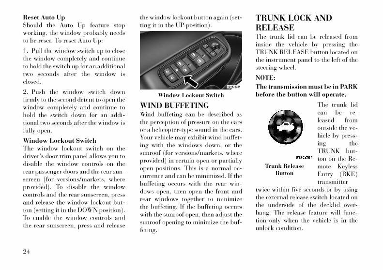
Window Lockout SwitchThe window lockout switch on thedriver's door trim panel allows you todisable the window controls on therear passenger doors and the rear sun-screen (for versions/markets, whereprovided). To disable the windowcontrols and the rear sunscreen, pressand release the window lockout but-ton (setting it in the DOWN position).To enable the window controls andthe rear sunscreen, press and release
the window lockout button again (set-ting it in the UP position).
WIND BUFFETINGWind buffeting can be described asthe perception of pressure on the earsor a helicopter-type sound in the ears.Your vehicle may exhibit wind buffet-ing with the windows down, or thesunroof (for versions/markets, whereprovided) in certain open or partiallyopen positions. This is a normal oc-currence and can be minimized. If thebuffeting occurs with the rear win-dows open, then open the front andrear windows together to minimizethe buffeting. If the buffeting occurswith the sunroof open, then adjust thesunroof opening to minimize the buf-feting.
TRUNK LOCK ANDRELEASEThe trunk lid can be released frominside the vehicle by pressing theTRUNK RELEASE button located onthe instrument panel to the left of thesteering wheel.
NOTE:
The transmission must be in PARKbefore the button will operate.
The trunk lidcan be re-leased fromoutside the ve-hicle by press-ing theTRUNK but-ton on the Re-mote KeylessEntry (RKE)transmitter
twice within five seconds or by usingthe external release switch located onthe underside of the decklid over-hang. The release feature will func-tion only when the vehicle is in theunlock condition.
Window Lockout Switch
Trunk ReleaseButton
24
With the ignition in the ON/RUN po-sition, the Trunk Open symbol willdisplay in the instrument cluster indi-cating that the trunk is open. Theodometer display will reappear oncethe trunk is closed.
With the ignition in the OFF position,the Trunk Open symbol will displayuntil the trunk is closed.
Refer to “Keyless Enter-N-Go” in“Things To Know Before StartingYour Vehicle” for more informationon trunk operation with the PassiveEntry feature.
TRUNK SAFETYWARNING
WARNING!Do not allow children to have access tothe trunk, either by climbing into thetrunk from outside, or through theinside of the vehicle. Always close thetrunk lid when your vehicle is unat-tended. Once in the trunk, young chil-dren may not be able to escape, even ifthey entered through the rear seat. Iftrapped in the trunk, children can diefrom suffocation or heat stroke.
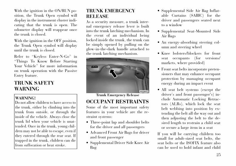
TRUNK EMERGENCYRELEASEAs a security measure, a trunk inter-nal emergency release lever is builtinto the trunk latching mechanism. Inthe event of an individual beinglocked inside the trunk, the trunk canbe simply opened by pulling on theglow-in-the-dark handle attached tothe trunk latching mechanism.
OCCUPANT RESTRAINTSSome of the most important safetyfeatures in your vehicle are the re-straint systems:
• Three-point lap and shoulder beltsfor the driver and all passengers
• Advanced Front Air Bags for driverand front passenger
• Supplemental Driver Side Knee AirBag
• Supplemental Side Air Bag Inflat-able Curtains (SABIC) for thedriver and passengers seated nextto a window
• Supplemental Seat-Mounted SideAir Bags
• An energy-absorbing steering col-umn and steering wheel
• Knee bolsters/blockers for frontseat occupants (for versions/markets, where provided)
• Front seat belts incorporate preten-sioners that may enhance occupantprotection by managing occupantenergy during an impact event
• All seat belt systems (except thedriver’s and front passenger's) in-clude Automatic Locking Retrac-tors (ALRs), which lock the seatbelt webbing into position by ex-tending the belt all the way out andthen adjusting the belt to the de-sired length to restrain a child seator secure a large item in a seat
If you will be carrying children toosmall for adult-sized seat belts, theseat belts or the ISOFIX feature alsocan be used to hold infant and child
Trunk Emergency Release
25
restraint systems. For more informa-tion, refer to ISOFIX — Child SeatAnchorage System.
NOTE:
The Advanced Front Air Bags havea multistage inflator design. Thisallows the air bag to have differentrates of inflation based on severalfactors, including the severity andtype of collision.
Please pay close attention to the infor-mation in this section. It tells you howto use your restraint system properly,to keep you and your passengers assafe as possible.
WARNING!In a collision, you and your passen-gers can suffer much greater injuriesif you are not properly buckled up.You can strike the interior of yourvehicle or other passengers, or youcan be thrown out of the vehicle. Al-ways be sure you and others in yourvehicle are buckled up properly.
Buckle up even though you are anexcellent driver, even on short trips.Someone on the road may be a poordriver and cause a collision that in-cludes you. This can happen far awayfrom home or on your own street.
Research has shown that seat beltssave lives, and they can reduce theseriousness of injuries in a collision.Some of the worst injuries happenwhen people are thrown from the ve-hicle. Seat belts reduce the possibilityof ejection and the risk of injurycaused by striking the inside of thevehicle. Everyone in a motor vehicleshould be belted at all times.
LAP/SHOULDER BELTSAll seating positions in your vehicleare equipped with combination lap/shoulder belts.
The belt webbing retractor is de-signed to lock during very suddenstops or impacts. This feature allowsthe shoulder part of the belt to movefreely with you under normal condi-tions. However, in a collision, the belt
will lock and reduce your risk of strik-ing the inside of the vehicle or beingthrown out.
WARNING!• It is dangerous to ride in a cargo
area, inside or outside of a vehicle.In a collision, people riding inthese areas are more likely to beseriously injured or killed.
• Do not allow people to ride in anyarea of your vehicle that is notequipped with seats and seat belts.
• Be sure everyone in your vehicle isin a seat and using a seat beltproperly.
• Wearing a seat belt incorrectly isdangerous. Seat belts are designedto go around the large bones ofyour body. These are the strongestparts of your body and can takethe forces of a collision best.
(Continued)
26
WARNING! (Continued)• Wearing your belt in the wrong
place could make your injuries ina collision much worse. You mightsuffer internal injuries, or youcould even slide out of part of thebelt. Follow these instructions towear your seat belt safely and tokeep your passengers safe, too.
• Two people should never be beltedinto a single seat belt. People beltedtogether can crash into one anotherin a collision, hurting one anotherbadly. Never use a lap/shoulder beltor a lap belt for more than oneperson, no matter what their size.
Lap/Shoulder Belt OperatingInstructions
1. Enter the vehicle and close thedoor. Sit back and adjust the frontseat.
2. The seat belt latch plate is abovethe back of your seat. Grasp the latchplate and pull out the belt. Slide thelatch plate up the webbing as far asnecessary to make the belt go aroundyour lap.
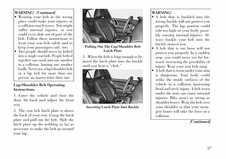
3. When the belt is long enough to fit,insert the latch plate into the buckleuntil you hear a “click.”
WARNING!• A belt that is buckled into the
wrong buckle will not protect youproperly. The lap portion couldride too high on your body, possi-bly causing internal injuries. Al-ways buckle your belt into thebuckle nearest you.
• A belt that is too loose will notprotect you properly. In a suddenstop, you could move too far for-ward, increasing the possibility ofinjury. Wear your seat belt snug.
• A belt that is worn under your armis dangerous. Your body couldstrike the inside surfaces of thevehicle in a collision, increasinghead and neck injury. A belt wornunder the arm can cause internalinjuries. Ribs aren't as strong asshoulder bones. Wear the belt overyour shoulder so that your stron-gest bones will take the force in acollision.
(Continued)
Pulling Out The Lap/Shoulder BeltLatch Plate
Inserting Latch Plate Into Buckle
27
WARNING! (Continued)• A shoulder belt placed behind you
will not protect you from injuryduring a collision. You are morelikely to hit your head in a colli-sion if you do not wear your shoul-der belt. The lap and shoulder beltare meant to be used together.
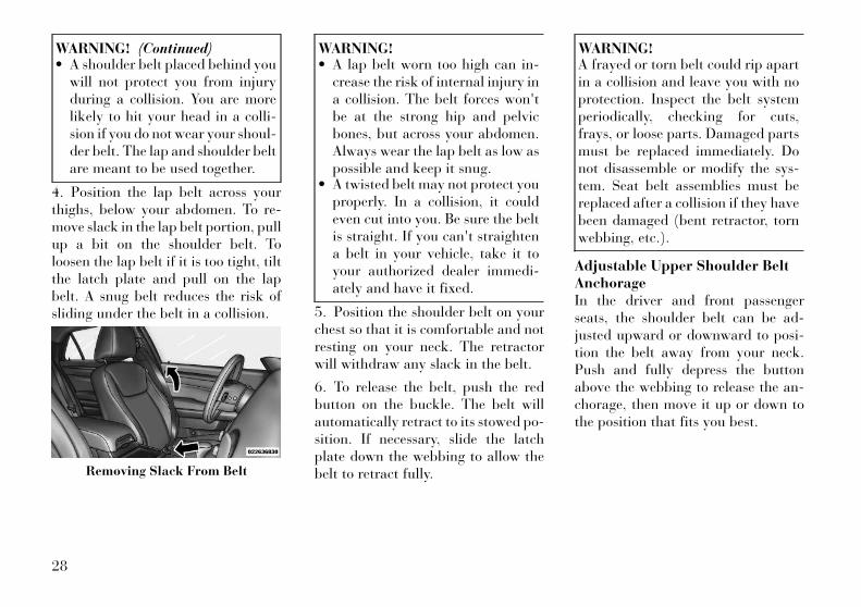
4. Position the lap belt across yourthighs, below your abdomen. To re-move slack in the lap belt portion, pullup a bit on the shoulder belt. Toloosen the lap belt if it is too tight, tiltthe latch plate and pull on the lapbelt. A snug belt reduces the risk ofsliding under the belt in a collision.
WARNING!• A lap belt worn too high can in-
crease the risk of internal injury ina collision. The belt forces won'tbe at the strong hip and pelvicbones, but across your abdomen.Always wear the lap belt as low aspossible and keep it snug.
• A twisted belt may not protect youproperly. In a collision, it couldeven cut into you. Be sure the beltis straight. If you can't straightena belt in your vehicle, take it toyour authorized dealer immedi-ately and have it fixed.
5. Position the shoulder belt on yourchest so that it is comfortable and notresting on your neck. The retractorwill withdraw any slack in the belt.
6. To release the belt, push the redbutton on the buckle. The belt willautomatically retract to its stowed po-sition. If necessary, slide the latchplate down the webbing to allow thebelt to retract fully.
WARNING!A frayed or torn belt could rip apartin a collision and leave you with noprotection. Inspect the belt systemperiodically, checking for cuts,frays, or loose parts. Damaged partsmust be replaced immediately. Donot disassemble or modify the sys-tem. Seat belt assemblies must bereplaced after a collision if they havebeen damaged (bent retractor, tornwebbing, etc.).
Adjustable Upper Shoulder BeltAnchorageIn the driver and front passengerseats, the shoulder belt can be ad-justed upward or downward to posi-tion the belt away from your neck.Push and fully depress the buttonabove the webbing to release the an-chorage, then move it up or down tothe position that fits you best.
Removing Slack From Belt
28
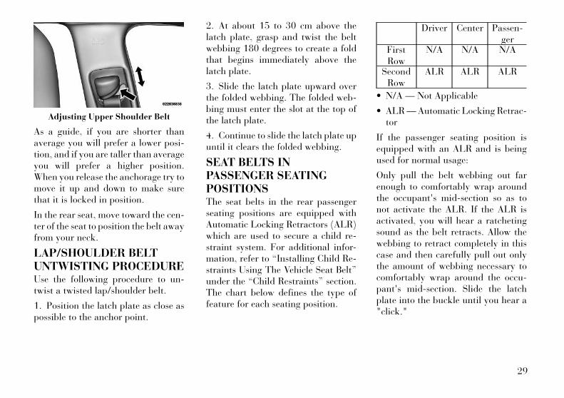
As a guide, if you are shorter thanaverage you will prefer a lower posi-tion, and if you are taller than averageyou will prefer a higher position.When you release the anchorage try tomove it up and down to make surethat it is locked in position.
In the rear seat, move toward the cen-ter of the seat to position the belt awayfrom your neck.
LAP/SHOULDER BELTUNTWISTING PROCEDUREUse the following procedure to un-twist a twisted lap/shoulder belt.
1. Position the latch plate as close aspossible to the anchor point.
2. At about 15 to 30 cm above thelatch plate, grasp and twist the beltwebbing 180 degrees to create a foldthat begins immediately above thelatch plate.
3. Slide the latch plate upward overthe folded webbing. The folded web-bing must enter the slot at the top ofthe latch plate.
4. Continue to slide the latch plate upuntil it clears the folded webbing.
SEAT BELTS INPASSENGER SEATINGPOSITIONSThe seat belts in the rear passengerseating positions are equipped withAutomatic Locking Retractors (ALR)which are used to secure a child re-straint system. For additional infor-mation, refer to “Installing Child Re-straints Using The Vehicle Seat Belt”under the “Child Restraints” section.The chart below defines the type offeature for each seating position.
Driver Center Passen-ger
FirstRow
N/A N/A N/A
SecondRow
ALR ALR ALR
• N/A — Not Applicable
• ALR — Automatic Locking Retrac-tor
If the passenger seating position isequipped with an ALR and is beingused for normal usage:
Only pull the belt webbing out farenough to comfortably wrap aroundthe occupant's mid-section so as tonot activate the ALR. If the ALR isactivated, you will hear a ratchetingsound as the belt retracts. Allow thewebbing to retract completely in thiscase and then carefully pull out onlythe amount of webbing necessary tocomfortably wrap around the occu-pant's mid-section. Slide the latchplate into the buckle until you hear a"click."
Adjusting Upper Shoulder Belt
29

AUTOMATIC LOCKINGRETRACTOR MODE (ALR)In this mode, the shoulder belt is au-tomatically pre-locked. The belt willstill retract to remove any slack in theshoulder belt. The Automatic LockingMode is available on all passenger-seating positions with a combinationlap/shoulder belt. Use the AutomaticLocking Mode anytime a child safetyseat is installed in a seating positionthat has a belt with this feature. Chil-dren 12 years old and under shouldalways be properly restrained in therear seat.
How To Engage The AutomaticLocking Mode
1. Buckle the combination lap andshoulder belt.
2. Grasp the shoulder portion andpull downward until the entire belt isextracted.
3. Allow the belt to retract. As thebelt retracts, you will hear a clickingsound. This indicates the safety belt isnow in the Automatic Locking Mode.
How To Disengage The AutomaticLocking ModeUnbuckle the combination lap/shoulder belt and allow it to retractcompletely to disengage the Auto-matic Locking Mode and activate thevehicle sensitive (emergency) lockingmode.
WARNING!• The belt and retractor assembly
must be replaced if the seat beltassembly Automatic Locking Re-tractor (ALR) feature or any otherseat belt function is not workingproperly when checked accordingto the procedures in the ServiceManual.
• Failure to replace the belt and re-tractor assembly could increasethe risk of injury in collisions.
SEAT BELTPRETENSIONERSThe seat belts for both front seatingpositions are equipped with preten-sioning devices that are designed toremove slack from the seat belt in theevent of a collision. These devices mayimprove the performance of the seat
belt by assuring that the belt is tightabout the occupant early in a colli-sion. Pretensioners work for all sizeoccupants, including those in childrestraints.
NOTE:
These devices are not a substitutefor proper seat belt placement bythe occupant. The seat belt stillmust be worn snugly and posi-tioned properly.
The pretensioners are triggered by theOccupant Restraint Controller(ORC). Like the air bags, the preten-sioners are single use items. A de-ployed pretensioner or a deployed airbag must be replaced immediately.
ACTIVE HOOD SYSTEM(for versions/markets,where provided)The Active Hood system is intended toenhance pedestrian protection by el-evating the vehicle’s hood upon animpact with a pedestrian or other ob-ject. The system is automatically acti-vated when the vehicle is movingwithin a specified vehicle speed range.In order to detect a range of pedestri-
30
ans, other objects that are impactedmay result in an Active Hood deploy-ment.
Deployment Sensors And ControlsThe Occupant Restraint Controller(ORC) determines if deployment ofthe actuators in a frontal impact isrequired. Based on the impact sensorssignals, the ORC determines when todeploy the actuators. The impact sen-sors are located within the front bum-per area.
The ORC monitors the readiness ofthe electronic parts of the Active Hoodsystem whenever the ignition switch isin the START or ON/RUN position. Ifthe key is in the LOCK position, in theACC position, or not in the ignition,the Active Hood system is not on andthe Active Hood will not deploy.
The ORC contains a backup powersupply system that may deploy theactuators even if the battery losespower or it becomes disconnectedprior to deployment.
Service Active Hood SystemIf the ORC has deployed the ActiveHood, or if it detects a malfunction in
any part of the system, it turns on theAir Bag Warning Light and it willdisplay the “SERVICE ACTIVEHOOD” message in the Electronic Ve-hicle Information Center (EVIC), forversions/markets, where provided. Asingle chime will sound if the Air BagWarning Light comes on again afterinitial startup. It also includes diag-nostics that will illuminate the Air BagWarning Light if a malfunction isnoted that could affect the ActiveHood system. The diagnostics also re-cord the nature of the malfunction. Ifthe Air Bag Warning Light is illumi-nated, or if “SERVICE ACTIVEHOOD” appears in the EVIC, seeyour authorized dealer.
In the event of an Active Hood deploy-ment, the vehicle should be servicedby an authorized dealer. The hoodhinges must be serviced and the ac-tuator assemblies replaced to restoresystem functionality.
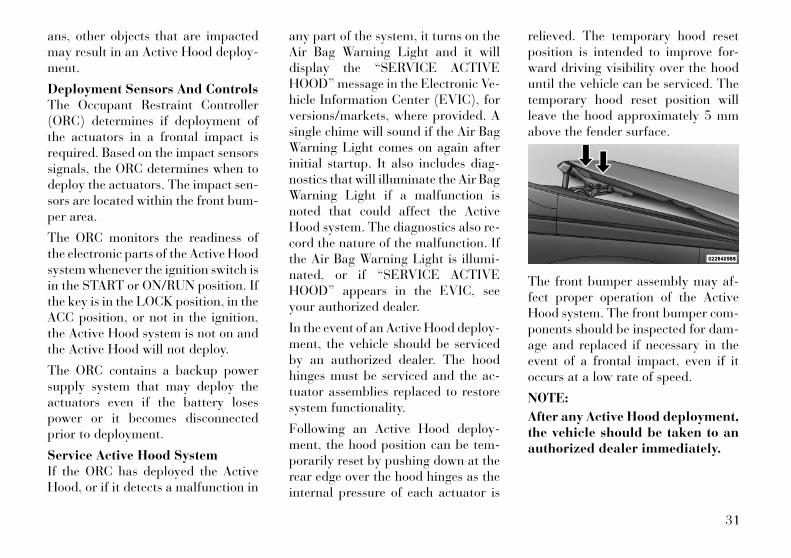
Following an Active Hood deploy-ment, the hood position can be tem-porarily reset by pushing down at therear edge over the hood hinges as theinternal pressure of each actuator is
relieved. The temporary hood resetposition is intended to improve for-ward driving visibility over the hooduntil the vehicle can be serviced. Thetemporary hood reset position willleave the hood approximately 5 mmabove the fender surface.
The front bumper assembly may af-fect proper operation of the ActiveHood system. The front bumper com-ponents should be inspected for dam-age and replaced if necessary in theevent of a frontal impact, even if itoccurs at a low rate of speed.
NOTE:
After any Active Hood deployment,the vehicle should be taken to anauthorized dealer immediately.
31
CAUTION!To prevent possible damage, do notslam the rear of the hood to reset it.Press the rear of the hood down untilit is approximately 5 mm above thefender. This should secure both hoodhinge reset mechanisms.
WARNING!• Ignoring the Air Bag Warning
Light in your instrument panel orthe “SERVICE ACTIVE HOOD”message in the EVIC could meanyou won’t have the Active Hood toenhance pedestrian protection. Ifthe light does not come on as a bulbcheck when the ignition is firstturned on, stays on after you startthe vehicle, or if it comes on as youdrive, see your authorized dealer.
• Modifications to any part of theActive Hood system could cause itto fail when you need it. Do notmodify the components or wiring.Do not modify the front bumper,vehicle body structure, or add anaftermarket front bumper or cover.
(Continued)
WARNING! (Continued)• It is dangerous to try to repair any
part of the Active Hood systemyourself. Be sure to tell anyonewho works on your vehicle that ithas an Active Hood system.
• Do not attempt to modify any partof your Active Hood system. TheActive Hood may deploy acciden-tally or may not function properlyif modifications are made. Takeyour vehicle to an authorizeddealer for any hood service.
• Drivers must be aware of pedestri-ans. Always be sure to check forpedestrians, animals, other ve-hicles, and obstructions. You areresponsible for safety and mustcontinue to pay attention to yoursurroundings. Failure to do so canresult in serious injury or death.
ENHANCED SEAT BELTUSE REMINDER SYSTEM(BeltAlert®)BeltAlert® is a feature intended to re-mind the driver and front passenger(for versions/markets, where providedwith front passenger BeltAlert®) to
fasten their seat belts. The feature isactive whenever the ignition is on. Ifthe driver or front seat passenger isunbelted, the Seat Belt Reminder Lightwill turn on and remain on until bothfront seat belts are fastened.
The BeltAlert® warning sequence be-gins after the vehicle speed is over8 km/h, by blinking the Seat BeltReminder Light and sounding an in-termittent chime. Once the sequencestarts, it will continue for the entireduration or until the respective seat-belts are fastened. After the sequencecompletes, the Seat Belt ReminderLight remains illuminated until therespective seat belts are fastened. Thedriver should instruct all other occu-pants to fasten their seat belts. If afront seat belt is unbuckled whiletraveling at speeds greater than8 km/h, BeltAlert® will provide bothaudio and visual notification.
The front passenger seat BeltAlert® isnot active when the front passengerseat is unoccupied. BeltAlert® may betriggered when an animal or heavyobject is on the front passenger seat orwhen the seat is folded flat (for
32
versions/markets, where provided). Itis recommended that pets be re-strained in the rear seat in pet har-nesses or pet carriers that are securedby seat belts, and cargo is properlystowed.
BeltAlert® can be enabled or disabledby your authorized dealer. LANCIAdoes not recommend deactivatingBeltAlert®.
NOTE:
Although BeltAlert® has been de-activated, the Seat Belt ReminderLight will continue to illuminatewhile the driver’s or front passen-ger (for versions/markets, whereprovided with BeltAlert®) seat beltremains unfastened.
SEAT BELTS ANDPREGNANT WOMENWe recommend that pregnant womenuse the seat belts throughout theirpregnancy. Keeping the mother safe isthe best way to keep the baby safe.
Pregnant women should wear the lappart of the belt across the thighs andas snug across the hips as possible.Keep the belt low so that it does notcome across the abdomen. That waythe strong bones of the hips will takethe force if there is a collision.
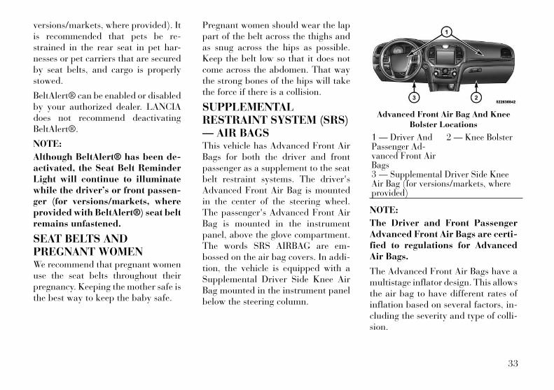
SUPPLEMENTALRESTRAINT SYSTEM (SRS)— AIR BAGSThis vehicle has Advanced Front AirBags for both the driver and frontpassenger as a supplement to the seatbelt restraint systems. The driver'sAdvanced Front Air Bag is mountedin the center of the steering wheel.The passenger's Advanced Front AirBag is mounted in the instrumentpanel, above the glove compartment.The words SRS AIRBAG are em-bossed on the air bag covers. In addi-tion, the vehicle is equipped with aSupplemental Driver Side Knee AirBag mounted in the instrument panelbelow the steering column.
NOTE:
The Driver and Front PassengerAdvanced Front Air Bags are certi-fied to regulations for AdvancedAir Bags.
The Advanced Front Air Bags have amultistage inflator design. This allowsthe air bag to have different rates ofinflation based on several factors, in-cluding the severity and type of colli-sion.
Advanced Front Air Bag And KneeBolster Locations
1 — Driver AndPassenger Ad-vanced Front AirBags
2 — Knee Bolster
3 — Supplemental Driver Side KneeAir Bag (for versions/markets, whereprovided)
33
This vehicle may be equipped with adriver and/or front passenger seatbelt buckle switch that detectswhether the driver or front passengerseat belt is fastened. The seat beltbuckle switch may adjust the inflationrate of the Advanced Front Air Bags.
This vehicle is equipped with Supple-mental Side Air Bag Inflatable Cur-tains (SABIC) to protect the driver,front, and rear passengers sitting nextto a window. The SABIC air bags arelocated above the side windows andtheir covers are also labeled: SRSAIRBAG.
This vehicle is equipped with Supple-mental Seat-Mounted Side Air Bags(SAB) to provide enhanced protectionfor an occupant during a side impact.The Supplemental Seat-MountedSide Air Bags are located in the out-board side of the front seats.
NOTE:
• Air Bag covers may not be obvi-ous in the interior trim, but theywill open during air bag deploy-ment.
• After any accident, the vehicleshould be taken to an autho-rized dealer immediately.
Air Bag System ComponentsYour vehicle may be equipped withthe following air bag system compo-nents:
• Occupant Restraint Controller(ORC)
• Air Bag Warning Light
• Steering Wheel and Column
• Instrument Panel
• Supplemental Driver Side Knee AirBag (for versions/markets, whereprovided)
• Knee Impact Bolster (for versions/markets, where provided)
• Driver Advanced Front Air Bag
• Passenger Advanced Front Air Bag
• Supplemental Seat-Mounted SideAir Bags (SAB)
• Supplemental Side Air Bag Inflat-able Curtains (SABIC)
• Front and Side Impact Sensors
• Front Seat Belt Pretensioners, SeatBelt Buckle Switch
• Active Hood System
Advanced Front Air Bag FeaturesThe Advanced Front Air Bag systemhas multistage driver and front pas-senger air bags. This system providesoutput appropriate to the severity andtype of collision as determined by theOccupant Restraint Controller(ORC), which may receive informa-tion from the front impact sensors.
The first stage inflator is triggeredimmediately during an impact thatrequires air bag deployment. This lowoutput is used in less severe collisions.A higher energy output is used formore severe collisions.
WARNING!• No objects should be placed over
or near the air bag on the instru-ment panel, because any such ob-jects could cause harm if the ve-hicle is in a collision severeenough to cause the air bag toinflate.
(Continued)
34
WARNING! (Continued)• Do not put anything on or around
the air bag covers or attempt toopen them manually. You maydamage the air bags and youcould be injured because the airbags may no longer be functional.The protective covers for the airbag cushions are designed to openonly when the air bags are inflat-ing.
• Do not drill, cut or tamper withthe knee bolster (for versions/markets, where provided) in anyway.
• Do not mount any accessories tothe knee bolster (for versions/markets, where provided) such asalarm lights, stereos, citizen bandradios, etc.
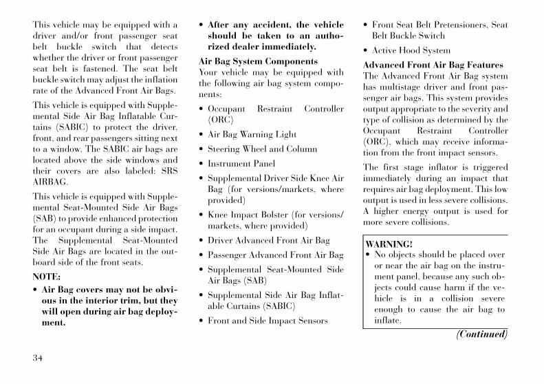
Supplemental Seat-Mounted SideAir Bags (SAB)Supplemental Seat-Mounted Side AirBags (SAB) may provide enhancedprotection to help protect an occupantduring a side impact. The SAB ismarked with an air bag label sewninto the outboard side of the frontseats.
When the air bag deploys, it opens theseam between the front and side of theseat's trim cover. Each air bag deploysindependently; a left side impact de-ploys the left air bag only and a right-side impact deploys the right air bagonly.
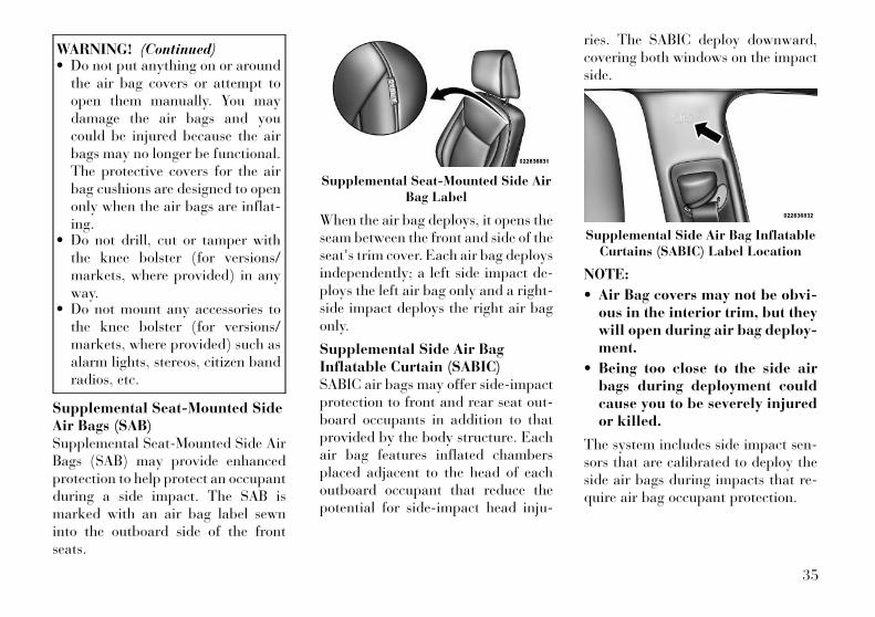
Supplemental Side Air BagInflatable Curtain (SABIC)SABIC air bags may offer side-impactprotection to front and rear seat out-board occupants in addition to thatprovided by the body structure. Eachair bag features inflated chambersplaced adjacent to the head of eachoutboard occupant that reduce thepotential for side-impact head inju-
ries. The SABIC deploy downward,covering both windows on the impactside.
NOTE:
• Air Bag covers may not be obvi-ous in the interior trim, but theywill open during air bag deploy-ment.
• Being too close to the side airbags during deployment couldcause you to be severely injuredor killed.
The system includes side impact sen-sors that are calibrated to deploy theside air bags during impacts that re-quire air bag occupant protection.
Supplemental Seat-Mounted Side AirBag Label
Supplemental Side Air Bag InflatableCurtains (SABIC) Label Location
35
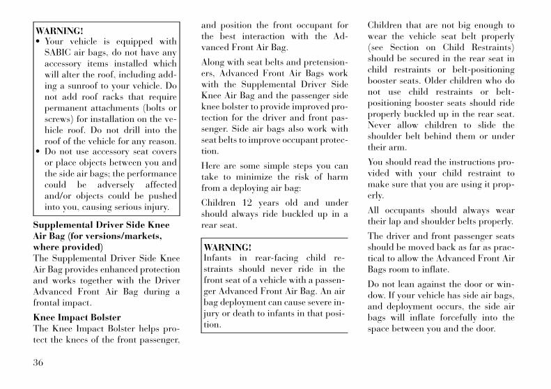
WARNING!• Your vehicle is equipped with
SABIC air bags, do not have anyaccessory items installed whichwill alter the roof, including add-ing a sunroof to your vehicle. Donot add roof racks that requirepermanent attachments (bolts orscrews) for installation on the ve-hicle roof. Do not drill into theroof of the vehicle for any reason.
• Do not use accessory seat coversor place objects between you andthe side air bags; the performancecould be adversely affectedand/or objects could be pushedinto you, causing serious injury.
Supplemental Driver Side KneeAir Bag (for versions/markets,where provided)The Supplemental Driver Side KneeAir Bag provides enhanced protectionand works together with the DriverAdvanced Front Air Bag during afrontal impact.
Knee Impact BolsterThe Knee Impact Bolster helps pro-tect the knees of the front passenger,
and position the front occupant forthe best interaction with the Ad-vanced Front Air Bag.
Along with seat belts and pretension-ers, Advanced Front Air Bags workwith the Supplemental Driver SideKnee Air Bag and the passenger sideknee bolster to provide improved pro-tection for the driver and front pas-senger. Side air bags also work withseat belts to improve occupant protec-tion.
Here are some simple steps you cantake to minimize the risk of harmfrom a deploying air bag:
Children 12 years old and undershould always ride buckled up in arear seat.
WARNING!Infants in rear-facing child re-straints should never ride in thefront seat of a vehicle with a passen-ger Advanced Front Air Bag. An airbag deployment can cause severe in-jury or death to infants in that posi-tion.
Children that are not big enough towear the vehicle seat belt properly(see Section on Child Restraints)should be secured in the rear seat inchild restraints or belt-positioningbooster seats. Older children who donot use child restraints or belt-positioning booster seats should rideproperly buckled up in the rear seat.Never allow children to slide theshoulder belt behind them or undertheir arm.
You should read the instructions pro-vided with your child restraint tomake sure that you are using it prop-erly.
All occupants should always weartheir lap and shoulder belts properly.
The driver and front passenger seatsshould be moved back as far as prac-tical to allow the Advanced Front AirBags room to inflate.
Do not lean against the door or win-dow. If your vehicle has side air bags,and deployment occurs, the side airbags will inflate forcefully into thespace between you and the door.
36

If the air bag system in this vehicleneeds to be modified to accommodatea disabled person, contact the Cus-tomer Center.
WARNING!• Relying on the air bags alone
could lead to more severe injuriesin a collision. The air bags workwith your seat belt to restrain youproperly. In some collisions, theair bags won't deploy at all. Al-ways wear your seat belts eventhough you have air bags.
• Being too close to the steeringwheel or instrument panel duringAdvanced Front Air Bag deploy-ment could cause serious injury,including death. Air Bags needroom to inflate. Sit back, comfort-ably extending your arms to reachthe steering wheel or instrumentpanel.
• Side air bags also need room toinflate. Do not lean against thedoor or window. Sit upright in thecenter of the seat.
AIR BAG DEPLOYMENTSENSORS AND CONTROLS
Occupant Restraint Controller(ORC)The ORC is part of a regulated safetysystem required for this vehicle.
The ORC determines if deployment ofthe front and/or side air bags in afrontal or side collision is required.Based on the impact sensor's signals,a central electronic ORC deploys theAdvanced Front Air Bags, SABIC airbags, SAB, Supplemental Driver SideKnee Air Bag, and front seat belt pre-tensioners, as required, depending onthe severity and type of impact.
Advanced Front Air Bags and Supple-mental Driver Side Knee Air Bag aredesigned to provide additional protec-tion by supplementing the seat beltsin certain frontal collisions dependingon the severity and type of collision.Advanced Front Air Bags are not ex-pected to reduce the risk of injury inrear, side, or rollover collisions.
The Advanced Front Air Bags andSupplemental Driver Side Knee AirBag will not deploy in all frontal col-
lisions, including some that may pro-duce substantial vehicle damage —for example, some pole collisions,truck underrides, and angle offset col-lisions. On the other hand, dependingon the type and location of impact,Advanced Front Air Bags may deployin crashes with little vehicle front-enddamage but that produce a severe ini-tial deceleration.
The side air bags will not deploy in allside collisions. Side air bag deploy-ment will depend on the severity andtype of collision.
Because air bag sensors measure ve-hicle deceleration over time, vehiclespeed and damage by themselves arenot good indicators of whether or notan air bag should have deployed.
Seat belts are necessary for your pro-tection in all collisions, and also areneeded to help keep you in position,away from an inflating air bag.
The ORC monitors the readiness ofthe electronic parts of the air bag sys-tem whenever the ignition switch is inthe START or ON/RUN position. Ifthe key is in the OFF position, in the
37
ACC position, or not in the ignition,the air bag system is not on and the airbags will not inflate.
The ORC contains a backup powersupply system that may deploy the airbags even if the battery loses power orit becomes disconnected prior to de-ployment.
Also, the ORC turns on theAir Bag Warning Light inthe instrument panel forapproximately four to eight
seconds for a self-check when the ig-nition is first turned on. After the self-check, the Air Bag Warning Light willturn off. If the ORC detects a mal-function in any part of the system, itturns on the Air Bag Warning Light,either momentarily or continuously. Asingle chime will sound if the lightcomes on again after initial startup.
It also includes diagnostics that willilluminate the instrument cluster AirBag Warning Light if a malfunction isnoted that could affect the air bagsystem. The diagnostics also recordthe nature of the malfunction.
WARNING!Ignoring the Air Bag Warning Lightin your instrument panel couldmean you won't have the air bags toprotect you in a collision. If the lightdoes not come on as a bulb checkwhen the ignition is first turned on,stays on after you start the vehicle,or if it comes on as you drive, havean authorized dealer service the airbag system immediately.
Driver And Passenger AdvancedFront Air Bag Inflator UnitsThe Driver and Passenger AdvancedFront Air Bag Inflator Units are lo-cated in the center of the steeringwheel and on the right side of theinstrument panel. When the ORC de-tects a collision requiring the Ad-vanced Front Air Bags, it signals theinflator units. A large quantity of non-toxic gas is generated to inflate theAdvanced Front Air Bags. Differentair bag inflation rates are possible,based on the collision type and sever-ity. The steering wheel hub trim coverand the upper right side of the instru-ment panel separate and fold out of
the way as the air bags inflate to theirfull size. The air bags fully inflate inabout 50 to 70 milliseconds. This isabout half of the time it takes to blinkyour eyes. The air bags then quicklydeflate while helping to restrain thedriver and front passenger.
The Advanced Front Air Bag gas isvented through the vent holes in thesides of the air bag. In this way, the airbags do not interfere with your con-trol of the vehicle.
Supplemental Driver Side KneeAir Bag Inflator Unit (forversions/markets, whereprovided)The Supplemental Driver Side KneeAir Bag unit is located in the instru-ment panel trim beneath the steeringcolumn. When the ORC detects a col-lision requiring the air bag, it signalsthe inflator units. A large quantity ofnon-toxic gas is generated to inflatethe Supplemental Driver Side KneeAir Bag. The trim cover separates andfolds out of the way allowing the airbag to inflate to the full size. The airbag fully inflates in about 15 to 20milliseconds. The Supplemental
38
Driver Side Knee Air Bag gas is ventedthrough small vent holes in the side ofthe air bag.
Supplemental Seat-Mounted SideAir Bag (SAB) Inflator UnitsThe Supplemental Seat-MountedSide Air Bags (SAB) are designed toactivate only in certain side collisions.
The ORC determines if a side collisionrequires the side air bags to inflate,based on several factors, including theseverity and type of collision.
Based on several factors, includingthe severity and type of collision, theside air bag inflator on the crash sideof the vehicle may be triggered, re-leasing a quantity of non-toxic gas.The inflating SAB exits through theseat seam into the space between theoccupant and the door. The SAB fullyinflate in about 10 milliseconds. Theside air bag moves at a very highspeed and with such a high force thatit could injure you if you are notseated properly, or if items are posi-tioned in the area where the side airbag inflates. This especially applies tochildren.
Supplemental Side Air BagInflatable Curtain (SABIC)Inflator UnitsDuring collisions where the impact isconfined to a particular area of theside of the vehicle, the ORC may de-ploy the SABIC air bags, dependingon the severity and type of collision. Inthese events, the ORC will deploy theSABIC only on the impact side of thevehicle.
A quantity of non-toxic gas is gener-ated to inflate the side curtain air bag.The inflating side curtain air bagpushes the outside edge of the head-liner out of the way and covers thewindow. The air bag inflates in about30 milliseconds (about one-quarter ofthe time that it takes to blink youreyes) with enough force to injure youif you are not belted and seated prop-erly, or if items are positioned in thearea where the side curtain air baginflates. This especially applies tochildren. The side curtain air bag isonly about 9 cm thick when it is in-flated.
Because air bag sensors estimate de-celeration over time, vehicle speed
and damage are not good indicators ofwhether or not an air bag should havedeployed.
Front And Side Impact SensorsIn front and side impacts, impact sen-sors can aid the ORC in determiningappropriate response to impact events.
Enhanced Accident ResponseSystemIn the event of an impact causing airbag deployment, if the communica-tion network remains intact, and thepower remains intact, depending onthe nature of the event the ORC willdetermine whether to have the En-hanced Accident Response Systemperform the following functions:
• Cut off fuel to the engine.
• Flash hazard lights as long as thebattery has power or until the igni-tion key is turned off.
• Turn on the interior lights, whichremain on as long as the battery haspower, until the ignition key is re-moved or the ignition switch ischanged to OFF using the KeylessGo Start/Stop button.
• Unlock the doors automatically.
39
In order to reset the Enhanced Acci-dent Response System functions afteran event, the ignition switch must bechanged from IGN ON to IGN OFF.
If A Deployment OccursThe Advanced Front Air Bags are de-signed to deflate immediately afterdeployment.
NOTE:
Front and/or side air bags will notdeploy in all collisions. This doesnot mean something is wrong withthe air bag system.
If you do have a collision which de-ploys the air bags, any or all of thefollowing may occur:
• The nylon air bag material maysometimes cause abrasions and/orskin reddening to the driver andfront passenger as the air bags de-ploy and unfold. The abrasions aresimilar to friction rope burns orthose you might get sliding along acarpet or gymnasium floor. Theyare not caused by contact withchemicals. They are not permanentand normally heal quickly. How-ever, if you haven't healed signifi-
cantly within a few days, or if youhave any blistering, see your doctorimmediately.
• As the air bags deflate, you may seesome smoke-like particles. Theparticles are a normal by-productof the process that generates thenon-toxic gas used for air bag infla-tion. These airborne particles mayirritate the skin, eyes, nose, orthroat. If you have skin or eye irri-tation, rinse the area with cool wa-ter. For nose or throat irritation,move to fresh air. If the irritationcontinues, see your doctor. If theseparticles settle on your clothing,follow the garment manufacturer'sinstructions for cleaning.
Do not drive your vehicle after the airbags have deployed. If you are in-volved in another collision, the airbags will not be in place to protectyou.
WARNING!Deployed air bags and seat belt pre-tensioners cannot protect you in an-other collision. Have the air bags,seat belt pretensioners, and the frontseat belt retractor assemblies re-placed by an authorized dealer im-mediately. Also, have the OccupantRestraint Controller (ORC) systemserviced as well.
Maintaining Your Air Bag System
WARNING!• Modifications to any part of the
air bag system could cause it tofail when you need it. You couldbe injured if the air bag system isnot there to protect you. Do notmodify the components or wiring,including adding any kind ofbadges or stickers to the steeringwheel hub trim cover or the upperright side of the instrument panel.Do not modify the front bumper,vehicle body structure, or add af-termarket side steps or runningboards.
(Continued)
40
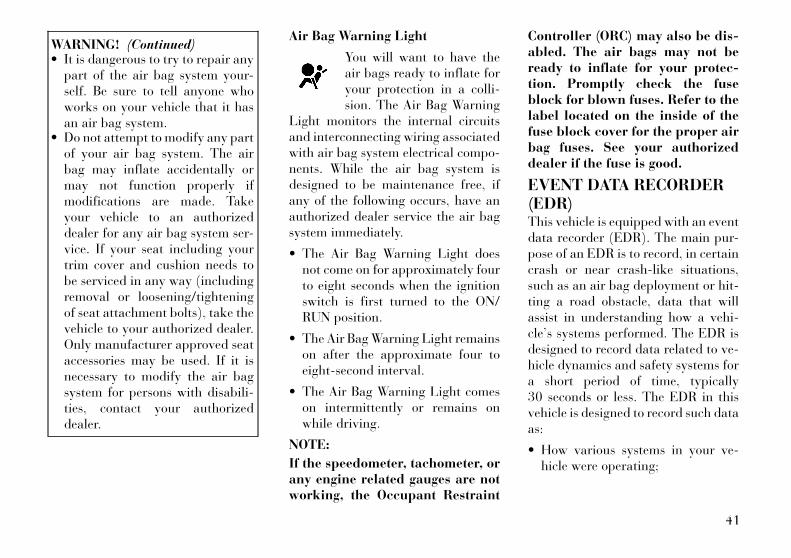
WARNING! (Continued)• It is dangerous to try to repair any
part of the air bag system your-self. Be sure to tell anyone whoworks on your vehicle that it hasan air bag system.
• Do not attempt to modify any partof your air bag system. The airbag may inflate accidentally ormay not function properly ifmodifications are made. Takeyour vehicle to an authorizeddealer for any air bag system ser-vice. If your seat including yourtrim cover and cushion needs tobe serviced in any way (includingremoval or loosening/tighteningof seat attachment bolts), take thevehicle to your authorized dealer.Only manufacturer approved seataccessories may be used. If it isnecessary to modify the air bagsystem for persons with disabili-ties, contact your authorizeddealer.
Air Bag Warning Light
You will want to have theair bags ready to inflate foryour protection in a colli-sion. The Air Bag Warning
Light monitors the internal circuitsand interconnecting wiring associatedwith air bag system electrical compo-nents. While the air bag system isdesigned to be maintenance free, ifany of the following occurs, have anauthorized dealer service the air bagsystem immediately.
• The Air Bag Warning Light doesnot come on for approximately fourto eight seconds when the ignitionswitch is first turned to the ON/RUN position.
• The Air Bag Warning Light remainson after the approximate four toeight-second interval.
• The Air Bag Warning Light comeson intermittently or remains onwhile driving.
NOTE:
If the speedometer, tachometer, orany engine related gauges are notworking, the Occupant Restraint
Controller (ORC) may also be dis-abled. The air bags may not beready to inflate for your protec-tion. Promptly check the fuseblock for blown fuses. Refer to thelabel located on the inside of thefuse block cover for the proper airbag fuses. See your authorizeddealer if the fuse is good.
EVENT DATA RECORDER(EDR)This vehicle is equipped with an eventdata recorder (EDR). The main pur-pose of an EDR is to record, in certaincrash or near crash-like situations,such as an air bag deployment or hit-ting a road obstacle, data that willassist in understanding how a vehi-cle’s systems performed. The EDR isdesigned to record data related to ve-hicle dynamics and safety systems fora short period of time, typically30 seconds or less. The EDR in thisvehicle is designed to record such dataas:
• How various systems in your ve-hicle were operating;
41

• Whether or not the driver and pas-senger safety belts were buckled/fastened;
• How far (if at all) the driver wasdepressing the accelerator and/orbrake pedal; and,
• How fast the vehicle was traveling.
These data can help provide a betterunderstanding of the circumstances inwhich crashes and injuries occur.
NOTE:
EDR data are recorded by your ve-hicle only if a non-trivial crashsituation occurs; no data are re-corded by the EDR under normaldriving conditions and no per-sonal data (e.g., name, gender, age,and crash location) are recorded.However, other parties, such aslaw enforcement, could combinethe EDR data with the type of per-sonally identifying data routinelyacquired during a crash investiga-tion.
To read data recorded by an EDR,special equipment is required, and ac-cess to the vehicle or the EDR isneeded. In addition to the vehiclemanufacturer, other parties, such aslaw enforcement, that have the spe-cial equipment, can read the informa-tion if they have access to the vehicleor the EDR.
CHILD RESTRAINTSEveryone in your vehicle needs to bebuckled up all the time, including ba-bies and children.
Children 12 years or younger shouldride properly buckled up in a rearseat, if available. According to crash
statistics, children are safer whenproperly restrained in the rear seatsrather than in the front.
WARNING!• “Extreme Hazard! Do not use a
rearward-facing child restraint ona seat protected by an air bag infront of it!” Refer to visor anddoor shut face mounted labels forinformation.
• In a collision, an unrestrainedchild, even a tiny baby, can be-come a projectile inside the ve-hicle. The force required to holdeven an infant on your lap couldbecome so great that you couldnot hold the child, no matter howstrong you are. The child and oth-ers could be badly injured. Anychild riding in your vehicle shouldbe in a proper restraint for thechild's size.
42
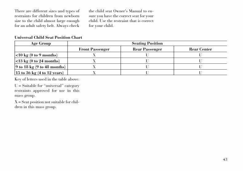
There are different sizes and types ofrestraints for children from newbornsize to the child almost large enoughfor an adult safety belt. Always check
the child seat Owner's Manual to en-sure you have the correct seat for yourchild. Use the restraint that is correctfor your child.
Universal Child Seat Position Chart
Age Group Seating Position
Front Passenger Rear Passenger Rear Center
<10 kg (0 to 9 months) X U U
<13 kg (0 to 24 months) X U U
9 to 18 kg (9 to 48 months) X U U
15 to 36 kg (4 to 12 years) X U U
Key of letters used in the table above:
U = Suitable for “universal” categoryrestraints approved for use in thismass group.
X = Seat position not suitable for chil-dren in this mass group.
43
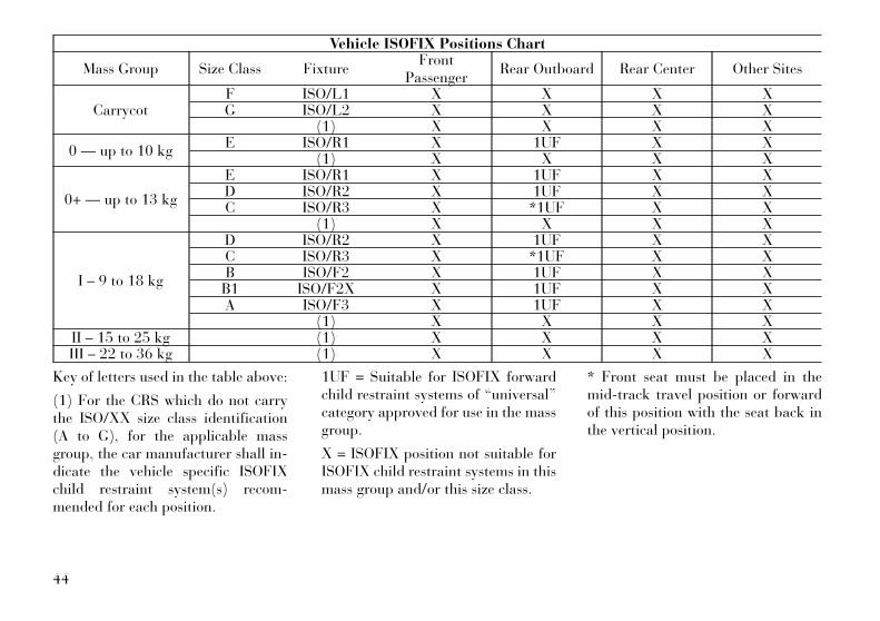
Vehicle ISOFIX Positions Chart
Mass Group Size Class FixtureFront
PassengerRear Outboard Rear Center Other Sites
CarrycotF ISO/L1 X X X XG ISO/L2 X X X X
(1) X X X X
0 — up to 10 kgE ISO/R1 X 1UF X X
(1) X X X X
0+ — up to 13 kg
E ISO/R1 X 1UF X XD ISO/R2 X 1UF X XC ISO/R3 X *1UF X X
(1) X X X X
I – 9 to 18 kg
D ISO/R2 X 1UF X XC ISO/R3 X *1UF X XB ISO/F2 X 1UF X XB1 ISO/F2X X 1UF X XA ISO/F3 X 1UF X X
(1) X X X XII – 15 to 25 kg (1) X X X XIII – 22 to 36 kg (1) X X X X
Key of letters used in the table above:
(1) For the CRS which do not carrythe ISO/XX size class identification(A to G), for the applicable massgroup, the car manufacturer shall in-dicate the vehicle specific ISOFIXchild restraint system(s) recom-mended for each position.
1UF = Suitable for ISOFIX forwardchild restraint systems of “universal”category approved for use in the massgroup.
X = ISOFIX position not suitable forISOFIX child restraint systems in thismass group and/or this size class.
* Front seat must be placed in themid-track travel position or forwardof this position with the seat back inthe vertical position.
44
Infants And Child RestraintsSafety experts recommend that chil-dren ride rearward-facing in the ve-hicle until they are two years old oruntil they reach either the height orweight limit of their rear facing childsafety seat. Two types of child re-straints can be used rearward-facing:infant carriers and convertible childseats.
The infant carrier is only usedrearward-facing in the vehicle. It isrecommended for children from birthuntil they reach the weight or heightlimit of the infant carrier. Convertiblechild seats can be used eitherrearward-facing or forward-facing inthe vehicle. Convertible child seats of-ten have a higher weight limit in therearward-facing direction than infantcarriers do, so they can be usedrearward-facing by children whohave outgrown their infant carrier butare still less than at least two yearsold. Children should remainrearward-facing until they reach thehighest weight or height allowed bytheir convertible child seat. Bothtypes of child restraints are held in the
vehicle by the lap/shoulder belt or theISOFIX child restraint anchor system.Refer to “ISOFIX — Child Seat An-chorage System”.
WARNING!Rearward-facing child seats mustnever be used in the front seat of avehicle with the front passenger airbag. An air bag deployment couldcause severe injury or death to in-fants in this position.
Older Children And ChildRestraintsChildren who are two years old or whohave outgrown their rear-facing con-vertible child seat can ride forward-facing in the vehicle. Forward-facingchild seats and convertible child seatsused in the forward-facing directionare for children who are over twoyears old or who have outgrown therear-facing weight or height limit oftheir rear-facing convertible childseat. Children should remain in aforward-facing child seat with a har-ness for as long as possible, up to thehighest weight or height allowed bythe child seat. These child seats are
also held in the vehicle by the lap/shoulder belt or the ISOFIX child re-straint anchorage system. Refer to“ISOFIX — Child Seat AnchorageSystem”.
All children whose weight or height isabove the forward-facing limit for thechild seat should use a belt-positioning booster seat until the ve-hicle’s seat belts fit properly. If thechild cannot sit with knees bent overthe vehicle's seat cushion while thechild's back is against the seatback,they should use a belt-positioningbooster seat. The child and belt-positioning booster seat are held inthe vehicle by the lap/shoulder belt.
Children Too Large For BoosterSeatsChildren who are large enough towear the shoulder belt comfortablyand whose legs are long enough tobend over the front of the seat whentheir back is against the seatbackshould use the lap/shoulder belt in arear seat.
• Make sure that the child is uprightin the seat.
45
• The lap portion should be low onthe hips and as snug as possible.
• Check belt fit periodically. A child'ssquirming or slouching can movethe belt out of position.
• If the shoulder belt contacts theface or neck, move the child closerto the center of the vehicle. Neverallow a child to put the shoulderbelt under an arm or behind theirback.
WARNING!• Improper installation can lead to
failure of an infant or child re-straint. It could come loose in acollision. The child could be badlyinjured or killed. Follow themanufacturer's directions exactlywhen installing an infant or childrestraint.
• A rearward-facing child restraintshould only be used in a rear seat.A rearward-facing child restraintin the front seat may be struck bya deploying passenger air bag,which may cause severe or fatalinjury to the infant.
Here are some tips on getting themost out of your child restraint:
• Before buying any restraint system,make sure that it has a label certi-fying that it meets all applicableSafety Standards. LANCIA alsorecommends that you make surethat you can install the child re-straint in the vehicle where you willuse it before you buy it.
• The restraint must be appropriatefor your child's weight and height.Check the label on the restraint forweight and height limits.
• Carefully follow the instructionsthat come with the restraint. If youinstall the restraint improperly, itmay not work when you need it.
• Buckle the child into the seat ac-cording to the child restraint manu-facturer's directions.
WARNING!When your child restraint is not inuse, secure it in the vehicle with theseat belt or remove it from the vehicle.Do not leave it loose in the vehicle. Ina sudden stop or accident, it couldstrike the occupants or seatbacks andcause serious personal injury.
ISOFIX — Child Seat AnchorageSystemYour vehicle's rear seat is equippedwith the child restraint anchoragesystem called ISOFIX. The ISOFIXsystem provides for the installation ofthe child restraint without using thevehicle's seat belts, instead securingthe child restraint using lower anchor-ages and upper tether straps from thechild restraint to the vehicle structure.
ISOFIX-compatible child restraintsystems are now available. However,because the lower anchorages are tobe introduced over a period of years,child restraint systems having attach-ments for those anchorages will con-tinue to have features for installationusing the vehicle's seat belts. Childrestraints having tether straps and
46
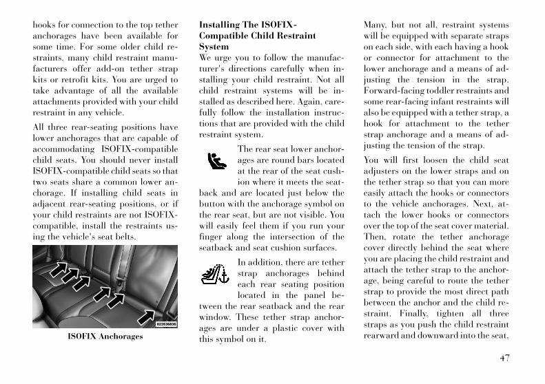
hooks for connection to the top tetheranchorages have been available forsome time. For some older child re-straints, many child restraint manu-facturers offer add-on tether strapkits or retrofit kits. You are urged totake advantage of all the availableattachments provided with your childrestraint in any vehicle.
All three rear-seating positions havelower anchorages that are capable ofaccommodating ISOFIX-compatiblechild seats. You should never installISOFIX-compatible child seats so thattwo seats share a common lower an-chorage. If installing child seats inadjacent rear-seating positions, or ifyour child restraints are not ISOFIX-compatible, install the restraints us-ing the vehicle's seat belts.
Installing The ISOFIX-Compatible Child RestraintSystemWe urge you to follow the manufac-turer's directions carefully when in-stalling your child restraint. Not allchild restraint systems will be in-stalled as described here. Again, care-fully follow the installation instruc-tions that are provided with the childrestraint system.
The rear seat lower anchor-ages are round bars locatedat the rear of the seat cush-ion where it meets the seat-
back and are located just below thebutton with the anchorage symbol onthe rear seat, but are not visible. Youwill easily feel them if you run yourfinger along the intersection of theseatback and seat cushion surfaces.
In addition, there are tetherstrap anchorages behindeach rear seating positionlocated in the panel be-
tween the rear seatback and the rearwindow. These tether strap anchor-ages are under a plastic cover withthis symbol on it.
Many, but not all, restraint systemswill be equipped with separate strapson each side, with each having a hookor connector for attachment to thelower anchorage and a means of ad-justing the tension in the strap.Forward-facing toddler restraints andsome rear-facing infant restraints willalso be equipped with a tether strap, ahook for attachment to the tetherstrap anchorage and a means of ad-justing the tension of the strap.
You will first loosen the child seatadjusters on the lower straps and onthe tether strap so that you can moreeasily attach the hooks or connectorsto the vehicle anchorages. Next, at-tach the lower hooks or connectorsover the top of the seat cover material.Then, rotate the tether anchoragecover directly behind the seat whereyou are placing the child restraint andattach the tether strap to the anchor-age, being careful to route the tetherstrap to provide the most direct pathbetween the anchor and the child re-straint. Finally, tighten all threestraps as you push the child restraintrearward and downward into the seat,ISOFIX Anchorages
47

removing slack in the straps accord-ing to the child restraint manufactur-er's instructions.
For center seating position route thetether strap over the seatback andadjustable headrest (with the head-rest in the full down position) thenattach the hook to the tether anchorlocated in the panel between the rearseatback and the rear window.
WARNING!An incorrectly anchored tether strapcould lead to increased head motionand possible injury to the child. Useonly the anchor positions directlybehind the child seat to secure achild restraint top tether strap.
NOTE:
• Ensure that the tether strap doesnot slip into the opening be-tween the seatbacks as you re-move slack in the strap.
• When using the ISOFIX attach-ing system to install a child re-straint, please ensure that allseat belts not being used for oc-cupant restraints are stowed andout of reach of children. It is
recommended that before in-stalling the child restraint,buckle the seat belt so the seatbelt is tucked behind the childrestraint and out of reach. If thebuckled seat belt interferes withthe child restraint installation,instead of tucking the seat beltbehind the child restraint, routethe seat belt through the childrestraint belt path and thenbuckle it. This should stow theseat belt out of the reach of aninquisitive child. Remind allchildren in the vehicle that theseat belts are not toys andshould not be played with, andnever leave your child unat-tended in the vehicle.
WARNING!Improper installation of a child re-straint to the ISOFIX anchoragescan lead to failure of an infant orchild restraint. The child could bebadly injured or killed. Follow themanufacturer's directions exactlywhen installing an infant or childrestraint.
Adjustable Headrest Release PushButton
Adjustable Headrest DownwardPosition
48
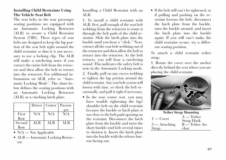
Installing Child Restraints UsingThe Vehicle Seat BeltThe seat belts in the rear passengerseating positions are equipped withan Automatic Locking Retractor(ALR) to secure a Child RestraintSystem (CRS). These types of seatbelts are designed to keep the lap por-tion of the seat belt tight around thechild restraint so that it is not neces-sary to use a locking clip. The ALRwill make a ratcheting noise if youextract the entire belt from the retrac-tor and then allow the belt to retractinto the retractor. For additional in-formation on ALR, refer to “Auto-matic Locking Mode”. The chart be-low defines the seating positions withan Automatic Locking Retractor(ALR) or a cinching latch plate.
Driver Center Passen-ger
FirstRow
N/A N/A N/A
SecondRow
ALR ALR ALR
• N/A — Not Applicable
• ALR — Automatic Locking Retrac-tor
Installing a Child Restraint with anALR:
1. To install a child restraint withALR, first, pull enough of the seat beltwebbing from the retractor to route itthrough the belt path of the child re-straint. Slide the latch plate into thebuckle until you hear a “click.” Next,extract all the seat belt webbing out ofthe retractor and then allow the belt toretract into the retractor. As the beltretracts, you will hear a ratchetingsound. This indicates the safety belt isnow in the Automatic Locking mode.
2. Finally, pull on any excess webbingto tighten the lap portion around thechild restraint. Any seat belt system willloosen with time, so check the belt oc-casionally, and pull it tight if necessary.
• In the rear center seat, you mayhave trouble tightening the lap/shoulder belt on the child restraintbecause the buckle or latch plate istoo close to the belt path opening onthe restraint. Disconnect the latchplate from the buckle and twist theshort buckle-end belt several timesto shorten it. Insert the latch plateinto the buckle with the release but-ton facing out.
• If the belt still can’t be tightened, orif pulling and pushing on the re-straint loosens the belt, disconnectthe latch plate from the buckle,turn the buckle around, and insertthe latch plate into the buckleagain. If you still can’t make thechild restraint secure, try a differ-ent seating position.
To attach a child restraint tetherstrap:
1. Rotate the cover over the anchordirectly behind the seat where you areplacing the child restraint.
Tether Strap Mounting
1 — Cover A — TetherStrap Hook
3 — AttachingStrap
B — Tether An-chor
49
2. Route the tether strap to providethe most direct path for the strap be-tween the anchor and the child seat.
3. Attach the tether strap hook (A) ofthe child restraint to the anchor (B)and remove slack in the tether strapaccording to the child restraint manu-facturer's instructions.
NOTE:
Ensure that the tether strap doesnot slip into the opening betweenthe seatbacks as you remove slackin the strap.
WARNING!An incorrectly anchored tether strapcould lead to increased head motionand possible injury to the child. Useonly the anchor positions directlybehind the child seat to secure achild restraint top tether strap.
Transporting PetsAir Bags deploying in the front seatcould harm your pet. An unrestrainedpet will be thrown about and possiblyinjured, or injure a passenger duringpanic braking or in a collision.
Pets should be restrained in the rearseat in pet harnesses or pet carriersthat are secured by seat belts.
ENGINE BREAK-INRECOMMENDATIONSA long break-in period is not requiredfor the engine and drivetrain (trans-mission and axle) in your vehicle.
Drive moderately during the first500 km. After the initial 100 km,speeds up to 80 or 90 km/h are desir-able.
While cruising, brief full-throttle ac-celeration within the limits of localtraffic laws contributes to a goodbreak-in. Wide-open throttle accel-eration in low gear can be detrimentaland should be avoided.
The engine oil installed in the engineat the factory is a high-quality energyconserving type lubricant. Oilchanges should be consistent with an-ticipated climate conditions underwhich vehicle operations will occur.For the recommended viscosity andquality grades, refer to “MaintenanceProcedures” in “Maintaining Your Ve-
hicle”. NON-DETERGENT ORSTRAIGHT MINERAL OILS MUSTNEVER BE USED.
A new engine may consume some oilduring its first few thousand kilome-ters of operation. This should be con-sidered a normal part of the break-inand not interpreted as an indication ofdifficulty.
Additional RequirementsFor Diesel Engine (forversions/markets, whereprovided)During the first 1500 km avoid heavyloads, e.g. driving at full throttle. Donot exceed 2/3 of the maximum per-missible engine speed for each gear.Change gear in good time. Do not shiftdown a gear manually in order tobrake.
SAFETY TIPS
Transporting PassengersNEVER TRANSPORT PASSEN-GERS IN THE CARGO AREA.
50
WARNING!• Do not leave children or animals
inside parked vehicles in hotweather. Interior heat build-upmay cause serious injury or death.
• It is extremely dangerous to ride ina cargo area, inside or outside of avehicle. In a collision, people rid-ing in these areas are more likelyto be seriously injured or killed.
• Do not allow people to ride in anyarea of your vehicle that is notequipped with seats and seatbelts.
• Be sure everyone in your vehicle isin a seat and using a seat beltproperly.
Exhaust Gas
WARNING!Exhaust gases can injure or kill.They contain carbon monoxide(CO), which is colorless and odor-less. Breathing it can make you un-conscious and can eventually poisonyou. To avoid breathing (CO), fol-low these safety tips:
(Continued)
WARNING! (Continued)• Do not run the engine in a closed
garage or in confined areas anylonger than needed to move yourvehicle in or out of the area.
• If you are required to drive withthe trunk/liftgate open, make surethat all windows are closed andthe climate control BLOWERswitch is set at high speed. DONOT use the recirculation mode.
• If it is necessary to sit in a parkedvehicle with the engine running,adjust your heating or coolingcontrols to force outside air intothe vehicle. Set the blower at highspeed.
The best protection against carbonmonoxide entry into the vehicle bodyis a properly maintained engine ex-haust system.
Whenever a change is noticed in thesound of the exhaust system, whenexhaust fumes can be detected insidethe vehicle, or when the underside orrear of the vehicle is damaged, have acompetent mechanic inspect the com-
plete exhaust system and adjacentbody areas for broken, damaged, de-teriorated, or mispositioned parts.Open seams or loose connectionscould permit exhaust fumes to seepinto the passenger compartment. Inaddition, inspect the exhaust systemeach time the vehicle is raised for lu-brication or oil change. Replace asrequired.
Safety Checks You ShouldMake Inside The Vehicle
Seat BeltsInspect the belt system periodically,checking for cuts, frays, and looseparts. Damaged parts must be re-placed immediately. Do not disas-semble or modify the system.
Front seat belt assemblies must bereplaced after a collision. Rear seatbelt assemblies must be replaced aftera collision if they have been damaged(i.e., bent retractor, torn webbing,etc.). If there is any question regard-ing belt or retractor condition, replacethe belt.
51

Air Bag Warning LightThe light should come on and remainon for four to eight seconds as a bulbcheck when the ignition switch is firstturned ON. If the light is not lit duringstarting, see your authorized dealer. Ifthe light stays on, flickers, or comeson while driving, have the systemchecked by an authorized dealer.
DefrosterCheck operation by selecting the de-frost mode and place the blower con-trol on high speed. You should be ableto feel the air directed against thewindshield. See your authorizeddealer for service if your defroster isinoperable.
Floor Mat Safety InformationAlways use floor mats designed to fitthe footwell of your vehicle. Use onlyfloor mats that leave the pedal areaunobstructed and that are firmly se-cured so that they cannot slip out ofposition and interfere with the pedals
or impair safe operation of your ve-hicle in other ways.
WARNING!Pedals that cannot move freely cancause loss of vehicle control and in-crease the risk of serious personalinjury.• Always make sure that floor mats
are properly attached to the floormat fasteners.
• Never place or install floor mats orother floor coverings in the vehiclethat cannot be properly secured toprevent them from moving andinterfering with the pedals or theability to control the vehicle.
• Never put floor mats or other floorcoverings on top of already in-stalled floor mats. Additionalfloor mats and other coveringswill reduce the size of the pedalarea and interfere with the pedals.
(Continued)
WARNING! (Continued)• Check mounting of mats on a
regular basis. Always properly re-install and secure floor mats thathave been removed for cleaning.
• Always make sure that objectscannot fall into the driver footwellwhile the vehicle is moving. Ob-jects can become trapped underthe brake pedal and acceleratorpedal causing a loss of vehiclecontrol.
• If required, mounting posts mustbe properly installed, if notequipped from the factory.
Failure to properly follow floor matinstallation or mounting can causeinterference with the brake pedaland accelerator pedal operationcausing loss of control of the vehicle.
52
Periodic Safety Checks YouShould Make Outside TheVehicle
TiresExamine tires for excessive tread wearand uneven wear patterns. Check forstones, nails, glass, or other objectslodged in the tread or sidewall. In-spect the tread for cuts and cracks.Inspect sidewalls for cuts, cracks andbulges. Check the wheel nuts for
tightness. Check the tires (includingspare) for proper cold inflation pres-sure.
LightsHave someone observe the operationof exterior lights while you work thecontrols. Check turn signal and highbeam indicator lights on the instru-ment panel.
Door LatchesCheck for positive closing, latching,and locking.
Fluid LeaksCheck area under vehicle after over-night parking for fuel, engine coolant,oil, or other fluid leaks. Also, if gaso-line fumes are detected or if fuel,power steering fluid, or brake fluidleaks are suspected, the cause shouldbe located and corrected immediately.
53

54

3
UNDERSTANDING THE FEATURES OF YOURVEHICLE• MIRRORS . . . . . . . . . . . . . . . . . . . . . . . . . . . . . . 63
• AUTOMATIC DIMMING MIRROR . . . . . . . . . . 63
• OUTSIDE MIRRORS . . . . . . . . . . . . . . . . . . . . 63
• OUTSIDE MIRRORS FOLDING FEATURE . . . . 63
• DRIVER'S AUTOMATIC DIMMING MIRROR(for versions/markets, where provided) . . . . . . 63
• OUTSIDE MIRRORS WITH TURN SIGNALAND APPROACH LIGHTING (forversions/markets, where provided) . . . . . . . . . 63
• TILT MIRRORS IN REVERSE (forversions/markets, where provided) . . . . . . . . . 64
• POWER MIRRORS . . . . . . . . . . . . . . . . . . . . . . 64
• POWER FOLDING OUTSIDE MIRRORS (forversions/markets, where provided) . . . . . . . . . 65
• HEATED MIRRORS (for versions/markets,where provided) . . . . . . . . . . . . . . . . . . . . . . . . 65
• ILLUMINATED VANITY MIRRORS (forversions/markets, where provided) . . . . . . . . . 65
• “SLIDE-ON-ROD” AND EXTENDERFEATURES OF SUN VISOR . . . . . . . . . . . . . . . 65
55
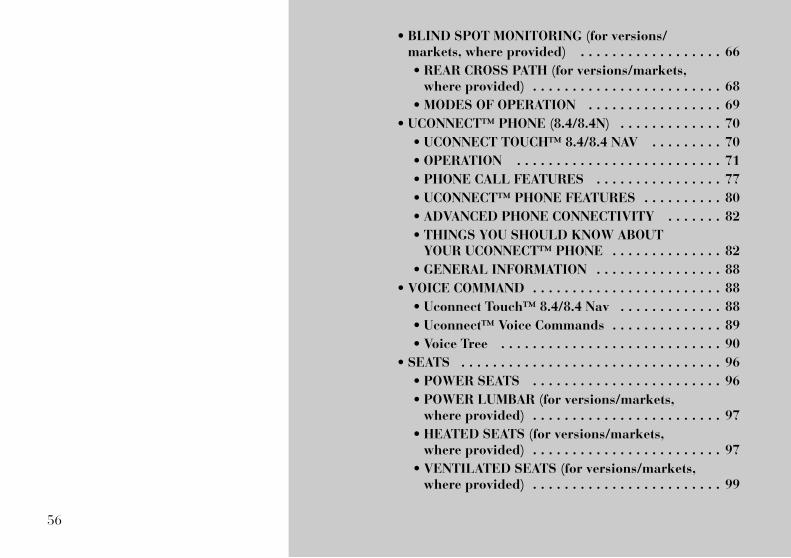
• BLIND SPOT MONITORING (for versions/markets, where provided) . . . . . . . . . . . . . . . . . . 66
• REAR CROSS PATH (for versions/markets,where provided) . . . . . . . . . . . . . . . . . . . . . . . . 68
• MODES OF OPERATION . . . . . . . . . . . . . . . . . 69
• UCONNECT™ PHONE (8.4/8.4N) . . . . . . . . . . . . . 70
• UCONNECT TOUCH™ 8.4/8.4 NAV . . . . . . . . . 70
• OPERATION . . . . . . . . . . . . . . . . . . . . . . . . . . 71
• PHONE CALL FEATURES . . . . . . . . . . . . . . . . 77
• UCONNECT™ PHONE FEATURES . . . . . . . . . . 80
• ADVANCED PHONE CONNECTIVITY . . . . . . . 82
• THINGS YOU SHOULD KNOW ABOUTYOUR UCONNECT™ PHONE . . . . . . . . . . . . . . 82
• GENERAL INFORMATION . . . . . . . . . . . . . . . . 88
• VOICE COMMAND . . . . . . . . . . . . . . . . . . . . . . . . 88
• Uconnect Touch™ 8.4/8.4 Nav . . . . . . . . . . . . . 88
• Uconnect™ Voice Commands . . . . . . . . . . . . . . 89
• Voice Tree . . . . . . . . . . . . . . . . . . . . . . . . . . . . 90
• SEATS . . . . . . . . . . . . . . . . . . . . . . . . . . . . . . . . . 96
• POWER SEATS . . . . . . . . . . . . . . . . . . . . . . . . 96
• POWER LUMBAR (for versions/markets,where provided) . . . . . . . . . . . . . . . . . . . . . . . . 97
• HEATED SEATS (for versions/markets,where provided) . . . . . . . . . . . . . . . . . . . . . . . . 97
• VENTILATED SEATS (for versions/markets,where provided) . . . . . . . . . . . . . . . . . . . . . . . . 99
56

• HEAD RESTRAINTS . . . . . . . . . . . . . . . . . . . . 99
• FOLDING REAR SEAT . . . . . . . . . . . . . . . . . . 101
• DRIVER MEMORY SEAT (for versions/markets, where provided) . . . . . . . . . . . . . . . . . 101
• PROGRAMMING THE MEMORY FEATURE . . 102
• LINKING AND UNLINKING THE REMOTEKEYLESS ENTRY TRANSMITTER TOMEMORY . . . . . . . . . . . . . . . . . . . . . . . . . . . . 102
• MEMORY POSITION RECALL . . . . . . . . . . . . 103
• EASY ENTRY/EXIT SEAT (Available WithMemory Seat Only) . . . . . . . . . . . . . . . . . . . . . 103
• TO OPEN AND CLOSE THE HOOD . . . . . . . . . . 104
• LIGHTS . . . . . . . . . . . . . . . . . . . . . . . . . . . . . . . 104
• HEADLIGHT SWITCH . . . . . . . . . . . . . . . . . . 104
• AUTOMATIC HEADLIGHTS . . . . . . . . . . . . . . 105
• HEADLIGHTS ON WITH WIPERS(Available With Automatic Headlights Only) . . 105
• HEADLIGHT TIME DELAY . . . . . . . . . . . . . . 105
• SMARTBEAM™ . . . . . . . . . . . . . . . . . . . . . . . 106
• DAYTIME RUNNING LIGHTS (DRLs) . . . . . . 106
• ADAPTIVE BI-XENON HIGH INTENSITYDISCHARGE HEADLIGHTS (forversions/markets, where provided) . . . . . . . . 106
• LIGHTS-ON REMINDER . . . . . . . . . . . . . . . . 107
• FOG LIGHTS . . . . . . . . . . . . . . . . . . . . . . . . . 107
• MULTIFUNCTION LEVER . . . . . . . . . . . . . . . 107
57

• TURN SIGNALS . . . . . . . . . . . . . . . . . . . . . . . 107
• LANE CHANGE ASSIST . . . . . . . . . . . . . . . . . 107
• HIGH/LOW BEAM SWITCH . . . . . . . . . . . . . . 107
• FLASH-TO-PASS . . . . . . . . . . . . . . . . . . . . . . 108
• COURTESY LIGHTS . . . . . . . . . . . . . . . . . . . 108
• FRONT MAP/READING LIGHTS . . . . . . . . . . 108
• AMBIENT LIGHT . . . . . . . . . . . . . . . . . . . . . . 108
• INTERIOR LIGHTS . . . . . . . . . . . . . . . . . . . . 108
• WINDSHIELD WIPERS AND WASHERS . . . . . . 110
• INTERMITTENT WIPER SYSTEM . . . . . . . . . 110
• MIST FEATURE . . . . . . . . . . . . . . . . . . . . . . . 110
• WINDSHIELD WASHERS . . . . . . . . . . . . . . . 111
• HEADLIGHTS ON WITH WIPERS(Available With Automatic Headlights Only) . . 111
• RAIN SENSING WIPERS (for versions/markets, where provided) . . . . . . . . . . . . . . . 111
• HEADLIGHT WASHERS (for versions/markets,where provided) . . . . . . . . . . . . . . . . . . . . . . . . . 112
• TILT/TELESCOPING STEERING COLUMN . . . . 112
• POWER TILT/TELESCOPING STEERINGCOLUMN (for versions/markets, whereprovided) . . . . . . . . . . . . . . . . . . . . . . . . . . . . . . 113
• HEATED STEERING WHEEL (forversions/markets, where provided) . . . . . . . . . . 114
• ADJUSTABLE PEDALS (for versions/markets,where provided) . . . . . . . . . . . . . . . . . . . . . . . . . 114
58

• ELECTRONIC SPEED CONTROL (forversions/markets, where provided) . . . . . . . . . . 115
• TO ACTIVATE . . . . . . . . . . . . . . . . . . . . . . . . 116
• TO SET A DESIRED SPEED . . . . . . . . . . . . . 116
• TO DEACTIVATE . . . . . . . . . . . . . . . . . . . . . . 116
• TO RESUME SPEED . . . . . . . . . . . . . . . . . . . 116
• TO VARY THE SPEED SETTING . . . . . . . . . . 116
• TO ACCELERATE FOR PASSING . . . . . . . . . . 117
• ADAPTIVE CRUISE CONTROL (ACC) (forversions/markets, where provided) . . . . . . . . . . 117
• ADAPTIVE CRUISE CONTROL (ACC)OPERATION . . . . . . . . . . . . . . . . . . . . . . . . . 119
• ACTIVATING ADAPTIVE CRUISECONTROL (ACC) . . . . . . . . . . . . . . . . . . . . . . 119
• TO ACTIVATE . . . . . . . . . . . . . . . . . . . . . . . . 119
• TO SET A DESIRED ACC SPEED . . . . . . . . . . 120
• TO CANCEL . . . . . . . . . . . . . . . . . . . . . . . . . . 120
• TO TURN OFF . . . . . . . . . . . . . . . . . . . . . . . . 120
• TO RESUME SPEED . . . . . . . . . . . . . . . . . . . 121
• TO VARY THE SPEED SETTING . . . . . . . . . . 121
• SETTING THE FOLLOWING DISTANCE INACC . . . . . . . . . . . . . . . . . . . . . . . . . . . . . . . . 122
• ADAPTIVE CRUISE CONTROL (ACC)MENU . . . . . . . . . . . . . . . . . . . . . . . . . . . . . . 123
• DISPLAY WARNINGS AND MAINTENANCE . . 124
59
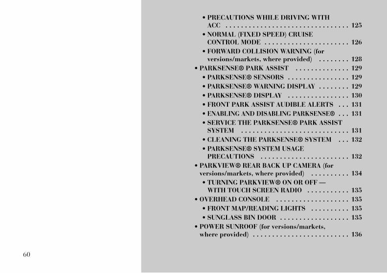
• PRECAUTIONS WHILE DRIVING WITHACC . . . . . . . . . . . . . . . . . . . . . . . . . . . . . . . . 125
• NORMAL (FIXED SPEED) CRUISECONTROL MODE . . . . . . . . . . . . . . . . . . . . . . 126
• FORWARD COLLISION WARNING (forversions/markets, where provided) . . . . . . . . 128
• PARKSENSE® PARK ASSIST . . . . . . . . . . . . . . 129
• PARKSENSE® SENSORS . . . . . . . . . . . . . . . . 129
• PARKSENSE® WARNING DISPLAY . . . . . . . . 129
• PARKSENSE® DISPLAY . . . . . . . . . . . . . . . . 130
• FRONT PARK ASSIST AUDIBLE ALERTS . . . 131
• ENABLING AND DISABLING PARKSENSE® . . . 131
• SERVICE THE PARKSENSE® PARK ASSISTSYSTEM . . . . . . . . . . . . . . . . . . . . . . . . . . . . 131
• CLEANING THE PARKSENSE® SYSTEM . . . 132
• PARKSENSE® SYSTEM USAGEPRECAUTIONS . . . . . . . . . . . . . . . . . . . . . . . 132
• PARKVIEW® REAR BACK UP CAMERA (forversions/markets, where provided) . . . . . . . . . . 134
• TURNING PARKVIEW® ON OR OFF —WITH TOUCH SCREEN RADIO . . . . . . . . . . . 135
• OVERHEAD CONSOLE . . . . . . . . . . . . . . . . . . . 135
• FRONT MAP/READING LIGHTS . . . . . . . . . . 135
• SUNGLASS BIN DOOR . . . . . . . . . . . . . . . . . . 135
• POWER SUNROOF (for versions/markets,where provided) . . . . . . . . . . . . . . . . . . . . . . . . . 136
60

• OPENING SUNROOF — EXPRESS . . . . . . . . . 136
• OPENING SUNROOF — MANUAL MODE . . . . 136
• CLOSING SUNROOF — EXPRESS . . . . . . . . . 136
• CLOSING SUNROOF — MANUAL MODE . . . . 136
• PINCH PROTECT FEATURE . . . . . . . . . . . . . 137
• PINCH PROTECT OVERRIDE . . . . . . . . . . . . 137
• VENTING SUNROOF — EXPRESS . . . . . . . . . 137
• SUNSHADE OPERATION . . . . . . . . . . . . . . . . 137
• WIND BUFFETING . . . . . . . . . . . . . . . . . . . . 137
• SUNROOF MAINTENANCE . . . . . . . . . . . . . . 137
• IGNITION OFF OPERATION . . . . . . . . . . . . . 137
• COMMANDVIEW® SUNROOF WITH POWERSHADE — (for versions/markets, whereprovided) . . . . . . . . . . . . . . . . . . . . . . . . . . . . . . 138
• OPENING SUNROOF — EXPRESS . . . . . . . . . 138
• OPENING SUNROOF — MANUAL MODE . . . . 138
• CLOSING SUNROOF — EXPRESS . . . . . . . . . 138
• CLOSING SUNROOF — MANUAL MODE . . . . 139
• OPENING POWER SHADE — EXPRESS . . . . 139
• OPENING POWER SHADE — MANUALMODE . . . . . . . . . . . . . . . . . . . . . . . . . . . . . . 139
• CLOSING POWER SHADE — EXPRESS . . . . 139
• CLOSING POWER SHADE — MANUALMODE . . . . . . . . . . . . . . . . . . . . . . . . . . . . . . 139
• PINCH PROTECT FEATURE . . . . . . . . . . . . . 139
• PINCH PROTECT OVERRIDE . . . . . . . . . . . . 139
61
• WIND BUFFETING . . . . . . . . . . . . . . . . . . . . 139
• SUNROOF MAINTENANCE . . . . . . . . . . . . . . 140
• IGNITION OFF OPERATION . . . . . . . . . . . . . 140
• SUNROOF FULLY CLOSED . . . . . . . . . . . . . . 140
• ELECTRICAL POWER OUTLETS . . . . . . . . . . . 140
• CUPHOLDERS . . . . . . . . . . . . . . . . . . . . . . . . . . 142
• FRONT SEAT CUPHOLDERS . . . . . . . . . . . . . 142
• REAR SEAT CUPHOLDERS . . . . . . . . . . . . . . 142
• STORAGE . . . . . . . . . . . . . . . . . . . . . . . . . . . . . 143
• GLOVEBOX STORAGE . . . . . . . . . . . . . . . . . 143
• CONSOLE FEATURES . . . . . . . . . . . . . . . . . . 143
• DOOR STORAGE . . . . . . . . . . . . . . . . . . . . . . 144
• REAR SEAT ARMREST STORAGE (forversions/markets, where provided) . . . . . . . . 144
• CARGO AREA — VEHICLES EQUIPPEDWITH 60/40 SPLIT-FOLDING REAR SEAT . . 144
• CARGO AREA FEATURES . . . . . . . . . . . . . . . . . 145
• TRUNK MAT (for versions/markets, whereprovided) . . . . . . . . . . . . . . . . . . . . . . . . . . . . 145
• GROCERY BAG HOOKS . . . . . . . . . . . . . . . . . 145
• REAR WINDOW FEATURES . . . . . . . . . . . . . . . 145
• REAR WINDOW DEFROSTER . . . . . . . . . . . . 145
• POWER SUNSHADE (for versions/markets,where provided) . . . . . . . . . . . . . . . . . . . . . . . 146
• LOAD LEVELING SYSTEM (for versions/markets, where provided) . . . . . . . . . . . . . . . . . 147
62

MIRRORS
AUTOMATIC DIMMINGMIRRORThis mirror automatically adjusts forheadlight glare from vehicles behindyou.
NOTE:
This feature is disabled when thevehicle is moving in reverse.
CAUTION!To avoid damage to the mirror dur-ing cleaning, never spray any clean-ing solution directly onto the mirror.Apply the solution onto a clean clothand wipe the mirror clean.
OUTSIDE MIRRORSTo receive maximum benefit, adjustthe outside mirror(s) to center on theadjacent lane of traffic and a slightoverlap of the view obtained from theinside mirror.
NOTE:
The passenger side convex outsidemirror will give a much wider viewto the rear, and especially of thelane next to your vehicle.
WARNING!Vehicles and other objects seen inthe passenger side convex mirrorwill look smaller and farther awaythan they really are. Relying toomuch on your passenger side convexmirror could cause you to collidewith another vehicle or other object.Use your inside mirror when judgingthe size or distance of a vehicle seenin the passenger side convex mirror.
OUTSIDE MIRRORSFOLDING FEATUREVehicles are equipped with mirrorsthat are hinged. The hinge allows themirror to pivot forward and rearward
to resist damage. The hinge has threedetent positions: full forward, fullrearward and normal.
DRIVER'S AUTOMATICDIMMING MIRROR (forversions/markets, whereprovided)The driver’s outside mirror will auto-matically adjust for glare from ve-hicles behind you. This feature is con-trolled by the inside automaticdimming mirror and can be turned onor off by pressing the button at thebase of the inside mirror. The mirrorwill automatically adjust for head-light glare when the inside mirror ad-justs.
OUTSIDE MIRRORS WITHTURN SIGNAL ANDAPPROACH LIGHTING (forversions/markets, whereprovided)Driver and passenger outside mirrorswith turn signals located within themirror housing and approach lightinglocated within mirror glass containfive LEDs.
Automatic Dimming Mirror
63
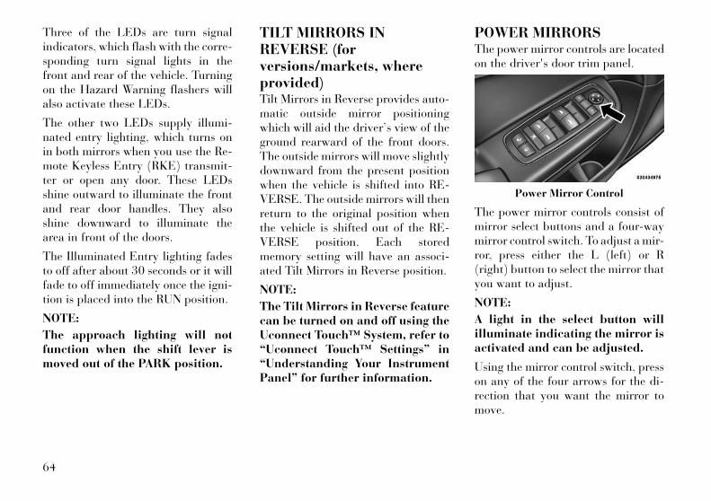
Three of the LEDs are turn signalindicators, which flash with the corre-sponding turn signal lights in thefront and rear of the vehicle. Turningon the Hazard Warning flashers willalso activate these LEDs.
The other two LEDs supply illumi-nated entry lighting, which turns onin both mirrors when you use the Re-mote Keyless Entry (RKE) transmit-ter or open any door. These LEDsshine outward to illuminate the frontand rear door handles. They alsoshine downward to illuminate thearea in front of the doors.
The Illuminated Entry lighting fadesto off after about 30 seconds or it willfade to off immediately once the igni-tion is placed into the RUN position.
NOTE:
The approach lighting will notfunction when the shift lever ismoved out of the PARK position.
TILT MIRRORS INREVERSE (forversions/markets, whereprovided)Tilt Mirrors in Reverse provides auto-matic outside mirror positioningwhich will aid the driver’s view of theground rearward of the front doors.The outside mirrors will move slightlydownward from the present positionwhen the vehicle is shifted into RE-VERSE. The outside mirrors will thenreturn to the original position whenthe vehicle is shifted out of the RE-VERSE position. Each storedmemory setting will have an associ-ated Tilt Mirrors in Reverse position.
NOTE:
The Tilt Mirrors in Reverse featurecan be turned on and off using theUconnect Touch™ System, refer to“Uconnect Touch™ Settings” in“Understanding Your InstrumentPanel” for further information.
POWER MIRRORSThe power mirror controls are locatedon the driver's door trim panel.
The power mirror controls consist ofmirror select buttons and a four-waymirror control switch. To adjust a mir-ror, press either the L (left) or R(right) button to select the mirror thatyou want to adjust.
NOTE:
A light in the select button willilluminate indicating the mirror isactivated and can be adjusted.
Using the mirror control switch, presson any of the four arrows for the di-rection that you want the mirror tomove.
Power Mirror Control
64
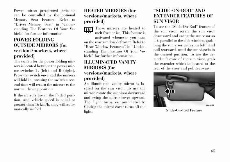
Power mirror preselected positionscan be controlled by the optionalMemory Seat Feature. Refer to“Driver Memory Seat” in “Under-standing The Features Of Your Ve-hicle” for further information.
POWER FOLDINGOUTSIDE MIRRORS (forversions/markets, whereprovided)The switch for the power folding mir-rors is located between the power mir-ror switches L (left) and R (right).Press the switch once and the mirrorswill fold in, pressing the switch a sec-ond time will return the mirrors to thenormal driving position.
If the mirrors are in the folded posi-tion, and vehicle speed is equal orgreater than 16 km/h, they will auto-matically unfold.
HEATED MIRRORS (forversions/markets, whereprovided)
These mirrors are heated tomelt frost or ice. This feature isactivated whenever you turn
on the rear window defroster. Refer to“Rear Window Features” in “Under-standing The Features Of Your Ve-hicle” for further information.
ILLUMINATED VANITYMIRRORS (forversions/markets, whereprovided)An illuminated vanity mirror is lo-cated on the sun visor. To use themirror, rotate the sun visor downwardand swing the mirror cover upward.The light turns on automatically.Closing the mirror cover turns off thelight.
“SLIDE-ON-ROD” ANDEXTENDER FEATURES OFSUN VISORTo use the “Slide-On-Rod” feature ofthe sun visor, rotate the sun visordownward and swing the sun visor soit is parallel to the side window, grab-bing the sun visor with your left handpull rearwards until the sun visor is inthe desired position. To use the ex-tender feature of the sun visor, grabthe extender which is located at therear of the visor and pull rearward.
Slide-On-Rod Feature
65
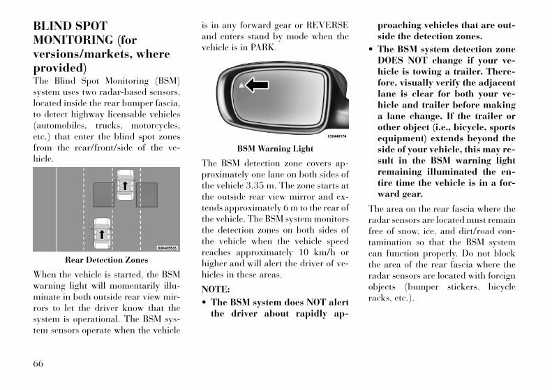
BLIND SPOTMONITORING (forversions/markets, whereprovided)The Blind Spot Monitoring (BSM)system uses two radar-based sensors,located inside the rear bumper fascia,to detect highway licensable vehicles(automobiles, trucks, motorcycles,etc.) that enter the blind spot zonesfrom the rear/front/side of the ve-hicle.
When the vehicle is started, the BSMwarning light will momentarily illu-minate in both outside rear view mir-rors to let the driver know that thesystem is operational. The BSM sys-tem sensors operate when the vehicle
is in any forward gear or REVERSEand enters stand by mode when thevehicle is in PARK.
The BSM detection zone covers ap-proximately one lane on both sides ofthe vehicle 3.35 m. The zone starts atthe outside rear view mirror and ex-tends approximately 6 m to the rear ofthe vehicle. The BSM system monitorsthe detection zones on both sides ofthe vehicle when the vehicle speedreaches approximately 10 km/h orhigher and will alert the driver of ve-hicles in these areas.
NOTE:
• The BSM system does NOT alertthe driver about rapidly ap-
proaching vehicles that are out-side the detection zones.
• The BSM system detection zoneDOES NOT change if your ve-hicle is towing a trailer. There-fore, visually verify the adjacentlane is clear for both your ve-hicle and trailer before makinga lane change. If the trailer orother object (i.e., bicycle, sportsequipment) extends beyond theside of your vehicle, this may re-sult in the BSM warning lightremaining illuminated the en-tire time the vehicle is in a for-ward gear.
The area on the rear fascia where theradar sensors are located must remainfree of snow, ice, and dirt/road con-tamination so that the BSM systemcan function properly. Do not blockthe area of the rear fascia where theradar sensors are located with foreignobjects (bumper stickers, bicycleracks, etc.).
Rear Detection Zones
BSM Warning Light
66

The BSM system notifies the driver ofobjects in the detection zones by illu-minating the BSM warning light lo-cated in the outside mirrors in addi-tion to sounding an audible (chime)alert and reducing the radio volume.Refer to “Modes Of Operation” forfurther information.
The BSM system monitors the detec-tion zone from three different entrypoints (side, rear, front) while drivingto see if an alert is necessary. The BSMsystem will issue an alert during thesetypes of zone entries.
Entering From The SideVehicles that move into your adjacentlanes from either side of the vehicle.
Entering From The RearVehicles that come up from behindyour vehicle on either side and enterthe rear detection zone with a relativespeed of less than 48 km/h.
Overtaking TrafficIf you pass another vehicle slowlywith a relative speed of less than16 km/h and the vehicle remains inthe blind spot for approximately1.5 seconds, the warning light will beilluminated. If the difference in speedbetween the two vehicles is greaterthan 16 km/h, the warning light willnot illuminate.
Side Monitoring
Rear Monitoring
Overtaking/Approaching
Overtaking/Passing
67
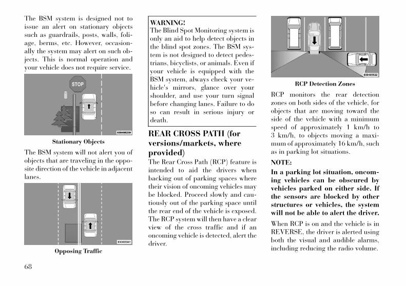
The BSM system is designed not toissue an alert on stationary objectssuch as guardrails, posts, walls, foli-age, berms, etc. However, occasion-ally the system may alert on such ob-jects. This is normal operation andyour vehicle does not require service.
The BSM system will not alert you ofobjects that are traveling in the oppo-site direction of the vehicle in adjacentlanes.
WARNING!The Blind Spot Monitoring system isonly an aid to help detect objects inthe blind spot zones. The BSM sys-tem is not designed to detect pedes-trians, bicyclists, or animals. Even ifyour vehicle is equipped with theBSM system, always check your ve-hicle's mirrors, glance over yourshoulder, and use your turn signalbefore changing lanes. Failure to doso can result in serious injury ordeath.
REAR CROSS PATH (forversions/markets, whereprovided)The Rear Cross Path (RCP) feature isintended to aid the drivers whenbacking out of parking spaces wheretheir vision of oncoming vehicles maybe blocked. Proceed slowly and cau-tiously out of the parking space untilthe rear end of the vehicle is exposed.The RCP system will then have a clearview of the cross traffic and if anoncoming vehicle is detected, alert thedriver.
RCP monitors the rear detectionzones on both sides of the vehicle, forobjects that are moving toward theside of the vehicle with a minimumspeed of approximately 1 km/h to3 km/h, to objects moving a maxi-mum of approximately 16 km/h, suchas in parking lot situations.
NOTE:
In a parking lot situation, oncom-ing vehicles can be obscured byvehicles parked on either side. Ifthe sensors are blocked by otherstructures or vehicles, the systemwill not be able to alert the driver.
When RCP is on and the vehicle is inREVERSE, the driver is alerted usingboth the visual and audible alarms,including reducing the radio volume.
Stationary Objects
Opposing Traffic
RCP Detection Zones
68
WARNING!RCP is not a Back Up Aid system. Itis intended to be used to help adriver detect an oncoming vehicle ina parking lot situation. Drivers mustbe careful when backing up, evenwhen using RCP. Always check care-fully behind your vehicle, look be-hind you, and be sure to check forpedestrians, animals, other vehicles,obstructions, and blind spots beforebacking up. Failure to do so canresult in serious injury or death.
MODES OF OPERATIONThree selectable modes of operationare available in the Uconnect Touch™System. Refer to “Uconnect Touch™Settings” in “Understanding Your In-strument Panel” for further informa-tion.
Blind Spot AlertWhen operating in Blind Spot Alertmode, the BSM system will provide avisual alert in the appropriate sideview mirror based on a detected ob-ject. However, when the system is op-erating in RCP, the system will re-spond with both visual and audiblealerts when a detected object is pres-ent. Whenever an audible alert is re-quested, the radio volume is reduced.
Blind Spot Alert Lights/ChimeWhen operating in Blind Spot AlertLights/Chime mode, the BSM systemwill provide a visual alert in the ap-propriate side view mirror based on adetected object. If the turn signal isthen activated, and it corresponds toan alert present on that side of thevehicle, an audible chime will also besounded. Whenever a turn signal anddetected object are present on thesame side at the same time, both thevisual and audio alerts will be issued.In addition to the audible alert, theradio (if on) volume will be reduced.
NOTE:
• Whenever an audible alert is re-quested by the BSM system, theradio volume is reduced.
• If the hazard flashers are on, thesystem will request the appro-priate visual alert only.
When the system is in RCP, thesystem shall respond with both vi-sual and audible alerts when a de-tected object is present. Wheneveran audible alert is requested, theradio is also muted. Turn/hazardsignal status is ignored; the RCPstate always requests the audiblechime.
Blind Spot Alert OffWhen the BSM system is turned off,there will be no visual or audiblealerts from either the BSM or RCPsystems.
NOTE:
The BSM system will store the cur-rent operating mode when the ve-hicle is shut off. Each time the ve-hicle is started, the previouslystored mode will be recalled andused.
69
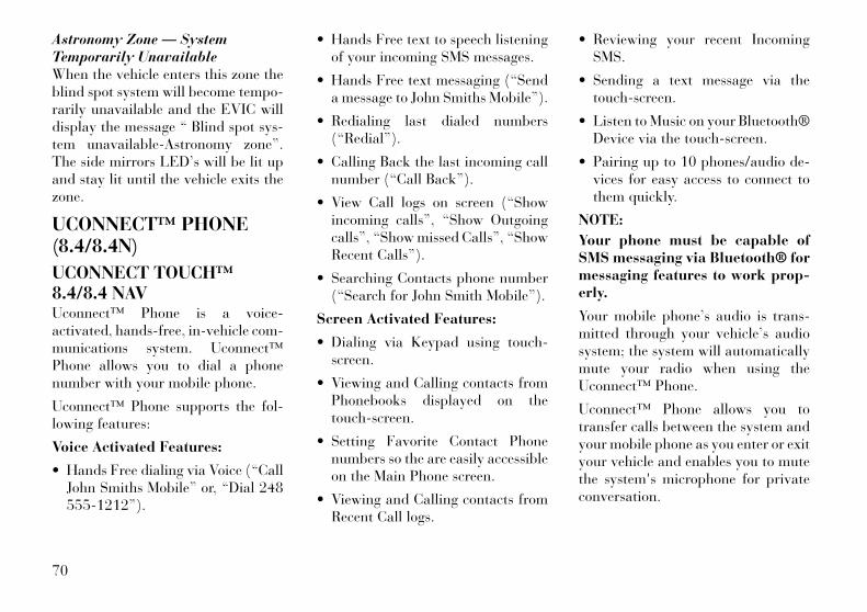
Astronomy Zone — SystemTemporarily UnavailableWhen the vehicle enters this zone theblind spot system will become tempo-rarily unavailable and the EVIC willdisplay the message “ Blind spot sys-tem unavailable-Astronomy zone”.The side mirrors LED’s will be lit upand stay lit until the vehicle exits thezone.
UCONNECT™ PHONE(8.4/8.4N)
UCONNECT TOUCH™8.4/8.4 NAVUconnect™ Phone is a voice-activated, hands-free, in-vehicle com-munications system. Uconnect™Phone allows you to dial a phonenumber with your mobile phone.
Uconnect™ Phone supports the fol-lowing features:
Voice Activated Features:
• Hands Free dialing via Voice (“CallJohn Smiths Mobile” or, “Dial 248555-1212”).
• Hands Free text to speech listeningof your incoming SMS messages.
• Hands Free text messaging (“Senda message to John Smiths Mobile”).
• Redialing last dialed numbers(“Redial”).
• Calling Back the last incoming callnumber (“Call Back”).
• View Call logs on screen (“Showincoming calls”, “Show Outgoingcalls”, “Show missed Calls”, “ShowRecent Calls”).
• Searching Contacts phone number(“Search for John Smith Mobile”).
Screen Activated Features:
• Dialing via Keypad using touch-screen.
• Viewing and Calling contacts fromPhonebooks displayed on thetouch-screen.
• Setting Favorite Contact Phonenumbers so the are easily accessibleon the Main Phone screen.
• Viewing and Calling contacts fromRecent Call logs.
• Reviewing your recent IncomingSMS.
• Sending a text message via thetouch-screen.
• Listen to Music on your Bluetooth®Device via the touch-screen.
• Pairing up to 10 phones/audio de-vices for easy access to connect tothem quickly.
NOTE:
Your phone must be capable ofSMS messaging via Bluetooth® formessaging features to work prop-erly.
Your mobile phone’s audio is trans-mitted through your vehicle’s audiosystem; the system will automaticallymute your radio when using theUconnect™ Phone.
Uconnect™ Phone allows you totransfer calls between the system andyour mobile phone as you enter or exityour vehicle and enables you to mutethe system's microphone for privateconversation.
70

WARNING!Any voice commanded systemshould be used only in safe drivingconditions following local laws andphone use. All attention should bekept on the roadway ahead. Failureto do so may result in an accidentcausing serious injury or death.
The Uconnect™ Phone is driventhrough your Bluetooth® “Hands-Free Profile” mobile phone.Uconnect™ features Bluetooth®technology - the global standard thatenables different electronic devices toconnect to each other without wires ora docking station, so Uconnect™Phone works no matter where youstow your mobile phone (be it yourpurse, pocket, or briefcase), as long asyour phone is turned on and has beenpaired to the vehicle's Uconnect™Phone. The Uconnect™ Phone allowsup to ten mobile phones or audio de-vices to be linked to the system. Onlyone linked (or paired) mobile phoneand one audio device can be used with
the system at a time. The system isavailable in English, Spanish, orFrench languages.
Uconnect™ Phone ButtonThe Uconnect™ PhoneButton is used to get intothe phone mode and makecalls, show recent, incom-
ing, outgoing calls, view phonebooketc., When you press the button youwill hear a BEEP. The beep is yoursignal to give a command.
Uconnect™ Voice Command ButtonThe Uconnect™ VoiceCommand Button isonly used for “barge in”and when you are already in
a call and you want to send Tones ormake another call.
The button is also used to accessthe Voice Commands for theUconnect™ Voice Command featuresif your vehicle is equipped. Please seethe Uconnect™ Voice Command sec-tion for direction on how to use the
button.
The Uconnect™ Phone is fully inte-grated with the vehicle's audio sys-
tem. The volume of the Uconnect™Phone can be adjusted either from theradio volume control knob or from thesteering wheel radio control (rightswitch), if so equipped.
OPERATIONVoice commands can be used to oper-ate the Uconnect™ Phone and tonavigate through the Uconnect™Phone menu structure. Voice com-mands are required after mostUconnect™ Phone prompts. Thereare two general methods for howVoice Command works:
1. Say compound commands like“Call John Smith mobile”.
2. Say the individual commands andallow the system to guide you to com-plete the task.
You will be prompted for a specificcommand and then guided throughthe available options.
• Prior to giving a voice command,one must wait for the beep, whichfollows the “Listen” prompt or an-other prompt.
71

• For certain operations, compoundcommands can be used. For ex-ample, instead of saying “Call” andthen “John Smith” and then “mo-bile”, the following compoundcommand can be said: “Call JohnSmith mobile”.
• For each feature explanation in thissection, only the compound com-mand form of the voice command isgiven. You can also break the com-mands into parts and say each partof the command when you areasked for it. For example, you canuse the compound command formvoice command “Search for JohnSmith”, or you can break the com-pound command form into twovoice commands: “Search Contact”and when asked “John Smith”.Please remember, the Uconnect™Phone works best when you talk ina normal conversational tone, as ifspeaking to someone sitting a fewmeters away from you.
Natural SpeechYour Uconnect™ Phone Voice systemuses a Natural Language Voice Rec-ognition (VR) engine.
Natural speech allows the user tospeak commands in phrases or com-plete sentences. The system filters outcertain non-word utterances andsounds such as “ah” and “eh”. Thesystem handles fill-in words such as “Iwould like to”.
The system handles multiple inputs inthe same phrase or sentence such as“make a phone call” and “to KellySmith”. For multiple inputs in thesame phrase or sentence, the systemidentifies the topic or context and pro-vides the associated follow-up promptsuch as “Who do you want to call?” inthe case where a phone call was re-quested but the specific name was notrecognized.
The system utilizes continuous dialog;when the system requires more infor-mation from the user it will ask aquestion to which the user can re-spond without pressing the VoiceCommand button.
Voice Command TreeRefer to “Voice Tree” in this section.
Help CommandIf you need assistance at any prompt,or if you want to know your options atany prompt, say “Help” following thebeep.
To activate the Uconnect™ Phonefrom idle, simply press the buttonand say a command or say “help”. AllUconnect™ Phone sessions beginwith a press of the button on theradio control head.
Cancel CommandAt any prompt, after the beep, youcan say “Cancel” and you will be re-turned to the main menu.
You can also press the orbuttons when the system is listeningfor a command and be returned to themain or previous menu.
NOTE:
Pressing the or buttonswhile the system is playing isknown as “Barging In”, refer to“Barge In — Overriding Prompts”for further information.
72
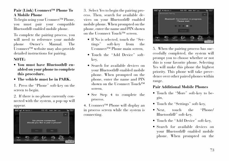
Pair (Link) Uconnect™ Phone ToA Mobile PhoneTo begin using your Uconnect™ Phone,you must pair your compatibleBluetooth® enabled mobile phone.
To complete the pairing process, youwill need to reference your mobilephone Owner's Manual. TheUconnect™ website may also providedetailed instructions for pairing.
NOTE:
• You must have Bluetooth® en-abled on your phone to completethis procedure.
• The vehicle must be in PARK.
1. Press the “Phone” soft-key on thescreen to begin.
2. If there is no phone currently con-nected with the system, a pop-up willappear.
3. Select Yes to begin the pairing pro-cess. Then, search for available de-vices on your Bluetooth® enabledmobile phone. When prompted on thephone, enter the name and PIN shownon the Uconnect Touch™ screen.
• If No is selected, touch the “Set-tings” soft-key from theUconnect™ Phone main screen,
• Touch the “Add Device” soft-key,
• Search for available devices onyour Bluetooth® enabled mobilephone. When prompted on thephone, enter the name and PINshown on the Uconnect Touch™screen,
• See Step 4 to complete theprocess.
4. Uconnect™ Phone will display anin process screen while the system isconnecting.
5. When the pairing process has suc-cessfully completed, the system willprompt you to choose whether or notthis is your favorite phone. SelectingYes will make this phone the highestpriority. This phone will take prece-dence over other paired phones withinrange.
Pair Additional Mobile Phones
• Touch the “More” soft-key to be-gin,
• Touch the “Settings” soft-key,
• Next, touch the “Phone/Bluetooth®” soft-key,
• Touch the “Add Device” soft-key,
• Search for available devices onyour Bluetooth® enabled mobilephone. When prompted on the
73
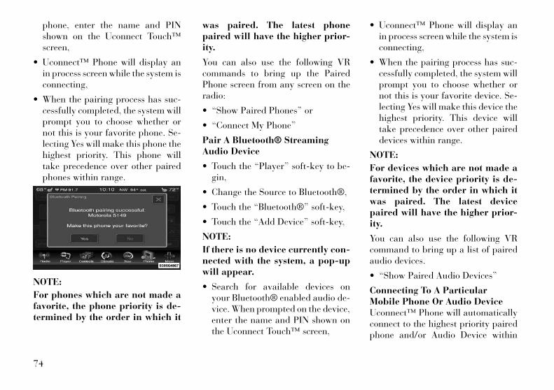
phone, enter the name and PINshown on the Uconnect Touch™screen,
• Uconnect™ Phone will display anin process screen while the system isconnecting,
• When the pairing process has suc-cessfully completed, the system willprompt you to choose whether ornot this is your favorite phone. Se-lecting Yes will make this phone thehighest priority. This phone willtake precedence over other pairedphones within range.
NOTE:
For phones which are not made afavorite, the phone priority is de-termined by the order in which it
was paired. The latest phonepaired will have the higher prior-ity.
You can also use the following VRcommands to bring up the PairedPhone screen from any screen on theradio:
• “Show Paired Phones” or
• “Connect My Phone”
Pair A Bluetooth® StreamingAudio Device
• Touch the “Player” soft-key to be-gin,
• Change the Source to Bluetooth®,
• Touch the “Bluetooth®” soft-key,
• Touch the “Add Device” soft-key,
NOTE:
If there is no device currently con-nected with the system, a pop-upwill appear.
• Search for available devices onyour Bluetooth® enabled audio de-vice. When prompted on the device,enter the name and PIN shown onthe Uconnect Touch™ screen,
• Uconnect™ Phone will display anin process screen while the system isconnecting,
• When the pairing process has suc-cessfully completed, the system willprompt you to choose whether ornot this is your favorite device. Se-lecting Yes will make this device thehighest priority. This device willtake precedence over other paireddevices within range.
NOTE:
For devices which are not made afavorite, the device priority is de-termined by the order in which itwas paired. The latest devicepaired will have the higher prior-ity.
You can also use the following VRcommand to bring up a list of pairedaudio devices.
• “Show Paired Audio Devices”
Connecting To A ParticularMobile Phone Or Audio DeviceUconnect™ Phone will automaticallyconnect to the highest priority pairedphone and/or Audio Device within
74
range. If you would need to choose aparticular phone or Audio Device fol-low these steps:
• Touch the “Settings” soft-key,
• Touch the “Phone/Bluetooth®”soft-key,
• Touch to select the particularPhone or the “Paired AudioSources” soft-key and then an Au-dio Device,
• Touch the X to exit out of the Set-tings screen.
Disconnecting A Phone or AudioDevice
• Touch the “Settings” soft-key,
• Touch the “Phone/Bluetooth®”soft-key,
• Touch the + soft-key located to theright of the device name,
• The options pop-up will be dis-played,
• Touch the “Disconnect Device”soft-key,
• Touch the X to exit out of the Set-tings screen.
Deleting A Phone Or AudioDevice
• Touch the “Settings” soft-key,
• Touch the Phone/Bluetooth® soft-key,
• Touch the + soft-key located to theright of the device name for a dif-ferent Phone or Audio Device thanthe currently connected device,
• The options pop-up will be dis-played,
• Touch the “Delete Device” soft-key,
• Touch the X to exit out of the Set-tings screen.
Making A Phone Or Audio DeviceA Favorite
• Touch the “Settings” soft-key,
• Touch the “Phone/Bluetooth®”soft-key,
• Touch the + soft-key located to theright of the device name,
• The options pop-up will be dis-played,
• Touch the “Make Favorite” soft-key; you will see the chosen devicemove to the top of the list,
• Touch the X to exit out of the Set-tings screen.
Phonebook Download —Automatic Phonebook TransferFrom Mobile PhoneIf equipped and specifically sup-ported by your phone, Uconnect™Phone automatically downloadsnames (text names) and number en-tries from the mobile phone’s phone-book. Specific Bluetooth® Phoneswith Phone Book Access Profile maysupport this feature. See Uconnect™website for supported phones.
• To call a name from a downloadedmobile phonebook, follow the pro-cedure in “Call by Saying a Name”section.
• Automatic download and update, ifsupported, begins as soon as theBluetooth® wireless phone connec-tion is made to the Uconnect™Phone, for example, after you startthe vehicle.
75

• A maximum of 1000 entries perphone will be downloaded and up-dated every time a phone is con-nected to the Uconnect™ Phone.
• Depending on the maximum num-ber of entries downloaded, theremay be a short delay before thelatest downloaded names can beused. Until then, if available, thepreviously downloaded phonebookis available for use.
• Only the phonebook of the cur-rently connected mobile phone isaccessible.
• This downloaded phonebook can-not be edited or deleted on theUconnect™ Phone. These can onlybe edited on the mobile phone. Thechanges are transferred and up-dated to Uconnect™ Phone on thenext phone connection.
Managing Your FavoritePhonebookThere are three ways you can add anentry to your Favorite Phonebook.
1. During an active call of a numberto make a favorite, touch and hold a
favorite button on the top of thephone main screen.
2. After loading the mobile phone-book, select phonebook from thePhone main screen, then select theappropriate number. Touch the + nextto the selected number to display theoptions pop-up. In the pop-up select“Add to Favorites”.
NOTE:
If the Favorites list is full, you willbe asked to remove an existing fa-vorite.
3. From the Phone main screen, se-lect phonebook. From the phonebookscreen, select the “Favorites” soft-keyand then select the + soft-key locatedto the right of the phonebook record.Select an empty entry and touch the +on that selected entry. When the Op-
tions pop-up appears, touch “Addfrom Mobile”. You will then be askedwhich contact and number to choosefrom your mobile phonebook. Whencomplete the new favorite will beshown.
To Remove A Favorite
• To remove a Favorite, select phone-book from the Phone main screen.
• Next select Favorites on the left sideof the screen and then touch the +Options soft-key.
• Touch the + next to the Favoriteyou would like to remove.
76
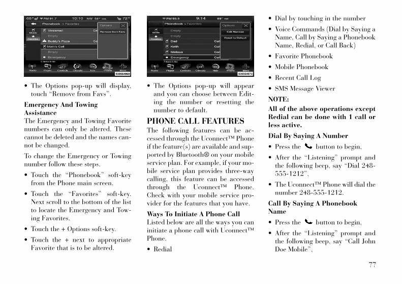
• The Options pop-up will display,touch “Remove from Favs”.
Emergency And TowingAssistanceThe Emergency and Towing Favoritenumbers can only be altered. Thesecannot be deleted and the names can-not be changed.
To change the Emergency or Towingnumber follow these steps.
• Touch the “Phonebook” soft-keyfrom the Phone main screen.
• Touch the “Favorites” soft-key.Next scroll to the bottom of the listto locate the Emergency and Tow-ing Favorites.
• Touch the + Options soft-key.
• Touch the + next to appropriateFavorite that is to be altered.
• The Options pop-up will appearand you can choose between Edit-ing the number or resetting thenumber to default.
PHONE CALL FEATURESThe following features can be ac-cessed through the Uconnect™ Phoneif the feature(s) are available and sup-ported by Bluetooth® on your mobileservice plan. For example, if your mo-bile service plan provides three-waycalling, this feature can be accessedthrough the Uconnect™ Phone.Check with your mobile service pro-vider for the features that you have.
Ways To Initiate A Phone CallListed below are all the ways you caninitiate a phone call with Uconnect™Phone.
• Redial
• Dial by touching in the number
• Voice Commands (Dial by Saying aName, Call by Saying a PhonebookName, Redial, or Call Back)
• Favorite Phonebook
• Mobile Phonebook
• Recent Call Log
• SMS Message Viewer
NOTE:
All of the above operations exceptRedial can be done with 1 call orless active.
Dial By Saying A Number
• Press the button to begin,
• After the “Listening” prompt andthe following beep, say “Dial 248-555-1212”,
• The Uconnect™ Phone will dial thenumber 248-555-1212.
Call By Saying A PhonebookName
• Press the button to begin,
• After the “Listening” prompt andthe following beep, say “Call JohnDoe Mobile”,
77
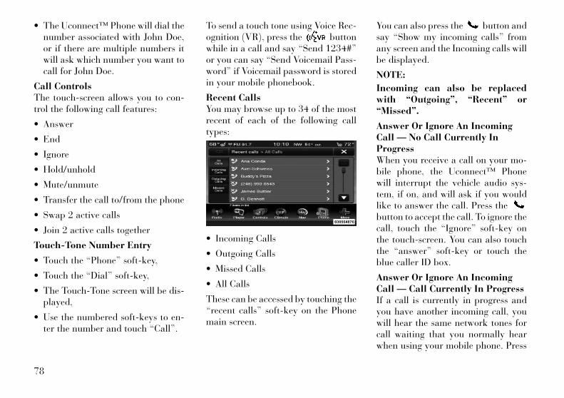
• The Uconnect™ Phone will dial thenumber associated with John Doe,or if there are multiple numbers itwill ask which number you want tocall for John Doe.
Call ControlsThe touch-screen allows you to con-trol the following call features:
• Answer
• End
• Ignore
• Hold/unhold
• Mute/unmute
• Transfer the call to/from the phone
• Swap 2 active calls
• Join 2 active calls together
Touch-Tone Number Entry
• Touch the “Phone” soft-key,
• Touch the “Dial” soft-key,
• The Touch-Tone screen will be dis-played,
• Use the numbered soft-keys to en-ter the number and touch “Call”.
To send a touch tone using Voice Rec-ognition (VR), press the buttonwhile in a call and say “Send 1234#”or you can say “Send Voicemail Pass-word” if Voicemail password is storedin your mobile phonebook.
Recent CallsYou may browse up to 34 of the mostrecent of each of the following calltypes:
• Incoming Calls
• Outgoing Calls
• Missed Calls
• All Calls
These can be accessed by touching the“recent calls” soft-key on the Phonemain screen.
You can also press the button andsay “Show my incoming calls” fromany screen and the Incoming calls willbe displayed.
NOTE:
Incoming can also be replacedwith “Outgoing”, “Recent” or“Missed”.
Answer Or Ignore An IncomingCall — No Call Currently InProgressWhen you receive a call on your mo-bile phone, the Uconnect™ Phonewill interrupt the vehicle audio sys-tem, if on, and will ask if you wouldlike to answer the call. Press thebutton to accept the call. To ignore thecall, touch the “Ignore” soft-key onthe touch-screen. You can also touchthe “answer” soft-key or touch theblue caller ID box.
Answer Or Ignore An IncomingCall — Call Currently In ProgressIf a call is currently in progress andyou have another incoming call, youwill hear the same network tones forcall waiting that you normally hearwhen using your mobile phone. Press
78

the phone button, answer soft-key or caller ID box to place the cur-rent call on hold and answer the in-coming call.
NOTE:
The Uconnect™ Phone compatiblephones in the market today do notsupport rejecting an incoming callwhen another call is in progress.Therefore, the user can only an-swer an incoming call or ignore it.
Making A Second Call WhileCurrent Call Is In ProgressTo make a second call while you arecurrently on a call, press thebutton and say “Dial” or “Call” fol-lowed by the phone number or phone-book entry you wish to call. The firstcall will be on hold while the secondcall is in progress. Or you can place acall on hold by touching the Holdsoft-key on the Phone main screen,then dial a number from the dialpad,recent calls, SMS Inbox or from thephonebooks. To go back to the firstcall, refer to “Toggling Between Calls”in this section. To combine two calls,refer to “Join Calls” in this section.
Place/Retrieve A Call From HoldDuring an active call, touch the“Hold” soft-key on the Phone mainscreen.
Toggling Between CallsIf two calls are in progress (one activeand one on hold), touch the “Swap”soft-key on the Phone main screen.Only one call can be placed on hold ata time.
You can also press the button totoggle between the active and heldphone call.
Join CallsWhen two calls are in progress (oneactive and one on hold), touch the“Join Calls” soft-key on the Phonemain screen to combine all calls into aConference Call.
Call TerminationTo end a call in progress, momentarilypress the button or the end soft-key. Only the active call(s) will beterminated and if there is a call onhold, it will become the new activecall. If the active call is terminated bythe far end, a call on hold may not
become active automatically. This iscell phone-dependent.
Redial
• Press the “Redial” soft-key,
• or press the and after the “Lis-tening” prompt and the followingbeep, say “Redial”,
• After the “Listening” prompt andthe following beep, say “Redial”,
• The Uconnect™ Phone will call thelast number that was dialed fromyour mobile phone.
Call ContinuationCall continuation is the progression ofa phone call on the Uconnect™ Phoneafter the vehicle ignition key has beenswitched to OFF.
NOTE:
The call will remain within the ve-hicle audio system until the phonebecomes out of range for theBluetooth® connection. It is rec-ommended to press the “transfer”soft-key when leaving the vehicle.
79

UCONNECT™ PHONEFEATURES
Emergency AssistanceIf you are in an emergency and themobile phone is reachable:
• Pick up the phone and manuallydial the emergency number foryour area.
If the phone is not reachable and theUconnect™ Phone is operational, youmay reach the emergency number asfollows:
• Press the button to begin.
• After the “Listening” prompt andthe following beep, say “Call Emer-gency or Dial Emergency” and theUconnect™ Phone will instruct thepaired mobile phone to call theemergency number. This feature issupported in the U.S., Canada, andMexico.
NOTE:
• The Emergency call may also beinitiated by using the touch-screen.
• The emergency number dialed isbased on the country where the
vehicle is purchased. The num-ber dialed may not be appli-cable with the available mobileservice and area.
• The Uconnect™ Phone doesslightly lower your chances ofsuccessfully making a phonecall as to that for the mobilephone directly.
WARNING!Your phone must be turned on andconnected to the Uconnect™ Phoneto allow use of this vehicle feature inemergency situations, when the mo-bile phone has network coverageand stays connected to theUconnect™ Phone.
Towing AssistanceIf you need towing assistance:
• Press the button to begin.
• After the “Listening” prompt andthe following beep, say “TowingAssistance”.
NOTE:
• The towing assistance call mayalso be initiated by touch.
• The towing assistance numberdialed is based on the countrywhere the vehicle is purchased.Please refer to the LANCIA 24-Hour “Towing Assistance” cov-erage details in the Warranty In-formation Booklet and on the24–Hour Towing AssistanceCard.
Voice Mail CallingTo learn how to access your voicemail, refer to “Working with Auto-mated Systems”.
Working With Automated SystemsThis method is used in instanceswhere one generally has to press num-bers on the mobile phone keypadwhile navigating through an auto-mated telephone system.
You can use your Uconnect™ Phoneto access a voice mail system or anautomated service, such as a pagingservice or automated customer serviceline. Some services require immediateresponse selection. In some instances,that may be too quick for use of theUconnect™ Phone.
80

When calling a number with yourUconnect™ Phone that normally re-quires you to enter in a touch-tonesequence on your mobile phone key-pad, you can utilize the touch-screenor press the button and say theword “Send” then the sequence youwish to enter. For example, if requiredto enter your PIN followed with apound, (3 7 4 6 #), you can press the
button and say, “Send 3 7 4 6#”. Saying “Send” followed by anumber, or sequence of numbers, isalso to be used for navigating throughan automated customer service centermenu structure, and to leave a num-ber on a pager.
You can also send stored mobilephonebook entries as tones for fastand easy access to voice mail andpager entries. For example, if you pre-viously created a Phonebook entrywith First and/or Last Name as“Voicemail Password”, then if youpress the button and say “SendVoicemail Password” the Uconnect™Phone will then send the correspond-
ing phone number associated with thephonebook entry, as tones over thephone.
NOTE:
• The first number encounteredfor that contact will be sent. Allother numbers entered for thatcontact will be ignored.
• You may not hear all of the tonesdue to mobile phone networkconfigurations. This is normal.
• Some paging and voice mail sys-tems have system time out set-tings that are too short and maynot allow the use of this feature.
• Pauses, wait or other charactersthat are supported by somephones are not supported overBluetooth®. These additionalsymbols will be ignored in thedialing a numbered sequence.
Barge In — Overriding PromptsThe button can be used whenyou wish to skip part of a prompt andissue your voice command immedi-ately. For example, if a prompt is ask-ing “There are 2 numbers with thename John. Say the full name” you
could press the button and say,“John Smith” to select that optionwithout having to listen to the rest ofthe voice prompt.
Voice Response LengthIt is possible for you to choose be-tween Brief and Detailed Voice Re-sponse Length.
• Touch the “More” soft-key, thentouch the “Settings” soft-key,
• Touch the “Display” soft-key, thenscroll down to Voice ResponseLength,
• Select either “Brief” or “Detailed”by touching the box next to theselection. A check-mark will ap-pear to show your selection.
Phone And Network StatusIndicatorsUconnect™ Phone will provide noti-fication to inform you of your phoneand network status when you are at-tempting to make a phone call usingUconnect™ Phone. The status isgiven for network signal strength andphone battery strength.
81
Dialing Using The Mobile PhoneKeypadYou can dial a phone number withyour mobile phone keypad and stilluse the Uconnect™ Phone (while di-aling via the mobile phone keypad,the user must exercise caution andtake precautionary safety measures).By dialing a number with your pairedBluetooth® mobile phone, the audiowill be played through your vehicle'saudio system. The Uconnect™ Phonewill work the same as if you dial thenumber using voice command.
NOTE:
Certain brands of mobile phonesdo not send the dial ring to theUconnect™ Phone to play it on thevehicle audio system, so you willnot hear it. Under this situation,after successfully dialing a num-ber the user may feel that the calldid not go through even though thecall is in progress. Once your call isanswered, you will hear the audio.
Mute/Un-Mute (Mute OFF)When you mute the Uconnect™Phone, you will still be able to hearthe conversation coming from theother party, but the other party willnot be able to hear you. In order tomute the Uconnect™ Phone simplytouch the Mute button on the Phonemain screen.
ADVANCED PHONECONNECTIVITY
Transfer Call To And FromMobile PhoneThe Uconnect™ Phone allows ongo-ing calls to be transferred from yourmobile phone to the Uconnect™Phone without terminating the call.To transfer an ongoing call from yourUconnect™ Phone paired mobilephone to the Uconnect™ Phone orvice versa, press the Transfer buttonon the Phone main screen.
Connect Or Disconnect LinkBetween The Uconnect™ PhoneAnd Mobile PhoneIf you would like to connect or discon-nect the Bluetooth® connection be-tween a Uconnect™ Phone pairedmobile phone and the Uconnect™Phone, follow the instructions de-scribed in your mobile phone User'sManual.
THINGS YOU SHOULDKNOW ABOUT YOURUCONNECT™ PHONE
Voice Command
• For best performance, adjust therearview mirror to provide at least1 cm gap between the overheadconsole (for versions/markets,where provided) and the mirror.
• Always wait for the beep beforespeaking.
82
• Speak normally, without pausing,just as you would speak to a personsitting a few meters away from you.
• Make sure that no one other thanyou is speaking during a voice com-mand period.
• Performance is maximized under:
• low-to-medium blower setting,
• low-to-medium vehicle speed,
• low road noise,
• smooth road surface,
• fully closed windows,
• dry weather condition.
• Even though the system is designedfor users speaking in North Ameri-can English, French, and Spanishaccents, the system may not alwayswork for some.
• When navigating through an auto-mated system such as voice mail, orwhen sending a page, before speak-ing the digit string, make sure tosay “Send”.
• Storing names in your favoritesphonebook when the vehicle is notin motion is recommended.
• Phonebook (Mobile and Favorites)name recognition rate is optimizedwhen the entries are not similar.
• You can say “O” (letter “O”) for“0” (zero).
• Even though international dialingfor most number combinations issupported, some shortcut dialingnumber combinations may not besupported.
• In a convertible vehicle, system per-formance may be compromisedwith the convertible top down.
Far End Audio Performance
• Audio quality is maximized under:
• low-to-medium blower setting,
• low-to-medium vehicle speed,
• low road noise,
• smooth road surface,
• fully closed windows,
• dry weather conditions, and
• operation from the driver's seat.
• Performance, such as audio clarity,echo, and loudness to a large degreerely on the phone and network, andnot the Uconnect™ Phone.
• Echo at the far end can sometimesbe reduced by lowering the in-vehicle audio volume.
• In a convertible vehicle, system per-formance may be compromisedwith the convertible top down.
83

SMSUconnect™ Phone can read or sendnew messages on your phone.
Your phone must support SMS overBluetooth® in order to use this fea-ture. If the Uconnect™ Phone deter-mines your phone is not compatiblewith SMS messaging over Bluetooth®the “Messaging” button will be greyedout and the feature will not be avail-able for use.
NOTE:
Uconnect™ Phone SMS is onlyavailable when the vehicle is not inmoving.
Read Messages:
If you receive a new text messagewhile your phone is connected toUconnect™ Phone, an announcementwill be made to notify you that youhave a new text message.
Once a message is received andviewed or listened to, you will havethe following options:
• Send a Reply
• Forward
• Call
Send Messages Using Soft-Keys:
You can send messages usingUconnect™ Phone. To send a newmessage:
• Touch the “Phone” soft-key,
• Touch the “messaging” soft-keythen “New Message”,
• Touch one of the 18 preset mes-sages and the person you wish tosend the message to,
• If multiple numbers are availablefor the contact select which numberyou would like to have the messagesent,
• Press “Send” or “Cancel”.
84
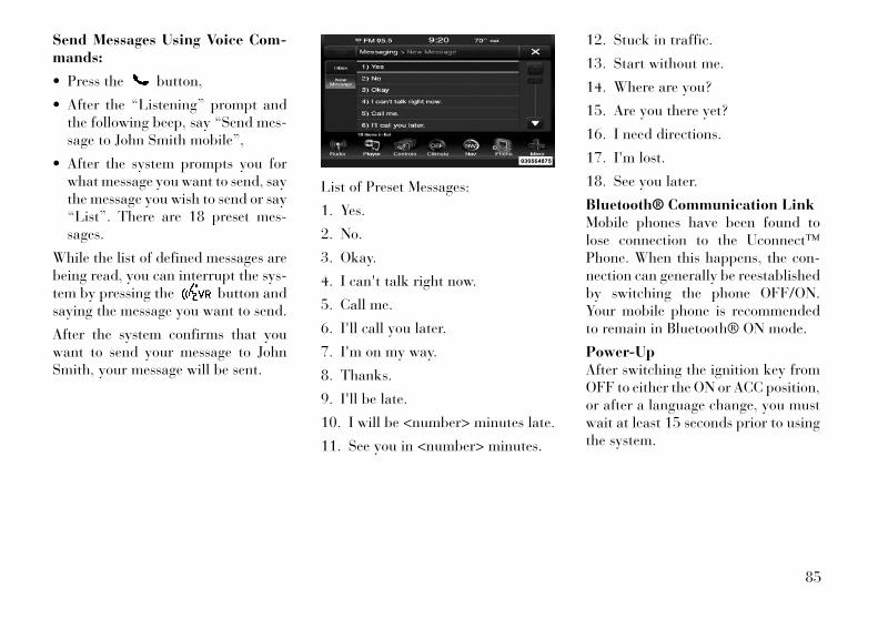
Send Messages Using Voice Com-mands:
• Press the button,
• After the “Listening” prompt andthe following beep, say “Send mes-sage to John Smith mobile”,
• After the system prompts you forwhat message you want to send, saythe message you wish to send or say“List”. There are 18 preset mes-sages.
While the list of defined messages arebeing read, you can interrupt the sys-tem by pressing the button andsaying the message you want to send.
After the system confirms that youwant to send your message to JohnSmith, your message will be sent.
List of Preset Messages:
1. Yes.
2. No.
3. Okay.
4. I can't talk right now.
5. Call me.
6. I'll call you later.
7. I'm on my way.
8. Thanks.
9. I'll be late.
10. I will be <number> minutes late.
11. See you in <number> minutes.
12. Stuck in traffic.
13. Start without me.
14. Where are you?
15. Are you there yet?
16. I need directions.
17. I'm lost.
18. See you later.
Bluetooth® Communication LinkMobile phones have been found tolose connection to the Uconnect™Phone. When this happens, the con-nection can generally be reestablishedby switching the phone OFF/ON.Your mobile phone is recommendedto remain in Bluetooth® ON mode.
Power-UpAfter switching the ignition key fromOFF to either the ON or ACC position,or after a language change, you mustwait at least 15 seconds prior to usingthe system.
85
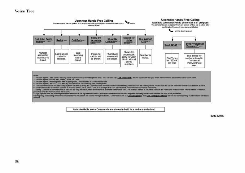
Voice Tree
86
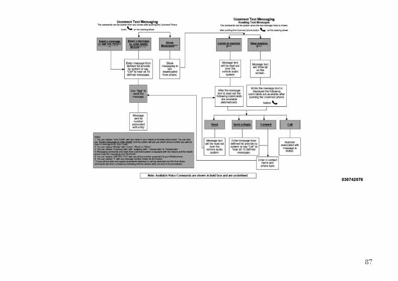
87

GENERAL INFORMATIONThis device complies with Part 15 ofthe FCC rules and RSS 210 of Indus-try Canada. Operation is subject tothe following conditions:
• Changes or modifications not ex-pressly approved by the party re-sponsible for compliance could voidthe user's authority to operate theequipment.
• This device may not cause harmfulinterference.
• This device must accept any inter-ference received, including interfer-ence that may cause undesired op-eration.
VOICE COMMAND
Uconnect Touch™ 8.4/8.4Nav
The Uconnect™ VoiceCommand system allowsyou to control your AM, FMradio, satellite radio, disc
player, SD Card or USB/iPod.
NOTE:
Take care to speak into the VoiceCommand system as calmly andnormally as possible. The abilityof the Voice Command system torecognize user voice commandsmay be negatively affected byrapid speaking or a raised voicelevel.
WARNING!Any voice commanded systemshould be used only in safe drivingconditions following local laws. Allattention should be kept on theroadway ahead. Failure to do so mayresult in a collision cau sing seriousinjury or death.
When you press the Uconnect™ VoiceCommand button, you will heara beep. The beep is your signal to givea command.
If no command is spoken the systemwill say one of two responses:
• I didn't understand
• I didn't get that, etc.,
If a command is not spoken a secondtime, the system will respond with anerror and give some direction as whatcan be said based on the context youare in. After three consecutive failuresof a spoken command the VR sessionwith end.
Pressing the Uconnect™ Voice Com-mand button while the systemis speaking is known as “barging in.”The system will be interrupted, andafter the beep, you can say a com-mand. This will become helpful onceyou start to learn the options.
NOTE:
At any time, you can say the words“Cancel” or “Help”.
These commands are universal andcan be used from any menu. All othercommands can be used dependingupon the active application.
When using this system, you shouldspeak clearly and at a normal speak-ing volume.
The system will best recognize yourspeech if the windows are closed, andthe heater/air conditioning fan is setto low.
88
At any point, if the system does notrecognize one of your commands, youwill be prompted to repeat it.
To hear available commands, pressthe Uconnect™ Voice Command
button and say “Help”. You willhear available commands for thescreen displayed.
Natural SpeechNatural speech allows the user tospeak commands in phrases or com-plete sentences. The system filters outcertain non-word utterances andsounds such as “ah” and “eh”. Thesystem handles fill-in words such as “Iwould like to”.
The system handles multiple inputs inthe same phrase or sentence such as“make a phone call” and “to KellySmith”. For multiple inputs in thesame phrase or sentence, the systemidentifies the topic or context and pro-vides the associated follow-up promptsuch as “Who do you want to call?” in
the case where a phone call was re-quested but the specific name was notrecognized.
The system utilizes continuous dialog;when the system requires more infor-mation from the user it will ask aquestion to which the user can re-spond without pressing theUconnect™ Voice Commandbutton.
Uconnect™ VoiceCommandsThe Uconnect™ Voice Command sys-tem understands two types of com-mands. Universal commands areavailable at all times. Local com-mands are available if the supportedradio mode is active.
Start a dialogue by pressing theUconnect™ Voice Commandbutton.
Changing the Volume
1. Start a dialogue by pressing theVoice Command button.
2. Say a command (e.g., “Help”).
3. Use the ON/OFF VOLUME rotaryknob to adjust the volume to a com-fortable level while the Voice Com-mand system is speaking. Please notethe volume setting for Voice Com-mand is different than the audio sys-tem.
Starting Voice Recognition (VR)Session in Radio/Player ModesIn this mode, you can say the follow-ing commands:
NOTE:
The commands can be said on anyscreen when a call is not activeafter pushing the Uconnect™Voice Command button.
DiscTo switch to the disc mode, say“Change source to Disc”. This com-mand can be given in any mode orscreen:
• “Track” (#) (to change the track)
89
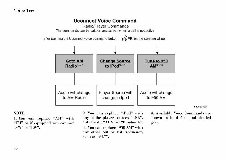
Voice Tree
NOTE:
1. You can replace “AM” with“FM” or if equipped you can say“SW” or “LW”.
2. You can replace “iPod” withany of the player sources “USB”,“SD Card”, “AUX” or “Bluetooth”.
3. You can replace “950 AM” withany other AM or FM frequency,such as “98.7”.
4. Available Voice Commands areshown in bold face and shadedgrey.
90
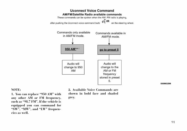
NOTE:
1. You can replace “950 AM” withany other AM or FM frequency,such as “98.7 FM”. If the vehicle isequipped you can command for“SW”, “MW”, and “LW” frequen-cies as well.
2. Available Voice Commands areshown in bold face and shadedgrey.
91
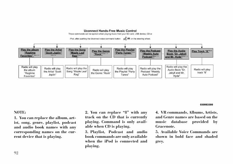
NOTE:
1. You can replace the album, art-ist, song, genre, playlist, podcastand audio book names with anycorresponding names on the cur-rent device that is playing.
2. You can replace “8” with anytrack on the CD that is currentlyplaying. Command is only avail-able when CD is playing.
3. Playlist, Podcast and audiobook commands are only availablewhen the iPod is connected andplaying.
4. VR commands, Albums, Artists,and Genre names are based on themusic database provided byGracenote.
5. Available Voice Commands areshown in bold face and shadedgrey.
92
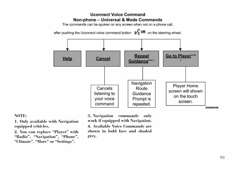
NOTE:
1. Only available with Navigationequipped vehicles.
2. You can replace “Player” with“Radio”, “Navigation”, “Phone”,“Climate”, “More” or “Settings”.
3. Navigation commands onlywork if equipped with Navigation.
4. Available Voice Commands areshown in bold face and shadedgrey.
93
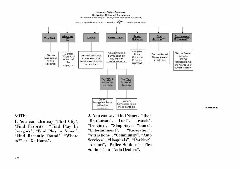
NOTE:
1. You can also say “Find City”,“Find Favorite”, “Find Play byCategory”, “Find Play by Name”,“Find Recently Found”, “Whereto?” or “Go Home”.
2. You can say “Find Nearest” then“Restaurant”, “Fuel”, “Transit”,“Lodging”, “Shopping”, “Bank”,“Entertainment”, “Recreation”,“Attractions”, “Community”, “AutoServices”, “Hospitals”, “Parking”,“Airport”, “Police Stations”, “FireStations”, or “Auto Dealers”.
94

NOTE:
Available Voice Commands areshown in bold face and shadedgrey.
95
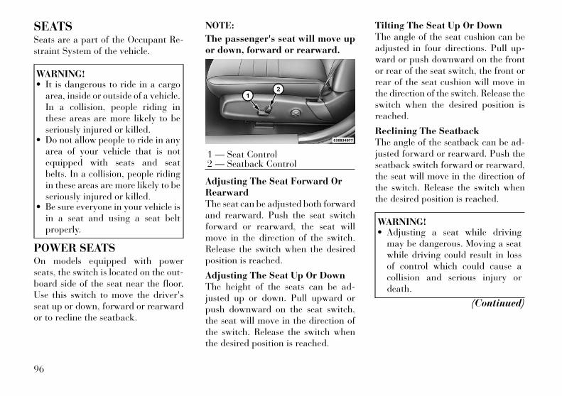
SEATSSeats are a part of the Occupant Re-straint System of the vehicle.
WARNING!• It is dangerous to ride in a cargo
area, inside or outside of a vehicle.In a collision, people riding inthese areas are more likely to beseriously injured or killed.
• Do not allow people to ride in anyarea of your vehicle that is notequipped with seats and seatbelts. In a collision, people ridingin these areas are more likely to beseriously injured or killed.
• Be sure everyone in your vehicle isin a seat and using a seat beltproperly.
POWER SEATSOn models equipped with powerseats, the switch is located on the out-board side of the seat near the floor.Use this switch to move the driver'sseat up or down, forward or rearwardor to recline the seatback.
NOTE:
The passenger's seat will move upor down, forward or rearward.
Adjusting The Seat Forward OrRearwardThe seat can be adjusted both forwardand rearward. Push the seat switchforward or rearward, the seat willmove in the direction of the switch.Release the switch when the desiredposition is reached.
Adjusting The Seat Up Or DownThe height of the seats can be ad-justed up or down. Pull upward orpush downward on the seat switch,the seat will move in the direction ofthe switch. Release the switch whenthe desired position is reached.
Tilting The Seat Up Or DownThe angle of the seat cushion can beadjusted in four directions. Pull up-ward or push downward on the frontor rear of the seat switch, the front orrear of the seat cushion will move inthe direction of the switch. Release theswitch when the desired position isreached.
Reclining The SeatbackThe angle of the seatback can be ad-justed forward or rearward. Push theseatback switch forward or rearward,the seat will move in the direction ofthe switch. Release the switch whenthe desired position is reached.
WARNING!• Adjusting a seat while driving
may be dangerous. Moving a seatwhile driving could result in lossof control which could cause acollision and serious injury ordeath.
(Continued)
1 — Seat Control2 — Seatback Control
96
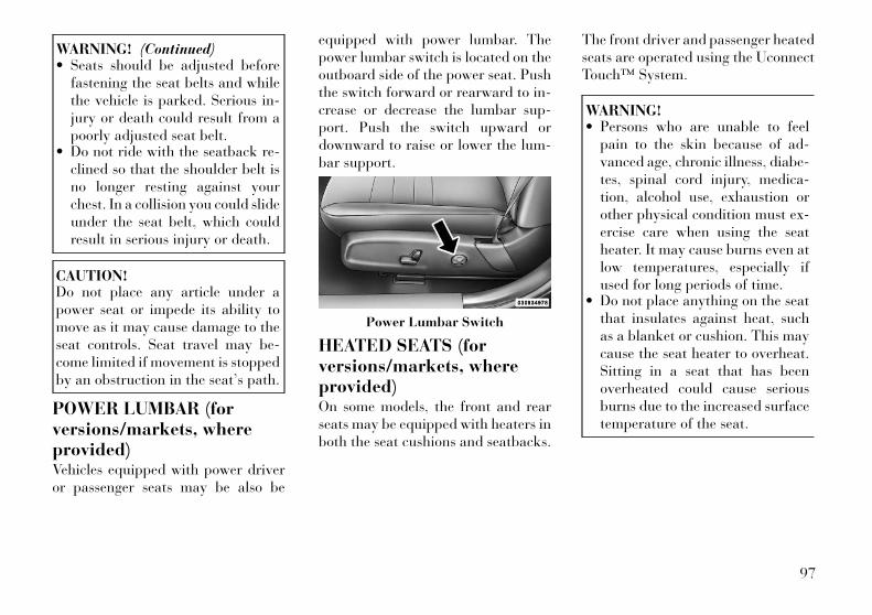
WARNING! (Continued)• Seats should be adjusted before
fastening the seat belts and whilethe vehicle is parked. Serious in-jury or death could result from apoorly adjusted seat belt.
• Do not ride with the seatback re-clined so that the shoulder belt isno longer resting against yourchest. In a collision you could slideunder the seat belt, which couldresult in serious injury or death.
CAUTION!Do not place any article under apower seat or impede its ability tomove as it may cause damage to theseat controls. Seat travel may be-come limited if movement is stoppedby an obstruction in the seat’s path.
POWER LUMBAR (forversions/markets, whereprovided)Vehicles equipped with power driveror passenger seats may be also be
equipped with power lumbar. Thepower lumbar switch is located on theoutboard side of the power seat. Pushthe switch forward or rearward to in-crease or decrease the lumbar sup-port. Push the switch upward ordownward to raise or lower the lum-bar support.
HEATED SEATS (forversions/markets, whereprovided)On some models, the front and rearseats may be equipped with heaters inboth the seat cushions and seatbacks.
The front driver and passenger heatedseats are operated using the UconnectTouch™ System.
WARNING!• Persons who are unable to feel
pain to the skin because of ad-vanced age, chronic illness, diabe-tes, spinal cord injury, medica-tion, alcohol use, exhaustion orother physical condition must ex-ercise care when using the seatheater. It may cause burns even atlow temperatures, especially ifused for long periods of time.
• Do not place anything on the seatthat insulates against heat, suchas a blanket or cushion. This maycause the seat heater to overheat.Sitting in a seat that has beenoverheated could cause seriousburns due to the increased surfacetemperature of the seat.
Power Lumbar Switch
97

Front Heated Seat Operations —Uconnect Touch™ 8.4 and 8.4Nav:Press the “Controls” soft-key locatedon the bottom of the UconnectTouch™ display.
Press the “Driver” or “Pas-senger” seat soft-key onceto select HI-level heating.Press the soft-key a second
time to select LO-level heating. Pressthe soft-key a third time to shut theheating elements OFF.
NOTE:
Once a heat setting is selected, heatwill be felt within two to five min-utes.
When the HI-level setting is selected,the heater will provide a boosted heatlevel during the first four minutes ofoperation. Then, the heat output willdrop to the normal HI-level. If theHI-level setting is selected, the systemwill automatically switch to LO-levelafter a maximum of 60 minutes ofcontinuous operation. At that time,the display will change from HI to LO,indicating the change. The LO-levelsetting will turn OFF automaticallyafter a maximum of 45 minutes.
Rear Heated SeatsOn some models, the two outboardseats are equipped with heated seats.The heated seat switches for theseseats are located on the rear of thecenter console. There are two heatedseat switches that allow the rear pas-sengers to operate the seats indepen-dently.
You can choose from HI, LO or OFFheat settings. Amber indicator lightsin each switch indicate the level ofheat in use. Two indicator lights willilluminate for HI, one for LO andnone for OFF.
Press the switch once to se-lect HI-level heating. Pressthe switch a second time toselect LO-level heating.
Press the switch a third time to shutthe heating elements OFF.
NOTE:
• Once a heat setting is selected,heat will be felt within two tofive minutes.
• The engine must be running forthe heated seats to operate.
Controls Soft-Key
Heated Seats Soft-Keys
98

When the HI-level setting is selected,the heater will provide a boosted heatlevel during the first four minutes ofoperation. Then, the heat output willdrop to the normal HI-level. If theHI-level setting is selected, the systemwill automatically switch to LO-levelafter a maximum of 60 minutes ofcontinuous operation. At that time,the number of illuminated LEDschanges from two to one, indicatingthe change. The LO-level setting willturn OFF automatically after a maxi-mum of 45 minutes.
VENTILATED SEATS (forversions/markets, whereprovided)On some models, both the driver andpassenger seats are ventilated. Lo-cated in the seat cushion and seatbackare small fans that draw air from theseat surface through fine perforationsin the seat cover to help keep thedriver and front passenger cooler inhigher ambient temperatures.
The ventilated seats can be operatedusing the Uconnect Touch™ System.
Front Ventilated Seat Operation— Uconnect Touch™ 8.4/8.4 Nav:Press the “Controls” soft-key locatedon the bottom of the UconnectTouch™ display.
Press the “Driver” or “Passenger”seat soft-key once to select HI-levelventilation. Press the soft-key a sec-ond time to select LO-level ventila-tion. Press the soft-key a third time toshut off the seat ventilation.
Press the “Driver” or “Passenger”seat soft-key once to select HI-levelventilation. Press the soft-key a sec-ond time to select LO-level ventila-tion. Press the soft-key a third time toshut off the seat ventilation.
NOTE:
The engine must be running for theventilated seats to operate.
HEAD RESTRAINTSHead restraints are designed to reducethe risk of injury by restricting headmovement in the event of a rear im-pact. Head restraints should be ad-justed so that the top of the headrestraint is located above the top ofyour ear.
Controls Soft-Key
Ventilated Seats Soft-Keys
99

WARNING!The head restraints for all occupantsmust be properly adjusted prior tooperating the vehicle or occupying aseat. Head restraints should never beadjusted while the vehicle is in mo-tion. Driving a vehicle with the headrestraints improperly adjusted or re-moved could cause serious injury ordeath in the event of a collision.
Active Head Restraints — FrontSeatsThe front driver and passenger seatsare equipped with Active Head Re-straints (AIR). In the event of a rearimpact the AHRs will automaticallyextend forward minimizing the gapbetween the back of the occupantshead and the AIR.
The AHRs will automatically returnto their normal position following arear impact. If the AHRs do not returnto their normal position see your au-thorized deal immediately.
To raise the head restraint, pull up-ward on the head restraint. To lowerthe head restraint, press the push but-
ton, located at the base of the headrestraint, and push downward on thehead restraint.
NOTE:
The head restraints should only beremoved by qualified technicians,for service purposes only. If eitherof the head restraints require re-moval, see your authorized dealer.
WARNING!Do not place items over the top of theActive Head Restraint, such ascoats, seat covers or portable DVDplayers. These items may interferewith the operation of the ActiveHead Restraint in the event of a col-lision and could result in serious in-jury or death.
Rear Head RestraintsThe center head restraint has two posi-tions, up or down. When the center seatis being occupied the head restraintshould be in the raised position. Whenthere are no occupants in the center seatthe head restraint can be lowered formaximum visibility for the driver.
To raise the head restraint, pull up-ward on the head restraint. To lowerthe head restraint, press the push but-ton, located at the base of the headrestraint, and push downward on thehead restraint.
NOTE:
The outboard head restraints arenot adjustable. Refer to “OccupantRestraints” in “Things To KnowBefore Starting Your Vehicle” fortether routing.
Push Button
Push Button
100
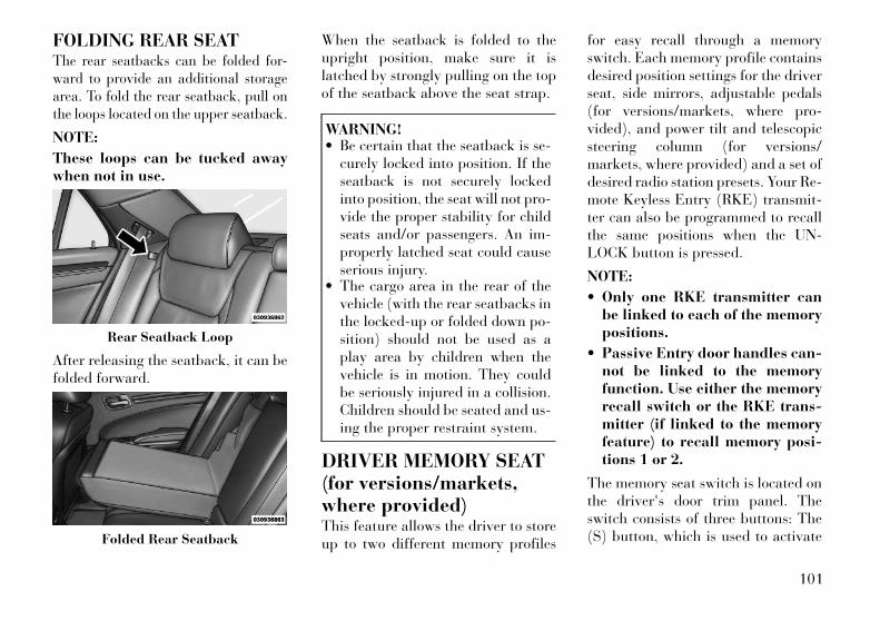
FOLDING REAR SEATThe rear seatbacks can be folded for-ward to provide an additional storagearea. To fold the rear seatback, pull onthe loops located on the upper seatback.
NOTE:
These loops can be tucked awaywhen not in use.
After releasing the seatback, it can befolded forward.
When the seatback is folded to theupright position, make sure it islatched by strongly pulling on the topof the seatback above the seat strap.
WARNING!• Be certain that the seatback is se-
curely locked into position. If theseatback is not securely lockedinto position, the seat will not pro-vide the proper stability for childseats and/or passengers. An im-properly latched seat could causeserious injury.
• The cargo area in the rear of thevehicle (with the rear seatbacks inthe locked-up or folded down po-sition) should not be used as aplay area by children when thevehicle is in motion. They couldbe seriously injured in a collision.Children should be seated and us-ing the proper restraint system.
DRIVER MEMORY SEAT(for versions/markets,where provided)This feature allows the driver to storeup to two different memory profiles
for easy recall through a memoryswitch. Each memory profile containsdesired position settings for the driverseat, side mirrors, adjustable pedals(for versions/markets, where pro-vided), and power tilt and telescopicsteering column (for versions/markets, where provided) and a set ofdesired radio station presets. Your Re-mote Keyless Entry (RKE) transmit-ter can also be programmed to recallthe same positions when the UN-LOCK button is pressed.
NOTE:
• Only one RKE transmitter canbe linked to each of the memorypositions.
• Passive Entry door handles can-not be linked to the memoryfunction. Use either the memoryrecall switch or the RKE trans-mitter (if linked to the memoryfeature) to recall memory posi-tions 1 or 2.
The memory seat switch is located onthe driver's door trim panel. Theswitch consists of three buttons: The(S) button, which is used to activate
Rear Seatback Loop
Folded Rear Seatback
101
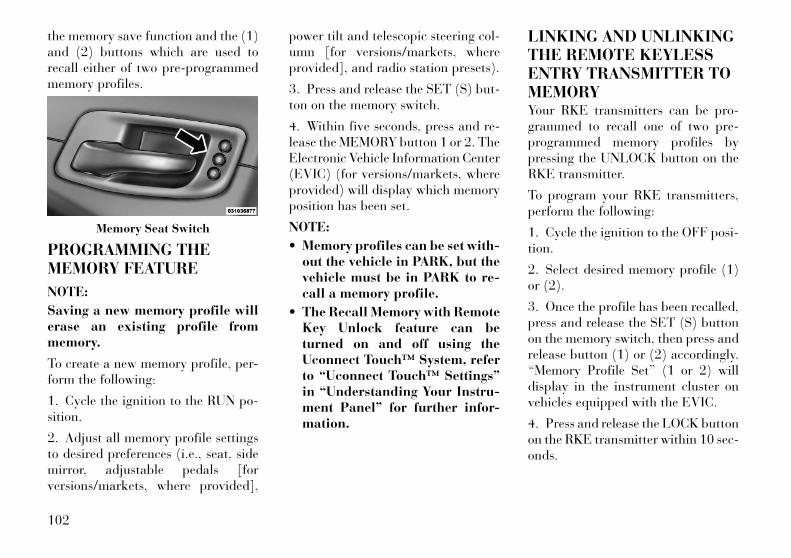
the memory save function and the (1)and (2) buttons which are used torecall either of two pre-programmedmemory profiles.
PROGRAMMING THEMEMORY FEATURE
NOTE:
Saving a new memory profile willerase an existing profile frommemory.
To create a new memory profile, per-form the following:
1. Cycle the ignition to the RUN po-sition.
2. Adjust all memory profile settingsto desired preferences (i.e., seat, sidemirror, adjustable pedals [forversions/markets, where provided],
power tilt and telescopic steering col-umn [for versions/markets, whereprovided], and radio station presets).
3. Press and release the SET (S) but-ton on the memory switch.
4. Within five seconds, press and re-lease the MEMORY button 1 or 2. TheElectronic Vehicle Information Center(EVIC) (for versions/markets, whereprovided) will display which memoryposition has been set.
NOTE:
• Memory profiles can be set with-out the vehicle in PARK, but thevehicle must be in PARK to re-call a memory profile.
• The Recall Memory with RemoteKey Unlock feature can beturned on and off using theUconnect Touch™ System, referto “Uconnect Touch™ Settings”in “Understanding Your Instru-ment Panel” for further infor-mation.
LINKING AND UNLINKINGTHE REMOTE KEYLESSENTRY TRANSMITTER TOMEMORYYour RKE transmitters can be pro-grammed to recall one of two pre-programmed memory profiles bypressing the UNLOCK button on theRKE transmitter.
To program your RKE transmitters,perform the following:
1. Cycle the ignition to the OFF posi-tion.
2. Select desired memory profile (1)or (2).
3. Once the profile has been recalled,press and release the SET (S) buttonon the memory switch, then press andrelease button (1) or (2) accordingly.“Memory Profile Set” (1 or 2) willdisplay in the instrument cluster onvehicles equipped with the EVIC.
4. Press and release the LOCK buttonon the RKE transmitter within 10 sec-onds.
Memory Seat Switch
102

NOTE:
Your RKE transmitters can be un-linked to your memory settings bypressing the SET (S) button fol-lowed by the UNLOCK button onthe RKE transmitter in Step 4above.
MEMORY POSITIONRECALL
NOTE:
The vehicle must be in PARK torecall memory positions. If a recallis attempted when the vehicle isnot in PARK, a message will dis-play in the EVIC (for versions/markets, where provided).
To recall the memory settings fordriver, press MEMORY button num-ber (1) on the driver's door or theUNLOCK button on the RKE trans-mitter linked to memory position 1.
To recall the memory setting fordriver, press MEMORY button num-ber (2) on the driver's door or theUNLOCK button on the RKE trans-mitter linked to memory position 2.
A recall can be cancelled by pressingany of the MEMORY buttons (S, 1, or2) on the driver's door during a recall.When a recall is cancelled, the driverseat, side mirror, adjustable pedals(for versions/markets, where pro-vided), and power tilt and telescopicsteering column (for versions/markets, where provided) stop mov-ing. A delay of one second will occurbefore another recall can be selected.
EASY ENTRY/EXIT SEAT(Available With MemorySeat Only)This feature provides automaticdriver seat positioning to enhancedriver mobility when entering and ex-iting the vehicle.
The distance the driver seat movesdepends on where you have the driverseat positioned when you place theignition to the OFF position.
• When you cycle the ignition to theOFF position, the driver seat willmove about 60 mm rearward if thedriver seat position is greater thanor equal to 67.7 mm forward of therear stop. The seat will return to its
previously set position when youplace the ignition into the ACC orRUN position.
• When you cycle the ignition to theOFF position, the driver seat willmove to a position 7.7 mm forwardof the rear stop if the driver seatposition is between 22.7 mm and67.7 mm forward of the rear stop.The seat will return to its previouslyset position when you place the ig-nition to the ACC or RUN position.
• The Easy Entry/Easy Exit featureis disabled when the driver seat po-sition is less than 22.7 mm forwardof the rear stop. At this position,there is no benefit to the driver bymoving the seat for Easy Exit orEasy Entry.
Each stored memory setting will havean associated Easy Entry and EasyExit position.
NOTE:
The Easy Entry/Easy Exit featurecan be enabled or disabled usingthe Uconnect Touch™ System, re-fer to “Uconnect Touch™ Settings”
103
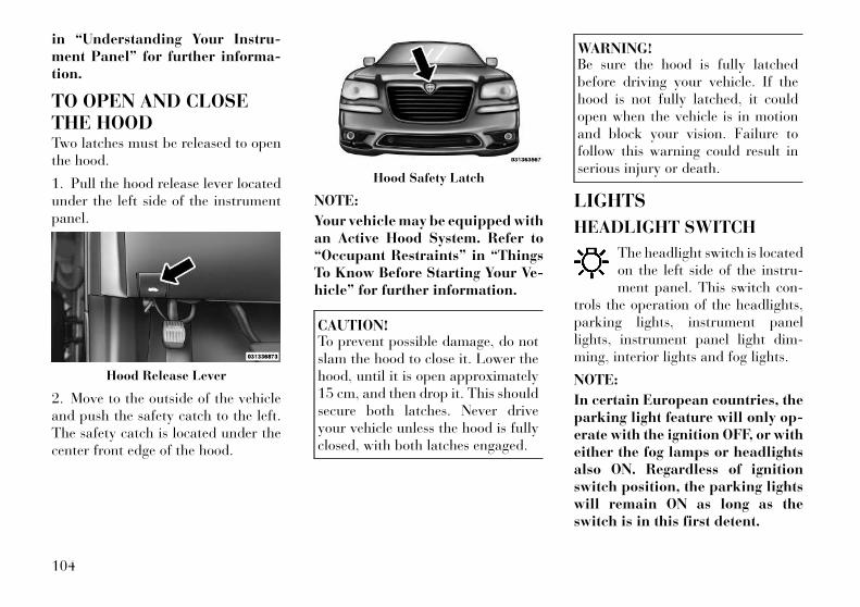
in “Understanding Your Instru-ment Panel” for further informa-tion.
TO OPEN AND CLOSETHE HOODTwo latches must be released to openthe hood.
1. Pull the hood release lever locatedunder the left side of the instrumentpanel.
2. Move to the outside of the vehicleand push the safety catch to the left.The safety catch is located under thecenter front edge of the hood.
NOTE:
Your vehicle may be equipped withan Active Hood System. Refer to“Occupant Restraints” in “ThingsTo Know Before Starting Your Ve-hicle” for further information.
CAUTION!To prevent possible damage, do notslam the hood to close it. Lower thehood, until it is open approximately15 cm, and then drop it. This shouldsecure both latches. Never driveyour vehicle unless the hood is fullyclosed, with both latches engaged.
WARNING!Be sure the hood is fully latchedbefore driving your vehicle. If thehood is not fully latched, it couldopen when the vehicle is in motionand block your vision. Failure tofollow this warning could result inserious injury or death.
LIGHTS
HEADLIGHT SWITCH
The headlight switch is locatedon the left side of the instru-ment panel. This switch con-
trols the operation of the headlights,parking lights, instrument panellights, instrument panel light dim-ming, interior lights and fog lights.
NOTE:
In certain European countries, theparking light feature will only op-erate with the ignition OFF, or witheither the fog lamps or headlightsalso ON. Regardless of ignitionswitch position, the parking lightswill remain ON as long as theswitch is in this first detent.
Hood Release Lever
Hood Safety Latch
104
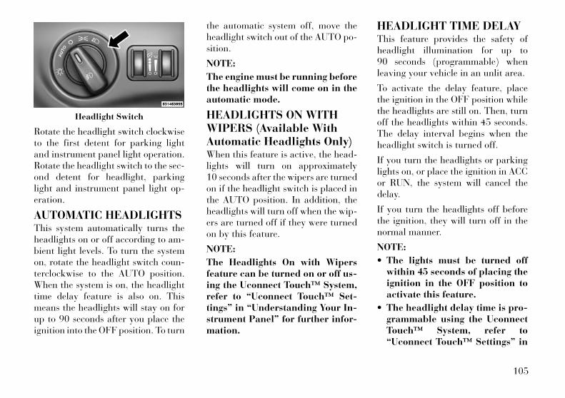
Rotate the headlight switch clockwiseto the first detent for parking lightand instrument panel light operation.Rotate the headlight switch to the sec-ond detent for headlight, parkinglight and instrument panel light op-eration.
AUTOMATIC HEADLIGHTSThis system automatically turns theheadlights on or off according to am-bient light levels. To turn the systemon, rotate the headlight switch coun-terclockwise to the AUTO position.When the system is on, the headlighttime delay feature is also on. Thismeans the headlights will stay on forup to 90 seconds after you place theignition into the OFF position. To turn
the automatic system off, move theheadlight switch out of the AUTO po-sition.
NOTE:
The engine must be running beforethe headlights will come on in theautomatic mode.
HEADLIGHTS ON WITHWIPERS (Available WithAutomatic Headlights Only)When this feature is active, the head-lights will turn on approximately10 seconds after the wipers are turnedon if the headlight switch is placed inthe AUTO position. In addition, theheadlights will turn off when the wip-ers are turned off if they were turnedon by this feature.
NOTE:
The Headlights On with Wipersfeature can be turned on or off us-ing the Uconnect Touch™ System,refer to “Uconnect Touch™ Set-tings” in “Understanding Your In-strument Panel” for further infor-mation.
HEADLIGHT TIME DELAYThis feature provides the safety ofheadlight illumination for up to90 seconds (programmable) whenleaving your vehicle in an unlit area.
To activate the delay feature, placethe ignition in the OFF position whilethe headlights are still on. Then, turnoff the headlights within 45 seconds.The delay interval begins when theheadlight switch is turned off.
If you turn the headlights or parkinglights on, or place the ignition in ACCor RUN, the system will cancel thedelay.
If you turn the headlights off beforethe ignition, they will turn off in thenormal manner.
NOTE:
• The lights must be turned offwithin 45 seconds of placing theignition in the OFF position toactivate this feature.
• The headlight delay time is pro-grammable using the UconnectTouch™ System, refer to“Uconnect Touch™ Settings” in
Headlight Switch
105
“Understanding Your Instru-ment Panel” for further infor-mation.
SMARTBEAM™The SmartBeam™ system providesincreased forward lighting at night byautomating high beam controlthrough the use of a digital cameramounted on the inside rearview mir-ror. This camera detects vehicle spe-cific light and automatically switchesfrom high beams to low beams untilthe approaching vehicle is out of view.
NOTE:
• SmartBeam™ can be turned onor off using the UconnectTouch™ System, refer to“Uconnect Touch™ Settings” in“Understanding Your Instru-ment Panel” for further infor-mation.
• Broken, muddy, or obstructedheadlights and taillights of ve-hicles in the field of view willcause headlights to remain onlonger (closer to the vehicle).Also, dirt, film, and other ob-structions on the windshield or
camera lens will cause the sys-tem to function improperly.
DAYTIME RUNNINGLIGHTS (DRLs)DRLs come ON when the vehicle isrunning and shifted out of park, theheadlights are OFF and the parkingbrake is OFF. The headlight switchmust be used for normal nighttimedriving. If a turn signal is activated,the DRL lamp on the same side of thevehicle will turn off for the duration ofthe turn signal activation. Once theturn signal is no longer active, theDRL lamp will illuminate.
NOTE:
Depending on your area's regula-tions, DRLs may be able to beturned on and off. The DRLs canbe turned on and off using theUconnect Touch™ System, refer to“Uconnect Touch™ Settings” in“Understanding Your InstrumentPanel” for further information.
ADAPTIVE BI-XENONHIGH INTENSITYDISCHARGE HEADLIGHTS(for versions/markets,where provided)This system automatically swivels theheadlight beam pattern horizontallyto provide increased illumination inthe direction the vehicle is steering.
NOTE:
• Each time the Adaptive Head-light System is turned on, theheadlights will initialize by per-forming a brief sequence of rota-tions.
• The Adaptive Headlight Systemis active only when the vehicle ismoving forward.
The Adaptive Headlight Systemcan be turned On or Off using theUconnect Touch™ System, refer to“Uconnect Touch™ Settings” in“Understanding Your InstrumentPanel” for further information.
106
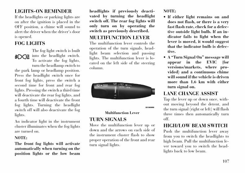
LIGHTS-ON REMINDERIf the headlights or parking lights areon after the ignition is placed in theOFF position, a chime will sound toalert the driver when the driver's dooris opened.
FOG LIGHTS
The fog light switch is builtinto the headlight switch.To activate the fog lights,turn the headlamp switch to
the park lamp or headlamp position.Press the headlight switch once forfront fog lights, press the switch asecond time for front and rear foglights. Pressing the switch a third timewill deactivate the rear fog lights, anda fourth time will deactivate the frontfog lights. Turning the headlightswitch off will also deactivate the foglights.
An indicator light in the instrumentcluster illuminates when the fog lightsare turned on.
NOTE:
The front fog lights will activateautomatically when turning on theposition lights or the low beam
headlights if previously deacti-vated by turning the headlightswitch off. The rear fog lights willonly turn on by operating theswitch as previously described.
MULTIFUNCTION LEVERThe multifunction lever controls theoperation of the turn signals, head-light beam selection and passinglights. The multifunction lever is lo-cated on the left side of the steeringcolumn.
TURN SIGNALSMove the multifunction lever up ordown and the arrows on each side ofthe instrument cluster flash to showproper operation of the front and rearturn signal lights.
NOTE:
• If either light remains on anddoes not flash, or there is a veryfast flash rate, check for a defec-tive outside light bulb. If an in-dicator fails to light when thelever is moved, it would suggestthat the indicator bulb is defec-tive.
• A “Turn Signal On” message willappear in the EVIC (forversions/markets, where pro-vided) and a continuous chimewill sound if the vehicle is drivenmore than 1.6 km with eitherturn signal on.
LANE CHANGE ASSISTTap the lever up or down once, with-out moving beyond the detent, andthe turn signal (right or left) will flashthree times then automatically turnoff.
HIGH/LOW BEAM SWITCHPush the multifunction lever awayfrom you to switch the headlights tohigh beam. Pull the multifunction le-ver toward you to switch the head-lights back to low beam.
Multifunction Lever
107

FLASH-TO-PASSYou can signal another vehicle withyour headlights by lightly pulling themultifunction lever toward you. Thiswill turn on the high beams headlightsuntil the lever is released.
COURTESY LIGHTS
The courtesy lights can be turned onby pressing the top corner of the lens.To turn the lights off, press the lens asecond time.
FRONT MAP/READINGLIGHTS
The front map/reading lights can beturned on by pressing a switch oneither side of the console. Theseswitches are backlit for night timevisibility. To turn the lights off, pressthe switch a second time. The lights
will also turn on when the UNLOCKbutton on the Remote Keyless Entry(RKE) is pressed.
AMBIENT LIGHTThe overhead console is equippedwith an ambient light feature. Thislight casts illumination for improvedvisibility of the floor center consoleand PRNDL area.
INTERIOR LIGHTSThe interior lights come on when adoor is opened.
To protect the battery, the interiorlights will turn off automatically10 minutes after the ignition switch ismoved to the LOCK position. Thiswill occur if the interior lights wereswitched on manually or are on be-cause a door is open. This includes the
Courtesy Lights
Front Map/Reading Lights
Front Map/Reading Light Switches
Ambient Light
108
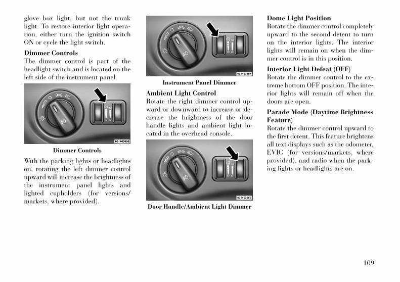
glove box light, but not the trunklight. To restore interior light opera-tion, either turn the ignition switchON or cycle the light switch.
Dimmer ControlsThe dimmer control is part of theheadlight switch and is located on theleft side of the instrument panel.
With the parking lights or headlightson, rotating the left dimmer controlupward will increase the brightness ofthe instrument panel lights andlighted cupholders (for versions/markets, where provided).
Ambient Light ControlRotate the right dimmer control up-ward or downward to increase or de-crease the brightness of the doorhandle lights and ambient light lo-cated in the overhead console.
Dome Light PositionRotate the dimmer control completelyupward to the second detent to turnon the interior lights. The interiorlights will remain on when the dim-mer control is in this position.
Interior Light Defeat (OFF)Rotate the dimmer control to the ex-treme bottom OFF position. The inte-rior lights will remain off when thedoors are open.
Parade Mode (Daytime BrightnessFeature)Rotate the dimmer control upward tothe first detent. This feature brightensall text displays such as the odometer,EVIC (for versions/markets, whereprovided), and radio when the park-ing lights or headlights are on.
Dimmer Controls
Instrument Panel Dimmer
Door Handle/Ambient Light Dimmer
109
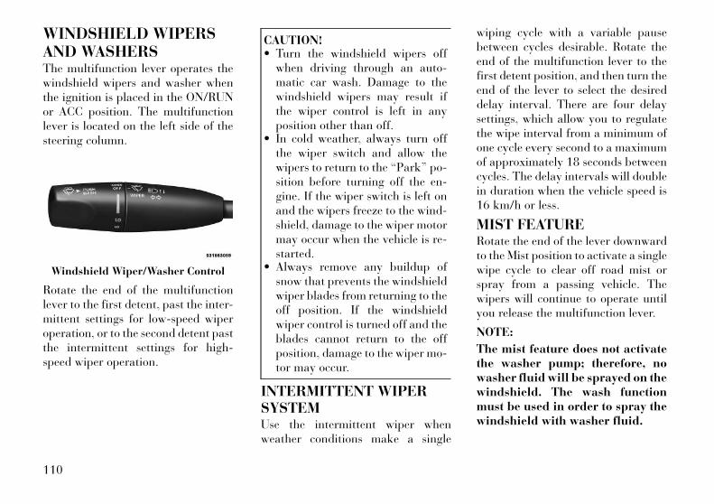
WINDSHIELD WIPERSAND WASHERSThe multifunction lever operates thewindshield wipers and washer whenthe ignition is placed in the ON/RUNor ACC position. The multifunctionlever is located on the left side of thesteering column.
Rotate the end of the multifunctionlever to the first detent, past the inter-mittent settings for low-speed wiperoperation, or to the second detent pastthe intermittent settings for high-speed wiper operation.
CAUTION!• Turn the windshield wipers off
when driving through an auto-matic car wash. Damage to thewindshield wipers may result ifthe wiper control is left in anyposition other than off.
• In cold weather, always turn offthe wiper switch and allow thewipers to return to the “Park” po-sition before turning off the en-gine. If the wiper switch is left onand the wipers freeze to the wind-shield, damage to the wiper motormay occur when the vehicle is re-started.
• Always remove any buildup ofsnow that prevents the windshieldwiper blades from returning to theoff position. If the windshieldwiper control is turned off and theblades cannot return to the offposition, damage to the wiper mo-tor may occur.
INTERMITTENT WIPERSYSTEMUse the intermittent wiper whenweather conditions make a single
wiping cycle with a variable pausebetween cycles desirable. Rotate theend of the multifunction lever to thefirst detent position, and then turn theend of the lever to select the desireddelay interval. There are four delaysettings, which allow you to regulatethe wipe interval from a minimum ofone cycle every second to a maximumof approximately 18 seconds betweencycles. The delay intervals will doublein duration when the vehicle speed is16 km/h or less.
MIST FEATURERotate the end of the lever downwardto the Mist position to activate a singlewipe cycle to clear off road mist orspray from a passing vehicle. Thewipers will continue to operate untilyou release the multifunction lever.
NOTE:
The mist feature does not activatethe washer pump; therefore, nowasher fluid will be sprayed on thewindshield. The wash functionmust be used in order to spray thewindshield with washer fluid.
Windshield Wiper/Washer Control
110
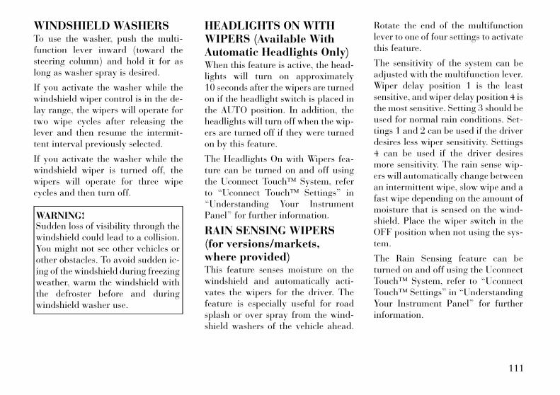
WINDSHIELD WASHERSTo use the washer, push the multi-function lever inward (toward thesteering column) and hold it for aslong as washer spray is desired.
If you activate the washer while thewindshield wiper control is in the de-lay range, the wipers will operate fortwo wipe cycles after releasing thelever and then resume the intermit-tent interval previously selected.
If you activate the washer while thewindshield wiper is turned off, thewipers will operate for three wipecycles and then turn off.
WARNING!Sudden loss of visibility through thewindshield could lead to a collision.You might not see other vehicles orother obstacles. To avoid sudden ic-ing of the windshield during freezingweather, warm the windshield withthe defroster before and duringwindshield washer use.
HEADLIGHTS ON WITHWIPERS (Available WithAutomatic Headlights Only)When this feature is active, the head-lights will turn on approximately10 seconds after the wipers are turnedon if the headlight switch is placed inthe AUTO position. In addition, theheadlights will turn off when the wip-ers are turned off if they were turnedon by this feature.
The Headlights On with Wipers fea-ture can be turned on and off usingthe Uconnect Touch™ System, referto “Uconnect Touch™ Settings” in“Understanding Your InstrumentPanel” for further information.
RAIN SENSING WIPERS(for versions/markets,where provided)This feature senses moisture on thewindshield and automatically acti-vates the wipers for the driver. Thefeature is especially useful for roadsplash or over spray from the wind-shield washers of the vehicle ahead.
Rotate the end of the multifunctionlever to one of four settings to activatethis feature.
The sensitivity of the system can beadjusted with the multifunction lever.Wiper delay position 1 is the leastsensitive, and wiper delay position 4 isthe most sensitive. Setting 3 should beused for normal rain conditions. Set-tings 1 and 2 can be used if the driverdesires less wiper sensitivity. Settings4 can be used if the driver desiresmore sensitivity. The rain sense wip-ers will automatically change betweenan intermittent wipe, slow wipe and afast wipe depending on the amount ofmoisture that is sensed on the wind-shield. Place the wiper switch in theOFF position when not using the sys-tem.
The Rain Sensing feature can beturned on and off using the UconnectTouch™ System, refer to “UconnectTouch™ Settings” in “UnderstandingYour Instrument Panel” for furtherinformation.
111
NOTE:
• The Rain Sensing feature willnot operate when the wiperspeed is in the low or high posi-tion.
• The Rain Sensing feature maynot function properly when iceor dried salt water is present onthe windshield.
• Use of RainX® or productscontaining wax or silicone mayreduce rain sensor performance.
The Rain Sensing system has protec-tive features for the wiper blades andarms. It will not operate under thefollowing conditions:
• Low Temperature Wipe Inhibit— The Rain Sensing feature willnot operate when the ignition isplaced in the RUN position, the ve-hicle is stationary and the outsidetemperature is below 0°C, unlessthe wiper control on the multifunc-tion lever is moved, the vehiclespeed becomes greater than 0 km/hor the outside temperature risesabove freezing.
• Neutral Wipe Inhibit — The RainSensing feature will not operatewhen the ignition is placed in theRUN position, the transmissionshift lever is in the NEUTRAL po-sition and the vehicle speed is lessthan 8 km/h, unless the wiper con-trol on the multifunction lever ismoved or the shift lever is movedout of the NEUTRAL position.
HEADLIGHT WASHERS(for versions/markets,where provided)The multifunction lever operates theheadlight washers when the ignitionswitch is in the ON position and theheadlights are turned on. The multi-function lever is located on the leftside of the steering column.
To use the headlight washers, pushthe multifunction lever inward (to-ward the steering column) to the sec-ond detent and release it. The head-light washers will spray a timed high-pressure spray of washer fluid ontoeach headlight lens. In addition, the
windshield washers will spray thewindshield and the windshield wiperswill cycle.
NOTE:
After turning the ignition switchand headlights ON, the headlightwashers will operate on the firstspray of the windshield washerand then every eleventh spray afterthat.
TILT/TELESCOPINGSTEERING COLUMNThis feature allows you to tilt thesteering column upward or down-ward. It also allows you to lengthen orshorten the steering column. The tilt/telescoping control handle is locatedbelow the steering wheel at the end ofthe steering column.
Tilt/Telescoping Control Handle
112
To unlock the steering column, pullthe control handle outward. To tilt thesteering column, move the steeringwheel upward or downward as de-sired. To lengthen or shorten thesteering column, pull the steeringwheel outward or push it inward asdesired. To lock the steering columnin position, push the control handleinward until fully engaged.
WARNING!Do not adjust the steering columnwhile driving. Adjusting the steeringcolumn while driving or driving withthe steering column unlocked, couldcause the driver to lose control of thevehicle. Be sure the steering columnis locked before driving your vehicle.Failure to follow this warning mayresult in serious injury or death.
POWER TILT/TELESCOPINGSTEERING COLUMN (forversions/markets, whereprovided)This feature allows you to tilt thesteering column upward or down-ward. It also allows you to lengthen orshorten the steering column. Thepower tilt/telescoping steering col-umn switch is located below the mul-tifunction lever on the steering col-umn.
To tilt the steering column, move theswitch up or down as desired. Tolengthen or shorten the steering col-
umn, pull the switch toward you orpush the switch away from you asdesired.
NOTE:
For vehicles equipped with DriverMemory Seat, you can use your Re-mote Keyless Entry (RKE) trans-mitter or the memory switch on thedriver's door trim panel to returnthe tilt/telescopic steering columnto pre-programmed positions. Re-fer to “Driver Memory Seat” in thissection.
WARNING!Do not adjust the steering columnwhile driving. Adjusting the steeringcolumn while driving or driving withthe steering column unlocked, couldcause the driver to lose control of thevehicle. Be sure the steering columnis locked before driving your vehicle.Failure to follow this warning mayresult in serious injury or death.
Power Tilt/Telescoping SteeringSwitch
113

HEATED STEERINGWHEEL (forversions/markets, whereprovided)The steering wheel contains a heatingelement that helps warm your handsin cold weather. The heated steeringwheel has only one temperature set-ting. Once the heated steering wheelhas been turned on it will operate forapproximately 58 to 70 minutes be-fore automatically shutting off. Theheated steering wheel can shut offearly or may not turn on when thesteering wheel is already warm.
The heated steering wheel can beturned on and off using the UconnectTouch™ System.
Touch the “Controls” soft-key thentouch the “Heated Steering Wheel”soft-key to turn on the heated steeringwheel. Press the “Heated SteeringWheel” soft-key a second time to turnthe heated steering wheel off.
NOTE:
The engine must be running for theheated steering wheel to operate.
WARNING!• Persons who are unable to feel
pain to the skin because of ad-vanced age, chronic illness, diabe-tes, spinal cord injury, medica-tion, alcohol use, exhaustion, orother physical conditions must ex-ercise care when using the steeringwheel heater. It may cause burnseven at low temperatures, espe-cially if used for long periods.
• Do not place anything on thesteering wheel that insulatesagainst heat, such as a blanket orsteering wheel covers of any typeand material. This may cause thesteering wheel heater to overheat.
ADJUSTABLE PEDALS(for versions/markets,where provided)The adjustable pedals system is de-signed to allow a greater range ofdriver comfort for steering wheel tiltand seat position. This feature allowsthe brake, accelerator, and clutchpedals (for versions/markets, whereprovided) to move toward or away
Controls Soft-Key
Heated Steering Wheel Soft-Key
114
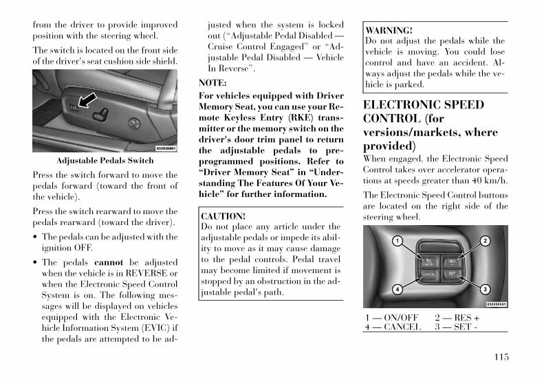
from the driver to provide improvedposition with the steering wheel.
The switch is located on the front sideof the driver's seat cushion side shield.
Press the switch forward to move thepedals forward (toward the front ofthe vehicle).
Press the switch rearward to move thepedals rearward (toward the driver).
• The pedals can be adjusted with theignition OFF.
• The pedals cannot be adjustedwhen the vehicle is in REVERSE orwhen the Electronic Speed ControlSystem is on. The following mes-sages will be displayed on vehiclesequipped with the Electronic Ve-hicle Information System (EVIC) ifthe pedals are attempted to be ad-
justed when the system is lockedout (“Adjustable Pedal Disabled —Cruise Control Engaged” or “Ad-justable Pedal Disabled — VehicleIn Reverse”.
NOTE:
For vehicles equipped with DriverMemory Seat, you can use your Re-mote Keyless Entry (RKE) trans-mitter or the memory switch on thedriver's door trim panel to returnthe adjustable pedals to pre-programmed positions. Refer to“Driver Memory Seat” in “Under-standing The Features Of Your Ve-hicle” for further information.
CAUTION!Do not place any article under theadjustable pedals or impede its abil-ity to move as it may cause damageto the pedal controls. Pedal travelmay become limited if movement isstopped by an obstruction in the ad-justable pedal's path.
WARNING!Do not adjust the pedals while thevehicle is moving. You could losecontrol and have an accident. Al-ways adjust the pedals while the ve-hicle is parked.
ELECTRONIC SPEEDCONTROL (forversions/markets, whereprovided)When engaged, the Electronic SpeedControl takes over accelerator opera-tions at speeds greater than 40 km/h.
The Electronic Speed Control buttonsare located on the right side of thesteering wheel.
Adjustable Pedals Switch
1 — ON/OFF 2 — RES +4 — CANCEL 3 — SET -
115
NOTE:
In order to ensure proper opera-tion, the Electronic Speed ControlSystem has been designed to shutdown if multiple Speed Controlfunctions are operated at the sametime. If this occurs, the ElectronicSpeed Control System can be reac-tivated by pushing the ElectronicSpeed Control ON/OFF button andresetting the desired vehicle setspeed.
TO ACTIVATEPush the ON/OFF button. The CruiseIndicator Light in the Electronic Ve-hicle Information Center (EVIC) willilluminate. To turn the system off,push the ON/OFF button a secondtime. The Cruise Indicator Light willturn off. The system should be turnedoff when not in use.
WARNING!Leaving the Electronic Speed Con-trol system on when not in use isdangerous. You could accidentallyset the system or cause it to go fasterthan you want. You could lose con-trol and have an accident. Alwaysleave the system OFF when you arenot using it.
TO SET A DESIRED SPEEDTurn the Electronic Speed ControlON. When the vehicle has reached thedesired speed, press the SET (-) but-ton and release. Release the accelera-tor and the vehicle will operate at theselected speed.
NOTE:
The vehicle should be traveling ata steady speed and on level groundbefore pressing the SET button.
TO DEACTIVATEA soft tap on the brake pedal, pushingthe CANCEL button, or normal brakepressure while slowing the vehicle willdeactivate Electronic Speed Controlwithout erasing the set speed memory.
Pressing the ON/OFF button or turn-ing the ignition switch OFF erases theset speed memory.
TO RESUME SPEEDTo resume a previously set speed,push the RES (+) button and release.Resume can be used at any speedabove 32 km/h.
TO VARY THE SPEEDSETTINGWhen the Electronic Speed Control isset, you can increase speed by pushingthe RES (+) button. If the button iscontinually pressed, the set speed willcontinue to increase until the button isreleased, then the new set speed willbe established.
Pressing the RES (+) button once willresult in the following set speeds:
• 2.0 km/h (3.0L Diesel Engine)
• 1.6 km/h (3.6L Engine)
Each subsequent tap of the buttonresults in an increase of 2.0 km/h(3.0L Diesel Engine) or 1.6 km/h(3.6L Engine).
116

To decrease speed while the Elec-tronic Speed Control is set, push theSET (-) button. If the button is con-tinually held in the SET (-) position,the set speed will continue to decreaseuntil the button is released. Releasethe button when the desired speed isreached, and the new set speed will beestablished.
Pressing the SET (-) button once willresult in the following decrease in setspeed:
• 2.0 km/h (3.0L Diesel Engine)
• 1.6 km/h (3.6L Engine)
Each subsequent tap of the buttonresults in a decrease of 2.0 km/h(3.0L Diesel Engine) or 1.6 km/h(3.6L Engine)
TO ACCELERATE FORPASSINGPress the accelerator as you wouldnormally. When the pedal is released,the vehicle will return to the set speed.
Using Electronic Speed ControlOn HillsThe transmission may downshift onhills to maintain the vehicle set speed.
NOTE:
The Electronic Speed Control sys-tem maintains speed up and downhills. A slight speed change onmoderate hills is normal.
On steep hills, a greater speed loss orgain may occur so it may be prefer-able to drive without Electronic SpeedControl.
WARNING!Electronic Speed Control can bedangerous where the system cannotmaintain a constant speed. Your ve-hicle could go too fast for the condi-tions, and you could lose control andhave an accident. Do not use Elec-tronic Speed Control in heavy trafficor on roads that are winding, icy,snow-covered or slippery.
ADAPTIVE CRUISECONTROL (ACC) (forversions/markets, whereprovided)Adaptive Cruise Control (ACC) in-creases the driving convenience pro-vided by cruise control while traveling
on highways and major roadways.However, it is not a safety system andnot designed to prevent collisions.
ACC will allow you to keep cruisecontrol engaged in light to moderatetraffic conditions without the con-stant need to reset your cruise control.ACC utilizes a radar sensor designedto detect a vehicle directly ahead ofyou.
NOTE:
• If the sensor does not detect avehicle ahead of you, ACC willmaintain a fixed set speed.
• If the ACC sensor detects a ve-hicle ahead, ACC will apply lim-ited braking or acceleration (notto exceed the original set speed)automatically to maintain a pre-set following distance, whilematching the speed of the ve-hicle ahead.
117
WARNING!• Adaptive Cruise Control (ACC) is
a convenience system. It is not asubstitute for active driving in-volvement. It is always the driv-er’s responsibility to be attentiveof road, traffic, and weather con-ditions, vehicle speed, distance tothe vehicle ahead; and, most im-portantly, brake operation to en-sure safe operation of the vehicleunder all road conditions. Yourcomplete attention is always re-quired while driving to maintainsafe control of your vehicle. Fail-ure to follow these warnings canresult in a collision and death orserious personal injury.
• The ACC system:− Does not react to pedestrians,
oncoming vehicles, and sta-tionary objects (i.e., a stoppedvehicle in a traffic jam or adisabled vehicle).
− Cannot take street, traffic, andweather conditions into account,and may be limited upon ad-verse sight distance conditions.
(Continued)
WARNING! (Continued)− Does not predict the lane cur-
vature or the movement of pre-ceding vehicles and will notcompensate for such changes.
− Does not always fully recognizecomplex driving conditions,which can result in wrong ormissing distance warnings.
− Can only apply a maximum of25% of the vehicle’s brakingcapability, and will not bringthe vehicle to a complete stop.
WARNING!You should switch off the ACC sys-tem:• When driving in fog, heavy rain,
heavy snow, sleet, heavy traffic,and complex driving situations(e.g., in highway constructionzones).
• When entering a turn lane orhighway off ramp; when drivingon roads that are winding, icy,snow-covered, slippery, or havesteep uphill or downhill slopes.
(Continued)
WARNING! (Continued)• When towing a trailer up or down
steep slopes.• When circumstances do not allow
safe driving at a constant speed.Failure to follow these warnings canresult in a collision and death orserious personal injury.
The Cruise Control system has twocontrol modes:
• Adaptive Cruise Control mode formaintaining an appropriate dis-tance between vehicles.
• Normal (fixed speed) cruise controlmode is for cruising at a constantpreset speed. For additional infor-mation, refer to “Normal (FixedSpeed) Cruise Control Mode” inthis section.
NOTE:
The system will not react to pre-ceding vehicles. Always be awareof the mode selected.
You can change the mode by using theCruise Control buttons. The two con-trol modes function differently. Al-ways confirm which mode is selected.
118
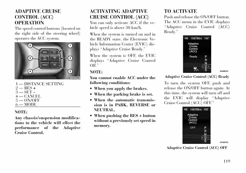
ADAPTIVE CRUISECONTROL (ACC)OPERATIONThe speed control buttons (located onthe right side of the steering wheel)operates the ACC system.
NOTE:
Any chassis/suspension modifica-tions to the vehicle will effect theperformance of the AdaptiveCruise Control.
ACTIVATING ADAPTIVECRUISE CONTROL (ACC)You can only activate ACC if the ve-hicle speed is above 30 km/h.
When the system is turned on and inthe READY state, the Electronic Ve-hicle Information Center (EVIC) dis-plays “Adaptive Cruise Ready.”
When the system is OFF, the EVICdisplays “Adaptive Cruise ControlOff.”
NOTE:
You cannot enable ACC under thefollowing conditions:
• When you apply the brakes.
• When the parking brake is set.
• When the automatic transmis-sion is in PARK, REVERSE orNEUTRAL.
• When pushing the RES + buttonwithout a previously set speed inmemory.
TO ACTIVATEPush and release the ON/OFF button.The ACC menu in the EVIC displays“Adaptive Cruise Control (ACC)Ready.”
To turn the system OFF, push andrelease the ON/OFF button again. Atthis time, the system will turn off andthe EVIC will display “AdaptiveCruise Control (ACC) OFF.”
1 — DISTANCE SETTING2 — RES +3 — SET -4 — CANCEL5 — ON/OFF6 — MODE
Adaptive Cruise Control (ACC) Ready
Adaptive Cruise Control (ACC) OFF
119
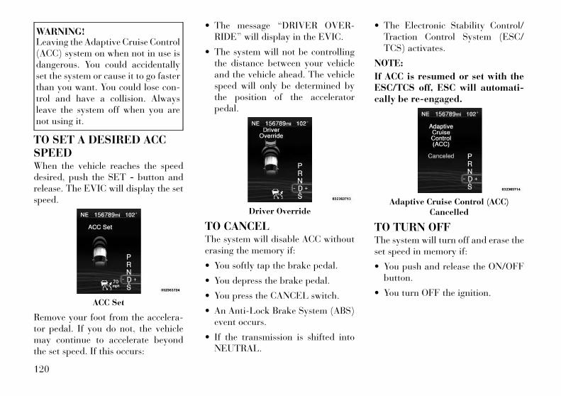
WARNING!Leaving the Adaptive Cruise Control(ACC) system on when not in use isdangerous. You could accidentallyset the system or cause it to go fasterthan you want. You could lose con-trol and have a collision. Alwaysleave the system off when you arenot using it.
TO SET A DESIRED ACCSPEEDWhen the vehicle reaches the speeddesired, push the SET - button andrelease. The EVIC will display the setspeed.
Remove your foot from the accelera-tor pedal. If you do not, the vehiclemay continue to accelerate beyondthe set speed. If this occurs:
• The message “DRIVER OVER-RIDE” will display in the EVIC.
• The system will not be controllingthe distance between your vehicleand the vehicle ahead. The vehiclespeed will only be determined bythe position of the acceleratorpedal.
TO CANCELThe system will disable ACC withouterasing the memory if:
• You softly tap the brake pedal.
• You depress the brake pedal.
• You press the CANCEL switch.
• An Anti-Lock Brake System (ABS)event occurs.
• If the transmission is shifted intoNEUTRAL.
• The Electronic Stability Control/Traction Control System (ESC/TCS) activates.
NOTE:
If ACC is resumed or set with theESC/TCS off, ESC will automati-cally be re-engaged.
TO TURN OFFThe system will turn off and erase theset speed in memory if:
• You push and release the ON/OFFbutton.
• You turn OFF the ignition.ACC Set
Driver OverrideAdaptive Cruise Control (ACC)
Cancelled
120

TO RESUME SPEEDPress the RES + button and release.Then remove your foot from the ac-celerator pedal. The EVIC will dis-play the last set speed.
NOTE:
You can resume ACC from a mini-mum of 30 km/h.
WARNING!The Resume function should only beused if traffic and road conditionspermit. Resuming a set speed that istoo high or too low for prevailingtraffic and road conditions couldcause the vehicle to accelerate ordecelerate too sharply for safe op-eration. Failure to follow thesewarnings can result in a collisionand death or serious personal injury.
TO VARY THE SPEEDSETTINGWhile ACC is set, you can increase theset speed by pressing and holding theRES + button. The increase in setspeed is reflected in the EVIC display:
While in US Mode, if the button iscontinually pressed, the set speed will
continue to increase in 8 km/h incre-ments. While in Metric Mode, if thebutton is continually pressed, the setspeed will continue to increase in10 km/h increments.
While in US Mode, pressing the RES +button once will result in a 1.6 km/hincrease in set speed. Each subse-quent tap of the button results in in-crease of 1.6 km/h. While in MetricMode, pressing the RES + button oncewill result in a 1.0 km/h increase in setspeed. Each subsequent tap of thebutton results in increase of 1.0 km/h.
While ACC is set, the set speed can bedecreased by pressing and holding theSET - button.
If the button is held while in US Mode,the set speed will continue to decreasein 8 km/h increments.
If the button is held while in MetricMode, the set speed will continue todecrease in 10 km/h increments.
While in US Mode, pressing the SET -button once will result in a 1.6 km/hdecrease in set speed. Each subse-quent tap of the button results in de-crease of 1.6 km/h.
While in Metric Mode, pressing theSET - button once will result in a1.0 km/h decrease in set speed. Eachsubsequent tap of the button results indecrease of 1.0 km/h.
NOTE:
• When you use the SET - buttonto decelerate, if the engine’sbraking power does not slow thevehicle sufficiently to reach theset speed, the brake system willautomatically slow the vehicle.
• The ACC system can only apply amaximum of 25% of the vehi-cle's braking capability and willnot bring the vehicle to a com-plete stop.
• The ACC system maintains setspeed when driving up hill anddown hill. However, a slightspeed change on moderate hillsis normal. In addition, down-shifting may occur while climb-ing uphill or descending down-hill. This is normal operationand necessary to maintain setspeed.
121
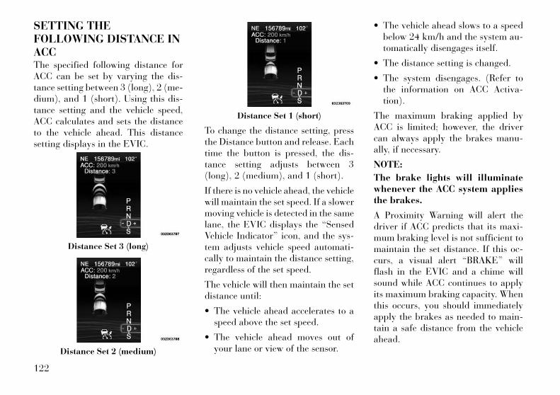
SETTING THEFOLLOWING DISTANCE INACCThe specified following distance forACC can be set by varying the dis-tance setting between 3 (long), 2 (me-dium), and 1 (short). Using this dis-tance setting and the vehicle speed,ACC calculates and sets the distanceto the vehicle ahead. This distancesetting displays in the EVIC.
To change the distance setting, pressthe Distance button and release. Eachtime the button is pressed, the dis-tance setting adjusts between 3(long), 2 (medium), and 1 (short).
If there is no vehicle ahead, the vehiclewill maintain the set speed. If a slowermoving vehicle is detected in the samelane, the EVIC displays the “SensedVehicle Indicator” icon, and the sys-tem adjusts vehicle speed automati-cally to maintain the distance setting,regardless of the set speed.
The vehicle will then maintain the setdistance until:
• The vehicle ahead accelerates to aspeed above the set speed.
• The vehicle ahead moves out ofyour lane or view of the sensor.
• The vehicle ahead slows to a speedbelow 24 km/h and the system au-tomatically disengages itself.
• The distance setting is changed.
• The system disengages. (Refer tothe information on ACC Activa-tion).
The maximum braking applied byACC is limited; however, the drivercan always apply the brakes manu-ally, if necessary.
NOTE:
The brake lights will illuminatewhenever the ACC system appliesthe brakes.
A Proximity Warning will alert thedriver if ACC predicts that its maxi-mum braking level is not sufficient tomaintain the set distance. If this oc-curs, a visual alert “BRAKE” willflash in the EVIC and a chime willsound while ACC continues to applyits maximum braking capacity. Whenthis occurs, you should immediatelyapply the brakes as needed to main-tain a safe distance from the vehicleahead.
Distance Set 3 (long)
Distance Set 2 (medium)
Distance Set 1 (short)
122
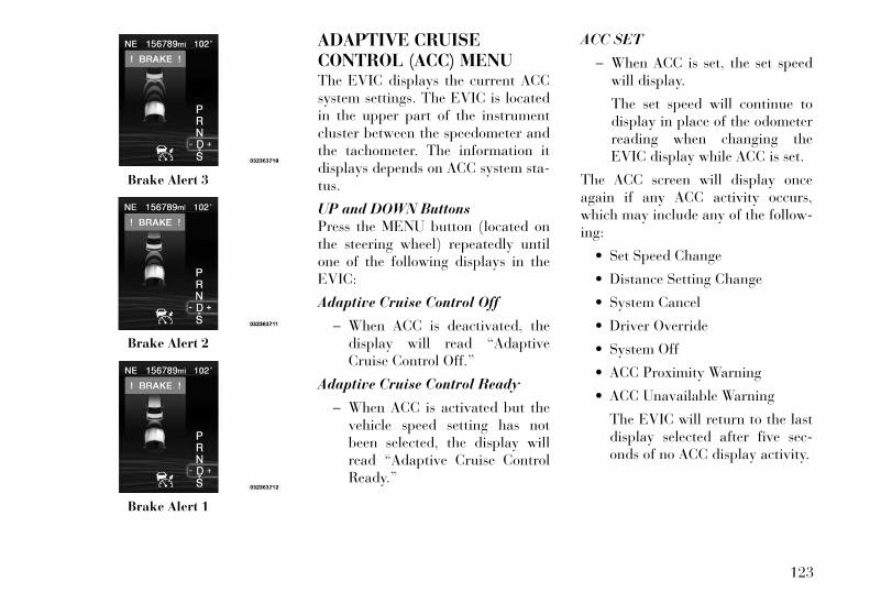
ADAPTIVE CRUISECONTROL (ACC) MENUThe EVIC displays the current ACCsystem settings. The EVIC is locatedin the upper part of the instrumentcluster between the speedometer andthe tachometer. The information itdisplays depends on ACC system sta-tus.
UP and DOWN ButtonsPress the MENU button (located onthe steering wheel) repeatedly untilone of the following displays in theEVIC:
Adaptive Cruise Control Off
− When ACC is deactivated, thedisplay will read “AdaptiveCruise Control Off.”
Adaptive Cruise Control Ready
− When ACC is activated but thevehicle speed setting has notbeen selected, the display willread “Adaptive Cruise ControlReady.”
ACC SET
− When ACC is set, the set speedwill display.
The set speed will continue todisplay in place of the odometerreading when changing theEVIC display while ACC is set.
The ACC screen will display onceagain if any ACC activity occurs,which may include any of the follow-ing:
• Set Speed Change
• Distance Setting Change
• System Cancel
• Driver Override
• System Off
• ACC Proximity Warning
• ACC Unavailable Warning
The EVIC will return to the lastdisplay selected after five sec-onds of no ACC display activity.
Brake Alert 3
Brake Alert 2
Brake Alert 1
123
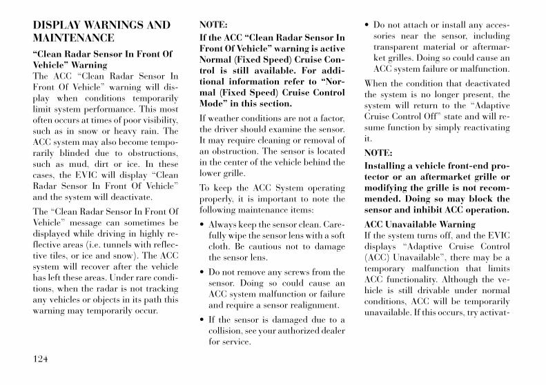
DISPLAY WARNINGS ANDMAINTENANCE
“Clean Radar Sensor In Front OfVehicle” WarningThe ACC “Clean Radar Sensor InFront Of Vehicle” warning will dis-play when conditions temporarilylimit system performance. This mostoften occurs at times of poor visibility,such as in snow or heavy rain. TheACC system may also become tempo-rarily blinded due to obstructions,such as mud, dirt or ice. In thesecases, the EVIC will display “CleanRadar Sensor In Front Of Vehicle”and the system will deactivate.
The “Clean Radar Sensor In Front OfVehicle” message can sometimes bedisplayed while driving in highly re-flective areas (i.e. tunnels with reflec-tive tiles, or ice and snow). The ACCsystem will recover after the vehiclehas left these areas. Under rare condi-tions, when the radar is not trackingany vehicles or objects in its path thiswarning may temporarily occur.
NOTE:
If the ACC “Clean Radar Sensor InFront Of Vehicle” warning is activeNormal (Fixed Speed) Cruise Con-trol is still available. For addi-tional information refer to “Nor-mal (Fixed Speed) Cruise ControlMode” in this section.
If weather conditions are not a factor,the driver should examine the sensor.It may require cleaning or removal ofan obstruction. The sensor is locatedin the center of the vehicle behind thelower grille.
To keep the ACC System operatingproperly, it is important to note thefollowing maintenance items:
• Always keep the sensor clean. Care-fully wipe the sensor lens with a softcloth. Be cautious not to damagethe sensor lens.
• Do not remove any screws from thesensor. Doing so could cause anACC system malfunction or failureand require a sensor realignment.
• If the sensor is damaged due to acollision, see your authorized dealerfor service.
• Do not attach or install any acces-sories near the sensor, includingtransparent material or aftermar-ket grilles. Doing so could cause anACC system failure or malfunction.
When the condition that deactivatedthe system is no longer present, thesystem will return to the “AdaptiveCruise Control Off” state and will re-sume function by simply reactivatingit.
NOTE:
Installing a vehicle front-end pro-tector or an aftermarket grille ormodifying the grille is not recom-mended. Doing so may block thesensor and inhibit ACC operation.
ACC Unavailable WarningIf the system turns off, and the EVICdisplays “Adaptive Cruise Control(ACC) Unavailable”, there may be atemporary malfunction that limitsACC functionality. Although the ve-hicle is still drivable under normalconditions, ACC will be temporarilyunavailable. If this occurs, try activat-
124
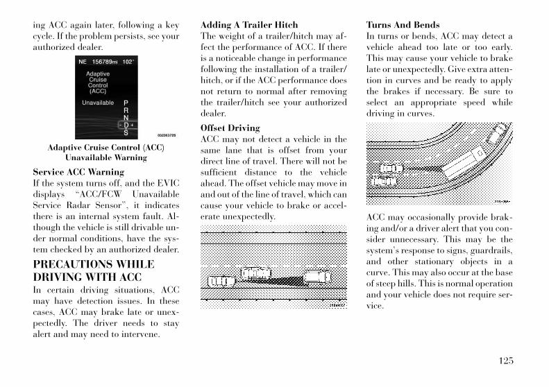
ing ACC again later, following a keycycle. If the problem persists, see yourauthorized dealer.
Service ACC WarningIf the system turns off, and the EVICdisplays “ACC/FCW UnavailableService Radar Sensor”, it indicatesthere is an internal system fault. Al-though the vehicle is still drivable un-der normal conditions, have the sys-tem checked by an authorized dealer.
PRECAUTIONS WHILEDRIVING WITH ACCIn certain driving situations, ACCmay have detection issues. In thesecases, ACC may brake late or unex-pectedly. The driver needs to stayalert and may need to intervene.
Adding A Trailer HitchThe weight of a trailer/hitch may af-fect the performance of ACC. If thereis a noticeable change in performancefollowing the installation of a trailer/hitch, or if the ACC performance doesnot return to normal after removingthe trailer/hitch see your authorizeddealer.
Offset DrivingACC may not detect a vehicle in thesame lane that is offset from yourdirect line of travel. There will not besufficient distance to the vehicleahead. The offset vehicle may move inand out of the line of travel, which cancause your vehicle to brake or accel-erate unexpectedly.
Turns And BendsIn turns or bends, ACC may detect avehicle ahead too late or too early.This may cause your vehicle to brakelate or unexpectedly. Give extra atten-tion in curves and be ready to applythe brakes if necessary. Be sure toselect an appropriate speed whiledriving in curves.
ACC may occasionally provide brak-ing and/or a driver alert that you con-sider unnecessary. This may be thesystem’s response to signs, guardrails,and other stationary objects in acurve. This may also occur at the baseof steep hills. This is normal operationand your vehicle does not require ser-vice.
Adaptive Cruise Control (ACC)Unavailable Warning
125

Using ACC On HillsWhen driving on hills, ACC may notdetect a vehicle in your lane. Depend-ing on the speed, vehicle load, trafficconditions, and the steepness of thehills, ACC performance may be lim-ited.
Lane ChangingACC will not detect a vehicle until it iscompletely in the lane in which youare traveling. In the illustrationshown, ACC has not yet detected thevehicle changing lanes and it may notdetect the vehicle until it's too late forthe ACC system to take action. ACCwill not detect a vehicle until it iscompletely in the lane. There will notbe sufficient distance to the lane-changing vehicle. Always be attentiveand ready to apply the brakes if nec-essary.
Narrow VehiclesSome narrow vehicles traveling nearthe outer edges of the lane or edginginto the lane are not detected untilthey have moved fully into the lane.There will not be sufficient distance tothe vehicle ahead.
Stationary Objects And VehiclesACC does not react to stationary ob-jects and stationary vehicles. For ex-ample, ACC will not react in situa-tions where the vehicle you arefollowing exits your lane and the ve-hicle ahead is stopped in your lane.Always be attentive and ready to ap-ply the brakes if necessary.
NORMAL (FIXED SPEED)CRUISE CONTROL MODEIn addition to Adaptive Cruise Con-trol mode, a normal (fixed speed)Cruise Control mode is available forcruising at fixed speeds. The normalCruise Control mode is designed tomaintain a set cruising speed withoutrequiring the driver to operate theaccelerator. Cruise Control can onlybe operated if the vehicle speed isabove 30 km/h.
126
To change modes, press the MODEbutton when the system is in either theOFF, READY, or SET position.“Cruise Ready” will be displayed ifthe system was in ACC READY orACC SET position. “Cruise Off” willbe displayed if the system was in theACC OFF position. To switch back toAdaptive Cruise Control mode, pressthe MODE button a second time.
WARNING!In the normal Cruise Control mode,the system will not react to vehiclesahead. In addition, the proximitywarning does not activate and noalarm will sound even if you are tooclose to the vehicle ahead since nei-ther the presence of the vehicleahead nor the vehicle-to-vehicle dis-tance is detected. Be sure to main-tain a safe distance between yourvehicle and the vehicle ahead. Al-ways be aware which mode is se-lected.
To Set A Desired SpeedWhen the vehicle reaches the speeddesired, press the SET - button andrelease. The EVIC will display the setspeed.
NOTE:
You must observe the display whensetting or changing speed, not thespeedometer.
To Vary The Speed SettingThere are two ways to change the setspeed:
• Use the accelerator pedal to adjustthe vehicle to the desired speed andpress the SET - button.
• Tap the RES + or SET - button toincrease or decrease the set speed in1 km/h increments respectively.Hold the RES + or SET - button for10 km/h increments.
To CancelThe system will disable normal CruiseControl without erasing the memoryif:
• You softly tap or depress the brakepedal.
• You press the CANCEL button.
• The Electronic Stability Control/Traction Control System (ESC/TCS) activates.
To ResumePress the RES + button and then re-move your foot from the acceleratorpedal. The EVIC will display the lastset speed.
To Turn OffThe system will turn off and erase theset speed in memory if:
• You push and release the ON/OFFbutton.
• You turn off the ignition.
• You switch off ESC.
If the Cruise Control system is turnedoff and reactivated, the system willreturn to the last driver setting (ACCor Normal Cruise Control).
127
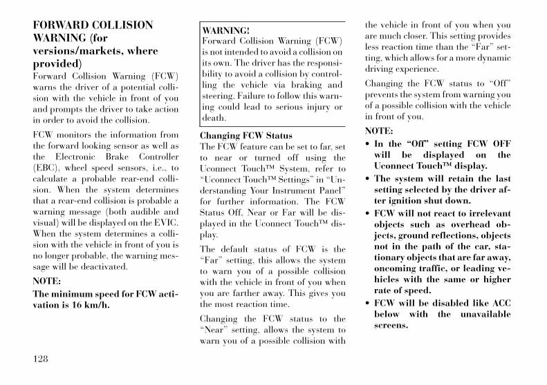
FORWARD COLLISIONWARNING (forversions/markets, whereprovided)Forward Collision Warning (FCW)warns the driver of a potential colli-sion with the vehicle in front of youand prompts the driver to take actionin order to avoid the collision.
FCW monitors the information fromthe forward looking sensor as well asthe Electronic Brake Controller(EBC), wheel speed sensors, i.e., tocalculate a probable rear-end colli-sion. When the system determinesthat a rear-end collision is probable awarning message (both audible andvisual) will be displayed on the EVIC.When the system determines a colli-sion with the vehicle in front of you isno longer probable, the warning mes-sage will be deactivated.
NOTE:
The minimum speed for FCW acti-vation is 16 km/h.
WARNING!Forward Collision Warning (FCW)is not intended to avoid a collision onits own. The driver has the responsi-bility to avoid a collision by control-ling the vehicle via braking andsteering. Failure to follow this warn-ing could lead to serious injury ordeath.
Changing FCW StatusThe FCW feature can be set to far, setto near or turned off using theUconnect Touch™ System, refer to“Uconnect Touch™ Settings” in “Un-derstanding Your Instrument Panel”for further information. The FCWStatus Off, Near or Far will be dis-played in the Uconnect Touch™ dis-play.
The default status of FCW is the“Far” setting, this allows the systemto warn you of a possible collisionwith the vehicle in front of you whenyou are farther away. This gives youthe most reaction time.
Changing the FCW status to the“Near” setting, allows the system towarn you of a possible collision with
the vehicle in front of you when youare much closer. This setting providesless reaction time than the “Far” set-ting, which allows for a more dynamicdriving experience.
Changing the FCW status to “Off”prevents the system from warning youof a possible collision with the vehiclein front of you.
NOTE:
• In the “Off” setting FCW OFFwill be displayed on theUconnect Touch™ display.
• The system will retain the lastsetting selected by the driver af-ter ignition shut down.
• FCW will not react to irrelevantobjects such as overhead ob-jects, ground reflections, objectsnot in the path of the car, sta-tionary objects that are far away,oncoming traffic, or leading ve-hicles with the same or higherrate of speed.
• FCW will be disabled like ACCbelow with the unavailablescreens.
128
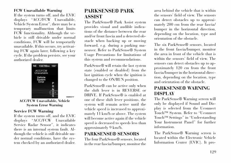
FCW Unavailable WarningIf the system turns off, and the EVICdisplays “ACC/FCW Unavailable,Vehicle System Error”, there may be atemporary malfunction that limitsFCW functionality. Although the ve-hicle is still drivable under normalconditions, FCW will be temporarilyunavailable. If this occurs, try activat-ing FCW again later, following a keycycle. If the problem persists, see yourauthorized dealer.
Service FCW WarningIf the system turns off, and the EVICdisplays “ACC/FCW UnavailableService Radar Sensor”, it indicatesthere is an internal system fault. Al-though the vehicle is still drivable un-der normal conditions, have the sys-tem checked by an authorized dealer.
PARKSENSE® PARKASSISTThe ParkSense® Park Assist systemprovides visual and audible indica-tions of the distance between the rearand/or front fascia and a detected ob-stacle when backing up or movingforward, e.g. during a parking ma-neuver. Refer to ParkSense® SystemUsage Precautions for limitations ofthis system and recommendations.
ParkSense® will retain the last systemstate (enabled or disabled) from thelast ignition cycle when the ignition ischanged to the ON/RUN position.
ParkSense® can be active only whenthe shift lever is in REVERSE orDRIVE. If ParkSense® is enabled atone of these shift lever positions, thesystem will remain active until thevehicle speed is increased to approxi-mately 11 km/h or above. The systemwill become active again if the vehiclespeed is decreased to speeds less thanapproximately 9 km/h.
PARKSENSE® SENSORSThe four ParkSense® sensors, locatedin the rear fascia/bumper, monitor the
area behind the vehicle that is withinthe sensors’ field of view. The sensorscan detect obstacles up to approxi-mately 200 cm from the rear fascia/bumper in the horizontal direction,depending on the location, type andorientation of the obstacle.
The six ParkSense® sensors, locatedin the front fascia/bumper, monitorthe area in front of the vehicle that iswithin the sensors’ field of view. Thesensors can detect obstacles up to ap-proximately 120 cm from the frontfascia/bumper in the horizontal direc-tion, depending on the location, typeand orientation of the obstacle.
PARKSENSE® WARNINGDISPLAYThe ParkSense® Warning screen willonly be displayed if Sound and Dis-play is selected from the UconnectTouch™ System. Refer to “UconnectTouch™ Settings” in “UnderstandingYour Instrument Panel” for furtherinformation.
The ParkSense® Warning screen islocated within the Electronic VehicleInformation Center (EVIC). It pro-
ACC/FCW Unavailable, VehicleSystem Error Warning
129
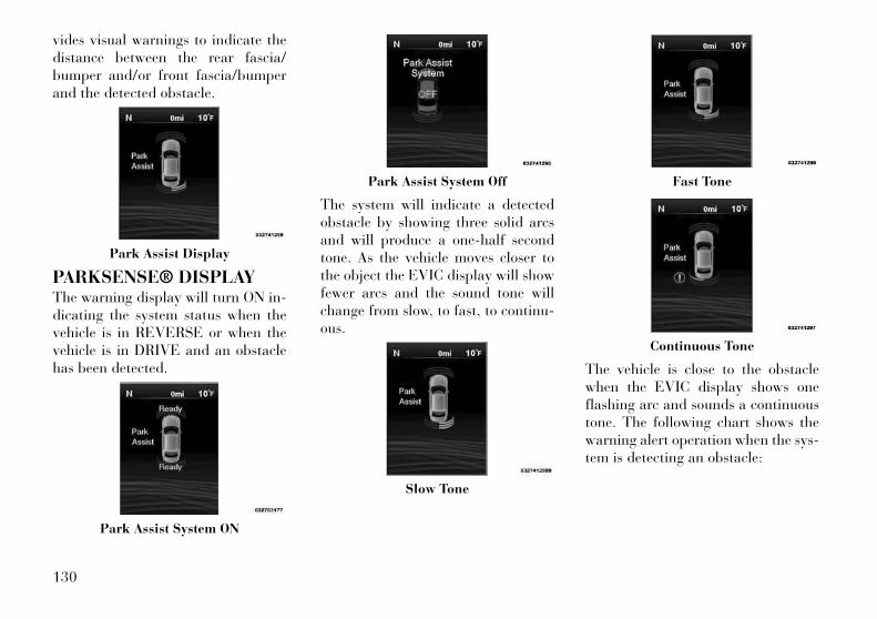
vides visual warnings to indicate thedistance between the rear fascia/bumper and/or front fascia/bumperand the detected obstacle.
PARKSENSE® DISPLAYThe warning display will turn ON in-dicating the system status when thevehicle is in REVERSE or when thevehicle is in DRIVE and an obstaclehas been detected.
The system will indicate a detectedobstacle by showing three solid arcsand will produce a one-half secondtone. As the vehicle moves closer tothe object the EVIC display will showfewer arcs and the sound tone willchange from slow, to fast, to continu-ous.
The vehicle is close to the obstaclewhen the EVIC display shows oneflashing arc and sounds a continuoustone. The following chart shows thewarning alert operation when the sys-tem is detecting an obstacle:
Park Assist Display
Park Assist System ON
Park Assist System Off
Slow Tone
Fast Tone
Continuous Tone
130
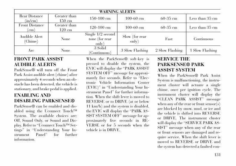
WARNING ALERTSRear Distance
(in/cm)Greater than
150 cm150-100 cm 100-60 cm 60-35 cm Less than 35 cm
Front Distance(cm)
Greater than120 cm
120-100 cm 100-60 cm 60-35 cm Less than 35 cm
Audible Alert(Chime)
NoneSingle 1/2 second
tone (for rearonly)
Slow (for rearonly)
Fast Continuous
Arc None3 Solid
(Continuous)3 Slow Flashing 2 Slow Flashing 1 Slow Flashing
FRONT PARK ASSISTAUDIBLE ALERTSParkSense® will turn off the FrontPark Assist audible alert (chime) afterapproximately 4 seconds when an ob-stacle has been detected, the vehicle isstationary, and brake pedal is applied.
ENABLING ANDDISABLING PARKSENSE®ParkSense® can be enabled and dis-abled using the Uconnect Touch™System. The available choices are:Off, Sound Only, or Sound and Dis-play. Refer to “Uconnect Touch™ Set-tings” in “Understanding Your In-strument Panel” for furtherinformation.
When the ParkSense® soft-key ispressed to disable the system, theEVIC will display the “PARK ASSISTSYSTEM OFF” message for approxi-mately five seconds. Refer to “Elec-tronic Vehicle Information Center(EVIC)” in “Understanding Your In-strument Panel” for further informa-tion. When the shift lever is moved toREVERSE or to DRIVE (at or below11 km/h) and the system is disabled,the EVIC will display the “PARK AS-SIST SYSTEM OFF” message for ap-proximately five seconds in RE-VERSE or for 5 seconds when thevehicle is in DRIVE.
SERVICE THEPARKSENSE® PARKASSIST SYSTEMWhen the ParkSense® Park AssistSystem is malfunctioning, the instru-ment cluster will actuate a singlechime, once per ignition cycle. Theinstrument cluster will display the“CLEAN PARK ASSIST” messagewhen any of the rear or front sensor(s)are blocked by snow, mud, or ice andthe vehicle is shifted into REVERSEor DRIVE. The instrument clusterwill display the “SERVICE PARK AS-SIST” message when any of the rearor front sensors are damaged and re-quire service. When the shift lever ismoved to REVERSE or DRIVE andthe system has detected a faulted con-
131

dition, the EVIC will display the“CLEAN PARK ASSIST”, “SERVICEPARK ASSIST” or the “SERVICEPARK ASSIST SYSTEM” message foras long as the vehicle is in REVERSEor DRIVE (at speeds less than11 km/h). Under this conditionParkSense® will not operate. Refer to“Electronic Vehicle Information Cen-ter (EVIC)” in “Understanding YourInstrument Panel” for further infor-mation.
If “CLEAN PARK ASSIST” appearsin the Electronic Vehicle InformationCenter (EVIC) make sure the outersurface and the underside of the rearfascia/bumper and/or front fascia/bumper is clean and clear of snow, ice,mud, dirt or other obstruction andthen cycle the ignition. If the messagecontinues to appear see an authorizeddealer.
If “SERVICE PARK ASSIST" or“SERVICE PARK ASSIST SYSTEM”appears in the EVIC, see an autho-rized dealer.
CLEANING THEPARKSENSE® SYSTEMClean the ParkSense® sensors withwater, car wash soap and a soft cloth.Do not use rough or hard cloths. Donot scratch or poke the sensors. Oth-erwise, you could damage the sensors.
PARKSENSE® SYSTEMUSAGE PRECAUTIONS
NOTE:
• Ensure that the front and rearbumper are free of snow, ice,mud, dirt and debris to keep theParkSense® system operatingproperly.
• Jackhammers, large trucks, andother vibrations could affect theperformance of ParkSense®.
• When you turn ParkSense® off,the EVIC will display “PARKASSIST SYSTEM OFF.” Further-more, once you turnParkSense® off, it remains offuntil you turn it on again, even ifyou cycle the ignition key.
• When you move the shift lever tothe REVERSE or DRIVE posi-tion and ParkSense® is turnedoff, the EVIC will display “PARKASSIST SYSTEM OFF” messagefor approximately five secondsin REVERSE or for 5 secondswhen the vehicle is in DRIVE.
• Clean the ParkSense® sensorsregularly, taking care not toscratch or damage them. Thesensors must not be coveredwith ice, snow, slush, mud, dirtor debris. Failure to do so canresult in the system not workingproperly. The ParkSense® sys-tem might not detect an obstaclebehind or in front of the fascia/bumper, or it could provide afalse indication that an obstacleis behind or in front of thefascia/bumper.
132
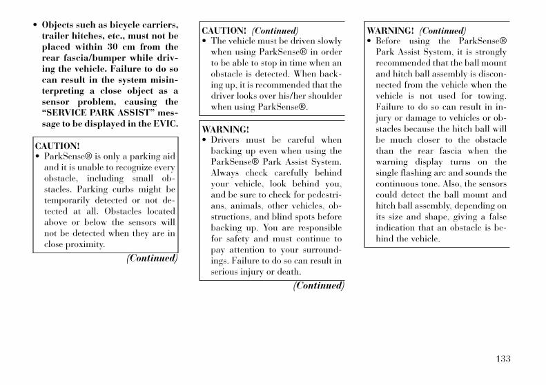
• Objects such as bicycle carriers,trailer hitches, etc., must not beplaced within 30 cm from therear fascia/bumper while driv-ing the vehicle. Failure to do socan result in the system misin-terpreting a close object as asensor problem, causing the“SERVICE PARK ASSIST” mes-sage to be displayed in the EVIC.
CAUTION!• ParkSense® is only a parking aid
and it is unable to recognize everyobstacle, including small ob-stacles. Parking curbs might betemporarily detected or not de-tected at all. Obstacles locatedabove or below the sensors willnot be detected when they are inclose proximity.
(Continued)
CAUTION! (Continued)• The vehicle must be driven slowly
when using ParkSense® in orderto be able to stop in time when anobstacle is detected. When back-ing up, it is recommended that thedriver looks over his/her shoulderwhen using ParkSense®.
WARNING!• Drivers must be careful when
backing up even when using theParkSense® Park Assist System.Always check carefully behindyour vehicle, look behind you,and be sure to check for pedestri-ans, animals, other vehicles, ob-structions, and blind spots beforebacking up. You are responsiblefor safety and must continue topay attention to your surround-ings. Failure to do so can result inserious injury or death.
(Continued)
WARNING! (Continued)• Before using the ParkSense®
Park Assist System, it is stronglyrecommended that the ball mountand hitch ball assembly is discon-nected from the vehicle when thevehicle is not used for towing.Failure to do so can result in in-jury or damage to vehicles or ob-stacles because the hitch ball willbe much closer to the obstaclethan the rear fascia when thewarning display turns on thesingle flashing arc and sounds thecontinuous tone. Also, the sensorscould detect the ball mount andhitch ball assembly, depending onits size and shape, giving a falseindication that an obstacle is be-hind the vehicle.
133
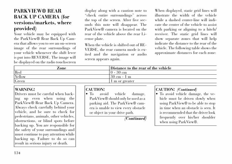
PARKVIEW® REARBACK UP CAMERA (forversions/markets, whereprovided)Your vehicle may be equipped withthe ParkView® Rear Back Up Cam-era that allows you to see an on-screenimage of the rear surroundings ofyour vehicle whenever the shift leveris put into REVERSE. The image willbe displayed on the radio touchscreen
display along with a caution note to“check entire surroundings” acrossthe top of the screen. After five sec-onds this note will disappear. TheParkView® camera is located on therear of the vehicle above the rear Li-cense plate.
When the vehicle is shifted out of RE-VERSE, the rear camera mode is ex-ited and the navigation or audioscreen appears again.
When displayed, static grid lines willillustrate the width of the vehiclewhile a dashed center-line will indi-cate the center of the vehicle to assistwith parking or aligning to a hitch/receiver. The static grid lines willshow separate zones that will helpindicate the distance to the rear of thevehicle. The following table shows theapproximate distances for each zone:
Zone Distance to the rear of the vehicleRed 0 - 30 cmYellow 30 cm - 1 mGreen 1 m or greater
WARNING!Drivers must be careful when back-ing up even when using theParkView® Rear Back Up Camera.Always check carefully behind yourvehicle, and be sure to check forpedestrians, animals, other vehicles,obstructions, or blind spots beforebacking up. You are responsible forthe safety of your surroundings andmust continue to pay attention whilebacking up. Failure to do so canresult in serious injury or death.
CAUTION!• To avoid vehicle damage,
ParkView® should only be used as aparking aid. The ParkView® cam-era is unable to view every obstacleor object in your drive path.
(Continued)
CAUTION! (Continued)• To avoid vehicle damage, the ve-
hicle must be driven slowly whenusing ParkView® to be able to stopin time when an obstacle is seen. Itis recommended that the driver lookfrequently over his/her shoulderwhen using ParkView®.
134
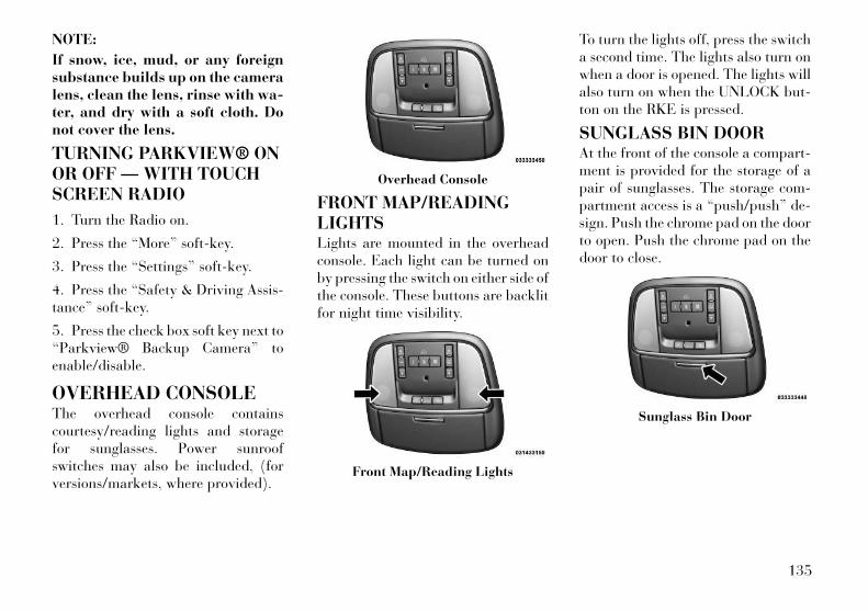
NOTE:
If snow, ice, mud, or any foreignsubstance builds up on the cameralens, clean the lens, rinse with wa-ter, and dry with a soft cloth. Donot cover the lens.
TURNING PARKVIEW® ONOR OFF — WITH TOUCHSCREEN RADIO
1. Turn the Radio on.
2. Press the “More” soft-key.
3. Press the “Settings” soft-key.
4. Press the “Safety & Driving Assis-tance” soft-key.
5. Press the check box soft key next to“Parkview® Backup Camera” toenable/disable.
OVERHEAD CONSOLEThe overhead console containscourtesy/reading lights and storagefor sunglasses. Power sunroofswitches may also be included, (forversions/markets, where provided).
FRONT MAP/READINGLIGHTSLights are mounted in the overheadconsole. Each light can be turned onby pressing the switch on either side ofthe console. These buttons are backlitfor night time visibility.
To turn the lights off, press the switcha second time. The lights also turn onwhen a door is opened. The lights willalso turn on when the UNLOCK but-ton on the RKE is pressed.
SUNGLASS BIN DOORAt the front of the console a compart-ment is provided for the storage of apair of sunglasses. The storage com-partment access is a “push/push” de-sign. Push the chrome pad on the doorto open. Push the chrome pad on thedoor to close.
Overhead Console
Front Map/Reading Lights
Sunglass Bin Door
135

POWER SUNROOF (forversions/markets, whereprovided)The power sunroof switch is locatedbetween the sun visors on the over-head console.
WARNING!• Never leave children in a vehicle
with the Remote Keyless Entry(RKE) transmitter in the passen-ger compartment. Occupants,particularly unattended children,can become entrapped by thepower sunroof while operating thepower sunroof switch. Such en-trapment may result in serious in-jury or death.
(Continued)
WARNING! (Continued)• In a collision, there is a greater
risk of being thrown from a ve-hicle with an open sunroof. Youcould also be seriously injured orkilled. Always fasten your seatbelt properly and make sure allpassengers are properly securedtoo.
• Do not allow small children to op-erate the sunroof. Never allowyour fingers, other body parts, orany object to project through thesunroof opening. Injury may re-sult.
OPENING SUNROOF —EXPRESSPress the switch rearward and releaseit within one-half second and the sun-roof will open automatically from anyposition. The sunroof will open fullyand stop automatically. This is called“Express Open”. During ExpressOpen operation, any movement of thesunroof switch will stop the sunroof.
OPENING SUNROOF —MANUAL MODETo open the sunroof, press and holdthe switch rearward to full open. Anyrelease of the switch will stop themovement and the sunroof will re-main in a partially opened conditionuntil the switch is pushed and heldrearward again.
CLOSING SUNROOF —EXPRESSPress the switch forward and release itwithin one-half second and the sun-roof will close automatically from anyposition. The sunroof will close fullyand stop automatically. This is called“Express Close”. During ExpressClose operation, any movement of theswitch will stop the sunroof.
CLOSING SUNROOF —MANUAL MODETo close the sunroof, press and holdthe switch in the forward position.Any release of the switch will stop themovement and the sunroof will re-main in a partially closed conditionuntil the switch is pushed and heldforward again.
Power Sunroof Switch
136
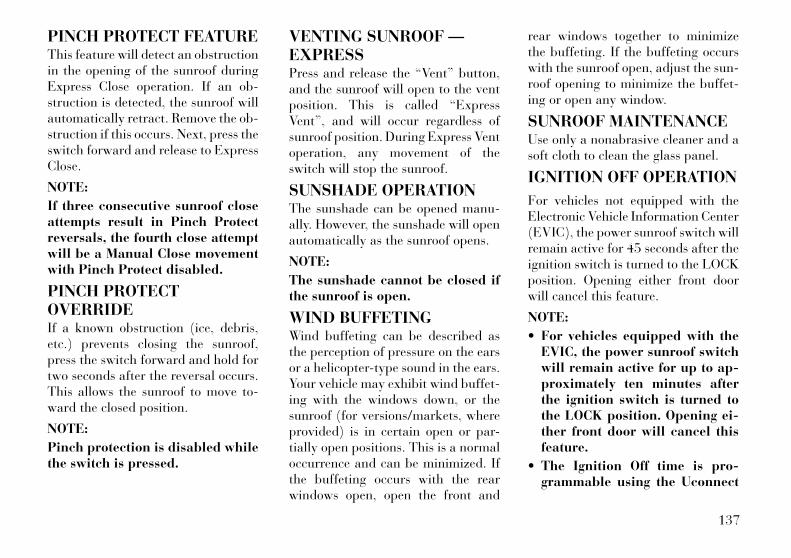
PINCH PROTECT FEATUREThis feature will detect an obstructionin the opening of the sunroof duringExpress Close operation. If an ob-struction is detected, the sunroof willautomatically retract. Remove the ob-struction if this occurs. Next, press theswitch forward and release to ExpressClose.
NOTE:
If three consecutive sunroof closeattempts result in Pinch Protectreversals, the fourth close attemptwill be a Manual Close movementwith Pinch Protect disabled.
PINCH PROTECTOVERRIDEIf a known obstruction (ice, debris,etc.) prevents closing the sunroof,press the switch forward and hold fortwo seconds after the reversal occurs.This allows the sunroof to move to-ward the closed position.
NOTE:
Pinch protection is disabled whilethe switch is pressed.
VENTING SUNROOF —EXPRESSPress and release the “Vent” button,and the sunroof will open to the ventposition. This is called “ExpressVent”, and will occur regardless ofsunroof position. During Express Ventoperation, any movement of theswitch will stop the sunroof.
SUNSHADE OPERATIONThe sunshade can be opened manu-ally. However, the sunshade will openautomatically as the sunroof opens.
NOTE:
The sunshade cannot be closed ifthe sunroof is open.
WIND BUFFETINGWind buffeting can be described asthe perception of pressure on the earsor a helicopter-type sound in the ears.Your vehicle may exhibit wind buffet-ing with the windows down, or thesunroof (for versions/markets, whereprovided) is in certain open or par-tially open positions. This is a normaloccurrence and can be minimized. Ifthe buffeting occurs with the rearwindows open, open the front and
rear windows together to minimizethe buffeting. If the buffeting occurswith the sunroof open, adjust the sun-roof opening to minimize the buffet-ing or open any window.
SUNROOF MAINTENANCEUse only a nonabrasive cleaner and asoft cloth to clean the glass panel.
IGNITION OFF OPERATION
For vehicles not equipped with theElectronic Vehicle Information Center(EVIC), the power sunroof switch willremain active for 45 seconds after theignition switch is turned to the LOCKposition. Opening either front doorwill cancel this feature.
NOTE:
• For vehicles equipped with theEVIC, the power sunroof switchwill remain active for up to ap-proximately ten minutes afterthe ignition switch is turned tothe LOCK position. Opening ei-ther front door will cancel thisfeature.
• The Ignition Off time is pro-grammable using the Uconnect
137
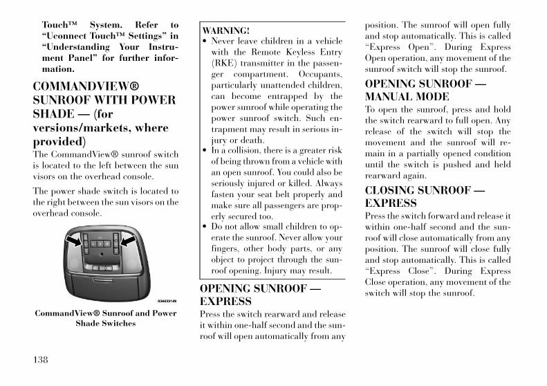
Touch™ System. Refer to“Uconnect Touch™ Settings” in“Understanding Your Instru-ment Panel” for further infor-mation.
COMMANDVIEW®SUNROOF WITH POWERSHADE — (forversions/markets, whereprovided)The CommandView® sunroof switchis located to the left between the sunvisors on the overhead console.
The power shade switch is located tothe right between the sun visors on theoverhead console.
WARNING!• Never leave children in a vehicle
with the Remote Keyless Entry(RKE) transmitter in the passen-ger compartment. Occupants,particularly unattended children,can become entrapped by thepower sunroof while operating thepower sunroof switch. Such en-trapment may result in serious in-jury or death.
• In a collision, there is a greater riskof being thrown from a vehicle withan open sunroof. You could also beseriously injured or killed. Alwaysfasten your seat belt properly andmake sure all passengers are prop-erly secured too.
• Do not allow small children to op-erate the sunroof. Never allow yourfingers, other body parts, or anyobject to project through the sun-roof opening. Injury may result.
OPENING SUNROOF —EXPRESSPress the switch rearward and releaseit within one-half second and the sun-roof will open automatically from any
position. The sunroof will open fullyand stop automatically. This is called“Express Open”. During ExpressOpen operation, any movement of thesunroof switch will stop the sunroof.
OPENING SUNROOF —MANUAL MODETo open the sunroof, press and holdthe switch rearward to full open. Anyrelease of the switch will stop themovement and the sunroof will re-main in a partially opened conditionuntil the switch is pushed and heldrearward again.
CLOSING SUNROOF —EXPRESSPress the switch forward and release itwithin one-half second and the sun-roof will close automatically from anyposition. The sunroof will close fullyand stop automatically. This is called“Express Close”. During ExpressClose operation, any movement of theswitch will stop the sunroof.
CommandView® Sunroof and PowerShade Switches
138

CLOSING SUNROOF —MANUAL MODETo close the sunroof, press and holdthe switch in the forward position.Any release of the switch will stop themovement and the sunroof will re-main in a partially closed conditionuntil the switch is pushed and heldforward again.
OPENING POWER SHADE— EXPRESSPress the shade switch rearward andrelease it within one-half second andthe shade will open automatically fromany position. The shade will open fullyand stop automatically. This is called“Express Open”. During Express Openoperation, any movement of the shadeswitch will stop the shade.
OPENING POWER SHADE— MANUAL MODETo open the shade, press and hold theswitch rearward to full open. Any re-lease of the switch will stop the move-ment and the shade will remain in apartially opened condition until theswitch is pushed and held rearwardagain.
CLOSING POWER SHADE— EXPRESSPress the switch forward and release itwithin one-half second and the shadewill close automatically from any po-sition. The shade will close fully andstop automatically. This is called “Ex-press Close”. During Express Closeoperation, any movement of theswitch will stop the shade.
CLOSING POWER SHADE— MANUAL MODETo close the shade, press and hold theswitch in the forward position. Anyrelease of the switch will stop themovement and the shade will remainin a partially closed condition untilthe switch is pushed and held forwardagain.
PINCH PROTECT FEATUREThis feature will detect an obstructionin the opening of the sunroof duringExpress Close operation. If an ob-struction is detected, the sunroof willautomatically retract. Remove the ob-struction if this occurs. Next, press theswitch forward and release to ExpressClose.
NOTE:
If three consecutive sunroof closeattempts result in Pinch Protectreversals, the fourth close attemptwill be a Manual Close movementwith Pinch Protect disabled.
PINCH PROTECTOVERRIDEIf a known obstruction (ice, debris,etc.) prevents closing the sunroof,press the switch forward and hold fortwo seconds after the reversal occurs.This allows the sunroof to move to-ward the closed position.
NOTE:
Pinch protection is disabled whilethe switch is pressed.
WIND BUFFETINGWind buffeting can be described asthe perception of pressure on the earsor a helicopter-type sound in the ears.Your vehicle may exhibit wind buffet-ing with the windows down, or thesunroof (for versions/markets, whereprovided) in certain open or partiallyopen positions. This is a normal oc-currence and can be minimized. If thebuffeting occurs with the rear win-
139
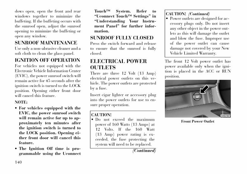
dows open, open the front and rearwindows together to minimize thebuffeting. If the buffeting occurs withthe sunroof open, adjust the sunroofopening to minimize the buffeting oropen any window.
SUNROOF MAINTENANCEUse only a non-abrasive cleaner and asoft cloth to clean the glass panel.
IGNITION OFF OPERATIONFor vehicles not equipped with theElectronic Vehicle Information Center(EVIC), the power sunroof switch willremain active for 45 seconds after theignition switch is turned to the LOCKposition. Opening either front doorwill cancel this feature.
NOTE:
• For vehicles equipped with theEVIC, the power sunroof switchwill remain active for up to ap-proximately ten minutes afterthe ignition switch is turned tothe LOCK position. Opening ei-ther front door will cancel thisfeature.
• The Ignition Off time is pro-grammable using the Uconnect
Touch™ System. Refer to“Uconnect Touch™ Settings” in“Understanding Your Instru-ment Panel” for further infor-mation.
SUNROOF FULLY CLOSEDPress the switch forward and releaseto ensure that the sunroof is fullyclosed.
ELECTRICAL POWEROUTLETSThere are three 12 Volt (13 Amp)electrical power outlets on this ve-hicle. The power outlets are protectedby a fuse.
Insert cigar lighter or accessory pluginto the power outlets for use to en-sure proper operation.
CAUTION!• Do not exceed the maximum
power of 160 Watts (13 Amps) at12 Volts. If the 160 Watt(13 Amp) power rating is ex-ceeded, the fuse protecting thesystem will need to be replaced.
(Continued)
CAUTION! (Continued)• Power outlets are designed for ac-
cessory plugs only. Do not insertany other object in the power out-lets as this will damage the outletand blow the fuse. Improper useof the power outlet can causedamage not covered by your NewVehicle Limited Warranty.
The front 12 Volt power outlet haspower available only when the igni-tion is placed in the ACC or RUNposition.
Front Power Outlet
140
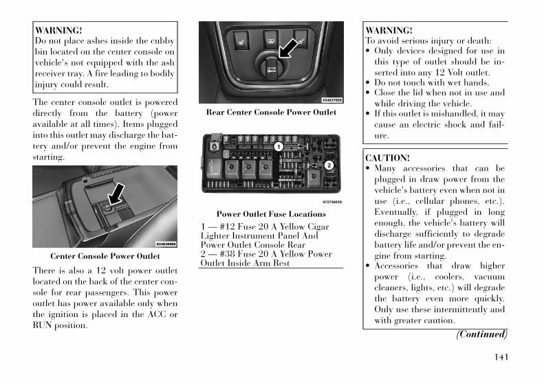
WARNING!Do not place ashes inside the cubbybin located on the center console onvehicle's not equipped with the ashreceiver tray. A fire leading to bodilyinjury could result.
The center console outlet is powereddirectly from the battery (poweravailable at all times). Items pluggedinto this outlet may discharge the bat-tery and/or prevent the engine fromstarting.
There is also a 12 volt power outletlocated on the back of the center con-sole for rear passengers. This poweroutlet has power available only whenthe ignition is placed in the ACC orRUN position.
WARNING!To avoid serious injury or death:• Only devices designed for use in
this type of outlet should be in-serted into any 12 Volt outlet.
• Do not touch with wet hands.• Close the lid when not in use and
while driving the vehicle.• If this outlet is mishandled, it may
cause an electric shock and fail-ure.
CAUTION!• Many accessories that can be
plugged in draw power from thevehicle's battery even when not inuse (i.e., cellular phones, etc.).Eventually, if plugged in longenough, the vehicle's battery willdischarge sufficiently to degradebattery life and/or prevent the en-gine from starting.
• Accessories that draw higherpower (i.e., coolers, vacuumcleaners, lights, etc.) will degradethe battery even more quickly.Only use these intermittently andwith greater caution.
(Continued)
Center Console Power Outlet
Rear Center Console Power Outlet
Power Outlet Fuse Locations
1 — #12 Fuse 20 A Yellow CigarLighter Instrument Panel AndPower Outlet Console Rear2 — #38 Fuse 20 A Yellow PowerOutlet Inside Arm Rest
141
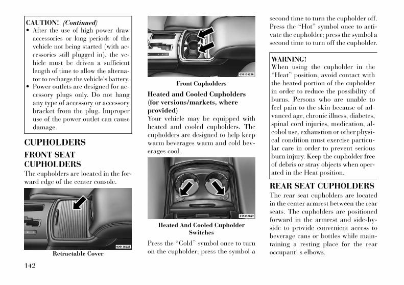
CAUTION! (Continued)• After the use of high power draw
accessories or long periods of thevehicle not being started (with ac-cessories still plugged in), the ve-hicle must be driven a sufficientlength of time to allow the alterna-tor to recharge the vehicle's battery.
• Power outlets are designed for ac-cessory plugs only. Do not hangany type of accessory or accessorybracket from the plug. Improperuse of the power outlet can causedamage.
CUPHOLDERS
FRONT SEATCUPHOLDERSThe cupholders are located in the for-ward edge of the center console.
Heated and Cooled Cupholders(for versions/markets, whereprovided)Your vehicle may be equipped withheated and cooled cupholders. Thecupholders are designed to help keepwarm beverages warm and cold bev-erages cool.
Press the “Cold” symbol once to turnon the cupholder; press the symbol a
second time to turn the cupholder off.Press the “Hot” symbol once to acti-vate the cupholder; press the symbol asecond time to turn off the cupholder.
WARNING!When using the cupholder in the“Heat” position, avoid contact withthe heated portion of the cupholderin order to reduce the possibility ofburns. Persons who are unable tofeel pain to the skin because of ad-vanced age, chronic illness, diabetes,spinal cord injuries, medication, al-cohol use, exhaustion or other physi-cal condition must exercise particu-lar care in order to prevent seriousburn injury. Keep the cupholder freeof debris or stray objects when oper-ated in the Heat position.
REAR SEAT CUPHOLDERSThe rear seat cupholders are locatedin the center armrest between the rearseats. The cupholders are positionedforward in the armrest and side-by-side to provide convenient access tobeverage cans or bottles while main-taining a resting place for the rearoccupant' s elbows.Retractable Cover
Front Cupholders
Heated And Cooled CupholderSwitches
142
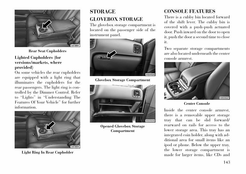
Lighted Cupholders (forversions/markets, whereprovided)On some vehicles the rear cupholdersare equipped with a light ring thatilluminates the cupholders for therear passengers. The light ring is con-trolled by the Dimmer Control. Referto “Lights” in “Understanding TheFeatures Of Your Vehicle” for furtherinformation.
STORAGE
GLOVEBOX STORAGEThe glovebox storage compartment islocated on the passenger side of theinstrument panel.
CONSOLE FEATURESThere is a cubby bin located forwardof the shift lever. The cubby bin iscovered with a push-push actuateddoor. Push inward on the door to openit, push the door a second time to closeit.
Two separate storage compartmentsare also located underneath the centerconsole armrest.
Inside the center console armrest,there is a removable upper storagetray that can be slid forward/rearward on rails for access to thelower storage area. This tray has anintegrated coin holder, along with ad-ditional area for small items like anipod or phone. Below the upper tray,the lower storage compartment ismade for larger items, like CDs and
Rear Seat Cupholders
Light Ring In Rear Cupholder
Glovebox Storage Compartment
Opened Glovebox StorageCompartment
Center Console
143

tissue boxes. In addition, the 12 voltpower outlet, USB and Aux jack arelocated here.
WARNING!Do not operate this vehicle with aconsole compartment lid in the openposition. Cellular phones, musicplayers, and other handheld elec-tronic devices should be stowedwhile driving. Use of these deviceswhile driving can cause an accidentdue to distraction, resulting in deathor injury.
DOOR STORAGEThe door panels contain storage ar-eas.
REAR SEAT ARMRESTSTORAGE (forversions/markets, whereprovided)For rear passengers there is a storagebin located in the armrest. Lift up-ward on the latch to open the storagecompartment.
CARGO AREA — VEHICLESEQUIPPED WITH 60/40SPLIT-FOLDING REARSEATThe 60/40 split-folding rear seat pro-vides cargo-carrying versatility. Theseatbacks fold down easily by pullingnylon tabs between the seatbacks andthe bolsters. When the seats are foldeddown, they provide a continuous,nearly-flat extension of the load floor.
When the seatback is folded to theupright position, make sure it islatched by strongly pulling on the topof the seatback above the seat strap.
WARNING!• Be certain that the seatback is se-
curely locked into position. If theseatback is not securely lockedinto position, the seat will not pro-vide the proper stability for childseats and/or passengers. An im-properly latched seat could causeserious injury.
• The cargo area in the rear of thevehicle (with the rear seatbacks inthe locked-up or folded down po-sition) should not be used as aplay area by children when thevehicle is in motion. They couldbe seriously injured in a collision.Children should be seated and us-ing the proper restraint system.
(Continued)
Front Door Trim Storage
Rear Armrest Storage
144
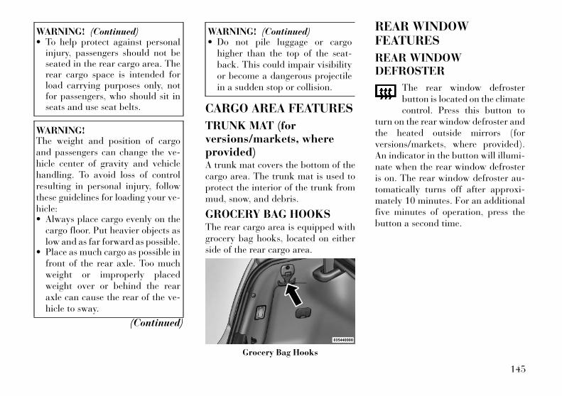
WARNING! (Continued)• To help protect against personal
injury, passengers should not beseated in the rear cargo area. Therear cargo space is intended forload carrying purposes only, notfor passengers, who should sit inseats and use seat belts.
WARNING!The weight and position of cargoand passengers can change the ve-hicle center of gravity and vehiclehandling. To avoid loss of controlresulting in personal injury, followthese guidelines for loading your ve-hicle:• Always place cargo evenly on the
cargo floor. Put heavier objects aslow and as far forward as possible.
• Place as much cargo as possible infront of the rear axle. Too muchweight or improperly placedweight over or behind the rearaxle can cause the rear of the ve-hicle to sway.
(Continued)
WARNING! (Continued)• Do not pile luggage or cargo
higher than the top of the seat-back. This could impair visibilityor become a dangerous projectilein a sudden stop or collision.
CARGO AREA FEATURES
TRUNK MAT (forversions/markets, whereprovided)A trunk mat covers the bottom of thecargo area. The trunk mat is used toprotect the interior of the trunk frommud, snow, and debris.
GROCERY BAG HOOKSThe rear cargo area is equipped withgrocery bag hooks, located on eitherside of the rear cargo area.
REAR WINDOWFEATURES
REAR WINDOWDEFROSTER
The rear window defrosterbutton is located on the climatecontrol. Press this button to
turn on the rear window defroster andthe heated outside mirrors (forversions/markets, where provided).An indicator in the button will illumi-nate when the rear window defrosteris on. The rear window defroster au-tomatically turns off after approxi-mately 10 minutes. For an additionalfive minutes of operation, press thebutton a second time.
Grocery Bag Hooks
145
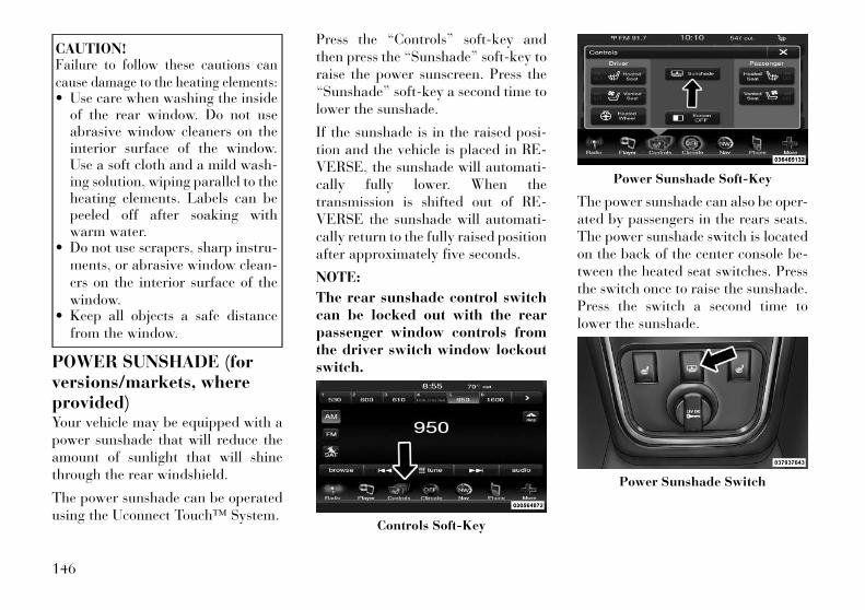
CAUTION!Failure to follow these cautions cancause damage to the heating elements:• Use care when washing the inside
of the rear window. Do not useabrasive window cleaners on theinterior surface of the window.Use a soft cloth and a mild wash-ing solution, wiping parallel to theheating elements. Labels can bepeeled off after soaking withwarm water.
• Do not use scrapers, sharp instru-ments, or abrasive window clean-ers on the interior surface of thewindow.
• Keep all objects a safe distancefrom the window.
POWER SUNSHADE (forversions/markets, whereprovided)Your vehicle may be equipped with apower sunshade that will reduce theamount of sunlight that will shinethrough the rear windshield.
The power sunshade can be operatedusing the Uconnect Touch™ System.
Press the “Controls” soft-key andthen press the “Sunshade” soft-key toraise the power sunscreen. Press the“Sunshade” soft-key a second time tolower the sunshade.
If the sunshade is in the raised posi-tion and the vehicle is placed in RE-VERSE, the sunshade will automati-cally fully lower. When thetransmission is shifted out of RE-VERSE the sunshade will automati-cally return to the fully raised positionafter approximately five seconds.
NOTE:
The rear sunshade control switchcan be locked out with the rearpassenger window controls fromthe driver switch window lockoutswitch.
The power sunshade can also be oper-ated by passengers in the rears seats.The power sunshade switch is locatedon the back of the center console be-tween the heated seat switches. Pressthe switch once to raise the sunshade.Press the switch a second time tolower the sunshade.
Controls Soft-Key
Power Sunshade Soft-Key
Power Sunshade Switch
146
LOAD LEVELINGSYSTEM (forversions/markets, whereprovided)The automatic load leveling systemwill provide a level-riding vehicle un-der most passenger and cargo loadingconditions.
A hydraulic pump contained withinthe shock absorbers raises the rear ofthe vehicle to the correct height. Ittakes approximately 1.6 km of driv-ing for the leveling to complete de-pending on road surface conditions.
If the leveled vehicle is not moved forapproximately 15 hours, the levelingsystem will bleed itself down. The ve-hicle must be driven to reset the sys-tem.
147

148
4
UNDERSTANDING YOUR INSTRUMENTPANEL• INSTRUMENT PANEL FEATURES . . . . . . . . . . . 152
• INSTRUMENT CLUSTER . . . . . . . . . . . . . . . . . . 153
• INSTRUMENT CLUSTER DESCRIPTIONS . . . . 154
• ELECTRONIC VEHICLE INFORMATIONCENTER (EVIC) . . . . . . . . . . . . . . . . . . . . . . . . . 159
• ELECTRONIC VEHICLE INFORMATIONCENTER (EVIC) DISPLAYS . . . . . . . . . . . . . . 160
• EVIC WHITE TELLTALES . . . . . . . . . . . . . . . 161
• EVIC AMBER TELLTALES . . . . . . . . . . . . . . . 162
• EVIC RED TELLTALES . . . . . . . . . . . . . . . . . 162
• OIL CHANGE DUE . . . . . . . . . . . . . . . . . . . . . 164
• DIESEL PARTICULATE FILTER (DPF)MESSAGES . . . . . . . . . . . . . . . . . . . . . . . . . . 164
• FUEL ECONOMY . . . . . . . . . . . . . . . . . . . . . . 165
• CRUISE CONTROL . . . . . . . . . . . . . . . . . . . . 165
• VEHICLE SPEED . . . . . . . . . . . . . . . . . . . . . . 166
• TRIP INFO . . . . . . . . . . . . . . . . . . . . . . . . . . . 166
• TIRE BAR . . . . . . . . . . . . . . . . . . . . . . . . . . . 166
• VEHICLE INFO (CUSTOMERINFORMATION FEATURES) . . . . . . . . . . . . . . 167
149

• MESSAGES # . . . . . . . . . . . . . . . . . . . . . . . . . 167
• TURN MENU OFF . . . . . . . . . . . . . . . . . . . . . 167
• Uconnect Touch™ SETTINGS . . . . . . . . . . . . . . 167
• HARD-KEYS . . . . . . . . . . . . . . . . . . . . . . . . . 167
• SOFT-KEYS . . . . . . . . . . . . . . . . . . . . . . . . . . 167
• CUSTOMER PROGRAMMABLE FEATURES— Uconnect Touch™ SYSTEM 8.4SETTINGS . . . . . . . . . . . . . . . . . . . . . . . . . . . 168
• SOUND SYSTEMS . . . . . . . . . . . . . . . . . . . . . . . 177
• NAVIGATION SYSTEM (for versions/markets,where provided) . . . . . . . . . . . . . . . . . . . . . . . . . 177
• SETTING THE ANALOG CLOCK . . . . . . . . . . . . 178
• iPod®/USB/MP3 CONTROL (for vehicles/markets, where provided) . . . . . . . . . . . . . . . . . 178
• HARMAN KARDON® Logic7® HIGHPERFORMANCE MULTICHANNELSURROUND SOUND SYSTEM WITHDRIVER-SELECTABLE SURROUND (DSS) (forversions/markets, where required) . . . . . . . . . . . 178
• STEERING WHEEL AUDIO CONTROLS . . . . . . 179
• Radio Operation . . . . . . . . . . . . . . . . . . . . . . 179
• CD Player . . . . . . . . . . . . . . . . . . . . . . . . . . . 179
• CD/DVD DISC MAINTENANCE . . . . . . . . . . . . . 179
• RADIO OPERATION AND MOBILE PHONES . . . 180
• CLIMATE CONTROLS . . . . . . . . . . . . . . . . . . . . 180
• GENERAL OVERVIEW . . . . . . . . . . . . . . . . . 180
150

• CLIMATE CONTROL FUNCTIONS . . . . . . . . . 183
• AUTOMATIC TEMPERATURE CONTROL(ATC) . . . . . . . . . . . . . . . . . . . . . . . . . . . . . . . 184
• OPERATING TIPS . . . . . . . . . . . . . . . . . . . . . 185
151

INSTRUMENT PANEL FEATURES
1 — Air Outlet 7 — ESC Off Switch 13 — Engine Start/Stop Button2 — Instrument Cluster 8 — Uconnect Touch™ System Hard
Controls14 — Trunk Release Button
3 — Hazard Switch 9 — SD Memory Card Slot 15 — Dimmer Controls4 — Uconnect Touch™ System 10 — Power Outlet 16 — Hood Release5 — Climate Control Hard Controls 11 — CD/DVD Slot 17 — Headlight Switch6 — Glove Compartment 12 — Storage Compartment 18 — Analog Clock
152

INSTRUMENT CLUSTER
153
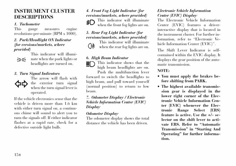
INSTRUMENT CLUSTERDESCRIPTIONS
1. TachometerThis gauge measures enginerevolutions-per-minute (RPM x 1000).
2. Park/Headlight ON Indicator(for versions/markets, whereprovided)
This indicator will illumi-nate when the park lights orheadlights are turned on.
3. Turn Signal IndicatorsThe arrow will flash withthe exterior turn signalwhen the turn signal lever isoperated.
If the vehicle electronics sense that thevehicle is driven more than 1.6 kmwith either turn signal on, a continu-ous chime will sound to alert you toturn the signals off. If either indicatorflashes at a rapid rate, check for adefective outside light bulb.
4. Front Fog Light Indicator (forversions/markets, where provided)
This indicator will illuminatewhen the front fog lights are on.
5. Rear Fog Light Indicator (forversions/markets, where provided)
This indicator will illuminatewhen the rear fog lights are on.
6. High Beam IndicatorThis indicator shows that thehigh beam headlights are on.Push the multifunction lever
forward to switch the headlights tohigh beam, and pull toward yourself(normal position) to return to lowbeam.
7. Odometer Display / ElectronicVehicle Information Center (EVIC)Display
Odometer DisplayThe odometer display shows the totaldistance the vehicle has been driven.
Electronic Vehicle InformationCenter (EVIC) DisplayThe Electronic Vehicle InformationCenter (EVIC) features a driver-interactive display that is located inthe instrument cluster. For further in-formation, refer to “Electronic Ve-hicle Information Center (EVIC)”.
The Shift Lever Indicator is self-contained within the EVIC display. Itdisplays the gear position of the auto-matic transmission.
NOTE:
• You must apply the brakes be-fore shifting from PARK.
• The highest available transmis-sion gear is displayed in thelower right corner of the Elec-tronic Vehicle Information Cen-ter (EVIC) whenever the Elec-tronic Range Select (ERS)feature is active. Use the +/- se-lector on the shift lever to acti-vate ERS. Refer to “AutomaticTransmission” in “Starting AndOperating” for further informa-tion.
154
8. Tire Pressure MonitoringTelltale Light (for versions/markets, where provided)
Each tire, including thespare (if provided), shouldbe checked monthly whencold and inflated to the in-
flation pressure recommended by thevehicle manufacturer on the vehicleplacard or tire inflation pressure la-bel. (If your vehicle has tires of adifferent size than the size indicatedon the vehicle placard or tire inflationpressure label, you should determinethe proper tire inflation pressure forthose tires.)
As an added safety feature, your ve-hicle has been equipped with a TirePressure Monitoring System (TPMS)that illuminates a low tire pressuretelltale when one or more of your tiresis significantly under-inflated. Ac-cordingly, when the low tire pressuretelltale illuminates, you should stopand check your tires as soon as pos-sible, and inflate them to the properpressure. Driving on a significantlyunder-inflated tire causes the tire tooverheat and can lead to tire failure.
Under-inflation also reduces fuel effi-ciency and tire tread life, and mayaffect the vehicle’s handling and stop-ping ability.
Please note that the TPMS is not asubstitute for proper tire mainte-nance, and it is the driver’s responsi-bility to maintain correct tire pres-sure, even if under-inflation has notreached the level to trigger illumina-tion of the TPMS low tire pressuretelltale.
Your vehicle has also been equippedwith a TPMS malfunction indicator toindicate when the system is not oper-ating properly. The TPMS malfunc-tion indicator is combined with thelow tire pressure telltale. When thesystem detects a malfunction, the tell-tale will flash for approximately oneminute and then remain continuouslyilluminated. This sequence will con-tinue upon subsequent vehicle start-ups as long as the malfunction exists.When the malfunction indicator is il-luminated, the system may not beable to detect or signal low tire pres-sure as intended. TPMS malfunctionsmay occur for a variety of reasons,
including the installation of replace-ment or alternate tires or wheels onthe vehicle that prevent the TPMSfrom functioning properly. Alwayscheck the TPMS malfunction telltaleafter replacing one or more tires orwheels on your vehicle, to ensure thatthe replacement or alternate tires andwheels allow the TPMS to continue tofunction properly.
CAUTION!The TPMS has been optimized forthe original equipment tires andwheels. TPMS pressures and warn-ing have been established for the tiresize equipped on your vehicle. Un-desirable system operation or sensordamage may result when using re-placement equipment that is not ofthe same size, type, and/or style.Aftermarket wheels can cause sensordamage. Do not use tire sealant froma can or balance beads if your ve-hicle is equipped with a TPMS, asdamage to the sensors may result.
155
9. Malfunction Indicator Light(MIL)
The Malfunction IndicatorLight (MIL) is part of an on-board diagnostic system,called OBD, that monitors en-
gine and automatic transmission con-trol systems. The light will illuminatewhen the key is in the ON/RUN posi-tion, before engine start. If the bulbdoes not come on when turning thekey from OFF to ON/RUN, have thecondition checked promptly.
Certain conditions, such as poor fuelquality, etc., may illuminate the MILafter engine start. The vehicle shouldbe serviced if the light stays onthrough several of your typical driv-ing cycles. In most situations, the ve-hicle will drive normally and will notrequire towing.
CAUTION!Prolonged driving with the MIL oncould cause damage to the enginecontrol system. It also could affectfuel economy and drivability. If theMIL is flashing, severe catalytic con-verter damage and power loss willsoon occur. Immediate service is re-quired.
WARNING!A malfunctioning catalytic con-verter, as referenced above, canreach higher temperatures than innormal operating conditions. Thiscan cause a fire if you drive slowly orpark over flammable substancessuch as dry plants, wood, cardboard,etc. This could result in death orserious injury to the driver, occu-pants or others.
10. SpeedometerIndicates vehicle speed.
11. Fuel Door ReminderThe arrow in this symbol isa reminder that the FuelFiller Door is located on theleft side of the vehicle.
12. Fuel GaugeThe pointer shows the level of fuel inthe fuel tank when the ignition switchis in the ON/RUN position.
13. Air Bag Warning LightThis light will turn on forfour to eight seconds as abulb check when the igni-tion switch is first turned to
ON/RUN. If the light is either not onduring starting, stays on, or turns onwhile driving, have the system in-spected at an authorized dealer assoon as possible. Refer to “OccupantRestraints” in “Things To Know Be-fore Starting Your Vehicle” for furtherinformation.
156
14. Brake Warning LightThis light monitors variousbrake functions, includingbrake fluid level and park-ing brake application. If the
brake light turns on it may indicatethat the parking brake is applied, thatthe brake fluid level is low, or thatthere is a problem with the anti-lockbrake system reservoir.
If the light remains on when the park-ing brake has been disengaged, andthe fluid level is at the full mark on themaster cylinder reservoir, it indicatesa possible brake hydraulic systemmalfunction or that a problem withthe Brake Booster has been detectedby the Anti-Lock Brake System (ABS)/ Electronic Stability Control (ESC)system. In this case, the light will re-main on until the condition has beencorrected. If the problem is related tothe brake booster, the ABS pump willrun when applying the brake and abrake pedal pulsation may be felt dur-ing each stop.
The dual brake system provides a re-serve braking capacity in the event ofa failure to a portion of the hydraulic
system. A leak in either half of thedual brake system is indicated by theBrake Warning Light, which will turnon when the brake fluid level in themaster cylinder has dropped below aspecified level.
The light will remain on until thecause is corrected.
NOTE:
The light may flash momentarilyduring sharp cornering maneu-vers, which change fluid level con-ditions. The vehicle should haveservice performed, and the brakefluid level checked.
If brake failure is indicated, immedi-ate repair is necessary.
WARNING!Driving a vehicle with the red brakelight on is dangerous. Part of thebrake system may have failed. It willtake longer to stop the vehicle. Youcould have a collision. Have the ve-hicle checked immediately.
Vehicles equipped with the Anti-LockBrake System (ABS), are alsoequipped with Electronic Brake Force
Distribution (EBD). In the event of anEBD failure, the Brake Warning Lightwill turn on along with the ABS Light.Immediate repair to the ABS system isrequired.
Operation of the Brake Warning Lightcan be checked by turning the ignitionswitch from the OFF position to theON/RUN position. The light shouldilluminate for approximately two sec-onds. The light should then turn offunless the parking brake is applied ora brake fault is detected. If the lightdoes not illuminate, have the lightinspected by an authorized dealer.
The light also will turn on when theparking brake is applied with the ig-nition switch in the ON/RUN posi-tion.
NOTE:
This light shows only that theparking brake is applied. It doesnot show the degree of brake ap-plication.
157

15. Anti-Lock Brake (ABS) LightThis light monitors theAnti-Lock Brake System(ABS). The light will turnon when the ignition switch
is turned to the ON/RUN position andmay stay on for as long as four sec-onds.
If the ABS light remains on or turns onwhile driving, it indicates that theAnti-Lock portion of the brake sys-tem is not functioning and that serviceis required. However, the conven-tional brake system will continue tooperate normally if the BRAKE warn-ing light is not on.
If the ABS light is on, the brake sys-tem should be serviced as soon aspossible to restore the benefits ofAnti-Lock brakes. If the ABS lightdoes not turn on when the ignitionswitch is turned to the ON/RUN posi-tion, have the light inspected by anauthorized dealer.
16. Vehicle Security Light (forversions/markets, where provided)
This light will flash at a fastrate for approximately15 seconds, when the ve-hicle security alarm is arm-
ing, and then will flash slowly untilthe vehicle is disarmed.
17. Electronic Stability Control(ESC) OFF Indicator Light (forversions/markets, where provided)
This light indicates theElectronic Stability Control(ESC) is off.
18. Electronic Stability Control(ESC) Activation/MalfunctionIndicator Light (for versions/markets, where provided)
The “ESC Activation/Malfunction IndicatorLight” in the instrumentcluster will come on when
the ignition switch is turned to theON/RUN position. It should go outwith the engine running. If the “ESCActivation/Malfunction IndicatorLight” comes on continuously with
the engine running, a malfunction hasbeen detected in the ESC system. Ifthis light remains on after several ig-nition cycles, and the vehicle has beendriven several kilometers at speedsgreater than 48 km/h, see your autho-rized dealer as soon as possible tohave the problem diagnosed and cor-rected.
NOTE:
• The “ESC Off Indicator Light”and the “ESC Activation/Malfunction Indicator Light”come on momentarily each timethe ignition switch is turned toON/RUN.
• Each time the ignition is turnedto ON/RUN, the ESC system willbe ON, even if it was turned offpreviously.
• The ESC system will make buzz-ing or clicking sounds when it isactive. This is normal; thesounds will stop when ESC be-comes inactive following themaneuver that caused the ESCactivation.
158
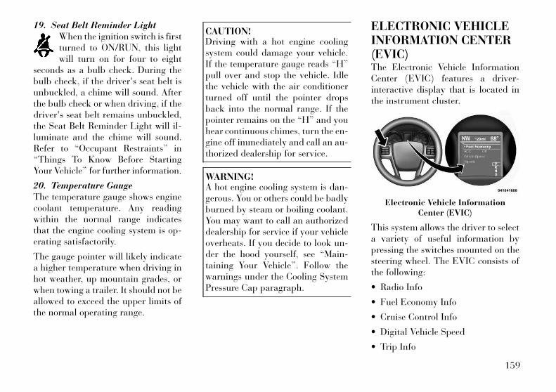
19. Seat Belt Reminder LightWhen the ignition switch is firstturned to ON/RUN, this lightwill turn on for four to eight
seconds as a bulb check. During thebulb check, if the driver's seat belt isunbuckled, a chime will sound. Afterthe bulb check or when driving, if thedriver's seat belt remains unbuckled,the Seat Belt Reminder Light will il-luminate and the chime will sound.Refer to “Occupant Restraints” in“Things To Know Before StartingYour Vehicle” for further information.
20. Temperature GaugeThe temperature gauge shows enginecoolant temperature. Any readingwithin the normal range indicatesthat the engine cooling system is op-erating satisfactorily.
The gauge pointer will likely indicatea higher temperature when driving inhot weather, up mountain grades, orwhen towing a trailer. It should not beallowed to exceed the upper limits ofthe normal operating range.
CAUTION!Driving with a hot engine coolingsystem could damage your vehicle.If the temperature gauge reads “H”pull over and stop the vehicle. Idlethe vehicle with the air conditionerturned off until the pointer dropsback into the normal range. If thepointer remains on the “H” and youhear continuous chimes, turn the en-gine off immediately and call an au-thorized dealership for service.
WARNING!A hot engine cooling system is dan-gerous. You or others could be badlyburned by steam or boiling coolant.You may want to call an authorizeddealership for service if your vehicleoverheats. If you decide to look un-der the hood yourself, see “Main-taining Your Vehicle”. Follow thewarnings under the Cooling SystemPressure Cap paragraph.
ELECTRONIC VEHICLEINFORMATION CENTER(EVIC)The Electronic Vehicle InformationCenter (EVIC) features a driver-interactive display that is located inthe instrument cluster.
This system allows the driver to selecta variety of useful information bypressing the switches mounted on thesteering wheel. The EVIC consists ofthe following:
• Radio Info
• Fuel Economy Info
• Cruise Control Info
• Digital Vehicle Speed
• Trip Info
Electronic Vehicle InformationCenter (EVIC)
159
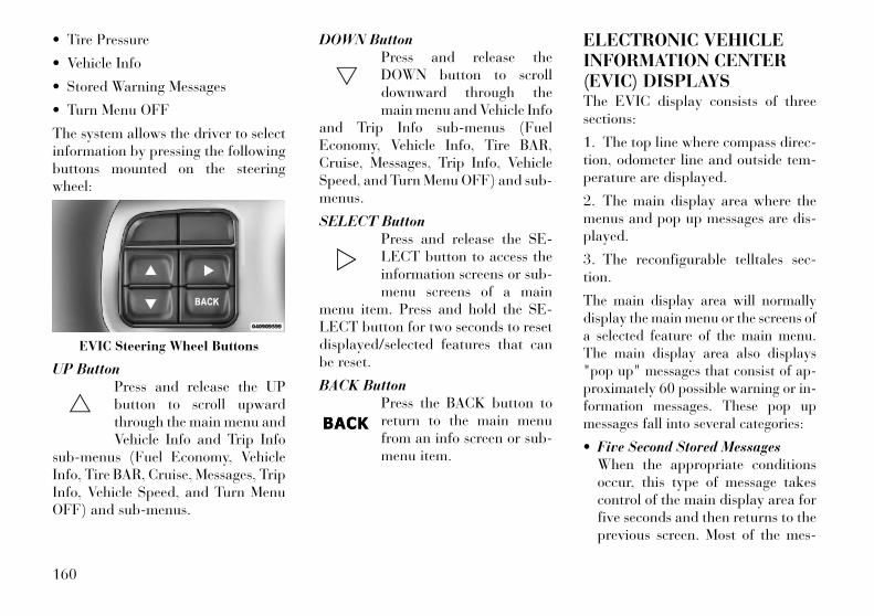
• Tire Pressure
• Vehicle Info
• Stored Warning Messages
• Turn Menu OFF
The system allows the driver to selectinformation by pressing the followingbuttons mounted on the steeringwheel:
UP ButtonPress and release the UPbutton to scroll upwardthrough the main menu andVehicle Info and Trip Info
sub-menus (Fuel Economy, VehicleInfo, Tire BAR, Cruise, Messages, TripInfo, Vehicle Speed, and Turn MenuOFF) and sub-menus.
DOWN ButtonPress and release theDOWN button to scrolldownward through themain menu and Vehicle Info
and Trip Info sub-menus (FuelEconomy, Vehicle Info, Tire BAR,Cruise, Messages, Trip Info, VehicleSpeed, and Turn Menu OFF) and sub-menus.
SELECT ButtonPress and release the SE-LECT button to access theinformation screens or sub-menu screens of a main
menu item. Press and hold the SE-LECT button for two seconds to resetdisplayed/selected features that canbe reset.
BACK ButtonPress the BACK button toreturn to the main menufrom an info screen or sub-menu item.
ELECTRONIC VEHICLEINFORMATION CENTER(EVIC) DISPLAYSThe EVIC display consists of threesections:
1. The top line where compass direc-tion, odometer line and outside tem-perature are displayed.
2. The main display area where themenus and pop up messages are dis-played.
3. The reconfigurable telltales sec-tion.
The main display area will normallydisplay the main menu or the screens ofa selected feature of the main menu.The main display area also displays"pop up" messages that consist of ap-proximately 60 possible warning or in-formation messages. These pop upmessages fall into several categories:
• Five Second Stored MessagesWhen the appropriate conditionsoccur, this type of message takescontrol of the main display area forfive seconds and then returns to theprevious screen. Most of the mes-
EVIC Steering Wheel Buttons
160
sages of this type are then stored (aslong as the condition that activatedit remains active) and can be re-viewed from the "Messages" mainmenu item. As long as there is astored message, an "i" will be dis-played in the EVIC's compass/outside temp line. Examples of thismessage type are "Right Front TurnSignal Lamp Out" and "Low TirePressure".
• Unstored MessagesThis message type is displayed indefi-nitely or until the condition that acti-vated the message is cleared. Ex-amples of this message type are "TurnSignal On" (if a turn signal is left on)and "Lights On" (if driver leaves thevehicle).
• Unstored Messages Until RUNThis message type is displayed untilthe ignition is in the RUN state. Anexample of this message type is "PressBrake Pedal and Push Button toStart".
• Five Second Unstored MessagesWhen the appropriate conditions oc-cur, this type of message takes controlof the main display area for five sec-onds and then returns to the previousscreen. Examples of this message typeare "Memory System Unavailable -Not in Park" and "Automatic HighBeams On".
The Reconfigurable Telltales sectionis divided into the white telltales areaon the right, amber telltales in themiddle, and red telltales on the left.
EVIC WHITE TELLTALESThis area will show reconfigurablewhite caution telltales. These telltalesinclude:
• Shift Lever Status — Diesel OnlyThe selected AutoStick gear is dis-played as D1, D2, D3, D4, D5 andindicate the Electronic Range Select(ERS) feature has been engaged andthe gear selected is displayed. For fur-ther information on Autostick, referto “Starting And Operating”.
• Electronic Speed Control ONThis telltale will illuminatewhen the electronic speedcontrol is ON. For furtherinformation, refer to “Elec-
tronic Speed Control” in “Under-standing The Features Of Your Ve-hicle.”
• Electronic Speed Control SETThis telltale will illuminatewhen the electronic speedcontrol is SET. For furtherinformation, refer to “Elec-
tronic Speed Control” in “Under-standing The Features Of Your Ve-hicle.”
• Adaptive Cruise Control (ACC)ON
This telltale will illuminatewhen the ACC is ON. Forfurther information, referto “Adaptive Cruise Control
(ACC)” in “Understanding The Fea-tures Of Your Vehicle.”
161
• Adaptive Cruise Control (ACC)SET
This telltale will illuminatewhen the ACC is SET. Forfurther information, referto “Adaptive Cruise Control
(ACC)” in “Understanding The Fea-tures Of Your Vehicle.”
EVIC AMBER TELLTALESThis area will show reconfigurableamber caution telltales. These tell-tales include:
• Forward Collision Warning(FCW) OFF
This telltale informs thedriver that the ForwardCollision Warning feature isOff. The telltale is On when
the front radar sensor is blocked andrequires cleaning, the ACC/FCW sen-sors require service, or the ACC/FCWsystem is unavailable because of asystem error. For further information,refer to “Adaptive Cruise Control(ACC)” in “Understanding The Fea-tures Of Your Vehicle.”
• Low Fuel TelltaleWhen the fuel level reaches ap-proximately 11.0 L this lightwill turn on, and remain on until
fuel is added.
• Windshield Washer Fluid LowIndicator
This telltale will turn on toindicate the windshieldwasher fluid is low.
• Adaptive Cruise Control (ACC)Malfunction
This light will turn on whena ACC is not operating andneeds service. For furtherinformation, refer to
“Adaptive Cruise Control (ACC)” in“Understanding The Features OfYour Vehicle.”
• Wait To Start Light — DieselEngines Only
The Wait To Start Light willturn on when the ignition key is
first turned to the ON/RUN position.Wait until the Wait To Start Lightturns OFF to start the engine. (Refer
to “Starting Procedures” in “StartingAnd Operating” for further informa-tion).
• Water In Fuel Indicator Light —Diesel Engines Only
Indicates there is water de-tected in the fuel filter. Ifthis light remains on, DONOT start the vehicle be-
fore you drain the water from the fuelfilter to prevent engine damage. Referto “Maintenance Procedures/ Drain-ing Fuel/Water Separator Filter” in“Maintaining Your Vehicle” for waterdrain procedure.
EVIC RED TELLTALESThis area will show reconfigurable redtelltales. These telltales include:
• Door AjarThis telltale turns on whenone or more doors are ajar.The telltale will show whichdoors are ajar.
162
• Trunk AjarThis light will turn on toindicate that the trunk lid isajar.
• Oil Pressure Warning TelltaleThis telltale indicates low en-gine oil pressure. If the light
turns on while driving, stop the ve-hicle and shut off the engine as soonas possible. A chime will sound forfour minutes when this light turns on.
Do not operate the vehicle until thecause is corrected. This light does notshow how much oil is in the engine.The engine oil level must be checkedunder the hood.
• Charging System TelltaleThis telltale shows the status ofthe electrical charging system.
If the telltale stays on or comes onwhile driving, turn off some of thevehicle's non-essential electrical de-vices or increase engine speed (if atidle). If the charging system telltaleremains on, it means that the vehicleis experiencing a problem with the
charging system. Obtain SERVICEIMMEDIATELY. See an authorizeddealer.
If jump starting is required, refer to“Jump Starting Procedures” in “WhatTo Do In Emergencies”.
• Electronic Throttle Control(ETC) Telltale
This telltale informs you ofa problem with the Elec-tronic Throttle Control(ETC) system. If the telltale
comes on while driving, have the sys-tem checked by an authorized dealer.
If a problem is detected, the telltalewill come on while the engine is run-ning. Cycle the ignition key when thevehicle has completely stopped andthe shift lever is placed in the PARKposition. The telltale should turn off.
If the telltale remains lit with the en-gine running, your vehicle will usuallybe drivable. However, see an autho-rized dealer for service as soon as pos-sible. If the telltale is flashing whenthe engine is running, immediate ser-vice is required. You may experiencereduced performance, an elevated/
rough idle or engine stall and yourvehicle may require towing.
• Engine Temperature WarningTelltale
This telltale warns of an over-heated engine condition. Astemperatures rise and the
gauge approaches H, this telltale willilluminate and a single chime willsound after reaching a set threshold.Further overheating will cause thetemperature gauge to pass H, the tell-tale will continuously flash and a con-tinuous chime will occur until the en-gine is allowed to cool.
If the telltale turns on while driving,safely pull over and stop the vehicle. Ifthe A/C system is on, turn it off. Also,shift the transmission into NEUTRALand idle the vehicle. If the tempera-ture reading does not return to nor-mal, turn the engine off immediatelyand call for service. Refer to “If YourEngine Overheats” in “What To Do InEmergencies” for more information.
163
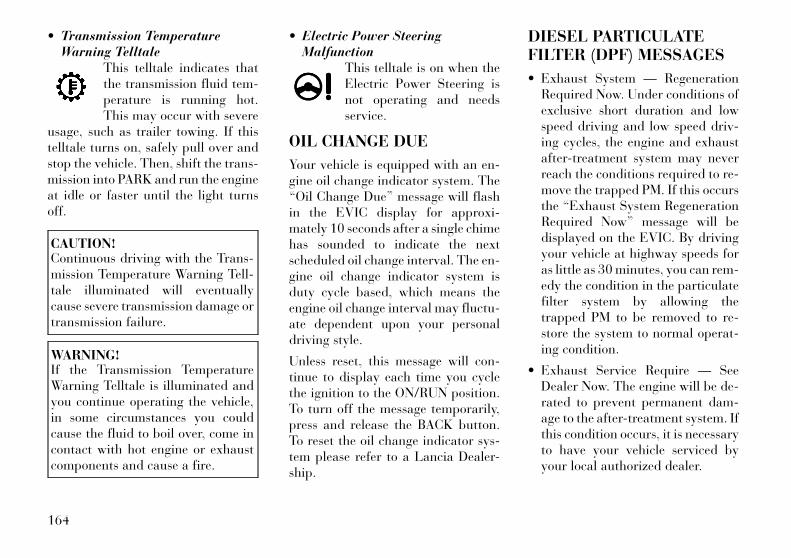
• Transmission TemperatureWarning Telltale
This telltale indicates thatthe transmission fluid tem-perature is running hot.This may occur with severe
usage, such as trailer towing. If thistelltale turns on, safely pull over andstop the vehicle. Then, shift the trans-mission into PARK and run the engineat idle or faster until the light turnsoff.
CAUTION!Continuous driving with the Trans-mission Temperature Warning Tell-tale illuminated will eventuallycause severe transmission damage ortransmission failure.
WARNING!If the Transmission TemperatureWarning Telltale is illuminated andyou continue operating the vehicle,in some circumstances you couldcause the fluid to boil over, come incontact with hot engine or exhaustcomponents and cause a fire.
• Electric Power SteeringMalfunction
This telltale is on when theElectric Power Steering isnot operating and needsservice.
OIL CHANGE DUE
Your vehicle is equipped with an en-gine oil change indicator system. The“Oil Change Due” message will flashin the EVIC display for approxi-mately 10 seconds after a single chimehas sounded to indicate the nextscheduled oil change interval. The en-gine oil change indicator system isduty cycle based, which means theengine oil change interval may fluctu-ate dependent upon your personaldriving style.
Unless reset, this message will con-tinue to display each time you cyclethe ignition to the ON/RUN position.To turn off the message temporarily,press and release the BACK button.To reset the oil change indicator sys-tem please refer to a Lancia Dealer-ship.
DIESEL PARTICULATEFILTER (DPF) MESSAGES
• Exhaust System — RegenerationRequired Now. Under conditions ofexclusive short duration and lowspeed driving and low speed driv-ing cycles, the engine and exhaustafter-treatment system may neverreach the conditions required to re-move the trapped PM. If this occursthe “Exhaust System RegenerationRequired Now” message will bedisplayed on the EVIC. By drivingyour vehicle at highway speeds foras little as 30 minutes, you can rem-edy the condition in the particulatefilter system by allowing thetrapped PM to be removed to re-store the system to normal operat-ing condition.
• Exhaust Service Require — SeeDealer Now. The engine will be de-rated to prevent permanent dam-age to the after-treatment system. Ifthis condition occurs, it is necessaryto have your vehicle serviced byyour local authorized dealer.
164

FUEL ECONOMYPress and release the UP or DOWNbutton until "Fuel Economy" is high-lighted. Press the SELECT buttonand the next screen will display thefollowing:
• Average Fuel Economy
• Distance To Empty (DTE)
• Instantaneous Liters Per 100km(L/100km)
Average Fuel Economy / ECO FuelSaver Mode (for versions/markets, where provided)Shows the average fuel economy sincethe last reset. When the fuel economyis reset, the display will read “RE-SET” or show dashes for two seconds.Then, the history information will beerased, and the averaging will con-
tinue from the last fuel average read-ing before the reset.
Press the SELECT button to reset theAverage Fuel Economy. Press theBACK button to return to the mainmenu.
There is an ECO icon in the lowerportion of the EVIC display. This iconwill appear whenever the Multi-Displacement System (MDS) (forversions/markets, where provided)allows the engine to operate on fourcylinders, or if you are driving in afuel efficient manner.
This feature allows you to monitorwhen you are driving in a fuel efficientmanner, and it can be used to modifydriving habits in order to increase fueleconomy.
Distance To Empty (DTE)Shows the estimated distance that canbe traveled with the fuel remaining inthe tank. This estimated distance isdetermined by a weighted average ofthe instantaneous and average fueleconomy, according to the currentfuel tank level. DTE cannot be resetthrough the SELECT button.
NOTE:
Significant changes in drivingstyle or vehicle loading will greatlyaffect the actual drivable distanceof the vehicle, regardless of theDTE displayed value.
When the DTE value is less than48 km estimated driving distance, theDTE display will change to a “LOWFUEL” message. This display willcontinue until the vehicle runs out offuel. Adding a significant amount offuel to the vehicle will turn off the“LOW FUEL” message and a newDTE value will display. Press theBACK button to return to the mainmenu.
Liters Per 100km (L/100km)The Liters Per 100km (L/100km)feature displays instantaneous fueleconomy in a bar graph below theDTE, this function cannot be reset.Press the BACK button to return tothe main menu.
CRUISE CONTROLPress and release the UP or DOWNbutton until "ACC" (for versions/markets, where provided with Adap-
Fuel Economy
165

tive Cruise Control) or "Cruise" ishighlighted in the EVIC. Status of theACC or Cruise is displayed in themenu line also. Press and release theSELECT (right arrow) button to dis-play the following information:
• For versions/markets, where pro-vided with ACC, one of severalmessages will be displayed giving adynamic update of the status of thefeature as the driver changes fea-ture status or following conditionschange. If ACC is active and awarning or other feature is in theEVIC main display, the ACC statuswill be displayed in place of theEVIC odometer line.
• For vehicles with Cruise, one of sev-eral messages will be displayed giv-ing a dynamic update of the statusof the feature as the driver changesfeature status or conditions change.If Cruise is active and a warning orother feature is in the EVIC maindisplay, the Cruise status will bedisplayed in place of the EVICodometer line.
Press and release the BACK button toreturn to the main menu.
VEHICLE SPEEDPress and release the UP or DOWNbutton until "Vehicle Speed" is high-lighted in the EVIC. Press the SELECTbutton to view a digital display of thecurrent speed in km/h or mph. Press-ing the SELECT button a second timewill toggle the unit of measure betweenkm/h or mph. Press the BACK buttonto return to the main menu.
NOTE:
Changing the unit of measure inthe Vehicle Speed menu will notchange the unit of measure in theEVIC.
TRIP INFOPress and release the UP or DOWNbutton until "Trip Info" is highlightedin the EVIC. Press and release theSELECT button to display the follow-ing three trip features in the nextscreen:
• Trip A
• Trip B
• Elapsed Time
Press the UP/DOWN buttons to cyclethrough all the Trip Computer func-tions or press the BACK button toreturn to the main menu.
The Trip Functions mode displays thefollowing information:
Trip AShows the total distance traveled forTrip A since the last reset.
Trip BShows the total distance traveled forTrip B since the last reset.
Elapsed TimeShows the total elapsed time of travelsince the last reset. Elapsed time willincrement when the ignition is in theON or START position.
Resetting A Trip Info FunctionTo Reset any of the three Trip Infofunctions, select the function youwant to reset using the UP or DOWNbuttons. Push the SELECT buttonuntil the feature displays zero.
TIRE BARPress and release the UP or DOWNbutton until “Tire BAR” is high-lighted in the EVIC. Press and release
166

the SELECT button and one of thefollowing will be displayed:
• If tire pressure is OK for all tires avehicle ICON is displayed with tirepressure values in each corner ofthe ICON.
• If one or more tires have low pres-sure, "Tire Pressure LOW" is dis-played with the vehicle ICON andthe tire pressure values in each cor-ner of the ICON.
• If the Tire Pressure system requiresservice, "Service Tire Pressure Sys-tem" is displayed.
Tire pressure is an information onlyfunction and cannot be reset. Pressand release the BACK button to re-turn to the main menu.
VEHICLE INFO(CUSTOMERINFORMATION FEATURES)Press and release the UP or DOWNbutton until "Vehicle Info" is high-lighted in the EVIC. Press and releasethe SELECT button and CoolantTemp will be displayed. Press the UP
or DOWN button to scroll through thefollowing information displays.
• Coolant TempDisplays the actual coolant tempera-ture.
• Oil Pressure (for versions/markets, where provided)
Displays the actual oil pressure.
• Trans TemperatureDisplays the actual transmission tem-perature.
• Engine HoursDisplays the number of hours of en-gine operation.
MESSAGES #Select from Main Menu using the UPor DOWN buttons. This feature showsthe number of stored warning mes-sages (in the # place holder). Pressingthe SELECT button will allow you tosee what the stored messages are.Pressing the BACK button takes youback to the Main Menu.
TURN MENU OFFSelect from Main Menu using theDOWN button. Pressing the SELECTbutton blanks the menu display.
Pressing any one of the four steeringwheel buttons brings the menu back.
Uconnect Touch™SETTINGSThe Uconnect Touch™ system uses acombination of soft and hard keyslocated on the center of the instru-ment panel that allows you to accessand change the customer program-mable features.
HARD-KEYSHard-Keys are located below theUconnect Touch™ system in the cen-ter of the instrument panel. In addi-tion, there is a Scroll/Enter controlknob located on the right side of theClimate Controls in the center of theinstrument panel. Turn the controlknob to scroll through menus andchange settings (i.e., 30, 60, 90),press the center of the control knobone or more times to select or change asetting (i.e., ON, OFF).
SOFT-KEYSSoft-Keys are accessible on theUconnect Touch™ display.
167
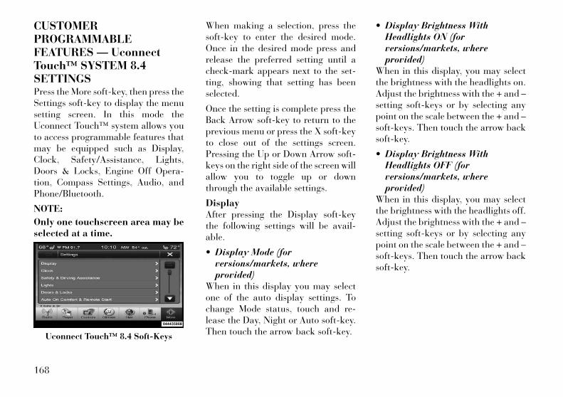
CUSTOMERPROGRAMMABLEFEATURES — UconnectTouch™ SYSTEM 8.4SETTINGSPress the More soft-key, then press theSettings soft-key to display the menusetting screen. In this mode theUconnect Touch™ system allows youto access programmable features thatmay be equipped such as Display,Clock, Safety/Assistance, Lights,Doors & Locks, Engine Off Opera-tion, Compass Settings, Audio, andPhone/Bluetooth.
NOTE:
Only one touchscreen area may beselected at a time.
When making a selection, press thesoft-key to enter the desired mode.Once in the desired mode press andrelease the preferred setting until acheck-mark appears next to the set-ting, showing that setting has beenselected.
Once the setting is complete press theBack Arrow soft-key to return to theprevious menu or press the X soft-keyto close out of the settings screen.Pressing the Up or Down Arrow soft-keys on the right side of the screen willallow you to toggle up or downthrough the available settings.
DisplayAfter pressing the Display soft-keythe following settings will be avail-able.
• Display Mode (forversions/markets, whereprovided)
When in this display you may selectone of the auto display settings. Tochange Mode status, touch and re-lease the Day, Night or Auto soft-key.Then touch the arrow back soft-key.
• Display Brightness WithHeadlights ON (forversions/markets, whereprovided)
When in this display, you may selectthe brightness with the headlights on.Adjust the brightness with the + and –setting soft-keys or by selecting anypoint on the scale between the + and –soft-keys. Then touch the arrow backsoft-key.
• Display Brightness WithHeadlights OFF (forversions/markets, whereprovided)
When in this display, you may selectthe brightness with the headlights off.Adjust the brightness with the + and –setting soft-keys or by selecting anypoint on the scale between the + and –soft-keys. Then touch the arrow backsoft-key.
Uconnect Touch™ 8.4 Soft-Keys
168
• Language (for versions/markets,where provided)
Press the Language soft-key tochange this display. When in this dis-play you may select a different lan-guage for all display nomenclature,including the trip functions and thenavigation system (for versions/markets, where provided). Press theGerman, French, Spanish, Italian,Dutch or English button to select thelanguage preferred followed by press-ing the arrow back soft-key. Then, asyou continue, the information willdisplay in the selected language.
• Units (for versions/markets,where provided)
When in this display, you may selectto have the EVIC, odometer, andnavigation system (for versions/markets, where provided) changedbetween US and Metric units of mea-sure. Touch US or Metric until acheck-mark appears next to the set-ting, showing that setting has beenselected. Touch the back arrow soft-key to return to the previous menu.
• Voice Response Length (forversions/markets, whereprovided)
When in this display, you may changethe Voice Response Length settings.To change the Voice Response Length,touch the Brief or Detailed soft-keyuntil a check-mark appears next tothe setting, showing that setting hasbeen selected. Touch the back arrowsoft-key to return to the previousmenu.
• Touchscreen Beep (forversions/markets, whereprovided)
When in this display, you may turn onor shut off the sound heard when atouch screen button (soft-key) ispressed. Touch the Touchscreen Beepsoft-key until a check-mark appearsnext to the setting, showing that set-ting has been selected. Touch the backarrow soft-key to return to the previ-ous menu.
• Navigation Turn-By-Turn InCluster (for versions/markets,where provided)
When this feature is selected, theturn-by-turn directions will appear inthe display as the vehicle approachesa designated turn within a pro-grammed route. To make your selec-tion, touch the Navigation Turn-By-Turn In Cluster soft-key, until acheck-mark appears next to the set-ting, showing that setting has beenselected. Touch the back arrow soft-key to return to the previous menu.
• Fuel Saver Display In Cluster(for versions/markets, whereprovided)
The “ECO” message is located in theinstrument cluster display, this mes-sage can be turned on or off. To makeyour selection, touch the Fuel SaverDisplay soft-key, until a check-markappears next to the setting, showingthat setting has been selected. Touchthe back arrow soft-key to return tothe previous menu.
169
ClockAfter pressing the Clock soft-key thefollowing settings will be available.
• Sync Time With GPS (forversions/markets, whereprovided)
When in this display, you may auto-matically have the radio set the time.To change the Sync Time settingtouch the Sync with GPS Time soft-key until a check-mark appears nextto the setting, showing that setting hasbeen selected. Touch the back arrowsoft-key to return to the previousmenu.
• Set Time Hours (forversions/markets, whereprovided)
When in this display, you may adjustthe hours. The Sync with GPS Timesoft-key must be unchecked. To makeyour selection touch the + or - soft-keys to adjust the hours up or down.Touch the back arrow soft-key to re-turn to the previous menu or touch theX soft-key to close out of the settingsscreen.
• Set Time Minutes (forversions/markets, whereprovided)
When in this display, you may adjustthe minutes. The Sync with GPS Timesoft-key must be unchecked. To makeyour selection touch the + or - soft-keys to adjust the minutes up ordown. Touch the back arrow soft-keyto return to the previous menu ortouch the X soft-key to close out of thesettings screen.
• Time Format (for versions/markets, where provided)
When in this display, you may selectthe time format display setting. Touchthe Time Format soft-key until acheck-mark appears next to the 12hrsor 24hrs setting, showing that settinghas been selected. Touch the back ar-row soft-key to return to the previousmenu.
• Show Time In Status Bar (forversions/markets, whereprovided)
When in this display, you may turn onor shut off the digital clock in thestatus bar. To change the Show TimeStatus setting touch the Show Time inStatus Bar soft-key until a check-mark appears next to setting, showingthat setting has been selected. Touchthe back arrow soft-key to return tothe previous menu.
Safety / AssistanceAfter pressing the Safety / Assistancesoft-key the following settings will beavailable.
• Front Collision Sensitivity (forversions/markets, whereprovided)
The Front Collision Warning (FCW)feature can be can be set to Far, set toNear or turned Off. The default statusof FCW is the Far setting. This meansthe system will warn you of a possiblecollision with the vehicle in front ofyou when you are farther away. Thisgives you the most reaction time. Tochange the setting for more dynamicdriving, select the Near setting. This
170

warns you of a possible collision whenyou are much closer to the vehicle infront of you. This allows for a moredynamic driving experience. Tochange the FCW status, touch andrelease the OFF, Near or Far button.Then touch the arrow back soft-key.
For further information, refer to“Adaptive Cruise Control (ACC)” in“Understanding The Features OfYour Vehicle”.
• Park Assist (for versions/markets, where provided)
The Rear Park Assist system will scanfor objects behind the vehicle whenthe transmission shift lever is in RE-VERSE and the vehicle speed is lessthan 11 mph (18 km/h). The systemcan be enabled with Sound Only,Sound and Display, or turned OFF. Tochange the Park Assist status, touchand release the OFF, Sound Only orSounds and Display button. Thentouch the arrow back soft-key. Referto “ParkSense® Rear Park Assist” in“Understanding The Features OfYour Vehicle” for system function andoperating information.
• Tilt Mirrors In Reverse (forversions/markets, whereprovided)
When this feature is selected, the out-side sideview mirrors will tilt down-ward when the ignition is in the RUNposition and the transmission shift le-ver is in the REVERSE position. Themirrors will move back to their previ-ous position when the transmission isshifted out of REVERSE. To makeyour selection, touch the Tilt MirrorsIn Reverse soft-key, until a check-mark appears next to setting, showingthat setting has been selected. Touchthe back arrow soft-key to return tothe previous menu.
• Blind Spot Alert (forversions/markets, whereprovided)
When this feature is selected, theBlind Spot Alert feature can be set toOff, Lights or Lights and Chime. TheBlind Spot Alert feature can be acti-vated in “Lights” mode. When thismode is selected, the Blind Spot Moni-tor (BSM) system is activated and willonly show a visual alert in the outsidemirrors. When “Lights & Chime”
mode is activated, the Blind SpotMonitor (BSM) will show a visualalert in the outside mirrors as well asan audible alert when the turn signalis on. When “Off” is selected, theBlind Spot Monitor (BSM) system isdeactivated. To change the Blind SpotAlert status, touch the Off, Lights orLights & Chime soft-key. Then touchthe arrow back soft-key.
NOTE:
If your vehicle has experiencedany damage in the area where thesensor is located, even if the fasciais not damaged, the sensor mayhave become misaligned. Takeyour vehicle to an authorizeddealer to verify sensor alignment.Having a sensor that is misalignedwill result in the BSM not operat-ing to specification.
171
• ParkView® Backup Camera (forversions/markets, whereprovided)
Your vehicle may be equipped withthe ParkView® Rear Back Up Cam-era that allows you to see an on-screenimage of the rear surroundings ofyour vehicle whenever the shift leveris put into REVERSE. The image willbe displayed on the radio touchscreendisplay along with a caution note to“check entire surroundings” acrossthe top of the screen. After five sec-onds, this note will disappear. TheParkView® camera is located on therear of the vehicle above the rear Li-cense plate. To make your selection,touch the ParkView® Backup Cam-era soft-key, until a check-mark ap-pears next to setting, showing thatsetting has been selected. Touch theback arrow soft-key to return to theprevious menu.
• Rain Sensing Auto Wipers (forversions/markets, whereprovided)
When this feature is selected, the sys-tem will automatically activate thewindshield wipers if it senses moistureon the windshield. To make your se-lection, touch the Rain Sensing soft-key, until a check-mark appears nextto setting, showing that setting hasbeen selected. Touch the back arrowsoft-key to return to the previousmenu.
• Hill Start Assist (forversions/markets, whereprovided)
When this feature is selected, the HillStart Assist (HSA) system is active.Refer to “Electronic Brake ControlSystem” in “Starting And Operating”for system function and operating in-formation. To make your selection,touch the Hill Start Assist soft-key,until a check-mark appears next tosetting, showing that setting has beenselected. Touch the back arrow soft-key to return to the previous menu.
LightsAfter pressing the Lights soft-key thefollowing settings will be available.
• Headlight Off Delay (forversions/markets, whereprovided)
When this feature is selected, thedriver can choose to have the head-lights remain on for 0, 30, 60, or90 seconds when exiting the vehicle.To change the Headlight Off Delaystatus touch the 0, 30, 60 or 90 soft-key. Then touch the arrow back soft-key.
• Headlight Illumination OnApproach (for versions/markets,where provided)
When this feature is selected, theheadlights will activate and remain onfor 0, 30, 60, or 90 seconds when thedoors are unlocked with the RemoteKeyless Entry (RKE) transmitter. Tochange the Illuminated Approach sta-tus, touch the + or - soft-key to selectyour desired time interval. Touch theback arrow soft-key to return to theprevious menu.
172
• Headlights With Wipers (forversions/markets, whereprovided)
When this feature is selected, and theheadlight switch is in the AUTO posi-tion, the headlights will turn on ap-proximately 10 seconds after the wip-ers are turned on. The headlights willalso turn off when the wipers areturned off if they were turned on bythis feature. To make your selection,touch the Headlights With Wiperssoft-key, until a check-mark appearsnext to setting, showing that settinghas been selected. Touch the back ar-row soft-key to return to the previousmenu.
• Auto Dim High Beams“SmartBeam™” (forversions/markets, whereprovided)
When this feature is selected, the highbeam headlights will deactivate auto-matically under certain conditions. Tomake your selection, touch the AutoHigh Beams soft-key, until a check-mark appears next to setting, showingthat setting has been selected. Touchthe back arrow soft-key to return to
the previous menu. Refer to “Lights/SmartBeam™ (for versions/markets,where provided)” in “UnderstandingThe Features Of Your Vehicle” forfurther information.
• Daytime Running Lights (forversions/markets, whereprovided)
When this feature is selected, theheadlights will turn on whenever theengine is running. To make your se-lection, touch the Daytime RunningLights soft-key, until a check-markappears next to setting, showing thatsetting has been selected. Touch theback arrow soft-key to return to theprevious menu.
• Steering Directed Lights (forversions/markets, whereprovided)
When this feature is selected, theheadlights turn relative to a change indirection of the steering wheel. Tomake your selection, touch the Steer-ing Directed Lights soft-key, until acheck-mark appears next to setting,showing that setting has been se-lected. Touch the back arrow soft-keyto return to the previous menu.
Doors & LocksAfter pressing the Doors & Locks soft-key the following settings will beavailable.
• Auto Unlock On Exit (forversions/markets, whereprovided)
When this feature is selected, all doorswill unlock when the vehicle isstopped and the transmission is in thePARK or NEUTRAL position and thedriver's door is opened. To make yourselection, touch the Auto Unlock OnExit soft-key, until a check-mark ap-pears next to setting, showing thatsetting has been selected. Touch theback arrow soft-key to return to theprevious menu.
• 1st Press Of Key Fob Unlocks(for versions/markets, whereprovided)
When 1st Press Of Key Fob Unlocks isselected, only the driver's door willunlock on the first press of the RemoteKeyless Entry (RKE) transmitter UN-LOCK button. When 1st Press Of KeyFob Unlocks is selected, you mustpress the RKE transmitter UNLOCKbutton twice to unlock the passenger's
173

doors. When Unlock All Doors On 1stPress is selected, all of the doors willunlock on the first press of the RKEtransmitter UNLOCK button.
NOTE:
If the vehicle is programmed 1stPress Of Key Fob Unlocks, alldoors will unlock no matter whichPassive Entry equipped doorhandle is grasped. If 1st Press OfKey Fob Unlocks is programmed,only the driver’s door will unlockwhen the driver’s door is grasped.With Passive Entry, if 1st Press OfKey Fob Unlocks is programmedtouching the handle more thanonce will only result in the driver’sdoor opening. If driver door first isselected, once the driver door isopened, the interior door lock/unlock switch can be used to un-lock all doors (or use RKE trans-mitter).
• Passive Entry (forversions/markets, whereprovided)
This feature allows you to lock andunlock the vehicle’s door(s) withouthaving to press the Remote KeylessEntry (RKE) transmitter lock or un-lock buttons. To make your selection,touch the Passive Entry soft-key, untila check-mark appears next to setting,showing that setting has been se-lected. Touch the back arrow soft-keyto return to the previous menu. Referto “Keyless Enter-N-Go” in “ThingsTo Know Before Starting Your Ve-hicle”.
• Personal Settings Linked To FOB(for versions/markets, whereprovided)
This feature provides automaticdriver seat positioning to enhancedriver mobility when entering and ex-iting the vehicle. To make your selec-tion, touch the Memory Linked ToFOB soft-key, until a check-mark ap-pears next to setting, showing thatsetting has been selected. Touch theback arrow soft-key to return to theprevious menu.
NOTE:
The seat will return to the memo-rized seat location (if RecallMemory with Remote Key Unlockis set to ON) when the Remote Key-less Entry (RKE) transmitter isused to unlock the door. Refer to“Driver Memory Seat” in “Under-standing The Features Of Your Ve-hicle” for further information.
Engine Off OptionsAfter pressing the Engine Off Optionssoft-key the following settings will beavailable.
• Easy Exit Seat (forversions/markets, whereprovided)
This feature provides automaticdriver seat positioning to enhancedriver mobility when entering and ex-iting the vehicle. To make your selec-tion, touch the Easy Exit Seats soft-key, until a check-mark appears nextto setting, showing that setting hasbeen selected. Touch the back arrowsoft-key to return to the previousmenu.
174

• Engine Off Power Delay (forversions/markets, whereprovided)
When this feature is selected, thepower window switches, radio,Uconnect™ phone system (forversions/markets, where provided),DVD video system (for versions/markets, where provided), powersunroof (for versions/markets, whereprovided), and power outlets will re-main active for up to 10 minutes afterthe ignition is cycled to OFF. Openingeither front door will cancel this fea-ture. To change the Engine Off PowerDelay status touch the 0 seconds,45 seconds, 5 minutes or 10 minutessoft-key. Then touch the arrow backsoft-key.
• Headlight Off Delay (forversions/markets, whereprovided)
When this feature is selected, thedriver can choose to have the head-lights remain on for 0, 30, 60, or90 seconds when exiting the vehicle.To change the Headlight Off Delaystatus touch the + or - soft-key toselect your desired time interval.Touch the back arrow soft-key to re-turn to the previous menu.
Compass SettingsAfter pressing the Compass Settingssoft-key the following settings will beavailable.
• Variance (for versions/markets,where provided)
Compass Variance is the differencebetween Magnetic North and Geo-graphic North. To compensate for thedifferences the variance should be setfor the zone where the vehicle isdriven, per the zone map. Once prop-erly set, the compass will automati-cally compensate for the differences,and provide the most accurate com-pass heading.
NOTE:
Keep magnetic materials awayfrom the top of the instrumentpanel, such as iPod's, MobilePhones, Laptops and Radar Detec-tors. This is where the compassmodule is located, and it can causeinterference with the compass sen-sor, and it may give false readings.
175
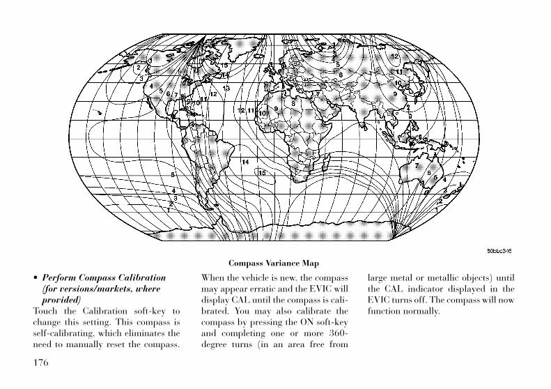
• Perform Compass Calibration(for versions/markets, whereprovided)
Touch the Calibration soft-key tochange this setting. This compass isself-calibrating, which eliminates theneed to manually reset the compass.
When the vehicle is new, the compassmay appear erratic and the EVIC willdisplay CAL until the compass is cali-brated. You may also calibrate thecompass by pressing the ON soft-keyand completing one or more 360-degree turns (in an area free from
large metal or metallic objects) untilthe CAL indicator displayed in theEVIC turns off. The compass will nowfunction normally.
Compass Variance Map
176
AudioAfter pressing the Audio soft-key thefollowing settings will be available.
• Balance/Fade (forversions/markets, whereprovided)
When in this display you may adjustthe Balance and Fade settings.
• Equalizer (for versions/markets,where provided)
When in this display you may adjustthe Bass, Mid and Treble settings. Ad-just the settings with the + and –setting soft-keys or by selecting anypoint on the scale between the + and –soft-keys. Then touch the arrow backsoft-key.
NOTE:
Bass/Mid/Treble allow you to sim-ply slide your finger up or down tochange the setting as well as touchdirectly on the desired setting.
• Speed Adjusted Volume (forversions/markets, whereprovided)
This feature increases or decreasesvolume relative to vehicle speed. Tochange the Speed Adjusted Volumetouch the Off, 1, 2 or 3 soft-key. Thentouch the arrow back soft-key.
• Music Info Cleanup (forversions/markets, whereprovided)
This feature helps organize music filesfor optimized music navigation. Tomake your selection, touch the MusicInfo Cleanup soft-key, select On or Offfollowed by pressing the arrow backsoft-key.
• Surround Sound (forversions/markets, whereprovided)
This feature provides simulated sur-round sound mode. To make your se-lection, touch the Surround Sound
soft-key, select On or Off followed bypressing the arrow back soft-key.
Phone/BluetoothAfter pressing the Phone/Bluetoothsoft-key the following settings will beavailable.
• Paired Devices (forversions/markets, whereprovided)
This feature shows which phones arepaired to the Phone/Bluetooth sys-tem. For further information, refer tothe Uconnect Touch™ Supplement.
SOUND SYSTEMSRefer to your Sound Systems Booklet.
NAVIGATION SYSTEM(for versions/markets,where provided)Refer to your Uconnect Touch™ UserManual.
177
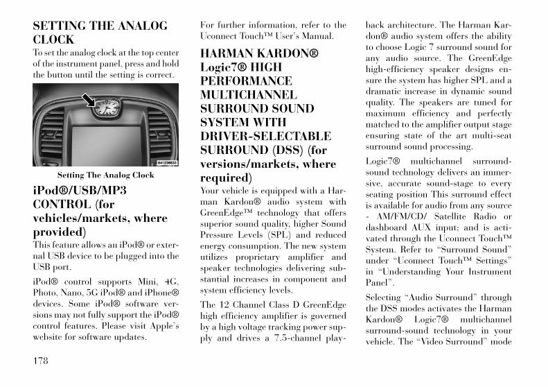
SETTING THE ANALOGCLOCKTo set the analog clock at the top centerof the instrument panel, press and holdthe button until the setting is correct.
iPod®/USB/MP3CONTROL (forvehicles/markets, whereprovided)This feature allows an iPod® or exter-nal USB device to be plugged into theUSB port.
iPod® control supports Mini, 4G,Photo, Nano, 5G iPod® and iPhone®devices. Some iPod® software ver-sions may not fully support the iPod®control features. Please visit Apple’swebsite for software updates.
For further information, refer to theUconnect Touch™ User’s Manual.
HARMAN KARDON®Logic7® HIGHPERFORMANCEMULTICHANNELSURROUND SOUNDSYSTEM WITHDRIVER-SELECTABLESURROUND (DSS) (forversions/markets, whererequired)Your vehicle is equipped with a Har-man Kardon® audio system withGreenEdge™ technology that offerssuperior sound quality, higher SoundPressure Levels (SPL) and reducedenergy consumption. The new systemutilizes proprietary amplifier andspeaker technologies delivering sub-stantial increases in component andsystem efficiency levels.
The 12 Channel Class D GreenEdgehigh efficiency amplifier is governedby a high voltage tracking power sup-ply and drives a 7.5-channel play-
back architecture. The Harman Kar-don® audio system offers the abilityto choose Logic 7 surround sound forany audio source. The GreenEdgehigh-efficiency speaker designs en-sure the system has higher SPL and adramatic increase in dynamic soundquality. The speakers are tuned formaximum efficiency and perfectlymatched to the amplifier output stageensuring state of the art multi-seatsurround sound processing.
Logic7® multichannel surround-sound technology delivers an immer-sive, accurate sound-stage to everyseating position This surround effectis available for audio from any source- AM/FM/CD/ Satellite Radio ordashboard AUX input; and is acti-vated through the Uconnect Touch™System. Refer to “Surround Sound”under “Uconnect Touch™ Settings”in “Understanding Your InstrumentPanel”.
Selecting “Audio Surround” throughthe DSS modes activates the HarmanKardon® Logic7® multichannelsurround-sound technology in yourvehicle. The “Video Surround” mode
Setting The Analog Clock
178
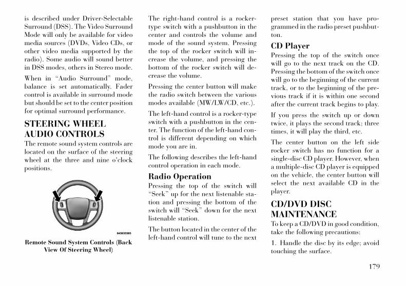
is described under Driver-SelectableSurround (DSS). The Video SurroundMode will only be available for videomedia sources (DVDs, Video CDs, orother video media supported by theradio). Some audio will sound betterin DSS modes, others in Stereo mode.
When in “Audio Surround” mode,balance is set automatically. Fadercontrol is available in surround modebut should be set to the center positionfor optimal surround performance.
STEERING WHEELAUDIO CONTROLSThe remote sound system controls arelocated on the surface of the steeringwheel at the three and nine o'clockpositions.
The right-hand control is a rocker-type switch with a pushbutton in thecenter and controls the volume andmode of the sound system. Pressingthe top of the rocker switch will in-crease the volume, and pressing thebottom of the rocker switch will de-crease the volume.
Pressing the center button will makethe radio switch between the variousmodes available (MW/LW/CD, etc.).
The left-hand control is a rocker-typeswitch with a pushbutton in the cen-ter. The function of the left-hand con-trol is different depending on whichmode you are in.
The following describes the left-handcontrol operation in each mode.
Radio OperationPressing the top of the switch will“Seek” up for the next listenable sta-tion and pressing the bottom of theswitch will “Seek” down for the nextlistenable station.
The button located in the center of theleft-hand control will tune to the next
preset station that you have pro-grammed in the radio preset pushbut-ton.
CD PlayerPressing the top of the switch oncewill go to the next track on the CD.Pressing the bottom of the switch oncewill go to the beginning of the currenttrack, or to the beginning of the pre-vious track if it is within one secondafter the current track begins to play.
If you press the switch up or downtwice, it plays the second track; threetimes, it will play the third, etc.
The center button on the left siderocker switch has no function for asingle-disc CD player. However, whena multiple-disc CD player is equippedon the vehicle, the center button willselect the next available CD in theplayer.
CD/DVD DISCMAINTENANCETo keep a CD/DVD in good condition,take the following precautions:
1. Handle the disc by its edge; avoidtouching the surface.
Remote Sound System Controls (BackView Of Steering Wheel)
179
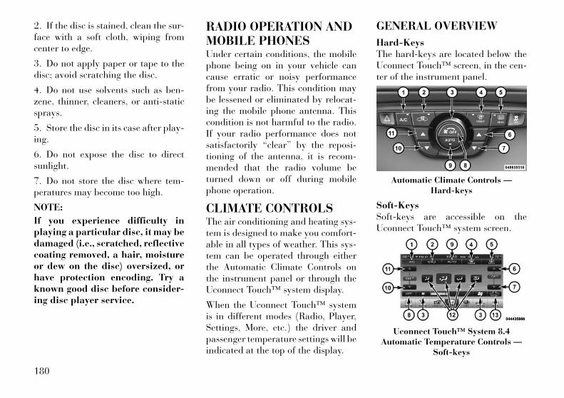
2. If the disc is stained, clean the sur-face with a soft cloth, wiping fromcenter to edge.
3. Do not apply paper or tape to thedisc; avoid scratching the disc.
4. Do not use solvents such as ben-zene, thinner, cleaners, or anti-staticsprays.
5. Store the disc in its case after play-ing.
6. Do not expose the disc to directsunlight.
7. Do not store the disc where tem-peratures may become too high.
NOTE:
If you experience difficulty inplaying a particular disc, it may bedamaged (i.e., scratched, reflectivecoating removed, a hair, moistureor dew on the disc) oversized, orhave protection encoding. Try aknown good disc before consider-ing disc player service.
RADIO OPERATION ANDMOBILE PHONESUnder certain conditions, the mobilephone being on in your vehicle cancause erratic or noisy performancefrom your radio. This condition maybe lessened or eliminated by relocat-ing the mobile phone antenna. Thiscondition is not harmful to the radio.If your radio performance does notsatisfactorily “clear” by the reposi-tioning of the antenna, it is recom-mended that the radio volume beturned down or off during mobilephone operation.
CLIMATE CONTROLSThe air conditioning and heating sys-tem is designed to make you comfort-able in all types of weather. This sys-tem can be operated through eitherthe Automatic Climate Controls onthe instrument panel or through theUconnect Touch™ system display.
When the Uconnect Touch™ systemis in different modes (Radio, Player,Settings, More, etc.) the driver andpassenger temperature settings will beindicated at the top of the display.
GENERAL OVERVIEW
Hard-KeysThe hard-keys are located below theUconnect Touch™ screen, in the cen-ter of the instrument panel.
Soft-KeysSoft-keys are accessible on theUconnect Touch™ system screen.
Automatic Climate Controls —Hard-keys
Uconnect Touch™ System 8.4Automatic Temperature Controls —
Soft-keys
180

Button Descriptions (Applies ToBoth Hard-keys And Soft-keys)
1. A/C ButtonPress and release to change the cur-rent Air Conditioning (A/C) setting,the indicator illuminates when A/C isON. Performing this function willcause the automatic operation toswitch into manual mode and theAUTO indicator will turn off.
2. Recirculation ButtonPress and release to change the cur-rent setting, the indicator illuminateswhen ON.
3. Blower ControlBlower control is used to regulate theamount of air forced through the cli-mate system. There are seven blowerspeeds available. Adjusting theblower will cause automatic mode toswitch to manual operation. Thespeeds can be selected using eitherhard-keys or soft-keys as follows:
Hard-keyThe blower speed increases as youturn the control clockwise from thelowest blower setting. The blowerspeed decreases as you turn the knobcounter-clockwise.
Soft-key — Uconnect Touch™System 8.4Use the small blower icon to reducethe blower setting and the largeblower icon to increase the blowersetting. Blower can also be selected bypressing the blower bar area betweenthe icons.
4. Front Defrost ButtonPress and release to change the cur-rent airflow setting to Defrost mode.The indicator illuminates when thisfeature is ON. Performing this func-tion will cause the ATC to switch intomanual mode. The blower speed mayincrease when Defrost mode is se-lected. If the front defrost mode isturned off the climate system will re-turn the previous setting.
5. Rear Defrost ButtonPress and release this button to turnon the rear window defroster and theheated outside mirrors (for versions/markets, where provided). An indica-tor will illuminate when the rear win-dow defroster is on. The rear windowdefroster automatically turns off after10 minutes.
CAUTION!Failure to follow these cautions cancause damage to the heating ele-ments:• Use care when washing the inside
of the rear window. Do not useabrasive window cleaners on theinterior surface of the window.Use a soft cloth and a mild wash-ing solution, wiping parallel to theheating elements. Labels can bepeeled off after soaking withwarm water.
• Do not use scrapers, sharp instru-ments, or abrasive window clean-ers on the interior surface of thewindow.
• Keep all objects a safe distancefrom the window.
181

6. Passenger Temperature ControlUp ButtonProvides the passenger with indepen-dent temperature control. Push thebutton for warmer temperature set-tings.
NOTE:
Pressing this button while in Syncmode will automatically exit Sync.
7. Passenger Temperature ControlDown ButtonProvides the passenger with indepen-dent temperature control. Push thebutton for cooler temperature set-tings.
NOTE:
Pressing this button while in Syncmode will automatically exit Sync.
8. Climate Control OFF ButtonPress and release this button to turnthe Climate Control ON/OFF.
9. AUTO Operation ButtonAutomatically controls the interiorcabin temperature by adjusting air-flow distribution and amount. Per-forming this function will cause theATC to switch between manual modeand automatic modes. Refer to “Au-tomatic Operation” for more informa-tion.
10. Driver Temperature ControlDown ButtonProvides the driver with independenttemperature control. Push the buttonfor cooler temperature settings.
NOTE:
In Sync mode, this button will alsoautomatically adjust the passengertemperature setting at the sametime.
11. Driver Temperature ControlUp ButtonProvides the driver with independenttemperature control. Push the buttonfor warmer temperature settings.
NOTE:
In Sync mode, this button will alsoautomatically adjust the passengertemperature setting at the sametime.
12. ModesThe airflow distribution mode can beadjusted so air comes from the instru-ment panel outlets, floor outlets, de-mist outlets and defrost outlets. TheMode settings are as follows:
• Panel ModeAir comes from the outlets in theinstrument panel. Each of theseoutlets can be individually ad-
justed to direct the flow of air. The airvanes of the center outlets and out-board outlets can be moved up anddown or side to side to regulate air-flow direction. There is a shut offwheel located below the air vanes toshut off or adjust the amount of air-flow from these outlets.
182

• Bi-Level ModeAir comes from the instrumentpanel outlets and floor outlets. Aslight amount of air is directed
through the defrost and side windowdemister outlets.
NOTE:
BI-LEVEL mode is designed undercomfort conditions to providecooler air out of the panel outletsand warmer air from the floor out-lets.
• Floor ModeAir comes from the floor outlets.A slight amount of air is directedthrough the defrost and side
window demister outlets.
• Mix ModeAir comes from the floor, defrostand side window demist outlets.This mode works best in cold or
snowy conditions.
• Defrost ModeAir comes from the windshieldand side window demist out-lets. Use Defrost mode with
maximum temperature settings forbest windshield and side window de-frosting and defogging. When the de-frost mode is selected, the blower levelmay increase.
13. SYNCPress the Sync soft-key to toggle theSync feature On/Off. The Sync indi-cator is illuminated when this featureis enabled. Sync is used to synchro-nize the passenger temperature set-ting with the driver temperature set-ting. Changing the passengertemperature setting while in Sync willautomatically exit this feature.
CLIMATE CONTROLFUNCTIONS
A/C (Air Conditioning)The Air Conditioning (A/C) buttonallows the operator to manually acti-vate or deactivate the air conditioningsystem. When the air conditioningsystem is turned on, cool dehumidi-fied air will flow through the outlets
into the cabin. For improved fueleconomy, press the A/C button to turnoff the air conditioning and manuallyadjust the blower and airflow modesettings.
NOTE:
• If fog or mist appears on thewindshield or side glass, selectDefrost mode and increaseblower speed.
• If your air conditioning perfor-mance seems lower than ex-pected, check the front of theA/C condenser (located in frontof the radiator), for an accumu-lation of dirt or insects. Cleanwith a gentle water spray frombehind the radiator and throughthe condenser. Fabric front fas-cia protectors may reduce air-flow to the condenser, reducingair conditioning performance.
Recirculation
When outside air containssmoke, odors, or high hu-midity, or if rapid cooling isdesired, you may wish to
recirculate interior air by pressing the
183

Recirculation control button. The re-circulation indicator will illuminatewhen this button is selected. Push thebutton a second time to turn off theRecirculation mode and allow outsideair into the vehicle.
NOTE:
In cold weather, use of Recircula-tion mode may lead to excessivewindow fogging. On systems withManual Climate Controls, the Re-circulation mode is not allowed inDefrost mode to improve windowclearing operation. Recirculationwill be disabled automatically ifthis mode is selected. Attemptingto use Recirculation while in thismode will cause the LED in thecontrol button to blink and thenturn off.
AUTOMATICTEMPERATURE CONTROL(ATC)ATC Hard-keys are located in the cen-ter of the instrument panel.
Soft-keys are accessible on theUconnect Touch™ system screen.
Automatic Operation
1. Press the AUTO hard-key or soft-key button (9) on the Automatic Tem-perature Control (ATC) Panel.
2. Next, adjust the temperature youwould like the system to maintain byadjusting the driver and passengertemperature hard or soft control but-tons (6, 7, 10, 11). Once the desiredtemperature is displayed, the systemwill achieve and automatically main-tain that comfort level.
3. When the system is set up for yourcomfort level, it is not necessary tochange the settings. You will experi-ence the greatest efficiency by simplyallowing the system to function auto-matically.
NOTE:
• It is not necessary to move thetemperature settings for cold orhot vehicles. The system auto-matically adjusts the tempera-ture, mode and blower speed toprovide comfort as quickly aspossible.
• The temperature can be dis-played in U.S. or Metric units by
selecting the US/M customer-programmable feature. Refer tothe “Uconnect Touch™ SystemSettings” in this section of themanual.
To provide you with maximum com-fort in the Automatic mode, duringcold start-ups the blower fan will re-main on low until the engine warmsup. The blower will increase in speedand transition into Auto mode.
Manual OperationThe system allows for manual selec-tion of blower speed, air distributionmode, A/C status and recirculationcontrol.
The blower fan speed can be set to anyfixed speed by adjusting the blowercontrol. The fan will now operate at afixed speed until additional speeds areselected. This allows the front occu-pants to control the volume of aircirculated in the vehicle and cancelthe Auto mode.
The operator can also select the direc-tion of the airflow by selecting one ofthe available mode settings. A/C op-
184
eration and Recirculation control canalso be manually selected in Manualoperation.
OPERATING TIPS
NOTE:
Refer to the chart at the end of thissection for suggested control set-tings for various weather condi-tions.
Summer OperationThe engine cooling system in air-conditioned vehicles must be pro-tected with a high-quality antifreezecoolant to provide proper corrosionprotection and to protect against en-gine overheating. A solution of 50%ethylene glycol antifreeze coolant and50% water is recommended. Refer to“Maintenance Procedures” in “Main-taining Your Vehicle” for proper cool-ant selection.
Winter OperationUse of the air Recirculation mode dur-ing Winter months is not recom-mended because it may cause windowfogging.
Vacation StorageAny time you store your vehicle orkeep it out of service (i.e., vacation)for two weeks or more, run the airconditioning system at idle for aboutfive minutes in the fresh air and highblower setting. This will ensure ad-equate system lubrication to minimizethe possibility of compressor damagewhen the system is started again.
Window FoggingInterior fogging on the windshield canbe quickly removed by turning themode selector to Defrost. The Defrost/Floor mode can be used to maintain aclear windshield and provide suffi-cient heating. If side window foggingbecomes a problem increase blowerspeed. Vehicle windows tend to fog onthe inside in mild but rainy or humidweather.
NOTE:
• Recirculate without A/C shouldnot be used for long periods, asfogging may occur.
• Automatic Temperature Con-trols (ATC) will automaticallyadjust the climate control set-tings to reduce or eliminate win-dow fogging on the front wind-shield.
Outside Air IntakeMake sure the air intake, located di-rectly in front of the windshield, isfree of obstructions such as leaves.Leaves collected in the air intake mayreduce airflow, and if they enter theplenum, they could plug the waterdrains. In Winter months, make surethe air intake is clear of ice, slush, andsnow.
A/C Air FilterThe climate control system filters out-side air containing dust, pollen andsome odors. Strong odors cannot betotally filtered out. Refer to “Mainte-nance Procedures” in “MaintainingYour Vehicle” for filter replacementinstructions.
185

186

5
STARTING AND OPERATING• STARTING PROCEDURES . . . . . . . . . . . . . . . . . 191
• AUTOMATIC TRANSMISSION . . . . . . . . . . . . 191
• KEYLESS ENTER-N-GO . . . . . . . . . . . . . . . . 191
• NORMAL STARTING — GASOLINE ENGINE . . 191
• EXTREME COLD WEATHER(BELOW −29°C) . . . . . . . . . . . . . . . . . . . . . . . 192
• IF ENGINE FAILS TO START . . . . . . . . . . . . . 192
• After Starting . . . . . . . . . . . . . . . . . . . . . . . . . 193
• NORMAL STARTING – DIESEL ENGINE . . . . 193
• AUTOMATIC TRANSMISSION . . . . . . . . . . . . . . 195
• KEY IGNITION PARK INTERLOCK . . . . . . . . 195
• BRAKE/TRANSMISSION SHIFTINTERLOCK SYSTEM . . . . . . . . . . . . . . . . . . 196
• EIGHT-SPEED AUTOMATICTRANSMISSION – 3.6L ENGINE . . . . . . . . . . 196
• GEAR RANGES . . . . . . . . . . . . . . . . . . . . . . . 196
• FIVE-SPEED AUTOMATIC TRANSMISSION– 3.0L DIESEL ENGINE . . . . . . . . . . . . . . . . . 199
• GEAR RANGES . . . . . . . . . . . . . . . . . . . . . . . 200
• AUTOSTICK® . . . . . . . . . . . . . . . . . . . . . . . . . . 202
• OPERATION – 3.0L DIESEL ENGINE . . . . . . . 203
187
• DRIVING ON SLIPPERY SURFACES . . . . . . . . . 204
• ACCELERATION . . . . . . . . . . . . . . . . . . . . . . 204
• TRACTION . . . . . . . . . . . . . . . . . . . . . . . . . . . 204
• DRIVING THROUGH WATER . . . . . . . . . . . . . . 204
• FLOWING/RISING WATER . . . . . . . . . . . . . . 204
• SHALLOW STANDING WATER . . . . . . . . . . . 205
• POWER STEERING . . . . . . . . . . . . . . . . . . . . . . 206
• PARKING BRAKE . . . . . . . . . . . . . . . . . . . . . . . 206
• ANTI-LOCK BRAKE SYSTEM . . . . . . . . . . . . . . 208
• ELECTRONIC BRAKE CONTROL SYSTEM . . . . 209
• ANTI-LOCK BRAKE SYSTEM (ABS) . . . . . . . 209
• TRACTION CONTROL SYSTEM (TCS) . . . . . . 209
• BRAKE ASSIST SYSTEM (BAS) . . . . . . . . . . . 209
• ELECTRONIC STABILITY CONTROL (ESC) . . 210
• HILL START ASSIST (HSA) . . . . . . . . . . . . . . 211
• READY ALERT BRAKING . . . . . . . . . . . . . . . 212
• RAIN BRAKE SUPPORT . . . . . . . . . . . . . . . . 213
• ESC ACTIVATION/MALFUNCTIONINDICATOR LIGHT AND ESC OFFINDICATOR LIGHT . . . . . . . . . . . . . . . . . . . . 213
• SYNCHRONIZING ESC . . . . . . . . . . . . . . . . . 213
• TIRES — GENERAL INFORMATION . . . . . . . . . 214
• TIRE PRESSURE . . . . . . . . . . . . . . . . . . . . . . 214
• TIRE INFLATION PRESSURES . . . . . . . . . . . 214
• TIRE PRESSURES FOR HIGH SPEEDOPERATION . . . . . . . . . . . . . . . . . . . . . . . . . 215
188
• RADIAL PLY TIRES . . . . . . . . . . . . . . . . . . . . 215
• COMPACT SPARE TIRE (for versions/markets, where provided) . . . . . . . . . . . . . . . 216
• LIMITED-USE SPARE (for versions/markets, where provided) . . . . . . . . . . . . . . . 216
• TIRE SPINNING . . . . . . . . . . . . . . . . . . . . . . 216
• TREAD WEAR INDICATORS . . . . . . . . . . . . . 217
• LIFE OF TIRE . . . . . . . . . . . . . . . . . . . . . . . . 217
• REPLACEMENT TIRES . . . . . . . . . . . . . . . . . 217
• TIRE CHAINS . . . . . . . . . . . . . . . . . . . . . . . . . . 218
• TIRE ROTATION RECOMMENDATIONS . . . . . . 219
• TIRE PRESSURE MONITOR SYSTEM (TPMS) . . 219
• PREMIUM SYSTEM . . . . . . . . . . . . . . . . . . . . 221
• TPMS DEACTIVATION . . . . . . . . . . . . . . . . . 222
• FUEL REQUIREMENTS — GASOLINEENGINES . . . . . . . . . . . . . . . . . . . . . . . . . . . . . . 223
• 3.6L ENGINE . . . . . . . . . . . . . . . . . . . . . . . . . 223
• FUEL REQUIREMENTS — DIESEL ENGINES . . 225
• ADDING FUEL . . . . . . . . . . . . . . . . . . . . . . . . . . 226
• EMERGENCY FUEL FILLER DOORRELEASE . . . . . . . . . . . . . . . . . . . . . . . . . . . 226
• VEHICLE LOADING . . . . . . . . . . . . . . . . . . . . . 227
• VEHICLE CERTIFICATION LABEL . . . . . . . . 227
• GROSS VEHICLE WEIGHT RATING(GVWR) . . . . . . . . . . . . . . . . . . . . . . . . . . . . . 227
• GROSS AXLE WEIGHT RATING (GAWR) . . . . 227
189
• OVERLOADING . . . . . . . . . . . . . . . . . . . . . . . 227
• LOADING . . . . . . . . . . . . . . . . . . . . . . . . . . . 228
• TRAILER TOWING . . . . . . . . . . . . . . . . . . . . . . 228
• COMMON TOWING DEFINITIONS . . . . . . . . . 228
• BREAKAWAY CABLE ATTACHMENT . . . . . . . 230
• TRAILER TOWING WEIGHTS (MAXIMUMTRAILER WEIGHT RATINGS) . . . . . . . . . . . . 231
• TRAILER AND TONGUE WEIGHT . . . . . . . . . 231
• TOWING REQUIREMENTS . . . . . . . . . . . . . . 232
• TOWING TIPS . . . . . . . . . . . . . . . . . . . . . . . . 235
• TRAILER HITCH ATTACHING POINTS . . . . . 236
• RECREATIONAL TOWING (BEHINDMOTORHOME, ETC) . . . . . . . . . . . . . . . . . . . . . 237
190
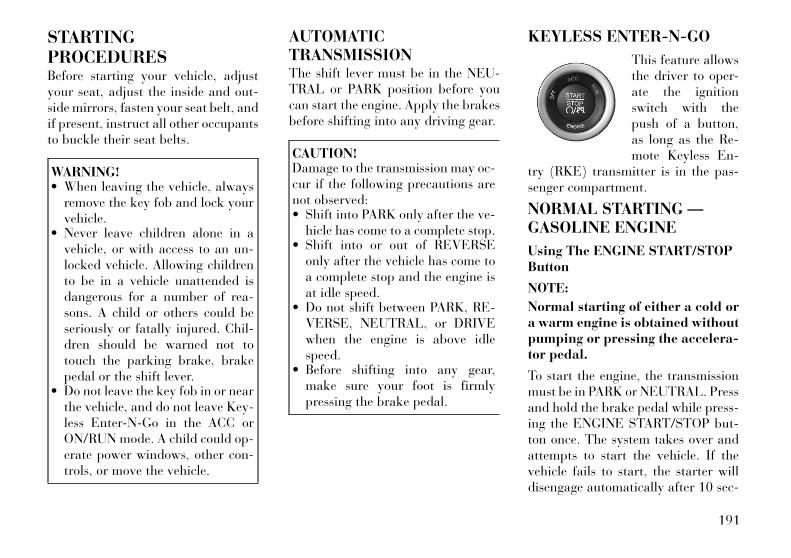
STARTINGPROCEDURESBefore starting your vehicle, adjustyour seat, adjust the inside and out-side mirrors, fasten your seat belt, andif present, instruct all other occupantsto buckle their seat belts.
WARNING!• When leaving the vehicle, always
remove the key fob and lock yourvehicle.
• Never leave children alone in avehicle, or with access to an un-locked vehicle. Allowing childrento be in a vehicle unattended isdangerous for a number of rea-sons. A child or others could beseriously or fatally injured. Chil-dren should be warned not totouch the parking brake, brakepedal or the shift lever.
• Do not leave the key fob in or nearthe vehicle, and do not leave Key-less Enter-N-Go in the ACC orON/RUN mode. A child could op-erate power windows, other con-trols, or move the vehicle.
AUTOMATICTRANSMISSIONThe shift lever must be in the NEU-TRAL or PARK position before youcan start the engine. Apply the brakesbefore shifting into any driving gear.
CAUTION!Damage to the transmission may oc-cur if the following precautions arenot observed:• Shift into PARK only after the ve-
hicle has come to a complete stop.• Shift into or out of REVERSE
only after the vehicle has come toa complete stop and the engine isat idle speed.
• Do not shift between PARK, RE-VERSE, NEUTRAL, or DRIVEwhen the engine is above idlespeed.
• Before shifting into any gear,make sure your foot is firmlypressing the brake pedal.
KEYLESS ENTER-N-GO
This feature allowsthe driver to oper-ate the ignitionswitch with thepush of a button,as long as the Re-mote Keyless En-
try (RKE) transmitter is in the pas-senger compartment.
NORMAL STARTING —GASOLINE ENGINE
Using The ENGINE START/STOPButton
NOTE:
Normal starting of either a cold ora warm engine is obtained withoutpumping or pressing the accelera-tor pedal.
To start the engine, the transmissionmust be in PARK or NEUTRAL. Pressand hold the brake pedal while press-ing the ENGINE START/STOP but-ton once. The system takes over andattempts to start the vehicle. If thevehicle fails to start, the starter willdisengage automatically after 10 sec-
191

onds. If you wish to stop the crankingof the engine prior to the engine start-ing, press the button again.
To Turn Off The Engine UsingENGINE START/STOP Button
1. Place the shift lever in PARK, thenpress and release the ENGINESTART/STOP button.
2. The ignition switch will return tothe OFF position.
3. If the shift lever is not in PARK, theENGINE START/STOP button mustbe held for two seconds and vehiclespeed must be above 8 km/h beforethe engine will shut off. The ignitionswitch position will remain in theACC position until the shift lever is inPARK and the button is pressed twiceto the OFF position. If the shift lever isnot in PARK and the ENGINESTART/STOP button is pressed once,the EVIC (for versions/markets,where provided) will display a “Ve-hicle Not In Park” message and theengine will remain running. Neverleave a vehicle out of the PARK posi-tion, or it could roll.
NOTE:
If the ignition switch is left in theACC or RUN (engine not running)position and the transmission is inPARK, the system will automati-cally time out after 30 minutes ofinactivity and the ignition willswitch to the OFF position.
ENGINE START/STOP ButtonFunctions – With Driver’s FootOFF The Brake Pedal (In PARKOr NEUTRAL Position)The Keyless Enter-N-Go feature oper-ates similar to an ignition switch. Ithas four positions, OFF, ACC, RUNand START. To change the ignitionswitch positions without starting thevehicle and use the accessories followthese steps.
• Starting with the ignition switch inthe OFF position:
• Press the ENGINE START/STOPbutton once to change the ignitionswitch to the ACC position (ACCwill illuminate),
• Press the ENGINE START/STOPbutton a second time to change the
ignition switch to the RUN position(RUN will illuminate),
• Press the ENGINE START/STOPbutton a third time to return theignition switch to the OFF position(OFF will illuminate).
EXTREME COLDWEATHER (BELOW −29°C)To ensure reliable starting at thesetemperatures, use of an externallypowered electric engine block heateris recommended.
IF ENGINE FAILS TOSTART
WARNING!• Never pour fuel or other flam-
mable liquids into the throttlebody air inlet opening in an at-tempt to start the vehicle. Thiscould result in a flash fire causingserious personal injury.
(Continued)
192

WARNING! (Continued)• Do not attempt to push or tow
your vehicle to get it started. Ve-hicles equipped with an automatictransmission cannot be startedthis way. Unburned fuel could en-ter the catalytic converter andonce the engine has started, igniteand damage the converter and ve-hicle. If the vehicle has a dis-charged battery, booster cablesmay be used to obtain a start froma booster battery or the battery inanother vehicle. This type of startcan be dangerous if done improp-erly. Refer to “Jump Starting” in“What To Do In Emergencies” forfurther information.
Clearing A Flooded Engine (UsingENGINE START/STOP Button)If the engine fails to start after youhave followed the “Normal Starting”or “Extreme Cold Weather" proce-dures, it may be flooded. To clear anyexcess fuel, press and hold the brakepedal, push the accelerator pedal allthe way to the floor and hold it, thenpress and release the ENGINE
START/STOP button once. Thestarter motor will engage automati-cally, run for 10 seconds, and thendisengage. Once this occurs, releasethe accelerator pedal and the brakepedal, wait 10 to 15 seconds, thenrepeat the “Normal Starting” proce-dure.
After StartingThe idle speed is controlled automati-cally and it will decrease as the enginewarms up.
NORMAL STARTING –DIESEL ENGINEObserve the following when the en-gine is operating.
• All message center lights are off.
• Malfunction Indicator Light (MIL)is off.
• Low Oil Pressure Light is off.
Cold Weather PrecautionsIf the outside temperature is very low,the diesel fuel thickens due to theformation of parrafin clots and couldclog the diesel filter. In order to avoidthese problems, different types of die-sel fuel are distributed according to
the season: summer type, winter typeand arctic type (cold, mountainousareas).
If refuelling with diesel fuel whosespecifications are not suitable for theoutside temperature, it is advisable tomix TUTELA DIESEL ART additivein the proportions shown on the con-tainer with the fuel. Pour the additiveinto the tank before the fuel.
When using or parking the vehicle fora long time in the mountains or coldareas, it is advisable to refuel usinglocally available diesel. In this case, itis also advisable to keep the tank over50% full.
Battery Blanket UsageA battery loses 60% of its crankingpower as the battery temperature de-creases to 18°C. For the same de-crease in temperature, the engine re-quires twice as much power to crankat the same RPM. The use of batteryblankets will greatly increase startingcapability at low temperatures.
193
Engine Starting Procedure
WARNING!Never pour fuel or other flammableliquid into the air inlet opening in anattempt to start the vehicle. Thiscould result in a flash fire causingserious personal injury.
1. The shift lever must be in theNEUTRAL or PARK position beforeyou can start the engine.
2. With your foot on the brake pedal,press the ENGINE START/STOPbutton.
3. Watch the “Wait To Start Light” inthe instrument cluster. Refer to “In-strument Cluster” in “UnderstandingYour Instrument Panel” for furtherinformation. It may glow for up tothree seconds, depending on enginetemperature.
4. When the “Wait To Start Light”goes out, the engine will automati-cally start.
5. After the engine starts, allow it toidle for approximately 30 seconds be-fore driving. This allows oil to circu-late and lubricate the turbocharger.
Avoid prolonged idling in ambienttemperatures below 18°C. Long pe-riods of idling may be harmful to yourengine because combustion chambertemperatures can drop so low that thefuel may not burn completely. Incom-plete combustion allows carbon andvarnish to form on piston rings andinjector nozzles. Also, the unburnedfuel can enter the crankcase, dilutingthe oil and causing rapid wear to theengine.
Engine Warm UpAvoid full throttle operation when theengine is cold. When starting a coldengine, bring the engine up to operat-ing speed slowly to allow the oil pres-sure to stabilize as the engine warmsup.
NOTE:
High-speed, no-load running of acold engine can result in excessivewhite smoke and poor engine per-formance. No-load engine speedsshould be kept under 1,200 RPMduring the warm-up period, espe-cially in cold ambient temperatureconditions.
If temperatures are below 0°C, operatethe engine at moderate speeds for fiveminutes before full loads are applied.
Engine Idling – In Cold WeatherAvoid prolonged idling in ambient tem-peratures below 18°C. Long periods ofidling may be harmful to your enginebecause combustion chamber tempera-tures can drop so low that the fuel maynot burn completely. Incomplete com-bustion allows carbon and varnish toform on piston rings and injectornozzles. Also, the unburned fuel canenter the crankcase, diluting the oil andcausing rapid wear to the engine.
Stopping The EngineBefore turning off your turbo dieselengine, always allow the engine toreturn to normal idle speed and runfor several seconds. This assuresproper lubrication of the turbo-charger. This is particularly necessaryafter any period of hard driving.
Idle the engine a few minutes beforeroutine shutdown. After full load op-eration, idle the engine three to fiveminutes before shutting it down. Thisidle period will allow the lubricating
194
oil and coolant to carry excess heataway from the combustion chamber,bearings, internal components, andturbocharger. This is especially im-portant for turbocharged, charge aircooled engines.
AUTOMATICTRANSMISSION
CAUTION!Damage to the transmission may oc-cur if the following precautions arenot observed:• Shift into PARK only after the ve-
hicle has come to a complete stop.• Shift into or out of REVERSE
only after the vehicle has come toa complete stop and the engine isat idle speed.
• Do not shift between PARK, RE-VERSE, NEUTRAL or DRIVEwhen the engine is above idle speed.
• Before shifting into any gear,make sure your foot is firmlypressing the brake pedal.
NOTE:
You must press and hold the brakepedal while shifting out of PARK.
WARNING!• It is dangerous to move the shift
lever out of PARK or NEUTRAL ifthe engine speed is higher thanidle speed. If your foot is notfirmly pressing on the brakepedal, the vehicle could acceleratequickly forward or in reverse. Youcould lose control of the vehicleand hit someone or something.Only shift into gear when the en-gine is idling normally and whenyour foot is firmly pressing on thebrake pedal.
• Unintended movement of a ve-hicle could injure those in or nearthe vehicle. As with all vehicles,you should never exit a vehiclewhile the engine is running. Be-fore exiting a vehicle, always ap-ply the parking brake, shift thetransmission into PARK, and turnthe engine OFF. When the ignitionis in the OFF position, the shiftlever is locked in PARK, securingthe vehicle against unwantedmovement.
(Continued)
WARNING! (Continued)• Never leave children alone in a
vehicle, or with access to an un-locked vehicle. Allowing childrento be in a vehicle unattended isdangerous for a number of rea-sons. A child or others could beseriously or fatally injured. Chil-dren should be warned not totouch the parking brake, brakepedal or the shift lever.
• Do not leave the key fob in or nearthe vehicle, and do not leave avehicle equipped with KeylessEnter-N-Go in the ACC or ON/RUN mode. A child could operatepower windows, other controls, ormove the vehicle.
KEY IGNITION PARKINTERLOCKThis vehicle is equipped with a KeyIgnition Park Interlock which re-quires the shift lever to be placed inPARK before the engine can be turnedoff. This helps the driver avoid inad-vertently leaving the vehicle withoutplacing the transmission in PARK.This system also locks the shift lever
195
in PARK whenever the ignition switchis in the OFF position.
BRAKE/TRANSMISSIONSHIFT INTERLOCKSYSTEMThis vehicle is equipped with a BrakeTransmission Shift Interlock (BTSI)that holds the shift lever in the PARKposition unless the brakes are applied.To move the shift lever out of thePARK position, the ignition switchmust be turned to the ON/RUN orSTART position (engine running ornot) and the brake pedal must bepressed.
EIGHT-SPEED AUTOMATICTRANSMISSION – 3.6LENGINEThe transmission gear display(PRND) (located in the instrumentpanel cluster) indicates the transmis-sion gear range. Transmission gearstate is also indicated in the display inthe shift knob. The shift lever isspring-loaded and returns to a homeposition when it is released. To select agear range, press the lock button onthe shift lever and move the lever rear-
ward or forward. You must also pressthe brake pedal to shift the transmis-sion out of the PARK position (refer to“Brake/Transmission Shift InterlockSystem” in this section). To shift pastmultiple gear ranges at once (such asPARK to DRIVE), move the lever pastthe first (or second) detent. Select theDRIVE range for normal driving.
The electronically-controlled trans-mission provides a precise shift sched-ule. The transmission electronics areself-calibrating; therefore, the firstfew shifts on a new vehicle may besomewhat abrupt. This is a normalcondition, and precision shifts will de-velop within a few hundred kilome-ters.
Shifting from DRIVE to PARK or RE-VERSE should be done only after theaccelerator pedal is released and thevehicle is stopped. Be sure to keepyour foot on the brake pedal whenmoving the shift lever between thesegears.
The shift lever has PARK, REVERSE,NEUTRAL, DRIVE, and LOW shiftpositions. Using the LOW position
manually downshifts the transmissionto a lower gear based on vehicle speed.
GEAR RANGESDO NOT race the engine when shift-ing from PARK or NEUTRAL intoanother gear range.
PARKThis range supplements the parkingbrake by locking the transmission.The engine can be started in thisrange. Never attempt to use PARKwhile the vehicle is in motion. Applythe parking brake when leaving thevehicle in this range.
When parking on a level surface, youmay place the shift lever in the PARKposition first, and then apply theparking brake.
When parking on a hill, apply theparking brake before placing the shiftlever in PARK. As an added precau-tion, turn the front wheels toward thecurb on a downhill grade and awayfrom the curb on an uphill grade.
196

WARNING!• Never use the PARK position as a
substitute for the parking brake.Always apply the parking brakefully when parked to guardagainst vehicle movement andpossible injury or damage.
• Your vehicle could move and in-jure you and others if it is not inPARK. Check by trying to movethe shift lever out of PARK withthe brake pedal released. Makesure the transmission is in PARKbefore leaving the vehicle.
• It is dangerous to move the shiftlever out of PARK or NEUTRAL ifthe engine speed is higher thanidle speed. If your foot is notfirmly pressing the brake pedal,the vehicle could acceleratequickly forward or in reverse. Youcould lose control of the vehicleand hit someone or something.Only shift into gear when the en-gine is idling normally and whenyour foot is firmly pressing thebrake pedal.
(Continued)
WARNING! (Continued)• Unintended movement of a ve-
hicle could injure those in or nearthe vehicle. As with all vehicles,you should never exit a vehiclewhile the engine is running. Be-fore exiting a vehicle, always ap-ply the parking brake, shift thetransmission into PARK, and turnthe engine off. When the ignitionis in the OFF position, the shiftlever is locked in PARK, securingthe vehicle against unwantedmovement.
• When leaving the vehicle, alwaysremove the key fob and lock yourvehicle.
• Never leave children alone in avehicle, or with access to an un-locked vehicle. Allowing childrento be in a vehicle unattended isdangerous for a number of rea-sons. A child or others could beseriously or fatally injured. Chil-dren should be warned not totouch the parking brake, brakepedal or the shift lever.
(Continued)
WARNING! (Continued)• Do not leave the key fob in or near
the vehicle, and do not leave Key-less Enter-N-Go in the ACC orON/RUN mode. A child could op-erate power windows, other con-trols, or move the vehicle.
CAUTION!• Before moving the shift lever out
of PARK, you must turn the igni-tion switch from the LOCK/OFFposition to the ON/RUN position,and also press the brake pedal.Otherwise, damage to the shift le-ver could result.
• DO NOT race the engine whenshifting from PARK or NEUTRALinto another gear range, as thiscan damage the drivetrain.
The following indicators should beused to ensure that you have engagedthe shift lever into the PARK position:
• When shifting into PARK, press thelock button on the shift lever andpush the lever all the way forward
197

until it stops. When released, thelever will return to its home posi-tion.
• With brake pedal released, look atthe shift lever position display andverify that it indicates the PARKposition.
REVERSEThis range is for moving the vehiclebackward. Shift into REVERSE onlyafter the vehicle has come to a com-plete stop.
NEUTRALUse this range when the vehicle isstanding for prolonged periods withengine running. The engine may bestarted in this range. Set the parkingbrake and shift the transmission intoPARK if you must leave the vehicle.
WARNING!Do not coast in NEUTRAL andnever turn off the ignition to coastdown a hill. These are unsafe prac-tices that limit your response tochanging traffic or road conditions.You might lose control of the vehicleand have a collision.
CAUTION!Towing the vehicle, coasting, ordriving for any other reason with thetransmission in NEUTRAL can re-sult in severe transmission damage.Refer to “Recreational Towing” in“Starting And Operating” and“Towing A Disabled Vehicle” in“What To Do In Emergencies” forfurther information.
DRIVEThis range should be used for mostcity and highway driving. It providesthe smoothest upshifts and down-shifts, and the best fuel economy. Thetransmission automatically upshiftsthrough all forward gears. TheDRIVE position provides optimumdriving characteristics under all nor-mal operating conditions.
During extremely cold temperatures(30°C or below), transmission op-eration may be modified dependingon engine and transmission tempera-ture as well as vehicle speed. Normaloperation will resume once the trans-mission temperature has risen to asuitable level.
LOWThis range should be used for enginebraking when descending very steepgrades. In this range, the transmissionwill downshift for increased enginebraking. To switch between DRIVEand LOW modes, tap the shift leverrearward. LOW mode is only acces-sible from DRIVE.
Transmission Limp Home ModeTransmission function is monitoredelectronically for abnormal condi-tions. If a condition is detected thatcould result in transmission damage,Transmission Limp Home Mode is ac-tivated. In this mode, the transmis-sion may operate only in certaingears, or may not shift at all. Vehicleperformance may be severely de-graded and the engine may stall. Insome situations, the transmission maynot re-engage if the engine is turnedoff and restarted. The Malfunction In-dicator Light (MIL) may be illumi-nated. A message in the instrumentcluster will inform the driver of themore serious conditions, and indicatewhat actions may be necessary.
198

In the event of a momentary problem,the transmission can be reset to regainall forward gears by performing thefollowing steps.
NOTE:
In cases where the instrumentcluster message indicates thetransmission may not re-engageafter engine shutdown, performthis procedure only in a desiredlocation (preferably, at your au-thorized dealer).
1. Stop the vehicle.
2. Shift the transmission into PARK,if possible.
3. Turn the engine OFF.
4. Wait approximately 30 seconds.
5. Restart the engine.
6. Shift into the desired gear range. Ifthe problem is no longer detected, thetransmission will return to normal op-eration.
NOTE:
Even if the transmission can bereset, we recommend that you visityour authorized dealer at your
earliest possible convenience.Your authorized dealer has diag-nostic equipment to determine ifthe problem could recur.
If the transmission cannot be reset,authorized dealer service is required.
FIVE-SPEED AUTOMATICTRANSMISSION – 3.0LDIESEL ENGINEThe shift lever position display (lo-cated in the instrument panel cluster)indicates the transmission gear range.You must press the brake pedal tomove the shift lever out of the PARKposition (refer to “Brake/Transmission Shift Interlock System”in this section). To drive, move theshift lever from PARK or NEUTRALto the DRIVE position.
The electronically-controlled trans-mission provides a precise shift sched-ule. The transmission electronics areself-calibrating; therefore, the firstfew shifts on a new vehicle may besomewhat abrupt. This is a normalcondition, and precision shifts will de-velop within a few hundred kilome-ters.
Shifting from DRIVE to PARK or RE-VERSE should be done only after theaccelerator pedal is released and thevehicle is stopped. Be sure to keepyour foot on the brake pedal whenmoving the shift lever between thesegears.
The transmission shift lever has onlyPARK, REVERSE, NEUTRAL, andDRIVE shift positions. Manual shiftscan be made using the “AutoStick®”shift control (refer to “AutoStick®” inthis section). Moving the shift lever tothe left or right (-/+) while in theDRIVE position will manually selectthe transmission gear, and will displaythat gear in the instrument cluster as5, 4, 3, 2, 1.
Shift Lever
199
GEAR RANGESDO NOT race the engine when shift-ing from PARK or NEUTRAL intoanother gear range.
PARKThis range supplements the parkingbrake by locking the transmission.The engine can be started in thisrange. Never attempt to use PARKwhile the vehicle is in motion. Applythe parking brake when leaving thevehicle in this range.
When parking on a level surface, youmay place the shift lever in the PARKposition first, and then apply theparking brake.
When parking on a hill, apply theparking brake before placing the shiftlever in PARK, otherwise the load onthe transmission locking mechanismmay make it difficult to move the shiftlever out of PARK. As an added pre-caution, turn the front wheels towardthe curb on a downhill grade andaway from the curb on an uphillgrade.
WARNING!• Never use the PARK position as a
substitute for the parking brake.Always apply the parking brakefully when parked to guardagainst vehicle movement andpossible injury or damage.
• Your vehicle could move and injureyou and others if it is not com-pletely in PARK. Check by trying tomove the shift lever rearward (withthe brake pedal released), after youhave placed it in PARK. Make surethe transmission is in PARK beforeleaving the vehicle.
• It is dangerous to move the shiftlever out of PARK or NEUTRAL ifthe engine speed is higher than idlespeed. If your foot is not firmlypressing the brake pedal, the ve-hicle could accelerate quickly for-ward or in reverse. You could losecontrol of the vehicle and hit some-one or something. Only shift intogear when the engine is idling nor-mally and when your foot is firmlypressing the brake pedal.
(Continued)
WARNING! (Continued)• Unintended movement of a ve-
hicle could injure those in or nearthe vehicle. As with all vehicles,you should never exit a vehiclewhile the engine is running. Be-fore exiting a vehicle, always ap-ply the parking brake, shift thetransmission into PARK, and turnthe engine off. When the ignitionis in the OFF position, the shiftlever is locked in the PARK, secur-ing the vehicle against unwantedmovement.
• When leaving the vehicle, alwaysremove the key fob and lock yourvehicle.
• Never leave children alone in avehicle, or with access to an un-locked vehicle. Allowing childrento be in a vehicle unattended isdangerous for a number of rea-sons. A child or others could beseriously or fatally injured. Chil-dren should be warned not totouch the parking brake, brakepedal or the shift lever.
(Continued)
200
WARNING! (Continued)• Do not leave the key fob in or near
the vehicle, and do not leave Key-less Enter-N-Go in the ACC orON/RUN mode. A child could op-erate power windows, other con-trols, or move the vehicle.
CAUTION!• Before moving the shift lever out
of PARK, you must turn the igni-tion switch from the LOCK/OFFposition to the ON/RUN position,and also press the brake pedal.Otherwise, damage to the shift le-ver could result.
• DO NOT race the engine whenshifting from PARK or NEUTRALinto another gear range, as thiscan damage the drivetrain.
The following indicators should beused to ensure that you have engagedthe shift lever into the PARK position:
• When shifting into PARK, move theshift lever all the way forward andto the left until it stops and is fullyseated.
• Look at the shift lever position dis-play and verify that it indicates thePARK position.
• With brake pedal released, verifythat the shift lever will not move outof PARK.
REVERSEThis range is for moving the vehiclebackward. Shift into REVERSE onlyafter the vehicle has come to a com-plete stop.
NEUTRALUse this range when the vehicle isstanding for prolonged periods withengine running. The engine may bestarted in this range. Set the parkingbrake and shift the transmission intoPARK if you must leave the vehicle.
WARNING!Do not coast in NEUTRAL andnever turn off the ignition to coastdown a hill. These are unsafe prac-tices that limit your response tochanging traffic or road conditions.You might lose control of the vehicleand have a collision.
CAUTION!Towing the vehicle, coasting, ordriving for any other reason with thetransmission in NEUTRAL can re-sult in severe transmission damage.Refer to “Recreational Towing” in“Starting And Operating” and“Towing A Disabled Vehicle” in“What To Do In Emergencies” forfurther information.
DRIVEThis range should be used for mostcity and highway driving. It providesthe smoothest upshifts and down-shifts, and the best fuel economy. Thetransmission automatically upshiftsthrough underdrive first, second, andthird gears, direct fourth gear andoverdrive fifth gear. The DRIVE posi-tion provides optimum driving char-acteristics under all normal operatingconditions.
When frequent transmission shiftingoccurs (such as when operating thevehicle under heavy loading condi-tions, in hilly terrain, traveling intostrong head winds, or while towingheavy trailers), use the “AutoStick®”
201

mode (refer to “AutoStick®” in thissection) to select a lower gear. Underthese conditions, using a lower gearwill improve performance and extendtransmission life by reducing exces-sive shifting and heat buildup.
Transmission Limp Home ModeTransmission function is monitoredelectronically for abnormal condi-tions. If a condition is detected thatcould result in transmission damage,Transmission Limp Home Mode is ac-tivated. In this mode, the transmis-sion remains in the current gear untilthe vehicle is brought to a stop. Afterthe vehicle has stopped, the transmis-sion will remain in second gear re-gardless of which forward gear is se-lected. PARK, REVERSE, andNEUTRAL will continue to operate.The Malfunction Indicator Light(MIL) may be illuminated. LimpHome Mode allows the vehicle to bedriven to an authorized dealer for ser-vice without damaging the transmis-sion.
In the event of a momentary problem,the transmission can be reset to regainall forward gears by performing thefollowing steps:
1. Stop the vehicle.
2. Shift the transmission into PARK.
3. Turn the engine OFF.
4. Wait approximately 10 seconds.
5. Restart the engine.
6. Shift into the desired gear range. Ifthe problem is no longer detected, thetransmission will return to normal op-eration.
NOTE:
Even if the transmission can bereset, we recommend that you visityour authorized dealer at yourearliest possible convenience.Your authorized dealer has diag-nostic equipment to determine ifthe problem could recur.
If the transmission cannot be reset,authorized dealer service is required.
Overdrive OperationThe automatic transmission includesan electronically controlled Overdrive
(fifth gear). The transmission will au-tomatically shift into the Overdrivegear if the following conditions arepresent:
• the shift lever is in the DRIVE po-sition,
• vehicle speed is sufficiently high,and
• the driver is not heavily pressingthe accelerator.
AUTOSTICK®AutoStick® is a driver-interactivetransmission feature that offersmanual gear shifting to provide youwith more control of the vehicle.AutoStick® allows you to maximizeengine braking, eliminate undesirableupshifts and downshifts, and improveoverall vehicle performance.
This system can also provide you withmore control during passing, citydriving, cold slippery conditions,mountain driving, trailer towing, andmany other situations.
202
OPERATION – 3.0L DIESELENGINEWhen the shift lever is in the DRIVEposition, the transmission will operateautomatically, shifting between thefive available gears. To engageAutoStick®, simply move the shift le-ver to the right or left (+/-) while inthe DRIVE position, or tap one of thesteering wheel-mounted shift paddles(+/-), for versions/markets, whereprovided. When AutoStick® is active,the current transmission gear is dis-played in the instrument cluster. InAutoStick® mode, the transmissionwill shift up or down when (+/-) ismanually selected by the driver (usingthe shift lever, or the shift paddles [forversions/markets, where provided]),unless an engine lugging or overspeedcondition would result. It will remainin the selected gear until another up-shift or downshift is chosen, except asdescribed below.
• If AutoStick® is engaged while inDRIVE mode, the transmission willautomatically shift up when maxi-mum engine speed is reached.
• If AutoStick® is engaged while inSPORT mode, the transmission willremain in the selected gear evenwhen maximum engine speed isreached. The transmission will up-shift only when commanded by thedriver.
• The transmission will automati-cally downshift as the vehicle slowsdown (to prevent engine lugging)and will display the current gear.
• The transmission will automati-cally downshift to first gear whencoming to a stop. After a stop, thedriver should manually upshift (+)the transmission as the vehicle isaccelerated.
• Heavily pressing the acceleratorpedal will generate an automaticdownshift (for improved accelera-tion) when reasonable.
• You can start out in first or secondgear. Tapping (+) (at a stop) willallow starting in second gear. Start-ing out in second gear is helpful insnowy or icy conditions.
• The system will ignore attempts toupshift at too low of a vehicle speed.
• Avoid using speed control whenAutoStick® is engaged.
• Transmission shifting will be morecrisp/abrupt when AutoStick® isengaged.
To disengage AutoStick® mode, holdthe shift lever to the right or press andhold the (+) shift paddle (forversions/markets, where provided)until “D” is once again displayed inthe instrument cluster. You can shiftin or out of the AutoStick® mode atany time without taking your foot offthe accelerator pedal.
WARNING!Do not downshift for additional en-gine braking on a slippery surface.The drive wheels could lose theirgrip and the vehicle could skid,causing a collision or personal in-jury.
203
DRIVING ON SLIPPERYSURFACES
ACCELERATIONRapid acceleration on snow covered,wet, or other slippery surfaces maycause the driving wheels to pull errati-cally to the right or left. This phenom-enon occurs when there is a differencein the surface traction under the rear(driving) wheels.
WARNING!Rapid acceleration on slippery sur-faces is dangerous. Unequal tractioncan cause sudden pulling of the rearwheels. You could lose control of thevehicle and possibly have a collision.Accelerate slowly and carefullywhenever there is likely to be poortraction (ice, snow, wet mud, loosesand, etc.).
TRACTIONWhen driving on wet or slushy roads,it is possible for a wedge of water tobuild up between the tire and roadsurface. This is known as hydroplan-ing and may cause partial or completeloss of vehicle control and stoppingability. To reduce this possibility, thefollowing precautions should be ob-served:
1. Slow down during rainstorms orwhen the roads are slushy.
2. Slow down if the road has standingwater or puddles.
3. Replace tires when tread wear in-dicators first become visible.
4. Keep tires properly inflated.
5. Maintain sufficient distance be-tween your vehicle and the vehicle infront of you to avoid a collision in asudden stop.
DRIVING THROUGHWATERDriving through water more than acentimeters deep will require extracaution to ensure safety and preventdamage to your vehicle.
FLOWING/RISING WATER
WARNING!Do not drive on or across a road orpath where water is flowing and/orrising (as in storm run-off). Flowingwater can wear away the road orpath's surface and cause your ve-hicle to sink into deeper water. Fur-thermore, flowing and/or rising wa-ter can carry your vehicle awayswiftly. Failure to follow this warn-ing may result in injuries that areserious or fatal to you, your passen-gers, and others around you.
204
SHALLOW STANDINGWATERAlthough your vehicle is capable ofdriving through shallow standing wa-ter, consider the following Cautionand Warning before doing so.
CAUTION!• Always check the depth of the
standing water before drivingthrough it. Never drive throughstanding water that is deeper thanthe bottom of the tire rimsmounted on the vehicle.
• Determine the condition of theroad or the path that is underwater and if there are any ob-stacles in the way before drivingthrough the standing water.
• Do not exceed 8 km/h when driv-ing through standing water. Thiswill minimize wave effects.
(Continued)
CAUTION! (Continued)• Driving through standing water
may cause damage to your vehi-cle’s drivetrain components. Al-ways inspect your vehicle’s fluids(i.e., engine oil, transmission,axle, etc.) for signs of contamina-tion (i.e., fluid that is milky orfoamy in appearance) after driv-ing through standing water. Donot continue to operate the vehicleif any fluid appears contami-nated, as this may result in furtherdamage. Such damage is not cov-ered by the New Vehicle LimitedWarranty.
• Getting water inside your vehi-cle’s engine can cause it to lock upand stall out, and cause seriousinternal damage to the engine.Such damage is not covered by theNew Vehicle Limited Warranty.
WARNING!• Driving through standing water
limits your vehicle’s traction ca-pabilities. Do not exceed 8 km/hwhen driving through standingwater.
• Driving through standing waterlimits your vehicle’s braking ca-pabilities, which increases stop-ping distances. Therefore, afterdriving through standing water,drive slowly and lightly press onthe brake pedal several times todry the brakes.
• Getting water inside your vehi-cle’s engine can cause it to lock upand stall out, and leave youstranded.
• Failure to follow these warningsmay result in injuries that are se-rious or fatal to you, your passen-gers, and others around you.
205

POWER STEERINGYour vehicle is equipped with anelectro-hydraulic power steering sys-tem that will give you good vehicleresponse and increased ease of ma-neuverability in tight spaces. The sys-tem will vary its assist to provide lightefforts while parking and good feelwhile driving. If the electro-hydraulicpower steering system experiences afault that prevents it from providingpower steering assist, then the systemwill provide mechanical steering ca-pability.
CAUTION!Extreme steering maneuvers maycause the electrically driven pump toreduce or stop power steering assis-tance in order to prevent damage tothe system. Normal operation willresume once the system is allowed tocool.
If the “SERVICE POWERSTEERING SYSTEM”message and a flashing iconare displayed on the EVIC
screen, it indicates that the vehicleneeds to be taken to the dealer for
service. It is likely the vehicle has lostpower steering assistance. Refer to“Electronic Vehicle Information Cen-ter (EVIC)” in “Understanding YourInstrument Panel” for further infor-mation.
If the “POWER STEERING SYSTEMOVER TEMP” message and an iconare displayed on the EVIC screen, itindicates that extreme steering ma-neuvers may have occurred, whichcaused an over temperature conditionin the power steering system. You willlose power steering assistance mo-mentarily until the over temperaturecondition no longer exists. Once driv-ing conditions are safe, then pull overand let vehicle idle for a few momentsuntil the light turns off. Refer to“Electronic Vehicle Information Cen-ter (EVIC)” in “Understanding YourInstrument Panel” for further infor-mation.
NOTE:
• Even if power steering assis-tance is no longer operational, itis still possible to steer the ve-hicle. Under these conditionsthere will be a substantial in-
crease in steering effort, espe-cially at very low vehicle speedsand during parking maneuvers.
• If the condition persists, seeyour authorized dealer for ser-vice.
PARKING BRAKEBefore leaving the vehicle, make surethat the parking brake is fully appliedand place the shift lever in the PARKposition.
The foot operated parking brake islocated below the lower left corner ofthe instrument panel. To apply thepark brake, firmly push the parkbrake pedal fully. To release the park-ing brake, press the park brake pedala second time and let your foot up asyou feel the brake disengage.
Parking Brake
206
When the parking brake is appliedwith the ignition switch in the ONposition, the “Brake Warning Light”in the instrument cluster will illumi-nate.
NOTE:
• When the parking brake is ap-plied and the transmission isplaced in gear, the “Brake Warn-ing Light” will flash. If vehiclespeed is detected, a chime willsound to alert the driver. Fullyrelease the parking brake beforeattempting to move the vehicle.
• This light only shows that theparking brake is applied. It doesnot show the degree of brake ap-plication.
When parking on a hill, it is importantto turn the front wheels toward thecurb on a downhill grade and awayfrom the curb on an uphill grade.Apply the parking brake before plac-ing the shift lever in PARK, otherwisethe load on the transmission lockingmechanism may make it difficult tomove the shift lever out of PARK. The
parking brake should always be ap-plied whenever the driver is not in thevehicle.
WARNING!• Never use the PARK position as a
substitute for the parking brake.Always apply the parking brakefully when parked to guardagainst vehicle movement andpossible injury or damage.
• When leaving the vehicle, alwaysremove the key fob from the igni-tion and lock your vehicle.
• Never leave children alone in avehicle, or with access to an un-locked vehicle. Allowing childrento be in a vehicle unattended isdangerous for a number of rea-sons. A child or others could beseriously or fatally injured. Chil-dren should be warned not totouch the parking brake, brakepedal or the shift lever.
(Continued)
WARNING! (Continued)• Do not leave the key fob in or near
the vehicle, and do not leave avehicle equipped with KeylessEnter-N-Go in the ACC or ON/RUN mode. A child could operatepower windows, other controls, ormove the vehicle.
• Be sure the parking brake is fullydisengaged before driving; failureto do so can lead to brake failureand a collision.
• Always fully apply the parkingbrake when leaving your vehicle,or it may roll and cause damage orinjury. Also be certain to leave thetransmission in PARK. Failure todo so may allow the vehicle to rolland cause damage or injury.
CAUTION!If the “Brake Warning Light” re-mains on with the parking brakereleased, a brake system malfunc-tion is indicated. Have the brakesystem serviced by an authorizeddealer immediately.
207
ANTI-LOCK BRAKESYSTEMThe Anti-Lock Brake System (ABS)provides increased vehicle stabilityand brake performance under mostbraking conditions. The system auto-matically “pumps” the brakes duringsevere braking conditions to preventwheel lock-up.
The Electronic Brake Force Distribu-tion (EBD) prevents the rear wheelsfrom over-braking and providesgreater control of available brakingforces applied to the rear axle.
When the vehicle is driven over11 km/h, you may also hear a slightclicking sound as well as some relatedmotor noises. These noises are the sys-tem performing its self check cycle toensure that the ABS is working prop-erly. This self check occurs each timethe vehicle is started and acceleratedpast 11 km/h.
ABS is activated during braking un-der certain road or stopping condi-tions. ABS-inducing conditions caninclude ice, snow, gravel, bumps, rail-road tracks, loose debris, or panicstops.
You also may experience the followingwhen the brake system goes into Anti-Lock:
• The ABS motor running (it maycontinue to run for a short timeafter the stop),
• The clicking sound of solenoidvalves,
• Brake pedal pulsations, and
• A slight drop or fall away of thebrake pedal at the end of the stop.
These are all normal characteristics ofABS.
WARNING!• The ABS contains sophisticated
electronic equipment that may besusceptible to interference causedby improperly installed or highoutput radio transmitting equip-ment. This interference can causepossible loss of anti-lock brakingcapability. Installation of suchequipment should be performedby qualified professionals.
• Pumping of the Anti-Lock Brakeswill diminish their effectivenessand may lead to a collision.Pumping makes the stopping dis-tance longer. Just press firmly onyour brake pedal when you needto slow down or stop.
• The ABS cannot prevent the natu-ral laws of physics from acting onthe vehicle, nor can it increasebraking or steering efficiency be-yond that afforded by the condi-tion of the vehicle brakes and tiresor the traction afforded.
(Continued)
208
WARNING! (Continued)• The ABS cannot prevent colli-
sions, including those resultingfrom excessive speed in turns, fol-lowing another vehicle too closely,or hydroplaning.
• The capabilities of an ABSequipped vehicle must never be ex-ploited in a reckless or dangerousmanner that could jeopardize theuser's safety or the safety of others.
All vehicle wheels and tires must bethe same size and type and tires mustbe properly inflated to produce accu-rate signals for the computer.
ELECTRONIC BRAKECONTROL SYSTEMYour vehicle is equipped with an ad-vanced electronic brake control sys-tem that include Anti-Lock BrakeSystem (ABS), Traction Control Sys-tem (TCS), Brake Assist System(BAS), and the Electronic StabilityControl (ESC). All four of these sys-tems work together to enhance vehiclestability and control in various driv-ing conditions.
Also, your vehicle is equipped withHill Start Assist (HSA), Ready AlertBraking, and Rain Brake Support.
ANTI-LOCK BRAKESYSTEM (ABS)This system aids the driver in main-taining vehicle control under adversebraking conditions by controlling hy-draulic brake pressure. This preventswheel lock-up to help avoid skiddingon slippery surfaces during braking.Refer to “Anti-Lock Brake System” in“Starting and Operating” for furtherinformation.
WARNING!The ABS cannot prevent the naturallaws of physics from acting on thevehicle, nor can it increase the trac-tion afforded by prevailing roadconditions. The ABS cannot preventcollisions, including those resultingfrom excessive speed in turns, driv-ing on very slippery surfaces, or hy-droplaning. The capabilities of anABS-equipped vehicle must never beexploited in a reckless or dangerousmanner that could jeopardize the us-er's safety or the safety of others.
TRACTION CONTROLSYSTEM (TCS)This system monitors the amount ofwheel spin of each driven wheel. Ifwheel spin is detected, brake pressureis applied to the slipping wheel(s) andengine power is reduced to provideenhanced acceleration and stability.
BRAKE ASSIST SYSTEM(BAS)This system complements the ABS byoptimizing the vehicle braking capa-bility during emergency brake ma-neuvers. This system detects an emer-gency braking situation by sensingthe rate and amount of brake applica-tion and then applies optimum pres-sure to the brakes. This can help re-duce braking distances.
Applying the brakes very quickly re-sults in the best BAS assistance. Toreceive the benefits of this system, youmust apply continuous brake pedalpressure during the stopping se-quence. Do not reduce brake pedalpressure unless braking is no longerdesired. Once the brake pedal is re-leased, the BAS is deactivated.
209
WARNING!The BAS cannot prevent the naturallaws of physics from acting on thevehicle, nor can it increase the trac-tion afforded by prevailing roadconditions. The BAS cannot preventcollisions, including those resultingfrom excessive speed in turns, driv-ing on very slippery surfaces, or hy-droplaning. The capabilities of aBAS-equipped vehicle must never beexploited in a reckless or dangerousmanner that could jeopardize the us-er's safety or the safety of others.
ELECTRONIC STABILITYCONTROL (ESC)This system enhances directional con-trol and stability of the vehicle undervarious driving conditions. The ESCcorrects for oversteering and under-
steering the vehicle by applying thebrake of the appropriate wheel. En-gine power may also be reduced toassist in counteracting the conditionof oversteer or understeer and helpthe vehicle maintain the desired path.
The ESC uses sensors in the vehicle todetermine the path that the driverintends to steer the vehicle and com-pares it to the actual path of the ve-hicle. When the actual path does notmatch the intended path, the ESCapplies the brake of the appropriatewheel to assist in counteracting thecondition of oversteer or understeer.
• Oversteer - when the vehicle isturning more than appropriate forthe steering wheel position.
• Understeer - when the vehicle isturning less than appropriate forthe steering wheel position.
WARNING!The Electronic Stability Control(ESC) cannot prevent the naturallaws of physics from acting on thevehicle, nor can it increase the trac-tion afforded by prevailing roadconditions. ESC cannot prevent ac-cidents, including those resultingfrom excessive speed in turns, driv-ing on very slippery surfaces, or hy-droplaning. Only a safe, attentive,and skillful driver can prevent acci-dents. The capabilities of an ESCequipped vehicle must never be ex-ploited in a reckless or dangerousmanner which could jeopardize theuser’s safety or the safety of others.
210
ESC Operating ModesThe ESC system has two availableoperating modes:
ESC OnThis is the normal operating mode forthe ESC. Whenever the vehicle isstarted, the ESC system will be in thismode. This mode should be used formost driving conditions. The ESCshould only be turned OFF for spe-cific reasons as noted in the followingparagraphs.
Partial OffThe “Partial Off” mode is intendedfor times when a more spirited drivingexperience is desired. It is also in-tended for driving in deep snow, sand,or gravel. This mode disables the TCSportion of the ESC and raises thethreshold for ESC activation, whichallows for more wheel spin than whatESC normally allows.
The “ESC Off” switch is located onthe switch bank in the center of theinstrument panel. To enter the “Par-
tial Off” mode, momentarily press the“ESC Off” switch and the “ESCActivation/Malfunction IndicatorLight” will illuminate. To turn theESC on again, momentarily press the“ESC Off” switch and the “ESCActivation/Malfunction IndicatorLight” will turn off.
NOTE:
• When in “Partial Off” mode, theTCS functionality of ESC, (ex-cept for the limited slip featuredescribed in the TCS section),has been disabled and the “ESCOff Indicator Light” will be illu-minated. All other stability fea-tures of ESC function normally.When in “Partial Off” mode, theengine power reduction featureof TCS is disabled, and the en-hanced vehicle stability offeredby the ESC system is reduced.
• To improve the vehicle's tractionwhen driving with snow chains,or when starting off in deepsnow, sand, or gravel, it may be
desirable to switch to the “Par-tial Off” mode by momentarilypressing the “ESC Off” switch.Once the situation requiring“Partial Off” mode is overcome,turn the ESC on again by mo-mentarily pressing the “ESC Off”switch. This may be done whilethe vehicle is in motion.
HILL START ASSIST (HSA)The HSA system is designed to assistthe driver when starting a vehiclefrom a stop on a hill. HSA will main-tain the level of brake pressure thedriver applied for a short period oftime after the driver takes their footoff of the brake pedal. If the driverdoes not apply the throttle during thisshort period of time, the system willrelease brake pressure and the vehiclewill roll down the hill. The system willrelease brake pressure in proportionto the amount of throttle applied asthe vehicle starts to move in the in-tended direction of travel.
211
HSA Activation CriteriaThe following criteria must be met inorder for HSA to activate:
• Vehicle must be stopped.
• Vehicle must be on a 6% (approxi-mate) grade or greater hill.
• Gear selection matches vehicle up-hill direction (i.e., vehicle facinguphill is in forward gear; vehiclebacking uphill is in REVERSEgear).
HSA will work in REVERSE and allforward gears when the activation cri-teria have been met. The system willnot activate if the vehicle is placed inNEUTRAL or PARK.
WARNING!There may be situations on minorhills (i.e., less than 8%), with aloaded vehicle, or while pulling atrailer, when the system will not ac-tivate and slight rolling may occur.This could cause a collision with an-other vehicle or object. Always re-member the driver is responsible forbraking the vehicle.
Towing With HSAHSA will provide assistance whenstarting on a grade when pulling atrailer.
WARNING!• If you use a trailer brake control-
ler with your trailer, your trailerbrakes may be activated and de-activated with the brake switch. Ifso, when the brake pedal is re-leased, there may not be enoughbrake pressure to hold the vehicleand trailer on a hill and this couldcause a collision with another ve-hicle or object behind you. In or-der to avoid rolling down the hillwhile resuming acceleration,manually activate the trailerbrake prior to releasing the brakepedal. Always remember thedriver is responsible for brakingthe vehicle.
• HSA is not a parking brake. Al-ways apply the parking brakefully when leaving your vehicle.Also, be certain to leave the trans-mission in PARK.
(Continued)
WARNING! (Continued)• Failure to follow these warnings
may cause the vehicle to roll downthe incline and could collide withanother vehicle, object or person,and cause serious or fatal injury.Always remember to use the park-ing brake while parking on a hilland that the driver is responsiblefor braking the vehicle.
HSA OffIf you wish to turn off the HSA sys-tem, it can be done using the Cus-tomer Programmable Features in theUconnect Touch™ System. Refer to“Uconnect TOUCH™ SETTINGS” in“Understanding Your InstrumentPanel” for further information.
READY ALERT BRAKINGReady Alert Braking may reduce thetime required to reach full brakingduring emergency braking situations.It anticipates when an emergencybraking situation may occur by moni-toring how fast the throttle is releasedby the driver. When the throttle isreleased very quickly, Ready AlertBraking applies a small amount of
212

brake pressure. This brake pressurewill not be noticed by the driver. Thebrake system uses this brake pressureto allow a fast brake response if thedriver applies the brakes.
RAIN BRAKE SUPPORTRain Brake Support may improvebraking performance in wet condi-tions. It will periodically apply a smallamount of brake pressure to removeany water buildup on the front brakerotors. It only functions when thewindshield wipers are in the LO or HImode, it does not function in the in-termittent mode. When Rain BrakeSupport is active, there is no notifica-tion to the driver and no driver inter-action is required.
ESC ACTIVATION/MALFUNCTIONINDICATOR LIGHT ANDESC OFF INDICATORLIGHT
The “ESC Activation/Malfunction IndicatorLight” in the instrumentcluster will come on when
the ignition switch is turned to the ONposition. It should go out with theengine running. If the “ESCActivation/Malfunction IndicatorLight” comes on continuously withthe engine running, a malfunction hasbeen detected in the ESC system. Ifthis light remains on after several ig-nition cycles, and the vehicle has beendriven several kilometers at speedsgreater than 48 km/h, see your autho-rized dealer as soon as possible tohave the problem diagnosed and cor-rected.
The “ESC Activation/Malfunction In-dicator Light” (located in the instru-ment cluster) starts to flash as soon asthe tires lose traction and the ESCsystem becomes active. The “ESCActivation/Malfunction IndicatorLight” also flashes when TCS is ac-tive. If the “ESC Activation/Malfunction Indicator Light” beginsto flash during acceleration, ease upon the accelerator and apply as littlethrottle as possible. Be sure to adaptyour speed and driving to the prevail-ing road conditions.
NOTE:
• The “ESC Activation/Malfunction Indicator Light”and the “ESC OFF IndicatorLight” come on momentarilyeach time the ignition switch isturned ON.
• Each time the ignition is turnedON, the ESC system will be ONeven if it was turned off previ-ously.
• The ESC system will make buzz-ing or clicking sounds when it isactive. This is normal; thesounds will stop when ESC be-comes inactive following themaneuver that caused the ESCactivation.
The “ESC OFF IndicatorLight” indicates the Elec-tronic Stability Control(ESC) is off.
SYNCHRONIZING ESC
If the power supply is inter-rupted (battery disconnectedor discharged), the “ESCActivation/Malfunction Indi-
cator Light” may illuminate with the
213
engine running. If this should occur,turn the steering wheel completely tothe left and then to the right. The “ESCActivation/Malfunction IndicatorLight” should go out. However, if thelight remains on, have the ESC and BASchecked at your authorized dealer assoon as possible.
TIRES — GENERALINFORMATION
TIRE PRESSUREProper tire inflation pressure is essen-tial to the safe and satisfactory opera-tion of your vehicle. Three primaryareas are affected by improper tirepressure:
Safety
WARNING!• Improperly inflated tires are dan-
gerous and can cause collisions.• Under-inflation increases tire
flexing and can result in tire over-heating and failure.
(Continued)
WARNING! (Continued)• Over-inflation reduces a tire's
ability to cushion shock. Objectson the road and chuckholes cancause damage that result in tirefailure.
• Over-inflated or under-inflatedtires can affect vehicle handlingand can fail suddenly, resulting inloss of vehicle control.
• Unequal tire pressures can causesteering problems. You could losecontrol of your vehicle.
• Unequal tire pressures from oneside of the vehicle to the other cancause the vehicle to drift to theright or left.
• Always drive with each tire in-flated to the recommended coldtire inflation pressure.
EconomyImproper inflation pressures cancause uneven wear patterns to de-velop across the tire tread. These ab-normal wear patterns will reducetread life resulting in a need for earliertire replacement. Under-inflation alsoincreases tire rolling resistance result-ing in higher fuel consumption.
Ride Comfort And VehicleStabilityProper tire inflation contributes to acomfortable ride. Over-inflation pro-duces a jarring and uncomfortableride.
TIRE INFLATIONPRESSURESThe proper cold tire inflation pressureis listed on the driver's side “B” Pillaror rear edge of the driver's side door.
Some vehicles may have Supplemen-tal Tire Pressure Information for ve-hicle loads that are less than the maxi-mum loaded vehicle condition. Thesepressure conditions will be found inthe “Supplemental Tire Pressure In-formation” section of this manual.
The pressure should be checked andadjusted as well as inspecting for signsof tire wear or visible damage at leastonce a month. Use a good qualitypocket-type gauge to check tire pres-sure. Do not make a visual judgementwhen determining proper inflation.Radial tires may look properly in-flated even when they are under-inflated.
214
CAUTION!After inspecting or adjusting the tirepressure, always reinstall the valvestem cap. This will prevent moistureand dirt from entering the valvestem, which could damage the valvestem.
Inflation pressures specified on theplacard are always “cold tire inflationpressure.” Cold tire inflation pressureis defined as the tire pressure after thevehicle has not been driven for at leastthree hours, or driven less than1.6 km after a three hour period. Thecold tire inflation pressure must notexceed the maximum inflation pres-sure molded into the tire sidewall.
Check tire pressures more often ifsubject to a wide range of outdoortemperatures, as tire pressures varywith temperature changes.
Tire pressures change by approxi-mately 0.07 BAR per 7°C of air tem-perature change. Keep this in mindwhen checking tire pressure inside agarage, especially in the Winter.
Example: If garage temperature =20°C and the outside temperature =0°C then the cold tire inflation pres-sure should be increased by 0.21BAR, which equals 0.07 kPa for every7°C for this outside temperature con-dition.
Tire pressure may increase from 0.13to 0.4 BAR during operation. DONOT reduce this normal pressurebuild up or your tire pressure will betoo low.
TIRE PRESSURES FORHIGH SPEED OPERATIONThe manufacturer advocates drivingat safe speeds within posted speedlimits. Where speed limits or condi-tions are such that the vehicle can bedriven at high speeds, maintainingcorrect tire inflation pressure is veryimportant. Increased tire pressureand reduced vehicle loading may berequired for high-speed vehicle op-eration. Refer to original equipmentor an authorized tire dealer for recom-mended safe operating speeds, load-ing and cold tire inflation pressures.
WARNING!High speed driving with your vehicleunder maximum load is dangerous.The added strain on your tires couldcause them to fail. You could have aserious collision. Do not drive a ve-hicle loaded to the maximum capac-ity at continuous speeds above120 km/h.
RADIAL PLY TIRES
WARNING!Combining radial ply tires withother types of tires on your vehiclewill cause your vehicle to handlepoorly. The instability could cause acollision. Always use radial ply tiresin sets of four. Never combine themwith other types of tires.
Cuts and punctures in radial tires arerepairable only in the tread area be-cause of sidewall flexing. Consultyour authorized tire dealer for radialtire repairs.
215
COMPACT SPARE TIRE (forversions/markets, whereprovided)The compact spare is for temporaryemergency use only. You can identifyif your vehicle is equipped with acompact spare by looking at the sparetire description on the Tire and Load-ing Information Placard located onthe driver’s side door opening or onthe sidewall of the tire. Compact sparetire descriptions begin with the letter“T” or “S” preceding the size desig-nation. Example: T145/80D18103M.
T, S = Temporary Spare Tire
Since this tire has limited tread life theoriginal equipment tire should be re-paired (or replaced) and reinstalledon your vehicle at the first opportu-nity.
Do not install a wheel cover or at-tempt to mount a conventional tire onthe compact spare wheel, since thewheel is designed specifically for thecompact spare tire. Do not installmore than one compact spare tire andwheel on the vehicle at any given time
WARNING!Compact spares are for temporaryemergency use only. With thesespares, do not drive more than50 mph (80 km/h). Temporary usespares have limited tread life. Whenthe tread is worn to the tread wearindicators, the temporary use sparetire needs to be replaced. Be sure tofollow the warnings, which apply toyour spare. Failure to do so couldresult in spare tire failure and loss ofvehicle control.
LIMITED-USE SPARE (forversions/markets, whereprovided)The limited-use spare tire is for tem-porary emergency use only. This tire isidentified by a label located on thelimited-use spare wheel. This labelcontains the driving limitations forthis spare. This tire may look like theoriginal equipped tire on the front orrear axle of your vehicle, but it is not.Installation of this limited-use sparetire affects vehicle handling. Since it isnot the same as your original equip-ment tire, replace (or repair) the origi-
nal equipment tire and reinstall on thevehicle at the first opportunity.
WARNING!Limited-use spares are for emer-gency use only. Installation of thislimited-use spare tire affects vehiclehandling. With this tire, do not drivemore than the speed listed on thelimit-use spare wheel. Keep inflatedto the cold tire inflation pressurelisted on your Tire and Loading In-formation Placard located on thedriver’s side door opening. Replace(or repair) the original equipmenttire at the first opportunity and rein-stall it on your vehicle. Failure to doso could result in loss of vehicle con-trol.
TIRE SPINNINGWhen stuck in mud, sand, snow, or iceconditions, do not spin your vehicle'swheels faster than 48 km/h or forlonger than 30 seconds continuouslywithout stopping when you are stuck.
216
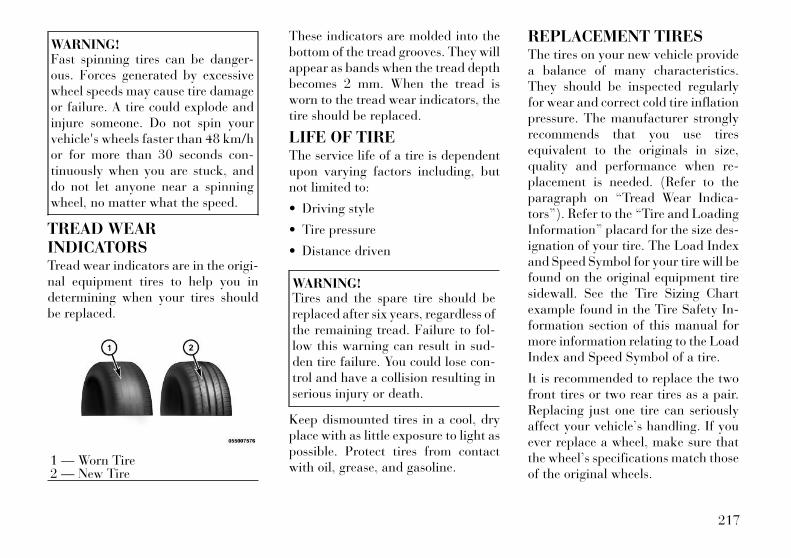
WARNING!Fast spinning tires can be danger-ous. Forces generated by excessivewheel speeds may cause tire damageor failure. A tire could explode andinjure someone. Do not spin yourvehicle's wheels faster than 48 km/hor for more than 30 seconds con-tinuously when you are stuck, anddo not let anyone near a spinningwheel, no matter what the speed.
TREAD WEARINDICATORSTread wear indicators are in the origi-nal equipment tires to help you indetermining when your tires shouldbe replaced.
These indicators are molded into thebottom of the tread grooves. They willappear as bands when the tread depthbecomes 2 mm. When the tread isworn to the tread wear indicators, thetire should be replaced.
LIFE OF TIREThe service life of a tire is dependentupon varying factors including, butnot limited to:
• Driving style
• Tire pressure
• Distance driven
WARNING!Tires and the spare tire should bereplaced after six years, regardless ofthe remaining tread. Failure to fol-low this warning can result in sud-den tire failure. You could lose con-trol and have a collision resulting inserious injury or death.
Keep dismounted tires in a cool, dryplace with as little exposure to light aspossible. Protect tires from contactwith oil, grease, and gasoline.
REPLACEMENT TIRESThe tires on your new vehicle providea balance of many characteristics.They should be inspected regularlyfor wear and correct cold tire inflationpressure. The manufacturer stronglyrecommends that you use tiresequivalent to the originals in size,quality and performance when re-placement is needed. (Refer to theparagraph on “Tread Wear Indica-tors”). Refer to the “Tire and LoadingInformation” placard for the size des-ignation of your tire. The Load Indexand Speed Symbol for your tire will befound on the original equipment tiresidewall. See the Tire Sizing Chartexample found in the Tire Safety In-formation section of this manual formore information relating to the LoadIndex and Speed Symbol of a tire.
It is recommended to replace the twofront tires or two rear tires as a pair.Replacing just one tire can seriouslyaffect your vehicle’s handling. If youever replace a wheel, make sure thatthe wheel’s specifications match thoseof the original wheels.
1 — Worn Tire2 — New Tire
217

It is recommended you contact youroriginal equipment or an authorizedtire dealer with any questions youmay have on tire specifications or ca-pability. Failure to use equivalent re-placement tires may adversely affectthe safety, handling, and ride of yourvehicle.
WARNING!• Do not use a tire, wheel size or
rating other than that specifiedfor your vehicle. Some combina-tions of unapproved tires andwheels may change suspension di-mensions and performance char-acteristics, resulting in changes tosteering, handling, and braking ofyour vehicle. This can cause un-predictable handling and stress tosteering and suspension compo-nents. You could lose control andhave a collision resulting in seri-ous injury or death. Use only thetire and wheel sizes with load rat-ings approved for your vehicle.
(Continued)
WARNING! (Continued)• Never use a tire with a smaller
load index or capacity, other thanwhat was originally equipped onyour vehicle. Using a tire with asmaller load index could result intire overloading and failure. Youcould lose control and have a col-lision.
• Failure to equip your vehicle withtires having adequate speed capa-bility can result in sudden tire fail-ure and loss of vehicle control.
CAUTION!Replacing original tires with tires ofa different size may result in falsespeedometer and odometer read-ings.
TIRE CHAINSUse of Security Chain Company(SCC) Super Z6 SZ143 or Iceman Z6IZ-643 cables or equivalent are rec-ommended on 225/65R17 tires.
NOTE:
Do not use tire chains on a com-pact spare tire.
CAUTION!To avoid damage to your vehicle ortires, observe the following precau-tions:• Use chains on 225/65R17 tires
only.• Because of restricted chain clear-
ance between tires and other sus-pension components, it is impor-tant that only chains in goodcondition are used. Broken chainscan cause serious damage. Stopthe vehicle immediately if noiseoccurs that could indicate chainbreakage. Remove the damagedparts of the chain before furtheruse.
• Install chains on the rear wheelsas tightly as possible and then re-tighten after driving about0.8 km.
• Do not exceed 48 km/h.• Drive cautiously and avoid severe
turns and large bumps, especiallywith a loaded vehicle.
• Use on rear wheels only.• Do not drive for prolonged period
on dry pavement.
(Continued)
218
CAUTION! (Continued)• Observe the tire chain manufac-
turer's instructions on the methodof installation, operating speed,and conditions for use. Always usethe lower suggested operatingspeed of the chain manufacturer ifdifferent from the speed recom-mended by the manufacture.
NOTE:
In order to avoid damage to tires,chains, and your vehicle do notdrive for a prolonged period on drypavement. Observe the tire chainmanufacturer's instructions onmethod of installation, operatingspeed, and conditions for usage.
Always use the lower suggested oper-ating speed if both the chain manu-facturer and vehicle manufacturersuggest a maximum speed. This no-tice applies to all chain traction de-vices, including link and cable (ra-dial) chains.
TIRE ROTATIONRECOMMENDATIONSTires on the front and rear axles ofvehicles operate at different loads andperform different steering, driving,and braking functions. For these rea-sons, they wear at unequal rates.
These effects can be reduced by timelyrotation of tires. The benefits of rota-tion are especially worthwhile with ag-gressive tread designs such as those onall season type tires. Rotation will in-crease tread life, help to maintain mud,snow and wet traction levels, and con-tribute to a smooth, quiet ride.
Refer to the “Maintenance Schedule”for the proper maintenance intervals.The reasons for any rapid or unusualwear should be corrected prior to ro-tation being performed.
TIRE PRESSUREMONITOR SYSTEM(TPMS)The Tire Pressure Monitor System(TPMS) will warn the driver of a lowtire pressure based on the vehicle rec-ommended cold placard pressure.
The tire pressure will vary with tem-perature by about 0.069 BAR for ev-ery 6.5°C. This means that when theoutside temperature decreases, thetire pressure will decrease. Tire pres-sure should always be set based oncold inflation tire pressure. This isdefined as the tire pressure after thevehicle has not been driven for at leastthree hours, or driven less than1.6 km after a three hour period. Thecold tire inflation pressure must notexceed the maximum inflation pres-sure molded into the tire sidewall. Re-fer to “Tires – General Information”in “Starting and Operating” for infor-mation on how to properly inflate thevehicle’s tires. The tire pressure willalso increase as the vehicle is driven -this is normal and there should be noadjustment for this increased pres-sure.
The TPMS will warn the driver of alow tire pressure if the tire pressurefalls below the low-pressure warninglimit for any reason, including lowtemperature effects and natural pres-sure loss through the tire.
219
The TPMS will continue to warn thedriver of low tire pressure as long asthe condition exists, and will not turnoff until the tire pressure is at or abovethe recommended cold placard pres-sure. Once the low tire pressure warn-ing (Tire Pressure Monitoring [TPM]Telltale Light) illuminates, you mustincrease the tire pressure to the rec-ommended cold placard pressure inorder for the TPM Telltale Light toturn off. The system will automati-cally update and the TPM TelltaleLight will turn off once the systemreceives the updated tire pressures.The vehicle may need to be driven forup to 20 minutes above 24 km/h inorder for the TPMS to receive thisinformation.
For example, your vehicle may have arecommended cold (parked for morethan three hours) placard pressure of2.07 BAR. If the ambient temperatureis 20°C and the measured tire pres-sure is 1.86 BAR, a temperature dropto 7°C will decrease the tire pressureto approximately 1.58 BAR. This tirepressure is sufficiently low enough toturn ON the TPM Telltale Light. Driv-
ing the vehicle may cause the tirepressure to rise to approximately 1.86BAR, but the TPM Telltale Light willstill be ON. In this situation, the TPMTelltale Light will turn OFF only afterthe tires are inflated to the vehicle’srecommended cold placard pressurevalue.
CAUTION!• The TPMS has been optimized for
the original equipment tires andwheels. TPMS pressures andwarning have been established forthe tire size equipped on your ve-hicle. Undesirable system opera-tion or sensor damage may resultwhen using replacement equip-ment that is not of the same size,type, and/or style. Aftermarketwheels can cause sensor damage.Do not use aftermarket tire seal-ants or balance beads if your ve-hicle is equipped with a TPMS, asdamage to the sensors may result.
(Continued)
CAUTION! (Continued)• After inspecting or adjusting the
tire pressure, always reinstall thevalve stem cap. This will preventmoisture and dirt from enteringthe valve stem, which could dam-age the TPM sensor.
NOTE:
• The TPMS is not intended to re-place normal tire care andmaintenance or to providewarning of a tire failure or con-dition.
• The TPMS should not be used asa tire pressure gauge while ad-justing your tire pressure.
• Driving on a significantly under-inflated tire causes the tire tooverheat and can lead to tirefailure. Under-inflation also re-duces fuel efficiency and tiretread life, and may affect the ve-hicle’s handling and stoppingability.
• The TPMS is not a substitute forproper tire maintenance, and itis the driver’s responsibility tomaintain correct tire pressure
220

using an accurate tire pressuregauge, even if under-inflationhas not reached the level to trig-ger illumination of the TPMTelltale Light.
• Seasonal temperature changeswill affect tire pressure, and theTPMS will monitor the actualtire pressure in the tire.
PREMIUM SYSTEMThe Tire Pressure Monitor System(TPMS) uses wireless technology withwheel rim mounted electronic sensorsto monitor tire pressure levels. Sen-sors mounted to each wheel as part ofthe valve stem transmit tire pressurereadings to the receiver module.
NOTE:
It is particularly important for youto check the tire pressure in all ofthe tires on your vehicle monthlyand to maintain the proper pres-sure.
The TPMS consists of the followingcomponents:
• Receiver module,
• Four TPM sensors,
• Various TPMS messages, whichdisplay in the Electronic Vehicle In-formation Center (EVIC), and
• TPM Telltale Light
Tire Pressure Monitoring LowPressure Warnings
The TPM Telltale Light will il-luminate in the instrumentcluster and a chime will sound
when tire pressure is low in one ormore of the four active road tires. Inaddition, the EVIC will display a"LOW TIRE" message and a graphicshowing the pressure values of eachtire with the low tire pressure valuesflashing.
Should this occur, you should stop assoon as possible and inflate the tireswith a low pressure condition (thoseflashing in the EVIC graphic) to thevehicle’s recommended cold placardpressure inflation value. Once the sys-tem receives the updated tire pres-sures, the system will automaticallyupdate, the graphic display in theEVIC will stop flashing, and the TPMTelltale Light will turn off. The ve-hicle may need to be driven for up to
20 minutes above 24 km/h in orderfor the TPMS to receive this informa-tion.
Service TPMS WarningIf a system fault is detected, the TPMTelltale Light will flash on and off for75 seconds and then remain on solid.The system fault will also sound achime. In addition, the EVIC will dis-play a "SERVICE TPM SYSTEM"message for a minimum of five sec-onds and then display dashes (- -) inplace of the pressure value to indicatewhich sensor is not being received.
If the ignition switch is cycled, thissequence will repeat, providing thesystem fault still exists. If the systemfault no longer exists, the TPM Tell-tale Light will no longer flash, and the"SERVICE TPM SYSTEM" messagewill no longer display, and a pressurevalue will display in place of thedashes. A system fault can occur dueto any of the following:
1. Signal interference due to elec-tronic devices or driving next to facili-ties emitting the same radio frequen-cies as the TPM sensors.
221
2. Installing aftermarket windowtinting that contains materials thatmay block radio wave signals.
3. Accumulation of snow or icearound the wheels or wheel housings.
4. Using tire chains on the vehicle.
5. Using wheels/tires not equippedwith TPM sensors.
The EVIC will also display a "SER-VICE TPM SYSTEM" message for aminimum of five seconds when a sys-tem fault related to an incorrect sen-sor location fault is detected. In thiscase, the "SERVICE TPM SYSTEM"message is then followed with agraphic display with pressure valuesstill shown. This indicates that thepressure values are still being receivedfrom the TPM sensors but they maynot be located in the correct vehicleposition. The system still needs to beserviced as long as the "SERVICETPM SYSTEM" message is displayed.
Vehicles With Compact Spare
1. The compact spare tire does nothave a TPM sensor. Therefore, theTPMS will not monitor the pressure inthe compact spare tire.
2. If you install the compact sparetire in place of a road tire that has apressure below the low-pressurewarning limit, upon the next ignitionswitch cycle, the TPM Telltale Lightwill remain ON and a chime willsound. In addition, the graphic in theEVIC will still display a flashing pres-sure value.
3. After driving the vehicle for up to20 minutes above 24 km/h, the TPMTelltale Light will flash on and off for75 seconds and then remain on solid.In addition, the EVIC will display a"SERVICE TPM SYSTEM" messagefor a minimum of five seconds andthen display dashes (- -) in place ofthe pressure value.
4. For each subsequent ignitionswitch cycle, a chime will sound, theTPM Telltale Light will flash on andoff for 75 seconds and then remain onsolid, and the EVIC will display a
"SERVICE TPM SYSTEM" messagefor a minimum of five seconds andthen display dashes (- -) in place ofthe pressure value.
5. Once you repair or replace theoriginal road tire and reinstall it onthe vehicle in place of the compactspare, the TPMS will update auto-matically. In addition, the TPM Tell-tale Light will turn OFF and thegraphic in the EVIC will display a newpressure value instead of dashes (- -),as long as no tire pressure is below thelow-pressure warning limit in any ofthe four active road tires. The vehiclemay need to be driven for up to20 minutes above 24 km/h in orderfor the TPMS to receive this informa-tion.
TPMS DEACTIVATIONThe TPMS can be deactivated if re-placing all four wheel and tire assem-blies (road tires) with wheel and tireassemblies that do not have TPMSSensors, such as when installing win-ter wheel and tire assemblies on yourvehicle To deactivate the TPMS, first,replace all four wheel and tire assem-blies (road tires) with tires not
222
equipped with Tire Pressure Monitor-ing (TPM) Sensors. Then, drive thevehicle for 20 minutes above24 km/h. The TPMS will chime, the“TPM Telltale Light” will flash onand off for 75 seconds and then re-main on and the Electronic VehicleInformation Center (EVIC) will dis-play the “SERVICE TPM SYSTEM”message and then display dashes (--)in place of the pressure values. Begin-ning with the next ignition switchcycle, the TPMS will no longer chimeor display the “SERVICE TPM SYS-TEM” message in the EVIC butdashes (--) will remain in place of thepressure values.
To reactivate the TPMS, replace allfour wheel and tire assemblies (roadtires) with tires equipped with TPMsensors. Then, drive the vehicle for upto 20 minutes above 24 km/h. TheTPMS will chime, the “TPM TelltaleLight” will flash on and off for 75 sec-onds and then turn off, and the Elec-tronic Vehicle Information Center(EVIC) will display the “SERVICETPM SYSTEM” message. The EVICwill also display pressure values in
place of the dashes. On the next igni-tion switch cycle the “SERVICE TPMSYSTEM” message will no longer bedisplayed as long as no system faultexists.
FUEL REQUIREMENTS— GASOLINE ENGINES
3.6L ENGINEAll engines are designed to meet allemissions regulations and provide ex-cellent fuel economy and performancewhen using high quality unleadedgasoline with a minimum research oc-tane rating of 91. The use of premiumgasoline is not recommended, as itwill not provide any benefit over regu-lar gasoline in these engines.
Light spark knock at low enginespeeds is not harmful to your engine.However, continued heavy sparkknock at high speeds can cause dam-age, and immediate service is re-quired. Poor quality gasoline cancause problems such as hard starting,stalling, and hesitations. If you expe-rience these symptoms, try anotherbrand of gasoline before consideringservice for the vehicle.
Over 40 auto manufacturers world-wide have issued and endorsed consis-tent gasoline specifications (the World-wide Fuel Charter, WWFC) whichdefine fuel properties necessary to de-liver enhanced emissions, perfor-mance, and durability for your vehicle.The manufacturer recommends the useof gasoline that meets the WWFCspecifications if they are available.
Besides using unleaded gasoline withthe proper octane rating, gasolinesthat contain detergents, corrosion andstability additives are recommended.Using gasolines that have these addi-tives may help improve fuel economy,reduce emissions, and maintain ve-hicle performance.
Poor quality gasoline can cause prob-lems such as hard starting, stalling andstumble. If you experience these prob-lems, try another brand of gasoline be-fore considering service for the vehicle.
Methanol(Methyl or Wood Alcohol) is used in avariety of concentrations whenblended with unleaded gasoline. Youmay find fuels containing 3% or more
223
Methanol along with other alcoholscalled cosolvents. Problems that re-sult from using Methanol/gasoline orE-85 Ethanol blends are not the re-sponsibility of the manufacturer.While MTBE is an oxygenate madefrom Methanol, it does not have thenegative effects of Methanol.
CAUTION!Do not use gasolines containingMethanol or E-85 Ethanol. Use ofthese blends may result in startingand driveability problems and maydamage critical fuel system compo-nents.
EthanolThe manufacturer recommends thatyour vehicle be operated on fuel con-taining no more than 10% Ethanol.Purchasing your fuel from a reputablesupplier may reduce the risk of ex-ceeding this 10% limit and/or of re-ceiving fuel with abnormal properties.It should also be noted that an in-crease in fuel consumption should beexpected when using Ethanol-blended fuels, due to the lower energycontent of Ethanol.
Problems that result from usingMethanol/gasoline or E-85 Ethanolblends are not the responsibility of themanufacturer. While MTBE is an oxy-genate made from Methanol, it doesnot have the negative effects ofMethanol.
CAUTION!Use of fuel with Ethanol contenthigher than 10% may result in en-gine malfunction, starting and oper-ating difficulties and materials deg-radation. These adverse effectscould result in permanent damage toyour vehicle.
Clean Air GasolineMany gasolines are now beingblended that contribute to cleaner air,especially in those areas where airpollution levels are high. These newblends provide a cleaner burning fueland some are referred to as “reformu-lated gasoline.”
The manufacturer supports these ef-forts toward cleaner air. You can helpby using these blends as they becomeavailable.
MMT In GasolineMMT is a manganese containing me-tallic additive that is blended intosome gasoline to increase octane.Gasoline blended with MMT providesno performance advantage beyondgasoline of the same octane numberwithout MMT. Gasoline blended withMMT reduces spark plug life and re-duces emission system performance insome vehicles. The manufacturer rec-ommends that gasoline without MMTbe used in your vehicle. The MMTcontent of gasoline may not be indi-cated on the gasoline pump; therefore,you should ask your gasoline retailerwhether or not his/her gasoline con-tains MMT.
Materials Added To FuelBesides using unleaded gasoline withthe proper octane rating, gasolinesthat contain detergents, corrosion andstability additives are recommended.Using gasolines that have these addi-tives will help improve fuel economy,reduce emissions, and maintain ve-hicle performance.
Indiscriminate use of fuel systemcleaning agents should be avoided.
224

Many of these materials intended forgum and varnish removal may con-tain active solvents or similar ingredi-ents. These can harm fuel system gas-ket and diaphragm materials.
WARNING!Carbon monoxide (CO) in exhaustgases is deadly. Follow the precau-tions below to prevent carbon mon-oxide poisoning:• Do not inhale exhaust gases. They
contain carbon monoxide, a color-less and odorless gas which cankill. Never run the engine in aclosed area, such as a garage, andnever sit in a parked vehicle withthe engine running for an ex-tended period. If the vehicle isstopped in an open area with theengine running for more than ashort period, adjust the ventila-tion system to force fresh, outsideair into the vehicle.
(Continued)
WARNING! (Continued)• Guard against carbon monoxide
with proper maintenance. Havethe exhaust system inspected ev-ery time the vehicle is raised.Have any abnormal conditions re-paired promptly. Until repaired,drive with all side windows fullyopen.
• Keep the trunk closed when driv-ing your vehicle to prevent carbonmonoxide and other poisonous ex-haust gases from entering the ve-hicle.
FUEL REQUIREMENTS— DIESEL ENGINESThis vehicle must only use pre-mium diesel fuel that meets therequirements of EN 590. Biodieselblends that meet EN 590 may alsobe used.
CAUTION!The manufacturer requires that youmust fuel this vehicle with UltraLow Sulfur Highway Diesel fuel(15 ppm Sulfur maximum) and pro-hibits the use of Low Sulfur High-way Diesel fuel (500 ppm Sulfurmaximum) to avoid damage to theemissions control system.
WARNING!Do not use alcohol or gasoline as afuel blending agent. They can beunstable under certain conditionsand hazardous or explosive whenmixed with diesel fuel.
Diesel fuel is seldom completely free ofwater. To prevent fuel system trouble,drain the accumulated water from thefuel/water separator using the fuel/water separator drain provided. If youbuy good quality fuel and follow thecold weather advice above, fuel condi-tioners should not be required in yourvehicle. If available in your area, a highcetane “premium” diesel fuel may offerimproved cold-starting and warm-upperformance.
225
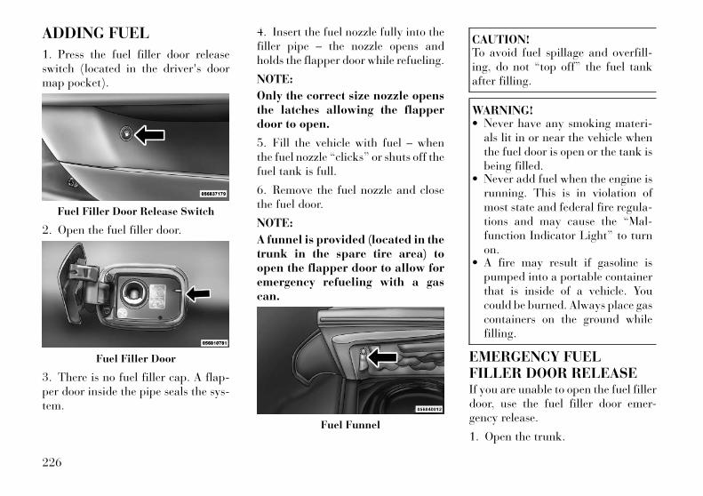
ADDING FUEL
1. Press the fuel filler door releaseswitch (located in the driver's doormap pocket).
2. Open the fuel filler door.
3. There is no fuel filler cap. A flap-per door inside the pipe seals the sys-tem.
4. Insert the fuel nozzle fully into thefiller pipe – the nozzle opens andholds the flapper door while refueling.
NOTE:
Only the correct size nozzle opensthe latches allowing the flapperdoor to open.
5. Fill the vehicle with fuel – whenthe fuel nozzle “clicks” or shuts off thefuel tank is full.
6. Remove the fuel nozzle and closethe fuel door.
NOTE:
A funnel is provided (located in thetrunk in the spare tire area) toopen the flapper door to allow foremergency refueling with a gascan.
CAUTION!To avoid fuel spillage and overfill-ing, do not “top off” the fuel tankafter filling.
WARNING!• Never have any smoking materi-
als lit in or near the vehicle whenthe fuel door is open or the tank isbeing filled.
• Never add fuel when the engine isrunning. This is in violation ofmost state and federal fire regula-tions and may cause the “Mal-function Indicator Light” to turnon.
• A fire may result if gasoline ispumped into a portable containerthat is inside of a vehicle. Youcould be burned. Always place gascontainers on the ground whilefilling.
EMERGENCY FUELFILLER DOOR RELEASEIf you are unable to open the fuel fillerdoor, use the fuel filler door emer-gency release.
1. Open the trunk.
Fuel Filler Door Release Switch
Fuel Filler Door
Fuel Funnel
226
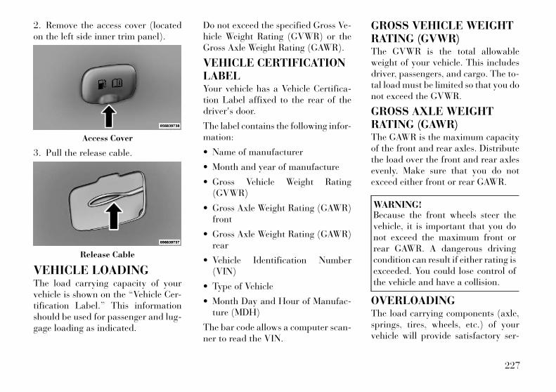
2. Remove the access cover (locatedon the left side inner trim panel).
3. Pull the release cable.
VEHICLE LOADINGThe load carrying capacity of yourvehicle is shown on the “Vehicle Cer-tification Label.” This informationshould be used for passenger and lug-gage loading as indicated.
Do not exceed the specified Gross Ve-hicle Weight Rating (GVWR) or theGross Axle Weight Rating (GAWR).
VEHICLE CERTIFICATIONLABELYour vehicle has a Vehicle Certifica-tion Label affixed to the rear of thedriver's door.
The label contains the following infor-mation:
• Name of manufacturer
• Month and year of manufacture
• Gross Vehicle Weight Rating(GVWR)
• Gross Axle Weight Rating (GAWR)front
• Gross Axle Weight Rating (GAWR)rear
• Vehicle Identification Number(VIN)
• Type of Vehicle
• Month Day and Hour of Manufac-ture (MDH)
The bar code allows a computer scan-ner to read the VIN.
GROSS VEHICLE WEIGHTRATING (GVWR)The GVWR is the total allowableweight of your vehicle. This includesdriver, passengers, and cargo. The to-tal load must be limited so that you donot exceed the GVWR.
GROSS AXLE WEIGHTRATING (GAWR)The GAWR is the maximum capacityof the front and rear axles. Distributethe load over the front and rear axlesevenly. Make sure that you do notexceed either front or rear GAWR.
WARNING!Because the front wheels steer thevehicle, it is important that you donot exceed the maximum front orrear GAWR. A dangerous drivingcondition can result if either rating isexceeded. You could lose control ofthe vehicle and have a collision.
OVERLOADINGThe load carrying components (axle,springs, tires, wheels, etc.) of yourvehicle will provide satisfactory ser-
Access Cover
Release Cable
227

vice as long as you do not exceed theGVWR and the front and rear GAWR.
The best way to figure out the totalweight of your vehicle is to weigh itwhen it is fully loaded and ready foroperation. Weigh it on a commercialscale to ensure that it is not over theGVWR.
Figure out the weight on the front andrear of the vehicle separately. It isimportant that you distribute the loadevenly over the front and rear axles.
Overloading can cause potentialsafety hazards and shorten useful ser-vice life. Heavier axles or suspensioncomponents do not necessarily in-crease the vehicle's GVWR.
LOADINGTo load your vehicle properly, firstfigure out its empty weight, axle-by-axle and side-by-side. Store heavieritems down low and be sure you dis-tribute their weight as evenly as pos-sible. Stow all loose items securelybefore driving. If weighing the loadedvehicle shows that you have exceededeither GAWR, but the total load iswithin the specified GVWR, you must
redistribute the weight. Improperweight distribution can have an ad-verse effect on the way your vehiclesteers and handles and the way thebrakes operate.
NOTE:
• Refer to the “Vehicle Certifica-tion Label” affixed to the rear ofthe driver's door for your vehi-cle's GVWR and GAWRs.
• Refer to the “Tire Placard” foryour vehicle's proper tire pres-sure.
TRAILER TOWINGIn this section, you will find safety tipsand information on limits to the typeof towing you can reasonably do withyour vehicle. Before towing a trailer,carefully review this information totow your load as efficiently and safelyas possible.
To maintain warranty coverage, fol-low the requirements and recommen-dations in this manual concerning ve-hicles used for trailer towing.
COMMON TOWINGDEFINITIONSThe following trailer towing relateddefinitions will assist you in under-standing the following information:
Gross Vehicle Weight Rating(GVWR)The GVWR is the total allowableweight of your vehicle. This includesdriver, passengers, cargo, and tongueweight. The total load must be limitedso that you do not exceed the GVWR.Refer to “Vehicle Loading/VehicleCertification Label” in “Starting andOperating” for further information.
Gross Trailer Weight (GTW)The GTW is the weight of the trailerplus the weight of all cargo, consum-ables, and equipment (permanent ortemporary) loaded in or on the trailerin its "loaded and ready for opera-tion" condition.
The recommended way to measureGTW is to put your fully loaded traileron a vehicle scale. The entire weight ofthe trailer must be supported by thescale.
228

Gross Combination Weight Rating(GCWR)The GCWR is the total permissibleweight of your vehicle and trailerwhen weighed in combination.
NOTE:
The GCWR rating includes a 68 kgallowance for the presence of adriver.
Gross Axle Weight Rating (GAWR)The GAWR is the maximum capacityof the front and rear axles. Distributethe load over the front and rear axlesevenly. Make sure that you do notexceed either front or rear GAWR.Refer to “Vehicle Loading/VehicleCertification Label” in “Starting andOperating” for further information.
WARNING!It is important that you do not ex-ceed the maximum front or rearGAWR. A dangerous driving condi-tion can result if either rating is ex-ceeded. You could lose control of thevehicle and have a collision.
Tongue Weight (TW)The tongue weight is the downwardforce exerted on the hitch ball by thetrailer. In most cases, it should not bemore than 5% of the trailer load. Youmust consider this as part of the loadon your vehicle.
Frontal AreaThe frontal area is the maximumheight multiplied by the maximumwidth of the front of a trailer.
Trailer Sway ControlThe trailer sway control is a telescop-ing link that can be installed betweenthe hitch receiver and the trailertongue that typically provides adjust-able friction associated with the tele-scoping motion to dampen any un-wanted trailer swaying motions whiletraveling.
Weight-Carrying HitchA weight-carrying hitch supports thetrailer tongue weight, just as if it wereluggage located at a hitch ball or someother connecting point of the vehicle.These kinds of hitches are the mostpopular on the market today and they
are commonly used to tow small- andmedium-sized trailers.
Weight-Distributing HitchA weight-distributing system worksby applying leverage through spring(load) bars. They are typically usedfor heavier loads to distribute trailertongue weight to the tow vehicle'sfront axle and the trailer axle(s).When used in accordance with themanufacturer's directions, it providesfor a more level ride, offering moreconsistent steering and brake controlthereby enhancing towing safety. Theaddition of a friction / hydraulic swaycontrol also dampens sway caused bytraffic and crosswinds and contrib-utes positively to tow vehicle andtrailer stability. Trailer sway controland a weight distributing (load equal-izing) hitch are recommended forheavier Tongue Weights (TW) andmay be required depending on vehicleand trailer configuration / loading tocomply with Gross Axle Weight Rat-ing (GAWR) requirements.
229

WARNING!• An improperly adjusted weight
distributing hitch system may re-duce handling, stability, brakingperformance, and could result in acollision.
• Weight distributing systems maynot be compatible with surgebrake couplers. Consult with yourhitch and trailer manufacturer ora reputable recreational vehicledealer for additional information.
BREAKAWAY CABLEATTACHMENTEuropean braking regulations forbraked trailers up to 3 500 kg requiretrailers to be fitted with either a sec-ondary coupling or breakaway cable.
The recommended location for at-taching the normal trailer's break-away cable is in the stamped slot lo-cated on the sidewall of the hitchreceiver.
With Attachment Point
• For detachable tow bar, pass thecable through the attachment pointand clip it back onto itself.
• For fixed ball tow bar, attach theclip directly to the designatedpoint. This alternative must be spe-cifically permitted by the trailermanufacturer since the clip maynot be sufficiently strong for use inthe way.
Without Attachment Points
• For detachable ball tow bar, youmust follow the recommendedmanufacturer or supplier proce-dure.
• For fixed ball tow bar, loop thecable around the neck of the towball. If you fit the cable like this, usea single loop only.
Detachable Ball Clip Loop Method
Fixed Ball Clip Loop Method
Detachable Ball Neck Loop Method
Fixed Ball Neck Loop Method
230
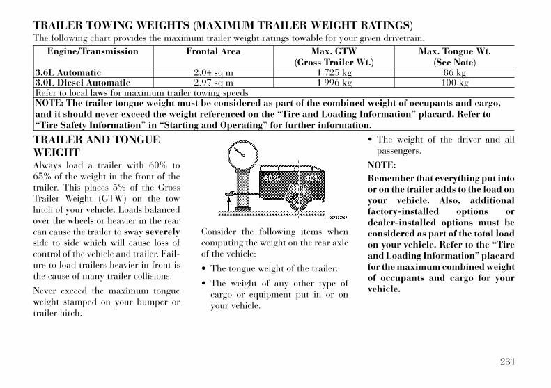
TRAILER TOWING WEIGHTS (MAXIMUM TRAILER WEIGHT RATINGS)The following chart provides the maximum trailer weight ratings towable for your given drivetrain.
Engine/Transmission Frontal Area Max. GTW(Gross Trailer Wt.)
Max. Tongue Wt.(See Note)
3.6L Automatic 2.04 sq m 1 725 kg 86 kg3.0L Diesel Automatic 2.97 sq m 1 996 kg 100 kgRefer to local laws for maximum trailer towing speedsNOTE: The trailer tongue weight must be considered as part of the combined weight of occupants and cargo,and it should never exceed the weight referenced on the “Tire and Loading Information” placard. Refer to“Tire Safety Information” in “Starting and Operating” for further information.
TRAILER AND TONGUEWEIGHTAlways load a trailer with 60% to65% of the weight in the front of thetrailer. This places 5% of the GrossTrailer Weight (GTW) on the towhitch of your vehicle. Loads balancedover the wheels or heavier in the rearcan cause the trailer to sway severelyside to side which will cause loss ofcontrol of the vehicle and trailer. Fail-ure to load trailers heavier in front isthe cause of many trailer collisions.
Never exceed the maximum tongueweight stamped on your bumper ortrailer hitch.
Consider the following items whencomputing the weight on the rear axleof the vehicle:
• The tongue weight of the trailer.
• The weight of any other type ofcargo or equipment put in or onyour vehicle.
• The weight of the driver and allpassengers.
NOTE:
Remember that everything put intoor on the trailer adds to the load onyour vehicle. Also, additionalfactory-installed options ordealer-installed options must beconsidered as part of the total loadon your vehicle. Refer to the “Tireand Loading Information” placardfor the maximum combined weightof occupants and cargo for yourvehicle.
231

TOWING REQUIREMENTSTo promote proper break-in of yournew vehicle drivetrain componentsthe following guidelines are recom-mended:
CAUTION!• Do not tow a trailer at all during
the first 805 km the new vehicle isdriven. The engine, axle or otherparts could be damaged.
• Then, during the first 805 km thata trailer is towed, do not driveover 80 km/h and do not makestarts at full throttle. This helpsthe engine and other parts of thevehicle wear in at the heavierloads.
WARNING!Improper towing can lead to an in-jury collision. Follow these guide-lines to make your trailer towing assafe as possible:
(Continued)
WARNING! (Continued)• Make certain that the load is se-
cured in the trailer and it will notshift during travel. When traile-ring cargo that is not fully se-cured, dynamic load shifts can oc-cur that may be difficult for thedriver to control. You could losecontrol of your vehicle and have acollision.
• When hauling cargo or towing atrailer, do not overload your ve-hicle or trailer. Overloading cancause a loss of control, poor per-formance, or damage to brakes,axle, engine, transmission, steer-ing, suspension, chassis structure,or tires.
• Safety chains must always be usedbetween your vehicle and trailer.Always connect the chains to theframe or hook retainers of the ve-hicle hitch. Cross the chains underthe trailer tongue and allowenough slack for turning corners.
(Continued)
WARNING! (Continued)• Vehicles with trailers should not
be parked on a grade. When park-ing, apply the parking brake onthe tow vehicle. Put the tow ve-hicle automatic transmission inPARK. Always, block or "chock"the trailer wheels.
• GCWR must not be exceeded.• Total weight must be distrib-
uted between the tow vehicleand the trailer such that thefollowing four ratings are notexceeded:
1. Max loading as defined on the“Tire and Loading Information”placard.2. GTW3. GAWR4. Tongue weight rating for thetrailer hitch utilized. (This require-ment may limit the ability to alwaysachieve the 10% to 15% range oftongue weight as a percentage oftotal trailer weight.)
Towing Requirements – Tires
− Do not attempt to tow a trailerwhile using a compact spare tire.
232
− Proper tire inflation pressures areessential to the safe and satisfac-tory operation of your vehicle. Re-fer to “Tires – General Informa-tion” in “Starting and Operating”for information on tire pressuresand for proper tire inflation proce-dures.
− Check the trailer tires for propertire inflation pressures beforetrailer usage.
− Check for signs of tire wear or vis-ible tire damage before towing atrailer. Refer to “Tires – GeneralInformation” in “Starting and Op-erating” for information on treadwear indicators and for the properinspection procedure.
− When replacing tires, refer to“Tires – General Information” in“Starting and Operating” for infor-mation on replacement tires andfor the proper tire replacement pro-cedures. Replacing tires with ahigher load carrying capacity willnot increase the vehicle's GVWRand GAWR limits.
Towing Requirements – TrailerBrakes
− Do not interconnect the hydraulicbrake system or vacuum system ofyour vehicle with that of the trailer.This could cause inadequate brak-ing and possible personal injury.
− An electronically actuated trailerbrake controller is required whentowing a trailer with electronicallyactuated brakes. When towing atrailer equipped with a hydraulicsurge actuated brake system, anelectronic brake controller is notrequired.
− Trailer brakes are recommendedfor trailers over 454 kg and re-quired for trailers in excess of907 kg.
CAUTION!If the trailer weighs more than454 kg loaded, it should have itsown brakes, and they should be ofadequate capacity. Failure to do thiscould lead to accelerated brake lin-ing wear, higher brake pedal effort,and longer stopping distances.
WARNING!• Do not connect trailer brakes to
your vehicle's hydraulic brakelines. It can overload your brakesystem and cause it to fail. Youmight not have brakes when youneed them and could have an col-lision.
• Towing any trailer will increaseyour stopping distance. Whentowing, you should allow for ad-ditional space between your ve-hicle and the vehicle in front ofyou. Failure to do so could resultin a collision.
Towing Requirements – TrailerLights And WiringWhenever you pull a trailer, regard-less of the trailer size, stoplights andturn signals on the trailer are requiredfor motoring safety.
The Trailer Tow Package may includea 7-pin or a 13-pin wiring harness.Use a factory approved trailer harnessand connector.
NOTE:
Do not cut or splice wiring into thevehicles wiring harness.
233
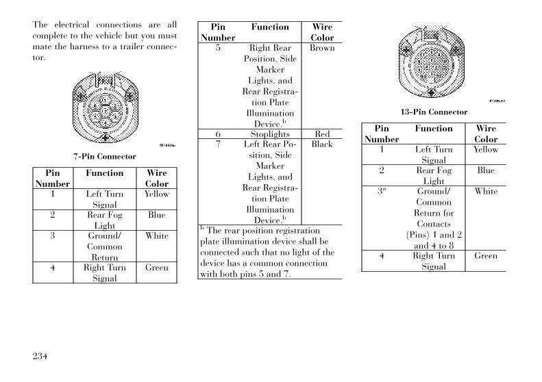
The electrical connections are allcomplete to the vehicle but you mustmate the harness to a trailer connec-tor.
PinNumber
Function WireColor
1 Left TurnSignal
Yellow
2 Rear FogLight
Blue
3 Ground/CommonReturn
White
4 Right TurnSignal
Green
PinNumber
Function WireColor
5 Right RearPosition, Side
MarkerLights, and
Rear Registra-tion Plate
IlluminationDevice.b
Brown
6 Stoplights Red7 Left Rear Po-
sition, SideMarker
Lights, andRear Registra-
tion PlateIllumination
Device.b
Black
b The rear position registrationplate illumination device shall beconnected such that no light of thedevice has a common connectionwith both pins 5 and 7.
PinNumber
Function WireColor
1 Left TurnSignal
Yellow
2 Rear FogLight
Blue
3a Ground/CommonReturn forContacts
(Pins) 1 and 2and 4 to 8
White
4 Right TurnSignal
Green
7-Pin Connector
13-Pin Connector
234
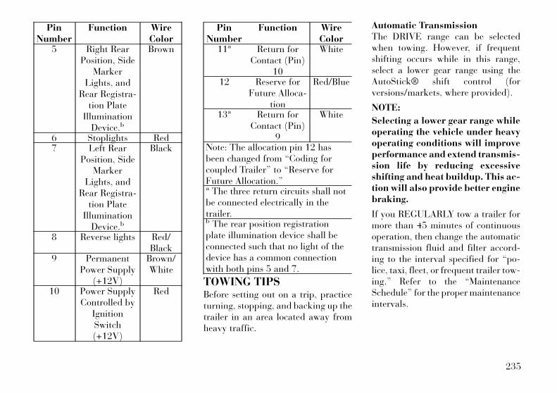
PinNumber
Function WireColor
5 Right RearPosition, Side
MarkerLights, and
Rear Registra-tion Plate
IlluminationDevice.b
Brown
6 Stoplights Red7 Left Rear
Position, SideMarker
Lights, andRear Registra-
tion PlateIllumination
Device.b
Black
8 Reverse lights Red/Black
9 PermanentPower Supply
(+12V)
Brown/White
10 Power SupplyControlled by
IgnitionSwitch(+12V)
Red
PinNumber
Function WireColor
11a Return forContact (Pin)
10
White
12 Reserve forFuture Alloca-
tion
Red/Blue
13a Return forContact (Pin)
9
White
Note: The allocation pin 12 hasbeen changed from “Coding forcoupled Trailer” to “Reserve forFuture Allocation.”a The three return circuits shall notbe connected electrically in thetrailer.b The rear position registrationplate illumination device shall beconnected such that no light of thedevice has a common connectionwith both pins 5 and 7.
TOWING TIPSBefore setting out on a trip, practiceturning, stopping, and backing up thetrailer in an area located away fromheavy traffic.
Automatic TransmissionThe DRIVE range can be selectedwhen towing. However, if frequentshifting occurs while in this range,select a lower gear range using theAutoStick® shift control (forversions/markets, where provided).
NOTE:
Selecting a lower gear range whileoperating the vehicle under heavyoperating conditions will improveperformance and extend transmis-sion life by reducing excessiveshifting and heat buildup. This ac-tion will also provide better enginebraking.
If you REGULARLY tow a trailer formore than 45 minutes of continuousoperation, then change the automatictransmission fluid and filter accord-ing to the interval specified for “po-lice, taxi, fleet, or frequent trailer tow-ing.” Refer to the “MaintenanceSchedule” for the proper maintenanceintervals.
235

Electronic Speed Control (forversions/markets, whereprovided)
− Do not use in hilly terrain or withheavy loads.
− When using the speed control, ifyou experience speed drops greaterthan 16 km/h, disengage until youcan get back to cruising speed.
− Use speed control in flat terrainand with light loads to maximizefuel efficiency.
AutoStick® (for versions/markets,where provided)
− By using the AutoStick® mode andselecting a specific gear range, fre-quent shifting can be avoided. Thehighest gear range should be se-lected that allows for adequate per-formance. For example, choose “4”if the desired speed can be main-tained. Choose “3” or “2” if neededto maintain the desired speed.
− Extended driving at high RPMshould be avoided to prevent excess
heat generation. A reduction in ve-hicle speed may be required toavoid extended driving at highRPM. Return to a higher gear rangeor vehicle speed when road condi-tions and RPM level allows.
Cooling SystemTo reduce potential for engine andtransmission overheating, take thefollowing actions:
− City DrivingWhen stopped for short periods oftime, shift the transmission into NEU-TRAL and increase engine idle speed.
− Highway DrivingReduce speed.
− Air ConditioningTurn off temporarily.
TRAILER HITCHATTACHING POINTSYour vehicle will require extra equip-ment to tow a trailer safely and effi-ciently. The trailer tow hitch must beattached to your vehicle using theprovided attaching points on the ve-
hicle's frame. Refer to the followingchart to determine the accurate at-taching points. Other equipment,such as trailer sway controls andbraking equipment, trailer equalizing(leveling) equipment and low profilemirrors, may also be required orstrongly recommended.
Trailer Tow Hitch AttachingPoints And Overhang Dimen-
sionsA 638.9 mmB 746.1 mmC 831.1 mmD (maximumoverhang)
1161.5 mm
E 535.3 mmF 520.3 mm
236

RECREATIONALTOWING (BEHINDMOTORHOME, ETC.)Recreational towing (with all fourwheels on the ground, or using a towdolly) is NOT ALLOWED. The onlyacceptable method for towing this ve-hicle (behind another vehicle) is on avehicle trailer with all four wheelsOFF the ground.
CAUTION!Towing this vehicle in violation ofthe above requirements can causesevere transmission damage. Suchdamage is not covered by the NewVehicle Limited Warranty.
237

238
6
WHAT TO DO IN EMERGENCIES• HAZARD WARNING FLASHERS . . . . . . . . . . . . 240
• IF YOUR ENGINE OVERHEATS . . . . . . . . . . . . . 240
• TIREFIT KIT (for versions/markets, whereprovided) . . . . . . . . . . . . . . . . . . . . . . . . . . . . . . 241
• TIREFIT STORAGE . . . . . . . . . . . . . . . . . . . . 241
• TIREFIT KIT COMPONENTS ANDOPERATION . . . . . . . . . . . . . . . . . . . . . . . . . 241
• TIREFIT USAGE PRECAUTIONS . . . . . . . . . . 242
• SEALING A TIRE WITH TIREFIT . . . . . . . . . 243
• JUMP-STARTING PROCEDURES . . . . . . . . . . . . 246
• PREPARATIONS FOR JUMP-START . . . . . . . 246
• JUMP-STARTING PROCEDURE . . . . . . . . . . . 247
• FREEING A STUCK VEHICLE . . . . . . . . . . . . . . 248
• TOW EYES . . . . . . . . . . . . . . . . . . . . . . . . . . . . 249
• SHIFT LEVER OVERRIDE — 5 SPEEDTRANSMISSION . . . . . . . . . . . . . . . . . . . . . . . . 249
• MANUAL PARK RELEASE — 8 SPEEDTRANSMISSION (3.6L Engine) . . . . . . . . . . . . . . 250
• TOWING A DISABLED VEHICLE . . . . . . . . . . . 251
• Without The Ignition Key . . . . . . . . . . . . . . . . 252
239
HAZARD WARNINGFLASHERSThe Hazard Warning flasher switch islocated in the center of the instrumentpanel between the center air outlets.
Press the switch to turn on theHazard Warning flashers.When the switch is activated,
all directional turn signals will flashon and off to warn oncoming traffic ofan emergency. Press the switch a sec-ond time to turn off the Hazard Warn-ing flashers.
This is an emergency warning systemand it should not be used when thevehicle is in motion. Use it when yourvehicle is disabled and it is creating asafety hazard for other motorists.
When you must leave the vehicle toseek assistance, the Hazard Warningflashers will continue to operate eventhough the ignition is placed in theOFF position.
NOTE:
With extended use the HazardWarning flashers may wear downyour battery.
IF YOUR ENGINEOVERHEATSIn any of the following situations, youcan reduce the potential for overheat-ing by taking the appropriate action.
• On the highways — slow down.
• In city traffic — while stopped,place the transmission in NEU-TRAL, but do not increase the en-gine idle speed.
NOTE:
There are steps that you can take toslow down an impending overheatcondition:
• If your air conditioner (A/C) ison, turn it off. The A/C systemadds heat to the engine coolingsystem and turning the A/C offcan help remove this heat.
• You can also turn the tempera-ture control to maximum heat,the mode control to floor and the
blower control to high. This al-lows the heater core to act as asupplement to the radiator andaids in removing heat from theengine cooling system.
CAUTION!Driving with a hot cooling systemcould damage your vehicle. If thetemperature gauge reads “H,” pullover and stop the vehicle. Idle thevehicle with the air conditionerturned off until the pointer dropsback into the normal range. If thepointer remains on the “H,” turn theengine off immediately and call forservice.
WARNING!You or others can be badly burnedby hot engine coolant (antifreeze) orsteam from your radiator. If you seeor hear steam coming from underthe hood, do not open the hood untilthe radiator has had time to cool.Never try to open a cooling systempressure cap when the radiator orcoolant bottle is hot.
240
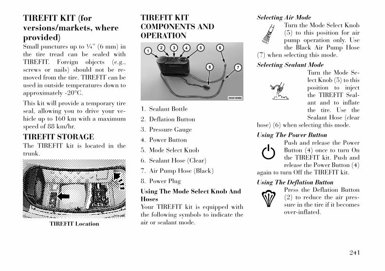
TIREFIT KIT (forversions/markets, whereprovided)Small punctures up to 1⁄4” (6 mm) inthe tire tread can be sealed withTIREFIT. Foreign objects (e.g.,screws or nails) should not be re-moved from the tire. TIREFIT can beused in outside temperatures down toapproximately 20°C.
This kit will provide a temporary tireseal, allowing you to drive your ve-hicle up to 160 km with a maximumspeed of 88 km/hr.
TIREFIT STORAGEThe TIREFIT kit is located in thetrunk.
TIREFIT KITCOMPONENTS ANDOPERATION
1. Sealant Bottle
2. Deflation Button
3. Pressure Gauge
4. Power Button
5. Mode Select Knob
6. Sealant Hose (Clear)
7. Air Pump Hose (Black)
8. Power Plug
Using The Mode Select Knob AndHosesYour TIREFIT kit is equipped withthe following symbols to indicate theair or sealant mode.
Selecting Air ModeTurn the Mode Select Knob(5) to this position for airpump operation only. Usethe Black Air Pump Hose
(7) when selecting this mode.
Selecting Sealant ModeTurn the Mode Se-lect Knob (5) to thisposition to injectthe TIREFIT Seal-ant and to inflatethe tire. Use theSealant Hose (clear
hose) (6) when selecting this mode.
Using The Power ButtonPush and release the PowerButton (4) once to turn Onthe TIREFIT kit. Push andrelease the Power Button (4)
again to turn Off the TIREFIT kit.
Using The Deflation ButtonPress the Deflation Button(2) to reduce the air pres-sure in the tire if it becomesover-inflated.
TIREFIT Location
241
TIREFIT USAGEPRECAUTIONS
• Replace the TIREFIT SealantBottle (1) and Sealant Hose (6)prior to the expiration date (printedon the bottle label) to assure opti-mum operation of the system. Referto “Sealing a Tire with TIREFIT”section (F) “Sealant Bottle andHose Replacement”.
• The Sealant Bottle (1) and SealantHose (6) are a one tire applicationuse. After each use, always replacethese components immediately atan authorized dealer.
• When the TIREFIT sealant is in aliquid form, clean water, and adamp cloth will remove the mate-rial from the vehicle or tire andwheel components. Once the seal-ant dries, it can easily be peeled offand properly discarded.
• For optimum performance, makesure the valve stem on the wheel isfree of debris before connecting theTIREFIT kit.
• You can use the TIREFIT air pumpto inflate bicycle tires. The kit alsocomes with two needles, located inthe Accessory Storage Compart-ment (on the bottom of the airpump) for inflating sport balls,rafts, or similar inflatable items.However, use only the Air PumpHose (7) and make sure the ModeSelect Knob (5) is in the Air Modewhen inflating such items to avoidinjecting sealant into them. TheTIREFIT Sealant is only intendedto seal punctures less than 6 mmdiameter in the tread of your ve-hicle.
• Do not lift or carry the TIREFIT kitby the hoses.
WARNING!• Do not attempt to seal a tire on the
side of the vehicle closest to traf-fic. Pull far enough off the road toavoid the danger of being hitwhen using the TIREFIT kit.
• Do not use TIREFIT or drive thevehicle under the following cir-cumstances:
(Continued)
WARNING! (Continued)− If the puncture in the tire tread
is approximately 6 mm orlarger.
− If the tire has any sidewalldamage.
− If the tire has any damage fromdriving with extremely low tirepressure.
− If the tire has any damage fromdriving on a flat tire.
− If the wheel has any damage.− If you are unsure of the condi-
tion of the tire or the wheel.• Keep TIREFIT away from open
flames or heat source.• A loose TIREFIT kit thrown for-
ward in a collision or hard stopcould endanger the occupants ofthe vehicle. Always stow theTIREFIT kit in the place pro-vided. Failure to follow thesewarnings can result in injuriesthat are serious or fatal to you,your passengers, and othersaround you.
(Continued)
242
WARNING! (Continued)• Take care not to allow the con-
tents of TIREFIT to come in con-tact with hair, eyes, or clothing.TIREFIT is harmful if inhaled,swallowed, or absorbed throughthe skin. It causes skin, eye, andrespiratory irritation. Flush im-mediately with plenty of water ifthere is any contact with eyes orskin. Change clothing as soon aspossible, if there is any contactwith clothing.
• TIREFIT Sealant solution con-tains latex. In case of an allergicreaction or rash, consult a physi-cian immediately. Keep TIREFITout of reach of children. If swal-lowed, rinse mouth immediatelywith plenty of water and drinkplenty of water. Do not inducevomiting! Consult a physician im-mediately.
SEALING A TIRE WITHTIREFIT
(A) Whenever You Stop To UseTIREFIT:
1. Pull over to a safe location andturn on the vehicle’s Hazard Warningflashers.
2. Verify that the valve stem (on thewheel with the deflated tire) is in aposition that is near to the ground.This will allow the TIREFIT Hoses(6) and (7) to reach the valve stemand keep the TIREFIT kit flat on theground. This will provide the best po-sitioning of the kit when injecting thesealant into the deflated tire and run-ning the air pump. Move the vehicle asnecessary to place the valve stem inthis position before proceeding.
3. Place the transmission in PARK(auto transmission) or in Gear(manual transmission) and turn Offthe ignition.
4. Set the parking brake.
(B) Setting Up To Use TIREFIT:
1. Turn the Mode Select Knob (5) tothe Sealant Mode position.
2. Uncoil the Sealant Hose (6) andthen remove the cap from the fittingat the end of the hose.
3. Place the TIREFIT kit flat on theground next to the deflated tire.
4. Remove the cap from the valvestem and then screw the fitting at theend of the Sealant Hose (6) onto thevalve stem.
5. Uncoil the Power Plug (8) and in-sert the plug into the vehicle’s 12 Voltpower outlet.
NOTE:
Do not remove foreign objects (e.g.,screws or nails) from the tire.
(C) Injecting TIREFIT SealantInto The Deflated Tire:
• Always start the engine beforeturning ON the TIREFIT kit.
NOTE:
Manual transmission vehiclesmust have the parking brake en-gaged and the shift lever in NEU-TRAL.
• After pressing the Power Button(4), the sealant (white fluid) will
243

flow from the Sealant Bottle (1)through the Sealant Hose (6) andinto the tire.
NOTE:
Sealant may leak out through thepuncture in the tire.
If the sealant (white fluid) does notflow within 0 – 10 seconds throughthe Sealant Hose (6):
1. Press the Power Button (4) to turnOff the TIREFIT kit. Disconnect theSealant Hose (6) from the valve stem.Make sure the valve stem is free ofdebris. Reconnect the Sealant Hose(6) to the valve stem. Check that theMode Select Knob (5) is in the SealantMode position and not Air Mode.Press the Power Button (4) to turn Onthe TIREFIT kit.
2. Connect the Power Plug (8) to adifferent 12 Volt power outlet in yourvehicle or another vehicle, if avail-able. Make sure the engine is runningbefore turning ON the TIREFIT kit.
3. The Sealant Bottle (1) may beempty due to previous use. Call forassistance.
NOTE:
If the Mode Select Knob (5) is onAir Mode and the pump is operat-ing, air will dispense from the AirPump Hose (7) only, not the Seal-ant Hose (6).
If the sealant (white fluid) doesflow through the Sealant Hose (6):
1. Continue to operate the pump un-til sealant is no longer flowingthrough hose (typically takes 30 -70 seconds). As the sealant flowsthrough the Sealant Hose (6), thePressure Gauge (3) can read as highas 5 Bar. The Pressure Gauge (3) willdecrease quickly from approximately70 psi (5 Bar) to the actual tire pres-sure when the Sealant Bottle (1) isempty.
2. The pump will start to inject airinto the tire immediately after theSealant Bottle (1) is empty. Continueto operate the pump and inflate thetire to the pressure indicated on thetire pressure label on the driver-sidelatch pillar (recommended pressure).Check the tire pressure by looking atthe Pressure Gauge (3).
If the tire does not inflate to at least1.8 Bar pressure within 15 min-utes:
• The tire is too badly damaged. Donot attempt to drive the vehicle fur-ther. Call for assistance.
NOTE:
If the tire becomes over-inflated,press the Deflation Button to re-duce the tire pressure to the rec-ommended inflation pressure be-fore continuing.
If the tire inflates to the recom-mended pressure or is at least 1.8Bar pressure within 15 minutes:
1. Press the Power Button (4) to turnoff the TIREFIT kit.
2. Remove the Speed Limit stickerfrom the top of the Sealant Bottle (1)and place the sticker on the instru-ment panel.
3. Immediately disconnect the Seal-ant Hose (6) from the valve stem,reinstall the cap on the fitting at theend of the hose, and place the TIRE-
244
FIT kit in the vehicle storage location.Quickly proceed to (D) “Drive Ve-hicle”.
CAUTION!• The metal end fitting from Power
Plug (8) may get hot after use, soit should be handled carefully.
• Failure to reinstall the cap on thefitting at the end of the SealantHose (6) can result in sealant con-tacting your skin, clothing, andthe vehicle’s interior. It can alsoresult in sealant contacting inter-nal TIREFIT kit componentswhich may cause permanentdamage to the kit.
(D) Drive Vehicle:Immediately after injecting sealantand inflating the tire, drive the vehicle8 km or 10 minutes to ensure distri-bution of the TIREFIT Sealant withinthe tire. Do not exceed 88 km/h.
WARNING!TIREFIT is not a permanent flat tirerepair. Have the tire inspected andrepaired or replaced after usingTIREFIT. Do not exceed 55 mph(88 km/h) until the tire is repairedor replaced. Failure to follow thiswarning can result in injuries thatare serious or fatal to you, your pas-sengers, and others around you.
(E) After Driving:Pull over to a safe location. Refer to“Whenever You Stop to Use TIRE-FIT” before continuing.
1. Turn the Mode Select Knob (5) tothe Air Mode position.
2. Uncoil the power plug and insertthe plug into the vehicle's 12 Voltpower outlet.
3. Uncoil the Air Pump Hose (7)(black in color) and screw the fittingat the end of hose (7) onto the valvestem.
4. Check the pressure in the tire byreading the Pressure Gauge (3).
If tire pressure is less than 1.3 Bar,the tire is too badly damaged. Do notattempt to drive the vehicle further.Call for assistance.
If the tire pressure is 1.3 Bar orhigher:
1. Press the Power Button (4) to turnon TIREFIT and inflate the tire to thepressure indicated on the tire andloading information label on thedriver-side door opening.
NOTE:
If the tire becomes over-inflated,press the Deflation Button to re-duce the tire pressure to the rec-ommended inflation pressure be-fore continuing.
2. Disconnect the TIREFIT kit fromthe valve stem, reinstall the cap on thevalve stem and unplug from 12 Voltoutlet.
3. Place the TIREFIT kit in its properstorage area in the vehicle.
4. Have the tire inspected and re-paired or replaced at the earliest op-portunity at an authorized dealer ortire service center.
245
5. Replace the Sealant Bottle (1) andSealant Hose (6) assembly at yourauthorized dealer as soon as possible.Refer to “(F) Sealant Bottle and HoseReplacement.”
NOTE:
When having the tire serviced, ad-vise the authorized dealer or ser-vice center that the tire has beensealed using the TIREFIT servicekit.
(F) Sealant Bottle And HoseReplacement:
1. Uncoil the Sealant Hose (6) (clearin color).
2. Locate the round Sealant Bottlerelease button in the recessed areaunder the sealant bottle.
3. Press the Sealant Bottle releasebutton. The Sealant Bottle (1) willpop up. Remove the bottle and dis-pose of it accordingly.
4. Clean any remaining sealant fromthe TIREFIT housing.
5. Position the new Sealant Bottle (1)in the housing so that the SealantHose (6) aligns with the hose slot in
the front of the housing. Press thebottle into the housing. An audibleclick will be heard indicating thebottle is locked into place.
6. Verify that the cap is installed onthe fitting at the end of the SealantHose (6) and return the hose to itsstorage area (located on the bottom ofthe air pump).
7. Return the TIREFIT kit to its stor-age location in the vehicle.
JUMP-STARTINGPROCEDURESIf your vehicle has a discharged bat-tery it can be jump-started using a setof jumper cables and a battery in an-other vehicle or by using a portablebattery booster pack. Jump-startingcan be dangerous if done improperlyso please follow the procedures in thissection carefully.
NOTE:
When using a portable batterybooster pack follow the manufac-turer’s operating instructions andprecautions.
CAUTION!Do not use a portable batterybooster pack or any other boostersource with a system voltage greaterthan 12 Volts or damage to the bat-tery, starter motor, alternator orelectrical system may occur.
WARNING!Do not attempt jump-starting if thebattery is frozen. It could rupture orexplode and cause personal injury.
PREPARATIONS FORJUMP-STARTThe battery is stored under an accesscover in the trunk. Remote batteryposts are located on the right side ofthe engine compartment for jump-starting.
NOTE:
The remote battery posts areviewed by standing on the rightside of the vehicle looking over thefender.
246
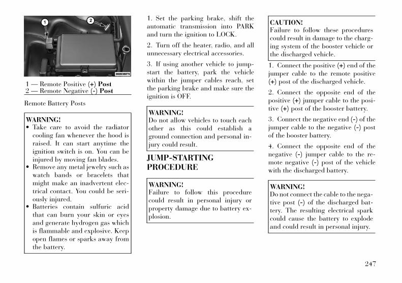
Remote Battery Posts
WARNING!• Take care to avoid the radiator
cooling fan whenever the hood israised. It can start anytime theignition switch is on. You can beinjured by moving fan blades.
• Remove any metal jewelry such aswatch bands or bracelets thatmight make an inadvertent elec-trical contact. You could be seri-ously injured.
• Batteries contain sulfuric acidthat can burn your skin or eyesand generate hydrogen gas whichis flammable and explosive. Keepopen flames or sparks away fromthe battery.
1. Set the parking brake, shift theautomatic transmission into PARKand turn the ignition to LOCK.
2. Turn off the heater, radio, and allunnecessary electrical accessories.
3. If using another vehicle to jump-start the battery, park the vehiclewithin the jumper cables reach, setthe parking brake and make sure theignition is OFF.
WARNING!Do not allow vehicles to touch eachother as this could establish aground connection and personal in-jury could result.
JUMP-STARTINGPROCEDURE
WARNING!Failure to follow this procedurecould result in personal injury orproperty damage due to battery ex-plosion.
CAUTION!Failure to follow these procedurescould result in damage to the charg-ing system of the booster vehicle orthe discharged vehicle.
1. Connect the positive (+) end of thejumper cable to the remote positive(+) post of the discharged vehicle.
2. Connect the opposite end of thepositive (+) jumper cable to the posi-tive (+) post of the booster battery.
3. Connect the negative end (-) of thejumper cable to the negative (-) postof the booster battery.
4. Connect the opposite end of thenegative (-) jumper cable to the re-mote negative (-) post of the vehiclewith the discharged battery.
WARNING!Do not connect the cable to the nega-tive post (-) of the discharged bat-tery. The resulting electrical sparkcould cause the battery to explodeand could result in personal injury.
1 — Remote Positive (+) Post2 — Remote Negative (-) Post
247
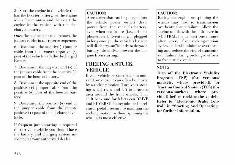
5. Start the engine in the vehicle thathas the booster battery, let the engineidle a few minutes, and then start theengine in the vehicle with the dis-charged battery.
Once the engine is started, remove thejumper cables in the reverse sequence:
6. Disconnect the negative (-) jumpercable from the remote negative (-)post of the vehicle with the dischargedbattery.
7. Disconnect the negative end (-) ofthe jumper cable from the negative (-)post of the booster battery.
8. Disconnect the opposite end of thepositive (+) jumper cable from thepositive (+) post of the booster bat-tery.
9. Disconnect the positive (+) end ofthe jumper cable from the remotepositive (+) post of the discharged ve-hicle.
If frequent jump-starting is requiredto start your vehicle you should havethe battery and charging system in-spected at your authorized dealer.
CAUTION!Accessories that can be plugged intothe vehicle power outlets drawpower from the vehicle’s battery,even when not in use (i.e., cellularphones, etc.). Eventually, if pluggedin long enough, the vehicle’s batterywill discharge sufficiently to degradebattery life and/or prevent the en-gine from starting.
FREEING A STUCKVEHICLEIf your vehicle becomes stuck in mud,sand, or snow, it can often be movedby a rocking motion. Turn your steer-ing wheel right and left to clear thearea around the front wheels. Thenshift back and forth between DRIVEand REVERSE. Using minimal accel-erator pedal pressure to maintain therocking motion, without spinning thewheels, is most effective.
CAUTION!Racing the engine or spinning thewheels may lead to transmissionoverheating and failure. Allow theengine to idle with the shift lever inNEUTRAL for at least one minuteafter every five rocking-motioncycles. This will minimize overheat-ing and reduce the risk of transmis-sion failure during prolonged effortsto free a stuck vehicle.
NOTE:
Turn off the Electronic StabilityProgram (ESP) (for versions/markets, where provided), orTraction Control System (TCS) (forversions/markets, where pro-vided) before rocking the vehicle.Refer to “Electronic Brake Con-trol” in “Starting And Operating”for further information.
248

CAUTION!• When “rocking” a stuck vehicle
by moving between DRIVE andREVERSE, do not spin the wheelsfaster than 24 km/h, or drivetraindamage may result.
• Revving the engine or spinningthe wheels too fast may lead totransmission overheating andfailure. It can also damage thetires. Do not spin the wheels above48 km/h while in gear (no trans-mission shifting occurring).
WARNING!Fast spinning tires can be danger-ous. Forces generated by excessivewheel speeds may cause damage, oreven failure, of the axle and tires. Atire could explode and injure some-one. Do not spin your vehicle'swheels faster than 48 km/h or forlonger than 30 seconds continuouslywithout stopping when you are stuckand do not let anyone near a spin-ning wheel, no matter what thespeed.
TOW EYESYour vehicle is equipped with toweyes, which are mounted in the frontand the rear.
CAUTION!Tow eyes are for emergency use only,to rescue a vehicle stranded off road.Do not use tow eyes for tow truckhookup or highway towing. Youcould damage your vehicle. Towstraps are recommended when tow-ing the vehicle; chains may causevehicle damage.
WARNING!Stand clear of vehicles when pullingwith tow eyes. Tow straps and chainsmay break, causing serious injury.
SHIFT LEVEROVERRIDE — 5 SPEEDTRANSMISSIONIf a malfunction occurs and the shiftlever cannot be moved out of thePARK position, you can use the fol-lowing procedure to temporarilymove the shift lever:
1. Firmly apply the parking brake.
2. Remove the rubber tray from thestorage bin located to the right of theshift lever. The override access port isnear the bottom of the bin to the rightof the shift lever gate.
3. Turn the ignition switch to the ON/RUN position without starting the en-gine (engine OFF).
4. Press and maintain firm pressureon the brake pedal.
5. Using a screwdriver or similar tool,press and hold the override tabthrough the access port on the centerconsole.
6. Move the shift lever to the NEU-TRAL position.
Shift Lever Override
249
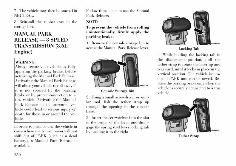
7. The vehicle may then be started inNEUTRAL.
8. Reinstall the rubber tray in thestorage bin.
MANUAL PARKRELEASE — 8 SPEEDTRANSMISSION (3.6LEngine)
WARNING!Always secure your vehicle by fullyapplying the parking brake, beforeactivating the Manual Park Release.Activating the Manual Park Releasewill allow your vehicle to roll away ifit is not secured by the parkingbrake or by proper connection to atow vehicle. Activating the ManualPark Release on an unsecured ve-hicle could lead to serious injury ordeath for those in or around the ve-hicle.
In order to push or tow the vehicle incases where the transmission will notshift out of PARK (such as a deadbattery), a Manual Park Release isavailable.
Follow these steps to use the ManualPark Release:
NOTE:
To prevent the vehicle from rollingunintentionally, firmly apply theparking brake.
1. Remove the console storage bin toaccess the Manual Park Release lever.
2. Using a small screwdriver or simi-lar tool, fish the tether strap upthrough the opening in the consolebase.
3. Insert the screwdriver into the slotin the center of the lever, and disen-gage the spring steel lever locking tabby pushing it to the right.
4. While holding the locking tab inthe disengaged position, pull thetether strap to rotate the lever up andrearward, until it locks in place in thevertical position. The vehicle is nowout of PARK and can be towed. Re-lease the parking brake only when thevehicle is securely connected to a towvehicle.Console Storage Bin
Locking Tab
Tether Strap
250
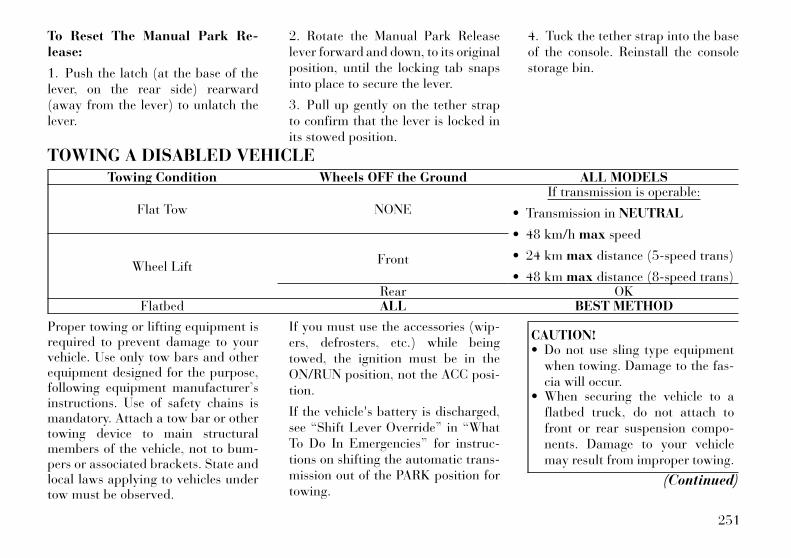
To Reset The Manual Park Re-lease:
1. Push the latch (at the base of thelever, on the rear side) rearward(away from the lever) to unlatch thelever.
2. Rotate the Manual Park Releaselever forward and down, to its originalposition, until the locking tab snapsinto place to secure the lever.
3. Pull up gently on the tether strapto confirm that the lever is locked inits stowed position.
4. Tuck the tether strap into the baseof the console. Reinstall the consolestorage bin.
TOWING A DISABLED VEHICLETowing Condition Wheels OFF the Ground ALL MODELS
Flat Tow NONE
If transmission is operable:
• Transmission in NEUTRAL
• 48 km/h max speed
• 24 km max distance (5-speed trans)
• 48 km max distance (8-speed trans)Wheel Lift
Front
Rear OKFlatbed ALL BEST METHOD
Proper towing or lifting equipment isrequired to prevent damage to yourvehicle. Use only tow bars and otherequipment designed for the purpose,following equipment manufacturer’sinstructions. Use of safety chains ismandatory. Attach a tow bar or othertowing device to main structuralmembers of the vehicle, not to bum-pers or associated brackets. State andlocal laws applying to vehicles undertow must be observed.
If you must use the accessories (wip-ers, defrosters, etc.) while beingtowed, the ignition must be in theON/RUN position, not the ACC posi-tion.
If the vehicle's battery is discharged,see “Shift Lever Override” in “WhatTo Do In Emergencies” for instruc-tions on shifting the automatic trans-mission out of the PARK position fortowing.
CAUTION!• Do not use sling type equipment
when towing. Damage to the fas-cia will occur.
• When securing the vehicle to aflatbed truck, do not attach tofront or rear suspension compo-nents. Damage to your vehiclemay result from improper towing.
(Continued)
251
CAUTION! (Continued)• Do not push or tow this vehicle
with another vehicle as damage tothe bumper fascia and transmis-sion may result.
• If the vehicle being towed requiressteering. the ignition switch mustbe in the ON/RUN position, notthe LOCK or ACC positions.
The manufacturer does not recom-mend that you tow this vehicle on atow dolly. Vehicle damage may occur.
The manufacturer recommends tow-ing your vehicle with all four wheelsOFF the ground using a flatbed.
If flatbed equipment is not available,and the transmission is operable, thevehicle may be flat towed (with allfour wheels on the ground) under thefollowing conditions:
• The shift lever must be in NEU-TRAL.
• The distance to be traveled mustnot exceed 24 km for 5-speedtransmission, or 48 km for 8-speedtransmission.
• The towing speed must not exceed48 km/h.
If the transmission is not operable, orthe vehicle must be towed faster than48 km/h or farther than 24 km for5-speed transmission, or 48 km for8-speed transmission, tow with therear wheels OFF the ground (on aflatbed, or with the rear wheels raisedusing a wheel lift and the transmissionin NEUTRAL).
CAUTION!Failure to follow these towing meth-ods can cause severe transmissiondamage. Such damage is not coveredby the New Vehicle Limited War-ranty.
Without The Ignition KeySpecial care must be taken when thevehicle is towed with the ignition inthe OFF position. The only approvedmethod of towing without the ignitionkey is with a flatbed truck. Propertowing equipment is necessary to pre-vent damage to the vehicle.
252

7
MAINTAINING YOUR VEHICLE• ENGINE COMPARTMENT — 3.6L . . . . . . . . . . . 255
• ENGINE COMPARTMENT — 3.0L DIESEL . . . . 256
• ONBOARD DIAGNOSTIC SYSTEM — OBD II . . . 257
• REPLACEMENT PARTS . . . . . . . . . . . . . . . . . . . 257
• MAINTENANCE PROCEDURES . . . . . . . . . . . . . 257
• ENGINE OIL – GASOLINE ENGINE . . . . . . . . 258
• ENGINE OIL – DIESEL ENGINE . . . . . . . . . . 259
• SYNTHETIC ENGINE OILS . . . . . . . . . . . . . . 259
• MATERIALS ADDED TO ENGINE OILS . . . . . 259
• DISPOSING OF USED ENGINE OIL ANDFILTERS . . . . . . . . . . . . . . . . . . . . . . . . . . . . 259
• ENGINE OIL FILTER . . . . . . . . . . . . . . . . . . . 259
• ENGINE AIR CLEANER FILTER . . . . . . . . . . 259
• MAINTENANCE-FREE BATTERY . . . . . . . . . 260
• AIR CONDITIONER MAINTENANCE . . . . . . . 261
• A/C AIR FILTER . . . . . . . . . . . . . . . . . . . . . . 261
• BODY LUBRICATION . . . . . . . . . . . . . . . . . . . 262
• WINDSHIELD WIPER BLADES . . . . . . . . . . . 263
• ADDING WASHER FLUID . . . . . . . . . . . . . . . 263
• INTERVENTION REGENERATIONSTRATEGY – 3.0L DIESEL ENGINE . . . . . . . 264
253

• EXHAUST SYSTEM . . . . . . . . . . . . . . . . . . . . 264
• COOLING SYSTEM . . . . . . . . . . . . . . . . . . . . 265
• BRAKE SYSTEM . . . . . . . . . . . . . . . . . . . . . . 268
• AUTOMATIC TRANSMISSION . . . . . . . . . . . . 270
• REAR AXLE . . . . . . . . . . . . . . . . . . . . . . . . . . 271
• APPEARANCE CARE AND PROTECTIONFROM CORROSION . . . . . . . . . . . . . . . . . . . . 271
• FUSES . . . . . . . . . . . . . . . . . . . . . . . . . . . . . . . . 274
• Integrated Power Module . . . . . . . . . . . . . . . . 274
• Rear Power Distribution Center . . . . . . . . . . . 276
• VEHICLE STORAGE . . . . . . . . . . . . . . . . . . . . . 279
• REPLACEMENT BULBS . . . . . . . . . . . . . . . . . . 280
• BULB REPLACEMENT . . . . . . . . . . . . . . . . . . . 281
• LOW BEAM HEADLAMP, HIGH BEAMHEADLAMP, PARK/TURN LAMP, INNERPARK LAMP, AND OUTER PARK LAMP . . . . 281
• FRONT TURN SIGNAL LAMPS . . . . . . . . . . . 282
• REAR TURN SIGNAL AND BACKUPLAMPS . . . . . . . . . . . . . . . . . . . . . . . . . . . . . 282
• LICENSE LAMP . . . . . . . . . . . . . . . . . . . . . . . 283
• FLUID CAPACITIES . . . . . . . . . . . . . . . . . . . . . . 283
• FLUIDS, LUBRICANTS, AND GENUINEPARTS . . . . . . . . . . . . . . . . . . . . . . . . . . . . . . . . 284
• ENGINE . . . . . . . . . . . . . . . . . . . . . . . . . . . . . 284
• CHASSIS . . . . . . . . . . . . . . . . . . . . . . . . . . . . 285
254

ENGINE COMPARTMENT — 3.6L
1 — Integrated Power Module (Fuses) 5 — Air Cleaner Filter2 — Engine Oil Dipstick 6 — Engine Oil Fill3 — Brake Fluid Reservoir Access Cover 7 — Remote Jump Start (Positive Battery Post)4 — Engine Coolant Reservoir 8 — Washer Fluid Reservoir
255
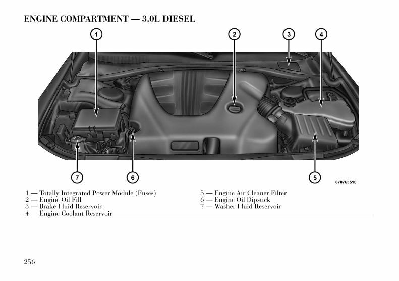
ENGINE COMPARTMENT — 3.0L DIESEL
1 — Totally Integrated Power Module (Fuses) 5 — Engine Air Cleaner Filter2 — Engine Oil Fill 6 — Engine Oil Dipstick3 — Brake Fluid Reservoir 7 — Washer Fluid Reservoir4 — Engine Coolant Reservoir
256
ONBOARD DIAGNOSTICSYSTEM — OBD IIYour vehicle is equipped with a so-phisticated onboard diagnostic sys-tem called OBD II. This system moni-tors the performance of the emissions,engine, and automatic transmissioncontrol systems. When these systemsare operating properly, your vehiclewill provide excellent performanceand fuel economy, as well as engineemissions well within current govern-ment regulations.
If any of these systems require service,the OBD II system will turn on the“Malfunction Indicator Light (MIL).”It will also store diagnostic codes andother information to assist your ser-vice technician in making repairs. Al-though your vehicle will usually bedrivable and not need towing, seeyour authorized dealer for service assoon as possible.
CAUTION!• Prolonged driving with the MIL
on could cause further damage tothe emissions control system. Itcould also affect fuel economyand driveability. The vehicle mustbe serviced before any emissionstests can be performed.
• If the MIL is flashing while theengine is running, severe catalyticconverter damage and power losswill soon occur. Immediate serviceis required.
REPLACEMENT PARTSUse of genuine parts for normal/scheduled maintenance and repairs ishighly recommended to ensure the de-signed performance.
Damage or failures caused by the useof parts which are not quality-equivalent to genuine parts for main-tenance and repairs will not be cov-ered by the manufacturer’s warranty.
MAINTENANCEPROCEDURESThe pages that follow contain the re-quired maintenance services deter-mined by the engineers who designedyour vehicle.
Besides those maintenance itemsspecified in the fixed maintenanceschedule, there are other componentswhich may require servicing or re-placement in the future.
CAUTION!• Failure to properly maintain your
vehicle or perform repairs andservice when necessary could re-sult in more costly repairs, dam-age to other components or nega-tively impact vehicleperformance. Immediately havepotential malfunctions examinedby an authorized dealership orqualified repair center.
(Continued)
257
CAUTION! (Continued)• Car maintenance should be done
at a LANCIA Dealership. For rou-tine and minor maintenance op-erations you wish to carry outyourself, we do recommend youhave the proper equipment, genu-ine LANCIA spare parts and thenecessary fluids; do not howevercarry out these operations if youhave no experience.
• Your vehicle has been built withimproved fluids that protect theperformance and durability ofyour vehicle and also allow ex-tended maintenance intervals. Donot use chemical flushes in thesecomponents as the chemicals candamage your engine, transmis-sion, power steering or air condi-tioning. Such damage is not cov-ered by the New Vehicle LimitedWarranty. If a flush is needed be-cause of component malfunction,use only the specified fluid for theflushing procedure.
ENGINE OIL – GASOLINEENGINE
Checking Oil LevelTo assure proper lubrication of yourvehicle's engine, the engine oil mustbe maintained at the correct level.The best time to check the engine oillevel is about five minutes after a fullywarmed up engine is shut off or beforestarting the engine after it has satovernight.
Checking the oil while the vehicle ison level ground will improve the ac-curacy of the oil level readings. Main-tain the oil level in the SAFE levelrange. Adding 0.95 Liter of oil whenthe level is at the bottom of the SAFErange will result in the level being atthe top of the SAFE range.
CAUTION!Overfilling or underfilling thecrankcase will cause aeration or lossof oil pressure. This could damageyour engine.
CAUTION!Car maintenance should be done ata LANCIA Dealership. For routineand minor maintenance operationsyou wish to carry out yourself, we dorecommend you have the properequipment, genuine LANCIA spareparts and the necessary fluids; donot however carry out these opera-tions if you have no experience.
Change Engine OilRefer to the “Maintenance Schedule”for the proper maintenance intervals.
Engine Oil Selection – 3.6LEngineSAE Grade 5W-30 SELENIA KPOWER fully synthetic engine oil thatmeets FIAT Qualification 9.55535API SN, ILSAC GF-5 or equivalent.
The engine oil filler cap also shows therecommended engine oil viscosity foryour vehicle. For information on en-gine oil filler cap location, refer to“Engine Compartment” in “Main-taining Your Vehicle” for further in-formation.
258

ENGINE OIL – DIESELENGINE
Engine Oil Selection – 3.0LEngine
CAUTION!Car maintenance should be done ata LANCIA Dealership. For routineand minor maintenance operationsyou wish to carry out yourself, we dorecommend you have the properequipment, genuine LANCIA spareparts and the necessary fluids; donot however carry out these opera-tions if you have no experience.
SAE Grade 5W-30 SELENIA MUL-TIPOWER C3 fully synthetic engineoil that meets FIAT Qualification9.55535 API SM/CF, ACEA C3 orequivalent.
The engine oil filler cap also shows therecommended engine oil viscosity foryour engine. For information on en-gine oil filler cap location, refer to“Engine Compartment” in “Main-taining Your Vehicle” for further in-formation.
SYNTHETIC ENGINE OILSYou may use synthetic engine oils pro-vided the recommended oil qualityrequirements are met, and the recom-mended maintenance intervals for oiland filter changes are followed.
MATERIALS ADDED TOENGINE OILSDo not add supplemental materials,other than leak detection dyes, to theengine oil. Engine oil is an engineeredproduct, and its performance may beimpaired by supplemental additives.
DISPOSING OF USEDENGINE OIL AND FILTERSCare should be taken in disposing ofused engine oil and oil filters fromyour vehicle. Used oil and oil filters,indiscriminately discarded, can pres-ent a problem to the environment.Contact your local authorized dealer,service station, or governmentalagency for advice on how and whereused oil and oil filters can be safelydiscarded in your area.
ENGINE OIL FILTERThe engine oil filter should be re-placed with a new filter at every oilchange.
Engine Oil Filter SelectionThe manufacturer's engines have afull-flow type disposable oil filter. Usea filter of this type for replacement.The quality of replacement filters var-ies considerably. Only high-qualityfilters should be used to assure mostefficient service. LANCIA engine oilfilters are high-quality oil filters andare recommended.
ENGINE AIR CLEANERFILTERRefer to the “Maintenance Schedule”for the proper maintenance intervals.
259
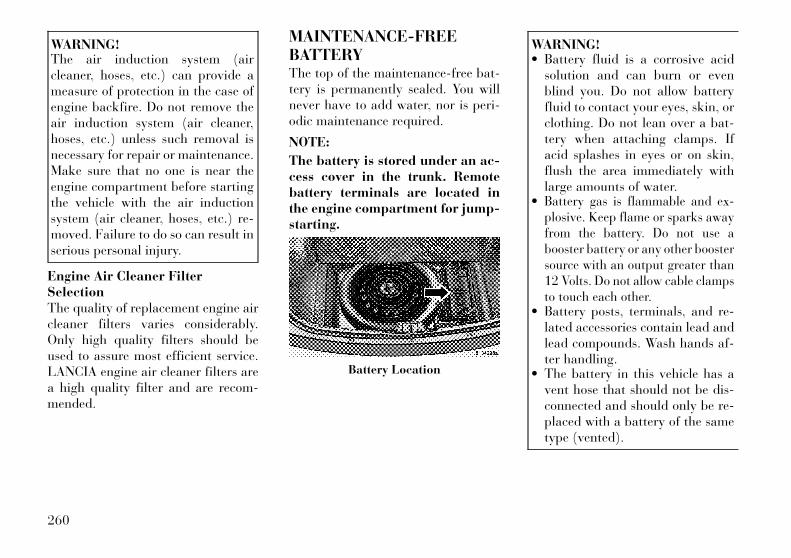
WARNING!The air induction system (aircleaner, hoses, etc.) can provide ameasure of protection in the case ofengine backfire. Do not remove theair induction system (air cleaner,hoses, etc.) unless such removal isnecessary for repair or maintenance.Make sure that no one is near theengine compartment before startingthe vehicle with the air inductionsystem (air cleaner, hoses, etc.) re-moved. Failure to do so can result inserious personal injury.
Engine Air Cleaner FilterSelectionThe quality of replacement engine aircleaner filters varies considerably.Only high quality filters should beused to assure most efficient service.LANCIA engine air cleaner filters area high quality filter and are recom-mended.
MAINTENANCE-FREEBATTERYThe top of the maintenance-free bat-tery is permanently sealed. You willnever have to add water, nor is peri-odic maintenance required.
NOTE:
The battery is stored under an ac-cess cover in the trunk. Remotebattery terminals are located inthe engine compartment for jump-starting.
WARNING!• Battery fluid is a corrosive acid
solution and can burn or evenblind you. Do not allow batteryfluid to contact your eyes, skin, orclothing. Do not lean over a bat-tery when attaching clamps. Ifacid splashes in eyes or on skin,flush the area immediately withlarge amounts of water.
• Battery gas is flammable and ex-plosive. Keep flame or sparks awayfrom the battery. Do not use abooster battery or any other boostersource with an output greater than12 Volts. Do not allow cable clampsto touch each other.
• Battery posts, terminals, and re-lated accessories contain lead andlead compounds. Wash hands af-ter handling.
• The battery in this vehicle has avent hose that should not be dis-connected and should only be re-placed with a battery of the sametype (vented).
Battery Location
260
CAUTION!• It is essential when replacing the
cables on the battery that thepositive cable is attached to thepositive post and the negativecable is attached to the negativepost. Battery posts are markedpositive (+) and negative (-) andare identified on the battery case.Cable clamps should be tight onthe terminal posts and free of cor-rosion.
• If a “fast charger” is used whilethe battery is in the vehicle, dis-connect both vehicle batterycables before connecting the char-ger to the battery. Do not use a“fast charger” to provide startingvoltage.
AIR CONDITIONERMAINTENANCEFor best possible performance, yourair conditioner should be checked andserviced by an authorized dealer atthe start of each warm season. Thisservice should include cleaning of thecondenser fins and a performance
test. Drive belt tension should also bechecked at this time.
CAUTION!Do not use chemical flushes in yourair conditioning system as thechemicals can damage your air con-ditioning components. Such damageis not covered by the New VehicleLimited Warranty.
WARNING!• Use only refrigerants and com-
pressor lubricants approved bythe manufacturer for your air con-ditioning system. Some unap-proved refrigerants are flammableand can explode, injuring you.Other unapproved refrigerants orlubricants can cause the system tofail, requiring costly repairs.
• The air conditioning system con-tains refrigerant under high pres-sure. To avoid risk of personal in-jury or damage to the system,adding refrigerant or any repairrequiring lines to be disconnectedshould be done by an experiencedtechnician.
Refrigerant Recovery AndRecyclingR-134a Air Conditioning Refrigerantis a hydrofluorocarbon (HFC) that isendorsed by the Environmental Pro-tection Agency and is an ozone-savingproduct. However, the manufacturerrecommends that air conditioningservice be performed by authorizeddealers or other service facilities usingrecovery and recycling equipment.
NOTE:
Use only manufacturer approvedA/C system sealers, stop leak prod-ucts, seal conditioners, compres-sor oil, and refrigerants.
A/C AIR FILTER
CAUTION!Car maintenance should be done ata LANCIA Dealership. For routineand minor maintenance operationsyou wish to carry out yourself, we dorecommend you have the properequipment, genuine LANCIA spareparts and the necessary fluids; donot however carry out these opera-tions if you have no experience.
261
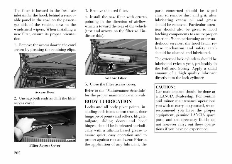
The filter is located in the fresh airinlet under the hood, behind a remov-able panel in the cowl on the passen-ger side of the vehicle, next to thewindshield wipers. When installing anew filter, ensure its proper orienta-tion.
1. Remove the access door in the cowlscreen by pressing the retaining clips.
2. Unsnap both ends and lift the filteraccess cover.
3. Remove the used filter.
4. Install the new filter with arrowspointing in the direction of airflow,which is toward the rear of the vehicle(text and arrows on the filter will in-dicate this).
5. Close the filter access cover.
Refer to the “Maintenance Schedule”for the proper maintenance intervals.
BODY LUBRICATIONLocks and all body pivot points, in-cluding such items as seat tracks, doorhinge pivot points and rollers, liftgate,tailgate, sliding doors and hoodhinges, should be lubricated periodi-cally with a lithium based grease toassure quiet, easy operation and toprotect against rust and wear. Prior tothe application of any lubricant, the
parts concerned should be wipedclean to remove dust and grit; afterlubricating excess oil and greaseshould be removed. Particular atten-tion should also be given to hoodlatching components to ensure properfunction. When performing other un-derhood services, the hood latch, re-lease mechanism and safety catchshould be cleaned and lubricated.
The external lock cylinders should belubricated twice a year, preferably inthe Fall and Spring. Apply a smallamount of a high quality lubricantdirectly into the lock cylinder.
CAUTION!Car maintenance should be done ata LANCIA Dealership. For routineand minor maintenance operationsyou wish to carry out yourself, we dorecommend you have the properequipment, genuine LANCIA spareparts and the necessary fluids; donot however carry out these opera-tions if you have no experience.
Access Door
Filter Access Cover
A/C Air Filter
262

WINDSHIELD WIPERBLADESClean the rubber edges of the wiperblades and the windshield periodi-cally with a sponge or soft cloth and amild nonabrasive cleaner. This willremove accumulations of salt or roadfilm.
Operation of the wipers on dry glassfor long periods may cause deteriora-tion of the wiper blades. Always usewasher fluid when using the wipers toremove salt or dirt from a dry wind-shield.
Avoid using the wiper blades to re-move frost or ice from the windshield.Keep the blade rubber out of contactwith petroleum products such as en-gine oil, gasoline, etc.
NOTE:
Life expectancy of wiper bladesvaries depending on geographicalarea and frequency of use. Poorperformance of blades may bepresent with chattering, marks,water lines or wet spots. If any of
these conditions are present, cleanthe wiper blades or replace as nec-essary.
ADDING WASHER FLUIDThe windshield washer and the head-light washer (for versions/markets,where provided) share the same fluidreservoir. The fluid reservoir is lo-cated in the front of the engine com-partment. Be sure to check the fluidlevel in the reservoir at regular inter-vals. Fill the reservoir with windshieldwasher solvent (not radiator anti-freeze) and operate the system for afew seconds to flush out the residualwater.
When refilling the washer fluid reser-voir, apply some washer fluid to acloth or towel and wipe the wiperblades clean. This will help blade per-formance.
To prevent freeze-up of your wind-shield washer system in cold weather,select a solution or mixture that meetsor exceeds the temperature range ofyour climate. This rating informationcan be found on most washer fluidcontainers.
The fluid reservoir will hold nearly4 Liters of washer fluid when the mes-sage “Low Washer Fluid” appears inthe Electronic Vehicle InformationCenter (EVIC) (for versions/markets,where provided).
WARNING!Commercially available windshieldwasher solvents are flammable.They could ignite and burn you.Care must be exercised when fillingor working around the washer solu-tion.
CAUTION!Car maintenance should be done ata LANCIA Dealership. For routineand minor maintenance operationsyou wish to carry out yourself, we dorecommend you have the properequipment, genuine LANCIA spareparts and the necessary fluids; donot however carry out these opera-tions if you have no experience.
263
INTERVENTIONREGENERATIONSTRATEGY – 3.0L DIESELENGINEThis vehicle is equipped with a state-of-the-art engine and exhaust systemcontaining a diesel particulate filter.The engine and exhaust after-treatment system work together tomeet the Emission standards. Thesystem manages engine combustion toallow the exhaust system’s catalyst totrap and burn Particulate Matter(PM) pollutants with no input or in-teraction on your part.
Refer to “Electronic Vehicle Informa-tion Center (EVIC)” in “Understand-ing Your Instrument Cluster” for fur-ther information.
EXHAUST SYSTEMThe best protection against carbonmonoxide entry into the vehicle bodyis a properly maintained engine ex-haust system.
Whenever a change is noticed in thesound of the exhaust system, whenexhaust fumes can be detected insidethe vehicle, or when the underside or
rear of the vehicle is damaged, have acompetent mechanic inspect the com-plete exhaust system and adjacentbody areas for broken, damaged, de-teriorated, or mispositioned parts.Open seams or loose connectionscould permit exhaust fumes to seepinto the passenger compartment. Inaddition, have the exhaust system in-spected each time the vehicle is raisedfor lubrication or oil change. Replaceas required.
WARNING!Exhaust gases can injure or kill.They contain carbon monoxide(CO), which is colorless and odor-less. Breathing it can make you un-conscious and can eventually poisonyou. To avoid breathing CO, refer to“Safety Tips/Exhaust Gas” in“Things To Do Before Starting YourVehicle” for further information.
CAUTION!The catalytic converter requires theuse of unleaded fuel only. Leadedgasoline will destroy the effective-ness of the catalyst as an emissionscontrol device and may seriously re-duce engine performance and causeserious damage to the engine.
Under normal operating conditions,the catalytic converter will not requiremaintenance. However, it is impor-tant to keep the engine properly tunedto assure proper catalyst operationand prevent possible catalyst damage.
CAUTION!Damage to the catalytic convertercan result if your vehicle is not keptin proper operating condition. In theevent of engine malfunction, par-ticularly involving engine misfire orother apparent loss of performance,have your vehicle serviced promptly.Continued operation of your vehiclewith a severe malfunction couldcause the converter to overheat, re-sulting in possible damage to theconverter and the vehicle.
264
NOTE:
Intentional tampering with emis-sions control systems can result incivil penalties being assessedagainst you.
WARNING!A hot exhaust system can start a fireif you park over materials that canburn. Such materials might be grassor leaves coming into contact withyour exhaust system. Do not park oroperate your vehicle in areas whereyour exhaust system can contactanything that can burn.
In unusual situations involvinggrossly malfunctioning engine opera-tion, a scorching odor may indicatesevere and abnormal catalyst over-heating. If this should occur, safelybring the vehicle to a complete stop,shut the engine OFF, and allow thevehicle to cool. Thereafter, obtain ser-vice, including a tune-up to manufac-turer's specifications immediately.
To minimize the possibility of catalystdamage:
• Do not shut off the engine or inter-rupt the ignition when the trans-mission is in gear and the vehicle isin motion.
• Do not try to start the engine bypushing or towing the vehicle.
• Do not idle the engine with anyspark plug wires disconnected orremoved, such as when diagnostictesting, or for prolonged periodsduring very rough idling or mal-functioning operating conditions.
COOLING SYSTEM
WARNING!• When working near the radiator
cooling fan, disconnect the fanmotor lead or turn the ignitionswitch to the LOCK position . Thefan is temperature controlled andcan start at any time the ignitionswitch is in the ON position.
(Continued)
WARNING! (Continued)• You or others can be badly burned
by hot engine coolant (antifreeze)or steam from your radiator. Ifyou see or hear steam comingfrom under the hood, do not openthe hood until the radiator hashad time to cool. Never try to opena cooling system pressure capwhen the radiator is hot.
CAUTION!Car maintenance should be done ata LANCIA Dealership. For routineand minor maintenance operationsyou wish to carry out yourself, we dorecommend you have the properequipment, genuine LANCIA spareparts and the necessary fluids; donot however carry out these opera-tions if you have no experience.
Coolant ChecksCheck engine coolant (antifreeze)protection every 12 months (beforethe onset of freezing weather, whereapplicable). If the engine coolant (an-tifreeze) is dirty or rusty in appear-ance, the system should be drained,
265
flushed, and refilled with fresh cool-ant. Check the front of the A/C con-denser for any accumulation of bugs,leaves, etc. If dirty, clean by gentlyspraying water from a garden hosevertically down the face of the con-denser.
Check the coolant recovery bottletubing for brittle rubber, cracking,tears, cuts, and tightness of the con-nection at the bottle and radiator. In-spect the entire system for leaks.
With the engine at normal operatingtemperature (but not running), checkthe cooling system pressure cap forproper vacuum sealing by draining asmall amount of engine coolant (anti-freeze) from the radiator drain cock.If the cap is sealing properly, the en-gine coolant (antifreeze) will begin todrain from the coolant recoverybottle. DO NOT REMOVE THECOOLANT PRESSURE CAP WHENTHE COOLING SYSTEM IS HOT.
Cooling System – Drain, Flush,And RefillIf the engine coolant (antifreeze) isdirty or contains a considerable
amount of sediment, clean and flushwith a reliable cooling system cleaner.Follow with a thorough rinsing to re-move all deposits and chemicals.Properly dispose of the old enginecoolant (antifreeze) solution.
Refer to the “Maintenance Schedule”for the proper maintenance intervals.
Selection Of CoolantUse only the manufacturer's recom-mended engine coolant (antifreeze).Refer to “Fluids, Lubricants, andGenuine Parts” in “Maintaining YourVehicle” for further information.
CAUTION!• Mixing of engine coolant (anti-
freeze) other than specified enginecoolant (antifreeze), may result inengine damage and may decreasecorrosion protection. If a non-specified engine coolant (anti-freeze) is introduced into the cool-ing system in an emergency, itshould be replaced with the speci-fied engine coolant (antifreeze) assoon as possible.
(Continued)
CAUTION! (Continued)• Do not use water alone or alcohol-
based engine coolant (antifreeze)products. Do not use additionalrust inhibitors or antirust prod-ucts, as they may not be compat-ible with the radiator engine cool-ant (antifreeze) and may plug theradiator.
• This vehicle has not been de-signed for use with propyleneglycol-based engine coolant (anti-freeze). Use of propylene glycol-based engine coolant (antifreeze)is not recommended.
Adding CoolantYour vehicle has been built with animproved engine coolant (antifreeze)that allows extended maintenance in-tervals. This engine coolant (anti-freeze) can be used up to five years or168 000 km before replacement. Toprevent reducing this extended main-tenance period, it is important thatyou use the same engine coolant (an-tifreeze) throughout the life of yourvehicle.
266

When adding engine coolant (anti-freeze):
Use only high purity water such asdistilled or deionized water whenmixing the water/engine coolant (an-tifreeze) solution. The use of lowerquality water will reduce the amountof corrosion protection in the enginecooling system.
Please note that it is the owner's re-sponsibility to maintain the properlevel of protection against freezing ac-cording to the temperatures occurringin the area where the vehicle is oper-ated.
NOTE:
Mixing engine coolant (antifreeze)types will decrease the life of theengine coolant (antifreeze) andwill require more frequent enginecoolant (antifreeze) changes.
Cooling System Pressure CapThe cap must be fully tightened toprevent loss of engine coolant (anti-freeze), and to ensure that enginecoolant (antifreeze) will return to theradiator from the coolant recoverybottle.
The cap should be inspected andcleaned if there is any accumulationof foreign material on the sealing sur-faces.
WARNING!• The warning words “DO NOT
OPEN HOT” on the cooling sys-tem pressure cap are a safety pre-caution. Never add engine coolant(antifreeze) when the engine isoverheated. Do not loosen or re-move the cap to cool an over-heated engine. Heat causes pres-sure to build up in the coolingsystem. To prevent scalding or in-jury, do not remove the pressurecap while the system is hot or un-der pressure.
• Do not use a pressure cap otherthan the one specified for yourvehicle. Personal injury or enginedamage may result.
Disposal Of Used CoolantUsed ethylene glycol-based enginecoolant (antifreeze) is a regulatedsubstance requiring proper disposal.Check with your local authorities todetermine the disposal rules for your
community. To prevent ingestion byanimals or children, do not store eth-ylene glycol-based engine coolant(antifreeze) in open containers or al-low it to remain in puddles on theground. If ingested by a child or pet,seek emergency assistance immedi-ately. Clean up any ground spills im-mediately.
Coolant LevelThe coolant bottle provides a quickvisual method for determining thatthe coolant level is adequate. With theengine OFF and cold, the level of thecoolant in the bottle should be be-tween the ranges indicated on thebottle.
The radiator normally remains com-pletely full, so there is no need toremove the radiator cap unless check-ing for engine coolant (antifreeze)freeze point or replacing engine cool-ant (antifreeze). Advise your serviceattendant of this. As long as the en-gine operating temperature is satis-factory, the coolant bottle need onlybe checked once a month.
267
When additional engine coolant (an-tifreeze) is needed to maintain theproper level, it should be added to thecoolant bottle. Do not overfill.
Points To Remember
NOTE:
When the vehicle is stopped after afew kilometers of operation, youmay observe vapor coming fromthe front of the engine compart-ment. This is normally a result ofmoisture from rain, or high hu-midity accumulating on the radia-tor and being vaporized when thethermostat opens, allowing hot en-gine coolant (antifreeze) to enterthe radiator.
If an examination of your engine com-partment shows no evidence of radia-tor or hose leaks, the vehicle may besafely driven. The vapor will soon dis-sipate.
• Do not overfill the coolant recoverybottle.
• Check engine coolant (antifreeze)freeze point in the radiator and inthe coolant recovery bottle. If en-gine coolant (antifreeze) needs to
be added, contents of coolant re-covery bottle must also be pro-tected against freezing.
• If frequent engine coolant (anti-freeze) additions are required, or ifthe level in the coolant recoverybottle does not drop when the en-gine cools, the cooling systemshould be pressure tested for leaks.
• Maintain engine coolant (anti-freeze) concentration at 50% en-gine coolant (antifreeze) (mini-mum) and distilled water forproper corrosion protection of yourengine, which contains aluminumcomponents.
• Make sure that the radiator andcoolant recovery bottle overflowhoses are not kinked or obstructed.
• Keep the front of the radiator clean.If your vehicle is equipped with airconditioning, keep the front of thecondenser clean.
• Do not change the thermostat forSummer or Winter operation. If re-placement is ever necessary, installONLY the correct type thermostat.Other designs may result in unsat-
isfactory engine coolant (anti-freeze) performance, poor gas mile-age, and increased emissions.
BRAKE SYSTEMIn order to assure brake system per-formance, all brake system compo-nents should be inspected periodi-cally. Refer to the “MaintenanceSchedule” for the proper maintenanceintervals.
WARNING!Riding the brakes can lead to brakefailure and possibly an accident.Driving with your foot resting or rid-ing on the brake pedal can result inabnormally high brake tempera-tures, excessive lining wear, and pos-sible brake damage. You would nothave your full braking capacity in anemergency.
268
CAUTION!Car maintenance should be done ata LANCIA Dealership. For routineand minor maintenance operationsyou wish to carry out yourself, we dorecommend you have the properequipment, genuine LANCIA spareparts and the necessary fluids; donot however carry out these opera-tions if you have no experience.
Master Cylinder – Brake FluidLevel CheckCheck the fluid level in the mastercylinder immediately if the brake sys-tem warning light indicates systemfailure.
Check the fluid level in the mastercylinder when performing underhoodservices.
Clean the top of the master cylinderarea before removing the cap. Addfluid to bring the level up to the“MAX” mark on the side of the mastercylinder reservoir.
Add enough fluid to bring the level upto the requirements described on thebrake fluid reservoir. With disc
brakes, fluid level can be expected tofall as the brake pads wear. However,low fluid level may be caused by aleak and a checkup may be needed.
Use only manufacturer's recom-mended brake fluid. Refer to “Fluids,Lubricants, and Genuine Parts” in“Maintaining Your Vehicle” for fur-ther information.
WARNING!• Use only manufacturer's recom-
mended brake fluid. Refer to“Fluids, Lubricants, and GenuineParts” in “Maintaining Your Ve-hicle” for further information. Us-ing the wrong type of brake fluidcan severely damage your brakesystem and/or impair its perfor-mance. The proper type of brakefluid for your vehicle is also iden-tified on the original factory in-stalled hydraulic master cylinderreservoir.
(Continued)
WARNING! (Continued)• To avoid contamination from for-
eign matter or moisture, use onlynew brake fluid or fluid that hasbeen in a tightly closed container.Keep the master cylinder reservoircap secured at all times. Brakefluid in a open container absorbsmoisture from the air resulting ina lower boiling point. This maycause it to boil unexpectedly dur-ing hard or prolonged braking,resulting in sudden brake failure.This could result in a accident.
• Overfilling the brake fluid reser-voir can result in spilling brakefluid on hot engine parts, causingthe brake fluid to catch fire. Brakefluid can also damage painted andvinyl surfaces, care should betaken to avoid its contact withthese surfaces.
• Do not allow petroleum basedfluid to contaminate the brakefluid. Brake seal componentscould be damaged, causing partialor complete brake failure. Thiscould result in an accident.
269
AUTOMATICTRANSMISSION
Selection Of LubricantIt is important that the proper lubri-cant is used in the transmission toassure optimum transmission perfor-mance. Use only manufacturer’s rec-ommended transmission fluid. Referto “Fluids, Lubricants, and GenuineParts” in “Maintaining Your Vehicle”for further information. It is impor-tant that the transmission fluid bemaintained at the prescribed level us-ing the recommended fluid. Nochemical flushes should be used inany transmission; only the approvedlubricant may be used.
Special AdditivesAutomatic Transmission Fluid (ATF)is an engineered product and its per-formance may be impaired by supple-mental additives. Therefore, do notadd any fluid additives to the trans-mission. The only exception to thispolicy is the use of special dyes to aidin detecting fluid leaks. In addition,avoid using transmission sealers asthey may adversely affect seals.
CAUTION!Do not use chemical flushes in yourtransmission as the chemicals candamage your transmission compo-nents. Such damage is not coveredby the New Vehicle Limited War-ranty.
Fluid Level CheckRegular automatic transmission fluidlevel checks are not required. For thisreason, the dipstick is omitted.
If you notice fluid loss or transmissionmalfunction, have your authorizeddealer check the transmission fluidlevel.
CAUTION!• Using a transmission fluid other
than the manufacturer's recom-mended fluid may cause deterio-ration in transmission shift qual-ity and/or torque convertershudder. Using a transmissionfluid other than that recom-mended by the manufacturer willrequire more frequent fluid andfilter changes. Refer to “Fluids,Lubricants, and Genuine Parts”in “Maintaining Your Vehicle” forfurther information.
• The fluid level is preset at thefactory and it does not requireadjustment under normal operat-ing conditions. If a transmissionfluid leak occurs, visit your autho-rized dealer immediately. Severedamage to the transmission mayoccur. Your authorized dealer hasthe proper tools to adjust the fluidlevel accurately.
270

Fluid And Filter ChangesRefer to the “Maintenance Schedule”for the proper maintenance intervals.
If the transmission is disassembled forany reason, the fluid and filter shouldbe changed.
CAUTION!Car maintenance should be done ata LANCIA Dealership. For routineand minor maintenance operationsyou wish to carry out yourself, we dorecommend you have the properequipment, genuine LANCIA spareparts and the necessary fluids; donot however carry out these opera-tions if you have no experience.
REAR AXLEFor normal service, periodic fluidlevel checks are not required. Whenthe vehicle is serviced for other rea-sons the exterior surfaces of the axleassembly should be inspected. If gearoil leakage is suspected inspect thefluid level. Refer to “Fluids, Lubri-cants, and Genuine Parts” in “Main-taining Your Vehicle” for further in-formation.
Fluid Level CheckCheck the fluid level by removing thefill plug on the axle. The fluid levelshould be at the bottom of the fillhole. Add fluid, if necessary, to main-tain the proper level. Refer to “Fluids,Lubricants, and Genuine Parts” in“Maintaining Your Vehicle” for fur-ther information.
Change Axle FluidRefer to the “Maintenance Schedule”for the proper maintenance intervals.
APPEARANCE CARE ANDPROTECTION FROMCORROSION
Protection Of Body And PaintFrom CorrosionVehicle body care requirements varyaccording to geographic locations andusage. Chemicals that are sprayed ontrees and road surfaces during otherseasons, are highly corrosive to themetal in your vehicle. Outside park-ing, which exposes your vehicle to air-borne contaminants, road surfaces onwhich the vehicle is operated, extremehot or cold weather and other extreme
conditions will have an adverse effecton paint, metal trim, and underbodyprotection.
The following maintenance recom-mendations will enable you to obtainmaximum benefit from the corrosionresistance built into your vehicle.
What Causes Corrosion?Corrosion is the result of deteriorationor removal of paint and protectivecoatings from your vehicle.
The most common causes are:
• Road salt, dirt, and moisture accu-mulation.
• Stone and gravel impact.
• Insects, tree sap, and tar.
• Salt in the air near seacoast locali-ties.
• Atmospheric fallout/industrial pol-lutants.
Washing
• Wash your vehicle regularly. Al-ways wash your vehicle in the shadeusing a mild car wash soap, andrinse the panels completely withclear water.
271
• Use a high quality cleaner wax toremove road film, stains and to pro-tect your paint finish. Take carenever to scratch the paint.
• Avoid using abrasive compoundsand power buffing that may dimin-ish the gloss or thin out the paintfinish.
CAUTION!Do not use abrasive or strong clean-ing materials such as steel wool orscouring powder that will scratchmetal and painted surfaces.
Special Care
• If you drive on salted or dusty roadsor if you drive near the ocean, hoseoff the undercarriage at least once amonth.
• It is important that the drain holesin the lower edges of the doors,rocker panels, and trunk be keptclear and open.
• If you detect any stone chips orscratches in the paint, touch themup immediately. The cost of suchrepairs is considered the responsi-bility of the owner.
• If your vehicle is damaged due to anaccident or similar cause, which de-stroys the paint and protectivecoating, have your vehicle repairedas soon as possible. The cost of suchrepairs is considered the responsi-bility of the owner.
• If you carry special cargo such aschemicals, fertilizers, de-icer salt,etc., be sure that such materials arewell packaged and sealed.
• If a lot of driving is done on gravelroads, consider mud or stoneshields behind each wheel.
• Use Touch Up Paint or equivalenton scratches as soon as possible.Your authorized dealer has touchup paint to match the color of yourvehicle.
Wheel And Wheel Trim CareAll wheels and wheel trim, especiallyaluminum and chrome-plated wheelsshould be cleaned regularly with amild soap and water to prevent corro-sion. To remove heavy soil and/or ex-cessive brake dust, use a nonabrasive,non-acidic cleaner. Do not use scour-ing pads, steel wool, a bristle brush, or
metal polishes. Do not use ovencleaner. Avoid automatic car washesthat use acidic solutions or harshbrushes that may damage the wheels’protective finish.
Stain Repel Fabric CleaningProcedure (for versions/markets,where provided)Stain Repel seats may be cleaned inthe following manner:
• Remove as much of the stain aspossible by blotting with a clean,dry towel.
• Blot any remaining stain with aclean, damp towel.
• For tough stains, apply a mild soapsolution to a clean, damp cloth andremove the stain. Use a fresh, damptowel to remove soap residue.
• Do not use any harsh solvents orany other form of protectants onStain Repel products.
Interior CareInterior trim should be cleaned start-ing with a damp cloth. Do not useharsh cleaners.
272
Your leather upholstery can be bestpreserved by regular cleaning with adamp soft cloth. Small particles ofdirt can act as an abrasive and dam-age the leather upholstery and shouldbe removed promptly with a dampcloth. Stubborn soils can be removedeasily with a soft cloth and appropri-ate products. Care should be taken toavoid soaking your leather upholsterywith any liquid. Please do not usepolishes, oils, cleaning fluids, sol-vents, detergents, or ammonia-basedcleaners to clean your leather uphol-stery. Application of a leather condi-tioner is not required to maintain theoriginal condition.
WARNING!Do not use volatile solvents forcleaning purposes. Many are poten-tially flammable, and if used inclosed areas they may cause respira-tory harm.
Cleaning HeadlightsYour vehicle has plastic headlightsthat are lighter and less susceptible tostone breakage than glass headlights.
Plastic is not as scratch resistant asglass and therefore different lenscleaning procedures must be fol-lowed.
To minimize the possibility of scratch-ing the lenses and reducing light out-put, avoid wiping with a dry cloth. Toremove road dirt, wash with a mildsoap solution followed by rinsing.
Do not use abrasive cleaning compo-nents, solvents, steel wool or otheraggressive material to clean thelenses.
Glass SurfacesAll glass surfaces should be cleanedon a regular basis with any commer-cial household-type glass cleaner.Never use an abrasive type cleaner.Use caution when cleaning the insiderear window equipped with electricdefrosters or the right rear quarterwindow equipped with the radio an-
tenna. Do not use scrapers or othersharp instrument that may scratchthe elements.
When cleaning the rear view mirror,spray cleaner on the towel or rag thatyou are using. Do not spray cleanerdirectly on the mirror.
Cleaning Plastic InstrumentCluster LensesThe lenses in front of the instrumentsin this vehicle are molded in clearplastic. When cleaning the lenses,care must be taken to avoid scratch-ing the plastic.
1. Clean with a wet soft rag or micro-fiber towel. A mild soap solution maybe used, but do not use high alcoholcontent or abrasive cleaners. If soap isused, wipe clean with a clean damprag.
2. Dry with a soft cloth.
273
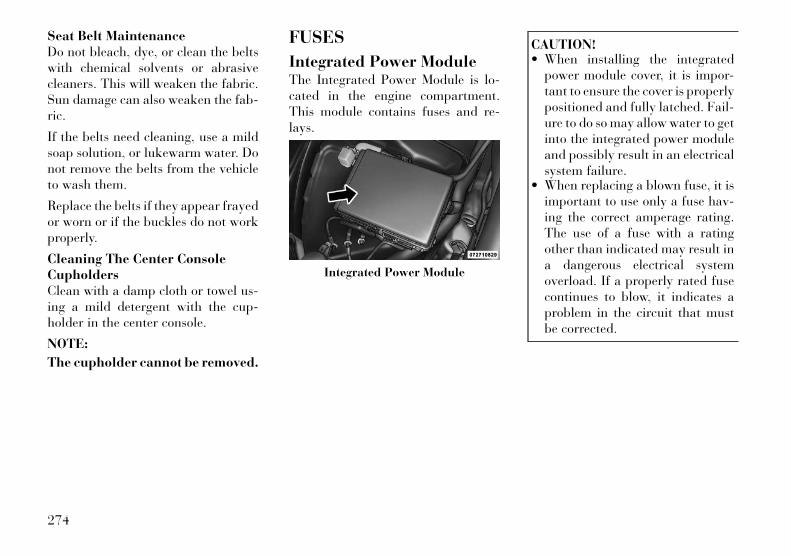
Seat Belt MaintenanceDo not bleach, dye, or clean the beltswith chemical solvents or abrasivecleaners. This will weaken the fabric.Sun damage can also weaken the fab-ric.
If the belts need cleaning, use a mildsoap solution, or lukewarm water. Donot remove the belts from the vehicleto wash them.
Replace the belts if they appear frayedor worn or if the buckles do not workproperly.
Cleaning The Center ConsoleCupholdersClean with a damp cloth or towel us-ing a mild detergent with the cup-holder in the center console.
NOTE:
The cupholder cannot be removed.
FUSES
Integrated Power ModuleThe Integrated Power Module is lo-cated in the engine compartment.This module contains fuses and re-lays.
CAUTION!• When installing the integrated
power module cover, it is impor-tant to ensure the cover is properlypositioned and fully latched. Fail-ure to do so may allow water to getinto the integrated power moduleand possibly result in an electricalsystem failure.
• When replacing a blown fuse, it isimportant to use only a fuse hav-ing the correct amperage rating.The use of a fuse with a ratingother than indicated may result ina dangerous electrical systemoverload. If a properly rated fusecontinues to blow, it indicates aproblem in the circuit that mustbe corrected.
Integrated Power Module
274
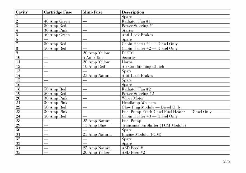
Cavity Cartridge Fuse Mini-Fuse Description1 — — Spare2 40 Amp Green — Radiator Fan #13 50 Amp Red — Power Steering #14 30 Amp Pink — Starter5 40 Amp Green — Anti-Lock Brakes6 — — Spare7 50 Amp Red — Cabin Heater #1 — Diesel Only8 50 Amp Red — Cabin Heater #2 — Diesel Only9 — 20 Amp Yellow DTCM10 — 5 Amp Tan Security11 — 20 Amp Yellow Horns12 — 10 Amp Red Air Conditioning Clutch13 — — Spare14 — 25 Amp Natural Anti-Lock Brakes15 — — Spare16 — — Spare18 50 Amp Red — Radiator Fan #219 50 Amp Red — Power Steering #220 30 Amp Pink — Wiper Motor21 30 Amp Pink — Headlamp Washers22 50 Amp Red — Glow Plug Module — Diesel Only23 30 Amp Pink — Fuel Pump Feed/Diesel Fuel Heater — Diesel Only24 50 Amp Red — Cabin Heater #3 — Diesel Only28 — 25 Amp Natural Fuel Pump29 — 15 Amp Blue Transmission/Shifter (TCM Module)30 — — Spare31 — 25 Amp Natural Engine Module (PCM)32 — — Spare33 — — Spare34 — 25 Amp Natural ASD Feed #135 — 20 Amp Yellow ASD Feed #2
275
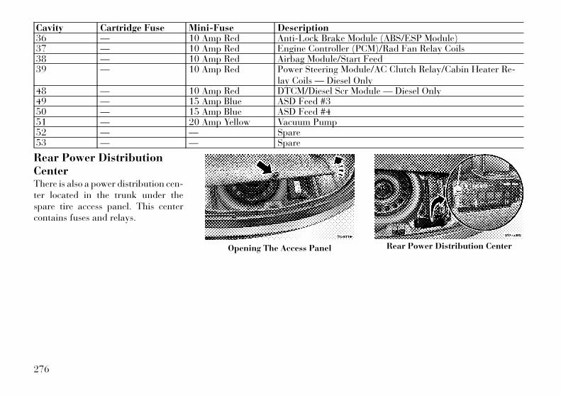
Cavity Cartridge Fuse Mini-Fuse Description36 — 10 Amp Red Anti-Lock Brake Module (ABS/ESP Module)37 — 10 Amp Red Engine Controller (PCM)/Rad Fan Relay Coils38 — 10 Amp Red Airbag Module/Start Feed39 — 10 Amp Red Power Steering Module/AC Clutch Relay/Cabin Heater Re-
lay Coils — Diesel Only48 — 10 Amp Red DTCM/Diesel Scr Module — Diesel Only49 — 15 Amp Blue ASD Feed #350 — 15 Amp Blue ASD Feed #451 — 20 Amp Yellow Vacuum Pump52 — — Spare53 — — Spare
Rear Power DistributionCenterThere is also a power distribution cen-ter located in the trunk under thespare tire access panel. This centercontains fuses and relays.
Opening The Access Panel Rear Power Distribution Center
276

CAUTION!• When installing the power distri-
bution center cover, it is impor-tant to ensure the cover is properlypositioned and fully latched. Fail-ure to do so may allow water to getinto the power distribution centerand possibly result in an electricalsystem failure.
(Continued)
CAUTION! (Continued)• When replacing a blown fuse, it is
important to use only a fuse hav-ing the correct amperage rating.The use of a fuse with a ratingother than indicated may result ina dangerous electrical systemoverload. If a properly rated fusecontinues to blow, it indicates aproblem in the circuit that mustbe corrected.
Cavity Cartridge Fuse Mini-Fuse Description2 60 Amp Yellow — Front PDC Feed #13 — — Spare4 60 Amp Yellow — Front PDC Feed #25 30 Amp Pink — Sunroof6 40 Amp Green — Exterior Lighting #17 40 Amp Green — Exterior Lighting #28 30 Amp Pink — Interior Lighting/Washer Pump9 30 Amp Pink — Power Locks10 30 Amp Pink — Driver Door11 30 Amp Pink — Passenger Door12 — 20 Amp Yellow Selectable Power Outlet #115 40 Amp Green — HVAC Blower16 30 Amp Pink — Power Inverter — 250 Watt17 — — Spare18 — — Spare19 30 Amp Pink — Electric Brake
277
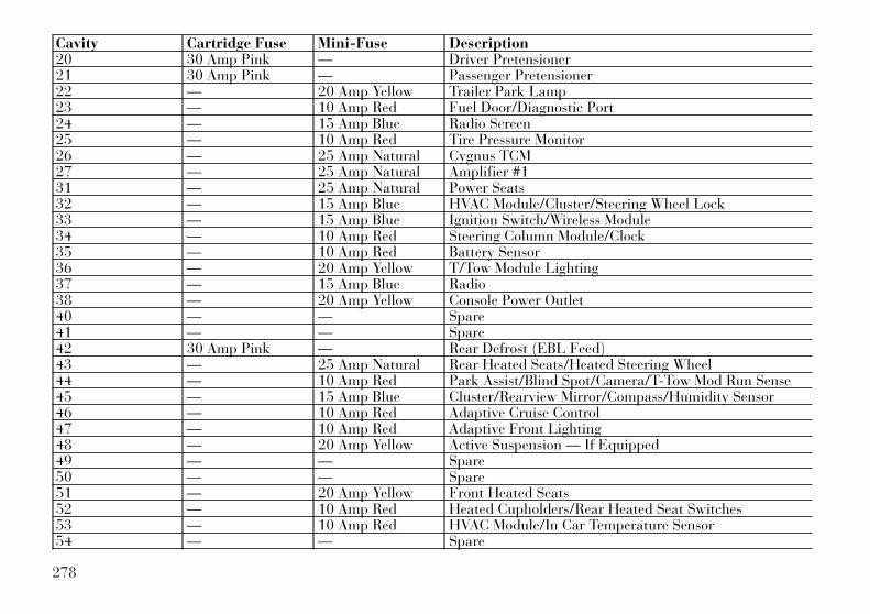
Cavity Cartridge Fuse Mini-Fuse Description20 30 Amp Pink — Driver Pretensioner21 30 Amp Pink — Passenger Pretensioner22 — 20 Amp Yellow Trailer Park Lamp23 — 10 Amp Red Fuel Door/Diagnostic Port24 — 15 Amp Blue Radio Screen25 — 10 Amp Red Tire Pressure Monitor26 — 25 Amp Natural Cygnus TCM27 — 25 Amp Natural Amplifier #131 — 25 Amp Natural Power Seats32 — 15 Amp Blue HVAC Module/Cluster/Steering Wheel Lock33 — 15 Amp Blue Ignition Switch/Wireless Module34 — 10 Amp Red Steering Column Module/Clock35 — 10 Amp Red Battery Sensor36 — 20 Amp Yellow T/Tow Module Lighting37 — 15 Amp Blue Radio38 — 20 Amp Yellow Console Power Outlet40 — — Spare41 — — Spare42 30 Amp Pink — Rear Defrost (EBL Feed)43 — 25 Amp Natural Rear Heated Seats/Heated Steering Wheel44 — 10 Amp Red Park Assist/Blind Spot/Camera/T-Tow Mod Run Sense45 — 15 Amp Blue Cluster/Rearview Mirror/Compass/Humidity Sensor46 — 10 Amp Red Adaptive Cruise Control47 — 10 Amp Red Adaptive Front Lighting48 — 20 Amp Yellow Active Suspension — If Equipped49 — — Spare50 — — Spare51 — 20 Amp Yellow Front Heated Seats52 — 10 Amp Red Heated Cupholders/Rear Heated Seat Switches53 — 10 Amp Red HVAC Module/In Car Temperature Sensor54 — — Spare
278
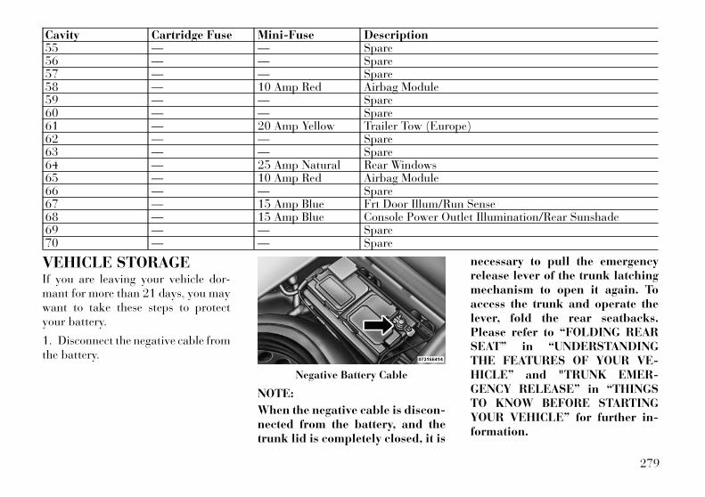
Cavity Cartridge Fuse Mini-Fuse Description55 — — Spare56 — — Spare57 — — Spare58 — 10 Amp Red Airbag Module59 — — Spare60 — — Spare61 — 20 Amp Yellow Trailer Tow (Europe)62 — — Spare63 — — Spare64 — 25 Amp Natural Rear Windows65 — 10 Amp Red Airbag Module66 — — Spare67 — 15 Amp Blue Frt Door Illum/Run Sense68 — 15 Amp Blue Console Power Outlet Illumination/Rear Sunshade69 — — Spare70 — — Spare
VEHICLE STORAGEIf you are leaving your vehicle dor-mant for more than 21 days, you maywant to take these steps to protectyour battery.
1. Disconnect the negative cable fromthe battery.
NOTE:
When the negative cable is discon-nected from the battery, and thetrunk lid is completely closed, it is
necessary to pull the emergencyrelease lever of the trunk latchingmechanism to open it again. Toaccess the trunk and operate thelever, fold the rear seatbacks.Please refer to “FOLDING REARSEAT” in “UNDERSTANDINGTHE FEATURES OF YOUR VE-HICLE” and "TRUNK EMER-GENCY RELEASE” in “THINGSTO KNOW BEFORE STARTINGYOUR VEHICLE” for further in-formation.
Negative Battery Cable
279

2. Anytime you store your vehicle, orkeep it out of service (i.e., vacation)for two weeks or more, run the airconditioning system at idle for aboutfive minutes in the fresh air and highblower setting. This will ensure ad-equate system lubrication to minimizethe possibility of compressor damagewhen the system is started again.
REPLACEMENT BULBS
Interior Bulb NumberRear Courtesy/ReadingLamps . . . . . . . . . . . . . . . . . W5WRear Compartment (Trunk)Lamp. . . . . . . . . . . . . . . . . . . 562Overhead Console ReadingLamps . . . . . . . . . . . . . . . . . . 578Visor Vanity Lamps . . . . . . . . . 194Glove Box Lamp (for versions/markets, where provided). . . . . 194Door Courtesy. . . . . . . . . . . . . 562Shift Indicator Lamp . . JKLE14140Optional Door Map Pocket/Cup-holder . . . . . . . . . . . . . . . . . . LED
(Serviced at Authorized Dealer)
NOTE:
For lighted switches, see your au-thorized dealer for replacementinstructions.
All of the interior bulbs are glasswedge base or glass cartridge types.Aluminum base bulbs are not ap-proved and should not be used forreplacement.
Exterior Bulb NumberLow Beam/High Beam (Bi-XenonHeadlamp). . . . . . . . . . . . . . . D3S
(Serviced at Authorized Dealer)Front Turn SignalLamp . . . . . . . . . . . . . PSY24WSVFront Park Lamp. . . . . . . . . . LED
(Serviced at Authorized Dealer)Daytime Running Lamp . . . . . LED
(Serviced at Authorized Dealer)Front Fog Lamp (for versions/markets, where provided) . . . . H11Front Position Lamp . . . . . . . LED
(Serviced at Authorized Dealer)Front Side Marker Lamp . . . . LED
(Serviced at Authorized Dealer)Side Repeater Lamps . . . . . . . LED
(Serviced at Authorized Dealer)
Rear Tail/Stop/Side MarkerLamp . . . . . . . . . . . . . . . . . . LED
(Serviced at Authorized Dealer)Rear Turn Signal Lamp. . . WY21WRear Fog Lamps . . . . . . . . . . LED
(Serviced at Authorized Dealer)Backup Lamp. . . . . . . . . . . W16WCenter High Mount Stop Lamp(CHMSL) . . . . . . . . . . . . . . . LED
(Serviced at Authorized Dealer)License . . . . . . . . . . . . . . . . W5W
280

BULB REPLACEMENT
LOW BEAM HEADLAMP,HIGH BEAM HEADLAMP,PARK/TURN LAMP, INNERPARK LAMP, AND OUTERPARK LAMP
High Intensity DischargeHeadlamps (HID) (forversions/markets, whereprovided)
CAUTION!Where possible, it is advisable tohave bulbs changed at a LANCIADealership. Proper operation andorientation of the external lights areessential for driving safety and com-plying with the law.
The headlamps are a type of highvoltage discharge tube. High voltagecan remain in the circuit even with the
headlamp switch off and the key re-moved. Because of this, you shouldnot attempt to service a headlampbulb yourself. If a headlamp bulbfails, take your vehicle to an au-thorized dealer for service.
WARNING!A transient high voltage occurs atthe bulb sockets of HID headlampswhen the headlamp switch is turnedON. It may cause serious electricalshock or electrocution if not servicedproperly. See your authorized dealerfor service.
NOTE:
On vehicles equipped with HIDheadlamps, when the headlampsare turned on, there is a blue hueto the lights. This diminishes andbecomes more white after ap-proximately 10 seconds, as the sys-tem charges.
Standard Low Beam Headlamp,High Beam Headlamp, Park/TurnLamp, Inner Park Lamp, AndOuter Park Lamp
CAUTION!Where possible, it is advisable tohave bulbs changed at a LANCIADealership. Proper operation andorientation of the external lights areessential for driving safety and com-plying with the law.
1. Open the hood.
NOTE:
Removal of the air cleaner filterhousing may be necessary prior toreplacing bulbs in the headlampassembly on the driver side of thevehicle.
281
2. Twist the appropriate bulb andsocket assembly counterclockwise,and then pull it out of the headlampassembly.
3. Disconnect the bulb from thesocket assembly and install the re-placement bulb.
4. Reinstall the bulb and socket as-sembly into the headlamp assembly,and then turn it clockwise.
CAUTION!Do not touch the new bulb with yourfingers. Oil contamination will se-verely shorten bulb life. If the bulbcomes in contact with an oily surface,clean the bulb with rubbing alcohol.
FRONT TURN SIGNALLAMPS1. Open the hood.
NOTE:
Removal of the air cleaner filterhousing may be necessary prior to
replacing bulbs in the headlampassembly on the driver side of thevehicle.
2. Remove plastic cap from the backof the headlamp housing.
3. Squeeze the two tabs on the side ofthe turn signal bulb socket and pullstraight out from the lamp.
4. Install replacement bulb and con-nector assembly straight into thelamp until it locks in place.
5. Reinstall plastic cap to headlampassembly housing.
REAR TURN SIGNAL ANDBACKUP LAMPS1. Open the trunk.
2. Remove the trunk trim by removingthe grocery hook (using a T-20 torxdriver or similar tool), remove the fas-tener, and pull back the weather strip.
3. Pull back the trunk liner to gainaccess to the tail lamp wing nuts.
4. Remove the three wing nuts fromthe back of the tail lamp assembly.
5. Pull the tail lamp assembly awayfrom the vehicle enough to access theelectrical connector.
6. Push the electrical connector lock-ing tab to the side.
7. Disconnect the electrical connector.
8. Continue removing lamp from ve-hicle in order to access the bulb(s).
9. Turn the appropriate bulb andsocket assembly counterclockwise toremove it from the tail lamp assembly.
10. Disconnect the bulb from thesocket assembly and install the re-placement bulb.
11. Reinstall the bulb and socket as-sembly into the tail lamp assembly,and then turn it clockwise.
12. Reinstall the tail lamp assembly,fasteners, electrical connector, andtrunk trim.
13. Close the trunk.
282
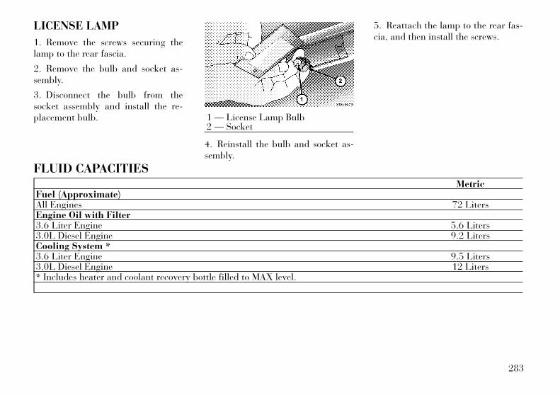
LICENSE LAMP
1. Remove the screws securing thelamp to the rear fascia.
2. Remove the bulb and socket as-sembly.
3. Disconnect the bulb from thesocket assembly and install the re-placement bulb.
4. Reinstall the bulb and socket as-sembly.
5. Reattach the lamp to the rear fas-cia, and then install the screws.
FLUID CAPACITIESMetric
Fuel (Approximate)All Engines 72 LitersEngine Oil with Filter3.6 Liter Engine 5.6 Liters3.0L Diesel Engine 9.2 LitersCooling System *3.6 Liter Engine 9.5 Liters3.0L Diesel Engine 12 Liters* Includes heater and coolant recovery bottle filled to MAX level.
1 — License Lamp Bulb2 — Socket
283
FLUIDS, LUBRICANTS, AND GENUINE PARTS
ENGINE
Component Fluids and Lubricants Specs (Genuine Parts)Engine Coolant* Contact a LANCIA Dealership.Engine Oil – 3.6L Engine** SAE Grade 5W-30 fully synthetic engine oil that meets FIAT Classification
9.55535, API SN, ILSAC GF-5 (SELENIA K POWER, Contractual TechnicalReference N° F042.F11)
Engine Oil – 3.0L Diesel Engine** SAE Grade 5W-30 fully synthetic engine oil that meets FIAT Classification9.55535, API SM/CF, ACEA C3 (SELENIA MULTIPOWER C3, ContractualTechnical Reference N° 510.D07)
Spark Plugs – 3.6L Engine RER8ZWYCB4 (Gap 1.1 mm)Fuel Selection – 3.6L Engine 91 Octane or higherFuel Selection – 3.0L Diesel Engine This vehicle must only use premium diesel fuel that meets the requirements of
EN 590. Biodiesel blends that meet EN 590 may also be used.Fuel Additive – 3.0L Diesel Engine Additive for diesel with antifreeze and protective action for diesel engines. (TU-
TELA DIESEL ART, Contractual Technical Reference N° F601.L06. To bemixed with the diesel fuel: 25 cc per 10 litres)
* Do not top up or mix with fluidswith different specifications.
** In the event of an emergency inwhich the original products are notavailable, lubricants with at least IL-SAC GF-5 performance for petrol en-
gines and ACEA C3 performance fordiesel engines are acceptable. In thiscase optimum engine performance isnot guaranteed and the lubricantsshould be replaced with recom-mended products as soon as possibleat a LANCIA Dealership. Using prod-
ucts with specifications lower thanILSAC GF-5 for gasoline engines orlower than ACEA C3 for Diesel en-gines may cause engine damage notcovered by warranty.
284
CHASSIS
Component Fluids and Lubricants Specs (Genuine Parts)Automatic Transmission – 3.6L Engine Totally synthetic lubricant that meets FIAT Qualification 9.55550-AV5 (TU-
TELA TRANSMISSION AS8, Contractual Technical Reference N° F139.I11).Automatic Transmission – 3.0L DieselEngine
Totally synthetic lubricant that meets FIAT Qualification 9.55550-AV3 (TU-TELA TRANSMISSION STARFLUID 7S, Contractual Technical Reference N°F037.F11).
Brake Master Cylinder Synthetic fluid that meets FIAT Classification 9.55597, FMVSS n° 116, DOT 4,ISO 4925, SAE J-1704 (TUTELA TOP 4, Contractual Technical Reference N°F001.A93)
Power Steering Reservoir Totally synthetic lubricant that meets FIAT Qualification 9.55550-AG3 (TU-TELA TRANSMISSION GI/R, Contractual Technical Reference N° F428.H04).
Rear Axle SAE Grade 75W–140 Synthetic gear lubricant that meets FIAT Classification9.55550-DA5, API GL-5, SAE J-2360 (TUTELA TRANSMISSION X-ROAD,Contractual Technical Reference N° F140.F11).
Windshield/Rear Window WasherFluid
Mixture of alcohol, water and surfactants that meets FIAT Classification9.55522, CUNA NC 956-11 (TUTELA PROFESSIONAL SC35, ContractualTechnical Reference N° F201.D02).
285
ARRANGEMENTS FOR DEALINGWITH THE VEHICLE AT THEEND OF ITS LIFELANCIA has been committed formany years to safeguarding the envi-ronment through the constant im-provement of its production processesand manufacturing products that areincreasingly “eco-compatible”.
To give customers the best possibleservice in terms of respecting environ-mental laws and in response to Euro-pean Directive 2000/53/EC govern-ing vehicles at the end of their life,LANCIA is offering its customers theopportunity of handing over their ve-hicle* at the end of its life withoutincurring any additional costs.
The European Directive sets out thatwhen the vehicle is handed over thelast keeper or owner should not incurany expenses as a result of it having azero or negative market value.
In all European Union countries, until1st January 2007, only vehicles regis-tered after 1st July 2002 were col-lected free of charge, while since 2007collection has been free of charge irre-
spective of the year of registration aslong as the vehicle contains its basiccomponents (in particular, the engineand bodywork) and has no additionalwaste.
To hand your vehicle over at the endof its life without extra cost, go to oneof our Dealerships or LANCIA-authorized collection and scrappingcentres.
These centres have been carefullychosen to offer high quality service forthe collection, treatment and recy-cling of unused vehicles with respectto the environment.
You can find further information onthese collection and scrapping centreseither from a LANCIA or LANCIACommercial Vehicle Dealership or bycalling the freephone number 00800526242 00 or by going on theLANCIA website.
(*) Vehicle for transporting passen-gers with a maximum of nine seatsand a total permitted weight of 3.5 t
286

287
288
8
MAINTENANCE SCHEDULES• MAINTENANCE SCHEDULE . . . . . . . . . . . . . . . 290
• MAINTENANCE SCHEDULE – GASOLINEENGINE . . . . . . . . . . . . . . . . . . . . . . . . . . . . . 290
• MAINTENANCE SCHEDULE – DIESELENGINE . . . . . . . . . . . . . . . . . . . . . . . . . . . . . 293
289

MAINTENANCESCHEDULE
MAINTENANCESCHEDULE – GASOLINEENGINEThe Scheduled Maintenance serviceslisted in this manual must be done atthe times or mileages specified to pro-tect your vehicle warranty and ensurethe best vehicle performance and reli-ability. More frequent maintenancemay be needed for vehicles in severeoperating conditions, such as dustyareas and very short trip driving. In-spection and service should also bedone anytime a malfunction is sus-pected.
The oil change indicator system willremind you that it is time to take yourvehicle in for scheduled maintenance.
On Electronic Vehicle InformationCenter (EVIC) equipped vehicles “OilChange Required” will be displayedin the EVIC and a single chime willsound, indicating that an oil change isnecessary.
The oil change indicator message willilluminate approximately 11 200 kmafter the most recent oil change wasperformed. Have your vehicle ser-viced as soon as possible, within800 km.
NOTE:
• The oil change indicator mes-sage will not monitor the timesince the last oil change. Changeyour vehicles oil if it has been12 months since your last oilchange even if the oil change in-dicator message is NOT illumi-nated.
• Under no circumstances shouldoil change intervals exceed12 000 km or 12 months, which-ever comes first.
Your authorized dealer will reset theoil change indicator message aftercompleting the scheduled oil change.
CAUTION!Failure to perform the requiredmaintenance items may result indamage to the vehicle.
Thousands Of Kilometers 24 48 72 96 120 144 168 192
Months 12 24 36 48 60 72 84 96
Flush and replace the engine coolant (or at 60 months). •
Inspect and replace PCV valve if necessary. •
Check battery charge status and possibly recharge. • • • • • • • •
290
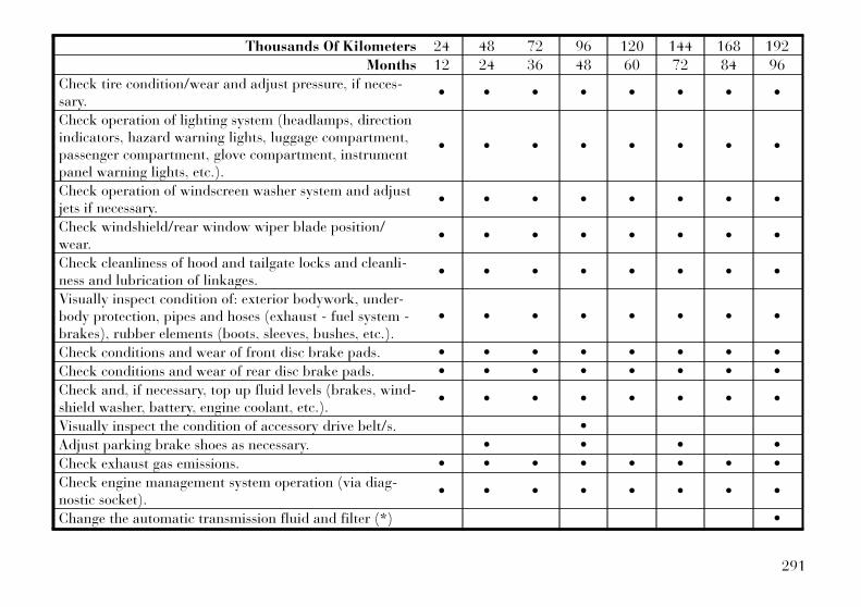
Thousands Of Kilometers 24 48 72 96 120 144 168 192
Months 12 24 36 48 60 72 84 96
Check tire condition/wear and adjust pressure, if neces-sary.
• • • • • • • •
Check operation of lighting system (headlamps, directionindicators, hazard warning lights, luggage compartment,passenger compartment, glove compartment, instrumentpanel warning lights, etc.).
• • • • • • • •
Check operation of windscreen washer system and adjustjets if necessary.
• • • • • • • •
Check windshield/rear window wiper blade position/wear.
• • • • • • • •
Check cleanliness of hood and tailgate locks and cleanli-ness and lubrication of linkages.
• • • • • • • •
Visually inspect condition of: exterior bodywork, under-body protection, pipes and hoses (exhaust - fuel system -brakes), rubber elements (boots, sleeves, bushes, etc.).
• • • • • • • •
Check conditions and wear of front disc brake pads. • • • • • • • •
Check conditions and wear of rear disc brake pads. • • • • • • • •
Check and, if necessary, top up fluid levels (brakes, wind-shield washer, battery, engine coolant, etc.).
• • • • • • • •
Visually inspect the condition of accessory drive belt/s. •
Adjust parking brake shoes as necessary. • • • •
Check exhaust gas emissions. • • • • • • • •
Check engine management system operation (via diag-nostic socket).
• • • • • • • •
Change the automatic transmission fluid and filter (*) •
291
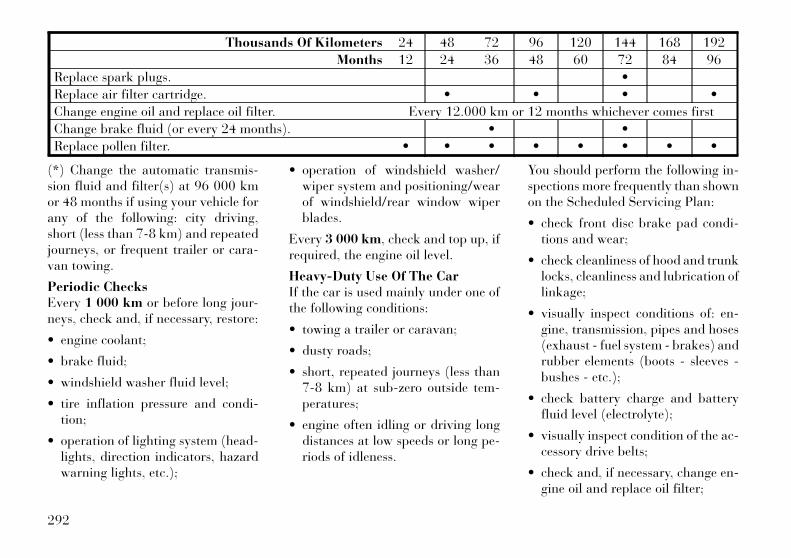
Thousands Of Kilometers 24 48 72 96 120 144 168 192
Months 12 24 36 48 60 72 84 96
Replace spark plugs. •
Replace air filter cartridge. • • • •
Change engine oil and replace oil filter. Every 12.000 km or 12 months whichever comes first
Change brake fluid (or every 24 months). • •
Replace pollen filter. • • • • • • • •
(*) Change the automatic transmis-sion fluid and filter(s) at 96 000 kmor 48 months if using your vehicle forany of the following: city driving,short (less than 7-8 km) and repeatedjourneys, or frequent trailer or cara-van towing.
Periodic ChecksEvery 1 000 km or before long jour-neys, check and, if necessary, restore:
• engine coolant;
• brake fluid;
• windshield washer fluid level;
• tire inflation pressure and condi-tion;
• operation of lighting system (head-lights, direction indicators, hazardwarning lights, etc.);
• operation of windshield washer/wiper system and positioning/wearof windshield/rear window wiperblades.
Every 3 000 km, check and top up, ifrequired, the engine oil level.
Heavy-Duty Use Of The CarIf the car is used mainly under one ofthe following conditions:
• towing a trailer or caravan;
• dusty roads;
• short, repeated journeys (less than7-8 km) at sub-zero outside tem-peratures;
• engine often idling or driving longdistances at low speeds or long pe-riods of idleness.
You should perform the following in-spections more frequently than shownon the Scheduled Servicing Plan:
• check front disc brake pad condi-tions and wear;
• check cleanliness of hood and trunklocks, cleanliness and lubrication oflinkage;
• visually inspect conditions of: en-gine, transmission, pipes and hoses(exhaust - fuel system - brakes) andrubber elements (boots - sleeves -bushes - etc.);
• check battery charge and batteryfluid level (electrolyte);
• visually inspect condition of the ac-cessory drive belts;
• check and, if necessary, change en-gine oil and replace oil filter;
292
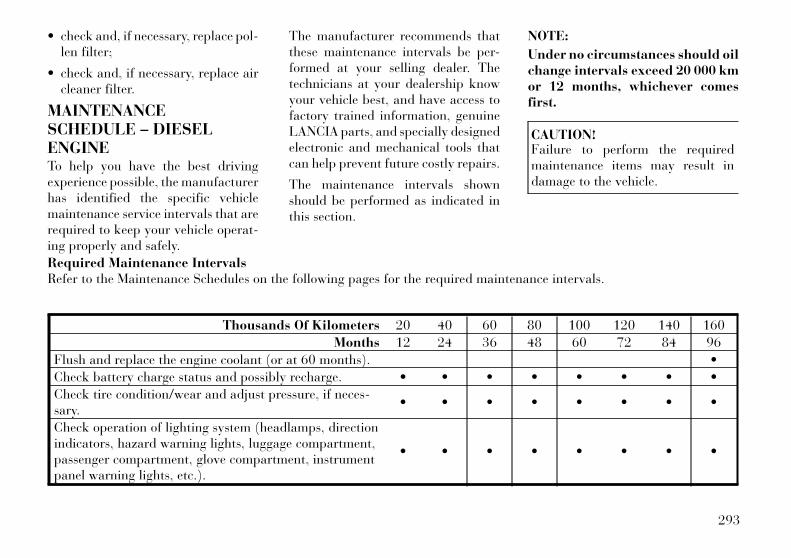
• check and, if necessary, replace pol-len filter;
• check and, if necessary, replace aircleaner filter.
MAINTENANCESCHEDULE – DIESELENGINETo help you have the best drivingexperience possible, the manufacturerhas identified the specific vehiclemaintenance service intervals that arerequired to keep your vehicle operat-ing properly and safely.
The manufacturer recommends thatthese maintenance intervals be per-formed at your selling dealer. Thetechnicians at your dealership knowyour vehicle best, and have access tofactory trained information, genuineLANCIA parts, and specially designedelectronic and mechanical tools thatcan help prevent future costly repairs.
The maintenance intervals shownshould be performed as indicated inthis section.
NOTE:
Under no circumstances should oilchange intervals exceed 20 000 kmor 12 months, whichever comesfirst.
CAUTION!Failure to perform the requiredmaintenance items may result indamage to the vehicle.
Required Maintenance IntervalsRefer to the Maintenance Schedules on the following pages for the required maintenance intervals.
Thousands Of Kilometers 20 40 60 80 100 120 140 160
Months 12 24 36 48 60 72 84 96
Flush and replace the engine coolant (or at 60 months). •
Check battery charge status and possibly recharge. • • • • • • • •
Check tire condition/wear and adjust pressure, if neces-sary.
• • • • • • • •
Check operation of lighting system (headlamps, directionindicators, hazard warning lights, luggage compartment,passenger compartment, glove compartment, instrumentpanel warning lights, etc.).
• • • • • • • •
293
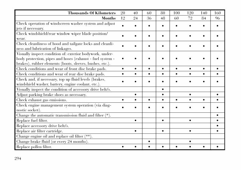
Thousands Of Kilometers 20 40 60 80 100 120 140 160
Months 12 24 36 48 60 72 84 96
Check operation of windscreen washer system and adjustjets if necessary.
• • • • • • • •
Check windshield/rear window wiper blade position/wear.
• • • • • • • •
Check cleanliness of hood and tailgate locks and cleanli-ness and lubrication of linkages.
• • • • • • • •
Visually inspect condition of: exterior bodywork, under-body protection, pipes and hoses (exhaust - fuel system -brakes), rubber elements (boots, sleeves, bushes, etc.).
• • • • • • • •
Check conditions and wear of front disc brake pads. • • • • • • • •
Check conditions and wear of rear disc brake pads. • • • • • • • •
Check and, if necessary, top up fluid levels (brakes,windshield washer, battery, engine coolant, etc.).
• • • • • • • •
Visually inspect the condition of accessory drive belt/s. •
Adjust parking brake shoes as necessary. • • • •
Check exhaust gas emissions. • • • • • • • •
Check engine management system operation (via diag-nostic socket).
• • • • • • • •
Change the automatic transmission fluid and filter (*). •
Replace fuel filter. • • • •
Replace accessory drive belt/s. •
Replace air filter cartridge. • • • •
Change engine oil and replace oil filter (**).
Change brake fluid (or every 24 months). • •
Replace pollen filter. • • • • • • • •
294
(*) Change the automatic transmis-sion fluid and filter(s) at 100 000 kmor 60 months if using your vehicle forany of the following: city driving,short (less than 7-8 km) and repeatedjourneys, or frequent trailer or cara-van towing.
(**) The actual oil and oil filter re-placement interval depends on the carusage conditions and is indicated by awarning light or message on the in-strument panel, or in any case every12 months.
Periodic ChecksEvery 1 000 km or before long jour-neys, check and, if necessary, restore:
• engine coolant;
• brake fluid;
• windshield washer fluid level;
• tire inflation pressure and condi-tion;
• operation of lighting system (head-lights, direction indicators, hazardwarning lights, etc.);
• operation of windshield washer/wiper system and positioning/wearof windshield/rear window wiperblades.
Every 3 000 km, check and top up, ifrequired, the engine oil level.
Heavy-Duty Use Of The CarIf the car is used mainly under one ofthe following conditions:
• towing a trailer or caravan;
• dusty roads;
• short, repeated journeys (less than7-8 km) at sub-zero outside tem-peratures;
• engine often idling or driving longdistances at low speeds or long pe-riods of idleness.
You should perform the following in-spections more frequently than shownon the Scheduled Servicing Plan:
• check front disc brake pad condi-tions and wear;
• check cleanliness of hood and trunklocks, cleanliness and lubrication oflinkage;
• visually inspect conditions of: en-gine, transmission, pipes and hoses(exhaust - fuel system - brakes) andrubber elements (boots - sleeves -bushes - etc.);
• check battery charge and batteryfluid level (electrolyte);
• visually inspect condition of the ac-cessory drive belts;
• check and, if necessary, change en-gine oil and replace oil filter;
• check and, if necessary, replace pol-len filter;
• check and, if necessary, replace aircleaner filter.
295

296

9
INDEX
297
About Your Brakes . . . . . . . . . 206ABS (Anti-Lock BrakeSystem) . . . . . . . . . . . . . . . . 208Adaptive Cruise Control (ACC)(Cruise Control) . . . . . . . . . . 117Adding Engine Coolant(Antifreeze) . . . . . . . . . . . . . . 266Adding Fuel . . . . . . . . . . . . . 226Adding Washer Fluid . . . . . . . 263Additives, Fuel . . . . . . . . . . . 224Adjustable Pedals . . . . . . . . . 114Air Cleaner, Engine (EngineAir Cleaner Filter) . . . . . . . . . 259Air Conditioner Maintenance . . 261Air Conditioning Filter . . . 185,261Air Conditioning Refrigerant . . 261Air Conditioning System . . 184,261Air Pressure, Tires . . . . . . . . . 214Airbag . . . . . . . . . . . . . . . . 33,39Airbag Deployment . . . . . . . . . 40Airbag Light . . . . . . 38,41,52,156Airbag Maintenance . . . . . . . . . 40Airbag, Side . . . . . . . . . . 35,37,39Airbag, Window(Side Curtain) . . . . . . . . 35,37,39Alarm Light . . . . . . . . . . . . . 158Alarm System (Security Alarm) . . 15Alterations/Modifications,Vehicle . . . . . . . . . . . . . . . . . . . 7
Anti-Lock Brake System(ABS) . . . . . . . . . . . . . . 208,209Anti-Lock Warning Light . . . . 158Antifreeze(Engine Coolant) . . . . . . . 266,283
Disposal . . . . . . . . . . . . . . 267Appearance Care . . . . . . . . . . 271Assist, Hill Start . . . . . . . . . . 211Auto Down Power Windows . . . 23Auto Unlock, Doors . . . . . . . . . 19Auto Up Power Windows . . . . . 23Automatic Dimming Mirror . . . 63Automatic Door Locks . . . . . . . 19Automatic Headlights . . . . . . . 105Automatic Oil ChangeIndicator . . . . . . . . . . . . . . . . 164Automatic TemperatureControl (ATC) . . . . . . . . . . . . 184Automatic Transaxle
Special Additives . . . . . . . . 270AutomaticTransmission . . . 196,199,270,271
Adding Fluid . . . . . . . . 271,285Autostick . . . . . . . . . . . . . . 202Fluid and Filter Changes . . . 271Fluid Change . . . . . . . . . . . 271Fluid Level Check . . . . . . . 270Fluid Type . . . . . . . . . . . . . 285Special Additives . . . . . . . . 270
Automatic Transmission LimpHome Mode . . . . . . . . . . . . . 198Autostick . . . . . . . . . . . . . . . 202Axle Fluid . . . . . . . . . . . . . . . 285Axle Lubrication(Axle Fluid) . . . . . . . . . . . . . 285
Battery . . . . . . . . . . . . . . . . . 260Keyless TransmitterReplacement (RKE) . . . . . . . 17Location . . . . . . . . . . . . . . 260
Belts, Seat . . . . . . . . . . . . . 26,51Body MechanismLubrication . . . . . . . . . . . . . . 262Brake Assist System . . . . . . . . 209Brake Control System,Electronic . . . . . . . . . . . . . . . 209Brake Fluid . . . . . . . . . . . . . . 285Brake System . . . . . . . . . . . . 268
Anti-Lock (ABS) . . . . . . . . 208Fluid Check . . . . . . . . 269,285Master Cylinder . . . . . . . . . 269Parking . . . . . . . . . . . . . . . 206Warning Light . . . . . . . . . . 157
Brake, Parking . . . . . . . . . . . 206Brake/TransmissionInterlock . . . . . . . . . . . . . . . . 196Brakes . . . . . . . . . . . . . . . . . 268
298
Break-In Recommendations,New Vehicle . . . . . . . . . . . . . . 50Brightness, Interior Lights . . . 109Bulb Replacement . . . . . . 280,281Bulbs, Light . . . . . . . . . . . 53,280
Camera, Rear . . . . . . . . . . . . 134Capacities, Fluid . . . . . . . . . . 283Caps, Filler
Radiator(Coolant Pressure) . . . . . . . 267
Car Washes . . . . . . . . . . . . . . 271Carbon Monoxide Warning . . . . 51Cargo (Vehicle Loading) . . . . . 227Cellular Phone . . . . . . . . . . . . 180Certification Label . . . . . . . . . 227Chains, Tire . . . . . . . . . . . . . 218Check Engine Light(Malfunction Indicator Light) . . 156Checking Your Vehicle ForSafety . . . . . . . . . . . . . . . . . . . 50Checks, Safety . . . . . . . . . . . . . 50Child Restraint . . . . . 42,45,47,49Child Restraint TetherAnchors . . . . . . . . . . . . . . . 46,47Child Safety Locks . . . . . . . . . . 20Child Seat . . . . . . . . . . . . . . . . 43Clean Air Gasoline . . . . . . . . . 224
CleaningWheels . . . . . . . . . . . . . . . 272Windshield Wiper Blades . . . 263
Climate Control . . . . . . . . . . . 180Clock . . . . . . . . . . . . . . . . . . 178Coin Holder . . . . . . . . . . . . . 143Cold Weather Operation . . . . . 192Compact Disc (CD)Maintenance . . . . . . . . . . . . . 179Compact Spare Tire . . . . . . . . 216Computer, Trip/Travel . . . . . . 166Connector
UCI . . . . . . . . . . . . . . . . . . 178Universal ConsumerInterface (UCI) . . . . . . . . . . 178
Conserving Fuel . . . . . . . . . . . 165Console, Floor . . . . . . . . . . . . 143Console, Overhead . . . . . . . . . 135Coolant Pressure Cap(Radiator Cap) . . . . . . . . . . . 267Cooling System . . . . . . . . . . . 265
Adding Coolant(Antifreeze) . . . . . . . . . . . . 266Coolant Capacity . . . . . . . . 283Coolant Level . . . . . . . 265,267Disposal of Used Coolant . . . 267Drain, Flush, and Refill . . . . 266Inspection . . . . . . . . . . . . . 267Points to Remember . . . . . . 268
Pressure Cap . . . . . . . . . . . 267Radiator Cap . . . . . . . . . . . 267Selection of Coolant(Antifreeze) . . . . . 266,283,284
Corrosion Protection . . . . . . . 271Cruise Control(Speed Control) . . . . . . . . . . . 117Cupholders . . . . . . . . . . . 142,274
Data Recorder, Event . . . . . . . . 41Daytime Brightness, InteriorLights . . . . . . . . . . . . . . . . . . 109Deck Lid, Emergency Release . . 25Deck Lid, Power Release . . . . . 24Defroster, Rear Window . . . . . 145Defroster, Windshield . . . . 52,183Delay (Intermittent) Wipers . . 110Diagnostic System, Onboard . . 257Diesel Fuel . . . . . . . . . . . . . . 225Dimmer Switch, Headlight . . . 107Dipsticks
Oil (Engine) . . . . . . . . . . . . 258Disposal
Antifreeze (Engine Coolant) . . 267Engine Oil . . . . . . . . . . . . . 259
Door Locks . . . . . . . . . . . . . . . 18Door Locks, Automatic . . . . . . 19Driving
On Slippery Surfaces . . . . . 204
299
Through Flowing, Rising, orShallow Standing Water . . . 204
Driving to Achieve MaximumFuel Economy . . . . . . . . . . . . 165
Electric Rear WindowDefrost . . . . . . . . . . . . . . . . . 145Electric Remote Mirrors . . . . . . 64Electrical Power Outlets . . . . . 140Electronic Brake ControlSystem . . . . . . . . . . . . . . . . . 209
Anti-Lock Brake System . . . 209Brake Assist System . . . . . . 209Traction Control System . . . 209
Electronic Power DistributionCenter (Fuses) . . . . . . . . . . . . 274Electronic Speed Control(Cruise Control) . . . . . . . 115,117Electronic Stability Control(ESC) . . . . . . . . . . . . . . . . . . 210Electronic Vehicle InformationCenter (EVIC) . . . . . . . . 134,159Emergency Deck Lid Release . . 25Emergency Trunk Release . . . . 25Emergency, In Case of
Freeing Vehicle WhenStuck . . . . . . . . . . . . . . . . 248Hazard Warning Flasher . . . 240Jump Starting . . . . . . . . . . 246
Overheating . . . . . . . . . . . . 240Towing . . . . . . . . . . . . . . . 251
EngineAir Cleaner . . . . . . . . . . . . 259Break-In Recommendations . . 50Compartment . . . . . . . 255,256CompartmentIdentification . . . . . . . . 255,256Coolant (Antifreeze) . . . 265,284Cooling . . . . . . . . . . . . . . . 265Exhaust Gas Caution . . . . . . 51Fails to Start . . . . . . . . . . . 192Flooded, Starting . . . . . . . . 192Fuel Requirements . . . . . . . 223Jump Starting . . . . . . . . . . 246Oil . . . . . . . . . . . . 258,283,284Oil Change Interval . . . 164,258Oil Disposal . . . . . . . . . . . . 259Oil Filter . . . . . . . . . . . . . . 259Oil Selection . . . . . 258,259,283Oil Synthetic . . . . . . . . . . . 259Overheating . . . . . . . . . . . . 240Starting . . . . . . . . . . . . . . . 191Temperature Gauge . . . . . . 159
Enhanced Accident ResponseFeature . . . . . . . . . . . . . . . . . . 39Entry System, Illuminated . . . . 16Ethanol . . . . . . . . . . . . . . . . 224Event Data Recorder . . . . . . . . 41
Exhaust Gas Caution . . . . . 51,264Exhaust System . . . . . . . . 51,264Exterior Folding Mirrors . . . . . . 63Exterior Lighting . . . . . . . . . . 104Exterior Lights . . . . . . . . . . . . 53
Filler Location Fuel . . . . . . . . 156Filters
Air Cleaner . . . . . . . . . . . . 259Air Conditioning . . . . . 185,261Engine Oil . . . . . . . . . . 259,284
Flash-To-Pass . . . . . . . . . . . . 108Flashers
Hazard Warning . . . . . . . . . 240Turn Signal . . . . . . . 53,107,154
Flooded Engine Starting . . . . . 192Floor Console . . . . . . . . . . . . 143Fluid Capacities . . . . . . . . . . . 283Fluid Leaks . . . . . . . . . . . . . . 53Fluid Level Checks
Automatic Transmission . . . 270Brake . . . . . . . . . . . . . . . . 269Cooling System . . . . . . . . . 265Engine Oil . . . . . . . . . . . . . 258
Fluid, Brake . . . . . . . . . . . . . 285Fluids . . . . . . . . . . . . . . . . . . 284Fluids, Lubricants andGenuine Parts . . . . . . . . . . . . 284Fog Lights . . . . . . . . . . . . . . 154
300

Fog Lights, Rear . . . . . . . . . . 107Folding Rear Seat . . . . . . . . . 101Forward CollisionWarning . . . . . . . . . . . . . 128,162Freeing A Stuck Vehicle . . . . . 248Fuel . . . . . . . . . . . . . . . . 223,225
Additives . . . . . . . . . . . . . . 224Conserving . . . . . . . . . . . . 165Diesel . . . . . . . . . . . . . . . . 225Filler Door (Gas Cap) . . . . . 156Gasoline . . . . . . . . . . . . . . 223Gauge . . . . . . . . . . . . . . . . 156Light . . . . . . . . . . . . . . . . . 162Octane Rating . . . . . . . 223,284Saver Mode . . . . . . . . . . . . 165Specifications . . . . . . . . . . . 284Tank Capacity . . . . . . . . . . 283
Fuel Optimizer . . . . . . . . . . . 165Fuel Saver . . . . . . . . . . . . . . . 165Fuses . . . . . . . . . . . . . . . . . . 274
Gasoline (Fuel) . . . . . . . . . . . 223Conserving . . . . . . . . . . . . 165
Gasoline, Clean Air . . . . . . . . 224Gauges
Coolant Temperature . . . . . 159Fuel . . . . . . . . . . . . . . . . . 156Speedometer . . . . . . . . . . . 156Tachometer . . . . . . . . . . . . 154
Gear Ranges . . . . . . . . . . 196,200Gear Select Lever Override . . . 249General Information . . . . 14,18,88General Maintenance . . . . . . . 257Glass Cleaning . . . . . . . . . . . . 273Gross Axle Weight Rating . . 227,229Gross Vehicle WeightRating . . . . . . . . . . . . . . 227,228GVWR . . . . . . . . . . . . . . . . . 227
HazardDriving Through Flowing,Rising, or Shallow StandingWater . . . . . . . . . . . . . . . . 204
Hazard Warning Flasher . . . . . 240Head Restraints . . . . . . . . . . . . 99Head Rests . . . . . . . . . . . . . . . 99Headlight Washers . . . . . 112,263Headlights . . . . . . . . . . . . . . 281
Automatic . . . . . . . . . . . . . 105Bulb Replacement . . . . . . . 281Cleaning . . . . . . . . . . . . . . 273Delay . . . . . . . . . . . . . . . . 105High Beam/Low Beam SelectSwitch . . . . . . . . . . . . . . . . 107Lights On Reminder . . . . . . 107On With Wipers . . . . . . 105,111Passing . . . . . . . . . . . . . . . 108Switch . . . . . . . . . . . . . . . . 104
Time Delay . . . . . . . . . . . . 105Washers . . . . . . . . . . . . . . . 112
Heated Mirrors . . . . . . . . . . . . 65High Beam/Low Beam Select(Dimmer) Switch . . . . . . . . . . 107Hill Start Assist . . . . . . . . . . . 211Holder, Coin . . . . . . . . . . . . . 143Holder, Cup . . . . . . . . . . . . . 142
IgnitionKey . . . . . . . . . . . . . . . . . . . 12
Illuminated Entry . . . . . . . . . . 16Immobilizer (Sentry Key) . . . . . 13Infant Restraint . . . . . . . . . 42,45Information Center, Vehicle . . 159Instrument Cluster . . . . . 153,154Instrument Panel andControls . . . . . . . . . . . . . . . . 152Instrument Panel LensCleaning . . . . . . . . . . . . . . . . 273Integrated Power Module(Fuses) . . . . . . . . . . . . . . . . . 274Interior Appearance Care . . . . 272Interior Fuses . . . . . . . . . . . . 274Interior Lights . . . . . . . . . . . . 108Intermittent Wipers (DelayWipers) . . . . . . . . . . . . . . . . . 110Intervention RegenerationStrategy . . . . . . . . . . . . . . . . 264
301
Introduction . . . . . . . . . . . . . . . 4
Jump Starting . . . . . . . . . . . . 246
Key-In Reminder . . . . . . . . . . . 13Key, Programming . . . . . . . . . . 14Key, Replacement . . . . . . . . . . 14Key, Sentry (Immobilizer) . . . . 13Keyless Enter-N-Go . . . . . . 20,191Keyless Entry System . . . . . . . . 16Keyless Go . . . . . . . . . . . . . . . 12Keys . . . . . . . . . . . . . . . . . . . . 12Kicker Sound System . . . . . . . 178Knee Bolster . . . . . . . . . . . . . . 33
Lane Change and TurnSignals . . . . . . . . . . . . . . . . . 107Lane Change Assist . . . . . . . . 107Lap/Shoulder Belts . . . . . . . . . 26LATCH (Lower Anchors andTether for CHildren) . . . . . . 46,47Latch Plate . . . . . . . . . . . . . . . 27Latches . . . . . . . . . . . . . . . . . 53Lead Free Gasoline . . . . . . . . 223Leaks, Fluid . . . . . . . . . . . . . . 53Life of Tires . . . . . . . . . . . . . 217Light Bulbs . . . . . . . . . . . 53,280Lights . . . . . . . . . . . . . . . 53,104
Airbag . . . . . . . . . 38,41,52,156
Alarm . . . . . . . . . . . . . . . . 158Anti-Lock . . . . . . . . . . . . . 158Automatic Headlights . . . . . 105Brake Assist Warning . . . . . 213Brake Warning . . . . . . . . . . 157Bulb Replacement . . . . 280,281Dimmer Switch,Headlight . . . . . . . . . . . . . 107Electronic Stability Program(ESP) Indicator . . . . . . . . . 213Exterior . . . . . . . . . . . . . . . . 53Fog . . . . . . . . . . . . . . . . . . 154Hazard Warning Flasher . . . 240Headlight Switch . . . . . . . . 104Headlights . . . . . . . . . 104,281Headlights On Reminder . . . 107Headlights On WithWipers . . . . . . . . . . . . 105,111High Beam . . . . . . . . . . . . 107High Beam Indicator . . . . . . 154High Beam/Low BeamSelect . . . . . . . . . . . . . . . . 107Illuminated Entry . . . . . . . . . 16Instrument Cluster . . . . . . . 104Intensity Control . . . . . . . . 109Interior . . . . . . . . . . . . . . . 108License . . . . . . . . . . . . . . . 283Lights On Reminder . . . . . . 107Low Fuel . . . . . . . . . . . . . . 162
Malfunction Indicator(Check Engine) . . . . . . . . . 156Map Reading . . . . . . . . . . . 108Parade Mode (DaytimeBrightness) . . . . . . . . . . . . 109Passing . . . . . . . . . . . . . . . 108Reading . . . . . . . . . . . 108,135Seat Belt Reminder . . . . . . . 159Security Alarm (TheftAlarm) . . . . . . . . . . . . . . . 158Service . . . . . . . . . . . . 280,281Service Engine Soon(Malfunction Indicator) . . . . 156SmartBeams . . . . . . . . . . . 106Theft Alarm (SecurityAlarm) . . . . . . . . . . . . . . . 158Tire Pressure Monitoring(TPMS) . . . . . . . . . . . 155,219Traction Control . . . . . . . . . 213Turn Signal . . . . . . . . . . 53,107Vanity Mirror . . . . . . . . . . . . 65Wait to Start . . . . . . . . . . . 162Warning (Instrument ClusterDescription) . . . . . . . . . . . . 154
Load Leveling System . . . . . . 147Loading Vehicle . . . . . . . 227,228
Capacities . . . . . . . . . . . . . 228Locks . . . . . . . . . . . . . . . . . . . 18
Auto Unlock . . . . . . . . . . . . 19
302
Automatic Door . . . . . . . . . . 19Child Protection . . . . . . . . . . 20Door . . . . . . . . . . . . . . . . . . 18Power Door . . . . . . . . . . . . . 19
Low Tire Pressure System . . . . 219Lower Anchors and Tether forCHildren (LATCH) . . . . . . . 46,47Lubrication, Body . . . . . . . . . 262
Maintenance Free Battery . . . . 260Maintenance Procedures . . . . . 257Maintenance Schedule . . . 290,293Maintenance, General . . . . . . . 257Malfunction Indicator Light(Check Engine) . . . . . . . . . . . 156Manual Transmission . . . . . . . 271
Fluid Level Check . . . . . . . 271Master Cylinder (Brakes) . . . . 269Memory Feature (MemorySeat) . . . . . . . . . . . . . . . . . . 101Memory Seat . . . . . . . . . . . . . 101Memory Seats and Radio . . . . 101Methanol . . . . . . . . . . . . . . . 223Methanol Fuel . . . . . . . . . . . . 223Mini-Trip Computer . . . . . . . . 166Mirrors . . . . . . . . . . . . . . . . . . 63
Automatic Dimming . . . . . . . 63Electric Powered . . . . . . . . . 64Electric Remote . . . . . . . . . . 64
Exterior Folding . . . . . . . . . . 63Heated . . . . . . . . . . . . . . . . 65Outside . . . . . . . . . . . . . . . . 63Vanity . . . . . . . . . . . . . . . . . 65
ModeFuel Saver . . . . . . . . . . . . . 165
Modifications/Alterations,Vehicle . . . . . . . . . . . . . . . . . . . 7Monitor, Tire PressureSystem . . . . . . . . . . . . . . . . . 219Multi-Function ControlLever . . . . . . . . . . . . . . . . . . 107
Navigation System(Uconnect™ gps) . . . . . . 134,177New Vehicle Break-In Period . . 50
Occupant Restraints . . . . 25,37,40Occupant Restraints(Sedan) . . . . . . . . . . . . . 35,37,39Octane Rating, Gasoline(Fuel) . . . . . . . . . . . . . . 223,284Odometer . . . . . . . . . . . . . . . 154Oil Change Indicator . . . . 154,164Oil Change Indicator,Reset . . . . . . . . . . . . . . . 154,164Oil, Engine . . . . . . . . . . . 258,284
Capacity . . . . . . . . . . . . . . 283Change Interval . . . . . . 164,258
Diesel . . . . . . . . . . . . . . . . 259Dipstick . . . . . . . . . . . . . . . 258Filter . . . . . . . . . . . . . 259,284Materials Added to . . . . . . . 259Recommendation . . 258,259,283Synthetic . . . . . . . . . . . . . . 259Viscosity . . . . . . . . . . . . . . 283
Onboard Diagnostic System . . 257Operating Precautions . . . . . . 257Operator Manual (Owner'sManual) . . . . . . . . . . . . . . . . . . 5Outside Rearview Mirrors . . . . . 63Overdrive . . . . . . . . . . . . . . . 202Overdrive OFF Switch . . . . . . 202Overhead Console . . . . . . . . . 135Overheating, Engine . . . . 159,240Owner's Manual (OperatorManual) . . . . . . . . . . . . . . . . . . 5
Paint Care . . . . . . . . . . . . . . . 271Park Sense System, Rear . . . . 129Parking Brake . . . . . . . . . . . . 206Passing Light . . . . . . . . . . . . 108Pedals, Adjustable . . . . . . . . . 114Pets . . . . . . . . . . . . . . . . . . . . 50Power
Deck Lid Release . . . . . . . . . 24Distribution Center(Fuses) . . . . . . . . . . . . 274,276
303
Door Locks . . . . . . . . . . . . . 19Mirrors . . . . . . . . . . . . . . . . 64Outlet (Auxiliary ElectricalOutlet) . . . . . . . . . . . . . . . 140Seats . . . . . . . . . . . . . . . . . . 96Steering . . . . . . . . . . . . . . . 206Sunroof . . . . . . . . . . . . 136,138Tilt/Telescoping SteeringColumn . . . . . . . . . . . . . . . 113Windows . . . . . . . . . . . . . . . 22
Power Steering Fluid . . . . . . . 285Pregnant Women and SeatBelts . . . . . . . . . . . . . . . . . . . . 33Pretensioners
Seat Belts . . . . . . . . . . . . . . 30Programming Transmitters(Remote Keyless Entry) . . . . . . 16
Radial Ply Tires . . . . . . . . . . . 215Radiator Cap (CoolantPressure Cap) . . . . . . . . . . . . 267Radio (Sound Systems) . . . . . 177Radio Operation . . . . . . . . . . 180Radio Remote Controls . . . . . . 179Rain Sensitive Wiper System . . 111Rear Camera . . . . . . . . . . . . . 134Rear Cupholder . . . . . . . . . . . 142Rear Fog Lights . . . . . . . . . . . 107Rear Park Sense System . . . . . 129
Rear Seat, Folding . . . . . . . . . 101Rear Window Defroster . . . . . 145Rear Window Features . . . . . . 145Recorder, Event Data . . . . . . . . 41Recreational Towing . . . . . . . . 237Refrigerant . . . . . . . . . . . . . . 261Reminder, Lights On . . . . . . . 107Reminder, Seat Belt . . . . . . . . . 32Remote Keyless Entry (RKE) . . 16Remote Sound System (Radio)Controls . . . . . . . . . . . . . . . . 179Remote Trunk Release . . . . . . . 24Replacement Bulbs . . . . . . . . 280Replacement Keys . . . . . . . . . . 14Replacement Parts . . . . . . . . . 257Replacement Tires . . . . . . . . . 217Resetting Oil ChangeIndicator . . . . . . . . . . . . 154,164Restraint, Head . . . . . . . . . . . . 99Restraints, Child . . . . . . . . . . . 42Restraints, Occupant . . . . . . . . 25Rocking Vehicle When Stuck . . 248Rotation, Tires . . . . . . . . . . . . 219
Safety Checks Inside Vehicle . . . 51Safety Checks Outside Vehicle . . 53Safety Tips . . . . . . . . . . . . . . . 50Safety, Exhaust Gas . . . . . . . . . 51Schedule, Maintenance . . 290,293
Seat Belt Maintenance . . . . . . 274Seat Belt Reminder . . . . . . . . . 32Seat Belts . . . . . . . . . . . 25,26,51
Adjustable Upper ShoulderAnchorage . . . . . . . . . . . . . . 28And Pregnant Women . . . . . . 33Child Restraint . . . . . . 42,45,49Front Seat . . . . . . . . . . . . 26,27Inspection . . . . . . . . . . . . . . 51Operating Instructions . . . . . 27Pretensioners . . . . . . . . . . . . 30Rear Seat . . . . . . . . . . . . . . . 26Untwisting Procedure . . . . . . 29
Seats . . . . . . . . . . . . . . . . . . . 96Adjustment . . . . . . . . . . . . . 96Easy Entry . . . . . . . . . . . . 103Head Restraints . . . . . . . . . . 99Height Adjustment . . . . . . . . 96Memory . . . . . . . . . . . . . . . 101Power . . . . . . . . . . . . . . . . . 96Rear Folding . . . . . . . . . . . 101Seatback Release . . . . . . . . 101Tilting . . . . . . . . . . . . . . . . . 96
Selection of Coolant(Antifreeze) . . . . . . . . . . 266,284Selection of Oil . . . . . . . . . . . 259Sentry Key (Immobilizer) . . . . . 13Sentry Key Programming . . . . . 14Sentry Key Replacement . . . . . . 14
304
Service Engine Soon Light(Malfunction Indicator) . . . . . 156Setting the Clock . . . . . . . . . . 178Shift Lever Override . . . . . . . 249Shifting . . . . . . . . . . . . . . . . 195
Automatic Transmission . . . 195Shoulder Belt UpperAnchorage . . . . . . . . . . . . . . . 28Shoulder Belts . . . . . . . . . . . . . 26Side Airbag . . . . . . . . . . . . . . . 39Side View Mirror Adjustment . . 63Signals, Turn . . . . . . . 53,107,154Slippery Surfaces, Driving On . 204SmartBeams . . . . . . . . . . . . . 106Snow Chains (Tire Chains) . . . 218Sound System
Kicker . . . . . . . . . . . . . . . . 178Sound Systems . . . . . . . . . . . 177Sound Systems (Radio) . . . . . 177Spare Tire . . . . . . . . . . . . . . . 216Spark Plugs . . . . . . . . . . . . . 284Specifications
Fuel (Gasoline) . . . . . . 223,284Oil . . . . . . . . . . . . . . . 259,284
Speed Control(Cruise Control) . . . . . . . 115,117Speedometer . . . . . . . . . . . . . 156Starting . . . . . . . . . . . . . . . . 191
Automatic Transmission . . . 191
Cold Weather . . . . . . . . . . . 192Engine Fails to Start . . . . . . 192
Starting and Operating . . . . . . 191Starting Procedures . . . . . . . . 191Steering
Column Controls . . . . . . . . 107Column Lock . . . . . . . . . . . 112Power . . . . . . . . . . . . . . . . 206Tilt Column . . . . . . . . . 112,113Wheel, Heated . . . . . . . . . . 114Wheel, Tilt . . . . . . . . . 112,113
Steering Wheel AudioControls . . . . . . . . . . . . . . . . 179Steering Wheel Mounted SoundSystem Controls . . . . . . . . . . . 179Storage . . . . . . . . . . . . . 143,279Storage, Vehicle . . . . . . . 185,279Storing Your Vehicle . . . . . . . . 279Stuck, Freeing . . . . . . . . . . . . 248Sun Roof . . . . . . . . . . . . 136,138Sunglasses Storage . . . . . . . . . 135Supplemental Restraint System- Airbag . . . . . . . . . . . . . . . . . 33Sway Control, Trailer . . . . . . . 229Synthetic Engine Oil . . . . . . . 259System, Navigation(Uconnect™ gps) . . . . . . . . . . 177
Tachometer . . . . . . . . . . . . . . 154
Telescoping SteeringColumn . . . . . . . . . . . . . 112,113Temperature Control,Automatic (ATC) . . . . . . . . . . 184Temperature Gauge, EngineCoolant . . . . . . . . . . . . . 159,240Tether Anchor, Child Restraint . . 46Tilt Steering Column . . . . 112,113Time Delay, Headlight . . . . . . 105Tires . . . . . . . . . . . . . . . . 53,214
Aging (Life of Tires) . . . . . . 217Air Pressure . . . . . . . . . . . . 214Chains . . . . . . . . . . . . . . . . 218Compact Spare . . . . . . . . . . 216General Information . . . . . . 214High Speed . . . . . . . . . . . . 215Inflation Pressures . . . . . . . 214Life of Tires . . . . . . . . . . . . 217Pressure Monitor System(TPMS) . . . . . . . . . . . . . . . 219Pressure Warning Light . . . . 155Radial . . . . . . . . . . . . . . . . 215Replacement . . . . . . . . . . . 217Rotation . . . . . . . . . . . . . . 219Safety . . . . . . . . . . . . . . . . 214Spinning . . . . . . . . . . . . . . 216Trailer Towing . . . . . . . . . . 232Tread Wear Indicators . . . . . 217
305

Tongue Weight/TrailerWeight . . . . . . . . . . . . . . . . . 231Towing . . . . . . . . . . . . . . . . . 228
Behind a Motorhome . . . . . . 237Disabled Vehicle . . . . . . . . . 251Guide . . . . . . . . . . . . . . . . 231Recreational . . . . . . . . . . . . 237Weight . . . . . . . . . . . . . . . 231
Towing Eyes . . . . . . . . . . . . . 249Towing Vehicle Behind aMotorhome . . . . . . . . . . . . . . 237Traction Control . . . . . . . . . . 209Trailer Towing . . . . . . . . . . . . 228
Cooling System Tips . . . . . . 236Hitches . . . . . . . . . . . . . . . 236Minimum Requirements . . . 232Tips . . . . . . . . . . . . . . . . . 235Trailer and TongueWeight . . . . . . . . . . . . . . . 231Wiring . . . . . . . . . . . . . . . . 233
Trailer Towing Guide . . . . . . . 231Trailer Weight . . . . . . . . . . . . 231Transfer Case
Fluid . . . . . . . . . . . . . . . . . 285Transmission . . . . . . . . . . . . . 270
Automatic . . . . . . . 196,199,270Fluid . . . . . . . . . . . . . . . . . 285Shifting . . . . . . . . . . . . . . . 195
Transmitter Battery Service(Remote Keyless Entry) . . . . . . 17Transmitter Programming(Remote Keyless Entry) . . . . . . 16Transmitter, Remote KeylessEntry (RKE) . . . . . . . . . . . . . . 16Transporting Pets . . . . . . . . . . 50Tread Wear Indicators . . . . . . 217Trip Odometer . . . . . . . . . . . . 154Trunk Lid (Deck Lid) . . . . . 24,25Trunk Release RemoteControl . . . . . . . . . . . . . . . . . . 24Trunk Release, Emergency . . . . 25Turn Signals . . . . . . . . . . 107,154
UCI Connector . . . . . . . . . . . 178Universal Child Seat PositionChart . . . . . . . . . . . . . . . . . . . 43Universal Consumer Interface(UCI) Connector . . . . . . . . . . 178Untwisting Procedure, SeatBelt . . . . . . . . . . . . . . . . . . . . 29
Vanity Mirrors . . . . . . . . . . . . . 65Vehicle Certification Label . . . 227Vehicle Identification Number(VIN) . . . . . . . . . . . . . . . . . . . . 7Vehicle Loading . . . . . . . 227,228
Vehicle Modifications/Alterations . . . . . . . . . . . . . . . . 7Vehicle Storage . . . . . . . . 185,279
Wait to Start Light . . . . . . . . . 162Warning Flasher, Hazard . . . . 240Warning Lights (InstrumentCluster Description) . . . . . . . . 154Warnings and Cautions . . . . . . . 7Washer
Adding Fluid . . . . . . . . . . . 263Washers, Headlight . . . . . . . . 112Washers, Windshield . . . . 111,263Washing Vehicle . . . . . . . . . . 271Water
Driving Through . . . . . . . . 204Wheel and Wheel Trim . . . . . . 272Wheel and Wheel Trim Care . . 272Wind Buffeting . . . . . . 24,137,139Window Fogging . . . . . . . . . . 185Windows . . . . . . . . . . . . . . . . . 22
Power . . . . . . . . . . . . . . . . . 22Windshield Defroster . . . . . . . . 52Windshield Washers . . . . . 110,111Windshield Wiper Blades . . . . 263Windshield Wipers . . . . . . . . . 110Wiper Blade Replacement . . . . 263Wipers, Intermittent . . . . . . . . 110Wipers, Rain Sensitive . . . . . . 111
306

Notes

Notes
Fiat Group Automobiles S.p.A. - Parts & Services - Technical Services - Service EngineeringLargo Senatore G. Agnelli, 3 - 10040 Volvera - Torino (Italia)
Print n. 603.99.124 - 02/2012 - Edition 1

We really know your car because we invented, designed and built it: we really know every single detail. At
Lancia Service authorised workshops you can find technicians directly trained by us, offering quality and
professionalism for all service operations. Lancia workshops are always close to you for the regular servicing operations, season checks and
practical recommendations by our experts.With Genuine Parts you keep the reliability,
comfort and performance features of your new car unchanged in time: that’s why you bought it for.Always ask for Genuine Parts for the components
used on our cars; we recommend them because they come from our steady commitment in research and
development of highly innovative technologies.For all these reasons: rely on Genuine Parts, because
they are the only ones designed for your car.
WHY CHOOSING GENUINE PARTS

Owner Handbook
The data contained in this publication is intended merely as a guide. Lancia reserves the right to modify the models and versions described in this booklet at any time for technical
and commercial reasons. If you have any further questions please consult your Lancia dealer. Printed in recycled paper without chlorine.
ENGLISH
Copyright © 2022 FDOKUMEN