2008 Dodge Ram Chassis/Cab Owner Manual - Dealer E ...
528
TABLE OF CONTENTS SECTION PAGE 1 INTRODUCTION ............................................................. 3 2 THINGS TO KNOW BEFORE STARTING YOUR VEHICLE ............................... 9 3 UNDERSTANDING THE FEATURES OF YOUR VEHICLE ............................... 77 4 UNDERSTANDING YOUR INSTRUMENT PANEL ................................... 167 5 STARTING AND OPERATING ................................................. 247 6 WHAT TO DO IN EMERGENCIES ...............................................377 7 MAINTAINING YOUR VEHICLE ............................................... 397 8 MAINTENANCE SCHEDULES .................................................. 479 9 IF YOU NEED CONSUMER ASSISTANCE ..........................................499 10 INDEX .................................................................... 509 1 2 3 4 5 6 7 8 9 10
-
Upload
khangminh22 -
Category
Documents
-
view
0 -
download
0
Transcript of 2008 Dodge Ram Chassis/Cab Owner Manual - Dealer E ...
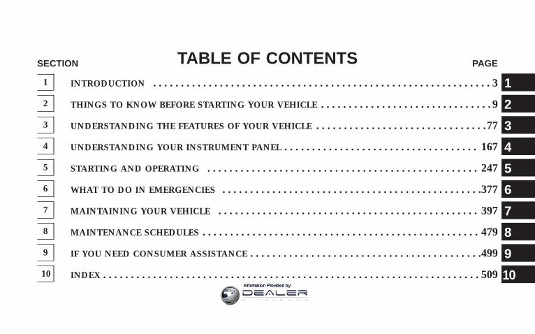
TABLE OF CONTENTSSECTION PAGE
1 INTRODUCTION . . . . . . . . . . . . . . . . . . . . . . . . . . . . . . . . . . . . . . . . . . . . . . . . . . . . . . . . . . . . . 3
2 THINGS TO KNOW BEFORE STARTING YOUR VEHICLE . . . . . . . . . . . . . . . . . . . . . . . . . . . . . . . 9
3 UNDERSTANDING THE FEATURES OF YOUR VEHICLE . . . . . . . . . . . . . . . . . . . . . . . . . . . . . . .77
4 UNDERSTANDING YOUR INSTRUMENT PANEL . . . . . . . . . . . . . . . . . . . . . . . . . . . . . . . . . . . 167
5 STARTING AND OPERATING . . . . . . . . . . . . . . . . . . . . . . . . . . . . . . . . . . . . . . . . . . . . . . . . . 247
6 WHAT TO DO IN EMERGENCIES . . . . . . . . . . . . . . . . . . . . . . . . . . . . . . . . . . . . . . . . . . . . . . .377
7 MAINTAINING YOUR VEHICLE . . . . . . . . . . . . . . . . . . . . . . . . . . . . . . . . . . . . . . . . . . . . . . . 397
8 MAINTENANCE SCHEDULES . . . . . . . . . . . . . . . . . . . . . . . . . . . . . . . . . . . . . . . . . . . . . . . . . . 479
9 IF YOU NEED CONSUMER ASSISTANCE . . . . . . . . . . . . . . . . . . . . . . . . . . . . . . . . . . . . . . . . . .499
10 INDEX . . . . . . . . . . . . . . . . . . . . . . . . . . . . . . . . . . . . . . . . . . . . . . . . . . . . . . . . . . . . . . . . . . . . 509
1
2
3
4
5
6
7
8
9
10Information Provided by:

Information Provided by:

INTRODUCTION
CONTENTS
m Introduction . . . . . . . . . . . . . . . . . . . . . . . . . . . 4
m A Message From DaimlerChrysler Corporation –Diesel Engines Only . . . . . . . . . . . . . . . . . . . . . . 4
m How To Use This Manual . . . . . . . . . . . . . . . . . . 5
m Warnings And Cautions . . . . . . . . . . . . . . . . . . . 7
m Van Conversions/Campers . . . . . . . . . . . . . . . . . 7
m Vehicle Identification Number . . . . . . . . . . . . . . . 8
m Vehicle Modifications/Alterations . . . . . . . . . . . . 8
1
Information Provided by:

INTRODUCTIONThis manual has been prepared with the assistance ofservice and engineering specialists to acquaint you withthe operation and maintenance of your new vehicle. It issupplemented by a Warranty Information Booklet andvarious customer oriented documents. You are urged toread these publications carefully. Following the instruc-tions and recommendations in this manual will helpassure safe and enjoyable operation of your vehicle.
NOTE: After you read the manual, it should be storedin the vehicle for convenient reference and remain withthe vehicle when sold, so that the new owner will beaware of all safety warnings.
When it comes to service, remember that your dealerknows your vehicle best, has the factory-trained techni-cians and genuine Mopart parts, and is interested inyour satisfaction.
A MESSAGE FROM DAIMLERCHRYSLERCORPORATION – DIESEL ENGINES ONLYDaimlerChrysler Corporation and Cummins welcomeyou as a new Dodge Ram Cummins Turbo Diesel-powered truck owner.
Almost 100% of the heavy duty trucks in the UnitedStates and Canada are diesel powered because of the fueleconomy, rugged durability, and high torque which per-mits pulling heavy loads. Cummins engines power wellover half of these trucks. Now this same technology andproven performance is yours in your new Dodge Ramtruck equipped with the Cummins 6.7 liter, Turbo-charged, Charge Air Cooled, Diesel engine.
Your diesel truck will sound, feel, drive, and operatedifferently from a gasoline-powered truck. It is importantthat you read and understand this manual. You may findthat some of the starting, operating, and maintenanceprocedures are different. However, they are simple to
4 INTRODUCTION
Information Provided by:
follow and careful adherence to them will ensure thatyou take full advantage of the features of this engine.
Thank you for choosing the Dodge Ram truck withCummins Turbo Diesel power.
HOW TO USE THIS MANUALConsult the table of contents to determine which sectioncontains the information you desire.
The detailed index, at the rear of this manual, contains acomplete listing of all subjects.
Consult the following table for a description of thesymbols that may be used on your vehicle or throughoutthis owner’s manual:
INTRODUCTION 5
1
Information Provided by:

6 INTRODUCTION
Information Provided by:
WARNINGS AND CAUTIONSThis manual contains WARNINGS against operatingprocedures which could result in an accident or bodilyinjury. It also contains CAUTIONS against procedureswhich could result in damage to your vehicle. If you donot read this entire manual you may miss importantinformation. Observe all Warnings and Cautions.
VAN CONVERSIONS/CAMPERSThe Manufacturer’s Warranty does not apply to bodymodifications or special equipment installed by vanconversion/camper manufacturers/ body builders. Seethe Warranty information book, Section 2.1.C. Suchequipment includes video monitors, VCRs, heaters,stoves, refrigerators, etc. For warranty coverage andservice on these items, contact the applicable manufac-turer.
Operating instructions for the special equipment in-stalled by the conversion/camper manufacturer shouldalso be supplied with your vehicle. If these instructionsare missing, please contact your selling dealer for assis-tance in obtaining replacement documents from theapplicable manufacturer.
For information on the Body Builders Guide go to:www.dodgebodybuilder.com. This website contains di-mensional and technical specifications for Dodge trucks.It is intended for Second Stage Manufacturer’s technicalsupport. For service issues, contact your Dodge dealer.
INTRODUCTION 7
1
Information Provided by:
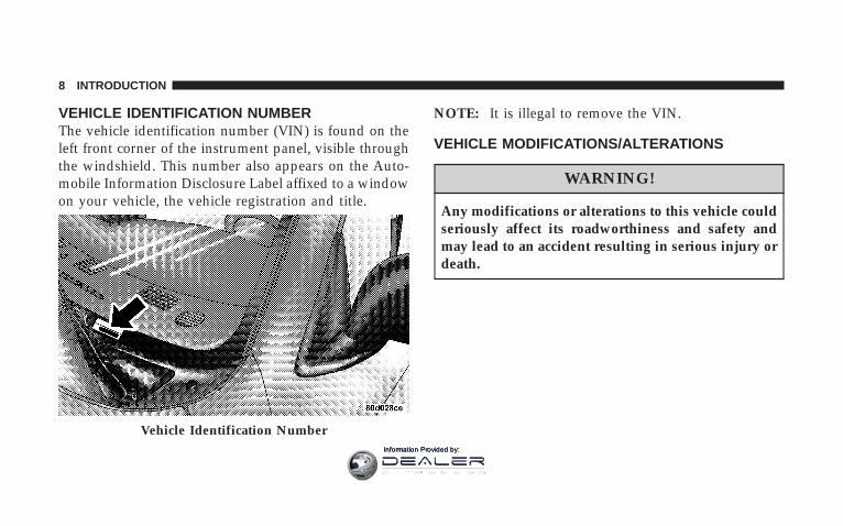
VEHICLE IDENTIFICATION NUMBERThe vehicle identification number (VIN) is found on theleft front corner of the instrument panel, visible throughthe windshield. This number also appears on the Auto-mobile Information Disclosure Label affixed to a windowon your vehicle, the vehicle registration and title.
NOTE: It is illegal to remove the VIN.
VEHICLE MODIFICATIONS/ALTERATIONS
WARNING!
Any modifications or alterations to this vehicle couldseriously affect its roadworthiness and safety andmay lead to an accident resulting in serious injury ordeath.
Vehicle Identification Number
8 INTRODUCTION
Information Provided by:
THINGS TO KNOW BEFORE STARTING YOUR VEHICLE
CONTENTS
m A Word About Your Keys . . . . . . . . . . . . . . . . . .12
▫ Ignition Key Removal . . . . . . . . . . . . . . . . . . .12
▫ Locking Doors With The Key . . . . . . . . . . . . . .14
m Sentry Key . . . . . . . . . . . . . . . . . . . . . . . . . . . .15
▫ Replacement Keys . . . . . . . . . . . . . . . . . . . . . .16
▫ Customer Key Programming . . . . . . . . . . . . . .17
▫ General Information . . . . . . . . . . . . . . . . . . . .18
m Steering Wheel Lock — If Equipped . . . . . . . . . .18
▫ If You Wish To Manually Lock The SteeringWheel . . . . . . . . . . . . . . . . . . . . . . . . . . . . . .18
▫ To Release The Steering Wheel Lock . . . . . . . . .18
▫ Automatic Transmission Ignition InterlockSystem . . . . . . . . . . . . . . . . . . . . . . . . . . . . . .19
m Security Alarm System — If Equipped . . . . . . . . .19
▫ Rearming Of The System . . . . . . . . . . . . . . . . .19
▫ To Set The Alarm . . . . . . . . . . . . . . . . . . . . . .19
▫ To Disarm The System . . . . . . . . . . . . . . . . . . .20
m Illuminated Entry System — If Equipped . . . . . . .20
2
Information Provided by:
m Remote Keyless Entry — If Equipped . . . . . . . . .21
▫ To Unlock The Doors . . . . . . . . . . . . . . . . . . .21
▫ To Lock The Doors . . . . . . . . . . . . . . . . . . . . .22
▫ Using The Panic Alarm . . . . . . . . . . . . . . . . . .24
▫ General Information . . . . . . . . . . . . . . . . . . . .24
▫ Transmitter Battery Service . . . . . . . . . . . . . . .25
m Remote Starting System — If Equipped . . . . . . . .26
m Door Locks . . . . . . . . . . . . . . . . . . . . . . . . . . . .27
▫ Manual Door Locks — If Equipped . . . . . . . . .27
▫ Power Door Locks — If Equipped . . . . . . . . . .28
▫ Child Protection Door Lock . . . . . . . . . . . . . . .31
m Windows . . . . . . . . . . . . . . . . . . . . . . . . . . . . .32
▫ Power Windows – If Equipped . . . . . . . . . . . . .32
▫ Power Sliding Rear Window – If Equipped . . . .34
▫ Sliding Rear Window – If Equipped . . . . . . . . .34
▫ Wind Buffeting . . . . . . . . . . . . . . . . . . . . . . . .34
m Occupant Restraints . . . . . . . . . . . . . . . . . . . . . .35
▫ Lap/Shoulder Belts . . . . . . . . . . . . . . . . . . . . .35
▫ Adjustable Upper Shoulder Belt Anchorage . . . .43
▫ Automatic Locking Restraint (ALR) Mode –If Equipped . . . . . . . . . . . . . . . . . . . . . . . . . .43
▫ Center Lap Belts . . . . . . . . . . . . . . . . . . . . . . .44
▫ Seat Belt Pretensioners . . . . . . . . . . . . . . . . . . .45
▫ Enhanced Driver Seat Belt Reminder System(BeltAlert) . . . . . . . . . . . . . . . . . . . . . . . . . . .45
▫ Seat Belts And Pregnant Women . . . . . . . . . . . .47
▫ Seat Belt Extender . . . . . . . . . . . . . . . . . . . . . .47
10 THINGS TO KNOW BEFORE STARTING YOUR VEHICLE
Information Provided by:
▫ Driver And Right Front Passenger SupplementalRestraint System (SRS)—Airbag . . . . . . . . . . . .47
▫ Event Data Recorder (EDR) . . . . . . . . . . . . . . .57
▫ Child Restraint . . . . . . . . . . . . . . . . . . . . . . . .59
m New Engine Break-In . . . . . . . . . . . . . . . . . . . . .71
▫ 5.7L Gas Engine . . . . . . . . . . . . . . . . . . . . . . .71
▫ 6.7L Diesel Engine . . . . . . . . . . . . . . . . . . . . . .72
m Safety Tips . . . . . . . . . . . . . . . . . . . . . . . . . . . .73
▫ Transporting Passengers . . . . . . . . . . . . . . . . .73
▫ Lock Your Vehicle . . . . . . . . . . . . . . . . . . . . . .74
▫ Exhaust Gas . . . . . . . . . . . . . . . . . . . . . . . . . .74
▫ Safety Checks You Should Make Inside TheVehicle . . . . . . . . . . . . . . . . . . . . . . . . . . . . . .75
▫ Safety Checks You Should Make OutsideThe Vehicle . . . . . . . . . . . . . . . . . . . . . . . . . .75
THINGS TO KNOW BEFORE STARTING YOUR VEHICLE 11
2
Information Provided by:

A WORD ABOUT YOUR KEYSThe dealer that sold you your new vehicle has the keycode numbers for your vehicle locks. These numbers canbe used to order duplicate keys from your dealer. Askyour dealer for these numbers and keep them in a safeplace.
Ignition Key Removal
Automatic Transmission — If EquippedPlace the shift lever in PARK. Turn the ignition switch tothe LOCK position, and remove the key.
Ignition Key
Ignition Switch Positions
12 THINGS TO KNOW BEFORE STARTING YOUR VEHICLE
Information Provided by:

NOTE: If you try to remove the key before you place thelever in PARK, the key may become trapped temporarilyin the ignition cylinder. If this occurs, rotate the key to theright slightly, then remove the key as described. If amalfunction occurs, the system will trap the key in theignition cylinder to warn you that this safety feature isinoperable. The engine can be started and stopped butthe key cannot be removed until you obtain service.
NOTE: For vehicles not equipped with the ElectronicVehicle Information Center (EVIC), the power windowswitches, radio, hands–free system (if equipped), andpower outlets will remain active for 10 minutes after theignition switch is turned off. Opening either front doorwill cancel this feature.
For vehicles equipped with the Electronic Vehicle Infor-mation Center (EVIC), the power window switches,radio, hands–free system (if equipped), and power out-lets will remain active for up to 10 minutes after the
ignition switch is turned off. Opening either front doorwill cancel this feature. The time for this feature isprogrammable. For details, refer to “KEY OFF POWERDELAY > OFF” under “Personal Settings (CustomerProgrammable Features),” under “Electronic Vehicle In-formation Center (EVIC)” in Section 3 of this manual.
WARNING!
Never leave children alone in a vehicle. Leavingchildren in a vehicle unattended is dangerous for anumber of reasons. A child or others could be seri-ously or fatally injured. Don’t leave the keys in theignition. A child could operate power windows,other controls, or move the vehicle.
THINGS TO KNOW BEFORE STARTING YOUR VEHICLE 13
2
Information Provided by:

CAUTION!
An unlocked car is an invitation to thieves. Alwaysremove key from the ignition and lock all doorswhen leaving the vehicle unattended.
Manual Transmission — If EquippedWhen the steering wheel is in the LOCK position, thesteering and ignition systems are locked to provideantitheft protection for your vehicle. It may be difficult toturn the key from the LOCK position when starting yourvehicle. Move the steering wheel left and right whileturning the key until it turns easily. To remove the key,depress and hold the release button located between theignition switch and the instrument panel. Turn the igni-tion key to LOCK and remove the key.
Locking Doors With The KeyYou can insert the key with either side up. To lock thedoor, turn the key rearward, to unlock the door, turn thekey forward. See Section 7 of this manual for door locklubrication.
Ignition Key Release Button
14 THINGS TO KNOW BEFORE STARTING YOUR VEHICLE
Information Provided by:

SENTRY KEYThe Sentry Key Immobilizer System prevents unautho-rized vehicle operation by disabling the engine. Thesystem does not need to be armed or activated. Operationis automatic, regardless of whether the vehicle is lockedor unlocked.
The system uses ignition keys, which have an embeddedelectronic chip (transponder), to prevent unauthorizedvehicle operation. Therefore, only keys that are pro-grammed to the vehicle can be used to start and operatethe vehicle. The system will shut the engine off in two (2)seconds if someone uses an invalid key to start theengine.
NOTE: A key, which has not been programmed, is alsoconsidered an invalid key even if it is cut to fit theignition switch lock cylinder for that vehicle.
During normal operation, after turning on the ignitionswitch, the Vehicle Security Alarm Indicator Light will
turn on for three (3) seconds for a bulb check. If the lightremains on after the bulb check, it indicates that there isa problem with the electronics. In addition, if the lightbegins to flash after the bulb check, it indicates thatsomeone used an invalid key to start the engine. Either ofthese conditions will result in the engine being shut offafter two (2) seconds.
If the Vehicle Security Alarm Indicator Light turns onduring normal vehicle operation (vehicle running forlonger than 10 seconds), it indicates that there is a fault inthe electronics. Should this occur, have the vehicle ser-viced as soon as possible.
NOTE:• The Sentry Key Immobilizer System is not compatible
with some after-market remote starting systems. Useof these systems may result in vehicle starting prob-lems and loss of security protection.
THINGS TO KNOW BEFORE STARTING YOUR VEHICLE 15
2
Information Provided by:
• Exxon/Mobil Speed Pass,™ additional Sentry Keys, orany other transponder-equipped components on thesame key chain will not cause a key-related (transpon-der) fault unless the additional part is physically heldagainst the ignition key being used when starting thevehicle. Cell phones, pagers, or other RF electronicswill not cause interference with this system.
All of the keys provided with your new vehicle havebeen programmed to the vehicle electronics.
Replacement Keys
NOTE: Only keys that are programmed to the vehicleelectronics can be used to start and operate the vehicle.Once a Sentry Key is programmed to a vehicle, it cannotbe programmed to any other vehicle.
CAUTION!
Always remove Sentry Keys from the vehicle andlock all doors when leaving the vehicle unattended.
At the time of purchase, the original owner is providedwith a four-digit PIN number. Keep the PIN in a securelocation. This number is required for dealer replacementof keys. Duplication of keys may be performed at anauthorized dealer or by using the Customer Key Pro-gramming procedure. This procedure consists of pro-gramming a blank key to the vehicle electronics. A blankkey is one, which has never been programmed.
NOTE: When having the Sentry Key ImmobilizerSystem serviced, bring all vehicle keys with you to thedealer.
16 THINGS TO KNOW BEFORE STARTING YOUR VEHICLE
Information Provided by:
Customer Key ProgrammingIf you have two valid sentry keys, you can program newsentry keys to the system by performing the followingprocedure:
1. Cut the additional Sentry Key Transponder blank(s) tomatch the ignition switch lock cylinder key code.
2. Insert the first valid key into the ignition switch. Turnthe ignition switch to the “ON” position for at least 3seconds, but no longer than 15-seconds. Then, turn theignition switch to the “LOCK” position and remove thefirst key.
3. Insert the second valid key into the ignition switch.Turn the ignition switch to the “ON” position within 15seconds. After ten seconds, a chime will sound. Inaddition, the Vehicle Security Alarm Indicator Light willbegin to flash. Turn the ignition switch to the “LOCK”position and remove the second key.
4. Insert a blank Sentry Key into the ignition switch. Turnthe ignition switch to the “ON” position within 60seconds. After 10 seconds, a single chime will sound. Inaddition, the Vehicle Security Alarm Indicator Light willstop flashing. To indicate that programming is complete,the indicator light will turn on again for 3 seconds andthen turn off.The new Sentry Key is programmed. The Keyless EntryTransmitter will also be programmed during this pro-cedure.
Repeat this procedure to program up to 8 keys. If you donot have a programmed sentry key, contact your dealerfor details.
NOTE: If a programmed key is lost, see your dealer tohave all remaining keys erased from the systemsmemory. This will prevent the lost key from starting yourvehicle. The remaining keys must then be repro-grammed. All vehicle keys must be taken to the dealer atthe time of service to be reprogrammed.
THINGS TO KNOW BEFORE STARTING YOUR VEHICLE 17
2
Information Provided by:

General InformationThe Sentry Key system complies with FCC rules part 15and with RSS-210 of Industry Canada. Operation issubject to the following conditions:
• This device may not cause harmful interference.
• This device must accept any interference that may bereceived, including interference that may cause undes-ired operation.
STEERING WHEEL LOCK — IF EQUIPPEDYour vehicle may be equipped with a passive steeringwheel lock. This lock prevents steering the vehicle with-out the ignition key. If the steering wheel is moved nomore than 1/2 turn in either direction and the key is notin the ignition switch, the steering wheel will lock.
If You Wish To Manually Lock The SteeringWheel:With the engine running, turn the steering wheel upsidedown, turn off the engine and remove the key. Turn thesteering wheel slightly in either direction until the lockengages.
To Release The Steering Wheel Lock:Insert the key in the ignition switch and start the engine.If the key is difficult to turn, move the wheel slightly tothe right or left to disengage the lock.
NOTE: If you turned the wheel to the right to engagethe lock, you must turn the wheel slightly to the right todisengage it. If you turned the wheel to the left to engagethe lock, turn the wheel slightly to the left to disengage it.
18 THINGS TO KNOW BEFORE STARTING YOUR VEHICLE
Information Provided by:

Automatic Transmission Ignition Interlock SystemThis system prevents the key from being removed unlessthe shift lever is in PARK. It also prevents shifting out ofPARK unless the key is in the ON positions, and thebrake pedal is depressed.
SECURITY ALARM SYSTEM — IF EQUIPPEDThis system monitors the vehicle doors and ignition forunauthorized operation. When the alarm is activated, thesystem provides both audible and visual signals. For thefirst 3 minutes the horn will sound and the headlightsand security telltale will flash repeatedly. For an addi-tional 15 minutes only the headlights and security telltalewill flash. The engine will run only if a valid Sentry Keyis used to start the vehicle. Use of the Sentry Key willdisable the alarm.
Rearming of the System:The security system will rearm itself after the 15 addi-tional minutes of headlights and security telltale flashing,if the system has not been disabled. If the conditionwhich initiated the alarm is still present, the system willignore that condition and monitor the remaining doorsand ignition.
To Set the Alarm:The alarm will set when you use the power door locks, oruse the Keyless Entry transmitter to lock the doors. Afterall the doors are locked and closed the SECURITY light inthe instrument cluster will flash rapidly to signal that thesystem is arming. The security light in the instrumentpanel cluster will flash rapidly for about 16 seconds toindicate that the alarm is being set. After the alarm is set,the security light will flash at a slower rate to indicatethat the system is armed.
THINGS TO KNOW BEFORE STARTING YOUR VEHICLE 19
2
Information Provided by:

NOTE: If the SECURITY light stays on continuouslyduring vehicle operation, have the system checked byyour dealer.
To Disarm the System:Use the Keyless Entry transmitter to unlock the door. Ifsomething has triggered the system in your absence, thehorn will sound three times when you unlock the doorsand the security lamp will flash for 30 seconds. Check thevehicle for tampering.The Security system will also disarm, if the vehicle isstarted with a programmed Sentry Key. If an unpro-grammed Sentry Key is used to start a vehicle, the enginewill run for 2 seconds and then the security alarm will beinitiated. To exit alarming mode, press the transmitterUnlock button, or start the vehicle with a programmedSentry Key.The Security Alarm System is designed to protect yourvehicle; however, you can create conditions where thesystem will arm unexpectedly. If you remain in the
vehicle and lock the doors with the transmitter, the alarmwill sound when you pull the door handle to exit. Thedoor will be locked but the Security Alarm will not arm.
ILLUMINATED ENTRY SYSTEM — IF EQUIPPEDThe courtesy lights will turn on when you use the keylessentry transmitter or open the doors. This feature is onlyavailable if you have Remote Keyless Entry.
The lights will fade to off after about 30 seconds or theywill immediately fade to off once the ignition switch isturned on.
NOTE:• The front courtesy overhead console, door courtesy
lights do not turn off if the dimmer control is in theinterior lights ON position (extreme top position).
• The illuminated entry system will not operate if thedimmer control is in the “defeat” position (extremedownward position).
20 THINGS TO KNOW BEFORE STARTING YOUR VEHICLE
Information Provided by:

REMOTE KEYLESS ENTRY — IF EQUIPPED
This system allows you to lock or unlock the doors fromdistances up to about 23 feet (7 meters) using a hand heldradio transmitter. The transmitter need not be pointed atthe vehicle to activate the system.
To unlock the doors:Press and release the UNLOCK button on the key fobonce to unlock only the driver’s door or twice to unlockall the doors. When the UNLOCK button is pressed, theilluminated entry will initiate, the parking lights willflash on twice and if installed, the cargo lamp will turn onfor 30 seconds.
The system can be programmed to unlock all the doors ordrivers door only upon the first UNLOCK button pressby using the following procedure:
• For vehicles equipped with the Electronic VehicleInformation Center (EVIC), refer to “Remote KeyUnlock,” under “Personal Settings (Customer Pro-grammable Features),” under “Electronic Vehicle In-formation Center (EVIC)” in Section 3 of this manualfor details.
• For vehicles not equipped with the EVIC, perform thefollowing procedure:
Three Button Transmitter
THINGS TO KNOW BEFORE STARTING YOUR VEHICLE 21
2
Information Provided by:
1. Perform this operation while standing outside thevehicle.
2. Press and hold the LOCK button on your key.
3. Continue to hold the LOCK button at least 4 seconds,but no longer than 10 seconds, then press and hold theUNLOCK button while still holding the LOCK button.
4. Release both buttons at the same time.
5. This will enable you to unlock all doors on the firstpress of the UNLOCK button.
6. To reactivate this feature, repeat the above steps.
To lock the doors:Press and release the LOCK button on the transmitter tolock all doors. If the ignition is OFF, when the doors arelocked, the parking lights will flash on once and the hornwill chirp once.
• For vehicles equipped with the Electronic VehicleInformation Center (EVIC), refer to “Remote KeyUnlock,” under “Personal Settings (Customer Pro-grammable Features),” under “Electronic Vehicle In-formation Center (EVIC)” in Section 3 of this manualfor details.
• For vehicles not equipped with the EVIC, perform thefollowing procedure:
The horn chirp feature will be shipped from the assemblyplants activated. If desired this feature can be disabled byusing the following procedure:
1. Perform this operation while standing outside thevehicle.
2. Press and hold the LOCK button on a programmed(i.e. functional) key fob.
22 THINGS TO KNOW BEFORE STARTING YOUR VEHICLE
Information Provided by:

3. Continue to hold the LOCK button, wait at least 4seconds, but no longer than 10 seconds, then press andhold the PANIC button. Release both buttons at the sametime.
4. To reactivate this feature, repeat the above steps.
Vehicles will be shipped from the assembly plants withthe park lamp flash feature activated. If desired, thisfeature can be disabled by using the following procedure:
• For vehicles equipped with the Electronic VehicleInformation Center (EVIC), refer to “Remote KeyUnlock,” under “Personal Settings (Customer Pro-grammable Features),” under “Electronic Vehicle In-formation Center (EVIC)” in Section 3 of this manualfor details.
• For vehicles not equipped with the EVIC, perform thefollowing procedure:
1. Perform this operation while standing outside thevehicle.
2. Press and hold the UNLOCK button on a programmed(i.e. functional) key fob.
3. Continue to hold the UNLOCK button, wait at least 4seconds, but no longer than 10 seconds, then press andhold the LOCK button. Release both buttons at the sametime.
4. To reactivate this feature, repeat the above steps.
THINGS TO KNOW BEFORE STARTING YOUR VEHICLE 23
2
Information Provided by:
Using the Panic AlarmTo activate the Panic mode while the ignition is OFF pressand release the PANIC button on the transmitter once.When the Panic mode is activated, the interior lights willilluminate, the headlamps and parking lights will flash,and the horn will sound.
To cancel the Panic mode press and release the PANICbutton on the transmitter a second time, after 5 seconds.Panic mode will automatically cancel after 3 minutes or ifthe vehicle is started and exceeds 15 mph. During thePanic Mode, the door locks and remote keyless entrysystems will function normally. Panic mode will notdisarm the security system on vehicles so equipped.
General InformationThis device complies with part 15 of FCC rules and withRS-210 of Industry Canada. Operation is subject to thefollowing conditions:
1. This device may not cause harmful interference.
2. This device must accept any interference that may bereceived including interference that may cause undesiredoperation.
NOTE: Changes or modifications not expressly ap-proved by the party responsible for compliance couldvoid the user’s authority to operate the equipment.
If your Keyless Entry Transmitter fails to operate from anormal distance, check for these two conditions.
1. Weak batteries in transmitter. The expected life of thebatteries is from one to two years.
2. Closeness to a radio transmitter such as a radio stationtower, airport transmitter, and some mobile or CB radios.
24 THINGS TO KNOW BEFORE STARTING YOUR VEHICLE
Information Provided by:

Transmitter Battery Service
NOTE: Perchlorate Material – special handling mayapply, see www.dtsc.ca.gov/hazardouswaste/perchlorate.
The recommended replacement battery is CR2032 bat-tery.
NOTE: Do not touch the battery terminals that are onthe back housing or the printed circuit board.
1. With the transmitter buttons facing down, remove thesmall screw, and separate the two halves of the transmit-ter. Make sure not to damage the rubber gasket duringremoval.
2. Remove and replace the battery. When replacing thebattery, match the + sign on battery to the + sign on theinside of the battery clip, located on back cover. Avoidtouching the new battery with your fingers. Skin oils maycause battery deterioration. If you touch a battery, clean itwith rubbing alcohol.
3. To reassemble the transmitter case, snap the twohalves of the case together. Make sure there is an even“gap” between the two halves. If equipped, install andtighten the screw until snug. Test transmitter operation.
Transmitter Battery Replacement
THINGS TO KNOW BEFORE STARTING YOUR VEHICLE 25
2
Information Provided by:

REMOTE STARTING SYSTEM — IF EQUIPPEDYour vehicle may be equipped with a remote startingsystem, which will allow the vehicle to be started fromdistances up to approximately 300 feet away from thevehicle using the remote keyless entry key fob which ispart of your ignition key.
In order to remote start your vehicle, the hood, and all thedoors must be closed.
To remote start your vehicle, press the REMOTE STARTbutton on the key fob twice within three seconds. Toindicate that the vehicle is about to start, the parkinglights will flash and the horn will sound briefly. Once the vehicle has started, the engine will run for 15
minutes. To cancel remote start, press the REMOTESTART button once.The parking lamps will remain illuminated to indicatethat the vehicle has remote started and the engine isrunning. The lamps will turn off when the ignition isturned to RUN or the remote start is cancelled.
Remote Start Transmitter
26 THINGS TO KNOW BEFORE STARTING YOUR VEHICLE
Information Provided by:
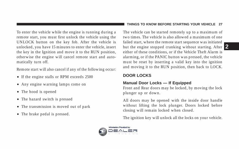
To enter the vehicle while the engine is running during aremote start, you must first unlock the vehicle using theUNLOCK button on the key fob. After the vehicle isunlocked, you have 15 minutes to enter the vehicle, insertthe key in the Ignition and move it to the RUN position,otherwise the engine will cancel remote start and auto-matically turn off.
Remote start will also cancel if any of the following occur:
• If the engine stalls or RPM exceeds 2500
• Any engine warning lamps come on
• The hood is opened
• The hazard switch is pressed
• The transmission is moved out of park
• The brake pedal is pressed.
The vehicle can be started remotely up to a maximum oftwo times. The vehicle is also allowed a maximum of onefailed start, where the remote start sequence was initiatedbut the engine stopped cranking without starting. Aftereither of these conditions, or if the Vehicle Theft Alarm isalarming, or if the PANIC button was pressed, the vehiclemust be reset by inserting a valid key into the ignitionand moving it to the RUN position, then back to LOCK.
DOOR LOCKS
Manual Door Locks — If EquippedFront and Rear doors may be locked, by moving the lockplunger up or down.
All doors may be opened with the inside door handlewithout lifting the lock plunger. Doors locked beforeclosing will remain locked when closed.
The ignition key will unlock all the locks on your vehicle.
THINGS TO KNOW BEFORE STARTING YOUR VEHICLE 27
2
Information Provided by:

WARNING!
• For personal security and safety in the event of anaccident, lock the vehicle doors when you drive aswell as when you park and leave the vehicle.
• Never leave children alone in a vehicle. Leavingchildren in a vehicle unattended is dangerous for anumber of reasons. A child or others could beseriously or fatally injured. Don’t leave the keys inthe ignition. A child could operate power win-dows, other controls, or move the vehicle.
Power Door Locks — If EquippedA power door lock switch is on each front door trimpanel. Use this switch to lock or unlock the doors.
If you press the power door lock switch while the key isin the ignition, and any front door is open, the powerlocks will not operate. This prevents you from acciden-tally locking your keys in the vehicle. Removing the keyor closing the door will allow the locks to operate. Achime will sound if the key is in the ignition switch anda door is open, as a reminder to remove the key.
Power Door Lock Switch Location
28 THINGS TO KNOW BEFORE STARTING YOUR VEHICLE
Information Provided by:

Automatic Door Locks – If EquippedIf this feature is enabled, your door locks will lockautomatically when the vehicle’s speed exceeds 15 mph.
Automatic Door Lock ProgrammingThis feature is enabled when your vehicle is shippedfrom the assembly plant and can be disabled by using thefollowing procedure:
• For vehicles equipped with the Electronic VehicleInformation Center (EVIC), refer to “Personal Settings(Customer Programmable Features)” under “Elec-tronic Vehicle Information Center (EVIC)” in Section 3of this manual for details.
• For vehicles not equipped with the EVIC, performingthe following procedure:
1. Enter your vehicle and close all doors.
2. Fasten your seat belt (Fastening the seat belt willcancel any chiming that may confuse you during thisprogramming procedure).
3. Place the key into the ignition.
4. Within 15 seconds cycle the key from the LOCKposition to the ON/RUN position a minimum of fourtimes; ending in the LOCK position (do not start theengine).
5. Within 30 seconds, press the driver’s door lock switchin the LOCK direction.
6. A single chime will be heard to indicate the feature hasbeen disabled.
7. To reactivate this feature, repeat the above steps.
8. If a chime is not heard, program mode was canceledbefore the feature could be disabled. If necessary, repeatthe above procedure.
THINGS TO KNOW BEFORE STARTING YOUR VEHICLE 29
2
Information Provided by:

Auto Unlock On Exit — If EquippedThis feature unlocks all of the doors of the vehicle whenany door is opened. This will occur only after the vehiclehas been shifted into the Park position after the vehiclehas been driven (shifted out of Park and all doors closed).This feature will not operate if there is any manualoperation of the power door locks (Lock or Unlock).
Auto Unlock On Exit Programming — If EquippedCustomer Programming sequence to enable or disablethe Auto Unlock Feature:• For vehicles equipped with the Electronic Vehicle
Information Center (EVIC), refer to “Personal Settings(Customer Programmable Features)” under “Elec-tronic Vehicle Information Center (EVIC)” in Section 3of this manual for details.
• For vehicles not equipped with the EVIC, performingthe following procedure:
1. Enter your vehicle and close all doors.
2. Fasten your seat belt (fastening the seat belt will cancelany chimes that may be confusing during this program-ming procedure).
3. Insert the key into the ignition.
4. Within 15 seconds, cycle the key from the LOCKposition to the ON/RUN position a minimum of fourtimes ending in the LOCK position (do not start theengine).
5. Within 30 seconds, press the driver’s door lock switchin the UNLOCK direction.
6. A single chime will sound to indicate the feature hasbeen changed.
7. Repeat the above steps to alternate the availability ofthis feature.
8. If a chime is not heard, program mode was canceledbefore the feature could be changed. If necessary repeatthe above procedure.
30 THINGS TO KNOW BEFORE STARTING YOUR VEHICLE
Information Provided by:

Child Protection Door LockTo provide a safer environment for children riding in therear seat, the rear doors of your vehicle have the child-protection door lock system.
To use the system, open each rear door, slide the lever UPto engage the locks and DOWN to disengage the child-protection locks. When the system on a door is engaged,that door can only be opened by using the outside doorhandle even if the inside door lock is in the unlockedposition.
Child Protection Door Lock Location
Child Lock Control
THINGS TO KNOW BEFORE STARTING YOUR VEHICLE 31
2
Information Provided by:

WARNING!
Avoid trapping anyone in a vehicle in a collision.Remember that the rear doors can only be openedfrom the outside when the child protection locks areengaged.
NOTE: After setting the child protection door locksystem, always test the door from the inside to makecertain it is in the desired position.
NOTE: For emergency exit with the system engaged,move the door lock switch to the UNLOCK position, rolldown the window and open the door with the outsidedoor handle.
WINDOWS
Power Windows – If Equipped
The control on the left front door panel has up-downswitches that give you fingertip control of all powerwindows. There is a single opening and closing switch onthe front passenger door for passenger window control
Power Window Switches
32 THINGS TO KNOW BEFORE STARTING YOUR VEHICLE
Information Provided by:

and on the rear doors of Quad Cab and Mega Cabmodels. The windows will operate only when the igni-tion switch is turned to the ON or ACC (Accessory)position.
WARNING!
Never leave children alone in a vehicle. Leavingchildren in a vehicle unattended is dangerous for anumber of reasons. A child or others could be seri-ously or fatally injured. Don’t leave the keys in theignition. A child could operate power windows,other controls, or move the vehicle.
Auto Down (Driver’s Side Only)The driver’s window switch has an Auto Down feature.Press the window switch past the detent, release, and thewindow will go down automatically.
Window Lockout Switch (4 Door Models Only)The window lockout switch on the driver’s door allowsyou to disable the window control on the other doors. Todisable the window controls on the other doors, press thewindow lock button. To enable the window controls,press the window control button again.
Window Lockout Switch
THINGS TO KNOW BEFORE STARTING YOUR VEHICLE 33
2
Information Provided by:

Power Sliding Rear Window – If Equipped
The power sliding rear window switch is located on theinstrument panel below the climate controls. Press theright side of the switch to open the glass and the left sideof the switch to close the glass.
Sliding Rear Window – If EquippedA locking device in the center of the window helps toprevent entry from the rear of the vehicle. Squeeze thelock to release the window.
Wind BuffetingWind buffeting can be described as the perception ofpressure on the ears or a helicopter type sound in theears. Your vehicle may exhibit wind buffeting with thewindows down or partially open positions. This is anormal occurrence and can be minimized. If the buffetingoccurs with the rear windows open, open the front andrear windows together to minimize the buffeting.
Power Sliding Rear Window Switch
34 THINGS TO KNOW BEFORE STARTING YOUR VEHICLE
Information Provided by:

OCCUPANT RESTRAINTSSome of the most important safety features in yourvehicle are the restraint systems. These include the frontand rear seat belts for the driver and all passengers, frontairbags for both the driver and front passenger. If youwill be carrying children too small for adult-size belts,your seat belts also can be used to hold infant and childrestraint systems.Please pay close attention to the information in this section.It tells you how to use your restraint system properly tokeep you and your passengers as safe as possible.
WARNING!
In a collision, you and your passengers can suffermuch greater injuries if you are not properly buckledup. You can strike the interior of your vehicle or otherpassengers, or you can be thrown out of the vehicle.Always be sure you and others in your vehicle arebuckled up properly.
Buckle up even though you are an excellent driver, evenon short trips. Someone on the road may be a poor driverand cause a collision that includes you. This can happenfar away from home or on your own street.
Research has shown that seat belts save lives, and thatthey can reduce the seriousness of injuries in a collision.Some of the worst injuries happen when people arethrown from the vehicle. Seat belts reduce the possibilityof ejection and the risk of injury caused by striking theinside of the vehicle. Everyone in a motor vehicle shouldbe belted at all times.
Lap/Shoulder BeltsAll seating positions except the Quad Cab front centerseating position have combination lap/shoulder belts.The belt webbing retractor is designed to lock duringvery sudden stops or collisions. This feature allows theshoulder part of the belt to move freely with you under
THINGS TO KNOW BEFORE STARTING YOUR VEHICLE 35
2
Information Provided by:
normal conditions. But in a collision, the belt will lockand reduce the risk of your striking the inside of thevehicle or being thrown out.
WARNING!
It is extremely dangerous to ride in a cargo area,inside or outside of a vehicle. In a collision, peopleriding in these areas are more likely to be seriouslyinjured or killed.
Do not allow people to ride in any area of yourvehicle that is not equipped with seats and seat belts.
Be sure everyone in your vehicle is in a seat andusing a seat belt properly.
WARNING!
• Wearing a seat belt incorrectly is dangerous. Seatbelts are designed to go around the large bones ofyour body. These are the strongest parts of yourbody and can take the forces of a collision the best.Wearing your belt in the wrong place could makeyour injuries in a collision much worse. You mightsuffer internal injuries, or you could even slide outof part of the belt. Follow these instructions towear your seat belt safely and to keep your pas-sengers safe, too.
• Two people should never be belted into a singleseat belt. People belted together can crash into oneanother in an accident, hurting one another badly.Never use a lap/shoulder belt or a lap belt for morethan one person, no matter what their size.
36 THINGS TO KNOW BEFORE STARTING YOUR VEHICLE
Information Provided by:

Lap/Shoulder Belt Operating Instructions
1. Enter the vehicle and close the door. Sit back andadjust the seat.
2. The seat belt latch plate is above the back of the frontseat, next to your arm in the rear seat. Grasp the latchplate and pull out the belt. Slide the latch plate up thewebbing as far as necessary to allow the belt to go aroundyour lap.
1 — Latch Plate
THINGS TO KNOW BEFORE STARTING YOUR VEHICLE 37
2
Information Provided by:

3. When the belt is long enough to fit, insert the latchplate into the buckle until you hear a “click.”
WARNING!
• A belt buckled into the wrong buckle will not protectyou properly. The lap portion could ride too high on yourbody, possibly causing internal injuries. Always buckleyour belt into the buckle nearest you.
• A belt that is too loose will not protect you as well. In asudden stop you could move too far forward, increasingthe possibility of injury. Wear your seat belt snugly.
• A belt that is worn under your arm is very dangerous.Your body could strike the inside surfaces of the vehiclein a collision, increasing head and neck injury. And a beltworn under the arm can cause internal injuries. Ribsaren’t as strong as shoulder bones. Wear the belt over yourshoulder so that your strongest bones will take the forcein a collision.
• A shoulder belt placed behind will not protect you frominjury during a collision. You are more likely to hit yourhead in a collision if you do not wear your shoulder belt.The lap and shoulder belt are meant to be used together.
Latch Plate To Buckle
38 THINGS TO KNOW BEFORE STARTING YOUR VEHICLE
Information Provided by:

4. Position the lap belt across your thighs, below yourabdomen. To remove slack in the lap belt portion, pull upon the shoulder belt. To loosen the lap belt if it is too tight,tilt the latch plate and pull on the lap belt. A snug beltreduces the risk of sliding under the belt in a collision.
WARNING!
• A lap belt worn too high can increase the risk ofinternal injury in a collision. The belt forces won’t beat the strong hip and pelvic bones, but across yourabdomen. Always wear the lap belt as low as pos-sible and keep it snug.
• A twisted belt can’t do its job as well. In a collisionit could even cut into you. Be sure the belt is straight.If you can’t straighten a belt in your vehicle, take it toyour dealer and have it fixed.
5. Position the shoulder belt on your chest so that it iscomfortable and not resting on your neck. The retractorwill withdraw any slack in the belt.
Removing Slack From Belt
THINGS TO KNOW BEFORE STARTING YOUR VEHICLE 39
2
Information Provided by:
6. To release the belt, push the red button on the buckle.The belt will automatically retract to its stowed position.If necessary, slide the latch plate down the webbing toallow the belt to retract fully.
WARNING!
A frayed or torn belt could rip apart in a collision andleave you with no protection. Inspect the belt systemperiodically, checking for cuts, frays, or loose parts.Damaged parts must be replaced immediately. Donot disassemble or modify the system. Seat beltassemblies must be replaced after a collision if theyhave been damaged (bent retractor, torn webbing,etc.) or if the airbag deployed.
Standard Cab Front Center Three Point Belt
1. The front center seat belt on the Standard Cab may bedisconnected to open up utilization of the storage areasbehind the front seats. The black latch plate can bedetached from the black keyed seat belt buckle located onthe inboard side of the passenger seat. Insert the vehicleignition key into the center white slot on the black buckle.The black buckle latch plate can be removed when thekey is pressed into the buckle. Allow the retractor to takeup the surplus webbing, and the buckles will hangvertically from the cab back exit bezel, thus freeing up allthe area behind the front seats.
40 THINGS TO KNOW BEFORE STARTING YOUR VEHICLE
Information Provided by:

2. To reattach the seat belt to the front center seat, pullthe black buckle latch plate forward from the cab backpanel and insert it into the black keyed buckle until thereis an audible click. Refer to the previous section for theproper seat belt usage.
WARNING!
• If the black latch and black buckle are not prop-erly connected when the seat belt is used by anoccupant, the seat belt will not be able to provideproper restraint and will increase the risk of injuryin a collision.
• When reattaching the black latch and blackbuckle, ensure the seat belt webbing is nottwisted. If the webbing is twisted, follow thepreceding procedure to detach the black latch andblack buckle, untwist the webbing, and reattachthe black latch and black buckle.
Detaching Buckle with Key
THINGS TO KNOW BEFORE STARTING YOUR VEHICLE 41
2
Information Provided by:

WARNING!
If the black latch and buckle are not connected whenthe seat belt is used by an occupant, the seat belt willnot restrain you properly.
Inserting Latch Plate In Use Position
42 THINGS TO KNOW BEFORE STARTING YOUR VEHICLE
Information Provided by:

Adjustable Upper Shoulder Belt AnchorageIn the front row outboard seats, the shoulder belt can beadjusted upward or downward to help position the beltaway from your neck. Press the button located on theupper belt guide, and then move it up or down to theposition that serves you best.
As a guide, if you are shorter than average, you willprefer a lower position, and if you are taller than average,you’ll prefer a higher position. When you release theanchorage, try to move it up or down to make sure thatit is locked in position.
Automatic Locking Restraint (ALR) Mode – IfEquippedIn this mode, the shoulder belt is automatically pre-locked. The belt will still retract to remove any slack inthe shoulder belt. The automatic locking mode is avail-able on all passenger seating positions with a combina-tion lap/shoulder belt.
When To Use The Automatic Locking ModeAnytime a child safety seat is installed in a passengerseating position. Children 12 years old and under shouldbe properly restrained in the rear seat whenever possible.
Adjusting Upper Shoulder Belt
THINGS TO KNOW BEFORE STARTING YOUR VEHICLE 43
2
Information Provided by:
How To Use The Automatic Locking Mode
1. Buckle the combination lap/shoulder belt.
2. Grasp the shoulder portion and pull downward untilthe entire belt is extracted.
3. Allow the belt to retract. As the belt retracts, you willhear a clicking sound. This indicates the safety belt isnow in the automatic locking mode.
How To Disengage The Automatic Locking ModeDisconnect the combination lap/shoulder belt and allowit to retract completely to disengage the automatic lock-ing mode and activate the vehicle sensitive (emergency)locking mode.
Center Lap BeltsThe center seating position for the Quad Cab front seathas a lap belt only. To fasten the lap belt, slide the latchplate into the buckle until you hear a 9click.9 To lengthenthe lap belt, tilt the latch plate and pull. To remove slack,pull the loose end of the webbing. Wear the lap belt snugagainst the hips. Sit back and erect in the seat, then adjustthe belt as tightly as is comfortable.
WARNING!
• A lap belt worn too loose or too high is dangerous.
• A belt worn too loose can allow you to slip downand under the belt in a collision.
• A belt that is too loose or too high will apply crashforces to the abdomen, not to the stronger hipbones. In either case, the risk of internal injuries isgreater. Wear a lap belt low and snug.
44 THINGS TO KNOW BEFORE STARTING YOUR VEHICLE
Information Provided by:

Seat Belt PretensionersThe seat belts for both front seating positions areequipped with pretensioning devices that are designed toremove slack from the seat belt system in the event of acollision. These devices improve the performance of theseat belt by assuring that the belt is tight about theoccupant early in a collision. Pretensioners work for allsize occupants, including those in child restraints.
NOTE: These devices are not a substitute for proper seatbelt placement by the occupant. The seat belt still must beworn snugly and positioned properly.
The pretensioners are triggered by the airbag controlmodule. Like the airbags, the pretensioners are single useitems. After a collision that is severe enough to deploythe airbags and pretensioners, both must be replaced.
Enhanced Driver Seat Belt Reminder System(BeltAlert)If the driver’s seat belt has not been buckled within 60seconds of starting the vehicle and if the vehicle speed isgreater than 5 mph (8 km/h), the Enhanced WarningSystem (BeltAlert) will alert the driver to buckle their seatbelt. The driver should also instruct all other occupants tobuckle their seat belts. If the driver unbuckles the seatbelt while the vehicle is in motion an immediate chimewill be heard and, the Enhanced Warning System(BeltAlert) will continue to chime and flash the Seat BeltWarning Light for 96 seconds or until the driver’s seatbelt is buckled. The Enhanced Warning System(BeltAlert) will be reactivated if the ignition is cycled,driver’s seat belt is unbuckled for more than 10 secondsand the vehicle speed is greater than 5 mph (8 km/h).
THINGS TO KNOW BEFORE STARTING YOUR VEHICLE 45
2
Information Provided by:

The Enhanced Warning System (BeltAlert) can be en-abled or disabled by your authorized dealer or byfollowing these steps:
NOTE: The following steps must occur within the first60 seconds of the ignition switch being turned to the ONor START position. DaimlerChrysler does not recom-mend deactivating the Enhanced Warning System(BeltAlert).
1. With all doors closed and the ignition switch in anyposition except On or Start, buckle the driver’s seat belt.
2. Turn the ignition switch to the ON position and waitfor the Seat Belt Warning Light to turn off.
3. Within 60 seconds of starting the vehicle, unbuckleand then re-buckle the driver’s seat belt at least threetimes within 10 seconds, ending with the seat beltbuckled.
4. Turn off the engine. A single chime will sound tosignify that you have successfully completed the pro-gramming.
The Enhanced Warning System (BeltAlert) can be reacti-vated by repeating this procedure.
NOTE: Although the Enhanced Warning System(BeltAlert) has been deactivated, the Seat Belt WarningLight will continue to illuminate while the driver’s seatbelt remains unbuckled.
46 THINGS TO KNOW BEFORE STARTING YOUR VEHICLE
Information Provided by:

Seat Belts and Pregnant WomenWe recommend that pregnant women use seat beltsthroughout their pregnancies. Keeping the mother safe isthe best way to keep the baby safe.
Pregnant women should wear the lap part of the beltacross the thighs and as snug against the hips as possible.Keep the belt low so that it does not come across theabdomen. That way the strong bones of the hips will takethe force if there is a collision.
Seat Belt ExtenderIf a seat belt is too short, even when fully extended, yourdealer can provide you with a seat belt extender. Thisextender should be used only if the existing belt is notlong enough. When it is not required, remove the ex-tender and store it.
WARNING!
Using a seat belt extender when not needed canincrease the risk of injury in a collision. Only use theseat belt extender when the lap belt is not longenough when it is worn low and snug, and in therecommended seating positions. Remove and storethe extender when not needed.
Driver And Right Front Passenger SupplementalRestraint System (SRS)—AirbagThis vehicle may have front airbags for both the driverand front passenger (if equipped) as a supplement to theseat belt restraint systems. The driver’s front airbag ismounted in the center of the steering wheel. The passen-ger’s front airbag (if equipped) is mounted in the instru-ment panel, above the glove compartment. The wordsSRS AIRBAG are embossed on the airbag covers.
THINGS TO KNOW BEFORE STARTING YOUR VEHICLE 47
2
Information Provided by:

These airbags are certified to the new Federal regulationsthat allow less forceful deployments.
This vehicle may also be equipped without a passengerside airbag. In this case the passenger side airbag will bereplaced with a storage bin.
WARNING!
• Do not put anything on or around the airbagcovers or attempt to manually open them. You maydamage the airbags and you could be injuredbecause the airbags are not there to protect you.These protective covers for the airbag cushions aredesigned to open only when the airbags are inflat-ing.
• Do not mount any aftermarket equipment such astrailer brake controllers, snowplow controllers,auxiliary light switches, radios, etc. on or behindthe knee bolster. Knee bolsters are designed towork with the air bag and seat belt to protect you.Mounting any additional equipment on or behindthe knee bolster can cause injury during a crash.
48 THINGS TO KNOW BEFORE STARTING YOUR VEHICLE
Information Provided by:

Airbags inflate in moderate to high speed impacts. Alongwith the seatbelts, front airbags work with the instrumentpanel knee bolsters to provide improved protection forthe driver and front passenger.
The seat belts are designed to protect you in many typesof collisions. The front airbags deploy in moderate tosevere frontal collisions. In certain types of collisions, thefront airbags may be triggered. But even in collisionswhere the airbags work, you need the seat belts to keepyou in the right position for the airbags to protect youproperly.
Here are some simple steps you can follow to minimizethe risk of harm from a deploying airbag.
• Children 12 years and under should ride buckled up ina rear seat, if available.
• Infants in rear facing child restraints must NEVERride in the front seat of a vehicle with a passenger front
airbag unless the airbag is turned off (Standard CabVehicles Only). An airbag deployment can cause se-vere injury or death to infants in that position. See thePassenger Airbag On/Off Switch (If Equipped) sec-tion.
• If your vehicle does not have a rear seat, see thePassenger Airbag On/Off Switch (If Equipped) sec-tion.
• Children that are not big enough to properly wear thevehicle seat belt (see section on Child Restraints)should be secured in the rear seat in child restraints orbelt-positioning booster seats. Older children who donot use child restraints or belt-positioning boosterseats should ride properly buckled up in the rear seat.Never allow children to slide the shoulder belt behindthem or under their arm.
• All occupants should use their seat belts properly.
THINGS TO KNOW BEFORE STARTING YOUR VEHICLE 49
2
Information Provided by:
• The driver and front passenger seats should be movedback as far as practical to allow the airbag room toinflate.
WARNING!
• Relying on the airbags alone could lead to moresevere injuries in a collision. The airbags workwith your seat belt to restrain you properly. Insome collisions the airbags won’t deploy at all.Always wear your seat belts even though you haveairbags.
• Being too close to the steering wheel or instrumentpanel during airbag deployment could cause seri-ous injury. Airbags need room to inflate. Sit back,comfortably extending your arms to reach thesteering wheel or instrument panel.
Airbag System Components
The airbag system consists of the following:
• Airbag Control Module
• AIRBAG Readiness Light
• Driver Airbag
• Passenger Airbag (If Equipped)
• Steering Wheel and Column
• Instrument Panel
• Crash Sensor
• Interconnecting Wiring
• Knee Impact Bolsters
• Passenger Side Frontal Airbag ON/OFF Switch (Stan-dard Cab Vehicles Only ) (If Equipped)
50 THINGS TO KNOW BEFORE STARTING YOUR VEHICLE
Information Provided by:

How The Airbag System Works
• The airbag control module determines if a frontalcollision is severe enough to require the airbags toinflate.
• The airbag control module will not detect roll over, orrear collisions.
• The airbag control module also monitors the readinessof the electronic parts of the system whenever theignition switch is in the START or RUN positions.These include all of the items listed above except theknee bolsters, the instrument panel, and the steeringwheel and column. If the key is in the 9Off9 position, inthe ACC position or not in the ignition, the airbags arenot on and will not inflate
• The airbag control module also turns on the AIR BAGlight in the instrument panel for 6 to 8 seconds whenthe ignition is first turned on, then turns the light off.
• If it detects a malfunction in any part of thesystem, it turns on the light either momen-tarily or continuously. The instrument clus-ter will flash the seat belt indicator if itdetects a fault with the airbag indicator.
WARNING!
Ignoring the AIR BAG light in your instrument panelcould mean you won’t have the airbags to protect youin a collision. If the light does not come on, stays onafter you start the vehicle, or if it comes on as youdrive, have the airbag system checked right away.
THINGS TO KNOW BEFORE STARTING YOUR VEHICLE 51
2
Information Provided by:

• When the airbag control module detects a collisionrequiring the airbags, it signals the inflator units. Alarge quantity of nontoxic gas is generated to inflatethe airbags. The airbag covers separate and fold out ofthe way as the airbags inflate to their full size. Theairbags fully inflate in milliseconds. This is less timethan it takes you to blink your eyes. The airbags thenquickly deflate while helping to restrain the driver andfront passenger (if equipped with passenger side air-bag). The driver’s front airbag deflates through ventstowards the instrument panel. The passenger’s frontairbag (if equipped) is deflated through vent holes inthe sides of the airbag. In this way the airbags do notinterfere with your control of the vehicle.
• The knee impact bolsters help protect the knees andposition you for the best interaction with the frontairbag.
Passenger Airbag On/Off Switch – (Standard CabVehicles Only) (If Equipped)
The passenger front airbag is to be turned off only if thepassenger:
• is an infant (less than 1 year old) who must ride in thefront seat because there is no rear seat, because the rearseat is too small for a rear-facing infant restraint or
52 THINGS TO KNOW BEFORE STARTING YOUR VEHICLE
Information Provided by:

because the infant has a medical condition whichmakes it necessary for the driver to be able to see theinfant,
• is a child, age 1 to 12 who must ride in the front seatbecause there is no rear seat, because there is no rearseat position available, or because the child has amedical condition which makes it necessary for thedriver to be able to see the child,
• has a medical condition which makes passenger airbag(if equipped) inflation (deployment) a greater risk forthe passenger than the risk of hitting the dashboard(instrument panel) or windshield in a crash.
WARNING!
Whenever an airbag is turned off, even a lap/shoulder belted passenger may hit their head, neck,or chest on the dashboard (instrument panel) orwindshield in a crash. This may result in seriousinjury or death.
To Shut Off the Passenger Airbag (Standard Cab Ve-hicles Only) (If Equipped)
Place the ignition key in the Passenger Airbag On/OffSwitch (if equipped), push the key in and turn clockwise,and remove the key from the switch. This will shut off thepassenger airbag (if equipped). The “Off” light near theswitch will illuminate when the ignition switch is turnedto the ON position.
THINGS TO KNOW BEFORE STARTING YOUR VEHICLE 53
2
Information Provided by:
To Turn On the Passenger Airbag (Standard Cab Ve-hicles Only) (If Equipped)
Place the ignition key in the Passenger Airbag On/OffSwitch (If Equipped), push the key in and turn counter-clockwise, and remove the key from the switch. This willturn on the passenger airbag (if equipped). The “Off”light near the switch will be off when the ignition switchis turned to the ON position.
If A Deployment OccursThe airbag system is designed to deploy when the air bagcontrol module detects a moderate-to-severe frontal col-lision, and then immediately to deflate.
NOTE: A frontal collision that is not severe enough toneed airbag protection will not activate the system. Thisdoes not mean something is wrong with the airbagsystem.
If you do have a collision which deploys the airbags, anyor all of the following may occur:
• The nylon airbag material may sometimes cause abra-sions and/or skin reddening to the driver and frontpassenger as the airbags deploy and unfold. Theabrasions are similar to friction rope burns or thoseyou might get sliding along a carpet or gymnasiumfloor. They are not caused by contact with chemicals.They are not permanent and normally heal quickly.However, if you haven’t healed significantly within afew days, or if you have any blistering, see your doctorimmediately.
• As the airbags deflate you may see some smoke-likeparticles. The particles are a normal by-product of theprocess that generates the nontoxic gas used for airbaginflation. These airborne particles may irritate the skin,eyes, nose, or throat. If you have skin or eye irritation,rinse the area with cool water. For nose or throat
54 THINGS TO KNOW BEFORE STARTING YOUR VEHICLE
Information Provided by:

irritation, move to fresh air. If the irritation continues,see your doctor. If these particles settle on yourclothing, follow the garment manufacturer’s instruc-tions for cleaning.
• It is not advisable to drive your vehicle after theairbags have deployed. If you are involved in anothercollision, the airbags will not be in place to protect you.
WARNING!
Deployed airbags can’t protect you in another colli-sion. Have the airbags replaced by an authorizeddealer as soon as possible.
Enhanced Accident Response SystemIf the airbags deploy after an impact and the electricalsystem remains functional, vehicles equipped withpower door locks will unlock automatically. In addition,approximately 10 seconds after the vehicle has stoppedmoving, the interior lights will light until the ignitionswitch is turned off.
THINGS TO KNOW BEFORE STARTING YOUR VEHICLE 55
2
Information Provided by:

Maintaining Your Airbag Systems
WARNING!
• Modifications to any part of the airbag systemcould cause it to fail when you need it. You could beinjured because the airbags are not there to protectyou. Do not modify the components or wiring,including adding any kind of badges or stickers tothe steering wheel hub trim cover or the upper rightside of the instrument panel. Do not modify thefront bumper, vehicle body structure, or frame.
• You need proper knee impact protection in a colli-sion. Do not mount or locate any aftermarket equip-ment on or behind the knee bolster.
• It is dangerous to try to repair any part of the airbagsystem yourself. Be sure to tell anyone who workson your vehicle that it has airbags.
NOTE: Perchlorate Material – special handling mayapply, See www.dtsc.ca.gov/hazardouswaste/perchlorate
Airbag LightYou will want to have the airbags ready toinflate for your protection in an impact. Whilethe airbag system is designed to be mainte-nance free, if any of the following occurs, have
an authorized dealer service the system promptly:
• The airbag light does not come on or flickers duringthe 6 to 8 seconds when the ignition switch is firstturned on.
• The light remains on or flickers after the 6 to 8 secondinterval.
• The light flickers or comes on and remains on whiledriving.
56 THINGS TO KNOW BEFORE STARTING YOUR VEHICLE
Information Provided by:

NOTE: If the speedometer, tachometer or any enginerelated gauges are not working, the airbag control mod-ule may also be disabled. The airbags may not be readyto inflate for your protection. Promptly check fuse blockfor blown fuses. Refer to the label located on the inside ofthe fuse block cover for the proper airbag fuses. See yourdealer if the fuse is good.
Event Data Recorder (EDR)In the event of an accident, your vehicle is designed torecord up to 5-seconds of specific vehicle data parameters(see the following list) in an event data recorder prior tothe moment of airbag deployment, or near deployment,and up to a quarter second of high-speed decelerationdata during and/or after airbag deployment. EDR dataare ONLY recorded if an airbag deploys, or nearlydeploys, and are otherwise unavailable.
NOTE:1. A near-deployment event occurs when the airbagsensor detects severe vehicle deceleration usually indica-tive of a crash, but not severe enough to warrant airbagdeployment.
2. Under certain circumstances, EDR data may not berecorded (e.g., loss of battery power).
In conjunction with other data gathered during a com-plete accident investigation, the electronic data may beused by DaimlerChrysler Corporation and others to learnmore about the possible causes of crashes and associatedinjuries in order to assess and improve vehicle perfor-mance. In addition to crash investigations initiated byDaimlerChrysler Corporation, such investigations maybe requested by customers, insurance carriers, govern-ment officials, and professional crash researchers, such asthose associated with universities, and with hospital andinsurance organizations.
THINGS TO KNOW BEFORE STARTING YOUR VEHICLE 57
2
Information Provided by:

In the event that an investigation is undertaken byDaimlerChrysler Corporation (regardless of initiative),the company or its designated representative will firstobtain permission of the appropriate custodial entity forthe vehicle (usually the vehicle owner or lessee) beforeaccessing the electronic data stored, unless ordered todownload data by a court with legal jurisdiction (i.e.,pursuant to a warrant). A copy of the data will beprovided to the custodial entity upon request. Generaldata that does not identify particular vehicles or crashesmay be released for incorporation in aggregate crashdatabases, such as those maintained by the US govern-ment and various states. Data of a potentially sensitivenature, such as would identify a particular driver, ve-hicle, or crash, will be treated confidentially. Confidentialdata will not be disclosed by DaimlerChrysler Corpora-tion to any third party except when:
1. Used for research purposes, such as to match datawith a particular crash record in an aggregate database,provided confidentiality of personal data is thereafterpreserved
2. Used in defense of litigation involving aDaimlerChrysler Corporation product
3. Requested by police under a legal warrant
4. Otherwise required by law
Data Parameters that May Be Recorded:
• Diagnostic trouble code(s) and warning lamp statusfor electronically-controlled safety systems, includingthe airbag system
• Airbag disable lamp status (if equipped)
• 9Time9 of airbag deployment (in terms of ignitioncycles and vehicle mileage)
58 THINGS TO KNOW BEFORE STARTING YOUR VEHICLE
Information Provided by:

• Airbag deployment level (if applicable)
• Impact acceleration and angle
• Seatbelt status
• Brake status (service and parking brakes)
• Accelerator status (including vehicle speed)
• Engine control status (including engine speed)
• Transmission gear selection
• Cruise control status
• Traction/stability control status
• Tire pressure monitoring system status (if equipped)
Child RestraintEveryone in your vehicle needs to be buckled up all thetime — babies and children, too. Every state in the UnitedStates and all Canadian provinces require that smallchildren ride in proper restraint systems. This is the law,and you can be prosecuted for ignoring it.
Children 12 years and under should ride properly buck-led up in a rear seat, if available. According to crashstatistics, children are safer when properly restrained inthe rear seats rather than in the front.
THINGS TO KNOW BEFORE STARTING YOUR VEHICLE 59
2
Information Provided by:

WARNING!
In a collision, an unrestrained child, even a tiny baby,can become a missile inside the vehicle. The forcerequired to hold even an infant on your lap canbecome so great that you could not hold the child, nomatter how strong you are. The child and others couldbe badly injured. Any child riding in your vehicleshould be in a proper restraint for the child’s size.
Infants and Small ChildrenThere are different sizes and types of restraints forchildren from newborn size to the child almost largeenough for an adult safety belt. Use the restraint that iscorrect for your child:
• Safety experts recommend that children riderearward-facing in the vehicle until they are at leastone year old and weigh at least 20 lbs (9 kg). Two types
of child restraints can be used rearward-facing: infantcarriers and 9convertible9 child seats. Both types ofchild restraints are held in the vehicle by the lap/shoulder belt.
• The infant carrier is only used rearward-facing in thevehicle. It is recommended for children who weigh upto about 20 lbs (9 kg). 9Convertible9 child seats can beused either rearward-facing or forward-facing in thevehicle. Convertible child seats often have a higherweight limit in the rearward-facing direction thaninfant carriers do, so they can be used rearward-facingby children who weigh more than 20 lbs (9 kg) but areless than one year old.
• Rearward-facing child seats must NEVER be used inthe front seat of a vehicle with a front passenger airbag(if equipped) unless the airbag is turned off. An airbagdeployment could cause severe injury or death toinfants in this position.
60 THINGS TO KNOW BEFORE STARTING YOUR VEHICLE
Information Provided by:

• Children who weigh more than 20 lbs (9 kg) and whoare older than one year can ride forward-facing in thevehicle. Forward-facing child seats and convertiblechild seats used in the forward-facing direction are forchildren who weigh 20 to 40 lbs (9 to 18 kg) and whoare older than one year. These child seats are also heldin the vehicle by the lap/shoulder belt.
• The belt-positioning booster seat is for children weigh-ing more than 40 lbs (18 kg), but who are still too smallto fit the vehicle’s seat belts properly. If the childcannot sit with knees bent over the vehicle’s seatcushion while the child’s back is against the seat back,they should use a belt-positioning-booster seat. Thechild and booster seat are held in the vehicle by thelap/shoulder belt. (Some booster seats are equippedwith a front shield and are held in the vehicle by thelap portion.) For further information refer towww.seatcheck.org.
WARNING!
• Improper installation can lead to failure of aninfant or child restraint. It could come loose in acollision. The child could be badly injured orkilled. Follow the manufacturer’s directions ex-actly when installing an infant or child restraint.
• A rearward facing child restraint should only beused in a rear seat, or in the front seat if thepassenger’s front airbag is Off. If the airbag is leftOn, a rearward facing child restraint in the frontseat may be struck by a deploying passengerairbag (if equipped) which may cause severe orfatal injury to the infant.
THINGS TO KNOW BEFORE STARTING YOUR VEHICLE 61
2
Information Provided by:
Here are some tips for getting the most out of your childrestraint:
• Before buying any restraint system, make sure that ithas a label certifying that it meets all applicable SafetyStandards. We also recommend that you make surethat you can install the child restraint in the vehiclewhere you will use it before you buy it.
• The restraint must be appropriate for your child’sweight and height. Check the label on the restraint forweight and height limits.
• Carefully follow the instructions that come with therestraint. If you install the restraint improperly, it maynot work when you need it.
• The passenger seat belts are equipped with AutomaticLocking Retractors (ALR), which are designed to keepthe lap portion tight around the child restraint so thatit is not necessary to use a locking clip.
Pull the belt from the retractor until there is enough toallow you to pass through the child restraint and slidethe latch plate into the buckle. Then pull on the beltuntil it is all removed from the retractor. Allow the beltto return to the retractor, pulling on the excess web-bing to tighten the lap portion about the child re-straint. Refer to the 9Automatic Locking Retractors(ALR) Mode9 earlier in this section.
• In the rear seat, you may have trouble tightening thelap/shoulder belt on the child restraint because thebuckle or latch plate is too close to the belt pathopening on the restraint. Disconnect the latch platefrom the buckle and twist the short buckle-end beltseveral times to shorten it. Insert the latch plate intothe buckle with the release button facing out.
• If the belt still can’t be tightened, or if pulling andpushing on the restraint loosens the belt, disconnectthe latch plate from the buckle, turn the latch plate
62 THINGS TO KNOW BEFORE STARTING YOUR VEHICLE
Information Provided by:
around, and insert the latch plate into the buckleagain. If you still can’t make the child restraint secure,try a different seating position.
• Buckle the child into the seat according to the childrestraint manufacturer’s directions.
• When your child restraint is not in use, secure it in thevehicle with the seat belt or remove it from the vehicle.Do not leave it loose in the vehicle. In a sudden stop orcollision, it could strike the occupants or seat backsand cause serious personal injury.
WARNING!
Improper installation can lead to failure of an infantor child restraint. It could come loose in a collision.The child could be badly injured or killed. Followthe manufacturer’s directions exactly when installingan infant or child restraint.
Lower Anchors and Tether for CHildren (LATCH)Each vehicle is equipped with the child restraint anchor-age system called LATCH, which stands for LowerAnchors and Tether for CHildren. LATCH child restraintanchorage systems are installed in the Standard Cabpassenger seat position and the Quad Cab rear seatoutboard positions. LATCH equipped seating positionsfeature both lower anchor bars, located at the back of theseat cushion, and tether strap anchorages, located behindthe seatback (refer to Child Restraint Tether Anchor laterin this section).
Identification dots are located above the standard cabfront seat lower anchorages as a guide for locating loweranchors.
THINGS TO KNOW BEFORE STARTING YOUR VEHICLE 63
2
Information Provided by:

NOTE: For children riding in the front seat of a Stan-dard Cab model refer to the “Passenger Airbag On/OffSwitch” (If Equipped) located in this section.
Standard Cab Passenger Seat
Quad Cab Rear Outboard Seats
64 THINGS TO KNOW BEFORE STARTING YOUR VEHICLE
Information Provided by:

Child restraint systems having attachments designed toconnect to the lower anchorages are now available. Childrestraints having tether straps and hooks for connectionto the seatback tether anchorage have been available forsome time. In fact, many child restraint manufacturerswill provide add-on tether strap kits for some of theirolder products.
Because the lower anchorages are to be introduced topassenger carrying vehicles over a period of years, childrestraint systems having attachments for those anchor-ages will continue to have features for installation invehicles using the lap or lap/shoulder belt. They will alsohave tether straps, and you are urged to take advantageof all of the available attachments provided with yourchild restraint in any vehicle.
NOTE: When using the LATCH attaching system toinstall a child restraint, please ensure that all seat beltsnot being used for occupant restraints are stowed and outof reach of children. It is recommended that beforeinstalling the child restraint, buckle the seat belt so theseat belt is tucked behind the child restraint and out ofreach. If the buckled seat belt interferes with the childrestraint installation, instead of tucking the seat beltbehind the child restraint, route the seat belt through thechild restraint belt path and then buckle it. This shouldstow the seat belt out of the reach of an inquisitive child.Remind all children in the vehicle that the seat belts arenot toys and should not be played with, and never leaveyour child unattended in the vehicle.
NOTE: If your child restraint seat is not LATCH com-patible, install the restraint using the vehicle seat belting.
THINGS TO KNOW BEFORE STARTING YOUR VEHICLE 65
2
Information Provided by:
Installing the Child Restraint System
WARNING!
Do not install child restraint systems equipped withLATCH attachments in the center position of a QuadCab model rear seat. The LATCH anchorages in thisseat are designed for the two outboard seating posi-tions only. A child may be placed in the rear centerseating position of a Quad Cab model using the seatbelt and child tether anchorage. Failure to follow thismay result in serious or fatal injury.
We urge that you carefully follow the directions of themanufacturer when installing your child restraint. Many,but not all, restraint systems will be equipped withseparate straps on each side, with each having a hook orconnector and a means for adjusting the tension in thestrap. Forward-facing toddler restraints and somerearward-facing infant restraints will also be equipped
with a tether strap, a hook and means for adjusting thetension in the strap.
In general, you will first loosen the adjusters on the lowerstraps and tether straps so that you can more easily attachthe hook or connector to the lower anchorages and tetheranchorages. Then tighten all three straps as you push thechild restraint rearward and downward into the seat.
Not all child restraint systems will be installed as wehave described here. Again, carefully follow the instruc-tions that come with the child restraint system.
WARNING!
Improper installation of a child restraint to theLATCH anchorages can lead to failure of an infant orchild restraint. The child could be badly injured orkilled. Follow the manufacturer’s directions exactlywhen installing an infant or child restraint.
66 THINGS TO KNOW BEFORE STARTING YOUR VEHICLE
Information Provided by:

Child Restraint Tether AnchorChild restraints having tether straps and hooks for con-nection to tether anchors have been available for sometime. In fact, many child restraint manufacturers willprovide add-on tether strap kits for their older products.Regular Cab models of Ram Pickups have two tetheranchorages, one each behind the front center and rightseats. Quad Cab and Mega Cab models have threeanchorages, one behind each of the rear seats.
WARNING!
An incorrectly anchored tether strap could lead toseat failure and injury to the child. In a collision, theseat could come loose and allow the child to crashinto the inside of the vehicle or other passengers, oreven be thrown from the vehicle. Use only the anchorpositions directly behind the child seat to secure achild restraint top tether strap. Follow the instruc-tions below. See your dealer for help if necessary.
Tether Anchorage Points at the Right and CenterFront Seat (Regular Cab - All Seats)
1. Place the child restraint on the seat and adjust the tetherstrap so that it will reach over the seat back under the headrestraint to the tether anchor directly behind the seat.
2. Lift the cover (if so equipped), and attach the hook tothe square opening in the sheet metal.
THINGS TO KNOW BEFORE STARTING YOUR VEHICLE 67
2
Information Provided by:

3. Install the child restraint and remove the slack in thetether strap according to the manufacturer’s instructions.
Multiple Child Restraint Installation Sequence -(Quad Cab Rear Seats)
1. Obtain tether straps by raising the head restraints andreaching between the rear glass and rear seat. The tether
strap may be retained with an elastic band. Accessibility tothe tether strap is greatly improved by raising the seatcushion to the “up” position. Remove the elastic before use.2. Place a child restraint on each outboard rear seat andadjust the tether strap so that it will reach under the headrestraint to the tether anchor directly behind the seat andthen to the anchor directly behind the center rear seat.3. Pass each tether strap hook under the head restraintand through the loop of webbing behind the child seat.4. Route each tether strap to the anchor behind the centerseat, and attach the hooks to the metal ring.5. Place a child restraint on the center rear seat andadjust the tether strap so that it will reach under the headrestraint to the tether anchor directly behind the seat andto the anchor directly behind the right seat.6. Install each child restraint and remove the slack in thetether strap according to the child restraint manufactur-er’s instructions.
Regular Cab Tether Strap Mounting
68 THINGS TO KNOW BEFORE STARTING YOUR VEHICLE
Information Provided by:

Multiple Child Restraint Quad Cab
THINGS TO KNOW BEFORE STARTING YOUR VEHICLE 69
2
Information Provided by:

Tether Anchorage Points at All Three SeatingPositions (Mega Cab)
1. Place the child restraint on the seat and adjust thetether strap so that it will reach over the seat back underthe head restraint to the tether anchor directly behind theseat.
2. Lift the cover, and attach the hook to the squareopening in the sheet metal.
3. Install the child restraint and remove the slack in thetether strap according to the manufacturer’s instructions.
Mega Cab Tether Strap Mounting
70 THINGS TO KNOW BEFORE STARTING YOUR VEHICLE
Information Provided by:
Children Too Large for Booster SeatsChildren who are large enough to wear the shoulder beltcomfortably, and whose legs are long enough to bendover the front of the seat when their back is against theseat back should use the lap/shoulder belt in a rear seat.
• Make sure that the child is upright in the seat.
• The lap portion should be low on the hips and as snugas possible.
• Check belt fit periodically. A child’s squirming orslouching can move the belt out of position.
If the shoulder belt contacts the face or neck, move thechild closer to the center of the vehicle. Never allow achild to put the shoulder belt under an arm or behindtheir back.
NEW ENGINE BREAK-IN
5.7L Gas EngineA long break-in period is not required for the engine inyour new vehicle. Drive moderately during the first 300miles (500 km). After the initial 60 miles (100 km), speedsup to 50 or 55 mph (80 or 90 km/h) are desirable. Whilecruising, brief full-throttle acceleration, within the limitsof local traffic laws, contributes to a good break-in.
Avoid wide open throttle acceleration in low gear.
The engine oil installed in the engine at the factory is ahigh quality, energy conserving type lubricant. Oilchanges should be consistent with the anticipated cli-matic conditions under which vehicle operation willoccur. The recommended viscosity and quality grades arediscussed in Section 7 under Maintenance Procedures,Engine Oil.
THINGS TO KNOW BEFORE STARTING YOUR VEHICLE 71
2
Information Provided by:

NON-DETERGENT OR STRAIGHT MINERAL OILSMUST NEVER BE USED.
A new engine may consume some oil during its first fewthousand miles of operation. This is a normal part of thebreak-in and is not an indication of difficulty.
CAUTION!
• During the first 500 miles (805 km) your newvehicle is driven, do not tow a trailer. Doing somay damage your axles, driveline and vehicle.
• Limit your speed to 50 mph (80 km/h) during thefirst 500 miles (805 km) of towing.
6.7L Diesel EngineYour Cummins 24 Valve Turbo Diesel engine does notrequire a break-in period due to its construction. Normaloperation is allowed, provided the following recommen-dations are followed:
NOTE: Light duty operation such as light trailer towingor no load operation, will extend the time before theengine is at full efficiency and may effect the performanceof the vehicle aftertreatment (exhaust) system. Reducedfuel economy and power may be seen at this time.
• Warm up the engine before placing it under load.
• Do not operate the engine at idle for prolongedperiods.
• Use the appropriate transmission gear to preventengine lugging.
• Observe vehicle oil pressure and temperature indica-tors.
72 THINGS TO KNOW BEFORE STARTING YOUR VEHICLE
Information Provided by:

• Check the coolant and oil levels frequently.
• Vary throttle position at highway speeds when carry-ing or towing significant weight.
Because of the construction of the Cummins Dieselengine, engine run-in is enhanced by loaded operatingconditions which allow the engine parts to achieve finalfinish and fit during the first 6,000 miles (10 000 km).
CAUTION!
• During the first 500 miles (805 km) your newvehicle is driven, do not tow a trailer. Doing somay damage your axles, drivetrain and vehicle.
• Limit your speed to 50 mph (80 km/h) during thefirst 500 miles (805 km) of towing.
SAFETY TIPS
Transporting PassengersThis vehicle is designed to carry passengers in the cabonly. For safety reasons, NEVER TRANSPORT PASSEN-GERS IN THE CARGO AREA.
WARNING!
It is extremely dangerous to ride in a cargo area,inside or outside of a vehicle. In a collision, peopleriding in these areas are more likely to be seriouslyinjured or killed.
Do not allow people to ride in any area of yourvehicle that is not equipped with seats and seat belts.
Be sure everyone in your vehicle is in a seat andusing a seat belt properly.
THINGS TO KNOW BEFORE STARTING YOUR VEHICLE 73
2
Information Provided by:

Lock Your VehicleAlways remove the keys from the ignition and lock alldoors when leaving the vehicle unattended, even in yourown driveway or garage. Try to park your vehicle in awell-lighted area and never invite theft by leaving ar-ticles of value exposed.
Exhaust Gas
WARNING!
Exhaust gases contain carbon monoxide, a potentiallytoxic gas that by itself is colorless and odorless. Toavoid inhaling these gases, the following precautionsshould be observed:
• Do not run the engine in a closed garage or in confinedareas any longer than needed to move your vehicle inor out of the area.
• If it is necessary to sit in a parked vehicle with theengine running for more than a short period, adjustyour climate control system to force outside air intothe vehicle. Set the blower at high speed and thecontrols in any position except OFF or MAX A/C.
• The best protection against carbon monoxide entryinto the vehicle body is a properly maintained engineexhaust system.
Be aware of changes in the sound of the exhaust system;exhaust fumes detected inside the vehicle; or damage tothe underside or rear of the vehicle. Have a competentmechanic inspect the complete exhaust system and adja-cent body areas for broken, damaged, deteriorated ormispositioned parts. Open seams or loose connectionscould permit exhaust fumes to seep into the passengercompartment. In addition, inspect the exhaust systemeach time the vehicle is raised for lubrication or oilchange. Replace or adjust as required.
74 THINGS TO KNOW BEFORE STARTING YOUR VEHICLE
Information Provided by:

Safety Checks You Should Make Inside TheVehicle
Heater Defroster DuctsInspect the heater defroster ducts for proper operation.Check for proper air flow through all defroster ducts. Ifthere are any question regarding the operation of yourheater defroster ducts, have the system checked by anauthorized dealer
Seat BeltsInspect the belt system periodically, checking for cuts,frays and loose parts. Damaged parts must be replacedimmediately. Do not disassemble or modify the system.
Seat belt assemblies must be replaced after an accident ifthey have been damaged (bent retractor, torn webbing,etc.) or if the front airbags have deployed. If there is anyquestion regarding belt or retractor condition, replace thebelt.
Airbag LightThe light should come on and remain on for 6 to 8seconds as a bulb check when the ignition switch is firstturned ON. If the light is not lit during starting, see yourauthorized dealer. If the light stays on, flickers or comeson while driving, have the system checked by an autho-rized dealer. If there is a problem with the airbag light theseatbelt light will flash.
Safety Checks You Should Make Outside TheVehicle
TiresExamine tires for tread wear or uneven wear patterns.Check for stones, nails, glass or other objects lodged inthe tread.
Inspect for tread cuts or sidewall cracks. Check wheelnuts for tightness and tires for proper pressure.
THINGS TO KNOW BEFORE STARTING YOUR VEHICLE 75
2
Information Provided by:

LightsCheck the operation of all exterior lights. Check turnsignal and high beam indicator lights on the instrumentpanel.
Door LatchesCheck for positive closing, latching and locking.
Fluid LeaksCheck area under vehicle after overnight parking for fuel,water, oil, or other fluid leaks. Also, if fuel fumes aredetected the cause should be located and corrected.
76 THINGS TO KNOW BEFORE STARTING YOUR VEHICLE
Information Provided by:

UNDERSTANDING THE FEATURES OF YOUR VEHICLE
CONTENTS
m Mirrors . . . . . . . . . . . . . . . . . . . . . . . . . . . . . . .81
▫ Inside Mirror . . . . . . . . . . . . . . . . . . . . . . . . .81
▫ Automatic Dimming Mirror – If Equipped . . . .82
▫ Outside Mirrors . . . . . . . . . . . . . . . . . . . . . . .82
▫ Exterior Mirrors Folding Feature . . . . . . . . . . .83
▫ Electronic Power Mirrors – If Equipped . . . . . .84
▫ Electric Rear Window Defroster And HeatedSideview Mirrors – If Equipped . . . . . . . . . . . .85
▫ Trailer Towing Mirrors – If Equipped . . . . . . . .85
m Hands–Free Communication (UConnect™) —If Equipped . . . . . . . . . . . . . . . . . . . . . . . . . . . .87
▫ Operations . . . . . . . . . . . . . . . . . . . . . . . . . . .89
▫ Phone Call Features . . . . . . . . . . . . . . . . . . . .96
▫ UConnect™ System Features . . . . . . . . . . . . . .99
▫ Advanced Phone Connectivity . . . . . . . . . . . . 103
▫ Things You Should Know About YourUConnect™ System . . . . . . . . . . . . . . . . . . . . 106
▫ General Information . . . . . . . . . . . . . . . . . . . 113
3
Information Provided by:

m Seats . . . . . . . . . . . . . . . . . . . . . . . . . . . . . . . . 114
▫ 40-20-40 Front Seat . . . . . . . . . . . . . . . . . . . . 114
▫ Reclining Seats . . . . . . . . . . . . . . . . . . . . . . . 115
▫ Adjustable Head Restraints . . . . . . . . . . . . . . 116
▫ Manual Rotary Lumbar Support Adjustment —If Equipped . . . . . . . . . . . . . . . . . . . . . . . . . 117
▫ Power Seats — If Equipped . . . . . . . . . . . . . . 117
▫ Heated Seats — If Equipped . . . . . . . . . . . . . 119
m To Open And Close The Hood . . . . . . . . . . . . . 120
m Lights . . . . . . . . . . . . . . . . . . . . . . . . . . . . . . . 122
▫ Interior Lights . . . . . . . . . . . . . . . . . . . . . . . 122
▫ Battery Saver . . . . . . . . . . . . . . . . . . . . . . . . 123
▫ Headlamp Delay . . . . . . . . . . . . . . . . . . . . . . 124
▫ Headlights, Parking Lights, Panel Lights . . . . . 124
▫ Daytime Running Lights(Canada Only And Fleet Vehicles) . . . . . . . . . . 125
▫ Lights-On Reminder . . . . . . . . . . . . . . . . . . . 125
▫ Fog Lights — If Equipped . . . . . . . . . . . . . . . 125
▫ Multifunction Control Lever . . . . . . . . . . . . . . 126
m Windshield Wipers And Washers . . . . . . . . . . . . 128
▫ Windshield Wipers . . . . . . . . . . . . . . . . . . . . 128
▫ Windshield Washers . . . . . . . . . . . . . . . . . . . 129
m Tilt Steering Column . . . . . . . . . . . . . . . . . . . . 130
m Driver Adjustable Pedals — If Equipped . . . . . . 131
▫ Adjustment . . . . . . . . . . . . . . . . . . . . . . . . . 131
m Electronic Speed Control — If Equipped . . . . . . 132
▫ To Activate . . . . . . . . . . . . . . . . . . . . . . . . . . 133
▫ To Set At A Desired Speed . . . . . . . . . . . . . . . 133
78 UNDERSTANDING THE FEATURES OF YOUR VEHICLE
Information Provided by:
▫ To Deactivate . . . . . . . . . . . . . . . . . . . . . . . . 133
▫ To Resume Speed . . . . . . . . . . . . . . . . . . . . . 133
▫ To Vary The Speed Setting . . . . . . . . . . . . . . . 133
▫ To Accelerate For Passing . . . . . . . . . . . . . . . 134
m Overhead Console With Compass/TemperatureMini-Trip Computer — If Equipped . . . . . . . . . . 135
▫ US/M Button . . . . . . . . . . . . . . . . . . . . . . . . 135
▫ Reset Button . . . . . . . . . . . . . . . . . . . . . . . . . 136
▫ Global Reset . . . . . . . . . . . . . . . . . . . . . . . . . 136
▫ Step Button . . . . . . . . . . . . . . . . . . . . . . . . . 136
▫ Average Fuel Economy (AVG ECO) . . . . . . . . 137
▫ Distance To Empty (DTE) . . . . . . . . . . . . . . . 137
▫ Trip Odometer (ODO) . . . . . . . . . . . . . . . . . . 138
▫ Elapsed Time (ET) . . . . . . . . . . . . . . . . . . . . . 138
▫ C/T Button . . . . . . . . . . . . . . . . . . . . . . . . . 139
▫ Automatic Compass Calibration . . . . . . . . . . . 139
▫ Manual Compass Calibration . . . . . . . . . . . . . 140
▫ Recalibrating The Compass . . . . . . . . . . . . . . 140
▫ Outside Temperature . . . . . . . . . . . . . . . . . . . 141
m Overhead Console With Electronic VehicleInformation Center (EVIC) — Diesel Only . . . . . 142
▫ Dome/Reading Lights . . . . . . . . . . . . . . . . . . 142
▫ Electronic Vehicle Information Center (EVIC) —If Equipped . . . . . . . . . . . . . . . . . . . . . . . . . 143
▫ Compass/Temperature Button . . . . . . . . . . . . 148
m Electrical Power Outlets . . . . . . . . . . . . . . . . . . 151
m Cigar Lighter And Ash Receiver . . . . . . . . . . . . 152
UNDERSTANDING THE FEATURES OF YOUR VEHICLE 79
3
Information Provided by:
m Cupholders . . . . . . . . . . . . . . . . . . . . . . . . . . . 154
▫ Front Instrument Panel Cupholders (40–20–40Seats) — Automatic Transmission . . . . . . . . . . 154
▫ Front Instrument Panel Cupholders(Bucket Seats) — Automatic Transmission . . . . 155
▫ Front Instrument Panel Cupholders — ManualTransmission . . . . . . . . . . . . . . . . . . . . . . . . 156
▫ Rear Cupholder (Quad Cab) — If Equipped . . 156
m Storage . . . . . . . . . . . . . . . . . . . . . . . . . . . . . . 157
▫ Center Storage Compartment (40–20–40 Seat) —If Equipped . . . . . . . . . . . . . . . . . . . . . . . . . 157
▫ Center Storage Compartment (Bucket Seats) —If Equipped . . . . . . . . . . . . . . . . . . . . . . . . . 158
▫ Storage And Seats (Quad Cab Models) . . . . . . 160
▫ Plastic Grocery Bag Retainers . . . . . . . . . . . . . 161
m Rear Window Features . . . . . . . . . . . . . . . . . . . 161
▫ Electric Rear Window Defroster And HeatedSide View Mirrors — If Equipped . . . . . . . . . . 161
▫ Power Sliding Rear Window — If Equipped . . 162
▫ Sliding Rear Window — If Equipped . . . . . . . 162
m Fold Flat Load Floor — If Equipped . . . . . . . . . 163
80 UNDERSTANDING THE FEATURES OF YOUR VEHICLE
Information Provided by:

MIRRORS
Inside MirrorThe mirror should be adjusted to center on the viewthrough the rear window.
Annoying headlight glare can be reduced by moving thesmall control under the mirror to the night position(toward rear of vehicle). The mirror should be adjustedwhile set in the day position (toward windshield).
Adjusting Rear View Mirror
UNDERSTANDING THE FEATURES OF YOUR VEHICLE 81
3
Information Provided by:

Automatic Dimming Mirror – If EquippedThis mirror automatically adjusts for annoying headlightglare from vehicles behind you. You can turn the featureon or off by pressing the button at the base of the mirror.A light in the button will indicate when the dimmingfeature is activated.
CAUTION!
To avoid damage to the mirror during cleaning, neverspray any cleaning solution directly onto the mirror.Apply the solution onto a clean cloth and wipe themirror clean.
Outside MirrorsTo receive maximum benefit, adjust the outside mirror(s)to center on the adjacent lane of traffic with a slightoverlap of the view obtained on the inside mirror.
Automatic Dimming Mirror
82 UNDERSTANDING THE FEATURES OF YOUR VEHICLE
Information Provided by:

WARNING!
Vehicles and other objects seen in a right side convexmirror will look smaller and farther away than theyreally are. Relying too much on your right sideconvex mirror could cause you to collide with an-other vehicle or other object. Use your inside mirrorwhen judging the size or distance of a vehicle seen inthe right side convex mirror. Some vehicles will nothave a convex right side mirror.
Exterior Mirrors Folding FeatureAll 6 x 9 inch exterior mirrors are hinged and may bemoved either forward or rearward to resist damage. Thehinges have three detent positions; full forward, fullrearward, and normal.
UNDERSTANDING THE FEATURES OF YOUR VEHICLE 83
3
Information Provided by:
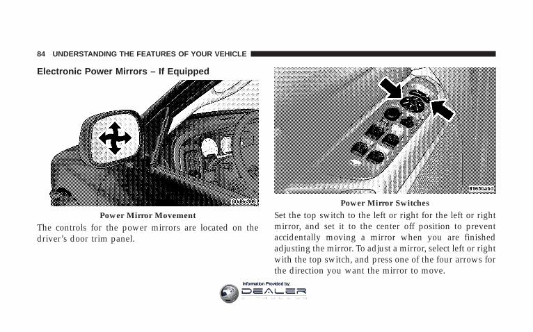
Electronic Power Mirrors – If Equipped
The controls for the power mirrors are located on thedriver’s door trim panel.
Set the top switch to the left or right for the left or rightmirror, and set it to the center off position to preventaccidentally moving a mirror when you are finishedadjusting the mirror. To adjust a mirror, select left or rightwith the top switch, and press one of the four arrows forthe direction you want the mirror to move.
Power Mirror Movement
Power Mirror Switches
84 UNDERSTANDING THE FEATURES OF YOUR VEHICLE
Information Provided by:

Electric Rear Window Defroster and HeatedSideview Mirrors – If Equipped
The Electric Rear Window Defroster and Heatedside view mirrors are activated by pressing the
heated grid button, located on the Climate Control panel,with the ignition On. Turning Off the rear windowdefroster or the ignition will deactivate the Electric RearWindow Defroster and Heated side view mirrors feature.These features turn off automatically after 15 minuteshave elapsed for the first activation per ignition cycle.Each subsequent activation of these features per ignitioncycle will shutoff automatically after 10 minutes haveelapsed. To reactivate, simply press the button again.
Trailer Towing Mirrors – If EquippedThese mirrors are designed with an adjustable mirrorhead to provide a greater vision range when towingextra-wide loads. To change position inboard or out-board, the mirror head should be rotated (flipped Out orIn). A small blindspot mirror is integrated onto the mainmirror surface.
UNDERSTANDING THE FEATURES OF YOUR VEHICLE 85
3
Information Provided by:

NOTE: Fold the 7 x 10 inch trailer towing mirrorsrearward prior to entering an automated car wash.
Blindspot Mirror
Trailer Towing Position
86 UNDERSTANDING THE FEATURES OF YOUR VEHICLE
Information Provided by:

HANDS–FREE COMMUNICATION (UConnect™) —IF EQUIPPED
NOTE: The sales code RER radio contains an inte-grated Hands-Free Communication (UConnect™) sys-tem. Refer to your “Navigation User’s Manual” forUConnect™ system operating instructions for this ra-dio.
UConnect™ is a voice-activated, hands-free, in- vehiclecommunications system. UConnect™ allows you to diala phone number with your cellular phone using simplevoice commands (e.g., 9Call” { “Mike” {”Work9 or 9Dial”{ “248-555-12129). Your cellular phone’s audio is trans-mitted through your vehicle’s audio system; the systemwill automatically mute your radio when using theUConnect™ system.
NOTE: The UConnect™ system use requires a cellularphone equipped with the Bluetooth 9Hands-Free Profile,9version 0.96 or higher. See www.chrysler.com/uconnectfor supported phones.
UConnect™ allows you to transfer calls between thesystem and your cellular phone as you enter or exit yourvehicle, and enables you to mute the system’s micro-phone for private conversation.
The UConnect™ phonebook enables you to store up to 32names and four numbers per name. Each language has aseparate 32-name phonebook accessible only in thatlanguage. This system is driven through your Blue-tooth™ Hands-Free profile cellular phone. UConnect™features Bluetooth™ technology - the global standardthat enables different electronic devices to connect toeach other without wires or a docking station, so UCon-nect works no matter where you stow your cellularphone (be it your purse, pocket, or briefcase), as long as
UNDERSTANDING THE FEATURES OF YOUR VEHICLE 87
3
Information Provided by:

your phone is turned on and has been paired to thevehicle’s UConnect™ system. The UConnect™ systemallows up to seven cellular phones to be linked to system.Only one linked (or paired) cellular phone can be usedwith the system at a time. The system is available inEnglish, Spanish, or French languages (as equipped).
The rearview mirror contains the microphone for thesystem and the control buttons that will enable you toaccess the system.
The UConnect™ system can be used with any Hands-Free Profile certified Bluetooth™ cellular phone. Seewww.chrysler.com/uconnect for supported phones. Ifyour cellular phone supports a different profile (e.g.,
UConnect™ Switches
88 UNDERSTANDING THE FEATURES OF YOUR VEHICLE
Information Provided by:

Headset Profile), you may not be able to use any UCon-nect™ features. Refer to your cellular service provider orthe phone manufacturer for details.
The UConnect™ system is fully integrated with thevehicle’s audio system. The volume of the UConnect™system can be adjusted either from the radio volumecontrol knob, or from the steering wheel radio control(right switch), if so equipped.
The radio display will be used for visual prompts fromthe UConnect™ system such as 9CELL9 or caller ID oncertain radios.
OperationsVoice commands can be used to operate the UConnect™system and to navigate through the UConnect™ menustructure. Voice commands are required after mostUConnect™ system prompts. You will be prompted for aspecific command and then guided through the availableoptions.
• Prior to giving a voice command, one must wait forthe voice on beep, which follows the 9Ready9 promptor another prompt.
• For certain operations, compound commands can beused. For example, instead of saying 9Setup9 and then9Phone Pairing,9 the following compound commandcan be said: 9Setup Phone Pairing.9
• For each feature explanation in this section, only thecombined form of the voice command is given. Youcan also break the commands into parts and say eachpart of the command, when you are asked for it. Forexample, you can use the combined form voice com-mand 9Phonebook New Entry,9 or you can break thecombined form command into two voice commands:9Phonebook9 and 9New Entry.9 Please remember, theUConnect™ system works best when you talk in anormal conversational tone, as if speaking to some onesitting eight feet away from you.
UNDERSTANDING THE FEATURES OF YOUR VEHICLE 89
3
Information Provided by:
Voice Command TreeRefer to “Voice Tree” at the end of this section.
Help CommandIf you need assistance at any prompt, or if you want toknow your options at any prompt, say 9Help9 followingthe voice on beep. The UConnect™ system will play allthe options at any prompt if you ask for help.
To activate the UConnect™ system from idle, simplypress the ’Phone’ button and follow audible prompts fordirections. All UConnect™ system sessions begin with apress of the ’Phone’ button on the mirror.
Cancel CommandAt any prompt, after the voice on beep, you can say9Cancel9 and you will be returned to the main menu.However, in a few instances the system will take youback to the previous menu.
Pair (Link) UConnect™ System to a Cellular PhoneTo begin using your UConnect™ system, you must pairyour compatible Bluetooth™ enabled cellular phone.
NOTE: The UConnect™ system use requires a cellularphone equipped with the Bluetooth 9Hands-Free Profile,9version 0.96 or higher. See www.chrysler.com/uconnectfor supported phones.
To complete the pairing process, you will need to refer-ence your cellular phone owner’s manual. One of thefollowing vehicle specific websites may also providedetailed instructions for pairing with the brand of phonethat you have:
NOTE:• www.chrysler.com/uconnect
• www.dodge.com/uconnect
• www.jeep.com/uconnect
90 UNDERSTANDING THE FEATURES OF YOUR VEHICLE
Information Provided by:

The following are general phone to UConnect™ Systempairing instructions:
• Press the ’Phone’ button to begin.
• After the 9Ready9 prompt and the following beep, say9Setup Phone Pairing9 and follow the audible prompts.
• When prompted, after the voice on beep, say 9Pair aPhone9 and follow the audible prompts.
• You will be asked to say a four-digit pin number,which you will later need to enter into your cellular.You can enter any four-digit pin number. You will notneed to remember this pin number after the initialpairing process.
• For identification purposes, you will be prompted togive the UConnect™ system a name for your cellularphone. Each cellular phone that is paired should begiven a unique phone name.
• You will then be asked to give your cellular phone apriority level between 1 and 7, 1 being the highestpriority. You can pair up to seven cellular phones toyour UConnect™ system. However, at any given time,only one cellular phone can be in use, connected toyour UConnect™ System. The priority allows theUConnect™ system to know which cellular phone touse if multiple cellular phones are in the vehicle at thesame time. For example, if priority 3 and priority 5phones are present in the vehicle, the UConnect™system will use the priority 3 cellular phone when youmake a call. You can select to use a lower prioritycellular phone at any time (refer to 9Advanced PhoneConnectivity9).
UNDERSTANDING THE FEATURES OF YOUR VEHICLE 91
3
Information Provided by:

Call/Dial by Saying a Number
• Press the ’Phone’ button to begin.
• After the 9Ready9 prompt and the following beep, say9Dial.9
• System will prompt you to say the number you wantcall.
• For example, you can say “234-567-8901.” The phonenumber that you enter must be of valid length andcombination. Based on the Country in which thevehicle was purchased, the UConnect™ limits the userfrom dialing invalid combination of numbers. Forexample, in USA, 234-567-890 is nine digits long,which is not a valid USA phone number - the closestvalid phone number has ten digits.
• The UConnect™ system will confirm the phone num-ber and then dial. The number will appear in thedisplay of certain radios.
Call/Dial by Saying a Name
• Press the “Phone” button to begin.
• After the 9Ready9 prompt and the following beep, say“Dial” or Call.9
• System will prompt you to say the name of the personyou want call.
• After the 9Ready9 prompt and the following beep, saythe name of the person you want to call. For example,you can say 9John Doe,9 where John Doe is a previ-ously stored name entry in the UConnect™ phone-book. Refer to 9Add Names to Your UConnect™Phonebook,9 to learn how to store a name in thephonebook.
• The UConnect™ system will confirm the name andthen dial the corresponding phone number, whichmay appear in the display of certain radios.
92 UNDERSTANDING THE FEATURES OF YOUR VEHICLE
Information Provided by:

Add Names to Your UConnect™ Phonebook
NOTE: Adding names to phonebook is recommendedwhen vehicle is not in motion.
• Press the “Phone” button to begin.
• After the 9Ready9 prompt and the following beep, say9Phonebook New Entry.9
• When prompted, say the name of the new entry. Use oflong names helps the voice recognition and is recom-mended. For example, say 9Robert Smith9 or 9Robert9instead of 9Bob.9
• When prompted, enter the number designation (e.g.,9Home,9 9Work,9 9Mobile,9 or 9Pager9). This will allowyou to store multiple numbers for each phonebookentry, if desired.
• When prompted, recite the phone number for thephonebook entry that you are adding.
After you are finished adding an entry into the phone-book, you will be given the opportunity to add morephone numbers to the current entry or to return to themain menu.
The UConnect™ system will allow you to enter up to 32names in the phonebook with each name having up tofour associated phone numbers and designations. Eachlanguage has a separate 32-name phonebook accessibleonly in that language.
Edit Entries in the UConnect™ Phonebook
NOTE: Editing phonebook entries is recommendedwhen vehicle is not in motion.
• Press the ’Phone’ button to begin.
• After the 9Ready9 prompt and the following beep, say9Phonebook Edit.9
UNDERSTANDING THE FEATURES OF YOUR VEHICLE 93
3
Information Provided by:

• You will then be asked for the name of the phonebookentry that you wish to edit.
• Next, choose the number designation (home, work,mobile, or pager) that you wish to edit.
• When prompted, recite the new phone number for thephonebook entry that you are editing.
After you are finished editing an entry in the phonebook,you will be given the opportunities to edit another entryin the phonebook, call the number you just edited, orreturn to the main menu.
9Phonebook Edit9 can be used to add another phonenumber to a name entry that already exists in thephonebook. For example, the entry John Doe may have amobile and a home number, but you can add John Doe’swork number later using the 9Phonebook Edit9 feature.
Delete Entries in the UConnect™ Phonebook
NOTE: Editing phonebook entries is recommendedwhen vehicle is not in motion.
• Press the ’Phone’ button to begin.
• After the 9Ready9 prompt and the following beep, say9Phonebook Delete.9
• After you enter the Phonebook Delete menu, you willthen be asked for the name of the entry that you wishto delete. You can either say the name of a phonebookentry that you wish to delete or you can say 9ListNames9 to hear a list of the entries in the phonebookfrom which you choose. To select one of the entriesfrom the list, press the 9Voice Recognition9 buttonwhile the UConnect™ system is playing the desiredentry and say 9Delete.9
94 UNDERSTANDING THE FEATURES OF YOUR VEHICLE
Information Provided by:

• After you enter the name, the UConnect™ system willask you which designation you wish to delete, home,work, mobile, or pager. Say the designation you wishto delete.
• Note that only the phonebook entry in the currentlanguage is deleted.
After confirmation, the phonebook entries will be de-leted. Note that only the phonebook in the currentlanguage is deleted.
Delete All Entries in the UConnect™ Phonebook
• Press the ’Phone’ button to begin.
• After the 9Ready9 prompt and the following beep, say9Phonebook Erase All.9
• The UConnect™ system will ask you to verify that youwish to delete all the entries from the phonebook.
• After confirmation, the phonebook entries will bedeleted.
List All Names in the UConnect™ Phonebook
• Press the ’Phone’ button to begin.
• After the 9Ready9 prompt and the following beep, say9Phonebook List Names.9
• The UConnect™ system will play the names of all thephonebook entries.
• To call one of the names in the list, press the 9VoiceRecognition’ button during the playing of the desiredname, and then say 9Call.9 NOTE: the user can alsoexercise 9Edit9 or 9Delete9 operations at this point.
• The UConnect™ system will then prompt you as tonumber designation you wish to call.
• The selected number will be dialed.
UNDERSTANDING THE FEATURES OF YOUR VEHICLE 95
3
Information Provided by:

Phone Call FeaturesThe following features can be accessed through theUConnect™ system if the feature(s) are available on yourcellular service plan. For example, if your cellular serviceplan provides three-way calling, this feature can beaccessed through the UConnect™ system. Check withyour cellular service provider for the features that youhave.
Answer or Reject an Incoming Call - No CallCurrently in ProgressWhen you receive a call on your cellular phone, theUConnect™ system will interrupt the vehicle audiosystem, if on, and will ask if you would like to answer thecall. To reject the call, press and hold the ’Phone’ buttonuntil you hear a single beep indicating that the incomingcall was rejected.
Answer or Reject an Incoming Call - CallCurrently in ProgressIf a call is currently in progress and you have anotherincoming call, you will hear the same network tones forcall waiting that you normally hear when using your cellphone. Press the ’Phone’ button to place the current callon hold and answer the incoming call.
NOTE: The UConnect™ system compatible phones inmarket today do not support rejecting an incoming callwhen another call is in progress. Therefore, the user canonly either answer an incoming call or ignore it.
96 UNDERSTANDING THE FEATURES OF YOUR VEHICLE
Information Provided by:
Making a Second Call while Current Call inProgressTo make a second call while you are currently in a call,press the ’Voice Recognition’ button and say 9Dial9 or9Call9 followed by the phone number or phonebook entryyou wish to call. The first call will be on hold while thesecond call is in progress. To go back to the first call, referto 9Toggling Between Calls.9 To combine two calls, referto 9Conference Call.9
Place/Retrieve a Call from HoldTo put a call on hold, press the 8Phone’ button until youhear a single beep. This indicates that the call is on hold.To bring the call back from hold, press and hold the8Phone’ button until you hear a single beep.
Toggling Between CallsIf two calls are in progress (one active and one on hold),press the ’Phone’ button until you hear a single beep
indicating that the active and hold status of the two callshave switched. Only one call can be placed on hold at onetime.
Conference CallWhen two calls are in progress (one active and one onhold), press and hold the ’Phone’ button until you hear adouble beep indicating that the two calls have beenjoined into one conference call.
Three-Way CallingTo initiate three-way calling, press the ’Voice Recogni-tion’ button while a call is in progress and make a secondphone call as described under 9Making a Second Callwhile Current Call in Progress.9 After the second call hasestablished, press and hold the ’Phone’ button until youhear a double beep indicating that the two calls havebeen joined into one conference call.
UNDERSTANDING THE FEATURES OF YOUR VEHICLE 97
3
Information Provided by:

Call TerminationTo end a call in progress, momentarily press the 8Phone’button. Only the active call(s) will be terminated and ifthere is a call on hold, it will become the new active call.If the active call is terminated by the far end, a call onhold may not become active automatically. This is cellphone dependent. To bring the call back from hold, pressand hold the ‘Phone’ button until you hear a single beep.
Redial
• Press the ’Phone’ button to begin.
• After the 9Ready9 prompt and the following beep, say9Redial.9
• The UConnect™ system will call the last number thatwas dialed on your cellular phone. Note: this may notbe the last number dialed from the UConnect™ sys-tem.
Call ContinuationCall continuation is progression of a phone call onUConnect™ system after the vehicle ignition key hasbeen switched to off. Call continuation functionalityavailable on the vehicle can be any one of three types:
• After ignition key is switched off, a call can continueon the UConnect™ system either until the call ends oruntil the vehicle battery condition dictates cessation ofthe call on the UConnect™ system and transfer of thecall to the mobile phone.
• After ignition key is switched to off, a call can continueon the UConnect™ system for certain duration, afterwhich the call is automatically transferred from theUConnect™ system to the mobile phone.
• An active call is automatically transferred to themobile phone after ignition key is switched to off.
98 UNDERSTANDING THE FEATURES OF YOUR VEHICLE
Information Provided by:
UConnect™ System Features
Language SelectionTo change the language that the UConnect™ system isusing,
• Press the ’Phone’ button to begin.
• After the 9Ready9 prompt and the following beep, saythe name of the language you wish to switch to(English, Espanol, or Francais, if so equipped).
• Continue to follow the system prompts to completelanguage selection.
After selecting one of the languages, all prompts andvoice commands will be in that language.
NOTE: After every UConnect™ language change op-eration, only the language specific 32-name phonebook isusable. The paired phone name is not language specificand usable across all languages.
For command translations and alternate commands insupported languages, refer to “Command Translations”at the end of this section.
Emergency AssistanceIf you are in an emergency and the mobile phone isreachable:
• Pick up the phone and manually dial the emergencynumber for your area.
If the phone is not reachable and the UConnect™ systemis operational, you may reach the emergency number asfollows:
• Press the ’Phone’ button to begin.
• After the 9Ready9 prompt and the following beep, say9Emergency9 and the UConnect™ system will instructthe paired cellular phone to call the emergency num-ber. This feature is only supported in the USA.
UNDERSTANDING THE FEATURES OF YOUR VEHICLE 99
3
Information Provided by:

NOTE: The emergency number dialed is based on theCountry where the vehicle is purchased (911 for USA andCanada and 060 for Mexico). The number dialed may notbe applicable with the available cellular service and area.
The UConnect™ system does slightly lower your chancesof successfully making a phone call as compared to thatfor the cell phone directly.
Your phone must be turned on and paired to the UCon-nect™ system to allow use of this vehicle feature inemergency situations when the cell phone has networkcoverage and stays paired to the UConnect™ system.
Towing AssistanceIf you need towing assistance,
• Press the ’Phone’ button to begin.
• After the 9Ready9 prompt and the following beep, say9Towing Assistance.9
NOTE: The Towing Assistance number dialed is basedon the Country where the vehicle is purchased (1-800-528-2069 for USA, 1-877-213-4525 for Canada, 55-14-3454for Mexico city and 1-800-712-3040 for outside Mexicocity in Mexico).
Please refer to the 24-Hour “Towing Assistance” cover-age details in the Warranty information booklet and onthe 24–Hour Towing Assistance Card.
PagingTo learn how to page, refer to 9Working with AutomatedSystems.9 Paging works properly except for pagers ofcertain companies which time-out a little too soon towork properly with the UConnect™ system.
Voice Mail CallingTo learn how to access your voice mail, refer to 9Workingwith Automated Systems.9
100 UNDERSTANDING THE FEATURES OF YOUR VEHICLE
Information Provided by:
Working with Automated SystemsThis method is designed to be used in instances whereone generally has to press numbers on the cellular phonekeypad while navigating through an automated tele-phone system.
You can use your UConnect™ system to access a voice-mail system or an automated service, such as, pagingservice or automated customer service. Some servicesrequire immediate response selection, in some instances,that may be too quick for use of UConnect™ system.
When calling a number with your UConnect™ systemthat normally requires you to enter in a touch-tonesequence on your cellular phone keypad, you can pushthe ’Voice Recognition’ button and say the sequence youwish to enter followed by the word 9Send.9 For example,
if required to enter your pin number followed with apound 3 7 4 6 #, you can press the ’Voice Recognition’button and say 93 7 4 6 # Send.9 Saying a number, orsequence of numbers, followed by 9Send9 is also to beused to navigate through an automated customer servicecenter menu structure and to leave a number on a pager.
Barge In - Overriding PromptsThe ’Voice Recognition’ button can be used when youwish to skip part of a prompt and issue your voicerecognition command immediately. For example, if aprompt is playing 9Would you like to pair a phone, cleara{,9 you could press the ’Voice Recognition’ button andsay 9Pair a Phone9 to select that option without having tolisten to the rest of the voice prompt.
UNDERSTANDING THE FEATURES OF YOUR VEHICLE 101
3
Information Provided by:
Turning Confirmation Prompts On/OffTurning confirmation prompts off will stop the systemfrom confirming your choices (e.g., the UConnect™system will not repeat a phone number before you dialit).
• Press the ’Phone’ button to begin.
• After the 9Ready9 prompt and the following beep, say9Setup Confirmations.9 The UConnect™ system willplay the current confirmation prompt status and youwill be given the choice to change it.
Phone and Network Status IndicatorsIf available on the radio and/or on a premium displaysuch as the instrument panel cluster, and supported byyour cell phone, the UConnect™ system will providenotification to inform you of your phone and networkstatus when you are attempting to make a phone callusing UConnect™. The status is given for roaming net-work signal strength, phone battery strength, etc.
Dialing Using the Cellular Phone KeypadYou can dial a phone number with your cellular phonekeypad and still use the UConnect™ system (whiledialing via the cell phone keypad, the user must exercisecaution and take precautionary safety measures). Bydialing a number with your paired Bluetooth™ cellularphone, the audio will be played through your vehicle’saudio system. The UConnect™ system will work thesame as if you dial the number using voice recognition.
NOTE: Certain brands of mobile phones do not send thedial ring to the UConnect™ system to play it on thevehicle audio system, so you will not hear it. Under thissituation, after successfully dialing a number, the usermay feel that the call did not go through even though thecall is in progress. Once your call is answered, you willhear the audio.
102 UNDERSTANDING THE FEATURES OF YOUR VEHICLE
Information Provided by:
Mute/Un-mute (Mute off)When you mute the UConnect™ system, you will still beable to hear the conversation coming from the otherparty, but the other party will not be able to hear you. Inorder to mute the UConnect™ system:
• Press the ’Voice Recognition’ button.
• After the 9Ready9 prompt and the following beep, say9Mute.9
In order to un-mute the UConnect™ system:
• Press the ’Voice Recognition’ button.
• After the 9Ready9 prompt and the following beep, say9Mute-off.9
Information ServiceWhen using AT&T Wireless Service, dialing to phonenumber 9#121,9 you can access voice activated automatedsystem to receive news, weather, stocks, traffic, etc.related information.
Advanced Phone Connectivity
Transfer Call to and from Cellular PhoneThe UConnect™ system allows on going calls to betransferred from your cellular phone to the UConnect™system without terminating the call. To transfer an ongo-ing call from your UConnect™ paired cellular phone tothe UConnect™ system or vice-versa, press the ’VoiceRecognition’ button and say 9Transfer Call.9
UNDERSTANDING THE FEATURES OF YOUR VEHICLE 103
3
Information Provided by:

Connect or Disconnect Link Between theUConnect™ System and Cellular PhoneYour cellular phone can be paired with many differentelectronic devices, but can only be actively 9connected9with one electronic device at a time.
If you would like to connect or disconnect the Blue-tooth™ connection between a UConnect™ paired cellularphone and the UConnect™ system, then follow theinstruction described in your cellular phone user’smanual.
List Paired Cellular Phone Names
• Press the ’Phone’ button to begin.
• After the “Ready” prompt and the following beep, say“Setup Phone pairing”.
• When prompted, say 9List Phones.9
• The UConnect™ system will play the phone names ofall paired cellular phones in order from the highest tothe lowest priority. To “select” or “delete” a pairedphone being announced, press the 8Voice recognition’button and say “Select” or “Delete.” Also, see the nexttwo sections for an alternate way to “select” or “de-lete” a paired phone.
104 UNDERSTANDING THE FEATURES OF YOUR VEHICLE
Information Provided by:

Select another Cellular PhoneThis feature allows you to select and start using anotherphone with the UConnect™ system. The phone musthave been previously paired to the UConnect™ systemthat you want to use it with.
• Press the ’Phone’ button to begin.
• After the 9Ready9 prompt and the following beep, say9Setup Select Phone9 and follow the prompts.
• You can also press the 8Voice Recognition’ buttonanytime while the list is being played, and then choosethe phone that you wish to select.
• The selected phone will be used for the next phonecall. If the selected phone is not available, the UCon-nect™ system will return to using the highest priorityphone present in or near (approximately with in 30feet) the vehicle.
Delete UConnect™ Paired Cellular Phones
• Press the ’Phone’ button to begin.
• After the 9Ready9 prompt and the following beep, say9Setup Phone Pairing.9
• At the next prompt, say 9Delete9 and follow theprompts.
• You can also press the 8Voice Recognition’ buttonanytime while the list is being played and then choosethe phone you wish to delete.
UNDERSTANDING THE FEATURES OF YOUR VEHICLE 105
3
Information Provided by:

Things You Should Know About Your UConnect™System
Voice TrainingFor users experiencing difficulty with the system recog-nizing their voice commands or numbers, the UConnectsystem Voice Training feature may be used. To enter thistraining mode, follow one of the two procedures: Fromoutside the UConnect mode (e.g. from radio mode),
• Press and hold the ‘Voice Recognition’ button for 5seconds until the session begins, or
• Press the ‘Voice Recognition’ button and say 9Setup,Voice Training9 command.
Repeat the words and phrases when prompted by theUConnect System. For best results, the Voice Trainingsession should be completed when the vehicle is parked,engine running, all windows closed, and the blower fanswitched off.
This procedure may be repeated with a new user. Thesystem will adapt to the last trained voice only.
To restore the Voice recognition system to factory defaultsettings, enter the Voice Training session via the aboveprocedure and follow the prompts.
Voice Recognition (VR)
• Always wait for the beep before speaking.
• Speak normally, without pausing, just as you wouldspeak to a person sitting approximately eight (8) feetaway from you.
• Make sure that no one other than you is speakingduring a voice recognition period.
• Performance is maximized under:
• low-to-medium blower setting,
• low-to-medium vehicle speed,
106 UNDERSTANDING THE FEATURES OF YOUR VEHICLE
Information Provided by:

• low road noise,
• smooth road surface,
• fully closed windows,
• dry weather condition.
• In a convertible vehicle, the system performance maybe compromised with roof top down.
• Even though the system is designed for users speakingin North American English, French, and Spanish ac-cents, the system may not always work for some.
• When navigating through an automated system, suchas voice mail, or when sending a page at the end ofspeaking the digit string, make sure to say 9send.9
• Storing names in phonebook when vehicle is not inmotion is recommended.
• It is not recommended to store similar soundingnames in the UConnect™ phonebook.
• UConnect™ phonebook nametag recognition rate isoptimized for the voice of the person who stored thename in the phonebook.
• You can say 9O9 (letter 9O9) for 909 (zero). 98009 must bespoken 9eight-zero-zero.9
• Even though international dialing for most numbercombinations is supported, some shortcut dialingnumber combinations may not be supported.
UNDERSTANDING THE FEATURES OF YOUR VEHICLE 107
3
Information Provided by:

Far End Audio Performance
• Audio quality is maximized under:
• low-to-medium blower setting,
• low-to-medium vehicle speed,
• low road noise,
• smooth road surface,
• fully closed windows, and
• dry weather condition.
• Operation from driver seat.
• In a convertible vehicle, the system performance maybe compromised with roof top down.
• Performance, such as audio clarity, echo, and loudnessto a large degree rely on the phone and network, andnot the UConnect™ system.
• Echo at far end can sometime be reduced by loweringthe in-vehicle audio volume.
Bluetooth Communication LinkOccasionally, Cellular phones have been found to loseconnection to the UConnect™ system. When this hap-pens, the connection can generally be re-established byswitching the phone off/on. Your cell phone is recom-mended to remain in Bluetooth 9on9 mode.
Power-UpAfter switching the ignition key from OFF to either ONor ACC position, or after a reset, you must wait at leastfive (5) seconds prior to using the system.
108 UNDERSTANDING THE FEATURES OF YOUR VEHICLE
Information Provided by:

UNDERSTANDING THE FEATURES OF YOUR VEHICLE 109
3
Information Provided by:

110 UNDERSTANDING THE FEATURES OF YOUR VEHICLE
Information Provided by:

UNDERSTANDING THE FEATURES OF YOUR VEHICLE 111
3
Information Provided by:

North American EnglishPrimary Alternate(s)ZeroOneTwoThreeFourFiveSixSevenEightNineStar (*)Plus (+)Pound (#)Add LocationAll
CallCancelConfirmation PromptsContinueDeleteDialEditEmergencyEnglishErase AllEspanolFrancaisHelpHomeLanguageList namesList phones
112 UNDERSTANDING THE FEATURES OF YOUR VEHICLE
Information Provided by:

MobileMuteMute offNew entryNoPagerPair a phonePhone pairing PairingPhonebook Phone bookPreviousRecord againRedialReturn to main menu Return. Main menuSelect phone SelectSendSet up Phone settings / Phone
set up
Towing assistanceTransfer callTry againVoice trainingWorkYes
General InformationThis device complies with part 15 of the FCC rules andRSS 210 of Industry Canada. Operation is subject to thefollowing conditions:
• This device may not cause harmful interference.
• This device must accept any interference received,including interference that may cause undesired op-eration.
UNDERSTANDING THE FEATURES OF YOUR VEHICLE 113
3
Information Provided by:

SEATSThe seating options available in this truck are the result ofextensive customer research and evaluations.
Seats are also a primary part of the Occupant Restraint(protection) System of the vehicle. They need to be usedproperly for safe operation of the vehicle.
WARNING!
It is extremely dangerous to ride in a cargo area,inside or outside of a vehicle. In a collision, peopleriding in these areas are more likely to be seriouslyinjured or killed.
Do not allow people to ride in any area of yourvehicle that is not equipped with seats and seat belts.
Be sure everyone in your vehicle is in a seat andusing a seat belt properly.
40-20-40 Front Seat
As the name implies, the seat is divided into 3 segments.The outboard seat portions are each 40% of the totalwidth of the seat. The back of the center portion (20%)easily folds down to provide an armrest/center storagecompartment (if equipped).
Manual Seat Adjuster
114 UNDERSTANDING THE FEATURES OF YOUR VEHICLE
Information Provided by:

Each outboard seat is independently adjustable forwardor rearward and is equipped with a back recliner. Themanual forward or rearward seat adjustment handle isfound at the front edge of each seat cushion. Pull up onthe handle and slide the seat to get the most comfortableposition.
WARNING!
Adjusting a seat while the vehicle is moving isdangerous. The sudden movement of the seat couldcause you to lose control. The seat belt might not beproperly adjusted and you could be injured. Adjustany seat only while the vehicle is parked.
Reclining SeatsThe recliner handle is on the outside of the seat cushion.Pull up on the handle, as shown, to release the seat backand adjust for comfort.
Manual Recline Lever
UNDERSTANDING THE FEATURES OF YOUR VEHICLE 115
3
Information Provided by:

WARNING!
You can be seriously, even fatally, injured riding in aseat with the seatback reclined. Do not ride with theseatback reclined so that the shoulder belt is nolonger resting against your chest. If you ride in thisposition, the shoulder harness will no longer berestraining you. In a collision you could slide underthe seat belt and receive serious or fatal injuries.Recline in a seat only when the vehicle is parked.
Adjustable Head RestraintsHead restraints can reduce the risk of neck injury in theevent of impact from the rear. Pull up or push down onthe restraints so that the upper edge is as high aspractical, at least to the level of the ears.
To lower the head restraint, push in the button and thenpush down on the head restraint.
Head Restraints
116 UNDERSTANDING THE FEATURES OF YOUR VEHICLE
Information Provided by:

Manual Rotary Lumbar Support Adjustment — IfEquippedRotating the lumbar control knob on the left side of thedriver’s seatback and on the right side of the passenger’sseatback increases or decreases the lumbar (lower back)support.
Power Seats — If Equipped
CAUTION!
Don’t put anything under a power seat. It may causedamage to the seat controls.
Manual Lumbar AdjustmentPower Seat Switch
UNDERSTANDING THE FEATURES OF YOUR VEHICLE 117
3
Information Provided by:

The power seat controls are on the outboard side of thefront seat cushions. Three switches control the seat move-ment. The four-way switch in the center can be movedforward or backwards to get the most comfortable posi-tion. The same switch can be moved up and down to
control seat height. Change the seat angle by using thetwo toggle switches, tilting it up or down.
Up, Down, Forward, and Rearward
Tilt Adjustment
118 UNDERSTANDING THE FEATURES OF YOUR VEHICLE
Information Provided by:

Heated Seats — If EquippedThe heated seat switches are located in the instrumentpanel under the climate controls.
Each heated seat switch has two settings (HI and LOW).Press the switch once to obtain High heat level, thenpress the switch again to obtain Low heat level. Pressingthe switch a third time will turn the heated seats OFF. Ifyou do not purposefully turn the switch OFF, the seatheating level will automatically change to the next lowerlevel, or OFF. The High heat level operates for 30 minutes(approximate), the Low heat level operates for 30 min-utes (approximate). The seat heat will also turn OFFwhen the ignition is turned OFF. Both of the indicatorsON identifies High heat level. The lower indicator Ononly, identifies Low heat level. Flashing indicator lightson the switch indicate that the Heated Seat System needsservicing.
Heated Seat Switches
UNDERSTANDING THE FEATURES OF YOUR VEHICLE 119
3
Information Provided by:

WARNING!
Persons who are unable to feel pain to the skinbecause of advanced age, chronic illness, diabetes,spinal cord injury, medication, alcohol use, exhaus-tion or other physical condition must exercise carewhen using the seat heater. It may cause burns evenat low temperatures, especially if used for longperiods of time.
Do not place anything on the seat that insulatesagainst heat, such as a blanket or cushion. This maycause the seat heater to overheat.
TO OPEN AND CLOSE THE HOOD
To open the hood, two latches must be released. First pullthe hood release lever located below the steering wheel atthe base of the instrument panel. Once the hood isreleased you must reach into the opening beneath thecenter of the grille and push up the latch to release thesafety catch before raising the hood.
Hood Release Lever
120 UNDERSTANDING THE FEATURES OF YOUR VEHICLE
Information Provided by:
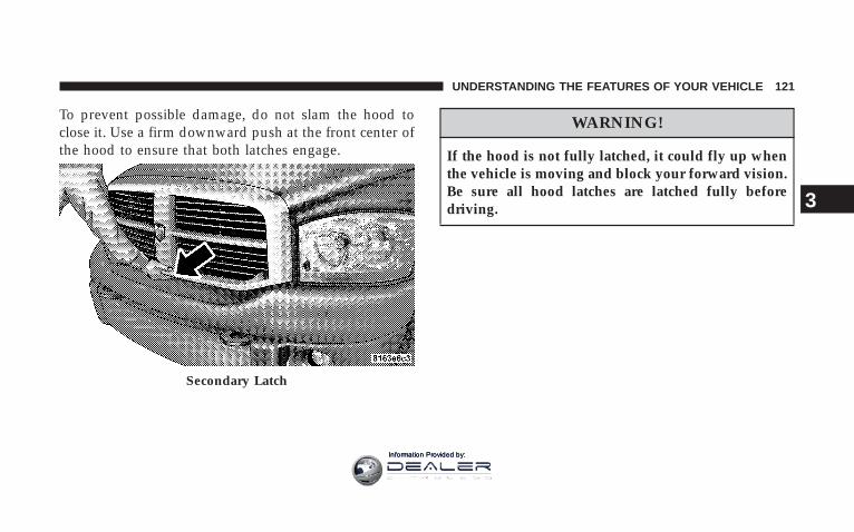
To prevent possible damage, do not slam the hood toclose it. Use a firm downward push at the front center ofthe hood to ensure that both latches engage.
WARNING!
If the hood is not fully latched, it could fly up whenthe vehicle is moving and block your forward vision.Be sure all hood latches are latched fully beforedriving.
Secondary Latch
UNDERSTANDING THE FEATURES OF YOUR VEHICLE 121
3
Information Provided by:
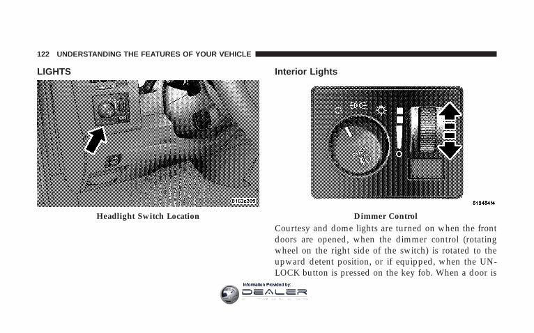
LIGHTS Interior Lights
Courtesy and dome lights are turned on when the frontdoors are opened, when the dimmer control (rotatingwheel on the right side of the switch) is rotated to theupward detent position, or if equipped, when the UN-LOCK button is pressed on the key fob. When a door is
Headlight Switch Location Dimmer Control
122 UNDERSTANDING THE FEATURES OF YOUR VEHICLE
Information Provided by:

open and the interior lights are on, rotating the dimmercontrol all the way down to the OFF detent will cause allthe interior lights to go out. This is also known as the9Party9 mode because it allows the doors to stay open forextended periods of time without discharging the vehi-cle’s battery.
The brightness of the instrument panel lighting can beregulated by rotating the dimmer control up (brighter) ordown (dimmer). When the headlights are ON you cansupplement the brightness of the odometer, trip odom-eter, radio and overhead console by rotating the controlup until you hear a click. This feature is termed the“Parade” mode and is useful when headlights are re-quired during the day.
Club Cab/Quad Cab models may have an optionalswitched dome lamp that may be operated by pressingthe lens.
Battery SaverTo protect the life of your vehicle’s battery, Load Shed-ding is provided for both the interior and exterior lights.
If the ignition is off and any door is left ajar for 10minutes or the dimmer control is rotated upwards for 10minutes, the interior lights will automatically turn off.
If the headlamps remain on while the ignition is cycledoff, the exterior lights will automatically turn off after 8minutes. If the headlamps are turned on and left on for 8minutes while the ignition is off, the exterior lights willautomatically turn off.
NOTE: Battery Saver mode is cancelled if the ignition isON.
UNDERSTANDING THE FEATURES OF YOUR VEHICLE 123
3
Information Provided by:

Headlamp DelayTo aid in your exit, your vehicle is equipped with aheadlamp delay that will leave the headlamps on for 90seconds. This delay is initiated when the ignition isturned OFF while the headlamp switch is on, and thenthe headlamp switch is cycled off. Headlamp delay canbe cancelled by either turning the headlamp switch ONthen OFF or by turning the ignition ON.
The Headlight delay time is programmable on vehiclesequipped with the Electronic Vehicle Information Center(EVIC). For details, refer to “Headlamp Off Delay”,under “Personal Settings (Customer Programmable Fea-tures),” under “Electronic Vehicle Information Center(EVIC)” in Section 3 of this manual.
Headlights, Parking Lights, Panel LightsWhen the headlight switch is rotated to the firstposition, the parking lights, taillights, side markerlights, license plate light and instrument panel
lights are all turned on. The headlights will turn ONwhen the switch is rotated to the second position.
Light Switch Rotation
124 UNDERSTANDING THE FEATURES OF YOUR VEHICLE
Information Provided by:

Your vehicle is equipped with plastic headlight lensesthat are lighter and less susceptible to stone breakagethan glass headlights.
Plastic is not as scratch resistant as glass and thereforedifferent lens cleaning procedures must be followed.
To minimize the possibility of scratching the lenses andreducing light output, avoid wiping with a dry cloth. Toremove road dirt, wash with a mild soap solution fol-lowed by rinsing.
Do not use abrasive cleaning components, solvents, steelwool or other abrasive materials to clean the lenses.
Daytime Running Lights (Canada Only and FleetVehicles)The headlights on your vehicle will illuminate when theengine is started and the transmission is in any gear
except park. This provides a constant 9Lights ON9 con-dition until the ignition is turned OFF. The lights illumi-nate at less than 50% of normal intensity. If the parkingbrake is applied the Daytime Running Lights will turnoff. Also, if a turn signal is activated, the DRL lamp on thesame side of the vehicle will turn off for the duration ofthe turn signal activation. Once the turn signal is nolonger active, the DRL lamp will illuminate
Lights-on ReminderIf the headlights, parking lights, or cargo lights are lefton, after the ignition is turned off, a chime will soundwhen the driver’s door is opened.
Fog Lights — If EquippedThe foglights are turned ON by placing the head-light rotary control in the parking light or head-light position and pushing in the headlight rotary
control. The fog lights will operate only when the parkinglights are ON or when the vehicle headlights are ON low
UNDERSTANDING THE FEATURES OF YOUR VEHICLE 125
3
Information Provided by:

beam. An indicator light located in the instrument clusterwill illuminate when the fog lights are on. The fog lightswill turn off when the switch is pushed a second time,when the headlight switch is rotated to the OFF position,or the high beam is selected.
Multifunction Control LeverThe multifunction control lever is located on the left sideof the steering column.
Turn SignalsMove the lever up or down to signal a right-hand orleft-hand turn.
The arrow on either side of the instrument cluster flashesto indicate the direction of the turn, and proper operationof the front and rear turn signal lights. If a defective bulbor wiring circuit is detected for the turn signal system, thearrow indicators will flash at a faster rate. If an indicatorfails to light when the lever is moved, it would suggestthat the switch or indicator lamp is defective.
You can signal a lane change by moving the leverpartially up or down.
Turn Signal Auto-ModeTap the multi-function control lever once and the turnsignal (left or right) will flash 3 times, and automaticallyturn off.
Turn Signal Lever
126 UNDERSTANDING THE FEATURES OF YOUR VEHICLE
Information Provided by:

Passing LightYou can signal another vehicle with your headlights bypartially pulling the multifunction lever toward the steer-ing wheel. This will cause the high beam headlights toturn on until the lever is released.
High Beam / Low Beam Select SwitchPull the multifunction control lever fully toward thesteering wheel to switch the headlights from HIGH orLOW beam.
High Beam / Low Beam
UNDERSTANDING THE FEATURES OF YOUR VEHICLE 127
3
Information Provided by:

WINDSHIELD WIPERS AND WASHERS
Windshield Wipers
The wipers and washers are operated by a switch in themultifunction control lever. Turn the end of the handle toselect the desired wiper speed.
Intermittent Wiper SystemThe intermittent feature of this system was designed foruse when weather conditions make a single wiping cycle,with a variable pause between cycles, desirable. Formaximum delay between cycles, rotate the control knobinto the upper end of the delay range.
The delay interval decreases as you rotate the knob untilit enters the LOW continual speed position. The delaycan be regulated from a maximum of about 15 secondsbetween cycles, to a cycle every 2 seconds. The delayintervals will double in duration when the vehicle speedis 10 mph (16 km) or less.
Windshield Wiper / Washer Switch
128 UNDERSTANDING THE FEATURES OF YOUR VEHICLE
Information Provided by:

WARNING!
Sudden loss of visibility through the windshieldcould lead to an accident. You might not see othervehicles or other obstacles. To avoid sudden icing ofthe windshield during freezing weather, warm thewindshield with defroster before and during wind-shield washer use.
Windshield WashersTo use the washer, push in on the washer knob on the endof the multifunction control lever and hold while spray isdesired. If the washer knob is depressed while in thedelay range, the wiper will operate for several secondsafter the washer knob is released. It will then resume theintermittent interval previously selected. If the washerknob is pushed, for a period greater than 1 second, whilein the OFF position, the wiper will wipe approximatelythree wipes, after the wash knob is released.
To prevent freeze-up of your windshield washer systemin cold weather, select a solution or mixture that meets orexceeds the temperature range of your climate. Thisrating information can be found on most washer fluidcontainers.
UNDERSTANDING THE FEATURES OF YOUR VEHICLE 129
3
Information Provided by:
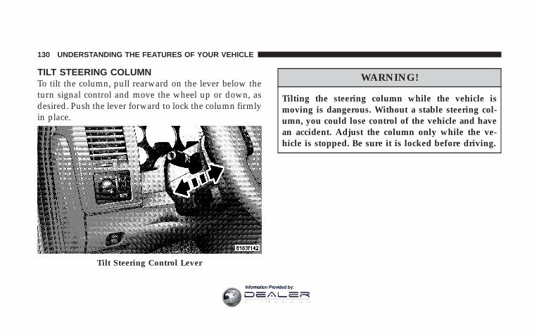
TILT STEERING COLUMNTo tilt the column, pull rearward on the lever below theturn signal control and move the wheel up or down, asdesired. Push the lever forward to lock the column firmlyin place.
WARNING!
Tilting the steering column while the vehicle ismoving is dangerous. Without a stable steering col-umn, you could lose control of the vehicle and havean accident. Adjust the column only while the ve-hicle is stopped. Be sure it is locked before driving.
Tilt Steering Control Lever
130 UNDERSTANDING THE FEATURES OF YOUR VEHICLE
Information Provided by:

DRIVER ADJUSTABLE PEDALS — IF EQUIPPED
The power adjustable accelerator and brake pedals allowthe driver to establish a comfortable position relative tothe steering wheel and pedals.
Adjustment
1. Position the driver seat so that you are at least 10inches (254 mm) away from the airbag located in thecenter of the steering wheel.
2. Fasten and adjust the seatbelts.
3. Move the adjustable pedal switch, located to the left ofthe steering column near the parking brake release, in thedirection you desire to move the pedals.
4. The pedals cannot be adjusted when the vehicle is inR (Reverse) or when the Speed Control is SET.
Adjustable Pedals Switch
UNDERSTANDING THE FEATURES OF YOUR VEHICLE 131
3
Information Provided by:

CAUTION!
Do not place any article under the adjustable pedalsor impede its ability to move as it may cause damageto the pedal controls. Pedal travel may become lim-ited if movement is stopped by an obstruction in theadjustable pedal’s path.
ELECTRONIC SPEED CONTROL — IF EQUIPPEDWhen engaged, this device takes over accelerator opera-tion at speeds greater than 35 mph (56 km/h). Thecontrols are mounted on the steering wheel. NOTE: The Electronic Speed Control System has been
designed to shut down if multiple speed control switchbuttons (i.e. SET and CANCEL) are operated simulta-neously in order to ensure proper operation. The systemcan be reactivated by pushing the speed control switchON/OFF button and re-establishing the desired vehicleSET speed.
132 UNDERSTANDING THE FEATURES OF YOUR VEHICLE
Information Provided by:

To ActivatePush the ON/OFF button to the ON position. An indi-cator light in the instrument cluster illuminates when thesystem is on.
To Set At A Desired SpeedWhen the vehicle has reached the desired speed, pressand release the SET button. Release the accelerator andthe vehicle will operate at the selected speed.
To DeactivateA soft tap on the brake pedal, normal braking, clutchpressure while slowing the vehicle, or pressing the CAN-CEL button will deactivate speed control without erasingthe memory. Pushing the ON/OFF button to the OFFposition or turning off the ignition erases the memory.
WARNING!
Leaving the Speed Control ON when not in use isdangerous. You could accidentally set the system tocause it to go faster than you want. You could losecontrol and have an accident. Always leave the sys-tem OFF when you aren’t using it.
To Resume SpeedTo resume a previously set speed, push and release theRESUME button. Resume can be used at any speed above30 mph (50 km/h).
To Vary The Speed SettingWhen the speed control is on, speed can be increased bypressing and holding the ACCEL button. When thebutton is released, a new set speed will be established.
UNDERSTANDING THE FEATURES OF YOUR VEHICLE 133
3
Information Provided by:
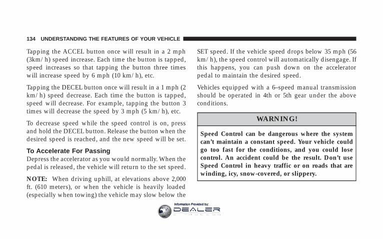
Tapping the ACCEL button once will result in a 2 mph(3km/h) speed increase. Each time the button is tapped,speed increases so that tapping the button three timeswill increase speed by 6 mph (10 km/h), etc.
Tapping the DECEL button once will result in a 1 mph (2km/h) speed decrease. Each time the button is tapped,speed will decrease. For example, tapping the button 3times will decrease the speed by 3 mph (5 km/h), etc.
To decrease speed while the speed control is on, pressand hold the DECEL button. Release the button when thedesired speed is reached, and the new speed will be set.
To Accelerate For PassingDepress the accelerator as you would normally. When thepedal is released, the vehicle will return to the set speed.
NOTE: When driving uphill, at elevations above 2,000ft. (610 meters), or when the vehicle is heavily loaded(especially when towing) the vehicle may slow below the
SET speed. If the vehicle speed drops below 35 mph (56km/h), the speed control will automatically disengage. Ifthis happens, you can push down on the acceleratorpedal to maintain the desired speed.
Vehicles equipped with a 6–speed manual transmissionshould be operated in 4th or 5th gear under the aboveconditions.
WARNING!
Speed Control can be dangerous where the systemcan’t maintain a constant speed. Your vehicle couldgo too fast for the conditions, and you could losecontrol. An accident could be the result. Don’t useSpeed Control in heavy traffic or on roads that arewinding, icy, snow-covered, or slippery.
134 UNDERSTANDING THE FEATURES OF YOUR VEHICLE
Information Provided by:

OVERHEAD CONSOLE WITHCOMPASS/TEMPERATURE MINI-TRIP COMPUTER— IF EQUIPPEDThis optional overhead console consists of the following:
• Courtesy Lights
• Compass/Temperature Mini-Trip Computer (CMTC)
This overhead console allows you to choose between acompass/temperature display and one of four trip con-ditions being monitored.
US/M Button
Use this button to change the display from U.S. to metricmeasurement units.
UNDERSTANDING THE FEATURES OF YOUR VEHICLE 135
3
Information Provided by:

RESET Button
Use this button to reset the following displays:Average Fuel Economy (AVG ECO)Trip Odometer (ODO)Elapsed time (ET)
Global ResetIf the RESET button is pressed twice within 2 secondswhile in any of the 3 resettable displays (AVG ECO,ODO, ET), the Global Reset will reset all 3 displays.
Step Button
Use this button to choose or cycle through the four tripconditions.
136 UNDERSTANDING THE FEATURES OF YOUR VEHICLE
Information Provided by:

Average Fuel Economy (AVG ECO)Shows the average fuel economy since the last reset.Average fuel economy is a running average of theamount of fuel used and the distance the vehicle hastraveled.
When the fuel economy is reset, the display will momen-tarily blank. Then, the history will be erased, and theAVERAGING WILL CONTINUE FROM WHERE ITWAS BEFORE THE RESET. The reset value is based on aminimal amount of fuel used and the distance traveledfrom the previous drive cycle. The display may takeseveral miles for this value to change dependent upondriving habits.
Distance To Empty (DTE)Shows the estimated distance that can be traveled withthe fuel remaining in the tank. This estimated distance isdetermined by weighted average of the instantaneousand average fuel economy, according to the current fueltank level. This is not resettable
NOTE: Significant changes in driving style or vehicleloading will greatly affect the actual drivable distance ofthe vehicle, regardless of the DTE displayed value.
When the DTE value is less than 30 miles estimateddriving distance, the DTE display will change to analternating test display of “LO” and “FUEL”. This dis-play will continue until the vehicle runs out of fuel.Adding a significant amount of fuel to the vehicle willturn off the “LO FUEL” text and a new DTE value will bedisplayed, based on the current values in the DTEcalculation and the current fuel tank level.
UNDERSTANDING THE FEATURES OF YOUR VEHICLE 137
3
Information Provided by:

NOTE: It is possible for DTE to display “LO FUEL”before the low fuel warning light turns on in the instru-ment cluster. This could occur because low fuel warningis set to a specified fuel tank volume and DTE is anestimated distance calculation based on fuel economyand remaining fuel tank volume.
Ram fuel tank volumes are as follows:
• 52 gallons - Standard rear tank
• 22 gallons - Optional Midship Tank
Trip Odometer (ODO)
NOTE: The maximum value is approximately 6000miles. Then the trip odometer must be reset in order toupdate the trip odometer miles.
This display shows the distance traveled since the lastreset. Resetting of this screen will cause the trip odometerto change to Zero.
Elapsed Time (ET)This display shows the accumulated ignition ON timesince the last reset. Resetting the Elapsed Time will causethe display to change to Zero.
138 UNDERSTANDING THE FEATURES OF YOUR VEHICLE
Information Provided by:
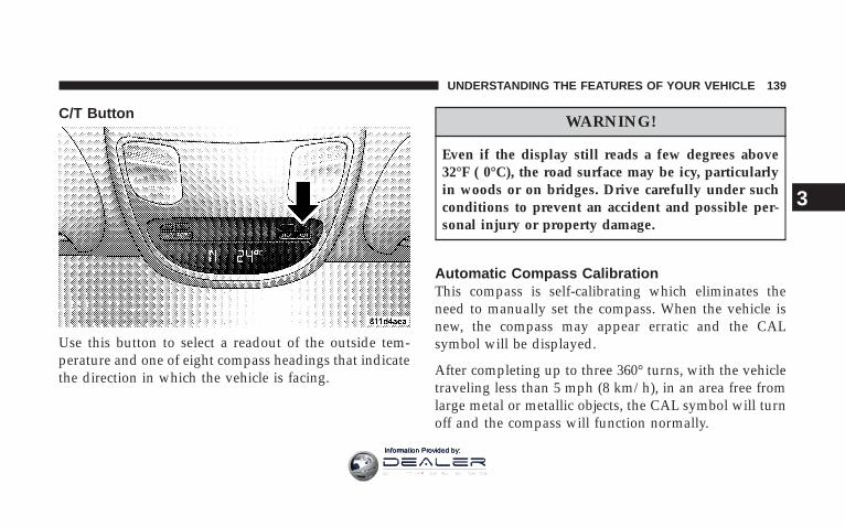
C/T Button
Use this button to select a readout of the outside tem-perature and one of eight compass headings that indicatethe direction in which the vehicle is facing.
WARNING!
Even if the display still reads a few degrees above32°F ( 0°C), the road surface may be icy, particularlyin woods or on bridges. Drive carefully under suchconditions to prevent an accident and possible per-sonal injury or property damage.
Automatic Compass CalibrationThis compass is self-calibrating which eliminates theneed to manually set the compass. When the vehicle isnew, the compass may appear erratic and the CALsymbol will be displayed.
After completing up to three 360° turns, with the vehicletraveling less than 5 mph (8 km/h), in an area free fromlarge metal or metallic objects, the CAL symbol will turnoff and the compass will function normally.
UNDERSTANDING THE FEATURES OF YOUR VEHICLE 139
3
Information Provided by:

Manual Compass Calibration
NOTE: To ensure proper compass calibration, makesure the compass variance is properly set before manu-ally calibrating the compass.
If the compass appears erratic and the CAL symbol doesnot appear, you must manually put the compass into the“Calibration” mode.
Recalibrating The CompassTurn on the ignition and set the display to “Compass/Temperature.” Press and hold the RESET button tochange the display between VAR (compass variance) andCAL (compass calibration) modes. When the CAL sym-bol is displayed slowly drive the vehicle 5 mph in acomplete 360° circle in an area free from large metalobjects or power lines. The CAL symbol will turn off andthe compass will function normally.
Compass Variance is the difference between magneticnorth and geographic north. In some areas of the country,the difference between magnetic and geographic north isgreat enough to cause the compass to give false readings.If this occurs, the compass variance must be set accordingto the Compass Variance Map.
140 UNDERSTANDING THE FEATURES OF YOUR VEHICLE
Information Provided by:

NOTE: The default for the compass variance is zone 8.
To set the variance: Turn the ignition ON and set thedisplay to “Compass/Temperature.” Press and hold theRESET button approximately five seconds. The last vari-ance zone number will be displayed. Press the STEPbutton to select the new variance zone and press theRESET button to resume normal operation.
Outside TemperatureBecause the ambient temperature sensor is located un-derhood, engine temperature can influence the displayedtemperature, therefore, temperature readings are slowlyupdated when the vehicle speed is below 20 mph (30km/h) or during stop and go driving.
UNDERSTANDING THE FEATURES OF YOUR VEHICLE 141
3
Information Provided by:

OVERHEAD CONSOLE WITH ELECTRONICVEHICLE INFORMATION CENTER (EVIC) —DIESEL ONLYThe overhead console contains dome/reading lights, andan Electronic Vehicle Information Center (EVIC).
Dome/Reading Lights
Located in the overhead console are two dome/readinglights.
The dome/reading lights illuminate when a door isopened or when the interior lights are turned on byrotating the dimmer control located on the HeadlightSwitch.
The reading lights are activated by pressing on therecessed area of the corresponding lens.
NOTE: The dome/reading lights will remain on untilthe switch is pressed a second time, so be sure they havebeen turned off before leaving the vehicle.
Dome/Reading Lights
142 UNDERSTANDING THE FEATURES OF YOUR VEHICLE
Information Provided by:

Electronic Vehicle Information Center (EVIC) — IfEquipped
Pressing the menu button will change thedisplay to one of the following features:
Trip FunctionsPressing the STEP button allows you to scroll throughone of the following Trip Function features:
• TRIP – Shows the total distance traveled since the lastreset. To reset the TRIP function, press and hold theRESET button.
• ELAPSED TIME – Shows the total elapsed time oftravel since the last reset. Elapsed time will incrementwhen the ignition switch is in the ON/RUN or STARTpositions.
• UNIT IN US/METRIC – Press the RESET button totoggle between US and METRIC.
• AVG. MPG – Shows the average fuel economy sincethe last reset. When the fuel economy is reset, thedisplay will show dashes for two seconds. Then thehistory information will be erased, and the averagingwill continue from the last fuel average reading before
Overhead Console with EVIC
UNDERSTANDING THE FEATURES OF YOUR VEHICLE 143
3
Information Provided by:
the reset. (Example: If your Electronic Vehicle Informa-tion Center (EVIC) displays 18 AVG. MPG and theRESET button is pressed, the previous averaging his-tory will be erased and the display will return to the 18AVG. MPG, not to 0 AVG. MPG). The display may takeseveral miles for the value to change dependent upondriving habits.
• MI TO EMPTY (Distance To Empty) – Shows theestimated distance that can be traveled with the fuelremaining in the tank. This estimated distance isdetermined by a weighted average of fuel economy,according to the current fuel tank level. MI TO EMPTYcannot be reset through the RESET button.
NOTE: Significant changes in driving style or vehicleloading will greatly affect the actual drivable distance ofthe vehicle, regardless of the DTE displayed value.
• When the DTE value is less than 30 miles (48 km)estimated driving distance, the DTE display will
change to a text display of 9LOW FUEL.9 This displaywill continue until the vehicle runs out of fuel. Addinga significant amount of fuel to the vehicle will turn offthe 9LOW FUEL9 text and a new DTE value willdisplay.
System Status (EVIC Displays)When the appropriate conditions exist, the ElectronicVehicle Information Center (EVIC) displays the followingmessages:
• TURN SIGNALS ON (with a continuous warningchime)
• PERSONAL SETTINGS NOT AVAILABLE – VehicleNot in Park
• LEFT/RIGHT FRONT DOOR AJAR (one or more,with a single chime if speed is above 1 mph)
• LEFT/RIGHT REAR DOOR AJAR (one or more, witha single chime if speed is above 1 mph)
144 UNDERSTANDING THE FEATURES OF YOUR VEHICLE
Information Provided by:
• DOOR(S) AJAR (with a single chime if vehicle is inmotion)
• LOW WASHER FLUID (with a single chime)
• OIL CHANGE REQUIRED (with a single chime)
• CATALYST FULL SEE OWNER MANUAL
• CATALYST STAT lllllll 90%
• CATALYST FULL SERVICE REQUIRED
• SERVICE AIR FILTER
• SERVICE CCV FILTER
• COOLANT LOW (with a single chime)
OIL CHANGE REQUIRED — If EquippedYour vehicle is equipped with an engine oil changeindicator system. The “Oil Change Required” messagewill flash in the EVIC display for approximately 10seconds after a single chime has sounded to indicate the
next scheduled oil change interval. The engine oil changeindicator system is duty cycle based, which means theengine oil change interval may fluctuate dependent uponyour personal driving style.
Unless reset, this message will continue to display eachtime you turn the ignition switch to the ON/RUNposition. To turn off the message temporarily, press andrelease the Menu button. To reset the oil change indicatorsystem (after performing the scheduled maintenance)refer to the following procedure.
1. Turn the ignition switch to the ON position (Do notstart the engine).
2. Fully depress the accelerator pedal slowly three timeswithin 10 seconds.
3. Turn the ignition switch to the OFF/LOCK position.
UNDERSTANDING THE FEATURES OF YOUR VEHICLE 145
3
Information Provided by:
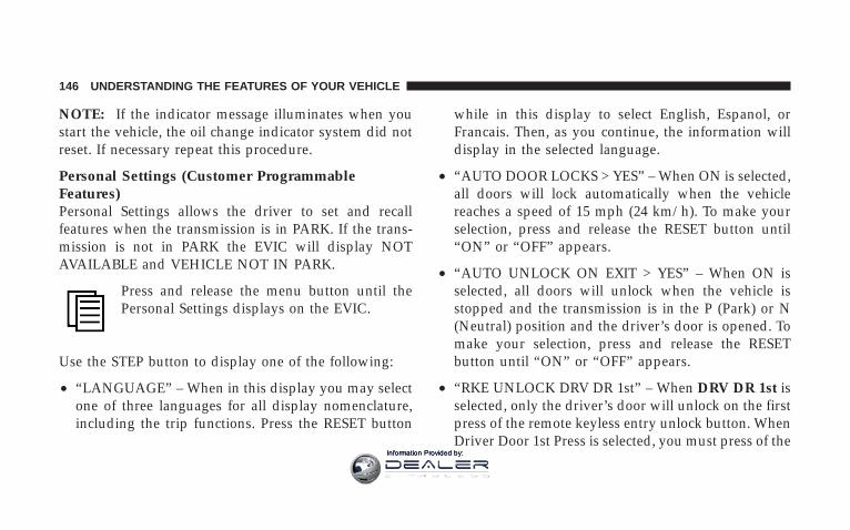
NOTE: If the indicator message illuminates when youstart the vehicle, the oil change indicator system did notreset. If necessary repeat this procedure.
Personal Settings (Customer ProgrammableFeatures)Personal Settings allows the driver to set and recallfeatures when the transmission is in PARK. If the trans-mission is not in PARK the EVIC will display NOTAVAILABLE and VEHICLE NOT IN PARK.
Press and release the menu button until thePersonal Settings displays on the EVIC.
Use the STEP button to display one of the following:
• “LANGUAGE” – When in this display you may selectone of three languages for all display nomenclature,including the trip functions. Press the RESET button
while in this display to select English, Espanol, orFrancais. Then, as you continue, the information willdisplay in the selected language.
• “AUTO DOOR LOCKS > YES” – When ON is selected,all doors will lock automatically when the vehiclereaches a speed of 15 mph (24 km/h). To make yourselection, press and release the RESET button until“ON” or “OFF” appears.
• “AUTO UNLOCK ON EXIT > YES” – When ON isselected, all doors will unlock when the vehicle isstopped and the transmission is in the P (Park) or N(Neutral) position and the driver’s door is opened. Tomake your selection, press and release the RESETbutton until “ON” or “OFF” appears.
• “RKE UNLOCK DRV DR 1st” – When DRV DR 1st isselected, only the driver’s door will unlock on the firstpress of the remote keyless entry unlock button. WhenDriver Door 1st Press is selected, you must press of the
146 UNDERSTANDING THE FEATURES OF YOUR VEHICLE
Information Provided by:

remote keyless entry unlock button twice to unlock thepassenger’s doors. To make your selection, press andrelease the RESET button until “DRV DR 1st ” appears.
• “RKE UNLOCK ALL DR 1ST” – When All ALL DR1ST is selected, all of the doors will unlock on the firstpress of the remote keyless entry unlock button. Tomake your selection, press and release the RESETbutton until “All DR 1st” appears.
• “SOUND HORN W/LOCK > YES” – When ON isselected, a short horn sound will occur when theremote keyless entry “Lock” button is pressed. Thisfeature may be selected with or without the flash lightson lock/unlock feature. To make your selection, pressand release the RESET button until “ON” or “OFF”appears.
• “FLASH LIGHTS w/LOCK > YES” – When ON isselected, the front and rear turn signals will flash whenthe doors are locked or unlocked with the remote
keyless entry transmitter. This feature may be selectedwith or without the sound horn on lock featureselected. To make your selection, press and release theRESET button until “ON” or “OFF” appears.
• “HEAD LAMP OFF DELAY > 0 SEC” – When thisfeature is selected, the driver can choose to have theheadlights remain on for 0, 30, 60, or 90 seconds whenexiting the vehicle. To make your selection, press andrelease the RESET button until “0,” “30,” “60,” or “90”appears.
• “KEY OFF POWER DELAY > OFF” – When thisfeature is selected, the power window switches, radio,hands–free system (if equipped), and power outletswill remain active for up to 10 minutes after theignition switch is turned off. Opening a vehicle doorwill cancel this feature. To make your selection, pressand release the RESET button until “Off,” “45 sec.,” “5min.,” “10 min appears.
UNDERSTANDING THE FEATURES OF YOUR VEHICLE 147
3
Information Provided by:

• “ILLUMINATED APRCH > OFF” – When this featureis selected, the headlights will activate and remain onfor up to 90 seconds when the doors are unlocked withthe remote keyless entry transmitter. To make yourselection, press and release the RESET button until“OFF,” “30 sec.,” “60 sec.,” or “90 sec.” appears.
NOTE: If this feature is enabled, the headlamps will beon during the engine pre-heat and cold crank; therefore,it is recommended that the feature be disabled whenovernight ambient temperature is at or below 20F (-7C) toprevent excessive drain on batteries during cold crank-ing.
• “UNIT IN > US/METRIC” – The EVIC, odometer canbe changed between English and Metric units ofmeasure. To make your selection, press and release theRESET button until “US” or “METRIC” appears.
• “COMPASS VARIANCE > 8” – Press the RESETbutton to change the compass variance setting. Referto Compass Variance, in this section for additionalinformation.
• “COMPASS CALIBRATE > YES” – Press the RESETbutton to calibrate the compass. Refer to ManualCompass Calibration, in this section for additionalinformation.
Compass/Temperature ButtonPressing the Compass/Temperature buttonwill return the display to the normal compass/temperature display.
NOTE: Temperature accuracy can be effected from heatsoak. For best accuracy, the vehicle should be driven at aspeed greater than 25 mph (40 km/h) for several min-utes.
148 UNDERSTANDING THE FEATURES OF YOUR VEHICLE
Information Provided by:

Automatic Compass CalibrationThis compass is self-calibrating, which eliminates theneed to set the compass manually. When the vehicle isnew, the compass may appear erratic and the EVIC willdisplay “CAL” until the compass is calibrated. You mayalso calibrate the compass by completing one or more360° turns (in an area free from large metal or metallicobjects) until the “CAL” message displayed in the EVICturns off. The compass will now function normally.
Manual Compass CalibrationIf the compass appears erratic and the “CAL” messagedoes not appear in the EVIC display, you must put thecompass into the Calibration Mode manually as follows:
1. Turn the ignition switch to the ON/RUN position.
2. Press the menu button until Personal Settings isdisplayed.
3. Press the STEP button until “Calibrate Compass YES”is displayed.
4. Press and release the RESET button
to start the calibration. The message “CAL” will displayin the EVIC.
5. Slowly drive the vehicle 5 mph in a complete 360°circle (in an area free from large metal or metallic objects)until the “CAL” message turns off. The compass will nowfunction normally.
UNDERSTANDING THE FEATURES OF YOUR VEHICLE 149
3
Information Provided by:
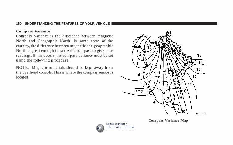
Compass VarianceCompass Variance is the difference between magneticNorth and Geographic North. In some areas of thecountry, the difference between magnetic and geographicNorth is great enough to cause the compass to give falsereadings. If this occurs, the compass variance must be setusing the following procedure:
NOTE: Magnetic materials should be kept away fromthe overhead console. This is where the compass sensor islocated.
Compass Variance Map
150 UNDERSTANDING THE FEATURES OF YOUR VEHICLE
Information Provided by:
1. Turn the ignition switch to the ON/RUN position.
2. Press the menu button until Personal Settings isdisplayed.
3. Press the STEP button until “Compass Variance” isdisplayed.
4. Press and release RESET button until the propervariance zone is selected according to the map.
5. Press and release the compass button to exit.
ELECTRICAL POWER OUTLETSThe auxiliary electrical outlet can provide power for incab accessories designed for use with the standard “cigarlighter” plug. The outlet is located in the instrumentpanel below and to the right of the Climate ControlPanel. A cap is attached to the outlet base indicating“Power Outlet” 12V-20A.
There is an additional Power Outlet inside the centerconsole of vehicles equipped with 40/20/40, or Bucketfront seats. There is also a Power Outlet located on therear of the center console for Quad Cab or Mega Cabvehicles (only) equipped with bucket seats.
The outlet(s) has/have a fused direct feed from thebattery so it/they receive power whether the ignition isON or OFF.
All accessories connected to this/these outlet(s) shouldbe removed or turned OFF when the vehicle is not in useto protect the battery against discharge.
NOTE: If desired, all of the power outlets can beconverted by your authorized dealer to provide powerwith the ignition switch in the ON position only.
UNDERSTANDING THE FEATURES OF YOUR VEHICLE 151
3
Information Provided by:
CAUTION!
Electrical Outlet Use With Engine Off• Many accessories that can be plugged in draw
power from the vehicle’s battery, even when not inuse (i.e. cellular phones, etc.). Eventually, ifplugged in long enough, the vehicle’s battery willdischarge sufficiently to degrade battery lifeand/or prevent engine starting.
• Accessories that draw higher power (i.e. coolers,vacuum cleaners, lights, etc.), will discharge thebattery even more quickly. Only use these inter-mittently and with greater caution.
• After the use of high power draw accessories, orlong periods of the vehicle not being started (withaccessories still plugged in), the vehicle must bedriven a sufficient length of time to allow thegenerator to recharge the vehicle’s battery.
CIGAR LIGHTER AND ASH RECEIVERThe removable ash receiver is located in the instrumentpanel cup holder tray.
The cigar lighter is located on the instrument panel,above and to the left of the ash receiver.
As a child safety precaution, the lighter only operateswith the ignition switch ON. It heats when pushed in andpops out automatically when ready for use. To preservethe heating element, do not hold the lighter in theheating position.
152 UNDERSTANDING THE FEATURES OF YOUR VEHICLE
Information Provided by:

Ash Tray Automatic Transmission Ash Tray Manual Transmission
UNDERSTANDING THE FEATURES OF YOUR VEHICLE 153
3
Information Provided by:

CUPHOLDERS
Front Instrument Panel Cupholders (40–20–40Seats) — Automatic TransmissionYour new Ram truck is equipped with two adjustablecupholders. The cupholder is opened by pulling on thecup holder door handle, on the front surface. Eachopening in the cupholder is adjustable and will hold cupsand mugs of various sizes.
To secure the cup, place the cup to be held into one of thecup wells and then push the cupholder arm toward thecup until it is held stable.
Cup Holder Door Handle
154 UNDERSTANDING THE FEATURES OF YOUR VEHICLE
Information Provided by:

Front Instrument Panel Cupholders (BucketSeats) — Automatic TransmissionIf your new Ram truck is equipped with bucket seatsthere are three cup holders located on the front of thecenter console.
Cup Holders Automatic Transmission
Cup Holders Bucket Seat
UNDERSTANDING THE FEATURES OF YOUR VEHICLE 155
3
Information Provided by:
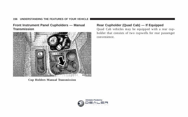
Front Instrument Panel Cupholders — ManualTransmission
Rear Cupholder (Quad Cab) — If EquippedQuad Cab vehicles may be equipped with a rear cup-holder that consists of two cupwells for rear passengerconvenience.
Cup Holders Manual Transmission
156 UNDERSTANDING THE FEATURES OF YOUR VEHICLE
Information Provided by:

STORAGE
Center Storage Compartment (40–20–40 Seat) —If Equipped
The center portion of the seat folds down to provide anarmrest with unique storage compartments under the lid.Push the button on the front of the armrest to raise thecover. Inside there is a power outlet (if equipped),
removable coin holder (if equipped), and two dividers toconfigure the storage area into compartments. For ex-ample, compartments can be configured to hold a lap-topcomputer, a cellular telephone, CD’s and miscellaneousitems. The top of the cover provides a generous firmsurface to serve as a desktop for your “mobile office.”
WARNING!
• This armrest is not a seat. Anyone seated on thearmrest could be seriously injured during vehicleoperation, or an accident. Only use the centerseating position when the armrest is fully upright.
• In an accident, the latch may open if the totalweight of the items stored exceeds about 10 lbs (4.5kg). These items could be thrown about endanger-ing occupants of the vehicle. Items stored shouldnot exceed a total of 10 lbs (4.5 kg).
UNDERSTANDING THE FEATURES OF YOUR VEHICLE 157
3
Information Provided by:
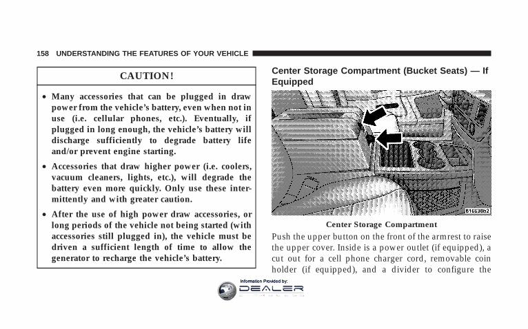
CAUTION!
• Many accessories that can be plugged in drawpower from the vehicle’s battery, even when not inuse (i.e. cellular phones, etc.). Eventually, ifplugged in long enough, the vehicle’s battery willdischarge sufficiently to degrade battery lifeand/or prevent engine starting.
• Accessories that draw higher power (i.e. coolers,vacuum cleaners, lights, etc.), will degrade thebattery even more quickly. Only use these inter-mittently and with greater caution.
• After the use of high power draw accessories, orlong periods of the vehicle not being started (withaccessories still plugged in), the vehicle must bedriven a sufficient length of time to allow thegenerator to recharge the vehicle’s battery.
Center Storage Compartment (Bucket Seats) — IfEquipped
Push the upper button on the front of the armrest to raisethe upper cover. Inside is a power outlet (if equipped), acut out for a cell phone charger cord, removable coinholder (if equipped), and a divider to configure the
Center Storage Compartment
158 UNDERSTANDING THE FEATURES OF YOUR VEHICLE
Information Provided by:

storage area into separate compartments. Lift the lowerhandle on the front of the armrest, and raise the armrestfor access to the lower storage bin. On Quad Cab modelsthe rear of the floor console offers a power outlet, and atip out bin.
WARNING!
• This armrest is not a seat. Anyone seated on thearmrest could be seriously injured during vehicleoperation, or an accident. Only use the centerseating position when the armrest is fully upright.
• In an accident, the latch may open if the totalweight of the items stored exceeds about 10 lbs (4.5kg). These items could be thrown about endanger-ing occupants of the vehicle. Items stored shouldnot exceed a total of 10 lbs (4.5 kg).
CAUTION!
• Many accessories that can be plugged in drawpower from the vehicle’s battery, even when not inuse (i.e. cellular phones, etc.). Eventually, ifplugged in long enough, the vehicle’s battery willdischarge sufficiently to degrade battery lifeand/or prevent engine starting.
• Accessories that draw higher power (i.e. coolers,vacuum cleaners, lights, etc.), will degrade thebattery even more quickly. Only use these inter-mittently and with greater caution.
• After the use of high power draw accessories, orlong periods of the vehicle not being started (withaccessories still plugged in), the vehicle must bedriven a sufficient length of time to allow thegenerator to recharge the vehicle’s battery.
UNDERSTANDING THE FEATURES OF YOUR VEHICLE 159
3
Information Provided by:
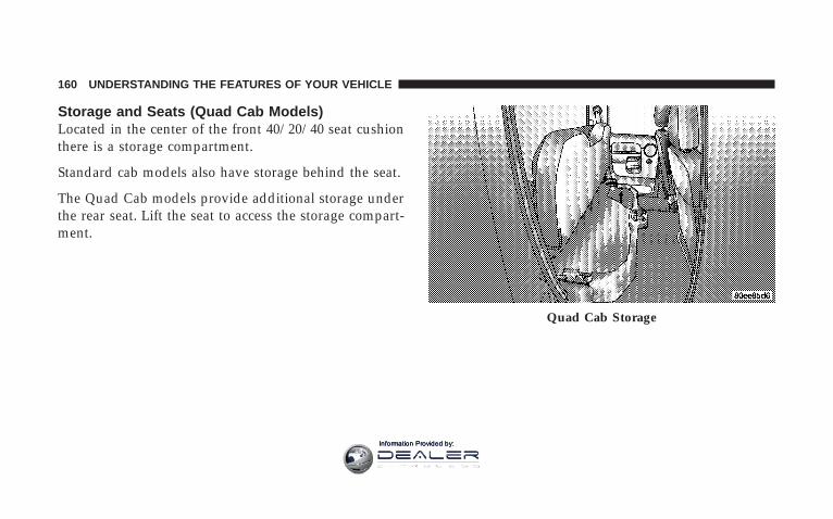
Storage and Seats (Quad Cab Models)Located in the center of the front 40/20/40 seat cushionthere is a storage compartment.
Standard cab models also have storage behind the seat.
The Quad Cab models provide additional storage underthe rear seat. Lift the seat to access the storage compart-ment.
Quad Cab Storage
160 UNDERSTANDING THE FEATURES OF YOUR VEHICLE
Information Provided by:

Plastic Grocery Bag RetainersRetainer hooks which will hold plastic grocery baghandles are built into the back panel of the cab, behindthe rear seat.
REAR WINDOW FEATURES
Electric Rear Window Defroster and Heated Sideview Mirrors — If Equipped
The Electric Rear Window Defroster and Heatedside view mirrors are activated by pressing the
heated grid button, located on the Climate Control panel,with the ignition On. Turning Off the ignition willdeactivate the Electric Rear Window Defroster andHeated side view mirrors feature. These features alsoturn off after activation, when 15 minutes have elapsed.To reactivate, simply press the button again.
Grocery Bag Hooks
UNDERSTANDING THE FEATURES OF YOUR VEHICLE 161
3
Information Provided by:

Power Sliding Rear Window — If Equipped
The power sliding rear window switch is located on theinstrument panel below the climate controls. Press theright side of the switch to open the glass and the left sideof the switch to close the glass.
Sliding Rear Window — If EquippedA locking device in the center of the window helps toprevent entry from the rear of the vehicle. Squeeze thelock to release the window.
Power Sliding Rear Window Switch
162 UNDERSTANDING THE FEATURES OF YOUR VEHICLE
Information Provided by:

FOLD FLAT LOAD FLOOR — IF EQUIPPEDQuad Cab models with a 60/40 rear seat, may beequipped with a folding load floor.
WARNING!
Do not operate the vehicle with loose items stored onthe load floor. While driving or in an accident youmay experience, abrupt stopping, rapid acceleration,or sharp turns. Loose objects stored on the load floormay move around with force and strike occupants,resulting in serious or fatal injury.
Quad Cab Rear 60/40 Seat
UNDERSTANDING THE FEATURES OF YOUR VEHICLE 163
3
Information Provided by:

Unfolding the Load Floor
1. Lift the 60/40 seat cushion(s) to the upward position.
2. Grasp the knob on the load floor and lift the knob untilthe load floor unfolds into position.
3. Reverse the procedure to store the load floor.Unfolding The Load Floor
Load Floor In Open Position
164 UNDERSTANDING THE FEATURES OF YOUR VEHICLE
Information Provided by:

Positioning the Load Floor for Storage Access Underthe Seat
1. Lift the 60/40 seat cushion(s) to the upward position.
2. Unsnap the securing snap located at either side of theload floor.
3. Lift the load floor up to access storage under the loadfloor.
WARNING!
Do not drive with the load floor in the up position.When stopping fast or in an accident, the load floorcould move to the down position causing seriousinjury.
4. Reverse the procedure to put the load floor back in thesecured down position before you operate the vehicle.
Load Floor Securing Straps
UNDERSTANDING THE FEATURES OF YOUR VEHICLE 165
3
Information Provided by:

Information Provided by:
UNDERSTANDING YOUR INSTRUMENT PANEL
CONTENTS
m Instruments And Controls . . . . . . . . . . . . . . . . . 171
m Instrument Clusters . . . . . . . . . . . . . . . . . . . . . 172
▫ 5.7L Gas Engines . . . . . . . . . . . . . . . . . . . . . . 172
▫ 6.7L Cummins Diesel Engines . . . . . . . . . . . . 173
m Instrument Cluster Description . . . . . . . . . . . . . 174
m Electronic Digital Clock . . . . . . . . . . . . . . . . . . 183
▫ Clock Setting Procedure . . . . . . . . . . . . . . . . . 184
m Radio General Information . . . . . . . . . . . . . . . . 184
▫ Radio Broadcast Signals . . . . . . . . . . . . . . . . . 184
▫ Two Types Of Signals . . . . . . . . . . . . . . . . . . 184
▫ Electrical Disturbances . . . . . . . . . . . . . . . . . . 185
▫ AM Reception . . . . . . . . . . . . . . . . . . . . . . . 185
▫ FM Reception . . . . . . . . . . . . . . . . . . . . . . . . 185
m Sales Code REF — AM/FM/CD (Single Disc)Radio With Optional Satellite Radio And HandsFree Phone Capability . . . . . . . . . . . . . . . . . . . 186
▫ Operating Instructions - Radio Mode . . . . . . . 186
▫ Operation Instructions - CD Mode . . . . . . . . . 190
▫ Operation Instructions - Auxiliary Mode . . . . . 192
4
Information Provided by:

▫ Operating Instructions - Hands Free Phone —If Equipped . . . . . . . . . . . . . . . . . . . . . . . . . 193
▫ Operating Instructions - Satellite Radio —If Equipped . . . . . . . . . . . . . . . . . . . . . . . . . 193
m Sales Code RAQ – AM/FM/CD (6-Disc) RadioWith Optional Satellite Radio, Hands Free Phone,And Vehicle Entertainment Systems (VES)Capabilities . . . . . . . . . . . . . . . . . . . . . . . . . . . 194
▫ Operating Instructions - Radio Mode . . . . . . . 194
▫ Operation Instructions - (CD Mode For CDAudio Play) . . . . . . . . . . . . . . . . . . . . . . . . . 199
▫ Load/Eject Button(CD Mode For CD Audio Play) . . . . . . . . . . . 201
▫ Notes On Playing MP3 Files . . . . . . . . . . . . . 203
▫ Operation Instructions - (CD Mode For MP3Audio Play) . . . . . . . . . . . . . . . . . . . . . . . . . 205
▫ Load/Eject Button (CD Mode For MP3 Play) . . 205
m Sales Code RAK – AM/FM/Cassette/CD (6-Disc)Radio With Optional Satellite Radio, Hands FreePhone, Video, MP3, And WMA Capabilities . . . . 208
▫ Operating Instructions - Radio Mode . . . . . . . 208
▫ Operating Instructions — Tape Player . . . . . . . 212
▫ Seek Button . . . . . . . . . . . . . . . . . . . . . . . . . 212
▫ Fast Forward (FF) . . . . . . . . . . . . . . . . . . . . . 213
▫ Rewind (RW) . . . . . . . . . . . . . . . . . . . . . . . . 213
▫ Tape Eject . . . . . . . . . . . . . . . . . . . . . . . . . . . 213
▫ Scan Button . . . . . . . . . . . . . . . . . . . . . . . . . 213
▫ Changing Tape Direction . . . . . . . . . . . . . . . . 213
▫ Metal Tape Selection . . . . . . . . . . . . . . . . . . . 213
▫ Pinch Roller Release . . . . . . . . . . . . . . . . . . . 213
168 UNDERSTANDING YOUR INSTRUMENT PANEL
Information Provided by:

▫ Noise Reduction . . . . . . . . . . . . . . . . . . . . . . 214
▫ Operation Instructions - (CD Mode For CDAudio Play) . . . . . . . . . . . . . . . . . . . . . . . . . 214
▫ Load/Eject Button (CD Mode For CD AudioPlay) . . . . . . . . . . . . . . . . . . . . . . . . . . . . . . 215
▫ Notes On Playing MP3 Files . . . . . . . . . . . . . 217
▫ Operation Instructions - (CD Mode For MP3And WMA Audio Play) . . . . . . . . . . . . . . . . . 219
▫ Load/Eject Button (CD Mode For MP3 AndWMA Play) . . . . . . . . . . . . . . . . . . . . . . . . . 219
m Sales Code REC — AM/FM/CD (6–Disc) RadioWith Navigation System . . . . . . . . . . . . . . . . . . 222
▫ Operating Instructions — Satellite Radio(If Equipped) . . . . . . . . . . . . . . . . . . . . . . . . 222
▫ REC Setting The Clock . . . . . . . . . . . . . . . . . 222
▫ Audio Clock Display . . . . . . . . . . . . . . . . . . . 225
m Video Entertainment System (Sales Code XRV) —If Equipped . . . . . . . . . . . . . . . . . . . . . . . . . . . 226
m Satellite Radio — If Equipped . . . . . . . . . . . . . . 226
▫ System Activation . . . . . . . . . . . . . . . . . . . . . 226
▫ Electronic Serial Number/Sirius IdentificationNumber (ESN/SID) . . . . . . . . . . . . . . . . . . . . 227
▫ Selecting Satellite Mode In REF, RAQ, AndRAK Radios . . . . . . . . . . . . . . . . . . . . . . . . . 228
▫ Selecting a Channel . . . . . . . . . . . . . . . . . . . . 228
▫ Storing And Selecting Pre-Set Channels . . . . . . 229
▫ Using The PTY (Program Type) Button — IfEquipped . . . . . . . . . . . . . . . . . . . . . . . . . . . 229
▫ PTY Button 9Scan9 . . . . . . . . . . . . . . . . . . . . . 229
UNDERSTANDING YOUR INSTRUMENT PANEL 169
4
Information Provided by:

▫ PTY Button 9Seek9 . . . . . . . . . . . . . . . . . . . . . 229
▫ Satellite Antenna . . . . . . . . . . . . . . . . . . . . . . 229
▫ Reception Quality . . . . . . . . . . . . . . . . . . . . . 230
m Remote Sound System Controls —If Equipped . . . . . . . . . . . . . . . . . . . . . . . . . . . 230
▫ Radio Operation . . . . . . . . . . . . . . . . . . . . . . 231
▫ Tape Player . . . . . . . . . . . . . . . . . . . . . . . . . 231
▫ CD Player . . . . . . . . . . . . . . . . . . . . . . . . . . 231
m Cassette Tape And Player Maintenance . . . . . . . 232
m Compact Disc Maintenance . . . . . . . . . . . . . . . . 233
m Radio Operation And Cellular Phones . . . . . . . . 233
m Climate Controls . . . . . . . . . . . . . . . . . . . . . . . 234
▫ Heater Only — If Equipped . . . . . . . . . . . . . . 234
▫ Air Conditioning And Heating —If Equipped . . . . . . . . . . . . . . . . . . . . . . . . . 237
▫ Air Conditioning With Dual Zone TemperatureControl — If Equipped . . . . . . . . . . . . . . . . . 240
▫ Operating Tips . . . . . . . . . . . . . . . . . . . . . . . 244
▫ Operating Tips Chart . . . . . . . . . . . . . . . . . . . 246
170 UNDERSTANDING YOUR INSTRUMENT PANEL
Information Provided by:

INSTRUMENTS AND CONTROLS
UNDERSTANDING YOUR INSTRUMENT PANEL 171
4
Information Provided by:
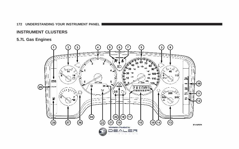
INSTRUMENT CLUSTERS
5.7L Gas Engines
172 UNDERSTANDING YOUR INSTRUMENT PANEL
Information Provided by:

6.7L Cummins Diesel Engines
UNDERSTANDING YOUR INSTRUMENT PANEL 173
4
Information Provided by:

INSTRUMENT CLUSTER DESCRIPTION
1. Check GagesThis light illuminates when the Voltmeter, EngineOil Pressure or Engine Coolant Temperature
gages indicate a reading either too high or too low.Examine the gages carefully, and follow the instructionscontained below for each indicated problem.
NOTE: When the ignition switch is turned to OFF, theFuel Gage, Voltmeter, Oil Pressure and Engine CoolantTemperature gages may not show accurate readings.When the engine is not running, turn the ignition switchto ON to obtain accurate readings.
2. VoltmeterWhen the engine is running, the gauge indicatesthe electrical system voltage. The pointer should
stay within the normal range if the battery is charged. If
the pointer moves to either extreme left or right andremains there during normal driving, the electrical sys-tem should be serviced.
NOTE: If the gauge pointer moves to either extreme ofthe gauge, the “Check Gages” indicator will illuminateand a single chime will sound.
NOTE:• The voltmeter may show a gauge fluctuation at vari-
ous engine temperatures. This cycling operation iscaused by the post-heat cycle of the intake manifoldheater system. The number of cycles and the length ofthe cycling operation is controlled by the enginecontrol module. Post-heat operation can run for sev-eral minutes, and then the electrical system and volt-meter needle will stabilize.
• The cycling action will cause temporary dimming ofthe headlamps, interior lamps, and also a noticeablereduction in blower motor speed.
174 UNDERSTANDING YOUR INSTRUMENT PANEL
Information Provided by:

3. Turn Signal IndicatorsLights in instrument cluster flash when outside turnsignals are operating.
4. TachometerThe tachometer indicates engine speed in revolutions perminute.
CAUTION!
Do not operate the engine with the tachometerpointer at high rpm for extended periods. Enginedamage may occur.
5. Airbag Indicator LightThe indicator lights and remains lit for 6 to 8 secondswhen the ignition is first turned on. If the light stays on,flickers or comes on while driving, have the airbagsystem checked by an authorized dealer.
6. High Beam IndicatorThis indicator shows that headlights are on highbeam.
7. Seat Belt Reminder LightWhen the ignition switch is first turned ON, thislight will turn on for 5 to 8 seconds as a bulb check.During the bulb check, if the driver’s seat belt is
unbuckled, a chime will sound. After the bulb check orwhen driving, if the driver seat belt remains unbuckled,the Seat Belt Warning Light will flash or remain oncontinuously. Refer to 9Enhanced Driver Seat Belt Re-minder System (BeltAlert™)9 in the Occupant Restraintssection for more information.(See page 35 for moreinformation.)
8. SpeedometerThe speedometer shows the vehicle speed in miles perhour and/or kilometers per hour.
UNDERSTANDING YOUR INSTRUMENT PANEL 175
4
Information Provided by:

9. Oil Pressure GaugeThe pointer should always indicate some oil pres-sure when the engine is running. A continuous
high or low reading, under normal driving conditions,may indicate a lubrication system malfunction. Immedi-ate service should be obtained.(See page 406 for moreinformation.)
NOTE: If the gauge pointer moves to either extreme ofthe gauge, the “Check Gages” indicator will illuminateand a single chime will sound.
10. Transfer Case Position(See page 289 for more information.)
11. TOW HAULThe TOW HAUL button is located at the end of the gearshift lever. This light will illuminate when the TOWHAUL OD/OFF button is pushed once.(See page 277 formore information.)
12. OD/OFFthe OD/OFF button is located at the end of the gear shiftlever. This light will illuminate when the TOW HAULOD/OFF button is pushed twice.(See page 277 for moreinformation.)
13. Temperature GaugeThe temperature gauge indicates engine coolanttemperature. Any reading within the normalrange indicates that the cooling system is operat-
ing satisfactorily. The gauge needle will likely indicate ahigher temperature when driving in hot weather, upmountain grades, in heavy traffic, or when towing atrailer. If the needle rises to the “245°F” mark, stop thevehicle, shift into N (Neutral), and increase the engineidle speed for 2 to 3 minutes. If the temperature readingdoes not return to normal, shut your engine OFF andallow it to cool. Seek authorized service immediately. SeeCooling System information in the section on “Maintain-ing Your Vehicle.”
176 UNDERSTANDING YOUR INSTRUMENT PANEL
Information Provided by:

CAUTION!
Do not leave your vehicle unattended with the en-gine running as you would not be able to react to thetemperature indicator if the engine overheats.
NOTE: Engine idle speed will automatically increase to1000 rpm at elevated coolant temperatures to improveengine cooling.
NOTE: If the gauge pointer moves to either extreme ofthe gauge, the “Check Gages” indicator will illuminateand a single chime will sound.
14. Security LightThe light will flash rapidly for approximately 16 secondswhen the vehicle theft alarm is arming. The light will
flash at a slower rate after the alarm is set. The securitylight will also come on for about two seconds when theignition is first turned ON.
15. Transmission Range Indicator (AutomaticTransmissions Only)When the gear selector lever is moved, this indicatorshows the automatic transmission gear range selected.
16. Odometer/Trip OdometerThe odometer shows the total distance the vehicle hasbeen driven. U.S. federal regulations require that upontransfer of vehicle ownership, the seller certify to thepurchaser the correct mileage that the vehicle has beendriven. Therefore, if the odometer reading is changedduring repair or replacement, be sure to keep a record ofthe reading before and after the service so that the correctmileage can be determined.
UNDERSTANDING YOUR INSTRUMENT PANEL 177
4
Information Provided by:

The two trip odometers show individual trip mileage. Toswitch from odometer to trip odometers, press andrelease the Trip Odometer button.
To reset a trip odometer, display the desired trip odom-eter to be reset then push and hold the button until thedisplay resets (approximately 2 seconds).
Vehicle Warning Messages
For non–Electronic Vehicle Information Center (EVIC)equipped vehicles, and the appropriate conditions exist,messages such as “door” (indicates that a door(s) may beajar), “hood” (if the hood is open or ajar, on vehicles withremote start), “gASCAP” (which indicates that your gascap is possibly loose or damaged), 9CHANgE OIL”(indicates that the engine oil should be change), “Lo-WASH” (low washer fluid),” LoCOOL” (low enginecoolant level) and “noFUSE” (indicates that the IOD fuseis removed from the Integrated Power Module), willdisplay in the odometer.
NOTE: If the vehicle is equipped with an EVIC, mostwarnings will display in the EVIC. For additional infor-mation, refer to “Electronic Vehicle Information Center(EVIC) — If Equipped” in Section 3.
NOTE: There is also an engine hour function. Thisindicates the total number of hours the engine has beenrunning. To display the engine hours perform the follow-ing: Place the ignition in RUN, but do not start theengine. With the odometer value displayed, hold the tripbutton down for a period of 6 seconds. The odometer willchange to trip value first, then it will display the enginehour value. The engine hours will be displayed for aperiod of 30 seconds until the ignition is turned off or theengine is started.
Change Oil Message
Your vehicle is equipped with an engine oil changeindicator system. The “Change Oil” message will flash inthe instrument cluster odometer for approximately 12
178 UNDERSTANDING YOUR INSTRUMENT PANEL
Information Provided by:

seconds after a single chime has sounded to indicate thenext scheduled oil change interval. The engine oil changeindicator system is duty cycle based, which means theengine oil change interval may fluctuate dependent uponyour personal driving style.
Unless reset, this message will continue to display eachtime you turn the ignition switch to the ON/RUNposition. To turn off the message temporarily, press andrelease the Trip Odometer button on the instrumentcluster. To reset the oil change indicator system (afterperforming the scheduled maintenance) refer to the fol-lowing procedure.
1. Turn the ignition switch to the ON position (Do notstart the engine).
2. Fully depress the accelerator pedal slowly threetimes within 10 seconds.
3. Turn the ignition switch to the OFF/LOCK position.
NOTE: If the indicator message illuminates when youstart the vehicle, the oil change indicator system did notreset. If necessary repeat this procedure.
17. Front Fog Light Indicator — If EquippedThis light shows when the front fog lights are ON.
18. Malfunction Indicator LightThis light is part of an onboard diagnostic systemwhich monitors the emissions and engine controlsystem. If the vehicle is ready for emissions
testing the light will come on when the ignition is firstturned on and remain on, as a bulb check, until theengine is started. If the vehicle is not ready for emissionstesting the light will come on when the ignition is firstturned on and remain on for 15 seconds, then blink for 5seconds, and remain on until the vehicle is started. If thebulb does not come on during starting, have the condi-tion investigated promptly.
UNDERSTANDING YOUR INSTRUMENT PANEL 179
4
Information Provided by:
If this light comes on and remains on while driving, itsuggests a potential engine control problem and the needfor system service.
Although your vehicle will usually be drivable and notneed towing, see your dealer for service as soon aspossible.
CAUTION!
Prolonged driving with the MIL on could causedamage to the engine control system. It also couldaffect fuel economy and driveability.
If the MIL is flashing, severe catalytic converterdamage and power loss will soon occur. Immediateservice is required.
19. Brake System Warning LightThis light illuminates when the ignition key is turned tothe ON position and remains on for a few seconds. If thelight stays on longer, it may be an indication that theparking brake has not been released. This light willilluminate if the brake fluid is low, especially whenbraking or accelerating hard. This light will illuminate ifthe ABS indicator light has a malfunction. This light willflash if the engine is running and the parking brake is on.If the light remains on when the parking brake isreleased, it indicates a possible brake hydraulic systemmalfunction. In this case, the light will remain on untilthe cause is corrected.
If brake failure is indicated, immediate repair is necessaryand continued operation of the vehicle in this condition isdangerous.
180 UNDERSTANDING YOUR INSTRUMENT PANEL
Information Provided by:

Acceleration which causes the rear wheels to slip for aperiod of time may result in the red brake light illumi-nating and a brake switch code being set on ABSequipped vehicles. Depressing the brake pedal shouldextinguish the red brake light.
20. ABS Warning LightThis light monitors the Anti-Lock Brake Systemwhich is described elsewhere in this manual. This
light will come on when the ignition key is turned to theON position and may stay on for five seconds. If the ABSlight remains on or comes on during driving, it indicatesthat the anti-lock portion of the brake system is notfunctioning and that service is required. See your autho-rized dealer immediately. The ABS light could alsoilluminate during loss of traction and remain illuminateduntil the brake pedal is pressed.
21. Electronic Throttle Control (ETC)This light informs you of a problem with theElectronic Throttle Control system. If a prob-lem is detected the light will come on while theengine is running. If the light remains lit with
the engine running your vehicle will usually be drivable,however, see your dealer for service as soon as possible.If the light is flashing when the engine is running,immediate service is required and you may experiencereduced performance, an elevated/rough idle or enginestall and your vehicle may require towing. The light willcome on when the ignition is first turned on and remainon for 15 seconds as a bulb check. If the light does notcome on during starting, have the system checked by anauthorized dealer.
22. SERV 4WD IndicatorThe 4WD indicator will be illuminated whenever the4WD mode is engaged for either the manual or electricshift 4WD systems. The SERV 4WD indicator monitors
UNDERSTANDING YOUR INSTRUMENT PANEL 181
4
Information Provided by:

the electric shift 4WD system. If the SERV 4WD lightstays on or comes on during driving, it means that the4WD system is not functioning properly and that serviceis required.
23. Water In Fuel Indicator — Diesel OnlyIndicates there is water detected in the fuelfilter. Refer to the Maintenance section, Drain-ing Fuel/Water Separator Filter, for waterdrain procedure.(See page 417 for more infor-mation.)
24. Transmission Oil Temperature Warning Light(Automatic Transmissions Only)
This light indicates that there is excessive trans-mission fluid temperature that might occurwith severe usage such as trailer towing. It mayalso occur when operating the vehicle in a high
torque converter slip condition, such as 4-wheel-driveoperation (e.g. snow plowing, off- road operation). If this
light comes on, stop the vehicle and run the engine at idleor faster, with the transmission in NEUTRAL until thelight goes off.
25. Wait To Start Indicator — Diesel OnlyThe Wait To Start Indicator will illuminate whenthe ignition is turned to the run position and the
intake manifold temperature is below 66 degrees F.Follow engine starting procedure for proper engine start-ing and operating. Wait until the Wait To Start Indicatorturns OFF then start the vehicle.
NOTE: The Wait To Start Indicator may not illuminate ifthe engine coolant temperature is warm enough.
26. Odometer/Trip Odometer ButtonPress this button to toggle between the odometer and thetrip odometer display. Holding the button in resets thetrip odometer reading when in trip mode.
182 UNDERSTANDING YOUR INSTRUMENT PANEL
Information Provided by:

27. Fuel GaugeShows level of fuel in tank when ignition switch is in theON position.
28. Low Fuel Warning LightGlows when the pointer is between “E” and 1/8indication mark (approximately 15% of tank vol-ume) on the fuel gauge. When the fuel gauge
pointer is on “E” (equivalent to Distance To Empty [DTE]= 0 on the overhead console if so equipped) there isreserve fuel capacity, which corresponds to approxi-mately 8% of tank volume. This reserve capacity was putin place to prevent the likelihood of customers runningout of fuel when operating at maximum load conditionsin areas where there aren’t many gas stations.(See page137 for more information.)
Ram fuel tank volumes are as follows:
• 52 gallons - Standard Rear Tank
• 22 gallons - Optional Mid Ship Tank
29. CRUISE LightThis indicator lights when the electronic speed controlsystem is turned on.
ELECTRONIC DIGITAL CLOCKThe clock and radio each use the display panel built intothe radio. A digital readout shows the frequency and/ortime in hours and minutes (depending on your radiomodel) whenever the ignition switch is in the “ON” or“ACC” position.
When the ignition switch is in the “OFF” position, orwhen the radio frequency is being displayed, time keep-ing is accurately maintained.
UNDERSTANDING YOUR INSTRUMENT PANEL 183
4
Information Provided by:

On the RAQ radio the time button alternates the locationof the time and frequency on the display. On the REF onlyone of the two, time or frequency is displayed at a time.
Clock Setting Procedure
1. Press and hold the time button until the hours blink.
2. Adjust the hours by turning the right side Tune /Audio control.
3. After the hours are adjusted, press the right side Tune/ Audio control to set the minutes.
4. Adjust the minutes using the right side Tune / Audiocontrol.
5. To exit, press any button/knob or wait approximately5 seconds.
RADIO GENERAL INFORMATION
Radio Broadcast SignalsYour new radio will provide excellent reception undermost operating conditions. Like any system, however, carradios have performance limitations, due to mobile op-eration and natural phenomena, which might lead you tobelieve your sound system is malfunctioning. To helpyou understand and save you concern about these “ap-parent” malfunctions, you must understand a point ortwo about the transmission and reception of radio sig-nals.
Two Types of SignalsThere are two basic types of radio signals... AM orAmplitude Modulation, in which the transmitted soundcauses the amplitude, or height, of the radio waves tovary... and FM or Frequency Modulation, in which thefrequency of the wave is varied to carry the sound.
184 UNDERSTANDING YOUR INSTRUMENT PANEL
Information Provided by:

Electrical DisturbancesRadio waves may pick up electrical disturbances duringtransmission. They mainly affect the wave amplitude,and thus remain a part of the AM reception. Theyinterfere very little with the frequency variations thatcarry the FM signal.
AM ReceptionAM sound is based on wave amplitude, so AM receptioncan be disrupted by such things as lightning, power linesand neon signs.
FM ReceptionBecause FM transmission is based on frequency varia-tions, interference that consists of amplitude variationscan be filtered out, leaving the reception relatively clear,which is the major feature of FM radio.
NOTE: The radio, steering wheel radio controls (ifequipped), and 6 disc CD/DVD changer (if equipped)will remain active for up to 10 minutes after the ignitionswitch has been turned off. Opening a vehicle front doorwill cancel this feature.
UNDERSTANDING YOUR INSTRUMENT PANEL 185
4
Information Provided by:

SALES CODE REF — AM/FM/CD (SINGLE DISC)RADIO WITH OPTIONAL SATELLITE RADIO ANDHANDS FREE PHONE CAPABILITY
NOTE: The radio sales code is located on the lower rightside of your radio faceplate.
Operating Instructions - Radio Mode
NOTE: The ignition switch must be in the ON or ACCposition to operate the radio.
Power Switch/Volume Control (Rotary)Press the ON/VOL control to turn the radio ON. Pressthe ON/VOL a second time to turn OFF the radio.
Electronic Volume ControlThe electronic volume control turns continuously (360degrees) in either direction without stopping. Turning thevolume control to the right increases the volume and tothe left decreases it.
When the audio system is turned on, the sound will beset at the same volume level as last played.
For your convenience, the volume can be turned down,but not up, when the audio system is off and the ignitionis ON.REF Radio
186 UNDERSTANDING YOUR INSTRUMENT PANEL
Information Provided by:

Mode Button (Radio Mode)Press the mode button repeatedly to select between theCD player and Satellite Radio (if equipped).
SEEK Button (Radio Mode)Press and release the SEEK button to search for the nextlistenable station in either AM/FM or Satellite (ifequipped) mode. Press the right side of the button to seekup and the left side to seek down. The radio will remaintuned to the new station until you make another selec-tion. Holding the button will bypass stations withoutstopping until you release it.
MUTE Button (Radio Mode)Press the MUTE button to cancel the sound from thespeakers. 9MUTE9 will display. Press the MUTE button asecond time and the sound from the speakers will return.Rotating the volume control, turning the radio ON/OFF,or turning ON/OFF the ignition, will cancel the MUTEfeature.
NOTE: In Hands Free Phone (if equipped) mode, theMUTE button mutes the microphone.
SCAN Button (Radio Mode)Pressing the SCAN button causes the tuner to search forthe next listenable station in either, AM, FM, or Satellite(if equipped) frequencies, pausing for 5 seconds at eachlistenable station before continuing to the next. To stopthe search, press SCAN a second time.
PSCAN Button (Radio Mode)Pressing the PSCAN button causes the tuner to scanthrough preset stations in either, AM, FM, or Satellite (ifequipped) frequencies, pausing for 5 seconds at eachpreset station before continuing to the next. To stop thesearch, press PSCAN a second time.
Time ButtonPress the time button and the time of day will display for5 seconds.
UNDERSTANDING YOUR INSTRUMENT PANEL 187
4
Information Provided by:

Clock Setting Procedure
1. Press and hold the time button until the hours blink.
2. Adjust the hours by turning the right side Tune/Audio control.
3. After the hours are adjusted, press the right sideTune/Audio control to set the minutes. The minutes willbegin to blink.
4. Adjust the minutes using the right side Tune/Audiocontrol.
5. To exit, press any button/knob or wait 5 seconds.
RW/FF (Radio Mode)Pressing the rewind/fast forward button causes the tunerto search for the next frequency in the direction of thearrows. This feature operates in either AM, FM or Satel-lite (if equipped) frequencies.
TUNE Control (Radio Mode)Turn the right side rotary control clockwise to increase orcounter-clockwise to decrease the frequency.
AM/FM Button (Radio Mode)Press the button to select AM or FM Modes.
Setting the Tone, Balance, and FadePress the rotary TUNE control and BASS will display.Turn the TUNE control to the right or left to increase ordecrease the Bass tones.
Press the rotary TUNE control a second time and MIDwill display. Turn the TUNE control to the right or left toincrease or decrease the Mid Range tones.
Press the rotary TUNE control a third time and TREB willdisplay. Turn the TUNE control to the right or left toincrease or decrease the Treble tones.
188 UNDERSTANDING YOUR INSTRUMENT PANEL
Information Provided by:

Press the rotary TUNE control a fourth time and BAL willdisplay. Turn the TUNE control to the right or left toadjust the sound level from the right or left side speakers.
Press the rotary TUNE control a fifth time and FADE willdisplay. Turn the TUNE control to the left or right to adjustthe sound level between the front and rear speakers.
Press the tune control again or wait 5 seconds to exitsetting tone, balance, and fade.
RND/SET Button (Radio Mode) To SET ThePush-Button MemoryWhen you are receiving a station that you wish tocommit to push-button memory, press the SET button.The symbol SET 1 will now show in the display window.Select the button (1-6) you wish to lock onto this stationand press and release that button. If a button is notselected within 5 seconds after pressing the SET button,the station will continue to play but will not be storedinto push-button memory.
You may add a second station to each push-button byrepeating the above procedure with this exception: Pressthe SET button twice and SET 2 will show in the displaywindow. Each button can be set for SET 1 and SET 2 inboth AM and FM. This allows a total of 12 AM, 12 FM,and 12 Satellite (if equipped) stations to be stored intopush-button memory. The stations stored in SET 2memory can be selected by pressing the push-buttontwice.
Every time a preset button is used, a correspondingbutton number will display.
Preset Buttons 1 - 6 (Radio Mode)These buttons tune the Radio to the stations that youcommit to push-button memory {12 AM, 12 FM, and 12Satellite (if equipped) stations}.
UNDERSTANDING YOUR INSTRUMENT PANEL 189
4
Information Provided by:

Operation Instructions - CD Mode
NOTE: The ignition switch must be in the ON or ACCposition to operate the radio.
Inserting The Compact Disc (Single CD Player)Gently insert one CD into the CD player with the CDlabel facing up. The CD will automatically be pulled intothe CD Player and the CD icon will illuminate on theradio display.
If the volume control is ON, the unit will switch to CDmode and begin to play. The display will show the tracknumber and play time in minutes and seconds. Play willbegin at the start of track one.
NOTE:• On some vehicles, you may insert or eject a disc with
the radio or ignition switch OFF.
• If you insert a disc with the ignition ON and the radioOFF, the CD will automatically be pulled into the CDPlayer.
• This radio does not play discs with MP3 tracks.
SEEK Button (CD Mode)Press the right side of the SEEK button for the next trackon the CD. Press the left side of the button to return to thebeginning of the current track, or return to the beginningof the previous track if the CD is within the first 10seconds of the current selection.
MUTE Button (CD Mode)Press the MUTE button to cancel the sound from thespeakers. 9MUTE9 will display. Press the MUTE button asecond time and the sound from the speakers will return.Rotating the volume control or turning OFF the ignitionwill also return the sound from the speakers.
190 UNDERSTANDING YOUR INSTRUMENT PANEL
Information Provided by:

SCAN Button (CD Mode)Press this button to play the first 10 seconds of each track.To stop the scan function, press the button a second time.
EJECT Button (CD Mode)Press this button and the disc will unload andmove to the entrance for easy removal. Theunit will switch to the last selected mode.
If you do not remove the disc within 15 seconds, it will bereloaded. The radio mode will continue to appear.
TIME Button (CD Mode)Press this button to change the display from elapsed CDplaying time to time of day. The time of day will displayfor 5 seconds.
RW/FF (CD Mode)Press and hold the FF (Fast Forward) and the CD playerwill begin to fast forward until FF is released. The RW(Reverse) button works in a similar manner.
RND/SET Button (Random Play Button) (CDMode)Press this button while the CD is playing to activateRandom Play. This feature plays the selections on thecompact disc in random order to provide an interestingchange of pace.
Press the SEEK button to move to the next randomlyselected track.
Press and hold the FF button to fast forward through thetracks. Release the FF button to stop the fast forwardfeature. If the RW button is pressed, the current track willreverse to the beginning of the track and begin playing.
Press the RND button a second time to stop RandomPlay.
UNDERSTANDING YOUR INSTRUMENT PANEL 191
4
Information Provided by:
Operation Instructions - Auxiliary ModeThe auxiliary (AUX) jack is an audio input jack, whichallows the user to plug in a portable device such as anMP3 player, cassette player, or microphone and utilizethe vehicle’s audio system to amplify the source and playthrough the vehicle speakers.
The auxiliary mode becomes active when an electricaldevice is plugged into the AUX jack using a standard 3.5mm stereo audio cable and the user presses and releasesthe MODE button until AUX appears on the display.
NOTE: The radio will return to the last stored mode ifthe ignition switch is turned from the OFF/LOCK posi-tion to the ACC position, the radio is turned on, and theradio was previously in the AUX mode.
SEEK Button (Auxiliary Mode)No function.
MUTE Button (Auxiliary Mode)Press the MUTE button to cancel the sound from thespeakers. 9MUTE9 will display. Press the MUTE button asecond time and the sound from the speakers will return.Rotating the volume control or turning OFF the ignitionwill also return the sound from the speakers.
SCAN Button (Auxiliary Mode)No function.
EJECT Button (Auxiliary Mode)No function.
PSCAN Button (Auxiliary Mode)No function.
192 UNDERSTANDING YOUR INSTRUMENT PANEL
Information Provided by:

TIME Button (Auxiliary Mode)Press this button to change the display from elapsedplaying time to time of day. The time of day will displayfor 5 seconds.
RW/FF (Auxiliary Mode)No function.
RND/SET Button (Auxiliary Mode)No function.
Mode Button (Auxiliary Mode)Press the mode button repeatedly to select between theCD player and Satellite Radio (if equipped).
Operating Instructions - Hands Free Phone — IfEquippedRefer to the “HANDS FREE PHONE (UConnect™)”section of the Owner’s Manual.
Operating Instructions - Satellite Radio — IfEquippedRefer to the “Satellite Radio” section of the Owner’sManual.
UNDERSTANDING YOUR INSTRUMENT PANEL 193
4
Information Provided by:

SALES CODE RAQ – AM/FM/CD (6-DISC) RADIOWITH OPTIONAL SATELLITE RADIO, HANDSFREE PHONE, AND VEHICLE ENTERTAINMENTSYSTEMS (VES) CAPABILITIES
NOTE: The radio sales code is located on the lower rightside of your radio faceplate.
Operating Instructions - Radio Mode
NOTE: The ignition switch must be in the ON or ACCposition to operate the radio.
Power Switch/Volume Control (Rotary)Press the ON/VOL control to turn the radio ON. Pressthe ON/VOL a second time to turn OFF the radio.
Electronic Volume ControlThe electronic volume control turns continuously (360degrees) in either direction without stopping. Turning thevolume control to the right increases the volume and tothe left decreases it.
When the audio system is turned on, the sound will beset at the same volume level as last played.
For your convenience, the volume can be turned down,but not up, when the audio system is off and the ignitionis ON.
RAQ Radio
194 UNDERSTANDING YOUR INSTRUMENT PANEL
Information Provided by:

Mode Button (Radio Mode)Press the mode button repeatedly to select between theCD player, Satellite Radio, or Vehicle EntertainmentSystem (VES) (if equipped).
SEEK Button (Radio Mode)Press and release the SEEK button to search for the nextlistenable station in either AM/FM or Satellite (ifequipped) mode. Press the right side of the button to seekup and the left side to seek down. The radio will remaintuned to the new station until you make another selec-tion. Holding the button will bypass stations withoutstopping until you release it.
MUTE Button (Radio Mode)Press the MUTE button to cancel the sound from thespeakers. 9MUTE9 will be displayed. Press the MUTEbutton a second time and the sound from the speakers
will return. Rotating the volume control, turning theradio ON/OFF, or turning OFF the ignition will alsoreturn the sound from the speakers
NOTE: In Hands Free Phone (if equipped) mode, theMUTE button mutes the microphone.
SCAN Button (Radio Mode)Pressing the SCAN button causes the tuner to search forthe next listenable station, in either AM, FM or Satellite (ifequipped) frequencies, pausing for 5 seconds at eachlistenable station before continuing to the next. To stopthe search, press SCAN a second time.
MSG or INFO Button (Radio Mode)Press the MSG or INFO button for an RBDS station (onewith call letters displayed). The radio will return a RadioText message broadcast from an FM station (FM modeonly).
UNDERSTANDING YOUR INSTRUMENT PANEL 195
4
Information Provided by:

Time ButtonPress the time button and the time of day will bedisplayed for 5 seconds.
Clock Setting Procedure
1. Press and hold the time button until the hours blink.
2. Adjust the hours by turning the right side Tune /Audio control.
3. After the hours are adjusted, press the right side Tune/ Audio control to set the minutes. The minutes willbegin to blink.
4. Adjust the minutes using the right side Tune / Audiocontrol.
5. To exit, press any button/knob or wait 5 seconds.
RW/FF (Radio Mode)Pressing the rewind/fast forward button causes the tunerto search for the next frequency in the direction of thearrows. This feature operates in either AM, FM or Satel-lite (if equipped) frequencies.
TUNE Control (Radio Mode)Turn the right side rotary control clockwise to increase orcounter-clockwise to decrease the frequency.
AM/FM Button (Radio Mode)Press the button to select AM or FM Modes.
Setting the Tone, Balance, and FadePress the rotary TUNE control and BASS will display.Turn the TUNE control to the right or left to increase ordecrease the Bass tones.
Press the rotary TUNE control a second time and MIDwill display. Turn the TUNE control to the right or left toincrease or decrease the Mid Range tones.
196 UNDERSTANDING YOUR INSTRUMENT PANEL
Information Provided by:

Press the rotary TUNE control a third time and TREBLEwill display. Turn the TUNE control to the right or left toincrease or decrease the Treble tones.
Press the rotary TUNE control a fourth time and BAL-ANCE will display. Turn the TUNE control to the right orleft to adjust the sound level from the right or left sidespeakers.
Press the rotary TUNE control a fifth time and FADE willdisplay. Turn the TUNE control to the left or right toadjust the sound level between the front and rear speak-ers.
Press the rotary TUNE control again to exit setting tone,balance and fade.
RND/PTY Button (Radio Mode)Pressing this button once will turn on the PTY mode for5 seconds. If no action is taken during the 5 second timeout the PTY icon will turn off. Pressing the PTY button orturning the TUNE rotary knob within 5 seconds will
allow the program format type to be selected. Many radiostations do not currently broadcast PTY information.
Toggle the PTY button to select the following formattypes:
Program Type 16 Digit-CharacterDisplay
No program type or un-defined None
Adult Hits Adult_HitsAlert Alert Alert AlertClassical Classical
Classic Rock Classic_RockCollege CollegeCountry Country
Emergency Test Emergency TestForeign Language Foreign_Language
Information Information
UNDERSTANDING YOUR INSTRUMENT PANEL 197
4
Information Provided by:
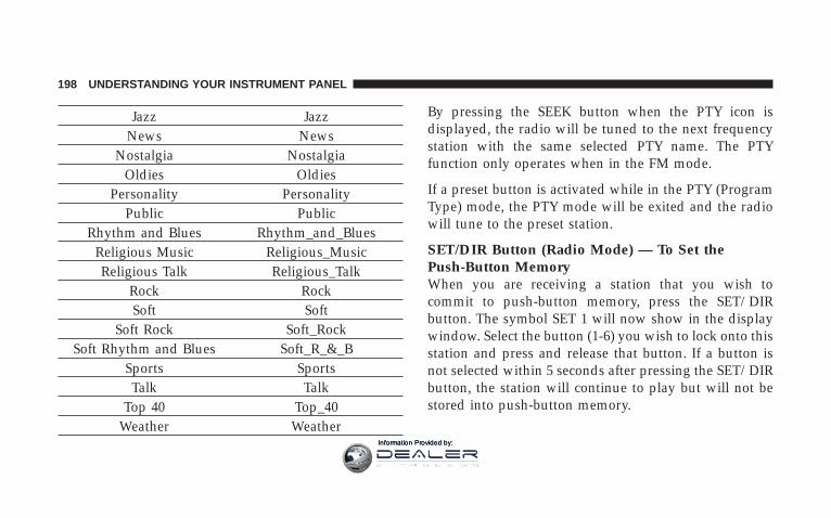
Jazz JazzNews News
Nostalgia NostalgiaOldies Oldies
Personality PersonalityPublic Public
Rhythm and Blues Rhythm_and_BluesReligious Music Religious_MusicReligious Talk Religious_Talk
Rock RockSoft Soft
Soft Rock Soft_RockSoft Rhythm and Blues Soft_R_&_B
Sports SportsTalk Talk
Top 40 Top_40Weather Weather
By pressing the SEEK button when the PTY icon isdisplayed, the radio will be tuned to the next frequencystation with the same selected PTY name. The PTYfunction only operates when in the FM mode.
If a preset button is activated while in the PTY (ProgramType) mode, the PTY mode will be exited and the radiowill tune to the preset station.
SET/DIR Button (Radio Mode) — To Set thePush-Button MemoryWhen you are receiving a station that you wish tocommit to push-button memory, press the SET/DIRbutton. The symbol SET 1 will now show in the displaywindow. Select the button (1-6) you wish to lock onto thisstation and press and release that button. If a button isnot selected within 5 seconds after pressing the SET/DIRbutton, the station will continue to play but will not bestored into push-button memory.
198 UNDERSTANDING YOUR INSTRUMENT PANEL
Information Provided by:

You may add a second station to each push-button byrepeating the above procedure with this exception: Pressthe SET/DIR button twice and SET 2 will show in thedisplay window. Each button can be set for SET 1 andSET 2 in both AM and FM. This allows a total of 12 AM,12FM and 12 Satellite (if equipped) stations to be stored intopush-button memory. The stations stored in SET 2memory can be selected by pressing the push-buttontwice.
Every time a preset button is used a correspondingbutton number will be displayed.
Buttons 1 - 6 (Radio Mode)These buttons tune the Radio to the stations that youcommit to push-button memory {12AM, 12 FM, and 12Satellite (if equipped) stations}.
Operation Instructions - (CD MODE for CD AudioPlay)
NOTE: The ignition switch must be in the ON or ACCposition to operate the radio.
NOTE: Note: This Radio is capable of playing compactdiscs (CD), recordable compact discs (CD-R), rewritablecompact discs (CD-RW) compact discs with MP3 tracksand multisession compact discs with CD and MP3 tracks.
Inserting Compact Disc(s)Gently insert one CD into the CD player with the CDlabel facing up. The CD will automatically be pulled intothe CD Player and the CD icon will illuminate on theradio display.
UNDERSTANDING YOUR INSTRUMENT PANEL 199
4
Information Provided by:
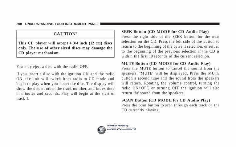
CAUTION!
This CD player will accept 4 3/4 inch (12 cm) discsonly. The use of other sized discs may damage theCD player mechanism.
You may eject a disc with the radio OFF.
If you insert a disc with the ignition ON and the radioON, the unit will switch from radio to CD mode andbegin to play when you insert the disc. The display willshow the disc number, the track number, and index timein minutes and seconds. Play will begin at the start oftrack 1.
SEEK Button (CD MODE for CD Audio Play)Press the right side of the SEEK button for the nextselection on the CD. Press the left side of the button toreturn to the beginning of the current selection, or returnto the beginning of the previous selection if the CD iswithin the first 10 seconds of the current selection.
MUTE Button (CD MODE for CD Audio Play)Press the MUTE button to cancel the sound from thespeakers. 9MUTE9 will be displayed. Press the MUTEbutton a second time and the sound from the speakerswill return. Rotating the volume control, turning theradio ON/OFF, or turning OFF the ignition will alsoreturn the sound from the speakers.
SCAN Button (CD MODE for CD Audio Play)Press the Scan button to scan through each track on theCD currently playing.
200 UNDERSTANDING YOUR INSTRUMENT PANEL
Information Provided by:

LOAD/EJECT Button (CD Mode for CD AudioPlay)
LOAD/ EJECT - LoadPress the LOAD/ EJECT button and the push-button with the corresponding number wherethe CD is being loaded. The radio will displayPLEASE WAIT and prompt when to INSERT
DISC. After the radio displays 9LOAD DISC9 insert theCD into the player.
Radio display will show 9LOADING DISC9 when the discis loading, and “READING DISC” when the radio isreading the disc.
LOAD / EJT - EjectPress the LOAD/ EJT button and the push-button with the corresponding number wherethe CD was loaded and the disc will unloadand move to the entrance for easy removal.
Radio display will show 9EJECTING DISC9 when the discis being ejected and prompt the user to remove the disc.
Press and hold the LOAD/ EJT button for 5 seconds andall CDs will be ejected from the radio.
If you have ejected a disc and have not removed it within15 seconds, it will be reloaded. If the CD is not removed,the radio will continue to play the non-removed CD. Ifthe CD is removed and there are other CD’s in the radio,the radio will play the next CD after a 2 minute timeout.If the CD is removed and there are no other CD’s in theradio, the radio will remain in CD mode and display9INSERT DISC” for 10 seconds. If no discs are insertedwithin 10 seconds “NO DISCS LOADED” will be dis-played.
On some vehicles a disc can be ejected with the radio andignition OFF.
UNDERSTANDING YOUR INSTRUMENT PANEL 201
4
Information Provided by:

TIME Button (CD MODE for CD Audio Play)Press this button to change the display from a large CDplaying time display to a small CD playing time display.
RW/FF (CD MODE for CD Audio Play)Press and hold FF (Fast Forward) and the CD player willbegin to fast forward until FF is released or RW oranother CD button is pressed. The RW (Reverse) buttonworks in a similar manner.
TUNE Control (CD MODE for CD Audio Play)Pressing the TUNE control allows the setting of the Tone,Fade, and Balance. See Radio Mode.
AM/FM Button (CD MODE for CD Audio Play)Switches the Radio to the Radio mode.
RND/PTY Button (Random Play Button) (CDMODE for CD Audio Play)Press this button while the CD is playing to activateRandom Play. This feature plays the selections on thecompact disc in random order to provide an interestingchange of pace.
Press the SEEK button to move to the next randomlyselected track.
Press and hold the FF button to fast forward through thetracks. Release the FF button to stop the fast forwardfeature.
Press the RND button a second time to stop RandomPlay.
Buttons 1 - 6 (CD MODE for CD Audio Play)Selects disc positions 1 - 6 for Play/Load/Eject.
202 UNDERSTANDING YOUR INSTRUMENT PANEL
Information Provided by:
Notes On Playing MP3 FilesThe radio can play MP3 files, however, acceptable MP3file recording media and formats are limited. Whenwriting MP3 files, pay attention to the following restric-tions.
Supported Media (Disc Types)The MP3 file recording media supported by the radio areCD-ROM, CD-R and CD-RW.
Supported Medium Formats (File Systems)The medium formats supported by the radio are ISO 9660Level 1 and Level 2 and includes the Joliet extension.When reading discs recorded using formats other thanISO 9660 Level 1 and Level 2, the radio may fail to readfiles properly and may be unable to play the file nor-mally. UDF and Apple HFS formats are not supported.
The radio uses the following limits for file systems:
• Maximum number of directory levels: 15
• Maximum number of files: 255
• Maximum number of folders: 100
• Maximum number of characters in file/folder names:
• Level 1: 12 (including a separator 9.9 and a3-character extension)
• Level 2: 31 (including a separator 9.9 and a3-character extension)
Multisession disc formats are supported by the radio.Multisession discs may contain combinations of normalCD audio tracks and computer files (including MP3 files).Discs created with an option such as 9keep disc open afterwriting9 are most likely multisession discs. The use ofmultisession for CD audio or MP3 playback may result inlonger disc loading times.
UNDERSTANDING YOUR INSTRUMENT PANEL 203
4
Information Provided by:

Supported MP3 File FormatsThe radio will recognize only files with the *.mp3 exten-sion as MP3 files. Non-MP3 files named with the *.mp3extension may cause playback problems. The radio isdesigned to recognize the file as an invalid MP3 and willnot play the file.
When using the MP3 encoder to compress audio data toan MP3 file, the bit rate and sampling frequencies in thefollowing table are supported. In addition, variable bitrates (VBR) are also supported. The majority of MP3 filesuse a 44.1 kHz sampling rate and a 192, 160, 128, 96 orVBR bit rates.
MPEG Specifi-cation
Sampling Fre-quency (kHz) Bit rate (kbps)
MPEG-1 AudioLayer 3 48, 44.1, 32
320, 256, 224,192, 160, 128,
112, 96, 80, 64,56, 48, 40, 32
MPEG-2 AudioLayer 3 24, 22.05, 16
160, 128, 144,112, 96, 80, 64,
56, 48, 40, 32, 24,16, 8
ID3 Tag information for artist, song title and album titleare supported for version 1 ID3 tags. ID3 version 2 is notsupported by the radios.
Playlist files are not supported. MP3 Pro files are notsupported.
204 UNDERSTANDING YOUR INSTRUMENT PANEL
Information Provided by:
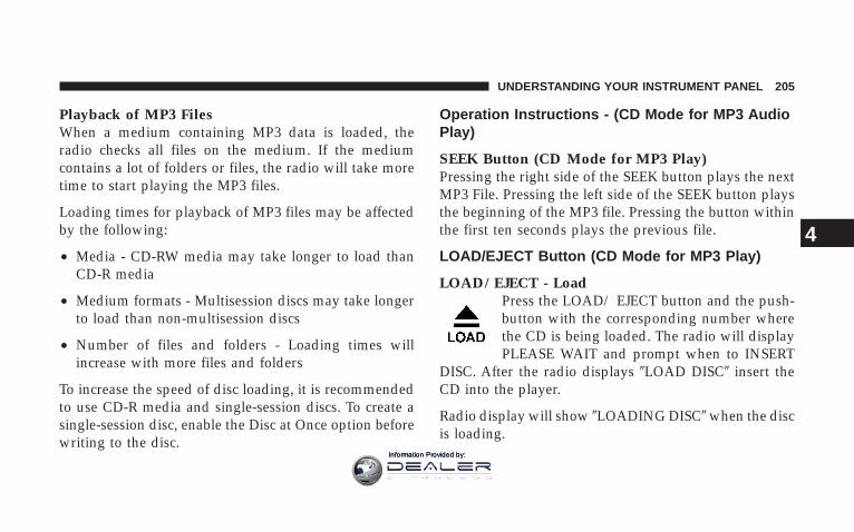
Playback of MP3 FilesWhen a medium containing MP3 data is loaded, theradio checks all files on the medium. If the mediumcontains a lot of folders or files, the radio will take moretime to start playing the MP3 files.
Loading times for playback of MP3 files may be affectedby the following:
• Media - CD-RW media may take longer to load thanCD-R media
• Medium formats - Multisession discs may take longerto load than non-multisession discs
• Number of files and folders - Loading times willincrease with more files and folders
To increase the speed of disc loading, it is recommendedto use CD-R media and single-session discs. To create asingle-session disc, enable the Disc at Once option beforewriting to the disc.
Operation Instructions - (CD Mode for MP3 AudioPlay)
SEEK Button (CD Mode for MP3 Play)Pressing the right side of the SEEK button plays the nextMP3 File. Pressing the left side of the SEEK button playsthe beginning of the MP3 file. Pressing the button withinthe first ten seconds plays the previous file.
LOAD/EJECT Button (CD Mode for MP3 Play)
LOAD/ EJECT - LoadPress the LOAD/ EJECT button and the push-button with the corresponding number wherethe CD is being loaded. The radio will displayPLEASE WAIT and prompt when to INSERT
DISC. After the radio displays 9LOAD DISC9 insert theCD into the player.
Radio display will show 9LOADING DISC9 when the discis loading.
UNDERSTANDING YOUR INSTRUMENT PANEL 205
4
Information Provided by:

LOAD / EJECT - EjectPress the LOAD/ EJECT button and the push-button with the corresponding number wherethe CD was loaded and the disc will unloadand move to the entrance for easy removal.
Radio display will show 9EJECTING DISC9 when the discis being ejected and prompt the user to remove the disc.
If you have ejected a disc and have not removed it within15 seconds, it will be reloaded. If the CD is not removed,the radio will continue to play the non-removed CD. Ifthe CD is removed and there are other CD’s in the radio,the radio will play the next CD after a 2 minute timeout.If the CD is removed and there are no other CD’s in theradio, the radio will remain in CD mode and display9INSERT DISC” for 2 minutes. After 2 minutes the radiowill go to the previous tuner mode.
MSG or INFO Button (CD Mode for MP3 Play)Press and MSG or INFO button while playing MP3 disc.The radio scrolls through the following TAG information:Song Title, Artist, File Name, and Folder Name (if avail-able).
Press the MSG or INFO button once more to return to9elapsed time9 priority mode.
Press and hold the MSG or INFO button while in themessage display priority mode or elapsed time displaypriority mode will display the song title for each file.
RW/FF (CD Mode for MP3 Play)Press the FF side of the button to move forward throughthe MP3 selection.
TUNE Control (CD Mode for MP3 Play)Pressing the TUNE Control allows the adjustment ofTone, Balance, and Fade.
206 UNDERSTANDING YOUR INSTRUMENT PANEL
Information Provided by:

AM/FM Button (CD Mode for MP3 Play)Switches back to Radio mode.
RND/ PTY Button (CD Mode for MP3 Play)Pressing this button plays files randomly.
SET/DIR Button (CD Mode for MP3 Play)Press the SET/DIR Button to display folders, whenplaying an MP3 discs that have a file/folder structure.Turn the TUNE control to display available folders ormove through available folders. Press the TUNE controlto select a folder.
Buttons 1 - 6 (CD Mode for MP3 Play)Selects disc positions 1 - 6 for Play/Load/Eject.
Operating Instructions - Hands Free Phone (IfEquipped)Refer to Hands Free Phone in Section 3 of the Owner’sManual.
Operating Instructions - Satellite Radio Mode (IfEquipped)Refer to the Satellite Radio section of the Owner’sManual.
Operating Instructions - Video EntertainmentSystem (VESt) (If Equipped)Refer to separate Video Entertainment System (VESt)Guide.
UNDERSTANDING YOUR INSTRUMENT PANEL 207
4
Information Provided by:

SALES CODE RAK – AM/FM/CASSETTE/CD(6-DISC) RADIO WITH OPTIONAL SATELLITERADIO, HANDS FREE PHONE, VIDEO, MP3, andWMA CAPABILITIES
NOTE: The radio sales code is located on the lower rightside of your radio faceplate.
Operating Instructions - Radio Mode
NOTE: The ignition switch must be in the ON or ACCposition to operate the radio.
Power Switch/Volume Control (Rotary)Press the ON/VOL control to turn the radio ON. Pressthe ON/VOL a second time to turn OFF the radio.
Electronic Volume ControlThe electronic volume control turns continuously (360degrees) in either direction without stopping. Turning thevolume control to the right increases the volume and tothe left decreases it.
When the audio system is turned on, the sound will beset at the same volume level as last played.
Mode Button (Radio Mode)Press the mode button repeatedly to select between theCD player, Cassette, Satellite, or Vehicle EntertainmentSystem (VES) (if equipped).RAK Radio
208 UNDERSTANDING YOUR INSTRUMENT PANEL
Information Provided by:

SEEK Button (Radio Mode)Press and release the SEEK button to search for the nextstation in either AM/FM or Satellite (if equipped) mode.Press the right side of the button to seek up and the leftside to seek down. The radio will remained tuned to thenew station until you make another selection. Holdingthe button and will bypass stations without stoppinguntil you release it.
SCAN Button (Radio Mode)Pressing the SCAN button causes the tuner to search forthe next station, in either AM, FM or Satellite (ifequipped) frequencies, pausing for 5 seconds (satellitescan 8 seconds) at each listenable station before continu-ing to the next. To stop the search, press SCAN a secondtime.
Time ButtonPress the time button and the time of day will display for5 seconds.
Clock Setting Procedure
1. Press and hold the time button until the hours blink.
2. Adjust the hours by turning the right side Tune/Audio control.
3. After the hours are adjusted, press the right sideTune/Audio control to set the minutes. The minutes willbegin to blink.
4. Adjust the minutes using the right side Tune/Audiocontrol.
5. To exit, press any button/knob or wait 5 seconds.
INFO Button (Radio Mode)Press the INFO button for an RBDS station (one with callletters displayed). The radio will return a Radio Textmessage broadcast (if available) from an FM station (FMmode only).
UNDERSTANDING YOUR INSTRUMENT PANEL 209
4
Information Provided by:
RW/FF (Radio Mode)Pressing the rewind/fast forward button causes the tunerto search for the next frequency in the direction of thearrows. This feature operates in either AM, FM or Satel-lite (if equipped) frequencies.
TUNE Control (Radio Mode)Turn the right side rotary control to increase or decreasethe frequency.
AM/FM Button (Radio Mode)Press the button to select AM or FM Modes.
Setting the Tone, Balance, and FadePress the rotary TUNE control and BASS will display.Turn the TUNE control to the right or left to increase ordecrease the Bass tones.
Press the rotary TUNE control a second time and MIDwill display. Turn the TUNE control to the right or left toincrease or decrease the Mid Range tones.
Press the rotary TUNE control a third time and TREBLEwill display. Turn the TUNE control to the right or left toincrease or decrease the Treble tones.
Press the rotary TUNE control a fourth time and BAL willdisplay. Turn the TUNE control to the right or left toadjust the sound level from the right or left side speakers.
Press the rotary TUNE control a fifth time and FADE willdisplay. Turn the TUNE control to the right or left to adjustthe sound level between the front and rear speakers.
Press the rotary TUNE control again to exit setting tone,balance, and fade.
RND/PTY Button (Radio Mode)Pressing this button once will turn on the PTY mode for5 seconds. If no action is taken during the 5-second timeout, the PTY icon will turn off. Turning the tune knobwithin 5 seconds will allow the program format type tobe selected. Many radio stations do not currently broad-cast PTY information.
210 UNDERSTANDING YOUR INSTRUMENT PANEL
Information Provided by:

Turn the tune knob to select the following format types:
Program Type 16 Digit-Character Dis-play
No program type or un-defined None
News NewsInformation Information
Sports SportsTalk TalkRock Rock
Classic Rock Classic_RockAdult Hits Adult_HitsSoft Rock Soft_Rock
Top 40 Top_40Country CountryOldies Oldies
Soft Soft
Nostalgia NostalgiaJazz Jazz
Classical ClassicalRhythm and Blues Rhythm_and_Blues
Soft Rhythm and Blues Soft_R_&_BForeign Language Foreign_LanguageReligious Music Religious_MusicReligious Talk Religious_Talk
Personality PersonalityPublic Public
College CollegeUnassigned
Weather Weather
By pressing the SEEK button when the PTY icon isdisplayed, the radio will be tuned to the next frequencystation with the same selected PTY name. The PTYfunction only operates when in the FM mode.
UNDERSTANDING YOUR INSTRUMENT PANEL 211
4
Information Provided by:
If a preset button is activated while in the PTY (ProgramType) mode, the PTY mode will be exited and the radiowill tune to the preset station.
NOTE: If you have selected a PTY with the tune knob,simply pressing the tune button in will go directly to a“PTY seek”.
Buttons 1 - 6 (Radio Mode)These buttons tune the Radio to the stations that youcommit to push-button memory {12 AM, 12 FM, and 12Satellite (if equipped) stations}.
Operating Instructions — Tape PlayerInsert the cassette with the exposed tape side toward theleft and the mechanical action of the player will gentlypull the cassette into the play position.
NOTE: When subjected to extremely cold temperatures,the tape mechanism may require a few minutes to warmup for proper operation. Sometimes poor playback maybe experienced due to a defective cassette tape. Clean anddemagnetize the tape heads at least twice a year.
Seek ButtonPress the SEEK button up for the next selection on thetape and down to return to the beginning of the currentselection.
Press the SEEK button up or down to move the tracknumber to skip forward or backward 1 to 6 selections.Press the SEEK button once to move 1 selection, twice tomove 2 selections, etc.
212 UNDERSTANDING YOUR INSTRUMENT PANEL
Information Provided by:

Fast Forward (FF)Press the FF button up momentarily to advance the tapein the direction that it is playing. The tape will advanceuntil the button is pressed again or the end of the tape isreached. At the end of the tape, the tape will play in theopposite direction.
Rewind (RW)Press the RW button momentarily to reverse the tapedirection. The tape will reverse until the button is pressedagain or until the end of the tape is reached. At the end ofthe tape, the tape will play in the opposite direction.
Tape EjectPress this button and the cassette will disen-gage and eject from the radio.
Scan ButtonPress this button to play 10 seconds of each selection.Press the scan button a second time to cancel the feature.
Changing Tape DirectionIf you wish to change the direction of tape travel (sidebeing played), press Preset 6. The lighted arrow in thedisplay window will show the new direction.
Metal Tape SelectionIf a standard metal tape is inserted into the player, theplayer will automatically select the correct equalization.
Pinch Roller ReleaseIf ignition power or the radio ON/OFF switch is turnedoff, the pinch roller will automatically retract to protectthe tape from any damage. When power is restored to thetape player, the pinch roller will automatically reengageand the tape will resume play.
UNDERSTANDING YOUR INSTRUMENT PANEL 213
4
Information Provided by:

Noise ReductionThe Dolby Noise Reduction System* is on whenever thetape player is on, but may be switched off.
To turn off the Dolby Noise reduction System: PressPreset 1 after you insert the tape. The NR light in thedisplay will go off when the Dolby System is off.
* ”Dolby” noise reduction is manufactured under licensefrom Dolby Laboratories Licensing Corporation. Dolbyand the double-D symbol are trademarks of Dolby Labo-ratories Licensing Corporation.
Operation Instructions - (CD MODE for CD AudioPlay)
NOTE: The ignition switch must be in the ON or ACCposition to operate the radio.
NOTE: Note: This Radio is capable of playing compactdiscs (CD), recordable compact discs (CD-R), rewritable
compact discs (CD-RW) compact discs with MP3 tracksand multisession compact discs with CD and MP3 tracksand WMA.
Inserting Compact Disc(s)
CAUTION!
This CD player will accept 4 3/4 inch (12 cm) discsonly. The use of other sized discs may damage theCD player mechanism.
You may eject a disc with the radio OFF.
If you insert a disc with the ignition ON and the radioON, the unit will switch from radio to CD mode andbegin to play when you insert the disc. The display willshow the disc number, the track number, and index timein minutes and seconds. Play will begin at the start oftrack 1.
214 UNDERSTANDING YOUR INSTRUMENT PANEL
Information Provided by:

SEEK Button (CD MODE for CD Audio Play)Press the right side of the SEEK button for the nextselection on the CD. Press the left side of the button toreturn to the beginning of the current selection, or returnto the beginning of the previous selection if the CD iswithin the first 5 seconds of the current selection.
SCAN Button (CD MODE for CD Audio Play)Press the Scan button to scan through each track on theCD currently playing.
LOAD/EJECT Button (CD Mode for CD AudioPlay)
LOAD/EJECT - LoadPress the LOAD/EJT button and the push-button with the corresponding number wherethe CD is being loaded. The radio will displayPLEASE WAIT and prompt when to INSERT
DISC. After the radio displays 9INSERT DISC,9 insert theCD into the player.
Radio display will show 9LOADING DISC9 when the discis loading and “READING DISC” when the radio isreading the disc.
LOAD/EJT - EjectPress the LOAD/EJT button and the push-button with the corresponding number wherethe CD was loaded and the disc will unloadand move to the entrance for easy removal.
Radio display will show 9EJECTING DISC9 when the discis being ejected and prompt the user to remove the disc.
Press and hold the LOAD/EJT button for 5 seconds andall CDs will be ejected from the radio.
If you have ejected a disc and have not removed it within15 seconds, it will be reloaded. If the CD is not removed,the radio will continue to play the non-removed CD. Ifthe CD is removed and there are other CD’s in the radio,the radio will play the next CD after a 2-minute timeout.If the CD is removed and there are no other CD’s in the
UNDERSTANDING YOUR INSTRUMENT PANEL 215
4
Information Provided by:

radio, the radio will remain in CD mode and display9INSERT DISC” for 2 minutes. After 2 minutes, the radiowill go to the previous tuner mode.
The disc can be ejected with the radio and ignition OFF.
TIME Button (CD MODE for CD Audio Play)Press this button to change the display from a large CDplaying time display to a small CD playing time display.
RW/FF (CD MODE for CD Audio Play)Press and hold FF (Fast Forward) and the CD player willbegin to fast forward until FF is released or RW oranother CD button is pressed. The RW (Reverse) buttonworks in a similar manner.
TUNE Control (CD MODE for CD Audio Play)Pressing the TUNE control allows the setting of the Tone,Fade, and Balance. See Radio Mode.
AM/FM Button (CD MODE for CD Audio Play)Switches the Radio to the Radio mode.
RND/PTY Button (Random Play Button) (CDMODE for CD Audio Play)Press this button while the CD is playing to activateRandom Play. This feature plays the selections on thecompact disc in random order to provide an interestingchange of pace.
NOTE: MP3 and WMA Random Play are for file foldersonly.
Press the SEEK button to move to the next randomlyselected track.
Press and hold the FF button to fast forward through thetracks. Release the FF button to stop the fast forwardfeature. If the RW button is pressed, the current track willreverse to the beginning of the track and begin playing.
Press the RND button a second time to stop RandomPlay.
216 UNDERSTANDING YOUR INSTRUMENT PANEL
Information Provided by:

Buttons 1 - 6 (CD MODE for CD Audio Play)Selects disc positions 1 - 6 for Play/Load/Eject.
Notes On Playing MP3 FilesThe radio can play MP3 files; however, acceptable MP3file recording media and formats are limited. Whenwriting MP3 files, pay attention to the following restric-tions.
Supported Media (Disc Types)The MP3 file recording media supported by the radio areCD-ROM, CD-R, and CD-RW.
Supported Medium Formats (File Systems)The medium formats supported by the radio are ISO 9660Level 1 and Level 2 and includes the Joliet extension.When reading discs recorded using formats other thanISO 9660 Level 1 and Level 2, the radio may fail to readfiles properly and may be unable to play the file nor-mally. UDF and Apple HFS formats are not supported.
The radio uses the following limits for file systems:
• Maximum number of directory levels: 15
• Maximum number of files: 255
• Maximum number of folders: 100
• Maximum number of characters in file/folder names:
• Level 1: 12 (including a separator 9.9 and a3-character extension)
• Level 2: 31 (including a separator 9.9 and a3-character extension)
Multisession disc formats are supported by the radio.Multisession discs may contain combinations of normalCD audio tracks and computer files (including MP3 files).Discs created with an option such as 9keep disc open afterwriting9 are most likely multisession discs. The use ofmultisession for CD audio or MP3 playback may result inlonger disc loading times.
UNDERSTANDING YOUR INSTRUMENT PANEL 217
4
Information Provided by:
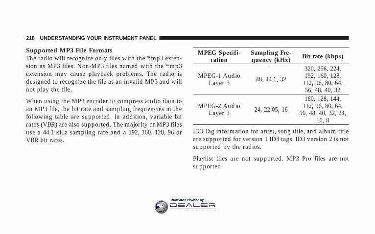
Supported MP3 File FormatsThe radio will recognize only files with the *.mp3 exten-sion as MP3 files. Non-MP3 files named with the *.mp3extension may cause playback problems. The radio isdesigned to recognize the file as an invalid MP3 and willnot play the file.
When using the MP3 encoder to compress audio data toan MP3 file, the bit rate and sampling frequencies in thefollowing table are supported. In addition, variable bitrates (VBR) are also supported. The majority of MP3 filesuse a 44.1 kHz sampling rate and a 192, 160, 128, 96 orVBR bit rates.
MPEG Specifi-cation
Sampling Fre-quency (kHz) Bit rate (kbps)
MPEG-1 AudioLayer 3 48, 44.1, 32
320, 256, 224,192, 160, 128,
112, 96, 80, 64,56, 48, 40, 32
MPEG-2 AudioLayer 3 24, 22.05, 16
160, 128, 144,112, 96, 80, 64,
56, 48, 40, 32, 24,16, 8
ID3 Tag information for artist, song title, and album titleare supported for version 1 ID3 tags. ID3 version 2 is notsupported by the radios.
Playlist files are not supported. MP3 Pro files are notsupported.
218 UNDERSTANDING YOUR INSTRUMENT PANEL
Information Provided by:

Playback of MP3 and WMA FilesWhen a medium containing MP3 data is loaded, theradio checks all files on the medium. If the mediumcontains a lot of folders or files, the radio will take moretime to start playing the MP3 files.
Loading times for playback of MP3 and WMA files maybe affected by the following:
• Media - CD-RW media may take longer to load thanCD-R media
• Medium formats - Multisession discs may take longerto load than non-multisession discs
• Number of files and folders - Loading times willincrease with more files and folders
To increase the speed of disc loading, it is recommendedto use CD-R media and single-session discs. To create asingle-session disc, enable the Disc at Once option beforewriting to the disc.
Operation Instructions - (CD Mode for MP3 andWMA Audio Play)
SEEK Button (CD Mode for MP3 and WMA Play)Pressing the right side of the SEEK button plays the nextfile. Pressing the left side of the SEEK button plays thebeginning of the file. Pressing the button within the firstten seconds plays the previous file.
LOAD/EJECT Button (CD Mode for MP3 and WMAPlay)
LOAD/EJT - LoadPress the LOAD/EJT button and the push-button with the corresponding number wherethe CD is being loaded. The radio will displayPLEASE WAIT and prompt when to INSERT
DISC. After the radio displays 9INSERT DISC,9 insert theCD into the player.The radio display will show 9LOADING DISC9 when thedisc is loading.
UNDERSTANDING YOUR INSTRUMENT PANEL 219
4
Information Provided by:

LOAD/EJT - EjectPress the LOAD/EJT button and the push-button with the corresponding number wherethe CD was loaded and the disc will unloadand move to the entrance for easy removal.
Radio display will show 9EJECTING DISC9 when the discis being ejected and prompt the user to remove the disc.
If you have ejected a disc and have not removed it within15 seconds, it will be reloaded. If the CD is not removed,the radio will continue to play the non-removed CD. Ifthe CD is removed and there are other CD’s in the radio,the radio will play the next CD after a 2-minute timeout.If the CD is removed and there are no other CD’s in theradio, the radio will remain in CD mode and display9INSERT DISC” for 2 minutes. After 2 minutes, the radiowill go to the previous tuner mode.
INFO Button (CD Mode for MP3 Play)Press and INFO button while playing MP3 or WMA disc.The radio scrolls through the following TAG information:Song Title, Artist, File Name, and Folder Name (if avail-able).
Press the INFO button once more to return to 9elapsedtime9 priority mode.
Press and hold the INFO button while in the messagedisplay priority mode or elapsed time display prioritymode will display the song title for each file.
RW/FF (CD Mode for MP3 and WMA Play)Press the FF side of the button to move forward throughthe file or MP3 and WMA selection.
TUNE Control (CD Mode for MP3 Play)Pressing the TUNE Control allows the adjustment ofTone, Balance, and Fade.
220 UNDERSTANDING YOUR INSTRUMENT PANEL
Information Provided by:

AM/FM Button (CD Mode for MP3 Play)Switches back to Radio mode.
RND/PTY Button (CD Mode for MP3 Play)Pressing this button plays files randomly.
SET/DIR Button (CD Mode for MP3 Play)Press the SET/DIR Button to display folders, whenplaying an MP3 discs that have a file/folder structure.Turn the TUNE control to display available folders ormove through available folders. Press the TUNE controlto select a folder.
Buttons 1 - 6 (CD Mode for MP3 Play)Selects disc positions 1 - 6 for Play/Load/Eject.
Operating Instructions - Hands Free Phone (IfEquipped)Refer to “Hands-Free Phone” in Section 3 of the Owner’sManual.
Operating Instructions - Satellite Radio Mode (IfEquipped)Refer to the “Satellite Radio” section of the Owner’sManual.
Operating Instructions - Video EntertainmentSystem (VES) (If Equipped)Refer to separate “Video Entertainment System (VES)Guide.”
UNDERSTANDING YOUR INSTRUMENT PANEL 221
4
Information Provided by:

SALES CODE REC — AM/FM/CD (6–DISC) RADIOWITH NAVIGATION SYSTEM
Satellite Navigation Radio with CD Player with MP3Capability (REC) - combines a Global-PositioningSystem-based navigation system with an integrated colorscreen to provide maps, turn identification, selection
menus and instructions for selecting a variety of destina-tions and routes, AM/FM stereo radio and six-disc CDchanger with MP3 capability.
Mapping information for navigation is supplied on aDVD that is loaded into the unit. One map DVD coversall of North America. Refer to your “Navigation User’sManual” for detailed operating instructions.
Operating Instructions — Satellite Radio (IfEquipped)Refer to your “Navigation User’s Manual” for detailedoperating instructions.
REC Setting the Clock
GPS ClockThe GPS receiver used in this system is synchronized tothe time data being transmitted by the GPS satellites. Thesatellites’ clock is Greenwich Mean Time (GMT). This is
REC Radio
222 UNDERSTANDING YOUR INSTRUMENT PANEL
Information Provided by:

the worldwide standard for time. This makes the sys-tem’s clock very accurate once the appropriate time zoneand daylight savings information is set.
1. At the Main Menu screen, highlight “Clock Setup”and press ENTER OR press and hold for 3 seconds theTIME button on the unit’s faceplate. The Clock Setupscreen appears.
2. To show the GPS clock, select “Displayed Clock: GPSClock” and press ENTER.
3. To adjust the time zone, Select “Time Zone” and pressENTER. Select the appropriate time zone and pressENTER.
4. To turn daylight savings on or off, select “DaylightSavings” and press ENTER. Select “On” or “Off” andpress ENTER.
5. Select DONE to exit from the clock setting mode. PressENTER to save your changes. If you press CANCEL orNAV then your changes will not be saved.
User Defined ClockIf you wish to set the clock to a time different than thesystem clock, you can manually adjust the time bychoosing the “User Defined Clock” option.
UNDERSTANDING YOUR INSTRUMENT PANEL 223
4
Information Provided by:

1. At the Clock Setup screen highlight “DisplayedClock: User Defined Clock”.
2. To increase the clock by hours, make sure “HR +” ishighlighted and press ENTER. Press ENTER again toincrease the clock by another hour. You will see on the“User Defined Time” display the number of hours youhave increased the clock by.
3. To decrease the clock by one hour, use the SelectEncoder to highlight the “-” sign. Press ENTER. PressENTER again to decrease the clock by another hour.
4. To increase the clock by minutes, make sure “MIN +”is highlighted and press ENTER. Press ENTER again toincrease the clock by another minute.
5. To decrease the clock by minutes, use the SelectEncoder to highlight the “-“ sign. Press ENTER. PressENTER again to decrease the clock by another minute.
6. Select “DONE” to exit from the clock setting mode.Press ENTER to save your changes. If you press CAN-CEL or NAV then your changes will not be saved.
224 UNDERSTANDING YOUR INSTRUMENT PANEL
Information Provided by:

Audio Clock Display
Select this option to change the size of the clock on theaudio screens.
1. When you are at an audio screen, quickly press theTIME button on the navigation faceplate.
2. In this example the large clock appears on the screen.
3. To switch the clock to the small clock, quickly pressTIME again.
4. To toggle back to the large clock, simply press TIME.
UNDERSTANDING YOUR INSTRUMENT PANEL 225
4
Information Provided by:
VIDEO ENTERTAINMENT SYSTEM (SALES CODEXRV) — IF EQUIPPEDThe optional VES™ (Video Entertainment System) con-sists of a DVD player and LCD (liquid crystal display)screen, a battery-powered remote control, and two head-sets. The system is located in the headliner behind thefront row seat. Refer to your VES™ User’s Manual fordetailed operating instructions.
SATELLITE RADIO — IF EQUIPPEDSatellite radio uses direct satellite to receiver broadcast-ing technology to provide clear digital sound, coast tocoast. The subscription service provider is Sirius™ Satel-lite Radio. This service offers over 100 channels of music,sports, news, entertainment, and programming for chil-dren, directly from its satellites and broadcasting studios.
System ActivationSirius Satellite Radio service is pre-activated, and youmay begin listening immediately to the one year ofSIRIUS audio service that is included with the factory-installed satellite radio system in your vehicle. Sirius willcontact you to supply a welcome kit and to confirmsubscription information, including the set up of youron-line listening account at no additional charge. Forfurther information, call the toll-free number 888-539-7474, or visit the Sirius web site at www.sirius.com.Please have the following information available whencalling:
1. The Electronic Serial Number/Sirius IdentificationNumber (ESN/SID).
2. Your Vehicle Identification Number.
226 UNDERSTANDING YOUR INSTRUMENT PANEL
Information Provided by:

Electronic Serial Number/Sirius IdentificationNumber (ESN/SID)The Electronic Serial Number/Sirius Identification Num-ber is needed to activate your Sirius Satellite Radiosystem. To access the ESN/SID, refer to the followingsteps:
ESN/SID Access with REF RadiosWith the ignition switch in the ACCESSORY position andthe radio OFF, press the CD Eject and Time buttonssimultaneously for 3 seconds. The first four digits of thetwelve-digit ESN/SID number will display. Press theSEEK UP button to display the next four digits. Continueto press the SEEK UP button until all twelve ESN/SIDdigits display. The SEEK DOWN will page down untilthe first four digits display. The radio will exit theESN/SID mode when any other button is pushed, theignition is turned OFF, or 5 minutes has passed since anybutton was pushed.
ESN/SID Access with RAQ and RAK RadiosWith the ignition switch in the ACCESSORY position andthe radio OFF, press the CD Eject and TIME buttonssimultaneously for 3 seconds. All twelve ESN/SID num-bers will display. The radio will exit the ESN/SID modewhen any other button is pushed, the ignition is turnedOFF, or 5 minutes has passed since any button waspushed.
ESN/SID Access with REC Navigation RadiosPlease refer to your Navigation User’s Manual.
With the ignition in the ACCESSORY position and theradio off, press the CD Eject and Set buttons simulta-neously until the 12 digits of the ESN/SID appear on thescreen.
UNDERSTANDING YOUR INSTRUMENT PANEL 227
4
Information Provided by:

Selecting Satellite Mode in REF, RAQ, and RAKRadios
Selecting Satellite Mode — REF RadioPress the MODE button repeatedly until the word 9SAT9appears in the display.
A CD may remain in the radio while in the Satellite radiomode.
Selecting Satellite Mode — RAQ and RAK RadioPress the MODE button repeatedly until the word 9SAT9appears in the display.
These radios will also display the current station nameand program type. For more information, such as songtitle and artist, press the MSG or INFO button.
A CD or tape may remain in the radio while in theSatellite radio mode.
Selecting a ChannelPress and release the SEEK or TUNE knob to search forthe next channel. Press the top of the button to search upand the bottom of the button to search down. Holding theTUNE button causes the radio to bypass channels untilthe button is released.
Press and release the SCAN button (if equipped) toautomatically change channels every 7 seconds. Theradio will pause on each channel for 7 seconds beforemoving on to the next channel. The word 9SCAN9 willappear in the display between each channel change. Pressthe SCAN button a second time to stop the search.
NOTE: Channels that may contain objectionable contentcan be blocked. Contact Sirius Customer Care at 888-539-7474 to discuss options for channel blocking or unblock-ing. Please have your ESN/SID information available.
228 UNDERSTANDING YOUR INSTRUMENT PANEL
Information Provided by:

Storing and Selecting Pre-Set ChannelsIn addition to the 12 AM and 12 FM pre-set stations, youmay also commit 12 satellite stations to push buttonmemory. These satellite channel pre-set stations will noterase any AM or FM pre-set memory stations. Follow thememory pre-set procedures that apply to your radio.
Using the PTY (Program Type) Button — IfEquippedFollow the PTY button instructions that apply to yourradio.
PTY Button (SCAN(When the desired program type is obtained, press the9SCAN9 button within five seconds. The radio will play 7seconds of the selected channel before moving to the nextchannel of the selected program type. Press the 9SCAN9button a second time to stop the search.
NOTE: Pressing the 9SEEK9 or 9SCAN9 button, whileperforming a music type scan, will change the channel byone and stop the search. Pressing a pre-set memorybutton during a music type scan, will call up the memorychannel and stop the search.
PTY Button (SEEK(When the desired program is obtained, press the 9SEEK9button within five seconds. The channel will change tothe next channel that matches the program type selected.
Satellite AntennaTo ensure optimum reception on vehicles available witha luggage rack, do not place items on the roof around therooftop antenna location. Metal objects placed within theline of sight of the antenna will cause decreased perfor-mance. Larger luggage items should be placed as farforward as possible. Do not place items directly on orabove the antenna.
UNDERSTANDING YOUR INSTRUMENT PANEL 229
4
Information Provided by:

Reception QualitySatellite reception may be interrupted due to one of thefollowing reasons.
• The vehicle is parked in an underground parkingstructure or under a physical obstacle.
• Dense tree coverage may interrupt reception.
• Driving under wide bridges or along tall buildings cancause intermittent reception.
• Placing objects over or too close to the antenna cancause signal blockage.
REMOTE SOUND SYSTEM CONTROLS — IFEQUIPPEDThe remote sound system controls are located on the rearsurface of the steering wheel. Reach behind the wheel toaccess the switches.
The right hand control is a rocker type switch with abutton in the center. Pressing the top of the switch willincrease the volume and pressing the bottom of theswitch will decrease the volume. The center button of theright hand control will allow you to change the mode.
Remote Sound System Controls
230 UNDERSTANDING YOUR INSTRUMENT PANEL
Information Provided by:
The left hand control is a rocker type switch with a pushbutton in the center. The function of the left hand controlis different depending on which mode you are in.
The following describes the left hand control operation ineach mode.
Radio OperationPressing the top of the left side switch will SEEK up forthe next listenable station and pressing the bottom of theswitch will SEEK down for the next listenable station.
The button located in the center of the left hand controlwill tune to the next pre-set station that you haveprogrammed in the radio pre-set push-buttons.
Tape PlayerPressing the top of the switch once will go to the nextselection on the cassette. Pressing the bottom of theswitch once will go to the beginning of the current
selection or to the beginning of the previous selection if itis within the first 5 seconds of the current selection.
If you press the switch up or down twice it plays thesecond selection, three times, it will play the third, etc.
The button in the center of the left hand switch has nofunction in this mode.
CD PlayerPressing the top of the switch once will go to the nexttrack on the CD. Pressing the bottom of the switch oncewill go to the beginning of the current track or to thebeginning of the previous track if it is within one secondafter the current track begins to play.
If you press the switch up or down twice it plays thesecond track, three times, it will play the third, etc.
The button in the center of the left hand switch has nofunction in this mode.
UNDERSTANDING YOUR INSTRUMENT PANEL 231
4
Information Provided by:

CASSETTE TAPE AND PLAYER MAINTENANCETo keep the cassette tapes and player in good condition,take the following precautions:
1. Do not use cassette tapes longer than C-90; otherwise,sound quality and tape durability will be greatly dimin-ished.
2. Keep the cassette tape in its case to protect fromslackness and dust when it is not in use.
3. Keep the cassette tape away from direct sunlight, heatand magnetic fields such as the radio speakers.
4. Before inserting a tape, make sure that the label isadhering flatly to the cassette.
5. A loose tape should be corrected before use. To rewinda loose tape, insert the eraser end of a pencil into the tapedrive gear and twist the pencil in the required directions.
Maintain your cassette tape player. The head and capstanshaft in the cassette player can pick up dirt or tapedeposits each time a cassette is played. The result ofdeposits on the capstan shaft may cause the tape to wraparound and become lodged in the tape transport. Theother adverse condition is low or “muddy” sound fromone or both channels, as if the treble tone control wereturned all the way down. To prevent this, you shouldperiodically clean the head with a commercially availableWET cleaning cassette.
As preventive maintenance, clean the head about every30 hours of use. If you wait until the head becomes verydirty (noticeably poor sound), it may not be possible toremove all deposits with a simple WET cleaning cassette.
232 UNDERSTANDING YOUR INSTRUMENT PANEL
Information Provided by:

COMPACT DISC MAINTENANCETo keep the compact discs in good condition, take thefollowing precautions:
1. Handle the disc by its edge; avoid touching thesurface.
2. If the disc is stained, clean the surface with a soft cloth,wiping from center to edge.
3. Do not apply paper or tape to the disc; avoid scratch-ing the disc.
4. Do not use solvents such as benzene, thinner, cleaners,or antistatic sprays.
5. Store the disc in its case after playing.
6. Do not expose the disc to direct sunlight.
7. Do not store the disc where temperatures may becometoo high.
NOTE: If you experience difficulty in playing a particu-lar disc, it may be damaged, oversized, or have theftprotection encoding. Try a known good disc beforeconsidering disc player service.
RADIO OPERATION AND CELLULAR PHONESUnder certain conditions, the operation of a cellularphone in your vehicle can cause erratic or noisy perfor-mance from your radio. This condition may be lessenedor eliminated by relocating the cellular phone antenna.This condition is not harmful to the radio. If your radioperformance does not satisfactorily “clear” by the repo-sitioning of the antenna, it is recommended that the radiovolume be turned down or off during cellular phoneoperation.
UNDERSTANDING YOUR INSTRUMENT PANEL 233
4
Information Provided by:

CLIMATE CONTROLSThe controls for the heating and ventilation system in thisvehicle consist of a series of rotary knobs. These comfortcontrols can be set to obtain desired interior conditions.
Heater Only — If Equipped
Climate Control Location
Manual Heating Controls
234 UNDERSTANDING YOUR INSTRUMENT PANEL
Information Provided by:

The mode control (at the right of thecontrol panel) can be set in any of thefollowing positions:
NOTE: To improve your selection choices, the systemallows you to operate at intermediate positions betweenthe major modes. These intermediate positions are iden-tified by the small dots.
PanelOutside air flows through the outlets located in theinstrument panel.
Recirculation Modes (Panel or Bi-Level)Select the recirculation modes whenthe outside air contains smoke orodors. This feature allows for recircu-lation of interior air only. Air flowsthrough the panel outlets in this mode.Air flows through the panel only orthrough both the panel and floor ventsdepending on the selected mode(panel vs bi-level).
Bi-LevelOutside air flows through the outlets located in theinstrument panel and at the floor.
MixOutside air flows in equal proportions through thefloor and defroster outlets.
UNDERSTANDING YOUR INSTRUMENT PANEL 235
4
Information Provided by:

DefrostOutside air is primarily directed to the windshieldthrough the defroster outlets located at the base of
the windshield, and the demister outlets located at theedge of each side of the instrument panel.
Blower ControlThe rotary knob on the left of thecontrol panel is the blower control.Turn the knob clockwise to one of thefour positions to obtain the blowerspeed you desire. To turn the bloweroff, turn the knob to the far left posi-tion.
Temperature ControlThe rotary knob at the center of thecontrol panel controls the temperatureof the interior air. You can choose yourdegree of comfort by rotating theknob. The coldest temperature settingis to the extreme left (blue region) andthe warmest setting is to the extremeright (red region) of the rotation.
236 UNDERSTANDING YOUR INSTRUMENT PANEL
Information Provided by:

Air Conditioning and Heating — If Equipped Air Conditioning OperationTo turn on the Air Conditioning, set the fancontrol at any speed and press the snowflakebutton located at the right of the control panel.Conditioned air will be directed through the
outlets selected by the mode control. A light in thesnowflake button shows that the air conditioning is on.Press the button a second time to turn the air condition-ing off.
Slight changes in engine speed or power may be noticedwhen the air conditioning compressor is on. This is anormal occurrence as the compressor will cycle on andoff to maintain comfort and increase fuel economy.
Air Conditioning And Heating
UNDERSTANDING YOUR INSTRUMENT PANEL 237
4
Information Provided by:

The mode control (at the right of thecontrol panel) can be set in any of thefollowing positions:
NOTE: To improve your selection choices, the systemallows you to operate at intermediate positions betweenthe major modes. These intermediate positions are iden-tified by the small dots.
Recirculation Modes (Panel or Bi-Level)Select the recirculation modes whenthe outside air contains smoke, odors,high humidity, or if rapid cooling isdesired. This feature allows for recir-culation of interior air only. Air flowsthrough the panel only or through
both the panel and floor vents depending on the selectedmode (panel vs bi-level).
NOTE: Selecting a “Recirculation Mode” mode does notnecessarily consume more fuel than normal A/C mode.
PanelOutside air flows through the outlets located in theinstrument panel.
Bi-LevelOutside air flows through the outlets located in theinstrument panel and at the floor.
FloorOutside air flows primarily through the floor out-lets located under the instrument panel.
MixOutside air flows in equal proportions through thefloor and defroster outlets, and the air conditioningmay be on.
238 UNDERSTANDING YOUR INSTRUMENT PANEL
Information Provided by:

DefrostOutside air is primarily directed to the windshieldthrough the defroster outlets located at the base of
the windshield, and the demister outlets located at theedge of each side of the instrument panel, and the airconditioning may be on.
Blower ControlThe rotary knob on the left of thecontrol panel is the blower control.Turn the knob clockwise to one of thefour positions to obtain the blowerspeed you desire. To turn the bloweroff, turn the knob to the far left posi-tion.
Temperature ControlThe rotary knob at the center of thecontrol panel controls the temperatureof the interior air. You can choose yourdegree of comfort by rotating theknob. The coldest temperature settingis to the extreme left (blue region) andthe warmest setting is to the extremeright (red region) of the rotation.
CirculationThe cab is designed with features to promote outside aircirculation. There are grilles in the cab back panel. Theseare air exhausters that provide the means for regularexchange of cab air.
Side window demisters direct air flow specifically to thewindow glass to help prevent interior fogging of theglass. They are located in the extreme outside upper
UNDERSTANDING YOUR INSTRUMENT PANEL 239
4
Information Provided by:

edges of the instrument panel. The demisters also pro-vide extra air ducts for circulation. They are in operationwhenever the Floor, Mix or Defrost modes are in use. Toremove frost from the side windows, it is best to use thefull defrost mode.
NOTE: When you turn off the engine you may hear ahissing sound from under the hood for a short period oftime. This is a normal condition that occurs if the airconditioning system has been on. It is not an indication ofa problem with the air conditioning system.
Air Conditioning with Dual Zone TemperatureControl — If EquippedWith the Dual Zone Temperature Control System, eachfront seat occupant can independently control the tem-perature of air coming from the outlets on their side ofthe vehicle.
Dual Zone Control Head
240 UNDERSTANDING YOUR INSTRUMENT PANEL
Information Provided by:

Air Conditioning and Heating OperationTo turn on the Air Conditioning, set the fan control at anyspeed and press the snowflake button located on thecontrol panel. Conditioned air will be directed throughthe outlets selected by the mode control. A light in thesnowflake button shows that the air conditioning is on.Press the button a second time to turn the air condition-ing off.
A/C PushbuttonWith the fan control in the ON posi-tion, pushing the A/C button turns onthe air conditioning compressor. Anindicator light on the button showsthat the Air Conditioning compressoris on. Conditioned air is now directedthrough the mode outlets selected.
Pushing the button a second time turns the compressorOFF.
Recirculation PushbuttonPushing the Recirculation button al-lows interior air to recirculate continu-ously in any position except defrostand defrost/floor mode for rapid cooldown of the interior. See “FastCooldown” later in this section.
Mode ControlThe mode control allows you tochoose from several patterns of airdistribution.
NOTE: To improve your selection choices, the systemallows you to operate at intermediate positions between
UNDERSTANDING YOUR INSTRUMENT PANEL 241
4
Information Provided by:

the major modes. These intermediate positions are iden-tified by the small dots and give an even blend of bothmodes.
PanelOutside air flows through the outlets located in theinstrument panel. These outlets can be adjusted todirect the airflow.
Bi-LevelAir flows through the outlets located in the instru-ment panel and those located on the floor.
NOTE: There is a difference in temperature between theupper and lower outlets for added comfort. The warmerair goes to the floor outlets. This feature gives improvedcomfort during sunny but cool conditions.
HeatOutside air flows primarily through the floor out-lets located under the instrument panel.
MixOutside air flows in equal proportions through thefloor and defroster outlets.
DefrostOutside air is primarily directed to the windshieldthrough the defroster outlets located at the base ofthe windshield and side window demist outlets.
NOTE: The air conditioning compressor operates inboth Mix and Defrost or a blend of these modes, even ifthe A/C button has not been pressed. This dehumidifiesthe air to help dry the windshield.
Blower ControlThe rotary knob on the left of the con-trol panel is the blower control. Turn theknob clockwise to one of the four posi-tions to obtain the blower speed youdesire. To turn the blower off, turn theknob to the far left position.
242 UNDERSTANDING YOUR INSTRUMENT PANEL
Information Provided by:

Dual Zone Temperature Control
Use this control to regulate the temperature of the airinside the passenger compartment. This is accomplishedby having separate temperature control slides for boththe driver and front passenger. The blue area of the scaleindicates cooler temperatures while the red area indicateswarmer temperatures.
CirculationThe cab is designed with features to promote outside aircirculation. There are grilles in the cab back panel. Theseare air exhausters that provide the means for regularexchange of cab air.
Side window demisters direct air flow specifically to thewindow glass to help prevent interior fogging of theglass. They are located in the extreme outside upperedges of the instrument panel. The demisters also pro-vide extra air ducts for circulation. They are in operationwhenever the Floor, Mix or Defrost modes are in use.
NOTE: When you turn off the engine you may hear ahissing sound from under the hood for a short period oftime. This is a normal condition that occurs if the airconditioning system has been on. It is not an indication ofa problem with the air conditioning system.
Dual Zone Temperature Control
UNDERSTANDING YOUR INSTRUMENT PANEL 243
4
Information Provided by:
Operating Tips
Fast CooldownFor a fast cooldown, turn the blower fan rotary knob tothe extreme right position, turn the mode control to thepanel fresh position, press the snowflake button to turnon the air conditioning, and drive with the windowsopen for the first few minutes. Once the hot air has beenexpelled, close the windows and press the recirculationpush-button, on dual zone control or switch the modefrom panel/fresh to panel/recirculate on single zonecontrol. When a comfortable condition has been reached,choose a mode position and adjust the temperaturecontrol slide and blower speed as necessary to maintaincomfort. For high humidity conditions it may be neces-sary to remain in the Recirculation mode to maintaincomfort.
Window FoggingWindows will fog on the inside when the humidity insidethe vehicle is high. This often occurs in mild or cooltemperatures when it’s rainy or humid. In most casesturning on the Air-conditioning (pressing the snowflakebutton) will clear the fog. Adjust the temperature control,air direction and blower speed to maintain comfort.
As the temperature gets colder it may be necessary todirect air onto the windshield by using MIX Modeposition on the control. Adjust the temperature controland blower speed to maintain comfort. Higher blowerspeeds will reduce fogging. Interior fogging on thewindshield can be quickly removed by selecting thedefrost mode.
Regular cleaning of the inside of the windows with anon-filming cleaning solution (vinegar and water worksvery well) will help prevent contaminates (cigarettesmoke, perfumes, etc.) from sticking to the windows.Contaminates increase the rate of window fogging.
244 UNDERSTANDING YOUR INSTRUMENT PANEL
Information Provided by:

Summer OperationAir conditioned vehicles must be protected with a highquality antifreeze coolant during summer to provideproper corrosion protection and to raise the boiling pointof the coolant for protection against overheating. A 50 %concentration is recommended. Refer to RecommendedFluids and Genuine Parts for the proper coolant type.
When using the air conditioner in extremely heavy trafficin hot weather especially when towing a trailer, addi-tional engine cooling may be required. If this situation isencountered, operate the transmission in a lower gear toincrease engine RPM, coolant flow and fan speed. Whenstopped in heavy traffic, it may be necessary to shift intoNEUTRAL and depress the accelerator slightly for fastidle operation to increase coolant flow and fan speed.
NOTE: On models equipped with Diesel engines, theidle speed will automatically increase to 1000 rpm atelevated coolant temperatures to improve engine cooling.
Your air conditioning system is also equipped with anautomatic recirculation system. When the system sensesa heavy load or high heat conditions, it may use partialRecirculation A/C mode to provide additional comfort.
Winter OperationWhen operating the system during the winter months,make sure the air intake, located directly in front of thewindshield, is free of ice, slush, snow, or other obstruc-tions.
UNDERSTANDING YOUR INSTRUMENT PANEL 245
4
Information Provided by:

Operating Tips Chart
246 UNDERSTANDING YOUR INSTRUMENT PANEL
Information Provided by:

STARTING AND OPERATING
CONTENTS
m Starting Procedures – Gas Engines . . . . . . . . . . . 252
▫ Manual Transmission – If Equipped . . . . . . . . 252
▫ Automatic Transmission – If Equipped . . . . . . 252
▫ Normal Starting . . . . . . . . . . . . . . . . . . . . . . 253
▫ If Engine Fails To Start . . . . . . . . . . . . . . . . . 253
▫ After Starting . . . . . . . . . . . . . . . . . . . . . . . . 255
m Starting Procedures – Diesel Engines . . . . . . . . . 255
▫ Manual Transmission – If Equipped . . . . . . . . 256
▫ Automatic Transmission – If Equipped . . . . . . 256
▫ Normal Starting Procedure — Engine ManifoldAir Temperature Above 66°F (19°C) . . . . . . . . 257
▫ Starting Procedure — Engine Manifold AirTemperature Below 66°F (19°C) . . . . . . . . . . . 258
▫ Starting Fluids . . . . . . . . . . . . . . . . . . . . . . . 261
m Normal Operation – Diesel Engine . . . . . . . . . . 262
▫ Cold Weather Precautions . . . . . . . . . . . . . . . 263
▫ Engine Idling — In Cold Weather . . . . . . . . . . 266
▫ Stopping The Engine . . . . . . . . . . . . . . . . . . . 267
▫ Engine Speed Control . . . . . . . . . . . . . . . . . . 268
5
Information Provided by:

▫ Operating Precautions . . . . . . . . . . . . . . . . . . 268
▫ Cooling System Tips — AutomaticTransmission . . . . . . . . . . . . . . . . . . . . . . . . 268
m Engine Block Heater (Gas Engines)—If Equipped . . . . . . . . . . . . . . . . . . . . . . . . . . . 270
m Diesel Exhaust Brake (Engine Braking) –If Equipped . . . . . . . . . . . . . . . . . . . . . . . . . . . 270
m Automatic Transmission . . . . . . . . . . . . . . . . . . 273
▫ Automatic Transmission With Overdrive(5 Speed 545RFE) — If Equipped . . . . . . . . . . 273
▫ Automatic Transmission (6 Speed AS68RC) —If Equipped . . . . . . . . . . . . . . . . . . . . . . . . . 279
m Manual Transmission . . . . . . . . . . . . . . . . . . . . 285
▫ Manual Transmission — 6 Speed (G56) . . . . . . 286
▫ Recommended Vehicle Shift Speeds . . . . . . . . 287
▫ Downshifting – Gas Engine . . . . . . . . . . . . . . 288
▫ Downshifting – Diesel Engine . . . . . . . . . . . . 288
m Four-Wheel-Drive Operation — If Equipped . . . . 289
▫ Manually Shifted Transfer Case OperatingInformation/Precautions . . . . . . . . . . . . . . . . 289
▫ Shifting Procedure — Manually ShiftedTransfer Case . . . . . . . . . . . . . . . . . . . . . . . . 292
▫ Transfer Case Reminder Light . . . . . . . . . . . . 293
▫ Electronically Shifted Transfer Case OperatingInformation/Precautions (4 Position Switch) —If Equipped . . . . . . . . . . . . . . . . . . . . . . . . . 294
▫ Shifting Procedure — Electronically ShiftedTransfer Case . . . . . . . . . . . . . . . . . . . . . . . . 298
m Limited-Slip Differential — If Equipped . . . . . . . 301
m Power Take Off Operation – If Equipped . . . . . . 302
248 STARTING AND OPERATING
Information Provided by:
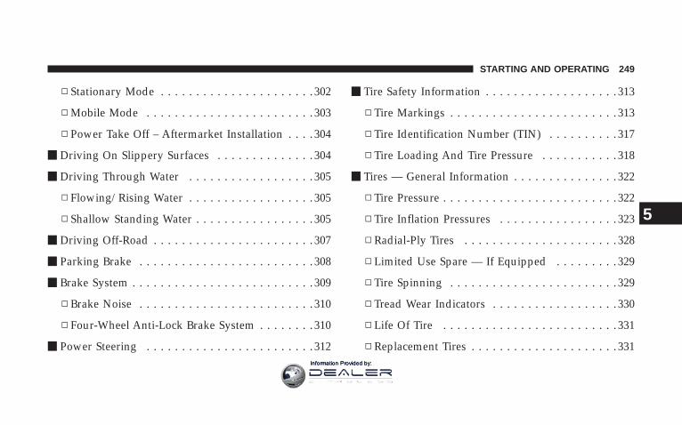
▫ Stationary Mode . . . . . . . . . . . . . . . . . . . . . . 302
▫ Mobile Mode . . . . . . . . . . . . . . . . . . . . . . . . 303
▫ Power Take Off – Aftermarket Installation . . . . 304
m Driving On Slippery Surfaces . . . . . . . . . . . . . . 304
m Driving Through Water . . . . . . . . . . . . . . . . . . 305
▫ Flowing/Rising Water . . . . . . . . . . . . . . . . . . 305
▫ Shallow Standing Water . . . . . . . . . . . . . . . . . 305
m Driving Off-Road . . . . . . . . . . . . . . . . . . . . . . . 307
m Parking Brake . . . . . . . . . . . . . . . . . . . . . . . . . 308
m Brake System . . . . . . . . . . . . . . . . . . . . . . . . . . 309
▫ Brake Noise . . . . . . . . . . . . . . . . . . . . . . . . . 310
▫ Four-Wheel Anti-Lock Brake System . . . . . . . . 310
m Power Steering . . . . . . . . . . . . . . . . . . . . . . . . 312
m Tire Safety Information . . . . . . . . . . . . . . . . . . . 313
▫ Tire Markings . . . . . . . . . . . . . . . . . . . . . . . . 313
▫ Tire Identification Number (TIN) . . . . . . . . . . 317
▫ Tire Loading And Tire Pressure . . . . . . . . . . . 318
m Tires — General Information . . . . . . . . . . . . . . . 322
▫ Tire Pressure . . . . . . . . . . . . . . . . . . . . . . . . . 322
▫ Tire Inflation Pressures . . . . . . . . . . . . . . . . . 323
▫ Radial-Ply Tires . . . . . . . . . . . . . . . . . . . . . . 328
▫ Limited Use Spare — If Equipped . . . . . . . . . 329
▫ Tire Spinning . . . . . . . . . . . . . . . . . . . . . . . . 329
▫ Tread Wear Indicators . . . . . . . . . . . . . . . . . . 330
▫ Life Of Tire . . . . . . . . . . . . . . . . . . . . . . . . . 331
▫ Replacement Tires . . . . . . . . . . . . . . . . . . . . . 331
STARTING AND OPERATING 249
5
Information Provided by:

▫ Alignment And Balance . . . . . . . . . . . . . . . . . 332
m Supplemental Tire Pressure Information — IfEquipped . . . . . . . . . . . . . . . . . . . . . . . . . . . . 333
m Tire Chains . . . . . . . . . . . . . . . . . . . . . . . . . . . 333
m Snow Tires . . . . . . . . . . . . . . . . . . . . . . . . . . . 334
m Tire Rotation Recommendations . . . . . . . . . . . . 335
▫ Dual Rear Wheels . . . . . . . . . . . . . . . . . . . . . 336
m Engine Runaway . . . . . . . . . . . . . . . . . . . . . . . 337
m Fuel Requirements . . . . . . . . . . . . . . . . . . . . . . 337
▫ Fuel Requirements (5.7L Gas Engines) . . . . . . . 337
▫ Fuel Requirements (6.7L Diesel Engines) . . . . . 341
m Adding Fuel . . . . . . . . . . . . . . . . . . . . . . . . . . 343
▫ Adding Fuel (Gas Engines) . . . . . . . . . . . . . . 343
▫ Adding Fuel (Diesel Engines) . . . . . . . . . . . . . 345
m Vehicle Loading . . . . . . . . . . . . . . . . . . . . . . . . 347
▫ Certification Label . . . . . . . . . . . . . . . . . . . . . 347
m Trailer Towing . . . . . . . . . . . . . . . . . . . . . . . . . 351
▫ Common Towing Definitions . . . . . . . . . . . . . 351
▫ Trailer Hitch Classification . . . . . . . . . . . . . . . 355
▫ Trailer Towing Weights (Maximum TrailerWeight Ratings) . . . . . . . . . . . . . . . . . . . . . . 356
▫ Trailer And Tongue Weight . . . . . . . . . . . . . . 356
▫ Towing Requirements . . . . . . . . . . . . . . . . . . 357
▫ Towing Tips . . . . . . . . . . . . . . . . . . . . . . . . . 362
▫ Trailer Towing Mirrors — If Equipped . . . . . . 364
m Snowplow . . . . . . . . . . . . . . . . . . . . . . . . . . . . 365
250 STARTING AND OPERATING
Information Provided by:

▫ Before Plowing . . . . . . . . . . . . . . . . . . . . . . . 366
▫ Snowplow Prep Package Model Availability . . 366
▫ Over The Road Operation With SnowplowAttached . . . . . . . . . . . . . . . . . . . . . . . . . . . 367
▫ Methods For Removing Snow . . . . . . . . . . . . 367
▫ Operating Tips . . . . . . . . . . . . . . . . . . . . . . . 368
▫ General Maintenance . . . . . . . . . . . . . . . . . . . 368
m Recreational Towing(Behind Motorhome, Etc.) . . . . . . . . . . . . . . . . . 369
▫ Recreational Towing – 2 Wheel DriveModels . . . . . . . . . . . . . . . . . . . . . . . . . . . . 369
▫ Recreational Towing – 4 Wheel DriveModels . . . . . . . . . . . . . . . . . . . . . . . . . . . . 369
STARTING AND OPERATING 251
5
Information Provided by:

STARTING PROCEDURES – GAS ENGINESBefore starting your vehicle, adjust your seat, adjust bothinside and outside mirrors, and fasten your seat belts.
The starter should not be operated for more than 15-second intervals. Waiting a few seconds between suchintervals will protect the starter from overheating.
WARNING!
Be sure to turn off the engine and remove the keyfrom the ignition switch if you want to rest or sleepin your car. Accidents can be caused by inadvertentlymoving the gear selection lever or by pressing theaccelerator pedal. This may cause excessive heat inthe exhaust system, resulting in overheating andvehicle fire which may cause serious or fatal injuries.
WARNING!
Do not leave children or animals inside parkedvehicles in hot weather. Interior heat build up maycause serious injury or death.
Manual Transmission – If EquippedApply the parking brake, place the gearshift control leverin NEUTRAL and depress the clutch pedal to the floorbefore starting the vehicle. This vehicle is equipped witha clutch interlocking ignition system. It will not startunless the clutch is fully depressed.
Automatic Transmission – If EquippedStart the engine with the selector lever in NEUTRAL orPARK position. Apply the brake before shifting to anydriving range.
252 STARTING AND OPERATING
Information Provided by:

Normal StartingNormal starting of either a warm or cold engine isobtained without pumping or depressing the acceleratorpedal. Turn the key to the START position and releasewhen the engine starts. If the engine fails to start within10 seconds, turn the key to the OFF position, wait 5seconds, then repeat the starting procedure.
NOTE: This vehicle is equipped with a transmissionshift interlocking system. The brake pedal must bedepressed to shift out of Park (P).
Tip Start Feature — Automatic Transmission OnlyDo not press the accelerator. Turn the ignition key brieflyto START position, and release it. The starter motor willcontinue to run, but will automatically disengage itselfwhen the engine is running.
If Engine Fails To StartIf the engine fails to start after you have followed thenormal starting procedure, it may be flooded. Push theaccelerator pedal all the way to the floor and hold it therewhile cranking the engine. This should clear any excessfuel in case the engine is flooded.
Ignition Key Positions
STARTING AND OPERATING 253
5
Information Provided by:

CAUTION!
To prevent damage to the starter, do not crank theengine for more than 15 seconds at a time. Wait 10 to15 seconds before trying again.
WARNING!
Never pour fuel or other flammable liquids into thethrottle body air inlet opening in an attempt to startthe vehicle. This could result in a flash fire causingserious personal injury.
WARNING!
Do not attempt to push or tow your vehicle to get itstarted. Vehicles equipped with an automatic trans-mission cannot be started this way. Unburned fuelcould enter the catalytic converter and once theengine has started, ignite and damage the converterand vehicle. If the vehicle has a discharged battery,booster cables may be used to obtain a start from abooster battery or the battery in another vehicle. Thistype of start can be dangerous if done improperly.See section 6 of this manual for the proper jumpstarting procedures and follow them carefully.
254 STARTING AND OPERATING
Information Provided by:

If the engine has been flooded, it may start to run, but nothave enough power to continue running when the key isreleased. If this occurs, continue cranking with the accel-erator pedal pushed all the way to the floor. Release theaccelerator pedal and the key once the engine is runningsmoothly.
If the engine shows no sign of starting after two 15second periods of cranking with the accelerator pedalheld to the floor, the normal starting procedure should berepeated.
After StartingThe idle speed is automatically controlled and will de-crease as the engine warms up.
STARTING PROCEDURES – DIESEL ENGINESBefore starting your vehicle, adjust your seat, adjust bothinside and outside mirrors, and fasten your seat belts.
The starter should not be operated for more than 15-second intervals. Waiting a few minutes between suchintervals will protect the starter from overheating.
WARNING!
Be sure to turn off the engine and remove the keyfrom the ignition switch if you want to rest or sleepin your car. Accidents can be caused by inadvertentlymoving the gear selection lever or by pressing theaccelerator pedal. This may cause excessive heat inthe exhaust system, resulting in overheating andvehicle fire which may cause serious or fatal injuries.
STARTING AND OPERATING 255
5
Information Provided by:
WARNING!
Do not leave children or animals inside parkedvehicles in hot weather. Interior heat build up maycause serious injury or death.
Manual Transmission – If EquippedApply the parking brake, place the gearshift control leverin NEUTRAL and depress the clutch pedal to the floorbefore starting the vehicle. This vehicle is equipped witha clutch interlocking ignition system. It will not startunless the clutch is fully depressed.
Automatic Transmission – If EquippedStart the engine with the selector lever in NEUTRAL orPARK position. Apply the brake before shifting to anydriving range.
The Cummins Diesel engine is equipped with severalfeatures designed to assist cold weather starting andoperation:
• The engine block heater is a resistance heater installedin the water jacket of the engine just above and behindthe oil filter. It requires a 110–115 volt AC electricaloutlet with a grounded, three-wire extension cord.
NOTE: The engine block heater cord is a factory in-stalled option. If your vehicle is not equipped, heatercords are available from your authorized Mopart dealer.
• A 12–volt heater built into the fuel filter housing aidsin preventing fuel gelling. It is controlled by a built-inthermostat.
• A heated intake air system both improves enginestarting and reduces the amount of white smokegenerated by a warming engine.
256 STARTING AND OPERATING
Information Provided by:

Normal Starting Procedure — Engine Manifold AirTemperature Above 66°F (19°C)Observe the Instrument Panel Cluster lights when start-ing the engine.
1. Always apply the parking brake.
2. Shift into PARK for an automatic transmission. Fullydepress and hold the clutch and shift into NEUTRAL fora manual transmission. Models with manual transmis-sion are equipped with a clutch interlocking crankingsystem. The clutch must be fully depressed to start thevehicle.
3. Turn the ignition key to the ON position and look atthe instrument panel cluster lamps.
CAUTION!
If WATER IN FUEL indicator light remains on DONOT START engine before you drain water from thefuel filter to avoid engine damage. See Section 7 —Maintaining Your Vehicle, for water drainprocedures.
4. Turn the ignition key to START and crank the engine.Do not press the accelerator during starting.
CAUTION!
Do not crank engine for more than 15 seconds at atime as starter motor damage may result. Turn key toOFF and wait at least two minutes before tryingagain.
STARTING AND OPERATING 257
5
Information Provided by:

5. When the engine starts, release the key.
6. Check to see that there is oil pressure.
7. Release the parking brake.
Starting Procedure — Engine Manifold AirTemperature Below 66°F (19°C)
NOTE: The temperature displayed on the overheadconsole (if equipped) does not necessarily reflect theengine manifold air temperature. When certain enginetemperatures fall below 66°F (19°C) the lamp will remainon indicating the intake manifold heater system is active.
Follow the steps in the Normal Starting Procedure ex-cept:
CAUTION!
Do not crank engine for more than 15 seconds at atime or starter motor damage may result. Turn key toOFF and wait at least 2 minutes for starter to coolbefore repeating start procedure.
• The WAIT TO START light will remain on for a periodof time (length of time depends on engine tempera-ture).
• After the WAIT TO START light goes off, turn theignition key to START. Do not press the acceleratorduring starting.
• After engine start-up, check to see that there is oilpressure.
258 STARTING AND OPERATING
Information Provided by:
• Allow the engine to idle about three minutes untilthe manifold heaters have completed the post-heatcycle.
• Release the parking brake and drive.
NOTE: Engine idle speed will automatically increase to1000 rpm at low coolant temperatures to improve enginewarm-up.
NOTE: If the engine stalls or if the ignition switch is leftOn for more than 2 minutes after the WAIT TO STARTlight goes out, reset the grid heaters by turning theignition switch to Off for at least 5 seconds and then backOn. Repeat steps 3 through 7 of the normal startingprocedure.
For Extremely Cold Weather Starting — EngineManifold Air Temperature Below 0°F (- 18°C)In extremely cold weather below 0°F (- 18°C) it may bebeneficial to cycle the manifold heaters twice beforeattempting to start the engine. This can be accomplishedby turning the ignition OFF for at least 5 seconds andthen back ON after the WAIT TO START light has goneoff, but before the engine is started. However, repeatedcycling of the manifold heaters will result in damage tothe heater elements or reduced battery voltage.
NOTE: If multiple pre-heat cycles are used beforestarting, additional engine run time may be required tomaintain battery state of charge at a satisfactory level.
• If the engine stalls after the initial start, the ignitionmust be turned to the OFF position for at least 5seconds and then to the ON position to recycle themanifold heaters.
STARTING AND OPERATING 259
5
Information Provided by:

NOTE: Excessive white smoke and poor engine perfor-mance will result if manifold heaters are not recycled.
• Heat generated by the manifold heaters dissipatesrapidly in a cold engine. If more than two minutespass between the time the WAIT TO START light goesOFF and the engine is started, recycle the manifoldheaters by turning the ignition OFF for at least 5seconds and then back ON.
• If the vehicle is driven and vehicle speed exceeds 19mph (31 km) before the manifold heater post-heat(after start) cycle is complete, the manifold heaters willshut off.
• If the engine is started before the WAIT TO STARTlight turns off, the preheat cycle will turn off.
• If the engine is cranked for more than 10 seconds, thepost-heat cycle will turn off.
NOTE: Engine idle speed will automatically increase to1000 rpm at low coolant temperatures to improve enginewarm-up.
NOTE: When a diesel engine is allowed to run out offuel or the fuel gels at low temperatures, air is pulled intothe fuel system.
You may try priming as described below.
1. Add a substantial quantity of fuel to the tank (5 to 10gallons) or eliminate the gelled fuel condition.
2. Crank the engine for 1 to 2 seconds. If the engine doesnot start, then release the key or starter button back to theRUN position (do not turn the key back to the OFFposition). The electric fuel transfer pump will continue torun and purge air from the system for about 20 seconds.After 20 seconds, attempt to start the engine again.
3. Start the engine using the Normal Starting Procedure.
260 STARTING AND OPERATING
Information Provided by:

4. Repeat the procedure if the engine does not start.
WARNING!
Do not open the high pressure fuel system whencranking the engine or with the engine running.Engine operation causes high fuel pressure. Highpressure fuel spray can cause serious injury or death.
NOTE: The engine may run rough until the air is forcedfrom all the fuel lines.
Starting Fluids
WARNING!
STARTING FLUIDS or flammable liquids areNEVER TO BE USED in the Cummins Diesel (seeWarning label). Never pour diesel fuel, flammableliquid, starting fluids (ether) into the air cleanercanister, air intake piping, or turbocharger inlet in anattempt to start the vehicle. This could result in aflash fire and explosion causing serious personalinjury and engine damage.
The engine is equipped with an automatic electric airpreheating system. If the instructions in this manual arefollowed, the engine should start in all conditions.
STARTING AND OPERATING 261
5
Information Provided by:

WARNING!
Do not leave children or animals inside parkedvehicles in hot weather. Interior heat build up maycause serious injury or death.
NORMAL OPERATION – DIESEL ENGINEObserve the following when the engine is operating.
• All message center lights are off.
• Check Engine Lamp is off.
• Engine Oil Pressure is above 10 psi (69 kPa) at idle.
• Low Oil Pressure light is off.
• Voltmeter Operation:
• The voltmeter may show a gauge fluctuation atvarious engine temperatures. This cycling operationis caused by the post-heat cycle of the intake mani-fold heater system. The number of cycles and thelength of the cycling operation is controlled by theengine control module. Post-heat operation can runfor several minutes, and then the electrical systemand voltmeter needle will stabilize.
• The cycling action will cause temporary dimming ofthe headlamps, interior lamps, and also a noticeablereduction in blower motor speed.
262 STARTING AND OPERATING
Information Provided by:
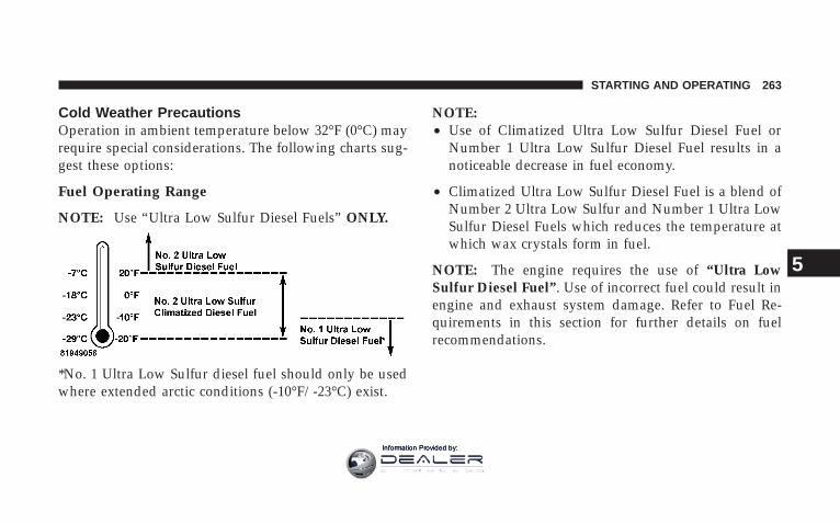
Cold Weather PrecautionsOperation in ambient temperature below 32°F (0°C) mayrequire special considerations. The following charts sug-gest these options:
Fuel Operating Range
NOTE: Use “Ultra Low Sulfur Diesel Fuels” ONLY.
*No. 1 Ultra Low Sulfur diesel fuel should only be usedwhere extended arctic conditions (-10°F/-23°C) exist.
NOTE:• Use of Climatized Ultra Low Sulfur Diesel Fuel or
Number 1 Ultra Low Sulfur Diesel Fuel results in anoticeable decrease in fuel economy.
• Climatized Ultra Low Sulfur Diesel Fuel is a blend ofNumber 2 Ultra Low Sulfur and Number 1 Ultra LowSulfur Diesel Fuels which reduces the temperature atwhich wax crystals form in fuel.
NOTE: The engine requires the use of “Ultra LowSulfur Diesel Fuel”. Use of incorrect fuel could result inengine and exhaust system damage. Refer to Fuel Re-quirements in this section for further details on fuelrecommendations.
STARTING AND OPERATING 263
5
Information Provided by:

Engine Block HeaterThe engine block heater warms engine coolant andpermits quicker starts in cold weather. Connect the heatercord to a ground–fault interrupter protected 110–115 voltAC electrical outlet with a grounded, three-wire exten-sion cord.
The engine block heater cord is routed under the hood tothe right side and can be located just behind the grillenear the headlamp.
NOTE: The engine block heater cord is a factory in-stalled option. If your vehicle is not equipped, heatercords are available from your authorized Mopart dealer.
The block heater must be plugged in at least one hour tohave an adequate warming effect on the coolant.
WARNING!
Remember to disconnect the cord before driving.Damage to the 110–115 volt electrical cord couldcause electrocution.
NOTE: The block heater will require 110 Volts AC and6.5 Amps to activate the heater element.
Block Heater Usage
A. Temperatures below 0°F (-18°C)
• Block Heater Required for 15W-40
• Block Heater Recommended for 5W-40
B. Temperatures below - 20°F (-29°C)
• Block Heater Required for 5W-40
264 STARTING AND OPERATING
Information Provided by:

Winter Front UsageIf a winter front or cold weather cover is to be used, apercentage of the total grille opening area must be leftuncovered to provide sufficient air flow to the charge aircooler and automatic transmission oil cooler. The per-centage of opening must be increased with the increasingambient air temperature and/or engine load. If thecooling fan can be heard cycling frequently, increase thesize of the opening in the winter front. A suitable coldweather cover is available from your Mopart dealer.
Battery Blanket UsageA battery loses 60% of its cranking power as the batterytemperature decreases to 0°F (-18°). For the same de-crease in temperature, the engine requires twice as muchpower to crank at the same RPM. The use of 120 VACpowered battery blankets will greatly increase startingcapability at low temperatures. Suitable battery blanketsare available from your authorized Mopart dealer.
Arctic OperationWhere there are no provisions to keep the engine warmwhen it is operating in ambient temperatures consistentlybelow (-10°F/-23°C), use 5W-40 synthetic engine oil andfuel that meets the requirements in Section 7, “Mainte-nance Procedures,” Engine Oil Selection.
Engine Warm-UpAvoid full throttle operation when the engine is cold.When starting a cold engine, bring the engine up tooperating speed slowly to allow the oil pressure tostabilize as the engine warms up.
NOTE: High-speed, no-load running of a cold enginecan result in excessive white smoke and poor engineperformance. No-load engine speeds should be keptunder 1,200 rpm during the warm-up period, especiallyin cold ambient temperature conditions.
STARTING AND OPERATING 265
5
Information Provided by:
If temperatures are below 32°F (0°C), operate the engineat moderate speeds for 5 minutes before full loads areapplied.
Engine Idling — In Cold WeatherAvoid prolonged idling in ambient temperatures below0°F. Long periods of idling may be harmful to yourengine because combustion chamber temperatures candrop so low that the fuel may not burn completely.Incomplete combustion allows carbon and varnish toform on piston rings and injector nozzles. Also, theunburned fuel can enter the crankcase, diluting the oiland causing rapid wear to the engine. Excessive idle timecan also cause damage to the engine exhaust aftertreat-ment system.
NOTE: An optional driver-controlled high idle speed isavailable on automatic transmission equipped vehicles
with speed control. This feature allows the driver toselect an elevated idle speed between 1100 and 1500rpms. Your dealer can enable this feature.
NOTE:• If ambient temperatures are low and the coolant
temperature is below 200°F (93°C), the engine idlespeed will slowly increase to 1000 RPM after 2 minutesof idle, if the following conditions are met:
• foot is off brake pedal and throttle pedal
• automatic transmission is in Park (P)
• vehicle speed is zero
• Applying the throttle will cancel fast idle
• If the engine is equipped with an exhaust brake,operating the exhaust brake at idle will greatly im-prove warm up rate and will help keep the engineclose to operating temperature during extended idle.
266 STARTING AND OPERATING
Information Provided by:

Stopping The EngineIdle the engine a few minutes before routine shutdown.After full load operation, idle the engine 3 to 5 minutesbefore shutting it down. This idle period will allow thelubricating oil and coolant to carry excess heat away fromthe combustion chamber, bearings, internal components,and turbocharger. This is especially important for turbo-charged, charge air cooled engines.
NOTE: During engine shut down on vehicles equippedwith manual transmissions, it is normal for the dieselengine to resonate heavily for a moment during engineshut off. When the engine is connected to a manualtransmission, this resonance causes load gear rattle fromthe transmission. This is commonly referred to as “shutdown rattle”. The manufacturer recommends performingengine shut down with the clutch pedal pushed to thefloor (clutch disengaged). When engine shut down isperformed in this manner the rattle is reduced (noteliminated).
DrivingCondition Load
Turbo-charger
Temperature
Idle Time(min.) Be-
fore EngineShutdown
Stop andGo
Empty Cool Less thanOne
Stop andGo
Medium One
HighwaySpeeds
Medium Warm Two
City Traffic MaximumGCWR
Three
HighwaySpeeds
MaximumGCWR
Four
UphillGrade
MaximumGCWR
Hot Five
STARTING AND OPERATING 267
5
Information Provided by:

Engine Speed Control
CAUTION!
Prevent overspeeding the engine going down hill.When descending steep grades, use a combination ofgears and service brakes to control vehicle/enginespeed. Overspeed can cause severe engine damage.
Operating Precautions
Avoid Overheating The EngineThe temperature of the coolant (a mixture of 50%ethylene-glycol and 50% water) must not exceed thenormal range of the temperature gauge (240°F/116°C)with a 16 psi (110 kPa) radiator cap.
Usually the coolant temperature indicated during opera-tion will be to the left of center in the normal range of thegauge.
Avoid Low Coolant Temperature OperationContinual operation at low coolant temperature belowthe normal range on the gauge (140°F/60°C) can beharmful to the engine. Low coolant temperature cancause incomplete combustion which allows carbon andvarnish to form on piston rings and injector nozzles.Also, the unburned fuel can enter the crankcase, dilutingthe lubricating oil and causing rapid wear to the engine.
Cooling System Tips — Automatic TransmissionTo reduce potential for engine and transmission over-heating in high ambient temperature conditions, take thefollowing actions:
• City Driving —when stopped, put transmission in neutral and increaseengine idle speed.
• Highway Driving —reduce your speed.
268 STARTING AND OPERATING
Information Provided by:
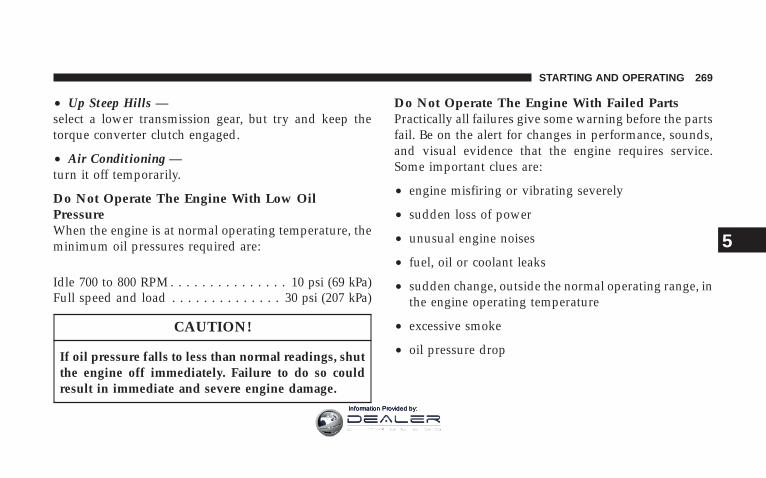
• Up Steep Hills —select a lower transmission gear, but try and keep thetorque converter clutch engaged.
• Air Conditioning —turn it off temporarily.
Do Not Operate The Engine With Low OilPressureWhen the engine is at normal operating temperature, theminimum oil pressures required are:
Idle 700 to 800 RPM . . . . . . . . . . . . . . . 10 psi (69 kPa)Full speed and load . . . . . . . . . . . . . . 30 psi (207 kPa)
CAUTION!
If oil pressure falls to less than normal readings, shutthe engine off immediately. Failure to do so couldresult in immediate and severe engine damage.
Do Not Operate The Engine With Failed PartsPractically all failures give some warning before the partsfail. Be on the alert for changes in performance, sounds,and visual evidence that the engine requires service.Some important clues are:
• engine misfiring or vibrating severely
• sudden loss of power
• unusual engine noises
• fuel, oil or coolant leaks
• sudden change, outside the normal operating range, inthe engine operating temperature
• excessive smoke
• oil pressure drop
STARTING AND OPERATING 269
5
Information Provided by:

ENGINE BLOCK HEATER (GAS ENGINES)— IFEQUIPPEDThe engine block heater warms engine coolant andpermits quicker starts in cold weather. Connect the cordto a standard 110-115 volt AC electrical outlet with agrounded, three-wire extension cord.
The engine block heater cord, on gas engines, is routedunder the hood on the driver side of the vehicle. It has aremovable cap that is located on the driver side of theIntegrated Power Module.
WARNING!
Remember to disconnect the cord before driving.Damage to the 110-115 volt electrical cord could causeelectrocution.
DIESEL EXHAUST BRAKE (ENGINE BRAKING) –IF EQUIPPEDThe exhaust brake feature will only function when thedriver turns the exhaust brake switch to the on position.Once the switch is in the on position and the vehicle ismoving faster than 5 MPH; the exhaust brake willautomatically operate when the driver removes pressurefrom the accelerator pedal. Exhaust braking is mosteffective when the engine RPM is higher. The automatictransmission has been programmed to downshift moreaggressively when the exhaust brake is enabled to in-crease brake performance.
270 STARTING AND OPERATING
Information Provided by:
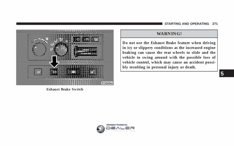
WARNING!
Do not use the Exhaust Brake feature when drivingin icy or slippery conditions as the increased enginebraking can cause the rear wheels to slide and thevehicle to swing around with the possible loss ofvehicle control, which may cause an accident possi-bly resulting in personal injury or death.
Exhaust Brake Switch
STARTING AND OPERATING 271
5
Information Provided by:

NOTE: For optimum braking power it is recommendedto use the Exhaust Brake while in Tow/Haul Mode.
The purpose of the exhaust brake (engine braking) fea-ture is to supply negative (braking) torque to the engine.Typically, the engine braking is used for, but not limitedto, vehicle towing applications where vehicle braking canbe achieved by the internal engine power, thereby spar-ing the mechanical brakes of the vehicle.
Benefits of the exhaust brake are:
• vehicle driving control
• reduced brake fade
• longer brake life
• faster cab warm-up.
The exhaust brake feature can also be used to reduce theengine warm up time. To use the exhaust brake as awarm-up device, the vehicle must be moving less than 5MPH, the exhaust brake switch must be in the onposition, and the coolant temperature must below 180 Fand ambient temperature below 60 F.
272 STARTING AND OPERATING
Information Provided by:

AUTOMATIC TRANSMISSION
CAUTION!
Damage to the transmission may occur if the follow-ing precautions are not observed:
• Shift into PARK only after the vehicle has come toa complete stop.
• Shift into or out of REVERSE only after thevehicle has come to a complete stop and the engineis at idle speed.
• Do not shift from REVERSE, PARK, or NEUTRALinto any forward gear when the engine is aboveidle speed.
• Before shifting into any gear, make sure your footis firmly on the brake pedal.
WARNING!
It is dangerous to shift the selector lever out of “P” or“N” if the engine speed is higher than idle speed. Ifyour foot is not firmly on the brake pedal, the vehiclecould accelerate quickly forward or in reverse. Youcould lose control of the vehicle and hit someone orsomething. Only shift into gear when the engine isidling normally and when your right foot is firmly onthe brake pedal.
Automatic Transmission with Overdrive (5 Speed545RFE) — If EquippedThe gear shift selector display, located in the instrumentpanel cluster, indicates the transmission gear range (theselector is illuminated for night driving). The selectorlever is mounted on the right side of the steering column.You must depress the brake pedal, to pull the selector
STARTING AND OPERATING 273
5
Information Provided by:

lever out of park (P) position (Brake Interlock System). Todrive, move the selector lever from Park or Neutral to thedesired drive position. Pull the selector lever toward youwhen shifting into Reverse, Second, First or Park, orwhen shifting out of Park.
Gear RangesDO NOT race the engine when shifting from Park orNeutral position into another gear range.
“P” ParkThis gear position supplements the parking brake bylocking the transmission. The engine can be started inthis range. Never use Park while the vehicle is in motion.Apply the parking brake when leaving the vehicle in thisrange. Always apply parking brake first, then place theselector in Park position. On 4-wheel drive vehicles besure that the transfer case is in a drive position!
WARNING!
Never use Park position on an automatic transmis-sion as a substitute for the parking brake. Alwaysapply parking brake fully when parked to guardagainst vehicle movement and possible injury ordamage.
WARNING!
Your vehicle could move and injure you and others ifit is not completely in P (Park). Check by trying tomove the gearshift lever back and forth without firstpulling it toward you after you have set it in P. Makesure it is in Park before leaving the vehicle.
274 STARTING AND OPERATING
Information Provided by:

WARNING!
It is dangerous to shift the selector lever out of “P” or“N” if the engine speed is higher than idle speed. Ifyour foot is not firmly on the brake pedal, the vehiclecould accelerate quickly forward or in reverse. Youcould lose control of the vehicle and hit someone orsomething. Only shift into gear when the engine isidling normally and when your right foot is firmly onthe brake pedal.
“R” ReverseUse this range only after the vehicle has come to acomplete stop.
“N” NeutralShift to Neutral when the vehicle is standing for pro-longed periods with the engine running. The engine maybe started in this range. Set the parking brake if you mustleave the vehicle.
“D” DriveThis position provides all forward gears, including 3rdgear direct and 4th or 5th gear overdrive (see OverdriveOperation). Use this range for most city and highwaydriving.
“2” SecondUse this position for driving slowly in heavy city trafficor on mountain roads where more precise speed controlis desirable. Use it also when climbing long grades, andfor engine braking when descending moderately steepgrades. To prevent excessive engine speed do not exceed45 mph (72 km/h) in this range.
STARTING AND OPERATING 275
5
Information Provided by:

“1” FirstUse this position for driving up very steep hills and forengine braking at low speeds 20 mph (32 km/h) or lesswhen going downhill. To prevent excessive engine speed,do not exceed 25 mph (40 km/h) in this range.
NOTE: Use caution when operating a heavily loadedvehicle in “2” Second or “1” First gear selections in highambients as torque converter slip can impose significantadditional heat load on the cooling system.
Overdrive OperationThe overdrive automatic transmission contains an elec-tronically controlled fourth and fifth speed (Overdrive).The transmission will automatically shift from Drive toOverdrive if the following conditions are present:
• the transmission selector is in Drive;
• the engine coolant has reached normal operating tem-perature;
• vehicle speed is above approximately 30 mph (48km/h);
• the “TOW HAUL O/D OFF” switch has not beenactivated;
• transmission has reached normal operating tempera-ture.
NOTE: If the vehicle is started in extremely cold tem-peratures, the transmission may not shift into Overdriveand will automatically select the most desirable gear foroperation at this temperature. Normal operation willresume when the transmission fluid temperature hasrisen to a suitable level. Refer also to the Note undertorque converter clutch, later in this section.
276 STARTING AND OPERATING
Information Provided by:

If the transmission temperature gets extremely hot, thetransmission will automatically select the most desirablegear for operation at this temperature. If the transmissiontemperature becomes hot enough the TRANS TEMP lightmay illuminate and the transmission may downshift outof Overdrive until the transmission cools down. Aftercooldown, the transmission will resume normal opera-tion.
The transmission will downshift from Overdrive to Driveif the accelerator pedal is fully depressed at vehiclespeeds above approximately 35 mph (56 km/h).
When To Use “TOW HAUL” and “O/D OFF”Modes
When driving in hilly areas, towing a trailer, carrying aheavy load, etc., and frequent transmission shifting oc-curs, press the “TOW HAUL O/D OFF” button once toselect TOW HAUL. This will improve performance and
Tow Haul O/D Off Switch
STARTING AND OPERATING 277
5
Information Provided by:

reduce the potential for transmission overheating orfailure due to excessive shifting. When operating in“TOW HAUL” mode, 5th gear is disabled and 2-3 and 3-4shift patterns are modified. Shifts into Overdrive (4thgear) are allowed during steady cruise (for improved fueleconomy) and automatic closed-throttle downshifts to3rd gear (for improved braking) will occur during steadybraking. Pressing the “TOW HAUL O/D OFF” button asecond time to select O/D OFF will disable 4th and 5thgear completely, which should eliminate any excessivetransmission shifting.
The “TOW HAUL” or “O/D OFF” light will illuminate inthe instrument cluster to indicate when the switch hasbeen activated. Pressing the switch a third time restoresnormal operation. If the “TOW HAUL” or “O/D OFF”modes are desired, the button must be pressed each timethe engine is started.
When To Lock Out OverdriveWhen driving in hilly areas, towing a trailer, carrying aheavy load, etc., and frequent 4–3–4 transmission shiftingoccurs, press the “TOW/HAUL” button twice to disablethe overdrive. This will improve performance and reducethe potential for transmission overheating or failure dueto excessive shifting.
Torque Converter ClutchA feature, designed to improve fuel economy, has beenincluded in the automatic transmission on your vehicle.A clutch within the torque converter engages automati-cally at calibrated speeds. This may result in a slightlydifferent feeling or response during normal operation inhigh gear. When the vehicle speed drops or duringacceleration when the transmission downshifts to secondgear, the clutch automatically disengages.
278 STARTING AND OPERATING
Information Provided by:

NOTE: The torque converter clutch will not engageuntil the transmission fluid and engine coolant are warm[usually after 1-3 miles (1.6 - 4.8 km) of driving]. Becausethe engine speed is higher when the torque converterclutch is not engaged, it may seem as if the transmissionis not shifting into Overdrive when cold. This is normal.Pressing the “TOW/HAUL” button, when the transmis-sion is sufficiently warm, will demonstrate that thetransmission is able to shift into and out of overdrive.
NOTE: If the vehicle has not been driven in severaldays, the first few seconds of operation after shifting thetransmission into gear may seem sluggish. This is due tothe fluid partially draining from the torque converter intothe transmission. This condition is normal and will notcause damage to the transmission. The torque converterwill refill within five seconds of shifting from Park intoany other gear position.
Automatic Transmission (6 Speed AS68RC) — IfEquippedThe gear shift selector display, located in the instrumentpanel cluster, indicates the transmission gear range (theselector is illuminated for night driving). The selectorlever is mounted on the right side of the steering column.You must depress the brake pedal, to pull the selectorlever out of park (P) position (Brake Interlock System). Todrive, move the selector lever from Park or Neutral to thedesired drive position. Pull the selector lever toward youwhen shifting into Reverse, Second, First or Park, orwhen shifting out of Park.
Gear RangesDO NOT race the engine when shifting from Park orNeutral position into another gear range.
STARTING AND OPERATING 279
5
Information Provided by:

“P” ParkThis gear position supplements the parking brake bylocking the transmission. The engine can be started inthis range. Never use Park while the vehicle is in motion.Apply the parking brake when leaving the vehicle in thisrange. Always apply parking brake first, then place theselector in Park position. On 4-wheel drive vehicles besure that the transfer case is in a drive position!
WARNING!
Never use Park position on an automatic transmis-sion as a substitute for the parking brake. Alwaysapply parking brake fully when parked to guardagainst vehicle movement and possible injury ordamage.
WARNING!
Your vehicle could move and injure you and others ifit is not completely in P (Park). Check by trying tomove the gearshift lever back and forth without firstpulling it toward you after you have set it in P. Makesure it is in Park before leaving the vehicle.
280 STARTING AND OPERATING
Information Provided by:
WARNING!
It is dangerous to shift the selector lever out of “P” or“N” if the engine speed is higher than idle speed. Ifyour foot is not firmly on the brake pedal, the vehiclecould accelerate quickly forward or in reverse. Youcould lose control of the vehicle and hit someone orsomething. Only shift into gear when the engine isidling normally and when your right foot is firmly onthe brake pedal.
“R” ReverseUse this range only after the vehicle has come to acomplete stop.
“N” NeutralShift to Neutral when the vehicle is standing for pro-longed periods with the engine running. The engine maybe started in this range. Set the parking brake if you mustleave the vehicle.
“D” DriveThis position provides all forward gears, including 4thgear direct and 5th or 6th (if equipped) gear overdrive(see Overdrive Operation). Use this range for most cityand highway driving.
“3” ThirdUse this position for driving in slight heavy city traffic oron mountain roads where more precise speed control isdesirable. Use it also when climbing long grades, and forengine braking when descending moderately steepgrades. To prevent excessive engine speed do not exceed40 mph (64 km/h) in this range.
STARTING AND OPERATING 281
5
Information Provided by:
“2” SecondUse this position for driving on more severe conditionsand lower speeds than “3” third. To prevent excessiveengine speed do not exceed 25 mph (40 km/h) in thisrange.
“1” FirstUse this position for driving up very steep hills and forengine braking at low speeds 12 mph (19 km/h) or lesswhen going downhill. To prevent excessive engine speed,do not exceed 12 mph (19 km/h) in this range.
NOTE: Use caution when operating a heavily loadedvehicle in “2” Second or “1” First gear selections in highambients as torque converter slip can impose significantadditional heat load on the cooling system.
Overdrive OperationThe overdrive automatic transmission contains an elec-tronically controlled 5th and 6th (if equipped) speed
(Overdrive). The transmission will automatically shiftfrom Drive to Overdrive if the following conditions arepresent:
• the transmission selector is in Drive;
• the engine coolant has reached normal operating tem-perature;
• vehicle speed is above approximately 38 mph (61km/h) for 5th gear and 55 mph (89 km/h) for 6th gear;
• the “TOW HAUL O/D OFF” switch has not beenactivated;
• transmission has reached normal operating tempera-ture.
NOTE: If the vehicle is started in extremely cold tem-peratures, the transmission shift schedule initially re-stricts transmission operation in forward gear ranges to3rd gear until the transmission fluid temperature rises to
282 STARTING AND OPERATING
Information Provided by:
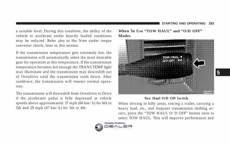
a suitable level. During this condition, the ability of thevehicle to accelerate under heavily loaded conditionsmay be reduced. Refer also to the Note under torqueconverter clutch, later in this section.
If the transmission temperature gets extremely hot, thetransmission will automatically select the most desirablegear for operation at this temperature. If the transmissiontemperature becomes hot enough the TRANS TEMP lightmay illuminate and the transmission may downshift outof Overdrive until the transmission cools down. Aftercooldown, the transmission will resume normal opera-tion.
The transmission will downshift from Overdrive to Driveif the accelerator pedal is fully depressed at vehiclespeeds above approximately 37 mph (60 km/h) for 6th to5th and 29 mph (47 km/h) for 5th to 4th.
When To Use “TOW HAUL” and “O/D OFF”Modes
When driving in hilly areas, towing a trailer, carrying aheavy load, etc., and frequent transmission shifting oc-curs, press the “TOW HAUL O/D OFF” button once toselect TOW HAUL. This will improve performance and
Tow Haul O/D Off Switch
STARTING AND OPERATING 283
5
Information Provided by:

reduce the potential for transmission overheating orfailure due to excessive shifting. When operating in“TOW HAUL” mode, 6th gear (if equipped) is disabledand 2-3 and 3-4 and 4–5 shift patterns are modified. Shiftsinto Overdrive (5th gear) are allowed during steadycruise (for improved fuel economy). Pressing the “TOWHAUL O/D OFF” button a second time to select O/DOFF will disable 5th and 6th gear completely, whichshould eliminate any excessive transmission shifting.
The “TOW HAUL” or “O/D OFF” light will illuminate inthe instrument cluster to indicate when the switch hasbeen activated. Pressing the switch a third time restoresnormal operation. If the “TOW HAUL” or “O/D OFF”modes are desired, the button must be pressed each timethe engine is started.
WARNING!
Do not use the Tow/Haul feature when driving in icyor slippery conditions as the increased engine brak-ing can cause the rear wheels to slide and the vehicleto swing around with the possible loss of vehiclecontrol, which may cause an accident possibly result-ing in personal injury or death.
When To Lock Out OverdriveWhen driving in hilly areas, towing a trailer, carrying aheavy load, etc., and frequent 6–5–6 or 5–4–5 transmis-sion shifting occurs, press the “TOW/HAUL” button.This will improve performance and reduce the potentialfor transmission overheating or failure due to excessiveshifting.
284 STARTING AND OPERATING
Information Provided by:

Torque Converter ClutchA feature, designed to improve fuel economy, has beenincluded in the automatic transmission on your vehicle.A clutch within the torque converter engages automati-cally at calibrated speeds. This may result in a slightlydifferent feeling or response during normal operation inhigh gear. When the vehicle speed drops or duringacceleration when the transmission downshifts to 1stgear, the clutch automatically disengages.
NOTE: The torque converter clutch will not engageuntil the transmission fluid and engine coolant are warm[usually after 1-3 miles (1.6 - 4.8 km) of driving]. Becausethe engine speed is higher when the torque converterclutch is not engaged, it may seem as if the transmissionis not shifting into Overdrive when cold. This is normal.Pressing the “TOW/HAUL” button, when the transmis-sion is sufficiently warm, will demonstrate that thetransmission is able to shift into and out of overdrive.
NOTE: If the vehicle has not been driven in severaldays, the first few seconds of operation after shifting thetransmission into gear may seem sluggish. This is due tothe fluid partially draining from the torque converter intothe transmission. This condition is normal and will notcause damage to the transmission. The torque converterwill refill within five seconds of shifting from Park intoany other gear position.
MANUAL TRANSMISSION
WARNING!
You or others could be injured if you leave thevehicle unattended without having the parkingbrake fully applied. The parking brake should al-ways be applied when the driver is not in the vehicle,especially on an incline.
STARTING AND OPERATING 285
5
Information Provided by:

Truck models with manual transmission are equippedwith a clutch interlocking ignition system. The clutchpedal must be fully depressed to start the vehicle.
Fully depress the clutch pedal before shifting gears. Asyou release the clutch pedal, lightly depress the accelera-tor pedal.
To shift into Reverse, come to a complete stop. Depressthe clutch and pause briefly to allow the gear train tostop. Move the shift lever from the Neutral positionstraight across and back into Reverse.
Never drive with your foot resting on the clutch pedal, orattempt to hold the vehicle on a hill with the clutch pedalpartially engaged, as this will cause abnormal wear onthe clutch.
Manual Transmission — 6 Speed (G56)Your vehicle may be equipped with the G56 manualtransmission. This transmission has a “creeper” 1st gearwhich should be used to start from a standing positionwhen carrying a payload or towing a trailer. Damage tothe clutch can result from starting in 2nd or 3rd gear witha loaded vehicle. An unloaded vehicle may be launchedin 2nd gear. Use each gear in numerical order – do notskip a gear.
For most city driving you may find it easier to use only1st through 5th gear ranges. For steady highway drivingwith light accelerations, 6th gear is recommended. Toshift into 5th gear, move the shift lever to the rightbeyond the spring pressure point and push it forward.When shifting from 5th to 4th gear, pull the lever downtoward you in one motion. Do not pull the lever sharplyleft as you may shift accidentally into 2nd gear anddamage the transmission.
286 STARTING AND OPERATING
Information Provided by:
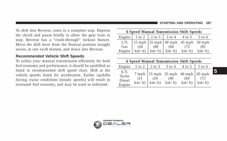
To shift into Reverse, come to a complete stop. Depressthe clutch and pause briefly to allow the gear train tostop. Reverse has a “crash-through” lockout feature.Move the shift lever from the Neutral position straightacross, in one swift motion, and down into Reverse.
Recommended Vehicle Shift SpeedsTo utilize your manual transmission efficiently for bothfuel economy and performance, it should be upshifted aslisted in recommended shift speed chart. Shift at thevehicle speeds listed for acceleration. Earlier upshiftsduring cruise conditions (steady speeds) will result inincreased fuel economy, and may be used as indicated.
6 Speed Manual Transmission Shift SpeedsEngine 1 to 2 2 to 3 3 to 4 4 to 5 5 to 6
5.7LGas
Engine
15 mph(24
km/h)
25 mph(40
km/h)
40 mph(64
km/h)
45 mph(72
km/h)
50 mph(81
km/h)
6 Speed Manual Transmission Shift SpeedsEngine 1 to 2 2 to 3 3 to 4 4 to 5 5 to 6
6.7LTurboDieselEngine
7 mph(11
km/h)
15 mph(24
km/h)
25 mph(40
km/h)
40 mph(64
km/h)
45 mph(72
km/h)
STARTING AND OPERATING 287
5
Information Provided by:

Downshifting – Gas EngineMoving from a high gear down to a lower gear isrecommended to preserve brakes when driving downsteep hills. In addition, downshifting at the right timeprovides better acceleration when you desire to resumespeed. For acceleration at speeds less than 20 mph (30km/h), 2nd gear is recommended.
CAUTION!
When descending a hill, be very careful to downshiftone gear at a time to prevent overspeeding the enginewhich can cause valve damage.
Failure to follow the recommended downshiftingspeeds may cause the engine to over speed and / ordamage the clutch disc even if the clutch pedal isdepressed.
To prevent clutch and transmission damage, your vehicleshould be downshifted at speeds no greater than thoselisted in the Maximum Recommended DownshiftingSpeed chart.
Maximum Recommended Downshifting Speeds
GearSelec-tion
1st 2nd 3rd 4th 5th
Maxi-mumSpeed
20 mph(32
km/h)
35 mph(56
km/h)
55 mph(88
km/h)
75 mph(120
km/h)
85 mph(135
km/h)
Downshifting – Diesel Engine
Moving from a high gear down to a lower gear isrecommended to preserve brakes when driving downsteep hills. In addition, downshifting at the right timeprovides better acceleration when you desire to resumespeed. Downshift progressively. Do not skip gears to
288 STARTING AND OPERATING
Information Provided by:

avoid overspeeding the engine and clutch. For accelera-tion at speeds less than 15 mph (25 km/h), 2nd gear isrecommended.
CAUTION!
When descending a hill, be very careful to downshiftone gear at a time to prevent overspeeding the enginewhich can cause valve damage.
Failure to follow the recommended downshiftingspeeds may cause the engine to over speed and / ordamage the clutch disc even if the clutch pedal isdepressed.
To prevent clutch and transmission damage, your vehicleshould be downshifted at speeds no greater than thoselisted in the Maximum Recommended DownshiftingSpeed chart.
Maximum Recommended Downshifting Speeds
GearSelec-tion
1st 2nd 3rd 4th 5th
Maxi-mumSpeed
10 mph(16
km/h)
19 mph(31
km/h)
32 mph(51
km/h)
50 mph(80
km/h)
68 mph(109
km/h)
FOUR-WHEEL-DRIVE OPERATION — IFEQUIPPEDFour-Wheel-Drive Dodge Ram Trucks are equipped witheither a Manually Shifted transfer case or an Electroni-cally Shifted transfer case. See the operating instructionsfor your transfer case, located within this section.
Manually Shifted Transfer Case OperatingInformation/PrecautionsThe transfer case provides 4 mode positions - 2 (rear)-wheel-drive high range, 4-wheel-drive high range, neu-tral, and 4-wheel-drive low range.
STARTING AND OPERATING 289
5
Information Provided by:
This transfer case is intended to be driven in the 2-wheel-drive position (2H) for normal street and highway con-ditions such as dry hard surfaced roads.
When additional traction is required the transfer case 4Hand 4L positions can be used to lock the front and reardriveshafts together and force the front and rear wheelsto rotate at the same speed. This is accomplished bysimply moving the shift lever to the desired positions.The 4H and 4L positions are intended for loose, slipperyroad surfaces only. Driving in the 4H and 4L positions ondry hard surfaced roads may cause increased tire wearand damage to the driveline components.
The 4-wheel-drive light (4WD), located in the instrumentcluster, alerts the driver that the vehicle is in 4-wheeldrive and that the front and rear driveshafts are lockedtogether. This light illuminates when the transfer case isshifted to either the 4H or 4L positions. There is no lightfor the 2H or N (Neutral) positions.
When operating your vehicle in 4L, the engine speed isapproximately three times that of the 2H or 4H positionsat a given road speed. Take care not to overspeed theengine and do not exceed 25 mph (40 km/h).
Proper operation of 4-wheel-drive vehicles depends ontires of equal size, type and circumference on each wheel.Any difference will adversely affect shifting and cancause damage to the transfer case.
NOTE: Do not attempt to make a shift while only thefront or rear wheels are spinning. The transfer case is notequipped with a synchronizer and therefore the front andrear driveshaft speeds must be equal for the shift to takeplace. Shifting while only the front or rear wheels arespinning can cause damage to the transfer case.
Because 4-wheel drive provides improved traction, thereis a tendency to exceed safe turning and stopping speeds.Do not go faster than road conditions permit.
290 STARTING AND OPERATING
Information Provided by:

NOTE: Delayed shifts out of four-wheel drive may beexperienced due to uneven tire wear, low or uneven tirepressures, excessive vehicle loading, or cold tempera-tures.
WARNING!
You or others could be injured if you leave thevehicle unattended with the transfer case in theNeutral (N) position without first fully engaging theparking brake. The transfer case Neutral (N) positiondisengages both the front and rear driveshafts fromthe powertrain and will allow the vehicle to moveregardless of the transmission position. The parkingbrake should always be applied when the driver isnot in the vehicle.
For additional information on the appropriate use of eachtransfer case mode position see the information below:
2HRear Wheel Drive High Range - Normal street andhighway driving. Dry hard surfaced roads.
4H4-Wheel-Drive High Range - Locks the front and reardriveshafts together. Forces the front and rear wheels torotate at the same speed. Additional traction for loose,slippery road surfaces only.
NNeutral - Disengages both the front and rear driveshaftsfrom the powertrain. To be used for flat towing behindanother vehicle. See Recreational Towing for more infor-mation.
STARTING AND OPERATING 291
5
Information Provided by:

4L4-Wheel-Drive Low Range - Low speed 4-wheel-drive.Locks the front and rear driveshafts together. Forces thefront and rear wheels to rotate at the same speed.Additional traction and maximum pulling power forloose, slippery road surfaces only. Do not exceed 25 mph(40 km/h). Vehicle’s equipped with the AISIN(AS68RC) Automatic Transmission, Overdrive gear (5thand 6th) will be disabled when the transfer case is in4L.
Shifting Procedure — Manually Shifted TransferCase
2H ⇔ 4HShifting between 2H and 4H can be made with thevehicle stopped or in motion. If the vehicle is in motion,shifts can be made up to 55 mph (88 km/h). With the
Manual Transfer Case Shifter
292 STARTING AND OPERATING
Information Provided by:

vehicle in motion, the transfer case will engage / disen-gage faster if you momentarily release the acceleratorpedal after completing the shift. Apply a constant forcewhen shifting the transfer case lever.
2H or 4H ⇔ 4LWith the vehicle rolling at 2 to 3 mph (3 to 5 km/h), shiftan automatic transmission to N (Neutral) or depress theclutch on a manual transmission. While the vehicle iscoasting at 2 to 3 mph (3 to 5 km/h), shift the transfercase lever firmly to the desired position. Do not pause intransfer case N (Neutral).
NOTE: Pausing in transfer case N (Neutral) in vehiclesequipped with an automatic transmission may requireshutting the engine OFF to avoid gear clash whilecompleting the shift. If difficulty occurs, shift automatictransmission to N (Neutral), hold foot on brake, and turnengine OFF. Make shift to the desired mode.
NOTE: Shifting into or out of 4L is possible with thevehicle completely stopped, however difficulty may oc-cur due to the mating clutch teeth not being properlyaligned. Several attempts may be required for clutchteeth alignment and shift completion to occur. The pre-ferred method is with the vehicle rolling 2 to 3 mph (3 to5 km/h). Avoid attempting to engage or disengage 4Lwith the vehicle moving faster than 2 to 3 mph (3 to 5km/h).
NOTE: Do not attempt to shift to or from 4L while thetransmission is in gear or clutch is engaged.
Transfer Case Reminder LightThe four-wheel-drive operating light (4WD), located inthe instrument cluster, is used to alert the driver that thefront axle is fully engaged and all four wheels aredriving.
STARTING AND OPERATING 293
5
Information Provided by:

Electronically Shifted Transfer Case OperatingInformation/Precautions (4 Position Switch) — IfEquipped
This is an electric shift transfer case and is operated bythe 4WD Control Switch (Transfer Case Switch), which islocated on the instrument panel.
This Electronically Shifted transfer case provides 4 modepositions: 2 (rear) wheel drive high range, 4 wheel drivelock range, 4 wheel drive low range, and neutral.
The Electronically Shifted transfer case is designed to bedriven in the 2 wheel drive position (2WD) for normalstreet and highway conditions (dry hard surfaced roads).
When additional traction is required, the transfer case4WD LOCK and 4WD LOW positions can be used to lockthe front and rear driveshafts together and force the frontand rear wheels to rotate at the same speed. This isaccomplished by rotating the 4WD Control Switch to thedesired position - see Shifting Procedure section forspecific shifting instructions. The 4WD LOCK and 4WDLOW positions are designed for loose, slippery roadsurfaces only. Driving in the 4WD LOCK and 4WD LOWpositions on dry hard surfaced roads may cause in-creased tire wear and damage to the driveline compo-nents.
Transfer Case Switch
294 STARTING AND OPERATING
Information Provided by:
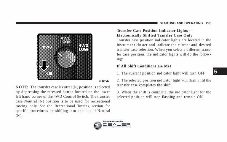
NOTE: The transfer case Neutral (N) position is selectedby depressing the recessed button located on the lowerleft hand corner of the 4WD Control Switch. The transfercase Neutral (N) position is to be used for recreationaltowing only. See the Recreational Towing section forspecific procedures on shifting into and out of Neutral(N).
Transfer Case Position Indicator Lights —Electronically Shifted Transfer Case OnlyTransfer case position indicator lights are located in theinstrument cluster and indicate the current and desiredtransfer case selection. When you select a different trans-fer case position, the indicator lights will do the follow-ing:
If All Shift Conditions are Met
1. The current position indicator light will turn OFF.
2. The selected position indicator light will flash until thetransfer case completes the shift.
3. When the shift is complete, the indicator light for theselected position will stop flashing and remain ON.
STARTING AND OPERATING 295
5
Information Provided by:

If One or More Shift Conditions are not Met
1. The indicator light for the current position will remainON.
2. The newly selected position indicator light will con-tinue to flash.
3. The transfer case will not shift.
NOTE: Before retrying a selection, make certain that allthe necessary requirements for selecting a new transfercase position have been met. To retry the selection, turnthe control knob back to the current position, wait five (5)seconds, and retry selection. To find the shift require-ments, refer to the 9Shifting Procedure9 for your transfercase, located in this section of the owner’s manual.
The “SERVICE 4WD” warning light monitors the electricshift 4WD system. If this light remains on after enginestart up or illuminates during driving, it means that the4WD system is not functioning properly and that serviceis required.
WARNING!
Always engage the parking brake when poweringdown the vehicle if the (Service 4WD( light is illu-minated. Not engaging the parking brake may allowthe vehicle to roll which may cause personal injury.
NOTE: Do not attempt to make a shift while only thefront or rear wheels are spinning, as this can causedamage to driveline components.
296 STARTING AND OPERATING
Information Provided by:

When operating your vehicle in 4WD LOW, the enginespeed is approximately three times that of the 2WD or4WD LOCK positions at a given road speed. Take carenot to overspeed the engine and do not exceed 25 mph(40 km/h).
Proper operation of 4 wheel drive vehicles depends ontires of equal size, type and circumference on each wheel.Any difference in tire size can cause damage to thetransfer case.
Because 4 wheel drive provides improved traction, thereis a tendency to exceed safe turning and stopping speeds.Do not go faster than road conditions permit.
WARNING!
You or others could be injured if you leave thevehicle unattended with the transfer case in theNeutral (N) position without first fully engaging theparking brake. The transfer case Neutral (N) positiondisengages both the front and rear driveshafts fromthe powertrain and will allow the vehicle to moveregardless of the transmission position. The parkingbrake should always be applied when the driver isnot in the vehicle.
For additional information on the appropriate use of eachtransfer case mode position see the information below:
2WDRear Wheel Drive High Range - Normal street andhighway driving. Dry hard surfaced roads.
STARTING AND OPERATING 297
5
Information Provided by:

4WD LOCK4 Wheel Drive Lock Range - Locks the front and reardriveshafts together. Forces the front and rear wheels torotate at the same speed. Additional traction for loose,slippery road surfaces only.
4WD LOW4 Wheel Drive Low Range - Low speed 4 wheel drive.Locks the front and rear driveshafts together. Forces thefront and rear wheels to rotate at the same speed.Additional traction and maximum pulling power forloose, slippery road surfaces only. Do not exceed 25 mph(40 km/h).
NNeutral - Disengages both the front and rear driveshaftsfrom the powertrain. To be used for flat towing behindanother vehicle. See Recreational Towing for more infor-mation.
Shifting Procedure — Electronically ShiftedTransfer Case
NOTE: If any of the requirements to select a newtransfer case position have not been met, the transfer casewill not shift.The indicator light for the previous positionwill remain ON and the newly selected position indicator
Transfer Case Switch
298 STARTING AND OPERATING
Information Provided by:

light will continue to flash until all the requirements forthe selected position have been met. To retry a shift:return the control knob back to the original position,make certain all shift requirements have been met, waitfive (5) seconds and try the shift again.
NOTE: If all the requirements to select a new transfercase position have been met, the current position indica-tor light will turn OFF, the selected position indicatorlight will flash until the transfer case completes the shift.When the shift is complete, the indicator light for theselected position will stop flashing and remain ON.
2WD⇔ 4WD LOCKRotate the 4WD Control Switch to the desired position.Shifts between 2WD and 4WD LOCK can be done withthe vehicle stopped or in motion. With the vehicle inmotion, the transfer case will engage / disengage faster ifyou momentarily release the accelerator pedal after turn-ing the control switch. If the vehicle is stopped, the
ignition key must be in the ON position with the engineeither RUNNING or OFF. This shift cannot be completedif the key is in the accessory position.
NOTE: The 4x4 system will not allow shifts between2WD/4WD LOCK if the front and/or rear wheels arespinning (no traction). In this situation the selectedposition indicator light will flash and the original posi-tion indicator light will remain ON. At this time, reducespeed and stop spinning the wheels to complete the shift.
2WD or 4WD LOCK⇔ 4WD LOW
NOTE: When shifting into or out of 4WD LOW somegear noise may be heard. This noise is normal and is notdetrimental to the vehicle or occupants.
Shifting can be performed with the vehicle rolling 2 to 3mph (3 to 5 km/h) or completely stopped. USE EITHEROF THE FOLLOWING PROCEDURES:
STARTING AND OPERATING 299
5
Information Provided by:

Preferred Procedure
1. With engine RUNNING, slow vehicle to 2 to 3 mph (3to 5 km/h).
2. Shift the transmission into NEUTRAL (depress clutchon manual transmissions).
3. While still rolling, rotate the transfer case controlswitch to the desired position.
4. After the desired position indicator light is ON (notflashing), shift transmission back into gear (release clutchon manual transmissions).
Alternate Procedure
1. Bring the vehicle to complete stop.
2. With the key ON and the engine either OFF orRUNNING, shift the transmission into NEUTRAL (de-press clutch on manual transmissions).
3. Rotate the transfer case control switch to the desiredposition.
4. After the desired position indicator light is ON (notflashing), shift transmission back into gear (release clutchon manual transmissions).
NOTE: If steps 1 or 2 of either the Preferred or AlternateProcedure are not satisfied prior to attempting the shiftthen the desired position indicator light will flash con-tinuously while the original position indicator light isON, until all requirements have been met.
NOTE: The ignition key must be ON for a shift to takeplace and for the position indicator lights to be operable.If the key is not ON then the shift will not take place andno position indicator lights will be on or flashing.
NOTE: If your are leaving your vehicle stored for longerthan 21 days, refer to the section on “Vehicle Storage.”
300 STARTING AND OPERATING
Information Provided by:

LIMITED-SLIP DIFFERENTIAL — IF EQUIPPEDThe limited-slip differential provides additional tractionon snow, ice, mud, sand and gravel, particularly whenthere is a difference between the traction characteristicsof the surface under the right and left rear wheels. Duringnormal driving and cornering, the limited-slip unit per-forms similarly to a conventional differential. On slip-pery surfaces, however, the differential delivers more ofthe driving effort to the rear wheel having the bettertraction.
The limited-slip differential is especially helpful duringslippery driving conditions. With both rear wheels on aslippery surface, a slight application of the acceleratorwill supply maximum traction. When starting with onlyone rear wheel on an excessively slippery surface, slightmomentary application of the parking brake may benecessary to gain maximum traction.
WARNING!
On vehicles equipped with a limited-slip differen-tial, never run the engine with one rear wheel off theground, since the vehicle may drive through the rearwheel remaining on the ground. You could losecontrol of the vehicle.
Care should be taken to avoid sudden accelerations whenboth rear wheels are on a slippery surface. This couldcause both rear wheels to spin, and allow the vehicle toslide sideways on the crowned surface of a road or in aturn.
STARTING AND OPERATING 301
5
Information Provided by:

POWER TAKE OFF OPERATION – IF EQUIPPEDThe Dodge Chassis Cab vehicle, when equipped witheither the automatic 6 speed or manual G-56 6 speedtransmissions, will allow for an aftermarket upfit with atransmission driven PTO (power take off). The customerwill have the ability to operate the PTO in either a“stationary” or “mobile” mode. The vehicles will befactory set to the “stationary” mode. In order to select the“mobile” mode a DaimlerChrysler Dealership is requiredto modify the vehicles settings using their proprietaryDealer service tool.
Stationary Mode
To operate the PTO in this mode the vehicle must meetthe following conditions:
• Be in “park” position (vehicles equipped with auto-matic transmission)
• Upfitter provider (on/off) switch has been activated
• Parking brake applied (vehicles equipped withmanual transmission)
• Vehicle must be running
• No vehicle, brake or clutch switch faults present
• PTO must be correctly installed using the vehicleprovided circuits
The customer has the choice to operate the PTO byutilizing the cruise control switches or by utilizing aremote control (provided by the PTO supplier). To oper-ate the feature using the cruise control switches thecustomer must first activate the up fitter provided on/offswitch. Next, the cruise control “on” switch is selected.Following this step the “set” switch must be depressed.The vehicle is now in the PTO mode and is ready for use.In order to increase or decrease the engine idle speed, tooptimize the PTO function, the “accel” and “decel” cruiseswitches can be used respectively. To disengage PTO
302 STARTING AND OPERATING
Information Provided by:

operation and return to “standard vehicle operation”simply turn the up fitter provided on/off switch to the offposition or press the “cancel” cruise switch.
To operate the PTO via a remote switch the customermust make sure the above conditions are met. It is vitalfor proper operation that the PTO and remote have beeninstalled correctly paying special attention to ensure thevehicle provided wiring has been connected properly.This is the responsibility of the installer of the PTO andswitches/remote system. It is the responsibility of thePTO manufacturer to ensure that their electrical (switchesand remote) system is compatible with the vehicle’selectrical architecture and software functionality.
Mobile Mode
To operate the PTO in this mode the vehicle must meetthe following conditions:
• Dealer selected “mobile” mode activated via Dealerproprietary service tool
• Upfitter provider (on/off) switch has been activated
• Vehicle must be in “park” or “drive” position (vehiclesequipped with automatic transmission)
• Parking brake must not be applied
• No vehicle, brake or clutch switch faults present
• Vehicle must be running
• PTO must be correctly installed using the vehicleprovided circuits
The customer may choose to use the PTO while thevehicle is moving. To do so the PTO function must beactivated prior to taking the vehicle out of “park”. This isaccomplished by activating the up fitter provided PTOon/off switch. At this point the customer may place thevehicle in a forward or reverse gear and have PTO
STARTING AND OPERATING 303
5
Information Provided by:

operation. To disengage PTO operation and return to“standard vehicle operation” simply turn the up fitterprovided on/off switch to the off position.
NOTE: For application specific information with respectto PTO and pump requirements and additional vehicleinformation (wiring schematics, preset idle values, en-gine speed limits, and vehicle hardware and softwarerequirements) please refer to the Dodge Body BuildersGuide by accessing “www.dodge.com/bodybuilder” andchoosing the appropriate links.
Power Take Off – Aftermarket InstallationIf you did not order the PTO (Power Take Off) PrepPackage from the factory and want to convert yourvehicle, refer to the Body Builders Guide atwww.dodge.com/bodybuilder or contact the manufac-turer directly at [email protected] (e-mail), 866–205–4102 (toll free) or 313–493–2020.
DRIVING ON SLIPPERY SURFACESWhen driving on wet or slushy roads, it is possible for awedge of water to build up between the tire and roadsurface. This is known as hydroplaning and may causepartial or complete loss of vehicle control and stoppingability. To reduce this possibility, the following precau-tions should be observed:
1. Slow down during rainstorms or when roads areslushy.
2. Slow down if road has standing water or puddles.
3. Replace tires when tread wear indicators first becomevisible.
4. Keep tires properly inflated.
5. Maintain sufficient distance between your vehicle andthe car in front to avoid a collision in a sudden stop.
304 STARTING AND OPERATING
Information Provided by:
6. Do not use trailer tow mode on vehicle’s with theAISIN 6 speed automatic transmission (6.7L Diesel En-gine only).
DRIVING THROUGH WATERDriving through water more than a few inches deep willrequire extra caution to ensure safety and prevent dam-age to your vehicle.
Flowing/Rising Water
WARNING!
Do not drive on or cross a road or a path where wateris flowing and/or rising (as in storm run-off). Flow-ing water can wear away the road or path’s surfaceand cause your vehicle to sink into deeper water.Furthermore, flowing and/or rising water can carryyour vehicle away swiftly. Failure to follow thiswarning may result in injuries that are serious orfatal to you, your passengers, and others around you.
Shallow Standing WaterAlthough your vehicle is capable of driving throughshallow standing water, consider the following beforedoing so:
STARTING AND OPERATING 305
5
Information Provided by:
CAUTION!
• Always check the depth of the standing water beforedriving through it. Never drive through standing waterthat is deeper than the bottom of the tire rims mountedon the vehicle.
• Determine the condition of the road or the path that isunder water and if there are any obstacles in the waybefore driving through the standing water.
• Do not exceed 5 mph (8 km/h) when driving throughstanding water. This will minimize wave effects.
• Driving through standing water may cause damage toyour vehicle’s drivetrain components. Always inspectyour vehicle’s fluids (i.e. engine oil, transmission, axle,etc.) for signs of contamination (i.e. fluid that is milky orfoamy in appearance) after driving through standingwater. Do not continue to operate the vehicle if any fluidappears contaminated, as this may result in furtherdamage. Such damage is not covered by the new vehiclelimited warranty.
• Getting water inside your vehicle’s engine can cause it tolockup and stall out and cause serious internal damage tothe engine. Such damage is not covered by the newvehicle limited warranty.
WARNING!
• Driving through standing water limits your vehi-cle’s traction capabilities. Do not exceed 5 mph (8km/h) when driving through standing water.
• Driving through standing water limits your vehi-cle’s braking capabilities, which increases stop-ping distances. Therefore, after driving throughstanding water, drive slowly and lightly press onthe brake pedal several times to dry the brakes.
• Getting water inside your vehicle’s engine cancause it to lockup and stall out and leave youstranded.
• Failure to follow these warnings may result ininjuries that are serious or fatal to you, yourpassengers, and others around you.
306 STARTING AND OPERATING
Information Provided by:

DRIVING OFF-ROADCare should be taken when attempting to climb steephills or driving diagonally across a hill or slope. If naturalobstacles force you to travel diagonally up or down a hill,choose a mild angle and keep as little side tilt as possible.Keep the vehicle moving and make turns slowly andcautiously.
If you must back down a hill, back straight down usingREVERSE gear. Never back down in NEUTRAL, ordiagonally across the hill.
When driving over sand, mud, and other soft terrain,shift to low gear and drive steadily. Apply the acceleratorslowly to avoid spinning the wheels.
DO NOT REDUCE the tire pressures for this type ofdriving.
NOTE: After off-road usage, particularly in sand ormud, inspect the underside of the vehicle for accumu-lated dirt at the propeller shaft, axles, U-joints, brakerotors and calipers.
Use a hose to clean off any accumulation of dirt or mud.
Check the exhaust system and all exposed componentsfor any sign of damage.
If you experience unusual vibration after driving in mud,slush or similar conditions, check the wheels for im-pacted material. Impacted foreign material can cause awheel imbalance. Removing the foreign material fromthe wheels will correct the situation.
STARTING AND OPERATING 307
5
Information Provided by:
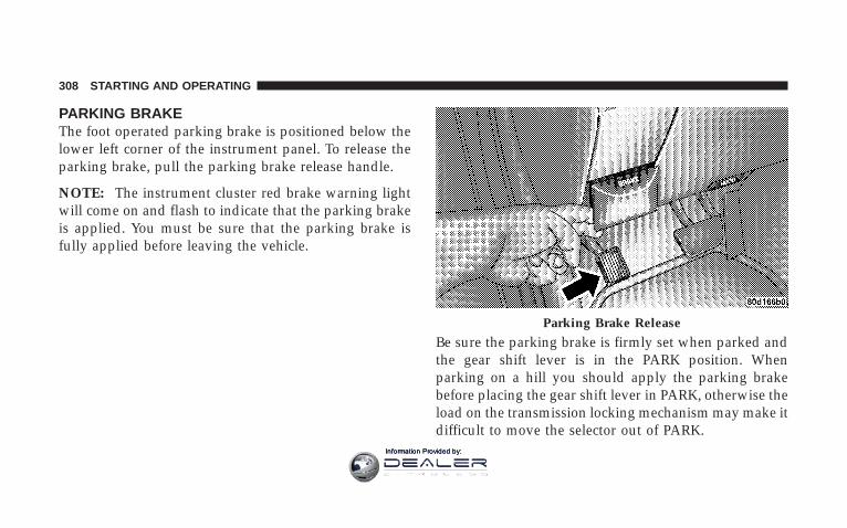
PARKING BRAKEThe foot operated parking brake is positioned below thelower left corner of the instrument panel. To release theparking brake, pull the parking brake release handle.
NOTE: The instrument cluster red brake warning lightwill come on and flash to indicate that the parking brakeis applied. You must be sure that the parking brake isfully applied before leaving the vehicle.
Be sure the parking brake is firmly set when parked andthe gear shift lever is in the PARK position. Whenparking on a hill you should apply the parking brakebefore placing the gear shift lever in PARK, otherwise theload on the transmission locking mechanism may make itdifficult to move the selector out of PARK.
Parking Brake Release
308 STARTING AND OPERATING
Information Provided by:

WARNING!
• Always fully apply the parking brake when leav-ing your vehicle, or it may roll and cause damageor injury. Also be certain to leave an automatictransmission in Park, a manual transmission inReverse or First gear. Failure to do so may allowthe vehicle to roll and cause damage or injury.
• Never leave children alone in a vehicle. Leavingchildren in a vehicle unattended is dangerous for anumber of reasons. A child or others could beseriously or fatally injured. Don’t leave the keys inthe ignition. A child could operate power win-dows, other controls, or move the vehicle.
• Be sure the parking brake is fully disengagedbefore driving, failure to do so can lead to brakeproblems due to excessive heating of the rearbrakes.
When parking on a hill, turn the front wheels toward thecurb on a downhill grade and away from the curb on anuphill grade.
The parking brake should always be applied wheneverthe driver is not in the vehicle.
BRAKE SYSTEMIf power assist is lost for any reason (for example,repeated brake applications with the engine off), thebrakes will still function. However, you will experience asubstantial increase in braking effort to stop the vehicle.
If either the front or rear hydraulic systems lose normalcapability, the remaining system will still function withsome loss of overall braking effectiveness. This will beevident by increased pedal travel during application,greater pedal force required to slow or stop, and activa-tion of the BRAKE warning lamp and the ABS lamp (ifequipped) during brake use.
STARTING AND OPERATING 309
5
Information Provided by:

Brake NoiseDuring normal operation of the brake system certainnoises may be present from time to time. Occasional9groan9 or 9squeal9 noises may occur during normaloperation of the brake system which may not be indica-tive of a problem. These noises may be heard at any timethe brakes are applied but may be more noticeable duringthe first few brake applications in the morning. Moisture,hot or cold temperature, dust, and or other debris mayalso contribute to the noise condition. Repeated or con-tinuous noises during braking may be an indication thatthe brake linings are worn and in need of replacement.
Four-Wheel Anti-Lock Brake System
WARNING!
Anti-Lock Brake Systems contain sophisticated elec-tronic equipment. It may be susceptible to interfer-ence caused by improperly installed or high outputradio transmitting equipment. This interference cancause possible loss of anti-lock braking capability.Installation of such equipment should be performedby qualified professionals.
310 STARTING AND OPERATING
Information Provided by:

WARNING!
• Anti-lock system (ABS) cannot prevent the naturallaws of physics from acting on the vehicle, nor canit increase braking or steering efficiency beyondthat afforded by the condition of the vehiclebrakes and tires or the traction afforded.
• The ABS cannot prevent accidents, includingthose resulting from excessive speed in turns,following another vehicle too closely, or hydro-planing. Only a safe, attentive, and skillful drivercan prevent accidents.
• The capabilities of an ABS equipped vehicle mustnever be exploited in a reckless or dangerousmanner which could jeopardize the user’s safetyor the safety of others.
This Anti-lock Brake System is designed to aid the driverin maintaining vehicle control under adverse brakingconditions. The system operates with a separate com-puter to modulate hydraulic pressure to prevent wheellockup and help avoid skidding on slippery surfaces.
The system’s pump motor runs during an ABS stop toprovide regulated hydraulic pressure. The pump motormakes a low humming noise during operation. This isnormal.
When you are in a severe braking condition involvinguse of the Anti-lock Brake System, you will experiencesome pedal drop as the vehicle comes to a complete stop.This is the result of the system reverting to the base brakesystem and is normal.
Engagement of the Anti-lock Brake System may beaccompanied by a pulsing sensation. You may also hear aclicking noise. These occurrences are normal, and indi-cate that the system is functioning.
STARTING AND OPERATING 311
5
Information Provided by:
ABS Warning LightThe Anti-lock Brake System includes an amber warninglight, located in the instrument cluster. When the light isilluminated, the Anti-lock Brake System is not function-ing. The system reverts to standard non-anti-lock brakes.
WARNING!
Pumping of the anti-lock brakes will diminish theireffectiveness and may lead to an accident. Pumpingmakes the stopping distance longer. Just press firmlyon your brake pedal when you need to slow down orstop.
POWER STEERINGThe standard power steering system will give you goodvehicle response and increased ease of maneuverabilityin tight spaces. The system will provide mechanicalsteering capability if power assist is lost.
If for some reason, the power assist is interrupted, it willstill be possible to steer your vehicle. Under these condi-tions you will observe a substantial increase in steeringeffort, especially at very low vehicle speeds and duringparking maneuvers.
NOTE: Increased noise levels at the end of the steeringwheel travel are considered normal and does not indicatethat there is a problem with the power steering system.
Upon initial start-up in cold weather, the power steeringpump may make noise for a short period of time. This isdue to the cold, thick fluid in the steering system. Thisnoise should be considered normal, and does not in anyway damage the steering system.
312 STARTING AND OPERATING
Information Provided by:

WARNING!
Continued operation with reduced power steeringassist could pose a safety risk to yourself and others.Service should be obtained as soon as possible.
CAUTION!
Prolonged operation of the steering system at the endof the steering wheel travel will increase the steeringfluid temperature and should be avoided when pos-sible. Damage to the power steering pump may occur.
TIRE SAFETY INFORMATION
Tire Markings
STARTING AND OPERATING 313
5
Information Provided by:

NOTE:• P (Passenger)-Metric tire sizing is based on U.S. design
standards. P-Metric tires have the letter “P” moldedinto the sidewall preceding the size designation. Ex-ample: P215/65R15 95H.
• European Metric tire sizing is based on Europeandesign standards. Tires designed to this standard havethe tire size molded into the sidewall beginning withthe section width. The letter 9P9 is absent from this tiresize designation. Example: 215/65R15 96H
• LT (Light Truck)-Metric tire sizing is based on U.S.design standards. The size designation for LT-Metrictires is the same as for P-Metric tires except for theletters “LT” that are molded into the sidewall preced-ing the size designation. Example: LT235/85R16.
• Temporary Spare tires are high-pressure compactspares designed for temporary emergency use only.Tires designed to this standard have the letter “T”molded into the sidewall preceding the size designa-tion. Example: T145/80D18 103M.
• High Flotation tire sizing is based on U.S. designstandards and it begins with the tire diameter moldedinto the sidewall. Example: 31x10.5 R15 LT.
314 STARTING AND OPERATING
Information Provided by:

Tire Sizing Chart
EXAMPLE:Size Designation:
P = Passenger car tire size based on U.S. design standards(....blank....( = Passenger car tire based on European design standardsLT = Light Truck tire based on U.S. design standardsT = Temporary Spare tire31 = Overall Diameter in Inches (in)215 = Section Width in Millimeters (mm)65 = Aspect Ratio in Percent (%)
—Ratio of section height to section width of tire.10.5 = Section Width in Inches (in)R = Construction Code
—9R9 means Radial Construction.—9D9 means Diagonal or Bias Construction.
15 = Rim Diameter in Inches (in)
STARTING AND OPERATING 315
5
Information Provided by:

EXAMPLE:Service Description:
95 = Load Index—A numerical code associated with the maximum load a tire can carry.
H = Speed Symbol—A symbol indicating the range of speeds at which a tire can carry a load correspondingto its load index under certain operating conditions.—The maximum speed corresponding to the Speed Symbol should only be achieved un-der specified operating conditions (i.e. tire pressure, vehicle loading, road conditions, andposted speed limits).
Load Identification:(....blank....( = Absence of any text on sidewall of the tire indicates a Standard Load (SL) TireExtra Load (XL) = Extra Load (or Reinforced) TireLight Load = Light Load TireC,D,E = Load range associated with the maximum load a tire can carry at a specified pressure
Maximum Load — Maximum Load indicates the maximum load this tire is designed to carry.Maximum Pressure — Maximum Pressure indicates the maximum permissible cold tire inflation pressure for this tire.
316 STARTING AND OPERATING
Information Provided by:

Tire Identification Number (TIN)The TIN may be found on one or both sides of the tire;however, the date code may only be on one side. Tires withwhite sidewalls will have the full TIN including date code
located on the white sidewall side of the tire. Look for the TINon the outboard side of black sidewall tires as mounted on thevehicle. If the TIN is not found on the outboard side then youwill find it on the inboard side of the tire.
EXAMPLE:DOT MA L9 ABCD 0301
DOT = Department of Transportation—This symbol certifies that the tire is in compliance with the U.S. Department of Transportation tiresafety standards, and is approved for highway use.
MA = Code representing the tire manufacturing location. (2 digits)L9 = Code representing the tire size. (2 digits)ABCD = Code used by tire manufacturer. (1 to 4 digits)03 = Number representing the week in which the tire was manufactured. (2 digits)
—03 means the 3rd week.01 = Number representing the year in which the tire was manufactured. (2 digits)
—01 means the year 2001.—Prior to July 2000, tire manufacturers were only required to have 1 number to represent the year inwhich the tire was manufactured. Example: 031 could represent the 3rd week of 1981 or 1991.
STARTING AND OPERATING 317
5
Information Provided by:

Tire Loading and Tire Pressure
Tire Placard Location
NOTE: The proper cold tire inflation pressure is listedon either the face of the driver’s door or the driver’s side“B” pillar.
Tire and Loading Information Placard
This placard tells you important information about the:1) number of people that can be carried in the vehicle2) the total weight your vehicle can carry3) the tire size designed for your vehicle4) the cold tire inflation pressures for the front, rear,and spare tires.
Tire Placard Location
Tire and Loading Information
318 STARTING AND OPERATING
Information Provided by:

LoadingThe vehicle maximum load on the tire must not exceedthe load carrying capacity of the tire on your vehicle. Youwill not exceed the tire’s load carrying capacity if youadhere to the loading conditions, tire size, and cold tireinflation pressures specified on the “Tire and LoadingInformation” placard and in the “Vehicle Loading” sec-tion of this manual.
NOTE: Under a maximum loaded vehicle condition,gross axle weight ratings (GAWR’s) for the front and rearaxles must not be exceeded. For further information onGAWR’s, vehicle loading, and trailer towing, refer to the“Vehicle Loading” section of this manual.
To determine the maximum loading conditions of yourvehicle, locate the statement “The combined weight ofoccupants and cargo should never exceed XXX kg or XXXlbs.” on the Tire and Loading Information placard. The
combined weight of occupants, cargo/luggage andtrailer tongue weight (if applicable) should never exceedthe weight referenced here.
Steps for Determining Correct Load Limit
1. Locate the statement “The combined weight of occu-pants and cargo should never exceed XXX pounds” onyour vehicle’s placard.
2. Determine the combined weight of the driver andpassengers that will be riding in your vehicle.
3. Subtract the combined weight of the driver and pas-sengers from XXX kilograms or XXX pounds.
4. The resulting figure equals the available amount ofcargo and luggage load capacity. For example, if “XXX”amount equals 1400 lbs. and there will be five 150 lb.passengers in your vehicle, the amount of available cargoand luggage load capacity is 650 lbs. (since 5 x 150 = 750,and 1400 – 750 = 650 lbs.)
STARTING AND OPERATING 319
5
Information Provided by:

5. Determine the combined weight of luggage and cargobeing loaded on the vehicle. That weight may not safelyexceed the available cargo and luggage load capacitycalculated in Step 4.
6. If your vehicle will be towing a trailer, load from yourtrailer will be transferred to your vehicle. Consult thismanual to determine how this reduces the availablecargo and luggage load capacity of your vehicle.
NOTE: The following table shows examples on how tocalculate total load, cargo/luggage, and towing capaci-ties of your vehicle with varying seating configurationsand number and size of occupants. This table is forillustration purposes only and may not be accurate forthe seating and load carry capacity of your vehicle.
NOTE: For the following example, the combined weightof occupants and cargo should never exceed 865 lbs. (392kg).
320 STARTING AND OPERATING
Information Provided by:

STARTING AND OPERATING 321
5
Information Provided by:

WARNING!
Overloading of your tires is dangerous. Overloadingcan cause tire failure, affect vehicle handling, andincrease your stopping distance. Use tires of therecommended load capacity for your vehicle. Neveroverload them.
TIRES — GENERAL INFORMATION
Tire PressureProper tire inflation pressure is essential to the safe andsatisfactory operation of your vehicle. Three primaryareas are affected by improper tire pressure:
1. Safety—
WARNING!• Improperly inflated tires are dangerous and cancause accidents.• Under inflation increases tire flexing and can resultin tire failure.• Over inflation reduces a tire’s ability to cushionshock. Objects on the road and chuckholes can causedamage that result in tire failure.• Unequal tire pressures can cause steering prob-lems. You could lose control of your vehicle.• Over inflated or under inflated tires can affectvehicle handling and can fail suddenly, resulting inloss of vehicle control.• Unequal tire pressures from one side of the vehicleto the other can cause the vehicle to drift to the rightor left.• Always drive with each tire inflated to the recom-mended cold tire inflation pressure.
322 STARTING AND OPERATING
Information Provided by:

2. Economy—Improper inflation pressures can cause uneven wearpatterns to develop across the tire tread. These abnormalwear patterns will reduce tread life resulting in a need forearlier tire replacement. Under inflation, also increasestire rolling resistance and results in higher fuel consump-tion.
3. Ride Comfort and Vehicle Stability—Proper tire inflation contributes to a comfortable ride.Over inflation produces a jarring and uncomfortable ride.
Tire Inflation PressuresThe proper cold tire inflation pressure is listed either onthe face of the driver’s door or on the driver’s side “B”pillar.
Some vehicles may have Supplemental Tire PressureInformation for vehicle loads that are less than themaximum loaded vehicle condition. These pressure con-ditions will be found in the “Supplemental Tire PressureInformation” section of this manual.
Tire Placard Location
STARTING AND OPERATING 323
5
Information Provided by:

The pressure should be checked and adjusted as well asinspecting for signs of tire wear or visible damage at leastonce a month. Use a good quality pocket-type gauge tocheck tire pressure. Do not make a visual judgementwhen determining proper inflation. Radial tires may lookproperly inflated even when they are under inflated.
CAUTION!
After inspecting or adjusting the tire pressure, al-ways reinstall the valve stem cap (if equipped). Thiswill prevent moisture and dirt from entering thevalve stem, which could damage the valve stem.
Inflation pressures specified on the placard are always“cold tire inflation pressure.” Cold tire inflation pressureis defined as the tire pressure after the vehicle has notbeen driven for at least 3 hours, or driven less than 1 mile
(1 km) after a 3 hour period. The cold tire inflationpressure must not exceed the maximum inflation pres-sure molded into the tire sidewall.
Check tire pressures more often if subject to a wide rangeof outdoor temperatures, as tire pressures vary withtemperature changes.
Tire pressures change by approximately 1 psi (7 kPa) per12 °F (7 °C) of air temperature change. Keep this in mindwhen checking tire pressure inside a garage, especially inthe winter.
Example: If garage temperature = 68 °F (20 °C) and theoutside temperature = 32 °F (0 °C) then the cold tireinflation pressure should be increased by 3 psi (21 kPa),which equals 1 psi (7 kPa) for every 12 °F (7 °C) for thisoutside temperature condition.
324 STARTING AND OPERATING
Information Provided by:

Tire pressure may increase from 2 to 6 psi (13 to 40 kPa)during operation. DO NOT reduce this normal pressurebuild up or your tire pressure will be too low.
Tire Inflation Pressure — 4500/5500 with SteelCarcass Ply TiresThis type of tire utilizes steel cords in the sidewall. Assuch, they cannot be treated like normal light truck tires.Adjusting tire pressure must be performed by personneltrained, supervised and equipped accordingly.
Inflation Pressure Adjustment When Mounted toVehicleDuring procedures when adding tire inflation pressure,the technician or individual must utilize a remote infla-tion devise, and ensure that all persons are clear of thetrajectory area. See figure below.
STARTING AND OPERATING 325
5
Information Provided by:
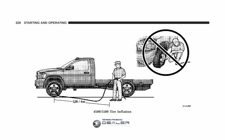
4500/5500 Tire Inflation
326 STARTING AND OPERATING
Information Provided by:

When adjusting inflation pressure to a tire and wheelassembly mounted on a vehicle, use Remote MountAutomatic Inflation Kit (similar to model number 27-cc1021234, available from TEAM PSE – PENTASTARService Equipment Phone Number 1-800-734-4334.
NOTE: Never attempt to re-inflate a tire and wheelassembly which has been run flat or extremely underinflated without first removing the tire from the wheelassembly for inspection.
Personnel trained, supervised, and equipped accordingto Federal Occupational Safety and Health Administra-tion (OSHA).
Inflation Pressure Adjustment When Not Mounted toVehicleWhen adjusting inflation pressure to a tire and wheelassembly not mounted on a vehicle, use a Remote MountAutomatic Inflation Kit and a Tire Inflation Cage similarto model number #174-2240 available from TEAM PSE(PENTASTAR Service Equipment – 1-800-223-5623).
Tire Pressures for High Speed OperationThe manufacturer advocates driving at safe speedswithin posted speed limits. Where speed limits or condi-tions are such that the vehicle can be driven at highspeeds, maintaining correct tire inflation pressure is veryimportant. Increased tire pressure and reduced vehicleloading may be required for high-speed vehicle opera-tion. Refer to original equipment or an authorized tiredealer for recommended safe operating speeds, loadingand cold tire inflation pressures.
STARTING AND OPERATING 327
5
Information Provided by:

WARNING!
High speed driving with your vehicle under maxi-mum load is dangerous. The added strain on yourtires could cause them to fail. You could have aserious accident. Don’t drive a vehicle loaded to themaximum capacity at continuous speeds above 75mph (120 km/h).
Radial-Ply Tires
WARNING!
Combining radial ply tires with other types of tireson your vehicle will cause your vehicle to handlepoorly. The instability could cause an accident. Al-ways use radial ply tires in sets of four (or 6, in caseof trucks with dual rear wheels). Never combinethem with other types of tires.
Cuts and punctures in radial tires are repairable only inthe tread area because of sidewall flexing. Consult yourauthorized tire dealer for radial tire repairs.
328 STARTING AND OPERATING
Information Provided by:

Limited Use Spare — If EquippedThe limited use spare tire is for temporary emergency useon your vehicle. This tire is identified by a limited usespare tire warning label located on the limited use sparetire and wheel assembly. This tire may look like theoriginal equipped tire on the front or rear axle of yourvehicle, but it is not. Installation of this limited use sparetire affects vehicle handling. Since it is not the same tire,replace (or repair) the original tire and reinstall on thevehicle at the first opportunity.
WARNING!
The limited use spare tires are for emergency useonly. Installation of this limited use spare tire affectsvehicle handling. With this tire, do not drive morethan 60 mph (100 km/h). Keep inflated to the cold tireinflation pressure listed on either your tire placard orlimited use spare tire and wheel assembly. Replace(or repair) the original tire at the first opportunityand reinstall it on your vehicle. Failure to do so couldresult in loss of vehicle control.
Tire SpinningWhen stuck in mud, sand, snow, or ice conditions, do notspin your vehicle’s wheels faster than 30 mph (48 km/h)or for longer than 30 seconds continuously withoutstopping when you are stuck.
STARTING AND OPERATING 329
5
Information Provided by:

Refer to “Freeing A Stuck Vehicle” in Section 6 of thismanual for additional information.
WARNING!
Fast spinning tires can be dangerous. Forces gener-ated by excessive wheel speeds may cause tire dam-age or failure. A tire could explode and injure some-one. Do not spin your vehicle’s wheels faster than 30mph (48 km/h) or for more than 30 seconds continu-ously when you are stuck, and don’t let anyone neara spinning wheel, no matter what the speed.
Tread Wear IndicatorsTread wear indicators are in the original equipment tiresto help you in determining when your tires should bereplaced.
These indicators are molded into the bottom of the treadgrooves. They will appear as bands when the tread depthbecomes 1/16 inch (2 mm). When the tread is worn to thetread wear indicators, the tire should be replaced.
Many states have laws requiring tire replacement at thispoint.
330 STARTING AND OPERATING
Information Provided by:

Life of TireThe service life of a tire is dependent upon varyingfactors including but not limited to:
• Driving style
• Tire pressure
• Distance driven
WARNING!
Tires and spare tire should be replaced after six years,regardless of the remaining tread. Failure to followthis warning can result in sudden tire failure. Youcould lose control and have an accident resulting inserious injury or death.
Keep dismounted tires in a cool, dry place with as littleexposure to light as possible. Protect tires from contactwith oil, grease, and gasoline.
Replacement TiresThe tires on your new vehicle provide a balance of manycharacteristics. They should be inspected regularly forwear and correct cold tire inflation pressure. The manu-facturer strongly recommends that you use tires equiva-lent to the originals in size, quality and performancewhen replacement is needed (refer to the paragraph on“Tread Wear Indicators”). Refer to the “Tire and LoadingInformation” placard for the size designation of your tire.The service description and load identification will befound on the original equipment tire. Failure to useequivalent replacement tires may adversely affect thesafety, handling, and ride of your vehicle. We recommendthat you contact your original equipment or an autho-rized tire dealer with any questions you may have on tirespecifications or capability.
STARTING AND OPERATING 331
5
Information Provided by:
WARNING!• Do not use a tire, wheel size or rating other than
that specified for your vehicle. Some combinationsof unapproved tires and wheels may change sus-pension dimensions and performance characteris-tics, resulting in changes to steering, handling, andbraking of your vehicle. This can cause unpredict-able handling and stress to steering and suspen-sion components. You could lose control and havean accident resulting in serious injury or death.Use only the tire and wheel sizes with load ratingsapproved for your vehicle.
• Never use a tire with a smaller load index orcapacity, other than what was originally equippedon your vehicle. Using a tire with a smaller loadindex could result in tire overloading and failure.You could lose control and have an accident.
• Failure to equip your vehicle with tires havingadequate speed capability can result in sudden tirefailure and loss of vehicle control.
CAUTION!
Replacing original tires with tires of a different sizemay result in false speedometer and odometerreadings.
Alignment And BalancePoor suspension alignment may result in:
• Fast tire wear.
• Uneven tire wear, such as feathering and one-sidedwear.
• Vehicle pull to right or left.
Tires may also cause the vehicle to pull to the left or right.Alignment will not correct this condition. See your dealerfor proper diagnosis.
332 STARTING AND OPERATING
Information Provided by:

Improper alignment will not cause vehicle vibration.Vibration may be a result of tire and wheel out-of-balance. Proper balancing will reduce vibration andavoid tire cupping and spotty wear.
SUPPLEMENTAL TIRE PRESSURE INFORMATION— IF EQUIPPEDA light load vehicle condition is defined as two passen-gers {150 lbs (68 kg) each} plus 200 lbs (91kg) of cargo.Cold tire inflation pressures for a lightly loaded vehiclewill be found on the face of the driver’s door.
TIRE CHAINSUse “Class U” chains on Ram Trucks, or other tractionaids that meet SAE Type “U” specifications.
NOTE: Chains must be the proper size for the vehicle,as recommended by the chain manufacturer.
CAUTION!To avoid damage to your vehicle, tires or chains, observethe following precautions:• Because of limited chain clearance between tires and other
suspension components, it is important that only chains ingood condition are used. Broken chains can cause seriousvehicle damage. Stop the vehicle immediately if noiseoccurs that could suggest chain breakage. Remove thedamaged parts of the chain before further use.
• Install chains as tightly as possible and then retightenafter driving about 1/2 mile (0.8 km).
• Do not exceed 45 mph (72 km/h).• Drive cautiously and avoid severe turns and large
bumps, especially with a loaded vehicle.• Do not install tire chains on front wheels of 4x2
vehicles.• Do not drive for a prolonged period on dry pavement.• Observe the tire chain manufacturer’s instructions on
method of installation, operating speed, and condi-tions for usage. Always use the lower suggested oper-ating speed of the chain manufacturer if different thanthe speed recommended by the manufacturer.
STARTING AND OPERATING 333
5
Information Provided by:
These cautions apply to all chain traction devices, includ-ing link and cable (radial) chains.
Tire chain use is permitted only on the rear tires of Ram4X2 trucks.
NOTE: The use of class “U” chains is permitted on thefront and rear of 4X4, Ram Trucks with Dual Rear Wheelsand LT235/80R17E tires.
NOTE: On 4X2 Ram Trucks, class “U” snow chains arepermitted on the rear wheels only of vehicles equippedwith LT245/70R17, LT265/70R17, and LT235/80R17 sizetires.
NOTE: On 4X4 Single Rear Wheel (SRW) Ram Trucks,class “U” snow chains are permitted on the rear wheelsonly of vehicles equipped with LT265/70R17.
CAUTION!
Do not use tire chains on the 4X2 front wheels ofSRW (Single Rear Wheels) equipped with LT245/70R17, LT265/70R17 tires or 4X4 front tires of RamTrucks equipped with LT265/70R17tires. There maynot be adequate clearance for the chains and you arerisking structural or body damage to your vehicle.
SNOW TIRESSnow tires should be of the same size and type construc-tion as the front tires. Consult the manufacturer of thesnow tire to determine any maximum vehicle speedrequirement associated with the tire. These tires shouldalways be operated at the vehicle maximum capacityinflation pressures under any load condition.
While studded tires improve performance on ice, skidand traction capability on wet or dry surfaces may be
334 STARTING AND OPERATING
Information Provided by:
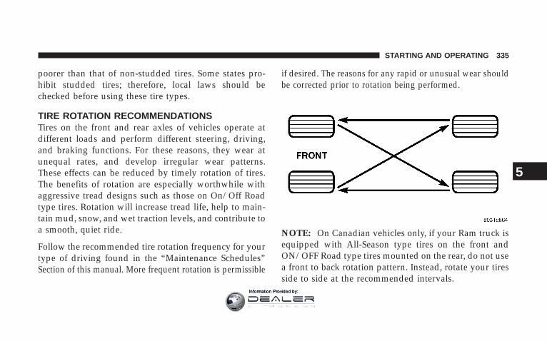
poorer than that of non-studded tires. Some states pro-hibit studded tires; therefore, local laws should bechecked before using these tire types.
TIRE ROTATION RECOMMENDATIONSTires on the front and rear axles of vehicles operate atdifferent loads and perform different steering, driving,and braking functions. For these reasons, they wear atunequal rates, and develop irregular wear patterns.These effects can be reduced by timely rotation of tires.The benefits of rotation are especially worthwhile withaggressive tread designs such as those on On/Off Roadtype tires. Rotation will increase tread life, help to main-tain mud, snow, and wet traction levels, and contribute toa smooth, quiet ride.
Follow the recommended tire rotation frequency for yourtype of driving found in the “Maintenance Schedules”Section of this manual. More frequent rotation is permissible
if desired. The reasons for any rapid or unusual wear shouldbe corrected prior to rotation being performed.
NOTE: On Canadian vehicles only, if your Ram truck isequipped with All-Season type tires on the front andON/OFF Road type tires mounted on the rear, do not usea front to back rotation pattern. Instead, rotate your tiresside to side at the recommended intervals.
STARTING AND OPERATING 335
5
Information Provided by:
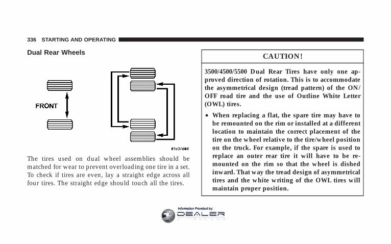
Dual Rear Wheels
The tires used on dual wheel assemblies should bematched for wear to prevent overloading one tire in a set.To check if tires are even, lay a straight edge across allfour tires. The straight edge should touch all the tires.
CAUTION!
3500/4500/5500 Dual Rear Tires have only one ap-proved direction of rotation. This is to accommodatethe asymmetrical design (tread pattern) of the ON/OFF road tire and the use of Outline White Letter(OWL) tires.
• When replacing a flat, the spare tire may have tobe remounted on the rim or installed at a differentlocation to maintain the correct placement of thetire on the wheel relative to the tire/wheel positionon the truck. For example, if the spare is used toreplace an outer rear tire it will have to be re-mounted on the rim so that the wheel is dishedinward. That way the tread design of asymmetricaltires and the white writing of the OWL tires willmaintain proper position.
336 STARTING AND OPERATING
Information Provided by:

ENGINE RUNAWAY
WARNING!
In case of engine runaway due to flammable fumesfrom gasoline spills or turbocharger oil leaks beingsucked into the engine do the following to help avoidpersonal injury and/or vehicle damage:
1. Shut off engine ignition switch.
2. Using a CO2 or dry chemical type fire extin-guisher, direct the spray from the fire extinguisherinto the grille on the passenger side so that the sprayenters the engine air intake.
The inlet for the engine air intake is located behindthe passenger side headlamp and receives airthrough the grille
FUEL REQUIREMENTS
Fuel Requirements (5.7L Gas Engines)The 5.7L engine is designed to meet allemissions regulations and provide satisfac-tory fuel economy and performance whenusing high quality unleaded gasoline hav-ing an octane range of 87 to 89. The manu-facturer recommends the use of 89 octane
for optimum performance. The routine use of premiumgasoline is not recommended. The use of premiumgasoline will provide no benefit over high quality regularand mid-grade gasolines, and in some circumstancesmay result in poorer performance.
Light spark knock at low engine speeds is not harmful toyour engine. However, continued heavy spark knock athigh speeds can cause damage and immediate service isrequired.
STARTING AND OPERATING 337
5
Information Provided by:

Poor quality gasoline can cause problems such as hardstarting, stalling and hesitations. If you experience thesesymptoms, try another brand of “regular” gasoline be-fore considering service for the vehicle.
Over 40 auto manufacturers world-wide have issued andendorsed consistent gasoline specifications (the World-wide Fuel Charter, WWFC) to define fuel propertiesnecessary to deliver enhanced emissions, performanceand durability for your vehicle. We recommend the useof gasolines that meet the WWFC specifications if theyare available.
Reformulated GasolineMany areas of the country require the use of cleanerburning gasoline referred to as “Reformulated Gasoline.”Reformulated gasolines contain oxygenates, and are spe-cifically blended to reduce vehicle emissions and im-prove air quality.
We strongly support the use of reformulated gasolines.Properly blended reformulated gasolines will provideexcellent performance and durability for the engine andfuel system components.
Gasoline/Oxygenate BlendsSome fuel suppliers blend unleaded gasoline with oxy-genates such as 10% ethanol, MTBE and ETBE. Oxygen-ates are required in some areas of the country during thewinter months to reduce carbon monoxide emissions.Fuels blended with these oxygenates may be used inyour vehicle.
CAUTION!
DO NOT use gasolines containing Methanol or E85Ethanol. Use of these blends may result in startingand driveability problems and may damage criticalfuel system components.
338 STARTING AND OPERATING
Information Provided by:

Problems that result from using methanol/gasoline orE85 Ethanol blends are not the responsibility of themanufacturer. While MTBE is an oxygenate made fromMethanol, it does not have the negative effects of Metha-nol.
MMT In GasolineMMT is a manganese-containing metallic additive that isblended into some gasoline to increase octane. Gasolinesblended with MMT provide no performance advantagebeyond gasolines of the same octane number withoutMMT. Gasolines blended with MMT reduce spark pluglife and reduce emission system performance. We recom-mend that gasolines free of MMT be used in your vehicle.The MMT content of gasoline may not be indicated onthe gasoline pump; therefore, you should ask your gaso-line retailer whether or not his/her gasoline containsMMT.
It is even more important to look for gasolines withoutMMT in Canada because MMT can be used at levelshigher than allowed in the United States. MMT is pro-hibited in Federal and California reformulated gasolines.
Materials Added To FuelAll gasolines sold in the United States are required tocontain effective detergent additives. Use of additionaldetergents or other additives is not needed under normalconditions and would result in unnecessary cost. There-fore, you should not have to add anything to the fuel.
Fuel System Cautions
CAUTION!
Follow these guidelines to maintain your vehicle’sperformance:
STARTING AND OPERATING 339
5
Information Provided by:
• The use of leaded gas is prohibited by Federal law.Using leaded gasoline can impair engine performance,damage the emission control system.
• An out-of-tune engine, or certain fuel or ignitionmalfunctions, can cause the catalytic converter tooverheat. If you notice a pungent burning odor orsome light smoke, your engine may be out of tune ormalfunctioning and may require immediate service.Contact your dealer for service assistance.
• When pulling a heavy load or driving a fully loadedvehicle when the humidity is low and the temperatureis high, use a premium unleaded fuel to help preventspark knock. If spark knock persists, lighten the load,or engine piston damage may result.
• The use of fuel additives which are now being sold asoctane enhancers is not recommended. Many of theseproducts contain high concentrations of methanol.
Fuel system damage or vehicle performance problemsresulting from the use of such fuels or additives is notthe responsibility of the manufacturer.
NOTE: Intentional tampering with emissions controlsystems can result in civil penalties being assessedagainst you.
Carbon Monoxide Warnings
WARNING!
Carbon monoxide (CO) in exhaust gases is deadly.Follow the precautions below to prevent carbonmonoxide poisoning:
• Do not inhale exhaust gases. They contain carbonmonoxide, a colorless and odorless gas which can kill.Never run the engine in a closed area, such as agarage, and never sit in a parked vehicle with the
340 STARTING AND OPERATING
Information Provided by:

engine running for an extended period. If the vehicle isstopped in an open area with the engine running formore than a short period, adjust the ventilation systemto force fresh, outside air into the vehicle.
• Guard against carbon monoxide with proper mainte-nance. Have the exhaust system inspected every timethe vehicle is raised. Have any abnormal conditionsrepaired promptly. Until repaired, drive with all sidewindows fully open.
• Keep the liftgate closed when driving your vehicle toprevent carbon monoxide and other poisonous ex-haust gases from entering the vehicle.
Fuel Requirements (6.7L Diesel Engines)Use good quality diesel fuel from a reputable supplier inyour vehicle. Federal law requires that you must fuel thisvehicle with Ultra Low Sulfur Highway Diesel fuel (15ppm Sulfur maximum) and prohibits the use of LowSulfur Highway Diesel fuel (500 ppm Sulfur maximum)
to avoid damage to the emissions control system. Formost year-round service, No. 2 diesel fuel meeting ASTMspecification D-975 Grade S15 will provide good perfor-mance. If the vehicle is exposed to extreme cold (below20°F or -7°C), or is required to operate at colder-than-normal conditions for prolonged periods, use climatizedNo. 2 diesel fuel or dilute the No. 2 diesel fuel with 50%No. 1 diesel fuel. This will provide better protection fromfuel gelling or wax-plugging of the fuel filters.
WARNING!
Do not use alcohol or gasoline as a fuel blendingagent. They can be unstable under certain conditionsand hazardous or explosive when mixed with dieselfuel.
STARTING AND OPERATING 341
5
Information Provided by:

Diesel fuel is seldom completely free of water. To preventfuel system trouble, drain the accumulated water fromthe fuel/water separator using the fuel/water separatordrain provided. If you buy good quality fuel and followthe cold weather advice above, fuel conditioners shouldnot be required in your vehicle. If available in your area,a high cetane “premium” diesel fuel may offer improvedcold-starting and warm-up performance.
Fuel SpecificationsThe Cummins Turbocharged, Charge Air Cooled, Dieselengine has been developed to take advantage of the highenergy content and generally lower cost No. 2 Ultra LowSulfur diesel fuel or No. 2 Ultra Low Sulfur climatizeddiesel fuels. Experience has shown that it also operateson No. 1 Ultra Low Sulfur diesel fuels or other fuelswithin specification.
NOTE: A maximum blend of 5% biodiesel meetingASTM specification D-6751 may be used with yourCummins Diesel equipped vehicle.
NOTE: In addition, commercially available fuel addi-tives are not necessary for the proper operation of yourCummins Diesel equipped vehicle.
NOTE: No. 1 Ultra Low Sulfur diesel fuel should onlybe used where extended arctic conditions (-10°F or -23°C)exist.
342 STARTING AND OPERATING
Information Provided by:

ADDING FUEL
Adding Fuel (Gas Engines)
CAUTION!
Damage to the fuel system or emission control sys-tem could result from using an improper fuel tankfiller tube cap (gas cap). A poorly fitting cap could letimpurities into the fuel system. Also a poorly fittedafter-market cap can cause the MIL (MalfunctionIndicator Light) to illuminate, due to fuel vaporsescaping from the system.
CAUTION!
A poorly fitting gas cap may cause the MalfunctionIndicator Light to turn on.
CAUTION!
To avoid fuel spillage and overfilling, do not “topoff” the fuel tank after filling.
NOTE: When the fuel nozzle “clicks” or shuts off, thefuel tank is full.
WARNING!
• Never have any smoking materials lit in or nearthe vehicle when the gas cap is removed or thetank filled.
• Never add fuel to the vehicle when the engine isrunning. This is in violation of most state andfederal fire regulations and will cause the Mal-function Indicator Light to turn on.
STARTING AND OPERATING 343
5
Information Provided by:
NOTE: Tighten the gas cap 1/4 turn until you hear oneclick. This is an indication that the cap is properlytightened.
If the gas cap is not tightened properly, the MalfunctionIndicator Light will come on, Be sure the gas cap istightened every time the vehicle is refueled.
WARNING!
A fire may result if gasoline is pumped into aportable container that is inside of a vehicle. Youcould be burned. Always place gas containers on theground while filling.
Loose Fuel Filler Cap MessageIf the vehicles diagnostic system determines that the fuelfiller cap in loose, improperly installed, or damaged, aGASCAP message will be displayed in the instrumentcluster. Tighten the gas cap until a “clicking” sound isheard. This is an indication that the gas cap is properlytightened. Press the odometer reset button to turn themessage off. If the problem persists, the message willappear the next time the vehicle is started. This mightindicate a damaged cap. If the problem is detected twicein a row, the system will turn on the MalfunctionIndicator Light (MIL). Resolving the problem will turnthe MIL light off.
344 STARTING AND OPERATING
Information Provided by:
Adding Fuel (Diesel Engines)
CAUTION!
To avoid fuel spillage and overfilling, do not “topoff” the fuel tank after filling.
NOTE:• When the fuel nozzle “clicks” or shuts off, the fuel
tank is full.
• Tighten the gas cap until you hear a “clicking” sound.This is an indication that the gas cap is properlytightened.
• Make sure that the gas cap is tightened each time thevehicle is refueled.
WARNING!
A fire may result if fuel is pumped into a portablecontainer that is on a truck bed. You could be burned.Always place fuel containers on the ground whilefilling.
Fuel Filler Cap (Gas Cap)If the gas cap is lost or damaged, be sure the replacementcap is for use with this vehicle.
CAUTION!
Damage to the fuel system or emission control sys-tem could result from using an improper fuel tankfiller tube cap (gas cap). A poorly fitting cap could letimpurities into the fuel system.
STARTING AND OPERATING 345
5
Information Provided by:

WARNING!
• Never have any smoking materials lit in or nearthe vehicle when the gas cap is removed or thetank filled.
• Never add fuel to the vehicle when the engine isrunning.
Avoid Using Contaminated FuelFuel that is contaminated by water or dirt can causesevere damage to the engine fuel system. Proper main-tenance of the engine fuel filter and fuel tank is essential.(See Section 7 for Maintenance Procedures).
NOTE: Climatized Ultra Low Sulfur diesel fuel is ablend of Number 2 Ultra Low Sulfur and Number 1 UltraLow Sulfur Diesel fuel which reduces the temperature atwhich wax crystals form in the fuel.
Bulk Fuel StorageIf you store quantities of fuel, good maintenance of thestored fuel is also essential. Fuel contaminated withwater will promote the growth of “microbes.” Thesemicrobes form “slime” that will clog fuel filters and lines.Drain condensation from the supply tank and change theline filter on a regular basis.
NOTE: When a diesel engine is allowed to run out offuel, air is pulled into the fuel system.
You may try priming as described below. However, if theengine will not start, refer to the fuel priming procedurein the Service Manual or have the vehicle towed to anauthorized Dodge dealer.
346 STARTING AND OPERATING
Information Provided by:

WARNING!
Do not open the high pressure fuel system with theengine running. Engine operation causes high fuelpressure. High pressure fuel spray can cause seriousinjury or death.
Priming if the engine has run out of fuel
1. Add a substantial quantity of fuel to the tank 5 to 10gallons (19 to 38L).
2. Crank the engine for 1 to 2 seconds. If the engine doesnot start, then release the key or starter button back to theRUN position (do not turn the key back to the OFFposition). The electric fuel transfer pump will continue torun and purge air from the system for about 20 seconds.After 20 seconds, attempt to start the engine again.
3. Start the engine using the Normal Starting Procedure.
4. Repeat the procedure if the engine does not start.
CAUTION!
Do not engage the starter motor for more than 15seconds at a time. Allow two minutes between thecranking intervals.
NOTE: The engine may run rough until the air is forcedfrom all the fuel lines.
VEHICLE LOADING
Certification LabelAs required by National Highway Traffic Safety Admin-istration Regulations, your vehicle has a certificationlabel affixed to the driver’s side door or pillar.
This label contains the month and year of manufacture,Gross Vehicle Weight Rating (GVWR), Gross Axle Weight
STARTING AND OPERATING 347
5
Information Provided by:

Rating (GAWR) front and rear, and Vehicle IdentificationNumber (VIN). A Month-Day-Hour (MDH) number isincluded on this label and indicates the Month, Day andHour of manufacture. The bar code that appears on thebottom of the label is your Vehicle Identification Number(VIN).
Gross Vehicle Weight Rating (GVWR)The GVWR is the total permissible weight of your vehicleincluding driver, passengers, vehicle, options and cargo.The label also specifies maximum capacities of front andrear axle systems (GAWR). Total load must be limited soGVWR and front and rear GAWR are not exceeded.
PayloadThe payload of a vehicle is defined as the allowable loadweight a truck can carry, including the weight of thedriver, all passengers, options and cargo.
Gross Axle Weight Rating (GAWR)The GAWR is the maximum permissible load on the frontand rear axles. The load must be distributed in the cargoarea so that the GAWR of each axle is not exceeded.
Each axle GAWR is determined by the components in thesystem with the lowest load carrying capacity (axle,springs, tires or wheels). Heavier axles or suspensioncomponents sometimes specified by purchasers for in-creased durability does not necessarily increase the vehi-cle’s GVWR.
Tire SizeThe tire size on the Label represents the actual tire size onyour vehicle. Replacement tires must be equal to the loadcapacity of this tire size.
Rim SizeThis is the rim size that is appropriate for the tire sizelisted.
348 STARTING AND OPERATING
Information Provided by:
Inflation PressureThis is the cold tire inflation pressure for your vehicle forall loading conditions up to full GAWR.
Curb WeightThe curb weight of a vehicle is defined as the total weightof the vehicle with all fluids, including vehicle fuel, at fullcapacity conditions, and with no occupants or cargoloaded into the vehicle. The front and rear curb weightvalues are determined by weighing your vehicle on acommercial scale before any occupants or cargo areadded.
LoadingThe actual total weight and the weight of the front andrear of your vehicle at the ground can best be determinedby weighing it when it is loaded and ready for operation.
The entire vehicle should first be weighed on a commer-cial scale to insure that the GVWR has not been exceeded.The weight on the front and rear of the vehicle shouldthen be determined separately to be sure that the load isproperly distributed over front and rear axle. Weighingthe vehicle may show that the GAWR of either the frontor rear axles has been exceeded but the total load iswithin the specified GVWR. If so, weight must be shiftedfrom front to rear or rear to front as appropriate until thespecified weight limitations are met. Store the heavieritems down low and be sure that the weight is distributedequally. Stow all loose items securely before driving.
Improper weight distributions can have an adverse effecton the way your vehicle steers and handles and the waythe brakes operate.
STARTING AND OPERATING 349
5
Information Provided by:

CAUTION!
Do not load your vehicle any heavier than the GVWRor the maximum front and rear GAWR. If you do,parts on your vehicle can break, or it can change theway your vehicle handles. This could cause you tolose control. Also overloading can shorten the life ofyour vehicle.
An EXAMPLE of a loaded vehicle is shown in thefollowing chart. Note that neither GVWR nor GAWRcapabilities are exceeded. Overloading can cause poten-tial safety hazards and shorten service life.
NOTE: The weights shown in this chart are notnecessarily the weights for your vehicle. Also, theamount of load added to both the front and rear axles
can be computed after the vehicle has been weighedboth in its (curb weight( condition, and in its (loadedand ready for operation( condition.
Gross Vehicle Weight Rating (GVWR) 6500 LBS.
350 STARTING AND OPERATING
Information Provided by:

TRAILER TOWINGIn this section you will find safety tips and informationon limits to the type of towing you can reasonably dowith your vehicle. Before towing a trailer carefully re-view this information to tow your load as efficiently andsafely as possible.
To maintain warranty coverage, follow the requirementsand recommendations in this manual concerning ve-hicles used for trailer towing.
Common Towing DefinitionsThe following trailer towing related definitions will assistyou in understanding the following information:
Gross Vehicle Weight Rating (GVWR)The GVWR is the total allowable weight of your vehicle.This includes driver, passengers, cargo and tongueweight. The total load must be limited so that you do notexceed the GVWR.
Gross Trailer Weight (GTW)The gross trailer weight (GTW) is the weight of the trailerplus the weight of all cargo, consumables and equipment(permanent or temporary) loaded in or on the trailer in its9loaded and ready for operation9 condition. The recom-mended way to measure GTW is to put your fully loadedtrailer on a vehicle scale. The entire weight of the trailermust be supported by the scale.
Gross Combination Weight Rating (GCWR)The gross combination weight rating (GCWR) is the totalpermissible weight of your vehicle and trailer whenweighed in combination. (Note that GCWR ratings in-clude a 68 kg (150 lbs) allowance for the presence of adriver).
STARTING AND OPERATING 351
5
Information Provided by:

Gross Axle Weight Rating (GAWR)The GAWR is the maximum capacity of the front and rearaxles. Distribute the load over the front and rear axlesevenly. Make sure that you do not exceed either front orrear GAWR.
WARNING!
It is important that you do not exceed the maximumfront or rear GAWR. A dangerous driving conditioncan result if either rating is exceeded. You could losecontrol of the vehicle and have an accident.
Tongue Weight (TW)The downward force exerted on the hitch ball by thetrailer. In most cases it should not be less than 10% ormore than 15% of the trailer load. You must consider thisas part of the load on your vehicle.
Frontal AreaThe maximum height and maximum width of the front ofa trailer.
Trailer Sway ControlThe trailer sway control is a telescoping link that can beinstalled between the hitch receiver and the trailer tonguethat typically provides adjustable friction associated withthe telescoping motion to dampen any unwanted trailerswaying motions while traveling.
Weight-Carrying HitchA weight-carrying hitch supports the trailer tongueweight, just as if it were luggage located at a hitch ball orsome other connecting point of the truck. These kind ofhitches are the most popular on the market today andthey’re commonly used to tow small- and medium-sizedtrailers.
352 STARTING AND OPERATING
Information Provided by:

Weight-Distributing HitchA weight-distributing system works by applying lever-age through spring (load) bars. They are typically usedfor heavier loads, to distribute trailer tongue weight tothe tow vehicle’s front axle and the trailer axle(s). Whenused in accordance with the manufacturers’ directions, itprovides for a more level ride, offering more consistentsteering and brake control thereby enhancing towingsafety. The addition of a friction / hydraulic sway controlalso dampens sway caused by traffic and crosswinds andcontributes positively to tow vehicle and trailer stability.Trailer sway control and a weight distributing (loadequalizing) hitch are recommended for heavier TongueWeights (TW) and may be required depending on Vehicleand Trailer configuration / loading to comply with grossaxle weight rating (GAWR) requirements.
WARNING!
An improperly adjusted Weight Distributing Hitchsystem may reduce handling, stability, braking per-formance, and could result in an accident.
Weight Distributing Systems may not be compatiblewith Surge Brake Couplers. Consult with your hitchand trailer manufacturer or a reputable RecreationalVehicle dealer for additional information.
STARTING AND OPERATING 353
5
Information Provided by:

Weight Distributing Hitch System Improper Adjustment of Weight Distributing System
354 STARTING AND OPERATING
Information Provided by:

Fifth-Wheel HitchA special high platform with a coupling that mounts overthe rear axle of the tow vehicle in the truck bed. Connectsa vehicle and fifth-wheel trailer with a coupling king pin.
Gooseneck HitchThe gooseneck hitch employs a pivoted coupling armwhich attaches to a ball mounted in the bed of a pickuptruck. The coupling arm connects to the hitch mountedover the rear axle in the truck bed.
Trailer Hitch ClassificationThe rear bumper is intended to tow trailers up to 2,000lbs (907 kg) without added equipment or alterations tothe standard equipment. Your vehicle may be factoryequipped for safe towing of trailers weighing over 2,000lbs (907 kg) with the optional Trailer Tow Prep Package.See your dealer for package content.
The following chart provides the industry standard forthe maximum trailer weight a given trailer hitch class can
tow and should be used to assist you in selecting thecorrect trailer hitch for your intended towing condition.Refer to “Trailer Towing Weights (Maximum TrailerWeight Ratings)” for the website address that containsthe necessary information for your specific drivetrain.
Trailer Hitch ClassificationClass Max. GTW
(Gross Trailer Wt.)Class I - Light Duty 2,000 lbs (907 kg)Class II - MediumDuty
3,500 lbs (1587 kg)
Class III - Heavy Duty 5,000 lbs (2268 kg)Class IV - ExtraHeavy Duty
10,000 lbs (4540 kg)
Fifth Wheel/Gooseneck
Greater than 10,000 lbs(4540 kg)
All trailer hitches should be professionally installed onyour vehicle.
STARTING AND OPERATING 355
5
Information Provided by:

Trailer Towing Weights (Maximum Trailer WeightRatings)
NOTE: For additional trailer towing information (maxi-mum trailer weight ratings) refer to the following websiteaddresses:
• http:// www.dodge.com/towing.
• http:// www.dodge.ca (Canada).
Trailer and Tongue WeightAlways load a trailer with 60% to 65% of the weight inthe front of the trailer. This places 10% to 15% of theGross Trailer Weight (GTW) on the tow hitch of yourvehicle. Loads balanced over the wheels or heavier in therear can cause the trailer to sway severely side to sidewhich will cause loss of control of vehicle and trailer.Failure to load trailers heavier in front is the cause ofmany trailer accidents.
Never exceed the maximum tongue weight stamped onyour bumper or trailer hitch.
Consider the following items when computing theweight on the rear axle of the vehicle:
• The tongue weight of the trailer.
356 STARTING AND OPERATING
Information Provided by:

• The weight of any other type of cargo or equipmentput in or on your vehicle.
• The weight of the driver and all passengers.
NOTE: Remember that everything put into or on thetrailer adds to the load on your vehicle. Also, additionalfactory-installed options, or dealer-installed options,must be considered as part of the total load on yourvehicle. Refer to the Tire and Loading Information plac-ard in the Tire Safety Information Section of this manual.
Towing RequirementsTo promote proper break-in of your new vehicle driv-etrain components the following guidelines are recom-mended:
CAUTION!
• Avoid towing a trailer for the first 500 miles (805km) of vehicle operation. Doing so may damageyour vehicle.
• During the first 500 miles (805 km) of trailertowing, limit your speed to 50 mph (80 km/h).
Perform the maintenance listed in Section 8 of thismanual. When towing a trailer, never exceed the GAWR,or GCWR, ratings.
STARTING AND OPERATING 357
5
Information Provided by:

WARNING!
Improper towing can lead to an injury accident.Follow these guidelines to make your trailer towingas safe as possible:
Make certain that the load is secured in the trailerand will not shift during travel. When traileringcargo that is not fully secured, dynamic load shiftscan occur that may be difficult for the driver tocontrol. You could lose control of your vehicle andhave an accident.
• When hauling cargo or towing a trailer, do not over-load your vehicle or trailer. Overloading can cause aloss of control, poor performance or damage to brakes,axle, engine, transmission, steering, suspension, chas-sis structure or tires.
• Safety chains must always be used between yourvehicle and trailer. Always connect the chains to theframe or hook retainers of the vehicle hitch. Cross thechains under the trailer tongue and allow enoughslack for turning corners.
• Vehicles with trailers should not be parked on a grade.When parking, apply the parking brake on the towvehicle. Put the tow vehicle automatic transmission inP for Park. With a manual transmission, shift thetransmission into reverse. And with four-wheel-drivevehicles, make sure the transfer case is not in neutral.Always, block or 9chock9 the trailer wheels.
• GCWR must not be exceeded.
• Total weight must be distributed between the towvehicle and the trailer such that the following fourratings are not exceeded:
1. GVWR
358 STARTING AND OPERATING
Information Provided by:

2. GTW
3. GAWR
4. Tongue weight rating for the trailer hitch utilized(This requirement may limit the ability to alwaysachieve the 10% to 15% range of tongue weight as apercentage of total trailer weight).
Towing Requirements — Tires
− Do not attempt to tow a trailer while using a compactspare tire.
− Proper tire inflation pressures are essential to the safeand satisfactory operation of your vehicle. Refer to theTires–General Information section of this manual onTire Pressures for proper tire inflation procedures.
− Also, check the trailer tires for proper tire inflationpressures before trailer usage.
− Check for signs of tire wear or visible tire damagebefore towing a trailer. Refer to the Tires–GeneralInformation section of this manual on Tread WearIndicators for the proper inspection procedure.
− When replacing tires refer to the Tires–General Infor-mation section of this manual on Replacement Tires forproper tire replacement procedures. Replacing tireswith a higher load carrying capacity will not increasethe vehicle’s GVWR and GAWR limits.
Towing Requirements — Trailer Brakes
− Do not interconnect the hydraulic brake system orvacuum system of your vehicle with that of the trailer.This could cause inadequate braking and possiblepersonal injury.
STARTING AND OPERATING 359
5
Information Provided by:
− An electronically actuated trailer brake controller isrequired when towing a trailer with electronicallyactuated brakes. When towing a trailer equipped witha hydraulic surge actuated brake system, an electronicbrake controller is not required.
− Trailer brakes are recommended for trailers over 1,000lbs (454 kg) and required for trailers in excess of 2,000lbs (907 kg).
CAUTION!
If the trailer weighs more than 1,000 lbs (454 kg)loaded, it should have its own brakes and theyshould be of adequate capacity. Failure to do thiscould lead to accelerated brake lining wear, higherbrake pedal effort, and longer stopping distances.
WARNING!
Do not connect trailer brakes to your vehicle’s hy-draulic brake lines. It can overload your brake sys-tem and cause it to fail. You might not have brakeswhen you need them and could have an accident.
Towing any trailer will increase your stopping dis-tance. When towing you should allow for additionalspace between your vehicle and the vehicle in frontof you. Failure to do so could result in an accident.
Towing Requirements — Trailer Lights & WiringWhenever you pull a trailer, regardless of the trailer size,stop lights and turn signals on the trailer are required formotoring safety.
Twelve trailer tow circuits are provided at the rear of thechassis. These circuits are unterminated and sealed.
360 STARTING AND OPERATING
Information Provided by:

Seven of the twelve circuits are the standard 7 pin trailerwiring circuits. Three of the twelve circuits are upfittercircuits used for aftermarket applications. Two of thetwelve circuits are additional trailer circuits. For addi-tional information about trailer tow circuits or otherexterior lighting capabilities of your Dodge Truck, pleaserefer to the Body Builder’s Guide by accessing“www.dodge.com/bodybuilder” and choosing the ap-propriate links.
NOTE: Do not cut or splice wiring into the vehicleswiring harness.
WARNING!
Any work done to the vehicles electrical system, orwiring, should be performed by a qualified automo-tive technician, if done improperly it may causedamage to the electrical system wiring and couldresult in serious or fatal injury.
The following chart identifies the maximum electricalloads that the trailer tow output circuits are capable ofsupporting.
STARTING AND OPERATING 361
5
Information Provided by:

Trailer Tow Additional Lamp LoadsOutput
FunctionsMaximum
CurrentAdditional BulbsAllowed ExampleOnly. Other bulbcombinations canbe used as long asmaximum currentis not exceeded.
Stop/Turn Left 16A 2 #3157 bulbs forstop/turn
Stop/TurnRight 16A 2 #3157 bulbs for
stop/turn
Trailer ParkLamps 14A
2 #1157 bulbs (twofilament park/
stop/turn) plus upto 24 #168 or #194
peanut bulbs.
Towing TipsBefore setting out on a trip, practice turning, stoppingand backing the trailer in an area away from heavytraffic.
If using a manual transmission vehicle for trailer towing,all starts must be in FIRST gear to avoid excessive clutchslippage.
Towing Tips — Automatic TransmissionThe “D” range can be selected when towing. However, iffrequent shifting occurs while in this range, the “TOWHAUL” or “OD/OFF” range should be selected.
NOTE: Using the “TOW HAUL” or “OD/OFF” rangewhile operating the vehicle under heavy operating con-ditions will improve performance and extend transmis-sion life by reducing excessive shifting and heat build up.This action will also provide better engine braking.
362 STARTING AND OPERATING
Information Provided by:

The automatic transmission fluid and filter should bechanged if you REGULARLY tow a trailer for more than45 minutes of continuous operation. See MaintenanceSchedule in section 8 of this manual for transmissionfluid change intervals.
NOTE: Check the automatic transmission fluid levelbefore towing.
Towing Tips — Tow/Haul (If Equipped)To reduce potential for automatic transmission overheat-ing, turn the “TOW HAUL OD/OFF” feature ON whendriving in hilly areas or shift the transmission to Driveposition 2 on more severe grades.
Towing Tips — Electronic Speed Control (IfEquipped)
− Don’t use in hilly terrain or with heavy loads.
− When using the speed control, if you experience speeddrops greater than 10 mph (16 km/h), disengage untilyou can get back to cruising speed.
− Use speed control in flat terrain and with light loads tomaximize fuel efficiency.
Towing Tips — Cooling SystemTo reduce potential for engine and transmission over-heating, take the following actions:
− City DrivingWhen stopped for short periods of time, put transmissionin neutral and increase engine idle speed.
− Highway DrivingReduce speed.
STARTING AND OPERATING 363
5
Information Provided by:

− Air ConditioningTurn off temporarily.
− refer to Cooling System Operating information in theMaintenance section of this manual for more informa-tion.
Trailer Towing Mirrors — If EquippedThese mirrors are designed with an adjustable mirrorhead to provide a greater vision range when towingextra-wide loads. To change position inboard or out-board, the mirror head should be rotated (flipped Out orIn). A small blindspot mirror is integrated onto the mainmirror surface.
NOTE: Fold the 7 x 10 inch trailer towing mirrorsrearward prior to entering an automated car wash.
Blindspot Mirror
364 STARTING AND OPERATING
Information Provided by:

SNOWPLOWSnowplow Prep Packages are available as a factoryinstalled option. These packages include componentsnecessary to equip your vehicle with a snowplow.
NOTE: Before installation of a snowplow it is highlyrecommended that the owner / installer obtain and
follow the recommendations contained within the cur-rent Dodge Body Builders Guide. See your dealer, in-staller or snowplow manufacture for this information.There are unique electrical systems that must be con-nected to properly assure operator safety and preventoverloading vehicle systems.
WARNING!
Attaching a snowplow to this vehicle could adverselyaffect performance of the airboat system in an acci-dent. Do not expect that the airbag will perform asdescribed earlier in this manual
CAUTION!
The “Lamp Out” indicator could illuminate if exte-rior lamps are not properly installed.
Trailer Towing Position
STARTING AND OPERATING 365
5
Information Provided by:

Before plowing
• Check the hydraulic system for leaks and proper fluidlevel.
• Check the mounting bolts and nuts for proper tight-ness.
• Check the runners and cutting edge for excessive wear.The cutting edge should be 1/4 to 1/2 inch aboveground in snow plowing position.
• Check that snowplow lighting is connected and func-tioning properly.
Snowplow Prep Package Model AvailabilityFor Information about snowplow applications visitwww.dodge.com or refer to the current Dodge BodyBuilders Guide.
1. The maximum number of occupants in the truckshould not exceed two.
2. The total GVWR or the Front GAWR or the RearGAWR should never be exceeded.
3. The snowplow prep packages are not available withthe Sport Package.
4. Cargo capacity will be reduced by the addition ofoptions or passengers, etc.
The loaded vehicle weight, including the snowplowsystem, all aftermarket accessories, driver, passengers,options, and cargo, must not exceed either the GrossVehicle Weight (GVWR) or Gross Axle Weight (GAWR)ratings. These weights are specified on the Safety Com-pliance Certification Label on the driver’s side dooropening.
NOTE: Detach the snowplow when transporting pas-sengers.
366 STARTING AND OPERATING
Information Provided by:

Vehicle front end wheel alignment was set to specifica-tions at the factory without consideration for the weightof the plow. Front end tow-in should be checked andreset if necessary at the beginning and end of thesnowplow season. This will help prevent uneven tirewear.
The blade should be lowered whenever the vehicle isparked.
Maintain and operate your vehicle and snowplow equip-ment following the recommendations provided by thespecific snowplow manufacturer.
Over the Road Operation With SnowplowAttachedThe blade restricts air flow to the radiator and causes theengine to operate at higher than normal temperatures.Therefore, when transporting the plow, angle the bladecompletely and position it as low as road or surface
conditions permit. Do not exceed 40 mph (64 km/h). Theoperator should always maintain a safe stopping distanceand allow adequate passing clearance.
Methods For Removing Snow
STARTING AND OPERATING 367
5
Information Provided by:

Operating TipsUnder ideal snow plowing conditions, 20 mph (32 km/h)should be maximum operating speed. The operatorshould be familiar with the area and surface to becleaned. Reduce speed and use extreme caution whenplowing unfamiliar areas or under poor visibility.
NOTE: During snowplow usage on vehicles equippedwith an overhead console module, the outside tempera-ture display will show higher temperatures than theoutside ambient temperature. The higher displayed tem-perature is due to blocked or reduced airflow to theunderhood ambient temperature sensor by the snow-plow. This is common and outside temperature displayoperation will return to normal when the snowplow isremoved.
General MaintenanceSnowplows should be maintained in accordance with theplow manufacturer’s instructions.
Keep all snowplow electrical connections and batteryterminals clean and free of corrosion.
When plowing snow, to avoid transmission and driv-etrain damage, the following precautions should be ob-served.
• Operate with transfer case in 4L when plowing smallor congested areas where speeds are not likely toexceed 15 mph (24 km/h). At higher speeds operate in4H.
• Vehicles with automatic transmissions should use 4Lrange when plowing deep or heavy snow for extendedperiods of time to avoid transmission overheating.
368 STARTING AND OPERATING
Information Provided by:

• Do not shift the transmission unless the engine hasreturned to idle and wheels have stopped. Make apractice of stepping on the brake pedal before shiftingthe transmission.
RECREATIONAL TOWING (BEHINDMOTORHOME, ETC.)
Recreational Towing – 2 Wheel Drive Models
Recreational towing of 2 Wheel Drive models is notallowed. Towing with the rear wheels on the ground canresult in severe transmission damage.
Recreational Towing – 4 Wheel Drive Models
CAUTION!
Failure to follow these requirements can cause severedamage to the transmission and/or transfer case.
CAUTION!
Internal damage to the transfer case will occur if afront or rear wheel lift is used when recreationaltowing.
NOTE: Both the Manual Shift and Electronic Shifttransfer cases must be shifted into Neutral (N) forrecreational towing. Automatic transmissions must beplaced in P (Park) position for recreational towing.Manual transmissions must be left in gear (not in neutral)for recreational towing. Refer below for the proper trans-fer case Neutral shifting procedure for your vehicle.
STARTING AND OPERATING 369
5
Information Provided by:

Recreational Towing Procedure — Manual ShiftTransfer Case — If EquippedUse the following procedure to prepare your vehicle forrecreational towing:
CAUTION!
It is necessary to follow these steps to be certain thatthe transfer case is fully in N (NEUTRAL) beforerecreational towing to prevent damage to internalparts.
1. Bring the vehicle to a complete stop.
2. Shut OFF the engine.
3. Depress the brake pedal.
4. Shift automatic transmission to N (NEUTRAL), ordepress the clutch on manual transmissions.
5. Shift transfer case lever into N (NEUTRAL).
6. Start the engine.
7. Shift automatic transmission into Reverse (R).
8. Release brake pedal for five seconds and ensure thatthere is no vehicle movement.
9. Repeat steps 7 and 8 with the transmission in Drive(D).
10. Shut OFF the engine and place the ignition key to theunlocked OFF position.
11. Shift automatic transmission into P (PARK).
12. Apply the parking brake.
13. Attach vehicle to tow vehicle with tow bar.
14. Release the parking brake.
370 STARTING AND OPERATING
Information Provided by:
CAUTION!
Damage to the automatic transmission may occur ifthe transmission is shifted into P (PARK) with thetransfer case in N (NEUTRAL) and the engine RUN-NING. With the transfer case in N (NEUTRAL)ensure that the engine is OFF prior to shifting thetransmission into P (PARK)
Returning to Normal Operation — Manual ShiftTransfer CaseUse the following procedure to prepare your vehicle fornormal usage:
1. Bring the vehicle to a complete stop.
2. Apply the parking brake.
3. Shut OFF the engine.
4. Depress the brake pedal.
5. Shift automatic transmission to N (NEUTRAL), ordepress the clutch on manual transmissions.
6. Shift transfer case lever to desired position.
7. Shift automatic transmission into P (Park).
WARNING!
You or others could be injured if you leave thevehicle unattended with the transfer case in the N(NEUTRAL) position without first fully engaging theparking brake. The transfer case N (NEUTRAL) po-sition disengages both the front and rear driveshaftsfrom the powertrain and will allow the vehicle tomove regardless of the transmission position. Theparking brake should always be applied when thedriver is not in the vehicle.
STARTING AND OPERATING 371
5
Information Provided by:

CAUTION!
• Do not use a bumper mounted clamp-on tow baron your vehicle. The bumper face bar will bedamaged.
• Do not disconnect the rear driveshaft becausefluid will leak from the transfer case and damagethe internal parts.
Recreational Towing Procedure — Electronic ShiftTransfer Case — If EquippedUse the following procedure to prepare your vehicle forrecreational towing.
CAUTION!
It is necessary to follow these steps to be certain thatthe transfer case is fully in Neutral (N) before recre-ational towing to prevent damage to internal parts.
1. Bring vehicle to a complete stop.
2. Shut OFF the engine.
3. Turn the ignition key to the ON position, but do notstart the engine.
4. Depress the brake pedal.
5. Shift automatic transmission to Neutral (N) or depressclutch on manual transmission.
372 STARTING AND OPERATING
Information Provided by:
6. Using the point of a ballpoint pen or similar object,depress the recessed transfer case Neutral (N) button for4 seconds.
7. After shift is completed and the Neutral (N) lightcomes on release Neutral (N) button.
8. Start engine.
9. Shift automatic transmission into Reverse (R).
10. Release brake pedal for five seconds and ensure thatthere is no vehicle movement.
11. Repeat steps 9 and 10 with the transmission in Drive(D).
12. Shut engine OFF and place ignition key to theunlocked OFF position.
13. Shift automatic transmission into Park (P).
14. Apply parking brake.
15. Attach vehicle to tow vehicle with tow bar.
16. Release parking brake.
NOTE: Items 1 through 5 are requirements that must bemet prior to depressing the Neutral (N) selection button,and must continue to be met until the 4 seconds elapsesand the shift has been completed. If any of these require-ments (with the exception of 3 - Key ON) are not metprior to depressing the Neutral (N) button or are nolonger met during the 4 second timer, then the Neutral(N) indicator light will flash continuously until all re-quirements are met or until the Neutral (N) button isreleased.
STARTING AND OPERATING 373
5
Information Provided by:

NOTE: The ignition key must be ON for a shift to takeplace and for the position indicator lights to be operable.If the key in not ON, the shift will not take place and noposition indicator lights will be on or flashing.
NOTE: Flashing neutral (N) position indicator lightindicates that shift requirements have not been met.
CAUTION!
Damage to the transmission may occur if the trans-mission is shifted into Park (P) with the transfer casein Neutral (N) and the engine RUNNING. With thetransfer case in Neutral (N) ensure that the engine isOFF prior to shifting the transmission into Park (P).
Returning to Normal Operation — Electronic ShiftTransfer CaseUse the following procedure to prepare your vehicle fornormal usage.
1. Bring vehicle to a complete stop.
2. Shut OFF the engine.
3. Turn the ignition key to the ON position, but do notstart the engine.
4. Depress the brake pedal.
5. Shift automatic transmission to Neutral (N) or depressclutch on manual transmission.
6. Using the point of a ballpoint pen or similar object,depress the recessed transfer case Neutral (N) button for1 second.
7. After the Neutral (N) indicator light turns off releasethe Neutral (N) button.
374 STARTING AND OPERATING
Information Provided by:

8. After the Neutral (N) button has been released thetransfer case will shift to the position identified by theselector switch.
9. Shift automatic transmission into P (Park).
NOTE: The transfer case can not be shifted into Neutral(N) from the 4Auto (if equipped) position.
NOTE: Items 1 through 5 are requirements that must bemet prior to depressing the Neutral (N) selection button,and must continue to be met until 1 second elapses andthe shift has been completed. If any of these requirements(with the exception of 3 - key ON) are not met prior to
depressing the Neutral (N) button or are no longer metduring the 1 second time, then all of the mode positionindicator lights will flash continuously until all require-ments are met or until the Neutral (N) button is released.
NOTE: The ignition key must be ON for a shift to takeplace and for the position indicator lights to be operable.If the key is not ON, the shift will not take place and noposition indicator lights will be on or flashing.
NOTE: Flashing neutral (N) position indicator lightindicates that shift requirements have not been met.
STARTING AND OPERATING 375
5
Information Provided by:

WARNING!
You or others could be injured if you leave thevehicle unattended with the transfer case in theNeutral (N) position without first fully engaging theparking brake. The transfer case Neutral (N) positiondisengages both the front and rear driveshafts fromthe powertrain and will allow the vehicle to movedespite the transmission position. The parking brakeshould always be applied when the driver is not inthe vehicle.
CAUTION!
• Do not use a bumper mounted clamp-on tow baron your vehicle. The bumper face bar will bedamaged.
• Do not disconnect the rear driveshaft becausefluid will leak from the transfer case and fluid losswill damage internal parts.
376 STARTING AND OPERATING
Information Provided by:
WHAT TO DO IN EMERGENCIES
CONTENTS
m Hazard Warning Flasher . . . . . . . . . . . . . . . . . . 378
m Jacking And Tire Changing . . . . . . . . . . . . . . . . 379
▫ 3500 Models – If Equipped . . . . . . . . . . . . . . 379
m Jacking Instructions . . . . . . . . . . . . . . . . . . . . . 380
▫ Tire Changing Procedure . . . . . . . . . . . . . . . . 380
m Hoisting . . . . . . . . . . . . . . . . . . . . . . . . . . . . . 389
m Jump-Starting . . . . . . . . . . . . . . . . . . . . . . . . . 390
▫ With Portable Starting Unit . . . . . . . . . . . . . . 393
m Freeing A Stuck Vehicle . . . . . . . . . . . . . . . . . . 393
m Emergency Tow Hooks — If Equipped . . . . . . . . 394
m Towing A Disabled Vehicle . . . . . . . . . . . . . . . . 395
▫ 4-Wheel- Drive Vehicles . . . . . . . . . . . . . . . . . 396
▫ 2–Wheel- Drive Vehicles . . . . . . . . . . . . . . . . 396
6
Information Provided by:

HAZARD WARNING FLASHERThe Hazard Warning switch is mounted on the top of thesteering column as shown in the illustration.
To engage the Hazard Warning lights, depress the buttonon the top of the steering column. When the HazardWarning switch is activated, all directional turn signalswill flash off and on to warn oncoming traffic of anemergency. Push the button a second time to turn off theflashers.
This is an emergency warning system and should not beused when the vehicle is in motion. Use it when yourvehicle is disabled and is creating a safety hazard forother motorists.
When you must leave the vehicle to seek assistance, theHazard Warning lights will continue to operate eventhough the ignition switch is OFF.
NOTE: With extended use, the Hazard Warning lightsmay discharge your battery.
Hazard Light Warning Switch
378 WHAT TO DO IN EMERGENCIES
Information Provided by:

JACKING AND TIRE CHANGING
WARNING!
• Being under a jacked-up vehicle is dangerous. Thevehicle could slip off the jack and fall on you. Youcould be crushed. Never put any part of your bodyunder a vehicle that is on a jack. Never start or runthe engine while the vehicle is on a jack. If youneed to get under a raised vehicle, take it to aservice center where it can be raised on a lift.
• The jack is designed to use as a tool for changingtires only. The jack should not be used to lift thevehicle for service purposes. The vehicle shouldbe jacked on a firm level surface only. Avoid ice orslippery areas.
3500 Models – If EquippedThe jack and jack tools are stored under the frontpassenger seat. Lift the flap on the side of the seat foraccess.
Remove the jack and tools by removing the wing bolt andsliding the assembly from under the seat.
Jack Location
WHAT TO DO IN EMERGENCIES 379
6
Information Provided by:

WARNING!
After using the jack and tools, always reinstall themin the original carrier and location. While drivingyou may experience, abrupt stopping, rapid accelera-tion, or sharp turns. A loose jack, tools, bracket orother objects in the vehicle may move around withforce, resulting in serious injury.
4500/5500 ModelsThese vehicles do not come with a jack.
NOTE: Jacking and tire changing on 4500/5500 modelsshould be performed by an authorized dealer, or knowl-edgeable service personnel with the appropriate heavyduty equipment like a tire service company.
JACKING INSTRUCTIONS
Tire Changing Procedure
WARNING!
Getting under a jacked-up vehicle is dangerous. Thevehicle could slip off the jack and fall on you. Youcould be crushed. Never get any part of your bodyunder a vehicle that is on a jack. Never start or runthe engine while the vehicle is on a jack. If you needto get under a raised vehicle, take it to a service centerwhere it can be raised on a lift.
Do not raise this vehicle using a bumper jack. The jack isdesigned as a tool for changing tires on this vehicle only.It is not recommended that the jack be used for servicepurposes or to lift more than one wheel at a time.
380 WHAT TO DO IN EMERGENCIES
Information Provided by:
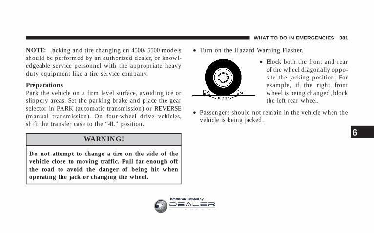
NOTE: Jacking and tire changing on 4500/5500 modelsshould be performed by an authorized dealer, or knowl-edgeable service personnel with the appropriate heavyduty equipment like a tire service company.
PreparationsPark the vehicle on a firm level surface, avoiding ice orslippery areas. Set the parking brake and place the gearselector in PARK (automatic transmission) or REVERSE(manual transmission). On four-wheel drive vehicles,shift the transfer case to the “4L” position.
WARNING!
Do not attempt to change a tire on the side of thevehicle close to moving traffic. Pull far enough offthe road to avoid the danger of being hit whenoperating the jack or changing the wheel.
• Turn on the Hazard Warning Flasher.
• Block both the front and rearof the wheel diagonally oppo-site the jacking position. Forexample, if the right frontwheel is being changed, blockthe left rear wheel.
• Passengers should not remain in the vehicle when thevehicle is being jacked.
WHAT TO DO IN EMERGENCIES 381
6
Information Provided by:

Instructions
WARNING!Carefully follow these tire changing warnings to helpprevent personal injury or damage to your vehicle:• Always park on a firm, level surface as far from
the edge of the roadway as possible before raisingthe vehicle.
• Block the wheel diagonally opposite the wheel tobe raised.
• Apply the parking brake firmly before jacking.• Never start the engine with the vehicle on a jack.• Do not let anyone sit in the vehicle when it is on a
jack.• Do not get under the vehicle when it is on a jack.• Only use the jack in the positions indicated.• If working on or near a roadway, be extremely
careful of motor traffic.
1. If equipped, remove the spare wheel, jack, and toolsfrom storage.
2. Using the wheel wrench, loosen, but do not remove,the wheel nuts by turning them counterclockwise oneturn while the wheel is still on the ground.
3. When changing the front wheel, assemble the jackdrive tube to the jack and connect the drive tube to theextension tube. Place the jack under the axle as close tothe tire as possible with the drive tubes extending to thefront. Connect the jack tube extension and wheel wrench.
382 WHAT TO DO IN EMERGENCIES
Information Provided by:

When changing a rear wheel, assemble the jack drivetube to the jack and connect the drive tube to theextension tube. Securely place the jack under the swaybar bracket (unless both tire’s are flat on one side, thenplace jack under shock bracket) facing forward in vehicle.Connect the jack tube extension and lug wrench.
Before raising the wheel off the ground, make sure thatthe jack will not damage surrounding truck parts andadjust the jack position as required.
NOTE: If the jack will not lower by turning the dial(thumb wheel) by hand, it may be necessary to use thejack drive tube in order to lower the jack.
WHAT TO DO IN EMERGENCIES 383
6
Information Provided by:
4. By rotating the wheel wrench clockwise, raise thevehicle until the wheel just clears the surface.
WARNING!
Raising the vehicle higher than necessary can makethe vehicle unstable and cause an accident. It couldslip off the jack and hurt someone near it. Raise thevehicle only enough to remove the tire.
5. Remove the wheel nuts and pull the wheel off. Installthe spare wheel and wheel nuts with the cone shaped endof the nuts toward the wheel on single rear wheel (SRW)models. On dual rear wheel models (DRW) the lug nutsare a two piece assembly with a flat face. Lightly tightenthe nuts. To avoid risk of forcing the vehicle off the jack,do not fully tighten the nuts until the vehicle has beenlowered.
6. Using the wheel wrench, finish tightening the nutsusing a crisscross pattern. Correct nut tightness is 135 ft.lbs. (183 N·m) torque for single rear wheel (SRW) modelsand 145 ft. lbs. (197 N·m) for dual rear wheel models. If indoubt about the correct tightness, have them checkedwith a torque wrench by your dealer or at a servicestation.
WARNING!
A loose tire or jack thrown forward in a collision orhard stop could injure someone in the vehicle. Al-ways stow the jack parts and the extra tire and wheelin the places provided.
7. Install wheel center cap (if equipped) and removewheel blocks. Do not install chrome or aluminum wheelcenter caps on the spare wheel. This may result in capdamage.
384 WHAT TO DO IN EMERGENCIES
Information Provided by:

8. Lower the jack to its fully closed position. If the jackwill not lower by turning the dial (thumb wheel) byhand, it may be necessary to use the jack drive tube inorder to lower the jack. Stow the replaced tire, jack, andtools as previously described.
9. Adjust the tire pressure when possible.
NOTE: Do not oil wheel studs. For chrome wheels, donot substitute with chrome plated wheel nuts.
Hub Caps/Wheel Covers — If EquippedThe hub caps must be removed before raising the vehicleoff the ground.
For single rear wheel (SRW) models, use the blade on theend of the lug wrench to pry the hub cap off. Insert theblade end into the pryoff notch and carefully pop off thehub cap with a back and forth motion.
On 3500 models with dual rear wheels (DRW), you mustfirst remove the hub caps. The jack handle driver has ahook at one end that will fit in the pry off notch of therear hub caps. Position the hook and pull out on theratchet firmly. The hub cap should pop off. The wheelskins can now be removed. For the front hub cap onmodels use the blade on the end of the lug wrench to prythe caps off. The wheel skin can now be removed.
CAUTION!
Use a back and forth motion to remove the hub cap.Do not use a twisting motion when removing the hubcap, damage to the hub cap finish may occur.
WHAT TO DO IN EMERGENCIES 385
6
Information Provided by:
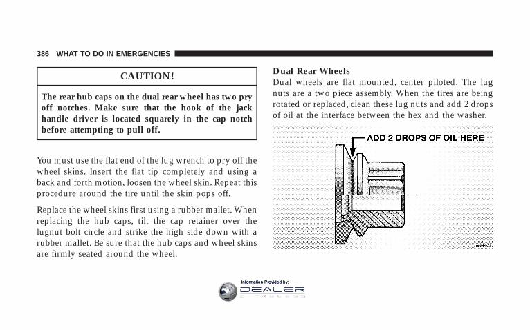
CAUTION!
The rear hub caps on the dual rear wheel has two pryoff notches. Make sure that the hook of the jackhandle driver is located squarely in the cap notchbefore attempting to pull off.
You must use the flat end of the lug wrench to pry off thewheel skins. Insert the flat tip completely and using aback and forth motion, loosen the wheel skin. Repeat thisprocedure around the tire until the skin pops off.
Replace the wheel skins first using a rubber mallet. Whenreplacing the hub caps, tilt the cap retainer over thelugnut bolt circle and strike the high side down with arubber mallet. Be sure that the hub caps and wheel skinsare firmly seated around the wheel.
Dual Rear WheelsDual wheels are flat mounted, center piloted. The lugnuts are a two piece assembly. When the tires are beingrotated or replaced, clean these lug nuts and add 2 dropsof oil at the interface between the hex and the washer.
386 WHAT TO DO IN EMERGENCIES
Information Provided by:

Slots in the wheels will assist in properly orienting theinner and outer wheels. Align these slots when assem-bling the wheels for best access to the tire valve on theinner wheel. The tires of both dual wheels must becompletely off the ground when tightening to insurewheel centering and maximum wheel clamping.
Dual wheel models require a special heavy-duty lug nuttightening adapter (included with the vehicle) to cor-rectly tighten the lug nuts. Also, when it is necessary toremove and install dual rear wheels, use a proper vehiclelifting device.
NOTE: When installing a spare tire (if equipped) as partof a dual rear wheel end combination, the tire diameter ofthe two individual tires must be compared. If there is asignificant difference, the larger tire should be installed ina front location. Correct direction of rotation for dual tireinstallations must also be observed.
These dual rear wheels should be tightened as follows:
WHAT TO DO IN EMERGENCIES 387
6
Information Provided by:
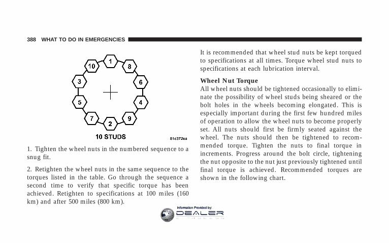
1. Tighten the wheel nuts in the numbered sequence to asnug fit.
2. Retighten the wheel nuts in the same sequence to thetorques listed in the table. Go through the sequence asecond time to verify that specific torque has beenachieved. Retighten to specifications at 100 miles (160km) and after 500 miles (800 km).
It is recommended that wheel stud nuts be kept torquedto specifications at all times. Torque wheel stud nuts tospecifications at each lubrication interval.
Wheel Nut TorqueAll wheel nuts should be tightened occasionally to elimi-nate the possibility of wheel studs being sheared or thebolt holes in the wheels becoming elongated. This isespecially important during the first few hundred milesof operation to allow the wheel nuts to become properlyset. All nuts should first be firmly seated against thewheel. The nuts should then be tightened to recom-mended torque. Tighten the nuts to final torque inincrements. Progress around the bolt circle, tighteningthe nut opposite to the nut just previously tightened untilfinal torque is achieved. Recommended torques areshown in the following chart.
388 WHAT TO DO IN EMERGENCIES
Information Provided by:
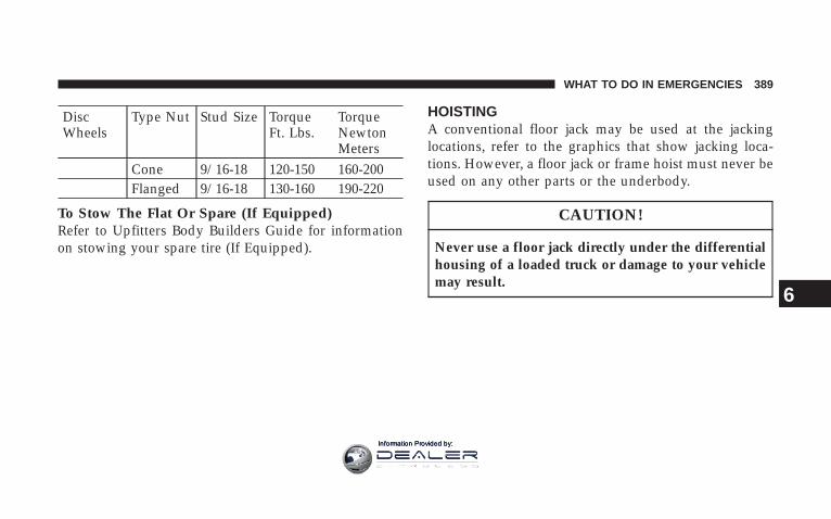
DiscWheels
Type Nut Stud Size TorqueFt. Lbs.
TorqueNewtonMeters
Cone 9/16-18 120-150 160-200Flanged 9/16-18 130-160 190-220
To Stow The Flat Or Spare (If Equipped)Refer to Upfitters Body Builders Guide for informationon stowing your spare tire (If Equipped).
HOISTINGA conventional floor jack may be used at the jackinglocations, refer to the graphics that show jacking loca-tions. However, a floor jack or frame hoist must never beused on any other parts or the underbody.
CAUTION!
Never use a floor jack directly under the differentialhousing of a loaded truck or damage to your vehiclemay result.
WHAT TO DO IN EMERGENCIES 389
6
Information Provided by:

JUMP-STARTING
WARNING!
To prevent personal injury or damage to clothing, donot allow battery fluid to contact eyes, skin or fabrics.Do not lean over a battery when connecting jumpercables or allow cable clamps to touch each other.Keep open flames or sparks away from battery ventholes. Always wear eye protection when workingwith batteries.
Do not use a booster battery or any other boostersource that has a greater than 12 volt system, i.e. donot use a 24 volt power source.
NOTE: Replacement batteries should both be of equalsize to prevent damage to the vehicles charging system.
Your vehicle is equipped with two 12–volt batteries. If itbecomes necessary to use a booster battery, with jumpercables, to start a vehicle’s engine because its batteries aredischarged, the following procedure should be followed:
Set the parking brake and place an automatic transmis-sion in PARK (or NEUTRAL for a manual transmission).Turn off lights, heater and other electrical loads. Observecharge indicator (if equipped) in both batteries. If indica-tor (if equipped) is light or yellow on either battery,replace that battery.
390 WHAT TO DO IN EMERGENCIES
Information Provided by:

CAUTION!
Use the Jump Start Procedure only when the chargeindicator (if equipped) in both batteries is dark in thecenter. Do not attempt jump starting when eitherbattery charge indicator (if equipped) is bright oryellow. If charge indicator (if equipped) has a greendot in the center, failure to start is not due to adischarged battery and cranking system should bechecked.
1. Attach one jumper cable to the positive terminal ofbooster battery and the other end of the same cable to thepositive terminal of the discharged battery.
WARNING!
Do not permit vehicles to touch each other as thiscould establish a ground connection and personalinjury could result.
WHAT TO DO IN EMERGENCIES 391
6
Information Provided by:

2. Connect one end of the other jumper cable to negative(-) post of booster battery. Connect the other end of thejumper cable to a good ground on the engine block of thevehicle with the discharged battery. Make sure a goodconnection is made, free of dirt and grease.
WARNING!
• Do not connect the cable to the negative post of thedischarge battery. The resulting electrical sparkcould cause the battery to explode.
• During cold weather when temperatures are be-low freezing point, electrolyte in a dischargedbattery may freeze. Do not attempt jump startingbecause the battery could rupture or explode. Thebattery temperature must be brought up abovefreezing point before attempting jump start.
3. Take care that the clamps from one cable do notinadvertently touch clamps from the other cable. Do notlean over the battery when making connection. Thenegative connection must provide good electrical con-ductivity and current carrying capacity.
4. After the engine is started or if the engine fails to start,cables must be disconnected in the following order:
a. Disconnect the negative cable at the engine ground.
b. Disconnect the negative cable at the negative poston booster battery.
c. Disconnect the cable from the positive post of bothbatteries.
392 WHAT TO DO IN EMERGENCIES
Information Provided by:

WARNING!
Any procedure other than above could result in:
1. Personal injury caused by electrolyte squirting outthe battery vent;
2. Personal injury or property damage due to batteryexplosion;
3. Damage to charging system of booster vehicle orof immobilized vehicle.
With Portable Starting UnitThere are many types of these units available. Follow themanufacturer’s instructions for necessary precautionsand operation.
CAUTION!
It is very important that the starting unit operatingvoltage does not exceed 12 Volts D.C. or damage tobattery, starter motor, alternator, or electrical systemmay occur.
FREEING A STUCK VEHICLEIf vehicle becomes stuck in snow, sand, or mud, it canoften be moved by a rocking motion. Move the gearselector rhythmically between DRIVE and REVERSE(automatic transmissions) and between 1st and RE-VERSE (manual transmissions), while applying slightpressure to the accelerator.
WHAT TO DO IN EMERGENCIES 393
6
Information Provided by:

In general, the least amount of accelerator pedal pressureto maintain the rocking motion without spinning thewheels or racing the engine is most effective. Racing theengine or spinning the wheels, due to the frustration ofnot freeing the vehicle, may lead to transmission over-heating and failure. Allow the engine to idle with thetransmission selector in NEUTRAL for at least oneminute after every five rocking-motion cycles. This willminimize overheating and reduce the risk of transmis-sion failure during prolonged efforts to free a stuckvehicle.
EMERGENCY TOW HOOKS — IF EQUIPPEDYour vehicle may be equipped with emergency towhooks.
NOTE: For off-road recovery, it is recommended to useboth of the front tow hooks to minimize the risk ofdamage to the vehicle.
WARNING!
Chains are not recommended for freeing a stuckvehicle. Chains may break, causing serious injury ordeath.
394 WHAT TO DO IN EMERGENCIES
Information Provided by:

WARNING!
Stand clear of vehicles when pulling with tow hooks.Tow straps and chains may break, causing seriousinjury.
CAUTION!
Tow hooks are for emergency use only, to rescue avehicle stranded off road. Do not use tow hooks fortow truck hookup or highway towing. You coulddamage your vehicle.
TOWING A DISABLED VEHICLEProper towing or lifting equipment is required to preventdamage to your vehicle. Use only tow bars and otherequipment designed for the purpose, following equip-ment manufacturer’s instructions. Use of safety chains ismandatory. Attach a tow bar or other towing device tothe main structural members of the vehicle—not tobumpers or associated brackets. State and local lawsapplying to vehicles under tow must be observed.
WHAT TO DO IN EMERGENCIES 395
6
Information Provided by:

4-Wheel- Drive Vehicles
CAUTION!
To avoid damage to the transfer case while towing,always use one of the following methods.
NOTE: The Transfer Case must be in the neutral posi-tion, and the transmission must be in Park (AutomaticTransmission), or in gear (Manual Transmission) to tow a4WD vehicle with one end of the vehicle raised.
The manufacturer recommends towing with all wheelsOFF the ground. Acceptable methods are to tow vehicleon a flatbed or with one end of vehicle raised and theopposite end on a towing dolly.
2–Wheel- Drive VehiclesProvided that transmission is operable, tow on a flatbedor with the front wheels raised and the rear wheels on adolly.
396 WHAT TO DO IN EMERGENCIES
Information Provided by:

MAINTAINING YOUR VEHICLE
CONTENTS
m Engine Compartment — 6.7L Diesel Engine . . . . 400
m Engine Compartment— 5.7L Gas Engine . . . . . . 401
m Onboard Diagnostic System (OBD II) . . . . . . . . . 402
▫ Loose Fuel Filler Cap Message . . . . . . . . . . . . 402
m Replacement Parts . . . . . . . . . . . . . . . . . . . . . . 403
m Engine Data Plate . . . . . . . . . . . . . . . . . . . . . . 403
m Dealer Service . . . . . . . . . . . . . . . . . . . . . . . . . 403
m Service Information . . . . . . . . . . . . . . . . . . . . . 404
m Maintenance Procedures . . . . . . . . . . . . . . . . . . 406
▫ Engine Oil . . . . . . . . . . . . . . . . . . . . . . . . . . 406
▫ Drive Belts (Gas Engines) . . . . . . . . . . . . . . . 413
▫ Drive Belt (Diesel Engines) . . . . . . . . . . . . . . 413
▫ Engine Air Cleaner Filter (Gas Engines) . . . . . 413
▫ Engine Air Cleaner Filter (Diesel Engines) . . . . 414
▫ Draining Fuel/Water Separator Filter (DieselEngines) . . . . . . . . . . . . . . . . . . . . . . . . . . . . 417
▫ Engine Fuel Filter (Gas Engines) . . . . . . . . . . . 420
▫ Spark Plugs (Gas Engines) . . . . . . . . . . . . . . . 420
7
Information Provided by:

▫ Catalytic Converter (Gas Engines) . . . . . . . . . 420
▫ Intervention Regeneration Strategy – EVICMessage Process Flow (Catalyst Full Message)(Diesel Engines Only) . . . . . . . . . . . . . . . . . . 422
▫ Emission-Related Components (Gas Engines) . . 425
▫ Maintenance Free Battery (Gas Engines) . . . . . 425
▫ Maintenance Free Batteries (Diesel Engines) . . . 426
▫ Air Conditioner Maintenance . . . . . . . . . . . . . 427
▫ Power Steering — Fluid Check . . . . . . . . . . . . 428
▫ Front Suspension Ball Joints . . . . . . . . . . . . . . 429
▫ Steering Linkage — Inspection . . . . . . . . . . . . 429
▫ Front Prop Shaft Lubrication . . . . . . . . . . . . . 430
▫ Front Axle Universal Drive Joints AndBall Joints . . . . . . . . . . . . . . . . . . . . . . . . . . . 430
▫ Body Lubrication . . . . . . . . . . . . . . . . . . . . . 430
▫ Windshield Wiper Blades . . . . . . . . . . . . . . . . 431
▫ Windshield Washers . . . . . . . . . . . . . . . . . . . 431
▫ Exhaust System . . . . . . . . . . . . . . . . . . . . . . 432
▫ Cooling System . . . . . . . . . . . . . . . . . . . . . . . 433
▫ Fan . . . . . . . . . . . . . . . . . . . . . . . . . . . . . . . 439
▫ Charge Air Cooler — Inter-Cooler(Diesel Engines) . . . . . . . . . . . . . . . . . . . . . . 439
▫ Hoses And Vacuum/Vapor Harnesses . . . . . . . 440
▫ Fuel System Connections . . . . . . . . . . . . . . . . 440
▫ Brake System . . . . . . . . . . . . . . . . . . . . . . . . 440
▫ Clutch Hydraulic System . . . . . . . . . . . . . . . . 443
▫ Clutch Linkage . . . . . . . . . . . . . . . . . . . . . . . 443
398 MAINTAINING YOUR VEHICLE
Information Provided by:
▫ Rear Axle And 4X4 Front Driving AxleFluid Level . . . . . . . . . . . . . . . . . . . . . . . . . . 443
▫ Transfer Case — If Equipped . . . . . . . . . . . . . 445
▫ Manual Transmission — If Equipped . . . . . . . 445
▫ Automatic Transmission (Gas Engine Only) . . . 446
▫ Automatic Transmission (Diesel EngineOnly) . . . . . . . . . . . . . . . . . . . . . . . . . . . . . . 448
▫ Front And Rear Wheel Bearings . . . . . . . . . . . 451
▫ Noise Control System Required Maintenance& Warranty . . . . . . . . . . . . . . . . . . . . . . . . . 451
▫ Appearance Care And Protection FromCorrosion . . . . . . . . . . . . . . . . . . . . . . . . . . . 457
m Fuses (Integrated Power Module) . . . . . . . . . . . 462
m Vehicle Storage . . . . . . . . . . . . . . . . . . . . . . . . 467
m Replacement Light Bulbs . . . . . . . . . . . . . . . . . 468
m Bulb Replacement . . . . . . . . . . . . . . . . . . . . . . 468
▫ Headlight (Halogen)/Front Park And TurnLights . . . . . . . . . . . . . . . . . . . . . . . . . . . . . 468
▫ Fog Lights . . . . . . . . . . . . . . . . . . . . . . . . . . 472
▫ Cab Top Clearance Lights — If Equipped . . . . 473
m Fluid And Capacities . . . . . . . . . . . . . . . . . . . . 474
m Fluids, Lubricants And Genuine Parts . . . . . . . . 476
▫ Engine . . . . . . . . . . . . . . . . . . . . . . . . . . . . . 476
▫ Chassis . . . . . . . . . . . . . . . . . . . . . . . . . . . . 478
MAINTAINING YOUR VEHICLE 399
7
Information Provided by:
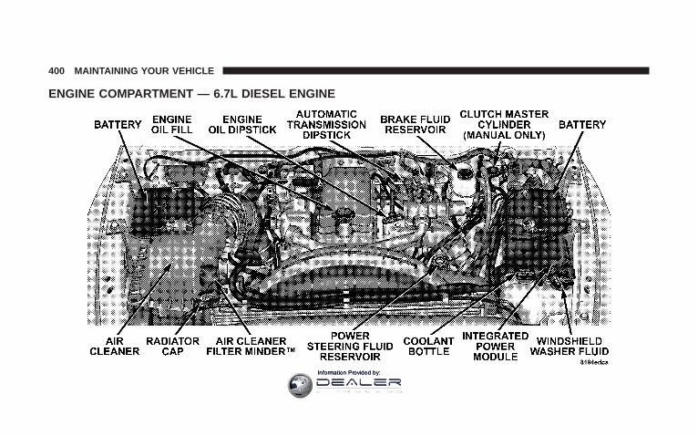
ENGINE COMPARTMENT — 6.7L DIESEL ENGINE
400 MAINTAINING YOUR VEHICLE
Information Provided by:

ENGINE COMPARTMENT— 5.7L GAS ENGINE
MAINTAINING YOUR VEHICLE 401
7
Information Provided by:
ONBOARD DIAGNOSTIC SYSTEM (OBD II)Vehicles equipped with California emissions controlshave a sophisticated onboard diagnostic system calledOBDII. This system monitors the performance of theemissions, engine, and automatic transmission controlsystems. When these systems are operating properly,your vehicle will provide excellent performance and fueleconomy, as well as engine emissions well within currentgovernment regulations.
If any of these systems require service, the OBD II systemwill turn on the “Malfunction Indicator Light.” It willalso store diagnostic codes and other information toassist your service technician in making repairs. Al-though your vehicle will usually be driveable and notneed towing, see your dealer for service as soon aspossible.
CAUTION!
Prolonged driving with the “Malfunction IndicatorLight” on could cause further damage to the emissioncontrol system. It could also affect fuel economy anddriveability. The vehicle must be serviced before anyemissions tests can be performed.
If the “Malfunction Indicator Light” is flashing,severe catalytic converter damage and power losswill soon occur. Immediate service is required.
Loose Fuel Filler Cap Message
If the vehicles diagnostic system determines that the fuelfiller cap in loose, improperly installed, or damaged, aGASCAP message will be displayed in the instrumentcluster. Tighten the gas cap until a “clicking” sound isheard. This is an indication that the gas cap is properly
402 MAINTAINING YOUR VEHICLE
Information Provided by:
tightened. Press the odometer reset button to turn themessage off. If the problem persists, the message willappear the next time the vehicle is started. This mightindicate a damaged cap. If the problem is detected twicein a row, the system will turn on the MalfunctionIndicator Light (MIL). Resolving the problem will turnthe MIL light off.
REPLACEMENT PARTSUse of genuine Mopart parts for normal/scheduledmaintenance and repairs is highly recommended to in-sure the designed performance. Damage or failurescaused by the use of non-Mopar parts for maintenanceand repairs will not be covered by the manufacturer’swarranty.
ENGINE DATA PLATEUse the information from the engine data plate whendiscussing service or sourcing parts for your engine. Theengine data plate is located on the intake side of thebreather cover.
DEALER SERVICEYour dealer has the qualified service personnel, specialtools and equipment to perform all service operations inan expert manner. Service manuals are available whichinclude detailed service information for your vehicle.Refer to these manuals before attempting any procedureyourself.
NOTE: Intentional tampering with emissions controlsystems can result in civil penalties being assessedagainst you.
MAINTAINING YOUR VEHICLE 403
7
Information Provided by:

WARNING!
You can be badly injured working on or around amotor vehicle. Do only that service work for whichyou have the knowledge and the proper equipment.If you have any doubt about your ability to performa service job, take your vehicle to a competentmechanic.
SERVICE INFORMATIONMopar Fluids, Lubricants and Parts are available fromyour dealer and will help you keep your vehicle operat-ing at its best. Your dealer also has the qualified servicepersonnel, special tools and equipment to perform allservice operations in an expert manner. Service manualsare available which include detailed service information
for your vehicle. Refer to these manuals before attempt-ing any procedure yourself. See Service Publicationsinformation at the back of this manual.
CAUTION!
To maintain your vehicle safely follow theseguidelines:
• Watch your vehicle’s mileage and check your Mainte-nance Schedules regularly for required servicing. Ex-cessive wear or damage to certain vehicle componentscan result if required services are not performed.
• If you have your vehicle undercoated, inspect forundercoating material on the propeller shafts. Suchmaterial could cause the shafts to become unbalancedand result in drivetrain vibrations. Remove any under-coating with solvent.
404 MAINTAINING YOUR VEHICLE
Information Provided by:

• If you have your vehicle undercoated, make sure noundercoating material is sprayed on the exhaust sys-tem or components of the seat belt system.
NOTE: It is not possible for the manufacturer andCummins, Inc. to anticipate every possible circumstancethat can involve a potential hazard.
WARNING!
To maintain your vehicle safely and avoid personalinjury, follow these guidelines:
• Never spray or pour diesel fuel, flammable liquid orstarting fluids (ether) into the air cleaner assembly, airintake piping or turbocharger inlet in an attempt tostart the vehicle, unintended engine acceleration mayoccur.
• Do not use alcohol or gasoline as a fuel blending agent.They can be unstable under certain conditions and behazardous or explosive when mixed with diesel fuel.
• If an engine has been operating and the coolant is hot,allow the engine to cool before you slowly loosen thefiller cap and relieve the pressure from the coolingsystem.
• To avoid burns, remember that the engine componentswill stay hot after the engine is shut off.
• Do not use gasoline or other flammable materials toclean parts. Always use approved cleaning solvents.
• Relieve all pressure in the fuel, oil and cooling systemsbefore any lines, fittings or related items are removedor disconnected. Be alert for possible pressure whendisconnecting any device from a system that utilizes
MAINTAINING YOUR VEHICLE 405
7
Information Provided by:

pressure. Do not check for pressure leaks with yourhand. High pressure oil or fuel can cause personalinjury.
WARNING!
Do not open the high pressure fuel system with theengine running. Engine operation causes high fuelpressure. High pressure fuel spray can cause seriousinjury or death.
• Important: All maintenance other than that listed inthis manual, as well as some procedures listed here,MUST be performed by your local Dodge TruckDealer. Your authorized Dodge Dealer has beentrained and has the necessary parts to maintain yourengine.
MAINTENANCE PROCEDURESThe pages that follow contain the required maintenanceservices determined by the engineers who designed yourvehicle.
Besides the maintenance items for which there are fixedmaintenance intervals, there are other items that shouldoperate satisfactorily without periodic maintenance.However, if a malfunction of these items does occur, itcould adversely affect the engine or vehicle performance.These items should be inspected if a malfunction isobserved or suspected.
Engine Oil
Checking Oil LevelTo assure proper lubrication of your vehicle’s engine, theengine oil must be maintained at the correct level. Checkthe oil level at regular intervals. The best time to checkthe oil level is before starting the engine after it has beenparked overnight. When checking oil after operating the
406 MAINTAINING YOUR VEHICLE
Information Provided by:
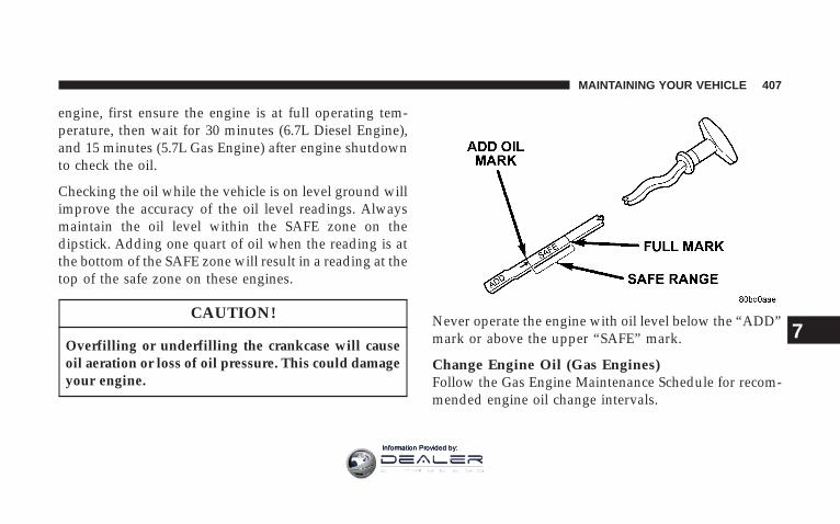
engine, first ensure the engine is at full operating tem-perature, then wait for 30 minutes (6.7L Diesel Engine),and 15 minutes (5.7L Gas Engine) after engine shutdownto check the oil.
Checking the oil while the vehicle is on level ground willimprove the accuracy of the oil level readings. Alwaysmaintain the oil level within the SAFE zone on thedipstick. Adding one quart of oil when the reading is atthe bottom of the SAFE zone will result in a reading at thetop of the safe zone on these engines.
CAUTION!
Overfilling or underfilling the crankcase will causeoil aeration or loss of oil pressure. This could damageyour engine.
Never operate the engine with oil level below the “ADD”mark or above the upper “SAFE” mark.
Change Engine Oil (Gas Engines)Follow the Gas Engine Maintenance Schedule for recom-mended engine oil change intervals.
MAINTAINING YOUR VEHICLE 407
7
Information Provided by:
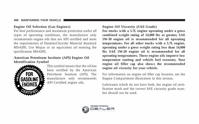
Engine Oil Selection (Gas Engines)For best performance and maximum protection under alltypes of operating conditions, the manufacture onlyrecommends engine oils that are API certified and meetthe requirements of DaimlerChrysler Material StandardMS-6395. Use Mopar or an equivalent oil meeting thespecification MS-6395.
American Petroleum Institute (API) Engine OilIdentification Symbol
This symbol means that the oil hasbeen certified by the AmericanPetroleum Institute (API). Themanufacture only recommendsAPI Certified engine oils.
Engine Oil Viscosity (SAE Grade)For trucks with a 5.7L engine operating under a grosscombined weight rating of 14,000 lbs or greater, SAE5W-30 engine oil is recommended for all operatingtemperatures. For all other trucks with a 5.7L engine,operating under a gross weight rating less than 14,000lbs SAE 5W-20 engine oil is recommended for alloperating temperatures. These engine oils improve lowtemperature starting and vehicle fuel economy. Yourengine oil filler cap also shows the recommendedengine oil viscosity for your vehicle.
For information on engine oil filler cap location, see theEngine Compartment illustration in this section.
Lubricants which do not have both, the engine oil certi-fication mark and the correct SAE viscosity grade num-ber should not be used.
408 MAINTAINING YOUR VEHICLE
Information Provided by:

Change Engine Oil (Diesel Engines)Follow the Diesel Maintenance Schedule for recom-mended engine oil change intervals.
Engine Oil Selection (Diesel Engines)For best performance and maximum protection under alltypes of operating conditions, the manufacture onlyrecommends engine oils that are API CJ-4 certified andmeet the requirements of DaimlerChrysler. Use Mopar oran equivalent oil meeting the specification MS-10902.Products meeting Cummins CES 20081 may also be used.The identification of these engine oils are typically lo-cated on the back of the oil container.
American Petroleum Institute (API) Engine OilIdentification Symbol
This symbol means that the oil hasbeen certified by the American Petro-leum Institute (API). The manufactureonly recommends API Certified en-gine oils.
Oils with a high ash content may produce deposits onvalves that can progress to guttering and valve burning.A maximum sulfated ash content of 1.00 mass % isrecommended for all oil used in the engine.
The same oil change interval is to be followed forsynthetic oil as for petroleum based oil. Also, synthetic oilmust meet the same performance specifications as petro-leum oil.
MAINTAINING YOUR VEHICLE 409
7
Information Provided by:

Engine Oil Viscosity (SAE Grade)Use SAE 15W-40 Engine Oil that meetsDaimlerChrysler Materials Standard MS-10902 and theAPI CJ-4 engine oil category.
Engine oil not designated by the DaimlerChrysler orCummins Material Standards and API CJ-4 should not beused, engine and exhaust system durability may becompromised. For lower temperature operation SAE5W-40 engine oils may be used. These oils must meet thesame requirements as stated previously. Your engine oilfiller cap also shows the recommended engine oil viscos-ity for your vehicle.
Synthetic Engine OilsYou may use synthetic engine oils provided the recom-mended oil quality requirements are met, and the recom-mended maintenance intervals for oil and filter changesare followed.
Materials Added to Engine OilThe manufacture strongly recommends against the addi-tion of any additives (other than leak detection dyes orlube odorants) to the engine oil. Engine oil is an engi-neered product and it’s performance may be impaired bysupplemental additives.
NOTE: The manufacturer offers a lube odorant (MoparDiesel Fresh) for diesel engines crankcases. The lubeodorant is recommended by the manufacturer to reducethe sulfur smell that may occur during engine idling.
Engine Oil FilterRefer to Fluids, Lubricants and Genuine Parts for thecorrect part number. The engine oil filter should bechanged at every engine oil change.
Engine Oil And Filter — ChangeOperate the engine until the coolant temperature reaches140°F (60°C). Shut the engine off. Remove the oil drainplug.
410 MAINTAINING YOUR VEHICLE
Information Provided by:
Use a container that can hold at least 12 quarts (11.3Liters) to hold the used oil.
Always check the condition of the used oil. This can giveyou an indication of some engine problems that mightexist.
• Thin, black oil indicates fuel dilution.
• Milky discoloration indicates coolant dilution.
Clean the area around the oil filter base. Remove the filterfrom the underside of the vehicle using a cap style oilfilter wrench.
Clean the gasket surface of the filter mount. The filtergasket can stick on the filter mount. Make sure it isremoved.
Change the engine oil filter with every engine oil change.
Only a high quality MOPAR filter should be used toassure most efficient service.
CAUTION!
The filtering medium of other aftermarket filtersmay disintegrate. Debris from failed filters may plugthe piston oil cooling nozzles, resulting in scuffedpistons and engine failure.
CAUTION!
Fill the oil filter element with clean oil before instal-lation. Use the same type oil that will be used in theengine. When filling the oil filter, prevent foreignmaterial from falling into the filter. Severe enginedamage may occur.
Apply a light film of lubricating oil to the sealing surfaceof the filter gasket before installing the filter.
MAINTAINING YOUR VEHICLE 411
7
Information Provided by:
CAUTION!
Overtightening may distort the threads or damagethe filter element seal.
Install the filter as specified by the filter manufacturer.Turn the filter 3/4 to one full turn after making contactwith the gasket.
Check the condition of the threads and sealing surface onthe oil pan and drain plug.
Install the drain plug and sealing washer and tighten to37 ft-lbs. (50 N·m).
Use only high-quality multi-grade lubricating oil in yourengine. Choose the correct oil for your operating condi-tions as outlined in the Selection of Engine Oil.
Fill the engine with the correct grade of new oil.
Start the engine and operate it at idle for several minutes.Check for leaks at the lubricating oil filter and oil pandrain plug.
Run the engine until it has reached operating tempera-ture, stop the engine. Wait approximately 15 minutes tolet the oil in the upper parts of the engine drain back tothe pan. Check the oil level again.
Add oil as necessary to bring the level to the “SAFE”mark on the dipstick.
Disposing Of Used Engine Oil And FilterCare should be taken in disposing of the used enginefluids from your vehicle. Used fluids, indiscriminatelydiscarded, can present a problem to the environment.Contact your local dealer, service station, or governmen-tal agency for advice on recycling programs and whereused fluids and filters can be safely discarded in yourarea.
412 MAINTAINING YOUR VEHICLE
Information Provided by:

Drive Belts (Gas Engines)Belt tension is controlled by means of an automatictensioner. No belt tension adjustments are required.However, belt and belt tensioner condition should beinspected at the specified intervals and replaced if re-quired. See your authorized dealer for service.
At the mileage indicated in the maintenance schedule, allbelts and tensioner should be checked for condition.Improper belt tension can cause belt slippage and failure.
Belts should be inspected for evidence of cuts, cracks,glazing or frayed cords and replaced if there is indicationof damage which could result in belt failure. Low gen-erator belt tension can cause battery failure.
Also check belt routing to make sure there is no interfer-ence between the belts and other engine components.
Drive Belt (Diesel Engines)
InspectionCheck the belt for intersecting cracks.
• Transverse (across the belt width) cracks are accept-able.
• Longitudinal (direction of belt length) cracks thatintersect with transverse cracks are NOT acceptable.
Replace the belt if it has unacceptable cracks, is frayed orhas pieces of material missing.
The engine speed sensor, located near the damper, shouldbe inspected for damage if a belt is frayed.
Engine Air Cleaner Filter (Gas Engines)Follow the appropriate Maintenance Schedule for recom-mended Air Cleaner Replacement intervals.
MAINTAINING YOUR VEHICLE 413
7
Information Provided by:

WARNING!
The air induction system (air cleaner, hoses, etc) canprovide a measure of protection in the case of enginebackfire. Do not remove the air induction system (aircleaner, hoses, etc) unless such removal is necessaryfor repair or maintenance. Make sure that no one isnear the engine compartment before starting thevehicle with the air induction system (air cleaner,hoses, etc) removed. Failure to do so can result inserious personal injury.
Engine Air Cleaner Filter (Diesel Engines)
CAUTION!
All air entering the engine intake must be filtered.The abrasive particles in unfiltered air will causerapid wear to engine components.
The air filter housing on your Diesel Ram is equippedwith a Filter Minder™. This is an air flow restrictiongauge that will indicate when the filter element needs tobe replaced.
Do not remove the top of the air filter housing toinspect the filter element on your diesel engine undernormal operating conditions.
NOTE: The air filter housing contains a Mass Air Flowsensor. This sensor is critical to proper engine operationand component longevity. Any damage or modification
414 MAINTAINING YOUR VEHICLE
Information Provided by:

to this sensor could result in major engine and/orexhaust aftertreatment damage. This includes the use ofnon-approved air filters. Use only MOPARt approved airfilters or equivalent.
The clear plastic housing on the Filter Minder™ allowsyou to view the amount of air pressure drop across thefilter element. It consists of a diaphragm and a calibrated
spring sealed inside the plastic housing. As the aircleaner filter becomes clogged and air pressure dropacross the filter element increases, a yellow disc travelsalong a graduated scale on the side of the FilterMinder™.
The yellow disc will always show the greatest restrictionexperienced by the filter element. When the disc reachesthe red zone, the filter element may need to be replaced.There is no other time or mileage interval for changingthe air cleaner filter element.
If the vehicle experiences a sudden loss of engine powerwhen being driven in heavy snow or rain or whenplowing snow, check the Filter Minder™
• If the Filter Minder™ is showing a plugged filter, thefilter should be visually inspected for snow/ice buildup or extreme water saturation.
MAINTAINING YOUR VEHICLE 415
7
Information Provided by:

• If the filter is not damaged, remove all snow/ice,reinstall filter and reset the Filter Minder™.
A visual inspection of the air cleaner filter element isnever recommended under normal circumstances. Abadly restricted element may appear clean while a soiledelement may be quite effective in filtering particleswithout restricting air flow. Rely on the Filter Minder™to determine when a filter change is necessary.
After a new filter element is inserted, press the rubberbutton on the top of the Filter Minder™. This action willreset the yellow disc to the clean position.
CAUTION!
When using an engine cleaner or a degreaser, be sureto wrap and tape the Filter Minder™ to protect theplastic housing from damage and discoloration.
CAUTION!
Many aftermarket performance air filter elements donot adequately filter the air entering the engine. Useof such filters can severely damage your engine.
416 MAINTAINING YOUR VEHICLE
Information Provided by:

Draining Fuel/Water Separator Filter (DieselEngines)
CAUTION!
Do not drain the fuel/water separator filter when theengine is running.
CAUTION!
Do not prefill the fuel filter when installing a newfuel filter. There is a possibility debris could beintroduced into the fuel filter during this action. It isbest to install the filter dry and allow the in-tank liftpump to prime the fuel system.
NOTE: The fuel filter and water separator assembly islocated on the driver’s side of the engine. The best accessto the water drain valve is through the driver’s sidewheel well.
NOTE: Care should be taken in disposing of used fluidsfrom your vehicle. Used fluids, indiscriminately dis-carded, can present a problem to the environment. Con-tact your local dealer, service station, or government
MAINTAINING YOUR VEHICLE 417
7
Information Provided by:
agency for advice on recycling programs and for whereused fluids and filters can be properly disposed of inyour area.
Drain a small amount from the fuel/water separatorfilter monthly or when the WATER IN FUEL indicatorlamp is on. Turn the drain valve, located on the bottom ofthe filter, counterclockwise and allow any accumulatedwater to drain. Leave the drain valve open until all waterand contaminants have been removed. Close the drainvalve, by turning it clockwise, when clean fuel is visible.
NOTE: The Fuel / Water separator drain valve islocated on the bottom of the fuel filter housing.
If more than a couple ounces of fuel has been drained,follow the directions below for “Priming if the engine hasrun out of fuel.”
WARNING!
Do not open the high pressure fuel system with theengine running. Engine operation causes high fuelpressure. High pressure fuel spray can cause seriousinjury or death.
Priming if the engine has run out of fuel
1. Add a substantial quantity of fuel to the tank 5 to 10gallons (19L to 38L).
2. Crank the engine for 1 to 2 seconds. If the engine doesnot start, then release the key or starter button back to theRUN position (do not turn the key back to the OFFposition). The electric fuel transfer pump will continue torun and purge air from the system for about 25 seconds.After 25 seconds, attempt to start the engine again.
3. Start the engine using the Normal Starting Procedure.
418 MAINTAINING YOUR VEHICLE
Information Provided by:

4. Repeat the procedure if the engine does not start.
CAUTION!
Do not engage the starter motor for more than 15seconds at a time. Allow two minutes between thecranking intervals.
NOTE: The engine may run rough until the air is forcedfrom all the fuel lines.
CAUTION!
Diesel fuel will damage black top paving surfaces.Drain the filter into an appropriate container.
WARNING!
Do not use alcohol or gasoline as a fuel blendingagent. They can be unstable under certain conditionsand be hazardous or explosive when mixed withdiesel fuel.
CAUTION!
Due to lack of lubricants in alcohol or gasoline, theuse of these fuels can cause damage to the fuelsystem.
NOTE: A maximum blend of 5% biodiesel, meetingASTM specification D-6751 may be used with yourCummins Diesel equipped vehicle. Use of bio-diesel
MAINTAINING YOUR VEHICLE 419
7
Information Provided by:

mixture in excess of 5% can negatively impact the on-engine fuel filter’s ability to separate water from the fuel,resulting in high pressure fuel system corrosion or dam-age.
NOTE: As sufficient testing has not been completed,ethanol blends are not recommended or approved for usewith your Cummins Diesel equipped vehicle.
NOTE: In addition, commercially available fuel addi-tives are not necessary for the proper operation of yourCummins Diesel equipped vehicle.
Engine Fuel Filter (Gas Engines)A plugged fuel filter can cause stalling, limit the speed atwhich a vehicle can be driven or cause hard starting.Should an excessive amount of dirt accumulate in thefuel tank, frequent filter replacement may be necessary.
Spark Plugs (Gas Engines)Spark plugs must fire properly to assure engine perfor-mance and emission control. New plugs should be in-stalled at the specified mileage. The entire set should bereplaced if there is any malfunction due to a faulty sparkplug, malfunctioning spark plugs can damage the cata-lytic converter. For proper type of replacement sparkplugs, refer to the Fluids, Lubricants and Genuine Partssection in this manual.
Catalytic Converter (Gas Engines)The catalytic converter requires the use of unleaded fuelonly. Leaded gasoline will destroy the effectiveness of thecatalyst as an emission control device.
Under normal operating conditions, the catalytic con-verter will not require maintenance. However, it is im-portant to keep the engine properly tuned to assureproper catalyst operation and prevent possible catalystdamage.
420 MAINTAINING YOUR VEHICLE
Information Provided by:

CAUTION!
Damage to the catalytic converter can result if yourvehicle is not kept in proper operating condition. Inthe event of engine malfunction, particularly involv-ing engine misfire or other apparent loss of perfor-mance, have your vehicle serviced promptly. Contin-ued operation of your vehicle with a severemalfunction could cause the converter to overheat,resulting in possible damage to the converter and thevehicle.
NOTE: Intentional tampering with emissions controlsystems can result in civil penalties being assessedagainst you.
WARNING!
A hot exhaust system can start a fire if you park overmaterials that can burn. Such materials might begrass or leaves coming into contact with your exhaustsystem. Do not park or operate your vehicle in areaswhere your exhaust system can contact anything thatcan burn.
In unusual situations involving grossly malfunctioningengine operation, a scorching odor may indicate severeand abnormal catalyst overheating. If this occurs, thevehicle should be stopped, the engine shut off and thevehicle allowed to cool. Thereafter, service, including atune-up to manufacturer’s specifications, should be ob-tained immediately.
MAINTAINING YOUR VEHICLE 421
7
Information Provided by:

To minimize the possibility of catalyst damage:
• Do not shut off the engine or interrupt the ignitionwhen the transmission is in gear and the vehicle is inmotion.
• Do not try to start engine by pushing or towing thevehicle.
• Do not idle the engine with any spark plug wiresdisconnected or removed, such as when diagnostictesting, or for prolonged periods during very roughidling or malfunctioning operating conditions.
Intervention Regeneration Strategy – EVICMessage Process Flow (Catalyst Full Message)(Diesel Engines Only)Your new Cummins 6.7L diesel meets all EPA HeavyDuty Diesel Engine Emissions Standards, resulting in thelowest emitting diesel engine ever produced.
To achieve these emission standards your vehicle isequipped with state of the art engine and exhaust system.The engine and exhaust aftertreatment system worktogether to achieve the EPA Heavy Duty Diesel EngineEmissions Standards. These systems are seamlessly inte-grated into your vehicle and managed by the Cummins6.7L engine Powertrain Control Module (PCM). The PCMmanages engine combustion to allow the exhaust sys-tem’s catalyst to trap and burn Particulate Matter (PM)pollutants, with no input or interaction on your part.
Additionally, the overhead console in your vehicle hasthe ability to alert you to additional maintenance re-quired on your truck or engine. Refer to the followingmessages that may be displayed on your ElectronicVehicle Information Center (EVIC):
422 MAINTAINING YOUR VEHICLE
Information Provided by:

WARNING!
A hot exhaust system can start a fire if you park overmaterials that can burn. Such materials might begrass or leaves coming into contact with your exhaustsystem. Do not park or operate your vehicle in areaswhere your exhaust system can contact anything thatcan burn.
Service CCV FilterThe 6.7L Cummins engine utilizes a Closed CrankcaseVentilation (CCV) system. This system filters and recyclesgasses produced in the crankcase during the normalcombustion process. Service CCV Filter will be displayedon the overhead console of your Dodge truck if the CCVfilter is due for required maintenance. This filter islocated on the top of the engine valve cover. For addi-tional information, see your Dodge truck dealer.
Catalyst Full See Owner ManualCatalyst Full See Owner Manual will be displayed on theoverhead console of your vehicle if the exhaust particu-late filter reaches 80% of its maximum storage capacity.Under conditions of exclusive short duration and lowspeed driving cycles, your Cummins engine and exhaustaftertreatment system may never reach the conditionsrequired to remove the trapped PM, if this occurs Cata-lyst Full See Owner Manual will be displayed on theoverhead console in your vehicle. If this message isdisplayed you will hear one chime to assist in alertingyou of this condition.
Catalyst Stat::::::::::80%Catalyst Stat::::::::::80% will replace the message CatalystFull See Owner Manual after it is displayed for oneminute. The engine Powertrain Control Module (PCM)will continue to monitor the amount of particulate matter
MAINTAINING YOUR VEHICLE 423
7
Information Provided by:
trapped in the particulate filter. This message indicatesthe percentage of the particulate filter capacity that hasbeen used.
By simply driving your vehicle at highway speeds for aslittle as 45 minutes you can remedy the condition in theparticulate filter system and allow your Cummins engineand exhaust Aftertreatment system to remove thetrapped PM and restore the system to normal operatingcondition.
Catalyst Stat:::::::::::80%, 90%, 99%Catalyst Stat:::::::::::80%, 90%, 99% If you are unable todrive your vehicle under these conditions for an ex-tended period of time after the initial warning notifica-tion, the Engine PCM will continue to monitor theparticulate filter and will display the progression ofparticulate filter usage (80, 90, 99%) on the EVIC messagecenter.
CATALYST FULL SERVICE REQDIf the particulate filter reaches 99% of it’s capacity theoverhead console in your vehicle will chime twice anddisplay the message CATALYST FULL SERVICE REQD.At this point the engine PCM will register a fault code,the instrument panel will display a MIL light and theengine PCM will derate the truck reducing its horse-power and torque output.
The PCM derates the engine in order to limit the likeli-hood of permanent damage to the aftertreatment system.If this condition is not corrected and a dealer service isnot performed, extensive exhaust aftertreatment damagecan occur. In order to correct this condition it will benecessary to have the truck serviced by your localauthorized dealer.
424 MAINTAINING YOUR VEHICLE
Information Provided by:

Emission-Related Components (Gas Engines)
Positive Crankcase (PCV) ValveProper operation of the crankcase ventilation systemrequires that the PCV valve be free of sticking or plug-ging from deposits. Deposits can accumulate in the PCVvalve and passages with increasing mileage. Have thePCV valve, hoses, and passages checked for properoperation at the intervals specified. If the valve isplugged or sticking, replace with a new valve— do notattempt to clean the old PCV valve! Check the ventila-tion hoses for indications of damage, weepage or plug-ging with deposits. Replace if necessary.
Maintenance Free Battery (Gas Engines)The top of the maintenance free battery is permanentlysealed. You will never have to add water, nor is periodicmaintenance required.
WARNING!
• Battery fluid is a corrosive acid solution and canburn or even blind you. Don’t allow battery fluidto contact your eyes, skin or clothing. Don’t leanover a battery when attaching clamps. If acidsplashes in eyes or on skin, flush the area imme-diately with large amounts of water.
• Battery gas is flammable and explosive. Keepflame or sparks away from the battery. Don’t use abooster battery or any other booster source with anoutput greater than 12 volts. Don’t allow cableclamps to touch each other.
• Battery posts, terminals and related accessoriescontain lead and lead compounds. Wash handsafter handling.
MAINTAINING YOUR VEHICLE 425
7
Information Provided by:

CAUTION!
• It is essential when replacing the cables on thebattery that the positive cable is attached to thepositive post and the negative cable is attached tothe negative post. Battery posts are marked (+)positive and negative (-) and identified on thebattery case.
• If a “fast charger” is used while battery is invehicle, disconnect both vehicle battery cablesbefore connecting the charger to battery. Do notuse a “fast charger” to provide starting voltage.
Maintenance Free Batteries (Diesel Engines)The top of the maintenance free batteries are perma-nently sealed. You will never have to add water, nor isperiodic maintenance required.
NOTE: Replacement batteries should both be of equalcapacity to prevent damage to the vehicle’s chargingsystem.
426 MAINTAINING YOUR VEHICLE
Information Provided by:

CAUTION!
It is essential when replacing the cables on thebattery that the positive cable is attached to thepositive post and the negative cable is attached to thenegative post. Battery posts are marked (+) positiveand negative (-) and identified on the battery case.Also, if a “fast charger” is used while battery is invehicle, disconnect both vehicle battery cables beforeconnecting the charger to battery. Do not use a “fastcharger” to provide starting voltage.
WARNING!
Battery posts, terminals, and related accessories con-tain lead and lead compounds. Always wash handsafter handling the battery.
Battery Blanket UsageA battery loses 60% of its cranking power as the batterytemperature decreases to 0°F (-18°). For the same de-crease in temperature, the engine requires twice as muchpower to crank at the same RPM. The use of 120 VACpowered battery blankets will greatly increase startingcapability at low temperatures. Suitable battery blanketsare available from your authorized Mopart dealer.
Air Conditioner MaintenanceFor best possible performance, your air conditionershould be checked and serviced by an Authorized Dealerat the start of each warm season. This service shouldinclude cleaning of the condenser fins and a performancetest. Drive belt tension should also be checked at thistime.
NOTE: Refer to Section 3 of the Warranty Informationbook for further warranty information.
MAINTAINING YOUR VEHICLE 427
7
Information Provided by:

WARNING!
• Use only refrigerants and compressor lubricantsapproved by the manufacturer for your air condi-tioning system. Some unapproved refrigerants areflammable and can explode, injuring you. Otherunapproved refrigerants or lubricants can causethe system to fail, requiring costly repairs. Refer toSection 3 of the Warranty Information book forfurther warranty information.
• The air conditioning system contains refrigerantunder high pressure. To avoid risk of personalinjury or damage to the system, adding refrigerantor any repair requiring lines to be disconnectedshould be done by an experienced repairman.
Refrigerant Recovery and RecyclingR-134a Air Conditioning Refrigerant is a hydrofluorocar-bon (HFC) that is endorsed by the Environmental Pro-tection Agency and is an ozone-saving product. How-ever, the manufacturer recommends that air conditioningservice be performed by dealers or other service facilitiesusing recovery and recycling equipment.
Power Steering — Fluid CheckChecking the power steering fluid level at a definedservice interval is not required. The fluid should only bechecked if a leak is suspected, abnormal noises areapparent, and/or the system is not functioning as antici-pated. Coordinate inspection efforts through a certifiedDaimlerChrysler Dealership.9
428 MAINTAINING YOUR VEHICLE
Information Provided by:

WARNING!
Fluid level should be checked on a level surface andwith the engine off to prevent injury from movingparts and to insure accurate fluid level reading. Donot overfill. Use only manufacturers recommendedpower steering fluid.
If necessary, add fluid to restore to the proper indicatedlevel. With a clean cloth, wipe any spilled fluid from allsurfaces. Refer to Fluids, Lubricants, and Genuine Partsfor correct fluid type.
Front Suspension Ball JointsThe ball joints originally supplied with the vehicle arepermanently lubricated at the factory and do not requireservice. The ball joints and seals should be inspectedwhenever the vehicle is serviced for other reasons.
Steering Linkage — InspectionWhenever the vehicle is hoisted, all steering linkagejoints should be inspected for evidence of damage. Ifseals are damaged, parts should be replaced to preventleakage or contamination of the grease.
MAINTAINING YOUR VEHICLE 429
7
Information Provided by:
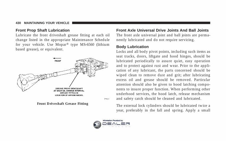
Front Prop Shaft LubricationLubricate the front driveshaft grease fitting at each oilchange listed in the appropriate Maintenance Schedulefor your vehicle. Use Mopart type MS-6560 (lithiumbased grease), or equivalent.
Front Axle Universal Drive Joints And Ball JointsThe front axle universal joint and ball joints are perma-nently lubricated and do not require servicing.
Body LubricationLocks and all body pivot points, including such items asseat tracks, doors, liftgate and hood hinges, should belubricated periodically to assure quiet, easy operationand to protect against rust and wear. Prior to the appli-cation of any lubricant, the parts concerned should bewiped clean to remove dust and grit; after lubricatingexcess oil and grease should be removed. Particularattention should also be given to hood latching compo-nents to insure proper function. When performing otherunderhood services, the hood latch, release mechanismand safety catch should be cleaned and lubricated.
The external lock cylinders should be lubricated twice ayear, preferably in the fall and spring. Apply a small
Front Driveshaft Grease Fitting
430 MAINTAINING YOUR VEHICLE
Information Provided by:

amount of a high quality lubricant such as Mopart LockCylinder Lubricant directly into the lock cylinder.
Windshield Wiper BladesThe rubber edges of the wiper blades and the windshieldshould be cleaned periodically with a sponge or soft clothand a mild nonabrasive cleaner. This will remove accu-mulations of salt or road film.
Operation of the wipers on dry glass for long periodsmay cause deterioration of the wiper blades. Always usewasher fluid when using the wipers to remove salt or dirtfrom a dry windshield.
Avoid using the wiper blades to remove frost or ice fromthe windshield. Keep the blade rubber out of contact withpetroleum products such as engine oil, gasoline, etc.
Windshield WashersThe fluid reservoir is located under the hood and shouldbe checked for fluid level at regular intervals. Fill thereservoir with windshield washer solvent only (not ra-diator antifreeze).
When refilling the washer fluid reservoir, take somewasher fluid and apply it to a cloth or towel and wipeclean the wiper blades, this will help blade performance.
To prevent freeze-up of your windshield washer systemin cold weather, select a solution or mixture that meets orexceeds the temperature range of your climate. Thisrating information can be found on most washer fluidcontainers.
MAINTAINING YOUR VEHICLE 431
7
Information Provided by:

WARNING!
Commercially available windshield washer solventsare flammable. They could ignite and burn you. Caremust be exercised when filling or working aroundthe washer solution.
After the engine has warmed, operate the defroster for afew minutes to reduce the possibility of smearing orfreezing the fluid on the cold windshield. Mopar AllWeather Windshield Washer Solution, used with water asdirected on the container, aids cleaning action, reducesthe freezing point to avoid line clogging, and is notharmful to paint or trim.
Exhaust SystemThe best protection against carbon monoxide entry intothe vehicle body is a properly maintained engine exhaustsystem.
Whenever a change is noticed in the sound of the exhaustsystem, when exhaust fumes can be detected inside thevehicle, or when the underside or rear of the vehicle isdamaged, have a competent mechanic inspect the com-plete exhaust system and adjacent body areas for broken,damaged, deteriorated, or mispositioned parts. Openseams or loose connections could permit exhaust fumesto seep into the passenger compartment. In addition,inspect the exhaust system each time the vehicle is raisedfor lubrication or oil change. Replace parts as required.
432 MAINTAINING YOUR VEHICLE
Information Provided by:

WARNING!
Exhaust gases can injure or kill. They contain carbonmonoxide (CO) which is colorless and odorless.Breathing it can make you unconscious and caneventually poison you. To avoid breathing CO, fol-low the preceding safety tips.
Exhaust System Rubber Isolator and Loop-TypeHanger — If EquippedInspect surfaces whenever the vehicle is hoisted forrubber to metal separation or deep cracks. If, however,excessively deep localized cracks are present, or any partof the exhaust system abnormally contacts the under-body hardware, the isolator and/or hanger should bereplaced.
Cooling System
WARNING!
You or others can be badly burned by hot coolant orsteam from your radiator. If you see or hear steamcoming from under the hood, don’t open the hooduntil the radiator has had time to cool. Never try toopen a cooling system pressure cap when the radiatoris hot.
Engine Coolant ChecksCheck the engine coolant (antifreeze) protection every 12months (before the onset of freezing weather, whereapplicable). If coolant is dirty or rusty in appearance, thesystem should be drained, flushed and refilled with freshcoolant. Check the front of the A/C condenser for any
MAINTAINING YOUR VEHICLE 433
7
Information Provided by:

accumulation of bugs, leaves, etc. If dirty, clean by gentlyspraying water from a garden hose vertically down theface of the condenser.
Check the coolant recovery bottle tubing for brittle rub-ber, cracking, tears, cuts and tightness of the connectionat the bottle and radiator. Inspect the entire system forleaks.
Extremely cold ambient temperature may require theaddition of a “winter front” for effective operation of thecab heating/cooling system. Make certain that a percent-age of the radiator is exposed for adequate air flowthrough the charge air cooler and automatic transmissionoil cooler. The percentage of opening must be increasedwith the increasing ambient air temperature and/orengine load. If the cooling fan can be heard cyclingfrequently, increase the size of the opening in the winterfront.
Coolant bottle level checkThe coolant reserve system provides a quick visualmethod of determining that the coolant level is adequate.With the engine idling, and warmed to the normaloperating temperature, the level of the coolant on thecoolant bottle should be between the fluid level marks.Check the coolant level whenever the hood is raised.
The radiator normally remains completely full, so there isno longer a need to remove the coolant pressure capexcept for checking coolant freeze point or replacementwith new antifreeze coolant.
WARNING!
Never add coolant to the radiator when the engine isoverheated. Do not loosen or remove pressure cap tocool overheated engine! The coolant is under pres-sure and severe scalding could result.
434 MAINTAINING YOUR VEHICLE
Information Provided by:
Cooling System — Drain, Flush and RefillAt the intervals shown on the Maintenance Schedules,the system should be drained, flushed and refilled.
If the solution is dirty or contains a considerable amountof sediment, clean and flush with a reliable coolingsystem cleaner. Follow with a thorough rinsing to removeall deposits and chemicals. Properly dispose of oldantifreeze solution.
Selection Of CoolantUse only the manufacturers recommended coolant, referto Fluids, Lubricants and Genuine Parts for correctcoolant type.
CAUTION!
Mixing of coolants other than specified HOAT en-gine coolants, may result in engine damage and maydecrease corrosion protection. If a non-HOAT coolantis introduced into the cooling system in an emer-gency, it should be replaced with the specified cool-ant as soon as possible.
Do not use plain water alone or alcohol base enginecoolant (antifreeze) products. Do not use additionalrust inhibitors or antirust products, as they may notbe compatible with the radiator engine coolant andmay plug the radiator.
This vehicle has not been designed for use withPropylene Glycol based coolants. Use of PropyleneGlycol based coolants is not recommended.
MAINTAINING YOUR VEHICLE 435
7
Information Provided by:
Adding CoolantYour vehicle has been built with an improved enginecoolant that allows extended maintenance intervals. Thiscoolant can be used up to 5 Years or 100,000 miles beforereplacement. To prevent reducing this extended mainte-nance period, it is important that you use the samecoolant throughout the life of your vehicle. Please reviewthese recommendations for using Hybrid Organic Addi-tive Technology (HOAT) coolant.
When adding coolant, a minimum solution of 50% rec-ommended Mopar Antifreeze/ Coolant 5 Year/100,000Mile Formula HOAT (Hybrid Organic Additive Technol-ogy), or equivalent, in water should be used. Use higherconcentrations (not to exceed 70%) if temperatures below234°F (237°C ) are anticipated.
Use only high purity water such as distilled or deionizedwater when mixing the water/engine coolant solution.
The use of lower quality water will reduce the amount ofcorrosion protection in the engine cooling system.
Please note that it is the owner’s responsibility to main-tain the proper level of protection against freezing ac-cording to the temperatures occurring in the area wherethe vehicle is operated.
NOTE: Mixing coolant types will decrease the life of theengine coolant and will require more frequent coolantchanges.
Cooling System Pressure CapThe cap must be fully tightened to prevent loss ofcoolant, and to insure that coolant will return to theradiator from the coolant recovery bottle.
The cap should be inspected and cleaned if there is anyaccumulation of foreign material on the sealing surfaces.
436 MAINTAINING YOUR VEHICLE
Information Provided by:

WARNING!
• The warning words “DO NOT OPEN HOT” onthe cooling system pressure cap are a safety pre-caution. Never add coolant when the engine isoverheated. Do not loosen or remove the cap tocool an overheated engine. Heat causes pressure tobuild up in the cooling system. To prevent scald-ing or injury, do not remove the pressure cap whilethe system is hot or under pressure.
• Do not use a pressure cap other than the onespecified for your vehicle. Personal injury or en-gine damage may result.
Disposal Of Used Engine CoolantUsed ethylene glycol based engine coolant is a regulatedsubstance requiring proper disposal. Check with yourlocal authorities to determine the disposal rules for your
community. Do not store ethylene glycol-based enginecoolant in open containers or allow it to remain inpuddles on the ground. Prevent ingestion by animals andchildren. If ingested by a child, contact a physicianimmediately. Clean up any ground spills immediately.
Coolant LevelThe coolant bottle provides a quick visual method fordetermining that the coolant level is adequate. With theengine cold, the level of the coolant in the coolantrecovery bottle should be between the ranges indicatedon the bottle.
The radiator normally remains completely full, so there isno need to remove the radiator cap unless checking forcoolant freeze point or replacing coolant. Advise yourservice attendant of this. As long as the engine operatingtemperature is satisfactory, the coolant bottle need onlybe checked once a month.
MAINTAINING YOUR VEHICLE 437
7
Information Provided by:

When additional coolant is needed to maintain theproper level, it should be added to the coolant bottle. Donot overfill.
Points To Remember
NOTE: When the vehicle is stopped after a few miles (afew kilometers) of operation, you may observe vaporcoming from the front of the engine compartment. This isnormally a result of moisture from rain, snow, or highhumidity accumulating on the radiator and being vapor-ized when the thermostat opens, allowing hot coolant toenter the radiator.
If an examination of your engine compartment shows noevidence of radiator or hose leaks, the vehicle may besafely driven. The vapor will soon dissipate.
• Do not overfill the coolant recovery bottle.
• Check coolant freeze point in the radiator and in thecoolant recovery bottle. If antifreeze needs to beadded, contents of coolant recovery bottle must also beprotected against freezing.
• If frequent coolant additions are required, or if thelevel in the coolant recovery bottle does not drop whenthe engine cools, the cooling system should be pres-sure tested for leaks.
• Maintain coolant concentration at 50% HOAT enginecoolant (minimum) and distilled water for propercorrosion protection of your engine which containsaluminum components.
• Make sure that the radiator and coolant recoverybottle overflow hoses are not kinked or obstructed.
• Keep the front of the radiator clean. If your vehicle isequipped with air conditioning, keep the front of thecondenser clean, also.
438 MAINTAINING YOUR VEHICLE
Information Provided by:
• Do not change the thermostat for summer or winteroperation. If replacement is ever necessary, installONLY the correct type thermostat. Other designs mayresult in unsatisfactory coolant performance, poor gasmileage, and increased emissions.
Fan
InspectionCheck the fan for cracks and bent or broken blades. If anyof these conditions exist, you must replace the fan. Makesure it is securely mounted.
NOTE: This service procedure must be performed by atrained service technician. Make arrangements with yourauthorized Dodge Truck Dealer for this inspection.
Charge Air Cooler — Inter-Cooler (DieselEngines)The charge air cooler is positioned between the radiatorand the air conditioner condenser. Air enters the enginethrough the air cleaner and passes through the turbo-charger where it is pressurized. This pressurized airrapidly reaches high temperature. The air is then directedthrough a hose to the charge air cooler and throughanother hose to the intake manifold of the engine. The airentering the engine has been cooled by about 50 to 100degrees Fahrenheit. This cooling process enables moreefficient burning of fuel resulting in fewer emissions.
To guarantee optimum performance of the system, keepthe surfaces of the charge air cooler, condenser andradiator clean and free of debris. Periodically check thehoses leading to and from the charge air cooler for cracksor loose clamps resulting in loss of pressure and reducedengine performance.
MAINTAINING YOUR VEHICLE 439
7
Information Provided by:

Hoses And Vacuum/Vapor HarnessesInspect surfaces of hoses and nylon tubing for evidenceof heat and mechanical damage. Hard or soft spots,brittle rubber, cracking, tears, cuts, abrasions, and exces-sive swelling indicate deterioration of the rubber.
Pay particular attention to those hoses nearest to highheat sources such as the exhaust manifold. Inspect hoserouting to be sure hoses do not come in contact with anyheat source or moving component which may cause heatdamage or mechanical wear.
Insure nylon tubing in these areas has not melted orcollapsed.
Inspect all hose connections such as clamps and cou-plings to make sure they are secure and no leaks arepresent.
Components should be replaced immediately if there isany evidence of wear or damage that could cause failure.
Fuel System ConnectionsElectronic Fuel Injection high pressure fuel systems aredesigned with tubes and special connects, connectionsand clamps which have unique material characteristics toprovide adequate sealing and resist attack by deterio-rated gasoline.
You are urged to use only the manufactures-specifiedtubes, connections and clamps, or their equivalent inmaterial and specification, in any fuel system servicing.
Brake System
Power Disc Brakes (Front and Rear)Disc brakes do not require adjustment; however, severalhard stops during the break-in period are recommendedto seat the linings and wear off any foreign material.
Brake And Power Steering HosesWhen the vehicle is serviced for scheduled maintenance,inspect surface of hoses and nylon tubing for evidence of
440 MAINTAINING YOUR VEHICLE
Information Provided by:
heat and mechanical damage. Hard and brittle rubber,cracking, tears, cuts, abrasion, and excessive swellingindicate deterioration of the rubber. Particular attentionshould be made to examining those hose surfaces nearestto high heat sources, such as the exhaust manifold.
Insure nylon tubing in these areas has not melted orcollapsed.
Inspect all hose connections such as clamps and cou-plings to make sure they are secure and no leaks arepresent.
NOTE: Often, fluid such as oil, power steering fluid,and brake fluid are used during assembly plant opera-tions to facilitate the assembly of hoses to couplings.Therefore, oil wetness at the hose-coupling area is notnecessarily an indication of leakage. Actual dripping ofhot fluid when systems are under pressure (duringvehicle operation), should be noted before hose is re-placed based on leakage.
NOTE: Inspection of brake hoses should be performedwhenever the brake system is serviced and every engineoil change. Inspect hydraulic brake hoses for surfacecracking, scuffing, or worn spots. If there is any evidenceof cracking, scuffing, or worn spots, the hose should bereplaced immediately! Eventual deterioration of the hosecan take place resulting in a possibility of a burst failure.
WARNING!
Worn brake hoses can burst and cause brake failure.You could have an accident. If you see any signs ofcracking, scuffing, or worn spots, have the brakehoses replaced immediately.
MAINTAINING YOUR VEHICLE 441
7
Information Provided by:

Brake Master Cylinder – Brake Fluid Level CheckThe fluid level of the master cylinder should be checkedwhen performing under the hood service, or immedi-ately if the brake system warning lamp indicates systemfailure.
The brake master cylinder has a translucent plasticreservoir. On the outboard side of the reservoir, there is a“MAX” mark and an “MIN” mark (3500 vehicles only)and a “FULL” and “ADD” mark (4500/5500 vehiclesonly). The fluid level must be kept within these twomarks. Do not add fluid above the full mark becauseleakage may occur at the cap.
With disc brakes the fluid level can be expected to fall asthe brake linings wear. However, an unexpected drop influid level may be caused by a leak and a system checkshould be conducted.
Refer to Fluids, Lubricants and Genuine Parts for thecorrect Fluid type.
WARNING!
Use of a brake fluid that may have a lower initialboiling point, or unidentified as to specification, mayresult in sudden brake failure during hard prolongedbraking. You could have an accident.
WARNING!
Overfilling the brake fluid reservoir can result inspilling brake fluid on hot engine parts and thebrake fluid catching fire.
Use only brake fluid that has been in a tightly closedcontainer to avoid contamination from foreign matter ormoisture.
442 MAINTAINING YOUR VEHICLE
Information Provided by:

CAUTION!
Do not allow a petroleum-base fluid to contaminatethe brake fluid. Seal damage and loss of brakeperformance may result.
Clutch Hydraulic SystemThe clutch hydraulic system is a sealed maintenance-freesystem. In the event of leakage or other malfunction, thesystem must be replaced.
Clutch LinkageIf the clutch pedal linkage begins to squeak or grunt, theclutch pedal pivot bushings should be lubricated. Referto Fluids, Lubricants and Genuine Parts for the correctlubricant type. Multipurpose Grease, NLGI Grade 2 E.P.
Rear Axle And 4x4 Front Driving Axle Fluid LevelFor Models with 9.25 Front Axles and 11.5” Rear Axlesrefer to Fluids, Lubricants and Genuine Parts for thecorrect lubricant type. For normal service, periodic fluidlevel checks are not required. When the vehicle is ser-viced for other reasons, the exterior surfaces of the axleassembly should be inspected.
When checking the fluid level (3500 only), the vehicleshould be in a level position. The fluid level should be1/4” ± 1/4” (6.4 mm ± 6.4 mm) below the fill hole on thefront axle. The fluid level should be 1/4” ± 1/4” (6.4 mm± 6.4 mm) below the fill hole on the rear axle.
When checking the fluid level (4500/5500 only), thevehicle should be in a level position. The fluid levelshould be 1/4” ± 1/4” (6.4 mm ± 6.4 mm) below the fillhole on the front axle. The fluid level should be level withthe bottom of the fill hole on the rear axle.
MAINTAINING YOUR VEHICLE 443
7
Information Provided by:
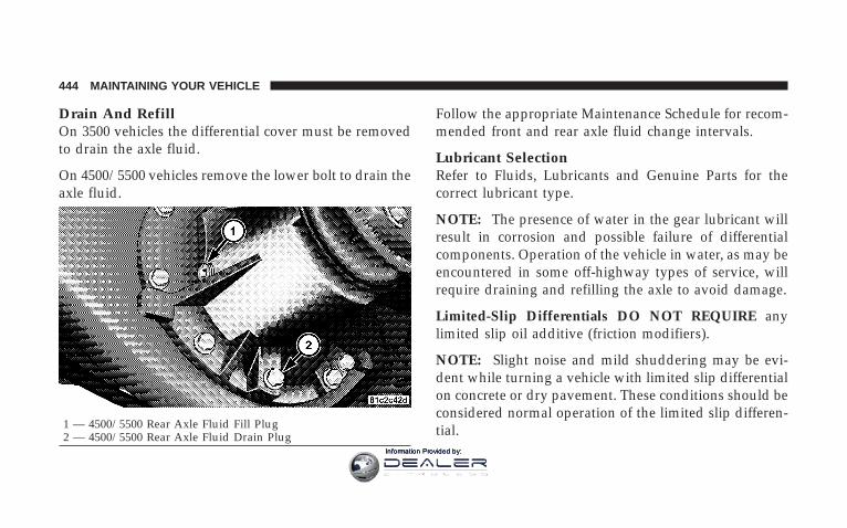
Drain And RefillOn 3500 vehicles the differential cover must be removedto drain the axle fluid.
On 4500/5500 vehicles remove the lower bolt to drain theaxle fluid.
Follow the appropriate Maintenance Schedule for recom-mended front and rear axle fluid change intervals.
Lubricant SelectionRefer to Fluids, Lubricants and Genuine Parts for thecorrect lubricant type.
NOTE: The presence of water in the gear lubricant willresult in corrosion and possible failure of differentialcomponents. Operation of the vehicle in water, as may beencountered in some off-highway types of service, willrequire draining and refilling the axle to avoid damage.
Limited-Slip Differentials DO NOT REQUIRE anylimited slip oil additive (friction modifiers).
NOTE: Slight noise and mild shuddering may be evi-dent while turning a vehicle with limited slip differentialon concrete or dry pavement. These conditions should beconsidered normal operation of the limited slip differen-tial.1 — 4500/5500 Rear Axle Fluid Fill Plug
2 — 4500/5500 Rear Axle Fluid Drain Plug
444 MAINTAINING YOUR VEHICLE
Information Provided by:

Transfer Case — If Equipped
Drain And RefillFollow the appropriate Maintenance Schedule for recom-mended transfer case fluid change intervals.
Lubricant SelectionRefer to Fluids, Lubricants and Genuine Parts for thecorrect lubricant type.
Fluid Level CheckThis fluid level can be checked by removing the fillerplug. The fluid level should be to the bottom edge of thefiller plug hole with the vehicle in a level position.
Manual Transmission — If Equipped
Lubricant Selection for 6-Speed ManualTransmission — If EquippedIf it becomes necessary to add fluid or change the fluid,be sure to use the same lubricant or equivalent. Refer toFluids, Lubricants and Genuine Parts for the correctlubricant type.
Follow the Maintenance Schedule for recommendedtransmission fluid change intervals.
Fluid Level CheckThis fluid level can be checked by removing the fillerplug. If the level of the lubricant is more than 1/4” belowthe bottom of the filler hole while the vehicle is on levelground, enough lubricant should be added to bring thelevel to the bottom of the filler hole.
MAINTAINING YOUR VEHICLE 445
7
Information Provided by:

Automatic Transmission (Gas Engine Only)
Selection Of LubricantRefer to Fluids, Lubricants and Genuine Parts for thecorrect lubricant type. It is important that the transmis-sion fluid be maintained at the prescribed level using therecommended fluid.
CAUTION!
Using a transmission fluid other than the manufac-turers recommended fluid may cause deterioration intransmission shift quality and/or torque convertershudder. Using a transmission fluid other than themanufacturers recommended fluid will result inmore frequent fluid and filter changes. Refer toFluids, Lubricants and Genuine Parts for correctfluid type.
Fluid Level Check – 545RFE TransmissionCheck the fluid level while the transmission is at normaloperating temperature 180° F (82° C). This occurs after atleast 15 mi (25 km) of driving. At normal operatingtemperature the fluid cannot be held comfortably be-tween the fingertips.
Procedure For Checking Fluid LevelTo properly check the automatic transmission fluid level,the following procedure must be used:
1. Operate the engine at idle speed and normal operatingtemperature.
2. The vehicle must be on level ground.
3. Fully apply parking brake.
4. Place the gear selector momentarily in each gearposition ending with the lever in P (Park).
446 MAINTAINING YOUR VEHICLE
Information Provided by:

5. Remove the dipstick, wipe it clean and reinsert it untilseated.
6. Remove the dipstick again and note the fluid level onboth sides. The fluid level should be between the HOT(upper) reference holes on the dipstick at normal operat-ing temperature. Verify that a solid coating of oil is seenon both sides of the dipstick. If the fluid is low, add asrequired into the dipstick tube. Do not overfill. Afteradding any quantity of oil through the dipstick tube, waita minimum of two (2) minutes for the oil to fully draininto the transmission before rechecking the fluid level.
NOTE: If it is necessary to check the transmission belowthe operating temperature, the fluid level should bebetween the two cold (lower) holes on the dipstick withthe fluid at approximately 70° F (21° C) (room tempera-ture). If the fluid level is correctly established at roomtemperature, it should be between the HOT (upper)
reference holes when the transmission reaches 180° F (21°C). Remember it is best to check the level at the normaloperating temperature.
CAUTION!
Be aware that if the fluid temperature is below 50° F(10° C), it may not register on the dipstick. Do not addfluid until the temperature is elevated enough toproduce an accurate reading.
7. Check for leaks. Release the Parking Brake.
NOTE: To prevent dirt and water from entering thetransmission after checking or replenishing fluid, makecertain that the dipstick cap is properly reseated. It isnormal for the dipstick cap to spring back slightly fromits fully seated positions, as long as its seal remainsengaged in the dipstick tube.
MAINTAINING YOUR VEHICLE 447
7
Information Provided by:

Automatic Transmission Fluid and Filter ChangeFollow the Maintenance Schedule for recommendedtransmission fluid and filter change intervals.
NOTE: If the transmission is disassembled for anyreason, the fluid and filter should be changed.
Special AdditivesThe manufacturer recommends against the addition ofany additives to the transmission. Exception to thispolicy is the use of special dyes to aid in detecting fluidleaks. The use of transmission sealers should be avoided,since they may adversely affect seals.
Automatic Transmission (Diesel Engine Only)
Selection Of LubricantRefer to Fluids, Lubricants and Genuine Parts for thecorrect lubricant type. It is important that the transmis-sion fluid be maintained at the prescribed level using therecommended fluid.
CAUTION!
Using a transmission fluid other than the manufac-turers recommended fluid may cause deterioration intransmission shift quality and/or torque convertershudder. Using a transmission fluid other than themanufacturers recommended fluid will result in se-rious damage to the transmission. Refer to Fluids,Lubricants and Genuine Parts for correct fluid type.
Fluid Level Check – AS68RC TransmissionCheck the fluid level while the transmission is at normaloperating temperature 167° F (76° C). This occurs after atleast 15 mi (25 km) of driving. At normal operatingtemperature the fluid cannot be held comfortably be-tween the fingertips.
448 MAINTAINING YOUR VEHICLE
Information Provided by:

Procedure For Checking Fluid LevelTo properly check the automatic transmission fluid level,the following procedure must be used:
1. The vehicle must be on level ground.
2. Operate the engine at idle speed for a minimum of 60seconds and normal operating temperature.
3. Fully apply parking brake and press the brake pedal.
4. Place the gear selector momentarily in each gearposition ending with the lever in P (Park). Make sure theengine is running at idle speed.
5. Remove the dipstick and determine if the fluid is hotor cold. Hot fluid is approximately 160° F - 175° F (70° C– 82° C), Which is the normal operating temperature afterthe vehicle has been driven at least 15 miles. The fluid cannot be comfortably held between the finger tips. Only use
the cold region on the dipstick as a rough reference whendoing initial oil level set after transmission rebuild ortransmission refill.
6. Wipe the dipstick clean and reinsert it until seated.
7. Remove the dipstick again and note the fluid level onboth sides. The fluid level should be between the HOT(upper) reference holes on the dipstick at normal operat-ing temperature. Verify that a solid coating of oil is seenon both sides of the dipstick. If the fluid is low, addMopart A68SRC™ Automatic Transmission Fluid asrequired into the dipstick tube. Do not overfill. Neveruse any ATF other than Mopart AS68RC™ AutomaticTransmission Fluid. After adding any quantity of oilthrough the dipstick tube, wait a minimum of two (2)minutes for the oil to fully drain into the transmissionbefore rechecking the fluid level.
NOTE: If it is necessary to check the transmission belowthe operating temperature, the fluid level should be
MAINTAINING YOUR VEHICLE 449
7
Information Provided by:

between the two cold (lower) holes on the dipstick withthe fluid at approximately 70° F – 85° F (20° C – 30° C). Ifthe fluid level is correctly established at room tempera-ture, it should be between the HOT (upper) referenceholes when the transmission reaches 160° F - 175° F (70°C – 82° C). Remember it is best to check the level at thenormal operating temperature.
CAUTION!
Be aware that if the fluid temperature is below 50° F(10° C), it may not register on the dipstick. Do not addfluid until the temperature is elevated enough toproduce an accurate reading. Never use any ATFother than Mopart AS68RC™ Automatic Transmis-sion Fluid.
8. Check for leaks. Release the Parking Brake.
NOTE: To prevent dirt and water from entering thetransmission after checking or replenishing fluid, makecertain that the dipstick cap is properly reseated. It isnormal for the dipstick cap to spring back slightly fromits fully seated positions, as long as its seal remainsengaged in the dipstick tube.
Automatic Transmission Fluid and Filter ChangeTo obtain best performance and long life for automatictransmissions, the manufacturer recommends that theybe given regular maintenance service by an AuthorizedDodge Dealer or Service Center. It is important that thetransmission fluid is maintained at the correct level, andthat it be drained and refilled as specified.
It is important that proper lubricant is used in thetransmission. Refer to Fluids, Lubricants and GenuineParts for the correct lubricant type. A filter change shouldbe made at the time of the oil change.
450 MAINTAINING YOUR VEHICLE
Information Provided by:

The fluid and filter(s) should be changed as specified inthe Maintenance Schedule (Section 8).
NOTE: If the transmission is disassembled for anyreason, the fluid and filter should be changed, and thebands adjusted (if equipped).
Special AdditivesThe manufacturer recommends against the addition ofany additives to the transmission. Exception to thispolicy is the use of special dyes to aid in detecting fluidleaks. The use of transmission sealers should be avoided,since they may adversely affect seals.
Front and Rear Wheel Bearings
Front Wheel BearingsFront wheel bearings for all Dodge Ram Trucks aresealed-for-life. They do not require greasing or sealreplacement. In some instances, these bearings will
“purge” excess grease and the bearing will look slightlywet. This is normal. Periodic inspection for excess play isrecommended.
Rear Wheel Bearings — Manufacturer’s AxlesThese bearings are normally considered permanentlylubricated. Cleaning and repacking is required onlywhen axle shafts are removed or in case of extreme wateror dust contamination.
Noise Control System Required Maintenance &WarrantyFor 3500/4500/5500 Two-Wheel Drive and Four-WheelDrive models over 10,000 lbs. (4 535 kg) Gross VehicleWeight Rating.
MAINTAINING YOUR VEHICLE 451
7
Information Provided by:

All vehicles built over 10,000 lbs. (4 535 kg) Gross VehicleWeight Rating and manufactured for sale and use in theUnited States are required to comply with the FederalGovernment’s Exterior Noise Regulations. These vehiclescan be identified by the Noise Emission Control Labellocated in the operator’s compartment.
Required Maintenance For Noise Control SystemsThe following maintenance services must be performedevery 6 months or 6,000 miles (9 600 km) whichevercomes first, to assure proper operation of the noisecontrol systems. In addition, inspection and serviceshould be performed anytime a malfunction is observedor suspected. Proper maintenance of the entire vehiclewill help the effectiveness of the noise control systems.
Exhaust SystemInspect the entire exhaust system for leaks and damagedparts. Devices such as hangers, clamps, and U-boltsshould be tight and in good condition. Damaged compo-nents, burned or blown out mufflers, burned or rustedout exhaust pipes should be replaced according to theprocedures and specifications outlined in the appropriateservice manual.
452 MAINTAINING YOUR VEHICLE
Information Provided by:

Air Cleaner AssemblyInspect air cleaner housing for proper assembly and fit.Make certain that the air cleaner is properly positionedand that the cover is tight. Check all hoses leading to theair cleaner for tightness. The air filter element must alsobe clean and serviced according to the instructions out-lined in the Maintenance Schedule Section of thismanual.
Tampering With Noise Control System ProhibitedFederal law prohibits the following acts or the causingthereof: (1) the removal or rendering inoperative by anyperson, other than for purposes of maintenance, repair, orreplacement, of any device or element of design incorpo-rated into any new vehicle for the purpose of noisecontrol prior to its sale or delivery to the ultimatepurchaser or while it is in use, or (2) the use of the vehicleafter such device or element of design has been removedor rendered inoperative by any person.
Among those acts presumed to constitute tampering arethe acts listed below.
• AIR CLEANER
− Removal of the air cleaner.
− Removal of the air cleaner filter element from the aircleaner housing.
− Removal of the air ducting.
• EXHAUST SYSTEM
− Removal or rendering inoperative exhaust systemcomponents including the muffler or tailpipe.
• ENGINE COOLING SYSTEM
− Removal or rendering inoperative the fan clutch.
− Removal of the fan shroud.
MAINTAINING YOUR VEHICLE 453
7
Information Provided by:

Noise Emission WarrantyThe manufacturer warrants that this vehicle as manufac-tured by the manufacturer, was designed, built andequipped to conform at the time it left the manufacturer’scontrol with all applicable U.S. EPA Noise Control Regu-lations.
This warranty covers this vehicle as designed, built andequipped by the manufacturer, and is not limited to any
particular part, component or system of the vehiclemanufactured by the manufacturer. Defects in design,assembly or in any part, component or system of thevehicle as manufactured by the manufacturer, which, atthe time it left the manufacturer’s control, caused noiseemissions to exceed Federal standards, are covered bythis warranty for the life of the vehicle.
454 MAINTAINING YOUR VEHICLE
Information Provided by:

Noise Systems Maintenance Chart and Service Log Maintenance Log and Service Chart (Gas Engines) InsertMonth, Day, Year under column mileage closest to the mileage at which service was performed.MILES 6,000 12,000 18,000 24,000 30,000 36,000 42,000 48,000KILOMETERS 9 600 19 000 29 000 36 000 48 000 58 000 67 000 77 000Exhaust system-inspectAir cleaner assembly-inspectODOMETER READINGPERFORMED BYPERFORMED AT
MILES 54,000 60,000 66,000 72,000 78,000 84,000 90,000 96,000KILOMETERS 87 000 96 000 106 000 116 000 126 000 135 000 145 000 154 000Exhaust system-inspectAir cleaner assembly-inspectODOMETER READINGPERFORMED BYPERFORMED AT
MAINTAINING YOUR VEHICLE 455
7
Information Provided by:

Maintenance Log and Service Chart (Diesel Engines)
Noise Systems Maintenance Chart and Service Log — Insert Month, Day, Year under column mileage closest tothe mileage at which service was performed.MILES 7,500 15,000 22,500 30,000 37,500 45,000 52,500 60,000KILOMETERS 12 000 24 000 36 000 48 000 60 000 72 000 84 000 96 000Exhaust system-inspectAir cleaner assembly-inspectODOMETER READINGPERFORMED BYPERFORMED AT
MILES 67,500 75,000 82,500 90,000 97,500 84,000 105,00 112,500KILOMETERS 108 000 120 000 132 000 144 000 126 000 156 000 168 000 181 000Exhaust system-inspectAir cleaner assembly-inspectODOMETER READINGPERFORMED BYPERFORMED AT
456 MAINTAINING YOUR VEHICLE
Information Provided by:
Appearance Care and Protection from Corrosion
Protection of Body and Paint from CorrosionVehicle body care requirements vary according to geo-graphic locations and usage. Chemicals that make roadspassable in snow and ice, and those that are sprayed ontrees and road surfaces during other seasons, are highlycorrosive to the metal in your vehicle. Outside parking,which exposes your vehicle to airborne contaminants,road surfaces on which the vehicle is operated, extremehot or cold weather and other extreme conditions willhave an adverse effect on paint, metal trim, and under-body protection.
The following maintenance recommendations will enableyou to obtain maximum benefit from the corrosionresistance built into your vehicle.
What Causes Corrosion?Corrosion is the result of deterioration or removal ofpaint and protective coatings from your vehicle.
The most common causes are:
• Road salt, dirt and moisture accumulation.
• Stone and gravel impact.
• Insects, tree sap and tar.
• Salt in the air near seacoast localities.
• Atmospheric fallout/industrial pollutants.
Washing
• Wash your vehicle regularly. Always wash your ve-hicle in the shade using Mopart Car Wash or a mildcar wash soap, and rinse the panels completely withclear water.
• If insects, tar or other similar deposits have accumu-lated on your vehicle, use Mopart Super Kleen Bugand Tar Remover to remove.
MAINTAINING YOUR VEHICLE 457
7
Information Provided by:

• Use Mopart Cleaner Wax to remove road film, stainsand to protect your paint finish. Take care never toscratch the paint.
• Avoid using abrasive compounds and power buffingthat may diminish the gloss or thin out the paintfinish.
CAUTION!
Do not use abrasive or strong cleaning materials suchas steel wool or scouring powder, which will scratchmetal and painted surfaces.
Special Care
• If you drive on salted or dusty roads or if you drivenear the ocean, hose off the undercarriage at least oncea month.
• It is important that the drain holes in the lower edgesof the doors, rocker panels and trunk be kept clear andopen.
• If you detect any stone chips or scratches in the paint,touch them up immediately. The cost of such repairs isconsidered the responsibility of the owner.
• If your vehicle is damaged due to an accident orsimilar cause which destroys the paint and protectivecoating, have your vehicle repaired as soon as pos-sible. The cost of such repairs is considered the respon-sibility of the owner.
• If you carry special cargo such as chemicals, fertilizers,de-icer salt, etc., be sure that such materials are wellpackaged and sealed.
• If a lot of driving is done on gravel roads, considermud or stone shields behind each wheel.
458 MAINTAINING YOUR VEHICLE
Information Provided by:
• Use Mopart touch up paint on scratches as soon aspossible. Your dealer has touch up paint to match thecolor of your vehicle.
Wheel and Wheel Trim CareAll wheels and wheel trim, especially aluminum andchrome plated wheels should be cleaned regularly with amild soap and water to prevent corrosion. To removeheavy soil and/or excessive brake dust, use MopartWheel Cleaner (05066247AB) or equivalent or select anonabrasive, non-acidic cleaner. Do not use scouringpads, steel wool, a bristle brush, or metal polishes. OnlyMopartor equivalent is recommended. Do not use ovencleaner. Avoid automatic car washes that use acidicsolutions or harsh brushes that may damage the wheels’protective finish.
YES Essentialst Fabric Cleaning Procedure – IfequippedYES Essentialst seats may be cleaned in the followingmanner:
• Remove as much of the stain as possible by blottingwith a clean, dry towel.
• Blot any remaining stain with a clean, damp towel.
• For tough stains, apply Mopart Total Clean or a mildsoap solution to a clean, damp cloth and remove stain.Use a fresh, damp towel to remove soap residue.
• For grease stains, apply Mopart Multi-purposecleaner to a clean, damp cloth and remove stain. Use afresh, damp towel to remove soap residue.
• Do not use any solvents or protectants on Yes Essen-tials products.
MAINTAINING YOUR VEHICLE 459
7
Information Provided by:

Interior CareUse Mopart Total Clean to clean fabric upholstery andcarpeting.
Use Mopart Total Clean to clean vinyl upholstery.
MopartTotal Clean is specifically recommended forleather upholstery.
Your leather upholstery can be best preserved by regularcleaning with a damp soft cloth. Small particles of dirtcan act as an abrasive and damage the leather upholsteryand should be removed promptly with a damp cloth.Stubborn soils can be removed easily with a soft clothand Mopart Total Clean. Care should be taken to avoidsoaking your leather upholstery with any liquid. Pleasedo not use polishes, oils, cleaning fluids, solvents, deter-gents, or ammonia based cleaners to clean your leatherupholstery. Application of a leather conditioner is notrequired to maintain the original condition.
WARNING!
Do not use volatile solvents for cleaning purposes.Many are potentially flammable, and if used inclosed areas they may cause respiratory harm.
Cleaning HeadlightsYour vehicle has plastic headlights that are lighter andless susceptible to stone breakage than glass headlights.
Plastic is not as scratch resistant as glass and thereforedifferent lens cleaning procedures must be followed.
To minimize the possibility of scratching the lenses andreducing light output, avoid wiping with a dry cloth. Toremove road dirt, wash with a mild soap solution fol-lowed by rinsing.
Do not use abrasive cleaning components, solvents, steelwool or other aggressive material to clean the lenses.
460 MAINTAINING YOUR VEHICLE
Information Provided by:

Glass SurfacesAll glass surfaces should be cleaned on a regular basiswith Mopart Glass Cleaner or any commercialhousehold-type glass cleaner. Never use an abrasive typecleaner. Use caution when cleaning the inside rear win-dow equipped with electric defrosters or the right rearquarter window equipped with the radio antenna. Donot use scrapers or other sharp instruments which mayscratch the elements. When cleaning the rear view mirror,spray cleaner on the towel or rag that you are using. Donot spray cleaner directly on the mirror.
Cleaning Plastic Instrument Cluster LensesThe lenses in front of the instruments in this vehicle aremolded in clear plastic. When cleaning the lenses, caremust be taken to avoid scratching the plastic.
1. Clean with a wet soft rag. A mild soap solution may beused, but do not use high alcohol content or abrasivecleaners. If soap is used, wipe clean with a clean damprag.
2. Dry with a soft tissue.
Seat Belt MaintenanceDo not bleach, dye or clean the belts with chemicalsolvents or abrasive cleaners. This will weaken the fabric.Sun damage can also weaken the fabric.
If the belts need cleaning, use a mild soap solution orlukewarm water. Do not remove the belts from the car towash them.
Replace the belts if they appear frayed or worn or if thebuckles do not work properly.
Dry with a soft tissue.
MAINTAINING YOUR VEHICLE 461
7
Information Provided by:

FUSES (INTEGRATED POWER MODULE)An integrated Power Module is located in the enginecompartment near the battery. This center contains car-tridge fuses and mini fuses. A description of each fuseand component may be stamped on the inside coverotherwise the cavity number of each fuse is stamped onthe inside cover that corresponds to the following chart.
Integrated Power Module Location
462 MAINTAINING YOUR VEHICLE
Information Provided by:

Cavity CartridgeFuse
MiniFuse
Description
1 20 AmpYellow
Power Outlet Console
2 20 AmpYellow
Cabin CompartmentNode (CCN) DoorLocks
3 — —4 15 Amp
BlueAisin TransmissionControls (Diesel Only)
5 20 AmpYellow
Power Sunroof
6 10 AmpRed
Vistronic Fan/Wastegate Solenoid
7 — —8 10 Amp
RedHeated Mirrors
Cavity CartridgeFuse
MiniFuse
Description
9 30 AmpPink
Off Road ModulePower
10 5 AmpOrange
Trx-Off Rd Pkg Sen(Gas Engine Only)NOTE: Insert 5 ampfuse in this cavity toenable the TRX capa-bility (If Equipped).
11 20 AmpYellow
Ignition Off Draw(IOD)-Cabin Com-partment Node(CCN)/Radio/UnderHood Lamp/WirelessControl Module(WCM)/Satellite Digi-tal Audio Receiver(SDARS)/Hands FreeModule (HFM)/EOM
MAINTAINING YOUR VEHICLE 463
7
Information Provided by:
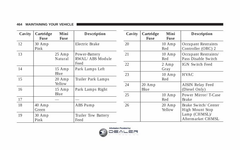
Cavity CartridgeFuse
MiniFuse
Description
12 30 AmpPink
Electric Brake
13 25 AmpNatural
Power-BatteryRWAL/ABS ModuleFeed
14 15 AmpBlue
Park Lamps Left
15 20 AmpYellow
Trailer Park Lamps
16 15 AmpBlue
Park Lamps Right
17 — —18 40 Amp
GreenABS Pump
19 30 AmpPink
Trailer Tow BatteryFeed
Cavity CartridgeFuse
MiniFuse
Description
20 10 AmpRed
Occupant RestraintsController (ORC) 2
21 10 AmpRed
Occupant Restraints/Pass Disable Switch
22 2 AmpGray
IGN Switch Feed
23 10 AmpRed
HVAC
24 20 AmpBlue
AISIN Relay Feed(Diesel Only)
25 10 AmpRed
Power Mirror/T-CaseBrake
26 20 AmpYellow
Brake Switch/CenterHigh Mount StopLamp (CHMSL)/Aftermarket CHMSL
464 MAINTAINING YOUR VEHICLE
Information Provided by:
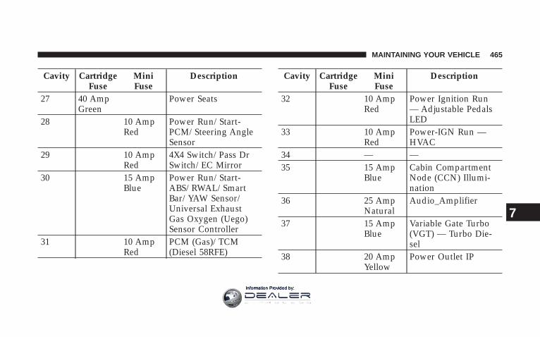
Cavity CartridgeFuse
MiniFuse
Description
27 40 AmpGreen
Power Seats
28 10 AmpRed
Power Run/Start-PCM/Steering AngleSensor
29 10 AmpRed
4X4 Switch/Pass DrSwitch/EC Mirror
30 15 AmpBlue
Power Run/Start-ABS/RWAL/SmartBar/YAW Sensor/Universal ExhaustGas Oxygen (Uego)Sensor Controller
31 10 AmpRed
PCM (Gas)/TCM(Diesel 58RFE)
Cavity CartridgeFuse
MiniFuse
Description
32 10 AmpRed
Power Ignition Run— Adjustable PedalsLED
33 10 AmpRed
Power-IGN Run —HVAC
34 — —35 15 Amp
BlueCabin CompartmentNode (CCN) Illumi-nation
36 25 AmpNatural
Audio_Amplifier
37 15 AmpBlue
Variable Gate Turbo(VGT) — Turbo Die-sel
38 20 AmpYellow
Power Outlet IP
MAINTAINING YOUR VEHICLE 465
7
Information Provided by:

Cavity CartridgeFuse
MiniFuse
Description
39 10 AmpRed
Seatbelt TensionReducer/Power IGNRun/Acc
40 20 AmpYellow
Power IGN Run/Acc— Cigar Lighter/RearPower Point
41 — —42 30 Amp
PinkDiesel PCM (DieselOnly)
CAUTION!
• When installing the Integrated Power Modulecover, it is important to ensure the cover is prop-erly positioned and fully latched. Failure to do somay allow water to get into the Integrated PowerModule, and possibly result in a electrical systemfailure.
• When replacing a blown fuse, it is important touse only a fuse having the correct amperage rating.The use of a fuse with a rating other than indicatedmay result in a dangerous electrical system over-load. If a properly rated fuse continues to blow, itindicates a problem in the circuit that must becorrected.
466 MAINTAINING YOUR VEHICLE
Information Provided by:

VEHICLE STORAGEIf you are storing your vehicle for more than 21 days, werecommend that you take the following steps to mini-mize the drain on your vehicle’s battery:
• Disconnect the Ignition-Off Draw fuse (I.O.D.) fuselocated in the Integrated Power Module, located in theengine compartment. The I.O.D. cavity includes asnap-in retainer that allows the fuse to be discon-nected, without removing it from the fuse block.
• The electronic shift transfer case should be placed inthe 4HI mode and kept in this position to minimize thebattery drain.
• As an alternative to the above steps you may, discon-nect the negative cables from both batteries.
• Anytime you store your vehicle, or keep it out ofservice (i.e. vacation) for two weeks or more, run theair conditioning system at idle for about five minutes
in the fresh air and high blower setting. This willinsure adequate system lubrication to minimize thepossibility of compressor damage when the system isstarted again.
NOTE: When reinstalling the IOD fuse push firmly untilfully seated, the gages in the Instrument Cluster will doa full sweep, when the ignition key is cycled to RUN. Thisis a normal condition.
NOTE: When the vehicle is shipped from the factory,the IOD fuse is in the up, or extracted position. If theradio, interior lamps, keyless entry, or other features donot work with the key off, check the position of the fuse(or check to see if the fuse is blown) to ensure that it isfully seated. When the IOD fuse is extracted, the instru-ment cluster, in the odometer window, will display 9NOFUSE
MAINTAINING YOUR VEHICLE 467
7
Information Provided by:

REPLACEMENT LIGHT BULBS
LIGHT BULBS — Inside Bulb No.Overhead Console Lights . . . . . . . . . . . . . . . TS 212-2Dome Light . . . . . . . . . . . . . . . . . . . . . . . . . . . . 7679
NOTE: For lighted switches, see your dealer for replace-ment instructions.
All of the inside bulbs are brass or glass wedge base.Aluminum base bulbs are not approved.
LIGHT BULBS — Exterior Bulb No.Back-Up . . . . . . . . . . . . . . . . . . . . . . . . . . . . . . 1156Fog Lamp . . . . . . . . . . . . . . . . . . . . . . . . . . . 9006LLHeadlamp (Halogen) . . . . . . . . . . . . . . . . . . . . . H13Side Marker, Park & Turn Signal . . . . . . . . . . . . . 1157Rear License Plate Lamp. . . . . . . . . . . . . . . . . . . 1157Rear Cargo Light . . . . . . . . . . . . . . . . . . . . . . . . . 912Tail & Stop . . . . . . . . . . . . . . . . . . . . . . . . . . . . 1157
BULB REPLACEMENT
Headlight (Halogen)/Front Park and Turn Lights
CAUTION!
This is a halogen bulb. Avoid touching the glass withyour fingers. Reduced bulb life will result.
1. Open the hood
468 MAINTAINING YOUR VEHICLE
Information Provided by:

2. Remove the two (2) bolts from the front of the head-light housing.
3. Remove the plug from the inner fender well andremove the nut through the access hole.
Front Headlight Housing Bolts Inner Fender Plug
MAINTAINING YOUR VEHICLE 469
7
Information Provided by:

4. Pull the housing out from the fender to allow room todisconnect the electrical connectors.
NOTE: For easier removal, pull the headlight assemblystraight forward, applying the greatest amount of force tothe outer edge of the headlight assembly.
Rear Headlight Housing Nut Access
Headlight Removal
470 MAINTAINING YOUR VEHICLE
Information Provided by:
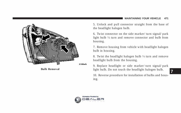
5. Unlock and pull connector straight from the base ofthe headlight halogen bulb.
6. Twist connector on the side marker/turn signal/parklight bulb 1⁄4 turn and remove connector and bulb fromhousing.
7. Remove housing from vehicle with headlight halogenbulb in housing.
8. Twist the headlight halogen bulb 1⁄4 turn and removeheadlight bulb from the housing.
9. Replace headlight or side marker/turn signal/parklight bulb. Do not touch the headlight halogen bulb.
10. Reverse procedure for installation of bulbs and hous-ing.
Bulb Removal
MAINTAINING YOUR VEHICLE 471
7
Information Provided by:

Fog Lights
1. Reach under the vehicle, unlock and twist connectorcounterclockwise 1⁄4 turn and remove connector and bulbfrom housing.
2. Pull bulb straight from the connector.
3. Reverse procedure for installation of bulbs and hous-ing.
472 MAINTAINING YOUR VEHICLE
Information Provided by:

Cab Top Clearance Lights — If Equipped
1. Remove the two screws from the top of the light.
2. Rotate the socket 1⁄4 turn and pull it from the lightassembly.
MAINTAINING YOUR VEHICLE 473
7
Information Provided by:

3. Pull the bulb straight from it’s socket and replace. FLUID AND CAPACITIES
U.S. MetricFuel (Appoximate)6.7L HO Turbo DieselEngine
Standard Rear Tank 52 gal. 197 LOptional Midship Tank 22 gal. 83L
Fuel (Appoximate)5.7L Gas Engine
Standard Rear Tank 52 gal. 197LOptional Midship Tank 22 gal. 83L
474 MAINTAINING YOUR VEHICLE
Information Provided by:

U.S. MetricEngine Oil (with filter)
6.7L HO Turbo DieselEngine (SAE 15W-40, APICJ-4 Certified, that meets
CES 20081 Standards.)
12 qts. 11.4L
5.7L Gas Engine V-8 (SAE5W-30, API Certified).
For trucks operating un-der a gross combinedweight rating greater
than 14,000 lbs.
7.0 qts. 6.6L
5.7L Gas Engine V-8 (SAE5W-20, API Certified).
For trucks operating un-der a gross combined
weight rating less than14,000 lbs.
7.0 qts. 6.6L
U.S. MetricCooling System
6.7L Diesel Engine I-6 22.6 qts. 21.4L5.7L Gas Engine (Mopart
Antifreeze/Coolant 5Year/100,000 Mile For-
mula) or equivalent
18.7 qts. 17.7L
MAINTAINING YOUR VEHICLE 475
7
Information Provided by:

FLUIDS, LUBRICANTS AND GENUINE PARTS
Engine
Component Fluids, Lubricants and Genuine PartsEngine Coolant Mopart Antifreeze/Coolant 5 Year/100,000 Mile Formula HOAT (Hybrid
Organic Additive Technology) or equivalent.6.7L HO Turbo Diesel Engine Oil Use (SAE 15W-40, API CJ-4 Certified, that meets CES 20081 Standards.)5.7L Gas Engine Oil (For trucks operatingunder a gross combined weight rating lessthan 14,000 lbs.)
Use SAE 5W-20, API Certified, meeting material standard MS-6395.
5.7L Gas Engine Oil (For trucks operatingunder a gross combined weight ratinggreater than 14,000 lbs.)
Use SAE 5W-30, API Certified, meeting material standard MS-6395.
Engine Oil Filter ( 5.7L Gas Engine ) Mopart Engine Oil Filter, P/N 5281090 or equivalent.Engine Oil Filter ( 6.7L Diesel Engine ) Mopart Engine Oil Filter, P/N 05083285AA or equivalent.Engine Fuel Filter ( 6.7L Diesel Engine ) Mopart Fuel Filter, P/N 05183410AA or equivalent. Must meet 7 micron
rating. Using a fuel filter that does not meet the manufacturers filtrationand water separating requirements can severely impact fuel system lifeand reliability.
476 MAINTAINING YOUR VEHICLE
Information Provided by:

Component Fluids, Lubricants and Genuine PartsCrankcase Ventilation Filter ( 6.7L DieselEngine )
Mopart CCV Filter, P/N 68001433AA or equivalent.
Fuel Selection ( 5.7L Gas Engine ) 89 Octane, (R+M)/2 Method, Mid-Grade Preferred (87 Octane acceptable).Fuel Selection ( 6.7L Diesel Engine ) Use good quality diesel fuel from a reputable supplier in your vehicle.
Federal law requires that you must fuel this vehicle with Ultra Low SulfurHighway Diesel fuel (15 ppm Sulfur maximum) and prohibits the use ofLow Sulfur Highway Diesel fuel (500 ppm Sulfur maximum) to avoiddamage to the emissions control system. For most year-round service, No.2 diesel fuel meeting ASTM specification D-975 Grade S15 will providegood performance. If the vehicle is exposed to extreme cold (below 20°For -7°C), or is required to operate at colder-than-normal conditions forprolonged periods, use climatized No. 2 diesel fuel or dilute the No. 2diesel fuel with 50% No. 1 diesel fuel. This will provide better protectionfrom fuel gelling or wax-plugging of the fuel filters. This vehicle is fullycompatible with biodiesel blends up to 5% biodiesel meeting ASTMspecification D-975.
Spark Plugs (5.7L Engine) REC14MCC4 (Gap 0.043”)
MAINTAINING YOUR VEHICLE 477
7
Information Provided by:

Chassis
Component Fluids, Lubricants and Genuine Parts.Automatic Transmission(5 Speed 545RFE)
Mopart ATF+4, Automatic Transmission Fluid.
Automatic Transmission(6 Speed AS68RC)
Mopart AS68RC™ Automatic Transmission Fluid
Transfer Case Mopart ATF+4, Automatic Transmission Fluid.Manual Transmission Fluid G-56 Mopart ATF+4, Automatic Transmission Fluid.Clutch Linkage Multipurpose Grease, NLGI Grade 2 E.P. or equivalent.Front and Rear Axle Fluid (3500) GL-5 SAE 75W-90 Synthetic or equivalent. Limited slip additive is not re-
quired.Front and Rear Axle Fluid(4500/5500)
GL-5 SAE 75W-90 Synthetic (MS-9763) or equivalent.
Brake Master Cylinder Mopart DOT 3 and SAE J1703 should be used or equivalent.Power Steering Reservoir Mopart ATF+4, Automatic Transmission Fluid.
478 MAINTAINING YOUR VEHICLE
Information Provided by:

MAINTENANCE SCHEDULES
CONTENTS
m Emission Control System Maintenance . . . . . . . . 480
m Maintenance Schedules — 6.7L Turbo Diesel . . . . 480
▫ Oil Change Indicator System . . . . . . . . . . . . . 482
▫ Maintenance Schedule . . . . . . . . . . . . . . . . . . 483
m Maintenance Schedule — 5.7L Gas Engine . . . . . 491
▫ Required Maintenance Intervals . . . . . . . . . . . 494
8
MAINTENANCE
SCHEDULES
Information Provided by:

EMISSION CONTROL SYSTEM MAINTENANCEThe “Scheduled” maintenance services, listed in boldtype in this section (Section 8) must be done at the timesor mileages specified to assure the continued properfunctioning of the emission control system. These, and allother maintenance services included in this manual,should be done to provide best vehicle performance andreliability. More frequent maintenance may be needed forvehicles in severe operating conditions such as dustyareas and very short trip driving.
Inspection and service also should be done any time amalfunction is suspected.
NOTE: Maintenance, replacement, or repair of the emis-sion control devices and systems on your vehicle may beperformed by any automotive repair establishment orindividual using any automotive part which has beencertified pursuant to U.S. EPA or, in the State of Califor-nia, California Air Resources Board regulations.
MAINTENANCE SCHEDULES — 6.7L TURBODIESEL
CAUTION!
Failure to perform the required maintenance itemsmay result in damage to the vehicle.
At Each Stop for Fuel
• Check the engine oil level about 30 minutes after afully warmed engine is shut off. Checking the oil levelwhile the vehicle is on level ground will improve theaccuracy of the oil level reading. Add oil only whenthe level is at or below the ADD or MIN mark.
480 MAINTENANCE SCHEDULES
8
MAINTENANCE
SCHEDULES
Information Provided by:

• Check the windshield washer solvent and add ifrequired. When refilling the washer fluid reservoir,take some washer fluid and apply it to a cloth or toweland wipe clean the wiper blades, this will help bladeperformance.
Once a Month
• Check tire pressure and look for unusual wear ordamage.
• Inspect the batteries and clean and tighten the termi-nals as required.
• Check the fluid levels of coolant reservoir, transmis-sion and transfer case (if equipped), add as needed.
• Check master cylinder reservoir fluid level for indica-tions of brake maintenance.
• Check Filter Minder™. Replace air cleaner filterelement if necessary.
• Check all lights and all other electrical items for correctoperation.
At Each Oil Change
• Change the engine oil filter.
• Inspect the exhaust system.
• Inspect the brake hoses.
• Inspect the U-Joints ( if equipped) and front suspen-sion components.
• Check the automatic transmission fluid level.
• Check the manual transmission fluid level.
• Check the coolant level, hoses, and clamps.
• Lubricate outer tie rod ends (4X4) models only.
• Lubricate Front Drive Shaft Fitting (4X4).
MAINTENANCE SCHEDULES 481
8
MAINTENANCE
SCHEDULES
Information Provided by:

Inspection and service should also be performed anytimea malfunction is observed or suspected. Retain all re-ceipts.
Oil Change Indicator SystemYour vehicle is equipped with an engine oil changeindicator system. This system will alert you when it istime to change your engine oil by displaying the words“Oil Change Required” on your Electronic Vehicle Infor-mation Center (EVIC). The engine oil change indicatorsystem is duty cycle based, which means the engine oilchange interval may fluctuate depending on your per-sonal driving style. Driving styles such as frequent stop
and go type driving can increase the frequency of theengine oil change. This is the result of more frequentregeneration of the exhaust aftertreatment system, whichcan decrease the life of the engine oil. Failure to changethe engine oil per the maintenance schedule can result ininternal engine damage.
For information on resetting the Oil Change Indicatormessage, refer to “Oil Change Required – If Equipped,”under “System Status (EVIC Displays)” in the “ElectronicVehicle Information Center (EVIC)” Section of thismanual.
482 MAINTENANCE SCHEDULES
8
MAINTENANCE
SCHEDULES
Information Provided by:

Maintenance Schedule
Miles 7,500 15,000 22,500 30,000 37,500(Kilometers) (12 000) (24 000) (36 000) (48 000) (60 000)[Months] [6] [12] [18] [24] [30]Change engine oil and engine oil filter. X X X X XLubricate Front Drive Shaft Fitting (4X4). X X X X XRotate tires. X X X X XCheck spare tire for proper pressure and correctstowage. X X X X X
Lubricate outer tie rod ends. X X X X XCheck transfer case fluid level (4X4). XChange front axle fluid (3500/4500/5500 4X4) (Die-sel Engine only). X X
Change rear axle fluid (3500 4X4 and 4X2) (DieselEngine Only) X X
Change automatic transmission fluid. XReplace fuel filter element. X X
MAINTENANCE SCHEDULES 483
8
MAINTENANCE
SCHEDULES
Information Provided by:

Miles 7,500 15,000 22,500 30,000 37,500(Kilometers) (12 000) (24 000) (36 000) (48 000) (60 000)[Months] [6] [12] [18] [24] [30]Inspect brake linings. XInspect and adjust parking brake if necessary. XInspect fan hub. XInspect damper. XInspect front wheel bearings. XInspect drive belt, replace as necessary. X
484 MAINTENANCE SCHEDULES
8
MAINTENANCE
SCHEDULES
Information Provided by:

Miles 45,000 52,500 60,000 67,500 75,000(Kilometers) (72 000) (84 000) (97 000) (109 000) (121 000)[Months] [36] [42] [48] [54] [60]Change engine oil and engine oil filter. X X X X XLubricate Front Drive Shaft Fitting (4X4). X X X X XRotate tires. X X X X XCheck spare tire for proper pressure and correctstowage. X X X X X
Lubricate outer tie rod ends. X X X X XDrain and refill transfer case fluid (4X4). XChange front axle fluid (3500/4500/5500 4X4) (Die-sel Engine only). X X X
Change rear axle fluid (3500 4X4 and 4X2) (DieselEngine only) X X X
Change rear axle fluid (4500/5500 4X4 and 4X2). XChange automatic transmission fluid. XChange manual transmission fluid. X
MAINTENANCE SCHEDULES 485
8
MAINTENANCE
SCHEDULES
Information Provided by:

Miles 45,000 52,500 60,000 67,500 75,000(Kilometers) (72 000) (84 000) (97 000) (109 000) (121 000)[Months] [36] [42] [48] [54] [60]Flush and replace engine coolant at 60 months, ifnot replaced at 100,000 miles (160 000 km). X
Inspect drive belt, replace as necessary. X XReplace fuel filter element. X X XInspect brake linings. X XInspect and adjust parking brake if necessary. X XInspect fan hub. XInspect damper. XInspect front wheel bearings. XReplace Crankcase Ventilation Filter (CCV). X
486 MAINTENANCE SCHEDULES
8
MAINTENANCE
SCHEDULES
Information Provided by:
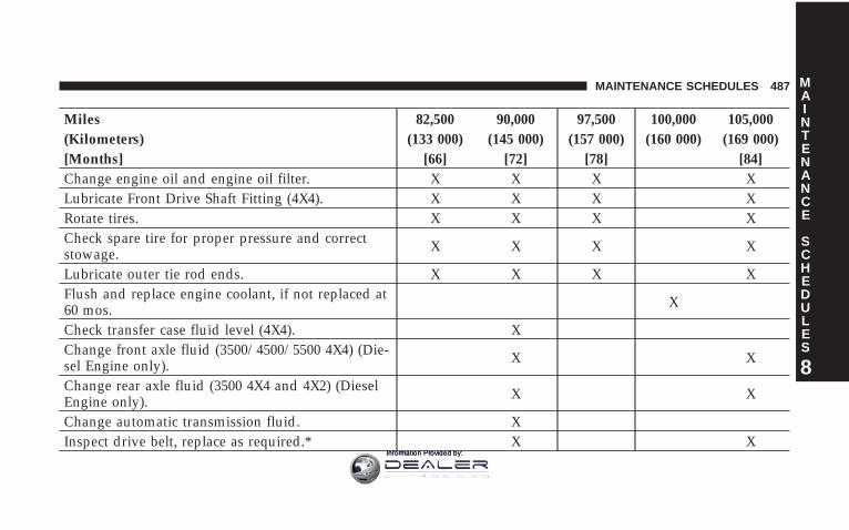
Miles 82,500 90,000 97,500 100,000 105,000(Kilometers) (133 000) (145 000) (157 000) (160 000) (169 000)[Months] [66] [72] [78] [84]Change engine oil and engine oil filter. X X X XLubricate Front Drive Shaft Fitting (4X4). X X X XRotate tires. X X X XCheck spare tire for proper pressure and correctstowage. X X X X
Lubricate outer tie rod ends. X X X XFlush and replace engine coolant, if not replaced at60 mos. X
Check transfer case fluid level (4X4). XChange front axle fluid (3500/4500/5500 4X4) (Die-sel Engine only). X X
Change rear axle fluid (3500 4X4 and 4X2) (DieselEngine only). X X
Change automatic transmission fluid. XInspect drive belt, replace as required.* X X
MAINTENANCE SCHEDULES 487
8
MAINTENANCE
SCHEDULES
Information Provided by:
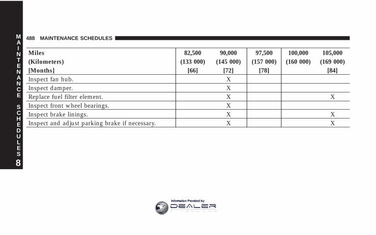
Miles 82,500 90,000 97,500 100,000 105,000(Kilometers) (133 000) (145 000) (157 000) (160 000) (169 000)[Months] [66] [72] [78] [84]Inspect fan hub. XInspect damper. XReplace fuel filter element. X XInspect front wheel bearings. XInspect brake linings. X XInspect and adjust parking brake if necessary. X X
488 MAINTENANCE SCHEDULES
8
MAINTENANCE
SCHEDULES
Information Provided by:
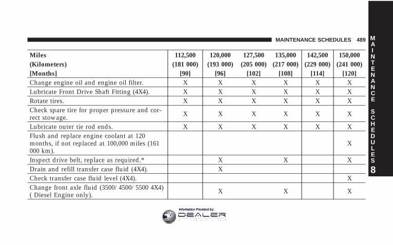
Miles 112,500 120,000 127,500 135,000 142,500 150,000(Kilometers) (181 000) (193 000) (205 000) (217 000) (229 000) (241 000)[Months] [90] [96] [102] [108] [114] [120]Change engine oil and engine oil filter. X X X X X XLubricate Front Drive Shaft Fitting (4X4). X X X X X XRotate tires. X X X X X XCheck spare tire for proper pressure and cor-rect stowage. X X X X X X
Lubricate outer tie rod ends. X X X X X XFlush and replace engine coolant at 120months, if not replaced at 100,000 miles (161000 km).
X
Inspect drive belt, replace as required.* X X XDrain and refill transfer case fluid (4X4). XCheck transfer case fluid level (4X4). XChange front axle fluid (3500/4500/5500 4X4)( Diesel Engine only). X X X
MAINTENANCE SCHEDULES 489
8
MAINTENANCE
SCHEDULES
Information Provided by:

Miles 112,500 120,000 127,500 135,000 142,500 150,000(Kilometers) (181 000) (193 000) (205 000) (217 000) (229 000) (241 000)[Months] [90] [96] [102] [108] [114] [120]Change rear axle fluid (3500 4X4 and 4X2)(Diesel Engine only). X X X
Change rear axle fluid (4500/5500 4X4 and4X2). X
Change automatic transmission fluid. X XChange manual transmission fluid. XInspect fan hub. X XInspect damper. X XReplace fuel filter element. X X XInspect front wheel bearings. X XInspect brake linings. X XInspect and adjust parking brake if necessary. X XAdjust valve lash clearance. XReplace Crankcase Ventilation Filter (CCV). X
490 MAINTENANCE SCHEDULES
8
MAINTENANCE
SCHEDULES
Information Provided by:

Inspection and service should also be performed anytimea malfunction is observed or suspected. Retain all re-ceipts.
*This maintenance is not required if belt was previouslyreplaced.
WARNING!
You can be badly injured working on or around amotor vehicle. Do only that service work for whichyou have the knowledge and the right equipment. Ifyou have any doubt about your ability to perform aservice job, take your vehicle to a competentmechanic.
MAINTENANCE SCHEDULE — 5.7L GAS ENGINEThe oil change indicator system will remind you that it istime to take your vehicle in for scheduled maintenance.
The “Change Oil” message will flash in the instrumentcluster odometer and a single chime will sound, indicat-ing that an oil change is necessary.
Based on engine operation conditions the oil changeindicator message will illuminate, this means that serviceis required for your vehicle. Have your vehicle servicedas soon as possible, within the next 500 miles (805 km).
NOTE:• The oil change indicator message will not monitor the
time since the last oil change. Change your vehicles oilif it has been 6 months since your last oil change evenif the oil change indicator message is NOT illumi-nated.
MAINTENANCE SCHEDULES 491
8
MAINTENANCE
SCHEDULES
Information Provided by:

• Change your engine oil more often if you drive yourvehicle off-road for an extended period of time.
• Under no circumstances should oil change intervalsexceed 6,000 miles (10,000 km) or 6 months, whichevercomes first.
Your dealer will reset the oil change indicator messageafter completing the scheduled oil change. If this sched-uled oil change is performed by someone other than yourdealer the message can be reset by referring to the stepsdescribed under “Odometer/Trip Odometer” under “In-strument Cluster Description” in Section 4 of thismanual.
At Each Stop for Fuel
• Check the engine oil level about 5 minutes after a fullywarmed engine is shut off. Checking the oil level while
the vehicle is on level ground will improve the accu-racy of the oil level reading. Add oil only when thelevel is at or below the ADD or MIN mark.
• Check the windshield washer solvent and add ifrequired.
Once a Month
• Check tire pressure and look for unusual wear ordamage.
• Inspect the battery and clean and tighten the terminalsas required.
• Check the fluid levels of coolant reservoir, brakemaster cylinder, power steering and transmission andadd as needed.
• Check all lights and other electrical items for correctoperation.
492 MAINTENANCE SCHEDULES
8
MAINTENANCE
SCHEDULES
Information Provided by:

At Each Oil Change
• Change the engine oil filter.
• Inspect the brake hoses and lines.
• Check the Manual Transmission fluid level.
CAUTION!
Failure to perform the required maintenance itemsmay result in damage to the vehicle.
MAINTENANCE SCHEDULES 493
8
MAINTENANCE
SCHEDULES
Information Provided by:

Required Maintenance Intervals
Perform Maintenance Every (Where time and mileageare listed, follow the interval that occurs first.)
Maintenance Items Miles Kilometers or MonthsChange the engine oil and engine oil filter. 6,000 10 000 6Rotate Tires. 6,000 10 000 6Lubricate outer tie rod ends. 6,000 10 000 6Lube Front Drive Shaft Fitting (4x4 only). 6,000 10 000 6If using your vehicle for any of the following: Dustyor off-road conditions. Inspect the engine air cleanerfilter, replace if necessary.
12,000 20 000 12
Inspect the brake linings, replace if necessary. 12,000 20 000 12Inspect the front and rear axle fluid, change if usingyour vehicle for police, taxi, fleet, off-road or frequenttrailer towing (Gas Engine Only).
18,000 30 000 18
Inspect the CV Joints. Perform the first inspection at12,000 miles (20 000 km) or 12 months. 24,000 40 000 24
494 MAINTENANCE SCHEDULES
8
MAINTENANCE
SCHEDULES
Information Provided by:
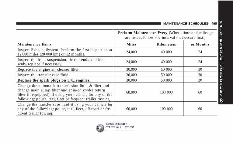
Perform Maintenance Every (Where time and mileageare listed, follow the interval that occurs first.)
Maintenance Items Miles Kilometers or MonthsInspect Exhaust System. Perform the first inspection at12,000 miles (20 000 km) or 12 months. 24,000 40 000 24
Inspect the front suspension, tie rod ends and bootseals, replace if necessary. 24,000 40 000 24
Replace the engine air cleaner filter. 30,000 50 000 30Inspect the transfer case fluid. 30,000 50 000 30Replace the spark plugs on 5.7L engines. 30,000 50 000 30Change the automatic transmission fluid & filter andchange main sump filter and spin-on cooler returnfilter (if equipped), if using your vehicle for any of thefollowing: police, taxi, fleet or frequent trailer towing.
60,000 100 000 60
Change the transfer case fluid if using your vehicle forany of the following: police, taxi, fleet, off-road or fre-quent trailer towing.
60,000 100 000 60
MAINTENANCE SCHEDULES 495
8
MAINTENANCE
SCHEDULES
Information Provided by:

Perform Maintenance Every (Where time and mileageare listed, follow the interval that occurs first.)
Maintenance Items Miles Kilometers or MonthsChange the manual transmission fluid if using yourvehicle for any of the following: trailer towing, snow-plowing, heavy loading, taxi, police, delivery service(commercial service), off-road, desert operation ormore then 50% of your driving is at sustained highspeeds during hot weather, above 90F° (32C°).
60,000 100 000 60
Inspect and replace PCV valve if necessary. 90,000 150 000 90Flush and replace the engine coolant. 102,000 170 000 60Change the automatic transmission fluid & filter andchange main sump filter and spin-on cooler returnfilter (if equipped).
120,000 200 000 120
Replace Accessory Drive Belt(s). 120,000 200 000 120
496 MAINTENANCE SCHEDULES
8
MAINTENANCE
SCHEDULES
Information Provided by:

WARNING!
You can be badly injured working on or around amotor vehicle. Do only that service work for whichyou have the knowledge and the right equipment. Ifyou have any doubt about your ability to perform aservice job, take your vehicle to a competentmechanic.
MAINTENANCE SCHEDULES 497
8
MAINTENANCE
SCHEDULES
Information Provided by:

Information Provided by:

IF YOU NEED CONSUMER ASSISTANCE
CONTENTS
m Suggestions For Obtaining Service For YourVehicle . . . . . . . . . . . . . . . . . . . . . . . . . . . . . . 500
▫ Prepare For The Appointment . . . . . . . . . . . . 500
▫ Prepare A List . . . . . . . . . . . . . . . . . . . . . . . . 500
▫ Be Reasonable With Requests . . . . . . . . . . . . . 500
m If You Need Assistance . . . . . . . . . . . . . . . . . . . 500
m Warranty Information (U.S. Vehicles Only) . . . . . 503
m Mopart Parts . . . . . . . . . . . . . . . . . . . . . . . . . 503
m Reporting Safety Defects . . . . . . . . . . . . . . . . . . 503
▫ In Canada . . . . . . . . . . . . . . . . . . . . . . . . . . 504
m Publication Order Forms . . . . . . . . . . . . . . . . . . 504
m Department Of Transportation Uniform TireQuality Grades . . . . . . . . . . . . . . . . . . . . . . . . 506
▫ Treadwear . . . . . . . . . . . . . . . . . . . . . . . . . . 506
▫ Traction Grades . . . . . . . . . . . . . . . . . . . . . . 506
▫ Temperature Grades . . . . . . . . . . . . . . . . . . . 507 9
Information Provided by:

SUGGESTIONS FOR OBTAINING SERVICE FORYOUR VEHICLE
Prepare For The AppointmentIf you’re having warranty work done, be sure to have theright papers with you. Take your warranty folder. Allwork to be performed may not be covered by thewarranty, discuss additional charges with the servicemanager. Keep a maintenance log of your vehicle’sservice history. This can often provide a clue to thecurrent problem.
Prepare A ListMake a written list of your vehicle’s problems or thespecific work you want done. If you’ve had an accident,or work done that is not on your maintenance log, let theservice advisor know.
Be Reasonable With RequestsIf you list a number of items, and you must have yourvehicle by the end of the day, discuss the situation withthe service advisor and list the items in order of priority.At many dealers, you may obtain a rental vehicle at aminimal daily charge. If you need a rental, it is advisableto make these arrangements when you call for an ap-pointment.
IF YOU NEED ASSISTANCEThe manufacturer and its dealers are vitally interested inyour satisfaction. We want you to be happy with ourproducts and services.
Warranty service must be done by an authorizedChrysler, Dodge, or Jeep dealer. We strongly recommendthat you take your vehicle to your selling dealer. Theyknow you and your vehicle best, and are most concernedthat you get prompt and high quality service. Themanufacturer’s dealers have the facilities, factory-trained
500 IF YOU NEED CONSUMER ASSISTANCE
Information Provided by:

technicians, special tools, and the latest information toassure your vehicle is fixed correctly and in a timelymanner.
This is why you should always talk to your dealer’sservice manager first. Most matters can be resolved withthis process.
• If for some reason you are still not satisfied, talk to thegeneral manager or owner of the dealership. Theywant to know if you need assistance.
• If your dealership is unable to resolve the concern, youmay contact the Manufacturer’s Customer Center.
Any communication to the Manufacturer’s CustomerCenter should include the following information:
• Owner’s name and address
• Owner’s telephone number (home and office)
• Dealership name
• Vehicle identification number
• Vehicle delivery date and mileage
DaimlerChrysler Motors Corporation Customer CenterP.O. Box 21–8004Auburn Hills, MI 48321–8004Phone: (800) 992-1997
DaimlerChrysler Canada Inc. Customer CenterP.O. Box 1621Windsor, Ontario N9A 4H6Phone —(800) 465–2001
In Mexico contact:Av. Prolongacion Paseo de la Reforma, 1240Sante Fe C.P. 05109Mexico, D. F.In Mexico (915) 729–1248 or 729–1240Outside Mexico (525) 729–1248 or 729–1240
IF YOU NEED CONSUMER ASSISTANCE 501
9
Information Provided by:

Customer Assistance For The Hearing Or SpeechImpaired (TDD/TTY)To assist customers who have hearing difficulties, themanufacturer has installed special TDD (Telecommuni-cation Devices for the Deaf) equipment at its CustomerCenter. Any hearing or speech impaired customer whohas access to a TDD or a conventional teletypewriter(TTY) in the United States can communicate with themanufacturer by dialing 1–800–380–CHRY.
Service ContractYou may have purchased a service contract for yourvehicle to help protect you from the high cost of unex-pected repairs after your manufacturer’s new vehiclelimited warranty expires. The manufacturer stands be-hind only the manufacturer’s Service Contracts. If youpurchased a manufacturer’s Service Contract, you willreceive Plan Provisions and an Owner Identification Cardin the mail within three weeks of your vehicle deliverydate. If you have any questions about your service
contract, call the manufacturer’s Service Contract Na-tional Customer Hotline at 1-800-521-9922.
The manufacturer will not stand behind any servicecontract that is not the manufacturer’s Service Contract. Itis not responsible for any service contract other than themanufacturer’s Service Contract. If you purchased aservice contract that is not a manufacturer’s ServiceContract, and you require service after your manufactur-er’s new vehicle limited warranty expires, please refer toyour contract documents, and contact the person listed inthose documents.
We appreciate that you have made a major investmentwhen you purchased your new vehicle. Your dealer hasalso made a major investment in facilities, tools, andtraining to assure that you are absolutely delighted withyour ownership experience. You’ll be pleased with theirsincere efforts to resolve any warranty issues or relatedconcerns.
502 IF YOU NEED CONSUMER ASSISTANCE
Information Provided by:

WARNING!
Engine exhaust, some of its constituents, and certainvehicle components contain or emit chemicalsknown to the State of California to cause cancer andbirth defects or other reproductive harm. In addition,certain fluids contained in vehicles and certain prod-ucts of component wear contain or emit chemicalsknown to the State of California to cause cancer andbirth defects or other reproductive harm.
WARRANTY INFORMATION (U.S. Vehicles Only)See the Warranty Information Booklet for the terms andprovisions of DaimlerChrysler’s warranties applicable tothis vehicle.
MOPART PARTSMopart fluids, lubricants, parts, and accessories areavailable from your dealer. They will help you keep yourvehicle operating at its best.
REPORTING SAFETY DEFECTSIn the 50 United States and Washington D.C.: If youbelieve that your vehicle has a defect, which could causea crash or cause injury or death, you should immediatelyinform the National Highway Traffic Safety Administra-tion (NHTSA) in addition to notifying the manufacturer.
If NHTSA receives similar complaints, it may open aninvestigation, and if it finds that a safety defect exists ina group of vehicles, it may order a recall and remedycampaign. However, NHTSA cannot become involved inindividual problems between you, your dealer, and themanufacturer.
IF YOU NEED CONSUMER ASSISTANCE 503
9
Information Provided by:

To contact NHTSA, you may either call the Auto SafetyHotline toll free at 1–888–327–4236 (TTY: 1–800–424–9153), or go to http://www.safercar.gov; or write to:Administrator, NHTSA, 400 Seventh Street, SW., Wash-ington, DC 20590. You can also obtain other informationabout motor vehicle safety from http://www.safercar.gov.
In Canada:If you believe that your vehicle has a safety defect, youshould contact the Customer Service Department imme-diately. Canadian customers who wish to report a safetydefect to the Canadian government should write toTransport Canada, Motor Vehicle Defect Investigationsand Recalls, 2780 Sheffield Road, Ottawa, Ontario K1B3V9.
PUBLICATION ORDER FORMSTo order the following manuals, you may use either thewebsite or the phone numbers listed below. Visa, Mas-tercard, American Express, and Discover orders are ac-cepted. If you prefer mailing your payment, please callfor an order form.
NOTE: A street address is required when orderingmanuals. (No P.O. Boxes).
• Service Manuals.
These comprehensive service manuals provide theinformation that students and professional techniciansneed in diagnosing/troubleshooting, problem solving,maintaining, servicing, and repairing DaimlerChryslerCorporation vehicles. A complete working knowledgeof the vehicle, system, and/or components is writtenin straightforward language with illustrations, dia-grams, and charts.
504 IF YOU NEED CONSUMER ASSISTANCE
Information Provided by:

• Diagnostic Procedure Manuals.
Filled with diagrams, charts and detailed illustrations,these practical manuals make it easy for students andtechnicians to find and fix problems on computer-controlled vehicle systems and features. They showexactly how to find and correct problems the first time,using step-by-step troubleshooting and driveabilityprocedures, proven diagnostic tests and a complete listof all tools and equipment.
• Owner’s Manuals.
These manuals have been prepared with the assistanceof service and engineering specialists to acquaint youwith specific Chrysler group vehicles. Included are
starting, operating, emergency and maintenance pro-cedures as well as specifications, capabilities andsafety tips.
Call Toll Free at:
• 1–800–890–4038 (U.S.)
• 1–800–387–1143 (Canada)
Or
Visit us on the World Wide Web at:
• www.techauthority.daimlerchrysler.com
• www.daimlerchrysler.ca/manuals
IF YOU NEED CONSUMER ASSISTANCE 505
9
Information Provided by:
DEPARTMENT OF TRANSPORTATION UNIFORMTIRE QUALITY GRADESThe following describes the tire grading categories estab-lished by the National highway Traffic Safety Adminis-tration. The specific grade rating assigned by the tire’smanufacturer in each category is shown on the sidewallof the tires on your car.
All Passenger Car Tires Must Conform to Federal SafetyRequirements in Addition to These Grades.
TreadwearThe treadwear grade is a comparative rating based on thewear rate of the tire when tested under controlled con-ditions on a specified government test course. For ex-ample, a tire graded 150 would wear one and a half (11/2) times as well on the government course as a tiregraded 100. The relative performance of tires dependsupon the actual conditions of their use, however, and
may depart significantly from the norm due to variationsin driving habits, service practices and differences in roadcharacteristics and climate.
Traction GradesThe traction grades, from highest to lowest, are AA, A, B,and C. Those grades represent the tire’s ability to stop onwet pavement as measured under controlled conditionson specified government test surfaces of asphalt andconcrete. A tire marked C may have poor traction perfor-mance.
WARNING!
The traction grade assigned to this tire is based onstraight-ahead braking traction tests, and does notinclude acceleration, cornering, hydroplaning, orpeak traction characteristics.
506 IF YOU NEED CONSUMER ASSISTANCE
Information Provided by:
Temperature GradesThe temperature grades are A (the highest), B, and C,representing the tire’s resistance to the generation of heatand its ability to dissipate heat when tested undercontrolled conditions on a specified indoor laboratorytest wheel. Sustained high temperature can cause thematerial of the tire to degenerate and reduce tire life, andexcessive temperature can lead to sudden tire failure. Thegrade C corresponds to a level of performance which allpassenger car tires must meet under the Federal MotorVehicle Safety Standard No. 109. Grades B and A repre-sent higher levels of performance on the laboratory testwheel than the minimum required by law.
WARNING!
The temperature grade for this tire is established fora tire that is properly inflated and not overloaded.Excessive speed, under inflation, or excessive load-ing, either separately or in combination, can causeheat buildup and possible tire failure.
IF YOU NEED CONSUMER ASSISTANCE 507
9
Information Provided by:

Information Provided by:
INDEX
10Information Provided by:

Adding Fuel . . . . . . . . . . . . . . . . . . . . . . . . 343,345Adjustable Pedals . . . . . . . . . . . . . . . . . . . . . . . 131Air Cleaner, Engine(Engine Air Cleaner Filter) . . . . . . . . . . . . 413,414,453Air Conditioner Maintenance . . . . . . . . . . . . . . . 427Air Conditioning Refrigerant . . . . . . . . . . . . . 427,428Air Conditioning System . . . . . . . . . . . . . . . . 237,427Air Conditioning System, Zone Control . . . . . . . . 240Air Filter . . . . . . . . . . . . . . . . . . . . . . . . . . . . . . 414Air Pressure, Tires . . . . . . . . . . . . . . . . . . . . 323,333Airbag . . . . . . . . . . . . . . . . . . . . . . . . . . . . . . 47,52Airbag Light . . . . . . . . . . . . . . . . . . . . . . . . . 75,175Airbag On/Off Switch . . . . . . . . . . . . . . . . . . . . . 52Alarm, Panic . . . . . . . . . . . . . . . . . . . . . . . . . . . . 24Alarm (Security Alarm) . . . . . . . . . . . . . . . . . 19,177Alarm System (Security Alarm) . . . . . . . . . . . . . . . 19Alignment and Balance . . . . . . . . . . . . . . . . . . . 332Alterations/Modifications, Vehicle . . . . . . . . . . . . . 8Antenna, Satellite Radio . . . . . . . . . . . . . . . . . . . 229
Antifreeze (Engine Coolant) . . . . . . . . . . . . . . 435,436Capacities . . . . . . . . . . . . . . . . . . . . . . . . . . . 474
Anti-Lock Warning Light . . . . . . . . . . . . . . . 181,312Anti-Theft Security Alarm (Theft Alarm) . . . . . . . . 19Anti-Theft System . . . . . . . . . . . . . . . . . . . . . 19,177Appearance Care . . . . . . . . . . . . . . . . . . . . . . . . 457Ashtray . . . . . . . . . . . . . . . . . . . . . . . . . . . . . . . 152Auto Unlock, Doors . . . . . . . . . . . . . . . . . . . . . . 146Automatic Dimming Mirror . . . . . . . . . . . . . . . . . 82Automatic Door Locks . . . . . . . . . . . . . . . . . . . . 146Automatic Transaxle . . . . . . . . . . . . . . . . . . . . . . 12
Interlock System . . . . . . . . . . . . . . . . . . . . . . . . 19Automatic Transmission . . . . . . . . . . . 273,279,446,448
Fluid and Filter Changes . . . . . . . . . . . . . . 448,450Fluid Level Check . . . . . . . . . . . . . . . . 446,448,449Fluid Type . . . . . . . . . . . . . . . . . . . . . 446,448,478Shift Indicator . . . . . . . . . . . . . . . . . . . . . . . . 177Special Additives . . . . . . . . . . . . . . . . . . . 448,451
Automatic Transmission (Diesel Engine Only) . . . . 446
510 INDEX
Information Provided by:
Automatic Transmission (Gas Engine Only) . . . . . 448Axle Fluid . . . . . . . . . . . . . . . . . . . . . . . . . . 444,478Axle Lubrication (Axle Fluid) . . . . . . . . . . . . . . . 444
Ball Joints . . . . . . . . . . . . . . . . . . . . . . . . . . . . . 429Battery . . . . . . . . . . . . . . . . . . . . . . . . . . . . 425,426
Blanket . . . . . . . . . . . . . . . . . . . . . . . . . . 265,427Emergency Starting . . . . . . . . . . . . . . . . . . . . . 390Keyless Transmitter Replacement (RKE) . . . . . . . 25Saving Feature (Protection) . . . . . . . . . . . . . . . 123
Bearings . . . . . . . . . . . . . . . . . . . . . . . . . . . . . . 451Belts, Drive . . . . . . . . . . . . . . . . . . . . . . . . . . . . 413Belts, Seat . . . . . . . . . . . . . . . . . . . . . . . . . . . . . . 35Body Builders Guide . . . . . . . . . . . . . . . . . . . . . . . 7Body Mechanism Lubrication . . . . . . . . . . . . . . . 430B-Pillar Location . . . . . . . . . . . . . . . . . . . . . . . . 318Brake Fluid . . . . . . . . . . . . . . . . . . . . . . . . . . . . 478Brake System . . . . . . . . . . . . . . . . . . . . . . . . 309,440
Anti-Lock (ABS) . . . . . . . . . . . . . . . . . . . . . . . 310
Disc Brakes . . . . . . . . . . . . . . . . . . . . . . . . . . 440Fluid Check . . . . . . . . . . . . . . . . . . . . . . . . . . 442Hoses . . . . . . . . . . . . . . . . . . . . . . . . . . . . . . 440Master Cylinder . . . . . . . . . . . . . . . . . . . . . . . 442Parking . . . . . . . . . . . . . . . . . . . . . . . . . . . . . 308Warning Light . . . . . . . . . . . . . . . . . . . . . . . . 180
Bulb Replacement . . . . . . . . . . . . . . . . . . . . . . . 468Bulbs, Light . . . . . . . . . . . . . . . . . . . . . . . . . . . . 468
Cab Top Clearance Lights . . . . . . . . . . . . . . . . . . 473Calibration, Compass . . . . . . . . . . . . . . . . . . 139,149Capacities, Antifreeze (Engine Coolant) . . . . . . . . 474Capacities, Fluid . . . . . . . . . . . . . . . . . . . . . . . . 474Caps, Filler
Oil (Engine) . . . . . . . . . . . . . . . . . . . . . . . 408,410Power Steering . . . . . . . . . . . . . . . . . . . . . . . . 428Radiator (Coolant Pressure) . . . . . . . . . . . . . . . 436
Car Washes . . . . . . . . . . . . . . . . . . . . . . . . . . . . 457Carbon Monoxide Warning . . . . . . . . . . . . . . . 74,340
INDEX 511
10Information Provided by:
Cassette Tape and Player Maintenance . . . . . . . . . 232Catalyst Full Message . . . . . . . . . . . . . . . . . . . . . 422Catalytic Converter . . . . . . . . . . . . . . . . . . . . . . 420CD (Compact Disc) Player . . . . . . . . . . . . 186,194,208Cellular Phone . . . . . . . . . . . . . . . . . . . . . . . . . . 87Center Lap Belts . . . . . . . . . . . . . . . . . . . . . . . . . 44Center Seat Storage Compartment . . . . . . . . . 157,158Certification Label . . . . . . . . . . . . . . . . . . . . . . . 347Charge Air Cooler . . . . . . . . . . . . . . . . . . . . . . . 439Chart, Tire Sizing . . . . . . . . . . . . . . . . . . . . . . . . 315Check Engine Light (Malfunction IndicatorLight) . . . . . . . . . . . . . . . . . . . . . . . . . . . . . . . . 179Child Restraint . . . . . . . . . . . . . . . . . . . . . . . . 59,60Child Restraint Tether Anchors . . . . . . . . . . . . . 63,67Child Seat . . . . . . . . . . . . . . . . . . . . . . . . . . . . 60,66Cigar Lighter . . . . . . . . . . . . . . . . . . . . . . . . . . . 152Cleaning
Wheels . . . . . . . . . . . . . . . . . . . . . . . . . . . . . 459Climate Control . . . . . . . . . . . . . . . . . . . . . . . . . 234
Clock . . . . . . . . . . . . . . . . . . . . . 183,188,196,209,222Clutch Linkage Maintenance . . . . . . . . . . . . . . . . 443Compact Disc (CD) Maintenance . . . . . . . . . . . . . 233Compass . . . . . . . . . . . . . . . . . . . . . . . . . . . . . . 139Compass Calibration . . . . . . . . . . . . . . . . . . 139,149Compass Variance . . . . . . . . . . . . . . . . . . . . 140,150Computer, Trip/Travel . . . . . . . . . . . . . . . . . . . . 135Console, Overhead . . . . . . . . . . . . . . . . . . . . . . . 142Contract, Service . . . . . . . . . . . . . . . . . . . . . . . . 502Coolant Pressure Cap (Radiator Cap) . . . . . . . . . . 436Cooling System . . . . . . . . . . . . . . . . . . . . . . . . . 433
Adding Coolant (Antifreeze) . . . . . . . . . . . . . . 436Coolant Capacity . . . . . . . . . . . . . . . . . . . . . . 474Coolant Level . . . . . . . . . . . . . . . . . . . 433,434,437Disposal of Used Coolant . . . . . . . . . . . . . . . . 437Drain, Flush, and Refill . . . . . . . . . . . . . . . . . . 435Inspection . . . . . . . . . . . . . . . . . . . . . . . . . . . 437Points to Remember . . . . . . . . . . . . . . . . . . . . 438Pressure Cap . . . . . . . . . . . . . . . . . . . . . . . . . 436
512 INDEX
Information Provided by:

Radiator Cap . . . . . . . . . . . . . . . . . . . . . . . . . 436Selection of Coolant (Antifreeze) . . . . . . . . . 435,476Temperature Gauge . . . . . . . . . . . . . . . . . . . . . 176
Cruise Control (Speed Control) . . . . . . . . . . . . . . 132Cup Holder . . . . . . . . . . . . . . . . . . . . . . . . . . . . 154Customer Assistance . . . . . . . . . . . . . . . . . . . . . 500
Data Recorder, Event . . . . . . . . . . . . . . . . . . . . . . 57Daytime Running Lights . . . . . . . . . . . . . . . . . . . 125Dealer Service . . . . . . . . . . . . . . . . . . . . . . . . . . 403Defroster, Rear Window . . . . . . . . . . . . . . . . . 85,161Defroster, Windshield . . . . . . . . . . . . . . . . 75,235,238Delay (Intermittent) Wipers . . . . . . . . . . . . . . . . . 128Diesel Exhaust Brake . . . . . . . . . . . . . . . . . . . . . 270Diesel Fuel . . . . . . . . . . . . . . . . . . . . . . . . . . . . 341Diesel Fuel Requirements . . . . . . . . . . . . . . . . . . 341
Bulk Storage of . . . . . . . . . . . . . . . . . . . . . . . . 346Differential, Limited-Slip . . . . . . . . . . . . . . . . . . 301Dipsticks . . . . . . . . . . . . . . . . . . . . . . . . . . . . . . 406
Power Steering . . . . . . . . . . . . . . . . . . . . . . . . 428Disc Brakes . . . . . . . . . . . . . . . . . . . . . . . . . . . . 440Disposal . . . . . . . . . . . . . . . . . . . . . . . . . . . . . . 412
Engine Oil . . . . . . . . . . . . . . . . . . . . . . . . . . . 412Used Coolant (Antifreeze) . . . . . . . . . . . . . . . . 437
Door Locks . . . . . . . . . . . . . . . . . . . . . . . . . . . . . 27Door Locks, Automatic . . . . . . . . . . . . . . . . . . . . 146Downshifting . . . . . . . . . . . . . . . . . . . . . . . . . . 288Draining Fuel/Water Separator Filter . . . . . . . . . . 417Drive Belts . . . . . . . . . . . . . . . . . . . . . . . . . . . . 413Driving
Through Flowing, Rising, or Shallow StandingWater . . . . . . . . . . . . . . . . . . . . . . . . . . . . . . 305
Dual Rear Wheels . . . . . . . . . . . . . . . . . . . . . 336,386DVD Player (Video Entertainment System) . . . . . . 226
Electric Rear Window Defrost . . . . . . . . . . . . . 85,161Electrical Power Outlets . . . . . . . . . . . . . . . . . . . 151Electronic Speed Control (Cruise Control) . . . . . . 132
INDEX 513
10Information Provided by:

Electronic Vehicle Information Center (EVIC) . . . . 143Electronically Shifted Transfer Case . . . . . . . . . . . 294Emergency Brake . . . . . . . . . . . . . . . . . . . . . . . . 308Emergency, In Case of
Freeing Vehicle When Stuck . . . . . . . . . . . . . . . 393Hazard Warning Flasher . . . . . . . . . . . . . . . . . 378Jacking . . . . . . . . . . . . . . . . . . . . . . . . . . . . . 380Jump Starting . . . . . . . . . . . . . . . . . . . . . . . . . 390Tow Hooks . . . . . . . . . . . . . . . . . . . . . . . . . . 394Towing . . . . . . . . . . . . . . . . . . . . . . . . . . . . . 395
Emission Control System Maintenance . . . . . . . . . 480Emission Related Components . . . . . . . . . . . . . . 425Engine . . . . . . . . . . . . . . . . . . . . . . . . . . . . 400,401
Air Cleaner . . . . . . . . . . . . . . . . . . . . . . . . 413,414Block Heater . . . . . . . . . . . . . . . . . . . . 256,264,270Break-In Recommendations . . . . . . . . . . . . . . . . 71Compartment . . . . . . . . . . . . . . . . . . . . . . . . . 400Compartment Identification . . . . . . . . . . . . . . . 401Coolant (Antifreeze) . . . . . . . . . . . . . . . . . . . . 476
Cooling . . . . . . . . . . . . . . . . . . . . . . . . . . . . . 433Data Plate . . . . . . . . . . . . . . . . . . . . . . . . . . . 403Exhaust Gas Caution . . . . . . . . . . . . . . . . . . . . 340Flooded, Starting . . . . . . . . . . . . . . . . . . . . . . 253Identification . . . . . . . . . . . . . . . . . . . . . . . . . 400Idling . . . . . . . . . . . . . . . . . . . . . . . . . . . . . . 266Jump Starting . . . . . . . . . . . . . . . . . . . . . . . . . 390Oil . . . . . . . . . . . . . . . . . . . . . . . . . . . . . . 406,476Oil Filler Cap . . . . . . . . . . . . . . . . . . . . . . 408,410Oil Selection . . . . . . . . . . . . . . . . . . . . . . . . . . 408Oil Synthetic . . . . . . . . . . . . . . . . . . . . . . . 265,410Runaway . . . . . . . . . . . . . . . . . . . . . . . . . . . . 337Temperature Gauge . . . . . . . . . . . . . . . . . . . . . 176
Event Data Recorder . . . . . . . . . . . . . . . . . . . . . . 57Exhaust Brake . . . . . . . . . . . . . . . . . . . . . . . . . . 270Exhaust Gas Caution . . . . . . . . . . . . . . . . 74,340,433Exhaust System . . . . . . . . . . . . . . . . . 74,432,433,452Exterior Lighting . . . . . . . . . . . . . . . . . . . . . . . . 124
514 INDEX
Information Provided by:
Fabric Care . . . . . . . . . . . . . . . . . . . . . . . . . . . . 459Fan . . . . . . . . . . . . . . . . . . . . . . . . . . . . . . . . . . 439Filters
Air Cleaner . . . . . . . . . . . . . . . . . . . . . . . . . . 413Engine Fuel . . . . . . . . . . . . . . . . . . . . . 417,420,476Engine Oil . . . . . . . . . . . . . . . . . . . . . 406,410,476
FlashersTurn Signal . . . . . . . . . . . . . . . . . . . . . . . . . . 126
Flat Tire Stowage . . . . . . . . . . . . . . . . . . . . . . . . 389Flooded Engine Starting . . . . . . . . . . . . . . . . . . . 253Fluid, Brake . . . . . . . . . . . . . . . . . . . . . . . . . . . 478Fluid Capacities . . . . . . . . . . . . . . . . . . . . . . . . . 474Fluid Level Checks
Brake . . . . . . . . . . . . . . . . . . . . . . . . . . . . . . . 442Manual Transmission . . . . . . . . . . . . . . . . . . . 445Power Steering . . . . . . . . . . . . . . . . . . . . . . . . 428Transfer Case . . . . . . . . . . . . . . . . . . . . . . . . . 445
Fluids, Lubricants and Genuine Parts . . . . . . . . . . 476Fog Lights . . . . . . . . . . . . . . . . . . . . . . . 125,179,472
Fold Flat Load Floor . . . . . . . . . . . . . . . . . . . . . 163Four Wheel Drive . . . . . . . . . . . . . . . . . . . . . . . 289Four-Way Hazard Flasher . . . . . . . . . . . . . . . . . . 378Freeing A Stuck Vehicle . . . . . . . . . . . . . . . . . . . 393Front Axle (Differential) . . . . . . . . . . . . . . . . 430,443Front Wheel Bearings . . . . . . . . . . . . . . . . . . . . . 451Fuel . . . . . . . . . . . . . . . . . . . . . . . . . . . . 337,341,345
Adding . . . . . . . . . . . . . . . . . . . . . . . . . . 343,345Diesel . . . . . . . . . . . . . . . . . . . . . . . . . 341,345,476Filter . . . . . . . . . . . . . . . . . . . . . . . . . 417,420,476Gauge . . . . . . . . . . . . . . . . . . . . . . . . . . . . . . 183Hoses . . . . . . . . . . . . . . . . . . . . . . . . . . . . . . 440Light . . . . . . . . . . . . . . . . . . . . . . . . . . . . . . . 183Octane Rating . . . . . . . . . . . . . . . . . . . . . . . . 337Requirements . . . . . . . . . . . . . . . . . . . . . . 337,341Specifications . . . . . . . . . . . . . . . . . . . . . . . . . 342System Hoses . . . . . . . . . . . . . . . . . . . . . . . . . 440Tank Capacity . . . . . . . . . . . . . . . . . . . . . . . . 474
Fuses . . . . . . . . . . . . . . . . . . . . . . . . . . . . . . . . 462
INDEX 515
10Information Provided by:

Gas Cap (Fuel Filler Cap) . . . . . . . . . . . . . . . 344,402Gasoline (Fuel) . . . . . . . . . . . . . . . . . . . . . . . . . 337Gasoline, Reformulated . . . . . . . . . . . . . . . . . . . 338Gauges . . . . . . . . . . . . . . . . . . . . . . . . . . . . . . . 174
Coolant Temperature . . . . . . . . . . . . . . . . . . . . 176Fuel . . . . . . . . . . . . . . . . . . . . . . . . . . . . . . . . 183Oil Pressure . . . . . . . . . . . . . . . . . . . . . . . . . . 176Speedometer . . . . . . . . . . . . . . . . . . . . . . . . . 175Tachometer . . . . . . . . . . . . . . . . . . . . . . . . . . 175Voltmeter . . . . . . . . . . . . . . . . . . . . . . . . . 174,262
Gear Ranges . . . . . . . . . . . . . . . . . . . . . . 274,279,287General Information . . . . . . . . . . . . . . . . . . . . 18,113Glass Cleaning . . . . . . . . . . . . . . . . . . . . . . . . . . 461Grocery Bag Retainer . . . . . . . . . . . . . . . . . . . . . 161Gross Axle Weight Rating . . . . . . . . . . . . . . . . . . 352Gross Vehicle Weight Rating . . . . . . . . . . . . . . . . 351Guide, Body Builders . . . . . . . . . . . . . . . . . . . . . . 7GVWR . . . . . . . . . . . . . . . . . . . . . . . . . . . . . . . 348
Hands-Free Phone (UConnect™) . . . . . . . . . . . . . . 87Hazard
Driving Through Flowing, Rising, or ShallowStanding Water . . . . . . . . . . . . . . . . . . . . . . . . 305
Hazard Warning Flasher . . . . . . . . . . . . . . . . . . . 378Head Restraints . . . . . . . . . . . . . . . . . . . . . . . . . 116Headlights . . . . . . . . . . . . . . . . . . . . . . . . . . . . 468
Cleaning . . . . . . . . . . . . . . . . . . . . . . . . . . . . 460High Beam . . . . . . . . . . . . . . . . . . . . . . . . . . . 127High Beam/Low Beam Select Switch . . . . . . . . 127Lights On Reminder . . . . . . . . . . . . . . . . . . . . 125Passing . . . . . . . . . . . . . . . . . . . . . . . . . . . . . 127Switch . . . . . . . . . . . . . . . . . . . . . . . . . . . . . . 124
Heated Mirrors . . . . . . . . . . . . . . . . . . . . . . . 85,161Heated Seats . . . . . . . . . . . . . . . . . . . . . . . . . . . 119Heater . . . . . . . . . . . . . . . . . . . . . . . . . . . . . . . 237Heater, Engine Block . . . . . . . . . . . . . . . . . . . . . 270High Beam/Low Beam Select (Dimmer) Switch . . 127
516 INDEX
Information Provided by:

HitchesTrailer Towing . . . . . . . . . . . . . . . . . . . . . . . . 355
Hoisting . . . . . . . . . . . . . . . . . . . . . . . . . . . . . . 389Hood Release . . . . . . . . . . . . . . . . . . . . . . . . . . 120Hoses . . . . . . . . . . . . . . . . . . . . . . . . . . . . . . . . 440Hub Caps . . . . . . . . . . . . . . . . . . . . . . . . . . . . . 385Hydraulic Clutch Fluid . . . . . . . . . . . . . . . . . . . . 443
Ignition . . . . . . . . . . . . . . . . . . . . . . . . . . . . . . . 12Key . . . . . . . . . . . . . . . . . . . . . . . . . . . . . . . . . 12
Ignition Key Removal . . . . . . . . . . . . . . . . . . . . . 12Illuminated Entry . . . . . . . . . . . . . . . . . . . . . . . . 20Immobilizer (Sentry Key) . . . . . . . . . . . . . . . . . . . 15Infant Restraint . . . . . . . . . . . . . . . . . . . . . . . . 59,60Inflation Pressure Tires . . . . . . . . . . . . . . . . . . . . 333Information Center . . . . . . . . . . . . . . . . . . . . . . 143Information Center, Vehicle . . . . . . . . . . . . . . . . . 143Inside Rearview Mirror . . . . . . . . . . . . . . . . . . . . 81Instrument Cluster . . . . . . . . . . . . . . . . . . . . 172,174
Instrument Panel and Controls . . . . . . . . . . . . . . 171Instrument Panel Lens Cleaning . . . . . . . . . . . . . 461Integrated Power Module (Fuses) . . . . . . . . . . . . 462Interior Appearance Care . . . . . . . . . . . . . . . . . . 460Interior Lights . . . . . . . . . . . . . . . . . . . . . . . . . . 122Intermittent Wipers (Delay Wipers) . . . . . . . . . . . 128Intervention Regeneration Strategy . . . . . . . . . . . 422Introduction . . . . . . . . . . . . . . . . . . . . . . . . . . . . . 4
Jack Location . . . . . . . . . . . . . . . . . . . . . . . . . . . 379Jack Operation . . . . . . . . . . . . . . . . . . . . . . . . . . 380Jump Starting . . . . . . . . . . . . . . . . . . . . . . . . . . 390
Key, Programming . . . . . . . . . . . . . . . . . . . . . . . . 17Key, Replacement . . . . . . . . . . . . . . . . . . . . . . . . 16Key, Sentry (Immobilizer) . . . . . . . . . . . . . . . . . . . 15Keyless Entry System . . . . . . . . . . . . . . . . . . . . . . 21Keys . . . . . . . . . . . . . . . . . . . . . . . . . . . . . . . . . 12
INDEX 517
10Information Provided by:

Lane Change and Turn Signals . . . . . . . . . . . . . . 126Lap Belts . . . . . . . . . . . . . . . . . . . . . . . . . . . . . . 44Lap/Shoulder Belts . . . . . . . . . . . . . . . . . . . . . . . 35LATCH (Lower Anchors and Tether forCHildren) . . . . . . . . . . . . . . . . . . . . . . . . . . . . . . 63Life of Tires . . . . . . . . . . . . . . . . . . . . . . . . . . . . 331Lights . . . . . . . . . . . . . . . . . . . . . . . . . . . . . . 76,122
Airbag . . . . . . . . . . . . . . . . . . . . . . . . . . . . 56,175Anti-Lock Warning . . . . . . . . . . . . . . . . . . 181,312Brake Warning . . . . . . . . . . . . . . . . . . . . . . . . 180Bulb Replacement . . . . . . . . . . . . . . . . . . . . . . 468Cap Top Clearance . . . . . . . . . . . . . . . . . . . . . 473Check Engine (Malfunction Indicator) . . . . . . . . 179Cruise . . . . . . . . . . . . . . . . . . . . . . . . . . . . . . 183Daytime Running . . . . . . . . . . . . . . . . . . . . . . 125Dome . . . . . . . . . . . . . . . . . . . . . . . . . . . . . . 142Fog . . . . . . . . . . . . . . . . . . . . . . . . . . 125,179,472Four-Wheel Drive Indicator . . . . . . . . . . . . . . . 293Hazard Warning Flasher . . . . . . . . . . . . . . . . . 378
Headlights . . . . . . . . . . . . . . . . . . . . . . . . . . . 124High Beam . . . . . . . . . . . . . . . . . . . . . . . . 127,175High Beam Indicator . . . . . . . . . . . . . . . . . . . . 175High Beam/Low Beam Select . . . . . . . . . . . . . 127Illuminated Entry . . . . . . . . . . . . . . . . . . . . . . . 20Instrument Cluster . . . . . . . . . . . . . . . . . . . . . 174Intensity Control . . . . . . . . . . . . . . . . . . . . . . . 123Interior . . . . . . . . . . . . . . . . . . . . . . . . . . . . . 122Lights On Reminder . . . . . . . . . . . . . . . . . . . . 125Passing . . . . . . . . . . . . . . . . . . . . . . . . . . . . . 127Reading . . . . . . . . . . . . . . . . . . . . . . . . . . . . . 142Seat Belt Reminder . . . . . . . . . . . . . . . . . . . . . 175Service . . . . . . . . . . . . . . . . . . . . . . . . . . . . . . 468Transfer Case . . . . . . . . . . . . . . . . . . . . . . . . . 293Transmission Warning . . . . . . . . . . . . . . . . . . . 182Turn Signal . . . . . . . . . . . . . . . . . . . . . 126,175,468Warning (Instrument Cluster Description) . . . . . 174
Limited-Slip Differential . . . . . . . . . . . . . . . . 301,444Loading Vehicle . . . . . . . . . . . . . . . . . . . . . . . . . 347
518 INDEX
Information Provided by:

Tires . . . . . . . . . . . . . . . . . . . . . . . . . . . . . . . 318Locks . . . . . . . . . . . . . . . . . . . . . . . . . . . . . . . . . 27
Child Protection . . . . . . . . . . . . . . . . . . . . . . . . 31Door . . . . . . . . . . . . . . . . . . . . . . . . . . . . . . . . 27Keys . . . . . . . . . . . . . . . . . . . . . . . . . . . . . . . . 12Power Door . . . . . . . . . . . . . . . . . . . . . . . . . . . 28Steering Wheel . . . . . . . . . . . . . . . . . . . . . . . . . 18
Lower Anchors and Tether for CHildren(LATCH) . . . . . . . . . . . . . . . . . . . . . . . . . . . . . . 63Lubrication, Body . . . . . . . . . . . . . . . . . . . . . . . 430Lug Nuts . . . . . . . . . . . . . . . . . . . . . . . . . . . 384,386Lumbar Support . . . . . . . . . . . . . . . . . . . . . . . . 117
Maintenance . . . . . . . . . . . . . . . . . . . . . . . . . . . 404Maintenance Free Battery . . . . . . . . . . . . . . . . . . 425Maintenance Procedures . . . . . . . . . . . . . . . . . . . 406Maintenance Schedule . . . . . . . . . . . . . . . . . 480,491Manual, Service . . . . . . . . . . . . . . . . . . . . . . . . . 504Manual Transmission . . . . . . . . . . . . . . . . . . 285,445
Fluid Level Check . . . . . . . . . . . . . . . . . . . . . . 445Lubricant Selection . . . . . . . . . . . . . . . . . . . . . 478Shift Speeds . . . . . . . . . . . . . . . . . . . . . . . . . . 287
Map/Reading Lights . . . . . . . . . . . . . . . . . . . . . 142Mirrors . . . . . . . . . . . . . . . . . . . . . . . . . . . . . . . . 81
Automatic Dimming . . . . . . . . . . . . . . . . . . . . . 82Electric Powered . . . . . . . . . . . . . . . . . . . . . . . 84Outside . . . . . . . . . . . . . . . . . . . . . . . . . . . . . . 82Rearview . . . . . . . . . . . . . . . . . . . . . . . . . . . . . 81Trailer Towing . . . . . . . . . . . . . . . . . . . . . . 85,364
Modifications/Alterations, Vehicle . . . . . . . . . . . . . 8Mopar Parts . . . . . . . . . . . . . . . . . . . . . . . . . 403,503Multi-Function Control Lever . . . . . . . . . . . . . . . 126
Navigation Radio . . . . . . . . . . . . . . . . . . . . . . . . 222Navigation System . . . . . . . . . . . . . . . . . . . . . . . 222New Vehicle Break-In Period . . . . . . . . . . . . . . . . 71Noise Control
Maintenance . . . . . . . . . . . . . . . . . . . . . . . . . . 452
INDEX 519
10Information Provided by:

Tampering Prohibited . . . . . . . . . . . . . . . . . . . 453Noise Emission Warranty . . . . . . . . . . . . . . . 451,454
Occupant Restraints . . . . . . . . . . . . . . . . . . . . . . . 35Octane Rating, Gasoline (Fuel) . . . . . . . . . . . . . . 337Odometer . . . . . . . . . . . . . . . . . . . . . . . . . . 177,182
Trip . . . . . . . . . . . . . . . . . . . . . . . . . . . . . 177,182Off-Pavement Driving (Off-Road) . . . . . . . . . . . . 307Off-Road Driving (Off-Pavement) . . . . . . . . . . . . 307Oil Change Indicator . . . . . . . . . . . . . . . . 145,178,482Oil, Engine . . . . . . . . . . . . . . . . . . . . . . . . . . . . 476
Capacity . . . . . . . . . . . . . . . . . . . . . . . . . . . . 474Change Interval . . . . . . . . . . . . . . . . . . . . 407,409Dipstick . . . . . . . . . . . . . . . . . . . . . . . . . . . . . 406Disposal . . . . . . . . . . . . . . . . . . . . . . . . . . . . 412Filter . . . . . . . . . . . . . . . . . . . . . . . . . 406,410,476Identification Logo . . . . . . . . . . . . . . . . . . 408,409Materials Added to . . . . . . . . . . . . . . . . . . . . . 410Pressure Gauge . . . . . . . . . . . . . . . . . . . . . . . 176
Recommendation . . . . . . . . . . . . . . . . . . . 408,409Synthetic . . . . . . . . . . . . . . . . . . . . . . . . . . . . 410Viscosity . . . . . . . . . . . . . . . . . . . . . . . . . . 408,410
Oil Filter, Change . . . . . . . . . . . . . . . . . . . . . . . . 410Onboard Diagnostic System . . . . . . . . . . . . . . . . 402Operating Precautions . . . . . . . . . . . . . . . . . . . . 402Outside Rearview Mirrors . . . . . . . . . . . . . . . . . . 82Overdrive . . . . . . . . . . . . . . . . . . . . . . . . . . 276,282Overdrive OFF Switch . . . . . . . . . . . . . . . . . 276,282Overhead Console . . . . . . . . . . . . . . . . . . . . 135,142Overhead Travel Information Center . . . . . . . . . . 135Owner’s Manual (Operator Manual) . . . . . . . . . . 504
Panic Alarm . . . . . . . . . . . . . . . . . . . . . . . . . . . . 24Parking Brake . . . . . . . . . . . . . . . . . . . . . . . . . . 308Passenger Airbag On/Off Switch . . . . . . . . . . . . . 52Passing Light . . . . . . . . . . . . . . . . . . . . . . . . . . . 127Pedals, Adjustable . . . . . . . . . . . . . . . . . . . . . . . 131Personal Settings . . . . . . . . . . . . . . . . . . . . . . . . 146
520 INDEX
Information Provided by:

Phone, Cellular . . . . . . . . . . . . . . . . . . . . . . . . . . 87Phone, Hands-Free (UConnect™) . . . . . . . . . . . . . 87Placard, Tire and Loading Information . . . . . . . . . 318Positive Crankcase Valve . . . . . . . . . . . . . . . . . . 425Power
Distribution Center (Fuses) . . . . . . . . . . . . . . . 462Door Locks . . . . . . . . . . . . . . . . . . . . . . . . . . . 28Mirrors . . . . . . . . . . . . . . . . . . . . . . . . . . . . . . 84Outlet (Auxiliary Electrical Outlet) . . . . . . . . . . 151Seats . . . . . . . . . . . . . . . . . . . . . . . . . . . . . . . 117Sliding Rear Window . . . . . . . . . . . . . . . . . 34,162Steering . . . . . . . . . . . . . . . . . . . . . . . . . . 312,428Take-Off Adapter . . . . . . . . . . . . . . . . . . . . . . 302Take-Off Operation . . . . . . . . . . . . . . . . . . . . . 302Windows . . . . . . . . . . . . . . . . . . . . . . . . . . . . . 32
Power Steering Fluid . . . . . . . . . . . . . . . . . . . . . 478Pregnant Women and Seat Belts . . . . . . . . . . . . . . 47Pretensioners
Seat Belts . . . . . . . . . . . . . . . . . . . . . . . . . . . . . 45
Programmable Electronic Features . . . . . . . . . . . . 146PTO (Power Take-Off) . . . . . . . . . . . . . . . . . . . . 302
Radial Ply Tires . . . . . . . . . . . . . . . . . . . . . . . . . 328Radiator Cap (Coolant Pressure Cap) . . . . . . . . . . 436Radio Broadcast Signals . . . . . . . . . . . . . . . . . . . 184Radio, Navigation . . . . . . . . . . . . . . . . . . . . . . . 222Radio Operation . . . . . . . . . . . . . . . . . . . 186,194,208Radio Remote Controls . . . . . . . . . . . . . . . . . . . . 230Radio, Satellite . . . . . . . . . . . . . . . . . . . . . . . 222,226Radio (Sound Systems) . . . . . . . . . . . . . . 186,194,208Rear Axle (Differential) . . . . . . . . . . . . . . . . . 443,444Rear Wheel Bearings . . . . . . . . . . . . . . . . . . . . . 451Rear Window Features . . . . . . . . . . . . . . . . . . . . 161Rear Window, Sliding . . . . . . . . . . . . . . . . . . . 34,162Reclining Front Seats . . . . . . . . . . . . . . . . . . . . . 115Recorder, Event Data . . . . . . . . . . . . . . . . . . . . . . 57Recreational Towing . . . . . . . . . . . . . . . . . . . . . . 369
Shifting into Transfer Case Neutral (N) . . . . 370,372
INDEX 521
10Information Provided by:
Shifting out of Transfer Case Neutral (N) . . . 371,374Reformulated Gasoline . . . . . . . . . . . . . . . . . . . . 338Refrigerant . . . . . . . . . . . . . . . . . . . . . . . . . . . . 428Reminder, Seat Belt . . . . . . . . . . . . . . . . . . . . . . . 45Remote Keyless Entry (RKE) . . . . . . . . . . . . . . . . . 21Remote Sound System (Radio) Controls . . . . . . . . 230Remote Starting System . . . . . . . . . . . . . . . . . . . . 26Replacement Keys . . . . . . . . . . . . . . . . . . . . . . . . 16Replacement Tires . . . . . . . . . . . . . . . . . . . . . . . 331Reporting Safety Defects . . . . . . . . . . . . . . . . . . . 503Resetting Oil Change Indicator . . . . . . . . . . . 145,178Restraint, Head . . . . . . . . . . . . . . . . . . . . . . . . . 116Restraints, Child . . . . . . . . . . . . . . . . . . . . . . . 59,66Restraints, Occupant . . . . . . . . . . . . . . . . . . . . . . 35Rotation, Tires . . . . . . . . . . . . . . . . . . . . . . . . . . 335
Safety Checks Inside Vehicle . . . . . . . . . . . . . . . . . 75Safety Checks Outside Vehicle . . . . . . . . . . . . . . . 75Safety Defects, Reporting . . . . . . . . . . . . . . . . . . 503
Safety Information, Tire . . . . . . . . . . . . . . . . . . . 313Safety Tips . . . . . . . . . . . . . . . . . . . . . . . . . . . . . 73Satellite Radio . . . . . . . . . . . . . . . . . . . . . . . 222,226Satellite Radio Antenna . . . . . . . . . . . . . . . . . . . 229Schedule, Maintenance . . . . . . . . . . . . . . . . . . . . 491Seat Belt Maintenance . . . . . . . . . . . . . . . . . . . . 461Seat Belt Reminder . . . . . . . . . . . . . . . . . . . . . . . 45Seat Belts . . . . . . . . . . . . . . . . . . . . . . . . . . . . 35,75
Adjustable Upper Shoulder Anchorage . . . . . . . . 43And Pregnant Women . . . . . . . . . . . . . . . . . . . 47Child Restraint . . . . . . . . . . . . . . . . . . . . . . . 59,71Extender . . . . . . . . . . . . . . . . . . . . . . . . . . . . . 47Front Seat . . . . . . . . . . . . . . . . . . . . . . . . . . . . 35Pretensioners . . . . . . . . . . . . . . . . . . . . . . . . . . 45Reminder . . . . . . . . . . . . . . . . . . . . . . . . . . . . 175
Seats . . . . . . . . . . . . . . . . . . . . . . . . . . . . . . . . . 114Adjustment . . . . . . . . . . . . . . . . . . . . . . . . . . 114Child . . . . . . . . . . . . . . . . . . . . . . . . . . . . . . . 71Cleaning . . . . . . . . . . . . . . . . . . . . . . . . . . . . 459
522 INDEX
Information Provided by:

Folding Floor . . . . . . . . . . . . . . . . . . . . . . . . . 163Heated . . . . . . . . . . . . . . . . . . . . . . . . . . . . . . 119Lumbar Support . . . . . . . . . . . . . . . . . . . . . . . 117Power . . . . . . . . . . . . . . . . . . . . . . . . . . . . . . 117Reclining . . . . . . . . . . . . . . . . . . . . . . . . . . . . 115
Security Alarm (Theft Alarm) . . . . . . . . . . . . . 19,177Selection of Coolant (Antifreeze) . . . . . . . . . . 435,476Sentry Key (Immobilizer) . . . . . . . . . . . . . . . . . . . 15Sentry Key Programming . . . . . . . . . . . . . . . . . . . 17Sentry Key Replacement . . . . . . . . . . . . . . . . . . . 16Service Assistance . . . . . . . . . . . . . . . . . . . . . . . 500Service Contract . . . . . . . . . . . . . . . . . . . . . . . . . 502Service Information . . . . . . . . . . . . . . . . . . . . . . 404Service Manuals . . . . . . . . . . . . . . . . . . . . . . . . 504Setting the Clock . . . . . . . . . . . . . 184,188,196,209,222Settings, Personal . . . . . . . . . . . . . . . . . . . . . . . . 146Shifting . . . . . . . . . . . . . . . . . . . . . . . . . . . . . . . 273
Manual Transmission . . . . . . . . . . . . . . . . . . . 285Transfer Case . . . . . . . . . . . . . . . . . . . . . . . . . 292
Transfer Case, Shifting into Transfer CaseNeutral (N) . . . . . . . . . . . . . . . . . . . . . . . 370,372Transfer Case, Shifting out of Transfer CaseNeutral (N) . . . . . . . . . . . . . . . . . . . . . . . 371,374
Shoulder Belt Upper Anchorage . . . . . . . . . . . . . . 43Shoulder Belts . . . . . . . . . . . . . . . . . . . . . . . . . . . 35Signals, Turn . . . . . . . . . . . . . . . . . . . . . . . . . . . 126Sliding Rear Window
Power . . . . . . . . . . . . . . . . . . . . . . . . . . . . 34,162Slippery Surfaces, Driving On . . . . . . . . . . . . . . . 304Snow Chains (Tire Chains) . . . . . . . . . . . . . . . . . 333Snow Plow . . . . . . . . . . . . . . . . . . . . . . . . . . . . 365Snow Tires . . . . . . . . . . . . . . . . . . . . . . . . . . . . 334Soot Filter . . . . . . . . . . . . . . . . . . . . . . . . . . . . . 422Spare Tire . . . . . . . . . . . . . . . . . . . . . . . . . . . . . 329Spark Plugs . . . . . . . . . . . . . . . . . . . . . . . . . 420,476Speed Control (Cruise Control) . . . . . . . . . . . . . . 132Speedometer . . . . . . . . . . . . . . . . . . . . . . . . . . . 175Starting . . . . . . . . . . . . . . . . . . . . . . . . . . . . 252,255
INDEX 523
10Information Provided by:

Automatic Transmission . . . . . . . . . . . . . . . 252,256Engine Block Heater . . . . . . . . . . . . . . . . . 256,264Engine Fails to Start . . . . . . . . . . . . . . . . . . . . 253Manual Transmission . . . . . . . . . . . . . . . . . 252,256Remote . . . . . . . . . . . . . . . . . . . . . . . . . . . . . . 26
Starting Procedures . . . . . . . . . . . . . . . . . . . . . . 255Starting Procedures (Diesel Engines) . . . . . . . . . . 255Starting Procedures (Gas Engines) . . . . . . . . . . . . 252Steel Carcass Ply Tires . . . . . . . . . . . . . . . . . . . . 325Steering
Linkage . . . . . . . . . . . . . . . . . . . . . . . . . . . . . 429Power . . . . . . . . . . . . . . . . . . . . . . . . . . . 312,428Wheel Lock . . . . . . . . . . . . . . . . . . . . . . . . . . . 18Wheel, Tilt . . . . . . . . . . . . . . . . . . . . . . . . . . . 130
Steering Wheel Mounted Sound SystemControls . . . . . . . . . . . . . . . . . . . . . . . . . . . . . . 230Storage, Behind the Seat . . . . . . . . . . . . . . . . . . . 157Storage Compartment, Center Seat . . . . . . . . . 157,158Storage, Vehicle . . . . . . . . . . . . . . . . . . . . . . . . . 467
Storing Your Vehicle . . . . . . . . . . . . . . . . . . . . . . 467Supplemental Tire Pressure Information . . . . . . . . 333Synthetic Engine Oil . . . . . . . . . . . . . . . . . . . 265,410System, Navigation . . . . . . . . . . . . . . . . . . . . . . 222System, Remote Starting . . . . . . . . . . . . . . . . . . . . 26
Tachometer . . . . . . . . . . . . . . . . . . . . . . . . . . . . 175Tether Anchor, Child Restraint . . . . . . . . . . . . . 63,67Tilt Steering Column . . . . . . . . . . . . . . . . . . . . . 130Tip Start . . . . . . . . . . . . . . . . . . . . . . . . . . . . . . 253Tire and Loading Information Placard . . . . . . 318,333Tire Identification Number (TIN) . . . . . . . . . . . . . 317Tire Markings . . . . . . . . . . . . . . . . . . . . . . . . . . 313Tire Safety Information . . . . . . . . . . . . . . . . . . . . 313Tires . . . . . . . . . . . . . . . . . . . . . . . . . . . . 75,322,506
Aging (Life of Tires) . . . . . . . . . . . . . . . . . . . . 331Air Pressure . . . . . . . . . . . . . . . . . . . . . . . . . . 322Alignment . . . . . . . . . . . . . . . . . . . . . . . . . . . 332Chains . . . . . . . . . . . . . . . . . . . . . . . . . . . . . . 333
524 INDEX
Information Provided by:

Changing . . . . . . . . . . . . . . . . . . . . . . . . . . . . 380Dual . . . . . . . . . . . . . . . . . . . . . . . . . . . . 336,386General Information . . . . . . . . . . . . . . . . . . . . 322High Speed . . . . . . . . . . . . . . . . . . . . . . . . . . 327Inflation Pressures . . . . . . . . . . . . . . . . . . . . . 323Jacking . . . . . . . . . . . . . . . . . . . . . . . . . . . . . 380Life of Tires . . . . . . . . . . . . . . . . . . . . . . . . . . 331Load Capacity . . . . . . . . . . . . . . . . . . . . . 318,319Quality Grading . . . . . . . . . . . . . . . . . . . . . . . 506Radial . . . . . . . . . . . . . . . . . . . . . . . . . . . . . . 328Replacement . . . . . . . . . . . . . . . . . . . . . . . . . 331Rotation . . . . . . . . . . . . . . . . . . . . . . . . . . . . . 335Safety . . . . . . . . . . . . . . . . . . . . . . . . . . . 313,322Sizes . . . . . . . . . . . . . . . . . . . . . . . . . . . . . . . 315Snow Tires . . . . . . . . . . . . . . . . . . . . . . . . . . . 334Spinning . . . . . . . . . . . . . . . . . . . . . . . . . . . . 329Steel Carcass Ply . . . . . . . . . . . . . . . . . . . . . . . 325Tread Wear Indicators . . . . . . . . . . . . . . . . . . . 330Wheel Mounting . . . . . . . . . . . . . . . . . . . . . . . 380
Wheel Nut Torque . . . . . . . . . . . . . . . . . . . . . 384Tongue Weight/Trailer Weight . . . . . . . . . . . . . . 356Torque Converter Clutch . . . . . . . . . . . . . . . . 278,285Tow Hooks, Emergency . . . . . . . . . . . . . . . . . . . 394Towing . . . . . . . . . . . . . . . . . . . . . . . . . . . . . . . 351
Disabled Vehicle . . . . . . . . . . . . . . . . . . . . . . . 395Guide . . . . . . . . . . . . . . . . . . . . . . . . . . . . . . 356Recreational . . . . . . . . . . . . . . . . . . . . . . . . . . 369Weight . . . . . . . . . . . . . . . . . . . . . . . . . . . . . . 356
Traction . . . . . . . . . . . . . . . . . . . . . . . . . . . . . . 304Traction Control . . . . . . . . . . . . . . . . . . . . . . . . . 445Trailer Towing . . . . . . . . . . . . . . . . . . . . . . . . . . 351
Cooling System Tips . . . . . . . . . . . . . . . . . . . . 363Hitches . . . . . . . . . . . . . . . . . . . . . . . . . . . . . 355Minimum Requirements . . . . . . . . . . . . . . . . . 357Mirrors . . . . . . . . . . . . . . . . . . . . . . . . . . . 85,364Trailer and Tongue Weight . . . . . . . . . . . . . . . . 356Wiring . . . . . . . . . . . . . . . . . . . . . . . . . . . . . . 360
Trailer Towing Guide . . . . . . . . . . . . . . . . . . . . . 356
INDEX 525
10Information Provided by:
Trailer Weight . . . . . . . . . . . . . . . . . . . . . . . . . . 356Transaxle
Automatic . . . . . . . . . . . . . . . . . . . . . . . . . . . . 12Manual . . . . . . . . . . . . . . . . . . . . . . . . . . . . . . 14
Transfer CaseElectronically Shifted . . . . . . . . . . . . . . . . . . . . 294Fluid . . . . . . . . . . . . . . . . . . . . . . . . . . . . . . . 478
TransmissionAutomatic . . . . . . . . . . . . . . . . . . . 273,279,446,448Fluid . . . . . . . . . . . . . . . . . . . . . . . . . . . . . . . 478Maintenance . . . . . . . . . . . . . . . . . . . . . . . 446,448Manual . . . . . . . . . . . . . . . . . . . . . 252,256,285,445Shifting . . . . . . . . . . . . . . . . . . . . . . . . . . . . . 273
Transmitter Battery Service (Remote KeylessEntry) . . . . . . . . . . . . . . . . . . . . . . . . . . . . . . . . . 25Tread Wear Indicators . . . . . . . . . . . . . . . . . . . . 330Trip Computer . . . . . . . . . . . . . . . . . . . . . . . . . . 135Trip Odometer . . . . . . . . . . . . . . . . . . . . . . . 177,182Turn Signals . . . . . . . . . . . . . . . . . . . . . . 126,175,468
UConnect™ (Hands-Free Phone) . . . . . . . . . . . . . . 87Underhood Fuses . . . . . . . . . . . . . . . . . . . . . . . . 462Uniform Tire Quality Grades . . . . . . . . . . . . . . . . 506
Variance, Compass . . . . . . . . . . . . . . . . . . . . 140,150Vehicle Identification Number (VIN) . . . . . . . . . . . . 8Vehicle Information Center . . . . . . . . . . . . . . . . . 143Vehicle Loading . . . . . . . . . . . . . . . . . . . . . . 319,347Vehicle Modifications/Alterations . . . . . . . . . . . . . . 8Vehicle Storage . . . . . . . . . . . . . . . . . . . . . . . . . 467Video Entertainment System (Rear Seat VideoSystem) . . . . . . . . . . . . . . . . . . . . . . . . . . . . . . . 226Viscosity, Engine Oil . . . . . . . . . . . . . . . . . . . . . . 410Voltmeter . . . . . . . . . . . . . . . . . . . . . . . . . . . 174,262
Warning Lights (Instrument ClusterDescription) . . . . . . . . . . . . . . . . . . . . . . . . . . . 174Warnings and Cautions . . . . . . . . . . . . . . . . . . . . . 7Warranty Information . . . . . . . . . . . . . . . . . . . . . 503
526 INDEX
Information Provided by:

Washers, Windshield . . . . . . . . . . . . . . . . . . 129,431Washing Vehicle . . . . . . . . . . . . . . . . . . . . . . . . . 457Water
Driving Through . . . . . . . . . . . . . . . . . . . . . . 305Water Separator, Diesel Fuel . . . . . . . . . . . . . . . . 417Wheel Alignment and Balance . . . . . . . . . . . . . . . 332Wheel and Wheel Trim . . . . . . . . . . . . . . . . . . . . 459Wheel and Wheel Trim Care . . . . . . . . . . . . . . . . 459Wheel Changing . . . . . . . . . . . . . . . . . . . . . . . . 380Wheel Cover . . . . . . . . . . . . . . . . . . . . . . . . . . . 385Wheel Mounting . . . . . . . . . . . . . . . . . . . . . . . . 380Wheel Nut Torque . . . . . . . . . . . . . . . . . . . . 384,388Wind Buffeting . . . . . . . . . . . . . . . . . . . . . . . . . . 34
Window Fogging . . . . . . . . . . . . . . . . . . . . . . . . 244Windows . . . . . . . . . . . . . . . . . . . . . . . . . . . . . . 32
Power . . . . . . . . . . . . . . . . . . . . . . . . . . . . . . . 32Rear Sliding . . . . . . . . . . . . . . . . . . . . . . . . 34,162
Windshield Defroster . . . . . . . . . . . . . . . . . . 235,238Windshield Washers . . . . . . . . . . . . . . . . 128,129,431
Fluid . . . . . . . . . . . . . . . . . . . . . . . . . . . . 128,431Windshield Wiper Blades . . . . . . . . . . . . . . . . . . 431Windshield Wipers . . . . . . . . . . . . . . . . . . . . . . . 128Wiper Blade Replacement . . . . . . . . . . . . . . . . . . 431Wipers, Intermittent . . . . . . . . . . . . . . . . . . . . . . 128
YES Essentialst Fabric Cleaning Procedure . . . . . . 459
INDEX 527
10Information Provided by:

INTRODUCTION INTRODUCTION A MESSAGE FROM DAIMLERCHRYSLER CORPORATION - DIESEL ENGINES ONLY HOW TO USE THIS MANUAL WARNINGS AND CAUTIONS VAN CONVERSIONS/CAMPERS VEHICLE IDENTIFICATION NUMBER VEHICLE
MODIFICATIONS/ALTERATIONS THINGS TO KNOW BEFORE STARTING YOUR VEHICLE A WORD ABOUT YOUR KEYS Ignition Key RemovalLocking Doors With The KeySENTRY KEY Replacement KeysCustomer Key ProgrammingGeneral InformationSTEERING
WHEEL LOCK - IF EQUIPPED If You Wish To Manually Lock The Steering WheelTo Release The Steering Wheel LockAutomatic Transmission Ignition Interlock SystemSECURITY ALARM SYSTEM - IF EQUIPPED Rearming of the SystemTo Set the AlarmTo Disarm the
SystemILLUMINATED ENTRY SYSTEM - IF EQUIPPED REMOTE KEYLESS ENTRY - IF EQUIPPED To unlock the doorsTo lock the doorsUsing the Panic AlarmGeneral InformationTransmitter Battery Service REMOTE STARTING SYSTEM - IF EQUIPPED DOOR LOCKS
Manual Door Locks - If EquippedPower Door Locks - If EquippedChild Protection Door LockWINDOWS Power Windows - If Equipped Power Sliding Rear Window - If Equipped Sliding Rear Window - If EquippedWind BuffetingOCCUPANT RESTRAINTS Lap/Shoulder Belts
Adjustable Upper Shoulder Belt AnchorageAutomatic Locking Restraint (ALR) Mode - If EquippedCenter Lap BeltsSeat Belt PretensionersEnhanced Driver Seat Belt Reminder System (BeltAlert) Seat Belts and Pregnant WomenSeat Belt ExtenderDriver And Right Front
Passenger Supplemental Restraint System (SRS)-AirbagEvent Data Recorder (EDR)Child RestraintNEW ENGINE BREAK-IN 5.7L Gas Engine6.7L Diesel EngineSAFETY TIPS Transporting PassengersLock Your VehicleExhaust GasSafety Checks You Should Make Inside
The VehicleSafety Checks You Should Make Outside The VehicleUNDERSTANDING THE FEATURES OF YOUR VEHICLE MIRRORS Inside MirrorAutomatic Dimming Mirror - If EquippedOutside MirrorsExterior Mirrors Folding FeatureElectronic Power Mirrors - If Equipped
Electric Rear Window Defroster and Heated Sideview Mirrors - If EquippedTrailer Towing Mirrors - If EquippedHANDS-FREE COMMUNICATION (UConnect) - IF EQUIPPED OperationsPhone Call FeaturesUConnect System FeaturesAdvanced Phone ConnectivityThings
You Should Know About Your UConnect SystemGeneral InformationSEATS 40-20-40 Front Seat Reclining SeatsAdjustable Head RestraintsManual Rotary Lumbar Support Adjustment - If EquippedPower Seats - If EquippedHeated Seats - If EquippedTO OPEN AND CLOSE
THE HOOD LIGHTS Interior Lights Battery SaverHeadlamp DelayHeadlights, Parking Lights, Panel LightsDaytime Running Lights (Canada Only and Fleet Vehicles)Lights-on ReminderFog Lights - If EquippedMultifunction Control LeverWINDSHIELD WIPERS AND
WASHERS Windshield Wipers Windshield WashersTILT STEERING COLUMN DRIVER ADJUSTABLE PEDALS - IF EQUIPPED AdjustmentELECTRONIC SPEED CONTROL - IF EQUIPPED To ActivateTo Set At A Desired SpeedTo DeactivateTo Resume SpeedTo Vary
The Speed SettingTo Accelerate For PassingOVERHEAD CONSOLE WITH COMPASS/TEMPERATURE MINI-TRIP COMPUTER - IF EQUIPPED US/M Button RESET Button Global ResetStep Button Average Fuel Economy (AVG ECO)Distance To Empty (DTE)Trip
Odometer (ODO)Elapsed Time (ET)C/T Button Automatic Compass CalibrationManual Compass CalibrationRecalibrating The CompassOutside TemperatureOVERHEAD CONSOLE WITH ELECTRONIC VEHICLE INFORMATION CENTER (EVIC) - DIESEL ONLY
Dome/Reading LightsElectronic Vehicle Information Center (EVIC) - If Equipped Compass/Temperature ButtonELECTRICAL POWER OUTLETS CIGAR LIGHTER AND ASH RECEIVER CUPHOLDERS Front Instrument Panel Cupholders (40-20-40 Seats) - Automatic
TransmissionFront Instrument Panel Cupholders (Bucket Seats) - Automatic TransmissionFront Instrument Panel Cupholders - Manual Transmission Rear Cupholder (Quad Cab) - If EquippedSTORAGE Center Storage Compartment (40-20-40 Seat) - If Equipped Center
Storage Compartment (Bucket Seats) - If Equipped Storage and Seats (Quad Cab Models)Plastic Grocery Bag Retainers REAR WINDOW FEATURES Electric Rear Window Defroster and Heated Side view Mirrors - If EquippedPower Sliding Rear Window - If Equipped
Sliding Rear Window - If EquippedFOLD FLAT LOAD FLOOR - IF EQUIPPED UNDERSTANDING YOUR INSTRUMENT PANEL INSTRUMENTS AND CONTROLS INSTRUMENT CLUSTERS 5.7L Gas Engines 6.7L Cummins Diesel Engines INSTRUMENT CLUSTER
DESCRIPTION ELECTRONIC DIGITAL CLOCK Clock Setting ProcedureRADIO GENERAL INFORMATION Radio Broadcast SignalsTwo Types of SignalsElectrical DisturbancesAM ReceptionFM ReceptionSALES CODE REF - AM/FM/CD (SINGLE DISC) RADIO WITH
OPTIONAL SATELLITE RADIO AND HANDS FREE PHONE CAPABILITY Operating Instructions - Radio ModeOperation Instructions - CD ModeOperation Instructions - Auxiliary ModeOperating Instructions - Hands Free Phone - If EquippedOperating Instructions - Satellite
Radio - If EquippedSALES CODE RAQ - AM/FM/CD (6-DISC) RADIO WITH OPTIONAL SATELLITE RADIO, HANDS FREE PHONE, AND VEHICLE ENTERTAINMENT SYSTEMS (VES) CAPABILITIES Operating Instructions - Radio ModeOperation Instructions - (CD MODE
for CD Audio Play)LOAD/EJECT Button (CD Mode for CD Audio Play)Notes On Playing MP3 FilesOperation Instructions - (CD Mode for MP3 Audio Play)LOAD/EJECT Button (CD Mode for MP3 Play)SALES CODE RAK - AM/FM/CASSETTE/CD (6-DISC) RADIO WITH
OPTIONAL SATELLITE RADIO, HANDS FREE PHONE, VIDEO, MP3, and WMA CAPABILITIES Operating Instructions - Radio ModeOperating Instructions - Tape PlayerSeek ButtonFast Forward (FF)Rewind (RW)Tape EjectScan ButtonChanging Tape DirectionMetal Tape
SelectionPinch Roller ReleaseNoise ReductionOperation Instructions - (CD MODE for CD Audio Play)LOAD/EJECT Button (CD Mode for CD Audio Play)Notes On Playing MP3 FilesOperation Instructions - (CD Mode for MP3 and WMA Audio Play)LOAD/EJECT Button
(CD Mode for MP3 and WMA Play)SALES CODE REC - AM/FM/CD (6-DISC) RADIO WITH NAVIGATION SYSTEM Operating Instructions - Satellite Radio (If Equipped)REC Setting the ClockAudio Clock DisplayVIDEO ENTERTAINMENT SYSTEM (SALES CODE XRV)
- IF EQUIPPED SATELLITE RADIO - IF EQUIPPED System ActivationElectronic Serial Number/Sirius Identification Number (ESN/SID)Selecting Satellite Mode in REF, RAQ, and RAK RadiosSelecting a ChannelStoring and Selecting Pre-Set ChannelsUsing the PTY (Program
Type) Button - If EquippedPTY Button SCANPTY Button SEEKSatellite AntennaReception QualityREMOTE SOUND SYSTEM CONTROLS - IF EQUIPPED Radio OperationTape PlayerCD PlayerCASSETTE TAPE AND PLAYER MAINTENANCE COMPACT DISC
MAINTENANCE RADIO OPERATION AND CELLULAR PHONES CLIMATE CONTROLS Heater Only - If Equipped Air Conditioning and Heating - If Equipped Air Conditioning with Dual Zone Temperature Control - If EquippedOperating TipsOperating Tips Chart STARTING
AND OPERATING STARTING PROCEDURES - GAS ENGINES Manual Transmission - If EquippedAutomatic Transmission - If EquippedNormal StartingIf Engine Fails To StartAfter StartingSTARTING PROCEDURES - DIESEL ENGINES Manual Transmission - If Equipped
Automatic Transmission - If EquippedNormal Starting Procedure - Engine Manifold Air Temperature Above 66 degrees F (19 degrees C)Starting Procedure - Engine Manifold Air Temperature Below 66 degrees F (19 degrees C)Starting FluidsNORMAL OPERATION - DIESEL
ENGINE Cold Weather PrecautionsEngine Idling - In Cold WeatherStopping The EngineEngine Speed ControlOperating PrecautionsCooling System Tips - Automatic TransmissionENGINE BLOCK HEATER (GAS ENGINES)- IF EQUIPPED DIESEL EXHAUST BRAKE
(ENGINE BRAKING) - IF EQUIPPED AUTOMATIC TRANSMISSION Automatic Transmission with Overdrive (5 Speed 545RFE) - If EquippedAutomatic Transmission (6 Speed AS68RC) - If EquippedMANUAL TRANSMISSION Manual Transmission - 6 Speed (G56)
Recommended Vehicle Shift SpeedsDownshifting - Gas EngineDownshifting - Diesel EngineFOUR-WHEEL-DRIVE OPERATION - IF EQUIPPED Manually Shifted Transfer Case Operating Information/PrecautionsShifting Procedure - Manually Shifted Transfer Case Transfer
Case Reminder LightElectronically Shifted Transfer Case Operating Information/Precautions (4 Position Switch) - If Equipped Shifting Procedure - Electronically Shifted Transfer Case LIMITED-SLIP DIFFERENTIAL - IF EQUIPPED POWER TAKE OFF OPERATION - IF
EQUIPPED Stationary ModeMobile ModePower Take Off - Aftermarket InstallationDRIVING ON SLIPPERY SURFACES DRIVING THROUGH WATER Flowing/Rising WaterShallow Standing WaterDRIVING OFF-ROAD PARKING BRAKE BRAKE SYSTEM Brake Noise
Four-Wheel Anti-Lock Brake SystemPOWER STEERING TIRE SAFETY INFORMATION Tire Markings Tire Identification Number (TIN)Tire Loading and Tire PressureTIRES - GENERAL INFORMATION Tire PressureTire Inflation PressuresRadial-Ply TiresLimited Use Spare
- If EquippedTire SpinningTread Wear IndicatorsLife of TireReplacement TiresAlignment And BalanceSUPPLEMENTAL TIRE PRESSURE INFORMATION - IF EQUIPPED TIRE CHAINS SNOW TIRES TIRE ROTATION RECOMMENDATIONS Dual Rear Wheels ENGINE
RUNAWAY FUEL REQUIREMENTS Fuel Requirements (5.7L Gas Engines)Fuel Requirements (6.7L Diesel Engines)ADDING FUEL Adding Fuel (Gas Engines)Adding Fuel (Diesel Engines)VEHICLE LOADING Certification LabelTRAILER TOWING Common Towing
DefinitionsTrailer Hitch ClassificationTrailer Towing Weights (Maximum Trailer Weight Ratings)Trailer and Tongue WeightTowing RequirementsTowing TipsTrailer Towing Mirrors - If EquippedSNOWPLOW Before plowingSnowplow Prep Package Model AvailabilityOver the
Road Operation With Snowplow AttachedMethods For Removing Snow Operating TipsGeneral MaintenanceRECREATIONAL TOWING (BEHIND MOTORHOME, ETC.) Recreational Towing - 2 Wheel Drive ModelsRecreational Towing - 4 Wheel Drive ModelsWHAT TO DO
IN EMERGENCIES HAZARD WARNING FLASHER JACKING AND TIRE CHANGING 3500 Models - If EquippedJACKING INSTRUCTIONS Tire Changing ProcedureHOISTING JUMP-STARTING With Portable Starting UnitFREEING A STUCK VEHICLE EMERGENCY
TOW HOOKS - IF EQUIPPED TOWING A DISABLED VEHICLE 4-Wheel- Drive Vehicles2-Wheel- Drive VehiclesMAINTAINING YOUR VEHICLE ENGINE COMPARTMENT - 6.7L DIESEL ENGINE ENGINE COMPARTMENT- 5.7L GAS ENGINE ONBOARD DIAGNOSTIC
SYSTEM (OBD II) Loose Fuel Filler Cap MessageREPLACEMENT PARTS ENGINE DATA PLATE DEALER SERVICE SERVICE INFORMATION MAINTENANCE PROCEDURES Engine OilDrive Belts (Gas Engines)Drive Belt (Diesel Engines)Engine Air Cleaner Filter (Gas
Engines)Engine Air Cleaner Filter (Diesel Engines)Draining Fuel/Water Separator Filter (Diesel Engines) Engine Fuel Filter (Gas Engines)Spark Plugs (Gas Engines)Catalytic Converter (Gas Engines)Intervention Regeneration Strategy - EVIC Message Process Flow (Catalyst
Full Message) (Diesel Engines Only)Emission-Related Components (Gas Engines)Maintenance Free Battery (Gas Engines)Maintenance Free Batteries (Diesel Engines)Air Conditioner MaintenancePower Steering - Fluid CheckFront Suspension Ball JointsSteering Linkage
- InspectionFront Prop Shaft LubricationFront Axle Universal Drive Joints And Ball JointsBody LubricationWindshield Wiper BladesWindshield WashersExhaust SystemCooling SystemFanCharge Air Cooler - Inter-Cooler (Diesel Engines)Hoses And Vacuum/Vapor Harnesses
Fuel System ConnectionsBrake SystemClutch Hydraulic SystemClutch LinkageRear Axle And 4x4 Front Driving Axle Fluid LevelTransfer Case - If EquippedManual Transmission - If EquippedAutomatic Transmission (Gas Engine Only)Automatic Transmission (Diesel Engine
Only)Front and Rear Wheel BearingsNoise Control System Required Maintenance and WarrantyAppearance Care and Protection from CorrosionFUSES (INTEGRATED POWER MODULE) VEHICLE STORAGE REPLACEMENT LIGHT BULBS BULB REPLACEMENT
Headlight (Halogen)/Front Park and Turn LightsFog LightsCab Top Clearance Lights - If EquippedFLUID AND CAPACITIES FLUIDS, LUBRICANTS AND GENUINE PARTS EngineChassisMAINTENANCE SCHEDULES EMISSION CONTROL SYSTEM MAINTENANCE
MAINTENANCE SCHEDULES - 6.7L TURBO DIESEL Oil Change Indicator SystemMaintenance ScheduleMAINTENANCE SCHEDULE - 5.7L GAS ENGINE Required Maintenance IntervalsIF YOU NEED CONSUMER ASSISTANCE SUGGESTIONS FOR OBTAINING
SERVICE FOR YOUR VEHICLE Prepare For The AppointmentPrepare A ListBe Reasonable With RequestsIF YOU NEED ASSISTANCE WARRANTY INFORMATION (U.S. Vehicles Only) MOPAR PARTS REPORTING SAFETY DEFECTS In CanadaPUBLICATION ORDER
FORMS DEPARTMENT OF TRANSPORTATION UNIFORM TIRE QUALITY GRADES TreadwearTraction GradesTemperature GradesINDEX
Information Provided by: