1989-1993 GALANT Chassis & Mechanical V1
1273
BACKUP Service Manual GRLRNT 1989-1990-1991-1992-1993 Volume 1 Chassis & Mechanical FOREWORD This Service Manual has been prepared with the latest service information available at the time of publication. It is subdivided into various group cate- gories and each section contains diagnostic, dis- assembly, repair, and installation procedures along with complete specifications and tightening ref- erences. Use of this manual will aid in properly per- forming any servicing necessary to maintain or res- tore the high levels of performance and reliability designed into these outstanding vehicles. This BACKUP DSM manual is to be used DNLY as a SACKUP. please DIJ NOT REDISTRIBUTE WHOLE SECTIONS. This BACKUP was sold to you under the fact that you do indeed DWN a GENUINE DSM MANUAL. It CANNOT BE considered a REPLACEMENT (Unless your original manual was lost or destroyed.) Please See README.TXT or README.HTML for additional information. 1 kyou. - Gjmpiemym_ay&?h @ A . .” WE SUPPORT VOLUNTARY TECHNICIAN CERTIFICATION THROUGH Nallonal lnsrltule for AU~~~v3~;VPCT:VE EXCELLENCE naiLcorn MITSUBISHI MOTOR SALES OF AMERICA. Inc. Mltsublshl Motors Corporat!on reserves the right to make changes in design or to make additions to or Improvements In Its products wlthout ~mposng any obllgatlons upon Itself to install them on its products previously manufactured 0 1992 Mitsubishi Motors Corporation RcprintedinUSA GROUP INDEX MOOAA- General ......................................................... Engine ........................................................... Fuel ................................................................ Cooling ......................................................... Intake and Exhaust .............................. Emission Control .................................... Clutch ............................................................ Manual Transaxle .................................. Automatic Transaxle ............................ Propeller Shaft ........................................ Front Axle .................................................. Rear Axle .................................................... Wheel and Tire ....................................... Power Plant Mount .............................. Front Suspension ................................... Active-Electronic Control Suspension .............................. m A Rear Suspension .................................... & Service Brakes ......................................... Parking Brakes ........................................ Alphabetical Index ................................. NOTE: Electrical system Information is contained in Volume 2 “Electrical” of this paired Service Manual. For overhaul procedures of engines or transmissions, refer to the separately issued Engine Service Manual or Manual/Automatic Transmission Service Manual.
-
Upload
khangminh22 -
Category
Documents
-
view
0 -
download
0
Transcript of 1989-1993 GALANT Chassis & Mechanical V1

BACKUPService Manual
GRLRNT1989-1990-1991-1992-1993
Volume 1Chassis & Mechanical
FOREWORDThis Service Manual has been prepared with thelatest service information available at the time ofpublication. It is subdivided into various group cate-gories and each section contains diagnostic, dis-assembly, repair, and installation procedures alongwith complete specifications and tightening ref-erences. Use of this manual will aid in properly per-forming any servicing necessary to maintain or res-tore the high levels of performance and reliabilitydesigned into these outstanding vehicles.
This BACKUP DSM manual is to be used DNLY as a SACKUP. please DIJ NOT REDISTRIBUTEWHOLE SECTIONS. This BACKUP was sold to you under the fact that you do indeed DWN
a GENUINE DSM MANUAL. It CANNOT BE considered a REPLACEMENT (Unless your originalmanual was lost or destroyed.)
Please See README.TXT or README.HTML for additional information.
1 kyou. - Gjmpiemym_ay&?h
@
A
.
.”
WE SUPPORTVOLUNTARY TECHNICIANCERTIFICATION THROUGH
Nallonal lnsrltule for
AU~~~v3~;VPCT:VE
EXCELLENCE
naiLcorn
MITSUBISHIMOTOR SALES OF AMERICA. Inc.
Mltsublshl Motors Corporat!on reserves the right to make changes indesign or to make additions to or Improvements In Its products wlthout~mposng any obllgatlons upon Itself to install them on its productspreviously manufactured
0 1992 Mitsubishi Motors Corporation RcprintedinUSA
GROUP INDEX MOOAA-
General .........................................................
Engine ...........................................................
Fuel ................................................................
Cooling .........................................................
Intake and Exhaust ..............................
Emission Control ....................................
Clutch ............................................................
Manual Transaxle ..................................
Automatic Transaxle ............................
Propeller Shaft ........................................
Front Axle ..................................................
Rear Axle ....................................................
Wheel and Tire .......................................
Power Plant Mount ..............................
Front Suspension ...................................Active-ElectronicControl Suspension .............................. m
A
Rear Suspension .................................... &
Service Brakes .........................................
Parking Brakes ........................................
Alphabetical Index .................................
NOTE: Electrical system Information is contained inVolume 2 “Electrical” of this paired Service Manual.For overhaul procedures of engines or transmissions,refer to the separately issued Engine Service Manualor Manual/Automatic Transmission Service Manual.


00-l
GENERALCONTENTS
GENERAL DATA AND SPECIFICATIONS ..... 23
HOW TO USE THIS MANUAL ...................... 3Definition of Terms ...................................... 3
Explanation of Circuit Diagrams .................. 7
Explanation of Manual Contents ................. 4
Explanation of the TroubleshootingGuide ............................................................. 6
Model Indications ......................................... 3
Scope of Maintenance, Repair andServicing Explanations .................................. 3
Troubleshooting ............................................. 3
LUBRICATION AND MAINTENANCE ............ 34
MAINTENANCE SERVICE ........ . ...................... 39
Air Cleaner Element ..................................... 39Automatic Transaxle ..................................... 43
Ball Joint and Steering Linkage Seals ........ 45
Brake Hoses ................................................. 45
Disc Brake Pads ........................................... 44
Drive Belt (For Water Pump andGenerator) ....................................................... 41
Drive Shaft Boots ......................................... 45
Engine Coolant ............................................. 44
Engine Oil ..................................................... 41
Engine Oil Filter ........................................... 41
Exhaust System ............................................ 45
Fuel Hoses ................................................... 39
Fuel System ................................................. 39
Manual Transaxle .......................................... 42
Rear Axle ...................................................... 45
Rear Drum Brake Linings andRear Wheel Cylinders .................................. 44
Spark Plugs ................................................... 40
Timing Belt ................................................... 40
MASTER TROUBLESHOOTING ..................... 28
PRECAUTIONS BEFORE SERVICE ................ 15
RECOMMENDED LUBRICANTS ANDLUBRICANT CAPACITIES TABLE .................. 35
SCHEDULED MAINTENANCE TABLE ........... 38
SPECIAL HANDLING INSTRUCTIONSFOR AWD MODELS ....................................... 20
TABLE OF MAIN SEALANTSAND ADHESIVES ............................................ 46
TIGHTENING TORQUE ................................... 27
TOWING AND HOISTING .............................. 17
VEHICLE IDENTIFICATION ............................. 8
Chassis Number ........................................... 11
Engine Model Stamping ............................... 12
Theft Protection ............................................ 12Vehicle Identification Code Chart Plate.. ..... 8
Vehicle Identification Number List .............. 8
Vehicle Identification Number Location ....... 8
Vehicle Information Code Plate ................... 1 1
Vehicle Safety Certification Label ................ 12

00-z
NOTES

GENERAL - How to Use This Manual 00-3
HOW TO USE THIS MANUAL MOOBMTO
SCOPE OF MAINTENANCE, REPAIR AND DEFINITION OF TERMSSERVICING EXPLANATIONS STANDARD VALUEThis manual provides explanations, etc. concerningprocedures for the inspection, maintenance, repairand servicing of the subject model. Unless other-wise specified, each service procedure covers allmodels. Procedures covering specific models areidentified by the model codes, or similar designation(engine type, transaxle type, etc.). A description ofthese designations is covered in this unit under“VEHICLE IDENTIFICATION”.
SERVICE ADJUSTMENT PROCEDURES“Service Adjustment Procedures” are proceduresfor performing inspections and adjustments ofparticularly important locations with regard to theconstruction and for maintenance and servicing, butother inspections (for looseness, play, cracking,damage, etc.) must also be performed.
SERVICE PROCEDURESThe service steps are arranged in numerical orderand attentions to be paid in performing vehicleservice are described in detail in SERVICE POINTS.
TROUBLESHOOTINGTroubleshootinqs are classified into master trou-bleshooting and group troubleshooting and locatedas follows:The master troubleshooting is prepared when thetrouble symptom relates to two or more groups andgiven in MASTER TROUBLESHOOTING.The group troubleshooting guide is prepared forcauses of problems related to that individual grouponly; a troubleshooting guide is prepared for eachappropriate group.
Indicates the value used as the standard for judgingthe quality of a part or assembly on inspectian or thevalue to which the part or assembly is corrected andadjusted. It is given by tolerance.
LIMITShows the standard for judging the quality of a partor assembly on inspection and means the maximumor minimum value within which the part or assemblymust be kept functionally or in strength. It is a valueestablished outside the range of standard value.
REFERENCE VALUEIndicates the adjustment value prior to starting thework (presented in order to facilitate assembly andadjustment procedures, and so they can be com-pleted in a shorter time).
CAUTIONIndicates the presentation of information particularlyvital to the worker during the performance ofmaintenance and servicing procedures in order toavoid the possibility of injury to the worker; ordamage to component parts, or a reduction ofcomponent or vehicle function or performance, etc.
MODEL INDICATIONSThe following abbreviations are used in this manual for classification of model types.
M/T . Indicates the manual transaxle, or models equipped with the manual transaxle.A/T: indicates the automatic transaxle, or models equipped with the automatic transaxle.MFI: Indicates the multiport fuel injection, or engines equipped with the multiport fuel injection.SOHC: Indicates an engine with the single overhead camshaft, or a model equipped with such an
engine.DOHC: Indicates an engine with the double overhead camshaft, or a model equipped with such an
engine.Turbo: Indicates an engine with turbocharger, or a model equipped with such an engine.Non-Turbo: Indicates an engine without turbocharger, or a model equipped with such an engine.FWD: Indicates the front wheel drive vehicles.AWD: Indicates the all wheel drive vehicles.ABS: Indicates the anti-lock braking system or models equipped with the anti-lock braking system.

00-4 GENERAL - How to Use This Manual
EXPLANATION OF MANUAL CONTENTS
Indicates procedures tobe performed before thework in that section isstarted, and proceduresto be performed afterthe work in that sectionis finished.
Maintenance and Servicing Procedures(1) A diagram of the component parts is
provided near the front of each section inorder to give the reader a better under-standing of the installed condition ofcomponent parts.
(2) The numbers provided within the diagramindicate the sequence for maintenanceand servicing procedures; the symbol mindicates a non-reusable part; the tighten-ing torque is provided where applicable.
l Removal steps:The part designation number corres-ponds to the number in the illustrationto indicate removal steps.
l Disassembly steps:The part designation number corres-ponds to the number in the illustrationto indicate disassembly steps.
l Installation steps:Specified in case installation is impossi-ble in reverse order of removal steps.Omitted if installation is possible inreverse order of removal steps.
8 Reassembly steps:Specified in case reassembly is im-possible in reverse order of disassem-bly steps.Omitted if reassembly is possible inreverse order of disassembly steps.
Classifications of Major Maintenance/Service PointsWhen there are major points relative to mainte-nance and servicing procedures (such as essentialmaintenance and service points, maintenance andservice standard values, information regarding theuse of special tools, etc.), these are arrangedtogether as major maintenance and service pointsand explained in detail.
*+ : Indicates that there are essential points forremoval or disassembly.
I)+ : Indicates that there are essential points forinstallation or reassembly.
necessary. In this exam-ple, sealant is applied(where indicated) to theI---
Symbols for Lubrication, Sealants andAdhesives
4 . . . . . Grease(multipurpose grease unless there is
Information concerning the locations for lubrica-tion and for application of sealants and adhesivesis provided, by using symbols, in the diagram ofcomponent parts or on the page following thecomponent parts page, and explarned.
a brand or type specified)4 . . . . Sealant or adhesive
a. . . . . Brake fluid. automatic transmission
fluid or air conditioner compressor oil
a . . . . . Engine oil or gear oil
. . . Adhesive tape or butyl rubber tape

GENERAL - How to Use This Manual
QfitIIICQ CTEEQINC CFAR RnY ..^-TV..&” Y.LLI.II.Y Y_.. w-1.
REMOVAL AND INSTALLATION
1, Jpn assemble and gear box connecting
2 Connectlo” for return tube3 Connectm for pressure hose4 cotter P!”6 T!e-rod end and knuckle connecting
I
J rl”.#l ~“,. dLlrr_. ..__10. Center member rear mouniing bou11, Front exhaust p’pe
4. H 12. Gear box assembly. . 13. Mounting rubber
Denotes non-re-p u s a b l e p a r t .
Y.T-*c As..
- 6
Repair kit or set parts are shown.(Only very frequently used parts
Operating procedures, cautions,II
-’ iY,W1 1 ’etc. on removal, installation, dis-
se&an: 3rM&rr&paNo.~3W[scribed, ,~ 1
assembly and reassembly are de-
37A-24 STEERING - NINA Steering Gear Box
-SERVICE POINTS OF REMOVALJ ll37?kM6. DlSCONNECllON OF TIEROD END
Using the special tool, disconnect the tie rod from theknuckle.
ceurion1 . Besretotiethewrdofthespeciaitodtomen
P-.2. Loosenthenutbutdonotremoveit.
12. REMOVAL OF GEAR BOX ASSEMBLY
Thus number corresponds to thenumber ?pyi:,“~&‘R~;;?Isteps”,“Installation s t e p s ” o r “Reas-semblv steps”.
/ LUBRlCATlON AND SEALING POINTS-
The title of the page (fOilOWingthe page on which the diagram ofcomponent parts is presented)indicating the locations of lubnca-tion and sealing procedures.

00-6 GENERAL - How to Use This Manual
EXPLANATION OF THE TROUBLESHOOTING GUIDE
Indicates con-nector’s termi-nal number.
3. Checking the pasmngw compartment-twnpwatu* UnSO!. ~ F, ah-thermo8tat sensor and refdgwant-tempnaturs sensor ufalits Indicates the
circuit diagram
(including theinterface of theair conditioningcontrol unit).
number. Num-bers are used
temperawe of the Sensor pm to resistancee a c h sensor t? order to convest lb+ amben
The sense, power-supply l2.W of The atrcOnd,f,oner control unit s aD&d~to each SmSOt snd lhevoltages of te,mmaIs 116). (151. (17) and (51 are dwded by the reslstme va!ueS.of each ““Freelstance R ..TmuMnhooting hints *Dtagnoss
in the opera-tion descrip-t ions only asnecessary, andthese numberscorrespond tothe numbersused in har-ness and com-ponent layoutdiagrams.
Provides thenecessary de-scription of cir-curt operationfor basic under-
( s t a n d i n g .
N O 1, The passenger cPrrlpmme”l-lemperatu4 -r tnput sigrml is hid toZ’C (77-F). ,, “”
N O 1’2 The ou~sde.ar sensor inpu srgnal IS held to WC (5IpF). .
_ N O 13 The air#t,?,mpSf~ SenSO, VlPut SlgMl 6 t+ 10 4% G33-F) : I
-Airwndtlimluconhdunittwmirutwtmge
~~
I16
I lYle *“MIPassenger com,wnme”t-tawa. 1 sensor Parr lem,mat”r~ 25-c OFFI 7 to WV 1,‘W . _: ,. L. .L
I17 A~r.,hermos,at sewor sensor Pm remoeraure 2% 177%
WM” m cQndlt*Ow IS O F F 1 Lo, o-‘l,W ,
terminals to be
4 _ .: ._. 4
-h iIndicates theconditions un-der which thecheck shouldbe made.
Provides hints(includingstandards forI--judgement)when trouble-shooting pro-cedures are fol-lowed.
Indicates the on-board diagnosticL:output code No.and the systemconditions dur-ina output.
Indicates the specification tobe used for judgement ofthe check results.If there is no particular men-t ion of condi t ions in the‘Conditions” column, thecolumn shows the specifica-:ion under normal condi-:ions.

GENERAL - How to Use This Manual 00-7EXPLANATION OF CIRCUIT DIAGRAMSThe symbols used in circuit diagrams are used as NOTEdescribed below. For detailed information concerning the reading of
, circuit diagrams, refer to GROUP 54lCircuit Dia-grams.
Indicates aI
The input/output (direrof current flow) relativthe electronic controlis indicated by sym(A.V).The (A) symbol indicthat current flows inupward direction.
output
The broken (-.line indicates the
t -/ r
same connector.
The connectorsymbol indicatesthe device sideconnector (for anintermediate con-nector, the maleside connectorjas seen from theterminal fronl( t h e connectoisrnnnection face).
RELAY
devce side con-
I MOTOR\
\
Indicatesthat the con-nector is thedirect-inser-t ion tvoe.
The direction of cu.r-reht flow is indicat-ed by the arrow.In this instance, thecurrent flow is inboth directions. UP

00-8 GENERAL - Vehicle Identification
VEHICLE IDENTIFICATION MOOCA-VEHICLE IDENTIFICATION NUMBER LOCATIONThe vehicle identification number (V.I.N.) is located on a plateattached to the left top side of the instrument panel.
/ OOAOOSO
VEHICLE IDENTIFICATION CODE CHART P+zE
All vehicle identification numbers contain 17 digits. The vehiclenumber is a code which tells country, make, vehicle type, etc.
\ \\L \ . u5th 6th 7th r\8th 9th 10th
Digit Digit Digit Digit Digit Digit
I
3rdDigit
/4thDigit
/2ndDigit
Line
H-GalantFWD
1 StDigit
Body
6-4 doorSedan
Priceclass
4-High5-Premium
EngineCheckdigits*
ModelyearMake
Vehicle
typeOthers Plant
SerialnumberCountry
OkazakiPlant
D-2.0 dm3(122cu.in.)[SOHC-MFI]E-2.0 dm3(122cu.in.)[DOHC-MFI]
K-1989YearL-1990YearM-1991Year
N-1992YearP-1993Year
J-Japan
A-Mitsu-bishr
3-Passen-9er Car
c-Auto-maticSeat BeltD-ManualSeat Belt
NOTE l “Check digit” means a single number or letter x used to verify the accuracy of transcription of vehicle identification number.
VEHICLE IDENTIFICATION NUMBER LIST Mlmcc-<I989 MODELS>VEHICLES FOR FEDERAL
V.I.N. (except sequence number) Brand Engine Displacement Models Code
JA3BR46VnKZ Mitsubishi Galant 2.0 dm3 (122 cu.in.) E33ASNHEL2M/RHEL2M
JA3BR56VaKZ[SOHC-MFI]
E33ASNXEL2MlFiXEL2M
JA3B R56RaKZ
/
2.0 dm3 ( 7 22 cu.in.)[DOHC-MFI]
E33ASNGMLZM
TSB Revision

GENERAL - Vehicle Identification 00-9VEHICLES FOR CALIFORNIA
V.I.N. (except sequence number) Brand Engine Displacement Models Code
JA3BR46VnKZ Mitsubishi Galant 2.0 dm3 (122 cu.in.1 E33ASNHEL7MIRHEL7M[SOHC-MFI]
JA3BR56VnKZ E33ASNXEL7MlRXEL7M
I JA3BR56RC]KZ 2.0 dm3 (122 cu.in.)[DOHC-MFI]
E33ASNGML7M
<I990 MODELS>VEHICLES FOR FEDERAL
V.I.N. (except sequence number) Brand Engine Displacement Models Code
JASCR46VOl-Z Mitsubishi 2.0 dm3 (122 cu.in.1 E33ASNHEL2MIRHEL2MGalant <FWD> [SOHC-MFI]
JA3CR56VOLZ E33ASNXEL2MIRXEL2M
JA3CR56RnLZ 2.0 dm3 (122 cuin.) E33ASNGML2M[DOHC-MFI]
JA3CX56RnLZ Mitsubishi E38ASNGML2MGalant tAWD>
VEHICLES FOR CALIFORNIA
V.I.N. (except sequence number) Brand Engine Displacement Models Code
JA3CR46VC]LZ Mitsubishi 2.0 dm3 (122 cuin.) E33ASNHEL7MlRHEL7MGalant <FWD> [SOHC-MFI]
JA3CR56VC]LZ E33ASNXEL7MIRXEL7M
JA3CR56RnLZ 2.0 dm3 (122 cuin.) E33ASNGML7M[DOHC-MFI]
JA3CX56ROLZ Mitsubishi E38ASNGML7MGalant <AWD>
<I991 MODELS>VEHICLES FOR FEDERAL
V.I.N. (except sequence number) Brand Engine Displacement Models Code
JA3CR46VC]MZ Mitsubishi 2.0 dm3 (122 cu.in.1 E33ASNHEL2MlRHEL2MGalant <FWD> [SOHC-MFI]
JA3CR56VnMZ E33ASRXEL2M
JA3CR56RnMZ 2.0 dm3 (122 cu.in.1[DOHC-MFI]
E33;;$ML2MIRGML2Ml
JA3CX56RnMZ Mitsubishi E38ASNGML2MlRGML2MGalant <AWD>
JA3CX56UOMZ 2.0 dm3 (122 cuin.) E39ASNPFL2M[DOHC-MFI-Turbo1
TSB Revision I
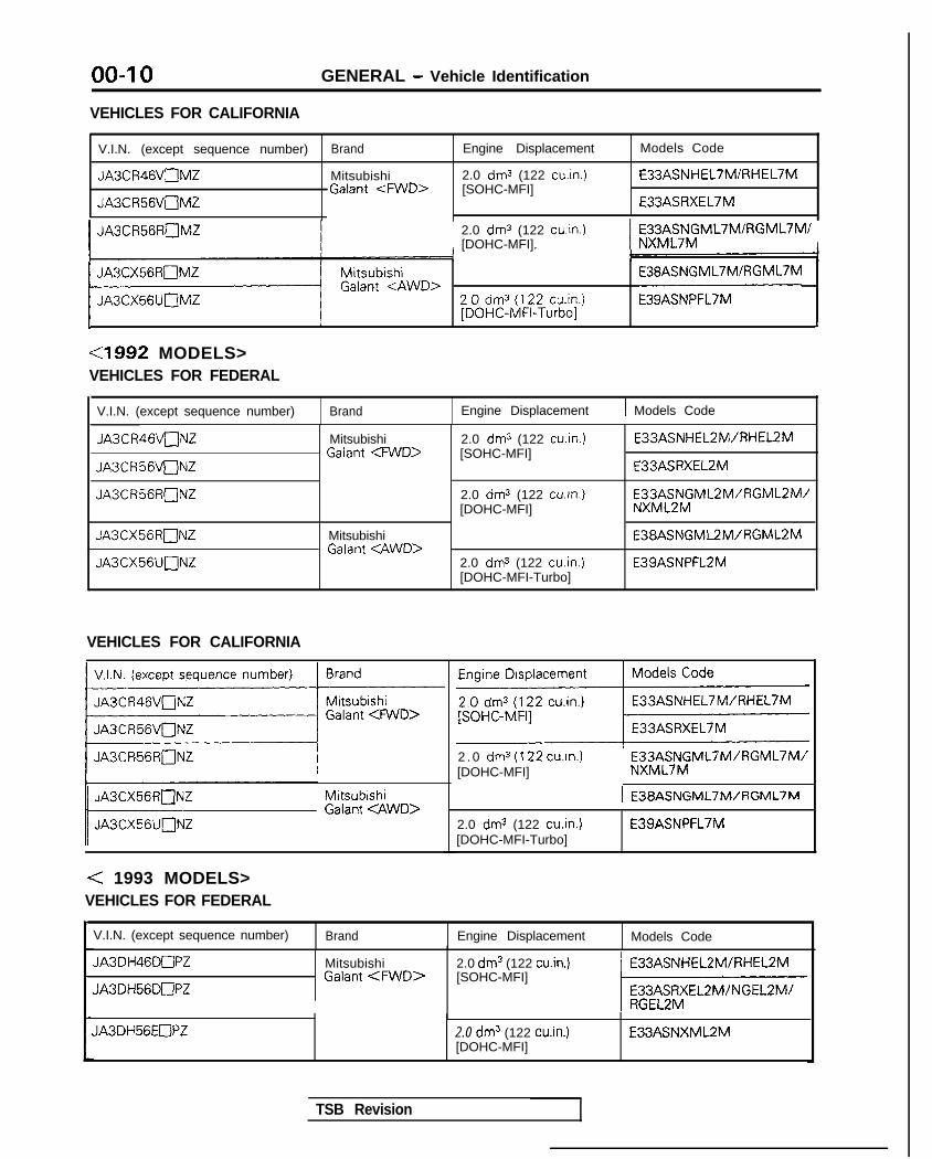
00-l 0 GENERAL - Vehicle Identification
VEHICLES FOR CALIFORNIA
V.I.N. (except sequence number) Brand Engine Displacement Models Code
JA3CR46VnMZ Mitsubishi 2.0 dm3 (122 cuin.) E33ASNHEL7MIRHEL7MGalant <FWD> [SOHC-MFI]
JA3CR56VuMZ E33ASRXEL7M
I JA3CR56RnMZ 2.0 dm3 (122 cuin.)[DOHC-MFI] I
FX3;;$ML7MIRGML7M/I
11 ““nUPi”WD> 200.0~‘~~~22x~.) :::::?:;IRGMVM .1 I , J
<1992 MODELS>VEHICLES FOR FEDERAL
V.I.N. (except sequence number) Brand
JA3CR46VaNZ
JA3CR56VuNZ
JA3CR56RONZ
JA3CX56R[ZlNZ
JA3CX56UnNZ
Mitsubishi1 Galant <FWD>
MitsubishiGalant <AWD>
Engine Displacement
2.0 dm3 (122 cu.in.)[SOHC-MFI]
2.0 dm3 (122 cu.in.)[DOHC-MFI]
2.0 dm3 (122 cu.in.)[DOHC-MFI-Turbo]
1 Models Code
E33ASNHEL2MIRHEL2M
E33ASRXEL2M
E3gf2N$ML2M/AGML2M/
E38ASNGML2M/RGML2M
E39ASNPFL2M
VEHICLES FOR CALIFORNIA
V.I.N. (except sequence number)
~
I JA3CR56RnNZ
j Mw;wm;;:1 g;;gwo,
< 1993 MODELS>VEHICLES FOR FEDERAL
2 . 0 dm3 (122 cu.in.)[DOHC-MFI]
E33ASNGML7M/RGML7M/NXML7M
2.0 dms (122 cu.in.)[DOHC-MFI-Turbo]
E39ASNPFL7M
V.I.N. (except sequence number) Brand Engine Displacement Models Code
JA3DH46DnPZ
JA3DH56DnPZ
MitsubishiGalant <FWD>
J,A3DH56EOPZ
2.0 dm3 (122 cu.in.)[SOHC-MFI]
2.0 dm3 (122 win.)[DOHC-MFI]
E33ASNXML2M
TSB Revision
GENERAL - Vehicle Identification 00-l 1
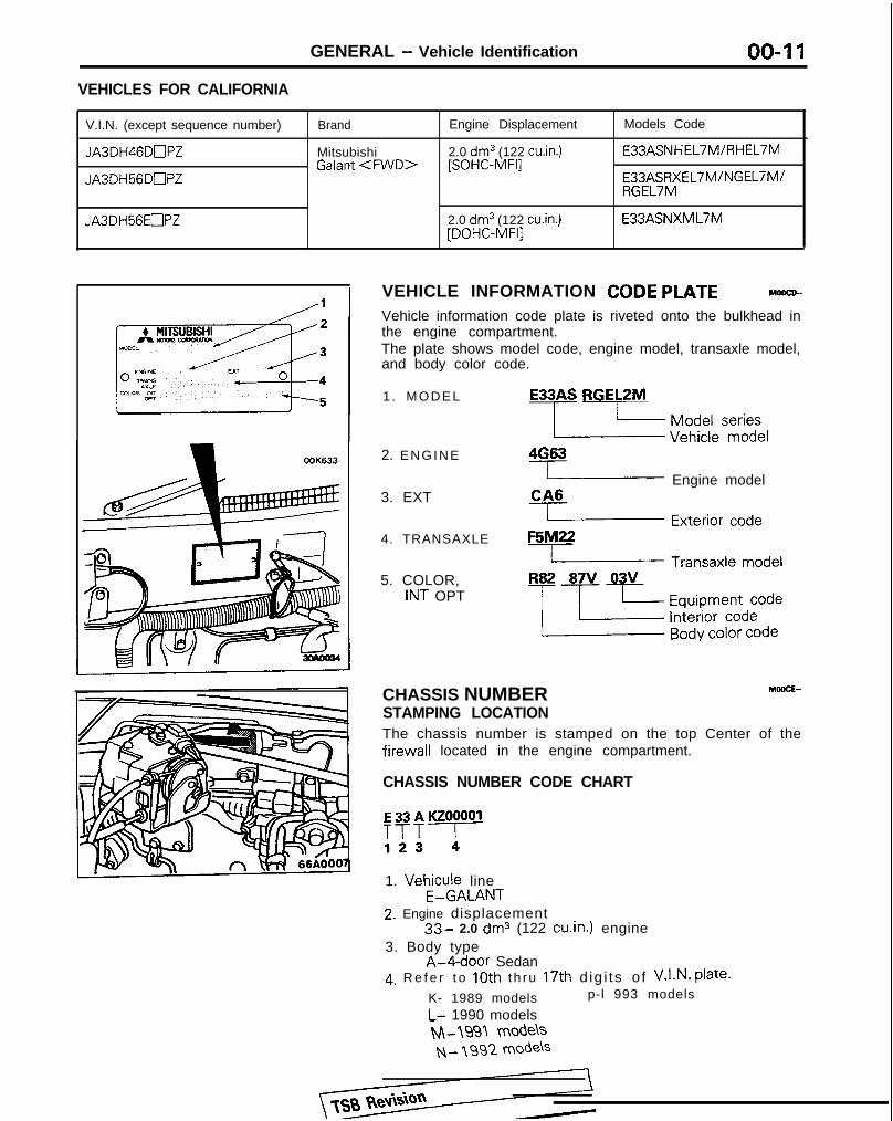
VEHICLES FOR CALIFORNIA
V.I.N. (except sequence number)
JA3DH46DmPZ
JA3DH56DnPZ
JA3DH56EOPZ
Brand
MitsubishiGalant <FWD>
Engine Displacement
2.0 dm3 (122 cu.in.)[SOHC-MFI]
2.0 dm3 (122 cu.in.)[DOHC-MFI]
Models Code
E33ASNHEL7M/RHEL7M
b;$,,%&EL7M/NGEL7M/
E33ASNXML7M
VEHICLE INFORMATION CODE PLATE MOOCD-
Vehicle information code plate is riveted onto the bulkhead inthe engine compartment.The plate shows model code, engine model, transaxle model,and body color code.
1 . M O D E L
2. ENGINE
3. EXT
4. TRANSAXLE
5. COLOR,INT OPT
E33AS RGELZM
-LzI ~~~~~S$)y&4G63
( Engine modelCA6I Exterior co&F5M22L Transaxle modelR82 87V 03V
-p+cf~~l;;
CHASSIS NUMBER MOOCE-
STAMPING LOCATIONThe chassis number is stamped on the top Center of thefirewall located in the engine compartment.
CHASSIS NUMBER CODE CHART
E33AKZOOOOl
T?T!
1. Vehicule lineE-GALANT
2. Engine displacement33- 2.0 dm3 (122 cu.in.) engine
3. Body typeA-4-door Sedan
4, R e f e r t o 10th t h ru 17th d ig i ts o f V.I.N. Plate.
K- 1989 models p-l 993 models
L- 1990 modelsM-1991 modelsN- 199'2 mode\s

GENERAL - Vehicle Identification
OOA0192
Theft protection label
For orIgInal parts
OOK619
For replacement parts
OOK621
VEHICLE SAFETY CERTIFICATION LABEL MWCF-
1. The vehicle safety certification label is attached to face ofleft door pillar.
2. This label indicates Gross Vehicle Weight Rating (G.V.W.R.), Gross Axle Weight Rating (G.A.W.R.) front, rear andVehicle Identification Number (V.I.N.).
ENGINE MODEL STAMPING M6ocG-.
1. The engine model number is stamped at the front side onthe top edge of the cylinder block as shown in thefollowing.
Engine model Engine displacement
4G63 2.0 dm3 (122 cu.in.)
2. The engine serial number is stamped near the enginemodel number, and the serial number cycles, as shownbelow.
THEFT PROTECTION MwclA9
In order to protect against theft, a Vehicle ldentificatlonNumber (VIN) is stamped in, or attached as a label to, thefollowing major parts of the engine and transaxle. as well asmain outer panels:
Engine cylinder block, Transaxle housing, Fender, Door, Quar-ter panel, Hood, Trunk lid, Bumpers
In addition, a theft-protection label is attached to replacementparts for the body outer panel main components, and the samedata are stamped into replacement parts for the engine and thetransaxle.
Cautions regarding panel repairs1. When repainting original parts, do so after first mask-
ing the theft-protection label, and, after painting, besure to peel off the masking tape.
2. The theft-protection label for replacement parts iscovered by masking tape, so such parts can be paintedas is. The masking tape should be removed afterpainting is finished.
3. The theft-protection label should not be removed fromoriginal parts or replacement par-&
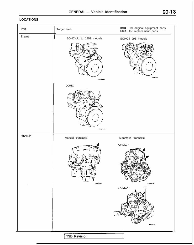
GENERAL - Vehicle Identification 00-13LOCATIONS
Part
Engine
*ansaxle
.
Target area : for original equipment partsLZZB : for replacement parts
SOHC-Up to 1992 models SOHC-l 993 models
DOHC
Manual transaxle Automatic transaxle
<FWD>
<AWD> 17
1 TSB Revision

GENERAL - Vehicle Identification
@g : for replacement parts
inner side of the parts shown
OOA0065The illustration indicates left hand side, outer.Right hand side is symmetrically opposite.
OOA0056OOAOO59
inner side of the parts shownin the figure.
The illustration indicates left hand side, outer.
TSB Revision
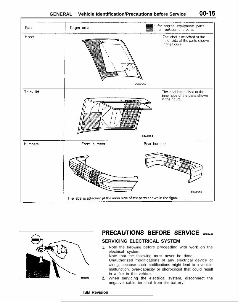
GENERAL - Vehicle Identification/Precautions before Service
OOA0063
inner side of the parts shown
PRECAUTIONS BEFORE SERVICE reomu~SERVICING ELECTRICAL SYSTEM1.
2.
Note the following before proceeding with work on theelectrical system.Note that the following must never be done:Unauthorized modifications of any electrical device orwiring, because such modifications might lead to a vehiclemalfunction, over-capacity or short-circuit that could resultin a fire in the vehicle.When servicing the electrical system, disconnect thenegative cable terminal from the battery.
TSB Revision

00-l 6 GENERAL - Precautions before Service
Caution1. Before connecting or disconnecting the negative
cable, be sure to turn off the ignition switch and thelighting switch.(If this is not done, there is the possibility ofsemiconductor parts being damaged.)
2. For MFI-equipped models, after completion of thework steps [when the battery’s negative (-) termi-nal is connected], warm up the engine and allow itto idle for approximately five minutes under theconditions described below, in order to stabilizeengine control conditions, and then check to besure that the idling is satisfactory.Engine coolant temperature: 85-95X (185-203°F)Lights, electric fans, accessories: OFFTransaxle: neutral position
(A/T models: “N” or “P”)Steering wheel: neutral (center) position
m m (tn.1
Scan Tool(Multi-use tester<MUT>)
ROM pack
1
VEHICLE WASHINGIf high-pressure car-washing equipment or steam car-washingequipment is used to wash the vehicle, be sure to maintain thespray nozzle at a distance of at least 300 mm (12 in.) from anyplastic parts and all opening parts (doors, luggage compart-ment, etc.).
SCAN TOOL(1) To operate the scan tool, refer to the “Scan Tool Operation
Instructions”.
Connection and disconnection of the scan tool shouldalways be made with the ignition switch in the OFFposition.
(2) Always use a ROM pack that is appropriate for the vehicle.
1 ROM oack 1 Aoblicable models
1 MB991307 1 1989 models I
1 MB991327 1 1990 models I
1 MB991359 ( 1991 models
I MB991 423 1992 models I
1 MB991466 1 1993 models
TSB Revision

GENERAL - Towina and Hoisting 00-l 7
Sling type
Wheel lift type
Flat bed type
Sling type
Wheel lift type
Flat bed type
TOWING AND HOISTINGWRECKER TOWING RECOMMENDATION<FWD>FRONT TOWING PICKUPCautionThis vehicle cannot be towed by a wrecker using sling-typeequipment to prevent the bumper from deformation.If this vehicle is towed, use wheel lift or flat bedequipment.
The vehicle may be towed on its rear wheels for extendeddistances provided the parking brake is released. It is recom-mended that vehicles be towed using the front pickupwhenever possible.
REAR TOWING PICKUPCautionThis vehicle cannot be towed by a wrecker using sling-typeequipment to prevent the axle beam from deformation.If this vehicle is towed, use wheel lift or flat bedequipment.Manual transaxle vehicles may be towed on the front wheels,provided the transaxle is in neutral and the drive-line has notbeen damaged. The steering wheel must be clamped in thestraight-ahead position with a steering wheel clamping devicedesigned for towing service use.
CautionDo not use steering column lock to secure front wheelposition for towing.Automatic transaxle vehicle may be towed on the front wheelsat speeds not to exceed 50 km/h (30 mob) for a distances notto exceed 30 km (18 miles).
CautionIf these limits cannot be met, the front wheels must beplaced on a tow dolly.
TOWING WHEN KEYS ARE NOT AVAILABLEWhen a locked vehicle must be towed and keys are notavailable, the vehicle may be lifted and towed from the front.provided the parking brake is released. If not released, the rearwheels should be placed on a tow dolly.
TSB Revision

00-l 8 GENERAL - Towing and Hoisting
SAFETY PRECAUTIONSThe following precautions should be taken when towing thevehicle.1. DO NOT LIFT OR TOW THE VEHICLE BY ATTACHING TO
OR WRAPPING AROUND THE BUMPER.2. Any loose or protruding parts of damaged vehicle such as
hoods, doors, fenders, trim, etc., should be secured prior tomoving the vehicle.
3. Operator should refrain from going under a vehicle while itis lifted by the towing equipment, unless the vehicle inadequately supported by satefy stands.
4. Never allow passengers to ride in a towed vehicle.5. State and local rules and regulations must be followed
when towing a vehicle.
<AWD>Refer to the section “Special Handling Instructions for AWDModels”.
Frame contact support locationI
<FWD>: 1,020 mm (40.2 in.)<AWD>: 1,120 mm (44.1 in.) OOAOO47
<FWD> Rear tAWD> I
HOISTINGPOST TYPESpecial care should be taken when raising the vehicle on aframe contact type hoist. The hoist must be equipped with theproper adapters in order to support the vehicle at the properlocations.
CautionWhen service procedures require removing rear suspen-sion, fuel tank, spare tire and lift gate, place additionalweight on rear end of vehicle or anchor vehicle to hoist toprevent tipping of center of gravity changes.
FLOOR JACKThe usual type of floor jack is used at the following locations.
Front:<FWD> Under the mid point of centermembertAWD> Under the mid point of crossmember
Rear:<FWD> Under the jack up bracket of rear floor pan<AWD> Under the rear differential
Cautions1. Never use a jack at the lateral rod or rear suspension
assembly. <FWD>2. In order to prevent scarring the centermember <FWD>
or crossmember <AWD>, place a piece of cloth on thejack’s contact surface (to prevent corrosion caused bydamage to the coating).
3. A floor jack must never be used on any part of theunderbody.
4. Do not attempt to raise one entire side of the vehicle byplacing a jack midway between front and rear wheels.This practice may result in permanent damage to thebody.
TSB Revision I

GENERAL - Towing and Hoisting
LIFTING, JACKING SUPPORT LOCATION
00-19
<FWD>
<AWD>
WA0020
00A0021
Floor jack locations -eApproximate center of gravity
@ Frame contact hoist, twin post hoist or scissors jack (emergency) locations
EMERGENCY JACKINGJack receptacles are located at the body sills to accept thescissors jack supplied with the vehicle for emergency roadservice. Always block opposite wheels and jack on levelsurface.
TSB Revision

00-20 GENERAL - Special Handling Instructions for AWD Models
SPECIAL HANDLING INSTRUCTIONS FOR AWD MODELSTOWING
MomMA
Towing methods
If a tow truck is usedLifting method for 4 wheels-Good
Remarks
l For AWD models, the basic principle is thatall four wheels are to be raised beforetowing.
l The shift lever should be set to 1 st gear andthe parking brake should be applied.< M / T >
l The selector lever should be set to “P”position and the parking brake should beapplied. <AK>
OOA0032
Front wheels lifted-No good l The vehicle must not be towed by placingonly its front wheels or only the rear wheelson a rolling dolly, because to do so willresult in deterioration of the viscouscoupling and result in the viscous couplingcausing the vehicle to jump forwardsuddenly.
OOA0034
Front wheels lifted-No good l If only the front wheels or only the rearwheels are lifted for towing, the bumperwill be damaged.In addition, lifting of the rear wheels causesthe oil to flow forward, and may result inheat damage to the rear bushing of thetransfer, and so should never be done.
Rear wheels lifted-No good
OOA0033
TSB Revision 1

GENERAL - Special Handling Instructions for AWD Models 00-21
Free roller
OOPO038
Axle stand
OOPOO37
Towino hook
Tenslon bar
Front
eJ
Anchor plate
&-16PO209
14AO198
OOP003E
SPEEDOMETER TESTIF A FREE ROLLER IS USED1. Set the free roller on the floor (at the rear wheels) so that it
is aligned with the vehicle’s wheelbase and the rear tread.2. Carefully move the vehicle onto the tester and free roller.3. Set the speedometer tester in place.4. Perform the speedometer test.
For information concerning the measurement of speed andthe allowable error, refer to GROUP 54-Meters andGauges.
CautionDo not operate the clutch suddenly, or increase orreduce speed suddenly during the work.
IF THE REAR WHEELS ARE JACKED UP1. Move the vehicle onto the speedometer tester.2. Jack up the rear wheels, and place axle stands at the
designated part of the side sill.3. Perform the speedometer test.
For information concerning the measurement of speed andthe allowable error, refer to GROUP 54-Meters andGauges.
CautionDo not operate the clutch suddenly, or increase orreduce speed suddenly during the work.
Front wheel side slipTo prevent the front wheels from moving from side to side,attach tension bars to the towing hooks, and secure both endsat anchor plates.
Accident prevention procedures
(1) Attach a chain or wire to the rear traction hook. Make surethe end of the wire or chain is secured firmly.
(2) Take all other necessary precautions.
BRAKE TESTIn order to stabilize the viscous coupling’s dragging force, thebrake test should always be conducted after the speedometertest.FRONT WHEEL MEASUREMENTS
1. Place the front wheels on the brake tester.2. Perform the brake test.
CautionThe rear wheels should remain on the ground.
3. If the brake dragging force exceeds the specified value,jack up the vehicle and manually rotate each wheel tocheck the rotation condition of each wheel.
NOTEIf the brake dragging force exceeds the specified value, thecause may be the effect of the viscous coupling’s draggingforce, so jack up the front wheels and check the rotationcondition of the wheels in this state for no effect by theviscous coupling’s dragging force.
,
TSB Revision

00-22 GENERAL - Special Handling Instructions for AWD Models
REAR WHEEL MEASUREMENTSAfter placing the rear wheels on the brake tester, follow thesame procedures as for the front wheel measurements.
WHEEL BALANCEFRONT WHEEL MEASUREMENTS1. Jack up the rear wheels, and place an axle stand at the
designated part of the side sill.2. Jack up the front wheels and set a pick-up stand and
balancing machine in place.
Caution1. Set so that the front and rear of the vehicle are at
the same height.
Balancingmachlne
OOA0046
Balancw
Pick-up stand0010024
TSB Revision
2. Release the parking brake.3. Rotate each wheel manually and check to be sure
that there is no dragging.3. Use the engine to drive the tires, and then make the
measurement.
Caution1. If an error is indicated in the state of engine drive,
motor drive can be used concurrently.2. Do not operate the clutch suddenly, or increase or
reduce speed suddenly during the work.REAR WHEEL MEASUREMENTS1. Jack up the front wheels, and place an axle stand at the
designated part of the side sill.2. Jack up the rear wheels, and then, after setting a pick-up
stand and balancing machine in place, follow the sameprocedure as for front wheel measurements.

GENERAL - General Data and Specifications 00-23
GENERAL DATA AND SPECIFICATIONS MOOHA-
3
I T T I8
GENERAL SPECIFICATIONS<Up to 1992 models>
Items FWD AWD
SOHC Engine DOHC Engine DOHC Engine DOHC Engine(Non-Turbo) (Turbo)
Vehicle dimensions mm (in.)Overall length 1 4,670 (183.9) 4,670 (183.9) 4,670 (183.9) 4,670 (183.9)Overall width 2 1,695 (66.7) 1,695 (66.7) 1,695 (66.7) 1,695 (66.7)Overall height 3 1,425 (56.1) 1.425 (56.1) 1,435 (56.5) 1,435 (56.5)
1,410 (55.5)"Wheel base 4 2,600 (102.4) 2,600 (102.4) 2,600 (102.4) 2,600 (102.4)Tread Front 5 1,460 (57.5) 1,460 (57.5) 1,460 (57.5) 1,460 (57.5)
Rear 6 1,450 (57.1) 1,450 (57.1) 1,450 (57.1) 1,450 (57.1)Overhang Front 7 980 (38.6) 980 (38.6) 980 (38.6) 980 (38.6)
Rear 8 1,090 (42.9) 1,090 (42.9) 1,090 (42.9) 1,090 (42.9)
Height at curb mass (wt.)Front bumper to ground 9 240 (9.4) 250 (9.8) 255 (10.0) 255 (10.0)Rear bumper to ground 10 215 (8.5) 290 (11.4) 230 (9.1) 230 (9.1)
Minimum running groundclearance 11 115 (4.5) 155 (6.1) 100 (4.0) 100 (4.0)Angle of approach 12 18.5" 19" 21" 21"
Angle of departure 13 12" 17" 12.5" 12.5"
NOTEl ’ : E33ASNXML2M/L7M
TSB Revision I

00-24 GENERAL - General Data and Specifications
Items FWD AWD
SOHC Engine DOHC Engine DOHC Engine DOHC Engine(Non-Turbo) (Turbo)
Vehicle weight kg (Ibs.)Curb weights
MIT 1.2 10 (2.668) 1.290 (2,844) or 1.405 (3.097). 1,495 (3.296)1.3 10 (2.8881e2
/-v-r 1,230 (2.7 12) or 1,300 (2,866) 1,425 (3.142)1,270 (2.800)”
Gross vehicle weight rating 1,700 (3,747) 1,780 (3,923) 1,900 (4,189) 1,900 (4,189)
Gross axle weight rating Front 900 (I ,984) 960 (2,116) 960 (2,116) 980 (2.161)
Rear 800 (1.763) 820 (1,807) 940 (2.072) 920 (2.028)
Seating capacity 5 5 5 5
Engine
Model No. 4G63 4G63 4G63 4G63
Transaxle
Model No.
Manual transaxle F5M22 F5M3 1 W5M31 W5M33
Automatic transaxle F4A22 F4A22 W4A32 -
Clutch
Type Dry-single disc Dry-single disc Dry-single disc Dry-single disc& diaphragm & diaphragm & diaphragm & diaphragmspring spring spring spring
Chassis
Tire 185/7OR14 87s 195/60R15 86i-i 195/60R15 86ti 195/60R15 86Hor195/65R14 89H
Front suspension
Type Independent Independent Independent Independentstrut strut strut strut
Rear suspension
Type 3L$k Torsion 3$k Torsion Double- Double-wishbone wishbone
Brake
Type Front Disc Disc Disc Disc
Rear Drum Disc Disc DiscSteering
Gear type Rack and pinion Rack and pinion Rack and pinion Rack and pinionGear ratio cc 00 m 03
Fuel tank
Capacity dm3(gals.) 6 0 (16) 60 (16) 62 (16.3) 62 (16.3)
NOTE+’ : E33ASRXEL2Mi7M ~2: E33ASNXML2Mi7M
TSB RevisionI

GENERAL - General Data and Specifications 00-25(1993 m o d e l s >
Items FWD
SOHC Engine DOHC Engine
Vehicle dimensions mm (in.)Overall length 1 4,670 (183.9) 4,670 (183.9)Overall width 2 1,695 (66.7) 1,695 (66.7)Overall height 3 1,425 (56.1) 1,425 (56.1)
I,41 0 (55.5)*’Wheel base 4 2,600 (102.4) 2,600 (102.4)Tread Front 5 1,460 (57.5) 1,460 (57.5)
Rear 6 1,450 (57.1) 1,450 (57.1)Overhang Front 7 980 (38.6) 980 (38.6)
Rear 8 1,090 (42.9) 1,090 (42.9)Height at curb mass (wt.)
Front bumper to ground 9 240 (9.4) 250 (9.8)Rear bumper to ground 10 215 (8.5) 290 (11.4)
Minimum running groundclearance 11 115 (4.5) 155 (6.1)
Angle of approach 12 18.5” 19”
Angle of departure 13 12” 17”
lehicle weight kg (tbs.)
Curb weightsM/T 1,230 (2,712) or 1,250 (2,755)*’ I,31 0 (2,888)A/T 1,250 (2,755) or 1,285 (2,833)*3 or
1,270 (2,800)*4
Gross vehicle weight rating 1,700 (3,747) 1,780 (3,923)
Gross axle weight rating Front 900 (1,984) 960 (2,116)Rear 800 (1,763) 820 (1,807)
ieating capacity 5 5
lngine
Model No. 4G63 4G63
-ransaxle
Model No.Manual transaxle F5M22 F5M22
Automatic transaxle F4A22
lutch
Type Dry-single disc & diaphragm spring Dry-single disc & diaphragm springd
TSB Revision
NOTE*l : E33ASNXML2MlL7M*2 : E33ASNGEL2MI7M*3 : E33ASRXEL2M/7M*4 : E33ASRGEL2M/7M

00-26
3ms
GENERAL - General Data and Specifications
FWD
iassis
Tire
Front suspension
TypeRear suspension
TypeBrake
Type
Steering
Gear type
Gear ratio
Fuel tank
Capacity
Front
Rear
dm3 (gals.)
L
SOHC Engine DOHC Engine
185/7ORl4 87s 195/60R15 86H
Independent strut independent strut
3-Link Torsion axle 3-Link Torsion axle
DiscDrum
DiscDisc
Rack and pinioncc
60 (16)
Rack and pinion/cu
60 (16)
ENGINE SPECIFICATIONS
Items
Type
Number of cylinders
Bore
StrokePiston displacement
Compression ratio
Firing order
4G63-SOHC
In line,Front Transverse
4
mm (in.) 85 (3.35)
mm (in.) 88 (3.46)
cm3 (win.) 1 , 9 9 7 (122)
8.51-3-4-2
TRANSAXLE SPECIFICATIONS
Items
Type
Gear ratio
1 st
2nd
3rd
4th
5th
ReverseTransaxle
Pnmary reduction ratioSecondary reductron ratioTransfer
F5M22 F5M3 1
5-speedM / T
W5M31
EFd5-speedM / T
F4A2 2
4-speedA /T
4-speedA /T
3.363 2.846 2.846 2.846
1.947 1.833 1.684 1.684
1.285 1.217 1.115 1.115
0.939 0.888 0.833 0.833
0.756 0.73 1 0.690 0.666
3.083 3.166 3.166 3.166
2.846 2.846
1.581 1.581
1 .ooo 1.000
0.685 0.685- -
2.176 2.176
4.02 1 4.913 1.680 1.275 4.007 1.228-- - 3.100 3.866 3.600-- - 1.090 1.090 1.090
4G63-DOHC(Non-Turbo)
4G63-DOHC (Turbo)
In line, In line,Front Transverse Front Transverse
4 4
85 (3.35) 85 (3.35)
88 (3.46) 88 (3.46)
1,997 (I 22) 1,997 (I 22)
9.0 7.81-3-4-2 1-3-4-2
W5M33 W4A3 2
TSB Revision 1

GENERAL - Tightening Torque 00-27
TIGHTENING TORQUEEach torque value in the table is a standard value for tightening under the following conditions.
(1) Bolts, nuts and washers are all mode of steel and plated with zinc.(2) The threads and bearing surface of bolts and nuts are all in dry condition.
The values in the table are not applicable:
(1) If toothed washers are inserted.(2) If plastic parts are fastened.(3) If bolts are tightened to plastic or die-cast inserted nuts.(4) If self-tapping screws or self-locking nuts are used.
Standard bolt and nut tightening torque
Bolt nominal Pitch Torque Nm (ft.lbs.1diameter b-m-dh-n) Head mark @ Head mark @ Head mark @M5 0.8 2-3 (1.4-2.2) 4-6 (2.9-4.3) 5 - 7 (3.6-5.1)
M6 1 .o 4 - 6 (2.9-4.3) 7 - 1 1 (5.1-8.0) 8 - 1 2 (5.8-8.7)
M8 1.25 9 - 1 4 (6.5-10) 17-26 (12-19) 20-30 (14-22)
Ml0 1.25 19-28 (14-20) 3 5 - 5 5 (25-40) 45-60 (33-43)
Ml2 1.25 34-50 (25-36) 70-95 (51-69) 85-110 (61-80)
Ml4 1.5 60-85 (43-61) 120-160 (87-116) 130-180 (94-130)
Ml6 1.5 95-130 (69-94) 180-240 (130-174) 200-270 (145-195)
Ml8 1.5 140-190 (101-137) 260-350 (188-253) 300-400 (217-289)
Bolt nominal Pitch Torque Nm (ft.lbs.1diameter h-n)b-m-d Head mark @ Head mark 0 Head mark @M6 1 .o 4 - 6 (2.9-4.3) 8-12 (5.8-8.7) 9 - 1 4 (6.5-10)
M8 1.25 lo-15 (7.2-11) 19-28 (14-20) 22-33 (16-24)
Ml0 1.25 21-31 (15-22) 39-60 (28-43) 50-65 (36-47)
Ml0 1.5 19-29 (14-21) 3 6 - 5 4 (26-39) 4 5 - 6 5 (33-47)
Ml2 1.25 3 8 - 5 5 (27-40) 80-1'10 (58-80) 90-120 (65-87)
Ml2 1.75 3 4 - 5 2 (25-38) 70-95 (51-69) 85-110 (61-80)
.
TSB Revision
M20 1.5 190-260 (137-188)
M22 1.5 260-350 (188-253)
M24 1.5 340-460 (246-333) 630-860 (456-622)
Flange bolt and nut tightening torque

00-28 GENERAL - Tightening Torque/Master Troubleshooting
Taper thread tightening torque
Thread sizeI Torque Nm (ftlbs.) I
r~Female thread material: Light alloy 1-Female thread material: Steel I
NPTF II6 5 - 8 (3.6-5.8)
PT 118 8- 12 (5.8-8.7)
PT 114, NPTF 114 20-30 (14-22)
PT 318 40-55 (29-40)
NOTE: NPTF IS dry seat pope thread, while PT is pipe thread.
8- 12 (5.8-8.7)
16-20 (12-14)
35-45 (25-33)
60-75 (43-54)
MASTER TROUBLESHOOTING hlooKAAB
ENGINE OVERHEATS
Symptom
Engine overheats
Probable cause Reference page
Coolrng system faulty 14-5
Incorrect ignition timing 16-39, 40
ENGINE WILL NOT CRANK OR CRANKS SLOWLY
Symptom Probable cause
Engine will not crank Starting system faultyor cranks slowly
Reference page
16-14
ENGINE WILL NOT START OR HARD TO START (CRANKS OK)
Symptom Probable cause Reference page
Engrne WIII not start or hard tostart (Cranks OK)
No fuel supply to injector
Injection system problems
Ignition system problems
Vacuum leaksl Purge control valve hosel Vacuum hosesl intake manifoldl Intake manifold plenuml Throttle bodyl EGR valve
13-90, 181, 295
13-90, 181, 295
16-32
17-3
Compression too low 11-6
TSB Revision

GENERAL - Master Troubleshooting 00-29
ROUGH IDLE OR ENGINE STALL
Symptom
Rough idle or engine stalls
Probable cause
Vacuum leaksl Purge control valve hosel Vacuum hosesl Intake manifoldl Intake manifold plenuml Throttle bodyl EGR valve
Ignition system problems
Idle speed set too low
Reference page or remedy
17-3
16-32
Check idle speed control sys-tem
Idle mixture too lean or too rich
Fuel injection system problems
Exhaust gas recirculation (EGR) systemproblems
Engine overheats
Compression too low
-
13-8, 119, 205
17-22
14-5
11-6
ENGINE HESITATES OR POOR ACCELERATION
Symptom
Engine hesrtates or pooracceleration
Probable cause
Ignition system problem
Vacuum leaks0 Purge control valve hosel Vacuum hosesl Intake manifoldl Intake manifold plenuml Throttle bodyl EGR valve
Reference page
16-32
17-3
Air cleaner clogged
Fuel line clogged
Fuel injection system problem
Emission control system probleml EGR system always on
Engine overheats
Compression too low
-
13-8, 119, 205
17-22
14-5
11-6
ENGINE DIESELING
Probable cause
Incorrect ignition timincc
TSB Revision
Symptom
Engine dieseling (runs afterignition switch is turned off)

00-30 GENERAL - Master Troubleshooting
EXCESSIVE OIL CONSUMPTION
Symptom Probable cause Reference page or remedy1r-Excessive 011 consumption Oil leak Repair as necessary.I
Valve stem seal worn or damaged. Repair as necessary.
Valve stem worn. Repair as necessary.
Piston ring worn or damaged. Repair as necessary.
POOR FUEL MILEAGE
Symptom
Poor fuel mtleage
Probable cause
Fuel leak
Air cleaner clogged.
Ignition system problems.
Fuel injection system problems.
Compression too low.
Tires improperly inflated.
Clutch slips.
Brakes drag.
Reference page or remedy
Repair as necessary.
-
16-32
13-8, 119, 205
1 l-6
31-3
21-4
35-l 3
NOISE
Symptom
Noise
Probable cause
Loose bolts and nuts.
Engine noise
Reference page or remedy
Retighten as necessary.
Repair as necessary.
HARD STEERING
Symptom
Hard steering
Probable cause Reference page or remedy
Loose power steering oil pump belt 37A-21
Low fluid level Replenish
Air in power steering system 37A-22
Low tire pressure 31-3
Excessive turning resistance of lower arm ball 33A-11joint
Excessively tightened of steering gear box 37A-33rack support cover
Improper front wheel alignment
Excessive turning resistance of tie-rod balljoint
Malfunctioning electronic controlled powersteering system
Sticky flow control valve
Bent rack in steering gear boxJ
TSB Revision I
33A-5
37A-15, 33
37A-9
37A-50, 51
37A-42
GENERAL - Master Troubleshooting 00-31
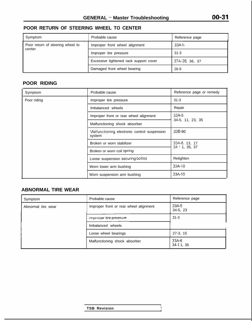
POOR RETURN OF STEERING WHEEL TO CENTER
Symptom Probable cause Reference page
’Poor return of steering wheel to Improper front wheel alignment 33A-5center
Improper tire pressure 31-3
Excessive tightened rack support cover 37A-35, 36, 37
Damaged front wheel bearing 26-9
POOR RIDING
Symptom
Poor riding
Probable cause Reference page or remedy
Improper tire pressure 31-3
lmbalanced wheels Repair
Improper front or rear wheel alignment 33A-534-5, 11, 23, 35
Malfunctioning shock absorber
Malfunctioning electronic control suspension 33B-90system
Broken or worn stabilizer 33A-6. 13, 1734-l 1, 35, 37
Broken or worn coil spri#ng
Loose suspension secuiring bolt(s) Retighten
Worn lower arm bushing 33A-10
Worn suspension arm bushing 33A-IO
TSB Revision
ABNORMAL TIRE WEAR
Symptom
Abnormal tire wear
Probable cause
Improper front or rear wheel alignment
Reference page
33A-534-5, 23
1 31-3
lmbalanced wheelsI I
Loose wheel bearings 27-3, 15
Malfunctioning shock absorber 33A-634-l 1, 35

00-32 GENERAL - Master Troubleshooting
ROAD WANDER
Symptom
Road wander
Probable cause
Improper front or rear wheel alignment
Reference page
33A-534-5, 23
Excessive play of steering wheel 37A-15
Poor turning resistance of lower arm ball joint 33A-11
Improper tire pressure 31-3
Loose or worn lower arm bushing 33A-1026-9
Loose or worn wheel bearings
Loose rack support cover in steering gear box 37A-35. 36, 37
VEHICLE PULLS TO ONE SIDE
Symptom Probable cause Reference page
Vehrcle pulls to one side Improper front or rear wheel alignment 33A-534-5. 2 3
lmbalanced or worn tires 31-3
Uneven tire pressure
Excessive turning resistance of lower arm ball 33A-17joint
Wheel bearing seizure Replace
Broken or weak coil spring 33A-7
Bent front axle drive shaft 26-13
Deformed lower arm 33A-10
STEERING WHEEL SHIMMY
Symptom
Steerlng wheel shlmmy
Probable cause
Improper front or rear wheel alignment
Reference page or remedy
33A-534-5, 23
Improper tire pressure I 31-3
lmbalanced wheels Replace
1 Poor turning resistance of lower arm ball joint ) 33A-11
] Excessive play of steering wheel ) 37A-15
Broken or weak front stabilizer
Worn lower arm bushing
33A-13. 17
33A-10
Malfunctioning shock absorber
Broken or weak coil spring
Wear, play, or seizure of wheel bearing
33A-634-11, 3 5
Replace
Wear, play, or seizure of drive shaft ball joint 26-12
TSB Revision 1

GENERAL - Master Troubleshootinn 00-33
BOTTOMING
Symptom Probable cause 1 Reference page or remedy
Bottoming
Malfunctioning shock absorber
WHEEL BEARING TROUBLESHOOTING
Trouble
Pitting
Flaking
Cracking
Sympton Probable cause
Pitting occurs because of uneven rotation of race Excessive bearing preloadand bearing surfaces Excessrve load
The surface peels because of uneven rotation of End of bearing life ,the race and bearing surfaces Improper bearing assembly
Chipping or cracking of cage or roller edges Impact when beanng was installed(such as being hit with a hammer)
Flat spotting When large load is applied, race and rollercontact surfaces compress, formingindentations
Excessive bearing preloadExcessive loadVibration when bearings are notused, such as during shipment onfreight cars, transport trucks, etc.
Nicks Instead of roiling along race surface, rollers slide, insufficient greasethus damaging surface Excessive bearing preload
Excessive loadFaulty oil seal
Smearing Damage or wear caused by minute particles Excessive variation of loads onadhering to surfaces results in rolugh movement bearingsand such high temperatures that parts of surface Use of grease other than thatmelt specified
Insufficient grease
Rust, corrosion Appears on various areas of the bearing Use of grease other than thatspecifiedFaulty oil sealPresence of water or moisture
Wear Wear of surface areas caused by friction Insufficient greaseForeign matterRust or corrosion due to moistureUse of grease other than thatspecifiedFaulty oil seal
Irscoloration Grease discoloration results from greasedeterioration which causes partic:les ofpigment contained in grease to adhereto surfacesHeat discoloration will appearas a deep brown on purple
Use of grease other than thatspecifiedFaulty oil sealExcessive bearing preloadExcessive load
TSB Revision

00-34 GENERAL - Lubrication and Maintenance
LUBRICATION AND MAINTE-NANCE MOOPA-
Maintenance and lubrication service recommenda-tions have been compiled to provide maximumprotection for the vehicle owner’s investmentagainst all reasonable types of driving conditions.Since these conditions vary with the individualvehicle owner’s driving habits, the area in which thevehicle is operated and the type of driving to whichthe vehicle is subjected, it is necessary to prescribelubrication and maintenance service on a timefrequency as well as mileage interval basis.Oils, lubricants and greases are classified andgraded according to standards recommended by theSociety of Automotive Engineers (SAE), the Amer-ican Petroleum Institute (API) and the NationalLubricating Grease Institute (NLGI).
MAINTENANCE SCHEDULESInformation for service maintenance is providedunder “SCHEDULED MAINTENANCE TABLE”.Three schedules are provided; one for “RequiredMaintenance”, one for “General Maintenance” andone for “Severe Usage Service”.The item numbers used in the “SCHEDULEDMAINTENANCE TABLE” cor respond to the“MAINTENANCE SERVICE” section numbers.
SEVERE SERVICEVehicles operating under severe service conditionswill require more frequent service.Component service information is Included i nappropriate units for vehicles operating under one ormore of the following conditrons:1. Trailer towing or police, taxi, or commerciai type
operation2. Operation of Vehicle
(1) Short-trip operation at freezing temperature(engine not thoroughly warmed up)
(2) More than 50% operation in heavy citytraffic during hot weather above 32°C (90°F)
(3) Extensive idling(4) Driving in sandy areas(5) Driving in salty areas(6) Driving in dusty conditions
ENGINE OILThe SAE grade number indicates the viscosity ofengine oils, for example, SAE 30, which is a singlegrade oil. Engine oils are also identified by a dualnumber, for example, SAE 1 OW-30, which Indicatesa multigrade oil.The API classification system defines oil perform-ance in terms of engine usage. Only engine oildesigned “For Service SG” or “For Service SGKD”,
when available, should be used. These oils containsufficient chemical additives to provide maximumengine protection. Both the SAE grade and the APIdesignation can be found on the container.
CautionTest results submitted to EPA have shown thatlaboratory animals develop skin cancer afterprolonged contact with used engine oil. Accor-dingly, the potential exists for humans to de-velop a number of skin disorders, includingcancer, from such exposure to used engine oil.Care should be taken, therefore, when changingengine oil, to minimize the amount and length ofexposure time to used engine oil on your skin.Protective clothing and gloves, that cannot bepenetrated by oil, should be worn. The skinshould be thoroughly washed with soap andwater, or use waterless hand cleaner, to removeany used engine oil. Do not use gasoline,thinners, or solvents.
GEAR LUBRICANTSThe SAE grade number also indicates the viscosityof Multi-Purpose Gear Lubricants.The API classfication system defines gear lubricantsin terms of usage. Typically gear lubricants conform-ing to API GL-4 or GL-5 with a viscosity of SAE75W-85W are recommended for manual transaxle.
LUBRICANTS - GREASESSemi-solid lubricants, bear the NLGI designation andare further classified as grades 0, 1, 2, 3 etc.Whenever “Chassis Lubricant” is specified, Multi-Purpose Grease, NLGI grade 2 should be used.
FUEL USAGE STATEMENTYour vehicle must use unleaded gasoline only.This vehicle has a fuel filler tube especially designedto accept only the smaller-diameter unleaded gaso-line dispensrng nozzle.
CautionUsing leaded gasoline in your vehicle will damagethe catalytic converter, and affect the warrantycoverage validity.All vehicles except those with DOHC enginesYour vehicle is designed to operate on unleadedgasoline having a minimum octane rating of 87 or91 RON (Research Octane Number).
Vehicles equipped with DOHC enginesYour vehicle is designed to operate on premiumunleaded gasoline having a minimum octane ratingof 91 or 95 RON (Research Octane Number).
TSB Revision

GENERAL - Lubrication and Maintenance/Recommended Lubricants and Lubricant Capacities Table 00-35
If premium unleaded gasoltne IS not available, MATERIALS ADDED TO FUELunleaded gasoline having a octane rating of 87 or91 RON (Research Octane Number) may be used.
Indiscriminate use of fuel system cleaning agents
In this case, the performance and fuel consumptionshould be avoided. Many of these materials in-
WIII suffer a little degradatron.tended for gum and varnish removal may containhighly active solvents or similar ingredients that canbe harmful to gasket and diaphragm materials usedin fuel system component parts.Gasolines containing alcohol
Some gasolrnes sold at service stations containalcohol, although they may not be SC identified. Useof fuels containing alcohol is not recommendedunless the nature of the blend can be determrnedas being satisfactory.Gasohol - A mixture of 10% ethanol (grain alcohol)and 90% unleaded gasoline may be used In yourcar. If driveability problems are experienced as aresult of using gasohol, it IS recommended that thecar be operated on gasoline.Methanol - Do not use gasolines containingmethanol (wood alcohol). Use of this type ofalcohol can result in vehicle performance deteriora-tion and damage critical parts in the fuel systemcomponents. Fuel system damage and performanceproblems, resulting from the use of gasolinescontaining methanol, may not be covered by thenew car warranty.
Gasolines containing MTBE (Methyl Tertiary ButylEther)Unleaded gasolrne containrng 15% or less MTBEmay be used in your car. (Fuel containing MTBEover 15% vol. may cause reduced engine per-formance and produce vapor lock or hard starting.)
RECOMMENDED LUBRICANTS AND LUBRICANT CAPACITIES TAB,&-
RECOMMENDED LUBRICANTS
Items
Engine Oil
Recommended lubricants
API classification SG or SGKD (For further details, refer to SAEviscosity number)
Manual Transaxle, Transfer <AWD>
Rear Axle <AWD>
API classification GL-4 or higher, SAE 75W-85W
Refer to P.OO-37.
Automatic Transaxle
Power Steering
Brake and Clutch
Engine Coolant
DIAMOND ATF SP or equivalent
Automatic transmission fluid “DEXRON II”
Conforming to DOT3 or DOT4
DIA-QUEEN LONG-LIFE COOLANT (Part No. 0103044) or Highqualitv ethvlene-qlvcol antifreeze coolant
Door Hinges Engine oil
1 TSB Revision

00-36 GENERAL - Recommended Lubricants and Lubricant Capacities Table
LUBRICANT CAPACITIES TABLE
Descrrptron
Engrne 011
Crankcase
Models built up to April 1992
< S O H C >
< D O H C >
Models built from May 1992
Oil filter
Oil cooler <Turbo>
Cooling System (rncludrng heater and coolant reserve system)
Manual Transaxle
<FWD> F5M22
F5M3 1
<AWD>
Transfer <AWD>
qear Axle <AWD>
4utomatrc Transaxle<FWD><AWD>
‘ower Steering
%el Tank
<FWD>
<AWD>
Metric measure
3.5 dm34.0 dm34.0 dm30.3 dm30.3 dm3
7.2 dm3
1.8 dm3 1.9 qts.
2.3 dm3 2.4 qts.2.3 dm3 2.4 qts.
3.6 dm3 63 qt.
3.7 dm3 74 qt.
6.1 dm3
6.5 dms
3.9 dm3
60 dm3
62 dm3
U.S. measure
3.7 qts.4.2 qts.4.2 qts.1 I2 qt.1 I2 qt.
7.6 qts.
5.4 qts.6.9 qts.
95 qt.
15.9 gals.
16.4 gals.
Temperature range anticipatedbefore next oil chanae
SAE SW-30 SW-40 IRecommendedviscosity (SAE) M03BOOl
SELECTION OF LUBRICANTSENGINE OILEngine oil should be used which conform to the requirementsof the API classification “For Service SG” or “For ServiceSGKD”, and have the proper SAE grade number for theexpected temperature range.
CautionNondetergent or straight mineral oil must never be used.Energy Conserving OilIn order to improve fuel economy and conserve energy new,lower friction engine oils have been developed. These oils arereadily available and can be identified by such labels as “EnergyConserving”, “Energy Saving”, “Improved Fuel Economy”,etc.
TSB Revision

GENERAL - Recommended LubricaMs and Lubricant Capacities Table 00-37
7 2 1 0 0 4 4
Oil Identification SymbolA standard .symbol appears on the top of oil containers and hasthree district areas for identifying various aspects of the oil.The top polqion will indicate the quality of the oil. The centerportion will show the SAE viscosity grade, such as SAElOW-30. “Energy Conserving” shown in the lower portion,indicates that the oil has fuel-saving capabilities.
REAR AXLE
API classificationGL-5 or higher
Anticipated temperature range
Above -23°C (- 10°F)
-23°C to --34°C (-10°F to -30°F)
Viscosity range
SAE 90SAE 85W-90SAE 8OW-90SAE 8OW. SAE 8OW-90
Below -34°C (-30°F) SAE 75W
SELECTION OF COOLANTCOOLANTRelation between Antifreeze Concentration and Specific Gravity
Safe operating Coolanttemperature concentration
“C(“F) (Specific volume)
-11 (12.2) 30%
-20 t-4) (,.‘_ -+j{@, ‘, :; 35%
-2O(-4) 40%
-25(-13) 45%
-31 (-23.8) 50%
-37(-35) 55%
-45(-49) 60%
Example:The safe operating temperature is - 15°C (5°F) when the measured specific gravity is 1.058 at the Coolanttemperature of 20°C (68°F).
Cautions1. If the concentration of the coolant is below 30%, the anti-corrosion property will be adversely
affected. In addition, if the concentration is above 60%, both the anti-freeze and engine coolingproperties will decrease, affecting the engine adversely. For these reasons, be sure to maintain theconcentration level within the specified range.
2. Do not use a mixture of different brands of anti-freeze.
TSE? Revision

00-38 GENERAL - Scheduled Maintenance Table
SCHEDULED MAINTENANCE TABLE MOOOA-
SCHEDULED MAINTENANCE SERVICES FOR EMISSION CONTROL AND PROPERVEHICLE PERFORMANCEInspection and Services should be performed any time a malfunction is observed or suspected. Retainreceipts for all vehicle emission services to protect your emission warranty.
Kilometers in Thousands 24 48 72 80 96No. Emwsron Control System Maintenance Service Intervals
Mileage in Thousands 15 30 45 50 60
1 Check Fuel System (Tank, Line and Connections and Fuel Tank Filler Tube Cap) or Xfor Leaks Every 5 Years
2 Check Fuel Hoses Every 2 Years for leaks or damage or X X
3 Replace Air Cleaner Element at X X
4 Replace Spark Plugs at X X
GENERAL MAINTENANCE SERVICE FOR PROPER VEHICLE PERFORMANCE
L
1
1
1
1
1
i
IO. General Maintenance Service Intervals
7 Engine Oil
8
9
IO
II
I2
I3
14
15
I6
I71
8
L
I
I
I
I
I\
I
II
I
I
;(
Kilometers in Thousands 24 48 72 80 96
Mileage in Thousands 15 30 45 50 60
Timing Belt (Including theBalancer Belt) Replace at X
Drive Belt (for Water Pump Inspect for tension at X Xand Generator)
Non-Turbo Change Every YearEvery 12,000 km
Or (7,500 miles)
Turbo Change Every 6 Months Every 8,000 kmOr (5.000 mi les)
I I
Non-Turbo Change Every Year or X X X X
Every 16,000 kmOr (10,000 miles)
Engine Oil FilterTurbo Change Every Year
Manual Transaxle Oil
4utomatrc Transaxle Fluid
Inspect Oil Level at X X
Inspect Fluid Level Every Year or X X X X
Change Fluid at X X
Engine Coolant Replace Every 2 Years OrI 1x1 I IX
Disc Brake Pads 1 inspect for Wear Every Year or/XlXlXl I X
3rum Brake Linings and ReariNheel Cylinders Inspect for Wear and Leaks Every 2 Years or X X
3rake Hoses Check for Deterioration or Leaks Every Year or X X X X
3all Joint and Steering Inspect for Grease Leaks and-inkage Seals Damage Every 2 Years Or I / XII xIrive Shaft Boots Inspect for Grease Leaks and Damage Every Year or X X X X
3ear Axle <AWD> Change Oil at X X
Exhaust System (Connectron>ortion of Muffler, Pipings and Check and Service as Required Every 2 YearsConverter Heat Shields)
TSB Revision 1

GENERAL - Scheduled Maintenance Table/Maintenance Service 00-39
SCHEDULED MAINTENANCE UNDER SEVEiRE USAGE CONDITIONSThe maintenance items should be performed according to the following table:
Maintenance Item Service to bePerformed
I Engine Oil Change Every or3 Months
(:z:.:a::IRear Drum BrakeLinings and RearWheel Cylinders
Inspect for Wearand Leaks 1
Mileage Intervals Kilometers in Thousands(Miles in Thousands)
Severe UsageConditions
More Frequently
Every 4,800 km (3,000 miles) /xlxlx/xI I I1Every 9,600 km (6,000 miles) IxIxlxIxI I I>(
More Frequently 1x1 I I I 1x1I I I I I I I
More FrequentlyIx1 I I I lx/
Severe usage conditionsA-Driving in dusty conditions- -B- I railer towing or police. taxi, or commercial type
operationC-Extensive idlingD-Short trip operation at freezing temperatures
(engine not thoroughly warmed up)
E-Driving in sandy areas- -..F-Dnvlng In salty areasG-More than 50% operation in heavy city trafic during
hot weather above 32°C (90°F)
MAINTENANCE SERVICE1. FUEL SYSTEM (Tank, Lines, Connections and
Fuel Tank Filler Tube Cap) (Check for leaks)/2.FUEL HOSES (Check for leaks or damagekOOSnOB.1. Check for damage or leakage in the fuel lines and con-
nections and looseness of the fuel tank filler tube cap.2. Inspect the surface of fuel hoses for heat and mecha-
nicall damage. Hard and brittle rubber, cracking, check-ing, tears, cuts, abrasions and excessive swellingindicate deterioration of the rubber.
3. If the fabric casing of the rubber hose is exposed bycracks and abrasions in the fuel system, the hosesshould be changed.
3. AIR CLEANER ELEMENT (Replace) MMlSAKHThe air cleaner element will become dirty and loaded withdust during use, and the filtering effect will be substantiallyreduced. Replace it with a new one.
<Non-Turbo>(1) Loosen the clamp coupling the air intake hose and the
air cleaner cover, and separate the hose.(2) Disconnect the volume air flow sensor connectors.(3) Unclamp the air cleaner cover clip.(4) Lifting the air intake hose, remove the air cleaner cover.
TSB Revision 1

00-40 GENERAL - Maintenance Service
CautionThe air cleaner cover should be removed carefully,because it includes the volume air flow sensor./
(5) Remove the air cleaner element.(6) Set a new air cleaner element and install the air cleaner
cover.
I hose ,I
Plug gapgauge
Measurementrection
01If
0110182
<Turbo>(1) Disconnect the volume air flow sensor connector.(2) Disconnect the breather hose, purge hose, by-pass air
hose and boost hose connections.(3) Remove the air intake hose on the air cleaner cover side
and then move the air intake hose to the front of the aircleaner body.
(4) Unclamp the air cleaner cover.
CautionCare must be taken when removing the air cleanercover, because the volume air flow sensor is at-tached.
(5) Take out the air cleaner element.(6) Check the air cleaner element for dirt or clogging; if
necessary, clean by using compressed air.(7) Replace the air cleaner element if the dirt or clogging is
serious.(8) Insert the element into the air cleaner body and install
the air cleaner cover.(9) Install the air intake hose.(10)Connect the breather hose, purge hose, by-pass air
hose and boost hose.(11 )Connect the volume air flow sensor connector.
4. SPARK PLUGS (Replace) h%OSAOFa
1. Spark plugs must spark properly to assure properengine performance and reduce exhaust emissionlevel.Therefore, they should be replaced periodically withnew ones.
2. The new plugs should be checked for the proper gap.
Spark plug gap:<Non-Turbo><Turbo>
1.0-1.1 m m (.039-.043 in.)0.7-0.8 mm (.028-.031 in.)
3. Install the spark plug and tighten to 20-30 Nm (15-21ftlbs.).
5. TIMING BELT (Replace) moossAsaReplace the belt with a new one periodically to assureproper engine performance.For disassembly and reassembly procedures, refer toGROUP 11 -Service Adjustment Procedures.
TSB Revision

GENERAL - Maintenance Service 00-41
-1
6COOO9
L! 6COO39
OlR0344
6. DRIVE BELT (For Water Pump andGenerator) (Inspect for tension) MOOSBBN
(1) Place straight edge as shown in the illustration.(2) Measure the deflection with a force of 100 N (22 Ibs.)
applied to belt mid-point between water pump pulleyand generator pulley. If the standard value is not ob-tained, make adjustment.Standard value: 9.0-l 1.5 mm (.354-.453 in.)
(3) Use a tension gauge to check the belt tension. If thestandard value is not obtained, make adjustment.When tension gauge is used, the tension may bemeasured between any two pulleys.
Standard value: 250-500 N (55-110 Ibs.)
7. ENGINE OIL (Change) MOOSAABc
Always use lubricants which conform to the requirementsof the API classification “For Service SG” or “For ServiceSG/CD” when available, and have the proper SAE gradenumber for the expected temperature range.Never Lose nondetergent or straight mineral oil.(1) After warming up the engine, remove the oil filler cap.(2) Remove the drain plug to drain the engine oil.(3) Replace the drain plug gasket with a new one and
tighten the drain plug.(4) Supply new engine oil through the oil filler.
Engiine oil capacity:
Items Engine oil capacity
Oil pan
1
Models built up to SOHC 3.5 dm3 (3.7 qts.)April 1992
DOHC 4.0 dm3 (4.2 qts.)
Models built from May 1992 4.0 dm3 (4.2 qts.)
Oil filter 0.3 dm3 (l/2 qt.)
Oil cooler (clnly models with turbo) 0.3 dm3 (I/2 qt.)
(5) Start and run the engine a few minutes.(6) Stop the engine and check the engine oil level.
8. ENGINE OIL FILTER (Change) MOOSABG
The quality of replacement filters varies considerably. Onlyhigh quatlity filters should be used to assure most efficientservice.Genuine oil filters require that the filter is capable ofwithstarlding a pressure of 256 psi are high quality filtersand are recommended as follows:
Oil Filter Part No.Mitsubishi Genuine Parts: MD135737, MD136466
TSB Revision

00-42 GENERAL - Maintenance Service
ENGINE OIL FILTER SELECTIONThis vehicle is equipped with a full-flow, throw-away oilfilter.The same type of replacement filter is recommended as areplacement filter for this vehicle. It is possible, particularilyin cold weather, that this vehicle may develop high oilpressure for a short duration. You should be sure that anyreplacement filter used on this vehicle is a high-quality filterand is capable of withstanding a pressure of 256 psi(manufacturer’s specifications) to avoid filter and enginedamage. The following is a high-quality filter and is stronglyrecommended for use on this vehicle : Mitsubishi EngineOil Filter Part No. MD1 35737 or MD1 36466.Any replacement oil filter should be installed in accordancewith the oil filter manufacturer’s installation instructions.(1) Remove the engine oil filler cap.(2) Remove the engine oil drain plug, and drain out the
engine oil.(3) Remove the engine oil filter by using the oil filter
(4) GLr!he oil filter mounting surface of the oil filterbracket.
OSPOO26 1 09A.0024
(5) Coat engine oil to the O-ring of new oil filter.(6) Screw in the oil filter with hand until it touches the sur-
face of the flange and then tighten it with the filterwrench, etc.l For MD135737: One full turn or 14 Nm (loft. Ibs.)0 For MD136466: 3/4 turn or 17 Nm (12 ft. Ibs.)
(7) Supply engine oil.(8) Start and run engine and check for engine oil leaks.(9) After stopping engine, check oil level and replenish as
necessary.
9. MANUAL TRANSAXLE (Inspect oil level)MOO66CE
Inspect each component for evidence of leakage, andcheck the oil level by remaining the filler plug. If the oil iscontaminated, it is necessary to replace it with new oil.I. With the vehicle parked at a level place, remove the
filler plug and check to be sure that the oil level is up tothe lower edge of the filler plug hole.
2. Check to be sure that the transmission oil is notnoticeably dirty, and that it has a suitable viscosity.
TSB Revision

GENERAL - Maintenance Service 00-43
1 O.AUTOMATIC TRANSAXLEInspect fluid level
MOOSSDA
1. Drive until the fluid temperature reaches the usualternperature [70-80°C (160- 18O”F)I.
2. Plaice vehicle on level floor.3. Move selector lever sequentially to every position to fill
torque converter and hydraulic circuit with fluid, thenplace lever in “N” Neutral position. This operation isnecessary to be sure that fluid level check is accurate.
4. Before removing dipstick, wipe all dirt from area arounddipstick. Then take out the dipstick and check thecondition of the fluid.The transaxle should be overhauled under the followingconditions.l If there is a “burning” odor.l If the fluid color has become noticeably blacker.l If there is a noticeably great amount of metal
particles in the fluid.5. Chleck to see if fluid level is in “HOT” range on dipstick.
If fluid level is low, add ATF until level reaches “HOT”range.LO\N fluid level can cause a variety of conditionsbecause it allows pump to take in air along with fluid. Airtrapped in hydraulic circuit forms bubbles which makefluid spongy. Therefore, pressures will be erratic.Improper filling can also raise fluid level too high. Whentransaxle has too much fluid, gears churn up foam andcause same conditions which occur with low fluid level,resulting in accelerated deterioration of ATF.In either case, air bubbles can cause overheating, fluidoxidation, which can interfere with normal valve, clutch,and servo operation. Foaming can also result in fluidescaping from transaxle vent where it may be mistakenfor a leak.
6. Be sure to examine fluid on dipstick closely.
Chaqge fluidDrain tlhe fluid and check whether there is any evidence ofcontamination.Replenish with new fluid after the cause of any contamina-tion has been corrected.(1) Rernove drain plugs to let fluid drain.(2) Rernove the oil pan.(3) Check the oil filter for clogging and damage and replace
if necessary.(4) Clean the inside of oil pan and 5 magnets.(5) Attach the five magnets to the concave part of the oil
pan.
1 TSB Revision
(6) Clean both gasket surfaces of transaxle case and oilpan.
(7) Install oil pan with new gasket and tighten oil pan boltsto IO-I 2 Nm (7.5-8.5 ftlbs.)
(8) Tighten drain plug with gasket to 30-35 Nm (22-25ft.lbs.).
(9) Supply 4 dm3 (4.23 qts.) of specified ATF into casethrough dipstick hole. [Total quantity of ATF required is6.1 dm3 (6.45 qts.).Actually however, approx. 4.5 dm3 (4.76 qts.) of fluidcar1 be replaced because rest of fluid remains in torqueconverter.]
1

GENERAL - Maintenance Service
(1O)Star-t engine and allow to idle for at least two minutes.Then, with parking brake on, move selector fevermomentarily to each position, ending in “N” Neutral
position.(11)Add sufficient ATF to bring fluid level to lower mark.
Recheck fluid level after transaxle is at normal Operatingtemperature.Fluid level should be between upper and lower marks of“HOT” range, Insert dipstick fully to prevent dirt fromentering transaxle.
OOA0051
11 .ENGINE COOLANT (Change) MOOSEEAC
Check the cooling system parts, such as radiator, heater,and oil cooler hoses, thermostat and connections forleakage and damage.
CHANGE COOLANT1. Remove the radiator cap.2. Loosen the drain plug to drain the coolant.3. Drain the coolant from the reserve tank.4. After draining the coolant, tighten the drain plug
securely.5. Supply the coolant into the radiator until it is filled up to
its filler neck.6. Supply the coolant into the reserve tank.7. After warming the engine until the thermostat opens,
remove the radiator cap and check the coolant level.8. Supply the coolant into the radiator until it is filled up to
its filler neck, and install the radiator cap securely.9. Fill the reserve tank with coolant up to the “FULL” line.
14K512
1 12.DISC BRAKE PADS (Inspect for wear) MWSBFA
Check for fluid contamination and wear. Replace completeset of pads if defective.
CautionThe pads for the right and left wheels should bereDlaced at the same time. Never “split” or intermixbrkke pad sets.All four pads must be replace as a complete set.Thickness of lining (A)
Limit: 2.0 mm (.08 in.)
13.REAR DRUM BRAKE LININGS AND REARWHEEL CYLINDERS (Inspect for wear andleaks) MOOSBGB
1. Remove the brake drum and check the thickness ofbrake shoe lining for wear. Check the automatic brakeadjusting system by hand to see if it operates smoothly.Also see if the gears are in proper mesh with eachother. To assure smooth functioning, apply a very thincoat of multipurpose grease to the friction surface ofadjuster and link shaft.
TSB Revision 1

14KO24
OOA0186
GENERAL - Maintenance Service 00-45
2. Inspect the wheel cylinder boots for evidence of a brakefluid leak. Visually check the boots for cuts, tears orheat cracks. (A slight amount of fluid on the boot maynot be a leak, but may be preservative fluid used atassembly.)
Checking the Brake Shoes for Wear.
Thiclkness of l ining (B)Limit: 1.0 mm (.04 in.)
14.BRAKEI HOSES (Check for deterioration orleaks) MOOSBHA
Inspection of brake hoses and tubing should be included inall brake service operations.
The hoses should be checked for:1. Correct length, severe surface cracking, pulling, scuf-
fing or worn spots. (If the fabric casing of the hoses isexposed by cracks of abrasion in the rubber hose cover,the hoses should be replaced. Eventual deterioration ofhose may occur with possible bursting failure.)
2. Faulty installation, casing twisting or interference withwheel, tire of chassis.
15.BALL ,IOINT AND STEERING LINKAGE SEALS(Inspect for grease leaks and damage) MOOSBJAa
I, These components, which are permanently lubricatedat the factory, do not require periodic lubrication.Damaged seals and boots should be replaced toprevent leakage or contamination of the grease.
2. Inspect the dust cover and boots for proper sealing,leakage and damage. Replace them if defective.
16.DRIVE SHAFT BOOTS (Inspect for grease leaksand damage) MOOSWAb
1. The.se components, which are permanently lubricatedat the factory, do not require periodic lubrication.Damaged boots should be replaced to prevent leakageor contamination of the grease.
2. Inspect the boots for proper sealing, leakage anddamage. Replace it if defective.
17.REAR AXLE (Inspect oil level)-AWD MOOSBPQ
Remove the filler plug and inspect the oil level at bottom offiller hole. If the oil level is slightly below the filler hole, it isin satisfactory condition.
18.EXHAIJST SYSTEM (CONNECTION PORTIONOF MUFFLER, PIPING AND CONVERTER HEATSHIELDS) (Check and service as require$LsBU
1. Check for holes and gas leaks due to damage, corro-sion, etc.
2. Check the joints and connections for looseness and gasleaks.
3. Check the hanger rubber and brackets for damage.
TSB Revision 1

00-46 GENERAL - Table of Main Sealants and Adhesives
TABLE OF MAIN SEALANTS AND ADHESIVES MONA--
Application Recommended brand
1. Sealing for engine accessory parts 3M ATD Part No.8660 or equivalent
(1) Sealing for semi-circular packing of rocker cover andcylinder head
(2) l Sealrng for semi-circular packing and rocker cover, 3M ATD Part No.8660 or equivalentcylinder head
l Oil pressure switch
(3) l Engine coolant temperature switchl Engine coolant temperature sensorl Thermal vacuum valvel Therm0 switchl Engine coolant temperature gauge unitl Joint
3M Nut Locking Part No.4171 or equivalent
(4) Oil pan MITSUBISHI GENUINE Part No.MD997110 orequivalent
2. Sealing for weatherstrip
(1) l Sealing of tempered glass and weatherstrip
3M ATD Part No. 8513 or equivalent
l Sealing of body flange and weatherstrip 3M ATD Part No.8509 or equivalent
(2) Sealing of laminated glass and weatherstrip 3M ATD Part No.8509 or equivalent
3. Gluing with ribbon sealer
l Door waterproof filml Fender panell Splash shieldl Mud guard
3M ATD Part No.8625 or equivalent
l Rear combination light
TSB Revision

GENERAL - Table of Main Sealants and Adhesives 00-47
Application
4. Interior adhesive
(1) Gluing of vinyl chloride leather cloth
Recommended brand
3M Part No. EC-l 368 or equivalent
(2) Gluing of door weatherstrip and body 3M ATD Part No.8001 or 3M ATD Part No. 8011 oequivalent
(3) Sealing of grommets, packing and metal 3M ATD Part No.8513 or equivalent
(4) l Gluing of headlining, interior materialsl Gluing of fuel tank and pad
3M Part No. EC-1368 or 3M ATD Part No.8080 01equivalent
j. Body sealant 3M ATD Part No.8531 or 3M ATD Part No.8646 or
l Sealing of sheet metal joints such as sheet metal, drip equivalent
rail, floor, body side panel, trunk, front panel, etc.l Sealing of tailgate hinge
Chassis sealant
(1) l Sealing of flanges and screwsl Fuel gauge unit packing
3M ATD Part No.8659 or equivalent
(2) Sealing of flange surfaces, screws, packing and dust 3M ATD Part No.8663 or equivalentcoverl Differential carrier packingl Dust cover for ball joint and linkagel Packing for steering gear box, shimsl Rack support cover and top cover for steering gear
housingl Joints, etc. of knuckle arm flanges
(3) Sealing of accelerator arm bracket and firewall Drying sealant
TSB Revision

00-48 GENERAL - Table of Main Sealants and Adhesives
Application Recommended brand
(4) Sealant for drum brake shoe hold-down pin, wheel 3M ATD Part No.8513 or equivalentcylinder
7. Instant super-strong adhesive
l Gluing of all kinds of material
3M ATD Part No.8155 or equivalent
<Exceptions are plyethylene, polypropylene,fluororesin and other surface absorbent materials>
3. Anaerobic super-strong adhesive(I) Fixing of screws, bolts, etc.
3M Stud locking Part No.4170 or equivalent
l Tightening parts for drive gear and differential casel Tilt steering upper, lower column joint bolt
(2) Fixing of joints of bearings, fan, pulley, gear, etc.
(3) Sealing of small gaps and flange surface
(4) Steering angle 3M Nut locking Part No.4171 or equivalentstopper bolt (Jeep)
3. Undercoating 3M ATD Part No.8864 or equivalent
1 TSB Revision
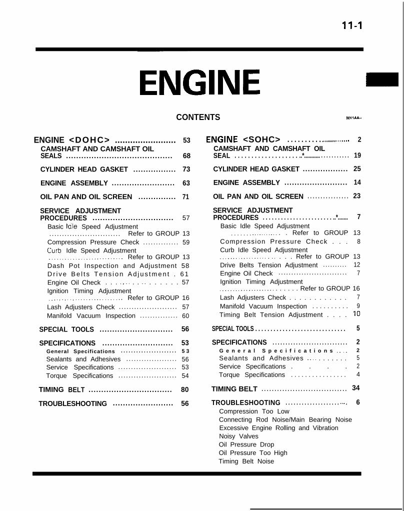
11-I
CONTENTS M11AA-
ENGINE <DOHC> ........................ 53CAMSHAFT AND CAMSHAFT OILSEALS .......................................... 68
CYLINDER HEAD GASKET ................. 73
ENGINE ASSEMBLY ......................... 63
OIL PAN AND OIL SCREEN ............... 71
SERVICE ADJUSTMENTPROCEDURES ................................ 57
Basic Idle Speed Adjustment. . . . . . . . . . . . . . . . . . . . . . . . . . . . Refer to GROUP 13
Compression Pressure Check . . . . . . . . . . . . . . 59Curb- Idle Speed Adjustment_.___..__._____....___._.... Refer to GROUP 13Dash Pot Inspection and Adjustment 58D r i v e B e l t s T e n s i o n A d j u s t m e n t . 6 1Engine Oil Check . . . _. _. . . _. . . . . . . 57Ignition Timing Adjustment__..._.__................... Refer to GROUP 16Lash Adjusters Check . . . . . . . . . . . . . . . . . . . . . . . 57Manifold Vacuum Inspection . . . . . . . . . . . . . . . 60
SPECIAL TOOLS ............................. 56
SPECIFICATIONS ............................ 53General Specifications . . . . . . . . . . . . . . . . . . . . . . 5 3
Sealants and Adhesives . . . . . . . . . . . . . . . . . . . . 56Service Specifications . . . . . . . . . . . . . . . . . . . . . . . 53Torque Specifications . . . . . . . . . . . . . . . . . . . . . . . 54
TIMING BELT ................................. 80
TROUBLESHOOTING ........................ 56
E,NGINE <SOHC> . . . . . . . . . . ..m........... 2CAMSHAFT AND CAMSHAFT OILSEAL . . . . . . . . . . . . . . . . . . . ..*........... . . . . . . . . . . . 19
CYLINDER HEAD GASKET .................. 25
ENGINE ASSEMBLY ......................... 14
OIL PAN AND OIL SCREEN . . . . . . . . . . . . . . . . 23
SERVICE ADJUSTMENTPROCEDURES . . . . . . . . . . . . . . . . . . . . . . . ..*....... 7
Basic Idle Speed Adjustment. . . . . . . .._........ . . Refer to GROUP 13
Compression Pressure Check . . . 8Curb Idle Speed Adjustment.__............... . _. . . . Refer to GROUP 13Drive Belts Tension Adjustment ... . . . . . . . 12Engine Oil Check . . . . . . . . . . . . . . . . . . . . . . . . . . . 7Ignition Timing Adjustment_...___.............. . . . . . . Refer to GROUP 16Lash Adjusters Check . . . . . . . . . . . . 7Manifold Vacuum Inspection . . . . . . . . . . 9Timing Belt Tension Adjustment . . . . 10
SPECIAL TOOLS . . . . . . . . . . . . . . . . . . . . . . . . . . . . . . 5
SPECIFICATIONS . . . . . . . . . . . . . . . . . . . . . . . . . . . . . 2G e n e r a l S p e c i f i c a t i o n s _. _. 2
Sealants and Adhesives ._ _. . . . . . . . 5Service Specifications . . . . 2Torque Specifications . . . . . . . . . . . . . . . . 4
TIMING BELT . . . . . . . . . . . . . . . . . . . . . . . . . . . . . . . . . 34
TROUBLESHOOTING . . . . . . . . . . . . . . . . . . . . m.. . 6Compression Too LowConnecting Rod Noise/Main Bearing NoiseExcessive Engine Rolling and VibrationNoisy ValvesOil Pressure DropOil Pressure Too HighTiming Belt Noise

11-2 ENGINE <SOHC> - Specifications
ENGINE <SOHC>SPECIFICATIONSGENERAL SPECIFICATIONS MllCA-A
Items
TypeNumber of cylinders
Bore
Stroke
Piston drsplacementCompression ratio
Firing order
Silent shaft
Valve timing
Intake valve
Opens (BTDC)
C l o s e s (ABDC)
Exhaust valve
Opens (BBDC)
Closes (ATDC)
Lubrication
Specifications
In-line Single Over Head Camshaft
4
mm (in.) 85 (3.35)
mm (in.) 88 (3.46)cm3 (cu.in.) 1,997 (121.9)
8.5 <8 VALVE>, 9.5 < 16 VALVE>
1-3-4-2
I Equipped
19”<8VALVE>,11”<16VALVE>
57” <8 VALUE>, 53” <I 6 VALUE>
57” <8 VALVE>, 63” <I6 VALVE>
19” <a VALVE>, 21” <16VALVE>
Pressure feed-full flow filtration
SERVICE SPECIFICATIONS MllCB-A
Items Standard Value Limit
Engine adjustments
Engine compression pressure
Engine compression pressure differencebetween each cylinderIntake manifold vacuum-at idle
kPa (psi)/rpm 1 , 2 5 0 (178)/250-400<8 VALVE>1,300 (185)/250-400< 16 VALUE>
kPa ( p s i ) -mmHg (in.Hg) Approx. 500 (20)
<8 VALVE>Approx. 510 (20)<16VALUE>
min. 880 (125)/250-400<8 VALUE>min. 980 (139)/250-400< 16 VALUE>
max. 100 (14)
Timing belt “B” tension mm (in.) 5 - 7 (.20-.28)
Cylinder head bolt < 16 VALUE> mm(in.) - max. 99.4 (3.91)
TSB Revision
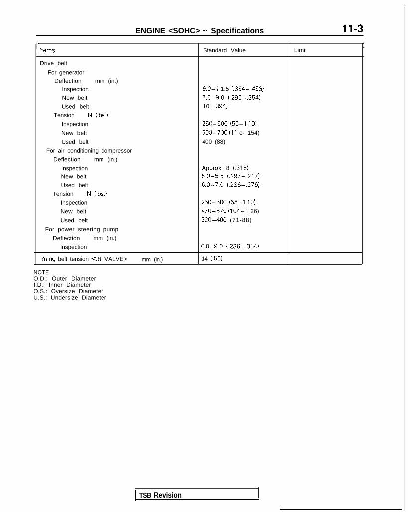
ENGINE <SOHC> - Specifications II-3
l-Items Standard Value Limit1
Drive belt
For generatorDeflection mm (in.)
Inspection 9.0-l 1.5 (.354-,453)
New belt 7.5-9.0 (.295-.354)
Used belt 10 (.394)
Tension N (Ibs.)
Inspection 250-500 (55-l IO)
New belt 500-700 (11 o- 154)
Used belt 400 (88)
For air conditioning compressor
Deflection mm (in.)
Inspection Approx. 8 (.315)
New belt 5.0-5.5 (.197-.217)
Used belt 6.0-7.0 (.236-,276)
Tension N (Ibs.)
Inspection 250-500 (55-l IO)
New belt 470-570 (104-I 26)
Used belt 320-400 (71-88)
For power steering pump
Deflection mm (in.)
Inspection 6.0-9.0 (.236-,354)
iming belt tension <8 VALVE> mm (in.) 14 (.55)
NOTEO.D.: Outer DiameterI.D.: Inner DiameterO.S.: Oversize DiameterU.S.: Undersize Diameter
TSB Revision

II-4 ENGINE <SOHC> - Specifications
TORQUE SPECIFICATIONS
Items Nm ft.lbs.
Engine mount insulator nut (large) 60-80 43-58Engrne mount insulator nut (small) 30-40 22-29
Engine mount bracket nut and bolt 50-65 36-47Front roll stopper insulator nut 50-65 36-47
Front roll stopper bracket to center member 40-50 29-36Rear roll stopper insulator nut 40-50 29-36
Rear roll stopper bracket to crossmember 40-50 29-36Transaxle mount insulator nut 60-80 43-58Transaxle mount bracket to body 40-50 29-36
Fuel high pressure hose to fuel rail 4 - 6 3 - 4Accelerator cable adjusting bolt 4 - 6 3 - 4Front exhaust pipe clamp bolt 30-40 22-29Front exhaust pipe to exhaust manifold 40- 50 29-36Power steering oil pump to bracket 35-45 25-33Air conditioning compressor to bracket 23-27 17-20Oil pan drain plug 35-45 26-33Oil pan 6 - 8 4 - 6Oil screen 15-22 11-16Timing belt cover IO-12 7 - 9Cylinder head bolt (Cold engine) 90- 100 65-72Camshaft sprocket 80-100 58-72dater pump pulley bolt 8-10 6 - 7Crankshaft pulley bolt 20-30 14-22Crankshaft sprocket bolt 110-130 80-94Timrng belt B tensioner bolt 15-22 11-16Tension pulley bracket bolt 23-27 17-20
Right silent shaft sprocket bolt 34-40”’ [43-49]*’ 25-29” [31-351”Oil sprocket nutpump 50-60 36-43Control wiring harness and intake manifold plenum or air intake manifold 4 - 6 3 - 4Front roll stopper bracket bolt 55-75 40-54Front engine support bracket bolt 50-70 36-51Exhaust pipe support bracket bolt 30-42 22-30Left engine support bracket bolt 30-42 22-30Rear roll stopper bracket bolt 110-130 80-94Front case bolt 20-27 14-20Bear cover bolt 5 - 7 4 - 5Iistributor nut IO-13 7 - 9Rocker arm and shaft assembly bolt (large) 19-21 14-15?ocker arm and shaft assembly bolt (small) 20-27 14-20ntake manifold stay bolt 18-25 13-18-iming belt tensioner spacer and bolt 43-55 31-40
NOTE*I: When a 2.0 mm (.08 in.) thick washer is used.~2: When a 2.6 mm (.I0 in.) thick washer is used.
TSB Revision

ENGINE <SOHC> - Specifications/Special Tools
SEALANTS AND ADHESIVES MllCE-A
Items Specified sealant
Engine support bracket bolt <I 6 VALVE>
3M ATD Part No.8660 or equivalent
MITSUBISHI GENUINE PART No.MD970389 or equivalent
SPECIAL TOOLS Ml1 DA-A
Tool Number Name Use
6-J
MD998306-01 INSTALLER, Installation of camshaft oil sealcamshaft oil seal (8 VALUE>
Q
Use withMD998307-01
@
MD998307-01 GUIDE, camshaft oilsealUse withM D998306-01
MD998713-01 Camshaft oil seal Installation of camshaft oil seal
6)
installer < 16 VALVE>
67%
MB990767-0 1 End yoke holder Supporting camshaft pulleySupporting crankshaft pulley< 16 VALVE>
El iis
M D998754 Crankshaft pulleyb. holder pin
fa fii3
B
MD998051 -01 WRENCH, cylinder Tightening of cylinder head to blockhead bolt <8 VALVE>
OPTIONAL: AVAILABLE FROM O.T.C.
GENERALSERVICE TOOL
Oil pan gasket cutter Removal of the oil pan
TSB Revision

11-6
Tool
ENGINE <SOHC> - Special Tools/Troubleshooting
Number Name Use
M D998443-01 HOLDER, lash Supporting of the lash adjuster to prevent itadjuster from falling when rocker shaft assembly IS
removed or installed
MD998752-01 Tension pulley Adjustment of timing belt tensionwrench <I 6 VALVE>
TROUBLESHOOTING MHEAAK
Symptom
Compression too low
Probable cause
Cylinder head gasket blown
Piston ring worn or damage
Piston or cylinder worn
Remedy
Replace gasket
Replace rings
Repair or replace piston and/or cylinderblock
Valve seat worn or damage Repair or replace valve and/or seat ring
Oil pressure drop Engine oil level too low Check engine oil level
Oil pressure switch faulty Replace oil pressure switch
Oil filter clogged Install new filter
Oil pump gears or cover worn Replace gears and/or cover
Thin or diluted engine oil Change engine oil to correct viscosity
Oil relief valve stuck (opened) Repair relief valve
Excessive bearing clearance Replace bearings
Oil pressure too high Oil relief valve stuck (closed) Repair relief valve
Noisy valves Incorrect lash adjuster Bleed air or replace lash adjuster
Thin or diluted engine oil (low oil pressure) Change engine oil
Valve stem or valve guide worn or damage Replace valve and/or guide
Connecting rod noise/ Insufficient oil supply Check engine oil levelmain bearing noise
Low oil pressure Refer to “Oil pressure drop”
Thin or diluted engine oil Change engine oil
Excessive bearing clearance Replace bearings
Timing belt noise Incorrect belt tension Adjust belt tension
Excessive engine rolling Loose engine roll stopper (Front, Rear)and vibration
RetightenLoose transaxle mount bracketLoose engine mount bracketLoose center member
Broken transaxle mount insulatorBroken engine mount insulatorBroken engine roll stopper insulator
Replace
TSB Revision

ENGINE <SOHC> - Service Adjustment Procedures 11-7
OlR0340
1 SERVICE ADJUSTMENT PROCEDU$$oENGINE OIL CHECK(1) Check to ensure that the engine oil level is within the level
range indicated on the oil dip stick.(2) Check to ensure that the oil is not noticeably dirty or mixed
with coolant or gasoline, and that it has the properviscosity.
IASH ACIJUSTERS CHECK MllFEAGa
NOTESoon after the engine is started or while it is running,abnormal noise (clattering) which may be attributed to theadjuster sounds but does not stop. In this case, check thefollowing.
(1) Check the engine oil, and refill or replace oil if necessary.
NOTE0 If the oil amount is small, air will be sucked from the oil
strainer and mixed in the oil passage.0 If the oil amount is excessive, the oil will be stirred by
the crank and mixed with a large amount of air.0 Air and oil can not be separated easily in the deterio-
rated oil, and the amount of air mixed in the oilincreases.
If such mixed-in air enters the high pressure chamber inthe lash adjuster, the air in the high-pressure chamber willbe compressed while the valve is opened, the lash adjusterwill be excessively compressed and abnormal noise will beproduced when the valve is closed.This is the same phenomenon which occurs when thevalve clearance is improperly adjusted to be excessivelylarge.However, it will return to be normal if the air entrapped inthe adjuster is released in this case.
(2) Start the engine, and slowly race* it several times (10 timesor less).If the ablnormal noise is eliminated by racing the engine, itmeans that the air is released from the high-pressurechamber of the lash adjuster and the function of the lashadjuster is returned to normal.l Graclually increase the engine speed from the idle
speed to 3,000 rpm (for 30 seconds), and thengradually slow down the engine to the idling speed (for30 seconds).
NOTE0 If the vehicle is parked on a slope for a long time, the
oil will be sometimes reduced in the lash adjuster, andair will enter the high-pressure chamber when theengine is started.
0 After the vehicle is parked for a long time, the oil will goout of the oil passage. Since it takes a little time tosupply oil to the lash adjuster, air sometimes enters thehigh-pressure chamber.
1 TSB Revision

II-8 ENGINE <SOHC> - Service Adjustment Procedures
8 VALVEW Tlmlng belt side
il6
16
727
(3) If any abnormal noise IS not eliminated by racing, check thelash adjuster.@ Stop the engine.@ Set the engine so that cylinder No. 1 is positioned at
the top dead centre of the compression.@ Press the rocker arm at the area indicated by the+
arrow mark to check whether the rocker arm is loweredor not.
@ Slowly turn the crankshaft 360 degrees clockwise.@ In the same procedure as Step 0, check the rocker
arm at the area indicated by the 0 arrow mark.
@ If the rocker arm lowers easily when the part directlyabove the rocker arm lash adjuster is pressed, the lashadjuster is defective and must be replaced. When re-placing the lash adjuster, bleed the air from all adjus-ters and then assemble them. Then inspect with proce-dures @ to 0, and confirm that there are no abnormal-ities
NOTEl The lash adjuster can be accurately checked for de-
fects with the leak down test.l Refer to the engine service manual for the leak
down test and lash adjuster air bleeding procedure.
If the rocker arm is extremely hard when presseddown, the lash adjuster is normal, so look for a differentcause of abnormal sound.
COMPRESSION PRESSURE CHECK MllFFAL
(1) Before inspection, verify that the engine oil, starter motorand battery are normal. Then, perform the following.l Engine coolant temperature: 80- 95°C (176- 203°F)l Lights, electric cooling fan and accessories: OFFl Transaxle: P range0 Steering wheel: Neutral position
(2) Disconnect the spark plug cable.(3) Remove all the spark plugs(4) Disconnect the connector of the distributor.
NOTEThis will prevent the engine control module from controll-ing the ignition and fuel injection.
TSB Revision

ENGINE <SOHC> - Service Adjustment Procedures 11-9
(5) Cover the spark plug holes with a cloth, etc., and crank theengine. Then verify that no foreign material sticks to thecloth, etc.
Caution1. During cranking, be especially careful of the spark plug
installing hole.2. Very hot water, oil, fuel, etc., which may have entered
the cylinder somehow, will violently spout through thespark plug hole if the compression is measured in theentrapped state. This is very dangerous.
MANIFOILD VACUUM INSPECTION MllFNAC
(6)
(7)
(8)
Set up the compression gauge in the spark plug mountinghole.Fully open the throttle valve, and cranking the engine,measure the compression pressure.
Standard value:<8VALVE> 1,250 kPa (178 psi) [250-400 rpm]< 1 Ei VALVE> 1,300 kPa (185 psi) [250-400 rpm]
Limit:(8 VALVE> 880 kPa (125 psi) [250-400 rpm]
<lEiVALVE> 980 kPa (139 psi) [250-400 rpm]
Measure the compression pressure of each cylinder, andverify that the pressure difference among the cylinders isless than the limit value.
Limit: max. 100 kPa (14 psi)(9) If a cylinder’s compression pressure or pressure difference
IS outside the limit, fill a small amount of engine oil throughthe spark plug hole and repeat Items (7) and (8) above.@ If the compression is increased when the oil is filled,
the piston and/or cylinder wall may be worn ordamaged.
@ If the compression is not increased even though the oilis filled, the valve may be thermally seized, the valvecontact may be improper or pressure may leak at thegasket.
(10) Connect the connector of the distributor.(11) Install the spark plug and spark plug cable.(12)Erase the diagnostic trouble code with the Scan tool or re-
connect the battery (-) cable 10 seconds or more after itwas disconnected.
NOTEThis will erase the memory of the diagnostic trouble codewhich resu,lted from disconnection of the distributor con-nector.
(1) Before inspection and adjustment, put the vehicle into thefollowin~g state.
l Engine coolant temperature: 85-95°C (185-203°F)l Ligt-Its, electric, cooling fan, and accessories: OFFl Transaxle: Neutral (N or P for vehicles with an automa-
tic transaxle)l Steering wheel: Neutral position
(2) Check that the idling revolution speed is normal.
TSB Revision

II-IO ENGINE <SOHC> - Service Adjustment Procedures
(3) Remove the PCV hose from the PCV valve and attach avacuum gauge.
(4) Check that the negative pressure at the intake manifoldduring idle revolution is normal.
Standard value:(8 VALVE> Approx. 500 mmHg (20 in.Hg)<16VALVE> Approx. 510 mmHg (20 in.Hg)
(5) If outside the standard value, isolate the cause by referringto the following table and repair the fault.
Symptom Cause R e m e d y
l The vacuum gauge reading is less than l Ignition timing is retarded. l Adjust the ignition timing.standard value, but the pointer isstable.
l The vacuum gauge pointer swings l The gas mixture is excessively l Check Multiport Fuel Injectionslowly. rich. system.
l The vacuum gauge pointer drops irre- l The gas mixture is excessively l Check Multiport Fuel Injectiongularly. lean. system.
l The vacuum gauge pointer drops inter- 0 Incomplete close contact of in- 0 Check and repair the valve.mittently to 30 to 160 mmHg (1.2 to take and exhaust valve seats.6.3 in.Hg).
l The vacuum gauge pointer drops sud- l Broken cylinder head gasket l ,Replace cylinder head gasket.denly from the normal reading to 250mmHg (9.8 in.Hg). then returns tonormal.
/ OlR0175 condition.
Timina mark‘timing mark
._*-
Camshaft sprocket
TIMING BELT TENSION ADJUSTMENT(8 VALVE> MllFGCEa
There are 2 access holes in the timing belt front lower cover.These can be used to readjust the tension of the timing belt bythe following procedure without removing the timing belt frontlower cover. However, timing belt “B”, which drives the rightsilent shaft, cannot be adjusted unless the cover is removed.(1) Turn the steering wheel all the way to the left.(2) Remove the left side undercover panel.
NOTEThis work is done so that the crankshaft can be turned.
(3) Place a piece of wood against the engine oil pan and jack
up.(4) Remove the engine mounting bracket.(5) Remove the timging belt front upper cover.(6) Remove the four spark plugs.(7) Turn the crankshaft clockwise and check the timing belt
(8) Turn the crankshaft clockwise and align the timing marks.
TSB Revision 1

ENGINE <SOHC> - Servioe Adjustment Procedures II-II
Accesscover
,-(0 a0
<
0 00 0
0
101 II0221
Access cover
Screwdriver slot
3EN075
(9) Remove the air conditioning drive belt and the generatordrive belt.
(10)Removle the access covers. There are easily removed byinserting a screwdriver into the slots indicated by the raisedarrows in the timing belt cover and twisting.
(1l)lnset-t the special tool (MD998051-01) from the pivot sideaccess hole and loosen the tension spacer (with a tensionerlock nut on it) 1 to 2 turn.Next insert a 14 mm socket wrench from the slot sideaccess hole and loosen the tensioner lock bolt 1 to 2 turn.
(12)Turn the crankshaft clockwise by two teeth of the camshaftsprocket.
(13)First ticjhten the timing belt tensioner installation bolt (onthe lo&er side), and then tighten the tensioner spacer(upper side).
CautionBe sure to tighten the bolt (lower side) first. lf thetensioner spacer of pivot side is tightened first, thetensioner will rotate with it and belt tension maybecorn; loose.
(14)lnstall the access cover. The access cover may be easilyinstalleNd by passing the hooks between the guides andsliding it in.
(15)lnstall the air conditioning drive belt and generator drivebelt and adjust the slack. (Refer to P.l l-l 2.)
(16)lnstall the timing belt front upper cover.(17)lnstall the engine mounting bracket.(18)lnstall the spark plugs.(19)lnstall the left side undercover panel.
TSB Revision

11-12 ENGINE <SOHC> - Service Adjustment Procedures
DRIVE BELTS TENSION ADJUSTMENT MllFMBBO
(1) Check that the belts are not damaged.
Powersteenngoil pumppulley
\
Waterpumppulley
I
Tensionpulley
/
Generatorcompressor
Crankshaftpulley
pulley
We
Spindle----As.
I RESET button
(2) Apply IOON (22 Ibs.) force to the belt back midwaybetween the pulleys as shown in the figure, measure thedeflection or, by using a belt-tension gauge, check thebelt’s tension.
Standard value:
Gauge 250-500 500-700 400 (88)N (Ibs.) (55-110) (110-154)
For AK Deflection Approx. 8.0 5.0-5.5 6.0-7.0compressor mm (in.) (.315) (.197-,217) (.236-.276)
For P/Spump
Gauge 250-500 320-400 470-570N (Ibs.) (55-110) (71-88) (104-126)
Deflection 6.0-9.0 -mm (in.) (.236-,354)
NOTEThere is more than one type of belt-tension gauge (type A andtype 8, for example), so be sure to use the gauge according toits instructions for use.
1 TSB Revision

ENGINE <SOHC> - Service Adjustment Procedures II-13
TENSION ADJUSTMENT OF THE GENERATOR DRIVEBELT
Pwot nut , ,, \\ // \ 01u0090
Belt tension
01A0060-
Water
OiA0059
Caution1. Before checking, turn the engine one time or more.2. If the belt tension is too strong, it is possible that the
generator or water pump bearing is damaged.If the b’elt tension is too weak, however, sounds of itsslipping will be heard, and the belt’s service life will bereduced.
1. Loosen the generator pivot nut.
2. Loosen the lock bolt of the belt tension adjuster.3. Using the adjustment bolt, adjust the belt tension to
specified.4. Tighten the lock bolt.5. Tighten the generator pivot nut.6. Check the deflection or the tension of the belt; readjust if
necessary.
NOTEEven for a new belt, the adjustment value for a used beltshould be used to make the adjustment if the belt has beenused for as long as five minutes or more.
DEFLECTION ADJUSTMENT OF POWER STEERING OILPUMP DRIVE BELT1. Loosen power steering oil pump fixing bolt.
2. Move power steering pump, tension belt moderately andadjust deflection.
3. Tighten fixing bolts.4. Run the engine one time or more.5. Check the belt deflection. Readjust, if necessary.
TENSION ADJUSTMENT OF THE AIR CONDITIONINGCOMPRESSOR DRIVE BELT1. Loosen tension pulley fixing bolt A.2. Adjust belt deflection with adjusting bolt B.3. Tighten fixing bolt A.4. Run the engine one time or more.5. Check the belt tension. Readjust, if necessary.
NOTEEven for a new belt, the adjustment value for a used beltshould be used to make the adjustment if the belt has beenused for as long as five minutes or more.
TSB Revision I

II-14 ENGINE <SOHC> - Ennine Assemblv
ENGINE ASSEMBLY (8 VALVE>REMOVAL AND INSTALLATION
Pre-removal Operationl Eliminating fuel pressure in fuel line
(Refer to GROUP 13-On-Vehicle Inspectionof MFI Components.)
*Removal of the Hood(Refer to GROUP 42-Hood.)
*Draining of the Coolant(Refer to GROUP OO-Maintenance Service.)
*Removal of the Transaxle Assembly(Refer to GROUP 22, 23-Transaxle.)
*Removal of the Radiator(Refer to GROUP 14-Radiator.)
I I
Post-installation Operation*Installation of the Radiator
(Refer to GROUP 14-Radiator.)*Installation of the Transaxle Assembly
(Refer to GROUP 22, 23-Transaxle.)*Refilling of the Coolant
(Refer to GROUP 00-Maintenance Servicl Installation of the Hood
(Refer to GROUP 42-Hood.)
:e.)
:1989 models>
- 6 Nm- 4 ft.lbs./
4 - 6 Nm3 - 4 ft.lbs.
cl990 models>
128
3 - 4 ftlbs.
MllSA-A
<1991,1992 models>
1-6 Nm5-4 ft.lbs.
1-6 Nm1-4 ft.lbs.
\
OlAO625
\,,OlA0647
1 TSB Revision
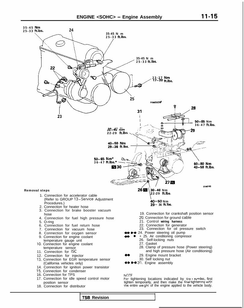
ENGINE <SOHC> - Engine Assembly 11-15
3 5 - 4 52 5 - 3 3
3 5 - 4 5 N m2 5 - 3 3 ft.lbs.
24
3 5 - 4 5 N m2 5 - 3 3 ft.lbs.
2 3 - 2 7
250166309
I23
:l;nbs.
50-65 Nm3 6 - 4 7 ft.lbs.
dv--iu wm : ’22-29 ft.lbs. \ d. (,(I3
L i‘9
50-65 Nm* Cb3 6 - 4 7 ft.lbs.* -
Removal steps1. Connection for accelerator cable
(Refer to GROUP 13-Service AdjustmentProcedures.)
2. Connection for heater hose3. Connection for brake booster vacuum
hose4. Connection for fuel high pressure hose5. O-ring6. Connection for fuel return hose7. Connection for vacuum hose8. Connection for oxygen sensor9. Connection for engine coolant
temperature gauge unit10. Connection for engine coolant
temperature sensor11. Connection for ISC12. Connection for injector13. Connection for EGR temperature sensor
(California vehicles only)14. Connection for ignition power transistor15. Connection for condenser16. Connection for TPS17. Connection for idle speed control motor
position sensor18. Connection for distributor
30-40 Nm
\22-29 ft.lbs.
bO-50 Nm29- 36 ft.lbs.
19. Connection for crankshaft position sensor20. Connection for ground cable21. Control wiring harness22. Connection for generator23. Connection for oil pressure switch
dae I)* 24. Power steering oil pump<ae l + 25. Air conditioning compressor
26. Self-locking nuts27. Gasket28. Clamp of pressure hose (Power steering)
and high pressure hose (Air conditioning)29. Engine mount bracket30. Self locking nut
,** *+ 31. Engine assembly
IdOTEf-or tightening locations indicated by the * symbol. firsttighten temporarily, and then make the final tightenrng wrth?he entire werght of the engine applied to the vehicle body.
TSB Revision 1

11-16 ENGINE <SOHC> - Engine Assembly
SERVICE POINTS OF REMOVAL Ml 1SBBC
24. REMOVAL OF POWER STEERING OIL PUMPRemove the oil pump (with the hose attached).
NOTESuspend the removed oil pump (by using wire or similarmaterial) at a place where no damage will be causedduring removal/installation of the engine assembly.
25. REMOVAL OF AIR CONDITIONING COMPRESSORDisconnect the connection of the air conditioning compres-sor, and then remove the compressor (with the hose at-tached) from the compressor bracket.
NOTESuspend the removed air conditioning compressor (byusing wire or similar material) at a place where no damagewill be caused during removal/installation of the engine as-sembly.
29. REMOVAL OF ENGINE MOUNT BRACKET(1) Attach wire or similar material to the engine hook, and
then suspend (to the extent that there is no slacknessof the wire) by using a chain block or similar arrange-ment.
(2) Remove the engine mount bracket.
31. REMOVAL OF ENGINE ASSEMBLY(1) Check to be sure that all cables, hoses, harness
connectors, etc. are disconnected from the engine.(2) Lift the chain block slowly to remove the engine
a s s e m b l y u p w a r d f r o m t h e e n g i n e c o m p a r t m e n t .
SERVICE POINTS OF INSTALLATION MllSDAX
31. INSTALLATION OF ENGINE ASSEMBLYInstall the engine assembly. When doing so, checkcarefully to be sure that all pipes and hoses are con-nected, and that none are twisted, damaged, etc.
25. INSTALLATION OF AIR CONDITIONINGCOMPRESSORI24. POWER STEERING OIL PUMPAdjust belt tension. (Refer to P. 1 1-l 2.)
TSB Revision

ENGINE <SOHC> -- Engine Assembly
ENGINE ASSEMBLY <I6 VALVE>REMOVAL AND INSTALLATION
II-17
Pre-removal Operation@Eliminating Fuel Pressure in Fuel Line (Refer
to GROUP 13-Service Adjustment Proce-dures.)
l Removal of the Hood(Refer to GROUP 42-Hood.)
l Draining of the Engine Coolant(Refer to GROUP 00-Maintenance Service)
l Removal of the Transaxle(Refer to GROUP 22,23-Transaxle.)
l Removal of the Radiator(Refer to GROUP 14-Radiator.)
Fuel rail
6 03AOO70
Engine oil
Post-installation Operationl Installation of the Radiator
(Refer to GROUP 14-Radiator.)l Installation of the Transaxle
(Refer to GROUP 22, 23-Transaxle.)l Refilling of the Engine Coolant
(Refer to GROUP 00-Maintenance Service.)l Installation of the Hood
(Refer to GROUP 42-Hood.)
4 - 6 Nm3-F ft.lbs.
I6m
Removal steps1. Vacuum hose connection2. Brake booster vacuum hose connection3. Heater hose connection (cylinder head -
heater unit)4. Heater hose connection (Heater unit +
water inlet pipe)5. Fuel high pressure hose connection6. O-ring7. Fuel return hose connection8. Accelerator cable connection9. Engine coolant temperature gauge unit
connector
OlA0676
10. Engine coolant temperature sensorconnector
II. Oxyqen sensor connector12. Distributor connector13. Condenser connector14. TPS connector15. IAC connector16. Injector connector17. Air conditioning compressor connector18. Control harness
1 TSB Revision I

11-18 ENGINE <SOHC> - Engine Assembly
35-45 Nm35-45 Nm25-33 ft.lbs.I
35-45 Nm/ 25-33 ft.lbs.
23-27,‘17-20
Lf+gPf--20 01A0671
36-47 ft.lbs.
40-5o’Nm29-36 ft.lbs.
Removal steps19. Connection for generator20. Connection for oil pressure switch
+e l a21 Power steering oil pump (Refer toP.ll-16.)
+e .422. Air conditioning compressor (Refer toP.l 1-16.)
23. Self-locking nuts24 . Gaske t -
l *
25. Clamp of pressure hose (Power steering)and high pressure hose (Air conditioning)
26. Engine mount bracket (Refer to P.l l-l 6.)27. Self locking nut
+* l C28. Engine assembly (Refer to P.l I-16.)
60-80 Nm43-58 ft.lbs.
OlAO670
1 TSB Revision

ENGINE <SOHC> - Camshaft and Camshaft Oil Seal II-19
CAMSHAFT AND CAMSHAFT OIL SEAL <8 VALVE> MllZA-A
REMOVAL AND INSTALLATION v-- 5-7 Nm4-5 ft.lbs.
0
0I‘
‘p4
Sealant: 3M ATD Part No. 8660or eauivalent
20-27 Nm14-20 ftlbs.
80-100 Nm5 8 - 7 2 ftlbs.
Romnval ztrms. . . . . . ..P-w. ---r-
1. Connection for spark plug cablesand hioh tension cable
3 nictrihl ,+r-,rL. U,illl lYUI”l
(Refer to GROUP 16-Ignition System.)3. timing belt
(Refer to P.l I-34.)4. Connection for breather hose5. Connection for P.C.V. hose6. Accelerator cable bracket7. Rocker cover8. Semi-circular packing9 Camshaft sorocket 01A0316_. __... -..- -r
LL IO O i l s e a l+e s< ii: Rocker arm and shaft assembly
,+ 12. Camshaft
TSB Revision

II-20 ENGINE <SOHC> - Camshaft and Camshaft Oil Seal
MD998443-01 1
6EN245
Oil sealMD998307-01 1
MD99
CaAshaft6ENOlZ
SERVICE POINTS OF REMOVAL MllZBAE
11. REMOVAL OF ROCKER ARM AND SHAFr ASSEMBLYBefore removing the rocker arm and shaft assembly, usethe special tool to ensure that the auto-lash adjusterdoesn’t fall out.
CautionDo not disassemble the rocker arm and shaft assembly.
SERVICE POINTS OF INSTALLATION MllZOAG
12. INSTALLATION OF CAMSHAFTInstall in the cylinder head after applying a coat of engineoil to the camshaft journal and cams.
11. INSTALLATION OF ROCKER ARM AND SHAFT ASSEM-BLY(1) Place the rocker arm and shaft assembly on the
cylinder head and tighten the bearing cap bolt.(2) Remove the special tool.
10. INSTALLATION OF OIL SEAL(1) Install special tool, camshaft oil sea) guide, to the end
of the camshaft and apply engine oil to the outersurface of special tool.
(2) Using special tool, camshaft oil seal installer, press-inthe oil seal.
TSB Revision 1
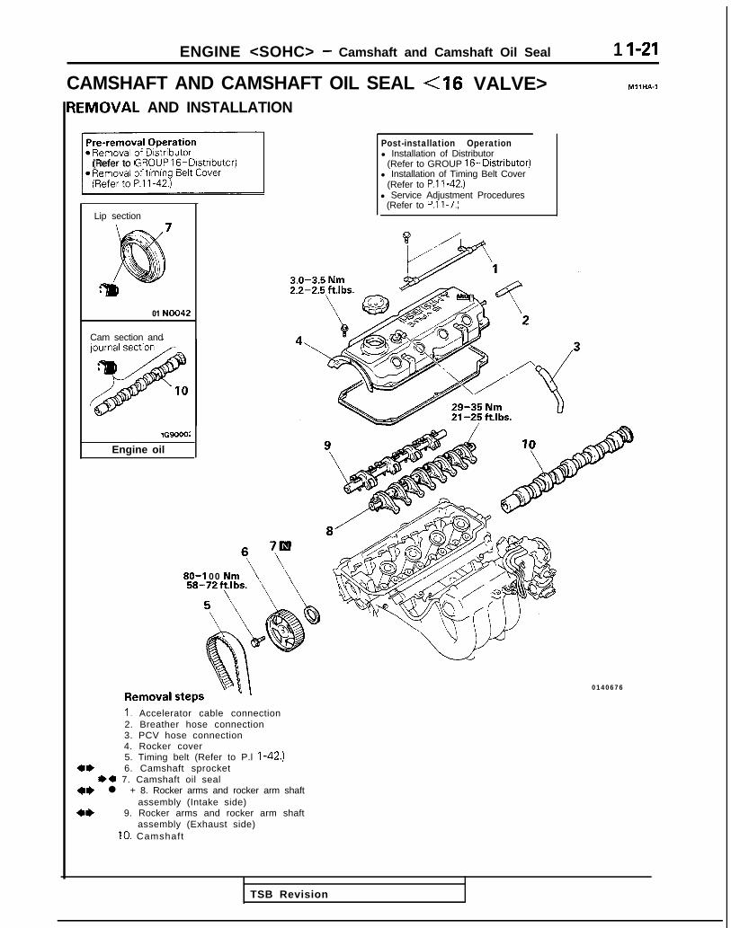
ENGINE <SOHC> - Camshaft and Camshaft Oil Seal 1 I-21
CAMSHAFT AND CAMSHAFT OIL SEAL <I6 VALVE> MllHA-1
IEMOVAL AND INSTALLATION
1(Refer to GRPUP 16-Distnbutor)
Lip section
01 NO042
Cam section and
lG9000:
Engine oil
Post-installation Operationl Installation of Distributor
(Refer to GROUP 16-Distributor)l Installation of Timing Belt Cover
(Refer to P.l l-42.)l Service Adjustment Procedures
(Refer to P.l l-7.)
3.0-3.5 Nm2.2-2.5 ft.lbs.
80-l 00 Nm
0140676RemovalstepsI. Accelerator cable connection2. Breather hose connection3. PCV hose connection4. Rocker cover5. Timing belt (Refer to P.l l-42.)
4* 6. Camshaft sprocketI)+ 7. Camshaft oil seal
*e l + 8. Rocker arms and rocker arm shaftassembly (Intake side)
** 9. Rocker arms and rocker arm shaftassembly (Exhaust side)
10. Camshaft
TSB Revision

ENGINE <SOHC> - Camshaft and Camshaft Oil Seal
SERVICE POINTS OF REMOVAL MllHBAL
6. REMOVAL OF CAMSHAFT SPROCKETUsing the special tool, remove the camshaft sprocket.
8. REMOVAL OF ROCKER ARMS AND ROCKER ARMSHAFT ASSEMBLY (INTAKE SIDE)/S. ROCKER ARMSAND ROCKER ARM SHAFT ASSEMBLY (EXHAUSTSIDE)Before removing the rocker arm and shaft assembly, usethe special tool to ensure that the auto-lash adjusterdoesn’t fall out.
CautionDo not disassemble the rocker arm and shaft assem-bly.
SERVICE POINTS OF INSTALLATION MllHCAM
8. INSTALLATION OF ROCKER ARMS AND ROCKERARM SHAFT ASSEMBLY (INTAKE SIDE)(1) Temporarily tighten the rocker shaft with the bolt so
that all rocker arms on the inlet valve side do not pushthe valves.
(2) Fit the rocker shaft spring from the above and positionit so that it is right angles to the plug guide.
NOTEInstall the rocker shaft spring before installinn therocker arm and rocker arm shaft on the ex haust side.
7.
(3)(4)
Remove the special tool for fixing the lash adjuster.Confirm that the rocker shaft notch is in the directionshown in the diagram.
INSTALLATION OF CAMSHAFT OIL SEALUsing the special tool, install the camshaft oil seal.
TSB Revision

ENGINE <SOHC> - Oil Pan and Oil Screen 11-23
OIL PAN AND OIL SCREEN MllHA-A
REMOVAL AND INSTALLATION
Pre-removal and Post-installation
Bolt holeportion
0180052
Sealant: MITSUBISHI GENUINEP A R T No.MD970389or equivalent
Removal steps1. Drain plug
4**4 2. Oil pan3. Oil screen4. Oil screen gasket
15-22 Nm11-16 ft.lbs.
U’@3 5 - 4 5 Nm a25--33 ft.lbs. i owaI32
d- -<--, \ 9 -
\ ’ 63
%e
;
01 LO583 \ 01 LO584
SERVICE POINTS OF REMOVAL MllHBAFO
2. REMOVAL OF OIL PAN(1) Remove the oil pan mounting bolts.(2) Tap the general service tool in between the cylinder
b lock and the o i l pan .
CautionDo not use a screwdriver, a chisel or a similar toolwhen removing the oil pan.
(3) Remove the oil pan by placing a brass bar at the cornerof the general service tool and then tapping with ahammer.
INSPECTION MllHCACO
l Check the oil pan for damage and cracks. Replace if faulty.l Check the oil screen for clogging; damage and cracks.
Replace if faulty.
1 TSB Revision

11-24 ENGINE <SOHC> - Oil Pan and Oil Screen
Sealant
2 roove
1 EN227
SERVICE POINTS OF INSTALLATION MllHDAOO
2. INSTALLATION OF OIL PAN
(1) Use a wire brush or other tool to scrape clean all gasketsurfaces of the cylinder block and oil pan so that allloose material is removed.
(2) Gasket surfaces must be free of oil and dirt.
(3) APP~ the specified sealant around the surface of oil panas specified in illustration.
Specif ied sealant: MITSUBISHI GENUINE PARTNo.MD970389 or equivalent
NOTETo squeeze out proper amount of sealant, cut off thenozzle of sealant. This will provide a nozzle 4 mm 1.16in.) in drameter.
(4) The sealant should be applied in a continuous beadapproximately 4 mm (.I6 in.) in diameter.
TSB Revision

ENGINE <SOHC> - Cylinder Head Gasket 11-25
CYLINDER HEAD GASKET <8 VALVE>REMOVAL AND INSTALLATION ,,j 4-6 Nm
3-4 ft.lbs.
MllJA-A
Pre-removal ODerationeDraInIng o f Coolant
(Refer to GROUP OO-Maintenance
Post-installation Operation
(Refer to GROUP 00-MaintenanceService.)
@Service Adjustment Procedures(Refer to P.ll-7.)
:1989 m o d e l s >
50-65 Nm36-47 ftlbs.
OlAO310
cl990 models>
4-6 Nm3-4 ftlbs.
:1991,1992 models> / OlA062450-65 Nm

Cyl1n&r’ ;;(oozhead
Sealant: 3M ATD Part No.8660or equivalent
5-7 Nm4-5 ft.lbs
90-100 Nm65-72 ftlbs.
40-50 Nm /29 - 36 ft.lbs.
30-40 Nm22- 29 ftlbs.
Removal stepsI. Air intake hose2. Connection for accelerator cable or
throttle cable (Refer to GROUP 13-Service Adjustment Procedures.)
+e +a 3. Connect ion for fue l h igh pressure hose4. O-ring
+e l + 5. Connection for radiator upper hose6. Connection for water by-pass hose7. Connection for heater hose8. Connection for brake booster vacuum
hose9. Connectron for fue l re turn hose
10. Connection for vacuum hose11. P.C.V. hose12. Connection for spark plug cable13. Connection for oxygen sensor14. Connection for engine coolant
temperature gauge unit15. Connection for engine coolant
temperature sensor16. Connection for ISC17. Connection for injector
olAo314
l *
18. Connection for EGR temperature sensor(California vehicles only)
19. Connection for ignition power transistor20. Connection for condenser21. Connection for TPS22. Connection for ISC motor position sensor23. Connection for distributor24. Connection for crankshaft position sensor25. Connection for ground cable26. Control wiring harness27. Clamp for pressure hose (Power steering)
and high pressure hose (Air conditioning)28. Engine mounting bracket29. Rocker cover30. Semi-circular packing31. Timing bel t f ront upper cover32. Camshaf t sprocket33. Self-locking nuts34. Gasket
+e ++ 35. Cyl inder head assemblyl + 36. Cylinder head gasket
TSB Revision

ENGINE <SOHC> - Cylinder Head Gasket 11-27
\rMatingC
-I
1
J-1.‘T
:-c’ 000510020
SERVICE POINTS OF REMOVAL MllJBAl
3. DISCONNECTION OF FUEL HIGH PRESSURE HOSECautionCover the hose connection with rags to prevent splashof fuel that could be caused by some residual pressurein the fuel pipe line.For information concerning the bleeding of the residualpressure, refer to GROUP 13-On-Vehicle Inspection ofMFI Components.
5. REMOVAL OF RADIATOR UPPER HOSEMake mating marks on the radiator hose and hose clamp,and then disconnect the radiator hose.
28. REMOVAL OF ENGINE MOUNTING BRACKETJack up the vehicle after placing a wooden blockbetween the jack and the engine’s oil pan.
CautionJack up carefully, so as not to apply an excessiveload to the various parts.Remove the engine mount bracket.
32. REMOVAL OF CAMSHAFT SPROCKET(1) Rotate the crankshaft and align the timing mark.
(2) Remove the camshaft sprocket (with the timing beltattached), and place on the timing belt front lower
cover.
CautionAfter removing the camshaft sprocket, be sure notto rotate the crankshaft.
TSB Revision
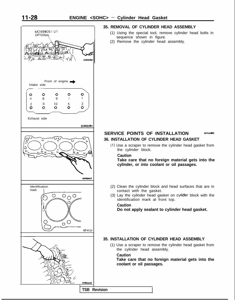
II-28 ENGINE <SOHC> - Cylinder Head Gasket
MD998051-01OPTIONAL
\
Front of engine +Intake side
km>
Exhaust side
OlR0391
OlRD417
Identificationmark I
6EN025
OlRO416
35. REMOVAL OF CYLINDER HEAD ASSEMBLY(1) Using the special tool, remove cylinder head bolts in
sequence shown in figure.(2) Remove the cylinder head assembly.
SERVICE POINTS OF INSTALLATION MllJDBC
36. INSTALLATION OF CYLINDER HEAD GASKET(1) Use a scraper to remove the cylinder head gasket from
the cylinder block.
CautionTake care that no foreign material gets into thecylinder, or into coolant or oil passages.
(2) Clean the cylinder block and head surfaces that are incontact with the gasket.
(3) Lay the cylinder head gasket on cylider block with theidentification mark at front top.
CautionDo not apply sealant to cylinder head gasket.
35. INSTALLATION OF CYLINDER HEAD ASSEMBLY(1) Use a scraper to remove the cylinder head gasket from
the cylinder head assembly.
CautionTake care that no foreign material gets into thecoolant or oil passages.
TSB Revision
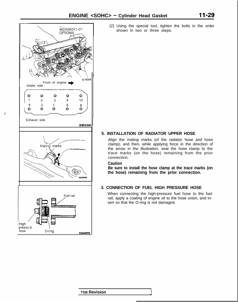
ENGINE <SOHC> - Cylinder Head Gasket II-29
Front of engine I)Intake side
6EN094
Exhaust side
OlR0391
Fuel rail
pr&surehose
\0-nng
TSB Revision
(2) Using the special tool, tighten the bolts in the ordershown in two or three steps.
5. INSTALLATION OF RADIATOR UPPER HOSEAlign the mating marks (of the radiator hose and hoseclamp), and then, while applying force in the direction ofthe arrow in the illustration, seat the hose clamp to thetrace marks (on the hose) remaining from the priorconnection.
CautionBe sure to install the hose clamp at the trace marks (onthe hose) remaining from the prior connection.
3. CONNECTION OF FUEL HIGH PRESSURE HOSEWhen connecting the high-pressure fuel hose to the fuelrail, apply a coating of engine oil to the hose union, and in-sert so that the O-ring is not damaged.

II-30 ENGINE <SOHC> - Cylinder Head Gasket
CYLINDER HEAD GASKET <I6 VALVE>REMOVAL AND INSTALLATION
Ml IJA-C
Pre-removal Operationl Releasing of Fuel Line Pressure
(Refer to GROUP 13-Service Adjust-ment Procedures.)
l Draining of the Engine Coolant(Refer to GROUP 14-Service Adjust-ment Procedures.)
l Draining of the Engine Oil
il 4-6 Nm
Post-installation Operationl Supplying of the Engine Coolant
(Refer to GROUP 14-Service Adjust-ment Procedures.)
l Supplying of the Engine Oill Accelerator Cable Adjustment
(Refer to GROUP 13-Service Adjust-ment Procedures.)
Removal stepsI. Breather hose2. Air intake hose3. Vacuum hose connection4. Brake booster vacuum hose connection5. Water hose connection (cylinder head -
throttle body)6. Heater hose connection (cylinder head --L
heater unit)7. Water hose connection (throttle body -
water inlet pipe)8. Fuel high pressure hose connection9. O-ring
10. Fuel return hose connection11. Accelerator cable connection
2
9.Engine oil
12. Engine coolant temperature gauge unitconnector
13. Engine coolant temperature sensorconnector
14. Oxygen sensor connector15. Distributor connector16. Condenser connector17. TPS connector18. IAC connector19. Injector connector20. Air conditioning compressor connector21. Control harness22. Spark plug cable
TSB Revision

ENGINE <SOHC> - Winder Head Gasket
3-3.5 Nm2.2-2.5 ft.lbs. 28
Cold Engine80 Nm + 0 Nm - 20 Nm - +1/4 turn + +I/4 turn58 ft.lbs. - 0 ftlbs. -+ 14fWbs. - +I/4 turn - +1/4 turn
/g$j?&-- Tiff i ”.\ ,)
/
3 2
lo-12 Nm7-nu,L.,
40-50 Nm29-36 ftJbs.9
;;I:: k. I@@
30-40 Nm22-29 ft.lbs.
/18-25 Nm13-18 ft.lbs.
GR‘ 2 4
OlA0660
23. Connection for radiator upper hose24. Connection for radiator lower hose
1)+25. Water inlet fitting, thermostat andthermostat case assembly
26. Timing belt upper cover4* 27. Camshaft sprocket
28. Rocker cover29. Self-locking nuts30. Gasket
*431_ Cylinder tiead bolt+e +432. Cylinder head assemblyl +33. Cylinder head gasket
TSB Revision
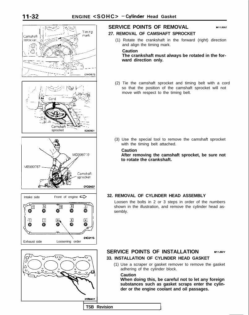
11-32 ENGINE <SOHC> - Winder Head Gasket
sprocket ’ lG90001
Intake side Front of engine e
IExhaust side
\ olCOll!iLoosening order
SERVICE POINTS OF REMOVAL MllJEAZ
27. REMOVAL OF CAMSHAFT SPROCKET(1) Rotate the crankshaft in the forward (right) direction
and align the timing mark.
CautionThe crankshaft must always be rotated in the for-ward direction only.
(3) Use the special tool to remove the camshaft sprocketwith the timing belt attached.
CautionAfter removing the camshaft sprocket, be sure notto rotate the crankshaft.
32. REMOVAL OF CYLINDER HEAD ASSEMBLYLoosen the bolts in 2 or 3 steps in order of the numbersshown in the illustration, and remove the cylinder head as-sembly.
SERVICE POINTS OF INSTALLATION MllJDCV
33. INSTALLATION OF CYLINDER HEAD GASKET(1) Use a scraper or gasket remover to remove the gasket
adhering of the cylinder block.
CautionWhen doing this, be careful not to let any foreignsubstances such as gasket scraps enter the cylin-der or the engine coolant and oil passages.
(2) Tie the camshaft sprocket and timing belt with a cordso that the position of the camshaft sprocket will notmove with respect to the timing belt.
TSB Revision 1

ENGINE <SOHC> - Cvlinder Head Gasket II-33
Identification mark r3Intake side “4G63K” Front of
Exhaust side OlA0669
Front of engine I)Intake side
Exhaust side
OlR0391
Ei;. -Qmm (in.) 0140674
(2) Place the cylinder head gasket on top of the cylinderblock so that the identification mark is facing upwardsas in the illustration.
CautionThe cylinder head gasket is easy to mis-install, sobe sure to check it. If it is mis-installed, malfunc-tions such as no oil rising to the cylinder head willoccur.
32. INSTALLATION OF CYLINDER HEAD ASSEMBLYI31.CYLINDER HEAD BOLT(1) Use a scraper to clean the gasket surface of the cylin-
der head assembly.
CautionTake care that no foreign material gets into theengine coolant passages or oil passages.
(2) When installing the cylinder head bolts, check that theshank length of each bolt meets the limit. If the limit isexceeded, replace the bolt.
Limit: Max. 99.4 mm (3.91 in.)(3) Apply engine oil to the threaded part of the bolt and the
washer.(4) According to the tightening sequence, tighten the bolts
to the specified torque 80 Nm (58 ftlbs.).(5) Loosen bolts completely.(6) Torque bolts to 20 Nm (14.5 ft.lbs.).(7) Tighten bolts l/4 turns (90”) more.(8) Tighten bolts l/4 turns (90”) additionally.
25. INSTALLATION OF WATER INLET FITTING,THERMOSTAT AND THERMOSTAT CASE ASSEMBLY(1) Loosen the water inlet pipe bolt shown in the illustra-
tion.(2) Apply specified sealant to the thermostat case assem-
bly as shown in the illustration.
Specified sealant: MITSUBISHI GENUINE PARTNo.MD970389 or equivalent
(3) Apply a small amount of water to the O-ring of thewater inlet pipe, and press the thermostat case assem-bly onto the water inlet pipe.
(4) Install the thermostat case assembly mounting bolt.(5) Tighten the water inlet pipe bolt.
TSB Revision
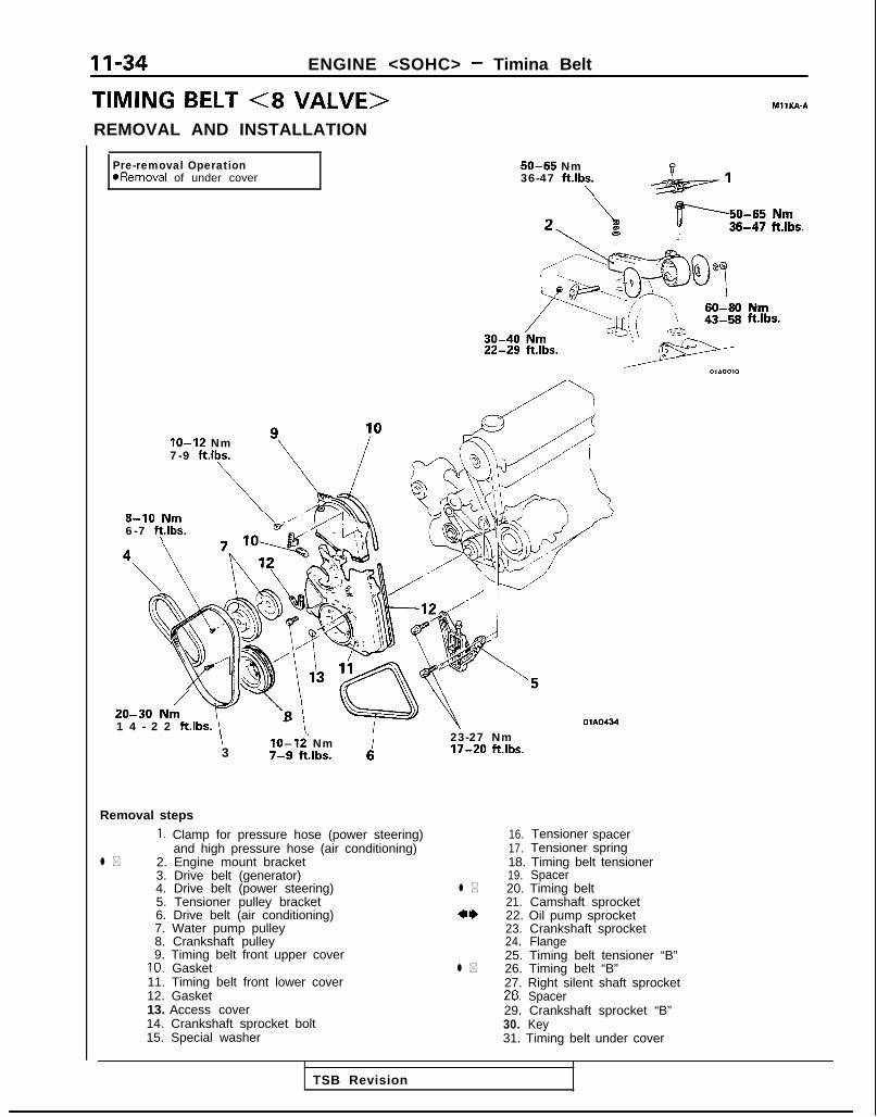
11-34 ENGINE <SOHC> - Timina Belt
TIMING BELT (8 VALVE> MIlKA-AREMOVAL AND INSTALLATION
Pre-removal OperationaRemoval of under cover
50-65 Nm36-47 ftlbs.
\
22-29 ft.lbs.
ft.lbs.
IO-12 Nm7-9 ft.lbs.
10
m \../.8-10 N6-7 ft.lbs.\
20-30 N,/ v \R \OlAO4341 4 - 2 2 ft.lbs. \
I3
10-12’ Nm7-S ftlbs. 6
23-27 Nm17-20 ft.lbs.
Removal steps
1. Clamp for pressure hose (power steering)and high pressure hose (air conditioning)
l * 2. Engine mount bracket3. Drive belt (generator)4. Drive belt (power steering)5. Tensioner pulley bracket6. Drive belt (air conditioning)7. Water pump pulley8. Crankshaft pulley9. Timing belt front upper cover
10. Gasket11. Timing belt front lower cover12. Gasket13. Access cover14. Crankshaft sprocket bolt15. Special washer
16. Tensioner spacer17. Tensioner spring18. Timing belt tensioner19. Spacer
l * 20. Timing belt21. Camshaft sprocket
*‘I) 22. Oil pump sprocket23.24.
Crankshaft sprocketFlange
25. Timing belt tensioner “B”l * 26. Timing belt “B”
27. Right silent shaft sprocket28. Spacer29. Crankshaft sprocket “B”30. Key31. Timing belt under cover
TSB Revision
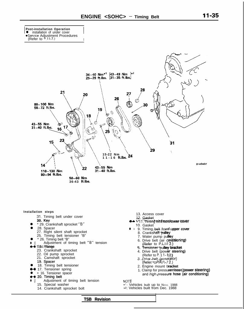
ENGINE <SOHC> - Timing Belt II-35
I Post-installation Operationl installation of under cover IaService Adjustment Procedures
(Refer to P.ll-7.) I
50-60 Nm36-43 ftlbs.
31
\ \15-22 Nm1 1 - 1 6 ft.lbs. 24
01 A0437
30. KevIL. -I"..--
+A ‘II T:m;nn halt fmnf lower cover
Installation steps31. Timing belt under cover30. Key
l * 29. Crankshaft sprocket “B”l 28. Spacer
27. Right silent shaft sprocket25. Timing belt tensioner “B”
l * 26. Timing belt “B”l 4 Adjustment of timing belt “B” tensionl * 24. Flange
23. Crankshaft sprocket22. Oil pump sprocket21. Camshaft sprocket19. Spacer
l 18. Timing belt tensioner~~ 17. Tensioner springl + 16. Tensioner spacer++ 20. Timing beltl 4 Adjustment of timing belt tension
15. Special washer14. Crankshaft sprocket bolt
tic 24. Flanae
, UtiIL , , WI ,t upper cover!hcaft n, dlqy
lb.:;d)rtroning)
\..“.w. .-c T-mrinnar r\n nliny bracket
er steering)1 2.)
19. Spacer
++ 20. Timing belt
13. Access cover12. Gasket
l + 11. Timing belt front lower cover10. Gasket
l + 9. Timing belt front upper cover8. Crankshaft pulley7. Water pump pulley6. Drive belt (air conditioning)
(Refer to P.l l-l 2.)5. Tensioner pulley bracket4. Drive belt (power steering)
(Refer to P. 1 l-l 2.)3. Drive belt (generator)
(Refer to P.l l-l 2.)2. Engine mount bracket1. Clamp for pressure hose (power steering)
and high pressure hose (air conditioning)
NOTE*I: Vehicles built up to NO V. 1988+2: Vehicles built from Dec. 1988
lrator)U. Vll”” ““SC \y”v’ulRpfcw tn P 1 l-l 2.)
racket
NOT=
ure hose (power steering)s-4, I” I “..J’I p.. .#““.a re hose (air conditioning)
TSB RevisionTSB Revision

11-36 ENGINE <SOHC> - Timinn Belt
Timing mark\
Camshaft sprocket
;/
i
\I lEN0017
Tite
I;
OlAO550
01A0551
SERVICE POINTS OF REMOVAL MllKBDF
2. REMOVAL OF ENGINE MOUNT BRACKET(1) Jack up the vehicle after placing a wooden block
between the jack and the engine’s oil pan.
CautionJack up carefully so as not to apply an excessiveload to the various parts.
(2) Remove the engine mount bracket.
20. REMOVAL OF TIMING BELT(1) Turn the crankshaft clockwise and align the timing
marks.
CautionThe crankshaft must always be turned clockwise.
(2) Make a mark on the back of the timing belt indicatingthe direction of rotation so it may be reassembled in thesame direction if it is to be reused.
(3) Loosen the bolt and tension spacer of the timing belttensioner.
(4) Move the timing belt tensioner to the water pump sideand loosely tighten the bolt so that the tensionerdoesn’t return; then remove the timing belt.
NOTEIf the timing belt is to be re-used, use chalk to mark (onits flat side) an arrow indicating the clockwise direc-tion.
Caution1. As water or oil on the belt can seriously reduce
its usable life, ensure that the timing belt,sprocket, and tensioner stay clean and dry whileremoved, and never wash them. Parts that havebecome too dirty should be replaced.
2. When any of the parts are oily, check to seewhether there are any oil leaks in any of the oilseals or the cam shaft oil seal on the front of theengine.
1 TSB Revision

ENGINE <SOHC> - Timing Belt II-37
-uw
rack
rack
Separ
Crack’7EN207
Rounded belt side
Abnormal wear(fluffy canvas fiber) 7EN20E
-1 TSB Revision
22. REMOVAL OF OIL PUMP SPROCKET(1) Remove the plug on the side of the cylinder block.(2) Insert a Phillips screwdriver [shank diameter 8 mm (.31
in.)] to block the left silent shaft.(3) Remove the oil pump sprocket nut.(4) Remove the oil pump sprocket.
26. REMOVAL OF TIMING BELT “B”Make a mark on the back of the timing belt indicating thedirection of rotation so it may be reassembled in the samedirection if it is to be reused.
CautionWater or oil on the belt shorten its life drastically, sothe removed timing belt, sprocket, and tensioner mustbe free from oil and water. These parts should not bewashed. Replace parts if seriously contaminated.If there is oil or water on each part check the front caseoil seals, camshaft oil seal and water pump for leaks.
INSPECTION MIlKCAD
TIMING BELTSThe timing belts must be checked closely. Should the followingdefects be evident, replace the belt with a new one.(1) Hardened back surface rubber
Glossy, non-elastic, and so hard that no mark is producedeven when scratched by a fingernail.
(2) Cracked back surface rubber.(3) Cracked or separated canvas.(4) Cracked tooth bottom.(5) Cracked side.
(6) Abnormal wear on side.
NOTENormal belt should have clear-cut sides as if cut by a sharpknife.

11-38 ENGINE <SOHC> - Timing Belt
Rubberexposed
Tooth missing andcanvas fiber exposed
lEN0002
Crankshaftsprocket “B”
Crankshaf t aENzo4
Spacer
Chamfered6EN009
(7) Abnormal wear on teeth.Initial stage:
Canvas on load side tooth flank worn (Fluffy canvasfibers, rubber gone and color changed to white, andunclear canvas texture)
Final stage:Canvas on load side tooth flank worn down and rubberexposed (tooth width reduced)
(8) Missing tooth.
TENSIONER PULLEYTurn the pulleys to check for possible binding, excessive play,and unusual noise. Replace the pulley if any of these defects isevident.
SERVICE POINTS OF INSTALLATION MllKDCE
29. INSTALLATION OF CRANKSHAFT SPROCKET “B”Install the crankshaft sprocket “B” as shown while payingattention to its direction.
28. INSTALLATION OF SPACER(1) Apply a thin coat of engine oil to the outer circumfer-
ence of the spacer.(2) Install the spacer with the chamfered end facing the oil
seal.
NOTEIf the spacer is installed adversely, the oil seal may bedamaged, resulting in the oil leaks.
26. INSTALLATION OF TIMING BELT “B”(1) Ensure that crankshaft sprocket “B” timing mark and
the silent shaft sprocket timing mark are aligned.(2) Fit timing belt “B” over crankshaft sprocket “B” and
the silent shaft sprocket. Ensure that there is no slack inthe belt.
1 TSB Revision

ENGINE <SOHC> - Timing Belt 11-39
Crankshaftsprocket
F,a,!,ge Crankshaft6EN272
0180047
Crankshaftsprocket “B”
tensioner
. ADJUSTMENT OF TIMING BELT “B” TENSION(1) Temporarily fix the timing belt “B” tensioner such that
the centre of the tensioner pulley is to the left andabove the centre of the installation bolt, and temporari-ly attach the tensioner pulley so that the flange istoward the front of the engine.
(2) Holding the timing belt “B” tensioner up with yourfinger in the direction of the arrow, place pressure onthe timing belt so that the tension side of the belt istaut. Now tighten the bolt to fix the tensio,ier.
CautionWhen tightening the bolt, ensure that the tensionerpulley shaft does not rotate with the bolt. Allowingit to rotate with the bolt can cause excessivetension on the belt.
(3) To ensure that the tension is correct, depress the belt(point A) with a finger. If not, adjust.
Standard value: 5-7 mm (.20-.28 in.)
24. INSTALLATION OF FLANGEInstall the flange in correct direction as shown.
18. INSTALLATION OF TIMING BELT TENSIONER/17. TENSIONER SPRING/lG. TENSIONER SPACER
(1) Install the tensioner spring, tensioner spacer andtiming belt tensioner.
(2) Place the upper end of the tensioner spring against thewater pump body.
1

II-40 ENGINE <SOHC> - Timing Belt
OlRO372
1 (3) Move tensioner fully toward water pump and tempo-rarily secure tensioner.
Timing mark Timing mark
(on cylinder head)
T i m i n g m a r k “1(on front case) ,A.
Timing mark 6EN063
3ENOO5
Tensior
of belt-I s i d e
Tension side of belt 6EN0065
20. INSTALLATION OF TIMING BELT(1) Ensure that the timing marks of the camshaft sprock-
et, the crankshaft sprocket, and the oil pump sprocketare all aligned.
(2) When aligning the timing mark of the oil pumpsprocket, remove the plug of the cylinder block; theninsert the shaft of a cross-tip (+) screwdriver with ashaft diameter of 8 mm (.31 in.) into the plug hole andcheck to be sure that the screwdriver’s shaft can beinserted at least 60 mm (2.36 in.). Do not remove thescrewdriver until the timing belt is completely at-tached.If the screwdriver’s shaft can be inserted only to adepth of about 20 to 25 mm (.79 to .98 in.) because itcontacts the silent shaft, turn the sprocket by onerotation and align the timing mark once again; thencheck again to be sure that the screwdriver’s shaft canbe inserted at least 60 mm (2.36 in.).
(3) Install timing belt. While making sure that tension sideof belt is not slackened, install timing belt ontocrankshaf t sprocket , o i l pump sprocket a n d c a m s h a f tsprocket in that order.
CautionIf the timing belt is reused, install so that the arrowmarked on it at the time of removal is pointing inthe clockwise direction.
l ADJUSTMENT OF TIMING BELT TENSION(1) Loosen tensioner mounting bolt. By so doing, tension-
er will be moved by spring and will apply tension tobelt.
(2) Recheck to be sure that each sprocket’s timing mark iscorrect.
1 TSB Revision I

ENGINE <SOHC> - Timina Belt 11-41
I I
(3) Turn the crankshaft clockwise by two teeth of thecamshaft sprocket.
CautionAs the purpose of this procedure is to apply theproper amount of tension on the timing belt, be surenot to rotate the crankshaft counter-clockwise orplace pressure on the belt to check the amount oftension.
Tensionerspacer
OlR0404
(4) Apply force on tensioner toward turning direction, (inthe direction of the arrow) such that no portion of thebelt raises out in portion A, place the belt on thecamshaft sprocket such that the belt sprocket teethare fully engaged.
(5) Tighten the tensioner installation bolt and tensionerspacer in that order.
CautionIf the tensioner spacer is tightened first, the ten-sioner will rotate with it and belt tension be thrownout of adjustment. Always tighten the bolt first.
TSB Revision
(6) Check to see that the clearance between the outsideof the belt and the cover are within the standard valueby grasping the tension side (between the camshaftsprocket and oil pump sprocket) of the centre part ofthe timing belt between the thumb and index finger.
Standard value: 14 mm (.55 in.)
6 x 20(23 x .78)
6 x 20(23 x .78)
6 x 25t.23 x ,981
11. INSTALLATION OF TIMING BELT FRONT LOWER COV-ER/9. TIMING BELT FRONT UPPER COVERNote that the timing belt lower and upper cover attachingbolts differ in size from one place to another.
Bolt diameter x lengthmm (in.)
6x 20t.23 x ,781
011672

11-42 ENGINE <SOHC> - Timing Belt
TIMING BELT <I6 VALVE>REMOVAL AND INSTALLATION
MIlKA-A
Pre-removal Operationl Removal of under cover
8-10 Nm6-7 ftlbs.
4 ’‘\
50-65 Nm36-47 ft.lbs.
\
IO-12 Nm7-9 ftlbs.
\\
ft.lbs. ’3 Q ’23-27 Nm17-20 ft.lbs.
Removal steps1.
2.
Clamp for pressure hose (power steering)and high pressure hose (air conditioning)Engine mount bracketDrive belt (generator)Drive belt (power steering)Tensioner pulley bracketDrive belt (air conditioning)Water pump pulleyCrankshaft pulleyTiming belt front upper coverTiming belt front lower coverAuto tensionerTiming belt
OlA0677
::5.6.
i:9.
10.11.12.13.14.
Tensioner pulleyTensioner arm
15.
::16.17.18.19.20.21.22.
4* 23.24.25.27.28.29.
idle pulleyCamshaft sprocketOil pump sprocketCrankshaft sprocket boltSpecial washerCrankshaft sprocketFlangeTiming belt tensioner “B”Timing belt “B”Right silent shaft sprocketSpacerKkyEngine support bracket boltTiming belt under cover
P
TSB Revision

ENGINE <SOHC> - Timing Belt II-43
+/@Service Adjustment Procedures
24 ?5
20-;7 Nm io14-20 ft.lbs.
\ is \ i7 Nm 50-60 Nm
80-94 ft.lbs. 36-43 ft.lbs.
Installation steps29. Timing belt under cover
l +28. Engine support bracket bolt27. Key
ea26. Crankshaft sprocket “6”l +25. Spacer
24. Right silent shaft sprocket22. Timing belt tensioner “B”
l +23. Timing belt “B”l * Adjustment of timing belt “B” tension1)421. Flangel +20. Crankshaft sprocket
19. Special washer18. Crankshaft sprocket bolt17. Oil pump sprocket16. Camshaft sprocket15. Idle pulley
l al 1. Auto tensioner14. Tensioner arm
1)+13. Tensioner pulley
ftlbs.
OlAO682
l +I 2. Timing beltl * Adjustment of timing belt tensionl 41 0. Timing belt front lower coverI)+ 9. Timing belt front upper cover
8. Crankshaft pulley7. Water pump pulley6. Drive belt (air conditioning) (Refer to
P.ll-12.)5. Tensioner pulley bracket4. Drive belt (power steering) (Refer to
P.l l-l 2.)3. Drive belt (generator) (Refer to P.l l-l 2.)2. Engine mount bracketI. Clamp for pressure hose (power steering)
and high pressure hose (air conditioning)
TSB Revision

ENGINE <SOHC> - Timing Belt
A Timing mark
Timingmark
mark - /Crank&aft swocket
OlA0667
lEN0017
SERVICE POINTS OF REMOVAL MllKBDG
2. REMOVAL OF ENGINE MOUNT BRACKET(1) With a wooden block placed against the oil pan part of
the engine, jack up the vehicle.
CautionJack up gently, so as not to apply a load to the va-rious parts.
(2) Remove the engine mount bracket.
11. REMOVAL OF AUTO TENSIONER(1) Turn the crankshaft clockwise and align the timing
marks so as to bring the No.1 cylinder to compressiontop-dead-centre position.At this time the timing marks of the camshaft sprocket
-and the upper surface of the cylinder head should coin-cide, and the dowel pin of the camshaft sprocketshould be at the upper side.
CautionThe crankshaft must always be rotated clockwise.
(2) Remove the auto tensioner.
12. REMOVAL OF TIMING BELTMake a mark on the back of the timing belt indicating thedirection of rotation so it may be reassembled in the samedirection if it is to be reused.
CautionWater or oil on the belt shorten its life drastically, sothe removed timing belt, sprocket, and tensionermust be free from oil and water. These parts shouldnot be washed. Replace parts if seriously contami-nated.If there is oil or water on each part check the frontcase oil seals, camshaft oil seal and water pump forleaks.
16. REMOVAL OF CAMSHAFT SPROCKET(1) Rotate the crankshaft in the forward (right) direction
and align the timing mark.
CautionThe crankshaft must always be rotated in the for-ward direction only.
TSB Revision

ENGINE <SOHC> - Timinn Belt 11-45
sprocket v lGVO001
MD998754
vlB990767-01
-
&00B00°
(2) Tie the camshaft sprocket and timing belt with a cordso that the position of the camshaft sprocket will notmove with respect to the timing belt.
(3) Use the special tool to remove the camshaft sprocketwith the timing belt attached.
CautionAfter removing the camshaft sprocket, be sure notto rotate the crankshaft.
17. REMOVAL OF OIL PUMP SPROCKET(1) Remove the plug on the side of the cylinder block.(2) Insert a Phillips screwdriver [shank diameter 8 mm (31
in.)] to block the left silent shaft.(3) Remove the oil pump sprocket nut.(4) Remove the oil pump sprocket.
23. REMOVAL OF TIMING BELT “B”Make a mark on the back of the timing belt indicating thedirection of rotation so it may be reassembled in the samedirection if it is to be reused.
CautionWater or oil on the belt shorten its life drastically, sothe removed timing belt, sprocket, and tensionermust be free from oil and water. These parts shouldnot be washed. Replace parts if seriously contami-nated.If there is oil or water on each part check the frontcase oil seals, camshaft oil seal and water pump forleaks.
INSPECTION Ml 1 KCAD
TIMING BELTSThe timing belts must be checked closely. Should the followingdefects be evident, replace the belt with a new one.(1) Hardened back surface rubber
Glossy, non-elastic, and so hard that no mark is producedeven when scratched by a fingernail.
\ TSB Revision I

. .Crack
II-46 ENGINE <SOHC> - Timing Belt
(2) Cracked back surface rubber.(3) Cracked or separated canvas.(4) Cracked tooth bottom.(5) Cracked side.
Separation
Crack ’7EN207
Rounded belt side
Abnormal wear(fluffy canvas fiber)
7EN208
Rubberexposed
Tooth mlsslng andcanvas fiber exposed
7EN209
6EN0159
c \/Ga//
@E3%00
t6EN0280
(6) Abnormal wear on side.
NOTENormal belt should have clear-cut sides as if cut by a sharpknife.
(7) Abnormal wear on teeth.Initial stage:
Canvas on load side tooth flank worn (Fluffy canvas fib-ers, rubber gone and color changed to white, and un-clear canvas texture)
Final stage:Canvas on load side tooth flank worn down and rubberexposed (tooth width reduced)
(8) Missing tooth.
TENSIONER PULLEY AND IDLER PULLEY(1) Turn the pulleys to check for possible binding, excessive
play, and unusual noise. Replace the pulley if any of thesedefects is evident.
(2) Replace if there is a grease leak.
AUTO TENSIONER(1) Check the auto tensioner for possible leaks and replace as
necessary.(2) Check the rod end for wear or damage and replace as
necessary.
TSB Revision

ENGINE <SOHC> - Timing Belt II-47
~7 12 rym
I (.47 In.)-
0
io
‘0
6EN0161
/
AL@Plug
6EN0281
Crankshaftsprocket “B”
(3) Measure the rod protrusion. If it is out of specification,replace the auto tensioner.
Standard value: 12 mm (.47 in.)
(4) Using a vise with soft jaws push in the auto tensioner rod.If the rod can be easily retracted, replace the autotensioner. You should feel a fair amount of resistance whenpushing the rod in.
Caution1. Clamp the auto tensioner in the vise so it maintains
a level position.
2. If the plug at the bottom of the auto tensionerprotrudes, surround it with a plain washer asillustrated to prevent the plug from being in directcontact with the vise.
SERVICE POINTS OF INSTALLATION M1lKDCF
28. INSTALLATION OF ENGINE SUPPORT BRACKETBOLTApply sealant to the bolt shown in the figure and tighten itto the specified torque.
Specified sealant: 3M ATD Part No.8660 or equivalent
26. INSTALLATION OF CRANKSHAFT SPROCKET “B”Install the crankshaft sprocket “B” as shown while payingattention to its direction.
Crankshaft 6EN304
TSB Revision I

II-48 ENGINE <SOHC> - Timing Belt
Soacer
ChaAfered
Silent shaftn sprocket
Center oftensionerpulley
Center ofinstallation bolt
installation bolt 01Aoo39-
1
25. INSTALLATION OF SPACER(1) Apply a thin coat of engine oil to the outer circumfer-
ence of the spacer.(2) Install the spacer with the chamfered end facing the oil
seal.
NOTEIf the spacer is installed adversely, the oil seal may bedamaged, resulting in the oil leaks.
23. INSTALLATION OF TIMING BELT “B”(1) Ensure that crankshaft sprocket “B” timing mark and
the silent shaft sprocket timing mark are aligned.(2) Fit timing belt “B” over crankshaft sprocket “B” and
the silent shaft sprocket. Ensure that there is no slack inthe belt.
. ADJUSTMENT OF TIMING BELT “B” TENSION(1) Temporarily fix the timing belt “B” tensioner such that
the center of the tensioner pulley is to the left andabove the center of the installation bolt, and temporarilyattach the tensioner pulley so that the flange is towardthe front of the engine.
(2) Holding the timing belt “B” tensioner up with yourfinger in the direction of the arrow, place pressure onthe timing belt so that the tension side of the belt istaut. Now tighten the bolt to fix the tensioner.
CautionWhen tightening the bolt, ensure that the tensionerpulley shaft does not rotate with the bolt. Allowingit to rotate with the bolt can cause excessivetension on the belt.
(3) To ensure that the tension is correct, depress the belt(point A) with a finger. If not, adjust.
Standard value: 5-7 mm (.20-.28 in.)
TSB Revision 1

ENGINE <SOHC> - Timing Belt II-49
Crankshaftsprocket “B”/
Crankshaft/ \ \sprocket Flange Crankshaft 6~~~72
Plain washer- J
26@Plug
6EN0281
I
21. INSTALLATION OF FLANGE
Install the flange in correct direction as shown.
CautionPay special attention to the direction of the flange. If itis installed in the wrong direction, a broken timing beltcould result.
20. INSTALLATION OF CRANKSHAFT SPROCKET
Install the crankshaft sprocket in the correct direction asshown.
CautionPay special attention to the direction of the flange. If itis installed in the wrong direction, a broken timing beltcould result.
11. INSTALLATION OF AUTO TENSIONER(1) If the auto tensioner rod is in its fully extended position,
reset it as follows.@ Keep the auto tensioner level and, in that position,
clamp it in the vise with soft jaws.
If the plug at the bottom of the auto tensionerprotrudes, surround it with a plain washer asillustrated to prevent the plug from being in directcontact with the vise.
@ Push in the rod little by little with the vise until theset hole @ in the rod is aligned with that @ in thecylinder.
@ Insert a wire [1.4 mm (055 in.) in diameter] into theset holes.
@ Unclamp the auto tensioner from the vise.

ENGINE <SOHC> - Timing Belt
Center bolt i\ \
6EN028:
Timina mark
Timingmark
Timingmark
Crankshaft sprocketOlAO668
(2) Install the auto tensioner.
CautionLeave the wire installed in the auto tensioner.
13. INSTALLATION OF TENSIONER PULLEY
(1) Install the tensioner pulley onto the tensioner arm.(2) Locate the pinhole in the tensioner pulley shaft to the
left of the center bolt. Then, tighten the center boltfinger-tight.
CautionLeave the wire installed in the auto tensioner.
12. INSTALLATION OF TIMING BELT
(1) Ensure that the timing marks of the camshaft sprocket,the crankshaft sprocket, and the oil pump sprocket areall aligned.
(2) Remove the plug on the cylinder block and insert aPhillips screwdriver [shank diameter 8 mm (.31 in.)]through the hole.If it can be inserted as deep as 60 mm (2.4 in.) or more,the timing marks are correctly aligned. If the inserteddepth is only 20-25 mm (.8-1.0 in.), turn the oil pumpsprocket one turn and realign timing marks. Then checkto ensure that the screwdriver can be inserted 60 mm(2.4 in.) or more. Keep the screwdriver inserted until theinstallation of the timing belt is finished.
NOTEStep (2) is performed to ensure that the oil pumpsprocket is correctly positioned with reference to thesilent shafts.
1 TSB Revision

ENGINE <SOHC> - Timing Belt 11-51
r
L
Camshaft sprocket
Idlerpulley
/Oil pump OlA0668
sprocket
6EN0175
(3) Install the timing belt around sprockets as follows.@ Install the timing belt around the tensioner pulley
and crankshaft sprocket and secure the timing beltonto the tensioner pulley with your left hand.
@ Pulling the belt with your right hand, install it aroundthe oil pump sprocket.
@ Install the belt around the idler pulley.@ Turn the camshaft sprocket one tooth clockwise to
align its timing mark with the cylinder head top sur-face (see illustration in step 0). Then, pulling thebelt with both hands, install it around the camshaftsprocket.
@ Gently raise the tensioner pulley as shown by thearrow, so that the belt does not sag, and temporar-ily tighten the center bolt.
. ADJUSTMENT OF TIMING BELT TENSION
(1) After turning the crankshaft l/4 turn counterclockwise,turn it clockwise to move the No.1 cylinder to top deadcenter.
(2) Loosen the center bolt, and then, as shown in the illus-tration, attach the special tool and a torque wrench andapply a torque of 2.6-2.8 Nm (1.88-2.03 ft.lbs.). If thebody interferes with the special tool and the torquewrench, use a jack to slightly raise the engine assem-bly.
NOTEUse a torque wrench that is capable of measurementwithin a range of O-3 Nm (O-2.2 ftlbs.)
(3) Holding the tensioner pulley with the special tool andtorque wrench, tighten the center bolt to specification.
(4) Screw the tool into the engine left support bracket untilits end makes contact with the tensioner arm. At thatpoint, screw the tool in some more and then removethe set wire attached to the auto tensioner.
(5) Remove the tool.
(6) Rotate the crankshaft two complete turns clockwiseand leave it as is for about 15 minutes. Then, measurethe auto tensioner protrusion “A” (distance betweenthe tensioner arm and auto tensioner body) to ensurethat it is up to specification.
Standard value: 3.8-4.5 mm (.15-.18 in.)
If it is out of specification, repeat steps (6) through (11)until the specified value is obtained.
TSB Revision I

ENGINE <SOHC> - Timing Belt
riiis;;o;~~@1 ip I-----$ j ggoner~
I :
1
llAO104 1lAOlOS
I I, /K. I . I
6x50(.24x1.97)
6x20(.24x.78)
6x22(.24x.87,
6x18(.24x.71)
6x251.24x.98) 6x18
(.24x.71)
OlAO666
(7) If the clearance between the tensioner arm and theauto tensioner body cannot be measured (when theengine is being mounted, etc.), the following proce-dures can be used to substitute for the ordinarymethod of measurement.@ Screw in the tool until it contacts the tensioner arm.@ From that point of contact, further screw in the tool,
screwing it in until the push rod of the auto ten-sioner body is caused to move backward and thetensioner arm contacts the auto tensioner body.Check to be sure that the amount that the tool hasbeen screwed in (when the push rod moves back-ward) is the standard value.
Standard value: 2.5-3 turns
(8) Install the rubber plug to the timing belt rear cover
10. INSTALLATION OF TIMING BELT LOWER COVER/S.TIMING MELT U P P E R COVER
The dimensions of the installation bolts for the timing co-vers differ according to the installation location, so be surenot to install the bolts in the incorrect locations.
TSB Revision

E N G I N E < D O H C > - S p e c i f i c a t i o n s
ENGINE <DOHC>
11-53
SPECIFICATIONSGENERAL SPECIFICATIONS MllCA-6
Items
TvpeNumber of cylinders
Bore
Stroke
Piston drsplacement
Compression ratto
Firing order
Silent shaft
Valve timing
Intake valve
Opens (BTDC)
Closes (ABDC)
Exhaust valve
Opens (BBDC)
Closes (ATDC)
Lubrication
l : 1992 models
Specifications
In-line Double, Over Head Camshaft
4
mm (in.) 85 (3.35)
mm (in.) 88 (3.46)
cm3 (cu.in.) 1 ,997 (121.9)
9.0 (Non-Turbo), 9.8 (Non-Turbo)*, 7.8 (Turbo)
l-3-4-2
Equrpped
26” (Non-Turbo), 21’ (Non-Turbo)*, 21’ (Turbo)
46” (Non-Turbo), 43” (Non-Turbo)*, 51” (Turbo)
55” (Non-Turbo), 57” (Non-Turbo)*, 57” (Turbo)
9” (Non-Turbo), 15” (Non-Turbo)“, 15” (Turbo)
Pressure feed-full flow filtration
SERVICE SPECIFICATIONS MllCB-B
Items Standard Value Limit
Engine adystmentsEngine compression pressure kPa (psi)/rpm
<Non-Turbo> Up to 1991 models 1,350 (I 92)/250-400 min. 960 (137)/250-400
from 1992 models 1,550 (220)/250-400 min. 1,120 (159)/250- 4OC
<Turbo> I,1 50 (164)/250- 400 min. 800 (114)/250-400
Engine compression pressure differencebetween each cylinder kPa ( p s i ) - max. 100 (14)
Intake manifold vacuum-at idle mmHg (in.Hg) Approx. 500 (20) -
Cylinder head bolt < 1993 models> - 99.4 (3.91)
Drive belt
For generator
Deflection mm (in.)
Inspectron 9.0- 11.5 (.354-.453)
New belt 7.5-9.0 (.295-.354)
Used belt 10 f.394)
Tension N (Ibs.)
Inspection 250-500 (55- 1 IO)
New belt 500-700 (1 lo- 154)
Used belt 400 (88)
TSB Revision
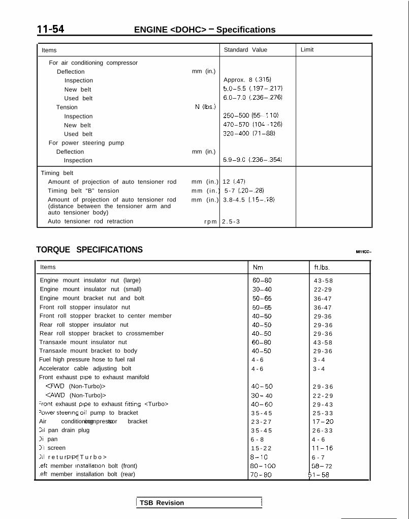
11-54 ENGINE <DOHC> - Specifications
Items
For air conditioning compressor
Deflection
Inspection
New belt
Used belt
Tension
Inspection
New belt
Used belt
For power steering pump
DeflectionInspection
Timing belt
Amount of projection of auto tensioner rod
Timing belt “B” tension
Amount of projection of auto tensioner rod(distance between the tensioner arm andauto tensioner body)
Auto tensioner rod retraction
Standard Value
mm (in.)Approx. 8 (.315)
5.0-5.5 (.197-,217)
6.0-7.0 (.236-.276)
N (Ibs.)250-500 (55-l 10)
470-570 (104-126)
320-400 (71-88)
mm (in.)6.9-9.0 (.236-,354)
mm (in.) 12 (.47)
mm ( i n . ) 5 -7 (.20-.28)
mm (in.) 3.8-4.5 (.15-.18)
r p m 2 . 5 - 3
Limit
TORQUE SPECIFICATIONS
Items
Engine mount insulator nut (large)
Engine mount insulator nut (small)
Engine mount bracket nut and bolt
Front roll stopper insulator nutFront roll stopper bracket to center member
Rear roll stopper insulator nutRear roll stopper bracket to crossmember
Transaxle mount insulator nutTransaxle mount bracket to body
Fuel high pressure hose to fuel rail
Accelerator cable adjusting bolt
Front exhaust pope to exhaust manifold
<FWD (Non-Turbo)>
CAWD (Non-Turbo)>+ont exhaust pope to exhaust fitting <Turbo>
‘ower steerrng 011 pump to bracketAir conditioning to bracketcompressor
311 pan drain plug
311 pan
3il screen
111 r e t u r n ( T u r b o >pope
.eft member installation bolt (front)-eft member installation bolt (rear)
Nm ft.ibs.
60-80 4 3 - 5 8
30-40 22-29
50-65 36-47
50-65 36-47
40-50 29-36
40-50 2 9 - 3 640-50 2 9 - 3 6
60-80 4 3 - 5 840-50 2 9 - 3 64 - 6 3 - 4
4 - 6 3 - 4
40-50 2 9 - 3 6
30- 40 2 2 - 2 9
40-60 2 9 - 4 33 5 - 4 5 2 5 - 3 32 3 - 2 7 17-20
3 5 - 4 5 2 6 - 3 3
6 - 8 4 - 6
1 5 - 2 2 11-16
8-10 6 - 7
80- 100 58- 72
70-80 51-58
MllCC--
( TSB Revision

ENGINE <DOHC> - SDecifications 11-55
Items Nm ft.lbs.
Transfer assembly
<M/T> 55-60 40-434f-r> 60-80 44-57
Front exhaust pipe to engine 30-40 22-29Center bearing bracket 36-46 26-33Timing belt cover IO-12 7 - 9Cylinder head bolt (Cold engine) <Up to 1992 models> 90-100 65-72
<From 1993 models> 20 -t l/4 turn 14- 1/4turn+ 1!4turn --t l/4 turn
Camshaft sprocket 80-100 58-72
Water pump pulley bolt 8-10 6 - 7Crankshaft pulley bolt 20-30 14-22
Crankshaft sprocket bolt 110-130 80-94
Timing belt B tensioner bolt 15-22 11-16
Tension pulley bracket bolt 23-27 17-20
Right silent shaft sprocket bolt 34-40*' [43-49]** 25-29*’ 131-351"
Oil pump sprocket nut 50-60 3 6 - 4 3Control wiring harness and intake manifold plenum or air intake manifold 4 - 6 3 - 4
Front roll stopper bracket bolt 55-75 40-54
Front engine support bracket bolt 50-70 36-51
Exhaust pipe support bracket bolt 30-42 22-30
Left engine support bracket bolt 30-42 22-30
Rear roll stopper bracket bolt 110-130 80-94
Front case bolt Bolts 30 mm (.I2 in.) long 27-34 20-25
Other bolts 20-27 14-20
Engine mount bracket to bracket 17-26 12-19
Front engine support bracket to bracket 17-26 12-19
%r cleaner body installation bolt 8-10 6 - 7
qir cleaner body and resonator assembly 8-10 6 - 7
Control wiring harness clamp bolt IO-12 7 - 9
3ocker cover bolt 2.5-3.5 2 - 3
Zenter cover bolt 2.5-3.5 2 - 3
Camshaft bearing cap bolt 19-21 14-15
Crankshaft position sensor nut IO-13 7 - 9
Throttle body stay 15-22 1 1 - 1 6
3adiator assembly bolt 9 - 1 4 7-10
3ranch tube bolt 8-10 6 - 7
ntake manifold stay bolt 25-30 18-22
quto tensioner 20-27 14-20
rension pulley bolt 43-55 31-40
dle pulley bolt 34-42 25-30
riming belt rear right cover 10-12 7 - 9
riming belt rear left cover (lower) 30-42 22-30- Faster together with the left engine support bracket
riming belt rear left cover (upper) IO-12 7 - 9
Jalve body bolt IO-12 7 - 9
NOTE*I: Vehicles built up to Nov. 1988**: Vehicles built from Dec. 1988
TSB Revision 1

1 l-56 ENGINE <DOHC> - Specifications/Special Tools/Troubleshooting
SEALANTS AND ADHESIVES MllCE-B
Items
Semi-circular packing
Rocker cover
Oil pressure switchEngine support bracket bolt<From 1993 models>
Oil pan MITSUBISHI GENUINE PART No.MD970389 or equivalent
Specified sealant
3M ATD Part No.8660 or equivalent
SPECIAL TOOLS MllDA-8
Tool Number Name Use
0
MD998306-01 INSTALLER, lnstallatlon of camshaft oil sealcamshaft oil seal
0
Use withM D998307-0 1
MD998307-01 GUIDE, camshaft oil
@
sealUse withMD998306-01
II
MD998051-01 WRENCH, cylinderhead bolt
Tightening of cylinder head to block<Up to 1992 models>
OPTIONAL: AVAILABLE FROM O.T.C.
T
GENERAL Oil pan gasket cutter Removal of the oil pan
r-SERVICE TOOL
MD998752-01 Tension pulleywrench
Adjustment of timing belt tension
TROUBLESHOOTINGRefer to P. 1 l-6.
TSB Revision

ENGINE <DOHC> - Service Adjustment Procedures 11-57
OlR0340
7EN0393
1 SERVICE ADJUSTMENT PROCEDUBFzoENGINE OIL CHECK(1) Check to ensure that the engine oil level is within the level
range indicated on the oil dip stick.(2) Check to ensure that the oil is not noticeably dirty or mixed
with coolant or gasoline, and that it has the propervtscosity.
IASH ADJUSTERS CHECKNOTE
MllFEAGb
Soon after the engine IS started or while it is running,abnormal noise (clattering) which may be attributed to theadjuster sounds but does not stop. In this case, check thefollowing.
(1) Check the engine oil, and refill or replace oil if necessary.
NOTE0 If the oil amount is small, air will be sucked from the oil
strainer and mixed in the oil passage.0 If the oil amount is excessive, the oil will be stirred by
the crank and mixed with a large amount of air.0 Air and oil can not be separated easily in the deterio-
rated oil, and the amount of air mixed in the oilincreases.
If such mixed-in air enters the high pressure chamber inthe lash adjuster, the air in the high-pressure chamber willbe compressed while the valve is opened, the lash adjusterwill be excessively compressed and abnormal noise will beproduced when the valve is closed.This is the same phenomenon which occurs when thevalve clearance is improperly adjusted to be excessivelylarge.However, it will return to be normal if the air entrapped inthe adjuster is released in this case.
(2) Start the engine, and slowly race* it several times (10 timesor less).If the abnormal noise is eliminated by racing the engine, itmeans that the air is released from the high-pressurechamber of the lash adjuster and the function of the lashadluster is returned to normal.l Gradually increase the engine speed from the idle
speed to 3,000 rpm (for 30 seconds), and thengradually slow down the engine to the idling speed (for30 seconds).
NOTE0 If the vehicle is parked on a slope for a long time, the
oil will be sometimes reduced in the lash adjuster, andair will enter the high-pressure chamber when theengine is started.
l After the vehicle is parked for a long time, the oil will goout of the oil passage. Since it takes a little time tosupply oil to the lash adjuster, air sometimes enters thehigh-pressure chamber.
TSR Revision

11-58 ENGINE <DOHC> - Service Adjustment Procedures
4 Timing belt side I
6EN0515
(3) lf any abnormal noise IS not eliminated by racing. check thelash adjuster@ Stop the engine.@ Set the engine so that cylinder No. 1 IS posit ioned at
the top dead centre of the compression.@ Press the rocker arm at the area indicated by the+
arrow mark to check whether the rocker arm is loweredor not.
@ Slowly turn the crankshaft 360 degrees clockwise.@ ln the same procedure as Step 0, check the rocker
arm at the area indicated by the 4 arrow mark.@ If the rocker arm lowers easily when the part directly
above the rocker arm lash adjuster is pressed, the lashadjuster is defective and must be replaced. When re-placing the lash adjuster, bleed the air from all adjus-ters and then assemble them. Then inspect with proce-dures @I to 0, and confirm that there are no abnormal-ities.
NOTEl The lash adjuster can be accurately checked for de-
fects with the leak down test.l Refer to the engine service manual for the leak
down test and lash adjuster air bleeding procedure.
If the rocker arm is extremely hard when presseddown, the lash adjuster is normal, so look for a differentcause of abnormal sound.
DASH POT INSPECTION AND ADJUSTMENT<Non-Turbo-M/T>(1) Perform after inspecting the idle rotation speed.(2) The vehicle should be prepared as follows before the
inspection.l Engine coolant temperature: 80- 95°C (176- 203°F)l Lights, electric cooling fan and accessories: OFFl Transaxle: Neutrall Steering wheel: neutral position
(3) Either set the tachometer or connect the data link connec-tor (white) to the scan tool.
NOTEFor setting the tachometer. refer to GROUP 13 - ServiceAdjustment Procedures.
(4) Start the engine.(5) Open the throttle valve until the dash pot rod is fully
stroked.(6) Gradually close the throttle valve until you find the point
where the throttle lever touches the dash pot rod (the dashpot begins to shorten).Maintain the throttle valve at this touching point,
(7) Check the engine speed (speed when the dash pot beginsto operate).
Standard value: 3,900 f 200 rpm
(8) If outside the standard value, loosen the rod’s lock nut andturn the rod to adjust.
(9) To release the maintained state of the throttle valve, checkthat the engine speed gradually decreases to the idle speed,
(10)Disconnect the closed throttle position switch connector(fixed SAS).
1 TSB Revision

ENGINE <DOHC> - Service Adiustment Procedures 11-59
7 Go;;ikv position
switch
(11)Check that there is continuity between the closed throttleposition switch terminal and body.
NOTEWhen there is continuity, a clearance will be createdbetween the throttle lever and dash pot rod when the dashpot rod is pressed lightly.
(12) When there is no continuity, lower the engine speed whenthe dash pot begins operation to within the standard valuetolerance. Make sure to create continuity between theclosed throttle position switch terminal and body.
COMPRESSION PRESSURE CHECK Ml 1 FFAL
(1) Before inspection, verify that the engine oil, starter motorand battery are normal. Then, perform the following.l Engine coolant temperature: 80- 95°C (1 76- 205’F)l Lights, electnc cooling fan and accessories: OFF0 Transaxle: P range0 Steering wheel: Neutral position
(2) Disconnect the spark plug cable.(3) Remove all the spark plugs.(4) Disconnect the connector of the crankshaft position sensor.
NOTEThis will prevent the engine control module from controll-ing the ignition and fuel injection.
(5) Cover the spark plug holes with a cloth, etc., and crank theengine. Then verify that no foreign material sticks to thecloth, etc.
Caution1. During cranking, be especially careful of the spark plug
installing hole.2. Very hot water, oil, fuel, etc., which may have entered
the cylinder somehow, will violently spout through thespark plug hole if the compression is measured in theentrapped state. This is vex/ dangerous.
(6) Set up the compression gauge in the spark plug mountinghole.
(7) Fully open the throttle valve, and cranking the engine.measure the compression pressure.
Standard value:<Non-Turbo>
Up to 1991: 1,350 kPa (192 psi) [250- 400 rpmlFrom 1992: 1,550 kPa (220 psi) [250-400 rpm]
<Turbo> 1 ,150 kPa (164 psi) [250- 400 rpmlLimit:
<Non-Turbo>up to 1991: 960 kPa (137 psi) [250- 400 rpmlFrom 1992: 1 ,120 kPa (159 psi) [250- 400 rpml
CTurbo> 800 kPa (114 psi) [250- 400 rpml
(8) Measure the compression pressure of each cylinder. andverify that the pressure difference among the cylinders isless than the limit value.
Limit: max. 100 kPa (14 psi)
TSB Revision I
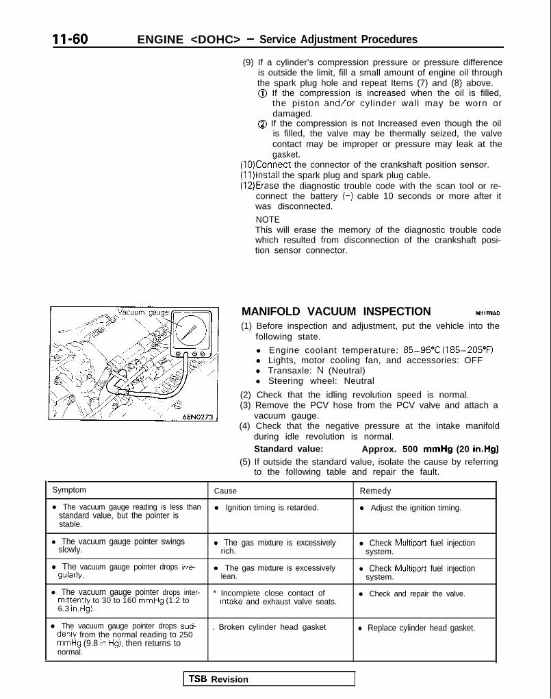
II-60 ENGINE <DOHC> - Service Adjustment Procedures
(9) If a cylinder’s compression pressure or pressure differenceis outside the limit, fill a small amount of engine oil throughthe spark plug hole and repeat Items (7) and (8) above.@ If the compression is increased when the oil is filled,
the piston and/or cylinder wall may be worn ordamaged.
@ If the compression is not Increased even though the oilis filled, the valve may be thermally seized, the valvecontact may be improper or pressure may leak at thegasket.
(10)Connect the connector of the crankshaft position sensor.(1l)lnstall the spark plug and spark plug cable.(12)Erase the diagnostic trouble code with the scan tool or re-
connect the battery (-) cable 10 seconds or more after itwas disconnected.
NOTEThis will erase the memory of the diagnostic trouble codewhich resulted from disconnection of the crankshaft posi-tion sensor connector.
MANIFOLD VACUUM INSPECTION MllFNAD
(1) Before inspection and adjustment, put the vehicle into thefollowing state.
l Engine coolant temperature: 85-95°C (185-205°F)l Lights, motor cooling fan, and accessories: OFFl Transaxle: N (Neutral)l Steering wheel: Neutral
(2) Check that the idling revolution speed is normal.(3) Remove the PCV hose from the PCV valve and attach a
vacuum gauge.(4) Check that the negative pressure at the intake manifold
during idle revolution is normal.Standard value: Approx. 500 mmHg (20 in.Hg)
(5) If outside the standard value, isolate the cause by referringto the following table and repair the fault.
Symptom Cause Remedy
l The vacuum gauge reading is less thanstandard value, but the pointer is
l Ignition timing is retarded. l Adjust the ignition timing.
stable.
l The vacuum gauge pointer swingsslowly.
l The gas mixture is excessivelyrich.
l Check Multiport fuel injectionsystem.
l The vacuum gauge pointer drops irre-gularly.
l The gas mixture is excessivelylean.
l Check Multiport fuel injectionsystem.
l The vacuum gauge pointer drops inter-mittently to 30 to 160 mmHg (1.2 to
* Incomplete close contact ofIntake and exhaust valve seats.
l Check and repair the valve.
6.3 in.Hg).
l The vacuum gauge pointer drops sud-denly from the normal reading to 250
. Broken cylinder head gasket l Replace cylinder head gasket.
mmHg (9.8 in.Hg), then returns tonormal.
TSB Revision

ENGINE <DOHC> - Service Adjustment Procedures 11-61
DRIVE BELTS TENSION ADJUSTMENT MllFMBBl
(1) Check that the belts are not damaged.
Powersteeringoil pumppulley ,
Waterpumppulley
Tensionpulley
f /
x I J
b
L ‘dp1
Genkrator I Ipulley Crankshaft Air
pulley conditioningcompressorpulley
Spindle
Spindle
2Y \ Hook
xi@--
V-ribbed belt
Hook
rType BRESET button
(2) Apply 100N (22 Ibs.) force to the belt back midwaybetween the pulleys as shown in the figure, measure thedeflection or, by using a belt-tension gauge, check thebelt’s tension.
Standard value:
I tems
For AK Deflection Approx. 8.0 5.0-5.5 6.0-7.0comDressor mm (in.) t.3151 (.197-,217) (.236-.276) I
NOTEThere is more than one type of belt-tension gauge (type A andtype B, for example), so be sure to use the gauge according toits instructions for use.
1 TSB Revision

II-62 ENGINE <DOHC> - Service Adjustment Procedures
Lock bolt
TENSION ADJUSTMENT OF THE GENERATOR DRIVEBELT
Caution1. Before checking, turn the engine one time or more.2. If the belt tension is too strong, it is possible that the
generator or water pump bearing is damaged. If thebelt tension is too weak, however, sounds of its slip-ping will be heard, and the belt’s service life will bereduced.
1. Loosen the generator pivot nut
2. Loosen the lock bolt of the belt tension adjuster.3. Using the adjustment bolt, adjust the belt tension to
specified.4. Tighten the lock bolt.5. Tighten the generator pivot nut.6. Check the deflection or the tension of the belt; readjust if
necessary.
NOTEEven for a new belt, the adjustment value for a used beltshould be used to make the adjustment if the belt has beenused for as long as five minutes or more.
DEFLECTION ADJUSTMENT OF POWER STEERING OILPUMP DRIVE BELT
1. Loosen power steering oil pump fixing bolt.
2. Move power steering pump, tension belt moderately andadjust deflection.
3. Tighten fixing bolts.4. Run the engine one time or more.5. Check the belt deflection. Readjust, if necessary.
II OlA0059
r
TSB Revision
TENSION ADJUSTMENT OF THE AIR CONDITIONINGCOMPRESSOR DRIVE BELT1. Loosen tension pulley fixing bolt A.2. Adjust belt deflection with adjusting bolt B.3. Tighten fixing bolt A.4. Run the engine one time or more.5. Check the belt tension. Readjust, if necessary.
NOTEEven for a new belt, the adjustment value for a used beltshould be used to make the adjustment if the belt has beenused for as long as five minutes or more.

ENGINE <DOHC> - Engine Assembly 11-63
ENGINE ASSEMBLYIEMOVAL AND INSTALLATION
Pre-removal Operationl Eliminating fuel pressure in fuel lines
(Refer to GROUP 13-On-Vehicle lnspectiorof MFI Components.)
*Removal of the hood(Refer to GROUP 42-Hood.)
eDraining of engine coolant(Refer to GROUP 00-Maintenance Service.:
@Removal of transaxle assembly(Refer to GROUP 22, 23-Transaxle.)
*Removal of radiator assembly(Refer to GROUP 14-Radiator.)
MIISA-6
Post-installation Operationl installation of radiator assembly
(Refer to GROUP 14-Radiator.)l Installation of transaxle assembly
Removal steps1. Connection for accelerator cable or
throttle cable (Refer to GROUP 13-Service Adjustment Procedures.)
2. Connection for throttle cable (Auto-cruisecontrol)
3. Connection for fuel return hose4. Connection forbrake booster vacuum
hose5. Connection for fuel pressure solenoid
(Turbo)6. Connection for EGR solenoid
(Turbo: California)7. Connection for air hose A (Turbo)8. Connection for air hose D (Turbo)9. Connection for fuel high pressure hose
10. O-ring11. Connection for heater hoses
TSB Revision

ENGINE <DOHC> - Engine Assembly
cl989 models> ‘P 15
4-6 Nm3-4 ftlbs..
3-4 ftlbs. lo-12 Nm7-9 ft.lbs.
< 1990 models>14
13 I15
\ /
Olb.0407
4-6 Nm3-4 ftlbs. \
16
17 3*
4 -6 Nm z -3-4 ftlbs. iwz 110-12 Nm
7-9 ftlbs.
OlA0623
20
TSB Revision

ENGINE <DOHC> - Engine Assembly 11-65
<From 1991 models>
4-6 Nm
25
18
05AO196
I23
\ il4-6 Nm3-4 ftlbs.
12. Connection for engine coolanttemperature switch
13. Connection for oxygen sensor14. Connection for engine coolant
temperature sensor15. Connection for engine coolant
temperature gauge unit16. Connection for air conditioning engine
coolant temperature switch17. Connection for IAC motor18. Connection for closed throttle position
switch
19. Connection for fuel injectors20. Connection for EGR temperature sensor
(California vehicles only)21. Connection for knock sensor (Turbo)22. Connection for ignition coil23. Connection for ignition power transistor24. Connection for throttle position sensor25. Connection for crankshaft position sensor26. Connection for ground cable27. Control wiring harness
TSB Revision 1

11-66 ENGINE <DOHC> - Engine Assembly
28
29
30
35-45 Nm25-33 ftlbs.
50-65 Nm36-47 ft.lbs.
I31 32
40-50 Nm29-36 ftlbs.
43-56 ft.lbs.
-- .__..36-47 ft.lbs.* 54 ’
q
28. z;tFhction for power steering pressure
29. Connection for generator30. Generator wiring harness clamps31. Connection for oil pressure switch
4W 1)432. Connection for power steering oil pump++ ++33. Connection for air conditioning
compressor34. Self-locking nut35. Gasket36. Bracket
4* 37. Engine mount bracket38. Self locking nut
+e l + 39. Engine assembly
22- 29 ftlbs.c-rurbo>40-60 Nm29- 43 ftlbs.
OlAO405
NOTEFor tightening locations indicated by the l , symbol, firsttighten temporarily, and then make the final tlghtenlng withthe entire weight of the engine applied to the vehicle body.
TSB Revision

ENGINE <DOHC> - Engine Assembly II-67
SERVICE POINTS OF REMOVAL MllSBDF
32. DISCONNECTION OF POWER STEERING OIL PUMP
Disconnect the oil pump with hoses from the bracket.
NOTEThe removed power steering oil pump should be fastened(by using rope, etc.) in a position that will not interferewith the removal/installation of the engine assembly.
33. DISCONNECTION OF AIR CONDITIONINGCOMPRESSOR
Disconnect air conditioning compressor connector and re-move it with hoses from the compressor bracket.
NOTEThe removed air conditioning compressor should be fas-tened (by using rope, etc.) in a position that will not inter-fere with the removal/installation of the engine assembly.
OlA0177
37. DISCONNECTION OF ENGINE MOUNT BRACKET
Before removing the engine mount bracket installationbolt, use a chain block or similar arrangement to suspendthe engine assembly (to the extent that there is nolooseness of the chain).
39. REMOVAL OF ENGINE ASSEMBLY
After checking that the cables, hoses, harness connec-tors, etc. are all removed, slowly raise the chain block tolift the engine assembly upward out of the enginecompartment.
SERVICE POINTS OF INSTALLATION MllSDAY
39. INSTALLATION OF ENGINE ASSEMBLY
When mounting the engine, check to be sure that thecables, hoses, harness connectors, etc. are all in thecorrect position.
33. INSTALLATION OF AIR CONDITIONINGCOMPRESSOR/32. POWER STEERING OIL PUMP
Adjust belt tension. (Refer to P.l l-61.)
TSB Revision
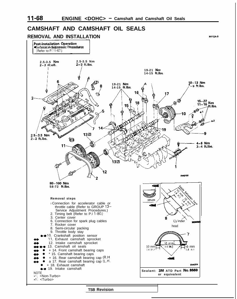
II-68 ENGINE <DOHC> - Camshaft and Camshaft Oil Seals
CAMSHAFT AND CAMSHAFT OIL SEALSREMOVAL AND INSTALLATION MIIZA-0
*Il Servtce Adjustment Procedures
2.5-3.5 Nm 2.5-3.5 Nm^ ^ *. I. -3 -3YIL-L--J I-LIDS. L-S TLIDS.
19-21 Nm14-15 ft.lbs.
4I ^19-21 Nm A lo-13 Nm-. . -IL-14-15 ft.lbs. -Y I-LIDS.
80-100 Nm58-72 ft.lbs.
Removal stepsI Connection for accelerator cable or
throttle cable (Refer to GROUP 13-Service Adjustment Procedures.)
2. Timing belt (Refer to P.l I-80.)3. Center cover6. Connection for spark plug cables7. Rocker cover8. Semi-circular packing9. Throttle body stay
++ 10. Crankshaft position sensor4, 11. Exhaust camshaft sprocket4* 12. Intake camshaft sprocket+e I)+ 13. Camshaft oil seals41) l + 14. Front camshaft bearing caps+e l * 15. Camshaft bearing caps+e l + 16. Rear camshaft bearing cap (R.H+e l a 17. Rear camshaft bearing cap (L.H.
l + 18. Exhaust camshafte+ 19. Intake camshaft
NOTE+1 : <Non-Turbo>*2 : <Turbo>
Nmft.lbs.
head
7
10 mm
@
10 mm (.4 in.) 10 mmc.4 In.) (.4 In )
OlAca
Sealant: 3M ATD Part No.8880or equivalent
TSB Revision

ENGINE <DOHC> - Camshaft and Camshaft Oil Seals 11-69
SERVICE POINTS OF REMOVAL MllZBAD
11. REMOVAL OF EXHAUST CAMSHAFT SPROCKET/12. INTAKE CAMSHAFT SPROCKET
(1) Using a wrench at the hexagonal part of the camshaft(to prevent the crankshaft from turning), loosen thecramshaft sprocket bolt.
(2) Remove the camshaft sprokets.
Plastic hammer
Intake side Exhaust side
q 48Slits
13. REMOVAL OF CAMSHAFT OIL SEALS
Remove the oil seals using a screwdriver or similar tool.
CautionTake care not to damage front camshaft bearing capand camshaft.
14./15./16./17. REMOVAL OF CAMSHAFT BEARING CAPS
(1) Loosen the bearing cap installation bolts in two orthree steps.
(2) Remove the bearing cap.
NOTEIf the bearing cap is difficult to remove, use a plastichammer to gently tap the rear part of the camshaft,and then remove.
SERVICE POINTS OF INSTALLATION M, 1zDAF
19. INSTALLATION OF INTAKE CAMSHAFT/18. EXHAUSTCAMSHAFT
(1) Install the camshafts on the cylinder head.
CautionBe sure not to mistake the intake side and th!exhaust side. There are slits for crankshaft posl-tion sensor drive in the rear end of the intake cam-shaft.
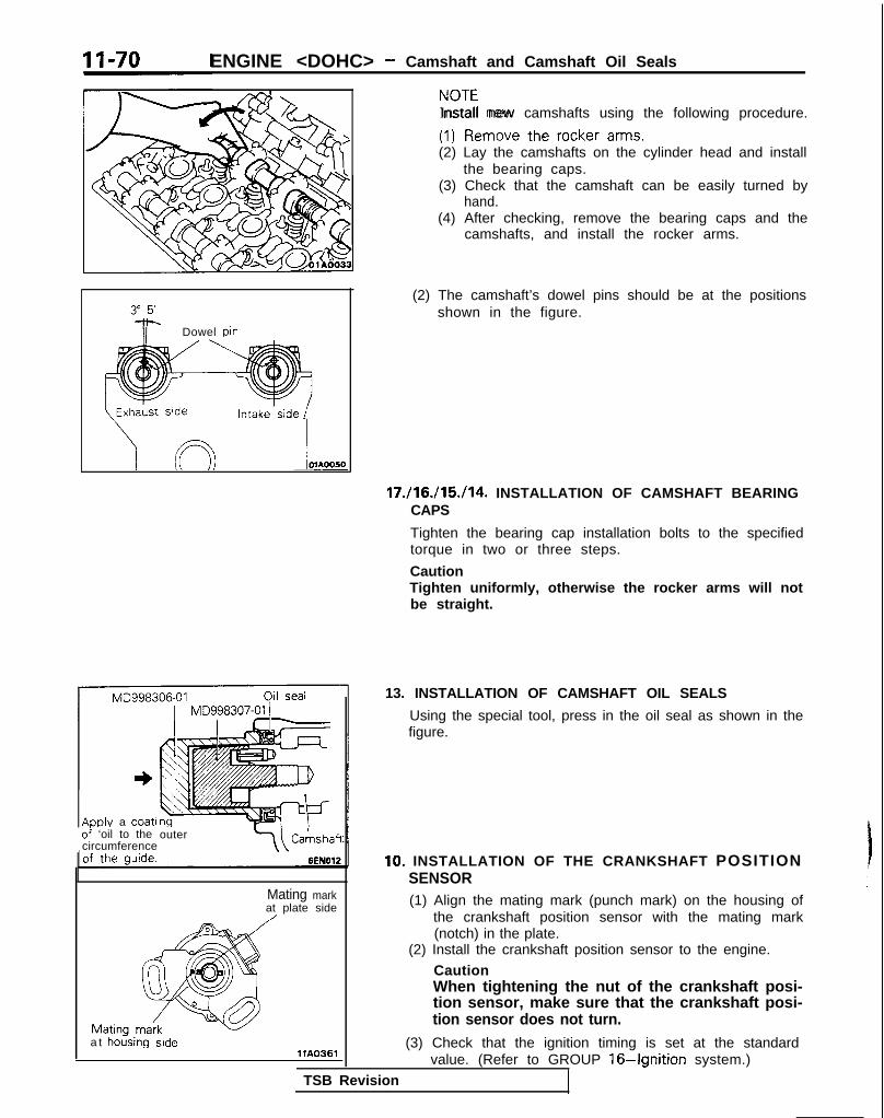
ENGINE <DOHC> - Camshaft and Camshaft Oil Seals
zI?mo”e the rocker arms.Install new camshafts using the following procedure.
(2) Lay the camshafts on the cylinder head and installthe bearing caps.
(3) Check that the camshaft can be easily turned byhand.
(4) After checking, remove the bearing caps and thecamshafts, and install the rocker arms.
3iF- Dowel Din
(2) The camshaft’s dowel pins should be at the positionsshown in the figure.
Intake.side
17./16./15./14. INSTALLATION OF CAMSHAFT BEARINGCAPS
Tighten the bearing cap installation bolts to the specifiedtorque in two or three steps.
CautionTighten uniformly, otherwise the rocker arms will notbe straight.
ADDIY a coatioi ‘oil to the outercircumference Cahshaft
Mating markat plate side/
a t hoising sidellA0361
(3) Check that the ignition timing is set at the standardvalue. (Refer to GROUP 16-Ignition system.)
TSB Revision
13. INSTALLATION OF CAMSHAFT OIL SEALS
Using the special tool, press in the oil seal as shown in thefigure.
10. INSTALLATION OF THE CRANKSHAFT POSITIONSENSOR(1) Align the mating mark (punch mark) on the housing of
the crankshaft position sensor with the mating mark(notch) in the plate.
(2) Install the crankshaft position sensor to the engine.
CautionWhen tightening the nut of the crankshaft posi-tion sensor, make sure that the crankshaft posi-tion sensor does not turn.

ENGINE <DOHC> - Oil Pan and Oil Screen 11-71
OIL PAN AND OIL SCREENREMOVAL AND INSTALLATION
Pre-removal and Post-installationOperation*Draining and Refilling of Engine 011
(Refer to GROUP OO-MamtenanceService.)
Sealant: MITSUBISHI GENUINEPART No. MD970389orequivalent
<AWD> <Up to 1992 models>
<Non-Turbo>30-40 Nm
1 22-28 Fibs.I <iurtbo .I-
MllHA-B
<FWD>/
11-16 ft.lbs.
I <MA> /55-60 Nm 35-45 Nm OlA0005
do-43 ft.lbs. 25-33 ft.lbs.
Removal steps1. Drain plug2. Left member3. Transfer assembly
(Refer to GROUP 22,23-Transfer.)6-8 Nm4-6 ft.lbs.
4. Drive shaft(Refer to GROUP 22.23-Transaxle.)
OlA0620
SO-:00 N m *58-72 ft.lbs.
70-80’ Nm51-58 ft.lbs.
/ - -e9 5. ixhaust pipe connedtion
, . A6. Gasket
Nm 17. Connection for oil return pipe (Turbo)
25-33 ft.lbs. 8. Gasket (Turbo)4* l 4 9. Oil pan
35-45- - - -
10. Oil screen11. Gasket
TSB Revision

11-72 ENGINE <DOHC> - Oil Pan and Oil Screen
1
OlR0606
Sealant
Groove
4 mm(.I 6 in.)
p4L
cut off
-01 BOOS1
e
SERVICE POINTS OF REMOVAL MllHBAFl
9. REMOVAL OF OIL PAN
(1) Remove the oil pan mounting bolts.(2) Tap the general service tool in between the cylinder
block and the oil pan.
CautionDo not use a screwdriver, a chisel or a similar toolwhen removing the oil pan.
(3) Remove the oil pan by placing a brass bar at the cornerof the general service tool and then tapping with ahammer.
INSPECTION MllHCACl
l Check the oil pan for damage and cracks. Replace if faulty.l Check the oil screen for clogging; damage and cracks.
Replace if faulty.
SERVICE POINTS OF INSTALLATION MllHDAOl
9. INSTALLATION OF OIL PAN
(1) Use a wire brush or other tool to scrape clean all gasketsurfaces of the cylinder block and oil pan so that allloose material is removed.
(2) Gasket surfaces must be free of oil and dirt.
(3) Apply the specified sealant around the surface of the oilpan as specified in illustration.
Specified sealant: MITSUBISHI GENUINE PARTNo.MD970389 or equivalent
NOTETo squeeze out proper amount of sealant, cut off thenozzle of sealant. This will provide a nozzle 4 mm (.I6in.) in diameter.
(4) The sealant should be applied in a continuous beadapproximately 4 mm (.I6 in.) in diameter.
1 TSB Revision
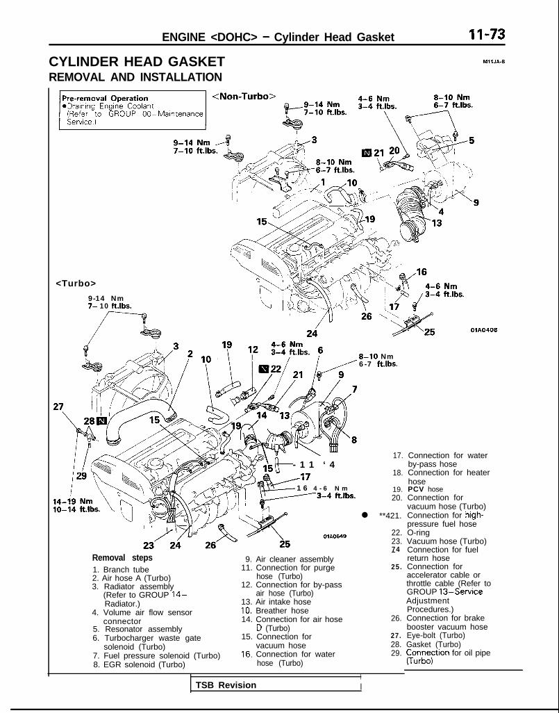
ENGINE <DOHC> - Cylinder Head Gasket 11-73
CYLINDER HEAD GASKET MllJA-9
REMOVAL AND INSTALLATION
<Turbo>
9-14 Nm7- 10 ft.lbs.
OlA0408
8-10 Nm6-7 ft.lbs.
- 1 1 ‘ 4A17- 1 6 4 - 6 N m---3-4 ftlbs.
OlA0649
17.
18.
19.20.
l **421.
22.23.74
Removal steps1. Branch tube2. Air hose A (Turbo)3. Radiator assembly
(Refer to GROUP 14-Radiator.)
4. Volume air flow sensorconnector
5. Resonator assembly6. Turbocharger waste gate
solenoid (Turbo)7. Fuel pressure solenoid (Turbo)8. EGR solenoid (Turbo)
-9. Air cleaner assembly
11. Connection for purge 25.hose (Turbo)
12. Connection for by-passair hose (Turbo)
13. Air intake hose10. Breather hose14. Connection for air hose 26.
D (Turbo)15. Connection for 27.
vacuum hose 28.16. Connection for water 29.
hose (Turbo)
I
Connection for waterby-pass hoseConnection for heaterhosePCV hoseConnection forvacuum hose (Turbo)Connection for high-pressure fuel hoseO-ringVacuum hose (Turbo)Connection for fuelreturn hoseConnection foraccelerator cable orthrottle cable (Refer toGROUP 13-ServiceAdjustmentProcedures.)Connection for brakebooster vacuum hoseEye-bolt (Turbo)Gasket (Turbo)pun;;;tron for oil pipe
TSB Revision I

11-74 ENGINE <DOHC> - Cylinder Head Gasket
<I989 models>
< 1990 models>
/d34/./At %L.
I4-6 Nm3-4 ftlbs.
‘ 3 6
4 -6 Nm3-4 ftlbs.
2.5-3.5 Nm \ 45 13 33
42
/A
38 39/ z-i ,“g,- . . OlA0622
TSB Revision

ENGINE <DOHC> - Cylinder Head Gasket II-75
<From 1991 models>
4-6 Nm
Z&-y,bfm
‘\ .
,,\:.,.s.
46
4-6 ‘Nm $73-4 ftlbs.
41
43
42
IO-12 Nm7-9 ft.lbs.
05A0199
Removal steps30. Connection for engine coolant
temperature switch31. Connection for oxygen sensor32. Connection for engine coolant
temperature sensor33. Connection for engine coolant
temperature gauge unit34. Connection for air conditioning engine
coolant temperature switch35. Connection for injector36. Connection for EGR temperature sensor
(California vehicles only)
37. Connection for knock sensor (Turbo)38. Connection for ianition coil39. Connection for ignition power transistor40. Connection for throttle position sensor41. Connection for crankshaft position sensor42. Connection for IAC motor43. Connection for closed throttle position
switch44. Connection for vacuum hoses45. Center cover46. Connection for spark plug cable assembly47. Control wiring harness
TSB Revision

11-76 ENGINE <DOHC> - Cylinder Head Gasket
2.5-3.5 N m2 - 3 ft.lbs. 49
l’ /
50
_ 6 5 - 7 2 ftlbs.e <I993 models>
g ;yb,- 0 Nm - 20 Nm - l/m. - 0 ftlbs. - 14 ft.lbs. -
4 turn + I/4 turna ,a _..-- /I In +n lQQ3 mnrimls>- II ~
<Non-Turbo> / <Turbo>i/4wrn + 114xurn rA
VJ.vp .” .““L . ..-..-.I-^^ -^^I.~
1
-_ _- .-..-
YU-IUU NIT5.
<199” ---I-‘-’80 Nn, - v ,.lll - Lw .-...
II I” I.._^
66-77 ft Ih!
* IA +.*r..
*Replenishing Engine Coolant(Refer to GROUP OO-Maintenance
l Service ‘Adjustment Procedures(Refer to P.l l-57.) I
12-15 Nm9-11 ft.lbs.
/
:WD>40-50 NmW3i,ft.lbs...,....I,
30-40 NmI
3_2- 29 ftlbs. b. I\\$ 1
‘\I<ID-, LI
MYL. I
Q51 ,-,?/*
r
r
30-46 Nm22-29 ft.lbs.
I.5 rrl”“els~n .nNm-7nNm
48. Timing belt (Refer to P.l I-80.)49. Rocker cover50. Semi-circular packing51. Self locking nut (Non-Turbo)52. Gasket (Non-Turbo)53. Heat protector (Turbo)54. Gasket (Turbo)55. Ring (Turbo)
+, l * 56. Cylinder head assembly~~ 57. Cylinder head gasket
+ I,4 L”,,, - #l-t L”lllj8 ft.lbs. - 0 ft.lbs. - 14 ft.lbs.
,J - 1 IA turn + 1 IO turn
25-30 him18-22 ft.lbs.
‘54m
OlA0567
TSB Revision

ENGINE <DOHC> - Cylinder Head Gasket II-77
SFAI ING POINTS Gal n
OlA0155
J
Front of engine I)Intake side
]
Exhaust side
SERVICE POINTS OF REMOVAL MllJBAUa
21. DISCONNECTION OF HIGH-PRESSURE FUEL HOSE
CautionCover the hose connection with rags to prevent splashof fuel that could be caused by some residual pressurein the fuel pipe line.
For information concerning the bleeding of the residualpressure, refer to GROUP 13-On-vehicle Inspection ofMFI Components.
56. REMOVAL OF CYLINDER HEAD ASSEMBLY
Using the tool, loosen the bolts in the order shown in thefigure (in 2 or 3 cycles) and remove. Then remove the cylin-der head assembly.
TSB Revision I

ENGINE <DOHC> - Cylinder Head Gasket
SERVICE POINTS OF INSTALLATION MllJDAN
57. INSTALLATION OF CYLINDER HEAD GASKET
(1) Use a scraper to clean the gasket surface of thecylinder block.
Ident i f ido c\ (Imark
\
OlAOO38
Front of engine+Intake side
.miJ
Exhaust side
CautionTake care that no foreign material gets into thecylinder, or into coolant passages or oil passages.
(2) Make sure that the gasket has the proper identificationmark for the engine.
(3) Lay the cylinder head gasket on the cylinder block withthe identification mark at the front top.
56. INSTALLATION OF CYLINDER HEAD ASSEMBLY<Up to 1992 models>
(1) Use a scraper to clean the gasket surface of the cylin-der head assembly.
CautionTake care that no foreign material gets into thecoolant passages or oil passages.
(2) Using the special tool and a torque wrench, tighten thebolts to the specified torque in the order shown in thefigure. (in two or three cycles.)
CautionInstall the head bolt washers as shown in thediagram.
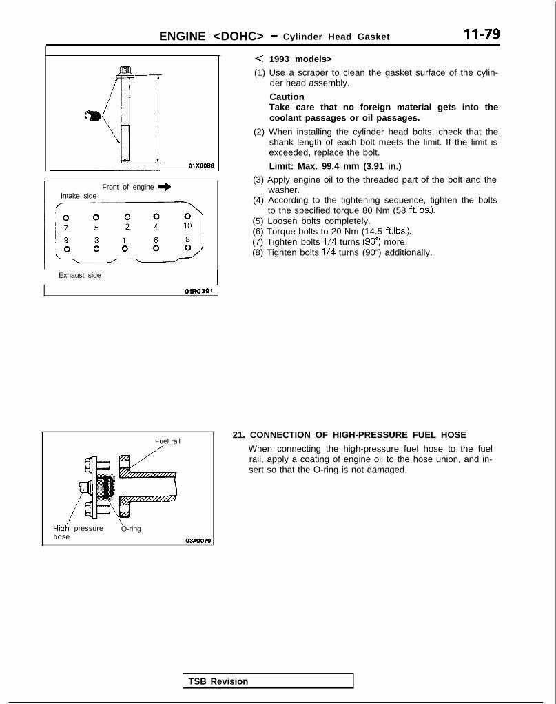
ENGINE <DOHC> - Cylinder Head Gasket 11-79
Front of engine I)Intake side
Exhaust side
OlR0391
Fuel rail/
Hig; pressure\O-ring
hose 03Aoo79
< 1993 models>
(1) Use a scraper to clean the gasket surface of the cylin-der head assembly.
CautionTake care that no foreign material gets into thecoolant passages or oil passages.
(2) When installing the cylinder head bolts, check that theshank length of each bolt meets the limit. If the limit isexceeded, replace the bolt.
Limit: Max. 99.4 mm (3.91 in.)
(3) Apply engine oil to the threaded part of the bolt and thewasher.
(4) According to the tightening sequence, tighten the boltsto the specified torque 80 Nm (58 ftlbs.).
(5) Loosen bolts completely.(6) Torque bolts to 20 Nm (14.5 ftlbs.).(7) Tighten bolts l/4 turns (90”) more.(8) Tighten bolts l/4 turns (90”) additionally.
TSB Revision
21. CONNECTION OF HIGH-PRESSURE FUEL HOSE
When connecting the high-pressure fuel hose to the fuelrail, apply a coating of engine oil to the hose union, and in-sert so that the O-ring is not damaged.

II-80 ENGINE <DOHC> - Timing Belt
TIMING BELTREMOVAL AND INSTALLATION
50-65 Nm36-47 ftlbs.
A7Pre-removal Operationl Removal of under cover I
MIlKA-B
50-65 Nm36-47 ft.lbs.
ii!&.
lo-12 Nm7-9 ft.lbs.
8-10 Nm
23--27 Nm17-20 ft.lbs.
20-A0 Nm lb-12 Nm14-22 ftlbs. 7-9 ft.lbs.
Removal steps1. Clamp for pressure hose (power steering)
and high pressure hose (air conditioning)2. Bracket3. Enoine mount bracket
ii 4. D&e belt (generator)5. Drive belt (power steering)6. Tensioner pulley bracket7. Drive belt (air conditioning)8. Water pump pulley9. Crankshaft pulley
10. Timing belt front upper coverII. Timing belt front lower cover12. Center cover13. Breather hose14. PCV hose15. Connection for spark plug cables
ft.lbs.
4*a*
4**I)
4*
OlAO436
16. Rocker coverI 7. Semi-circular packing18. Plug rubber19. Auto tensioner20. Timing belt21. Tensioner pulley22. Tensioner arm23. Idle pulley24. Camshaft sprocket25. Oil pump sprocket26. Crankshaft sprocket bolt27. Special washer28. Crankshaft sprocket29. Flange30. Tensioner “B”31. Timing belt “B”32. Silent shaft sprocket33. Spacer34. Crankshaft sprocket “B”35. Timing belt rear right cover36. Timing belt rear left cover (upper)37. Engine support bracket38. Timing belt rear left cover (lower)
TSB Revision

ENGINE <DOHC> - Timing Belt 11-81
f”.53A51b;m
r----v 1 3
lo-12 Nm
11-16 ftlbs.
80-100 Nm y ~x-di58-72 ft.lbs. 22 34 !?!I
2125
43-55 Nm31-40, ff.lbs. b&-.,\ ‘-
/20-27 Nm14-20 ftlbs. 110;130 Nm
80-94 ftlbs.Installation steps
38. Timing belt rear left cover (lower)1H37. Engine support bracket
36. Timing belt rear left cover (upper)35. Timing belt rear right cover
+4 34. Crankshaft sprocket “B”l * 33. Spacer
32. Silent shaft sprocketI)+ 31. Timing belt “B”l * Adjustment of timing belt “B” tension
30. Tensioner “B”~~ 29. Flangel C 28. Crankshaft sprocket
27. Special washer26. Crankshaft sprocket bolt
~~ 25. Oil pump sprocketl 24. Camshaft sprocket
23. Idle pulleyl + 19. Auto tensioner
22. Tensioner arm+a 21. Tensioner pulley*C 20. Timing beltI)* Adjustment of timing belt tension
18. Plug rubber17. Semi-circular packing16. Rocker cover15. Connection for spark plug cables14. PCV hose13. Breather hose
!_-;‘ 3 6
\3,“”
30-42 Nm22-30 ftlbs.
1 2550-60 Nm36-43 ftlbs. OlA0435
sl Service Adjustment Procedures
12. Center cover~~ 11, Timing belt front lower coverl + IO. Timing belt front upper cover
9. Crankshaft pulley8. Water pump pulley7. Drive belt (air conditioning)
(Refer to P.l I-61 .)6. Tensioner pulley bracket5. Drive belt (power steering)
(Refer to P.ll-61.)4. Drive belt (generator)
(Refer to P.l I-61 .)3. Engine mount bracket2. Bracket1. Clamp for pressure hose (power steering)
and high pressure hose (air conditioning)
NOTE+I: Vehicles built up to NOV. 1988+2: Vehicles built from Dec. 1988
TSB Revision I

II-82SEALING POINTS
ENGINE <DOHC> - Timing Belt
olaoo4~0 1 A0583
Sealant: 3M ATD Part No.8660or equivalent
04UOO27 1
Intake cam- IDowel pin shaft sprocket
/~~*;~i~g~\ Timing 1
- .,I
Crankshatt-Oil p u m p
, _ sprockek IsproKer OlAOOSl 1
SERVICE POINTS OF REMOVAL Ml 1KBDG
3. REMOVAL OF ENGINE MOUNT BRACKET
(1) With a wooden block placed against the oil pan part ofthe engine, jack up the vehicle.
CautionJack up gently, so as not to apply a load to thevarious parts.
(2) Remove the engine mount bracket.
4. REMOVAL OF DRIVE BELT
Before removing the drive belt, loosen the water pumppulley mounting bolts.
19. REMOVAL OF AUTO TENSIONER(1) Turn the crankshaft clockwise and align the timing
marks so as to bring the No. 1 cylinder to compresslontop-dead-centre position.At this time the timing marks of the camshaft sprocketand the upper surface of the cylinder head shouldcoincide, and the dowel pin of the camshaft sprocketshould be at the upper side.
CautionThe crankshaft must always be rotated clockwise.
(2) Remove the auto tensioner.
TSB Revision 1

ENGINE <DOHC> - Timing Belt 11-83
1
r
20. REMOVAL OF TIMING BELT
Make a mark on the back of the timing belt indicating thedirection of rotation so it may be reassembled in the samedirection if it is to be reused.
CautionWater or oil on the belt shorten its life drastically, sothe removed timing belt, sprocket, and tensioner mustbe free from oil and water. These parts should not bewashed. Replace parts if seriously contaminated.If there is oil or water on each part check the front caseoil seals, camshaft oil seal and water pump for leaks.
24. REMOVAL OF CAMSHAFT SPROCKETS
(1) Using a wrench, hold the camshaft at its hexagon(between the No.2 and No.3 journals) and remove thecamshaft sprocket bolt.
CautionLocking the camshaft sprocket with a tool damagesthe sprocket.
(2) Remove the camshaft sprockets.
25. REMOVAL OF OIL PUMP SPROCKET
(1) Remove the plug on the side of the cylinder block.(2) Insert a Phillips screwdriver [shank diameter 8 mm (.31
in.)] to block the left silent shaft.(3) Remove the oil pump sprocket nut.(4) Remove the oil pump sprocket.
31. REMOVAL OF TIMING BELT “B”
Make a mark on the back of the timing belt indicating thedirection of rotation so it may be reassembled in the samedirection if it is to be reused.CautionWater or oil on the belt shorten its life drastically, sothe removed timing belt, sprocket, and tensioner mustbe free from oil and water. These parts should not bewashed. Replace parts if seriously contaminated.If there is oil or water on each part check the front caseoil seals, camshaft oil seal and water pump for leaks.
TSB Revision

11-84 ENGINE <DOHC> - Timing Belt
QdiJ00°00B
rackCrack
Crack ’7EN207
Separation
Rounded belt side
Abnormal wear(fluffy canvas fiber) 7EN208
Rubberexposed
Tooth missing andcanvas fiber exposed
7EN209
6EN0159
Y
1-
INSPECTIONTIMING BELTS
MIlKCAC
The timing belts must be checked closely. Should the followingdefects be evident, replace the belt with a new one.(1) Hardened back surface rubber
Glossy, non-elastic, and so hard that no mark is producedeven when scratched by a fingernail.
(2) Cracked back surface rubber.(3) Cracked or separated canvas(4) Cracked tooth bottom.(5) Cracked side.
(6) Abnormal wear on side.
NOTENormal belt should have clear-cut sides as if cut by a sharpknife.
(7) Abnormal wear on teeth.Initial stage:
Canvas on load side tooth flank worn (Fluffy canvasfibers, rubber gone and color changed to white, andunclear canvas texture)
Final stage:Canvas on load side tooth flank worn down and rubberexposed (tooth width reduced)
(8) Missing tooth.
TENSIONER PULLEY AND IDLER PULLEY
(1) Turn the pulleys to check for possible binding, excessiveplay, and unusual noise. Replace the pulley if any of thesedefects is evident.
(2) Replace if there is a grease leak.
I
1 TSB Revision

ENGINE <DOHC> - Timing Belt II-85
6EN0280
6EN0161
/ 6Ei40162
668Plug
6EN0281 j
AUTO TENSIONER
(1) Check the auto tensioner for possible leaks and replace asnecessary.
(2) Check the rod end for wear or damage and replace asnecessary.
(3) Measure the rod protrusion. If it is out of specification,replace the auto tensioner.
Standard value: 12 mm (.47 in.)
(4) Using a vise with soft jaws push in the auto tensioner rod.If the rod can be easily retracted, replace the autotensioner. You should feel a fair amount of resistance whenpushing the rod in.
Caution1. Clamp the auto tensioner in the vise so it maintains
a level position.
2. If the plug at the bottom of the auto tensionerprotrudes, surround it with a plain Lvasher asillustrated to prevent the plug from being in directcontact with the vise.
SERVICE POINTS OF INSTALLATION MllKDCF
37. INSTALLATION OF ENGINE SUPPORT BRACKET
Apply sealant to the bolt shown in the figure and tighten itto the specified torque.
Specified sealant: 3M ATD Part No.8660 or equivalent
TSB Revision

11-86 ENGINE <DOHC> - Timing Belt
Crankshaftsprocket “B”
Crankshaft 6EN304 j
SpacerI
Chamfered
Silent shaftn sprocket I
Center oftenslonerpulley
Center ofinstallation bolt
34. INSTALLATION OF CRANKSHAFT SPROCKET “B”
Install the crankshaft sprocket “B” as shown while payingattention to its direction.
33. INSTALLATION OF SPACER
(1) Apply a thin coat of engine oil to the outer circumfer-ence of the spacer.
(2) Install the spacer with the chamfered end facing the oilseal.
NOTEIf the spacer is installed adversely, the oil seal may bedamaged, resulting in the oil leaks.
31. INSTALLATION OF TIMING BELT “B”
(1) Ensure that crankshaft sprocket “B” timing mark andthe silent shaft sprocket timing mark are aligned.
(2) Fit timing belt “B” over crankshaft sprocket “B” andthe silent shaft sprocket. Ensure that there is no slack inthe belt.
. ADJUSTMENT OF TIMING BELT “B” TENSION
(1) Temporarily fix the timing belt “B” tensioner such thatthe center of the tensioner pulley is to the left andabove the center of the installation bolt, and temporarilyattach the tensioner pulley so that the flange is towardthe front of the engine.
(2) Holding the timing belt “B” tensioner up with yourfinger in the direction of the arrow, place pressure onthe timing belt so that the tension side of the belt istaut. Now tighten the bolt to fix the tensioner.
CautionWhen tightening the bolt, ensure that the tensionerpulley shaft does not rotate with the bolt. Allowingit to rotate with the bolt can cause excessivetension on the belt.
TSB Revision

.
ENGINE <DOHC> - Timing Belt 11-87
installation bolt ~~~-
Crankshaftsprocket “B”/
Crankshaft / \ \sprocket Flange Crankshaft 6~~272
6EN172I
(3) To ensure that the tension is correct, depress the belt(point A) with a finger. If not, adjust.
Standard value: 5-7 mm (.20-.28 in.)
29. INSTALLATION OF FLANGE
Install the flange in correct direction as shown
CautionPay special attention to the direction of the flange. If itis installed in the wrong direction, a broken timing beltcould result.
28. INSTALLATION OF CRANKSHAFT SPROCKET
Install the crankshaft sprocket in the correct direction asshown.
CautionPay special attention to the direction of the flange. If itis installed in the wrong direction, a broken timing beltcould result.
25. INSTALLATION OF OIL PUMP SPROCKET
(1) Insert a Phillips screwdriver [shank diameter 8 mm (.31in.) shaft] through the plug hole on the left side ofcylinder block to block the left silent shaft.
(2) Install the oil pump sprocket.(3) apply engine oil to the nut bearing surface and tighten
the nut to the specified torque.
24. INSTALLATION OF CAMSHAFT SPROCKETS
Using a wrench, hold the camshaft at its hexagon (betweenthe No.2 and No.3 journals) and tighten the bolt tospecification.
CautionLocking the camshaft sprocket with a tool damages thesprocket.
TSB Revision

ENGINE <DOHC> - Timing Belt
6@Plug
6EN0281
Center bolt :
6EN026:-
19. INSTALLATION OF AUTO TENSIONER(1) If the auto tensioner rod is in its fully extended position,
reset it as follows.@I Keep the auto tensioner level and, in that position,
clamp it in the vise with soft jaws.
If the plug at the bottom of the auto tensionerprotrudes, surround it with a plain washer asillustrated to prevent the plug from being in directcontact with the vise.
@ Push in the rod little by little with the vise until theset hole @ in the rod is aligned with that @I in thecylinder.
@ Insert a wire Il.4 mm (055 in.) in diameter] into theset holes.
@I Unclamp the auto tensioner from the vise.
(2) Install the auto tensioner.
CautionLeave the wire installed in the auto tensioner.
21. INSTALLATION OF TENSIONER PULLEY(1) Install the tensioner pulley onto the tensioner arm.(2) Locate the pinhole in the tensioner pulley shaft to the
left of the center bolt. Then, tighten the center boltfinger-tight.
CautionLeave the wire installed in the auto tensioner.
TSB Revision I

ENGINE <DOHC> - Timing Belt 11-89
Camshaft sprocket
Top surface ofcylinder head/b*TJ,$: -; /e\ I’ \ ii )’
Timing mark
6EN028L
--.- ./Dowel pin
Timingmark
6EN0304
20. INSTALLATION OF TIMING BELT
(1) Turn the two sprockets so that their dowel pins arelocated on top. Then, align the timing marks facing eachother with the top surface of the cylinder head. Whenyou let go of the exhaust camshaft sprocket, it willrotate one tooth in the counterclockwise direction. Thisshould be taken into account when installing the timingbelt on the sprockets.
NOTEThe same camshaft sprocket is used for the intake andexhaust camshafts and is provided with two timingmarks. When the sprocket is mounted on the exhaustcamshaft, use the timing mark on the right with thedowel pin hole on top. For the intake camshaftsprocket, use the one on the left with the dowel pinhole on top.
TSB Revision
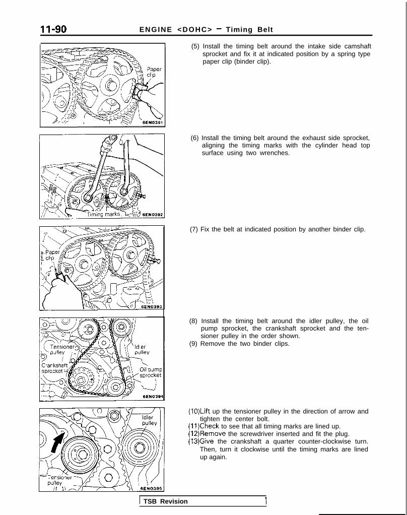
II-90 ENGINE <DOHC> - Timing Belt
(5) Install the timing belt around the intake side camshaftsprocket and fix it at indicated position by a spring typepaper clip (binder clip).
(6) Install the timing belt around the exhaust side sprocket,aligning the timing marks with the cylinder head topsurface using two wrenches.
(7) Fix the belt at indicated position by another binder clip.
(8) Install the timing belt around the idler pulley, the oilpump sprocket, the crankshaft sprocket and the ten-sioner pulley in the order shown.
(9) Remove the two binder clips.
(1O)Lift up the tensioner pulley in the direction of arrow andtighten the center bolt.
(11)Check to see that all timing marks are lined up.(12)Remove the screwdriver inserted and fit the plug.(13)Give the crankshaft a quarter counter-clockwise turn.
Then, turn it clockwise until the timing marks are linedup again.
1 TSB Revision

ENGINE <DOHC> - Timing Belt 11-91
J
Tensioner armTensioner arm
TSB Revision
. ADJUSTMENT OF TIMING BELT TENSION
(1) After turning the crankshaft l/4 turn counterclockwise,turn it clockwise to move the No. 1 cylinder to top deadcenter.
(2) Loosen the center bolt, and then, as shown in theillustration, attach the special tool and a torque wrenchand apply a torque of 2.6-2.8 Nm (1.88-2.03 ft.lbs.). Ifthe body interferes with the special tool and the torquewrench, use a jack to slightly raise the engine assembly.
NOTEUse a torque wrench that is capable of measurementwithin a range of 0- 3 Nm (0- 2.2 ftlbs.).
(3) Holding the tensioner pulley with the special tool andtorque wrench, tighten the center bolt to specification.
(4) Screw the tool into the engine left support bracket untilits end makes contact with the tensioner arm. At thatpoint, screw the tool in some more and then remove theset wire attached to the auto tensioner.
(5) Remove the tool.
(6) Rotate the crankshaft two complete turns clockwiseand leave it as is for about 15 minutes. Then, measurethe auto tensioner protrusion “A” (distance betweenthe tensioner arm and auto tensioner body) to ensurethat it is up to specification.
Standard value: 3.8-4.5 mm (.15-.I8 in.)
If it is out of specification, repeat steps (6) through (11)until the specified value is obtained.
(7) If the clearance between the tensioner arm and theauto tensioner body cannot be measured (when theengine is being mounted, etc.), the following proce-dures can be used to substitute for the ordinary methodof measurement.@j Screw in the tool until it contacts the tensioner arm.@ From that point of contact, further screw in the tool.
screwing it in until the push rod of the autotensioner body is caused to move backward and thetensioner arm contacts the auto tensioner body.Check to be sure that the amount that the tool hasbeen screwed in (when the push rod moves back-ward) is the standard value.
Standard value: 2.5- 3 turns

(8) Install the rubber plug to the timing belt rear cover.
ENGINE <DOHC> - Timing Belt
*‘: Up to 1990 models*>. Up to 1992 models
A*
B+2 C*’
Thread diameterx thread lengthA: 6x 16 1.24x.63)B: 6x22 (.24?87j*‘, 6x18 (.24~.70)*~,*~C: 6x20 (.24x.79)*‘, 6x25 (.24x.98)*2,*3D: 6x28 (.24x1.10) mm (in.) OlA0681
11. INSTALLATION OF TIMING BELT LOWER COVER/10. TIMING BELT UPPER COVER
The dimensions of the installation bolts for the timingcovers differ according to the installation location, so besure not to install the bolts in the incorrect locations.
1 TSB Revision
13-1
FUELCONTENTS M’ISAA--
AUTO-CRUISE CONTROL SYSTEM .. . . . . . . . . . . . . 332AUTO-CRUISE CONTROL . . . . . . . . . . . . . . . . . . . . . . . . . . . . . 408SERVICE ADJUSTMENT PROCEDURES . . . . . . . . . . . . . . . . . 397
Accelerator Cables inspectron and Adjustment . . . . . . . . . 398Auto-cruise Control System Inspection . . . . . . . . . . . . . . 397Individual Parts Inspection . . . . . . . . . . . . . . . . . . . . . . 401
SPECfAL TOOLS . . . . . . . . . . . . . . . . . . . . . . . . . . . . . . . . . . . . . 333SPECIFICATIONS . . . . . . . . . . . . . . . . . . . . . . . . . . . . . . . . . . . . 332TROUBLESHOOTING . . . . . . . . . . . . . . . . . . . . . . . . . . . . . . . . . 334
Auto-cruise Control Components Location . . . . . . . . . . 368Auto-cruise Control Related Harnesses . . . . . . . . . . 365Check Chart <Electrical Type> . . . . . . . . . . . . . . . . 339Check Chart <Vacuum Type> . . . . . . . . . . . . . . 354Circuit Diagram . . . . . . . . . . . . . . . . . . . . . . . . . . . . . . . . 371input Checking . . . . . . . . . . . . . . . . . . . . . . . . . . . . . . . . . 366On-board Diagnostic Checking . . . . . . . . . . . . . . . . . . . . . . 361Troubleshooting Quick-reference Chart<Electrical Type> . . . . . . . . . . . . . . . . . . . . . . . . . . 334Troubleshooting Quick-reference Chart<Vacuum Type> . . . . . . . . . . . . . . . . . . . . . . . . . . . . . 350
ENGINE CONTROL . . . . . . . . . . . . . . . . . . . . . . . . . . . . . . . . 328ENGINE CONTROL . . . . . . . . . . . . . . . . . . . . . . . . . . . . . . . . . . 330SERVICE ADJUSTMENT PROCEDURES . . . . . . . . . . . . . . . . . 329
Accelerator Cable inspectron and Adjustment . . . . . . . . . . . 329Accelerator Switch Inspection and Adjustment . . . . . . . . . . 329
SPECIFICATIONS . . . . . . . . . . . . . . . . . . . . . . . . . . . . . . . . . . . . 328TROUBLESHOOTlNG . . . . . . . . . . . . . . . . . . . . . . . . . . . . . . . . . 328
Accelerator Cable and Accelerator Pedal . . . . . . . . . . . . . . 328
FUEL SYSTEM <DOHC> . . . . . . . . . . . . . . . . . . . . . . . . 196FUEL FILTER . . . . . . . . . . . . . . . . . . . . . . . . . . . . . . . . . . . . . . . . . 327FUEL LINE AND VAPOR LINE <AWD> . . . . . . . . . . . . . . . . 326FUEL LINE AND VAPOR LINE <FWD> . . . . . . . . . . . . . . . . 324FUEL TANK <AWD> . . . . . . . . . . . . . . . . . . . . . . . . . . . . . . . . 322FUELTANK <FWD> . . . . . . . . . . . . . . . . . . . . . . . . . . . . . . . . 318GENERAL INFORMATION . . . . . . . . . . . . . . . . . . . . . . . . . . . . 196ON-VEHICLE INSPECTION OF MFI COMPONENTS . . . . . . 251
Air Conditioning Switch and A/C CompressorClutch Relay . . . . . . . . . . . . . . . . . . . . . . . . . . . . . . . . . . . . . 285Barometric Pressure Sensor . . . . . . . . . . . . . . . . . . . . 266Boost Meter <Turbo> . . . . . . . . . . . . . . . . . . . . . . . . . . . . . 311Camshaft Position Sensor . . . . . . . . . . . . . . . . . . . . . . . . . 277Closed Throttle Position Switch . . . . . . . . . . . . . . . . . . . . . . 274Component Location . . . . . . . . . . . . . . . . . . . . . . . . . . . . . 251Components Inspection Pocedure . . . . . . . . . . . . . . . . . 255Crankshaft Position Sensor . . . . . . . . . . . . . . . . . . . . . 280
EGR Solenord <California> . . . . . . . . . . . . . . . . . . . . 307EGR Temperature Sensor <California> . . . . . . . . . . . . . . 288Engrne Control Module Power Ground . . . . . . . . . . . . . . . . . 257Engine Coolant Temperature Sensor . . . . . . . . . . . . . . . . . . 268Evaporative Emission Purge Solenoid . . . . . . . . . . . . . . . . . . 307Fuel Pressure Solenoid <Turbo> . . . . . . . . . . . . . . . . . . . . 307Fuel Pressure Test . . . . . . . . . . . . . . . . . . . . . . . . . . . . . . . . 312Fuel Pump . . . . . . . . . . . . . . . . . . . . . . . . . . . . . . . . . . . . . . 258Heated Oxygen Sensor . . . . . . . . . . . . . . . . . . . . . . . . . . . . 290Idle Air Control Motor (Stepper Motor) . . . . . . . . . . . . . . . . 238Ignition Coil and Ignition Power Transistor . . . . . . . . . . . . . . 302Ignition Switch-ST . . . . . . . . . . . . . . . . . . . . . . . . . . . . . . . . . . 284Ignition Switch-ST and Park/Neutral Position Switch . . . . . 284Injectors . . . . . . . . . . . . . . . . . . . . . . . . . . . . . . . . . . . . . . . 295Inspection of Engine Control Module TerminalVoltage . . . . . . . . . . . . . . . . . . . . . . . . . . . . . . . . . . . . . . . . 315Intake Air Temperature Sensor . . . . . . . . . . . . . . . . . . . . . . . 263Knock Sensor<Turbo, Non-Turbo From 1992 Models> . . . . . . . . . . . . . 287Power Steering Pressure Switch . . . . . . . . . . . . . . . . . . . . . . 284Power Supply and Ignition Switch . . . . . . . . . . . . . . . . . . . . 255Resistor <Turbo> . . . . . . . . . . . . . . . . . . . . . . . . . . . . . . . 298Terminal Voltage Check Chart . . . . . . . . . . . . . . . . . . . . . . . 315Throttle Position Sensor . . . . . . . . . . . . . . . . . . . . . . . . . . . 270Turbocharger Waste Gate Solenoid <Turbo> . . . . . . . . . . 309Vehicle Speed Sensor . . . . . . . . . . . . . . . . . . . . . . . . . . . . . . . 284Volume Air Flow Sensor . . . . . . . . . . . . . . . . . . . . . . . . . . . . 261
SERVICE ADJUSTMENT PROCEDURES . . . . . . . . . . . . . . . . 245Basic idle Speed Adjustment . . . . . . . . . . . . . . . . . . . . . . . . 245Closed Throttle Position Switch (Fixed SAS)Adjustment . . . . . . . . . . . . . . . . . . . . . . . . . . . . . . . . . . . . . . . 250Curb Idle Speed Inspection . . . . . . . . . . . . . . . . . . . . . . . . . . 245Throttle Body (Throttle Valve Area) Cleaning . . . . . . . . . . . . 248Throttle Position Sensor Adjustment . . . . . . . . . . . . . . . . . . . 248
SPECIALTOOLS . . . . . . . . . . . . . . . . . . . . . . . . . . . . . . . . . . . . 204SPECIFICATIONS . . . . . . . . . . . . . . . . . . . . . . . . . . . . . . . . . . . 201TROUBLESHOOTING . . . . . . . . . . . . . . . . . . . . . . . . . . . . . . . . 205
Check Engine/Malfunction Indicator Lamp . . . . . . . . . . . . . . 205Circuit Diagram . . . . . . . . . . . . . . . . . . . . . . . . . . . . . . . . . . . . 214Clear Memory of Diagnostic Trouble Code . . . . . . . . . . . . . 211Explanation and Precaution Related to HarnessChecking . . . . . . . . . . . . . . . . . . . . . . . . . . . . . . . . . . . . . . . 205Explanation of Troubleshooting Procedures . . . . . . . . . . . . . 205Failsafe/Back-up Functions List . . . . . . . . . . . . . . . . . . . . . . 211Fuel tank and Fuel Line . . . . . . . . . . . . . . . . . . . . . . . . . . . . . 244Read Out Diagnostic Trouble Code . . . . . . . . . . . . . . . . . . . 211Troubleshooting Table . . . . . . . . . . . . . . . . . . . . . . . . . . . . . . 208
(CONTINUED ON NEXT PAGE)

13-2
FUEL SYSTEM <SOHC-8 VALVE> . . . . . . . . . .FUEL FILTER . . . . . . . . . . . . . . . . . . . . . . . . . . . . . . . . . . . .FUEL LINE AND VAPOR LINE . . . . . . . . . . . . . . . . . . . . .FUELTANK . . . . . . . . . . . . . . . . . . . . . . . . . . . . . . . . . . . . .GENERAL INFORMATION . . . . . . . . . . . . . . . . . . . . . . . .ON-VEHICLE INSPECTION OF MFI COMPONENTS . .
Air Conditionrng Switch and A/C CompressorClutch Relay . . . . . . . . . . . . . . . . . . . .Barometric Pressure Sensor . . . . . . . . .Camshaft Position Sensor . . . . . . . . . . .Closed Throttle Position Switch . . . . . . . . . . .Component Location . . . . . . . . . . . . .
Components Inspectron Procedure . . . . . . . .Crankshaft Positron Sensor . . . . . . . . . . . .EGR Solenoid <California> . . . . . .
. . . 3
. . 115
..,. 113
. 109
. . 3
. . . 38
83536961384173
101EGR Temperature Sensor <California> . . . . . . . . . . 85Enqine Control Module Power Ground . . . . . . . . . . . 45Engine Coolant Temperature Sensor . . . . . . . . . . . . . . . 55Evaporative Emission Purge Solenord . . . . . . . . . . . . . . . 99Fuel Pressure . . . . . . . . . . . . . . . . . . . . . . . . . . . . . . . 102Fuel Pump . . . . . . . . . . . . . . . . . . . . . . . . . . . . . . . . . . . . 46Idle Speed Control Motor (DC Motor) . . . . . . . . . . . . . . . . . 93Idle Speed Control Motor Positron Sensor . . . . . . . . . . . . . 64lgnitron Co11 and Ignition Power Transistor . . . . . . . . . . 96Ignition Switch-ST . . . . . . . . . . . . . . . . . . . . . . . . . . 77Ignition Switch-ST and Park/Neutral Position Switch . . . 78Injectors . . . . . . . . . . . . . . . . . . . . . . . . . . . . . . . . . . . 90Inspection of Engrne Control Module TerminalVoltage . . . . . . . . . . . . . . . . . . . . . . . . . . . . . . . . . . . . 105Intake Air Temperature Sensor . . . . . . . . . . . . . . . . . . . 51Oxygen Sensor . . . . . . . . . . . . . . . . . . . . . . . . . . . . . 87Power Steering Pressure Switch . . . . . . . . . . . . . . . . . . . 81Power Supply . . . . . . . . . . . . . . . . . . . . . . . . . . 42Terminal Voltage Check Chart . . . . . . . . . . . . . . . . . . . . . . 106Throttle Positron Sensor . . . . . . . . . . . . . . . . . . . . . . 57Vehicle Speed Sensor . . . . . . . . . . . . . . . . . . . . . . . . . . 80Volume Air Flow Sensor . . . . . . . . . . . . . . . . . . . . . . . . . 49
SERVICE ADJUSTMENT PROCEDURES . . . . . . . . . . . . . . . . . 32Basic Idle Speed Adjustment . . . . . . . . . . . . . . . . . . . . 33Curb Idle Speed Inspection . . . . . . . . . . . . . . . . . . . . . . . . . . 32Throttle Body (Throttle Valve Area) Cleaning . . . . . . . . . 35Throttle Positron Sensor Adjustment . . . . . . . . . . . . . . . . 35
SPECIAL TOOLS 7. . . . . . . . . . . . . . . . . . . . . . . . . . . . . . . . . . . .SPECIFICATIONS . . . . . . . . . . . . . . . . . . . . . . . . . . . . . . . . . . . . 5TROUBLESHOOTING . . . . . . . . . . . . . . . . . . . . . . . . . . . . . . . . . 8
Check Engine/Malfunction Indicator Lamp . . . . . . . . . . . . . . 10Crrcuit Diagram . . . . . . . . . . . . . . . . . . . . . . . . . . . . . . . . . . 20Clear Memory of Diagnostic Trouble Code . . . . . . . . . . . . 17Explanation and Precaution Related to HarnessChecking . . . . . . . . . . . . . . . . . . . . . . . . . . . . . . . . . . . . . . . 9Explanation of Troubleshooting Procedures . . . . . . . . . . . . 8Failsafe/Back-up Functions List . . . . . . . . . . . . . . . . . . . . 16Fuel Tank and Fuel Lrne . . . . . . . . . . . . . . . . . . . . . . . . . . 32Read Out of Diagnostic Trouble Code . . . . . . . . . . . . . . . . 16Troubleshooting Table . . . . . . . . . . . . . . . . . . . . . . . . . . 13
FUEL SYSTEM <SOHC-16 VALVE> . . . . . . . . . . . 116FUEL FILTER . . . . . . . . . . . . . . . . . . . . . . . . . . . . . . . . . . . . . . . 195FUEL LINE AND VAPOR LINE . . . . . . . . . . . . . . . . . . . . . . . . 195FUEL TANK . . . . . . . . . . . . . . . . . . . . . . . . . . . . . . . . . . . . . . . . 195GENERAL INFORMATION . . . . . . . . . . . . . . . . . . . . . . . . . . . . 116ON-VEHICLE INSPECTION OF MFI COMPONENTS
Air Conditioning Switch and A/C CompressorClutch Relay . . . . . . . . . . . . . . . . . . . . . . . . . . . . .
Barometric Pressure Sensor . . . . . . . . . . . . . . . . .
Camshaft Position Sensor . . . . . . . . . . . . . . . . . . . .Closed Throttle Position Switch . . . . . . . . . . . . . . . .Component Location . . . . . . . . . . . . . . . . . . . . . . .
Components Inspectron Pocedure . . . . . . . . . . . . . .Crankshaft Position Sensor . . . . . . . . . . . . . . . . .EGR Solenoid <California> . . . . . . . . . . . . . . . . .EGR Temperature Sensor <California> . . . . . . .Engine Control Module Power Ground . . . . . . . . . .Engine Coolant Temperature Sensor . . . . . . . . . . . . .Evaporative Emission Purge Solenoid . . . . . . . . . . . .Fuel Pressure Test . . . . . . . . . . . . . . . . . . . . . . . . . . .
Fuel Pump . . . . . . . . . . . . . . . . . . . . . . . . . . . . . . . . . .IAC Valve Positon Sensor . . . . . . . . . . . . . . . . . . . . . .Idle Air Control Motor (DC Motor) . . . . . . . . . . . . . .lgnrtion Coil and Ignition Power Transistor . . . . . . . .Ignition Switch-ST . . . . . . . . . . . . . . . . . . . . . . . . . . .
Ignition Switch-ST and Park/Neutral Position SwitchInjectors . . . . . . . . . . . . . . . . . . . . . . . . . . . . . . . . . . . .
Inspection of Engine Control Module TerminalVoltage . . . . . . . . . . . . . . . . . . . . . . . . . . . . . . . . . . . . .Intake Air Temperature Sensor . . . . . . . . . . . . . . . . .Oxygen Sensor . . . . . . . . . . . . . . . . . . . . . . . . . . . . .Power Steering Pressure Swatch . . . . . . . . . . . . . . .Power Supply . . . . . . . . . . . . . . . . . . . . . . . . . . . . . . .
Terminal Voltage Check Chart . . . . . . . . . . . . . . . . . .Throttle Position Sensor . . . . . . . . . . . . . . . . . . . . . . .Vehicle Speed Sensor . . . . . . . . . . . . . . . . . . . . . . . . .
. . . . 139
176154165160139
1421 6 7..,_ 191
177146
155189192147162184186171172181
192152179175143192157173
Volume Air Flow Sensor . . . . . . . . . . . . . . . . . . . . . . . . . . . . 150
SERVICE ADJUSTMENT PROCEDURES . . . . . . . . . . . . . . . . 133Basic Idle Speed Adjustment 133Closed Throttle Position Switch and Throttle PositionSensor Adjustment . . . . . . . . . . . . . . . . . . . . . . . . . . . . . . . . . 136Curb Idle Speed Inspection . . . . . . . . . . . . . . . . . . . . . . . . . . 133Fixed SAS Adjustment . . . . . . . . . . . . . . . . . . . . . . . . . . . . . . 138Throttle Body (Throttle Valve Area) Cleaning . . . . . . . . . . . . 136
SPECIAL TOOLS . . . . . . . . . . . . . . . . . . . . . . . . . . . . . . . . . . . . 119SPECIFICATIONS 118. . . . . . . . . . . . . . . . . . . . . . . . . . . . . . . . . .TROUBLESHOOTING . . . . . . . . . . . . . . . . . . . . . . . . . . . . . . . 119
Check Engine/Malfunction Indicator Lamp . . . . . . . . . . . . . . 120Circuit Diagram . . . . . . . . . . . . . . . . . . . . . . . . . . . . . . . . . . . . 128Clear Memory of Diagnostic Trouble Code . . . . . . . . . . . . . 126Explanation and Precaution Related to HarnessChecking . . . . . . . . . . . . . . . . . . . . . . . . . . . . . . . . . . . . . . . . . 119Explanation of Troubleshooting Procedures . . . . . . . . . . . . . 119Failsafe/Back-up Fuctions List . . . . . . . . . . . . . . . . . . . . . . . . 126Fuel Tank and Fuel Line . . . . . . . . . . . . . . . . . . . . . . . . . . . . . 133Read Out of Diagnostic Trouble Code . . . . . . . . . . . . . . . . . 126Troubleshooting Table . . . . . . . . . . . . . . . . . . . . . . . . . . . . . . 123

FUEL SYSTEM <SOHC-8 VALVE> - General Information 13-3
FUEL SYSTEM <SOHC-8 VALVE>GENERAL INFORMATIONMFI SYSTEM DIAGRAM<Federal>
*1 Oxygen sensor*2 Volume air flow sensor*3 Intake air temperature
sensor*4 Engine coolant tempera-
ture sensor*5 Throttle position sensor*6 Closed throttle position
switch*7 Camshaft position sensor*8 Crankshaft position sen-
sor‘9 Idle speed control motor
position sensor
*I 0 Barometric pressuresensorl Ignition switch-STl Power supplyl Vehicle-speed sensorl Air conditioning switchl Park/neutral position
switchl Power steering
pressure switch
A/T: Vehicles with an automatic transaxle
() / $%?i m o d u l e
Closed throttle Evaporative
position switch emissioncanister
ir-con.)/ \
10
Throttle position
temp. sensor
Fuel tank - =
Oxygen
M13BA-
I
*I Injector~2 Idle speed control motort3 Evaporative emission
purge solenoidl Fuel pump controll Multiport fuel
injection relayl A/C compresser clutch
relayl Ignition timing controll On-board diagnostic
outputl Check engine/mul-
function indicator lamp
F u e l: -I pump
purge solenolo
Catalvtic converter\ / *4 Thermal vacu<m valve
Vacuum hose colorG: GreenR: RedB: BlackL: Light blueY: Yellow
dJJ/ U’Engine coolant temp. sensor
PCV: Positive CrankcaseVentilation
6FU1125
TSB Revision

13-4 FUEL SYSTEM <SOHC-8 VALVE> - General Information
<California>
*I Oxygen sensor*2 Volume air flow sensor$3 Intake air temperature
sensor*4 Engine coolant tempera-
ture sensor“5 Throttle position sensor‘6 Closed throttle position
switch*7 Camshaft position sensor*8 Crankshaft position sen-
sor*9 Idle speed control motor
position sensor
“I 0 Barometric pressuresensor
‘11 EGR temperature sensorl Ignition switch-STl Power supplyl Vehrcle-speed sensorl Air conditioning switchl Park/neutral position
switchl Power steering
pressure switch
I 13 Engrnecontrol module 10
rl Injectort2 Idle speed control motorr3 Evaporative emission
purge solenoidr4 EGR solenoid
l Fuel pump control(Multiport fuelinjection relay)
l A/C compresser clutchrelay
0 Ignition timing controll On-board diagnostic
outputl Check engine/muj-
function indicator lamp
A/T: Vehicles with an automatrc transaxleClosed throttleposition switch
Evaporativeemission
/(For auto air-con.) can’ster
/ n
Vacuum hoseG: GreenR: RedB: BlackL: Light blueY: Yellow
erature sensor
Air filter
Fuel tank - =
Oxygen sensor
\ U /Eni coolant temp. sensor1FUO447
Crankshaftposition sensor
Camshaftpositionsensor
color
PCV: Posrtive Crankcase
TSB Revision

FUEL SYSTEM <SOHC-8 VALVE> - Specifications
SPECIFICATIONSGENERAL SPECIFICATIONS
Items
Fuel
Tank capacity
Return systemFilter
Fuel pump
TypeDriven by
Throttle body
Throttle bore
Throttle position sensor
Idle speed control motor
Closed throttle position switch
Idle speed control motor position sensor
Engine control moduleIdentification model No.
<Federal>
<California>
Sensors
Volume air flow sensor
Barometric pressure sensor
Intake air temperature sensor
Engine coolant temperature sensor
Oxygen sensorVehicle speed sensor
Park/neutral position switch
Camshaft position sensor
Crankshaft position sensorEGR temperature sensor <California>
Power steering pressure switch
ActuatorsMultiport fuel injection relay type
Injector type and number
Injector identification mark
Evaporative emission purge solenoid
EGR solenoid <California>
Fuel pressure regulator
Regulated pressure
NOTE*I: <I989 models>*2: <I990 mode ls>*3: <From 1990.5 models>
Specifications
dm3 (gal.) 60 (15.9)EquippedHigh pressure type
Electrical, in-tank type
Electric motor
mm (in.) 50 (1.9691Variable resistor type
Electric motor
Contact type, within idle speed control motor
Variable resistor type
E2T14473*‘, E2T36273*2, E2T36278*3
E2T14472”. E2T36272*2, E2T36277*3
Karman vortex typeSemiconductor diffusion type
Thermistor type
Thermistor type
Zirconia type
Reed switch typeContact switch type
Photo interrupter type
Photo interrupter type
Thermistor type
Contact switch type
Contact switch type
Electromagnetic, 4B21 OH*‘,*2, N21 OH*3
ON/OFF type solenoid valveDuty cycle type solenoid valve
kPa (ps i ) 335 (47.6)
TSB Revision I

13-6 FUEL SYSTEM <SOHC-8 VALVE> - Specifications
SERVICE SPECIFICATIONS Ml3CE.
Items Specifications
Basic ignition timing 5”?2”BTDC at curb idle
Curb idle speed r p m 7502 100
Idle speed when air conditioning is on rpm-am-r> 850 at neutral position
4A> 700 at D range
Basic idle speed r p m 750+50
Throttle position sensor adjusting voltage V 0.48-0.52 at curb id le
Throttle position sensor resistance k-2 3 . 5 - 6 . 5
Idle speed control motor coil resistance Q 5 - 3 5 [ a t 20°C (68”F)l
Idle speed control motor position sensor resistance M-2 4 - 6
Intake air temperature sensor resistance kQ 2 . 7 [at 20°C (68”F)l
Engine coolant temperature sensor resistance kc2
20°C (68°F) 2.5
80°C (176°F) 0.3
Fuel pressure kPa (psi)
Vacuum hose disconnection 330-350 (47-50) at curb idle
Vacuum hose connection Approx. 270 (38) at curb idle
Injector coil resistance R 1 3 - 1 6 [ a t 20°C (68”F)]
TORQUE SPECIFICATIONS MIICC-
Items
Oxygen sensor
Engine coolant temperature sensor
Throttle position sensor attaching screws
Idle speed control motor attaching screws
Fuel rail mounting bolts
High-pressure fuel hose to fuel rail
Fuel pressure regulator to fuel rail
Throttle body mounting boltsAccelerator cable adjusting bolts
Fuel tank drain plug
Electrical fuel pump
Screws
Bolt (at lower side)
F u e l u n i t m o u n t i n g s c r e w sgaugeHigh pressure hose to electrical fuel pump
High pressure hose to fuel main pipeFuel main pipe to fuel filter
Eye bolt
Fuel filter mounting bolts
Fuel pipes clip attaching bolt
N m ft.lbs.
40-50 30-36
20-40 15-29
1.5-2.5 1.1-1.8
2.5-4.5 1.8-3.3
IO-13 7 - 9
4 - 6 3 - 4
7-11 5 - 8
15-22 11-164 - 6 3 - 4
1 7 - 2 6 12-19
2 - 3 1.4-2.2
9 - 1 4 7-10
2 - 3 1.4-2.2
30-40 2 2 - 2 9
30-40 22-29
30-40 22-29
2 5 - 3 5 18-25
9 - 1 4 7-10
9 - 1 4 7-10
1 TSB Revision

FUEL SYSTEM <SOHC-8 VALVE> - Specifications/Special Tools 13-7SEALANT M13CE-
Items Specified sealant
Engine coolant temperature sensor threaded portion 3M NUT locking No.4171 or equivalent
SPECIAL TOOLS Ml JDA-
Number Name I Use
OPTIONAL: AVAI
OPTIONAL: AVAILABLE FROM O.T.C.
MB991 341 l z
NOTE‘1: <1 989 models>l *: <From 1990 models>
TSB Revision
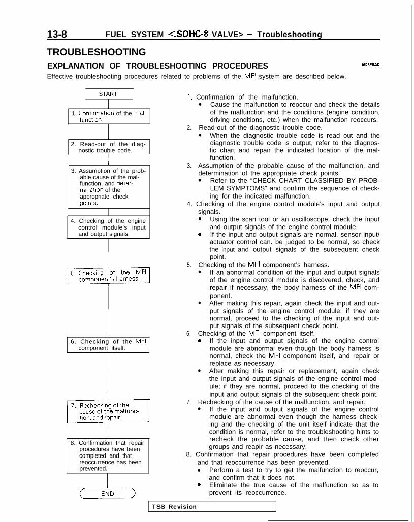
13-8 FUEL SYSTEM <SOHC-8 VALVE> - Troubleshooting
TROUBLESHOOTINGEXPLANATION OF TROUBLESHOOTING PROCEDURES MlBEBAD
Effective troubleshooting procedures related to problems of the MFI system are described below.
START
1. Confrrmatron of the mal-functron.
2. Read-out of the diag-nostic trouble code.
II
3. Assumption of the prob-able cause of the mal-function, and deter-mrnatron of theappropriate checkpoints.
4. Checking of the enginecontrol module’s inputand output signals.
6. Checking of the MFIcomponent itself.
8. Confirmation that repairprocedures have beencompleted and thatreoccurrence has beenprevented.
I. Confirmation of the malfunction.l Cause the malfunction to reoccur and check the details
of the malfunction and the conditions (engine condition,driving conditions, etc.) when the malfunction reoccurs.
2. Read-out of the diagnostic trouble code.l When the diagnostic trouble code is read out and the
diagnostic trouble code is output, refer to the diagnos-tic chart and repair the indicated location of the mal-function.
3. Assumption of the probable cause of the malfunction, anddetermination of the appropriate check points.l Refer to the “CHECK CHART CLASSIFIED BY PROB-
LEM SYMPTOMS” and confirm the sequence of check-ing for the indicated malfunction.
4. Checking of the engine control module’s input and outputsignals.0 Using the scan tool or an oscilloscope, check the input
and output signals of the engine control module.a If the input and output signals are normal, sensor input/
actuator control can. be judged to be normal, so checkthe input and output signals of the subsequent checkpoint.
5. Checking of the MFI component’s harness.l If an abnormal condition of the input and output signals
of the engine control module is discovered, check, andrepair if necessary, the body harness of the MFI com-ponent.
l After making this repair, again check the input and out-put signals of the engine control module; if they arenormal, proceed to the checking of the input and out-put signals of the subsequent check point.
6. Checking of the MFI component itself.a If the input and output signals of the engine control
module are abnormal even though the body harness isnormal, check the MFI component itself, and repair orreplace as necessary.
l After making this repair or replacement, again checkthe input and output signals of the engine control mod-ule; if they are normal, proceed to the checking of theinput and output signals of the subsequent check point.
7. Rechecking of the cause of the malfunction, and repair.l If the input and output signals of the engine control
module are abnormal even though the harness check-ing and the checking of the unit itself indicate that thecondition is normal, refer to the troubleshooting hints torecheck the probable cause, and then check othergroups and reapir as necessary.
8. Confirmation that repair procedures have been completedand that reoccurrence has been prevented.l Perform a test to try to get the malfunction to reoccur,
and confirm that it does not.a Eliminate the true cause of the malfunction so as to
prevent its reoccurrence.
TSB Revision

FUEL SYSTEM <SOHC-8 VALVE> - Troubleshooting 13-9
r
I Connector
6FU1216
EXPLANATION AND PRECAUTION RELATED TOHARNESS CHECKINGl Connector symbols are described as seen from the end of
the terminal for the connector.l The abbreviation “B+” used for the normal judgment value
when checking the voltage is the abbreviation for batterypositive voltage.
Test harnessset (MB991348)
Jumper wire
& 6FU1217
Harness<
LQ Q,
6FUlZlBj
l Be sure to use the special tool (test harness) when, for awaterproof connector, checking while the circuit is conduc-tive.If a probe is inserted from the harness side, the waterproofcapability will be lowered, thereby causing/corrosion, SO
never do so.
If there is no test harness compatible with the connector, itis OK to use the test harness set (MB991348) that can bedirectly connected between terminals.
l When a connector is disconnected in order to checkterminal voltage, etc., never insert a probe if the terminal tobe checked is a female pin, because the forceful insertionof a probe will cause improper or incomplete contact.
l When checking for damaged or disconnected wiring of aharness (open circuit) and if both ends of the harness areunconnected, use a jumper wire to ground one end of theharness, and then check for continuity between the otherend and ground. By doing this, you can check for damagedor disconnected wiring ., and, if there is no continuity, theharness should be repaired.
l When checking for a harness short-circuit (short-circuit toground), open one end of the harness and then check forcontinuity between the other end and ground.If there is continuity, the harness is short-circuited toground and should be repaired.
TSB Revision
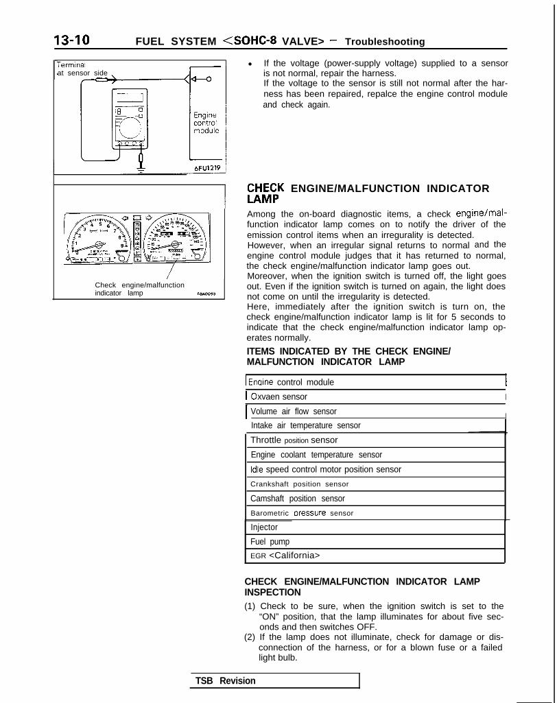
13-10 FUEL SYSTEM <SOHC-8 VALVE> - Troubleshooting
Terminalat sensor side
1\~“‘,““W,O,’ ‘\*N 4 -cnDQ5 a,, \ llllf,,c 3 c-11 ‘.<-!
( .[&;%* \ g ~ &.$$~&%,;
0%: E
.Oj-,,
giI lOWI -,n/ ~ ( ~~‘-~~~
-.mo .u. m,.0 - rj*> ;; <I, r\ .F, &‘~~“&??y? 5;
Check engine/malfunctionindicator lamp 68AOO93
l If the voltage (power-supply voltage) supplied to a sensoris not normal, repair the harness.If the voltage to the sensor is still not normal after the har-ness has been repaired, repalce the engine control moduleand check again.
W&K ENGINE/MALFUNCTION INDICATOR
Among the on-board diagnostic items, a check engine/mal-function indicator lamp comes on to notify the driver of theemission control items when an irregurality is detected.However, when an irregular signal returns to normal and theengine control module judges that it has returned to normal,the check engine/malfunction indicator lamp goes out.Moreover, when the ignition switch is turned off, the light goesout. Even if the ignition switch is turned on again, the light doesnot come on until the irregularity is detected.Here, immediately after the ignition switch is turn on, thecheck engine/malfunction indicator lamp is lit for 5 seconds toindicate that the check engine/malfunction indicator lamp op-erates normally.
ITEMS INDICATED BY THE CHECK ENGINE/MALFUNCTION INDICATOR LAMP
1 Enaine control module
IOxvaen sensor I
I Volume air flow sensor IIntake air temperature sensor
Throttle position sensor
Engine coolant temperature sensor
Idle speed control motor position sensor
Crankshaft position sensor
Camshaft position sensor
Barometric rxessure sensor
Injector
Fuel pump
EGR <California>
CHECK ENGINE/MALFUNCTION INDICATOR LAMPINSPECTION(1) Check to be sure, when the ignition switch is set to the
“ON” position, that the lamp illuminates for about five sec-onds and then switches OFF.
(2) If the lamp does not illuminate, check for damage or dis-connection of the harness, or for a blown fuse or a failedlight bulb.
TSB Revision
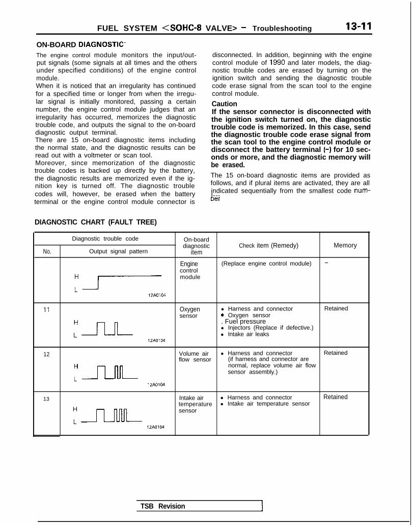
FUEL SYSTEM <SOHC-8 VALVE> - Troubleshooting 13-11
ON-BOARD DIAGNOSTIC-The engine control module monitors the input/out-put signals (some signals at all times and the othersunder specified conditions) of the engine controlmodule.When it is noticed that an irregularity has continuedfor a specified time or longer from when the irregu-lar signal is initially monitored, passing a certainnumber, the engine control module judges that anirregularity has occurred, memorizes the diagnostictrouble code, and outputs the signal to the on-boarddiagnostic output terminal.There are 15 on-board diagnostic items includingthe normal state, and the diagnostic results can beread out with a voltmeter or scan tool.Moreover, since memorization of the diagnostictrouble codes is backed up directly by the battery,the diagnostic results are memorized even if the ig-nition key is turned off. The diagnostic troublecodes will, however, be erased when the battery
disconnected. In addition, beginning with the enginecontrol module of 1990 and later models, the diag-nostic trouble codes are erased by turning on theignition switch and sending the diagnostic troublecode erase signal from the scan tool to the enginecontrol module.
CautionIf the sensor connector is disconnected withthe ignition switch turned on, the diagnostictrouble code is memorized. In this case, sendthe diagnostic trouble code erase signal fromthe scan tool to the engine control module ordisconnect the battery terminal (-) for 10 sec-onds or more, and the diagnostic memory willbe erased.The 15 on-board diagnostic items are provided asfollows, and if plural items are activated, they are allindicated sequentially from the smallest code num-I---
terminal or the engine control module connector is uer
DIAGNOSTIC CHART (FAULT TREE)
No.
-
Diagnostic trouble code On-boarddiagnostic Check item (Remedy) Memory
Output signal pattern item
-Engine (Replace engine control module)control
:r
module
12A0104
11 Oxygen l Harness and connector Retainedsensor 0 Oxygen sensor
:-JLJ--
. Fuel pressurel Injectors (Replace if defective.)l Intake air leaks
12A0104
12 Volume air l Harness and connector Retainedflow sensor (if harness and connector are
:-JJ-M-
normal, replace volume air flowsensor assembly.)
12A0104
13 Intake air l Harness and connector Retainedtemperature l Intake air temperature sensor
:n
sensor
12A0104
TSB Revision
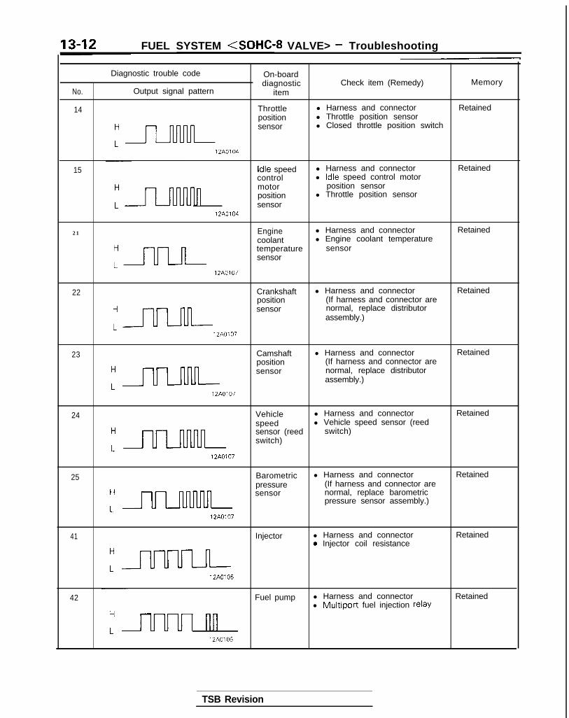
13-12 FUEL SYSTEM <SOHC-8 VALVE> - Troubleshooting
No.
14
Diagnostic trouble code On-boarddiagnostic Check item (Remedy) Memory
Output signal pattern item
Throttle l Harness and connector Retainedposition l Throttle position sensor
:-
sensor l Closed throttle position switch
12A0104
15 Idle speed l Harness and connector Retainedcontrol l Idle speed control motor
n
motor position sensorposition l Throttle position sensorsensor
12A0104
21 Engine l Harness and connector Retainedcoolant l Engine coolant temperature
“=
temperature sensorsensor
12A0107
22 Crankshaft l Harness and connector Retainedposition (If harness and connector are
:-
sensor normal, replace distributorassembly.)
12A0107
23 Camshaft l Harness and connector Retainedposition (If harness and connector are
:=
sensor normal, replace distributorassembly.)
12A0107
24 Vehicle l Harness and connector Retainedspeed l Vehicle speed sensor (reed
H
uulnnn
sensor (reed switch)switch)
L12A0107
25 Barometric l Harness and connector Retainedpressure (If harness and connector are
H
ULnMnn
sensor normal, replace barometricpressure sensor assembly.)
L12A0107
41 Injector l Harness and connector Retained0 Injector coil resistance
:a12A0105
42 Fuel pump l Harness and connector Retainedl Multiport fuel injection relay
L uuul nn12A0105
TSB Revision

FUEL SYSTEM <SOHC-8 VALVE> - Troubleshooting 13-13
No.
434-
Diagnostic trouble code
Output signal pattern
On-boarddiagnostic
itemCheck item (Remedy) Memory
EGR l Harness and connector Retained<Califor- l EGR temperature sensor
H nia> l EGR valvel EGR solenoid
L u u u I nnn l EGR valve control vacuum12A0105
Normal -state
-
H
L12A0104 I 1
NOTEReplace the engine control module if a diagnostic trouble code is output although the inspection reveals that there is nooroblem with the check items.
TROUBLESHOOTING TABLENOTE*: The failsafe back-up function is in operation.
Diagnostic On-boardtrouble diagnostic Diagnostic content
code No. itemMajor cause Remarks (trouble
phenomenon, etc.)
- Engine The engine control module - l Engine stopcontrol itself is abnormal. l Impossible startmodule
11 Oxygen Though the air/fuel mixture (1) The oxygen sensor is troubled. l Deterioration ofsensor ratio closed loop control is (2) Open-circuit, short-circuit or exhaust gas
operated, the signal voltage of improper connector contact purifyingthe oxygen sensor does not occurs in the oxygen sensor performance*vary (to be lean/rich). circuit.
(3) The fuel pressure is improper. l Deterioration of(4) The injector is troubled. exhaust gas(5) Air is sucked through the purifying
gasket clearance, etc. performance*(6) The engine control module is l Abnormal start
troubled. l Unstable idlingl Abnormal
acceleration
12 Volumeair flowsensor
Though the engine is running, (I) Volume air flow sensor is l Abnormalthe signal frequency of the air troubled. acceleration*flow sensor is 1 OHz or less. (2) Open-circuit, short-circuit or
improper connector contactoccurs in the volume air flowsensor circuit.
(3) The engine control module is l Unstable idling*troubled.
13 Intake air (1) The signal voltage of the (1) The intake air temperature l Slightly impropertemperatu- intake air temperature sensor is troubled. driveability*re sensor sensor is 4.5V or higher. (2) Open-circuit, short-circuit or l At high
(2) The signal voltage of the improper connector contact temperatures,intake air temperature occurs in the air intake (a) Improper start*sensor is 0.27V or lower. temperature sensor circuit.
(3) The engine control module is(b) ;J;pe
troubled.
1 TSB Revision

13-14 FUEL SYSTEM <SOHC-8 VALVE> - Troubleshooting
Iiagnostic On -boa rdtrouble diagnostic Diagnostic content Major cause Remarks (trouble
phenomenon, etc.)code No. item
14 Throttle (1) The signal voltage of the (1) The throttle position sensor is l Slightly improperposition throttle position sensor is troubled or improperly accelerationsensor 0.2V or lower. adjusted. < M / T >
(2) Though the closed throttle (2) Open-circuit, short-circuit Or l Improperposition switch is on, the improper connector contactsignal voltage of the occurs in the throttle position
d$eybzty
throttle position sensor is sensor circuit. l Engine stop2V or higher.
(3) The closed throttle position l Engine stopswitch ON is troubled.
(4) The closed throttle position 0 Racing isswitch signal line is t impossibleshort-circuited.
(5) The engine control module istroubled.
15 Idle speed (1) The signal voltage of the (1) The idle speed control motor l Engine stop*control idle speed control motor position sensor is troubled.motor position sensor is 4.8V or (2) Open-circuit, short-circuit orposition higher. improper connector contactsensor (2) The signal voltage of the occurs in the idle speed control
idle speed control motor motor position sensor circuit.position sensor is 0.2V or (3) The throttle position sensor islower. troubled or improperly
(3) During idling, the signal adjusted.voltage of the idle speed (4) Open-circuit, short-circuit orcontrol motor position improper connector contactsensor for the throttle occurs in the throttle positionvalve opening degree is sensor circuit.excessively low. (5) The engine control module is
troubled.
21 Engine (1) The signal voltage of the (1) The engine coolant During cold weather,coolant engine coolant temperature sensor is troubled. l Starting istemperatu- temperature sensor is (2) Open-circuit, short-circuit or impossible*.re sensor 4.6V or higher. improper connector contact l Unstable idling*
(2) The signal voltage of the occurs in the engine coolant 0 Improperengine coolant temperature sensor circuit. acceleration*temperature sensor is (3) The engine control module is0.11 V or lower. troubled.
(3) During enginewarming-up, the enginecoolant temperaturesensor signal indicatesthat the engine coolanttemperature drops.
22 Crankshaft Though the engine is cranking (1) The crankshaft position sensor l Engine stopposition 4 seconds or more, the signal is troubled. 0 Startrng 1ssensor voltage of the crankshaft (2) Open-circuit, short-circuit or impossible.
position sensor does not vary improper connector contact(to be high/low). occurs in the crankshaft
position sensor circuit.(3) The engine control module is
troubled.
23 Camshaft Though the engine is running, (1) The camshaft position sensor is l Unstable idling*position the signal voltage of the troubled. 0 Impropersensor camshaft position sensor does (2) Open-circuit, short-circuit or acceleration*
not vary (to be high/low). improper connector contactoccurs in the camshaft positionsensor circuit.
(3) The engine control module istroubled.
TSB Revision
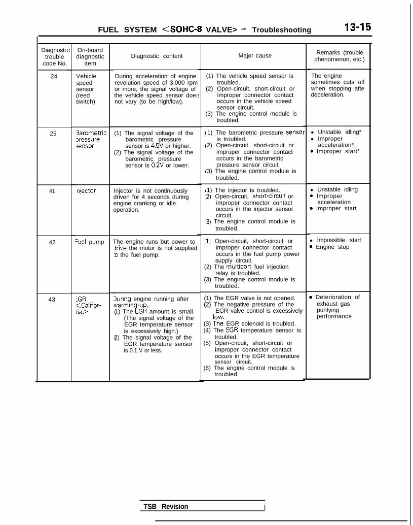
FUEL SYSTEM <SOHC-8 VALVE> - Troubleshooting 13-15
Diagnostitrouble
code No.
24
25
41
42 Set pump
43 iGR;aC;lifor-
C On-boarddiagnostic
item
Vehiclespeedsensor(reedswitch)
3arometricIressuresensor
njector
Diagnostic content Major cause
During acceleration of enginerevolution speed of 3,000 rpmor more, the signal voltage ofthe vehicle speed sensor doe:not vary (to be high/low).
(1) The vehicle speed sensor istroubled.
(2) Open-circuit, short-circuit orimproper connector contactoccurs in the vehicle speedsensor circuit.
(1) The signal voltage of thebarometric pressuresensor is 4.5V or higher.
(2) The signal voltage of thebarometric pressuresensor is 0.2V or lower.
Injector is not continuouslydriven for 4 seconds duringengine cranking or idleoperation.
The engine runs but power toirive the motor is not supplied:o the fuel pump.
luring engine running afterNarming-up,1) The EGR amount is small.
(The signal voltage of theEGR temperature sensoris excessively high.)
2) The signal voltage of theEGR temperature sensoris 0.1 V or less.
(3) The engine control module istroubled.
1) The barometric pressure senseis troubled.
2) Open-circuit, short-circuit orimproper connector contactoccurs in the barometricpressure sensor circuit.
‘3) The engine control module istroubled.
‘1) The injector is troubled.12) Open-circuit, short-crrcuit or
improper connector contactoccurs in the injector sensorcircuit.
13) The engine control module istroubled.
:I) Open-circuit, short-circuit orimproper connector contactoccurs in the fuel pump powersupply circuit.
(2) The multiport fuel injectionrelay is troubled.
(3) The engine control module istroubled.
(1) The EGR valve is not opened.(2) The negative pressure of the
EGR valve control is excessively
(3) ?h”e EGR solenoid is troubled.(4) The EGR temperature sensor is
troubled.(5) Open-circuit, short-circuit or
improper connector contactoccurs in the EGR temperaturesensor circuit.
(6) The engine control module istroubled.
r 1l Unstable idling*l Improper
acceleration*0 Improper start*
l Unstable idling0 Improper
acceleration0 Improper start
l Impossible start3 Engine stop4
4
,
B Deterioration ofexhaust gaspurifyingperformance
Remarks (troublephenomenon, etc.)
The enginesometimes cuts offwhen stopping aftedeceleration.
TSB Revision I

13-16 FUEL SYSTEM <SOHC-8 VALVE> - Troubleshooting
FAILSAFE/BACK-UP FUNCTIONS LISTIf trouble with any major sensor is detected by the on-board diagnostic, the vehicle will be kept in the safedriving conditions according to the preset control logic.
Trouble item Control content for trouble
Volume air flow Fuel injection timing and ignition timing are determined according to the throttle positionsensor sensor (TPS) and engine revolution speed signal (crankshaft position sensor signal).
Intake air temperature The control is executed with the suction air temperature regarded as 25°C (77°F).sensor
Throttle position The fuel injection rate is not increased for acceleration according to the throttle positionsensor (TPS) sensor signal.
Idle speed control After the idle speed control motor plunger is driven and contracted, the idle revolution speedmotor position sensor is not controlled.
Engine coolant The control is executed with the engine coolant temperature regarded as 8OO.C (176°F).temperature sensor (Even if the sensor signal becomes normal again, the control is continued until the ignltlon
switch is turned off.)
Camshaft position Simultaneous injection of fuel is executed for all cylinders. (In this case, the No.1 cylinder topsensor dead center is not detected at all after the ignition key is turned on.)
Barometric pressure The control is executed with the pressure regarded as 760 mmHg (30 in.Hg).sensor
Oxygen sensor Closed loop control of the air/fuel mixture ratio is not executed. i
READ OUT OF DIAGNOSTIC TROUBLE CODEPrecautions for operation(1) When battery voltage is low, no detection of failure is
possible. Be sure to check the battery for voltage andother conditions before starting the test.
(2) On-board diagnostic item is erased if the battery orthe engine control module connector is discon-nected. Do not disconnect the battery before the di-agnostic result is completely read.
Using Scan Tool(1) Switch OFF the ignition switch.(2) Connect the power-source terminal of the scan tool to the
cigarette lighter socket.(3) Connect the scan tool to the data link connector.(4) Turn ignition switch to ON.(5) Using the scan tool, read out and make a note of the on-
board diagnostic output.(6) Refer to the diagnostic chart, and repair the indicated loca-
tion of malfunction.(7) Erase the diagnostic trouble code. (Refer to P.13-17.)
1 TSB Revision I
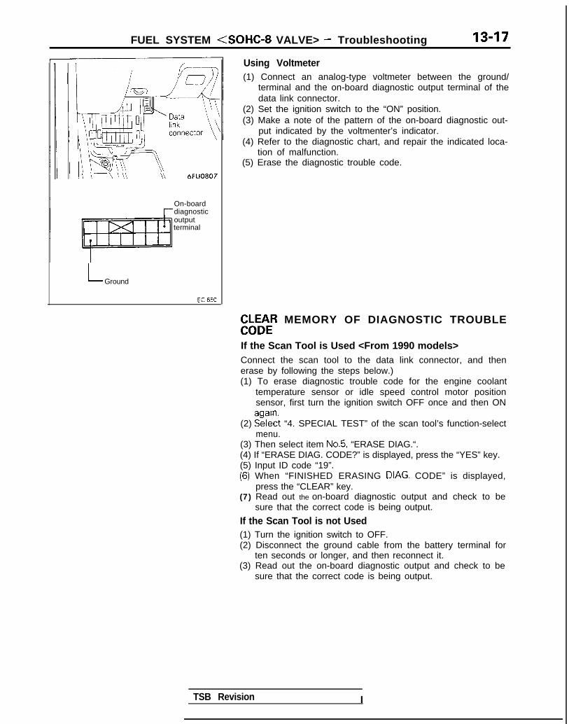
FUEL SYSTEM <SOHC-8 VALVE> - Troubleshooting 13-17
\ I\-\\\\ \\ 6FUO807
Using Voltmeter(1) Connect an analog-type voltmeter between the ground/
terminal and the on-board diagnostic output terminal of thedata link connector.
(2) Set the ignition switch to the “ON” position.(3) Make a note of the pattern of the on-board diagnostic out-
put indicated by the voltmenter’s indicator.(4) Refer to the diagnostic chart, and repair the indicated loca-
tion of malfunction.(5) Erase the diagnostic trouble code.
On-boarddiagnosticoutputterminal
L Ground
EbLbtR MEMORY OF DIAGNOSTIC TROUBLE
If the Scan Tool is Used <From 1990 models>Connect the scan tool to the data link connector, and thenerase by following the steps below.)(1) To erase diagnostic trouble code for the engine coolant
temperature sensor or idle speed control motor positionsensor, first turn the ignition switch OFF once and then ON
(2) EE?$t “4. SPECIAL TEST” of the scan tool’s function-selectmenu.
(3) Then select item No.5, “ERASE DIAG.“.(4) If “ERASE DIAG. CODE?” is displayed, press the “YES” key.(5) Input ID code “19”.(6) When “FINISHED ERASING DIAG. CODE” is displayed,> I
press the “CLEAR” key.(7) Read out the on-board diagnostic output and check to be
sure that the correct code is being output.
If the Scan Tool is not Used(1) Turn the ignition switch to OFF.(2) Disconnect the ground cable from the battery terminal for
ten seconds or longer, and then reconnect it.(3) Read out the on-board diagnostic output and check to be
sure that the correct code is being output.
TSB Revision I

13-18 FUEL SYSTEM <SOHC-8 VALVE> - Troubleshooting
CHECK CHART CLASSIFIED BY PROBLEM SYMPTOMS
:heck items
GR solenoid <California>
uel pressure @El@lEl oEloElom
0: Warm engine (Figures inside the 0 indicate the checking sequence.)0: Cold engine (Figures inside the q indicate the checking sequence.)
1 TSB Revision I

FUEL SYSTEM <SOHC-8 VALVE> - TroubleShooting 13-19
PROBLEM SYMPTOMS TABLE (FOR YOUR INFORMATION)
:t
Shock
Surge
Knocking
0,G Run ona (“dieselrng”)
6
Items Symptom- - -... __----. -~-
The starter IS used to crank the engine, but there IS no combustron wrthrn the cylinders.(no rnrtral combustron) and the engine won’t start
~-.-__
Startrng problem There IS combustron wrthrn the cylrnders. but then the engrne soon stalls.(Initial combustion, then stall)
(Startrng takes a long t1me.l
I Idling rnstabrlrty
/ Engrne won’t start qurckly~--_~ -...
Engine speed doesn’t remain constant; changes during idling.Usually, aludgement can be based upon the movement of the tachometer pointer, andthe vibration transmitted to the steering wheel, shift lever, body, etc. This is called rougtIdling.
The engtnedoesn’t idle at the usual correct speed.
Thus non-contrnuity of rdlrng Includes the followrng elements(1) Die out . . . . ..The engine stalls when the foot IS taken from the accelator pedal,
regardless of whether the vehicle IS moving or not.(2) Pass out . . . ..The engine stalls when the accelerator pedal IS depressed or while it IS
berng used.
“Hestatton” IS the delay In response ofthe vehicle (engine rpm) that occurswhen the accelerator is depressed Inorder to accelerate from the speed atwhich the vehicle is now traveling, or atemporary drop in vehicle speed (enginerpm) during such acceleration.
Hesltatron
Serious hesstatlon IS called “sag”.
Poor acceleration
E S t u m b l e25
Time lFUO223
Poor acceleration IS rnabilrty to obtain an acceleration corresponding to the degree ofthrottle opening, even though acceleration IS smooth, or the rnabrlrty to reach maxmumspeed.
Engrne rpm response IS delayed when .
the accelerator pedal is initrally depressedfor acceleratron from the stoppedcondition
ldllngStumble
Trme lFUO224
The feeling of a comparatlvley large Impact or vrbration when the engine IS acceleratedor decelerated.
This IS repeated surging ahead dunng constant speed travel or dunng vanable speedtravel.
A sharp sound IIke a hammer strtklng the cylinder walls during dnvtng and whrchadversely affects driving.
The condrtion In which the engrne continues to run after the lgnltion switch 1s turned toOFF. Also called “dreselrng”.
TSB Revision

13-20 FUEL SYSTEM <SOHC-8 VALVE> - Troubleshooting
CIRCUIT DIAGRAMcl989 models>
iER IGNITIONSWITCHbST)-
SUB F_US IBLE
.-__-____----w-w--
2-BW0
LINK@
A-08
;;IJkKPUMP
:ONNECTOR
t
\ I
M/T g' A/T z
1 ch7 L CL/.
MFIRELAY
r
TuT;T
Im
\
Zi/T A/r;
09 108_--- ---------
X35-AC-H0525-NY
1 TSB Revision

FUEL SYSTEM <SOHC-8 VALVE> - Troubleshooting 13-21
3-2c:2(:-----2A
o-
TION'CH(IG1)
2-BW
,,lIGNITION
y COILB-07
Fj@g j
4z/rg2
:
%I B-06IISTRIBUTOR
g,3LD
IGNITIONI\ POWERTRANSISTORB-09m
-I1
AUTO COMPRESSORCONTROL UNITm c-30
BC-57 [p$aq
8C-23
ON: 235kPa
$i?f;7kPB
A-21
GRr-t
631Fi
j4 103m -11 65
p&7iGaJ$p
TSB Revision

13-22 FUEL SYSTEM <SOHC-8 VALVE> - Troubleshooting
CIRCUIT DIAGRAM (CONTINUED)< 1989 models>
IGNITIONSWITCHlIGl)#OF?OWER
MFIRELAY
IGNIlTRANf
;ROLKUN1
a m\lR Fl.tlW i=XNSOR
A-57
II I l-
EF g?JEi _______ JLllO I: 02&j 12_1---& im
Y-+-I
k$$Yh
I 5VI I
5Y syv s_v- e - * - e - “, *- r
-5. I I I I 5.5
cL
II I I
I I I 1 II - - I - - I II,---
1’ 8 I is % %Gi3
m v1 a+2 pg3 $14I?Ic
IDLE SPEEDCONTROL MOTORPOSITJON SENSORA-53 12
El(VEHICLES FOR94 CALIFORNIA)
B-02 B @
KX35-AC-HO525A-NY
B-04 m
1 TSB Revision1 I

FUEL SYSTEM <SOHC-8 VALVE> - Troubleshooting 13-23
--r-B-20 I
LXYG~!tEN6OR 1’I W!E~W~,F;~R
-2 EVAPORATIVE ! ““L;,$ m&S-ONh SOLENOID
,\,C” 1 PI FR
*q1:
2_1 El ,Lk.i,i ii I
NJECTOi- 11
B-12 =m
2
7'
2
A-56I
IQI2
/A T/ /cp IIIi
ime Ii i aI%
i
‘OR
7VE IC I A
I “d
OT
4-1 ;;
I I
5v
r5
s.- -
I
14J
POWERPRESSU
' OXYGEN SENSOR'(VEHICLES FOR
FEDE;zdC-18 FRONT SIDE
DATA LINKCONNECTOR
4 IENG) (DATA)
c-40
plqismqC-38
7F J/B
cp4
", H
I eEll94
TSB Revision I

13-24 FUEL SYSTEM <SOHC-8 VALVE> - Troubleshooting
CIRCUIT DIAGRAM< 1990 models>
TER IGNITIONSWITCH(ST)
$ s- 3 C-24 cl
-i
__---____-_-_------ ____-- ___-_---------4,_--- -_---- -
C-08.-----
SUB FUSIBLEcu3
'4
A-413cp
2-BW0
PARK/ 3"NEUTRAL "pI"O~~~~ON
cugp8
P
A-43 $99sCL
;;EbKPUMP
:ONNECTOR
mL-b1=1 L M/T, ;+.y
3
I1 !
:!r
MFIRELAYc-35
T A/T-T
t5
5 9-’ cc FdI I .Akcr-l
% 1zs
R R.s G ;. v
!m:X35-AC-H0526-NY
1 TSB Revision

FUEL SYSTEM <SOHC-8 VALVE> - Troubleshooting 13-25
g
30c
30i
- - - - -
30c!
a - -
TIONCH(IG3)
!MF"HfSOR
-I c-30
C-36
2-BW
7 FEE'ACATED
- -7
8
“6
1 IGNITIONCOILB-07
Ii32
>F<7 B-061ISTRIBUTOR
%3m
A _ IGNITIONf!$$ISTOR
- l-i%35l
.--13
i4
t~;m&NATlON
C-52E-23-j
l- O N : 235kPa
#$lkPa
A-21ON:210OkPa(299PS I)
OFF:270OkPa(384PS 1)
hL2‘1 I
co s 1:I
DUAL IIF:.Wyg;RE
OFFIi
GRmc;gm -
:OMPRESSOR8\2
iTI“1 "2348 2
;- al
7,\- _____ --A+-----
,?3 B-05I 2
3
ilIp=
g#g~$‘C Y
b
;4 _____ -- ---- 103 gg 0111 654
m l ,
“r4
r4 -LT E R Y B A C K UP
I- r
TSB Revision I

13-26 FUEL SYSTEM <SOHC-8 VALVE> - Troubleshooting
CIRCUIT DIAGRAM (CONTINUED)(1990 models>
IGNITIONRY SWITCH(IG37
1
4YIGNITION POWERTRANSISTOR
?-::.?a,::
VOLUME AIR FLOW GENSORA~rnIC nmtit AIR VlEw!
A-47 awea l?YPEPAnsle LIP PLOTsetlsmm
\I \/ \, \I“3 “5 “4 “6 “1
3 F s 3 d
LI
A-57
.s Gi 2
MPIKrTRoL ~,1_6_--AL,'10 ‘I IJO2 g5jj 21---- 22 &a
” A v V V V
L GND “t?V-
&a rio-6m
4 f 74 I k@J@ ________ -r
i-J101 ~~--~~~-~~~-~--~~-~~~-~20 7-g----- :
r
gt&g B-02 /-J ,jm’ CALIFORNJ
B-04 m
TSB Revision

FUEL SYSTEM (SOHC-8 VALVE> - Troubleshooting 13-27
INJECTOR&INJECTOR&INJECTOR&NJEC
--!-B-20 -7
!OXYGE!!ENSOR I'(VEHICLES FOR
CALIFORNIA)
5v
-w-Q z - I - - ^
_____--- ______-_- ---____--&vs-- -__---- T18I1>
,..
-----.2
15
12
I
----.58
8
I
1
IDLE SPEEDDATA LINK CONTROL MOTORCONNECTOR
59cl-11
I
2
1
m
II!II I I1
ib-I
' OXYGEN SENSOR'(VEHICLES FOR
FEDE89":;i 63 i
TSB Revision I
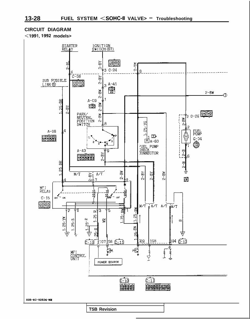
13-28 FUEL SYSTEM <SOHC-8 VALVE> - Troubleshooting
CIRCUIT DIAGRAM<1991,1992 models>
SUB FUSIBLELINK 8
-7
MFlRELAY
c-15
jER IGNITIONSWITCH(ST)
- l--
I____-------C-08
5 2m 3 C-24 c:
c JM/T & A/T z
cb7 CL/\ s
ymKPUMP
:ONNECTOR
dOFF - ON
34FF - ON
r I . .r
"2 "6 \I \Icd3 5
Fcp yzgLA
z ;cN 51.G 1
1.s .A z
B
m-p___-----
i/T
I
i
m
104 fyy$
4
2-BW0
:, 2t
D-26143
X95-AC-H0534-NH
TSB Revision

FUEL SYSTEM <SOHC-8 VALVE> - Troubleshooting 13-29
;NIr(IT
zis-N 2-BW
?II
1234 c-4:3 a77 mlss7.3 -77
J/B Gi>
I
@
101 R IO
2‘c-39'0
577
I,
r
,- - - -
i
r
AUTO COMPRESSORCONTROLUYITITqIf3
Cl36
5
c:
'61
I!aACATED
i
b c-57f?J%aq
1 2 C-23
1 IGNITIONCOIL
? A-07-2X
i4
ON:235uPa
" A-21l%M;“Pa
DUAL OF:
PRESSURESW1 TCH
2
r
m
A-086
54-.-----------. 0355!j ,1165cd4
pATTERY B A C K U P )1
TSB Revision

13-30 FUEL SYSTEM <SOHC-8 VALVE> - Troubleshooting
CIRCUIT DIAGRAM (CONTINUED)<1991,1992 models>
IGNITIONSWITCH(IG1)IGNITION POWER
TRANSISTOR
FROL91
\lxIz;.FR
VOLUME AIR FLOW SENSOR s
LYAYE
zm1rl
\I \I/ ,, I
"3 "5 "4 "6 "1E s tz 8 d
j,Y 4Y (gj ~~p=q~ @
5v 5v 5v
) f $ T$z T T $5 $ $GNI
CLOSED 'THROTTLE :;:/,fT
THROTTLE EGRPOSITION ;;;;!;TURE
@~#ON ~&~~~~ATUREsENSoRB-02-1 (VEHICLES
FORB-02 1 4-1
RICALIFORNIA)
B-04 /@KX35-AC-HOSWA-NY
TSB Revision

FUEL SYSTEM <SOHC-8 VALVE> - Troubleshooting 13-31
MFIRELAY
IIOXYGEN SENSOR
(VEHICLES FORCALIFORNIA)
g k______ -___----__ -------------ml I ----5 18>E F
!, -Is A-08 c-09f@p&g ~ ,,-yg@
POWER STEERINGPRESSURE SWITCH
.
-- - -1
3
14- - -
3
1-
I_------3
15
P
10I [
12
t
-----58
(ENG) (DATA)
c-40- 0 3
12
1C-38
DATA LINK CONTROL MOTORCONNECTOR
' OXYGEN SENSOR'(VEHICLES FOR
1 TSB Revision I

13-32 FUEL SYSTEM <SOHC-8 VALVE> - Troubleshooting/Service Adjustment Procedures
FUEL TANK AND FUEL LINE MlBEAAA
Symptom Probable cause Remedy
Engtne malfunctions Bent or kinked fuel pipe or hose Repair or replace3ue to insufficient fuelSUPPlY Clogged fuel pipe or hose Clean or replace
Clogged fuel filter or in-tank fuel filter Replace
Water in fuel filter Replace the fuel filter or clean the fuel tankand fuel line
Dirty or rusted fuel tank interior
Malfunctioning fuel pump(Clogged filter in the pump)
Clean or replace
Replace
Evaporative emission Mispiping of vapor line Correctcontrol system malfunc-tions (When fuel tank Disconnect vapor line piping joint Correctfiller tube cap is re-moved, pressure releas- Folded, bent, cracked or clogged vapor line Replaceng noise is heard)
Faulty fuel tank filler tube cap
Malfunctioning fuel tank pressure controlvalve
Replace
Replace
LLm ~~: Paper clip-
F l!;“I /yFp- -
izd--_7- 01 A0086
SERVICE ADJUSTMENT PROCEDURESCURB IDLE SPEED INSPECTION MlBFHAFt
(1) The vehicle should be prepared as follows before theinspection.
l Engine coolant temperature: 85-95°C (185-203°F)l Lights, electric cooling fan and accessories: OFFl Transax le : Neu t ra l (P for vehicles with an automatic
transaxle)(2) Connect a tachometer or connect the scan tool to the data
link connector.
NOTERefer to P.13-33 for information concerning connection Ofa tachometer.
(3) Set a timing light in position.(4) Ground the terminal for adjustment of ignition timing.(5) Start the engine and let it idle.(6) Check whether or not the ignition timing is the standard
value; if not, adjust.
Standard value: 5”BTDC + 2”(7) Stop grounding the terminal for adjustment of ignition
timing. .(8) Let the engine idle for two minutes.(9) Check the idling rpm.
Curb idle speed: 7502 100 rpmNOTEThe idling rpm is automatically regulated by the idle-speedcontrol system.
1
TSB Revision
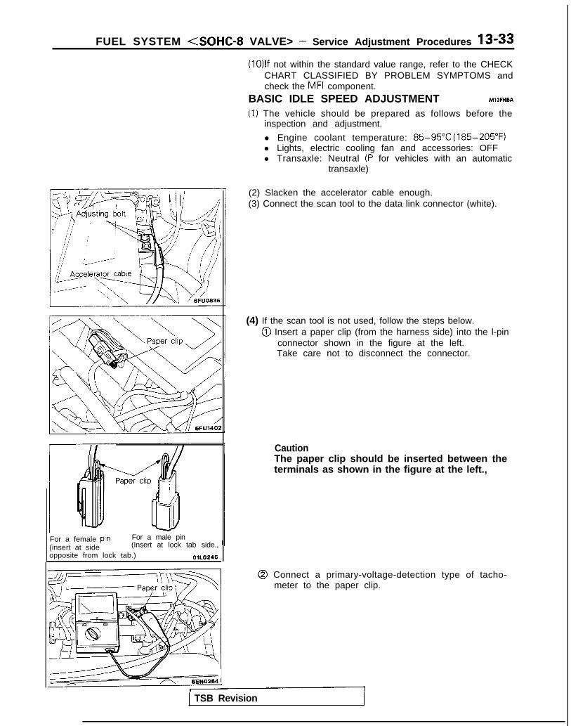
FUEL SYSTEM <SOHC-8 VALVE> - Service Adjustment Procedures 13-33
For a female pin For a male pin(insert at side (Insert at lock tab side.,opposite from lock tab.) OlLO246
(10)lf not within the standard value range, refer to the CHECKCHART CLASSIFIED BY PROBLEM SYMPTOMS andcheck the MFI component.
BASIC IDLE SPEED ADJUSTMENT MlBFHBA
(1) The vehicle should be prepared as follows before theinspection and adjustment.
l Engine coolant temperature: 85-95°C (185-205°F)l Lights, electric cooling fan and accessories: OFFl Transaxle: Neutral (P for vehicles with an automatic
transaxle)
(2) Slacken the accelerator cable enough.(3) Connect the scan tool to the data link connector (white).
(4) If the scan tool is not used, follow the steps below.@I Insert a paper clip (from the harness side) into the l-pin
connector shown in the figure at the left.Take care not to disconnect the connector.
CautionThe paper clip should be inserted between theterminals as shown in the figure at the left.,
@ Connect a primary-voltage-detection type of tacho-meter to the paper clip.
TSB Revision
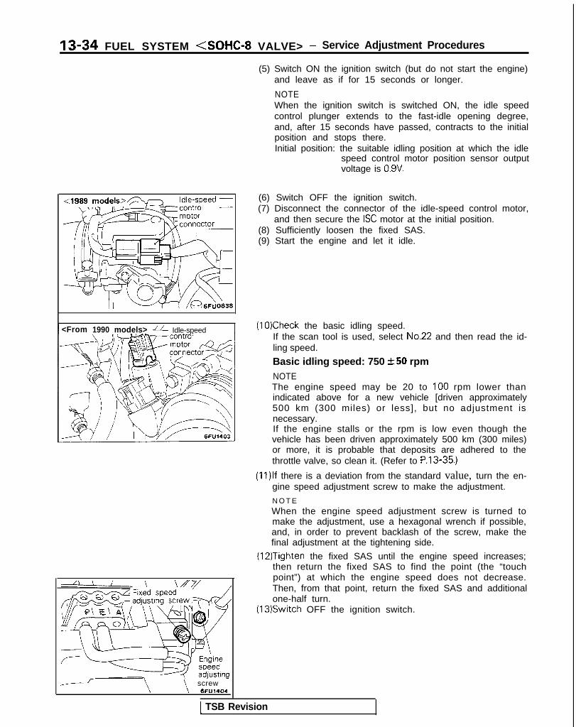
13-34 FUEL SYSTEM <SOHC-8 VALVE> - Service Adjustment Procedures
(5) Switch ON the ignition switch (but do not start the engine)and leave as if for 15 seconds or longer.
NOTEWhen the ignition switch is switched ON, the idle speedcontrol plunger extends to the fast-idle opening degree,and, after 15 seconds have passed, contracts to the initialposition and stops there.Initial position: the suitable idling position at which the idle
speed control motor position sensor outputvoltage is 0.9V.
<From 1990 models> fi Idle-speed
--\ \
screw6FU1404
(6) Switch OFF the ignition switch.(7) Disconnect the connector of the idle-speed control motor,
and then secure the ISC motor at the initial position.(8) Sufficiently loosen the fixed SAS.(9) Start the engine and let it idle.
(10)Check the basic idling speed.If the scan tool is used, select No.22 and then read the id-ling speed.
Basic idling speed: 750 +-50 rpmNOTEThe engine speed may be 20 to 100 rpm lower thanindicated above for a new vehicle [driven approximately500 km (300 miles) or less], but no adjustment isnecessary.If the engine stalls or the rpm is low even though thevehicle has been driven approximately 500 km (300 miles)or more, it is probable that deposits are adhered to thethrottle valve, so clean it. (Refer to P.13-35.)
(1l)lf there is a deviation from the standard value, turn the en-gine speed adjustment screw to make the adjustment.
N O T E
When the engine speed adjustment screw is turned tomake the adjustment, use a hexagonal wrench if possible,and, in order to prevent backlash of the screw, make thefinal adjustment at the tightening side.
(12)Tighten the fixed SAS until the engine speed increases;then return the fixed SAS to find the point (the “touchpoint”) at which the engine speed does not decrease.Then, from that point, return the fixed SAS and additionalone-half turn.
(13)Switch OFF the ignition switch.
1 TSB Revision

FUEL SYSTEM <SOHC-8 VALVE> - Service Adjustment Procedures 13-35
(14)Adjust the play of the accelerator cable. (Refer to P.13-329.)
(15)Connect the idle-speed control motor’s connector.(16)Adjust the throttle-position sensor.(17)Start the engine again and let it run at idle speed for about
ten minutes; check to be sure that the idling condition isnormal.
THROTTLE BODY (THROTTLE VALVE AREA)CLEANING MllFlCK
(1) Start the engine and warm it up until the temperature of theengine coolant reaches 80°C (176°F) or higher; then stopthe engine.
(2) Disconnect the air intake hose at the throttle body side.(3) Spray cleaning liquid (from the intake port of the throttle
body) onto the valve, and then leave as is for about fiveminutes.
(4) Start the engine and race it a few times; then let it run atidle speed for about one minute.
NOTEIf the engine idling speed is unstable (or the engine stalls),let the engine run with the throttle valve slightly open.
(5) If deposits are not removed from the throttle valve, repeatsteps (3) and (4).
(6) Connect the air intake hose.(7) Using the scan tool, erase the diagnostic trouble code, or
disconnect the battery’s ground cable for ten seconds orlonger and then reconnect it.
(8) Adjust the basic idle speed (engine speed adjusting screw).(Refer to P.13-33.)
(9) Adjust the throttle position sensor.
<I989 models> - rottle posi t ion ” ynsor connector
(2) If a scan tool is not used, perform the following operation.< 1989 models>@ Disconnect the throttle position sensor connector and
use the special tool (test harness) between the discon-nected connector.
r1 TSB Revision
THROTTLE POSITION SENSOR ADJUSTMEiW&
CautionThe adjustment of the throttle-position sensor should bemade after completion of the basic idle-speed adjustment.(1) Connect the scan tool to the data link connector (white).
,
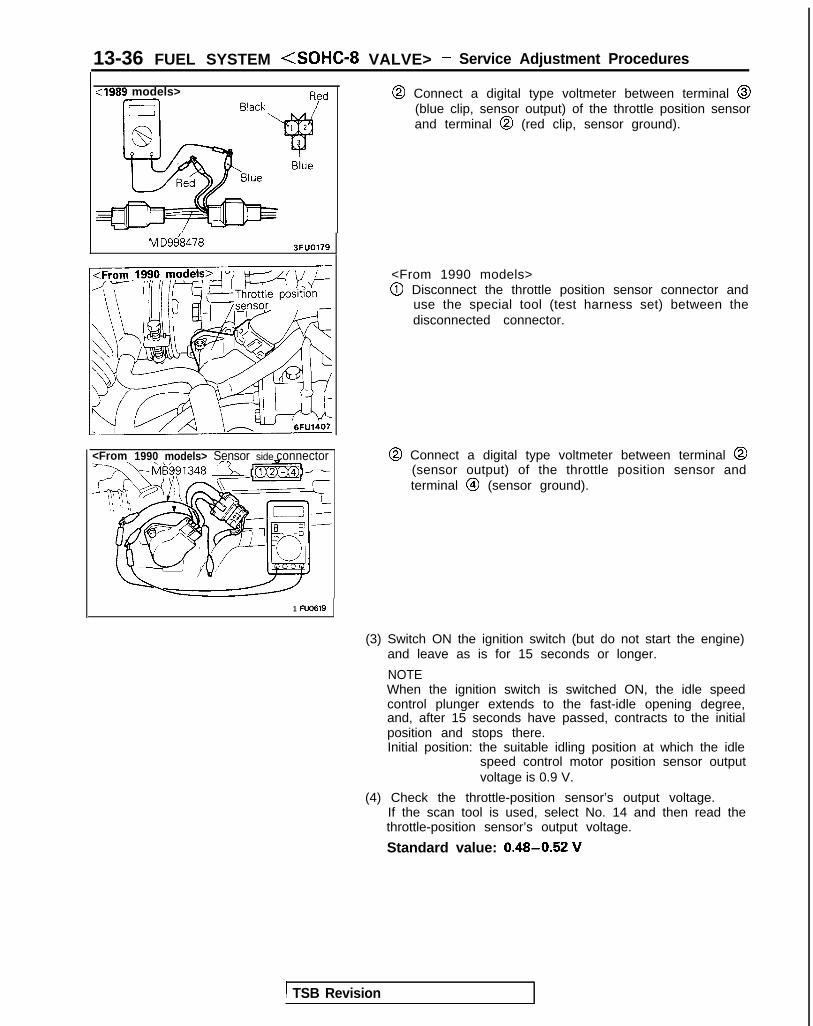
13-36 FUEL SYSTEM <SOHC-8 VALVE> - Service Adjustment Procedures
:I989 models>
M D968478 3FUO179
<From 1990 models> Sensor side connector
@ Connect a digital type voltmeter between terminal @(blue clip, sensor output) of the throttle position sensorand terminal @I (red clip, sensor ground).
<From 1990 models>@I Disconnect the throttle position sensor connector and
use the special tool (test harness set) between thedisconnected connector.
@ Connect a digital type voltmeter between terminal @(sensor output) of the throttle position sensor andterminal @I (sensor ground).
1 FU0619
(3) Switch ON the ignition switch (but do not start the engine)and leave as is for 15 seconds or longer.
NOTEWhen the ignition switch is switched ON, the idle speedcontrol plunger extends to the fast-idle opening degree,and, after 15 seconds have passed, contracts to the initialposition and stops there.Initial position: the suitable idling position at which the idle
speed control motor position sensor outputvoltage is 0.9 V.
(4) Check the throttle-position sensor’s output voltage.If the scan tool is used, select No. 14 and then read thethrottle-position sensor’s output voltage.
Standard value: 0.48-0.52 V
1 TSB Revision

FUEL SYSTEM (SOHC-8 VALVE> - Service Adjustment Procedures 13-37
<From 1990 m$ek>--
MO-L6FU1405
(5) If there is a deviation from the standard value, loosen thethrottle-position sensor installation bolt and then turn thethrottle-position sensor itself to make the adjustment. Besure to securely retighten the bolt after making theadjustment.
NOTEl The output voltage becomes higher when the throttle-
position sensor is turned clockwise.l A diagnostic trouble code for idle speed control motor
position sensor may be output when adjusting thethrottle position sensor. The reason is that, when thethrottle position sensor is turned, the throttle positionsensor voltage may differ from the normal voltage dur-ing idling, but this is no malfunction of the idle speedcontrol motor position sensor.
(6) Switch OFF the ignition switch.(7) If a diagnostic trouble code is output when adjusting the
throttle position sensor, use the scan tool and erase the di-agnostic trouble code or first disconnect the battery (-)cable from the battery terminal for IO seconds or more andthen reconnect it. (This will erase the memory for the diag-nostic trouble code due to adjustment of the throttle posi-tion sensor.)
TSB Revision

13-38 FUEL SYSTEM <SOHC-8 VALVE> - On-Vehicule inspection of MFI Components
ON-VEHICLE INSPECTION OF MFI COMPONENTSCOMPONENT LOCATION
Ii111 I ‘I 1 II
bEM0148
6FUO843
M?BYA-
Name Symbol Name Symbol
Air conditioning compressor clutch relay J Ignition coil (ignition power transistor) F
Air conditioning switch 0 Ignition timing adjustment terminal R
Crankshaft position sensor and camshaft posi- Injector IGtion sensor
- Multiport fuel injection relay NData link connector S
- Oxygen sensor AEGR solenoid <California> K
- Park/neutral position switch <A/T> MEGR temperature sensor <California> L
- Power steering pressure switch UEngine control module Q
- Throttle position sensor DEngine coolant temperature sensor E
- Vehicle speed sensor (reed switch) PEvaporative emission purge solenoid H
Volume air flow sensor (incorporating intakeFuel pump check terminal T air temperature sensor and barometric pres- B
- sure sensor)Idle speed control motor (closed throttle posi-tion switch, idle speed control motor position Csensor)
NOTEThe “Name” column is arranged in alphabetical order
TSB Revision

FUEL SYSTEM <SOHC-8 VALVE> - On-Vehicule Inspection of MFI Components 13-39
Oxygen sensor
<I989 models> n
1 <19& &odekw
sensor
,,< \;F”O85:
:Frory zy models>7-
motor (closed throttlesition switch and
or Dosition sensor)
1;’ Y/\l IV /A 6FU;406 1
1 \ 6FUO8571\ \I / /
TSB Revision

13-40 FUEL SYSTEM <SOHC-8 VALVE> - On-Vehicule Inspection of MFI Components
k J Au condltioning’~l 1 1 iz iiswitch
/
\\O /r-j@$ Q I)
RF7 ;;AJ’,;I \, _I i
,--\y-,
,‘c/ ’
ili-
/---: P ‘\\‘\‘\ i,; ,,/‘I
(L ,’.I?\’ ! ,’
- A/’A’fCI ,nl‘lS
:/r11,r/lill’ “‘I I,, , 1, [bi
2%.
6FUO984
1 TSB Revision 1

FUEL SYSTEM <SOHC-8 VALVE> - On-Vehicule Inspection of MFI Components 13-41
Ciaarette
COMPONENTS INSPECTION PROCEDURE-USING THE SCAN TOOL Ml BYBAG
(1) Switch OFF the ignition switch.(2) Insert the power-supply terminal of the scan tool into the
cigarette lighter socket.lf it is necessary to make the inspection while cranking theengine, use the battery harness to take power directly fromthe battery.
(3) Connect the scan tool to the data link connector.(4) Switch ON the ignition switch.(5) Select the vehicle model and the system.
l Select by pressing the m key.
(6) Select the function, and then check the input and outputsignals of the engine control module.If there is an abnormal condition, check the body harness,the component itself, etc., and repair as necessary.l Function selection menuq SELF-DIAG CODEq DATA LISTq ACTUATOR TESTq SPECIAL TEST
l After checking, press the m key.
(7) After making the repair, use the scan tool to recheck, andconfirm that the abnormal condition of the input and outputsignals has been corrected to the normal condition by the
(9) FrizE’the diagnostic trouble code from the memory.l Use the scan tool to make the erasure. (Refer to P.13
17.) <From 1990 models>l Switch OFF the ignition switch and disconnect the
ground cab\e from the batteq Ie’tm\na\ for ten seconds

13-42 FUEL SYSTEM <SOHC-8 VALVE> - On-Vehicule Inspection of MFI Components
(9) Switch OFF the ignition switch.(10)Disconnect the scan tool.(11)Restart the engine and perform a driving test, etc. to
confirm that the malfunction has been corrected.
POWER SUPPLY
Enginecontrol module u\\ v
OPERATIONl While the ignition switch is ON, battery power
supply is supplied to the engine control module,injectors, volume air flow sensor, etc.
l When the ignition switch is switched ON, cur-rent flows from the ignition switch, via the MFIrelay coil to ground.
INSEPCTIONUsing Scan Tool
relay ’
\/ \/ \/“ 2 “3 “6
CLI
4,
Harnessside connector
Engine control module connector
OlLO838
As a result, the MFI relay switch is switched ON,and power is supplied, by way of the MFI relayswitch, from the battery to the engine controlmodule.
I Function Data display I Check conditions I Standard value I
Data reading 16 Engine control modulepower-supply voltage
Ignition switch: ON Battery positive voltage
1 TSB Revision

FUEL SYSTEM <SOHC-8 VALVE> - On-Vehicule Inspection of MFI Components 13-43
HARNESS INSPECTION
Harness sideconnector
Measure the power supply voltage ofthe multiport fuel injection relay.. Multiport fuel injection relay con-
nector: Disconnected. Ignition switch: ON q2
Check for continuity of the ground Icircuit.* Multiport fuel injection relay con-
nector: Disconnected
Repair theharness.VBEil-Ground)
J
TSB Revision
@Harness sideconnector
Repair theharness.
l(Ignitionswitch-@5)
OlA0361
Measure the power supply voltage ofthe multiport fuel injection relay.* Multiport fuel injection relay con-
nector: Disconnected El4
Repair theharness
F E & -
@Harnessside connector
Check for open-circuit or short-circuitto ground between the engine con-trol module and the multiport fuel in-jection relay.. Engine control module connec-
tor: Disconnected. Multiport fuel injection relay con-
nectar: DisconnectedRepair theharnessllEW&Bl)llIEl-@5)
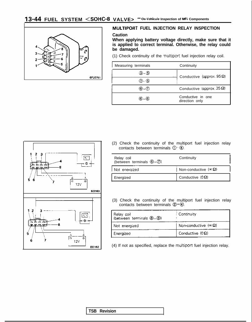
‘13-44 FUEL SYSTEM <SOHC-8 VALVE> - On-Vehicule Inspection of MFI Components
6FUO751
EC1163
When applying battery voltage directly, make sure that itis applied to correct terminal. Otherwise, the relay couldbe damaged.(1) Check continuity of the multiport fuel injection relay coil.
I Measuring terminals Continuity
MULTIPORT FUEL INJECTION RELAY INSPECTION
Caution
111 Conductive (approx. 9551)
Conductive (approx. 35 52)
@-@I Conductive in onedirection only
(2) Check the continuity of the multiport fuel injection relaycontacts between terminals @-@.
TSB Revision
Relay coil(between terminals @>-a)
ContinuityI
Gienergized 1 Non-conductive (=S2)
Energized Conductive (OQ)
(3) Check the continuity of the multiport fuel injection relaycontacts between terminals 0-O.
(4) If not as specified, replace the multiport fuel injection relay.

FUEL .SYSTEM <SOHC-8 VALVE> - On-Vehicule Inspection of MFI Components 13-45
ENGINE CONTROL MODULE POWER GROUND MlJYDAA
control module
Engine control module
p7 v101
F
106
Engine control module connector
01A0191
OlL0838
1
OPERATIONGrounding of the engine control module.
TROUBLESHOOTING HINTSIf there is incorrect or incomplete contact of the en-aine control module’s ground line, the engine con-?rol module will not function correctly.
HARNESS INSPECTION
TSB Revision
IJ Engine control moduleharness side connector Check for continuity of the ground
circuit wiring.* Engine control module connector:
Disconnected
harness
--* !!%nd
Rind)

13-46 FUEL SYSTEM <SOHC-8 VALVE> - On-Vehicule Inspection of MFI Components
FUEL PUMP MlBYEAB
@ Component sideconnector
-
\ 1 Fuel pumpM
$1I -
MultiportfuelinjectionrelayComponent side 7/-
/
L2 :<
\
6’
_!
4,
@connector ,
I-~ i1
SlLl”’-- ----
-., \OFF IOIL ,’e-
\/ \/ 1\/ \/
5 1
2 ’-
I
I T - - - - - -
1 !
check terminal - 5EL1200j
Enginecontrolmodule
@ Harness sideconnector@ Harness side
connector
I6FU1236
Engine control module connector
OlLO838
TSB Revision I

FUEL SYSTEM <SOHC-8 VALVE> - On-Vehicule Inspection of MFI Components 13-47
OPERATIONl Activates the fuel pump during engine cranking
and while the engine is running.l When the ignition switch is set to the START
position, current flows, by way of the multiportfuel injection relay coil, from the ignition switchto ground. As a result, the multiport fuel injec-tion relay switch is switched ON, and the powerfor activation of the fuel pump is supplied, byway of the multiport fuel injection relay switch,from the battery to the fuel pump.
INSPECTIONUsing Scan tool
l While the engine is running, the engine controlmodule switches ON the power transistor, afterwhich current f lows to the multiport fuel injec-tion relay coil, and the power for activation ofthe fuel pump is supplied to the fuel pump.
l When the multiport fuel injection relay switch isswitched ON, battery voltage is also applied tothe engine control module, and so the enginecontrol module detects the fact that the powerfor activation of the fuel pump is being suppliedto the fuel pump.
Function Item No. Actuation Inspection conditions Description Normal condition
Actuator test 07 Actuates fuel . Engine cranking Hold the return hose Pulsation can be felt.pump, clrcu- . Fuel pump forced between two fingerslating fuel. activation so as to feel the
The inspection pulsation of the flow-should be conducted ing of fuel.for both of the aboveconditions. Listen to the pump Pump sound can be
sound at a place near heard.the fuel tank.
Check for continuity of the groundcircuit. I
. ;E;;,, pump connector: Discon-
2 1Y- ! Repair theharness.@El-
@ Harness Ground)connector
O~AOZOl3
ICheck for continuity between the fuelpump and the checking terminal.
connector: Discon-
1
@uide 1
B0 . ;;;;,, pump
L
Check the fuel pump.. Apply battery voltage to the check-
ing terminal and operate the pump.
!I:7
OK
connector :1= 6FUl238
TSB Revision

13-48 FUEL SYSTEM <SOHC-8 VALVE> - On-Vehicule Inspection of MFI Components
Check for continuity between thechecking terminal and the enginecontrol module, and between themultiport fuel Injection relay termi-nals.
connector01 A0579
. Multiport fuel injection relay con-nector: Disconnected
. Engine control module connec-tor: Disconnected
. Fuel pump connector : Discon-netted
Repair theharness.
Measure the power supply voltage ofthe multiport fuel injection relay.. Multiport fuel injection relay con-
Harness sideconnector
Engine controlmodule harness Check for an open-circuit, or a short-side connector circuit to ground, between the multi-
port fuel injection relay and the en-gine control module.. Multiport fuel injection relay con-
nectar: Disconnected. Engine control module connec-
tor: DisconnectedRepair the
-+ harness.(@a-8)
Harness sideconnector
@
Check for continuity, of the groundcircuit.- Multiport fuel injection relay con-
nectar: Disconnected.
Repair theharness.
a vmil-Ground)
@ Harness sideconnector
Check for an open-circuit, or a short-circuit to ground, between the multi-port fuel injection relay and the fuelw-we Multiport fuel injection relay con-
nector: Disconnected. Fuel pump connector : Discon-
nettedRepair the
-+ harness.
GilIl-@El)T
OlA0401
MULTIPORT FUEL INJECTION RELAY INSPECTIONRefer to P.13-44.
TSB Revision

FUEL SYSTEM <SOHC-8 VALVE> - On-Vehicule Inspection of MFI Components 13-49
VOLUME AIR FLOW SENSOR
@ ;;vonentconnector
Intake air amount(Wsec) 162451
Multipoh fuelinjection relay
Volume air flow sensor /\2/\N
Harness sideconnector
IHjhcillo)1. 10
f-i5V
Enginecontrolmodule
MlOYFAA
J 6FU1394
OPERATIONl The volume air flow sensor is incorporated
within the air cleaner; it functions to convert theamount of engine air intake to pulse signals of afrequency proportional to the amount of engineair intake, and to input those/signals to the en-gine control module. The engine control modulethen, based upon those signals, calculates theamount to fuel injection, etc.
TROUBLESHOOTING HINTSHint 1:If the engine sometimes stalls, try starting the en-gine and shaking the volume air flow sensor har-ness.If the engine then stalls, incorrect or improper con-tact of the volume air flow sensor connector is theprobable cause.Hint 2:If, when the ignition switch is switched ON (but theengine is not started), the volume air flow sensoroutput frequency is any value other than zero, amalfunction of the volume air flow sensor or of theengine control module is the probable cause.Hint 3:If idling is possible even though the volume air flowsensor output frequency is deviated from the stand-ard value, the cause is usually a malfunction otherthan of the volume air flow sensor.
l The power for the volume air flow sensor issupplied from the multiport fuel injection relayto the volume air flow sensor, and is groundedat the engine control module. The volume airflow sensor, by intermitting the flow of the 5Vvoltage applied from the engine control module,produces pulse signals.
Examples:(1) The flow of air within the volume air flow sensor
is disturbed. (Air duct disconnection or cloggedair cleaner element)
(2) Incomplete combustion within a cylinder.(Malfunction of spark plugs, ignition coil, injec-tors, compression pressure, etc.)
(3) Air is taken into the intake manifold through aleaking gasket, etc.
(4) Incomplete close contact of the EGR valve seat.
TSB Revision

13-50 FUEL SYSTEM <SOHC-8 VALVE> - On-Vehicule Inspection of MFI Components
INSPECTION
Using Scan Tool
Item No. Data display Inspection conditions
12 Sensor de-tection airvolume (fre-quency)
. Engine coolanttemperature: 85-95°C(185-205°F)
. Lights, cooling fan, elec-trical accessories: OFF
. Transaxle: neutral (iVTmodels: “P” range) Racing Frequency in-
creases as racingrpm increases.
NOTEThe volume air flow sensor output frequency may be about 10% higher than indicated above when the vehicle is new[driven approximately 500 km (300 miles) or less].
Regular waveform 03A0203
HARNESS INSPECTION
@Harness sideconnector
6 0-0
~
0=
Using Oscilloscope
(1) Run the engine at idle speed.(2) Connect the probe to the osilloscope pick-up point as
shown in the circuit diagram, and check the wave form.
Measure the power supply voltage.. Connector: Disconnected. Ignition switch: ON --P
I Repair the
Harness sideconnector
Measure the terminal voltage.. Connector: Disconnected. Ignition switch: ON ~ 0OK ’ 3
0
Repair theharness.cm-an)
TSB Revision 1

FUEL SYSTEM <SOHC-8 VALVE> - On-Vehicule Inspection of MFI Components I%51
Harness sideCheck for continuity of the groundcircuit.. Connector: Disconnected
@+A
Repair theharness.
@3l-FiBill
J
INTAKE AIR TEMPERATURE SENSOR MlJYGAA
Volume air flow
s e n s o r ) \
Intake airtemperature sensor
Temperature16Z456 L-
@ Volume air flowsensor connector
Harness side connector I
rEGine control module A 24 ,
wTemperature
1621008
&5V 17FUO479
OPERATIONl The intake air temperature sensor functions to sensor; it passes through the intake air temper-
convert the temperature of the air (intaken to ature sensor, which is a type of resistor, and isthe engine) to voltage, and to input that voltage grounded at the engine control module.(as signals) to the engine control module. The Note that the resistance of the intake air tem-engine control module, based upon those sig- perature sensor decreases when the tempera-nals, then corrects the amount of fuel injection, ture of the intake air increases.etc. l The intake air temperature sensor terminal vol-
l The 5V power supply within the engine control tage becomes higher when the resistance ofmodule is supplied, by way of the resistance the intake air temperature sensor increases, andwithin the unit, to the intake air t empera tu re becomes lower when the resistance decreases.
TSB Revision
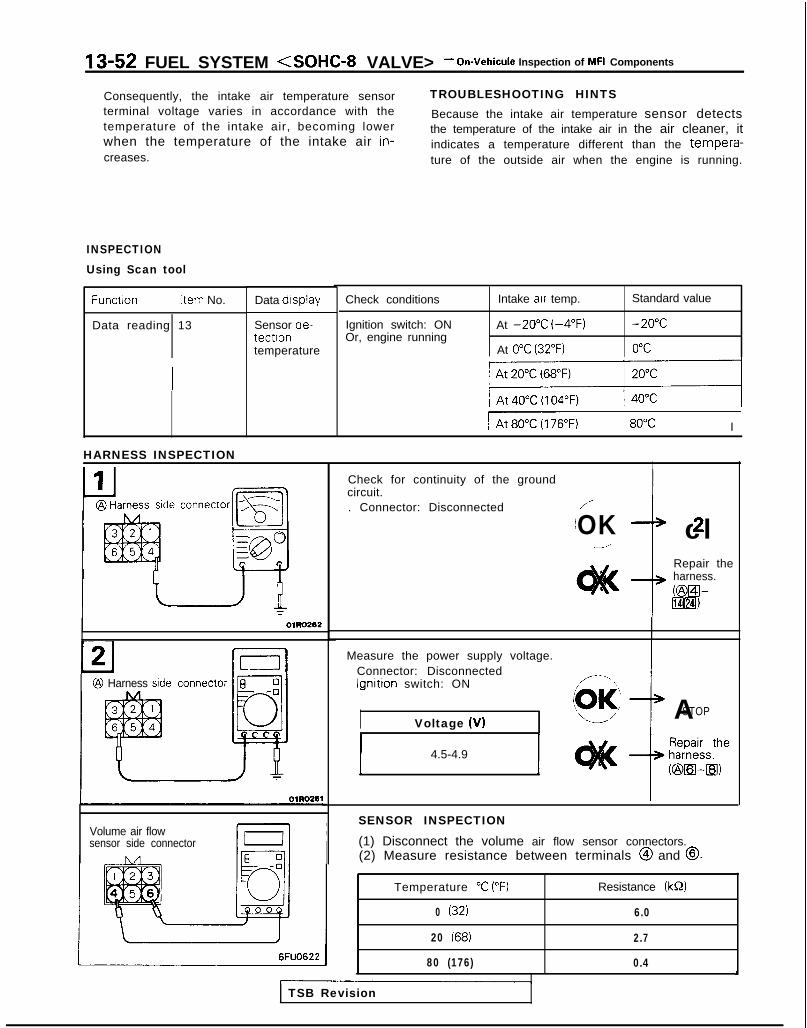
13-52 FUEL SYSTEM <SOHC-8 VALVE> - On-Vehicule Inspection of MFI Components
Consequently, the intake air temperature sensorterminal voltage varies in accordance with thetemperature of the intake air, becoming lowerwhen the temperature of the intake air in-creases.
TROUBLESHOOTING HINTSBecause the intake air temperature sensor detectsthe temperature of the intake air in the air cleaner, itindicates a temperature different than the tempera-ture of the outside air when the engine is running.
INSPECTIONUsing Scan tool
Function Item No.
Data reading 13
Data display
Sensor de-tectlontemperature
connector -,-S=
[ ary:EQOn
OlRO262
Check conditions
Ignition switch: ONOr, engine running
Intake air temp.
At -20°C (-4°F)
At 0°C (32°F)
Standard value
-20°C
0°C
IAt60~) I 80°C I
HARNESS INSPECTIONI
@ Harness side connector 8 0-0JillI54
T
Volume air flowsensor side connector
Check for continuity of the groundcircuit.. Connector: Disconnected /-
/OK cl2--/
Repair theharness.@El-lT$lH)
IMeasure the power supply voltage.
Connector: DisconnectedIgnition switch: ON
I ASTOPVoltage (V)
1 4.5-4.9 1
SENSOR INSPECTION
(1) Disconnect the volume air flow sensor connectors.(2) Measure resistance between terminals @ and @.
6FUO622
Temperature “C (“F)
0 (32)
20 (68)
80 (176)
Resistance (kS2)
6.0
2.7
0.4 A
TSB Revision

FUEL SYSTEM <SOHC-8 VALVE> - On-Vehicule Inspection of MFI Components 13-53
BAROMETRIC PRESSURE SENSORVolume air
Barometric.pressuresensor
lutput Voltage
ECl53.
Barometnc pressure mmHg 760 ~~1551
(3) Measure resistance while heating the sensor using a hairdrier.
Tempera tu re “C (“F) Resistance (kQ)
Higher Smaller
(4) If the value deviates from the standard value or the resist-ance remains unchanged, replace the volume air flow sen-sor assembly.
MlBYHAA
@ Volume air flowsensor connector
@ Harness sideconnector
t
113 j23 b ‘I 24j i
IEngine control module
6FU1293
Enaine control module connector
OlL0838
OPERATIONl The barometric-pressure sensor functions to
convert the barometric pressure to voltage, andto input that voltage (as signals) to the enginecontrol module.The engine control module, based upon thosesignals, then corrects the amount to fuel injec-tion, etc.
l The 5V power supply within the engine controlmodule is supplied to the barometric-pressuresensor; it passes through the circuitry within thesensor, and is grounded at the engine controlmodule.
l The barometric-pressure sensor output voltageis sent to the engine control module in propor-tion to the barometric pressure (absolute pres-sure).
TSB Revision I

13-54 FUEL SYSTEM <SOHC-8 VALVE> - On-Vehicule Inspection of MFI Components
TROUBLESHOOTING HINTSHint 1: Hint 2:
If there is a malfunction of the barometric-pressure If, during high-speed driving, there is a noticeable
sensor, driveability of the vehicle will become worse sharp d rop o f t he d i sp layed p ressu re o f t hebarometric-rxessure sensor, check for clogging ofparticularly at hig’h a l t i tude .the air cleaner.
INSPECTIONUsing Scan tool
Altitude Standard value ICheck conditionsItem No. Data display
25 Sensor detec-tion pressure
Function
Data reading Ignition switch: ON At 0 m (0 ft.) 760 mmHg
At 600 m(1,969ft.j
710 mmHg
I
At 1,200 m 660 mmHg(3,937 ft.)
At 1,800 m(5,906 ft.)
610 mmHgI
HARNESS INSPECTION
Check for continuity of the groundcircuit.. Connector: Disconnectedconnector L,?
laFigg-
CI
e
Repair theharness.KBEil-IBHZI)
Measure the power supply voltage ofthe barometric oressure sensor.. Connector: Disconnected. Ignition switch: ON
Harness sideconnector
Check for an open-circuit or a short-circuit to ground between the enginecontrol module and the barometricpressure sensor.f Volume air flow sensor connector:
Disconnected
Engine controlmodule harness
@ Harness side side connector
Engine control module connec-tor: Disconnected Repair the
harness.
ozsEl-~)
1 TSB Revision

FUEL SYSTEM <SOHC-8 VALVE> - On-Vehicule Inspection of MFI Components 13-55ENGINE COOLANT TEMPERATURE SENSOR Ml3wAB
Coolant- tempera& Coolant temperature
Harness side Component side Engine coolant temperature sensorIconnector connector I -
1 5EL12011I I
A14”24 A20
Enginecontrolmodule If9-3
5v
6FU1239
OPERATIONl The engine coolant temperature sensor func-
tions to convert the barometric pressure to vol-tage, and to input that voltage (as signals) to theengine control module.The engine control module, based upon thosesignals, regulates the amount ot fuel injectionand the fast-idling speed when the engine iscold.
l The 5V power supply within the engine controlmodule is supplied, by way of the resistancewithin the unit, to the engine coolant tempera-ture sensor; it passes through the enginecoolant temperature sensor, which is a type ofresistor, and is grounded at the engine controlmodule.
TROUBLESHOOTING HINTSif, during engine warm-up, the fast-idling speed isnot correct, or black smoke is emitted the problemis usually a malfunction of the engine coolant tem-perature sensor.
Note that the resistance of the engine coolanttemperature sensor decreases when the tem-perature of the coolant increases.
l The engine coolant temperature sensor terminalvoltage becomes higher when the resistance ofthe engine coolant temperature sensor in-creases, and becomes lower when the resist-ance decreases. Consequently, the enginecoolant temperature sensor terminal voltage va-ries in accordance with the temperature of thecoolant, becoming lower when the temperatureof the coolant increases.
TSB Revision

13-56 FUEL SYSTEM <SOHC-8 VALVE> - On-Vehicule Inspection of MFI Components
INSPECTIONUsing Scan tool
Function Item No.
Data reading -*LI
Data display
Sensor de-tectiontemperature
HARNESS INSPECTION
connector
OlLO461
Check conditions
Ignition switch: ONOr, engine running
Coolant temperature Standard value
At -20°C (-4°F) -20°C
At 0°C (32°F) 0°CI
At 20°C (68°F) 20°C
c o n n e c t o r - Ic
OIL0463L
-16R1251
Temperature “C (“F) Resistance (kS2)
0 (32) 5.9
20 (68) 2.5
40 (104) 1.1
80 (176) 0.3
(3) If the resistance deviates from the standard value greatlyreplace the sensor.J
TSB Revision
At 40°C (104°F) 40°C
At 80°C (176°F) 80°C
1
Check for continuity of the groundcircuit.. Connector: Disconnected
Repair theharness.b&[email protected]
Measure the power supply voltage. I. Connector: DisconnectedIgnition switch: ON
Voltage (VI
SENSOR INSPECTION(1) Remove engine coolant temperature’ sensor from the
intake manifold.(2) With temperature sensing por t ion of engine coolant
temperature sensor immersed in hot water check resist-ance.
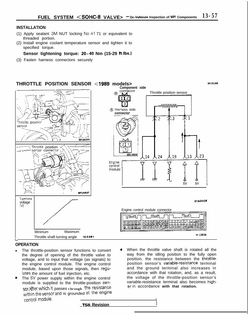
FUEL SYSTEM <SOHC-8 VALVE> - On-Vehicule Inspection of MFI Components 13-57
INSTALLATION(1) Apply sealant 3M NUT locking No.41 71 or equivalent to
threaded portion.(2) Install engine coolant temperature sensor and tighten it to
specified torque.
Sensor tightening torque: 20-40 Nm (15-29 ft.lbs.1(3) Fasten harness connectors securely
THROTTLE POSITION SENSOR <I989 models>
-(‘Throttle position a\ “ ’
6FUO637
TerminalvoltageWI
L
Minimum Maximum01 LO838
Throttle shaft turning angle 162461
Component sideThrottle position sensor
connector
olAO336
Engine control module connector
Ml3YJAE
OPERATIONl The throttle-position sensor functions to convert 0 When the throttle valve shaft is rotated all the
the degree of opening of the throttle valve to way from the idling position to the fully openvoltage, and to input that voltage (as signals) to position, the resistance between the throttle-the engine control module. The engine control position sensor’s variable-resistapce terminalmodule, based upon those signals, then regu- and the ground terminal also increases inlates the amount of fuel injection, etc. accordance with that rotation, and, as a result,
0 The 5V power supply within the engine control the voltage of the throttle-position sensor’smodule is supplied to the throttle-position sen- variable-resistance terminal also becomes high-
SOT after which it passes through the resistanceer in accordance with that rotation.
w&in the sensor and is grounded at the engine
COMO\ module.TSB Revision I

13-58 FUEL SYSTEM <SOHC-8 VALVE> - On-Vehicule Inspection of MFI Components
TROUBLESHOOTING HINTSHint 1: Hint 2:The signals of the throttle-position sensor are more If the voltage of the throttle-position sensor deviatesimportant for control of the automatic transaxle than from the standard value, check once again afterfor control of the engine; shifting “impact shocks” making the throttle-position sensor adjustment.are produced if there is a malfunct ion of thethrottle-position sensor.
INSPECTIONUsing Scan tool
Function / Item No. 1 Data display 1 Inspection conditions 1 Throttle valve 1 Standard value
Data reading 14 Sensor vol-tage
Ignition switch: ON heldfor 15 sec. or more
HARNESS INSPECTION
E q-0JJ ~@ Harness side 0
connector
@ Harness sideconnector
Harness sideconnector
Measure the power supply voltage ofthe throttle position sensor.. Connector:’ Disconnected. Ignition switch: ON
Check for continuity of the groundcircuit.
Connector: Disconnected
Repair theharness.bZilZl-m*&I)
Check for an open-circuit, or a short-circuit to ground, between the enginecontrol module and the throttle posi-
. Throttle position sensor connector:
Engine control module connector:Disconnected Repair the
harness.Fi&TUI-mj
01103611
TSB Revision

FUEL SYSTEM <SOHC-8 VALVE> - On-Vehicule Inspection of MFI Components 13-59
Re
Blu
THROlTLE POSITION SENSOR
SENSOR INSPECTION(1) Disconnect the throttle position sensor connector, and
connect the special tool (Test harness) between thedisconnected connectors.
(2) Measure the resistance between terminal @ (black clip ofspecial tool) and terminal @ (red clip) of the connector onthrottle position sensor side.
Standard value: 3.5-6.5 kS2
(3) Measure the resistance between terminal @ (black clip ofspecial tool) and terminal @ (blue clip).
Open the throttle valve slowly Resistance should vary fromfrom idle position to fully open approx. 0.5 kQ to 3.5-6.5 kQposition smoothly in proportion to
change in throttle valve opening
(4) If the resistance does not conform with specification, ordoes not vary smoothly, replace the throttle positionsensor.
Throttle position sensor installation torque:1.5-2.5 Nm (1.1-1.8 ft.lbs.1
<From 1990 models> M13YJAF
Component srde@ connector Throttle posltlon Sensor
I
Harness side@ connector
m 1,. I,, .I,, I,, It,~$-T~ ;I
TerminalvoltageIV1
Engine control module connector
Minimum Maximum01 LO.0838
Throttle shaft turning angle 102461
TSB Revision

13-60 FUEL SYSTEM <SOHC-8 VALVE> - On-Vehicule Inspection of MFI Components
OPERATIONTROUBLESHOOTING HINTSINSPECTION-Using Scan toolRefer to P.13-57.
HARNESS INSPECTION
Measure the power supply voltage ofthe throttle positlon sensor.. Connector: Disconnected. Ignition switch: ON
6FU1241
. Connector: Disconnected
6FU1242
Er’ ” I
miglne controlodule harness Check for an open-circuit, or a short-
side connector circuit to ground between the engineI control module and the throttle posi-
tion sensor.19!!F!= 6FU1243
. Throttle position sensor connector:Disconnected 0OK
. Engine control module connector:Disconnected
rASTOP
L I \:
Throttle posltlon/
sensor connector 6FU1244
Repair theharness.
i
K292Ha)
SENSOR INSPECTION(1) Disconnect the throttle position sensor connector.(2) Measure resistance between terminal @ (sensor ground)
and terminal @ (sensor power).
Standard value: 3.5-6.5 kQ(3) Connect a pointer type ohmmeter between terminal @
(sensor ground terminal) and terminal @ (sensor outputterminal).
(4) Operate the throttle valve slowly from the idle position tothe fu l l open pos i t i on and check tha t t he res i s tancechanges smoothly in proport ion wi th the throt t le valveopening angle.
(5) If the resistance is out of specification, or fails to changesmoothly, replace the throttle position sensor.
Throttle position sensor installation torque:1.5-2.5 Nm (1.1-1.8 ft.lbs.)
TSB Revision

FUEL SYSTEM <SOHC-8 VALVE> - On-Vehicule Inspection of MFI Components 13-61
CLOSED THROTTLE POSITION SWITCH <I989 models> MlBYKAE
c o n t r o l - Idle speed controlmotor connector
@ Component sideconnector
@ Harness sideconnector
I I
ISC plunger
_---__
III *
Throttle shaft turning angle
0 1 2 0 9 2
-
Engine control module
16
3
OFFaION
-z
Closed throttleDosition switch
lFUO479
OPERATIONl The closed throttle position switch functions to
convert (to HIGH/LOW-level voltage) data as towhether the accelerator is depressed or re-leased, and to input that voltage (as signals) tothe engine control module. The engine controlmodule, based upon those signals, regulates theidle-speed control motor.
TROUBLESHOOTING HINTS
l Voltage within the engine control module is ap-plied, by way of the resistance, to the closedthrottle position switch.When the foot is taken off the accelerator, theclosed throttle position switch is switched ON,so the current is grounded.As a result, the closed throttle position switchterminal voltage changes from HIGH to LOWlevel.
If there is an abnormal condition of the closed throt-tle position switch output even though the resultsof the checking of the closed throttle positionswitch harness and of the component itself indicatea normal condition, the cause may be presumed tobe one of the following.
TSB Revision
(1) Improper adjustment of the accelerator cable orthe automatic-cruise-control cable.
(2) Improper adjustment of the fixed SAS.

13-62 FUEL SYSTEM <SOHC-8 VALVE> - On-Vehicule Inspection of MFI Components
INSPECTION
Using Scan tool
Function Item No.
Data reading 26
Data display Inspection conditions
Switch status Ignition switch: ON(Check after pumpingaccelerator several times.)
Throttle valve Normal indication
To idle position ON
Slightly opened OFF
HARNESS INSPECTION
Harness sideconnector
YOlR085
motor connector1 FUO480
Measure the power supply voltage ofthe closed throttle position switch.. Connector: Disconnected. Ignition switch: ON
I Voltage (V) I
I 4 or more I
Repair theharness.c@a-m)
SENSOR INSPECTION(1) Disconnect the idle speed control motor connector.(2) Check the continuity between terminal @ and body ground.
TSB Revision
I Accelerator Dedal I Continuitv IDepressed Non-conductive (42)Released Conductive (0. Q)
(3) If out of specification, replace the idle speed control motorassembly.
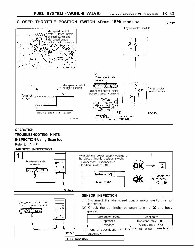
FUEL SYSTEM <SOHC-8 VALVE> - On-Vehicule Inspection of MFI Components 13-63
CLOSED THROTTLE POSITION SWITCH <From 1990 models>
Engine control module
M13YKAf
Idle speed controlmotor (Closed throttleposition switch andidle speed controlmotor cosition sensor)
Idle speed control/ plunger position
Throttle shaft -x-ring angle -
0 1 2 0 9 2
Idle speed control motorposition sensor connector/ c- ~ IONrZi i ???FT%;e’ TA’,- a
Closed throttleposition switch
/cmgso,l ,“,“,‘;a;;o;ide
6FU1245
OPERATIONTROUBLESHOOTING HINTSINSPECTION-Using Scan toolRefer to P.13-61.
HARNESS INSPECTION
0II @ Harness side
connector
\L I
6FU1246
6Fu12a
(2) Check the continuity between terminal @ and bodyground.
Accelerator pedal ContinuityDepressed Non-conductive (ma)
I Released I Conduc t i ve (0. Q) 1
(3) If out of specification, rep\ace the idle speed corm\ motor
7 / assembly.
TSB Revision
Measure the power supply voltage ofthe closed throttle position switch.. Connector: Disconnected. Ignition switch: ON
SENSOR INSPECTION /(1) Disconnect the idle speed control motor position sensor
connector.
I
II

IS-64 FUEL SYSTEM <SOHC-8 VALVE> - On-Vehicule Inspection of MFI Components
IDLE SPEED CONTROL MOTOR POSITION SENSOR <I989 models> MIOWAD
@ Component side Idle speed control motorconnector position sensor
l - F - - - -@ Harness side I--
connector
i5EL1402,
4, 0
t t
1 3 A23 A17 A14 A24Enginecontrolmodule
:5v 5v
lFUO514
Fnnirw rnntrol module connector
Plunger strokeOlROlOl OlL0838
OPERATIONl The idle speed control motor position sensor
functions to convert the data concerning theposition of the plunger (located within the idle-speed control motor) to voltage, and to inputthat voltage (as signals) to the engine controlmodule. The engine control module, based uponthose signals, then functions to regulate theidle-speed control motor.
l The 5V power supply within the engine controlmodule is supplied to the idle speed controlposition sensor; it then passes through the re-sistance within the sensor and is grounded atthe engine control module.
TROUBLESHOOTING HINTSHint 1’The idle speed control motor position sensor is themost important sensor for control of the idlingspeed; there is very often a malfunction of this sen-sor if a problem occurs when the ,engine load iscaused to fluctuate, such as when, during idling, theair conditioning switch is switched back and forthbetween OFF and ON, etc.
l When the plunger located within the idle-speedcontrol motor extends from its contracted con-dition, the resistance between the idle speedcontrol motor position sensor’s variable-resist-ance terminal and the ground terminal also in-creases in accordance with that extension. As aresult, the voltage of the idle speed controlmotor position sensor’s variable-resistance ter-minal also becomes higher in accordance withthe extension.
Hint 2:If the output voltage of the idle speed control motorposition sensor deviates from the standard valueeven though the results of the checking of the idlespeed control motor position sensor harness and ofthe component itself are normal, the malfunctionmay be presumed to be among the following:
TSB Revision1

FUEL SYSTEM <SOHC-8 VALVE> - On-Vehicule Inspection of MFI Components 13-65
(1) Improper adjustment of the basic idling speed.(2) Deposits adhering to the ttirottle valve.(3) Air being taken into the intake manifold due to a
gasket leak, etc.
OPERATIONISC motor position sensor is a variable resistor type,and is integrated in the ISC motor system. The slid-ing pin of ISC motor position sensor is in contactwith the end of the plunger. Therefore, as the plun-ger moves, the internal resistance of ISC motor pos-ition sensor varies. This leads to the variation of the
(4) Improper seating of the EGR valve seat.(5) lmcomplete combustion within a cylinder. (Mal-
function of spark plugs, ignition coil, injectors,compression pressure, etc.)
the plunger position of the ISC motor system, andsends the signal to ECM. ECM processes the ISCmotor position sensor signal, idle signal, coolanttemperature signal, load signal (A/T & A/C) and ve-hicle speed signal to control the opening angle ofthe throttle valve and revolution speed during en-
output voltage. ISC motor position sensor detects gine idling.
TROUBLESHOOTING HINTSSince idling is not controlled when ISC motor posi-tion sensor is troubled, idling may not be evenlymaintained.
INSPECTION
Using Scan tool
Function Item No. Data display Inspection conditions Load conditions Standard value
Data reading 15 Sensor detec- . Engine coolant tempera- Air conditioning 500- 1,300 mVtion voltage ture: 85-95’C (185-203°F) switch: OFF
. Lights, cooling fan, electricalaccessories: OFF Air conditioning 800- 1,800 mV
. Transaxle: neutral (A/T mod- switch: ONels: “P” range)
1 Closed throttle position Air conditioning 900- 1,900 mVswitch: ON (The compressor switch: ONclutch must be operating Select lever:when the air conditioning shift to “D”switch is ON.) range.
* Engine: running at idle
NOTEThe idle speed control motor position sensor output voltage may be about 500 mV higher than indicated above whenthe vehicle is new [driven approximately 500 km (300 miles) or less].
CautionBefore shifting the select lever to the “D” range, apply the brakes to prevent the vehicle from moving forward.
HARNESS INSPECTION
Measure the power supply voltage ofthe idle speed control motor position
ei;;;it;;sco$ected
__...._ -.-
TSB Revision

13-66 FUEL SYSTEM <SOHC-8 VALVE> - On-Vehicule Inspection of MFI Components
Harnesssdeconnector I
OlAO362
@ Harness sideconnector
Engine controlmodule harnessside connector
I-
r
MD998464 6FUO666
MD998464 6FUo666
A
Check for continuity of the groundcircuit.. Connector: Disconnected
t
Repair theharness.@iDI-•.l&l)
Check for an open-circuit, or a short-circuit to ground between the enginecontrol module and the idle speedcontrol motor position sensor.* Engine control module connector:
f-
A1
Disconnected. idle speed control motor position
sensor connector: DisconnectedRepair theharness.~@[z1-8)
I
SENSOR INSPECTIONDisconnect the idle speed control motor position sensorconnector, and connect the special tool (test harness) tothe connector on idle speed control motor position sensorside.Measure the resistance between terminal @ (black clip ofspecial tool) and terminal 0 (white clip) of the idle speedcontrol motor position sensor connector.
Standard value: 4-6 kS2(3) Disconnect the idle speed control motor connector.
(4) Connect a 6V DC power supply between terminals 0 and@ of the idle speed control motor connector to activate(extend and retract) the idle speed control motor. Measurethe resistance between terminal @ (black clip of specialtool) and terminal 0 (red clip) of the idle speed controlmotor position sensor connector.
Standard value: Smooth increase/decrease in ac-cordance with extension and retrac-tion of idle speed control motorplunger.
CautionApply only a 6V DC or lower voltage. Application ofhigher voltage could cause locking of the servo gears.
(5) If there is a deviation from the standard value, or if thechange is not smooth, replace the idle speed control motorassembly.
TSB Revision

.-•r 12-67FUEL SYSTEM <SOHC-8 VALVE> - On-Vehicule Inspection of MFI Compontl=a m - - =
IDLE SPEED CONTROL MOTOR POSiTiON SENSOR < F r o m 1990 m o d e l s > MlOWAE
@ Component sideconnector Idle speed control mc)tor position sensor
‘{*q-r
T@ Harness side L
connector
Voltagebetween@n-@B1.
Plunger strokeI 01R0101
I-@=%260jlEn$eecontrol
I3 A23 ’A L
7 A14 " 2 4
I!-Engine control module connector
6FU1246
01 LO838
OPERATIONTROUBLESHOOTING HINTSINSPECTION-Using Scan toolRefer to P.13-64.
HARNESS INSPECTIONL
L-J1@ Harness side
connector
Measure the power supply voltage ofthe idle speed control motor positionsensor.* Connector: Disconnected- Ignition switch: ON
Check for continuity of the groundcircuit.. Connector: Disconnected
Repair theharness.@[zI E l -m , [231,
TSB Revision \
Repair theharness.K&y-m*

13-68 FUEL SYSTEM <SOHC-8 VALVE> - On-Vehicule Inspection of MFI Components
Engine controlmodule harnessside connector
Check for an open-circuit, or a short-circuit to ground, between the enginecontrol module and the idle speedcontrol motor position sensor.. Engine control module connec-
tor: Disconnected. Idle speed control motor position
sensor connector: Disconnected
0O K 1 ASTOP
i
Repair theharness.KzEwDlfl,
!
Idle speed control motorposition sensor connector 6FU1252
Idle speed controlmotor connector
\ A
6FU1253-
SENSOR INSPECTION(1) Disconnect the idle speed control motor position sensor
connector.(2) Measure the resistance between terminals @ and 0.
Standard value: 4-6 k&2I) Disconnect the idle speed control motor connector..) Connect DC 6V between terminals @ and @ of the idle
speed control motor connector, and then measure the re-sistance between terminals @ and @ of the idle speedcontrol motor position sensor connector when the idlespeed control motor is activated (caused to expand andcontract).
Standard value: Smooth increase/decrease in ac-cordance with expansion and con-traction of the idle speed controlmotor plunger.
CautionApply only a 6V DC or lower voltage. Application ofhigher voltage could cause locking of the servo gears.
(5) If there is a deviation from the standard value, or if thechange is not smooth, replace the idle speed control motorassembly.
TSB Revision

FUEL SYSTEM <SOHC-8 VALVE> - On-Vehicule lnwection of MFI Components 13-69
CAMSHAFT POSITION SENSOR <Up to 1990 models>
\ /‘4 i I ‘j6FUO857
r1
Out put characteristic
‘“!I pm
One rotation of distributorOlR0102
Ignition switch (IG,)
~~~!%k?nt side ,Distributor4 3
Camshaft position sensor
Distributorconnector
5EL1401
@ Harness sideconnector T
Engine control module A22V
L
6FU1255
OPERATIONl The camshaft position sensor functions to de-
tect the top dead center position of the No. 1cylinder and to convert those data to pulse sig-nals that are input to the engine control module.The engine control module, based upon thosesignals, calculates the sequence of fuel injec-tion.
TROUBLESHOOTING HINTSIf there is a malfunction of the camshaft positionsensor, the sequential injection will not be correct,
l The power for the camshaft position sensor issupplied from the ignition switch-IG and isgrounded to the vehicle body. The camshaftposition sensor, by intermitting the flow (toground) of the 5V voltage applied from the en-gine control module, produces pulse signals.
resulting in such problems as engine stalling, un-stable idling, and poor acceleration.
TSB Revision I

‘13-70 FUEL SYSTEM <SOHC-8 VALVE> - On-Vehicule inspection of MFI Components
(1) Run the engine at the idle speed.(2) Connect the probe to the oscilloscope pick-up point in the
5v - - circuit diagram, and check the waveform.
ov -Normal waveform
6FU1395
HARNESS INSPECTION
IJHarcon@
Measure the power supply voltage.. Connector: Disconnected. Ignition switch: ON
switch)
ZJHarness sideconnector
--[a/T
Ygp
TT
,
TSB Revision
Check for continuity of the groundcircuit.. Connector: Disconnected
Repair theharness.@El-Ground)
Check the voltage of the output cir-cuit.. Connector: Disconnected. Ignition switch: ON

FUEL SYSTEM <SOHC-8 VALVE> - On-Vehicule Inspection of MFI Components 13-71
CAMSHAFT POSITION SENSOR <From 1991 models> MlBYU8
sensor /
WV?
: ( I 6FUO857
Out put charactenstic
I- > Time
One rotatton of distributor01 R0102
@ Component sideconnector
Ignition switch (IG,)I
\/ \/ \/\/ \/ \/
4 2
&T]
f-b9r
Engine control module A 22
h5v
OPERATIONTROUBLESHOOTING HINTSINSPECTION-Using OscilloscopeRefer to P.13-69.
HARNESS INSPECTION
Harness sideconnector@
7FUO49tr1 TSB Revision
Measure the power supply voltage.. Connector: Disconnected. Ignition switch: ON
Voltage (V)
Battery positive voltage
Iswitch)

13-72 FUEL SYSTEM <SOHC-8 VALVE> - On-Vehicule Inspection of MFI Components
2 Harness stde Check for continuity of the groundcircuit.Connector: Disconnected
Repair theharness.
* Fzml-Ground)
7FUO497
. Connector: Disconnected
. Ignition switch: ON
TSB Revision

FUEL SYSTEM <SOHC-8 VALVE> - On-Vehicule inspection of MFI Components 13-73
CRANKSHAFT POSITION SENSOR <Up to 1990 models> MllYMAA
\I DikZ!utoJP
[VI 1 Out put characteristic
One rotation of distributor
Ignition switch (IG,)
@ Component sideconnector Distributor 3
Distributorconnector
@ Harness sideconnector
/ CraTSiti0 y$/
A 21 Engine control module
LD5vL I
6Fu1256
OPERATIONl The crankshaft position sensor functions to de-
tect the crank angle (position) of each cylinder,and to convert those data to pulse signals,which are then input to the engine control mod-ule. The engine control module, based uponthose signals, calculates the engine rpm, andalso regulates the fuel injection timing and theignition timing.
TROUBLESHOOTING HINTSHint 1:If an impact is suddenly felt during driving or the en-gine suddenly stalls during idling, try shaking thecrankshaft position sensor during idling.If the engine stalls, the cause may be presumed tobe improper or incomplete contact of the crank-shaft position sensor’s connector.Hint 2:If the crankshaft position sensor output rpm is 0rpm during cranking when the engine cannot bestarted, the cause may be presumed to be a mal-
l The power for the crankshaft position sensor issupplied from the ignition switch-IG and isgrounded to the vehicle body. The crankshaftposition sensor, by intermitting the flow (toground) of the 5V voltage applied from the en-gine control module, produces pulse signals.
function of the crankshaft position sensor or a bro-ken timing belt.Hint 3:If the indicated value of the crankshaft position sen-sor output rpm is 0 rpm during cranking when theengine cannot be started, the cause may be pre-sumed to be a failure of the ignition coil’s primarycurrent to intermittently pulse correctly, so a mal-function of the ignition system circuitry, the ignitioncoil and/or the ignition power transistor is the prob-able cause.
TSB Revision 1
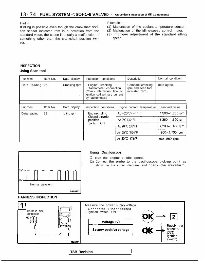
13-74 FUEL SYSTEM <SOHC-8 VALVE> - On-Vehicule inspection of MFI Components
Hint 4:If idling is possible even though the crankshaft posi-tion sensor indicated rpm is a deviation from thestandard value, the cause is usually a malfunction ofsomething other than the crankshaft position sen-sor.
Examples:(1) Malfunction of the coolant-temperature sensor.(2) Malfunction of the idling-speed control motor.(3) Improper adjustment of the standard idling
speed.
INSPECTIONUsing Scan tool
Function Item No.
Data reading 22
Data display Inspection conditions Description Normal condition
Cranking rpm . Engine: Cranking Compare cranking Both agree.. Tachometer connection rpm and scan tool(Check intermittent flow of indicated rpm.
_ ignition coil primary currentby tachometer.)
Function
Data reading
Item No.
22
Data display 1 Inspection conditions 1 Engine coolant temperature 1 Standard value 1
1 At 40°C (104°F) 1 900-1,100rpm 1I I I -I
( At 80°C (176°F) 1 150-850 rpm
Normal waveform
03AO202
HARNESS INSPECTION
Ilr I
Using Oscilloscope(1) Run the engine at idle speed.(2) Connect the probe to the oscilloscope pick-up point as
shown in the circuit diagram, and check the waveform.
Harness sideconnector@
Measure the power SUPPIY voltaoe.. Connec to r : D i sconnec ted -. Ignition switch: ON
1 TSB Revision

FUEL SYSTEM <SOHC-8 VALVE> - On-Vehicule lnsoection of MFI Comoonents 13975
@ Harness srdeconnector
@ Harness sideconnector
Check for continuity of the groundcircuit.. Connector: Disconnected
1 Reoair the
t
hainess.(@B-Ground)
Check the voltage of the output cir-cuit.. Connector: Disconnected. ignition switch: ON
uO K ASTOP
Repair theharness.(@m-m)
CRANKSHAFT POSITION SENSOR <From 1991 models> MIBYMAB
m/i / i 6FUO6571
[VI 1 Output characteristic
@ Component sideconnector
Ignition switch (IG1)
One rotation of crankshaftposition sensor
01R0’05
TSB Revision
Engine control module ,( 21
m---l 7F”04pp
I

13-76 FUEL SYSTEM <SOHC-8 VALVE> - On-Vehicule Inspection of MFI Components
OPERATIONTROUBLESHOOTING HINTSINSPECTION-Using Scan toolINSPECTION-Using OscilloscopeRefer to P.13-73.
HARNESS INSPECTION
7
7FlJO49t
@Harness sideconnector
7FUO497
ISS stde connector
Measure the power supply voltage.. Connector: Disconnected. Ignition switch: ON
Voltage (VI
Battery positive voltageI
cl2Repair theharness.K%l-Ignitionswitch)
Check for continuity of the groundcircuit,
Connector: Disconnected
Repair theharness.@RI-Ground)
Check the voltage of the output cir-cuit.. Connector: Disconnected. Ignition switch: ON 0O K
a@
Repair theharness.vi!iaI-m1,
TSB Revision

FUEL SYSTEM <SOHC-8 VALVE> - On-Vehicule Inspection of MFI CmpOnentS 13977IGNITION SWITCH-ST <M/T>
Engine control module connectorI I
Enginecontrolmodule
01 LO838
Ignition switch (ST)
7
Tr108 104
T-7JL
6FU1257
OPERATIONl The ignition switch-ST inputs HIGH-level signals l When the ignition switch is set to START, the
to the engine control module during engine battery voltage during engine cranking is, bycranking. The engine control module, based on way of the ignition switch, applied to the enginethose signals, regulates fuel injection during control module, and the engine control modulestarting, etc. thus detects the fact that the engine is cranking.
INSPECTIONUsing Scan tool
Function Item No. 1 Data display Inspection conditions Engine Normal indication
Data reading 18 Switch status Ignition switch: ON Stopping OFF
Cranking ON
HARNESS INSPECTlON
Engine controlmodule harnessside connector
Measure the input voltage to the en-gine control module.. Engine control module connector:
Disconnected- Ignition switch: START
r 6FU1259 i
Repair theharness.
@El-Ground)
TSB Revision

13-78 FUEL SYSTEM <SOHC-8 VALVE> - On-Vehicule inspection of MFI Components
IGNITION SWITCH-ST AND PARK/NEUTRAL POSITION SWITCH <A/T> MI3YOAa
Park/neutral position s( I ‘\\ \
1 lclnition switch (ST)
Componentside connector@
108
Engine ’controlmodule
Harness side@I connector
I 7
Engine control module connector
OlLO838
OPERATIONl The ignition switch-ST inputs HIGH-level signals
to the engine control module during enginecranking. The engine control module, based onthose signals, regulates fuel injection duringstarting, etc.
l When the ignition switch is set to START, thebattery voltage during engine cranking is, byway of the ignition switch and the park/neutralposition switch, applied to the engine controlmodule, and the engine control module thus de-tects the fact that the engine is cranking.Note that battery voltage is not applied to theengine control module if the position of the se-lector lever is other than the “P” or “N” range.
l The park/neutral position switch functions toconvert the voltage to HIGH level or LOW level
TROUBLESHOOTING HINTSIf the output of the park/neutral position switch isabnormal even though the results of the checkingof the park/neutral position switch harness and of
depending upon whether the selector lever is atthe “P” or “N” range or is at some position otherthan the “P” or “N” range, and inputs the resultto the engine control module. The engine con-trol module, based upon those signals, then reg-ulates the operation of the idle speed controlmotor.
l Battery voltage within the engine control mod-ule is applied, by way of the resistance, to thepark/neutral position switch. When the selectorlever is set to the ‘7” or “N” range, continuity iscreated, via the starter motor, between the en-gine control module’s park/neutral positionswitch terminal and ground, and the terminalvoltage becomes LOW level.
the component itself are normal, it is probable thatthe cause is improper adjustment of the controlcable.
TSB Revision

FUEL SYSTEM <SOHC-8 VALVE> - On-Vehicule Inspection of MFI Components 13-79
INSPECTIONUsing Scan toolIgnition switch-ST
Function Item No. Data display Check conditions Engine Normal display
Data reading 18 Switch status . Ignition switch: ON Stopped OFF
Cranking ON
Park/neutral position switch
Function Item No. Data display Check conditions Selector lever position Normal display
Data reading 29 Shift position . Ignition swatch: ON Por N Por N
D, 2, Lor R D, 2, L or R
HARNESS INSPECTION
Harness sideconnector
Engine control Measure the input voltage of enginecontrol module.. Engine control module connector:
Disconnected. Park/neutral position switch con-
nector: Connected* Selector lever: “P” range. Ignition switch: START
Voltage (V)
:
1
Y-OlLO42’f
PARK/NEUTRAL POSITION SWITCH INSPECTION
Measure the power supply voltage ofthe park/neutral position switch.. Engine control module connector:
Disconnected. Park/neutral position switch con-
nector: Disconnected
Check the
I+ powersupply cir-cuit.
Measure the park/neutral positionswitch terminal input voltage.* Engine control module connector:
ConnectedPark/neutral position switch con-nector: Disconnected
8 or more
ASTOP
Repair theharness.C@WlIEI)
Refer to GROUP 23-Troubleshooting.TSB Revision I
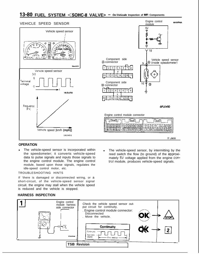
13-80 FUEL SYSTEM <SOHC-8 VALVE> - On-Vehicule Inspection of MFI Components
VEHICLE SPEED SENSOR
Vehicle speed sensor
Vehicle speed sensorIV1
-errnInafoltage
102418
Frwyy 1 /
Component side@ connector
Component side@ connector
6FU1410
Engine controlmodule5v
MIBVPAA
Vehicle speed sensor
Engine control module connector
Vetwle speed [km/h (mph)]
1 6 2 4 5 1
OlLO838
OPERATIONl The vehicle-speed sensor is incorporated within
the speedometer; it converts vehicle-speeddata to pulse signals and inputs those signals tothe engine control module. The engine controlmodule, based upon those signals, regulates theidle-speed control motor, etc.
TROUBLESHOOTING HINTS
l The vehicle-speed sensor, by intermitting by thereed switch the flow (to ground) of the approxi-mately 5V voltage applied from the engine con-trol module, produces vehicle-speed signals.
If ‘there is damaged or disconnected wiring, or ashort-circuit, of the vehicle-speed sensor signalcircuit. the engine may stall when the vehicle speedis reduced and the vehicle is stopped.
HARNESS INSPECTION
- side connector_--- _ia_, - .,:_--gp p
L
11 Engine controlmodule harness
=l01AOW(1
I
Check the vehicle speed sensor out-put circuit for continuity.. Engine control module connector:
Disconnected. Move the vehicle.
) TSB Revision

FUEL SYSTEM <SOHC-8 VALVE> - On-Vehicule Inspection of MFI Components 13-81
@ Harness sideconnector
6FU1265
n8171615141312 1
1 9 11 7 1 6 1 5 1 4 1 3 1 2 ~ 1 ~ 1 0
I
Measure the power supply voltage ofthe vehicle speed sensor.. Connector: Disconnected. Ignition switch: ON 6&lo
I w IVoltage (V)
I 4.5-4.9 --I Repair theharness.ozml-•el)
I II
Check for continuity of the groundcircuit.
Connector: Disconnected
Repair theharness.@WGround)
SENSOR INSPECTIONRefer to GROUP 54-Meters and Gauges.
POWER STEERING PRESSURE SWITCH MI3Yclha
------LI~lI I ’ 6FUO65f
TSB Revision
Engine
Power steering 1 @bl
Harness sideconnector
Enoine control module connector

13-82 FUEL SYSTEM <SOHC-8 VALVE> - On-Vehicule Inspection of MFI Components
OPERATIONl The power-steering pressure switch functions
to convert data as to whether there is or is not apower steering load to LOW-or HIGH-level vol-tage, and the resulting signals are input to theengine control module. The engine control mod-ule, based upon those signals, regulates theidle-speed control motor.
l The battery voltage within the engine controlmodule is applied, by way of the resistance, tothe power-steering pressure switch. Whensteering maneuvers are made, the pressure ofthe power-steering oil increases, thus switchingON the power-steering pressure switch, withthe result that the current is grounded. As a re-sult, the power-steering pressure switch vol-tage changes from HIGH level to LOW level.
INSPECTIONI) Using Scan tool
Function Item No.
Data reading 27
Data display Inspection conditions Steering wheel Normal indication
Switch status Engine: Idling Steering wheel idle state OFF
During steering wheel ONoperation
(2) Checking Oil Pressure
Steering wheel
Straight forward
Turned
Oil pump delivery pressure (ref. value)
less than 1,470- 1,961 kPa (213-284 psi)
more than 1,470- 1,961 kPa (213-284 psi)
HARNESS INSPECTION
I-E-IHarness side connector 6 0@ =- -0
Q4 1
Measure the power supply voltage.. Connector: Disconnected. Ignition switch: ON
[ TSB Revision

FUEL SYSTEM <SOHC-8 VALVE> - On-Vehicule inspection of MFI Components 13-83
AIR CONDITIONING SWITCH AND A/C COMPRESSOR CLUTCH RELAY M13YRAE
Air conditioning switch
Sub fl
FUSC ?
Air conditic@ compressc
clutch relal
Magneticclutch
Jsibie li
7
)ningIr /k
!Ik 171 control unitAuto compressor
- -)N
Engine control 65module A I 7
‘1
6FU1411
Engine control module connector
IhJ-Jl r--vrJ=-Jl/l
OlLO838
OPERATIONl The air conditioning switch applies battery vol-
tage to the engine control module when the airconditioning is switch is switched ON.
TROUBLESHOOTING HINTSIf the air conditioning compressor’s magnetic clutchis not activated when the air conditioning switch isswitched ON during idling, it is probable that the
l When the air conditioning signals are input, theengine control module activates the idle-speedcontrol motor, and also switches ON the powertransistor. AS a result, current flows to thepower relay coil and the relay switch isswitched ON, the air conditioning compressor’smagnetic clutch is activated.
cause is a malfunction of the air conditioning controlsystem.
TSB Revision

13-84 FUEL SYSTEM <SOHC-8 VALVE> - On-Vehicule Inspection of MFI Components
INSPECTIONUsing Scan toolAir conditioning switch
Function Item No.
Data reading 28
Data display Check conditions Air conditioning switch Normal display
Switch status . Engine idling (The air OFF OFFconditioning com-pressor should be ac- ON ONtivated when the airconditioning switch isswitched ON.)
Air conditioning compressor clutch relay
Function
Data reading
Item No. Data display
49 Air condition-ing compres-sor clutchrelay status
Check conditions
. Engine: idling afterwarm up
HARNESS INSPECTION
Air conditioning switch Normal display
OFF OFF (Compressorclutch non-activation)
ON ON(Compressorclutch activation)
,--=+aI
_I Engine controlmodule harnessside connector
OlROB13
Measure the power supply voltage ofthe air conditioning circuit.. Engine control module connector:
Disconnected. ignition switch: ON* Air conditioning switch: ON 4 ASTOP
Check theair condi-tioning cir-cuit.
AIR CONDITIONING INSPECTIONRefet to GROUP 55-Air conditioning.
TSB Revision

FUEL SYSTEn rll (SOHC-8 VALVE> - On-Vehicule Inspection of MFI Components 13-85EGR TEMPERATURE SENSOR <Calif.>
Ml3Yza
\+\+I connectorComponent side EGR temperaturn r-n~nr
r Harness side@ connector
6FlJ1412
1 I wTemperature lEzlooB
OPERATIONl The EGR temperature sensor functions to con-
vert the data regarding the temperature of theEGR gas downstream from the EGR valve tovoltage, and to input that voltage (as signals) tothe engine control module.
l The 5V power supply within the engine controlmodule is supplied, by way of the resistancewithin the unit, to the EGR temperature sensor;it passes through the EGR temperature sensor,which is a type of resistor, and is grounded atthe engine control module.Note that the resistance of the EGR temperature
6FU1269
sensor decreases when the EGR gas volumeincreases and the temperature of the EGR gasincreases.
l The EGR temperature sensor terminal voltagebecomes higher when the resistance of the EGRtemperature sensor increases, and becomeslower when the resistance decreases.Consequently, the EGR temperature sensorterminal voltage varies in accordance with thetemperature of the EGR gas, becoming lowerwhen the temperature of the EGR gas in-creases.
TSB Revision I

13-86 FUEL SYSTEM <SOHC-8 VALVE> - On-Vehicule inspection of MFI Components
Using Scan tool
Function Item No. Data display Inspection conditions Engine condition Standard value
Data reading 43 Sensor . Engine: warm up 750 rpm (Idling) 70°C or lowertemperature . Engine is maintained in a
constant state for 2 minutes 3,500 rpm 70°C or higheror more
. Remove the vacuum hose(green stripes) from the EGRsolenoid and plug both theremoved vacuum hose endand solenoid valve nipple.
HARNESS INSPECTION
Harness sideconnector@qqJI
I IEL -:f7Q,
L * A’-1I
01.0523
Measure the power supply voltage.. Connector: Disconnected. Ignition switch: ON
Harness sideconnector
Check for continuity of the groundcircuit.. Connector: Disconnected
SENSOR INSPECTIONRefer to GROUP 17-Exhaust Gas Recirculation (EGR) System.
-wSTOP
TSB Revision
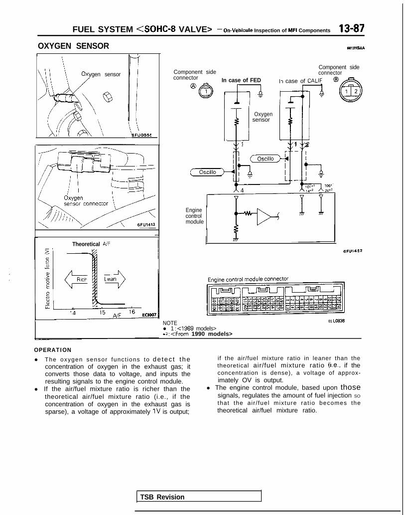
FUEL SYSTEM <SOHC-8 VALVE> - On-Vehicule Inspection of MFI Components 13-87
OXYGEN SENSOR M13VSAa
/
Oxygen sensor)G/’ ‘;‘@
i b\A
-I
6FUO659
Theoretical A/F
Component sideComponent sideconnector
connector In case of FED In case of CALIFI r
Oxygensensori klJI -
1 1 2
Enginecontrolmodule
6FU1452
NOTE 01 Lo836
l 1 : <I989 models>*2: <From 1990 models>
OPERATIONl The oxygen sensor funct ions to detec t the
concentration of oxygen in the exhaust gas; itconverts those data to voltage, and inputs theresulting signals to the engine control module.
l If the air/fuel mixture ratio is richer than thetheoretical air/fuel mixture ratio (i.e., if theconcentration of oxygen in the exhaust gas issparse), a voltage of approximately 1V is output;
if the air/fuel mixture ratio in leaner than thetheoretical air/fuel mixture ratio (Le., if theconcentration is dense), a voltage of approx-imately OV is output.
l The engine control module, based upon thosesignals, regulates the amount of fuel injection SO
that the air / fuel mixture rat io becomes thetheoretical air/fuel mixture ratio.
TSB Revision

13-88 FUEL SYSTEM <SOHC-8 VALVE> - On-Vehicule Inspection of MFI Components
TROUBLESHOOTING HINTSHint I’The exhaust gas purification performance will
Examples:(1) Malfunction of an injector.
worsen if there is a malfunction of the oxygensensor.Hint 2:If the oxygen sensor output voltage deviates fromthe standard value even though the results of thechecking of the oxygen sensor are normal, thecause is probably a malfunction of a componentrelated to mixture control.
(2) Air leakage into the intake manifold from aleaking gasket.
(3) Malfunction of the volume air flow sensor, theintake air temperature sensor, the barometric-pressure sensor, or the engine coolant tempera-ture sensor.
Data reading
INSPECTIONUsing Scan tool
HARNESS INSPECTION
Data display
Sensor de-tection vol-tage
Inspection conditions Engine condition Standard value
Engine: warm up When sudden decel- 250 mV or lower(Make the mixture lean eration from 4,000 rpmby engine speed reduc-tion, and rich by racing) When engine is sud- 500- 1,000 mV
denly raced
Engine: warm up 750 rpm (Idling)(using the oxygen sen-sor sianal. check the air/
400 mV or lower
I I (changes)
fuel mixture ratio, and 600-l ,000 mValso check the condition 2,000 rpmof control by the enginecontrol module)
I CALIF@I Hal
FEDHarness
ness side connector
Engine controlmodule harnessside connector
Check for an open-circuit, or a short-circuit to ground between the enginecontrol module and the oxwen sen- f7_- ~~SOT. ‘-. r$;rdn sensor connector: Drscon-
. Engine control module connector:Disconnected
CALIFHarness side
Check for continuity of the ground.“‘..“...;;”Repair theharness.KEEI-Ground)
1
TSB Revision

FUEL SYSTEM <SOHC-8 VALVE> - On-Vehicule inspection of MFI Components 13-89
:Federab
:California>
Ea
SENSOR INSPECTIONCaution1. Before checking, warm up the engine until engine
coolant temperature reaches 85 to 95°C (185 to 205°F).2. Use an accurate digital voltmeter.(1) Disconnect the oxygen sensor connector and connect a
voltmeter to the oxygen sensor connector.(2) While repeating engine racing, measure the oxygen sensor
output voltage.,
I Engine Oxygen sensoroutput voltage Remarks
Race 0.6-l .OVMake air-fuel mixture
rich by acceleratoroperation
NOTEFor removal and installation of the oxygen sensor, refer toGROUP 15-Exhaust Manifold.
Oxygen sensor installation torque: 40-50 Nm(30-36 ft.lbs.1
TSB Revision I

13-90 FUEL SYSTEM <SOHC-8 VALVE> - On-Vehicule Inspection of MFI Components
INJECTORS
Fuel
Connector
Solenoid coilPlunger
Needle valve -----IInjection
Filter
6FUO514
M13rrAA
Multiport fuel injection relay
No.1 &j No.2& No.3& No,4+
t IlFUO642
Engine control module connector
CJ=JW=U-I0 1 LO636
OPERATIONl The injectors are electromagnetic-valve-
equipped injection nozzles that function to injectfuel based upon injection signals from theengine control module.
l Because the surface area of the injection ports isfixed and because the pressure of the fuelrelative to the pressure within the manifold isalso regulated to a fixed pressure, the amount offuel injection by injectors is determined by the
TROUBLESHOOTING HINTSHint 1:If there is a problem with starting while the engine iswarm, perform the combustion test and check forleakage of the injectors.Hint 2,If the engine can’t be started, and the injectors arenot activated during cranking, the cause is probablya malfunction such as described below, not with theinjectors.(I) Malfunction of the circuit for supply of power to
the engine control module, or of the ground cir-cuit.
(2) Malfunction of the multiport fuel injection relay.(3) Malfunction of the crankshaft position sensor
and/or the camshaft position sensor.Hint 3.If there is a cylinder for which the idling conditiondoes not change when, during idling, the fuel
length of time that the needle valve is open, or,in other words, by the length of time of current
~-
flow to the solenoid coil.l Battery power supply is supplied, by way of the
multiport fuel injection relay, to the injectors.When the engine control module switches ONthe power transistor within the unit and currentflows to the solenoid coil, the injectors open andfuel is injected.
injection of the injectors is cut off in sequence,check that cylinder as described below.(1) Check the injector and harness.(2) Check the spark plugs and the high-tension
cable.(3) Check the compression pressure.Hint 4:If the injector activation time deviates from thestandard value even though the results of thechecking of the injector’s harness and of the injectoritself are normal, the cause may be pressumed tobe one of the following,(1) Incomplete combustion within the cylinder.
(Malfunction of the spark plugs, the ignition coil,the compression pressure, etc.)
(2) Incomplete close contact of the EGR valve seat.(3) Increased engine resistance.
1 TSB Revision I

FUEL SYSTEM <SOHC-8 VALVE> - On-Vehicule Inspection of MFI Components 13-91INSPECTIONUsing Scan tool
Function Item No. Data display
Data reading 41 III~~~ion
Inspection conditions Engine coolant temperature Standard value
Engine cranking At 0°C (3~2°F)“~ Approx. 21 ms
At 20°C (68°F) Approx. 43 ms
At 80°C (176°F) Approx. 10 ms
Function Item No.
Data reading 41
L
Data display
Ac&a$ion
Inspection conditions
. Engine coolant tempera-ture:85-95°C (185-205°F)
* Lights, cooling fan, electric-al accessories: OFF
. Transaxle: neutral(A/T models: “P” range)
Engine condition Standard value I
750 rpm (Idling) 2.5-4.0 msI
NOTE*I: The injector activation time indicates the time under the following conditions: a power source voltage of 11V and a
cranking rpm of 250 rpm or less.**: Simultaneous injection at four cylinders when engine coolant temperature is 0°C (32°F).*3: The injector activation time may be about 10% longer than indicated above when the vehicle is new [driven
approximately 500 km (300 miles) or less].
Function Item No.
Actuator test 01
02
03
04
Description
No. 1 injector is shut off.
No. 2 injector is shut off.
No. 3 injector is shut off.
No. 4 injector is shut off.
Inspection conditions Normal indication
Engine: idling after warm The idling conditionchanges more.
r”sput off the injectors in (Either becomes more un-sequence during after stable, or engine stalls.)engine warm-up, checkthe idling condition.)
- I i-. --.-~-
db$- A: Injector~__
Normal waveform drrve time
HARNESS INSPECTION
1P
Using Oscilloscope(1) Run the engine at idle speed.(2) Connect the probe to the oscilloscope pick-up point as
shown in the circuit diagram, and check the waveform atthe drive side of each injector.
Measure the power supply voltage ofthe injector.. Connector: Disconnected. Ignition switch: ON
TSB Revision
I
I
4
i1
k j i,v,
11
\YIY’ .

13-92 F U E L S Y S T E M <SOHC-8 V A L V E > - On-Vehicule Inspection of MFI Components
21Harnesssideconnector
g *’
gr
module harnessside connector
-rlFUO643
‘/ 6FUO870
Check for an open-circuit, or a short-circuit to ground between the enginecontrol module and the injector.. Engine control module connector:
Disconnected. Injector connector: Disconnected
:
ASTOP
Repair theharness.
ACTUATOR INSPECTIONCHECKING OPERATION SOUNDUsing a sound scope, check the operation sound (“chi-chi-chi”)of injectors during idling or during cranking.Check that as the rotating speed increases, the frequency ofthe operating sound also increases.
CautionNote that even if the injector you are checking is notoperating, you will hear the operating sound of the otherinjectors.NOTEIf no operating sound is heard from the injector that is beingchecked, check the injector drive circuit. If there is nothingwrong with the circuit, a defective injector or engine controlmodule is suspected.
MEASURING RESISTANCE BETWEEN TERMINALS(1) Remove the injector connector.(2) Measure the resistance between the terminals.
Standard value: 13-16 Q [at 20” (68”F)](3) Install the injector connector.
TSB Revision

FUEL SYSTEM <SOHC-8 VALVE> - On-Vehicule Inspection of MFI Components 13-93
IDLE SPEED CONTROL MOTOR (DC MOTOR)
Idle speed control 9-/m o t o r /---T-,I \
6FUO852
i id l -Idle speed -control
r 1 /&46~U0838
Harness side@ connector
< 1989 models>Enoine control module
M13YUAF
Component sideconnector
!
a,Yg
z.-t;Fs8
B
1 2d Idlespeedcontrol
M motor
lFUO495
Engine control module connector
1
OPERATIONl The volume of intake air during idling is reg-
ulated by the opening and closing of the throttlevalve, caused by expansion and contraction ofthe servo plunger.
l The servo plunger expands or contracts inaccordance with whether the DC motor (locatedwithin the idle speed control motor) is driven inthe forward or reverse direction.
l The DC motor is driven in either the forward orreverse direction according to the direction ofswitching of the current flow of the motor-activation IC within the engine control module.
TROUBLESHOOTING HINTSIf there is unstable idling or engine stalling, etc., andit is difficult to presume the cause of the problem,switch ON the ignition switch and leave as is for 15seconds or longer; then disconnect the servoconnector.
HARNESS INSPECTION
The cause of the problem can then be easilypresumed by checking in this condition.Note that, if necessary, the engine speed adjustingscrew should be turned to adjust the engine rpm.
I connector
Engine controlmodule harnessside connector
II
rIsEI
r-
r-
II
01.03,~ ITSB Revision
Check for an open-circuit, or a short-circuit to ground between the engine
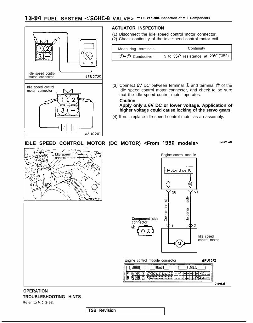
13-94 FUEL SYSTEM <SOHC-8 VALVE> - On-Vehicule Inspection of MFI Components
1
Idle speed controlmotor connector
Idle speed controlmotor connector
6FUO750
6FUO9&
ACTUATOR INSPECTION(1) Disconnect the idle speed control motor connector.(2) Check continuity of the idle speed control motor coil.
Measuring terminals Continuity
0-0 Conductive 5 to 359 resistance at 20°C (68°F)
(3) Connect 6V DC between terminal @I and terminal @ of theidle speed control motor connector, and check to be surethat the idle speed control motor operates.
CautionApply only a 6V DC or lower voltage. Application ofhigher voltage could cause locking of the servo gears.
(4) If not, replace idle speed control motor as an assembly.
IDLE SPEED CONTROL MOTOR (DC MOTOR) <From 1990 models>
Component sideconnector@ 43m00
Engine control module
77 V
s.- :z
'ZcE Es I2
21 <\2
Idle speedcontrol motor
MlOYUAG
Engine control module connector 6FU1275
OPERATIONTROUBLESHOOTING HINTSRefer to P. ? 3-93.
TSB Revision

FUEL SYSTEM <SOHC-8 VALVE> - On-Vehicule inspection of MFI Components 13-95
HARNESS INSPECTION
3 Harnesssideconnector
Engine controlmodule harnesssde connector
+ 6FU1276
I I
Lit02
Idle speed controlmotor connector 6FU1277
6FU1253
Check for an open-circuit, or a short-circuit to ground between the enginecontrol module and the idle speedcontrol motor.
Repair the-+ harness.
OZGII-8@m-8)
TSB Revision
ACTUATOR INSPECTION(1) Disconnect the idle speed control motor connector.(2) Check continuity of the idle speed control motor coil.
Measuring terminals Continuity
0-0 Conductive 5 to 3552 resistance at 20°C (68°F)
(3) Connect 6V DC between terminal @ and terminal @ of theidle speed control motor connector, and check to be surethat the idle speed control motor operates.
CautionApply only a 6V DC or lower voltage. Application ofhigher voltage could cause locking of the servo gears.
(4) If not, replace idle speed control motor as an assembly.

13-96 FUEL SYSTEM <SOHC-8 VALVE> - On-Vehicule Inspection of MFI Components
IGNITION COIL AND IGNITION POWER TRANSISTOR
ignition coil (IGI)
Ml3WAA
Harness side@ connector 0
Harness side
Component side
Distributor \/ 2
4. I_lgnltion
. .!
I@LZ)TachcImeter timing
A? I--:*:^^ adjustment-_ Lllrnacr r;rlnI 101 i IG.72 Jl”F
Componenr side
6FU1280
OPERATIONl When the ignition power transistor unit is
switched ON by the signals from the enginecontrol module, the primary current of the igni-tion coil will flow. When the ignition power tran-sistor unit is switched OFF, the primary currentflow is interrupted, and high voltage is producedat the secondary coil.
l When the engine control module switches OFF
INSPECTION
the power transistor within the unit, the batteryvoltage within the unit is applied to the ignitionpower transistor unit, and the ignition powertransistor unit is switched ON. In addition, thepower transistor unit is switched OFF when theengine control module switches ON the powertransistor within the unit.
Using Scan tool
1 Function 1 Item No. 1 Data display / Inspection conditions / Engine condition 1 Standard value
Data reading 44 Ignitionadvance
. Engine: warm up 750 rpm (idling) 5- 15 “BTDC
. Timing light: set(Use the timing light tocheck the actual ignition 2,000 rpm 30-40 “BTDCtiming.)
1 TSB Revision
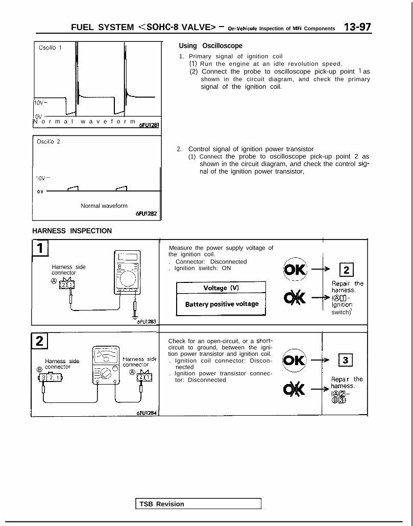
FUEL SYSTEM (SOHC-8 VALVE> - On-Vehicule Inspection of MFI Components 13-97
Oscillo 1
If-N o r m a l w a v e f o r m 6Fu,28,
lOV-
ov
i
nal of the ignition power transistor,
(1
Normal waveform6Fu1282
Using Oscilloscope1. Primary signal of ignition coil
(1) Run the engine at an idle revolution speed.(2) Connect the probe to oscilloscope pick-up point 1 as
shown in the circuit diagram, and check the primarysignal of the ignition coil.
2. Control signal of ignition power transistor(1) Connect the probe to oscilloscope pick-up point 2 as
shown in the circuit diagram, and check the control sig-
Harness sideconnector
@
HARNESS INSPECTION
III I
IMeasure the power supply voltage ofthe ignition coil.. Connector: Disconnected. Ignition switch: ON c--vOK/ III2
-‘B-6FU1283
TSB Revision
Harness side
switch)
Check for an open-circuit, or a short-circuit to ground, between the igni-tion power transistor and ignition coil.. Ignition coil connector: Discon-
nected. Ignition power transistor connec-
tor: Disconnected

IS-98 FUEL S Y S T E M <SOHC-8 VALVE> - On-Vehicule Inspection of MFI Components
Check for continuity of the groundcircuit.
IP--^^^+rrr. n;ronnnnr+prjL”,,, ,wdL”I VlJlr”l I4 IbUI”” I r-l4
I -@ Repair the
harness.@El-Ground)
Harness
6FU1285 1 I
Measure the voltage of the ‘control
@connector
6FU1286
Repair the-+ harness.
CtxHm
:6FU1287
ACTUATOR INSPECTIONRefer to GROUP 16-Ignition System.
TSB Revision I

FUEL SYSTEM <SOHC-8 VALVE> - On-Vehicule lnsuection of MFI Components 13-99
EVAPORATIVE EMISSION PURGE SOLENOID MlBYwAA
Multiport fuel injection
@ Harness sideconnector
Componentside connector
i
5EL1206
Enginecontrolmodule
TSB Revision
Evaporative emission
62
Engine control module connectorI,
OlLO838
OPERATIONl The evaporative emission purge solenoid is an
ON/OFF type of solenoid valve; it functions toregulate the introduction of purge air from theevaporat ive emission canister to the intakemanifold plenum.
INSPECTIONUsing Scan tool
l Battery power supply is supplied, by way of themultiport fuel injection, to the evaporative emis-sion purge solenoid. When the engine controlmodule switches ON the power transistorwithin the unit, current flows to the coil, andpurge air is introduced.
I Function 1 Item No. 1 Activation 1 Check conditions 1 Normal condition
Actuator test 08 Solenoid valve is switched from . Ignition switch: ON Operating sound is heardOFF to ON. when driven.

13-100 FUEL SYSTEM <SOHC-8 VALVE> - On-Vehicule Inspection of MFI Components
HARNESS INSPECTION
1
2PIzj----=2T !r/
‘3“L jk&
-&@ Harness side
connector 6FUO967
Measure the power supply voltage.Connector: DisconnectedIgnition switch: ON
Voltage (V)Repair theharness.
-* (Multiportfuel injec-tion relay-@B3)
1Battery positive voltage 1
P2 _Fq,/-\i-1- /-
F
&--Y
Enginecontrolmoduleharnesssideconnector
=m
Check for an open-circuit, or a short-circuit to ground between the evapo-rative emission purge solenoid and /-Athe engine control module.* Evaporative emission purge sole-
noid connector: Disconnected. Enaine control module connec--a ~~
tor: Disconnected
6FUO973 1
ACTUATOR INSPECTIONRefer to GROUP 17-Evaporative Emission Control System.
TSB Revision

FUEL SYSTEM <SOHC-8 VALVE> - On-Vehicule Inspection of MFI Components 13-101
EGR SOLENOID <Calif.>
L
Multiport fuel injection
EGR solenoid
Component@I side connector
_ ”Enginecontrolmodule
L OlW557
01 LO838
OPERATIONl The EGR solenoid is a duty-control type of sole-
noid valve; it performs its control function byleaking the EGR valve-activation vacuum to thethrottle body A port.
TROUBLESHOOTING HINTSIf the diagnostic trouble code for EGR systemmalfunction is output even though the results ofchecking the EGR solenoid harness and the
INSPECTION
l Battery power supply is supplied, by way of themultiport fuel injection, to the EGR solenoid.When the engine control module switches OFFthe power transistor within the unit, currentstops flowing to the coil, and the EGR valve-ac-tivation negative pressure leaks.
component itself are normal, check the EGR valve,the vacuum hose piping, and the EGR passage forclogging.
Using Scan tool
Function Item No.
A c t u a t o r t e s t 10
Description Inspection conditions Normal condition
$i;;,oi$;;alve switched from Ignition switch: ON Operating sound isheard when driven.
TSB Revision

13-102 FUEL SYSTEM <SOHC-8 VALVE> - On-Vehicule Inspection of MFI Components
HARNESS INSPECTION
Harness sideconnector
L
Harness sideconnector
Engine
1controlmodule
Check for an open-circuit, or a short-circuit to ground between the EGRsolenoid and the engine control mod-
harness ule.side . EGR solenoid connector: Discon-connector nected
+ Engine control module connec-tor: Disconnected Repair the
-+ harness.Kzix2l-a)
-I
Measure the power supply voltage.. Connector: Disconnected. Ignition switch: ON
-
ACTUATOR INSPECTIONRefer to GROUP 17-Exhaust Gas Recirculatin (EGR) System.
FUEL PRESSURERELEASE OF RESIDUAL PRESSURE FROM HIGH PRESS-URE FUEL HOSEMake the following operations to release the pressure remain-
ing in fuel pipe line so that fuel will not flow out.@ Disconnect the fuel pump harness connector at the fuel
tank rear side.@ Start the engine and after it stops by itself, turn the ignition
switch to OFF.@ Disconnect the battery (-) terminal.@I Connect the fuel pump harness connector.
FUEL PUMP OPERATION CHECK(1) Connect the (+) battery terminal to the fuel pump drive
terminal and the (-) terminal to the chassis. Confirm thatthe fuel pump operates at this time.
( TSB Revision 1

FUEL SYSTEM <SOHC-8 VALVE> - On-Vehicule Inspection of MFI Components 13-103
TSB Revision
---I g$qfq, tcJ-s6FUO633
(2) Lift up the chassis, and disconnect the connector from thefuel pump which is mounted on the rear area of the fueltank.
(3) Check the terminals, wiring, etc., for damage.(4) Using an ohmmeter, check the motor continuity.
FUEL PRESSURE TEST
(1) Reduce the internal pressure of the fuel pipes and hoses.(Refer to P.13-1 OZ.)
(2) Disconnect the fuel high pressure hose at the fuel railside.
CautionCover the hose connection with shop towel to preventsplash of fuel that could be caused by some residualpressure in the fuel pipe line.
(3) Place the MD998742-01 adapter on the end of thefuel rail, then attach the fuel high pressure hose to theadapter using the bolts supplied with the MIT2 10196 fuelpressure test assembly.
(4) Attach one end of the fuel hose supplied with theMIT21 0196 to the quick-disconnect f i t t ing on theMD998742-01 adapter. Attach the other end of the hoseto the fuel pressure gauge.
(5) Connect the (-) battery terminal.
(6) Connect a jumper wire to the fuel pump check terminal andto the positive (+) terminal of the battery to activate thefuel pump. With fuel pressure applied, check to be surethat there is no fuel leakage from the fuel pressure gaugeand the special tool connection part.
(7) Disconnect the jumper wire (from the fuel pump checkterminal) to stop the fuel pump.
(8) Start the engine and let it idle.
(9) Measure the fuel pressure during idling.
Standard value: Approx. 270 kPa (38 psi) at curb idle
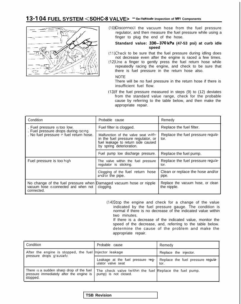
13-I 04 FUEL SYSTEM <SOHC-8 VALVE> - On-Vehicule Inspection of MFI Components
(10)Disconnect the vacuum hose from the fuel pressureregulator, and then measure the fuel pressure while using afinger to plug the end of the hose.
Standard value: 330-370 kPa (47-53 psi) at curb idlespeed
(11)Check to be sure that the fuel pressure during idling doesnot decrease even after the engine is raced a few times.
(12)&e a finger to gently press the fuel return hose whilerepeatedly racing the engine, and check to be sure thatthere is fuel pressure in the return hose also.
NOTEThere will be no fuel pressure in the return hose if there isinsufficient fuel flow.
(13)lf the fuel pressure measured in steps (9) to (12) deviatesfrom the standard value range, check for the probablecause by referring to the table below, and then make theappropriate repair.
Condition Probable cause Remedy
. Fuel pressure IS too low. Fuel filter is clogged. Replace the fuel filter.
. Fuel pressure drops during racing.
. No fuel pressure In fuel return hose. Malfunction of the valve seat with- Replace the fuel pressure regula-in the fuel pressure regulator, or tor.fuel leakage to return side causedby spring deterioration.
Fuel pump low discharge pressure. Replace the fuel pump.
Fuel pressure is too high The valve within the fuel pressure Replace the fuel pressure regula-regulator is sticking. tor.
Clogging of the fuel return hose Clean or replace the hose and/orand/or the pipe. pipe.
No change of the fuel pressure when Damaged vacuum hose or nipple Replace the vacuum hose, or cleanvacuum hose IS connected and when not clogging. the nipple.connected.
(14)Stop the engine and check for a change of the valueindicated by the fuel pressure gauge. The condition isnormal if there is no decrease of the indicated value withintwo minutes.If there is a decrease of the indicated value, monitor thespeed of the decrease, and, referring to the table below.determine the cause of the problem and make theappropriate repair.
Condition Probable cause
After the engine is stopped, the fuel Injector leakagepressure drops graudally.
Remedy
Replace the injector.
Leakage at the fuel pressure reg- Replace the fuel pressure regula-ulator valve seat tor.
There IS a sudden sharp drop of the fuel The check valve (within the fuel Replace the fuel pump.pressure immediately after the engine is pump) is not closed.stopped.
TSB Revision

FUEL SYSTEM <SOHC-8 VALVE> - On-Vehicule Inspection of MFI Components 13-105
fine probe 7FU1264 1
(15) Reduce the internal pressure of the fuel pipes and hoses.(Refer to P.13-102.)
(16) Disconnect the fuel pressure gauge and the special toolsfrom the fuel rail.
CautionBecause there will be some residual pressure in the fuelpipe line, use a shop towel to cover so that fuel doesn’tsplatter.
(17)Replace the O-ring at the end of the fuel high-pressurehose with a new one.
(18)After connecting the fuel high-pressure hose to the fuelrail, tighten the installation bolt.
(19)Check to be sure that there is no fuel leakage.@ Apply battery voltage to the terminal for activation of
the fuel pump so as to activate the fuel pump.@ With fuel pressure applied, check for leakage of the fuel
line.
INSPECTION OF ENGINE CONTROL MODULETERMINAL VOLTAGE Ml 3ZALBa(1) Connect the extremely fine probe (paper clip, etc.) to the
probe of the voltmeter.(2) At each terminal of the engine control module connector,
insert the extremely fine probe from the wire side, andmeasure the voltage referring to the check chart.
NOTE1. In the state in which the connector of the engine
control module is connected, measure the voltage.2. Measure the voltage across each terminal to the
terminal No. 106. (ground terminal).3. You may find it convenient to pull out the engine
control module to make it easier to reach the connectorterminals.
4. Inspection need not be executed in the chart’s sequence.CautionShort-circuiting the positive (+) probe between a con-nector terminal and ground could damage the vehiclewiring, the sensor, the engine control module, or allthere. Use care to prevent this!
(3) If voltmeter shows any deviation from standard value,check the corresponding sensor, actuator and relatedelectrical wiring, then repair or replace.
(4) After repair or replacement, recheck with the voltmeter toconfirm that the repair has corrected the problem.

13-106 FUEL SYSTEM <SOHC-8 VALVE> - On-Vehicule Inspection of MFI Components
TERMINAL VOLTAGE CHECK CHARTTerminal arrangement of engine control module connector
NflTF01 LO838
. .- -B+: Battery positive voltage
TerminalNo. Check condition (Engine state) Standard
value RemarksCheck item
103 Backup powersupply
lgnitron switch: OFF
102 Power supply ignition switch: ON B+
107
109 Fuel pumpdnve signal
Engine: Cranking 8V or higher
Engine: Idling B+ I
Ignition switch: ON
Engine: ldlrng
Ignition switch: ON
Engine: idling
Engine speed: 2,000 rpm
B+ I
o-3v
4.5- 5.5v
2.2- 3.2V
56
23
10
Multiport fuelinjection relay(Fuel pump)
Sensor rmpressecvoltage
Volume air flowsensor
Air intaketemperaturesensor
Ignition Air intake temperature of 0°C (32°F)switch:ON Air Intake temperature of 20°C (68°F); ji/
Air Intake temperature of 40°C (104°F) 1.5-2.1V
Air intake temperature of 80°C (176’F) 0.4- 1 .OV
Barometricpressure sensor
Ignition Altitude of 0 m (0 ft.) 3.7-4.3vswitch:ON Altitude of 1,200 m (3,937 ft.) 3.2-3.av
Engrne coolant lgnitron Coolant temperature of 0°C (32°F) 3.2-3.Wtemperature swi tch: -sensor ON Coolant temperature of 20°C (68°F) 2.3-2.9v
1 Coolant temperature of 40°C (104°F) 1 1.3- 1.9V (
) Coolant temperature of 80°C (176’F) 1 0.3-0.9V
Throttle posrtionsensor
Ignition swatch: It Set the throttle valve to theis kept ON for 15seconds or more
Closed throttleposition switch
II
I
I
-
Ignition Set the throttle valve to the idling o-1vswitch: position.3N
Slightly open the throttle valve. 4V or higher
3
16
!O
9
1 TSB Revision 1
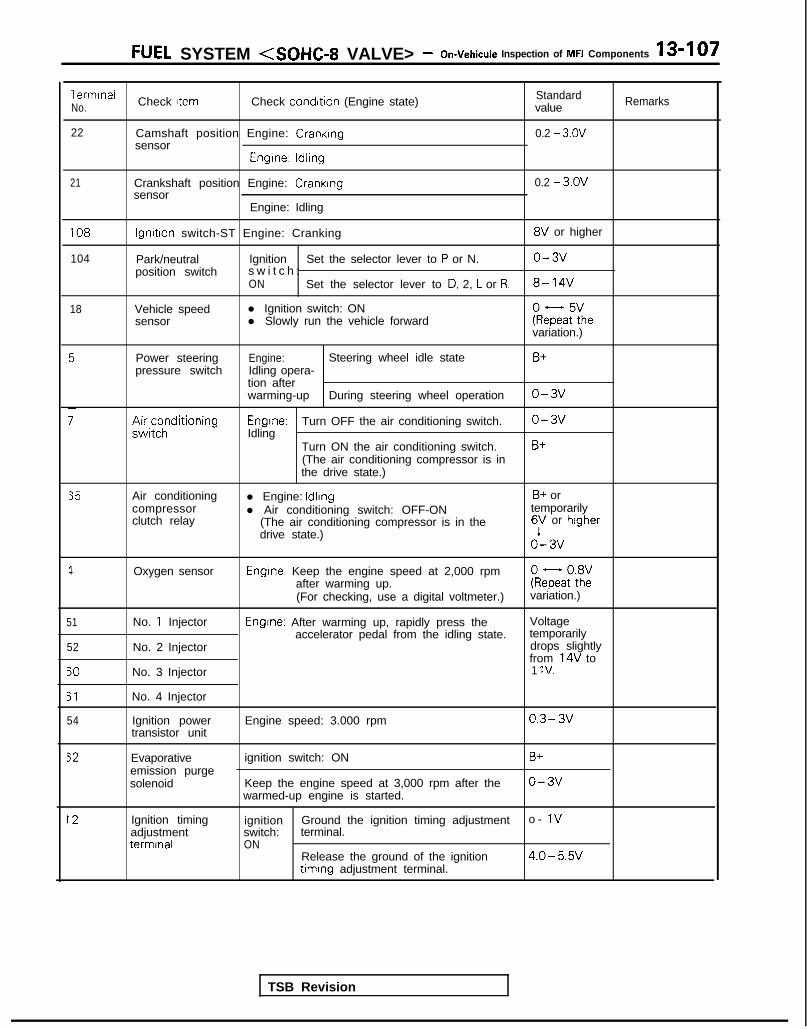
FUEL SYSTEM <SOHC-8 VALVE> - On-Vehicule Inspection of MFI Components 13-107
Terminal Check Item Check condition (Engine state) StandardNo. value Remarks
22 Camshaft position Engine: Cranking 0.2 - 3.ovsensor
Engrne: ldllng
21 Crankshaft position Engine: Crankingsensor
Engine: Idling
0.2 - 3.ov
108
104
18
lgnrtron switch-ST Engine: Cranking 8V or higher
Park/neutral Ignition Set the selector lever to P or N. o-3vposition switch s w i t c h :
ON Set the selector lever to D, 2, L or R. 8- 14V
Vehicle speed l Ignition switch: ONsensor l Slowly run the vehicle forward keFaF:he
variation.)
Power steeringpressure switch
;;ir;z;ditioning
Engine: Steering wheel idle stateIdling opera-tion afterwarming-up During steering wheel operation
Engrne: Turn OFF the air conditioning switch.Idling
Turn ON the air conditioning switch.(The air conditioning compressor is inthe drive state.)
B+
o-3v
o-3v
B+
35
1
51
52
50
51
54
Air conditioningcompressorclutch relay
Oxygen sensor
No. 1 Injector
No. 2 Injector
No. 3 Injector
No. 4 Injector
Ignition powertransistor unit
l Engine: Idling B+ orl Air conditioning switch: OFF-ON temporarily
(The air conditioning compressor is in the 6V or higherdrive state.)
o’- 3v
Engine: Keep the engine speed at 2,000 rpmafter warming up. kQatot8h2:(For checking, use a digital voltmeter.) variation.)
Engine: After warming up, rapidly press the Voltageaccelerator pedal from the idling state. temporarily
drops slightlyfrom 14V to1 IV.
Engine speed: 3.000 rpm 0.3- 3v
Evaporativeemission purgesolenoid
ignition switch: ON
Keep the engine speed at 3,000 rpm after thewarmed-up engine is started.
B+
o-3v
12 Ignition timingadjustmentterminal
ignition Ground the ignition timing adjustment o - 1vswitch: terminal.ON
Release the ground of the ignition 4.0- 5.Wtiming adjustment terminal.
TSB Revision

13-108 FUEL SYSTEM <SOHC-8 VALVE> - On-Vehicule Inspection of MFI Components
TermrnalNo.
64
__-53
15
58
59
Check Item
Check engine/malfunctionIndicator lamp
EGR solenoid
EGR temperaturesensor
Idle speed controlmotor(Contraction)
Idle speed controlmotor(Expansion)
IIdle speed controlrnotor positions;ensor
Check condrtron (Engrne state)
lgnrtron swatch: OFF - ON
lgnrtron swatch: ON
Engine: After warming up, raprdly press theaccelerator pedal from the rdlrng state.
lgnrtron Sensor temperature of 50°C (122°F)swrtch,ON Sensor temperature of 100°C (2 12°F)
Ignition swatch:15 seconds have elapsed since the IgnitlOnswitch was turned on.
Ignition switch:Soon after the ignitron switch is turned on.
gnition switch:15 seconds have elapsed since the ignitionswitch was turned on.
Standardvalue
o-3v
9’- 13v(After severalminutes haveelapsed)
B+
It temporarilydrops slightlyfrom B+.
3.6-4.4v
2.2- 3.OV
4V or higher(:emporarily)
o-1v
4V or higher(:emporarily)
o - IV
1.2V or higher
A- 1.1v
qemarks
TSB Revision

FUEL SYSTEM <SOHC-8 VALVE> - Fuel Tank 13-109
FUEL TANK MlSGA-
{EMOVAL AND INSTALLATIONr
30-40 N m22-?9 ft.lbs.
2 - 3 N m1.4-2.2,ft.lbs.
I P2 - 3 N m1.4-2.2 f-Lit
6.5-10 ft.lbs.
!I1 7 - 2 6 N m12- 19 ft.lbs.
Removal steps
1. Fuel tank filler tube cap2. Drain plug
l + 3. Return hosel + 4. Vapor hose
5. Fuel gauge unit connector6. Electrical fuel pump connector
l + 7. High pressure hose to fuel pumpconnection
l + 8. Filler hosel + 9. Vapor hosel + 10. Self-locking nut
11, Tank band stay12. Tank band13. Fuel tank
l 4 14. Vapor hosee+ 15. Fuel tank pressure control valve
16. Fuel gauge unit17. Electrical fuel pump18. Fuel tnak filler tube
i8
03A0142
CautionWhen disconnecting the high pressure fuel hose, coverthe hose connection with rags to prevent splash of fuelthat could be caused by some residual pressure in thefuel pipe line.
TSB Revision

Fuel tank pressurecontrol valve
Rubber hose
n-110 FUEL SYSTEM <SOHC-8 VALVE> - Fuel Tank
INSPECTION Ml3GCAI
l Check the hoses and the pipes for crack or damage.l Check the fuel tank filler tube cap for malfunction.l Check the fuel tank for deformation, corrosion or crack.l Check the fuel tank for dust or foreign material.
NOTEIf the inside of the fuel tank is to be cleaned, use any oneof the following:(1) Kerosene(2) Trichloroethylene(3) A neutral emulsion type detergent
FUEL TANK PRESSURE CONTROL VALVE
(1) Remove the fuel tank pressure control valve.(2) Check the valve function after a clean rubber hose is
installed on it.
Check procedure Normal function
Blow from the inlet Air passes through after you feel(fuel tank side). a slight resistance.
Blow from the outlet Air flows.(evaporative emission canister side).
(3) Check the valve for crack or leakage.
SERVICE POINTS OF INSTALLATION M13GDAI
15. INSTALLATION OF FUEL TANK PRESSURECONTROL VALVE
Install so that the fuel tank pressure control valve is facingin the direction shown in the figure.
14./4. CONNECTION OF VAPOR HOSE/3. RETURN HOSE
When attaching the fuel hose to the pipe, be sure that thehose is attached as shown in the illustration.
Standard value : 2530 mm (l.sl.2 in.)
03F007
10. INSTALLATION OF SELF-LOCKING NUT
Tighten the self-locking nuts until the rear end of the tankband contacts the body.
TSB Revision

FUEL SYSTEM <SOHC-8 VALVE> - Fuel Tank 13-111
03R0297
Vapor hose
mmin.) Filler
hose
i2.l
B
3FOO7 A<R 0 3 1 0 3 4 1
Flare nut
Skure side
03Yo43
9. CONNECTION OF VAPOR HOSE/8. FILLER HOSE
(1) The vapor hose should be connected all the way at thetank, and approximately 40 mm (1.6 in.) at the fuel tankfiller tube.
(2) The end of the filler hose with the shorter straight pipepart should be connected at the tank side.
7. CONNECTION OF HIGH PRESSURE HOSE TO FUELPUMP
Temporarily tighten the flare nut by hand, and then tightenit to the specified torque, being careful that the fuel hosedoes not become twisted.
CautionWhen tightening flare nut, be careful not to bend ortwist line to prevent damage to fuel pump low connec-tion.
FUEL PUMP REPLACEMENT(1) Disconnect the fuel pump connector.(2) Remove the fuel tank filler tube cap.(3) Drain the fuel.
MllGFAC
(4) Disconnect the fuel high pressure hose and main pipe.
CautionCover the hose connection with rags to prevent splashof fuel that could be caused by some residual pressurein the fuel. pipe line.
(5) Loosen the self-locking nuts to the end of the stud bolt.(6) Disconnect the lateral rod right side body coupling; then
lower the lateral rod and use wire or similar material tosuspend from the axle beam.
(7) For models equipped with the ACTIVE-Electronic ControlSuspension (E.C.S.) disconnect the rear height sensor andthe lateral rod. (Refer to GROUP 33B-Service AdjustmentProcedures.)

13-112 FUEL SYSTEM <SOHC-8 VALVE> - Fuel Tank
03L0018
Q cD ua .CF
a
cc
0 c aa 0u0 a a
Positioning projection03L0009
(8) Remove the fuel pump installation screws and the bolt forholding the fuel pump (at the lower side of the fuel tank),and then remove the fuel pump from the fuel tank.
(9) Align the three positioning projections of the packing withthe holes in the fuel pump.
(lO)When the fuel pump is installed, the holding bolt at thelower side of the fuel tank should be installed first.Care should be taken at this time that the O-ring is notpinched.
(1 l)For models equipped with the ACTIVE-E.C.S., check theoperation of the ACTIVE-E.C.S. after installation of the rearheight sensor. (Refer to GROUP 33B-Service AdjustmentPrnrwiI irps II I ““VW-. W.S.,
1 TSB Revision

FUEL SYSTEM (SOHC-8 VALVE> - Fuel Line and VaDor Line 13-l 13
FUEL LINE AND VAPOR LINEREMOVAL AND INSTALLATION M13KA-
I I
Pre-removal Operationl Removal of the Battery Tray
(Refer to GROUP 54-Starter Motor)*Release of Residual Pressure from High
Pressure Fuel Hose(Refer to P.13-102.)
-Post-installation Operation*Measurement of Fuel Pressure
(Refer to P.13-103.)l Installation of the Battery Tray
(Refer to GROUP 54-Starter Motor)
4-6 N m3 - 4 ft.lbs.
25-35 Nm18-25 ftlbs.
9-14 Nm7-10 ftlbs.
\
&ring‘lm
30-40 Nm2 2 - 2 9 ft.lbs.
9 - 1 4 Nm7-10 klbs.
Removal steps** 1. Eye bolt
l * 2. High pressure fuel hosel **+ 3. Fuel filterl + 4. Fuel return hose
5. Check valvel + 6. Fuel vapor hose
7. Vapor pipe assembly8. Evaporative emission canister9. Evaporative emission canister holder
10. Clip11. Fuel main pipe12. Fuel return pipe13. Fuel vapor pipe
7-10 ft.lbs. 03AO233
TSB Revision

13-114 FUEL SYSTEM <SOHC-8 VALVE> - Fuel Line and Vapor Line
SERVICE POINTS OF REMOVAL MlIKBAM
1. REMOVAL OF EYE BOLT
Remove the eye bolt while holding the fuel filter nutsecurely.
CautionCover the hose connection with rags to prevent splashof fuel that could be caused by some residual pressurein the fuel pipe line.
I Mountingbolts
1
OJFOOB
L 03FOO7
High-pressurhose
~-Eye bolt
Gasket
Fuel filter
w-Flare nut
Fuel mainpipe ---A
3. REMOVAL OF FUEL FILTER
(1) Loosen the main pipe flare nut while holding the fuelfilter nut securely.
(2) Remove the fuel filter mounting bolts, and then removethe fuel filter from the bracket.
INSPECTION M13KCAB
l Check the hose and pipes for cracks, bend, deformationand clogging.
l Check the evaporative emission canister for clogging.l Check the fuel filter for clogging and damage.
TSB Revision I
SERVICE POINTS OF INSTALLATION Ml3KDAP
6. INSTALLATION OF FUEL VAPOR HOSE/4. FUEL RE-TURN HOSE
(1) If the fuel pipe has a stepped part, connect the fuelhose to the pipe securely, up to the stepped part, asshown in the figure.
(2) If the fuel pipe does not have a stepped part, connectthe fuel hose to the pipe securely, so that it is thestandard value.
Standard value: 20-25 mm (.8-1.0 in.)
3. INSTALLATION OF FUEL FILTER
(1) When installing the fuel filter, first temporarily install thefilter to the filter bracket; then insert the main pipe atthe connector part of the filter, and manually screw inthe main pipe’s flare nut.
(2) Holding the fuel filter nut, tighten the fuel main pipe’sflare nut and eye bolt at the specified torque. Thentighten the filter to the bracket.

FUEL SYSTEM <SOHC-8 VALVE> - Fuel Line and Vapor Line/Fuel Filter 13-115
Higtfuel
&ring Oi’
FUEL FILTERREMOVAL AND INSTALLATION
~zgz&i&r” 1@Release of Residual Pressure from High
2. INSTALLATION OF HIGH PRESSURE FUEL HOSE
Apply engine oil to the hose union.Insert the hose, being careful not to damage the O-ring, andtighten securely.
CautionBecause there is high pressure applied between thefuel pump and the injection mixer, be especially surethat there is no fuel leakage in this area.
2 5 - 3 5 N m18-25 ft.lbs.
Post-installation Operation@Measurement of Fuel Pressure
Fuel filter removal steps1. Eye bolt (Refer to P.13-114.)2. O-ring3. Connection for high pressure fuel hose4. O-ring5. Connection for fuel main pipe6. Mounting bolt7. Fuel filter (Refer to P.13-114.)
TSB Revision
03AO231
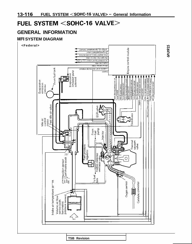
13-116 FUEL SYSTEM (SOHC-16 VALVE> - General Information
FUEL SYSTEM <SOHC-l6 VALVE>GENERAL INFORMATIONMFI SYSTEM DIAGRAM
<Federa l> I101s1s”ell ,aMo* uolllu6l ‘,I03 UOll~U6l
Awli duJ”d la”,lOlOW ,muo3 lie WI
PE
‘3 c 2F.G? 25
LL
Ei$.-5?E & /wwv
LUWLO
m
I7’
PIOUB,OS a6md UOISSIW~ awaoden3 E
%. -
w%1013alUI P
w>Q
.e c/ 1C
88conssgE0;‘3 4-‘5 m83zz_t 0,
5z 5 .s
2
E22 2 +‘0tL?
;i
5r
8 $c E% 08 5
to60
1
gx 86 :g 8
:s
;
Y I: 0? a5 J21: 0,5 $1
TSB Revision

FUEL SYSTEM <SOHC-16 VALVE> - General Information 13-117
<California>
F=c2.0 GEt 2.297 6UWO
2T.:w5
L-- t;.-OL ccIob_oLLs?=o\oEE
I-L
.
.
aEI;?sF?5ze65
1
‘1
TSB Revision

13418 FUEL SYSTEM (SOHC-16 VALVE> - Specifications
SPECIFICATIONSGENERAL SPECIFICATIONS MISCA-
Items
FuelTank capacityReturn system
Filter
Fuel pump
TypeDriven by
Throttle body
Throttle bore
Throttle position sensorIdle air control motor
Closed throttle position switch
IAC valve position sensor
Engine control module
Identification model No.
< Federal >
<California>
SensorsVolume air flow sensor
Barometric pressure sensor
Intake air temperature sensor
Engine coolant temperature sensor
Oxygen sensor
Vehicle speed sensor
Park/neutral position switch
Camshaft position sensor
Crankshaft position sensorEGR temperature sensor <California>
Power steering pressure switch
CvctuatorsMultiport fuel injection relay type
Injector type and number
Injector identification mark
Evaporative emission purge solenoid
EGR solenoid <California>
%el pressure regulator
Regulated pressure
Specifications
60 (15.9)
EquippedHigh pressure type
Electrical, in-tank type
Electric motor
mm (in.) 50 (1.969)
Variable resistor type
DC motor typeDC motor type by-pass air control system withthe Fast Idle Air Valve (FIAV)
Rotary contact type, within throttle position sensor
Hall element type
E2T36281
E2T36280
Karman vortex type
Semiconductor diffusion type
Thermistor type
Thermistor type
Zirconia type
Reed switch type
Contact switch type
Hall element type
Hall element typeThermistor type
Contact switch type
Contact switch type
Electromagnetic, 4
MDH240
ON/OFF step solenoid valve
Duty cycle type solenoid valve
kPa (psi) 335 (47.6)
1 TSB Revision

Specifications/Special Tools/FUEL SYSTEM <SOHC-16 VALVE> - Troubleshooting
SERVICE SPECIFICATIONS
13-119
MlOCB-
Items Specifications
Basic ignition timing 5”f 2”BTDC at curb idle
Curb idle speed r p m 700-C 100
Idle speed when air conditioning is on vm< M / T > 850 at neutral position
< A / T > 650 at D range
Basic idle speed r p m 700+50
Throttle position sensor adjusting voltage mV 400-I , 0 0 0
Throttle position sensor resistance kQ 3 . 5 - 6 . 5
Intake air temperature sensor resistance kQ 2.7 [at 20°C (68”F)]
Engine coolant temperature sensor resistance kQ
20°C (68°F) 2.4
80°C (176°F) 0.3
Oxygen sensor output voltage V 0.6-1.0
Fuel pressure kPa (psi)
Vacuum hose disconnection 330-350 (47-50) at curb idle
Vacuum hose connection Approx. 270 (38) at curb idle
Injector coil resistance 52 13-16 [at 20°C (68”F)]
TSB Revision
TORQUE SPECIFICATIONSRefer to P.13-6.
SEALANTRefer to P.13-7.
SPECIAL TOOLSRefer to P.13-7.
MlBDA-B
TROUBLESHOOTINGEXPLANATION OF TROUBLESHOOTINGPROCEDURES MllEBCC
Refer to P.13-8.
EXPLANATION AND PRECAUTION RELATEDTO HARNESS CHECKINGRefer to P.13-9.

13-120 FUEL SYSTEM <SOHC-16 VALVE> - Troubleshooting
CHH;K ENGINE/MALFUNCTION INDICATOR
Among the on-board diagnostic items, a check engine/mal-function indicator lamp comes on to notify the driver of theemission control items when an irregurality is detected.However, when an irregular signal returns to normal and theengine control module judges that it has returned to normal,the check engine/malfunction indicator lamp goes out.Moreover, when the ignition switch is turned off, the light goes
Check engine/malfunction out. Even if the ignition switch is turned on again, the light doesindicator lamp 68A.0093 not come on until the irregularity is detected.
Here, immediately after the ignition switch is turn on, thecheck engine/malfunction indicator lamp is lit for 5 seconds toindicate that the check engine/malfunction indicator lamp op-erates normally.
ITEMS INDICATED BY THE CHECK ENGINE/MALFUNCTION INDICATOR LAMP
Engine control module
Oxygen sensor
Volume air flow sensor
Intake air temperature sensor
Throttle position sensor
Engine coolant temperature sensor
Crankshaft position sensor
Camshaft position sensor
Barometric pressure sensor
Ignition timing adjustment signal
Injector
EGR <California>
CautionCheck engine/malfunction indicator lamp will come oneven when terminal for ignition timing adjustment isshort-circuited. Therefore, it is not abnormal that thelight comes on even when terminal for ignition timingadjustment is short-circuited at the time of ignition tim-ing adjustment.CHECK ENGINE/MALFUNCTION INDICATOR LAMPINSPECTION
(1) Check to be sure, when the ignition switch is set to the“ON” position, that the lamp illuminates for about fiveseconds and then switches OFF.
(2) If the lamp does not illuminate, check for damage or dis-connection of the harness, or for a blown fuse or a failedlight bulb.
TSB Revision

FUEL SYSTEM <SOHC-16 VALVE> - Troubleshooting 13-121
ON-BOARD DIAGNOSTIC
The engine control module monitors the input/out-put signals (some signals at all times and the othersunder specified conditions) of the engine controlmodule.When it is noticed that an irregularity has continuedfor a specified time or longer from when the irregu-lar signal is initially monitored, passing a certainnumber, the engine control module judges that anirregularity has occurred, memorizes the diagnostictrouble code, and outputs the signal to the on-boarddiagnostic output terminal.There are 15 on-board diagnostic items includingthe normal state, and the diagnostic results can beread out with a voltmeter or scan tool.Moreover, since memorization of the diagnostictrouble codes is backed up directly by the battery,the diagnostic results are memorized even if the ig-nition key is turned off. The diagnostic troublecodes will, however, be erased when the batteryterminal or the engine control module connector isdisconnected. In addition, beginning with the enginecontrol module of 1990 and later models, the diag-nostic trouble codes are erased by turning on theignition switch and sending the diagnostic troublecode erase signal from the scan tool to the engine
DIAGNOSTIC CHART (FAULT TREE)
control module.
CautionIf the sensor connector is disconnected withthe ignition switch turned on, the diagnostictrouble code is memorized. In this case, sendthe diagnostic trouble code erase signal fromthe scan tool to the engine control module ordisconnect the battery terminal (-) for 10 sec-onds or more, and the diagnostic memory willbe erased.
The 15 on-board diagnostic items are provided asfollows, and if plural items are activated, they are allindicated sequentially from the smallest code num-ber.
CautionThe diagnostic trouble code of ignition timingadjustment signal is outputted when terminalfor ignition timing adjustment is short-cir-cuited. Therefore, it is not abnormal that thecode is outputted even when terminal for igni-tion timing adjustment is short-circuited at thetime of ignition timing adjustment.
rNo. Output signal pattern
:i1zA0104
11
12
I3
:-J-l-J-12Ao104
Diagnostic trouble code- I -
On-boarddiagnostic
item
Enginecontrolmodule
Check item (Remedy) I Memory
(Replace engine control module) -
Oxygensensor
l Harness and connector Retainedl Oxygen sensorl Fuel pressurel Injectors (Replace if defective.)l Intake air leaks
Volume air l Harness and connector Retainedflow sensor (If harness and connector are
normal, replace volume air flowsensor assembly.)
Intake air l Harness and connector Retainedtemperature l Intake air temperature sensorsensor
TSB Revision

13-122 FUEL SYSTEM <SOHC-l6 VALVE> - Troubleshooting
Diagnostic trouble code On-boarddiagnostic Check item (Remedy) Memory
No. Output signal pattern item
14 Throttle l Harness and connector Retainedposition l Throttle position sensor
:n
sensor l Closed throttle position switch
12Ao104
21 Engine l Harness and connector Retainedcoolant l Engine coolant temperature
Cnn
temperature sensorsensor
lzAO107
22 Crankshaft l Harness and connector Retainedposition (If harness and connector are
:nn
sensor normal, replace distributorassembly.)
lzAOlO7
23 Camshaft l Harness and connector Retainedposition (If harness and connector are
:-
sensor normal, replace distributorassembly.)
12Ao107
24 Vehicle l Harness and connector Retainedspeed l Vehicle speed sensor (reed
H sensor (reed switch)switch)
L ULl-uulnlzAO107
25
H
Barometricpressure
l Harness and connector(If harness and connector are
L ULMlvul
sensor normal, replace barometricpressure sensor assembly.)
VA0107
Retained
36 Ignition l Harness and connector -
timingH
L u u LnllMnn
adjustmentsignal
12Ao107
41 Injector l Harness and connector0 Injector coil resistance
Retained
12Ao107
1 TSB Revision

Check item (Remedy)
l EGR valve control vacuum
FUEL SYSTEM <SOHC-l6 VALVE> - Troubleshooting 13423
NOTE1. Replace the engine control module if a diagnostic trouble code is output although the inspection reveals that there
is no problem with the check items.2. The code numbers will be displayed in order, starting from the lowest.
TROUBLESHOOTING TABLENOTE*: The failsafe/back-up function is in operation.
DE;;;zic On-boarddiagnostic
code No. itemDiagnostic content Major cause Remarks (trouble
phenomenon, etc.)
Engine The engine control module -- l Engine stopcontrol itself is abnormal. l Impossible startmodule
11 Oxygensensor
Though the air/fuel mixture (1) The oxygen sensor is troubled. l Deterioration ofratio closed loop control is (2) Open-circuit, short-circuit or exhaust gasoperated, the signal voltage of improper connector contact purifyingthe oxygen sensor does not occurs in the oxygen sensor performance*vary (to be lean/rich). circuit.
(3) The fuel pressure is improper. l Deterioration of(4) The injector is troubled. exhaust gas(5) Air is sucked through the purifying
gasket clearance, etc. performance*(6) The engine control module is l Abnormal start
troubled. l Unstable idlingl Abnormal
acceleration
12 Volumeair flowsensor
Though the engine is running, (1) Volume air flow sensor is l Abnormalthe signal frequency of the air troubled. acceleration*flow sensor is 1 OHz or less. (2) Open-circuit, short-circuit or l Unstable idling*
improper connector contactoccurs in the volume air flowsensor circuit.
(3) The engine control module is l Inappropriate idletroubled. speed*
TSB Revision

13-124 FUEL SYSTEM <SOHC-16 VALVE> - Troubleshooting
Diagnostic On-boardtrouble diagnostic
code No. itemDiagnostic content Major cause Remarks (trouble
phenomenon, etc.)
13
14
Intake air (1) The signal voltage of the (1) The intake air temperature l Slightly impropertemperatu- intake air temperature sensor is troubled. driveability*re sensor sensor is 4.5V or higher. (2) Open-circuit, short-circuit or l At high
(2) The signal voltage of the improper connector contact temperatures,intake air temperature occurs in the air intake (a) Improper startsensor is 0.27V or lower. temperature sensor circuit.
(3) The engine control module isiWJ;sn$aple
troubled.
Throttle (1) The signal voltage of the (1) The throttle position sensor is l Slightly improperposltion throttle position sensor is troubled or improperly accelerationsensor 0.2V or lower. adjusted. < M / T >
(2) Though the closed throttle (2) Open-circuit, short-circuit or l Improperposition switch is on, the improper connector contactsignal voltage of the occurs in the throttle position
d&eTbQ
throttle position sensor is sensor circuit. l Engine stop2V or higher.
(3) The closed throttle position l Engine stopswitch ON is troubled.
(4) The closed throttle position l Racing isswitch signal line is impossibleshort-circuited.
(5) The engine control module istroubled.
21 Engine (1) The signal voltage of the (1) The engine coolant During cold weathercoolant engine coolant temperature sensor is troubled. l Starting istemperatu- temperature sensor is (2) Open-circuit, short-circuit or impossible*.re sensor 4.6V or higher. improper connector contact l Unstable idling*
(2) The signal voltage of the occurs in the engine coolant l Improperengine coolant temperature sensor circuit. acceleration*temperature sensor is (3) The engine control module is0.11 V or lower. troubled.
(3) During enginewarming-up, the enginecoolant temperaturesensor signal indicatesthat the engine coolanttemperature drops.
22 Crankshaft Though the engine is cranking (1) The crankshaft position sensor l Engine stopposition 4 seconds or more, the signal is troubled. 0 Starting issensor voltage of the crankshaft (2) Open-circuit, short-circuit or impossible.
position sensor does not vary improper connector contact(to be high/low). occurs in the crankshaft
position sensor circuit.(3) The engine control module is
troubled.
23 Camshaft Though the engine is running, (1) The camshaft position sensor is l Unstable idling*position the signal voltage of the troubled. 0 Impropersensor camshaft position sensor does (2) Open-circuit, short-circuit or acceleration*
not vary (to be high/low). improper connector contactoccurs in the camshaft positionsensor circuit.
(3) The engine control module istroubled.
TSB Revision

FUEL SYSTEM <SOHC-16 VALVE> - Troubleshootinn 13-125
Dta,i;o;ic On-boarddiagnostic
code No. itemDiagnostic content Major cause Remarks (trouble
phenomenon, etc.)
24 Vehiclespeedsensor(reedswitch)
During acceleration of engine (1) The vehicle speed sensor is The enginerevolution speed of 3,000 rpm troubled. sometimes cuts offor more, the signal voltage of (2) Open-circuit, short-circuit or when stopping aftethe vehicle speed sensor does improper connector contact deceleration.not vary (to be high/low). occurs in the vehicle speed
sensor circuit.(3) The engine control module is
troubled.
25 Barometric (1) The signal voltage of the (1) The barometric pressure sensor l Unstable idling*pressure barometric pressure is troubled. l Impropersensor sensor is 4.5V or higher. (2) Open-circuit, short-circuit or acceleration*
(2) The signal voltage of the improper connector contact 0 Improper start*barometric pressure occurs in the barometricsensor is 0.2V or lower. pressure sensor circuit.
(3) The engine control module istroubled.
36 Ignitiontimingadjustingsignal
The ignition timing adjusting (1) The ignition timing adjusting l Impropersignal line is short-circuited to signal line is short-circuited to accelerationthe ground. the ground. l Engine overheat
(2) The engine control module istroubled.
41 Injector Injector is not continuouslydriven for 4 seconds duringengine cranking or idleoperation.
(1) The injector is troubled.(2) Open-circuit, short-circuit or
improper connector contactoccurs in the injector sensorcircuit.
l Unstable idlingl Improper
acceleration0 improper start
(3) The engine control module istroubled.
43 EGR During engine running after (1) The EGR valve is not opened. l Deterioration of<Califor- warming-up, (2) The negative pressure of the exhaust gasnia> (1) The EGR amount is small. EGR valve control is excessively purifying
(The signal voltage of the low. performanceEGR temperature sensor (3) The EGR solenoid is troubled.is excessively high.) (4) The EGR temperature sensor is
(2) The signal voltage of the troubled.EGR temperature sensor (5) Open-circuit, short-circuit oris 0.1 V or less. improper connector contact
occurs in the EGR temperaturesensor circuit.
(6) The engine control module istroubled.
55 IAC valve IAC valve does not move to (1) The IAC valve position sensor isposition the intended position (opening troubled.
l ;papp$Priate idle
sensor angle), even though idle air (2) Open-circuit, short-circuit or l Engine stops*control motor operates many improper connector contact l Unstable idling*times. occurs in the IAC valve position
sensor circuit.(3) The idle air control motor (DC
motor) is troubled.(4) Open-circuit, short-circuit or
improper connector contactoccurs in the idle air controlmotor (DC motor) circuit.
(5) The engine control module istroubled.
TSB Revision

13-126 FUEL SYSTEM <SOHC-16 VALVE> - Troubleshooting
FAILSAFE/BACK-UP FUNCTIONS LISTIf trouble with any major sensor is detected by the on-board diagnostic, the vehicle will be kept in the safedriving conditions according to the preset control logic.
Trouble item Control content for trouble
Volume air flow (1) Fuel injection timing and ignition timing are determined according to the throttle positionsensor sensor (TPS) and engine revolution speed signal (crankshaft position sensor signal).
(2) The IAC motor is fixed in the appointed position so idle air control is not performed.
Intake air temperature The control is executed with the suction air temperature regarded as 25°C (77°F).sensor
Throttle position The fuel injection rate is not increased for acceleration according to the throttle positionsensor (TPS) sensor signal.
Engine coolant The control is executed with the coolant temperature regarded as 80°C (176’F).temperature sensor
Camshaft position Simultaneous injection of fuel is executed for all cylinders. (In this case, the No.1 cylinder topjenS0r dead center is not detected at all after the ignition key is turned on.)
3arometric pressure The control is executed with the pressure regarded as 760 mmHg (30 in. Hg.).sensor
AC valve position Idle air control motor is not performed.;ensor
Ixygen sensor Closed loop control of the air/fuel mixture ratio is not executed.
READ OUT OF DIAGNOSTIC TROUBLE CODERefer to P.13-16.
EbW&R MEMORY OF DIAGNOSTIC TROUBLE
Refer to P.13-17.
TSB Revision

FUEL SYSTEM <SOHC-16 VALVE> - Troubleshootins
CHECK CHART CLASSIFIED BY PROBLEM SYMPTOMS
Problemsymptoms
Starting Idling stability Driving r”.-%scn
E5$4.a,o_5;icz
iP.13-143
-
Ea,Ll2aF.-sG-
DE-
c-El c
-->El
)El-)I3-)@I
I- -
i-
5‘32a,$%b
a”
D&lDEIi>El
-0%,a>
+y -2.g
PE.-
50 z.E r 2?p9 6=& g- - -Sheck items
‘ower supply
%gine control module power groundI
1 P.13-146:uel pump
Jolume air flow sensor
B
fE3DELI @El
cP.13-162
P.13-165II I P.13-167 I
1 / P.l3-171 1
P.l3-172
P.l3-173
P.l3-175
P.13-176
P.l3-179
ntake air temperature sensor
BIB
DEI0DEl3El
3
-I
iarometric pressure sensor
ingine coolant temperature sensor
‘hrottle position sensor
Iosed throttle position switch
K valve oosition sensor
lamshaft position sensor
i-:rankshaft position sensorI I
lnition switch-ST <M/T> I
-I---0lnition switch-ST and park/neutralosition switch <A/T>
chicle speed sensor
ower steering pressure switch
ir conditioning switch and/C compressor clutch relay
I / I- I Ilxygen sensor
@El @ P.l3-181
@El P.13-184
@El @El P.13-186Ile air control motor (DC motor)
inition coil and ignition power OFI @piJ OEIansistortiaporative emission purge solenoid 0 1 P.13-189
1 Idklctrt
EGR solenoid <California> @El @El @El P.13-191
Fuel pressure OIlI @El 8E.l @El @El @El @El P.13-192
0 : Warm engine (number inside indicates check order)0 : Cold engine (number inside indicates check order)
PROBLEM SYMPTOMS TABLE (FOR YOUR INFOMATION)Refer to P.13-19.
TSB Revision
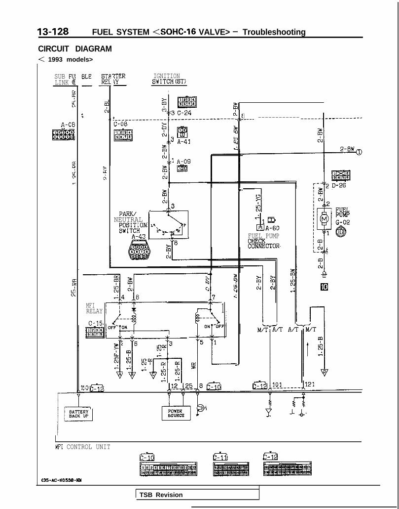
13-128 FUEL SYSTEM <SOHC-16 VALVE> - Troubleshooting
CIRCUIT DIAGRAM< 1993 models>
IGNITIONSWITCH(ST)
I
SUB F'JILINK @
2Licl 360
Ct \J.---------------~------------------. ,\A-08 C-08
I@34
m
2i‘I
12El3 A343L
6670 lru Ic;
BLE E-w
Ec!1
2c:
3.____ ------------ --q-w-1___--_--q-w
?+d<I-
(N3PARK/
NEUTRALKlJ;;ON
“1EbLY P
&I
A-433’ .a AA-60
FUEL PUMPk%%&TOR
-+i I
kcJ
i
:7 :-
MFIRELAY 1c-15
6TT
gl? 3
;.R.i 3KY !x ry -8.A
kc ;cs -
1oa
-J-Q
6
MFI CONTROL UNIT
t35-AC-HOW-WY
1 TSB Revision

FUEL SYSTEM <SOHC-16 VALVE> - Troubleshooting 13-129
'10N:H(IGl)
7
2F-BW
1
CONDENSERB-02-5
It!35e
----_-_--__':DISTRIBUTOR
IGNITIONCOIL ;ASSEMBLY
r IIIIIII
+ I2 g&I IGTR I BUTOR ,
IIGNITIONPOKERTFaN616TOR
B-02-4 5---jffjTIn G
Lk & COMBINATIONMETERtTACHO)
J/B7 ca10R
7
8
1COMBINATIOhMETER
) C-52
IBLEAUTO COMPRESSORCONTROL UNIT
12C-23
i
's
2
r-l 1GR
6 Ia 22
,--
ON: 235uPa
A-21
A-086,t
65m
1 TSB Revision 1

13-130 FUEL SYSTEM <SOHC-l6 VALVE> - Troubleshooting
CIRCUIT DIAGRAM (CONTINUED)< 1993 models>
VOLUME
A-47 1 &- -%--t
MFIRELAY
IGNITIONSWITCH (IGl)
AIR FLOW EXNSOR ,,2,\VCLLW7nwmAm
m 468 1ES
1
“3 75 y4 6 1
1 IIt I I I
HFL b!. _-____ JLk? ______________ -bdl8 tQjbui kk
B-02-4m
0 .sT--
q--0
OF;- ONL
25rlI
1G
ENGINE#k&@"RE
:NSOR
KX35AC-H0538A-NM
TSB Revision I

FUEL SYSTEM <SOHC-16 VALVE> - Troubleshooting 13-131
z.
i
:r:
RE: IDLE SPEED
CONTROL -MOTORB-03
(ii-G-q
\I .I \ w t,i "6 “2 "4"3 “1
EC3LLrL
s 'f 5LL LL rl
1 A /\37 5 18_---A v v I
1I 5%LL,rl
21
E
---_----_103
I2116
wijc-40
C-381 2Ei54
POWE&TEERINGPRESSUR SWITCH
C-38(EN’S) (DATA)
&T
DATA LINKCONNECTOR
:------.63
I
IGNTIONTIMINGADJUSTIMENTCONNECTOR
1 TSB Revision I

13-132
NOTE
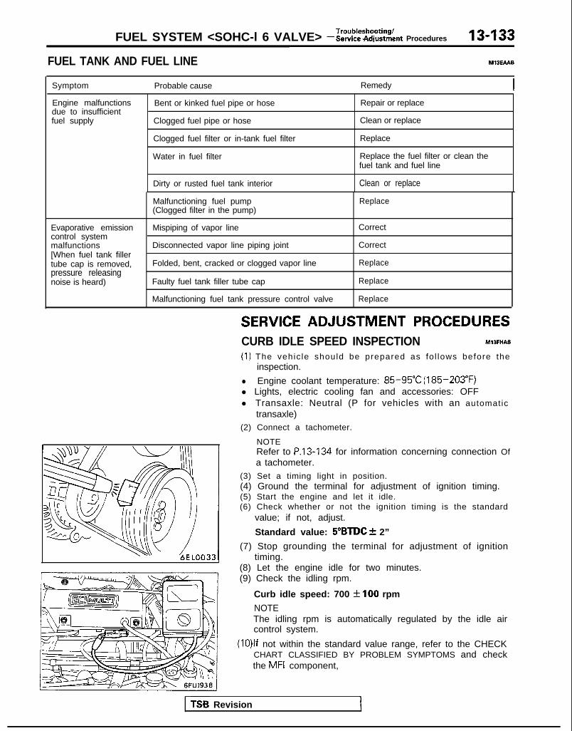
FUEL SYSTEM <SOHC-l 6 VALVE> - I?~FS~~ZFZLnt Procedures 13-133
FUEL TANK AND FUEL LINE MIBEAAB
Symptom Probable cause Remedy
Engine malfunctionsdue to insufficientfuel supply
Bent or kinked fuel pipe or hose
Clogged fuel pipe or hose
Clogged fuel filter or in-tank fuel filter
Water in fuel filter
Repair or replace
Clean or replace
Replace
Replace the fuel filter or clean thefuel tank and fuel line
Dirty or rusted fuel tank interior Clean or replace
Malfunctioning fuel pump(Clogged filter in the pump)
Replace
Evaporative emissioncontrol systemmalfunctions[When fuel tank fillertube cap is removed,pressure releasingnoise is heard)
Mispiping of vapor line
Disconnected vapor line piping joint
Folded, bent, cracked or clogged vapor line
Faulty fuel tank filler tube cap
Malfunctioning fuel tank pressure control valve
Correct
Correct
Replace
Replace
Replace
SERVICE ADJUSTMENT PROCEDURESCURB IDLE SPEED INSPECTION hll3MAE
(1) The vehic le should be prepared as fo l lows before theinspection.
l Engine coolant temperature: 85-95°C (185-203°F)l Lights, electric cooling fan and accessories: OFFl Transaxle: Neutral (P for vehicles with an automatic
transaxle)(2) Connect a tachometer.
NOTERefer to P.13-134 for information concerning connection Ofa tachometer.
(3) Set a timing light in position.(4) Ground the terminal for adjustment of ignition timing.(5) Start the engine and let it idle.(6) Check whether or not the ignition timing is the standard
value; if not, adjust.
Standard value: 5”BTDC f 2”
(7) Stop grounding the terminal for adjustment of ignitiontiming.
(8) Let the engine idle for two minutes.(9) Check the idling rpm.
Curb idle speed: 700 31100 rpm
NOTEThe idling rpm is automatically regulated by the idle aircontrol system.
(lO)lf not within the standard value range, refer to the CHECKCHART CLASSIFIED BY PROBLEM SYMPTOMS and checkthe MFI component,
TS6 Revision 1

13-134 FUEL SYSTEM (SOHC-16 VALVE> - Service Adjustment Procedures
BASIC IDLE SPEED ADJUSTMENT MlIFHBX
NOTE1. The standard idling speed has been adjusted, by the en-
gine speed adjusting screw, by the manufacturer, andthere should usually be no need for readjustment.
2. Use the following procedure to adjust when the idlingspeed drops due to an incorrect adjustment, high idlingspeed, or when a load such as the air conditioning is ap-plied on the engine.
3. The adjustment, if made, should be made after first con-firming that the spark plugs, the injectors, the idle air con-trol motor, the compression pressure, etc. are all normal.
(I ) The vehicle should be prepared as follows before the inspec-tion and adjustment.l Engine coolant temperature: 85-95°C (185-203°F)l Lights, cooling fan and accessories: OFFl Transaxle: neutral (A/T for P range)l Steering wheel: neutral position
(2) Connect the scan tool to the data link connector (white).
NOTEWhen the scan tool is connected, the diagnostic test modecontrol terminal should be grounded.
(3) If the scan tool is not used, follow the steps below.@I Insert a paper clip into the l-pin connector (blue)
shown in the figure at the left.
0 Connect a primary-voltage-detection type of tacho-meter to the paper clip.
1 TSB Revision I

FUEL SYSTEM <SOHC-16 VALVE> - Service Adjustment Procedures 13-135
Diagnostictest mode
@ Use a jumper wire to ground the diagnostic test modecontrol terminal of the data link connector.
TSB Revision
(4) Remove the waterproof female connector from the ignitiontiming adjustment connector.
(5) Use a jumper wire to ground the ignition timing adjustmentterminal.
(6) Start the engine and run at idle.(7) Check the basic idle speed. If the scan tool is used, select
item No.22 and read the idle speed.Standard value: 750 *50 rpm
NOTE1. The engine speed may be 20 to. 100 rpm lower than
indicated above for a new vehicle (drive approximately500 km (300 miles) or less), but no adjustment isnecessary.
2. If the engine stalls or the rpm is low even though thevehicle has been driven approximately 500 km (300miles) or more, it is probable that deposits are adhered tothe throttle valve, so’clean it. (Refer to P.13-136.)
(8) If not within the standard value range, turn the enginespeed adjusting screw to make the necessary adjustment.
NOTEIf the idling speed is higher than the standard value rangeeven when the RPM adjusting screw is fully closed, checkwhether or not there is any indication that the fixed SAShas been moved. If there is an indication that it has beenmoved, adjust the fixed SAS. If there are no indications thatit has been moved, it is possible that there is leakage as aresult of deterioration of the fast idle air valve (FIAV), and, ifso the throttle body should be replaced.
(9) Switch OFF the ignition switch.(lO)lf the scan tool was not used, disconnect the jumper wire
from the diagnostic test mode control terminal.(11) Disconnect the jumper wire from the ignition timing adjust-
ment terminal and return the connector to its original condi-tion.
(12) Start the engine again and let it run at idle speed for about tenminutes; check to be sure that the idling condition is normal.
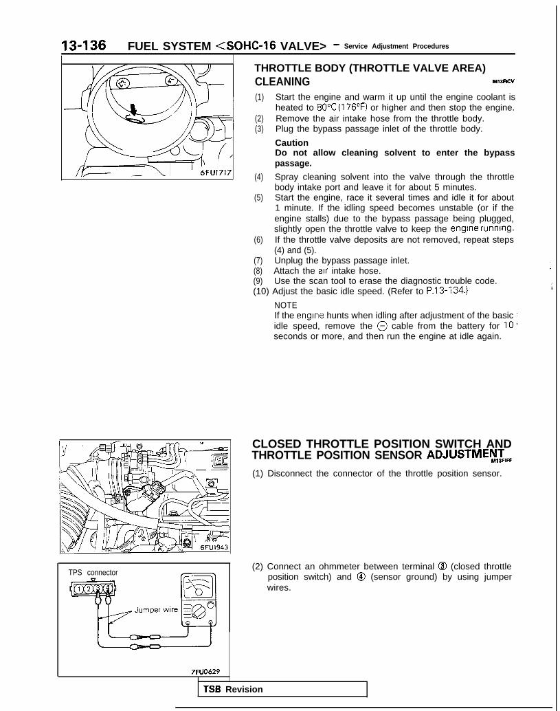
13-136 FUEL SYSTEM <SOHC-16 VALVE> - Service Adjustment Procedures
TPS connector
7FUO629
THROTTLE BODY (THROTTLE VALVE AREA)CLEANING Ml3Rcv
(1) Start the engine and warm it up until the engine coolant isheated to 80°C (176°F) or higher and then stop the engine.
(2) Remove the air intake hose from the throttle body.(3) Plug the bypass passage inlet of the throttle body.
CautionDo not allow cleaning solvent to enter the bypasspassage.
(4) Spray cleaning solvent into the valve through the throttlebody intake port and leave it for about 5 minutes.
(5) Start the engine, race it several times and idle it for about1 minute. If the idling speed becomes unstable (or if theengine stalls) due to the bypass passage being plugged,slightly open the throttle valve to keep the engine running.
(6) If the throttle valve deposits are not removed, repeat steps(4) and (5).
(7) Unplug the bypass passage inlet.(8) Attach the air intake hose.(9) Use the scan tool to erase the diagnostic trouble code.(10) Adjust the basic idle speed. (Refer to P.13-134.)
NOTEIf the engrne hunts when idling after adjustment of the basicidle speed, remove the @ cable from the battery for 10seconds or more, and then run the engine at idle again.
CLOSED THROTTLE POSITION SWITCH ANDTHROTTLE POSITION SENSOR ADJUSTMEy,zIFF(1) Disconnect the connector of the throttle position sensor.
(2) Connect an ohmmeter between terminal @I (closed throttleposition switch) and @ (sensor ground) by using jumperwires.
TSB Revision

FUEL SYSTEM <SOHC-16 VALVE> - Service Adjustment Procedures 13437
I ;g Fixed SAS
Terminal @ Terminal @(sensor output) (sensor ground) /
(3) Insert a feeler gauge with a thickness of 0.65 mm (.0256 in.)between the fixed SAS and the throttle lever.
(4) Loosen the throttle position sensor mounting bolt; thenturn the throttle position sensor body fully counter clock-wise.
(5) In this condition, check for continuity between terminals @and 0.
(6) Slowly turn the throttle position sensor in the clockwise di-rection until the point at which continuity between termi-nals @I and @ changes to non-continuity is found.Tighten the throttle position sensor installation bolt at thatposition.
(7) Connect the connector of the throttle position sensor.
(8) Connect the scan tool to the data link connector (white).(9) If not using the scan tool, proceed as follows:
0 Disconnect the throttle position sensor connectors andconnect the special tool, Test Harness Set, betweenthe disconnected connectors.
0 Connect a digtal voltmeter between the throttle posi-tion sensor terminal @ (sensor output) and terminal Q(sensor ground).
(lO)Turn the ignition switch ON (but do not start the engine).(11)Check the throttle position sensor output voltage.
When using the scan tool, select item No.14 and read thethrottle position sensor output voltage.
Standard value: 400-1000 mV
(12) If there is a deviation from the standard value, check thethrottle position sensor and the related harness.
(13) Remove the feeler gauge.(14) Switch OFF the ignition switch.
TSB Revision

13-138 FUEL SYSTEM (SOHC-16 VALVE> - Service Adjustment Procedures
FIXED SAS ADJUSTMENT M13FlDE
NOTEI, The fixed SAS should not be moved unnecessarily; it has
been precisely adjusted by the manufacturer.2. If the adjustment for any reason is disturbed, readjust as
follows.
(1) Loosen the tension of the accelerator cable sufficiently.(2) Back out the fixed SAS lock nut.(3) Turn the fixed SAS anti-clockwise until it is sufficiently
backed out, and fully close the throttle valve.(4) Tighten the fixed SAS until the point where the throttle lever
is touched (i.e., the point at which the throttle valve begins toopen) is found.From that point, tighten the fixed SAS l-1/4 turn.
(5) While holding the fixed SAS so that it doesn’t move, tightenthe lock nut securely.
(6) Adjust the tension of the accelerator cable.(7) Adjust the basic idling speed.(8) Adjust the closed throttle position switch and throttle posi-
tion sensor. (Refer to P.13-136.)
TSB Revision I

FUEL SYSTEM <SOHC-l 6 VALVE> - ?::;:r%t~pection Of MF’ 13439
ON-VEHICLE INSPECTION OF MFI COMPONENTSCOMPONENT LOCATION
6FUO843
Name Symbol Name Symbol
Air conditioning compressor clutch relay A Ignition coil (ignition power transistor) L
Air conditioning switch T Ignition timing adjustment terminal K
Camshaft position sensor and crankshaft posi- Injector HMtion sensor
- Multiport fuel injection relay UCheck engine/malfunction indicator lamp S
- Oxygen sensor NData link connector Q
- Park/Neutral position switch (A/T) 6EGR solenoid <California> I
- Power steering pressure switch PEGR temperature sensor <California> 0
Throttle position sensor (with closed throttleposition switch)
EEngine control module v
Engine coolant temperature sensor F Vehicle speed sensor (reed switch) R
Evaporative emission purge solenoid J Volume air flow sensor (with incorporated,in-take air temperature sensor and barometnc C
Fuel pump check terminal G pressure sensor)
Idle air control motor D
NOTEThe “Name” column is arranged in alphabetical order.
TSB Revision

13-140On-Vehicle Inspection of MFI
FUEL SYSTEM <SOHC-16 VALVE> - Components
6FU 0985
6FUO99-J
TSB Revision

FUEL SYSTEM <SOHC-l 6 VALVE> - ::ii,,k:t~pection Of MF’ 13-141
6FuO984
Crankshaft position sensor
\\ 6FU193~
I (7-T
I ;.’ E ,/ii
;
i
; ~&qqLk~
)
’ [,,“\,k@$&b;,,,“\
I’
/ \, pQi, >{,
1; /
‘\l>,
/ \\\ 6FUO8Oi
,<,$+$GgT z Jp$j&& ‘\,
“2$--- 8%\.35 Fqp2; ,I <,, c LTgg.&~.
,D~~,
1 sl ) g , a&&iI& I.“: :(;-omd!gs?~ 5, gt : .“*I--
L l
2,, m �IFiTb;qF
/Check engine/malfunctionindicator lamp 68b.0093
B :iG i 1
,i mIl-
11
’ 0_;
3
(1P
I”;l-i-yCL, ,\i / ,---_ /’ - ’ +-+j$p2E~~;:c9h
/ /I ----4 ) Jj 1 1 ’ 6FU0656
68mosJ
I( >/ !, ij”_II. .:a L-2
__--. ~-~-Air conditioning I~.~ ~..
LT. --..- 6FUO64!
TSB Revision

On-Vehicle Inspection of MFI13-142 FUEL SYSTEM (SOHC-16 VALVE> - Components
16AO.31116AO.311
COMPONENTS INSPECTION PROCEDURE-USING THE SCAN TOOL Ml WSAG
Refer to P.13-41.
TSB Revision 1
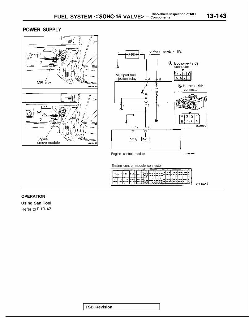
On-Vehicle Inspection of MFIFUEL SYSTEM <SOHC-16 VALVE> - Components 13-143
POWER SUPPLY
16AO411
contra module
, ;;lii’l’l’lb Ig;lon switch (IG)
MultIport fuelinjection relay /\4 /t\8
" 2 't'3 "6rt 4,
Equipment sideconnector
@ Harness sideconnector- - -
Engine control module 01105.4
Enaine control module connector
7FlJO653I
OPERATION
Using San Tool
Refer to P.13-42.
TSB Revision

On-Vehicle Inspection of MFI13-144 FUEL SYSTEM <SOHC-16 VALVE> - Components
HARNESS INSPECTION1
1 I Measure the power supply voltage ofthe multiport fuel injection relay.
l Multiport fuel injection relay con-nector: Disconnected
r ,
LNC; Jr=- -cl7
I
?-i3I+-
c-@ H arness side
connector
Repair theharness.
~ ( Ign i t i on
swrtch.
_J2 L5-l Measure the power- supply voltage ofthe multiport fuel injection relay.
l Multiport fuel injection relay con-nectar: Disconnected@ Harness sde
connector
3i Check for continuity of the groundcrrcuit.
l Multiport fuel iniection relay con-nectar: Disconnected
3 Harness sideconnector
Repair theIM. - zf$
Engine controlmodule harnessside connector
Check for open circuit, or short circuitto ground, between the engine con-trol module and the multiport fuel in-jection relay.
(03 -2 ql Engine control module connec-
tor: Disconnectedl Multiport fuel injection relay con-
nectar: Disconnected
Repair theharness.
- @I - @El,@I - @Ia
connector
Measure the power voltage to theactuatorl Multiport fuel injection relay con-
nector: Connectedl ECM connector: Connected
1 li
Replacethe multi-
+ p o r t f u e linjection
Harness sideconnector
relay.6FU1751
1 TSB Revision 1

‘On-Vehicle Inspection of MFIFUEL SYSTEM (SOHC-16 VALVE> - Components 13-145
9FUOOlO
9FUOO18
1
TSB Revision I
MULTIPORT FUEL INJECTION RELAY INSPECTION
(1) Remove the multiport fuel injection relay.(2) Check the continuity between the multiport fuel injection
relay terminals.
(3) Use jumper leads to connect multiport fuel injection relayterminal 0 to the battery (+) terminal and terminal 0 to thebattery (-) terminal.
CautionWhen connecting the jumper leads, be careful not tomistake the connection terminals, as damage to therelay will result.
(4) Check the voltage at multiport fuel injection relay terminal@I while connecting and disconnecting the jumper lead atthe battery (-) terminal.
(5) Use the jumper leads to connect multiport fuel injectionrelay terminal @I to the battery (+) terminal and terminal @to the battery (-) terminal.
(6) Check the continuity between multiport fuel injection relayterminals @-@I and terminals @-@I while connecting anddisconnecting the jumper lead at the battery (-) terminal.
9FUOOl9
(7) If there is a defect, replace the multiport fuel injection relay.

13-146 FUEL SYSTEM <SOHC-16 VALVE> - ::$:%i-- Of MF’
ENGINE CONTROL MODULE POWER GROUND
Engine control module
LIirzl13
Y
26
Engine control module connector
7FU06.53
OPERATION
TROUBLESHOOTING HINTS
Refer to P.13-45.
HARNESS INSPECTION
mddule harnessside connector
Check for continuity of the groundcircuit.
l Connector: Disconnected
I1 Repair the
harness.e (O-Ground)
, @ - G r o u n d )
TSB Revision

FUEL SYSTEM (SOHC-16 VALVE> - :::;::tt?ction Of MF’ 13-147
FUEL PUMP M13YEAB
6FUO985-
@ Equipment srdeconnector
@ Harness sideconnector
I
Ignition switch (IG)
Multiport fuel
@I Equipment sideconnector
TSB Revision
Fuel pump-I
@ Harness sideconnector
Engine COntrOl module A 8
7Fuom
6FU1951
OPERATION
a The fuel pump is dr iven when the engine iscranking and while the engine is running.
l When the engine is cranking and while the engineis running, the engine control module turns thepower transistor ON to supply power to the
multiport fuel injection relay coil. This causesthe multiport fuel injection relay switch to turnON, and current is supplied from the ignitionswitch via the multiport fuel injection relayswitch to drive the fuel pump.
INSPECTION
Using Scan ToolRefer to P.13-46.

On-Vehicle Inspection of MFI13-148 FUEL SYSTEM (SOHC-16 VALVE> - Components
HARNESS INSPECTION
@ Harness sideconnector
Check for continuity of the fuel pumpgrounding line.
l Fuel pump connector: Discon-netted
Repair the4 harness
~ @El-Ground)
Check for open-circuit or short circuitbetween the fuel pump and the fuelpump drive terminal.
l Fuel pump connector: Drscon-netted
l Multiport fuel injection relay con-nectar: Disconnected
I/
2 .lr/ Repair the
L^Srr,-..-r
P
9vh
connector T- y 6FU1238!
I
@ Harness srdeconnector
Measure the power supply voltage ofthe multiport fuel injection relay.
l Multiport fuel injection relay con-nector: Disconnected
r
9FUOO23;
I I IEngine control
Check for an open circuit, or short-cir-cuit to ground between the multiportfuel injection relay and the enginecontrol module.
l Multiport fuel injection relay con-nector: Disconnected
l Engine control module connec-tor: Disconnected
!
Repair the+ harness.
~ @H-B)
TSB Revision

On-Vehicle Inspection of MFIFUEL SYSTEM <SOHC-16 VALVE> - Components 13-149
a Harness sideconnector
--------mJ-----k
NqpCI
F
Check for continuity between the fuelpump checking terminal and betweenthe multiport fuel injection relay ter-minals.
l Multiport fuel injection relay con-nector: Disconnected Fipnn~r t h e
l Fuel pump connector: Discon-nected
.-P-” _’ ‘-& harness.
(@m-00,
I9FUOO24
OlA0401
Check for an open circuit, or short-cir-cuit to ground between the multiportfuel injection relay and the fuel pump.
l Multiport fuel injection relay con-nectar: Disconnected
l Fuel pump connector: Discon-nected
@ Harness sideconnector
Measure the power supply voltage ofthe fuel pump.
l Multiport fuel injection relay con-nector: Connected
l Enoine control module connec-tor: Connected
Engine 1 Voltage IV1
cCranking ~ 8V or more-
IMultiport
I f u e l injec-__, tion relay or
1 engine con-~ trol m o d u l e
TSB Revision
I Racing I id+ : is defective.6FU175.3 I
MULTIPORT FUEL INJECTION RELAY IN-SPECTION
Refer to P.13-145.

On-Vehicle Inspection of MFI
13450 FUEL SYSTEM <SOHC-16 VALVE> - Components
VOLUME AIR FLOW SENSOR
Intake air amountWsec) 1 6 2 4 5 1
@ Componentsideconnectof
Multiport fuelinjection relay
/ohme air flow sensor /\2/\-
@Harness side
I sv x I6FU1952
OPERATION
TROUBLESHOOTING HINTS
Refer to P.13-49.
INSPECTION
Using Scan Tool
Item No.
12
Data display Inspection conditions Engine condition Standard value
Sensor de- . Engine coolant Idle speed 18-44 Hztection air temperature: 85-95°Cvolume (fre- (185-205°F)quency) . Lights, cooling fan, elec- 2,000 rpm 64-l 04 Hz
tricaI accessories: OFFTransaxle: neutral (PJT
models: “P” range) Racing Frequency in-creases as racingrpm increases.
NOTEThe volume air flow sensor output frequency may be about 10% higher than indicated above when the vehicle is new[driven approximately 500 km (300 miles) or less].
TSB Revision 1

On-Vehicle Inspection of MFIFUEL SYSTEM <SOHC-16 VALVE> - Components 13451
Using Oscilloscope
(1) Run the engine at idle speed.(2) Connect the probe to the osilloscope pick-up point as
shown in the circuit diagram, and check the wave form.
Regular waveform 03AO203
HARNESS INSPECTION
Check for continuity between volumeair flow sensor and multiport fuel in-jection relay.
l Multiport fuel injection relay con-nector: Disconnected
l Volume air flow sensor connec-tor: Disconnected
NOTETouch the circuit tester probes toboth ends of the harness
a+OK 121
harness sideconnector 6FU1953
connector
Check for continuity of the ground - Icircuit.
0 Volume air flow sensor connec- WI+ 131tor: Disconnected L-l I
OlR0262/ Imodule harness
@ Harness sideconnector
= =6FU1954
0O K -I+Check for broken wire or short-circuitto ground, between volume air flowsensor and engine control module.l Volume air flow sensor connec-
tor: Disconnectedl Engine control module connec-
tor: Disconnected
El4
Repair theharness.(ml-El)
Measure the impressed voltage.
0 Volume air flow sensor connec-tor: Disconnected
l Engine control module connec-tor: Connected
l Ignition switch: ON
connector
Voltage (V)
4.8 - 5.2
I TSB Revision

13-152 FUEL SYSTEM (SOHC-16 VALVE> - %i;:%~spection Of MF’
INTAKE AIR TEMPERATURE SENSOR Ml3YGAA
Volume air flow sensorVolume air flow sensor(built in intake air(built in intake air
Intake airtemoerature sensor
Engine controlmodule connector
ITemperature
w
Temperature1621006142468
@ Volume arr tlowsensor connector [-1 ~$%re
Harness side connector k
A 72
~o~~~e p-$-J
5v7FlD&53 6FU1955
OPERATION
TROUBLESHOOTING HINTS
INSPECTIONUsing Scan Tool
Refer to P.13-51.
HARNESS INSPECTION
@ Harness side connector -,T
[ a1g@-
r.
Check for continuity of the groundcircuit.
l Volume air flow sensor connec-tor: Disconnected
Repair the+ harness.
/ (ml-El)
OlRo262 I I
TSB Revision

FUEL SYSTEM <SOHC-16 VALVE> - ::ii$%tt=pection Of MF’ 13-153
@ Harness srdeconnector
Check for open circuit or short circuitto ground, between intake air tempera-ture sensor and engine control mod-ule.
0 Volume air flow sensor connec- /
tor: Disconnectedl Engine control module connec-
tor: Disconnected
I Repair the+ harness.
I @El -El)
@ Harness side connector
6FU195C
1
[ I Measure the impressed voltage. n ~ A0 Volume air flow sensor connec-
tor: Disconnectedl Engine control module connec-
tor: Disconnectedl lqnition switch: ON
-
Replace
Voltage (VI 1 c#?g -+ zl;;fne
4.5 - 4.9 moaule.
SENSOR INSPECTION
Refer to P.13-52.
TSB Revision

On-Vehicle Inspection of MFI13-154 FUEL SYSTEM <SOHC-16 VALVE> - components
BAROMETRIC PRESSURE SENSOR MlJYHA4
Barometnc -pressuresensor
htput Voltage
Barometric pressure mmHg 760 ~~1551
CR Volume air flowBarometric pressure sensor
II I-.____A__sensor conneclur
mB Harness side
connector
,\ , , ,.k ,Im jfl
5EL1600
6FU1957
Engine control module connector
7FlfO653
OPERATION
TROUBLESHOOTING HINTS
INSPECTION
Using Scan ToolRefer to P.13-53.
HARNESS INSPECTION
@ Harness side connector I,?la1gg
n
1 Check for continuity of the ground - I Ij c i r cu i t .
/ 0 V o l u m e a i r f l o w ----^- ^^^^^^ ibd-b 121 Isensor GUI II IGL-tor: Disconnected w -
I
OlRO262 j
TSB Revision
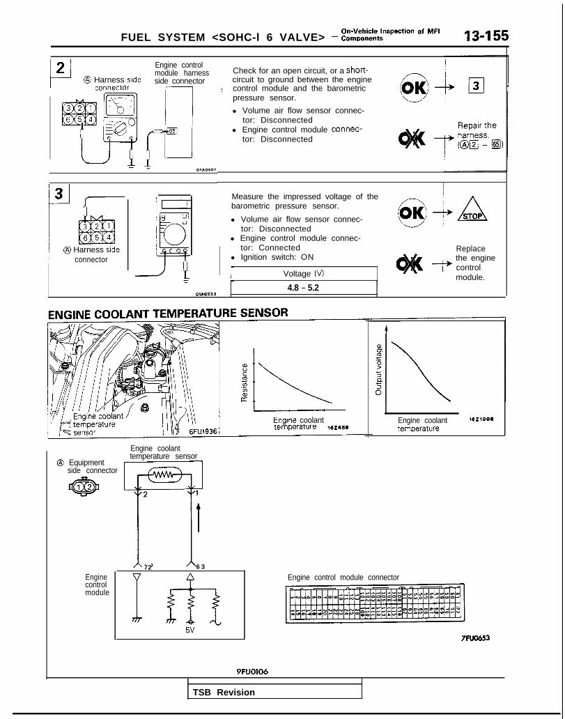
FUEL SYSTEM <SOHC-l 6 VALVE> - ::~,%~t~pection Of MF’ 13-155
L-J2 @ Harness side
@ Harness stdeconnector
Engine controlmodule harnessside connector
r----l65
mr 01AO107
~ Check for an open circuit, or a short-circuit to ground between the engine
: control module and the barometricpressure sensor.
i l Volume air flow sensor connec-tor: Disconnected
l Engine control module connec-tor: Disconnected
Measure the impressed voltage of thebarometric pressure sensor.
l Volume air flow sensor connec-tor: Disconnected
l Engine control module connec-tor: Connected
l Ignition switch: ON
Voltage (VI
Replace- the engine
1 controlmodule.
IOIAO233 I 4.8 - 5.2
I
Engrne coolant
Engine coolant
@ Equipmenttemperature sensor
side connector
Enginecontrolmodule
72 6 3
I fh5v
Engine coolanttemoerature
Engine control module connector
7FW6!53
9FUO106
TSB Revision

13-156On-Vehicle Inspection of MFI
FUEL SYSTEM (SOHC-16 VALVE> - Components
OPERATION
TROUBLESHOOTING HINTS
INSPECTION
Using Scan Tool
Refer to P.13-55.
HARNESS INSPECTION
Harness sideconnector
Check for continuity of the groundcircuit.
l Engine coolant temperaturesensor connector: Drsconnected
9FUO112
01OK+ /2/Repair the
& harness.i @lz -@i,
r
21t@ Harness side
connector
2 17Check for open circuit or short-circuitto ground, between engine coolanttemperature and engine control mod-
!:I->,
OK+ 131
ule.l Engine coolant temperature
connector: Disconnectedl Engine control module connec-
~ 1 h h L ~ tor: Disconnected$)#!& ” g$jnii
7 7
c
module harnessside connector
9FUO113
3
@ Harness sideconnectx
Measure the Impressed voltage.
l Engine coolant temperature sensorconnector: Dlsconnected
l Engine control module connec-tor: Connected
l Ignition switch. ON Replace& the engine
control, I
9FUO114
moaure.
SENSOR INSPECTION
Caution
J
Be careful not to touch the tool against the connector (resinsection) when removing and installing.
(1) Remove engine coolant temperature sensor from the ther-mostat housing.
TSB Revision
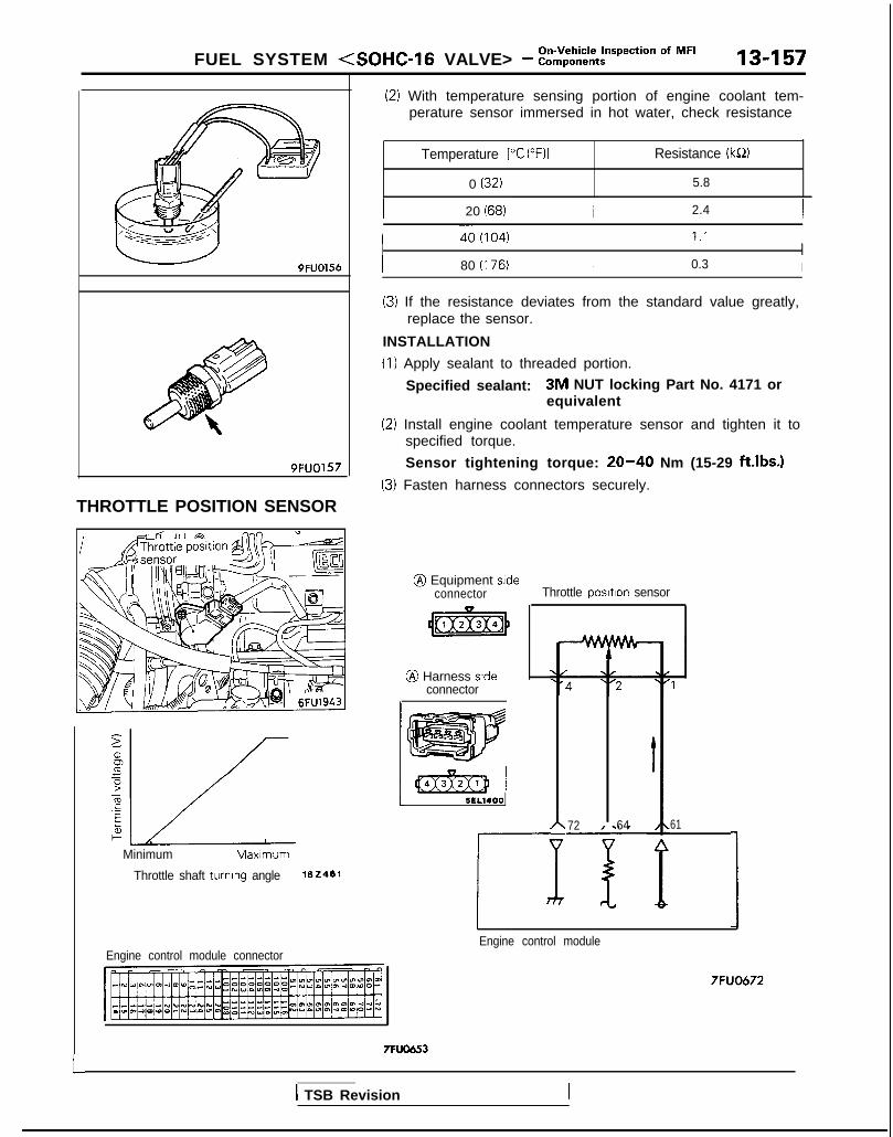
FUEL SYSTEM (SOHC-16 VALVE> - ::ii,,k%ti=pec*ion Of MF’ 13-157
9FUO156
9FUO157
THROTTLE POSITION SENSOR
Minimum Maxlmum
Throttle shaft turning angle 162461
(21 With temperature sensing portion of engine coolant tem-perature sensor immersed in hot water, check resistance
Temperature PC (“F)l Resistance (k!S)
0 (32) 5.8
I 20 (68) ~1 2.4 I
I 80 (I 76) I 0.3 I
Engine control module connector
(3) If the resistance deviates from the standard value greatly,replace the sensor.
INSTALLATION
(1) Apply sealant to threaded portion.
Specified sealant: 3M NUT locking Part No. 4171 orequivalent
(2) Install engine coolant temperature sensor and tighten it tospecified torque.
Sensor tightening torque: 20-40 Nm (15-29 ft.lbs.)
(3) Fasten harness connectors securely.
@ Equipment sideconnector Throttle posltlon sensor
@ Harness srdeconnector
pJ$q] 15EL1400 I 72-E 64 61r 1
Engine control module
7FUO672
L7FUO653
1 TSB Revision
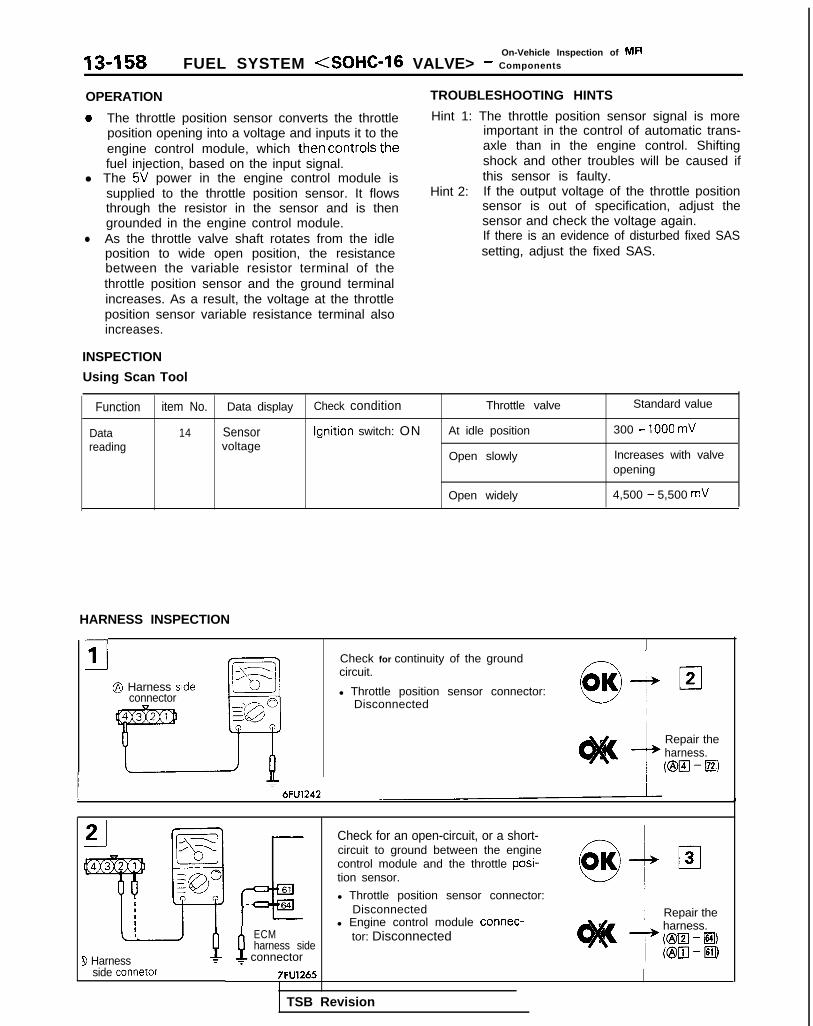
On-Vehicle Inspection of MFI13-158 FUEL SYSTEM (SOHC-16 VALVE> - Components
OPERATION
a The throttle position sensor converts the throttleposition opening into a voltage and inputs it to theengine control module, which then controls thefuel injection, based on the input signal.
l The 5V power in the engine control module issupplied to the throttle position sensor. It flowsthrough the resistor in the sensor and is thengrounded in the engine control module.
l As the throttle valve shaft rotates from the idleposition to wide open position, the resistancebetween the variable resistor terminal of thethrottle position sensor and the ground terminalincreases. As a result, the voltage at the throttleposition sensor variable resistance terminal alsoincreases.
INSPECTION
Using Scan Tool
TROUBLESHOOTING HINTS
Hint 1: The throttle position sensor signal is moreimportant in the control of automatic trans-axle than in the engine control. Shiftingshock and other troubles will be caused ifthis sensor is faulty.
Hint 2: If the output voltage of the throttle positionsensor is out of specification, adjust thesensor and check the voltage again.If there is an evidence of disturbed fixed SASsetting, adjust the fixed SAS.
Function item No. Data display Check condition Throttle valve Standard value
Data 14 Sensor Ignition switch: ON At idle position 300 - 1000 mVreading voltage
Open slowly Increases with valveopening
Open widely 4,500 - 5,500 mV
HARNESS INSPECTION
-
i1@ Harness side
connector
Check for continuity of the groundcircuit.
l Throttle position sensor connector:Disconnected
Repair theharness.(ml-m
3 Harnessside connetor
P ECMharness side
f connector
Check for an open-circuit, or a short-circuit to ground between the enginecontrol module and the throttle posi-tion sensor.
l Throttle position sensor connector:Disconnected
l Engine control module connec-tor: Disconnected
Repair theharness.@El - El)(@III-ElII
TSB Revision

FUEL SYSTEM <SOHC-16 VALVE> - ~:~t%~t~pection Of MF’ 13-159
@ Harness sideconnector
Measure the impressed voltage of thethrottle position sensor.
l Throttle position sensor connector:Disconnected
l Engine control module connec-tor: Connected
7 6FU1241
7FlJO485
TSB Revision
7FUa673
SENSOR INSPECTION
(1) Disconnect the throttle position sensor connector.
(2) Measure the resistance between the throttle position sensorside connector terminal @ and terminal @.
Standard value: 3.5 - 6.5 kQ
(3) Measure the resistance between the throttle position sensorside connector terminal @ and terminal @.
Throttle valve slowly opens Changes smoothly in propor-until fully open from the idle tion to the opening angle of theposition throttle valve
(4) If the resistance is outside the standard value, or if it doesn’tchange smoothly, replace the throttle position sensor.
N O T EFor the throttle position sensor adjustment procedure, referto P.13-136.
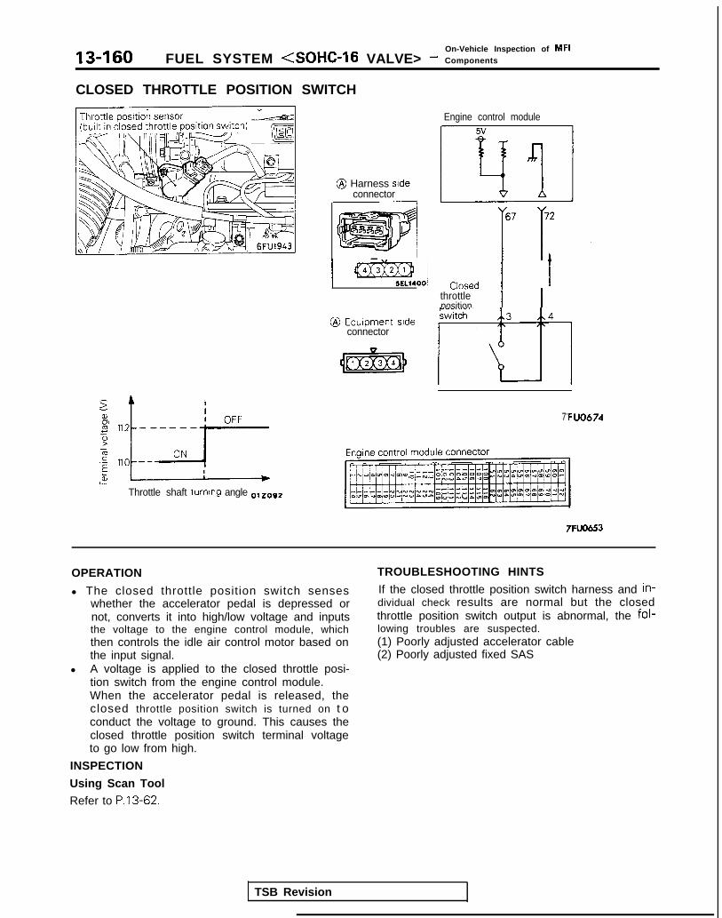
On-Vehicle Inspection of MFI13-160 FUEL SYSTEM (SOHC-16 VALVE> - Components
CLOSED THROTTLE POSITION SWITCH
za,
L
% ;; ----,-p
&Throttle shaft turning angle 0,z092
@ Harness sideconnector
Engine control module5v
‘il
67 72
II’1
1 -00, Closed 1/ 1
throttleposition
@ Equipment srdeswitch 3 4
connector ITT-l7 ‘F:UO674
TSB Revision
7FUO653
OPERATION
l The closed throttle position switch senseswhether the accelerator pedal is depressed ornot, converts it into high/low voltage and inputsthe voltage to the engine control module, whichthen controls the idle air control motor based onthe input signal.
l A voltage is applied to the closed throttle posi-tion switch from the engine control module.When the accelerator pedal is released, theclosed throttle position switch is turned on t oconduct the voltage to ground. This causes theclosed throttle position switch terminal voltageto go low from high.
INSPECTION
Using Scan Tool
Refer to P.13-62.
TROUBLESHOOTING HINTS
If the closed throttle position switch harness and in-dividual check results are normal but the closedthrottle position switch output is abnormal, the fol-lowing troubles are suspected.(1) Poorly adjusted accelerator cable(2) Poorly adjusted fixed SAS

FUEL SYSTEM <SOHC-l 6 VALVE> - :::;k%l;nspection Of MF’ 13-161
HARNESS INSPECTION
Check for open-circuit, or short-circuitto ground, between closed throttleposition switch and engine controlmodule.
l Engine control module connec-tor: Disconnected
l Closed throttle position switchconnector: Disconnected
@ Harness side^^^^^^ *^-
Check for continuitv of the groundt.
l Llosed throttle position switchconnector: Disconnected
1
! Repair t h e4 harness.
6FU1242 /
connector
TSB Revision 1
Measure the impressed voltage ofthe closed throttle position switch.
l Connector: Disconnectedl Engine control module connec-
tor: Connectedl Ignition switch: ON
Voltage (VI
I
I ReplaceI the engine
7 control
1 4 or more 1 module.
7FUO676
SENSOR INSPECTION
(I) Disconnect the throttle position sensor connector.(2) Check the continuity between the throttle position sensor
connector side terminal @I and terminal @.
(3) If out of specification, replace the throttle position sensor.
NOTEAfter replacement, the throttle position sensor and closedthrottle position switch should be adjusted. (Refer to P.13-136.)

On-Vehicle Inspection of MFI
13-162 FUEL SYSTEM (SOHC-16 VALVE> - Components
IAC VALVE POSITION SENSOR
@ Equipment sideconnector
7FlJO653
Enginecontrolmodule
IAC valve position sensor
h61 A\5 A72 Al8
%5v
I
9FUOO26
OPERATION
l The IAC valve position sensor converts thechanges (increase or decrease) in the valveposition of the idle air control motor into pulsesignals and inputs these signals to the enginecontrol module. The engine control module de-termines the valve position from these signalsand also controls the idle air control motor.
l 5V power is supplied to the IAC valve positionsensor from the engine control module, and theground connection is positioned in the enginecontrol module.
l 5V power is applied to the two IAC valve posi-tion sensor output terminals from the enginecontrol module. When the IAC valve position ischanged (increased or decreased) by the DCmotor inside the idle air control motor, the IACvalve position sensor generates a pulse signalfrom the opening and closing between the out-put terminal and the ground.
TROUBLESHOOTING HINTS
Hint 1: The IAC valve position sensor is the mostimportant sensor for controlling the idlespeed. If a malfunction develops when theengine is idling and the engine load is variedby turning the air conditioning switch to ONand OFF, etc., this sensor is probably defec-tive.
TSB Revision

FUEL SYSTEM <SOHC-16 VALVE> - :::,:k:t?=tiion Of MF’ 13-163
INSPECTION
Using Scan Tool
Function ( Item No.
Data reading / 5 5
l -
+
L
Data display
IAC valveposition step
T
Check condition
l Engine coolant tem-perature: 85 to 95°C(185 to 203’F)
l Lights, electric cool-ing fan, accesso-ries: OFF
l Transaxle: Neutral(P range for A/T)
l Closed throttle posi-tion switch: ON
l Engine: At idle(Compressor clutchto be operating incase air conditioningswitch is ON)
Load state
Air conditioning switch:OFF
Air conditioning switch:Turn from OFF to ON
l Air conditioningswitch: OFF
l Selector lever: Shift toD range
,,,,,,,,,IIncrease from 3-40 Istep
NfOTEIn a new vehicle [driven approximately 500 km (300 miles) or less], the IAC valve position sometimes exceeds thestandard value by approximately 20 steps.
CautionWhen shifting the selector lever to the D range, apply brake to prevent the vehicle from moving forward.
HARNESS INSPECTION
I IL\-11 r@Harm ” ’ -conna
tA Engine control
-tmodule harnessside rnnnnctor
Check for open circuit, or short-circuitto ground, between engine controlmodule and IAC valve position sensor.
l Engine control module connec-tor: Disconnected
l IAC valve position sensor connec-tor. Disconnected
21@Harness side
connector
0,OK-& 121
i Repair the--L harness(@lcl- El)
/ ml-~)(@pJ - @I)
Check for continuity of the groundcircuit.l IAC valve position sensor connec-
tor: Disconnected

13-164On-Vehicle Inspection of MFI
FUEL SYSTEM (SOHC-16 VALVE> - Components
Measure the impressed voltage.
l IAC valve position sensor connec-tor: Disconnected
l Engine control module connec-tor: Connected
*6FU1724
$Harness sideconnector
Measure the impressed voltage.
l IAC valve position sensor connec-tor: Disconnected
* Engine control module connec-tor: Connected
l Ignition switch: ON
6FU1723
TSB Revision 1

FUEL SYSTEM (SOHC-16 VALVE> - %$k%lnspectio” Of MF’ 13-165
CAMSHAFT POSITION SENSOR
@ Equipment sideconnector
Output characteristic PJ)
‘One rotation of distributor
@ Harness stdeconnector
lgnltion switch (IG,)
Distributorpistributor& 2 ,
Iz
Camshaftposition
Enginecontrolmodule
Engine control module connector
TSB Revision I
7FUO6539FuOO27
OPERATION
l The camshaft position sensor detects the topdead center on the compression stroke of theNo.1 cylinder, converts it into a pulse signal andinputs it to the engine control module. The en-gine control module determines the fuel injec-tion sequence based on this signal.
l Power to the camshaft position sensor is sup-plied from the ignition switch (IG), and theground is located in the engine control module.A 5V voltage is applied from the engine controlmodule to the camshaft position sensor outputterminal, and the camshaft position sensor gen-erates a pulse signal as it switches from OPENto SHORT (power transistor inside the sensorswitches ON/OFF) between the output terminaland the ground.
TROUBLESHOOTING HINTS
Hint 1: If the camshaft position sensor is defective,proper sequential injection will not occur, sothe engine will stall, or unstable idling andpoor acceleration will occur.
Hint 2: When the camshaft position sensor outputsa pulse signal when the ignition switch isturned to ON (without starting the engine),the camshaft position sensor or engine con-trol module is probably defective.

13-166On-Vehicle Inspection of MFI
FUEL SYSTEM <SOHC-16 VALVE> - Components
INSPECTION
Using Oscilloscope
Refer to P.13-69.
HARNESS INSPECTION
c
I IlFUO633 j switch
121 8 Harness-.-..-A side connector
Check for continuity of the groundcircuit.
l Crankshaft position sensor connec-tor: Disconnected
Ground)lFUO634
I
3:@ Harness
side connector fF68
Engine controlmodule harnessside connector
J 9P-
l Crankshaft position sensor connec-tor: Disconnected
9FUOO29 I I
Check for open circuit or short circuitto ground, between camshaft positionsensor and engine control module.
l Engine control module connec-tor: Disconnected
Measure the impressed voltage.
l Crankshaft position sensor connec-tor: Disconnected
l Engine control module connec-tor: Connected
l ignition switch: ON
Voltage (V)
4.8 - 5.2 module
TSB Revision

FUEL SYSTEM <SOHC-16 VALVE> - ::ii,,:::ti=pection Of MF’ 13-167
CRANKSHAFT POSITION SENSOR
@ Equipmentside connector
Output characteristic (V)
::L * Time
One rotation of distributor
01R0103
Engine control module connector
@ Harness sideconnector
Enginecontrolmodule
Ignition switch (IG,)
IDistributor
Crankshaft positionsensor
I/\2
B
/\
TSB Revision I
Oscillo1 I”69 , .68
IIL hh5V 5v
7FUO6539FUOO27

13-168 FUEL SYSTEM <SOHC-16 VALVE> - ::ii$%%spection Of MF’
OPERATION
l The crankshaft position sensor detects thecrank angle (piston position) of each cylinder,converts it to a pulse signal and inputs it to theengine control module. The engine control mod-ule computes the engine speed and the intakeair amount for one stroke and outputs the injec-tor drive signal and injection command signalbased on this signal.
0 Power to the crankshaft position sensor is sup-plied from the ignition switch (IG), and theground is located in the engine control module.A 5V voltage is applied from the engine controlmodule to the crankshaft position sensor outputterminal, and the crankshaft position sensorgenerates a pulse signal as it switches fromOPEN to SHORT (power transistor inside thesensor switches ON/OFF) between the outputterminal and the ground.
TROUBLESHOOTING HINTS
Hint 1: If unexpected shocks are felt during drivingor the engine stalls suddenly during idling,shake the crankshaft position sensor har-ness. if this causes the engine to stall, poorcontact of the sensor connector is sus-pected.
Hint 2: If the crankshaft position sensor outputs apulse signal when the ignition switch isturned to ON, (without starting the engine),the crankshaft position sensor or enginecontrol module is probably defective.
Hint 3: If the tachometer reads 0 rpm when the en-gine that has failed to start is cranked, faultycrankshaft position sensor or broken timingbelt is suspected.
Hint 4: If the tachometer reads 0 rpm when the en-gine that has failed to start is cranked, theprimary current of the ignition coil is notturned on and off. Therefore, troubles in theignition circuit and ignition coil or faulty igni-tion power transistor is suspected.
Hint 5: If the engine can be run at idle even thoughthe crankshaft position sensor reading is outof specification, troubles are often in otherthan the crankshaft position sensor.[Examples](1) Faulty water temperature sensor(2) Faulty idle air control motor(3) Poorly adjusted basic idle speed
TSB Revision

FUEL SYSTEM (SOHC-16 VALVE> - :::%%t:nspection Of MF’ 13-169
INSPECTION
Using Scan Tool
i
t
/Function Item No. i Data display Check condition Check content Normal state
Data reading ) 22 ( Cranking l Engine crankingspeed l Tachometer con-
’ Compare cranking speed, Indicated speed toand scan tool reading agree
netted (check on and
~ I
off of primary current 1of ignition coil by 1tachometer)
Function 1 Item No. Data display I C h e c k c o n d i t i o n ! Check content Normal state
Data reading i 22 ~ Idle speed l Engine: idling! l Closed throttle posi-t i o n s w i t c h : O N
p i ;;:;;:::;;:;;;
20°C (68°F) 1 l,lOO-1,300 rpm
40°C (I 04°F) 950-I ,I 50 rpm
: 80°C (176°F) ~ 600-800 rpmI
Using Oscilloscope
Refer to P.13-74.
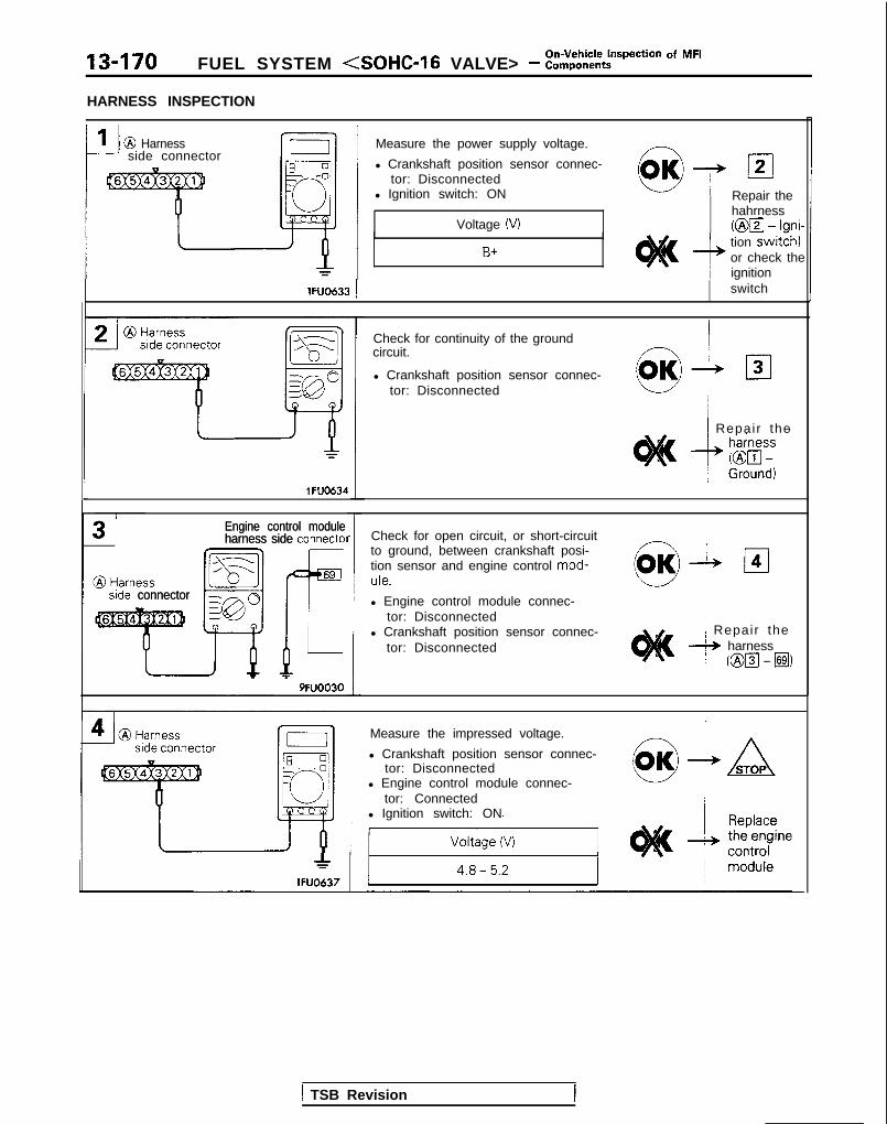
13-170 FUEL SYSTEM <SOHC-16 VALVE> - ::$%:ti=pection Of MF’
HARNESS INSPECTION
III @ Harness Measure the power supply voltage. - /-J side connector
l Crankshaft position sensor connec-tor: Disconnected
l Ignition switch: ON
Voltage (VI
Repair thehahrness(@a - Igni-
B+tion switch)or check theignition
lFUO633 ! switch
1 FU0634
side connectorside connector
Engine control moduleEngine control moduleharness side connect01harness side connect01
9FUOO30
Check for continuity of the groundcircuit.
l Crankshaft position sensor connec-tor: Disconnected
1 Repair the
Check for open circuit, or short-circuitto ground, between crankshaft posi-tion sensor and engine control mod-ule.
l Engine control module connec-tor: Disconnected
l Crankshaft position sensor connec-tor: Disconnected
~ Repair the+ harness
/ @El-El)
*lFUO637
Measure the impressed voltage.
l Crankshaft position sensor connec-tor: Disconnected
l Engine control module connec-tor: Connected
l Ignition switch: ON
1 TSB Revision

On-Vehicle Inspection of MFIFUEL SYSTEM (SOHC-16 VALVE> - Components 13-171
IGNITION SWITCH-ST <M/T>Ignition switch (ST)
Engine control module connector
T
-nEngine control module 51 71
OPERATION
INSPECTION
Using Scan Tool
Refer to P.13-77.
7FUO653 6FU1267
HARNESS INSPECTION
Engine controlmodule harness Measure the input voltage to theside connector engine control module.
l Engine control module connec-tor: Disconnected
l Ignition switch: START harness(j?iJ - lgnitiolswitch) orcheck theignition
6FUl258 switch/
module harnesside connector
l Engine control module connec-tor: Disconnected
TSB Revision

13-172On-Vehicle inspection of MFI
FUEL SYSTEM <SOHC-16 VALVE> - Components
IGNITION SWITCH-ST AND PARK/NEUTRAL POSITION SWITCH <A/T>Ignition switch (ST)
-T-@ k&pe;grt side
Starter Sterminal
f
8
I
7FUO653Engine control module 0~~~2~5
Engine control module connector
OPERATION
TROUBLESHOOTING HINTS
INSPECTION
Using Scan Tool
Refer to P.13-78.
HARNESS INSPECTION
rI!-
@ Harnessside connector
II 1 Measure the power supply voltage of
B o
4’
_ j
F---l
the park/neutral position switch.-
0I
l Engine control module connec-tor: Disconnected I
l Park/neutral position switch con-0 /
r
I nectar: DisconnectedI l Ignition switch: START
Voltage (V)
he
9FUO266 ~ / B+
Ii Engine controlmodule harness
9 Harness IFside connector
Check for continuity between park/neutral position switch and enginecontrol module.
l Engine control module connec-tor: Disconnected
l Park/neutral position switch con-nector: Disconnected
NOTETouch the circuit tester probes toboth ends of the harness
9~~0267
TSB Revision
clOK
/ Repair the-I, harness
j ml-m

FUEL SYSTEM <SOHC-l6 VALVE> - ::i%%?ction Of MF’ 13-173
r
srde connector
nectar: Disconnectedl Ignition switch: ON
PARK/NEUTRAL POSITION SWITCH INSPECTION
Refer to GROUP 23-Troubleshooting.
VEHICLE SPEED SENSOR
Vehicle speed sensor
Vehicle speed sensorWI
rerminal(oltage
Frequency[Hz1
MIBYQAA
Component side@ connector
Engine control module connector
6FU14101./Vehicle speed [km/h (mph)]
1 6 2 4 5 1OlLO838
OPERATION
TROUBLESHOOTING HINTS
Refer to P.13-80.
TSB Revision

13-174 FUEL SYSTEM <SOHC-16 VALVE> - :::;:%t~pection Of MF’
HARNESS INSPECTION
Engine control moduleharness side connector Check the vehicle speed sensor -
output circuit for continuity.
l Engine control module connec-tar! Disconnected
l Move the vehicle.
Engine controlmodule harnessside connector
66r,‘= 6FUl778
Check for open circuit or short-circuitto ground, between engine controlmodule and vehicle speed sensor.
l Engine control module connec-tor: Disconnected
l Vehicle speed sensor connector:Disconnected Repair the
harness@El - 8)
Check for continuity of the ground
speed sensor: Discon-
TSB Revision
6FU1465 /
Measure the impressed voltage.
l Vehicle speed sensor connector:Disconnected
l Engine control module connec-
SENSOR INSPECTION
Refer to GROUP 54-Meters and Gauges.

On-Vehicle Inspection of MFIFUEL SYSTEM <SOHC-16 VALVE> - Components
POWER STEERING PRESSURE SWITCH
13475
700 - 2,000(7 - 20,
;i~~*~2,000
100 - 284) 213- 164)
Pressure fkPa (kg/on?*. psi11
Enaine control module connector
Enginecontrolmodule
Power steeringpressure switch
@ Harnessside connector
IIll
7FUO536
I
OPERATION
INSPECTION
Using Scan Tool
Refer to P.13-82.
7Fuo653
HARNESS INSPECTION
side connector
Engine controlmodule harnessside connector
I 7FU1235
Check for open circuit or short-circuitto ground, between engine controlmodule and power steering pressureswitch.
l Power steerina messure switchconnector: Disconnected
l Engine control module connec-tor: Disconnected
IRepair theharness(@m -11071)
TSB Revision

13-176 FUEL SYSTEM <SOHC-16 VALVE> - ::i$%%-ti=pection Of MF’
1
@ Harnesssrde connector
7FUOSO5
Measure the impressed voltage. /\ 1 Al Power steering pressure switch
connector: Disconnectedl Engine control module connec-
tor: Connectedl Ignition switch: O N
Voltage 04
1 m o d u l e
J
AIR CONDITIONING SWITCH AND A/C COMPRESSOR CLUTCH RELAY hl13YRABl
ii++----- ,L’AI:Air conditionino
1 s w i t c h -
‘ A //A\‘A /,,--.l, ,+q‘\
\\Wj i EYAJ2
6FUO645
Air conditioningc o m p r e s s o rc lu tch relav
~-1 6FUO612
Engine control module connector
Sub fusible link
TSB Revision
Air conditioning 1
@ m i”“:F$
1
Engine control module ,
I 7FUO653
-,4,
g:2
[
22
Auto compressorcontrol unit
6
2 Dual pressure
I
switch
3N
3N
1
1 Air conditioningOFF engine COOlant
,^N temperature
2switch
1 1 5
6FU145.7
OPERATION
TROUBLESHOOTING HINTS
INSPECTION
Using Scan Tool
Refer to P.13-83.

On-Vehicle Inspection of MFIFUEL SYSTEM (SOHC-16 VALVE> - Components 13-177
HARNESS INSPECTION
YEngine controlmodule harness-; side connector
01noee3
AIR CONDITIONING INSPECTION
Refer to GROUP 55-Air Conditioning.
Measure the power supply voltage ofthe air conditioning circuit.
I
l Air conditioning switch: ONl Engine control module connec-
tor: Disconnectedl Ignition switch: ON
EGR TEMPERATURE SENSOR <California>
GR temperature s
@ Equipment sideconnector
Check theair condi-tioningcircuit
EGR temperature sensor71 @ Harness side
connector
i
I *
Temperature 1621006 7FU1013
OPERATION
Refer to P.13-85.
INSPECTION
Using Scan tool
Function
Data reading IItem No
43 IData display
Sensortemperature I
Inspection conditions Engine condition Standard value
. Engine: warm up* Engine is maintained in a .
Idle speed 7o’C (158°F) or lower
constant state for 2minutes or more
3,500 rpm 70°C (158°F) or higher
* Remove the vacuumhose (green stripes) fromthe EGR solenoid andplug both the removedvacuum hose end andsolenoid valve nipple.
TSB Revision

13-178 FUEL SYSTEM <SOHC-16 VALVE> - ::$%?=pection Of MF’
HARNESS INSPECTION
Harness stdeconnector
OlAOS22L-j-J
Harness sideconnector
SFUOOS:3
T Check for continuity of the groundcircuit.
l EGR temperature sensor connec-tor: Disconnected
Check for an open circuit, or a shortcircuit to ground between the enginecontrol module and the EGR tempera-ture sensor. bi- 03l EGR temperature sensor connec- ‘u’
tor: Disconnectedl Engine control module connec-
tor: Disconnected
Repair thei-, harness.
j @El-H)
TSB Revision
Measure the Impressed voltage.l Connector: Disconnectedl Engine control module connec-
tor: Connected
l Ignition switch: ON
Voltage (V)
4.3 - 4.7
1 R e p l a c eA the engine
c o n t r o lmodule.
SENSOR INSPECTION
Refer to GROUP 17 - Exhaust Gas Recirculation (EGR) System.

On-Vehicle Inspection of MFIFUEL SYSTEM <SOHC-16 VALVE> - Components 13-179
OXYGEN SENSOR
\ l-f
\Oxygen sensor
J
q :
i’ 1%
Lkm uA 6FUO6.5
28.5s.-EE?za,w
Theoretical A/F
14 15 164/F EClW7
j5
Enginecontrolmodule
@ Equipment sideconnector
iIxy;n se;‘i,G,
A56 h72
fhx5v
@ Harness sideconnector
9FUOO32
Engine control module connector
7FL0553
OPERATION
TROUBLESHOOTING HINTS
INSPECTION
Using Scan ToolRefer to P.13-87.
HARNESS INSPECTION
Engine controlmodule harnesside connector
56
1’r Y lFUO5%
Check for an open circuit, or a shortcircuit to ground, between the enginecontrol module and the oxygen sen-sor.
l Oxygen sensor connector: Discon-nected
l Engine control module connec-tor: Disconnected
clOK + 02
’ Repair theA harness
( @El-@I)
TSB Revision

13-180 FUEL SYSTEM <SOHC-16 VALVE> - :::;:%?pection Of MF’
@ Harness sideconnector
Check for continuity of the ground
Repair theharness(@lzl - El)
I lFUOS97 1 I
L
G-l I’ ‘Ilar rI L / I
I JlFUO598J
SENSOR INSPECTION
(I) Warm the engine and check to be sure that the enginecoolant temperature is 85-95°C (185-203°F).
(2) Disconnect the oxygen sensor connector and connect adigital voltmeter.
CautionWhen disconnecting the oxygen sensor connector, donot pull the connector or lead wire too strongly.
(3) Race the engine repeatedly and measure the oxygen sensoroutput voltage.
EngineSensor output
voltage Remark
When When the a/r/fuel mixtureracingthe 0.6 - 1 .O V
ratio is enriched by racing theengine repeatedly, a normal
engine oxygen sensor will output avoltage of 0.6 - 1 .OV.
(4) If the sensor is defective, replace the oxygen sensor.
NOTEFor removal and installation of the oxygen sensor, refer toGROUP 15 - Exhaust Manifold.
TSB Revision

FUEL SYSTEM <SOHC-l 6 VALVE> - :::,:%?pection Of MF’ 13-181
INJECTORS
Fuel
Connect01
Soienold co11
Plunger
Needle valve
Injectlop
Multiport fueliniection relay
TSB Revision
connector
Engine control module
Engine control module connector
lFUO642
7FUO653
I
OPERATION
TROUBLESHOOTING HINTS
Refer to P.13-90.

13-182 FUEL SYSTEM <SOHC-16 VALVE> - ~~~;~~~t~pection Of MF’
INSPECTION
Using Scan Tool
Function 1 Item No. ’ Data display 1 Check condition I Coolant temperature Standard value
IData reading / 41 Dr ive trme *’ 1 Engine: Cranking 0°C (32°F) *2 Approx. 20 ms
j: 20°C (68°F) Approx. 40 ms
80°C (176°F) / Approx. 9.8 ms
Data reading
NOTE
Item No.
41
iData display 1 C h e c k c o n d i t i o n I Engine state 1 Standard value
Drive time *3 l Engine coolanttemperature: 85 to95°C (185 to 203°F)
l Lights, electriccooling fan, accesso-ries: OFF
l Transaxle: Neutral(P range for AIT)
Idle speed 1 2.2-3.4 ms
*‘: The injector drive time refers to when the supply voltage is 11 V and the cranking speed is less than 250 rpm.*2: When engine coolant temperature is lower than 0°C (32°F). injection is made by four cylinders simultaneously.*3: When the vehicle is new [within initial operation of about 500 km (300 miles)], the injector drive time may be about
10% longer
F u n c t i o n I t e m N o . D r i v e c o n t e n t Check condition Normal state
Actuator test 01 No. 1 injector shut off Engine: Idling after I Idle state to change further
0 2 No. 2 injector shut off- warm-up (becoming less stable or
(Shut off the injectors in stalling)
03 li No. 3 injector shut offsequence during after
- engine warm-up, check 1
I 04 No. 4 injector shut off the idling condition)
- kImp4 AL A: Inje,t,r--m--m-
Normal waveform drive time 03*0209
(1) Run the engine at idle speed.(2) Connect the probe to the oscil loscope pick-up point as
shown in the circuit diagram, and check the waveform atthe drive side of each injector.
1TSB Revision
1 Using Oscilloscope

FUEL SYSTEM <SOHC-16 VALVE> - ~:$%:t?on Of MF’ 13-183
HARNESS INSPECTION
@ Multiport fuelinjection relayharness sideconnector
,\---LEll---l0
!I?
pJ”D
Harnesssideconnector
6FU1779
@@@03Harness sideconnector
1
Pmodule harnessside connector
=lFUO643
ACTUATOR INSPECTION
Refer to P.13-92.
r I
I-
T
L
Check for continuity between injectorand multiport fuel injection relay.
l lniector connector: Disconnectedl tviultiport fuel injection relay con-
nector: Disconnected
NOTETouch the circuit tester probes to bothends of the harness.
Repair theharnessCm- 0@3,
Check for an open circuit, or a shortcircuit to ground between the enginecontrol module and the injector.
l Engine control module connec-tor: Disconnected
l Injector connector: Disconnected
TSB Revision I

13-184On-Vehicle Inspection of MFI
FUEL SYSTEM (SOHC-16 VALVE> - Components
IDLE AIR CONTROL MOTOR (DC MOTOR)
@ Harness sideconnector
I
L
[@Ex@ziJ 15ELWOlJ
j
e;
j 55ww3 )A’,’
/
@ Equipment sideconnector
Engine control module
Idle air control motor
6FU1734
Engine control module connector
7FUCJG3
OPERATION
l The volume of intake air during engine idling iscontrolled by the opening and closing of the IACvalve for bypassing the throttle valve, located atthe air intake port.
l The IAC valve opens and closes depending onwhether the DC motor inside the idle air controlmotor is turning clockwise or anti-clockwise.
l The DC motor turns clockwise or anti-clockwiseaccording to the change in the direction of cur-rent in the motor drive IC inside the engine con-trol module.
TROUBLESHOOTING HINTS
Hint 1: While the engine is idling, if the idle speedand IAC valve position (step) change whenthe air conditioning switch is turned to ONand OFF, it can be assumed that the idle aircontrol motor and the IAC valve positionsensor are operating normally.
Hint 2: If the IAC valve position (step) is outside thestandard position, the malfunction is prob-ably one of the following:(I) Basic idle speed adjustment is wrong.(2) Some deposit is adhering to the throttle
valve.(3) Air is being drawn into the air intake
manifold through a defectivegasket seal.(4) EGR valve sheet adhesion is defective.(5) Combustion malfunction inside a cylin-
der.(Spark plug, ignition coil, injector orcompression pressure is defective.)
TSB Revision
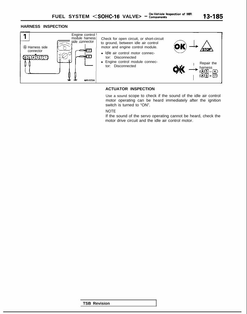
FUEL SYSTEM <SOHC-16 VALVE> - :,%,,k%$spection Of MF’ 13-1g5
HARNESS INSPECTION
@ Harness sideconnector
Engine control )module harnessside connector
- - 6FU1735
Check for open circuit, or short-circuitto ground, between idle air controlmotor and engine control module.
l Idle air control motor connec-tor: Disconnected
l Engine control module connec-tor: Disconnected
0OK SASTOP
Repair theharnessml - El)Km - El)
J
ACTUATOR INSPECTION
Use a sound scope to check if the sound of the idle air controlmotor operating can be heard immediately after the ignitionswitch is turned to “ON”.
NOTEIf the sound of the servo operating cannot be heard, check themotor drive circuit and the idle air control motor.
TSB Revision

13-186On-Vehicle Inspection of MFI
FUEL SYSTEM <SOHC-16 VALVE> - Components
IGNITION COIL AND IGNITION POWER TRANSISTOR
-Distributor(built inignition coiland Ignitionpowertransistor)
Equrpment srdeconnector 8 ”
Engine control module connector
Sparkplug
Iynitron coil ‘r ,
lgnitron switch (IG,)
Distributor /,@)f 1
9 Harness sideconnector
4lgnrtion timingadjustmentconnector
7FU0653
Engine control module
9FUOO35
OPERATION
Refer to P.13-96.
INSPECTIONUsing Scan Tool
Function / Item No.
Data reading i 44
Data display i C h e c k c o n d i t i o n j Engine state Standard value_.-___-- - -
Ignitionadvance
l Engine: Warming up Idle speed 0- 13 “BTDCl Timing light: Set (set
timing light to checkactual ignition timing)
/- - -
2,000 rpm 19-39 “BTDC
1 TSB Revision 1
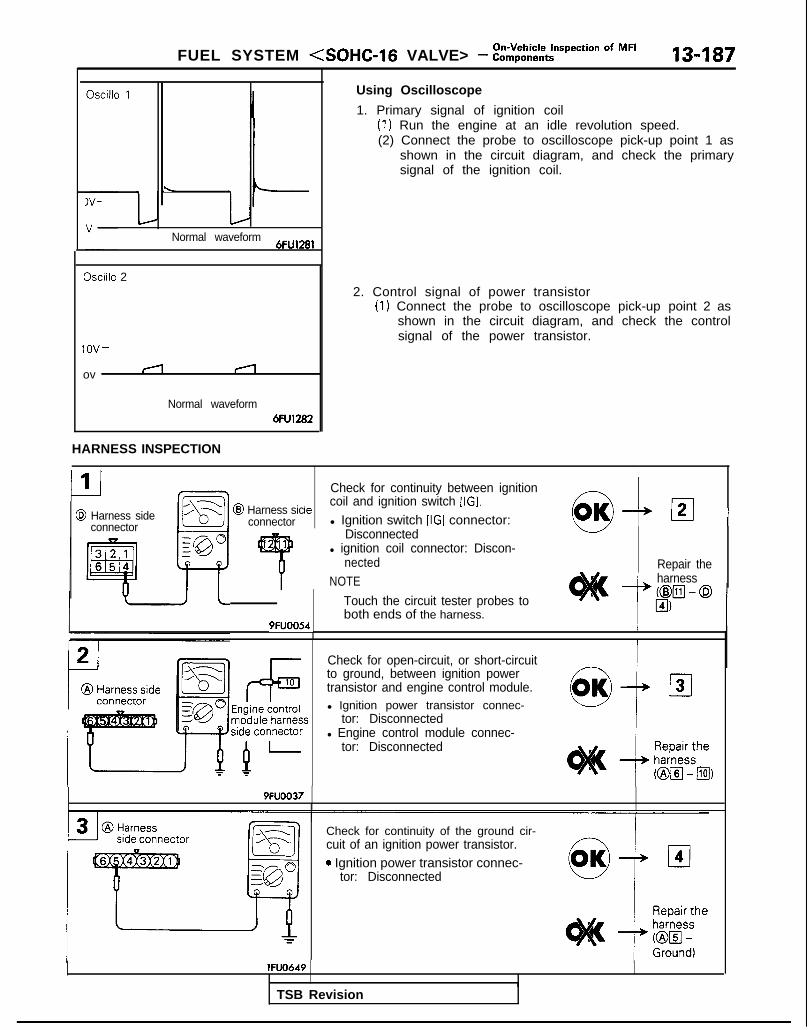
FUEL SYSTEM <SOHC-l6 VALVE> - :::;:it,t*?pec*ion Of MF’ 13-187
\
Normal waveform6FU1281
Oscillo 2
lOV-
ov II
Normal waveform6FU1282
HARNESS INSPECTION
Using Oscilloscope
1. Primary signal of ignition coil(1) Run the engine at an idle revolution speed.(2) Connect the probe to oscilloscope pick-up point 1 as
shown in the circuit diagram, and check the primarysignal of the ignition coil.
2. Control signal of power transistor(I) Connect the probe to oscilloscope pick-up point 2 as
shown in the circuit diagram, and check the controlsignal of the power transistor.
CI1@ Harness side
connector
Check for continuity between ignition
‘R/ 4 (21 I@I Harness sicle coil and ignition switch [IGI.
connector l Ignition switch [IGI connector: /,‘\0”Disconnected
1
4
l ignition coil connector: Discon-nected
NOTE
Touch the circuit tester probes toboth ends of the harness.
19FUOO54, /I
Repair theharness_A- h
Check for open-circuit, or short-circuitto ground, between ignition powertransistor and engine control module.l Ignition power transistor connec-
tor: Disconnectedl Engine control module connec-
tor: Disconnected
9FUOO37
Check for continuity of the ground cir-cuit of an ignition power transistor.0 Ignition power transistor connec-
tor: Disconnected
lFUO649
TSB Revision

-i4
@ Harness sideconnector
/
Check to be sure that there is nocontinuity between the ignition coiland the earth.
l Ignition coil connector: Discon-netted
/ Check forshort in theignition coilprimary
/ circuit9FUOO38 1
13-188On-Vehicle Inspection of MFI
FUEL SYSTEM <SOHC-16 VALVE> - Components
6I
--ml---X
A!g@0
TlFUO650
lgnltion tlmlngadjustmentconnector
E -:1
ll!?!*
7FU1060
L
Measure the voltage of the controlsignal circuit of the ignition powertransistor.
0 Ignition power transistor connec-tor: Disconnected
l Ignition switch: START
Voltage (VI I
Measure the voltage of the ignrtiontiming adjustment terminal.
l Ignition switch: ON
Voltage (VI
0OK lIzI6
Repair theharness(@El - Ial
4.0 - 5.2
ACTUATOR INSPECTION
Refer to GROUP 16 - Ignition System.
Repair theharness(@El - 11041)
TSB Revision I

On-Vehicle Inspection of MFIFUEL SYSTEM (SOHC-16 VALVE> - Components 13-189
EVAPORATIVE EMISSION PURGE SOLENOID
I Evaporative emission /
Multipomfuelinjection relay
Evaporative emissionpurge solenoid
-cofxiector
V I@ Harness side
connector
p
Q I:1
@ Eauioment side
Engine !!!I module ki
J
5ELl205)
TSB Revision
Engine control module connector
OPERATION
INSPECTION
Using Scan Tool
Refer to P.13-99.

13-190On-Vehicle Inspection of MFI
FUEL SYSTEM <SOHC-16 VALVE> - Components
HARNESS INSPECTION
@ Multiport
connector
~Harness side Check for continuity between evapo-
connector~ rative emission purge solenoid and
multiport fuel injection relay.
l Evaporative emission purge sole-noid connector: Disconnected
I ~ l Multiport fuel injection relay con-nector: Disconnected
1 ; N O T ETouch the circuit tester probes to
9FUOO39 !both ends of the harness.
Check for an open circuit, or a short-circuit to ground, between the evapo-rative emission purge solenoid andthe engine control module.
Harness srdeconnector
l Evaporative emission purge sole-noid connector: Disconnected
l Engine control module connec-tor: Disconnected
,I Repair the* harness
@m-El)
I
ACTUATOR INSPECTION
Refer to GROUP 17 - Evaporative Emission Control System.
I%% Revision I

FUEL SYSTEM <SOHC-l 6 VALVE> - %i,,:::ti-pection Of MF’ 13-191
EGR SOLENOID <California>I
Engine control module connector
Multiport fuelinjection relay
EGR solenoid
connector
\/ ‘“ 2
A6Enginecontrolmodule
r - w
7FlJOU3OlWIS7
OPERATION
TROUBLESHOOTING HINTS
INSPECTION
Using Scan ToolRefer to P.13-101.
HARNESS INSPECTION
_11I IIF5
connector
@I Harness sidec o n n e c t o r ul[ J
9FUOO53
Check for continuity between EGRsolenoid and multiport fuel injection - !relay.
l EGR solenoid connector: Discon-netted w
l Multiport fuel injection relay con- Inectar: D i s c o n n e c t e d
NOTE
Touch the circuit tester probes toboth ends of the harness. 1 MI,
1 TSB Revision

On-Vehicle Inspection of MFI13-192 FUEL SYSTEM (SOHC-16 VALVE> - Components
connector
Engine control moduleharness Check for an open circuit, or a short-
circuit to ground, between the EGRsolenoid and the engine control mod-ule.
l EGR solenoid connector: Discon-nected
l Engine control module connec-tor: Disconnected
0OK +ASTOP
,wsL
Repair theharnessmzl- El)
ACTUATOR INSPECTION
Refer to GROUP 17 - Exhaust Gas Recirculation (EGR) System.
FUEL PRESSURE TESTRefer to P.13-102.
INSPECTION OF ENGINE CONTROL MODULETERMINAL VOLTAGENOTEMake the voltage measurement between terminal No.26(ground terminal) and each terminal.
Refer to P.13-105.
TERMINAL VOLTAGE CHECK CHARTTerminal arrangement of engine control module connector
7FUQ653 NOTEB+: Battery positive voltage
Terminal ~N o . Check Item ~ Check Condition (Engine Condition) / Standard
/ value
60 j Backup power supply i Ignrtron: OFFI - -
,12 / Power supply I Ignrtion: ON
25 j
B+
B+
8 Multiport fuel lgnrtion switch: ON ~ B+injection relay
~ (Fuel pump) Enqine: Idle speed o-3v
61 ’ Sensor impressed Ignition switch: ON i 4.5-5.5vvoltage
70 Volume air flow Engine: Idle speed / 2.2-3.2Vj sensor
IEngine rpm: 2,000 rpm
1 TSB Revision

FUEL SYSTEM <SOHC-16 VALVE> - i%$-%~pection Of MF’ 13-193
TerminaNo.
19
52
-rII
i
t
c65
L
63
64t
I:
I
Check Item : Check Condition (Engrne Condrtron)
Volume air flow j Engine: Idle speedsensor reset signal 1
Engine rpm: 3,000 rpm
Intake air tempera- 1Ignition switch: ON When Intake atr temperature IS 0°C (32°F)ture sensor
When intake air temperature IS 20°C (68°F)
i When intake air temperature is 40°C (104°F)
When intake air temperature is 80°C (176°F)
lgnltlon switch: ON ’ When altitude is 0 m
When altitude is 1,200 m (3,937 ft.)
Ignition switch: ON i When engine coolant temperature IS 0°C (32°F)
When engine coolant temperature is 20°C (68°F)
When engine coolant temperature is 40°C (104°F)
Barometnc pressuresensor
Engine coolanttemperature sensor
Throttle positionsensor
67
68
69
51
115
11
Ic22
Closed throttleposition switch
Camshaft positionsensor
Crankshaft positionsensor
Ignition switch-ST
Park/neutral positionswitch
Vehicle speed sensor
Power steeringpressure switch
Air conditioningswitch
-II When engine coolant temperature is 80°C (176°F)
‘I
) 0.3-0.9v
Ignition switch: ON Set throttle valve to idle position. 0.3-0.6V
iFully open throttle valve. 1 4.5-5.5v
Ignition switch: ON Set throttle valve to idle position. o-1v
’ Slightly open throttle valve 4V or more
Engine: Cranking 0.2-3.OV
Engine: Idle speed
Engine: Cranking 0.2-3.OV
Engine: Idle speed
Engine: Cranking 8V or more
Ignition switch: ON ( SetselectorlevertoPorN. o-3v
i Set selector lever to D. 2, L or R. 8-14V
Ignition switch: ON i 04d5v
Move the vehicle slowly forward. (Changesrepeatedly)
Engine. Idling after warmrng up Steering wheel idle state B+
During steering wheel operation o-3v
Engine: Idle speed ’ Turn the air conditioning switch OFF o-3vI’ Turn the air conditioning switch ON. 1 B+
(Air conditioning compressor is operating) !
Engine: Idle speed 1 B+orAir conditioning switch: OFF-ON I temporarilyTurn the conditioning switch ON. (Air conditioning compressor is operating) 1 6V or more
j 11 o-3v
/ Standardvalue
/ o-1v
1 6-9V
1 3.2-3.8V
: 2.3-2.9v
1.5-2.1V
i 0.4-I .ov
j 3.7-4.3v
/ 3.2-3.8V
, 3.2-3.8V
1, 2.3-2.9v
1.3-l .9vI
Air conditioningcompressor clutchrelay
TSB Revision 1

13-194 FUEL SYSTEM <SOHC-16 VALVE> - ::~;:%~specion Of MF’
7-i
Termrnal INo. , C h e c k I t e m
,Check Condrtion (Engine Condition)
Standardvalue
OttO.8V(Changesrepeatedly)
TFrom 1 l-14v.momen-tarily dropsslightly
B+
o-1v
4.0-5.5v
o-3v1
9-13v(Afterseveralsecondshaveelapsed)
B+
‘rom B+nomentarlly drop IS
I
56 1 Oxygen sensor i Engine: Running at 2,000 rpm after havrng warmed up. (Check using a
I~ drgltal type voltmeter.)
3.6-4.4 V
2.2-3.OV
1.5-4v(Momen-tarily)O-l V or4.55.5v
1.5-4v(Momen-tarily)
1D-IV or4.5-5.5v
2V or moreIMomen-tarily)
LI-1 v
4V or moreMomen-:arily)
1I-1v
No. 1 Injector
No. 2 Injector
’ While engine is Idling after having warmed up, suddenly depress theaccelerator pedal.
1
14
2 No. 3 Injector
15 No. 4 Injector
Ignition power transistor unit ~ Engine rpm: 3,000 rpm___-
Evaporative emission Ignition swatch: ONpurge solenoid
Runnrng at 3,000 rpm while engine is warmrng up after having beeni started.
I
10 II-
9
104 Ignition timingadjustment terminal
lgnttion switch: ON 1 Earth the ignition trming adjustment terminal
I Remove the earth connection from the ignitiontiming adjustment terminal.
Check Air conditioning switch: OFF-ONengine/malfunctionindicator lamp i
106
6 EGR solenoid<California>
lgnrtion switch: O N
; Engine IS idling after having warmed up /jEGR temperaturesensor <California>
Ignition switch: ON When the sensor temperature is 50°C (122°F).
When the sensor temperature is 180°C (212°F).
I 1I </ ’AC valve positlonsensor No.1
Ignition switch: Immediately after turnrng ON5
18 AC valve positionsensor No.2
lgnltion switch: lmmedlately after turning ON
dle air control motorclosed)
Ignition switch: Immediately after turning ON
3le air control motorwen)
lgnitlon switch: Immediately after turning ON 1
(
t
i (
1 TSB Revision

Fuel Tank/Fuel Line and Vapor Line/FUEL SYSTEM (SOHC-16 VALVE> - Fuel Filter 13-195
FUEL TANKRefer to P.13-109.
FUEL LINE AND VAPOR LINERefer to P.13-113.
FUEL FILTERRefer to P.13-115.
TSB Revision
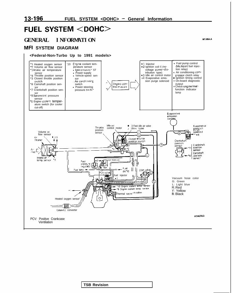
13-196 FUEL SYSTEM <DOHC> - General Information
FUEL SYSTEM <DOHC>GENERAL INFORMATIONMFI SYSTEM DIAGRAM
Ml 3BA-A
<Federal-Non-Turbo Up to 1991 models>
*1 Injector*2 Ignition coil (Low-
voltage power-drs-tribution type)
*3 Idle air control motork4 Evaporative emis-
sion purge solenoid
l Fuel pump control(Multiport fuel injec-tion relay)
l Air conditioning corm-pressor clutch relay
* Ignition timing control) On-board diagnostic
output) Check engine/mal-function indicatorlamp
Engine coolant tem-perature sensorl Ignition swatch STl Power supplyl Vehicle-speed sen-
sor. Arr conditioning
switchl Power steering
pressure swatch
‘I Heated oxygen sensor ‘10*2 Volume air flow sensor*3 Intake air temperature
sensor‘4 Throttle position sensor*5 Closed throttle position
swrtch*6 Camshaft position sen-
sor“7 Crankshaft position sen-
sor“8 Barometrrc pressure
sensor‘9 Engine coolant temper-
ature switch (for coolercut-off)
Evaporatrveemrssioncanister
Evaporatrveemlsslo”
Idle airThronle control motor
l 3 Fast idle air valveI (Wax tvoe)
position\Volume air /sensor 3
flow sensor f \ //n,r \ l 2 '8
- lnnhnn toll III1 II
II-“,--?% 11 11 EGR, /alveI.l”lll)i
Fuel injector II IIVacuum hose colorG: GreenL: Light blueI?: RedY: Yellow5: Black
Heated oxygen sensor
Thermal vacuu
a uCatalytrc converter
HMO163PCV: Positive Crankcase
Ventilation
TSB Revision
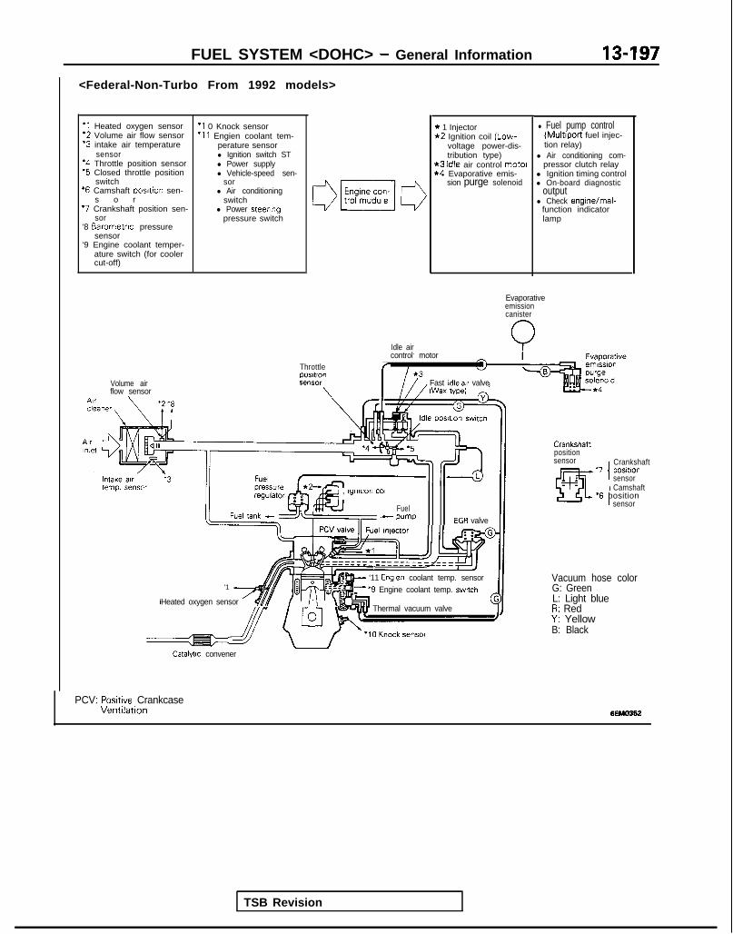
<Federal-Non-Turbo From 1992 models>
‘1 Heated oxygen sensor‘2 Volume air flow sensor“3 intake air temperature
sensor‘4 Throttle position sensor‘5 Closed throttle position
switch‘6 Camshaft Dosltion sen-
s o r*7 Crankshaft position sen-
sor‘8 Barometnc pressure
sensor‘9 Engine coolant temper-
ature switch (for coolercut-off)
‘I 0 Knock sensor‘11 Engien coolant tem-
perature sensorl Ignition switch STl Power supplyl Vehicle-speed sen-
sorl Air conditioning
switchl Power steering
pressure switch
Volume airflow sensor\
Idle air
FUEL SYSTEM <DOHC> - General Information 13-197
* 1 Injector*2 Ignition coil (Low-
voltage power-dis-tribution type)
*3 Idle air control motel*4 Evaporative emis-
sion purge solenoid
l Fuel pump control(Multiport fuel injec-tion relay)
l Air conditioning com-pressor clutch relay
l Ignition timing controll On-board diagnostic
outputl Check engine/mal-
function indicatorlamp
Evaporativeemissioncanister
QThrottlepOSltlOnSt?“SW
\
control motor
r
Fast Idle air valveWax tape)
TSB Revision
e , lylllll”rl COll
Fuel- wmp EGR valve
'1 A
Heated oxygen sensor /$$y /.\‘“I
w ‘11 Englen coolant temp. sensorF ‘9 Engine coolant temp. switch
Thermal vacuum valve
Crankshaftpositionsensor
‘7 positlonI
Crankshaft
sensor
I
Camshaft‘6 position
sensor
Vacuum hose colorG: GreenL: Light blueR: RedY: YellowB: Black
Catalytic convener
PCV: Posmve CrankcaseVentllatlon 6EMO362

13-198 FUEL SYSTEM <DOHC> - General information
<California-Non-Turbo Up To 1991 models>
*I Heated oxygen sensor *IO EGR temperature sen-*2 Volume air flow sensor sor‘3 Intake air temperature *I 1 Engien coolant tem-
sensor perature sensor‘4 Throttle position sensor . Ignition switch ST*5 Closed throttle position l Power supply
switch l Vehicle-speed sen-‘6 Camshaft posltion sen- sor
sor l Air conditioning“7 Crankshaft positron sen- switch
SOT 0 Power steering‘8 Barometric pressure pressure switch
sensor‘9 Engine coolant temper-
ature switch (for coolercut-off)
*l Injector*2 Ignition coil (Low-
voltage power-dis-tribution type)
*3 idle air control mot01*4 Evaporative emis-
sion purge solenoid*5 EGR solenoid
) Fuel pump control(Multiport fuel injec-tion relay)
I Air conditioning com-pressor clutch relay
I Ignition timing control) On-board diagnostic
output) Check enginejmal-function indicatorlamp
Evaporativeemissioncanister
Volume airflow sensor
A.. \
IIoressure db ,Fun, taw”l”‘“‘~
Heated 0~““~”
le ax valve
e”SOrgme coolant temp.
Vacuum hose colorG: GreenL: Light blueR: RedY: YellowR. Rlnrk
Catalytic converter6FU1596
PCV: Positive CrankcaseVentilation
TSB Revision

FUEL SYSTEM <DOHC> - General Information
<California-Non-Turbo From 1992 models>
*1 Heated oxygen sensor*2 Volume air flow sensor‘3 Intake air temperature
sensor*4 Throttle position sensor‘5 Closed throttle position
switch*6 Camshaft position sen-
sor‘7 Crankshaft position sen-
sor‘8 Barometric pressure
sensor‘9 Engine coolant temper-
ature switch (for coolercut-off)
Volume air
‘10 Knock sensor‘11 EGR temperature sen
sor‘12 Engien coolant tem-
perature sensorl Ignition switch STl Power supplyl Vehicle-speed sen-
sorl Air conditioning
switchl Power steering
pressure switch
3
Throttlepositionsensor
I
Intake air .‘3 Fueltemp. sensor p r e s s u r e *2-
regulator A - -. c d ’
*l Injector l Fuel pump control*2 Ignition coil (Low- (Multiport fuel injec-
voltage power-dis- tion relay)tribution type)
*3 Idle air control motorl Air conditioning com-
l 4 Evaporative emis-pressor clutch relay
sion purge solenoidl Ignition timing control
t5 EGR solenoidl On-board diagnostic
outputl Check engine/mal-
function indicatorlamp
Idle aircontrol motor
I
Wax wei
I I
TSB Revision
Evaporativeemissioncanister
Heared oxygen
It= ‘12 Engine coolant temp.sensor -‘I u
‘ 9 Engine coolant temp switch\
l 10 Knock sensor
EGR temperature
Crankshaftposltlon
EGR‘solenoid
Vacuum hose colorG: GreenL: Light blueR: RedY: YellowB: Black
Catalfllc converter
PCV: Positive CrankcaseVentilation

13-200 FUEL SYSTEM <DOHC> - General Information
<Federa l -Turbo>
*l Heated oxygen sensor‘2 Volume air flow sensor*3 Intake air temperature
sensor‘4 Throttle position sensor‘5 Closed throttle position
switch*6 Camshaft posrtion sen-
sor‘7 Crankshaft posrtion sen-
sor‘8 Barometric pressure
sensor“9 Engrne coolant temper-
ature swatch (for coolercut-off)
‘10 Knock sensor‘1 1 Engien coolant tem-
perature sensorl lgnitton switch STl Power supplyl Vehicle-speed sen-
sor. Arr conditioning
switchl Power steering
pressure switch
Volume arrflow sensor
l 6
* 1 Injector . Fuel pump Control*2 Ignition coil (Low- (Multiport fuel injec-
voltage power-dis- tion relay)tribution type) l Air conditioning com-
*3 Idle air control motor pressor clutch relay*4 Evaporative emis- . Ignition timing control
sion purge solenoid l On-board diagnostic*5 Fuel pressure sole- output
noid . Check enginelmal-*6 Turbocharger waste
gate solenoidf;r$ion indicator
EVAP canisterA
Throttle
9 Engine coolant temp. switchThermal VaCUUm valve
b;~ype; waste e-5 /I \ - I”-
Catalyw converter
Vacuum hose colorG: GreenL: Light blueR: RedY: YellowB: BlackW : White
6FU1597
PCV: Positive CrankcaseVentilation
FIAV Fast Idle Air Valve
I
TSB Revision

FUEL SYSTEM <DOHC> - General Information/Specifications 13-201
<California-Turbo>
I-
‘1 Heated oxygen sensor‘2 Volume air flow sensor‘3 Intake arr temperature
sensor‘4 Throttle position sensor“5 Closed throttle position
switch‘6 Camshaft position sen-
sor‘7 Crankshaft positron sen-
sor‘8 Barometric pressure
sensor‘9 Engrne coolant temper-
ature switch (for coolercut-off)
ArrInlet
lntaltern1
Volume airflow sensor
‘IO Knock sensor‘11 EGR temperature sen-
sor‘12 Engien coolant tem-
perature sensorl Ignition switch STl Power supplyl Vehicle-speed sen-
sorl Air conditroning
switchl Power steering
pressure swatch
Throttle
Charge air coolerposmonsensor
\ \
*I Injector*2 Ignition coil (Low-
voltage power-dis-tribution type)
*3 Idle air control moto*4 Evaporative emis-
sion purge solenoid*5 EGR solenoid*6 Fuel pressure sole-
noid*7 Turbocharger waste
gate solenoid
l Fuel pump control(Multiport fuel injec-tion relay)
l Air conditioning com-pressor clutch relay
l Ignition timing controll On-board diaanostic
output -l Check enginelmal-
function indicatorlamp
EVAxniy
&0
rurge controll 3 ld,le,~ir control motor valve
,n/ Evaporatrveemrssron
\tcln-^- temp. sensor
,Ir I-, . -,sensor
7 ’ <‘I +c 1 Camshaft
Crankshaft 1p”3111”I I
position sensorsensor
it temp SWl,Ch \ - Vacuum hose colort
WV:0 K n o c k sensor$bgha;ge;zte //
Catalyuc converter
G: GreenL: Light blueR: RedY: YellowB: Black
PCV: Positive CrankcaseVentilation
W: White
FIAV: Fast Idle Air Valve 6FU1598
SPECIFICATIONSGENERAL SPECIFICATIONS M13CA-A
Items
Fuel
Tank capacity
<FWD>
<AWD>
Return systemFilter
Fuel pump
TypeDriven by
Specifications
dm3 (gal.)60 (15.9)
62 (16.4)
EquippedHigh pressure type
Electrical, in-tank typeElectric motor
TSB Revision

13-202 FUEL SYSTEM <DOHC> - Specifications
Items
Throttle body
Throttle bore
Throttle position sensor
idle air control motor
Closed throttle position switch
Engine control module
Identification model No.
<Federal>
<California>
Specifications
mm (in.) 60 (2.362)
Variable resistor type
Stepper motor typeThe stepper motor type by-pass air COntrOlsystem with the Fast Idle Air Valve (FIAV)
Contact switch type
E2T33375: FWD”, E2T36 17 1: FWD’2E2T36 18 1: FWD.3, E2T37372: FWDe4E2137380: FWDa5E2T36 178: AWD-Non-Turbo’2E2T37374: AWD-Non-Turboe4E2T37382: AWD-Non-Turbo*5E2T37378: AWD-Turbo’4
E2T33373: FWD”. E2T36175: FWDe2E2T36 180: FWD’3, E2T3737 1: FWDa4E2T37379: FWD’SE2T36 177: AWD-Non-Turbo’2E2T37373: AWD-Non-Turbo’4E2T37381: AWD-Non-Turbo’5E2T37377: AWD-Turbo*4
Sensors
Volume air flow sensor Karman vortex type
Barometric pressure sensor Semiconductor diffusion-type
Intake air temperature sensor Thermistor type
Engine coolant temperature sensor Thermistor type
Heated oxygen sensor Zirconia sensor
Vehicle-speed sensor Reed switch type
Knock sensor <Turbo, Non-Turbo From 1992 models> Piezoelectric device type
Camshaft position sensor Photo interrupter type
Crankshaft position sensor Photo interrupter type
EGR temperature sensor <California> Thermistor type
Power steering pressure switch Contact switch type
ActuatorsMultiport fuel injection relay type Contact switch type
Injector type and number Electromagnetic, 4
Injector identification mark B240H: Non-Turbo*1**2.*3N240H: Non-Turbo*4,*5B450L: Turbo*4**5
Evaporative emission purge solenoid ON/OFF type solenoid valve
EGR solenoid <California> Duty cycle type solenoid valve
Fuel pressure solenoid <Turbo> ON/OFF type solenoid valve
Turbocharger waste gate solenoid <Turbo> ON/OFF type solenoid valve
Fuel pressure regulator
Regulated pressure kPa (psi)
<Non-Turbo> 335 (47.6)
<Turbo> 255 (36.3)
NOTEl l: <1989 models>, l 2: <1990 models>, ‘3: <1990.5 models>, l 4: <1991 models>, l 5: <From 1992 models>
TSB Revision

FUEL SYSTEM <DOHC> - Specifications 13-203
iERVlCE SPECIFICATIONS
Items
Basic ignition timing
Curb idle speed rpm
Idling rpm when air conditioning ON vm<M/T><AA>
Basic idle speed rm
Throttle position sensor adjustment voltage V
Throttle position sensor resistance kQ
Idle air control motor (stepper motor) coil resistance a
Intake air temperature sensor resistance kQ
Engine coolant temperature sensor resistance kS2
20°C (68°F)
80°C (176°F)
Fuel pressure kPa (psi)
Vacuum hose disconnection<Non-Turbo>
<Turbo>
Vacuum hose connection
<Non-Turbo>
<Turbo>
Injector coil resistance a
<Non-Turbo>
<Turbo>
Qel hose insertion distance mm (in.)
TORQUE SPECIFICATIONS Ml3CGA
m13caA
Specifications
5” f 2”BTDC at curb idle
750 + 100: Non-Turbo800? 100: Turbo
850 at neutral position700 at D range750 & 50: Non-Turbo800 + 50: Turbo
0.48-0.52 at curb idle
3.5-6.5
28-33 [a t 20°C (68”F)l
2.7 [at 20°C (68”F)j
2.5
0.3
330-350 (47-50) at curb idle
250-270 (36-38) at curb idle
Approx. 270 (38) at curb idle
Approx. 190 (27) at curb idle
13-16 [a t 20°C (68”F)]
2-3 [a t 20°C (68”F)]25-30 (1 .o- 1.2)
Items
Heated sensoroxygenEngine coolant temperature sensorThrottle position sensor attaching screws
Idle air control motor attaching screwsFuel rail mounting bolts
High-pressure fuel hose to fuel rail
Fuel pressure regulator to fuel railThrottle body mounting bolts and nuts
Accelerator cable adjusting bolts
Fuel tank drain plug
Electrical fuel pumpFuel tank mounting bolt
F u e l u n i t m o u n t i n g s c r e w sgaugeHigh pressure hose to electrical fuel pump
High pressure hose to fuel main pipeFuel main pipe to fuel filterEye bolt
TSB Revision
Nm ft.lbs.
40-50 30-36
20-40 15-29
1.5-2.5 1.1-1.8
2.5-4.5 1.8-3.3
IO-13 7 - 9
4 - 6 3 - 48-10 6 - 7
15-22 11-6
4 - 6 3 - 4
1 7 - 2 6 12-19
1-2 .7-1.4
21-31 15-22
2 - 3 1.4-2.230-40 22-29
30-40 22-29
30-40 22-29
2 5 - 3 5 18-25

13-204 FUEL SYSTEM <DOHC> - Specifications/Special Tools
Items
Fuel filter mounting bolts
Fuel pipes clip attaching bolt
N m ft.lbs.
9 - 1 4 7-10
9 - 1 4 7-10
SEALANT MlJCE-A
I Items 1 Specified sealant I
Engine coolant temperature sensor threaded portion
Fuel tank hole cover <AWD>
3M NUT locking No.4171 or equivalent3M ART Part No.8626 or 3M Adhesive EC-5310 orequivalent
SPECIAL TOOLS MlBDA-A
Name I IISP
OPTIONAL: AVAI
(For the number, refer to GROUP OO-Precautions before service.
NOTE*I: <I989 models>, ‘2: <From 1990 models>
TSB Revision

FUEL SYSTEM <DOHC> - Troubleshootina 13-205
Check engine/malfunctionindicator lamp 6w.0093
TROUBLESHOOTING M13EBADa
E X P L A N A T I O N O FPROCEDURESRefer to P.13-8.
TROUBLESHOOTING
EXPLANATION AND PRECAUTION RELATEDTO HARNESS CHECKINGRefer to P.13-9.
ft&;K ENGINE/MALFUNCTION INDICATOR
Among the on-board diagnostic items, a check engine/mal-function indicator lamp comes on to notify the driver of theemission control items when an irregurality is detected.However, when an irregular signal returns to normal and theengine control module judges that it has returned to normal,the check engine/malfunction indicator lamp goes out.Moreover, when the ignition switch is turned off, the light goesout. Even if the ignition switch is turned on again, the light doesnot come on until the irregularity is detected.Here, immediately after the ignition switch is turned on, thecheck engine/malfunction indicator lamp is lit for 5 seconds toindicate that the check engine/malfunction indicator lamp op-erates normally.
ITEMS INDICATED BY THE CHECK ENGINE/MALFUNCTION INDICATOR LAMP
Engine control module
Heated oxygen sensor
Volume air flow sensor
Intake air temperature sensor
Throttle position sensor
Engine coolant temperature sensor
Crankshaft position sensor
Camshaft position sensor
Barometric pressure sensor
Knock sensor <Turbo, Non-Turbo from 1992 models>
Injector
Fuel pumpEGR <California>
Ignition coil, Ignition power transistor unit
CHECK ENGINE/MALFUNCTION INDICATOR LAMPINSPECTION
(1) Check to be sure, when the ignition switch is set to the“ON” position, that the lamp illuminates for about five sec-onds and then switches OFF.
(2) If the lamp does not illuminate, check for damage or dis-connection of the harness, or for a blown fuse or a failedlight bulb.
TSB Revision

13-206 FUEL SYSTEM <DOHC> - Troubleshooting
ON-BOARD DIAGNOSTIC
The engine control module monitors the input/out-put signals (some signals at all times and the othersunder specified conditions) of the engine controlmodule.When it is noticed that an irregularity has continuedfor a specified time or longer from when the irregu-lar signal is initially monitored, passing a certainnumber, the engine control module judges that anirregularity has occurred, memorizes the diagnostictrouble code, and outputs the signal to the on-boarddiagnostic output terminal.There are 16 on-board diagnostic items, includingthe normal state, and the diagnostic results can beread out with a voltmeter or scan tool.Moreover, since memorization of the diagnostictrouble codes is backed up directly by the battery,the diagnostic results are memorized even if the ig-nition key is turned off. The diagnostic troublecodes will, however, be erased when the batteryterminal or the engine control module connector is
DIAGNOSTIC CHART (FAULT TREE)
disconnected. In addition, beginning with the enginecontrol module of 1990 and later models, the diag-nostic trouble code are erased by turning on the ig-nition switch and sending the diagnostic troublecode erase signal from the scan tool to the enginecontrol module.
CautionIf the sensor connector is disconnected withthe ignition switch turned on, the diagnostictrouble code is memorized. In this case, sendthe diagnostic trouble code erase signal fromthe scan tool to the engine control module ordisconnect the battery terminal (-) for 10 sec-onds or more, and the diagnosis memory willbe erased.
The 16 on-board diagnostic items are provided asfollows, and if plural items are activated, they are allindicated sequentially from the smallest code num-ber.
ti0.
Diagnostic trouble code
Output signal pattern
On-boarddiagnostic
itemCheck item (Remedy)
- Engine (Replace engine control module)control
H I module
L - J12A0104
Heatedoxygensensor
l Harness and connectorl Heated oxygen sensorl Fuel pressurel Injectors (Replace if defective.)
12A0104l Intake air leaks
12
13
12A0104
Volume air l Harness and connectorflow sensor (If harness and connector are
normal, replace volume air flowsensor assembly.)
Intake air l Harness and connectortemperature l intake air temperature sensorsensor
12A0104
Memory
Retained
Retained
Retained
TSB Revision

FUEL SYSTEM <DOHC> - Troubleshooting
No.
14
Diagnostic trouble code On-board
Output signal patterndiagnostic
itemCheck item (Remedy) Memory
Throttle l Harness and connector Retained
:-
position l Throttle position sensorsensor l Closed throttle position switch
12A0104
21 Engine l Harness and connector Retained
:nn
coolant l Engine coolant temperaturetemperature sensorsensor
12A0107
22 Crankshaft l Harness and connector Retained
:nn
position (If harness and connector aresensor normal, replace crankshaft
position assembly.)
12A0107
23 Camshaftpositionsensor
l Harness and connector(If harness and connector arenormal, replace crankshaftposition assembly.)
Retained
12A0107 I
24
25
Vehicle l Harness and connector Retained
H speedsensor (reed
l Vehicle speed sensor (reed
L switch)switch)
12A0107-.
Barometric l Harness and connector Retained
H
ULJuuuvl
pressure (If harness and connector aresensor normal, replace barometric
L pressure sensor assembly.)12A0107
31 Knock l Harness and connector Retained
:-
sensor<Turbo,
(If harness and connector are
Non-Turbonormal, replace knock sensor.)
12RO468 from 1992models>
Injector l .Harness and connectorl Injector coil resistance
Retained
12AO105I
12 Fuel pump l Harness and connector RetainedH l Multiport fuel injection relay
L uuul I-Ill12AO105
I
TSB Revision

13-208 FUEL SYSTEM <DOHC> - Troubleshooting
No.
43
Diagnostic trouble code On-boarddiagnostic Check item (Remedy) Memory
Output signal pattern item
EGR l Harness and connector Retained
H<Califor- l EGR temperature sensor
II u u Llvlnnia> l EGR valve
l EGR solenoidL
12A0105l EGR valve control vacuum
44 Ignition coil, l Harness and connector Retained
Hl Ignition coil
L UUULnl-lM-
Ignitionpower l Ignition power transistortransistor
12A0105unit
- Normal - -
stateH
L nm12A0104
NOTEReplace the engine control module if a diagnostic trouble code is output although the inspection reveals that there is noproblem with the check items.
TROUBLESHOOTING TABLENOTE* : The failsafe/back-up function is in operation.
Diagnostic On-boardtrouble diagnostic
code No. itemDiagnostic content Major cause
Remarks (troublephenomenon, etc.)
- Engine The engine control module - l Engine stopcontrol itself is abnormal. l Impossible startmodule
11 Heated Though the air/fuel mixture (1) The heated oxygen sensor is l Deterioration ofoxygen ratio closed loop control is troubled. exhaust gassensor operated, the signal voltage of (2) Open-circuit, short-circuit or purifying
the heated oxygen sensor improper connector contact performance*does not vary (to be lean/rich). occurs in the heated oxygen
sensor circuit.
(3) The fuel pressure is improper. l Deterioration of(4) The injector is troubled. exhaust gas(5) Air is sucked through the purifying
gasket clearance, etc. performance*(6) The engine control module is l Abnormal start
troubled. l Unstable idlingl Abnormal
acceleration
12 ;zc$rne air Though the engine is running, (1) Volume air flow sensor is l Abnormalthe signal frequency of the troubled. acceleration*
sensor volume air flow sensor is (2) Open-circuit, short-circuit or l Improper idling1 OHz or less. improper connector contact revolution speed*
occurs in the volume air flow l Unstable idling*sensor circuit.
(3) The engine control module istroubled.
TSB Revision

FUEL SYSTEM <DOHC> - Troubleshootina 1 s-209
agnostic On-boardtrouble diagnosticode No. item
Diagnostic content Major cause Remarks (troublephenomenon, etc.)
13 Intake air (1) The signal voltage of the (1) The intake air temperature l Slightly impropertemperatu- intake air temperature sensor is troubled. driveability*re sensor sensor is 4.5V or higher. (2) Open-circuit, short-circuit or l At high
(2) The signal voltage of the improper connector contact temperatures,intake air temperature occurs in the air intake (a) Improper start*sensor is 0.27V or lower. temperature sensor circuit. (b)Unstable idling’
(3) The engine control module istroubled.
14 Throttlepositionsensor
(1) The signal voltage of the (1) The throttle position sensor is l Slightly improperthrottle position sensor is troubled or improperly acceleration0.2V or lower. adjusted. < M / T >
(2) Though the closed throttle (2) Open-circuit, short-circuit or l Improperposition switch is on, the improper connector contact driveabilitysignal voltage of the occurs in the throttle position <A/T>throttle position sensor is sensor circuit. l Engine stop2V or higher.
(3) The closed throttle position l Engine stopswitch ON is troubled.
(4) The closed throttle position l Racing isswitch signal line is impossibleshort-circuited.
(5) The engine control module istroubled.
21 Engine (1) The signal voltage of the (1) The engine coolant During cold weather,coolant engine coolant temperature sensor is troubled. l Starting istemperatu- temperature sensor is (2) Open-circuit, short-circuit or impossible.*re sensor 4.6V or higher. improper connector contact l Unstable idling*
(2) The signal voltage of the occurs in the engine coolant 0 Improperengine coolant temperature sensor circuit. acceleration*temperature sensor is (3) The engine control module is0.1 1 V or lower. troubled.
‘(3) During enginewarming-up, the enginecoolant temperaturesensor signal indicatesthat the engine coolanttemperature drops.
22 Crankshaft Though the engine is cranking (1) The crankshaft position sensor l Engine s,tOpposition 4 seconds or more, the signal is troubled. 0 Starting Issensor voltage of the crankshaft (2) Open-circuit, short-circuit or impossible.
position sensor does not vary improper connector contact(to be high/low). occurs in the crankshaft
position sensor circuit.(3) The engine control module is
troubled.
23 Camshaft Though the engine is running, (1) The camshaft pOSitiOn Sensor iS l Engine stoP*position the signal voltage of the troubled.sensor camshaft position sensor does (2) Open-circuit, short-circuit or
not vary (to be high/low). improper connector contactoccurs in the camshaft positionsensor circuit.
(3) The engine control module istroubled.
24 Vehiclespeedsensor(reedswitch)
During acceleration of engine (1) The vehicle speed sensor is The enginerevolution speed of 3,000 rpm troubled. sometimes cuts offor more, the signal voltage of (2) Open-circuit, short-circuit or when stopping afterthe vehicle speed sensor does improper connector contact deceleration.not vary (to be high/low). occurs in the vehicle speed
sensor circuit.(3) The engine control module is
troubled.
I I1 TSB Revision I
c

13-210 FUEL SYSTEM <DOHC> - Troubleshooting
Xaia;;;ic On-boarddiagnostic
code No. itemDiagnostic content Major cause
Remarks (troublephenomenon, etc
25 Barometric (1) The signal voltage of the (1) The barometric pressure sensor l Unstable idling*pressure barometric pressure is troubled. l Impropersensor sensor is 4.5V or higher. (2) Open-circuit, short-circuit or acceleration*
(2) The signal voltage of the improper connector contact 0 Improper start*barometric pressure occurs in the barometricsensor is 0.2V or lower. pressure sensor circuit.
(3) The engine control module istroubled.
31 Knocksensor
Open-circuit in the knocksensor circuit.
(1) The knock sensor is troubled.(2) Open-circuit, short-circuit or
improper connector contactoccurs in the knock sensorcircuit.
0 Improperacceleration*
(3) The engine control module istroubled.
41 Injector Injector is not continuouslydriven for 4 seconds duringengine cranking or idleoperation.
(1) The injector is troubled.(2) Open-circuit, short-circuit or
improper connector contactoccurs in the injector sensorcircuit.
(3) The engine control module istroubled.
l Unstable idling0 Improper
acceleration0 Improper start
42 Fuel pump The engine runs but power to (1) Open-circuit, short-circuit or l Impossible startdrive the motor is not supplied improper connector contact l Engine stopto the fuel pump. occurs in the fuel pump power
supply circuit.(2) The multiport fuel injection
relay is troubled.(3) The engine control module is
troubled.
43 EGR During engine running after (1) The EGR valve is not opened. l Deterioration of<Califor- warming-up, (2) The negative pressure of the exhaust gasnia> (1) The EGR amount is small. EGR valve control is excessively purifying
(The signal voltage of the low. performanceEGR temperature sensor (3) The EGR solenoid is troubled.is excessively high.) (4) The EGR temperature sensor is
(2) The signal voltage of the troubled.EGR temperature sensor (5) Open-circuit, short-circuit oris 0.1 V or less. improper connector contact
occurs in the EGR temperaturesensor circuit.
(6) The engine control moduletroubled.
44 Ignition During engine running, the (1) The ignition coil is troubled. l Unstable idling*coil/ignitio- ignition signal is not input. (2) Open-circuit, short-circuit or 0 Impropern power However, cases in which improper connector contact acceleration*transistor ignition signals are input to all occurs in the igntion primary l Improper start*unit cylinders are excluded. circuit.
(3) The ignition power transistorunit is troubled.
(4) The engine control module istroubled.
TSB Revision 1

FUEL SYSTEM <DOHC> - Troubleshooting 13-211
FAILSAFE/BACK-UP FUNCTIONS LISTIf trouble with any major sensor is detected by the on-board diagnostic, the vehicle will be kept in the safedriving conditions-accdrding to the preset control logic.
Trouble item
Volume air flowsensor
Control content for trouble
(1) Fuel injection timing and ignition timing are determined according to the throttle positiorsensor (TPS) and engine revolution speed signal (crankshaft position sensor signal).
(2) The idle air control motor is fixed at the specified position, and the idle revolution speeccontrol is not executed.
Intake airtemperature sensor
The control is executed with the suction air temperature regarded as 25’C (77°F).
Throttle positronsensor (TPS)
The fuel injection rate is not increased for acceleration according to the throttle positionsensor signal.
Engine coolanttemperature sensor
The control IS executed with the engine coolant temperature regarded as 80°C (176°F).(Even if the sensor signal becomes normal again, the control is continued until the ignitionswitch is turned off.)
Camshaft positionsensor
(1) Simultaneous injection of fuel is executed for all cylinders.(In this case, the No. 1 cylinder top dead center is not detected at all after the ignitionkey is turned on.)
(2) Fuel is cut 4 seconds after trouble is detected.(In this case, the No. 1 cylinder top dead center IS not detected at all after the ignitionkey is turned on.)
Barometric pressuresensor
The control is executed with the pressure regarded as 760 mmHg (30 in.Hg.).
Knocksensor The ignition timing is retarded further from the normal state, and ignition is executed evenwhen knocking does not occur.
Ignition coil, ignitionpower transistor unit
Fuel is cut in the cylinder where the ignition signal is abnormal.
Heated oxygen sensor Closed loop control of the air/fuel mixture ratio is not executed.
TSB Revision
READ OUT OF DIAGNOSTIC TROUBLE CODERefer to P.13-16.
CLEAR MEMORY OF DIAGNOSTIC TROUBLECODERefer to P.13-17.

13-212 FUEL SYSTEM <DOHC> - Troubleshooting
CHECK CHART CLASSIFIED BY PROBLEM SYMPTOMS
Starting Idling stability Driving
>.czx .-
EE
E 2-8
0’
52 F
Check Itemsz gp ~ =g
if8
e5; ms 0 0 a, L%
a ‘;E 2F
5 i5 .-5 scp ‘-re,
t2 aDo’ 6 %
.f P .x z YP f
bz 2 ‘5 uE
22
%il= 58 8 8gzzg-c$z
8
z
Power supply and ignition switch-IG OnI 255
Engine control module power ground @ [ZI 45
Fuel pump oI51oul olIioDloiIl 258
Jolume air flow sensor cam @Ea@@l @EilO[41 @ q 261
‘ntake air temperature sensor 0 OlEiiOEtl @ q 263
3arometric pressure sensor 0 @lB@El @ q 266
Fngine coolant temperature sensor EloiIlomoaol7loEloD O@ 268
Throttle position sensor @El @ix 270.27
Closed throttle position switch 0[51@D@D0[31 @El 274.27
Tamshaft position sensor OrnOlsl @El am 277,27
Crankshaft position sensor @El@El @El OD 280.28
gnltion switch-ST <MIT> olzl3oa 77
anitlon switch-ST and park/neutral)os,t,on switch <A/T> @ElODl @ 78
/ehlcle speed sensor 0 0 80
‘ower steering oil pressure switch 0 81
w conditlonlng swtch andr/C compressor clutch relay 0 285
knock sensor:Turbo. Non-Turbo From 1992 models> @ q 287
ieated oxygen sensor @ 290.29
njectors @,[Hl@lzl@lz3 @,161@Di080151 @El 295
die air control motor (stepper motor) 0[63@!zl@al08 63 298
gnition coil and ignition power transistor 0 m @El @El @ a 302.30’
Evaporative emission purge solenoid 0 99
iGR solenoid @La OK3 @II3 101
uel pressure solenoid <Turbo> @ @Ia @El 307
urbocharger waste gate contrololenoid <Turbo> oE!l 309
‘uel pressure OD@l5l @D@D0121 00 312
0: Warm engine (Figures inside the 0 indicate the checking sequence.)a: Cold engine (Figures inside the q indicate the checking sequence.)
TSB Revision 1

FUEL SYSTEM <DOHC> - Troubleshooting 13-213
PROBLEM SYMPTOMS TABLE (FOR YOUR INFORMATION)
Item Symptom
Won’t start The starter IS used to crank the engine, but there is no combustron withrn tht(no inrtial combustion) cylinders, and the engine won’t start.
p Starting problem There is combustion within the cylinders, but then the engine soon stalls.g $$a combustion, then
5
(Starting takes a long Engine won’t start quickly.time.)
Idling instability (Rough Engine speed doesn’t remain constant; changes during idling.idling) Usually, a judgment can be based upon the movement of the tachometer pointer
and the vibration transmitted to the steering wheel, shift lever, body, etc. This i:>.c called rough idling.=%z
Incorrect idling speed The engine doesn’t Idle at the usual correct speed.
F Improper idling continui- This non-continuity of idling includes the following elements.-0 tY (I 1 Die out .._.__... The engine stalls when the foot is taken from the accelerator- Die out pedal, regardless of whether the vehicle is moving or not.
Pass out (2) Pass out .._.... The engine stalls when the accelerator pedal is depressed 01while it is being used.
Hesitation
Sag
“Hesitation” is the delay in response 1 Hesitation
of the vehicle speed (engine rpm) that Normaloccurs when the accelerator is de- ,--pressed in order to accelerate from
\alnrtral -’‘** /
the speed at which the vehicle is now z accelerator ,’ ’traveling, or a temporary drop in vehi- 8 pedal /*’
,’ ,’
cle speed (engine rpm) during suchacceleration. aSerious hesitation is called “sag”.
4s AK
m depression.I’ 1’,’
*;’ I(,
r----- 4’>
TimeIFUOZ23
Poor acceleration Poor acceleration is inability to obtain an acceleration corresponding to the degree Ofthrottle opening, even though acceleration is smooth, or the inability to reachmaximum speed.
F S tumb le55
Engine rpm response is delayed whenthe accelerator pedal is initially de-pressed for acceleration from thestopped condition.
4
B NormalBm Initiala acceleratorg pedal
I ’
-2
/#’
01 depression4
t’> ’ /Idling L’ Stumble
IFUO224
Shock The feeling of a comparatively large impact or vibration when the engine isaccelerated or decelerated.
Surge This is repeated surging ahead during constant speed travel or during variable speedtravel.
Knocking A sharp sound like a hammer striking the cylinder walls during driving and whichadversely affects driving.
I I1 TSB Revision 1

13-214 FUEL SYSTEM <DOHC> - Troublesh’ooting
CIRCUIT DIAGRAM< 1989 models>
SUB ILINK
A-08
"IBLE3
1
:F
FER-
BI A-______-_-_-------C-08
8_______________--___---------------- -----
2-BW o
CONNECTOR
IK X35AC-H0528-NY - -
TSB Revision 1
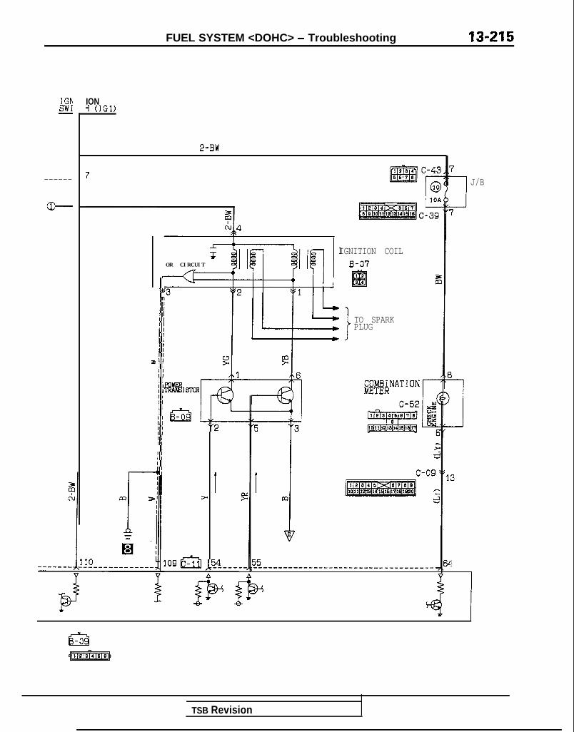
FUEL SYSTEM <DOHC> - Troubleshooting 13-215
IGhSW1-
------
P
IONY (IGl)
2-BW
ra,r,IIIIiIIIIt$I I
III IIIfII II IIIIIItI IIII I
-+I
IGNITION COILOR CIRCUIT B-07
12El34
TO SPARKPLUG
“2
I>
109 al ,5_4_---.
+
1
1
PASTOR
m
J
I:I c-09
rm :
55------------------------------------.
N
4
73
J/B
7
3
TSB Revision
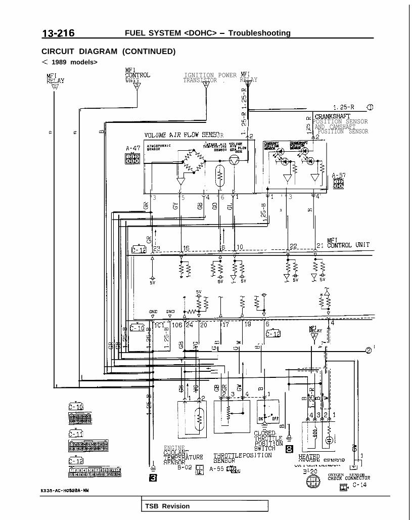
13216 FUEL SYSTEM <DOHC> - Troubleshooting
CIRCUIT DIAGRAM (CONTINUED)< 1989 models>
KTROL IGNITION POWER MFIUNIT TRANSISTOR RELAY
,nr ,nrc n TD CT nv c!crw.fl\ “l.I”mL c)I‘\ IAl”” ULtll”JR "/\2,PTAKB *,A VOLUkz
! FLOWIBOR
1.25-RLI: CRANKSHAFT
1 POSITION SENSORg AND CAMSHAFT. POSITION SENSORa
A-57
\/ / 1 I,t“3 "5 "4 "6 "1 ‘$1 '"3 *54
t5 G k3 s 6 mIz
3 m1,
WI w m =-i ! QI
III1 * I
z-l t' I
- ____-- J,-----3 I
m
ENGINE
%%&TURE
A-55 m“‘3 1 “&a,. YYI..d”..
73 nn LxD-C” OXYGEN SENSOR
CHECK CONNECTORB c-14
KX35-AC-H052SA-NY
TSB Revision

FUEL SYSTEM <DOHC> - Troubleshooting 13-217
1.25-R
d I11 58 5E--- -.
bb
v v--------- _-------___---__-_--__ ---
5------- ----------------
18F 1 2 12
sA-08-
8 r^ 3
il
F
>I%ccl 3 lo ?
B-14 -AlL 71
Iv/(ENG) (DATA) I f.N I T I ON
-.-- . .-.-. -...*-.IJHIH LINK IIMINCONNECTOR $flI;,S 9MENT
VVIVIYXTOR
C-18 A-61FRONT SIDE
2 $kl B-04* @g
-e--POWERSTEERING;;TqsJRE
gg$ssfiMERATURE
(VEHICLES FORCALIFORNIA)
TSB Revision

13-218 FUEL SYSTEM <DOHC> - Troubleshooting
CIRCUIT DIAGRAM (CONTINUED)< 1989 models>
A-40I@
aI3I C-36
J/B
r
@
101
MFIRELAY
Ii-l
EGK
x
SOLENOID(VHEICLES FOFCALIFORNIA)
2r631 ii!.?
53 c-10 ,V
I FUSIBLE LINl
A-07X r
Q
AUTO COMPRESSORCDNTROL UNIT
s52218 C-23
G..2
DUAL ,\g;&#RE 9
~g,'~:yP"
A-21 OFb-‘;oN ~&~f~“‘”
@ 0ON:2100kPa(299PS I )OFF:2700kPa(384PSl)
"I
F5
A-OSIss 65 iii
B-22~1 AIR" CONDITIONING
q@
XI ON:lOS'C(228'F2 OFF:115'C(239' k 1
03 65Y Y
-I I MAGNETiC CLUTCH
MFI CONTROL UNIT
KX35-AC-H05288-NY
TSB Revision

FUEL SYSTEM <DOHC> - Troubleshooting 13-219
CIRCUIT DIAGRAM< 1990 models>
A-OE
ST1REI-
4 zi1 CL_-----------------.
C-081224
m6878
I
& $ ON+-i- -iK-i % d 2G %A m+f-lh Ii g IA IIY% d d& Gl107 62 66 ____ ------__ 56
v v V V
IYFF
jHibKPUMP
:ONNECTOR
TSB Revision

13-220 FUEL SYSTEM <DOHC> - Troubleshooting
CIRCUIT DIAGRAM (CONTINUED)< 1990 models>
IGNISW17
7
B-22-lr
;;;;yN"ER BA
L!r3B-06m
.AI;F $1 I$ $I I fl I
$52 *c 12 Y 4
*b
IIGNITION%%STOR FB-09 _-4-s 2 I 8
t 9
34__-_---
TSB Revision
2 3-I+m
GNITION COIL
B-07 z
I ;euiPARK
ENGINE SPEEDDETECTIONCONNECTOR
,7\I
I:
J/B
1'7
13
64
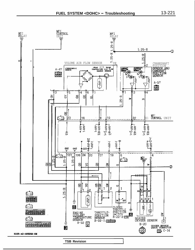
FUEL SYSTEM <DOHC> - Troubleshooting 13-221
AY!&&ROLUNIT
MFIRELAY
$1r 1.25-R a
YzVOLUME AIR FLOW SENSOR Is : CRANKSHAFT
POSITION
ZEWM;;ON
I\
A-47IYIAKC AIR VDLUIO!.
ZCYPLRA’T”RE AIR ?LW
IEI
BCYBOR BLR8OR1es166
Ly, 3 4
aI2-----1,21 t%TROL UNIT
0SV 5V
A-57
OXYGEN SENSORCHECK CONAIECTOR
KX35-AC-HOWA-NY
TSB Revision
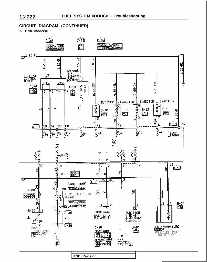
13-222 FUEL SYSTEM <DOHC> - Troubleshooting
CIRCUIT DIAGRAM (CONTINUED)< 1990 models>
1.25-R!YA ct? 7 FN 2 z 2c s s
flG_------u----------------y
A-06- 9.\c-50/\ s 3
0 COMBINATION -LQfj METER
gh1 B-04
EBi- -(ENG) (DATA)
J/B !i%&E%
GNITION
IW%ENTONNECTOR
I.F
A-61f&l
&@MERATURE
(VEHICLES FORCALIFORNIA)
POWER
I
4STEERING mi;T;g;RE
&
TSB Revision
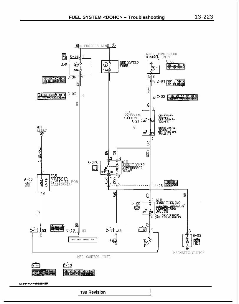
FUEL SYSTEM <DOHC> - Troubleshooting 13-223
JE
I
MFIRELAY
A-40IEEl
$92
B
EGHS@LENOID(VHEICLES FORCALIFORNIA)
03 65
1 Y I1 BATTERY BACK UP j
@2
1 FUSIBLE LIN
'6
A-07X r
>c
DUAL
DmREA-21 OF;-
@ i
AUTO COMPRESSOR;ONTROG UNIT
12 c-23
2
m1 I$$;i?~pP”
lIFJ;WPkP.a
ON:2100kPe(29QPS 1)
II OFF:2700kPaf384PS I)
1
'A-06
ENGINE COOLANT
I MAGNETIC CLUTCHMFI CONTROL UNIT'
KX35-AC-HOSeBE-NY
TSB Revision 1

13-224 FUEL SYSTEM <DOHC> - Troubleshooting
CIRCUIT DIAGRAM<1991 models (Non-turbo)>
:R IGNITIONSWITCHKiT)-
I
#E&F B8
IBLE
3 C-24 2I cl_________-----.
3,
EbUA)r-
P
;I ______ - ___________ j________ ---;;;;;C-08 2i
6~ 3
t
A-41‘Smcl FWD !AWD
I \
FUEL PUMPAND GAUGE
#&SLY
g 3 A-09& m
PARK/
t
NEUTRAL g;;s;;;ON Ck 8
4A-06sk
m,234s M/T 2S-78810rk-10 cl
c-15
E;/m~KPUMP
:ONNECTOR
cpcud
i
r
?i/T
Im
\
Eh 1 &-i-TI \J \I ‘I I# ,
cd'4 y"5 "6 "6 “7 " 2
i 2 d zi. .- 0 m g CL(-1 a-
;
Es*Ial t
107,@-,$S-----e------v+,56 -I v v v V
g/T A
3 J&Q8---~~~~gKL-- _____ --__----___----P
x35-AC-H0535-Nn
TSB Revision
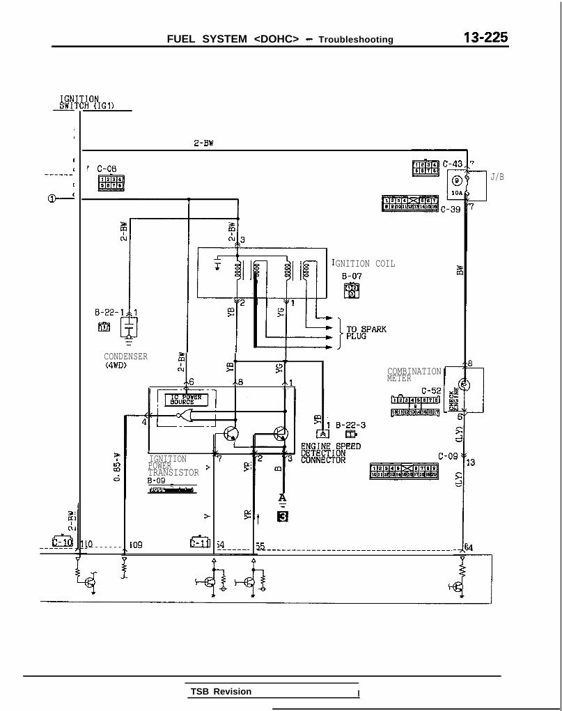
FUEL SYSTEM <DOHC> - Troubleshooting
gSY’I,
II------
@J
F&-------
IOPIGl,
2-BW
7 C-08
c-39
B-22-
m
j:zd
IO- - - - - - - -
TSB Revision I
1
IGNITIONPOWERTRANSISTOR z+
I
7P
54-------
CONDENSER(4WD) ,I
cl 2 g4x6 ,<8 d\lI\
GNITION COILB-07
I bh!ZPARK
B-09 _*v13.4 5 8 I II
>
109 I53
COMBINATIONMETER
C-52
L
A
t h
55----------------~-~--~------------.
!7
I3
J/B
17
8
>
1
33
x

13-226 FUEL SYSTEM <DOHC> - Troubleshooting
CIRCUIT DIAGRAM (CONTINUED)< 1990 models (Non-turbo)>
MFIRELAY
0vD:
a
I
zs 1.25-R
1 0
m VOLUME AIR FLOW SENSOR ",,2lNT.RP AIR VOLUYL
TLYPRRIWRl AIR ?LWP.L”SDP BUISOR
"3 "5 "4 "6 "1
% G s s $l
CRANKSHAFTPOSITIONsNJl&+m
i=;=&;;ON
A-47
A-57
22 I:------ 21 !&TROL UNIT
$85V 5V
-r
mII I I
! I I I e
L
OXYGEN SENSORCH,ECK CONNECTOR
KX35-AC-HOS3Sb-NM
TSB Revision 1

FUEL SYSTEM <DOHC> - Troubleshootina 13-227
IDLE AIR ,,2 5CONTROLMOTOR
B-03 cMllea
m "1PS \,456
::
EVAPOR;TIVE
T T 7
i?ii 78 1 k.1 CQMBINATION q 31
I"(ENG) (DATA)
DATA LINKCONNECTOR
C-18 %FRONT SIDE
5v
+3---__-- ----------------_11
i
12
2IGNITIONTIMINGADJUSTMENTCONNECTOR
B-04f&l
A-61 EGR TEMERATURE@ SENSOR
(VEHICLES FORCALIFORNIA)

13-228 FUEL SYSTEM <DOHC> - Troubleshooting
CIRCUIT DIAGRAM (CONTINUED)< 1990 models (Non-turbo)>
&
A-07-2X
liziE
1 9 3 4 c-37-1
J/B
MFIRELAY
vL
c-39
I f
I&
A-48
@jlM-!EICLES FOF ?
CALIFORNIA)
I*l. Ei1-13 53 c-10
9.
F U S I B L E L I N K
IOD O RETORAGECONNECTOR
AUTO COMPRESSORCONTROL UNIT
i2 “, c-57pa1
s
-I
QC-23
3-a
%0
55 5 g..3 ..4
A-07X ’ ” ” -
-~4-~&7 ________ ----4 A-O8
B-22
@3
103Y Y I
MFI CONTROL UNIT
tm fci2
KX35-AC-ti05358-NY
MT
‘C CLUTCH
TSB Revision

FUEL SYSTEM <DOHC> - Troubleshootina 13-229CIRCUIT DIAGRAM< 1992 models (Non-turbo)>I
GTAFRELI:
6c:
&U&F B8
IBLE
A-06
!$c
C-15r
3R-
IGNITIONSWITCH(ST)
I
zC-08 i
3 C-24 Ecl.--------_---- --------------.
iii
St
PARK/NEUTRAL FIG';;ON "$ \8
P
\1
I
M/T G A/T L%10 Al-9 CL
rk k-------- ---
, , \xd'4 I$'5 "8 "6 "7 "2d-Jcu Ki g z. .- CI m g &I-, IV
$
&IsI x
,307~~~-~~~------------~56 cI v v v V ,
@---- ____________ -----I __________ ;,;;t
pwKPUMP
CONNECTOR
M/?&T A,
FWD 1 AWDf \
l-lS/T
1m
-1,faml3 1108-------g-e4------- ---------------
H
TSB Revision

13-230 FUEL SYSTEM <DOHC> - Troubleshooting
CIRCUIT DIAGRAM (CONTINUED)< 1992 models (Non-turbo)>
8 i8
2r:
2c:_---s-w!
o---”
2
Es_------
ON(IGl)
2-BW
C-08
B-22-
I.@
CONDENSER z(4WD) ci
j:zd
XL-----
I
9I I :IGNITION COIL
B-07: $1 I@- 41 IF $2El3
352 '"1m 9
TSB Revision
IGNITION "7POWER-/?li~SISTOR +
5
I e 3 4 5.8 7 e
ENGINE 6PEED>L"2
;; DETECTION3 CONNECTOR
In
109
Fe
c-09
F;;
A
f ii
~~-_____-------------------------------
8-
> 113
7
1 J/B
7

FUEL SYSTEM <DOHC> - Troubleshooting 13-231
4:;zs 1.25-R
1 0
'1;rOLUK!Z AIR FLOW SENSOR
ANDA-47
1 2
mI122 1 t%TE!OL U N I T
“? I@ 1 Yi YqEqsrp---~--~g---[~---------;;-~4 iuY& ii’------
1 mi mi E I wT”ill’liI I I’-1 q-1’ I
f I I IT-11 I l-i jdrnl &$$$I I
i IIIII
z IIIa2 1
0
KNOCKu
SENSOR
EII WI- CLiiED dTHROTTLE =ENGINECOOLANT THROTTLE-
l'#;&ON
##@ATURE @&ON B-22-2mEl %
HEATEDOXYGEN SENSOR
11i B-04-1
B-02 Il!d
B-02-1- B-20 OXYGEN SENSORg@ e
CHECK CONNECTOR
m c-14 H
l-L
xX35-Ac-n0537wiu
,TSB Revision I

13-232 FUEL SYSTEM <DOHC> - Troubleshooting
CIRCUIT DIAGRAM (CONTINUED)< 1992 models (Non-turbo)>
1.25-R7
g: 4:kc R
7 ez R
8-A c ,. s
$3--.G
5v
b 11“4,
__- -__- ---ys ------YE--
____-__-_-------- --- ---m--s’
r T1 2
TPOWERSTEERINGg;y'z;RE
@
FA-06-
(ENG) (DATA)
DATA LINKCONNECTOR
C-18 m(1FRONT SIDE
2
!3
8 I
5>2 ,,l
IGNITIONTIMINGADJUSTMENTCONNECTOR
B-04
1IElI
A-61ma
EMEMERATURE
(VEHICLES FORCALIFORNIA)
I'ROLT(AWD>
TSB Revision

FUEL SYSTEM <DOHC> - Troubleshootina
SUB FUSIBLE LIhI
A-48m
;I2Ll
zku2
i
IE
??
is1
1 EGK
x
SOLENOIDWHEICLES FORCALIFORNIA)
2
E
E-r
A-07X
El3 4
IK
T>si EFATEDA
AUTO COMPRESSORCONTROL UNIT
; E5 6A3 ,,4
.
:
‘o/
‘12 c-23
6 A-08 : : : ::lIIxB3
1 AIR
1 CONDITIONINGENGINE COOLANT
I ;E&#$TURE
! 8F~!?8;%!~~&Fk1
I J MAGNETIC CLUTCHMFI CONTROL UNIT
KX35-AC-H03378-NW
TSB Revision

13-234 FUEL SYSTEM <DOHC> - Troubleshootinca
CIRCUIT DIAGRAM<From 1991 models (Turbo)>
c-15 r
IBLE
:C
C
hc;
;ER
z
4 C.---- -------------.C-08
zCL
1 jk3
I, “ 7 "2
zg CL
2
ml=+&&i6 ____ -------m&6
I Y Y Y Y- -
P 5 ...8 $-4
u&PUMP
FONNECTOR
95-AC-H0530-KU
TSB Revision

FUEL SYSTEM <DOHC> - Troubleshooting 13-235
[ONI (IGl)
2-BW
IGNITION
%%hTORF-
a
109 m
79
54__-----
TSB Revision I
I::
ENGINE SPEED>f :: 3 '"2 DETECTIONCONNECTOR -09
m :.:
GNITION COB-07
f
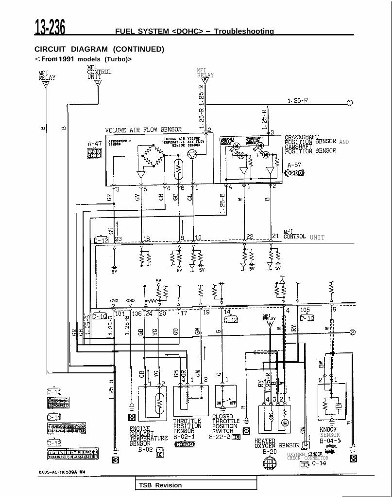
13-236 FUEL SYSTEM <DOHC> - Troubleshooting
CIRCUIT DIAGRAM (CONTINUED)<From 1991 models (Turbo)>
MFIRELAY
9czs 1.25-R
T 0r
IKTA‘E AIR VDLUYEEWEPATMB AIn ?Lov
EJEYBOR 8ElBORAND
r%hROL UNIT
tiNDV “G” w b
~“l~-l~~106~~~-~~~---~~~-
: A.mi cw ? %4, <,
-,L4)
I I3 IIm
2 1
h--+-PCKNOCKSENSORB-04-1
I-
B-20 -OXYGEN GENSORw :
CHECK CONNECTOR
TSB Revision

FUEL SYSTEM <DOHC> - Troubleshooting 13-237
IDLE AIR 5~~ 5CONTROL
?E.2
EVA!=OFAT I VEEMISSION
9
8__-_-v----
> 0
1x F ;i: z %z k IAa> 2
lb d d .A
T T%I1
IGNITION
EIW%ENTCONNECTOR
B-04m
KXT;MERATURE
(VEHICLES FORCALIFORNIA)
TSB Revision
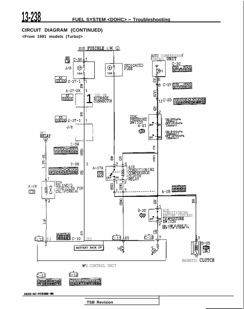
13-238 FUEL SYSTEM <DOHC> - Troubleshooting
CIRCUIT DIAGRAM (CONTINUED)<From 1991 models (Turbo)>
FUSIBLE LINFsvkJT0 COMPRESSORCONTROL UNIT
c-30
EA-07-2X
$-231 IOD OR
~6oNFIK%OFI3
L2EiE
,234 C-37-l
J/B
MFIRELAY
B kc-39
6A-07X
Els4
A-48
m A-08
I AIRCONDITIONINGENGINE COOLANTg rfIi EFiTURE
@;j&FJQgQ'~.)
I B-22 I
103 t%d, 1. Ea 53 c-10
V B-05I J- -
I I MAGNETIC CLUTCHMFI CONTROL UNIT
KX35-AC-HO53QB-NY
TSB Revision
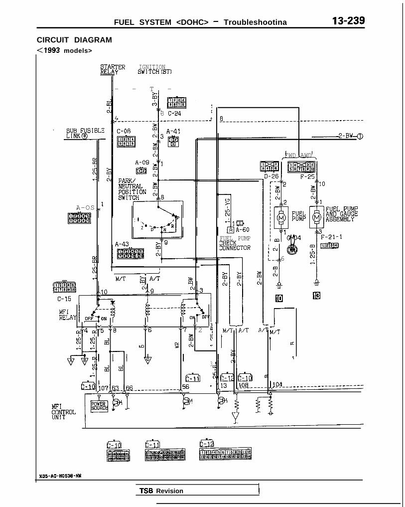
FUEL SYSTEM <DOHC> - Troubleshootina 13-239
CIRCUIT DIAGRAM-Cl993 models>
A-OS
JER IGNITIONSWlTCH(ST)
- - T -
3 C-24 c4 c
L l , P‘*2
A-43
+$1 A’T z
, .I \/ \, , \/ 3
I$'4 $'5 "8 "6 "7 "2 9
% Ki d F ;rv,. 84 m !z C-kJ Lc--o e-
d 23
2
107x~~-~~~______-------,56 -
I
&ROL
8_-____-___-_-__--___---------------------
2-BW
FWD AWD
FUEL PUMP
%#cT~R I I!”J @12k. 6mcl1
;
rM/T1 ci
T
X35-AC-HO!i3&NM
TSB Revision

1 S-240 FUEL SYSTEM <DOHC> - Troubleshooting
CIRCUIT DIAGRAM (CONTINUED)< 1993 models>
IGNISW11
2C
30z’-------2
ci+
21
&--------
I?YGl)
2-BW
7 C-08
1134
m5870
CONDENSER z(AWD) ct j--IER11
I ’IGNITIONnn3IIPl-,
I e3 4 c-43ED507 5
C
@1011
c-39
IGNITION COIL
iFZ;NAT I ON
w, 1 C-52
&) B-g-3
ENGINE SPEEDDETECT I ONCONNECTOR Irl
j: 5 m
83 B-09
61
4;5ALI.i,
,
1 J/B
J
‘/0i?0I- ]
9
%
~
I 4
iz
:I
liEA3
u
TSB Revision

FUEL SYSTEM <DOHC> - Troubleshooting 13-241
MFICONTROL l&Y
lxlAcu.-i 1.25-R
0
AY
a
A-47
MFICONTROL UNIT
!
z
&%R l.Tl
KNOCK,"";y
I lg@l 42CTOR El
2-14
TSB Revision 1
KX35-AC-lt0536kNY
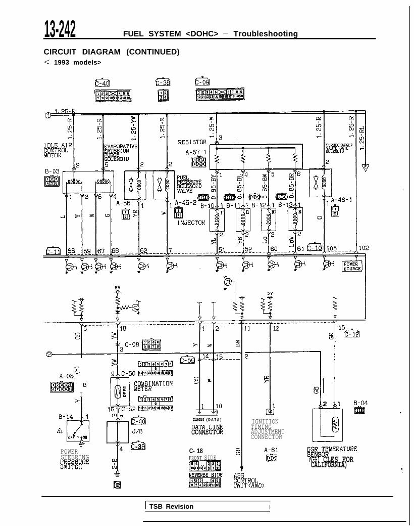
13-242 FUEL SYSTEM <DOHC> - Troubleshooting
CIRCUIT DIAGRAM (CONTINUED)< 1993 models>
sA-OB-
I
6
TPOWERSTEERINGgpX&RE
J/l3\,\I
4 c-3
m
clLl
;
z~~+l~:&--
*.z 3.
1 10+ v]
(CNG) ( D A T A )
C- 18 EFRONT SIDE
5V
I
4 %
_-__-_- _________-----.--
11
r
12g 15g%1
2
i
F
1
IGNITIONTIMINGADJUSTMENTCONNECTOR
1II
E2 1
2
A-61ml
%ES&$MERATUREWEHI CLES FORCALIFORNIA)
E-04Igig .
TROLP(AWD>
1 TSB Revision I

FUEL SYSTEM <DOHC> - Troubleshooting 13-243
A-48IEEl
Sl-
c-37-3,:
l&llx
1e34
MFIRELAY J/B
r
1
1x BSLHENOI D(VHEICLES FORCALIFORNIA)
2
&
53 c-10
-
103
, BAWL”‘,
E2-J
G
I FUSIBLE LINb
C010A
4 A-07-2X
1liizEa1234
IOD ORGTORAGE
3 CONNECTOR
2
12
AUTO COMPRESSORCONTROL UNIT
OF? N
i
!
%
#j;;y;,(3OPSl)
0N:ZlOOhPa(29DPSi)
OFF:2’i’OOkPa(384PS I)
I
[
MAGNET1 C CLUTCH
3
lh
B-05
Elle.
3
=
MFI CONTROL UNIT
TSB Revision

13-244 FUEL SYSTEM <DOHC> - Troubleshooting
FUEL TANK AND FUEL LINE MlBEAAh
Symptom Probable cause Remedy
Engine malfunctions Bent or kinked fuel pipe or hose Repair or replacedue to insufficient fuelsupply Clogged fuel pipe or hose Clean or replace
Clogged fuel filter or in-tank fuel filter Replace
Water in fuel filter Replace the fuel filter or clean the fuel tankand fuel line
Dirty or rested fuel tank interior
Malfunctioning fuel pump(Clogged filter in the pump)
Clean or replace
Replace
Zvaporative emission Mispiping of vapor line Correct:ontrol system malfunc-:ions (When fuel tank Disconnect vapor line piping joint Correct‘iller tube cap is re-noved, pressure releas- Folded, bent, cracked or clogged vapor line Replaceng noise is heard)
Faulty fuel tank filler tube cap
Malfunctioning fuel tank pressure controlvalve
Replace
Replace
TSB Revision I
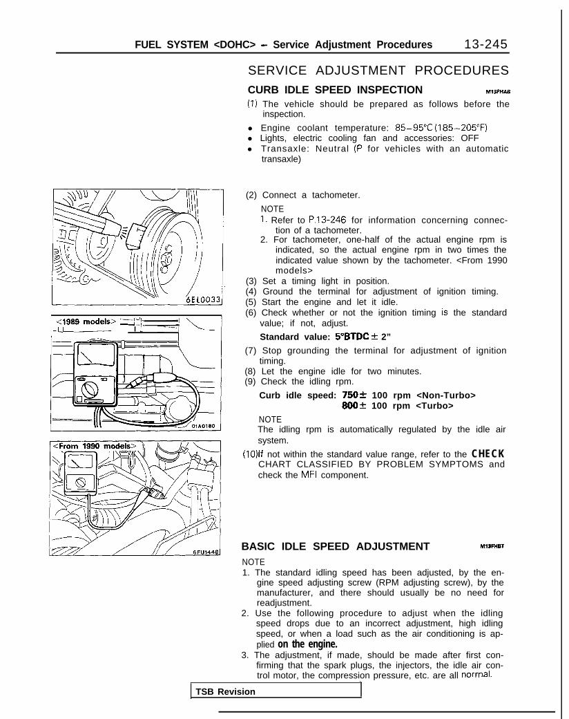
FUEL SYSTEM <DOHC> - Service Adjustment Procedures 13-245
cl989 models> -a’i\.-up I t
SERVICE ADJUSTMENT PROCEDURES
CURB IDLE SPEED INSPECTION MlSFHAB
(1) The vehicle should be prepared as follows before theinspection.
l Engine coolant temperature: 85-95°C (185-205°F)l Lights, electric cooling fan and accessories: OFFl Transaxle: Neutral (P for vehicles with an automatic
transaxle)
(2) Connect a tachometer.
NOTE1. Refer to P.13-246 for information concerning connec-
tion of a tachometer.2. For tachometer, one-half of the actual engine rpm is
indicated, so the actual engine rpm in two times theindicated value shown by the tachometer. <From 1990models>
(3) Set a timing light in position.(4) Ground the terminal for adjustment of ignition timing.(5) Start the engine and let it idle.(6) Check whether or not the ignition timing is the standard
value; if not, adjust.
Standard value: 5”BTDC f 2”
(7) Stop grounding the terminal for adjustment of ignitiontiming.
(8) Let the engine idle for two minutes.(9) Check the idling rpm.
Curb idle speed: 75Ok 100 rpm <Non-Turbo>800+ 100 rpm <Turbo>
NOTEThe idling rpm is automatically regulated by the idle airsystem.
(10)lf not within the standard value range, refer to the CHECKCHART CLASSIFIED BY PROBLEM SYMPTOMS andcheck the MFI component.
BASIC IDLE SPEED ADJUSTMENT Ml3FHBl
NOTE1. The standard idling speed has been adjusted, by the en-
gine speed adjusting screw (RPM adjusting screw), by themanufacturer, and there should usually be no need forreadjustment.
2. Use the following procedure to adjust when the idlingspeed drops due to an incorrect adjustment, high idlingspeed, or when a load such as the air conditioning is ap-plied on the engine.
3. The adjustment, if made, should be made after first con-firming that the spark plugs, the injectors, the idle air con-trol motor, the compression pressure, etc. are all normal.~~-
TSB Revision

13-246 FUEL SYSTEM <DOHC> - Sewice Adjustment Procedures
17k&---,!E~,~~ /iY I
(1) The vehicle should be prepared as follows before theinspection and adjustment.l Engine coolant temperature: 85-95°C (185-205°F)l Lights, electric cooling fan and accessories: OFFl Transaxle: Neutral
(P for vehicles with an automatic transaxle)(2) Connect the scan tool to the data link connector (white).
NOTEWhen the scan tool is connected, the diagnostic test modecontrol terminal is grounded.
(3) If the scan tool is not used, follow the steps below.@ Insert a paper clip (from the harness side) into the l-pin
connector shown in the figure at the left.Take care not to disconnect the connector.
/Paper chp -f!f--i!tAh
-II
For a female pin For a male ptn(Insert at side (Insert at lock tab side.opposite from lock tab.) OlL0246
CautionThe paper clip should be inserted between the termin-als as shown in the figure at the left.
@ Connect a primary-voltage-detection type of tacho-meter to the paper clip.
TSB Revision

FUEL SYSTEM <DOHC> - Service Adjustment Procedures 13-247
NOTEFor rpm, one-half of the actual engine rpm is indicated,so the actual engine rpm in two times the indicatedvalue shown by the tachometer. <From 1990 models>
@I Use a jumper wire to ground the diagnostic test modecontrol terminal of the data link connector.
(4) Use a jumper wire to ground the terminal for adjustment ofignition timing.
(5) Start the engine and let it idle.(6) Check the standard idling rpm.
If the scan tool is used, select item No.22 and read out theidling rpm.
Basic idle speed: 750+50 rpm <Non-Turbo>800f 50 rpm <Turbo>
NOTE1. The engine speed may be 20 to 100 rpm lower than
indicated above for a new vehicle [driven approximately500 km (300 miles) or less], but no adjustment isnecessary.
2. If the engine stalls or the rpm is low even though thevehicle has been driven approximately 500 km (300miles) or more, it is probable that deposits are adheredto the throttle valve, so clean it. (Refer to P.13-248.)
TSB Revision 1
(7) If not within the standard value range, turn the enginespeed adjusting screw (RPM adjusting screw) to make thenecessary adjustment.
NOTEIf the idling speed is higher than the standard value rangeeven when the RPM adjusting screw is fully closed, checkwhether or not there is any indication that the CTP switch(fixed SAS) has been moved.If there is an indication that it has been moved, adjust theCTP switch (fixed SAS). If there are no indications that ithas been moved, it is possible that there is leakage as a re-sult of deterioration of the fast idle air valve (FIAV), and, ifso, the throttle body should be replaced.

13-248 FUEL SYSTEM <DOHC> - Service Adjustment Procedures
(8) Switch OFF the ignition switch.(9) If the scan tool was not used, disconnect the jumper wire
from the diagnostic test mode control terminal.(10)Disconnect the jumper wire from the terminal for adjust-
ment of ignition timing, and return the connector to itsoriginal condition.
(11 )Start the engine again and let it run at idle speed for aboutten minutes; check to be sure that the idling condition isnormal.
THROTTLE BODY (THROTTLE VALVE AREA)CLEANING Ml3ACL
(1) Start the engine and warm it up until the temperature of theengine coolant reaches 80°C (176°F) or higher; then stopthe engine.
(2) Disconnect the air intake hose at the throttle body side.(3) Plug the bypass passage entrance of the throttle body.
CautionBe absolutely sure that no cleaning liquid enters thebypass passage.
(4) Spray cleaning liquid (from the intake port of the throttlebody) onto the valve, and then leave as is for about fiveminutes.
(5) Start the engine and race it a few times; then let it run atidle speed for about one minute.
NOTEIf, because the bypass passage is plugged, the engineidling speed is unstable (or the engine stalls), let the enginerun with the throttle valve slightly open.
(6) If deposits are not removed from the throttle valve, repeatsteps (4) and (5).
(7) Remove the plug from the bypass passage entrance.(8) Connect the air intake hose.(9) Using the scan tool, erase the diagnostic trouble code, or
disconnect the battery’s ground cable for ten seconds orlonger and then reconnect it.
(lO)Adjust the basic idle speed (engine speed adjusting screw).(Refer to P.13-245.)
THROTTLE POSITION SENSOR ADJUSTMEyTmEE(1) Connect the scan tool to the data link connector (white).
TSB Revision

FUEL SYSTEM <DOHC> - Service Adjustment Procedures 13-249
<1989 m o d e l s > /zz Throttle position (2) If a scan tool is not used, perform the following operation.,-~1989 models>@ Disconnect the throttle-position sensor connector,
and connect the special tool (test harness) between thedisconnected connectors.
:1989 models> @ Connect a digital-type voltmeter between the @ termin-al (red clip, sensor ground) and the @I terminal (blue clip,sensor output) of the throttle-position sensor connec-tor.
Blue clip
<From 1990 models>@ Disconnect the throttle.position sensor connector and
use the special tool (test harness set) between thedisconnected connector.
@ Connect a digital type voltmeter between terminal @(sensor output) of the throttle position sensor andterminal @ (sensor ground).
(3) Switch ON the ignition switch.(Do not start the engine.)
(4) Check the throttle-position sensor’s output voltage.When a scan tool is used, select Item No.14 to read thethrottle position sensor output voltage.Standard value: 0.48-0.52 V.
TSB Revision I

13-250 FUEL SYSTEM <DOHC> - Service Adjustment Procedures
/ -- --au
Mlv&‘1 I ‘1,1, ,--A // ; ~’ \ /$fF+/ l-----x11-<1989 models>- ( T V = = = - - (5) If there is a deviation from the standard value, loosen the
throttle-position sensor installation bolt and then turn thethrottle-position sensor itself to make the adjustment afterthe throttle body was removed. Be sure to securelyretighten the bolt after making the adjustment.
NOTE
/’ 1 i [ 1 1” . L.-Y \Iv I
\, 1’ /,/
The output voltage becomes higher when the throttle-position sensor is turned clockwise.For removal and installation of throttle body, refer to
“Engine Service Manual”.1 )i’ :LJ& J&Jj, 1 I)/ j ‘Y/i - !t 6FUO885 1
1 <From 1990 models> ‘-tzJ I
i~Thr?Jle~~ fi
/ - ::,“;LT e
/
Closed throttleposition switchconnector
:-I
\IllC’i ’ 6FUO566
(6) Switch OFF the ignition switch.(7) If the diagnostic trouble code is output while adjusting the
throttle position sensor, use a scan tool to erase the diag-nostic trouble code, or disconnect the battery cable fromthe negative terminal of the battery for more than 10 sec-onds and then reconnect the cable. (This will cancel thememory of the failure code due to throttle position sensoradjustment.)
CLOSED THROTTLE POSITION SWITCH (FIXED SAS) ADJUSTMENT Ml3FIDA
NOTE1. The closed throttle position switch has been precisely ad-
justed by the manufacturer; it should not, therefore, bemoved to another setting.
2. If however, the adjustment is for any reason accidentallydisturbed, or the closed throttle position switch is replaced,make the necessary readjustment by following the steps
(1) .?%izkntly relax the tension of the accelerator cable.(2) Disconnect the connector of the closed throttle position
switch (fixed SAS).(3) Loosen the lock nut of the closed throttle position switch
(fixed SAS).(4) Turn the closed throttle position switch (fixed SAS) in the
counter-clockwise direction until it is sufficiently loosened,and securely close the throttle valve fully.
(5) Connect an ohmmeter between the closed throttle positionswitch terminal and the body.
(6) Begin tightening the closed throttle position switch and lo-cate the point at which the closed throttle position switchis switched ON (conductive with body). (This is the point atwhich the throttle valve begins to open.) From that point,then tighten the closed throttle position switch 15/16 turn.
(7) Securely tighten the lock nut while holding the closedthrottle position switch so that it won’t turn.
(8) Adjust the tension of the accelerator cable.(9) Adjust the basic idling speed (engine speed adjusting
screw). (P.13-245.)(lO)Adjust the throttle-position sensor. (P.13-248.)
1 TSB Revision I

FUEL SYSTEM <DOHC> - On-Vehicle Inspection of MFI Components 13-251
ON VEHICLE INSPECTION OF MFI COMPONENTSCOMPONENT LOCATION
4 QCiW41QQWPQWQ
I l-+-Y8’-,..I - - IIII \< I I J I
/ \lI/ --Gl/El q
I &q
�\
P P6EM0166
MIBYA-A
6FUO843
Name Symbol Name Symbol
Air conditioning compressor clutch relay K idle air control motor (stepper motor) C
Air conditioning switch 0 Ignition coil (ignition power transistor) G
Closed throttle position switch (fixed SAS) E Ignition timing adjustment terminal R
Crankshaft position sensor and camshaft posi-H Injector J
tion sensor- Knock sensor Y
Data link connector S~ Multiport fuel injection relay N
Engine control module Q- Park/neutral position switch <A/T> v
Engine coolant temperature sensor F- Power steering pressure switch U
EGR solenoid L- Throttle position sensor D
EGR temperature sensor M- Turbocharger waste gate solenoid X
Evaporative emission purge solenoid I~ Vehicle speed sensor (reed switch) P
Fuel pressure solenoid wVolume air flow sensor (incorporating intake
Fuel pump check terminal T air temperature sensor and barometric pres- B- sure sensor)
Heated oxygen sensor IA
I-
NOTEThe “Name” column is arranged in alphabetical order.I I
TSB Revision I

13-252 FUEL SYSTEM <DOHC> - On-Vehicle Inspection of MFI Components
Heated oxygen sensor
la&/+$& ,s ‘T*1 \‘! ;/ *- 7)lY-7
\ I--. P--&O596I ~~
- ~~~- ,,od&>/ ‘I.! m ”<1989 I lgnltlon co11 (Ignition:Dower transistor).\
[ TSB Revision

FUEL SYSTEM <DOHC> - On-Vehicle Inspection of MFI Components 13-253
1 16AO41I
!
,
I-
.~-A. 6FUOf512 1
I
I\
-
’ ‘J je,u-.-.-Air condk&g .~
I- _ .~ ~~-switch ___.. ~- -
6FUO845
\ TSB Revision

13-254 FUEL SYSTEM <DOHC> - On-Vehicle Inspection of MFI Components
Vehicle speed sensor
adjustment terminal
- check t e r m i n a l - - - -
I I
,
Turbochargerwaste gate
a,ylenoid
‘I K&h--
=yq@control module
1 TSB Revision

FUEL SYSTEM <DOHC> - On-Vehicle Inspection of MFI Components 13-255
COMPONENTS INSPECTION PROCEDURE-Using Scan Tool MlsYsAGaRefer to P.13-41.
POWER SUPPLY AND IGNITION SWITCH-IG
zT=f?Qjkeinjection relay contrc! qcdule ,6A04,,-
----_OFF/ (IN
t5
’ i
4
-
‘OWE;uppl-
Ignition switch [IG,]
Componentside connect<
763 66.----1 6FU1331,
)r
Ml3YcAB
Harness@ side connector
01 LO838
OPERATION
l While the ignition switch is ON, battery powersupply is supplied to the engine control module,injectors, volume air flow sensor, etc.
l When the ignition switch is switched ON, cur-rent flows from the ignition switch, via the mul-tiport fuel injection relay coil to ground.
INSPECTION
Using Scan tool
As a result, the multiport fuel injection relayswitch is switched ON, and power is supplied,by way of the multiport fuel injection relayswitch, from the battery to the engine controlmodule.
Function
Data reading
Item No. Data display Check conditions Standard value
16 Engine control module power- Ignition switch: O N Battery positive voltagesupply voltage
TSB Revision I

HARNESS INSPECTION
Engine controlmodule harness
1- OlLO421
Measure the ignition switch terminalinput voltage.. Engine control module connector:
Disconnected. Ignition swatch: ON
13-256 FUEL SYSTEM <DOHC> - On-Vehicle Inspection of MFI Components
Repair theharness.(Ignitionswitch -Ilrol)
@ Harness sideconnector
Measure the power supply voltage ofthe multioort fuel iniection relav.. Connector: Disconnected
Voltage (V)
I Battery positive voltageI
Repair theharness.(Batter-y-@@I)
connector
Engine controlmodule harness Check for an open-circuit, or a short-
circuit to ground, between the enginecontrol module and the multiport fuelinjection relay.. Engine control module connec-
tor: Disconnected. Multiport fuel injection relay con-
nectar: DisconnectedRepair theharness.
7FUO467
alJ*:k!ii0
5 4 3 2 -109 9 7 6
Engine controlmodule harnessside connector
@ Harness sideconnector
Check for an open-circuit, or a short-circuit to ground, between the enginecontrol module and the multiport fuelinjection relay.. Multiport fuel injection relay con-
nector: Disconnected@--A
. Engine control module connec-tor: Disconnected Repair the
-+ harness.@@I~ El-@?J. 11071)
TSB Revision

FUEL SYSTEM <DOHC> - On-Vehicle inspection of MFI Components 13-257
OlLO521
01 LO220
fx!l.‘,~‘,_C;:i2J,‘:,
OlLO222
1 J 7FUO470
1 MULTIPORT FUEL INJECTION RELAY INSPECTION(1) Remove the multiport fuel injection relay.
(2) Use jumper wires and connect multiport fuel injection relayterminal @I to the battery 0 terminal and terminal @I to thebattery 0 terminal.CautionBe very careful when connecting the jumper wiresbecause the relay will be damaged if a mistake is madewith the contact terminals.
(3) With battery 0 terminal jumper wire connected and dis-connected, measure the voltage at multiport fuel injectionrelay terminals @ and 0.
(4) Use jumper wires to connect multiport fuel injection relayterminal @I to the battery 0 terminal and terminal @ to thebattery 0 terminal.
(5) Disconnecting the jumper wire on the terminal 0 side ofthe battery, check whether or not continuity exists acrossterminals @ and @ of the multiport fuel injection relay.
Continuity between terminals 0-0
(6) Use jumper wires and connect multiport fuel injection relayterminal @ to the battery 0 terminal and terminal 0 to thebattery 0 terminal.
(7) With the battery 0 terminal jumper wire connected anddisconnected, measure the voltage at multiport fuel injec-tion relay terminal 0.
Jumper wire Terminal Voltage @
Connection Battery positive voltage
Not connected OV
(8) Replace the multiport fuel injection relay if faulty
ENGINE CONTROL MODULE POWER GRtXJNla
Refer to P.13-45.
TSB Revision

k.
13-258 FUEL SYSTEM <DOHC> - On-Vehicle Inspection of MFI Components
FUEL PUMPFuel pumpcheck terminal- I - - -
I g n i t i o n s w i t c h [r
Ignition switch [IGI
@Component sideconnector
@ Harness sideIc o n n e c t o r
Fuel pump connectorI
,- __ _ / OlAO488
-T
IComponent sideconnector
@
h 56
@ Harness side
1
v y
connector
-NC-
lrll
0
1 -z
Fuel pump checkA 13 terminal harness side
-1 connector
IEngine control module connector
Engine control module
6FU1295
01 LO838
OPERATIONl Activates the fuel pump during engine cranking
and while the engine is running.l When the ignition switch is set to the START
position, the current flows, by way of the multi-port fuel injection relay coil, from the ignitionswitch to ground. As a result, the multiport fuelinjection relay switch is switched ON, and thepower for activation of the fuel pump is sup-plied, by way of the multiport fuel injection relayswitch, from the battery to the fuel pump.
l While the engine is running, the engine controlmodule switches ON the power transistor, afterwhich current flows to the multiport fuel injec-tion relay coil, and the power for activation ofthe fuel pump is supplied to the fuel pump.
l When the multiport fuel injection relay switch isswitched ON, battery voltage is also applied tothe engine control module, and so the enginecontrol module detects the fact that the powerfor activation of the fuel pump is being suppliedto the fuel pump.
TSB Revision

FUEL SYSTEM <DOHC> - On-Vehicle lnwection of MFI Components 13-259
INSPECTION
Using Scan tool
Actuator test
Item No.
07
Actuation 1 Inspection conditions 1 Descriotion 1 Normal condition
Actuates fuel . Engine cranking Hold the return hose Pulsation can be felt.pump, circu- . Fuel pump forced between two fingerslating fuel. activation so as to feel the
The inspection pulsation of the flow-should be conducted ing of fuel.for both of the aboveconditions. Listen to the pump Pump sound can be
sound at a place near heard.the fuel tank.
iCTlON
TGrrW’-rTTrrrrrrrrrrrrrrrrrrri 1 SAL T
Check the fuel pump._---__. Apply battery voltage to the check-
ing terminal and operate the pump.
@ Harnessconnector
connector 1
sideI_
Check the ground circuit of the fuelm-m.
Connector: Disconnected
Repair theharness.
if?%d
Check for continuity between the fuelpump and the checking terminal.
Repair theharness.CW-Ml)
Check for continuity between thechecking terminal and the enginecontrol module, and between themultiport fuel Injection relay termi-nals.* Multiport fuel injection relay con-
nector: Disconnected- Engine control module connec-
tor: Disconnected- ;~-:edPump connector: Discon-
Repair theharness.@O-00OIHl3)
1 TSB Revision

13-260 FUEL SYSTEM <DOHC> - On-Vehicle Inspection of MFI Components
!5J @ Harness srdeconnector
7FUO474
Harness srdc@ connector
Engine controlmodule harnessside connector
7FUO475
7FUO476@ Harness side
I 7FllO477
Measure the power supply voltage ofthe multiport fuel injection relay ignition switch.Connector: Disconnected. Ignition switch: START (@a when
checked). Ignition switch: ON (@@ when
Check for an open-circuit, or a short-circuit, to ground between the multi-port fuel injection relay and the en-gine control module.. Multiport fuel injection relay con-
nectar: Disconnected. Engine control module connec-
tor: DisconnectedRepair theharness.uziul-8)
Check for continuity, of the groundcircuit.. Connector: Disconnected.
cl8Repair theharness.
%ih,
TSB Revision J
Check for an open-circuit, or a short-circuit to ground, between the multi-port fuel injection relay and the fuelpump.- Multiport fuel injection relay con-
nector: Disconnected- nf;;;edw-w connector: Discon-
MULTIPORT FUEL INJECTION RELAY IN-SPECTION
Refer to P. 13-257.

FUEL SYSTEM <DOHC> - On-Vehicle inspection of MFI Components 13-261
VOLUME AIR FLOW SENSOR MlWFAAs
/
side
@Harness sideconnector
I@ Harness sideconnector
Fnnine control module connector
Multiport fuelThe area enclosed with :I: is injection relayapplicable only for Turbo vehicle.
I
<Turbo>@I Component
connector
(Filter reset circuit)
Engine control module
6FU1537
Intake air amount(Wsec) 162451
OlLO838
OPERATION
l The volume air flow sensor is incorporatedwithin the air cleaner; it functions to convert theamount of engine air intake to pulse signals of afrequency proportional to the amount of engineair intake, and to input those/signals to the en-gine control module. The engine control modulethen, based upon those signals, calculates theamount of fuel injection, etc.
TROUBLESHOOTING HINTS
HINT 1:If the engine sometimes stalls, try starting the en-gine and shaking the volume air flow sensor har-ness.If the engine then stalls, incorrect or improper con-tact of the volume air flow sensor connector is theprobable cause.Hint 2:If, when the ignition switch is switched ON (but theengine is not started), the volume air flow sensoroutput frequency is any value other than zero, amalfunction of the volume air flow sensor or of theengine control module is the probable cause.Hint 3:If idling is possible even though the volume air flowsensor output frequency is deviated from the stand-
l The power for the volume air flow sensor issupplied from the multiport fuel injection relayto the volume air flow sensor, and is groundedat the engine control module. The volume airflow sensor, by intermitting the flow of the 5Vvoltage applied from the engine control module,produces pulse signals.
ard value, the cause is usually a malfunction otherthan of the volume air flow sensor.Examples:(1) The flow of air within the volume air flow sensor
is disturbed. (Air duct disconnection or cloggedair cleaner element)
(2) Incomplete combustion within a cylinder.(Malfunction of spark plugs, ingnition coil, injec-tors, compression pressure, etc.)
(3) Air is taken into the intake manifold through aleaking gasket, etc.
(4) Incomplete close contact of the EGR valve seat.
TSB Revision

13-262 FUEL SYSTEM <DOHC> - On-Vehicle Inspection of MFI Components
INSPECTION
Using Scan tool
1 Data 12reading
LData display Inspection conditions
Sensor de- . Engine coolanttection air temperature: 85-95°Cvolume (fre- (185-205°F)quency) . Lights, cooling fan, elec-
trical accessories: OFF. Transaxle: neutral (PJT
models: “P” range)
Engine condition
Idling
2,000 rpm
Racing
Standard value
25-50 Hz <Non-Turbo>30-50 Hz <Turbo>
60-90 Hz <Non-Turbo>50-80 Hz <Turbo>
Frequency increases asracing rpm increases.
NOTEThe volume air flow sensor output frequency may be about 10% higher than indicated above when the vehicle is new[driven approximately 500 km (300 miles) or less].
i
Regular waveform 03AO203
HARNESS INSPECTION
Using Oscilloscope
(1) Run the engine at idle speed.(2) Connect the probe to the osilloscope pick-up point a s
shown in the circuit diagram, and check the wave form.
Measure the terminal voltage.. Connector: Disconnected. Ignition switch: ON
connector OlMaa
Measure the power supply voltage.. Connector: Disconnected. Ignition switch: ON
Harness sideconnector the multiport fue
injection relay.
TSB Revision

FUEL SYSTEM <DOHC> - On-Vehicle Inspection of MFI Components 13-263
<Non-Turbo>Check for continuity of the groundcircuit of the VAF sensor.. Connector: Disconnected
\--connector
4Harness side
Check for continuity between the en-3 air
__.. --.. ..-gine control moduie and volumt UIIflow sensor. Y---L1 A. Engine control module connec-
tor: Disconnected- Volume air f low sensor connec-
tor: Disconnected
kTOA
Repair theharness.NliwHBl)
DlAO!XO
MlJYGAAlUTAKE AIR TEMPERATURE SENSORI
I
Temperature-
Temperature1621008
<Non-Turbo>
142454
<Turbo>-
sensor connector ,Intake air temperature sensor<Non-Turbo> Intake air
temperature sensor
I24Intake air @I Harness side
connector@I Harness side
.8.I
4Enginecontrolmodule
5VI 16FU1298
Iv---
I1 TSB Revision

13-264 FUEL SYSTEM <DOHC> - On-Vehicle Inspection of MFI Components
OPERATION
l The intake air temperature sensor functions toconvert the temperature of the air (intaken to theengine) to voltage, and to input that voltage (assignals) to the eingine control module. The en-gine control module, based upon those signals,then corrects the amount of fuel injection, etc.
l The 5V power supply within the engine controlmodule is supplied, by way of the resistancewithin the unit, to the intake air temperaturesensor; it passes through the intake air temper-ature sensor, which is a type of resistor, and isgrounded at the engine control module.
Note that the resistance of the intake airtemperature sensor decreases when thetemperature of the intake air increases.
* The intake air temperature sensor terminalvoltage becomes higher when the resistance ofthe intake air temperature sensor increases, andbecomes lower when the resistance decreases.Consequently, the intake air temperature sensorterminal voltage varies in accordance with thetemperature of the intake air, becoming lowerwhen the temperature of the intake air in-creases.
TROUBLESHOOTING HINTS
Because the intake air temperature sensor detectsthe temperature of the intake air in the air cleaner, itindicates a temperature different than the tempera-ture of the outside air when the engine is running.
INSPECTION
Using Scan tool
Function
Data reading
Item No.
13
Data display
Sensor de-tectiontemperature
HARNESS INSPECTION
II< N o n - T u r b o >
<Turbo
77<Non-Tur
<Turbo> h
ICheck conditions
Ignition switch: ONOr, engine running
Intake air temp.
At -20°C (-4°F)
At 0°C (32°F)
At 20°C (68°F)
At 40°C (104°F)
At 80°C (176°F)
Standard value
-20°C
0°C
20°C
40°C
80°C
Measure the power supply voltage.- Connector: Disconnected. Ignition switch: ON
j/ ‘“:;~~~v’ 0OK Ll2Repair theharness.Cm--aoE!l-@)
Check for continuity of the glroundcircuit of the intake air temperaturesensor.. Connector: Disconnected
I
side v I I 1~ I
I
H a r n e s s fi
connector ‘------- i01A051.1
1 TSB Revision 1

FUEL SYSTEM <DOHC> - On-Vehicle Inspection of MFI Components 13-265< N o n - T u r b o >
Volume air flow sensorside connector
< T u r b o >
IJ
1
I 6FUO62:-I
r<Non-Turbo>
rature sensor
TSB Revision
:Turbo>
lerature sensor,$kpntak _-.-.- --i\PJtemp - - “, ’w\
SENSOR INSPECTION(1) Disconnect the volume air flow sensor connectors.(2) Measure resistance between terminals @ and @. <Non-
(3) Er$%e resistance between terminals @ and 0,.<Turbo>
Temperature “C (“F)
0 (32)
20 (68)
80 (176)
Resistance (kQ)
6.0
2.7
0.4
(3) Measure resistance while heating the sensor using a hairdrier.
Temperature “C (“F)
Higher
Resistance (kR)
Smaller
(4) If the value deviates from the standard value or the resist-ance remains unchanged, replace the volume air flow sen-sor assembly.

13-266 FUEL SYSTEM <DOHC> - On-vehicle Inspection of MFI Components
BAROMETRIC PRESSURE SENSOR Ml3VHPYPl
\ Volume air
Barometricpressuresensor
Output Voltage/-4
3
2
1
v 0LzLBarometric pressure mmHg 760 ~~1551
EC1537
(7
\
‘i6
!
I
I1(
<Non-Turbo> <Turbo>B Volume air flow @ Volume air flow
sensor connector sensor connector
5EL1600, L
-@I Harness sideconnector
@Harness sidernnn~rtnr 131 11, I ’““, ,. Iv-.-. ,\L4 ,\-5 A17 h24
Fnnine 1 A n v u I
Barometric pressure sensor
-“J -
controlmodule
I
OllO537
Engine control module connector
01 LOB38
OPERATION
l The barometric-pressure sensor functions toconvert the barometric pressure to voltage, andto input that voltage (as signals) to the enginecontrol module.The engine control module, based upon thosesignals, then corrects the amount of fuel injec-tion, etc.
TROUBLESHOOTING HINTS
Hini 1:If there is a malfunction of the barometric-pressuresensor, driveability of the vehicle will become worseparticularly at high altitude.
l The 5V power supply within the engine controlmodule is supplied to the barometric-pressuresensor; it passes through the circuitry within thesensor, and is grounded at the engine controlmodule.
l The barometric-pressure sensor output voltageis sent to the engine control module in propor-tion to the barometric pressure (absolute pres-sure).
Hint 2:If. during high-speed driving, there is a noticeablesharp drop of the displayed pressure of thebarometric-pressure sensor, check for clogging ofthe air cleaner.
TSB Revision

FUEL SYSTEM <DOHC> - On-Vehicle inspection of MFI Components 13-267
INSPECTION
Using Scan tool
Function Item No. Data display
Data reading 25 Sensor detec-tion pressure
HARNESS INSPECTION
Check conditions 1 Altitude 1 Standard value
lanltion switch: ON 1 At 0 m (0 ft.) LrnmmHq
At 600 m(1,969 ft.)
710 mmHg
At 1,200 m 660 mmHg(3,937 ft.)
At I:800 m 610 mmHg(5,906 ft.)
. Connector: Disconnected
Measure the power supply voltage Ofthe barometric pressure sensor.
connector
TSB Revision
-Engine controlmodule harnessside connector
6%< N o n -
<TI nrhn>
Check for an open-circuit, or a shqrt-circuit to ground, between the enginecontrol module and the barometricpressure sensor.. Volume air flow sensor connec-
tor: Disconnected@--/LA
- Engine control module connec-tor: Disconnected

13-26813-268 FUEL SYSTEM <DOHC> -FUEL SYSTEM <DOHC> - On-Vehicle Inspection of MFI ComponentsOn-Vehicle Inspection of MFI Components
ENGINE COOLANT TEMPERATURE SENSORENGINE COOLANT TEMPERATURE SENSOR Ml3YIABlMl3YIABl
Coolant temperatureCoolant temperature1ez4sa
Coolant temperatureCoolant temperature16210081621008
t+arness s,de Compon e nt side Engine coolant temperature s e n s o rIconnector connector i- ,
J r
Enginecontrolmodule
Ih5v
6FU1239
OPERATION
l The engine coolant temperature sensor func-tions to convert the barometric pressure to vol-tage, and to input that voltage (as signals) to theengine control module.The engine control module, based upon thosesignals, regulates the amount of fuel injectionand the fast-idling speed when the engine iscold.
l The 5V power supply within the engine controlmodule is supplied, by way of the resistancewithin the unit, to the engine coolant tempera-ture sensor; it passes through the enginecoolant temperature sensor, which is a type ofresistor, and is grounded at the engine controlmodule.
TROUBLESHOOTING HINTSIf, during engine warm-up, the fast-idling speed isnot correct, or black smoke is emitted, the problem
Note that the resistance of the engine coolanttemperature sensor decreases when the tem-perature of the coolant increases.
l The engine coolant temperature sensor terminalvoltage becomes higher when the resistance ofthe engine coolant temperature sensor in-creases, and becomes lower when the resist-ance decreases. Consequently, the enginecoolant temperature sensor terminal voltage va-ries in accordance with the temperature of thecoolant, becoming lower when the temperatureof the coolant increases.
is usually a malfunction of the engine coolant tem-perature sensor.
TSB Revision

1 V-L “IVILI., . ““I ,“I vn-ven,c,e lnsprcrlorl 91 l”lb-l b”mp”nerlrr I” L””
INSPECTION
Using Scan tool
Function Item No. Data display Check conditions Coolant temperature Standard value
Data reading 2 1 Sensor de- Ignition switch: ON At -20°C (-4°F) - 20°Ctection Or, engine runningtemperature At 0°C (32°F) 0°C
At 20°C (68°F) 20°C
At 40°C (104°F) 40°C
At 80°C (176°F) 80°C
HARNESS INSPECTION
@ Harnesssideconnector
OlL0463
connector
OlL0461
Check for continuity of the groundcircuit.. Connector: Disconnected
Measure the power supply voltage.. Connector: Disconnected. Ignition switch: ON
I Voltage (V)
4.5-4.9
SENSOR INSPECTION(1) Remove engine coolant temperature sensor from the
intake manifold.(2) With temperature sensing portion of engine coolant
temperature sensor immersed in hot water check resist-ance.
Temperature “C V’F) Resistance (kQ)
‘0 (32) 5.9
20 (68) 2.5
40 (104) 1.1
80 (176) 0.3
(3) If the resistance deviates from the standard value greatlyreplace the sensor.
TSB Revision
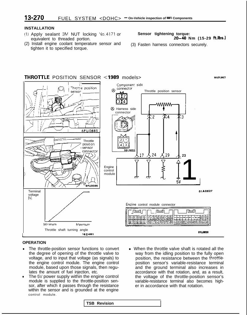
13-270 FUEL SYSTEM <DOHC> - On-Vehicle inspection of MFI Components
INSTALLATION
(1) Apply sealant 3M NUT locking No.4171 orequivalent to threaded portion.
(2) Install engine coolant temperature sensor andtighten it to specified torque.
Sensor tightening torque:20-40 Nm (15-29 ft.lbs.1
(3) Fasten harness connectors securely.
THROlTLE POSITION SENSOR <I989 models> M13YJAEl
F” Throttle
TerminalvoltageWI
//-L/:
MInimum Maxlmum
Throttle shaft turning angle162461
ComDonent side
Throttle position sensor
@ Harness sideconnector I
;:2 %4 :
0
t
~17 ~24 /,19 ,
Enginecontrolmodule
23
1Enqine control module connector
01L0838LOPERATION
l The throttle-position sensor functions to convertthe degree of opening of the throttle valve tovoltage, and to input that voltage (as signals) tothe engine control module. The engine controlmodule, based upon those signals, then regu-lates the amount of fuel injection, etc.
l The 5V power supply within the engine controlmodule is supplied to the throttle-position sen-sor, after which it passes through the resistancewithin the sensor and is grounded at the enginecontrol module.
l When the throttle valve shaft is rotated all theway from the idling position to the fully openposition, the resistance between the throttle-position sensor’s variable-resistance terminaland the ground terminal also increases inaccordance with that rotation, and, as a result,the voltage of the throttle-position sensor’svariable-resistance terminal also becomes high-er in accordance with that rotation.
TSB Revision

FUEL SYSTEM <DOHC> - On-Vehicle Inspection of MFI Components 13-271
TROUBLESHOOTING HINTS
Hint 1:The signals of the throttle-position sensor are moreimportant for control of the automatic transaxle thanfor control of the engine; shifting “impact shocks”are produced if there is a malfunction of thethrottle-position sensor.
INSPECTION
Using Scan tool
Hint 2:If the voltage of the throttle-position sensor deviatesfrom the standard value, check once again aftermaking the throttle-position sensor adjustment. inaddition, if there are any indications that the fixedSAS has been moved, adjust the fixed SAS.
Function
Data reading
Item No. Data display
14 Sensor de-tection vol-tage
HARNESS INSPECTION
connector
Harness sideconnector
Inspection conditions Throttle valve Standard value
Ignition switch: ON / To idle position 1 450-550 mV
Gradually opening Becomes higherproportional tovalve opening.
To fully open 4,500-5,500 mV
Measure the power supply voltage ofthe TPS.. Connector: Disconnected. Ignition switch: ON
Check for continuity of the groundcircuit of the TPS.. Connector: Disconnected
Repair theharness.
+ K25xz.l-~~IZI)
LZheck for an open-circuit, or a shqrt-Yrcuit to ground, between the er-.--control module and the throttle ~USI-tion sensor.. Throttle position sensor connec-
tnr: Disconnected I -- Engine. control module connec-
tor: Disconnected Repair theharness.u23Bl-m)
TSB Revision

13-272 FUEL SYSTEM <DOHC> - On-Vehicle inspection of MFI Components
Throttle positionsensor connector
6FU1348-i
SENSOR INSPECTION
(1) Disconnect the throttle position sensor connector.(2) Measure resistance between terminal @ (sensor ground)
and terminal @ (sensor power).Standard value: 3.5-6.5 kR
(3) Connect a pointer type ohmmeter between terminal @(sensor ground) and terminal @ (sensor .output).
(4) Operate the throttle valve slowly from the idle position tothe full open position and check that the resistancechanges smoothly in proportion with the throttle valveopening angle.
(5) If the resistance is out of specification, or fails to changesmoothly, replace the throttle position sensor.Throttle position sensor installation torque:
1.5-2.5 Nm (1.1-1.8 ftlbs.)
THROTTLE POSITION SENSOR <From 1990 models> MlSYJAFl
L
TerminalvoltageWI (;
LL “-*:,Minimum Maximum
Throttle shaft turning angle 162461
@ connkctorComDonent side Throttle position sensor
I
4-IHarness side$I connector
/t17 A24 Ar--'--crlylriecontrolmodule
7FUO481
Engine control module connector
OPERATIONTROUBLESHOOTING HINTS
INSPECTION-Using Scan tool
Refer to P.13-270.
i,
TSB Revision

FUEL SYSTEM <DOHC> - On-Vehicle inspection of MFI Components 13-273
@ Harness srdeconnector
HARNESS INSPECTION
1 I IMeasure the power supply voltage ofthe throttle position sensor.. Connector: Disconnected. Ignition switch: ON
-
~ LfEf piziq
6FU1241
Check for continuity of the groundcircuit.. Connector: Disconnected
Repair the-+ harness.
R2Wl-a*IZI)
T6FU1242
Engine controlmodule harness
~=YY=zY=~ side connector
connector
?IAFIll 1
TSB Revision
Check for an open-circuit, or a short-circuit to ground, between the enginecontrol module and the throttle oosi- Y---Y Ation sensor.+ Throttle aosition sensor connec- (OK) + /sroa\
tor: Disconnected k-l I. Engine control module connec-
tor: Disconnected
i
Repair theharness.k%lmBl)
SENSOR INSPECTION
(1) Disconnect the throttle position sensor connector.(2) Measure resistance between terminal @ (sensor ground)
and terminal 0 (sensor power).
Standard value: 3.5-6.5 kQ
(3) Connect a pointer type ohmmeter between terminal @(sensor ground terminal) and terminal @ (sensor outputterminal).
Throttle positionsensor connector 6FU124d
(4) Operate the throttle valve slowly from the idle position tothe full open position and check that the resistancechanges smoothly in proportion with the throttle valveopening angle.
(5) If the resistance is out of specification, or fails to changesmoothly, replace the throttle position sensor.Throttle. position sensor installation torque:
1.5-2.5 Nm (1.1-1.8 ft.lbs.1
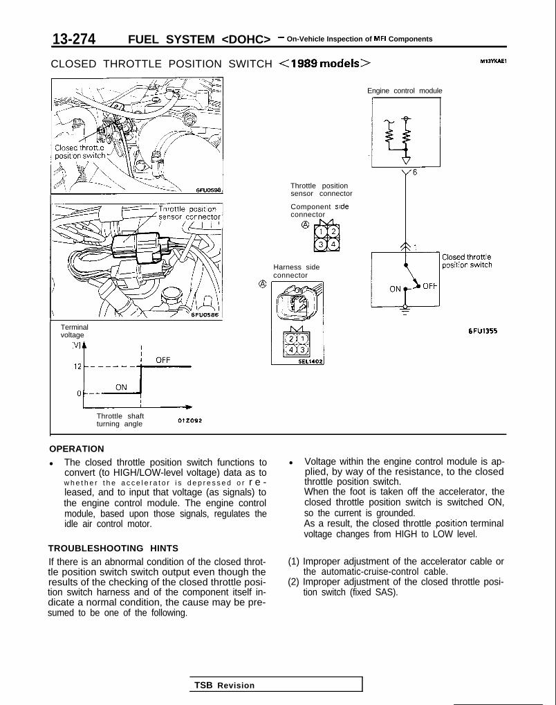
13-274 FUEL SYSTEM <DOHC> - On-Vehicle Inspection of MFI Components
CLOSED THROTTLE POSITION SWITCH <IS89 models> MlSYKAEl
Terminalvoltage
Throttle shaftturning angle
Engine control module
1
Throttle positionsensor connector
Component sideconnector
Harness sideconnector
6FU1355
OPERATION
l The closed throttle position switch functions toconvert (to HIGH/LOW-level voltage) data as tow h e t h e r t h e a c c e l e r a t o r i s d e p r e s s e d o r r e -leased, and to input that voltage (as signals) tothe engine control module. The engine controlmodule, based upon those signals, regulates theidle air control motor.
TROUBLESHOOTING HINTS
If there is an abnormal condition of the closed throt-tle position switch switch output even though theresults of the checking of the closed throttle posi-tion switch harness and of the component itself in-dicate a normal condition, the cause may be pre-sumed to be one of the following.
l Voltage within the engine control module is ap-plied, by way of the resistance, to the closedthrottle position switch.When the foot is taken off the accelerator, theclosed throttle position switch is switched ON,so the current is grounded.As a result, the closed throttle .position terminalvoltage changes from HIGH to LOW level.
(1) Improper adjustment of the accelerator cable orthe automatic-cruise-control cable.
(2) Improper adjustment of the closed throttle posi-tion switch (fixed SAS).
TSB Revision
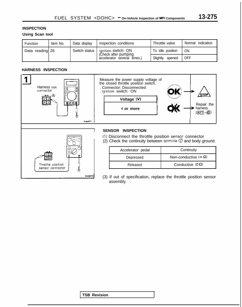
FUEL SYSTEM <DOHC> - On-Vehicle Inspection of MFI Components 13-275
INSPECTION
Using Scan tool
Function Item No.
Data reading 26
Data display Inspection conditions Throttle valve Normal indication
Switch status Ignition switch: ON To idle position ON(Check after pumpingaccelerator several times.) Slightly opened OFF
HARNESS INSPECTION
71-
Harness side
Measure the power supply voltage ofthe closed throttle position switch. -. Connector: Disconnected. Ignition switch: ON
1 Voltage (VI
4 or more
ASTOP
Repair theharness.~@a-Q)
I SENSOR INSPECTION
I (1) Disconnect the throttle position senso_r connector(2) Check the continuity between terminal QI and body ground.
TSB Revision
Accelerator pedal Continuity
Depressed Non-conductive (m S2)
Released Conductive (0 52)
(3) If out of specification, replace the throttle position sensorassembly.
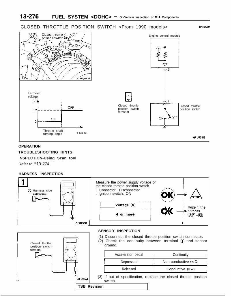
13-276 FUEL SYSTEM <DOHC> - On-Vehicle Inspection of MFI Components
CLOSED THROTTLE POSITION SWITCH <From 1990 models>
Termrnalvoltage
Throttle shaftturning angle 012092
a1
Closed throttleposition switchterminal
Engine control module
ci
Closed throttleposition switch
6FU13 56
OPERATION
TROUBLESHOOTING HINTS
INSPECTION-Using Scan tool
Refer to P.13-274.
HARNESS INSPECTIONL
P1
I:
I
@ Harness sideconnector
Closed throttleposition switchterminal
L
Measure the power supply voltage ofthe closed throttle position switch.. Connector: Disconnected. Ignition switch: ON
SENSOR INSPECTION
(1) Disconnect the closed throttle position switch connector.(2) Check the continuity between terminal @I and sensor
ground.
I Accelerator pedal I Continuity II Depressed I Non-conductive (a Q) I
Released Conductive (0 S2)I
(3) If out of specification, replace the closed throttle positionswitch.
TSB Revision

FUEL SYSTEM <DOHC> - On-Vehicle Inspection of MFI Components 13-277
CAMSHAFT POSITION SENSOR <Up to 1990 models> Multiport fuelM13Yuh
1 Output characteristic
I- c Time
One rotation of crankshaft position sensor
injection relay
Component side Crankshaftconnector position sensor 2
I14,
Crankshaftpositionsensorconnector
I_ /i 7; !~\==, ’60,Giiz!!
@ Harness sideconnector
Camshatt posItIon sensor
Engine control module A 22
Q
6FU1255
OPERATION
l The camshaft position sensor functions to de-tect the top dead center position of the No.1 cy-linder and to convert those data to pulse signalsthat are input to the engine control module. Theengine control module, based upon those sig-nals, calculates the sequence of fuel injection.
TROUBLESHOOTING HINTS
If there is a malfunction of the camshaft positionsensor, the sequential injection will not be correct,
l The power for the camshaft position sensor issupplied from the multiport fuel injection relayand is grounded to the vehicle body. The cam-shaft position sensor, by intermitting the flow (toground) of the 5V voltage applied from the en-gine control module produces pulse signals.
resulting in such problems as engine stalling, un-stable idling, and poor acceleration.
5v-- - r-
ovL_--..---I2 - -
Normal waveform
INSPECTION
Using Oscilloscope
(1) Run the engine at an idle speed.(2) Connect the probe to the oscilloscope pick-up point as
shown in the circuit diagram, and check the waveform.

13-278 FUEL SYSTEM <DOHC> - On-Vehicle inspection of MFI Components
J-JHarness sideconnector
E -:
~
0r01.0512
HARNESS INSPECTION
1 I Measure the power supply voltage.
Harnesssideconnector
_ --_m/--,
~
p”c1
r
Check for continuity of the groundcircuit.
Connector: Disconnected
Repair theharness.@III-Ground)
3@
u
Harness sideconnector
Check the output circuit voltage.. Connector: Disconnected
TSB Revision I

FUEL SYSTEM <DOHC> - On-Vehicle Inspection of MFI Components 13-279
CAMSHAFT POSITION SENSOR <From 1991 models> M13YlABl
@ Component sideconnector
Output characteristicWINo.4
5
) Time
One rotation of crankshaft position sensor
Multiport fuelinjection relay
Crankshaft position sensor I3
Engine control module
7FUO493
OPERATIONTROUBLESHOOTING HINTS
INSPECTION-Using Oscilloscope
Refer to P.13-277.
HARNESS INSPECTION
Harness sideconnector
Measure the power supply voltage.
. Connector: Disconnected
. Ignition switch: ON
7FUO496
TSB Revision

13-280 FUEL SYSTEM <DOHC> - On-Vehicle Inspection of MFI Components
2r Harness sideconnector
@-----.ml----L=s- 0
Hz/Q
=7FVO497
P3 @ Harness srdeconnector E 0
-0
40
c7FVO498
Check for cont inui ty of the groundcircuit.
. Connector : Disconnected
Repair theharness.@WGround)
Check the output circuit voltage.. Connector : Disconnected. Ign i t ion swi tch: ON
I Voltage (V)
1 4.8-5.2 (
CRANKSHAFT POSITION SENSOR <Up to 1990 models>
v] ) Output character is t ic
L Ia Time -
One rotation of crankshaft position sensor OlROlO3
Multiport fuelinjection relay
@ Component side Crankshaft positionconnector
@ Harness side ), 27 Engine control module
MIOYYAAI
TSB Revision

FUEL SYSTEM <DOHC> - On-Vehicle Inspection of MFI Components 13-281
OPERATION
l The crankshaft position sensor functions to de-tect the crank angle (position) of each cylinder,and to convert those data to pulse signals,which are then input to the engine control mod-ule. The engine control module, based uponthose signals, calculates the engine rpm, andalso regulates the fuel injection timing and theignition timing.
TROUBLESHOOTING HINTS
Hint 1:If an impact is suddenly felt during driving or the en-gine suddenly stalls during idling, try shaking thecrankshaft position sensor during idling.If the engine stalls, the cause may be presumed tobe improper or incomplete contact of the crank-shaft position sensor’s connector.Hint 2:If the crankshaft position sensor output rpm is 0rpm during cranking when the engine cannot bestarted, the cause may be presumed to be a mal-function of the crankshaft position sensor or a bro-ken timing belt.Hint 3:If the indicated value of the crankshaft position sen-sor output rpm is 0 rpm during cranking when theengine cannot be started, the cause may be pre-
INSPECTION
Using Scan tool
l The power for the crankshaft position sensor issupplied from the ignition switch-IG and isgrounded to the vehicle body. The crankshaftposition sensor, by intermitting the flow (toground) of the 5V voltage applied from the en-gine control module, produces pulse signals.
sumed to be a failure of the ignition coil’s primarycurrent to intermittently pulse correctly, so a mal-function of the ignition system circuitry, the ignitioncoil and/or the power transistor is the probablecause.Hint 4:If idling is possible even though the crankshaft posi-tion sensor indicated rpm is a deviation from thestandard value, the cause is usually a malfunction ofsomething other than the crankshaft position sen-sor.Examples:(1) Malfunction of the coolant-temperature sensor.(2) Malfunction of the idle air control motor.(3) Improper adjustment of the standard idling
speed.
Inspection conditions Description Normal condition
. Engine: Cranking Compare cranking Both agree.
. Tachometer connection rpm and scan tool(Check intermittent flow of indicated rpm.ignition coil primary currentby tachometer.)
burn N o . / ~i~~~~,, Inspection conditions
At 40°C (104°F)
At 80°C (176°F)
1 ,OOO- 1,250 rpm
650-850 rpm <Non-Turbo>700-900 mm < T u r b o >
TSB RevisionI

13-282 FUEL SYSTEM <DOHC> - On-Vehicle Inspection of MFI Components
(1) Run the engine at an idle speed.-1 Using Oscilloscope
(2) Connect the probe to the oscilloscope pick-up point asshown in the circuit diagram, and check the waveform.
!A--- - - - - - -
ov--------Normal waveform
I 0310202
Measure the power supply voltage.asure the power supply voltage.. Connector: Disconnected. Ignition switch: ON
HARNESS INSPECTION
1
Harness sideconnector
I= I
Check for cont inui ty of the groundcircuit.. Connector: Disconnected
Repair theharness.K&III-Ground)
131Harness side
@ connector
TSB Revision
Check the voltage of the output cir-cuit.. Connector: Disconnected. Ignition switch: ON
ir Repair theharness.
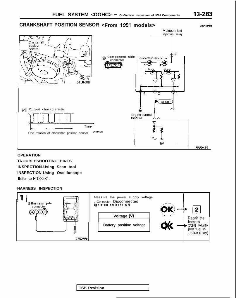
FUEL SYSTEM <DOHC> - On-Vehicle Inspection of MFI Components
CRANKSHAFT POSITION SENSOR
[VI 1 Output character is t ic
One rotation of crankshaft position sensor 01R0’03
Engine controlmqdule 21
R5V J7FUO499I
<From 1991 models>Multiport fuelinjection relay
@ Component s ideconnector
MlBYhlABl
OPERATION
TROUBLESHOOTING HINTS
INSPECTION-Using Scan tool
INSPECTION-Using Oscilloscope
Refer to P.13-281.
HARNESS INSPECTION
11 I1’1 Measure the power supply voltage.
@ H a r n e s s side . Connector: Disconnectedconnector I g n i t i o n s w i t c h : O N
Voltage (VI
Battery positive voltage
-7FUO496
Repair theharness.
-+ (@a-Multi-port fuel in-jection relay)
TSB Revision I

13-284 FUEL SYSTEM <DOHC> - On-Vehicle Inspection of MFI Components
(
Check for continuity of the groundcircuit.. Connector: Disconnected
7FUO497
Repair theharness.
* cm-Ground)
a Harness side connector
Check the voltage of the output cir-cut.. Connector: Disconnected. Ignition switch: ON
7FUOSOlLIGNITION SWITCH-STRefer to P.13-77.
M13VNAAa
IGNITION SWITCH-ST AND PARK/NEUTRALPOSITION SWITCH M13YOAc
Refer to P.13-78.
VEHICLE SPEED SENSORRefer to P.13-80.
M13YPAAa
POWER STEERING PRESSURE SWITCH M13VQAAa
Refer to P.13-81.
TSB Revision

FUEL SYSTEM <DOHC> - On-Vehicle Inspection of MFI Components 13-285
AIR CONDITIONING SWITCH AND A/C COMPRESSOR CLUTCH RELAY mt3n7.4al
Jk: L 1 /J l-k~-~+ L!- Air conditioning switch
0/’ ’ ’ -~. i>
‘\ /,
(\ QeF --:
’ -q, ,T
(‘a/ A-.,>*/ \) !I/ ,+ f---J;I’, ,p
s- / :\,$jy W/’
\mc-- -; --
\\ \\$ &
IF -~1. b
I /~-~ i E--z
\ \I i
!
L-,-1&L.- ~~~~.
6FUO845
I
Sub fusible link
‘7 IpI Z%37°GZressor
2 Dual pressureswitch
1
t
Air conditioningOFF engif’Ie codant* temperatureON swi tch
T 2
TSB Revision
Engine control module ,(65 1\7
v v
Engine control module connector 6FU1457
OlLo838
OPERATION
l The air conditioning switch applies battery vol-tage to the engine control module when the airconditioning is switched ON.
TROUBLESHOOTING HINTS
If the air conditioning compressor’s magnetic clutchis not activated when the air conditioning switchis switched ON during idling, it is probable that the
. When the air conditioning signals are input, theengine control module activates the idle air con-trol motor, and also switches ON the powertransistor. As a result, current flows to the A/Ccompressor clutch relay coil and the relayswitch is switched ON, the air conditioningcompressor’s magnetic clutch is activated.
cause is a malfunction of the air conditioning controlsystem.

13-286 FUEL SYSTEM <DOHC> - On-Vehicle Inspection of MFI Components
INSPECTION
Using Scan tool
Air conditioning switch
Function Item No.
Data reading 28
Data display Check conditions Air conditioning switch Normal display
Switch status . Engine idling OFF OFF(The air conditioningcompressor should be ON ONactivated when the airconditioning switch isswitched ON.)
Air conditioning compressor clutch relay
Function Item No.
Data reading 49
Data display Check conditions Air conditioning switch Normal display
Air condition- . Engine: idling after OFF OFF (Compressoring compres- warm up clutch non-sor clutch activation)relay status
ON ONKompressorclutch activation)
HARNESS INSPECTION________ --- -__-. -- ~~-Measure the power supply voltage ofthe air conditioning circuit.. Engine control module connec-
tor: Disconnected- Ignition switch: ON+ Air conditioning switch: ON
side connector
AIR CONDITIONING INSPECTIONRefer to GROUP 55-Air Conditioning.
1 TSB Revision I

FUEL SYSTEM <DOHC> - On-Vehicle Inspection of MFI Components 13-287
KNOCK SENSOR <Turbo, Non-Turbo From 1992 models> M13zAAA
Engine control module
1
@ Component side Oscilloconnector I it’
ti hoc: !A!’ A2 II I
s e n s o r ! T1 I I
I SEL12081
@ Harness sideconnector
OPERATION
The knock sensor converts cylinder block vibrationsdue to knocking into voltage according to thestrength of the vibrations and inputs it to the engineTROUBLESHOOTING HINTS
When knocking occurs when driving at maximumload, the following troubles, other than the knock
control module.The engine control module controls the delay inspark timing according to this signal.
sensor, can be inferred.
(1) Incorrect spark plug heat rating(2) Incorrect gasoline(3) Mis-adjustment of standard spark timing
Normal waveform 03A0205
INSPECTION
Using Oscilloscope
(1) Connect the probe to the oscilloscope pick-up point asshown in the circuit diagram.
(2) Rev up the engine to 5,000 rpm, and check the waveform.
TSB Revision

12,7QQ FI IFI GVSXFM <lMX-lr.> - On-Vehicle lnmection of MFI ComponentsId-Luv I “Lh V.V. h.1. .--..v- _.. .- .
connector
Measure the terminal vol tage.. Connector: Disconnected
pf?q f$!?;
1 FU0513
Check for cont inui ty of the groundcircuit.. Connector: Disconnected
@p/LA
Repair theharness.
KBB-Ground)
76FU1302
EGR TEMPERATURE SENSOR <Calif.> hn3m1
fiFU1424
Component side EGR temperature sensorconnector I
1
. /
r
t-lA 17 A24
JI;
t
\ 15
Enginecontrolmodule
lrn5v
6FU1269
Harness side@ connector
!?ll@lfiiit?rl2 1
KL1202
ITemperature 1521005
TSB Revision

FUEL SYSTEM <DOHC> - On-Vehicle Inspection of MFI Components 13-289
OPERATION
l The EGR temperature sensor functions to con-vert the data regarding the temperature of theEGR gas downstream from the EGR valve tovoltage, and to input that voltage (as signals) tothe engine control module.
l The 5V power supply within the engine controlmodule is supplied, by way of the resistancewithin the unit, to the EGR temperature sensor;it passes through the EGR temperature sensor,which is a type of resistor, and is grounded atthe engine control module.Note that the resistance of the EGR tempera-
ture sensor decreases when the EGR gas vol-ume increases and the temperature of the EGRgas increases.
l The EGR temperature sensor terminal voltagebecomes higher when the resistance of the EGRtemperature sensor increases, and becomeslower when the resistance decreases.
Consequently, the EGR temperature sensorterminal voltage varies in accordance with thetemperature of the EGR gas, becoming lowerwhen the temperature of the EGR gas in-creases.
INSPECTION
Using Scan tool
Function Item No.
Data reading 43
Data display 1 Inspection conditions 1 Engine condition 1 Standard value I
Sensor . Engine: warm up Idling 100°C (212°F) or lowertemoerature * Enaine is maintained in <Non-Turbo> I
a &nstant state for 2minutes or more
. Remove the vacuum
11 7J$lfifiF~ nr lower 1
hose (green stripes) fromthe EGR solenoid and
3,500 rpm 150°C (302°F) or higher/hlnn-Turbo>
plug both the removedvacuum hose end andsolenoid valve nipple.
HARNESS INSPECTION
Harness sideconnector
Measure the power supply voltage.. Connector: Disconnected. Ignition switch: ON
Voltage (V)Repair the
Harness sideconnector
Check for continuity of the groundcircuit.. Connector: Disconnected
SENSOR INSPECTION
Refer to GROUP l7-Exhaust Gas Recirculation (EGR) System.
Repair theharness.@El-IIll. q l)
TSB Revision

13-290 FUEL SYSTEM <DOHC> - On-Vehicle Inspection of MFI Components
HEATED OXYGEN SENSOR <Up to 1990.5 model-Non-Turbo, Turbo> M13YSAAa
sensor connector
2 Theoretical A/F
8.5P.-5E
Pt;2
Lw 14 15 16
AJF EC1007
Component side
Heated oxygen. sensor
y3y4 $1y2n ri rlT ” II
Multiport fuelinjection relay d
; II
TII :‘aII Il. 7
Engine control module x4H106@ Harness side
connector
OlLoB38
OPERATION
l The heated oxygen sensor functions to detectthe concentration of oxygen in the exhaust gas;it converts those data to voltage, and inputs theresulting signals to the engine control module.
l If the air/fuel mixture ratio is richer than thetheoretical air/fuel mixture ratio (i.e., if the con-centration of oxygen in the exhaust gas issparse), a voltage of approximately IV is output;if the air/fuel mixture ratio in leaner than thetheoretical air/fuel mixture ratio (i.e., if the con-centration is dense), a voltage of approximatelyov is output.
TROUBLESHOOTING HINTS
HINT 1:The exhaust gas purification performance will wor-sen if there is a malfunction of the heated oxygensensor.Hint 2:If the heated oxygen sensor output voltage deviatesfrom the standard value even though the results ofthe checking of the heated oxygen sensor are nor-mal, the cause is probably a malfunction of a com-ponent related to mixture control.
l The engine control module, based upon thosesignals, regulates the amount of fuel injection sothat the air/fuel mixture ratio becomes thetheoretical air/fuel mixture ratio.
l Battery power supply is applied, by way of themultiport fuel injection relay, to the oxygen sen-sor heater. As a result, the sensor element isheated by the heater, so that the heated oxygensensor shows excellent response even if thetemperature of the exhaust gas is low.
Examples:(1) Malfunction of an injector.(2) Air leakage into the intake manifold from a leak-
ing gasket.(3) Malfunction of the volume air flow sensor, the
intake air temperature sensor, the barometric-pressure sensor, or the engine coolant tempera-ture sensor.
TSB Revision

FUEL SYSTEM <DOHC> - On-Vehicle inspection of MFI Components 13-291
INSPECTION
Using Scan tool
Function
Data reading
Item No.
11
HARNESS INSPECTION
T
Data display
Sensor de-tection vol-tage L
Inspection conditions Engine condition Standard value
Engine: warm up When sudden decel- 250 mV or lower(Make the mixture lean eration from 4,000 rpmby engine speed reduc-tion, and rich by racing) When engine is sud- 500- 1,000 mV
denly raced
Engine: warm up 750 rpm (Idling)(using the oxygen sen- <Non-Turbo>~~~,s~~~r~hr~~i~t~~~ir’ 6JO;K~~ldling)
also check the conditionof control by the engine 2,000 rpmcontrol module)
400 mV or lower
I(changes)
600- 1,000 mV
connector
Enginecontrol moduleharness side
@ ZTE-mector -La
@ El
4 3
-l
g;
@ Harness sideconnector
Measure the power supply voltage ofthe heated oxygen sensor.
Connector : DisconnectedIgnition switch: ON
I II
Check for an open-circuit or a short-circuit to ground, between the enginecontrol module and the heated oxy-gen sensor.. Heated oxygen sensor connec-
tor: Disconnected 1 03. Engine control module connec-
tor: Disconnected
i
Repair theharness.Nzm+l)
Check for continuity of the groundcircuit.. Connector: Disconnected
@fR&eharness.
t
C@rzI-m,@El-Ground)
1 TSB Revision I ’

13-292 FUEL SYSTEM <DOHC> - On-Vehicle Inspection of MFI Components
Harnessoxygen sensorside connec
MD998460 6FUO937
MD998460 6FUO938
SENSOR INSPECTION
(1) Disconnect the heated oxygen sensor connector, and con-nect the special tool (harness connector) to the heated ox-ygen sensor side.
(2) Check that there is continuity [approx. 1252 at 20°C (68”F)]between heated oxygen sensor connector terminal @ (redclip of special tool) and terminal @ (blue clip).
(3) If there is no continuity, replace the heated oxygen sensor.(4) Warm up the engine until the engine coolant temperature
exceeds 80°C (176°F).(5) Use jumper wires to connect heated oxygen sensor termi-
nal @ (red clip of special tool) and terminal @I (blue clip) tothe battery 0 terminal and 0 terminal.CautionBe very careful when connecting the jumper wiresbecause the heated oxygen sensor will be damaged ifa mistake is made in the connecting terminals.
(6) Connect a digital voltmeter between terminal @ (yellowclip of special tool) and terminal @ (black clip).
(7) While repeatedly racing the engine, measure the outputvoltage of the heated oxygen sensor.
’ Engine Heated oxygen Remarksensor outputvoltage
When racing 0.6-1.0 V When the air/fuel mixture ratioengine becomes rich by repeatedly
racing the engine, the normalheated oxygen sensor output isapproximately 0.6-I .O V.
TSB Revision 1

FUEL SYSTEM <DOHC> - On-Vehicle Inspection of MFI Components 13-293
HEATED OXYGEN SENSOR <From 1991 model-Non-Turbo> M13YSAAa
sensor connector
\ \ 6FU1425
2d6
25Egt;a,W
TheoreWal A/F
14 15 16
A/F EC1007
OPERATION
TROUBLESHOOTING HINTS
INSPECTION-Using Scan tool
Refer to P.1.3-290.
HARNESS INSPECTION
connector
Heated oxygensensor
ComDonent sideMultiport fuelinjection relay
Engine control module
Engine control module connector
@ Harness sideconnector
6FU1628
OlLO838
Measure the power supply voltage ofthe heated oxygen sensor.
Connector: DisconnectedIgnition switch: O N
,
TSB Revision

13-294 FUEL SYSTEM <DOHC> - On-Vehicle Inspection of MFI Components
L
21@ ~~kn~~nnector -
@
m
4 3
~
gP
Enginecontrol mod&harness sideconnector
@ Harness sideconnector
6FU1545
41 Harness side@ connector
,1
”
m/YL/-- 0I&0 0
Enginecontrol moduleharness sideconnector
If*-L- 6FU154.5
Check for an open-circuit or a short-circuit to ground, between the enginecontrol module and the heated oxy-gen sensor.. Heated oxygen sensor connec-
tor: Disconnected. Engine control module connec-
tor: DisconnectedRepair the
-+ harness.C@[II-•J,
Check for continuity of the groundcircuit.. Connector: Disconnected cl4
Repair theharness.RzsEl-llosl)
Check for an open-circuit or a short-circuit to ground, between the enginecontrol module and the heated oxy-gen sensor.. Heated oxygen sensor connec-
tor: Disconnected. Engine control module connec-
tor: Disconnected
SENSOR INSPECTlON
Refer to P.13-292.
1 TSB Revision
lASTOP
Repair the+ harness.
h23xl--11051)

FUEL SYSTEM <DOHC> - On-Vehicle Inspection of MFI Components 13-295
Filter
Connector
Solenoid coilPlunger
Needle valve -&$
lnjedtion 6FUO51
Multiport fuel injection relay MIBvrbA1
IThe area enclosed with ~~~~ is
@I Harness side applicable onlv for Turbo.connector
Enginecofitrolmodule
Engine control module connectorI 6FU1547
OlLo63
OPERATIONl The injectors are electromagnetic-valve-
equipped injection nozzles that function to injectfuel based upon injection signals from theengine control module.
l Because the surface area of the injection ports isfixed and because the pressure of the fuelrelative to the pressure within the manifold isalso regulated to a fixed pressure, the amount offuel injection by injectors is determined by the
TROUBLESHOOTING HINTSHint 1:If there is a problem with starting while the engine iswarm, perform the combustion test and check forleakage of the injectors.Hint 2:If the engine can’t be started, and the injectors arenot activated during cranking, the cause is probablya malfunction such as described below, not with theinjectors.(1) Malfunction of the circuit for supply of power to
the engine control module, or of the ground cir-cuit.
(2) Malfunction of the multiport fuel injection relay.(3) Malfunction of the crankshaft position sensor
and/or the camshaft position sensor.Hint 3:If there is a cylinder for which the idling conditiondoes not change when, during idling, the fuel
injection of the injectors is cut off in sequence,length of time that the needle valve is open, or,in other words, by the length of time of currentflow to the solenoid coil.
l Battery power supply is supplied, by way of themultiport fuel injection relay, to the injectors.When the engine control module switches ONthe power transistor within the unit and currentflows to the solenoid coil, the injectors open andfuel is injected.
check that cylinder as described below.(1) Check the injector and harness.(2) Check the spark plugs and the high-tension
cable.(3) Check the compression pressure.Hint 4:if the injector activation time deviates from thestandard value even though the results of thechecking of the injector’s harness and of the injectoritself are normal, the cause may be pressumed tobe one of the following,(1) Incomplete combustion within the cylinder.
(Malfunction of the spark plugs, the ignition coil,the compression pressure, etc.)
(2) Incomplete close contact of the EGR valve seat.(3) Increased engine resistance.
TSB Revision
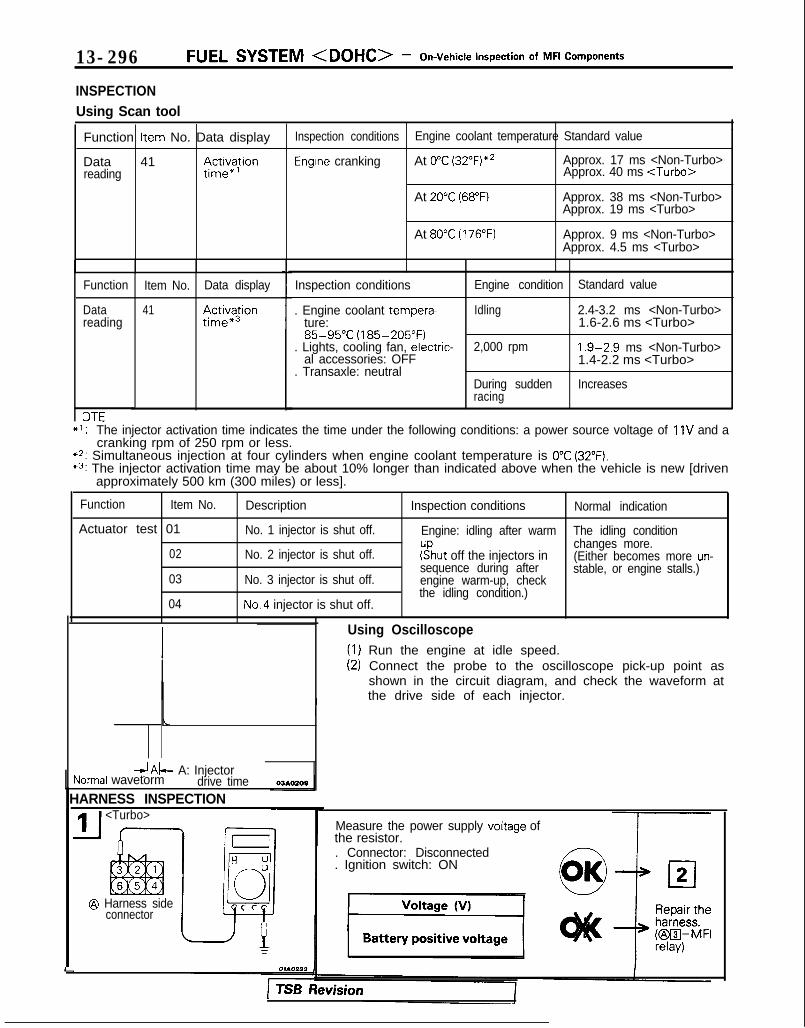
13-296 FUEL SYSTEM <DOHC> - On-Vehicle Inspection of MFI Components
INSPECTIONUsing Scan tool
Function Item No. Data display Inspection conditions Engine coolant temperature Standard value1
Data 41 ;ctJ$on Engine cranking At 0°C (32”F)*2 Approx. 17 ms <Non-Turbo>reading Approx. 40 ms <Turbo>
At 20°C (68°F) Approx. 38 ms <Non-Turbo>Approx. 19 ms <Turbo>
At 80°C (176°F) Approx. 9 ms <Non-Turbo>Approx. 4.5 ms <Turbo>
Function
Datareading
3TE
Item No.
41
Data display
$ctX$on
Inspection conditions Engine condition Standard value
. Engine coolant tempera- Idling 2.4-3.2 ms <Non-Turbo>ture: 1.6-2.6 ms <Turbo>85-95°C (185-205°F)
. Lights, cooling fan, electric- 2,000 rpm 1.9-2.9 ms <Non-Turbo>al accessories: OFF 1.4-2.2 ms <Turbo>
. Transaxle: neutralDuring sudden Increasesracing
+l: The injector activation time indicates the time under the following conditions: a power source voltage of 11V and acranking rpm of 250 rpm or less.
*2: Simultaneous injection at four cylinders when engine coolant temperature is 0°C (32°F).*3: The injector activation time may be about 10% longer than indicated above when the vehicle is new [driven
approximately 500 km (300 miles) or less].
Function Item No. Description Inspection conditions Normal indication
Actuator test 01 No. 1 injector is shut off. Engine: idling after warm The idling condition
02 No. 2 injector is shut off. ?!hut off the injectors inchanges more.(Either becomes more un-
03 No. 3 injector is shut off.
04 No.4 injector is shut off.
sequence during afterengine warm-up, checkthe idling condition.)
stable, or engine stalls.)
, d&- A: InjectorNormal wavetorm drive time
HARNESS INSPECTION<Turbo>
@ Harness sideconnector I
L
Using Oscilloscope(1) Run the engine at idle speed.(2) Connect the probe to the oscilloscope pick-up point as
shown in the circuit diagram, and check the waveform atthe drive side of each injector.
Measure the power supply voltage ofthe resistor.. Connector: Disconnected. Ignition switch: ON
1 TSB hevision

FUEL SYSTEM <DOHC> - On-Vehicle inspection of MFI Components 13-297
@I Harness sideconnector
Measure the power supply voltage ofthe injector.. Resistor connector: Connected
<Turbo>. Injector connector: Disconnected. Ignition switch: ON
module harnessside connecror
ACTUATOR INSPECTIONINJECTORCHECKING OPERATION SOUNDUsing a sound scope, check the operation sound (“chi-chi-chi”)of injectors during idling or during cranking.Check that as the rotating speed increases, the frequency ofthe operating sound also increases.
CautionNote that even if the injector you are checking is notoperating, you will hear the operating sound of the otherinjectors.NOTEIf no operating sound is heard from the injector that is beingchecked, check the injector drive circuit. If there is nothingwrong with the circuit, a defective injector or engine controlmodule is suspected.
MEASURING RESISTANCE BETWEEN TERMINALS(1) Remove the injector connector.(2) Measure the resistance between the terminals.
Standard value:13-16 Sz [at 20°C (68”F)I <Non-Turbo>2-3 Q [at 20°C (68”F)] <Turbo>
(3) Install the injector connector.
1 TSB Revision I

131298 FUEL SYSTEM <DOHC> - On-Vehicle Inspection of MFI Components
E 0,-I3
4El00
RESISTOR <Turbo>MEASURING RESISTANCE BETWEEN TERMINALS(1) Disconnect the resistor connector.
(2) Measure the resistance between the terminals.
Standard value:
Measurement terminals Resistance (52)
O-0 I1-1 [ a t %$%&)I
t @-0 I
(3) If the resistance deviates from the standard value, replaceL 6FUO630 the resistor.
IDLE AIR CONTROL MOTOR (STEPPER MOTOR)
Idle air control motor(stepper motor)
-~~~~:Froty ?990 models>\\ v-,
6FU142(
Coil
Steppermotor
Ball bearing
Magnetic rotor
Ball bearing
Pintle
Lead z1screw 0
Multiport fuelinjection relay
--l-
MlJYUAH
1 Harness sidelnnector”
.Engine control module connectorI I
N O T E olLos3s
*: Indicates a connector that, from 1990 models, is the
7FUO586
Idle aircontrol motor

FUEL SYSTEM <DOHC> - On-Vehicle Inspection of MFI Components 13-299
OPERATIONl The amount of air taken in during idling is
regulated by the opening and closing of theservo valve located in the air passage thatbypasses the throttle valve.
l The servo valve is opened or closed by theactivation of the stepper motor (incorporatedwithin the idle air control motor) in the forwardor reverse direction.
TROUBLESHOOTING HINTSHint 1: If the number of stepper motor steps
increases to IOO- 120 steps or decreasesto 0 step, the cause may be presumed tobe a malfunction of the stepper motor ordamaged or disconnected wiring of theharness.
Hint 2: If the number of stepper motor stepsdeviates from the standard value eventhough the results of the checking of theharness of the idle air control motor and ofthe comoonent itself indicate no abnormalcondition, the cause may be presumed tobe one of the following.
INSPECTIONUsing Scan tool
l Battery power supply is supplied, by way of themultiport fuel injection relay, to the coil of thestepper motor. The engine control moduleswitches ON the power transistors (locatedwithin the engine control module) in sequentialorder, and, when current flows to the steppermotor coil, the stepper motor is activated in theforward or reverse direction.
(1) Improper adjustment of the standardidling speed.
(2) Deposits adhered to the throttle valve.(3) Leakage of air into the intake manifold
from a gasket gap, etc.(4) Incomplete close contact of the EGR
valve seat.(5) Incomplete combustion within the
cylinder.(Malfunction of the spark plugs, theignition coil, the iniectors, the com-pression pressure, etc.)
Function Item No. Data display Check conditions Load conditions Standard value
Data reading 45 Steppermotor steps
. Engine coolant tempera- . Air conditioning 4-14Stepture: switch: OFF <Non-Turbo>
85-95°C (185-205°F). Lights, electrical cooling :$b::p
fan and accessories: OFF. Transaxle: neutral. Closed throttle switch: ON
- Air conditioning 20-60 Stepswitch: ON <Non-Turbo>
(The compressor clutchshould be activated whenthe air conditioning switch
;J-;;o~P
is switched ON.)* Engine: idling
1;:!,1;:!,/!-I\/!-I\
f$&$:”f$&$:”! ,‘,! ,‘,4);4);
;jj\(Q(j!jGZ-);jj\(Q(j!jGZ-)liliq#Q~Hq#Q~H F]F]
ii 2 L J 2 L ~ -0SClllO 4ii 2 L J 2 L ~ -0SClllO 4
NOTEWhen the vehicle is new (driven approximately 500 km (300 miles) or less) the number of steps may be about30 steps greater than the standard value indicated above.
Using Oscilloscope(1) Connect the probe to each oscilloscope pick-up point as
shown in the circuit diagram.(2) Start the engine.(3) When the air conditioning switch is turned on, the idling
speed increases to operate the idle air control. Check theinstantaneous waveform.
NOTEKeep in mind that the waveform can be observed onlywhen idle air control is in operation.

FUEL SYSTEM <DOHC> - On-Vehicle Inspection of MFI Components
HARNESS INSPECTION
connector
@ Harness side7
connectorharnessside connw&
c I7FUOOlO
Measure the power supply VOltage ofthe idle air control motor.
. e Idle air control motor connec-tor: Disconnected
. Ignition switch: ON
Check for an open-circuit, or a short-circuit to ground, between the enginecontrol module and idle air controlmotor.. Engine control module connec-
tor: Disconnected* Idle air control motor connec-
‘--R&heharness.
tor: Disconnected
ACTUATOR INSPECTIONChecking the Operation Sound(1) Check that the operation sound of the stepper motor can
be heard after the ignition is switched ON (but withoutstarting the motor).
(2) If the operation sound cannot be heard, check the steppermotor’s activation circuit.If the circuit is normal, it is probable that there is amalfunction of the stepper motor or of the engine controlmodule.
Checking the Coil Resistance(1) Disconnect the idle air control motor connector and con-
nect the special tool (Test harness).(2) Measure the resistance between terminal @ (white clip of
the special tool) and either terminal @ (red clip) or terminal$d;!lue clip) of the connector at the idle air control motor
Standard value: 28-33 & at 20°C (68°F)(3) Measure the resistance between terminal @ (green clip of
the special tool) and either terminal @ (yellow clip) or ter-minal @ (black clip) of the connector at the idle air controlmotor side.
Standard value: 28-33 51 at 20°C (68°F)
J
TSB Revision

FUEL SYSTEM <DOHC> - On-Vehicle lnsoection of MFI ComDonents 13-301<:I989 models> d
\’ @ml
Idle aircontrol motor
10 /(stepper motor)
w- 6FUO609
<From 1990 models>
6FU1426L
MD9984f
\7FUOOll
i
Operational Check(1) Remove the throttle body.(2) Remove the stepper motor
(3) Connect the special tool (Test harness) to the idle air con-trol motor connector.
(4) Connect the positive (+) terminal of a power supply(approx. 6 V) to the white clip and the green clip.
(5) With the idle air control motor as shown in the illustration,connect the negative (-) terminal of the power supply toeach clip as described in the following steps, and checkwhether or not a vibrating feeling (a feeling of very slightvibration of the stepper motor) is generated as a result ofthe activation of the stepper motor.
@ Connect the negative (-) terminal of the power supplyto the red and black clip.
@ Connect the negative (-) terminal of the power supplyto the blue and black clip.
@ Connect the negative (-) terminal of the power supplyto the blue and yellow clip.
@I Connect the negative (-) terminal of the power supplyto the red and yellow clip.
@ Connect the negative (-) terminal of the power supplyto the red and black clip.
@ Repeat the tests in sequence from (5) to (1).
(6) If, as a result of these tests, vibration is detected, thestepper motor can be considered to be normal.
TSB Revision

13-302 FUEL SYSTEM <DOHC> - On-Vehicle Inspection of MFI Components
IGNITION COIL AND IGNITION POWER TRANSISTOR <I989 models>Batterv
tm3wAAa
@ Harness sideconnector
@ Harness sideconnector
/gnition, coil ,fz ,,
5EL1401/
fY@gT$J p$=ppt.~~or JJ$& Spark7 b b b A Plug
Engine control module connector
2 q$gFQ%y@TgLQIgnition No 2 No.3 No 4 No 1tlmlngadjustment 0connecfor
31 E$;control
01 LO838
OPERATIONl When ignit ion power transistor unit A is
switched ON by signals from the engine controlmodule, primary current flows to ignition coil A.When ignit ion power transistor unit A isswitched OFF, the primary current is inter-rupted, high voltage is generated at secondarycoil A, and the spark plug for the No.1 and No.4cylinders sparks. When, however, ignitionpower transistor unit 6 is switched from ON toOFF, the spark plug for the No.2 and No.3 cylin-ders sparks.
l When the engine control module switches OFFthe power transistor inside the unit, battery vol-tage is applied to the ignition power transistorunit, and the ignition power transistor unit isswitched ON.When the engine switches ON the ignitionpower transistor within the unit, however, theignition power transistor unit is switched OFF.
TSB Revision

r
FUEL SYSTEM <DOHC> - On-Vehicle Inspection of MFI Components 13-303INSPECTIONUsing Scan tool
Function Item No.
Data reading 44
Data display Inspection conditions Engine condition Standard value
Ignitionadvance
. Engine: warm
. Timing light: set750 rpm (idling) 5-15” BTDC
(Use the timing light tocheck the actual ignition 2,000 rpm 32 - 4 1 “BTDCtiming.)
Oscillo 1
Normal waveform
Oscilio 2
! 1ov - - -
ovNormal waveform
HARNESS INSPECTION
Harness sideconnector E 0-0
JEl0
connectorI
lEnginecontrolmoduleharnesssideconnector
Using Oscilloscope1. Primary signal of ignition coil
(1) Run the engine at an idle revolution speed.(2) Connect the probe to oscilloscope pick-up point 1 as
shown in the circuit diagram, and check the primarysignal of the ignition coil.
2. Control signal of ignition power transistor(3) Connect the probe to oscilloscope pick-up point 2 as
shown in the circuit diagram, and check the controlsignal of the ignition power transistor.
Measure the power supply voltage ofthe ignition coil.. Connector: Disconnected. Ignition switch: ON
Voltage (VI
I Battery positive voltageI I Ignition
switch)
Check for an open-circuit, or a short-circuit to ground, between the enginecontrol module and the ignition coil.* Engine control module connec-
tor: Disconnected* Ignition coil connector: Discon-
nected
i
Repair theharness.N23l3k-m)
TSB Revision

13-304 FUEL SYSTEM <DOHC> - On-Vehicle Inspection of MFI Components
Harness sideconnector
Check for an open-circuit, or a short-circuit to around, between the iani-
~ tion power transistor and the ignisonc o i l .
* ignition coil connector: Discon-netted
. Ignition power transistor connec-tor: Disconnected
Harness side
6FU1381
Harness side@ connector
+-6FU1382
Ignition timingadjustment I ’ 7l-i---3connector
0 l-
t!-
:6FU1287
ACTUATOR INSPECTIONRefer to GROUP 16-Ignition System.
I
Check for continuity of the groundcircuit.‘. Connector: Disconnected
cl5
Repair theharness.KBEil-Ground)
Measure the voltage of the controlsignal circuit of the ignition powertransistor.* Ignition power transistor connec-
tor: Disconnected. Ignition switch: START
Measure the voltage of the ignitiontiming adjustment terminal.. Ignition switch: ON
Voltage (V)
1 4.0-5.2 1 Repair theharness.KaIl--~)
TSB Revision

FUEL SYSTEM <DOHC> - On-Vehicle Inspection of MFI Components 13-305IGNITION COIL AND IGNITION POWER TRANSISTOR <From 1990 models>
Ml3WAAb
@ Harness sideconnector
@ Harness sideconnector
5EL13031
@ Component sideconnector
1 5EL1700
Battery
@CompmntStde con-
controlmodule
a SparkPlUGI.-
'. 1
Enoine
Engine control module connector
OPERATIONINSPECTIONUsing Scan tool
Refer to P.13-302.
cm
i
Function Item No. Data display Inspection conditions Engine condition Standard valueI
reading 44 5- 15” BTDC
BTDC <Non-Turbo>) BTDC <Turbo>
TSB Revision

13-306 FUEL SYSTEM <DOHC> - On-Vehicle Inspection of MFI Components
Harnesscirio-.-.,
@ connector
Measure the power supply voltage ofthe ignition coil.. Connector: Disconnected. Ignition switch: ON
HARNESS INSPECTION
Harness side
IMeasure the power supply voltage ofthe ignition coil.. Connector: Disconnected. ignition switch: ON
control module and the ignitionpower transistor.. Engine control module connec-
tor: Disconnected. Ignition power transistor connec-
tor: Disconnected Repair theharness.KI3zil-m)
6FU1387 I
t I I I 1an open-circuit, or a short-ground, between the igni-
power transistor and the ignition
coil connector: Discon-
* Ignition power transistor connec-tor: Disconnected Reoair the
t
hamess.KBEI-GUI~GZWBXZl)
IJ5Harness side
@ connector
J
TSB Revision
Check for continuity of the groundcircuit.. Connector: Disconnected
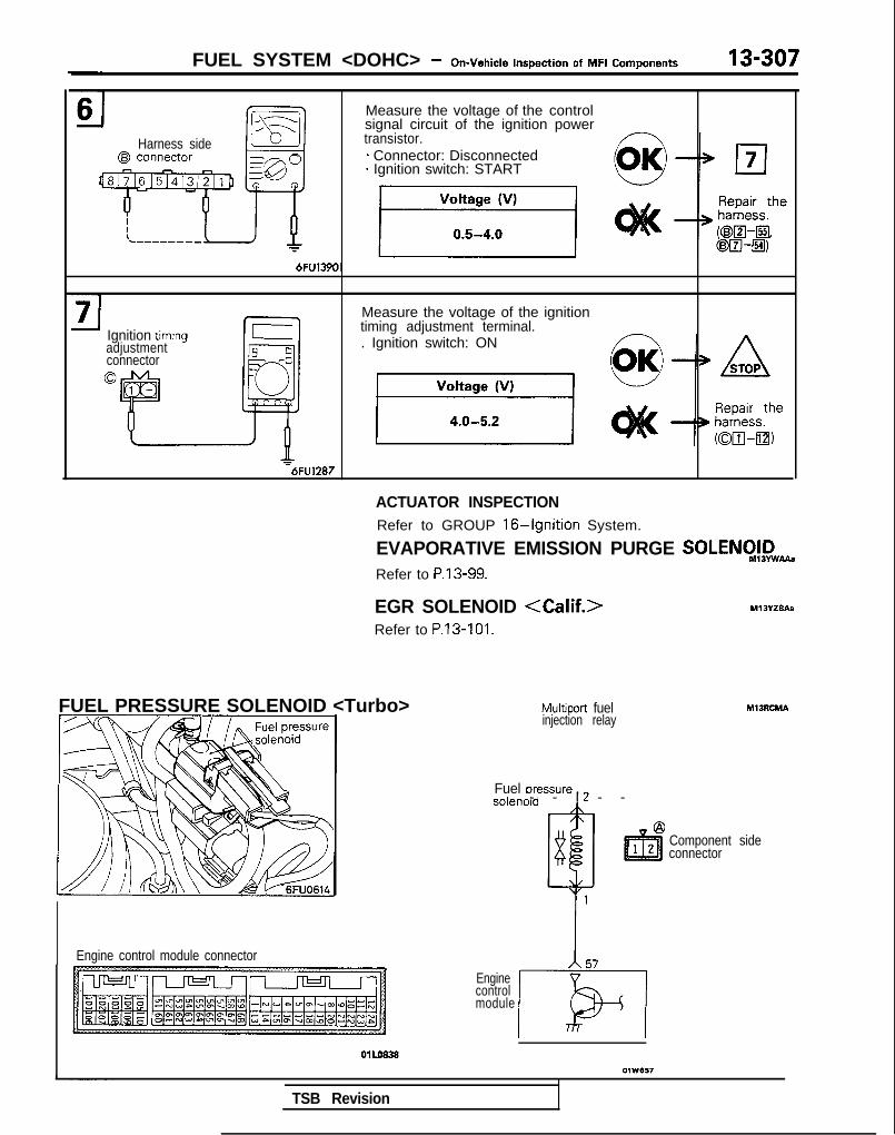
FUEL SYSTEM <DOHC> - On-Vehicle Inspection of MFI Components 13-307
Harness side
Measure the voltage of the controlsignal circuit of the ignition powertransistor.* Connector: Disconnected* Ignition switch: START
Ignition timrngadjustmentconnector0
Measure the voltage of the ignitiontiming adjustment terminal.. Ignition switch: ON
=6FU1287
FUEL PRESSURE SOLENOID <Turbo>
Engine control module connector
ACTUATOR INSPECTIONRefer to GROUP 16-Ignition System.
EVAPORATIVE EMISSION PURGE SOLENCI!,D,,.Refer to P.13-99.
EGR SOLENOID <Calif.>Refer to P.13-101.
Multiport fuelinjection relay
- - I - -Fuel uressure , 2
Component sideconnector
Enginecontrolmodule
TSB Revision

13-308 FUEL SYSTEM <DOHC> - On-Vehicle Inspection of MFI Components
OPERATIONl The fuel pressure solenoid is an ON-OFF type of
solenoid valve and changes pressure fed intothe fuel pressure regulator to intake manifoldpressure and barometric pressure.
l Battery power is supplied to the fuel pressuresolenoid via the multiport fuel injection relay.When the engine control module turns on thepower transistor in the unit, current flows in thecoil and barometric pressure is fed to the fuelpressure regulator.
INSPECTIONUsing Scan tool
0 If engine coolant temperature (approximately95°C (203°F) or more) and also air intaketemperature (approximately 50°C (122°F) ormore) are high when the engine is started, fuelpressure is controlled in order to maintainpressure at approximately 260 kPa (37 psi)immediately after starting and then, after a lapseof approximately 30 seconds to 2 minutes, tolower it to approximately 190 kPa (27 psi).
Function Item No.
Actuator test 09
Description Inspection conditions Normal condition
$$;;i;;;alve switched from Ignition switch: ON Operating sound isheard when driven.
HARNESS INSPECTION
Harness side
Measure the power supply VokW1 . Connector: Disconnected1 . Ignition switch: ON
Voltage 04
1 Battery positive voltage 1t)lt<
02Repair theharness.@I4,MFI
Engine control moduleharness side connecto
Harness side
Check for an open-circuit, or shot-t-circuit to ground, between the fuelpressure solenoid and the enginecontrol module.- Engine control module connec-
tor: Disconnected. Fuel pressure solenoid connec-
tor: Disconnected Repair theharness.h25xwzl21,
1 TSB Revision

FUEL SYSTEM <DOHC> - On-Vehicle Inspection of MFI Components 13-309
ACTUATOR INSPECTIONOperation inspectionNOTEWhen removing the vacuum hose, make a mark so that it canlater be installed in the original connecting position.(1) Remove the vacuum hose (blue stripe, black) from the
solenoid valve.(2) Cut off the harness connector.
(3) Apply a negative pressure in the nipple to which the blackvacuum hose is connected with a hand vacuum pump andcheck that it is airtight when voltage is applied to thesolenoid valve terminal and when not applied.
Battery Other solenoid Normal conditionvoltage valve nipple
Not applied Open Vacuum leaks.
Closed by finger Vacuum is maintained.
Applied Open Vacuum is maintained.
Inspection of coil resistance
Measure coil resistance with a tester.
Standard value: 36-46 S2 [at 20°C (68”F)I
TURBOCHARGER WASTE GATE SOLENOID <Turbo>Multiport fuelinjection relay
@Component side ,,2connector /\
1
lE?l2 83
@J Harness side\/
connector “1I I
Engine control module connector
MlJZABA
Turbocharger wastegate solenoid
Enginecontrol
1module 105
1 OlLo838 1 I
0110324
TSB Revision
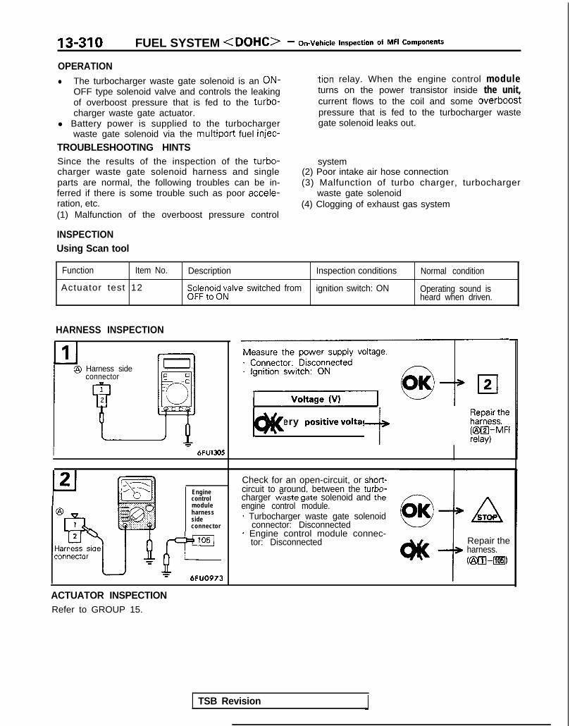
13-310 FUEL SYSTEM <DOHC> - On-Vehicle Inspection of MFI Components
OPERATIONl The turbocharger waste gate solenoid is an ON- tion relay. When the engine control module
OFF type solenoid valve and controls the leaking turns on the power transistor inside the unit,of overboost pressure that is fed to the turbo- current flows to the coil and some overboostcharger waste gate actuator. pressure that is fed to the turbocharger waste
l Battery power is supplied to the turbocharger gate solenoid leaks out.waste gate solenoid via the multiport fuel injec-
TROUBLESHOOTING HINTSSince the results of the inspection of the turbo-charger waste gate solenoid harness and singleparts are normal, the following troubles can be in-ferred if there is some trouble such as poor accele-ration, etc.(1) Malfunction of the overboost pressure control
system(2) Poor intake air hose connection(3) Malfunction of turbo charger, turbocharger
waste gate solenoid(4) Clogging of exhaust gas system
INSPECTIONUsing Scan tool
Function Item No.
Actuator test 12
Description Inspection conditions Normal condition
Sp:$r?,oi$;;alve switched from ignition switch: ON Operating sound isheard when driven.
HARNESS INSPECTION
Harness sideconnector
1@
uI 6FU1305
Enginecontrolmoduleharnesssideconnector
105JP--r 6FUO973
Measure the power supply voltage.91 Battery positivevoltage ]c)ll< f k&f$i
Check for an open-circuit, or short-circuit to around, between the turbn-charger w’aste g&e solenoid and thkengine control module.* Turbocharger waste gate solenoid
connector: Disconnected* Engine control module connec-
tor: Disconnected Repair theharness.C@O--rn)
ACTUATOR INSPECTIONRefer to GROUP 15.
TSB Revision

FUEL SYSTEM <DOHC> - On-Vehicle Inspection of MFI Components 13-311
BOOST METER <Turbo>
meter/
Ignition switch (IG,)I
M13ZACA
Boost meter
Engine control module connector
OlLO838A 6FU1552
HARNESS INSPECTION
@ Harness sideconnector
6FU1550
Enginecontrolmoduleharnesssideconnectc
ii+7 = 6FU1551
Measure the power supply voltage.. Connector: Disconnected. Ignition switch: ON
Voltage (VI
1Battery positive voltage 1
cl2Repair theharness.@~,“”
Check for an open-circuit or a short-circuit to ground, between the enginecontrol module and the boost meter.* Booste meter connector: Discon-
nected* Engine control module connec-
tor: Disconnected
4.ASTOP
i+
Repair theharness.vAlB-[33)
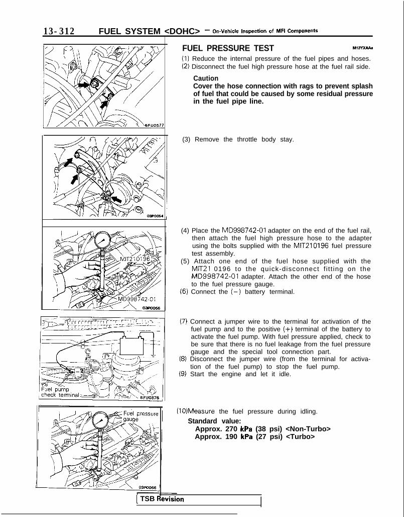
13-312 FUEL SYSTEM <DOHC> - On-Vehicle Inspection of MFI Components
FUEL PRESSURE TEST MxwXAAe(1) Reduce the internal pressure of the fuel pipes and hoses.(2) Disconnect the fuel high pressure hose at the fuel rail side.
CautionCover the hose connection with rags to prevent splashof fuel that could be caused by some residual pressurein the fuel pipe line.
(3) Remove the throttle body stay.
(4) Place the MD998742-01 adapter on the end of the fuel rail,then attach the fuel high pressure hose to the adapterusing the bolts supplied with the MIT210196 fuel pressuretest assembly.
(5) Attach one end of the fuel hose supplied with theMIT21 0196 to the quick-disconnect f i t t ing on theMD998742-01 adapter. Attach the other end of the hoseto the fuel pressure gauge.
(6) Connect the (-) battery terminal.
(7) Connect a jumper wire to the terminal for activation of thefuel pump and to the positive (+) terminal of the battery toactivate the fuel pump. With fuel pressure applied, check tobe sure that there is no fuel leakage from the fuel pressuregauge and the special tool connection part.
(8) Disconnect the jumper wire (from the terminal for activa-tion of the fuel pump) to stop the fuel pump.
(9) Start the engine and let it idle.
(10)Measure the fuel pressure during idling.
Standard value:Approx. 270 kPa (38 psi) <Non-Turbo>Approx. 190 kPa (27 psi) <Turbo>
1 TSB Revision

FUEL SYSTEM <DOHC> - On-Vehicle Inspection of MFI Components 13-313
(11)Disconnect the vacuum hose from the fuel pressureregulator, and then measure the fuel pressure while using afinger to plug the end of the hose.
Standard value:330-350 kPa (47-50 psi) <Non-Turbo>250-270 kPa (36-38 psi) <Turbo>
(12)Check to be sure that the fuel pressure during idling doesnot decrease even after the engine is raced a few times.
(13)Use a finger to gently press the fuel return hose whilerepeatedly racing the engine, and check to be sure thatthere is fuel pressure in the return hose also.
NOTEThere will be no fuel pressure in the return hose if there isinsufficient fuel flow.
(14)lf the fuel pressure measured in steps (IO) to (13) deviatesfrom the standard value range, check for the probablecause by referring to the table below, and then make theappropriate repair.
Condition Probable cause Remedy
. Fuel pressure is too low. Fuel filter is clogged. Replace the fuel filter.
. Fuel pressure drops during racing. .
. No fuel pressure in fuel return hose. Malfunction of the valve seat with- Replace the fuel pressure regula-in the fuel pressure regulator, or tor.fuel leakage to return side causedby spring deterioration.
Fuel pump low discharge pressure. Replace the fuel pump.
Fuel pressure is too high. The valve within the fuel pressure Replace the fuel pressure regula-regulator is sticking. tor.
Clogging of the fuel return hose Clean or replace the hose and/orand/or the pipe. pipe.
No change of the fuel pressure when Damaged vacuum hose or nipple Replace the vacuum hose, or cleanvacuum hose is connected and when not clogging. the nipple.connected.
IMalfunction of the fuel pressure Checking the fuel pressure controlcontrol system <Turbo> system <Turbo> I
TSB Revision

13-314 FUEL SYSTEM <DOHC> - On-Vehicle Inspection of MFI Components
(15)Stop the engine and check for a change of the valueindicated by the fuel pressure gauge. The condition isnormal if there is no decrease of the indicated value withintwo minutes.If there is a decrease of the indicated value, monitor thespeed of the decrease, and, referring to the table below,determine the cause of the problem and make theappropriate repair.
Condition Probable cause Remedy
After the engine is stopped, the fuel injector leakagepressure drops graudally.
Replace the injector.
Leakage at the fuel pressure reg-ulator valve seat
Replace the fuel pressure regula-tor.
There is a sudden sharp drop of the fuelpressure immediately after the engine is
The check valve (within the fuelpump) is not closed.
Replace the fuel pump.
stopped.
(16) Reduce the internal pressure of the fuel pipes and hoses.(Refer to P. 13-l 02.)
(17) Disconnect the fuel pressure gauge and the special toolsfrom the fuel rail.
CautionBecause there will be a some residual pressure in thefuel pipe line, use a shop towel to cover so that fueldoesn’t splatter.
(18)Replace the O-ring at the end of the fuel high-pressurehose with a new one.
(19)After connecting the fuel high-pressure hose to the fuelrail, tighten the installation bolt.
(20)Check to be sure that there is no fuel leakage.@ Apply battery voltage to the terminal for activation of
@the fuel pump so as to activate the fuel pump.With fuel pressure applied, check for leakage of the fuelline.
TSB Revision1

FUEL SYSTEM <DOHC> - On-Vehicle Inwection of MFI ComDonents 13-315
INSPECTION OF ENGINE CONTROL MODULETERMINAL VOLTAGE M13zALCa
Refer to P.13-105.
TERMINAL VOLTAGE CHECK CHARTTerminal arrangement of engine control module connector
l!m n-J-J-l-II
NOTE:B+: Battery positive voltage
Terminal Check item Check condition (Engine state) Standardv a l u e Remarks
No.
103
102
107
Backup powerSUPPlY
Power supply
Ignition switch: OFF B+
Ignition switch: ON B+
110
13
63
66
56
23
Ignition switch-IG Ignition switch: ON
Fuel pump Engine: Crankingdrive signal
Engine: Idling
Multiport fuel Ignition switch: OFFinjection relay(Power supply) Ignition switch: ON
Multiport fuel Ignition switch: ONinjection relay(Fuel pump) Engine: Idling
Sensor impressed Ignition switch: ONvoltage
B+
8V or higher
B+
B+
o-3v
B+
o-3v
4.5- 5.w
10
8
16
20
Volume air flowsensor
Ax intaketemperaturesensor
Barometricpressure sensor
Engine coolanttemperaturesensor
Engine: Idling 2.2-3.2V
Engine speed: 2,000 rpm
Ignition Air Intake temperature of 0°C (32°F) 3.2- 3.8Vswitch:ON Air intake temperature of 20°C (68°F) 2.3- 2.9V
Air intake temperature of 40°C (104°F) 1.5-2.1V
Air intake temperature of 80°C (176°F) 0.4- 1 .OV
Ignition Altitude of 0 m (0 ft.) 3.7-4.3vsw i t ch :ON Altitude of 1,200 m (3,937 ft.) 3.2-3.8V
Ignition Coolant temperature of 0°C (32’F) 3.2- 3.Wswitch:ON Coolant temperature of 20°C (68°F) 2.3- 2.9V
Coolant temperature of 40°C (104°F) 1.3- 1.9V
Coolant temperature of 80°C (176°F) 0.3-0.9V
TSB Revision

13-316 FUEL SYSTEM <DOHC> - On-Vehicle Inspection of MFI Components
TerminalNo. Check item Check condition (Engine state) Standard
value Remarks
19 Throttle positron Ignition switch: It Set the throttle valve to the 0.4- 0.wsensor IS kept ON for 15
seconds or moreidlrng position.
Fully open the throttle valve. 4.5- 5.5v
14 Closed throttle lgnrtron o-1vposition switch switch:
Set the throttle valve to the idlingposition.
ONSlightly open the throttle valve. 4V or higher
22 Camshaft posi-tion sensor
Engine: Cranking 0.2- 3.ov
Engine: ldlrng
21 Crankshfat posi-tion sensor
Engine: Cranking 0.2- 3.ov
Engine: Idling
108 lgnrtion switch-ST Engine: Cranking 8V or higher
104 Park/neutral pos-ition switch
Ignition Set the selector lever to P or N. o-3vswitch:ON Set the selector lever to D, 2, L or R. 8- 14V
18 Vehicle speed l Ignition switch: ONsensor l Slowly run the vehicle forward
0 - 5v(Repeat thevariation.)
5 Power steeringpressure switch
Engine:Idling opera-
Steering wheel idle state B+
tion afterwarming-up During steering wheel operation o-3v
7 A&;;;ditioning Engine:Idling _
Turn OFF the air conditioning switch. o-3v
Turn ON the air conditioning switch. B+(The air conditioning compressor is inthe drive state.)
35 Air conditioning l Engine: Idling B+ orcompressorclutch relay
l Air conditioning switch: OFF -, ON(The air conditioning compressor is in the
temporarily
drive state.)6V or higher
o’- 3v
1 Heated oxygensensor
Engine: Keep the engrne speed at 2.000 rpmafter warming up.(For checking, use a digital voltmeter.)
ke;atoZivariation.)
51 No. 1 Injector Engine: After warming up, rapidly press the
52 No. 2 Injectoraccelerator pedal from the idlrng state,
Voltagetemporarilydrops slightly
30 No. 3 Injector from 14V to1 IV.
51 No. 4 Injector
j8 Stepper motorcoil <Al>
Engine: Soon after the warmed up engine is B+started (approx. 1 minute)
i9 Stepper motor 0%
coil <A2> (Repeat thevariation.)
‘7 Stepper motorcoil <Bl>
8 Stepper motorco11 <B2>
TSB Revision

FUEL SYSTEM <DOHC> - On-Vehicle Inspection of MFI Components 13-317TerminalNo.
54
55
62
57
105
I
01
2
i
E
Check item
Ignition powertransistor unit
Check condition (Engine state)
Engine speed: 3.000 rpm
Standardvalue
0.3- 3v
Remarks
Evaporativeemission purge
Ignition switch: ON B+solenoid Keep the engrne speed at 3.000 rpm after the
warmed-up engine is started,o-3v
Fuel pressuresolenoid
lgnltlon switch: ON
Engine: Cranking - Idling(Within approx. 2 seconds)
B+
o- 3v1
B+TurbochargerNaste gate sole-
Ignition switch: ON B+ioid Engine: Idling (When premrum gasoline IS used.) 0-3~3oost meter Ignition switch: ON 4-13v
Engine: After warming up, rapldly press theaccelerator pedal from the idling state
It temporarilydrops-slightly
I from B+.Engine ignrtlonslgnal
Engine: 3,000 rpm 0.3-3v
lgnrtion timingadjustmentterminal
Ignition Ground the ignition timing adjustment 0 - 1Vswitch: terminal.ON
Release the ground of the ignition 4.0- 5.5vtiming adjustment terminal.
Check engine/malfunction indi-
Ignition switch: OFF - ON o-3v
cator lamp 9’- 13v(After severalminutes haveelapsed)
EGR solenoid Ignition switch: ON B+
Engine: After warming up, rapidly press theaccelerator pedal from the idling state.
It temporarilydrops slightlyfrom B+.
EGR temperature Ignition Sensor temperature of 50°C (122’F) 3.6- 4.4V
r St?MX I swlrcrl:nhi r--.%?nY/V
-_. ..sof temperature of 100°C (21.20~)2.2-3.0~
Engine: Idling operation after warming UPo-3v
B+Engine &ed: 5.000 rPm B+
\ Anti-lock brakingsignal
TSR Revision-
- ‘i

13-318 FUEL SYSTEM <DOHC> - Fuel Tank <FWD>
FUEL TANK <FWD> MIBGA-A
REMOVAL AND INSTALLATION <up to 1990 models>
<From 1991 models>
3
Removal steps 03A0284
1. Fuel tank filler tube cap2. Drain plug
l + 3. Return hosel + 4. Vapor hose
5. Fuel gauge unit connector6. Electrical fuel pump connector
l 4 7. High pressure hose to fuel pumpconnection
I)+ 8. Filler hose~1Weasuerment of Fuel Pressure
H 9. Vapor hose+4 10. Self-locking nut
1 I. Tank band stay12. Tank band13. Fuel tank
I)+ 14. Vapor hosel + 15. Fuel tank pressure control valve Caution
16. Fuel gauge unit When disconnecting the high pressure fuel hose, cover17. Electrical fuel pump the hose connection with rags to prevent splash of fuel18. Fuel tank filler tube that could be caused by some residual pressure in the
fuel pipe line.
TSB Revision 1

FUEL SYSTEM <DOHC> - Fuel Tank <MID> 13-319
Fuel tank pressurecontrol valve
Rubb& hose
side
003041
03FOO1
INSPECTION Ml3GCAIl
l Check the hoses and the pipes for crack or damage.l Check the fuel tank filler tube cap for malfunction.l Check the fuel tank for deformation, corrosion or crack.l Check the fuel tank for dust Qr foreign material.
NOTEIf the inside of the fuel tank is to be cleaned, use any oneof the following:(1) Kerosene(2) Trichloroethylene(3) A neutral emulsion type detergent
FUEL TANK PRESSURE CONTROL VALVE(1) Remove the fuel tank pressure control valve.(2) Check the valve function after a clean rubber hose is in-
stalled on it.
1 Check procedure Normal function
I Blow from the inlet Air pressure through after you(fuel tank side). feel a slight resistance. I
I Blow from the outlet (evapora- Air flows.tive emission canister side). I
(3) Check the valve for crack or leakage.
SERVICE POINTS OF INSTALLATION MlJGDAIl
15. INSTALLATION OF FUEL TANK PRESSURECONTROL VALVEInstall so that the fuel tank pressure control valve is facingin the direction shown in the figure.
14./4. CONNECTION OF VAPOR HOSE/3. RETURN HOSE
When attaching the fuel hose to the pipe, be sure that thehose is attached as shown in the illustration.
Standard value : 25-30 mm (1.0-1.2 in.)
10. INSTALLATION OF SELF-LOCKING NUTTighten the self-locking nuts until the rear end of the tankband contacts the body.
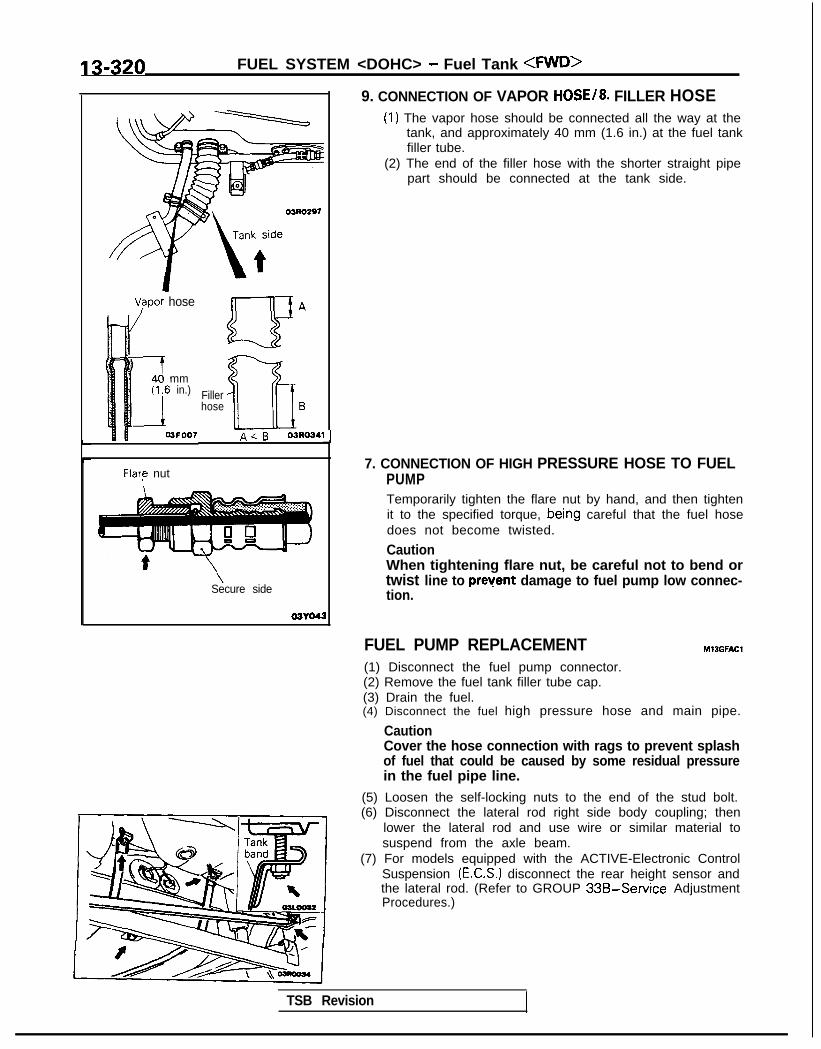
13-320 FUEL SYSTEM <DOHC> - Fuel Tank <FWD>
03RO297
V/apor hose
mmin.)
3FOO7
Fillerhose B
A<B 03R0341
Flare nut
\Secure side
03YO43
Ll
9. CONNECTION OF VAPOR HOSE/8. FILLER HOSE(1) The vapor hose should be connected all the way at the
tank, and approximately 40 mm (1.6 in.) at the fuel tankfiller tube.
(2) The end of the filler hose with the shorter straight pipepart should be connected at the tank side.
7. CONNECTION OF HIGH PRESSURE HOSE TO FUELPUMPTemporarily tighten the flare nut by hand, and then tightenit to the specified torque, bein,g careful that the fuel hosedoes not become twisted.
CautionWhen tightening flare nut, be careful not to bend ortwist line to prevent damage to fuel pump low connec-tion.
FUEL PUMP REPLACEMENT(1) Disconnect the fuel pump connector.(2) Remove the fuel tank filler tube cap.(3) Drain the fuel.
Ml3GFAt.X
(4) Disconnect the fuel high pressure hose and main pipe.
CautionCover the hose connection with rags to prevent splashof fuel that could be caused by some residual pressurein the fuel pipe line.
(5) Loosen the self-locking nuts to the end of the stud bolt.(6) Disconnect the lateral rod right side body coupling; then
lower the lateral rod and use wire or similar material tosuspend from the axle beam.
(7) For models equipped with the ACTIVE-Electronic ControlSuspension (E.C.S.) disconnect the rear height sensor andthe lateral rod. (Refer to GROUP 33B-Service AdjustmentProcedures.)
TSB Revision

FUEL SYSTEM <DOHC> - Fuel Tank <FWD> 13-321
I 03LOO18
-Q GB ua \
a=
C-CT
0 ac oc3i2 0’0Q a aPositidning projection
03L0000
(8) Remove the fuel pump installation screws and the bolt forholding the fuel pump (at the lower side of the fuel tank),and then remove the fuel pump from the fuel tank.
(9) Align the three positioning projections of the packing withthe holes in the fuel pump.
(lO)When the fuel pump is installed, the holding bolt at thelower side of the fuel tank should be installed first.Care should be taken at this time that the O-ring is notpinched.
(1 l)For models equipped with the ACTIVE-E.C.S., check theoperation of the ACTIVE-E.C.S. after installation of the rearheight sensor. (Refer to GROUP 33B-Service AdjustmentProcedures.)

13-322 FUEL SYSTEM <DOHC> - Fuel Tank <AWD>
FUEL TANK <AWD> MlJGA-B
REMOVAL AND INSTALLATION
Sealant:3M ATD Part No.8625or equivalent
30-40 Nm22-29 ftlbs. 5
\ \
\I@Release of Residual Pressure from High
11aMeasurement of Fuel Pressure
l-2 Nm0.7-1.4 ftlbs.
\30-40 Nm22-29 ftlbs.
\h
21-31 N/m15-22 ftlbs.
Removal steps1. Fuel tank filler tube cap2. Drain plug3. Return hose (Refer to P.13-319.)4. Vapor hose5. Fuel high pressure hose (Refer to
P.13-319.1
1 7 - 2 612-1s
;~\*3~o,,.
Es. 6
6. Filler ho&7. Vapor hose (Refer to P.13-319.)8. Protector9. Hole cover
IO. Self-locking nut11. Fuel tank12. Fuel tank pressure control valve (Refer to
P.13-319.)13. Fuel pump and gauge assembly14. Fuel tank filler tube
CautionWhen disconnecting the high pressure fuel hose, coverthe hose connection with rags to prevent splash of fuelthat could be caused by some residual pressure in thefuel pipe line.
TSB Revision

FUEL SYSTEM <DOHC> - Fuel Tank 4WD> 13-323
03AOllO 03AOlll
f%? hose‘F;el high pressure
-Fuel gauge and \n pump assembly
- 03AO107
TSB Revision
FUEL PUMP AND GAUGE ASSEMBLY REPLACE-MENT MlBGEAG
(1) Remove the protectors.(2) Disconnect the fuel pump and gauge assembly harness
connector, and then remove the hole cover.
(3) Bleed the remaining pressure from the fuel pipe line toprevent fuel discharge. (Refer to P.13-312.)
(4) Disconnect fuel high pressure hose and remove the fueltank pressure control valve, then remove the fuel pumpand gauge assembly.
(5) Apply the specified sealant to the rear floor pan.
Specified sealant: 3M ATD Part No.8625 or equivalent
(6) After installing the fuel pump and gauge assembly, start theengine and check to ensure that there is no fuel leakage.

13-324 FUEL SYSTEM <DOHC> - Fuel tine and Vapor Line <FWD>
FUEL LINE AND VAPOR LINE <FWD>REMOVAL AND INSTALLATION M13KA-A
Pre-removal Operation@Removal of the Battery Tray
(Refer to GROUP 54-Starter Motor)*Release of Residual Pressure from High
Pressure Fuel Hose(Refer to P.13-312.)
4-6 Nm3-4 ft.lbs.
9-14 Nm7-10 ftlbs.
25-35 Nm18-25$.lbs.
b 76
y@qz+;y
g----GF 4 6’
9-14 Nm vv .‘$7-10 ftlbs.
#a&g
Ill/--c
9-14 Nm7-10 ft.lbs.
Post-installation Operation*Measurement of Fuel Pressure
*Installation of the Battery Tray(Refer to GROUP 54-Starter Motor)
High-presfuel hose
9-14 Nm7-10 ft.lbs.
12
9-14 Nm7-10 ft.lbs.
\
30-40 Nm22-29 ft.lbs,
I
9-14’Nm7-10 ft.lbs.
9-14 Nm7-10 ft.lbs. lo
\ 9-14 Nm
e?? /;o10 7-10 ftlbs.
/ \10 I 9-14 Nm
Removal steps 7-10 ft.lbs.4+ 1. Eye bolt 9-14 Nm
l + 2. High 9-14 Nm 7- 10 ft.lbs.
l * l apressure fuel hose
3. Fuel filter7-10 ft.lbs. 03AO233
l * 4. Fuel return hose5. Check valve
I)+ 6. Fuel vapor hose7. Vapor pipe assembly8. Evaporative emission canister9. Evaporative10. emissionClip canister holder
11. Fuel main pipe12. Fuel return pipe13. Fuel vapor pipe
TSB Revision
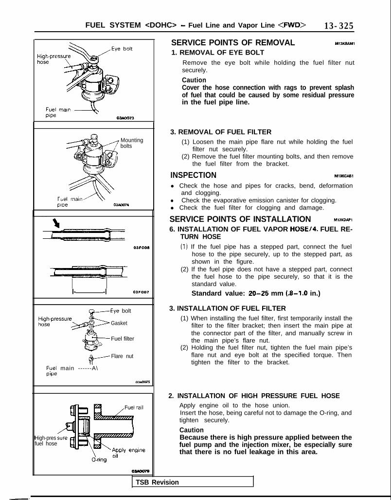
FUEL SYSTEM <DOHC> - Fuel Line and Vapor Line <FWD> 13-325
Mountingbolts
03F008
I- -l 03FOO7 Standard value: 20-25 mm (8-1.0 in.)
t&-----Eye bolt
Gasket
Fuel filter
#-----Flare nut
;y;; main ------A\
J
I
-.
High-presfuel hose
J-ring O”
SERVICE POINTS OF REMOVAL MlSKBAMl
1. REMOVAL OF EYE BOLTRemove the eye bolt while holding the fuel filter nutsecurely.
CautionCover the hose connection with rags to prevent splashof fuel that could be caused by some residual pressurein the fuel pipe line.
3. REMOVAL OF FUEL FILTER(1) Loosen the main pipe flare nut while holding the fuel
filter nut securely.(2) Remove the fuel filter mounting bolts, and then remove
the fuel filter from the bracket.
INSPECTION MlOKCABl
l Check the hose and pipes for cracks, bend, deformationand clogging.
l Check the evaporative emission canister for clogging.l Check the fuel filter for clogging and damage.
SERVICE POINTS OF INSTALLATION MlJKDAPl
6. INSTALLATION OF FUEL VAPOR HOSE/4. FUEL RE-TURN HOSE(1) If the fuel pipe has a stepped part, connect the fuel
hose to the pipe securely, up to the stepped part, asshown in the figure.
(2) If the fuel pipe does not have a stepped part, connectthe fuel hose to the pipe securely, so that it is thestandard value.
3. INSTALLATION OF FUEL FILTER(1) When installing the fuel filter, first temporarily install the
filter to the filter bracket; then insert the main pipe atthe connector part of the filter, and manually screw inthe main pipe’s flare nut.
(2) Holding the fuel filter nut, tighten the fuel main pipe’sflare nut and eye bolt at the specified torque. Thentighten the filter to the bracket.
TSB Revision
2. INSTALLATION OF HIGH PRESSURE FUEL HOSEApply engine oil to the hose union.Insert the hose, being careful not to damage the O-ring, andtighten securely.
CautionBecause there is high pressure applied between thefuel pump and the injection mixer, be especially surethat there is no fuel leakage in this area.

13-326 FUEL SYSTEM <DOHC> - Fuel Line and Vapor tine <AWD>
FUEL LINE AND VAPOR LINE <AWD> MlBKA--B
REMOVAL AND INSTALLATION
Pre-removal Operation*Removal of the Battery Tray
(Refer to GROUP 54-Starter Motor)*Release of Residual Pressure from High
Pressure Fuel Hose(Refer to P.13-312.)
*Installation of the Battery Tray(Refer to GROUP 54-Starter Motor.)
25-35 Nm4-6 Nm3-4 ft.lbs. i
3-14 Nmv-10 ftlbs.,
I rail
9-14 rGm7-10 ft.lbs.
30-40 Nm
7- 10 ftlbs.
13AO3329-14 Nm7-10 ft.lbs. 7-10 ft.lbs. 7-10 ftlbs.
Removal steps1. Eye bolt (Refer to P.13-325.)2. Fuel high-pressure hose (Refer to P.13-
325.)3. Fuel filter (Refer to P.13-325.)4. Fuel return hose (Refer to P.13-325.)5. Check valve6. Fuel vapor hose (Refer to P.13-325.)7. Evaporative emission canister8. Clip9. Fuel main pipe
10. Fuel return pipe11. Fuel vapor pipe
CautionBecause there is high pressure applied between the fuelpump and the injection mixer, be especially sure thatthere is no fuel leakage in this area.
TSB Revision

FUEL SYSTEM <DOHC> - Fuel Filter
FUEL FILTERREMOVAL AND INSTALLATION MlOVA-A
Pre-removal Operation@Release of Residual Pressure from High
Pressure Fuel Hose(Refer to P.l3-312.)
Post-installation Operation*Measurement of Fuel Pressure
(Refer to P.13-312.)
Fuel filter removal steps1. Eye bolt (Refer to P.13-325.)2. O-ring3. Connection for high pressure fuel hose4. O-ring5. Connection for fuel main pipe6. Mounting bolt7. Fuel filter (Refer to P.13-325.)
30-22-
25-35 Nm18-25 ft.lbs.
03AO231
TSB Revision

13-328 ENGINE CONTROL - Specifications/Troubleshooting
ENGINE CONTROLSPECIFICATIONSSERVICE SPECIFICATIONS M13CB-B
Items Specifications
Standard valueAccelerator cable play mm (in.)
<M/T> 1-2 (.04-,081<fw> 3 - 5 (.12-,201
Accelerator switch switching point mm (in.) 4 - 8 (.16-,311
TORQUE SPECIFICATIONS MlBCC--B
Items
Accelerator arm bracket to bodyThrottle body side inner cable to intake manifold plenumAccelerator arm side inner cable to body
Nm ft.lbs.
8-12 6-94 - 6 3 -44 - 6 3 -4
SEALANT MlOCE--B
Items
Accelerator arm bracket
Specified sealant
3M ATD Part No.8663 or equivalent
TROUBLESHOOTINGACCELERATOR CABLE AND ACCELERATOR PEDAL
MlBEGAB
Symptom
Throttle valve will notfully open or close
Probable cause Remedy
Misadjusted accelerator cable Adjust
Misadjusted automatic speed-control cable Adjust
Broken return sprinq Replace
Accelerator pedaloperation not smooth(over acceleration)
Throttle lever malfunction
Accelerator pedal wrongly tightened
Misinstalled accelerator cable
Accelerator cable requires lubrication
Replace
Repair
Repair
Lubricate or replace
TSB Revision I

ENGINE CONTROL - Service Adjustment Procedures 13-329
SERVICE ADJUSTMENT PROCEDW,E,t&
ACCELERATOR CABLE INSPECTION ANDADJUSTMENTFor models equipped with the auto-cruise control system, referto P. 13-398.
(1) Confirm there are no sharp bends in accelerator cable.(2) On models with an SOHC engine, turn the ignition switch
to the ON position (without starting the engine) and leavein that condition for approximately 15 seconds.
(3) Loosen the adjusting bolts on the intake manifold plenum,and then secure the outer cable so that the free play of theinner cable will be the standard value.
Standard value:< M / T > 1 - 2 mm (.04- .08 in.)-a/T> 3-5 mm (.12-.20 in.)
NOTEIf there is excessrve play of the accelerator cable, thevehicle speed drop (“undershoot”) when climbing a slopewill be large.If there is no play (excessive tension) of the acceleratorcable, the idling speed will increase.
(4) After adjusting, confirm that throttle valve fully opens andcloses by operating pedal.
(5) Adjust accelerator cable play and confirm throttle leverstopper touches the closed throttle position switch.
Stopper \CTP switch 03AO278
A.-\\‘\.\ ‘\
!4:l/. \\ \\‘\ I\*\ \”
j 07R0024
ACCELERATOR SWITCH INSPECTION ANDADJUSTMENT M13FTBBa
(1) After warning up the engine, check to be sure that theaccelerator switch is ON when the accelerator pedal is inthe free condition. If there is a malfunction, adjust by usingthe adjusting bolt.
(2) Press the accelerator pedal by hand until the acceleratorswitch switches from ON to OFF and confirm that theamount of pedal movement (A in the figure) is within thestandard value range.
Standard value:Accelerator switch switching point
4-8 mm (.16-.31 in.)(3) If the distance (A in the figure) is not within the standard
value, adjust it by using the adjusting bolt.I
1 TSB Revision

13-330 ENGINE CONTROL - Engine Control
ENGINE CONTROLREMOVAL AND INSTALLATION M13OA--
Post-installation Operation Adjustment*Accelerator Cable*Accelerator Switch I 1
i
4-6 Nm
/ 3-4 ft-‘bs.
4-6 Nm3-4 ft.lbs.\
Sealant:3M ATD Part No.8663or equivalent
\8-12 Nm6-9 ft.lbs.
07A0025
lr 07A0031
Removal steps1. Adjusting bolt2. Throttle body side inner cable
l 4 3. BushingI)+ 4. Accelerator arm side inner cable
4* 5. Accelerator pedal6. Spring7. Accelerator switch connector CM>
l + 8. Accelerator arm bracket9. Split pin
10. Accelerator arm11. Return spring12. Accelerator switch CM>13. Accelerator arm stopper14. Bolt <A/T>
SERVICE POINTS OF REMOVAL M13oBAC
5. REMOVAL OF ACCELERATOR PEDALPull the left side of the accelerator pedal toward you, andthen remove the accelerator pedal from the acceleratorarm.
TSB Revision
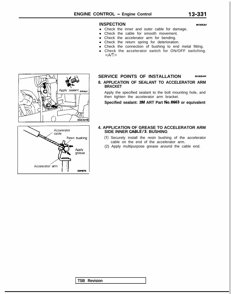
ENGINE CONTROL - Engine Control 13-331
4. APPLICATION OF GREASE TO ACCELERATOR ARMSIDE INNER CABLE/3. BUSHING(1) Securely install the resin bushing of the accelerator
cable on the end of the accelerator arm.(2) Apply multipurpose grease around the cable end.
INSPECTION Ml3ocAH
l Check the inner and outer cable for damage.l Check the cable for smooth movement.l Check the accelerator arm for bending.l Check the return spring for deterioration.l Check the connection of bushing to end metal fitting.l Check the accelerator switch for ON/OFF switching.
<Al-r>
SERVICE POINTS OF INSTALLATION MlJODAW
8. APPLICATION OF SEALANT TO ACCELERATOR ARMBRACKETApply the specified sealant to the bolt mounting hole, andthen tighten the accelerator arm bracket.
Specified sealant: 3M ART Part No.8663 or equivalent
TSB Revision
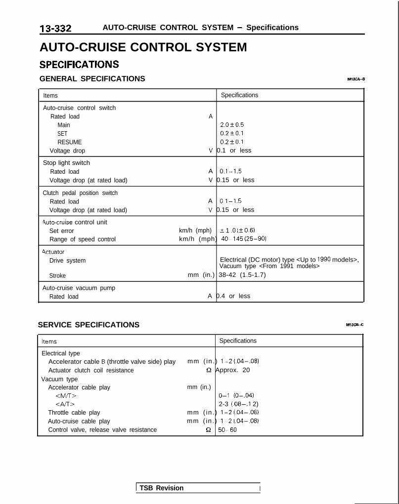
13-332 AUTO-CRUISE CONTROL SYSTEM - Specifications
AUTO-CRUISE CONTROL SYSTEMSPECIFICATIONSGENERAL SPECIFICATIONS M13CA--B
Items
Auto-cruise control switchRated load
MainSETRESUME
Voltage drop
Stop light switchRated loadVoltage drop (at rated load)
Clutch pedal position switchRated loadVoltage drop (at rated load)
4uto-cruise control unitSet errorRange of speed control
4ctuatorDrive system
Stroke
Auto-cruise vacuum pumpRated load
Specifications
A2.0f0.50.2fO.l0.2t-0.1
V 0.1 or less
A 0.1-1.5V 0.15 or less
A 0.1-1.5V 0.15 or less
km/h (mph) IL 1 .O (kO.6)km/h (mph) 40-145 (25-90)
Electrical (DC motor) type <Up to 1990 models>,Vacuum type <From 1991 models>
mm (in.) 38-42 (1.5-1.7)
A 0.4 or less
SERVICE SPECIFICATIONS Ml3CB-.C
Items Specifications
Electrical typeAccelerator cable B (throttle valve side) play mm ( in . ) l-2 (.04-.08)Actuator clutch coil resistance Q Approx. 20
Vacuum typeAccelerator cable play mm (in.)
<M/T> O-l (O-.04)Gv-r~ 2-3 (.08-.I 2)
Throttle cable play mm ( in . ) l-2 (.04-.08)Auto-cruise cable play mm ( in . ) l-2 (.04-.08)Control valve, release valve resistance 52 50-60
1 TSB Revision I

AUTO-CRUISE CONTROL SYSTEM - Specifications/Special Tools 13-333
TORQUE SPECIFICATIONS MlOCC-.C
Items N m ftlbs.
Electrical type
Auto-cruise control actuator protector 4 - 6 3 -4
Actuator bracket 9-14 7-10
Accelerator cable plate 4 - 6 3 - 4Vacuum type
Link protector 4 - 6 3 -4
Link assembly 9-14 7-10
Auto-cruise vacuum pump 4 - 6 3-4
Accelerator cable plate 4 - 6 3 -4
SPECIAL TOOLS M14DA-C
Number Name Use
MB991 269*’ orMB991341 **
Scan tool (Multi-use l Checking of the on-board diagnostic outputtester <MUT>)
ROM pack
(For the number, refer to NOTEGROUP 00-Precautions BeforeService.)
‘1: <1989 models> l ? <1991 models>l *: <I 990 models> l 4: <1992 models>
TSB Revision

13-334 AUTO-CRUISE CONTROL SYSTEM - Troubleshooting
TROUBLESHOOTING MlJEBDH
<Electrical type: Up to 1990 models>
The auto-cruise control system performs control functions forthe setting or cancellation of the fixed-speed driving speed bas-ed upon the data provided by input signals. As a result, whenthe auto-cruise control system is canceled, the cause of thecancellation is memorized in a separate circuit by the ECU,regardless of whether or not the auto-cruise control systemcondition is normal or abnormal, thus providing the ECU withthe on-board diagnostic function by certain fixed patterns, aswell as the function of being able to check whether or not theECU’s input switches or sensor are normal. Thus, by effectivelyusing these function, the time required checking and repair canbe shortened.
NOTEWhen the computer (ECU) power supply (ignition switch andmain switch) is switched OF-F, the memorized diagnostictrouble codes are erased, and so for this reason the powersupply must be left ON until the checking is completed.
TROUBLESHOOTING QUICK-REFERENCE CHART
when cancellation not wanted.
be set after an automatic cancellation.ECU: Electronic control unit
After the occurrence of the problem, wasYes . With the main switch ON and the engine
the ignition switch and main switch left running, check the diagnostic trouble code.ON? + (P.13-361)
No
Can the auto-cruise control system be set_r-l;Yes
No (new normal)Check whether or not, then, the vehicle was driven on asteep slope, or the SET and RESUME control switcheswere operated simultaneously. (The cause is not clearunder the present circumstances.)
TSB Revision I
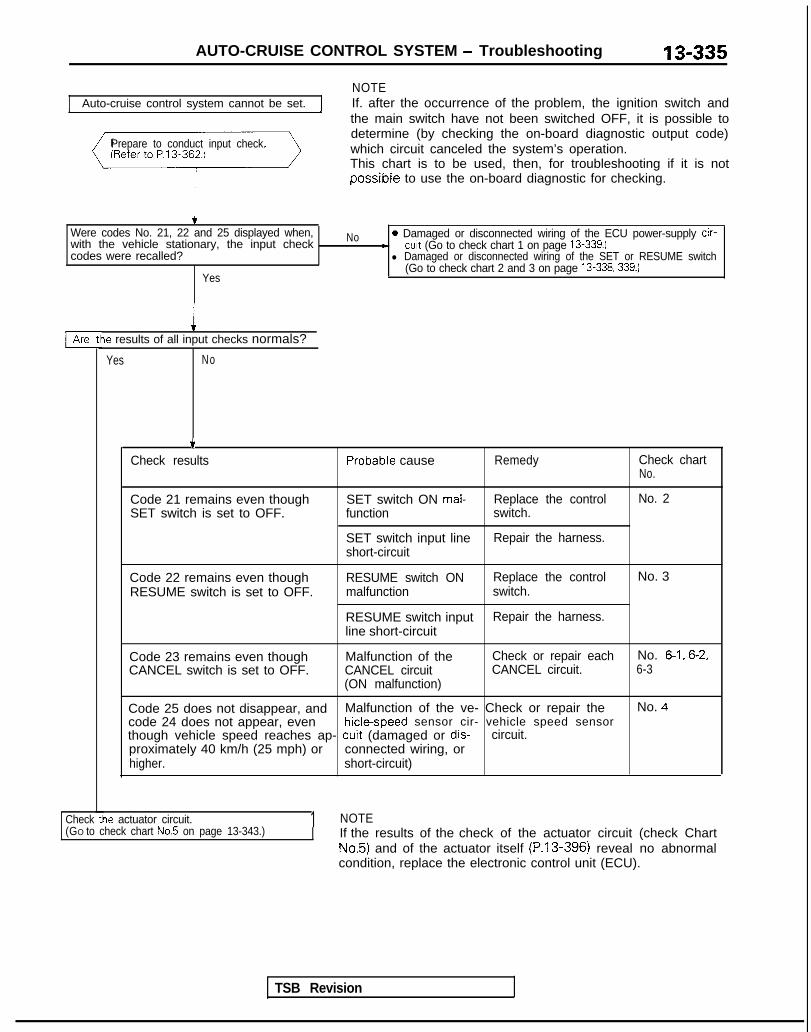
AUTO-CRUISE CONTROL SYSTEM - Troubleshooting
Auto-cruise control system cannot be set.NOTEIf. after the occurrence of the problem, the ignition switch andthe main switch have not been switched OFF, it is possible to
Prepare to conduct input check.determine (by checking the on-board diagnostic output code)which circuit canceled the system’s operation.This chart is to be used, then, for troubleshooting if it is notpossible to use the on-board diagnostic for checking.
Were codes No. 21, 22 and 25 displayed when,with the vehicle stationary, the input checkcodes were recalled?
Yes
No 0 Damaged or disconnected wiring of the ECU power-supply cir-- cuit (Go to check chart 1 on page 13-339.)l Damaged or disconnected wiring of the SET or RESUME switch
(Go to check chart 2 and 3 on page 13-338.339.)
le results of all input checks normals?
Yes No
.t
TSB Revision
.Check results Probable cause Remedy Check chart
No.
Code 21 remains even thoughSET switch is set to OFF.
SET switch ON mal- Replace the control No. 2function switch.
SET switch input line Repair the harness.short-circuit
Code 22 remains even thoughRESUME switch is set to OFF.
RESUME switch ON Replace the control No. 3malfunction switch.
RESUME switch input Repair the harness.line short-circuit
Code 23 remains even thoughCANCEL switch is set to OFF.
Malfunction of theCANCEL circuit(ON malfunction)
Check or repair each No. 6-1, 6-2,CANCEL circuit. 6-3
Code 25 does not disappear, and Malfunction of the ve- Check or repair the No. 4code 24 does not appear, even hicle-speed sensor cir- vehicle speed sensorthough vehicle speed reaches ap- cuit (damaged or dis- circuit.proximately 40 km/h (25 mph) or connected wiring, orhigher. short-circuit)
ie actuator circuit. 1 NOTECheck tl(GO to check chart No.5 on page 13-343.) If the results of the check of the actuator circuit (check Chart
No.5) and of the actuator itself (P.13-396) reveal no abnormalcondition, replace the electronic control unit (ECU).

13-336 AUTO-CRUISE CONTROL SYSTEM - Troubleshooting
Probable cause 1 Check chart No. 1 Remedy
l The set vehicle speed varies Malfunction of the ve- No.4 Repair the vehicle speecgreatly upward or downward. hicle speed sensor cir- sensor system, or re-
l “Hunching” (repeated alternating cuit place the part.acceleration and deceleration) oc-curs after setting is made. Malfunction of the spee-
dometer cable or spee-dometer drive gear
Actuator circuit poorcontact
Malfunction of the ac-tuator
No.5 Repair the actuator sys-tern or replace the part.
Malfunction of the ECU - Replace the ECU.
The auto-cruise control system is not Damaged or discon- If the input check code Repair the harness or recanceled when the brake pedals is netted wiring of the stop No.23 indicates a mal- place the stop lightdepressed. light switch input circuit; function. No.6-1 switch.
brake switch (for auto-cruise control) malfunc-tion (short-circuit)
Actuator drive circuit No.5 Repair the harness or reshort-circuit. place the actuator.
Malfunction of the ECU - Replace the ECU.
-he auto-cruise control system is not Damaged or discon- If the input check code Repair the harness, or:anceled when the clutch pedal is netted wiring of clutch No.23 indicates a mal- repair or replace thedepressed. (vehicles with a manual pedal position switch function. No.6-3 clutch pedal positionransaxle) input circuit switch.It is canceled, however, when the)rake pedal is depressed.) Clutch pedal position
switch improper installa-tion (won’t switch ON)
Malfunction of the ECU - Replace the ECU.
-he auto-cruise control system is not Damaged or discon- If the input check code Repair the harness, orzanceled when the shift lever is netted wiring of park/ No.23 indicates a mal- repair or replace thenoved to the “N” position. (vehicles neutral position switch function. No.6-2 park/neutral positionvith an automatic transaxle) input circuit switch.t is canceled, however, when theIrake pedal is depressed.) Improper adjustment of
park/neutral positionswitch
Malfunction of the ECU - Replace the ECU.
TSB Revision

AUTO-CRUISE CONTROL SYSTEM - Troubleshooting 13-337
Trouble symptom
Cannot decelerate by using theSET switch
Probable cause Check chart No. Remedy
Temporary damaged No. 2 Repair the harness oror disconnected wir- replace the SETing of SET switch switch.
Actuator circuit poor No. 5 Repair the harness orreplace the actuator.
Malfunction of the
1 Malfunction of theECU
- Replace the ECU.
Cannot accelerate or resumespeed by using the RESUMEswitch.
Damaged or discon- No. 3netted wiring, orshort-circuit, of RE-SUME switch inputcircuit
Repair the harness orreplace the RESUMEswitch.
Actuator circuit poor No. 5 i Repair the harness or; contact replace the actuator.
Malfunction of theactuator
,
Malfunction of the - Replace the ECU.ECU
Jute-cruise control system can be i Malfunction of the No. 4 Repair the vehicle-set while traveling at a vehicle vehicle-speed sensor speed sensor system,speed of less than 40 km/h (25 circuit or replace the part.nph), or there is no automaticzancellation at that speed.
Malfunction of thespeedometer cable orthe speedometerdrive gear
Malfunction of the’ ECU
- Replace the ECU.
The indicator light of the combination Damaged or discon-neter does not illuminate. netted bulb ofBut auto-cruise control system is indicator lightlormal.1
- Repair the harness orreplace the lightbulb.
Harness damaged ordisconnected
TSB Revision

13-338 AUTO-CRUISE CONTROL SYSTEM - Troubleshooting
Trouble symptom Probable cause Check chart No. Remedy
Malfunction of control function by Malfunction of circuit No. 7 Repair the harness orON/OFF switching of ELC 4 A/T related to accelerator replace the part.accelerator switch switch OFF function(Non-operation of torque converterclutch, 2nd gear hold, etc.)
Malfunction of theECU
Overdrive is not canceled duringfixed speed driving. <A/T>
Malfunction of circuit No. 8 Repair the harness orrelated to overdrive replace the part.cancelation, or mal-function of ECU
No shift to overdrive during man-ual driving. <A/T>
.
TSB Revision

AUTO-CRUISE CONTROL SYSTEM - Troubleshooting 13-339
CHECK CHART1. CHECKING THE CONTROL UNIT POWER SUPPLY CIRCUIT
Ignitionswitch<IGl>
(8)
Description of operation
When the “MAIN” switch (of the cruise-control’sswitches) is switched ON while the ignition switchis ON, current flows to the ignition switch (IGl), to
fuse no. (9) of the junction block, and to the cruise-control switch, the control unit, and to ground.
Troubleshooting hint
ECU terminal voltaget
Terminal voltageI TerminalNo.
Conditions
7 Control unit power sup- When the cruise-control switch (main switch)is switched ON 12v
PlY
10 Control unit ground At all times o vt
TSB Revision

13-340 AUTO-CRUISE CONTROL SYSTEM - Troubleshooting
2. CHECKING THE SET SWITCH CIRCUIT
ECU
Description of operation
When the SET switch is switched ON (at thevehicle speed desired to be maintained, and withthe main switch of the cruise-control switches ON)that vehicle speed is maintained as a constantspeed.Furthermore, the constant speed is gradually re-duced (the “coasting” feature) when the SET
switch is pressed and held while the vehicle istraveling at the previously set constant speed, and,when the SET switch is released, tne vehicle thenmaintains that newly set constant speed ( thespeed at which the SET switch was released).Current flows to the control unit, the cruise controlswitch (“SET”), and to ground.
Troubleshooting hint
Diagnostic-No.1 5 (automatically cancelled)
ECU terminal voltage
TerminalNo. Signal Conditions Terminal voltage
5 SET switch When the SET switch is switched ON ov
When the SET switch is switched OFF 12v
TSB Revision

AUTO-CRUISE CONTROL SYSTEM - Troubleshooting 13-341
3. CHECKING THE RESUME SWITCH CIRCUIT
ECU
(12)
RESUME
E-2
TerminalNo. Signal Conditions Terminal voltage
4 RESUME switch When the RESUME switch is siitched ON ov
When the RESUME switch is switched OFF 12v
TSB Revision I
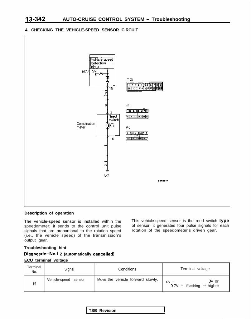
13-342 AUTO-CRUISE CONTROL SYSTEM - Troubleshooting
4. CHECKING THE VEHICLE-SPEED SENSOR CIRCUIT
Combinationmeter
E-2
Description of operation
The vehicle-speed sensor is installed within thespeedometer; it sends to the control unit pulsesignals that are proportional to the rotation speed(i.e., the vehicle speed) of the transmission’soutput gear.
This vehicle-speed sensor is the reed switch typeof sensor; it generates four pulse signals for eachrotation of the speedometer’s driven gear.
Troubleshooting hint
Diagnostic-No.1 2 (automatically cancelled)
ECU terminal voltage
TerminalNo.
Signal Conditions Terminal voltage
15Vehicle-speed sensor Move the vehicle forward slowly. ov - 3V or
0.7v - Flashing -+ higher
TSB Revision 1

AUTO-CRUISE CONTROL SYSTEM - Troubleshooting
5. CHECKING THE ACTUATOR CIRCUIT
Electromannetic clutch coil Clutch @at’! Planetarv oinion
To junction blockfuse No. (9)<IGl>
Ccdtnr riri\m chnftMainSun <ear Worm gear
Cruise-controlswitch To junction block
fuse No. (9)<IGl>
Actuator
/ (15)
p$%Emig
j yl; _________________ ; F:;;:ght
z " (LG)-1 ( LG),l A ,l\BW
I(17)
Diode2d 1 11n\
Actuator
ECU
(12) -+ E-l -
1610620
NOTENC: ON at all timesNO: OFF at all times
TSB Revision

13-344 AUTO-CRUISE CONTROL SYSTEM - Troubleshooting
Description of operation * - LimA switch
DC motor
7 coil
-
1. When (with the main switch ON) the driverswitches ON the SET switch when the pre-scribed vehicle speed is reached, the controlunit sends current to the electromagnetic clutchcoil of the actuator, thus attracting the clutchplate, and also illuminating the auto-cruise in-dicator light, Then, when the ring gear of theplanetary pinion is secured, the control motor atthe same time causes the DC motor to beswitched ON, and the DC motor operates athigh speed.
2. The rotation of the DC motor is, as described inthe illustration above, transmitted to the wormgear, and thereafter to the worm wheel, thesun gear, and the planetary pinion in thatsequence. Because the ring gear is secured atthis time, the planetary pinion rotates whilerevolving around the sun gear. Because theplanetary pinion is installed to the carrier, boththe carrier and the selecotr drive shaft unifiedwith it, as well as the selector, are caused torotate.
3. The switching of the direction (PULL or REL.) ofrotation of the selector is accomplished by
reversing the direction of current flow to themotor, and this is automatically regulated bythe control unit.
4. The current flow to the electromagnetic clutchis interrupted if the driver switches OFF themain switch, or if the operation of the autocruise control system is cancelled as a result ofthe input of a cancel signal to the control unitbecause the stop light switch, clutch pedal posi-tion switch (for a manual transaxle) or the park/neutral position switch (for an automatic trans-axle) is activated.
5. As a result of the interruption of current to theelectromagnetic clutch, the clutch plate iscaused to return from the electromagneticclutch side to the ring gear side by the force ofthe spring, and therefore the ring gear be-comes free.
6. When the ring gear becomes free, the plane-tary pinion becomes free relative to the sungear, and thus the selector is caused, by thereturn spring installed to the selector part, toreturn to its original position.
Troubleshooting hint
Diagnostic-No.1 1 (automatically cancelled)
ECU terminal voltage
TerminalNO. Signal Conditions Terminal voltage
8 Transistor for electro- When the cruise-control switch (main switch) is switch-magnetic clutch coil ed ON o v
9 DC motor drive (“PULL” During acceleration by RESUME switchside) 12v
DC motor drive (“REL.” During speed reduction (coasting) by SET switchside) ov
20 DC motor drive (“PULL” During acceleration by RESUME switchside) ov
DC motor drive (“REL.” During speed reduction (coasting) by SET switchside) 12v
TSB Revision

AUTO-CRUISE CONTROL SYSTEM - Troubleshooting 13-3456-1. CHECKING THE STOP LIGHT SWITCH CIRCUIT
Battery
7Tco
A
9%6I-(GO) :
To stop light
NOTENC: ON at all timesNO: OFF at all times
Description of operation
When the brake pedal is depressed during con-stant-speed travel, the stop light switch’s (NC)contacts for the cruise-control system open, withthe result that the current to the electromagneticclutch of the actuator is interrupted, thus cancell-ing the constant-speed travel.At the same time, moreover, the closing of the(NO) contacts for the stop light results in the
Troubleshooting hint
sending of the cancel signal to the control unit, sothat the actuator’s electromagnetic clutch currentis discontinued within the control unit, therebycanceling the constant-speed travel.The flow of current is from the battery to fuse NO.(15) of the junction block, the stop light switch.and the control unit.
Diagnostic-No.16 (automatically cancelled)
ECU terminal voltage
TerminalN o . Signal Conditions
3Stop light switch (load When the brake pedal is depressedside)
When the brake pedal is not depressed
11 Stop light switch (pow- At all times, er supply side)
TSB Revision
Termianl voltage
12v
ov
12v

13-346 AUTO-CRUISE CONTROL SYSTEM - Troubleshooting
6-2. CHECKING THE PARK/NEUTRAL POSITION SWITCH CIRCUIT <A/T>
ECU
-IJ (12)2mi
Park/neutralpositionswitch
zc:
1&
AI 3 pry
iz,:
T 3qpIII
1 ? 3
;m456
/
I
Starter motor
to the control unit, park/neutral position switch,starter motor, and to ground; the cancel signal istherefore input to the control unit, thus cancelingthe constant-speed travel.
Description of operation
The park/neutral position switch also functions asthe switch for the starter.If the selector handle is moved to the “N” posi-tion during constant-speed travel, current flows
Troubleshooting hint
Diagnostic-No.16 (automatically cancelled)ECU terminal voltage
Terra’ Signal
2 Park/neutral position switch At all times
Conditions Terminal voltage
12v
TSB Revision
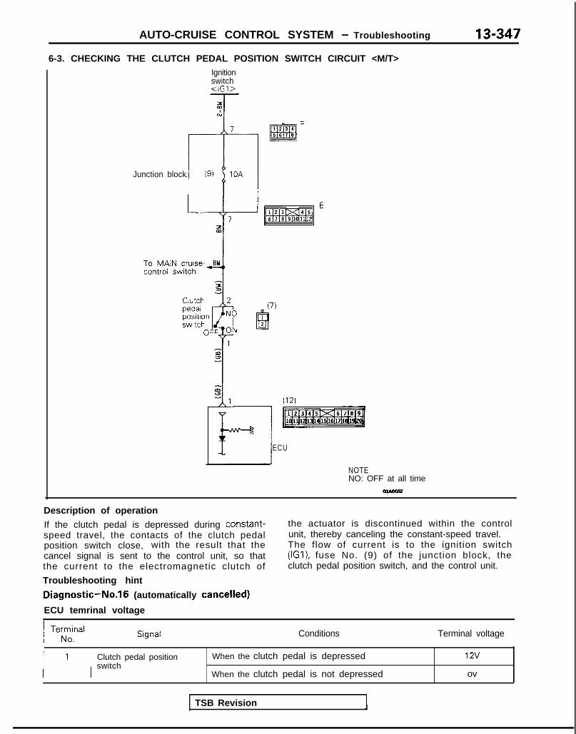
AUTO-CRUISE CONTROL SYSTEM - Troubleshooting 13-347
6-3. CHECKING THE CLUTCH PEDAL POSITION SWITCH CIRCUIT <M/T>Ignitionswitch
Junction block
ECU
NOTENO: OFF at all time
Description of operation
If the clutch pedal is depressed during constant-speed travel, the contacts of the clutch pedalposition switch close, with the result that thecancel signal is sent to the control unit, so thatthe current to the electromagnetic clutch of
Troubleshooting hint
Diagnostic-No.16 (automatically cancelled)
ECU temrinal voltage
the actuator is discontinued within the controlunit, thereby canceling the constant-speed travel.The flow of current is to the ignition switch(IGI), fuse No. (9) of the junction block, theclutch pedal position switch, and the control unit.
/ Te;z,nal 1 Conditions Terminal voltage
Clutch pedal positionswitch
When the clutch pedal is depressed
When the clutch pedal is not depressed
12v
ov
TSB Revision

13-348 AUTO-CRUISE CONTROL SYSTEM - Troubleshooting
7. CHECKING THE CIRCUITS RELATED TO THE ACCELERATOR SWITCH OFF FUNCTION <A/T>
(16)
[ml
Ignitionswitch<IG2>
Junctionblock
r------ _--- ___--- ---
4 A/Tcontrolmodule
NOTENC: ON at all time
Iescription of operation
The accelerator switch is a switch that detect-s theoperational status of the accelerator pedal; it isone of the sensors of the automatic transaxle.Because the status of the accelerator pedal duringconstant-speed driving is non-operational, the
ground circuit (transistor Tr2) of the acceleratorswitch is switched OFF only during constant-speeddriving in order not to interfere with the function ofthe automatic transaxle.
Troubleshooting hint
ECU terminal voltage
Terminal 1No. , Signal Conditions Terminal voltage
6’ Control unit power sup- At all times 12v
ply (IG2)
16 Accelerator switch When the accelerator pedal is depressed ov
When the accelerator pedal is not depressed 12v
TSB Revision
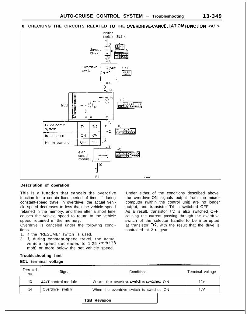
AUTO-CRUISE CONTROL SYSTEM - Troubleshooting 13-349
8. CHECKING THE CIRCUITS RELATED TO THE OVERDRIVE-CANCELLATION FUNCTlON <A/T>
Ignitionswitch <IG2>
4 A/Tcontrolmodule
IO-I-m7
E-l WA001
Description of operation
This is a function that cancels the overdrivefunction for a certain fixed period of time, if duringconstant-speed travel in overdrive, the actual vehi-cle speed decreases to less than the vehicle speedretained in the memory, and then after a short timecauses the vehicle speed to return to the vehiclespeed retained in the memory.Overdrive is canceled under the following condi-tions.1. If the “RESUME” switch is used.2. If, during constant-speed travel, the actual
vehicle speed decreases to 1.25 km/h (.78mph) or more below the set vehicle speed.
Under either of the conditions described above,the overdrive-ON signals output from the micro-computer (within the control unit) are no longeroutput, and transistor Trl is switched OFF.As a result, transistor Tr2 is also switched OFF,causing the current passing through the overdriveswitch of the selector handle to be interruptedat transistor Tr2, with the result that the drive iscontrolled at 3rd gear.
Troubleshooting hint
ECU terminal voltage
Termianl 1No. :
Conditions Terminal voltage
13 ) 4AlT control module When the overdrlve switch IS swrtched O N 12vi I
14 Overdrive switch When the overdrive switch is switched ON 12v
TSB Revision

13-350 AUTO-CRUISE CONTROL SYSTEM - Troubleshooting
TROUBLESHOOTING MlBEBoa
<Vacuum type: From 1991 models>
The auto-cruise control system performs control functions forthe setting or cancellation of the fixed-speed driving speedbased upon the data provided by input signals. As a result,when the auto-cruise control system is canceled by abnormalsystem operation, the cause of the cancellation is memorizedin a separate circuit by the ECU, thus providing the ECU withthe on-board diagnostic function by certain fixed patterns, aswell as the function of being able to check whether or not theECU’s input switches or sensor are normal. Thus, by effectivelyusing these function, the time required checking and repair canbe shortened.
TROUBLESHOOTING QUICK-REFERENCE CHART
Auto-cruise control system is canceledwhen cancellation not wanted. ECU: Electronic control unit
Can the auto-cruise control system be set
Set the auto-cruise con-trol system and conducta road test.
No (new normal) . Check whether or not, then, the vehicle was driven on a steepslope.
TSB Revision

AUTO-CRUISE CONTROL SYSTEM - Troubleshooting
NOTE
13-351
Auto-cruise control system cannot be set. This chart is to be used, then, for troubleshooting if it is notpossible to use the on-board diagnostic for checking.
Prepare to conduct input check.
Where codes No.21, 22, 23, 25 and 26,displayed when, with the vehicle stationary,the input check codes were recalled?
Damaged or disconnected wiring of the ECU power-supply cir-
l Damaged or disconnected wiring of the SET or RESUMEswitch (Go to check chart 2 and 3.)
l Damaged or disconnected wiring of the stop light switch,clutch pedal position switch or park/neutral position switch (Go
1 Are the results of all input checks normals?
Yes No
ck the auto-cruise vacuum pump circuit.1 (Go to check chart No.5.)
TSB Revision 1
7
Check results ’ Probable cause Remedy Check chartNo.
Code 21 remains even though SETswitch is set to OFF.
SET switch ON mal-function
SET switch input lineshort-circuit
F,I~JI;? the control
Repair the harness.
No. 2
Code 22 remains even though RE-SUME switch is set to OFF.
RESUME switch ON Replace the control No.3malfunction switch.
RESUME switch input Repair the harness.line short-circuit
Code 23 is not canceled even if the Malfunction of stop Replace stop light No.6stop light switch is turned OFF by light switch circuit. switch or repair har-releasing the brake pedal. ness.
Code 25 does not disappear, and Malfunction of the Check or repair the No.4code 24 does not appear, even vehicle-speed sensor vehicle speed sensorthough vehicle speed reaches appro- circuit (damaged or dis- circuit.ximately 40 km/h (25 mph) or higher. connected wiring, or
short-circuit)
Code 26 is not canceled even if the Malfunction of clutch Replace clutch pedal No.8clutch pedal position switch is turned pedal position switch position switch or repairOFF by releasing the clutch pedal. circuit. harness.
Code 26 is not canceled even if the Malfunction of park/ Replace park/neutral No. 7select lever is moved to anything but neutral position ,switch position switch or repairv. P <A/T>. circuit. harness.
NOTEIf the results of the check of the auto-cruise vacuum pumpcircuit (check chart No. 5) and of the auto-cruise vacuum pumpand actuator itself (P.13-401.) reveal no abnormal condition, re-place the electronic control unit (ECU).
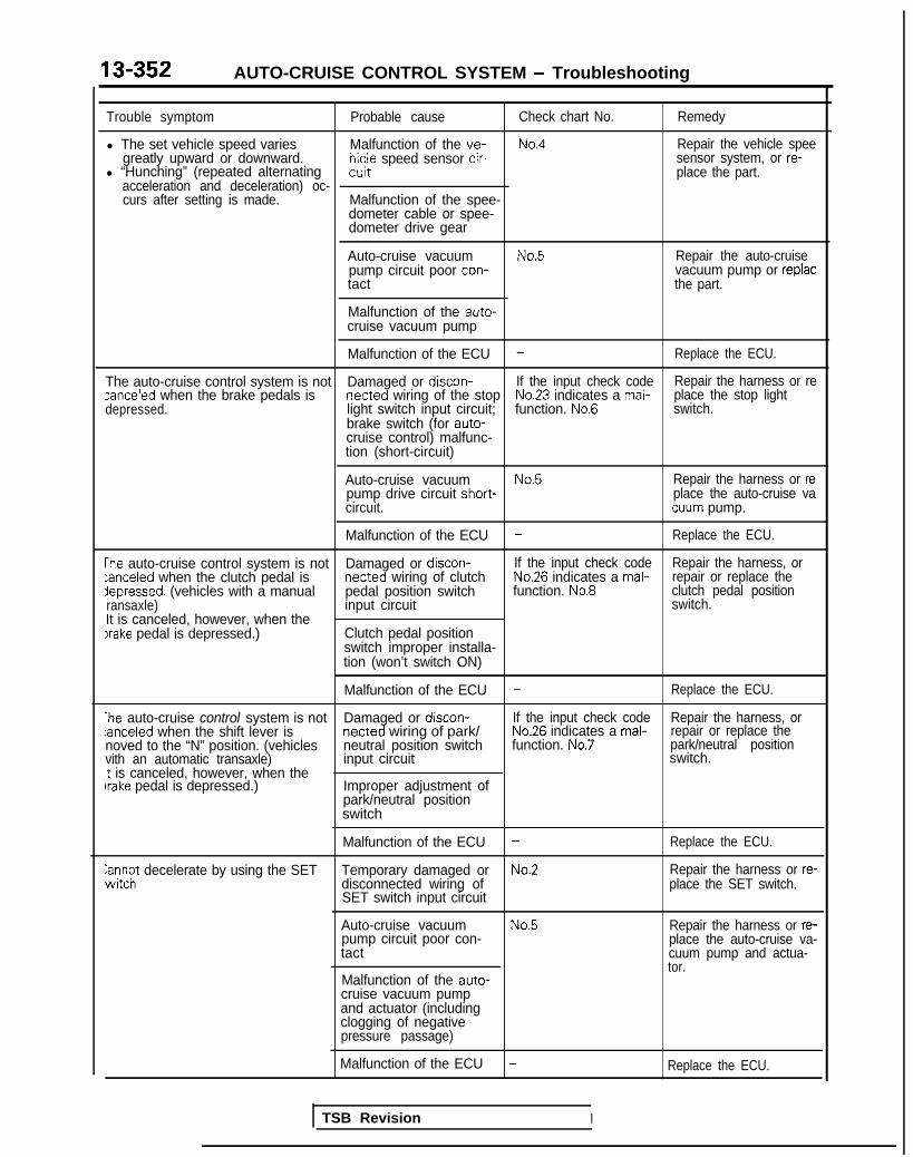
13-352 AUTO-CRUISE CONTROL SYSTEM - Troubleshooting
Trouble symptom Probable cause Check chart No. Remedy
l The set vehicle speed varies Malfunction of the ve- No.4 Repair the vehicle speegreatly upward or downward. hicle speed sensor cir-
l “Hunching” (repeated alternatingsensor system, or re-
wit place the part.acceleration and deceleration) oc-curs after setting is made. Malfunction of the spee-
dometer cable or spee-dometer drive gear
Auto-cruise vacuum No.5 Repair the auto-cruisepump circuit poor con- vacuum pump or replactact the part.
Malfunction of the auto-cruise vacuum pump
Malfunction of the ECU - Replace the ECU.
The auto-cruise control system is not Damaged or discon- If the input check code Repair the harness or rezanceled when the brake pedals is netted wiring of the stop No.23 indicates a mal-depressed. light switch input circuit; function. No.6
place the stop lightswitch.
brake switch (for auto-cruise control) malfunc-tion (short-circuit)
Auto-cruise vacuum No.5 Repair the harness or repump drive circuit short- place the auto-cruise vacircuit. cuum pump.
Malfunction of the ECU - Replace the ECU.
The auto-cruise control system is not Damaged or discon- If the input check code Repair the harness, or:anceled when the clutch pedal is netted wiring of clutch No.26 indicates a mal- repair or replace thedepressed. (vehicles with a manual pedal position switch function. No.8 clutch pedal positionransaxle) input circuit switch.It is canceled, however, when theIrake pedal is depressed.) Clutch pedal position
switch improper installa-tion (won’t switch ON)
Malfunction of the ECU - Replace the ECU.
*he auto-cruise control system is not Damaged or discon- If the input check code Repair the harness, or:anceled when the shift lever is netted wiring of park/ No.26 indicates a mal- repair or replace thenoved to the “N” position. (vehicles neutral position switch function. No.7 park/neutral positionvith an automatic transaxle) input circuit switch.t is canceled, however, when thebrake pedal is depressed.) Improper adjustment of
park/neutral positionswitch
Malfunction of the ECU - Replace the ECU.
anc$ decelerate by using the SET Temporary damaged or No.2 Repair the harness or re-disconnected wiring ofSET switch input circuit
place the SET switch.
Auto-cruise vacuum No.5 Repair the harness or re-pump circuit poor con-tact
place the auto-cruise va-cuum pump and actua-tor.
Malfunction of the auto-cruise vacuum pumpand actuator (includingclogging of negativepressure passage)
Malfunction of the ECU - Replace the ECU.
TSB Revision I

AUTO-CRUISE CONTROL SYSTEM - Troubleshooting 13-353
Trouble symptom Probable cause Check chart No. Remedy
Cannot accelerate or resume speed No.3by using the RESUME switch.
Damaged or discon-netted wiring, or short-
Repair the harness or
circuit, of RESUMEreplace the RESUMEswitch.
switch input circuit
Auto-cruise vacuum No. 5 Repair the harness orpump circuit poor con- replace the auto-cruisetact vacuum pump and
actuator.Malfunction of the auto-cruise vacuum pumpand actuator (includingair leak from negativepressure passage)
Malfunction of the ECU - Replace the ECU,
4uto-cruise control system can be Malfunction of the No.4 Repair the vehicle-set while traveling at a vehicle speed vehicle-speed sensor speed sensor system,3f less than 40 km/h (25 mph), or circuit ‘or replace the part.there is no automatic cancellation atthat speed. Malfunction of the
speedometer cable orthe speedometer drivegear
The indicator light of combinationneter does not illuminate.But auto-cruise control system isiormal.)
Malfunction of the ECU - Replace the ECU.
Damaged or discon- - Repair the harness ornetted bulb of indicator replace the bulb.light
Harness damaged ordisconnected
vlalfunction of control function by Malfunction of circuit re- No. 9 Repair the harness orIN/OFF switchrng of ELC 4 AT lated to accelerator replace the part.accelerator switch switch OFF functionNon-operation of torque converter:lutch, 2nd gear hold, etc.) Malfunction of the ECU
Overdrive is not canceled during Malfunction of circuit re- No. 10 Repair the harness orixed speed driving. <A/T> lated to overdrive can- replace the part.
cellation, or malfunction\lo shift to overdrive during manualIriving. </VT>
of ECU
TSB Revision

13-354 AUTO-CRUISE CONTROL SYSTEM - Troubleshooting
CHECK CHART1. CHECKING THE CONTROL UNIT POWER SUPPLY CIRCUIT
Ignitionswitch<IG,>
I
Cruise-controlswitch I (8)
pmTzREq
4 atAuto-cruise control unit
13A0377
Description of operation
When the cruise control switch (CRUISE) is switched ON whilethe ignition switch is ON, current flows to the ignition swrtch(IG,), to fuse No.(ll) of the junction block, and to thecruise-control switch (MAIN switch), the control unit, and toground.When the ignition switch is turned OFF, the MAIN switch in thecruise control switch is also turned OFF.
Troubleshooting hint
ECU terminal voltage
Terminal Signal Conditions TerminalNo. voltage
2 Control unit When the cruise- Batterypower supply control switch positive
(CRUISE) is voltageswitched ON.
6. 8 Control unitground
At all times ov
NOTEl : The connector Nos. in Section “AUTO-CRUISE CONTROL
RELATED HARNESSES” and the connector names in thejunction block are represented.(Applicable on the next page and subsequence.)
2. CHECKING THE SET SWITCH
I
Auto-cruise ’control unit
T
v“17
3
A-3SET
Crulse- OFF
control TON
switch>: 13
63)
13AO386
Description of operation
When the SET switch is switched ON (at the vehicle speeddesired to be maintained, and with the CRUISE switch of thecruise-control switches ON) that vehicle speed is maintained asa constant speed.Furthermore, the constant speed is gradually reduced (the“coasting” feature) when the SET switch is pressed and heldwhile the vehicle is traveling at the previously set constantspeed, and, when the SET switch is released, the vehicle thenmaintains that newly set constant speed (the speed at whichthe SET switch was released).Current flows to the control unit. the cruise control switch(“SET”), and to ground.
Troubleshooting hint
Diagnostic-No.15 (automatically cancelled)
ECU terminal voltage
Terminal Signal Conditions TerminalNo. voltage
17 SET switch When the SET ovswitch is switchedON.
When the SET;yv$h is swrtched
Batterypositivevoltage
TSB Revision

AUTO-CRUISE CONTROL SYSTEM - Troubleshooting 13-355
3. CHECKING THE RESUME SWITCH CIRCUIT
Auto-cruisecontrol unit
--fY
Cruise-controlswitch
Description of operation
The set speed (before cancellation) resumes when the RE-SUME switch is swrtched ON, even if the constant-speedcontrol has been cancelled.That speed will not resume, however, even if the RESUMEswitch is switched ON, if the CRUISE switch is switched OFFand if the vehicle speed decreases to 40 km/h (25 mph) orlower.In addition, when the RESUME is switched ON and held whi!ethe vehicle is traveling at a constant speed, the vehicle speedwill increase; the speed at which the switch is subsequentlyreleased will become the newly set constant speed.Current flows to the control unit, the cruise control switch(RESUME), and to ground.
Troubleshooting hint
Diagnostic-No.1 5 (automatically cancelled)
ECU terminal voltage
13AO382
Terminal Signal Conditions TermrnalNo. voltage
18 RESUME When the RESUME OVswrtch switch is switched
ON.
When the RESUME Batteryswitch is switched positiveOFF. voltaae
4. CHECKING THE VEHICLE-SPEED SENSOR CIRCUIT
Auto-cruisecontrol unit
Combinationmeter
Junctionblock
(6)
Description of operation
The vehicle-speed sensor is installed within the speedometer; itsends to the controlunit pulse signals that are proportional tothe rotatron speed (i.e., the vehicle speed) of the transaxle’soutput gear.This vehicle-speed sensor IS the reed switch type of sensor; itgenerates four pulse signals for each rotation of the speedo-meter’s driven gear.
Troubleshooting hint
Diagnostic-No.12 (automatically cancelled)
ECU terminal voltage
Terminal Signal Conditions TerminalNo. voltage
19 Vehicle-speed Move the vehicle ov-0.7vsensor forward slowly. t
FlashingJ
3V-higher
13A0381
TSB Revision
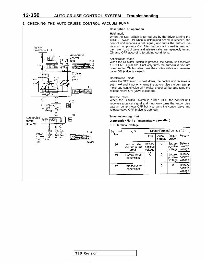
13-356 AUTO-CRUISE CONTROL SYSTEM - Troubleshooting
5. CHECKING THE AUTO-CRUISE CONTROL VACUUM PUMP
Description of operation
Hold modeWhen the SET switch is turned ON by the driver turning theCRUISE switch ON when a determined speed is reached, thecontrol unit receives a set signal, and turns the auto-cruisevacuum pump motor ON. After the constant speed is reached,the motor, control valve and release valve are repeatedly turnedON and OFF according to driving conditions.
Ignitionswitch <IG,>
Auto-cruiseAcceleration modeWhen the RESUME switch is pressed, the control unit receivesa RESUME signal and it not only turns the auto-cruise vacuumpump motor ON but also turns the control valve and release
(10)
c o n t r o l ’ “”unit 13AO376
valve ON (valve is closed)
Deceleration modeWhen the SET switch is held down, the control unit receives aset srgnal and it not only turns the auto-cruise vacuum pumpmotor and control valve OFF (valve is opened) but also turns therelease valve ON (valve IS closed).
Release modeWhen the CRUISE switch is turned OFF, the control unitreceives a cancel signal and it not only turns the auto-cruisevacuum pump motor OFF but also turns the control valve andrelease valve OFF (valve is opened).
Troubleshooting hint
Diagnostic-No.1 1 (automatically cancelled)
ECU terminal voltage
TSB Revision

AUTO-CRUISE CONTROL SYSTEM - Troubleshooting
6. CHECKING THE STOP LIGHT SWITCH CIRCUIT
13-357
Stop lrght
Sub fusible link @I
Stop lrght
Auto-cruisecontrol unit
13AQ375
Description of operation
When the brake pedal is depressed during constant-speedtravel, the stop light swrtch’s (NC) contacts for the cruise-control system open, with the result that the current to theauto-cruise vacuum pump is interrupted, thus canceling theconstant-speed travel.At the same time, moreover, the closing of the (NO) contactsfor the stop light results in the sending of the cancel signal tothe control unit, so that the auto-cruise vacuum pump current isdiscontinued within the control unit, thereby canceling theconstant-speed travel.The flow of current is from the sub fusible link @ to fuse No. @Iof the junction block, the stop light switch, and the control unit.
Troubleshooting hint
ECU terminal voltage
Terminal Signal Conditions TerminalNo. voltage
15 Stop light When the brake Batteryswitch (load pedal is depressed. positiveside) voltage
When the brake ovpedal is notdepressed.
NOTENC: Indicates ON at all times. (For cruise control)NO: Indicates OFF at all times. (For stop light)
7. CHECKING THE PARK/NEUTRAL POSITION SWITCH CIRCUIT <A/T>
Description of operation
The park/neutral position switch also functions as the switchfor the starter. If the selector lever is moved to the “N” pos-ition during constant-speed travel, current flows to the con-trol unit, park/neutral position switch, starter motor, and toground; the cancel signal is therefore input to the controlunit, thus canceling the constant-speed travel.
Troubleshooting hint
ECU terminal voltage
(I)ia
Startermotor
TSB Revision

13-358 AUTO-CRUISE CONTROL SYSTEM - Troubleshooting
8. CHECKING THE CLUTCH PEDAL POSITION SWITCH CIRCUIT <M/T>
13A0378
Description of operation
If the clutch pedal is pressed when driving at a constantspeed, the clutch pedal position switch is turned ON and acancel signal is input to the control unit and the determineddriving speed is canceled because current flows to theclutch pedal position switch junction block from the controlunit and to ground.
Troubleshooting hint
ECU terminal voltage
Terminal Signal Conditions TerminalNo. voltage
1 Clutch medal When the clutch ov
I position switch pedal is depressed.I
When the clutchpedal is notdepressed.
Batterypositivevoltage
9. CHECKING THE CIRCUITS RELATED TO THE ACCELERATOR SWITCH OFF FUNCTION<A/T>
Ignition switch<IG$ Description of operation
The accelerator switch is a switch that detects the operationalstatus of the accelerator pedal; it is one of the sensors of theautomatic transaxle.Because the status of the accelerator pedal during constant-speed driving is non-operational, the ground circuit (transistorTr2) of the accelerator switch is switched OFF only duringconstant-speed driving in order not to interfere with the functionof the automatic transaxle.
Troubleshooting hint
ECU terminal voltage
TerminalNo.
Signal Conditions Terminalvoltage
I I
3 Control unit At all times Batterypower supply positive
voltage
I g Acceleratorswitch
NOTENC: Indicates ON at all time
1 Not rn operation / OFF ) ON 1
TSB Revision

AUTO-CRUISE CONTROL SYSTEM - Troubleshootina 13-359
10. CHECKING THE CIRCUITS RELATED TO THE OVERDRIVE-CANCELLATION FUNCTION <A/T>
$;c;tly switch
+ c
Overdriveswrtch
4Auto-cruise T-kcontrol unit li
I V
ICruise-control
(14)
m34,:
4 A/Tcontrolmodule
13A0379
Description of operation
This is a function that cancels the overdrive function for acertain fixed period of time, if during constant-speed travel inoverdrive, the actual vehicle speed decreases to less than thevehicle speed retained in the memory. and then after a shorttime causes the vehicle speed to return to the vehicle speedretained in the memory.Overdrive is cancelled under the following conditions.If, during constant-speed travel, the actual vehicle speeddecreases to 7 km/h (4.4 mph) or more below the set vehiclespeed.Under either of the conditions described above, the overdrive-ON signals output from the microcomputer (with the controlunit) are no longer output, and transistor Tr, is switched OFF.As a result, transistor Tr2 is also switched OFF, causing thecurrent passing through the overdrive switch of the selectorhandle to be interrupted at transistor Tr2. with the result that thedrive is controlled at 3rd gear.
Troubleshooting hint
ECU terminal voltageh I
I Terminal SignalI
Conditions TerminalNo. voltaoe I
10 4 A/T control When the overdrive Batterymodule switch is switched positive
ON. voltageI
11 CIIt;rive When the overdrive Batteryswitch is switched positiveON. voltage
TSB Revision
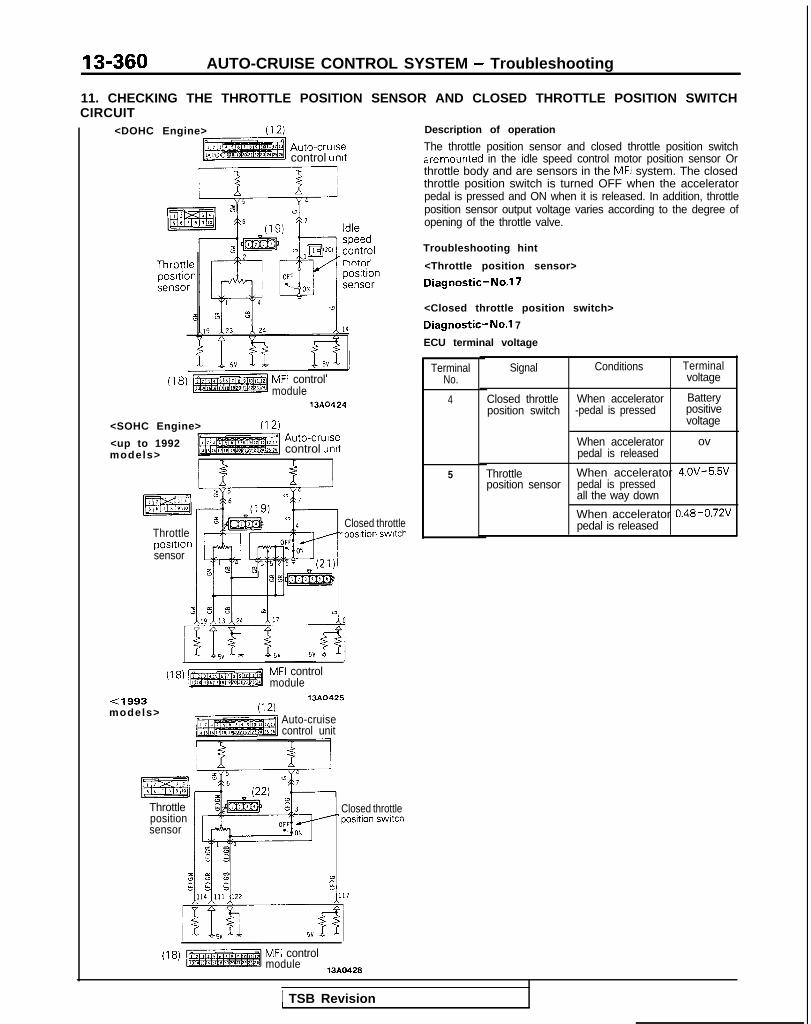
13-360 AUTO-CRUISE CONTROL SYSTEM - Troubleshooting
11. CHECKING THE THROTTLE POSITION SENSOR AND CLOSED THROTTLE POSITION SWITCHCIRCUIT
<DOHC Engine> (12)
Auto-crursecontrol unit
I 2EB16 I
lntr’
(18) MFI controlmodule
1380424
<SOHC Engine> (12)<up to 1992 Auto-crursemodels> control unrt
I f
Throttleposrtronsensor
Closed throttle-position swrtch
(18) MFI controlmodule
<1993models>
13A0425
(12)Auto-cruisecontrol unit
Throttlepositionsensor
Closed throttle‘position switch
(18) MFI controlmodule
13A0428
Description of operation
The throttle position sensor and closed throttle position switchare mounted in the idle speed control motor position sensor Orthrottle body and are sensors in the MFI system. The closedthrottle position switch is turned OFF when the acceleratorpedal is pressed and ON when it is released. In addition, throttleposition sensor output voltage varies according to the degree ofopening of the throttle valve.
Troubleshooting hint
<Throttle position sensor>
Diagnostic-No.17
<Closed throttle position switch>
Diagnostic-No.1 7
ECU terminal voltage
TerminalNo.
4
5
Signal Conditions Terminalvoltage
Closed throttle When accelerator Batteryposition switch -pedal is pressed positive
voltage
When acceleratorpedal is released
ov
Throttle When accelerator 4.0v-5%’position sensor pedal is pressed
all the way down
When accelerator 0.48~0.72vpedal is released
1 TSB Revision

AUTO-CRUISE CONTROL SYSTEM - Troubleshooting 13-361
With scan tool
With voltmeter
Auto-cruisecontrol
\
Data linkconnector
III
n,
/r-I
/Ground
161009
Data linkconnector
TSB Revision
ON-BOARD DIAGNOSTIC CHECKOn-board diagnostic checking is performed when there hasbeen an automatic cancellation, without cancel switch opera-tion.(1) The following two methods can be used for checking the
diagnostic. Note that the data link connector is locatedunder the driver’s side instrument panel.@ If a scan tool is used
Connect the scan tool’s socket and connector to thecigarette lighter socket and the data link connector, andset the tester. Use the tester according to its operationinstructions; display the diagnostic trouble code num-ber and then check.
@ If a voltmeter is usedConnect a voltmeter between the ground terminal andthe terminal for auto-cruise control of the data link con-nector.It is possible to discover which circuit is the cause ofthe cancellation by verifying the indication shown bythe voltmeter with the display patterns shown on thenext page.
(2) When the diagnostic trouble code No. is displayed, checkby referring to the check chart applicable to that number.
NOTECanceling the diagnostic trouble codesThe diagnostic trouble codes remain in memory until thebattery is turned off but they can be canceled in the follo-wing ways without disconnecting the battery terminals.@ By turning on the ignition switch.@ By turning the main switch ON while the SET switch is
ON and then, within 1 second, turning the RESUMEswitch ON. (Put into condition for input check recep-tion).
@ By turning ON the SET switch and stop light switch atthe same time and continuing the ON condition for 5seconds or more.
@I By checking that the diagnostic trouble codes arecanceled using a scan tool or voltmeter.

13-362 AUTO-CRUISE CONTROL SYSTEM - Troubleshooting
DIAGNOSTIC DISPLAY PATTERNS AND TROUBLE CODES
Code Display patterns (output codes)No. (use with voltmeter)
11
xJa-.tu
Probable cause Check chart No.
Abnormal condition of actuator drive system No.5<Electrical type>Abnormal condition of auto-cruise vacuumpump drive system <Vacuum type>
12 12v Abnormal condition of vehicle-speed signal No. 4system
ov /
13" 12v Low-speed limiter activation (The system is -normal if it can be reset.) <Electrical type>
ov
14* 12v1 4 Automatic cancellation activated by vehicle -
speed reduction. (The system is normal if itov can be reset.) <Electrical type>
15" 12v 1 5 Control switch malfunction (when SET and No.2, 3RESUME switches switched ON simul-
ov taneously)
16" Cancel switch ON signal input (including input No. 6-1, 6-2. 6-3
12v1 6 wirings damage or disconnection, or problem
in circuitry within the control unit) <Electrical
ov we>
Abnormal condition of auto-cruise control unit -
17" 12v 1 7 Throttle position sensor malfunction No. 11Closed throttle position switch malfunction
ov
NOTE1. Codes indicated by the * symbol are displayed, if the conditions are satisfied, even if the system is
normal. In either case, the system is normal if it can be reset. If there is an automatic cancellation notintentionally made by the driver, however, excluding cancellations explicitly made by the cancelprocedure, there may be a temporary malfunction such as poor contact of a harness connector eventhough the system can be reset, and for that reason it is necessary to check according to eachindividual check chart that is applicable.
ON
OFF
-Display when vehicle speed is less thanapproximately 20 km/h (12 mph), or beforethe auto-cruise control system is set
0.5 set++P5 set
Diagnostic trouble codes are displayed when, after cancel-lation of the auto-cruise control system, the vehicle speeddecreases to less than approximately 20 km/h (12 mph),and are canceled by turning OFF the battery or cancelingthe diagnostic trouble codes. (Refer to P.13-361.) <Va-cuume type>03ROlS6
TSB Revision
2. Diagnostic trouble codes are displayed when, after cancel-lation of the auto-cruise control system, the vehicle speeddecreases to less than approximately 20 km/h (12 mph),and are erased by switching OFF the ignition switch or themain switch. <Electrical type>

AUTO-CRUISE CONTROL SYSTEM - Troubleshooting 13-363
With scan tool ri++, lighter ;
03A0258
TSB Revision
After the diagnostic trouble codes in the memory areerased, if (when the power supply of the electronic controlunit is switched ON once again) the power supply of theelectronic control unit is normal, the on-board diagnosticoutput code display will be as below, regardless ofwhether the system condition is normal or not.@ If a scan tool is used:
“NORMAL!!” will be displayed.@ If a voltmeter is used:
Continuous ON/OFF signals will be displayed at 0.5second intervals.(Refer to the figure at the left.)
INPUT CHECKINGInput checks should be made when the auto-cruise controlsystem cannot be set and when it is necessary to check(when a malfunction related to the auto-cruise contra! systemoccurs) whether or not the input signals are normal.
NOTE1. If inspection of on-board diagnostic is necessary, confirm
diagnostic trouble code first and conduct input check.2. Input check can be conducted by set operations. On-board
diagnostic terminal outputs display patterns.3. Display codes are displayed only if the circuit is normal ac-
cording to the conditions shown in the table on the nextpaw
WITH SCAN TOOL(1) The setting of the scan tool is the same as for the on-board
diagnostic check.(2) Turn the ignition switch to ON and switch OFF the main
switch.(3) Select the cruise control system from the scan tool’s menu.(4) With the set switch ON, switch ON the main switch, andthen, within one second, switch ON the resume switch.(5) Select the diagnostic trouble code from the scan tool’s
menu.(6) Perform each input operation according to the input check
table (on the next page) and read the codes.(7) Switch the main switch OFF.
WITH VOLTMETER(1) The voltmeter is set in the same way as for the on-board
diagnostic check.(2) Turn the ignition switch to ON and switch OFF the main
switch.(3) With the set switch ON, switch ON the main switch, and
then, within one second, switch ON the resume switch.(4) Perform each input operation according to the input check
table (on the next page) and read the codes.(5) Switch the main switch OFF.
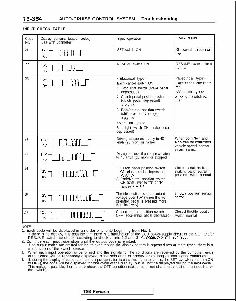
13-364 AUTO-CRUISE CONTROL SYSTEM - Troubleshooting
INPUT CHECK TABLE
Code Display patterns (output codes) Input operation Check resultsNo. (use with voltmeter)
21 SET switch ON SmE,: switch circuit nor-
RESUME switch ON RESUME switch circuitnormal
23 <Electrical type> <Electrical type>Each cancel switch ON Each cancel circuit nor-1. Stop light switch (brake pedal mal
depressed) <Vacuum type>2. Clutch pedal position switch
(clutch pedal depressed)St;p light switch nor-
< M / T >3. Park/neutral position switch
(shift lever to “N” range)< A / T >
<Vacuum type>Stop light switch ON (brake pedaldepressed)
24
25
n r Driving at approximately to 40 When both No.4 andkm/h (25 mph) or higher No.5 can be confirmed,
vehicle-speed sensorcircuit normal.
n r
Driving at less than approximatelyto 40 km/h (25 mph) or stopped
26 I. Clutch pedal position switchsNJFy;h pedal depressed)
2. Park/Neutral position switchON (shift lever to “N” or “P”range) <A/T>
Clutch pedal positionswitch, park/neutralposition switch normal
28 Throttle position sensor outputvoltage over 1.5V (when the ac-celerator pedal is pressed morethan half way)
$yro;e position sensor
Closed throttle position switch Closed throttle positionOFF (accelerator pedal depressed) switch normal
NOTE1. Each code will be displayed in an order of priority beginning from No. 1.
If there is no display, it is possible that there is a malfunction of the ECU power-supply circuit or the SET and/orRESUME switch, so check according to check charts 1.2 and 3 (P.13-339,340,341,354,355).
2. Continue each input operation until the output code is emitted.If no output codes are emitted for inputs even though the display pattern is repeated two or more times, there is amalfunction of the switch sensor.
3. When each input operation is performed and the signals for the conditions are received by the computer, eachoutput code will be repeatedly displayed in the sequence of priority for as long as that signal continues.
4. If, during the display of output codes, the input operation is canceled (if, for example, the SET switch is set from ONto OFF), the code will be displayed for one cycle of the display, but will not be displayed during the next cycle.This makes it possible, therefore, to check the OFF condition (existence of not of a short-circuit of the input line orthe switch).
TSB Revision
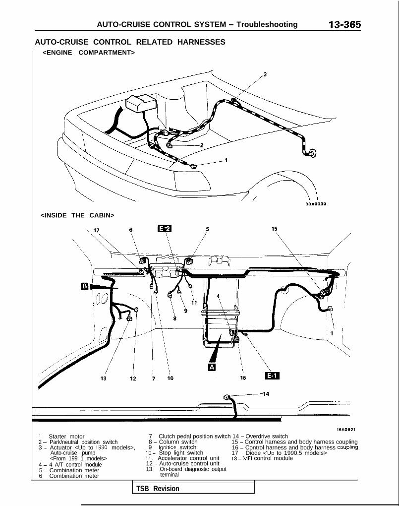
AUTO-CRUISE CONTROL SYSTEM - Troubleshooting 13-365
AUTO-CRUISE CONTROL RELATED HARNESSES<ENGINE COMPARTMENT>
<INSIDE THE CABIN>
16AO621
1 - Starter motor 7 - Clutch pedal position switch 14 - Overdrive switch2 - Park/neutral position switch 8 - Column switch 15 - Control harness and body harness coupling3 - Actuator <Up to 1990 models>, 9 - lgnrtion switch 16 - Control harness and body harness Coupling
Auto-cruise pump 10 - Stop light switch 17 - Diode <Up to 1990.5 models><From 199 1 models> 11 - Accelerator control unit 16 - MFI control module
4 - 4 A/T control module 12 - Auto-cruise control unit5 - Combination meter 13 - On-board diagnostic output6 - Combination meter terminal
TSB Revision
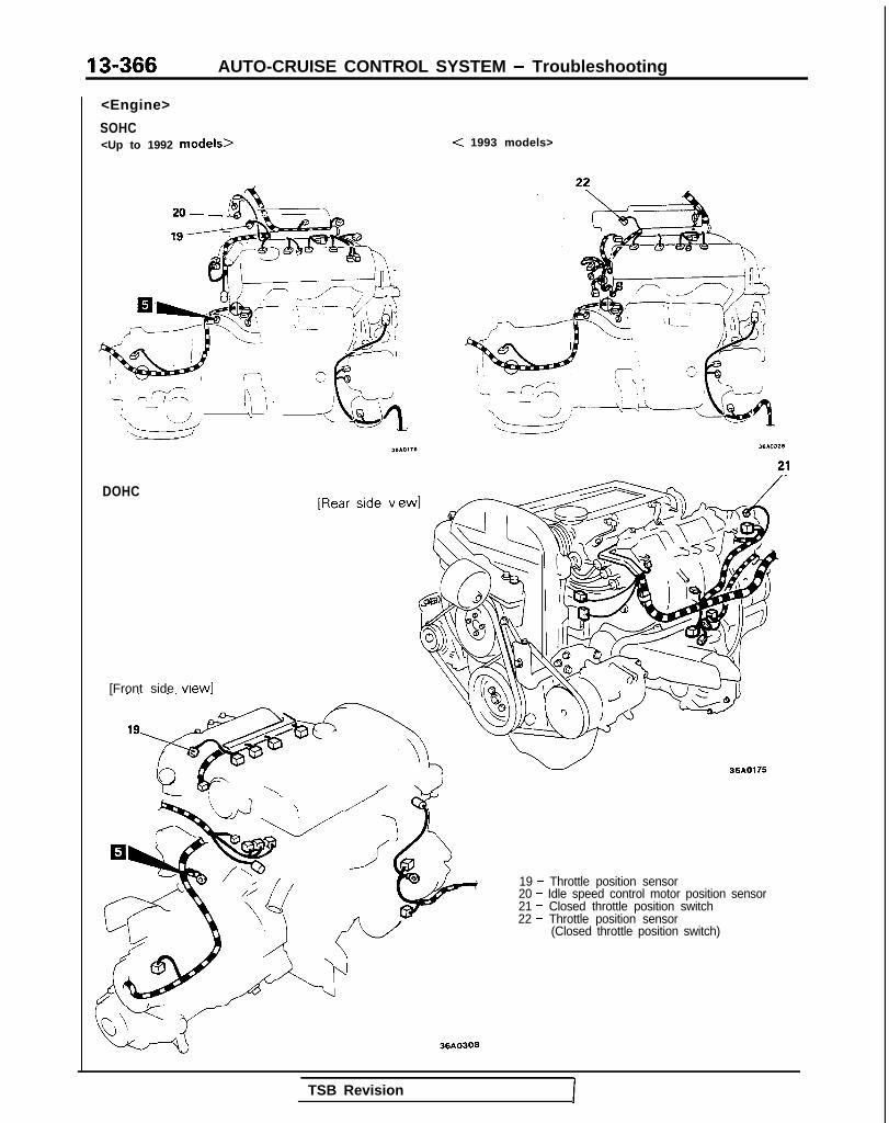
13-366 AUTO-CRUISE CONTROL SYSTEM - Troubleshooting
<Engine>
SOHC<Up to 1992 models>
w ,-,’ <:z
\ ‘8.-.-, ‘I\ 1: FI ‘iiI -I \’ 1: j\
\dd
/T&Jq
< 1993 models>
DOHC
[Front side view1-.._ -.-- ~l’e‘--
??A-‘LA\ \ /’ w
36AO175
19 - Throttle position sensor20 - Idle speed control motor position sensor21 - Closed throttle position switch22 - Throttle position sensor
(Closed throttle position switch)
36AO303
TSB RevisionI

AUTO-CRUISE CONTROL SYSTEM - Troubleshootinn 13-367
LOCATION OF CONTROL UNIT
w 16AO406
GROUND POINT
JUNCTION BLOCK p-;a
Frontharness
t
Instrument
Roofharness
r’ I I
Ji- I
$!&;I panelharness Body
harness
z$gger ~----#$jfiill ITi Heater- relav
7
J fuses)
16A0002m36I
TSB Revision

13-368 AUTO-CRUISE CONTROL SYSTEM - Troubleshooting
AUTO-CRUISE CONTROL COMPONENTS LOCATION
NOTEThe “Name” column is arranged in alphabetical order.
<Engine compartment>
SOHC DOHC
07AOO35
<Interior>
13A0218
TSB Revision
i

AUTO-CRUISE CONTROL SYSTEM - Troubleshooting 13-369
( Vehicle speed sensor(Reed switch)
1610051
cl989 models> 1,1 I 1. ‘\-
-Auto-cruise ’-control swItchI
_\\ 07AOO23
< F r o m 1 9 9 0 models> ‘\
rn-1 /---yy--
-.---- ‘L/---
_ \ 03A0275
I TSB Revision

AUTO-CRUISE CONTROL SYSTEM - Troubleshooting
Accelerator pedalswitch
07R003E
1750407
TSB Revision

AUTO-CRUISE CONTROL SYSTEM - Troubleshooting 13-371
CIRCUIT DIAGRAM<M/T (1989 models)>
IGNITION WITCH(IG1) SUB FUSIB LINK Q
J/B
COLUMN SWITCH
G101
730
c
I/AUTO-CRUISE \ I YA*h
c-01AUTO-CRUISECONTROL UNIT
v 5v
Lr!O
\CONTROL SWITCH/
C-69
aA
15-AC-H1534-NY
2.3-I
II1
3c:c
1 C-36
TSB Revision

‘13-372 AUTO-CRUISE CONTROL SYSTEM - Troubleshooting
CIRCUIT DIAGRAM (CONTINUED)<M/T (1989 models)>
AUTO CRUISECONTROL ACTUATOR
COMBINA-TMETER
J/B
z6j 1zd
,,l ISTOP LIGHTSWITCH __--_-
C-48 OFFO.JON oN*-&, .$2 3
s y=! mm
i
AUTO-CRUISECONTROL UNIT c-01
IBV
I
5.
OPENCONNEC-TOR
STOP LIGHT
Gln
1~2~3~41516[7[8I 2 I
lo~lr(l~lslloll~lkql
7
F .rx6 :
9 c-50
i ;;X&NAT'ON
'?SC-52
a
m
c-407I\
J/B--
C-38
- -"412
El945
ml i C-18
FRDNT SIDE
piziisqREVERSE SIDE
TSB Revision

AUTO-CRUISE CONTROL SYSTEM - Troubleshooting 13-373
CIRCUIT DIAGRAM<M/T (1990 models)>
LINK@
1 C-36
IGNITION SWITCH(IG1) SUB FUSIB
z
';,\7 c-43J/B
/t615
6
CLUTCH PEDALI'f'+&ON
C-46
AUTO-CRUISECONTROL UNIT'
Y 5^v
13
16 17- - - _--_-_
r;I1 ,*3
COLUMN SWITCHAUTO-CRUISECONTROL SWITCH
18
C-69
&J;T"igfUISEACTUATOR
iKl(3%AC-Hl535-NY
1 TSB Revision

13-374 AUTO-CRUISE CONTROL SYSTEM - Troubleshooting
CIRCUIT DIAGRAM (CONTINUED)
J/B
<M/T (1990 models)>
AUTO CRUISECONTROL ACTUATOR
DIODEc-49
J/B
1
STOP LIGHTSWITCH
C-48f 2B94
AUTO-CRUISECONTROL UNIT c-01
F(7
52
zd
,,l
\, .$'4 32 ?- %
6 1,
?s6
0
OPENCONNECTORc-47
:
STOP LIGHT
J/B
E-7
ALI
m
--7C
2‘\I
5
n1~2~3I4I516171E
I 8 I10~11~12112,14~15,16,1~
3 c-50
11: C$!&NAT'ON16C-52
C-40
i.
5WC-18
EBT&k48W
TSB Revision
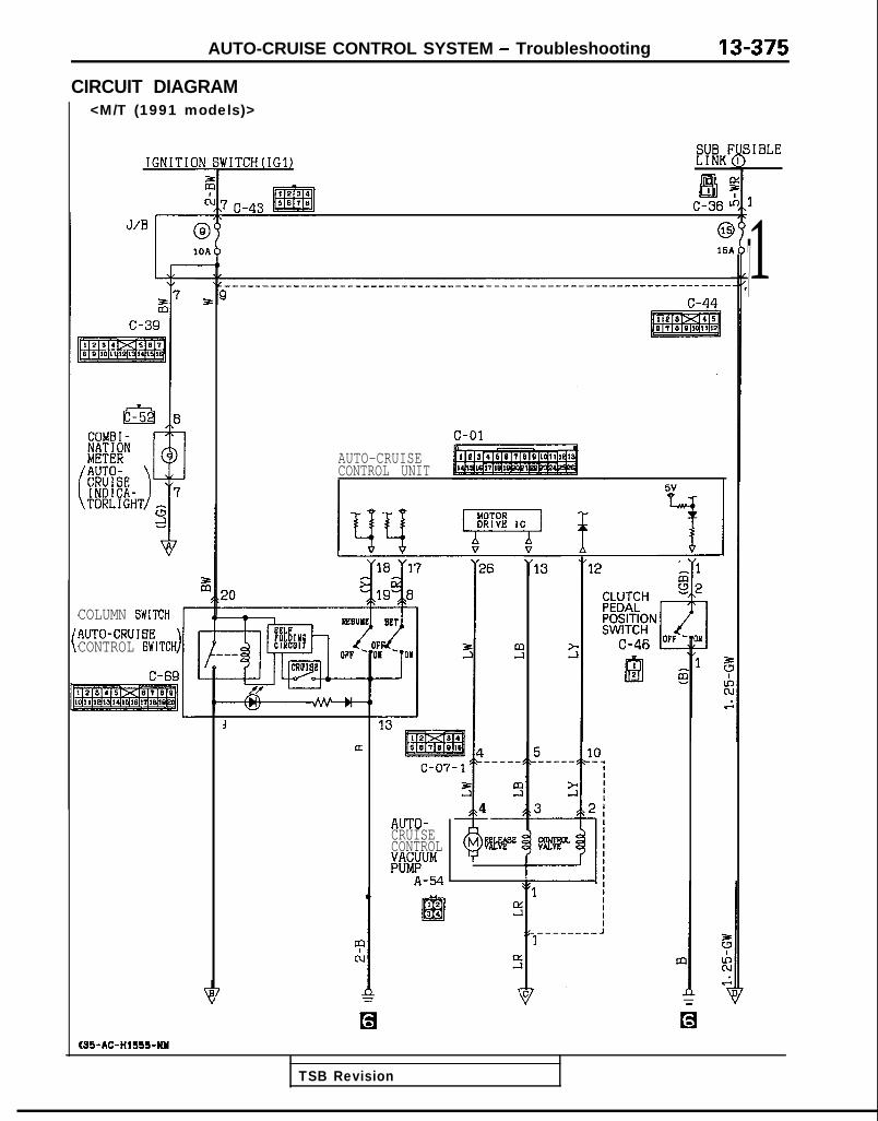
AUTO-CRUISE CONTROL SYSTEM - Troubleshooting 13-375
CIRCUIT DIAGRAM<M/T (1991 models)>
jIBLEb'ITCH(IG31 Eil?
wc-h ’
@151
IGNITIC
1
17
AUTO-CRUISECONTROL UNIT
5;
COLUMN GWITCHAUTO-CRUIBECONTROL GWITCH FKIY OY
1C-69
13
lx 5 10----- -_I
t;3
:I:21
I
3&
54:
MBelNiAUTO-CRUISECONTROLKPM
A-54 :512
m34
4cl
K35-AC-HISS+KM
TSB Revision

13-376 AUTO-CRUISE CONTROL SYSTEM - Trotibleshooting
CIRCUIT DIAGRAM (CONTINUED)<M/T (1991 models)>
K(%&NATION ;;:
I
STOP 'LIGHTSWITCH
C.
:
,,1
-0\I4
3
ti,
<OR
J/B
T
AUTO-CRUISECONTROL UNIT c-01
BY
4
L-
I“115
/ Cu
H#ECTOR
c-47IE?2
AUTO-CRUISECONTROL UNIT STOP LIGHT
B “? (6
Ls 6
P
A
n
svd
44 . r19
R-lg CD&NATION
C-38
jIC-18
FRONT 8JDE
pzliimqREVERSE SIDE
TSB Revision

AUTO-CRUISE CONTROL SYSTEM - Troubleshooting 13-377
AUTO-CRUISECONTROL UNIT c-01
~~----------~ - -----------
i /
r
zG
l-HROTTLEg&p3-02-lmj
rI I-+ 7
I I
b I ,
I I
I e+ 8G I s
%I
!a(36 (7
L5v SV
__-_-__-___- - - - - - - - - -
6 ! ! II I s'5
I
4 5
I I
4
t W ii St w i
IDLE SPEEDCONTROL MOTORPOSITION SENSOR
RbROLc-12
KX35-AC-Hl555A-NY
TSB Revision

13-378 AUTO-CRUISE CONTROL SYSTEM - Troubleshooting
CIRCUIT DIAGRAM<M/T (1992 models)>
aEiI
3 C-36
17
IGNITION
2(1
J/E!I@I IOA
z7
c-39
UTO-CRUISEONTROL UNIT
“12”
z 1q2
CLUTCH
@&ON / 1
3C-46 OFT -,:o
\I-.E!
IYI
I.------e-J1
COLUMN EWITCHAUTO-CRUIGBCONTROL SWITCH
13.I4_----c-07- 1
3
a:I
I5I m-1
TSB Revision

AUTO-CRUISE CONTROL SYSTEM - Troubleshooting 13-379
#FCONACT
1
:<ORENATION
' COLUMNSWITCH
rlGJ
AUTO-CRUISECONTROL UNIT C-01
59C-18
8V
:
5
SV
I
I
59!21-
?0
F
BI (
.I
c-07-1
pi%lq
9 c-502 ,.71
I’
[Ish‘
i6C-52l-9t1e131416161718j1 0 1
~10[11llq13110115(1611
m I
c-40
; pL+sREH]
J C-38
45
mIfI(u.i
II
I/B 7c
[h‘
m1
c-b I
a
g i
FRONT BIDE
j?4zhRq
?TOP
MFHB~MEcT~Rc-47
19,2
J?3
AUTO-CRUISECONTROL UNIT STOP LIGHT
1 TSB Revision 1

13-380 AUTO-CRUISE CONTROL SYSTEM - Troubleshooting
CIRCUIT DIAGRAM (CONTINUED)<M/T (1992 models)>
AUTO-CRUISECONTROL UNIT c-01
- - -I _ _ - - _ _ _ - - - -
(SOHC) -? r--------(DOHC>
I I
7---------------------,~c3
c6_--es-
0c3I:
t-
IDLE SPEEDCONTROL MOTORPOSITION SENSOR
B-02-2j-xeJjT4Tsfiiap,,4
,.,,&#%!LEPOSITION
I“1 "4
k!3"' 6~
z+G
G%
c F5g
,I A
I I
I II I
I II I
I I4 I
I I, I
I II I
I II I
I II I
I II 6
I II I
! I F,c
I I
\
I s
I I+
&La"4
-FiELEFTITI+;~ON
B-22-2ml
E5 8 cI$1 6 E
t ci t
9 113 124 117 A
%fl!j f-iSV
5
05
G
jp~FFJi~ t
I-02-1ttlm) ,,2
I.
AL,.
1
E-
4
I II II I
KXSS-AC-Hl556A-NY
TSB Revision
WI c-12CONTROLUNIT

AUTO-CRUISE CONTROL SYSTEM - Troubleshooting
CIRCUIT DIAGRAM<M/T (1993 models)>
IIGNITIO
J/BI (
:OLUMN BWITCH
:ONTROL SWITCH
VITCHtIGl) SUB FUSIBI
123,EmSF70
7 c-43
(ij151
)----------_----_---_____________________-----------------------
c-44
f7TFRQ
AUTO-CRUISECONTROL UNITI
aCL
1@L-II m
I’ :C
LE
siIA
1,,
227
I
LINKQ
IDBI
1 C-36
1
TSB Revision

13-382 AUTO-CRUISE CONTROL SYSTEM - Troubleshooting
CIRCUIT DIAGRAM (CONTINUED)<M/T (1993 models)>
r%FIANATION CA;;:
COLUMN TSWITCH
P
STOP -LIGHTSWITCH
C
ELTOR
AUTO-CRUISECONTROL UNIT c-01
%d
1 ,
.0-w--06 0.OK
i q°F 6
z6 1 <
AUTO-CRUISECONTROL UNIT STOP LIGHT
“tD ““0” f14 "22 39
F
I- -I’s5 m z
<c
m
mKi C-18,.
Dci$T&K%
5V
t
L5Y4
i.I
REVERSE SIDE
TSB Revision

AUTO-CRUISE CONTROL SYSTEM - Troubleshooting 13-383
t%ii%Eii%i~T C-01
j-__-_____(SOHC> -7 I----------
I I
(DOHC>
1 6I I
1 6
Y5 Y4 Y5 Y4
..3"CLOSED
! II II ,I II II II I
!
I I, 6I II tI I,z1) gI I-t II I! III&!
5 tw ’,,s------- J,7 c-07-1
3w w
0 05 W
iz ;2v
&pgKi I
j-02- 1pJ@JzJ ,,2 ,,l
>Li CL&DI4 gp#i
B-22-2aI
0iz“I
9 ,14 ,
-_-___-__-_-_II _-_-_ --_--I
MFICONTROL c-12 c- 12UNIT (SOHC> (DOHC>
KX35-AC-HlSglA-NY
TSB Revision

13-384 AUTO-CRUISE CONTROL SYSTEM - Troubleshooting
CIRCUIT DIAGRAM<A/T (1989 models)>
J/B
C-58
2iCL
C-24
2 zA C-L
A-41
3 -
3 10
F zm
A-09 cu lcII ---z
-- 1
111 c-59,234EBI3373
12IDa
gizJ
I I
01
ELC~$g%I’,,TRANSAXLE
iit!rnL
V
OD OFFINDICATORLIGHT
hAUTO-CRUISECONTROL UNIT
jV5v
r 7,
1 B-191
C-18DATA LINKCONNECTOR
FRONT 61DE
STARTER==
MOTOR
X35-AC-H1538-NY
1
TSB Revision 1
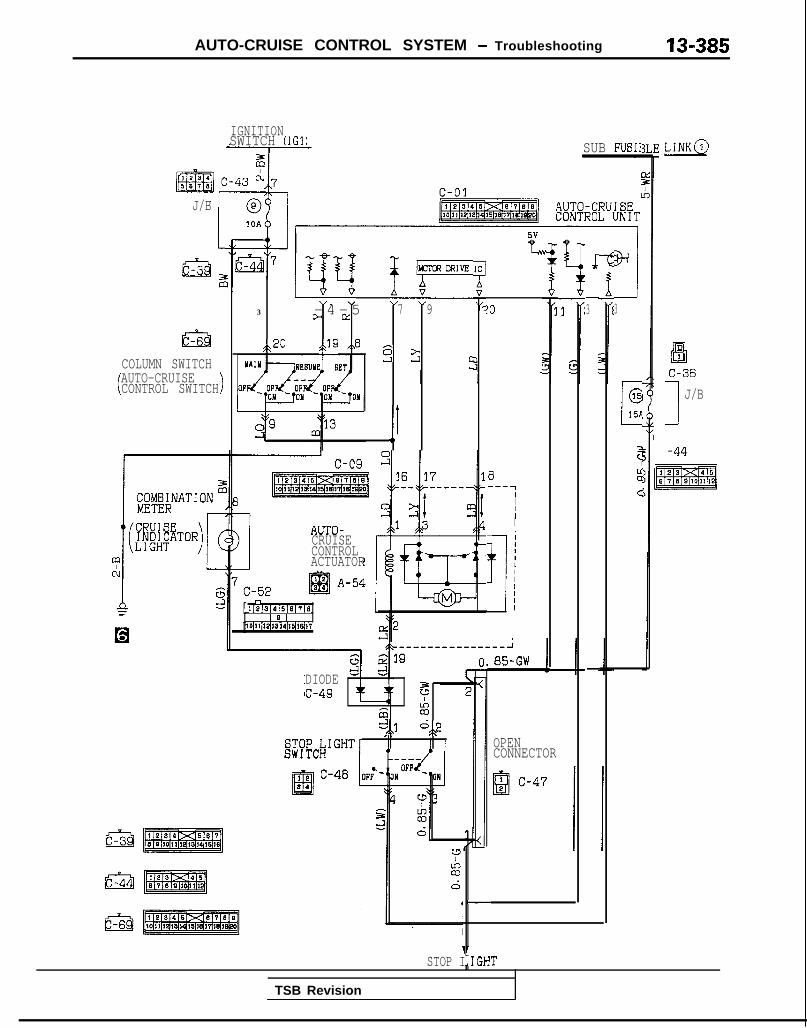
AUTO-CRUISE CONTROL SYSTEM - Troubleshooting 13-385
IGNITIONSWITCH (1Gl) SUB FUSIf
J/B
1
c-69COLUMN SWITCHAUTO-CRUISEiCONTROL SWITCH)
,yy p-
3 - 4 - 5 7> rz 9
,?20 ,$Q ,,82 2 0c
,)r
AUTO-CRUISECONTROLACTUATOR
3-lllel314’5’3’7~
I 8 I10~11~12~13~14~1~1~17
!O
0---7I
IIIIIIIII
%
DIODEc-49 $
m^ z+,1, "3/\
i1STOP I,IGH
85-GW
OPENCONNECTOR
-
T
d
-3
-
a,’3
c
(315P
3c1
I
::
C
LINK@
iDEi1C-36
I
J/B
:-44
TSB Revision

13-386 AUTO-CRUISE CONTROL SYSTEM - Troubleshooting
CIRCUIT DIAGRAM<A/T (1990 models)>
I
1
ELC$gi%cTRlvlsAx~
%WLD-44rOVERDRIVE opjSWITCHL4c3lx7
J!I4
6
14=
1 ) n
I13
1 AUTO-CRUISECONTROL UNIT
OD OFF.INDICATORLIGHT
PARK/NEUTRAL@#ftON
A-43 1
5V
J-
5v
I GNDV 4i
.oY2
Ei
nm::16 C-52 f~121sf4/51e171eJ
lo~lllYqrs4l4llelrq1
BATTERYI I
% zz &
A
zq ck �
B-18 1 3
17zE1@-5 c- 18DATA LINKCONNECTOR
FRONT 61DE
piJfbmqREVERSE SIDE
I -L I
L!u1 =1
STARTERMOTOR
X35-AC-Hl537-NY
1 TSB Revision

AUTO-CRUISE CONTROL SYSTEM - Troubleshooting 13-387
IGNITIONSWITCH (IGl) LINK@
aEl!1C-36
1 J/B
SUB FUSII
c-01 IAUTO-CRUISECONTROL UNIT
I1OAb 1 7-1
B‘3
Iis+-I3
IG151
c
:
C
MJFV-
@-=YQ3 "20
3
Yi
_I3
1w
4
0
7
/
>f3 c
I
COLUMN SWITCH
AUTO-CRUIEECONTROLSWITCH >
I , I I
2 9 m l3I 1,c-09 2 16
Y-44
@sq
_-------- ---- 2
0.85-GW
n111131415161718
I 6 Ilo~llllq1ql~1q1q1
OPENCONNECTOR
I
STOP FIGHT
TSB Revision I

13-388 AUTO-CRUISE CONTROL SYSTEM - Troubleshooting
CIRCUIT DIAGRAM<A/T (1991 models)>
IN:IG2)
@A-OS
IOA
1 LC-42
2
tm34611D-44;-
2cb
,J-"725I
;$&
Y?‘- ----1
2i43
czch
rI%CL
I 2zld
I zc
ELC$i%%%cTRANSAXLEiitlrnL
-K
~~
0
C-60
I/F-1t h 53I L
s 107
1; 1L-T 3~.2 20IN
1
6
II=-
*
J
3
IIIIIIIIIIIII 2I clI
OD OFFINDICATORLIGHT\ 1. p
1 AUTO-CRUISECONTROL UNIT
24 C-0';'s
C-18
DATA LINKCONNECTOR
J/B
FRONT SIDE
pEL&mjiWERSE SIDE
TSB Revision

AUTO-CRUISE CONTROL SYSTEM - Troubleshooting 13-389
BLEIGNITION
Ec-01
3
”
AUTO-CRUISECONTROL UNIT
J/B
1 I-
5----
3
26
c.
1.----.
cc4
12
c
-
@Ji!3.IC-36J/B
CCLUMN SW 1 TCH
;0+!;4&?U I SE
BW ITCH >
C01SA
E1
::
L
c-
0
GHTr
!O--u
II1
) $jl$ NATIONK
1> (z j#:TOI?)
AUTO-CRUISESXKBSLPUMP’ C-52
A-54, 2El94
------m-J
l-25-GW\-
5 2Iz6,,2
-*cl1,
u3,ACDd 1
/IA7kc.-J
OPENCONNECTOR
8; c-47
AUTO-CRUISECONTROL UNIT
L
STOP LIGHT
1 TSB Revision

13-390 AUTO-CRUISE CONTROL SYSTEM - Troubleshooting
CIRCUIT DIAGRAM (CONTINUED)<A/T (1991 models)>
AUTO-CRUISECONTROL UNIT c-01
I - - - - - - - - -(SOHC)- _ _ _ _ _ _ _ - I I _-_-_ -_--
<DOHC>
‘h 5'
I II II ‘6
IY4 I Y5 Y4 ,
I
; ;
I II ‘
I II I
I II I
I II a
I II I
I II I
I II #
I I, I
I II I
‘1 IE
4g
I I’ ’
I I&
3w It WI
--A-l
I
IEsci
!3
W
sCL1OPb‘ ON-
I - -
5G
9I\E- 14
1 5’:tMFI c-12CONTROLUNIT
KXS-AC-HlSWA-NM
TSB Revisio,n

AUTO-CRUISE CONTROL SYSTEM - Troubleshooting 13-391
CIRCUIT DIAGRAM<A/T (1992 models)>
IGNITION IGNI’ISW1 TCH(ST) GWITC
c-43
C-42
(IG2)
I
1D-441
r
I23'a* A-41
C-60JN1
62=!
.1
IIIIIIIIIIII
JlIII
7-J
C-60-1OD OFFINDICATORLIGHT'ARK/NEUTRAL
;~~+~pN
A-43 E qAUTO-CRUISECONTROL UNIT
BATTERY
24 C-0;2
C-18DATA LINKCONNECTOR
FRONT SIDE
REVERSE SIDE
f!TzERq
35AC-HlSSS-NM
TSB Revision
--

13-392 AUTO-CRUISE CONTROL SYSTEM - Troubleshooting
J/B
CIRCUIT DIAGRAM (CONTINUED)<A/T (1992 models)>
I I 1
d913m
1 i#f&NATION
CRUISEINDICATORLIGHT >
AUTO-CRUISECONTROL UNIT
mpliE%q_--
uA
1 1 1
----------J1.25-GW
5 $T2n
!2,,1 0,,2I\
@!EcT’ c-47Q2
s z6 1
1 ALCZJ1?I.i
0
AUTO-
I 5----- ------
m >21 *3 -
SUB FUSIBI
2Li
AUTO-CRUISECONTROL UNIT
-
STOP LIGHT
BJ,
C015A
F
z
d
LINK@
Els1 C-36
1 J/B
jggl
TSB Revision

AUTO-CRUISE CONTROL SYSTEM - Troubleshooting 13-393
AUTO-CRUISECONTROL UNIT C-01
I__-_-_-____l-‘--------l
(SOHC) I 0
-I-I I
(DOHC)
I IAv5
st,,s- - - - - - - - - - - - - - - - - - -
c-07-1
2
I1i
‘6"4
w__I ,7
W
I,wA
t-tI II II I
1 Itx.
IDLE SPEEDCONTROL MOTORPOSITION SENSOR
B-02-2(~@@zjijg# ,,4
1 ‘sY5 Y4 J
5 1 cJ,,s 7
:>c-07-1---._---
5 p7zsq0 I.5 w
s i2
e-02-1mfmj ,,2 ,.l
, ,, I\
OPV on
Ii
-A-
l
%I g
!3
CLOsED3 THROTTLE;$W$AON
B-22-2ia
“1Es
E
sE
,
Fs 8G I G
6I
MFI c-12CONTROLUNIT
KX35-AC-HlSSW-NY
1 TSB Revision

13-394 AUTO-CRUISE CONTROL SYSTEM - Troubleshooting
CIRCUIT DIAGRAM(A/T (1993 models)>
hc-4312
@J/B
IOA
.IC-42"2 .I
Ef: 13 c-39
1234I!335811
1 2E!l3
@
Iel10
t
OD OFFINDICATORLIGHTPARK/NEUTRAL
~~yCl;AON
A-43 :jIc-
4.L
“bDGiDC
AUTO-CRUISECONTROL UNIT
.IBATTERYII
!4 c-01
cful
I~
c-u,:
=STARTERMOTOR
X35-AC-H1582-IIY
, 1
TSB Revision I

AUTO-CRUISE CONTROL SYSTEM - Troubleshooting 13-395
IGNITIONLE~ LINK@
cc')
51C-36
1 J/B;a
SUB FUSIB
c-01 3II
AUTO-CRUISECONTROL UNIT
1
J/B
I
m
3C
[
(
cz
r
r’ l-J *
”13 12
3 c
5 A10'----- ---IZgRNAT 1 ON
I
(Fiii t ETORLIGHT >
C-52I)P]514~5[61718
/a’l0~11’Gq13’14’1~lej1
,------- --- J1.25-GW
5 (7 2LA00
d,2 .:OPENCONNECTOE
1a' Q
c-471
Y3zd 1~ <AL
Y%s
1
A-54
5ccA
H
AUTO-CRUISECONTROL UNIT
STOP LIGHT
TSB Revision

13-396 AUTO-CRUISE CONTROL SYSTEM - Troubleshooting
CIRCUIT DIAGRAM (CONTINUED)<A/T (1993 models)>
P6.
,,2 ,,3I-.
CLOSEDTHROTTLE 0!g#~ON ,.
ON OFF
.,
“1 "4
B-02-1mj)
MFI c-12CONTROLUNIT
KX35-AC-IilWA-NY
1 TSB Revision I

AUTO-CRUISE CONTROL SYSTEM - Setice Adjustment ~m~edures 13-397
i
ON
y SET
03AO258
03AO258
y SET
CGA0258
(1) Set to the desired speed.(2) Press the SET button.(3) Check to be sure that deceleration continues while the
switch is pressed, and that when it is released theconstant speed at the time when it was released becomesthe driving speed.
NOTEWhen the vehicle speed reaches the low limit [approxi-mately 40 km/h (25 mph)] during deceleration, the auto-matrc speed control will be cancelled.
TSB Revision I
SERVICE ADJUSTMENT PROCEDU$$jF
AUTO-CRUISE CONTROL SYSTEM INSPECTIONAUTO-CRUISE CONTROL MAIN SWITCH CHECK
(I) Turn the ignition key to ON.(2) Check to be sure that the indicator light within the switch
illuminates when the main switch is switched ON.
AUTO-CRUISE CONTROL SETTING CHECK
(1) Switch ON the main switch.(2) Drive at the desired speed within the range of approxi-
mately 40-145 km/h (25-90 mph).(3) Press the SET button.(4) Check to be sure that the speed is the desired constant
speed when the switch is released, and also check to besure that the auto cruise indicator light (within the combina-tion meter) illuminates.
NOTE<Electrical type>If the vehicle speed decreases to approximately 20 km/h(12 mph) below the set speed, because of climbing a hill forexample, the auto-cruise control will be cancelled.<Vacuum type>If the vehicle speed decreases to approximately 15 km/h (9mph) below the set speed, because of climbing a hill forexample, the auto-cruise control will be cancelled.
SPEED-INCREASE SETl-ING CHECK
(1) Set to the desird speed.(2) Turn the control switch to RESUME position.(3) Check to be sure that acceleration continues while the
switch is hold, and that when it is released the constantspeed at the time when it was released becomes thedriving speed.
NOTEEven if, during acceleration, the vehicle speed reaches orexceeds the high limit [approximately 145 km/h (90mph)], acceleration will continue, however, when theswitch is released, the set speed (“memorized speed”) willbecome the high limit of the vehicle speed.
SPEED REDUCTION SEITING CHECK
--
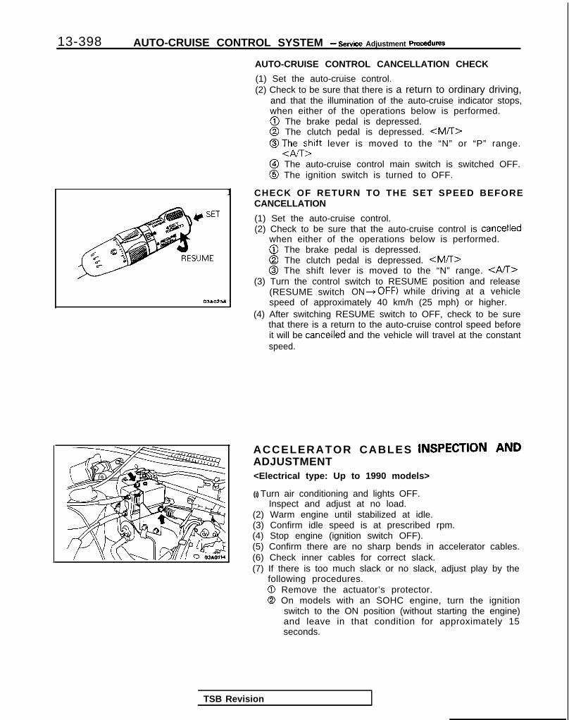
13-398 AUTO-CRUISE CONTROL SYSTEM - Setice Adjustment procedures
03*02.5*
1
AUTO-CRUISE CONTROL CANCELLATION CHECK
(1) Set the auto-cruise control.(2) Check to be sure that there is a return to ordinary driving,
and that the illumination of the auto-cruise indicator stops,when either of the operations below is performed.@ The brake pedal is depressed.@ The clutch pedal is depressed. <MA>@ TJhEzift lever is moved to the “N” or “P” range.
@I The auto-cruise control main switch is switched OFF.@ The ignition switch is turned to OFF.
CHECK OF RETURN TO THE SET SPEED BEFORECANCELLATION
(1) Set the auto-cruise control.(2) Check to be sure that the auto-cruise control is cancelled
when either of the operations below is performed.@ The brake pedal is depressed.@ The clutch pedal is depressed. <M/T>@ The shift lever is moved to the “N” range. CAST>
(3) Turn the control switch to RESUME position and release(RESUME switch ON *OFF) while driving at a vehiclespeed of approximately 40 km/h (25 mph) or higher.
(4) After switching RESUME switch to OFF, check to be surethat there is a return to the auto-cruise control speed beforeit will be cancelled and the vehicle will travel at the constantspeed.
ACCELERATOR CABLES INSPECTION ANDADJUSTMENT<Electrical type: Up to 1990 models>
(I) Turn air conditioning and lights OFF.Inspect and adjust at no load.
(2) Warm engine until stabilized at idle.(3) Confirm idle speed is at prescribed rpm.(4) Stop engine (ignition switch OFF).(5) Confirm there are no sharp bends in accelerator cables.(6) Check inner cables for correct slack.(7) If there is too much slack or no slack, adjust play by the
following procedures.0 Remove the actuator’s protector.0 On models with an SOHC engine, turn the ignition
switch to the ON position (without starting the engine)and leave in that condition for approximately 15seconds.
TSB Revision

AUTO-CRUISE CONTROL SYSTEM - Setice Adjustment ~rccedures 13-399
Accelerator cable B
Intake manifold plenum
VAdjusting bolts 07A0021
Thro t t l e -.--
Stopper Closkd throttleposition swrtch 03~0278
Acceleratorcable A
I
03A0271
-Ai+1-2 mm (.04-.08 in.)
TSB Revision
@ Adjust accelerator cable B (throttle valve side); afterloosening the adjustment bolts at the intake manifoldplenum side and freeing the inner cable, use the adjust-ment bolts to secure the plate so that the free play ofthe inner cable becomes the standard value.
Standard value: l-2 mm (.04-.08 in.)NOTEIf there is excessive play of the accelerator cable, thevehicle speed drop (“undershoot”) when climbing aslope will be large.If there is no play (excessive tension) of the acceleratorcable, the idling speed will increase.
@ Confirm that the throttle lever touches the closed throt-tle position switch.
@ Adjust accelerator cable A (accelerator pedal side) byloosening the lock nut.
< M / T > O- l mm (O-.04 in.)< A / T > 2-3 m m (.08-.12 in.)
CautionDo not decrease the play of cable B.
@ After making the adjustment of the cable as describedabove, check to be sure that the throttle lever at theengine side is caused to move the distance shown inthe illustration when the actuator link is turned.
@ Install the protector to the actuator.
(8) After adjusting, confirm that throttle valve fully opens andcloses by operating pedal.

13-400 AUTO-CRUISE CONTROL SYSTEM - Service Adjustment procedures
r Throttle cable Adjusting nut B
\uto-cruise dontrol cableThrottlecable Adjusting nut D
A
03A0281
Stopper
Throttle Lock nut/ Adjusting nut B
Stopper 07AOO54
07AOO55
<Vacuum type: From 1991 models>
(1) Remove the link protector. (Refer to P.13-402.)(2) Check that there are. no sharp bends and breaks in the
accelerator cable, throttle cable and auto-cruise controlcable.
(3) Turn the ignition switch to the ON position (without startingthe engine) and leave in that condition for approximately 15seconds.
(4) Leave plenty of play in each cable and temporarily installadjusting nuts A, B, C and adjusting bolts D.
(5) Adjust with adjusting nut A so when link A hits the stopper,the accelerator cable play (inner cable play) reaches thestandard value.
Standard valueM/T: O- l mm (O-.04 in.)A/T: 2-3 mm (.08-.12 in.)
(6) Fix the accelerator cable with the lock nut.
(7) Adjust with adjusting nut B so when link B hits the stopperof link C, throttle cable play (inner cable play) reaches thestandard value.
Standard value: l-2 mm (&I-.08 in.)(8) Fix the throttle cable with lock nut and adjusting bolt D.
(9) Adjust with adjusting nut C so when the link C stopper hitsthe end of link B, the auto-cruise control cable play (innercable play) reaches the standard value.
Standard value: l-2 mm (.04-.08 in.)
(1O)Fix the auto-cruise cable with the lock nut.(1 l)After adjusting, confirm that throttle valve fully opens and
closes by operating pedal.
-
rTSB Revision
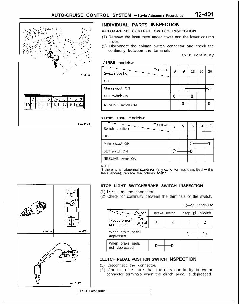
AUTO-CRUISE CONTROL SYSTEM - Setice Adiustment Procedures 13-401
16AO192
--Ib/-SJy-
iii3 1
24 J
14LO142
INDIVIDUAL PARTS INSPEtiTIONAUTO-CRUISE CONTROL SWITCH INSPECTION
(1) Remove the instrument under cover and the lower columncover.
(2) Disconnect the column switch connector and check thecontinuity between the terminals.
C-O: cont inuity
<1989 models>
13 19 20
OFF
Maln switch ON O/ I0I I I ISET swttch ON
RESUME switch ON
0 0
0 0
<From 1990 models>
Switch position
OFF
Main switch ON
SET switch ON
RESUME switch ON
0 0
0 0
NOTEIf there is an abnormal condition (any condltlon not described In thetable above), replace the column switch.
STOP LIGHT SWITCH/BRAKE SWITCH INSPECTION
(1) Diconnect the connector.(2) Check for continuity between the terminals of the switch.
M :continuity
Brake switch Stop light siwtch
3 4 1 1 2I ----I I I
When brake pedaldepressed. / b-t-4When brake pedalnot depressed. 0 0
CLUTCH PEDAL POSITION SWITCH INSPECTION(1) Disconnect the connector.(2) Check to be sure that there is continuity between
connector terminals when the clutch pedal is depressed.
1 TSB Revision

13-402 AUTO-CRUISE CONTROL SYSTEM - service Adjusbnent PWSXIU~S
PARK/NEUTRAL POSITION SWITCH (“N” AND “P”POSITIONS) INSPECTION
(1) Disconnect the connector.(2) Check to be sure that there is continuity ,between
connector terminals 8 and 9 when the shift lever IS movedto the “N” range.
ACTUATOR INSPECTION <Electrical type: Up to 1990models>(1) Disconnect the connector.(2) Measure the resistance value of the clutch coil.
Resistance of clutch coil between connector terminals(1) - (3)Standard value: Approx. 2Ofl
ACTUATOR OPERATION CHECK <Electrical type: Up to1990 models>
Disconnect the actuator’s connector and, in the ordey de-scribed below, check the actuator’s operation and the clrculttester’s indication; replace the actuator assembly if anyabnormal condition is discovered.(1) Checking the clutch coil solenoid operation
Connect terminal (3) of the actuator through the ammeterto the positive (+) terminal of the battery, and connectterminal (1) to the negative (-) terminal.
Actuator
Actuator side cO/nectOr 16R1080 1SR1032
r Judaement
Normal
Solenoid operationsound (“click”) can beheard.
T-t
A , : 0.5-0.7A
NOTENC: ON at all times
No solenoid soundA,= mA
Short-circuit of clutch coil
N O : O F F at all times
TSB Revision I

AUTO-CRUISE CONTROL SYSTEM - Service Adjustment procedures 13-403
(2) Checking the motor (PULL direct ion) and l imi t swi tchoperationIn the condition described in (1). connect terminal (2) ofthe actuator, through the ammeter, to the positive (+)side and terminal (4) to the negative (-) side.
Actuator sideconnector
16R1082
~1 L-E~~~~~~stroke (fully open). A: : 0.5-0.7A between shaft and
AI : 0.5-0.7A metalA Z : less than 0.5A l Insufficient thrust(when current ON) clearance
Selector doesn’t move. l Shaft burnedAzequal or more than IA l Foreign material caugtAI : 0.5-0.7A between gears
l Motor burned
Selector doesn’t move.Az=OAA I : 0.3-0.7A
l Damaged ordisconnected internallead wire
l Damaged ordisconnected motorwiring
0 Poor contact of limitswitch
l Open diode
Nith the selector stroke The selector doesn’t return to Malfunciion of clutch3t the intermediate level, the original position even if operationdisconnect the the current to the clutch coil (Clutch plate remains:onnection to terminal is cut. engaged with clutch)3) and cut the currentlow to the clutch coil.
1t
TSB Revision

13-404 AUTO-CRUISE CONTROL SYSTEM - Service Adjustment procedures
(3) Checking the motor (REL. d i rect ion) and l imi t swi tchoperationReverse the connections to terminal (4) and terminal (2)from those described in (2).
c
Actuator sideconnector
II *16R1081
Judgement
Normal
Current is cut off whenselector is turned inREL. direction for fullstroke (fully closed).
A, : 0.5-0.7AAZ: less than 0.5A(when current ON)
Abnormal
Selector moves in REL.direction but
Apequa or more than IAA,: 0.5-0.7A
Selector doesn’t move.ATequal or more than IAAI : 0.5-0.7AI
cSelector doesn’t move
Az=OAA, : 0.3-0.7A
-I1
Ii
1
Probable cause 1l Improper backlash
between gearsl Imminent burning
between shaft andmetal
l Insufficient thrustclearance
l Shaft burnedl Foreign material caugh
between gearsl Motor burned
l Damaged ordisconnected internallead wire
l Damaged ordisconnected motorwiring
0 Poor contact of limitswitch
l Open diode
1 TSB Revision I

AUTO-CRUISE CONTROL SYSTEM - Sewice Adjustment Procedures
ECU connector terminals
19 17 15 13 ll>< 7 5 3 120 18 16 14 12 101 9 8 6 4 2
16A1060
ELECTRONIC CONTROL UNIT (ECU) SIGNAL CIRCUITCHECK <Electrical type: Up to 1990 models>
Disconnect the connector of the ECU, and then check at thebody side wiring harness according to the chart below.
IG SW: Ignition switchMAIN SW: Main switch
OD SMI: Overdrive switch
Termi-~ Connection or mea-nal ~ sured part
Measure- Tester con-ment item nection
Check conditions Standard
I -
I-
1 ~ Ac tua to r (mo to r ) Resistance 1 - “‘2 Actuator selector Approx. 120(Fully closed position)
12
3 I Stop light switch Voltage 3-Ground ~ IG S/W O N , M a i n SW O N Battery positive~ (for auto-cruise~ control cancellation)
j )
i (Don’t press brake pedal.) j voltage
and actuator (clutch) I Press brake pedal after checking Battery positive
5 1 Power supply (MAIN)
/ above. voltage -0V
Voltage 5-Ground 1 IG S/W ON, Main S/W ON Battery positivevoltage
6 None -i - i-
7 1 Power supp ly (IGz) Vol tage 7-Ground IG SfW O N Battery positivevoltage
8*z ~ On-board diagnostic - - i- -
TSB Revision
9 Accelerator pedal Voltage g-Ground IG SW O N Battery positiveswitch (Accelerator pedal free) voltage
1 Press accelerator pedal after / Battery positiveI I checking above. [ voltage -0V
IO I Vehicle speed sensor Voltage 1 O-Ground ’ With the ignition key at the ON
’ ~
4 voltageposition, slowly turn the speedom- changes/ ca-eter cable. ble rotation
11 SET switch Continuity 1 l-Ground ’ SET switch ON (Press) Continuity
SET switch OFF (Release) No continuity
12 OD switch
13 RESUME switch1
Voltage
Continuity
12-Ground IG SNV ON OD SW ON position Battery positivevoltage
OD SW OFF position ~ OV
13-Ground ~ RESUME switch ON (Turn) Continuity
; RESUME switch OFF (Release) No continuity
14’2 ~ 4 A/T control module ( - /- I- ! -I /
15 1 Stop light switch load ~ Vol tage 15-Ground ’ Press the brake pedal. Battery positiveside / voltage
16 j Ground Continuity 1 16-Ground At all t imes ~ Continuity

13-406 AUTO-CRUISE CONTROL SYSTEM - Service A&tment ~mcec~ure~
Termi-nal
17
18
19
20
l-
it
L
Connection of mea-sured part
Park/neutral positionswitch (P, N)
T
f
+Stop light switchpower supply side
Continuity ~ 17-Ground
1.~.~.~ ~.-. _ - ~~- -~/Voltage ) 18-Ground
~~ ____~ _~ ~.. ----+--.. .-~Clutch pedal position Voltage 1 1 g-Groundswitch
Measure- 1 Testerment item 1 connection
Ground1
~ Continuity ~ 20-Ground
-Conrrol junit j I! @jII I LNOtOMl ‘-r’
+-j---J --L--
Actuator motor
03R0210
Check conditions Standard
“P” or “N” range Continuity
Other than “P” or “N” range
,
No continui-v
At all times j Battery positive
IG S/W ON
Clutch pedal position switch OFF
At all times / Continuity 1
NOTE1. As shown by the “1 symbol, the limit switch within the
actuator will become as shown in the figure at the left ifthe. actuator selector is at the fully closed position whenthe resistance between terminals No. 1 and No. 2 i smeasured; for that reason, after checking the polarity ofthe tester, the tester’s probe should be connected so thatcurrent flows from the No. 1 terminal to the No. 2terminal.
2. For terminals No. 8 and 14 indicated by the “2 symbol, it isnecessary to check individual terminal voltages with theECU’s harness connector connected and with the ignitionswitch ON.(1) The No.8 terminal is normal if the diagnostic trouble
code can be confirmed. (Refer to P.13-361.)(2) The No. 14 terminal is normal if there is approximately
12V with the auto-cruise control system not functioningand the overdrive switch switched ON. (Refer toP. 13-349.)
VEHICLE-SPEED SENSOR INSPECTION
Refer to GROUP 54-Meters and Gauges for checking ofvehicle speed sensor.
TSB Revision
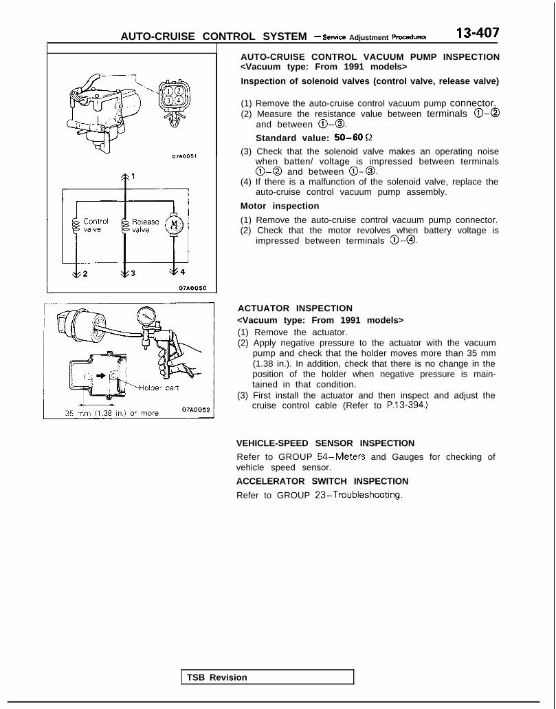
AUTO-CRUISE CONTROL SYSTEM - Setice Adjustment procedures 13-407
=\
07A005.1
ControlvalveL2
07AOO50
AUTO-CRUISE CONTROL VACUUM PUMP INSPECTION<Vacuum type: From 1991 models>
Inspection of solenoid valves (control valve, release valve)
(1) Remove the auto-cruise control vacuum pump connector.(2) Measure the resistance value between terminals 0-0
and between 0-0.
Standard value: 50-60 Q
(3) Check that the solenoid valve makes an operating noisewhen batten/ voltage is impressed between terminals0-0 and between 0-0.
(4) If there is a malfunction of the solenoid valve, replace theauto-cruise control vacuum pump assembly.
Motor inspection
(1) Remove the auto-cruise control vacuum pump connector.(2) Check that the motor revolves when battery voltage is
impressed between terminals @-0.
TSB Revision
ACTUATOR INSPECTION<Vacuum type: From 1991 models>(1) Remove the actuator.(2) Apply negative pressure to the actuator with the vacuum
pump and check that the holder moves more than 35 mm(1.38 in.). In addition, check that there is no change in theposition of the holder when negative pressure is main-tained in that condition.
(3) First install the actuator and then inspect and adjust thecruise control cable (Refer to P.13-394.)
VEHICLE-SPEED SENSOR INSPECTION
Refer to GROUP 54-Meters and Gauges for checking ofvehicle speed sensor.
ACCELERATOR SWITCH INSPECTION
Refer to GROUP 23-Troubleshooting.

13-408 AUTO-CRUISE CONTROL SYSTEM - Auto-cruise Control
AUTO-CRUISE CONTROLREMOVAL AND INSTALLATION
1 <Electrical type: Up to 1990 models>
4 - 6 Nm3-4 ft.lbs.
Post-installation Operationa Accelerator Cable Adwstment (Refer
to P. 13-398.)
,**.“qy “y ,,,, ezls:’ 3 -. .- ,*% L’J
01
,\@&&,-<2 8- E +c- - - --.c,
T
$$y= *g i ;g+j$T-3
18
Removal steps of actuator1. Protector2. Accelerator cable B adjusting nut3. Accelerator cable A adjusting nut4. Actuator side inner cable5. Actuator connector6. Actuator7. Air hoses
<ACTIVE-Electronic Control Suspension>8. Bracket
Removal steps of sensor and switches9. Accelerator switch <A/T>
10. Stop light switch11. Clutch pedal position switch <M/T>12. Park/neutral position switch <A/T>13. Vehicle speed sensor (Refer to GROUP
54-Met&sand Gauges.)14. Auto-cruise control switch (Refer to
GROUP 54-Column Switch.)Removal steps of control unit
15. Instrument under cover16. Lap shower duct and foot shower
nozzle17. Control unit18. Auto-cruise control indicator light (Refer to
GROUP 54-Meters and Gauges.)
9’ -L.-l I I07A0024
fa lQA0237
TSB Revision

AUTO-CRUISE CONTROL SYSTEM - Auto-cruise Control
<Vacuum type: From 1991 models>
*Accelerator Cable Adjustment
Removal steps of actuator1. Link protector2. Throttle cable3. Accelerator cable4. Auto-cruise control cable5. Auto-cruise pump connector
l * 6. Vacuum hose7. Link assembly8. Pump bracket9. Auto-cruise pump assembly
IO. Auto-cruise bracket11, Actuator bracket12. Auto-cruise actuator
1307AOO58
9 - 1 4 Nm7- 10 ftlbs.
21
19AO237
Removal steps of sensor and switches13. Accelerator switch <AfT>14. Stop light switch15. Clutch pedal position switch <M/T>16. Park/neutral position switch <A/T>17. Vehicle speed sensor (Refer to GROUP
54-Meters and Gauges.)18. Auto-cruise control switch (Refer to
GROUP 54-Column Switch.)
Removal steps of control unit19. Instrument under cover20. Lap shower duct and foot shower nozzle21. Control unit22. Auto-cruise control indicator light (Refer to
GROUP 54-Meters and Gauges.)
TSB Revision
.-

13-410 AUTO-CRUISE CONTROL SYSTEM - Auto-cruise Control
INSPECTIONl Check the inner and outer cable for damage.l Check the cable for smooth movement.l Check the actuator cover for damage.
CHECKING THE ACTUATOR
Refer to P.13-397.
M13lDCC
SERVICE POINTS OF INSTALLATION6. INSTALLATION OF VACUUM HOSE
Align the marking end of the vacuum hose to the clampposition and install.
TSB Revision I

14-1
COOLING
ENGINE COOLANT TEMPERATURE GAUGEUNIT, ENGINE COOLANTTEMPERATURE SENSOR AND ENGINECOOLANT TEMPERATURE SWITCH ............. 31
RADIATOR ....................................................... 9
RADIATOR FAN MOTOR ASSEMBLY .......... 12
SERVICE ADJUSTMENT PROCEDURES.. ..... 8
Engine Coolant Concentration Test ............. 8
Engine Coolant Leak Check ........................ 8
Engine Coolant Replacement ....................... 8
Radiator Cap Pressure Test ......................... 8
SPECIAL TOOL ................................................ 5
SPECIFICATIONS ............................................. 2
General Specifications .................................. 2
Lubricant ....................................................... 4
CONTENTS IM14AA-
Sealant . . . . . . . . . . . . . ..__...........’ . . . . . . . . . . . . . . . . . . .._......... 4
Service Specifications . . . . . . . . . . . . . . . . . . . . . . . . . . . . . . . . . . 2
Torque Specifications . . . . . . . . . . . . . . . . . . . . . . . . . . . . . . . . . . . 3
THERMOSTAT . . . . . . . . . . . . . . . . . . . . . . . . . . . . . . . . . . . . . . . . . . . . . . . . . 13
TROUBLESHOOTING . . . . . . . . . . . . . . . . . . . . . . . . . . . . . . . . . . . . . . 5
No rise in temperature
Overheat
WATER HOSE AND WATER PIPE<DOHC (Non-Turbo)> . . . . . . . . . . . . . . . . . . . . . . . . . . . . . . . . . . . 26
WATER HOSE AND WATER PIPE<DOHC (Turbo)> . . . . . . . . . . . . . . . . . . . . . . . . . . . .. . . . . . . . . . . . . . . 28
WATER HOSE AND WATER PIPE<SOHC> . . . . . . . . . . . . . . . . . . . . .. . . . . . . . . . . . . . . . . . . . . . . . . . . . . ..a..... 23
WATER PUMP <DOHC> . . . . . . . . . . . . . . . . . . . . . . . . . . . . . . . 20
WATER PUMP <SOHC> . . . . . . . . . . . . . . . . . . . . . . . . . . . . . . . 15

14-2 COOLING - Specifications
SPECIFICATIONSGENERAL SPECIFICATIONS MlICA-
Items
Cooling method
Specifications
Water-cooled, pressurized, forced circulationwith electrical fan
Radiator
TypeRadiator fan motor
TypeWater pump
TypeThermostat
TypeIdentification mark
Drive belt
Type.Engine coolant temperature gauge unit
TypeEngine coolant temperature sensor (Engine control)
TypeAir conditioning engine coolant temperature switch<Normal closed type>
TypeEngine coolant temperature switch<Normal opened type> (Air conditioning or A/T control)
Type
* . . . SOHC 1 GVALVE
Pressurized corrugated fin type
Direct current ferrite type
Centrifugal impeller type
Wax pellet type with jiggle valve
88 (Stamped on flange), *82 (Stamped on flange)
V-ribbed belt
Thermistor type
Thermrstor type
Thermistor type
Thermistor type
SERVICE SPECIFICATIONS MlOCB-
Items
Standard valueRange of coolant antifreeze concentration
Thermostat
Valve opening temperature of thermostat
Full-opening temperature of thermostat
Opening pressure of radiator cap high pressure valve
Therm0 sensor (on radiator)Operating temperature
OFF + ONON + OFF
* . . . SOHC 1 GVALVE
Specifications
% 30-60
“C (“F) 88 (IgO), *82 (180)T (OF) 100 (212) or more, *95 (203) or more
kPa (psi) 75-105 ( 1 1 - 1 5 )
“C (“F) 8 2 - 8 8 (180-190)
“C (“F) 7 8 - 8 4 ( 1 7 2 - 1 8 3 )
TSB Revision
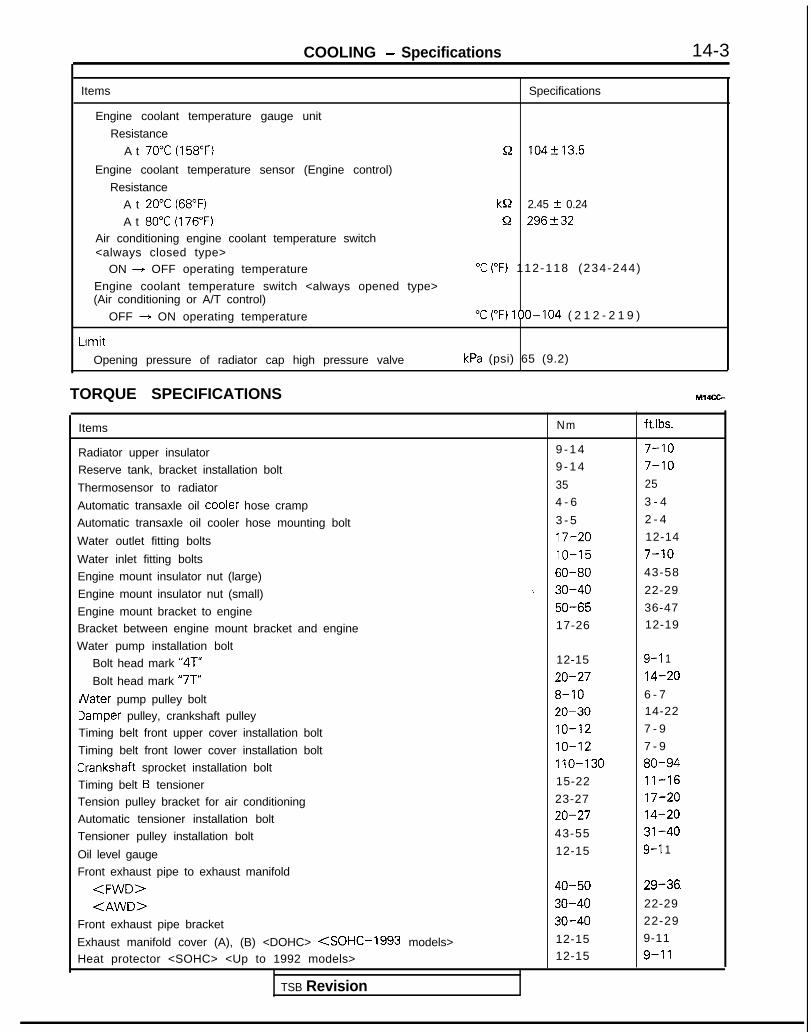
COOLING - Specifications 14-3
Items Specifications
Engine coolant temperature gauge unit
Resistance
A t 70°C (158°F) n 104f13.5
Engine coolant temperature sensor (Engine control)
Resistance
A t 20°C (68°F) kQ 2.45 f 0.24
A t 80°C (176°F) Q 296+32
Air conditioning engine coolant temperature switch<always closed type>
ON + OFF operating temperature “C (“F) 112-118 (234-244)
Engine coolant temperature switch <always opened type>(Air conditioning or A/T control)
OFF + ON operating temperature “C (“F) 100-104 ( 2 1 2 - 2 1 9 )
Limit
Opening pressure of radiator cap high pressure valve kPa (psi) 65 (9.2)
TORQUE SPECIFICATIONS MWCG-
Items Nm ft.lbs.
Radiator upper insulator 9 - 1 4 7-10
Reserve tank, bracket installation bolt 9 - 1 4 7-10
Thermosensor to radiator 35 25
Automatic transaxle oil coole: hose cramp 4 - 6 3 - 4
Automatic transaxle oil cooler hose mounting bolt 3 - 5 2 - 4
Water outlet fitting bolts 17-20 12-14
Water inlet fitting bolts IO-15 7-10
Engine mount insulator nut (large) 60-80 43-58
Engine mount insulator nut (small) \ 30-40 22-29
Engine mount bracket to engine 50-65 36-47
Bracket between engine mount bracket and engine 17-26 12-19
Water pump installation bolt
Bolt head mark “4T” 12-15 9-l 1
Bolt head mark “7T” 20-27 14-20
dater pump pulley bolt 8-10 6 - 7
Jamper pulley, crankshaft pulley 20-30 14-22
Timing belt front upper cover installation bolt IO-12 7 - 9
Timing belt front lower cover installation bolt IO-12 7 - 9
Crankshaft sprocket installation bolt 110-130 80-94
Timing belt B tensioner 15-22 11-16
Tension pulley bracket for air conditioning 23-27 17-20
Automatic tensioner installation bolt 20-27 14-20
Tensioner pulley installation bolt 43-55 31-40
Oil level gauge 12-15 9-l 1
Front exhaust pipe to exhaust manifold
<FWD> 40-50 29-36.
<AWD> 30-40 22-29
Front exhaust pipe bracket 30-40 22-29
Exhaust manifold cover (A), (B) <DOHC> <SOHC-l993 models> 12-15 9-11
Heat protector <SOHC> <Up to 1992 models> 12-15 9-11
TSB Revision

14-4 COOLING - Specifications
Items
Exhaust manifold to cylinder head<SOHC> <Up to 1992 models>
< 1993 models>
< D O H C >Engine hanger to engine bracket
Oxygen sensor
Water inlet pipe installation boltTransaxle side
Engine block side <Up to 1992 models>< 1993 models>
Engine coolant temperature gauge unit
Engine coolant temperature sensor (Engine control)
Air conditioning engine coolant temperature switch <always closed type>
Engine coolant temperature switch <always opened type>(Air conditioning or A/T control)Rocker cover installation bolt
Exhaust manifold to turbocharger
Eye bolt (oil pipe)Air outlet fitting installation bolt
Water pipe B
Front exhaust pipe to turbocharger
Eye bolt (water pipe)
Water pipe B clampOil return pipe
Water hose installation bolt<M8>
<M6>
Nater hose to turbocharger
Ixhaust pipe support bracket
Exhaust pipe support bracket to front exhaust pipe
Nm ft.lbs.
15-20 11-14
25-30 18-2227-33 20-2325-30 18-2212-15 9-11
40-50 29-36
43-55 31-40
IO-15 7-10
12-15 9-11
IO-12 7 - 9
20-40 14-29
30-40 22-29
IO-14 8-10
5 - 7 4 - 5
55-65 40-47
14-19 IO-14
9 - 1 4 7-10
40-50 29-36
40-60 29-43
35-50 25-36
IO-12 7 - 9
8-10 6 - 7
12-15 9-11
IO-12 7 - 9
8-10 6 - 730-42 22-30
30-40 22-29
LUBRICANT Ml4CD-
Item
Engine coolant
Specified lubricant
High quality ethylene glycol antifreeze coolant
Quantity
6.5 dm3(6.9 qts.)
SEALANT M14CE-
Items Specified sealant
Engine coolant temperature sensor (Engine control) 3M nut locking Part No.4171 or equivalent
Air conditioning engine coolant temperature switch <alwaysclosed type>
Engine coolant temperature switch <always opened type>(Air conditioning or A/T control)
Engine coolant temperature gauge unit 3M ATD Part No.8660 or equivalent
TSB Revision
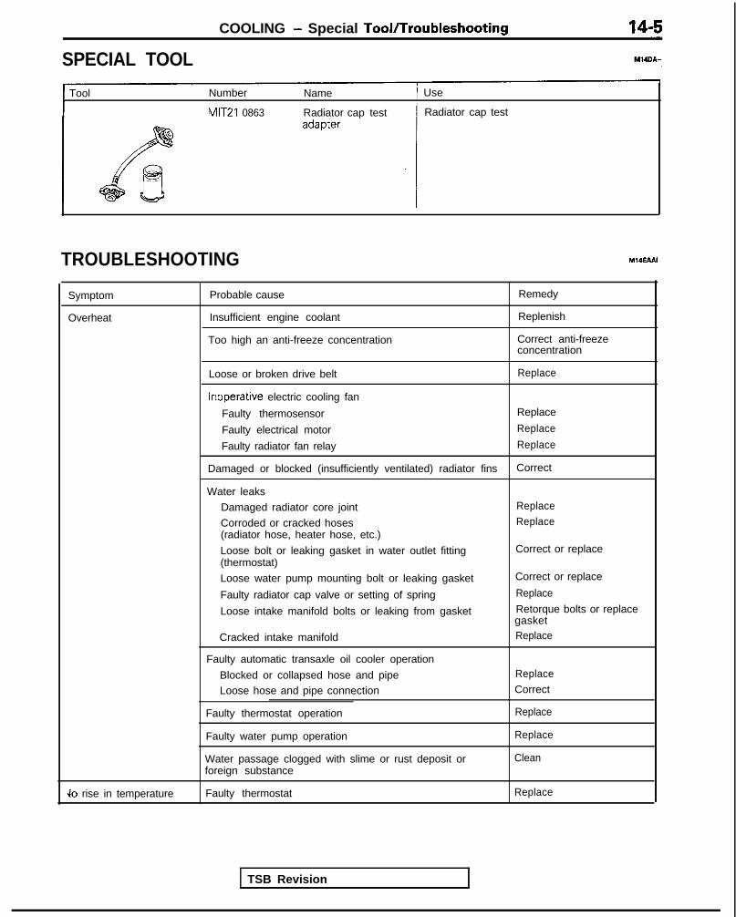
COOLING - Special TooVTroubleshooting
SPECIAL TOOL
1 Tool Number Name 1 Use
MIT21 0863 Radiator cap test Radiator cap test
TROUBLESHOOTING M14EAAI
Symptom
Overheat
Probable cause
Insufficient engine coolant
Too high an anti-freeze concentration
Remedy
Replenish
Correct anti-freezeconcentration
Loose or broken drive belt Replace
Inoperative electric cooling fan
Faulty thermosensor Replace
Faulty electrical motor Replace
Faulty radiator fan relay Replace
Damaged or blocked (insufficiently ventilated) radiator fins Correct
Water leaks
Damaged radiator core joint Replace
Corroded or cracked hoses Replace(radiator hose, heater hose, etc.)
Loose bolt or leaking gasket in water outlet fitting(thermostat)
Loose water pump mounting bolt or leaking gasket
Faulty radiator cap valve or setting of spring
Loose intake manifold bolts or leaking from gasket
Cracked intake manifold
Faulty automatic transaxle oil cooler operation
Blocked or collapsed hose and pipeLoose hose and pipe connection
Faulty thermostat operation
Faulty water pump operation
Water passage clogged with slime or rust deposit orforeign substance
Correct or replace
Correct or replace
Replace
Retorque bolts or replacegasketReplace
Replace
Correct
Replace
Replace
Clean
Jo rise in temperature Faulty thermostat Replace
TSB Revision

14-6 COOLING - Troubleshooting
CIRCUIT DIAGRAM
<Non-Turbo (FWD, AWD-M/T)>
IGNJvJ
ccc
c
IONH(IG2)
W&FUj$?LE
C-24
3 CONDENSERFAN MOTOR
5r;
5
(GY)(GY)
,,43AExAy4x3,“4 s
[“1 “1 "2
RADIATOR RADIATORFAN MOTOR + FAN MOTOR
1 RELAYCHI) g RELAYCLO)J 5 E
d
I I
THERM0 SENSORON:85’C
(185’F)OFF38 C
(172’Fl
A-29
* 2-E
40---4
g 51
Pu
4 11di
FAN MOTOR
2CONDENSERFAN MOTORRELAY (HI)
&WE;""
A-15a3ON:1800kPa
e56Ds I )
OFF:1500kPe(233DSl)
KXBS-AC-HOEIf-NY
TSB Revision

COOLING - Troubleshootina 14-7
L
<Non-Turbo (AWD-A/T), Turbo>
ICSk-iNIq
ci
'ION:H(IG2)
W&FUS$BLEAUTOCOMPRESSORCONTROL UNIT
A-29
'RADIATORFAN MOTOR
43 RELAYCHI)cu
A-29
RESISTOR>'Mf AToR
m
ON:SSCOFF -p (165'F)OFF:?8’C
(172’F)
$5m6 ‘5I% 66 .
B-22-4 m ?
"AOFF-ON: 102’ C 0
KX35-AC-H0612-NY
I(GY) ;
2 "1 "1
;-' SX!D%%
BRELAY(L0)
0? -N
d0-
A-24
2
f
A-15
I /OFF GE31 0N:lBOOkPa
(256DS II
0FF:lSOOkPs
2(213PSl)
OPERATION
l When the engine coolant temperature reachesapproximately 85°C (185°F) in the ignition switch“ON” position, the therm0 sensor is turned onto flow electricity through the radiator fan motorrelay (coil) and the therm0 sensor to the ground.The radiator fan motor relay contact will beclosed.
l Then, electricity will flow through the radiator
fan motor and the radiator fan motor relay(contact) to the ground to rotate the radiator fanmotor.
NOTEFor models equipped with the air conditioning,refer to GROUP 55-Troubleshooting for in-formation concerning the operation of the con-denser fan.
TSB Revision

14-8 COOLING - Service Adjustment Procedures
T210863
SERVICE ADJUSTMENT PROCEDUl$t&
ENGINE COOLANT LEAK CHECK1. Loosen radiator cap.2. Confirm that the engine coolant level is up to the filler
neck.3. Install a radiator cap tester to the radiator filler neck and
apply 160 kPa (23 psi) pressure. Hold pressure for. twominutes, while checking for leakage from the radiator,hose or connections.
CautionBe sure to completely clean away any moisture fromthe places checked.When the tester is removed, be careful not to spill anyengine coolant from it.Be careful, when installing and removing the testerand when testing, not to deform the filler neck of theradiator.
4. If there is leakage, repair or replace the appropriate part.
RADIATOR CAP PRESSURE TEST MlOFBAA
1. Use a special tool to attach the cap to the tester.2. Increase the pressure until the indicator of the gage stops
moving.
Limit: 65 kPa (9.2 psi)Standard value: 75- 105 kPa (1 1 - 15 psi)
3. Replace the radiator cap if the reading does not remain ator above the limit.
NOTEBe sure that the cap is clean before testing, since rust orother foreign material on the cap seal will cause an im-proper indication.
ENGINE COOLANT REPLACEMENT MMFCAARefer to GROUP 00-Maintenance Service.
ENGINE COOLANT CONCENTRATION TEST,,wti
Refer to GROUP 00-Maintenance Service.
TSB Revision

COOLING - Radiator
RADIATORREMOVAL AND INSTALLATION
14-9
M14OA-
Pre-removal and Post-installation
@Draining and Supplying of the En-gine Coolant(Refer to GROUP 00-Maintenancekervice.)
9-14 Nm
(j/-&j
:Vehicles with anti-lock&braking system>
9-14 Nm7-10 ft.lbs.
4 - 6 Nm3-4 ftlbs.
04AOO48
2-4 ft.lbs.
Removal steps1. Branch tube bracket <Non-Turbo>2. Branch tube <Non-Turbo>3. Radiator cap4. Drain plug5. Overflow tube6. Reserve tank
41) l + 7. Radiator upper hose+e ,+ 8. Radiator lower hosea+ 9. Automatic transaxle oil cooler hoses
<Vehicles with A/T>10. Therm0 sensor connector11. Radiator fan motor COnneCtOr
12. Condenser fan motor connector<Non-Turbo (FWD, AWD-MIT&Vehicleswith air conditioning>
13. Upper insulator14. Radiator assembly15. Radiator fan motor assembly16. Condenser fan motor assembly
<Non-Turbo (FWD, AWD-M/T)-Vehicleswith air conditioning>
17. Therm0 sensor18. Lower insulator
TSB Revision

14-10 COOLING - Radiator
‘I !--.
\
\I 8005mo20
SERVICE POINTS OF REMOVAL MlIOBAH
7. REMOVAL OF RADIATOR UPPER HOSE/& RADIATORLOWER HOSE
After making mating marks on the radiator hose and thehose clamp, disconnect the radiator hose.
:Non-Turbo (FWD, AWD-M/T)>
04AOO23
:Non-Turbo (AWD-A/T), Turbo>
-I- -.
1 TSB Revision I
9. DISCONNECTION OF AUTOMATIC TRANSAXLE OILCOOLER HOSES
Use a plug or otherwise cover the hose and nipple part ofthe radiator so that dust, dirt, foreign materials, etc. do notenter after the hose has been disconnected from theradiator.
INSPECTION MWQCANa Check for foreign material between radiator fins.l Check the radiator fins for bent, or damage.l Check the radiator for corrosion, damage, rust or scale.a Check the radiator hoses for cracks, damage or deteriora-
tion.l Check the reserve tank for damage.l Check the automatic transaxle oil cooler hoses for cracking,
damage or deterioration.
RADIATOR FAN MOTOR INSPECTION
(1) Check to be sure that the radiator fan rotates when batteryvoltage is applied between terminals (as shown in thefigure).
(2) Check to see that abnormal noises are not produced,while motor is turning.

COOLING - Radiator 14-11
04A0020
A
B’ - WaterI
423°C (725°F)temperature
TSB Revision
RESISTOR INSPECTION <Non-Turbo (AWD-ATT), Turbo>
(1) Remove‘ the radiator fan motor connector.(2) Measure the resistance between terminals 0 and @.(3) It can be judged OK if the resistance value is within the
following range.
Resistance value: 0.26-0.32 Q
THERM0 SENSOR INSPECTION
Check for continuity with the therm0 sensor in hot water.
NOTEImmerse therm0 sensor in hot water up to mounting thread tocheck for continuity.
Standard value:Continuity at 82-88”C (180-190°F) . . . . . . . . . . . . . . . at A pointNo continuity at 7844°C (172-183°F) . . . . . . . . . . . at B point
RADIATOR FAN MOTOR RELAY INSPECTION
(1) Remove radiator fan motor. relay from engine room relaybox.

14-12 COOLING - Radiator/Radiator Fan Motor Assembly
Circuit tester
\, :1,h\‘\‘-:--
t‘\1 11 @00510020
(2) Connect battery to terminal 2 and check continuitybetween terminals with terminal 1 grounded.
SERVICE POINTS OF INSTALLATION M14OOAF
8. INSTALLATION OF RADIATOR LOWER HOSEI7. RADIA-TOR UPPER HOSE
Align the mating marks on the radiator hose and hoseclamp and then connect them; then, applying force in thedirection indicated by the arrow in the illustration, seat theclamp to the trace marks of the previous connection.
CautionBe sure to install the hose clamps at the trace marks ofthe previous connection.
RADIATOR FAN MOTOR ASSEMBLY MlITA-
DISASSEMBLY AND REASSEMBLY
Disassembly steps1. Fan2. Radiator fan motor3. Resistor
<Non-Turbo (AWD-AIT), Turbo>4. Shroud 04AOO22
TSB Revision 1

COOLING - Thermostat
THERMOSTATREMOVAL AND INSTALLATION
14-13
M14GE-
00-Maintenance
<DOHC>
17-20 Nm
i/
12-14 ft.lbs.
17-20 Nm12-14 ft.lbs.
3
5lEl
6
< 1993 models>
lo-15 N7-10 ft.l
Removal steps~~ w+ 1. Connection for radiator upper hose~~ ~~ 2. Connection for radiator lower hose
3. Water outlet fitting4. Water inlet fitting5. Gasket
~~ 6. Thermostat 04AO211
SERVICE POINTS OF REMOVAL m14GcAA
1. DISCONNECTION OF RADIATOR UPPER HOSE/Z.RADIATOR LOWER HOSE
After making mating marks on the radiator hose and thehose clamp, disconnect the radiator hose.
INSPECTION M14GDAl
l Check that valve closes tightly at room temperature.l Check for defects or damage.l Check for rust or encrustation on valve. Remove if any.0 Immerse thermostat in container of water. Stir to raise
water temperature and check that thermostat valve openingtemperature and the temperature with valve fully open[valve lift-over 8 mm (.31 in.)] are at the standard value.
04UOO16
TSB Revision I

14-14 COOLING - Thermostat
04UOO18
<SOHC><Up to 1992 models>
< 1993 models>
04AOlZI
Standard value:Valve opening temperature
DOHC, SOHC 8VALVESOHC 1 GVALVE
Full-open temperatureDOHC, SOHC 8VALVESOHC 16VALVE
NOTE
88°C (19O’F)82°C (180°F)
100°C (212°F)95°C (203°F)
Measure valve height when fully closed. Calculate lift bymeasuring the height when fully open.
SERVICE POINTS OF INSTALLATION MWGEAG
6. INSTALLATION OF THERMOSTAT
Install the thermostat so that the flange fits perfectly to therecessed seat of the thermostat case or intake manifold.
2. CONNECTION OF RADIATOR LOWER HOSE/1. RADIATOR UPPER HOSEAlign the mating marks on the radiator hose and hoseclamp and then connect them; then seat the clamp to thetrace marks of the previous connection.
CautionIf the radiator hose and hose clamp mating marks arenot aligned and installed, water leaks may occur.
TSB Revision

COOLING - Water Pump <SOHC>
WATER PUMP <SOHC>REMOVAL AND INSTALLATION
14-15
M14MEA
? /’I
50-65 Nm36-47 ft.lbs. a
(Refer to GROUP 00-Maintenance
Post-installation Operation*Installation of the Under Cover*Supplying of the Engine Coolant
(Refer to GROUP 00-MaintenanceService.)
aEngine Adjustment(Refer to GROUP 1 l-ServiceAdjustment Procedures.)
/30-40 Nm22-29 ft.lbs.
14-22 ft.lb= \6
03AOl39
Removal steps
I 23-27 Nm3 IT-20 ft.lbs.
OlAOOlO
I. Clamp part of hoses (Power steering andair conditioning)
2. Engine mount bracket3. Drive belt (Air conditioning) (Refer t0
GROUP 00-Maintenance Service.)4. Drive belt (Power steering) (Refer to
GROUP 00-Maintenance Service.)5. Drive belt (Refer to GROUP OO-
Maintenance Service.)6. Tension pulley bracket7. Water pump pulley (Power steering)8. Water pump pulley9. Damper pulley
TSB Revision 1

14-16 COOLING - Water Pump <SOHC>
<Up to 1992 models>
5-7 N m
/
4-5 ftlbs.
14 20-27 NmI 14-20 ftlbs. 24 ’
\ ‘G\@;&
\ “7”f=-is .I n 23
ii-16 ftlbs.
i2-15 Nm9- 11 ft.lbs.
03AOWO
10. Spark plug cableII. Rocker cover (Refer to GROUP ll-
Timing Belt)12. Rocker cover gasket13. Semi-circular packing (Refer to GROUP
11 -Timing Belt)14. Timing belt front upper cover (Refer to
GROUP 11 -Timing Belt)
22. Timing belt B (Referto GROUP ll-Timing Belt B.)
23. Generator bracel 424. Water pump
25. Water pump gasket1)+26. O-ring
15. Timing belt front lower cover (Refer toGROUP 11 -Timing Belt)
18. Timing belt (Refer to GROUP 11 -TimingBelt)
19. Crankshaft sprocket20. Flange (Refer to GROUP 11 -Timing Belt B.)21. Timing belt B tensioner
1 TSB Revision

COOLING - Water Pump <SOHC> 14-w
10-7 - 9
Cl993 models>
43-55 Nm31-40 ftlbs.
\20-27 Nm14-20 ftlbs.
3-3.5 Nm I2.2-2.5 ftlbs.
y
12 Nmftlbs.
i,4-2Oft.l;~
Nrn’x@<,I 1-16 ft.lbs.
,OlAO675
I110-130 Nm80-94 ft.lbs.
11. Rocker cover (Refer to GROUP11 -Timing Belt.)
12. Rocker cover gasket14. Timing belt front upper cover (Refer to
GROUP 11 -Timing Belt.)15. Timing belt front lower cover (Refer to
GROUP 11 -Timing Belt.)16. Automatic tensioner (Refer to GROUP
11 -Timing Belt.)17. Tension pulley18. Timing belt (Refer to GROUP 11 -Timing
Belt.)
20. Flange (Refer to GROUP 11 -Timing BeltB.1
21. Timing belt B tensioner22. Timing belt B (Refer to GROUP
11 -Timing Belt B.)23. Generator brace
+424. Water pump25. Water pump gasket
++26. O-ring
19. Crankshaft sprocket
1 TSB Revision

14-18 COOLING - Water Pump <SOHC>
Quality canvas
Core wire
\\Adhesive rubber\
Rib rubber lCOO29
Water pump
J--iLi+O-ring
Water pipe
I I
SERVICE POINTS OF REMOVAL Ml4MCAK
2. REMOVAL OF ENGINE MOUNT BRACKET
(1) Place a wooden block at the oil pan part of the engine, andthen jack up the vehicle.
CautionJack up carefully, so as not to apply a load to each part.
(2) Remove the engine mount bracket.
5. REMOVAL OF DRIVE BELT
Before removing the V-ribbed belt, loosen the water pumppulley installation bolt.
INSPECTIONV-RIBBED BELT
M14MDAG
Check following items and replace if faulty.l Check belt surface for damage, peeling or cracks.l Check belt surface for oil or grease.l Check belt rubber for wear or brittleness.l Check the pulleys for cracks or damage.
WATER PUMP
l Check each part for cracks, damage or wear, and replacethe water pump assembly if necessary.
l Check the bearing for damage, abnormal noise andsluggish rotation, and replace the water pump assembly ifnecessary.
l Check the seal unit for leaks, and replace the water pumpassembly if necessary.
l Check for water leakage. If water leaks from hole “A”, sealunit is leaking. Replace as an assembly.
SERVICE POINTS OF INSTALLATION Ml4MEAm26. INSTALLATION OF O-RING
Insert the O-ring to the water inlet pipe, and coat the outercircumference of the O-ring with water.By coating with water, the insertion to the water pump willbecome easier.
Caution1. Care must be taken not to permit engine oil or other
greases to adhere to the O-ring.2. When inserting the pipe, check to be sure that there
is no sand, dirt, etc. on its inner surface.
1 TSB Revision
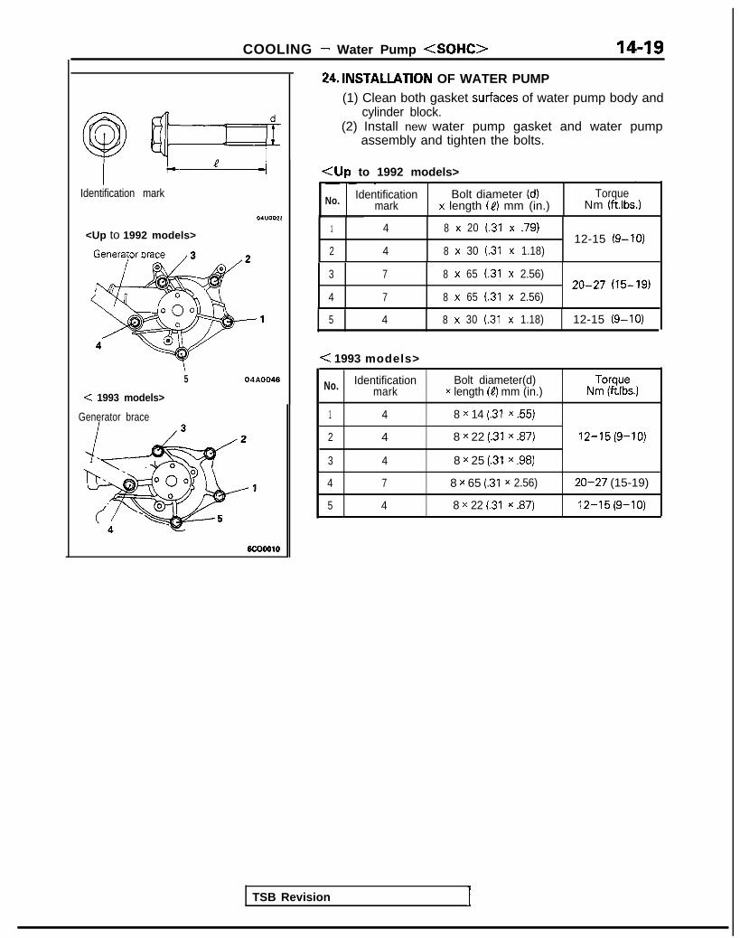
COOLING - Water Pump <SOHC> 14-19
Identification mark
<Up to 1992 models>
5 04A0046
< 1993 models>
Generator brace
6c00010
24.lNSTALLATlON OF WATER PUMP(1) Clean both gasket surfaces of water pump body and
cylinder block.(2) Install new water pump gasket and water pump
assembly and tighten the bolts.
<Up to 1992 models>
No. Identification Bolt diameter (d) Torquemark x length (C) mm (in.) Nm (ftlbs.)
1 4 8 x 20 (31 x .79)12-15 (g-10)
2 4 8 x 30 (.31 x 1.18)
3 7 8 x 65 (.31 x 2.56)20-27 (15-19)
4 7 8 x 65 (.31 x 2.56)
TSB Revision 1
5 4 8 x 30 (31 x 1.18) 12-15 (9-10)
< 1993 models>
No. Identification Bolt diameter(d)mark x length (4) mm (in.) N~i-.“s.)
1 4 8 x 14 (.31 x 55)
2 4 8 x 22 (.31 x .87) 12-15(9-10)
3 4 8 x 25 (.31 x .98)
4 7 8 x 65 (31 x 2.56) 20-27 (15-19)
5 4 8 x 22 (.31 x .87) 12-15(9-10)

14-20 COOLING - Water Pump <DOHC>
WATER PUMP <DOHC> M14ME6
REMOVAL AND INSTALLATION w .I50-65 Nm
(Refer to GROUP 00-Maintenance
Post-installation Operation*Installation of the Under Cover*Supplying of the Engine Coolant
(Refer to GROUP 00-MaintenanceService.)
aEngine Adjustment(Refer to GROUP 11-ServiceAdjustment Procedures.)
30-40 Nm22-29 ft.lbs.
12-19 ft.lbs.
OlA0308
20-27 Nm14-20 ft.lbs. /
8-10 Nm6-7 ftlbs.
IO-12 Nm7-9 ft.lbs.
b..43-55 Nm31-40 ft.lbs.
v
&l-30 Nm 23-27 Nm14-22 ftlbs. 17-20 ft.lbs. OlA0113
Removal steps1. Clamp part of hoses (Power steering and
air conditioning)2. Engine mount bracket (Refer to P.14-18.)3. Drive belt (Refer to GROUP OO-
Maintenance Service.)4. Drive belt (Power steeringj (Refer to
GROUP 00-Maintenance Service.)5. Tension pullev bracket6. Drive belt (Air conditioning) (Refer to
10. Timing belt upper cover (Refer to GROUP11 -Timing Belt.)
11. Timing belt lower cover (Refer to GROUP11 -Timing Belt.)
12. Automatic tensioner (Refer to GROUP11 -Timing Belt.)
13. Tensioner pulley14. Timing belt (Refer to GROUP 11 -Timing
Belt B.)GROUP 00-Maintenance Service.)
7. Water pump pulley8. Water pump pulley (Power steering)9. Crankshaft pulley
1 TSB Revision I

COOLING - Water Pump <DOHC> 14-21
15. Crankshaft sprocket15. Crankshaft sprocket16. Flange (Refer to GROUP 11 -Timing Belt16. Flange (Refer to GROUP 11 -Timing Belt
B.)B.)17. Timing belt B tensioner17. Timing belt B tensioner18. Timing belt B (Refer to GROUP II-
Timing Belt B.)19. Generator brace
*4 20. Water pump .,.21. Water pump gasket C.’22. O-ring (Refer to P.14-18.) .‘* .
18. Timing belt B (Refer to GROUP ll-Timing Belt B.)
19. Generator brace*4 20. Water pump .,.
21. Water pump gasket C.’22. O-ring (Refer to P.14-18.) .‘* 1
TSB RevisionTSB Revision
20-2714-20
olAol4

14-22 COOLING - Water Pump <DOHC>
ldeniification mark
Generator brace
INSPECTIONV-RIBBED BELT
Refer to P.14-18.
Ml4mDAN
WATER PUMP
0 Check each part for cracks, damage or wear, and replacethe water pump assembly if necessary.
l Check the bearing for damage, abnormal noise andsluggish rotation, and replace the water pump assembly ifnecessary.
l Check the seal unit for leaks, and replace the water pumpassembly if necessary.
l Check for water leakage.
SERVICE POINTS OF INSTALLATION MMMEAU
20. INSTALLATION OF WATER PUMP
(1) Clean both gasket surfaces of water pump body andcylinder block.
(2) Install new water pump gasket and water pumpassembly and tighten the bolts.
No, identification Bolt diameter (d)mark x length (4) mm (in.) NmT”iptK.)
1 4 8 x 14 (.31 x ,551
2 4 8 x 22 (.31 x ,871 12-15 (9-10)
3 4 8 x 30 t.31 x 1.18)
4 7 8 x 65 (.31 x 2.56) 20-27 (15-l 9)
5 4 8 x 28 (.31 x 1.10) 12-15 (9-10)
TSB Revision
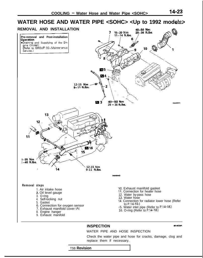
COOLING - Water Hose and Water Pipe <SOHC> 14-23
WATER HOSE AND WATER PIPE <SOHC> <Up to 1992 models>MldA-A
REMOVAL AND INSTALLATION
Pre-removal and Post-installation
*Draining and Supplying of the En-
(Refer to GROUP 00-Maintenance
12-15 Nmg-11 ft.lbs.
7 15-20 Nm
Ill329 - 36 fths.
\ 12-15 Nm9-11 ft.lbs.
Mbm42
Removal steps1. Air intake hose2. Oil level gauge3. O-ring4. Self-locking nut5. Gasket6. Connection for oxygen sensor7. Exhaust manifold cover (A)8. Engine hanger9. Exhaust manifold
10. Exhaust manifold gasket11. Connection for heater hose12. Water by-pass hose13. Water hosei41 Connection for radiator lower hose (Refer
to P.14-IO.)I 5. Water inlet pipe (Refer to P.14-18.)16. O-ring (Refer to P.14-18.)
INSPECTION Ml4lcAA
WATER PIPE AND HOSE INSPECTION
Check the water pipe and hose for cracks, damage, clog andreplace them if necessary.
ITSB Revision

14-24 COOLING - Water Hose and Water Pipe <SOHC>
WATER HOSE AND WATER PIPE <SOHC> <I993 models> M141A-B
REMOVAL AND INSTALLATION
Pre-removal and Post-installationODeration*braining and Supplying of the Engine
12-15 Nm
4(,-s‘, ,,,,,, /29-36 ftlbs.
/
, ‘r- y’ ft”bs.\.
30-40 Nm \
22-29 ft.lbs.‘,L.\
‘7;\ “.‘i
\
Removal steps1. Condenser fan motor assembly
<Vehicles with air conditioning>2. Self-locking nut3. Gasket
6. Self-locking nut ’7. Engine hanger8. Exhaust manifold9. Exhaust manifold gasket
10. Exhaust manifold cover (6)4. Connection for oxygen sensor connector5. Exhaust manifold cover (A)
TSB Revision

COOLING - Water Hose and Water Pipe <SOHC> ,I 4-25
7-lOft.lbs.
04AO123
11. Connection for heater hose12. Water by-pass hose13. Water hose14. Connection for thermostat case15. Water inlet pipe16. O-ring
TSB Revision
INSPECTION M07cAAal
WATER PIPE AND HOSE INSPECTIONCheck the water pipe and hose for cracks, damage, clog andreplace them if necessary.
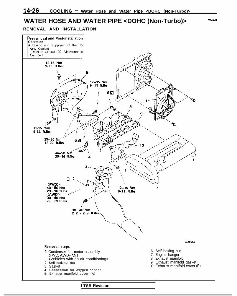
14-26 COOLING - Water Hose and Water Pipe <DOHC (Non-Turbo)>
WATER HOSE AND WATER PIPE <DOHC (Non-Turbo)>REMOVAL AND INSTALLATION
MlUA-B
IF‘re-removal and Post-installationOperationeDraIning and Supplying of the En-
glne Coolant(Refer to GROUP 00-MaintenanceService.)
12-15 Nm9-11 ftlbs.
12-15 ‘Nm9-11 ft.lbs.
25-30 Nm ’ 718-22 ft.lbs.
68A
40 50 Nm’&\29136 ft.lbs. 4 I b.
q 2, h<FWD>40-50 Nm
9-11 ft.lbs.
30-40 Nm22 - 29 ft.lbs.
30-40 Nm\2 2 - 2 9 ft.lbs. \
OSAOOSS
Removal steps1. Condenser fan motor assembly
(FWD, AWD-M/T)<Vehicles with an air conditioning>
2 Self-locking nut3. Gasket4. Connect ion for oxygen sensor5. Exhaust manifold cover (A)
6. Self-locking nut7. Engine hanger8. Exhaust manifold9. Exhaust manifold gasket
10. Exhaust manifold cover (B)
1 TSB Revision

COOLING - Water Hose and Water PiDe <DOHC /Non-Turbo)> 14-27
-55 Nm
Removal steps11. Connection for oxygen sensor and
control harness12. Water hose13. Water by-pass hose14. Connection for heater hose15. Connection for radiator lower hose (Refer
to P.14-10.)16. Water inlet pipe (Refer to P.14-18.)17. O-ring (Refer toP.14-18.)
04A0050
TSB Revision

14-28 COOLING - Water Hose and Water Pipe <DOHC (Turbo)>
WATER HOSE AND WATER PIPE <DOHC (Turbo)><Up to 1992 models>
Pre-removal and Post-installation Operation 1eDraining and Filling of the Engine Coolant
(Refer to GROUP 00-Maintenance Service.)*Draining and Filling of the Engine Oil
(Refer to GROUP 11 -Service Adjustment Pro-cedures.)
REMOVAL AND INSTALLATION
12-15 Nm9-l 1 ft.lbs.
25-30 Nm18-24 ft.lbs.
M141A-C
‘1
Flare nut
55-65 N m/-A 40-47 ft.lbs.
12-15 Nk9-11 ftlbs.
30-40 Nm22-29 ft.lbs:
,“k.
Removal stepsI. Radiator (Refer to P.14-9.)2. Connection for air intake hose3. Connection for vacuum hose4. Connection for air hose A5. Air outlet fitting6. Gasket7. Heat protector A8. Heat protector B9. Self-locking nut
10. Engine hanger
\40-50 Nm29-36 ftlbs.
05Aoo54\
40-60 Nm29-43 ft.lbs.
II. Eye bolt12. Gasket13. Connection for water hoseI 4. Connection for water pipe B15. Self-locking nut16. Gasket -17. Exhaust manifold18. Exhaust manifold gasket19. Ring20. Gasket
i TSB Revision

- Wntmr Hncn and Water Pine < D O H C (Turbo)> 14-29
21. Connection for oxygensensor harness connector
22. Oil return pipe23. Gasket
+, I)+ 24. Turbocharger25. Eye bolt26. Gasket27. Water pipe B28. Eye bolt29. Gasket30. Water pipe A
27
35-50 Nm
8-10 Nm6-7 ftlbs. 230
/ ’ ,! I,!, ” /40 s-i1 ft.lbs.
lo-12 Nm 30-40 N m 22-3t7 - 9 ft.lbs. 22-29 ft.lbs.
04c.0116
! Nm1 ftlbs.
31. Water hose (To turbocharger)32. Water hose33. Water by-pass hose34. Connection for heater hose35. Water hose36. Water hose
37. Water hose38. Exhaust pipe support bracket39. Water pipe40. Water inlet pipe (Refer to P.14-18.)41. O-ring (Refer to P.14-18.)
TSB Revision 1

14-30 COOLING - Water Hose and Water Pipe <DOHC (Turbo)>
05AOO26
SERVICE POINTS OF REMOVAL MWBAG
24. REMOVAL OF TURBOCHARGER ASSEMBLY
Remove the turbocharger assembly with the exhaustfitting, water pipe A, water pipe B and the oil pipe attachedto it.
INSPECTIONWATER PIPE AND HOSE INSPECTION
Refer to P.14-23.
Ml4lcAE
SERVICE POINTS OF INSTALLATION MWDAR
24. INSTALLATION OF TURBOCHARGER ASSEMBLY
Clean the alignment surfaces shown in the illustration.
CautionWhen cleaning, care must be taken so that a piece ofthe gasket does not enter the oil passage hole.
TSB Revision

COOLING -Engine Coolant Temperature Gauge Unit, Engine CoolantTemoerature Sensor and Engine Coolant Temperature Switch 14-31
ENGINE COOLANT TEMPERATURE GAUGE UNIT, ENGINE COOLANTTEMPERATURE SENSOR AND ENGINE COOLANT TEMPERATURESWITCH M14oE-REMOVAL AND INSTALLATION <DOHC>
30-40 Nm /
gine Coolant lo-14 Nm(Refer to GROUP 00-Maintenance 8-10 ft.lbs.Service.)
/ I r lcooloSealant: 3M ATD Part No.8660
or equivalent04A0118
<SOHC><Up to 1992 models> < 1993 models>
10 12 Nrny~~~~~7-9 ft.lbs. 2
1. Engine coolant temperature gauge unit2. Engine coolant temperature sensor
(Engine control)3. Air conditioning engine coolant
temperature switch <always closedtype>
4. Engine coolant temperature switch, .<always opened type> (Air condltloningor A/T control)
Sealant: 3M Nut locking PartNo.4171 or equivalent
TSB Revision
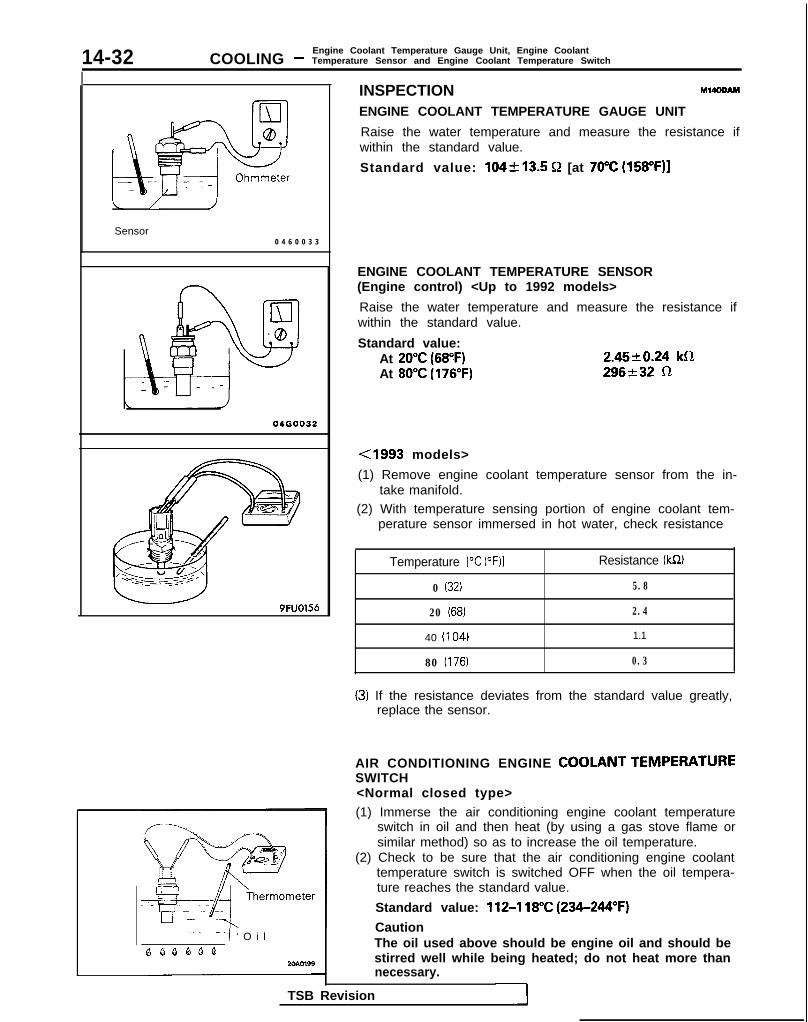
14-32 COOLING -Engine Coolant Temperature Gauge Unit, Engine CoolantTemperature Sensor and Engine Coolant Temperature Switch
/
Sensor
J
0 4 6 0 0 3 3
04GOO32
9FUO156
--- --I ‘ O i l
QQQQQQ2cmn99
INSPECTION M14OOAM
ENGINE COOLANT TEMPERATURE GAUGE UNIT
Raise the water temperature and measure the resistance ifwithin the standard value.
Standard value: 104k13.5 Q [at 70°C (158”F)]
ENGINE COOLANT TEMPERATURE SENSOR(Engine control) <Up to 1992 models>
Raise the water temperature and measure the resistance ifwithin the standard value.
Standard value:At 20°C (68°F)At 80°C (176°F)
2.4520.24 klR296232 R
<1993 models>
(1) Remove engine coolant temperature sensor from the in-take manifold.
(2) With temperature sensing portion of engine coolant tem-perature sensor immersed in hot water, check resistance
Temperature 1°C (OF)1 Resistance (kR)
0 (32) 5.8
20 (68) 2.4
40 (I 04) 1.1
80 (176) 0.3
(3) If the resistance deviates from the standard value greatly,replace the sensor.
AIR CONDITIONING ENGINE COOLANT TEMPERATURESWITCH<Normal closed type>(1) Immerse the air conditioning engine coolant temperature
switch in oil and then heat (by using a gas stove flame orsimilar method) so as to increase the oil temperature.
(2) Check to be sure that the air conditioning engine coolanttemperature switch is switched OFF when the oil tempera-ture reaches the standard value.
Standard value: 112-l 18°C (234-244°F)
CautionThe oil used above should be engine oil and should bestirred well while being heated; do not heat more thannecessary.
TSB Revision

COOLING -Engine Coolant Temperature Gauge Unit, Engine CoolantTemperature Sensor and Engine Coolant Temperature Switch 14-33
20R0586
ENGINE COOLANT TEMPERATURE SWITCH<Normal opened type>(Air conditioning or A/T control)
(1) Remove the engine coolant temperature switch from thewater outlet fitting.
(2) immerse the engine coolant temperature switch in oil andheat by a gas stove or similar method so as to increase theoil temperature.
(3) Check to be sure that the engine coolant temperatureswitch is switched ON when the oil temperature reachesthe standard value.
Standard value: lOO-104% (212-219°F)
CautionUse engine oil for this test; stir it well while heating,and do not heat more than necessary.
TSB Revision 1

NOTES

15-1
INTAKE ANDEXHAUST
CONTENTS Ml!iAn-
AIR CLEANER . . . . . . . . . . . . . a.. . . . . . . . . . . . . . . . . . . . 9
CHARGE AIR COOLER . . . . . . . . . . . . . . . . . . . . . . . . . 12
EXHAUST MANIFOLD<DOHC-Non-Turbo> . . . . . . . . . . . . . . . . . . . . . . . . 30
EXHAUST MANIFOLD<SOHC-8 VALVE> . . . . . . . . . . . . . . . . . . . . . . . . . . . 27
EXHAUST MANIFOLD<SOHC-16 VALVE> . . . . . . . . . . . . . . . . . . . . . . . . . 28
EXHAUST PIPE AND MAIN MUFFLER< D O H C > . . . . . . . . . . . . . . . . . . . . . . . . . . . . . . . . . . . . . . . . 33
EXHAUST PIPE AND MAIN MUFFLER< S O H C > . . . . . . . . . . . . . . . . . . . . . . . . . . . . . . . . . . . . . . . . 32
INTAKE MANIFOLD <DOHC> . . . . . . . . . . . . . . 21
INTAKE MANIFOLD<SOHC-8 VALVE> . . . . . . . . . . . . . . . . . . . . . . . . . . . 14
INTAKE MANIFOLD(SOHC-16 VALVE> . . . . . . . . . . . . . . . . . . . . . . . . . 18
SERVICE ADJUSTMENT PROCEDURES .... 6
Air Cleaner Element Inspection andReplacement ..... .:. . . . . . . . . . . . . . . . . . . . . . . . . . . . . 6
Intake Charge Pressure Control SystemInspection . . . . . . . . . . . . . . . . . . . . . . . . . . . . . . . . . . . . . . . 7
Turbocharger Bypass Valve Inspection ... . . . 8
Turbocharger Supercharging PressureInspection . . . . . . . . . . . . . . . . . . . . . . . . . . . . . . . . . . . . . . . 7
Turbocharger Waste Gate SolenoidInspection . . . . . . . . . . . . . . . . . . . . . . . . . . . . . . . . . . . . . . . 8
Intake Manifold VacuumInspection . . . . . . . . . . . . . . . . . . Refer to GROUP 11
SPECIAL TOOL .. . . . . . . . . . . . . . . . . . . . . . . . . . . . . . . . . 5
SPECIFICATIONS .. . . . . . . . . . . . . . . . . . . . . . . . . . . . . . 2
General Specifications . . . . . . . . . . . . . . . . . . . . . . . . . 2
Service Specifications . . . . . . . . . . . . . . . . . . . . . . . . . . 2
Torque Specifications . . . . . . . . . . . . . . . . . . . . . . . . . . 2
TROUBLESHOOTING ........................... 5Abnormal NoiseExhaust Gas Leakage
TURBOCHARGER .. . . . . . . . . . . . . . . . . . . . . . . . . . . . . . 24

15-2 INTAKE AND EXHAUST - Specifications
SPECIFICATIONSGENERAL SPECIFICATIONS MEch-
Items
Air cleanerElement
Exhaust systemFront exhaust pipe <Non-Turbo>Front exhaust pipe <Turbo>MufflerCouplingSuspension system
Turbocharger
TypeIdentification No.intake charge pressure control
Intercooler
Type
Specifications
Unwoven cloth type
Dual typeSingle typeExpansion resonance typeFlat couplingRubber hangers and O-rings
Exhaust gas turbine typeTD05H-14B-6Turbocharger waste gate actuator and valve
Air cooled type
SERVICE SPECIFICATIONS
Items
Intake and exhaust manifolds
Standard Limit
Distortion of cylinder head contacting surface mm (in.) Less than 0.15 (0059) 0.3 (.012)
Turbocharger waste gate solenoid terminal resistance[at 20°C (68”F)l 5-2 3 6 - 4 4
TurbochargerSupercharging pressure kPa (ps i ) 31-70 (4.4-10.1)
TORQUE SPECIFICATIONS
Items
Air cleanerAir cleaner to bodyAir ductResonatorBranch tube
Charge air coolerAir hose BAir pipe AAir pipe BTurbocharger by-pas valve to air pipe BCharge air cooler
Nm ft.lbs.
8-10 6-78-10 6-78-10 6-78-10 6-7
8-10 6-712-15 9-1112-15 9-1115-22 11-1612-15 9-11
TSB Revision

INTAKE AND EXHAUST - Specifications 15-3
Items ) Nm 1 ftlbs.
Intake manifold <SOHC>Accelerator cable to intake manifold plenumFuel high pressure hose to fuel railFuel rail to intake manifoldIgnition coil <8 VALVE>Intake manifold stayIntake manifold to engineThrottle body
<8 VALVE><I6 VALVE>
Intake manifold plenum stayIntake manifold plenum to intake manifoldWater outlet fittingEGR valve
(8 VALVE>Cl6 VALVE>
EGR temperature sensor <Vehicles for California>DistributorTherm0 valve <Vehicles for Federal>Control harness protector to intake manifold plenumVacuum pipe and hose assembly to intake manifold
ntake manifold <DOHC>Accelerator cable to intake manifoldThrottle body stayFuel high pressure hose to fuel railFuel rail to engineIntake manifold stayIntake manifold to engine
Mounting bolt (M8)Mounting nut and bolt (MIO)
Ignition coilIgnition power transistor unitThrottle bodyEGR valve
EGR temperature sensor <Vehicles for California>Control harness protector to intake manifoldControl harness clamp bolt
xhaust manifold <SOHC>Heat protector to exhaustExhaust manifold to engine
(8 VALVE>< 16 VALVE>
Oxygen sensorxhaust manifold <DOHC (Non-turbo)>
Exhaust manifold cover (A), (8)Engine hanger to engine mountEngine manifold to engineOxygen sensor
4-64-6IO-1312-1518-2515-20
3-43-47-99-1113-1811-14
IO-13 7-915-22 II-1615-20 II-1415-20 11-1417-20 12-14
IO-15 7-1117-26 13-18IO-12 7-9IO-13 7-920-40 14-284-6 3-48-12 6-8
4-6 3-415-22 II-164-6 3-4IO-13 7-925-30 18-22
15-2030-4220-27IO-1215-2215-22IO-124-6IO-12
II-1422-3014-207-911-1611-167-93-4
12-15
7-9
9-11
15-20 11-1425-30 18-2227-33 20-2340-50 29-36
12-15 9-1112-15 9-1125-30 18-2240-50 29-36
TSB Revision I

15-4 INTAKE AND EXHAUST - Specifications
Items
Exhaust manifold <DOHC (turbo)>Front exhaust pipe to exhaust fittingFront exhaust pipe to engineHeat protector (A), (B)
Engine oil level gauge guide mounting boltEngine hanger to engineExhaust manifold to engineExhaust manifold to turbochargerOil pipe to engine
Water pipe.(B) to water inlet pipeTurbocharger waste gate actuatorOxygen sensorWater pipe (B) to turbochargerAir outlet fittingOil pipe to turbochargerWater pipe (A) to turbocharger
Water pipe (A) mounting boltExhaust fittingOil return pipe
!xhaust manifold and turbochargerFront exhaust pipe to turbochargerFront exhaust pipe to engineHeat protector (A), (B)Engine hanger to engineExhaust manifold to engineExhaust manifold to turbocharger
Oil pipe to engineWater pipe (B) to water inlet pipeOxygen sensorWater pipe (B) to turbochargerAir outlet fittingOil pipe to turbochargerWater pipe (A) to turbocharger
W ater pipe (A) mounting boltExhaust fittingOil return pipe
Exhaust pipe and main mufflerFront exhaust pipe to exhaust manifold
<FWD><AWD (Non-Turbo)><AWD (Turbo)>
Front exhaust pipe clampRubber hangerFront exhaust pipe to catalytic converterCatalytic converter to center exhaust pipeHanger bracket to bodyHook to center exhaust pipeCenter exhaust pipe to main mufflerMoulding to main muffler
1 TSB Revision
N m
40-6030-4012-1512-1512-1525-3055-6514-1940-50IO-1340-5035-5017-2028-3435-50IO-1255-658-10
40-6030-4012-1512-1525-3055-6514-1940-5040-5035-5017-2028-3435-50IO-12
55-658-10
40-5030-4040-6030-40IO-1540-6030-40IO-15IO-1530-404 - 6
1
ft.lbs.
29-4322-299-119-119-1118-2240-4710-1429-367-929-3625-3612-1420-2525-367-940-476-7
29-4322-299-119-1118-2240-47IO-1429-3629-3625-3612-1420-2525-367 - 9
40-476-7
29-3622-2929-4322-297-1129-4322-297-117-1122-293 - 4
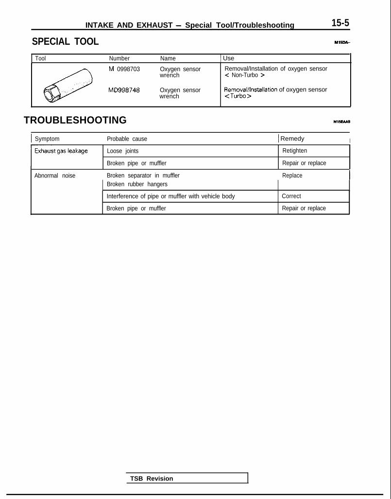
INTAKE AND EXHAUST - Special Tool/Troubleshooting 15-5
SPECIAL TOOL MlSDA-
Tool Number Name 1 Use
M 0998703
MD998748
Oxygen sensorwrench
Oxygen sensorwrench
Removal/Installation of oxygen sensor< Non-Turbo >
Removal/installation of oxygen sensor<Turbo>
TROUBLESHOOTING Yl5EAa8
I Symptom Probable cause 1 Remedy I
Loose joints
Broken pipe or muffler
Retighten
Repair or replace
Abnormal noise Broken separator in muffler ReplaceBroken rubber hangers
Interference of pipe or muffler with vehicle body
Broken pipe or muffler
Correct
Repair or replace
TSB Revision

15-6 INTAKE AND EXHAUST - Service Adjustment Procedures
SERVICE ADJUSTMENT PROCEDU&$AIR CLEANER ELEMENT INSPECTION AND RE-PLACEMENT<Non-Turbo>(1) Disconnect the volume air flow sensor connector.(2) Disconnect the connection of the breather hose.(3) Remove the air intake hose.(4) Push the air intake hose backward, and remove the air
cleaner cover.
CautionCare must be taken when removing the air cleanercover, because the volume air flow sensor is at-tached.
(5) Take out the air cleaner element.
(6) Check the air cleaner element for dirt or clogging; ifnecessary, clean by using compressed air.
(7) Replace the air cleaner element if the dirt or clogging isserious.
(8) Insert the element into the air cleaner body and install theair cleaner cover.
(9) Install the air intake hose.(1O)Connect the breather hose and the volume air flow sensor
connector.
<Turbo>(1) Disconnect(2) Disconnect
the volume air flow sensor connector.the breather hose, purge hose, by-pass air hose.-.
and boost hose connections.(3) Remove the air intake hose on the air cleaner cover side
and then move the air intake hose to the front of the aircleaner body.
(4) Unclamp the air cleaner cover.
CautionCare must be taken when removing the air cleanercover, because the volume air flow sensor is at-tached.
(5) Take out the air cleaner element.(6) Check the air cleaner element for dirt or clogging; if
necessary, clean by using compressed air.(7) Replace the air cleaner element if the dirt or clogging is
serious.(8) Insert the element into the air cleaner body and install the
air cleaner cover.(9) Install the air intake hose.(10)Connect the breather hose, purge hose, by-pass air hose
and boost hose.(11 )Connect the volume air flow sensor connector.
TSB Revision

INTAKE AND EXHAUST - Service Adjustment Procedures 15-7
Turbocharger wastegate actuator
05A0150
OSAOlSl
TURBOCHARGER SUPERCHARGING PRESSUREINSPECTION M7!%3AAB
CautionPerform running inspection with two passengers in thavehicle and where full throttle acceleration can ba sefelymade.The pressure gauge reading is taken by a front seatpassenger.
(1) Disconnect the supercharging pressure control hose at thesolenoid valve (fixed to the air cleaner), and plug the nipple.Attach the pressure gauge to the hose.
(2) Drive the vehicle with full throttle and accelerate the engineto a speed of more than 3,500 rpm at 2nd gear. Measurethe supercharging pressure when the pointer is stabilized.
Standard value: 31-70 kPa (4.4-10.1 psi)
CautionIf the supercharging pressure deviates from the standardvalue, check the following items for possible causes.
When pressure is high:Turbocharger waste gate actuator malfunction
When pressure is low:Turbocharger waste gate actuator malfunctionSupercharging pressure leaksFaulty turbocharger
INTAKECHARGEPRESSURECONTROLSYSTEM INSPECTION MlSGFAAa
(1) Disconnect the vacuum hose (white-striped) from the tur-bocharger waste gate actuator, and connect the hand va-cuum pump to the vacuum hose.
(2) Disconnect the vacuum hose (black) from the boost nipplewhich controls the turbocharger waste gate actuator.
(3) Insert the blind plug into the nipple from which thevacuum hose was disconnected.
(4) Keep the (-) terminal of the battery disconnected for 10seconds or longer, and then reconnect the terminal.
(5) Close and open the vacuum hose (black) end with yourfinger, and apply negative pressure to check the negativepressure state.
Engine state
stop(Ignitionswitch: ON)
Idling
Hose (black)
Opened
Normal state
Negative pressureleaks.
Closed by finger Negative pressure ismaintained.
Negative pressureleaks.
NOTEIf negative pressure is not normal, it can be assumed thatthere is a malfunction in the turbocharger waste gate sole-noid or vacuum hose.
TSB Revision

15-8 INTAKE AND EXHAUST - Service Adjustment Procedures
u-- 05A0155
61 N006C
6 I NO056
(6) Put a blind plug on the vacuum hose (black) end.(7) Apply negative pressure when idling. and check the
negative pressure state when the knock sensor is con-nected and disconnected.
I Engine state Knock sensor Normal stateconnector I
Idling
ml
NOTEIf negative pressure is not normal, it can be assumed thatthere is a malfunction in the knock sensor circuit.
(8) Turn off the ignition switch, and connect the connector ofthe knock sensor.
(9) Use scan tool to erase the diagnostic trouble code or dis-connect the (-) terminal of the battery for 10 seconds ormore.
NOTEThis erases the diagnostic memory of the knock sensortrouble by disconnecting the knock sensor connector.
TURBOCHARGER WASTE GATE SOLENOIDINSPECTION MlSGGM
(1) Operation checkUsing a hand vaccum pump, apply a negative pressure tothe solenoid valve nipple on which the white vacuum hoseis connected, and check air-tightness when the voltage isapplied to the solenoid valve terminal and when it is releasedfrom the terminal.
IOther nipple ofBattery Voltage solenoid valve Normal state
OpenedNegative pressureleaks. I
When appliedClosed by finger
Negative pressureis maintained.
L I I INegative pressureis maintained. II When released Opened
(2) Continuity check of coil
Measure the solenoid valve terminal resistance.
Standard value: 36-44 0 [at 20°C (68OF)l
TURBOCHARGER BYPASS VALVE INSPECTIONMlSGHAA
(1) Remove the turbocharger bypass valve.(2) Connect the hand vacuum pump to the nipple of the turbo-
charger bypass valve.(3) Apply a negative pressure of approx. 53.3 kPa (7.7 psi), and
check operation of the valve. Also check that air tightnessis maintained.
I Negative ‘pressure Valve operation -1I About 53.3 kPa (7.7 psi) It starts opening. I
TSB Revision

INTAKE AND EXHAUST - Air Cleaner 1’5-9
AIR CLEANERREMOVAL AND INSTALLATION MlSFA-
<Non-Turbo> 8-10 Nm6-7 ft.lbs.
IKI II
II /I /
I , s ;qr
i i - - l - -
05AOO97
Removal steps1. Battery2. Resonator3. Branch tube4. Connection for volume air flow sensor
Bconnector
5. EGR solenoid <Vehicles for California>6. Breather hose7. Air intake hose8. Air cleaner9. Air duct
IO. Air cleaner cover11. Air cleaner element12. Volume air flow sensor assembly13. Volume air flow sensor gasket14. Noise reduction filter15. Cover16. Grommet17. Air cleaner body18. Insulator19. Collar
TSB Revision I
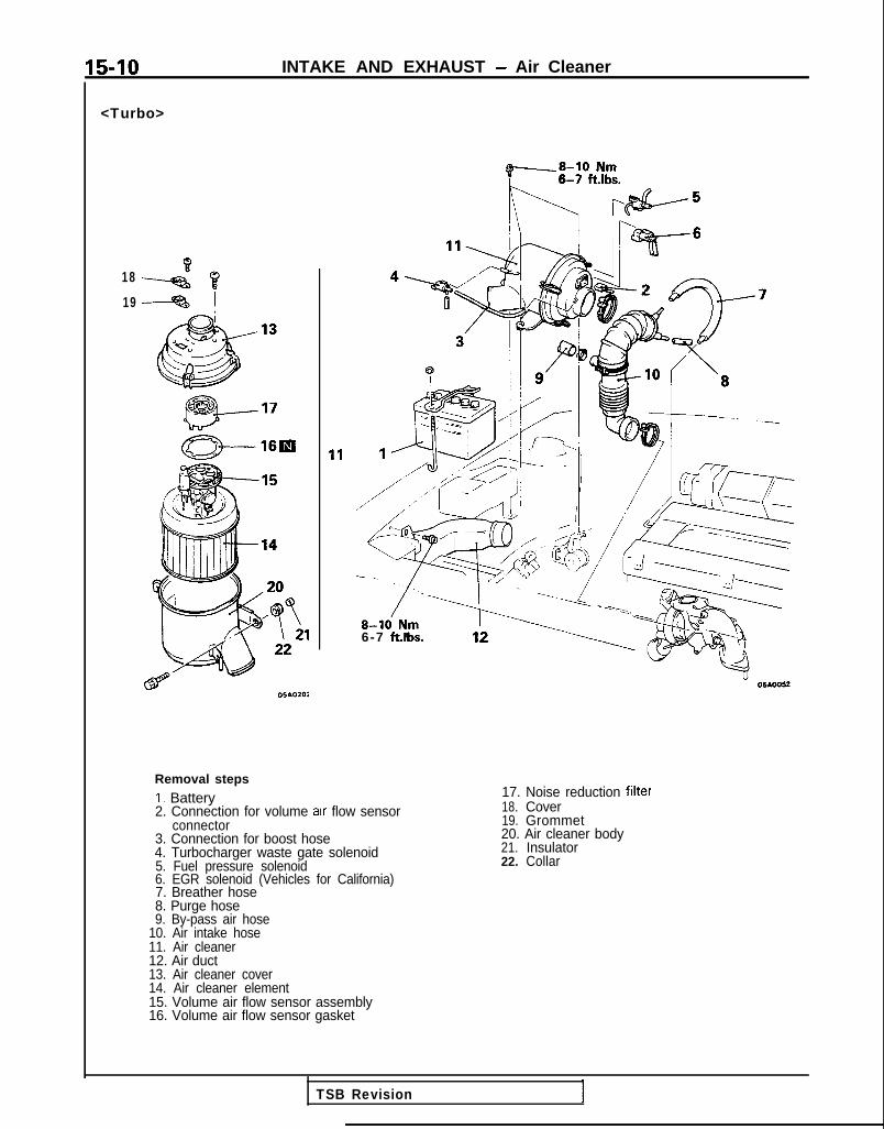
15-10 INTAKE AND EXHAUST - Air Cleaner
<Turbo>
~8-10 Nm
K nlbF+5
1819
!\ / ~2%6Td4fba5-9 /z-l
8-k Nm6-7 ft.lbs.
Removal stepsI. Battery2. Connection for volume arr flow sensor
connector3. Connection for boost hose4. Turbocharger waste gate solenoid5. Fuel pressure solenoid6. EGR solenoid (Vehicles for California)7. Breather hose8. Purge hose9. By-pass air hose
10. Air intake hose11. Air cleaner12. Air duct13. Air cleaner cover14. Air cleaner element15. Volume air flow sensor assembly16. Volume air flow sensor gasket
17. Noise reduction filter18. Cover19. Grommet20. Air cleaner body21. Insulator22. Collar
TSB Revision
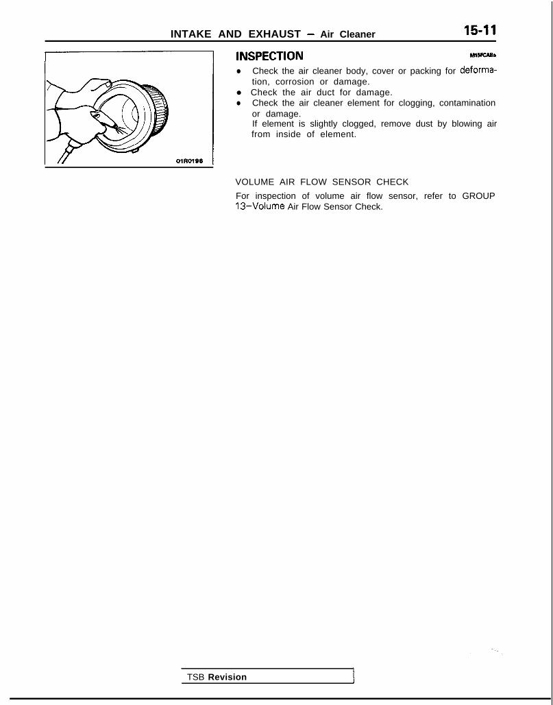
INTAKE AND EXHAUST - Air Cleaner 15-11
4 'NSPECT'oNMl5iCA95
l Check the air cleaner body, cover or packing for deforma-1 tion, corrosion or damage.
l Check the air duct for damage.l Check the air cleaner element for clogging, contamination
or damage.If element is slightly clogged, remove dust by blowing airfrom inside of element.
VOLUME AIR FLOW SENSOR CHECK
For inspection of volume air flow sensor, refer to GROUP13-Volume Air Flow Sensor Check.
TSB Revision I

15-12 INTAKE AND EXHAUST - Charge Air Cooler
CHARGE AIR COOLERREMOVAL AND INSTALLATION
A
12-15 Nm &-2-s--TX.<.\-@\\’ 1
9-11 ft.lbs., _
12-15 Nm9-11 ftlbs.
12-15-Nm9-l 1 ft.lbs.
05A0191
Removal steps1. Radiator grille (Refer to GROUP 51 -Front
Grille.) -+e *+ 2. Front combination light (Refer to GROUP
54-Headlight.)3. Headliaht4. Front bumper face coupling clip5. Air intake hose6. Air cleaner (Refer to P.15-9.)7. Air by-pass hose8. Vacuum hose
9. Air hose A10. Power relay assembly (for A/C)11. Air pipe A12. Air hose B13. Air pipe B14. Turbocharger by-pass valve15. Gasket16. Air hose C
l + 17. Charge air cooler
MXiTA-
TSB Revision

INTAKE AND EXHAUST - Charge Air Cooler 15-13
INSPECTION Ml5lcM
l Check the charge air cooler fins for bending, damage, orforeign matter.
l Check the charge air cooler hoses for cracking, damage, orwear.
SERVICE POINTS OF INSTALLATlON MlSTDAB
17. INSTALLATION OF CHARGE AIR COOLER
Connect the air hoses and air pipes by aligning the paintmarks on the hoses with the projections and indentations onthe pipes.
CautionBe careful not to allow any foreign matter to get into thehoses, pipes, or the charge air cooler itself.
NOTE<=J : Projection or indentation (pipe)C : Paint mark (hose)
TSB Revision

15-14 INTAKE AND EXHAUST - Intake Manifold <SOHC-8 VALVE>
INTAKE MANIFOLD <SOHC-8 VALVE> <Up to 1992 models>{EMOVAL AND INSTALLATION
4-6 N m
Y “1 ~/c 3-4 ft.‘bs. At
4-6 ‘Nm3 - 4 ft.lbs.
Removal stepsI. Air intake hose2. Connection for accelerator cable
+e l + 3. Connection for radiator upper hose4. Connection for water by-pass hose5. Water hose6. Connection for heater hose7. Connection for brake booster vacuum
hose8. Connection for fuel high pressure hose9. O-ring
10. Connection for fuel return hoseII. Connection for vacuum hoses12. Vacuum pipe13. PCV hose14. Connection for control harness
MlSMA-A
4-6 N m3 - 4 ft.lbs. OlA0647
Pre-removal Operationl Draining of Engine Coolant
(Refer to GROUP 00-MaintenanceService.)
Post-installation Operationl Filling of Engine Coolant
(Refer to GROUP 00-MaintenanceService.)
l Adjustment of Accelerator Cable(Refer to GROUP 13-Engine Con-trol.)
l inspection of Fuel Pressure(Refer to GROUP 13-On-VehicleInspection of MFI Components.)
TSB Revision 1
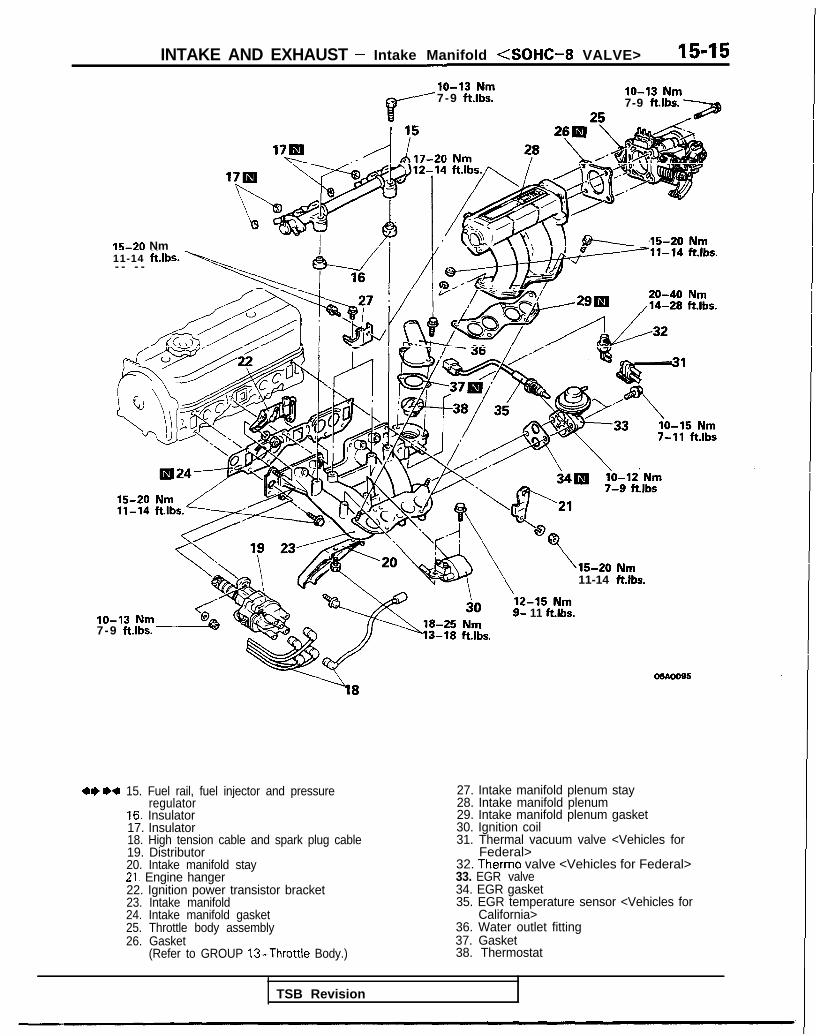
INTAKE AND EXHAUST - Intake Manifold <SOHC-8 VALVE> 15-15
lo-13 Nm
r
7-9 ftlbs. IO-13 Nm7-9 ftlbs.
IS-20 Nm11-14 ft Ibs- - - - --I-
7-11 ft.lbs
‘S-20 Nm11-14 ftlbs.
9- 11 ftlbs.lo-13 Nm7-9 ftlbs.
20-40 Nm,14-28 ft.lbs.
osAooss
--l8
++ ** 15. Fuel rail, fuel injector and pressureregulator
16. Insulator17. Insulator18. High tension cable and spark plug cable19. Distributor20. Intake manifold stay21. Engine hanger22. Ignition power transistor bracket23. Intake manifold24. Intake manifold gasket25. Throttle body assembly26. Gasket
(Refer to GROUP 13-Throttle Body.)
27. Intake manifold plenum stay28. Intake manifold plenum29. Intake manifold plenum gasket30. Ignition coil31. Thermal vacuum valve <Vehicles for
Federal>32. Therm0 valve <Vehicles for Federal>33. EGR valve34. EGR gasket35. EGR temperature sensor <Vehicles for
California>36. Water outlet fitting37. Gasket38. Thermostat
TSB Revision

15-16 INTAKE AND EXHAUST - Intake Manifold <SOHC-8 VALVE>
05AOO89
I 05A0081 (
SERVICE POINTS OF REMOVAL M15M9Ah
3. DISCONNECTION OF RADIATOR UPPER HOSE
Make mating marks on the radiator hose and the hoseclamp, and then remove the radiator hose.
8. DISCONNECTION OF FUEL HIGH PRESSURE HOSE
Relieve pressure in the fuel pipe line to prevent fueloutflow.(Refer to GROUP 13-Service Adjustment Procedures.)
CautionCover fuel pipe line with rag after relieving pressure ascertain pressure may still remain.
15. REMOVAL OF FUEL RAIL, FUEL INJECTION ANDPRESSURE REGULATOR
Remove fuel rail with fuel injector and pressure regulator.
CautionDo not drop injector when removing fuel rail.
INSPECTION MlSMCAI
Check the following points; replace the part if a problem isfound.
INTAKE MANIFOLD PLENUM
(1) Check intake manifold plenum for defect or cracks. Re-place if defective or cracked.
(2) Check load (negative pressure) of drain port. Checkcooling water and jet air passages for clogging. Clean ifrequired.
(3) Check deflection of installation surface with straight edgeand feeler gauge.
Standard value: 0.15 mm (.006 in.) or lessLimit: 0.3 mm (.012 in.)
1
TSB Revision

INTAKE AND EXHAUST - Intake Manifold <SOHC-8 VALVE> 15-17
\
05A0074
TSB Revision I
INTAKE MANIFOLD
(1) Check for damage or cracking of any part.(2) Check load (negative pressure) of drain port. Check
cooling water and jet air passages for clogging. Clean ifrequired.
(3) Check deflection of installation surface with straight edgeand feeler gauge.
Standard value: 0.15 mm I.006 in.) or lessLimit: 0.3 m m (.012 in.1
SERVICE POINTS OF INSTALLATION, MlSMDAK
15. INSTALLATION OF FUEL RAIL, FUEL INJECTORAND PRESSURE REGULATOR
CautionBe careful not to drop the injector when the fuel railis installed.
3. CONNECTION OF RADIATOR UPPER HOSE
Align the mating marks on the radiator hose and the hoseclamp and install; then apply pressure where shown bythe arrows in the illustration so that the clamp is correctlyseated at the clamp’s previous trace indentations.
CautionBe absolutely sure that the hose clamp is correctlyseated to its previous trace indentations.

15-18 INTAKE AND EXHAUST - Intake Manifold (SOHC-16 VALVE>
INTAKE MANIFOLD <SOHC-16 VALVE>REMOVAL AND INSTALLATION
< 1993 models>?.llSt.lA-A
4-6 N m3 - 4 ft.lbs.
7#jfi6
/ '
6-8 ft.lbs.
210 OSAO215
Removal steps1. Air intake hose2. Connection for accelerator cable3. Connection for brake booster vacuum
hose4. Connection for vacuum pipe and hose
assembly5. Connection for water hose6. Connection for fuel high pressure hose7. O-ring8. PCV hose9. Connection for vacuum hose
IO. Connection for fuel return hose
(Refer to GROUP OO-Maintenance
Post-installation Operationl Filling of Engine Coolant
(Refer to GROUP 00-MaintenanceService.)
l Adjustment of Accelerator Cable(Refer to GROUP 13-Engine Control.)
l inspection of Fuel Pressure(Refer to GROUP 13-On-vehicle In-spection of MFI Components.)
TSB Revision

INTAKE AND EXHAUST - Intake Manifold <SOHC-l 6 VALVE> 15-19
16 \3 05A0220
lo-13 Nm7-9 ft.lbs.
/R24
,,/13-18 ft.lbs.
’15-20 Nm11-14ft.lbs.
11. Engine coolant temperature gauge unitconnector
12. Engine coolant temperature sensorconnector
13. Oxygen sensor connector14. Distributor connector15. Condenser connector16. TPS connector17. IAC connector18. injector connector19. Control harness
18-2iNm13-18 ft.lbs.
05AO222
4I) 1)+20. Fuel rail, injector and pressure regulatorassembly
21. Insulator22. Intake manifold stay23. Intake manifold24. Intake manifoii gasket25. Throttle body
1)+26. Throttle body gasket27. EGR valve28. EGR gasket29. EGR temperature sensor <Vehicles for
California>
TSB Revision I

15-20 INTAKE AND EXHAUST - Intake Manifold (SOHC-16 VALVE>
05AO217
SERVICE POINTS OF REMOVAL MlSMBAJ
6. DISCONNECTION OF FUEL HIGH PRESSURE HOSE
Relieve pressure in the fuel pipe line to prevent fuel out-flow. (Refer to GROUP 13-Service Adjustment Proce-dures.)
CautionCover fuel pipe line with rag after relieving pressure ascertain pressure may still remain.
20. REMOVAL OF FUEL RAIL, FUEL INJECTOR ANDPRESSURE REGULATOR
Remove fuel rail with fuel injector and pressure regulatoron.
CautionDo not drop injector when removing fuel rail.
INSPECTION MlSMCAJ
Check the following points; replace the part if a problem isfound.
INTAKE MANIFOLD
1. Check for damage or cracking of any part.2. Check for obstruction of the negative pressure (vacuum)
outlet port, and for obstruction of the water passage orgas passage.
3. Using a straight edge and a thickness gage, check fordistortion of the cylinder head installation surface.
Standard value: 0.15 mm (006 in.) or lessLimit: 0.3 mm (.012 in.)
SERVICE POINTS OF INSTALLATION MllMDAL
26. INSTALLATION OF GASKET
Refer to GROUP 13-Throttle Body.
20.lNSTALLATlON OF FUEL RAIL, FUEL INJECTORAND PRESSURE REGULATOR
CautionBe careful not to drop the injector when the fuel railis installed.
TSB Revision I

INTAKE AND EXHAUST - Intake Manifold <DOHC> 15-21
INTAKE MANIFOLD <DOHC>REMOVAL AND INSTALLATION 4-6 N m
14<Turbo>.
3 - 4 ft.lbs.
i15-22 Nm11-16 ft.lbs. /’
/6 *=
15-22 Nm11-16 ft.lbs.
‘urbo>fl\sT
M15MA-9
/I 05AO183
12 9
for
o!wn39
Removal steps1. Air intake hose <Non-Turbo>2. Air hose D <Turbo>3. Connection for control harness4. Connection for accelerator cable5. Ground plate installation screw6. Throttle body stay and ground plate7. Connection for water by-pass hose8. Connection for water hose9. Connection for brake booster vacuum
hose10. Connection for fuel high pressure hose11. O-ring12. Connection for fuel return hose13. Connection for PCV hose14. Connection for vacuum hoses15. Connection for spark plug cable
NOTEl l : <Non-Turbo>+2: <Turbo>
05A0045
Pre-removal Operationl Draining of Engine Coolant
(Refer to GROUP 00-MaintenanceService.)
Post-installation Operationl Filling of Engine Coolant
(Refer to GROUP 00-MaintenanceService.)
l Adjustment of Accelerator Cable(Refer to GROUP 13-Engine Con-trol.)
l Inspection of Fuel Pressure(Refer to GROUP 13-On-Vehiclelnseection of MFI Comgonents.)
TSB Revision

15-22 INTAKE AND EXHAUST - Intake Manifold <DOHC>
lo-13 Nm/ 7-9 ftlbs.
15-22 Nm11-16 ftlbs.n
20-27 Nm14-20 ft.lbs. 7-9 ftlbs.
+e I)4 16. Fuel rail, fuel injector and pressureregulator
17. Insulator18. Insulator19. Intake manifold stay20. Intake manifold21. Intake manifold gasket22. Ignition coil23. Power transistor unit24. EGR valve25. Gasket26. EGR temperature sensor <Vehicles for
California>27. Air fitting <Turbo>28. Gasket <Turbo>29. Throttle body30. G a s k e t
(Refer to GROUP 13-Throttle Body.)
lo-12 Nm7-9 ft.lbs.
1 25-30 Nm18-22 ftlbs. 05AQ197
15-2211-16
<Turbo> OSAO196
TSB Revision

INTAKE AND EXHAUST - Intake Manifold <DOHC> 15-23
SERVICE POINTS OF REMOVAL M1SMEAJa
10. DISCONNECTION OF FUEL HIGH PRESSURE HOSE
Relieve pressure in the fuel pipe line to prevent fueloutflow. (Refer to GROUP 13-MFI Components on VehicleInspection.)
CautionCover fuel pipe line with rag after relieving pressure ascertain pressure may still remain.
16.REMOVAL OF FUEL RAIL, FUEL INJECTOR ANDPRESSURE REGULATOR
Remove fuel rail with fuel injector and pressure regulatoron.
CautionDo not drop injector when removing fuel rail.
INSPECTION MlSMCAJ
Check the following points; replace the part if a problem isfound.
INTAKE MANIFOLD
1. Check for damage or cracking of any part.2. Check for obstruction of the negative pressure (vacuum)
outlet port, and for obstruction of the water passage orgas passage.
3. Using a straight edge and a thickness gage, check fordistortion of the cylinder head installation surface.
Standard value: 0.15 mm (406 in.) or lessLimit: 0.3 mm (.012 in.)
05AOO28
SERVICE POINTS OF INSTALLATION MlSMDAL
16.lNSTALLATlON OF FUEL RAIL, FUEL INJECTORAND PRESSURE REGULATOR
CautionBe careful not to drop the injector when the fuel railis installed.

15-24 INTAKE AND EXHAUST - Turbocharger
TURBOCHARGERREMOVAL AND INSTALLATION
12-15 Nm9-11 ft.lbs. )
nMlSLA-
40-47 ftlbs.
v I”12-15 Nm g9-11 ftlbs.
i40-50 Nm29-36 ft.lbs.
05A0193
30-40 Nm22-29 ftlbs.
*Draining and Refilling Engine
(Refer to GROUP OO-Main-tenance Service.)
aDraining and Refilling Engine---. .- _^ . ._;_
I (Refer to CiKUUi-’ UU-M~III-11 tenance Service.) -I
Removal steps1. Radiator (Refer to GROUP 14-Radiator.) 13. Gasket2. Connection for air intake hose 14. Connection for water hose3. Connection for vacuum hose I 5. Connection for water pipe B4. Connection for air hose A 16. Self-locking nut
4* 5. Oxygen sensor 17. Gasket6. Air outlet fitting 18. Exhaust manifold7. Gasket 19. Exhaust manifold gasket8. Heat protector A 20. Ring9. Heat protector B 21. Gasket
10. Self-locking nut11. Engine hanger12. Eye bolt
1‘TSB Revision I

INTAKE AND EXHAUST - Turbocharger 15-25
35-50 Nm
25-3\6 fubs*
28-34 Nm 920-25 ftlbs.
31 33
26H ,a
/IW32
Rk .p&
/25
55-6540-47
25-36 ftlbs.
22. Oil return pipe23. Gasket
l I) l + 24. Turbocharger25. Eye bolt26. Gasket27. Water pipe B28. Eye bolt29. Gasket30. Water pipe A31. Eye bolt32. Gasket
l 4 33. Oil pipe34. Exhaust fitting35. Gasket
r
8-10 Nm6-7 ft.lbs.
Flare nut
OJK557
SERVICE POINTS OF REMOVAL M15lBAoa
5. REMOVAL OF OXYGEN SENSOR
Disconnect the connector of the oxygen sensor, and installthe special tool to the oxygen sensor.Then, using an offset (box-end) wrench, remove theoxygen sensor.
0510023
I‘“*“n,&
.”
1 TSB Revision

15-26 INTAKE AND EXHAUST - Turbocharger
24. REMOVAL OF TURBOCHARGER ASSEMBLY
Remove the turbocharger assembly with the exhaust fitting,water pipe A, water pipe B and the oil pipe attached to it.
33. REMOVAL OF OIL PIPE
CautionAfter disconnecting the oil pipe, take care that foreignmaterial does not enter the oil passage hole of theturbocharger assembly.
INSPECTION MlSLCAC
TURBOCHARGER ASSEMBLY CHECK
l Visually check the turbine wheel and the compressor wheelfor cracking or other damage.
l Check whether the turbine wheel and the compressor wheelcan be easily turned by hand.
l Check for oil leakage from the turbocharger assembly.0 Check whether or not the turbocharger waste gate valve
remains open. If any problem is found, replace the partafter disassembly.
OIL PIPE AND OIL-RETURN PIPE CHECK
Check the oil pipe and oil-return pipe for clogging, bending, orother damage.If there is clogging, clean it.
SERVICE POINTS OF INSTALLATION M15lDADa
24. INSTALLATION OF TURBOCHARGER ASSEMBLY
Clean the alignment surfaces shown in the illustration.
CautionWhen cleaning, care must be taken so that a piece of thegasket does not enter the oil passage hole.
1 TSB Revision I
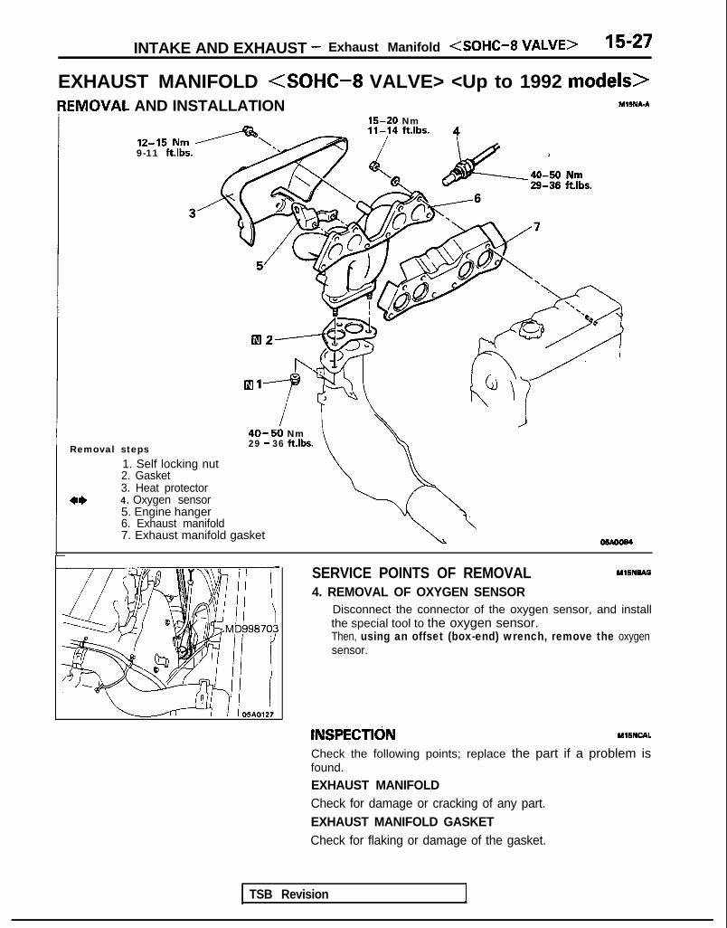
INTAKE AND EXHAUST - Exhaust Manifold (SOHC-8 VALVE> 15-27
EXHAUST MANIFOLD <SOHC-8 VALVE> <Up to 1992 models>IEMOVAL AND INSTALLATION YSNA-A
15-20 Nm
9-11 ftlbs.
40-50 NmRemoval steps 29 - 36 ft.lbs.
1. Self locking nut2. Gasket3. Heat protector
a* 4. Oxygen sensor5. Engine hanger6. Exhaust manifold7. Exhaust manifold gasket
SERVICE POINTS OF REMOVAL MlSNBAG
4. REMOVAL OF OXYGEN SENSORDisconnect the connector of the oxygen sensor, and installthe special tool to the oxygen sensor.Then, using an offset (box-end) wrench, remove the oxygensensor.
INSPECTldN MllNCAL
Check the following points; replace the part if a problem isfound.
EXHAUST MANIFOLDCheck for damage or cracking of any part.EXHAUST MANIFOLD GASKETCheck for flaking or damage of the gasket.
TSB Revision 1

15-28 INTAKE AND EXHAUST - Exhaust Manifold <SOHC-16 VALVE>
EXHAUST MANIFOLD <SOHC-l6 VALVE> <I993 models>PEMOVAL AND INSTALLATION MlSNA-B
.15 Nm1 ft.lbs.7-l
40-50Nm ----‘--A
40-50 Nm /-29-36 ft.lbs.
30-40Nmj’22-29 ft.lbs.
Removal steps1. Condenser fan motor (Vehicles with air
conditioning)2. Self locking nut3. Gasket
4* 4. Oxygen sensor5. Exhaust manifold cover (A)6. Self locking nut7. Engine hanger8. Exhaust manifold9. Exhaust manifold gasket
IO. Exhaust manifold cover(B)
TSB Revision 1

INTAKE AND EXHAUST - Exhaust Manifold <SOHC-l6 VALVE> 15-29
SERVICE POINTS OF REMOVAL MlBNBAFl
4. REMOVAL OF OXYGEN SENSORDisconnect the connector of the oxygen sensor, and installthe special tool to the oxygen sensor.Then, using an offset (box-end) wrench, remove theoxygen sensor.
INSPECTION MlSNCALl
Check the following points; replace the part if a problem isfound.EXHAUST MANIFOLDCheck for damage or cracking of any part.EXHAUST MANIFOLD GASKETCheck for flaking or damage of the gasket.

15-30 INTAKE AND EXHAUST - Exhaust Manifold <DOHC-Non-Turbo>
EXHAUST MANIFOLD <DOHC-Non-Turbo>REMOVAL AND INSTALLATION
I12-15 Nm9- 11 ft.lbs.
27-33 Nm20-23 fklbs.
40 50 Nm29136 ft.lbs.yAS
<FWD>40-50 Nm29- 36 ft.lbs.<AWD>30-40 Nm22- 29 ft.lbs. 12-15 1
30-40 Nm9-11 ft.
\UrnIbs.
MlINA-B
22-29 ft.lbs
Removal steps*b’.
1. Condenser fan motor (Vehicleswith air conditioning except AWD A/T)
2. Self locking nut3. Gasket4. Exhaust manifold cover (A)
l * 5. Oxygen sensor6. Self locking nut7. Engine hanger8. Exhaust manifold9. Exhaust manifold gasket
10. Exhaust manifold cover (B)
SERVICE POINTS OF REMOVAL Ml5NNAH
5. REMOVAL OF OXYGEN SENSORDisconnect the connector of the oxygen sensor, and installthe special tool to the oxygen sensor.Then, using an offset (box-end) wrench, remove the oxygensensor.
INSPECTIONRefer to P.15-29
i
TSB Revision
M15NCA-l

INTAKE AND EXHAUST - Exhaust Manifold <DOHC-Turbo> 15-31
EXHAUST MANIFOLD <DOHC-TURBO>REMOVAL AND INSTALLATION 12-15 Nm
Removal
12-15.Nm -g-11 ft.lbs.
steps
9-l 1 ftlbs.
lh ./-I
‘Uc
Ml5NA.C
05AO192
Coolant(Refer to GROUP 00-Maimtenance Service.)
eDraining and Refilling Engine
1. Radiator (Referto GROUP 14-Radiator.)2. Connection for air intake hose3. Connection for vacuum hose4. Connection for air hose A5. Oxygen sensor connector6. Air outlet fitting7. Gasket8. Heat protector A9. Heat protector B
10. Self-locking nut11. Engine hanger12. Eye bolt
‘\!I 1 5Ilation Operationl Draining and Refilling Engine
Oil -(Refer to GROUP 00-Main.tenance Service.)
13. Gasket14. Connection for water hose15. Connection for water pipe.B16. Self-locking nut17. Gasket18. Exhaust manifold19. Exhaust manifold gasket20. Ring21. Gasket
TSB Revision 1

15-32 INTAKE AND EXHAUST - Exhaust Pipe and Main Muffler <SOHC>
EXHAUST PIPE AND MAIN MUFFLER <SOHC> M15RA.Ai
REMOVAL AND INSTALLATIONIO-15 Nm7-l 1 ft.lbs.
hlo-15 Nm7-11 ft.lbs.
<up toIO-15 Nm7- 11 ft.lbs.
23
30-40 Nm22-29 ft.lbs.
’17 15lIl
30-40 Nm
22-29 ftlbs. 29-43 ft.lbs.22-29 ft.lbs.
40-50 Nm29 - 36 ftlbs.
05A0069
< 1993 models>IO-15 Nm
22.1 7-11 ftlbs. 20
40-50 Nm 30-40Nm 21 40-60 Nm29-36 ft.lbs. 22-29 ft.lbs. 29-43 ftlbs. 05A0216
Removal steps1. Hanger2. Main muffler3. Gasket4. Hanger bracket5. Self locking nut6. O-ring7. Hook8. Bracket
9. Stopper10. Hanger bracket11. Hanger12. Protector13. Hanger bracket14. Center exhaust pipe15. Gasket16. Dynamic damper
17. Catalytic converter18. Gasket19. Self locking nut20. Hanger21. Front exhaust pipe22. Gasket23. Front floor heat protector panel
INSPECTION MlSRCAH
l Check the mufflers and pipes for corrosion or damage.l Check the rubber hangers and rubber O-rings for deterio-
ration or damage.l Check for gas leakage from mufflers and pipes.
TSB Revision

INTAKE AND EXHAUST - Exhaust Pipe and Main Muffler <DOHC>
EXHAUST PIPE AND MAIN MUFFLER <DOHC>
15-33
M15R4-8
REMOVAL AND INSTALLATION
<FWD> 24
IO-15 Nm lo-15 Nm7-11 ft.lbs. 5 1 5 7-11 ft.lbs., ,
IO-15 Nm7-11 ft.lbs.
30-40 Nm22-29 ft.lbs.
30-40 Nm I22-29 ft.lbs. 40-60 Nm
29-43 ftlbs.
40-50 Nm29 - 36 ft.lbs.
Removal steps1. Hanger2. Main muffler3. Gasket4. Moulding5. Hanger bracket6. Self locking nut7. O-ring8. Hook9. Bracket
10. Stopper11. Hanger bracket12. Hanger
13. Protector14. Hanger bracket15. Center exhaust pipe16. Gasket17. Catalytic converter18. Gasket19. Self locking nut20. Hanger22. Front exhaust pipe23. Gasket24. Front floor heat protector panel
TSB Revision I

15-34 INTAKE AND EXHAUST - Exhaust Pipe and Main Muffler <DOHC>
<AWD Non-Turbo> lo-15 Nm
7-Y ft*lbs.
10-15 Nm7-11 ft.lbs
24
lN23 40-60 Nm
/29-43 ft.lb
3-4 ft.lbs.
30-10 Nm $0-40 Nm22-29 ft.lbs. 22-29 ft.lbs. I
<AWD Turbo> 40-60 Nm29-y ft.lbs.
/ \Ignr ?, 40 Nm40-60 Nm 22-29 ft.lbs.29-43 ft.lbs.
\30-40 NmZ-29 ft.lbs.
IO-15 Nm7-11 ft.lbs.
05A0195
Removal steps1. Hangers2. Main muffler3. Gasket4. Moulding5. Hanger bracket6. Self locking nut
12. Hanger13. Protector14. Hanger bracket15. Center exhaust pipe16. Gasket
17. Catalytic converter18. Gasket19. Self locking nut20. Hanger21. Hanger bracket22. Front exhaust pipe23. Gasket24. Front floor heat protector panel
INSPECTIONRefer to P.15-32
MllRCAL
1 T S B R e v i s i o n I

EMISSION CONTROLSYSTEMS
CONTENTS r.w?API-
CATALYTIC CONVERTER ..................... 29
EVAPORATIVE EMISSION CONTROLSYSTEM .......................................... 15
Air Conditioning Switch ........................ 21Component Location ........................... 15Evaporative Emission Canister ................ 21Evaporative Emission Purge Solenoid ....... 21Fuel Tank Filler Tube Cap Inspection ........ 21Fuel Tank Pressure Control Valve ............ 21Purge Control System Inspection<Non-Turbo> ................................. 17Purge Control System Inspection<Turbo> ....................................... 18Purge Control Valve <Turbo> .............. 20Purge Port Vacuum ............................ 19Volume Air Flow Sensor, Engine CoolantTemperature Sensor and Intake AirTemperature Sensor ........................... 21
EXHAUST GAS RECIRCULATION (EGR)SYSTEM .......................................... 22
Component Location ........................... 22EGR Solenoid <California> .................. 28EGR System Inspection <California> ...... 25EGR System Inspection <Federal> ........ 25
EGR Temperature Sensor <California> ... 28EGR Valve ...................................... 27EGR Valve Control Vacuum .................. 26
Thermal Vacuum Valve <Federal> ........ 27
MIXTURE CONTROL (MFI) SYSTEM . . . . . . . . 29
POSITIVE CRANKCASE VENTILATIONSYSTEM .......................................... 13
Component Location .......................... 13Crankcase Ventilation System Inspection ... 14Positive Crankcase Ventilation (PCV)Valve Inspection ............................... 14
SPECIFICATIONS .................................. 2
General Specifications ........................... 2
Sealant ............................................ 2Service Specifications ........................... 2Torque Specifications ........................... 2
TROUBLESHOOTING ............................. 3
VACUUM HOSES ................................. 4Vacuum Circuit Diagram ........................ 9
Vacuum Hoses Routing ......................... 4

17-2 EMISSION CONTROL SYSTEMS - Specifications
SPECIFICATIONSGENERAL SPECIFICATIONS Ml’IcA-
Positive crankcase ventilation system
Evaporative emission control systemEvaporative emission canister
Exhaust emission control systemExhaust gas recirculation system
EGR valveThermal vacuum valve <Federal>EGR temperature sensor <California>EGR solenoid <California>
Catalytic converterLocation
Closed type with Positive Crankcase Ventilation valve
Evaporative emission canister storage typeCharcoal type
Vacuum-actuated diaphragm typeBimetal typeThermistor typeDuty cycle solenoid valveMonolith typeUnder floor
SERVICE SPECIFICATIONS M17CB-
Items 1 Specifications
Evaporative emission purge solenoid coil resistanceThermal vacuum valve closing temperatureEGR temperature sensor resistance
Q 36-44 [a t 20°C (68”F)I‘C (“F) 65 (149)
kQ 60-83 [ a t 50°C (122”F)l11-14 [at 100°C (212”F)l
EGR solenoid coil resistance 52 36-44 [at 20°C (68°F))
TORQUE SPECIFICATIONS
Items N m ft.1 bs.
Positive crankcase ventilation valve 8-12 6-8.6EGR valve installation bolt 17-26 12-19Thermal vacuum valve 20-40 15-30EGR temperature sensor IO-12 7.3-8.6
SEALANT
Items
Thermal vacuum valve thread portion
Specified sealant
3M NUT locking Part No.4171 or equivalent
TSB Revision

EMISSION CONTROL SYSTEMS - Troubleshooting 17-3
TROUBLESHOOTING MVEA-
Symptom Probable cause Remedy
Engine will not start or hard Vacuum hose disconnected or Repair or replaceto start damaged
The EGR valve is not closed. Repair or replace
Malfunction of the evaporative Repair or replaceemission purge solenoid
Rough idle or engine stalls The EGR valve is not closed. Repair or replace
Vacuum hose disconnected or damaged Repair or replace
Malfunction of the positive crankcase Replaceventilation valve
Malfunction of the purge control system Check the system; if there is aproblem, check its component parts.
Engine hesitates or poorIcceleration
Zxcessive oil consumption
)oor fuel mileage
Malfunction of the exhaust gasrecirculation system
Positive crankcase ventilation lineclogged
Malfunction of the exhaust gasrecirculation system
Check the system; if there is aproblem, check its component parts.
Check positive crankcase ventilationsystem
Check the system; if there is a problem,check its component parts.
TSB Revision

17-4 EMISSION CONTROL SYSTEMS - Vacuum Hoses
VACUUM HOSESVACUUM HOSES ROUTING
M17.M-
<Federal-SOHC (1989 models)>
Evaporativeemission cani*--
Evaporative emissionpurge solenoid
Throttle body
G: GreenThermal vacuum valve
\Y : YellowL : Light blueR: RedB : Black
EGR’ valve
FRONT
Fuel pressureregulator
6EM0189
<California-SOHC (1989 models)>
Evaporative Evaporative emissionemission canister ,I purge solenoid
Th r ot t IihR
Y
G: GreenY: YellowL : Light blueR: RedB : Black
EGR \alve FRGT
6EM0190
TSB Revision
EGR solenoid
Fuel pressureregulator

EMISSION CONTROL SYSTEMS - Vacuum Hoses 17-5
<Federal-SOHC (From 1990 models)>
Evaporativeemission canister
\
Evaporative emissionpurge solenoid
/
G: GreenY : YellowL : Light blueR: RedB : Black
Throttle body
Thermal vacuum valve
6EM0283
<California-SOHC (From 1990 models)>
Evaporativeemission canister
Evaporative emissionpurge solenoid
G: GreenY : YellowL : Light blueR: RedB : Black
EGR valve FRONT
Fuel pressureregulator
6EM0284
1 TSB Revision
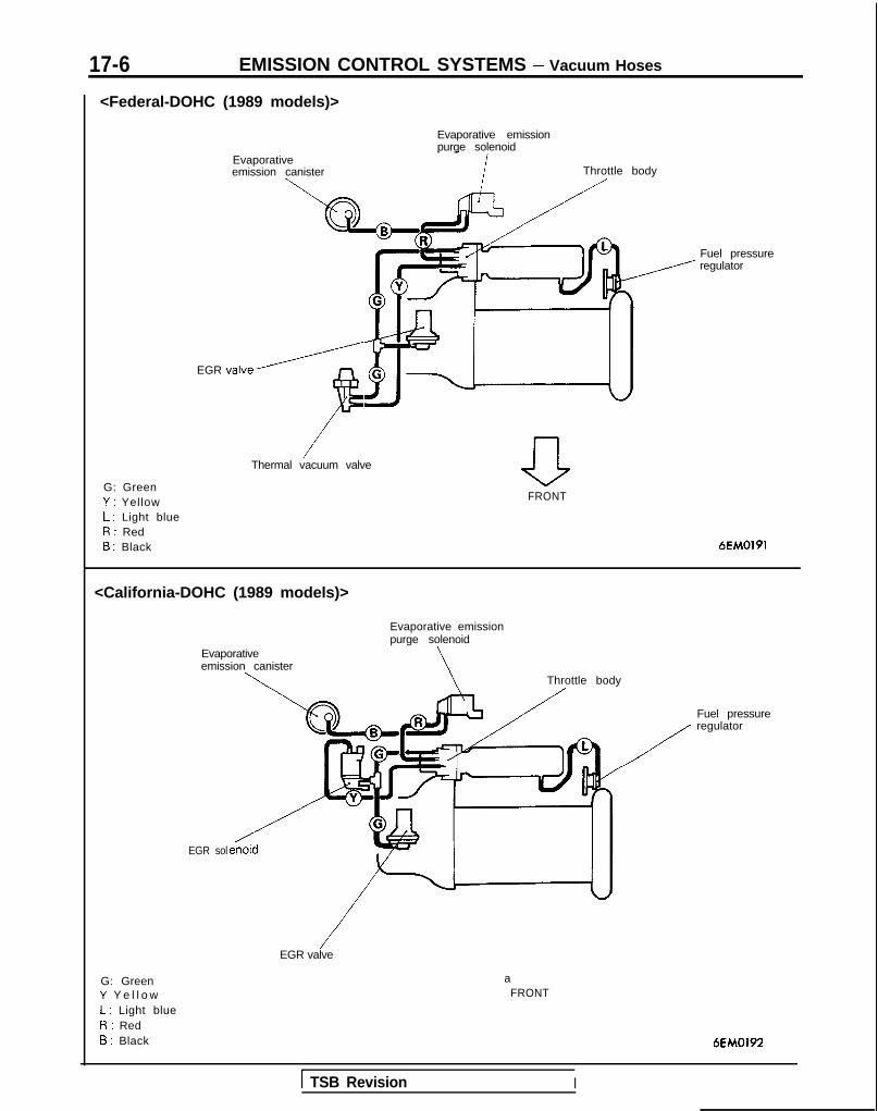
17-6 EMISSION CONTROL SYSTEMS - Vacuum Hoses
<Federal-DOHC (1989 models)>
Evaporative emissionpurge solenoid
Evaporativeemission canister
EGR valve/
F
Throttle body
/Thermal vacuum valve
G: GreenY : YellowL : Light blueR: RedB : Black
Fuel pressureregulator
aFRONT
6EM0191
<California-DOHC (1989 models)>
Evaporativeemission canister
\
Evaporative emissionpurge solenoid
\ Throttle body
EGR sol
G: GreenY Y e l l o wL : Light blueR: RedB : Black
/EGR valve
aFRONT
Fuel pressureregulator
6EM0192
1 TSB Revision I

EMISSION CONTROL SYSTEMS - Vacuum Hoses 17-7
<Federal-DOHC (From 1990 models)>
Evaporative emissionpurge solenoid
/Evaoorativeemission canister
G: GreenY : YellowL : Light blueR: RedB : Black
/Thermal vacuum valve
aFRONT
6EM0318
<California-DOHC (From 1990 models)>
Evaporative emission
Evaoorativepurge solenoid
/emission canister
Fuel pressure regulator
aFRONT
6EM0319
G: GreenY : YellowL : Light blueR: RedB : Black
TSB Revision

17-8 EMISSION CONTROL SYSTEMS - Vacuum Hoses
<Federal - DOHC T/C (From 1991 models)> Evaporat,ve emiSSionpurge solenoid Throttle body/ /
Purge control valve
Fuel pressure
11 “Y , Fuel pressure regulator
Thermal vacuum UJ-\,~l\,P
I L uypassvalve
Air cleaner
G: GreenY : Yellow
IEGR valve
Turbocharger Wasten-t= 2rt1 r3tor
Turbocharger Wastegate solenoid
0L : Light blueR: RedB : B lackW: White
FRONT 6EM0320
<California- DOHC T/C (From 1991 models)>Evaporative emissionpurge solenoid Throttle body
Purge control valve\
/
EGR solenoid\PL
regulatorruIil rlessure
/
Fuel pressuresolenoid
Turbocharger waste/aate actuator
TC bypass.,4111,n
A i r cle&er
-0FR‘;;NT
6EM0321
G: GreenY : Ye l lowL : Light blueR: RedB : B lackW: White
Turbocharger wastegate solenoid
EGR valve
TSB Revision

EMISSION CONTROL SYSTEMS - Vacuum Hoses 17-9
VACUUM CIRCUIT DIAGRAM<Federal-SOHC (Up to 1992 models), Federal-DOHC (Up to 1991 models)>
Intake manifold plenum Throttle body
\-l-l I r/////////////LTo combustion chamber
From air cleaner
G: GreenY: YellowL: Light blueR: RedB: Black
<California-SOHC (Up to 1992 models), California-DOHC (Up to 1991 models)>
Intake manifold plenum Throttle body
I v///////////l/,From air cleaner
To combustion chamber
G: GreenY: YellowL: Light blueR: RedB: Black
Fuel pressureregulator
3EM0141EVAP canister
TSB Revision
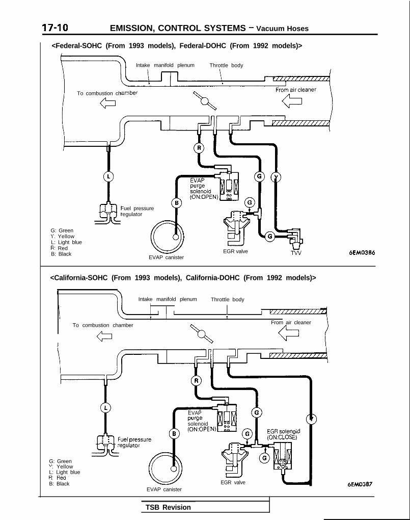
17-10 EMISSION, CONTROL SYSTEMS - Vacuum Hoses
<Federal-SOHC (From 1993 models), Federal-DOHC (From 1992 models)>
Intake manifold plenum Throttle body
To combustion ch
G: GreenY: YellowL: Light blueR: RedB: Black
Fuel pressureregulator
EGR valveEVAP canister
6EM0386
<California-SOHC (From 1993 models), California-DOHC (From 1992 models)>
Intake manifold plenum Throttle body,
II ) I I v///////i////1
To combustion chamber From air cleaner
I
G: GreenY: YellowL: Light blueD. 0,.,-dI,. IIC”
B: Black
pressulilator
re
EVAPpurgesolenoid(0N:OPE oil
El
EGR valve 6EM0387EVAP canister
TSB Revision
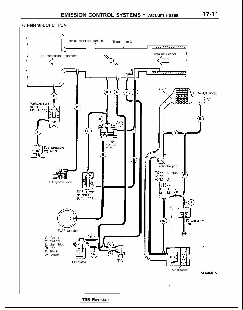
EMISSION CONTROL SYSTEMS - Vacuum Hoses
: Federal-DOHC T/C>
Intake manifold plenum
\--p
Throttle body
\ I vff/ffffffffffff
I To combustion chamber c\From air cleaner
a
e body
0
l5Bii-TC bypass valve
Y Purgecontrolvalve
B>
1.fi . .EV ALi 1;o?psoler(ON3ZLOSEi)
EVAP canister
Turbocharger
ixwsolen(ONA
E
te gate ,
:N,
!4Q
B
G: GreenY: YellowL: Light blueR: RedB: BlackW: White
EGR valve
Air cleaner6EM0406
- I.
TSB Revision 1

EMISSION CONTROL SYSTEMS - Vacuum Hoses
<California-DOHC T/C>
Intake manifold plenum
I /IThrottle body
\\ i
To combustion chamber
IFrom air cleaner
IVI////////////
.J J CAC
le body
G
Turbodharger
T C waste gate B
- ;
Slslenoid (0N:OPEN)
urge
:SE)
‘urge:ontrol/alve
TC bypass valve
EV?solei(ON:
EVAP canister
G: GreenY: YellowL: Light blueR: RedB: BlackW: White Air cleaner
6EMO407
TSB Revision
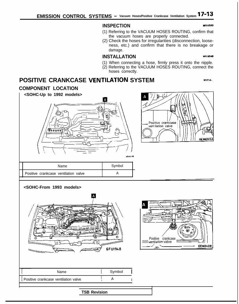
EMISSION CONTROL SYSTEMS - Vacuum Hoses/Positive Crankcase Ventilation System 17-13
INSPECTION Ml7JcAo
(1) Referring to the VACUUM HOSES ROUTING, confirm thatthe vacuum hoses are properly connected.
(2) Check the hoses for irregularities (disconnection, loose-ness, etc.) and confirm that there is no breakage ordamage.
INSTALLATION Ml7JDAD
(1) When connecting a hose, firmly press it onto the nipple.(2) Referring to the VACUUM HOSES ROUTING, connect the
hoses correctly.
POSITIVE CRANKCASE VENTILATION SYSTEM M171A-
COMPONENT LOCATION<SOHC-Up to 1992 models>
Name Symbol
Positive crankcase ventilation valve A
<SOHC-From 1993 models>
Name 1 Symbol 1
1 Positive crankcase ventilation valve I A I
Positive crankcase---ventilation valveI
I
TSB Revision

17-14 EMISSION CONTROL SYSTEMS - Positive Crankcase Ventilation System
<DOHC>
Name Symbol
Positive crankcase ventilation valve A
<SOHC-Up to 1992 models, DOHC>
OlGOllO
<SOHC-Up to 1992 models,
CRANKCASE VENTILATION SYSTEMINSPECTION M17IAAO
(1) Disconnect the ventilation hose from the positive crank-case ventilation (PCV) valve. Then, remove PCV valve fromthe rocker cover and reconnect it to the ventilation hose.
(2) Idle the engine and put a finger to the open end of PCVvalve to make sure that intake manifold vacuum is felt onthe finger.NOTEAt this time, the plunger inside the PCV valve moves backand forth.
(3) If vacuum is not felt on finger, clean the PCV valve and ven-tilation hose in cleaning solvent or replace if necessary.
POSITIVE CRANKCASE VENTILATION (PCV)VALVE INSPECTION(1) Remove the PCV valve.(2) Insert a thin rod from the side of the PCV valve that is
mounted to the rocker cover. Move the rod back and forthand confirm that the plunger moves.
(3) If the plunger does not move, the PCV valve is clogged, soclean or replace it.
INSTALLATION <SOHC-Up to 1992 models, DOHC>Install PCV valve and tighten to specified torque.Specified tightening torque: 8-12 Nm (6-8.5 ftlbs.)
TSB Revision

EMISSION CONTROL SYSTEMS -Positive Crankcase Ventilation System/Evaporative emission Control System 17-15
_ <SOHC-From 1993 models>
EVAPORATIVE EMISSION CONTROL SYSTEMCOMPONENT LOCATION
M171B-
<SOHC-Up to 1992 models> <SOHC-From 1993 models>
Name
Evaporative emission canister
Evaporative emission purge solenoid
Symbol
B
A
1 TSB Revision

17-16 EMISSION CONTROL SYSTEMS - Evaporative Emission Control System
<DOHC>
6EM0166
1 Symbol 1
Evaporative emission canister C
Evaporative emission purge solenoid A
Purge control valve <Turbo> B
Evaporative emission puige solenoid
1 TSB Revision I

EMISSION CONTROL SYSTEMS - Evaporative Emission Control System 17-17
‘URGE CONTROL SYSTEM INSPECTION <Non-Turbo>
I
Throttle body
M17lBBF
Enginecontrolmodule
Intake air temperature
<SOHC (1999 models)>
<DOHC (1999 models)>
6EM153
(1) Disconnect the vacuum hose (red stripes) from the throttlebody and connect it to a hand vacuum pump.
(2) Plug the nipple from which the vacuum hose was removed.(3) Under the engine conditions described below, provide a
vacuum by using the hand vacuum pump, and then check.When engine is cold-coolant temperature:
60°C (140°F) or less
~1
When engine is hot-coolant temperature:70°C (158°F) or hiaher
, -- ---~“----
Engine operating Applying vacuum Resultcondition
Idling 375 mmHg(14 in.Hg.)
Vacuum is maintained
Within 3 minutes Try applyingafter engine start vacuum3,000 rpm
Vacuum leaks
After 3 minutes 375 mmHghave passed after (14 in.Hg.)engine start3,000 rpm
Vacuum will be main-tained momentarily,after which it willleaks.NOTE:The vacuum will leakcontinuously if thealtitude is 2,200 m(7,200 ft.) or higher,or the intake airtemperature is 50°C(122°F) or higher.
ITSB Revision I

EMISSION CONTROL SYSTEMS - Evaporative Emission Control System
PURGE CONTROL SYSTEM INSPECTION <Turbo> M17lBBL
Evaporativeemission canister
Intake air temperature sensor
Engine coolant temperature sensor
re
Engine control module
I (1) Disconnect the purge air hose from the air intake hose, andplug the air intake hose. Then, connect the hand vacuumpump to the purge air hose.
(2) Under the engine conditions shown below, check byapplying vacuum from a hand vacuum pump.
When engine is cold-coolant temperature:60°C (140°F) or less
Engine operating Applying vacuum Resultcondition
1 vacuum is maintained 1ldldl rpm 1 gy?r$y)
[ TSB Revision

EMISSION CONTROL SYSTEMS - Evaporative Emission Control System 17-19
When engine is hot-coolant temperature:70% (158°F) or higher
Engine operatingcondition
Applying vacuum Result
Idling Vacuum is maintained
3,000 rpm within Try applyingthree minutes after vacuumstarting engine
Vacuum leaks
3,000 rpm afterthree minuteshave elapsedafter startingengine
375 mmHg(14.8 in.Hg.1
Vacuum will be main-tained momentarily,after which it willleaks.NOTEThe vacuum will leakcontinuously if thealtitude is 2,200 m(7,200 ft.) or higher,or the intake airtemperature is 50°C(122°F) or higher.
PURGE PORT VACUUM MITFVBC
INSPECTION <SOHC-Up to 1992 models, DOHC Non-Turbo-Up to 1991 models, DOHC Turbo>Engine coolant temperature: 85- 95°C (185- 205°F)(1) Disconnect the vacuum hose from the throttle body purge
hose nipple and connect a hand vacuum pump to thenipple.
TSB Revision
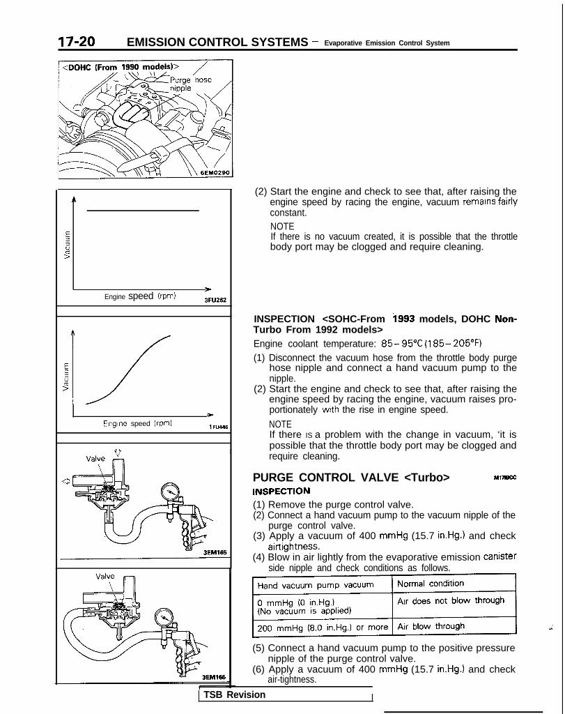
17-20 EMISSION CONTROL SYSTEMS - Evaporative Emission Control System
Engine speed (rpm)>3FU262
E
2
id>
‘_/- )
Engine speed (rpm) 1 FU446
1 TSB Revision
(2) Start the engine and check to see that, after raising theengine speed by racing the engine, vacuum remains fairlyconstant.NOTEIf there is no vacuum created, it is possible that the throttlebody port may be clogged and require cleaning.
INSPECTION <SOHC-From i993 models, DOHC Non-Turbo From 1992 models>Engine coolant temperature: 85- 95°C (185- 205°F)(1) Disconnect the vacuum hose from the throttle body purge
hose nipple and connect a hand vacuum pump to thenipple.
(2) Start the engine and check to see that, after raising theengine speed by racing the engine, vacuum raises pro-portionately with the rise in engine speed.
NOTEIf there IS a problem with the change in vacuum, ‘it ispossible that the throttle body port may be clogged andrequire cleaning.
PURGE CONTROL VALVE <Turbo>INSPECTION
Ml7B.X
(1) Remove the purge control valve.(2) Connect a hand vacuum pump to the vacuum nipple of the
purge control valve.(3) Apply a vacuum of 400 mmHg (15.7 in.Hg.) and check
airtightness.(4) Blow in air lightly from the evaporative emission Canister
side nipple and check conditions as follows.
(5) Connect a hand vacuum pump to the positive pressurenipple of the purge control valve.
(6) Apply a vacuum of 400 mmHg (15.7 in.Hg.) and checkair-tightness.
I

EMISSION CONTROL SYSTEMS - Evaporative Emission Control System 17-21
EC1510
6EM137
EVAPORATIVE EMlS$lON PURGE SOLENOIDINSPECTION M17lBFD
NOTEWhen disconnecting the vacuum hose, make an identificationmark on it so that it can be reconnected to the original posi-tion.(1) Disconnect the vacuum hoses (non stripe and red stripe
hoses) from the solenoid valve(2) Disconnect the harness connector from solenoid valve.(3) Connect a hand vacuum pump to the nipple to which the
red-striped vacuum hose was connected.(4) Apply a vacuum and check for air-tightness when voltage
applied directly to the evaporative emission purge solenoidwhen the voltage is discontinued.
Battery voltage Result
Non-Turbo When applied Vacuum leaks
When discontinued Vacuum is maintained
Turbo When applied Vacuum is maintained
When discontinued Vacuum leaks
(5) Measure the resistance between the terminals of the sole-noid valve.Standard value: 36-44 Q [at 20°C (68”F)l
VOLUME AIR FLOW SENSOR, ENGINECOOLANT TEMPERATURE SENSOR ANDINTAKE AIR TEMPERATURE SENSOR M17IBGB
To inspect these parts, refer to GROUP 13-On-Vehicle Inspec-tion of MFI Components.
AIR CONDITIONING SWITCH Ml7IBHB
To inspect the air conditioning switch, refer to GROUP 55-AirConditioning Switch.
FUEL TANK PRESSURE CONTROL VALVE MI’IIBEB
To inspect the fuel tank pressure control valve, refer to GROUP13-Fuel Tank.
EVAPORATIVE EMISSION CANISTER M17lBlB
To inspect the evaporative emission canister, refer to GROUP13-Fuel Line and Vapor Line.
FUEL TANK FILLER TUBE CAP INSPECTIONM,7,w~
Check the gasket of the fuel tank filler tube cap, and the fillercap itself, for damage or deformation; replace the cap if neces-sary.
TSB Revision I

17-22 EMISSION CONTROL SYSTEMS - Exhaust Gas Recirculation (EGR) System
EXHAUST GAS RECIRCULATION (EGR) SYSTEMCOMPONENT LOCATION
<SOHC-Up to 1992 models>
Name
EGR solenoid <California>
EGR valve
EGR temperature sensor <California>
Thermal vacuum valve <Federal>
Symbol
D
B
C
A
\ temperature
-, ‘F-$3
i
bEM0148
1 TSB Revision
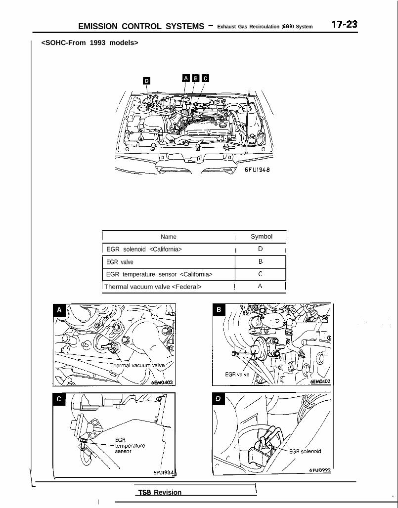
EMISSION CONTROL SYSTEMS - Exhaust Gas Recirculation (EGR) System 17-23
<SOHC-From 1993 models>
I Name I Symbol 1
I EGR solenoid <California> I D I
EGR valve
EGR temperature sensor <California>
B
C
1 Thermal vacuum valve <Federal> 1 A 1
\. ,
6FUl93~
ITSB Revision \ i

17-24 EMISSION CONTROL SYSTEMS - Exhaust Gas Recirculation (EGR) System
<DOHC>
Name
EGR solenoid <California>
EGR valve
EGR temperature sensor <California>
Thermal vacuum valve <Federal>
Symbol
D
B
C
A
6EM0166
TSB Revision

EMISSION CONTROL SYSTEMS - Exhaust Gas Recirculation (EGR) System 17-25
<SOHC (1989 models)> 1
.
<DOHC (1989 models)>
EGR SYSTEM INSPECTION <Federal> Ml7ICJF
(1) Disconnect the vacuum hose (green stripe) from thethrottle body, and connect a hand vacuum pump to thevacuum hose.
(2) Under the engine conditions described below, provide avacuum by using the hand vacuum pump, and then check.
When Engine is Cold-coolant temperature 50°C (122°F) or below
Engine operatingcondition
Applying vacuum R e s u l t
Idling Try applying vacuum Vacuum leaks
When Engine is Hot-coolant temperature 85”-95°C (185”-205°F) or higher
Engine operatingcondition
Applying vacuum Result
Idling 45 mmHg(1.7 in.Hg.1
Vacuum is maintained
Changes fromidling to slightlyunstable
Vacuum is maintained
EGR SYSTEM INSPECTION <California>(1) Disconnect the vacuum hose (green striped hose) from the
exhaust gas recirculation (EGR) valve, and then connect amanual vacuum pump via the three-way terminal.
(2) Check the following points when the engine is cold [enginecoolant temperature is 20°C (68°F) or below] and when theengine is warm [engine coolant temperature is 70°C (158°F)or higher].
1 1 6EMOZW
TSB Revision

17-26 EMISSION CONTROL SYSTEMS - Exhaust Gas Recirculation (EGR) System
<When the engine is cold>
~
<When the engine is warm>
I 6EM0224 1
(3) Disconnect the three-way terminal and connect the manualvacuum pump directly to the exhaust gas recirculation(EGR) valve.
(4) Check whether the engine stalls or the idling is unstablewhen a vacuum of 155 mmHg (5.9 in.Hg) or higher isapplied during idling.
EGR VALVE CONTROL VACUUMINSPECTION
M17WBB
Engine coolant temperature: 85-95°C (185-205°F)(1) Disconnect the vacuum hose from the throttle body EGR
vacuum nipple and connect a hand vacuum pump to thenipple.
TSB Revision
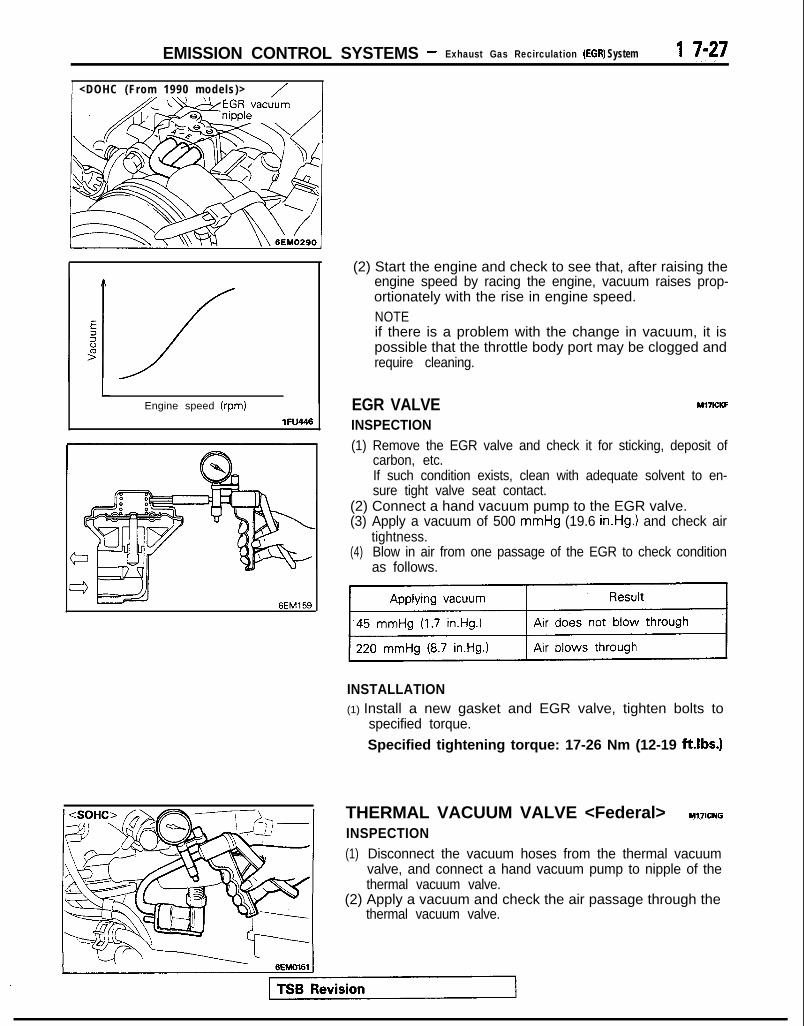
EMISSION CONTROL SYSTEMS - Exhaust Gas Recirculation (EGR) System 1 T-27
1 <DOHC (From 1990 models)> / ]
LEngine speed (rpm)
lFU446
4zJ - 6EM159
(2) Start the engine and check to see that, after raising theengine speed by racing the engine, vacuum raises prop-ortionately with the rise in engine speed.NOTEif there is a problem with the change in vacuum, it ispossible that the throttle body port may be clogged andrequire cleaning.
EGR VALVEINSPECTION
MI’IICKF
(1) Remove the EGR valve and check it for sticking, deposit ofcarbon, etc.If such condition exists, clean with adequate solvent to en-sure tight valve seat contact.
(2) Connect a hand vacuum pump to the EGR valve.(3) Apply a vacuum of 500 mmHg (19.6 in.Hg.) and check air
tightness.(4) Blow in air from one passage of the EGR to check condition
as follows.
INSTALLATION(1) Install a new gasket and EGR valve, tighten bolts to
specified torque.
Specified tightening torque: 17-26 Nm (12-19 ft.lbs.1
THERMAL VACUUM VALVE <Federal> Y~JICNG
INSPECTION(1) Disconnect the vacuum hoses from the thermal vacuum
valve, and connect a hand vacuum pump to nipple of thethermal vacuum valve.
(2) Apply a vacuum and check the air passage through thethermal vacuum valve.

17-28 EMISSION CONTROL SYSTEMS - Exhaust Gas Recirculation (EGR) Svstem
n
7@
REMOVAL(1) When removing the thermal vacuum valve, do not use
wrenches or other tools on the resin part.(2) When disconnecting the vacuum hose, put a mark on the
hose so that it may be reconnected at original position.
INSTALLATION(1) Apply specified sealant to the threads of thermal vacuum
valve and tighten to specified torque. When installing thethermal vacuum valve, do not use wrenches or other toolson the resin part.Specified sealant:
3M NUT Locking Part No.4171 or equivalentSpecified torque: 20-40 Nm (15-30 ft.lbs.)
(2) Reconnect the vacuum hose as it was before.
EGR TEMPERATURE SENSOR <California> Ml’IICZB
INSPECTION(1) Remove the EGR temperature sensor.(2) Place the EGR temperature sensor in water, and then
measure the resistance value between terminals 1 and 2while increasing the water’s temperature.Replace the EGR temperature sensor if there is a signifi-cant deviation from the standard value.
INSTALLATION(1) Install the EGR temperature sensor, tighten to specified
torque.Specified tightening torque:
lo-12 Nm (7.3-8.6 ft.lbs.1
EGR SOLENOID <California>INSPECTIONNOTE
Ml7ICRB
When disconnecting the vacuum hose, make an identificationmark on it so that it can be reconnected to the original posi-tion.
(1) Disconnect the vacuum hoses (yellow and green stripe)from the solenoid valve.
(2) Disconnect the harness connector.(3) Connect a hand vacuum pump to the nipple to which the
green-striped vacuum hose was connected.
TSB Revision

I 6EM0187
EMISSION CONTROL SYSTEMSExhaust Gas Recirculation (EGR) System/
- Catalytic Converter/Air-fuel Ratio Control (MPI) System17-29
(4) Apply a vacuum and check for air-tightness when voltageapplied directly to the EGR solenoid when the voltage isdiscontinued.
(5) Measure the resistance between the terminals of the sole-noid valve.Standard value: 36-44 Q [at 20°C (68”F)]
CATALYTIC CONVERTER Ml7lcBc
INSPECTIONCheck for damage, cracks or fusion and replace if faulty.Caution1. Operation of any type, including idling, should be
avoided if engine misfiring occurs. Under this condi-tion the exhaust system will operate at abnormallyhigh temperature, which may cause damage to thecatalyst or under-body parts of the vehicle.
2. Alteration or deterioration of ignition or fuel system,or any type of operating condition which results inengine misfiring must be corrected to avoid overheat-ing the catalytic converters.
3. Proper maintenance and tuneup according to manu-facturer’s specifications should be made to correct theconditions as soon as possible.
TSB Revision I
MIXTURE CONTROL (MFI) SYSTEMNI,I,w
l For the inspection of mixture control (MFI) system, refer toGROUP 13.
l For the on-board diagnostic, refer to GROUP 13-On-boardDiagnostic.

NOTE

21-1
CLUTCHCONTENTS
CLUTCH CONTROL . . . . . . . . . . . . . . . . . . . . . . . . . . . . . . . . . . . . . . . . . 10 SPECIFICATIONS . . . . . . . . . . . . . . . ..*........................... 2
CLUTCH MASTER CYLINDER . . . . . . . . . . . . . . . . . . . . . . . . 12 General Specifications . . . . . . . . . . . . . . . . . . . . . . . . . . . . . . . . . . 2
CLUTCH PEDAL Lubricants . . . . . . . . . . . . . . . . . . . . . . . . . . . . . . . . . . . . . . . . . . . . . . . . . . . . . . 3. . . . . . . . . . . . . . . . . . . . . . . . . . . . . . . . . . . . . . . . . . . . . . 7Service Specifications . . . . . . . . . . . . . . . . . . . . . . . . . . . . . . . . . . . 2
CLUTCH RELEASE CYLINDER . . . . . . . . . . . . . . . . . . . . . . . 13 Torque Specifications . . . . . . . . . .._....................... 3
SERVICE ADJUSTMENT PROCEDURES . . . . . . . 5 TROUBLESHOOTING . . . . . . . . . . . . . . . . . . . . . . . . . . . . . . . . . . . . . . 4Bleeding . . . . . . . . . . . . . . . . . . . . . . . . . . . . . . . . 6 Clutch chattersClutch Pedal Inspection and Adjustment . . . . 5 Clutch noise
Clutch pedal feels “heavy”Clutch slipsGear shift malfunction
CAUTIONWhen servicing clutch assemblies or com-ponents for vehicles with SOHC engine(Up to 1991 models), do NOT create dustby sanding or by cleaning clutch partswith a dry brush or with compressed air.(A water dampened cloth should be used).The clutch disc contains “Asbestos Fibers”which can become airborne if dust iscreated during service operations. Breath-ing dust containing “Asbestos Fibers”may cause serious bodily harm.

21-2 CLUTCH - Specifications
SPECIFICATIONSGENERAL SPECIFICATIONS MZlCA-
Items
Clutch operattng method
Clutch disc”
TypeFacing diameter
O.D. x I.D.
Specifications
Non-Turbo Turbo
Hydraulic type Hydraulic type
Single dry disc type Single dry disc type
mm (In.) 215 x 140 (8.5 x 5.5) 225 x 150 (8.9 x 5.9)225 x 150 (8.9 x 5.9)‘2
Clutch cover assembly
Type
Clutch release cylinderI.D.
Diaphragm spring Diaphragm springstrap drive type strap drive type
mm (in.) 20.64 (13/l 6) 20.64 (13/16)‘319.05 (3/4)‘4
NOTE+l: Non-asbestos discs on vehicles with DOHC engine and SOHC engine (From 1992 models)‘2: 1992 models DOHC enginel 3: 1991 models“: 1992, 1993 models
SERVICE SPECIFICATIONS
Items Specifications
Standard valueClutch pedal height mm (in.) 176-181 (6.9-7.1)Clutch pedal clevis pin play mm (in.) l-3 (.04-.I21Clutch pedal free play mm (in.) 6-13 (.24-.51)Distance between the clutch pedal and the firewallwhen the clutch is disengaged mm (in.) 55 (2.2) or more
LimitFacing rivet sink mm (in.) 0.3 1.012)Diaphragm spring end height difference mm (in.) 0.5 f.02)
1 TSB Revision

CLUTCH - Specifications 21-3
TORQUE SPECIFICATIONS M2lcc-
Items N m ft.lbs.
Clutch pedal to clutch pedal support bracket 25-35”’ or 20-25*2 18-25”’ or 14-18*2Clutch pedal support bracket 8-12 6 - 9Clutch pedal bracket 8-12 6 - 9
Clutch pedal support bracket to firewall 10-15 7-l 1Brake booster installation nut 11-17 8-12Master cylinder to firewall 10-15 7-l 1
Pedal rod to clutch pedal support bracket 17-26 12-19Clutch tube flare nut 13-17 9-12Clutch tube bracket 8-12 6.0-8.7Clutch release cylinder 15-21 11-15
Clutch release cylinder to union bolt 20-25 14-18Clutch cover assembly 15-21 11-15
NOTE*’ : 1989 models*‘: From 1990 models
LUBRICANTS MZlCD-
Items
inner surface of’ clutch release bearingInner surface of clutch disc splineInput shaft spline
Specified lubricants
MITSUBISHI genuine greasePart No.010101 1 or equivalent
Contact portion of release fork to release cylinder push rod
Inner surface of clutch release cylinder and outer circumference Conforming to DOT 3 or DOT 4of piston and cap
TSB Revision

CLUTCH - Troubleshootinn
TROUBLESHOOTING
Symptom Probable cause Remedy
Clutch slips Insufficient clutch pedal play Adjust
Excessive wear of clutch disc facing Replace
Hardening of clutch disc facing, or adhesion of oil Replace
Clutch release fork catching Repair or replace parts
Weak or damaged diaphragm spring Replace
Clogging of hydraulic system Repair or replace parts
Gear shift malfunction Excessive clutch pedal play Adjust
Distorted clutch disc, excessive oscillation Replace
Clutch cover assembly worn Replace
Clutch disc spline worn or corroded Replace
Clutch disc facing peeling Replace
Clutch release bearing worn Replace
Damaged pressure plate or flywheel Replace
Leakage, air introduction or clogging of hydraulic system Repair or replace parts
Iutch noise Insufficient clutch pedal play Adjust
Improper installation of clutch cover assembly Repair or replace parts
Excessive wear of clutch disc facing Replace
Clutch release fork catching Repair or replace parts
Clutch release bearing worn Replace
Weak or damaged torsion spring Replace
Damaged pilot bushing Replace
Insufficient lubrication of bearing sleeve sliding surface Repair
Clutch pedal feels “heavy” Insufficient lubrication of clutch pedal Repair
Insufficient lubrication of clutch disc spline Repair
Clutch release fork catching Repair or replace parts
Insufficient lubrication of bearing sleeve sliding surface Repair
Iutch chatters Worn or damaged clutch disc facing Replace
Oil adhered to clutch disc facing Replace
Uneven height of diaphragm spring Repair or replace parts
Weak or damaged torsion spring Replace
Damaged pressure plate or flywheel Replace
Loose or damaged mounting Replace or tightenmounting
1 TSB Revision I

CLUTCH - Service Adiustment Procedures 21-5
Clutch pedal height Clutch pedal clevispin play
08104, 08YO43
Vehicles withoutauto-cruise control
Vehicles withauto-cruise control
08A0025
I L\\A- i.14 in.)Nnt,erlock s.y,ityh , Clutch
I I/ / ?--pedal 08AOO41
Clutch pedal free play
08YO43
Distance between theclutch pedal and thefirewall when theclutch is disengaged
‘5 :: :
*\ \\ ;.,\. .-‘.* ..,.
--. . .:,
eir-
.;
D
l3sFO13
SERVICE ADJUSTMENT PROCEDURESCLUTCH PEDAL INSPECTION AND ADJUSTM&‘+d+d
1. Measure the clutch pedal height (from the face of the pedalpad to the firewall) and the clutch pedal clevis pin play(measured at the face of the pedal pad.)Standard value (A): 176-181 mm (6.9-7.1 in.)Standard value (B): l-3 mm (.04-.12 in.)
2. If either the clutch pedal height or the clutch pedal clevispin play are not within the standard value range, adjust asfollows :(1) For vehicles without auto-cruise control system, turn
and adjust the bolt so that the pedal height is thestandard value, and then secure by tightening the locknut.Vehicles with auto-cruise control system, disconnectthe clutch pedal position switch connector and turn theswitch for standard clutch pedal height. Then lock withthe lock nut.NOTEWhen the pedal height is lower than the standardvalue, loosen the bolt or clutch pedal position switch,and then turn the push rod to make the adjustment.After making the adjustment, tighten the bolt or clutchpedal position switch to reach the pedal stopper, andthen lock with the lock nut.
(2) Turn the push rod to adjust the clutch pedal clevis pinplay to agree with the standard value and then securethe push rod with the lock nut.CautionWhen adjusting the pedal height or the clutch pedalclevis pin play, be careful not to push the push rodtoward the master cylinder.
3. Check to be sure that the interlock switch is as shown inthe illustration when the clutch pedal is depressed its fullstroke [I51 mm (6.0 in.)]. If necessary, loosen the lock nutand adjust.
4. After completing the adjustments, confirm that the clutchpedal free play (measured at the face of the pedal pad)and the distance between the clutch pedal (the face of thepedal pad) and the firewall when the clutch is disengagedare within the standard value ranges.Standard value (C): 6-13 mm (.24--51 in.)Standard value (D): 55 mm (2.2 in.) or more
1 TSB Revision
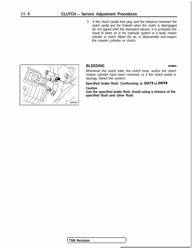
21-6 CLUTCH - Service Adjustment Procedures
5. If the clutch pedal free play and the distance between theclutch pedal and the firewall when the clutch is disengageddo not agree with the standard values, it is probably theresult of either air in the hydraulic system or a faulty mastercylinder or clutch. Bleed the air, or disassemble and inspectthe master cylinder or clutch.
BLEEDING M2lFBAD
Whenever the clutch tube, the clutch hose, and/or the clutchmaster cylinder have been removed, or if the clutch pedal isspongy, bleed the system.
Specified brake fluid: Conforming to DOT3 or DOT4CautionUse the specified brake fluid. Avoid using a mixture of thespecified fluid and other fluid.
1 TSB Revision

CLUTCH - Clutch Pedal m-7
CLUTCH PEDALREMOVAL AND INSTALLATION
<Non-Turbo>
Pre-removal and Post-installation Operation*Removal and Installation of Instrument
Under Cover(Refer to GROUP 52-Instrument Panel.)l Removal and Installation of Steering Col-
umn Assembly (Refer to GROUP 37A-Steering Wheel and Shaft.)
Adjustmentl Adjustment of Brake Pedal (Refer tc
GROUP 35-Service Adjustment Procedures.)
@Adjustment of Clutch Pedal(Refer to P.21-5.)
MZIPA-
2
8-12 Nm6-9 ft.lbs.
r:-20-25 Nmi12Lib-18 ft.lbs.*2 1
lo-15 Nm -7-11 ftlbs.
23
2409AOO79
Semoval steps1. Return spring2. Interlock switch3. Clutch pedal position switch <Vehicles
with auto-cruise control system>4. Bolt <Vehicles without auto-cruise control
system>12. Cotter pin13. Washer14. Clevis pin15. Clutch pedal bracket16. Pedal suppon bracket17. Nut18. Lever
19. Bushing (small)20. Pedal rod21.22.
Bushing (large)Clutch pedal
23. Brake pedal24. Pedal pad
NOTEl ‘: 1989 modelsl *: From 1990 models
TSB Revision

21-8 CLUTCH - Clutch Pedal
<Turbo>
Pre-removal and Post-installation Op-eration*Removal and Installation of instrument
Under Cover(Refer to GROUP 52-Instrument Panel.)
*Removal and Installation of Steering Col-umn Assembly (Refer to GROUP 37A-Steering Wheel and Shaft.)
Adjustmentl Adjustment of Brake Pedal (Refer to
GROUP 35-Service Adjustment Proce-dures.)
*Adjustment of Clutch Pedal(Refer to P.21-5.1
322“,24
00AOO82
Removal stepsI. Return spring 14. Clevis pin
15. @fch pedal bracket2. Interlock switch3. Clutch pedal position switcn5. Cotter pin6. Washer7. Bushing;: E;;i; pin
; ;: poTrer spring
12. Cotter pin13. Washer
16. Pedal support bracket17. Nut18. Lever19. Bushing (small)20. Pedal rod21. Bushing (large)22. Clutch pedal23. Brake pedal24. Pedal pad
TSB Revision

CLUTCH - Clutch Pedal 21-9
INSPECTION M!ZlPCAG
l Check the pedal shaft and bushing for wear.l Check the clutch pedal for bend or torsion.l Check the return spring for damage or deterioration.l Check the pedal pad for damage or wear.
l INTERLOCK SWITCH INSPECTION
Ohmmeter (1) Disconnect the connector.(2) Check to be sure that there is continuity between
connector terminals 1 and 2 when the clutch pedal isdepressed fully.
OGAOO45
TSB Revision

21-10 CLUTCH - Clutch Control
CLUTCH CONTROL h121 JA-
REMOVAL AND INSTALLATION rPre-removal Operationl Draining of the Clutch Fluid Ipiigsql Bleeding of the Clutch Line (Refer
lo-15 Nm7-11 ft.lbs. ,
13-17 Nm9-12 ft.lbs.
9-12 ft.lbs.
\-\ 8-12 Nm6.0-8.7 ft.lbs.
/13-17 Nm9-12 ftlbs.
13-17 Nm9-12 ft.lbs.
Removal stepsI. Cotter pin2. Washer3. Clevis pin
l a 4. Clutch tubel + 5. Clutch tube
a* 6. Hose clips*I) wq 7. Clutch hose
8. Bracket9. Clutch master cylinder
10. Sealer
08A0035
TSB Revision

CLUTCH - Clutch Control
Clutdh hose
-Clutch tube
.., Hose clip
Secure side
08W507
SERVICE POINTS OF REMOVAL M2lJBAD
6. DISCONNECTION OF HOSE CLIPSI7. CLUTCH HOSETo disconnect clutch hose from the clutch tube, proceed.as follows:(1) Secure the nut on the clutch hose and loosen the flare
nut on the clutch tube.
(2) Remove the clip from the clutch hose to remove clutchhose from bracket.
INSPECTION M21JCAC
l Check the clutch hose or tube for cracks or clogging.
SERVICE POINTS OF INSTALLATION hl21JiW
7. INSTALLATION OF CLUTCH HOSE/S. CLUTCH TUBE/4.CLUTCH TUBE
Temporarily tighten the flare nut by hand, and then tightenit to the specified torque, being careful that the clutchhose does not become twisted.

21-12 CLUTCH - Clutch Master Cylinder
CLUTCH MASTER CYLINDERDISASSEMBLY AND REASSEMBLY
MZlNA-
Disassembly steps1. ‘Piston stop ring2. Push rod3. Boot
*I) 4. Piston assembly5. Reservoir cap6. Reservoir band7. Reservoir8. Master cylinder body
08AOO34
Brake Fluid: Conforming to DOT3or DOT4
SERVICE POINTS OF DISASSEMBLY MZlNBAC
4. REMOVAL OF PISTON ASSEMBLYCaution1. Do not damage the master cylinder body and piston
assembly.2. Do not disassemble piston assembly.
\\ 08AOOi4
INSPECTION M21NcAc
l Check the inside cylinder body for rust or scars.l Check the piston cup for wear or deformation.l Check the piston for rust or scars.l Check the clutch tube connection part for clogging.
TSB Revision
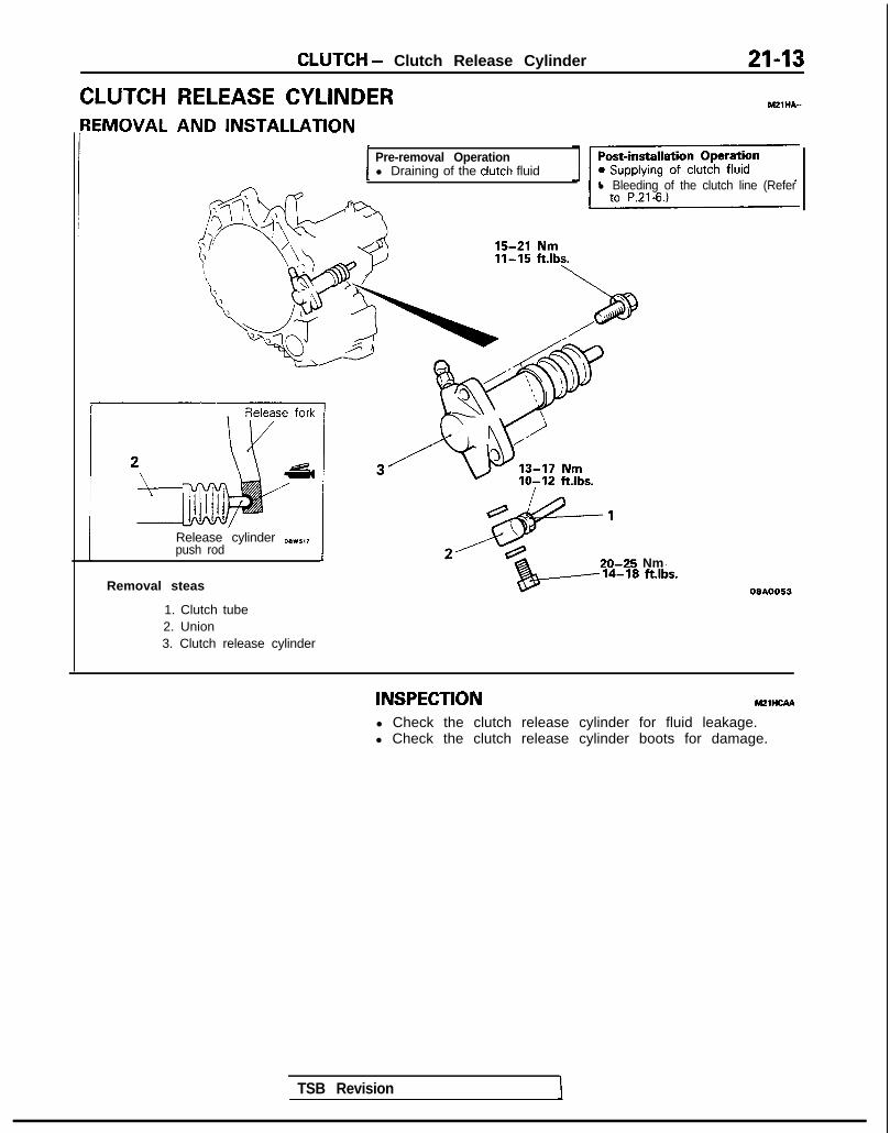
CLUTCH - Clutch Release Cylinder
CLUTCH RELEASE CYLINDER{EMOVAL AND INSTALLATION
Pre-removal Operationl Draining of the clutch fluid
l Bleeding of the clutch line (Refer
Release cylinder O(Ivl,,push rod
TSB Revision 1
20-25 Nm
Removal steas
1. Clutch tube2. Union3. Clutch release cylinder
INSPECTION m21ncAA
l Check the clutch release cylinder for fluid leakage.l Check the clutch release cylinder boots for damage.

NOTES

22-1
MANUALTRANSAXLE
CONTENTS
--mMANUAL TRANSAXLE <MID> . . . . . . . 2MANUAL TRANSAXLE <AWD> ...... 15
SERVICE ADJUSTMENTPROCEDURES .............................................. 17
Drive Shaft Oil Seals Replacement ......... 18
Speedometer Cable Replacement ........... 19
Transaxle Oil Level Inspection ................. 17
Transaxle Oil Replacement ...................... 18
Transfer Oil Seal Replacement ................ 19
SERVICE ADJUSTMENTPROCEDURES .............................................. 4
Drive Shaft Oil Seals Replacement ......... 4
Speedometer Cable Replacement ........... 5
Transaxle Oil Level Inspection ................. 4
Transaxle Oil Replacement ...................... 4
SHIFT LEVER ASSEMBLY . . . . . . . . . . . . . . . . . . . . . . . . . . 9
SPECIAL TOOLS ......................................... 17
SHIFT LEVER ASSEMBLY .......................... 19
SPECIFICATIONS ......................................... 15General Specifications .............................. 15
Lubricants .................................................. 16
Sealants and Adhesives ........................... 16
Torque Specifications ............................... 15
TRANSAXLE ................................................ 20
TRANSAXLE CONTROL .............................. 19
TRANSFER ................................................... 23
TROUBLESHOOTING .................................. 17
SPECIAL TOOLS . . . . . . . . . . . . . . . . . . . . . . . . . . . . . . . . . . . . . . . . . . 3
SPECIFICATIONS ......................................... 2
General Specifications .............................. 2
Lubricants .................................................. 3
Torque Specifications ............................... 2
TRANSAXLE ................................................ 10
TRANSAXLE CONTROL .............................. 6
TROUBLESHOOTING .................................. 3
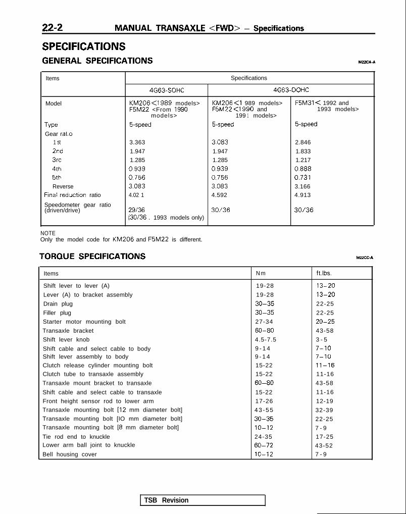
22-2 MANUAL TRANSAXLE <FWD> - Specifications
SPECIFICATIONSGENERAL SPECIFICATIONS MZXA-A
Items Specifications
4G63-SOHC 4G63-DOHC
Model KM206 <1989 models> KM206 <I 989 models> F5M31 < 1992 andF5M22 <From 1990 F5M22 <1990 and 1993 models>
models> 199 1 models>
Type 5-speed 5-speed 5-speed
Gear ratio1 St 3.363 3.083 2.846
2nd 1.947 1.947 1.833
3rd 1.285 1.285 1.217
4th 0.939 0.939 0.888
5th 0.756 0.756 0.731
Reverse 3.083 3.083 3.166Frnal reductron ratio 4.02 1 4.592 4.913
Speedometer gear ratio(driven/drive) 29136 30/36 30/36
(30/36 . 1993 models only)
NOTEOnly the model code for KM206 and F5M22 is different.
TORQUE SPEClFlCATiONS MUCC-A
Items N m ftlbs.
Shift lever to lever (A) 19-28 13-20
Lever (A) to bracket assembly 19-28 13-20
Drain plug 30-35 22-25
Filler plug 30-35 22-25
Starter motor mounting bolt 27-34 20-25
Transaxle bracket 60-80 43-58
Shift lever knob 4.5-7.5 3 - 5
Shift cable and select cable to body 9 - 1 4 7-10Shift lever assembly to body 9 - 1 4 7-10
Clutch release cylinder mounting bolt 15-22 11-16
Clutch tube to transaxle assembly 15-22 11-16
Transaxle mount bracket to transaxle 60-80 43-58
Shift cable and select cable to transaxle 15-22 11-16
Front height sensor rod to lower arm 17-26 12-19
Transaxle mounting bolt [I2 mm diameter bolt] 4 3 - 5 5 32-39Transaxle mounting bolt [IO mm diameter bolt] 30-35 22-25Transaxle mounting bolt [8 mm diameter bolt] IO-12 7 - 9
Tie rod end to knuckle 24-35 17-25Lower arm ball joint to knuckle 60-72 43-52
Bell housing cover 10-12 7 - 9
TSB Revision

MANUAL TRANSAXLE <FWD> - Soec~cations/SpeciI Tools/Troubleshooting 22-3
LUBRICANTS YZZCD-A
Items 1 Specified lubricant 1 Quantity
Manual transaxle oil Hypoid gear oil SAE 75W-85Wconforming to API classificationGL-4 or higher
1.8 dma <KM206, F5M22>(1.9 qts.)2.3 dma <F5M3 l>(2.4 qts.)
Shift lever bushing Front Wheel BearingGrease Part Number 3837794or eauivalent
As required
SPECIAL TOOLS WDA-A
Tool Number Name 1 UseI
MB991 113-01 Steering linkagepuller
OPTIONAL: AVAIlABLE FROM 0.T.C
MD998325-01 Differential oil sealinstaller
0 Disconnection of the coupling of theknuckle and lower arm ball joint
0 Disconnection of the coupling of theknuckle and tie-rod end ball joint
Installation of input shaft front oil seal
TROUBLESHOOTING
Symptom
Vibration, noise
3il leakage
-lard shift
lumps out of gear
Probable cause Remedy
a. Loose or damaged transaxle and a. Tighten or replace mountsengine mounts
b. Inadequate shaft end play b. Correct end play
c. Worn of damaged gears c. Replace gears
d. Use of inadequate grade of oil d. Replace with specified oil
e. Low oil level e. Replenish
f. Inadequate engine idle speed f. Adjust idle speed
a. Broken or damaged, oil seal or O-ring a. Replace oil seal or O-ring
a. Faulty control cable a. Replace control cable
b. Poor contact or wear of synchronizer ring b. Correct or replaceand gear cone
c. Weakened synchronizer spring c. Replace synchronizer spring
d. Use of inadequate grade of oil d. Replace with specified oil
a. Worn gear shift fork or broken poppet a. Replace shift fork or poppet springspnng
b. Synchronizer hub to sleeve spline clear- b. Replace synchronizer hub and sleeveante too large
TSB Revision I

22-4 MANUAL TRANSAXLE <FWD> - Service Adjustment Procedures
09”0110 09FO12
R.H. side x
I I 09K567 I
Front exhaust pipe
SERVICE’ ADJUSTMENT PROCEDURAF
TRANSAXLE OIL LEVEL INSPECTIONRefer to GROUP 00-Maintenance Service.
TRANSAXLE OIL REPLACEMENT MZZFCAD
(1) Position vehicle on a flat level.(2) Remove filler and drain plugs and allow the transaxle oil to
drain.(3) Refill the transaxle to the proper level with specified
transaxle oil. The oil level should be the bottom of the oilfiller hole.
Transaxle oil: Hypoid gear oil SAE 75W-85W conform-ing to API classification GL-4 or higher<KM206, F5M22> 1.8 dm3 (1 .S qts.)<F5M31> 2.3 dm3 (2.4 qts.)
DRIVE SHAFT OIL SEALS REPLACEMENT MYSDAG
(1) Disconnect the drive shaft from the transaxle.(Refer to GROUP 26-Drive Shaft.)
(2) Using a flat-tip (-) screwdriver, remove the oil seal.
(3) Using the special tool, tap the drive shaft oil seal into thetransaxle.
(4) Apply a coating of the transaxle oil to the lip of the oil seal.
Transaxle oil: Hypoid gear oil, SAE 75W-85W con-forming to API GL-4 or higher
MD998325-01 160024
1 TSB Revision

MANUAL TRANSAXLE <FWD> - Service Adjustment Procedures 27-5
Adapter 09A0058
TSB Revision
SPEEDOMETER CABLE REPLACEMENT ~~FEIE1. Correctly insert the adapter into the instrument panel, and
fasten the new speedometer cable.
2. Install the grommet so that, as shown in the illustration, the’cable attachment part is positioned upward.
Caution1. The cable arrangement should be made so that the
radius of cable bends is 150 mm (5.9 in.) or more.2. The arrangement of the speedometer cable should
be such that it does not interfere with brake tubes,etc.
3. At the transaxle end of the speedometer cable, the keyjoint should be inserted into the transaxle, and the nutshould be securely tightened.
CautionIf the cable is not correctly and securely connected, itmay cause incorrect indication by the speedometer, orabnormal noise. Be sure to connect it correctly.

22-6 MANUAL TRANSAXLE <FWD> - Transaxle Control
TRANSAXLE CONTROLREMOVAL AND INSTALLATION hl22JA-A
Removal steps1. Cotter pin2. Retainer3. Retainer4. Cotter pin
l * 5. Shift cablel + 6. Select cable
7. Shift lever assembly
Pre-removal and Post-installation 1Operation*Removal and Installation of Console I
~$%!m$$NP Z-Floor Con-l
<Up t o 1990 models>
<From 1991 models>
9-14 Nm7-10 ftlbs.
09A0060
OSAO185
INSPECTIONl Check the select cable for function and for damage.l Check the shift cable for function and for damage.l Check the boot for damage.l Check each bushing for wear or abrasion, sticking,
impeded action, and damage.l Check the spring for deteriorated strength.
TSB Revision

MANUAL TRANSAXLE <FWD> - Transaxle Control 22-7
ect- cable \
I
Lever (B)
09A0160
I Incorrect-I I
SERVICE POINTS OF INSTALLATION M22JDAK6. INSTALLATION OF SELECT CABLE
(1) Move the transaxle shift lever to the neutral position.
NOTEThe select lever will be set to the neutral position whenthe transaxle shift lever is moved to the neutralposition.
(2) Move lever (B) to the neutral position.
(3) Adjust, by using the adjuster, so that the end of theselect cable is positioned as shown in the illustrationrelative to lever (B).
(4) The flange side of the resin bushing at the select cableend should be at the lever (B) end surface.
5. INSTALLATION OF SHIFT CABLE(1) With the select lever in neutral, move the transaxle shift
lever (in the direction shown in the illustration) to set itto 4th gear.
NOTEIf the shift lever does not move easily, depress and holdthe clutch pedal.
1 TSB Revision

22-8 MANUAL TRANSAXLE <FWD> - Transaxle Control
09A0037
Incorrect
Shiftlever
Correct
Incorrect
09AO159
(2) Move the shift lever (at the vehicle interior side)downward, in the direction (4th gear position) shown inthe illustration until it contacts the stopper.
(3) Adjust, by using the adjuster, so that the end of the shiftcable is positioned as shown in the illustration relativeto the shift lever (interior side).
(4) The flange side of the resin bushing at the shift cableend should be at the split pin side.
(5) Adjust the length of the shift cable, by using theadjuster, so that the clearance (A) and (B) between theshift lever and the two stoppers are equal when theshift lever is shifted to 3rd gear and 4th gear.
(6) Move the shift lever to each position and check that theshifting is smooth.
TSB Revision

MANUAL TRANSAXLE <FWD> - Shift Lever Assembly
SHIFT LEVER ASSEMBLY MZZGE-A
DISASSEMBLY AND REASSEMBLY<up to 1990 models>
119-28 Nm
<From 1991 models> 13-20 \ft.lbs. 12 A .2
19-28 Nm 6 - 6 w*- “yk!3
m8 /
17-28 Nm13T18 ft.lbs.
Disassembly steps1. Shift lever2. Bushing
l + 3. Return spring4. Bushing5. Lever (A)6. Bushing7. Collar <From 1991 models>8. Bushing9. Snap ring
10. Lever (B)11. Bushing12. Bracket assembly
- i9AOl60
SERVICE POINTS OF REASSEMBLY M22GHAJ
3. INSTALLATlON OF RETURN SPRINGMake sure that the end of the spring contacts the part(shown in the illustration) of the bracket.
I1 TSB Revision I

22-10 MANUAL TRANSAXLE <FVVD> - Transaxle
TRANSAXLEREMOVAL AND INSTALLATION
MZMA-A
27-34 Nm20-25 ft.lbs.
60-80 Nm*43-58 ft.lbs.*
11-16 ft.lbs. 71
11-16 ftlbs.
Removal steps
l * 1, Connection for compressor assembly<ACTIVE-ECS>
2. Cotter pin3. Connection for select cable4. Connection for shift cable
a* 5. Connection for clutch release cylinder6. backup light switch connector7. Connection for speedometer cable
l + 8. Connection for starter9. Transaxle assembly upper part coupling
tJ01t10. Transaxle mount bracket
Pre-removal Operation@Draining of the Transaxle Oil (Refer to P.22-4.)*Removal of the Battery and Battery Trayl Removal of the Air Cleaner Assembly
(Refer to GROUP 15-Air Cleaner.)
Post-installation Operationasupplying of Transaxle Oil (Refer to P.224.)l Installation of the Air Cleaner Assembly
(Refer to GROUP 15-Air Cleaner.)l Installation of the Battery and Battery Tray*Checking the Operation of the Shift Leverl Checking the Ooeration of the Meters and Gauaes
NOTE-t-or tightening locations indicated by the * symbol, firsttighten temporarily, and then make the final tightening withthe entire weight of the engine applied to the vehicle body.
1 TSB Revision

MANUAL TRANSAXLE <FWD> - Transaxle
60-72 Nm43-52 ftfbs.
i“1
30-35 Nm2 2 - 2 5 ft.lbs. /(
7-4 filhs
60-72 Nm43-52 ftlbs.
/-
.,- 17-25 ft.lbs.17-26 Nm12-19 ft.lbs.
09A0019
+I) Il. Under cover12. Cotter pin
*I) 13. Connection for tie rod end14. Self-locking nut
l 4 15. Front height sensor rod <ACTIVE-ECS=i4* 16. Connection for lower arm ball jointCI) +4 17. Connection for drive shaft
18. Circiip19. Bell housing cover20. /?a;saxle assembly lower part coupling
21. Transaxle assembly
TSB Revision
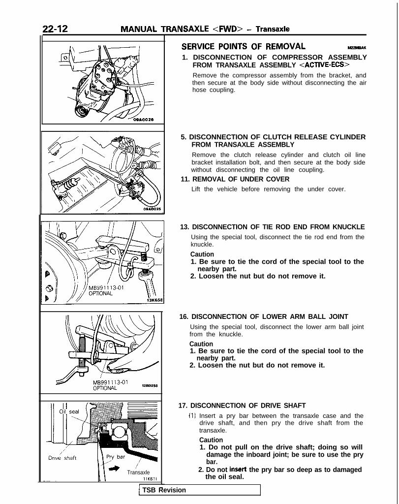
22-12 MANUAL TRANSAXLE <FWD> - Transaxle
* ’TransaxlellK611
I -I-
1 TSB Revision
SERVICE POINTS OF REMOVAL M22MBAK1. DISCONNECTION OF COMPRESSOR ASSEMBLY
FROM TRANSAXLE ASSEMBLY <ACTIVE-ECS>Remove the compressor assembly from the bracket, andthen secure at the body side without disconnecting the airhose coupling.
5. DISCONNECTION OF CLUTCH RELEASE CYLINDERFROM TRANSAXLE ASSEMBLYRemove the clutch release cylinder and clutch oil linebracket installation bolt, and then secure at the body sidewithout disconnecting the oil line coupling.
11. REMOVAL OF UNDER COVERLift the vehicle before removing the under cover.
13. DISCONNECTION OF TIE ROD END FROM KNUCKLEUsing the special tool, disconnect the tie rod end from theknuckle.
Caution1. Be sure to tie the cord of the special tool to the
nearby part.2. Loosen the nut but do not remove it.
16. DISCONNECTION OF LOWER ARM BALL JOINTUsing the special tool, disconnect the lower arm ball jointfrom the knuckle.
Caution1. Be sure to tie the cord of the special tool to the
nearby part.2. Loosen the nut but do not remove it.
17. DISCONNECTION OF DRIVE SHAFT(1) Insert a pry bar between the transaxle case and the
drive shaft, and then pry the drive shaft from thetransaxle.
Caution1. Do not pull on the drive shaft; doing so will
damage the inboard joint; be sure to use the prybar.
2. Do not insert the pry bar so deep as to damagedthe oil seal.

MANUAL TRANSAXLE <FWD> - Transaxle 22-13
part of irive shaft ITransaxle
09LOO58
12R0124
Normal
12R036: s
TSB Revision
(2) Keep the removed drive shaft as far away from thetransaxle case as possible, and secure (by using rope,etc.) the joints to the body so that it does not fall.
21. REMOVAL OF TRANSAXLE ASSEMBLYSupport the transaxle assembly by using a transaxle jack;then, after moving the transaxle assembly to the right,lower it.
NOTEWhen supporting the transaxle’assembly by the transaxlejack, take care to be sure that the jack’s force is applied to awide area, not to only a small localized area.
SERVICE POINTS OF INSTALLATION MZ?MDAK
17. INSTALLATION OF DRIVE SHAFT(1) Provisionally install the drive shaft so that the inboard
joint part of the drive shaft is straight, and not bentrelative to the transaxle.
CautionCare must be taken to ensure that the oil seal lippart of the transaxle is not damaged by the serratedpart of the drive shaft.
(2) Align the serrations and securely insert the drive shaftinto the transaxle.
15. INSTALLATION OF FRONT HEIGHT SENSOR RODInstall the rod so that dimension A in the figure is within thefollowing range.
Dimension A: 254.5* 0.5 mm (lo& .02 in.)NOTE(1) Adjust the rod length so that dimension B is equal.
(2) The ball joint on the end of the rod should be installedwith the ball centered.Defective
I

22-W MANUAL TRANSAXLE <FWD> - Transaxle
r I 8. INSTALLATION OF STARTERTighten with the lower starter installation the wiringharness clip bolt.
09POOl3
1 TSB Revision

MANUAL TRANSAXLE <AWD> - SDecifications 2245
SPECIFICATIONS M?zcA-BGENERAL SPECIFICATIONS
Items Specifications
Model W5M31Applicable engine 4G63
Tvw 5-speedGear ratio
1 St 2.8462nd 1.6843rd 1.1154th 0.8335th 0.690Reverse 3.166
Reduction ratioPrimary 1.680Secondary 3.100Transfer 1.090
Speedometer gear ratio (driven/drive) 30136
NOTE: The AWD vehicles have been discontinued from 1993 models.
W5M33
4G63-TIC
5-speed
2.846
1.684
1.115
0.833
0.666
3.166
1.275
3.866
1.090
30136
TORQUE SPECIFICATIONSTRANSAXLE
Items
Bell housing cover mounting bolt 10-12 7 - 9Starter motor mounting bolt 27-34 20-25Transaxle mount bracket mounting bolt 60-80 4 3 - 5 8Shift cable and select cable bracket mounting bolt 15-22 11-16Rear cover mounting bolt 35-42 26-30Transaxle case mounting bolt 35-42 26-30Clutch release cylinder mounting bolt 15-22 11-16Clutch tube to transaxle assembly 15-22 11-16Front height sensor rod to lower arm 17-26 12-19Transaxle mounting bolt [I2 mm diameter bolt] 4 3 - 5 5 32-39Transaxle mounting bolt [IO mm diameter bolt] 30-35 22-25Transaxle mounting bolt 18 mm diameter bolt] IO-12 7 - 9Tie rod end to knuckle 24-35 17-25Lower arm ball joint to knuckle 60-72 43-52Center bearing bracket installation bolts 36-46 26-33Front exhaust pipe to exhaust fitting 30-40 22-29Front exhaust pipe clamp 30-40 22-29Right member installation bolt (front) 30- 100 58-72qight member installation bolt (rear) 70-80 jl-58rransfer assembly mounting bolt 55-60 IO-43
Nm
M22CGB
ft.lbs.
TSB Revision I

22-16 MANUAL TRANSAXLE <AWD> - Specifications
Items Nm ftlbs.
Restrict ball 30-35 22-25Speedometer mounting bolt 3 - 5 2.5-3.5Oil filler plug 30-35 22-25Oil drain plug 30-35 22-25Input shaft lock nut 140-160 102-115Intermediate shaft lock nut 140-160 102-115Center differential drive gear mounting bolt 70-80 51-57Front differential drive gear mounting bolt 130-140 95-101Stopper bracket mounting bolt 15-22 11-15Reverse idler gear shaft mounting bolt 43-55 32-39Reverse shift lever mounting bolt 15-22 71-15Bearing retainer mounting bolt 15-22 11-15Interlock plate mounting bolt 20-27 15-19Center member mounting bolt 60-80 43-58
Drive shaft center bearing mounting bolt 36-46 26-33
Driven bevel gear lock nut 740-160 lOl-‘1’15Select lever assembly mounting bolt 15-22 11-15qeverse brake cone screw bolts 4.0-5.5 3 - 4
TRANSFER
1 Items ) Nm ) ft.lbs. I
Transfer assembly mounting bolt 55-60 40-43Hanger bracket mounting bolt 15-22 11-15
Front exhaust pipe and exhaust manifold <Non-Turbo> 30-40 2 2 - 2 9
Front exhaust pipe to exhaust fitting <Turbo> 40-60 29-43Front exhaust pipe clamp bolt 30-40 22-29
LUBRICANTS Mz2co-B
Items
Transaxle
Transfer
Specified lubricant Quantity drnj (qts.)
Hypoid gear oil, SAE 75W/8OW conforming to API classification GL-4 or higher 2.3 (2.4)
Hypoid gear oil, SAE 75W/8OW conforming to API classification GL-4 or higher 0.6 t.6)
SEALANTS AND ADHESIVESTransaxle
M22cE.B
I Items 1 Specified sealant and adhesive I
Faying surfaces of transaxle case and clutch housing Mitsubishi genuine sealantPart No. MD997740 or equivalent
Faying surfaces of clutch housing and adapter
TSB Revision

MANUAL TRANSAXLE <AWD> - k% :;%t,rtb’kkii%i 22-l 7
SPECIAL TOOLS MZSDA-
Tool Number Name I Use
w MB99 1193r
Plug Prevention of entry of foreign objects intothe transaxle and transfer
L
MD998803 Differential 011 seal Installation of differential oil seal
t&-
installer
MD998304-0 1 Oil seal installer Installation of front output shaft bearing andtransfer extention housing oil seal
TROUBLESHOOTINGRefer to P.22-3.
M22EAAE
SERVICE ADJUSTMENT PROCEDURESTRANSAXLE OIL LEVEL INSPECTION mRefer to GROUP 00-Maintenance Service.
\ //’ 09AOO24

22-18 MANUAL TRANSAXLE <AWD> - Service Adjustment Procedures
I I 09K567
09K56f
For L.H. For R.H.
Dust
5
-
TRANSAXLE OIL REPLACEMENT M22FC.AH
(1) Position vehicle on a flat level and remove filler and drainplugs to drain transaxle oil.
(2) Pour in fresh transaxle oil through filler port until it reachesthe bottom of filler port.
Transaxle oil: Hypoid gear oil SAE 75W-85W conform-ing to API classification GL-4 or higher
Transaxle: 2.3 dm3 (2.4 qts.)Transfer: 0.6 dm3 (.6 qt.)
DRIVE SHAFT OIL SEALS REPLACEMENT MZZFDAH(1) Disconnect the drive shaft from the transaxle.
(Refer to GROUP 26-Drive Shaft.)(2) Remove the transfer assembly.(3) Using a flat-tip (-) screwdriver, remove the oil seal.
(4) Install the oil seals using the following procedure:Using the special tool, tap the oil seal into the transaxle.Note that there are two types of oil seals, one for R.H. andthe other for L.H., and the shape of each type is different,as shown.
1 TSB Revision

MANUAL TRANSAXLE <AWD> Service Adjustment Procedures/- Transaxle Control/Shift Lever Assembly 22-19
I L.H. side _
MC;998~3 / ( )
TRANSFER OIL SEAL REPLACEMENT hl22FGAF
(1) Pull out the propeller shaft from the transaxle. (Refer toGROUP 25-Propeller Shaft.)
(2) Using a fiat-tip (-) screwdriver, remove the oil seal.
(3) Using the special tool, tap the drive shaft oil seal into thetransaxle.
(4) Apply a coating of the transaxle.
Transaxle oil: Hypoid gear oil SAE 75W-85W conform-ing to API classification GL-4 or higher
SPEEDOMETER CABLE REPLACEMENT ~22~Refer to P.22-5.
TRANSAXLE CONTROL M22JA.B
Refer to P.22-6.
SHIFT LEVER ASSEMBLY MZZGE-8
Refer to P.22-9.
TSB Revision

22-20 MANUAL TRANSAXLE <AWD> - Transaxle
TRANSAXLEREMOVAL AND INSTALLATION MZMA-B
l Removal of the Battery and Battery Tray*Removal of the Air Cleaner Assembly
(Refer to GROUP 15-Air Cleaner.)
15-22 Nm11-16 ft.lbs.-
lo-12 Nm7-8 ft.lbs. ;
Post-installation Operation@Supplying of Transaxle Oil
(Refer to P.22-18.)l Installation of the Air Cleaner Assembly
(Refer to GROUP 15-Air Cleaner.)*Installation of the Battery and Battery
Tray*Checking the Operation of the Shift
Lever*Checking the Operation of the Meters
and Gauges
60-80 Nm*
27-34 Nm43-58 ft.lbs.*
20-25 ft.lbs. 60-80 Nm
43-55 Nm _
15-22’ Nm11-16 ft.lbs.
6
-15-22 Nm11-16 ftlbs.
09AOOS4
Removal steps1. Cotter pin2. Connection for select cable3. Connection for shift cable4. Connection for clutch release cylinder
(Refer to P.22-12.)5. Connection for backup light switch
connector6. Connection for speedometer cable7. Connection for starter (Refer to P.22-14.)8. ;,,:saxle assembly upper part coupling
9. Transaxle mount bracket
NOTEFor tightening locations indicated by the * symbol. firsttighten temporarily, and then make the final tightening withthe entire weight of the engine applied to the vehicle body.
TSB Revision

MANUAL TRANSAXLE <AWD> - Transaxle 22-21
24 30
30-35 Nm22-25\ ftlbs.
-. 60-72 Nm\‘I..- \) 43-52 ti.lhe~
lo-12 Nm7-9 ft.lbs. 1
40-43 ftlbs..-
3d-2F Nm
--A 17-25 ft.lbs.36-46 -_ -- Nm _ _. -7.
--.--l ‘-“’ 2 6 - 3 3 ftlbs. ,f ’ 80-106 NmEQ-73 fi Ihr 77
30-40’ Nm22-28 ft.lbs.
<Non-Turbo>30-40 Nm22-29 ftlbs.
70-80 Nm51-58 ft.lbs.
<Turbo>40-60 Nm29-43 ft.lbs.
l *
10. Under cover11. Speed sensor <Vehicles with Anti-lock
Braking System>12. Cotter pin13. Connection for tie rod end (Refer to
P.22-12.)14. Self-locking nut15. Connection for lower arm ball joint (Refer
to P.22-12.)16. Connection for drive shaft (Refer to P.22-
12.)
17. Circlip18. Front exhaust pipe19. Transfer assembly (Refer to P.22-23.120. Bell housing cover21. Right member22. Gusset23. ;f;saxle assembly lower part coupling
24. Transaxle assembly (Refer to P.22-13.1
TSB Revision

MANUAL TRANSAXLE <AWD> - Transaxle
“\)I
wbI 1 \I
1M #\\ 11Aoooo
SERVICE POINTS OF REMOVAL M22MBAT
16. DISCONNECTION OF DRIVE SHAFT<R.H.>insert a pry bar between the transaxle case and the driveshaft, and then pry the drive shaft from the transaxle.
Caution1. Do not pull on the drive shaft; doing so will damage
the inboard joint; be sure to use the pry bar.2. Do not insert the pry bar so deep as to damage the
oil seal.<L.H.>(1) Take out the drive shaft by lightly tapping the drive shaft
T.J. case with a plastic hammer.
NOTERemove the drive shaft with the hub and knuckle, etc.,as an assembly.
Caution1. Removing the drive shaft from the outboard
joint side can cause damage to the inboard joint.Always use a plastic hammer, etc., to removethe drive shaft.
2. Tapping on the center bearing can damage it.Never tap on the bearing.
(2) Keep the removed drive shaft as far away from thetransaxle case as possible, and secure (by using rope.etc.) the joints to the body so that it does not fall.
TSB Revision
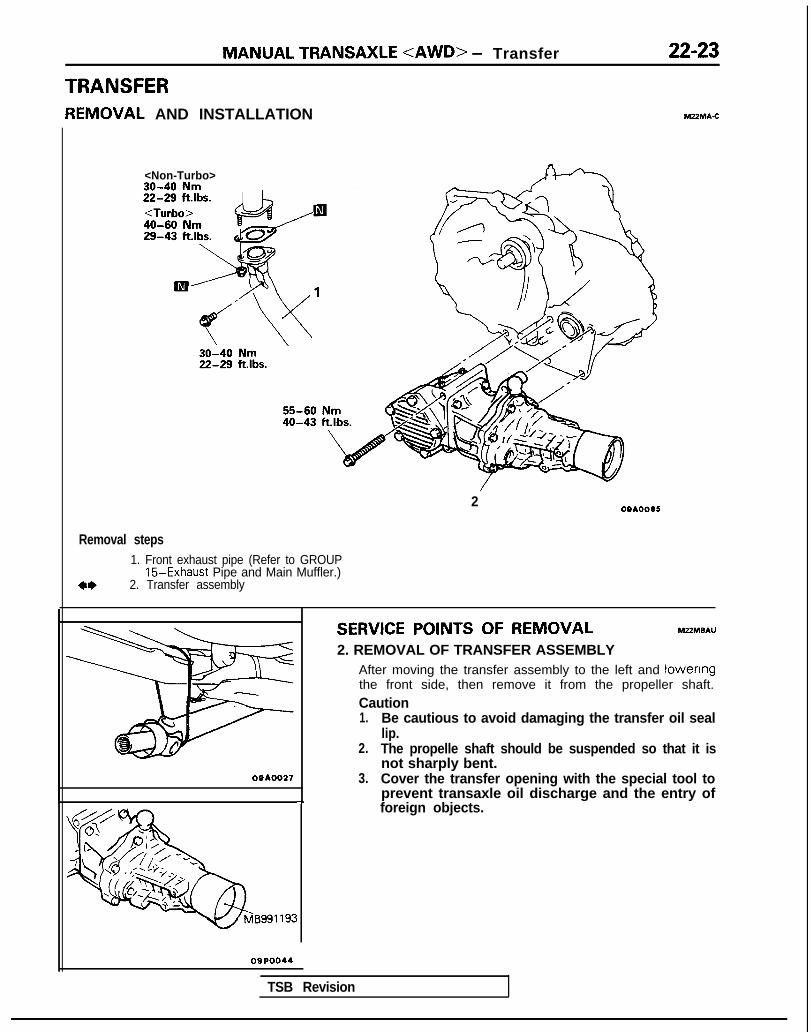
MANUAL TRANSAXLE <AWD> - Transfer
TRANSFERREMOVAL AND INSTALLATION
22-23
M22MA.C
<Non-Turbo>
Removal steps1. Front exhaust pipe (Refer to GROUP
15-Exhaust Pipe and Main Muffler.)2. Transfer assembly
SERVICE POINTS OF REMOVAL MZZMBAU
2. REMOVAL OF TRANSFER ASSEMBLYAfter moving the transfer assembly to the left and lowenngthe front side, then remove it from the propeller shaft.Caution1. Be cautious to avoid damaging the transfer oil seal
lip.2. The propelle shaft should be suspended so that it is
not sharply bent.09AOO27 3. Cover the transfer opening with the special tool to
prevent transaxle oil discharge and the entry of-I foreign objects.
20910095
OQPOO44
TSB Revision

NOTES

23-1
AUTOMATICTRANSAXLE
CONTENTS hl23AA-
GENERAL INFORMATION . . . . . . . . . . . . . . . . . . . . . . . . . . . .
SERVICE ADJUSTMENT PROCEDURES.. ...Drive Shaft Oil Seals Replacement ...........
Key Interlock Mechanism Check ...............
Kickdown Servo Adjustment ......................
Line Pressure Adjustment .........................
Park/Neutral Position SwitchAdjustment ............................................................
Reducing Pressure Adjustment .................
Selector Lever Operation Check ...............
Shift Lock Mechanism Check ....................
Speedometer Cable Replacement .............
Throttle-position Sensor Adjustment ..........
Transaxle Fluid Level Inspection ........... i ...
Transaxle Fluid Replacement .....................
Transfer Oil Level Inspection .....................
Transfer Oil Replacement ..........................
SPECIAL TOOLS . . . . . . . . . . . . . . . . . . . . . . . . . . . . . . . . . . . . . . . . . . . 21
SPECIFICATIONS ........................................... 19General Specifications ................................ 19
Lubricants .................................................... 20Torque Specifications ................................. 20
2 TRANSAXLE ASSEMBLY <AWD> . . . . . . . . . . . . . 105
8292838688
84918384939282828282
TRANSAXLE ASSEMBLY <FWD> . . . . . . . . . . . . . 101
TRANSAXLE CONTROL . . . . . . . . . . . . . . . . . . . . . . . . . . . . . . . 94
TRANSAXLE OIL COOLER HOSES . . . . . . . . . . . . . 100
TRANSFER . . . . . . . . . . . . . . . . . . . . . . . . . . . . . . . . . . . . . . . . . . . . . . . . . . . . . 108
TROUBLESHOOTING .............. . .....................Circuit Diagram ...........................................
Converter Stall Test ...................................
Data link and Test ................................................
E.L.C. 4-speed Automatic TransaxleControl Components Layout ......................
Element in Use at Each Positionof Selector Lever .......................................
Fail-safe Item ..............................................
Fault Code Description ...............................
Oil Pressure Tests .....................................
Shift Patterns ..............................................
Transaxle Control ........................................
22605926
80
373228523759


2 3 - 2 AUTOMATIC TRANSAXLE - General Information
GENERAL tNFORMATlONlydraulic CirCuit-Neutral for 1989 and 1990 model
owe Converterl”tCh Controloienold
TO ILiDilCdliUlllfl”llllTO l11111,i .,I,“”, cari
m Ll”P ,ireasure
0 MOd”ldle’i ,<ne *,eiaure
0TO,qlle ~o,I”Br,PI sod l”biiCJliO”preiaure
~%d”,,I-
m TOrg”econ”arte‘ClUtCl3res9”ie
0 Ple*s”le CO”lr”l pressure
0Torque COnvelter ClutchControl pressure
0 P”m* s”~tlon pressure
m Reducing ,11~55118 tbsttral
1750224
I TSB Revision


AUTOMATIC TRANSAXLE - General Information 23-3
iydraulic Circuit-Parking for 1989 and 1990 model
OFF
b@
o,c;ue COPYe~i”Wh rnntmdenold
1” llllllcdt~on,,W”llTO ,“tmc,ltlnrl c=m,c,,r,
m LN”F pr”,““P
0 Mi!d”l‘lWd IIllS ,>w+5ure
Torque ColwCllel arci l”br~ca:l”n0 prelFI;IP
] TorquF “onverter 3 P,< ,,l,lD CO”llll we>wrsC’UWh pressue
1 T"rq"P convene clutchCO"VOl ples5"le 0 P,,,,W F"C!lUll r)lesd~e
1 Reduclr 9 P ess.lrc PNklnp


23-4
.-- ..-. - _~_.
AUTOMATIC TRANSAXLE - General Information
ydraulic Circuit-Drive First for 1989 and 1990 model
E”T&e COnYeltel,lCll cmtr31,e”“ld
i<> ILll~IlI 1l~W/I,( 1.1:
T,, il1ihl 1111!>mu<, III
m ,I”P”‘CSSIIIP0 Maduialed IhrP PIPSSU’U
Torque co”Y’,lel and l”bl~c:lior0 p,llY5Llle
1: -J-Jjq~ Ai,
uTorqde COnYelIerhmh P~BSS”ll
o hTZ ;;12;!r Cl”ml
m R&K “q pressure
[? P,eSS”le‘“nvOl plesS”rP
0 Pump IX, “I. pleliwe
Drive (FW
TSB Revision 1


AUTOMATIC TRANSAXLE - General Information 23-5
Hvdraulic Circuit-Drive Second for 1989 and 1990 model
~ qT Ml” ?Itrn,
::_ “_
El CO”llO.“lC110 d
I,,WF “4”‘
lmTorque COnYenFlClLe‘h oress”T

23-6
..-- -
AUTOMATIC TRANSAXLE - General Information
lydraulic Circuit-Drive Third for 1989 and 1990 model
c
=G-1Olq”e cmr:,:,,rrrh ““ntral,lWOld
TO IMmc,,llor~/,r,,,,,: -1,,11111111 .111”1 L
,11~.111
kz;e, pf
Y,II”I:
iv*, ,C”P,Fi(F ,,,I, L “ldl qe,,, L,“,rh bldk ill’l LlUKh
\:
FfJfB, ik3 ,
2 F.I
1;
I
, ill,? /PI eiii “1l”C
tr
e converte,pressure
cj Pressure tonlw ,IW~S”~C
e convener Clutch>/ ore98”re 0 PUrn~ blJrf,o” P’cswle
m Reduclrly OresSUre mive mw
1 TSB Revision

c
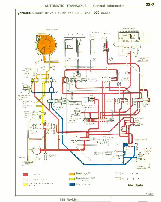
AUTOMATIC TRANSAXLE - General Information 23-7
lydraulic Circuit-Drive Fourth for 1989 and 1990 model
Ol‘l-.
E--
3
I,, IIi-
.I!4Olil,,,, ,p ii
1 JIWI’,I/b” ,/
r~ ,.,. 0 ,. ,., ,, , ,,< > /,,/ 8,. ,I.,, 1,,1,1,,, .,
,&
1 Ps1-i 1 /
--1
If@+ ILl-111 1
'47 ii ’I,?
Lo .Y_P RNDZL..
-: ?: -1)
I :,1, ,ll,l1.6 .,,,,_
I -;;;;;;-/,L.
- . ,FI,X,ldOn rot WOOLI?
TO,‘q”l < Wlil II/1 181 111, ,,r/ Cl’xCh !m3S”E El, II 111 II
0 M ,,,I/, I/ 1/, /III (1 ITorque COnYener ClLllChCO”l‘Ol piessule 01, / ,I, 111
,,,,,, I, , r,\ (1, 11\1/ ,111 I/ I, II0, 111 m R,Pdhi 111, ,/lji\5U/< Jlriue (Fourth)
I i,,l,,‘>i,
TSB Revision I


23-8 AUTOMATIC TRANSAXLE - General Information
lydraulic Circuit-Lock-up for 1989 and 1990 model
orque Cc’““PTtCI~e~tllnm
T , 11,111 /11<11,,1>,1
r> ,,,r ow,I /I,
/ “4 1L,“l?i-l cr
,I<> FI,/, E>
hml C!“fCii
EII
TOrq”Pca”“ene,Cl”w7 DressuieTorque cO”Yerte~ ClAChCOnm prrsnure
m R&“C “9 *ieiS”ri
0 Pr,.FFIIvc”nlrJl PlP%“le
0 P”mDs”ctl, I, rr5sure
Lwk-up ttirsff
) TSB Revision


AUTOMATIC TRANSAXLE - General Information
lydraulic Circuit-Reverse for 1989 and 1990 model
23-9
T” “b 11101’ .,llW I,
l!!!z
Hrpulafor“dl”r
!lir?
I
t
011 ilIter 011,l”WJ
---__-_ONI pan
m hC PI<ISSIIIP0 Modulaled lk DreIsurP
Torq”econ”erterorld IlJbr~cat~orpEJ presi”re
I %$&d”~et J
m TOrq”ecan”ener 0 P,eZF”,eC”ritl”l pleiS”iPCl”tCh pre95ure
m Torque converter C1UlChCLmlOi pressure
0 &ml&z Flrtl011 VlPrFUle
m %iucing L)ILISIIIPRevefsr


23-10 AUTOMATIC TRANSAXLE - General Information
Hydraulic Circuit-Neutral for 1990.5, 1991, 1992 and 1993 model
IFF!
‘;q 1’7 ,/‘a
-“;qj,,
/ l‘d”saXleconm module
1 I---r-
/~,““”CilJtCh Controlsolenoid
TO l”bllCatlO” .Ih”f,
70 l”bllCdll’>” .Irear,
-3 I’-7r ~Tz=+h/==Ht~F=%ll
bme
0 01, p,mp i”CIl”” VESSUIL0 Torque conumer
C,LxCh p‘essure
0 Modulared ,,ne PreSSLilP 0Torque ronvener ClutchContra, BOlenOlc PrP5s”re
0p,eiwre Control SOWOldValve piesslm
pGGq
VA0070
/ TSB Revision


AUTOMATIC TRANSAXLE - General Information2 3 - 1 1
Hydraulic Circuit-Parking for 1990.5, 1991, 1992 and 1993 model
TCChSC
r
/
~derxld
TO ,“brlcarlon _(fW,lf,~o~cmo� l
Torque
E~m~<wp
dYC .I
1’ ’Pi! Jlk El
+k*:ki1i5g=y19 - ras‘J-JzJf :h?P~!“,’ *‘ ii*
e-4 j4;ia
“p C”““e”Cl 3”O 1s “rlCauJ’S”T
,c,ng pieTF”rC
0 o,, pump 5uct,on P‘ePs”-
0 Mod”,a;ed ,sne plersllle
0pre5ju,e CO”fl”l sOiEf~nd“he plessur?
1 22 r0 Torque COnYemrC,“Wh pleFS”re0 TWQW COnYerlel ClJfChCO”mJ menold ore*sure
TFA0071
1 T S R R e v i s i o n


23-12 AUTOMATIC TRANSAXLE - General Information
Hlydraulic Circuit-Drive Stopping for 1990.5, 1991, 1992 and 1993 model
T
5
If
orquc 3”““~l”lCh COrw”l0lC”“ld \
10 lllbl’catlon -3:,:0,,t,To lL101~Cl,W
TWll”er”““er:;5”, y=tr
I III I
(Drivem\TFA0242
1 TSB Revision

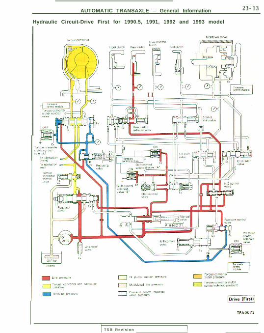
AUTOMATIC TRANSAXLE - General Information
Hydraulic Circuit-Drive First for 1990.5, 1991, 1992 and 1993 model
23-13
i If-- IrJd J”lI I cZ,“ii
I II cL-zceY++!
r,, ,“br,cdTlon .iledrl
iarqueye”~ter
pYBIYP ,I
Oil pm
m Line Dle55”re
Torque COllYPne‘ and IUbr~caflanIT
‘“ly DlL?SI”‘C
0 Oil pump SUCtlO” Presiule 0 IxpE”rF
0 Modulaied line pressure 0 2% ~~~~~b;“:~~e
0Pwss”le COrtlOl S”lBl~Oldvalve pressule
piiziiq
TFA0072
TSB Revision


23-14 AUTOMATIC TRANSAXLE - General Information
Hydraulic Circuit-Drive Second for 1990.5, 1991, 1992 and 1993 model
KlCkdw”v” ierxTorque ^.. .^“^.LY WC> Lrl
a kr”PtCI”+Cn Rear- “lCh kP” cye’se - -
m iuiT ,/,, .&‘lJll , ,Ll Iab ‘“% , / m\]IIP AN +-6h LlYIsF!j I
Ji‘P 7’ &l-YJ
-O ’ J@;c&,,I
c.I
Lb
TrarsaxlrCC”llOl rnO”Nl e
-
m / ,ne plesule 0 o;, pump wcm” veiwre 0 ;;;~p;::;:;:r
- T..... C”,,Yene, dlld l”brlcdl,n,. 0 Moduldleo 1,ne prCSS”l=0 TOrque Converter Cl”tCn
COntlO, s’J,enn,c OreswrPe
‘4 press”le0 P.Bss”re ContlOl zolenold
“abe pless”iP
[OLiGGZi
TFA0073
TSB Revision i


AUTOMATIC TRANSAXLE - General Information 23-15
Hydraulic Circuit-Drive Third for 1990.5, 1991, 1992 and 1993 model
TiCl1
5c
>rque rOll”ertPifcho~~“trol
7-i h,,, 111m“‘--‘--(front, cTO lbnncation c!IPiiil
;,I”.- ixr
K
r
7[Dive (Third)
TFA0074
I~--- _ _ II T S B Revwon --A
-

23-16 AUTOMATIC TRANSAXLE - General Information
Hydraulic Circuit-Drive Fourth for 1990.5, 1991, 1992 and 1993 model
II II /
k3
II-f rit
0 cO”Yenel011 pump 5UL110” pressute ressure
0 Modulated ,\ne pressure cO”Yenel ClutchEolenold P‘essurc
0pressure Control 5”lemd“alYE pless”re
~ive(Fourthjl
TFA0075
-TSB Revision~__


AUTOMATIC TRANSAXLE - General Information 23-17
Hydraulic Circuit-Lock-up for 1990.5, 1991, 1992 and 1993 modelI
011 *an
w 1 ne prL5511rP
r ^ ^ C”““Cl,tP, and l”b cat*,”c e
I ‘4 plP9s”rL
0 o,, p,mp ,x:on OIPSS”IC
0 M-dLlaied lhnr PleSS”~-
p,eSF”m CO”’ 0, solerlold0 valve WCS111 e
Torque cowerterC,“Wh pressure
pg Torque Converter Clutchrnntrnlsolenald prsss”~P
[ L o c k - u p(Firs4
TFA0076
T S R Revision


23-18 AUTOMATIC TRANSAXLE - General Information
Hydraulic Circuit-Reverse for 1990.5, 1991, 1992 and 1993 model
i
;f~c~m”” -5ia l”bwatlon e:lleal,
‘aA I,exha;st,la,“ein ~ y ‘I,E’ Y Roar, lllirh I'll Ii f
r* ~__I T OFF
A2.@B1iad& "94dlVP
TFA0077
~~__~TSB R e v i s i o n


AUTOMATIC TRANSAXLE - Specifications
SPECIFICATIONSThe AWD vehicles have been discontinued from 1993 models.
GENERAL SPECIFICATIONSM23CA--
Items Specifications
Tvw KM1 75-5-Rl F4A22-2-MPA2 F4A22-Z-MPD3 F4A22-2-MPE4 F4A22-2-MdD4 F4A22-2-MQD6(1989 model) (1990 model) (1991, 1992 model) (1993 model) (1991 model) (1992 model)4G63 4G63 4G63 4G63-SOHC 4G63-DOHC 4G63-DOHC
Torque converter
Me 3-element with 3-element with 3-element with 3-element wrth 3-element with It-element withtorque conver- torque conver- torque conver- torque conver- torque conver- torque conver-
Engrne stall ter clutch ter clutch ter clutch ter clutch ter clutch ter clutchspeed rpm 1.800-2.800 1.800-2.800 1.800-2.800 1.800-2.800 1.800-2.800 1,800-2,800Stall torque ratto 2.17 2.17 2.17 1.90 1.90 1.90
Transaxle
Type Electronically Electronically Electronically Electronrcally Electronically Electronicallycontrolled controlled controlled controlled controlled controlled4-speed 4-speed 4-speed 4-speed 4-speed 4-speedfull-automatic full-automatic full-automatic full-automatic full-automatic full-automatic
Gear ratioFirst 2.846 2.846 2.846 2.846 2.846 2.846Second 1.581 1.581 1.581 1.581 1.581 1.581Third 1 .ooo 1.000 1.000 1.000 1 .ooo 1.000Fourth 0.685 0.685 0.685 0.685 0.685 0.685Reverse 2.176 2.176 2.176 2.176 2.176 2.176
Final ratiogear 4.007 4.007 4.007 4.007 4.007 4.007
Speeddmetergear ratio(dnven/drive) 29136 29136 29136 30136 30136 30/36
Items Specifications
Type W4A32-l-UQA (1991 model) W4A32-1 -UQA2 (1992 model)4G63-DOHC 4G63-DOHC
Torque converter
Type 3-element with torque converter clutch 3-element with torque converter clutc!Engine stall speed rpm 1.800-2.800 1.800-2.800Stall torque ratio 1.90 1.90
Transaxle
Type Electrontcally controlled Electronically controlled4-speed full-automatic 4-speed full-automatic
Gear ratioFirst 2.846 2.846Second 1.581 1.581Third 1.000 1.000Fourth 0.685 0.685Reverse 2.176 2.176
Reduction ratioPrimary 1.228 1.228Secondary 3.600 3.600
Speedometer gear ratio (drwe/drivenJ 36/30 36130
Transfer
Type Constant mesh Constant meshGear ratio 1.090 1.090
TSB Revision I

23-20 AUTOMATIC TRANSAXLE - Specifications\
TORQUE SPECIFICATIONS Mz3cc-
Items Nm ft.lbs.
Oil pan bolts 10-12 7 - 9Tie rod end to knuckle 24-35 17-25
Lower arm ball joint to knuckle 60-72 43-52Transaxle mounting bracket to transaxle 60-80 43-58Special bolts 46-53 33-38Selector lever assembly mounting bolts 9 - 1 4 7-10Starter motor mounting bolt 27-34 20-25Oil cooler hose clamp 4 - 6 3 - 4Hose bracket 3 - 5 2 - 4
Cover to selector knob 2.0 or more 1.4 or more
Selector knob to lever assembly 2.0 or more 1.4 or moreBell housing cover to engine 10-12 7 - 9
Transaxle mounting bolt [IO mm (.40 in.) diameter bolt1 10-12 7.2-8.7
Transaxle mounting bolt [8 mm (.31 In.) diameter bolt1 30-35 22-25Control cable to body 9 - 1 4 7-10Indicator panel l-2 0.7- 1.4Lever assembly to bracket assembly 10-14 8-10Drive plate-to-converter tightening bolt 46-53 34-38Drain plug 30-35 22-25Pressure check plug 8-10 6 - 7
Pulse generator mounting bolt IO-12 7 - 9
Valve body assembly mounting bolt IO-12 7 - 9Oil filter bolt 5 - 7 4 - 5Kickdown locking nut 25-32 18-23
LUBRICANTS MPCD--
Items
Transaxle fluid
Specified lubricant Quantity
dm3 (qts.) DIAMOND ATF SP or equivalent 6.1 (6.4): FWD AA6.5 (6.9): AWD PJT
Transfer oil (AWD only) dm3 (qts.) Hypoid gear oil SAE 75W-85Wconforming to API GL-4 or higher
0.6 (0.6)
TSB Revision

AUTOMATIC TRANSAXLE - Special Tools 23-21
SPECIAL TOOLS M23DA-
OPTIONAL: AVAILABLE FROM O.T.C.
(For the number, refer to GROUP OO-Precautions before service.)
Oil pressure gauge easurement 0
MD998916141
MD9989162-01
MD99891 N-01
Outlet sleeve
Inner sleeve
SERVICE TOOL
TSB Revision J
NOTE*I: 1989 model*z: From 1990 model

23-22 AUTOMATIC TRANSAXLE - Troubleshooting
Based upon use of the troubleshootingguide, the probable location of the prob-lem should be estimated.
Checks should be made of fluid levelsand the condition of the ATF, as well as
1 f o u n d t o b e n e c e s s a r y .
the condition of the manual control ca-bles; adjustments should then be made if
If a presumption has been made thatthere is an abnormal condition some-where in the electronic-control system,check the fault code, in order to determinethe probable location of the problem, byusing a scan tool or voltmeter.
When the abnormal system is discovered,check each element (sensors, etc.) one byone, and make repairs as necessary.
When the abnormal condition is pre-sumed to be in the oil-pressure-control
When the result of the oil-pressure testdoes not satisfy the specified pressure,
1 p a s s a g e s f o r l e a k a g e , e t c .
check each system at places related tothe valve body, check the oil-pressure
If the problem is unusually dirty ATF,abnormal noises, oil leakage, or slippage
L##t he traniaxle.1
of the clutch or brakes or an abnormalcondition of the transaxle Itself, disassem-
TROUBLESHOOTINGF u n c t i o n a l m a l f u n c t i o n s of the ELGWT can lead to otherproblems, such as those described below:(1) Improper maintenance and/or adjustments(2) Malfunctions of the electronic control functions(3) Malfunctions of mechanical functions(4) Malfunctions of hydraulic control functions(5) Malfunctions of engine performanceetc.
I n order to properly determine (“Troubleshoot”) the source ofthese malfunctions, it is first essential to methodically ques-tion the user concerning the details of the problem, such asthe condition of the problem, the situation at the time theproblem occurred, and any other relevant information, all in asmuch detail as possible. The user should also be askedwhether or not the problem has occurred more than once,and under what conditions.Subsequently, certain tests should be conducted in a certainorder, as described at the left.
1 TSB Revision

23-23
NOTES

23-24 AUTOMATIC TRANSAXLE - Troubleshooting
TROUBLESHOOTING GUIDE
T- - ---
lO"ni31-
z.Ip.c
8Ea=s"oz6E.;In.ci!a-
F
X--
X77
c-X
F-
i-
1g I”,PC-
ms?AE
EEF.
E053%2
xsib- or z-
Pp
s
Ea=
g
n
6
BE0.cY.20
(befl- St.3-
zbazti?BEa,fs
off)-
dI?
f
s50>z
6-0vi@zEiECE$,aZ5%-
-
7-
-
Ibr
IProblem
Presumed cause
Ti3::
-0 e2 Ts
y .=:, 02 EF
g '5 +v -60F $2s? $=2 $5
X
@ 63
X
X
I’-57-
-X-
-G--
X--X
X
e:, Damaged or worn gear or other rotating part. or rnproper
adjustment of the preloadn
8 Malfunction o f parklng mechamsm
9 Cracked drive plate. or loose bolt
10 Worn InsIde diameter of front clutch retainer
11 L o w flutd level
X
-
1z 12 Line pressure too low (seal damaged, leakage, looseness, etc.)
E:o 13 Malfunctton of valve body (sticking valve. worktng cavity,
j$adjustment, etc )
X X
I
:?I 14‘c
Malfunction of front clutch or poston
)_O 15 Malfunction of rear clutch or pistoni;;E 1 6 Malfunction of klckdown b a n d o r piston
le 17 Improper adjustment of kickdown servoj3 18 Malfunction of low-reverse brake or piston-6s 19 O-ring of low-reverse brake circuit between valve
body and case not Installed
20 Malfunction of end clutch or piston (check ball hole, other)
2, Malfunction of Park/Neutral positjon switch, damagedor disconnected wiring, or improper adjustment
22 Malfunction of TPS. or improper adjustment
23 Pulse generator (A) damaged or disconnectedwlnng. o r short&cut^
NOTE: Qo indicates items of high priority during inspection.Abbreviations: TPS = Throttle position sensor SCSV = Shift control solenoid valve

AUTOMATIC TRANSAXLE - Troubleshooting 23-25
r star
P=<
zzGs
Ea
c”65
srBZzi;4
1
1
Y-
a
s
s-
7
ii-
s-
3-1
z-
3
1_:5
s
5
f-
d
1i
‘I3
E*aOm5s;K
;$2
zIrg:,8
EP2.2
$2-
If
E:p2zz0om,c .Gis:75’‘5$5oz28---
7-_/-
4
X
?I-
92L”
$El
E0
-
zmz“$P::g=f,i?Ppzz?$5.- -CE$2gsi
-
=00752=o-+u$Z
52
gEEO- -
nsaxl’-
;
4
i?3
b
$
:b
?mk?::w
nalfu-
f3
::2?
gmyQr
0.3-J$G
bGLF!‘,
SO” c-
f3
5eL?
g_mc?PV,L
0.FnEC+
8r35-
x-
,hlft-r-
if5-0
::2B
g
z5
Pz=$5
3 4-
ck l a-fte
T
z
2
B5t8s,-55
P$%88,3d-
x
-i
1
Is,c5‘0mcgi?DEEf
ge‘2c”dp$“=‘EiumTNm,ci
)th(l -
jhO#
X-
--
-
X X
X-
X-
--
g,-
X
-.
I
-
5cIpcg;UCa, 22,$ ‘cG$68-
gz?&SiEss
555m$g
IcE-?5g26a2
_’s
8fsz
gD
$;i058-cw3
5z
YE8g$nso’51b’Fm
asz fis-$2x-uo
E(19
-zN
E2
2m-
z-
r035fc2 .ss:!0=3;Pg-
x x-- x -
X-X
-
-
-
-
-
x-
-
-
-
-
-
-
-
6F-
X
X
x X-
--
PSCV = Pressure control solenoidTCC = Torque converter clutch
I-
X
T
X
X
X
X
x-
X
X
X-
X
-
X
valve
TSB Revision

23-26 AUTOMATIC TRANSAXLE - Troubleshooting
HOT
TFA0715
A W D
TFA0700
DATA LINK AND TESTFLUID LEVEL AND CONDITION
1. Drive until the fluid temperature reaches the usual tem-perature [70-80°C (160- 18O”F)l.
2. Place vehicle on level floor.3. Move selector lever sequentially to every position to fill
torque converter and hydraulic circuit with fluid, then placelever in “N” Neutral position. This operation is necessary t0be sure that fluid level check is accurate.
4. Before removing dipstick, wipe all dirt from area arounddipstick. Then take out the dipstick and check the conditionof the fluid.The transaxle should be overhauled under the followingconditions.l If there is a “burning” odor.l If the fluid color has become noticeably blacker.l If there is a noticeably great amount of metal particles in
the fluid.5. Check to see if fluid level is in “HOT” range on dipstick. If
fluid level is low, add automatic transaxle fluid until levelreaches “HOT” range.Low fluid level can cause a variety of conditions because itallows pump to take in air along with fluid. Air trapped inhydraulic circuit forms bubbles which make fluid spongy.Therefore, pressures will be erratic.Improper filling can also raise fluid level too high. Whentransaxle has too much fluid, gears churn up foam andcause same conditions which occur with low fluid level,resulting in accelerated deterioration of automatic transaxlefluid.In either case, air bubbles can cause overheating, fluidoxidation, which can interfere with normal valve, clutch,and servo operation. Foaming can also result in fluidescaping from transaxle vent where it may be mistaken fora leak.
6. Be sure to examine fluid on dipstick closely.
CONTROL CABLE
Whether control cable is properly adjusted can be confirmedby checking whether park/neutral position switch is perform-ing well.1. Apply parking brakes and service brakes securely.2. Place selector lever to “R” range.3. Set ignition key to “ST” position.4. Slowly move the selector lever upward until it clicks as it
fits in notch of “P” range. If starter motor operates whenlever makes a click, “P” position is correct.
5. Then slowly move selector lever to “N” range by the sameprocedure as in foregoing paragraph. If starter motoroperates when selector lever fits in ‘IN”, “N” position iscorrect.
6. Also check to be sure the vehicle doesn’t begin to moveand the lever doesn’t stop between P-R-N-D.
7. The control cable is properly adjusted if, as describedabove,the starter motor starts at both the “P” range andthe “N” range.
TSB Revision

AUTOMATIC TRANSAXLE - Troubleshooting 23-27
READ OUT OF FAULT CODES
(1) Connect the voltmeter or scan tool to the connector fordata link.
ItI ITi i i I_ . . c - 7 I IIL:‘!‘/‘!’ ‘j’:‘J6666 S@
16R13388,: ELC-4PJT 12 modes1@: Data link control@: Ground
(2) Read the output fault codes.Then follow the remedy procedures according to the “FaultCode Description” on the following page.
NOTEl As many as a maximum of ten fault codes, in the
sequence of occurrence, can be stored in the RandomAccess Memory (RAM) incorporated within the controlmodule.
l The same fault code can be stored as many as threetimes.
l If the number of stored fault codes or fault patternsexceeds ten, already stored fault codes will be erased,in sequence beginning with the oldest.
l Do not disconnect the battery until all fault codes orfault patterns have been read out, because al! storedfault codes or fault patterns will be canceled when thebattery is disconnected.
~ ~~<Scan tool>
(3) If the fail-safe system is activated and the transaxle islocked in 3rd gear, the fault code in the Fail-Safe CodeDescription will be stored in the RAM.Three of these fault codes can be stored. . ,.
Cigarettelightersocket
1 (4) The cancelation will occur if, with the transaxle locked rn3rd gear, the ignition key is turned to the OFF position, butData link
connector the fault code is stored in the RAM.
MB991 341\
ROM back
16PO151
TSB Revision

23-28 AUTOMATIC TRANSAXLE - Troubleshooting ’
Fault Code Description for 1989 and 1990 model
Faultcode
Fault code (for voltmeter) Cause Remedy
21 Abnormal increase of TPS output l Check the throttle position sen-sor connector.
l Check the throttle position sen-sor itself.
22
23
- l Adjust the throttle position sen-Abnormal decrease of TPS output sor.
l Check the accelerator switch(No. 28: output or not).
l Check the throttle position sen-sor output circuit harness.
Incorrect adjustment of thethrottle-position sensor system
24 Damaged or disconnected wiringof the oil temperature sensor sys-tern
l Check the oil temperature sen-sor circuit harness.
l Check the oil temperature sen-sor connector.
l Check the oil temperature sen-sor itself.
25
26
Damaged or disconnected wiring l Check the kickdown servoof the kickdown servo switch sys- switch output circuit harness.tern. or improper contact l Check the kickdown servo
switch connector.l Check the kickdown servo
Short circuit of the kickdown servo switch itself.switch system
27 Damaged or disconnected wiringof the ignition pulse pick-up cablesystem
l Check the ignition pulse signalline.
28 Short circuit of the acceleratorswitch system or improper adjust-ment
l Check the accelerator switchoutput circuit harness.
l Check the accelerator switchconnector.
l Check the accelerator switch it-self.
31
l Adjust the accelerator switch.
Malfunction of the microprocessor l Replace the control unit.
32 First gear command during hrgh-speed driving
l Replace the control unit.
Damaged or disconnected wiringof the pulse generator B system
l Check the pulse generator Boutput circuit harness.
l Check pulse generator B itself.l Check the vehicle speed reed
switch (for chattering).
TSB Revision

AUTOMATIC TRANSAXLE - Troubleshootina
Faultcode Fault code (for voltmeter) Cause Remedy
41
UUU-LJ-I-
Damaged or disconnected wiring l Check the solenoid valve con-of the shift control solenoid valve A nectar.system l Check shift control solenoid
valve A itself.
42 Short circuit of the shift-controlsolenoid valve A system
l Check the shift control solenoidvalve A drive circuit harness
Damaged or disconnected wiring l Check the solenoid valve con-of the shift control solenoid valve B nectar.system l Check shift control solenoid
valve B itself.
Short circuit of the shift controlsolenoid valve B system
l Check the shift control solenoidvalve B drive circuit harness.
45 Damaged or disconnected wiring l Check the solenoid valve con-of the pressure control solenord nectar.
uuuLnnnM- valve system l Check the pressure control Sole-noid valve itself.
46
l Check the pressure control sole-Short circuit of the pressure control noid valve drive circuit harness.solenoid valve system
Damaged or disconnected wiringof the torque converter clutch con-trol solenoid system
Short circuit of the damper clutchcontrol solenoid valve system
l Check the solenoid valve con-nector.
l Check the torque COnVeIterclutch control solenoid itself.
l Check the torque converterclutch control solenoid drive cir-cuit harness.
49 Malfunction of the torque con-vetter clutch system
l Check the torque Converterclutch control solenoid drive cir-cuit harness.
l Check the torque COnVeITerclutch hydraulic pressure SYS-tern.
l Check the torque COnVerterclutch control solenoid itself.
l Replace the control unit.
51 First gear non-synchronous l Check the pulse generator out-put circuit harness.
l Check the pulse generator con-nector.
l Check pulse generator A andpulse generator B themselves.
l Kickdown brake slippage.
52 Second gear non-synchronous l Check the pulse generator Aoutput circuit harness.
l Check the pulse generator Aconnector.
l Check pulse generator A itself.0 Kickdown brake slippage.
TSB Revision

23-30 AUTOMATIC TRANSAXLE - Troubleshooting
l Check the pulse generator Aoutput circuit harness.
0 Check the pulse venerator con-nectar. -
l Check pulse generator A andpulse generator B themselves.
Fault Code Description for 1990.5, 1991, 1992 and 1993 model
rP
Faultcode I
Fault code (for voltmeter) Cause I Remedy
53 Third gear non-synchronous
* Front clutch slippage.l Rear clutch slippage.
54 Fourth gear non-synchronous l Check the pulse generator Aoutput circuit harness.
l Check the pulse generator Aconnector.
l Check pulse generator A itself.l Kickdown brake slippage.
ipproprlate transa-4Wl-
0
0
0
0
0
-
0
-
0
0
FWI
0
0
0
0
-
-
0
0
xle1 CodeNo, output pattern Description Remedy
‘I n
Abnormal increase of TPS out-Put
Abnormal decrease of TPS out-Put
l Adjust the throttle positionsensor.
l Check the accelerator switch(Code No. 24 output or not).
Malfunction of the throttle-position sensor or incorrectadjustment
Damaged or disconnected wir-ing of low oil temperature sen-
l Check the oil temperaturesensor connector.
sor (1992 model) or oil temper- l Check the oil temperatureature sensor (1993 model) sensor itself.
16 Short circuit of hiah oil temDer-ature sensor (1992 model) ’
17 Damaged or disconnected wir-ing of high oil temperaturesensor or short-circuit of lowoiz;eyIperature sensor (1992
Damaged or disconnected wir-ing of the kickdown servoswitch
Short circuit of the kickdownservo switch
l Check the throttle positionsensor connector.
l Check the throttle positionsensor itself.
D Check the kickdown servoswitch connector.
B Check the kickdown servoswitch itself.
TSB Revision

AUTOMATIC TRANSAXLE - Troubleshooting 23-31
CodeNo.
propriate transaxl
,WD FWCOutput pattern Description Remedy
Damaged or disconnected wir-ing of the ignition pulse pick-upcable
l Check the ignition puke sig-nal line.
Short circuit of the accelerator l Check the accelerator switchswitch or improper adjustment connector.
l Check the accelerator switchitself.
l Adjust the accelerator switch.
Damaged or disconnected wir-ing of the pulse generator A
+
l Check the pulse generator(AWD) A and pulsegenerator B themselves.
l Check the vehicle speed reedswitch (for chattering).
Damaged or disconnected wir-ing of the pulse generator B
tDamaged or disconnected wir-ing of the shift control solenoidvalve A
l Check the solenoid valve con-nector.
l Check shift control solenoidvalve A itself.
Short circuit of the shift controlsolenoid valve A
Damaged or disconnected wir-ing of the shift control solenoidvalve B
l Check the solenoid valve con-nector.
-Ll Check shift control solenoid
valve B itself.
Short circuit of the shift controlsolenoid valve B
i
Damaged or disconnected wir-ing of the pressure controlsolenoid valve
l Check the solenoid valve con-nector.
l Check the pressure controlsolenoid valve itself.
Short circuit of the pressurecontrol solenoid valve
Damaged or disconnected wir-ing of the torque converterclutch control solenoid
0 Check the solenoid valve con-nector.
0 Check the torque converterclutch control solenoid itself.
Short circuit of the torque con-verter clutch control solenord
Malfunction of the torque con-verter clutch system
l Check the torque COnVefterclutch hydraulic pressuresystem.
0 0
0 0
0 -
0 0
0 0
0 0
0 0
0 0
0 0
0 0
0 0
0 0
0 0
23
24
31
32
41
n
uuuul
UUUI n42
nn43
uum
44
45
uum
46
47
48
TSB Revision I
l Check the torque Converterclutch control solenoid itself.
l Replace the control Unit.
49

23-32 AUTOMATIC TRANSAXLE - Troubleshooting
Jipproprrate transax CodeNo. Output pattern Description Remedy
51 First gear non-synchronous
uuuul n
52 Second gear non-synchronous
l Check the pulse generator Aand pulse generator B con-nectors
l Check pulse generator A andpulse generator B them-selves.
l Rear clutch slippage.
l Check the pulse generator Aand pulse generator B(AWD only) connectors.
l Check pulse generator A andpulse generator B (AWDonly) themselves.
l Rear clutch slippage (AWDonly).
l Kickdown brake slippage.
l Check the pulse generator Aand pulse generator B con-nectors.
l Check the pulse generator Aand pulse generator B them-selves.
l Front clutch slippage.l Rear clutch slippage.
l Check the pulse generator Aand pulse generator B(AWD only) connectors.
l Check pulse generator A andpulse generator B (AWDonly) themselves.
l End clutch slippage (AWDonly).
l Kickdown brake slippage.
-
l TCM power supply inspectionl TCM ground inspectionl TCM replacement
AWC ‘WC
0
0
0
0
0
UUUUJ-u-l-
53 Third gear non-synchronous
0
0
UUUUuwL
54 Iourth gear non-synchronous
0
i
Vormal
10 change as a constantoutput (or OV)
Iefective transaxle controlnodule (TCM)0
Fail Safe Item for 1989 and 1990 model
ri DescriptionOutput pattern (for voltmeter)
Fail-safeNote(relation tofault code)
CodeNo.
Malfunction of themicroprocessor
3rd gear hold When code No. 31 isgenerated 4th time.
First gear commandduring high speeddriving
3rd gear(D) or 2ndgear (2, L) hold
When code No. 32 isgenerated 4th time.
n nnn
Damaged or discon-netted wiring of the
p u l s e g e n e r a t o r Bsystem
3rd gear(D) or 2ndgear (2. L) hold
When code No. 33 isgenerated 4th time.
TSB Revision

AUTOMATIC TRANSAXLE - Troubleshooting 23-33
15
16
17
Output code
Output pattern (for voltmeter)Description
Damaged or discon-nected wiring, orshort circuit, of shiftcontrol solenoid valveA
Damaged or discon-nected wiring, orshort circuit, of shiftcontrol solenoid valveB
Damaged or discon-nected wiring, orshort circuit, of thepressure control sole-noid valve
Shift steps non-synchronous
T Fail-safe
3rd gear hold
3rd gear hold
3rd gear(D) or 2ndgear (2, L) hold
3rd gear(D) or 2ndJear (2, L) hold
Note(relation tofault code)
When code No. 41 or42 is generated 4thtime.
When code No. 43 or44 is gnerated 4thtime.
When code No.45 or46 is generated 4thtime.
flhen either codeNo. 51,52 53 or 54 isgenerated 4th time.
Fail Safe Item for 1990.5, 1991, 1992 and 1993 modelI
pproprlate transaxle Code Output pattern NoteDescription Fail-safe (relation to
IWD F W D No. fault code)
81 Damaged or disconnected wir- 3rd gear(D) or 2nd 31
0 -ing of the pulse generator A gear (2, L) hold
82 Damaged or disconnected wir- 3rd gear (D) or 2nd 32
0 0;ng of the pulse generator B gear (2, L) hold
83 Damaged or disconnected wir- 3rd gear hold 41.42
0 0 ming, or short circuit, of shaftcontrol solenoid valve A
84 Damaged or disconnected wir- 3rd gear hold 43,44
0 0 ming, or short circuit, of shiftcontrol solenoid valve B
85 Damaged or disconnected wir- 3rd gear(D) or 2nd 45.46
0 0m ing, or short crrcurt, of tne gear (2. L) hold
pressure control solenord valve
0 0Shift steps non-synchronous 3rd gear (D) or 2nd 51,52, 53.
gear (2, L) hold 54
No change as a constant Defective transaxle control Fixed for 3rd -
0 0 -output (or OV) module (TCM) speed
ITSB Revision

23-34 AUTOMATIC TRANSAXLE - Troubleshooting
CHECKING THE CONTROL SYSTEM (WHEN A SCAN TOOL IS USED) FOR 1989 AND 1990MODEL
Pulse generator Al Service datal Item No. 1’9
Throttle positron sensorTPS)m Service dataD Item No. 21
I!(
(44
c44
I!.,I(,
\,4
:44
C..
F..
A00
D range, stopprng state 0 rpm l Defectrve pulse generator B or harness
D range, 3rd speed, driving at 50 km/h (31 mph) 1.600-2.000 rpm*Defective shield cable of pulse gene-
rator B
D range, 4th speed, drivrng at 50 km/h (31 mph) 1.600-2.000 rpml External noise invasion
D range. 2nd speed, driving at 30 km/h (19 mph) 0 rpm l Defective pulse generator A or harness
D range, 3rd speed, driving at 50 km/h (31 mph) 1.400-1.800 rpml Defective shield cable of pulse gene-
rator A
D range, 4th speed, drivrng at 50 km/h (31 mph) 0 rpm l External noise Invasion*Slip of kick-down brake
Accelerator is fully closed. 0.5-0.6V l If voltage is high at the full opening or
Slowly press In the accelerator pedal. Variatron ofclosing, TPS is adjusted improperly.
opening degreeelf no variation is observed, TPS or
circuit harness is defective.
Accelerator is fully opened. 4.5-5.ov elf it does not vary smoothly, TPS oraccelerator cable is defective.
Xl temperature sensor) Servtce data) Item No. 24
When engtne is cold (before starting) Equivalent toatmospherictemperature
*Oil temperature sensor or circuit har-ness is defective.
cickdown servo switch) Servrce data1 Item No. 25
Durrng engine warming-up driving
After engine is warmed up
L range. idling
D range, 1st or 3rd speed
D range, 2nd or 4th speed
It gradually rises.
80- 110°C(176”F-230°F)
ON *Kick-down servo IS adjusted improper-
ON IV.l Kickdown servo switch or circuit har-
OFF ness is defective.l Defective kick-down servo
bItem No.34al position switch or circuit
harness is defective.*Manual control cable is defective.
Iverdnve switch1 Servrce data1 item No. 35
‘owedeconomy swatch‘Servrce dataItem No. 36
Shift to L range
Turn on the overdrive switch.
Turn off the overdrive switch.
Select the power pattern.(Including E pattern control at the low oil tem-perature)
L
OD
OD-OFF
Power
moverdrive switch or circuit harness isdefective.
*Power/economy switch or circuit har-ness is defective.
Select the economy pattern. Economy
.ir conditioning relay signalService data
D range. air conditioning, idling-up state ON l Harness of circuit which detects the air
Item No.37 D range, air conditioning, switch-off state OFFconditioning power relay ON signal isdefective.
Inspectron ttemInspectron content
Inspection condition
Possible cause (or remedy)
Criterion value for the abnormalrty
Pulse generator Bl Service datal Item No. 13
TSB Revision

AUTOMATIC TRANSAXLE - Troubleshooting 23-35
l TPS system is defective.
il pressure is improper.verter clutch (TCC) solenoid
B Service datam Item No.49
CHECKING THE CONTROL SYSTEM (WHEN A SCAN TOOL IS USED) FOR 1990.5, 1991, 1992AND 1993 MODEL
Inspection item
;;;yle posrtion sensor
*Data listl Item No. 11
Oil temperature sensor*Data list0 Item No. 15
Krck-down servo switch*Data list*Item No 21
‘gnition signalInjectron signal),Data listD Item No. 23
iccelerator pedal switchexcept 1993 models)~Data listbItem No.24
Qr conditioning relay signalrData listrltem No.26
Transaxle gear position~Data listm Item No. 27
-rInspection content
Inspection condition
Accelerator is fullv closed.
LSlowly press in the accelerator pedal.
1 Possible cause (or remedy)for the abnormality
l If voltage is high at the full opening 01closing, TPS IS adjusted improperlv.
elf no variation is observed. TPS 01
Accelerator IS fully opened.
-- circuit harness ic r(afndi\rO,a “ClrULIIu.
4.5-5.ov *If it does not vary smoothly. TPS OII- .- d-L__.:__accelerator cable IS oerectrve.
When engine is cold (before starting) Equivalent to *Oil temperature sensor or circuit barbarometric ness is defective.
During engine warming-up driving
After engine is warmed up
temperature
It gradually rises.
80- 110°C(176”F-230°F)
L range, idling
D range. 1st or 3rd speed
D range, 2nd or 4th speed
ON
ON
OFF
l Kick-down servo IS adjusted improperIv.l Krckdown servo switch or circurt bar
ness IS defective.*Defective kick-down servo
N range, idling
N range, 2.500 rpm (read on the tachometer)
650-900 rpm l Ignition system is defective.
2.400-2.600 rpml Harness of ignition signal pick-up cir-
cuit is defective.
Accelerator IS fully closed.
Press in the accelerator pedal sliphtlv.I
ON
OFF
l Accelerator pedal switch is adjustedimproperly.
*Accelerator oedal switch or circuit har-ness is defective.
D range, air conditioning, idling-up state
D range, air conditioning, switch-off state
ON
OFF
l Harness of circuit which detects the airconditioning power relay ON signal isdefective.
D range, idling
L range, idling
C l TCM is defective.r A~d~r~tnr nednl +witch svstem is de-
! IST, -;,,tl;;..- r..--. -.-.--.. -,---
,.,.,.,.v.
l Park/Neutral position switch system isdefective.2nd ran!ge. 2nd speed
D renqe. O/D-OFF. 3rd speed l TPS system is defective.-~~~~~
D range, O/D. 4th speed 4TH
1 TSB Revision

23-36 AUTOMATIC TRANSAXLE - Troubleshooting
Inspectron ItemInspection content
Inspectron condrtion
Possible cause (or remedy)1 Criterion value for the abnormality
Pulse generator A (FWD) D range, 2nd speed, drivrng at 30 km/h (19 mph) 0 rpm l Defective pulse generator A or harness*Data list *Defective shield cable of pulse genel item No.31 D range, 3rd speed, drivrng at 50 km/h (31 mph) 1.600-2.000 rpm rafnr A
D range, 4th speed, driving at 50 km/h (31 mph) n
Pulse generator AW’J’JD)*Data lrstl Item No. 31
D range, stopprng state 0 rpm l Defective pulse generator A or harness*Defective shield cable of pulse gene
D range, 3rd speed, drivrng at 50 km/h (31 mph) 1.800-2.200 rpm rator A
D range, 4th speed, driving at 50 km/h (31 mph) 1.200-1.600 rpm l External noise rnvasronl Slip of kickdown brake
Pulse generator Bl Data listl Item No. 32
D range, stopping state 0 rpm l Defective pulse generator B or harness
D range, 3rd speed, driving at 50 km/h (31 mph) 1.600-2.200 rpm*Defective shield cable of pulse gene
rator B
D ranoe. 4th soeed. drivina at 50 km/h (31 mph) 1.600-2.200 mml External noise invasron
Overdrive switch*Data list*Item No.35
Turn on the overdrive switch.
Turn off the overdrive switch.
OD
OD-OFF
moverdrive switch or circuit harness isdefective.
Power/economy switch*Data listl item No.36
Select the power pattern.(Including economy pattern control at the low oiltemperature)
Power l Powedeconomy switch or circuit har-ness is defective.
Park/Neutral posrtion(PNP) switchl Data list*Item No.37
Select the economy pattern.
Shaft to P range
Shift to R range
Shift to N range
Shift to D range
Shift to 2 ranqe
Economy
P l Park/Neutral position switch is adjustedimproperly.
R l Park/Neutral position switch or circuil
N harness is defective.aManual control cable is defective.
D l inspect the shift lock device when theselector lever is not moving.
2
1 Shift to L ranqe I L I
vehicle speed reed switch*Data lrstl Item No.38
0 km/h (0 mph)
-1
l If high speed signal is output when thevehicle stops, the vehicle speed reed
s w i t c h i s d e f e c t i v e .*In other cases, vehicle speed reed
switch or circuit harness is defective.
=CSV dutyl Data listl item No. 45
l If accelerator pedal is pressed in evenslightly in the idling state of D range
*Accelerator pedal switch IS defective.
rorque converter clutch slrp D range, 3rd speed 1,500 rpmamount (read on the tachometer)m Data listmltem No.47 D range, 3rd speed 3,500 rpm
(read on the tachometer)
100-300 rpm
0 rpm
l Torque converter clutchis defective.
l Ignition signal cable or pulse generatorsystem is defective.
l Transaxle oil pressure is improper.l Torque converter clutch (TCC) solenoid
is defective.
rorque converter clutch D range, 3rd speed 1.500 rpm 0% l TCM is defective.TCC) solenoid duty (read on the tachometer)) Data list
l TPS system is defective.
Dltem No.49 D range, 3rd speed 3,500 rpm Variationl Pulse generator B system is defective.
(read on the tachometer) deoendina
TSB Revision

AUTOMATIC TRANSAXLE - Troubleshooting 23-37ELEMENT IN USE AT EACH POSITION OF SELECTOR LEVER
NOTECl . . . . . . . . . Front clutchC2 . . . . . . . . . Rear clutchC3 . . . . . . . . . End clutchOWC . . . . . . One-way clutch
Bl . . . . . . Kickdown brake82 .._.. Low-reverse brake
SHIFT PATTERNSTwo shift patterns are pm-stored in the control ‘unit of t h i stransaxle. One is the power pattern (for more powerfulperformance), and the other is the economy pattern (forimproved fuel consumption and quieter operation). (Refer tothe diagram below.)The driver can select and switch to the desired pattern by usingthe power/economy select switch on the center console.The solid lines shown in these shift patterns indicate up-shifts,and the broken lines indicate. down-shifts. The reason whythere is a difference between the shift points for up-shifts andfor down-shifts is so that up-shifts and down-shifts will notoccur frequently when driving at a speed in the vicinity of theshift point.When the vehicle is stopped, there is a shift to -2nd gear inorder to obtain a suitable “creeping”, but when the acceleratorpedal is then depressed the vehicle starts off in 1st gear.
TSB Revision
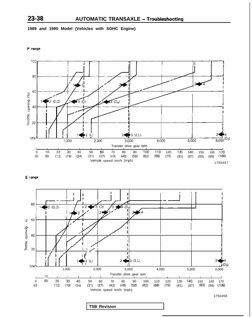
23-38 AUTOMATIC TRANSAXLE - Troubleshooting
1989 and 1990 Model (Vehicles with SOHC Engine)
P range
Transfer drive gear rpmI I I I I 1 I I I , 1 1 I I I0 50 60 70 80 90 100 110 120 130 140 150 160 170
(0) (31) 137) (43) (49) (56) (62) (68) (75) (81) (87) (93) (99) (106)Vehicle speed km/h (mph)
1750457
E range
---P 9: j-- l J
I
T 60
5a.G /Y !A
6 I x/ IAI I I I
40.I/ I / II/ I I I
8 I
a, I75 I/! /Tp 20 / I/ I)
/. AI I/ 1
1 III I ’ I IIdle1 r( I( 1+2 u 2+3 (2.U
I1,000 2,000 3,000 4,000 5,000 6,000
Transfer drive gear rpmI I I I I I I I I I I I L I I I I 1
0 :69 50 60 70 80 90 100 110 120 130 140 150 160 170(0) (31) 137) (43) (49) (56) (62) (68) (75) (81) (87) (93) (99) (106)
Vehicle speed km/h (mph)
1750458
TSB Revision

AUTOMATIC TRANSAXLE - Troubleshooting 23-39
1990.5, 1991 and 1992 Model (Vehicles with SOHC Engine)
P range
Transfer drive gear rpm 1Lgo loo 110 120 130 140 150 160 170
(ii :69 (:;) (;390) (;:) (35:) (i;) (ii, (it, (56) (62) (68) (75) (81) (87) (93, (99) (106)
Vehicle speed km/h (mph) TFA0482
E range
I403)
Transfer drive aear rpm-
L I I 1
ii, 7; (;i, (T:, (;t) (i:, (!i (ii, (ii) (56) 90 (62) loo 110 (68) (75) 120 130 (81) (87) 140 (93) 150 (99) 160 (106) 170
Vehicle speed km/h (mph) VA0483
TSB Revision

23-40 AUTOMATIC TRANSAXLE - Troubleshooting
1990.5 Model (Vehicles with DOHC Engine)
P range
100 I80
r;;' 60 I,"'E
2. I0 40az5g 20 I
I2+.3(2.L) 3 q- 403)
Idle I1,000 2,000 3,000 4,000 5,000 6,000 7,000
Transfer drive gearrpm1 1 I I I I I 1 1 I I I 1 1 1 I I I I I0
;6; (:i) (::) (;:) (::) (:;) (ii)
go
(1:) ( 5 6 )
loo 110 120 130 140 150 160 170 180 190(0) (62) (68) (75) (81) (87) (93) (99) (106) (113)(118)
Vehicle speed km/h (mph)
TFA0397
E range
100 I 1l-I2(D.2)
I II3 ~401)I
80 r / I/ I
/ II I
g 6 0I
/1I
p " J~2&-+--+-3& i1 I
0 Ia, I5
g 202*=3(2.L) 3-l
5 II
Idle I I1 , 0 0 0 2,000 3,000 4,000 5,000 6,000
14tD3)
TransferdrivegearrpmI I t 1 I I I 1 I I I I I I I0 10 20 30 40 50 60 70 80 90 100 110 120 130 140 150 160
(0) (6) (12) (19) (24) (31) (37) (43) (49) (56) (62) (68) 175) (81) (87) (93) (99)
Vehicle speed km/h (mph)
TFA0398
TSB Revision I
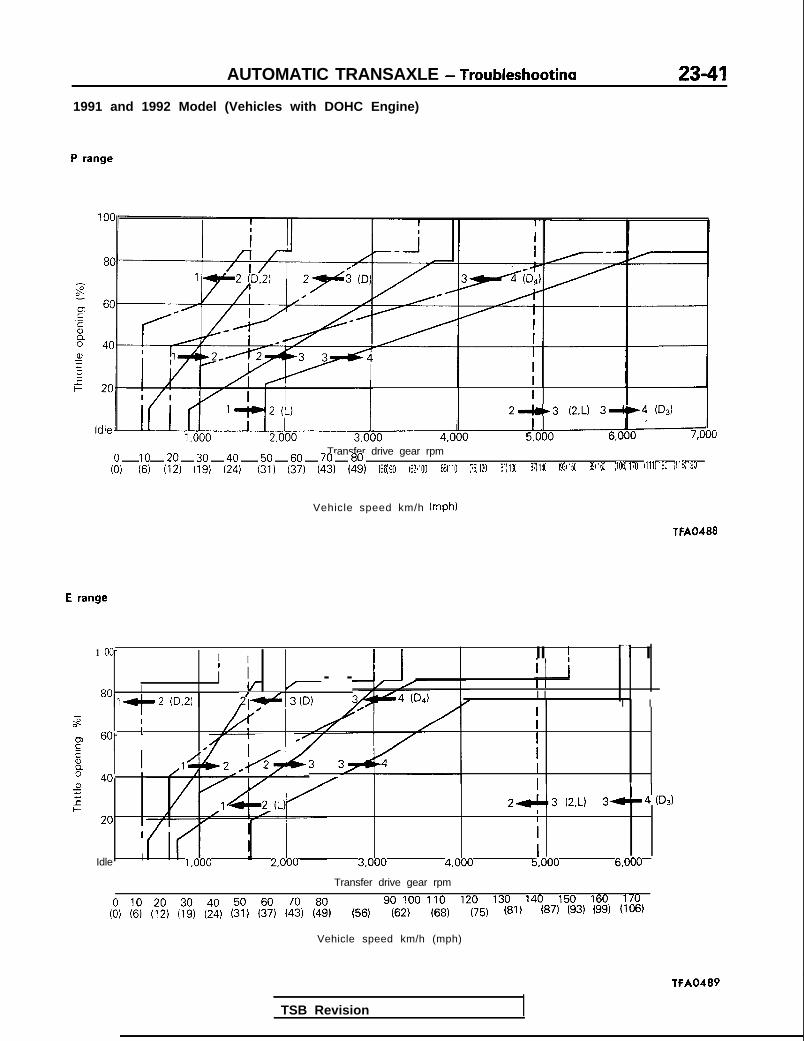
AUTOMATIC TRANSAXLE - Troubleshootina 23-411991 and 1992 Model (Vehicles with DOHC Engine)
P range
I2"t3 (2.L) 39-4 03)
Transfer drive gear rpmI
(:I 2; (:;I (:;, (i:) (35:) (36;) (ii) (t:, (56) so (62) 100 (68) 110 (75) 120 (81) 130 (87) 140 (93, 150 (99) 160 (106) 170 (111) 180 (118) 190
Vehicle speed km/h (mph)
TFA0488
E range
1 oo- I I I I I II ! II III I - -
80 IId-2 03.2) i'id 3 (D)
I Ig4 (DA I I
I ‘I II-z I
a- l607 ’ I
P ,1!
/ I 1
E
: 40alz I I75L 2&13 (2.L) 3 4 (D3)= I
20 II I
I IIdle 1,000 2,000 3,000 4,000 5,000 6,000
Transfer drive gear rpm
so loo 110 120 130 140 150 160 170(i, (69 (:;) (7:) (;:) (%, (i;, & (% (56) (62) (68) (75) (81) (87) (93) (99) (106)
Vehicle speed km/h (mph)
TFA0489
TSB Revision

23-42 AUTOMATIC TRANSAXLE - Troubleshooting
1991 and 1992 Model (AWD Vehicles with DOHC Engine)
P range
T$-
P.-58a,355
100
80
60
40
20
Idle
1 e- 2 (0.2)
1,000 2.000 3.000 4,000 5,000 6,000
Transfer drive gear rpmI I I I I I I 1 I I I I I I
(i,80 SO 100 110 120 130 140 150 160
;; 1::) (:i, (:!, (& (% 6:) (49) (56) (62) (68) (75) (81) (87) (93) (99)
TFAO093
E range
I I I I I II
1 1 1 2&3'iD) i 1 3+4iDJt 1
Transfer drive gear rpmI I I I -I 1 I I I I I I
i,so loo 110 120 130 140 150 160
;; (:;, (?:, (;:, (::I i?, 6% (::I (56) (62) (68) (75) (81) (87) (93) (99)
Vehicle speed km/h (mph) T FA0094
TSB Revision

AUTOMATIC TRANSAXLE - Troubleshootina
1993 model
P range
100
80
60
40
20
Idle
1-1 2 (D.2)
c
tfI* 2(L) 2-13 (2,L) 3--4(b)
I I I I I I I1,000 2,000 3,000 4,000 5,000 6,000 7,000
Transferdrive gearrpm1
0 10 20 30 40 50 60 70 80 90 100 110 120 130 140 150 160 170 180 1 9 0
(0) (6) (12) 119) (24) (31) (37) (43) (49) (56) (62) (68) (75) (81) (87) (93) (99) (106)(111)(118)
Vehiclespeed km/h(mph)
TFA0932
E range
31
F.-c
tia,5:‘5
if
100
80-
60
Idle
I I I I I II I I 1
1,000 2,000 3,000 4,000 5,000 6,000 7,000
Transferdrivegearrpm, I I I t I I I I , , , t I
(00) (6) 10 (12) 20 (19) 30 (24) 40 (31) 50 (37) 60 (43) 70 (49) 80 (56) 90 (62) 100 (68) 110 (75) 120 (81) 130 (87) 140 (93) 150 (99)(106)(111)(118) 160 170 180 190
Vehiclespeed km/h(mph)
TFA0933
TSB Revision

23-44 AUTOMATIC TRANSAXLE - Troubleshooting
INSPECTION OF ELECTRONIC CONTROL SYSTEM COMPONENTS
1. WiringBased on the wiring diagram,
improper connection of
check whether the continuity andconnector, damaged ordisconnected harness,
grounding of each harness IS OK. or incorrect wiring con-
4nection.
c Continuity >4
4 Reconnect the connec-
I Normal Itor; repair or replace theharness.
2. Oil-temperaturesensor
temperature and check the resist-ante between the terminals 1 and2 (FWD), 1 and 2 or 2 and 3
Damaged or disconnected
Replace the oil-temperature sensor
FWD (1993 model)
TFA0821
AWD (Up to 1992 model)
1 1. Low temperature side~ 2. Ground
3. High temperature side
TSB Revision
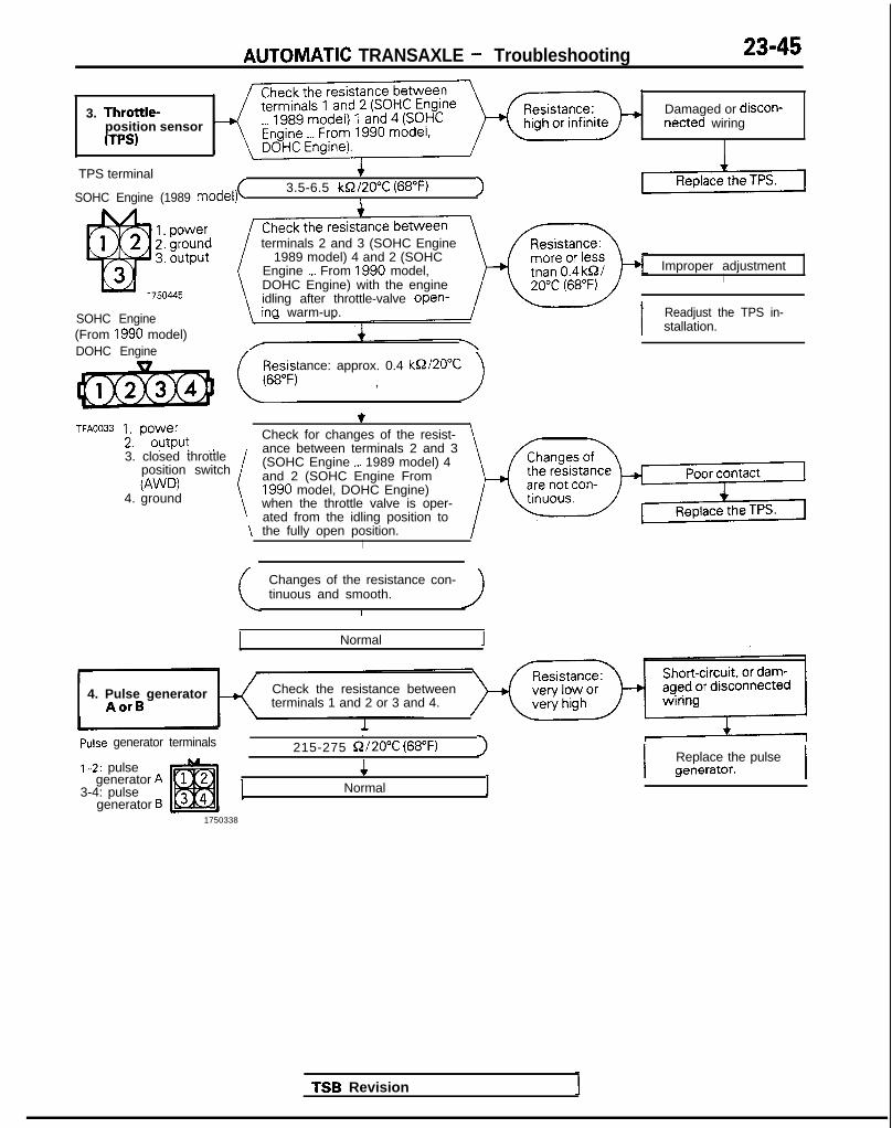
AlJTCMVlATlC TRANSAXLE - Troubleshooting 23-45
3. Throttle-position sensorUPS)
Damaged or discon-netted wiring
TPS terminal
SOHC Engine (1989 model)(3.5-6.5 kQ/20”C (68°F) 1
I
SOHC Engine(From 1990 model)DOHC Engine
TFA0033 1. power
2. outpur .,
terminals 2 and 3 (SOHC Engine1989 model) 4 and 2 (SOHC
Engine _._ From 1990 model,DOHC Engine) with the engineidling after throttle-valve open-ina warm-up.
Resistance: approx. 0.4 kQZ20”C(,6,, , )
3. closed throttleposition switchW’D)
4. ground
\
Check for changes of the resist-ance between terminals 2 and 3(SOHC Engine ,._ 1989 model) 4and 2 (SOHC Engine From1990 model, DOHC Engine)when the throttle valve is oper-ated from the idling position tothe fully open position.
I
Changes of the resistance con-tinuous and smooth.
Normal
4. Pulse generatorAorB
Check the resistance betweenterminals 1 and 2 or 3 and 4.
Pulse generator terminals.
215-275 Q/20% (68°F) I1-2: pulse
generator A3-4: pulse
generator B
4Normal 1
1750338
Improper adjustmentI
I Readjust the TPS in-stallation.
TSB Revision
I Replace the pulsegenerator. I

23-46 AUTOMATIC TRANSAXLE - Troubleshootincl
5. Pulse generatorA or B (checkingby an oscillo-scope)
K
Connect the pulse generator andbody harness, and connect anoscilloscope. Check with thechassis on a dynamo or with thefront wheels raised.
Oscilloscope waveform
FWD /VT
Noise
/Ah --LAr
IP-i E
171091
AWD AA
Noise
With the selector lever at the “L”position and the engine running at1,000 rpm, check the voltagewaveform between terminals 1and 2.
1With the selector lever at the “L”position and the engine running at1,000 rpm, check the voltagewaveform between terminals 3and 4.
Noise
A(6171092 +
Normal
incorrect installation ofthe pulse generator, ormalfunction of the pulsegenerator.
4
Correct the installationcondition, or replace thepulse generator.
Replace the pulsegenerator.
Incorrect installation ofthe pulse generator, ormalfunction of the pulsegenerator.
4
Correct the installationcondition, or replace thepulse generator.
r Replace the pulsegenerator.
TSB Revision
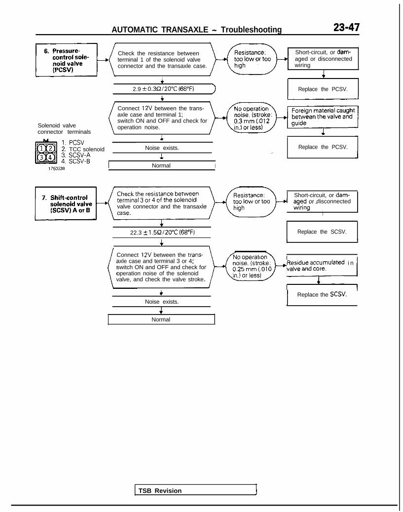
AUTOMATIC TRANSAXLE - Troubleshooting 23-47
Check the resistance between Short-circuit, or dam-terminal 1 of the solenoid valve aged or disconnectedconnector and the transaxle case. wiring
44
2.9 + 0.3Q/20°C (68°F) 1 Replace the PCSV.
t
Solenoid valveconnector terminals
PCSVTCC solenoid
;g;:;
Connect 12V between the trans-axle case and terminal 1;switch ON and OFF and check foroperation noise.
1
Noise exists.
1
Replace the PCSV.1J
Normal I
valve connector and the transaxleAl Short-circuit, or dam-
aoed or disconnected-=!-- -’ -.wrring I
I
f22.3 k l.5Q/20°C (68°F) Replace the SCSV.
4I I
, 1I \
Connect 12V between the trans-axle case and terminal 3 or 4;switch ON and OFF and check foroperation noise of the solenoidvalve, and check the valve stroke.
TSB Revision
yF$$;za;:pulated i n /
+Noise exists.
4Normal
1 Replace the SCSV.]

23-48 AUTOMATIC TRANSAXLE - Troubleshooting
1 press the foot, brake firmly.1W i t h t h e e n g i n e idliqg, de-
Let the engine continue idling.3
TSB Revision
4;ry;pn”g’ y stment 1
+Readjust the ,idling.
1 ~i$.;h~,~~~e c l u t c h 1

AUTOMATIC TRANSAXLE - Troubleshootinn
9. Torque conver-ter clutch (TCC)solenoid
Check the resistance betweenterminal 2 of the solenoid valveconnector and the transaxlecase.
Short-circuit, or dam-too low or too aged or disconnected
wiringI
Solenoid valve
4 *( Standard value: 3 Q/2O”C
Replace the TCC solenoid/ -
connector terminalsConnect 12V between the trans-
*Sticking isusually at the
1750338 4
Normal 1
release side.
4Replace the TCC solenoid
With the accelerator pedal notdepressed, check the resistancebetween terminals 1 and 2.
1Continuity exists (resistance: 0)
Problem not solved.
1
1E/l2171096
Replace the acceleratorswitch.
With the accelerator pedal de-
No continuity (resistance: CQ)I
TSB Revision
+Normal

23-50 AUTOMATIC TRANSAXLE - Troubleshooting
11. Park/Neutralposition switch
In the “P” range, check for con-tinuity between terminals 3 and4, and terminals 8 and 9 ___ Up to1992 model or terminals 1 and4, and terminals 5 and 8 _._ 1993
Up to 1992 model
1993 model
‘FA0802
\ model\ I
4
c Continuitv exists -I
In the “R” range, check for con-tinuity between terminals 4 and7, and terminals 10 and 11 Up \
to 1992 model or terminals 4and IO, and terminals 6 and 71993 model I
+Continuity exists
>I
tinuity between’terminals 2 and
~~
Continuity existsIiv-
trnurty between termrnals 4 and
\ nals4 and 9 __. 1993 model /
Continuity existsI
(()trnurty between terminals 1 and
( Continuity exists
In the “L” range, check for con-tinuitv between terminals 4 and5 . Up to 1992 model or termi-nals 4 and 11 . 1993 model
( Continuitv exists
Normal
F No continuity-)+I1
,1
Replace the park/neu-tral position switch.
TSB Revision

AUTOMATIC TRANSAXLE - Troubleshooting 23-51
Check for continuity between the
1989 and 1990 model
1750447
1990.5, 1991 and1992 model
19811
TFAO389
check for continuity between thekickdown servo switch terminaland the transaxle case.
Poor contact (sticking)
NOTE: Be sure the brakes are\ a p p l i e d during’this c h e c k . /\ I
+
No continuity
1993 model
A6-l+
Normal 1k&f TFA0809
, ,Disconnect the
13. Transaxle con- hicle’s TCM. Then connect, via Malfunction of theoriginal TCM
TSB Revision
Same problem (as before TCMexchange) occurs.

23-52 AUTOMATIC TRANSAXLE - Troubleshooting
OIL PRESSURE TESTS1. Completely warm up the transaxle.2. Raise the vehicle by using a jack so that the drive wheels
can be rotated.3. Connect an engine tachometer and place it in a positron
where it’s easy to see.4. Attach the special oil-pressure gauge (MD998330-01)
and the adaptor (MD998332-01) to each oil-pressureoutlet port. When the reverse position pressure is to betested, the 3,000 kPa (400 psi) type of gauge should beused.
I AWU II /I
brake pressure
zT?ziw@ Klckdown brake
pressure (Release)
5. Measure the oil pressure under various conditions , andcheck to be sure that the measured results are within thestandard value range shown in the “Standard oil pressuretable” below.If the oil pressure is not within the specified range, checkand repair as described in the section “Remedial steps if oilpressure is not normal” on the next page.
1 TSB Revision 1

AUTOMATIC TRANSAXLE - Troubleshooting 23-53
STANDARD OIL PRESSURE TABLEKM175, F4A22 . . . Up to MODEL 1990
Conditions Standard oil pressure kPa (psi)
NO. 1 p -,-,.. ,-,,-_ 1 Engine 1 Ch;J+ 1 - 0. 1 ,,._,?...- 1 F%tclutch
1 E;;;;;;h 1 Lov$rse 1 To;;er 13eleLL IfsYCI
position speedrpm
cl,1111position
neaucrngpressure
hlCI(aOWrIbrake
pressure pressure )I
pressure pressure
1 N ldlrng Neutral - - *
2 D Idling 2nd gear 100-210(14-30) -
3 (SWDON, Approx.830-900 830-900 400-600
--2,500 4th gear (118-128) (118-128) (56-84)
(SWZFFI Approx. 3rd gear370-490 830-900 830-900 830-900 400-600-4 2.500 (52-70) (118-128) (118-128) (118-128) (56-84)
5 2 Approx.2,500 2nd gear370-490 830-900 400-600-(52-70) (118-128) - (56-84)
- *6 L Approx. 1st gear 370-4901,000 (52-70)
- ;g:gp
7 R
A;pp56od(.
Approx.
1,000
Reverse370-490(52-70)
1.640-2.240 1.640-2.240(233-318) (233-318)
--1.000 (142) 1 .OOO (I 42)or more or more
F4A22 . . . From Model, 1990.5
Conditions Standard 011 pressure kPa (Psi)
0 0 0 co 0 @No. Enqine Chik “__l__^:__ KrlrA,vrrn Front End clutch Low-reverse Torque-Select leve brake converterposition pressure
‘ressure p-“cxm”1~ , pressure pressure:r speed cl,,,i; ne”“l;lily
wmposition pressure
I I
I I 360-4801 N Idling Neutral (51~6P’2,
-- *--
TSB Revision
171 D Idling 2nd gear 360-4f(51-6b, , \
I
30 ?y;I;;p - *->i
30-900 830-900 450-650-1n-17RI - (118-128) (64-92)A2pPg 4th gear 360-480
I I ,.lY”-“Iv, (51-681
830-9004 (SWZFF) A2pWg. 3rd gear (118-128) ,- .~,,, ,“~ .--, ~. - lL”l,E% 830-900 -
fllR-l=' 4g::;p
I I5 2
I IA2pg;. 2nd gear ~~~~~~p
830-900 -(118-128) - $g:;p
300-450- *--” L
ApP&y. 1st gear(43-63)
1
ICI I
1 EEi2840 / _ 1 ‘~o~$~ ) 4iiIi;p7 R Reverse
360-480(51-68) - 1.000 (142)
or more
NOTEmust be 10 kPa (I .4 psi) or less.
SW-ON: Switch ON the overdrive control switchSW-OFF: Switch OFF the overdrive control switch*: Hydraulic pressure is generated, but not the standard value

23-54 AUTOMATIC TRANSAXLE - Troubleshooting
AWD
Conditions Standard oil pressure kPa (Psi)
0 0 0 @ 0 @ 0 @No. Select m;; Shift Reducing Kickdown Kickdown Front Rear End Low- Torque-lever pressure brake brake clutch clutch clutch reverse converter
position vmposition pressure pressure pressure pressure pressure brake pressure
(Apply) (Release) pressure
1 N Idling Neutral 360-480 - - - *(51-68) -
-
360-480 lfyfI;;; _ 730-8302 D ldlrng 2nd war (51-68) (104-118) - *-
(sw!oN) AgFil’ 4th gear360-480 830-900 830-900 _3 - -(51-68) (118-128) - (118-128) g:gp
830-9004 (SW%FF)Approx. 830-900
2.500 3rd g e a r ~~~I$p (y$$zr (~$$EJ (??i??$) ( 1 1 8 - 1 2 8 ) ( 1 1 8 - 1 2 8 ) - g::;p
Approx. 2nd gear 360-480 830-900 830-900 450-650-5 2 (51-68) (118-128)_ -
2,500 (118-128) - (64-92)
6 L Approx. 360-480 830-9001,000 1st gear (51 -66) - - -
(118-128) - ;:;I$; *
Ap&;. 1.640-2.240 1.640-2.240 1.640-2.240
7 R ’ R e v e r s e ~~~$~p -(223-319) (223-319) (223-319) @O-65,,
( 6 4 - 9 2 )Ap”do”o”. 1.000 (142) 1.000 (142) 1.000 (142)
or more or more or more
NOTEmust be 10 kPa (1.4 PSI) or less.
SW-ON: Switch ON the overdrive control switchSW-OFF: Switch OFF the overdrrve control switch6: Hydraulrc pressure IS generated, but not the standard value.
TSB Revision

AUTOMATIC TRANSAXLE - Troubleshooting 23-55Remedial Steps If Oil Pressure Is Not Normal
FWD A/T
Trouble symptom Probable cause Remedy
1. *Line pressures a. a.are all low (or high).
Clogging of oil filter Visually inspect the oil filter; replace the oil filte
NOTE b. Improper adjustment of oil press-if it is cl,ogged.
b. Measure line pressure @ (kickdown brake*“Line pressures” ure,(line pressure) of regulator pressure); if the pressure is not the standardrefers to oil ress- valve value, readjust the line pressure, or, if neces-ures@,@, 4 and6 sary, replace the valve body assembly.@ in the “Standard c. Sticking of regulator valve c. Check the operation of the regulator valve;oil pressure table” repair if necessary, or replace the valve bodyon the previous assembly.
we d. Looseness of valve body tighten- d. Tighten the valve body tightening bolt anding part installation bolt.
e. Improper oil pump dischange e. Check the side clearance of the oil pump gear;pressure replace the oil pump assembly if necessary.
2. Improper reducing a. Improper line pressure a. Check the @ kickdown brake pressure /linepressure pressure); if the line pressure is not the
standard value, check as described in item 1above.
b. Clogging of the filter (L-shaped b. Disassemble the valve body assembly andtype) of the reducing-pressure cir- check the filter; replace the filter if it is clogged.cuit
c. Improper adjustment of the re- c. Measure the @ reducing pressure; if it is notducing pressure the standard value, readjust, or replace the
valve body assembly.d. Sticking of the reducing valve d. Check the operation of the reducing valve; if
necessary, repair it, or replace the valve bodyassembly.
e. Looseness of valve body tighten- e. Tighten the valve body tightening bolt anding part installation bolt.
3. Improper kick- a. Malfunction of the D-ring or seal a. Disassemble the kickdown servo and checkdown brake press- ring of the sleeve or kickdown whether the seal ring or D-ring is damaged.ure servo piston. If it is cut or has scratches, replace the seal ring
or D-ring.b. Looseness of valve body tighten- b. Tighten the valve body tightening bolt and
ing part installation bolt.c. Functional malfunction of the c. Replace the valve body assembly.
valve body assembly
1. Improper frontclutch pressure
a. Malfunction of the D-ring or seal a. Disassemble the kickdown servo and checkring of the sleeve or kickdown whether the seal ring or D-ring is damaged.servo piston. If it is cut or has scratches, replace the seal ring
or D-ring.b. Looseness of valve body tighten- b. Tighten the valve body tightening bolt and
ing part installation bolt.c. Functional malfunction of the c. Replace the valve body assembly.
valve body assemblyd. Wear of the front clutch piston or d. Disassemble the transaxle itself and check
retainer, or malfunction of the @ whether or not there is wear of the front clutchD-ring. @ seal ring. piston and retainer inner circumference, orRefer to the figure on the next damage of the D-ring. If there is any wear orpage.) damage, replace the piston, retainer, D-ring
and/or seal ring.
i. Improper endclutch pressure
a. Malfunction of a D-ring @or oil a. Disassemble the end clutch and check the oilseal 0.0 of the end clutch orO-ring 8 of the pipe (Refer to
seal, D-ring of the piston, seal ring of the
the following figure.)retainer, etc.; replace if there are cuts, scars,scratches or damage.
b. Looseness of valve body tighten- b. Tighten the valve body tightening bolt anding part installation bolt.
c. Functional malfunction of the c. Replace the valve body assembly.valve body assembly
TSB Revision
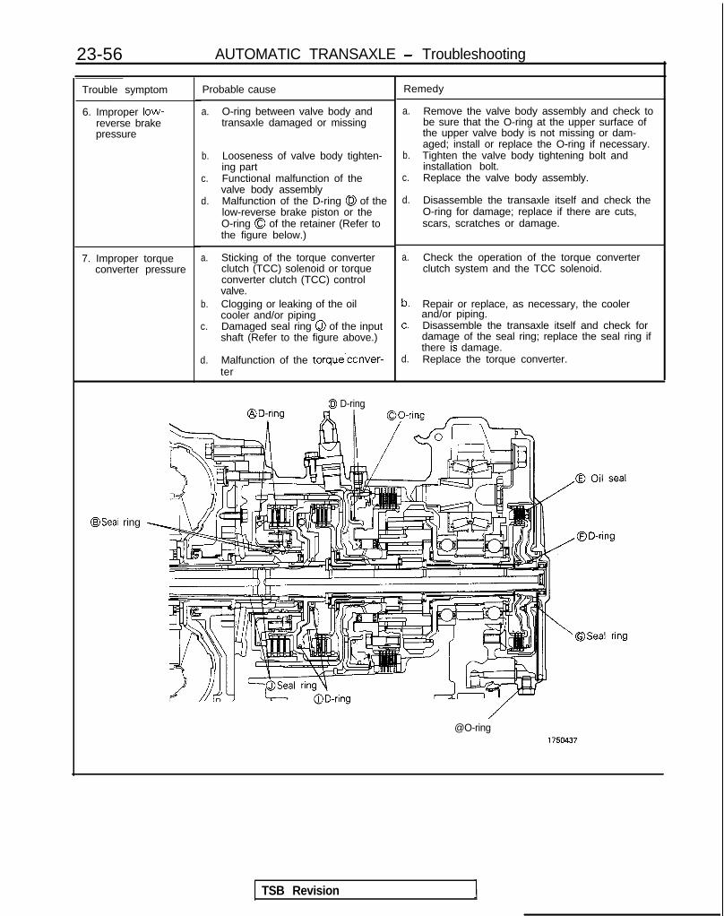
23-56 AUTOMATIC TRANSAXLE - Troubleshooting
Trouble symptom
6. Improper low-reverse brakepressure
Probable cause
a. O-ring between valve body andtransaxle damaged or missing
b. Looseness of valve body tighten-ing part
c. Functional malfunction of thevalve body assembly
d. Malfunction of the D-ring 0 of thelow-reverse brake piston or theO-ring 0 of the retainer (Refer tothe figure below.)
a. Sticking of the torque converterclutch (TCC) solenoid or torqueconverter clutch (TCC) controlvalve.
b. Clogging or leaking of the oilcooler and/or piping
c. Damaged seal ring Q of the inputshaft (Refer to the figure above.)
d. Malfunction of the torque’conver-ter
7. Improper torqueconverter pressure
0 D-ring
Remedy
a. Remove the valve body assembly and check tobe sure that the O-ring at the upper surface ofthe upper valve body is not missing or dam-aged; install or replace the O-ring if necessary.
b. Tighten the valve body tightening bolt andinstallation bolt.
c. Replace the valve body assembly.
d. Disassemble the transaxle itself and check theO-ring for damage; replace if there are cuts,scars, scratches or damage.
a. Check the operation of the torque converterclutch system and the TCC solenoid.
b. Repair or replace, as necessary, the coolerand/or piping.
c. Disassemble the transaxle itself and check fordamage of the seal ring; replace the seal ring ifthere 7s damage.
d. Replace the torque converter.
@Seal ring
@O-ring
TSB Revision

AUTOMATIC TRANSAXLE - Troubleshootinn 23-57
AWD A/T
Problem Probable cause(s) Remedy
1. All line pressures are a. Clogged oil filter.low (or high).
a. Visually check the oil filter; replace it if it isb. Improper adjustment of the oil clogged.
NOTE pressure (line pressure) of the b. Measure line pressure @ (kick-down brakeLine pressures are oil regulator valve. pressure); readjust the line pressure if there is apressures 2 ,, 0, @,
8
c. Malfunction of the valve body deviation from the standard value, or replace the0, @and 7 In t he assembly. valve body assembly.standard oil pressure d. Looseness of the valve body c. Replace the valve body assembly.table on the preced- bolts. d. Tighten the valve body bolts to the specifieding page. e. Improper discharge pressure of torque.
the oil pump. e. Check the side clearance of the oil pump gear;Looseness of each check plug, replace the oil pump assembly if necessary.or malfunction of the O-ring. f. Check each check plug; replace it if necessary.
2. Inappropriate reduc- a. Reducing pressure circuit filter a. Disassemble the valve body assembly and checking pressure. (L shaped) is clogged. the filter; replace the filter if it is clogged.
b. Reducing pressure is improperly b. @ Measure the reducing pressure; readjust ifadjusted. there is a diviation from the standard value, or
c. Malfunction of the valve body replace the valve body assembly.assembly. c. Replace the valve body assembly.
3. Inappropriate kick- a. Malfunction of the kick-down a. Disassemble the kick-down servo and check thedown brake pressure servo piston’s @ seal ring, 43 seal ring, O-ring and D-ring for damage.(appb). D-ring and/or the sleeve’s 0 Replace the seal ring, O-ring or D-ring if they are
O-ring. cut, scarred or scratched.b. Malfunction of the valve body b. Replace the valve body assembly.
assembly.
1. Inappropriate kick-down brake releasepressure.
a. Malfunction of the kickdownservo piston’s @ seal ring.
b. Malfunction of the valve bodyassembly.
a. Disassemble the kickdown servo and check theseal ring, for damage.Replace the seal ring if it is cut, scarred orscratched.
b. Replace the valve body assembly.
j. inappropriate frontclutch pressure.
a. Malfunction of the kickdown a. Disassemble the kickdown servo and check theservo piston’s @ seal ring. seal ring for damage.
b. Malfunction of the valve body Replace the seal ring if it is cut, scarred orassembly. scratched.
c. Unusual wear or abrasion of the b. Replace the valve body assembly.front clutch piston and/or the c. Disassemble the transaxle itself and check forretainer, or malfunction of the 0 unusual wear or abrasion of the front clutchD-ring and/or the @ seal ring. piston and/or retainer inner circumference, or for
damage of the D-ring and/or seal ring.If unusual wear or abrasion, or damage, isdiscovered, replace the piston, retainer, D-ring orseal ring.
j. Inappropriate rearclutch pressure.
a. Malfunction of one or more ofthe following parts of the rearclutch: the piston’s @I D-ring, orthe retainer’s 68 seal ring, or theinput shaft’s @I seal ring or @O-ring.
b. Malfunction of the valve bodyassembly.
a. Disassemble the rear clutch and check the inputshaft’s O-ring, the retainer’s seal ring, the pis-ton’s D-ring, etc.; replace any part that isdiscovered to be cut, scarred or scratched.
b. Replace the valve body assembly.
Inappropriate endclutch pressure.
a. Malfunction of the end clutch’s($ z;ea/,ring, @I D-ring and/or 0
b. Malfunction of the valve bodyassembly.
a. Disassemble the end clutch and check thepiston’s oil seal and D-ring, and the retainer’sseal ring, etc.; replace any part that is cut,scarred or scratched.
b. Replace the valve body assembly.
1 TSB Revision

23-58 AUTOMATIC TRANSAXLE - Troubleshooting
Problem
8. Inappropriate low-reverse brake press-ure.
9. Inappropriate torqueconverter pressure.
Probable cause(s)
a. Damage of the O-ring locatedbetween the valve body and thetransaxle.
b. Malfunction of the valve bodyassembly.
c. Malfunction of the lo&reversebrake piston’s @I D-ring and/orthe center support’s @I O-ring.
a. The torque converter clutch(TCC) solenoid or torque con-verter clutch (TCC) control valve.
b. Clogging or leakage from the oilcooler or piping.
c. Damage to the input shaft’s @seal ring.
d. Malfunction of the torque con-verter.
Remedy
a. Remove the valve body assembly and checkwhether or not there is an O-ring at the uppersurface of the upper valve body, and if sowhether it is damaged or not; replace it if it is cut,scarred or scratched.
b. Replace the valve body assembly.c. Disassemble the transaxle itself and check for
damage to the O-ring; replace it if it is cut,scarred or scratched.
a. Check the functioning of the torque converterclutch system and the TCC solenoid.
b. Repair, or replace, the oil cooler or the piping.c. Disassemble the transaxle itself and check for
damage to the seal ring; replace the seal ring if itis damaged.
d. Replace the torque converter.
TSB Revision

AUTOMATIC TRANSAXLE - Troubleshooting 23-59
ring
brake
CONVERTER STALL TESTStall test consist of determining maximum enginespeed obtained at full throttle in “D” and “R”positions. This test checks torque converter statoroverrunning clutch operation, and holding ability oftransaxle clutches and low-reserve brake.CautionDuring this test, make sure that no one stand infront of or behind vehicle.1. Check transaxle fluid level. Fluid should be at
normal operating temperature [70-80°C (160-18O”F)j. Engine coolant should also be at normaloperating temperature [80-90°C (180-19O”F)l.
2. Apply chocks to both rear wheels.3. Attach engine tachometer.4. Apply parking and service brakes fully.5. Start engine.6. With selector lever in “D” position, depress
accelerator pedal fully to read engine maximumrpm. Do not hold throttle wide open any longerthan is necessary to obtain maximum enginerpm reading, and never longer than 5 seconds ata time. If more than one stall test is required,operate engine at approximatey 1,000 rpm in
TRANSAXLE CONTROL
neutral for 2 minutes to cool transaxle fluidbetween tests.Stall speed: 1,800-3,200 rpm
7. Place selector lever to “R” position and performstall test by the same procedure as in foregoingitem.
Stall Speed Above Specification in “D”If stall speed is higher than specification, rear clutchor overrunning clutch of transaxle is slipping. In thiscase, perform hydraulic test to locate cause ofslippage.Stall Speed Above Specification in “I?”If stall speed is higher than specification, frontclutch of transaxle or low-reverse brake is slipping.In this case, perform hydraulic test to locate causeof slippage.Stall Speed Below Specification in “D” and “R”If stall speed is lower than specification, insufficientengine output or faulty torque converter is sus-pected. Check for engine misfiring, ignition timing,valve clearance etc. If these are good, torqueconverter is faulty.
Svmotom Probable cause Remedy
Selector lever operation is Incorrect adjustment of sleeve 1 Adjuststiff
Starter motor does not oper-
Incorrect adjustment of control cable
Excessive wear of detent plate
Worn contact surfaces of pushbutton and sleeve
Malfunction in park/neutral position switch
Replace
Replaceate with the selector lever inthe “N” or “P” position
Malfunction of starter relayI
Incorrect adjustment of control cable AdjustI
Will not shift to 4-speed ( Malfunction of OD switch ) Replace I
TSB Revision

23-60 AUTOMATIC TRANSAXLE - Troubleshooting
CIRCUIT DIAGRAMcl989 models>
IGNITION
- ‘\ - ‘\ I - /.d 2 -s/R‘* A-43
2.‘Da-2‘-- R
D* l N D N
\$ \I \I $6 >’ pg $5 \I
- I 1:2
9 ‘ki 62 7 3 '11
AJ 5gp &% dII -IIIIIII1IIIIIIIIIIIIIIIIIIIIIIIIII-*-:
;2
III
:
R fiKJ
Ill,14(B'1 I10 RI
1' 2 iB1IY :( 6
12 (YB) 114 (YB':( 6 (YR) :( 5 (YR; 1 I
0 ,16 (BY) I:( 7
By @
; x15(RL) I RL @(BW) BW @(Y) Y
, "I2 @I I1 I\ I I ;;; 8
L
I--+
P-@
@-
-@-
(RG):: 1 I (GL)
(RG) @I
(GR) '(GL) a(GR) 0
&iL__-..___-------------------------~~---------------
$5 ‘r -----_______________5 10 ;gyg;NATION A-09 2
is@jJA2,\
r BY 432 Et?CL 7t BACK-UP LIGHT
STARTERMOTOR
:X35-AC-H0707-NY
1 TSB Revision I

AUTOMATIC TRANSAXLE - Troubleshooting
TAILLIGHTRELAY
I334m6678____-__-_--__----------- 2 c-43
0 1OA
@
c-01 "'&,"'$,5‘r
AUTO-CRUISECDWROL-UNIT
(RG)@ (GL)
1 9
g (GR)I 'f% I
3 I
C-16
1OA 1
-1!I ”5
5>13 55
e
'8 C-32
D-47
POWER/ECONOMYCHANGE OVERSWITCH
1 J/B(TAIL)
IPOYERBY 12,RLBW 1::s" /I -;B li:m kiYR 5<F
(RG) 17<
ELC4-SPEEDAUTOMATIC
FGEt;;kEMODULE
REMARKtMARK INDICATES THE OPTIONAL WIRINGHARNESS FOR AUTO-CRUISE CONTROL SYSTEM.
TSB Revision \

23-62 AUTOMATIC TRANSAXLE - Troubleshooting
CIRCUIT DIAGRAM (CONTINUED)<1989 models>
FRONT SIDE
REVERBE SIDE
C-18
e!T&Lcl%
C-58
ELC4-SPEED!#i!.E%CECONTROLMODULE
r'.I
AUTO COMPRESSORCONTROL UNIT
IIIIIIII1IIIIIII
I
IGNITIC
WITH AUTO- WITHOUT0 AUTO-CRUIBE CONTROL CRUIBE CONTROL I
= =I I I
( @ (~~~~)~~~~(~~~~)(~~~~~D)
\ *ese3 43
cd7
puJJE'o- -5
CONTROL q
ELC 4-SPEED AUTOMATICTRANSAXLE SOLENOID VALVE
%COIL
1B-06 8
5
18______ --------
A-08:6
1
------
63
KXs5-AC-n0707A-nn UNIT
TSB Revision

AUTOMATIC TRANSAXLE - Troubleshooting
MFI CONTROL UNIT
THROTTLEW#ON
n cc
E-01m
fY;KFU1 IBLE23
J/B(GROUND)
C-32 xi.16I3 C-42E 5 13 ~1~11~1Ef13(14l15#611 17 J/B
c-38 4
T
41cu-
c-58 >0i.___ -’ s_Q- -----
fl
,-- -_-_---
5v 9-T
A-45
1
A-46
a
mm265
+ KlCKDOWN J/Biv0 SWITCH
4 c-38 w El
q REMARKtMARK INDICATES THE OPTIONAL WIRINGHARNESS FOR AUTO-CRUISE CONTROL SYSTEM.
TSB Revision

23-64 AUTOMATIC TRANSAXLE - Troubleshooting
CIRCUIT DIAGRAM< 1990 models>
IGNITION
WCHI
A-09@
RK/,_________ -_----__----L ' / p Lo\
J ,"
-LB!f#kON
p SWITCH'*
I A-43
a
il- 'jR 2 -o,-wdRN
Ej 2'7 5\t113
P
(BY)(RL)
(BW)(Y)
(YB)(YR)
tI I II I
BY @I- I 1
!RL @Bw @YYB $jYR @
I
R
NEEiD
2I I 1 I Iai
t5w ,113Y :tS
:( 2 ',YB) 114:( 6 (YR) J 5I
IE .,12 E -5 1
I :: 1 IIP4
+< \r _____--_---__-------
I 5 10 COMBINATIONi METER;zi
mc:4
4L2 E3
I
ci I
t
STARTERMOTOR
BACK-UP LIGHT
X35-AC-HOTOWNY
TSB Revision

AUTOMATIC TRANSAXLE - Troubleshooting 23-65
IGNITION%w
TAILRELl
2 i
cl ':
I =
12.94
E c
05878 10A
--_--_-_--__---_____----~2 C-43 z
(q
mjC-42z'~---------;~;-----;'4g
I ?
D-44 I 2 11
VE (TrrU
AUTO-CRUISECDNI’ROL-UNIT
i
(3 1,.@ I I I I I II I I I
o ;;L
----. -.3
I' BWi
t i3 I"D I
@ (RG) I(GL)
g (GR) 3
2 g4_-----------------------,, -__----..------
C-16
I GHT
1 WATED-
a c-37 I234
1m5313
J/B
EI C-32
D-47
POWER/ECONOMYCHANGE OVERSWITCH
2IJ/B(TAIL)
I-----+
ELC4-SPEEDAUTOMATIC
TC%%kEMODULE
REMARK%MARK INDICATES THE OPTIONAL WIRlNGHARNESS FOR AUTO-CRUISE CONTROL SYSTEM.
TSB Revision

23-66 AUTOMATIC TRANSAXLE - Troubleshooting
CIRCUIT DIAGRAM (CONTINUED)< 1990 models>
C-18
AUTO COMPRESSORCONTROL UNIT
8 C-57 8 7 o ~~011sf!l!EsB
A-21@
ON:2lOOkPa(2BBPsl)OFF:2700kPa (384psl)
IGNITION POWER %TRANSISTOR
I
ELC4-SPEEDt%iJ##Ec
MODULE
KX35-AC-H0705A-NY
pJ;o- $fit&ROL qUNIT
ELC 4-SPEED AUTOMATICTRANSAXLE SOLENOID VALVE
JUMPER j-7,16 (BrR)-
1 TSB Revision

AUTOMATIC TRANSAXLE - Troubleshooting 23-67
c-12MFI CONTROL UNIT
D i51 w,
D 157 BiI
-- ____ ------d
SERVO SWITCH
PULSEGENERATORA-45
q REMARKtMARK INDICATES THE OPTIONAL WIRINGHARNEBS FOR AUTO-CRUISE CONTROL SYSTEM.
TSB Revision

AUTOMATIC TRANSAXLE - Troubleshooting
CIRCUIT DIAGRAM< 1990.5 models>
IGNITIONYETFH
I
IGNITION
%YCHI
A-09 v1 (i)@j
34.J
",,ll__-----. -----
2LB a
0 *4 lx 10i3%L
I \L-x
(BY)(RL)(BW)_... I
O/D II:( 2 (YB) :(14 (YM) I 14i6 (YR) x 5 1 (YR) 1 I
c IYR G
_..__-./"I A-a,?
J.3: 1 -1I 1 (GL)If .T I I ,Prl\
.12 6d j 1 (RG) --g
, \"K,
4R
COMBINATION.-
%ziz
.
m
BACK-UP LIGHT
35-AC-HOTlO-NY
TSB Revision I

AUTOMATIC TRANSAXLE - Troubleshooting 23-69
@L$GHT
I
r-l I J’B
n-aa I? I4 I-RI, I i-lu-47
POWER/ECONOMYUIA# OVER
AU’
II 1 I l+iI ~lc! I J/BI '0 (TAIL)AUTO-CRUIGECONTROL-UNIT
%C-01 l F3=wnnmsn
@m ;B
I II I
-~----------------------~-------i-----” 1 jiE;;;;/F5
@ BY I ’ IC-60-1
ELC4-SPEEDAUTOMATICmN;;;LE
MODULE
REMARKXMARK INDICATES THE OPTIONAL WIRINGHARNESS FOR AUTO-CRUISE CONTROL SYSTEM.
1 TSB Revision 1

23-70 AUTOMATIC TRANSAXLE - Troubleshooting
CIRCUIT DIAGRAM (CONTINUED)< 1990.5 models>
FRONT 61DE
C-18
C-58r-----lIIIII
MODULE II
3 10
73
t G23
-------1 0
"i213
_
C-23 :t;
ON:2100kPa(298DSl)OFF:2700kPa(384L'Si)
55_____ :gp. ______________ ------------7
t-086
E--e-- ___-___-_------
1 AUTO COMPRESSORb CONTROL UNIT
A-21@
#%~RE
WITHOUT AUTO-CRUIGE CONTROL
GERVO GWITCH
UNITKX35-AC-H0710A-NY
TSB Revision

AUTOMATIC TRANSAXLE - Troubleshooting 23-71
SUB FU IBLELINK 1d
l-I!!1
c-12MFI CONTROL UNIT
11 14THROTTLEW$W~~ON
\I
RHEOSTAT
E-01
19 pis%Jg
t IGNITION!~!#!ISTOR
I
J/B(RHEO)
d- -1 113_------- -------:1
r_____-- _-em-------:
T64
m
I
/
4
1t- L IIEl ELC 4-SPEED AUTOMATIC
TRANSAXLE SOLENOID VALVE
Z#&ATORA-45
REMARKXMARK INDICATES THE OPTIONAL WIRINGHARNESS FOR AUTO-CRUISE CONTROL SYSTEM.
1 TSB Revision I

AUTOMATIC TRANSAXLE - Troubleshooting
CIRCUIT DIAGRAM,<1991 and 1992 models>
II1IIIIIIIIIIIIII1II1lIIIIIII
IIIIII -IIII
R mw
IGNITION
W"I
le 5Bl
33 m
c;Efc-u
IGNITION%F"
I
E ,,I2 &$I (RG) (RG) @I (GL)
P (GR) 8a
I I’ -----s-e e-m---- __--w-s-______--------------J ______ ----- ---. ------
, 10 fO’OH$AT I ON
;;@g x,2
+
%;. BY 43
iicl 97 BACK-UP LIGHT
STARTERMOTOR
TSB Revision

AUTOMATIC TRANSAXLE - Troubleshootina
IG2)
-T-
tes4
Ia6371
@ 10A
I II
C-16
I GHT
#&CATED
6 C-37
1( J/B
POWER/~i%%OVERSWITCH
1 J/C(TAIL) -1,4I
IfzPOkBY 101 4RL 102:~BY 103kaY 1041<&YB 105\-YR 106' 4
k
ELC4-SPEEDAUTOMATIC;;$!;gLEMODULE
C-60-1
Remarktmarlc inaicates t h e optional w i r i n
harness for AUTO-CRUISE CONTROL SYSTEM.
1 TSB Revision

23-74 AUTOMATIC TRANSAXLE - Troubleshooting
CIRCUIT DIAGRAM (CONTINUED)(1991 and 1992 models> El AUTO
#bI;1W&&"ORUNIT"-
c-12MFI CONTROL UNITI 1
ON: 235kPa (33.4~a I IOFF: 2lOkPa C22. BPS I)
ON:2100kPa(2Q2~al)OFF: 2TOOkPa V384Ps I )
DATA LINKCONNJiCTOR
C-18FRONT SIDE
,
g&p ;”
F
--------------- _” 66“,tiia
n V
I II I/ II II II II II II I1 I; .L-- _---___--,IL-~--.~~~~~~~~~
_-_--__--_ -_--------.31 64
T
ccG Ii
I I -I
;
SERVO SWITCH FWD-------
TSB Revision I
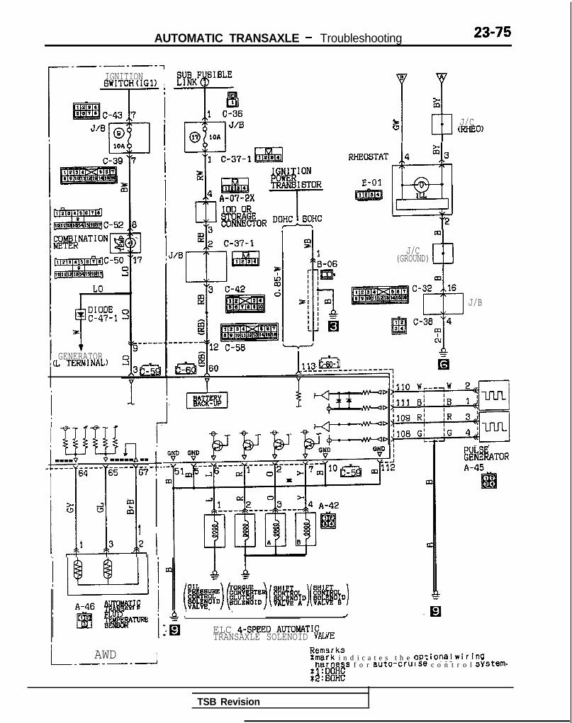
AUTOMATIC TRANSAXLE - Troubleshooting 23-75
IGNITIONBWITCH(IG1) IIa
I
1 ’i RHEO6TAT
E-01
5 J/CmHE0)
GENERATORl(L TERMNAL)
4 $3
@
I L
2
I I-? iwb& q--- ---- .-.-.-- -----65 67I Y
.l!.G J al
t1 3 2
$- .
I
J/C(GROUND)
J/B
s -iA.’ . . ~ JELC 4-SPEED AUTOtdATICTRANSAXLE SOLENOID VALVIZ
8rksI AWD I E::-...-rk i n d i c a t e s t h e Optional WirinQharness f o r auto-cruise c o n t r o l system...a .nnu
L_-_-____1
8ki%ATORA-45
TSB Revision

23-76 AUTOMATIC TRANSAXLE - Troubleshooting
CIRCUIT DIAGRAM<From 1993 models>
IGNITIONT#TCH
I
IIIIIIIIIIIIIIIIIIIIIIII
I
iII--
5
m
4
C-24
A-41
A-09I&
ii,,CA zi
cb----‘3 “7
?zcl,\ A-08
",e "10,.
z zCL &
“1
Gl)I
10A
STARTERMOTOR
PARK/lg@&bN
A-43
KSS-AC-H0711-W
TSB Revision

AUTOMATIC TRANSAXLE - Troubleshootina
-
E1OP
3
@ IOA
PT.-. L-_..il Tr-ltn
- .-
-~-------y~-J4~
!kJ-LB I I I II rrl
6Y
* YBI
7 "D I .
(RG)@ (GL)
I
g (GR)Is
2t I e_-_-_----_~~__---~~~~~~~ ------- w-v----
BY 1
2 s
1 DEDICATEDFUSE
6 C-37
7J/B
8 C-32
POWER/ECONOMY!RRi OVER
1 J/C(TAIL)
ELC-4SPEEDAUTOMATIC;;;f?;;lfLE
MODULE
(GR) 58;&(RW) 574~
C-60
RemarkXmark i n d i c a t e s t h e Optional w i r i n g
h a r n e s s f o r a u t o c r u i s e c o n t r o l system
1 TSB Revision I

AUTOMATIC TRANSAXLE - Troubleshooting
CIRCUIT DIAGRAM (CONTINUED)<From 1993 models>
El
AUTO COMPRESSORCONTROL UNIT
C-18
ELC4-SPEED :
6
5
J/B
IOD ORSTORAGECONNECTOR
T
C-42 3@I
A-44
'631KICKDOWNSERVO SWITCH
1(x95-AC-IlWlU-NW
TSB Revision

AUTOMATIC TRANSAXLE - Troubleshooting 23-79
c-12MFI CONTROL UN1 T
I5V
IFI I! Im~131>22~117 . .
I-
aJ”
c
;It------V
IGNITION?!RE-I BT&
I
1B-06
[ lm
3;t7fmI! 1
J/C ’ P’L) !%flg
5 J/BWIEO)
RHEOSTAT
E-01
J/B
1.
El
66 C-60_____-_-m-w- --v-v-
Y li
I-~I~ i64 w,--,w i!’ u Jtt ; i 4-l”” II!C? ni iR 1
. rll G!D
- - -
m2&jg”57 L& .z’ e
IEB34 A-4:
twT&AAg
rGN:-- - -- ,
- -
V
,,, 1
-
ii#d%ATORA-45 ._I2IEil34
43tc
\ J qELC 4-SPEED AUTOMATICTRANSAXLE SOLENOID VALVE
TSB Revision

23-80 AUTOMATIC TRANSAXLE - Troubleshooting
E.L.C. 4-SPEED AUTOMATIC TRANSAXLE CONTROL COMPONENT LAYOUT ,
Name Symbol Name
Data link connector F Pulse generator A
4 A/T control module H Pulse generator 6
MFI control module I Solenoid valve
Oil temperature sensor D Throttle position sensor
Power (PWR)/Economy (ECO) switch G Vehicle-speed sensor
NOTEThe “Name” column is arranged in alphabetrcal order.C and D are built into the transaxle. <From 1991 models>
Symbol
A
A
C
B
E
FWD . . . From 1993 model
TSB Revision

AUTOMATIC TRANSAXLE - Troubleshooting 23-81
control module
Vet-kle-sbeed sensor
16AOOSl4
<1989 models> <From 1990 models>
Power (PWR)/Economy (ECO)switch
16AO463
Power (PWR)/Economy (ECO)switch
WA0776
TSB Revision
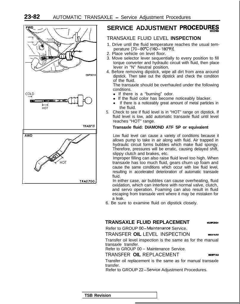
23-82 AUTOMATIC TRANSAXLE - Service Adjustment Procedures
HOT
TFA0715
AWD
L T FA0700 J
SERVICE ADJUSTMENT PROCEDUR&g
TRANSAXLE FLUID LEVEL INSPECTION1. Drive until the fluid temperature reaches the usual tem-
perature [70-80°C (160- 18O”F)I.2. Place vehicle on level floor.3. Move selector lever sequentially to every position to fill
torque converter and hydraulic circuit with fluid, then placelever in “N” Neutral position.
4. Before removing dipstick, wipe all dirt from area arounddipstick. Then take out the dipstick and check the conditionof the fluid.The transaxle should be overhauled under the followingconditions.l If there is a “burning” odor.l If the fluid color has become noticeably blacker.l If there is a noticeably great amount of metal particles in
the fluid.5. Check to see if fluid level is in “HOT” range on dipstick. If
fluid level is low, add automatic transaxle fluid until levelreaches “HOT” range.Transaxle fluid: DIAMOND ATF SP or equivalent
Low fluid level can cause a variety of conditions because itallows pump to take in air along with fluid. Air trapped inhydraulic circuit forms bubbles which make fluid spongy.Therefore, pressures will be erratic, causing delayed shift,slippy clutch and brakes, etc.Improper filling can also raise fluid level too high. Whentransaxle has too much fluid, gears churn up foam andcause the same conditions which occur with low fluid level,resulting in accelerated deterioration of automatic transaxlefluid.In either case, air bubbles can cause overheating, fluidoxidation, which can interfere with normal valve, clutch,and servo operation. Foaming can also result in fluidescaping from transaxle vent where it may be mistaken fora leak.
6. Be sure to examine fluid on dipstick closely.
TRANSAXLE FLUID REPLACEMENT M23FcsGaRefer to GROUP 00-Maintenance Service.TRANSFER OIL LEVEL INSPECTION Mm=xMTransfer oil level inspection is the same as for the manualtransaxle transfer.Refer to GROUP 00 - Maintenance Service.TRANSFER OIL REPLACEMENT M23FYAATransfer oil replacement is the same as for manual transaxletransfer.Refer to GROUP 22-Service Adjustment Procedures.
TSB Revision

AUTOMATIC TRANSAXLE - Service Adjustment Procedures 23-83
I:I’
4989 models> <From 1990 models>
09A0140
6% Button pressed (while brakepedal is depressed)
c Button not pressed0 Button pressed
SELECTOR LEVER OPERATION CHECK M23flAE
1. Shift selector lever to each range and check that levermoves smoothly and is controled. Check that positionindicator is correct.
2. Check to be sure the selector lever can be shifted to eachposition (by button operation as shown in the illustration).
3. Start the engine and check if the vehicle moves forwardwhen the selector lever is shifted from N to D, and movesbackward when shifted to R.
4. When the shift lever malfunctions, adjust control cableand selector lever sleeve. Check for worn shift leverassembly sliding parts.NOTETo move the selector lever from the “P” position to anyother position, first turn the ignition key to any positionother than “LOCK (OFF)” and depress the brake pedal.<From 1990 models>
KEY INTERLOCK MECHANISM CHECK M23FUAA
Completely stop the vehicle and switch OFF the engine beforemaking the check.1. Check to be sure that, under the following conditions, the
selector lever cannot be moved from the “P” position toany other position.Also check, at the same time, that the button cannot bepressed.Ignition key position: “LOCK (OFF)“, or removedBrake pedal: Depressed
2. Check to be sure that, under the following conditions, theselector lever can be moved from the “P” position to anyother position.Press the button a few times and check to be sure that theselector lever moves smoothly.Ignition key position: “ACC”Brake pedal : DepressedButton: Pressed
3. Check to be sure that, at all positions of the selector lever(other than “P”), the ignition key cannot be turned to the“LOCK (OFF)” position.Check to be sure that the ignition key smoothly turns to the“LOCK (OFF)” position when the selector lever is then setto the “P” position and the button is released.If a malfunction is discovered when following the abovechecking procedures, either adjust or check the keyinterlock cable mechanism. (Refer to P.23-97.)
-I
TSB Revision

23-84 AUTOMATIC TRANSAXLE - Service Adiustment Procedures
Brakepedal
I OSM0045
A
iection A-A
Switch body
- 17513312 mm (.47 in.)
SHIFT LOCK MECHANISM CHECK Mz3Fv~1.
2.
3.
4.
Check to be sure that, under the following conditions, theselector lever cannot be moved from the “P” position toany other position.Ignition key position: “ACC”Brake pedal: Not depressedButton: PressedCheck to be sure that, under the following conditions, theselector lever can be moved smoothly from the “P”position to other position.Ignition key position: “ACC”Brake pedal: DepressedButton : PressedCheck to be sure that, under the following conditions, theselector lever can be moved smoothly from, the “I?”position to the “P” position.Ignition key position: “ACC”Brake pedal: ReleasedButton : PressedIf a malfunction is discovered when following the abovechecking procedures, either adjust or check the shift lockcable mechanism. (Refer to P.23-97.) ’
PARK/NEUTRAL POSITION SWITCHADJUSTMENT M23FKAla
PARK/NEUTRAL POSITION SWITCH <1989 models>
1. Place selector lever in “N” (Neutral) position.2. Loosen control cable to manual control lever coupling
adjusting nuts (2 PCS.) to set cable and lever free.
3. Place manual control lever in “N” (neutral) position.4. Turn park/neutral position switch body until 12 mm (.47 in.)
wide end of manual control lever aligns with switch bodyflange [I 2 mm (.47 in.) wide portion].
5. Tighten attaching bolts (2 PCS.) taking care so that switchbody is not displaced.

AUTOMATIC TRANSAXLE - Service Adjustment Procedures 23-85
ection A-A09*0111
Switch body
6. Loosen adjusting nuts A and B and keep them apart fromthe adjuster, and then gently pull the end of the cable inthe direction of F.
7. Gently tighten adjusting nut A until there is contact withthe adjuster.
8. Secure adjusting nut A and then turn nut B to lock.9. Check that the selector lever is at the “N” position.10. Check that the manual control lever moves to the positions
corresponding to each position of the selector lever whenthe selector lever is operated.
PARK/NEUTRAL POSITION SWITCH < 1990 models>1. Place selector lever in “N” (Neutral) position.2. Place manual control lever in “N” (Neutral) position.3. For adjustment, turn the park/neutral position switch body
in order to align the end [12 mm (.47 in.) wide area] of themanual control lever to the flange [I2 mm (.47 in.) widearea] of the park/neutral position switch body.
4. Tighten the mounting bolts of the park/neutral positionswitch body to the specified torque. At this time, take careto prevent dropping the switch body.Specified torque: lo-12 Nm (7-9 ft.lbs.)
5. Loosen the nut shown in the figure, and lightly pull the endof the transaxle control cable in the “F” direction by hand.
6. Tighten the nut to the specified torque.Specified torque: lo-14 Nm (7-10 ft.lbs.)
7. Check that the selector lever is in “N” po?ition.8. Check that it securely operates and functions on the
transaxle side in the range which corresponds to eachposition of the selector lever.
TSB Revision

23-86 AUTOMATIC TRANSAXLE - Service Adjustment Procedures
<FWD> <AWD>
09A0179control lever
control lever
5 mmSection A-A i.2 in.) Manual
Switch body
175133
,PARK/NEUTRAL POSITION SWITCH<From 1991 models>1. Place selector lever in “N” (Neutral) position.2. Place manual control lever in “N” (Neutral) position.3. To adjust, rotate the switch body so that the manual control
lever 5 mm (.2 in.) hole and the switch body 5 mm (.2 in.)hole are aligned.
4. Tighten the mounting bolts of the park/neutral positionswitch body to the specified torque. At this time, take careto prevent dropping the switch body.Specified torque: 1 O-l 2 Nm (7-9 ftlbs.)
5. Loosen the nut shown in the figure, and lightly pull the endof the transaxle control cable in the “F” direction by hand.
6. Tighten the nut to the specified torque.Specified torque: lo-14 Nm (7-10 ft.lbs.1
7. Check that the selector lever is in “N” position.8. Check that it securely operates and functions on the
transaxle side in the range which corresponds to eachposition of the selector lever.
KICKDOWN SERVO ADJUSTMENT r&?3~61. Completely remove all dirt and other materials adhered
around the kickdown servo switch.2. Remove the snap ring.3. Remove the kickdown servo switch.4. To prevent rotation of the piston, engage the pawl of the
special tool into the notch of the piston, and using theadapter, fix the piston as shown in the left.Caution1. Don’t press in the piston with the special tool.2. When mounting the adapter on the transaxle case,
tighten it by hand. Don’t apply much torque.
TSB Revision
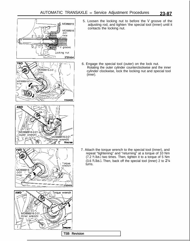
AUTOMATIC TRANSAXLE - Service Adjustment Procedures 23-875. Loosen the locking nut to before the V groove of the
adjusting rod, and tighten ‘the special tool (inner) until itcontacts the locking nut.
6. Engage the special tool (outer) on the lock nut.Rotating the outer cylinder counterclockwise and the innercylinder clockwise, lock the locking nut and special tool(inner).
7. Attach the torque wrench to the special tool (inner), andrepeat “tightening” and “returning” at a torque of 10 Nm(7.2 ft.lbs.) two times. Then, tighten it to a torque of 5 Nm(3.6 ft.Ibs.). Then, back off the special tool (inner) 2 to 2%turns.
TSB Revision

23-88 AUTOMATIC TRANSAXLE - Service Adjustment Procedures
8. Engage the special tool (outer) on the locking nut.Rotating the outer cyliner clockwise and the inner cylindercounterclockwise, unlock the locking nut and special tool(inner).CautionWhen unlocking the lock, apply equal force to bothtools.
WD . . . Up to 1992 model -&@~o-&q
9. Tighten the locking nut by hand until the locking nutcontacts the piston. Then, using the torque wrench, tightento the specified torque.Locking nut: 25-32 Nm (18-23 ft.lbs.)CautionIf it is rapidly tightened with the socket wrench ortorque wrench, the lock nut and adjusting rod mayrotate together.
10. Remove the special tool which fastens the piston.Attach the plug to the outlet of the low reverse pressure.
LINE PRESSURE ADJUSTMENT1. Drain out the automatic transaxle fluid.2. Remove the oil pan.3. Remove the oil filter.4. Remove the oil-temperature sensor.
J
1 TSB Revision
M23F9A9

AUTOMATIC TRANSAXLE - Service Adjustment Procedures 23-89
4WD . . . Up to 1992 model
Oil erature sensor
FWD . . . From MODEL 1990.5
5. Remove the solenoid valve connector holding clip, andpress in the connector.
6. Press the tabs of the solenoid valve harness grommet, andthen push into the case and remove.

AUTOMATIC TRANSAXLE - Service Adjustment Procedures
1_DTZii+!ilz$F~I\B
-g----J a----- .f-iL (i
&Fgi
Tit\I;; ;gTjqy ?“,,,,,,FWD . . . Up to MODEL 1990 I
Oil pan gasketsurfacecase 0
1750435
7. Remove the valve body assembly. The manual valve cancome out, so be careful not to drop it.
8. Turn the adjustment screw of the regulator valve and adjustso that the line pressure (kickdown brake pressure)becomes the standard value.When the adjustment screw is turned to the clockwise, theline pressure becomes lower; when it is turned tocounter-clockwise, it becomes higher.Standard value: 870-890 kPa (124-127 psi)Oil pressure change for each turn of
adjustment screw: 38 kPa (94 psi)
9. Check to be sure that the O-ring is installed on the uppersurface of the valve body at the place shown in the figure.
10. Replace the O-ring of the solenoid valve connector with anew one.
11. Install the valve body assembly to the case and then insertthe solenoid valve connector into the case. Be sure, at thistime, that the notched part of the connector faces asshown in the figure.Also be careful that the lead wiring isn’t caught.
TSB Revision
12. Replace the O-ring of the solenoid valve harness with anew one.
13. Tilt the solenoid valve harness over from the inner side ofthe transaxle case to the harness grommet installation hole’and install the harness grommet securely.
14. Install the harness grommet so that the lead wiring of thesolenoid valve harness faces in the direction indicated bythe arrow in the illustration. (FWD . . . From MODEL1990.5)

AUTOMATIC TRANSAXLE - Service Adjustment Procedures 23-91
15. Tighten valve body assembly mounting.Valve body assembly mounting bolts:
11 Nm (8.0 ftlbs.)A: 18 mm (.709 in.) longB: 25 mm (.984 in.) longC: 40 mm (1.575 in.) longCaution (AWD)Fix the solenoid valve and oil temperature sensor harnesssecurely in the position shown. Since the harness of thepressure control solenoid valve (PCSV) is separatelyprovided from the other harness, route the formerharness as illustrated and clamp it. If clamping isforgotten, it will come into contact with the detent plateand parking rod.
16. Install the oil filter.17. Install a new oil pan gasket and oil pan.18. Pour in the specified amount of Automatic transaxle fluid.19. Make the oil pressure test. Readjust if necessary.
REDUCING PRESSURE ADJUSTMENT MZ3FTAb
(If the scan tool is not available)1. Remove parts up to the oil filter in the same way as for
adjustment of the line pressure. The valve body need notbe removed.
2. Turn the adjustment screw of the lower valve body andadjust so that the reducing pressure is the standard value.When the adjustment screw is turned to the right, thereducing pressure becomes lower; when it is turned to theleft, it becomes higher.

23-92 AUTOMATIC TRANSAXLE - Service Adjustment Procedures
NOTEWhen adjusting the reducing pressure, aim for the centervalue (425 kPa, 60 psi) of the standard value allowance.Standard value: 415-435 kPa (59-62 psi)Oil pressure change for each turn of adjustment screw:
22 kPa (3.1 psi) . . . FWD (Up to MODEL 1990)45 kPa (6.4 psi) . . . FWD (From MODEL 1990.5, AWD)
3. Install the oil filter and oil pan in the same way as foradjustment of the line pressure.
4. Make the oil pressure test. Readjust if necessary.
(If the scan tool is used)1. Using the scan tool, forcibly drive the pressure control
solenoid valve at 50% duty, and measure the kick-downbrake apply pressure.If the kick-down brake apply pressure does not exist withinthe standard value width, adjust the pressure with thereducing pressure adjustment screw.Standard value: 275 + 10 kPa (39 + 1 psi)Oil pressure change for each turn of adjustment screw:
25 kPa (3.6 psi) FWD (Up to MODEL 1990)22 kPa (3.1 psi) FWD (From MODEL 1990.5), AWD
2. Check to be sure that the reducing pressure (after theadjustment is completed) is within the range of 360-480kPa (51 -68 psi.).CautionThis adjustment should be made at an oil temperatureof 70- 80°C (160- 180°F).If the adjustment is made at a temperature that is toohigh, the line pressure will drop during idling, with theresult that it might not be possible to make the correctadjustment.
I / Oii seal09K561
THROTTLE-POSITION SENSOR ADJUSTMEF&
Refer to GROUP 13-On-Vehicle Inspection of MFI Compo-nents.DRIVE SHAFT OIL SEALS REPLACEMENT MZ3FDBC
(1) Disconnect the drive shaft from the transaxle.(Refer to GROUP 26-Drive Shaft.)
(2) Using a flat-tip (-) screwdriver, remove the oil seal.
1 TSB Revision 1

AUTOMATIC TRANSAXLE - Service Adjustment Procedures 23-93
MD998325-01
1 6 0 0 2 4-
(3) Using the special tool, tap the drive shaft oil seal into thetransaxle.
(4) Apply a coating of the transaxle fluid to the lip of the oil seal.Transaxle fluid: DIAMOND ATF SP or equivalent
SPEEDOMETER CABLE REPLACEMENT MUFEAEa
1. Correctly insert the adapter into the instrument panel, andfasten the new speedometer cable.
TSB Revision
2. Install the grommet so that, as shown in the illustration, thecable attachment part is positioned upward.Caution(1) The cable arrangement should be made so that the
radius of cable bends is 150 mm (5.9 in.) or more.(2) The arrangement of the speedometer cable should
be such that it does not interfere with brake tubes,etc.
3. At the transaxle end of the speedometer cable, the keyjoint should be inserted into the transaxle, and the nutshould be securely tightened.CautionIf the cable is not correctly and securely connected, itmay cause incorrect indication by the speedometer, orabnormal noise. Be sure to connect it correctly.

23-94 AUTOMATIC TRANSAXLE - Transaxle Control
TRANSAXLE CONTROLREMOVAL AND INSTALLATION
Pre-removal and Post-installation Operationl Removal and Installation of Console Box Assembly
(Refer to GROUP 52-Floor Console.)*Removal and Installation of Air Cleaner
(Refer to GROUP 15-Air Cleaner.)
cl989 models> <From 1990 models>
MUIA-
7-10 ft.lbs. 7-10 ft.lbs.
‘ransaxle control cable and selector leverssmebly removal steps
1. Snap pin2. Key-interlock cable
(selector lever 1assembly side)
7. Shift-lock cable I<From 1990 models>
(selector leverassembly side) I
10. Snap pin11. Clip12. Snap pin13. Adjusting nut
+* 14. Clipl + 15. Transaxle control cable
16. Bushing17. Selector lever assembly
4999 models>
0910158
1 TSB Revision

AUTOMATIC TRANSAXLE - Transaxle Control 23-95
<From 1990 models>
4-6‘Nm3-4 ftlbs.
Pre-removal and Post-installation Operation*Removal and Installation of Console Box Assembly
(Refer to GROUP 52-Floor Console.)@Removal and Installation of Instrument Under Cover Assem-s;bly, Column Cover, Lap Shower Duct and Foot Shower
(Refer to GROUP 5’2-Instrument Panel.)
9-14 Nm7-10 ftlbs.
4-6 N m3-4 ftlbs.
09A0138
Key-interlock cable removal steps1. Snap pin
l + 2. Key-interlock cable (selector leverassembly side)
3. Clamp4. Cover
I)* 5. Key-interlock cable (steering lockassembly side)
I)+ 6. Slide lever
NOTEBefore connecting the key-interlock cable or the shift-lockcable, be sure to first connect and adjust the transaxle
Shift-lock cable removal steps3. Clam
I)+ 7 . Shift- ock cableP(selector lever assembly side)
8. Coffer pin9. Shift-lock cable (brake pdeal side)
control cable.
TSB Revision

23-96 AUTOMATIC TRANSAXLE - Transaxle Control
I<1989 models> /<From 1990 models:
switch 16A0463 18A077E
09*0029
09A0039
<FWD> <AWD>
Neutral oosition
INSPECTION M23lcAKl Check the control cable for function and for damage.l Check the bushing for wear or damage.
POWER (PWR)/ECONOMY (ECO) SWITCH(1) Remove the POWER (PWRVECONOMY (ECO) switch from
the console box.(2) Check for continuity between terminals when the switch is
OFF and when ON.
NOTEO-O indicates that there is continuity between the terminals.
OVERDRIVE CONTROL SWITCHCheck for continuity between terminals when the switch is OFFand when ON.
ON (Overdrive activation) 0 0
OFF (Overdrive non-activation) 0 3
NOTEO-O indicates that there is continuity between the terminals.
SERVICE POINTS OF INSTALLATION M231DAO
15. INSTALLATION OF TRANSAXLE CONTROL CABLEMove the selector lever and the park/neutral positionswitch to the “N” position, and install the transaxle controlcable.
I OSAO179 1
TSB Revision

AUTOMATIC TRANSAXLE - Transaxle Control 23-97
mount
\ 09R0058
3tent pin A ~ r\,I, ./
/
lock cable
0910143
Key interlock cable O0A0125
,T’--
@ ;:-.-
09AO126
09A0142
14. INSTALLATION OF CLIPWhen connecting the control cable to the transaxle mountbracket, install the clip until it contacts the control cable, inthe position shown in the figure.
. ADJUSTMENT OF TRANSAXLE CONTROL CABLERefer to the section concerning adjustment of the park/neutral position switch. (Refer to P.23-84.)
7. INSTALLATION OF SHIFT LOCK CABLE (SELECTORLEVER ASSEMBLY SIDE)(1) Move the selector lever to the “R” position.(2) Clamp the shift lock cable.(3) Connect the shift lock cable to the selector lever
assembly, and temporarily tighten the nut.(4) Slide the shift lock cable so that the distance between
the selector lever assembly’s detent pin and the end ofthe shift lock cable is the standard value, and thentighten the nut at the specified torque.
Standard value (A): 1-4 mm (.04-.15 in.)(5) After connecting the shift lock cable, check the shift
lock mechanism. (Refer to P.23-84.)
6. INSTALLATION OF SLIDE LEVERI5. KEY INTERLOCKCABLE (STEERING LOCK ASSEMBLY SIDE)(1) With the ignition key either at the “LOCK” position or
removed, install the slide lever to the key cylinder.(2) Connect, as shown in the figure, the key interlock cable
to the slide lever and the key cylinder.(3) Apply a light coating of multi-purpose grease where
shown in the figure.(4) Install the key interlock cable.
2. INSTALLATION OF KEY INTERLOCK CABLE (SELECTORLEVER ASSEMBLY SIDE)(1) Move the selector lever to the “P” postion.(2) Connect the key interlock cable to the selector lever
assembly’s lock cam. Be sure that the spring installedto the key interlock cable is as shown in the figure.
(3) While gently pressing the lock cam in the F direction,tighten the nut to secure the key interlock cable.
(4) After connecting the key interlock cable, check the keyinterlock mechanism. (Refer to P.23-83.)
11 TSB Revision I

23-98 AUTOMATIC TRANSAXLE - Transaxle Control
DISASSEMBLY AND REASSEMBLY (SELECTOR LEVER ASSEMBLY)
2.0 Nm or more1.4 ft.lbs. or more
2.0 Nm or more/ 1.4 ft.lbs. or more
k%-h.lbs.
Disassembly steps*I) 1. Overdrive control switch connector
2. Cover3. Selector knob
a* 4. Overdrive control switch button4, 5. Overdrive control switch
6. Pin7. Pushbutton8. Spring9. Indicator panel
10. Slider11. Indicator panel lower12.
l 4 13.Socket assemblySleeve
14. Lever assembly15. Bushina16. Pipe ”17. Cotter pin <From 1990 models>18. Lock cam19. Bracket assembly
-10
-11
09190135
TSB Revision

AUTOMATIC TRANSAXLE - Transaxle Control 23-99
Screwdriver
I 09A0043 (
SERVICE POINTS OF DISASSEMBLY mz3oFhC1. REMOVAL OF OVERDRIVE CONTROL SWITCH CON-
NECTORDisconnect the overdrive control switch connector andthen remove the terminal from the overdrive controlswitch connector.
4. REMOVAL OF OVERDRIVE CONTROL SWITCHBUlTON/5. OVERDRIVE CONTROL SWITCH(1) Using the flat-tip screwdriver, remove the overdrive
control switch button.(2) FW&ng the switch, remove the overdrive control
INSPECTION MuOOADl Check the detent plate for wear.l Check the bushing for wear or damage.l Check the spring for damage or deterioration.
SERVICE POINTS OF REASSEMBLY Mz3oHhL13. INSTALLATION OF SLEEVE
(1) Place the selector lever in the “N” position, and thenturn the sleeve so that the clearance between thesleeve and the lever assembly end is within thestandard value.
Standard value (A): 15.2-15.9 mm (.598-.825 in.)(2) Apply a coating of multi-purpose grease to the surface
of the sleeve.
TSB Revision

23-100 AUTOMATIC TRANSAXLE - Transaxle Oil Cooler Hoses
TRANSAXLE OIL COOLER HOSESREMOVAL AND INSTALLATION
<Up to 1992 models>3-5 Nm2-4 ft.lbs. 4 - 6 Nm\ 3-4 ft.lbs.
3-4 ft.lbs.
4-6 Nm3-4 ft.lbs. 09A0041
< 1993 models>2
Pre-removal and Post-installationOperationl Drainage and Filling of Automatic Trans-
axle Fluid(Refer to GROUP 00 - MaintenanceService.)
Removal steps1. Hose clamp2. Cable clamp3. Oil cooler hose assembly
Caution1. Take care not to spill the transaxle fluid
when removing components.2. After removing the oil cooler hose as-
sembly, plug so that foreign materialscannot enter the transaxle.
2-4 ftlbs.
bs. I /-\ nhu-l,no
INSPECTIONl Check the hose for crack, damage and clog.l Check for rusted or clogged radiator oil cooler.
TSB Revision

AUTOMATIC TRANSAXLE - Transaxle Assembly <FWD>
TRANSAXLE ASSEMBLY <FWD>REMOVAL AND INSTALLATION
23-101
mz3u-
Pre-removal and Post-installation Op-eration@Draining and Supplying of the Transaxle
Fluid(Refer to GROUP 00-Maintenance Ser-vice.)
*Removal and Installation of the Batteryand Battery Tray
ofRemoval and Installation of the Air Clean-
fRrefer to GROUP 15-Air Cleaner.)*Removal and Installation of the Air Com-
pressor(Vehicles with ACTIVE-ECS)(Refer to GROUP 33B-Air Compressor.)
cl989 models> 27-34 Nm20-25 ft.lbs.
I 360-80 Nm43-58 ft.lbS.
60-80 Nm43-58 ft.lbs.
43-55 Nm
IO-12 Nm7.2-8.7 ft.lbs.
27-34 Nm20-25 ft.lbs.
30-35 km b22-25 ft.lbs.
Iii ’30-35 Nm22-25 ft.lbs.
ternoval steps1. Snap pin3. Connection for transaxle control cable
(Refer to P.23-84.)4. Solenoid connector5. Park/neutral position switch connector6. Pulse generator connector7. Kickdown servo switch connector8. Oil temperature sensor connector
9. Connection for sppedometer cable10. Connection for oil cooler hose11. Connection for starter motor12. Upper coupling bolt for transaxle
assembly and engine assembly13. Transaxle mount bracket
TSB Revision

23-102 AUTOMATIC TRANSAXLE - Transaxle Assemblv <FliVD>
<From 1990 models>
27-34 Nm 220-25 ftlbs. \
43-55 Nm
60-80 Nm
60-80 Nm
/43-58 ftlbs.
43-58 ftlbs.
/ \ / \ 930-35 Nm D m 30-35 N m22-25 ftlbs. 22-25 ft.lbs.
Iemoval steps2. Adjusting nut3. Connection for transaxle control cable
(Refer to P.23-85.)4. Solenoid connector5. Park/neutral position switch connector6. Pulse generator connector7. Kickdown servo switch connector8. Oil temperature sensor connector9. Connection for speedometer cable
10. Connection for oil cooler hose11. Connection for starter motor12. Upper coupling bolt for transaxle
assembly and engine assembly13. Transaxle mount bracket
TSB Revision
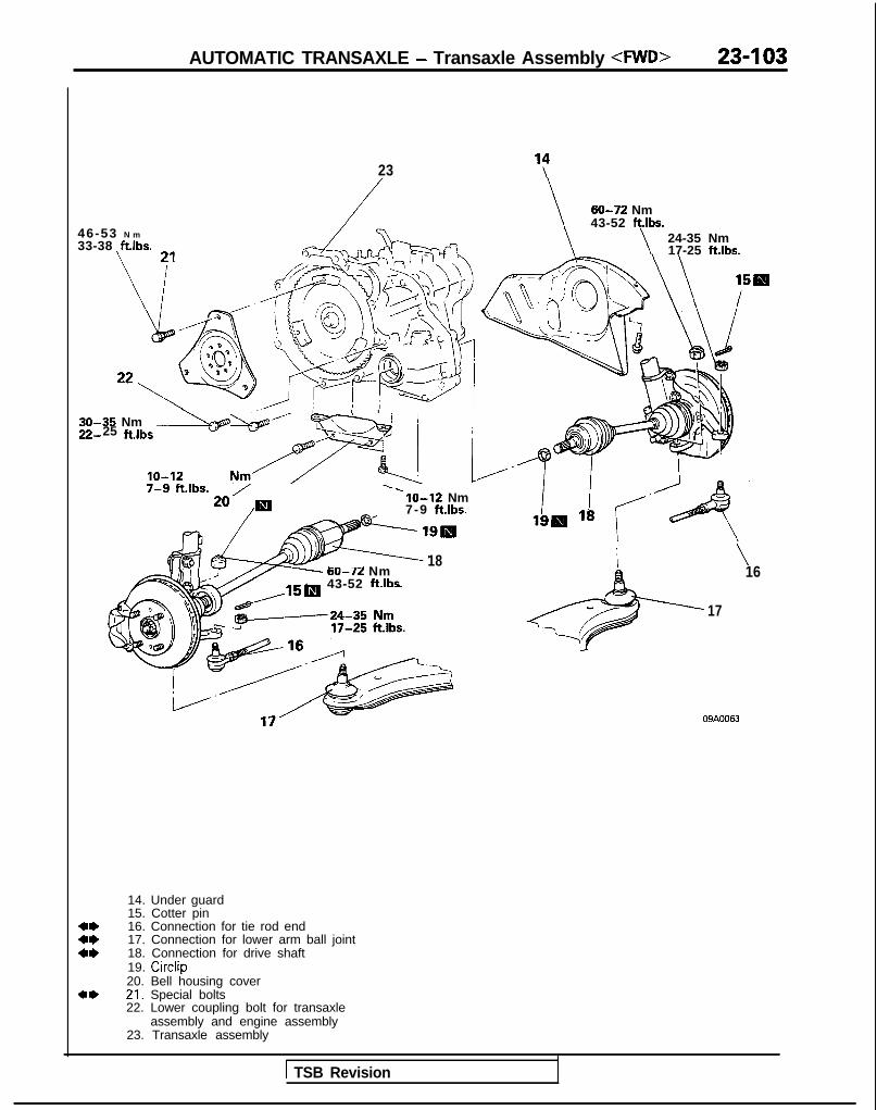
AUTOMATIC TRANSAXLE - Transaxle Assembly dVVD> 23-103
23 ‘;1
46-53 N m
33-38 ftlbs.
30-35 Nm22 25 filbs *---.- <l - ;j I
- . .
lo-12 Nrn/F< 17-g --ftlbs.
20’/m. .
lo-12 Nm7-9 ftlbs.
18- - -- Nm60-72
43-52 ftlbs.
60-72 Nm43-52 ft.lbs.
\24-35 Nm17-25 ftlbs.
i \16
17
09AOO63
+*
14. Under guard15. Cotter pin16. Connection for tie rod end17. Connection for lower arm ball joint18. Connection for drive shaft19. Circlip20. Bell housing cover21. Special bolts22. Lower coupling bolt for transaxle
assembly and engine assembly23. Transaxle assembly
1 TSB Revision

23-104 AUTOMATIC TRANSAXLE - Transaxle Assembly 4WD>
OPTIONAL 12K513
Pry bar aTransaxle
llKf311 I
SERVICE POINTS OF REMOVAL M23LBAK
16. DISCONNECTION OF TIE ROD END
Using the special tool, disconnect the tie rod end from theknuckle.
Caution1. Be sure to tie the cord of the special tool to the
nearby part.2. Loosen the nut but do not remove it.
17. DISCONNECTION OF LOWER ARM BALL JOINTUsing the special tool, disconnect the lower arm ball jointfrom the knuckle.
Caution1. Be sure to tie the cord of the special tool to the
nearby part.2. Loosen the nut but do not remove it.
18. DISCONNECTION OF DRIVE SHAFT(1) Insert a pry bar between the transaxle case and the
drive shaft, and then pry the drive shaft from thetransaxle.
Caution1. Do not pull on the drive shaft; doing so will
damage the T.J.; be sure to use the pry bar.2. Do not insert the pry bar so deep as to damaged
the oil seal.(2) Keep the removed drive shaft as far away from the
transaxle case as possible, and secure (by using rope.etc.) the T.J. to the body so that it does not fall.
21. REMOVAL OF SPECIAL BOLTS(1) Remove the three special bolts connecting the con-
verter to the drive plate.
NOTETo remove the special bolts of torque converter, turnengine crankshaft with a box wrench to bring one ofthe bolts to the position appropriate for removal. Afterremoving the bolt, turn the crankshaft in the samemanner as above and remove all remaining bolts oneafter another.
(2) After removing the special bolts, push the torqueconverter toward transaxle so that it does not remain onthe engine side.
1 TSB Revision

AUTOMATIC TRANSAXLE - Transaxle Assembly <AWD> 23-I 05
TRANSAXLE ASSEMBLY <AWD> hl33lA-1
REMOVAL AND INSTALLATION
Pre-removal and Post-installationOperationeDraining and Supplying of the Trans-
axle Fluid(Refer to GROUP 00-MaintenanceService.)l Removal and Installation of the Bat-
tery and Battery Tray*Removal and Installation of the Air
Cleaner(Refer to GROUP 15-Air Cleaner.) 20-27 Nm lo-14 Nm
14.5-19 ft.lbs.0 /
7-10 ft.lbs./
, \ f p,/7-9 f%.lbs.
27-34 Nm20-25 ft.lbs.
-27-34 Nm20-25 ft.lbs.
30-35 Nm22-25 ft.lbs.
30-35 Nm22-25 ft.lbs.
OSA0183
Removal steps1. Connection for transaxle control cable
(Refer to P.23-86.)2. Connection for oil cooler hose3. Automatic transaxle dipstick4. Connection for solenoid connector5. Park/neutral position switch (Refer to
P.23-86.)6. Connection for kickdown servo switch
connector
7. Connection for pulse generator connector8. Connection for oil temperature sensor
connector9. Connection for speedometer cable
10. Starter motor11. Upper coupling bolt for transaxle
assembly and engine assembly
TSB Revision
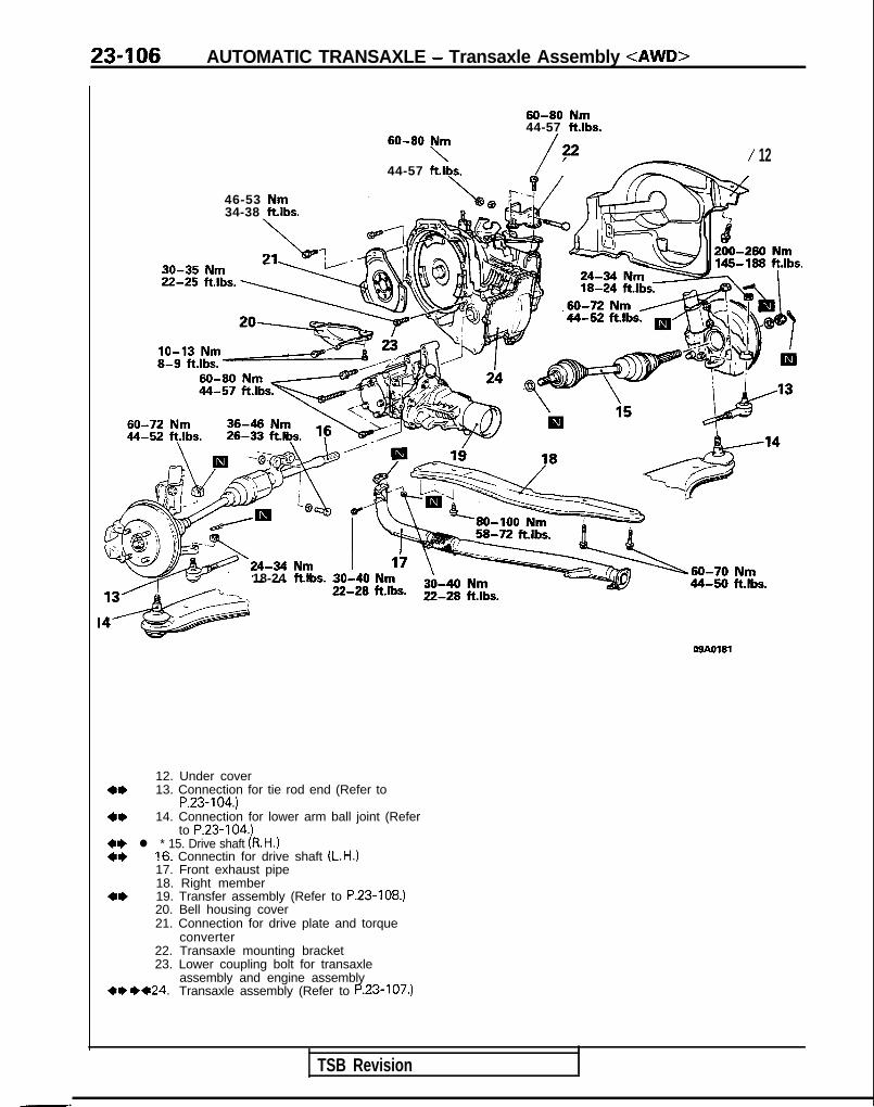
23-106 AUTOMATIC TRANSAXLE - Transaxle Assembly <AWD>
46-53 Nm34-38 ftlbs.
30-35 Nm
60-80 Nm44-57 ftlbs.
60-80 Nm
44-57 ftlbs.\
/,22 / 12
18-24 ftlbs. 30-40
08AO181
4*
4*
12. Under cover13. Connection for tie rod end (Refer to
P.23-104.)14. Connection for lower arm ball joint (Refer
to P.23-104.)~~ l * 15. Drive shaft (R.H.)4* 16. Connectin for drive shaft (L.H.)
17. Front exhaust pipe18. Right member
4* 19. Transfer assembly (Refer to P.23-108.)20. Bell housing cover21. Connection for drive plate and torque
converter22. Transaxle mounting bracket23. Lower coupling bolt for transaxle
assembly and engine assembly+O ++24. Transaxle assembly (Refer to P.23-107.)
TSB Revision

AUTOMATIC TRANSAXLE - Transaxle Assembly <AWD> 23407
OSAOl82
Hub
SERVICE POINTS OF REMOVAL MZ3LMU
15. REMOVAL OF DRIVE SHAFT (R.H.)(1) Use the general service tool to push out the drive shaft
from the front hub.
(2) Insert a pry bar at the projection part and remove thedrive shaft (R.H.) from the transaxle.
CautionDo not pull out the drive shaft; doing so willdamage the T.J.; be sure to use the pry bar.
16. DISCONNECTION OF DRIVE SHAFT (L.H.)(1) Disconnect the inner shaft assembly from the transaxle
by lightly tapping the T.J. case with a plastic hammer,etc.
(2) Suspend the drive shaft with wire or something similarso that there are no sudden bends in the joints.
SERVICE POINTS OF INSTALLATION MZ3LOAN
24. INSTALLAnON OF TRANSAXLE ASSEMBLYFirst install the torque converter on the transaxle and theninstall the transaxle assembly on the engine.CautionBe sure to install the torque converter on the transaxlefirst. lf it is first installed on the engine, the oil seal onthe transaxle side will be damaged.
15. INSTALLATION OF DRIVE SHAFT (R-H.)Install the drive shaft nut for the drive shaft (R.H.) in thefollowing way.(1) Be sure to install1 the washer and drive shaft nut in the
specified direction.(2) After installing the wheel, lower the vehicle to the
ground and finally tighten the drive shaft nut.(3) If the position of the cotter pin holes does not match,
tighten the nut up to 260 Nm (188 ft.lbs.1 in maximum.(4) Install the cotter pin in the first matching holes and
bend it securely.
TSB Revision

23-108 AUTOMATIC TRANSAXLE - Transfer
TRANSFERREMOVAL AND INSTALLATIONI
M23VA-
30-40 Nm22-29 ftlbs.
60-80 Nm44-57 ftlbs.
O!IAOlSO
Removal steps
4*1. Front exhaust pipe2. Transfer assembly (Refer to P.23-105.)
TSB Revision I

25-1
PROPELLERSHAFT
CONTENTS MPAA-
PROPELLER SHAFT . . . . . . . . . . . . . . . . . . . . . . . . . . . . . . . . . . . . . . . . 4 Lubricants . . . . . . . . . . . . . . . . . . . . . . . . . . . . . . . . . . . . . . . . . . . . . . . . . . . . . . 3
SPECIAL TOOLS . . . . . . . . . . . . . . . . . . . . . . . . . . . . . . . . . . . . . . . . . . . . . 3
SPECIFICATIONS . . . . . . . . . . . . . . . . . . . . . . . . . . . . . . . . . . . . . . . . . . . . . 2General Specifications . . . . . . . . . . . . . . . . . . . . . . . . . . . . . . . .._ 2
Service Specifications ................................... 2
Torque Specifications .................................. . 2m
TROUBLESHOOTING ...................................... 3

25-2 PROPELLER SHAFT - Specifications
SPEClFlCATjONSThe AWD vehicles have been discontinued from 1993 models.
GENERAL SPECIFICATIONS M2scA-
SpecificationsItems
M/T Arr
Propeller shaft
Type 4 joint propeller shaft 4 joint propeller shaft
Length x O.D. mm (in.)
Front 707 x 50.8 (27.8 x 2.00) 707 x 50.8 (27.8 x 2.00)
Center 777.5 x 65 (30.8 x 2.56) 764.4 x 65 (30.1 x 2.56)
Rear 530.5 x 50.8 (20.9 x 2.00) 543.3 x 50.8 (21.4 x 2.00)
Universal joint
TypeNo. 1 (front) Cross type Cross type
No.2 (center front) Cross type Cross type
No.3 (center rear) [Lobro joint Equal velocity type Equal velocity type
No. 4 (rear) or D.O.J.1 Cross type Cross type
Cross type universal joint bearing Needle roller bearing (oilless type) Needle roller bearing (oilless type)
Cross type universal joint
Journal O.D. mm (in.) 14.689 l.5783) 14.689 i.5783)
Equal velocity joint type Lobro joint (oilless type) D.O.J. (oilless type)
Equal velocity joint size O.D.mm (in.) 94 (3.7) 94 (3.7)
NOTEPropeller shaft length indicates the length between the center points of each joint.
SERVICE SPECIFICATIONS Mz5c&-
Items Specifications
Standard valueJournal axial play mm (in.) 0.02-0.06 (.0008-.0024)
LimitPropeller shaft runout(Dial indicator reading)
Front mm (in.) 0.6 t.024) or lessCenter mm (in.) 0.6 t.024) or lessRear mm (in.) 0.6 (.024) or less
TORQUE SPECIFICATIONS Mzxc-
Items 1 Nm
Center bearing self locking nut 30-40 22-29Flange yoke to differential companion flange 30-35 22-25Center propeller shaft to center yoke 160-220 116-159Rear propeller shaft to companion flange 160-220 116-159Companion flange to Lobro joint assembly <M/T> 30-40 22-29Companion flange to D.O.J. assembly </VT> 30-40 2 2 - 2 9
ft.lbs.
TSB Revision

PROPELLER SHAFT - Specifications/Special Tools/T;oubleshooting 25-3
LUBRICANTS Mz5ch
Items
Sleeve yoke surface
Specified lubricant Quantity
Hypoid gear oil API classification GL-4 or As requiredhigher, SAE 75W-85W
Lobro jointassembly<MTT>
Outer and inner racesball groovesRubber packing
Repair kit grease As required
Lobro joint assemblyinner part
Repair kit grease 4 5 - 5 5 gt 1.59- 1.94 02)
D.O.J.
2ziib’y
Outer and inner racesball grooves
Rubber packing
Repair kit grease As required
D.O.J. assemblyinner part
Repair kit grease 105-115 g(3.7-4.0 02)
SPECIAL TOOLS( Tool Number Name I Use
MB991 193 Plug Prevention of entry of foreign objects intothe transaxle and transfer
TSB Revision
TROUBLESHOOTING
Symptom
Noise at start
Probable cause
Worn journal bearing
Worn sleeve yoke spline
Remedy
Replace
Loose propeller shaft installation Retighten
Noise and vibration Unbalanced propeller shaft Replaceat high speed
Improper snap ring selection Adjust the clearance
Worn journal bearing Replace
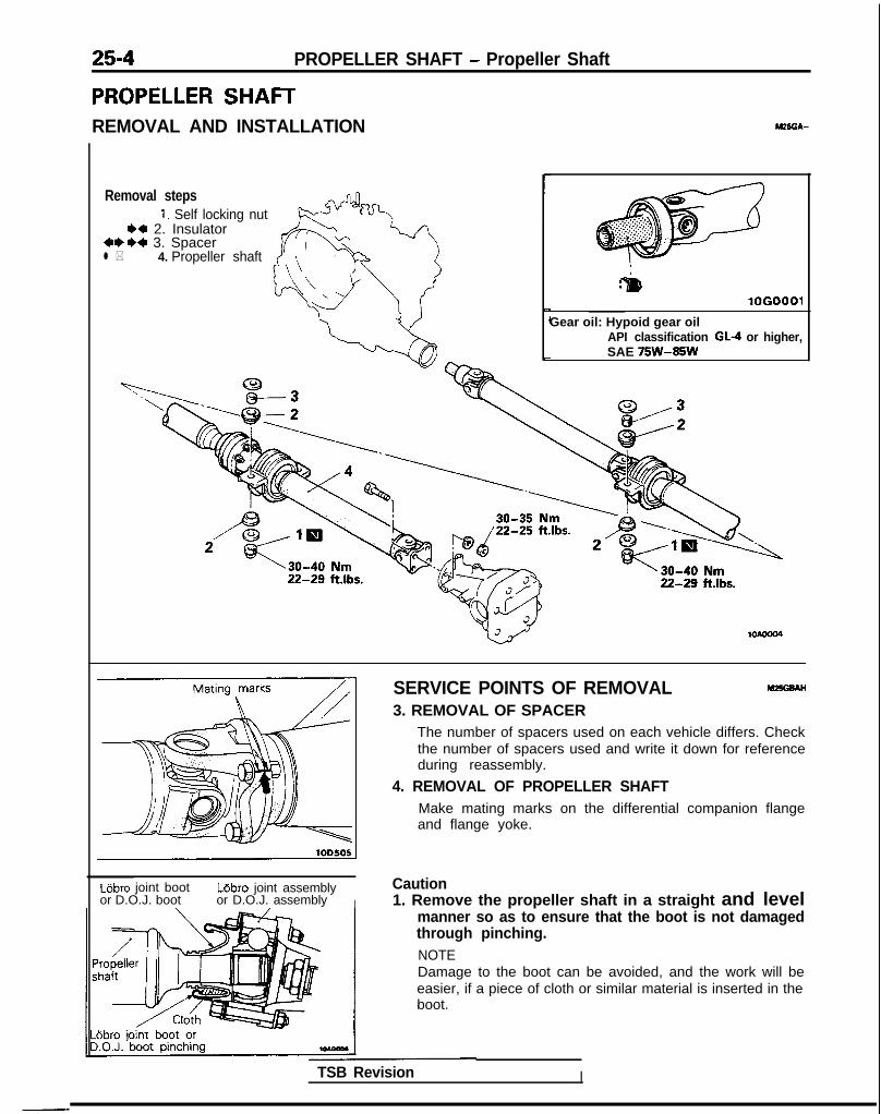
25-4 PROPELLER SHAFT - Propeller Shaft
PROPELLER SHAFTREMOVAL AND INSTALLATION
Removal steps1. Self locking nut
** 2. Insulator***a 3. Spacerl * 4. Propeller shaft
r
:&IlOGO
Gear oil: Hypoid gear oilAPI classification GL-4 or higher,SAE 75W-85W
SERVICE POINTS OF REMOVAL MEGBAH
3. REMOVAL OF SPACERThe number of spacers used on each vehicle differs. Checkthe number of spacers used and write it down for referenceduring reassembly.
4. REMOVAL OF PROPELLER SHAFTMake mating marks on the differential companion flangeand flange yoke.
Lijbro joint boot L6bro joint assemblyor D.O.J. boot or D.O.J. assembly I
Caution1. Remove the propeller shaft in a straight and level
manner so as to ensure that the boot is not damagedthrough pinching.NOTEDamage to the boot can be avoided, and the work will beeasier, if a piece of cloth or similar material is inserted in theboot.
TSB Revision I

PROPELLER SHAFT - Propeller Shaft 25-5
,.\@Jjiig\ .!’
Lower
Upper
Spacer
1060012
2.
3.
4.
Do not lower rear end of the vehicle as the oil will flowout of the transfer.Be cautious to avoid damage to the oil seal lip of thetransfer.Use the special tool provided as a cover to prevent theentry of foreign objects into the transfer.
INSPECTION M2SGCAH
l Check the sleeve yoke, center yoke and flange yoke forwear, damage or cracks.
l Check the propeller shaft yokes for wear, damage orcracks.
l Check the propeller shaft for bends, twisting or damage.
l Measure the propeller shaft runout with a dial indicator.
Limit:Front propeller shaft 0.6 mm (.024 in.) or lessCenter propeller shaft 0.6 mm (.024 in.) or lessRear propeller shaft 0.6 mm (.024 in.) or less
NOTESet the V-blocks as much as possible to the end of theshaft. Measure deflection at the center of the shaft.
l Check the universal joints for smooth operation in alldirections.
l Check the’center bearing for smooth movement.l Check the center bearing mounting rubber for damage or
deterioration.
SERVICE POINTS OF INSTALLATION M25GDAN3. INSTALLATION OF SPACER/P. INSULATOR
install spacers and insulators as indicated in the illustration.
CautionWhen installing the center bearing, assemble the samespacers as removed from it (or new spacers of equalthickness).
1 TSB Revision
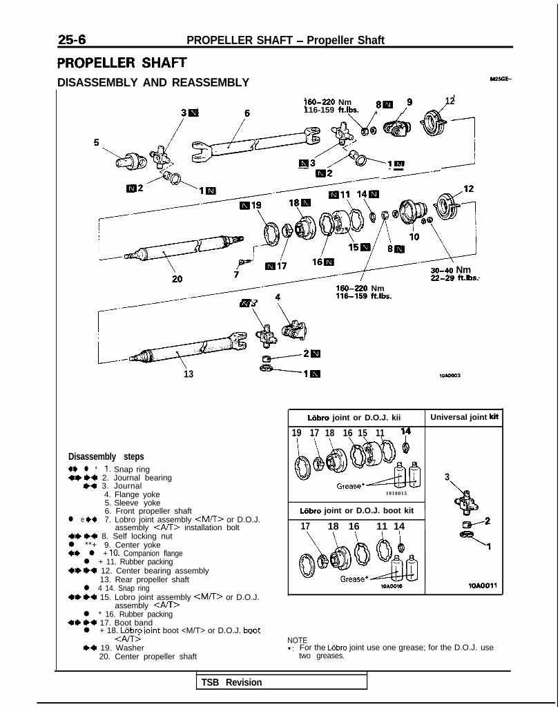
25-6 PROPELLER SHAFT - Propeller Shaft
PROPELLER SHAFTDISASSEMBLY AND REASSEMBLY
160-220 Nm 8W /9 12116-159 ft.lbs. ,
--I=------
30-40 NmZG?~ ft.lbs.
/------ d3
r Q”‘ ;+’
4s.
G
*I 4 :
_c w20
13 -----lig
Disassembly steps4I) l * I, Snap ring+* I)+ 2. Journal bearing
,a 3. Journal4. Flange yoke5. Sleeve yoke6. Front propeller shaft
l e +4 7. Lobro joint assembly <MTT> or D.O.J.assembly <AA> installation bolt
+e ~~ 8. Self locking nutl **+ 9. Center yoke+* l + 10. Companion flangel + 11. Rubber packing
~~ ~~ 12. Center bearing assembly13. Rear propeller shaft
l 4 14. Snap ring~~ ~~ 15. Lobro joint assembly <M/l> or D.O.J.
assembly <AK>l * 16. Rubber packing
+e ++ 17. Boot bandl + 18. LGbro ioint boot <M/T> or D.O.J. boot
<Al-G,a 19. Washer
20. Center propeller shaft
--.
160-220 Nm116-159 ft.lbs.
LIbro joint or D.O.J. kii Universal joint kit
19 17 18 16 15 11
1010015
Liibro joint or D.O.J. boot kit 1
3
+bf ”
17 18 16 11 14
lOAOO16 1OAOOll
NOTE*: For the Ldbro joint use one grease; for the D.O.J. use
two greases.
TSB Revision
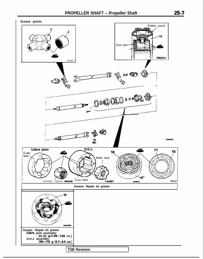
PROPELLER SHAFT - Propeller Shaft 25-7Grease points
I lOY607 1
Dust seal
Rubber mount
c&---?/L- Y$!!@Q@@ @q@Q
/------.//------’r-/------L&m&r
bl1 i
I n n e r r a c e ioxoow
’ A Inner race ‘“m
vyLc:I race w ‘- I3
llAO357 107.0037
Grease: Repair kii grease
Grease: ‘Repair kit greaseWbro joint assembly:
45-55 g (1.59-1.94 oz.]D.O.J. assembly:
105-115 g (3.7-4.0 OZ.]
1 TSB Revision
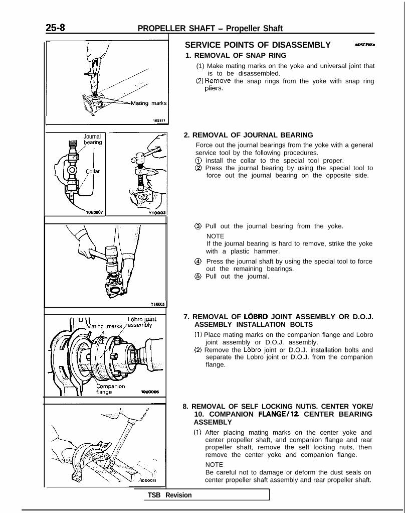
25-8 PROPELLER SHAFT - Propeller Shaft
Journal
YIOCO!
L6bro joint
Ll
SERVICE POINTS OF DISASSEMBLY MZ5GFAKa
1. REMOVAL OF SNAP RING(1) Make mating marks on the yoke and universal joint that
is to be disassembled.(2) 13;e~s~ the snap rings from the yoke with snap ring
2. REMOVAL OF JOURNAL BEARINGForce out the journal bearings from the yoke with a generalservice tool by the following procedures.@ install the collar to the special tool proper.@ Press the journal bearing by using the special tool to
force out the journal bearing on the opposite side.
@ Pull out the journal bearing from the yoke.
NOTEIf the journal bearing is hard to remove, strike the yokewith a plastic hammer.
@ Press the journal shaft by using the special tool to forceout the remaining bearings.
@ Pull out the journal.
7. REMOVAL OF LOBRO JOINT ASSEMBLY OR D.O.J.ASSEMBLY INSTALLATION BOLTS(I) Place mating marks on the companion flange and Lobro
joint assembly or D.O.J. assembly.(2) Remove the Lijbro joint or D.O.J. installation bolts and
separate the Lobro joint or D.O.J. from the companionflange.
TSB Revision
8. REMOVAL OF SELF LOCKING NUT/S. CENTER YOKE/10. COMPANION FLANGE/lZ. CENTER BEARINGASSEMBLY(1) After placing mating marks on the center yoke and
center propeller shaft, and companion flange and rearpropeller shaft, remove the self locking nuts, thenremove the center yoke and companion flange.
NOTEBe careful not to damage or deform the dust seals oncenter propeller shaft assembly and rear propeller shaft.

PROPELLER SHAFT - Propeller Shaft 25-9
I Puller(commercially avaiiabl
Mating marks
(2) After placing mating marks on the center bearingassembly (front) bracket and center propeller shaft, andthe center bearing assembly (rear) bracket and rearpropeller shaft, remove the center bearing bracket.
CautionThe mounting rubber cannot be removed from thecenter bearing bracket.
(3) Pull out the front and rear center bearings with acommercially available puller.
15. REMOVAL OF LOBRO JOINT ASSEMBLY <M/T>(1) Remove the Lobro joint boot from the Lobro joint
assembly.
(2) Remove the Lobro joint assembly as follows:@ Put mating marks on the outer race, cage and inner
race with a scriber.@ Remove the outer race and balls.
CautionNote the positions of balls so that they can bereinstalled in their original positions.
@ Remove the inner race with cage from the centerpropeller shaft by using a commercially availablepuller.
NOTEWhen changing the grease on the Lobro jointassembly, wipe off the grease and clean the outerand inner races, cage and balls.
1 TSB Revision I
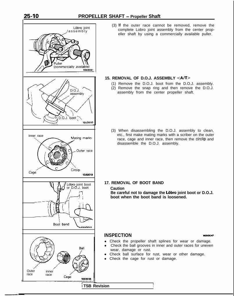
25-10 PROPELLER SHAFT - Propeller Shaft
Lijbro joint/ a s s e m b l y
10u0010
Inner race
10AOOlS
Lejbro joint boot
Outerrace
/innerrace
(3) If the outer race cannot be removed, remove thecomplete Lobro joint assembly from the center prop-eller shaft by using a commercially available puller.
15. REMOVAL OF D.O.J. ASSEMBLY <A/T>(1) Remove the D.O.J. boot from the D.O.J. assembly.(2) Remove the snap ring and then remove the D.O.J.
assembly from the center propeller shaft.
(3) When disassembling the D.O.J. assembly to clean,etc., first make mating marks with a scriber on the outerrace, cage and inner race, then remove the circlip anddisassemble the D.O.J. assembly.
17. REMOVAL OF BOOT BANDCautionBe careful not to damage the Liibro joint boot or D.O.J.boot when the boot band is loosened.
INSPECTION Mi5GCAF
l Check the propeller shaft splines for wear or damage.l Check the ball grooves in inner and outer races for uneven
wear, damage or rust.l Check ball surface for rust, wear or other damage.l Check the cage for rust or damage.
II TSB Revision I

PROPELLER SHAFT - Propeller Shaft 25-11
Washer
Tape
Inner race I Rnll
Recessed endof inner raceChamfered end
fitting the packing
SERVICE POINTS OF REASSEMBLY MZ9GHAQ
19. INSTALLATION OF WASHER/18. LOBRO JOINT BOOTOR D.O.J. BOOT/17. BOOT BAND/lG. RUBBERPACKING/15. LOBRO JOINT ASSEMBLY OR D.O.J.ASSEMBLY / 14. SNAP RING(1) Put the washer and boot band on the center propeller
shaft.(2) Wrap the splined end of center propeller shaft with
adhesive tape.
(3) Install the Lobro joint boot on the center propeller shaftand then remove the adhesive tape on the splined endof the propeller shaft.
(4) Assemble the Lobro joint as follows:@ Apply a thin coat of the specified grease to the ball
grooves of the inner and outer races.
Specified grease: Repair kit grease
@ Put the cage on the inner race with the matingmarks aligned and install two balls, one in a grooveand the other in the groove opposite to that groove.Both balls should be placed in the grooves wherethey were before disassembly.
@I Assemble the inner race and cage in the outer racewith their mating marks aligned.
NOTEMake sure that the recessed end (where snap ringwill be fitted) of the inner race, the recessed end(where packing will be fitted) of the outer race, andthe chamfered end of the cage are all on the sameside. Also ensure that the relative positions of theinner and outer races are as shown in the illustra-tion.
@I Install the remaining balls in their original positions.@ Check that the outer race rotates on the inner race
smoothly.
TSB Revision I

25-12 PROPELLER SHAFT - Propeller Shaft
10x0040
Rubberking
Mounting bolts
LBbro joint bootI lOUOO16 1
(5) Apply specified grease to the Lobro joint assembly.
Specified grease: Repair kit grease[45-55 g (1.59-1.94 oz.)]
(6) Apply a thin and even coat of the specified grease to therubber packing and fit the packing in the boot side endof the Lobro joint assembly.
Specified grease: Repair kit grease
CautionFor the Lobro joint assembly, the side that has theconcave part (for the rubber packing) in the outerrace is the Lobro joint boot side.
(7) Install the Lobro joint assembly on the rear propellershaft while aligning their bolt holes, and drive the jointassembly with a hammer using a socket wrench on theinner race for complete installation.
(8) Secure the inner race with the snap ring.(9) Realign the bolt holes in the boot and Lobro joint
assembly utilizing the mounting bolts and fit the boot onthe joint assembly.
(10)Secure the boot with the boot band.
CautionPosition the boot band clip on the side opposite tothe bosses which are provided in the boot forventilation. Be sure to remove grease, if present,from around the bosses. Grease obstructs theventilation air passage.

PROPELLER SHAFT - Propeller Shaft_ 25-13
(11 )Check that the Lobro joint assembly moves smoothly.
-41ouoo17
Washer1ouoo14
Tape
D.O.J. boot
-
c @
@0 2
c0 @ \
a@llAO357
10x0040
I
19. INSTALLATION OF WASHER/18. D.O.J. JOINT BOOT/17. BOOT BAND/lG. RUBBER PACKING/15 D.O.J.ASSEMBLY <A/T>/14. SNAP RING(1) Put the washer and boot band on t.he center propeller
shaft.(2) Wrap the splined end of center propeller shaft with
adhesive tape.
(3) Install the D.O.J. boot on the center propeller shaft andthen remove the adhesive tape on the splined end ofthe propeller shaft.
(4) Assemble the D.O.J. as follows:@ Apply a th’tn coat of the specified grease to the ball
grooves of the inner and outer races.
Specified grease: Repair kit grease0 Assemble the inner race and cage in the outer race
with their mating marks aligned.@ Install the circlip.
(5) Apply specified grease to the D.O.J. assembly.
Specified grease: Repair kit grease[105-115 g (3.7-4.0 oz.)1
1 TSB Revision I

25-14 PROPELLER SHAFT - Propeller Shaft
king
Mounting bolts
D.O.J. bootlOUOO16
Boot bandcl@ position fi
1ouoo13
Rubber mount I
Dust seal
(6) Apply a thin and even coat of the specified grease tothe rubber packing and fit the packing in the bootside end of the D.O.J. assembly.
Specified grease: Repair kit greaseCautionFor the D.O.J. assembly, the side that has theconcave part (for the rubber packing) in theouter race is the D.O.J. boot side.
(7) Secure the inner race with the snap ring.(8) Realign the bolt holes in the boot and D.O.J. assembly
utilizing the mounting bolts and fit the boot on the jointassembly.
(9) Secure the boot with the boot band.
CautionPosition the boot band clip on the side opposite tothe bosses which are provided in the boot forventilation. Be sure to remove grease, if present,from around the bosses. Grease obstructs theventilation air passage.
(10)Check that the D.O.J. assembly moves smoothly.
12. INSTALLATION OF CENTER BEARING ASSEMBLY(1) Apply multipurpose grease to the center bearing front
and rear grease grooves and to the dust seal lip.(2) Be sure to fit the bearing into the rubber mount groove
on the center bearing bracket.
NOTEFace the bearing dust seal to the side of center bearingbracket mating mark.
(3) Assemble the center bearings to the center propellershaft and rear propeller shaft.

PROPELLER SHAFT - Propeller Shaft 25-15 ?
NOTEFace the side onto which the center bearing bracketmating mark is placed and the dust seal is installed tothe side of the center propeller shaft and rear propellershaft.
10X0032
1 Center yoke 10x0012 -I
11. INSTALLATION OF RUBBER PACKING/lo. COMPAN-ION FLANGE/S. CENTER YOKE/8. SELF LOCKINGNUT(1) Apply a thin and even coat of the specified grease to the
rubber packing and fit the packing on the companionflange.
Specified grease: Repair kit grease
(2) Align the mating marks on the center propeller shaftand center yoke, and the rear propeller shaft andcompanion flange, then press fit the center bearingwith self locking nuts, tightening to the specifiedtorque.
7. INSTALLATION OF LOBRO JOINT ASSEMBLY ORD.O.J. ASSEMBLY INSTALLATION BOLTS(1) Secure the companion flange and Lobro joint assembly
or D.O.J. assembly with installation bolts.(2) Check for grease leakage from the Lobro joint boot or
D.O.J. boot and companion flange installation parts.
3. JOURNALS/Z. JOURNAL BEARING
TSB Revision
lOY607
(1) Apply multipurpose grease to the following parts of theuniversal joint kit.@ Shafts and grease sumps of journal@ Dust seal lips@ Needle roller bearings
CautionDo not apply excessive grease. Otherwise, faultyfitting of bearing caps and errors in the selection ofsnap rings may result.

25-16 PROPELLER SHAFT - Propeller Shaft
(2) Press fit the journal bearings to the yoke by using thegeneral service tool according to the following proce-
$?stall the base to the general service tool proper.@ Insert both bearings in the yoke, and hold and press
fit them by using the general service tool.
Matingmarks
J
1. INSTALLATION OF SNAP RING(1) Install snap rings of the same thickness onto both sides
of each yoke.(2) Press the bearing and journal into one side by using a
brass bar with a diameter of 15 mm (59 in.).
(3) Measure the clearance between the snap ring and thegroove wall of the yoke with a filler gauge.If the clearance exceeds the standard value, the snaprings should be replaced.
Standard value: 0.02-0.06 mm (.0008-.0024 in.)
TSB Revision

26-1
FRONT AXLECONTENTS
DRIVE SHAFT .................................................. 12 SPECIFICATIONS ............................................. 2General Specifications .................................. 2
HUB AND KNUCKLE ...................................... 6Lubricants ................ . ..................................... 3
SERVICE ADJUSTMENT PROCEDURES.. ..... 5 Service Specifications ...................................
Hub End Play Inspection 5 Torque Specifications 2m............................. ................................... 2
SPECIAL TOOLS ............................................. 3 TROUBLESHOOTING ...................................... 5

26-2
SPECIFICATIONS
FRONT AXLE - Specifications
GENERAL SPECIFICATIONS
Items
Wheel bearing
TypeO.D. x I.D.
Drive shaft
Joint type
Outer
Inner
LengthL.H. shaft
R.H. shaft
FWD AWD
Double-row angular-contact ball bearing
mm (in.) 80 x 40 (3.15 x 1.57)
<Up to 1992 models> <From 1993 models>R.J. or B.J.* B.J. B.J.
T.J. T.J. T.J.
mm (in.)
708 (27.9) or 706 (27.8) 368 (14.5) <M/T>,706 (27.8)’ 365 (14.4) <A/T>
368 (14.5) or 366 (14.4) 368 (14.5) <M/T>,366 (14.4)* 371 (14.6) <A/T>
NOTER.J. : Rzeppa jointB.J. : Bit-field jointT.J. : Tripod joint* : < D O H C >
SERVICE SPECIFICATIONS
Items FWD AWD
SOHC DOHC
Standard value
Setting of T.J. boot lengthmm (in.) <Up to 1992 <From 1993
models> models>
L.H. 82 + 3 (3.23 k .I 2) 80f3 (3.15f.12) 80 + 3 (3.15 f .I 2) 85 f 3 (3.35 k .I 2)R.H. 85 III 3 (3.35 + .I 2) 80 IL 3 (3.15 f .I 2) 80 f 3 (3.15 f .I 2) 85 f 3 (3.35 31 .I 2)
Limit X.
Hub end play mm (in.) 0.2 (.008) or less
Wheel bearing startingtorque (Hub startingtorque) Nm (inlbs.) 1.8 (16) or less
TORQUE SPECIFICATIONS
Items Nm ftlbs.
Drive shaft nut 200-260 144-188Tie rod end ball joint 2 4 - 3 4 17-25Knuckle to ball joint 60-72 43-52Knuckle to strut assembly 110-140 80-101Caliper assembly mounting bolt 80-I 00 58-72Center bearing bracket 3 6 - 4 6 26-33Front speed sensor bracket 9 - 1 4 7-10Front toothed rotor 9 - 1 4 7-10
TSB Revision
-_

LUBRICANTS
FRONT AXLE - Specifications/Special Tools 26-3
M26cD-
Items
T.J. boot grease
<SOHC>
<FWD-DOHC>
<AWD-DOHC>
B.J. boot grease<FWD-DOHC>, < S O H C > *
<AWD-DOHC>
R.J. boot grease <SOHC>
inner dust seal
Outer dust seal
: From 1993 models
Specified lubricants
Repair kit grease
Repair kit grease
Repair kit grease
Multipurpose grease
Quantity
120 g (4.2 oz.)
130 g (4.5 oz.)
110 g (3.9 oz.)
110 g (3.9 oz.)
90 g (3.2 oz.)
120 g (4.2 oz.)
7-10 (.25-.35 oz.)
4 - 6 (.14-.21 oz.)
SPECIAL TOOLS M26DA-
OPTIONAL: AVAilABLE FROM O.T.C.
ear suspensronbushing remover andinstaller base
1 TSB Revision

26-4 FRONT AXLE - Special Tools
Td Number Name I Use. .-. .- -----.CD
MB990890-01 Rear suspension Press-fitting of the wheel bearing and oil sealbushing base
OPTIONAL: AVAILABLE FROM O.T.C.
MB990883-01 Rear suspensionarbor
/OPTIONAL: AVAILABLE FROM O.T.C.
\
J!D
GENERAL Axle puller Removal of the drive shaftSERVICE TOOL
000
1
MB991 248 or Inner shaft remover Removal of the inner shaftMD998801
GENERALSERVICE TOOL
Bearing and oil sealinstaller set
Removal of wheel bearing
H MB990938-01 H a n d l e
TSB Revision

FRONT AXLE - Troubleshooting/Service Adjustment Procedures 26-5
TROUBLESHOOTING m6E6AA
Symptom
Vehicle pulls to one side
Probable cause
Seizure of drive shaft ball joint
Abnormal wear, play or seizure of wheel bear-ing
Remedy
Replace
Replace
Vibration
Shimmy
Excessive noise
Malfunction of front suspension or steering
Bend, damage or abnormal wear of drive shaft
Play in drive shaft and hub serration
Abnormal wear, play or seizure of wheel bear-ing
Improper wheel alignment
Malfunction of front suspension or steering
Broken boot, grease leakage
Bend, damage or abnormal wear of drive shaft
Play of drive shaft and hub serration
Abnormal wear, play or seizure of centerbearing
Adjust or replace
Replace
Replace
Replace
Adjust or replace
Adjust or replace
Replace, repack grease
Replace
Replace
Replace
Abnormal wear, play or seizure of wheel bear-ing
Loose wheel nut
Malfunction of front suspension and steering
Replace
Retighten
Adjust or replace
SERVICE ADJUSTMENT PROCEDURESHUB END PLAY INSPECTION M26FAAB
1. Jack up the vehicle and remove the front wheels.2. Remove the disc brake caliper and suspend it with a wire.
(Refer to GROUP 35-Service Adjustment Procedures.)3. Attach a dial indicator as shown in the illustration, and then
measure the axial play while moving the hub back andforth.
Limit : 0.2 mm (.008 in.) or less
4. If axial play exceeds the limit, disassemble and check parts.
TSB Revision

26-6 FRONT AXLE - Hub and Knuckle
HUB AND KNUCKLEREMOVAL AND INSTALLATION
SO-105 Nm65-76 ft.lbs.
Vehicles with ACTIVE-ECS*’
80-100 Nm’\58-72 ftlbs.
9-14 Nm7- 10 ft.lbs. I I
5 rq :Iu- 4. .i,'-
B8 60-72 Nm 200-‘260 Nm43-52 ft.lbs. IU-188 ft.lbs.
llA0121
Removal stepsl + 1. Cotter pin
+e I)+ 2. Drive shaft nutl + 3. Washer
a* 4. Front speed sensor connection< Vehicules with A.B.S.*‘> (Refer toGROUP 35-Speed sensor)
a* 5. Caliper assembly6. Brake disc7. Front height sensor connection
<Vehicules with ACTIVE-ECS*2>(Refer to GROUP 33B-Height sensor)
8. Self locking nut
+e ~~ 9. Lower arm ball joint connection10. Cotter pin
::11. Tie rod end connection12. Drive shaft13. Front strut mounting bolt14. Hub and knuckle
NOTE
::: Anti-lock braking system: ACTIVE-Electronic Control Suspension
TSB Revision

FRONT AXLE - Hub and Knuckle 26-7
SERVICE POINTS OF REMOVAL M261sAE2.
4.
REMOVAL OF DRIVE SHAFT NUTLoosen the drive shaft nut while the vehicle is on the floorwith the brakes applied.
DISCONNECTION OF FRONT SPEED SENSORRemove the mounting bolts which hold the speed sensorbracket to the knuckle, and then remove the speedsensor.
CautionBe careful when handling the pole piece at the tip of thespeed sensor and the toothed edge of the rotor so asnot to damage them by striking against other parts.REMOVAL OF CALIPER ASSEMBLYRemove the caliper assembly and suspend it with wires.
9. DISCONNECTION OF LOWER ARM BALL JOINTUsing the special tool, disconnect the lower arm ball jointfrom the knuckle.
Caution1. Be sure to tie the cord of the special tool to the
nearby part.2. Loosen the nut but do not remove it.
11. DISCONNECTION OF TIE ROD ENDUsing the special tool, disconnect the tie rod end from theknuckle.
Caution1. Be sure to tie the cord of the special tool to the
nearby part.2. Loosen the nut but do not remove it.
12. REMOVAL OF DRIVE SHAFT(1) Use the general service tool to push out the drive shaft
from the front hub.
l\\11RO101 1
TSB Revision

26-8 FRONT AXLE - Hub and Knuckle
Transaxle
Cotter pin/
(2) Insert a pry bar between the transaxle case and thedrive shaft, and then pry the drive shaft from thetransaxle.
Caution1. Do not pull on the drive shaft; doing so will
damage the T.J.; be sure to use the pry bar.2. Do not insert the pry bar so deep as to damage
the oil seal.
INSPECTIONl Check the hub for cracks and spline for wear.l Check the oil seal for damage.l Check the knuckle for cracks.l Check for defective bearing.
NOTE
M26icAD
If the meshing of the wheel bearing outer race and theknuckle, or of the wheel bearing inner race and the hub. isloose, replace the bearing or damaged parts.
SERVICE POINTS OF INSTALLATION MZMDAD
9. INSTALLATION OF LOWER ARM BALL JOINTLower the vehicle to the ground and tighten the knuckle tothe lower arm ball joint connecting bolt.
3. INSTALLATION OF WASHER/2. DRIVE SHAFT NUT/l.COTTER PIN(1) Be sure to install the washer and wheel bearing nut in
the specified direction.(2) After installing the wheel, lower the vehicle to the
ground and finally tighten the wheel bearing nut.(3) If the position of the cotter pin holes does not match,
tighten the nut up to 260 Nm (188 ft.lbs.) in maximum.(4) Install the cotter pin in the first matching holes and
bend it securely.
TSB Revision

FRONT AXLE - Hub and Knuckle 26-9
DISASSEMBLY AND REASSEMBLY
9-14 Nm7-10 ft.lbs. i !8
1
Disassembly steps
::I. Front hub2. Oil seal (drive shaft side)3. Snap ring4. Oil seal (hub side)
4* 5. Wheel bearing6. Dust shield7. Knuckle8. Front toothed rotor <A.B.S.>
(Refer to GROUP 35-Wheel SpeedSensor.)
WA0374
Reassembly steps8. Front toothed rotor <A.B.S.>
(Refer to GROUP 35-Wheel SpeedSensor.)
7. Knuckle.6. Dust shield
I)+ 5. Wheel bearingl + 4. Oil seal (hub side)
3. Snap ringI)+ 1. Front hubI)* Adiustment of wheel bearing starting
torqueI)+ 2. Oil seal (drive shaft side)
SERVICE POINTS OF DISASSEMBLY Mz6lFAM
1. REMOVAL OF FRONT HUB(1) Attach the special tools to the knuckle and front hub.(2) Secure the knuckle in a vise.(3) Tighten the nut of the special tool and remove the front
hub from the knuckle.
Caution1. Be sure to use the special tools.2. If the front hub and knuckle are disassembled by
striking them with a hammer, the bearing willbe damaged.
TSB Revision I

26-10 FRONT AXLE - Hub and Knuckle
2. REMOVAL OF OIL SEAL (DRIVE SHAFT SIDE)Remove the oil seal (drive shaft side) from the knuckle.
Snao
MB991056llROO40 12AO54t
5. REMOVAL OF WHEEL BEARING(1) Crush the oil seal in two places so that the tabs of the
special tool will be caught on the wheel bearing innerrace.
(2) Remove the wheel bearing inner race from the fronthub by using the general service tool.
NOTEBe careful that the front hub will not fall down as thewheel bearing inner race (outer side) is removed fromthe hub
(3) Remove the snap ring from the knuckle.(4) Remove the bearing by using the special tools.
CautionRemoval is easier if the outer side inner raceremoved from the hub is placed on the bearing andthe wheel bearing is then removed.
INSPECTIONl Check the front hub and brake disc mounting surfaces for
galling and contamination.l Check the knuckle inner surface for galling and cracks.l Check for defective bearing.
1 TSB Revision 1
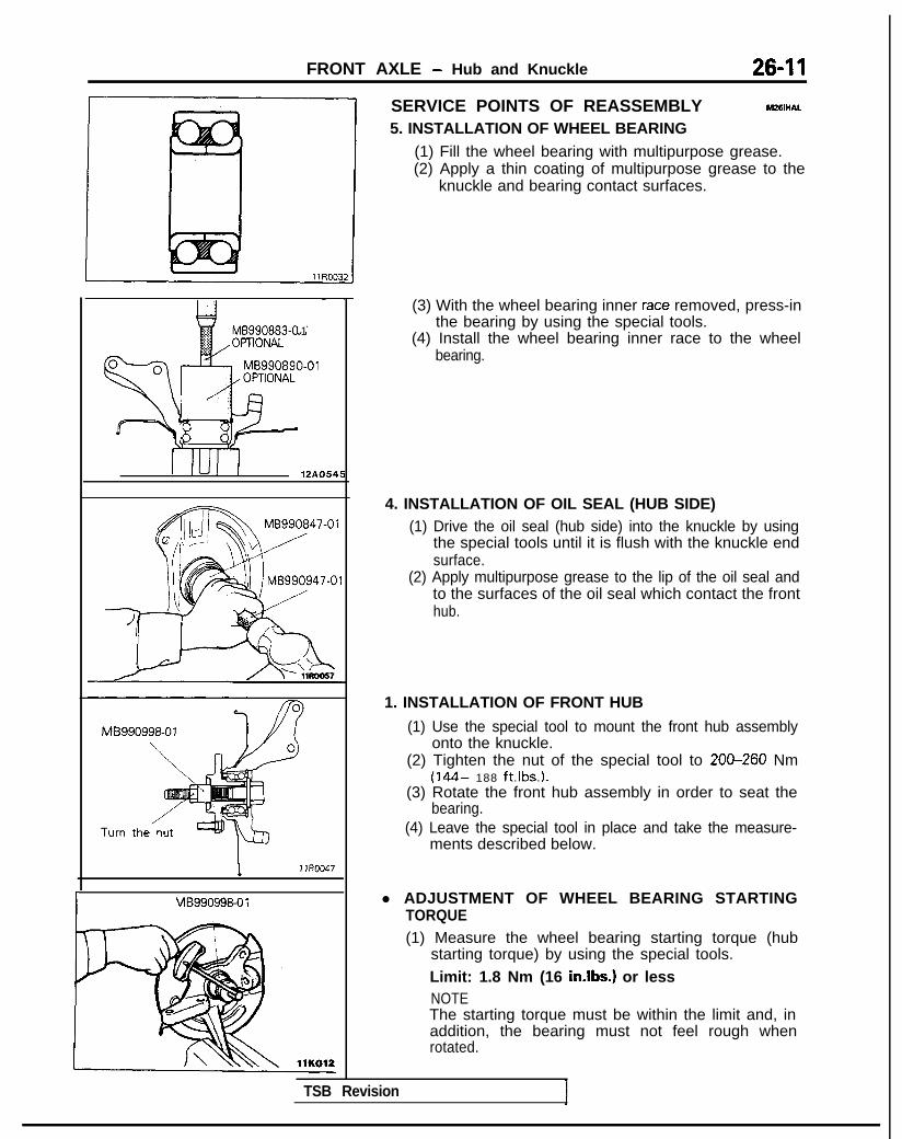
FRONT AXLE - Hub and Knuckle 26-11
MB990883-0 1
I IUI I 12A0545
m MB990847-01
MB990998-07
I MB99099&0 1
SERVICE POINTS OF REASSEMBLY M26lHAL
5. INSTALLATION OF WHEEL BEARING(1) Fill the wheel bearing with multipurpose grease.(2) Apply a thin coating of multipurpose grease to the
knuckle and bearing contact surfaces.
(3) With the wheel bearing inner race removed, press-inthe bearing by using the special tools.
(4) Install the wheel bearing inner race to the wheelbearing.
4. INSTALLATION OF OIL SEAL (HUB SIDE)(1) Drive the oil seal (hub side) into the knuckle by using
the special tools until it is flush with the knuckle endsurface.
(2) Apply multipurpose grease to the lip of the oil seal andto the surfaces of the oil seal which contact the fronthub.
1. INSTALLATION OF FRONT HUB
(1) Use the special tool to mount the front hub assemblyonto the knuckle.
(2) Tighten the nut of the special tool to 200-260 Nm(144- 188 ft.Ibs.).
(3) Rotate the front hub assembly in order to seat thebearing.
(4) Leave the special tool in place and take the measure-ments described below.
l ADJUSTMENT OF WHEEL BEARING STARTINGTORQUE(1) Measure the wheel bearing starting torque (hub
starting torque) by using the special tools.Limit: 1.8 Nm (16 in.lbs.) or lessNOTEThe starting torque must be within the limit and, inaddition, the bearing must not feel rough whenrotated.
TSB Revision

26-12 FRONT AXLE - Hub and Knuckle/Drive Shaft
(2) Measure to determine whether the end play of the hubis within the specified limit or not.Limit: 0.2 mm (.008 in.) or less
(3) If the starting torque and hub end play are not within thelimit range while the nut is tightened to 200-260 Nm(144- 188 ft.lbs.), the bearing, hub and/or knuckle haveprobably not been installed correctly. Repeat thedisassembly and assembly procedure.
rMB990998-01
2. INSTALLATION OF OIL SEAL (DRIVE SHAFT SIDE)Drive the oil seal (drive shaft side) into the knuckle until itcontacts the snap ring.Apply multipurpose grease to the lip of the oil seal.
MB990890-01
L
DRIVE SHAFT <FWD>The T.J.-R.J. type of drive shaft is used for SOHCengines, and the T.J.-B.J. type is used for DOHCe n g i n e s .PARTS DISTINCTIONBoots and boot bands can be distinguished by theindicated part numbers shown below.T.J.-R.J. TYPE
R.J. bootT.J. boot band Boot band (small)T.J. boot
a
,;: IIII 1it jii’w
Part shapes andpart identificationnumber location
0identificationlocation
Identificationlocation IdentificationIdentification Identification
location locationllA0125 llRO1!56
110 019
llK033
218” o r 206*2
llA0125
tI 020Part identification No.
NOTE*‘: R.J. side, *2: T.J. sideT.J-B.J TYPE
B.J. boot bandIdentificationlocation
B.J. boot
Part shapes andpart identificationnumber location
T.J. boot bandIdentificationlocation
llK033
Part identification No. 20-12
Identificationlocation
llKO3317-31 #BJ92L17-69#BJ92L* 20-75
i: : From 1993 models <SOHC>rTSB Revision

FRONT AXLE - Drive Shaft 2643
REMOVAL AND INSTALLATION 7m 24-34 Nm17-25ft.Ibs.
144- 188 ft.lbs.
617-26 Nm12-19 ft.lbs.
Removal steps 11 A0099
1. Front height sensor connection<Vehicles with ACTIVE-ECS> (Refer toGROUP33B-Height Sensor)
l + 2. Cotter pin+e l C 3. Drive shaft nutl * 4. Washer
5. Self locking nut
4I) l + 6. Lower arm ball joint connection7. Cotter pin
4+ 8. Tie rod end connection4* 9. Drive shaft
10. Circlip
12R0258
SERVICE POINTS OF REMOVAL M280BAL
3. REMOVAL OF DRIVE SHAFT NUTLoosen the drive shaft nut while the vehicle is on the floorwith the brakes applied.
6. DISCONNECTION OF LOWER ARM BALL JOINTUsing the special tool, disconnect the lower arm ball jointfrom the knuckle.Caution1. Be sure to tie the cord of the special tool to the
nearby part.2. Loosen ~the nut but do not remove it.
8. DISCONNECTION OF TIE ROD ENDUsing the special tool, disconnect the tie rod end from theknuckle.Caution1. Be sure to tie the cord of the special tool to the
nearby part.2. Loosen the nut but do not remove it.
TSB Revision

26-14 FRONT AXLE - Drive Shaft
Pfb1
+$$$A y 7
@jQp I
\ “dt 5
\.i 1J Jd
llRO(O1
llE526
i+gJ#
\‘II 1 m\IIIJ I+
1
llE530
9. REMOVAL OF DRIVE SHAFT(1) Use the general service tool to push out the drive shaft
from the front hub.
(2) Insert a pry bar between the transaxle case and thedrive shaft, and then pry the drive shaft from thetransaxle.Caution1. Do not pull on the drive shaft; doing so will
damage the T.J.; be sure to use the pry bar.2. Do not insert the pry bar so deep as to damage
the oil seal.
CautionDo not apply the vehicle weight to the wheel bearingwhile the drive shaft is disconnected. If the vehicleweight must unavoidably be applied (because ofvehicle movement or some other reason), use thespecial tool to hold the wheel bearing, as shown in thefigure.
4. INSTALlATlON OF WASHER/3. DRIVE SHAFT NUT/P.COTTER PIN
(1) Be sure to install the washer and wheel bearing nut inthe specified direction.
(2) After installing the wheel, lower the vehicle to theground and finally tighten the wheel bearing nut.
(3) If the position of the cotter pin holes does not match,tighten the nut up to 260 Nm (188 ft.lbs.) in maximum.
(4) Install the cotter pin in the first matching holes andbend it securely.
TSB Revision
INSPECTION M28OChC
l Check the drive shaft boot for damage or deterioration.l Check the ball joints for wear or operating condition.l Check the spline part for wear or damage.
SERVICE POINTS OF INSTALLATION w26QDAJ6. INSTALLATION OF LOWER ARM BALL JOINT
Lower the vehicle to the ground and tighten the knuckle tothe lower arm ball joint connecting nut.

FRONT AXLE - Drive Shaft (T.J.-R.J. Type) 26-15
DISASSEMBLY AND REASSEMBLY (T.J.-R.J. TYPE)
i b i2 llA013'
I R.J. Joint and shaft kit
Disassembly stepsl + 1. T.J. boot bandl + 2. Boot band (small)
3. T.J. case+* 4. Snap ring4* 5. Spider assembly+e ,+ 6. T.J. boot
7. R.J. boot band8. Boot band (small)
+e I)+ 9. R.J. boot10. R.J. assembly11. Dust cover12. Circlip
T.J. Joint kit
12
dllA0138
R.J. Boot kit
llA0135
TSB Revision 1
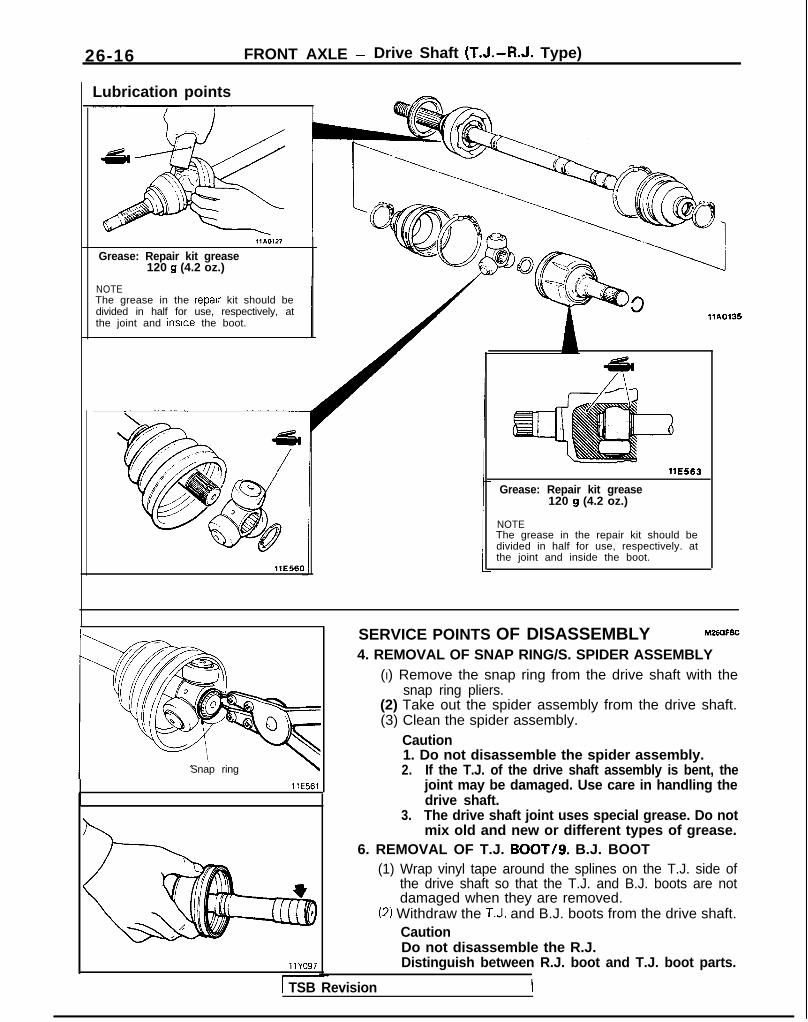
26-16 FRONT AXLE - Drive Shaft (T.J.-R.J. Type)
Lubrication points
llA0127
Grease: Repair kit grease120 g (4.2 oz.)
NOTEThe grease in the repalr kit should bedivided in half for use, respectively, atthe joint and inslde the boot.
llE560
llA0135
WE563
Grease: Repair kit grease120 g (4.2 oz.)
NOTEThe grease in the repair kit should bedivided in half for use, respectively. atthe joint and inside the boot.
Snap ring
llE561
SERVICE POINTS OF DISASSEMBLY M2alFBC4. REMOVAL OF SNAP RING/S. SPIDER ASSEMBLY
(I) Remove the snap ring from the drive shaft with thesnap ring pliers.
(2) Take out the spider assembly from the drive shaft.(3) Clean the spider assembly.
Caution1. Do not disassemble the spider assembly.2. If the T.J. of the drive shaft assembly is bent, the
joint may be damaged. Use care in handling thedrive shaft.
3. The drive shaft joint uses special grease. Do notmix old and new or different types of grease.
6. REMOVAL OF T.J. BOOT/g. B.J. BOOT(1) Wrap vinyl tape around the splines on the T.J. side of
the drive shaft so that the T.J. and B.J. boots are notdamaged when they are removed.
(2) Withdraw the T.J. and B.J. boots from the drive shaft.CautionDo not disassemble the R.J.Distinguish between R.J. boot and T.J. boot parts.
1 TSB Revision

FRONT AXLE - Drive Shaft (T.J.-R.J. Type) 26-17
INSPECTION M26OGBC
l Check the drive shaft for damage, bending or corrosion.l Check the drive shaft splines for wear or damage.l Check for entry of water and/or foreign material into R.J.l Check the spider assembly for roller rotation, wear or
corrosion.l Check the groove inside T.J. case for wear or corrosion.l Check the boots for deterioration, damage or cracking.
SERVICE POINTS OF REASSEMBLY MZbOHBE
9. INSTALLATION OF R.J. BOOT/6. T.J. BOOT(1) Wrap vinyl tape around the spline part on the drive
shaft, and then install the R.J. boot and and T.J. boot, inthat order.CautionDistinguish between R.J. boot and T.J. boot partsaccording to the section “Parts Distinction”, and besure to assemble them correctly.
llAQl27
Fitting
32320.3 m m 8720.3 m m(1.27 2 .Ol in.) (3.43 k .Ol u7.1
11 R005i
i-lj4AI Al II II I L-1 llR0049
ITSB Revision
(2) Fill the inside of the R.J. and R.J. boot with thespecified grease.Specified grease:
Repair kit grease 120 g (4.2 oz.)
NOTEThe grease in the repair kit should be divided in half foruse, respectively, at the joint and inside the boot.
(3) Install the R.J. boot to the R.J. assembly.CautionThe boot bands should be tightened with the driveshaft at a 0” break angle.
(4) Apply a light coating of the repair kit grease (used inthe R.J.) to the installation surface of the boot band.
(5) Tighten so that the outer diameter of the boot band isthe dimension indicated in the illustration, and thenbend at the fitting part.
(6) Using a punch, crimp the centre part of the boot bandfitting so as to securely hold the band.CautionCare must be taken not to cut,.tear or puncture theboot.

26-18 FRONT AXLE - Drive Shaft (T.J.-R.J. Type)
(7) For the boot band (small), cut away so that the lengthof the band width remains, and then bend it over thecrimped band fitting.For the boot band (large), cut away so that the lengthuntil the clip holder position remains, and then secureby the clip.
Fitting
32.3kO.3 m m(I .27 t .Ol in.)
llR0052
2. INSTALLATION OF BOOT BAND (SMALL)/l. T.J. BOOTBAND(1) Set the T.J. boot bands at the specified distance in
order to adjust the amount of air inside the T.J. boot,and then tighten the T.J. boot band securely.Standard value: L.H. 82+3 mm (3.23k.12 in.)
R.H. 85+3 mm (3.35f.12 in.)
(2) Apply a light coating of the repair kit grease (used inthe T.J.) to the installation surface of the boot band.
(3) Tighten so that the outer diamter of the boot band isthe dimension indicated in the illustration, and thenbend at the fitting part.
(4) Using a punch, crimp the centre part of the boot bandfitting so as to securely hold the band.CautionCare must be taken not to cut, tear or puncture theboot.
(5) For the boot band (small), cut away so that the lengthof the band width remains, and then bend it over thecrimped band fitting.For the boot band (large), cut away so that the lengthuntil the clip holder position remains, and then secureby the clip.
TSB Revision
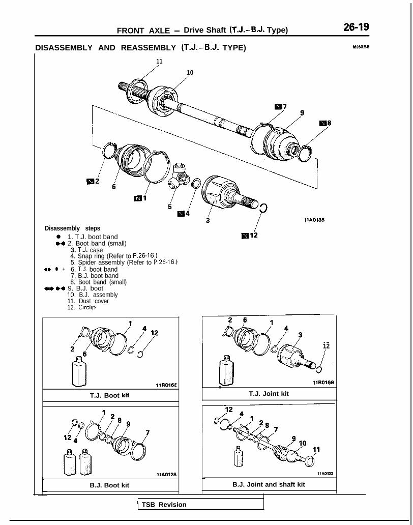
FRONT AXLE - Drive Shaft ‘(T.J.-B.J. Type) 26-19
DISASSEMBLY AND REASSEMBLY (T.J.-B.J. TYPE)
11
/ 10
Disassembly stepsl 1. T.J. boot bandM 2. Boot band (small)
3. T.J. case4. Snap ring (Refer to P.26-16.)5. Spider assembly (Refer to P.26-16.)
4I) l + 6. TIJ. boot band7. B.J. boot band8. Boot band (small)
+I)*+ 9. B.J. boot10. B.J. assembly11. Dust cover12. Circlip
llR016E
T.J. Boot kit
llA0126
B.J. Boot kit
llA0135
3”12
d.LI llR0169
T.J. Joint kit
llA0132
B.J. Joint and shaft kit
1 TSB Revision

26-20 FRONT AXLE - Drive Shaft (T.J.-B.J. Type)
Lubrication points
NOTEThe grease in the repair kit should bedivided in half for use. respectively, atthe ioint and inside the boot.
11E563
Grease: Repair kit grease120 g (4.2 oz.) <SOHC>130 g (4.5 oz.) <DOHC>
NOTEThe grease in the repair kit should bedivided in half for use, respectively, atthe joint and inside the boot.
SERVICE POINTS OF DESASSEMBLY M2mFDD6. REMOVAL OF T.J BOOT/g. B.J. BOOT
(1) Wrap vinyl tape around the spline part on the T.J. sideof the drive shaft so that the T.J. and B.J. boots are notd a m a g e d w h e n t h e y a r e r e m o v e d .
(2) Withdraw the T.J. and R.J. boots from the drive shaft.CautionDo not disassemble the B.J.Distinguish between B.J. boot and T.J. boot parts.
INSPECTION M26D6Dcl Check the drive shaft for damage, bending or corrosion.l Check the drive shaft splines for wear or damage.l Check for entry of water and/or foreign material into R.J.l Check the spider assembly for ,roller rotation, wear or
corrosion.l Check the groove inside T.J. case for wear of corrosion.l Check the boots for deterioration, damage or cracking.
TSB Revision

FRONT AXLE - Drive Shaft (T.J.-B.J. Type) 26-21
SERVICE POINTS OF REASSEMBLY M26OtlDE
9. INSTALLATION OF B.J. BOOT/6. T.J. BOOT(1) Wrap vinyl tape around the splines on the drive shaft,
and then install the R.J. boot and T.J. boot, in that order.order.
CautionDistinguish between B.J. boot and T.J. boot partsaccording to the section “Parts Distinction”, and besure to assemble them correctly.
(2) Fill the inside of the B.J. and B.J. boot with thespecified grease.Specified grease: Repair kit grease
110 g (3.9 oz.)NOTE
llAOl27
The grease in the repair kit should be divided in half foruse, respectively, at the joint and inside the boot.
(3) Secure the boot bands.CautionThe boot bands should be tightened with the driveshaft at a 0” joint angle.
2. INSTALLATION OF BOOT BAND (SMALL) / 1. T.J.BOOT BANDSet the T.J. boot bands at the specified distance in order toadjust the amount of air inside the T.J. boot, and thentighten the T.J. boot band securely.
Standard value: 8023 mm (3.15f0.12 in.)
llE55E
TSB Revision
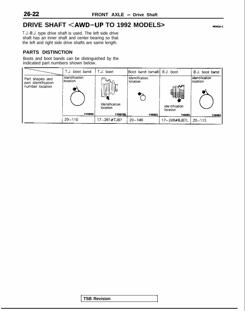
FRONT AXLE - Drive Shaft
DRIVE SHAFT <AWD-UP TO 1992 MODELS> M26aA-c
T.J.-B.J. type drive shaft is used. The left side driveshaft has an inner shaft and center bearing so thatthe left and right side drive shafts are same length.
PARTS DISTINCTIONBoots and boot bands can be distinguished by theindicated part numbers shown below.
TSB Revision

FRONT AXLE - Drive Shaft
REMOVAL AND INSTALLATION
26-23
Pm-removal and Post-installation Operationl Removal and installation of the Under Cover
145- 188 ft.lbs
60-72 Nm43-52 ftlbs.
60-72 Nm43-52 ft.lbs.
24-34 Nm17-25 ft.lbs.
145-188 ft.lbs.
36-k Nm26-33 ft.lbs.
8
llAOl22
Removal steps1. Cotter pin2. Drive shaft nut (Refer to P.26-13, 14.)3. Lower arm ball joint connection (Refer to
P.26-3.) l *
6. Center bearing bracket installation bolt7. Spacer (Vehicles without air conditioning)8. Drive shaft and inner shaft assemblv (L.H.)
4. Cotter pin l * 9. Drive shaft (R.H.)5. Tie rod end connection (Refer to P.26-13.) 10. Circlip
SERVICE POINTS OF REMOVAL M26OBAW
8. REMOVAL OF DRIVE SHAFT AND INNER SHAFTASSEMBLY (L.H.)/9. DRIVE SHAFT (R.H.)(1) Use the general service tool to push out the drive shaft
and inner shaft assembly (L.H.) or the drive shaft (R.H.)from the front hub.
1 TSB Revision I

26-24 FRONT AXLE - Drive Shaft
C
I1
c
1:
9
M8
Pry bar Trarkaxle
llE526
(2) Remove the drive shaft and inner shaft assembly (L.H.)from the transaxle by lightly tapping the T.J. case with aplastic hammer, etc.
(3) Remove the drive shaft (R.H.) as described below.<Ml-bInsert a pry bar between the transaxle case and thedrive shaft, and then pry the drive shaft from thetransaxle.Caution1. Do not pull out the drive shaft; doing so will
damage the T.J.; be sure to use the pry bar.2. Do not insert the pry bar so deep as to damage
the oil seal.
Inset-t a pry bar at the projection part and remove thedrive shaft (R.H.) from the transaxle.CautionDo not pull out the drive shaft; doing so willdamage the T.J.; be sure to use the pry bar.
INSPECTIONl Check the drive shaft boot for damage or deterioration.l Check the ball joints for wear or operating condition.l Check the spline part for wear or damage.l Check the operation of the center bearing.
TSB Revision

FRONT AXLE - Drive Shaft 26-25
DISASSEMBLY AND REASSEMBLY
\
T.J. boot repair kit
T.J. kit
B.J. boot repair kit
Disassembly stepsl + 1. T.J. boot bandl + 2. Boot band (small)l + 3. T.J. case and inner shaft assembly
4. T.J. case5. Seal plate
+ee* 6. Inner shaft7. Bracket assembly
I&+ 8. Outer dust sealW4 9. Inner dust seal
+e l + 10. Center bearing11. Center bearino bracket12. Circlip -13. Snap ring (Refer to P.26-17.)14. Spider assembly (Refer to P.26-17.)
llA0315
B.J. kii
,,A0113
Bearing dust seal kii
llA0317
Bracket assembly kii
15. T.J. boot (Refer to P.26-17, 18.116. B.J. boot band17. Boot band (small)18. B.J. boot (Refer to P.26-17. 18.)19. B.J. assembly20. Dust cover
TSB Revision

26-26 FRONT AXLE - Drive Shaft
irease Points
llA0321 1
llE560
llAO320
Grease: Multipurpose greaseInner dust seal 7-10 g (.25-.35 oz.)outer dust seal 4-6 g (.14-.21 oz.)
llAOO65
Grease: Repair kit grease110 g (3.9 oz.)
NOTEThe grease in the repair kit should bedivided in half for use, respectively, atthe joint and inside the boot.
Grease: Repair kit grease9 0 g (3.2 oz.)
NOTEThe grease in the repair kit should bedivided in half for use, respectively, atthe joint and inside the boot.
L 2
TSB Revision

FRONT AXLE - Drive Shaft 26-27
I
llA0092
llLOOO6
SERVICE POINTS OF DISASSEMBLY M26QFEC
6. REMOVAL OF INNER SHAFT(1) Using the special tool, remove the inner shaft assem-
bly, together with the seal plate, from the T.J. case.NOTEPress the tool directly against the seal plate. The toolunder pressure will puncture and deform the seal plate,and push out the inner shaft underneath.
(2) Use the general service tool to remove the inner shaftfrom the center bearing bracket.
10. REMOVAL OF CENTER BEARINGUse the special tools to remove the center bearing from thecenter bearing bracket.
TSB Revision I
INSPECTION hl26MEB
000
0 Check the dust cover for damage or deterioration.
Check the drive shaft for damage, bending or corrosion.Check the inner shaft for damage, bending or corrosion.Check the drive shaft splines for wear or damage.Check the inner shaft splines for wear or damage.Check for entry of water and/or foreign material into B.J..Check the spider assembly for roller rotation, wear orcorrosion.Check the groove inside T.J. case for wear of corrosion.Check the boots for deterioration, damage or cracking.Check the center bearing for seizure, discoloration orroughness of rolling surface.

FRONT AXLE - Drive Shaft
llAOO9'
MB990938-01
\c- 1
11 LOO10
Inner dust seal Outer dust seal
1110011 llLOO12
Inner dust seal, w MB990938-01
llLooo9
Outer dust seal
I MBgg0g38-0’
I
-
SERVICE POINTS OF REASSEMBLY10. INSTALLATION OF CENTER BEARING
(1) Apply multipurpose grease to the center bearing andinside the center bearing bracket.
(2) Use the special tools to press-fit the center bearing intothe center bearing bracket.
9.18. INSTALLATION OF DUST SEALS(1) Apply multipurpose grease to the rear surfaces of all
dust seals.Inner dust seal 7-10 g (.25-.35 oz.)Outer dust seal 4-6 g (.14-.21 oz.)
(2) Use the special tools to install the dust seal so that itssurface runs even with that of the center bearingbracket.
(3) Apply multipurpose grease to the lip of each dust seal.
NOTEWhen applying grease, make sure that it does not adhere toanything outside the lip.
1 TSB Revision

FRONT AXLE - Drive Shaft 26-29
Inner shaft
~
llA0083
Inner shaftassembly
---.
T.J. case
MB990938-01
Seal plate
-MB991 248orMD998801
-...A
llAOO05
I HA0087 1
6. INSTALLATION OF INNER SHAFTUse the pipe to hold the inner race of the center bearingand force the inner shaft into place.
3. INSTALLATION OF T.J. CASE AND INNER SHAFTASSEMBLY(1) Apply multipurpose grease to the inner shaft spline,
then press fit it into the T.J. case.
(2) Using the special tools, press the seal plate into the T.J.case.
(3) Fill the specified grease furnished in the repair kit to theT.J. case.Specified grease: Repair kit grease 110 g (3.9 oz.)
NOTEThe grease in the repair kit should be divided in half foruse, respectively, at the joint and inside the boot.CautionThe drive shaft joint uses special grease. Do not mixold and new or different types of grease.
2. INSTALLATlON OF BOOT BAND (SMALL)/ 1. T.J.BOOT BANDSet the T.J. boot bands at the specified distance in order toadjust the amount of air inside the T.J. boot, and thentighten the T.J. boot band securely.Standard value: 85+3 mm (3.35-1- .12 in.)
TSB Revision
NOTES
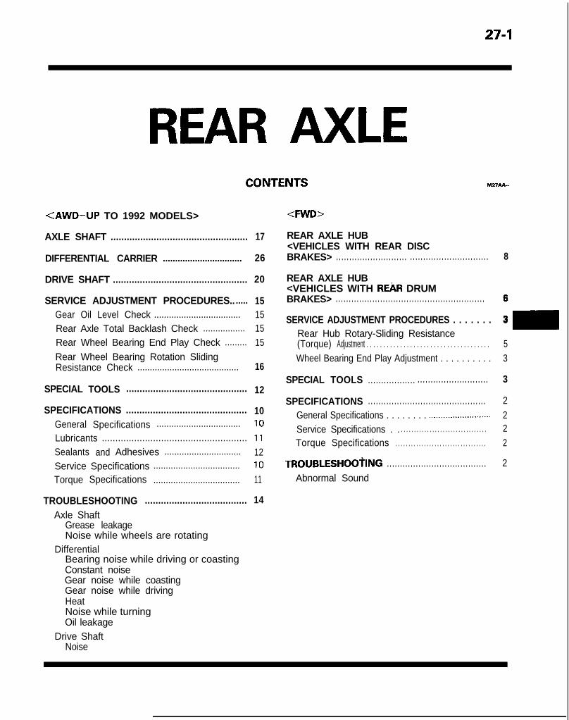
27-1
mnAA-
<AWD-UP TO 1992 MODELS> <FWD>
AXLE SHAFT ................................................... 17
DIFFERENTIAL CARRIER ................................ 26
DRIVE SHAFT .................................................. 20
SERVICE ADJUSTMENT PROCEDURES.. ..... 15Gear Oil Level Check ................................... 15Rear Axle Total Backlash Check ................. 15Rear Wheel Bearing End Play Check ......... 15Rear Wheel Bearing Rotation SlidingResistance Check ......................................... 16
REAR AXLE HUB
SPECIAL TOOLS ............................................. 12
SPECIFICATIONS ............................................. 10General Specifications .................................. 10Lubricants ...................................................... 11Sealants and Adhesives ............................... 12Service Specifications ................................... 10Torque Specifications ................................... 11
TROUBLESHOOTING ...................................... 14
Axle ShaftGrease leakageNoise while wheels are rotating
DifferentialBearing noise while driving or coastingConstant noiseGear noise while coastingGear noise while drivingHeatNoise while turningOil leakage
Drive ShaftNoise
<VEHICLES WITH REAR DISCBRAKES> . . . . . . . . . . . . . . . . . . . . . . . . . . . . . . . . . . . . . . . . . . . . . . . . . . . . . . . . . 8
REAR AXLE HUB<VEHICLES WITH REAR DRUMBRAKES> . . . . . . . . . . . . . . . . . . . . . . . . . . . . . . . . . . . . . . . . . . . . . . . . . . . . . . . . .
SERVICE ADJUSTMENT PROCEDURES . . . . . . .h3
Rear Hub Rotary-Sliding Resistance(Torque) Adjustment . . . . . . . . . . . . . . . . . . . . . . . . . . . . . . . . . . . . . 5Wheel Bearing End Play Adjustment . . . . . . . . . . 3
SPECIAL TOOLS . . . . . . . . . . . . . . . . . . . . . . . . . . . . . . . . . . . . . . . . . . . . . 3
SPECIFICATIONS . . . . . . . . . . . . . . . . . . . . . . . . . . . . . . . . . . . . . . . . . . . . . 2General Specifications . . . . . . . . .._....................... 2Service Specifications . . . . . . . . . . . . . . . . . . . . . . . . . . . . . . . . . . . 2Torque Specifications . . . . . . . . . . . . . . . . . . . . . . . . . . . . . . . . . . . 2
TROUBLESHOOtING . . . . . . . . . . . . . . . . . . . . . . . . . . . . . . . . . . . . . . 2
Abnormal Sound

27-2 REAR AXLE <FWD> - Specifications/Troubleshooting
REAR AXLE <FWD>SPECIFICATIONSGENERAL SPECIFICATIONS M2?CA-A
Items
Wheel bearing
TypeO.D. x I.D.
Outerinner
SOHC DOHC
Tapered roller bearing Unit ball bearingmm (in.)
39.9 x 17.5 (1.57 x ,691 -50.3 x 27.0 (1.98 x 1.06) -
SERVICE SPECIFICATIONS hl27CEA
Items
Standard valueRear hub rotary-sliding resistance
When a new bearing is usedWhen the bearing is reused
LimitWheel bearing end playRear hub rotary-sliding resistance
SOHC
N (Ibs.)14 (3.08) or less11 (2.42) or less
mm (in.) -N (Ibs.) -
DOHC
--
0.05 i.020) or less31 (7) or less
1i-ORQUE SPECIFICATIONS MnCGA
Items
Wheel bearing nut (vehicles with rear drum brakes)Wheel bearing nut (vehicles with rear disc brakes)Caliper assembly mounting nutFeed tube to rear oil pumpRear hub to rotorRear oil pump attaching boltRear speed sensor brackets
Nm ft.lbs.
20 + 0 + IO 14+0+7200-260 144-18850-60 36-4314-21 IO-159-14 7-1019-28 14-20
9-14 7-10
TROUBLESHOOTING M27EA-A
Symptom
Abnormal Sound
Probable cause
Loose wheel nuts
Damaged or worn wheel bearingsBent or distorted brake discs or drums
Remedy
Tighten
Replace
TSB Revision

REAR AXLE <FWD> - Special Tools/Service Adjustment Procedures 27-3
SPECIAL TOOLS MZ7VA-A
Tool Number
GENERALSERVICE TOOL
Name Use
Bearing and oil sealinstaller set
Installation of outer bearing outer raceInstallation of inner bearing outer raceInstallation of oil seal
M B990938-01 Handle
MB990890-01 Bushing removerand installer base
Installation of the drive gear
OPTIONAL: AVAIlABLE FROM O.T.C.
Turn 180” or more
360” or more.
SERVICE ADJUSTMENT PROCEDURESWHEEL BEARING END PLAY ADJUSTMENTmw
<VEHICLES WITH REAR DRUM BRAKES>1. Inspect the play of the bearings while the vehicle is jacked
up and resting on floor jack.2. If there is any play, remove the hub cap, cotter pin, and lock
cap, and then loosen the lock nut.3. After tightening the lock nut to 20 Nm (14 ft.lbs.1, turn the
hub a few times to seat it to the bearing.
4. In order to seat the bearing properly, turn the hub (brakedrum) 180” or more and then return it 360” or more; repeatthis procedure again three or more times.
5. Return the lock nut to 0 Nm (0 ft.lbs.).6. After tightening the lock nut at a torque of 10 Nm (7 ft.lbs.1,
rotate the hub again in the same way as described in step 4so as to seat the bearing.
7. Then once again tighten the lock nut to 10 Nm (7 ft.lbs.).8. Install the lock cap and cotter pin.
If the position of the cotter pin is not matched with theholes of the lock cap, reposition the lock cap so that theholes align. If this can not be accomplished, back off the nutby not more than 15”.CautionCheck to be sure that the lock nut cannot be loosenedmanually.
9. After setting the cotter pin in place, seat the bearing in thesame manner as in step 4.
TSB Revision

27-4 REAR AXLE <FWD> - Service Adjustment Procedures
11 PO033
10. After securing the wheel nuts, attach a spring balance andrope to the hub bolt, and, pulling at a 90” angle from thehub bolt, measure to determine whether or not the rotary-sliding resistance of the rear hub is the standard value.
Standard value:Rear hub rotary-sliding resistance
When a new bearing is used14 N (3.08 Ibs.) or less
When the bearing is reused11 N (2.42 Ibs.) or less
NOTEIf the standard value is exceeded, the lock nut should betightened or the bearing replaced.
11. Check the bearing’s end play.Place a dial gauge against the hub surface; then move thehub in the axial direction and check whether or not there isend play.Limit: 0 mm (0 in.)
12. If there is any play, the lock nut should be tightened or thebearing replaced.
13. After checking, be sure the hub rotates smoothly and thatthe cotter pin is correctly installed.
<VEHICLES WITH REAR DISC BRAKES>1. Inspect the play of the bearings while the vehicle is
jacked up and resting on floor jack.2. Remove the hub cap and then release the parking brake.3. Remove the caliper assembly and the brake disc.4. Check the bearing’s end play.
Place a dial gauge against the hub surface; then move thehub in the axial direction and check whether or not there isend play.
Limit: 0.05 mm (.0020 in.) or lessNOTEIf the limit value is exceeded, the lock nut should betightened to the specified torque and check the end playagain.
5. Replace the rear hub bearing unit if an adjustment cannotbe made to within the limit.
TSB RevisionI

REAR AXLE <FWD> - Service Adiustment Procedures 27-5
REAR HUB ROTARY-SLIDING !RESlSTANCE(TORQUE) ADJUSTMENT MZ7FCAC
1.
2.3.4.
Inspect the play of the bearings while the vehicle isjacked up and resting on floor jack.Release the parking brake.Remove the caliper assembly and the brake disc.After turning the hub a few times to seat the bearing,attach a spring balance and rope to the hub bolt, and, pull-ing at a 90” angle from the hub bolt, measure to determinewhether or not the rotary-sliding resistance of the rear hubis the standard value.Limit:
5.
6.
Rear hub rotary-sliding resistance31 N (7 Ibs.) or less
If the rear hub rotary-sliding resistance is exceed, loosenthe nut and then tighten it to the specified torque, andcheck the rear hub rotary-sliding resistance again.Replace the rear hub bearing unit if an adjustment cannotbe made to within the limit.
TSB Revision 1

27-6 REAR AXLE <FWD> - Rear Axle Hub <Vehicles with rear drum brakes>
REAR AXLE HUB <VEHICLES WITH REAR DRUM BRAKES>REMOVAL AND INSTALLATION
6
I 1 12ElOl
65
Removal steps1. Hub cap2. Split pin3. Lock cap4. Lock nut
I)+ Adjustment of wheel bearing end play(Refer to P.27-3.)
5. Tongued washer6. Outer bearing inner race7. Rear hub assembly
20+0+10 Nm14+0+7 ft.lbs.
llAO025
INSPECTIONl Check the surface of bearings for seizure, discoloration or
roughened raceway.l Check the rear hub for wear or damage.
TSB Revision

REAR AXLE <FWD> - Rear Axle Hub <Vehicles with rear drum brakes> 27-7DISASSEMBLY AND REASSEMBLY M27ME-
5
Disassembly steps-
11 A0026
l * 1. Oil seal2. Inner bearing
*e ea 3. Outer bearing outer raceae l c 4. Inner bearing outer race
5. Rear hub
Outer bearingouter race
i
L 12E042
Inner bearingouter race
Brass rod
4
*+I?(-‘I!r %i 3
L A- AP h12E043
Outer bearing Inner bearing
,‘)!=,,I 12E045
MB990938-01
c
SERVICE POINTS OF DISASSEMBLY M27MEAB
3./4. REMOVAL OF BEARING RACESRemove the inner and outer bearing outer races by drivingwith a brass rod.
INSPECTION M7.7MFAAO
l Check the oil seal for crack or damage.l Check the surface of bearings for seizure, discoloration or
roughened raceway.l Check the rear hub for wear or damage.
SERVICE POINTS OF REASSEMBLY M~MOAP.4./3. INSTALLATION OF BEARING RACES
(1) Install the bearing outer races by using the specialtool as illustrated.
(2) Apply multipurpose grease to the bearings.
1. INSTALLATION OF OIL SEAL(1) Press the oil seal into the end of the rear hub by using
the special tool.(2) Apply multipurpose grease to the oil seal lip.
1 TSB Revision

27-8 REAR AXLE -4WD> - Rear Axle Hub <Vehicles with rear disc brakes>
REAR AXLE HUB <VEHICLES WITH REAR DISC BRAKES>REMOVAL AND INSTALLATION
M27MA-A
9-14 Nm7-10 ft.lbs.
50-60 Nm36-43 ftlbs.
Removal steps+* 1. Rear speed sensor <Vehicles with
A.B.S.>4* 2. Caliper assembly
3. Brake disc
I!jiEl 4
llA00304. Hub cap
l 4 5. Nut6. Tongued washer7. Rear hub assembly
+* 8. Rear rotor <Vehicles with A.B.S.>9. Rear hub bearing unit
Rear speed sensor 14ROlMI
SERVICE POINTS OF REMOVAL1. REMOVAL OF REAR SPEED SENSOR
Caution
M27wBAB
When removing the speed sensor from the adapter, becareful that the end pole piece does not strike the teethof the rotor or other parts.
TSB Revision

REAR AXLE <FWD> - Rear Axle Hub <Vehicles with rear disc brakes> 27-9
2. REMOVAL OF CALIPER ASSEMBLY
Remove the caliper assembly and suspend it with a pieceof wire.
8. REMOVAL OF REAR ROTORCautionCare must be taken not to scratch or otherwise damagethe teeth of the rotor. The rotor must never be dropped.If the teeth of the rotor are chipped, resulting in adeformation of the rotor, it will not be able to accurate-ly detect the wheel rotation speed, and the system willnot function normally.
INSPECTION M27MFAAI
l Check the oil seal for crack or damage.l Check the surface of bearings for seizure, discoloration or
roughened raceway.l Check the rear hub for wear or damage.
SERVICE POINTS OF INSTALLATION MnMDAC
5. INSTALLATION OF NUTAfter tightening the nut, crimp the slit part.
TSB Revision

27-10 REAR AXLE <AWD> - Specifications
REAR AXLE <AWD-UP TO 1992 MODELS>SPECIFICATIONSGENERAL SPECIFICATIONS M27cA.B
Items
Axle shaftTypeShaft dimensions
Outer bearing portion dia.Inner bearing portion dia.Center portion dia.Overall length
BearingO.D. x I.D. Outer
innerDrive shaft
Joint type OuterInner
Length (joint to joint) x diameterIifferential
Reduction gear typeReduction ratio
AWD AITAWD TurboOthers
Differential gear type and configurationSide gearPinion gear
Number of teethDrive gear
AWD AAAWD TurboOthers
Drive pinionAWD TurboOthers
Side gearPinion gear
Specifications
Semi-floating type
mm (in.) 35 (1.38)mm (in.) 28 (1.10)mm (in.) 34.5 (1.36)mm (in.) 214.9 (8.46)
mm (in.) 72 x 35 (2.83 x 1.38)mm (in.) 58 x 28 (2.28 x 1.10)
D.O.J.B.J.
mm (in.) 397 x 24 (15.6 x .94)
Hypoid gear
3.3073.5452.846
Straight bevel gear x 2Straight bevel gear x 2
433937
11131410
NOTED.O.J.: Double offset jointB.J.: Birfield joint
SERVICE SPECIFICATIONS Mz7cs-s
Items Specifications
Standard valueRear wheel bearing rotation sliding resistanceSetting of D.O.J. boot lengthFinal drive gear backlash
TSB Revision
N (Ibs.) 12 (2.6) or lessmm ( in . ) 7623 (3.00rt.12)mm (in.) 0.1 l-0.16 (.004-.006)
I

REAR AXLE <AWD> - SDecifications 27-11
Items
Differential gear backlashDrive pinion rotation starting torque
with oil sealNew partNew part/reusable part
without oil sealNew partNew part/reusable part
-imitRear axle total backlashDrive gear runoutRear wheel bearing end playDifferential gear backlash
Specifications
mm (in.) O-0.076 (O-.003)
Nm (in.lbs.)1.0-1.3 (9-11)0.5-0.6 (4-5)
Nm (in.lbs.10.9-1.2 (8-10)0.4-0.5 (3-4)
mm (in.) 5 (2)mm (in.) 0.05 (.002)mm (in.) 0.8 (.031)mm (in.) 0.2 (008)
TORQUE SPECIFICATIONS M27cc-B
Items N m ft.lbs.
Drive shaft to companion flange 55-65 40-47Axle shaft installation nut 160-220 116-159Rear brake assembly installation bolts 50-60 36-43Speed sensor installation bolts 9-14 7-10Differential carrier to crossmember 100-120 72-87Differential carrier to propeller shaft 30-35 22-25Differential carrier to dynamic damper 80- 100 58-72Differential support member to bolt 110-130 80-94Drain plug 60-70 43-51Filler plug 40-60 29-43Companion flange to drive pinion 160-220 116-159Bearing cap installation bolt 40-60 29-43Drive to differential casegear 80-90 58-65 1Cover to carriergear 30-42 22-30
TSB Revision
LUBRICANTS
I Items Specified lubricants 1 Quantity I
lit. (qts.) 0.7 (74)
B.J. boot grease Repair kit grease g (oz.) 90 (3.2)D.O.J. boot grease

27-12 REAR AXLE <AWD> - Specifications/Special Tools
SEALANTS AND ADHESIVES MZICE-
Items Specified sealants and adhesives
Vent plug 3M ATD Part No.8661, or 3M ATD Part No.8663 or equivalentDifferential cover
Drive gear threaded hole 3M stud locking Part No.4170 or equivalent
SPECIAL TOOLS M27DA-B
‘nnl Number Name I Use
ide hammer with
Removal of the drive pinion rear bearing inner
TSB Revision

Tool Number Name I Use
MB990905-l-01
Lower arm bushing Driving-out and installation of differentialinstaller and remover support member bushing
MB990938-01
llation of drive pinion front bearing outer
oval of axle shaft inner bearingllation of axle shaft inner bearing
eanng Inner raceRemoval of drive pinion rear bearing inner race
REAR AXLE <AWD> - Special Tools 27-13
TSB Revision

27-14 REAR AXLE <AWD> - Troubleshooting
rROUBLESHOOTlNG
Symptom
AXLE SHAFTNoise while wheels arerotating
Grease leakage
IRIVE SHAFTNoise
IIFFERENTIALConstant noise
Gear noise while driving
Gear noise while coasting
Bearing noise whiledriving or coasting
Noise while turning
Heat
Oil leakage
c
Probable cause
Brake dragBent axle shaftWorn or scarred axle shaft bearing
Worn or damaged oil sealMalfunction of bearing seal
Remedy
Replace
Replace
Wear, play or seizure of ball jointExcessive drive shaft spline looseness
Replace
Improper final drive gear tooth contact adjustmentLoose, worn or damaged side bearingLoose, worn or damaged drive pinion bearing
Correct or replace
Worn drive gear, drive pinionWorn side gear spacer or pinion shaftDeformed drive gear or differential caseDamaged gear -
Replace
Foreign material Eliminate the foreign materialand check; replace the parts ifnecessary
Insufficient oil
Poor gear engagementimproper gear adjustmentImproper drive pinion preload adjustment
Replenish
Correct or replace
Damaged gear
Foreign material
Replace
Eliminate the foreign materialand check; replace the parts ifnecessary
Insufficient oil
Improper drive pinion preload adjustmentDamaged gear
Cracked or damaged drive pinion rear bearing
Replenish
CZ23rar2cr replace
Replace
Loose side bearingDamaged side gear, pinion gear or pinion shaft
Insufficient gear backlashExcessive preload
Insufficient oil
Clogged vent plug
Cover insufficiently tightenedSeal malfunction
R e p l a c e
Adjust
Replenish
Clean or replace
Retighten, apply sealant, or re-place the gasket
Worn or damaged oil seal
Excessive oil
Replace
Adjust the oil level
TSB Revision

REAR AXLE <AWD> - Service Adjustment Procedures 27-15
Matina marks /I
1
SERVICE ADJUSTMENT PROCEDURESREAR AXLE TOTAL BACKLASH CHECK MZ’IFAAF
If the vehicle vibrates and produces a booming sound due to animbalance of the driving system, measure the rear axle totalbacklash by the following procedures to see if the differentialcarrier assembly requires removal.(1) Place the gearshift lever in the neutral position, apply the
parking brake and jack up the vehicle.
(2) Manually turn the propeller shaft clockwise as far as it willgo and make mating marks on the companion flange dustcover and the differential carrier.
(3) Manually turn the propeller shaft counterclockwise as far asit will go and measure the movement of the mating marks.Limit: 5 mm (.2 in.)
(4) If the backlash exceeds the limit, remove the differentialcarrier assembly and adjust the backlash. (Refer to P.27-29.)
GEAR OIL LEVEL CHECK M27FcAA1. Remove the filler plug, and check the oil level.2. The oil level is sufficient if it reaches the filler plug hole.
Specified gear oil: Hypoid gear oil API ClassificationGL-5 or higher [0.7 liter (.74 qt.)]
NOTEAbove -23°C (-10°F): SAE 90, 85W-90, 8OW-90From -34°C (-30°F)to -23°C (-10°F): SAE 8OW, 8OW-90Below -34°C (-30°F): SAE 75W
REAR WHEEL BEARING END PLAY CHECK~FBAE(1) Support the vehicle on axle stands positioned at the
specified locations and remove the rear wheel.(2) Separate the parking brake cable from the rear brake.(3) Remove the caliper assembly and brake disc.(4) Place a dial gauge as shown in the figure, and then
measure the play when the axle shaft is moved in the axialdirection.Limit: 0.8 mm (.031 in.)
(5) If the play exceeds the limit, check the tightening torque ofthe companion flange of the axle shaft; if it is correct,replace the wheel bearing.llA0065 IJ d -

REAR AXLE <AWD> - Service Adjustment Procedures
REAR WHEEL BEARING ROTATION SLIDING RE-SISTANCE CHECK nnnFFA6(1) Remove the drive shaft from the companion flange.(2) Remove the brake pad or caliper assembly.(3) Attach a spring balance and rope to the hub bolt, then, pull-
ing the balance at a right angle to the hub bolt, measurethe rotation sliding resistance to see whether it is withinthe standard value.
Standard value: 12N (2.6 Ibs.) or less(4) If the rotation sliding resistance exceeds the standard
value, check the tightening torque of the axle shaft com-panion flange. If it is normal, replace the bearing.
TSB Revision

REAR AXLE <AWD> - Axle Shaft 27-17
AXLE SHAFTIEMOVAL AND INSTALLATION
55-65 Nm40-47 ftlbs. 160-220 Nm
I 116-159 I ft.lbs. 36-43 50-60 ft.lbs. Nm
Post-installation OperationKonnecting of Parking Brake Cable End@Adjusting Parking Brake Lever
Stroke (Refer to GROUP 36-ServiceAdjustment Procedures.)
9-14 Nmq------7-10 ft.lbs.
llA0041Removal steps
4* 1. ifsa.yyed sensor <Vehicles with
4* 2. Brake caliper assembly3. Brake disc4. Drive shaft mounting nut
+I) e+ 5. Self locking nut6. Washer7. Companion flange
4* 8. Axle shaft assembly+e l + 9. Rear rotor <Vehicles with A.B.S.>l e l + 10. Outer bearing+e ++ 11. Dust cover
~~ 12. Dust cover13. Axle shaft
4* l 4 14. Oil seal+e l + 15. inner bearing
Trailing arm 15
SERVICE POINTS OF REMOVAL MmwAN1. REMOVAL OF REAR SPEED SENSOR <VEHICLES WITH
A.B.S.>NOTEBe cautious to ensure that the tip of the pole piece doesnot come in contact with other parts when removing thespeed sensor.
2. REMOVAL OF BRAKE CALIPER ASSEMBLYRemove the brake caliper assembly and suspend it with apiece of wire.
I- _,1 TSB Revision I

27-18 REAR AXLE <AWD> - Axle Shaft
-
MB990938-01 Trailing arm
5. REMOVAL OF SELF LOCKING NUTWith the special tool, secure the axle shaft and remove thecompanion flange self-locking nut.
8. REMOVAL OF AXLE SHAFT ASSEMBLYWith the special tool, remove the axle shaft from the trailingarm.
9. REMOVAL OF REAR ROTOR <VEHICLES WITH A.B.S.>Remove the rear rotor from the axle shaft.
10. REMOVAL OF OUTER BEARING/ll. DUST COVERRemove the outer bearingfrom the axle shaft.
and dust cover concurrently
14. REMOVAL OF OIL SEAL/15 INNER BEARINGWith the special tool, remove the inner bearing and oil sealfrom the trailing arm.
INSPECTION M27wAFl Check the companion flange for wear or damage.l Check the dust cover for deformation or damage.l Check the wheel bearings for burning or discoloration.l Check the wheel bearing for unsmooth rotation.l Check the axle shaft for cracking, wear or damage.l Check oil seal for cracking or damage.
TSB Revision

REAR AXLE <AWD> - Axle Shaft 27-19
Trailing arm
/ MB990938-01
Trailing arm MB990799-01
llAOO40
11 A0033
Outer bearing
Seal lip surfac’111026
SERVICE POINTS OF INSTALLATION W7HDAQ
15. INSTALLATION OF INNER BEARINGWith the special tool, press fit the inner bearing onto thetrailing arm.
14. INSTALLATION OF OIL SEALWith the special tool, press fit the oil seal onto the trailingarm with the depression in the oil seal facing upward, anduntil it contacts the shoulder on the inside of the inner arm.NOTEWhen tapping the oil seal in, use a plastic hammer to lightlytap the top and circumference of the special tool, pressfitting gradually and evenly.
12. INSTALLATION OF DUST COVEROrienting the dust cover as shown in the illustration, andusing the special tool, press fit the dust cover until itcontacts the axle shaft shoulder.NOTEWhen tapping the oil seal in, use a plastic hammer to lightlytap the top and circumference of the special tool, pressfitting gradually and evenly.
11. INSTALLATION OF DUST COVERWith the special tool, install the dust cover so that thedepression is facing upward.NOTEWhen tapping the oil seal in, use a plastic hammer to l ightlytap the top and circumference of the special tool, pressfitting gradually and evenly.
10. INSTALLATION OF OUTER BEARING(1) .Apply multi-purpose grease around the entire cir-
cumference of the inner side of the outer bearing seallip.
(2) Press fit the outer bearing to the axle shaft so that thebearing seal lip surface is facing towards the axle shaftflange.
1 TSB Revision I

27-20 REAR AXLE <AWD> - Axle Shaft/Drive Shaft
DRIVE SHAFTPARTS DISTINCTION
9. INSTALLATION OF REAR ROTOR <VEHICLES WITHA.B.S.>Press fit the rear rot,or to the axle shaft with the rear rotorgroove surface toward the axle shaft flange.
5. INSTALLATION OF SELF LOCKING NUTWith the special tool, secure the axle shaft and tighten thecompanion flange self locking nut.
M27JA-
Boots and boot bands can be distinguished by theindicated part numbers shown below.
TSB Revision
Part shapesidentificationlocation
D.O.J. bootband
Identificationlocation
D.O.J. boot
Identification
B.J. boot B.J. boot band
Identification
Identificationlocation llAO356
ran laenrirrcarlon 110. 17-131 #BJ82 ) 20-83 I 17-169#BJ82 ) 20-110

REAR AXLE <AWD> - Drive Shaft 27-21
REMOVAL AND INSTALLATION
Removal steps1. Bolt
4, l + 2. Drive shaft3. Circlip
l 4 4. Oil seal
llAO32f llAO324
SERVICE POINTS OF REMOVAL M27JBAo2. REMOVAL OF DRIVE SHAFT
Using a tire lever, etc. remove the drive shaft from thedifferential carrier.
INSPECTION M27JHAAl Check the drive shaft boots for damage or deterioration.l Check the ball joints (B.J. and D.O.J.) for excessive play or
check operation.0 Check the drive shaft spline for wear or damage.
SERVICE POINTS OF INSTALLATION M27JCAF
4. INSTALLATlON OF OIL SEALIf the oil seal is to be replaced because of damage, drive itin by using the special tool.
2. INSTALLATION OF DRIVE SHAFT
CautionBe cautious to ensure that the differential carrier oilseal is not damaged by the drive shaft spline.
TSB Revision
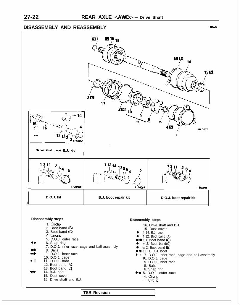
27-22 REAR AXLE <AWD> - Drive Shaft
DISASSEMBLY AND REASSEMBLY M27JD-
c
I - “&” -Y llA0075
5
1 lAOO69 llAOO57 1 lAoo66
I I
D.O.J. kit B.J. boot repair kit D.O.J. boot repair kit
Disassembly steps
1. Circlip2. Boot band (B)3. Boot band (C)a n.4. Lrrcnp5. D.O.J. outer race
** 6. Snap ring
**7. D.O.J. inner race, cage and ball assembly8. Balls
:: 9. D.O.J. inner race
l *10. D.O.J. cage11. D.O.J. boot12. Boot band (A)13. Boot band (C)
*I) 14. B.J. boot15. Dust cover16. Drive shaft and B.J.
l 4 12. Boot band (A)
Reassembly steps
~~ 13. Boot band (C)l + 3. Boot band(C)l a 2. Boot band (B)*4’ 11. D.O.J. boot
16. Drive shaft and B.J.
l +
15. Dust cover
7. D.O.J. inner race, cage and ball assembly10. D.O.J. cage9. D.O.J. inner race
l 4 14. B.J. boot
8. Balls6. Snap ring
I)+ 5. D.O.J. outer race4. Circlip1. Circlip
TSB Revision 1

REAR AXLE <AWD> - Drive Shaft 27-23LUBRICATION POINTS
llWI6#Grease: Repair kit grease
TSB Revision
Grease: Repair kit grease 90 g (3.20 oz.)CautionThe orease in the repair kit should bedivided in half for use, respectively, atthe joint and inA soecial tvoe of
ide the boot.orease is used on the
joint. Be caitious ti ensure that no othergrease is allowd to come in contact withthe joint.
\ -\ llVlO6 llvlos
Grease: Repair kit grease 90 g (3.20 oz.)CautionThe grease in the repair kit should bedivided in half for use, respectively, atthe joint and inside the boot.A special type of grease is used on thejoint. Be cautious to ensure that no othergrease is allowed to come in contactwith the joint.

27-24 REAR AXLE <AWD> - Drive Shaft
WE507
llYG97
7___-- - - - - - -. I
A C
~~~~~
B
” /
B.J: boot Boot bands D.O.J. bootVW592
SERVICE POINTS OF DISASSEMBLY MZ7JEAC
8. REMOVAL OF SNAP RING/8. BALLS/S. D.O.J. INNERRACE/lo. D.O.J. CAGE(I ) Remove the snap ring with the snap ring pliers and then
remove the D.O.J. inner race, the D.O.J. cage, and theballs as a unit.
(2) Clean the D.O.J. inner race, the D.O.J. cage, and theballs, without dismantling them.
Caution1. Be careful that balls do not drop out of the cage.2. If the balls drop out, press them back into the
D.O.J. cage with the D.O.J. inner race.11. REMOVAL OF D.O.J. BOOT/14. B. J. BOOT
(1) Wipe the grease off of the spline portion.(2) Remove the D.O.J. boot and B.J. boot.
NOTEIf the boots are reused, wrap vinyl tape around the driveshaft spline so that the boots are not damaged whenthey are removed.
CautionDo not disassemble the B.J.
INSPECTION MZ7JFAC
l Check the drive shaft for damage, bending or corrosion.l Check the drive shaft spline for wear or damage.l Check the B.J. for entry of water and/or foreign material.l Check the D.O.J. outer race for damage or corrosion.l Check the D.O.J. cage, balls and D.O.J. inner race for
damage, corrosion or wear.
SERVICE POINTS OF REASSEMBLY MnJoAD14. INSTALLATION OF B.J. BOOTI12. BOOT BAND (A)/13.
BOOT BAND (C)/3. BOOT BAND (C)/2. BOOT BAND(B)/ll. D.O.J. BOOT(I) Wrap vinyl tape around the drive shaft spline.(2) Insert the drive shaft in B.J. boot, boot band (A), (C), (C),
(B), D.O.J. boot in that sequence.
(3) Fill the inside of the B.J. and B.J. boot with thespecified grease.
Specified grease: Repair kit greaseCaution
90 g (3.2 oz.)
The grease in the repair kit should be divided in halffor use, respectively, at the joint and inside theboot.A special type of grease is used on the joint. Becautious to ensure that not other grease is allowedto come in contact with the joint.
TSB Revision 1

REAR AXLE <AWD> - Drive Shaft 27-25t
Snap
inner race
1180116
(4) Secure the B.J. boot with boot bands (A) and (C) to thedrive shaft and B.J.
CautionEnsure that the B.J. is at a zero angle with the driveshaft to ensure the boot contains the specifiedamount of air.
7. INSTALLATION OF D.O.J. INNER RACE, CAGE ANDBALL ASSEMBLY(1) Apply the specified grease to the D.O.J. cage, the balls
and the D.O.J. inner race.
Specified grease: Repair kit grease (As required)(2) Install the cage, balls and inner race to the drive shaft,
then, using snap ring pliers, fit the snap ring securelyinto the groove in the shaft.
5. APPLICATION OF GREASE TO D.O.J. OUTER RACE(1) Fill the specified grease to the D.O.J. outer race, fit the
drive shaft into the D.O.J. outer race, and then fill moregrease to the D.O.J. outer race.
Specified grease: Repair kit grease 90 g (3.2 OZ.)CautionThe grease in the repair kit should be divided in halffor use, respectively, at the joint and inside theboot.A special type of grease is used on the joint. Becautious to ensure that no other grease is allowedto come in contact with the joint.
(2) Install the circlip to the D.O.J. outer race.(3) Assemble the D.O.J. boot to the D.O.J. outer race, then
secure the boot to the drive shaft with boot band (C).(4) Place boot band (B) on the D.O.J. boot.
NOTEDo not secure boot band (B).
(5) Set the D.O.J. boot bands at the specified distance inorder to adjust the amount of air inside the D.O.J. boot,and then tighten the D.O.J. boot band (C) securely.
Standard value: 76f3 mm @JO+ 23 in.)(6) Release a part of the D.O.J. boot from the D.O.J. outer
race to allow pressure to escape from the boot.(7) Tighten boot band (B) and secure the D.O.J. boot.

1 Pre-removal and Post-installation IOperationl Draining and Refilling of Differential
Oil (Refer to P.27-15.)l Removai and installation of Centf
haust Pipe (Refer to GROUPExhaust PiDe and Main Muffler.)
Gear
:r Ex-15-
19-28 Nm14-20 ft.lbs.
27-26 REAR AXLE <AWD> - Differential Carrier
DIFFERENTIAL CARRIERREMOVAL AND INSTALLATION
M27w
100-120 Nm72-87 ft.lbs.
\ “\ //
5a/
i / /14-21 NmIO-15 ft.lbs.
/9-14 Nm7-10 ft.lbs.
loo-120 Nm72-87 ft.lbs.
/
I
- -
TSB Revision1 I
I-
M-85 Nm/40-47 ft.lbs.
I\ --90-70
/Nm
43-51 ft.lbs.30-35 Nm22-25 ft.lbs. /
1
y I’ .c.. ,/-W?c\. fQ(- 0
1
R3&I
0
Removal steps
llAo373
1. Drive shaft (Refer to P.27-21.)2. Circlip
3. Propeller shaft connection(Refer to GROUP 25-Propeller Shaft)
4. Feed tube (Vehicles with 4WS)5. O-ring (Vehicles with 4WS)6. Rear oil pump (Vehicles with 4WS)7. O-ring (Vehicles with 4WS)8. f$erential support member installation
9. Stopper (lower)10. D$erentral support member installation
11. Dynamic damper (I 990 models)12. Differential support member13. F;fprentral support member installation
14. Differential carrier

REAR AXLE <AWD> - Differential Carrier 27-27
Beveled placeDIFFERENTIAL SUPPORT MEMBER BUSHING RE-PLACEMENT M27lKAA
Use the special tool to pull out and press in the differentialsupport member bushing.
NOTEPress in the bushing from the beveled part of the differentialsupport member; press in until the end surface of the bushingouter cylinder is flush with the support member.
llGO073 \
INSPECTION BEFORE DISASSEMBLY MmEAlHold the working base in a vice, and attach the differentialcarrier to the working base.
FINAL DRIVE GEAR BACKLASHWith the drive pinion locked in place, measure the final drivegear backlash with a dial indicator on the drive gear.
NOTEMeasure at four points or more on the circumference of the,drive gear.
Standard value: 0.11-0.16 mm (.004-.006 in.)
DRIVE GEAR RUNOUTMeasure the drive gear runout at the shoulder on the reverseside of the drive gear.
Limit: 0.05 mm (.002 in.)
DIFFERENTIAL GEAR BACKLASHWhile locking the side gear with the wedge, measure thedifferential gear backlash with a dial indicator on the piniongear.
Standard value: O-0.076 mm (O-.003 in.)Limit: 0.2 mm (.008 in.)

27-28 REAR AXLE <AWD> - Differential Carrier
FINAL DRIVE GEAR TOOTH CONTACTCheck the final drive gear tooth contact by following the steps
~l”~~ply a thin, uniform coat of machine blue to both surfacesof the drive gear teeth.
(2) Insert a brass rod between the differential carrier and thedifferential case, and then rotate the companion flange byhand (once in the normal direction, and then once in thereverse direction) while applying a load to the drive gear, sothat the revolution torque [approximately 2.5-3.0 Nm(28-33 in.lbs.)l is applied to the drive pinion.
CautionIf the drive gear is rotated too much, the tooth contactpattern will become unclear and difficult to check.
(3) Check the tooth contact condition of the drive gear anddrive pinion.
TSB Revision

REAR AXLE <AWD> - Differential Carrier
Standard tooth contact pattern1 Narrow tooth side2 Drive-side tooth surface (the side applying power
during forward movement)3 Wide tooth side4 Coast-side tooth surface (the side applying pow-
er during reverse movement)
Problem
Tooth contact pattern resulting from exces-sive pinion height
Solution
3
The drive pinion is positioned too far from thecenter of the drive gear.
3
Increase the thickness of the pinion height adjustingshim, and position the drive pinion closer to thecenter of the drive gear.Also, for backlash adjustment, position the drivegear farther from the drive pinion.
rooth contact pattern resulting from insuffi-:ient pinion height
3
The drive pinion is positioned too close to the centerIf the drive gear.
3
Decrease the thickness of the pinion height adjust-ing shim, and position the drive pinion farther fromthe center of the drive gear.Also, for backlash adjustment, position the drivegear closer to the drive pinion.
lls642
NOTE(1) Tooth contact pattern is a method for judging the result of the adjustment of drive pinion height and final drive gear
backlash. The adjustment of drive pinion hight and final drive gear backlash should be repeated until tooth contactpatterns bear a similarity to the standard tooth contact pattern.
(2) When adjustment is not able to obtain a correct pattern, it may be judged that the drive gear and drive pinion haveexceed their usage limits and both gears should be replaced as a set.
TSB Revision I

27-30
DISASSEMBLY
REAR AXLE <AWD> - Differential Carrier
Inspection Before Disassembly*Final Drive Gear Backlash (Refer to P.27-
27.)*Differential Gear Backlash
<Conventional type>(Refer to P.27-27.)
@Drive Gear Runout (Refer to P.27-27.)*Final Drive Gear Tooth Contact (Refer to
P.27-28.)
llA0260
Disassembly steps1. Differential cover2. Vent plug
**l *l *
3. Bearing cap4. Differential case assembly5. Side bearing spacern n.* I0. slae oeanng outer race7. Side bearing inner race8. Drive9.
gear
10.Lock pinPinion shaft
11. Pinion12.
gearPinion washer
13. Side gears14. Side gear spacer15. Spring pin (Vehicles with 4WS)16. Drive gear (Vehicles with 4WS)17. Differential case18.19.
Self-loclhg nutWasher
l * 20. Drive pinion assembly21. Companion flange22. Drive pinion front shim
(for preload adjustment)23. Drive pinion spacer24. Drive pinion rear bearing inner race25. Drive pinion rear shim
(for pinion height adjustment)26. Drive pinion27. Oil seal28. Drive pinion front bearing29. Drive pinion rear bearing outer race30. Oil seal31. Gear carrier
TSB Revision

REAR AXLE <AWD> - Differential Carrier 27-31
‘71
I
I
SERVICE POINTS OF DISASSEMBLY M27lGBC
4. REMOVAL OF DIFFERENTIAL CASE ASSEMBLYPrize out the differential case assembly using hammershafts.
NOTEWhen removing the differential case assembly, the remov-al should be accomplished slowly and carefully and cautionpaid to ensure that the side bearing outer race is notdropped.Keep the right and left side bearings separate, so that theydo not become mixed at the time of reassembly.
7. REMOVAL OF SIDE BEARING INNER RACESPull out the side bearing inner races by using the specialtools.
8. REMOVAL OF DRIVE GEAR(1) Make the mating marks to the differential case and the
drive gear.(2) Loosen the drive gear attaching bolts in diagonal
sequence to remove the drive gear.
9. REMOVAL OF LOCK PINDrive out the lock pin with a punch and remove the piniongears, pinion washers, side gears and side gear spacers.
18. REMOVAL OF SELF-LOCKING NUTUse the special tools to hold the companion flange andremove the companion flange self-locking nut.
\ TSB Revision I

27-32 REAR AXLE <AWD> - Differential Carrier
Mating marks
n
0161
llY175
llY176
20. REMOVAL OF DRIVE PINION) Make the mating marks to the drive pinion and
companion flange.
NOTEMating marks should not be made to the contactsurfaces of companion flange and propeller shaft.
!) Drive out the drive pinion together with the drive pinionspacer and drive pinion front shims.
24. REMOVAL OF DRIVE PINION REAR BEARING INNERRACEPull out the drive pinion rear bearing inner race by using thespecial tools.
27. REMOVAL OF OIL SEAL/28. DRIVE PINION FRONTBEARINGDrive out the drive pinion front bearing from the gearcarrier.
29. REMOVAL OF DRIVE PINION REAR BEARING OUTERRACEDrive out the drive pinion rear bearing outer race from thegear carrier.
INSPECTION M27lHADl Check the companion flange for wear or damage.l Check the oil seal for wear or deterioration.l Check the bearings for wear or discoloration.l Check the gear carrier for cracks.l Check the drive pinion and drive gear for wear or cracks.l Check the side gears, pinion gears and pinion shaft for wear
or damage.l Check the side gear spline for wear or damage.
TSB Revision

REASSEMBLY
REAR AXLE <AWD> - Differential Carrier 27-33M27n-
160-220 Nm116-159 ft.lbs.
Differential gear set11BOO66
Final drive gear set
Reassembly steps1. Gear carrier
*a 2. Oil seal++ 3. Drive pinion rear bearing outer racel + 4. Drive pinion front bearing outer race*a Adjustment of pinion height
5. Drive pinion6. Drive pinion rear shim
(for pinion height adjustment)7. Drive pinion rear bearing inner race8. Drive pinion spacer
*a Adjustment of drive pinion preload9. Drive pinion front shim
(for preload adjustment)10. Drive pinion assembly11. Drive pinion front bearing inner race12. Oil seal13. Companion flange14. Washer15. Self-locking nut16. Differential case
so-9d Nm*5845 ft.lbs.*
llA0260
~~ 17. Drive gear (Vehicles with 4WS)e+ 18, Spring pin (Vehicles with 4WS)l * Adjustment of differential gear backlash
19. Side gear spacer20. Side gear21. Pinion washer22. Pinion gear23. Pinion shaft
l a 24. Lock pinl a 25. Drive gearl * 26. Side bearing inner race
27. Side bearing outer racel * Adjustment of final drive gear backlash
28. Side bearing spacer29. Differential case assembly30. Bearing cap31. Vent plug32. Differential cover
NOTEl : Tightening torque with oil applied
TSB Revision I
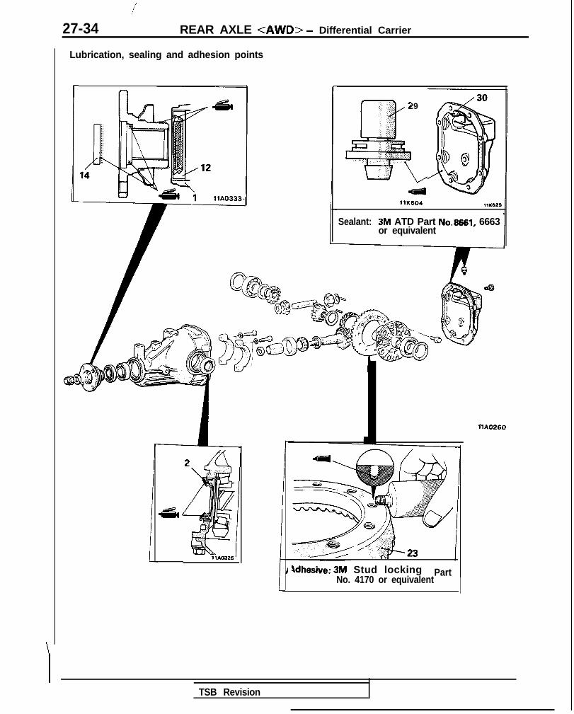
27-34 REAR AXLE <AWD> - Differential Carrier
\
Lubrication, sealing and adhesion points
r
1 MO326
r‘, 29c.
,’ :
~
;I: :a e-**,i ,,,,3;;,*; :i
L
Adhesive: 3M Stud lockingNo. 4170 or equivalent
Part
llK604 11K626
Sealant: 3M ATD Part No.6661, 6663or equivalent
llA0260
TSB Revision

REAR AXLE <AWD> - Differential Carrier 27-35
I llK610
90938-o 1
llY181llY182
MB990905-4-C
MIT216335MIT216336
MB990905-2-01u- MB990905l-01
llW616
SERVICE POINTS OF REASSEMBLY M27lJ6c62. PRESS FITTING OF OIL SEAL
(1) With the special tool, press fit the oil seal until it iswith the end of the gear carrier.
(2) Apply multipurpose grease to the oil seal lip.
flush
3. INSTALLATION OF DRIVE PINION REAR BEARINGOUTER RACE/A DRIVE PINION FRONT BEARINGOUTER RACEPress-fit the drive pinion rear and front bearing outer racesinto the gear carrier by using the special tool.
CautionBe careful not to press in the outer race at an angle.
. ADJUSTMENT OF PINION HEIGHTAdjust the drive pinion height by the following procedures:(I) Install special tools and drive pinion front and rear
bearing inner races on the gear carrier in the sequenceshown in the illustration.
(2) Tighten the handle of the special tool until the standardvalue of drive pinion turning torque is obtained.
(3) Ea;sure the drive pinion turning torque (without the oil
Standard value:
I IBearing BearingRotation torque
classification lubrication(starting friction torque)
Nm (in.lbs.)
I,;,r,used 1 EJi!x%;; 1/ ;;;;y;-;NOTE(1) Gradually tighten the handle ?f the special tool while
checking the drive pinion turning torque.(2) Because the special tool cannot be turqed one tur?, turn
it several times within the range that It can be turned;then, after fitting to the bearing, measure the rotation
torque.
TSB Revision \

27-36 REAR AXLE <AWD> - Differential Carrier
lllllllll
1
7
(4) Position the special tool in the side bearing seat of thegear carrier, and then select a drive pinion rear shim of athickness which corresponds to the gap between thespecial tools.
NOTEClean the side bearing seat thoroughly. Confirm that thespecial tool is in close contact with the side bearingsf?at---_.
When selectina the drive oinion rear shims. keen the .--~ _.._number of shims to a minimum.
(5) Fit the selected drive pinion rear shim(s) to the drivepinion, and press-fit the drive pinion rear bearing innerrace by using the special tool.
. ADJUSTMENT OF DRIVE PINION PRELOADAdjust the drive pinion turning torque by using the followingprocedures :
(1) Fit the drive pinion front shim(s) between the drivepinion spacer and the drive pinion front bearing innerrace.
(2) Tighten the companion flange to the specified torque byusing the special tools.
NOTEDo not install the oil seal.
(3) Measure the drive pinion turning torque (without the oilseal) by using the special tools.
Standard value:
Bearing Bearingclassification lubrication
Rotation torque(starting friction torque)
Nm (in.lbs.)
(4) If the drive pinion turning torque is not within the rangeof the standard value, adjust the turning torque byreplacing the drive pinion front shim(s) or the drivepinion spacer.
NOTEWhen selecting the drive pinion front shims, if thenumber of shims is large, reduce the number of shimsto a minimum by selecting the drive pinion spacers.
(5) Remove the companion flange and drive pinion onceagain.Drive the oil seal into the gear carrier front lip by usingthe special tool.
II1 TSB Revision

REAR AXLE <AWD> - Differential Carrier 27-37
(6) Install the drive pinion assembly and companion flangewith mating marks properly aligned, and tighten thecompanion flange self-locking nut to the specifiedtorque by using the special tools.
(7) Measure the drive pinion turning torque (with oil seal) toverify that the drive pinion turning torque complies withthe standard value.
Standard value:
Bearing Bearingclassification lubrication
Rotation torque(starting friction torque)
Nm (in.lbs.1
;;oy:;; (;5,,,,,, 1 ~%L; !If there is a deviation from the standard value, checkwhether or not there is incorrect tightening torque ofthe companion flange tightening self-locking nut, orincorrect fitting of the oil seal.
. ADJUSTMENT OF DIFFERENTIAL GEAR BACKLASH
Adjust the differential gear backlash by the followingprocedures:
(1) Assemble the side gears, side gear spacers, piniongears, and pinion washers into the differential case.
(2) Temporarily install the pinion shaft.
NOTEDo not drive in the lock pin yet.
(3) Adjust the differential gear backlash by the followingprocedures:
@ While locking the side gear with the wedge,measure the differential gear backlash with a dialindicator on the pinion gear.
NOTEThe measurement should be made for both piniongears individually.
Standard value: O-0.076 mm (O-.003 in.)Limit: 0.2 mm (.008 in.1
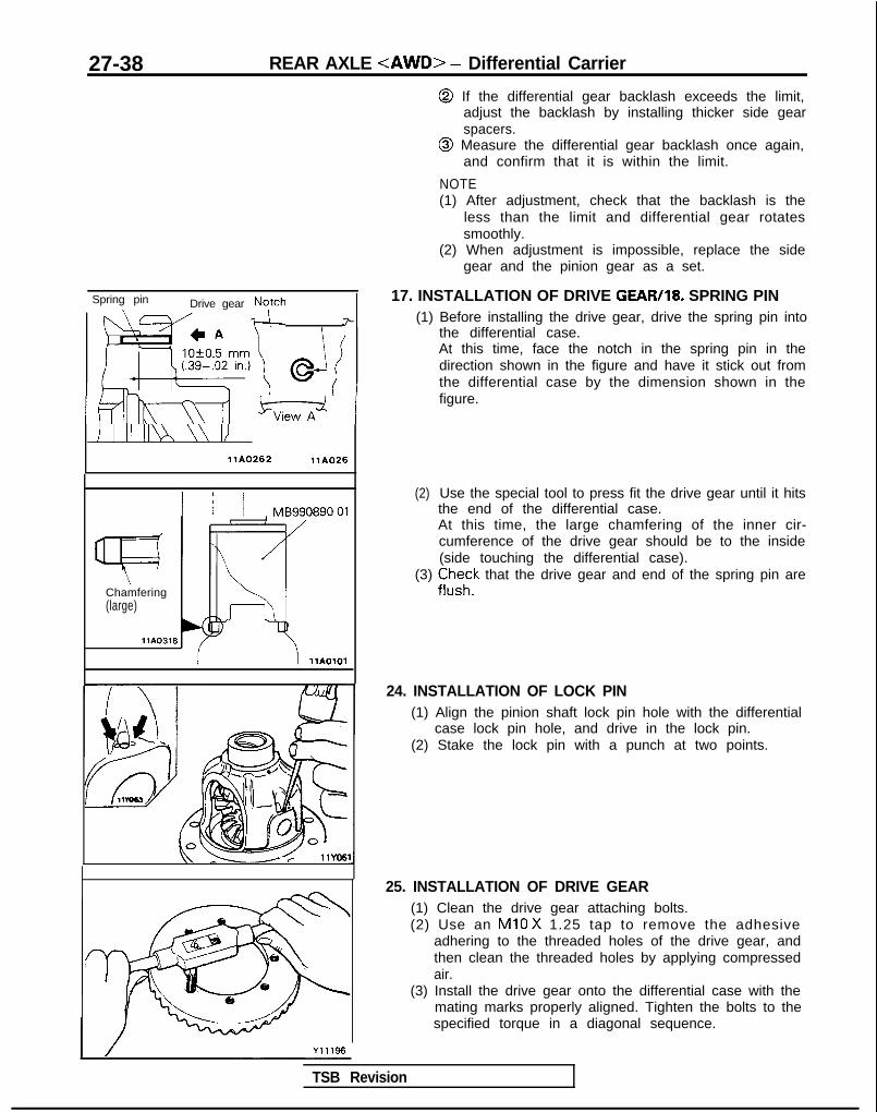
27-38 REAR AXLE <AWD> - Differential Carrier
@ If the differential gear backlash exceeds the limit,adjust the backlash by installing thicker side gearspacers.
@ Measure the differential gear backlash once again,and confirm that it is within the limit.
NOTE(1) After adjustment, check that the backlash is the
less than the limit and differential gear rotatessmoothly.
(2) When adjustment is impossible, replace the sidegear and the pinion gear as a set.
Spring pin
‘\ /
Drive gear TNyh fl
l~1/p(---\y-jj !5Lz+ /
17. INSTALLATION OF DRIVE GEAR/18. SPRING PIN(1) Before installing the drive gear, drive the spring pin into
the differential case.At this time, face the notch in the spring pin in thedirection shown in the figure and have it stick out fromthe differential case by the dimension shown in thefigure.
I I II II\ \\ IIllAO262 llA026
1 / / MB990890-01
Chamfering(large)
llA0316
llA0101
(2) Use the special tool to press fit the drive gear until it hitsthe end of the differential case.At this time, the large chamfering of the inner cir-cumference of the drive gear should be to the inside(side touching the differential case).
(3) ii,“;k that the drive gear and end of the spring pin are
24. INSTALLATION OF LOCK PIN(1) Align the pinion shaft lock pin hole with the differential
case lock pin hole, and drive in the lock pin.(2) Stake the lock pin with a punch at two points.
25. INSTALLATION OF DRIVE GEAR(1) Clean the drive gear attaching bolts.(2) Use an Ml0 X 1.25 tap to remove the adhesive
adhering to the threaded holes of the drive gear, andthen clean the threaded holes by applying compressedair.
(3) Install the drive gear onto the differential case with themating marks properly aligned. Tighten the bolts to thespecified torque in a diagonal sequence.
TSB Revision

REAR AXLE <AWD> - Differential Carrier 27-39
26. PRESS-FITTING OF SIDE BEARING INNER RACEPress-fit the side bearing inner races to the differential caseby using the special tool.
=Thickness of thespacer on one side
llY241
l ADJUSTMENT OF FINAL DRIVE GEAR BACKLASHAdjust the final drive gear backlash by the followingprocedures:
(1) Install the side bearing spacers, which are thinner thanthose removed, to the side bearing outer races, andthen mount the differential case assembly into the gearcarrier.
NOTESelect side bearing spacers with the same thickness forboth the drive pinion side and the drive gear side.
(2) Push the differential case to one side, and measure theclearance between the gear carrier and the sidebearing.
(3) Measure the thickness of the side bearing spacers onone side, select two pairs of spacers which correspondto that thickness plus one half of the clearance plus0.05 mm I.002 in.), and then install one pair each to thedrive pinion side and the drive gear side.
(4) Install the side bearing spacers and differential case, assembly, as shown in the illustration, to the gear
carrier.
TSB Revision I
31-I
WHEELAND TIRE
CONTENTS MJlAA-
SERVICE ADJUSTMENT PROCEDURES . . . . . . . 4 TROUBLESHOOTING . . . . . . . . . . . . . . ..*..................... 3Tire Inflation Pressure Check . . . . . . . . . . . . . . . . . . . . . . 4 Bald SpotsTire Wear Check . . . . . . . . . . . . . . . . . . . . . . . . . . . . . . . . . . . . . . . . . . 4 Cracked Treads
Wheel Runout Check . . . . . . . . . . . . .._.................... 4 Feathered Edge
SPECIFICATIONS 2Rapid Wear at Center
.............................................
General Specifications 2Rapid Wear at Shoulders
..................................
Service Specifications 2Scalloped Wear
...................................
Torque Specifications 2Wear on One Side
...................................
WHEEL AND TIRE . . . . . . . . . . . . . . . . . . . . . . . . . . . . . . . . . . . . . . . . . . 5
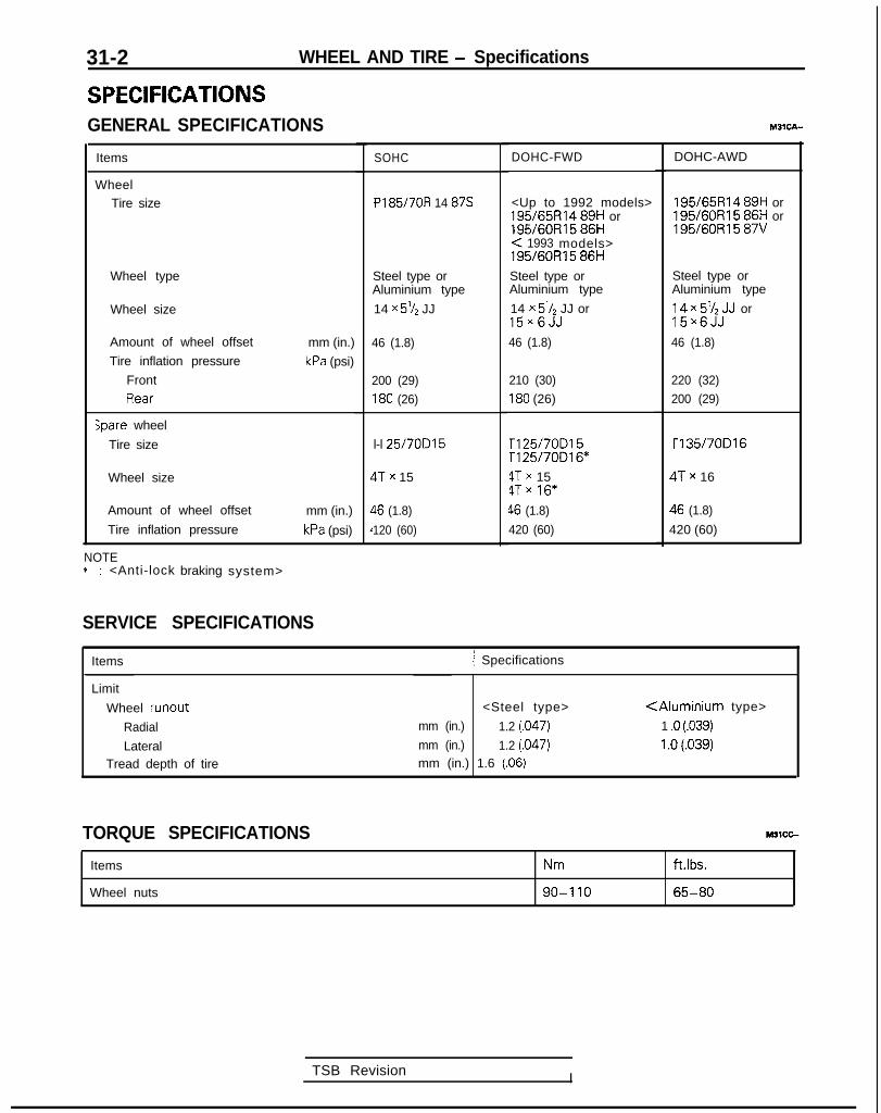
31-2 WHEEL AND TIRE - Specifications
SPECIFICATIONSGENERAL SPECIFICATIONS
Items
WheelTire size
Wheel type
Wheel size
Amount of wheel offset
Tire inflation pressure
Front
Rear
;pare wheel
Tire size
mm (in.)
kPa (psi)
Wheel size
Amount of wheel offset
Tire inflation pressure
mm (in.)
kPa (psi)
NOTE* : <Anti-lock braking system>
SERVICE SPECIFICATIONS
SOHC
PI 85/7OR 14 87s
Steel type orAluminium type
14 x 5% JJ
46 (1.8)
200 (29)
180 (26)
l-l 25/70D15
ITx 15
$6 (1.8)
120 (60)
TSB Revision I
DOHC-FWD
<Up to 1992 models>195/65Fil4 89H or195/60R15 86H< 1993 models>195/60R15 86H
Steel type orAluminium type
14 x 5’/2 JJ or15~6JJ
46 (1.8)
210 (30)
180 (26)
rl25/70D15Tl25/70016*
4Tx 154Tx 16*
46 (1.8)
420 (60)
DOHC-AWD
195/65R14 89H or195/60R15 86H or195/60R15 87V
Steel type orAluminium type
; g x ;‘$JJJ orX
46 (1.8)
220 (32)
200 (29)
T135/70D16
!Tx 16
$6 (1.8)
420 (60)
M3lcA--
Items 1 Specifications
Limit
Wheel runout
Radial
LateralTread depth of tire
<Steel type>
mm (in.) 1.2 j.047)
mm (in.) 1.2 (.047)mm (in.) 1.6 (.06)
<Aluminium type>
1 .o (.039)
1 .o (.039)
TORQUE SPECIFICATIONS
Items
Wheel nuts
Nm
90-I 10
ft.lbs.
65-80

WHEEL AND TIRE - Troubleshooting 31-3
TROUBLESHOOTING M31EA-
Symptom RemedyProbable cause
Under-inflation orlack of rotation
Adjust the tire pressureRapid wearat shoulders
Rapid wearat center
Over-inflation orlack of rotation
Crackedtreads
Under-inflation
Excessivecamber
nspect the camberNear on)ne side
idjust the toe-inIeathered?dge
ncorrectoe-in
laid spots Jnbalancedvheel
Adjust the imbalanced wheels
calloped ack of rotation of tyres or worn orut-of-alignment suspension
Rotate the tires Inspect the front sus-pension alignmentfear
TSB Revision
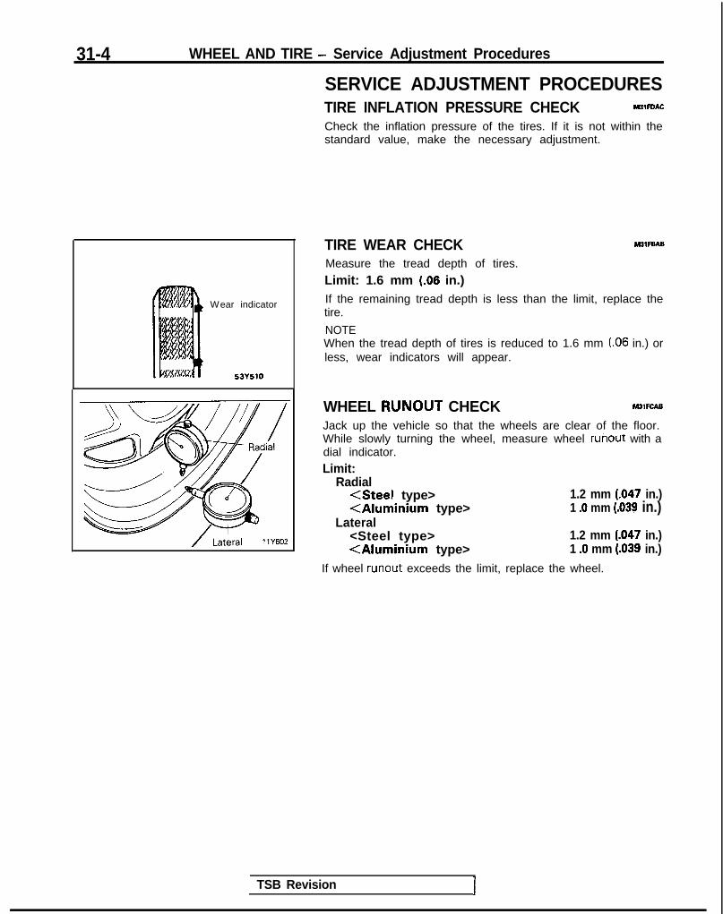
31-4 WHEEL AND TIRE - Service Adjustment Procedures
SERVICE ADJUSTMENT PROCEDURESTIRE INFLATION PRESSURE CHECK M3lFOAC
Check the inflation pressure of the tires. If it is not within thestandard value, make the necessary adjustment.
Wear indicator
53YJlO
TIRE WEAR CHECK M31FBAB
Measure the tread depth of tires.
Limit: 1.6 mm (.06 in.)If the remaining tread depth is less than the limit, replace thetire.
NOTEWhen the tread depth of tires is reduced to 1.6 mm LO6 in.) orless, wear indicators will appear.
WHEEL RUNOUT CHECK WlFcABJack up the vehicle so that the wheels are clear of the floor.While slowly turning the wheel, measure wheel runout with adial indicator.Limit:
Radial<Steel type> 1.2 mm (.047 in.)<Aluminium type> 1 .O mm (.039 in.)
Lateral<Steel type> 1.2 mm (.047 in.)<Aluminium type> 1 .O mm (.039 in.)
If wheel runout exceeds the limit, replace the wheel.
TSB Revision I

WHEEL AND TIRE - Wheel and Tire
WHEEL AND TIRE M31GA..
REMOVAL AND INSTALLATION
Steel wheel
, /-----%10lm65-80 ft.lbs.
3
<SOHC> 1
<DOHC><up to 1
mode
1110396
Aluminium type wheel
<14 inch- SOHC> <14 inch-DOHC><Up to 1992 models>
2
0
Removal steps1. Wheel cover
/ -llAO279 /
llA0395
twit7~- . .
(15 inch><15 inch> <From 1993 models>
Q<Vehicles withwheel cover>
2. Center cover<Vehicles withcenter cover>
3. Wheel nuts4. Center cap
<Vehicles withcenter cap>
5. Spring6. Ornament7. Balance weight8. Tire9. Wheel
9
dLit
3
11 A0408
1 TSB Revision I

31-6 WHEEL AND TIRE - Wheel and Tire
INSTRUCTIONS FOR ALUMINUM TYPE WHk&g
1. Aluminum is vulnerable to alkalies. If a vehicle washingdetergent has been used, or salt from sea water or roadchemicals has adhered, wash the vehicle as soon aspossible. After washing the vehicle, apply body or wheelwax to the aluminum type wheels to prevent corrosion.
2. When cleaning the vehicle with steam, do not direct steamonto the aluminum type wheels.When tightening nuts for aluminum type wheels, particular-ly observe the following:(I) Clean the hub surface of aluminum type wheels.(2) After finger-tightening wheel nuts, tighten them to
specifications.(3) Do not use an impact wrench or push the wrench by
foot to tighten the wheel nuts.(4) Do not apply oil to the threaded portions.
INSTRUCTIONS FOR TIRE CHAINS AND SNOWTIRES M31GGbl
1. Use tire chains only on front wheels. Do not use tire chainson rear wheels.
2. When using snow tires, use them on all four wheels formaneuverability and safety.
INSTRUCTIONS FOR COMPACT SPARE TlR,E,,,,
1. The compact spare tire is designed to save space in theluggage compartment, and its lighter weight makes iteasier to use if a flat tire occurs.
2. The following instructions for the compact spare tire shouldbe observed.(1) Check the inflation pressure after installing the spare,
and adjust to the specified pressure.(2) Avoid driving through automatic car washes and over
obstacles that could possibly damage the vehicle’sundercarriage. Because the tire is smaller than theoriginal tire, car ground clearance is slightly reduced.
(3) The compact spare tire should not be used on any otherwheels, nor should standard tires, snow tires, wheelcovers or trim rings be used with the compact sparewheel. If such use is attempted, damage to these itemsor other vehicle components may occur.
TSB Revision
32-1
POWER PLANTMOUNT
CONTENTS M32AA-
CENTERMEMBER AND CROSSMEMBER.. ..... 8 SPECIFICATIONS ............................................... 2
Service Specifications ..................................... 2ENGINE MOUNTING ........................................ 4
Torque Specifications ....... .............................. 2
ENGINE ROLL STOPPER ................................. 6TRANSAXLE MOUNTING ................................ 5
SPECIAL TOOL ................................................. 3TROUBLESHOOTING ........................................ 4

32-2 POWER PLANT MOUNT - Specifications
SPECIFICATIONSSERVICE SPECIFICATIONS M3ZCE-
Items
Standard value
Crossmember bushing (A) projection
Crossmember bushing (B) projection
Specifications
m m ( i n . ) 7.2-10.2 (.28-.40)
mm ( in. ) 6 .5-9.5 (.26-.37)
TORQUE SPECIFICATIONS M32cc-
Items
Engine mounting
Engine mount insulator nut (large)
Engine mount insulator nut (small)
Engine mount bracket bolt
Engine mount bracket nut
Bracket
Transaxle mounting
Transaxle mount insulator nut
Transaxle mount bracket to body
Engine roll stopper
Front roll stopper insulator nut
Front roll stopper bracket to centermember
Rear roll stopper insulator nut
Rear roll stopper bracket to crossmember
Centermember and crossmember <FWD>
Centermember installation bolts (front)
Centermember installation bolts (rear)
Stay installation bolts
Stabilizer bar bracket to crossmember
Stabilizer link installation bolts
Tie rod end ball joint to knuckle
Joint assembly and gear box connecting boltSteering gear box assembly to return tube
Steering gear box assembly to pressure hose
Steering gear box assembly to crossmember
Pressure hose blacketLower arm clamp to crossmember (nut)
Lower arm clamp to crossmember (bolt)
Lower arm clamp shaft to body
Lower arm mounting bolt
Crossmember to body
NOTE*I: Vehicles built up to Dec. 1988**: Vehicles built from Jan. 1989
N m ftlbs.
60-80 43-58
30-40 22-29
50-65 36-47
50-65 36-47
17-26 12-19
60-80 43-58
40-50 29-36
50-65 36-47
40-50 29-36
40-50 29-36
40-50 29-36
80-100 58-72
80-I 00 58-7270-80 51-58
30-42 22-30
35-45 25-33
24-34 17-25
15-20 11-1412-18 9 - 1 3
12-18 9 - 1 3
60-80 43-58
9 - 1 4 7-10
35-47 25-34
80-100 58-7280-loo*’ [100-120]*2 58-72*’ [72-87]*’
100-120 72-87
80-100 58-72
1 TSB Revision I

POWER PLANT MOUNT - Specifications/Special Tool 32-3
Items
Centermember and crossmember <AWD>
Front roll stopper to No. 1 crossmember
Front roll stopper insulator nut
No. 1 crossmember installation nutGusset installation bolt
Right member installation bolt (front)
Right member installation bolt (rear)
Left member installation bolt (front)
Left member installation bolt (rear)
Front exhaust pipe to exhaust fitting <Turbo>
Front exhaust pipe to engine <Turbo>
Front exhaust pipe to exhaust manifold <Non-Turbo>
Front exhaust pipe clamp <Non-Turbo>Front exhaust pipe rear installation bolt
Front exhaust pipe hanger installation bolt
Stabilizer bar bracket to crossmember
Stabilizer link installation nutTransfer assembly installation bolt
MIT
Al-r
Tie rod end ball joint to knuckle
Joint assembly and gear box connecting bolt
Steering gear box assembly to return tube
Steering gear box assembly to pressure hose
Steering gear box assembly to crossmember
Lower arm clamp to crossmember (nut)
Lower arm clamp to crossmember (bolt)
Lower arm clamp shaft to body
Lower arm mounting bolt
Crossmember to body
N m ftlbs.
40-50 29-36
50-65 36-47
80-100 58-72
70-80 51-58
80-100 58-72
70-80 51-58
80-100 58-72
70-80 51-58
40-60 29-36
30-40 22-29
30-40 22-29
30-40 22-29
30-40 22-29
10-15 7-l 1
30-42 22-30
35-45 25-33
55-60 40-43
60-80 44-57
24-34 17-25
15-20 11-14
12-18 9 - 1 3
12-18 9 - 1 3
60-80 43-58
35-47 25-34
80-100 58-72
100-120 72-87
95-120 69-87
80-100 58-72
SPECIAL TOOL
Tool Number
MB991 045
Name
Bushing removerand installer
Use
Removal and installation of the crossmemberbushing
TSB Revision I

32-4 POWER PLANT MOUNT - Troubleshooting/Engine Mounting
TROUBLESHOOTING
Symptom Probable cause Remedy
Excessive engine wob- Cracked rubber parts of insulator Replaceble or vibration (with en-gine rn normal condition) Insufficiently tightened parts Retighten
Abnormal noise Insufficiently tightened parts Retighten
ENGINE MOUNTINGREMOVAL AND INSTALLATION
.
TSB Revision I
30-40 Nm22-29 ft.lbs.
Removal steps
Post-installation Operation@Lower the Engine
50-65 Nm36-47 ftlbs.
43-56 ft.lbs.
1. Pressure hose (power steering) and highpressure hose (air conditioner)
2. Bracket
OIA0306
3. Engine mount bracket and bodyconnection bolt
4. Engine mount bracketl + 5. Mounting stopper
INSPECTIONl Check each insulator for cracks or damage.l Check each bracket for deformation or damage.

POWER PLANT MOUNT - Engine Mounting/Transaxle Mounting 32-5
Engine side
1
Mounting stopper
Arrow01AQOO4
TRANSAXLE MOUNTINGREMOVAL AND INSTALLATION
(Refer to GROUP 15-Air Cleaner.)
< M / T >
SERVICE POINTS OF INSTALLATION M32GDAK
5. INSTALLATION OF MOUNTING STOPPER
Install the mounting stopper of the engine mount bracketso that the arrow faces the center part of the engine.
Post-installation Operation@Lower the Transaxle@Installation of the Air Cleaner
(Refer to GROUP 15-Air Cleaner.)
60-60 Nm43-58 ft.lbs.
40-50 Nm29-36 ft.lbs.
60-80 Nm43-58 ft.lbs.
Transaxle mount
Removal steps1. Transaxle mount bracket and transaxle
connection bolt2. Cap3. Transaxle mount bracket installation bolt4. Transaxle mount bracket5. Mounting stopper
OlA0009
INSPECTION NUZGCAHZ
l Check each insulator for cracks or damage.l Check each bracket for deformation or damage.
TSB Revision

32-6 POWER PLANT MOUNT - Engine Roll Stopper
ENGINE ROLL STOPPERREMOVAL AND INSTALLATION
M32GF-
Pre-removal Operation*Raise and Suspend the Engine to the
Extent Force IS not applied to the EngrneMount
I Post-installation Operationl Lower the Engine I
<AWD-UP TO 1992 MODELS>
40-50 Nm29-36 ftlbs.
I
40-50 Nm29-36 ft.lbs.
n A5
<FWD>40-50 Nm29-36 ft.lbs.
40-50 Nm29-36 ft.lbs. 2
1 36-47 ft.lbs.*
50-65 Nm36-47 ft.lbs.
Front roll stopper bracket removal steps1. Front roll stopper bracket and engine
connection bolt2. Front roll stopper bracket installation bolt
l + 3. Front roll stopper bracket
Rear roll stopper bracket removal steps4. Rear roll stopper bracket and engine
connection bolt5. Rear roll stopper bracket installation bolt
l + 6. Rear roll stopper bracket
NOTE+ Indicates parts which should be temporarily tightened.
and then fully tightened with the weight of the enginesupported by the body
INSPECTION M32GcAH3l Check each insulator for cracks or damage .l Check each bracket for deformation or damage.
TSB Revision

POWER PLANT MOUNT - Engine Roll Stopper 32-7
SERVICE POINTS OF INSTALLATION M32GJAB
6. INSTALLATION OF REAR ROLL STOPPER BRACKET<Vehicles with FWD-A/T>b
Rear roll
in.)
After temporarily tightening the rear roll stopper bracket,tighten so that, in the unladen vehicle condition, thedimension of the clearance of the insulator is the specifieddimension.
Rear roll
86.7-92.7 mm
46.7-52.7 mm(1.8-2.1 in.)
<FWD-M/T> Front rollstopper bracket/
OlR0033
cAWD-M/T> Front rollstopperbracket
44-50 m m(1.7-2.0 in.
OlAOBlOr
,-
<Vehicles with AWD-A/T>After temporarily tightening the rear roll stopper bracket,tighten so that, in the unladen vehicle condition, thedistance from the center hole of the insulator to the loweredge of the bracket is the specified distance.
3. INSTALLATION OF FRONT ROLL STOPPER BRACKET(1) Install the front roll stopper bracket so that the part
where the round hole is made is facing the front of thevehicle.
(2) After temporarily tightening the front roll stopperbracket, tighten so that, in the unladen vehicle condi-tion, the distance from the center hole of the insulatorto the lower edge of the bracket is the specifieddistance.
1 TSB Revision

32-8 POWER PLANT MOUNT - Centermember and Crossmember
CENTERMEMBER AND CROSSMEMBER <FWD>REMOVAL AND INSTALLATION M3ZYA-A
Pre-removal Operationl Disconnection of the Front Exhaust Pipe
when removing the Crossmember (Re-fer to GROUP 15-Exhaust Pipe andMain Muffler.)
aRaise and Suspend the Engine to theExtent Force IS not applied to the EngineMount
@Draining of the Power-steering Fluid (Re-fer to GROUP 37A-Service AdjustmentProcedures.)
40-50 N29-36 ft
Post-installation Operationl Lower the Engine*Coupling of the Front Exhaust Pipe (Re-
fer to GROUP 15-Exhaust Pipe andMain Muffler.)l Air bleeding of the Power-steering Fluid
(Refer to GROUP 37A- Service Adjust-ment Procedures.)l Adjustment of the Front Wheel Align-
ment(Refer to GROUP 33A-Service Adjust- Iment Procedures.)
80-100 Nm58-72 ft.lbs.
80-100 Nm58-72 ft.lbs.
Removal steps1. Front roll stopper bracket mounting bolt2. Centermember installation bolts (front)3. Stopper4. Bushing5. Bushing6. Collar7. Centermember installation bolts (rear)8. Centermember9. Stay
llA0283
TSB Revision

POWER PLANT MOUNT - Centermember and Crossmember 32-9
35-4525-33
14\
SW13
I e
-22-30 ii.&.15T-\-- .- 30-42
15-20 Nm11-14 ftlbs. 18
60-80 Nm43-58 ft.lbs.
&dOlA0473
10. Stabilizer link installation nut(Refer to GROUP 33A-Stabilizer Bar.)
11. Stabilizer link12. Stabilizer bar bracket installation bolt13. Stabilizer bar bracket14. Bushing15. Stabilizer bar
(Refer to GROUP 33A-Stabilizer Bar.)
16. Cotter pin17. Tie-rod end connection nut18. Joint assembly connection bolt19. Return tube connection20. Pressure hose connection21. Mounting brackets22. Steering gear box assembly
(Refer to GROUP 37A-Steering Gear Box.)
TSB Revision 1

32-10 POWER PLANT MOUNT - Centermember and Crossmember
32
loo-120 Nm*’72-87 ft.lbs.*’ ------@
28D
\80-100 Nm58-72 ftlbs.
58-72 ft.lbs.llA0282
23. Self locking nut24. Clamp25. Lower arm mounting bolt26. Stopper27. Rear roll stopper bracket mounting bolt28. Self locking nut29. Lower plate30. Crossmember
NOTE~1: Indicates parts which should be temporarily tightened,
and then fully tightened with the vehicle in the unladencondition.
31. Stopper32. Bushing
*2: Vehicles built up to Dec. 1988*3: Vehicles built from Jan. 1989
TSB Revision

POWER PLANT MOUNT - Centermember and Crossmember 32-11
INSPECTION M32YcAAl
l Check the crossmember for cracks or deformation.l Check the bushings for cracks or deterioration.l Check the centermember for cracks or deformation.
Press out Press fit
Bushing A Bushing B
Inn& sleeve
12130128 12R0129
BUSHING REPLACEMENT hl32YDAAa
(1) Use the special tool to remove and press in bushings Aand B.
(2) Press in bushings A and B so that the projecting amountof the inner sleeve agrees with the standard value.
Standard value:Bushing A 7.2-10.2 mm (.28-.40 in.)Bushing B 6.5-9.5 mm (.26-.37 in.)
CautionWhen pressing in, apply a solution of soap and water tothe sliding part of the bushings, and then press them inwithout stopping one after the other.If there is a pause during the pressing operation, thefrictional resistance will prevent installation.
TSB Revision
-1

32-12 POWER PLANT MOUNT - Centermember and Crossmember
C&Et;;rSM>EMBER AND CROSSMEMBER <AWD-UP TO 1992
REMOVAL AND INSTALLATION M32Yh-0
40-50 Nm29-36 ft.lbs.
50-65 Nm36-47 ft.lbs.
80-100 Nm58-72 ftlbs.
80-100 Nm58-72 ft.lbs.
1 ’- - --_
ii-58 it.,tTlAO619
I70-r80 km51-58 klbs.
Removal steps1. Cover installation screw2. Left member3. Right member4. Front roll stopper installation bolt5. No. 1 crossmember installation nut6. Lower plate7. No. 1 crossmember8. Stopper(B)9. Bushing (B)
10. Gusset
Pre-removal OperationeDraining of the Power-steering Fluid
(Refer to GROUP 37A-Service Adjust-ment Procedures.)
Post-installation Operation@Air bleeding of the Power-steering Fluid
(Refer to GROUP 37A-Service Adjust-ment Procedures.)l Adjustment of the Front Wheel Align-
ment(Refer to GROUP 33A-Service Adjust-ment Procedures.)
TSB Revision

POWER PLANT MOUNT - Centermember and Crossmember 32-13
<Turbo> 40-60 Nm29-43 ftlbs.
11.12.13.
Front exhaust pipe rear installation boltGasketSelf locking nutFront exhaust pipeGasket
14.15.
<Non-l
40-60 Nm29-43 ft.lbs.
30-40 Nm22-29 ftlbs. 11\ I D12
‘urbo> 30-40 Nm22-29 ftlbs. /
/ 05140117lo-15 Nm7-11 ftlbs.
35-4525-33
16. Stabilizer link installation nut(Refer to GROUP 33A-Stabilizer Bar.)
17. Stabilizer link18. Stabilizer bar bracket installation bolt19. Stabilizer bar bracket
(Refer to GROUP 33A-Stabilizer Bar.)20. Bushing21. Stabilizer bar
(Refer to GROUP 33A-Stabilizer Bar.)
TSB Revision
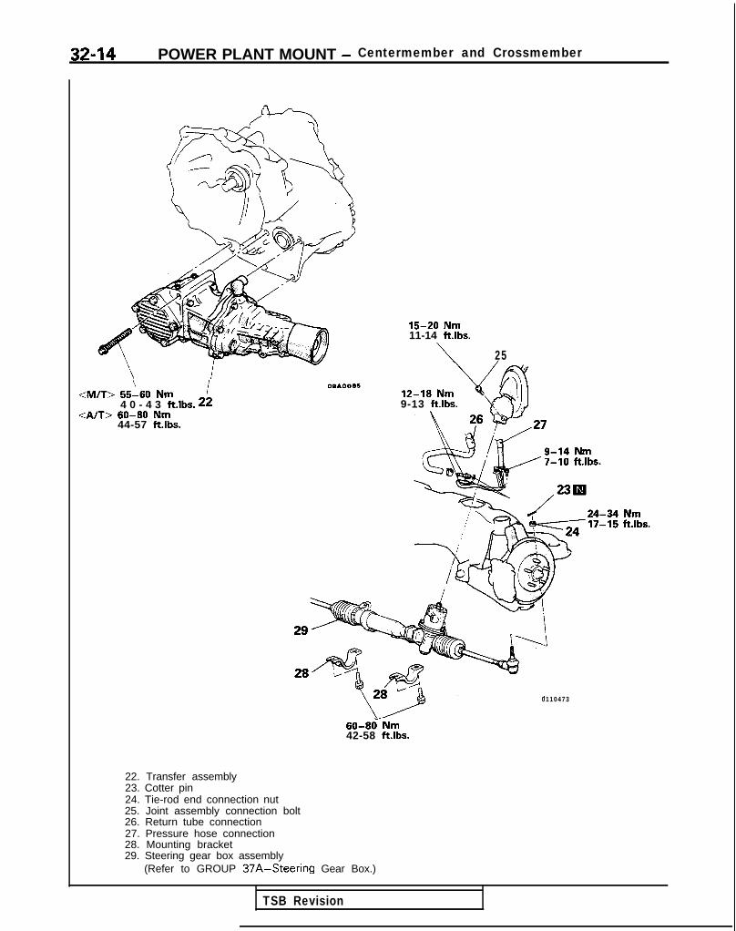
32-14 POWER PLANT MOUNT - Centermember and Crossmember
\ I<M/T> 55-60 Nm4 0 - 4 3 ftlbs. 22
<A/T> 60-80 Nm44-57 ft.lbs.
OQAOOA5
15-20 Nm11-14 ftlbs.
\ 25
9-13 ftlbs.
0110473
60-8&Nm42-58 ft.lbs.
22. Transfer assembly23. Cotter pin24. Tie-rod end connection nut25. Joint assembly connection bolt26. Return tube connection27. Pressure hose connection28. Mounting bracket29. Steering gear box assembly
(Refer to GROUP 37A-Steering Gear Box.)
TSB Revision

POWER PLANT MOUNT - Centermember and Crossmember 32-15
40-50 Nm29-36 ftlbs.
38I/
100-120 Nm*72-87 ft.lbs.*
30. Self locking nut31. Clamp32. Lower arm mountino bolt
41
36
35m
80-100 Nm’ 58-72 ftlbs.
/80-100 Nm*58-72 ft.lbs.*
OlAO472
33. Stopper34. Rear roll stopper bracket mounting bolt35. Self locking nut36. Lower plate37. Crossmember38. Stopper39. Spacers40. Bushing
NOTE* Indicates parts which should be temporarily tightened.
and then fully tightened with the vehicle in the unladencondition.
INSPECTION m327cAA2l Check the crossmember for cracks or deformation.l Check the bushings for cracks or deterioration.l Check the centermember for cracks or deformation.
BUSHING REPLACEMENTRefer to P-32-1 1.
M32YDAB
TSB Revision 1

NOTES

33A-1
FRONTSUSPENSION
CONTENTS Mx(AA-
LOWER ARM . . . . . . . . . . . . . . . . . . . . . . . . . . . . . . . . . . . . . . . . . . . . . . . . . . . 10
SERVICE ADJUSTMENT PROCEDURES . . . . . . . 5Front Wheel Alignment . . . .._..__._...______..__....... 5
Wheel Bearing Adjustment . . . . . . . 5
SPECIAL TOOLS . . . . . . . . . . . . . . . . . . . . . . . . . . . . . . . . . . . . . . . . . . . . . 4
SPECIFICATIONS . . . . . . . . . . . . . . . . . . . . . . . . . . . . . . . . . . . . . . . . . . . . . 2General Specifications 2. . . . . . . . . . . . . . . . . . . . . . . . . . . . . . . . .
Service Specifications . . . . . . . . . . . . . . 3
Torque Specifications .._...._.__.....___..............,. 3
STABILIZER BAR . . . . . . . . . . . . . . . . . . . . . . . . . . . . . . . . . . . . . . . . . . . . . 13
STRUT ASSEMBLY . . . . . . . . . . . . . . . . . . . . . . . . . . . . . . . . . . . . . . . . . 6
4TROUBLESHOOTING . . . . . . . . . . . . . . . . . . . . . . . . . . . . . . . . . . . . . .Excessive Vehicle RollingInclination of VehicleNoisePoor RidingSteering Wheel is Heavy, Vibratesor Pulls to One Side

33A-2 FRONT SUSPENSION - Specifications
SPECIFICATIONSGENERAL SPECIFICATIONS<FWD>
Items
Suspension system
Coil spring
Wire dia. x O.D. x free lengthmm (in.)
Coil spring identification color
Spring constantN/mm (IbsAn.)
Shock absorber
TypeMaximum length mm (in.)
Compressed length mm (in.)
Stroke mm (in.)
Damping force [at 0.3 misec.t.984 ft./sec.)l
Expansion N (Ibs.)Contraction N (Ibs.)
MIT Al-r
McPherson strut with coil spring McPherson strut with coil springand compression rod type and compression rod type
13.5x173.5x358 14.0x174.0x376*(.53x6.83x14.1) (55x6.85x14.8)
Blue x 2 Pink x 2”
20.0 (112) 20.0 (112)”
13.8x173.8x367 14.0x174.0x376*(54x6.84x14.4) (.55x6.85x14.8)
Pink x 1 Pink x 2”
20.0 (112) 20.0 (112)*
Hydraulic, cylindrical double acting type487 (19.17)
340 (13.39)
147 (5.j9)
1,000 (220)
300 (66)
NOTE* mark: <DOHC>
<AWD-UP TO 1992 MODELS>
Items
Suspension system
Coil spring
Wire dia. x O.D. x free lengthmm (in.)
Coil spring identification colorSpring constant N/mm (Ibs./in.)
Shock absorber
TypeMaximum length mm (in.)Compressed length mm (in.)Stroke mm (in.)Damping force [at 0.3 m/set.t.984 ft./set.)]
Expansion N (Ibs.)Contraction N (Ibs.)
MIT A/T, Turbo
McPherson strut with coil spring McPherson strut with coil springand compression rod type and compression rod type
14.2 x 174.2 x 352(56 x 6.86 x 13.9)Orange x 1
24 (134)
14.3 x 174.3 x 359.5(56 x 6.86 x 14.2)Orange x 2
24 (134)
Hydraulic, cylindrical double acting type
501 (19.72)
356 (14.01)145 (5.71)
1,400 (309)450 (99)
1 TSB Revision

FRONT SUSPENSION - Specifications 33A-3
SERVICE SPECIFICATIONS M33cB-
Items
Standard value
Camber
Caster
Toe-in
Protruding length of stabilizer bar mounting bolt
Lower arm ball joint starting torque
Stabilizer link ball joint starting torque
NOTE*: <I989 mode ls>
FWD AWD
22’ k 30’ 31’f30’
2” + 30’ lo56 f 30’
m m ( i n . ) Ok3 (Of.12) 0+3 (0+.12)
m m ( i n . ) 1 6 - 1 8 (.63-.70)* -
N m (in.lbs.1 3-10 (26-87) 3- 10 (26-87)
N m (in.lbs.) 1 .7-3.2 (15-28) 1.7-3.2 (15-28)
TORQUE SPECIFICATIONS
Items
Strut assembly to body
Knuckle to ball joint
Knuckle to strut assemblyStrut top end nut
Stabilizer bar bracket to crossmember
Stabilizer link
Lower arm clamp to crossmember (nut)Lower arm clamp to crossmember (bolt)
Lower arm to crossmember
Stay to crossmember
Front exhaust pipe to exhaust manifoldFront exhaust pipe clamp
Stay to crossmember
Crossmember to body
Centermember installation bolts (rear)
Gusset to centermember
Left member installation bolt (front)Left member installation bolt (rear)
Transfer assemblyM/T
Al-r
Nm ft.lbs.
40-50 29-36
60-72 43-52
go-105 65-76
60-70 43-51
30-42 22-30
3 5 - 4 5 25-33
3 5 - 4 7 25-37
80- 100 58-72
100-120 72-87
70-80 51-81
40-50 2 9 - 3 6
30-40 22-29
70-80 51-58
80-loo*’ 58-72”’[100-120]*2 [72-871”’
80-100 58-72
70-80 51-58
80-100 58-7270-80 51-58
55-60 40-43
60-80 44-57
TSB Revision
NOTE*I: Bolt embossed @I on bolt head*2: Bolt embossed @ on bolt head

33A-4 FRONT SUSPENSION - Special Tools/Troubleshooting
SPECIAL TOOLS
Number Name I Use
OPTIONAL: AVAILABLE FROM O.T.C.
6
TROUBLESHOOTING
Symptom -wheel is heavy, vibrates or
pulls to one side
-I Excessive vehicle rolling
Poor riding
Inclination of vehicle
Noise
Probable cause
Suspension malfunctionBall jointCoil springWheel alignment
Unbalanced or worn tires
Broken or deteriorated stabilizerShock absorber malfunciton
Remedy
Adjust or replace
Adjust or replace
Replace
Improper tire inflation pressure
Broken or deteriorated coil springShock absorber malfunction
Adjust
Replace
Broken or deteriorated coil spring
Lack of lubrication
Looseness and wear of each part
Broken coil springShock absorber malfunction
Replace
Lubricate
Retighten or replace
Replace
TSB Revision

FRONT SUSPENSION - Service Adiustment Procedures 33A-5
e I
- a , -
\ ~,I 1, 1
FY
TSB Revision
SERVICE ADJUSTMENT PROCEDURES
FRONT WHEEL ALIGNMENT M33FBAQNOTEThe front suspension assembly must be free of worn, loose ordamaged parts prior to measurement of front wheel align-ments.Measure wheel alignment by using the tool.
CAMBER AND CASTERStandard value: <FWD> <AWD>
Camber 22’ f 30’ 31’& 30Caster 2”f30 1”56’rtr30
Camber and caster are pre-set at the factory and cannot beadjusted.
NOTEIf camber and caster are not within specifications, replace bentor damaged parts.
TOE-INStandard value: Ok3 mm (Of .12 in.)
1. Adjust the toe-in by undoing the clips and turning the leftand right tie rod turnbuckles by the same amount (inopposite directions).
2. The toe will move out as the left turnbuckle is turnedtoward the front of the vehicle and the right turnbuckle isturned toward the rear of the vehicle.
3. For each half turn of the left and right tie rods, the toe-in willbe adjusted by 6 mm (24 in.).
4. After making the adjustments, use a turning radius gauge toconfirm that the steering wheel turning angle is within thestandard value range. (Refer to GROUP 37A-ServiceAdjustment Procedures.)
WHEEL BEARING ADJUSTMENT M?SCAA
Bearing preload is pre-set to the specified value by design andtherefore can not be adjusted.

33A-6 FRONT SUSPENSION - Strut Assembly
STRUT ASSEMBLYREMOVAL AND INSTALLATION -
Removal steps
::1. Brake hose and tube bracket2. Strut lower mounting bolt3. Strut upper mounting nut
WI 4. Strut assembly
40-50 Nm -3
14AO294
SERVICE POINTS OF REMOVAL M32UAF
1. REMOVAL OF BRAKE HOSE AND TUBE BRACKETDo not pry the brake hose and tube clamp away whenremoving it.
i. REMOVAL OF STRUT LOWER MOUNTING BOLTSAfter the union between the strut and the knucke hasbeen removed, jack up the lower arm, attaching the brakehose, tube and drive shaft to the knuckle with wire so thatthey will not be pulled on.
IINSPECTION MasLcABl Check for oil leaks from the strut assembly.l Check the strut assembly shock absorber for damage or
deformation.
1 TSB Revision I

FRONT SUSPENSION - Strut Assembly 33A-7
/Strutinsulator
Front
12A0003
SERVICE POINTS OF INSTALLATION M33lDAG
4. INSTALLATION OF STRUT ASSEMBLYInstall the strut assembly so that the strut insulator facesin the direction indicated in the illustration.
NOTEBe sure to confirm that the direction is correct, becausethere will be a deviation of the wheel alignment if it is not.
J
DISASSEMBLY AND REASSEMBLY
8
Disassembly steps1. Dust cover
+I) l + 2. Self-locking nut3. Strut insulator
‘+* 4. Spring seat, upper5. Spring pad, upper
l + 6. Bump rubberl + 7. Dust cover
8. Coil spring+* 9. Strut assembly
60-70 Nm
12A0469
: :: I I 12AOO61
When applying the grease, take care
1 ~~~~~~r s rubber part.\that gre?se does not adhere to the
TSB Revision

FRONT SUSPENSION - Strut Assembly
12AO319
12L0254
Strut insulator bearing 1 ZAOOBO
7
SERVICE POINTS OF DISASSEMBLY hl33LFAl2. REMOVAL OF SELF-LOCKING NUT
(1) Holding the spring upper seat with the special tool,loosen the self-locking nut.
CautionThe self-locking nut should be loosened only, notremoved.
(2) Using the special tools, compress the coil spring, andthen remove the self-locking nut.
NOTEInstall the special tools evenly, and so that themaximum length will be attained within the installationrange.
9. REMOVAL OF STRUT ASSEMBLYIf it is to be discarded, place it horizontally with the pistonrod sticking out and drill a hole approximately 3 mm (.12 in.)in diameter in the position shown in the figure to releasethe gas.
CautionThe gas is non-toxic but wear protective glassesbecause there is danger that dust from the drill, etc.may fly out along with the gas.
INSPECTION M33LGAEl Check the strut insulator bearing for wear or rust.l Check the rubber parts for damage or deterioration.l Check the spring for deformation, deterioration or dam-
age.l Check the shock absorber for deformation.
TSB Revision

FRONT SUSPENSION - Strut Assembly 33A-9
Bump rubber Dust iover12LOo22
Pipe 010 mm x 300(0.4 in. x 11.8
TSB Revision
12L0251
SERVICE POINTS OF REASSEMBLY M33u?AL7. INSTALLATION OF DUST COVER/G. BUMP RUBBER
Join the dust cover and bump rubber.
4. INSTALLATION OF SPRING UPPER SEAT ASSEMBLY(1) Assemble the sprivg upper seat to the piston rod,
fitting the notch in the rod to the shaped hole in springseat.
(2) Line up the holes in the strut assembly spring lowerseat with the hole in the spring upper seat.
NOTEThe job is easily accomplished with a pipe [alO mm x300 mm (0.4 in. x 11.8 in.)].
I 2. INSTALLATON OF SELF-LOCKING NUT(1) With the coil spring held compressed by the special
tools (MB991237 and MB991238), temporarily tightenthe self-locking nut.
(2) Correctly align both ends of the coil spring with thegrooves in the spring seat, and then loosen the specialtools (MB991237 and MB991238).
(3) Using the special tool, tighten the strut insulator at thespecified torque.

33A-10 FRONT SUSPENSION - Lower Arm
LOWER ARMREMOVAL AND INSTALLATION
cl989 models>
<From 1990 models>
60-72 Nm43-52 ft.lbs.
;>J$Jj!jQg&
3 -\
(/
100-120 Nm*72-87 ft.lbs.*
35-47 Nm
60-72 Nm43-52 ft.lbs.
00-320 Nm*2-87 ft.lbs.*
35-47 Nm/25-34 ft.lbs.
‘9s80-100 km*58-72 ft.lbs.*
Removal stepl + 1. Stabilizer bar mounting nut
2. Stabilizer bar mounting bolt3. Joint cup and bushing4. Collar
4* *a 5. Stabilizer link mounting nut6. Stabilizer link
l * 7. Self-locking nut8. Lower arm mounting nut and bolt9. Self-locking nut
10. Clamp11. Lower arm12. Stopper13. Ball joint dust cover
’ Bolt embossed @on bolt head
80-100 Nm58-72 ftlbs.
Bolt embossed @on bolt head
loo-120 Nm, 72-87 ft.lbs.
WA0526
(Bolt embossed@on bolt head
80-100 Nm58-72 ftlbs.
Bolt embossed @on bolt head
loo-120 Nm\ 72-87 ft.lbs.
12AO527
12Ro487
NOTEl : Indicates parts which should be temporarily tightened,
and then fully tightened with the vehicle in the unladencondition.
TSB Revision
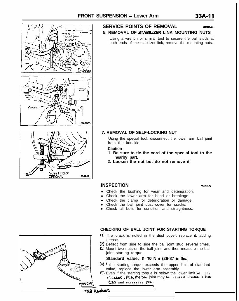
FRONT SUSPENSION - Lower Arm 33A-11
12u00~0TSB tieviSion
L/ &tag and excessive p\ay.
. \
SERVICE POINTS OF REMOVAL M33N6AL
5. REMOVAL OF STABlLlZEk LINK MOUNTING NUTSUsing a wrench or similar tool to secure the ball studs atboth ends of the stabilizer link, remove the mounting nuts.
7. REMOVAL OF SELF-LOCKING NUTUsing the special tool, disconnect the lower arm ball jointfrom the knuckle.
Caution1. Be sure to tie the cord of the special tool to the
nearby part.2. Loosen the nut but do not remove it.
INSPECTION M33NCAE
l Check the bushing for wear and deterioration.l Check the lower arm for bend or breakage.l Check the clamp for deterioration or damage.l Check the ball joint dust cover for cracks.l Check all bolts for condition and straightness.
CHECKING OF BALL JOINT FOR STARTING TORQUE(1) If a crack is noted in the dust cover, replace it, adding
grease.(2) Deflect from side to side the ball joint stud several times.(3) Mount two nuts on the ball joint, and then measure the ball
joint starting torque.
Standard value: 3-10 Nm (26-87 in.lbs.)(4) lf the starting torque exceeds the upper limit of standard
value, replace the lower arm assembly.(5) Even if the starting torque is below the lower limit of the
standard va\ue, the ba\\ joint may be reused unless it has

33/b12 FRONT SUSPENSION - Lower Arm
BALL JOINT DUST COVER REPLACEMENTM~~NEAF
(1) Remove the dust cover.(2) Apply multipurpose grease to the lip and inside of the dust
cover.
(3) Drive in the dust cover with special tool until it is fullyseated.
SERVICE POINTS OF INSTALLATION M33NFAO
5. INSTALLATION OF STABILIZER LINK MOUNTINGNUTSUsing a wrench or similar tool to secure the ball studs atboth ends of the stabilizer link, tighten the mounting nuts.
TSB Revision
1. INSTALLATION OF STABILIZER BAR MOUNTING NUTTighten the nut on the stabilizer bar bolt to the specifieddistance.
Protruding length of stabilizer bar mounting boltStandard value: 16-18 mm (.63-.70 in.)
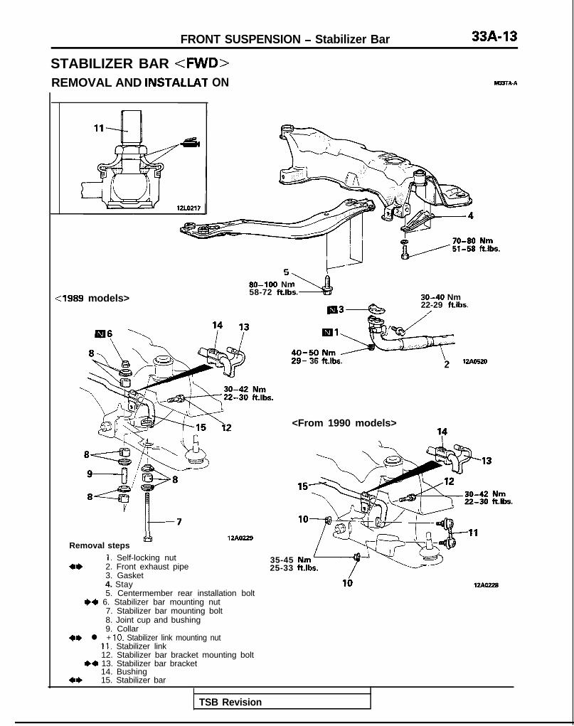
FRONT SUSPENSION - Stabilizer Bar
STABILIZER BAR <FWREMOVAL AND INSTALLAT ON M23TA-A
cl989 models>
P
80-100 Nm%?58-72 ft.lbs. 30-40 Nm
22-29 ftlbs./
Removal steps&!I
1. Self-locking nuta* 2. Front exhaust pipe
3. Gasket
29- 36 ft.lbs. 2
12Ao229
<From 1990 models>
4. Stay5. Centermember rear installation bolt
W 6. Stabilizer bar mounting nut7. Stabilizer bar mounting bolt8. Joint cup and bushing9. Collar
+e l + 10. Stabilizer link mounting nut11. Stabilizer link12. Stabilizer bar bracket mounting bolt
.+ 13. Stabilizer bar bracket14. Bushing
*I) 15. Stabilizer bar
35-4525-33
UAW28
TSB Revision

33A-14 FRONT SUSPENSION - Stabilizer Bar
N-; /fO’) / --Wire ’
SERVICE POINTS OF REMOVAL MalBAFa2. REMOVAL OF FRONT EXHAUST PIPE
After disconnection of the front exhaust pipe assembly andthe exhaust manifold, use wire, etc. to hang the frontexhaust pipe down.
CautionThere is danger of damage to the interior if the flexiblejoint is bent very much. Do not bend it more thanshown in the figure.
10. REMOVAL OF STABILIZER LINK MOUNTING NUTUsing a wrench or similar tool to secure the ball studs atboth ends of the stabilizer link, remove the mounting nuts.
15. REMOVAL OF STABILIZER BAR(1) Pull out both ends of the stabilizer bar to the rear of the
drive shaft.
(2) Move the right stabilizer bar until the end of thestabilizer bar clears the lower arm.
(3) With the end that has cleared the lower arm, pull outthe stabilizer bar diagonally.
TSB Revision

FRONT SUSPENSION - Stabilizer Bar 33A-15
12LO244
rpose
12LO217
lZLO242
INSPECTION M22lCAF
l Check the bushing for wear and deterioration.l Check the stabilizer bar for deterioration or damage.l Check the stabilizer link ball joint dust cover for cracks.l Check all bolts for condition and straightness.
CHECKING OF STABILIZER LINK BALL JOINT FOR START-ING TORQUE(1) If a crack is noted in the dust cover, replace it, adding
(2) !%% side to side the stabilizer link ball joint stud severaltimes.
(3) Mount two nuts on the ball joint, and then measure the balljoint starting torque.
Standard value: 1.7-3.2 Nm (15-28 in.lbs.1(4) If the starting torque exceeds the upper limit of standard
value, replace the stabilizer link.(5) Even if the starting torque is below the lower limit of the
standard value, the ball joint may be reused unless it hasdrag and excessive play.
BALL JOINT DUST COVER REPLACEMENT-(1) Remove the clip ring and the dust cover.
(2) Apply multipurpose grease to the lip and inside of the dustcover.
(3) Use vinyl tape to tape the stabilizer link where shown in theillustration, and then install the dust cover to the stabilizerlink.
(4) Secure the dust cover by the clip link.
TSB Revision

33A-16 FRONT SUSPENSION - Stabilizer Bar
SERVICE POINTS OF INSTALLATION M33TDAK
13. INSTALLATlON OF STABILIZER BAR BRACKET(1) Temporarily tighten the stabilizer bar bracket.(2) Align the bushing end with the marked part of the
stabilizer bar, and then fully tighten the stabilizer barbracket.
10. INSTALLATION OF STABILIZER LINK MOUNTINGNUTUsing a wrench or similar tool to secure the ball studs atboth ends of the stabilizer link, tighten the mounting nuts.
6. INSTALLATION OF STABILIZER BAR MOUNTING NUTTighten the nut on the stabilizer bar bolt to the specifieddistance.
Protruding length of stabilizer bar mounting boltStandard value: 16-18 mm (.63-.70 in.)
TSB Revision

FRONT SUSPENSION - Stabilizer Bar
STABILIZER BAR <AWD-UP TO 1992 MODELS>REMOVAL AND INSTALLATION
Pre-removal and Post-installation Operation@Removal of Front Exhaust Pipe
(Refer to GROUP 15-Exhaust Pipe and Main
\
:M/T> 55-60 Nm40-43 ftlbs.
:A/T> 60-80 Nm44-57 ft.lbs. *
Iemoval steps
::3.4.
::
i:9.
Left memberGussetTransferStabilizer link mounting nut(Refer to P.33A-14, 16.)Stabilizer linkStabilizer bar bracket installationStabilizer bar bracket (Refer to PBushingStabilizer bar
80-100 Nm58-72 ftlbs.
35-4525-33
bolt.33A-16.)
70-80 Nm51-58 ftlbs.
MBJTA-B
-42 Nmiik.30 ft.lbs
TSB Revision

33A-18 FRONT SUSPENSION - Stabilizer Bar
SERVICE POINTS OF REMOVAL9. REMOVAL OF STABILIZER BAR
(1) Disconnect the coupling of the knuckle and lower armat the right side.
(2) Pull out the left side stabilizer bar edge, pulling it outbetween the drive shaft and lower arm.
(3) Pull out the right side stabilizer bar edge, pulling it outfrom below the lower arm.
INSPECTIONRefer to P.33A-15.
hl33lcAI
BALL JOINT DUST COVER REPLACEMENTM~ERefer to P.33A-15.
TSB Revision

339-l
ACTIVE-ELECTRONICCONTROL
SUSPENSIONACTIVE-ECS RELAY ...................................... 141
ACTIVE-ECS SENSOR .................................. 138
AIR COMPRESSOR ....................................... 125
AIR TUBE ....................................................... 133
CONTROL UNIT ............................................ 140
HEIGHT SENSOR .......................................... 135
INDICATOR ASSEMBLY ............................... 140
LATERAL ROD ............................................... 117
LOWER ARM ................................................. 103
REAR SUSPENSION ASSEMBLY ................ 114
RESERVE TANK ............................................ 122
SERVICE ADJUSTMENT PROCEDURES.. ... 86Alarm Light Check ..................................... 87
Checking by On-board Diagnostic .............. 88
Front Wheel Alignment .............................. 86
G sensor Output Voltage Check ............... 96
High-pressure Switch(High-pressure Tank Side)Actuation Pressure Check .......................... 94
Hub End Play Inspection ........................... 86
M33AA-
Low-pressure Switch(Low-pressure Tank Side)Actuation Pressure Check . . . . . . . . . . . . . . . . . . . . . . . . . 95
Normal Vehicle Height Check andAdjustment . . . . . . . . . . . . . . . . . . . . . . . . . . . . . . . . . . . . . . . . . . . . . . . . . . 88
Rolling Diaphragm Check . . . . . . . . . . .._.............. 89
System Checking by Using AlarmLight . . . . . . . . . . . . . . . . . . . . . . . . . . . . . . . . . . . . . . . . . . . . . . . . . . . . . . . . . . . . 87
System Operation Check . . . . . . . . . . . . . . . . . . . . . . . . . . . 90
Wheel Bearing Adjustment . . . . . . . . . . .._........... 87
SHOCK ABSORBER ASSEMBLY . . . . . . . . . . . . . . . . . 110
SOLENOID VALVE AND DRYER . . . . . . . . . . . . . . . . . 127
SPECIAL TOOLS . . . . . . . . . . . . . . . . . . . . . . . . . . . . . . . . . . . . . . . . . . . 7
SPECIFICATIONS . . . . . . . . . . . . . . . . . . . . . . . . . . . . . . . . . . . . . . . . . . . 2General Specifications . . . . . . . . . . . . . . . . . . . . . . . . . . . . . . . . 2
Service Specifications . . . . . . . . . . . . . . . . . . . . . . . . . . . . . . . . . 3
Torque Specifications . . . . . . . . . . . . . . . . . . . . . . . . . . . . . . . . . 4
STABILIZER BAR . . . . . . . . . . . . . . . . . . . . . . . . . . . . . . . . . . . . . . . . . . . 106
STRUT ASSEMBLY . . . . . . . . . . . . . . . . . . . . . . . . . . . . . . . . . . . . . . . 97
TORSION AXLE AND ARMASSEMBLY . . . . . . . . ..*......................................... 119,
TROUBLESHOOTING . . . . . . . . . . . . . . . . . . . . . . . . . . . . . . . . . . . . 10

33B-2 ACTIVE-ELECTRONIC CONTROL SUSPENSION - Specifications
SPECIFICATIONS M33CA-
GENERAL SPECIFICATIONS
Items Front suspension Rear suspension
Suspension system McPherson strut with coil spring 3-link, torsion axle with coiland compression rod type spring type
Coil spring
Front <Up to 1990 models> <Up to 1990 mode ls>Wire dia. x upper end O.D. L.H. side L.H. sidex lower end O.D. 13.0 x 173 x 193 x 391 9.5 x 119.5 x 119.5 x 428x free length mm (in.) (51 x 6.81 x 7.59 x 15.39) (.37 x 4.70 x 4.70 x 16.85)[Coil spring identification color1 [Light green x II [Light green x 11
R.H. side R.H. side13.0 x 173 x 193 x 379 9.5 x 119.5 x 119.5 x 412;;lexx6$1 x 7.59 x 14.92) (51 x 4.70 x 4.70 x 16.22)
U [Light green x 21Rear <From 1990.5 models> <From 1990.5 models>
Wire dia. x O.D. x free length L.H. side L.H. sidemm (in.) 13.5 x 173.5 x 192.5 X 317 10.1 x 122.1 x 381.5
[Coil spring identification color] (.53 x 6.83 x 7.58 x 12.48) (.40 x 4.81 x 15.02)[Light green x 11 [Light green x 21R.H. side R.H. side13.5 x 173.5 x 192.5 x 309 10.1 x 122.1 x. 370(53 x 6.83 x 7.58 x 12.17) (.40 x 4.81 x 14.57)[Blue x 21 [Light green x 11
Spring constant N/mm (Ibs./in.) 12.9 (72.24) <Up to 1990 models> 9.4 (52.64) <Up to 1990 models>19.4 (108.63) 13.5 (75.60)<From 1990.5 models> <From 1990.5 models>
Shock absorber
Type Hydraulic, cylindrical double Hydraulic, cylindrical doubleacting type acting type<up to 1990 < F r o m 1 9 9 0 . 5 < u p t o 1990 < F r o m 1 9 9 0 . 5
models> models> models> models>Max. length mm (in.) 489.5 (19.27) 489.5 (19.27) 491 (19.33) 491 (19.33)Min. length mm (in.) 339.5 (13.37) 339.5 (13.37) 341 (13.43) 341 (13.43)Stroke mm (in.) 150 (5.91) 150 (5.91) 150 (5.91) 150 (5.91)
Damping force [at 0.3 m/set.(.9 ft./sec.)l
Expansion N (Ibs.)HARD 1 , 6 5 0 ( 3 6 4 ) 2 , 2 5 0 (496) 1 , 4 5 0 ( 3 2 0 ) 1 , 7 0 0 ( 3 7 5 )MEDIUM 1 , 1 0 0 ( 2 4 3 ) 1 , 1 0 0 ( 2 4 3 ) 850 (187) 850 (187)SOFT 300 (66) 300 (66) 270 (60) 270 (60)
Contraction N (Ibs.)HARD 570 (126) 570 (126) 500 (1 IO) 540 (119)MEDIUM 400 (88) 400 (88) 350 (77) 350 (77)SOFT 220 (49) 220 (49) 200 (44) 200 (44)
1 TSB Revision I

ACTIVE-ELECTRONIC CONTROL SUSPENSION - Specifications 33B-3
SERVICE SPECIFICATIONS M33cE-
Items Specifications
Standard value
Toe-in mm (in.) O&3 (O-t.12)
Camber 20’ t 30’
Caster 2” t 30’
Rear height sensor rod Installation location dimension mm (in.) 314-316 (12.36-12.44)
Wheel arch height to center of wheel mm (in.)
Front 381-391 (15.0-15.4)
Rear 357-367 (14.1-14.4)
High-pressure switch
Pressure switch shut off pressure kPa (psi) 900 (128) or more
Pressure switch operatton pressure kPa (psi) 710-810 (101-115)
Low-pressure switch
Return pump activation pressure kPa (psi) 100-180 (14.2-25.6)
Return pump stop pressure kPa (psi) 50 (7.1) or less
Setting of T.J. boot length mm (in.) 80+3 (3.152.12)
Lower arm ball joint starting torque Nm (inlbs.) 3-l 0 (26-87)
Stabilizer link ball joint starting torque Nm (in.lbs.) 1.7-3.2 (15-28)
Crossmember bushings projection mm (in.)
Bushing A 7.2-10.2 (.28-.40)
Bushing B 6.5-9.5 (.26-.37)
Air compressor relief pressure kPa (psi) l,OOO-1,300 (142-185)
TSB Revision

33B-4 ACTIVE-ELECTRONIC CONTROL SUSPENSION - Specifications
TORQUE SPECIFICATIONS
Items
Strut assembly
Front strut upper mounting nutAir tube to strutFront height sensor rod mounting bolt
Front strut lower mounting nut
Actuator bracket to strut
Strut insulator installation nut
Lower arm
Lower arm ball joint to knuckle
Lower arm clamp to crossmember (nut)
Lower arm clamp to crossmember (bolt)
Lower arm to crossmember
Stabilizer link mounting nutFront height sensor rod mounting bolt
Stabilizer bar
Center member rear installation bolt
Stay to crossmember
Front exhaust pipe to exhaust manifold
<FWD (Non-Turbo)>
<AWD (Non-Turbo)>
Front exhaust pipe to exhaust fitting (Turbo>
Front exhaust pipe clamp
Front exhaust pipe to hanger
Stabilizer link mounting nutStabilizer bracket mounting bolt
N m ftlbs.
40-50 29-368-10 6-717-26 12-19go-105 16-7640-60 29-4380-100 58-72
60-72 43-5235-47 25-3480-100 58-7295-120 69-8735-45 25-3317-26 12-18
80-100 58-7270-80 51-58
40-50 29-36
30-40 22-2940-60 29-4330-40 22-29IO-15 7-1135-45 25-3330-42 22-30
TSB Revision

ACTIVE-ELECTRONIC CONTROL SUSPENSION - Specifications 33B-5
Items N m ft.lbs.
Shock absorber assembly
Air tube to shock absorber
Shock absorber upper mounting nut
Shock absorber lower mounting nut
Rear height sensor mounting bolt
Actuator bracket mounting nut
Piston rod tightening nut
Rear suspension assemblyBrake tube bracket mounting bolt
Rear brake assembly mounting bolt
Dust shield mounting bolt
Flange nut
8-10 6 - 7
40-50 29-3680-100 58-7217-26 12-19
45-55 33-4045-55 33-40
Rear speed sensor mounting bolt <Vehicles with *A.B.S.>
Air tube to shock absorber
Shock absorber upper mounting nut
Lateral rod mounting nut (body side)
Trailing arm mounting bolt
Rear height sensor rod mounting bolt
-ateral rod
17~26 12-1950-60 36-439 - 1 4 7-10200-260 144-188
9 - 1 4 7-10
8-10 6 - 7
40-50 29-36
80-100 58-72100-120 72-87
17-26 12-19
Lateral rod mounting nut (body side)
Lateral rod mounting nut (axle beam side)
Rear height sensor rod mounting bolt
rorsion axle and arm assembly
Brake tube bracket mounting bolt
Rear brake assembly mounting bolt
Dust shield mounting bolt
Flange nut
80-100100-120
17-26
58-7272-87
12-19
Rear speed sensor mounting bolt <Vehicles with *A.B.S.>
Shock absorber lower mounting nut
Rear height sensor rod mounting bolt
Lateral rod mounting nut (axle beam side)
Trailing arm mounting bolt
deserve tank
17-26
50-60
3-14
200-260
3-14
30- 100
17-26
100-120
100-120
12-19
36-43
7-10
144-188
7-10
58-72
12-19
72-8772-87
Tank holder to bodyAir tube to reserve tank
7-10
s-7
TSB Revision
NOTE“A.B.S.: Anti-lock braking system
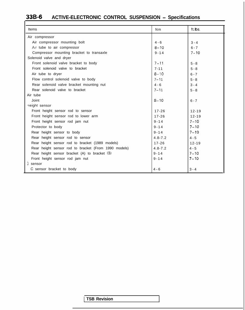
33B-6 ACTIVE-ELECTRONIC CONTROL SUSPENSION - Specifications
Items
Air compressor
Air compressor mounting bolt
Arr tube to air compressor
Compressor mounting bracket to transaxle
Solenoid valve and dryer
Front solenoid valve bracket to body
Front solenoid valve to bracket
Air tube to dryer
Flow control solenoid valve to body
Rear solenoid valve bracket mounting nut
Rear solenoid valve to bracket
Air tube
Jointieight sensor
Front height sensor rod to sensor
Front height sensor rod to lower arm
Front height sensor rod jam nut
Protector to body
Rear height sensor to body
Rear height sensor rod to sensor
Rear height sensor rod to bracket (1989 models)
Rear height sensor rod to bracket (From 1990 models)
Rear height sensor bracket (A) to bracket (B)
Front height sensor rod jam nut; sensor
G sensor bracket to body
N m ftlbs.
4 - 6 3 - 48-10 6 - 79 - 1 4 7-10
7-l 1 5 - 8
7-11 5 - 8
8-10 6 - 7
7-l 1 5 - 8
4 - 6 3 - 47-l 1 5 - 8
8-10 6 - 7
17-26 12-19
17-26 12-19
9 - 1 4 7-10
9 - 1 4 7-10
9 - 1 4 7-10
4.8-7.2 4 - 5
17-26 12-194.8-7.2 4 - 59 - 1 4 7-109 - 1 4 7-10
4 - 6 3 - 4
1 TSB Revision

ACTIVE-ELECTRONIC CONTROL SUSPENSION - Special Tools 336-7
SPECIAL TOOLS M33DA-A
Number Name I Use
djustment Procedures
For the number, refer to
tr pressure gauge
OPTIONAL. AVAILA
OPTIONAL: AVAILABLE FROM O.T.C.
TSB Revision

33B-8 ACTIVE-ELECTRONIC CONTROL SUSPENSION - Special Tools
Tool Number Name I Use
(MB991237, MB9912381Compression of the rear coil spring(MB991237, MB9912391
TSB Revision
33B-9NOTES

33B-10 ACTIVE-ELECTRONIC CONTROL SUSPENSION - Troubleshooting
Ifagnosticervice -ata 0utDut
Diagnostic servicedata switching inputSimulated vehicle-speed inputGround
1 Cl nno,
TROUBLESHOOTING hw3EAAtmTROUBLESHOOTING POINTSREGARDING THE DIAGNOSTIC FUNCTIONFor the ACTIVE-Electronic Control Suspension (ACTIVE-ECS),the electronic control unit has been provided with the followingfunctions in order to make checking of the electronic-controlsystem easier.(1) Diagnostic trouble code output(2) Service data output(3) Actuator test
Note that all of the above can be checked by using thescan tool.Also note that the diagnostic trouble codes can be checkedby using the voltmeter.
NOTEFor information concerning testing procedures by using thescan tool, refer to P.33B-11.
CHECKING THE ELECTRONIC CONTROL UNIT (ECU) SIG-NAL CIRCUIT(1) The circuit tester used must be highly sensitive and highly
precise, with internal batteries of 3V or more.(2) Care should be taken about the outflow of current from the
tester when checking for continuity of terminals and thepower-supply circuitry for the photo sensors (front and rearheight sensors and steering angle velocity sensor). Use ofthe x10 range is preferable, but the xl range can be usedif the indicator does not move sufficiently to the right.
(3) The resistance values noted as standard values are simplyreference values. If there is continuity, the part can beconsidered to be OK.
(4) If a power relay or solenoid valve is to be activated, firstcheck carefully to be sure that there is no damaged ordisconnected wiring or a short-circuit. Also do not makeunnecessary connections so that wiring contacts the body.Take particular care to be sure that the wiring of batterypower-supply connections is secure.
TSB Revision

ACTIVE-ELECTRONIC CONTROL SUSPENSION - Troubleshooting 33B-11
CHECKING BY USING THE SCAN TOOL1. DIAGNOSTIC TROUBLE CODE OUTPUTTROUBLESHOOTING CHART
Diagnostictrouble Malfunction Vehicle conditioncode No.
Probable cause Action
0 Normal - - -
Damaged or disconnected Alarm light illuminates; 0 Improper installation Troubleshoofwiring or short-circuit of G among attitude-control of G sensor.sensor input circuit, or G
ing hintsmodes, only rolling control
sensor malfunction.l G sensor internal wiring classified by
stops. damaged or disconnected. circuit [I]
“11 (Others operate normally.) l Damaged or disconnectedwiring or short-circuit of Gsensor circurt.
l Connector of G sensorcircuit disconnected.
0 Malfunction of ECU.
With the ignition key at the The charging warning lightON position and the vehicle illuminates, and,
0 Insufficient generator “L” Troubleshoot
speed at 40 km/h (25 mph) furthermore, the systemterminal output voltage ing hints
or higher, the output does not function when the(malfunction of the classified bycharging system). circuit [2]
voltage of the generator ‘I” vehicle is stopped (vehicle 0 Harness short-circuitterminal is approximately speed of 3 km/h (2 mph) or5V or lower lower).
between the generator“L” terminal and the ECU.
“12 NOTE l ECU malfunction.The alarm light does notilluminate, and,furthermore, there is nodetection of harnessdamage or disconnectionbetween the generator “L”terminal and the ECU.
The low-pressure switch is The alarm light illuminates, l Low-pressure switch is Troubleshootnot switched OFF even and only the attitude-control fused.though the attitude-control
ing hintsfunction stops. (Other l Damaged or disconnected classified by
function is performed 30 functions are normal.) circuit 131
13times. The return pump is
wiring, or short-circuit, ofthe low-pressure switch
activated frequently. circuit harness.0 The connector of the
low-pressure switchcircuit is disconnected.
l Air leakage from thelow-pressure tank(including tubing).
l ECU malfunction.
“21
Damaged or disconnected The alarm light illuminates, l Steering angular-velocity Troubleshoot-wiring of the steering and the attitude-control sensor malfunction.angular-velocity sensor
ing hintsfunction stops. The
input circuit, or al Damaged or disconnected classified by
damping force is held to wiring of the steering circuit 191malfunction of the steenng MEDIUM, and the vehicleangular-velocity sensor.
angular-velocity sensorheight is held to NORMAL circuit harness.
l Disconnection of theconnector of the steeringangular-velocity sensorcircuit.
l ECU malfunction.
TSB Revision

33B-12 ACTIVE-ELECTRONIC CONTROL SUSPENSION - Troubleshooting
Diagnostictrouble Malfunction Vehicle condition Probable cause Actioncode No.
An abnormal signal (a signal The alarm light illuminates, l Front height sensor Troubleshootunlike any normal srgnal and the attitude-control malfunction. ing hintssuch as an error code, etc.) function and the vehicle- l Damaged or disconnected classified byis input from the front height control function are wiring, or a short-circuit, of circuit [IO]height sensor; or, a stopped. The damping the front height sensor
“22 malfunction of the force is held to MEDIUM. circuit.vehicle-height NOTE l Disconnection of thediscrimination circuit withinthe ECU.
Note that 32 seconds are connector of the front
required to determine that height sensor circuit.
there is a malfunction. l ECU malfunction.
“23
An abnormal signal is input The alarm light illuminates, l Rear height sensor Troubleshootfrom the rear height sensor; and the attitude-control malfunction. ing hintsor, a malfunction of the function and the vehicle l Damaged or disconnected classified byvehicle-height height control function are wiring, or a short-circuit, of circuit [I 11discrimination circuit within stopped. The damping the rear height sensorthe ECU. force is held to MEDIUM circuit.
NOTE l Disconnection of the
Note that 32 seconds are connector of the rear
required to determine that height sensor circuit.
there is a malfunction. l ECU malfunction
There is damaged or The alarm light illuminates, l Malfunction of the Troubleshoot-disconnected wiring, or a and the attitude-control vehicle-speed sensor ing hintsshort-circuit, of the function stops. The (damaged or disconnected classified byvehicle-speed sensor Input damping force IS held to wiring, or a short-circuit). circuit [ 121circuit. MEDIUM, and the vehicle l Damaged or disconnected
“24(The throttle is open 30% or height is held to NORMAL. wiring, or a short-circuit, ofmore, and the output of the the vehicle-speed sensorgenerator “L” terminal is circuit.HIGH level, but even so the l The connector of theinput of the vehicle-speed vehicle-speed sensorpulses is not 30*’ seconds circuit is disconnected.or longer.) l ECU malfunction.
There is damaged or The attitude-control l Rear pressure sensor Troubleshoot.disconnected wiring of function and the vehicle- malfunction. ing hints
/ the rear pressure height control function are l Damaged or disconnected classified bysensor input circuit. stopped. wiring, or a short-circuit, of circuit [I31(The rear internal The damping force is held the rear pressure sensor
25pressure is abnormally to MEDIUM. circuit.high.) NOTE l Disconnection of the
This code is also output connector of the rear
during driving in an pressure sensor circuit.
overloaded condition. l ECU malfunction
NOTE+1: 1989 models
From 1990 models: 60
TSB Revision

ACTIVE-ELECTRONIC CONTROL SUSPENSION - Troubleshooting 33B-13
Diagnostictroublezode No.
Malfunction Vehicle condition Probable cause Action
Damaged or disconnected The alarm light illuminates, l All connectors of the Troubleshootwiring of the damping force and the attitude-control damping-force switching ing hintsswitching actuator (step function and the damping- actuator (step motor classified bymotor type) or of the force control function are type) and the actuator circuit [ 171actuator circuit, or a stopped. circuit are disconnected.malfunction of an output The vehicle height is held to l Damaged or disconnected
41 transistor within the ECU. NORMAL. wiring, or a short-circuit, ofthe damping-forceswitching actuator (stepmotor type) and theharness of the ECU part ofthe actuator circutt.
l ECU malfunction.
There is damaged or The alarm light illuminates, l The solenoid valve power Troubleshoot-disconnected wiring, or a and the attitude-controlshort-circuit, of the solenoid
source relay contacts are ing hintsfunction and the vehicle- fused. classified by
valve power source relay height control function arecircuit.
l Damaged or disconnected circuit (71stopped. wiring of the solenoidThe damping force is held valve power source relayto MEDIUM. coil.
42 l Damaged or disconnectedwiring, or a short-circuit, ofthe solenoid valve powersource relay circuit.
l Disconnection of theconnector of the solenoidvalve power source relaycircuit.
l ECU malfunction.
Damaged or disconnected The alarm light illuminates, l Damaged or disconnected Troubleshoot-wiring, or a short-circuit, of and the attitude-control wiring, or a short-circuit, of ing hintsthe compressor relay function and the vehicle- the compressor relay coil. classified bycircuit, or a malfunction of height control function are l Damaged or disconnected circuit [I81an output transistor within stopped.
43 the ECU.wiring, or a short-circuit, of
The damping force is held the compressor relayto MEDIUM. circuit harness.
l Disconnection of thecompressor relay circuitconnector.
l ECU malfunction.
Damaged or disconnected The alarm light illuminates, l Damaged or disconnected Troubleshoot-wiring, or a short-circuit, of and the attitude-control wiring, or a short-circuit, of ing hintsthe return pump relay function and the vehicle- the return pump relay coil. classified bycircuit, or a malfunction of height control function are l Damaged or disconnected circuit [I91an output transistor within stopped.the ECU. The damping force is held
wrring, or a short-circuit, of44 the return pump relay
to MEDIUM. circuit harness.l Disconnection of the
return pump relay circuitconnector.
l ECU malfunction.
TSB Revision

33B-14 ACTIVE-ELECTRONIC CONTROL SUSPENSION - Troubleshooting
Diagnostictrouble Malfunction Vehicle condition Probable cause Actioncode No.
Damaged or disconnected The alarm light illuminates, l Damaged or disconnect- Troubleshootwiring, or a short-circuit, of and the attitude-control ed wiring, or a short ing hintsthe exhaust valve actuation function and the vehicle- -circuit, of the exhaust classified bycircuit (for vehicle-height height control function are valve coil (for vehicle circuit [20]adjustment), or a stopped. -height adjustment).malfunction of an output The damping force is held l Damaged or disconnect-transistor within the ECU. to MEDIUM. ed wiring, or a short
-circuit, of the exhaust45 valve actuation circuit (for
vehicle-heightadjustment).
0 Disconnection of theconnector of the exhaustvalve actuation circuit (forvehicle-heightadjustment).
l ECU malfunction.
46
Damaged or disconnected The alarm light illuminates, l Damaged or disconnected Troubleshoot-wiring, or a short-circuit, of and the attitude-control wiring, or a short -circuit, of ing hintsthe flow-rate switchover function and the vehicle- the flow-rate switchover classified byvalve actuation circuit, or a height control function are valve coil. circuit [21]malfunction of an output stopped. l Damaged or disconnectedtransistor within the ECU. The damping force is held wiring, or a short-circuit, of
to MEDIUM. the flow-rate switchovervalve circuit harness.
l Disconnection of theflow-rate switchovervalve circuit connector.
l ECU malfunction.
47
Damaged or disconnected The alarm light illuminates, l Damaged or disconnect- Troubleshoot-wiring of the front or rear and the attitude-control ed wiring of the front or ing hintsexhaust valve actuation function and the vehicle- rear exhaust valve coil (for classified bycircuit (for active control), or height control function are active control). circuit [22]a malfunction of an output stopped. 0 Damaged or disconnect-transistor within the ECU. The damping force is held ed wiring of the front or
to MEDIUM. rear exhaust valve circuit(for active control).
l Disconnection of theconnector of the front orrear exhaust valve circuit(for active control).
l ECU malfunction.
51
Damaged or disconnected The alarm light illuminates, 0 Damaged or disconnected Troubleshoot-wiring of the front or rear and the attitude-control wiring of the front or rear ing hintsair-supply valve actuation function and the vehicle- air-supply valve coil. classified bycircuit, or a malfunction of height control function are l Damaged or disconnected circuit [23],an output transistor within stopped. wiring of the front or rear 1241the ECU. The damping force is held air-supply valve circuit
to MEDIUM. harness.l Disconnection of the
connector of the front orrear air-supply valve circuit.
l ECU malfunction.
TSB Revision

ACTIVE-ELECTRONIC CONTROL SUSPENSION - Troubleshootina 33B-15
Diagnostictroublecode No
Malfunction Vehicle condition Probable cause Action
52
Damaged or disconnected The alarm light illuminates, l Damaged or disconnected Troubleshoowiring of the left front or and the attitude-control wiring of the left front or ing hintsright front valve actuation function and the vehicle- right front valve coil. classified bycircuit, or a malfunction of height control function are l Damaged or disconnected circuit [25]an output transistor within stopped. wiring of the left front orthe ECU. The damping force is held right front valve circuit
to MEDIUM. harness.l Disconnection of the
connector of the left frontor right front valve circuit.
l ECU malfunction.
53
Damaged or disconnected The alarm light illuminates,wiring of the left rear or right
l Damaged or disconnected Troubleshootand the attitude-control wiring of the left rear or
rear valve actuation circuit,ing hints
function and, the vehicle- right rear valve coil. classified byor a malfunction of an output height control function aretransistor within the ECU.
l Damaged or disconnected circuit [26]stopped. wiring of the left rear orThe damping force is held right rear valve circuitto MEDIUM. harness.
l Disconnection of theconnector of the left rearor right rear valve circuit.
l ECU malfunction.
54
55
Even though three mrnutes The alarm light illuminates, 0 Overloaded condition. Refer toor more have passed for the and the attitude-control l Improper adjustment of Malfunctionvehicle-height adjustments function and the vehicle- the front or rearof the front and the rear, and
Symptomsheight control function are vehicle-height sensor. Chart [A] on
the pressure within the stopped. l Air-pressure line is P.33B-17.high-pressure tank is The damping force is heldsufficient (the high-pressure
clogged.to MEDIUM. l Malfunction of the front
switch is OFF), the strut unit or the rear shockvehicle-height adjustments absorber unit air spring.are not completed. l ECU malfunction.
Even though three minutes The alarm light illuminates, l Compressor malfunction. Refer toor more have passed for the and the attitude-control Damaged or Malfunctionvehicle-height adjustments function and the vehicle- disconnected wiring of Symptomsof the front and the rear, and height control function are the harness between the Chart LB1 onwith insufficient pressure stopped. compressor relay and the P.33B-17.withtn the high-pressure tank The damping force is held compressor.(the high-pressure switch is to MEDIUM. Malfunction of the air iON), the vehicle-height compression of theadjustments are not compressor.completed, or the l Air leakage from thecompressor has operatedcontinuously for four
high-pressure tank
minutes or longer.(non-airtight connectionwith the low-pressuretank).
l High-pressure switch isfused.
The return pump is Control functions are not Air leakage within the front Replace thecontinuously activated stopped (alarm lamp does (left or right) or rear (left or front or rear(repeatedly starts and stops not illuminate). right) valve. solenoid
56 erght times), even though valve.neither the attitude-control
function nor thevehicle-height controlfunction has been initiated.
TSB Revision

33B-16 ACTIVE-ELECTRONIC CONTROL SUSPENSION - Troubleshooting
NOT’=(1)(2)
13)
(4)
(5)
‘T‘he alarm light does not illuminate for an abnormal condition (code No.12) of the generator output voltage (#,.terminal) or for air leakage (code No.56) within the front or rear valves.For malfunctions represented by a code number with the * symbol, if the malfunction is of a temporary nature (suchas improper contact of a connector, etc.), the warning lamp’s illumination will stop when the malfunction stops, andthe function will return to normal.When the alarm light is illuminated (i.e. when a malfunction has been detected), the control mode cannot beswitched (with the exception of a certain few malfunctions) when the control switch is pressed,.If two or more malfunctions occur at the same time, the corresponding code numbers will be displayed In order fromthe lowest one.Cancellation of malfunction codes after checking and repair (from 1990 models)Method 1: Connect a scan tool and cancel as described below.
1
w
Select “4 SPECIAL TEST” of the scan tool’s function-select menu.2 Next, select item No.5 “ERASE DIAG.“.3 Press the YES key when “ERASE DIAG. DODE?” is displayed.4 lnout I D NBR. “ 3 7 ” .
85 Press the CLEAR key when “FINISHED ERASING DIAG. CODE” is displayed.6 Disconnect the scan tool.
Method 2: Disconnect the ground cable from the battery’s negative terminal for 10 seconds or longer, and thenreconnect.If this method is used, note that data entered to the memory of the radio and the clock will be erased,so readjustment is necessary after the work is completed.
TSB Revision 1
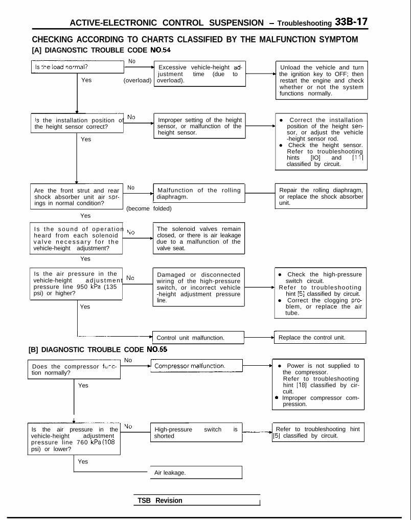
ACTIVE-ELECTRONIC CONTROL SUSPENSION - Troubleshooting 33B-17
CHECKING ACCORDING TO CHARTS CLASSIFIED BY THE MALFUNCTION SYMPTOM[A] DIAGNOSTIC TROUBLE CODE NO.54
No
Yes
b Excessive vehicle-height ad-justment
(overload) overload).time (due to -
Unload the vehicle and turn* the ignition key to OFF; then
restart the engine and checkwhether or not the systemfunctions normally.
Is the installation position of Nothe height sensor correct?
Yes
Improper setting of the heightc sensor, or malfunction of the
height sensor.
l Correct the installationc position of the height sen-
sor, or adjust the vehicle-height sensor rod.
l Check the height sensor.Refer to troubleshootinghints [IO] and [ll]classified by circuit.
Are the front strut and rear No Malfunction of the rollingshock absorber unit air spr- * diaphragm.
Repair the rolling diaphragm,or replace the shock absorber
ings in normal condition? L unit.(become folded)
Yes
Is t he sound o f ope ra t i on No The solenoid valves remainheard from each solenoid closed, or there is air leakagev a l v e n e c e s s a r y f o r t h e ’ due to a malfunction of thevehicle-height adjustment? valve seat.
Yes
Is the air pressure in thevehicle-height ad jus tmen t Nopressure line 950 kPa (135psi) or higher?
IYes
Damaged or disconnectedwiring of the high-pressureswitch, or incorrect vehicle-height adjustment pressureline.
l Check the high-pressureswitch circuit.
* Refer to t roubleshoot inghint [5] classified by circuit.
l Correct the clogging pro-blem, or replace the airtube.
Control unit malfunction.
[B] DIAGNOSTIC TROUBLE CODE NO.55- No
Does the compressor func-tion normally?
Yes
Replace the control unit.
c l Power is not supplied tothe compressor.Refer to troubleshootinghint [18] classified by cir-cuit.
0 Improper compressor com-pression.
Is the air pressure in the Novehicle-height adjustmentpressure line 760 kPa (108psi) or lower?
High-pressure switch is Refer to troubleshooting hintshorted ____* [5] classified by circuit.
Yes
Air leakage.
TSB Revision I
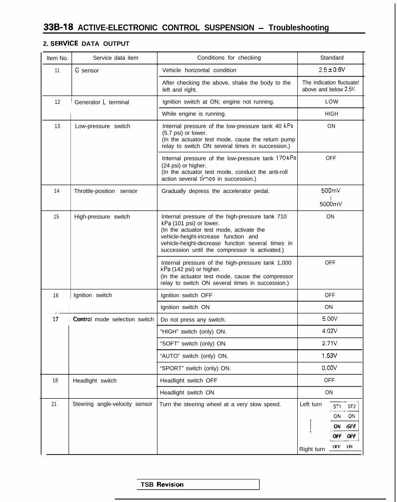
33B-18 ACTIVE-ELECTRONIC CONTROL SUSPENSION - Troubleshooting
2. SERlflCE DATA OUTPUT
Item No. Service data item Conditions for checking Standard
11 G sensor Vehicle horizontal condition 2.520.6V
After checking the above, shake the body to the The indication fluctuate!left and right. above and below 2.5V.
12 / Generator L terminal Ignition switch at ON; engine not running. LOW
While engine is running. HIGH
13 Low-pressure switch Internal pressure of the low-pressure tank 40 kPa ON(5.7 psi) or lower.(In the actuator test mode, cause the return pumprelay to switch ON several times in succession.)
Internal pressure of the low-pressure tank 170 kPa(24 psi) or higher.(In the actuator test mode, conduct the anti-rollaction several times in succession.)
OFF
14 Throttle-position sensor Gradually depress the accelerator pedal. 500mVI
5000mV
15 High-pressure switch Internal pressure of the high-pressure tank 710 ONkPa (101 psi) or lower.(In the actuator test mode, activate thevehicle-height-increase function andvehicle-height-decrease function several times insuccession until the compressor is activated.)
Internal pressure of the high-pressure tank 1,000kPa (142 psi) or higher.
OFF
(In the actuator test mode, cause the compressorrelay to switch ON several times in succession.)
16 Ignition switch Ignition switch OFF OFF
I
Ignition switch ON ON
17 Control mode selection switch Do not press any switch. 5.oov
“HIGH” switch (only) ON. 4.02V
“SOFT” switch (only) ON. 2.71V
“AUTO” switch (only) ON. 1.53V
“SPORT” switch (only) ON. o.oov
18 Headlight switch Headlight switch OFF OFF
Headlight switch ON ON
21 Steering angle-velocity sensor Turn the steering wheel at a very slow speed. Left turn ST1 ST2
__I
’ E3
ON OFF
OFF OFF
Right turn OFF ON j
TSB Revisio.n I

ACTIVE-ELECTRONIC CONTROL SUSPENSION - Troubleshootina 33B-19r
Item No. I Service data item Conditions for checking
Switch ON the “HIGH” switch to set to the highvehicle height.
Standard
H 1011
Switch ON the “AUTO” switch to set to the normavehicle height.
N 1111
Simulate a vehicle speed of 130 km/h (81 mph) toset to the low vehicle height.
I LO011
-cSwitch ON the “HIGH switch to set to the highvehicle height.
HI011
Switch ON the “AUTO” switch to set to the normavehicle height.
N 1111
Simulate a vehicle speed of 130 km/h (81 mph) toset to the low vehicle height.
LOO11
Actual driving The speedometerindication and the valueindicated by the scantool must agree.
In the actuator test mode, activate the The indicated value shouldvehicle-height-increase function several times in Increase to the range of 0order to increase the internal pressure of the rear to 5V each time the vehiclestruts. height is increased.
-
8i When the vehicle is at the normal height, withi
E Ithe vehicle in the unladen condition.
0.9ov
Front vehicle-height sensor
23 ’/ Rear vehicle-height sensor-4
c24 Vehicle-speed sensor
t25 Rear pressure sensor
Fa,
%When the vehicle is at the high height.
[r i When the vehicle is at the low height.
1.6OV
I 0.86VT
26 Stop light switch Brake pedal not depressed. I OFF I
Brake pedal depressed.I
ON Ic
32 Back-up light switch
33 T Door switches
I
Move the shift lever to “reverse” -E-----l-Return the shift lever to “neutral”
Close all doors.I
OFF/
Open each door one by one. I ON
3. ACTUATOR TEST
Before conducting the actuator test, check to be sure that the vehicle attitude is level.
Item No. Actuator test description Standard
01 ~
!lActivation of the SOFTd a m p i n g - s w i t c h i n g i
I Check, one wheel at a time, to be sure that the damping
02 actuator t’ becomes higher step by step when the check is conducted in
AUTO-SOFT ~ the sequence 01 to 02 to 03 to 04.
03 MEDIUM
04 HARD
05 Compressor relay: ON The compressor should be activated at the moment of thesetting to item No. 05, and then should stop three seconds later.
Return pump relay: ON ~ The return pump should be activated at the moment of thesetting to item No. 06, and then should stop three seconds later.
06
1 TSB Revision
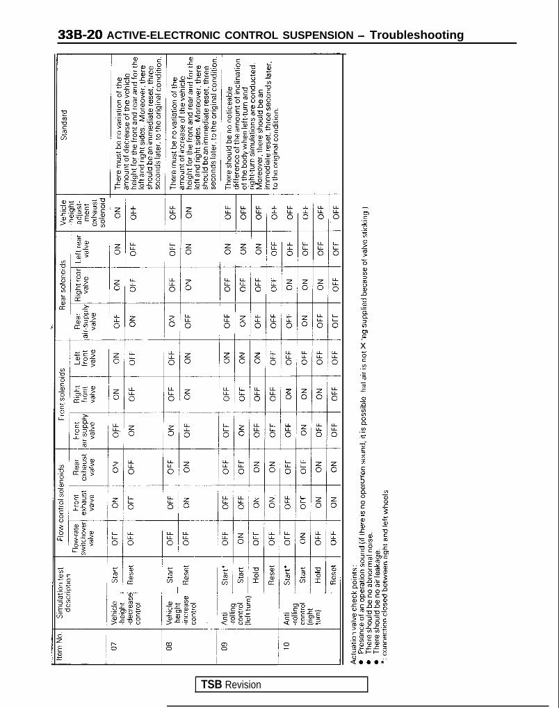
33B-20 ACTIVE-ELECTRONIC CONTROL SUSPENSION - Troubleshooting
IFr.o5;L”9
75%2xa-0siz2P.-xE.”.km5ra,G2B
.I?.C22Ins.-5G0”2
.EF
TSB Revision

ACTIVE-ELECTRONIC CONTROL SUSPENSION - Troubleshooting 33B-21
TROUBLESHOOTING HINTS CLASSIFIED ACCORDING TO CIRCUITSContents
No.
PI G-sensor circuit
Item paw
P.33B-22/ I
PI Generator “L” terminal circuit P.33B-24
[31 Low-pressure switch circuit P.33B-26
I41 Throttle-position sensor circuit P.33B-28
[51 High-pressure switch circuit P.338-30
) [6] / ACTIVE-ECS power-supply circuit
I PI I ACTIVE-ECS indicators circuit
1 P.33B-32 1
1 P.33B-34 1
/ P.33B-38 1I L81 I Headlight switch circuit
1 [9] / Steering angular-velocity sensor circuit / P.33B-40 1
[lOI /I
Front-height sensor circuit ( P:33B-42I
PII Rear-height sensor circuit
[I21 Vehicle-speed sensor circuit
[13] Rear-pressure sensor circuit
[I41 Stop light switch circuit
[I51 Back-up switch circuit
P.33B-44
P.33B46
P.33B-48
P.338-50
P.33B-52
TSB Revision I
[If31 Door switch circuit P.33B-53
[17] Damping force switching actuator drive circuit P.338-54
1181 Compressor drive circuit P.33B-561
WI II
Return pump drive circuit / P.33B-58
ml /I
Exhaust valve actuation circuit (for vehicle-height adjustment) / P.33B-60
I PII / Flow-rate switchover valve actuation circuit / P.33B-62 1
I WI / Front/rear exhaust valve activation circuit 1 P.33B-64 I
( 1231 1 Front air-supply valve activation circuit 1 P.33B-66 1
1241 Rear air-supply valve activation circuit P.33B-68
[25] Left front/right front valve activation circuit P.33B-70
[=I Left rear/right rear valve activation circuit P.33B-72
[271 ACTIVE-ECS-related diagnostic/service data output circuit P.33B-74
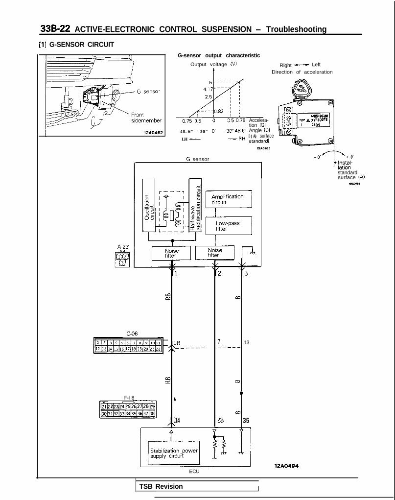
33B-22 ACTIVE-ELECTRONIC CONTROL SUSPENSION - Troubleshooting
[l] G-SENSOR CIRCUIT
1 12A0462
A-23
G-sensor output characteristic
Output voltage (VI Right- Left
IDirection of acceleration
-48.6" -30" 0’ 3P48.6"
LH - -RH
Accelera-tion (G)Angle (D)[(A) surfacestandard]
G sensor
C-06
-1
F-l 8
[jiiEB%]
.8_-----
14
ECU
M
7 13_----
M
0
m
78 351
standardsurface (A)-
12A0494
TSB Revision I

ACTIVE-ELECTRONIC CONTROL SUSPENSION - Troubleshooting 33B-23Operation
The G-sensor detects the amount of accelerationthat is generated (to the left or right) when the vehi-
response to acceleration, and these changes are
cle body turns. Applying the principle of the dif-taken out as changes of voltage. Within the coil,
ferential transformer, the magnetic field changessilicon oil is enclosed in order to suppress the vibra-tion of the movable iron core. Note that the G-sen-
when the movable iron core within the coil moves in
Diagnostic
sor is a special sensor for control of rolling.
When signals that are otherwise virtually in-conceivable are input due to damaged or discon-
a heavy-line circuit, the alarm light illuminates andcontrol is as described in the table below.
netted wiring or a short-circuit or similar problem of
Diagnostic No. Attitude control Damplng forcecontrol
Vehicle-heightcontrol
Switch acceptance
HIGH SPORT AUTO SOFT
I 11 Rolling controlonly stops Normal operation Normal operation Accept
Service data indication
Code No Indication Standard value Display
11 G-sensor output voltage 2.5V when vehicle is horizontal 1 1 : G SNSR: 2.5V
ECU terminal voltages (when connector is connected)
TerminalNo Condition
Terminalvoltage I
I I
34 Power supply for sensor When the ECU is activated 7.3vI
28 G-sensor output signal
35 Sensor circuit earth
When stopped i
When wiring is damaged or disconnected
Constantly
2.5V
o v
o v
TSB Revision
-.
Checking the G-sensor circuit (with the connector disconnected)
Terminal ConnectIon destination or MeasurementNo measured part Tester connection Check condition Standard
28 G-sensor output Resistance 28-2 Constantly Continuity
34 G-sensor power source Resistance 34-1 Constantly Continuity
Troubleshooting hints
Malfunctionmode Malfunction probable cause MatfunctIon Note
Silicon oil leakage Because the sillcon oil for suppresslon of l Rolling control occurs frequently -vlbratlons of the G-sensor movable iron core isleaktng due to a collision. the sensitivity isoversensitive.
Damaged ordisconnectedearth line
The ground line is damaged or disconnected. l -Malfunction is not detected because the
There are times of a feeling of
ground line is grounded to the G sensor’s bodyincompatibility of the rolling control
l
itself, however, noise is easily picked up.Rolling control occurs suddenly; an erroroccurs

33B-24 ACTIVE-ELECTRONIC CONTROL SUSPENSION - Troubleshooting
[2] GENERATOR ‘I” TERMINAL CIRCUIT
rminal
12AO385
Battery ECUI t I 1
Main1OOA
fusible 0hk
*33 >
&CAI
2
I
I\ //\ /
Relaybox
I
(1989 models)
I 1T G E N E R A T O R %
NOTE* mark is applicable for 1990, 1991, 1992, 1993 models.
B-16
C-23
[Isl:j(From 1990 models)
12AQ496
1 TSB Revision

ACTIVE-ELECTRONIC CONTROL SUSPENSION - Troubleshooting 33B-25
Operation
The generator ‘I-” terminal signal is used to deter- pressor operation, and is because activation of themine whether or not the engine is operating.This is in order to reduce the frequency of com-
system is possible while the engine is operating, orat a vehicle speed of 3 km/h (2 mph) or higher.
Diagnostic
When the generator “L” terminal is LOW level (as aresult of a short-circuit of the heavy-line circuit ordue to an abnormal condition of the generator) eventhough the vehicle speed is 40 km/h (25 mph), con-
trol is as described in the table below. Note,however, that there is no detection if there isdamaged or disconnected wiring of the harness,and the alarm light does not illuminate.
Diagnostic No. Attitude control Damping forcecontrol
Vehrcle-heightcontrol HIGH
Switch acceptance
SPORT AUTO SOFT
I 12 ‘“L” terminal “L” logic
““L” terminal “L” logic: As a result of system operation conditions, the system is not activated at a vehicle speed of less than 3 km/h (2mph). When the vehicle speed becomes 3 km/h (2 mph) or higher all functions are normal. (Refer to the explanation of the opera-tron.)
Service data indication
1 CodeNo. / Indication Display
I 12 The output voltage level of the 12: ALT. LTERMI. HIGH/LOWgenerator “L” terminal is indicated.
TSB Revision
ECU terminal voltage (when connector is connected)
TerminalNo. Signal Condition
Termrnalvoltage
52 Generator ‘I” terminal signal When engine stalls
When engine is operating
When harness wiring is damaged or disconnected
0.5-3v
13-15v
5v
Checking the generator “L” terminal circuit (with the connector disconnected)
Term ina l Connec t i on des t i na t i on o r Me a s u r e m e n t
No. measured part Tester connectron Check condrtion Standard
52 Generator Voltage 52 ground Ignition switch ON 2-5V
While engine is operating B+
B+: Battery positive voltage

33B-26 ACTIVE-ELECTRONIC CONTROL SUSPENSION - Troubleshooting
[3] LOW-PRESSURE SWITCH CIRCUIT
Low-pressureswitch
/ L>w-pressure switchHigh-pressure switch
12AO172
o:t- -__-__-_--70 (10) 140 (20)
Pressure kPa (psi)
12AO461
fw Low-pressure tankpressure detectlon
Low-pressureswitch
5
A-38
12440492
TSB Revision 1

ACTIVE-ELECTRONIC CONTROL SUSPENSION - Troubleshooting 33B-27Operation
The low-pressure switch is switched ON and OFFby the pressure in the low-pressure tank, and as a
becomes 140 kPa (20 psi) or higher, it is switched *
result the ECU functions to control the activationOFF, and as a result the ECU sends the drive signal
and stop of the return pump.to the return pump. It is switched ON at a pressure
When the pressure in the low-pressure tankof 70 kPa (10 psi) or lower, and the return pumpstops two seconds later.
Diagnostic
If there is a short-circuit, or damaged or discon-netted wiring, of the heavy-line circuit, or if thelow-pressure switch becomes shorted, and thelow-pressure switch is as a result always ON, (the
trol)“, and control is as described in the table below.
alarm light illuminates during active attitude con-
*: Information in ( ) is applicable to 1989 models.Not applicable to 1990 models.
Diagnostic No. Attitude control Damping force Vehicle-height Switch acceptance
control control HIGH SPORT AUTO SOFT
13 Control stop Normal operation Normal operation Accept
Service data indication
Code No. lndicatron Display
13 Indicates ON or OFF condition of 13: LOW PRESS. SW. ON/OFFthe low-pressure switch
ECU terminal voltages (when connector is connected)
TSB Revision
/ Te;;,nal 1Condition
Terminalvoltage
Low-pressure tank pressuresignal
When the low-pressure switch is ON ov
When the low-pressure switch is OFF 5v
Checking the low-pressure switch circuit [with the connector disconnected).
I No.Terminal Connection destination Measurement! or measured partTester connection Check condition Standard
38 Low-pressure switch Resistance 38-36 Low-pressure tank internal Continuitypressure 70 kPa (10 psi) orbelow
Low-pressure tank internal Nopressure 140 kPa (20 psi) or continuityhigher.

33B-28 ACTIVE-ELECTRONIC CONTROL SUSPENSION - Troubleshooting
[4] THROll-LE-POSITION SENSOR CIRCUIT
(1989 models)
(From 1990 models)
A-54
+@7jg
(From 1990 models)
Throttle-position sensor output characteristic
5
2 4
%1 393 2a50 1
0’ ’ ’I I I I I II
10 20 30 40 50 60 70 80 82
Fully Throttle opening FUIIYc l o s e d (degrees) open
7FUO75
ECM
A-54
(1989models)
Throttle-positionsensor
NOTE* mark is applicable for 1990, 1991, 1992, 1993 models.
12A0432
TSB Revision

ACTIVE-ELECTRONIC CONTROL SUSPENSION - Troubleshooting 33B-29
Operation
The throttle-position sensor is the same for theECM of engine and transaxle. The ECM estimatesthe acceleration status of the vehicle according tothe sensor output.
Service data indication
) Code No 1 lndrcatron Display
I l4 1 The output voltage of the throttle 14 : TPS 549mV-postron sensor IS indicated. I
ECU terminal voltages (when connector is connected)
TerminalNo. Condition
Terminalvoltage
511 ! Throttle-posrtlon sensor signal During idle o-1v
When fully open 5v
/ When there is damaged or disconnected wiring I ov I
Checking the throttle-position sensor circuit (with the connector disconnected)
Terminal Connection destrnation or MeasurementNo measured part Tester connection Check condition Standard
51 Throttle-positronsensor
Resistance 51 -ground Change according to the throttle 0.5-5 k0opening should be smooth andwithin the standard value rangeshown at the right.
TSB Revision

33B-30 ACTIVE-ELECTRONIC CONTROL SUSPENSION - Troubleshooting
[51 HIGH-PRESSURE SWITCH CIRCUIT
Shield plate
/v (right)
/Lo&pressure switch
High-pressure switch
High-pressureswitcho~~---~---~~-~l
760 (108) 950 (135)Pressure kPa (psi)
72AO172
FCI I
I-Detection ofhigh-pressuretank pressure
1/\
0mA-ln
6
A-38
High-pressureswitch
12 A0493
TSB Revision

ACTIVE-ELECTRONIC CONTROL SUSPENSION - Troubleshooting 33B-31
Operation
The high-pressure switch is switched ON and OFFby the pressure in the high-pressure tank, and as aresult the ECU functions to control the activationand stop of the compressor.When the pressure in the high-pressure tank be-comes 760 kPa (108 psi) or lower, the high-pressureswitch is switched ON, and as a result the ECUsends the drive signal to the compressor.
Conversely, when the pressure of the high-pressuretank becomes 950 kPa (135 psi) or higher, thehigh-pressure switch is switched OFF, and thecompressor is stopped two seconds thereafter.Note, however, that the compressor is not ac-tivated, even if the high-pressure switch is switchedON, if the return pump is in operation. Note alsothat there is no diagnostic function for thehigh-pressure switch.
Service data indication
Code No lndlcation DisDlav
15 Indicates the ON/OFF status of thehigh-pressure switch.
15: HIGH PRESS. SW. ON/OFFI
ECU terminal voltages (with connector connected)
TerminalNo. Signal Condition T e r m i n a l
voltaae I
59 High-pressure tank pressure signal When high-pressure switch is ON (low pressure) o v
When high-pressure switch is OFF (high pressure) 5v
Checking the high-pressure switch circuit (with the connector disconnected)
Term ina l Connec t i on des t i na t i on o r Me a s u r e m e n t
No measured part Tester connection , Check condition Standard
59 High-pressure switch Reststance 59-36 High-pressure tank internalpressure 760 kPa (108 psi) orlower
Continuity
High-pressure tank internalpressure 950 kPa (135 psi) orhigher
Nocontinurty
Troubleshooting hints
Malfunctlonmode Malfunction probable cause Malfunction Note
TSB Revision
Harness wlrlngdamage ordlsconnectlon
Harness wiring damage or disconnection, orImproper switch contact
Compressor doesn’t operate. -
Harnessshort-crrcuit
Air leakage.
Harness short-circuit, or switch short-circuit,
O-ring worn or damaged.
Compressor operates without stopplng. DiagnosticNo.55output.
Rolling control feehng of Incompatibility. very -freauent oaeration of compressor.

33B-32 ACTIVE-ELECTRONIC CONTROL SUSPENSION - Troubleshooting
[6] ACTIVE-ECS POWER SOURCE CIRCUIT
Relay box
‘
Solenoid :valve .
A-06X
*‘:
b OFFJ Iv! 1
EyllAy 1 Junction block
4‘BI
F-17j$----hJ _ _ _ _ _ 15--- ~4&L---v----.6
iI
1 2 3 4 5
m67891F-18
b;
/ b i-i
Valve actwation 3m,nute* OFFcontrol circuit A^,^., .i”..%*
ECU
Sfabdization WwWL guse circuit---------J I
L---T 122042l
Solenoid valve power source
TSB Revision

ACTIVE-ELECTRONIC CONTROL SUSPENSION - Troubleshooting 33B-33
Operation
When the ignition is switched ON, the ECS powerrelay is also switched ON, and power is supplied tothe system. At the same time, the ECU switchesON the solenoid valve power relay, and power issupplied to the solenoid valve activation circuit. As aresult, system operation is possible.
Diagnostic
When problems such as damage or disconnectionof the heavy-line circuit, or fusing of the contacts ofthe solenoid valve power relay, etc. occur, the alarm
When the ignition switch is switched OFF after driv-ing, the three-minute OFF delay timer makesvehicle-height adjustment (down only) possible for aperiod of three minutes, thus preventing the vehicleheight from increasing while passengers get out ofthe vehicle, etc.
light illuminates, and control is as described in thetable below.
Diagnostic No.
42
Attitude control
Rolling controlonlv stoos.
Damping force Vehicle-height Switch acceptance
control control / HIGH SPORT AUTO SOFT
Held at MEDIUM Rolling control Not acceptonlv stoos
Service data indication
CodeNo / Indication Display
16 Indicates ON/OFF status of theiqnition switch. 16: IGNITION SW. ON/OFF
ECU terminal voltage (when connector is connected)
valve power relay output
26 Solenoid valve power relay drivesignal
When solenoid valve power relay is ON
When solenoid valve power relay is OFF B+
B+: Battery positive voltage
Checking the ACTIVE-ECS power source circuit (with the connector disconnected)
Terminal Connection destination or Measurement ’No. measured part Tester connection Check condition
5 Ignition switch i Voltage 5-ground Ignition switch OFF
Ignition switchO F F - O N
8 Solenoid valve power Voltage 8-ground Terminal 26 open.relay
Terminal 26 grounded
Standard
o v
O+B+
ov
O-B+
10 ECU back-up powersource
i Voltage 1 O-ground
TSB Revision
/ Constantly B+
B+: Batten/ positive voltage
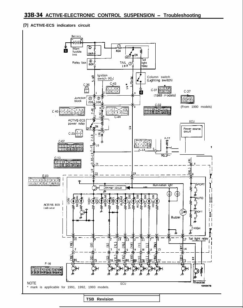
33B-34 ACTIVE-ELECTRONIC CONTROL SUSPENSION - Troubleshooting
[7] ACTIVE-ECS indicators circuit
Battery
Column switch
-------
c n-2 1
f
ACTIVE-ECS 1indicator
I
(From 1990 models)
ECUI I
F-17
Power source,circuif
/
EEzQ15~JgJ 1 ,2-LR
i 181lllumlnatlon light SPOK
1 1 c
1’I’III 1III IiI’I I/II’I 1
NOTEI-
* mark is applicable for 1991, 1992, 1993 models.ECU I
TSB Revision

ACTIVE-ELECTRONIC CONTROL SUSPENSION - Troubleshooting 33B-35
Service data indication
Code No Indication Standard value
17 ECU input voltage indications when When switches are openSPORT, AUTO, SOFT, HIGH
5V
switches are pressed. When SPORT switch is ON OV
When AUTO switch is ON 1.53v
When SOFT switch is ON 2.71V
When HIGH swrtch is ON 4.02V
ACTIVE-ECS indicators check chart
1. Checking the power source c i rcui t
Disconnect the battery terminals, and, after erasure of theECU mode memory, turn the ignition key to the ON position.
1
Indication example
17: MANUAL CNG. SW4.03v
The sound of the damplng force switching actuators (step lNo The ACTIVE-ECS power relay doesn’t function
motors), installed at the front struts and at the rear shock --+ l Disconnected or damaged wiring of the fusible link, the
absorbers, will be heard. fuse and/or the harness between the battery and the AC-TIVE-ECS power relay contacts
Yes
When terminal 15 of the ACTIVE-ECS indicator is grounded, yesthe “SOFT” damping force characteristic indicator and the - l Disconnected or damaged wiring of the ground line 15 of
“NORM” vehicle-height indicator will illuminate. the ACTIVE-ECS indicator.
No
Approximately 12V is measured when the voltage between Noground and terminal 20 of the indicator and the ACTIVE-ECS --+
l Disconnected or damaged wiring between the AC-
is measured.TIVE-ECS power relay and ECS Indicator terminal 20.
I Yes
TSB Revision
-.
ACTIVE-ECS Indicator power source circuit OK Proceed tochecking of the individual ACTIVE-ECS lndlcators

33B-36 ACTIVE-ELECTRONIC CONTROL SUSPENSION - Troubleshooting
2. Checking the individual ACTIVE-ECS indicators
After disconnecting the control unit’s connector, turn thenition kev to ON
1All items shown in the tables on the next page are satisfied ~~ 8 Poor or improper contact of the ACTIVE-ECS indicatorwhen each terminal of the ACTIVE-ECS indicator’s connector F and the connector terminal.is grounded and the resistance is then measured. l ACTIVE-ECS malfunction
Yes
All items shown in the tables on the next page are satisfiedwhen each terminal of the wiring harness connector discon- No l Damaged or disconnected wiring or large contact
netted from the control unit is grounded and the resistance __* resistance, between the ACTIVE-ECS indicator and the
is then measured. connector of the control unit.
YesI
l Poor or improper contact of the control unit and the con-c nectar t e r m i n a l .
0 Control unit malfunction.
TSB Revision

ACTIVE-ELECTRONIC CONTROL SUSPENSION - Troubleshooting 33B-37r
ACTIVE-ECS indicator Control unit wiring
connector terminal No harness connector Normalterminal No
All termrnals are notI
- The’SOFT” damprng force characteristic indicator and the “NORM”earthed vehicle-height indicator illuminate. I
1 - 1 The illumination light illuminates when battery voltage is applied to terminali 19.
2 76 In addition to the “SOFT” and “NORM” indicators, the “MEDIUM” dampingi force characteristic Indicator also illuminates.
I 3 / 88 In addition to the “SOFT” and “NORM” indicators, the “SOFT”*’ switchindicator also illuminates. I
Ll 90 Connect a circuit tester andmeasure the resistance whenthe control mode andvehicle-height select switchesare pressed
1 b;h is pressed.1 E;i;yi;;a 1
SOFT 1 Approx. 890 fZ 1
/ HIGH 1 Approx. 3090 121
5 77 In addition to the “SOFT” and “NORM” Indicators. the “HIGH” switchindicator also illuminates
6*2 - In addition to the “SOFT” and “NORM” Indicators, the alarm lightilluminates.
7 87 In addition to the “SOFT” and “NORM” indicators, the “SOFT” swatchindrcator also illuminates.
9 75 The “NORM” vehicle-height rndicator illumination stops, and the “HIGH”vehicle-height indicator illuminates; the “SOFT” damping force characteristicindicator remains illuminated.
10 85 The “NORM” vehicle-height Indicator illumination stops, and the “LOW”vehicle-height indicator illuminates; the “SOFT” damping force characteristicindicator remains illuminated.
11 78 In addition to the “SOFT” and “NORM” indicators, the “AUTO” switchindicator also illuminates.
13 80 In addition to the “SOFT” and “NORM” indicators, the alarm lightilluminates.
14 86 In addrtion to the “SOFT” and “NORM” indicators, the “MEDIUM” and“HARD” damping force characteristic indicators also illuminate
15 - The “SOFT” damping force characterrstic indicator and the vehicle-herghtindicator illuminate.
17
19
71
-
The buzzer sounds.
The “SOFT” and “NORM” indicators become slightly dimmer when terminal20 is connected to terminal 19
NOTE*l: 1989 models
“SPORT” mode is applicable for 1990, 1991, 1992, 1993 modelsl *: Applicable to 1989 models only.
TSB Revision

33B-38 ACTIVE-ELECTRONIC CONTROL SUSPENSION - Troubleshooting
[8] HEADLIGHT SWITCH CIRCUIT
Battery1 I
4 Ignition
T switch (ACC)
c-43 l-
(From 1991 models)
(From 1990 models)
A-01X
Head-light
ECU
-L
II
;
50>
c
;-ii -I
Kin.>r(
3OA
/\7'6
1
I
To column switch TL
‘89F-l 6
I ITo meter (upper beamindicator light)
8A
headlight
pjjimmjC-23 (From 1990 models)
12*0642
NOTE* mark and chain line indicate 1991, 1992, 1993 models.
TSB Revision

ACTIVE-ELECTRONIC CONTROL SUSPENSION - Troubleshooting 33B-39
Operation
The ACTIVE-ECS system functions, in order toimprove the “air drag” characteristic, to adjust the
During the nighttime, however, in order to prevent
vehicle height to the LOW setting at the front enddeviation of the headlight beams from the required
only during the daytime when the vehicle speeddirectional path, the vehicle height is adjusted to the
reaches 90 km/h (56 mph) or higher and continuesLOW setting for both the front end and the rear end
at that speed for a period of ten seconds or longer.when signals from the headlight relay are input.
Service data indication
Code No. lndlcation Display
18 Indicates the ON or OFF status of 18: HEADLAMP SW. ON/OFFthe headlight switch.
ECU terminal voltages (when connector is connected) /
TerminalNo.
Slgnal Condition Terminalvoltage
89 Headlight switch signal When headlight switch is ON
When headlight switch is OFF
B+
o v
When there is damaged or disconnected wiring 5vJ
B+: Battery positive voltage
Headlight switch circuit (with the connector disconnected)
TSB Revision
TeKJna’89
Connection destination Measurement Tester connection Check condition Standardor measured Dart
Headlight relay Voltage 89-ground ph&the headlight switch ov
rt$z; the headlight switch B+
~.A. -II___B+: Battery posrrrve voltage

33B-40 ACTIVE-ELECTRONIC CONTROL SUSPENSION - Troubleshooting
[9] STEERING ANGULAR-VELOCITY SENSOR CIRCUIT
\ k=3 -2Steering angular-veloclty sensor- m0439
Photo-Interruptor B/
12A0208
F-19 ECU
heel anoular- 1
F-06
pT$q
pFlz$EJc-07
Ad 2 7
I!tii --
ii -I7 a
C-68
1 2 3
P4 r _ v n
w jTT~jR-$+j 1
Steering angular-velocity sensor-1
12AO411
TSB Revision
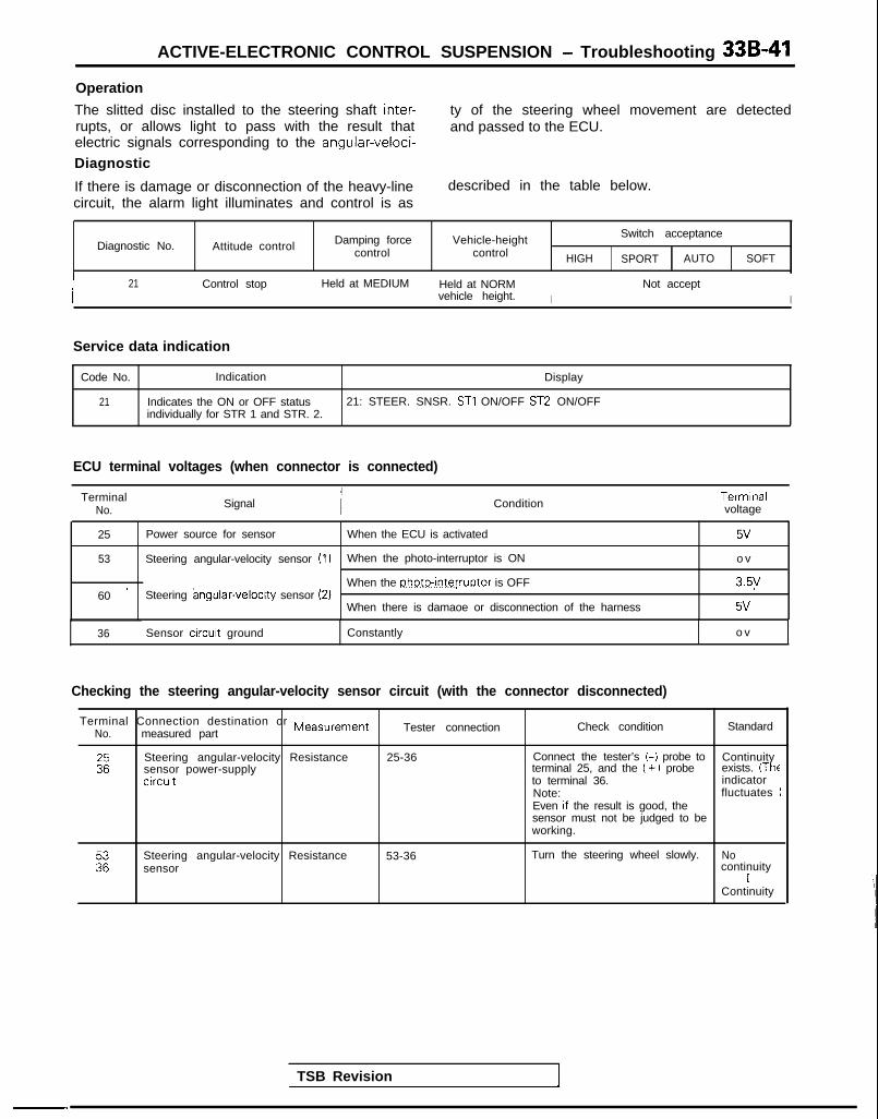
ACTIVE-ELECTRONIC CONTROL SUSPENSION - Troubleshooting 33B-41
Operation
The slitted disc installed to the steering shaft inter-rupts, or allows light to pass with the result thatelectric signals corresponding to the angular-veloci-
Diagnostic
If there is damage or disconnection of the heavy-linecircuit, the alarm light illuminates and control is as
ty of the steering wheel movement are detectedand passed to the ECU.
described in the table below.
Diagnostic No. Attitude control Damping forcecontrol
Vehicle-heightcontrol HIGH
Switch acceptance
SPORT AUTO SOFT
I 21 Control stop Held at MEDIUM Held at NORMI
Not acceptvehicle height. I
Service data indication
Code No. Indication Display
21 Indicates the ON or OFF status 21: STEER. SNSR. ST1 ON/OFF ST2 ON/OFFindividually for STR 1 and STR. 2.
ECU terminal voltages (when connector is connected)
TerminalNo. Signal Condition
Termrnalvoltage
25 Power source for sensor When the ECU is activated 5v
53 Steering angular-velocity sensor (1) When the photo-interruptor is ON o v
60 ’ Steering angular-velocrty sensor (2)When the photo-interruptor is OFF 3.5y
When there is damaoe or disconnection of the harness 5v
-“.
TSB Revision
36 Sensor circuit ground Constantly o v
Checking the steering angular-velocity sensor circuit (with the connector disconnected)
Terminal Connection destination or MeasurementNo. measured part Tester connection Check condition Standard
Steering angular-velocity Resistancesensor power-supplycircut
25-36 Connect the tester’s t-i probe to Continuityterminal 25, and the (+ ) probe exists. (Theto terminal 36. indicatorNote: fluctuatesEven If the result is good, thesensor must not be judged to beworking.
Steering angular-velocity Resistancesensor
53-36 Turn the steering wheel slowly. Nocontinuity
IContinuity

33B-42 ACTIVE-ELECTRONIC CONTROL SUSPENSION - Troubleshooting
IO] FRONT-HEIGHT SENSOR CIRCUIT
.ever
Seysor
,..e
Relationship between N (normal vehicle height) and othervehicle-height levels
High
1
Normal
50 (1.97)
40 (1.57)
30 (1.18)
20 1.791
10 C.39)
0
t EH (highest)._--
HH (higher than HIGH)
H (HIGH vehicle height)
NH (higher than NORM)
N (NORMAL vehicle height)
EL (lowest)
A-27
[Unit: mm (in.11
Front-helghf sensor
Operation
The front-height sensor detects (by detecting the sistors, and the slits in the disc thus interrupt, or letrelative position of the body and the front axle) theaction movements (bouncing, nose diving, etc.),
pass, the light beams between the light-emittingdiodes and the photo-transistors.By employing the data gathered in this way, the sen-sor can detect the vehicle height as any one of thenine level classifications.
and the vehicle height, of the front of the vehicle,The rotating disc plate rotates in the area betweenfour pairs of light-emitting diodes and photo-tran-
TSB Revision

ACTIVE-ELECTRONIC CONTROL SUSPENSION - Troubleshooting 33B-43
Diagnostic
When a signal (error code) indicating an abnormalcondition (resulting from damage or disconnectionof the heavy-line circuit, or a malfunction of a
photo-transistor, etc.) is input, the alarm light illu-minates and control is as described in the tablebelow.
Diagnostic No. Attitude control Damping force Vehic le-height ~ Switch acceptance
control control HIGH SPORT 1 AUTO SOFT
22 Control stop j Held at MEDIUM Control stop Not accept
Service data indication
Code No lndrcation Indication example
22 Current vehicle-height level (ERROR When 22:N 1111when there is a malfunction) normallndrcates the ON or OFF status of
lndtcates the vehicle-height -Status of each photo-interruptorlevel. 1: ON,O: OFF
each photointerruptor.If mal- 22; ERRORfunction
0010Indicates that an error code is L Status of each photo-interruptorbeina output. l:ON.O:OFF
ECU terminal voltages (when connector is connected)
TermrnalNo Condition Terminal
voltaae
25
54,5556.57
Power source for sensor
Front vehicle-herght signal
When the ECU is activated 5V
When the photo-rnterruptors are ON o v
When the photo-interruptors are OFF 5V
1 36 / Sensor circuit ground I Constantlv I o v IChecking the front-height sensor circuit (with the connector disconnected)
Terminal Connectron destination cNo measured part
:zFront-height sensorpower-supply crrcuit
225657
Front-height sensor Resistance
br Measurement
Resistance 25-36
Tester connection
54-3655-3656-3657-36
t
Troubleshooting hints (mechanical malfunctions)
Check condition Standard
Contact the tester’s (-1 probe to Contrnuityterminal 25, and the ( + ) probe to (Theterminal 36. rndrcatorNote fluctuates)Even if the result is good here,the sensor must not be judged tcbe certainly good.
Contact the tester’s (-1 probe toterminal 25, and the (+ 1 probe toterminal 36, and check to be surethat there is continuity, leave theconnections as they are.Connect the tester’s (-1 probe toeach terminal of the wiringharness connector, and the (+ Jprobe to terminal 36Separate the lever (of the heightsensor) from the rod, and slowlynave the lever up and down.
NoContinurty
IContinuity
Malfunctionmode Malfunction probable cause Malfunction Note
Improper Because of the improper adjustment of the -adjustment of thefront-height sensor
front-height sensor rod, a signal notl When the engine is stopped and left as it is,
corresponding to the actual vehicle height isthe height of onlythe front end decreases to
rod being sent to the ECUlower than the NORMAL vehicle height
l With the engrne running, the height of the frontend IS lower than the NORMAL vehicle height
l With the engine running (AUTO mode andNORMALvehicle hetght). the height of the frontend becomes higher than the NORMAL helght)
1 TSB Revision I

33B-44 ACTIVE-ELECTRONIC CONTROL SUSPENSION - Troubleshooting
[ll] REAR-HEIGHT SENSOR CIRCUIT
1989 models
F-18
-1
F-l 9
pjimlq
piTgs%q
c-07
D-27
G-05
High
I
Normal
50 (1.97)4.
.:::.:.:_
~-.^::::::::“.“::i
+E
jr;:::::::::
:_:
40 (1.57)
30 (1.18)
Low I[Unit: mm (in.11
ECU
1 Rear vehicle-height/ fisjnmy3tp I (I
Rear-height sensor 12AQ414
- LL (lower than LOW)
HH (higher than HIGH)
H (HIGH vehicle height)
NH (higher than NORM)
N (NORMAL vehicle height)
NL (lower than NORM)
L (LOW vehicle height)
12AO182
Operation
The rear-height sensor detects (by detecting therelative position of the body and the rear axle) theaction movements (bouncing, pitching, etc.), andthe vehicle height, of the rear of the vehicle. Therotating disc plate rotates in the area between threepairs of light-emitting diodes and photo-transistors,
and the slits in the disc thus interrupt, or let pass.the light beams between the light-emitting diodesand the photo-transistors. By employing the datagathered in this way, the sensor can detect the vehi-cle height as any one of the seven level classifica-tions.
TSB Revision

ACTIVE-ELECTRONIC CONTROL SUSPENSION - Troubleshootina 33B-45
Diagnostic
When a signal (error code) indicating an abnormalcondition (resulting from damage or disconnectionof the heavy-line circuit, or a malfunction of a
photo-transistor, etc.) is input, the alarm light illu-minates and control is as described in the tablebelow.
Diagnostic No. Attitude control
23 Control stop
Service data indication
Damping forcecontrol
Held at MEDIUM
V e h i c l e - h e i g h t Switch acceptance
control HIGH SPORT AUTO SOFT
Control stop Not accept
Code No Indication Indication example
23 Current vehicle-height level (ERROR When 23;N 1111when there is a malfunction) normalIndicates the ON or OFF status of
Indicates the vehicle-heightlevel
L Status of each photo-interruptor
each photo-interruptor.1: ON, 0. OFF
If mal- 23; ERROR 0010function Indicates that an error code IS
being output.L Status of each photointerruptor
1: ON, 0. OFF
ECU terminal voltages (when connector is connected)
TerminalNo. Signal Condition
25 Power source for sensor When the ECU is activated
61.6263,64
Front vehicle-height sIgnal When the photo-mterruptors are ON
When the photo-interruptors are OFF
36 Sensor circuit ground Constantly
Terminalvoltage
5v
o v
5V
o v
Checking the rear-height sensor circuit (with the connector disconnected)
rTerm ina l Connec t i on des t i na t i on o r Me a s u r e m e n t
No measured part Tester connection Check condition Standard
Rear-herght sensorpower-supply circuit
Resistance 25-36 Contact the tester’s (-) probe to Continuityterminal 25. and the (+) probe to (Theterminal 36 indrcatorNote fluctuates)Even if the result is good here,the sensor must not be judged tobe certainly good.
61
Es
Rear-height sensor A Resrstance 61-36 No
F
Contact the tester’s (-) probe to62-36 terminal 25, and the ( +) probe to Continuity63-36 terminal 36, and check to be sure I
that there is continuity; leave the Continuityconnections as they are.Connect the tester’s (-1 probe toeach termrnal of the wiringharness connector, and the ( +)probe to terminal 36.Separate the lever (of the heightsensor) from the rod, and slowlymove the lever up and down
64
- _. .
D Resistance 64-ground Constantly Continuity
1 roubleshooting hints (mechanical malfunctions)
Malfunctionmode Malfunction probable cause Malfunction Note
Improper Because of the improper adjustment of the l When the engine is stopped and left as it IS, -adjustment of therear-height sensor
rear-height sensor rod, a signal not the height of only the rear end decreases to
rodcorrespondrng to the actual vehicle height ISberng sent to the ECU
lower than the NORMAL vehicle height.l With the engrne running, the height of the rear
end is lower than the NORMAL vehicle heightl With the engine running (AUTO mode and
NORMAL vehicle herght). the height of the rearend becomes higher than the NORMAL height).
TSB Revision

33B-46 ACTIVE-ELECTRONIC CONTROL SUSPENSION - Troubleshooting
1121 VEHICLE-SPEED SENSOR CIRCUIT
1BAOOSl
r__---- 1I ElectronicI controlledII
!i%& ECU ,
8VI
I~:!~1L- - - - - - J
ECU
I
F-l 9
C-Oi
9
;
11M
6
Meterassembly
C-52
12AO416
TSB Revision I

ACTIVE-ELECTRONIC CONTROL SUSPENSION - Troubleshooting 33B-47
Operation
The vehicle-speed sensor is a reed switch type with pulse signals being sent four times for each rotation ofthe transaxle output gear.
Diagnostic
If there is damage or disconnection of the heavy-line the alarm light illuminates and control is as de-circuit, or a malfunction of the vehicle-speed sensor, scribed in the table below.
Diagnostic No.
24
Attitude control Damping force Vehicle-height Switch acceptance
control control HIGH SPORT AUTO SOFT
Control stop Held at MEDIUM Held at NORMAL Not accept
Service data indication
Code No lndrcation Display
24 Indicates the vehicle speed Input to 24: SPEED SNSR. 0 km/hthe ECU (including the simulatedvehicle speed)
ECU terminal voltages (when connector is connected)
I TerNmo_na’ Condition Terminalvoltage
I I
58 /
I
Vehicle-speed signal 1 When the vehicle-speed sensor reed switch is ON ovI I I I
*When the vehicle-speed sensor reed switch is OFF 8V
TSB Revision
*In order to supply the EPS pull-up power (8V)
Checking the vehicle-speed sensor circuit (with the connector disconnected)
Termrnal Connectron d e s t i n a t i o n o r Me a s u r e m e n t
No measured part Tester connection Check condition Standard
58 Vehrcle-speed sensor Resistance 58-ground With the battery’s (-1 termrnal Continuitydisconnected, move the vehicle Iback and forth. No
continuity
Troubleshooting hints
In actual urban driving, it is not so likely that the sensor fails.., ^_^.tnrottle IS kept 3U% or more open for more than 30seconds. Therefore, the conditions have been
This takes into account that the vehicle speed sen-
somewhat stricter to prevent unnecessary applica-sor is shared by many systems such as EPS, Auto-
tion of the fall safe function due to the racing of thecruise control, etc. and that the failure of the sensor
engine when stopped. However, the vehicle maycan also be detected from the state of these sys-terns.
run uncontrolled for some distance when the speed
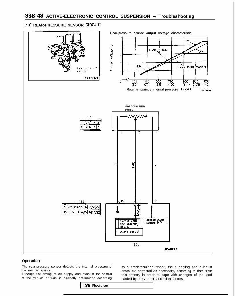
33B-48 ACTIVE-ELECTRONIC CONTROL SUSPENSION - Troubleshooting
[13] REAR-PRESSURE SENSOR CIRCUI
12AC371
Rear-pressure sensor output voltage characteristic5
I Afl
F-27
F-l 8
-1
2 4
b2 39zia 2
% ,
45' I I I
0 400 500 6 7(57) (71) Kz; (I?$ f?lt) f%, :l?!!
Rear air springs internal pressure kPa (psi) 12AO460
Rear-pressuresensor
I
8
t
25
ECU
VAc-
il
Sensor power
1source 5 V
12*02*1
OperationThe rear-pressure sensor detects the internal pressure of to a predetermined “map”, the supplying and exhaustthe rear air springs. times are corrected as necessary, according to data fromAlthough the timing of air supply and exhaust for control this sensor, in order to cope with changes of the loadof the vehicle attitude is basically determined according carried by the vehicle and other factors.
TSB Revision

ACTIVE-ELECTRONIC CONTROL SUSPENSION - Troubleshooting 33B-49
Diagnostic
If, because of damage or disconnection of the heavy-line below. Note, however, this diagnostic signal is given ifcircuit, or a malfunction of the rear-pressure sensor, etc., there is an overload.a htgher than normal value of the internal pressure of the l : 1989 modelsair springs is indicated continuously, the alarm light The alarm light does not illuminate for 1990, 1991,illuminates*, and control is as described in the table 1992, 1993 models.
I 1
Damping force Vehicle-height Switch acceptanceDiagnostic No. Attitude control control control HIGH 1 SPORT 1 AUTO 1 SOFT
25 Control stop Normal Only the vehicle-height increase Not Acceptoperation control function stops. accept
I
1990, 1991, 1992, HIGH-AUTO change possible. If the above diagnostic number is detected, the damping force that is1993 models: the base of the SOFT mode and AUTO mode changes to the MEDIUM damping force.
Service data indication
1 Code No. 1 Indication Standard value Display
25 Rear-pressure sensor output Fluctuates within a range of 0.5V to 4.5V 25; RR. PRESS. SNSR. 2.45Vvoltage when the body is shaken from side to side.
Condition Reference value
Front seats: 2 persons When HIGH vehicle height
When NORMAL vehicle height
When LOW vehicle height
1.6OV
0.9ov
0.86V
ECU terminal voltages (when connector is connected)
ConditionTerminalvoltage
25 Power supply for sensor
37 Rear air spring pressure signal
When the ECU is activated
Low rear air spring pressureHigh rear air spring pressure
5v
0.5vI
4.5v
When wiring IS damaged or disconnected 5v
35 Sensor circuit ground Constantly ov
Checking the rear-pressure sensor (with the connector disconnected)
Terminal Connection destination or MeasurementNo measured part
Tester connection Check condition Standard
ERear-pressure sensor Resistance 25-35 Constantly Approx.All resistances 5 kll
37 Rear-pressure sensor Resistance 37-35 Change should be smooth (according O-5 klloutput to the air pressure applied to the rear
-pressure sensor) within the standardvalue range shown at the right
Troubleshooting hints (mechanical malfunctions)
Malfunctionmode Malfunction probable cause Malfunction Note
Harnessshort-circuit
Because of a short-circurt of the harness, etc , Insufficient control of the attitude, resulting in a -no correction of the air-supply and exhaust time feeling of incompatibilitycan be made to compensate for a loadedcondition of the vehicle.
Air leakage Wear, damage, etc. of the O-ring Vehicle height decreases if not corrected -
TSB Revision

33B-50 ACTIVE-ELECTRONIC CONTROL SUSPENSION - Troubleshooting
1141 STOP LIGHT SWITCH CIRCUIT
Battew
IP
I
C-36 I
7 1 4*15A / JbJ;;ion
c-47
To stoplights
F-l 6
1-1
183 It
Target vehicle height order of priorityJ I
12A0495
TSB Revision

ACTIVE-ELECTRONIC CONTROL SUSPENSION - Troubleshooting 33B-51
OperationWhen the brake pedal is depressed, the stop lightswitch is switched ON and 1% is sent to the ECU,thus resulting in the detection that braking is inprogress.
Service data indication
Code No. Indication Display
I 26 I Indicates the ON or OFF status of 26; STOP LAMP SW.the stop light switch. ON/OFF I
ECU terminal voltages (when connector is connected)
Terminal Signal ConditionTerminal
No voltage
83 Stop light switch signal When the stop light switch is ON o v
When the stop light switch is OFF B+
B+: Battery positive voltage
Checking the stop light switch circuit (with the connector disconnected)
Terminal Connection destination or MeasurementNo measured part Tester connection Check condition Standard
83 Stop light switch Voltage 83-ground Ignition Depress the brakeswitch ON pedal. B+
Do not depress the o vbrake pedal.
B+: Battery positive voltage
TSB Revision
-,

33B-52 ACTIVE-ELECTRONIC CONTROL SUSPENSION - Troubleshooting
[15] BACK-UP LIGHT SWITCH CIRCUIT Ignition switch (IG,)
c-43 -T----
From 1990 models
1989models
C-23
-1
From 1990 models
Junctionblock
B-21
C-23 A
fiYl%mq
1989 models
F-lfi
& 12 *
c
2 12,16
ifi
Back-uplight switch
+ From 1990 models
*To back-uplight
ECU 12AO400
Checking the back-up light switch circuit (with the connector disconnected)
Terminal Connection destination or ,v,easurement TesterNo. measured Dart connection
Check condition Standard
72 Back-up light Voltage 72-ground With the shift lever Ignition switch OFF o vshifted to theREVERSE position Ignition switch ON B+
Service data indication B+: Battery positive voltage
Code No. Indication Display
32 Indicates the ON or OFF status of 32; M/T BACK LAMP ON/OFFthe back-up light switch.
ECU terminal voltages (when connector is connected)
TerminalNo Condition Terminal
voltage
72 Manual transaxle back-up signal
I
When the back-up light switch is ON
When the back-up light switch is OFF1
1 TSB Revision
B+
o vI 1
B+: Battery positive voltage
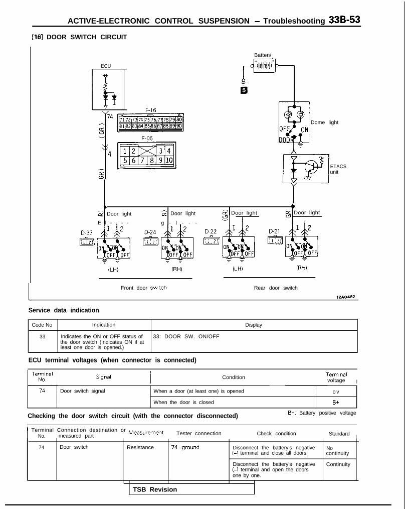
ACTIVE-ELECTRONIC CONTROL SUSPENSION - Troubleshooting 33B-53
1161 DOOR SWITCH CIRCUIT
L
ECU
Batten/
Dome light
ETACSunit
b +G Door light 2 Door light 6? Door light
E l - - - - g - l - - - sl--
z Door light
I
Front door swatch Rear door switch
Service data indication
Code No Indication Display
33 Indicates the ON or OFF status of 33: DOOR SW. ON/OFFthe door switch (Indicates ON if atleast one door is opened.)
ECU terminal voltages (when connector is connected)
Condition Termrnalvoltage I
Door switch signal When a door (at least one) is opened
When the door is closed
o v
B+
Checking the door switch circuit (with the connector disconnected) B+: Battery positive voltage
I Terminal Connection destination or MeasurementNo. measured part Tester connection Check condition Standard I
74 Door switch Resistance 74-ground Disconnect the battery’s negative(-) terminal and close all doors.
Disconnect the battery’s negative(-) terminal and open the doorsone by one.
Nocontinuity
Continuity
TSB Revision

33B-54 ACTIVE-ELECTRONIC CONTROL SUSPENSION - Troubleshooting
[17] DAMPING FORCE SWITCHING ACTUATOR DRIVE CIRCt JI’
ECU
*
F-17
A-62 F-05 F-10
jtTIff&@f&q
<Front. L.H.) (Front, R.H.) (Rear, R.H.)Y
Actuator
J
17I
tll F-06
t ttt
a-I2d
AJL7 -*UC 1
m .T
(Rear, L.H.)/
12A0454
1 TSB Revision

ACTIVE-ELECTRONIC CONTROL SUSPENSION - Troubleshooting 33B-55
Operation
The damping force switching actuator is the stepmotor. That allows the control rod of each shock
at one of four levels (HARD, MEDIUM, AUTO-SOFTor SOFT).
absorber to rotate, thus selecting the damping force
Diagnostic
If there is damage or disconnection of the heavy-linecircuit, the alarm light illuminates, and control is asdescribed in the table below. (Because the ac-
tuators are connected in parallel, there can be nodetection if wiring damage or disconnection occursat the final circuit.)
Diagnostic No. Attitude control
41 Control stop
Actuator compulsory activation
Damplng forcecontrol
Control stop
Vehicle-heightcontrol
Held at NORMAL
HIGH
Switch acceptance
SPORT AUTO
Not accept
SOFT
Code No. Applrcable operatron Descriptron of activation
01 SOFT damplng force The damplng force is compulsorily swltched to SOFT: there is a return to theonginal damping force three seconds thereafter
02 AUTO-SOFT damping force The damping force is compulsorily switched to AUTO-SOFT; there is a return tothe onginal damping force three seconds thereafter
03 MEDIUM damping force The damping force is compulsorily switched to MEDIUM; there is a return to theonginal damping force three seconds thereafter
04 HARD damplng force The damping force IS compulsorily switched to HARD; there IS a return to theonginal damping force three seconds thereafter
ECU terminal voltages (when connector is connected)
TerminalNo Slgnal Condition Terminal
voltage
1 Damping force swrtchlng actuatoractlvatlon signal
When the damping force switching actuator IS stopped 6V
Phase AO=B+
2p When the damping force switching actuator is activated
Damping force switching actuatoractivation signalPhase B When wiring is damaged or dlsconnected B+
6 Damplng force switchrng actuatoractivation slgnal
When the damping force switching actuator IS stopped 6V
Phase C
7p When the damping force switching actuator is activatedDamping force switching actuator
B+ = 0 pulse
activation signalPhase D When wiring is damaged or disconnected o v
B+: Battery positive voltage
Checking the damping force switching actuator drive circuit (with the connector disconnected)
TSB Revision
Terminal Connection destination or MeasurementNo measured part Tester connection Check condltlon Standard
1
ADamping force switching Resistance 1-6 Four coils that have a constantactuator (step motor)
Approxresistance of 6.4 i-O.1 ohms are 1611connected in parallel (front and rear)
2 Damping force swltchlng Resistance 2-7 Four coils that have a constant7 actuator (step motor)
Approx.resistance of 6.4 t 0.1 ohms are 1.612connected in parallel (front and rear).

33B-56 ACTIVE-ELECTRONIC CONTROL SUSPENSION - Troubleshooting
[18] COMPRESSOR DRIVE CIRCUIT
Exhaust valve for vehicle-height
12A026 1
BatteW
r=-
r
dii
\
Compressor relay----
-d-i==1
a
-I
Sub@ 40A fusible
link-1@ 15A
A-39
compres-sor relay
A-1 2
Ccmcms-scar
IPhfdlf”nctmdetectmECU
A-06X
fEJ
s&nodvalve powersource relay
F-l?
F-16
12AO484
I fl / is*oo4s~
1 TSB Revision

ACTIVE-ELECTRONIC CONTROL SUSPENSION - Troubleshooting 33B-57Operation
The compressor is activated when the pressurewithin the high-pressure tank decreases to 760 kPa(108 psi) or lower, and then stops two seconds afterthe pressure reaches 950 kPa (135 psi). Note,however, that the compressor is not activated while
Diagnostic
If there is damage or disconnection of the heavy-linecircuit, or a short-circuit, or a malfunction of theoutput transistor within the ECU, the alarm lightilluminates and control is as described in the table
the return pump is operating. A thermal switch isprovided at the motor circuit. This thermal switchfunctions to interrupt the power to the motor (inorder to protect the compressor) if the temperaturewithin the compressor becomes high.
below.(Note that the diagnostic is only applicable up to thecompressor relay.)
Diagnostic No.
43
Attitude control
Control stop
Damping forcecontrol
Held at MEDIUM
Vehicle-heightcontrol
Control stop
HIGH
Switch acceptance
SPORT AUTO SOFT
Not accept
Actuator compulsory activation
1 CodeNo. / Applicable operation I Description of activation I
05 Compressor relay ON The compressor relay is compulsorily switched ON for a period of three seconds.
ECU terminal voltages (when connector is connected)
TerminalNo. Signal Condition
Terminalvoltage
23 Compressor relay actrvatron signal When the compressor relay is ON B+
When the compressor relay is OFF o v
During fail-safe o v(solenoid valve power-source relay switch OFF)
- - -
TSB Revision
Checking the compressor drive circuit (with the connector disconnected)B+: Battery positive voltage
Terminal Connection destination or MeasurementNo. measured part
Tester connection Check condition Standard
~~
Compressor relay Resistance 52-ground
Troubleshooting hints (mechanical malfunctions)
Malfunctionmode Malfunction probable cause Malfunction Note
The compressorrelay is fused.
The compressor relay contacts are shorted. The compressor won’t stop, causing the battery -to discharge.
The compressor is The compressor won’t operate due to shorting, The vehicle height can’t be increased. -stuck. etc.

33B-58 ACTIVE-ELECTRONIC CONTROL SUSPENSION - Troubleshooting
[19] RETURN PUMP DRIVE CIRCUIT
R e t u r n p u m p r e l a y -
Battery
“ 2mA
(.(B)
mA
xl
Reserve tank assembly 12A0262
JI 1
ECU
F-17
F-18
12AOuw
Operation
The return pump is activated when the pressurewithin the low-pressure pressure tank increases to140 kPa (20 psi) or higher, and then stops twoseconds after the pressure is reduced to 70 kPa (10psi) or lower.
A thermal switch is provided at the motor circuit.This thermal switch functions to interrupt the powerto the motor (in order to protect the return pump) ifthe temperature within the return pump becomeshigh.
1TSB Revision

ACTIVE-ELECTRONIC CONTROL SUSPENSION - Troubleshooting 33B-59Diagnostic
If there is damage or disconnection of the heavy-line illuminates and ‘control is as described in the tablecircuit, or a short-circuit, or a malfunction of the out-pu t t rans i s to r w i th in the ECU, the a la rm l i gh t
below. (Note that the diagnostic is only applicableup to the compressor relay.)
I I / 6
Diagnostic No. Attitude control Damping forcecontrol
Vehicle-heightcontrol
Switch acceptance
HIGH 1 SPORT j AUTO ) S O F T
I 44 Rolling control only Held atstops. MEDIUM
Rolling control onlystoos.
Not accept
Actuator compulsory activation
CodeNo ’ Applicable operation Descnption of activation
06 Return pump relay ON The return pump relay is compulsorily switched ON for a period of three seconds.
ECU terminal voltages (when connector is connected)
Terminalvoltage I
3 2 Return pump relay activation signal When the return pump relay is ON B+
When the return pump relay is OFF o v
During fail-safe o v(solenoid valve power source relay switch OFF)
Checking the return pump drive circuit (with the connector disconnected)B+: Battery positive voltage
Connectron destrnation o r Measurementmeasured part Tester connectron Check condrtron Standard
32 Return pump relay Resistance 32-ground Constatly Approx 750I
Next apply battery voltage toterminal 32.
Return pumpoperation
NOTE (Refer to Vol.2 GENERAL for the circuit diagram.)Procedures for changing the internal pressure of the low-pressure tank(1) For 70 kPa (IO psi) or lower
Short-circuit the battery power-source @ terminal to the return pump relay @ terminal in order to activate the returnpump for a few seconds, and then leave as is.
(2) For 140 kPa (20 psi) or higherShort-circuit the battery power-source @ terminal to the front intake-air solenoid @I terminal and the front rightsolenoid @I terminal in order to connect the high-pressure tank and low-pressure tank, and then leave as is for a fewseconds.
Procedures for changing the internal pressure of the high-pressure tank(I) For 760 kPa (108 psi) or lower
Short-circuit the battery power-source @I terminal to the discharge-air solenoid (for vehicle-height adjustment) @Iterminal, the front intake-air solenoid @I terminal and the front right solenoid @ terminal and the front discharge-airsolenoid @I terminal in order to release the atmosphere inside the high-pressure tank, and then leave as is for a fewseconds.
(2) For 950 kPa (135 psi) or higherShort-circuit the battery power-source @ terminal to the compressor relay @ terminal in order to activate thecompressor for a few seconds, and then leave as is.
Troubleshooting hints (mechanical malfunctions)
Malfunctionmode Malfunction probable cause Malfunction Note 1
The return pump The return pump relay contacts are shorted.relay is fused
The return pump won’t stop, causing thebattery to discharge.
The return pump is The return pump won’t operate due to short- * Insufficient attitude-control effect. -
stuck. ing. etc. l Vehicle height increases after rolling control.
TSB Revision

33B-60 ACTIVE-ELECTRONIC CONTROL SUSPENSION - Troubleshooting
[20] EXHAUST VALVE ACTIVATION CIRCUIT (FOR VEHICLE-HEIGHT ADJUSTMENT)
Exhaust valve[for vehicle-heightadjustment)
Usually OFF; ON
vehicle-heightdownward
Air cleaner
0 lOOA Main fusible
4-J link
R&Vbox
F-17
l!!!bMalfunctm*e*ectwnctrcwt
A-l 1
2
8 (1;*- 1mm
=
Exhaust valvef o r vehicle-heightadjustment >
12A0251
*: 1991 models 1312AO498
TSB Revision
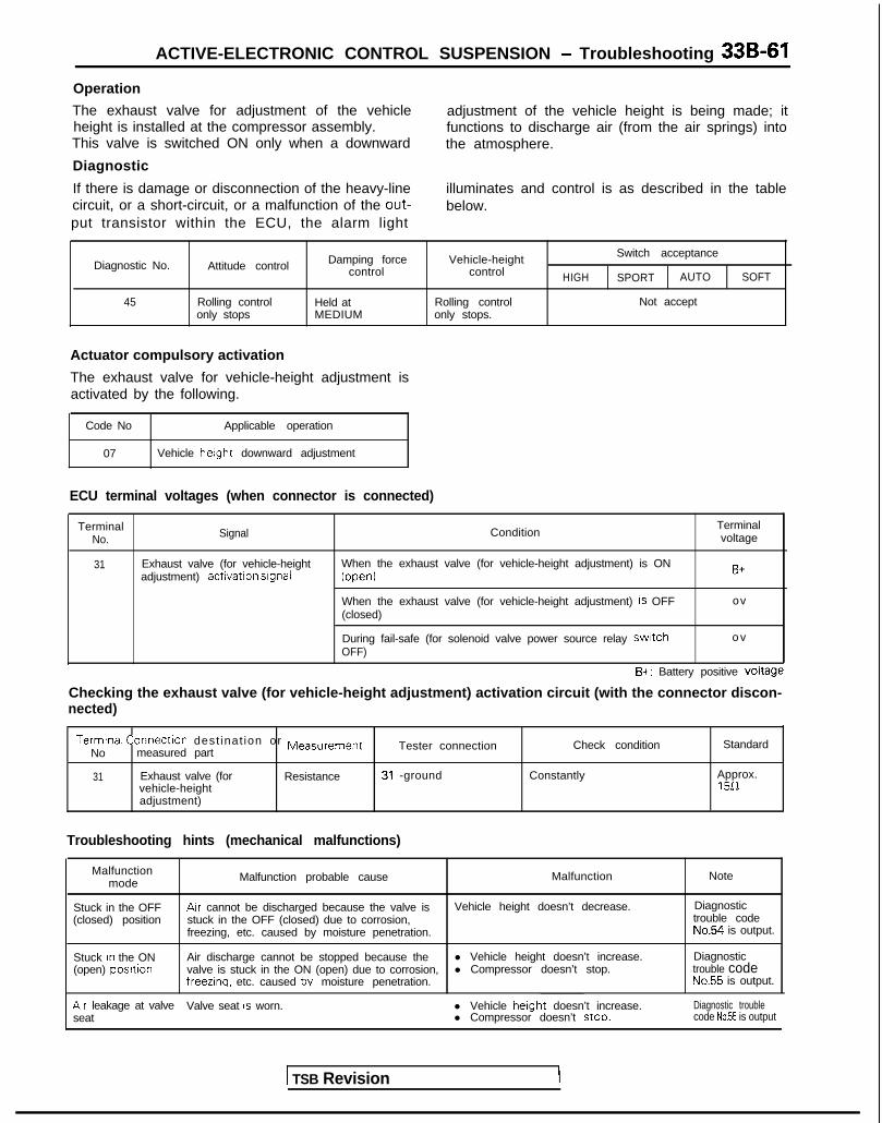
ACTIVE-ELECTRONIC CONTROL SUSPENSION - Troubleshooting 33B-61
Operation
The exhaust valve for adjustment of the vehicleheight is installed at the compressor assembly.This valve is switched ON only when a downward
Diagnostic
If there is damage or disconnection of the heavy-linecircuit, or a short-circuit, or a malfunction of the out-put transistor within the ECU, the alarm light
adjustment of the vehicle height is being made; itfunctions to discharge air (from the air springs) intothe atmosphere.
illuminates and control is as described in the tablebelow.
Diagnostic No.
45
Attitude control
Rolling controlonly stops
Damping forcecontrol
Held atMEDIUM
Vehicle-heightcontrol
Rolling controlonly stops.
Switch acceptance
HIGH SPORT AUTO SOFT
Not accept
Actuator compulsory activation
The exhaust valve for vehicle-height adjustment isactivated by the following.
Code No Applicable operation
07 Vehicle height downward adjustment
ECU terminal voltages (when connector is connected)
TerminalNo. Signal Condition
Terminalvoltage
31 Exhaust valve (for vehicle-heightadjustment) activation srgnal
When the exhaust valve (for vehicle-height adjustment) is ON(open)
When the exhaust valve (for vehicle-height adjustment) is OFF(closed)
B+
ov
During fail-safe (for solenoid valve power source relay swatch o vOFF)
B+: Battery positive voltage
Checking the exhaust valve (for vehicle-height adjustment) activation circuit (with the connector discon-nected)
Termtnal Connectlon dest inat ion or Measurement Check condition StandardNo measured part
Tester connection
31 Exhaust valve (for Resistance 31 -ground Constantly Approx.vehicle-height 1511adjustment)
Troubleshooting hints (mechanical malfunctions)
Malfunctionmode Malfunction probable cause Malfunction Note
Stuck in the OFF Arr cannot be discharged because the valve is Vehicle height doesn’t decrease. Diagnostic(closed) position stuck in the OFF (closed) due to corrosion, trouble code
freezing, etc. caused by moisture penetration. No.54 is output.
Stuck rn the ON(open) positlon
Air discharge cannot be stopped because the l Vehicle height doesn’t increase. Diagnosticvalve is stuck in the ON (open) due to corrosion, l Compressor doesn’t stop. trouble codefreezlna. etc. caused bv moisture penetration. No.55 is output.
Arr leakage at valve Valve seat IS worn.seat
l Vehicle herght doesn’t increase.l Compressor doesn’t stoo.
Diagnostic troublecode No.55 is output
1 TSB Revision
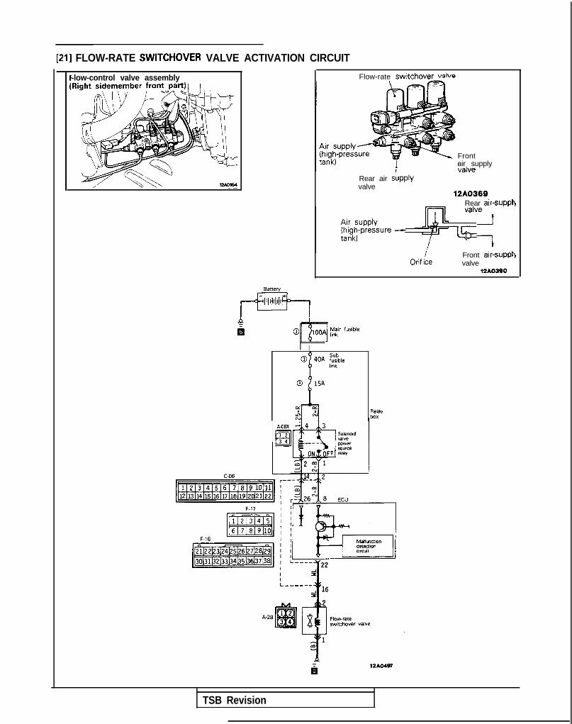
[21] FLOW-RATE SWITCHOVER VALVE ACTIVATION CIRCUIT
-low-control valve assembly Flow-rate switchovpr \J~I\~P
Frontair supply
Rear air sLpplyvalve
12A0369Rear air-suppl)
Orif i/ccFront air-suppi)valve
12hO390
BaWW
pK+,
P I
Ia
I
R&vbox
iilZAO497
TSB Revision
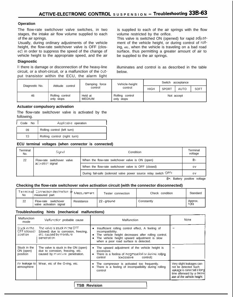
ACTIVE-ELECTRONIC CONTROL S U S P E N S I O N - Troubleshooting 3%~63
Operation
The flow-rate switchover valve switches, in twostages, the intake air flow volume supplied to eachof the air springs.Usually, during ordinary adjustments of the vehicleheight, the flow-rate switchover valve is OFF (clos-ed) in order to suppress the speed of the change ofvehicle height to the appropriate speed, and the air
Diagnostic
is supplied to each of the air springs with the flowvolume restricted by the orifice.This valve is switched ON (opened) for rapid adjust-ment of the vehicle height, or during control of roll-ing, etc., when the vehicle is traveling on a bad roadsurface, thus permitting a greater amount of air tobe supplied to the air springs.
If there is damage or disconnection of the heavy-line illuminates and control is as described in the tablecircuit, or a short-circuit, or a malfunction of the out- below.put transistor within the ECU, the alarm light
Switch acceptanceDiagnostic No. Attitude control Damping force Vehicle-height
control control HIGH SPORT AUTO SOFT
46 Rolling control Held at Rolling control Not acceptonly stops MEDIUM only stops
Actuator compulsory activation
The flow-rate switchover valve is activated by thefollowing.
1 Code No 1 Applrcable operation
09 Rolling control (left turn)
10 Rolling control (right turn)
ECU terminal voltages (when connector is connected)
TerminalNo. Srgnal Condition
Terminalvoltage
22 Flow-rate switchover valveactrvation signal
When the flow-rate switchover valve is ON (open) B+
When the flow-rate switchover valve is OFF (closed) ov
During fail-safe (solenoid valve power source relay switch OFF) o v
B+: Battery positive voltage
Checking the flow-rate switchover valve activation circuit (with the connector disconnected)
T e r m i n a l Connectron destinatron or MeasurementNo measured part Tester connection Check condition Standard
22 Flow-rate switchover Resistance 22-ground Constantly Approx.valve activation signal 1 OIL
Troubleshooting hints (mechanical malfunctions)
Malfunctionmode Malfunctron probable cause
(closed) due to corrosion, freezing
Stuck in the The valve is stuck in the ON (open)ON (open) due to corrosion, freezing, etc.position caused by morsture penetration.
Arr leakage to Wear, etc of the O-ring, etc.atmosphere
Malfunction
l Insufficient rolling control effect, A feeling ofincompatibility.
l The vehicle height decreases after rolling control.l The vehicle height upward adjustment is slow
when a poor road surface is detected.
l The upward adjustment of the vehicle height isexcessive.
l There is a feelina of incomoatibilitv durinq rollingcontrol (excessi;e control): - -
l The compressor is activated too frequently.l There is a feeling of incompatibility during rolling
control
“i
4-Very slight leakages can-not be detected Such
time afterward by a decrease of the vehicle height
\ TSB Revision

33B-64 ACTIVE-ELECTRONIC CONTROL SUSPENSION - Troubleshooting
[22] FRONT/REAR EXHAUST VALVE ACTIVATION CIRCUIT
Flow-control valve assembly(Right sidemember front part) Rear exhaust valve
To dryer valve 12AO369
Right front- o r r i g h t
rear valve
Left front-or left rear
valve
12AO389
Front exhaustvalve
1 TSB Revision 1

ACTIVE-ELECTRONIC CONTROL SUSPENSION - Troubleshooting 33B-65Operation
These valves switch the air exhausted (from thefront and rear left and right strut air springs) to eitherinternal recirculation or discharge to the at-mosphere. These valves are OFF (closed) duringthe attitude-control air-exhaust mode, and the ex-haust air is led to the low-pressure tank and is onceagain circulated within the system. The valves areON (open) during downward adjustment of the vehi-cle height, and the exhaust air, after passing
Diagnostic
through the dryer, is discharged (from the exhaustvalves for vehicle-height adjustment) into the at-mosphere. These valves are switched ON (opened),in order to maintain the differential pressure of thestrut air springs, when the rolling control is beingmaintained.(At this time, because the exhaust valves forvehicle-height adjustment are OFF (closed), air isnot discharged to the atmosphere.)
If there is damage or disconnection of the heavy-line control is as described in the table below.circuit, or a malfunction of an output transistor Note that the malfunction-detection circuit is thewithin the ECU, the alarm light illuminates, and same for the front and the rear exhaust valves.
Damping force Vehrcle-heightSwitch acceptance
Diagnostic No. Attitude control control control HIGH SPORT AUTO SOFT
47 Control stoo Held at MEDIUM Control stop Not acceot
Actuator compulsory activationThe front or the rear exhaust valves are activated bythe following.
Code No Applicable operation
07 Vehicle height downward adjustment
09 Rollrng control (left turn)
10 Rolling control (right turn)
ECU terminal voltage (when connector is connected)
TerminalNo. Signal
Terminalvoltage
24
33
Front exhaust valve activation When the front/rear exhaust valves are ON (open) B+signal~ When the front/rear exhaust valves are OFF (closed) o v
Rear exhaust valve activationsignal During fail-safe (for solenoid valve power source relay switch OFF) o v
B+: Battery positive voltageChecking the front/rear exhaust valves activation circuit (with the connector disconnected)
I I ITerminal Connection destination or M easur e m ent
No measured pan Tester connection Check condition Standard
I24 Front exhaust valve Resistance 24-ground
33 Rear exhaust valve Resistance 33-ground
Troubleshooting hints (mechanical malfunctions)
Constantly
Constantly
Approx. 100
Approx 1 OQ
Malfunctionmode
Stuck In the OFF(closed) position
Stuck in the ON(open) position I
Malfunction probable cause Malfunction Note
The exhaust air cannot be switched to theoutside-discharge mode because the valve isstuck in the OFF (closed) due to corrosion,freezing, etc caused by moisture penetration
l The vehicle-height adjustment (downward) -cannot be made at the front or rear.
l The vehicle height decreases at the front orrear during rolling control hold.
l The vehicle-height adjustment (downward) istoo fast and is excessive.
l The return pump is activated during thevehicle-height adjustment (downward)
The exhaust air cannot be switched to the l Insufficient attitude control effect (air cannot -internal-circulation mode because the valve is be discharged).stuck in the ON (open) due to corrosion, l The front or rear vehicle height increasesfreezing, etc caused by moisture penetration. after the rolling control.
TSB Revision

33B-66 ACTIVE-ELECTRONIC CONTROL SUSPENSION - Troubleshooting
[23] FRONT AIR-SUPPLY VALVE ACTIVATION CIRCUIT
Front solenoid valve assembly(Cowl top panel center) Front air-supply , Front valve (right)
v 12A0370
Usually OFF (closed).O N (open) duringfront air SUpplY
Right froit ’Left front valvevalve 12A0265
TSB Revision
0 15A
8
12AO486

ACTIVE-ELECTRONIC CONTROL SUSPENSION - Troubleshooting 33B-67Operation
The front air-supply valves are switched ON (open-ed) for air supply to the left and right strut air springsduring attitude control and during vehicle-height ad-justment upward.
Diagnostic
If there is damage or disconnection of the heavy-linecircuit, or a malfunction of an output transistorwithin the ECU, the alarm light illuminates, and
Usually, and during air exhaust, these valves areOFF (closed).Note that a check valve is provided in these valves inorder to prevent reverse flow of the air.
control is as described in the table below.Note that the malfunction-detection circuit is thesame for the rear air-supply valves.
Diagnostic No. Attitude control Damping forcecontrol
Vehicle-heightcontrol HIGH
Switch acceptance
SPORT AUTO SOFT
51 Control stop 1 Held at MEDIUM Control stop Not acceptI
Actuator compulsory activation
The front air-supply valves are activated by thefo l lowing .
CodeNo ~ Applicable operation
I 0 81Vehicle herght upward adjustment I
I 09 i Rolling control (left turn) I
L 10 Rolling control (right turn)I
ECU terminal voltage {when connector is connected)
TerminalNo Signal Conditron
’ T e r m i n a lvoltage
21 Front atr-supply valveactivation signal
When the front air-supply valves are ON (open) B+
When the front arr-supply valves are OFF (closed) ov
During fail-safe (for solenoid valve power source relay switch OFF] o v
B+: Battery positive voltage
Checking the front air-supply valve activation circuit (with the connector disconnected)
Terminal Connect ion dest inat ion or M easu remen t
No. measured part Tester connection Check condition Standard
21 Front air-supply valve Resrstance 21 -ground Constantly Approx. 1011
Troubleshooting hints (mechanical malfunctions)
Malfunctionmode Malfunction probable cause Malfunction Note
<Stuck in the Arr cannot be supplied in because l The front vehicle-height will not increase. -OFF (closed) the valve IS stuck in the OFF (closed) l Insufficient control of rolling and braking diveposition due to corrosion, freezing, etc l The front vehicle-height decreases after rolling
caused by morsture penetration control.
Stuck in the Air supply cannot be stoppedON (open)
The front vehicle-height increases and the body tilts -because the valve is stuck in the ON to one side
posrtion (open) due to corrosron. freezing,etc. caused by morsture penetratron.
Air leakage at Valve seat IS worn, l When left as is, the front vehrcle-height increases. Diagnostic No.56the valve l The front vehicle-height downward adjustment outputseat frequency increases.
Arr leakage Wear, etc of the O-ring, etc. l When left as IS. the front vehicle-height decreases. Very slight leakages can-to l not be detected Suchatmosphere
Air is not accumulated in the high-pressure tank.l The compressor is activated too frequently. leakage is detected a long
time afterward by a decre-ase of the vehicle height
TSB Revision
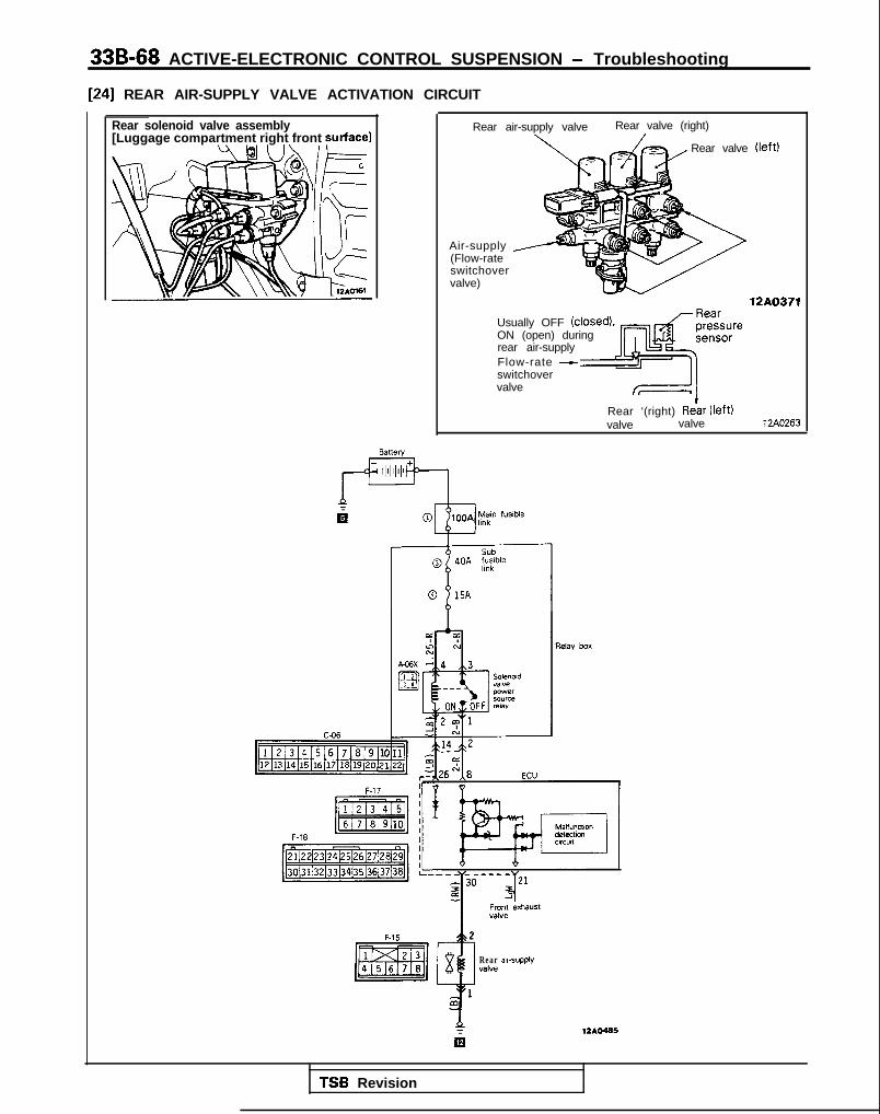
33B-68 ACTIVE-ELECTRONIC CONTROL SUSPENSION - Troubleshooting
[24] REAR AIR-SUPPLY VALVE ACTIVATION CIRCUIT
Rear solenoid valve assembly[Luggage compartment right front surface)
Rear air-supply valve Rear valve (right)
Rear valve (left)
Air-supply y(Flow-rateswitchovervalve)
12A0371
Usually OFF (closed).ON (open) duringrear air-supplyFlow-rate Aswitchovervalve fF--=fI
Rear ‘(right) Relar (left)valve valve 12AO263
4Frontvalve
2
sRear aarvalve
1m
eXha”St
SUPPlY
412AO465
TSB Revision

ACTIVE-ELECTRONIC CONTROL SUSPENSION - Troubleshooting 33B-69Operation
The rear air-supply valves are switched ON (opened)for air supply to the left and right air springs duringattitude control and during vehicle-height adjust-ment upward.
Diagnostic
Usually, and during air exhaust, these valves areOFF (closed). Note that the rear-pressure sensors,for detection of the internal pressure of the rearshock absorbers, are installed in thesevalves.
If there is damage or disconnection of the heavy-line control is as described in the table below.circuit, or a malfunction of an output transistor Note that the malfunction-detection circuit is thewith in the E C U , t h e a la rm l i gh t i l l um ina tes , and same for the front air-supply valves.
Switch acceptanceDiagnostic No. Attrtude control Damping force Vehrcle-height
control control HIGH SPORT AUTO SOFT
51 Control stop Held at MEDIUM Control stop Not accept
Actuator compulsory activation
The rear air-supply valves are activated by thefollowing.
Code No Applicable operation
08 Vehicle height dov/nward adjustment
09 Rolling control (left turn)
10 Rolling control (right turn)
ECU terminal voltage (when connector is connected)
TerminalNo. Condition
Terminalvoltage
30 Rear alr-supply valveactivation signal
When the rear air-supply valves are ON (open) B+
When the rear arr-supply valves are OFF (closed) o v
During fail-safe (for solenoid valve power source relay switch OFF) o v
B+: Battery positive voltage
Checking the rear air-supply valve activation circuit (with the connector disconnected)
Terminal Connection destination or MeasurementNo. measured part Tester connection Check condition Standard
30 Rear air-supply valve Reststance 30-ground
Troubleshooting hints (mechanical malfunctions)
Constantly Approx. 1012
Malfunctionmode Malfunction probable cause Malfunction Note
Stuck in the Air cannot be supplied in because l The rear vehicle-height will not increase -OFF (closed) the valve IS stuck in the OFF (closed) l Insufficient control of rolling and squat.posrtion due to corroson. freezrng, etc. l The rear vehicle-height decreases after rolling
caused by moisture penetration. control.
Stuck in the Air supply cannot be stopped The rear vehicle-height increases and the body tilts -ON (open) because the valve is stuck in the ON to one sideposition (open) due to corrosion, freezing,
etc. caused by moisture penetration.
Air leakage at Valve seat is worn. l When left as is, the rear vehicle-height increases Diagnostic No.56the valve l The rear vehicle-height downward adjustment outputseat frequency increases.
Arr leakage Wear, etc. of the O-ring, etc l When left as IS, the rear vehrcle-height decreases Very slrght leakages can-to l Air is not accumulated in the high-pressure tank not be detected Suchatmosphere l The compressor is activated too frequently. leakage is detected a long
trme afterward by a decre-ase of the vehicle height
TSB Revision

33B-70 ACTIVE-ELECTRONIC CONTROL SUSPENSION - Troubleshooting
[25] LEFT FRONT/RIGHT FRONT VALVE ACTIVATION CIRCUIT
Front solenoid valve assembly(Cowl top panel center)
Front “/irontexhaustvalve
air springs12A0370
Usually. andduring exhaust. FrontOFF (closed) - ;;,PPlY
Left frontFront and rightexhaust - - f r o n t a i rvalve springs 12AO264
Riaht front Left front valvevaive
Fronair-supplyvalve
4
12AO490
TSB Revision

ACTIVE-ELECTRONIC CONTROL SUSPENSION - Troubleshooting 33B-71
Operation
The left front and right front valves are for switchingthe air intake and exhaust for the left front and rightfront strut air springs. These valves are usually,
Diagnostic
and during air intake, OFF (closed), and are ON(open) during exhaust.
If there is damage or disconnection of the heavy-line control is as described in the table below.circuit, or a malfunction of an output transistor Note that the malfunction-detection circuit is thewithin the ECU, the alarm light illuminates, and same for the left front and right front valves.
Diagnostic No.
52
Damping force Vehicle-herght Switch acceptanceAttitude control
control control HIGH SPORT AUTO SOFT
Control stop Held at MEDIUM Control stop Not accept
Actuator compulsory activation
The left front and right front valves are activated bythe following.
Code No. Applicable operation
07 Vehicle height aownward adjustment
09.10 Rolling control (left turning: left valve)/rollingcontrol (rrght turning: right valve)
ECU terminal voltages (when connector is connected]
TermrnalNo Slgnal Condition
Terminalvoltage
3 Left front valve activatron When the left/right front valves are ON B+srgnal~ When the left/right front valves are OFF o v
4 Right front valve activatronsrgnal During fail-safe (for solenoid valve power source relay switch OFF) ov
B+: Battery positive voltage
Checking the left front/right front valves activation circuit (with the connector disconnected)
I No.Terminal Connection destination or MeasurementI measured part Tester connection Check condition Standard
3 Left front valve Resrstance 3-ground Constantly Approx 1012
4 Right front valve Resistance 4-ground Constantly Approx 1012
Troubleshooting hints (mechanical malfunctions)
Malfunctronmode
Stuck In theOFF (closed)position
Stuck In theON (open)oositron
Air leakageat valve seat
Air leakage tcatmosphere !
Malfunction probable cause Malfunction Note
Air cannot be discharged because l -the valve is stuck in the OFF (closed)
The left front and right front vehicle height
due to corrosion, freezing, etc.increases after rolling control.
0 Insufficient active control effect.caused by moisture penetration.
Air cannot be taken in because the l
valve is stuck in the ON (open) dueThe left front and right front vehicle height Diagnostic troubledecreases, and the body tilts to one side.
to corrosion. freezing, etc. causedcode No.56 is output.
l The return pump is activated too frequently.by moisture penetration
Valve seat is worn
Wear, etc of the O-ring, etc
When left as is, the front vehicle-height willdecrease.
Diagnostic troublecode No.56 is output.
When left as is. the front vehicle-height willdecrease.
Very slight leakages can-not be detected. Suchleakage IS detected a longtime afterward by a decre-ase of the vehicle height
TSB Revision

33B-72 ACTIVE-ELECTRONIC CONTROL SUSPENSION - Troubleshooting
[26] LEFT REAR/RIGHT REAR VALVE ACTIVATION CIRCUIT
tear solenoid valve assemblyLuggage compartment right front surface)
Rear (riaht) Rear (left)valve
Rearair-supplyvalve
Rear exhaust valve springs12A0371
Usually, andduring exhaust,OFF (closed)
Rearc- air-supply
valve
Rearexhaust -
Left rear/right- rear air springs
valve 12A0264
040A Sub
fwblehnkl-l-70
15A
Relay box
C-06
~~oL&~~ , 2J$$iECU
F~‘7 IIY * - - _..
m1 2
TSB Revision
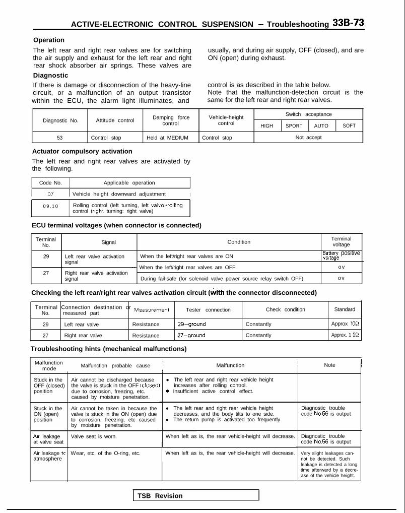
ACTIVE-ELECTRONIC CONTROL SUSPENSION - Troubleshooting 33B-73Operation
The left rear and right rear valves are for switchingthe air supply and exhaust for the left rear and rightrear shock absorber air springs. These valves are
Diagnostic
usually, and during air supply, OFF (closed), and areON (open) during exhaust.
If there is damage or disconnection of the heavy-linecircuit, or a malfunction of an output transistorwithin the ECU, the alarm light illuminates, and
control is as described in the table below.Note that the malfunction-detection circuit is thesame for the left rear and right rear valves.
Diagnostic No.
53
Damping force Vehicle-height Switch acceptanceAttitude control control control HIGH SPORT AUTO SOFT
Control stop Held at MEDIUM Control stop Not accept
Actuator compulsory activation
The left rear and right rear valves are activated bythe following.
Code No. Applicable operation
I 07 / Vehicle height downward adjustment I
0 9 . 1 0 Rolling control (left turning, left valve)/rollingcontrol (right turning: right valve)
ECU terminal voltages (when connector is connected)
TerminalNo. Signal Condition
Terminalvoltage
29 Left rear valve activation When the left/right rear valves are ONsignal
E3a3azg~ positive
~ When the left/right rear valves are OFF o v27 Right rear valve activation
signal During fail-safe (for solenoid valve power source relay switch OFF) o v
Checking the left rear/right rear valves activation circuit (with the connector disconnected)
Terminal Connection destination or MeasurementNo. measured part
Tester connection
29 Left rear valve Resistance 29-ground
27 Right rear valve Resistance 27-ground
Troubleshooting hints (mechanical malfunctions)
Check condition
Constantly
Constantly
Standard
Approx 1011
Approx. 1 Of2
Malfunctionmode Malfunction probable cause
IMalfunction Note
Stuck in theOFF (closed)position
Stuck in theON (open)position
Air leakageat valve seat
Air leakage tcatmosphere
Air cannot be discharged because l The left rear and right rear vehicle heightthe valve is stuck in the OFF (closed) increases after rolling control.due to corrosion, freezing, etc. 0 Insufficient active control effect.caused by moisture penetration.
Air cannot be taken in because the l The left rear and right rear vehicle heightvalve is stuck in the ON (open) due decreases, and the body tilts to one side.to corrosion, freezing, etc caused l The return pump is activated too frequentlyby moisture penetration.
Valve seat is worn. When left as is, the rear vehicle-height will decrease.
Wear, etc. of the O-ring, etc. When left as is, the rear vehicle-height will decrease.
TSB Revision
Diagnostic troublecode No.56 is output
Diagnostic troublecode No.56 is output
Very slight leakages can-not be detected. Suchleakage is detected a longtime afterward by a decre-ase of the vehicle height.
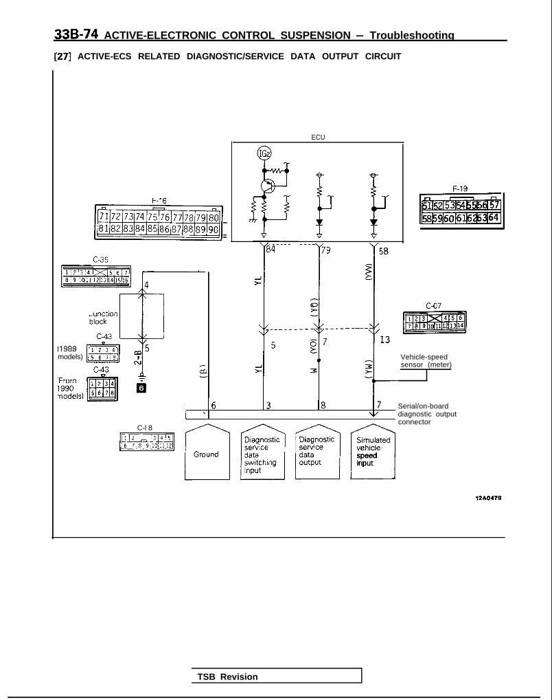
33B-74 ACTIVE-ELECTRONIC CONTROL SUSPENSION - Troubleshooting
[27] ACTIVE-ECS RELATED DIAGNOSTIC/SERVICE DATA OUTPUT CIRCUIT
ECU
IGz
8’ i- 1 F-19
F-16
mi _-___- ____79
-I I
58
E
0___--1
_-___---g73.-
13
t
r
16 13 18 17\I/
(1989models) Vehicle-speed
sensor (meter)c-43
Serial/on-boarddiagnostic outputconnector
C-l 8
p!5iE&qSimulatedvehicle--1speedinput
12AO479
TSB Revision

ACTIVE-ELECTRONIC CONTROL SUSPENSION - Troubleshooting 33B-75
ECU terminal voltages (when connector is connected)
TerminalNo. Condition Terminal
voltage
79 Diagnostic/service dataswitching signal
When scan tool is connected
Usual
o v
3.3v
84 Diagnostic/service dataswitching signal
ConstantlyO;JBattery posi-tive voltage
ACTIVE-ECS related diagnostic/service data output circuit (with the connector disconnected)
Terminal Connection destination or MeasurementNo. measured part Tester connection Check condition Standard
79 Diagnostic/servicedata switching signal
Resistance Diagnostic79- concentrated
connector
~ Constantly Continuity
84 Harness fordiagnostic/servicedata output
Resistance Diagnostic84- concentrated
connector
Constantly Continuity
TSB Revision

33B-76 ACTIVE-ELECTRONIC CONTROL SUSPENSION - Troubleshooting
CONFIGURATION DIAGRAMSENGINE ROOM
A-l 1 A-12 A-54
A-28 A-27
2:;. Refer to CENTRALIZED JUNCTIONIA-l 1 ACTIVE-ECS exhaust solenoid valveA-l 2 ACTIVE-ECS air compressorA-23 ACTIVE-ECS G sensorA-27 ACTIVE-ECS front vehicle height sensorA-28 ACTIVE-ECS flow-control solenoid valveA-37 ACTIVE-ECS return pumpA-38 ACTIVE-ECS pressure switchA-39 ACTIVE-ECS air compressor relayA40 ACTIVE-ECS return pump relayA-41 Front wiring harness and battery
cable combinationA-50 ACTIVE-ECS front actuatorA-54 Throttle position sensor (1989 models)A-58 ACTIVE-ECS front solenoid valveA-63 ACTIVE-ECS front actuator
TSB Revision

ACTIVE-ELECTRONIC CONTROL SUSPENSION - Troubleshooting 33B-77
A-58 A-63
-.__- --~- ~---~
111111111
Ground point (detailed view)
TSB Revision

336-78 ACTIVE-ELECTRONIC CONTROL SUSPENSION - Troubleshooting
Concentrated junction
Dedicated fuses @I-@ A-01X Headlight relayA-06X ACTIVE-ECS solenoid
valve power source relay
‘\
I,BR/LB
A-01X\
8383mB
Sub fusible link 0-a
/
16A0567
ENGINE AND TRANSAXLE
B-l 5 AlternatorB-21 Backup l ight switchB-02-1 Throttle posltion sensor (From 1990 models)
Ground point (detailed view)
36A0308
TSB Revision

ACTIVE-ELECTRONIC CONTROL SUSPENSION - Troubleshooting 33B-79
DASHBOARD PANEL
Junction block
C-36c-37 Front harness and junction
c-37-1 block coupling
C-38c-39c-4o Body harness and junctionc-43 block coupling
c-44
piiziqC-36 c-37 C-38
TSB Revision 1
i 0duu
fb!J~LO16Aooo2

33B-80 ACTIVE-ELECTRONIC CONTROL SUSPENSION - Troubleshooting
DASHBOARD PANEL
c-05
C-06
c-07
C-l 2C-l 3
C-l 8c-20C-32
Control wiring harness and ACTIVE-ECSwiring harness combinationFront wiring harness and ACTIVE-ECSwiring harness combinationBody wiring harness and ACTIVE-ECSwiring harness combinationEngine control moduleACTIVE-ECS wiring harness andinstrument wirina harness combinationData link connect&ACTIVE-ECS relavInstrument wiring harness and junctionblock combination
C-36
block combrnatlon1 Front wiring harness and junction
Body wiring harness and juncitionblock combination
C-47 Stop l ight switch (2-pjn)rC&$ Stop l ight switch (4-pin)
c-52 Combination metert
C-68 Column swi tchC-71 Diode (for ACTIVE-ECS Circuit)
\ \ \// \ \ ?b
c-71
-If 8 C-68
TSB Revision

ACTIVE-ELECTRONIC CONTROL SUSPENSION - Troubleshootina 33B-81
c-y5 C-y6 c-p7
.c-12
C-l 3
\
36AOO35 Junction block
Front side Rear sideC-44 C-38
-37-l c-39
c-40c-43
C-32
16A1264
TSB Revision I

33B-82 ACTIVE-ELECTRONIC CONTROL SUSPENSION - Troubleshooting
INTERIOR
\ \ 16AO353
’ c r o s s m e m b e
\ / / WA0492
1 TSB Revision I

ACTIVE-ELECTRONIC CONTROL SUSPENSION - Troubleshooting 33B-83
D-21
TSB Revision I
>\D-24
36A0185
D-21 Door switch (Rear, R.H.)D-22 Door switch (Rear, L.H.lD-24 Door switch (Front, R.H.)D-27 Body wiring harness and fuel
wiring harness combinationD-33 Door switch (Front, L.H.)

33B-84 ACTIVE-ELECTRONIC CONTROL SUSPENSION - Troubleshooting
IF
c
USTRUMENT PANEL
Ll36AOO30
E-03 ACTIVE-ECS indicator
TSB Revision
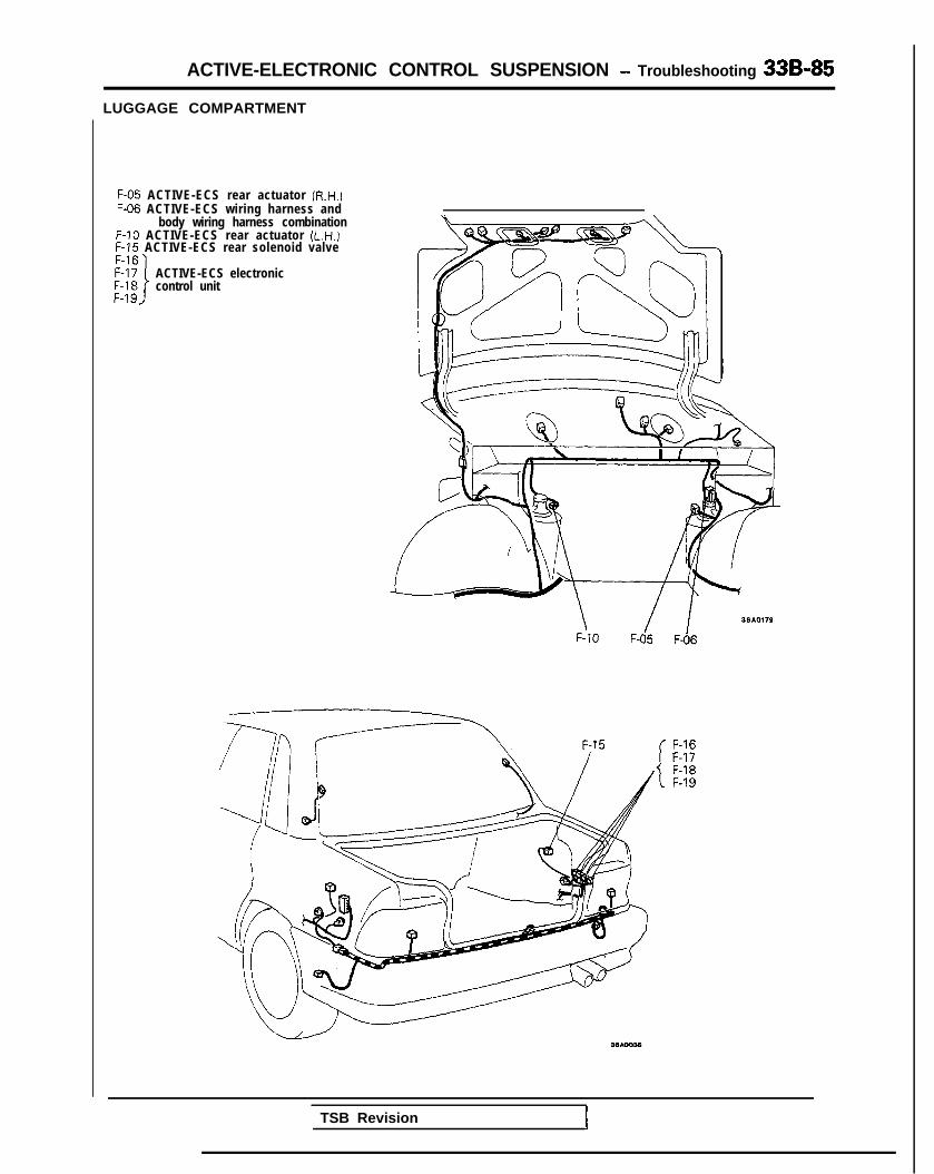
ACTIVE-ELECTRONIC CONTROL SUSPENSION - Troubleshooting 33B-85
LUGGAGE COMPARTMENT
F-05 ACTIVE-ECS rear actuator (R.H.)F-06 ACTIVE-ECS wiring harness and
body wiring harness combinationF-10 ACTIVE-ECS rear actuator (L.H.)F-15 ACTIVE-ECS rear solenoid valve
ACTIVE-ECS electroniccontrol unit
\F-10
1 IF-05 F-06
F-16F-17F-18F-19
TSB Revision 1

33B-86 ACTIVE-ELECTRONIC CONTROL SUSPENSION - ~~u,:~%i?:~~~~
REAR UNDER FLOOR
G-05 ACTIVE-ECS rearvehicle-height sensor
16A0266
SERVICE ADJUSTMENT PROCEDURAZ
HUB END PLAY INSPECTION1. Jack up the vehicle and remove the front wheels.2. Remove the disc brake caliper and suspend it with a wire.
Refer to GROUP 26 FRONT AXLE-Service AdjustmentProcedures.
3. Attach a dial indicator as shown in the illustration, and thenmeasure the axial play while moving the hub back andforth.
Limit: 0.2 mm t.008 in.) or less
NOTESecure the brake disc and hub by the wheel nut so that thebrake disc won’t come of the hub.
4. If axial play exceeds the limit, disassemble and check parts.
FRONT WHEEL ALIGNMENT M33f6AD
NOTEThe front suspension assembly must be free of worn, loose ordamaged parts prior to measurement of front wheel align-ments.Measure wheel alignment by using the tool.
CAMBER AND CASTERStandard value: Camber 22’f30
Caster ZY30
Camber and caster are pre-set at the factory and cannot beadjusted.
NOTEIf camber and caster are not within specifications, replace bentor damaged parts.
I TSB Revision I

ACTIVE-ELECTRONIC CONTROL SUSPENSION Service Adjustment- Procedures 33B-87
Alarm light
With scan tool
Diagnostic check terminal
Serial/on-boarddiagnostic’outwt
TSB Revision I
Serial/diagnostic-switching input
Simulated vehicle--speed input
-Ground
16LOO91
! TOE-IN
Standard value: Ok3 mm (Of.12 in.)1. Adjust the toe-in by undoing the clips and turning the left
and right tie rod turnbuckles by the same amount (inopposite directions).
2. The toe will move out as the left turnbuckle is turnedtoward the front of the vehicle and the right turnbuckle isturned toward the rear of the vehicle.
3. For each half turn of the left and right tie rods, the toe-in willbe adjusted by 6 mm (.24 in.).
4. After making the adjustments, use a turning radius gage toconfirm that the steering wheel turning angle is within thestandard value range. (Refer to GROUP 37A POWERSTEERING-Service Adjustment Procedures.)
WHEEL BEARING ADJUSTMENT M33FcAABearing preload is pre-set to the specified value by design andtherefore can not be adjusted.
ALARM LIGHT CHECK MPFNAC
The bulb of the alarm light can be checked by whether or not itis illuminated for approximately 0.5 of a second by theElectronic Control Suspension control unit when the ignitionkey is turned ON, and, after the engine is started.
SYSTEM CHECKING BY USING ALARM LIGHT1. After checking the alarm light bulb to be sure it has not
failed, let the engine idle for approximately 4 minutes ormore to check to be sure that the alarm light does notilluminate.
2. While the alarm light is on, connect the scan tool or a volt-meter to the data link connector of the wiring harness andcheck the on-board diagnostic output code.
3. Use the output pattern for troubleshooting (Refer toP.33B-11.)
NOTE*Although the alarm light illuminates under the followingcircumstances, there is no actual malfunction if, after thefollowing procedures have been followed and then thealarm light does not illuminate after waiting about fourminutes or more.1. When there is an overload
Stop the engine, unload the cargo, and then restart theengine.
2. When the vehicle is stopped (with the engine running)on a steep hill or slope.Move the vehicle to a horizontal place and stop; thenstop the engine and restart it.

338-88 ACTIVE-ELECTRONIC CONTROL SUSPENSION - ~~~%.,~Rment
With voltmeter
! / /ii’12A0476
L
edge surface17AOOW
(RightFront)
(LeftRear)
12A0224 J
3. When vehicle-height adjustments are made frequentlyAfter stopping the engine, open the hood and allowthe compressor to cool; then restart the engine.
4. When the vehicle is driven on winding roads in themountains continuously for 18 minutes or longer.To protect the return pump from damage, stop theengine and then restart it.
*: Applicable to 1989 models only.
CHECKING BY ON-BOARD DIAGNOSTIC1. Regardless of whether or not the alarm light is illuminated,
check the diagnostic output codes at the diagnostic termi-nal.
2. If a malfunction code is output to the diagnostic terminal,perform the troubleshooting procedures according to theoutput code.
NOTEDiagnostic trouble codes are entered into the memory, even ifthe ignition is at the OFF position, so that it is possible to checkfor the existence of malfunctions that occurred previously.
NORMAL VEHICLE HEIGHT CHECK AND ADJUST-MENT1. Park the vehicle on a flat surface.2. Measure dimension L (in the illustration) of the rear height
sensor mounting bracket installation location.
Rear height sensor mounting bracket installationlength:
Standard value (L): 314-316 mm (12.36-12.44 in.)
3. If dimension is not within the standard value, loosen thebracket mounting bolt and make the adjustment to withinthe standard value.
4. With the vehicle unloaded, start the engine and let it run for3 minutes, Then check to be sure that, after the vehicleheight adjustment is completed, the NORM vehicle heightindicator light illuminates (indicating that the vehicle heightadjustment is finished).
5. Measure the distance between the wheel arch and thecentre of the axle for both the right front and left rear.
Standard value:A (Front) 381391 mm (15.9-15.4 in.)6 (Rear) 357-367 mm (14.1-14.4 in.)
CautionCheck to be sure that the mounted dimension of therear height sensor mounting bracket is within thestandard value.
TSB Revision

ACTIVE-ELECTRONIC CONTROL SUSPENSION - ~~:i%,~:iustment 33B-89
Without disconnecting:he air tubing
Remainingpressure
P = 120 kPa(17 psi)
By disconnecting thefir tubing
normalcondition
P ‘=. 0
Front
tear (From 1990model!
rmzIIconditlui
12AO281
Vehicle-height switch
6. If the vehicle height is not within the standard value,loosen the turnbuckles of the front and rear height sensorrods, and then make the adjustment by changing thelength of the rods. The vehicle height becomes higherwhen the rods are lengthened.
Caution1. Both the front and rear heights must be checked,
because, even though only the front or the rear isadjusted, the other height (rear or front) is alsochanged.
2. The adjustments of the vehicle height must be madewhile the engine is idling (vehicle stopped).
ROLLING DIAPHRAGM CHECKUnder normal conditions, the rolling diaphragm is as shown inthe “normal condition” half of the figure. If, however, thevehicle is jacked up while there is no air in the air springs andthen let down suddenly, the diaphragm may become doublefolded, as shown in the “abnormal condition” half of theillustration.If the vehicle is driven in abnormal condition, the diaphragmwill soon be damaged, so the procedure below should befollowed to prevent this.
Checking method
Front: Jack the front end up and check visually or feel thediaphragm.
Rear: Check to be sure that movement is smooth when therear part of the body is bounced up and down.
Repair method
1. Jack up the vehicle and start the engine.2. Press the HIGH vehicle-height switch for two seconds or
longer.3. Supply air to each air spring so as to return the diaphragm
to the normal form.
NOTEAir should be introduced to the rear air springs and front airsprings, in that sequence, for five seconds each.
The diaphragm will return easily if a solution of soap and wateris applied to the diaphragm.
CautionIn order to prevent double-folding of the diaphragm, besure, if the air tubing is disconnected in the course ofservicing, to follow step 2 above after connecting thetubing in order to introduce air into the air springs.
74AOOQ8
TSB Revision
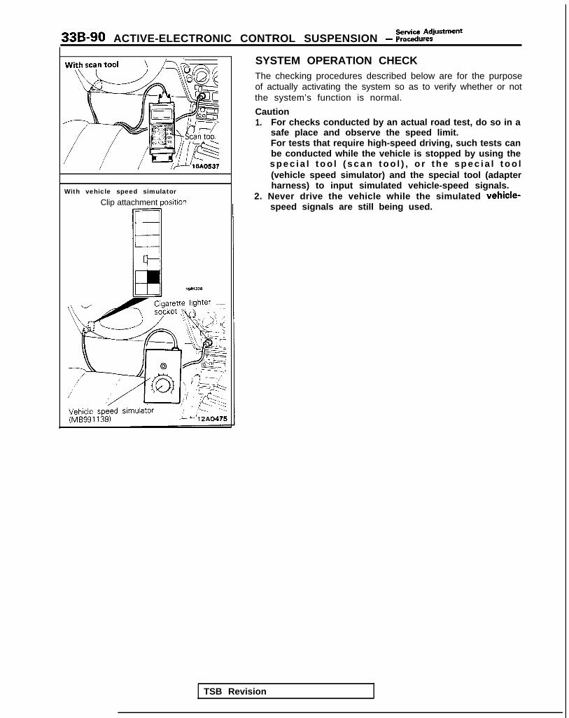
33B-90 ACTIVE-ELECTRONIC CONTROL SUSPENSION - i?:~i~:i@~~=“~
With vehicle speed simulatorClip attachment posltion
SYSTEM OPERATION CHECKThe checking procedures described below are for the purposeof actually activating the system so as to verify whether or notthe system’s function is normal.
Caution1. For checks conducted by an actual road test, do so in a
safe place and observe the speed limit.For tests that require high-speed driving, such tests canbe conducted while the vehicle is stopped by using thes p e c i a l t o o l ( s c a n t o o l ) , o r t h e s p e c i a l t o o l(vehicle speed simulator) and the special tool (adapterharness) to input simulated vehicle-speed signals.
2. Never drive the vehicle while the simulated vehicle-speed signals are still being used.
TSB Revision

ACTIVE-ELECTRONIC CONTROL SUSPENSION - %ii%:justment 33B-91
Indicator lights that illuminate for 0.5second after ECU power ON
Control mode AUTO mode indi-cator
CHECKING THE ACTIVE-ECS INDICATOR LIGHTS
1. Check to be sure that the lights listed at the left illuminatewhen the ignition key is turned to the ON position, and forapproximately 0.5 second after the engine is started, andthat thereafter they indicate the control mode entered in
Damping forcelevel
Vehicle-heightlevel
SOFT (one lightON)
NORM
the memory.2. Check to be sure that the nighttime illumination light
illuminates when the lighting switch is switched ON, andthat the indicator lights become dimmer.
Vehicle-heightindicator lights
Damping forcelevel indicatorlights
12A0142
Control mode switches -60
Symbol Function Illumina- Night- Symbol Function Illumina- Night-tion time tion timecolor dim color dim
A HIGH vehicle-height Orange Yes J ELECTRONIC CON- Green* -indicator light TROL SUSPENSION
B NORMAL vehicle- Orange Yes K HIGH (vehicle-height) Orange Yesheight indicator light switch indicator light
C LOW vehicle-height Orange Yes L SPORT mode indica- Orange Yesindicator light tor light
D Illuminates during Orange Yes M AUTO mode indicator Orange YesHARD light
E Illuminates during Orange Yes N SOFT mode indicator Orange YesHARD or MEDIUM light
F Illuminates during Orange Yes P N i g h t t i m e i l l u m i n a t i o n G r e e n * -HARD, MEDIUM or lightSOFT
G Alarm light Red Yes Q
H ECS symbol Green* - RIA-r-Cl”lC
T‘he illumination color indicated by the * symbol indicates the nighttime illumination color (letters or lines onlyilluminate).
TSB Reyision

33B-92 ACTIVE-ELECTRONIC CONTROL SUSPENSION - ~~:%:?stment
CHECKING THE DAMPING FORCE
12A0279
Damping force characteristicindicator lights
,\,IH A R D 0 H A R D 0 HARD;g!;= - \\I, = \\ l,= 0 -= -,F; f ;F:
SOFT ,gi S O F T <F: S O F T ,@:
Weak Medium Strong
:SOFT or (MEDIUM) (HARD)4UTOSOFT)
12AQ271
./I,
HARD 0 HARD 0 HARD ;g;
z-0 -\k 3, \I I,
SOFT ;p; SOFT ;R- SOFT I@;
45” or more 45” or more
stop Slight Sharp
16AQ460
1. Move the wheels to the straight-ahead position.2. Start the engine.3. Set to the AUTO mode (normal vehicle height).4. Press the control mode switches, and check the illumina-
tion of the damping force level indicator lights when themodes shown below are selected.In addition, check to be sure that there is a difference ofthe damping force for each control mode when the vehicleis moved up and down at a rate of twice per second.
Control mode Damping force level 1 Damping forceindicator lights
SOFT One indicator lightON
SOFT
SPORTI
Three indicator lights HARDe3ON
NOTEl I- 1989 models
SOFT for 1990,1991,1992,1993 models.l *: 1989 models
Not applicable for 1990,1991, 1992, 1993 models.l 3: 1989 models
MEDIUM for 1990,1991,1992,1993 models.
CHECKING THE ANTI-ROLLING FUNCTION
1. Move the wheels to the straight-ahead position.2. Turn the ignition key to ON.3. When simulated vehicle-speed signals of 35 km/h (22
mph) or higher are input and the steering wheel is turned45” or more, the damping force characteristic indicatorlight will change to MEDIUM or HARD, depending on thespeed at which the steering wheel is turned.Check to be sure that this sensitivity increases (for eachcontrol mode) as the vehicle speed increases.
NOTEThe damping force characteristic will return to its previouslevel about tow seconds*4 after the change to MEDIUM orHARD.
l 4: 1989 modelsFor 1990,1991,1992,1993 models: one second
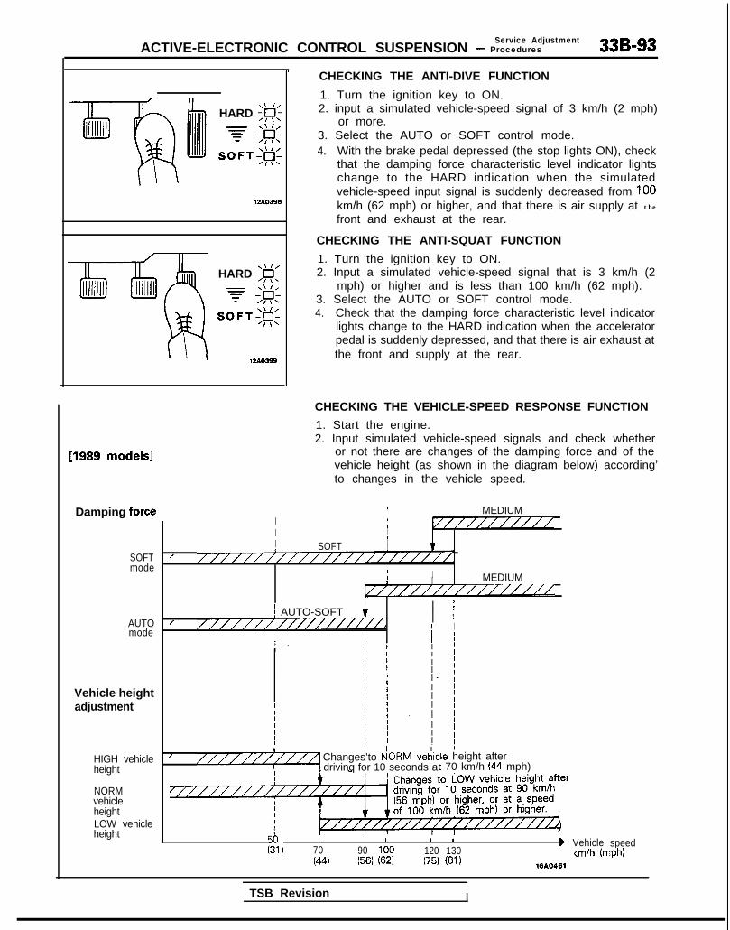
Service AdjustmentACTIVE-ELECTRONIC CONTROL SUSPENSION - Procedures 33B-93
\\ I/HARD ;g;
7 #
SOFT;#c
\\ I/HARD ;F;
7 ;&
SOFT;@;
I 12AO399
CHECKING THE ANTI-DIVE FUNCTION
1. Turn the ignition key to ON.2. input a simulated vehicle-speed signal of 3 km/h (2 mph)
or more.3. Select the AUTO or SOFT control mode.4. With the brake pedal depressed (the stop lights ON), check
that the damping force characteristic level indicator lightschange to the HARD indication when the simulatedvehicle-speed input signal is suddenly decreased from 100km/h (62 mph) or higher, and that there is air supply at the
front and exhaust at the rear.
CHECKING THE ANTI-SQUAT FUNCTION
1. Turn the ignition key to ON.2. Input a simulated vehicle-speed signal that is 3 km/h (2
mph) or higher and is less than 100 km/h (62 mph).3. Select the AUTO or SOFT control mode.4. Check that the damping force characteristic level indicator
lights change to the HARD indication when the acceleratorpedal is suddenly depressed, and that there is air exhaust atthe front and supply at the rear.
[1989 models1
Damping force
SOFTmode
AUTOmode
Vehicle heightadjustment
HIGH vehicleheight
NORMvehicleheightLOW vehicleheight
CHECKING THE VEHICLE-SPEED RESPONSE FUNCTION
1. Start the engine.2. Input simulated vehicle-speed signals and check whether
or not there are changes of the damping force and of thevehicle height (as shown in the diagram below) according’to changes in the vehicle speed.
I MEDIUMI 1I //////////I III I8 SOFT I
/ ///////////////////////II II MEDIUMI////////////////
j AUTO-SOFTI ;I ,
/ ///////////////i//dI I
II j I
I/ Changes’to P!ORM veiic“““““1 drivinq for 10 seconds a
:le height aftert 70 km/h (44 mph)
I I I I 1
g, 70 90 100 120 130b Vehicle speed
(44 (56) (62) (75) (81)km/h (mph)
1610461
TSB Revision I

33B-94 ACTIVE-ELECTRONIC CONTROL SUSPENSION - ;;:i%::iUsfment
[From 1990 models]
33A0552
Air tubeMB991 229
HIGH-PRESSURE SWITCH (HIGH-PRESSURETANK SIDE) ACTUATION PRESSURE CHECK1. Remove joint A of the yellow-marked air tube (for the front
air-supply valves) of the front solenoid valve assembly.
NOTE
Pull out. Press
12AO280
Joint A
Removal is easier if the special tool is used to pull the airtube out, and then a socket wrench is used for removal.
I

ACTIVE-ELECTRONIC CONTROL SUSPENSION - ;;:i~%:?~~“~ 33B-95
Adaptor E (MB991227)
Shut-off valve
12A.0350
iigh-pressurewitch
Air-pressure gauge (MB991075)
Adaptor C(MB991 075.q
,daptor E (MB991226) /P-
3int H &‘xb
2.
3.
4.
5.
Connect the gauge side air tubes of the special tool (air-pressure gauge) to the disconnected air tube and joint,connecting them via the special tube (adaptor E).
NOTEThe shut-off valve of the air-pressure gauge should beclosed.
Start the engine and activate the compressor.
NOTEIf the system is in normal condition, the compressor willbe activated after the engine is started, because thepressure within the high-pressure tank has decreased.
After activation of the compressor, the pressure within thehigh-pressure tank will increase; check whether or not thepressure is the standard value when the compressor isstopped.
Standard value: 900 kPa (128 psi) or higher
Gradually open the shut-off valve of the air-pressure gaugewhile watching the indicator of the air-pressure gauge;check whether or not the pressure that actuates thecompressor’s operation (when the pressure within thehigh-pressure tank has dropped) is within the standardvalue range.
Standard value: 710-810 kPa (101-115 psi)
NOTEThe ON/OFF status of the high-pressure switch at thistime can be checked by the special tool MB991269 (1989models), MB991341 (1990, 1991, 1992 models).(Refer to P.33B-18.)
6. If the pressure within the high-pressure tank is not withinthe standard value range when the compressor is stopped(high-pressure switch OFF) or the compressor is activated(high-pressure switch ON), remove the reserve tankassembly and replace the high-pressure switch.
LOW-PRESSURE SWITCH (LOW-PRESSURE TANKSIDE) ACTUATION PRESSURE CHECK1. Remove joint H of the blue-marked air tube (for the left
front valve) of the front solenoid valve assembly.2. Connect the special tool (air-pressure gauge) between the
disconnected air tube and the front solenoid valve assem-bly by using the special tools (adaptors E and C).
TSB Revision I

338-96 ACTIVE-ELECTRONIC CONTROL SUSPENSION - ;;~:;u~:iusment
Low-pressureswitch
PressurekPa (psi)
I OFF
t
140 (20)70 (10)
ON
12AO226
12A04P
3. Connect the scan tool, start the engine, and wait until thecompressor stops (the high-pressure switch is OFF).
4. Input simulated vehicle-speed signals [3 km/h (2 mph) orhigher].
5. With the simulated vehicle-speed signals still being input.conduct actuator test No. 09 (left turn) or No. IO (rightturn) so as to increase the pressure within the low-pressure tank chamber.
6. During the actuator test, monitor the pressure gaugeindication and check whether or not the pressure whenthe return pump activation starts (i.e., the maximumgauge reading) and the pressure when the return pumpstops are both within the standard value.
Standard value:Return pump actuation pressure
loo-180 kPa (14-26 psi)Return pump cut-off pressure
50 kPa (7 psi) or lower
7. If the internal pressure of the low-pressure tank is notwithin the standard values when the return pump opera-tion is actuated (i.e., the low-pressure switch is OFF) orwhen the operation of the return pump is stopped (low-pressure switch ON), remove the reserve tank assemblyand replace the low-pressure switch.
G-SENSOR OUTPUT VOLTAGE CHECK1. Unload the vehicle and move it to a horizontal surface.2. Connect the special tool (scan tool) and start the engine.3. Check whether the G-sensor output voltage is within the
standard value range when the vehicle-height is theNORMAL vehicle-height.
Standard value: 2.520.16V
4. If the G-sensor output voltage is not within the standardvalue range, check the installation condition of the Gsensor; if there is bolt loose, deformation of the body,etc., repair it. If the problem is not repairable, replace theG sensor.
NOTEIf the G-sensor installation surface is at an angle (tilted)due to body deformation or some other cause, a washer(s)or shim(s) may be used to make an adjustment so that theoutput voltage is within the standard value range.
1 TSB Revision

ACTIVE-ELECTRONIC CONTROL SUSPENSION - Strut Assembly 33B-97
STRUT ASSEMBLY M33zOACREMOVAL AND INSTALLATION
6
40-50 Nm29-36 ft.lbs.
Right side
17-26 Nm12-19 ftlbs.
12A0230
Removal steps1. Dust cover
l + 2. Air tube3. O-ring4. Bush5. Actuator connector6. Front strut upper mounting nut7. Actuator
4* 8. Front height sensor rod:: 9. Brake hose and tube clamp
10. Front speed sensor clamp<Vehicles with A.B.S.>
4* 11. Front strut lower mounting bolts12. Front strut upper mounting nuts
+a 13. Strut assembly
16-76 ft.lbs.
TSB Revision 1

33B-98 ACTIVE-ELECTRONIC CONTROL SUSPENSION - Strut Assembly i
SERVICE POINTS OF REMOVAL M33lBAE8. REMOVAL OF FRONT HEIGHT SENSOR ROD
When removing the right strut assembly and knuckleunion, always first remove the lower arm and front heightsensor rod union.
l1RoooP
-
, Reserve tank
Joint assemblyAdaptor E
1 -
1210289
9. REMOVAL OF BRAKE HOSE AND TUBE CLAMP
Remove the brake hose and tube without prying them.
10. REMOVAL OF FRONT SPEED SENSOR CLAMP
Remove the front speed sensor clamp; be sure the frontspeed sensor harness doesn’t stretch.
11. REMOVAL OF FRONT STRUT LOWER MOUNTINGBOLTS
After the strut and knuckle union have been removed, jackup the lower arm, then hold the knuckle with wire, etc. notto pull on the brake hose and tube, the speed sensorwiring harness and the drive shaft.
INSPECTION M33LCAC
CHECKING FOR STRUT ASSEMBLY AIR LEAKAGE
(1) Disconnect the flow-control solenoid valve’s air tube(connected to the high-pressure side of the reservoir tank)shown in the i l lustrat ion, a n d t h e n t a k e o f f t h e j o i n t
assembly.
NOTEThis air tube is connected, via the reservoir tank and thedryer, to the compressor assembly.
(2) Install the removed joint assembly to the special tool(adaptor set) and then connect to the disconnected airtube.
TSB Revision

ACTIVE-ELECTRONIC CONTROL SUSPENSION - Strut Assembly 33B-99
12Ao291
Strutator
a .Front
12AO.0003
Apply rubber grease
WA0327
(3) Connect the air tube at the shut-off valve side of thespecial tool (air-pressure gauge) to the air tube side, andthe other one to the strut assembly.The installation at the strut side is done by using thespecial tool (adaptor set).
CautionTo prevent the entry of moisture during the strutassembly air leak check, utilize air from the dryer.
(4) Remove the compressor connector, then operate it byconnecting it directly to the battery.
NOTERefer to P.33B-126 for compressor connector array.
(5) Insert the strut assembly into a water tank and check for airleakage at a pressure of about 500 kPa (71 psi).
Caiition1. Don’t mistake the rise of bubbles attached to the
outside of the strut for air leakage.2. Dry the strut with an air blower after the check has
been completed.
(6) When air leakage is found, check the strut assembly andreplace it as necessary.
CHECKING THE ACTUATORFor detailed information concerning the checking of theactuator, refer to the troubleshooting guide and to the serviceadjustment procedures section.
SERVICE POINTS OF INSTALLATION M33LDAB
13. INSTALLATION OF STRUT ASSEMBLY
Install the strut assembly so that the strut insulator is inthe direction shown in the figure.
NOTEBe sure to check to be sure that the installation direction iscorrect, because if it is not the wheel alignment will beincorrect.
2. INSTALLATION OF AIR TUBE
(1) After coating the O-ring with rubber grease, install the O-ring, bush and flare nut to the strut assembly.
Caution1. The O-ring may be damaged if it is installed at the
air tube side when the connection is made.2. The bush must be installed so that the projection
part is facing in the direction indicated in theillustration.
1 TSB Revision

33B-100 ACTIVE-ELECTRONIC CONTROL SUSPENSION - Strut Assembly
(2) First insert the air tube until resistance is felt, and thenpush the tube in until the painted place on the air tube.
CautionAir leakage may occur if the air tube connection is notcomplete and secure.
C
ELECTRONIC CONTl
Vehicle-height switch
IISASSEMBLY AND REASSEMBLY
(3) In order to prevent double-folding of the air spring di-aphragm after reconnection of the air tube, the vehicle-height switch should be pressed (with the vehicle lifted)two seconds or more so as to supply air to the air spring.
NOTEBy using the switch as described above, air should beintroduced to the rear air springs and front air springs, inthat sequence, for five seconds each.
Disassembly steps,4 1. Jointl + 2. O-ring
3. Actuator bracket mounting nut4. Actuator bracket
l * l * 5. Strut insulator mounting nut6. Strut insulator
*+ 7. Upper spring seat8. Upper spring pad
l * 9. Coil spring10. Lower spring pad11. Strut assembly
n
1 0 ’
11
MULE-C
80-100 Nm
1 TSB Revision I

ACTIVE-ELECTRONIC CONTROL SUSPENSION - Strut Assembly 33B-101
12AO275
12LO254
Strut insulator bearing12LOO34
12LO254
SERVICE POINTS OF DISASSEMBLY M23LFAD
5. REMOVAL OF STRUT INSULATOR MOUNTING NUT
(1) Using the special tool, loosen (but do not remove) thestrut insulator installation nut while holding the springseat (upper).
CautionTake care: Do not remove the nut.
(2) Using the special tool, compress the coil spring andthen remove the strut insulator installation nut.
Cautions for coil spring compression during dis-assembly(1) Place the strut assembly on a flat floor and attach
the special tool.(2) Install the arms of the special tool uniformly and so
that, within the installation rang of the special tool,the length is maximum.
(3) Be careful that the position of attachment of thespecial tool’s arm is not too deep or too shallow,and that the coil spring does not bend improperlyduring compression.
NOTEThe reinstallation of the coil spring will be madeeasier if, when the special tool is removed from thecoil spring, a mark is made (by using a white felt penor similar method) at the set position of the arm.
INSPECTION MPLGAC
0 Check the rubber parts for damage or deterioration.l Check the coil spring for deformation, deterioration or
damage.l Check the strut insulator bearing for wear.a Check the shock absorber for deformation.
SERVICE POINTS OF REASSEMBLY M32LHAs
9. INSTALLATION OF COIL SPRING
TSB Revision
Attach the special tool to the coil spring and compress thespring, and then install to the strut.
Caution for coil spring compression during reassembly
Insert the special tool from the direction opposite from theend of the coil spring, and set so that the arm’s tab is at theapproximate center of the coil spring’s diameter.
NOTEIf the position of attachment of the arm of the special tool istoo deep or too shallow, the coil spring will bend improperlyduring compression and will be difficult to fit to the springseat.

33B-IO2 ACTIVE-ELECTRONIC CONTROL SUSPENSION - Strut Assembly
12Ao3l8
Bea
12AOSI2
Insulatorrubber
1 7. INSTALLATION OF UPPER SPRING SEAT
(1) Install the spring upper seat to the piston rod, andalign the notched part of the piston rod and the hole inthe spring seat.
(2) Align the bead of the spring upper seat and the facingdirection of the knuckle bracket.
5. INSTALLATION OF STRUT INSULATOR MOUNTINGNUT
Nut tightening
(1) Loosely attach the strut insulator installation nut to thestrut assembly.
(2) Correctly align both ends of the coil spring with thegroove in the spring seat, and then loosen the specialtool.
(3) Using the special tool, hold the spring upper seat inplace and tighten the strut insulator installation nut.Spring upper seat
(4) Apply a coating of multipurpose grease to the insulatorbearing channel.
CautionWhen coating with grease, take care that the greasedoes not adhere to the insulator rubber part.
I1 TSB Revision

ACTIVE-ELECTRONIC CONTROL SUSPENSION - f:::,%tmb’y’ 33B-103
pF&O - r i n g
81210311
2. INSTALLATION OF O-RING/l. JOINT
Apply a coating of rubber grease to the O-ring, install it tothe joint, and then install to the piston rod.
LOWER ARMREMOVAL AND INSTALLATION .
35-45 Nm25-33 ft.lbs.
.-- ~~69-87 .ft.lbs.*
eLII-uu . . ..“a.80-100 Nni* 1.
35-45 Nm 1 7 ' - /I
MJJNA-A
58-72 ft.lbs.* 9 - - -. .- ..__.
SO-100 Nm 12A0316
10 58-72 ft.lbs.
\ 17-26 Nm12-18 ft.lbs.
lZA0230
Removal steps
4* 1. Front height sensor rod+e I)+ 2. Stabilizer link mounting nut (Stabilizer
bar side)+e I)* 3. Stabilizer link mounting nut (Lower arm
side)4. Stabilizer link
4* 5. Lower arm ball-joint and knucklecoupling self-locking nut
6. Lower arm mounting nut7. Lower arm mounting bolt
8. Clamp mounting self locking nut9. Clamp mounting bolt (small)
10. Clamp mounting bolt (large)11. Lower arm mounting clamp12. Lower arm13. Stopper14. Dust cover15. Rod bushing
NOTE* : Indicates parts which should be temporarily tight-ened, and then fully tightened with the vehicle inthe unladen condition.
TSB Revision I

339-l 04 ACTIVE-ELECTRONIC CONTROL SUSPENSION - Lower Arm
SERVICE POINTS OF REMOVAL hl33NBAC
1. REMOVAL OF FRONT HEIGHT SENSOR ROD
When removing the right strut assembly and knuckleunion, always first remove the lower arm’and front heightsensor rod union.
yz--q--o .-LT Front height sensor
lzAm66
12RO258
2./3. REMOVAL OF STABILIZER LINK MOUNTING NUT
Use wrench or similar tool to secure the ball stud part atboth ends of the stabilizer link, and then remove the nut.
5. REMOVAL OF LOWER ARM BALL JOINT
Using the special tool, disconnect the lower arm ball jointfrom the knuckle.
NOTE(1) Always tie the cord of the special tool to the nearby
part.(2) Loosen the nut but do not remove it.
INSPECTIONl Check the lower arm for bend or breakage.l Check the clamp for deterioration or damage.l Check the bushing for wear and deterioration.l Check the ball joint dust cover for cracks.l Check all bolts for condition and straightness.
TSB Revision

ACTIVE-ELECTRONIC CONTROL SUSPENSION - Lower Arm 339-l 05
12UOO18
Dustcover
12R0487
j/MB990800-01
BALL JOINT CHECKING FOR STARTING TORQUE
(1) If a crack is noted in the dust cover, replace it, adding
(2) ?:“rE?/de to side the ball joint stud several times.(3) Mount two nuts on the ball joint, and then measure the
ball joint starting torque.
Standard value: 3-10 Nm (26-87 in.lbs.)(4) If the starting torque exceeds the upper limit of standard
value, replace the lower arm assembly.Even if the starting torque is below the lower limit of thestandard value, the ball joint may be reused unless it hasdrag and excessive play.
BALL JOINT DUST COVER REPLACEMENT M=NEAC(1) Remove the dust cover.(2) Apply multipurpose grease to the lip and inside of the dust
cover.
(3) Drive in the dust cover with special tool until it is fullyseated.
SERVICE POINTS OF INSTALLATION M33NFAB
3./2. INSTALLATION OF STABILIZER LINK MOUNTINGNUT
Use wrench or similar tool to secure the ball stud part atboth ends of the stabilizer link, and then tighten the nut.
1 TSB Revision

33B-106 ACTIVE-ELECTRONIC CONTROL SUSPENSION - Stabilizer Bar
STABILIZER BAR MBBTA-A
REMOVAL INSTALLATION
lo-15 Nm
Removal steps1, Self locking nuts
4* 2. Front exhaust pipe3. Gasket4. Stay5. Centermember rear installation bolts6. Dynamic damper
+I) .C 7. Stabilizer link mounting nuts8. Stabilizer link9. Stabilizer bar bracket mounting bolt
l + 10. Stabilizer bar bracket11. Bushing
*I) 12. Stabilizer bar
35-45 Nm25-33 ft.lbs.
I---.I
5 ‘_.x4,,
BOL;OO Nm58-72 ft.lbs.
, 7-11 ti.lbs./
~OWD$NN~-TurbO 30-40 Nm22-29 ft.lbs.
22- 29 ft.lbs.crurbo>40-60 Nm29- 43 ft.lbs.
11
12440228
TSB Revision 1

ACTIVE-ELECTRONIC CONTROL SUSPENSION - Stabilizer Bar 33Bl107
UL Wire /
12A0283
SERVICE POINTS OF REMOVAL2. REMOVAL OF FRONT EXHAUST PIPE
After disconnection of the front exhaust pipe assembly andthe exhaust manifold, use wire, etc. to hang the frontexhaust pipe down.
CautionDo not bend the flexible joint more than shown in thefigure, because there is danger the inside may bedamaged if it is bent too much.
7. REMOVAL OF STABILIZER LINK MOUNTING NUTS
Using a wrench or similar tool to secure the ball studs atboth ends of the stabilizer link, remove the mounting nuts.
12. REMOVAL OF STABILIZER BAR
(1) Disconnect either the left or right lower arm from thecrossmember, and slightly lower the installation part.
(2) Pull out both ends of the stabilizer bar to the rear ofthe drive shaft.
NOTEFirst pass the end of the stabilizer bar (at the side atwhich the lower arm was not lowered) under the driveshaft, and then pull out toward the rear.

33B-108 ACTIVE-ELECTRONIC CONTROL SUSPENSION - Stabilizer Bar
/Clip ring
Multipurpose
(3) Move either the left or right stabilizer bar until the endof the stabilizer bar clears the lower arm.
(4) With the end that has cleared the lower arm, pull outthe stabilizer bar diagonally.
INSPECTION M33lCAH
l Check the bushing for wear and deterioraton.l Check the stabilizer bar for deterioration or damage.l Check the stabilizer link bail joint dust cover for cracks.l Check all bolts for condition and straightness.
CHECKING OF STABILIZER LINK BALL JOINT FOR START-ING TORQUE
(1) If a crack is noted in the dust cover, replace it, adding
(2) ?:“li?de to side the stabilizer link ball joint stud several
(3) h!E% two nuts on the ball joint, and then measure theball joint starting torque.
Standard value: 1.7-3.2 Nm (15-28 in.lbs.1(4) If the starting torque exceeds the upper limit of standard
value, replace the stabilizer link.(5) Even if the starting torque is below the lower limit of the
standard value, the ball joint may be reused unless it hasdrag and excessive play.
BALL JOINT DUST COVER REPLACEMENT mxrrmc
(1) Remove the clip ring and the dust cover.
(2) Apply multipurpose grease to the lip and inside of the dustcover.
12LO217 J
TSB Revision

ACTIVE-ELECTRONIC CONTROL SUSPENSION - Stabilizer Bar 33B-109
(3) Use vinyl tape to tape the stabilizer link where shown inthe illustration, and then install the dust cover to thestabilizer link.
(4) Secure the dust cover by the clip link.
SERVICE POINTS OF INSTALLAION M33TOAN
10. INSTALLATION OF STABILIZER BAR BRACKET
(1) Provisionally tighten the stabilizer bar bracket.(2) Align the bushing end with the marked part of the
stabilizer bar, and then fully tighten the stabilizer barbracket.
(3) Provisionally tighten the removed lower arm installationpart to the crossmember.
CautionMake the final tightening with the vehicle in theunladen condition; the tightening should be at thespecified tightening torque.
7. INSTALLATION OF STABILIZER LINK MOUNTINGNUTS
Using a wrench or similar tool to secure the ball studs atboth ends of the stabilizer link, tighten the mounting nuts.
TSB Revision I
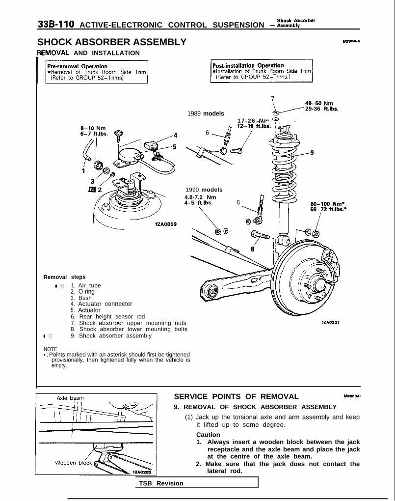
33B-110 ACTIVE-ELECTRONIC CONTROL SUSPENSION - i=ttbborber
SHOCK ABSORBER ASSEMBLY hl33MA-A
[EMOVAL AND INSTALLATION
1989 models
40-50 Nm29-36 ft.lbs.
Removal
l *
l *
8-10 Nm
steps1. Air tube2. O-ring3. Bush4. Actuator connector5. Actuator6. Rear height sensor rod
6
17-26 Nm 9127 ft.lbs;.i
1990 models z??4.8-7.2 Nm4 - 5 ftlbs.
\
6 80-100 Nm*58-72 ft.lbs.*
7. Shock at%orber upper mounting nuts8. Shock absorber lower mounting bolts9. Shock absorber assembly
WA0331
NOTE*: Points marked with an asterisk should first be tightened
provisionally, then tightened fully when the vehicle isempty.
SERVICE POINTS OF REMOVAL m33hlsN
9. REMOVAL OF SHOCK ABSORBER ASSEMBLY
(1) Jack up the torsional axle and arm assembly and keepit lifted up to some degree.
Caution1. Always insert a wooden block between the jack
receptacle and the axle beam and place the jackat the centre of the axle beam.
2. Make sure that the jack does not contact thelateral rod.
TSB Revision

Shock AbsorberACTIVE-ELECTRONIC CONTROL SUSPENSION - Assembly 339-111
(2) Remove the shock absorber upper mounting nuts andthe lower mounting bolts, and then remove the shockabsorber assembly.
Apply rubber greaseI
Air tube absorber assembly side
12A0327
Vehicle-height switch
741IOO08
INSPECTION M33McA8CHECKING FOR SHOCK ABSORBER ASSEMBLY AIR LEAK-AGE
For information concerning checking for air leakage of theshock absorber assembly, refer to the section concerning thestrut assembly (P.33B-98.)
CHECKING ACTUATOR
For information concerning the checking of the actuator, referto the troubleshooting guide and the service adjustmentprocedures section.
SERVICE POINTS OF INSTALLATION M33MEAF
1. CONNECTION OF AIR TUBE
(1) After applying a coating of rubber grease to the O-ring,install the O-ring, bush and joint at the shock absorberassembly side.
Caution1. The O-ring might be damaged if it is installed at
the air tube side and then the insertion is made.2. The bush must be installed so that the projec-
tion part is facing in the direction indicated inthe illustration.
(2) First insert the air tube until resistance is felt, and thenpush in the tube until the painted place on the air tube.
CautionAir leakage may occur if the air tube connection isnot complete and secure.
(3) In order to prevent double-folding of the air springdiaphragm after reconnection of the air tube. thevehicle-height switch should be pressed (wrth thevehicle lifted) two seconds or more so as to Supply airto the air spring.NOTEBy using the switch as described above, air should beintroduced to the rear air springs and front air springs, inthat sequence, for five seconds each.
TSB Revision

339-l 12 ACTIVE-ELECTRONIC CONTROL SUSPENSION - :i%rher
DISASSEMBLY AND REASSEMBLY M33MLbA
Disassembly stepsl + I. Joint** 2. O-ring
3. Actuator bracketmounting nut
4. Actuator bracket+e I)+ 5. Piston rod tightening nut
6. Washer7. Upper bushing (A)
I)+ 8. Bracket assembly9. Spring pad
10, Upper bushing (B)11. Collar
l a 12. Coil spring13. Shock absorber
I\ cd 1d
~-xi Nm -2m
\
33-40 tt.lbs. w 3
45-55 ’ a-a?!3Nm -==
‘33-40 If+Ihc -5
\
\ 8
\‘\ -9
12AO329
MB991237
MB991 239
12LO253
SERVICE POINTS OF DISASSEMBLY hl33MVA8
5. REMOVAL OF PISTON ROD TIGHTENING NUT
(1) Compress the coil spring using the special tool.
CautionDo not use an air tool to tighten the bolt of thespecial tool.
(2) While holding the piston rod, remove the piston rodtightening nut.

Shock AbsorberACTIVE-ELECTRONIC CONTROL SUSPENSION - Assemblv 33B-113
seat
12AOO49
, Bracket
TSB Revision
12AO310
1O-ring
INSPECTION M33MOAB
l Check the rubber parts for damage.l Check the coil springs for crack, damage or deterioration.0 Check the shock absorber for oil leakage malfunction and
abnormal sound.
SERVICE POINTS OF REASSEMBLY M33MWAB
12. INSTALLATION OF COIL SPRING
(1) Use the special tool (MB991237 and MB991239) tocompress the coil spring and insert it in the shockabsorber.
(2) Align the edge of the coil spring to the position of theshock absorber spring seat as shown.
8. INSTALLATION OF BRACKET ASSEMBLY/5. PISTONROD TIGHTENING NUT
(I) With the position of the bracket assembly as shown inthe figure, tighten the tightening nut to the specifiedtorque.
(2) Install the coil spring so that the lower edge fits intothe spring seat groove and the upper edge fits into thespring pad groove, then remove the special tool(MB991 237 and MB991 239).
2. INSTALLATION OF O-RING/l. JOINT
Apply a coating of rubber grease to the O-ring, install it tothe joint, and then install to the piston rod.

33B-114 ACTIVE-ELECTRONIC CONTROL SUSPENSION - ~:h%pension
REAR SUSPENSION ASSEMBLY M33GA-A
REMOVAL AND INSTALLATION
50-60 Nm17-26 Nm 36-43 ftlbs.12-19 ft.lbs.
2,
9-14 ‘Nm7-10 ftlbs.
Vehicles with A.B.S.
9-14 Nm7-10 ft.lbs.
12A0366
Removal steps
1. Parking brake cable2. Brake tube and hose bracket3. Rear disc brake4. Brake disc5. Hub cap
l + 6. Flange nut7. Washer8. Speed sensor <Vehicles with A.B.S.>9. Rear axle assembly
10. Dust shield
200-260 Nm
12A0355
%I*Removal of Trunk Room Srde Tnm
Post-installation Operationl installation of Trunk Room Side
Trim. (Refer to GROUP 52-Trims.)l Check the Brake Disc Runout, and
Adjust.(Refer to GROUP 35-ServiceAdjustment. Procedures.)l Check the Rear Disc Brakes Drag-
ging Torque, and Adjust.(Refer to GROUP 35-ServiceAdjustment Procedures.)
achecking Parking Brake LeverStroke.(Refer to GROUP 36-ServiceAdjustment Procedures.)
@Check the Rolling Diaphragm forDouble-folding.(Refer to P.33B-89.)
TSB Revision

ACTIVE-ELECTRONIC CONTROL SUSPENSION - ~~%f;pension 33B-115
Removal
8-10 Nm
loo-120 Nm*72-87 ftlbs.’
stepsl * 11. Air tube
12. Joint13. O-ring14. Bush15. Actuator connector
40-50 Nm
29-36 fi*‘v’g
SO-100 Nm*58-72 ft.lbs.*
I
18
12AO337
16. Actuator17. Rear heiaht sensor rod mounting bolt (1989 models)
::**+*
17-l. Rear height sensor rod mounting nut(From 1990 models)
18. Lateral rod mounting bolt (body side)19. Shock absorber upper mounting nuts20. Trailling arm mounting bolts21. Rear suspension assembly
NOTE*: Points marked with an asterisk shoud first be tightened
provisionally, then tightened fully when the vehicle isempty.
1989 models-
From 1990 models
17-26 Nm12-19 ftlbs.
17
12AoG37
SERVICE POINTS OF REMOVAL M33GBBE
18. REMOVAL OF LATERAL ROD MOUNTING BOLT (BODYSIDE)
(1) Remove the lateral rod from the body.(2) Secure and hold the lateral rod to the axle beam with
wire, etc.
TSB Revision
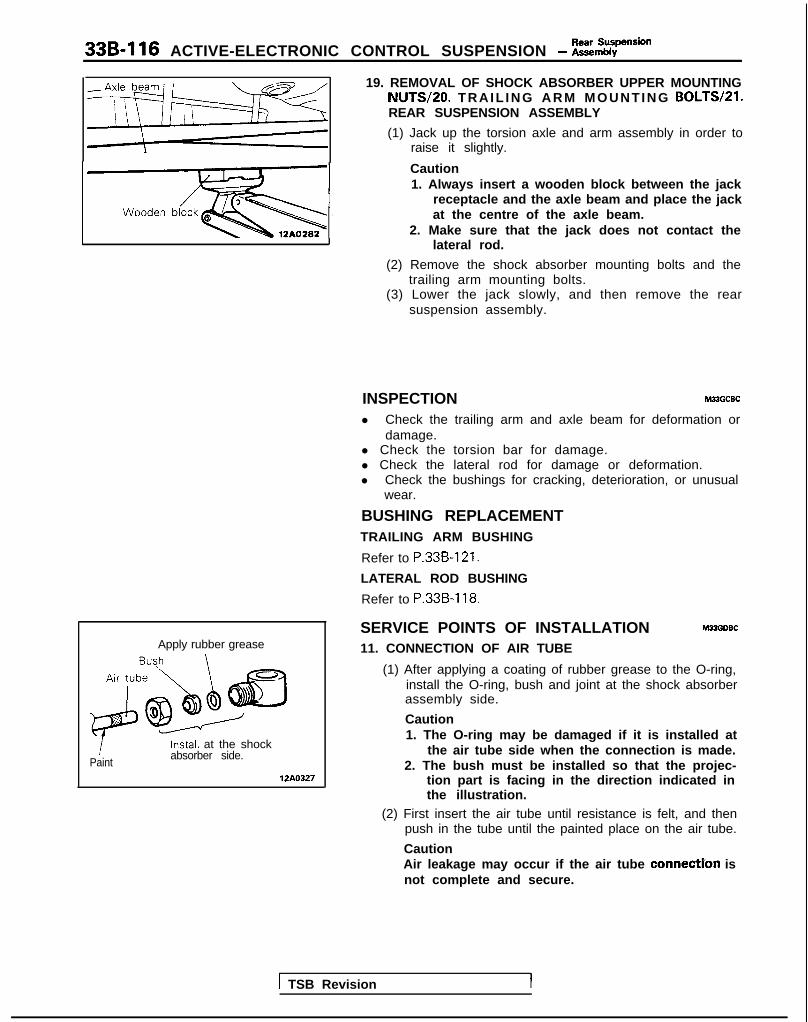
33B-116 ACTIVE-ELECTRONIC CONTROL SUSPENSION - z%rension
‘3.
Apply rubber grease
1Paint
Install at the shockabsorber side.
12A0327
19. REMOVAL OF SHOCK ABSORBER UPPER MOUNTINGNUTS/PO. TRAIL ING ARM MOUNTING BOLTS/Zl.REAR SUSPENSION ASSEMBLY
(1) Jack up the torsion axle and arm assembly in order toraise it slightly.
Caution1. Always insert a wooden block between the jack
receptacle and the axle beam and place the jackat the centre of the axle beam.
2. Make sure that the jack does not contact thelateral rod.
(2) Remove the shock absorber mounting bolts and thetrailing arm mounting bolts.
(3) Lower the jack slowly, and then remove the rearsuspension assembly.
INSPECTION M33GCBC
l Check the trailing arm and axle beam for deformation ordamage.
l Check the torsion bar for damage.l Check the lateral rod for damage or deformation.l Check the bushings for cracking, deterioration, or unusual
wear.
BUSHING REPLACEMENTTRAILING ARM BUSHING
Refer to P.33B-121.
LATERAL ROD BUSHING
Refer to P.33B-118.
SERVICE POINTS OF INSTALLATION M33GDSC
11. CONNECTION OF AIR TUBE
(1) After applying a coating of rubber grease to the O-ring,install the O-ring, bush and joint at the shock absorberassembly side.
Caution1. The O-ring may be damaged if it is installed at
the air tube side when the connection is made.2. The bush must be installed so that the projec-
tion part is facing in the direction indicated inthe illustration.
(2) First insert the air tube until resistance is felt, and thenpush in the tube until the painted place on the air tube.
CautionAir leakage may occur if the air tube connectYon isnot complete and secure.
1 TSB Revision I

ACTIVE-ELECTRONIC CONTROL SUSPENSION - ii%%;%% god 336417
12AOO88
LATERAL RODREMOVAL AND INSTALLATION
i
80-100 Nm*
‘3J@ a - -
58-72 ft.lbs.*
6. INSTALLATION OF THE FLANGE NUT
After tightening the flange nut, align with the indentationin the spindle, and crimp.
MBJUA-A
6’ rrom IJJU mooers 1989 models
9-14Nms 7v7-10 ft.lbs.
12A0602
Removal steps*I)
111.Rear height sensor rod mounting bolt (1989 models)Rear height sensor rod mounting nut (From 1990 models)
l + 2. Rear height sensor bracket mountingbolt
3. Rear height sensor bracket B4. Rear heigh sensor bracket A
::SpacerLateral rod mounting bolt (body side)
++ 7. Lateral rod mounting bolt (axle beam NOTEside) +: Points marked with an asterisk should first be tightenedLateral rod provisionally, then tightened fully when the vehicle is
9. Lateral rod bushing empw.
T S B R e v i s i o n I

33B-118 ACTIVE-ELECTRONIC CONTROL SUSPENSION - Lateral Rod
1989 models SERVICE POINTS OF REMOVAL M22UB6A
1. REMOVAL OF REAR HEIGHT SENSOR ROD
NOTEIf anything other than the rear height sensor rod mountingbolt are removed, the height sensor installation dimensionmust be readjusted so remove other parts only whenabsolutely necessary.
\
12A0600
From 1990 models
-f--_
(-_ \41L-r 12A0601
MB990947-01-4
12R0142
Lateral rodmounting bolt
I II Axle beam
12Ao322
Move the height sensor bracket so that the displaydimensions assume the standard values, then secure thebracket in place with the height sensor bracket mountingbolts.
Standard value (L): 315&l mm (12.4k.04 in.)
Bolt centre ;’Bracket left edge surface,TSB Revision
INSPECTION M22UCAA
l Check lateral rod for damage and deformation.l Check each bushing for cracks, deterioration and wear.
LATERAL ROD BUSHING REPLACEMENT WUEAA(1) Drive out the lateral rod bushing using the special tools.(2) Press in the bushing using the special tools so that the
amount of projection is equal at the left and right.
SERVICE POINTS OF INSTALLATION M22UDAA
7. INSTALLATION OF LATERAL ROD MOUNTING BOLT(AXLE BEAM SIDE)
Install the lateral rod mounting bolt from the directionshown in the illustration.
2. ADJUSTMENT OF REAR HEIGHT SENSOR BRACKETMOUNTING BOLT

Torsion Axle andACTIVE-ELECTRONIC CONTROL SUSPENSION - Arm Assemblv 33B-119
TORSION AXLE AND ARM ASSEMBLY MSPA-A
F{EMOVAL AND INSTALLATION
17-26 Nm
. _ . _.T-10 ftlbs.
12AO355
Vehicles with A.B.S.
9-14 Nm7-10 ftlbs.
I 12AO356 1
Removal steps1. Parking brake cable2. Brake hose and tube bracket3. Rear disc brake4. Rear brake disc5. Hub cap
ea 6. Flange nut7. Washer8. Speed sensor <vehicles with A.B.S.>9. Rear axle assembly
IO. Dust shield
1 TSB Revision
Post-installation Operationl Check the Brake Disc Runout, and
Adiust. I(Refer to GROUP 35-ServiceAdjustment Procedures.)
NIheck the Rear Disc Brakes Drag-ging Torque, and Adjust.(Refer to GROUP 35-ServiceAdjustment Procedures.)l Checking for Parking Brake Lever
Stroke.(Refer to GROUP 35-ServiceAdjustment Procedures.)

33B-120 ACTIVE-ELECTRONIC CONTROL SUSPENSION - Z%iZky8”d
11. Rear height sensor rodmounting bolt or nut
~~ 12. Lateral rod mounting bolt13. Shock absorber mounting bolts
17-26 Nma* 12-19 ftlbs.*I) 14. Trailing arm mounting bolts4* 15. Torsion axle and arm assembly
(1989 models)
(From 1990 models)
loo-120 Nm*72-87 ft.lbs.*A
‘g0 loo-120 Nm*
72-87 ft.lbs.*
VOTE*: Points marked with an asterisk should first be tightened
provrslonally. then tightened fully when the vehicle isempty.
SERVICE POINTS OF REMOVAL M33PaAF13. REMOVAL OF SHOCK ABSORBER MOUNTING
BOLTW14. TRAILING ARM MOUNTING BOLTW15.TORSION AXLE AND ARM ASSEMBLY(1) Jack up the torsion axle and arm assembly in order to
raise it slightly.
Caution1. Always insert a wooden block between the jack
receptacle and the axle beam and place the jackat the centre of the axle beam.
2. Make sure that the jack does not contact thelateral rod.
(2) Remove the shock absorber mounting bolts and thetrailing arm mounting bolts.
(3) Lower the jack slowly, and then remove the torsionaxle and arm assembly.
INSPECTION M22PcAEl Check the trailing arm and axle beam for deformation or
damage.l Check the torsion bar for damage.
TSB Revision

Torsion Axle andACTIVE-ELECTRONIC CONTROL SUSPENSION - Arm Assembly 33B-121
hive out MB991 159A
BasecRacy , )*
surface, n Arfor ’
Nut Bearing‘- I Iu 12LO246
‘ressure insertionMB991 159
Base
\Arbor
ace I
Be’aring12L0247
CROSS SECT. A-A
Chamfered side
12AO403
Lateral rodmounting bolt
I II Axle beam
12AOO88
TRAILIN% ARM BUSHING REPLACEMENT WPEM(1) Drive out and press in the arm bushing using the special
tool.
CautionMount the bearing of the special tool so that the racesurface faces toward the nut.
(2) Press in the bushing from the chamfered side onto thetrailing arm so that the hole is in position as shown.
(3) Press in the bushing so that the amount of projection isuniform throughout.
SERVICE POINTS OF INSTALLATION M33PDAB
12. INSTALLATION OF LATERAL ROD MOUNTING BOLT
Install the lateral rod mounting bolt from the directionshown in the illustration.
6. INSTALLATION OF THE FLANGE NUT
After tightening the flange nut, align with the indentationin the spindle, and crimp.
TSB Revision

33B-122 ACTIVE-ELECTRONIC CONTROL SUSPENSION - Reserve Tank
RESERVE TANKREMOVAL AND INSTALLATION
M33ASAC
Removal steps
I, Air intake shield panel2. Battery3. Battery tray4. Reserve tank connector
l ) l c 5. Air tubes.I .6. O-ring
l * l + 7. Reserve tank8. Tank holders9. Bushes
6
= \ / 12AO395
9-14 Nm@!+--7-10 ft.lbs.
TSB Revision

I ACTIVE-ELECTRONIC CONTROL SUSPENSION - Reserve Tank 33B-123
Air tube12 :“b
\
w
ic ‘-
0
I Joint assemblyMB991 229
12A0280
12AO325
Grommet
10P0081
Install to the body beforehand
SERVICE POINTS OF REMOVAL5. REMOVAL OF AIR TUBES
(1) Push the special tool inward, in direction 0 shown in thefigure, in order to expand the tabs of the joint.
(2) Pull out the air tube, together with the special tool, indirection 0.
CautionTo prevent dust, dirt and other foreign material fromgetting into the air tubes, dryer or solenoid valveopenings, use vinyl tape or similar material to coverthese openings.
7. REMOVAL OF RESERVE TANK
(1) Remove the splash shield’s installation clips (shown inthe figure) and the bolt.Note that the clips should be removed by the proce-dures described below.@ Using a cross-point (+) screwdriver or similar tool,
push the pin at the center of the pin inward about 2mm (08 in.).
0 Pull the clip outward to remove it.
NOTEDo not push the pin in more than necessary, becausethe grommet may be damaged or the pin may fallinside if pushed too much.
(2) Remove the reserve tank installation nut, and then,taking care not to damage the air tube, remove .thereserve tank.
INSPECTIONFor detailed information concerning the checking of the returnpump, the high-pressure switch and the low-pressure switch,refer to the troubleshooting guide and service adjustmentprocedures section.
SERVICE POINTS OF INSTALLATION7. INSTALLATION OF RESERVE TANK
(1) Install the tank holders to the body.(2) Install the reserve tank to the tank holders, taking care
not to damage the air tube.
TSB Revision
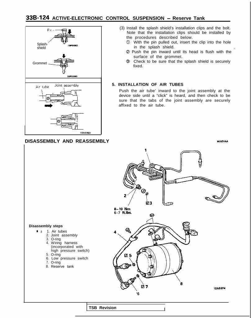
33B-124 ACTIVE-ELECTRONIC CONTROL SUSPENSION - Reserve Tank
Splashshield
Grommet
12A0363
DISASSEMBLY AND REASSEMBLY
(3) Install the splash shield’s installation clips and the bolt.Note that the installation clips should be installed bythe procedures described below.0 With the pin pulled out, insert the clip into the hole
in the splash shield.0 Push the pin inward until its head is flush with the ’
surface of the grommet.0 Check to be sure that the splash shield is securely
fixed.
5. INSTALLATION OF AIR TUBES
Push the air tube’ inward to the joint assembly at thedevice side until a “click” is heard, and then check to besure that the tabs of the joint assembly are securelyaffixed to the air tube.
M33zvAA
8-10 Nm6-7 ft.lbs.
Disassembly stepsl a 1. Air tubes
2. Joint assembly3. O-ring4. Wiring harness
(incorporated withhigh pressure switch)
5. O-ring6. Low pressure switch7. O-ring8. Reserve tank
‘612A0374
TSB Revision I

ACTIVE-ELECTRONIC CONTROL SUSPENSION - ~~~,:B,:w,r 336-125
Paint
12Ao323
AIR COMPRESSORREMOVAL AND INSTALLATION
31(Refer to GROUP ISAir cleaner.)
Post-installation Operationl Installation of Air Cleaner
(Refer to GROUP 15-Air cleaner.)
Removal steps1. Front wiring harness
connector+* I)+ 2. Air tube
3. Joint4. O-ring5. Connector6. Air compressor assembly7. Compressor mounting rubberes8. Compressor mount bracket
SERVICE POINTS OF REASSEMBLY1. CONNECTION OF AIR TUBE
Connect the air tube securely, all the way to the paintedmark.
CautionBe sure that the connection is secure; if it is not, an airleak may result.
: :12AO418
9-14‘7-10
TSB Revision 1

33B-126 ACTIVE-ELECTRONIC CONTROL SUSPENSION - Air compressor
L
MB991 075
w
I 12AO443
12A0444
Exhaust solenoid valve
JointAir iJbe x ~~~~~~~~8,:,,.: :.:.:.:.: .,._, :. ............... .:. ............ . .............................i==Ja................. : . : . .... ... ................
SERVICE POINTS OF REMOVAL2. REMOVAL OF AIR TUBE
Caution1. In order to prevent dust, dirt and other foreign
material from getting into the air tube and aircompressor openings, cover these opening withvinyl tape or similar material.
2. Be careful not to bend the air tubes.
INSPECTION(1) Using special tool (adaptor C), connect the air tube on the
gauge side of the special tool to the air compressor.(2) Apply battery voltage (12V) between terminals (1) and (2)
compressor.(3) Check whether the relief pressure of the air compressor is
the standard value.
Standard value: l,OOO-1,300 kPa (142-185 psi)
NOTEBecause of pulsation caused by the opening and closingof the exhaust solenoid valve combined with the reliefvalve, the gauge’s indicator will show a reading whichfluctuates within a range of 200-300 kPa (29-43 psi). Usethe mid-point of this fluctuation to make the gauge reading.
(4) Stop the air compressor and, with the pressure held, applybattery voltage (12V) between air compressor terminals (3)and (4). At this time, check to be sure that the exhaustsolenoid valve makes a “click” sound and the pressure isgradually decreasing.
(5) If air compressor relief pressure is not within the standardvalue, or if there is a malfunction of the exhaust solenoidvalve, replace the air compressor.
CautionWhen the air compressor is replaced, first check to besure that there is no air leakage at air tube joints, nopoor contacts of wiring, and that the therm0 switch isnot in operation.
SERVICE POINTS OF INSTALLATION2. INSTALLATION OF AIR TUBE
(1) First insert the air tube at the lower part of the dryeruntil resistance is felt, and then press the tube furtherinward to the paint mark on the air tube.
CautionAir leakage may occur if the air tube connection isnot complete and secure.
(2) Connect air tubes correctly to the air compressor.Apply a soap-and-water solution to the air tubeconnections to check to be sure that there is no airleakage.
TSB Revision

Solenoid Valve andACTIVE-ELECTRONIC CONTROL SUSPENSION - Dryer 33B-127
SOLENOID VALVE AND DRYER hl33ZPAC
REMOVAL AND INSTALLATION7-11 Nm5-8 ft.lbs.
5-8 ft.lbs.
Front solenoid valve removal steps
+e I)+ 1. Air tubes2. 0-rinas3. Fran< solenoid valve
assembly4. Front solenoid valve
bracketDryer removal steps*I) I)+ 1. Air tubes
2. O-rings3. Joint assembly4. Bush5. O-ring6. Dryer
Flow control solenoid valveassembly removal steps
*I) l + 1. Air tubes2. O-rings7. Flow control solenoid
valve assembly
m 1e-
I
-la2
7-11 Nm5-8 ft.lbs.
u-b 3f!&I ,
1
TSB Revision I

33B-128 ACTIVE-ELECTRONIC CONTROL SUSPENSION - fi%?d Va’ve and
7-11 Nm5-8 ft.lbs.
4-6 Nm3-4 ft.lbs.
Pre-removal Operation I-im\.j -7
l Removal of Trunk Room Side Tr(Refer to GROUP 52-Trims.)
Air tube 0
\ e 7”
tiB9912291210280
Rear solenoid valve removal steps
+e ,+ 1. Ai r tubes2. O-rings8. Rear solenoid valve assembly9. Rear solenoid valve bracket
12A0450
SERVICE POINTS OF REMOVAL1. REMOVAL OF AIR TUBES
(1) Push the special tool inward, in direction 0 shown in thefigure, in order to expand the tabs of the joint.
(2) Pull out the air tube, together with the special tool. indirection 0.
CautionIn order to prevent dust, dirt and other foreignmaterial from getting into the air tube, solenoidvalve and dryer openings. Cover these openingswith vinyl tape or similar material.
(3) For the air tube at the lower part of the dryer, l oosen
Hold topreventturning.
the joint, and then pull off.
NOTEWhen loosening the joint, use a spanner at thehexagonal part of the joint installation part so as toprevent it from turning.
Joint
12AO278
TSB Revision I

ACTIVE-ELECTRONIC CONTROL SUSPENSION - &ttid Va’ve and 33B-129
12A0369
1 nql \- I E
II-II-II-II--~
G
DFIH 12AO292
soap-and-watersolution.
INSPECTION1. FLOW CONTROL SOLENOID VALVE
Check the No. l-3 solenoid valves shown in the figure forcorrect operation and air leakage.
TSB Revision
Check item Condition Result
Inject air from Part A “click” noise will GoodA and apply battery be heard, and thevoltage to terminal volume of air blown0, and then earth out from joints Bterminal 0. and C will become
greater.
Other than as de- Malfunction ofscribed abooe. No. 1 sole-
noid valve
Blow air in at joint A “click” noise will GoodE. apply battery be heard, and thevoltage (12V) to ter- air being blown outminal 0, and then will change fromearth terminal 0. joint D to joint I.
Other than as de- Malfunction ofscribed above No. 2 sole-
noid valve
inject air from part A “click” noise will GoodG and apply battery be heard, and thevoltage (12~) to ter- air being blown outminal @, and then will change fromearth terminal 0. joint F to joint H .
Other than as de- Malfunction ofscribed above. No. 3 so le -
noid valve
nject air from part Air is not blown GoodPir. out.
Air is blown out Malfunction offrom joint B. check valve
With an air pressure No air leakage Good
of 1,000 kPa (142 Malfunction ofpsi) from parts 9, H Air leakage
solenoid valveand I, apply a soap- sealand-water solutionwhere shown in theillustration.
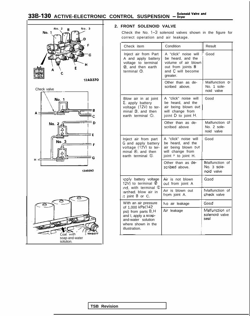
33B-130 ACTIVE-ELECTRONIC CONTROL SUSPENSION - ?Eid “=lve and
2. FRONT SOLENOID VALVE
Check the No. l-3 solenoid valves shown in the figure forcorrect operation and air leakage.
No. 2 N o . 3
Check item Result
Good
Condition
Inject air from PartA and apply batteryvoltage to terminal0, and then earthterminal 0.
A “click” noise willbe heard, and thevolume of air blowout from joints Band C will becomegreater.
n112A0370Malfunction oiNo. 1 sole-noid valve
Other than as de-scribed above.
Check valve
A “click” noise willbe heard, and theair being blown ou’will change fromjoint D to joint H.
GoodBlow air in at jointE, apply batteryvoltage (12V) to ter-minal 0. and thenearth terminal 0.
t I
H =
Malfunction oiNo. 2 sole-noid valve
Other than as de-scribed above
A “click” noise willbe heard, and theair being blown 0u1will change fromjoint F to joint H.
Other than as de-xribed above.
Air is not blownout from joint A
GoodInject air from partG and apply batteryvoltage (12V) to ter-minal @, and thenearth terminal 0.
t
I=
i
r
(
Malfunction ofYo. 3 sole-loid valve
;ood
12AO293
4pply battery voltage12V) to terminal 0rnd. with terminal @earthed, blow air inrt joint B or C.
vlalfunction of:heck valver
C
(1P
5
c
Air is blown outYom joint A.
Vo air leakageWith an air pressureof 1,000 kPa (142psi) from parts B, Hand I, apply a soap-and-water solutionwhere shown in theillustration.
;ood
vlalfunction o f;olenoid valveieal
lir leakage
soap-and-watersolution.
TSB Revision

Solenoid Valve andACTIVE-ELECTRONIC CONTROL SUSPENSION - Dryer 33B-131
3
F
‘G
\
12A0371
>
Rearpressuresensor
l------i-l
12AO294
TSB Revision
-n
Coat withsoap-and-watersolution.
3. REAR SOLENOID VALVECheck the No. l-3 solenoid valves shown in the figure forcorrect operation and air leakage.
Check item Condition Result
Inject air from Part A “click” noise will GoodA and apply battery be heard, and thevoltage (12V) to ter- air will be blownminal 0, and then out from joints Bearth terminal 0. and C.
Other than as de- Malfunction ofscribed above. No. 1 sole-
noid valve
Blow air in at joint A “click” noise will GoodE, apply battery be heard, and thevoltage (12V) to ter- air being blown outminal 0, and then will change fromearth terminal 0. joint D to joint H. /
: Other than as de- Malfunction ofI scribed above No. 2 sole-
noid valve
Inject air from part A “click” noise will Good3 and apply battery i be heard, and thedoltage (12V) to ter- 1 air being blown outninal @, and then will change fromsarth terminal 0. joint F to joint H.
I Other than as de- Malfunction ofscribed above. No. 3 sole-
noid valve
i/Vith an air pressure No air leakage Goodof 1,000 kPa (142xi) from parts A and
Air leakage Malfunction of
-l, apply a soap-and-solenoid valve
Nater solutionseal
Nhere shown in theIlustration.

33B-132 ACTIVE-ELECTRONIC CONTROL SUSPENSION - p$? Va’ve and
Joint assembly
ezAir tube identification color
12AO363
12AO278
SERVICE POINTS OF INSTALLATION1. INSTALLATION OF AIR TUBES
(1) For the one-touch type of air tube, press in to the jointassembly at the device side until a “click” is heard, andthen check that the tabs of the joint assembly aresecurely affixed to the air tube.
CautionBefore connecting the air tube, check that theidentification color of the tube and the color at thejoint agree.
(2) First insert the air tube at the lower part of the dryeruntil resistance is felt, and then press the tube furtherinward to the paint mark on the air tube.
CautionAir leakage may occur if the air tube connection isnot complete and secure.
(3) After connection of the air tube, check for double-folding of the rolling diaphragm. (Refer to P.338-89.)
TSB Revision

ACTIVE-ELECTRONIC CONTROL SUSPENSION - Air tube 336-133
AIR TUBE M332QAC
REMOVAL AND INSTALLATION
l , l * 1. *Air tubes(flow control solenoid valve to jointassembly)
+e l + 2. Air tube(front solenoid valve to actuator)
+e l e 3. Air tubes(flow control solenoid valve to frontsolenoid valve)
4~ l + 4. *Air tubes(joint assembly to rear solenoid valve)
+, I)+ 5. Ai r tube(rear solenoid valve to actuator)
+e ++ 6. Ai r tube(flow control solenoid valve to air com-pressor)
l , ,+ 7. Air tubes(dryer to flow control solenoid valve)
l e l a 8. Air tubes (to reserve tank)9. Joint assembly
10. O-rings11. Joint12. Bush
NOTE(1) Connections within ( ) are air tube connections.(2). Air tubes indicated by the l symbol are interwound with
the harness.
12AO450
12AO378
Cross-section of air tubejoint<one-touch type>
810I
<flare-nut type>S-IO N m8-7 ftlbs. 11
I
TSB Revision

33B-134 ACTIVE-ELECTRONIC CONTROL SUSPENSION - Air tube
AirTab
\Joint asset
MB991229nbly
12AO280
Dryer lower pa
\
t-t connection part Flare-nut typeLoosen the joint and pull out the air tube.
NOTE
12A0278
When loosening the joint at the lower part of the dryer, use aspanner to hold the hexagonal part of the joint installation partto prevent it from turning.
CautionIn order to prevent the entry of dust, foreign material, etc.,use vinyl tape or similar material to close the end of the airtube and the opening at the device side.
tLe*~Identificationcolor Joint assembly
12AO363
1210278
SERVICE POINTS OF REMOVALREMOVAL OF AIR TUBES
One-touch type
(1) Push the special tool inward, in direction 0 shown in thefigure, in order to expand the tabs of the joint.
(2) Pull out the air tube, together with the special tool, indirection 0.
SERVICE POINTS OF INSTALLATIONINSTALLATION OF AIR TUBES
One-touch type
Push the air tube in the joint assembly at the device side untila “click” is heard, and then check to be sure that the tabs ofthe joint assembly are securely affixed to the air tube.
CautionBefore connecting the air tube, check to be sure that theidentification color of the tube and the color at the jointagree.
Flare-nut type
First insert the air tube until resistance is felt, and then pressthe tube further inward to the paint mark on the air tube.
CautionAir leakage may occur if the air tube connection is notcomplete and secure.
INSPECTION AFTER AIR TUBE INSTALLATION
(1) Check for double-folding at the rolling diaphragm. (Refer toP.33B-89.)
(2) Apply a soap-and-water solution to the joint part to checkfor air leakage; also visually check the air tube forbreakage, crushing, pinching, etc.
TSB Revision

ACTIVE-ELECTRONIC CONTROL SUSPENSION - Heiaht Sensor 33B-135
HEIGHT SENSORREMOVAL AND INSTALLATION
Front height sensor
17-26 Nm
li-26 Nm12-19 ft.lbs.
l Removal of Air Compressor for
17-26 Nm I- I” n.,os.12-19 ft.lbs.
l checking and Adjustment of the 14 Nm10 ftlbs.
1989 modelsFront height sensor removal steps
1. Front wiring harness connector* 2. Front height sensor
e+ 3. Front rod assembly
Rear height sensor removal steps
4. Body wiring harness connector5. Rear height sensor6. Protector
l a 7. Rear rod assembly8. Rear height sensor bracket (B)9. Spacer
10. Rear height sensor bracket (A) l2A0358
12AO464
M332TAE
Rear height sensor
9-14 Nm- .a #.&IL-
12AO358
‘19901
i.8-7.2 Nm4-5 ft.lbs. 12A0608
TSB Revision

33B-136 ACTIVE-ELECTRONIC CONTROL SUSPENSION - Height Sensor
Front height sensor connectorterminal array
1
1270185
No 1 Sensor A No. 4 GroundNo 2 Sensor B No. 5 Sensor DNo 3 Sensor C No. 6 Sensor power
supply i + 5W
Front height sensor position
Rear height sensor connectorterminal array
12R0185
No. 1 Sensor A No. 4 GroundNo 2 Sensor B No. 6 Sensor powerNo. 3 Sensor C SUPPlY (+ 5w
Rear height sensor position
1TSB Revision
INSPECTIONl Check the rod and link plate for bending or damage.l Check the rod adjustment lock nut for looseness.
CHECKING THE SENSOR TERMINAL VOLTAGE
Connect the height sensor to the body harness and thencheck that each terminal voltage changes as shown in thetable below when, with the ignition key at the ON position,the sensor’s link plate is turned.
NOTETo check the sensor terminal voltage, one method which canbe used is to move the rod up and down while the sensor isinstalled to the chassis.
Front Height Sensor Terminal Voltages
P
Vehicle height level Sensor Terminal No.link
position 1 2I3 5
Maximum level 0 4.5-Eo-o.5 -
Higher than HIGH 0 4.5-5o-o.5
HIGH (target height) 04.5-5
Higher than NORMAL @
NORMAL (target height) 0 / o-o.5 O-O.!
Lower than NORMAL 63 o-o.5
LOW (target height) 0 4.5-5
Lower than LOW Q 4.5-54.5-5 -
Minimum level 8 4.5-E
Rear Height Sensor Terminal Voltages
b
Vehicle height level Sensor Terminal No.link
position 1 2 3
Higher than HIGH 0 o-o.54.5-5
HIGH (target height) 0o-o.5 . 4.5-5
Higher than NORMAL 0
NORMAL (target height) 63 o-o.5
Lower than NORMAL 0 o-o.5
LOW (target height) 8 4.5-54.5-5
Lower than LOW 0 4.5-5

ACTIVE-ELECTRONIC CONTROL SUSPENSION - Height Sensor 33B-137
From 1990 models
GoodI
Bad1
I I 12R0363
Bolt center left edgesurface
SERVICE POINTS OF INSTALLATION7. INSTALLATION OF REAR ROD ASSEMBLY / 3. FRONT
ROD ASSEMBLY
(1) Adjust the front and rear height sensors so thatdimension A of the rod in the illustration is withinspecification.
Rod assembly length (A)Front 254-255 mm (9.9-10.0 in.)Rear 149.5-150.5 mm (5.89-5.93 in.)
Caution1. When adjusting the length of the rod, adjust so
that dimension B is uniform2. Height sensors must be installed so that the ball
joint at the rod end is at rocking centre.
(2) When installing the rear rod assembly, install the rearheight sensor brackets so that the dimension L in theillustration. is the standard value.
Standard value (L): 314-316 mm (12.3-12.4 in.)
a-- -
TSB Revision
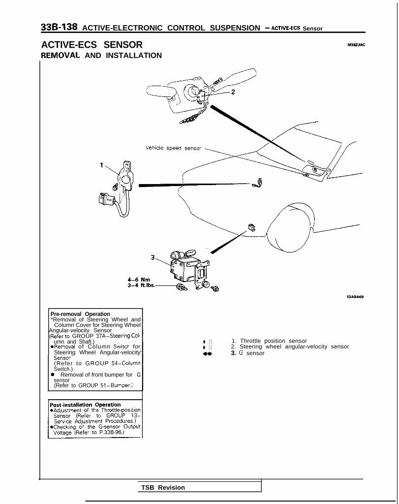
33B-138 ACTIVE-ELECTRONIC CONTROL SUSPENSION - ACTIVE-ECS Sensor
ACTIVE-ECS SENSOR M33ZVAC
IEMOVAL AND INSTALLATION
Pre-removal Operation*Removal of Steering Wheel and
Column Cover for Steering WheelAngular-velocity Sensor(Referto GROUP 37A-Steering Cof-
umn and Shaft.)~ @Removal of Column Switch for
Steering Wheel Angular-velocitySensor-(Refer to GROUP 54-ColumnSwitch.)l Removal of front bumper for G
sensor(Refer to GROUP 51-Bumper.)
1210449
l * 1. Throttle position sensorl * 2. Steering wheel angular-velocity sensor4* 3. G sensor
TSB Revision

ACTIVE-ELECTRONIC CONTROL SUSPENSION - ACTIVE-ECS Sensor 33B-139
Steering wheel angular-velocity sensor
TSB Revision
- -
12A046
SERVICE POINTS OF REMOVAL1. REMOVAL OF THROTTLE POSITION SENSOR
Disconnect the harness connector, then remove thethrottle position sensor from the throttle body.
2. REMOVAL OF STEERING WHEEL ANGULAR-VELOCITYSENSORRemove the pin terminal from the column switch connec-tor, then remove the steering wheel angular-velocitysensor from the column switch.
Caution1. The steering wheel angular-velocity sensor utilizes a
photo coupler and care should be paid to ensurethat no dust or grease are allowed to come intocontact with it.
2. Be careful and ensure that the column switch sideslit panel is not bent nor oil allowed to come intocontact with it.
3. REMOVAL OF G SENSORDisconnect the connection of the harness connector, andthen remove the G sensor.
C a u t i o nWhen removing the G sensor, take care not to drop it orsubject it to severe impact.
INSPECTIONFor information concerning the procedures for checking eachsensor, refer to the service adjustment procedures sectionand to the troubleshooting guide.

338-140 ACTIVE-ELECTRONIC CONTROL SUSPENSION - t:%%%=mb’y’
INDICATOR ASSEMBLYSERVICE POINTS OF REMOVAL(1) Using a plastic trim tool, remove the indicator assembly
from the instrument panel.(2) Disconnect the connector and remove the indicator
assembly.
INSPECTION(1) Indicator light does not light (the circuit, light bulb, or LED
have failed).
NOTEOperate the ECS and check to see that the light bulbs andLED light.
(2) Do the lights loose intensity when the lighting switch isplaced at 50 0: and $D . For procedures for otherinspections, refer to the troubleshooting section.
CONTROL UNITSERVICE POINTS OF REMOVAL(1) Remove the trunk side trim.
(Refer to GROUP 52-Trims.)(2) Remove the installation bolts and connectors, and then
remove the control unit.
INSPECTIONReferring to the troubleshooting section, check whether thereis terminal voltage.
TSB Revision

ACTIVE-ELECTRONIC CONTROL SUSPENSlON - ACTIVE-ECS Relay 338-141
ACTIVE-ECS RELAY -VA-A
REMOVAL AND INSTALLATION
I, Power relay2. Solenoid valve power relay3. Compressor relay4. Return pump relay
TSB Revision I

33B-142 ACTIVE-ELECTRONIC CONTROL SUSPENSION - ACTIVE-ECS Relay
Power relay
Circuit tester
INSPECTIONConnect battery power source to terminal 1. Check circuitbetween terminals with terminal 2 grounded.
Power is supplied Between 3-4 ter- Continuityminals
Power is notsupplied
Between l-2 ter-minals
Between 34 ter-minals
Continuity
No continuity
0’16L0346
Solenoid valve power relayr
12AO276
Compressor relay, Return pump relay
12A0277
TSB Revision 1

34-1
REARSUSPENSION
CONTENTS M%AA-
<AWD-UP TO 1992 MODELS> <FWD>
REAR SUSPENSION ASSEMBLY .................. 24
SERVICE ADJUSTMENT PROCEDURES.. ..... 23Rear Wheel Alignment Inspection ............... 23
SHOCK ABSORBER ASSEMBLY ................... 35
SPECIAL TOOLS ............................................. 21
SPECIFICATIONS ............................................. 19General Specifications .................................. 19
Service Specifications ................................... 19Torque Specifications ................................... 20
STABILIZER BAR ............................................. 37
TRAILING ARM ............................................... 31
TROUBLESHOOTING ...................................... 22
UPPER AND LOWER ARM ............................ 28
LATERAL ROD ................................................. 14
REAR SUSPENSION ASSEMBLY .................. 6
SERVICE ADJUSTMENT PROCEDURES.. ..... 5Rear Wheel Alignment Inspection ............... 5
SHOCK ABSORBER ASSEMBLY ................... 11
SPECIAL TOOLS ............................................. 4
SPECIFICATIONS ............................................. 2
General Specifications .................................. 2
Service Specifications ...................................
Torque Specifications ...................................
TORSION AXLE AND ARM ASSEMBLY.. .... 15
TROUBLESHOOTING ...................................... 5

34-2 REAR SUSPENSION <MD> - Specifications
SPECIFICATIONS <FWD>GENERAL SPECIFICATIONS M3CA-A
Items
Suspension system
Coil spring
High line
SOHCDOHC
Plemium line
3-link. torsion axle with coil spring type
<Vehicles without Active ECS>
Wire dia. x O.D. x free length < 1989 models> < 1989 models> <From 1990.5 models>
mm h-d[Coil spring identification color]
10.5 x 105.5 x 342.5 10.5 x 105.5 x 349.5 10.8 x 105.8 x 356.5(.41 x 4.15 x 13.48) (.41 x 4.15 x 13.76) (.43 x 4.17 x 1 4 . 0 4 )[Blue x 11 [Blue x 21 [Whi te x II
<From 1990 <From 1990models> models>
10.5 x 105.5 x 349.5 10.8 x 105.8 x 356.5(41 x 4.15 x 13.76) (.43 x 4.17 x 14.04)[Blue x 21 [Whi te x 11
Coil spring
<Vehicles with Active ECS>
Wire dia. x upper end O.D. - - <Up to 1990 models>x lower end O.D. L.H. sidex free length mm (in.) 9.5 x 119.5 x 119.5 x 428[Coil spring identification color] (.37 x 4.70 x 4.70 x 16.85)
[Light green x II
R.H. side9.5 x 119.5 x 119.5 x 412(.51 x 4.70 x 4.70 x 16.22)[Light green x 21
<From 1991 models>
L.H. side10.1 x 122.1 x 381.5(.40 x 4.81 x 15.02)[Light green x 21
R.H. side10.1 x 122.1 x 370(.40 x 4.81 x 14.57)[Light green x 11
Spring constant N/mm (Ibs./in.) 21 (117.6)<Vehicles without Active ECS>
21 (117.6) 21 (117.6)
Spring constant N / m m (Ibs./in.) -
<Vehicles with Active ECS>
- 9.4 (52.64)<Up to 1990 models>
13.5 (75.60)<From 1991 models>
Shock absorber
Type Hydraulic, cylindrical, double-acting type Hydraulic, cylindrical double-acting type
TSB Revision

REAR SUSPENSION <WD> - Specifications 34-3
SOHCItems
High line Plemium line
<Vehicles without Active EC.S>
Max. length mm (in.) 505 (19.9)
Min. length mm (in.) 315 (12.4)
Stroke mm (in.) 190 (7.5)
Damping force[at 0.3 m/set. (.9 ft.Isec.11
Expansion N (Ibs.) 7 5 0 (165)Contraction N (Ibs.) 3 5 0 (77)
<Vehicles with Active ECS>
Max. length mm ( in.) -
Min. length mm ( in.) -
Stroke mm ( in.) -
Damping force [at 0.3 m/set.I.9 ft./sec.)l
Expansion N (Ibs.)
HARD -
MEDIUM -
SOFTContraction N (Ibs.)
HARD
MEDIUM
SOFT -
JVheel bearing
Type Tapered roller bearing
O.D. x I.D. mm (in.)
Outer 39.9 x 17.5 (1.57 x .69)
Inner 50.3 x 27.0 (1.98 x 1.06)
DOHC
<From 1990.5 models>
505 (19.9)
315 (12.4)
190 (7.5)
750 (165)350 (77)
<Up to 1990 <From 1 9 9 1models> models>
491 (19.33) 491 (19.33)
341 (I 3.43) 341 (13.43)
150 (5.91) 150 (5.91)
1,450 (320) 1,700 (375)
850 (187) 850 (187)
270 (60) 270 (60)
500 (110) 540 (119)
350 (77) 350 (77)
200 (44) 200 (44)
Unit ball bearing
SERVICE SPECIFICATIONS
Items
Standard value
Toe-in (Left-right difference)
Camber
NOTEToe-in and camber cannot be adjusted.
MWX-A
SOHC DOHC
m m ( i n . ) 0+3 (0+.118) 0 4 3 (O&.118)
-45’ 2 30’ -45’ + 30’
TSB Revision I
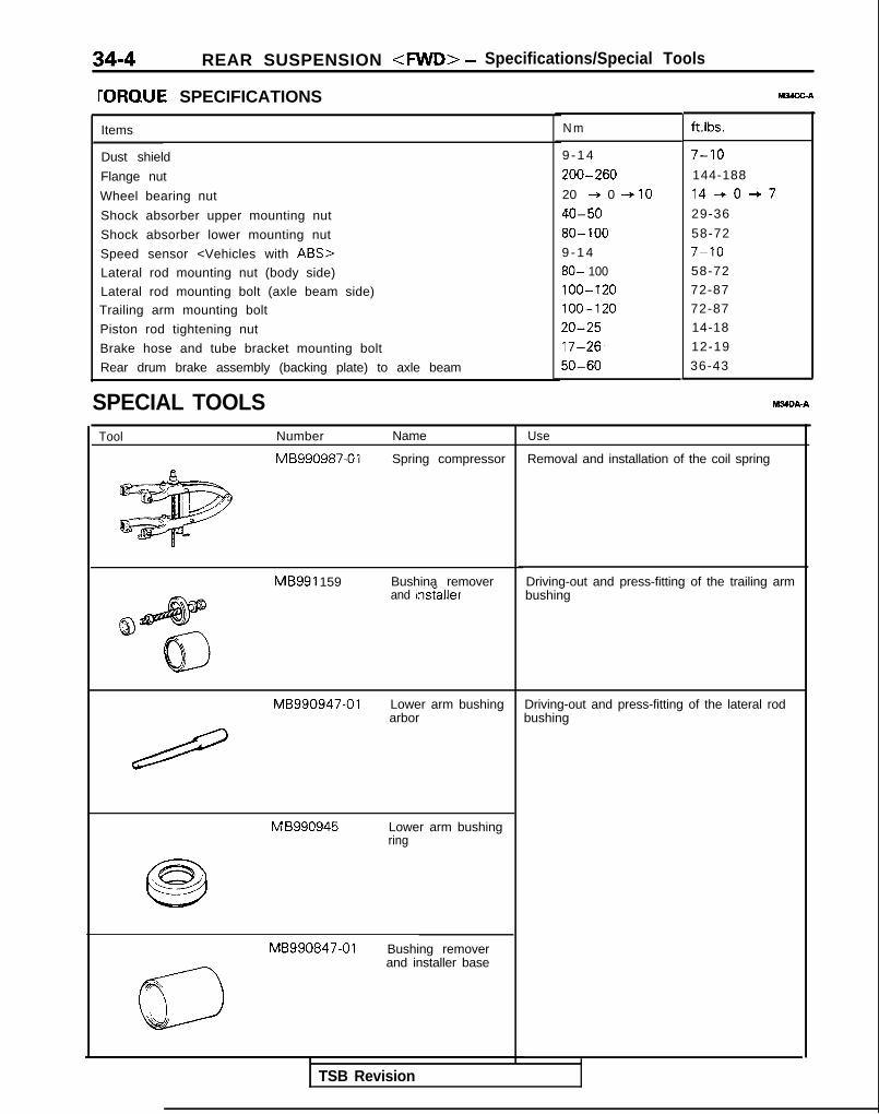
34-4 REAR SUSPENSION <MD> - Specifications/Special Tools
rORQUE SPECIFICATIONS t&4X-A
Items
Dust shield
Flange nut
Wheel bearing nut
Shock absorber upper mounting nut
Shock absorber lower mounting nut
Speed sensor <Vehicles with ABS>
Lateral rod mounting nut (body side)
Lateral rod mounting bolt (axle beam side)Trailing arm mounting bolt
Piston rod tightening nut
Brake hose and tube bracket mounting bolt
Rear drum brake assembly (backing plate) to axle beam
SPECIAL TOOLS M34DA-A
Tool Number Name
MB990987-01 Spring compressor
MB991 159 Bushina removerand insraIler
MB990947-01 Lower arm bushingarbor
M B990945 Lower arm bushingring
MB990847-01 Bushing removerand installer base
N m ft.lbs.
9 - 1 4 7-10
200-260 144-188
20 + 0 + IO 14-+0+7
40-50 29-36
80- 100 58-72
9 - 1 4 7-10
80- 100 58-72
100-120 72-87
100-120 72-87
20-25 14-18
17-26, 12-19
50-60 36-43
Use
Removal and installation of the coil spring
Driving-out and press-fitting of the trailing armbushing
Driving-out and press-fitting of the lateral rodbushing
TSB Revision

REAR SUSPENSION <MD> - Troubleshooting/Service Adjustment Procedures 34-5
TROUBLESHOOTING M34EAA
Symptom Probable cause ( Remedy
Squeaks or otherabnormal noise
Loose rear suspension installation bolts and nuts RetightenI
Malfunction of shock absorberWorn bushings
Replace
Poor ride Excessive tire inflation pressure I Adjust the pressure
Malfunction of shock absorberWeak or broken springs
Replace
Body tilting Weak or deteriorated bushingsWeak or broken springs
Replace
TSB Revision
SERVICE ADJUSTMENT PROCEDUEZ$
REAR WHEEL ALIGNMENT INSPECTIONThe rear suspension assembly must be free of worn, loosen ordamaged parts prior to measurement of rear wheel alignment.
Standard value:Toe-in (Left-right difference)
0+3 mm (Ok.118 in.)Camber -45’ f 30’
NOTEThe rear wheel alignment is set at the factory and cannot beadjusted.If toe-in or camber is not within the standard value, replacebent or damaged parts.

34-6 REAR SUSPENSION <FVVD> - Rear Suspension Assembly
REAR SUSPENSION ASSEMBLYREMOVAL AND INSTALLATION
<Vehicles with Rear Drum Brake>
1017-26 Nm
12-19 “‘“s. y+.,
6 54 3
2wdy4d 1( t)
e
._-.
l Removal of the Trunk Side Trim (Refer to
l installation of the Trunk Side Tnm (Referto GROUP 52-Trims.)l Parking Brake Lever Stroke Adjustment
(Refer to GROUP 36-Service Adjust-
Removal steps
Adjustment of wheel bearing end play(Refer to GROUP 27-Service AdjustmentProcedures)
1. Hubcap2. Cotter pin3. Lockcap
l 4 4. Wheel bearing nut5. Washer
7:8.9.
10.11.12.13.14.
M34GA.A
50-60 N m3 6 - 4 3 ft.lbs.
Outer wheel bearing inner raceBrake drumRear drum brake(Referto GROUP 35-Rear Drum Brakes)Parking brake cableBrake hose and tube bracketLateral rod mounting boltCapShock absorber upper mounting nutTrailing arm mounting bolt
7 20-*0~10 Nm1440+7 ft.lbs. 14AO438
12
40-50 N m2 9 - 3 6 ft.lbs.
80-100 Nm*5 8 - 7 2 ft.lbs.*
I
loo-120 Nm*7 2 - 8 7 ft.lbs.*
4* 15. Rear suspension assembly12AO335
NOTE*. Indicates part which should be temporarily tightened, and
then fully tightened with the vehicle in the unladencondition.
TSB Revision
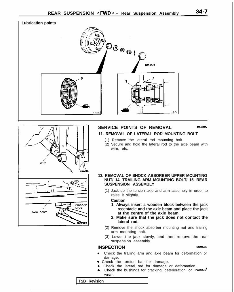
REAR SUSPENSION <RND> - Rear Suspension Assembly
Lubrication points
12ElOl
SERVICE POINTS OF REMOVAL M34GsAJ
11. REMOVAL OF LATERAL ROD MOUNTING BOLT(1) Remove the lateral rod mounting bolt.(2) Secure and hold the lateral rod to the axle beam with
wire, etc.
\
13. REMOVAL OF SHOCK ABSORBER UPPER MOUNTING-INUT/ 14. TRAILING ARM MOUNTING BOLT/ 15. REARSUSPENSION ASSEMBLY
(1) Jack up the torsion axle and arm assembly in order toraise it slightly.
Caution1. Always insert a wooden block between the jack
receptacle and the axle beam and place the jackat the centre of the axle beam.
2. Make sure that the jack does not contact thelateral rod.
(2) Remove the shock absorber mounting nut and trailingarm mounting bolt.
(3) Lower the jack slowly, and then remove the rearsuspension assembly.
INSPECTION M34Glxl.
l Check the trailing arm and axle beam for deformation ordamage.
0 Check the torsion bar for damage.l Check the lateral rod for damage or deformation.0 Check the bushings for cracking, deterioration, or unusual
wear.
TSB Revision

Drive out
Race
BUSHING REPLACEMENT M34GlAEMB991 159
Base ArborTRAILING ARM BUSHING
Oh (1) Drive out the trailing arm bushing using the special tool.
Caution
34-8 REAR SUSPENSION <FM/D> - Rear Suspension Assembly
The bearing within the special tool should be installed,as shown in the figure, at the race surface nut side ofthe bearing.
12LO246
Pressure insertionMB991159
XOSS SECT. A-A
Chamfered side
12LO247
12A040:
k
MB990947-01
’ MB990945
\ MB990847-01
12R0142
(2) Press the bushing with the special tool into the trailingarm (from the chamfered part of the trailing arm) so thatthe bushing hole is at the position indicated in the figure.
(3) Be careful that the bushing hole is at the position indicatedin the figure and that the difference in bushing projectiondistances does not exceed the following value.
l-1 - L2 = 0 f 1.0 mm (0 f .04 in.)
LATERAL ROD BUSHING (BODY SIDE)(1) Drive out the lateral rod bushing using the special tool.(2) Press in the bushing using the special tool so that the
amount of projection is equal at the left and right.NOTEThe replacement of the lateral rod’ bushing at the axlebeam side is made by the same procedures described insteps (1) and (2) above.
TSB Revision

REAR SUSPENSION <FM/D> - Rear Suspension Assembly 34-9Turn 180” or more antreturn 360” or more.
epeat 3 times of
TSB Revision 1.
SERVICE POINTS OF INSTALLATION MS4GDAS
4. INSTALLATION OF WHEEL BEARING NUT(1) After tightening the wheel bearing nut to 20 Nm (14
ft.lbs.), turn the hub a few times to seat the bearing.(2) In order to seat the bearing properly, turn the hub (brake
drum) 180” or more and then return it 360” or more;repeat this procedure again three or more times.
(3) Return the wheel bearing nut to 0 Nm (0 ft.lbs.).(4) After tightening the wheel bearing nut at a torque of 10
Nm (7 ftlbs.), rotate the hub again in the same way asdescribed in step (2) so as to seat the bearing.
(5) Then once again tighten the wheel bearing nut to 10Nm (7 ft.lbs.).
(6) Install the lock cap and cotter pin.(7) If the position of the cotter pin is not matched with the
holes of the lock cap, reposition the lock cap so that theholes align. If this can not be accomplished, back off thenut by not more than 15”.
CautionCheck to be sure that the lock nut cannot beloosened manually.
(8) After setting the split pin in place, seat the bearing inthe same manner as in step (2).

34-10 REAR SUSPENSION <FWD> - Rear Suspension Assembly
<Vehicles with Rear Disc Brake>
1 7 - 2 6 Nm 50-60 Nm1 2 - 1 9 ft.lbs. 2 36-43 ft.lbs. 1
9 - 1 4 N m7-10 ft.lbs.
200-240 Nm144-188 ft.lbs.
9 - 1 4 N m7-10 ft.lbs.
8 n
11
40-50 N m29-36 ft.lbs. \
12 12AO355
1380-100 Nm*58-72 ft.lbs.*
\
I loo-120 Nm* .-- -- _. . . ”Post-installation Operation*Check the Brake Disc Runout. and
Adiust. (Refer to GROUP 35-
*Check the Rear Disc Brakes Draq-Iging Torque, and Adjust. (Refer foGROUP 35-Service Adjustment I
Sehice Adjustment Procedures.) 1
Procedures.)@Checking Parking Brake Lever
Stroke. (Refer to GROUP 36-Service Adjustment Procedures.)
Removal steps
1. Parking brake cable2. Brake tube and hose bracket3. Rear disc brake4. Brake disc5. Hubcap
~~ 6. Flange nut (Refer to GROUP 33B-RearSuspension Assembly.)
7. Washer8. Speed sensor <Vehicles with A.B.S.>^ ^
WA0336
12. Cap13. Shock absorber upper mounting nut
(Refer to P.34-6.)14. Tr$ling arm mounting bolt (Refer to P.34-
6.)15. Rear suspension assembly (Refer to P.34-
6.)
c*
Y. Hear axle assembly10. Dust shield11. Lateral rod mounting bolt (Refer to P.34-
6.)
NOTE*: indicates part which should be temporarily tightened, and
then fully tightened with the vehicle in the unladencondition.
1 TSB Revision I

REAR SUSPENSION <FWD> - Shock Absorber Assemblv
SHOCK ABSORBER ASSEMBLYREMOVAL AND INSTALLATION
hl34NA-A
Pre-removal and Post-installation Op-r*Removal and lnstallatlon of the TrunkSide Trim (Refer to GROUP 52-Trims.)
Removal steps1. Cap
4* 2. Shock absorber upper mounting nuts4* 3. Shock absorber lower mounting bolt4* 4. Shock absorber
29-38 .,bs.-JLzd ’40-50 N m
80-100 Nm*58-72 ft.lbs.*
NOTE*: Indicates part which should be temporarily tightened, and
then fully tightened with the vehicle in the unladencondition. 12AO462
TSB Revision
SERVICE POINTS OF REMOVAL M34NsAA2. REMOVAL OF SHOCK ABSORBER UPPER MOUNTING
NUT/B. SHOCK ABSORBER LOWER MOUNTINGBOLT/4. SHOCK ABSORBER(1) Jack up the torsion axle and arm assembly in order to
raise it slightly.
Caution1. Always insert a wooden block between the jack
receptacle and the axle beam and place the jackat the center of the axle beam.
2. Be sure that the jack does not contact the lateralrod.
(2) Remove the shock absorber’s upper mounting nut andlower mounting bolt, and then remove the shockabsorber.

34-12 REAR SUSPENSION <FWD> - Shock Absorber Assembly
DISASSEMBLY AND REASSEMBLY M34GM-A
i
r
Disassembly steps
+e l + 1. Piston rod tightening nut2. Washer3. Upper bushing (A)
1)4 4. Bracket assembly5. Upper spring pad6. Upper bushing (B)7. Collar
I)+ 8. Cup assemblyea 9. Dust cover
10. Bump rubberl + 11. Coil spring
12. Shock absorber
9-
11
12
-Y-R\-
Ef‘i I\2%P
2I--’
,:14q-=L57
-IdC
\
20-25 Nm'14-18 ft.lbs.
@%9--s-
12A0328
WY 12KO39
SERVICE POINTS OF DISASSEMBLY M34GNAA
1. REMOVAL OF PISTON ROD TIGHTENING NUT(1) Before removing the piston rod tightening nut,
compress the coil spring using the special tools.
CautionDo not use an air tool to tighten the bolt of thespecial tool.
TSB Revision I
(2) While holding the piston rod, remove the piston rodtightening nut.
INSPECTION M34GOAA
l Check the rubber parts for damage.l Check the coil springs for crack, damage or deterioration.

REAR SUSPENSION <FWD> - Shock Absorber Assembly 34-13
oil springseat
12A0049
Cup assembly
DE> cover
Bracket assembly
Shock absorber lower bushing 12R0140
SERVICE POINTS OF REASSEMBLY M34GPA3
11. INSTALLATION OF COIL SPRING
(1) Use the special tool (MB990987-01) to compress thecoil spring and insert it in the shock absorber.
(2) Align the edge of the coil spring to the position of theshock absorber spring seat as shown.
9. INSTALLATION OF DUST COVEl?/8. CUP ASSEMBLYAs shown in the illustration, fit the dust cover to the cupassembly.
4. INSTALLATION OF BRACKET ASSEMBLY/l. PISTONROD TIGHTENING NUT(1) With the position of the bracket assembly as shown in
the figure, tighten the tightening nut to the specifiedtorque.
(2) Install the coil spring so that the lower edge fits into thespring seat groove and the upper edge fits into thespring pad groove, then remove the special tool(MB990987-01).
TSB Revision

34-14 REAR SUSPENSION <FWD> - Lateral Rod
LATERAL RODREMOVAL AND INSTALLATION MMOA-
Removal steps
I. LateralI)+ 2. Lateral
side)3. Lateral4. Lateral
rod mounting bolt (body side)rod mounting bolt (axle beam
rodrod bushing
80-100 Nm*~ / 58-72 ft.lbs.*
100-120 Nm*72-87 ft.lbs.*
%!A0232NOTE*: Indicates part which should be temporarily tightened, and
then fully tightened with the vehicle in the unladencondition.
INSPECTIONl Check the lateral rod for damage or deformation.0 Check the bushings for cracking, deterioration, or unusual
wear.
NOTEFor information concerning the replacement of the lateralrod bushing, refer to P.34-8.
Lateral rodnounting b,ylt Axle beamr
I
SERVICE POINTS OF INSTALLATION m4oDAA2. INSTALLATION OF LATERAL ROD MOUNTING BOLT
(AXLE BEAM SIDE)Install the lateral rod mounting bolt from the directionshown in the illustration.
1 TSB Revision

REAR SUSPENSION <MID> - Torsion Axle and Arm Assembly 34-15
TORSION AXLE AND ARM ASSEMBLY PAWPA-
REMOVAL AND INSTALLATION<Vehicles with Rear Drum Brake>
10
50-60 N m36-43 ft.lbs.
20+0-+10 N m14-+0+7 ftlbs.
100-120 Nm* 137 2 - 8 7 ft.lbs.*
loo-120 Nm*7 2 - 8 7 ft.lbs.*
Removal steps
Adjustment of wheel bearing end play
12AO334
(Refer to GROUP 27-Service AdjustmentProcedures)
9. Parking brake cable
1. Hubcap10. Brake hose and tube bracket
2. Cotter pinI)+ 11. Lateral rod mounting bolt
3. Cap12. Shock absorber lower mounting bolt
l + 4. Wheel bearing nut:: 13. Trailing arm mounting bolt
5. Washer4* 14. Torsion axle and arm assembly
6. Outer wheel bearing inner race7. Brake drum
NOTE
8. Rear drum brake*: Indicates part which should be temporarily tightened, and
(Refer to GROUP 35-Rear Drum Brakes)then fully tightened with the vehicle in the unladencondition.
1 TSB Revision

34-16 REAR SUSPENSION <FWD> - Torsion Axle and Arm Assemblv
L
.ubrication points
12ElOl
SERVICE POINTS OF REMOVAL M34PBAC
12. REMOVAL OF SHOCK ABSORBER LOWER MOUNTINGBOLT/ 13. TRAILING ARM MOUNTING BOLT14. TORSION AXLE AND ARM ASSEMBLY
(1) Jack up the torsion axle and arm assembly in order toraise it slightly. ICaution1. Always insert a wooden block between the jack
receptacle and the axle beam and place the jackh
at the center of the axle beam.2. Be sure that the jack does not contact the lateral
rod.
(2) Remove the shock absorber’s mounting bolts and thetrailing arm mounting bolt.
(3) Lower the jack slowly, and then remove the torsionaxle and arm assembly.
INSPECTIONl Check the trailing arm and axle beam for deformation or
damage.0 Check the torsion bar for damage.l Check the bushings for cracking, deterioration, or unusual
wear.
NOTEFor information concerning the replacement of the trailingarm bushing, refer to P.34-8.
TSB Revision

REAR SUSPENSION <MD> - Torsion Axle and Arm Assembly 34-17
Lateral rodmounting bolt
1 Turn 180” or more ant1
TSB Revision
SERVICE POINTS OF INSTALLATION MtOPDAH
11. INSTALLATION OF LATERAL ROD MOUNTING BOLTInstall the lateral rod mounting bolt from the directionshown in the illustration.
4. INSTALLATION OF WHEEL BEARING NUT(1) After tightening the wheel bearing nut to 20 Nm (14
ft.lbs.), turn the hub a few times to seat the bearing.(2) In order to seat the bearing properly, turn the hub (brake
drum) 180” or more and then return it 360” or more;repeat this procedure again three or more times.
(3) Return the wheel bearing nut to 0 Nm (0 ftlbs.).(4) After tightening the wheel bearing nut at a torque of 10
Nm (7 ftlbs.), rotate the hub again in the same way asdescribed in step (2) so as to seat the bearing.
(5) Then once again tighten the wheel bearing nut to 10Nm (7 ft.lbs.).
(6) Install the lock cap and cotter pin.(7) If the position of the cotter pin is not matched with the
holes of the lock cap, reposition the lock cap so that theholes align. If this can not be accomplished, back off thenut by not more than 15”.
CautionCheck to be sure that the lock nut cannot beloosened manually.
(8) After setting the cotter pin in place, seat the bearing inthe same manner as in step (2).
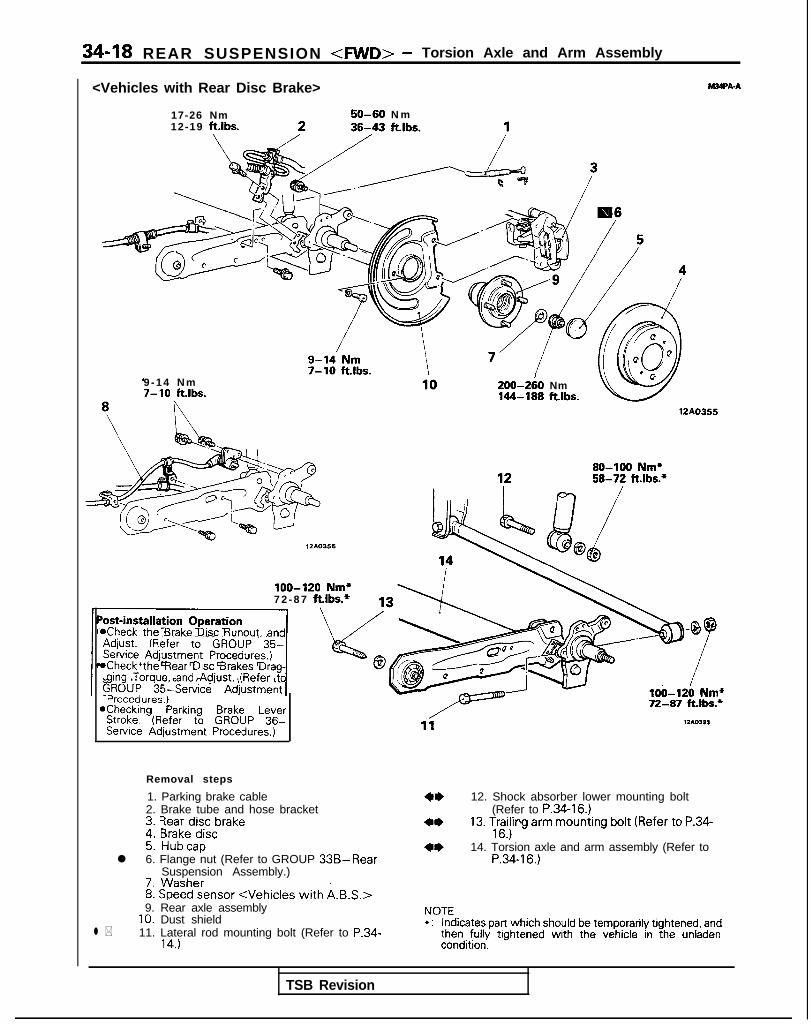
34-18 REAR SUSPENSION <FWD> - Torsion Axle and Arm Assembly
<Vehicles with Rear Disc Brake> WA-A
17-26 Nm12-19 ftlbs.
50-60 N m
9 - 1 4 N m7-10 ft.lbs.
200-2iO Nm144-189 ftlbs.
12A0355
loo-120 Nm*7 2 - 8 7 ft.lbs.*
*Check the Brake Disc Runout. and
*Check the Rear Disc Brakes Drag-ging Torque, and Adjust. (Refer to
Procedures.)*Checking Parking Brake Lever
Stroke. (Refer to GROUP 36-Service Adjustment Procedures.)
Removal steps
1. Parking brake cable2. Brake tube and hose bracket
*I) 12. Shock absorber lower mounting bolt
3. Rear disc brake(Refer to P.34-16.)
4. Brake disc4* 13. Trailing arm mounting bolt (Refer to P.34-
5. Hubcap16.)
l 6. Flange nut (Refer to GROUP 33B-Rear4* 14. Torsion axle and arm assembly (Refer to
Suspension Assembly.)P.34-16.)
7. Washer
l *
8. Speed sensor <Vehicles with A.B.S.>9. Rear axle assembly
10. Dust shield11. Lateral rod mounting bolt (Refer to P.34-
14.)
NOTE*: Indicates part which should be temporarily tightened, and
then fully tightened with the vehicle in the unladencondition.
TSB Revision

REAR SUSPENSION <AWD> - Specifications 34-19
SPECIFICATIONS <AWD-UP TO 1992 MODELS>GENERAL SPECIFICATIONS M34cA-0
Items Specifications
Suspension system Double wishbone suspension type
Coil spring
Wire dia. x O.D. x free length mm (in.) 11.0 x 106.0 x 389.5 (.43 x 4.17 x 15.3)
Coil spring identification colour Pink x 1
Spring constant N/mm (Ibs./in.) 20.0 (112.0)
Shock absorber
Type Hydraulic, cylindrical, double-acting type
Max. length m m (in.) 583 (23.0)
Min. length mm (in.) 391 (15.4)
Stroke mm (in.) 192 (7.6)
Damping force [at 0.3m/sec. (0.9 ft./sec.)l
Expansion N (Ibs.) 1 ,200 (265)
Contraction N (Ibs.) 4 5 0 ( 9 9 )
SERVICE SPECIFICATIONS
Items
Standard value
Toe-in
Camber
mm (in.)
Lower and upper arm ball joint starting torque
Protruding length of stabilizer link installation nut
Stabilizer link ball joint starting torque
Nm (inlbs.)
mm (in.)
Nm (inlbs.)
Specifications
TSB Revision
. .
3+3 (.12+.12)
-1”00’+30’
2-9 (17-78)
9-l 1 (.354-.433)
1.7-3.2 (15-28)

34-20 REAR SUSPENSION <AWD> - SDecifications
TORQUE SPECIFICATIONS M34cGB
Items
Rear suspension assembly
Center exhaust pipe to main muffler installation bolt
Hook installation bolt
Hanger installation bolt
Center exhaust pipe to front exhaust pipe installation nut
Rear shock absorber installation nutDifferential carrier to differential support member
Differential support member to bodyBrake tube bracket to rear shock absorber
Differential carrier to propeller shaft
Crossmember bracket to body
Crossmember bracket to crossmember
Rear brake assembly installation boltUpper and lower arm
Upper arm to crossmember
Upper arm to knuckle
Lower arm to crossmember
Lower arm to knuckleTrailing arm
Companion flange to rear axle shaft
Companion flange to drive shaft
Trailing arm to crossmember
Upper arm to knuckle
Lower arm to knuckle
Rear shock absorber (lower)
Rear brake assembly installation bolt
Rear speed sensorjhock absorber assembly
Shock absorber installation nutShock absorber installation boltBrake tube bracket to rear shock absorber
Piston rod tightening nutitabilizer bar
Differential support member to body
Crossmember bracket to crossmember
Crossmember bracket to body
Stabilizer link to stabilizer bar
N m ftlbs.
30-40 2 2 - 2 9
IO-15 7-11
IO-15 7-11
30-40 2 2 - 2 9
40-50 2 9 - 3 680-100 58-72
110-130 80-94
17-26 12-19
30-35 2 2 - 2 5
70-85 51-61
110-130 80-94
50-60 3 6 - 4 3
140-160 101-116
60-72 4 3 - 5 2
90-I 10 65-80
60-72 4 3 - 5 2
160-220 116-159
55-65 40-47
140-160 101-116
60-72 4 3 - 5 2
60-72 4 3 - 5 2
90-I 10 65-80
50-60 3 6 - 4 3
9 - 1 4 7-10
40-50 2 9 - 3 690-I 10 65-8017-26 12-19
20-25 14-18
110-130 80-94
110-130 80-94
70-85 51-61
3 5 - 4 5 2 5 - 3 3
TSB Revision 1
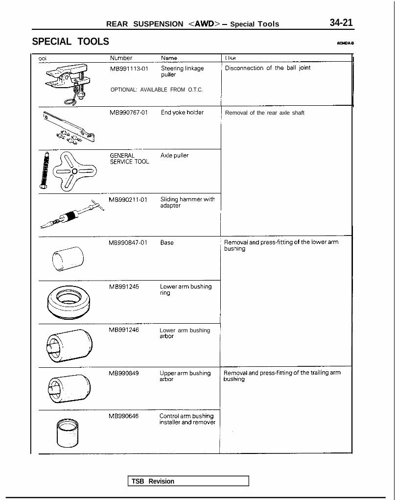
REAR SUSPENSION <AWD> - Special Tools 34-21
SPECIAL TOOLS M34DA-B
nnl Name I II‘S
MB991 113-01
OPTIONAL: AVAILABLE FROM O.T.C.
Removal of the rear axle shaft
MB99021 l-01
MB990847-01
Lower arm bushing
TSB Revision
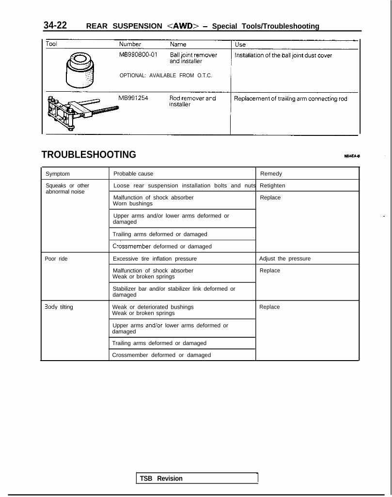
34-22 REAR SUSPENSION <AWD> - Special Tools/Troubleshooting
OPTIONAL: AVAILABLE FROM O.T.C.
TROUBLESHOOTING
Symptom
Squeaks or otherabnormal noise
Probable cause Remedy
Loose rear suspension installation bolts and nuts Retighten
Malfunction of shock absorberWorn bushings
Replace
Upper arms and/or lower arms deformed ordamaged
Poor ride
3ody tilting
Trailing arms deformed or damaged
Crossmember deformed or damaged
Excessive tire inflation pressure
Malfunction of shock absorberWeak or broken springs
Stabilizer bar and/or stabilizer link deformed ordamaged
Weak or deteriorated bushingsWeak or broken springs
Upper arms and/or lower arms deformed ordamaged
Adjust the pressure
Replace
Replace
Trailing arms deformed or damaged
Crossmember deformed or damaged
TSB Revision 1

REAR SUSPENSION <AWD> - Service Adjustment Procedures 34-23
12AOO83
12A0081
SERVICE ADJUSTMENT. PROCEDURESREAR WHEEL ALIGNMENT INSPECTION mmThe rear suspension assembly must be free of worn, loosen ordamaged parts prior to measurement of wheel alignment.
TOE-IN(1) Measure the toe-in with a toe-in gauge.
Standard value: 3+3 mm (.12+.12 in.)
(2) If the toe-in is not within the standard value, adjust it bymoving the mounting bolts located on the crossmemberside of the trailing arm.
NOTEMake the adjustment by moving the left and the right boltsequally.Movement of one division on the scale will cause toe-invariation of about 2 mm (.08 in.).
CAMBER(1) Measure the camber with a camber/caster/kingpin gauge.
Standard value: -1”OO’f30’(2) If the camber is not within the standard value, adjust it by
moving the mounting bolt located on the crossmemberside of the upper arm.
NOTEMovement of one division on the scale will cause cambervariation of about 15’.
Caution1. As toe-in will vary 0.9 mm LO35 in.) for every
camber scale adjustment, adjust the toe afteradjusting camber.
2. The difference between the left and the rightcamber shall be less than 15’.
TSB Revision \

34-24 ’ REAR SUSPENSION <AWD> - Rear Suspension Assembly
REAR SUSPENSION ASSEMBLYREMOVAL AND INSTALLATION M24GA.B
9 - 1 4 N m7- 10 ftlbs.
7 - 1 1 ft.lbs.
IO-15 N m /7-l 1 ft.lbs.
Removal steps
1. Shock absorber installation nut2. Brake tube bracket installation bolt
l + 3. Parking brake cable end4* 4. Caliper assembly
5. Center exhaust pipe6. Gasket7. Gasket
** I)+ 8. Propeller shaft installation bolt and nut
lo-15 N m7- 11 ft.lbs.
-30-40 N m2 2 - 2 9 ftlbs.
12AO514
Post-installation Operation*Check of Wheel Alignment
(Refer to P.34-23.)aCheck of Parking Brake Lever Stroke
(Refer to GROUP 36-Service Adjust-ment Procedures.)
*Installation of Trunk Room Trim(Refer to GROUP 52-Trims.)
TSB Revision I

REAR SUSPENSION <AWD> - Rear Suspension Assembly 34-25
40-50 Nm29-36 ftlbs.
80-100 N m5 8 - 7 2 ft.lbs.
2 2 - 2 5 ftlbs.
\50-60 Nm3 6 - 4 3 ftlbs.
70-85 Nm 70-85 Nm 110-130 Nm51-61 ft.lbs. 51-61 ftlbs. 80-94 ftlbs.
12AO619
9. Self locking nut10. Differential support memberII. Crossmember bracket12. Parking brake cable and rear speed sensor
installation bolt13. Cable band14. Rear speed sensor connector15. O-ring16. Rear suspension assembly
TSB Revision 1

34-26 REAR SUSPENSION <AWD> - Rear Suspension Assembly
I 4 12AOlOS
J
TSB Revision
SERVICE POINTS OF REMOVAL4. REMOVAL OF CALIPER ASSEMBLY
M?dGSAP
(1) Remove the lock pin, rotate the caliper assemblyupward, then remove the caliper assembly and secureit with wire, etc.
CautionThe lock pin has a special grease applied to it, so besure not to wipe it off, and ensure that the lock pinstays clean.
I
(2) After removing the caliper assembly, cover the guidepin with a cloth, etc.
8. REMOVAL OF PROPELLER SHAFT’ INSTALLATIONBOLT AND NUTPlace mating marks on the differential carrier companionflange and the propeller shaft flange yoke.
NOTEThe mating marks should be used as a reference forre-installation.
9. REMOVAL OF SELF LOCKING NUT(1) Before removing the self locking nuts, support the
differential case with a transaxle jack.(2) Remove the self locking nuts.
12. REMOVAL OF PARKING BRAKE CABLE AND REARSPEED SENSOR INSTALLATION BOLT(1) Lower the transaxle jack slightly.(2) Remove the parking brake cable and the rear speed
sensor installation bolts.
NOTEThe task may be made easier by increasing the gapbetween the body and the crossmember.

REAR SUSPENSION <AWD> - Rear Suspension Assembly 34-27
12A0222
12A.0221
,
16. REMOVAL OF REAR SUSPENSION ASSEMBLY(1) Supporting the rear suspension assembly with a trans-
mission jack, move it toward the rear (in the direction ofthe fuel tank).
(2) Graduallyibwer the transmission jack, avoiding contactwith the stabilizer bar and the propeller shaft.
Caution1. Ensure that the propeller shaft does not bend
greatly.2. Ensure that the liibro joint does not receive any
shock.NOTEThe lowering of the rear suspension assembly from thetransmission jack requires three individuals due to theamount of weight being handled (one on the differen-tial, and one on either side of the lower arm).
(3) In order to protect the rear suspension assembly dustshield, support the lower arm ball joint with a woodenblock.
TSB Revision
INSPECTION M24GCAM
l Check crossmember for cracks or other damage.
SERVICE POINTS OF INSTALLATION M34GDAfl
8. INSTALLATION OF PROPELLER SHAFT INSTALLATIONBOLT AND NUTInstall the propeller shaft to the differential carrier, ensuringthat the mating marks are aligned.
3. INSTALLATION OF PARKING BRAKE CABLE ENDNOTEConnecting a parking brake cable end to parking brake leverand prying up the parking brake lever, the installation of theother cable end will be easy.

34-28 REAR SUSPENSION <AWD> - Upper and Lower Arm
UPPER AND LOWER ARMREMOVAL AND INSTALLATION
Upper arm+I)
::
140-160 Nm*101-116 ft.lbs.*
W-72,y7 43-52
8
removal stepsSelf locking nutUDDer arm installation nut
3. Upper arm installation bolt4. Upper arm
Lower arm removal steps*I) 5. Self locking nut+I) I)4 6. Stabilizer link installation nut
7. Lower arm installation nut8. Lower arm installation bolt9. Lower arm
NOTE*: Indicates parts whtch should first be temporarily tight-
ened, then fully tightened with the vehicle on the groundwith no load (curb weight).
EL.
Dustcove1
SERVICE POINTS OF REMOVAL1. REMOVAL OF SELF LOCKING NUT
With the special tool, disconnect the upper arm ball jointand knuckle.
CautionWhile the special tool is being used, do not remove theself locking nut; only loosen it.
TSB Revision

II 12A0098
REAR SUSPENSION <AWD> - Upper and Lower Arm 34-29
6. REMOVAL OF SELF LOCKING NUTWith the special tool, disconnect the lower arm ball jointand knuckle.
CautionWhile the special tool is being used, do not remove theself locking nut; only loosen it.
I I
IMB990800-0 1
6. REMOVAL OF STABILIZER LINK INSTALLATION NUTHold the stabilizer link with a wrench and remove theinstallation nut.
INSPECTIONl Check the bushing for wear and deterioration.l Check the upper arm or lower arm for bend or breakage.l Check the ball joint dust cover for cracks.l Check all bolts for condition and straightness.
CHECKING OF BALL JOINT FOR STARTING TORQUE(1) If a crack is noted in the dust cover, replace it, adding
grease.(2) Deflect side to side the ball joint stud several times.(3) Mount two nuts on the ball joint, and then measure the ball
joint starting torque.
Standard value: 2-9 Nm (17-78 in.lbs.)(4) If the starting torque exceeds the upper limit of standard
value, replace the upper and lower arm assembly.(5) Even if the starting torque is below the lower limit of the
standard value, the ball joint may be reused unless it hasdrag and excessive play.
BALL JOINT DUST COVER REPLACEMENTn(1) Remove the dust cover.(2) Apply multipurpose grease to the lip and inside of the dust
cover.(3) F;Fein the dust cover with special tool until it is fully
LOWER ARM BUSHING REPLACEMENT MJOSFAA(1) Use the special tool to remove and press fit the bushing.
1 TSB Revision I

34-30 REAR SUSPENSION <AWD> - Upper and Lower Arm
Pipe Outer pipe(lower (bushing)arm)
12AOO39
12A0100
(2) Press fit the lower arm bushing until the bushing outer pipeedge flush with the lower arm pipe edge.
SERVICE POINTS OF INSTALLATION M34sDAA6. INSTALLATION OF STABILIZER LINK INSTALLATION
NUTHolding the stabilizer link with a wrench, tighten the selflocking nut so that the protrusion of the stabilizer link(cil;l,nsion A indicated in illustration) is within the standard
Standard value: 9-11 mm (.364-433 in.)
TSB Revision

REAR SUSPENSION <AWD> - Trailing Arm 34-31
TRAILING ARMREMOVAL AND INSTALLATION
160-220 Nm116-15y ft.lbs.
9 - 1 4 N m7-10 ftlbs.
50-60 Nm36-43 ft.lbs.
\
5 5 - 6 5 N m40-47 ft Ibs
\ . .\~- -
140-160 Nm*101-116 ft.lbs.*
Connecting rod// I
Y li0
60-7i Nm43-52 ft.lbs.
90-110 Nm65-80 ftlbs.
Removal steps1. Parking cable end
4* 2. Rear brake assembly3. Rear brake disc4. Drive shaft and companion flange
installation bolt, nut4I) l + 5. Self locking nutl + 6. Companion flange
7. Rear speed sensor installation bolt<Vehicles with ABS
8. O-ring+e l + 9. Rear axle shaft
10. Dust shield
::11. Self locking nut (upper arm)12. Self locking nut (lower arm)13. Parking brake cable and rear speed sensor
installation bolt14. Trailing arm installation bolt, nut15. Rear shock absorber installation bolt16. Trailing arm
12AO621
Post-installation Operationl Zheck of Wheel Alignment(Refer to P.3423.)l Check of Parking Brake Lever Stroke
(Refer to GROUP 36-Service Adjust-ment Procedures.)
@Rear Brake Disc Run-out Check(Refer to GROUP 35Service Adjust-ment Procedures.)
NOTE*: Indicates parts which should first be temporarily tight-
ened, then fully tightened with the vehicle on the groundwith no load (cerb weight).
TSB Revision I

34-32 REAR SUSPENSION <AWD> - Trailina Arm
12AOO64
MB991 113-0112AOO96-
SERVICE POINTS OF REMOVAL2. REMOVAL OF REAR BRAKE ASSEMBLY
Remove the rear brake assembly installation bolts, thensuspend the rear brake assembly from the vehicle withwire, etc.
5. REMOVAL OF SELF LOCKING NUTWith the special tool, secure the rear axle shaft, thenremove the self locking nut.
9. REMOVAL OF REAR AXLE SHAFTWith the special tool, remove the rear axle shaft.
11. REMOVAL OF SELF LOCKING NUT (UPPER ARM)With the special tool, disconnect the upper arm ball jointand knuckle.
CautionWhile the special tool is being used, do not remove theself locking nut; only loosen it.
12. REMOVAL OF SELF LOCKING NUT (LOWER ARM)With the special tool, disconnect the lower arm ball jointand knuckle.
CautionWhile the special tool is being used, do not remove theself locking nut; only loosen it.
TSB Revision

Pressure fitting Removal
REAR SUSPENSION <AWD> - Trailing Arm 34-33
INSPECTiON M34TCAA
0 Check trailing arm for cracks and deformation.l Check bushing for cracks, deterioration and wear.
TRAILING ARM BUSHING REPLACEMENT wmUse the special tool to remove and press fit the bushing.
i Le$ i MBggo646 w12AO305
-‘Trailing arm bushing12AO296
Bolt B
MB991254 12AO299
BodyGuide shaftcenter line
.\/ ’
MB991254 12A0339
MB991 254 -
CONNECTING ROD REPLACEMENT MwrFAAReplace the connecting rod using the following procedure:
(1) Remove the trailing arm bushing.(2) Remove the bolt and nut.
(3) Set the special tool onto the trailing arm as shown in theillustration.
NOTE(1) Apply lubricant to the sliding portion of the special tool
(at the arrow marked “A” in the illustration).(2) Install bolt B to the trailing arm, at the point shown in
the figure.(4) Use a spanner, etc., to turn the portion marked “C” in the
illustration to remove the connecting rod.
(5) Installation of the body (special tool) should be performedwith the screw shaft and guide shaft center lines orientedas shown in the illustration.
(6) zdyly soapy water to the rubber portion of the connecting
(7) Reverse the removal procedures to press fit. I
TSB Revision

34-34 REAR SUSPENSION <AWD> - Trailing Arm
<Reference>Special tool
(8) Remove the special tool after aligning the holes inspecial tool and trailing arm.
(9) Tighten the bolts and nuts to the specified torque.
Tightening torque: 85-l 10 Nm (61-80 ft.lbs.)(10)Press fit the trailing arm bushing. (Refer to P.34-33
(MB991254) - Rnl1
Holder AMB991258
I”..Ml2Length 80 mm (3.15 in.)
Guide shaftMB991 256/
/Screw ‘shaftMB991255
%’ BodyMB991 257
12AO336
the
.I
SERVICE POINTS OF INSTALLATION M34ToAA9. INSTALLATION OF REAR AXLE SHAFT/G. COM-
PANION FLANGE/5. SELF LOCKING NUT(1) Temporarily assemble the rear axle shaft to the trailing
arm.(2) Install the companion flange to the rear axle shaft, then
install the self locking nut.(3) Hold the rear axle shaft with the special tool so that it
doesn’t turn and tighten the locking nut.
1 TSB Revision
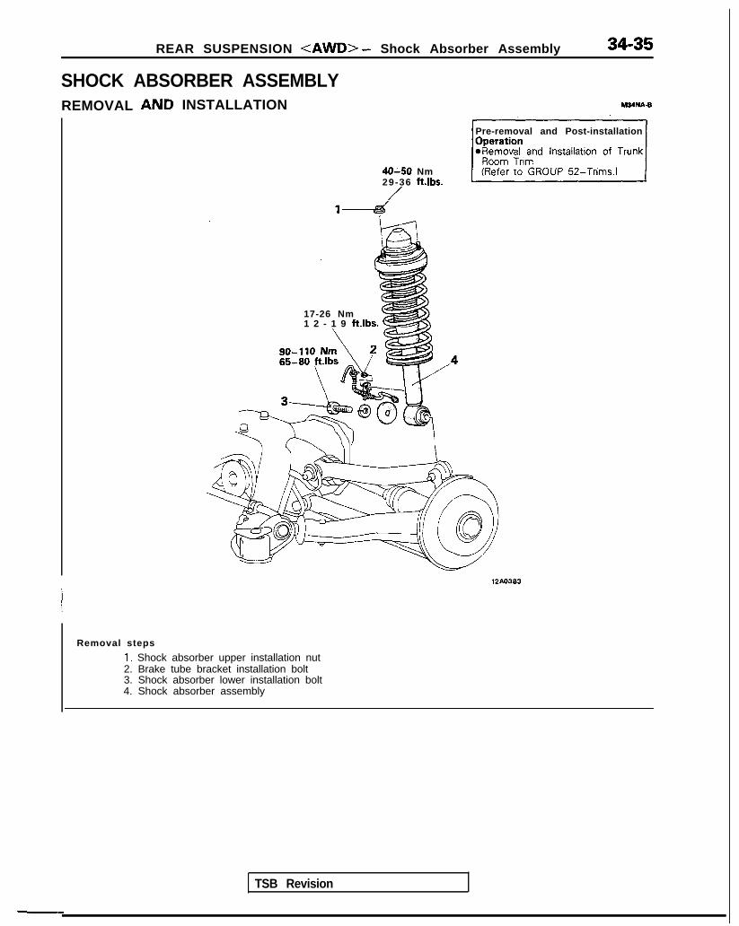
REAR SUSPENSION <AWD> - Shock Absorber Assembly
SHOCK ABSORBER ASSEMBLYINSTALLATIONREMOVAL
17-26 Nm1 2 - 1 9 ft.lbs. 6
Pre-removal and Post-installation
40-50 Nm29-36 ftlbs.
/
TSB Revision
12AO383
Removal steps
I. Shock absorber upper installation nut2. Brake tube bracket installation bolt3. Shock absorber lower installation bolt4. Shock absorber assembly

34-36 REAR SUSPENSION <AWD> - Shock Absorber Assembly
DISASSEMBLY AND REASSEMBLY M34OM-B
Disassembly steps1. Cap2. Piston rod tightening nut
(Refer to P.34-13.)3. Washer4. Upper-bushing (A)5. Bracket assembly (Refer to P.34-6. Sorina oad
20-25 N m14- 18
1-aft.‘bs-BS-
3Je3
7. U’pper bushing (B)8. Collar9. Cup assembly (Refer to P.34-I 3.)
10. Dust cover (Refer to P.34-I 3.)11. Bums rubber12. Coil spring (Refer to P.34-13,)13. Shock absorber
INSPECTION
I-B- 9
G?- 11
8
6
~-EB
12AO360
l Check the rubber parts for damage.l Check the coil springs for crack, damage or deterioration.
1 TSB Revision

REAR SUSPENSION <AWD> - Stabilizer Bar
STABILIZER BARREMOVAL AND INSTALLATION
34-37
M36lA-
12AO620
70-85 N m/
llo-li0 N m51-61 ft.lbs. 80-94 ft.lbs.
9-14 N m7-10 ft.lbs. ‘q ,4
I-
1 12L0217
Removal steps
*I) 1. Self locking nut4* 2. Crossmember bracket
3. Parking brake cable and rear speed sensorinstallation bolt
4. Stabilizer bracket5. Bushing
+e I)+ 6. Self locking nut7. Joint cup (A)8. Stabilizer rubber9. Joint cup (B)
+e e+ 10. Self locking nut+e l + 11. Stabilizer link
12. Joint cup (A)13. Stabilizer rubber
4w 14. Stabilizer bar
7-- --e
IllSA12A0113
TSB Revision
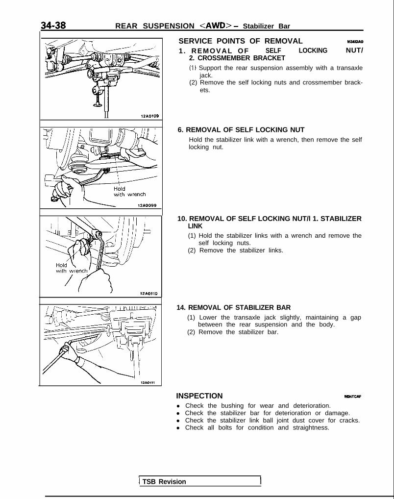
34-38 REAR SUSPENSION <AWD> - Stabilizer Bar
II 12AO109
/ 12AOllO
SERVICE POINTS OF REMOVAL M34lDAB
1 . REMOVAL OF SELF LOCKING NUT/2. CROSSMEMBER BRACKET(1) Support the rear suspension assembly with a transaxle
jack.(2) Remove the self locking nuts and crossmember brack-
ets.
6. REMOVAL OF SELF LOCKING NUTHold the stabilizer link with a wrench, then remove the selflocking nut.
10. REMOVAL OF SELF LOCKING NUT/l 1. STABILIZERLINK(1) Hold the stabilizer links with a wrench and remove the
self locking nuts.(2) Remove the stabilizer links.
14. REMOVAL OF STABILIZER BAR(1) Lower the transaxle jack slightly, maintaining a gap
between the rear suspension and the body.(2) Remove the stabilizer bar.
INSPECTION M34TcAFl Check the bushing for wear and deterioration.l Check the stabilizer bar for deterioration or damage.l Check the stabilizer link ball joint dust cover for cracks.l Check all bolts for condition and straightness.
1 TSB Revision

REAR SUSPENSION <AWD> - Stabilizer Bar 34-39
CHECKING OF STABILIZER LINK BALL JOINT FOR START-ING TORQUE(1) If a crack is noted in the dust cover, replace it, adding
(2) gz;zEt side to side the stabilizer link ball joint stud several
(3) h!z% two nuts on the ball joint, and then measure the balljoint starting torque.
Standard value: 1.7-3.2 Nm (15-28 in.lbs.1(4) If the starting torque exceeds the upper limit of standard
value, replace the stabilizer link.(5) Even if the starting torque is below the lower limit of the
standard value, the ball joint may be reused unless it hasdrag and excessive play.
Clip kg A12LO245
I
12LO217 J
12LO243 J
Hold withwrench
12AOlOO
BALL JOINT DUST COVER REPLACEMENT-w(1) Remove the clip ring and the dust cover.
(2) Apply multipurpose grease to the lip and inside of the dustcover.
(3) Use vinyl tape to tape the stabilizer link where shown in theillustration, and then install the dust cover to the stabilizerl i n k .
(4) Secure the dust cover by the clip ring.
SERVICE POINTS OF INSTALLATION11. INSTALLATlON OF STABILIZER LINK/ 10. SELF LOCK-
ING NUT/G. SELF LOCKING NUT(1) Hold the stabilizer link ball studs with a wrench and
install the self locking nut (A).(2) Holding the stabilizer link with a wrench, tighten the self
locking nut (B) so that the protrusion of the stabilizer linkis within the standard value.
Standard value: 9-11 mm (.354-.433 in.)
TSB Revision 1

NOTES

35-1
SERVICE BRAKESCONTENTS M35AA-
ANTI-LOCK BRAKING SYSTEMTROUBLESHOOTING . . . . . . . . . . . . . . . . . . . . . . . . . . . . . 15
BRAKE BOOSTER . . . . . . . . . . . . . . . . . . . . . . . . . . . . . . . . . 85
BRAKE FLUID PRESSURE SWITCH<AWD-A.B.S.: Up to 1991 models> . . . . . . . . . . . 133
BRAKE LINE . . . . . . . . . . . . . . . . . . . . . . . . . . . . . . . . . . . . . . . 87
BRAKE PEDAL . . . . . . . . . . . . . . . . . . . . . . . . . . . . . . . . . . . . 76
ELECTRONIC CONTROL UNIT<VEHICLES WITH A.B.S.> . . . . . . . . . . . . . . . . . . . . . . 134
FRONT DISC BRAKE . . . . . . . . . . . . . . . . . . . . . . . . . . . . . 94
G-SENSOR <AWD-A.B.S.> . . . . . . . . . . . . . . . . . . . . . 132
HYDRAULIC UNIT<VEHICLES WITH A.B.S.> . . . . . . . . . . . . . . . . . . . . . . 121
MASTER CYLINDER . . . . . . . . . . . . . . . . . . . . . . . . . . . . . . 81
REAR BRAKE WHEEL CYLINDER . . . . . . . . . . . . . . . . 111
REAR DISC BRAKE . . . . . . . . . . . . . . . . . . . . . . . . . . . . . . . 114
REAR DRUM BRAKE .... . . . . . . , . . . . . . . . . . . . . . . . . . 108
SERVICE ADJUSTMENT PROCEDURES . . . . . . . . 53A.B.S. Power Relay Check . . . . . . . . . . . . . . . . . . . . . . 74
Anti-lock Braking System (A.B.S.) Check(Checking by the A.B.S. Warning Light) . . . . . . . . . 68
Bleeding . . . . . . . . . . . . . . . . . . . . . . . . . . . . . . . . . . . . . . . . . 57
Brake Booster Operating Inspection . . . . . . . . . . . . 54
Brake Drum Inside Diameter Check . . . . . . . . . . . . 67
Brake Fluid Level Sensor Check . . . . . . . . . . . . . . . . 54
Brake Fluid Pressure Switch Check<AWD-A.B.S.> . 75
Brake Lining and Brake Drum ConnectionCheck _. _. . _. _. . . 67
Brake Lining Thickness Check . . . . . . . . . . . . . . .
Brake Pedal Inspection and Adjustment . . . . .
Check Valve Operation Check . . . . . . . . . . . .:. ..
Delay Valve Check <FWD-A.B.S.> . . . . . . . . .
Flat Battery Remedy . . . . . . . . . . . . . . . . . . . . . . . . .
Front Disc Brake Pad Check andReplacement . . . . . . . . . . . . . . . . . . . . . . . . . . . . . . . . . .
inspection of Hydraulic Unit . . . . . . . . . . . . . . . . . .
Measurement of Wheel Speed SensorOutput Voltage . . . . . . . . . . . . . . . . . . . . . . . . . . . . . . .
Proportioning Valve Function. Test . . . . . . . . . . .
Rear Brake Disc Run-out Check . . . . . . . . . . . . .
Rear Brake Disc Run-out Correction . . . . . . . . .
Rear Brake Disc Thickness Check . . . . . . . . . . .
Rear Disc Brake Pad Check andReplacement . . . . . . . . . . . . . . . . . . . . . . . . . . . . . . . . . .
Run-out Check . . . . . . . . . . . . . . . . . . . . . . . . . . . . . . . .
. 67
. 535 47 4. 75
59
70
. 69
5 6. 66. 66. 66
. 65
. 63
Run-out Correction . . . . . . . . . . . 64
Thickness Check . . . . . . . . . . . . . .
Wheel Speed Sensor Output Voltage Check .
SPECIAL TOOLS . . . . . . . . . . . . . . . . . . . . . . . . . . . . . . . . . . 11
SPECIFICATIONS . . . . . . . . . . . . . . . . . . . . . . . . . . . . . . . . . 2General Specifications . . . . . . . . . . . . . . . . . . . . . . . . . . . 2
Lubricants . . . . . . . . . . . . . . . . . . . . . . . . . . . . . . . . . . . . . . . 11
Sealant and Adhesives . . . . . . . . . . . . . . . . . . . . . . . . . . 11
Service Specifications . . . . . . . . . . . . . . . . . . . . . . . . . . . 7
Torque Specifications . . . . . . . . . . . . . . . . . . . . . . . . . . . 10
TROUBLESHOOTING . . . . . . . . . . . . . . . . . . . . . . . . . . . . . 12
WHEEL SPEED SENSOR<VEHICLES WITH A.B.S.> . . . . . . . . . . . . . . . . . . . . . . 126
CAUTIONWhen servicing brake assemblies or components, do not create dust by sanding, grinding or by cleaningbrake parts with a dry brush or with compressed air. A WATER DAMPENED CLOTH SHOULD BE USED.Many brake components contain asbestos fibers which can become air-borne if dust is created duringservice operations. Breathing dust which contains asbestos fibers can cause seriouj bodily harm.

35-2 SERVICE BRAKES - Specifications
SPECIFICATIONSG E N E R A L S P E C I F I C A T I O N S [ u p to 1990.5 models1 M3!iCA-
<MID>
Items Vehicles without A.B.S.* Vehicles with A.B.S.
Master cylinder
Type Tandem type Tandem type(with level sensor) (with level sensor)
I.D. mm (in.) 22.2 (718) 23.8 (15/16)
Brake booster
Type Vacuum type Vacuum type
Effective dia. of power cylinder mm (in.) 230 (9.0) Front side: 178 (7.0)
Rear side: 203 (8.0)
Boosting ratio [Brake pedal depressing force1 4.0 [at 280 N (62 tbs.)] 5.0 [at 270 N (59 Ibs.)l
‘roportioning valve
Split point kPa (psi) 4,200 (597) 4,200 (597)
Decompression ratio 0.3 0.3
Iront brakes
Type Floating caliper, single- Floating caliper, single-piston, ventilated disc(AD54*’ o r M-R44V”‘)
piston, ventilated disc(AD54*’ o r M-R44V**)
Disc O.D. mm (in.) 266 (10.5) 266 (10.5)
Disc thickness mm ( in. ) 24 (.94) 24 i.94)
Pad thickness mm (in.) 15.5 (.61)*’ or 16 (63)“’ 15.5 (.61)*’ or 16 (.63)**
Wheel cylinder I.D. mm (in.) 53.9 (2%) 53.9 (2’/8)
Clearance adjustment Automatic Automatic
qear disc brakes
Type - Floating caliper, single-piston, non-ventilateddisc (AD30P)
Disc O.D. mm ( in . ) - 265 (10.4)
Disc thickness mm ( in . ) - 10 (.39)
Pad thickness mm ( in . ) - 14.5 (.57)
Wheel cylinder I.D. mm ( in . ) - 30.1 (13/16)
Clearance adjustment - Automatic
{ear drum brakes
Type Leading-trailing
Drum I.D. mm (in.) 203 (8.0)
Wheel cylinder I.D. mm (in.) 17.4 V’/16)
Clearance adjustment Automatic
Iotor teeth
Front wheel side 98
Rear wheel side - 98
;peed sensor Magnet coil type- - -NUlt* : Anti-lock Brakina Svstem*I: <Up to 1990 m o d e l s >+2: ~1990.5 mode ls>
TSB Revision I

SERVICE BRAKES - Specifications 35-3
<AWD>
Items Vehicles without A.B.S. Vehicles with A.B.S.
Master cylinder
Type Tandem type Tandem type(with level sensor) (with level sensor)
I.D. mm (in.) 23.8 (15/16) 25.4 (I)
Brake booster
Type Vacuum type Vacuum typeEffective dia. of power cylinder mm (in.) Front side: 178 (7.0) Front side: 203 (8.0)
Rear side: 203 (8.0) Rear side: 230 (9.0)Boosting ratio [Brake pedal depressing force] 5.0 [at 280 N (62 Ibs.)] 5.5 Iat 280 N (62 Ibs.)]
Proportioning valve
Split point kPa (psi) 5,200 (740) 5,200 (740)
Decompression ratio 0.4 0.4
Front brakes
Type Floating caliper, single- Floating caliper, single-piston, ventilated disc(AD54”’ o r M-R44V**)
piston, ventilated disc(AD54*’ o r M-R44V**)
Disc O.D. mm (in.) 266 (10.5) 266 (10.5)
Disc thickness mm (in.) 24 (.94) 24 (.94)
Pad thickness mm (in.) 15.5 (.61)*’ or 16 (.63)*’ 15.5 f.61)“’ or 16 (.63)*2
Wheel cylinder I.D. mm (in.) 53.9 (2%) 53.9 (2%)Clearance adjustment Automatic Automatic
Rear disc brakes
Type Floating caliper, single- Floating caliper, single-piston, non-ventilated piston, non-ventilateddisc (AD30P) disc (AD30P)
Disc O.D. mm (in.) 265 (10.4) 265 (10.4)
Disc thickness m m ( i n . ) 10 L39) 10 (.39)
Pad thickness mm (in.) 14.5 f.57) 14.5 (.57)
Wheel cylinder I.D. mm (in.) 30.1 (13/16) 30.1 (13/16)
Clearance adjustment Automatic Automatic
Rotor teethFront wheel side - 86
Rear wheel side 43
Speed sensor Magnet coil type
NOTE+‘: <Up to 1990 m o d e l s >**: <1990.5 m o d e l s >
TSB Revision

35-4 SERVICE BRAKES - Specifications
GENERAL SPECIFICATIONS [Up to 1992 models]<fYVD>
Vehicles without A.B.S.Items Vehicles with A.B.S.
SOHC DOHC
Master cylinder
Type Tandem type Tandem type Tandem type(with level sensor) (with level sensor) (with level sensor)
I.D. mm (in.) 22.2 (7/8) 23.8 (15/l 6) 25.4 (I)
Brake booster
Type Vacuum type Vacuum type Vacuum type
Effective dia. of power cylinder Front side: 178 (7.0)mm (in.) 230 (9.0) 230 (9.0) Rear side: 203 (8.0)
Boosting ratio 4.0 5.0 5.5[Brake pedal depressing force] [at 280 N (62 Ibs.)] [at 220 N (48 Ibs.)] [at 250 N (55 Ibs.11
Proportioning valve
Split point kPa (psi) 4,200 (597) 3,700 (526) 3,700 (526)
Decompression ratio 0.4 0.3 0.3
Front brakes
Type Floating caliper, single- Floating caliper, single- F!oating caliper, singlep is ton , ven t i l a ted d isc y$or&entrlated disc r;;;6ventrlated drsc(MR44V)
Disc O.D. mm (in.) 256 (10.1) 256 (10.1) 256 (10.1)
Disc thickness mm (in.) 24 (.94) 24 (.94) 24 (.94)
Pad thickness mm (in.) 16 (.63) 16 (63) 16 (.63)
Wheel cylinder I.D. m m ( i n . ) 53.9 (2%) 60.3 (z3/8) 60.3 (23/8)
Clearance adjustment Automatic Automatic Automatic
Rear disc brakes
Type - Floating caliper, single-piston, non-ventilated
Floating caliper, singlepiston, non-ventilated
disc (AD35P) disc (AD35P)
Disc O.D. mm ( in.) - 265 (10.4) 265 (10.4)
Disc thickness mm ( in.) - IO i.39) 10 (.39)
Pad thickness mm ( in.) - 14.5 (57) 14.5 (.57)
Wheel cylinder I.D. mm ( in.) - 34.9 u3h) 34.9 (1%)
Clearance adjustment - Automatic Automatic
Rear drum brakes
Type Leading-trailing -
Drum I.D. mm (in.) 203 (8.0)Wheel cylinder I.D. m m ( i n . ) 17.4 (‘l/16) - -
Clearance adjustment Automatic - -
3otor teeth
Front wheel side 98”. 43’2Rear wheel side - - 98”. 43’2
speed sensor - - Magnet coil type
NOTEl l: 1991 modelsl ? 1992 models
TSB Revision

SERVICE BRAKES - Specifications 35-5
<AWD>
Vehicles without Vehicles with A.B.S.Items A.B.S. DOHC (Non-Turbo) DOHC (Turbo)
Master cylinder
Type Tandem type Tandem type Tandem type(with level sensor) (with level sensor) (with level sensor)
I.D. mm (in.) 25.4 (1) 25.4 (I) 25.4 (I)
Brake booster
Type Vacuum type Vacuum type Vacuum typeEffective dia. of power Front side: 178 (7.0) Front side: 203 (8.0) Front side: 203 (8.0)c y l i n d e r mm (in.) Rear side: 203 (8.0) Rear side: 230 (9.0) Rear side: 230 (9.0)
Boosting ratio 5.5 6.0 6.0[Brake pedal depressing force] (at 250 N (55 Ibs.)] [at 280 N (62 Ibs.)] [at 280 N (62 Ibs.)l
Proportioning valve
Split point kPa (psi) 5,200 (740) 5,200 (740) 5,200 (740)
Decompression ratio 0.4 0.4 0.4
Front brakes
Type Floating caliper, single- Floating caliper, single- Floating caliper,piston, ventilated disc piston, ventilated disc double-piston, venti-(M R46V) (MR46V) lated disc (MR56W)
Disc O.D. mm (in.) 256 (10.1) 256 (10.1) 276 (10.9)
Disc thickness mm (in.) 24 (.94) 24 (.94) 24 l.94)
Pad thickness mm (in.) 16 (.63) 16 (.63) 16 (63)
Wheel cylinder I.D. mm (in.) 60.3 (23/s) 60.3 (23/8) 41.3 (1%) x 2
Clearance adjustment Automatic Automatic Automatic
Rear disc brakes
Type Floating caliper, single- Floating caliper, single- Floating caliper. Single-piston, non-ventilated piston, non-ventilated piston, non-ventilateddisc (AD35P) disc (AD35P) disc (AD35P)
Disc O.D. mm (in.) 265 (10.4) 265 (10.4) 265 (10.4)
Disc thickness m m ( i n . ) 10 (.39) 10 l.39) 10 l.39)
Pad thickness mm (in.) 14.5 (.57) 1 4 . 5 (.57) 14.5 (57)
Wheel cylinder I.D. mm (in.) 34.9 (13/8) 34.9 (13h) 34.9 (1%8)
Clearance adjustment Automatic Automatic Automatic
Rotor teethFront wheel side - 86”. 43’2 86”‘. 43’2
Rear wheel side - 43 43
Speed sensor - Magnet coil type Magnet coil type
NOTE+I: 1991 m o d e l s‘2: 1992 models
1 TSB Revision I

35-6 SERVICE BRAKES - Specifications
3ENERAL SPECIFICATIONS [1993 models]
Items
Master cylinder
Type
I.D. m m (in.1
Brake booster
TypeEffective dia. of power cylinder
mm (in.)
Boosting ratio[Brake pedal depressing force1
Proportioning valve
Split point kPa (psi)Decompression ratio
Front brakes
Type
Disc O.D.
Disc thickness
Pad thickness
Wheel cylinder I.D.
Clearance adjustment
Rear disc brakes
Type
mm (in.)
mm (in.)
mm (in.)
mm (in.)
Disc O.D.
Disc thickness
Pad thickness
Wheel cylinder I.D.
Clearance adjustment
mm (in.)
mm (in.)
mm (in.)
mm (in.)
{ear drum brakes
TypeDrum I.D.Wheel cylinder I.D.Clearance adjustment
jotor teeth
Front wheel side
Rear wheel side
mm (in.)mm (in.)
ipeed sensor
TL
I
Tandem type(with level sensor)
22.2 (718)
Vacuum type
230 (9.0)
4.0[at 280 N (62 Ibs.11
4,200 (597)
0.4
Floating caliper, single-piston, ventilated disc(M R44V)
256 (10.1)
24 f.94)
16 (.63)
53.9 (2’/8)
Automatic
-
----
I-eading-trailing
I
SOHC1 DOHC 1
Vehicles without A.B.S.
Tandem type(with level sensor)
23.8 (15/I 6)
Vacuum type
230 (9.0)
5.0[at 220 N (48 Ibs.11
3,700 (526)
0.3
Floating caliper, single-piston, ventilated disc(MR46V)
256 (10.1)
24 l.94)
1 6 (.63)
60.3 (23/8)
Automatic
Floating caliper, single-piston, non-ventilateddisc (AD35P)
265 (10.4)
10 (.39)
14.5 (.57)
34.9 (1 3/8)
Automatic
TSB Revision
7Vehicles with A.B.S.
Tandem type(with level sensor)
25.4 (1)
Vacuum type
Front side: 178 (7.0)
Rear side: 203 (8.0)
5.5[at 250 N (55 Ibs.11
3,700 (526)
0.3
Floating caliper, single-piston, ventilated disc(MR46V)
256 (10.1)
24 (.94)
16 (.63)
60.3 (23/8)
Automatic
Floating caliper, single-piston, non-ventilateddisc (AD35P)
265 (10.4)
10 i.39)
14.5 (.57)
34.9 (13/8)%tomatic
13
I3
dagnet coil type
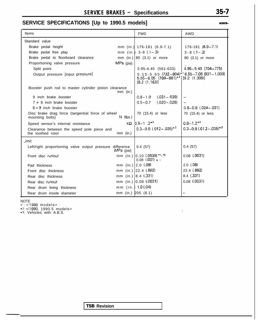
SERVICE BRAKES - Specifications 357
SERVICE SPECIFICATIONS [Up to 1990.5 models]
Items FWD AWD
Standard value
Brake pedal height mm (in.) 176-181 (6.9-7.1) 176-181 (6.9-7.1)Brake pedal free play mm ( i n . ) 3 -8 (.I-.3) 3 - 8 (.l-.3)Brake pedal to floorboard clearance mm (in.) 80 (3.1) or more 80 (3.1) or moreProportioning valve pressure MPa (psi)
Split point 3.95-4.45 (561-633) i.95-5.45 (704-775)
Output pressure [input pressure] 5 . 1 5 - 5 . 6 5 (732-804)*’ 6.55-7.05 (931-1,003)5.55-6.05 (789-861)“’ [9.2 (1.309)][8.2 (1,163)l
Booster push rod to master cylinder piston clearancemm (in.)
9 inch brake booster 0.8-1.0 (.031-,039) -7 + 8 inch brake booster 0.5-0.7 (.020-,028) -8+9 inch brake booster 0.6-0.8 (.024-,031)
Disc brake drag force (tangential force of wheel 70 (15.4) or less 70 (15.4) or lessmounting bolts) N (Ibs.)
Speed sensor’s internal resistance kB 0.8-I .2*3 0.8-I .2*3
Clearance between the speed pole piece and 0.3-0.9 (.012-.035)*3 0.3-0.9 (.Ol 2-.035)*3the toothed rotor mm (in.)
-imit
Left/right proportioning valve output pressure difference 0.4 (57) 0.4 (57)MPa (psi)
Front disc runout mm (in.) 0.10 (.0039) ‘1,*3 0.08 (.0031)0.08 (.0031) l 2
Pad thickness mm (in.) 2.0 (08) 2.0 (08)
Front disc thickness mm (in.) 22.4 (.882) 22.4 (.882)
Rear disc thickness mm (in.) 8.4 (.331) 8.4 (331)
Rear disc runout mm (in.) 0.08 (.0031) 0.08 (0031)
Rear drum lining thickness m m ( i n . ) 1.0 (04)
Rear drum inside diameter mm (in.) 205 (8.1) -
NOTE~1: cl989 mode ls>+2: <1990, 1990.5 models>*3: Vehicles with A.B.S.
i
TSB Revision
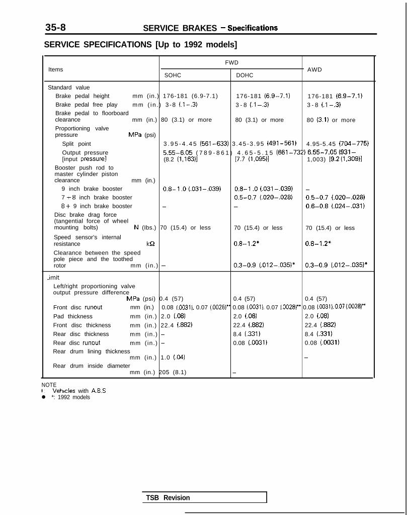
35-8 SERVICE BRAKES - SDecifications
SERVICE SPECIFICATIONS [Up to 1992 models]
FWDItems AWD
SOHC DOHC
Standard valueBrake pedal height mm (in.) 176-181 (6.9-7.1) 176-181 (6.9-7.1) 176-181 (6.9-7.1)Brake pedal free play mm ( i n . ) 3 -8 (l-.3) 3 - 8 (.I -.3) 3 - 8 (.I -.3)Brake pedal to floorboardclearance mm (in.) 80 (3.1) or more 80 (3.1) or more 80 (3.1) or moreProportioning valvepressure MPa (psi)
Split point 3 . 9 5 - 4 . 4 5 (561-633) 3 . 4 5 - 3 . 9 5 (491-561) 4.95-5.45 (704-775)
Output pressure 5.55-6.05 ( 7 8 9 - 8 6 1 ) 4 . 6 5 - 5 . 1 5 (661-732) 6.55-7.05 (931-[input pressure] (8.2 (1,163)1 [7.7 (1,095)1 1,003) 19.2 (1,309)1
Booster push rod tomaster cylinder pistonclearance mm (in.)
9 inch brake booster 0.8-l .O (.031-,039) 0.8-I .O (.031-.039) -7 +8 inch brake booster 0.5-0.7 (.020-.028) 0.5-0.7 (.020-.028)8+ 9 inch brake booster - - 0.6-0.8 (.024-.031)
Disc brake drag force(tangential force of wheelmounting bolts) N (Ibs.) 70 (15.4) or less 70 (15.4) or less 70 (15.4) or less
Speed sensor’s internalresistance kQ - 0.8-I .2* 0.8-1.2”
Clearance between the speedpole piece and the toothedrotor mm ( in.) - 0.3-0.9 (.012-,035)” 0.3-0.9 (.012-.035)*
.imitLeft/right proportioning valveoutput pressure difference
MPa (psi) 0.4 (57) 0.4 (57) 0.4 (57)
Front disc runout mm (in.) 0.08 (.0031), 0.07 (.0028)” 0.08 (0031). 0.07 (0028)” 0.08 (0031). 0.07 (.0028)”
Pad thickness mm (in.) 2.0 (.08) 2.0 (.08) 2.0 (.08)
Front disc thickness mm (in.) 22.4 (.882) 22.4 (.882) 22.4 (.882)
Rear disc thickness mm ( in.) - 8.4 (.331) 8.4 (.331)
Rear disc runout mm ( in.) - 0.08 (.0031) 0.08 (.0031)Rear drum lining thickness
mm (in.) 1.0 (.04) -
Rear drum inside diametermm (in.) 205 (8.1) -
NOTEl : Vehicles with ABSl *: 1992 models
TSB Revision

SERVICE BRAKES - Specifications 35-9
SERVICE SPECIFICATIONS [1993 models]
Items SOHC DOHC
Standard valueBrake pedal height mm (in.) 176-181 (6.9-7.1) 176-181 (6.9-7.1)Brake pedal free play mm (in.) 3-8 (.I -.3) 3-8 (.I -.3)Brake pedal to floorboard clearance mm (in.) 80 (3.1) or more 80 (3.1) or more
Proportioning valve pressure MPa (psi)
Split point 3.95-4.45 (561-633) 3.45-3.95 (491-561)
Output pressure 5.55-6.05 (789-861) 4.65-5.15 (661-732)[input pressure] [8.2 (1 ,I 63)] [7.7 (1,095)]
Booster push rod to master cylinder piston clearance mm (in.)
9 inch brake booster 0.8-l .O (.031-,039) 0.8- 1 .O (.031-.039)
7 + 8 inch brake booster 0.5-0.7 (.020-.028)Disc brake drag force (tangential force of wheel mounting bolts)
N (Ibs.) 70 (15.4) or less 70 (15.4) or less[Disc brake dragging torque] Nm (ftlbs.) [4 (3) or less] [4 (3) or less]
Speed sensor’s internal resistance k& - 0.8- 1.2*
Clearance between the speed pole piece and the toothed rotormm (in.) - 0.3-0.9 (.012-.035)*
-imit
Left/right proportioning valve output pressure differenceMPa (psi) 0.4 (57) 0.4 (57)
Front disc runout mm (in.) 0.07 (.0028) 0.07 (0028)
Pad thickness mm (in.) 2.0 (.08) 2.0 (.08)
Front disc thickness mm (in.) 22.4 (.882) 22.4 (882)
Rear disc thickness mm(in.) - 8.4 (.331)
Rear disc runout mm (in.) - 0.08 (.003 1)
Rear drum lining thickness mm (in.) 1 .O (04)
Rear drum inside diameter mm (in.) 205 (8.1)
NOTE* : Vehicles with A.B.S.
TSB Revision

35-10 SERVICE BRAKES - Specifications
TORQUE SPECIFICATIONS
Items
Pedal support bracket installation bolts
Pedal support bracket installation nutPedal rod to pedal support bracket
Pedal rod to clutch pedal bracket
Stop light switch mounting nut
Clutch master cylinder installation nuts
Clutch pedal installation nut
Lever assembly (A) installation nut-ever assembly (B) installation nut
Vlaster cylinder to brake booster
qeservoir installation bolt
‘iston stopper boltVipple installation screw3rake booster installation nuts
q itting
Ilared brake line nuts
3rake hose bracket installation bolts
+ont disc brake assembly installation bolts
-ock pin (front)
3uide pin (front)31eeder screw
3acking plate to axle beam
JVheel bearing nut (vehicles with rear drum brakes)JVheel cylinder installation bolts
Yheel bearing nut (vehicles with rear disc brakes)just shield to axle beam
Iear disc brake assembly installation bolts
srake hose to caliper body (rear).ock pin (rear)
&ride pin (rear)
Irive shaft to companion flange
\xle shaft installation nut<ear brake assembly installation bolt
‘arking brake lever installation nut<ear speed sensor installation bolt
iydraulic unit mounting bolts
Ieserve tank bracket (upper)
bracket A installation bolts
;peed sensor bracket installation bolt
totor to front hub
‘otor to rear hub
G-sensor installation bolt and nut
NOTE*I: <I989 mode ls>~2: <From 1990 models>*3: <Up to 1990 models>*4: <From 1990.5 models>
N m ft.lbs.
8-12 6 - 9IO-15 7-1117-26 12-1917-26 12-19
IO-15 7-l 1
IO-15 7-11
,25-35”’ [20-251*2 18-25”’ [14-181*2
25-35*’ [20-251*2 18-25*’ [14-181*220-25 14-188 - 1 2 6 - 91.5-3.0 l-21.5-3.0 l-21.5-3.0 l-211-17 8 - 1 215-18 11-1313-17 9 - 1 217-26 12-19
80-100 58-72
22-32*3 [64-86]*4 1 6-23*3 [46-621*4
22-32*3 [64-86]*4 1 6-23*3 [46-62]*47 - 9 5 - 750-60 3 6 - 4 320~0~10 14-0478 - 1 2 6 - 9ZOO-260 144-1889 - 1 4 7-10
50-60 3 6 - 4 3
25-35 18-2522-32 16-2322-32 16-2355-65 40-47160-220 116-15950-60 3 6 - 4 340-55 29-409 - 1 4 7-1017-26 12-199 - 1 4 7-1017-26 12-199 - 1 4 7-109 - 1 4 7-109 - 1 4 7-109 - 1 4 7-10
TSB Revision

SERVICE BRAKES - Specifications/Special Tools 35-l 1
LUBRICANTS
Items
Brake fluid
Brake piston seal
Brake piston boot inner surfaces
Brake lock pin boot inner surfaces
Guide pin boot inner surfaces
Lock pin sleeve
Guide pin and caliper support contact surface
Lock pin and caliper support contact surface
Rear drum brake wheel cylinder ends
Spindle lever, lever boot, connecting link, O-ring andauto adjuster spindle
Specified lubricant
Conforming to DOT3 or DOT4
Repair kit grease (orange)
Pad and outer shim contact surface and inner shimand inner shim contact surface and inner shim and pad
Rear drum brake backing plate contact surfaces
Rear drum brake anchor plates and piston ends
Brake grease SAE J310, NLGI No. 1
SEALANT AND ADHESIVES,
Items Specified sealant
Thread part fitting 3M ATD Part No.8663 or equivalent
Wheel cylinder mounting surfaces 3M ATD Part No.8513 or equivalent
SPECIAL TOOLS
[ TSB Revision

SERVICE BRAKES - Special Tools/Troubleshooting
SERVICE TOOL
(For the number, refer to GROUP OO-Precautions before service.)
TROUBLESHOOTING
Symptom
Vehicle pulls to one sidewhen brakes are applied
Probable cause
Grease or oil on pad or lining surface
Inadequate contact of pad or lining
Auto adjuster malfunction
Drum eccentricity or uneven wear
Remedy
Replace
Correct
Adjust
Repair or replace as necessary
1 TSB Revision

SERVICE BRAKES - Troubleshooting 35-13
Symptom
Insufficient brakingpower
Probable cause
Low or deteriorated brake fluid
Air in brake system
Overheated brake rotor due to dragging of pad orlining
Remedy
Refill or change
Bleed air
Correct
Inadequate contact of pad or lining
Brake booster malfunction
Clogged brake line
Grease or oil on pad or lining surface Replace
Proportioning valve malfunction
Auto adjuster malfunction Adjust
Increased pedal stroke Air in brake system Bleed air’(Reduced pedal to floor-board clearance) Worn lining or pad Replace
Broken vacuum hose
Faulty master cylinder
Brake fluid leaks Correct
Auto adjuster malfunction Adjust
Excessive push rod to master cylinder clearance
Brake drag Incomplete release of parking brake Correct
Clogged master cylinder return port
Incorrect parking brake adjustment Adjust
Improper push rod to master cylinder clearance
Faulty master cylinder piston return spring Replace
Worn brake pedal return spring
Broken rear drum brake shoe return spring
Lack of lubrication in sliding parts Lubricate
Insufficient parking Worn brake lining or pad ReplaceDrake function
Grease or oil on lining or pad surface
Parking brake cable sticking
Stuck wheel cylinder or caliper piston
Excessive parking brake lever stroke Adjust the parking brake leverstroke or check the parking brakecable routing
Auto adjuster malfunction Adjust
TSB Revision
-..

35-14 SERVICE BRAKES - Troubleshooting
Symptom
Scraping or grindingnoise when brakes areapplied
Probable cause
Worn brake lining or pad
Caliper to wheel interference
Dust cover to disc interference
Remedy
Replace
Correct or replace
Bent brake backing plate
Cracked drums or brake disc
Squealing, groaning orchattering noise whenbrakes are applied
Disc brakes-missing or damaged brake pad anti-squeak shim
Replace
Brake drums and linings, discs and pads worn orscored
Correct or replace
Improper lining parts
Disc brake-burred or rusted calipers
Dirty, greased, contaminated or glazed linings
Drum brakes-weak, damaged or incorrect shoehold-down springs, loose or damaged shoe hold-down pins and springs
Clean or deburr
Clean or replace
Correct or replace
Squealing. noise when,rakes are not applied
Incorrect brake pedal or booster push rod
Bent or warped backing plate causing interferencewith drum
Drum brakes-weak, damaged or incorrect shoe-to-shoe spring
Adjust
Replace
jquealing noise whenIrakes are not applied
Poor return of brake booster or master cylinder orwheel cylinder
Loose or extra parts in brakes Retighten
Improper positioning of pads in caliper
Improper installation of support mounting to caliperbody
Correct
Improper machining of drum causing interferencewith backing plate or shoe
Disc brakes-rusted, stuck
Worn, damaged or insufficiently lubricated wheelbearings
Replace drum
Lubricate or replace
Incorrect brake pedal or booster push-rod Adjust
sroaning. clicking or rat- Stones or foreign material trapped inside wheel Remove stones, etc.ling noise when brakes coversIre not applied
Loose wheel nuts Retighten
Disc brakes-loose installation bolt
Worn, damaged or dry wheel bearings
Disc brakes-failure of shim
Disc brakes-wear on sleeve
Lubricate or replace
Replace
Incorrect brake pedal or booster push-rod Adjust
1 TSB Revision

SERVICE BRAKES - Anti-lock Braking System Troubleshooting 35-15
ANTI-LOCK BRAKING SYSTEMTROUBLESHOOTING M35EElAE
PARTICULAR CHARACTERISTICS OFTHE ANTI-LOCK BRAKING SYSTEMModels equipped with the anti-lock braking system(A.B.S.) may exhibit one or more of the followingcharacteristics from time to time, but none of theseis abnormal.(1)
(2)
A pulsing feeling in the brake pedal, or vibrationof the body or the steering wheel, when theanti-lock braking system is activated by suddenbraking or by braking on a slippery road surface.Actually, this phenomenon is an indication thatthe anti-lock braking system is functioning nor-mally.When the vehicle speed reaches approximately6 km/h (4 mph) after the engine is started andthe vehicle starts off (for the first time), awhining motor noise may be heard from theengine compartment if the vehicle is traveling ina quiet place. This noise is simply the result of aself-check being made of the anti-lock brakingsystem operation.
TROUBLESHOOTING METHODSProblems related to the anti-lock braking system(A.B.S.) can be classified into two general categor-ies: problems in the electrical system and those inthe hydraulic system.
For problems in the electrical system, the on-boarddiagnostic is built into the electronic control unit(E.C.U.) causing the A.B.S. warning light to illuminateas a warning to the driver. In this instance, checkscan be made by using the scan tool and oscillo-scope.Problems in the hydraulic system (poor braking,etc.) can be located in the same way as for ordinarybrakes. There is, however, the necessity to check todetermine whether the problem is related to ordi-nary brake components or to the components re-lated to the A.B.S. To make this check, use the scantool.
HOW TO USE THE TROUBLESHOOTINGFLOW CHART(1) Using the flow chart, check the ABS warning
light light-up sequence. Read the diagnostictrouble codes and check the condition of bra-king operation.
(2) Following the check chart listed in the remedycolumn, perform the checks. There are [Expla-nation] and [Hint] in each check chart. Refer tothem when troubleshooting.NOTEECU: Electronic control unitHU: Hydraulic unit
TSB Revision

35-16 SERVICE BRAKES - Anti-lock Braking System Troubleshooting
TROUBLESHOOTING (ABS-FWD)Confirm condition in the following way and diagnose accordingly.
Ioes the ABS warning light illuminate as described power to the ABS ECU is interrupted and thelelow up to the time the engine starts? ABS warning light remains lit because the valve1) When the ignition key is turned to the “ON” relay is OFF.
position, the ABS warning light blinks twice for (3) When the ignition key is turned from the “START’approximately 1 second due to the ABS ECU (as position to the “ON” position, the ABS warninga self check of the valve relays is performed), light blinks twice for approximately 1 secondand goes out and stays out. (during this time a recheck of the valve relays is
2) With the ignition key in the “START” position, performed), and then goes out and stays out.
ABS warning
,,lseq (se+
light II
OFF - I
Ignitionkey
ABS warnmg/;,ght 68A009314A0589
YAS r ICONTINUE TO NEXT PAGE No
No. Trouble condition
ABS warning light does not light up at all.
ABSwarnina
ON
OFF
1light -
lgnltionkey
I 14 A0590
When the ignition key is turned to the l Fail safe is functioning due to ECU on-“ON” position, it remains lighted. board diagnostic
ABSwarning
2 lightOZ7
l Short in ECU warning light drive circuitl Malfunction of ECU
lgnitlonkev
ACC. LOi+14A0591
Does not illuminate when ignition key isin “START” position.
ABSwarning
3 light
Ignition
key A C C . LO:+14AO592
Major causes
l ABS warning light bulb is burnt out.l Open in ABS warning light electrical
circuit (check for blown fuse)
l Malfunction of valve relayl Break in harness between ABS warn-
ing light and HUl Break in harness between HU and
body ground
Remedy
Check, using flowchart A (Refer toP.35-21.)
Check, using flowchart B (Refer toP.35-24.)
Check, using flow:hart C (Refer to‘.35-26.)
1 TSB Revision

SERVICE BRAKES - Anti-lock Braking System Troubleshooting 35-I 7
No.
4
Trouble condition
After the ignition key is turned to the“ON” position, it blinks once and thenilluminates when it is turned to the“START” position. When the key isreturned to the “ON” position, the lightblinks again. (Blinking with the ignitionkey in the “ON” position is synchronizedwith operation noise of the valve relay.)
ABSwarningight o:=
gnition:ey ACC. LCFY-
14AO593
Major causes
l Break in harness for ECU warninglight drive circuit
l Malfunction of ECU
CONTINUED FROM PREVIOUS PAGE
Does the ABS warning light illuminate _ Yes Trouble with the motor re-when starting to drive the car? c lay, solenoid valve [due to
self test when driving above6 km/h (4 mph)] or malfunc-
Notion of wheel speed sensor
I
Is there one-sided braking, insufficientNo
Lbraking force or malfunction of ABSoperation?
I
Y e s
t
Trouble condition
One-sided brakingInsufficient braking force
Decline in ABS function
I
Major causes
l Mechanical lock of HU solenoid valvel Hydraulic line in HU is clogged.
l Malfunction in HU solenoid valve op-(Wheels easily lock when there is sud- erationden braking.) l Hydraulic line in HU is clogged.
ABS sometimes functions even when l Insufficient wheel speed sensor out-there is no sudden braking. (ABS opera- put voltage (sensor malfunction, to0
tion vibration is transmitted.) large a gap between sensor rotor ormissing rotor teeth or temporarilybroken wire in sensor harness)
l Malfunction of ABS ECU
Remedy
Check, using flowchart D. (Refer toP.35-27.)
Remedy
Check HU operation (Refer toP.35-20.) and, if necessary,replace HU.If HU is normal, checkstructural parts for normalbraking. (Refer to P.35-12.)
Check wheel speed sensor(Refer to P.35-126.) and, ifnecessary. replace sensor,adjust gap or replace rotor.If tests indicate that there areno mechanical or electricalfailures, replace the ECU.
TSB Revision

35-18 SERVICE BRAKES - Anti-lock Braking System Troubleshooting
CONTINUED FROM PREVIOUS PAGE
After a test drive*, use on-board diag-ostic to check. (Refer to P.35-19.)
No diagnostic trouble codes output andnormal codes are displayed?
No on-board diagnosticNo outputNo Diagnostic trouble codes
are outputD Check and repair the har-
ness between the ABSECU serial/on-board di-agnostic output terminalsand the data link connec-tor. (Refer to P.35-25.)
Yes
All ABS functions are normal.(Nor are there stored memory of past di-agnostic trouble code.)
tThere was trouble in thepast.NOTEStore diagnostic troublecodes in the memory.
Referring to the diagnos-tic trouble code check
c chart E-l-E-6, make thediagnostic trouble codereoccur to discover themain cause of intermit-tent or other trouble.
If diagnostic trouble doesnot reappear, watch ve-hicle movements until itreappears.
l : Run for over 30 sets. at a speed exceeding 30 km/h (18.6 mph).
1 TSB Revision I

SERVICE BRAKES - Anti-lock Braking System Troubleshooting 35-19
(1) With the ignition switch OFF, connect the adapter harnessand scan tool, turn the ignition ON and select the ABS sys-tem. (The ABS warning light lights up, it goes into the scantool mode. In the scan tool mode, ABS does not func-tion.)If it does not go into the scan tool mode, check the ECUpower circuit and the harness between the ECU and datalink connector.
(2) Read the on-board diagnostic output codes from the ECU
(3) ?a\?zl’ythe diagnostic trouble codes once from memory.(Refer to P.35-20.)If the memory can not be canceled, the ECU is currentlydetecting the trouble. If it can be cleared, the trouble iseither temporary or appears only when driving.
(4) When the diagnostic trouble codes are cleared, or whenthe ABS system goes into fail safe during another test driveand diagnostic trouble codes are outputed, check accord-ing to diagnostic trouble code check charts (E-l -E-6).
DIAGNOSTIC TROUBLE CODE CHART
Diagnostic trouble code Check Reference Diagnostic trouble code Check Referencechart name paw chart name paw
No. Scan tool display letters or remedy No. Scan tool display letters or remedy
11 FL SPD SENSOR 41 SOL V FRONT L
12 FR SPD SENSOR 42 SOL V FRONT R E-4 P.35-31E-l P.35-28
13 RL SPD SENSOR 43 SOL V REAR
14 RR SPD SENSOR 51 VALVE RLY E-5 P.35-32
15 SENSOR FAULT E-2 P.35-28 52 MOTOR RLY E-6 P.35-33
22 S T O P S W E-3 P.35-30 55 ECU ECUreplacement -
TSB Revision

35-20 SERVICE BRAKES - Anti-lock Braking System Troubleshooting
METHOD OF CLEARING DIAGNOSTICTROUBLE CODE MEMORYCautionl When servicing is finished, clear the diag-
nostic trouble code memory.Diagnostic trouble codes cannot be cleared frommemory when the ABS ECU system in fail safe.Proceed to diagnosis and repair.(1) Clear memory using scan tool.
(For details, refer to the scan tool instructionmanual.)
(2) After clearing, recheck the diagnostic troublecodes, and check that memory is cleared.
Actuator test specifications
ACTUATOR TEST FUNCTIONThe actuator can be forcibly driven in the followingway by using the scan tool.NOTEl The actuator test cannot be carried out when
the ABS ECU system is fail safe.l When using forced drive using the scan tool, the
vehicle must be stopped.l During forced drive using the scan tool, forced
drive operation is stopped when any wheelspeed reaches 10 km/h (6 mph).
No. ScGc;r$ol display Drive solenoidvalve and motor
01
02
FR VALVE A
FL VALVE A
Solenoid valve andpump motor foreach HU corres-ponding channel.<Auto pattern>
I
03 REAR VALVE A
Solenoid valve and04 FR VALVE M pump motor for
each HU corres-ponding channel.<Manual pattern>
05 FL VALVE M
I
06 REAR VALVE M
Drive pattern
Not used
Pressureincrease I I
Solenoid Pressurevalve
Pump ON Ims! 3s I 3sI
motorOFFI
Start of forced driveI
End of forced drive

SERVICE BRAKES - Anti-lock Braking System Troubleshooting 35-21
A ABS warning light does not light at all.
[Explanation]When it does not light up at all, there is a strongpossibility that there is trouble with ABS warninglight or with power to the light.
[Hint]If other warning lights do not light up either, fuse isprobably blown.
MAIN FUSIBLELINK @
IGNITIONSWITCH (IG2)
IGNITIONSWITCH (IGl)
Ea
1
0
U
, ,8--1
I CL
, VALVE fI*I
1 RELAY 1 Ii 1,
M
i 10
z 13-
--3z2-&
rc11_ 3t”71_----a-II
2d t II
z zc:
3 5 126J.27 ABS ECU
1
GND GND GNDv v v
TSB Revision I
14A0085
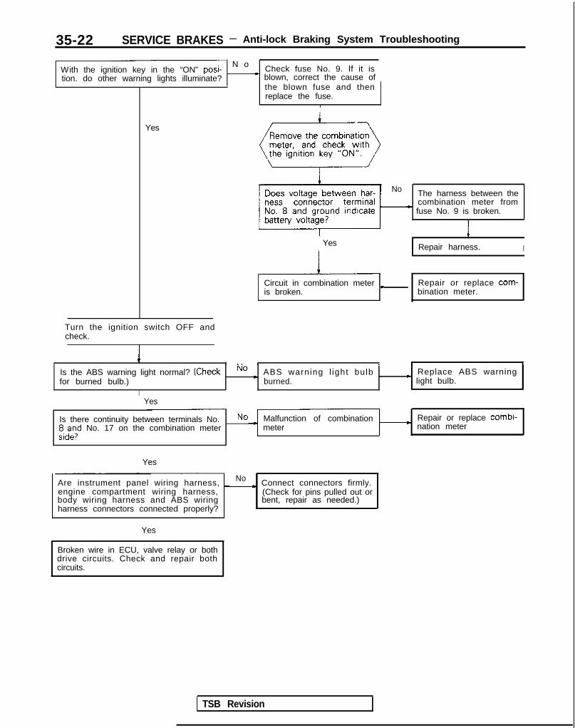
35-22 SERVICE BRAKES - Anti-lock Braking System Troubleshooting
- N oWith the ignition key in the “ON” posi- Check fuse No. 9. If it istion. do other warning lights illuminate? * blown, correct the cause of
the blown fuse and thenreplace the fuse.
I
Yes
Turn the ignition switch OFF andcheck.
4I I ., I I I ,Is the ABS warning light normal? (Check No c ABS warning l ight bulb Replace ABS warningfor burned bulb.) burned. * light bulb.
I
Yes
No The harness between thecombination meter from
* fuse No. 9 is broken.
1
Repair harness. I
Circuit in combination meter c Repair or replace com-is broken. bination meter.
Yes
Is there continuity between terminals No. No Malfunction of combination Repair or replace combi-;,d”,l” No. 17 on the combination meter - meter nation meter
Yes
Are instrument panel wiring harness, _ No c Connect connectors firmly.engine compartment wiring harness,body wiring harness and ABS wiringharness connectors connected properly?
(Check for pins pulled out orbent, repair as needed.)
Yes
Broken wire in ECU, valve relay or bothdrive circuits. Check and repair bothcircuits.
TSB Revision

SERVICE BRAKES - Anti-lock Braking System Troubleshooting 35-23
the ignition key in theposition, remove the ECU connector
Does the voltage between ECU harness No r Broken wire between ABS .connector terminal No.25 and groundindicate battery voltage?
warning light and ECU.Repair harness.
Yes Replace ABS ECU.
(Remove valve relay and check. >
Valve relay malfunction Replace valve relay.
IYes
/Install the valve relay and,
\ignition key in the “ON”remove the HU connector and
TSB Revision
Does voltage between the HU harness No * Broken harness wire be- - Repair harness.connetor terminal No.8 and ground indi- tween ABS warning light I
cate battery voltage? and HUII Yes
Is there continuity between HU harness No - Broken harness wire be- Repair harness.connector terminal No.9 and ground? tween HU and ground
I
‘- N oIs there continuity between terminals No.8 and No. 9 on the HU side connector?
I
- Repair harness or replaceHU.
Yes Connector connection mal-function
NOTEWhen inspecting the parts marked with l , take care to the diode polarity. (Refer to the circuit diagram on P.35-21.)

35-24 SERVICE BRAKES - Anti-lock Braking System Troubleshooting
B ABS warning light illuminated after the engine is started and remains on.
[Explanation]This is the symptom when the ABS ECU does notpower up due to broken ECU power circuit, etc.,when the fail safe function operates and isolates thesystem or when the warning light drive circuit isshort circuited.
[Hint]Check the on-board diagnostic output and if there isno output voltage or if the scan tool and ABS ECUcannot communicate, there is a good possibil itythat power is not flowing to the ECU.
Cautionl If there is no output of diagnostic trouble
codes, there is a good possibility that thefail safe is functioning.
J/B
IGNITION
%FH
z&7
i
CD10A
72
8
Is there on-board diagnostic No )output? (Is there communi-cation with scan tool?)
CONTINUE TONEXT PAGE
Yes
TSB Revision
Does the ABS warning lightremain illuminated evenwith the ECU connector dis-connected?
Yes
No Short in ECU transistor
1 Replace ECU. I

SERVICE BRAKES - Anti-lock Braking System Troubleshooting 35-25
MAIN IGNITION
REVERSE SIDEDATA LINKCONNECTOR
I CONTINUED FROMPREVIOUS PAGE II II-
Can other electronic control _ No . Scan. tool related mal-systems communicate withscan tool?
Fhnc;;n. Repair a n d re-
Yes
No c Correct cause of blownfuse and replace fuse.
With the ignition key in the _No ) Is power relay normal?
“ON” pos i t i on , does ,thf (Refer to P.35-74.);;I;; relay make a click
Disconnect ECU connectorand check harness connec-tor.
I
14A0667
Yes
With the ignition key in the“ON” position, does voltagebetween ECU connector ter-minal No. 18 and ground in-dicate the battery voltage?
Yes
Is there continuity betweenbody harness terminalsNo. 9, No. 20 and No. 34, andground?
ECU ground line broken
Yes
tpNo
I s t h e r e c o n t i n u i t y b e t w e e n Harness wire betweenbody harness connector ter- data link connector andminals No.23 and No.24, and ABS ECU is broken.f2;;k connectors No.4 &
I
Repair harness.Yes
Malfunction of ABS ECU Replace ABS ECU.1
TSB Revision

35-26 SERVICE BRAKES - Anti-lock Braking System Troubleshooting
C ABS warning light does not illuminate when ignition key is in “START” position.
[Explanation]The ABS ECU uses the IG2 power source which istu rned o f f i n t he “START” pos i t i on . The ABSwarning light uses the IGl power source which isno t t u rned o f f even i n t he “START” pos i t i on .Consequently, in the “START” position, power is off
and the ECU turns the valve relay OFF. I f thewarning light does not illuminate at this time, thereis trouble in the warning light circuit on the valverelay side.
MAIN IGNITIONFUSIBLELINK @
1440677
Remove and inspect10 pin connectors ofthe hydraulic unit.
With the ignition key in theNo
“ON” position, does voltagec Harness wire between
HU and warning light isbetween body connector broken.terminal No.8 and groundindicate the battery voltage?
Yes
TSB Revision
Is there continuity between , No
body connector terminal. Broken line between HU
No.9 and ground?and body ground
Remove the valve relay. Is Nothere continuity between
Valve relay malfunction
terminal No. 87a and No. 30?
Replace valve relay.I
HU harness malfunction
I Replace HU. I
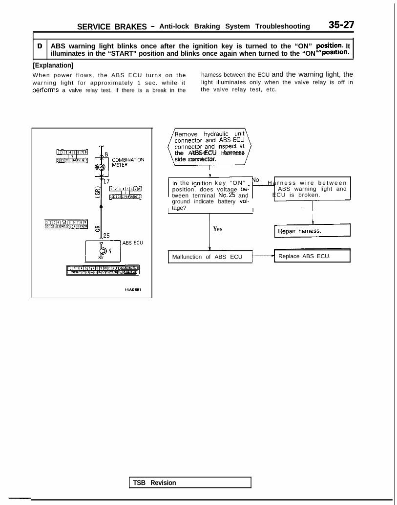
SERVICE BRAKES - Anti-lock Braking System Troubleshooting 35-27
D ABS warning light blinks once after the ignition key is turned to the “ON” yFsiti?r!. Itilluminates in the “START” position and blinks once again when turned to the “ON postilon.
[Explanation]When power f lows, the ABS ECU turns on the harness between the ECU and the warning light, thewarning l ight for approximately 1 sec. whi le i t light illuminates only when the valve relay is off inperforms a valve relay test. If there is a break in the the valve relay test, etc.
TSB Revision
-.
14AO681
Remove hydraulic unitconnector and ABS-ECUconnector and inspect atL---Jthe ABS-ECU harnessside connector.
In the ignition k e y “ O N ” _ No c H a r n e s s w i r e b e t w e e nposition, does voltage be- ABS warning light andtween terminal No.25 and ECU is broken.ground indicate battery vol-tage? I II
IYes
Malfunction of ABS ECU Replace ABS ECU.
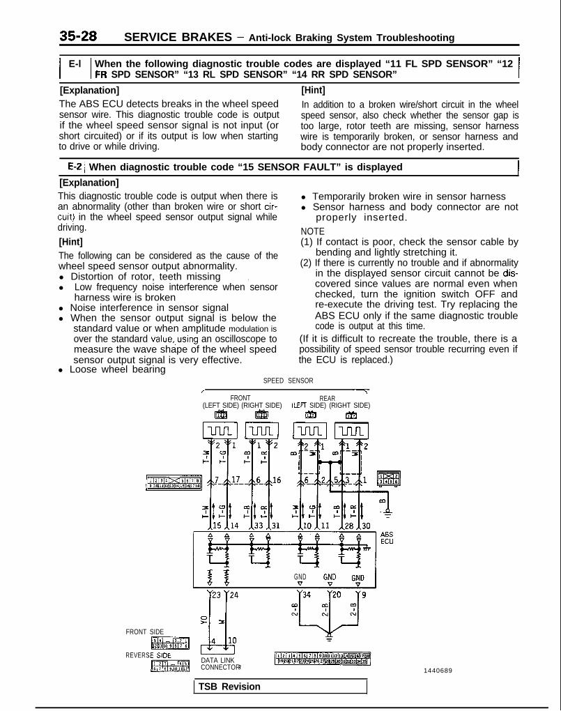
35-28 SERVICE BRAKES - Anti-lock Braking System Troubleshooting
E-lI I When the following diagnostic trouble codes are displayed “11 FL SPD SENSOR” “12FR SPD SENSOR” “13 RL SPD SENSOR” “14 RR SPD SENSOR” I
[Explanation]The ABS ECU detects breaks in the wheel speedsensor wire. This diagnostic trouble code is outputif the wheel speed sensor signal is not input (orshort circuited) or if its output is low when starting
[Hint]In addition to a broken wire/short circuit in the wheelspeed sensor, also check whether the sensor gap istoo large, rotor teeth are missing, sensor harnesswire is temporarily broken, or sensor harness and
to drive or while driving. body connector are not properly inserted.
E-2 1 When diagnostic trouble code “15 SENSOR FAULT” is displayed
[Explanation]This diagnostic trouble code is output when there is l Temporarily broken wire in sensor harnessan abnormality (other than broken wire or short cir-cuit) in the wheel speed sensor output signal while
l Sensor harness and body connector are notproperly inserted.
driving. NOTE[Hint] (1) If contact is poor, check the sensor cable byThe following can be considered as the cause of the bending and lightly stretching it.wheel speed sensor output abnormality. (2) If there is currently no trouble and if abnormalityl Distortion of rotor, teeth missing in the displayed sensor circuit cannot be dis-,l Low frequency noise interference when sensor covered since values are normal even when
harness wire is broken checked, turn the ignition switch OFF andl Noise interference in sensor signal re-execute the driving test. Try replacing thel When the sensor output signal is below the ABS ECU only if the same diagnostic trouble
standard value or when amplitude modulation is code is output at this time.over the standard value,.using an oscilloscope to (If it is difficult to recreate the trouble, there is ameasure the wave shape of the wheel speed possibility of speed sensor trouble recurring even ifsensor output signal is very effective. the ECU is replaced.)
l Loose wheel bearingSPEED SENSOR
/ ~7FRONT REAR
(LEFT SIDE) (RIGHT SIDE) (LEFT SIDE) (RIGHT SIDE)ggj ggjj m m
GND
y23 y24
FRONT SIDE
REVERSDATA LINKCONNECTOR
1 TSB Revision
1440689
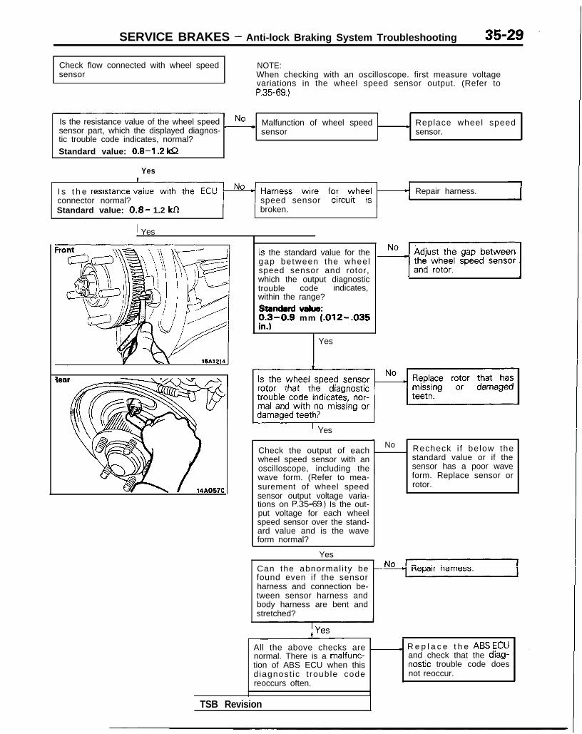
SERVICE BRAKES - Anti-lock Braking System Troubleshooting
Check flow connected with wheel speedsensor
NOTE:When checking with an oscilloscope. first measure voltagevariations in the wheel speed sensor output. (Refer toP.35-69.)
Is the resistance value of the wheel speed Nosensor part, which the displayed diagnos- -
Malfunction of wheel speed ) Replace wheel speedsensor sensor.
tic trouble code indicates, normal?
Standard value: 0.8-I .2 kQ
Yes
I s t h e resrstance vconnector normal? speed sensor
Repair harness.
Standard value: 0.8- 1.2 kRI
broken.
I Yes
Is the standard value for thegap between the wheelspeed sensor and rotor,which the output diagnostictrouble code indicates,within the range?standard value:;y-0.9 mm (.012--035
.
Yes
Yes
Check the output of eachwheel speed sensor with anoscilloscope, including thewave form. (Refer to mea-surement of wheel speedsensor output voltage varia-tions on P.35-69.) Is the out-put voltage for each wheelspeed sensor over the stand-ard value and is the waveform normal?
Yes
No Recheck i f below thestandard value or if thesensor has a poor waveform. Replace sensor orrotor.
Can the abnormal i ty be Nofound even if the sensorharness and connection be-tween sensor harness andbody harness are bent andstretched?
All the above checks are _normal. There is a malfunc-tion of ABS ECU when thisdiagnost ic t rouble codereoccurs often.
I R e p l a c e t h e ABS ECUand check that the diag-nostic trouble code doesnot reoccur.
TSB Revision

35-30 SERVICE BRAKES - Anti-lock Braking System Troubleshooting
E-3 When diagnostic trouble code “22 STOP SW” is displayed 1[Explanation] [Hint]The ABS ECU outputs this diagnostic trouble code If the stop light operates normal, the ABS harnessin the following cases. wire for the stop light switch input circuit to the ECUl Stop light switch may remain on for more than is broken or there is a malfunction in the ABS ECU.
15 minutes without the ABS functions.l The harness wire for the stop light switch may
be open.
SUB FUSIBLELINK @
ABSECU
[1 12 13 14 / 5 16 1 7 16 ~9~10~11~12~13~14~15(16~17~18]~19DOC1122~3~4125l26~27~2~2913013ll3Z~33(341351
Do the stop lights light upand go out normally?
No c Check the stop light re-lated circuit and repairproblem spots.
Yes
connector and inspect atthe harness side connec-
When the brake pedal is _ No Harness wire betweenpressed forcefully, does thevoltage between connector
stop light switch and ABSECU is broken.
terminal No. 29 and groundindicate battery voltage? c
Repair harness.
Yes
rMalfunction of ABS ECU Replace ABS ECU.
I
14AO683
TSB Revision

SERVICE BRAKES - Anti-lock Braking System Troubleshooting 35-31
E-4 When diagnostic trouble codes “41 SOL V FRONT L”, “42 SOL V FRONT R” OR “43SOL V REAR” are displayed
[Explanation]The ABS ECU normally monitors the solenoid valvedrive circuit.If no current flows in the solenoid even if the ECUturns the solenoid ON or if it continues to flow even
when turned OFF, the ECU determines the solenoidcoil wire is broken/short circuited or the harness isbroken short circuited and then these diagnostictrouble codes are output.
IGNITIONSWITCH(IGl)
U0
&cY 10
2: p:\,8 , ---------7
HUI 1 I
Ll 12 [ 3 14 [ 5 16 1 7 18 ~9110/11112113114115116117l18I~19~0~1~22~3~24~25~26~27~28)29~30~31~32~33~~~35~
tor and check with the HU
\ /
Is the resistance value for thesolenoid valve, that the dis-played diagnostic troublecode indicates, within therange of the standard values?
Standard value:1.07-1.17 52
Is the solenoid valve resist-ance value, that the outputdiagnostic trouble code dis-plays, within the range of thestandard values when mea-sured at the ECU connector?
Standard value:1.07-1.17 Q
Replace HU.
No The harness wire for thesolenoid valve circuitwhose resistance value isoutside the range of thestandard value is brokenor short circuited.
IRepair ABS harness.
Malfunction of ABS ECU Replace ABS ECU. I
TSB Revision
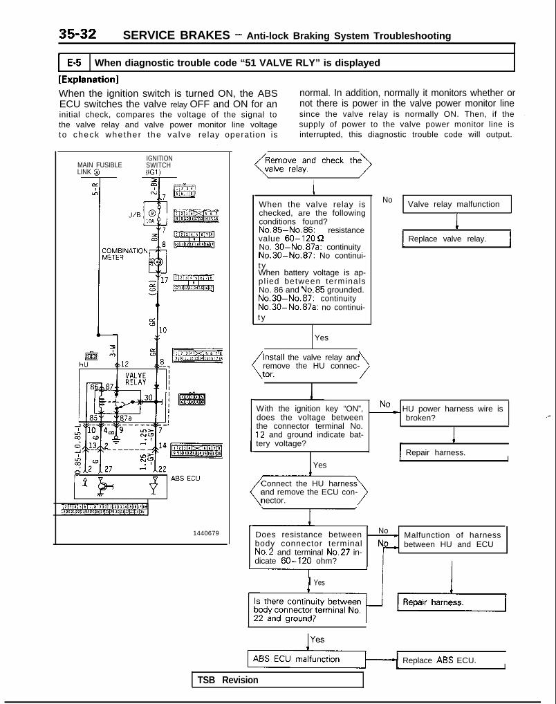
35-32 SERVICE BRAKES - Anti-lock Braking System Troubleshooting
E-5 When diagnostic trouble code “51 VALVE RLY” is displayed
[Explanation]When the ignition switch is turned ON, the ABS normal. In addition, normally it monitors whether orECU switches the valve relay OFF and ON for an not there is power in the valve power monitor lineinitial check, compares the voltage of the signal to since the valve relay is normally ON. Then, if thethe valve relay and valve power monitor line voltage supply of power to the valve power monitor line isto check whe the r the va l ve relay operat ion is interrupted, this diagnostic trouble code will output.
IGNITIONMAIN FUSIBLE SWITCHLINK @ (IGl)
1440679
\ /
IWhen the valve relay ischecked, are the followingconditions found?No.85-No.86: resistancevalue 60-120 QNo. 30-No. 87a: continuityNo.30-No.87: No continui-t yWhen battery voltage is ap-pl ied between terminalsNo. 86 and No.85 grounded.No.30-No.87: continuityNo.30-No.87a: no continui-t y
Yes
the valve relay andremove the HU connec-
>
No Valve relay malfunction
IReplace valve relay.
I
With the ignition key “ON”,does the voltage between
No ~ HU power harness wire isbroken? ,-
the connector terminal No.12 and ground indicate bat-tery voltage? I
Repair harness.
YesI
Connect the HU harnessand remove the ECU con-nector. >
Does resistance between No c Malfunction of harnessbody connector terminal between HU and ECUNo.2 and terminal No.27 in-dicate 60-120 ohm? I
I Yes
TSB Revision
Replace ABS ECU.I
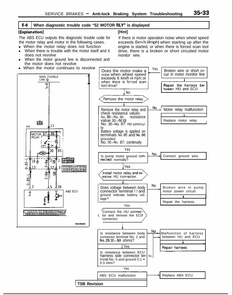
MAIN FUSIBLELINK @
SERVICE BRAKES - Anti-lock Braking System Troubleshooting 35-33
E-6 When diagnostic trouble code “52 MOTOR RLY” is displayed
[Explanation] [Hint]The ABS ECU outputs this diagnostic trouble code for If there is motor operation noise when wheel speedthe motor relay and motor in the following cases. exceeds Gkm/h (4mph) when starting up after thel When the motor relay does not function engine is started, or when there is forced scan tooll When there is trouble with the motor itself and it drive, there is a broken or short circuited motor
does not revolve monitor wire.l When the motor ground line is disconnected and
the motor does not revolvel When the motor continues to revolve
Does the motor make a Yes Broken wire or short cir-noise when wheel speed
)
1 cuit in motor monitor lineexceeds 6 km/h (4 mph) or 1
[ 1 ,2 / 3 14 15 I6 1 I 18 I9l10l11112113114115116117l1sJ~l9~0~1~2tz3l2~~25t6~27~2~29~~~31~32b3134135/
14A0684
L
Remove the motor relay andcheck resistance values.No. 85-No. 86: resistancevalue 30-60 9No. 30-No. 87: no continui-
Motor relay malfunction4
Replace motor relay. ItYBattery voltage is applied onterminals No.85 and No.86grounded.No. 30-No. 87: continuity
Yes
Is pump motor ground con-netted normally?
Connect ground wire.
\ /i
Does voltage between body Broken wire in pumpconnector terminal 11 and
No *motor power circuit
ground indicate battery vol-tage? 1
Repair the harness.Yes
Connect the HU tonnetor and remove the ECUconnector.
I
Is resistance between body No - Malfunction of harnessconnector terminal No. 2 and - between HU and ECUNo.26 30-60 ohms?
1 YesIs resistance between ECUharness side connector ter- NO
minal No. 5 and ground 0.1 -0.3 ohm?
Yes
ABS ECU malfunction
1 TSB Revision
Replace ABS ECU.

35-34 SERVICE BRAKES - Anti-lock Braking System Troubleshooting
TROUBLESHOOTING (ABS-AWD)Confirm condition in the following way and diagnose accordingly.
c
P
t:
1
-
)oes the ABS warning light illuminate as describedelow up to the time the engine starts?1) When the ignition key is turned to the “ON”
position, the ABS warning light blinks four timesfor approximately 1 second due to the ABS ECU(as a self check of the valve relays is performed),and goes out and stays out.
2) W ith the ignition key in the “START” position,power to the ABS ECU is interrupted and the
ABS warning light remains lit because the valverelay is OFF.
(3) When the ignition key is turned from the “START’position to the “ON” position, the ABS warningl igh t b l i nks fou r t imes fo r approx imate ly 1second (during this time a recheck of the valverelays is performed), and then goes out andstays out.
,,,\~~\l’l”“F’,r//,,,l/,,a+’4 4 5 r’o,(j /z$$+3,,,, %
&73,
:
f=&L-gy
821 cJz
x 1000 rimonUILEAED nxL GNL”
Oyg@O@~ 2F
ABS warnmg’l~ght 66A0093
ABS warninglight
ON I
OFF
Ignitionkey
ACC, LOCK 114AO594
YesCONTINUE TO NEXT PAGE
No
1No. Trouble condition
ABS warning light does not light up at all.
1
ABSwarninglight
Ignitionkey ACC,
ON
OFF
LOCK 1
IWhen the lgnltlon key IS turned to the“ON” position, it remains lighted.
ABSwarnina ON ,
l Short in ECU warning light drive circuitl Malfunction of ECU
- “l-l- - I I Iignitionkey
ACC. LO!?-14AO591
Major causes
l ABS warning light bulb is burnt out.l Open in ABS warning light electrical
circuit (check for blown fuse)
l Fail safe is functioning due to ECU on-board diagnostic
Does not illuminate when ignition key isin “START” position.
l Malfunction of valve relayl Break in harness between ABS warn-
ing light and HUl Break in harness between HU and
14AO595
Remedy
Check, using flowchart A (Refer toP.35-39.)
Check, using flowchart B (Refer toP.35-42.)
1 2 /light -
Check, using flowchart C (Refer toP.35-44.)
TSB Revision

SERVICE BRAKES .- Anti-lock Braking System Troubleshooting 35-35
No.
4
rBSvarningght
I!Jnitlonk ey
L
Trouble condition
After the ignition key is turned to the“ON” position, it blinks once and thenilluminates when it is turned to the“START” position. When the key isreturned to the “ON” position, the lightblinks again. (Blinking with the ignitionkey in the “ON” position is synchronizedwith operation noise of the valve relay.)
14A0593
CONTINUED FROM PREVIOUS PAGE
Major causes
l Break in harness for ECU warninglight drive circuit
l Malfunction of ECU
when starting to drive the car?Does the ABS warning light illuminate Yes Trouble with the motor re-
lay, solenoid valve [due to1 self test when driving above
6 km/h (4 mph)] or malfunc-
Notion of wheel speed sensor
t tIs there one-sided braking, insufficient No
braking force or malfunction of ABSc CONTINUE TO
NEXT PAGEoperation?
Yes
4
Trouble condition
One-sided brakingInsufficient braking force
Decline in ABS function(Wheels easily lock when there is sud-den braking.)
ABS sometimes functions even whenthere is no sudden braking. (ABS opera-tion vibration is transmitted.)
Major causes
l Mechanical lock of HU solenoid valvel Hydraulic line in HU is clogged.
l Malfunction in HU solenoid valve op-eration
l Hydraulic line in HU is clogged.
l Insufficient wheel speed sensor out-put voltage (sensor malfunction, toolarge a gap between sensor rotor ormissing rotor teeth or temporarilybroken wire in sensor harness)
8 Malfunction of ABS ECU
Remedy
Check, using flowchart D. (Refer toP.35-45.)
TSB Revision 1
Remedy
Check HU operation (Refer toP.35-36.) and, if necessary,replace HU.If HU is normal, checkstructural parts for normalbraking. (Refer to P.35-12.)
Check wheel speed sensor(Refer to P.35-126.) and, ifnecessary, replace sensor,adjust gap or replace rotor.If tests indicate that there areno mechanical or electricalfailures, replace the ECU.

35-36 SERVICE BRAKES - Anti-lock Braking System Troubleshooting
CONTINUED FROM PREVIOUS PAGE
I
fter a test drive*, use on-board diag-nostic to check. (Refer to P.35-37.)
No diagnostic trouble codes output andnormal codes are displayed?
NoNo on-board diagnosticoutput
l
No Diagnostic trouble codesare output
Yes
Check and repair the har-ness between the ABSECU serial/on-board di-agnostic output terminalsand the data link connec-tor. (Refer to P.35-43.)
tThere was trouble in thepast.NOTEStore diagnostic troublecodes in the memory.
Referring to the diagnos-tic trouble code check
- chart E-l-E-7, make thediagnostic trouble codereoccur to discover themain cause of intermit-tent or other trouble.
c
TSB Revision
All ABS functions are normal.(Nor are there stored memory of past di-agnostic trouble code.) l .8 Run for over 30 sets. at a speed exceeding 30 km/h (18.6 mph).

SERVICE BRAKES - Anti-lock Braking System Troubleshooting 35-37
Connector terminal arrangement fortroubleshooting
[l I2 / 3 14 15 1617 16 I9[10~11~12(13~14~15(16~17[16j[lQ~20~21~22~23~24)25~26~27~28(29130~31~32~33~34~35~
Terminal arrangement shown on thespecial tool connector
-.
TSB Revision
ABS-AWDCaution1. When carrying out inspection of the ABS-ECU ter-
minal voltage and resistance, the special tool(MB991356) should be used.
2. Because the ABS-ECU connector terminal arrange-ment for troubleshooting is different from the termi-nal arrangement shown on the special tool connec-tor, when using the special tool for inspecting, takethe readings from the terminal numbers of the spe-cial tool.Example
ABS-ECU connector terminal Terminal number shown onnumber for troubleshooting the special tool connector
18 1
CHECK, USING ON-BOARD DIAGNOSTIC(1) With the ignition switch OFF, connect the adapter harness
and scan tool, turn the ignition ON and select the ABS sys-tem. (The ABS warning light lights up, it goes into the scantool mode. In the scan tool mode, ABS does not func-tion.)If it does not go into the scan tool mode, check the ECUpower circuit and the harness between the ECU and datalink connectors.
(2) Read the on-board diagnostic output codes from the ECUmemory.
(3) Cancel the diagnostic trouble codes once from memory.(Refer to P.35-38.)If the memory can not be canceled, the ECU is currentlydetecting the trouble. If’it can be cleared, the trouble iseither temporary or appears only when driving.
(4) When the diagnostic trouble codes are cleared, or whenthe ABS system goes into fail safe during another test driveand diagnostic trouble codes are outputed, check accord-ing to diagnostic trouble code check charts (E-l -E-7).

35-38 SERVICE BRAKES - Anti-lock Braking System Troubleshooting
DIAGNOSTIC TROUBLE CODE CHART
Diagnostic trouble code Check Reference Diagnostic trouble code Check Referencechart name we chart name
No. Scan tool display letters or remedy No. Scan tool display letters or remedypage
11 FL SPD SENSOR
12 FR SPD SENSOR
13 RL SPD SENSOR
14 RR SPD SENSOR
15 SENSOR FAULT
21 G SENSOR
22 STOP SW
E-l
E-2
E-3
E-4
41 SOL V FRONT L
42 SOL V FRONT R E-5 P.35-50P.35-46
43 SOL V DRIFT
51 VALVE RLY E-6 P.35-51
P.35-46 52 MOTOR RLY E-7 P.35-52
P.35-4855 ECU ECU
P.35-49 replacement -
METHOD OF CLEARING DIAGNOSTICTROUBLE CODE MEMORYCautionl When servicing is finished, clear the diag-
nostic trouble code memory.Diagnostic trouble codes cannot be cleared frommemory when the ABS ECU system in fail safe.Proceed to diagnosis and repair.(1) Clear memory using scan tool.
(For details, refer to the scan tool instructionmanual.)
(2) After clearing, recheck the diagnostic troublecodes, and check that memory is cleared.
ACTUATOR TEST FUNCTIONThe actuator can be forcibly driven in the followingway by using the scan tool.NOTEl The actuator test cannot be carried out when
the ABS ECU system is fail safe.l When using forced drive using the scan tool, the
vehicle must be stopped.l During forced drive using the scan tool, forced
drive operation is stopped when any wheelspeed reaches 10 km/h (6 mph).
Actuator test specifications
No. FGc$ool display Drive solenoidvalue and motor Drive pattern
Solenoid valve and Not used
01 FR VALVE Ap u m p m o t o r f o reach HU corres-ponding channel.<Auto pattern>
02 FL VALVE A
Solenoid valve and Pressure
04 FR VALVE Mpump motor foreach HU corres- %Fwidponding channel.<Manual pattern>
05 FL VALVE MPumpmotor
TSB Revision
Start of forced drive End of forced drib14AO581
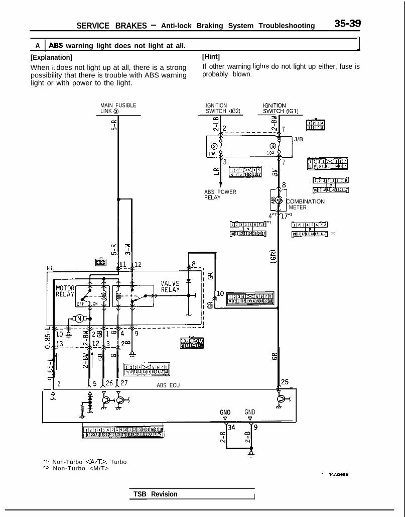
SERVICE BRAKES - Anti-lock Braking System Troubleshooting 35-39
A ABS warning light does not light at all. 1[Explanation] [Hint]
When it does not light up at all, there is a strong If other warning lighrs do not light up either, fuse ispossibility that there is trouble with ABS warning probably blown.light or with power to the light.
MAIN FUSIBLELINK @
ofLA
IGNITION IGNITSWITCH (IG2) SWIT
-Tr-- -z
ABS POWERRELAY
‘IOct:I1__-------- I,7r
.I
:
,\c
AL1-f.
C.
dU
dr-3
gl” pzElzmq4
4*I
2 1\5 ,&A27 ABS ECU
;(IGI,
1234
7 m5670
1 J/B
7
1 COMBINATION1 METER
1r2
gizizgl *
tGNO GNDV V
*I: Non-Turbo <A/D, Turbo‘2: Non-Turbo <M/T>
TSB Revision I

SERVICE BRAKES - Anti-lock Braking System Troubleshooting
With the ignition key in the “ON” posi- No Check fuse No. 9. If it istion, do other warning lights illuminate? blown, correct the cause of
-T-
Yes
the blown fuse and thenreplace the fuse.
I
Remove the combinationmeter, and check withthe ignition key “ON”.
I
Does voltage between har- No The harness between theness connector terminalNo. 8 and ground indicate -
combination meter fromfuse No. 9 is broken.
battery voltage?
IYes Repair harness.
Circuit in combination meteris broken.
L R e p a i r o r r e p l a c e com-bination meter.
Turn the ignition switch OFF ancheck.
I
Is the ABS warning light normal? (Check Nofor burned bulb.)
c A$Eedyrning l i g h t b u l b , c Replace ABS warninglight bulb.
Yes
Is there continuity between terminals No. N o -
8 and 4” or 17’2 on the combinationI M a l f u n c t i o n o f c o m b i n a t i o n
meterI Repair or replace combi-
meter side?nation meter
Are instrument panel wiring harness, No -
~ engine compartment wiring harness,. Connect connectors firmly.
body wiring harness and ABS wiring(Check for pins pulled out or
harness connectors connected properly?bent, repair as needed.)
I1 Yes
I Broken wire in ECU, valve relay or bothdrive circuits. Check and repair bothcircuits. I
NOTE‘1: Non-Turbo <A/T>. Turbol *: Non-Turbo <M/T>
TSB Revision

35-42 SERVICE BRAKES - Anti-lock Braking System Troubleshooting
B ABS warning light illuminated after the engine is started and remains on.
[Explanation]This is the symptom when the ABS ECU does notpower up due to broken ECU power circuit, etc.,when the fail safe function operates and isolates thesystem or when the warning light drive circuit isshort circuited.[Hint]Check the on-board diagnostic output and if there isno output voltage or if the scan tool and ABS ECUcannot communicate, there is a good possibilitythat power is not flowing to the ECU.
Cautionl If there is no output of diagnostic trouble
codes, there is a good possibility that thefail safe is functioning.
MAINFUSIBLELINK @
IGNITIONSWITCH(IG1)
I LOIE;NATION
+ 10
3@izJ”,
HUZ8 p
:r12 /e-,
xx
III
* I
; 16 4= 9
II
d
+ qfimamq!2 a
I -L Q-7 ABS ECUm 1
: Non-Turbo <A/T>. Turbo: Non-Turbo <M/1) 14A0676
Is there on-board diagnostic Noc CONTINUE TO
output? (Is there communi- NEXT PAGEcation with scan tool?)
IYes
Does diagnostic troublecode output display normalcodes?
No . Check, using the diagnos-tic trouble code checkchart. (Refer to P.35-38.)
II
I L I
Short in harness betweenrgl;r ECU and ABS warning
) Repair harness or replacecombination meter.I I
TSB Revision

SERVICE BRAKES - Anti-lock Braking System Troubleshooting 35-41
1 Check ABS ECU. I
W ith the ignition key in the “ON”position, remove the ECU connector
(nd check. ,)
Does the voltage between ECU harness No - Broken wire between ABSconnector terminal No.25 and ground warning light and ECUindicate battery voltage?
Yes Replace ABS ECU.
Check ABS valve relay.
<Remove valve relay and check. >
Is valve relay normal Replace valve relay.I
rgnrtron key in the “ON” position,
Does voltage between the HU harness No - Broken harness wire be- - Repair harness.connetor terminal No. 8 and ground indi- tween ABS warning lightcate battery voltage? and HU
I
Yes
Is there continuity between HU harness No - B roken ha rness w i re be- Repair harness.connector terminal No.9 and ground? tween HU and ground
I
’ N oIs there continuity between terminals No.8 and No. 9 on the HU side connector?
- Repair harness or replaceHU.
Yes * Connector connection mal-function
NOTEWhen inspecting the parts marked with l , take care to the diode polarity. (Refer to the circuit diagram on R.S5-39.)
TSB Revision

SERVICE BRAKES - Anti-lock Braking System Troubleshooting 35-43
MAINFUSIBLELINK @
IGNITION
KgCHml
CONTINUED FROMPREVIOUS PAGE
CONNECTOR
t ,Is there continuity between No F Harness wire betweenbody harness connector ter- data link connector andminals No.23 and No.24, and ABS ECU is broken.data link connectors No.4 &No.1 O? I
Repair harness.Yes I
1 Malfunction of ABS ECUI
1-4 Replace ABS ECU.I I
I1
TSB Revision
1 Yes
No - Correct cause of blownfuse and replace fuse.
r
L
With the ignition key in the No ~ Is power relay normal?“ON” position, does the (Refer to P.35-74.)power relay make a “click”noise?
Yes NoYes
t I ,
Disconnect ECU connectorand check harness connec-tor.
t
Replace power relay.1
With the ignition key in the No Harness wire between“ON” position, does voltage - power relay and ECU isbetween ECU connector ter- broken.minal No. 18 and ground in-dicate the battery voltage? 4
Repair harness.
Yes
tpIs there continuity between No ECU ground line brokenbody harness terminalsNo.9 and No. 34, and c
ground? Repair harness.I
Yes

35-44 SERVICE BRAKES - Anti-lock Braking System Troubleshooting
C ABS warning light does not illuminate when ignition key is in “START” position.I
[Explanation]The ABS ECU uses the IG2 power source which is and the ECU turns the valve relay OFF. If theturned off in the “START” position. The ABS warning light does not illuminate at this time, therewarning light uses the IGl power source which is is trouble in the warning light circuit on the valvenot turned off even in the “START” position. relay side.Consequently, in the “START” position, power is off
KLlh-
0u
:LEIGNITIONSWITCH
0 (IGl)
0
Es10
1
7IIIIIIIII!
: Non-Turbo <A/T>. TurboI: Non-Turbo <M/D 14A0678
1
Remove the fuse fopower source of theABS power relay in thejunction block andswitch off ABS-ECU.
l Remove and inspect10 pin connectors ofthe hydraulic unit.
“ON” position, does voltagebetween body connectorterminal No.8 and around 1indicate the battery vcltage?
b!$%iii&Broken line between HUand body ground I
Yest
Remove the valve relay. Is - Nothere continuity between
Valve relay malfunction
terminal No. 87a and No. 30?I
Yes [Replace-relay
HU harness malfunction
I Replace HU. I
TSB Revision

SERVICE BRAKES - Anti-lock Braking System Troubleshooting 35-45
D ABS warning light blinks once after the ignition key is turned to the “ON” positi??. Itilluminates in the “START” position and blinks once again when turned to the “ON” posItron.
[Explanation]When power flows, the ABS ECU turns on the harness between the ECU and the warning light, thewarning light for approximately 1 sec. while it light illuminates only when the valve relay is off inperforms a valve relay test. If there is a break in the the valve relay test, etc.
El
ABS ECU
11 ,* (3 14 1 5 j 6 1 ,I 8 I 9)10111112113114115l161171~8)[19~0p1l22~3lz4125126127129l29l,ol31l32l33l~l35l
‘1. Non-Turbo <A/T>. Turbo‘2: Non-Turbo <M/T>
14AO662
Remove hydraulic unitconnector and ABS-ECUconnector and inspect atthe ABS-ECU harness
\side connect:/
-.
TSB Revision
Yes
Replace ABS ECU. I

35-46 SERVICE BRAKES - Anti-lock Braking System Troubleshooting
E-l When the following diagnostic trouble codes are displayed “11 FL SPD SENSOR” “12FR SPD SENSOR” “13 RL SPD SENSOR” “14 RR SPD SENSOR”
[Explanation] [Hint]The ABS ECU detects breaks in the wheel speed In addition to a broken wire/short circuit in the wheelsensor wire. This diagnostic trouble code is outputif the wheel speed sensor signal is not input (or
speed sensor, also check whether the sensor gap istoo large, rotor teeth are missing, sensor harness
short circuited) or if its output is low when starting wire is temporarily broken, or sensor harness andto drive or while driving. body connector are not properly inserted.
E-2 When diagnostic trouble code "15 SENSOR FAULT” is displayed
[Explanation]This diagnostic trouble code is output when there isan abnormality (other than broken wire or short cir-cuit) in the wheel speed sensor output signal whiledriving.[Hint]The following can be considered as the cause of thewheel speed sensor output abnormality.l Distortion of rotor, teeth missingl Low frequency noise interference when sensor
harness wire is brokenl Noise interference in sensor signal0 When the sensor output signal is below the
standard value or when amplitude modulation isover the standard value., using an oscilloscope tomeasure the wave shape of the wheel speedsensor output signal is very effective.
l Loose wheel bearing
l Temporarily broken wire in sensor harnessl Sensor harness and body connector are not
properly inserted.NOTE(1) If contact is poor, check the sensor cable by
bending and lightly stretching it.(2) If there is currently no trouble and if abnormality
in the displayed sensor circuit cannot be dis-covered since values are normal even whenchecked, turn the ignition switch OFF andre-execute the driving test. Try replacing theABS ECU only if the same diagnostic troublecode is output at this time.
(If it is difficult to recreate the trouble, there is apossibility of speed sensor trouble recurring even ifthe ECU is replaced.)
SPEED SENSOR
FRONT REAR(LEFT SIDE) (RIGHT SIDE) (LEFT SIDE) (RIGHT SIDE)
ABSECU
GND G!D
r23 )‘24 ;34 Y9
FRONT SIDE
REVERSE SIDE DATA LlNK
CONNECTOR14A0690
TSB Revision

SERVICE BRAKES - Anti-lock Braking System Troubleshooting 35-47
Check flow connected with wheel speedsensor
NOTE:When checking with an oscilloscope, first measure voltagevariations in the wheel speed sensor output. (Refer toP.35-69.)
Is the resistance value of the wheel speed No Malfunction of wheel speed . Replace wheel speedsensor part, which the displayed diag- sensor sensor.nostic trouble code indicates, normal?
Standard value: 0.8-I .2 kSZ
Yes
Is the resistance value with the ECU No* Harness wire for wheelconnector normal? speed sensor circuit isStandard value: 0.8- 1.2 k0 broken.
I
Repair harness.
tIs the standard value for thegap between the wheelspeed sensor and rotor,which the output diagnostictrouble code indicates,within the range?
stendllrd value:!I$0.9 mm (.012- .035
) YesI
1 Yes.Check the output of eachwheel speed sensor with anoscilloscope, including thewave form. (Refer to mea-surement of wheel speedsensor output voltage varia-tions on P.35-69.) Is the out-put voltage for each wheelspeed sensor o v e r thestandard value and is thewave form normal?
Yes
Can the abnormal i ty befound even if the sensorharness and connection be-tween sensor harness andbody harness are bent andstretched?
No- Recheck i f below the
standard value or if thesensor has a poor waveform. Replace sensor orrotor.
1 TSB Revision

35-48 SERVICE BRAKES - Anti-lock Braking System Troubleshooting
I IE-3 When diagnostic trouble code “21 G SENSOR” is displayed I
[Explanation]The ABS ECU outputs this diagnostic trouble codein the following cases.l OFF trouble turning G sensor OFF (It is judged
that the G sensor continues to be OFF for morethan approximately 13 seconds except when the
vehicle is stopped or when there is stop lightswitch input.
l When there is a broken wire or short circuit inthe harness for the G sensor system.
ABSPOWERRELAY
MAIN FUSIBLE IGNITIONLINK @ SWITCH (IG2)
G-SENSOR
qABSECU
II21314 15161 ~/819110111l12l1P/14l15~~6l17l16~~19120121122123l24125l26l27128129/30131j32b3134(15~
14AO702
Is G sensor normal?(Refer to P.35-132.)
No Replace G sensor.
1 Yes
Remove the ABS ECUconnector and check atthe harness connector.
I
With the ignition key “ON” No m The harness between thedoes the voltage between G sensor and the ABSterminal No.6 and ground ECU is broken.indicate battery voltage?
Yes*
Repair harness.
Replace ABS ECU.
1 TSB Revision

SERVICE BRAKES - Anti-lock Braking System Troubleshooting 35-49
1 E-4 1 When diagnostic trouble code “22 STOP SW” is displayed
[Explanation]The ABS ECU outputs this diagnostic trouble codein the following cases.l Stop light switch may remain on for more than
15 minutes without the ABS functions.l The harness wire for the stop light switch may
be open.
[Hint]If the stop light operates normal, the ABS harnesswire for the stop light switch input circuit to the ECUis broken or there is a malfunction in the ABS ECU.
SUB FUSIBLELINK 0
WITHAUTO-CRUISECONTROL
SWITCH -G
_.ABSECU
F-l
14A0663
Do the stop lights light up - Noand go out normally?
~ Check the stop light re-lated circuit and repairproblem spots.
Yes
connect the ABS ECconnector and inspect atthe harness side connec-
When the brake pedal is No Harness wire betweenpressed forcefully, does thevoltage between connector
stop light switch and ABSECU is broken.
terminal No. 29 and groundindicate battery voltage?
Yes
1
Repair harness.
1
Malfunction of ABS ECU Replace ABS ECU.I

35-50 SERVICE BRAKES - Anti-lock Braking System Troubleshooting
E-5I I When diagnostic trouble codes “41 SOL V FRONT L”, “42 SOL V FRONT R” OR “43SOL V DRIFT” are displayed I
[Explanation]The ABS ECU normally monitors the solenoid valvedrive circuit.If no current flows in the solenoid even if the ECUturns the solenoid ON or if it continues to flow even
when turned OFF, the ECU determines the solenoidcoil wire is broken/short circuited or the harness isbroken short circuited and then these diagnostictrouble codes are output.
IGNITIONSWITCHllG1)
HU
1 / 2 / 3 14 15 16 I 7 ~8~9h0~11~12~13~14~15[16[17@,19bO~21i22~3~24~25)26~27~28~29~30)31$2~33)34[35j
: Non-Turbo <M/D: Non-Turbo CA/D, Turbo
14A0692
tor and check with the HUside connector.
Connect HU IOP connec-tor, disconnect ECU con-nector and check.
Is the solenoid valve resis-tance value within the ranae
The harness wire for thesolenoid valve circuit 1
nectar?Standard value: 1.0-l .3 Q
Yes I Repair ABS harness. 1
Replace ABS ECU. 1
I1 TSB Revision

SERVICE BRAKES - Anti-lock Braking System Troubleshooting 35-51
E-5 When diagnostic trouble code “51 VALVE RLY” is displayed
[Explanation]When the ignition switch is turned ON, the ABSECU switches the valve relay OFF and ON for aninitial check, compares the voltage of the signal tothe valve relay and valve power monitor line voltageto check whether the valve relay operation is
normal. In addition, normally it monitors whether ornot there is power in the valve power monitor linesince the valve relay is normally ON. Then, if thesupply of power to the valve power monitor line isinterrupted, this diagnostic trouble code will output.
MAIN FUSIBLE$tW&N
LINK @I (IGl)
gEli!z$; lf*x**IT5
10
IU- 412 &-,8
ABS ECU
: Non-Turbo <A/T>. Turbo: Non-Turbo <M/D 14AO680
y+iw+w;,aay;check thy
When the valve relay ischecked, are the followingconditions found?No. 85-No. 86: resistancevalue 60-120 52No.30-No.87a: continuityNo. 30-No. 87: No continui-
When battery voltage is ap-pl ied between terminalsNo. 86 and No. 85 grounded.No.30-No.87: continuityNo. 30-No. 87a: no continui-t y
remove the HU connec-
\ /I
With the ignition key “ O N ” , No c HU power harness wire isdoes the voltage between broken?the connector terminal No.12 and ground indicate bat-tery voltage? I
I Repair harness.
YesI I
IbI \ I
Does resistance betweenbody connector terminalNo. 2 and terminal No. 27 in-dicate 60-120 ohm?
IYes
Is there continuity betweenbody connector terminal No.22 and ground?
Repair harness.
ABS ECU malfunction Replace ABS ECU.
1 TSB Revision 1

35-52 SERVICE BRAKES - Anti-lock Braking System Troubleshooting
E-7 When diagnostic trouble code “52 MOTOR RLY” is displayed I[Explanation] [Hint]
The ABS ECU outputs this diagnostic trouble code for If there is motor operation noise when wheel speedthe motor relay and motor in the following cases. exceeds Gkm/h (4mph) when starting up after thel When the motor relay does not function engine is started, or when there is forced scan tooll When there is trouble with the motor itself and it drive, there is a broken or short circuited motor
does not revolve monitor wire.l When there is trouble with the motor itself and it
the motor does not revolvel When the motor continues to revolve Yes Broken wire or short cir-
-I noise when wheel speed cuit in motor monitor lineMAIN FUSIBLELINK @
&
1 j 2 I3 I4 I5 I6 I 7 18 I9 l10l11112113114115116l17 1819p0~1122~3~24l2S~26I27(2~29130131l32l33l3~~3~
(Remove the motor relay>
r
l -
\ /4~
Remove the motor relay and -check resistance values.
No c Motor relay malfunction
No. 85-No. 86: resistance 4
value 30-60 QNo.30-No.87: no continui-
Replace motor relay.
tyBattery voltage is applied onterminals No.86 and No.85groundedNo.30-No.87: continuity
1Yes
Is pump motor ground con- No
netted normally?Connect ground wire.
lYes
<Install motor relay andmove HU connector.
Does voltage between bodyconnector terminal 11 and
No ) B r o k e n w i r e i n p u m p
ground indicate battery vol-motor power circuit
tage? 4
YesRepair the harness.
I
tor and remove the ECU
Is resistance between body - No - Malfunction of harnessconnector terminal No. 2 and NoNo.26 30-60 ohms?
between HU and ECUI
4 Yes .Repair harness. II
ABS ECU malfunction Replace ABS ECU.I
TSB Revision

SERVICE BRAKES - Service Adjustment Procedures 35-53
switch
switch
c/ 14F516
Pedal
I d o w n /
\ \ F14517
TSB Revision
F14518
SERVICE ADJUSTMENT PROCEDURESBRAKE PEDAL INSPECTION AND ADJUSTMAN-1. Measure the brake pedal height as illustrated. If the brake
pedal height is not within the standard value, adjust asfollows.Standard value (A): 176-181 mm (6.9-7.1 in.)
(1) Disconnect the stop light switch connector, loosen thelock nut, and move the stop light switch to a positionwhere it does not contact the brake pedal arm.
(2) Adjust the brake pedal height by turning the operatingrod with pliers (with the operating rod lock nutloosened), until the correct brake pedal height isobtained.
(3) After screwing in the stop light switch until it contactsthe brake pedal stopper (just before the brake pedal iscaused to move), return the stop light switch l/2 to 1turn and secure by tightening the lock nut.
2.
(4) Connect the connector of the stop light switch.(5) Check to be sure that the stop light is not illuminated
with the brake pedal unpressed.Reference value (B): 0.5-1.0 mm (.02-.04 in.)
With the engine stopped, depress the brake pedal two orthree times. After eliminating the vacuum in the powerbrake booster, press the pedal down by hand, and confirmthat the amount of movement before resistance is met(the free play) is within the standard value range.Standard value (C): 3-8 mm (.l-.3 in.)If the free play is less than the standard value, confirm thatthe clearance between the stop light switch and brakepedal is within the standard value.If the free play exceeds the standard value, it is probablydue to excessive play between the clevis pin and brakepedal arm. Check for excessive clearance and replacefaulty parts as required.

35-54 SERVICE BRAKES - Service Adjustment Procedures
F14519
14UOO61
When engine isstopped
No good0w\/‘ 14UOO62
z;redengine is
14UOO60
,3. Start the engine, depress the brake pedal with approxi-mately 500 N (110 Ibs.) of force, and measure the clearancebetween the brake pedal and the floorboard.Standard value(D): 80 mm (3.1 in.) or moreIf the clearance is less than the standard value, check forair trapped in the brake line and for brake fluid leaks. Ifnecessary, check the brake system mechanism (excessiveshoe clearance due to faulty auto adjuster) and repairfaulty parts as required.
<From 1990 models>4. After adjusting the height of the brake pedal, inspect the
shift lock device.5. If there is any trouble in the functioning of the shift lock
device, adjust the shift lock cable.NOTERefer to GROUP 23 for details about inspection andadjustment of the shift lock device.
BRAKE FLUID LEVEL SENSOR CHECK M35F6A6(1) Connect a circuit tester to the brake fluid level sensor.(2) Move the float from top to bottom and check for
continuity.(3) The brake fluid level sensor is in good condition if there is
no continuity when the float surface is above “A”, and ifthere is continuity when the float surface is below “A”.
BRAKE BOOSTER OPERATING INSPECTION MlKcAJFor simple checking of brake booster operation, carry out thefollowing tests.(1) Run the engine for one or two minutes, and then stop it.(2) Step on the brake pedal several’ times with normal
pressure.If the pedal depressed fully the first time but graduallybecomes higher when depressed succeeding times, thebooster is operating properly.If the pedal height remains unchanged, the booster isfaulty.
(3) With the engine stopped, step on the brake pedal several
(4
If
times with the same foot pressure to make sure that thepedal height will not change.Then step on the brake pedal and start the engine.If the pedal moves downward slightly, the booster is ingood condit’on. If there is no change, the booster is faulty.
.) With the engine running, step on the brake pedal and thenstop the engine.Hold the pedal depressed for 30 seconds. If the pedalheight does not change, the booster is in good condition.If the pedal rises, the booster is faulty.
the above three tests are okay, the booster performancecan be determined as gooa.If one of the above three tests is not okay at last, the checkvalve, vacuum hose, or booster will be faulty.
CHECK VALVE OPERATION CHECK M3!3FNAK
cl989 models>1. Remove the vacuum hose at the brake booster side.2. Remove the check valve from the brake booster.
TSB Revision

SERVICE BRAKES - Service Adjustment Procedures 35-55
Valve . ,Spring
3rake)oostelside
14AO358
3. Check the operation of the check valve by using a vacuumpump.
Vacuum pump connection Accept/reject criteria
Connection at the brake A negative pressure (vacuum) isbooster side @I created and held.
Connection at the intakemainfold side @
A negative pressure (vacuum) is notcreated.
<From 1990 models>When checking the check valve, keep the check valve fit in thevacuum hose.1. Remove the vacuum hose.
CautionThe check valve is press-fit inside the vacuum hose anddo not remove the check valve from the vacuum hose.
2. Check the operation of the check valve by using a vacuumpump.
Spring
Valve
14A0417
TSB Revision 1
Vacuum pump connection Accept/reject criteria
Connection at the brake A negative pressure (vacuum) isbooster side @ created and held.
Connection at the intakemanifold side @
A negative pressure (vacuum) is notcreated.
CautionIf the check valve is defective, replace it as an assemblyunit together with the vacuum hose.

35-56 SERVICE BRAKES - Service Adiustment Procedures
Pressurew-w Pressure
Proportioning v a l v e momi
,.,’
S p l i t p o i n t ,,s*”I’
I’,’
Outpur ,’I’
pressure
izl
Input pressure
14uoo55
PROPORTIONING VALVE FUNCTION TEST M~KKAK1. Connect two pressure gauges, one each to the input side
and output side of the proportioning valve, as shown.2. Bleed the air from the brake line and the pressure gauge.3. While gradually depressing the brake pedal, make the
following measurements and check to be sure that themeasured values are within the allowable range.(1) Output pressure begins to drop relative to input
pressure (split point).
Standard value:<Up to 1990.5 models>
ii:3.95-4.45 Mpa (561-633 psi)4.95-5.45 Mpa (704-775 psi)
cl991 models>FWD-SOHC 3.95-4.45 Mpa (561-633 psi)FWD-DOHC 3.45-3.95 Mpa (491-561 psi)AWD 4.95-5.45 Mpa (704-775 psi)
(2) Ou;x~; fluid pressure when input fluid pressure are as
Standard value:< 1989 models>
FWD 5.15-5.65 Mpa (732-804 psi)[at 8.2 Mpa (1,163 psi)]
<1990, 1990.5 models>FWD 5.55-6.05 Mpa (789-861 psi)
[at 8.2 Mpa (1,163 psi)]AWD 6.55-7.05 Mpa (931- 1,003 psi)
[at 9.2 Mpa (1,309 psi)]<From 1991 models>
FWD-SOHC 5.55-6.05 Mpa (789-861 psi)[at 8.2 Mpa (1,163 psi)]
FWD-DOHC 4.65-5.15 Mpa (661-732 psi)[at 7.7 Mpa (1,095 psi)]
AWD 6.55-7.05 Mpa (931-1,003 psi)[at 9.2 Mpa (1,309 psi)]
(3) Output pressure difference between left and rightbrake lines
Limit: 0.4 MPa (57 psi)4. If the measured pressures are not within the permissible
ranges, replace the proportioning valve.
TSB Revision

SERVICE, BRAKES - Service Adjustment Procedures 35-57
<Vehicles without A.B.S.>
4 1
2 314AQ456
<Vehicles with A&S.>
FWDDelay valve Lflc ’-c
i 1
L3
14AO4l
mit
14RD120
AWD5 1
6 2 4 14AO4E
BLEEDING <Up to 1991 models> M35FYAM
Because the master cylinder employed is the type without thecheck valve, air should be bled from the master cylinder byfollowing the procedures described below (if there is no brakefluid in the master cylinder).
(1) Disconnect the brake tube from the master cylinder.(2) Two persons’ should conduct the air bleeding, one person
slowly depressing the brake pedal and holding the pedaldepressed.
(3) In this condition, the other person should use a finger toclose the outlet part of the master cylinder, and then thefirst person should release the brake pedal.
(4) Steps (2) and (3) should be repeated three or four times,and then the master cylinder should be filled with brakefluid to the specified level.
I(]OTEThe air is completely bled from the master cylinder bysteps (1) to (4).
(5) Connect the brake tube to the master cylinder.(6) Start the engine; then, in the sequence shown in the
illustration, bleed the air from each wheel cylinder, delayvalve and hydraulic unit.
Specified brake fluid: Confoming to DOT3 or DOT4Caution1. Use the specified brake fluid. Avoid using a mixture
of the specified brake fluid and other fluid.2. If brake fluid is exposed to the air, it will absorb
moisture; as water is absorbed from the atmo-sphere, the boiling point of the brake fluid willdecrease and the braking performance will beseriously impaired. For this reason, use a hermeti-cally sealed 1 dms (1.06 qt.) or 0.5 dms (0.52 qt.)brake fluid container.
3. Firmly close the cap of the brake fluid containerafter use.
4. For vehicles with the anti-lock braking system, besure to install a filter to the master cylinderreservoir tank when supplying brake fluid.
NOTEFor FWD-vehicles with the anti-lock braking system, thebrake pedal will have a “heavier” feeling for air bleeding ofthe rear brakes than for the front brakes, but this is theresult of the constriction of fluid pressure within the delayvalve, and is not a malfunction.
1 TSB Revision

35-58 SERVICE BRAKES - Service Adjustment Procedures
14*ooat
Delayvalve
Bleeder screw(for the left rear brakes)
i
Bleeder screw
I.LOO.1lheck valve bolt20-25 N m (14-18 ft.lbs.)
ORDINARY AIR-BLEEDING PROCEDURES(1) Depress the brake pedal several times until resistance is
felt; then, with the pedal depressed, loosen the bleederscrew 113 to l/2 turn and then tighten it before the fluidpressure is all gone.
(2) Release the brake pedal. Repeat this procedure until thereare no more air bubbles in the brake fluid.
AIR BLEEDING FROM DELAY VALVE 4WD-ABS>
(1) Return the check valve bolt of the delay valve by aboutone turn and then bleed the air by following the stepsdescribed above in “Ordinary air-bleeding procedures”.
CautionThere is a delay valve bleeder screw for the left rearwheel brake and for the right rear wheel brake, ensurethe correct one is used.
(2) Be sure to tighten the check valve bolt at the specifiedtorque after completing the air bleeding.
AIR BLEEDING FROM HYDRAULIC UNIT <VEHICLES WITHA.B.S. >
(1) Attach the brake bleeder wrench to the bleeder screw.(2) Using an offset (box) wrench 114 mm (55 in.)], loosen the
bleeder screw.
CautionUse an offset (box) wrench to open and close thebleeder, not a spanner wrench, because a spannerwrench might cause deformation of the hexagonal part.
(3) Bleed the air by following the steps described above in“Ordinary air-bleeding procedures”.
TSB Revision

SERVICE BRAKES - Service Adjustment Procedures 35-59
14 LO169
FRONT DISC BRAKE PAD CHECK AND REPLACE-MENT <Up to 1990 models> M36FQAG
1. Check brake pad thickness through caliper body checkport.
Limit: 2.0 mm (.08 in.)Caution1. When the limit is exceeded, replace the pads at both
sides, and also the brake pads for the wheels on theopposite side at the same time.
2. If there is a significant difference in the thicknessesof the pads on the left and right sides, check thesliding condition of the piston, lock pin sleeve andguide pin sleeve.
2. Remove lock pin. Lift caliper assembly and retain withwires.
CautionDo not wipe off the special grease that is on the lockpin or allow it to contaminate the lock pin.
3. Remove the following parts from caliper support.(1) Shim holder(2) Inner shim(3) Pad assembly(4) Outer shim(5) Pad clips B(6) Pad clips C
Cl989 models> < 1990 models>
(6) MAO523
14AOO361
4. Measure hub torque with pad removed to measure brakedrag torque after pad installation.
NOTETighten the nuts in order to secure the disc to the hub.
TSB Revision

35-60 SERVICE BRAKES - Service Adjustment Procedures
Pad assembly
\
l4RO367
I When new When worn I
Pad
Wea
5. Securely attach the pad clip to the caliper support.6. Apply a coating of the specified grease to the pad, shim
and shim holder installation surfaces, and then install theshim and shim holder.Apply the grease so that the grease doesn’t ooze out fromthe edges.
Specified grease: Brake grease SAE 5310,NLGI No. 1
CautionDo not deposit grease or other dirt on pad or brake discfriction surfaces.
7. Be careful that the piston boot does not become caught,when lowering the caliper assembly and install the lockpin.
8. Check brake drag torque as follows.(1) Start engine and hold brake pedal down for 5 seconds.(2) Stop engine.(3) Turn brake disc forward IO times.(4) Check brake drag torque with spring scale.
If the difference between brake drag torque and hubtorque exceeds the standard value, disassemble pistonand clean the piston. Check for corrosion or worn pistonseal, and check the sliding condition of the lock pin sleeveand guide pin sleeve.
Standard value: 70 N (15.4 Ibs.) or less[4 Nm (3 ftlbs.)] or less
FRONT DISC BRAKE PAD CHECK ANDREPLACEMENT <From 1990.5 models> Y35FaAH
NOTEThe brake pads have been equipped with wear indicators, sothat when the brake pad thickness reached 2 mm (.08 in.), thewear indicator touches the brake discs and produces a warningsqueaking sound.
Brake disc

SERVICE BRAKES - Service Adjustment Procedures 35-61
I CM-R44V, M-R46V>
MAO563
14AOO23
1. Check brake pad thickness through caliper body check port.
Limit: 2.0 mm (.08 in.)Caution1. When the limit is exceeded, replace the pads on
both sides, and also the brake pads for the wheelson the opposite side at the same time.
2. If there is a significant difference in the thicknessesof the pads on the left and right sides, check thesliding condition of the piston, lock pin and guidepin.
2. Remove guide pin. Lift caliper assembly and retain withwire.
CautionDo not wipe off the special grease that is on the guidepin or allow it to contaminate the guide pin.
3. Remove the following parts from caliper support.
<One-shim type> <Four-shim type>
14Lo293 (414N0284
(1) Pad and wear indicator assembly(2) Pad assembly(3) Outer shim(4) Pad clips(5) Inner shim
TSB Revision

35-62 SERVICE BRAKES - Service Adjustment Procedures
u /@$fi 14A0Ol5
CM-R56W> II I
Pad
c
4s14FOO97
!m
!
bly
c
4. With the pad removed, use a spring balance to measurethe rotation sliding resistance of the hub in the forward di-rection.
NOTETighten the nuts in order to secure the disc to the hub.
5. Securely attach the pad clip to the caliper support.
6. Clean piston and insert into cylinder with tool.7. Be careful that the piston boot does not become caught,
when lowering the caliper assembly and install the guidepin.
8. Apply repair kit grease to both sides of the inner shims.
Specified grease: Brake grease SAE 5310,NLGI No.1
Caution1. Make sure that the friction surfaces of pads and
brake discs and free of grease and other contami-nants.
2. The grease should never squeeze out from aroundthe shim.
9. Check the disc brake drag force as follows.(1) Start the engine, and after depressing the brake pedal
hard two or three times, stop the engine.(2) Turn brake disc forward 10 times.(3) Use a spring balance to measure the rotation sliding re-
sistance of the hub in the forward direction.
TSB hevision

SERVICE BRAKES - Service Adjustment Procedures 35-63
(4) Calculate the drag torque of the disc brake (differencebetween measured values in 3 and 4).
Standard value: 70 N (15.4 Ibs.) or less10. If the disc brake drag force exceeds the standard value,
disassemble piston and clean the piston. Check for corro-sion or worn piston seal, and check the sliding condition ofthe lock pin and guide pin.
Front Disc Brake Rotor InspectionCAUTIONWhen servicing disc brakes, it is necessary to exercise caution to keep the disc brakes within theallowable service values in order to maintain normal brake operation.Before re-finishing or re-processing the brake disc surface, the following conditions should be checked.
Inspection items
Scratches, rust, saturated lining materialsand wear
Run-out or drift
Change in thickness (parallelism)
Inset or warping (flatness)
Remarks
l If the vehicle is not driven for a certain period, the sections of the discsthat are not in contact with lining will become rusty, causing noise andshuddering.
l If grooves resulting from excessive disc wear and scratches are not re-moved prior to installing a new pad assembly, there will momentarilybe inappropriate contact between the disc and the lining (pad).
Excessive run-out or drift of the discs will increase the pedal depressionresistance due to piston knock-back.
If the thickness of the disc changes, this will cause pedal pulsation, shud-dering and surging.
Overheating and improper handling while servicing will cause inset orwarping.
RUN-OUT CHECK M35F5AB
1. Remove the caliper support; then raise the caliper assem-bly upward and secure by using wire.
2. Inspect the disc surface for grooves, cracks, and rust. Cleanthe disc throughly and remove all rust.
3. Place a dial gauge approximately 5 mm (.2 in.) from theouter circumference of the brake disc, and measure therun-out of the disc.
Limit:<Vehicles without A.B.S.>
Up to 1991 models 0.08 mm (.0031 in.)From 1992 models 0.07 mm (.0028 in.)
<Vehicles with A.B.S.>*1989 models 0.10 mm (.0039 in.)
Up to 1991 models 0.08 mm (0031 in.)From 1992 models 0.07 mm (.0028 in.)
NOTETighten the nuts in order to secure the disc to the hub.
1 TSB Revision

35-64 SERVICE BRAKES - Service Adjustment Procedures
RUN-OUT CORRECTION M35FTAB
1. If the run-out of the brake disc is equivalent to or exceedsthe limit specification, change the phase of the disc andhub, and then measure the run-out again.(1) Before removing the brake disc, chalk both sides of the
wheel stud on the side at which run-out is greatest.
14LOOB7
(2) Remove the brake disc, and then place a dial gauge asshown in the illustration; then move the hub in the axialdirection and measure the play.
Limit: 0.2 mm (.008 in.)If the play is equivalent to or exceeds the limit, disas-semble the hub knuckle and check each part.
(3) If the play does not exceed the limit specification, andthen check the run-out of the brake disc once again.Mount the brake disc on the position dislocated fromthe chalk mark.
2. If the run-out cannot be corrected by changing the phaseof the brake disc, replace the disc or turn rotor with on thecar type brake lathe (MAD DL-8700PF or equivalent).
THICKNESS CHECK1. Using a micrometer, measure disc thickness at eight posi-
tions, approximately 45” apart and 10 mm (.39 in.) in fromthe outer edge of the disc.
Brake Disc ThicknessStandard value: 24 mm (.94 in.)Limit: 22.4 mm (.882 in.)
Thickness Variation (At least 8 position)The difference between any thickness measure-ments should not be more than 0.015 mm (.OOOSin.).
2. If the disc is beyond the limits for thickness, remove it andinstall a new one. If thickness variation exceeds the specifi-cation, replace the disc or turn rotor with on the car typebrake lathe (MAD, DL-8700PF or equivalent).
TSB Revision

SERVICE BRAKES - Service Adjustment Procedures 35-65’
14AO281
WA0204
grooves
Q0 0
Projection
1410037I-
REAR DISC BRAKE PAD CHECK ANDREPLACEMENT MBBFUAE
1. Check brake pad thickness through caliper body checkport.
Limit: 2.0 mm (.08 in.)Caution1. When the limit is exceeded, replace the pads at both
sides, and also the brake pads for the wheels on theopposite side at the same time.
2. If there is a significant difference in the thicknessesof the pads on the left and right sides, check thesliding condition of the piston, lock pin sleeve and.guide pin sleeve.
2. Loosen the parking brake cable (from the vehicle interior),and disconnect the parking brake end installed to the rearbrake assembly.
3. Remove lock pin. Lift caliper assembly and retain withwires.
CautionDo not wipe off the special grease that is on the lockpin or allow it to contaminate the lock pin.Remove the following parts from caliper support.(1) Outer shim(2) Pad assembly(3) Pad clips C(4) Pad clips B
4. Measure hub torque with pad removed to measure brakedrag torque after pad installation.
N O T ETo secure the disc to the hub, tighten the nuts.
5. Securely attach the pad clip to the caliper support.
CautionDo not deposit grease or other dirt on pad or brake discfriction surfaces.
6. Clean the piston; then use the special tool to thread thepiston into the cylinder.Be sure, at this time, that the stopper groove of the piston,correctly fits to the projection on the pad’s rear surface.
7. Be careful that the piston boot does not become caught,when lowering the caliper assembly and install the lockpin.With the engine running, forcefully depress the brakepedal five or six times, and then check whether or not thestroke of the parking brake lever is within the standardvalue.If there is a deviation from the standard value, adjust thestroke of the parking brake lever.(Refer to GROUP 36-Service Adjustment Procedures.)
I) TSB Revision I

35-66 SERVICE BRAKES - Service Adjustment Procedures
14AOO67
8. Check brake drag torque as follows.(1) Start engine and hold brake pedal down for 5 seconds.(2) Stop engine.(3) Turn brake disc forward 10 times.(4) Check brake drag torque with spring scale.
If the difference between brake drag torque and hubtorque exceeds the standard value, disassemble pistonand clean piston. Check for corrosion or worn piston seal,and check the sliding condition of the lock pin sleeve andguide pin sleeve.
Standard value: 70 N (15.4 Ibs.) or less14 Nm (3 ft.lbs.)J or less
REAR BRAKE DISC THICKNESS CHECK M35FVAB
1. Remove dirt and rust from brake disc surface.2. Measure disc thickness at 4 locations or more.
Limit: 8.4 mm (.331 in.)Replace the discs and pad assembly for both sides leftand right of the vehicle if they are worn beyond thespecified limit.
REAR BRAKE DISC RUN-OUT CHECK M35FWAB
1. Remove the caliper support, raise the caliper assembly,and secure it by using a wire, etc.
2. Place a dial gauge approximately 5 mm (.2 in.) from theouter circumference of the brake disc, and measure therun-out of the disc.
Limit: 0.08 mm (.0031 in.)N O T ETo secure the disc to the hub, tighten the nuts.
REAR BRAKE DISC RUN-OUT CORRECTION MFXAA1. If the run-out of the brake disc is equivalent to or exceeds
the limit specification, change the phase of the disc andhub, and then measure the run-out again.
NOTEThe procedures for checking by changing the installationphase of the disc are the same as those for the front brakediscs. (Refer to P.35-64.)
2. If the problem cannot be corrected by changing the phaseof the brake disc, replace the disc.
TSB Revision

SERVICE BRAKES - Service Adjustment Procedures 35-67
BRAKE LINING THICKNESS CHECK M35FlAA1. Remove the brake drum.2. Measure the wear of the brake lining at the place worn the
most.
Limit: 1.0 mm (.04 in.)Replace the shoe and lining assembly if brake liningthickness is less than the limit and/or if it is not wornevenly. For information concerning the procedures forinstallation of the shoe and lining assembly, refer toP.35-108.
Caution1. Whenever the shoe and lining assembly is replaced,
replace both RH and LH assemblies as a set toprevent car from pulling to one side when braking.
2. If there is a significant difference in the. thicknessesof the shoe and lining assemblies on the left andright sides, check the sliding condition of the piston.
BRAKE DRUM INSIDE DIAMETER CHECKRemove the brake drum.
M3!5FJAA
Measure the inside diameter of the hub and drum at two ormore locations.
Limit: 205 mm (8.1 in.)Replace brake drums and shoe and lining assembly when wearexceeds the limit value or is badly imbalanced.
TSB Revision
I lAR0170 1
14K664
BRAKE LINING AND BRAKE DRUM CONNECTIONCHECK M35FFAA1. Remove the brake drum.2. Remove the shoe and lining assembly. (Refer to P.35-108.)3. Chalk inner surface of brake drum and rub with shoe and
lining assembly.4. Replace shoe and lining assembly or brake drums if very
irregular contact area.For information concerning the procedures for installationof the shoe and lining assembly, refer to P.35-108.
NOTEClean off chalk after check.

35-68 SERVICE BRAKES - Service Adjustment Procedures
A.B.S. warning light
Ignition switch
sT;!i;%
lARD175
Filter
4 kR
14A0171
ANTI-LOCK BRAKING SYSTEM (A.B.S.) CHECK(CHECKING BY THE A.B.S. WARNING LIGHT)<Up to 1991 models> M35FOAK
By following the procedures described below, check whetherthe system is good or not by checking the illumination andnon-illumination of the A.B.S. warning light.(1) Check to be sure that the A.B.S. warning light illuminates
when the ignition key is turned to the ON position, andthat it again illuminates two times during a short period oftime (approximately 0.5 second) after the engine isstarted, and that it then stops illumination.
(2) After checking that the A.B.S. warning light does notilluminate during a period of approximately 2 minuteswhile the engine is left idling, test drive at a vehiclespeed of approximately 30 km/h (18.6 mph) or more forabout 30 seconds or longer and check that the A.B.S.warning light does not illuminate during that time.
(3) If any abnormal condition is discovered during steps (1)and (2) above, check the system by following the anti-skid brake system troubleshooting procedures.
CautionBefore checking the anti-lock braking system by theA.B.S. warning light as described above, first checkthe ordinary brake system that there are no problemssuch as leakage of the brake fluid, incorrect connec-tions of the brake tubes, etc.
WHEEL SPEED SENSOR OUTPUT VOLTAGECHECK <Up to 1991 models> M3sFoAE(1) Jack up the vehicle and release the parking brake.(2) Disconnect the electronic control unit harness connector,
and measure the speed sensor output voltage at thevehicle side harness connector.
(3) Rotate the wheel to be measured at a speed of about one-half to one rotation per second and while doing S O
measure the speed sensor output voltage by using avoltmeter or oscilloscope.
(4) If an oscilloscope is used, use the filter shown in thefigure at the left.
Speed sensor 1-1 Standard value
1 Front left 15-4 (22-4 I50 mV or more 1I I I I I
I Front rightI
1 23-21 1 23-21 1I I I
II
1 Rear right 1 24-26 1 24-26 1 II I II I II Rear left ( 7-9 18-9 1 II I I 1
NOTE1. A voltmeter with AC mV range indication should be used
for measurement.2. When disconnecting the adaptor from the body harness
connector, attach a cord to the male connector and thenpull to disconnect.
TSB Revision

SERVICE BRAKES - Service Adjustment Procedures 35-69
(5) The probable cause if the output voltage is 50 mV or lower, or if the one-side deflection width of theoscilloscope’s waveform is 70 mV or lower
Probable causes Remedy
Excessive clearance between the speed sensor polepiece and rotor Adjust to the standard value.
Foreign material attached to the speed sensor polepiece Remove the foreign material.
Damaged speed sensor pole piece Replace the speed sensor.
Damaged rotor teeth ~~~ rReplace the rotor.
Loose speed sensor or rotor installation bolt I Tighten to the specified torque.
1NOTEThe speed sensor internal resistance and harness side are normal.
CautionIt is conceivable, because the movement of a speed-sensor cable “follows” the movement of the frontor rear suspension, that the damaged wiring condition may be apparent only during travel on poorroad surfaces, and may be normal on better road surfaces. Therefore, when measuring the outputvoltage of a speed sensor, recheck the condition of the cable connections by removing the clamp andpulling the cable and bending it near the clamp position in order to check for the existence of damagedwiring.
1 / 2 1314 j 5 16 17) 6 1 Q ~10~11~12)13~14~15)16~17~1~~19~20~21~22~23~24~25~26(27~26~2Q~30(31~32~33~34~35~
Check connector
74=f=n
ECU*
Body harness MB991 356fl
14N018C
MEASUREMENT OF WHEEL SPEED SENSOROUTPUT VOLTAGE <From 1991 models> IWSFOAQ
1. Lift up the vehicle and release the parking brake.2. Disconnect the ECU harness connector and measure with
the adapter harness (MB991 356) connected to the harnessside connector.
Caution1. Never insert a probe, etc. into the connector as it
may result in poor contact later.2. Do not connect the connector (Special Tool) marked
with u*n except when recording the waveform on adriving test. In such a case, connect the connectorto the ECU.
Terminal No. (same for AWD and FWD)
FL RR FR RL
4 24 21 8
5 26 23 . 9
TSB Revision

35-70 SERVICE BRAKES - Service Adjustment Procedures
I, ! I ! I4 IO II I IWhen turned manually :---;---i-.-l---L--.
I 8 ! I a I 1 11 1 II ’ I 1’ I I I ;
-;--1---:--‘---+---t--- i ’I I
L---)-.-i---+--.I
I ’ I I 1 , 1 , I--:--~---;---:---~--~--
POINTS IN WAVEFORM MEASUREMENT
3. Manually turning the wheel to be measured by l/2 to 1turn/second, measure the output voltage with a circuittester or oscilloscope.Output voltage:
When measured with circuit tester: 70 mV or moreWhen measured with oscilloscope (max. voltage): 100mV or more
Probable causes of low output voltage0 Speed sensor pole piece-to-rotor clearance too largel Faulty speed sensor
4. Then, in order to observe the output state of the wheelspeed sensors, shift into low gear (AWD vehicle) and drivethe wheels, observe the output voltage waveform of eachwheel speed sensor with an oscilloscope.In the case of the FWD vehicle, observe the waveform withan oscilloscope; for the front wheels, shift into low gear anddrive the wheels; for the rear wheels, turn the wheelsmanually at a constant speed.
NOTE1. Waveform may also be observed by actually driving the
vehicle.2. The output voltage is low when the wheel speed is low
and increases as the wheel speed increases.
Symptom
Too small or zero waveformamplitude
Probable causes
Faulty wheel speed sensor
Remedy
Replace sensor
Incorrect pole piece-to-rotor clearance Adjust clearance
Waveform amplitude fluctuates Axle hub eccentric or with large runout Replace hubexcessively (this is no problem ifthe minimum amplitude is 100 mVor more)
Noisy or disturbed waveform Open circuit in sensor Replace sensor
Open circuit in harness Correct harness
Incorrectly mounted wheel speed sensor Mount correctly
Rotor with missing or damaged teeth Replace rotor
NOTEThe wheel speed sensor cable moves following motion of the front or rear suspension. Therefore, it is likely that it has anopen circuit only when driving on rough roads and it functions normally on ordinan/ roads. It is, therefore, recommendedto observe sensor output voltage waveform also under special conditions, such as rough road dnvlng.
TSB Revision
INSPECTION OF HYDRAULIC UNITINSPECTION BY FEEL(1) Jack up the vehicle and support the vehicle with rigid racks
placed at the specified jack-up points.(2) Release the parking brake and determine the drag force
(drag torque) of each wheel by feel.(3) Set the scan tool through the adapter harness (MB991 377)
as illustrated.(4) After confirming that the shift lever or selector lever is in
the neutral position, start the engine.The ABS warning light lights up, it goes into the scan toolmode. In the scan tool mode, ABS does not function.
I

SERVICE BRAKES - Service Adjustment Procedures 35-71
(5) Operate the scan tool to force the actuator to operate (itemNo.04, 05, 06).
(6) Turning the wheel manually, check the change of thebraking force when the brake pedal is depressed.The change should be as shown in the following illustration.
NOTEWhile the ABS is in the fail safe mode, the scan tool actua-tor test cannot be made.
Pressure decrease
-Pedaloperation DepressRelease
Drag force whenpedal is released
Scan tool actuator
/test start
I
1 3sec. y
Pedal operation Pedal operationpattern @ pattern @/ /r”-“““““----
IIII--m-e- e-m- --------_---------d
1 6 sec.
14FOOS6
(7) If any abnormality is found in the check, take correctiveaction according to the following “Judgement in Inspectionby Feel” table:
Judgement in Inspection by Feel
05' FL VALVEM
06” Rear VALVEM”
Operation
(1) Depress brake pedal tolock wheel.
(2)Using the scan tool,select the wheel to bechecked and force theactuator to operate.
(3)Turn the selected wheelmanually to check thechange of brake force.
Judgement
Normal
Brake forcereleased for 6seconds afterlocking.
Abnormal
Wheel doesnot lock whenbrake pedalis depressed.
Brake force isnot released
Probablecause
Clogged brake/JII other than
Clogged hy-draulic circuitin HU
Incorrect HUbrake tubeconnection
HU solenoidvalve notfunctioningcorrectly
Remedy
Check andclean brakeline
Replace HUassembly
Connectcorrectly
Replace HUassembly
NOTEl : FWD
TSB Revision

35-72 SERVICE BRAKES - Service Adjustment Procedures
14AO701 1
INSPECTION BY USING BRAKE FORCE TESTERNOTE(1) The brake force tester roller and tire must be dry during the
test.(2) When testing the front brakes, apply the parking brake and
when testing the rear brakes, apply chocks to the frontwheels to lock them.
(1) Place the front or rear wheels on the brake force tester
(2) &(%:he scan tool through the adapter harness (MB991377)as illustrated.
(3) After confirming that the shift lever or selector lever is inthe neutral position, start the engine.(The ABS warning light lights up, it goes into the scan toolmode. In the scan tool mode, ABS does not function.)
(4) Operate the brake force tester roller.(5) Depress the brake pedal until the brake force tester
indicates the following value and keep the brake force atthis level during the test.
Front wheels: 800- 1 ,OOON (176 - 220 Ibs.)Rear wheels: 600 - 800N (132 - 176 Ibs.)
(6) Allow the brake tester indication to stabilize before operat-ing the scan tool to perform actuator test (Item No.01, 02,03). Then, read change of tester indication.Referring to the following “Judgement in Inspection byUsing Brake Force Tester” table, judge and take correctiveaction if necessary.
NOTEWhile the ABS is in the fail safe mode, the scan tOOf actua-tor test cannot be made.
TSB Revision

SERVICE BRAKES - Service Adjustment Procedures 35-73
%5 $25 2
t; 2 ‘E 2E
eiii, z PD=r
s .z&Q3za
i? 2alg r” u5x 8-zc : %a, 56 s a)x$
CLo- 0
Pg&8 u- $I.- IL” 3
II - 0 E E
= cm 1d, a+-$ 5
E ‘E&S-0 2’-..c
;.= cg
~CJ-Jc“;Oc k$gj
T i 0 2.E g&I rnh? Ial =cJ)vt;;
g%i=,-o@jf$g
22 a, - .-Pz;w
<p-“cTJ-Ea
Sg’rEE
‘cnu r:
ZZ’a,!
8 G5j$-,bs!g~,o~G &” z:
m VI) V) 0.G !Za)Oh- CL-A5
%
e=c f/J -z z
2;$ p
zsz&
CD CD,EiT .
hl
$$5 b- ;: -z
2I 1 h E E rf
s G 80
c* m- cv8 I
bIg
h b 5.5 a, c
Pam is -
ot>v) c)b
0 ‘C a, mg; 5 z
Ix-0 5:
$%scs b-’
s-00, b
rnfi z8%
v c cj
;Jbs gP-Jm
a’- 0r2.3, c
I 1 m I v m *L
;i;a,
N FL!
9f = gJ i ‘;
$2 E 8LC9,aa .L”
-m co$a ii .z x Qcl
coO(lJa
8~~ a, 0 ijfi
2ijij
rzi”tal a-z c
s -F.$ zi - $3 hl g 8 i - 2,2 Nf
E -z mu’-7 tQ)l
r-3+ acacQ)--0 c E 8-CO52 G ci
&I e 8 aam,
3 9nu $ii3 z E=% a
1 9.56
2
5
0°C 5 aJS&Z;;
@u- c ma,
5 &$i.-fi;
a,s$jman+b
GAL*% KS 02c? cn 0.c
8n--C3$@~c”a,-&z;ezpp’a’gj+ a-,om,oaS28,0akZ2
5 Y2
9=-Y
dCmCJQ
$3 $2 '50.59
co-0 E JLL 2
it2
2 $ g fs
TSB Revision
l-z5 EE
92
$ 8i! ‘L5 4a, .ijrzc .‘a+ Yi,rEs Emac ‘g s gf# v)$
&g +ggg g n
BZh 2“aa 2,v,‘--0 ac6,” b.ov+J 5t;;EG 0$25 2S$ g$8+ tQ*AZ xg $2TiLs
5
,u r’-. E”ooc3 2Z’E z8 2.E %
=Z%-B Egz g
gBE -iiim E
.g;s .1CT,s;G g:pxz .w Q) 9“a$ Ezg.2 aox ;szji,oS&.8,,,-gE
.E 5jralQ~~aval&%i ES,
ii.G9
%:E”4E
g ;ii$E al” ‘.
f 023 z0 b- L

SERVICE BRAKES - Service Adjustment Procedures
A.B.S. POWER RELAY CHECK M3EFOAQ
(1) Remove the A.‘B.S. power relay from the left cowl sidetrim.
16LO312 wveoa
(2) Connect battery to terminal 2 and check continuitybetween terminals with terminal 4 grounded.
DELAY VALVE CHECK <MID-A.B.S.: Up to 1991models> M35FOAE
In the same way as for other hydraulic circuits, the delay valvehas little effect upon the operation of the A.B.S. unless dirt,etc. get into the oil passage and clog it. Moreover, there arealmost no malfunctions other than clogging.Consequently, 9 gauge is not used when checking the delayvalve; a simple check is made as described below.
1) Loosen the bleeder for air beeding of the rear brakes, andthen remove the brake fluid by following the method usedfor air bleeding. (Do this for the left and right wheels.)
2) If, after the brake fluid is removed, the force required todepress the brake pedal is more than that required forvehicles with ordinary brakes, the condition is normal.
3) If the brake fluid doesn’t come out, remove the delay valveand check for clogging. If brake fluid comes out but thebrake pedal depressing force doesn’t feel “heavy”, thedelay valve is malfunctioning and must be replaced.
1 TSB Revision I

SERVICE BRAKES - Service Adjustment Procedures 35-75
14AO197
FLAT BATTERY REMEDY M35FOAF
When booster cables are used to start the engine when thebattery is completely flat and then the vehicle is immediatelydriven without waiting for the battery to recharge itself tosome extent, the engine may misfire, and driving might not bepossible. This happens because A.B.S. consumes a greatamount of current for its self-check function; the remedy is toeither allow the battery to recharge sufficiently, or to removethe fuse for A.B.S. circuit, thus disabling A.B.S.The A.B.S. warning light will illuminate when the main fusiblelink (for A.B.S.) is removed.After the battery has sufficiently charged, install the mainfusible link (for A.B.S.) and restart the engine; then check to besure the A.B.S. warning light is not illuminated.
TSB Revision
BRAKE FLUID PRESSURE SWITCH CHECK<AWD-A.B.S.: Up to 1991 models> hl35FOAL
(1) Disconnect the hydraulic pressure switch connector.(2) Check the continuity between the terminals of hydraulic
pressure switch.
Condition Between terminals
Brake pedal not depressed No conductance
Brake pedal depressed lightly No conductance
Brake pedal depressedstrongly Conductance

35-76 SERVICE BRAKES - Brake Pedal
BRAKE PEDAL
REMOVAL AND INSTALLATION
<M/T (Non-Turbo)>
IO-15 Nm
lo-15 Nm7 .*&&IL- IO-\15 Nm
lemoval steps1. Stop light switch connector
<Vehicles with auto-cruise controlsystem>
2. Stop light switch connector<Vehicles without auto-cruise controlsvstem>
7 /-11 TLIDS.
14AO534
Pre-removal Operation*Removal of Instrument Under Cover
(Refer to GROUP 52-Instrument Panel.)IShaft., 1@Removal of Steering Column Assembly(Refer to GROUP 37A-Steering Wheel and
-I---.
3. Stop light switch<Vehicles with auto-cruise controlsystem>
4. Stop light switch<Vehicles without auto-cruise controlsystem>
5. Clutch pedal position switch connector<Vehicles with auto-cruise controlsystem>
6. interlock switch connectorI)* 7. Return spring
15. Cotter pin16. Washer17. Clevis pin20. Pedal support bracket installation bolt and
nut21. Clutch pedal bracket installation bolt and
Post-installation Operation4nstallation of Steering ColuFn Assembly
iyafe;j to GROUP 37A-Steenng Wheel ant
4nstallation of Instrument Under Cover(Refer to GROUP 52-Instrument Panel.)
*Brake Pedal Adjustment(Refer to P.35-53.)
24. Interlock switch25. Clutch pedal29. Bushing31. Pedal rod32. Bushing33. Brake pedal
nut22. Pedal support bracket NOTE
*I: cl989 mode l s>23. Clutch pedal bracket **: <From 1990 models>
TSB Revision

SERVICE BRAKES - Brake Pedal 35-77:M/T (Turbo)>
lo-15 Nm 20-25 Nm17-26 Nm 7-11 ftlbs. 14-18 ft.lbs.12-19. ft.lbs. I ?9 \
a- 6 ’
Removal steps2. Stop light switch connector4. Stop light switch5. Clutch pedal position switch connector6. Interlock switch connector
I)+ 7. Return spring8. Cotter pin9. Washer
10. Busing11. Clevis pin12. RodB; 2: ‘,l%;rer spring
15. Cotter pin16. Washer17. Clevis pin20. Pedal support bracket installation bolt and
nut21. Clutch pedal bracket installation bolt and
nut22. Pedal support bracket23. Clutch pedal bracket
-14AO623
Pre-removal Operation*Removal of Instrument Under Cover
(Refer to GROUP 52-Instrument Panel.)l Removal of Steering Column, Assembly
r;affer) to GROUP 37A-Steenng Wheel and
I
Post-installation Operationl installation of Steering Column Assembly
(Fyaffer) to GROUP 37A-Steenng Wheel and
*Installation of Instrument Under Cover(Refer to GROUP 52-Instrument Panel.)l Brake Pedal Adiustment
(Refer to P.35-53.) 1
24. Interlock switch25. Clutch pedal29. Bushing31. Pedal rod32. Bushing33. Brake pedal
TSB Revision I

35-78 SERVICE BRAKES - Brake Pedal
<A/T>
25-35 Nm*’
20-25 Nm 17-26 Nm14-18
8-12 Nm ftjlbs.12-19 ft.lbs.
29 \
Removal steps1. Stop light switch connector
<Vehicles with auto-cruise controlsystem>
2. Stop light switch connector<Vehicles without auto-cruise controlsystem>
3. Stop light switch<Vehicles with auto-cruise controlsystem>
4. Stop light switch<Vehicles without auto-cruise controlsystem>
*+ 7. Return spring15. Cotter pin16. Washer17. Clevis pin
14A0535
18. Cotter pin19. Shift lock cable connection20. Pedal support bracket installation bolt and
nut22. Pedal support bracket26. Lever assembly (A) mounting nut27. Lever28. Lever assembly (A)29. Bushing30. Pedal rod32. Bushing33. Brake pedal34. Lever assembly (B) mounting nut35. Lever assembly (B)36. Bushing
NOTE~1: cl989 models>~2: <From 1990 models>
TSB Revision

SERVICE BRAKES - Brake Pedal 35-79
Lubrication points
Part A
14AO256 1 14UOO5l
TSB Revision

35-80 SERVICE BRAKES - Brake Pedal
INSPECTION M35GcAJl Check the bushing for wear.l Check the brake pedal for bend or twisting.l Check the brake pedal return spring for damage.
STOP LIGHT SWITCH
14L0142
No continuity Continuity
m m (.16 in.)
14L0171
<Vehicles with auto-cruisecontrol system> 3
Connect a circuit tester to the stop light switch, and checkwhether or not there is continuity when the plunger of the stoplight switch is pushed in and when it is released.The stop light switch is in good condition if there is nocontinuity when the plunger is pushed in to a depth of within 4mm (.16 in.) from the outer case edge surface, and if there iscontinuity when it is released.For vehicles with the auto-cruise control system, the check forcontinuity should be made at connectors “a” and “b” of thestop light switch.
/*- Br\ake pedal return springI
14AO234
SERVICE POINTS OF INSTALLATION M25GOBF
7. INSTALLATION OF RETURN SPRINGInstall the return spring in the direction indicated in theillustration.
TSB Revision

SERVICE BRAKES - Master Cylinder 35-81
MASTER CYLINDERREMOVAL AND INSTALLATION
Pre-removal OperationeDrainIng of Brake Fluid
Post-installation Operationl Supplying Brake Fluid*Bleeding (Refer to P.3557.)@Adjustment of Brake Pedal(Refer to P.35-53.)
8-l: Nm6-9 ft.lbs.
M351A-
Removal stepsI. Fluid level sensor connector2. Brake tubes3. Reservoir hoses.4. Master cylinder5. Reservoir6. Bracket
l 4 Adjustment of clearance between brakebooster push rod and primary piston
TSB Revision

35-82 SERVICE BRAKES - Master Cylinder
14110065
14w573
SERVICE POINTS OF INSTALLATION M35lDAOa
. ADJUSTMENT OF CLEARANCE BETWEEN BRAKEBOOSTER PUSH ROD AND PRIMARY PISTONAdjust the clearance (A) between the brake booster pushrod and primary piston as follows:
(1) Measure the dimension (B) between the .master cylinderend face and piston.
NOTETo obtain (B), first take measurement with a square placedon the master cylinder end face. Then, subtract thethickness of the square to arrive at (B).
(2) Obtain the dimension (C) between the brake boostermounting surface on the master cylinder and the end face.
(3) Measure the dimension (D) between the master cylindermounting surface on brake booster and the push rod end.
NOTETo obtain (D), first take measurement with a square placedon the brake booster. Then, subtract the thickness of thesquare to arrive at (D).
(4) Using the measured values obtained in (1) through (3).obtain the clearance (A) between the brake booster pushrod and primary piston.Standard value: [A (A= B-C-D)]
9 inch brake booster0.8-1.0 mm (.031-.039 in.)
7+8 inch brake booster0.5-0.7 mm (.020-.028 in.)
8+9 inch brake booster0.6-O-8 mm (.024-.031 in.)
(5) If the clearance is not within the standard value range,adjust by changing the push rod length by turning theadjustable end of the push rod.
CautionImproper clearance may cause excessive brake drag.
[ TSB Revision 1

SERVICE BRAKES - Master Cvlinder 35-83
DISASSEMBLY AND REASSEMBLY
L
1.5-3.0 Nm1-2 ft.lbs./
-11m
-?
1‘5.1.5-3.0 Nml-2 ft.lbs.
10 <Vehicles withoutABS>
<Vehicles with ABS(up to 1990.5 models)>
I Brake master cylinder kit
3rake fluid: Conforming to DOT3 or DOT4
14Ao!575
Disassembly steps1. Reservoir cap assembly2. Diaphragm3. Reservoir cap4. Filter
<Vehicles with A.B.S.>;: FELte fluid level sensor
7. Reservoir
I)+ 8. Nipples9. Reservoir seals
4* 10. Piston stopper bolt11. Gasket
l * 12. Piston stopper ringI 3. Primary piston assembly
a* 14. Secondary piston assembly15. Master cylinder body
CautionDo not disassemble the primary and secondary pistonassembly.
TSB Revision

35-84 SERVICE BRAKES - Master Cylinder
14AO237
i
SERVICE POINTS OF DISASSEMBLY hl25HBAAa
10. DISASSEMBLY OF PISTON STOPPER BOLT
Remove the piston stopper bolt, while depressing thepiston.
12. DISASSEMBLY OF PISTON STOPPER RINGRemove the piston stopper ring, while depressing thepiston.
14. DISASSEMBLY OF SECONDARY PISTON ASSEMBLYNOTEIf it is hard to remove the secondary piston from thecylinder, gradually apply compressed air from the outletport on the secondary end of the master cylinder.
INSPECTION M2.5HDAC
l Check the inner surface of master cylinder body for rust orpitting.
l Check the primary and secondary pistons for rust, scoring,wear, damage or wear.
l Check the diaphragm for cracks and wear.
SERVICE POINTS OF REASSEMBLY MJSHCAK
8. INSTALLATION OF NIPPLEBe sure that the primary side nipple and secondary sidenipple are not mistaken one for the other when installed.
TSB Revision

SERVICE BRAKES - Brake Booster 35-85
BRAKE BOOSTERREMOVAL AND INSTALLATION
MJSJA--
Pre-removal Operation
12@Draining of Brake Fluid
-!3\
Cl989 models> 6-9 ft.lbs. A
1 Post-installation Operation6upplying Brake Fulid*Bleeding (Refer to P.35-57.)l Adjustment of Brake Pedal
(Refer to P.35-53.)
15-18 Nrh ‘7II-13 ftlbs.
:From 1990 models>
15-18 Nm 7II-13 ft.lbs.
Removal steps1. Brake fluid level sensor connector2. Brake tube3. Master cylinder, hose, reservoir assembly
+* l + 4. Vacuum hose5. Check valve
+* l + 6. Vacuum hose with check valve7. Fitting8. Cotter pin9. Washer
10. Clevis p in11. Sealer
c*
12. Proportioning valve installation bolt13. Brake tube (front left) installation bolt14. Brake booster
14A0536 0
.a
QI1 I I ;‘,:
4% 14u0050
14Y626
Sealant: 3M ATD Part No.8663or equivalent
TSB Revision

35-86 SERVICE BRAKES - Brake Booster
SERVICE POINTS OF REMOVAL M35JBAK4. REMOVAL OF VACUUM HOSE
To remove the vacuum hose from the brake booster, pull itstraight upward.
CautionPrying off the vacuum hose could damage the checkvalve installed in the brake booster.
Vacuum hose
14AO394
Vacuum hose
mm (in.) 14A0395
Vacuum hose
i 4043 mm (1.57-1.69 in.)
I I__/
Chec/k valve ’ Clip
14LOZ15
6. REMOVAL OF VACUUM HOSE WITH CHECK VALVENOTESince the check valve is fit to the vacuum hose, replace thecheck valve as an assembly unit together with the vacuumhose if the check valve is defective.
14. REMOVAL OF BRAKE BOOSTERCautionBe careful not to damage the body or bend theair-conditioner’s high-pressure hose.
SERVICE POINTS OF INSTALLATION M35JDBB
6. INSTALLATION OF VACUUM HOSE WITH CHECKVALVE(1) Attach the vacuum hose so that it may be inserted to a
dimension illustrated.
CautionPrevent interference between the check valve andbrake booster.
(2) The vacuum hose at the engine should be securelyconnected until it contacts the hexagonal edge of thefitting, and then should be secured by the hose clip.
4. CONNECTION OF VACUUM HOSE(1) The vacuum hose at the brake booster should be
connected for the distance shown in the illustration,and should be secured by the.hose clip so that there isno contact with the check valve.
(2) The vacuum hose at the engine should be securelyconnected until it contacts the hexagonal edge of thefitting, and then should be secured by the hose clip.
TSB Revision

SERVICE BRAKES - Brake Line 35-87
BRAKE LINEREMOVAL AND INSTALLATIONVehicles without A.B.S.
7 8
I Pre-removal Operationl Draining of Brake Fluid
Post-installation Operationasupplying Brake Fluidl Bleeding (Refer to P.35-57.)
17-2612-19
+e l 4 1. Front brake hose2. Strut brake tube
2i :
16.17.
:: l 4 :;:23.
Front brake tube (R.H.)Front brake tube (L.H.)Brake tube (A)Brake tube(B)Main brake tube (R.H.)Main brake tube (L.H.)Proportioning valveRear brake hoseRear brake tube
<Vehicles with rear drum brakes>23
23
I <Vehicles with rear disc brakes>
2225-3519-26
d
12-19 ft.lbs.
17-26 Nm AWD
Nmftlbs.
TSB Revision

35-88 SERVICE BRAKES - Brake Line
WD-A.B.S. <Up to 1991 models>Pre-removal Operationl Draining of Brake Fluid
l Bleeding (Refer to P.35-57.)
, wfl@ -19 \ ,&$ 6li?-‘,V \\ \ \-iW/
l a 1. Front brake hose2. Strut brake tube3. Front brake tube (R.H.14. Front brake tube (L.H.)5. Brake tube (A)6. Brake tube (B)9. Front brake hose (L.H.1
10. Front brake hose (R.H.111. Brake tube12. Connector (2 way type)
w+ 13. Rear brake tube (R.H.)l * 14. Rear brake tube (L.H.)+a 15. Hydraulic unit
16. Main brake tube (R.H.)17. Main brake tube (L.H.)18. Connector (6 way type)19. Proportioning valve20. Rear brake tube (R.H.)21. Rear brake tube (L.H.)
l * 22. Rear brake hose23. Rear brake tube24. Delay valve25. Brake tube bracket26. Brake hose bracket
6
25-35 Nm19-25 ft.lbs.
JA- 24 14AO620
TSB Revision

SERVICE BRAKES - Brake Line
MID-A.B.S. <From 1992 models> Pre-removal OperationeDraining of Brake Fluid
17l Bleeding (Refer to P.35-57.)
4*+4 1. Front brake hose2. Strut brake tube3. Front brake tube (R H.)4. Front brake tube (L.H.)5. Brake tube (A)6. Brake tube (B)
11. Brake tube12. Connector (2 way type)
l 4 13. Rear brake tube (R.H.)l * 14. Rear brake tube (L.H.)l a 15. Hydraulic unit
16. Mam brake tube (R.H.)17. Main brake tube (L.H.)
4* 19. Proportioning valve+**4 22. Rear brake hose
23. Rear brake tube
Connection part ofhydraulic unit
6
5
14AO693
25-35 Nm,19- 25 ft.lbs.
25-35 Nm
17-26 F’-12- 19 f...,.
L---
IT-26/Nm12- 19 ft.ibs. 14A0694
TSB Revision I

35-90 SERVICE BRAKES - Brake Line
AWD-A.B.S. <Up to 1990.5 models>
Pre-removal Operationl Draining of Brake Fluid
1: 1227‘f Iid i
+*W 1. Front brake hose2. Strut brake tube3. Front brake tube (R.H.14. Front brake tube (L.H.)5. Brake tube (A)6. Brake tube (B)
11. Brake tube12. Connector (2 way type)
l * 13. Rear brake tube (R.H.1+4 14. Rear brake tube (L.H.1l + 15. Hydraulic unit
16. Main brake tube (R.H.)17. Main brake tube (L.H.)
l * 19. Proportioning valve++I)+ 22. Rear brake hose
25. Brake tube bracket27. Brake fluid pressure switch
Connecting part ofhydraulic unit
6
14AO618
TSB Revision

SERVICE BRAKES - Brake Line
AWD-A.B.S. <Up to 1991 models>
Pre-removal OperationeDraining of Brake Fluid
@Bleeding (Refer to P.35-57.)
Flared brake line nuts
13-17 Nm
Zonnecting part oflydraulic unit
6
+e l 4 1. Front brake hose2. Strut brake tube3. Front brake tube (R.H.!4.
::11.12.
I)* 13.l * 14.l 4 15.
16.17.
:: l 4 ii:27.
Front brake tube (L.H.1Brake tube (A)Brake tube (B)Brake tubeConnector (2 way type)Rear brake tube (R.H.)Rear brake tube (L.H.)Hydraulic unitMain brake tube (R.H.)Main brake tube (L.H.)Proportioning valveRear brake hoseBrake fluid pressure switch
14AO619
TSB Revision I

35-92 SERVICE BRAKES - Brake Line
AWD-A.B.S. < 1992 models> Pre-removal Operationl Drammg of Brake Fluid
-1l Bleeding (Refer to P.35-57.)
Flared brake line nuts
13-17 Nm9-12 ft.lbs. \
Connection part ofhydraulic unit
6
1410693
17-26 Nm
14AO696
a+ l a I. Front brake hose2. Strut brake tube3. Front brake tube (R.H.)4. Front brake tube (L.H.)5. Brake tube (A)6. Brake tube (B)
11. Brake tube12. Connector (2 way type)
l a 13. Rear brake tube (R.H.)l a 14. Rear brake tube (L.H.)~~ 15. Hydraulic unit
16. Main brake tube (R.H.)17. Main brake tube (L.H.)
++ 19. Proportioning valve+,*+22. Rear brake hose
TSB Revision

SERVICE BRAKES - Brake Line 35-93
Brake hose
14w593 14uooG7
SERVICE POINTS OF REMOVAL M35KBAla
1. REMOVAL OF FRONT BRAKE HOSE/22. REAR BRAKEHOSE(1) Holding the lock nut on the brake hose side, loosen
the flared brake line nut.(2) Pull off the brake hose clip and remove the brake hose
from the bracket.
19. REMOVAL OF PROPORTIONING VALVE/24. DELAYVALVEDo not disassemble the proportioning valve and delayvalve because its performance depends on the set load ofthe spring.
INSPECTION M35KCAAl Check the brake tubes for cracks, crimps and corrosion.l Check the brake hoses for cracks, damage and leakage.0 Check the flared brake line nuts for damage and leakage.
SERVICE POINTS OF INSTALLATION M35KDAGa
15.CONNECTlON OF TUBE AND HOSE TO HYDRAULICUNITConnect the tubes and hoses to the hydraulic unit asshown in the illustration.
NOTEConnect each tube to the hydraulic unit in accordancewith the identification colour codes.
<Up to 1991 models><MID>
1 2 5
<From 1992 models>
<AWD>
414AOlOl
1.
2.
3.
4.
5.
6.
From the hydraulic unit to the front(L.H.)From the hydraulic unit to the rear(R.H.)From the hydraulic unit to the front(R.H.)From the hydraulic unit to the rear(L.H.)From the master cylinder(for left front and right rear)From the master cylinder(for riaht front and left rear)
brake
brake
brake
brake
14A0639
1 TSB Revision

35-94 SERVICE BRAKES - Brake Line/Front Disc Brake
14./13. CONNECTION OF BRAKE TUBEArrange the brake tubes so that there is no contac? withedges, weld “beats”, etc., and make the connectionssecurely.
22. INSTALLATION OF REAR BRAKE HOSE/l. FRONTBRAKE HOSEInstall the brake hoses without twisting them.
FRONT DISC BRAKEREMOVAL AND INSTALLATION
r
Pre-removal OperationeDraining of Brake Fluid
*Bleeding (Refer to P.35-57.)
13-17 Nmg-12 ft.lbs.
Removal steps
c* 1. Connection for the brake hosel * 2. Front brake assembly
3. Brake disc
-w 14AO205
M35LA-
SERVICE POINTS OF REMOVAL hlanAF1. DISCONNECTION OF BRAKE HOSE
Holding the nut on the brake hose side. Loosen the flaredbrake line nut.
1
TSB Revision

SERVICE BRAKES - Front Disc Brake 35-95
INSPECTION M35LcADl Check disc for wear. (Refer to P.35-64, Thickness Check.)l Check disc for runout. (Refer to P.35-63, Run-out Check.)l Check disc for damage.
14w 593
\ ” 14AOO36
SERVICE POINTS OF INSTALLATION M35LDAG
2. INSTALLATION OF FRONT BRAKE ASSEMBLYMeasure the disc brake drag force after installation of thebrake assembly by the following procedure.(1) With the brake assembly removed, use a spring bal-
ance to measure the rotation sliding resistance of thehub in the forward direction.
NOTETighten the nuts in order to secure the disc to the hub.
(2) After installing the caliper support to the knuckle,expand the piston, and then install the caliper body.
I 14AOOl4 1
(3) Start the engine, and after depressing the brake pedalhard two or three times, stop the engine.
(4) Turn brake disc forward 10 times.(5) Use a spring balance to measure the rotation sliding re-
sistance of the hub in the forward direction.(6) Calculate the drag torque of the disc brake (difference
between measured values in 5 and 1).
Standard value: 70 N (15.4 Ibs.) or less(7) If the disc brake drag force exceeds the standard value,
disassemble piston and clean the piston. Check for cor-rosion or worn piston seal.
TSB Revision I
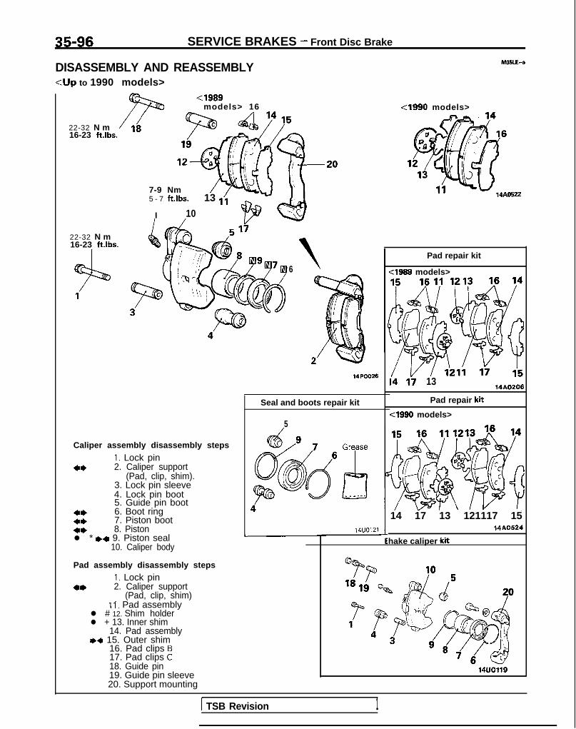
35-96 SERVICE BRAKES - Front Disc Brake
DISASSEMBLY AND REASSEMBLY<Up to 1990 models>
22-32 N m16-23 ft.lbs.
22-32 N m16-23 ft.lbs.
<I989models> 16
7-9 Nm5 - 7 ft.lbs.
I
13 1;
10
6
Seal and boots repair kit
Caliper assembly disassembly steps
I. Lock pin4* 2. Caliper support
(Pad, clip, shim).3. Lock pin sleeve4. Lock pin boot5. Guide pin boot
4, 6. Boot ringc* 7. Piston boot+* 8. Pistonl * I)* 9. Piston seal
10. Caliper body
Pad assembly disassembly stepsI. Lock pin
4* 2. Caliper support(Pad, clip, shim)
I i, Pad assemblyl # 12. Shim holderl + 13. Inner shim
14. Pad assembly,+ 15. Outer shim
16. Pad clips B17. Pad clips C18. Guide pin19. Guide pin sleeve20. Support mounting
L
5
14UO121
<I990 models>
14AO522
Pad repair kit
<I999 models>
i4 li 13 14A0206
Pad repair kit
cl990 models>
14 17 13 121117 15
hake caliper kit
14A0524
1 TSB Revision 1
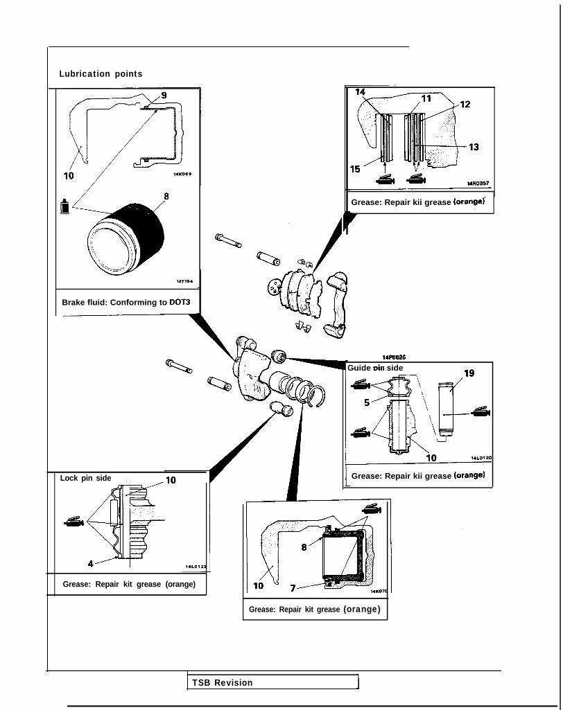
Lubrication points
I8
Brake fluid: Conforming to DOT3
ND
Q?c/
Lock pin side ,
Grease: Repair kii grease (orange)
7
Grease: Repair kit grease (orange)
14POO26Guide Din side
Grease: Repair kii grease (Orange)
Grease: Repair kit grease (orange)
TSB Revision

35-98 SERVICE BRAKES - Front Disc Brake
pin
Caliper /support(pad, cl ip, shim) 1410356
Boot ring14KO54 14G0054
14KO57
SERVICE POINTS OF DISASSEMBLY M35LFAH
When disassembling the front disc brakes, disassemble bothsides (left and right) as a set.
2. REMOVAL OF CALIPER SUPPORT (PAD, CLIP, SHIM)Remove caliper support from caliper body.
6. REMOVAL OF BOOT RINGRemove boot ring *with (-) screwdriver
7. REMOVAL OF PISTON BOOT/8. PISTONProtect caliper body with cloth. Blow compressed airthrough brake hose to remove piston boot and piston.
CautionBlow compressed air gently.
9. REMOVAL OF PISTON SEAL(1
(2
) Remove piston seal with finger tip.
CautionDo not use ( - ) screwdriver or other tool to preventdamage to inner cylinder.
I) Clean piston surface and inner cylinder with trichloro-ethylene, alcohol or specified brake fluid.
Specified brake fluid: Conforming to DOT3 or DOT4
INSPECTION M35LGAH
l Check cylinder for wear, damage or rust.l Check piston surface for wear, damage or rust.l Check caliper body or sleeve for wear.l Check pad for damage or adhesion of grease, check
backing metal for damage.
1 TSB Revision

SERVICE BRAKES - Front Disc Brake 35-99
PAD WEAR CHECKMeasure thickness at the thinnest and worn area of the pad.Replace pad assembly when pad thickness is less than the limitvalue.
Limit value: 2.0 mm (.08 in.)
14UOO72
SERVICE POINTS OF REASSEMBLY M35LHAN15. APPLICATION OF BRAKE GREASE TO OUTER SHIM/
,13. INNER SHIM/ 12. SHIM HOLDERCaution1. Do not deposit grease or other dirt on pad or brake
disc friction surfaces.2. Apply grease so that it does not seep out from the
edges of the shim and shim holder.9. INSTALLATION OF PISTON SEAL
Install piston seal in cylinder groove.
CautionDo not wipe special grease on piston seal.
TSB Revision

35-100 SERVICE BRAKES - Front Disc Brake
<1990.5 models><From 1991 models (Non-Turbo)>
<Four-shim type>
11
M35LE-b
<One-shim type>/a
14N0284
I .64-88 Nm
ft Iha~ 5a ’ P7El- I
SW
Caliper assembly disassembly steps~~ 1. Guide pinl + 2. Lock pin
3. Bush;: CA&x support (Pad, clip, shim)
::6. Boot ring7. Piston boot
4* 8. Piston+* l * 9. Piston seal
10. Caliper body
Pad assembly disassembly stepsl + 1. Guide pin1)4 2. Lock pin
3. Bush4. Caliper support (Pad, clip, shim)
II. Pad and wear lndlcator assembly12. Pad assembly13. Inner shim14. Outer shim15. Clip
4 ’ 14AO537
Seal and boots repair kit
14A05405
Pad repair kit
<One-shim type> <Four-shim type>
1; 14AO539
r Brake caliper kit
14AO538
TSB Revision

Lubrication points
SERVICE BRAKES - Front Disc Brake 35401
Lock pin side
Guide pin side
14AO541
Grease: Repair kit grease (orange)
r
14FOO9;
Grease: Repair kit grease (orange)Caution-
14N0284
1400265
Grease: Repair kit grease(orange)
TSB Revision

35-102 SERVICE BRAKES - Front Disc Brake
Boo; ring14KO54 14G0054
14KO57
14UOO72
I
SERVICE POINTS OF DISASSEMBLY MSLFAK
When disassembling the front disc brakes, disassemble bothsides (left and right) as a set.
6. REMOVAL OF BOOT RINGRemove boot ring with a small flat blade screwdriver.
7. REMOVAL OF PISTON BOOT/8. PISTONProtect caliper body with cloth. Blow compressed airthrough brake hose to remove piston boot and piston.
CautionBlow compressed air gently.Keep hands away from piston area and cover with shoptowels!
9. REMOVAL OF PISTON SEAL(1
(2
) Remove piston seal with finger tip.
CautionDo not use a small flat blade screwdriver or othertool to prevent damage to inner cylinder.
I) Clean piston surface and inner cylinder with trichloro-ethylene, alcohol or specified brake fluid.
Specified brake fluid: Conforming to DOT3 or DOT4
INSPECTIONl Check cylinder for wear, damage or rust.0 Check piston surface for wear, damage or rust.l Check caliper body, guide pin and lock pin for Wear.l Check pad for damage or adhesion of grease, check
backing metal for damage.
PAD WEAR CHECKMeasure thickness at the thinnest and worn area of the pad.Replace pad assembly when pad thickness is less than the limitvalue.
Limit value: 2.0 mm (.08 in.)
1 TSB Revrslon
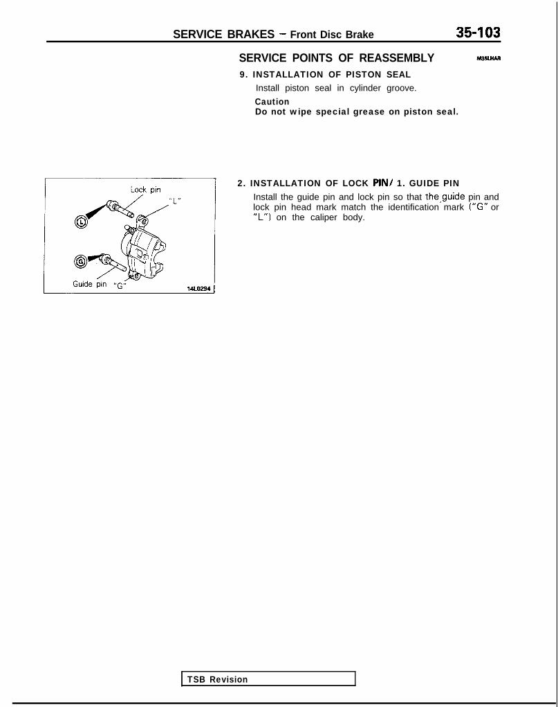
SERVICE BRAKES - Front Disc Brake 35-103
SERVICE POINTS OF REASSEMBLY9. INSTALLATION OF PISTON SEAL
Install piston seal in cylinder groove.
CautionDo not wipe special grease on piston seal.
2. INSTALLATION OF LOCK PIN/ 1. GUIDE PINInstall the guide pin and lock pin so that the,guide pin andlock pin head mark match the identification mark (“G” or“L”) on the caliper body.
TSB Revision

35-104 SERVICE BRAKES - Front Disc Brake
<From 1991 models (Turbo)>hl3SLE-C
64-86 Nm46-62 ft.lbs.
46-62 ft.lbs.
Caliper assembly disassembly stepsW+ 1. Guide pinI)4 2. Lock pin
3. Bush4. Calioer support (Pad, clip. shim)5. Bodt
4* 6. Boot ring:: 7. 8. Piston Piston boot
l * +* 9. Piston seal10. Caliper bodyPad assembly disassembly steps
+4 1. Guide pin+4 2. Lock pin
3. Bush4. Caliper support (Pad, clip, shim)
11. Pad and wear indicator assembly12. Pad assembly13. Outer shim14. Clip
Pad repair kit
lh vi 14LO7.97
1 Seal and boots repair kit
Greke
97 5
kJd
@
/oy6
osPQ q97 6__ --.
Brake caliper kit
TSB Revision 1

Lubrication points
SERVICE BRAKES - Front Disc Brake 35-105
, / II
Grease: Repair kii grease(orange)
14AO541
Grease: Repair kit grease(orange)
9
1
14we44
941194
Brake fluid: Conforming toDOT3 or DOT4
TSB Revision

35-106 SERVICE BRAKES - Front Disc Brake
SERVICE POINTS OF DISASSEMBLY M35LFAL
When disassembling the front disc brakes;disassemble bothsides (left and right) as a set.
14AO550
14AO55
14AO551
I
3
a-
6. REMOVAL OF BOOT RING
Remove boot ring with (-) screwdriver
7. REMOVAL OF PISTON BOOT/8. PISTON
Blow compressed air through brake hose to remove pistonboot and piston.
CautionBlow air gradually to remove the pistons while adjust-ing with a plastic hammer, etc. so that the two pistonscome out equably together.lf only one piston is pulled out, it will be impossible toremove the other.
9. REMOVAL OF PISTON SEAL
(1) Remove piston seal with finger tip.
CautionDo not use (-) screwdriver or other tool to preventdamage to inner cylinder.
(2) Clean piston surface and inner cylinder with trichloro-ethylene, alcohol or specified brake fluid.
Specified brake fluid: Conforming to DOT3 or DOT4
1 TSB Revision
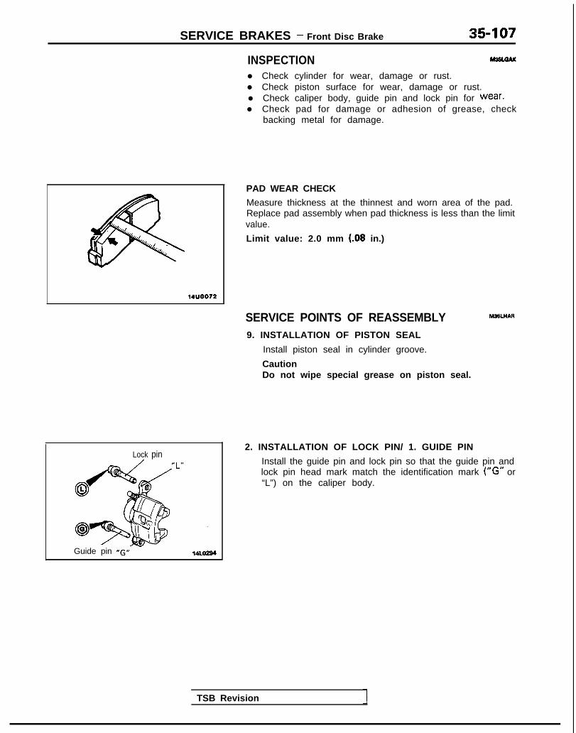
SERVICE BRAKES - Front Disc Brake 35-107
INSPECTIONl Check cylinder for wear, damage or rust.l Check piston surface for wear, damage or rust.l Check caliper body, guide pin and lock pin for wear.l Check pad for damage or adhesion of grease, check
backing metal for damage.
14UO072
PAD WEAR CHECK
Measure thickness at the thinnest and worn area of the pad.Replace pad assembly when pad thickness is less than the limitvalue.
Limit value: 2.0 mm (.08 in.)
SERVICE POINTS OF REASSEMBLY9. INSTALLATION OF PISTON SEAL
Install piston seal in cylinder groove.
Caution
M35LHAR
Do not wipe special grease on piston seal.
2. INSTALLATION OF LOCK PIN/ 1. GUIDE PINLock pin
“L” Install the guide pin and lock pin so that the guide pin andlock pin head mark match the identification mark (“G” or“L”) on the caliper body.
Guide pin -G”
TSB Revision

35-108 SERVICE BRAKES - Rear Drum Brake
REAR DRUM BRAKEREMOVAL AND INSTALLATION
13-17 Nm9 - 1 2 ftlbs.
50-60 N m3 6 - 4 3 ftlbs.
/
13 12 11
14A.0359Removal stepsAdjustment of wheel bearing end play(Refer to GROUP 27-Service AdjustmentProcedures.)
1. Hubcap2. Cotter pin3. Lock cap
++ 4. Wheel bearing nut5. Tongued washer6. Outer bearing inner race7. Brake drum
I)+ Adjustment of shoe outside diameter8. Shoe-to-lever spring9. Shoe-to-shoe spring
10. Auto adjuster assembly1 I. Retainer spring12. Shoe hold down cups13. Shoe hold down springs14. Shoe hold down pins15. Shoe and lining assembly16. Shoe and lever assembly17. Retainer18. Wahser
Pre-removal Operationl Draining of Brake Fluid
(Refer to GROUP 36-Service Adjust-
19. Auto adjuster lever20. Parking brake lever21. Snap ring22. Brake tube23. Backing plate
TSB Revision

SERVICE BRAKES - Rear Drum Brake
Lubrication points
Grease: Brake grease SAE 5310,NLGI No.1
r
llE030
14LO263
3rease: Brake grease SAE J310,NLGI No.1
14AO359
df& II lZEl01
TSB Revision

35-110 SERVICE BRAKES - Rear Drum Brake
14uoo75
14R0170
14K664
r
nm (in.) G $%?-7?~i” >1,4A0361
Turn 180” or more anoreturn 360” or more.(Repeat 3 times or
> more.)
D
I
-
INSPECTION M36UCAM
BRAKE LINING THICKNESS CHECK
(1) Measure the wear of the brake lining at the place worn themost.
Limit: 1.0 mm (84 in.)
(2) Replace the shoe assembly if brake lining thickness is lessthan the limit if it is not worn evenly.
CautionWhenever the shoe assembly is replaced, replace bothRH and LH assemblies as a set to prevent car frompulling to one side when braking.If there is a significant difference in the thicknesses ofthe shoe and lining assemblies on the left and rightsides, check the sliding condition of the piston.
BRAKE DRUM INSIDE DIAMETER CHECK
(1) Measure the inside diameter of the brake drum at two ormore locations.
Limit : 205 mm (8.1 in.)
(2) If the measured diameter is the limit value or higher, or ifwear is unusually irregular, replace the brake drum andshoe-and-lining assembly as a set for both sides.
BRAKE LINING AND BRAKE DRUM CONNECTION CHECK
Chalk inner surface of brake drum and rub with shoe and liningassembly.Replace shoe and lining assembly or brake drum if veryirregular contact area.
NOTEClean off chalk after check.
SERVICE POINTS OF INSTALLATION M35UDAV
. ADJUSTMENT OF SHOE OUTSIDE DIAMETER
Adjust the shoe outside diameter to the specified measure-ment by turning the adjuster screw.
CautionRelease the parking brake lever and confirm that theparking brake cable is not pulling the lever inside thebrake. If the lever is being pulled by the cable, theautomatic shoe clearance adjustment will not function.
4. INSTALLATION OF WHEEL BEARING NUT
(1) After tightening the wheel bearing nut to 20 Nm (14ft.lbs.), t u r n t h e h u b a f e w t i m e s t o s e a t t h e
(2) ~~~~~‘to seat the bearing properly, turn the hub (brakedrum ) 180” or more and then return it 360” or more;repeat this procedure again three or more times.
(3) Return the wheel bearing nut to 0 Nm (0 ftlbs.).(4) After tightening the wheel bearing nut at a torque of
10 Nm (7 ft.1b.s.). rotate the hub again in the same wayas described in step (2) so as to seat thebearina.
1 TSB Revision

SERVICE BRAKES - Rear Drum Brake/Rear Brake Wheel Cylinder 35-I 11
(5) Then once again tighten the wheel bearing nut to 10Nm (7 ft.lbs.).
(6) Install the lock cap and split pin.(7) If the position of the cotter pin is not matched with the
holes of the lock cap, reposition the lock cap so that theholes align. If this can not be accomplished, back off thenut by not more than 15”.
CautionCheck to be sure that the lock nut cannot b eloosened manually.
(8) After setting the split pin in place, seat the bearing inthe same manner as in step (2).
REAR BRAKE WHEEL CYLINDERREMOVAL AND INSTALLATION
8 - 1 2 Nm ?6 - 9 ft.lbs. / -
r
14LO122
plant: ~AA;;~~n’: No.8513
Removal stepsAdjusting of wheel bearing end play(Refer to GROUP 27-Service AdjustmentProcedures.)
1. Hub cap2. Cotter pin3. Lock cap
~~ 4. Wheel bearing nut5. Tongued washer6. Outer wheel bearing inner race7. Brake drum8. Shoe-to-lever spring9. Shoe-to-shoe spring
10. Bleeder screw11. Brake tubeVI Fezel cylinder assembly
I Pre-removal Operationl Draininq of Brake Fluid I
‘+iGJql Bleeding (Refer to P.35-57.)
20-+0+10 Nm14-+0-+7 fklbs.
2& ‘. 14A0357
TSB Revision

35-112 SERVICE BRAKES - Rear Brake Wheel Cylinder
Turn 180” or more and360” or more.
SERVICE POINTS OF INSTALLATION m34obw
4. INSTALLATION OF WHEEL BEARING NUT
12R0389
(1) After tightening the wheel bearing nut to 20 Nm (14ft.lbs.), turn the hub a few times to seat the bearing.
(2) In order to seat the bearing properly, turn the hub (brakedrum) 180” or more and then return it 360” or more;repeat this procedure again three or more times.
(3) Return the wheel bearing nut to 0 Nm (0 ft.lbs.).(4) After tightening the wheel bearing nut at a torque of 10
Nm (7 ft.lbs.), rotate the hub again in the same way asdescribed in step (2) so as to seat the bearing.
(5) Then once again tighten the wheel bearing nut to 10Nm (7 ft.lbs.).
_(6) Install the lock cap and cotter pin.(7) If the position of the cotter pin is not matched with the
holes of the lock cap, reposition the lock cap so that theholes align. If this cannot be accomplished, back off thenut by not more than 15”.
CautionCheck to be sure that the lock nut cannot beloosened manually.
(8) After setting the split pin in place, seat the bearing inthe same manner as in step (2).
IISASSEMBLY AND REASSEMBLY
I-
14Y554
Grease: Repair kit grease(orange)
Brake fluid: Conforming toDOT3 o r DOT4
14 LO192
hl35VE-
I- ~~ Wheel cylinder repair kit I
Disassembly steps
1. Boots2. Piston assembly
l * 3. Pistons+* l * 4. Piston cups
5. Wheel cylinder body
TSB Revision 1

SERVICE BRAKES - Rear Brake Wheel Cylinder 35-113
MB991008
Have the lip facing upwards.
14uoo93
SERVICE POINTS OF DISASSEMBLY M35VFAE
When disassembling the wheel cylinders, disassemble bothsides (left and right) as a set.
4. REMOVAL OF PISTON CUPS
Remove the piston cup, being careful not to damage thepiston.
INSPECTION M35VGAD
Check the piston and wheel cylinder walls for rust or damage,and if there is any abnormality, replace the entire wheelcylinder assembly.
SERVICE POINTS OF REASSEMBLY M35VHAK
4. REASSEMBLY OF PISTON CUPS/3. PISTONS
(1) Use alcohol or the specified brake fluid to clean thewheel cylinder and the piston.
(2) Apply the specified brake fluid to the piston cups andthe special tool.
Specified brake fluid: Conforming to DOT3 or DOT4
(3) Set the piston cup on the special tool with the lip ofthe cup facing up, fit the cup onto the special tool, andthen slide it down the outside of the tool into thepiston groove.
CautionIn order to keep the piston cup from becomingtwisted or slanted, slide the piston cup down thetool slowly and carefully, without stopping.
TSB Revision

35-114 SERVICE BRAKES - Rear Disc Brake
REAR DISC BRAKEIEMOVAL AND INSTALLATION
<WD>
9 - 1 4 Nm 50-60 Nm7-10 ft.lbs. 36-43 ft.lbs.
13-17 Nm9- 12 ft.lbs.
200-260 Nm144-199 ft.lbs.
Removal steps1. Parking brake cable connection
4, 2. Brake hose connection3. Rear brake assembly4. Rear brake disc5. Hub cap
l * 6. Wheel bearing nut7. Washer8. Rear speed sensor bracket
<Vehicles wi th A.B.S.>9. Rear hub assembly
14. Dust shield
I Pre-removal Operation*Draining of Brake Fluid I
TSB Revision I

SERVICE BRAKES - Rear Disc Brake
<AWD-UP TO 1992 MODELS>
35-115
50-60 Nm
55-65 Nm3 9 - 4 7 ft.lbs.
Removal steps1. Parking brake cable connection
l * 2. Brake hose connection3. Rear brake assembly4. Rear brake disc
~~ H 10. Self locking nutl + 11. Companion flange
12. Rear speed sensor<Vehicles with A.B.S.>
4* l + 13. Rear axle shaft14. Dust shield
TSB Revision
Pre-removal Operationl Draining of Brake Fluid
I 1Post-installation Operationl Filling of Brake Fluid and Air Bleed-
ing (Refer to P.35-57.)l Adjustment of Parking Brake Lever
I Siioke(Refer to GROUP 36-Service Ad- I
1 justment Procedures.) I

35-116 SERVICE BRAKES - Rear Disc Brake
Spindle
12AOO88
SERVICE POINTS OF REMOVAL M35hlBAE
2. DISCONNECTION OF BRAKE HOSE
Holding the locking nut on the brake hose side. Loosen theflared brake line nut.
10. REMOVAL OF SELF LOCKING NUT
Using the special tool, secure and hold the rear axleshaft, and remove the self locking nut.
13. REMOVAL OF REAR AXLE SHAFT
Using the special tool, remove the rear axle shaft.
INSPECTION M25MDABs
l Check disc for wear. (Refer to P.35-66, Rear Brake DiscThickness Check.)
l Check disc for runout. (Refer to P.35-66, Rear Brake DiscRun-out Check.)
l Check disc for damage.
SERVICE POINTS OF INSTALLATlON MEMCAF1 3 . INSTALLATlON O F REAR AXLE SHAFT/
11. COMPANION FLANGE/ 10. SELF LOCKING NUT
(1) Provisionally install the rear axle shaft to the trailinga r m .
(2) Install the companion flange to the rear axle shaft,and install the self locking nut.
(3) Then, using the special tool, secure and hold the rearaxle shaft, and tighten the self locking nut.
6. INSTALLAnON OF WHEEL BEARING NUT
After tightening the wheel bearing nut, align with theindentation in the spindle, and then crimp.
TSB Revision

SERVICE BRAKES - Rear Disc Brake35-117
1 <AWD-UP TO - ii <MID> kidt 1992 MODELS> a 75-35 N m ’-- --
3-j; 21 23
DISASSEMBLY AND REASSEMBLY
t
MISNA-
7 - 9 N m‘5-7 ftlbs.
Brake seal kitL
Caliper assembly disassembly steps1. Connection for brake hose2. Lock pin4. Lock pin sleeve5. Lock pin boot6. Guide pin boot7. Boot ring8. Piston boot
41) l 9. Piston assemblyl * 10. Piston seal4* *+ 11. Snap ring
12. Spring case13. Return spring14. Stopper plate15. Stopper16. Auto-adjuster spindle17. Connecting link18. O-ring19. Spindle lever20. Lever boot21. Parking brake lever22. Return spring23. Bleeder screw24. Caliper body
Pad assembly disassembly steps
l *2. Lock pin3. Support mounting (pad. shim. clip)
25. Outer shim26. Pad assembly27. Pad clips C28. Pad clips B29. Guide pin30. Guide pin sleeve31. Support mounting
ib!!?I ??-=A ?-18Ib. '+
IL Ii 14AO569
I
26
2526 25
14AOZlg
Brake pad kit
22-32 Nm16-23 ft.lbs.
14AO279
TSB Revision I

35418 SERVICE BRAKES - Rear Disc Brake
Lubrication points
Grease: Repair kit grease (Orange) Grease: Repair kit grease (Orange)Grease: Repair kit grease (Orange)
t
14R0051
Grease: Repair kit grease (Orange)
A /I Grease: Repair kit grease (Orange)
14110047
Grease: Repair kii grease (Grange)
1 TSB Revision 1

SERVICE BRAKES - Rear Disc Brake 35-119
/ 14R0062
WUOO72
SERVICE POINTS OF DISASSEMBLY MSNBAE
When disassembling the rear disc brakes, disassemble bothsides (left and right) as a set.
3. REMOVAL OF SUPPORT MOUNTING
With the lock pin removed, pull the support mounting offfrom the caliper body.
9. DISASSEMBLY OF PISTON ASSEMBLY
Use the special tool to twist the piston out of the caliperbody.
10. DISASSEMBLY OF PISTON SEAL
(1) Remove piston seal with finger tip.
CautionDo not use (-) screwdriver or other tool to preventdamage to inner cylinder.
(2) Clean piston surface and inner cylinder with trichloro-ethylene, alcohol or specified brake fluid.
Specified brake fluid: Conforming to DOT3 or DOT4
11. DISASSEMBLY OF SNAP RING
While using a 19 mm (.75 in.) diameter steel pipe to pressthe spring case into the caliper body, use the snap ringpliers to remove the snap ring from the caliper body.
INSPECTION M26NcAAal Check the connecting link and the spindle for wear or
damage.l Check the caliper body for cracks or rust.l Check the spindle lever shaft for rust.0 Check the bearing for wear.l Check the piston for rust.l Check the piston seal for wear or deterioration.l Check the piston boot for cracks or deterioration.
P A D WEAR CH E C K
(1) Measure the thickness of the pad at the thinnest place.
Limit: 2.0 mm (.08 in.)
(2) If the pad assemblies are worn beyond the limit, replacethem.
1 TSB Revision

35-120 SERVICE BRAKES - Rear Disc Brake
Steel pips
ring
ring
St&+3
groovea0 0
SERVICE POINTS OF REASSEMBLY M35NDAH
11. REASSEMBLY OF SNAP RING
While using a 19 mm (.75 in.) diameter steel pipe to pressin the spring case, use the snap ring pliers to attach thesnap ring to the caliper body.
CautionAttach the snap ring to the caliper body with theopening facing the bleeder.
9. REASSEMBLY OF PISTON ASSEMBLY
(1) Push the piston into the caliper with special tool.
NOTEAlign the grooves as illustrated.
(2) The pins on the back side of the brake pad must beplaced in the grooves in the position.
TSB Revision 1

SERVICE BRAKES - Hydraulic Unit <Vehicles with A&S.> 35-121HYDRAULIC UNIT <VEHICLES WITH A.B.S.>
hl35OXAB
L
IEMOVAL AND INSTALLATION<Up to 1991 models><FWD>
Flared brake line nuts
I 13-17 Nm A9- 12 ftlbs. I @
9 - 1 4 Nm7-10 ft.lbs. 6
i1 7 - 2 6 Nm1 2 - 1 9 ft.lbs. _ _
17-26 Nm /12-19 ft.lbs. \
1 7 - 2 6 Nm /12-19 ft.lbs.
Removal Steps
1. Dust shield2. Engine coolant reservoir3. Engine coolant reservoir bracket
I)+ 4. Brake hose connectionI)+ 5. Brake tube connection
*I) 6. Relay box cover7. Connector8. Bracket installation bolt
l + 9. Bracket A+* 10. Hydraulic unit
11. Bracket D12. Bracket B13. Bracket C16. Motor relay17. Valve relay
Pre-removal and Post-installation
l Draining and Supplying of Brake
l Removai and Installation of the
1 7 - 2 6 Nm,12-19 ft.lbs.
TSB Revision I

35-122 SERVICE BRAKES - Hydraulic Unit <Vehicles with A.B.S.>
<AWD>
9-14 Nm1 7 - 2 6 Nm12-19 ft.lbs. 8
17-26 Nm12-19 ft.lbs.
16
17-26 Nm ,
17-26 Nm12-19 ft.lbs.
17-26 Nm12-19 ft.lbs.
12-19 ft.lbs.
Removal StepsI. Dust shield2. Engine coolant reservoir
l +3. Engine coolant reservoir bracket4. Brake hose connection
W 5. Brake tube connection6. Relay box cover7. Connector8. Bracket installation bolt
l + 9. Bracket A4* IO. Hydraulic unit
11. Bracket D12. Bracket B13. Bracket C16. Motor relay17. Valve relay
Pre-removal and Post-installation Op-erationeDraining and Supplying of Brake Fluid*Removal and Installation of the Solash
(Refer to GROUP 42-Fender.) I
TSB Revision

SERVICE BRAKES - Hydraulic Unit <Vehicles with A.B.S.> 35-123
<From 1992 models>
w1480636
Pre-removal and Post-installation Op-
Flared brake line nuts
13-17 Nm9 - 1 2 ft.lbs.
14FO38
17-26 Nm12- 19 ft.lbs.
7- 10 ft.lbs.
Removal steps
I. Dust shield2. Engine coolant reservoir3. Engine coolant reservoir
++ 5. Bracket tube connection8. Bracket installation bolt
~~ 9. Bracket A4* 10. Hydraulic unit
14. Hydraulic unit bracket15. Relay box cover16. Motor relay17. Valve relay18. Bracket tube19. 2 way connector
bracket
8

35-124 SERVICE BRAKES - Hydraulic Unit <Vehicles with A.B.S.>
I-
Motor relay
16Fi1773
I___-
SERVICE POINTS OF REMOVAL6. REMOVAL OF RELAY BOX COVER <RND>
Insert the tip of a screwdriver into the space between thehydraulic unit and the relay box cover and use it to openthe tab at one place, and then remove the cover.
10. REMOVAL OF HYDRAULIC UNIT
Remove the bracket B, C and D installation bolts, and thentake out the hydraulic unit downward.
Caution1. The hydraulic unit is heavy, and so care should be
taken when removing it.2. The hydraulic unit is not to be disassembled; its
nuts and bolts should absolutely not be loosened.3. The hydraulic unit must not be dropped or other-
wise subjected to impact shocks.4. The hydraulic unit must not be turned upside down
or laid on its side.
INSPECTIONCheck whether there is continuity between terminals whenthere is no current flow at each relay and when there iscurrent flow.
M O T O R R E L A YI I I
) 2ZSowsy/( When current / I I
flows between Betweentermin I
Continuity
0685 - 86terminals @ - @ (approx. 0 0)
1 TSB Revision

SERVICE BRAKES - Hydraulic Unit <Vehicles with A.B.S.> 35-125 ’
Valve relay
16R0670
I 16R1771
14AO201
1 <AWD>
I U 14AOlS9
VALVE RELAY
FE%:; @ - @ 6 0 - 120 R
Between No continuity
When current terminals @I - @ (wfuflows betweenterminal@I-@
Continuity(approx. 0 fl)
TSB Revision I
5. CONNECTION OF BRAKE TUBE/4. CONNECTION OFBRAKE HOSEWhen connecting the tubes and hoses to the hydraulicunit, be sure they are connected correctly.(Refer to P.35-93.)

35-126 SERVICE BRAKES - Wheel Speed Sensor <Vehicles with A.B.S.>
WHEEL SPEED SENSOR <VEHICLES WITH A.B.S.> M35oVAEREMOVAL AND INSTALLATION
<FWD>
9 - 1 4 N m7-10 ft.lbs.
9- ld Nm7- 10 ft.lbs.
~~Q!-yJl~~@9 - 1 4 N m7- 10 ft.lbs.
14A0615
Pre-removal and Post-installationOperation@Removal and Installation of the
Splash Shield(Refer to GROUP 42-Fender.)Front speed sensor removal steps
4w 1. Front toothed rotor2. Clip3. Connection for front speed sensor
l e e+ 4. Front speed sensorl + 5. Front speed sensor bracket
Rear speed sensor removal steps
*I) 6. Rear toothed rotor7. Clip8. Cable band9. Connection for rear speed sensor
+e l + 10. Rear speed sensorw+ 11. Rear speed sensor bracket
TSB Revision
/-..

Pre-removal and Post-installation
SERVICE BRAKES - Wheel Speed Sensor <Vehicles with A.B.S.> 35-127<AWD-UP TO 1992 MODELS>
2
7-10 ftlbs.
7-10 ft.lbs. 9 - 1 4 Nm
Front speed sensor removal steps*I) 1. Front toothed rotor
2. Clip
+* l a3. Front speed sensor connection
**4. Front speed sensor5. Front speed sensor bracket
14AO616
Rear speed sensor removal steps6. Rear toothed rotor
(Refer to GROUP 27-Rear Axle Hub)7. Clip8. Cable band
l * I)49. Rear speed sensor connection
10. Rear speed sensor12. O-ring
TSB Revision

35-128 SERVICE BRAKES - Wheel Speed Sensor <Vehicles with A.B.S.>
I I 14AO215
Front speed sensor Rear speed sensor INSPECTION
Pole hiece Pole &ce
-
SERVICE POINTS OF REMOVAL1. REMOVAL OF THE FRONT TOOTHED ROTOR
Refer to GROUP 26-Hub and Knuckle.
CautionCare must be taken not to scratch or scar the rotor’stoothed surface, and not to drop it.If the rotor’s toothed surface is chipped or the rotor isdeformed, it might not be able to accurately sense thewheel rotation speed and the system as a result mightnot perform normally.
4. REMOVAL OF FRONT SPEED SENSOR
Remove the mounting bolts which hold the speed sensorbracket to the knuckle, and then remove. the speedsensor.
CautionBe careful when handling the pole piece at the tip of thespeed sensor and the toothed edge of the rotor so asnot to damage them by striking against other parts.
6. REMOVAL OF REAR TOOTHED ROTOR
For FWD vehicles, remove together with the rear axleassembly, as shown in the figure, and then remove the reartoothed rotor from the rear axle assembly.CautionCare must be taken not to scratch or scar the rotor’stoothed surface, and not to drop it.If the rotor’s toothed surface is chipped or the rotor isdeformed, it might not be able to accurately sense thewheel rotation speed and the system as a result mightnot perform normally.
10. REMOVAL OF REAR SPEED SENSOR
Remove the speed sensor bracket and rear axle spindleinstallation nut, and then remove the speed sensor.
CautionBe careful when handling the pole piece at the tip of thespeed sensor and the toothed edge of the rotor so asnot to damage them by striking against other parts.
SPEED SENSOR CHECK
(1) Check whether any metallic foreign material has adheredto the pole piece at the speed sensor tip, and, is so,remove it.Also check whether the pole piece is damaged, and, if so,replace it with a new one.
1 TSB Revision

SERVICE BRAKES - Wheel Speed Sensor <Vehicles with A.B.S.> 35-129
:FWD>FrontRear (left)
Rear (right)
<AWD> NOTE
14AOO46
The pole piece can become magnetized because of themagnet built into the speed sensor, with the result thatmetallic foreign material easily adheres to it. Moreover,the pole piece may not be able to function to correctlysense the wheel rotation speed if it is damaged.
(2) Measure the resistance between the speed sensor termi-nals.
14NO295
14R0146
R or L
%0
00
14AOO47
ITSB Revision
Standard value: 0.8-1.2 ks1
If the internal resistance of the speed sensor is not withinthe standard value, replace it with a new speed sensor.
(3) Measure the resistance between each terminal on thespeed sensor and the sensor body.
Standard value: 100 kfI or moreWhen the insulated resistance is not within the standardvalue, replace the sensor.
(4) Check the speed sensor cable for breakage, damage ordiscorrnection; replace with a new one if a problem isfound.
NOTEWhen checking for cable damage, remove the cable clamppart from the body and then bend and pull the cable nearthe clamp to check whether or not temporary disconnectionoccurs.
TOOTHED ROTOR CHECKCheck whether rotor teeth are broken or deformed, and, if so.replace the rotor.
SERVICE POINTS OF INSTALLATION11. INSTALLATION OF REAR SPEED SENSOR BRACKET
Assemble the speed sensor and the speed sensor brack-et.
NOTEThe shape is different for the left and right speed sensorbrackets. Each bracket has an identification symbol, so besure to note these symbols and install correctly.R: Indicates that the bracket is for the right wheel.L: Indicates that the bracket is for the left wheel.
II

35-130 SERVICE BRAKES - Wheel Speed Sensor <Vehicles with A.B.S.>
Left side view
Right side
U14AOO45
Left side viewLeft side
lo. INSTALLATION OF REAR SPEED SENSOR <MID>(1) Temporarily install the speed sensor to the rear axle
spindle.
CautionBe careful when handling the pole piece at the tip ofthe speed sensor and the toothed edge of the rotorso as not to damage them by striking against metalobjects.
(2 ) Note the following points when connecting the speedsensor cable, and secure the cable by the clip.0 Secure the clip so that the white-painted part
(shaded in the illustration) of the speed sensorcable is not twisted.
0 Be sure that there is space (where shown in theillustration) so that the trailing arm and speedsensor cable do not contact, and then secure bythe clip.
CautionBecause there is the possibiliti of damage to thecable during driving if the speed sensor cable andthe trailing arm come into contact, or if the speedsensor cable is twisted, care must be taken regard-ing this point.
(3) Inset-t a feeler gauge into the space between thespeed sensor’s pole piece and the rotor’s toothedsurface, and then tighten the speed sensors at theposition where the clearance is the standard value.
Standard value: 0.3-0.9 mm (.012--035 in.)
NOTECheck to be sure that there is no contact of the speedsensor’s pole piece and the rotor’s toothed surfacewhen the rear hub assemlby is slowly rotated onetime.If there is contact, it is probable that the rotor or therear hub is installed incorrectly, recheck installation.
10. INSTALLATION OF REAR SPEED SENSOR <AWD>
Install the rear speed sensors as shown in the illustration.
Cross-section A-A
TSB Revision
Parkingcable
’ 2Rear speedsensor 1240076
Cross-section B-B Cross-section C-C
Rear speedsensor

SERVICE BRAKES - Wheel Speed Sensor <Vehicles with A&S.> 35-131
0 % 80 0 0PT0 0
6 A
5. INSTALLATION OF FRONT SPEED SENSOR BRACKET
Assemble the speed sensor and the speed sensor brack-et.
NOTE(1) The shape is different for the left and right speed
sensor brackets. Each bracket has an identificationsymbol, so be sure to note these symbols and installcorrectly.FR: Indicates that the bracket is for the front speed
sensor.R: Indicates that the bracket is for the right wheel.L: Indicates that the bracket is for the left wheel.
(2) Check to be sure, when installing the speed sensor tothe bracket, that the letters “FR” are visible.
4. INSTALLATION OF FRONT SPEED SENSOR
(1) Temporarily install the speed sensor to the knuckle.
CautionBe careful when handling the pole piece at the tip ofthe speed sensor and the toothed edge of the rotorso as not to damage them by striking against otherparts.
Cross-section A-A
(2) Note the following points when connecting the speedsensor cable, and secure the cable by the clip.0 Secure the cable by the clip so that the whitepaint-
ed parts of the blackened parts (in the illustration)of the speed sensor cable are within the range ofthe angles indicated by cross-section A-A andcross-section B-B in the illustration.
0 Check to be sure that the white-painted part(shaded in the illustration) of the speed sensorcable is not twisted.
I14L0079 Caution
Because there is the possibilii~of damage to thecable during driving if the speed sensor cable istwisted, care must be taken regarding this point.Cross-section B-B
14Ro157
(3) Insert a feeler gauge into the space between thespeed sensor’s pole piece and the rotor’s toothedsurface, and then tighten the speed sensor at theposition where the clearance is the standard value allaround.
Standard value: 0.3-0.9 mm (.012-.035 in.)
NOTEIf the clearance between the speed sensor’s polepiece ant\ the rotor’s toothed surtace is not within thestandard value range, it is probable that the rotor isincorrect\Y .insta\\ed, recheck insta\iation-
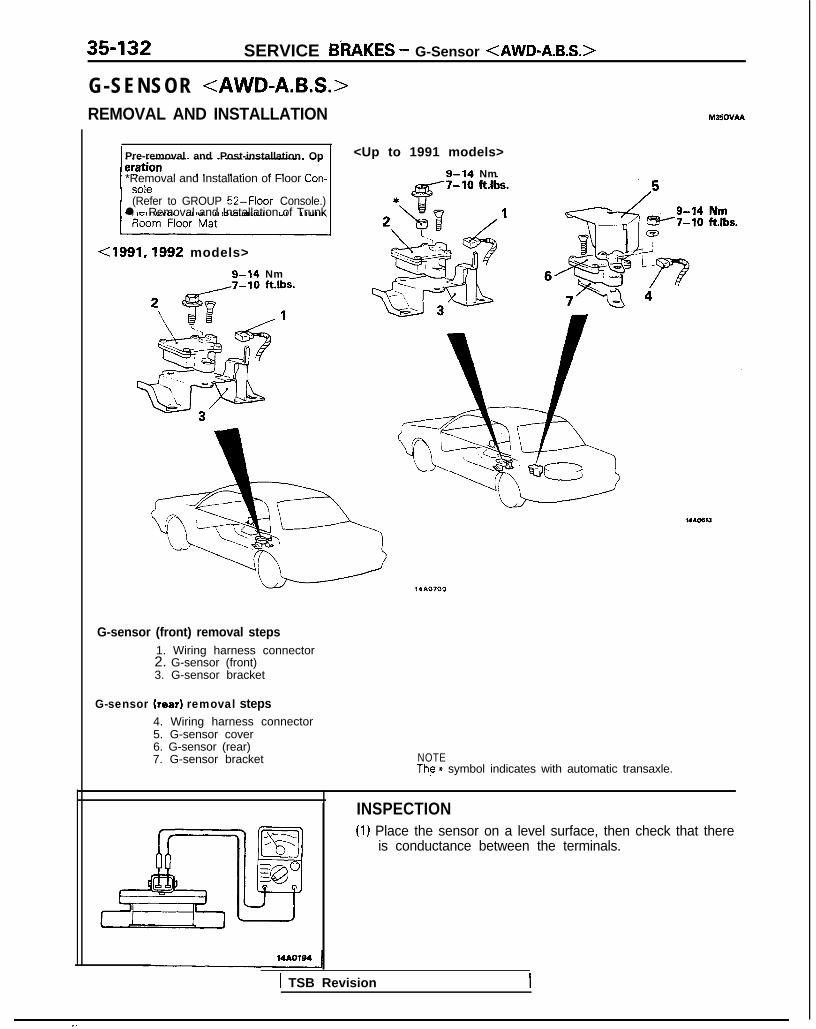
SERVICE BRAKES - G-Sensor <AWD-A&S.>
G-SENSOR <AWD-A.B.S.>REMOVAL AND INSTALLATION
Pre-removal and Post-installation Op
*Removal and Installation of Floor Con-
(Refer to GROUP 52-Floor Console.)l Removal and Installation of Trunk
<1991,1992 models>
g-14 Nm
M35OVAA
<Up to 1991 models>
9-14 Nm
G-sensor (front) removal steps1. Wiring harness connector2. G-sensor (front)3. G-sensor bracket
G-sensor (rear) removal steps4. Wiring harness connector5. G-sensor cover6. G-sensor (rear)7. G-sensor bracket NOTE
The * symbol indicates with automatic transaxle.
INSPECTION(1) Place the sensor on a level surface, then check that there
is conductance between the terminals.
1 TSB Revision

SERV,CE BRAKES _ G-Sensor-<AWD-A.B.S.?Brake FluId Pressure Switch <AWD-A.B.S.: Up to 1991 models> 35433
14AOlss
14AOlBB
(2) Slowly inclining the G-sensor in the direction of forwardvehicle travel, check that there is no conductance above asensor angle of 30 degrees.
(3) Slowly inclining the G-sensor in the direction of reversevehicle travel, check that there is no conductance above asensor angle of 30 degrees.
BRAKE FLUID PRESSURE SWITCH 4WD-A,.B.S.: Up to 1991 models>REMOVAL AND INSTALLATION
Pre-removal Operationl Draining of Brake Fluid
(Refer to P.35-57.)
Removal steps1. Wiring harness connector2. Brake tubes connection3. Brake fluid pressure switch
TSB Revision I

35-134 SERVICE BRAKES - Electronic Control Unit <Vehicles with A.B.S.>
ELECTRONIC CONTROL UNIT <VEHICLES WITH A.B.S.>3EMOVAL AND INSTALLATION
R e m o v a l s t e p s
4* 1. Electronic control unit connection2. ABS bracket
l + 3. Electronic control unit4. Bracket
Pre-removal and Post-installation
14A0696
M3sozAs
SERVICE POINTS OF REMOVAL1. DISCONNECTION OF ELECTRONIC CONTROL UNIT
Unlock the connector and take the connector out.
SERVICE POINTS OF INSTALLATION3. INSTALLATION OF ELECTRONIC CONTROL UNIT
When installing the electronic control unit to the bracket,fasten the connector’s ground wire to the bracket.After connecting the connector to the electronic controlunit, secure the connector by the holding spring.
TSB Revision

36-1
PARKINGBRAKES
CONTENTS M36AA-
PARKING BRAKE CABLE ..,............................ 5 SPECIFICATIONS . . . . . . . . . . . . . . . . . . . . . . . . . . . . . . . . . . . . . . . . . . . . . 2
General Specifications .................................. 2PARKING BRAKE LEVER ............................... 4
Service Specification ..................................... 2
SERVICE ADJUSTMENT PROCEDURES.. ..... 2TROUBLESHOOTING ...................................... 2
Parking Brake Lever Stroke Check ............. 2
Parking Brake Switch Check . . . . . . ..__....._......_ 3

36-2 PARKING BRAKES - Specifications/Troubleshooting/Service Adjustment Procedures
SPECIFICATIONSGENERAL SPECIFICATIONS
Items Specifications
Type Mechanical brake acting on rear wheels
Parking brake lever type Lever typeCable arrangement V-type
SERVICE SPECIFICATION
Items
Standard valueParking brake lever stroke
Specifications
5-7 notches
TROUBLESHOOTING
Symptom Probable cause Remedy
Poor parking brakefunction +
Worn brake pad
Poor condition of brake pad surface
Replace
Parking brake cable sticking
Auto-adjuster malfunction Adjust
Excessive parking brake lever stroke Adjust the parking brake leverstroke or check the parkingbrake cable arrangement
Ii!14A023C
SERVICE ADJUSTMENT PROCEDURESPARKING BRAKE LEVER STROKE CHECK M~~FEAJ1. Pull the parking brake lever with a force of approx. 200 N
(45 Ibs.), and count the number of notches.
CautionThe 200 N (45 Ibs.) force of the parking brake lever mustbe strictly observed.
Standard value: 5-7 notches2. If the parking brake lever stroke is not the standard value,
adjust as described below.(1) Remove the carpet in the floor console.(2) Loosen the adjusting nut to the end of the cable rod,
thus freeing the parking brake cable.(3) With the engine idling, firmly depress the brake pedal
five or six times and confirm that the pedal stroke stopschanging.
NOTEIf the pedal stroke stops changing, it indicates that theautomatic adjusting mechanism has functioned proper-ly to adjust the clearance b&ween’the pads and thedisc to the correct value.
TSB Revision
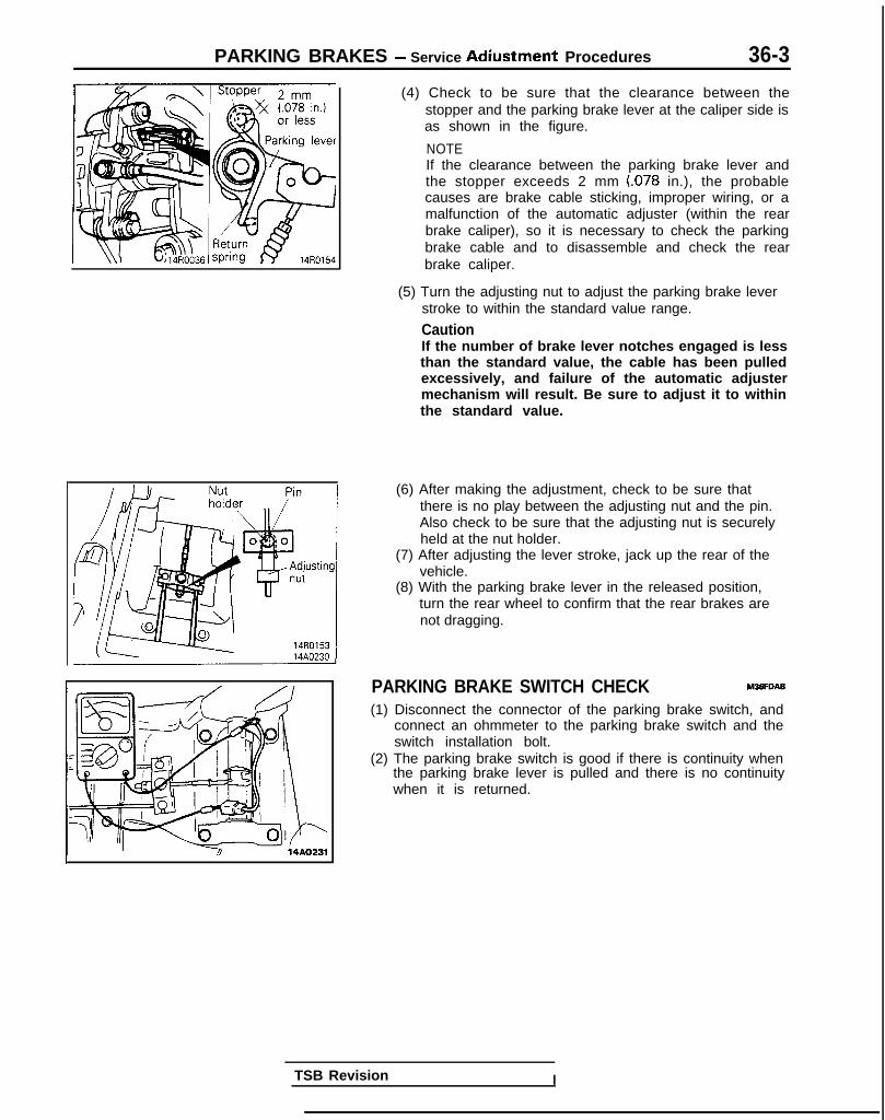
PARKING BRAKES - Service Adiustment Procedures 36-3
(4) Check to be sure that the clearance between thestopper and the parking brake lever at the caliper side isas shown in the figure.
NOTEIf the clearance between the parking brake lever andthe stopper exceeds 2 mm (078 in.), the probablecauses are brake cable sticking, improper wiring, or amalfunction of the automatic adjuster (within the rearbrake caliper), so it is necessary to check the parkingbrake cable and to disassemble and check the rearbrake caliper.
(5) Turn the adjusting nut to adjust the parking brake leverstroke to within the standard value range.
CautionIf the number of brake lever notches engaged is lessthan the standard value, the cable has been pulledexcessively, and failure of the automatic adjustermechanism will result. Be sure to adjust it to withinthe standard value.
(6) After making the adjustment, check to be sure thatthere is no play between the adjusting nut and the pin.Also check to be sure that the adjusting nut is securelyheld at the nut holder.
(7) After adjusting the lever stroke, jack up the rear of thevehicle.
(8) With the parking brake lever in the released position,turn the rear wheel to confirm that the rear brakes arenot dragging.
PARKING BRAKE SWITCH CHECK M3SFDAB
(1) Disconnect the connector of the parking brake switch, andconnect an ohmmeter to the parking brake switch and theswitch installation bolt.
(2) The parking brake switch is good if there is continuity whenthe parking brake lever is pulled and there is no continuitywhen it is returned.
TSB Revision I

PARKING BRAKES - Parking Brake Lever
PARKING BRAKE LEVEREMOVAL AND INSTALLATION
(Refer to GROUP 52-Floor Console.)*Parking Brake Lever Stroke Adjust-
l Installation of Floor Console(Referto GROUP 52-Floor Console.)
Cross-section A-A Cross-section B-B
14AO517
INSPECTION .l Check the parking brake lever ratchet for wear.l Check the parking brake lever for damage and operation.
TSB Revision

PARKING BRAKES - Parking Brake Cable
PARKING BRAKE CABLEREMOVAL AND INSTALLATION
~$y$y$Y&
M36xA-
(Refer to GROUP 52-Floor Console.)*Removal of Rear Seat Cushion <FWD>
(Refer to GROUP 52-Rear Seat.)<Vehicles with rear drum brakes>
l Parking Brake Lever Stroke Adjustment
l installation of Rear Seat Cushion
3y_on,“6,:;;0; ConsoleA rl-~ I Ill (77 I i /
<Vehicles with rear disc brakes>
:/AWD-UP TO 1992 MODELS>
Parking brake cable removal steps1. Adjusting nut2 . Clamn -3. Gromrmet
+4 4. Cableend5. Snap ring6. Parking clip7. Retainer spring
++ 8. Parking brake cable
14A0544
14AO529
TSB Revision 1

36-6 PARKING BRAKES - Parking Brake Cable
Identification mark
14A0441
SERVICE POINTS OF INSTALLATION WXDAE
8. INSTALLATION OF PARKING BRAKE CABLE
Check the parking brake cables for an identification markand install as appropriate on the left and right sides.
Item
Identifica-tion mark
Left Yellow Green None
Red* Blue*
1 Right 1 Orange Brown I White II
Yellow green*I
Green*
NOTE*: Vehicles with automatic seat belt
4. INSTALLATION OF CABLE END
(1) Connect the cable end to the brake shoe assembly.(2) Install the brake shoe assembly.(3) Turn the brake shoe adjuster to adjust the outside
diameter of brake shoe to the specified value.
NOTEAdjusting the outside diameter of brake shoe to thespecified value will facilitate adjustment of the shoeclearance.
.‘,, I
.**i:,1;q ,.’
TSB Revision

ALPHABETICAL INDEX 1
AABS
Checking by the ABS Warnrng Light . . . . . . . . . . . . . . . . . 35-68-l
Troubleshooting . . . . . . . . . . . . . . . . . . . . . . . . . . . 35-l 5-l
A B S P O W E R R E L A Y , C h e c k 35-74-l
ACCELERATOR CABLE
Inspection and Adjustment <Auto-cruise control> 13-398-l
Inspection and Adjustment <Engine control> . . . . . . . . 13-329-l
ACCELERATOR SWITCH, Inspection and Adjustment 13-329-I
A/C COMPRESSOR CLUTCH RELAY
On-vehicle Inspection <DOHC> . . . . . . . . . . . . . . 13-285-l
On-vehrcle Inspection <SOHC-8VALVE> . . . . . . . . . . 13-83-t
On-vehicle Inspection <SOHC-lGVALVE> . . . . . . . 13-176-l
ACTIVE-ECS ON-BOARD DIAGNOSTIC, Check . . . . . . . 338-88-I
ACTIVE-ECS RELAY . . . . . . . . . . . . . . . . . . . . . . . . 338-141 -I
ACTIVE-ECS SENSOR . . . . . . . . . . . . . . . . . . . . . . . 338-138-I
ACTIVE-ECS SYSTEM
Checking by Using Alarm Light . . . . . . . . . . . . . . . . . . 338-87-I
Operation Check . . . . . . . . . . . . . . . . . . . . . . . . . . . 338-90-I
AERO PARTS . . . . . . . . . . . . . . . . . . . . . . . . . . . . . . 51-18-l
AIR CLEANER . . . . . . . . . . . . . . . . . . . . . . . . . . . . . . . . 15-9-I
AIR CLEANER ELEMENT
Inspection and Replacement . . . . . . . . . . . . . . . . . . . . . 15-6-l
Maintenance . . . . . . . . . . . . . . . . . . . . . . . . . . 00-39-l
AIR COMPRESSOR . . . . . . . . . . . . . . . . . . . . . . . . . . . 338-125-I
AIR CONDITIONING SWITCH
Emission control . . . . . . . . . . . . . . . . . . . . . . . . . . . . 17-21 -I
Heater, Air Conditionrng and Ventilation . . . . . . . . . . . . . . 55-29-l
On-vehicle Inspection <DOHC> . . . . . . . . . . . . . . . . . 13-285-l
On-vehicle Inspection <SOHC-BVALVE> . . . . . . . . . . . . 13-83-l
On-vehicle Inspection <SOHC-76VALVE> . . . . . . . . . . . 13-176-l
AIR TUBE . . . . . . . . . . . . . . . . . . . . . . . . . . . . . . . . . . . . . . 338-133-I
ALARM LIGHT, Check. . . . . . . . . . . . . . . . . . . . . . . . . . 338-87-I
ALARM SYSTEM, Theft . . . . . . . . . . . . . . . . . . . . . . . . . . 54-165-11
ALIGNMENT
Front Wheel, Adjustment . . . . . . . . . . . . . . . . . . . . . . . . 33A-5-l
Rear Wheel, inspection <AWD> . . . . . . . . . . . . . . . . . . . 34-23-l
Rear Wheel, Inspection <FWD> . . . . . . . . . . . . . . . . . . . . . 34-5-l
ANTENNA . . . . . . . . . . . . . . . . . . . . . . . . . . . . . . . . . . . . . . 54-153-11
ANTI-LOCK BRAKING SYSTEM, Troubleshooting . . . . . . . . . . 35-15-1
ARM
Lower <Actrve-ECS> . . . . . . . . . . . . . . . . . . . . . . . 338-103-I
Lower <Front Suspension> . . . . . . . . . . . . . . . . . . . . . . . 33A-10-I
Lower <Rear Suspension-AWD> . . . . . . . . . . . . . . . . . . . 34-28-lTorsion <Active-ECS> . . . . . . . . . . . . . . . . . 338-l 19-l
Torsion <Rear Suspension-FWD> . . . . . . . . . . . . . . . . . . . 34-l 5-lTrailing <Rear Suspension-AWD> . . . . . . . . . . . . . . . . . 34-31-lUpper <Rear Suspension-AWD> . . . . . . . . . . . . . . . . . . 34-28-l
AUDIO SYSTEM . . . . . . . . . . . . . . . . . . . . . . . . . . . . . . . . . . 54-l 12-11
AUTO-CRUISE CONTROL. . . . . . . . . . . . . . . . . . . . . . . . . . . . 13-408-I
AUTO-CRUISE CONTROL INDIVIDUAL PARTS, inspection . . . 13-401-I
AUTO-CRUISE CONTROL SYSTEM . . . . . . . . . . . . . . . . . . . . 13-332-l
AUTO-CRUISE CONTROL SYSTEM, Inspection . . . . . . . . . . . 13-397-l
AUTOMATIC TRANSAXLE, Maintenance . . . . . . . . . . . . . . . . . 00-43-I
AXLE
Rear, Maintenance . . . . . . . . . . . . . . . . . . . . . . . . . . . . . . . . 00-45-I
Torsion <Active-ECS> . . . . . . . . . . . . . . . . . . . . . . . . . 338-l 19-l
Torsion <FWD> . . . . . . . . . . . . . . . . . . . . . . . . . . . . . . . 34-15-l
AXLE HUB
Rear <FWD-Rear Disc Brakes> . . . . . . . . . . . . . . . . . . . . . . 27-8-l
Rear CFWD-Rear Drum Brakes> . . . . . . . . . . . . . . . . . . . 27-6-l
AXLE SHAFT <AWD> . . . . . . . . . . . . . . . . . . . . . . . . . . . . . . . 27-17-1
BBACKLASH. Total, Rear Axle, Check <AWD> . . . . . . . . . . . . . 27-15-l
BALL JOINT
Rotation Starting Torque Check . . . . . . . . . . . . . . . . . . . . . . 378-8-I
Tie Rod End, Staning Torque Check . . . . . . . . . . . . . . . . . . 37A-15-l
Tie Rod End, Variation Check . . . . . . . . . . . . . . . . . . . . . . . 37A-15-l
BALL JOINT SEALS, Maintenance . . . . . . . . . . . . . . . . . . . . . 00-45-I
BAR
Stabilizer <Active-ECS> . . . . . . . . . . . . . . . . . . . . . 338-106-I
Stabilizer <Front Suspension> . . . . . . . . . . . . . . . . . . . . 33A-13-l
Stabilizer <Rear Suspension-AWD> . . . . . . . . . . . . . . . . 34-37-l
BAROMETRIC PRESSURE SENSOR
On-vehicle Inspection <DOHC> . . . . . . . . . . . . . . . . . 13-266-l
O n - v e h i c l e I n s p e c t i o n <SOHC-BVALVE> 13-53-l
On-vehicle Inspection <SOHC-lGVALVE> . . . . . . . . . . . 13-154-l
BASIC IDLE SPEED
Adjustment <DOHC> . . . . . . . . . . . . . . . . . . . . . . . . . . . . 13-245-l
Adjustment <SOHC-8VALVE> ..................... 13-33-l
Adjustment <SOHC-lGVALVE> . . . . . . . . . . . . . . . . . . . . 13-133-l
BATTERY . . . . . . . . . . . . . . . . . . . . . . . . . . . . . . . . . . . . . . . . . . 54-2-11
BATTERY, Flat Remedy. . . . . . . . . . . . . . . . . . . . . . . . . . . . . . . 35-75-l
BEARING
Wheel, Adjustment <Active-ECS> . . . . . . . . . . . . . . . . . 338-87-I
Wheel, Adjustment <Front Suspension> . . . . . . . . . . . . . 33A-5-l
BELT
Drive, Compressor, Adjustment . . . . . . . . . . . . . . . . . . . . . 55-17-l
Drive (For Water Pump and Generator), Maintenance . . . . . 00-41-I
Drive, Tension Adjustment <DOHC> . . . . . . . . . . . . . . . . . 11-61-I
Drive, Tension Adjustment <SOHC> . . . . . . . . . . . . . . . . . 11-12-l
Seat . . . . . . . . . . . . . . . . . . . . . . . . . . . . . . . . . . . . . . . . . . . 52-39-l
Timing <DOHC> . . . . . . . . . . . . . . . . . . . . . . . . . . . . . . . 11-80-I
Timing<SOHC> . . . . . . . . . . . . . . . . . . . . . . . . . . . . . . . . . 11-34-l
Timing, Maintenance . . . . . . . . . . . . . . . . . . . . . . . . . . . . . . . 00-40-I
Timing, Tension Adjustment <SOHC> . . . . . . . . . . . . . . . . 11-10-I
BLEEDING
Clutch . . . . . . . . . . . . . . . . . . . . . . . . . . . . . . . . . . . . . . . . . . . 21-6-l
4ws . . . . . . . . . . . . . . . . . . . . . . . . . . . . . . . . . . . . . . . . . . . . 370-4-I
Service Brakes. . . . . . . . . . . . . . . . . . . . . . . . . . . . . . . . . . . 35-57-l
Steering . . . . . . . . . . . . . . . . . . . . . . . . . . . . . . . . . . . . . . . . 37A-22-l
BLOWER . . . . . . . . . . . . . . . . . . . . . . . . . . . . . . . . . . . . . . . . . . . 55-32-l
BOOSTER
Brake . . . . . . . . . . . . . . . . . . . . . . . . . . . . . . . . . . . . . . . . . . 35-85-l
Brake, Operating Inspection . . . . . . . . . . . . . . . . . . . . . . . . . 35-54-l
BOOST METER, On-vehicle Inspection <DOHC-Turbo> . . . 13-311-l
BOOTS, Drive Shaft, Maintenance . . . . . . . . . . . . . . . . . . . . . . . 00-45-IBRAKE
Disc, Front . . . . . . . . . . . . . . . . . . . . . . . . . . . . . . . . . . . . . . . 35-94-l
Disc, Rear . . . . . . . . . . . . . . . . . . . . . . . . . . . . . . . . . . . . . . 35-l 14-l
BRAKE BOOSTER . . . . . . . . . . . . . . . . . . . . . . . . . . . . . . . . . . . . 35-85-l
BRAKE BOOSTER, Operating Inspection . . . . . . . . . . . . . . . . . . 35-54-l
BRAKE DISC
Front, Run-out Check. . . . . . . . . . . . . . . . . . . . . . . . . . . . . . . 35-63-l
Front, Run-out Correction . . . . . . . . . . . . . . . . . . . . . . . . . . . 35-64-l
Front, Thickness Check . . . . . . . . . . . . . . . . . . . . . . . . . . . . . 35-65-l
Rear, Run-out Check . . . . . . . . . . . . . . . . . . . . . . . . . . . . . . . 35-66-l
Rear, Run-out Correction. . . . . . . . . . . . . . . . . . . . . . . . . . . . 35-66-l
Rear, Thickness Check . . . . . . . . . . . . . . . . . . . . . . . . . . . . . 35-66-l
BRAKE DRUM, tnside Diameter, Check . . . . . . . . . . . . . . . . . . . 35-67-l
BRAKE FLUID LEVEL SENSOR, Check . . . . . . . . . . . . . . . . . . . . 35-54-l
BRAKE FLUID PRESSURE SWITCH
AWD-ABS (Up to 1991 Models) . . . . . . . . . . . . . . . . . . . . . 35-133-lAWD-ABS (Up to 1991 models), Check . . . . . . . . . . . . . . . . 35-75-l
BRAKE HOSES, Maintenance . . . . . . . . . . . . . . . . . . . . . . . . . . . 06-45-tBRAKELINE . . . . . . . . . . . . . . . . . . . . . . . . . . . . . . . . . . . . . . . . 35-87-l

2 ALPHABETICAL INDEX
BRAKE LINING
ThicknessCheck .., ..,............
D r u m , R e a r , M a i n t e n a n c e
BRAKE LINING AND BRAKE DRUM, Connection Check..
BRAKE PAD
Drsc, F r o n t , C h e c k a n d R e p l a c e m e n t
Disc, Rear, Check and Replacement
BRAKEPEDAL..
B R A K E P E D A L , I n s p e c t i o n a n d A d j u s t m e n t
BUMPER. . . . .
35-67-l
00-44-l
35-67-l
35-59-l
35-65-l
35-76-l
35-53-l
51-7-I
CCABLE
Accelerator, Inspection and Adjustment<Auto-cruise Control> 13-398-l
Accelerator, Inspection and Adjustment<Engrne Control> 13-329-I
High Tensron, Spark Test <SOHC-8VALVE> . . . . . . . . . 16-42-11Parking Brake . . . . . . . . . . . . . . . . . . . . . . . . . . . . . . . . . 36-5-lS p a r k Plug, T e s t . . . . . . . . . . . . . . . . . . . . . . . . 16-42-11Speedometer, Replacement <A/T> . . . . . . . . . . . . . . . . 23-93-lSpeedometer, Replacement <M/T-AWD> . . . . . . . . . . 22-19-ISpeedometer, Replacement <M/T-FWD> . . . . . . . . . . . . . 22-5-l
CAMSHAFTD O H C . . . . . . . . . . . . . . . . . . . 1 l-68-lSOHC . . . . . . . . . . . . . . . . . . . . . . . . . . . . . . . . . . 11-19-I
CAMSHAFT OIL SEALS
DOHC . . . . . . . . . . . . . . . . . . . . . . . . . . . . . . . . . . . . 11-68-ISOHC . . . . . . . . . . . . . . . . . . . . . . . . . . . . . . . . . . . . . . . . . 11-19-I
CAMSHAFT POSITION SENSOR
On-vehrcle Inspection <DOHC> . . . . . . . . . . . . . . . . . . . 13-277-lOn-vehicle Inspection <SOHC-8VALVE> . . . . . . . . . . . . . 13-69-lOn-vehicle Inspection <SOHC-lGVALVE> . . . . . . . . . 13-165-I
CANISTER, Evaporatjve Emission . . . . . . . . . . . . . . . . . . 17-21-lCATALYTIC CONVERTER . . . . . . . . . . . . . . . . . . . . . . . . . . . . . 17-24-lCENTERMEMBER . . . . . . . . . . . . . . . . . . . . . . . . . . . 32-8-lCENTRAL DOOR LOCKING SYSTEM . . . . . . . . . . . . . . . . . . . 42-101-ICHARGE AIR COOLER . . . . . . . . . . . . . . . . . . . . . . . . . . . . . . . . 15-l 2-lCHARGING . . . . . . . . . . . . . . . . . . . . . . . . 55-17-ICHARGING SYSTEM . . . . . . . . . . . . . . . . . . . . . . . . . . . . . . . . 16-2-11CHARGING SYSTEM, Inspection . . . . . . . . . . . . . . . . . . . . . . . . 16-5-11CHECK VALVE, Operation Check . . . . . . . . . . . . . . . . . . . . . . . 35-54-lCIGARETTE LIGHTER . . . . . . . . . . . . . . . . . . . . . . . . . . . 54-106-11CLOCK . . . . . . . . . . . . . . . . . . . . . . . . . . . . . . . . . . . . . . . . . 54-109-11CLOSED THROTTLE POSITION SWITCH
Adjustment <SOHC-l GVALVE> . . . . . . . . . . . . . . . . . . 13-136-IFrxed SAS, Adjustment <DOHC> . . . . . . . . . . . . . . . . . . . 13-250-IOn-vehicle inspection <DOHC> . . . . . . . . . . . . . . . . . . 13-274-lOn-vehicle Inspection <SOHC-8VALVE> . . . . . . . . . . . . . 13-61-IOn-vehicle Inspection <SOHC-lGVALVE> . . . . . . . . . . 13-160-I
CLUTCH CONTROL . . . . . . . . . . . . . . . . . . . . . . . . . . . . . . . . . . 21-10-ICLUTCH MASTER CYLINDER . . . . . . . . . . . . . . . . . . . . . . . . . . 21-12-lCLUTCH PEDAL . . . . . . . . . . . . . . . . . . . . . . . . . . . . . . . . . . . . . . 21-7-lCLUTCH PEDAL, Inspection and Adjustment . . . . . . . . . . . . . . . . 21-5-1CLUTCH RELAY, A/C Compressor, On-vehicle Inspection< D O H C > . . . . . . . . . . . . . . . . . . . . . . . . . . . . . . . . . . . . . . . 13-285-lCLUTCH RELEASE CYLINDER ......................... 21-13-lCOIL
I g n i t i o n , O n - v e h i c l e Inspectron < D O H C > 13-302-I
Ignition, On-vehicle InspectIon <SOHC-8VALVE> . . . . . . . 13-96-lIgni t ion. On-vehic le Inspect ion <SOHC-16VALVE> 13-186-l
COLUMN SWITCH . . . . . . . . . . . . . . . . . . . . . . . . . . . . . 54-100-11COMBINATION LIGHT, Rear. . . . . . . . . . . . . . . . . . . . . . . . . . . 54-95-11COMPRESSION PRESSURE
Check <DOHC> . . . . . . . . . . . . . . . . . . . . . . . . . . . . . . . . 1 i-59-1
Check <SOHC> . . . . . . . . . . . . . . . . . . . . . . . . . . . . . . . . . . 11-8-l
COMPRESSOR . . . . . . . . . . . . . . . . . . . . . . . . . . . . . . . . . . . . 55-38-lCOMPRESSOR, Air . . . . . . . . . . . . . . . . . . . . . . . . . . . . . . . . 338-125-I
COMPRESSOR DRIVE BELT, Adjustment, . . . . . . . . . . . . . . . . . 55-17-lCOMPRESSOR NOISE, Adjustment . . . . . . . . . . . . . . . . . . . . . . 55-23-l
CONDENSER, . . . . . . . . . . . . . . . . . . . . . . . . . . . . . . . . . . . . . . 55-48-lCONDENSER FAN MOTOR . . . . . . . . . . . . . . . . . . . . . . . . . . . . 55-48-lCONSOLE, Floor . . . . . . . . . . . . . . . . . . . . . . . . . . . . . . . . . . . . . 52-29-lCONTROL
Engine . . . . . . . . . . . . . . . . . . . . . . . . . . . . . . . . . . . . . . . . . 13-328-lTransaxle <A/T> . . . . . . . . . . . . . . . . . . . . . . . . . . . . . . . 23-94-lTransaxle <M/T-AWD> . . . . . . . . . . . . . . . . . . . . . . . . . . . 22-19-ITransaxle <M/T-FWD> . . . . . . . . . . . . . . . . . . . . . . . . . . . . 22-6-l
CONTROL SYSTEM
Evaporative Emission . . . . . . . . . . . . . . . . . . . . . . . . . . . . . . 17-15-lIntake Charge Pressure, Inspection. . . . . . . . . . . . . . . . . . . . . 15-7-lM i x t u r e ( M F I ) . . . . . . . . . . . . . . . . . . . . . . . . . . . . . . 17-29-l
Purge, Inspection <Non-Turbo> . . . . . . . . . . . . . . . . . . . . 17-17-l
Purge, Inspection <Turbo> . . . . . . . . . . . . . . . . . . . . . . . 17-18-lCONTROL UNIT
ABS . . . . . . . . . . . . . . . . . . . . . . . . . . . . . . . . . . . . . . . . . 35-134-l
Active-ECS . . . . . . . . . . . . . . . . . . . . . . . . . . . . . . . . . . . 338-140-I
EPS . . . . . . . . . . . . . . . . . . . . . . . . . . . . . . . . . . . . . . ...37A-59-lCONTROL VALVE <4WS> . . . . . . . . . . . . . . . . . . . . . . . . . . . 378-12-ICOOLANT
Engine, Concentration Test . . . . . . . . . . . . . . . . . . . . . . . . . . 14-8-lEngine, Leak Check . . . . . . . . . . . . . . . . . . . . . . . . . . . . . . . . . 14-8-lEngine, Maintenance. . . . . . . . . . . . . . . . . . . . . . . . . . . . . 00-44-I
Engine, Replacement . . . . . . . . . . . ................... 14-8-lCRANKCASE VENTILATION SYSTEM, inspection . . . . . . . . . . . 17-14-lCRANKSHAFT POSITION SENSOR
On-vehicle Inspection <DOHC> . . . . . . . . . . . . . . . . . . . 13-280-IOn-vehicle Inspection <SOHC-8VALVE> . . . . . . . . . . . . . 13-73-lO n - v e h i c l e I n s p e c t i o n <SOHC-lGVALVE> 13-167-l
CROSSMEMBER . . . . . . . . . . . . . . . . . . . . . . . . . . . . . . . . . . . . . 32-8-lCURB IDLE SPEED
Inspection <DOHC> . . . . . . . . . . . . . . . . . . . . . . . . . . . . 13-245-l
Inspection <SOHC-8VALVE> 13-32-l
Inspection <SOHC-lGVALVE> . . . . . . . . . . . . . . . . . . . . . 13-133-lCYLINDER
Master . . . . . . . . . . . . . . . . . . . . . . . . . . . . . . . . . . . . . . . . . . 35-81 -IPower . . . . . . . . . . . . . . . . . . . . . . . . . . . . . . . . . . . . . . . . . . 378-9-IWheel,RearBrake . . . . . . . . . . . . . . . . . . . . . . . . . . . . . . . . 35-111-l
Wheel, Rear, Maintenance . . . . . . . . . . . . . . . . . . . . . . . . . . 00-44-ICYLINDER HEAD GASKET
DOHC . . . . . . . . . . . . . . . . . . . . . . . . . . . . . . . . . . . . . . . . 11-73-lS O H C . . . . . . . . . . . . . . . . . : . . . . . . . . . . . . . . . . . . . . . . . . . 11-25-l
DDASH POT, Inspection and Adjustment <DOHC> 1 l-58-lDEFOGGER, Rear Window 64-156-11
D E F O G G E R R E L A Y .54-163-11DEFOGGER SWITCH, Rear Window. 54-163-11
DEFOGGER TIMER 54-164-11
DELAY VALVE, Check <FWD-ABS> 35-74-l
DIAPHRAGM, Rolling, Check 33B-89-l
DIFFERENTIAL CARRIER <AWD> 27-26-l
DISC
Brake, Front, Run-out Check 35-63-l
Brake, Front, Run-out Correction 35-64-l
Brake, Front. Thichness Check 35-65-l
Brake, Rear, Run-out Check 35-66-l
Brake, Rear, Run-out Correction 35-66-lB r a k e , R e a r , Thichness C h e c k 35-66-l

ALPHABETICAL INDEX 3DISC BRAKE
Front . . . . . . . . . . . . . . . . . . . . . . . . . . . . . . . . . . . . . . . 35-94-I
Rear . . . . . . . . . . . . . . . . . . . . . . . . . . . . . . . . . . . . . . . 35-114-l
DlSC BRAKE PADS. Marntenance . . . . . . . . . . . . . . . . . . . . . . . . 00-44-j
DWHARGlNG S Y S T E M . . . . . . . . . . . . . . . . . . . . . . . . . 55-26-lDISJRIBUTOR . . . . . . . . . . . . . . . . . . . . . . . . . . . . . . . 16-55-11
DOoR . . . . . . . . . . . . . . . . . . . . . . . . . . . . . . . . . . . . . . . . 42-74-lDOOR. Fit Adjustment . . . . . . . . . . . . . . . . . . . . . . . . . . . . . . . 42-51-lDOOR DRIP LINE WEATHERSTRIP
Front . . . . . . . . . . . . . . . . . . . . . . . . . . . . . . . . . . . 42-112-j
Rear . . . . . . . . . . . . . . . . . . . . . . . . . . . . . . . . . . . . . . 42-114-IDOOR GLASS
Adjustment . . . . . . . . . . . . . . . . . . . . . . . . . . . . . . . 42-52-fFront . . . . . . . . . . . . . . . . . . . . . . . . . . . . . . . . . . . 42-80-lRear . . . . . . . . . . . 42-83-I
DOOR HANDLE
Front . . . . . . . . . . . . . . . . . . . . . . . . . . . . . . . . 42-96-l
Rear. . . . . . . . . . . . . . . . . . . . . . . . . . . . . . . . . . . . 42-99-lDOOR INSIDE HANDLE, Play Check . . . . . . . . . . . . . . . . . . . . . . 42-52-lDOOR LATCH
Front . . . . . . . . . . . . . . . . . . . . . . . . . . . . . . . . . 42-96-l
Rear . . . . . . . . . . . . . . . . . . . . . . . . . . . . . . . . . . 42-99-l
DOOR MIRROR . . . . . . . . . . . . . . . . . . . . . . . . . . . . . . . . 51-33-1
DOOR MOULDING
Front . . . . . . . . . . . . . . . . . . . . . . . . . . . . . . . . . . . . . 42-112-l
Rear . . . . . . . . . . . . . . . . . . . . . . . . . . . . . . . . . . . . . . . 42-114-l
DOOR REGULATOR
Front . . . . . . . . . . . . . . . . . . . . . . . . . . . . . . . . . . . . . . . 42-80-I
Rear . . . . . . . . . . . . . . . . . . . . . . . . . . . . . . . . . . . . 42-83-l
DOOR RUNCHANNEL . . . . . . . . . . . . . . . . . . . . . . . . . . . 42-l 10-l
DOOR TRIM
Front . . . . . . . . . . . . . . . . . . . . . . . . . . . . . . . . . . . . . . . 42-76-l
Rear . . . . . . . . . . . . . . . . . . . . . . . . . . . . . . . . . . . . . . . . 42-78-i
DOOR WATERPROOF FILM
F r o n t . . . . . . . . . . . . . . . . . . . . . . . . . . . . . . . . . . . . 42-76-l
Rear . . . . . . . . . . . . . . . . . . . . . . . . . . . . . . . . . . . . . . . . . 42-78-l
DRIVE BELT
Compressor, Adjustment . . . . . . . . . . . . . . . . . . . . . 55-17-lTension Adjustment <DOHC> . . . . . . . . . . . . . . . . . . . . . 11-61-l
Tension Adjustment <SOHC> . . . . . . . . . . . . . . . . . . . . . . 11-12-IWater Pump and Generator, Maintenance . . . . . . . . . . . . . . 00-41 -I
DRIVE SHAFTFront Axle . . . . . . . . . . . . . . . . . . . . . . . . . . . . . . . . . . . . . . 26-12-lRear Axle <AVVD> . . . . . . . . . . . . . . . . . . . . . . . . . . . . . 27-20-I
DRIVE SHAFT BOOTS, Maintenance . . . . . . . . . . . . . . . . . . . . . 00-45-jDRIVE SHAFT OIL SEALS
Replacement <A/T> . . . . . . . . . . . . . . . . . . . . . . . . . . . . 23-92-I
Replacement <M/T-AWD> . . . . . . . . . . . . . . . . . . . . . . . . 22-18-l
Replacement <M/T-FWD> . . . . . . . . . . . . . . . . . . . . . . . . . 22-4-l
DRUMBrake, inside Diameter, Check . . . . . . . . . . . . . . . . . . . . . . . 35-67-jBrake, Rear . . . . . . . . . . . . . . . . . . . . . . . . . . . . . . . . . . . . 35-108-l
DRUM BRAKE, Rear . . . . . . . . . . . . . . . . . . . . . . . . . . . . . . . . . 35-108-1
DRUM BRAKE LININGS, Rear, Maintenance . . . . . . . . . . . . . . . 06-44-jDRYER . . . . . . . . . . . . . . . . . . . . . . . . . . . . . . . . . . . . . . . . . 33B-127-l
EEGR SOLENOID <California>
Emission Control . . . . . . . . . . . . . . . . . . . . . . . . . . . . . . . . . . 17-28-j
On-vehicle Inspect ion <DOHC> . . . . . . . . . . . . . . . . . 13-307-j
On-vehicle Inspection <SOHC-6VALVE> .. I . . . . . . . . . 13-101-t
On-vehicle Inspection <SOHC-lGVALVE> . . . . . . . . . . . 13-191-l
EGR SYSTEM\nspeccon <California> . . . . . . . . . . . . . . . . . . . . . . . . . . . 17-25-j
inspection <Federal> . . . . . . . . . . . . . . . . . . . . . . . . . . . . 17-25-1
EGR TEMPERATURE SENSOR <California>
Emission Control . . . . . . . . . . . . . . . . . . . . . . . . . . . . . . . . . 17-28-l
On-vehicle Inspection <DOHC> . . . . . . . . . . . . . . . . . . 13-288-l
O n - v e h i c l e Inspection <SOHC-8VALVE> 13-85-l
On-vehicle Inspection <SOHC-lGVALVE> . . . . . . . . . . . 13-177-l
EGRVALVE . . . . . . . . . . . . . . . . . . . . . . . . . . . . . . . . . . . . . . . . . 17-27-fEGR VALVE CONTROL VACUUM . . . . . . . . . . . . . . . . . . . . . . . . 17-26-l
ELECTRONIC CONTROL UNIT <ABS> 35-134-jELEMENT
Air Cleaner. Inspection and Replacement . . . . . . . . . . . . . . . . 15-6-l
Air Cleaner, Maintenance . . . . . . . . . . . . . . . . . . . . . . . . . . . go-39-jEND PLAY
Hub. Inspection <Active-ECS> . . . . . . . . . . . . . . . . . 33B-86-l
Hub. Inspection <Front Axle> . . . . . . . . . . . . . . . . . . . . 26-5-l
Rear. Wheel Bearing, Adjustment <FWD> . . . . . . . . . . . . 27-3-l
Rear Wheel Bearing. Check <AWD> . . . . . . . . . . . . . . . . 27-15-iENGINE
DOHC . . . . . . . . . . . . . . . . . . . . . . . . . . . . . . . . . . . . . . . . 11-63-l
SOHC . . . . . . . . . . . . . . . . . . . . . . . . . . . . . . . . . . . . . . . . 11-14-1
ENGINE CONTROL . . . . . . . . . . . . . . . . . . . . . . . . . . . . . . . . . 13-328-lENGINE CONTROL MODULE POWER GROUND
On-vehicle Inspectron <DOHC> . . . . . . . . . . . . . . . . . . . 13-257-l
On-vehicle Inspection <SOHC-8VALVE> . . . . . . . . . . . . . 13-45-l
On-vehicle Inspection <SOHC-lGVALVE> . . . . . . . . . . . 13-146-1
ENGINE CONTROL MODULE TERMINAL VOLTAGE
On-vehicle Inspection <DOHC> . . . . . . . . . . . . . . . . . . . 13-315-I
On-vehicle Inspection <SOHC-8VALVE> ........... 13-105-I
On-vehicle Inspection <SOHC-lGVALVE> . . . . . . . . . . . 13-192-l
ENGINE COOLANT
Concentration Test . . . . . . . . . . . . . . . . . . . . . . . . . . . . . . . . . 14-8-l
LeakCheck . . . . . . . . . . . . . . . . . . . . . . . . . . . . . . . . . . . . . . . 14-8-l
Maintenance . . . . . . . . . . . . . . . . . . . . . . . . . . . . . . . . . . . . . 00-44-I
Replacement . . . . . . . . . . . . . . . . . . . . . . . . . . . . . . , . . . . . . . 14-8-I
ENGINE COOLANT TEMPERATURE GAUGE UNIT . . . . . . . . . . 14-31-l
ENGINE COOLANT TEMPERATURE SENSOR
Cooling . . . . . . . . . . . . . . . . . . . . . . . . . . . . . . . . . . . . . . . . . 14-31-I
Emission Control . . . . . . . . . . . . . . . . . . . . . . . . . . . . . . . . . . 17-21-l
On-vehicle Inspection <DOHC> . . . . . . . . . . . . . . . . . . . 13-268-l
On-vehicle Inspection <SOHC-8VALVE> . . . . . . . . . . . . . 13-55-j
On-vehicle Inspection <SOHC-lGVALVE> . . . . . . . . . . . 13-155-l
ENGINE COOLANT TEMPERATURE SWITCHCooling . . . . . . . . . . . . . . . . . . . . . . . . . . . . . . . . . . . . . . . . . 14-31-IHeater, Air Conditioning and Ventilation . . . . . . . . . 55-57-l
ENGINE MOUNTING . . . . . . . . . . . . . . . . . . . . . . . . . . . . . . . . . . . 32-4-l
ENGINE OILCheck <DOHC> . . . . . . . . . . . . . . . . . . . . . . . . . . . . . . . . . 11-57-j
Check<SOHC> . . . . . . . . . . . . . . . . . . . . . . . . . . . . . . . . . . 11-7-l
Maintenance . . . . . . . . . . . . . . . . . . . . . . . . . . . . . . . . . . . . . 00-41-1
ENGINE OIL FILTER, Maintenance . . . . . . . . . . . . . . . . . . . . . . . 60-41-j
ENGINE RPLL STOPPER . . . . . . . . . . . . . . . . . . . . . . . . . . . . . . . 32-6-j
EPS CONTROL UNIT . . . . . . . . . . . . . . . . . . . . . . . . . . . . . . . . . 37A-59-l
EPS MODE SELECTOR SWITCH. . . . . . . . . . . . . . . . . . . . . . . . 37A-59-j
EpS SOLENOID, Check . . . . . . . . . . . . . . . . . . . . . . . . . . . . . . . 37A-19-j
EVAPORATIVE EMISSION CANISTER . . . . . . . . . . . . . . . . . . . . 77-21-j
EVAPORATIVE EMISSION CONTROL SYSTEM . . . . . . . . . . . . . 17-15-l
EVAPORATIVE EMISSION PURGE SOLENOIDEmission Control . . . . . . . . . . . . . . . . . . . . . . . . . . . . . . . . . . 17-21-1
On-vehicle Inspection <DOHC> . . . . . . . . . . . . . . . . . . , 13-307-I
On-vehicle Inspection <SOHC-8VALVE> . . . . . . . . . . . . . 13-99-1
On-v&i& inspection <SOHC-l GVALVE> . . . . . . . . . . . 13-189-j
EVAPORATOR . . . . . . . . . . . . . . . . . . . . . . . . . . . . . . . . . . . . . 55-34-f
EXHAUST GAS RECIRCULATION (EGR) SYSTEM . . . . . . . . . . . 17-22-I
EXHAUST MANIFOLDDOHC-Non-Turbo.. . . . . . . . . . . . . . . . . . . . . . . . . . . . . . . . 15-30-1
4 ALPHABETICAL INDEX
DOHC-Turbo . . . . . . . . . . . . . . . . . . . . . . . . . . . . . . . . . . 15-31-f
SOHC-8VALVE . . . . . . . . . . . . . . . . . . . . . . . . . . . . . . . . . . . 15-27-tSOHC-1 GVALVE . . . . . . . . . . . . . . . . . . . . . . . . . . . . . 15-28-l
EXHAUST PIPED O H C . . . . . . . . . . . . . . . . . . . . . . . . . 15-33-ISOHC . . . . . . . . . . . . . . . . . . . . . . . . . . . . . . . . . . . . . . 15-32-l
EXHAUST SYSTEM, Maintenance . . . . . . . . . . . . . . . . . . . . . 00-45-I
FFAN MOTOR
Condenser . . . . . . . . . . . . . . . . . . . . . . . . . . . . . . 55-48-lRadiator . . . . . . . . . . . . . . . . . . . . . . . . . . . . . 14-12-I
FEEDER CABLE . . . . . . . . . . . . . . . . . . . . . . . . . . 54-l 55-11FENDER . . . . . . . . . . . . . . . . . . . . . . . . . . . . . . . . . 42-61-tFILLER DOOR, Fuel Tank . . . . . . . . . . . . . . . . . . . . . . . . . . 42-60-IFILLER TUBE CAP, Fuel Tank, Inspection . . . . . . . . . . . . . . . . 17-21 -IFILTER
Engine 011. Maintenance . . . . . . . . . . . . . . . . . . . . . 00-41-IFuel <DOHC> . . . . . . . . . . . . . . . . . . . . . . . . . . . 13-327-lFuel <SOHC-8VALVE> . . . . . . . . . . . . . . . . . . . . . . . . 13-I 15-lFuel <SOHC-lGVALVE> . . . . . . . . . . . . . . . . . . . . . . . . . 13-195
FITTINGS, Handling . . . . . . . . . . . . . . . . . . . . . . . . . . . . . . . . . 55-22-l
FIXED SAS
Adjustment <DOHC> . . . . . . . . . . . . . . . . . . . . . . . . . 13-250-IAdjustment <SOHC-lGVALVE> . . . . . . . . . . . . . . . . . . . . 13-138-I
FLAT BATTERY, Remedy . . . . . . . . . . . . . . . . . . . . . . . . . . . . . 35-75-lFLOOR CONSOLE . . . . . . . . . . . . . . . . . . . . . . . . . . . . . . . . . 52-29-lFLUID
Power Steering, Level Check . . . . . . . . . . . . . . . . . . . . 37A-21-lPower Steering, Replacement . . . . . . . . . . . . . . . . . 37A-21-lTransaxle, Replacement . . . . . . . . . . . . . . . . . . . . . 23-82-l
FLUID LEVEL, Transaxle, Inspection . . . . . . . . . . . . . . . . . . 23-82-lFOG LIGHT . . . . . . . . . . . . . . . . . . . . . . . . . . . . . . . . . . . . . . . 54-94-11FOG LIGHT SWITCH . . . . . . . . . . . . . . . . . . . . . . . . . . . . . . . . . 54-99-114WS, Function Check . . . . . . . . . . . . . . . . . . . . . . . . . . . 37B-6-l
FRONT BRAKE DISC
Run-out Check . . . . . . . . . . . . . . . . . . . . . . . . . . . . . . . . . . . . 35-63-I
Run-out Correction . . . . . . . . . . . . . . . . . . . . . . . . . . . 35-64-l
Thickness Check . . . . . . . . . . . . . . . . . . . . . . . . . . . . . . 35-65-lFRONT DISC BRAKE . . . . . . . . . . . . . . . . . . . . . . . . . . . . . . . . . . 35-94-lFRONT DISC BRAKE PAD, Check and Replacement . . . . . . . . . 35-59-lF R O N T D O O R D R I P L I N E W E A T H E R S T R I P 42-112-I
FRONT DOOR GLASS . . . . . . . . . . . . . . . . . . . . . . . . . . . . . . . . 42-80-lFRONT DOOR HANDLE . . . . . . . . . . . . . . . . . . . . . . . . . . 42-96-lFRONT DOOR LATCH . . . . . . . . . . . . . . . . . . . . . . . 42-96-lFRONT DOOR MOULDING . . . . . . . . . . . . . . . . . . . . . . . . . . . 42-112-IFRONT DOOR REGULATOR . . . . . . . . . . . . . . . . . . . . . . . . . 42-80-IFRONT DOOR TRIM . . . . . . . . . . . . . . . . . . . . . . . . . . . . . . . . . . 42-76-l
FRONT DOOR WATERPROOF FILM . . . . . . . . . . . . . . . . . . . . . 42-76-lFRONT GRILLE ............. . . . . . . . . . . . . . . . . . . . . . . 51-12-lFRONT SEAT, . . . . . . . . . . . . . . . . . . . . . . . . . . . . . . . . . . . . 52-35-l
FRONT WHEEL ALIGNMENT
Adjustment <Active-ECS> . . . . . . . . . . . . . . . . . . . . . . 338-86-IAdjustment <Front Suspension> . . . . . . . . . . . . . . . . . . . . 33A-5-l
FUEL FILTER
DOHC . . . . . . . . . . . . . . . . . . . . . . . . . . . . . . . . . . . . . . . . 13-327-ISOHC-8VALVE . . . . . . . . . . . . . . . . . . . . . . . . . . . . . . . . . 13-l 15-lSOHC-IGVALVE . . . . . . . . . . . . . . . . . . . . . . . . . . . . . . . . 13-195-I
FUEL HOSES, Maintenance . . . . . . . . . . . . . . . . . . . . . . . . . . . . 00-39-1
FUEL LINE
DOHC-AWD . . . . . . . . . . . . . . . . . . . . . . . . . . . . . . . . . . . 13-326-lDOHC-FWD . . . . . . . . . . . . . . . . . . . . . . . . . . . . . . . . . . . . . 13-324-lSOHC-8VALVE . . . . . . . . . . . . . . . . . . . . . . . . . . . . . . . . . 13-113-lSOHC-1 ~VALVE . . . . . . . . . . . . . . . . . . . . . . . . . . . . . 13-l 95-I
FUEL PRESSURE
On-vehicle Inspection <DOHC>
On-veh i c l e I nspec t i on <SOHC-8VALVE>
On-vehic le Inspect ion <SOHC-lGVALVE>
FUEL PRESSURE SOLENOID <Turbo>,O n - v e h i c l e I n s p e c t i o n < D O H C >
FUEL PUMP
On-vehicle Inspection <DOHC>
On-veh i c l e I nspec t i on <SOHC-8VALVE>
On-vehic le Inspect ion <SOHC-lGVALVE>
F U E L S Y S T E M , M a i n t e n a n c e
FUEL TANK
DOHC-AWD .,.......
D O H C - F W D
SOHC-8VALVE
SOHC-16VALVE
F U E L T A N K F I L L E R D O O R
FUEL TANK FILLER TUBE CAP, Inspection
FUEL TANK PRESSURE CONTROL VALVE.
13-312-l
13-102-I
,..... 13-I 92-l
13-307-I
...... 13-258-l
. . . . . . . 13-46-l
. . . . . . 13-147-l
. . . . . . . 00-39-l
...... 13-322-l
. . . . . . 13-318-l
. . . . . 13-109-I
. . . . . . 13-195-I
. . . . . . . 42-60-I
. . . . . . . 17-21-I
. . . . . . . 17-21-l
GGARNISHES 51-13-l
GASKET
Cylinder Head <DOHC> 1 l-73-l
Cylinder Head <SOHC> 1 l-25-l
GAUGE UNIT, Engine Coolant Temperature 14-31-lGEAR BOX, Power Steering 37A-32-l
GEAR OIL, Level Check <AWD> 27-15-l
GENERATOR 16-g-11
GLASS
D o o r , A d j u s t m e n t 42-52-lD o o r , F r o n t 42-80-I
D o o r , R e a r 42-83-l
Quarter Window 42-70-I
W i n d o w . . . . . . . . . . . . . .._......_...... 42-63-i
Window,Rear 42-72-i
GRILLE,Front _. _. _. 51-12-l
G-SENSOR
Service Brakes <AWD-ABS> 35-132-l
Output Voltage, Check 336-96-l
HHANDLE
Door, Front . . . . . . . . . . . . . . . . . . . . . . . . . . .Door,Rear . . . . . . . . . . . . . . . . . . . . . . . . . . .
Door Inside, Play Check. . . . . . . . . . . . . . . . . . .
HAZARD SWITCH . . . . . . . . . . . . . . . . . . . . . . . . . .
HEADLIGHTS . . . . . . . . . . . . . . . . . . . . . . . . . . . . .
HEADLINING.. . . . . . . . . . . . . . . . . . . . . . . . . . . . .
HEATED OXYGEN SENSOR, On-vehicle Inspection< D O H C > . . . . . . . . . . . . . . . . . . . . . . . . . . . . . . .
HEATER CONTROL. . . . . . . . . . . . . . . . . . . . . . . .HEATER UNIT . . . . . . . . . . . . . . . . . . . . . . . . . . . . .HEIGHT SENSOR . . . . . . . . . . . . . . . . . . . . . . . . . .HIGH MOUNTED STOP LIGHT . . . . . . . . . . . . . . . .
42-96-142-99-l
42-52-l
54-98-11
54-92-11
52-31-l
13-290-I55-25-l
55-30-I338-l 35-l
54-96-11HIGH PRESSURE SWITCH (HIGH-PRESSURE TANK SIDE),Actuation Pressure Check. 338-94-I
16-42-11
42-55-l
42-50-I
54-l 03-11
54-105-11
HIGH TENSION CABLE, Spark Test <SOHC-8VALVE>
HOOD .__...._..._......__._...................
HOOD, Alignment Adjustment .
H O R N . . . . . . . . . . . . . . . . . . . . . . . . . . . . . . . . . . . . . . .
HORNRELAY ._.._._....___.........__.._._..___
HOSE
B r a k e , M a i n t e n a n c e . 00-45-I

ALPHABETICAL INDEX 5
F u e l , M a i n t e n a n c e . .
Power Steering
Transaxle 011 Cooler
V a c u u m ..,. ..,..,.......
W a t e r < D O H C ( N o n - T u r b o ) >
Water <DOHC (Turbo)>
Water <SOHC>
HUB
E n d P l a y i n s p e c t i o n <Active-ECS>
End P lay , I nspec t ion <Fron t Ax le>
Fron t Ax le
Rear Axle <FWD-Rear Disc Brakes>
R e a r Axle <FWD-Rear D r u m B r a k e s >
H Y D R A U L I C U N I T
HYDRAULIC UNIT, Inspection
I
00-39-I
37A-58-I
23-l 00-l
17-4-I
14-26-I
14-28-l
14-23-l
338-86-I
26-5-l
26-l-l
27-8-l
27-6-1
35-121-l
35-70-t
IAC VALVE POSITION SENSOR, On-vehicle Inspection<SOHC-16VALVE> . . . . . . . . . . . . . . . . . . . . . . . . . 13-162-l
IDLE AIR CONTROL MOTOR
DC Motor, On-vehicle Inspection <SOHC-l GVALVE> 13-184-I
Stepper Motor, On-vehicle Inspection <DOHC> . . . . . . . 13-298-l
IDLE SPEED
Basic, Adjustment <DOHC> . . . . . . . . . . . . . . . . . . . . . . 13-245-l
Basic, Adjustment <SOHC-8VALVE> . . . . . . . . . . . . . . . . 13-33-l
Basrc. Adjustment <SOHC-lGVALVE> . . . . . . . . . . . . 13-133-l
Curb, Inspection <DOHC> . . . . . . . . . . . . . . . . . . . . . . 13-245-I
Curb, Inspection <SOHC-8VALVE> . . .. .. . . . . . . . . . . . . 13-32-I
Curb, Inspection <SOHC-lGVALVE> . . . . . . . . . . . . . . 13-133-I
IDLE SPEED CONTROL MOTOR (DC Motor),On-vehrcle Inspectron <SOHC-8VALVE> . . . . . . . . . . . . . . 13-93-l
IDLE SPEED CONTROL MOTOR POSITION SENSOR,On-vehicle Inspection <SOHC-8VALVE> . . . . . . . . . . . . . . . 13-64-I
IDLE-UP OPERATION, Check . . . . . . . . . . . . . . . . . . . . . . . 55-24-l
IGNITION COIL
On-vehtcle Inspection <DOHC> . . . . . . . . . . . . . . . . . 13-302-I
On-vehicle Inspectron <SOHC-8VALVE> . . . . . . . . . . 13-96-l
On-vehicle Inspection <SOHC-lGVALVE> . . . . . . . . 13-186-I
IGNITION POWER TRANSISTOR
On-vehrcle Inspection <DOHC> . . . . . . . . . . . . . . . . 13-302-I
On-vehicle Inspection <SOHC-8VALVE> ............. 13-96-l
On-vehicle inspection <SOHC-lGVALVE> . . . . . . . . . . 13-186-l
IGNITION SWITCH
Chassis Electrical. . . . . . . . . . . . . . . . . . . . . . . . . . . . . . . . . . 54-6-11
On-vehicle Inspection <DOHC> . . . . . . . . . . . . . . . . . . . 13-284-lOn-vehicle Inspection <SOHC-8VALVE. A/T> . . . . . . . 13-78-l
On-vehicle Inspection <SOHC-8VALVE. M/T> . . . . . . . . 13-77-l
On-vehicle Inspection <SOHC-16VALVE. A/T> . . . . . . . 13-172-l
On-vehicle inspection <SOHC-l GVALVE. M/T> . . . . . . . 13-171 -IIGNITION SYSTEM . . . . . . . . . . . . . . . . . . . . . . . . . . . . 16-32-11. . . . . .
IGNITION TIMING
Adjustment <DOHC> . . . . . . . . . . . . . . . . . . . . . . . . . . . 16-40-11
Adjustment <SOHC> 16-39-11. . . . . . . . . . . . . . . . . . . . . . . . . . . .
INDICATOR . . . . . . . . . . . . . . . . . . . . . . . . . . . . . . . . . . . . . . 33B-140-l
INDIVIDUAL PARTS, Auto-cruise Control, Inspection . . . . . . . 13-401 -I
INFLATION PRESSURE, Tire, Check . . . . . . . . . . . . . . . . . . . . . . . 31-4-l
INJECTORS
On-vehicle Inspection <DOHC> . . . . . . . . . . . . . . . . . . . 13-295-I
On-vehicle Inspection <SOHC-8VALVE> . . . . . . . . . . . . 13-90-I
On-vehicle Inspection <SOHC-l GVALVE> . . . . . . . . . . . 13-l 81-l
INSTRUMENT PANEL . . . . . . . . . . . . . . . . . . . . . . . . . . . . . . . . . 52-22-l
INTAKE AIR TEMPERATURE SENSOR
Emission Control . . . . . . . . . . . . . . . . . . . . . . . . . . . . . . . 17-21 -I
On-vehicle inspection <DOHC> . . . . . . . . . . . . . . . . . . 13-263-l
On-vehicle Inspection <SOHC-8VALVE> . . . . . . . . . . . . . 13-51-I
O n - v e h i c l e I n s p e c t i o n <SOHC-lGVALVE>
INTAKE CHARGE PRESSURE CONTROL SYSTEM,Inspection . . . . . . . . . . . . . . .
INTAKE MANIFOLD
DOHC ,. . . . . . . . . . . . ,,...
SOHC-WALVE
S O H C - l GVALVE
KK E Y I N T E R L O C K M E C H A N I S M , C h e c k .
KICKDOWN SERVO, Adjustment
KNOCK SENSOR, On-vehicle Inspection<DOHC-Turbo and DOHC (1992 From models)>
K N U C K L E
LLASH ADJUSTERS
C h e c k < D O H C >
C h e c k < S O H C >
LATCHD o o r , F r o n t
D o o r , R e a r
LATERAL ROD
A c t i v e - E C S
R e a r S u s p e s i o n <FWD>
LEAK, Refrrgerant. Repair Procedure
LEVELFluid, Transaxle, Inspection
Oil, Transfer, Inspection.
LEVERP a r k i n g B r a k e
Parking Brake, Stroke Check
Selector, Operation Check.
S h i f t <AWD>
S h i f t <FWD>
LIDTrunk ._, . . . . . . . . . . . . .
T r u n k , A d j u s t m e n t
LIGHT
......
......
...........
......
......
.....
......
......
......
......
......
......
......
......
......
......
......
......
......
.......
........
.......
........
........
........
........
........
........
........
........
........
........
........
........
........
........
A l a r m , C h e c k
R e a r C o m b i n a t i o n
S t o p , H i g h M o u n t e d
L I G H T I N G S Y S T E M
LINEBrakeF u e l <DOHC-AWD>
F u e l <DOHC-FWD>
F u e l <SOHC-8VALVE>
F u e l <SOHC-lGVALVE>
R e f r i g e r a n t .
V a p o r <DOHC-AWD>
V a p o r <DOHC-FWD>
Vapor <SOHC-8VALVE>
Vapor <SOHC-l GVALVE>
LINE PRESSURE, Adjustment
LININGBrake, Thickness Check.
Rear Drum Brake, Maintenance
L O O S E P A N E L
LOWER ARMActive-KS
F r o n t S u s p e n s i o n
R e a r S u s p e s i o n <AWD>
........
........
.......
.......
........
........
........
........
........
........
........
........
.........
.........
.........
.........
.........
........
13-152-I
15-7-l
15-21 -I
15-14-I
15-18-I
23-83-1
23-86-i
13-287-l
26-6-l
11-57-1
1 l-7-l
42-96-l
42-99-l
338-l 17-l
34-14-I ’
55-21-I
23-82-l
23-82-l
36-4-l
36-2-l
23-83-l
22-19-l
22-9-l
42-57-l
42-50-I
338-87-I
54-95-11
54-96-11
54-38-11
35-87-I13-326-I
13-324-I
13-113-I
13-I 95-l
55-54-l
13-326-I
13-324-l
13-I 13-l
13-195-1
23-88-l
35-67-l
00-44-I
42-62-i
338-l 03-l
33A-10-I34-28-l

6 ALPHABETICAL INDEX
LOW PRESSURE SWITCH (LOW-PRESSURE TANK SIDE)A c t u a t i o n P r e s s u r e C h e c k .
M
MAIN MUFFLER
D O H C
SOHC
MANIFOLD
Exhaust <DOHC-Non-Turbo>
E x h a u s t < D O H C - T u r b o >
E x h a u s t <SOHC-8VALVE>
E x h a u s t <SOHC-lGVALVE>
I n t a k e < D O H C >
I n t a k e <SOHC-8VALVE>
I n t a k e <SOHC-lGVALVE> 1
Vacuum Inspec t i on <DOHC>
Vacuum Inspec t i on <SOHC>
MANUAL TRANSAXLE
AWD
F W D
Maintenance
MASTER CYLINDER
Clutch
Service Brakes.
METER, Boost, On-vehrcle Inspectron <DOHC-Turbo>
METERS AND GAUGESMIRROR, Door
MIRROR SWITCH. Remote ControlledMIXTURE CONTROL [MFI) SYSTEM : : : : : :
MODE SELECTOR SWITCH EPS
MOTOR
15-30-I
15-31 -I
15-27-l
15-28-l
15-21-l
15-14-l15-18-l
11-60-I
11-9-l
22-l 5-l
22-2-i
00-42-l
21-12-l
35-81 -I
13-311-I
54-8-11
51-33-l
51-34-l
17-29-l
37A-59-l
Idle Arr Control (DC Motor), On-vehicle Inspection<SOHC-lGVALVE>
Idle Air Control (Stepper Motor), On-vehicle Inspection< D O H C >
Idle Speed Control (DC Motor), 6n-vehicle Inspection<SOHC-8VALVE>
S t a r t e r
MOULDING
D o o r . F r o n t
Door. Rear
E x t e r i o rMOUNTING
42-112-l
42-1 14-l
51-15-l
E n g i n e . ,,,.....
T r a n s a x l e
MUFFLER
M a i n <DOHC>
M a i n < S O H C >
32-4-l
32-5-l
15-33-l
15-32-I
NN O I S E . C o m p r e s s o r , A d j u s t m e n t
NORMAL VEHICLE HEIGHT, Check and Adjustment
OIL
55-23-l
338-88-I
0
E n g i n e . C h e c k < D O H C >
E n g i n e . C h e c k < S O H C > 1 : : 1 : 1
E n g i n e , M a i n t e n a n c e . .
Transaxle. Replacement <AWD>
T r a n s a x l e . R e p l a c e m e n t <FWD>
T r a n s f e r . R e p l a c e m e n t
O I L C O O L E R H O S E S , T r a n s a x l e
O I L F I L T E R , E n g i n e , M a i n t e n a n c e .
11-57-l
11-7-l
00-41-I
22-18-l
22-4-l
23-82-l
23-l 00-l
00-41 -I
338-95-I
15-33-l
15-32-l
13-l 84-l
13-298-l
13-93-l
16-19-f
OIL LEVELGear, Check <AWD> . . . . . . . . . . . . . . . . . . . . . . . . . . . . . 27-l 5-f
Transaxle, Inspection <AWD> . . . . . . . . . . . . . . . . . . . . . 22-17-l
Transaxle, Inspection <FWD> . . . . . . . . . . . . . . . . . . . . . . . 22-4-l
Transfer, Inspection . . . . . . . . . . . . . . . . . . . . . . . . . . . . . . . 23-82-l
OIL LINE, Rear. . . . . . . . . . . . . . . . . . . . . . . . . . . . . . . . . . . . 378-13-I
OIL PAN
DOHC . . . . . . . . . . . . . . . . . . . . . . . . . . . . . . . . . . . . . . 11-71-l
SOHC . . . . . . . . . . . . . . . . . . . . . . . . . . . . . . . . . . . . . . . . . 11-23-l
OIL PRESSURE SWITCH, Power Steering. Check . . . . . . . . . . . 37A-24-l
OIL PUMP
Power Steering . . . . . . . . . . . . . . . . . . . . . . . . . . . . . . . . . 37A-48-l
Power Steering, Pressure Test . . . . . . . . . . . . . . . . . . . . . . 37A-23-l
Rear . . . . . . . . . . . . . . . . . . . . . . . . . . . . . . . . . . . . . . . 378-15-I . . .
Rear, Discharge Flow Volume Check . . . . . . . . . . . . . . . . . . 378-6-I “s
OIL SCREEN .
DOHC . . . . . . . . . . . . . . . . . . . . . . . . . . . . . . . . . . . . . . 11-71-l
SOHC. . . . . . . . . . . . . . . . . . . . . . . . . . . . . . . . . . . . . . . . 1 l-23-l
OIL SEALS
Camshaft <DOHC> . . . . . . . . . . . . . . . . . . . . . . . . . . 11-68-I
Camshaft <SOHC> ........................... 11-19-l
Drive Shaft. Replacement <A/T> . . . . . . . . . . . . . . . . . . . . 23-92-l
Drive Shaft, Replacement <AWD> . . . . . . . . . . . . . . . . . 22-18-l
Drive Shaft, Replacement <FWD> . . . . . . . . . . . . . . . . . . . . 22-4-l
Transfer, Replacement <AWD> . . . . . . . . . . . . . . . . . . . . 22-19-l
OUTPUT VOLTAGE, G sensor, Check . . . . . . . . . . . . . . . . . . . 33B-96-l
OXYGEN SENSOR
On-vehicle inspectron <SOHC-8VALVE> . . . . . . . . . . . . . 13-87-l
On-vehicle Inspection <SOHC-lGVALVE> . . . . . . . . . . 13-179-l
PPAD
Disc Brake. Front, Check and Replacement . . . . . . . . . . . . . 35-59-l
Disc Brake. Maintenance. . . . . . . . . . . . . . . . . . . . . . . . . . . . 00-44-i
Disc Brake. Rear, Check and Replacement ’. . . . . . . . . . . . . . 35-65-l
PANEL. Loose . . . . . . . . . . . . . . . . . . . . . . . . . . . . . . . . . . . . . . . 42-62-l
PARKING BRAKE CABLE . . . . . . . . . . . . . . . . . . . . . . . . . . . . . . . 36-5-l
PARKING BRAKE LEVER . . . . . . . . . . . . . . . . . . . . . . . . . . . . . . . . 36-4-l
PARKING BRAKE LEVER, Stroke Check . . . . . . . . . . . . . . . . . . . . 36-2-l
PARKING BRAKE SWITCH, Check . . . . . . . . . . . . . . . . . . . . . . . . 36-3-l
PARK/NEUTRAL POSITION SWITCH
Adjustment . . . . . . . . . . . . . . . . . . . . . . . . . . . . . . . . . . . . . 23-84-l
On-vehrcle Inspection <DOHC, A/T> . . . . . . . . . . . . . . . . 13-284-l
On-vehicle Inspection <SOHC-8VALVE. A/T> . . . . . . . . . 13-78-l
On-vehicle Inspection <SOHC-16VALVE. A/T> . . . . . . . 13-172-l
PCV VALVE, Inspection . . . . . . . . . . . . . . . . . . . . . . . . . . . . . . . . 17-14-l
PEDAL
Brake . . . . . . . . . . . . . . . . . . . . . . . . . . . . . . . . . . . . . . . . . . . 35-76-l
Brake, Inspection and Adjustment . . . . . . . . . . . . . . . . . . . . 35-53-l
Clutch . . . . . . . . . . . . . . . . . . . . . . . . . . . . . . . . . . . . . . . . . . 21-7-l
Clutch. Inspection and Adjustment . . . . . . . . . . . . . . . . . . . . . 21-5-l
PERFORMANCE TEST . . . . . . . . . . . . . . . . . . . . . . . . . . . . . . . . 55-21-lPIPE
Exhaust <DOHC> ................................ 15-33-1
Exhaust <SOHC>\-
. . . . . . . . . . . . . . . . . . . . . . . . . . . . . . . . 15-32-l
Water <DOHC (Non-Turbo)> ....................... 14-26-l
Water <DOHC (Turbo)> . . . . . . . . . . . . . . . . . . . . . . . . . . . 14-28-l
Water <SOHC> . . . . . . . . . . . . . . . . . . . . . . . . . . . . . . . . . 14-23-lPLAY
End. Hub, Inspection <Active-ECS> ................. 338-86-I
End. Hub. Inspection <Front Axle> . . . . . . . . . . . . . . . 26-6-l
E n d , R e a r W h e e l B e a r i n g , C h e c k <AWD> 27-15-1End, Wheel Bearing, Adjustment <FWD> . . . . . . . . . . . . . . 27-3-l

ALPHABETICAL INDEX
PLUGSpark, Maintenance. 00-40-I
Spark, Test.. 16-42-11
POSITIVE CRANKCASE VENTILATION SYSTEM 17-13-lPOSITIVE CRANKCASE VENTILATION (PCV) VALVE,Inspection 17-14-I
P O W E R A M P L I F I E R 54-151-11P O W E R C Y L I N D E R 378-9-I
POWER GROUND
Engine Control Module, On-vehicle Inspection< D O H C > 13-257-lEngrne Control Module, On-vehicle Inspection<SOHC-8VALVE> . . . . . . . . . . . 13-45-lEngine Control Module, On-vehicle Inspection<SOHC-lGVALVE> . . . . . . . . . . . . . . . . . . . . . 13-146-I
POWER RELAY
ABS. Check . . . . . . . . . . . . . . . . . . . . . . . . . . . . . . . . . 35-74-lAir Conditionrng and Ventrlation. Check . . . . . . . . . 55-24-l
POWER STEERING, Stationary Steering Effort Check . . . . . . . 37A-18-lPOWER STEERING FLUID
Level Check . . . . . . . . . . . . . . . . . . . . . . . . . . . . . . . . . . 37A-21-lReplacement . . . . . . . . . . . . . . . . . . . . . . . . . . . . . . . . . . . . 37A-21-I
POWER STEERING GEAR 80X. . . . . . . . . . . . . . . . . . . . . 37A-32-lPOWER STEERING HOSES. . . . . . . . . . . . . . . . . . . . 37A-58-lPOWER STEERING OIL PUMP . . . . . . . . . . . . . . . . . . . . . . . 37A-48-lPOWER STEERING OIL PUMP, Pressure Test . . . . . . . . . . . . 37A-23-lPOWER STEERING PRESSURE SWITCH
Check . . . . . . . . . . . . . . . . . . . . . . . . . . . . . . . . . . . . . . . . . 37A-24-lOn-vehicle Inspection <DOHC> . . . . . . . . . . . . . . . . 13-284-lOn-vehicle Inspection <SOHC-8VALVE> . . . . . . . . . . . 13-81 -IOn-vehicle Inspection <SOHC-lGVALVE> . . . . . . . . . . 13-175-l
POWER SUPPLY
On-vehicle Inspectron <DOHC> . . . . . . . . . . . . . . . . . . 13-255-lOn-vehicle Inspection <SOHC-8VALVE> . . . . . . . . . . . . . 13-42-IOn-vehrcle Inspection <SOHC-lGVALVE> . . . . . . . . . . . 13-143-l
POWER TRANSISTOR
Ignition, On-vehicle Inspection <DOHC> . . . . . . . . . . . . . 13-302-IIgnition, On-vehicle Inspection <SOHC-8VALVE> . . . . . . . 13-96-lIgni t ion, On-vehic le Inspect ion <SOHC-lGVALVE> 13-186-I
POWER WINDOW . . . . . . . . . . . . . . . . . . . . . . . . . . . . . . . . . . . 42-86-lPRESSURE
Compression, Check <DOHC> . . . . . . . . . . . . . . . . . . . . . 11-59-iCompression, Check <SOHC> . . . . . . . . . . . . . . . . . . . 1 l-8-lFuel, On-vehicle Inspection <DOHC> . . . . . . . . . . . . . . 13-312-IFuel, On-vehicle Inspection <SOHC-8VALVE> . . . . . . . . 13-102-IFuel, On-vehicle Inspection <SOHC-lGVALVE> . . . . . . . 13-192-lInflation,Tire, Check . . . . . . . . . . . . . . . . . . . . . . . . . . . . 31-4-ILine, Adjustment . . . . . . . . . . . . . . . . . . . . . . . . . . . . . . . . . . 23-88-lReducing, Adjustment . . . . . . . . . . . . . . . . . . . . . . . . 23-91 -I
PRESSURE SWITCH
Brake Fluid <AWD-ABS, Up to 1991 Models> . . . . . 35-133-IBrake Fluid, Check AWD-ABS: Up to 1991 Models> . . . . . 35-75-l
PROPELLER SHAFT . . . . . . . . . . . . . . . . . . . . . . . . . . . . . . . . . . 25-4-lPROPORTIONING VALVE, Function Test . . . . . . . . . . . . . . . . . 35-56-lPUMP
Fuel, On-vehicle Inspection <DOHC> . . . . . . . . . . . . . . 13-258-lFuel, On-vehicle Inspection <SOHC-8VALVE> . . . . . . . . . 13-46-lFuel, On-vehicle Inspection <SOHC-lGVALVE> . . . . . . . 13-147-lOiLRear . . . . . . . . . . . . . . . . . . . . . . . . . . . . . . . . . . . . . . . 37B-15-lWater <DOHC> ................................ 14-20-IWater <SOHC> . . . . . . . . . . . . . . . . . . . . . . . . . . . . . . . . 14-I 5-1
PURGE CONTROL SYSTEM
Inspection <Non-Turbo> . . . . . . . . . . . . . . . . . . . . . . . . . . 17-17-IInspection <Turbo> . . . . . . . . . . . . . . . . . . . . . . . . . . . . . . 17-18-I
PURGE CONTROL VALVE <Turbo> . . . . . . . . . . . . . . . . . . . . 17-20-IPURGE PORT VACUUM . . . . . . . . . . . . . . . . . . . . . . . . . . . . . 17-19-I
QQUARTER WINDOW GLASS . . . . . . . . . . . . . . . . . . . . . . . 42-70-I
RRADIATOR . . . . . . . . . . . . . . . . . . . . . . . . . . . . . . . . . . . . . . . . . . 14-9-lRADIATOR CAP, Pressure Test . . . . . . . . . . . . . . . . . . . . . . . . 14-8-lRADIATOR FAN MOTOR . . . . . . . . . . . . . . . . . . . . . . . . . . . . . 14-12-lRADIO AND TAPE PLAYER . . . . . . . . . . . . . . . . . . . . . . . . . . . 54-149-11REAR AXLE
Maintenance . . . . . . . . . . . . . . . . . . . . . . . . . . . . . . 00-45-ITotal Backlash Check <AWD> . . . . . . . . . . . . . . . . . . . . . 27-15-I
REAR AXLE HUB
FWD-Rear Disc Brakes . . . . . . . . . . . . . . . . . . . . . . . . . . . . . . 27-8-lFWD-Rear Drum Brakes . . . . . . . . . . . . . . . . . . . . . . . . . . . 27-6-l
REAR BRAKE DISC
Run-out Check. . . . . . . . . . . . . . . . . . . . . . . . . . . . . . . . . . . 35-66-lRun-out Correction . . . . . . . . . . . . . . . . . . . . . . . . . . . . . . 35-66-lThickness Check . . . . . . . . . . . . . . . . . . . . . . . . . . . . . . . 35-66-l
REAR BRAKE WHEEL CYLINDER . . . . . . . . . . . . . . . . . . . . . . . 35-l 1 l-lREAR COMBINATION LIGHT . . . . . . . . . . . . . . . . . . . . . . . . . . . 54-95-IREAR DISC BRAKE . . . . . . . . . . . . . . . . . . . . . . . . . . . . . . . . . . 35-l 14-lREAR DISC BRAKE PAD, Check and Replacement . . . . . . . . . . 35-65-lREAR DOOR DRIP LINE WEATHERSTRIP . . . . . . . . . . . . . . 42-l 14-lREAR DOOR GLASS . . . . . . . . . . . . . . . . . . . . . . . . . . 42-83-lREAR DOOR HANDLE . . . . . . . . . . . . . . . . . . . . . . . . . . . . . 42-99-lREAR DOOR LATCH . . . . . . . . . . . . . . . . . . . . . . . . . . . . . . . . . 42-99-lREAR DOOR MOULDING . . . . . . . . . . . . . . . . . . . . . . . . 42-l 14-lREAR DOOR REGULATOR . . . . . . . . . . . . . . . . . . . . . . . . . . . 42-83-lREAR DOOR TRIM . . . . . . . . . . . . . . . . . . . . . . . . . . . . . . . . . 42-78-lREAR DOOR WATERPROOF FILM . . . . . . . . . . . . . . . . . . . . . . . 42-78-lREAR DRUM BRAKE . . . . . . . . . . . . . . . . . . . . . . . . . . . . . . . . 35-108-IREAR DRUM BRAKE LININGS, Maintenance . . . . . . . . . . . . . . . 00-44-IREAR HUB, Rotary-sliding Resistance (Torque)Adjustment <FWD> . . . . . . . . . . . . . . . . . . . . . . . . . . . . . . . . . 27-5-lREAR OIL LINE . . . . . . . . . . . . . . . . . . . . . . . . . . . . . . . . . . . 378-13-IREAR OIL PUMP
Discharge Flow Volume Check . . . . . . . . . . . . . . . . . . . . 378-6-I4WS . . . . . . . . . . . . . . . . . . . . . . . . . . . . . . . . . . . . . . . . . . . 378-15-I
REAR SEAT . . . . . . . . . . . . . . . . . . . . . . . . . . . . . . . . . . . . . . . 52-37-lREAR SUSPENSION
Active-ECS . . . . . . . . . . . . . . . . . . . . . . . . . . . . . . . . . . . . 338-l 14-lAWD . . . . . . . . . . . . . . . . . . . . . . . . . . . . . . . . . . . . . . . . . . . 34-24-lFWD . . . . . . . . . . . . . . . . . . . . . . . . . . . . . . . . . . . . . . . . . . . 34-6-l
REAR WHEEL ALIGNMENTInspection <AWD> . . . . . . . . . . . . . . . . . . . . . . . . . . . . . . 34-23-lInspection <FWD> . . . . . . . . . . . . . . . . . . . . . . . . . . . . . . . . 34-5-l
REAR WHEEL BEARING
End Play Check <AWD> . . . . . . . . . . . . . . . . . . . . . . . . . . 27-15-I‘Rotation Sliding Resistance Check <AWD> . . . . . . . . . . . 27-16-I
REAR WHEEL CYLINDERS, Maintenance, 00-44-I
REAR WINDOW DEFFOGER . . . . . . . . . . . . . . . . . . . . . . . . . . . 54-156-11REAR WINDOW DEFOGGER SWITCH . . . . . . . . . . . . . . . . . . . 54-163-11REAR WINDOW GLASS . . . . . . . . . . . . . . . . . . . . . . . . . . . . . . . 42-72-lREDUCING PRESSURE, Adjustment. . . . . . . . . . . . . . . . . . . . . . 23-91-lREFRIGERANT, Leak Repair Procedure . . . . . . . . . . . . . . . . . . 55-21-lREFRIGERANT LINE .................................. 55-54-lREGULATOR
Door, Front . . . . . . . . . . . . . . . . . . . . . . . . . . . . . . . . . . . . . . 42-80-IDoor, Rear . . . . . . . . . . . . . . . . . . . . . . . . . . . . . . . . . . . . . . . 42-83-l
RELAY
A/C Compressor Clutch, On-vehicle Inspection<SOHC-8VALVE> . . . . . . . . . . . . . . . . . . . . . . . . . . . . . . . 13-83-lA/C Compressor Clutch, On-vehicle Inspection<SOHC-lGVALVE> ............................. 13-176-I

8 ALPHABETICAL INDEX
A C T I V E - K S . . . . . . . . . . . . . . . . . . . . . . . . . . . . . . 338-l 41-1Defogger . . . . . . . . . . . . . . . . . . . . . . . . . . . . . . . . .54-163-11
H o r n , . . . . . . . . . . . . . . . 54-105-11
Lightrng System . . . . . . . . . . . . . . . . . . . . . . . . . . . . . 54-97-l)
Power, Check . . . . . . . . . . . . . . . . . . . . . . . . . . . . . . 55-24-lRELEASE CYLINDER, Clutch . . . . . . . . . . . . . . . . . . . . . . . . 21-13-lREMOTE CONTROLLED MIRROR SWITCH . . . . . . . . . . . . . . . 51-34-lRESERVE TANK . . . . . . . . . . . . . . . 338-122-I
RESISTANCE
Rotary-sliding. Rear Hub, Adjustment <FWD> . . . . . . 27-5-l
fiotation Sliding, Rear Wheel Bearing, Check <AWD> . . . 27-16-lRESISTOR
Heater, Arr Conditioning and Ventilation . . . . . . . . . . . . . 55-28-l
On-vehicle Inspection <DOHC-Turbo> . . . . . . . . . . . . 13-298-t
RHEOSTAT . . . . . . . . . . . . . . . . . . . . . . . . . . . . . . . 54-99-11
ROD
Lateral <Active-ECS> . . . . . . . . . . . . . . . . . . . . . . . 338-l 17-l
Lateral <Rear Suspesion-FWD> . . . . . . . . . . . . . . . 34-14-l
ROLLING DIAPHRAGM, Check . . . . . . . . . . . . . . . . . . 338-89-I
ROLL STOPPER, Engine . . . . . . . . . . . . . . . . . . . . . . . . . . . . 32-6-l
ROTARY-SLIDING RESISTANCE (TORQUE), Rear Hub,Adjustment <FWD> . . . . . . . . . . . . . . . . . . . . . . . . . . . . . 27-5-lROTATION SLIDING RESISTANCE, Rear Wheel Bearing,Check<AWD> . . . . . . . . . . . . . . . . . . . . . . . . . . . . . . . . . . . . . 27-16-l
RUNCHANNEL. Door . . . . . . . . . . . . . . . . . . . . . . . . . . . . . . 42-l 10-l
RUN-OUT
Front Brake Disc, Correction . . . . . . . . . . . . . . . . . . . . 35-64-l
Rear Brake Disc, Check . . . . . . . . . . . . . . . . . . . . . . . . . 35-66-l
Rear Brake Disc, Correction . . . . . . . . . . . . . . . . . . . . . . 35-66-i
WheeLCheck . . . . . . . . . . . . . . . . . . . . . . . . . . . . . . . . . 31-4-I
SSAFETY PRECAUTIONS
SEALS55-12-l
B a l l Joint, M a i n t e n a n c e
Steering Linkage, Maintenance
SEAT
F r o n t .._........
R e a r . . . .
S E A T B E L T
SELECTOR LEVER, Operation Check
SENSOR
........ 00-45-I
. . . . . . 00-45-I
........ 52-35-l
. . . . . . . 52-37-l
. . . . 52-39-l
. . . . . . . . 23-83-l
A C T I V E - E C S
Barometric Pressure, On-vehicle Inspection< D O H C > . . . . . . . . . . . . . . . . . . . . . . . .
33B-138-i
13-266-lBarometric Pressure, On-vehicle inspection<SOHC-8VALVE> 13-53-lBarometric Pressure, On-vehicle Inspection<SOHC-lGVALVE> _. 13-154-lB r a k e Fluld L e v e l , C h e c k 35-54-lCamshaft Position, On-vehicle inspection <DOHC> 13-277-l
Camshaft Position, On-vehicle Inspectron<SOHC-8VALVE> 13-69-l
Camshaft Position, On-vehicle Inspection< S O H C - l GVALVE> 13-l 65-l
Crankshaft Position, On-vehicle Inspection <DOHC> 13-280-I
Crankshaft Position, On-vehicle Inspection<SOHC-8VALVE> 13-73-l
Crankshaft Position, On-vehicle Inspection<SOHC-l GVALVE> 13-167-I
EGR Temperature California 17-28-l
EGR Temperature California, On-vehicle Inspection< D O H C > 13-288-lEGR Temperature California, On-vehicle Inspection<SOHC-8VALVE> 13-85-l
EGR Temperature California, On-vehicle Inspection<SOHC-lGVALVE> 13-177-l
E n g i n e C o o l a n t T e m p e r a t u r e < C o o l i n g > 14-31-l
Engine Coolant Temperature <Emiss ion Contro l> 17-21-l
Engine Coolant Temperature, On-vehicle Inspection<DOHC> . 13-268-l
Engine Coolant Temperature, On-vehicle Inspection<SOHC-8VALVE> 13-55-l
Engine Coolant Temperature, On-vehicle Inspection<SOHC-l GVALVE> 13-l 55-l
G <AWD-ABS> 35-132-l
Heated Oxygen, On-vehic le Inspect ion <DOHC> 13-290-I
H e i g h t 338-135-I
IAC Valve Position, On-vehicle Inspection<SOHC-lGVALVE> 13-162-l
idle Speed Control Motor Position, On-vehicle Inspection<SOHC-BVALVE> 13-64-l
Intake Air Temperature 17-21-l
Intake Air Temperature, On-vehicle Inspection< D O H C > 13-263-l
Intake Air Temperature, On-vehicle Inspection<SOHC8VALVE> 13-51-l
Intake Air Temperature, On-vehicle Inspection<SOHC-l GVALVE> 13-l 52-l
Knock, On-vehicle Inspection <DOHC-Turbo and DOHC(1992 From models)>
O x y g e n , O n - v e h i c l e Inspection <SOHC-8VALVE>
Oxygen, On-vehicle Inspection <SOHC-lGVALVE>
T h r o t t l e P o s i t i o n , A d j u s t m e n t < A / T >
T h r o t t l e P o s i t i o n , A d j u s t m e n t < D O H C >
T h r o t t l e Position, A d j u s t m e n t <SOHC-8VALVE>
Throttle Position, Adjustment <SOHC-lGVALVE>
Throttle Position, On-vehicle Inspection <DOHC>
13-287-1
13-87-l
13-179-l
23-92-l
13-248-l
13-35-l
13-136-I
13-270-I
Throttle Position, On-vehicle Inspection<SOHC-8VALVE> 13-57-1
Throttle Position, On-vehicle Inspection<SOHC-lGVALVE> . . . . . . . . . . . . . . . . . . . . . . . . . . . . 13-157-l
Vehicle Speed, On-vehicle Inspection <DOHC> . . . . . . . 13-284-l
Vehicle Speed, On-vehicle Inspection<SOHC-8VALVE> . . . . . . . . . . . . . . . . . . . . . . . . . . . . . . . 13-80-I
Vehicle Speed, On-vehicle Inspection<SOHC-l GVALVE> . . . . . . . . . . . . . . . . . . . . . . . . . . . . . 13-l 73-l
Volume Air Flow, Emission Control . . . . . . . . . . . . . . . . . . . . 17-21 -I
Volume Air Flow, On-vehicle Inspection <DOHC> . . . . . 13-261-l
Volume Air Flow, On-vehicle Inspection<SOHC-8VALVE> . . . . . . . . . . . . . . . . . . . . . . . . . . . . . . . 13-49-l
Volume Air Flow, On-vehicle Inspection<SOHC-lGVALVE> . . . . . . . . . . . . . . . . . . . . . . . . . . . . . 13-150-I
Wheel Speed <ABS> . . . . . . . . . . . . . . . . . . . . . . . . . . . . 35-126-l
Wheel Speed, Output Voltage Measurement . . . . . . . . . . . . 35-69-l
SERVO, Kickdown. Adjustment . . . . . . . . . . . . . . . . . . . . . . . . . . 23-86-l
SHAFT
Axle <AWD> . . . . . . . . . . . . . . . . . . . . . . . . . . . . . . . . . . . 27-17-I
Drive . . . . . . . . . . . . . . . . . . . . . . . . . . . . . . . . . . . . . . . . . 26-12-I
Drive <AWD> . . . . . . . . . . . . . . . . . . . . . . . . . . . . . . . . . . 27-20-I
Propeller . . . . . . . . . . . . . . . . . . . . . . . . . . . . . . . . . . . . . . . . 25-4-l
Steering . . . . . . . . . . . . . . . . . . . . . . . . . . . . . . . . . . . . . . . . 37A-25-lSHIFT LEVER
AWD . . . . . . . . . . . . . . . . . . . . . . . . . . . . . . . . . . . . . . . . . . 22-19-l
F W D 22-9-l. . . . . . . . . . . . . . . . . . . . . . . . . . . . . . . . . . . . . . . . . . . .
SHIFT LOCK MECHANISM, Check . . . . . . . . . . . . . . . . . . . . . . . 23-84-l
SHOCK ABSORBER
Active-ECS . . . . . . . . . . . . . . . . . . . . . . . . . . . . . . . . . . . . 338-110-l
RearSuspension<AWD> . . . . . . . . . . . . . . . . . . . . . . . . . 34-35-l
Rear Suspension <FWD> . . . . . . . . . . . . . . . . . . . . . . . . . 34-l 1-ISOLENOID VALVE
Active-ECS . . . . . . . . . . . . . . . . . . . . . . . . . . . . . . . . . . ..33B-127- I
EGR <California> . . . . . . . . . . . . . . . . . . . . . . . . . . . . . . . . 17-28-l
EGR <California>, On-vehicle Inspection <DOHC> 13-307-I
EGR <California>, On-vehicle Inspection<SOHC-8VALVE> .............................. 13-101-I

ALPHABETICAL INDEX
EGR <California>, On-vehicle Inspection<SOHC-l GVALVE> 13-191 -IEPS. C h e c k 37A-19-IEvaporative Emission Purge 17-21 -IEvaporative Emission Purge, On-vehicle Inspection<DOHC> 13-307-I
Evaporative Emission Purge, On-vehicle Inspection<SOHC8VALVE> 13-99-l
Evaporative Emission Purge, On-vehicle Inspection<SOHC-lGVALVE> 13-189-lFuel Pressure <Turbo>, On-vehicle Inspection< D O H C > 13-307-ITurbocharger Waste Gate, Inspectron 15-8-lTurbocharger Waste Gate, On-vehicle Inspection<DOHC-Turbo> 13-309-I
00-40-I
16-42-11
16-42-11
54-151-I
35-126-l
35-69-l
23-93-l
22-19-l
22-5-l
SPARK PLUG
M a i n t e n a n c e . . . . . . . .
Test . . . . . . . . . . . . . . . . . . . . . . . . .
SPARK PLUG CABLE, Test . . . . . . . . .
SPEAKER . . . . . . . . . . . . . . . . . . . . . . . .
SPEED SENSOR
Wheel<ABS> ., . . . . . . . . . . .
Wheel, Output Voltage Measurement
SPEEDOMETER CABLE
Replacement <A/T> . . . . . . . . . . .
Replacement <M/T-AWD> . . . . . .
Replacement <M/T-FWD> . . . .
STABILIZER BAR
Active-ECS . . . . . . . . . .
Front Suspensron . . . . . . . . . . . .
Rear Suspension <AWD> . . . . . .
STARTER MOTOR . . . . . . . . . . . . . . . . . . .
STARTING SYSTEM . . . . . . . . . . . . . . . . .
STEERING GEAR BOX, Power . . . . . . . . . .
STEERING LINKAGE SEALS, Maintenance
STEERING SHAFT . . . . . . . . . . . . . . . . . .
STEERING WHEEL . . . . . . . . . . . . . . .
STEERING WHEEL
AngleCheck . . . . . . . . . . . . . . . . . . . . . . 37A-15-l
Centering . . . . . . . . . . . . . . . . . . . . . . 37A-16-l
Free Play Check. . . . . . . . . . . . . . . . 37A-15-l
Return to Center Check . . . . . . . . . . . . . 37A-19-l
STOP LIGHT, High Mounted . . . . . . . . . . . 54-96-l I
STOPPER, Roll. Engine . . . . . . . . . . . . . . . . . 32-6-i
STRUT
Active-ECS 338-97-I. . . . . . .
Front Suspension. . . . . . . . . . . . . . . . . . . . . . . . . . . . 33A-6-l. . .
SUNROOFBody . . . . . . . . . . . . . . . . . . . . . . . . . . . . . . . . . . . . . 42-116-l
Fit Adjustment . . . . . . . . . . . . . . . . . . . . . . . . . . . . . . . . 42-53-l
SUPERCHARGING PRESSURE, Turbocharger, Inspection . . . . . . 15-7-lSUSPENSION
Rear <Active-ECS> . . . . . . . . . . . . . . . . . . . . . . 33B-114-l
Rear<AWD> . . . . . . . . . . . . . . . . . . . . . . . . . . . . . . . . . . 34-24-lRear<FWD> . . . . . . . . . . . . . . . . . . . . . . . . . . . . . . . . . 34-6-i
SWITCHAccelerator, Inspection and Adjustment . . . . . . . . . . . . . . . 13-329-l
Air Conditioning <Emission Control> . . . . . . . . . . . . . . . . . 17-21-l
33B-106-l
33A-13-l
34-37-l
16-19-1116-14-I
37A-32-l
00-45-I
37A-25-1
37A-25-I
Air Conditioning<Heater, Air Conditioning and Ventilation> 55-29-l
Ai r Condi t ioning, On-vehic le Inspect ion <DOHC> 13-285-l
Air Conditioning, On-vehicle Inspection<SOHC-8VALVE> 13-83-l
Air Conditioning, On-vehicle Inspection<SOHC-l GVALVE> 13-176-l
Brake Fluid Pressure <AWD-ABS:Up to 1991 Models> 35-l 33-1
Brake Fluid Pressure, Check <AWD-ABS:Up to 1991 Models> 35-75-l
Closed T h r o t t l e P o s i t i o n , A d j u s t m e n t < D O H C > 13-250-l
Closed Throttle Position, Adjustment<SOHC-lGVALVE> 13-136-lClosed Throttle Position, On-vehicle Inspection< D O H C > 13-274-lClosed Throttle Position, On-vehicle Inspection<SOHC-8VALVE> 13-61-l
Closed Throttle Position, On-vehicle Inspection<SOHC-lGVALVE> 13-160-I
C o l u m n .54-100-11E n g i n e C o o l a n t T e m p e r a t u r e < C o o l i n g > 14-31-l
Engine Coolant Temperature<Heater, Air Conditioning and ventilation>
FogLight...
H a z a r d ., .._.
High-Pressure (High-Pressure Tank Side),A c t u a t i o n P r e s s u r e C h e c k
Ignrtion, Chasscs Electr ical
I gn i t i on , On -veh i c l e I nspec t i on <DOHC-A /T>
Ignition, On-vehicle Inspection <DOHC-M/T>
Ignition, On-vehicle Inspection <SOHC-8VALVE. A/T>
55-57-l54-99-11
54-98-11
33B-94-l54-6-11
13-284-i
13-284-l
13-78-l
Ignitron. On-vehicle Inspection<SOHC-8VALVE. M/T> 13-77-1
Ignition, On-vehicle Inspection< S O H C - l GVALVE. A / T > : 13-I 72-l
Ignition. On-vehicle Inspection<SOHC-16VALVE. M / T > 13-171-l
Ignition. Power Supply, On-vehicle Inspection< D O H C > 13-255-l
Low-Pressure (Low-Pressure Tank Side),A c t u a t i o n P r e s s u r e C h e c k
P a r k i n g Brake. C h e c k . .
Park/Neutral Posrtion, Adjustment <A/T>
Park/Neutral Posrtion, On-vehicle Inspection< D O H C - A / T >
Park/Neutral Position, On-vehicle Inspection<SOHC-8VALVE. A/T>
338-95-I
36-3-l
23-84-l
13-284-I
13-78-l
Park/Neutral Position, On-vehicle Inspection<SOHC-lGVALVE,A/T> _. 13-172-l
P o w e r S t e e r i n g P r e s s u r e , C h e c k , S t e e r i n g 37A-24-l
Power Steering Pressure, On-vehicle Inspection< D O H C > 13-284-l
Power Steering Pressure, On-vehicle Inspection<SOHC-8VALVE>Power Steering Pressure, On-vehicle Inspection<SOHC-lGVALVE>
R e a r W i n d o w D e f o g g e r
R e m o t e C o n t r o l l e d M i r r o r
13-81-l
13-175-l
54-163-1151-34-l
TTANK
Fuel <DOHC-AWD> . . . . . . . . . . . . . . . . . . . . . . . . . . . 13-322-l
Fuel <DOHC-FWD> . . . . . . . . . . . . . . . . . . . . . . . . . . . . . 13-318-I
Reserve . . . . . . . . . . . . . . . . . . . . . . . . . . . . . . . . . . . . . . . 338-122-I
TENSIOND r i v e B e l t A d j u s t m e n t < D O H C > 11-61-1
Drive Belt Adjustment <SOHC> 11-12-I
Timing Belt Adjustment <SOHC> 11-10-I
TERMINAL VOLTAGE
Engine Control Module, On-vehicle Inspection< D O H C > . . . . . . . . . . . . . . . . . . 13-315-l.. . . . . . . . . . . . . . . . . .
Engine Control Module, On-vehicle Inspection<SOHC8VALVE> . . . . . . . . . . . . . . . . . . 13-l 05-i.. . . . . . . . . . .
Engine Control Module, On-vehicle Inspection<SOHC-lGVALVE>
T E S T P R O C E D U R E S
T H E F T A L A R M S Y S T E M
T H E R M A L V A C U U M V A L V E < F e d e r a l >
13-192-l
55-13-l
54-165-1117-27-l

10 ALPHABETICAL INDEX
THERMOSTAT . . . . . . . . . . . . . . . . . . . . . . . . . . . . . . 14-13-ITHICKNESS
Brake Lining, Check . . . . . . . . . . . . . . . . . . . . . . . . . . . . . 35-67-lFront Brake Disc, Check . . . . . . . . . . . . . . . . . . . . . . . . 35-65-lRear Brake Disc, Check . . . . . . . . . . . . . . . . . . . . . . . . . 35-66-l
THROTTLE BODY (THROTTLE VALVE AREA)Cleaning <DOHC> . . . . . . . . . . . . . . . . . . . . . . . . . . 13-248-lCleaning <SOHC-8VALVE> . . . . . . . . . . . . . . . . . . . . . 13-35-ICleaning <SOHC-lGVALVE> . . . . . . . . . . . . . . . . . . . . . 13-136-l
THROTTLE POSITION SENSOR
Adjustment <A/T> . . . . . . . . . . . . . . . . . . . . . . . . . . . 23-92-lAdjustment <DOHC> . . . . . . . . . . . . . . . . . . . . . . . . 13-248-lAdjustment <SOHC-8VALVE> . . . . . . . . . . . . . . . . . . . . . . 13-35-lAdjustment <SOHC-lGVALVE> . . . . . . . . . . . . . . . . . . 13-136-1On-vehicle Inspection <DOHC> . . . . . . . . . . . . . . . . . . . 13-270-IOn-vehicle Inspectron <SOHC-8VALVE> . . . . . . . . . . . . . 13-57-lOn-vehicle Inspection <SOHC-lGVALVE> . . . . . . . . . . . 13-157-l
TIE ROD END BALL JOINT
Startrng Torque Check. . . . . . . . . . . . . . . . . . . . . . . . . 37A-15-lVariation Check . . . . . . . . . . . . . . . . . . . . . . . . . . . . . . 37A-15-l
TIMER. Defogger . . . . . . . . . . . . . . . . . . . . . . . . . . . . . . . . . . 54-164-11TIMING
lgnition,Ad)ustment <DOHC> . . . . . . . . . . . . . . . . . . . . . . 16-40-11Ignition, Adjustment <SOHC> . . . . . . . . . . . . . . . . . . . . . . 16-39-11
TIMING BELT
D O H C . . . . . . . . . . . . . . . . . . . . . . . . . . . . . . . 11-80-IMaintenance . . . . . . . . . . . . . . . . . . . . . . . . . . . . . . . . . . . 00-40-lSOHC. . . . . . . . . . . . . . . . . . . . . . . . . . . . . . 11-34-ITension Adjustment <SOHC> . . . . . . . . . . . . . . . . . . . . 11-10-I
TIRE . . . . . . . . . . . . . . . . . . . . . . . . . . . . . . . . . . . . . . . . 31-5-lTIRE, Wear Check . . . . . . . . . . . . . . . . . . . . . . . . . . . . . . . . . 31-4-ITIRE INFLATION PRESSURE, Check ................... 31-4-1TORSION ARM
Active-ECS . . . . . . . . . . . . . . . . . . . . . . . . . . . . . . . . . 338-l 19-lRear Suspension <FWD> . . . . . . . . . . . . . . . . . . . . . . . . . 34-15-1
TORSION AXLE
Active-ECS . . . . . . . . . . . . . . . . . . . . . . . . . . . . . . . . . . . . 338-l 19-l
Rear Suspensron <FWD> . . . . . . . . . . . . . . . . . . . . . . . . 34-15-1TORSION BAR, Trunk Lid, Adjustment . . . . . . . . . . . . . . . . . . . 42-51-f
TOTAL BACKLASH. Rear Axle. Check <AWD> . . . . . . . . . . . . 27-15-ITRAILING ARM <AWD> . . . . . . . . . . . . . . . . . . . . . . . . . . 34-31 -ITRANSAXLE
Automatic <AWD> . . . . . . . . . . . . . . . . . . . . . . . . . . . 23-105-I
Automatic <FWD> . . . . . . . . . . . . . . . . . . . . . . . . 23-101-IAutomatic. Maintenance . . . . . . . . . . . . . . . . . . . . . . . . . 00-43-1Manual <AWD>Manual<FWD>.
.... . . . . 22-20-I..I:.::: :::::.:::I::, 1:. 22-10-1
Manual. Maintenance . . . . . . . . . . . . . . . . . . . . . . . . go-42-iTRANSAXLE CONTROL
A/T . . . . . . . . . . . . . . . . . . . . . . . . . . . . . . . . . . . . . . . . . . 23-94-iMIT <AWD> .................................. 22-19-fMIT <FWD> . . . . . . . . . . . . . . . . . . . . . . . . . . . . . . . . . . 22-6-l
TRANSAXLE FLUID
Level hSp?CtiOn . . . . . . . . . . . . . . . . . . . . . . . . . . . . . . . . . 23-82-lReplacement . . . . . . . . . . . . . . . . . . . . . . . . . . . . . . . . . . . . 23-82-f
TRANSAXLE MOUNTING . . . . . . . . . . . . . . . . . . . . . . . . . . . . . . . 32-5-tTRANSAXLE OIL
Replacement <AWD> 22-18-1OIL, Replacement <FWD>........................ : :
............
TRANSAXLE OIL COOLER HOSES . . . . . . . . . . . . . : : : :
..........
23212;;:;TRANSAXLE OIL LEVEL
Inspection <AWD> . . . . . . . . . . . . . . . . . . . . . . . . . . . . . . 22-17-l
Inspection <FWD> . . . . . . . . . . . . . . . . . . . . . . . . . . . . . . . . 22-4-l
TRANSFER
A / T . . . . . . . . . . . . . . . . . . . . . . . . . . . . . . . . . . . . . . . 23-108-I
M/T-AWD . . . . . . . . . . . . . . . . . . . . . . . . . . . . . . . . . . . . . . . 22-23-lTRANSFER OIL, Replacement . . . . . . . . . . . . . . . . . . . . . . . . . . 23-82-l
TRANSFER OIL Level Inspection . . . . . . . . . . . . . . . . . . . . . . . . 23-82-l
TRANSFER OIL SEAL, Replacement <AWD> . . . . . . . . . . . . . 22-19-lTRANSISTOR, Ignition Power, On-vehicle Inspection< D O H C > . . . . . . . . . . . . . . . . . . . . . . . . . . . . . . . . . . . . . . . . 13-302-ITRIM
Door, Front . . . . . . . . . . . . . . . . . . . . . . . . . . . . . . . . . . . . . . 42-76-lDoor, Rear . . . . . . . . . . . . . . . . . . . . . . . . . . . . . . . . . . . . . . 42-78-lInterior . . . . . . . . . . . . . . . . . . . . . . . . . . . . . . . . . . . . . . . . . 52-33-l
TRUNK LID . . . . . . . . . . . . . . . . . . . . . . . . . . . . . . . . . . . . . . . 42-57-l
TRUNK LID, Adjustment . . . . . . . . . . . . . . . . . . . . . . . . . . . . . . 42-50-I
TRUNK LID TORSION BAR, Adjustment . . . . . . . . . . . . . . . . . . . 42-51-I
TUBE, air . . . . . . . . . . . . . . . . . . . . . . . . . . . . . . . . . . . . . . . . 338-133-I
TUBING, Handling . . . . . . . . . . . . . . . . . . . . . . . . . . . . . . . . . . . 55-22-l
TURBOCHARGER ................................... 15-24-l
TURBOCHARGER BYPASS VALVE, Inspection. . . . . . . . . . . . . . . 15-8-ITURBOCHARGER SUPERCHARGING PRESSURE, Inspection 15-7-l
TURBOCHARGER WASTE GATE SOLENOID
Inspection . . . . . . . . . . . . . . . . . . . . . . . . . . . . . . . . . . . . . . . . 15-8-lOn-vehicle Inspection <DOHC-Turbo> . . . . . . . . . . . . . . 13-309-t
UUPPER ARM <AWD> 34-28-l
vVACUUM
EGR Valve Control . . . . . . . . . . . . . . . . . . . . . . . . . . . . . . . . 17-26-lManifold Inspection <DOHC> . . . . . . . . . . . . . . . . . . . . . 11-60-IManifold Inspection <SOHC> . . . . . . . . . . . . . . . . . . . . . . . 1 l-9-lPurge Port . . . . . . . . . . . . . . . . . . . . . . . . . . . . . . . . . . . . . . 17-19-l
VACUUM HOSES . . . . . . . . . . . . . . . . . . . . . . . . . . . . . . . . . . . 17-4-lVACUUM HOSES, Routing . . . . . . . . . . . . . . . . . . . . . . . . . . . . . . 17-4-IVALVE
Bypass, Turbocharger, Inspection . . . . . . . . . . . . . . . . . . . . . . 15-8-lCheck, Operation Check . . . . . . . . . . . . . . . . . . . . . . . . . . . 35-54-lControl . . . . . . . . . . . . . . . . . . . . . . . . . . . . . . . . . . . . . . . . . 378-12-IDelay, Check <FWD-ABS> . . . . . . . . . . . . . . . . . . . . . . . . 35-74-lEGR . . . . . . . . . . . . . . . . . . . . . . . . . . . . . . . . . . . . . . . . . . . . 17-27-lFuel Tank Pressure control . . . . . . . . . . . . . . . . . . . . . . . . . . 17-21-1Positive Crankcase Ventilation (PCV). Inspection . . . . . . . . . 17-14-lProportioning, Function Test . . . . . . . . . . . . . . . . . . . . . . . . . 35-56-lPurge Control <Turbo> . . . . . . . . . . . . . . . . . . . . . . . . . . . 17-20-IThermal Vacuum <Federal> . . . . . . . . . . . . . . . . . . . . . . 17-27-I
VAPOR LINE
DOHC-AWD . . . . . . . . . . . . . . . . . . . . . . . . . . . . . . . . . . . . 13-326-IDOHC-FWD . . . . . . . . . . . . . . . . . . . . . . . . . . . . . . . . . . . . . 13-324-lSOHC-8VALVE . . . . . . . . . . . . . . . . . . . . . . . . . . . . . . . . . . 13-I 13-lSOHC-16VALVE . . . . . . . . . . . . . . . . . . . . . . . . . . . . . . . . . 13-195-I
V-BELT, Tension Check . . . . . . . . . . . . . . . . . . . . . . . . . . . . . . . 37A-21-lVEHICLE HEIGHT, Normal, Check and Adjustment . . . . . . . . . 33B-88-lVEHICLE SPEED SENSOR
On-vehicle Inspection <DOHC> . . . . . . . . . . . . . . . . . . . 13-284-lO n - v e h i c l e I n s p e c t i o n <SOHC-8VALVE> 13-80-I
On-vehicle Inspection <SOHC-lGVALVE> . . . . . . . . . . . 13-173-lVENTILATION SYSTEM
Crankcase, Inspection . . . . . . . . . . . . . . . . . . . . . . . . . . . . . . 17-14-IPositive Crankcase . . . . . . . . . . . . . . . . . . . . . . . . . . . . . . . . 17-13-I
VENTILATORS
Air Inlet and Air Outlet . . . . . . . . . . . . . . . . . . . . . . . . . . . . . . 55-56-lInstrument Panel and Floor . . . . . . . . . . . . . . . . . . . . . . . . . . 55-55-l
VOLUME AIR FLOW SENSOR
Emission Control . . . . . . . . . . . . . . . . . . . . . . . . . . . . . . . . . . 17-21-I

ALPHABETICAL INDEX 11
O n - v e h i c l e I n s p e c t i o n < D O H C > 13-261 -IO n - v e h i c l e I n s p e c t i o n <SOHC-8VALVE> 13-49-lO n - v e h i c l e Inspection <SOHC-lGVALVE> 13-150-I
WWASHER, Windshreld . . . . . . . . . . . . . . . . . . . . . . . . . . 51-20-I
WATER HOSE
DOHC (Non-Turbo) . . . . . . . . . . . . . . . . . . . . 14-26-l
DOHC (Turbo) . . . . . . . . . . . . . . . . . . . . . 14-28-l
SOHC . . . . . . . . . . . . . . . . . . . . . . . . . . 14-23-l
WATER PIPE
DOHC (Non-Turbo) . . . . . . . 14-26-l
DOHC (Turbo) . . . . . . . . . . . . . . . . . . . . . . . . . . . . . 14-28-I
SOHC . . . . . . . . . . . . . . . . . . . 14-23-l
WATERPROOF FILM
Door, Front . . . . . . . . . . . . . . . . . . . . . . . . . . . . . . . . . 42-76-lDoor, Rear . . . . . . . . . . . . . . . . . . . . 42-78-l
WATER PUMP
DOHC . . . . . . . . . . . . . . . . . . . . . . . . . . . . . . 14-20-I
SOHC. . . . . . . . . . . . . . . . . . . . . . . . . . . . . . . . . . . . 14-15-lWATERTEST . . . . . . . . . . . . . . . . . . . . . . . . . . . . . . . . . . . 42-52-l
WEAR, Tire, Check . . . . . . . . . . . . . . . . . . . . . . . . . . . 31-4-l
WEATHERSTRIP
Front Door Drip Line . . . . . . . . . . . . . . . . . . . . . . . . . 42-l 12-l
Rear Door Drip Line. . . . . . . . . . . . . . . . . . . . . . . . . . . 42-114-l
W H E E L . . . . . . . . . . . . . . . . . . . . . . . . . . . . . . . . . . . 31-5-l
WHEEL
RunoutCheck . . . . . . . . . . . . . . . . . . . . . . . . . . . . . . . . . . . . 31-4-l
Steering . . . . . . . . . . . . . . . . . . . . . . . . . . . . . . . . . . . 37A-25-l
WHEEL ALIGNMENT
Front, Adjustment <Active-ECS> . . . . . . . . . . . . . . 338-86-I
Front, Adjustment <Front Suspension> . . . . . . . . . . . . . . 33A-5-l
Rear, Inspection <AWD> . . . . . . . . . . . . . . . . . . . . . . . . . 34-23-lRear, Inspection <FWD> . . . . . . . . . . . . . . . . . . . . . 34-5-I
WHEEL BEARING
Adjustment <Active-ECS> . . . . . . . . . . . . . . . . . . . . . . 338-87-I
Adjustment <Front Suspension> . . . . . . . . . . 33A-5-l
End Play Adjustment <FWD> . . . . . . . . . . . . . . . . . . . . . 27-3-l
WHEEL CYLINDER
Rear Brake . . . . . . . . . . . . . . . . . . . . . . . . . . . . . . . . . . . . 35-111-l
Rear, Maintenance . . . . . . . . . . . . . . . . . . . . . . . . . . . . . 00-44-I
WHEEL SPEED SENSOR
ABS . . . . . . . . . . . . . . . . . . . . . . . . . . . . . . . . . . . . . . . . . 35-126-l
Output Voltage Check . . . . . . . . . . . . . . . . . . . . . . . . . . 35-68-iOutput Voltage Measurement . . . . . . . . . . . . . . . . . . 35-69-l
WINDOW, Power . . . . . . . . . . . . . . . . . . . . . . . . . . . . . . . 42-86-lWINDOW GLASS . . . . . . . . . . . . . . . . . . . . . . . . . . . . 42-63-iWINDOW GLASS
Quarter . . . . . . . . . . . . . . . . . . . . . . . . . . . . . . . . . . . 42-70-I
Rear . . . . . . . . . . . . . . . . . . . . . . . . . . . . . . . . . . . . . . . . . 42-72-l
WINDSHIELD . . . . . . . . . . . . . . . . . . . . . . . . . . . . . . . . . . . . 42-66-l
WINDSHIELD WASHER . . . . . . . . . . . . . . . . . . . . . . . . . . . . 51-20-I
WINDSHIELD WIPER . . . . . . . . . . . . . . . . . . . . . . . . . . . . 51-20-I
RJAK206014-1602
I-,

NOTES
t