
4DS2 v1 - 4D Doors
44
Installation instructions and user guide Sectional and Tilting door operator 4DS2 v1
-
Upload
khangminh22 -
Category
Documents
-
view
0 -
download
0
Transcript of 4DS2 v1 - 4D Doors

Installation instructions and user guide Sectional and Tilting door operator
4DS2 v1


Please read the manual carefully before installation and use.
The installation of your new door opener must be carried out by a technically qualified or licensed person.
Attempting to install or repair the door opener without suitable technical qualification may result in severe personal injury, death and / or property damage.
WARNING
Installation Instructions and User Guide
4DS2 v1
Sectional and Tilting Door Opener
S/N
FS 1000 1000N
Document No: ENGR.00003 ABN 96 659 631 559Rev: 1.0 Date: 30MAY2019 www.4ddoors.com.au


Important Safety Recommendations
Product Description & Features
Pre-Installation Recommendations
Installation (Wall Bracket & Door Bracket)
Installation (Steel Track)
Installation (Sectional Steel Track Assembly)
Battery Backup Assembly (optional)
Display Menu Instructions (Plus II)
Programming Instructions
Terminal Introduction and Application
Manual Disengagement
Maintenance
Technical Specifications
Parts Listing
Common Fault & Solutions
Warranty
6
9
11
12
12
13
15
16
17
32
34
35
36
37
38
40
WARNING

6
FAILURE TO COMPLY WITH THE FOLLOWING SAFETY RECOMMENDATIONS MAY RESULT IN SERIOUS PERSONAL INJURY, DEATH AND / OR PROPERTY DAMAGE.
1. PLEASE READ CAREFULLY AND ADHERE TO ALL SAFETY AND INSTALLATION RECOMMENDATIONS.
2. The opener is designed and manufactured to meet local regulations. The installer must be familiar with AS/NZS 4505:2012 and any other local regulations required in respect of the installation of the opener.
3. Unqualified personnel or those persons who do not know the occupational health and safety standards being applicable to automatic gates and other doors, must in no circumstances carry out installations or implement systems.
4. Persons who install or service the equipment without observing all the applicable safety standards will be responsible for any damage, injury, cost, expense or claim whatsoever any person suffered as a result of failure to install the system correctly and in accordance with the relevant safety standards and installation manual whether directly or indirectly.
This opener incorporates a pressure sensitive Safety Obstruction Force system. It must be configured correctly by a qualified installer. Its purpose is to provide personal safety and may still result in damage if a delicate object is encountered by a closing door. For additional safety, we strongly recommend the inclusion of a Photo Beam. Photo Beam is mandatory if autoclose mode is enabled. Autoclose mode is only recommended for doors assessed to be a low risk installation by a qualified installer. Autoclose mode must be disabled if the door and drive is not operating normaly or is not regularly inspected for safe opperation and serviced. A photo beam is mandatory for doors where the opening force at the bottom edge of the door exceeds 400N.
5. Remove or disengage all door locks prior to drive installation.
6. The drive must be installed >1.8m above ground level. Installation at less than this height is unsafe due to unguarded pinch points.
7. The drive must not be installed on doors incorporating a wicket door unless a safety interlock is added.
IMPORTANT SAFETY RECOMMENDATIONS

7
8. The drive must be installed in a protected area. Do not allow it to be sprayed with water.
9. If the garage does not have a pedestrian access door, an emergency access device must be installed. This allows manual door opening from outside in the event of occupant incapacitation, power supply failure or opener failure.
10. Do not operate the opener unless the garage door is in full view and free from objects such as cars and children or people.
11. Make sure that the garage door is fully open & stationary before driving in or out of the garage.
12. Make sure the garage door is fully closed & stationary before leaving.
13. Keep hands and loose clothing off the opener and garage door all the time.
14. The Safety Obstruction System is designed to work on STATIONARY objects only. Serious personal injury, death and / or property damage may occur if the garage door comes into contact with a moving object
15. This appliance is not intended for use by persons (including children) with reduced physical, sensory or mental capabilities, or lack of experience and knowledge, unless they have been given supervision or instruction concerning use of the appliance by a person responsible for their safety. Children should be supervised to ensure that they do not play with the appliance.
16. Waste electrical products should not be disposed of with household waste. Please recycle where facilities exist. Check with your local authority or retailer for recycling advice.
17. If the supply cord is damaged, it must be replaced by the manufacturer, its service agent or similarly qualified persons in order to avoid a hazard.
8
- WARNING: Important safety instructions. It is important for the safety of persons to follow all instructions. Save these instructions.
- Do not allow children to play with door controls. Keep remote controls away from children.
- Watch the moving door and keep people away until the door is completely opened or closed.
- Take care when operating the manual release since an open door may fall rapidly due to weak or broken springs, or being out of balance. . Provide a 2m exclusion zone around a door that is left open under manual release.
- Frequently examine the installation, in particular check cables, springs and mountings for signs of wear, damage or imbalance. Do not use if repair or adjustment is needed since a fault in the installation or an incorrectly balanced door may cause injury.
- Each month check that the drive reverses when the door contacts a 50 mm high object placed on the floor. Adjust if necessary and recheck since an incorrect adjustment may present a hazard, for drives incorporating an entrapment protection system depending on contact with the bottom edge of the door.
- Familiarise the user with the instructions on how to use the manual release.
- Information concerning the adjustment of the door and drive.
- Disconnect the power supply when cleaning or carrying out other maintenance. The drive unit will remember its coding and all other configuations for normal operation when power is reapplied.

9
1. Obstruction force adjustmentThe minimum force displayed IS “1” and it can be adjusted upward. Display “5” meansIS the maximum force . “3” Is the factory set default which is equivalent to 150N
2. Travel speed adjustmentIf “8” appears on the display it means 80% of the maximum travel speed. Display “A” means the maximum speed of 160 mm/s.
3. Reversal height adjustmentIf“0” appears on the display it means the door will rebound to the fully open position. Display “1~9” means the door will rebound to corresponding fraction of whole travel. One tenth to Nine tenth of the whole travel etc.
4. Partial open/height If “0” appears on the display it means that the partial open function is disabled. Display“1~9” means the partial open position is set to a fraction of whole travel.
5. Transmitter buttons can be coded individualy or grouped to a common codeIf“0” appears on the display it means that the grouped buttons recognition function is disabled. Each transmitter button is coded individualy. Display“1”means the grouped buttons recognition function is enabled. Each transmitter button is now grouped to a common code.
6. Codes memory quantityIf “A” appears on the display it means the maximal code memory quantity is 50. Press the UP/DOWN buttons once, to increase or decrease the quantity. The code memory quantity is set on 5pcs*N, N=1~9. (The quantity is the multiple of 5).
7. Maintenance alarmIf “b” appears on the display and the led light flashes 10 times quickly it means the garage door and motor are outside of normal safe operating limits. Use the door in manual released mode and contact your service agent.
8. Automatic safety reverse Automatic stop with automatic reverse are basic safety features that must be correctly configured by the installer. They cannot be relied on for safe unattended operation around children, pets or other goods.
9. Soft start / Soft stopRamping speed up and down at the start and end of each cycle reduces stress on the door and opener for longer life, and makes for quieter operations.
10. Auto-Close Auto- Close by time out automatically closes the door upon entering or exiting the garage. This mode has associated safety and property risks and must not be enabled without the use of a P.E beam .
PRODUCT DESCRIPTION & FEATURES

10
11. Self learning open and close obstruction force The opener power at different stages of the door’s travel is learnt during setup and is constantly re-profiled. Opener obstruction force limits are automatically adjusted to be in a suitable range above and below this profile.
12. Electronic detection of door travel limits, with simple adjustmentDoor travel limits are set by auto detection and can then fine-tuned by user configuration.
13. Available terminal for Photo beams & Extra receivers & Wire or wireless wall switch & Caution light & wicket door protection device.
14. Energy saving - L.E.D courtesy light A 3 minute L.E.D light delay, switching on with each cycle to illuminate your darkened garage.
15. Battery backup is available The Openers can be powered by an optional battery backup. This allows continued operation in the event of a power failure at your home.
16. Manual release A manual release system allows for operation of the door at any time. This is to be used in the event of power failure or other critical fault.
17. Manual release, automatic reengagement. Self-Lock in gear motorsThe manual release will re-engage automatically after the first powered door operation.
18. Transmitter technology Rolling Code technology (7.38 x 10¹⁹ Combinations), 433.92 MHz frequency and, 4 channels design to ensure you can control 4 different doors with one transmitter.
19. ApplicationsWith as little as 30mm required between the ceiling and the highest point of the door travel, the opener can be flush mounted for low headroom applications.
20. Metal bottom plate, stronger and security.21. Up / Down moving operation buttons (UP / DOWN)
OPEN
CLOSE

11
1. Garage door must be able to be lifted and closed easily by hand and without much effort. A well balanced & sprung door is critical for proper installation and the rated opener life..
2. The garage door opener can’t compensate for a badly installed garage door and should not be used as a solution for a “hard to open” door.
3. If the unit is being installed on an existing door, make sure any existing locking devices are removed or warranty will be void.
4. An approved outlet must be installed near where the opener is being installed.
5. There should be a minimum gap of 30mm between the bottom of the chain drive rail and the top of the garage door at its closest point. (refer to Fig 1.)
Important note: As for additional safety rules, we strongly recommends the fitting of Photo Electric safety beams on all installations.
PRE-INSTALLATION RECOMMENDATIONS
FIGURE 1

12
Mount Wall Bracket and Door Bracket (Fig2)
Wall Bracket - Close the garage door and measure the garage door width at the top and mark the center. Locate and mount the wall bracket 2cm-15cm above the door on the inside wall.
(Depend on the actual installation space).
Door Bracket – Fix the door bracket to a structural part of the door as close to the top edge as possible.
INSTALLATION INSTRUCTIONS
Installation (Steel Track)
STEP1 (Fig.3)
Attach the opener head to the steel track. Assembly the 2 “U” Hanging brackets with 6mm nuts supplied to 12nm.
FIGURE 2
FIGURE 3

13
STEP2 (Fig.3)
WARNING: Do not allow children around the door, opener or supporting ladder serious injury and/or damage may result from failure to follow this warning.Place the steel track and opener head assembly centrally on the garage floor, with the open head furthest away from the door. Lift the front of the track up to the door bracket. Insert the pivot pin and secure it with the split pin supplied.
STEP3 (Fig.3, Fig.4) Lift and support the opener head (with a ladder) so it is positioned centrally and level. Fix the opener and track on ceiling steel bracket A & B.
STEP4 (Fig.3, Fig.5)
Connect the straight arm to the bent arm with the bolt. Position and bolt the arms to the top edge of the door using the bolt supplied.
STEP5
Lift the garage door until the shuttle locks into the chain shuttle.
Now, ready to program the openers.
Sectional Steel Track Assembly
2 Parts Steel Track
FIGURE 4
FIGURE 5
FIGURE 6A: 1500 MM B: 1500 MMSLEEVE

14
3 Parts Steel Track
1. 2-Parts Track:Per Fig.6, slide the A rail into the sleeve then, slide the B rail into the sleeve.3-Parts Track:Per Fig.7, slide the C rail into the sleeve, slide the D rail into the sleeve; slide the E rail into the sleeve.
2. Cut the plastic thread and; pull the screw rod along with inner chain to the end rail position shown in (Fig.8)
3. As Fig.9, release the nut & spring.
4. Tighten the nut to the right position as shown in Fig.10, cut the plastic tape, cut the plastic thread on sprocket, then rail assembly is finished.
FIGURE 7
C: 1000 MM D: 1000 MM E: 1000 MMSLEEVE SLEEVE
FIGURE 8
FIGURE 9 FIGURE 10

15
Battery backup Assembly (optional)
Option 1 - Top Fixed
STEP1
Assemble the battery & battery bracket per fig 1 then,
STEP2 (Fig.12)
Assemble the battery to opener, (Fig.12), fix by screws suppled.
Option 2 - Side Fixed
STEP1 (Fig.13)
Assemble the battery & battery bracket per (Fig.13),
STEP2 (Fig.14)
Assemble the battery to opener, (Fig13) then fix by screws supplied (Fig.14)
FIGURE 11
FIGURE 13
FIGURE 12
FIGURE 14

16
FEATURES SETTINGS:
a. Press and hold SET button until “1” appears on the display then release the button.
b. Press the UP / Down buttons, to change the feature being configured. The display will read “1-E” where E is the feature number.
c. Press the SET button to enter the interface for detailed settings of the selected feature.
d. In the detail setting interface, it displays “0-A” with a flashing dot.
e. Press UP / Down button to choose the feature you need to set.
f. Press SET button to confirm the set and it will then return to standby status automatically and display “ll”.
DISPLAY MENU INSTRUCTIONS

17
Pre- Instruction for program buttons
1. Short click the SET button : When in standby, it will clear the error and, alarm display, then return to a normal display.
2. Short click the CODE button :
• (In the Setting Status) Exit the current operation and return to the standby interface.
• When in standby, press the code button, A dot will be indicated in the corner, it now enters the code leaning mode.
Now click the button on the hand transmitter you want to assign, the dot will disappear ,then press again the same button on the hand transmitter and, the dot will flash, confirming the code learning is complete.
3. Short press the UP button: The door will open.
4. Short press the DOWN button: The door will close.(When the door is opening or closing, it will stop if you press any key.)
5. Long press the SET button: Enter the function setting interface.
6. Long press the CODE button : Press and hold CODE button until a C is indicated on the display. All stored remotes will be deleted.
7. Long press the UP button: Increase the resilience. (Keep press DOWN button, after 4 seconds, it will scroll to display 0-1-2, choose the number you want. 1=increase 25% 2=increase 50%)
8. Long press the DOWN button : Restore Factory Settings Long press the DOWN button, after 4 seconds, it will scroll
to display, then the garage door opener will revert to factory default settings. .
All configuring , except for the transmitter code learning needs to be done again.
PROGRAMMING INSTRUCTIONS

18
1. PROGRAMMING OPEN & CLOSE LIMITS
a. Press and hold the SET button until “1” appears on the display then release the button.
b. Press the SET button again. The door opener is now in Programming Mode. And then you will see “n” with dot appears on the display.
c. Press and hold the UP button until the door reaches the desired open position, you will see “n” without dot on the display.
d. Press SET button to confirm the open position, then you will see “u” with dot on the display.
e. Next press and hold the DOWN button until the door reaches the desired close position, you will see “u” without dot on the display.
NOTE: For fine adjustments toggle UP & DOWN buttons.
f. Now press the SET button to confirm the close position, then you will see “II” on the display.
After confirm the close position, the door will now cycle open and close to set the travel limits and force sensitivity adjustments. The door is now set for normal operation.
CAUTION: After the cycle open and close, there will be figures shown on the display (0~9), “0” means the doors is balanced, the smaller figure means the better door balance, strongly recommend that the figure need to be smaller than the power force.
PROGRAMMING INSTRUCTIONS

19
2. OBSTRUCTION FORCE ADJUSTMENT
CAUTION: The obstruction force adjustment is set automatically during programming. Normally no adjustment is necessary.
a. Press and hold the SET Button until “1”appears on the display, next press the UP Button until “2” appears on the display to enter this function setting then release the button.
b. Press the SET button again, The unit is now in force adjustment mode. And then you will see a figure “3” with flash dot appears on the display.
c. Press the UP button to increase the force setting or the DOWN button to decrease the force setting.
d. The minimum force is “1” and it can be adjusted upward. The maximum force is “5”.
Press the SET button to confirm the set and it will back to standby status automatically and display “ll”.
NOTE: The force is set on “3” as standard in factory.
PROGRAMMING INSTRUCTIONS
INCREASE FORCE
DECREASE FORCE

20
3. TRAVEL SPEED SETTING
CAUTION: If you changed the speed again, it will cancel the previous travel limit. The speed adjustment function will be available only after you reset the travel limit.
a. Press and hold the SET Button until “1”appears on the display, next press the UP button until “3” appears on the display to enter this function setting then release the button.
b. Press the SET button again. The unit is now in speed adjustment mode. And then you will see a letter “A” with flash dot appears on the display.
c. Press the UP & DOWN button to choose the speed. Figure “8” means the 80% of the travel speed. Figure “A” means the full speed.
d. Press the SET button to confirm the set and it will back to standby status automatically and display “ll”.
NOTE: The travel speed is set on full speed “A” as standard in factory.
PROGRAMMING INSTRUCTIONS
INCREASE SPEED
DECREASE SPEED
21
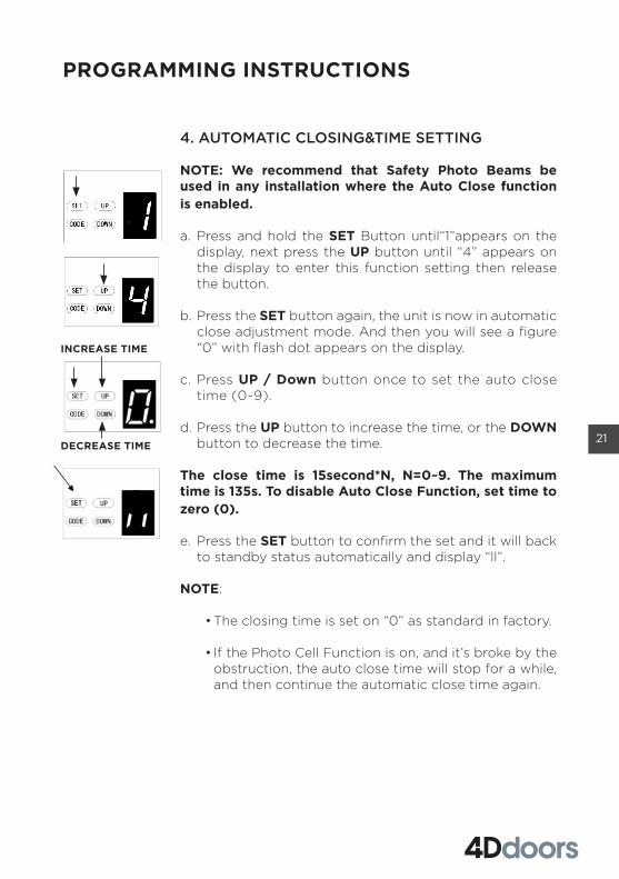
4. AUTOMATIC CLOSING&TIME SETTING
NOTE: We recommend that Safety Photo Beams be used in any installation where the Auto Close function is enabled.
a. Press and hold the SET Button until“1”appears on the display, next press the UP button until “4” appears on the display to enter this function setting then release the button.
b. Press the SET button again, the unit is now in automatic close adjustment mode. And then you will see a figure “0” with flash dot appears on the display.
c. Press UP / Down button once to set the auto close time (0~9).
d. Press the UP button to increase the time, or the DOWN button to decrease the time.
The close time is 15second*N, N=0~9. The maximum time is 135s. To disable Auto Close Function, set time to zero (0).
e. Press the SET button to confirm the set and it will back to standby status automatically and display “ll”.
NOTE:
• The closing time is set on “0” as standard in factory.
• If the Photo Cell Function is on, and it’s broke by the obstruction, the auto close time will stop for a while, and then continue the automatic close time again.
PROGRAMMING INSTRUCTIONS
INCREASE TIME
DECREASE TIME
22
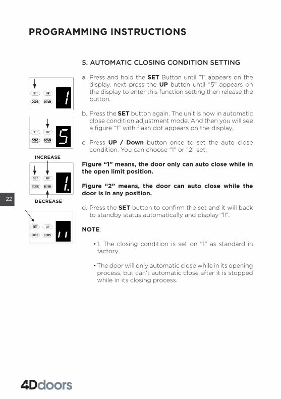
5. AUTOMATIC CLOSING CONDITION SETTING
a. Press and hold the SET Button until “1” appears on the display, next press the UP button until “5” appears on the display to enter this function setting then release the button.
b. Press the SET button again. The unit is now in automatic close condition adjustment mode. And then you will see a figure “1” with flash dot appears on the display.
c. Press UP / Down button once to set the auto close condition. You can choose “1” or “2” set.
Figure “1” means, the door only can auto close while in the open limit position.
Figure “2” means, the door can auto close while the door is in any position.
d. Press the SET button to confirm the set and it will back to standby status automatically and display “ll”.
NOTE:
• 1. The closing condition is set on “1” as standard in factory.
• The door will only automatic close while in its opening process, but can’t automatic close after it is stopped while in its closing process.
PROGRAMMING INSTRUCTIONS
INCREASE
DECREASE

23
6. LED OFF DELAY TIME SETTING
a. Press and hold the SET Button until “1” appears on the display, next press the UP button until “6” appears on the display to enter this function setting then release the button.
b. Press the SET button again. The unit is now in LED off delay time adjustment mode. And then you will see a figure“3”with flash dot appears on the display.
c. Press UP / Down button once to set the LED off delay time (1~9).
d. Press UP button to increase the time, or DOWN button to decrease the time.
The delay time is 1 minute*N, N=1~9. The maximum delay time is 9 minutes.
e. Press the SET button to confirm the set and it will back to standby status automatically and display “ll”.
NOTE: The LED off delay time is set on “3” as standard in factory.
PROGRAMMING INSTRUCTIONS
INCREASE TIME
DECREASE TIME

24
7. REVERSAL HEIGHT SETTING
a. Press and hold the SET Button until “1” appears on the display, next press the the UP button until “7” appears on the display to enter this function setting then release the button.
b. Press the SET button again. The unit is now in reversal height adjustment mode. And then you will see a figure “0” with flash dot appears on the display.
c. Press UP / Down button once to set the reversal height while closing (0~9).
d. Press the UP button to increase , or the DOWN button to decrease.
Figure “0” means the door will rebound to the open limit position. Figure “1~9” means the door will rebound to the position of the whole travel. One tenth to Nine tenth of the whole travel etc...
e. Press the SET button to confirm the set and it will back to standby status automatically and display “ll”.
NOTE: The reversal height is set on “0” as standard in factory.
PROGRAMMING INSTRUCTIONS
INCREASE HEIGHT
DECREASE HEIGHT

25
8. PARTIAL OPEN/HEIGHT SETTING
a. Press and hold the SET Button until “1” appears on the display, next press the UP button until “8” appears on the display to enter this function setting then release the button.
b. Press the SET button again. The unit is now in partial-open/height adjustment mode. And then you will see a figure “0” with flash dot appears on the display.
c. Press UP / Down button once to select if you want to open the partial open function or set the partial open height. (0~9). Press the UP button to increase , or the DOWN button to decrease.
Figure “0” means close the partial open function. Figure “1~9” means set the partial open position of the whole travel. One tenth to Nine tenth of the whole travel etc...
d. Press the SET button to confirm the set and it will back to standby status automatically and display “ll”.
NOTE:
• The artial open/height is set to “0” as standard in factory
.• If you open the partial open/height function, the
buttons’ recognition finction will be disabled.
• Other details please refer to the instruction manual of the remote carefully.
• If you enabled the partial open function then disabled this function later, please notice that only the coded button you leaned in the beginning can control the opener now.
PROGRAMMING INSTRUCTIONS
INCREASE
DECREASE

26
9. TRANSMITTER PAIRED BUTTONS RECOGNITION FUNCTION SETTING
a. Press and hold the SET button to enter this function setting until “9” appears on the display then release the button.
b. Press the SET button again. The unit is now in paired buttons recognition function adjustment mode. And then you will see a figure “1” with flash dot appears on the display.
c. Press UP / Down button once to select if you want the top and bottom pairs of buttons control one opener each, or each separate coded button to control the opener.
Figure “0” means the buttons recognition function is closed. It means if you coded 1 button with 1 opener, then its top or bottom pair will also control the opener. It’s convenient for the users who only have 1 automation door at home. Figure “1” means the buttons recognition function is open. If you coded first button with first opener, then the first button will be the only button on the remote can control the opener. It’s convenient for the users who have more than 1 automation doors/gates at home.
d. Press the SET button to confirm the set and it will back to standby status automatically and display “ll”.
NOTE:
1. The buttons recognition is set on “1” as standard in factory.
2. After you changed the buttons un-recognition into recognition, please notice that only the coded button can control the opener.
PROGRAMMING INSTRUCTIONS
BUTTON RECOGNITION FUNCTION IS CLOSED
BUTTON RECOGNITION FUNCTION IS OPEN
27
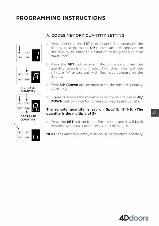
A. CODES MEMORY QUANTITY SETTING
a. Press and hold the SET Button until “1” appears on the display, next press the UP button until “A” appears on the display to enter this function setting then release the button.
b. Press the SET button again, the unit is now in remote quantity adjustment mode. And then you will see a figure “A” again, but with flash dot appears on the display.
c. Press UP / Down button once to set the remote quantity. (A or 1~9).
d. Figure “A”means the maximal quantity 50pcs. Press UP/DOWN button once to increase or decrease quantity.
The remote quantity is set on 5pcs*N, N=1~9. (The quantity is the multiple of 5)
e. Press the SET button to confirm the set and it will back to standby status automatically and display “ll”.
NOTE: The remote quantity is set on “A” as standard in factory.
PROGRAMMING INSTRUCTIONS
INCREASE QUANTITY
DECREASE QUANTITY

28
B. REVERSAL HEIGHT IGNORANCE SETTING
a. Press and hold the SET Button until “1” appears on the display, next press the UP button until “b” appears on the display to enter this function setting then release the button.
b. Press the SET button again. The unit is now in reversal height ignorance adjustment mode. And then you will see a figure “1” with flash dot appears on the display.
c. Press UP / Down button once to set the reversal height ignorance while closing (0~9).
d. Press the UP button to increase , or the DOWN button to decrease.
Figure “1~9” means the door will still not rebound even though there’s obstacles in its closing path within 1cm~9cm away from the close position. This function is most suitable for the Northern Europe where will always snow on the ground.
e. Press the SET button to confirm the set and it will back to standby status automatically and display “ll”.
NOTE: The reversal height is set on “1” as standard in factory.
PROGRAMMING INSTRUCTIONS
INCREASE HEIGHT
DECREASE HEIGHT

29
C. WICKET DOOR SAFETY INTERLOCK SWITCH TYPE SETTING
a. Press and hold the SET Button until “1” appears on the display, next press the UP button until “C” appears on the display to enter this function setting then release the button.
b. Press the SET button again. The unit is now in the wicket door switch type adjustment mode. And then you will see a figure “0” with flash dot appears on the display.
c. Press UP / Down button once to set the wicket door switch type. You can choose “0” or “1” set.
Figure “0” means, the wicket door function is normally open.
Figure “1” means, the wicket door function is normally close.
d. Press SET button to confirm the set and it will back to standby status automatically and display “ll”.
NOTE: The wicket door switch is set on “0” as standard in factory.
PROGRAMMING INSTRUCTIONS

30
D. PHOTO CELL ON/OFF SETTING
NOTE: Make sure the photo cell has been correctly installed and used Normally Closed contacts to the accessory terminals of the opener.
Also note that the photo beam function must be disabled if NO photo beams are fitted, otherwise the door cannot be closed, and the LED display will show the letter“ r ”as an indication.
a. Press and hold the SET Button until “1” appears on the display, next press the UP button until “d” appears on the display to enter this function setting then release the button.
b. Press the SET button again. The unit is now in the photo cell ON/OFF adjustment mode. And then you will see a figure “0” with flash dot appears on the display.
c. Press UP / Down button once to set the photo cell ON/OFF switch. You can choose “0” or “1”set.
Figure “0” means, the photo cell function is closed.
Figure “1” means, the photo cell function is open.
d. Press the SET button to confirm the set and it will be back to standby status automatically and display “ll”.
NOTE: The photo cell is set on “0” as standard in factory.
PROGRAMMING INSTRUCTIONS

31
E. MAINTENANCE ALARM--OPERATION CYCLES COUNT SETTING
a. Press and hold the SET Button until “1” appears on the display, next press the UP button until “E” appears on the display to enter this function setting then release the button.
b. Press the SET button again. The unit is now in the maintenance alarm adjustment mode. And then you will see a figure “0” with flash dot appears on the display.
c. Press UP / Down button, you can select the operation cycles you need the opener to make you notice. You can choose from “1-5” set.
Figure “1” means, after garage door operated to 1000 times, the L.E.D light will flash 10 times quickly after the door stop working every time. In order to make you notice that your garage door need to do maintenance . And at the same time, you will see a figure “t” appears on the display.
Figure “2” means the maintenance alarm count cycle is set on 2000 times. Figure “3” means the maintenance alarm count cycle is set on 3000 times.Figure “4” means the maintenance alarm count cycle is set on 4000 times.Figure “5” means the maintenance alarm count cycle is set on 5000 times.
d. Press the SET button to confirm the set and it will be back to standby status automatically and display “ll”.
NOTE:
• The operation cycles count is set on “0” as standard in factory.
• “b” appears on display and led light flashes 10 times quickly means the door lost balance, strong recommend the maintenance for garage doors.
• “Check” the status, or “ Re-learn” the travel limit after maintenance alarm cautions.
PROGRAMMING INSTRUCTIONS

32
F. OPEN / STOP / CLOSE TERMINALS
The O/S/C facility can be used for an external push button switch to operate the opener. The switch must have voltage free normally open contacts.
PROGRAMMING INSTRUCTIONS
Photo beam connection (optional) – Fig.15,Fig.16 Switch control connection (optional) – Fig.15
Remark:
1. Flash (Caution Light) Should be less than 25W.2. PB (External Push Button) Should be “ NO”.
TERMINAL INTRODUCTION AND APPLICATION
FIGURE 15

33
Other terminal introduction and application
1. The O/S/C interfaces available. (Fig. 17, Fig. 18)Add a new O/S/C button to open or close the door.
2. Flash light function. (Fig. 17, Fig. 18)There are corresponding interfaces for this function and provide 24v-35v flash light voltage. Connect the flash light with DC 24v-28v, current≤100mA. When use AC 220V power flash lights, please match an adapter, and wiring as required
3. Wicket door (SD) protection (Fig. 17, Fig. 18)This function ensures that the door can’t be opened unless the small wicket door is closed. The door panel won’t be damaged.
FIGURE 16
FIGURE 17 FIGURE 18

34
The opener is equipped with a manual release cord to disengage shuttle and move door by hand while holding the handle down (Fig 19). Pull on the handle to disengage the shuttle. To re-engage the door simply run opener in automatic mode or move door by hand until the trolley engages in the chain shuttle.
If the garage does not have a pedestrian access door, an emergency access device must be installed. This allows manual door opening from outside in the event of occupant incapacitation, power supply failure or opener failure (Fig 20).
MANUAL DISENGAGEMENT
FIGURE 19 FIGURE 20

35
1. No particular maintenance is required for the logic circuit board.
Check the door at least twice a year if it is properly balanced, and all working parts are in good working condition or not.
Check the reversing sensitivity at least twice a year, and adjust if it is necessary.
Make sure that the safety devices are working effectively (photo beams, etc.)
2. LED strip replacing:
Notice: Make sure the power supply has been cut off before replacing the LED strip (service part item 3). Take the lamp cover away, and then unplug the old LED light. Replace with a new LED light strip and refit the lamp cover.
3. Before installing a caution light, please ensure the rate is within 5 Watt.
4. Regarding the maintenance alarm function, LED light flashes 10 times quickly means the door has lost counter balance. “Check” the status, or “ Re-learn” the travel limit after maintenance alarm cautions. If this fails to resume normal operation, use the door in manual released mode and contact a service agent.
Notice: A poorly operating door can affect the life of the automatic opener due to higher loads, and may void the warranty.
MAINTENANCE

36
FS 1000
Input voltage 220 - 240V / 110 - 127V, 50–60 Hz
Max. pull force 1000 N
Max. door area 15.0m2
Max. door weight (Balanced)
100kg
Max. door height 2400 - 3500mm
Drive mechanism Chain / Belt
Opening / Closing speed 160mm / Second
L.E.D 24V / 15pcs LED bulbs
Limit setting Electronic
Transformer Overload protection technology
Radio frequency 433.92 MHz
Coding format Rolling code (7.38 x 10¹⁹ Combinations)
Status display transmitter 2 X
Code storage capacity 50 different codes
Caution light terminal Included
Working temperature -400C - +500C
Safety protectionSoft start & Soft stop, photo cell option,
caution light option
Protection level IP20
TECHNICAL SPECIFICATIONS
Standard door height: 2400mmMaximum door height: 3500 mm
Rated door area: ≤ 15.0m2
FS 1000

37
Item Qty Description
1 1 Top cover
2 1 L.E.D cover
3 1 L.E.D light
4 1 PCB-1
5 1 Control panel cover-2
6 1 Control panel cover-1
7 1 Panel label
8 1 PCB-2
9 1 Main cover
10 1 DC gear motor
11 1 Steel bottom base
12 1 Transformer plate
Item Qty Description
13 1 Transformer
14 1 Chain/ Belt rail
15 1 Chain/ Belt connection
16 1 Trolley assy
17 1 Straight arm
18 1 Bent arm
19 2 Transmitter
20 1 Transmitter bracket
21 1 Door bracket
22 1 Wall bracket
23 1 Track ending bracket
24 1 Wheel bracket
Item Qty Description
25 1 Chain wheel
26 2 Mounting bracket
27 1 C rail- steel
28 1 Click bracket
29 2 U hanging bracket
30 1 Motor shaft sleeve
31 1 Sprocket assy
32 1 Caution card
33 1 Release handle
PARTS LISTING

38
Fault appearance Fault cause Solutions
No responseLCD screen is not bright
1. Power supply2. Plug wire is loosing
1. Check whether the motor socket is energized2. Check whether Fuse tube is broken3. Check whether the low-voltage wire of transformer is connected to the power board4. Check whether the ribbon cable is plugged5. Check whether there is 26v AC at the transformer low-voltage side, if there is 26v AC, replace the PCB. If not, replace the transformer
Stop positions incorrect System error Re-set the limit traveling
While learning, the digital display
Travel less than 30cm or more than 9m
Re-set the limit traveling
Digital display Insufficient voltage Check the power supply
Opener does not work or stop working
Digital display The Garage door system is in poor condition and needs maintenance
The garage door and motor need total maintenance. Manual Release door and check if operation loads are acceptable. Correct or continue to reset force limits
LED light will flash quickly for 10 times
Digital display The gear motor cannot self-lock well
Replace the gear motor
Opener is not working Fail to learn the up and down limit setting Improperly learn the up and down limit setting
Learn “UP” and “DOWN” limit traveling again follow the manualDigital display
LED is always on The control panel is broken or the power supply board is broken
Replace the control board or power board
When remoting the door,opener stops automatically after running 10cm
Hall sensor wire is loosed or damaged
Open the cover, check the Hall sensor wire, re-plug or replace.
Digital display
Opener does not work.Hear the relay ‘kaka’ sound
The wire between gear motor and board is loosing
Open the cover and check the wire between gear motor and board
Digital display
Opener stops automatically after running 10cm
The wire between gear motor and board is plugged inversely
Power off firstly, open the cover and reverse the plug wire between gear motor and board. Re-set limit traveling.
Digital display
COMMON FAULT & SOLUTIONS

39
Door is up moving only. Do not work in down moving and the
Photo cell function is enabled without connecting a photo cell device.
Turn off the photo cell function if there is no anyphoto cell device connected. ( Refer the instruction manual)2. Check if the photo cell is connected correctly, or if there is any obstruction between the photo cell.
Digital display
The door is fully open, automatically close after some timeLED lights flash 4 times
Automatic closing function is turned on
Set the automatic closing time, or turn off the automatic closing function. ( Refer the instruction manual)
When the door stops, the caution light is always on
The power board is broken Replace the power board
LED lights do not work 1. The LED wire is not plugged2. The LED is broken3. The circuit board is broken
1. Check the LED wire2. Replace the LED3. Replace the circuit board
Door is automatically reversed to the upper limit before the door closed completely
In operation with automatic reverse functionThe door is not installed correctlyThere is some binding along the track movement
1.Check the track and roller condition of the door and re-set the limit traveling2. Increased force number for automatic reverse
Door automatically stops while opening
In operation with automatic protect function when obstruction is detectedThe door is not installed correctlyThere is some track binding
1.Check for track binding and re-set the limit traveling2. Increased force number for automatic reverse
The remote control cannot be used or the operation distance is short
1. Flat battery2. Antenna is loosed or not well extended3. Interference from other devices
1. Replace new battery 2. Extended the antenna on the opener3. Get rid of interference
Cannot code in the new remotes
New remote control is not compatible with opener
Choose our remote control only
Digital display Stored remote code is full Delete all stored codes (Refer the instruction manual)
Standby, Digital display Door in door function effects Check the door in door switch
The opener is working while the door is not moving
Motor shaft sleeve worn Replace the motor shaft sleeve
The battery do not supply power
1. Flat battery 2. The battery wire is plugged inversely3. The battery wire is broken
1. Charge the battery2. Open the cover, check “+” “-” of the battery 3. Replace the battery wire
Other abnormal issues External devices is not compatible with the opener
Remove all the external devices. If the abnormal issues still exist, replace the circuit board
Digital display The Garage door system needs maintenance
The garage door and motor need total maintenance

40
IMPORTANT DOCUMENT: TO BE KEPT BY THE USER OF THE PRODUCT
If you are a consumer under the Australian Consumer Law, 4D Garage Doors Pty Ltd (4D Garage Doors) will provide you, the original purchaser of this 4D SDO2 V1 (Product), with this limited warranty in addition to any rights that you have under Australian consumer protection laws. This warranty is in addition to, and does not exclude, restrict or modify your guarantees and other legal rights under Australian Consumer law. Our goods come with guarantees that cannot be excluded under the Australian Consumer Law. You are entitled to a replacement or refund for a major failure and compensation for any other reasonably foreseeable loss or damage. You are also entitled to have the goods repaired or replaced if the goods fail to be of acceptable quality and the failure does not amount to a major failure. This warranty only applies to Product sold by 4D Garage Doors or an authorised dealer in Australia. An approved and authorised dealer meaning an approved reseller of 4D Garage Doors products purchased from 4D Garage Doors for the purpose of supplying those products to the end consumer. This warranty document is not intended to create a contract between 4D Garage Doors and the purchaser.
Except for this warranty, 4D Garage Doors gives no warranties of any kind whatsoever (whether express or implied) in relation to the Product and all warranties relating to the Product are hereby excluded to the extent permissible by law. 4D Garage Doors will not accept any additional warranties or conditions provided by others which attempt to modify the terms of this warranty.
Subject to your non-excludable rights under the Australian Consumer Law, 4D Garage Doors expressly excludes any liability for consequential loss, incidental or indirect damages (including but not limited to damages for loss of business profits, business interruption and loss of business information) due to a defect of the Product. In particular, any loss or damage caused to other equipment or accessories used with the Product or any loss resulting from a delay in repair, is excluded to the extent permitted by law.
Conditions of Warranty
Subject to the terms of this warranty, 4D Garage Doors warrants to the original purchaser that:
1. the Product will be free from defects in materials and workmanship for a period of 5 years from the date of purchase or 8,000 cycles (whichever
4D GARAGE DOORS PTY LTD WARRANTY4D SDO 2 V1
Document No: ENGR.00003 ABN 96 659 631 559Rev: 1.0 Date: 30MAY2019 www.4ddoors.com.au

41
occurs first) for the motor, and 2 years from the date of purchase or 4,000 cycles (whichever occurs first) for the electronics and mechanics. A cycle means one opening and closing of the door.
2. the remote-controlled transmitters and accessories included with the Product will be free from defects in materials and workmanship for a period of 6 months from the date of purchase.
3. where the Product is not installed by a professional authorised by 4D Garage Doors, the product is covered for a period of 12 months from date of purchase defects in materials and workmanship.
Subject to the following conditions and any non-excludable statutory rights, 4D Garage Doors will, at its option, either repair or replace any proven defects in materials or workmanship; a. The garage door to which the Product is fitted must be “spring balanced” and
able to be opened and closed by a force not exceeding 14 kilograms. b. Proof of purchase must be presented. c. The Product must have been serviced by a professional authorised by 4D Garage
Doors at intervals not exceeding 12 months (the cost of servicing is not covered by this warranty).
d. The Product is well maintained and kept in good working condition. e. The supplier must be notified as soon as practicable of any defect covered by this
warranty. If the Product was supplied by an authorised 4D Garage Doors dealer and this dealer cannot be contacted, then notification must be made as soon as practicable to 4D Garage Doors.
f. This Warranty is limited to Return-to-Base (RTB) repair and does not cover labour or associated costs for on-site attendance. The purchaser is responsible for the cost of returning the Product to the supplier or to 4D Garage Doors. The purchaser is responsible for the cost of labour and any travel or other additional expenses incurred for any on-site attendance.
g. Any Product repaired or replaced during the warranty period will be covered by the terms of this warranty until the expiration of the original warranty period.
h. Where 4D Garage Doors, or its Authorised Dealer, in its absolute discretion determines that a warranty claim is not being covered under the conditions of this warranty, then 4D Garage Doors or its authorised dealer (as the case may be) reserves the right to charge for reasonable reimbursement of expenses for assessing the claim, and these must be paid by the purchaser before the Product will be returned (at the purchaser’s expense)
i. This warranty is not transferrable.j. Repairs may be conducted using refurbished components, and Products
presented for repair may be replaced with refurbished products of similar type.k. Products must be returned in original or suitably safe packaging.l. This warranty is only applicable for repairs to Products in Australia.
Document No: ENGR.00003 ABN 96 659 631 559Rev: 1.0 Date: 30MAY2019 www.4ddoors.com.au

42
What this warranty does not cover: a. Corrosion: Damage from salt, water or any other form of corrosion. b. Installation: damage or defect due to faulty installation of the Product (except
where installed by 4D Garage Doors). c. Service: damage or defect due to a failure to properly service, care for or maintain
the Product in accordance with the instruction manual. d. Damage due to misuse (including failure to follow the instruction manual) or
deliberate, negligent or accidental damage of any sort. e. Modifications: 4D Garage Doors will not be required to incorporate any
modifications made to existing or future models. f. Electrical Power: Any damage, issues or faults caused by electrical surge or
fluctuation.g. Problems that are directly or indirectly caused by or relate to the garage door or
garage door hardware, which could include but are not limited to door springs, rollers, curtain wear, fixings and alignment.
h. Normal wear and tear.i. Non-authorised repairs.j. Acts or omissions of any person, including approved dealers, other than 4D
Garage Doors and its staff.k. Travel Expenses: Expenses incurred by 4D Garage Doors or its authorised dealer
in travelling and or transporting Products to and from the location of the Product are not included and will be paid for by the purchaser.
l. Additional access or equipment required: Expenses incurred by 4D Garage Doors or its authorised dealer required to provide clear access, or the equipment used to access the Product (for example: Lifting hardware such as forklift or scissor lift) are not covered by this warranty and must be paid for by the purchaser.
m. Frequency Interference: Where remote transmitters cannot operate the opener due to frequency interference at the location where the Product is installed.
n. Damage due to matters outside of the reasonable control of 4D Garage Doors including, but not limited to, rain, hail, flood, water, fire, insects or any other event beyond the reasonable control of 4D Garage Doors.
o. Consumer Goods: Components such as globes, accessories, batteries and other consumable parts are not covered by this warranty.
p. Secondary damage to vehicles or any other fragile objects after door collision and obstruction force detection
What will void this warranty: 4D Garage Doors will be relieved of all obligations, responsibilities and liabilities under this warranty if, in the opinion of 4D Garage Doors, the defects in the Product result from: a. Any modifications, repairs or works carried out to the Product which are not
authorised by 4D Garage Doors.b. The fitment of any device to the Product which is not approved by 4D Garage Doors.c. Misuse or unreasonable use of the Product, as determined by 4D Garage Doors.
Document No: ENGR.00003 ABN 96 659 631 559Rev: 1.0 Date: 30MAY2019 www.4ddoors.com.au

43
d. Any use of the Product other than for residential application only (i.e. for use in a single-family dwelling or individual garages within an apartment complex).
e. Failure to follow any directions or instructions, including any warning notifications in instruction manuals or signs on or provided with the Product.
If any part of this warranty is or becomes illegal, void or unenforceable, this does not invalidate the rest of the warranty.
How to make a claim Please be aware you are responsible for the expense of making a claim under this warranty. To make a claim, if the Product was supplied to you directly from 4D Garage Doors please forward a copy of your original receipt as proof of purchase and a completed warranty claim form to 4D Garage Doors directly. If the Product was supplied by an authorised 4D Garage Doors dealer, please provide the copy of your original receipt along with a completed warranty claim form to that dealer. If the authorised dealer cannot be contacted, then please contact 4D Garage Doors and provide the copy of the receipt and the completed warranty claim form and 4D Garage Doors will forward these to the relevant authorised dealer. This warranty is supplied by 4D Garage Door Pty Ltd (ACN 168 477 263) at [email protected] Garage Doors PTY LTDPO BOX 61Wellers Hill 4121
WARRANTY CERTIFICATE
Invoice No: Installation Date:
Your Name: Phone No:
Address: State:
Installed by:
Motor Serial #: Door Model:
Please retain this completed warranty form along with your invoice as proof of purchase to validate you claim.
Document No: ENGR.00003 ABN 96 659 631 559Rev: 1.0 Date: 30MAY2019 www.4ddoors.com.au

www.4ddoors.com.au
instructions for fitting, operating and maintenanceSectional and Tilting door operator
4DS2 v1