FLASH manual v1 - CARF Models
44
-
Upload
khangminh22 -
Category
Documents
-
view
0 -
download
0
Transcript of FLASH manual v1 - CARF Models

CARF-Models Ultra Flash
New for 2010 the Ultra Flash is an updated version of the best selling Flash, designed for higher
performance with a new wing and tailplane. The new wing is swept back with greater span, larger
flaps and tapering section from root to tip. The swept design makes the Ultra Flash easier to balance
with the lighter Li-Po cells now used by the majority of jet modellers. The wing design has been
successfully tested on designs like the Spark and Ultra Lightning. The Ultra Flash has also been
designed from the start for use with a trailing link undercarriage set, the main wheel wells are a few
mm back from the leg centre and the main leg openings are wider to accept the CARF supplied
trailing link legs.
Construction follows the same process as the original Flash, the fuselage is identical, as is the
process for installing the elevator servos. The wings use the same combined gear cover and
aileron/flap servo mounting plate, screwed to the wing with 9 screws.
Follow the construction process shown in the manual, using this addendum.
Wings
The wings follow the same assembly process. If you are using the original straight Oleo leg from the
original Flash, leg cover plates are supplied. These can also be fitted to some trailing link main legs if
you want a cleaner lower wing surface.
The kit also includes a pair of moulded U section mouldings to seal the leg openings. These will
require trimming around the under carriage units and to length.
The wing flaps use a ball link connection at the flap end and a clevis at the servo. The flap is factory
fitted with a pair of horns ready to accept the supplied ball link. A long Allen driver is required to fit
the M3 x 16 ball link screw. Access is from inside the moulded hinge cover knuckle. Move the aileron
up and flap down to gain access.
Spend some time setting the Flap pushrod length before fully screwing the cover plate down.
The threaded rod should be approximately 50mm long and a good starting point for the push rod
centres would be 75mm. This is centre of ball link to clevis pin.
The aileron pushrods need to be approximately 60mm long with 86mm centres. Both figures based
on JR 8411 servos.
The flap settings for the Ultra Flash are:
The Ultra Flash requires down elevator with flap. Take off 1.5mm and Landing 4.5-5mm measured at
the elevator trailing edge tip. Exact figures will be affected by balance position.
Movements ailerons 15mm up and 18mm down-Expo 35-40%. Elevators 15mm up and 16mm down
45-50% expo, Rudder 45mm each way 30-35% expo. Ail/Elev tip joint. Rudder lower TE point.
Balance point, gear up 220-225mm back from the wing/fuselage joint.


‘Flash’
Thank you very much for purchasing our CARF-Models ‘Ultra Flash’ sport-jet, made with the revo-
lutionary Total Area Vacuum Sandwich (TAVS) technology.
Please note that a few of the photos in this Instruction manual show some views from the 2 pro-
totypes, so please don’t get confused by the slightly different colour schemes!
Before you get started building and setting-up your aircraft, please make sure you have read this
instruction manual, and understood it. If you have any questions, please don’t hesitate to con-
tact your Rep, or CARF directly. Below are the contact details:
Email:
Website:
Liability Exclusion and Damages
You have acquired a kit, which can be assembled into a fully working R/C model when fitted out
with suitable accessories, as described in the instruction manual with the kit.
However, as manufacturers, we at CARF-Models are not in a position to influence the way you
build and operate your model, and we have no control over the methods you use to install,
operate and maintain the radio control system components. For this reason we are obliged to
deny all liability for loss, damage or costs which are incurred due to the incompetent or incorrect
application and operation of our products, or which are connected with such operation in any
way. Unless otherwise prescribed by binding law, the obligation of the CARF-Models compa-
ny to pay compensation is excluded, regardless of the legal argument employed.
This applies to personal injury, death, damage to buildings, loss of turnover and business,
interruption of business or other direct and indirect consequent damages. In all circumstances
our total liability is limited to the amount which you actually paid for this model.
BY OPERATING THIS MODEL YOU ASSUME FULL RESPONSIBILITY FOR YOUR ACTIONS.
It is important to understand that CARF-Models Co., Ltd, is unable to monitor whether you
follow the instructions contained in this instruction manual regarding the construction, operation
and maintenance of the aircraft, nor whether you install and use the radio control system
correctly. For this reason we at CARF-Models are unable to guarantee, or provide, a
contractual agreement with any individual or company that the model you have made will
function correctly and safely. You, as operator of the model, must rely upon your own expertise
and judgement in acquiring and operating this model.
2

Attention !
This ‘jet’ aircraft is a high-end product and can create an enormous risk for both pilot and spec-
tators, if not handled with care & used according to the instructions. Make sure that you operate
your ‘Flash’ according to the laws and regulations governing model flying in the country of use.
The engine, landing gear, servos, linkages and control surfaces have to be attached properly.
Please use only the recommended servos and accessories. Make sure that the ‘Centre of
Gravity’ is located in the recommended place. Use the nose heavy end of the CG range for your
first flights. A tail heavy plane can be an enormous danger for you and all spectators. Fix any
weights, and heavy items like batteries, very securely into the plane.
Make sure that the plane is secured properly
when you start the engine. Have a helper hold
your plane from the nose before you start the
engine. Make sure that all spectators are far
behind, or far in front, of the aircraft when run-
ning up the engine.
Make sure that you range check your R/C sys-
tem thoroughly before the 1st flight. It is
absolutely necessary to range check your
complete R/C installation first WITHOUT the
engine running. Leave the transmitter antenna
retracted, and check the distance you can walk
before ‘fail-safe’ occurs. Then start the engine,
run at about half throttle and repeat this range
check. Make sure that there is no range reduc-
tion before ‘fail-safe’ occurs. If the range with
engine running is less then with the engine off,
please DON’T FLY at that time.
Check that the wing and stab retaining bolts are tight, and that all linkages are secured. Please
don’t ignore our warnings, or those provided by other manufacturers. They refer to things and
processes which, if ignored, could result in permanent damage or fatal injury.
Important/General Notes
Elastic Hinges:The ailerons, elevators, flaps and rudder are all hinged already for you - laminated in the mould
and attached with a special nylon hinge-cloth, sandwiched between the outer skin and the foam.
This nylon hinge is 100% safe and durable. You will never have to worry about breaking it, or
wearing it out. There is no gap at all on the top side of the surface, and there is a very narrow
slot in the bottom surface, where the control surface slides under the skin during ‘down’ throw.
This means that the hinge axis line is on the top surface of the wing and stab, not in the centre.
This is NOT a disadvantage, but you need to program in about 10% NEGATIVE differential in
your transmitter. This means that the ‘down’ throw needs to be about 10% more than the ‘up’
throw. Why? Because the axis of the hinge is not at the centreline of the aileron/elevator, so it
moves slightly in and out when operated, and the control surface gets a little "smaller" in surface
3
Secure the
plane
before starting
engine.
DANGER ZONES
NO !!!
NO NO

4
area when moving downwards.
The slot needs some explanation, too. The cut line is
exactly in the correct position so that the control surface
slides under the wing skin smoothly. If the cut was a few
mm forward or backwards, it would not work properly. So,
make sure that the lip is not damaged, and that the control
surface slides under this lip perfectly. It will not lock at any
time, as long as the lip is not damaged. If damage occurs,
you can cut a maximum of 2-3 mm off the lip on the wing in front of the control surface, but you
should never cut off more than this.
Servo Choice:We strongly advise that you use the recommended high-torque digital metal-geared
JR/Graupner servos on all the main flight controls, and the milled plywood mounts are specifi-
cally designed for these.
The elevator servos cannot be thicker than 19mm, otherwise they will not fit in the stabiliser,
and we have used JR8311 in all our prototypes without any problems.
The ailerons are very large surfaces, and the shock-load on the servo geartrain in a ‘hard’
landing is quite severe - so please use a metal geared servo like the JR8411 for these.
A good alternative for the ailerons, flaps and rudder is the Futaba S9351, but this servo is too
thick to fit in the stabiliser. See the recommended servo list on page 6.
Servo Screws:Fix the all the servos into the milled plywood servo mounts using the 2.9 Ø x13mm or 16mm
sheet metal screws provided in the kit, not the standard screws normally supplied with servos
by the servo manufacturer. This is because all the holes in our milled servo mounts are 2mm
diameter, due to our CNC manufacturing process, and this is too big for the normal screws.
Building Sequence:The actual building sequence is your choice, but it is definitely most efficient to start at the
back of the fuselage and work forwards, in the same order as shown below.
Take Care:Composite sandwich parts are extremely strong, but fragile at the same time. Always keep in
mind that these contest airplanes are designed for minimum weight and maximum strength in
flight. Please take care of it, especially during transport, to make sure that none of the critical
parts and linkages are damaged. Always handle your airplane with great care, especially on the
ground and during transport, so you will have many hours of pleasure with it.
To protect the finished paint on the outside of the model from scratches and dents during build-
ing, cover your work table with a piece of soft carpet, cloth or bubble-plastic. The best way to
stop small spots of glue getting stuck to the outside painted surfaces is to give the whole model
2 good coats of clear car wax first, but of course you must be sure to remove this 100% proper-
ly before adding any additional paint, markings or trim.
Centreline of hinge axis
Phenolic control horn
Adhesives and Solvents
Not all types of glues are suited to working with composite parts. Here is a selection of what we
normally use, and what we can truly recommend. Please don’t use inferior quality glues - you will
end up with an inferior quality plane, that is not so strong or safe.
Jet models require good gluing techniques, due to the higher flying speeds, and hence higher
loads on many of the joints. We highly recommend that you use a slow filled thixotropic epoxy
for gluing highly stressed joints (eg: Hysol 9462). The self-mixing nozzles make it easy to apply
exactly the required amount, in exactly the right place, and it will not run or flow onto places
where you don’t want it! It takes about 1 - 2 hours to start to harden so it also gives plenty of time
for accurate assembly. Finally it gives a superb bond on all fibreglass and wood surfaces. Of
course there are many similar glues available, and you can use your favourite type.
1. CA glue ‘Thin’ and ‘Thick’ types. We recommend ZAP, as this is very high quality.
2. ZAP-O or Plasti-ZAP, odourless, or ZAP canopy glue 560 (for clear canopy)
3. 30 minute epoxy (stressed joints must be glued with at least 30 min & NOT 5 min epoxy).
4. Loctite Hysol 9462 or equivalent (optional, but highly recommended)
5. Epoxy laminating resin (12 - 24 hr cure) with hardener.
6. Milled glass fibre, for adding to slow epoxy for stronger joints.
7. Micro-balloons, for adding to slow epoxy for lightweight filling.
8. Thread-locking compound (Loctite 243, ZAP Z-42, or equivalent)
We take great care during production at the factory to ensure that all joints are properly glued,
but of course it is wise to check these yourself and re-glue any that might just have been missed.
When sanding areas on the inside of the composite sandwich parts to prepare the surface for
gluing something onto it, do NOT sand through the layer of lightweight glasscloth on the inside
foam sandwich. It is only necessary to rough up the surface, with 80/120 grit, and wipe off any
dust with acetone or de-natured alcohol (or similar) before gluing to make a perfect joint. Of
course, you should always prepare both parts to be joined before gluing for the highest quality
joints. Don’t use Acetone for cleaning external, painted, surfaces as you will damage the paint.
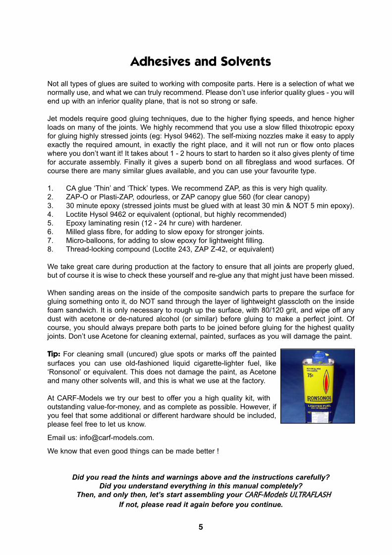
Tip: For cleaning small (uncured) glue spots or marks off the painted
surfaces you can use old-fashioned liquid cigarette-lighter fuel, like
‘Ronsonol’ or equivalent. This does not damage the paint, as Acetone
and many other solvents will, and this is what we use at the factory.
At CARF-Models we try our best to offer you a high quality kit, with
outstanding value-for-money, and as complete as possible. However, if
you feel that some additional or different hardware should be included,
please feel free to let us know.
Email us: [email protected].
We know that even good things can be made better !
Did you read the hints and warnings above and the instructions carefully?
Did you understand everything in this manual completely?
Then, and only then, let’s start assembling your
If not, please read it again before you continue.
5

Accessories
This is a list of the main additional items you will need to get your CARF Ultra Flash into
the air. Some of them are mandatory, and some can be chosen by you. What we list here are
highly recommended items, and have been thoroughly tested.
1. Power servos (min. 7). All main flight surfaces require a minimum 8kg digital servo, such
as the excellent JR 8311/8411, and these are what the Ultra Flash was designed for. The
Futaba S9351 is an alternative for the ailerons, flaps and rudder. See list below.
2. Turbine engine set. Recommended thrust range 8 - 12kg (18 - 27lbs). The Ultra Flash is
designed for a maximum turbine thrust of 120 Newtons. Please do not exceed this.
3. Retractable Landing gear set (C-ARF product #670500). The Flash is designed specifical
ly around the high-quality Behotec C-36/2 set, and this includes parts designed specially
for the Ultra Flash. Set includes trailing link noseleg, and Intairco main wheels and brakes.
4. Retract & brake valves: The Behotec combined retract/brake mechanical valve included
in the landing gear set works perfectly and is efficient with air volume used. However you
can use any valve type that you chose, and CARF can supply the proven ‘Jet-tronics’ elec
tronic brake and retract valves as an option.
5. Batteries and extension leads (see list below for JR extension leads required).
6. Powerbox Sensor switch. A highly recommended item which combines 2 voltage regula
tors with 2 separate electronic switches for connecting 2 separate batteries to your
receiver. Available from C-ARF as an option. Product # 960600.
7. Heavy duty plastic servo arms (8 pieces).
JR part #JRPA215 or Graupner # Nr. 3544.
Recommended Servos:Ailerons 2 x JR/Graupner 8411
Flaps/speedbrakes 2 x JR/Graupner 8311 or 8411
Elevators 2 x JR/Graupner 8321/8311/8411 (max. thickness 19mm)
Rudder: 1 x JR/Graupner 8311 or 8411
Nosegear steering: 1 x any standard-sized, metal output gear, servo with min. 5 kg torque.
Retract/Brake valve: 1 x mini-servo, min. torque 2.5kg.(eg JR/GR3041, 3241, 361 etc)
If you choose alternative servos of similar quality and torque for the main flight surfaces, for
example Futaba S9351, you might have to adjust the cnc milled plywood servo mounts a little.
Extension leads:If using the JR/Graupner servos listed above, installed as recommended, you will require the fol-
lowing length extension leads to reach the normal receiver position under the cockpit.
Elevator and rudder servos; 3 x 1050mm, 1 x 180mm and 1 x 320mm
Flaps and Ailerons: 4 x 550mm (in wing) and 4 x 180mm from Receiver.
Standard RX battery cable lengths will reach the Powerbox ‘Sensor’ switch in the recommend-
ed position, as will standard Turbine fuel pump and Turbine battery cables.
6

About the ‘FLASH’
The CARF Ultra Flash's aerodynamical design is based on the CARF Ultra Lightning.
The Ultra Flash is 20% reduced in size, and has a few additional modifications made. After more
than a year of experience with the Lightning we were able to further simplify the design and
even improve the aerobatic performance.
We decided to build the whole Flash based on the K.I.S.S. principle. A single piece wing and sta-
biliser means that the plane consists of only 3 structural parts, plus a canopy frame and an
exhaust nozzle. With a wingspan of 1.64m transportation is not an issue and assembly at the
field is made very easy and quick. Servo installation is made very easy, too. We omitted the need
for gear doors, another important point to keep the design simple. The well proven
Behotec/Intairco landing gear/wheels & brakes does its job in the Ultra Flash with authority.
Prefabrication is taken to the limits of what is possible. Only R/C, fuel system and engine equip-
ment needs to be installed, there is absolutely no building work necessary. We give you the
choice of using a lightweight engine (eg: P-70, P-80), and only carrying about 2.3 litres of fuel in
the plane, with a perfect ducting system around the engine, or a heavier, more powerful turbine,
with an additional wing fuel tank available as an optional item. We strongly recommend to keep
the Flash as simple and light as possible, so that it can best present its breathtaking aerobatic
manouverability.
The Flash's maximum speed easily reaches the AMA's legal limit (200 mph) but this is not what
the plane is designed for. Control surface arrangement, airfoils, wing loading and tail moments
are all designed for perfect pattern-style aerobatics. Constant speed vertically up and down is
more important than top speed in a low pass. Still, the low wing loading and the powerful
flaps/spoilers give the Flash incredible slow speed characteristics, feeling very ‘light’ with no ten-
dency to ‘tipstall’ at all. Very high angles of attack of 20 - 30 degrees are possible in slow flight.
Still, the plane ‘snaps’ really well and, due to the single piece wing, it takes a lot of hard flying
without "hard feelings" !
The Flash is the "right-sized" Sport Jet for most of us. Easy to transport, easy to store, quick to
put together at the field, yet large enough for unbeatable flying performance. Incredibly strong
structure, combined with the strong but simple landing gear even lets it take some abuse. Short
landings on small and rough fields are handled with ease due to the slow landing speed.
The CARF Ultra Flash if the best flying Jet possible for the money paid, there is no question
about that. It is the most prefabricated and strongest design for the money paid - no question
about that either. How much more can you expect ? How much more would you need ?
How much more would you possibly want to spend, especially when the "Go Fly Price" of others
equals the "Go-Fly-Twice-Price" of CARF-Models ?
CARF-Models rules...!
7

Building Instructions
Exhaust NozzleThe fibreglass exhaust nozzle is completely painted, fin-
ished and trimmed for you at the factory. It is secured to
the fuselage at the top using an M3 x 6mm button-head
bolt that slides into a slot you must file in the exhaust noz-
zle, and 2 sheetmetal screws at the bottom that are
screwed into plywood plates glued in side the exhaust noz-
zle. You can remove the exhaust nozzle through the stab
opening in the bottom of the fuselage, without having to
remove the thrust tube.
Glue a small piece of the 3mm x 12mm plywood strip
inside the top of the fuselage, as shown. Drill a 2.5mm Ø
hole thru the fuselage into the plywood, and screw in an
M3 button-head bolt, leaving about 1.5mm between the
head and the fibreglass. With a small flat file, cut a 3mm
wide slot in the top edge of the exhaust nozzle that will
slide tightly over the thread of the bolt. Screw bolt in until it
just touches the inside if the exhaust nozzle. After final
adjustment, secure the bolt with a drop of thin CA.
Firmly tape the exhaust nozzle exactly in final position, and
drill 2 holes (2mm Ø) from the inside of the fuselage ,
using a long drill, for the Ø2.9 x 13mm sheetmetal screws.
Glue another 2 small ply plates on the inside of the
exhaust nozzle for the screws to go into, using thick CA.
Redrill holes thru’ the plywood plates, and then secure with
the 2 screws.
There are several times when an extra-long drill bit is use-
ful during the assembly, and these can easily be made by
gluing a drill bit into a length of brass tube with thick CA.
Stabiliser
The stabiliser is 99% factory-completed. It is held to the fuselage with a 10mm diameter car-
bon pin at the front, and two M4 x 30 bolts at the back, which screw into two steel insert-nuts
which have been bonded into the fuselage at the factory. Alignment and incidence is pre-set.
The dual phenolic elevator horns are also jig-installed for you.
Servo Choice: Because of the thickness of the stabiliser profile you cannot use any servo that
is more than 19mm thick. The servo fixing system was designed specifically for the
JR/Graupner 8321, 8311, 8411 servos and we highly recommend that you fit these.
The 2 stab servos are secured to the CNC milled composite servo hatches using aluminium
angles and bolts supplied. Check the fit of both servo hatches in the moulded recesses in the
8
(above) Top of exhaust nozzle is
held by button-head bolt in slot.
(below) Use a long drill to make
the holes for the sheetmetal
screws, into small 3mm ply plates
glued into the exhaust nozzle.
Lower photo also shows insert
nuts for stab bolts bonded into
fuselage at factory.

stab, and sand the edges a little if necessary
for a perfect fit. Glue the milled 1.5mm ply-
wood triangles under each corner of the servo
bay (where the fixing screws will be) to rein-
force the area, using thick CA. Sand and trim
the inside edges of the servo bays to reduce
the width of the lips between each corner to
about 1.5 - 2mm wide. (photo right)
Fit the rubber grommets and brass eyelets
into the servos, and loosely bolt them to the
angles with the M3 x 10 allen bolts and wash-
ers (with the servo output shafts towards the
back). Using the M3 x 6 button-head bolts secure the ali.
brackets to the hatches, with a small drop of Loctite on
each. The milled holes in the hatch are 2.5mm diameter,
and the bolts will cut their own thread in the composite ply-
wood. Check that the upper face of the servos is complete-
ly flush against the inside of the servo hatches, and then
tighten the securing allen bolts.
Centre both servos with your R/C, and fit a heavy-duty
plastic servo arms, using a drop of Loctite on the servo
arm bolts for safety. Drill two 9mm Ø holes for the supplied
plastic grommets, in the position shown in the photo,
thread the servo cables through and fit the grommets in
place. We recommend that you protect the servo cables
with a short length of spiral-wrap, or similar, just in case
you have a turbine ‘wet-start’, as they are quite close to
the thrust tube. With the servo hatches in place, drill
Ø2mm through the fixing holes in each corner, and secure
the hatches with the Ø 2.9 x 10mm sheetmetal screws.
Make up the linkages from the 45mm long M3 all-threaded
rod provided, with an M3 steel clevise and M3 nut to con-
nect to the outer hole of the HD servo arm and an M3 ball-
link bolted between the dual phenolic elevator horns with
an M3 x 16mm bolt and M3 lock nut.
Check the servo centering again with your R/C system, as
it’s more tricky to adjust the linkages after the linkage cov-
ers are glued in place. When satisfied, trim and sand the
painted stab linkage covers, and glue onto the stab hatch
with a couple of drops of thick CA. See photo P1.
Fit the completed stabiliser, making sure that there are M4
washers under the heads of the M4 x 30mm steel bolts.
The stab has a chamfer on the upper back edge, so that
you can fit and remove it easily without having to remove,
or loosen, the exhaust nozzle.
We recommend that you protect the elevator servo exten-
sion leads inside the fuselage with aluminium tape (includ-
9
(below) Protect servo cables with
the supplied aluminium tape.
(above) Glue 1.5mm ply reinforce-
ments under corners. Trim the lips
around the edge of the servo bays
to 2mm wide. Note position of
grommets for servo cables.
(below) Stabs servos are mounted
to hatches on aluminium angles.
Chamfer corners if needed for fit.

ed), as shown in the photo here - as it is directly above the exhaust ducting and could be dam-
aged if you have any accidental wet-starts or similar.
Rudder
The rudder is cut loose, hinged and the dual phenolic con-
trol horns are installed at the factory, and you just need to
fit the rudder servo and linkage.
Servo Choice: Any standard sized minimum 8kg torque
digital servo will be OK for the rudder, but we highly rec-
ommend the JR8311 or 8411.
Centre the rudder servo using your R/C, and fit a plastic
HD (Heavy Duty) servo arm. Fit the rudder servo
(JR8311/8411/Futaba S9351) into the plywood servo
mount, with the output shaft towards the back end of the
servo, and screw into place with the 2.9Ø x 13mm sheet-
metal screws provided. As the servo is mounted inverted,
you should fit the brass eyelets upside-down into the rub-
ber grommets on the servo. Cut a small slot (5mm wide) in
the side of the fin in line with your servo output arm, and
lengthen this slot to suit the linkage later.
Glue the 50mm x 100m balsa plate across the fuselage
under the servo, and cover the plate with aluminium tape.
This will give the servo and extension cable some protec-
tion in the case of an accidental hot, or wet, start.
Make up the linkage using the M3 x 120mm all-thread,
steel clevise and nut at servo end, and the M3 ball-link,
and M3 x 16mm bolt and locknut to secure the ball-link
between the dual phenolic horns (see photo P2).
Supplied in the kit is plastic linkage fairing, pre-painted to
match the fin colour, which can be glued in place to cover
the linkage with a couple of drops of CA. (photo right).
Route the rudder and elevator servo extension cables
down one side of the fuselage, and the turbine cables and
fuel/propane tubes down the other side. Secure them so
that they cannot touch the thrust tube. Protect them with
spiral-wrap sleeves, or similar, where they pass through
plywood bulkheads, and especially when they pass
through fibreglass or carbon-fibre parts which could cut
through the cables or tubes in a few seconds.
10
(above) Rudder servo mount is
installed for you at the factory.
(below) Servo installed with balsa
protection glued in position.
(above) Secure rudder & stab
servo extensions to fuselage.
Cover rudder servo plate with alu-
minium tape for heat protection.
(below) Rudder linkage fairing.

Exhaust Duct/Thrust tube
The thrust tube consists of a lightweight aluminium outer
tube and a 0.25mm thick stainless steel inner tube,
spotwelded together. It is designed to work with a wide
range of turbines and it is, therefore, a compromise - but has
already been used very successfully with several different
turbines with thrust ranges from 8kgs (18Lbs) up to the max-
imum allowed of 12 kgs (28 Lbs).
Drill a 3mm diameter hole centrally in each of the 2 small
stainless steel angle brackets that are pop-rivetted to the
sides of the aluminium tube. With the fibreglass exhaust
nozzle fixed in place, slide the outer tube into the fuselage
from the wing opening until the angle brackets touch the
front face of the bulkhead F7. The back end of the outer
thrust tube should be flush with the back of the exhaust noz-
zle, or maximum 1mm in front of it (see photo P3). Bend the
angle brackets if needed to set this length. Rotate the thrust
tube so that the brackets are at about the 3 o’clock and 9
o’clock positions. Using a long Ø 2mm drill bit, make two
pilot holes into the bulkhead F7 and secure the tube with the
Ø2.9 x 10mm sheetmetal screws.
Bend the 6 metal tabs spot-welded onto the back of the
inner tube into a shallow ‘V’ shape as shown, to centre the
inner tube in the outer tube (photo right). The inner tube
must be secured inside the carbonfibre bellmouth (entry
cone). You can either use the 4 small (2.2 x 10mm) sheet-
metal screws provided, or 4 small pop-rivets. Both methods
work fine. Push the tube into the carbon bellmouth about
10mm (it is a tight fit and you may need to sand the carbon
a little), and insert into the fuselage so that the front face of
the carbon is exactly flush with the front of bulkhead F6.
Check that the back of the inner thrust tube is 6 - 8mm inside
the outer thrust tube (see photo P3). Adjust the position of
the tube in the carbon bellmouth to set this length. When the
length is correct, drill the 4 pilot holes through the carbon
and thrust tube for either screws or rivets (photo P4). Hold a
strip of plywood inside the thrust tube to prevent the drill bit
bending the tube (photo right), and use a sharp drill bit.
Fix the 2 small angle brackets (included) to the outside
edges of the carbon bellmouth as shown, using either the
small sheetmetal screws, or pop-rivets. Make sure that the
brackets align with the slots milled in the rear engine bulk-
head (F6) as shown. Adjust the size of slots to match brack-
ets if necessary. Drill 2mm Ø pilot holes and secure the bell-
mouth centrally in F6 with two Ø2.9 x 10mm screws.
We advise that you cut 2 small ‘NACA-style’ auxiliary air
intakes in the bottom of the fuselage either side of the ven-
11
(above) Drill Ø 3mm hole in
brackets on outer tube.
(below) Bend the 6 tabs at back
of inner tube into ‘V’ shape.
(above) Fix carbon bellmouth to
inner tube with rivets or screws.
(below) Fix 2 small angle brackets
to the bellmouth as shown here.
(bottom) Bellmouth brackets
secured to F6 with small screws.

tral fin, as shown, to allow extra cooling air to enter the outer
thrust tube - and this is especially important if you fly in high
ambient temperatures. They should be approx. 60mm long
and 30mm wide. On both prototypes, with these intakes, the
fuselage did not get warm - even after 2 or 3 minutes of
engine idling in ambient temperatures of around 30° C. See
template at end of Manual for shape.
Engine and Bypass/Inlet Joiner Installation
Turbine installation is extremely simple with easy access
thru’ the large wing opening. It is a fully-bypassed system,
using a new carbon composite bypass duct, and a sepa-
rate fibreglass joiner to connect the bypass to the inlet
ducts that are already installed for you at the factory.
We recommend a turbine of 8 - 12kg thrust, and the proto-
types have been flown extensively with both Jetcat P70
and P120. Both give more than adequate performance,
and take-off from grass is only about 75metres with the
P70 - and any similar turbine in this thrust range will be
suitable. The bypass duct is 135mm diameter, which suits
installation of turbines up to a maximum of 116mm max.
diameter. With the recommended receiver and turbine bat-
teries positioned in the pockets either side of the nosegear,
you will find that Centre of Gravity is easily set without
adding any additional weight in the nose.
IMPORTANT: Please note that the Flash is designed for a
maximum turbine thrust of 14kg (140 Newtons) and this
must not be exceeded. All the photos in this section show
a JetCat P120 installed.
Large engine mounting:If fitting a ‘standard-sized’ 116mm diameter turbine (eg:
Jetcat P80 or P120) secure the engine mount to the motor
with the glowplug (or kerosene start) orientated as shown
(see photo P6).
Most brands of turbine have slightly offset mounting brack-
ets (eg: JetCat), and in this case you should pack them off
the ply mounting rails with plywood spacers to get the tur-
bine in the precise vertical centre of the bypass, which is
very important for the best performance and cooling of the
motor and thrust tube. For Jetcat P80 or P120 this spacer
should be 5mm thick. Cut the spacers from the 3mm x
12
(above) Glue spacers onto the
factory-installed engine mounting
rails to centre your turbine in the
bypass as necessary.
(above) Inlet ducts are factory-
installed and painted for you.
(below) General view of P120
installed in carbon bypass duct.

12mm wide plywood strip included in the kit, sand to required thickness, and glue to the
mounting rails with CA (photo above).
Normally the turbine will need to be mounted right at the front of the engine mounting rails,
against F5, so that the back edge of the outer casing (the ‘chromed’ part on Jetcats’) is about
15 - 18mm in front of the front edge of the carbon bellmouth and F6 bulkhead.
Make sure that the turbine is aligned exactly central with the thrust tube and then drill the
Ø4mm mounting holes, using the mounting bracket as the template. Remove the mounting
bracket and open the holes up to Ø 5.5mm for the T-nuts. Using one M4 bolt and a large
washer, pull each T-nut into the mounting rails just a little, with a drop of 30 minute epoxy on
each. Then re-install the engine and mounting bracket and tighten all four M4 x 16 bolts tightly,
which will make sure that the T-nuts are perfectly aligned when the glue has cured.
Final vertical alignment of the turbine can be adjusted by using 1 or 2 of the extra M4 washers
supplied, glued to the plywood with a drop of thick CA.
Small engine mounting:If you chose a turbine at the smaller end of the recom-
mended range you will find that the plywood mounting rails
are too far apart for the turbine mounting bracket, and we
include adapter plates to solve this.
In the milled wood pack you will find 4 plywood rectangles
80mm long x 30mm wide (2 @ 3mm thick, and 2 @
1.5mm thick). Glue one of each thickness together with 30
minute epoxy to make 2 adapter plates at 4.5mm thick.
Use the supplied M4 x 16 bolts and T-nuts (as described
above) to fix these new plates to the original plywood
engine mounting rails to reduce the width between the
mounting rails, and also raise them 4.5mm to centralise
‘Jetcat type’ mounting brackets in the bypass duct. In the
hardware are 4 extra M4 bolts and M4 locknuts you can
use to secure the aluminium engine mounting bracket to
the small engine mounting plates.
Bypass duct:The carbon bypass duct needs final trimming to suit your
engine mounting bracket and installation, and the photos
here show it trimmed for a P120. The fine lines moulded
into the parts to guide your trimming and sanding are for
this engine size. If fitting a smaller engine you will need to
adjust these to suit.
Note: The ‘upper’ bypass half is the one that will be at the
top when the fuselage is the correct way up, but all the
next section is done with the plane upside down - working
thru’ the hatch in the bottom of the fuselage. In this case
the ‘cover’ is the lower part of the bypass. Please don’t get
confused !
Take the 4 small pieces of milled 3mm ply and glue togeth-
13
(above & below) Upper bypass
ducting is secured to these 2
blocks with M3 bolts & T-nuts.
(below) Small engine mounting
adapters are made by gluing the
milled ply 3mm and 1.5mm rectan-
gles together with 30 min epoxy.

er as shown above. Then glue these 2 parts into the milled
slots in the front engine bulkhead as shown, using epoxy.
These will have M3 T-nuts glued to them to secure the
upper bypass later.
Trim and fit the ‘upper’ bypass. The stepped flange at the
back goes over the outside of the carbon bellmouth, and if
it is a tight fit you can sand the Ø140mm hole in bulkhead
F6 a little. File the small notches in the back corners of the
bypass to clear the bellmouth mounting angles, and also in
each side to clear the turbine mounting. You might need to
sand the front outside edges of the carbon bellmouth a lit-
tle for the bypass duct to fit nicely over it.
When satisfied with the fit and alignment, drill Ø3mm diam-
eter through the bypass into the centre of each of the 2
small plywood blocks that you glued into the front of F5
earlier. There are small dimples in the carbon bypass
moulding to guide you on the hole position. Remove the
upper bypass, and redrill the 2 holes in the plywood blocks
to Ø4.5mm. Fit an M3 T-nut to the back of each block, with
a small drop of 30 minute epoxy. Refit the bypass and
secure it with two M3 x 12mm allen bolts and washers, screwed tightly into the T-nuts before
the epoxy cures to ensure perfect alignment (photo P5).
The bypass cover has stepped flanges that fit over the outside of the upper bypass, and it also
fits over the outside of the carbon bellmouth in F6. Trim it as shown, checking the fit on the
upper part several times to get good alignment. Chamfer the back end of the cutouts that go
over the engine mounting bracket, so that it is easy to get on and off - in case you have to
change a glow-plug at the airfield. If you fit a 116mØ JetCat with kerosene starting, then you
will have to make a small hole for clearance around the starter plug. Make sure that it is orient-
ed as shown in the photos, right at one end of the mounting bracket slot - so that it clears the
wing ! If necessary you can even mill a small clearance hole ( Ø 25mm) in the upper wing sur-
face without any loss of strength.
The cover is secured to the upper bypass with a single wrap of double-sided velcro band at
the front, as shown. These photos show 3 ‘handmade’ ply-
wood hoops glued to the upper bypass to retain the Velcro,
but production kits have CNC milled parts that give more
gluing area (inset photo). Mark where the fuel, gas and
electrical services will enter the bypass duct first, to deter-
mine the correct position of the Velcro band. Sand the
surface of the bypass as needed and glue them in place
with 30 minute epoxy.
Included in the hardware pack are some small and large
plastic grommets to protect the tubes and wires that must
enter the bypass duct for the turbine, and we strongly rec-
ommend that you use these. Carbon composite is
extremely abrasive, and electrically conductive, and can
cut through your fuel line or RPM sensor cables in just a
couple of seconds - maybe even from the vibration during
transporting your plane. Drill suitable holes, oval shaped if
14
(above) Upper bypass trimmed for
P80/P120 installation.
(below) Bypass cover trimmed
ready for final installation.
(below) View of upper bypass,
showing plastic grommets for tube
and cable protection and hoops
to retain Velcro strap. Inset is CNC
milled hoop included in kits

needed for an electrical connector, and fix the grommets
to the bypass with a small drop of thin CA.
Inlet Joiner:
The pre-painted inlet ducts are factory-installed, and only
the back end may need trimming a little to exact length to
fit the fibreglass inlet joiner. The inlet joiner is joined in the
factory for you, and has 2 reinforcing ribs laminated into it
during manufacture to ensure that it cannot be sucked flat
by the turbine. Check the fit over the back of the inlet
ducts. Included in the hardware pack is a length of 1” wide
fibreglass band, and you can apply one wrap of this
around the back of the inlets if necessary to get a nice tight
fit of the joiner over the inlets. Sand the outer surface of
the inlets, clean, and apply the band with slow (24hr) lami-
nating resin and sand smooth when cured.
The back of the inlet joiner fits inside the moulded flange
at the front of the the bypass duct. Trim the inlet joiner
length to fit exactly. After final trimming to length, apply 1
wrap of the fibreglass joining tape around the back edge
with laminating epoxy for a nice tight fit inside the bypass
duct. The flange on the side of the inlet joiner needs to be
notched at the back so that it just clears the front of the
bypass, but stops the inlet joiner moving backwards dur-
ing operation. (photo right)
Now you can make all the tube and electrical connections to your turbine, and secure them to
the fuselage on the opposite side to the extension cables from your rudder and stabiliser ser-
vos, as shown in photos P6 and P7.
Important: Whatever make of turbine you install, please read, and follow, the manufacturers
instructions and recommendations before installing your motor.
15
(above) Inlet joiner is pre-joined
at the factory, and only needs
final trimming and fitting.
(below) Trim back end & joining
flange of joiner so that it fits inside
the bypass, and cannot move
backwards. Sand cutouts as need-
ed to clear fuel and gas feeds.

Fuel System.
The standard Flash kit includes a single composite fuel
tank (2.2 litres) that installed in the fuselage above the
inlet ducts, and a hopper tank that is installed in the cock-
pit area. If you are installing a turbine of 9kg thrust or
more, you will also need to install the optional wing fuel
tank (1.4 litres) to give reasonable length flight times.
Important Note: Please wash out all fuel tanks carefully
before final assembly and installation to remove any parti-
cles from the manufacturing and joining processes.
Fuselage Tank:The fuselage tank is pre-joined and tested at the factory
and has a central baffle installed to prevent fuel surge and
Centre of Gravity changes during aerobatic manoeuvres.
It is installed above the inlet ducts on 2 composite glass-
balsa plates that you need to fit.
Trim the flanges all around the back of the cockpit open-
ing by about 3 - 4mm so that you can push the fuel tank
into place. Don’t trim them too much - the tank should still
be a little tight to push into the fuselage at the top. Also
trim the horizontal flanges at the back of the cockpit area
for about 35mm length (behind the canopy hook slots),
which makes it easier to get the tank in and out of the
fuselage. (see photos right)
Position the front face of the fuel tank about 10mm (3/8”)
behind the back of the cockpit opening. Cut 2 strips of the
3mm thick composite balsa-fibreglass sheet provided,
both 25mm wide, to secure the back end of the tank.
Sand the surfaces of the fuselage, and glue the horizontal
strip across the fuselage first with slow epoxy. Then shape
the ‘stop’ that fits vertically behind it to match the fuselage
shape and glue it in place. Finally reinforce the glue joints
with a couple of pieces (approx. 60mm x 40mm) of the
200 gram fibreglass cloth provided and slow (24hr) lami-
nating resin.
Cut another strip of the composite balsa 152mm wide and
50mm deep, to make the front tank support. Taper the
sides a little so that it is about 148mm wide at the back to
match the shape of the fuselage. With the tank in place
against the back stop, fit this strip under the front of the
tank as shown here, with 2 scrap pieces of 3mm balsa or
plywood as temporary packers between the strip and the
bottom of the tank. These packers are important! (see
photo P8)
The front edge of the tank support should be about 5 -
16
(above) The fuselage tank com-
pleted, ready for installation.
(below) Trim the flanges of the
cockpit area as shown to fit the
the fuel tank.
(above) Rear fuel tank support
reinforced with fibreglass cloth.
(below) Tack front front tank sup-
port in place with 3mm thick
packers under the tank.

6mm in front of the tank. Check that it is horizontal and
then tack glue to the fuselage sides with a couple of drops
of thin CA. Remove the temporary packers and the tank.
Prepare the inside surface of the fuselage and tank sup-
port by sanding and cleaning, and glue the support in per-
manently with 30 min. epoxy. When cured, reinforce the
joints with small patches of the fibreglass cloth and lami-
nating epoxy in the same way as the rear tank support.
The ‘stop‘ to prevent the tank moving forward is made
from a milled plywood strip (151 x 15mm) screwed into the
front of 2 blocks glued against the fuselage sides. Each
block is made from 2 pieces of 3mm plywood laminated
together with CA. (see photo right and P8). Prepare the
surfaces of the fuselage, and glue the blocks to the sides
with 30 minute epoxy. You may need to sand or file them a
little to clear the edges of the fuel tank.
Assemble the included aluminium tank cap hardware with
2 of the Ø 4mm brass tubes as shown. Solder the short
lengths of Ø 5mm brass tube on all the ends of the 4mm
tube to act as ‘barbs’ and prevent the fuel tube sliding off.
Make up the connections exactly as shown, using Tygon or
equivalent flexible tubing that is suitable for kerosene fuel.
The tube to the clunk must be joined in the middle with a
length of the brass tube where it passes through the fibre-
glass baffle - otherwise it will be cut in a few seconds! The
length from the back of the stopper to the centre of the
brass tube should be 125mm, and after assembly check
that the baffle cannot touch the Tygon tube in any position.
For extra safety you can add a small tie-wrap or length of
stainless steel tying wire around each connection.
If fitting only the fuselage tank, it is most con-
venient if you fit the overflow/vent tube in the
bottom of the fuselage immediately behind
the wing, to one side of the Ventral fin.
This is so that you can put the fuselage on its
nose for assembly on the airfield, even when
there is fuel in the tanks and it will not drain
out. See ‘Wing Tank’ section for assembly of
the vent tube.
Hopper Tank:Included in the kit is a 180ml hopper tank, and all the hardware required to complete and install
it in the CNC milled plywood mount at the back of the cockpit area for easy visibility and main-
tenance. Assemble the mount from the plywood parts as shown in photo below with thin CA, and
then glue permanently with 30 minute epoxy. The hopper tank is secured in position using a short
17
(above) Front fuel tank support
glue joints reinforced with F’glass
cloth and laminating epoxy.
(below) Front stop is a milled ply-
wood strip, screwed to small
milled blocks glued against the
fuselage sides.
(above) Detail view of the fuel tank cap assem-
bly, with the short lengths of 4mm I.D tube sol-
dered on to act as ‘barbs’ and prevent the tub-
ing sliding off.
(below) From the back of the cap hardware to
the centre of the brass tube should be 125mm
(5”) to place it at the baffle position.
150 mm 125 mm

length of the included double-sided Velcro.
Our preferred method is to have a felt clunk (Webra #1121)
fixed to the end of the brass feed tube inside the hopper
tank, in the 3-dimensional centre of the fuel tank, which is
connected to the fuel pump. Photo P9 shows the detail of
how to assemble this, using a short length of the included
clear 4mm I.D fuel tube. The very short length of Tygon tube
immediately in front of the felt clunk is to prevent the felt slid-
ing forwards off the metal clunk, and this is retained with a
small cable-tie. Connect the ‘vent’ tube of the hopper tank to
the ‘feed’ tube and clunk o the main fuselage tank.
The photo here shows the recommended position of the
hopper tank and mount, which is glued to the fuselage floor
with 30 minute epoxy and micro-balloon mixture. This posi-
tion gives nice short connections between the hopper an
main tank, which is directly above it. You can install the fuel
pump, on its milled plywood mount, on the underside of the
front fuel tank support (above the hopper), as shown in the
photos in the ‘Gear Installation’ section.
If you wish you can fit a 3rd brass tube into the hopper tank
cap for filling the fuel system. Alternatively you can install a
quick-connect Festo or Rectus (or similar) fitting between
the feed tube and the fuel pump and disconnect here to fill.
This has the added advantage that you cannot accidentally
fill the turbine with fuel if the manual shut-off valve has been
left open, or the fuel solenoid valve allows a small amount of
fuel to pass thought it. It’s your choice.
Wing Tank (Optional):The wing tank has a capacity of about 1.3 litres, and is fitted
in the pre-cut and hinged tank bay in the centre of the wing.
It is joined and leak-tested at the factory, and is supplied
with aluminium cap hardware, kerosene stopper and brass
tubes needed.
Assemble the included aluminium tank cap hardware with
2 of the Ø 4mm brass tubes in the same way as for the
main tank. You will need to bend the ‘vent/overflow’ brass
tube inside the tank almost 90 degrees to make sure that it
reaches to top of the tank, and it can be extended with a
short length of Tygon as shown here.
To prevent kinking or flattening the tube when you bend it
you can fit a spring over the outside of the tube (eg: the
ones available at “K&S metal centres” in most good hobby
stores). Extend the brass tube as necessary with a short
length of Tygon, as shown, to reach the top surface of the
18
(above) Wing fuel tank cap assem-
bly details, with felt clunk.
(Below) A spring is used to bend
the brass tube without kinking.
(above) Assemble hopper tank
mount from the milled plywood.
(below) Hopper tank is held in
the mount with velcro band.
(bottom) Hopper tank shown in
the recommended position.

tank and give you the maximum fuel capacity.
Included in the hardware is a felt clunk, or you can use a
normal clunk if you prefer. Connect the clunk to the brass
‘feed’ tube with Tygon, and make sure that it almost reach-
es the back end of the tank. If you fit the hopper tank in the
recommended position on the floor at the back of the cock-
pit you can bend the brass tubes a little to the right side
where they extend out of the front of the tank so that the
fuel tubes clear the hopper tank support. The feed line
from the clunk in the wing tank is connected to the ‘vent’
on the main (fuselage tank).
Fit the completed tank in the tank bay, and glue 6 or 7
small blocks (cut from the 10mm balsa strip included)
around the edges with thick CA to prevent the tank moving.
(see photo P10). To gain additional space for the wing
tank, if needed, you can sand away the 2mm foam sand-
wich strip on the front of the wing spar, which is used in
the manufacturing process to locate the carbon rovings.
Trim a large enough round hole at the front of the tank bay
for the tank cap, and also the wing servo cables and
retract tubes, to exit.
It is most convenient that the overflow/vent tube is posi-
tioned in the tank bay itself, right at the back of the tank so
that you can put the Flash on it’s nose for assembly at the
airfield. Glue a short length of the 4mm brass tube into a
small block of the 10mm thick balsa strip, drill a 4mm hole
in the bottom of the wing immediately in front of the wing
spar for the tube to exit under the wing, and glue the block
into position as shown (right). Connect the vent/overflow
tube from the tank with the tubing supplied. Connect the
‘feed’ from the clunk in the wing tank to the ‘vent’ of the
fuselage tank, using the 4mm I.D clear tubing and the
‘push-fit’ connector included in the wing tank hardware.
FuellingBecause the fuselage tank has a baffle in it, it is important to
remember to fuel the model until the excess comes out of
the overflow/vent under the model, and then wait for a few
seconds before topping it up again. If not, you may end up
taking off without full tanks....
19
(above) Vent/overflow tube posi-
tion inside the wing tank bay.
(below) Wing tank bay is cut and
hinged for you at the factory.
(bottom) Secure the tank bay
cover with a couple of the small
sheetemetal screws, into small ply-
wood tabs glued under the lip at
the front corners.
(above) Completed wing tank,
ready to install in the tank bay.

Nosegear
All 3 Behotec C36 retract units are the identical, and there
is no ‘special’ nosegear unit. See photo P11 for view of
complete assembled nosegear.
Assemble the nosegear as shown here. Grind a small ‘flat’
about 5mm from the chamfered end of the longest (50mm)
Ø6mm ground steel connecting pin. Fit the wheel collar
provided with the bevelled edge towards the end of the pin
(see photo right), and tighten the M3 set screw firmly with
a drop of Loctite on the thread. Insert the pin from the top
of the retract unit and slide the trailing-link noseleg onto it,
making sure it fits on completely. If the connecting pin is a
bit long you can cut off a few millimetres.
The oleo leg is secured to the connection pin using the 2
black steel steering arms. These need to be shortened by
one ‘notch’. Grind or cut the last notch off each arm as
shown in the photo here. With the oleo fully on the con-
necting pin, tighten one steering arm to hold the leg in
place, and mark through the other hole with a felt pen.
Remove leg and grind a flat spot for that steering arm,
then reassemble, and tighten the arm into the flat spot
firmly. Mark through the other hole and repeat the proce-
dure. Finally apply a drop of Loctite to the threads.
The 65mm diameter dual ball-raced nosewheel has an alu-
minium hub in 2 halves that are fixed together using the 3
short countersunk bolts included. Centre the wheel in the
oleo forks using the 2 short aluminium tubes provided,
which slide over the threaded aluminium axle. If the wheel
does not turn smoothly when the axle is tightened you can
sand the ends of the tubes a little to reduce the length.
Secure with a drop of Loctite.
The nosegear retract unit should be fixed right at the back
edge of the factory-installed plywood mounting rails,
against bulkhead F2, as shown below. The cutout for the
nosegear retract and leg has been done at the factory for
you, and only needs a little sanding around the sides up to
the moulded-in lines.
Important: Do NOT trim the front end of the opening for
the nose retract unit - leave the cut about 3mm inside the
moulded-in line.
With the oleo leg in the retracted position, lay the retract
unit in position at the back end of the mounting rails and
use the leg and wheel to make sure it is centred on the
fuselage axis. Drill Ø4mm through one of the mounting
holes in the retract unit, and insert one of the M4 x 16 allen
20
(above) Grind ‘flat’ in connecting
pin for wheelcollar.
(below) Wheelcollar must be at
end of pin, with bevel as shown.
(above) Shorten steering arms.
(below) Grind flats on connector
pin for steering arms as shown.
(bottom) Nosewheel oleo with
axle and centering tubes.

bolts to hold it in position. Then drill the other 3 holes, also
inserting a bolt to keep the correct alignment after each
hole is drilled. Remove the retract unit and open up all the
holes to Ø5.5mm for the M4 T-nuts.
Using one M4 bolt and a large washer, pull the spikes of
each T-nut into the top surface of the mounting rails just a
little, with a drop of 30 minute epoxy on each. Then re-
install the retract unit and tighten all four M4 x 16 bolts
tightly, which will make sure that the T-nuts are perfectly
aligned when the glue has cured.
Check that the steering arms clear the bottom edge of the
bulkhead F2 when the gear is operated by hand. Sand F2
until there is at least 2mm clearance. We have provided
1.5mm thick milled plywood packers for all the retract
units, and if needed you can add these under the retract
unit to raise it off the mounting rails a little.
To keep the trailing-link nose oleo centered, and stop it
rotating in the retracted position which could prevent it
coming down, there is a plywood ‘U’ shape milled in the
bulkhead above the ‘knuckle’ of the oleo leg. Cut a length
of the 12mm wide thin fibreglass strip, gently bend it in to a
‘U’ shape, and glue into the plywood with CA as shown.
Fit your nosegear steering servo into the factory-installed
plywood mount using the Ø 2.9 x 13mm sheetmetal
screws provided. Make up the steering cables, passing
them through the holes in the plywood either side of the
noseleg centering ‘U’ shape bulkhead. For extra security,
thread the cables through the crimping tubes 2 times as
shown below. Connect the cables to the servo arm using
the threaded connectors and M3 steel clevises. When the
cables have been finally adjusted, use 2 short lengths of
the supplied heatshrink tube over each connector to make
sure that the cables can’t kink and prevent the gear
extending (see photo P12).
The steering cables must be prevented from fouling the
nosegear when it is retracted. Here we show a simple
method, using a couple of rubber bands to pull them
upwards, attached with small hooks made from paperclips
and glued under scrap balsa blocks to the cockpit siderails.
Works perfectly every time!
Nosegear DoorIncluded in the kit is a moulded and painted nosegear
door, which is hinged at the front with a flat plastic hinge,
and pushed open by the noseleg oleo itself. Air pressure
keeps it closed during flight. No air cylinders or complex
21
(above/below) Noseleg is centred
with ‘U-shape’ fibreglass strip
above the oleo knuckle.
(below) 2 small rubber bands
keep steering cables tight, and
prevent fouling when retracted.
(below) Sand Bulkhead F2 for
steering arm clearance if needed.

linkages are needed. This door also gives some speed-
braking effect during landing.
Trim the door to fit in the opening with about 1mm gap all
round. Leave the front edge of the retract opening as far
backwards as possible, as this improves the operating
angle. Normally the front edge of the opening should be
about 2mm behind the moulded-in line. Prepare the inside
of the fuselage for gluing the hinge by sanding with 80 grit,
and also the inside front surface of the door. Rough up one
side of the plastic hinge in the same way, and tack-glue it
inside the fuselage as shown, with 1 drop of thick CA.
Make sure that the hinge is level and exactly parallel to the
fuselage centreline. NB: Don’t use any CA-Activator
(‘Kicker”) as it can make the plastic hinge go brittle.
Trial fit the nosegear door to the hinge with one small drop
of thick CA, and check that it operates smoothly and stays
parallel and centred on the oleo leg in the gear up and
down positions. Using thin CA, glue 2 squares (25 x
25mm) of the 0.8mm thick plywood supplied onto a block
of the 10mm thick balsa strip to make a sandwich. Cut to
shape as shown, and sand a smooth radius on the back
corner. The block should be 25mm wide and 25mm high at
this time.
With the retract in the fully down position, tack glue this
block to the back of the nosegear door with one small drop
of CA, directly in front of the oleo, and only 2 - 3mm above
‘knuckle’ of the trailing link oleo mechanism (see photo
P13 and P14). Operate the retract by hand to check that
the door just clears the oleo knuckle during opening and
closing. At this point you the block will be too wide (25mm)
and although it clears the knuckle, the door will not lie flush
with the fuselage when the gear is retracted.
Remove the block from the door and sand the front face of
it, and check the fit again, until the door is about 1.5 - 2mm
(1/16” - 3/32”) above the surface of the fuse-
lage in the ‘closed’ position. This last small
adjustment to the thickness is made by sanding
a small radius inside the back of the block with
a round file until the door lies completely flush.
This radius also keeps the door centralised on
the leg during gear operation.
When satisfied, glue the block to the door per-
manently with a 30 minute epoxy, and secure
the plastic hinge to the door and fuselage using
3 of the small (Ø2.2 x 10mm) sheetmetal
screws, tightened into pilot holes drilled at
1.6mm (1/16”) diameter.
22
(above) Nosegear door hinge
glued and screwed in position.
(below) Nose door should have
1mm gap all round.
(above) Block is made from sand-
wich of 0.8mm plywood and
10mm balsa. Shape as shown.
(below) Adjust thickness of block
and depth of radius so that door
just clears oleo knuckle when
opening, and closes completely.

Cockpit Frame and Canopy
The moulded fibreglass canopy frame has already been
trimmed at the factory, and the retaining method completed
for you. It only remains for you to fit the clear cockpit canopy,
and the plastic cockpit tub if you chose.
The cockpit canopy frame is held in place by a pair of phe-
nolic hooks at the back, a small phenolic tab at the top to
centre it, and is retained at the front by a 2mm wire that
slides into a tube from the nose. This is a very simple and
reliable retaining method, and no tools are needed to
remove the canopy on the flight-line. All you need to do is
solder the metal ball taken from the M2 ball-link (in the hard-
ware pack) onto the end of the 2mm wire. Clean and lightly
sand the end of the wire and solder the ball onto it, and sand
to a smooth round shape. Countersink the hole in the nose
of the fuselage so that the ball fits almost flush. (photo right)
Fitting clear canopies can be a little bit tricky, but the canopy
on the Flash is one of the easiest to do as it is not too big,
and quite rigid.
This is the method we use: Sand the inside edges of the
fibreglass canopy frame and central hoop (especially the
fibreglass joining tapes) carefully with 120 grit sandpaper, to
ensure a perfect fit of the canopy inside. Cover the outer
surface of the clear canopy completely with paper masking
tape. This prevents you scratching it while checking the size
and fit, and it’s easy to mark clear lines on it for trimming.
Lay the clear canopy on top of the frame, and mark the
shape with a felt pen, about 6mm outside the edges of the
fibreglass frame. Trim to the line with curved scissors, and
then trial fit the canopy inside the frame. Visually check from
the front and back to make sure sure that the canopy is cen-
tral and straight in the frame. Now you can accurately mark
all the edges of the canopy frame with a pen. Remove the
canopy and trim 6 - 8mm outside the lines.
Tip: Do all the trimming in a warm room to make sure that
you don’t split the clear canopy.
Remove the masking tape from the outside of the canopy
only in the areas that will be glued to the fibreglass frame.
Apply a small bead of aliphatic type canopy glue to the
inside of the central hoop only. (we use Pacer/ZAP canopy
glue #560 which is excellent and cleans up with water). Re-
install the canopy in the frame and tape in position from the
inside. Fit the canopy frame onto the fuselage and secure
with the wire at the front. Check alignment again.
23
(above) Canopy frame is held to
the fuselage by a 2mm wire that
engages in a plastic tube - all
completed at the factory for you.
(below) Solder the metal ball
from the ball-link onto the the
wire, and countersink the hole.
(above) Cover the clear canopy in
masking tape while trimming to
protect it from scratches etc.
(below) Make tape ‘handles’ and
use them to ‘pull’ the canopy
tightly into the frame for tacking in
place with odourless CA.

Make several hand-holds with duct-tape or masking tape on
the outside of the canopy (see photo). Using the tape ‘han-
dles’ pull the canopy tightly up into the frame in the centre
and secure it with a tiny drop of slow CA (odourless ZAP-O
or Plasti-ZAP recommended) either side of the central fibre-
glass ‘hoop’. You can use the tip of a modelling knife blade
for this. Check alignment of the front and back of the canopy
again, and then pull them tightly into the frame with the han-
dles and secure these also with a tiny drop of CA.
Note: Do NOT use any CA accelerator/kicker - you will
immediately ‘fog’ the clear canopy!
When the CA has cured the canopy and frame cannot twist
any more and you can remove it from the fuselage and com-
plete the rest of the gluing from the inside, using a small
bead of slow epoxy (such as Hysol 9462) to trap the clear
canopy in the frame. Be sure that you make a good job of
this, with careful surface preparation, so that there is no risk
of the clear canopy coming off in flight which would serious-
ly affect the flying characteristics of the plane.
Cockpit Tub
A moulded ABS plastic cockpit tub is included in the kit. It
consists of 4 pieces, which should be joined with plastic
cement and painted/trimmed to your choice, in the usual
way. Paint and add details and pilot bust to your choice.
When completed it can be glued permanently inside the
cockpit canopy frame, or glued onto a lightweight balsa
base-plate and left loose. The photo here shows the plain,
unpainted parts, as supplied in the kit.
Wing
The wing is secured to the fuselage with two Ø 10mm car-
bon pins at the front (into carbon tubes glued into bulkhead
F4), and two M4 x 45mm high-tensile steel bolts at the
back, which screw into special nuts that are bonded into
the fuselage during manufacture. Ailerons and flaps are
hinged and cut free, and all the phenolic horns are
installed for you at the factory. The hatch cover for the fuel
tank bay is also hinged and cut out ready for you. If you
are only fitting a tank in the fuselage, then this hatch is just
used to access the pneumatic tubes from the landing gear
and the servo extension cables. (see photo P20)
The aileron and flap servos are screwed into a CNC milled
plywood frame that you must glue to the milled carbon-com-
posite servo covers, and then the covers are secured to the
wing with Ø 2.9 x10mm sheetmetal screws.
24
(above) Trap the inside edges of
the clear canopy into the frame
with a small bead of slow epoxy
all around. Note also the phenolic
canopy hooks seen here.
(below) Plastic cockpit tub dry-
fitted into the cockpit. Add detail-
ing and paint as required.
(above) Wing servo hatches and
outer gear doors are CNC milled
carbon-composite parts.

The openings for the servos (and retracts) in wing have
been roughly cut out at the factory, but you need to finish
trimming these. Using the servo mounts and servo hatch
covers as templates, trim around the edges, reducing the
width of the lip between the tabs for the hatch securing
screws to just 1 - 2mm wide, and mark the holes for the
cover fixing screws. Check that the servo mounts fit inside
with a little clearance all round. You may need to sand the
angle on the front outer edge of the mount a little for a per-
fect fit (photo above).
Assemble the servo mounts from the milled plywood as
shown. Make a ‘left’ and ‘right’ servo mounts! Tack them
together with thin CA, and then reinforce all joints with a
good fillet of 30 minute epoxy.
Servo Choice: We strongly recommend that you install the
metal-geared digital JR8411 servos for the ailerons, as
they are such a large surface, and either JR8311 or 8411
servos for the flaps.
Fit a heavy duty servo arm to the aileron servo and install
in the mount using the Ø 2.9 x 13mm sheetmetal screws
as shown. With the servo arm in the middle of the milled
slot, carefully mark the position of the mount on the servo
cover. The back edge of the plywood mount should be 3 -
4mm (1/8” - 3/16”) from the back edge of the servo hatch.
Sand and clean the surface of the servo hatch carefully
where it will be glued on (see also photos P15 and P16)
Remove the aileron servo, and glue the servo mount to the
hatch using slow epoxy (Hysol 9462 recommended), and
clamp firmly in place until the glue has cured. Now install
both the flap and aileron servos, with the output shafts at
the back. Centre both servo arms using your R/C. The flap
servo arm only needs the inner 2 holes for the clevise, so
you can cut the end off. Protect and secure the servo
cables as shown (P15), so that they cannot get trapped
when installing the servo covers.
If using the recommended servos, you will need to extend
all 4 cables with a 550mm long extension lead, and secure
the plug and socket connections using a short length of
heatshrink tube or equivalent (photo right). The servo
cables are routed through the large oval hole in the spar in
front of the servo bay, and then to the tank bay in the cen-
tre of the wing.
Make up the aileron and Flap linkages from the hardware
supplied. The Flap linkage uses the 75mm length of M3
all-thread, with a steel clevise and nut on both ends, con-
nected to the inner hole of the servo arm. The aileron link-
age uses a clevise and nut at the servo end, on the outer
25
(above) Servo mount used as
template for trimming servo bays.
(below) Servo hatch used as tem-
plate to mark fixing holes.
(above) CNC Milled plywood parts
for the servo mounts. Make a left
and right handed versions!
(below) Sand covers for good
glue bond with slow epoxy.

hole of the servo arm, and an M3 ball-link secured in
between the dual phenolic aileron horns with an M3 x 16
bolt and locknut. Trial fit the completed servo plate and
linkages.
Adjust the size of the small slot that we have already
milled in the false trailing edge of the wing to suit the flap
linkage if needed (see photo P17). Make sure that the flap
servos are exactly centered with your R/C, and that the
lengths of the linkages for the flaps are absolutely identical,
so that travels will be the same. See ‘Setting-Up’ section at
end of manual for throws.
Main Landing Gear
The C-ARF landing gear set is specially manufactured for
the Flash, integrating the very high quality engineering of
the Behotec C-36/2 (Germany) retract units and oleo legs,
with the superb reliability of the well-known Intairco
(Australia) wheels and brakes, and high quality acces-
sories and connectors. The whole assembly is designed to
handle grass runways, and the 2 prototypes were tested
extensively from short grass strips. It is incredibly strong,
but all spare parts are available if necessary.
The main LG mounts are jig-assembled in the wing moulds
from aircraft-grade plywood, and are fully integrated into the
wing spar structure, locked together with tabs and slots -
bringing you the highest strength with the lowest weight.
Insert the steel connector pins into the trunion blocks of the
retracts, mark the position of the ‘flats’ for the two M4 set-
screws and grind with a cutting disc as usual. Secure the
set-screws with a drop of Loctite or equivalant. Slide the
oleo legs onto the pins, and temporarily secure with one of
the M5 set-screws. Fit the brake hubs, wheels and axles
onto the legs temporarily also.
Install the retract units onto the mounting plates in the
wing, with the wheels exactly central in the moulded wheel
wells. Drill Ø4mm through one of the mounting holes in the
26
(above) Completed aileron link-
age with M3 lock-nut, and Tygon
tube over clevise for safety.
(below) Detailed view of flap link-
age and clevise connection.
(above) You must grind small ‘flat’s
on all the connecting pins and
axles when assembling the
Landing Gear. Use a drop of loc-
tite on all set-screws for safety
(below) Retract installed on the
wing mount. Trim around cutout
in wing as needed, and keep
aligned with wheel-well.

retract unit, and insert one of the M4 x 16 allen bolts to
hold it in position. Then drill the other 3 holes, also insert-
ing a bolt to keep the correct alignment after each hole is
drilled. Remove the retract unit and open up all the holes
to Ø5.5mm for the M4 T-nuts. Using one M4 bolt and a
large washer, pull the spikes of each T-nut into the top sur-
face of the mounting rails just a little, with a drop of 30
minute epoxy on each. Re-install the retract units and tight-
en all four M4 x 16 bolts tightly, which will make sure that
the T-nuts are perfectly aligned when the glue has cured.
With wheels retracted into the wheel-wells the bottom sur-
face of the wheel should be flush with the wing, or maxi-
mum 1mm inside it (see photos P18 and P19). This height
can be adjusted using the milled 1.5mm plywood packers
provided, glued to the retract mounting rails with CA.
Now set the alignment of the wheels using a large 90
degree set-square from the trailing edge of the wing, which
is exactly at 90° to the fuselage centreline. Set the main
wheels with a very little ‘toe-in’ (front edge of the wheel
angles inwards towards the centreline of the fuselage),
about 1 - 1.5mm only, for best ground handling. Mark
through the empty M5 set-screw hole in the oleo leg with a
felt pen, remove the oleo and grind the flat spot. Refit the
oleo legs to the retracts, check wheel alignment, and
repeat for the other set screw on each leg. When satisfied
tighten all the set-screws fully with a drop of Loctite on
them. Complete the final assembly of the wheels, brakes
and axles - securing the set screws with a little Loctite onto
the ‘flats’ ground on the wheel axles.
The supplied fibreglass leg-covers need trimming as
shown to fit into the wing - and cover the space between
the retract unit and the wheel-wells. Use a small pair of
scissors and a straight sanding block, checking several
times to get a good fit.
Note that there is a ‘left’ and ‘right’ fibreglass leg cover.
The front side of each cover is about 2mm higher than the
back side to allow for the wing profile.
You may also need to sand the inner edges of the moulded
flanges in the wing until the leg covers fit flush. The width
inside the wheel covers should be 24 - 25mm. When com-
plete drill a hole in them for routing the tubes from the
retracts, as shown above, Route the retract tubes through
the 10mm diameter holes in the wing spar just inboard of
the retract units, into the tank bay. Glue the leg-covers in
position with a little 5-minute epoxy, and then reinstall the
retract units and servo covers.
27
(above) Mark the slots on the
servo covers exactly in line with
the oleo legs, and mill as shown.
Make them at least 38mm long, so
that there is space for the brake
tube to enter the wing outboard
of the retract unit.
(above) Trim the moulded fibre-
glass leg-covers as shown to fit
into the flanges in the wing.
(below) Fibreglass leg covers
trimmed and trial installed in wing
for final adjustment. You can also
see the ply packers used to adjust
height of wheels in wheel-wells.

Main Gear doors:
Actually these are not really gear doors - just covers over
the main oleo legs (see photo above). Mark the servo cov-
ers as shown and mill 17mm wide ‘U’ shaped slots in each,
38mm long, for clearance of the oleo leg when the gear is
down.
Sand the milled parts to fit inside the fibreglass leg covers
in the wing, with about 1mm gap either side. Make up 4
more sandwich blocks (22mm wide and 25mm high) from
the 10mm balsa strip, with the 0.8mm plywood glued onto
both sides. Sand the rounded shape in each block as
shown in the photo (right), using a Dremel sanding drum
which exactly the correct diameter. Carefully drill a 3mm
diameter hole in each block for the brake tube. It’s a good
idea to strengthen the soft balsa block in this are with thin
CA before drilling, as it stops the wood breaking out. Don’t
make the holes too big - the supplied brake tubing should
be a tight fit in these holes so that the oleo leg pushes the
excess tube into the wing when the gear is extended,
rather than allowing it to bend and kink outside the wing
surface which could prevent proper gear operation.
Adjust the thickness of the 4 blocks by sanding, so that the
‘doors’ will lay flush with the bottom surface of the wing
when they are glued in place. Wipe any oil or grease off
the surface of the oleo legs with Acetone, or similar, and
tack glue 2 blocks to each leg with a drop of thick CA.
Sand the inside surface of the doors, and glue to the
blocks with a thick 30 minute epoxy and micro-balloons
mixture - to give you time for final adjustment before the
glue cures. Keep the end of the leg nearest to the retract
about 4 - 6mm away from the edge of the servo cover for
clearance during operation. Reinforce the CA joint between
the blocks and leg with 5 minute epoxy. Don’t use a very
strong glue for this, or the doors could be damaged in a
bad landing. It is better that they come off the legs !
When the glue is hard, install the brake tubing though the
pre-drilled holes and connect to the nipples on the back of
the wheel brakes. Mill a small clearance hole, or slot, in
the upper end of each ‘door’ for access to the M5 set-
screws that secures the oleo legs to the connecting pins.
Route the brake tube through the hole in the plywood rib
outside the landing gear mount, and then through the oval
hole in the spar with the servo extension cables.
28
(above) The blocks to support the
gear doors are 10mm balsa strip
and 0.8mm ply sandwich. Shape
with a Dremel sanding drum.
(below) The blocks are glued to
oleo legs with CA.

R/C and Gear Installation
There is plenty of space in the cockpit area to make a really nice neat gear layout, but still with
easy access to everything. Included in the kit are cnc milled plywood plates for the Receiver,
Rx switch and retract/brake valve on the right side of the cockpit - and another for the Turbine
ECU, solenoid valves, etc., on the left side. The layout shown in the photos in this manual and
on the photosheets is our suggestion, and has proved to
work very well, but of course it is your choice exactly how
and where you wish to install the main components.
However, we would recommend that you keep the turbine
equipment, and especially the ECU and fuel pump, as far
away as possible from the Receiver. Likewise, please route
all the electrical cables from the turbine, especially the
power supply for the glow-plug or kerosene starting system
and the electric starter on the opposite side of the fuselage
from the extension leads from the stab and rudder servos.
Photos P21 thru’ P24 should give you a clear idea of our
suggested layout and equipment. Both milled gear plates
are secured with a pair of M3 bolts that screw into T-nuts
under plywood blocks or strips glued across the bottom of
the cockpit area. Modify the plates to suit you equipment
as necessary. Included in the hardware pack is enough
double-sided velcro strap to secure the batteries, receiver
and turbine ECU in the milled slots provided.
The Powerbox ‘Sensor’ switch is a superb and very reli-
able unit, and we use this in all our planes that do not have
‘Powerboxes’ in them. It combines 2 independent linear volt-
age regulators with 2 separate ‘fail-on’ electronic switches
for connecting 2 separate (5 cell NiCD or NiMH) or 7.4 volt
Lipo batteries to your receiver. Likewise the combined
mechanical retract & brake valve included with the Behotec
landing gear has proved very reliable, efficient with use of
air, and simple to set-up.
But perhaps the innovation that most people will like when
doing the gear installation in the Flash is the ‘Battery-
pockets’ either side of the nosegear unit. Perfectly posi-
tioned you will need no added lead to set the correct
Centre of Gravity when using normal sized Nicads or NiMH
cells in here. No more scraped and bleeding fingers from
squeezing batteries into the nose area and packing them
in with foam!
Plenty of room for two 5-cell NiCads or NiMH receiver
packs on one side, and a large ECU pack on the other
side - as well as the usual-sized propane tank. And if you
prefer to use LiPo or Li-Ion cells it’s easy and quick to
remove your packs from the model for safe charging. With
a JetCat P120 turbine installation, you will find that the
29
(above) ECU and RX plates are
fixed with M3 bolts into T-nuts
under a ply strip and 2 blocks
glued into cockpit floor.
(below) Fuel pump is secured to
milled ply mount with cable-ties,
and glued under tank support.
(below) Excellent Behotec com-
bined retract/brake valve installed
on supplied milled ply mount.


Setting Up Your Flash
Depending on your turbine and battery choice, and
what accessories you use, your completed Flash
(dry) should weigh between 8.5 - 10 kgs dry.
Centre of Gravity Set the Centre of Gravity at 360 - 370mm in front of
the back end of the wingtip tanks, with empty fuel
tanks and full hopper tank.
For first flights we recommend that you keep to the
forward end of this range.
Control ThrowsTo maximize the performance of your Flash we recommend that you use ‘flight mode’ settings,
if your transmitter allows. 3 flightmodes (takeoff, flying and landing) allow you to change maxi-
mum throws and expo-settings between the flight modes.
For example, in normal flight during aerobatic manouvers, the plane can use quite a high amount
of expo and qhite small max. throws, but during landing, with the flaps fully deployed, this set-
ting is not very suitable. So that you are not forced to compromise you should increase elevator
throw and reduce the expo to an almost linear elevator curve, and at the same time also reduce
the expo on your ailerons. With the 3 flightmodes you also make it easy to mix different values
of ‘down’ elevator to the flaps.
Flight Mode 1: Flap setting Zero for normal flight:
Aileron: 20mm up, 22mm down, 30 - 50% Exponential
Elevator: 18mm up and down, 30 - 50% Expo
Rudder: Max deflection, 10 - 20% Expo
Flight Mode 2: Flap setting “Take-Off” (Flaps: 15mm down at trailing edge)
Aileron: 20mm up, 22mm down, Expo 25-30%
Elevator: 25mm up, 18mm down, Expo 20-30%, 3 - 4% down elevator mix
Rudder: Max deflection, 25 - 30% Expo
Flight Mode 3: Flap setting “Landing” (Flaps: 65 mm down at trailing edge)
Aileron: 20mm up, 22mm down, Expo 20-25%
Elevator: 20mm up, 18mm down, Expo 10 - 20%, 2 - 3% down elevator mix
Rudder: Max deflection, 10 - 20% Expo
Important: For landing you must remember to rotate the nose up clearly to a positive angle-of-
attack to slow the plane down on final approach, as the wing has a fully symmetrical section and
will not generate sufficient ‘lift’ otherwise.
31
360 -
370m
m
Centre of Gravity

Appendix
Flash Kit Contents:Product # Quantity Description
67x100 1 Fuselage (nosegear door taped to fuselage)
67x201 1 Wing (with servo covers/LG doors)
670106 1 Fuel tank, fibreglass (for fuselage)
67x101 1 Canopy frame (with fixings completed)
670102 1 Exhaust nozzle (fibreglass)
67x104 1 Clear Canopy
67x301 1 Stabiliser assembly (with servo covers taped on)
xxxxxx 1 Plastic fairing for Rudder Linkage (painted)
xxxxxx 2 Plastic fairings for Stab Linkages (painted)
910510 1 Entry cone/Bellmouth for thrust tube (carbon)
670107 1 Inlet duct joiner (Fibreglass)
670108 1 Bypass ducting (carbon), top and bottom halves
670111 1 Cockpit tub - 4 pieces (moulded plastic, white)
67x204 1 pair Leg Covers, painted, (left and right)
670101 1 Exhaust ducting (inner and outer tube)
xxxxxx 1 Fuel system hardware pack
670109 1 Hardware pack
xxxxxx 1 Instruction Manual and photosheets (English)
670110 2 Wing and Stab Protection bags
Hardware bag:Fuselage pack
Quantity Description
1 Plastic Hinge, Flat, 25mm wide. (nosedoor fixing)
2 Aluminium angles, 12 x 12 x 10mm approx. (carbon cone fixing)
4 Sheet metal screw, 2.9Ø x 10 mm (fixing carbon cone & outer thrust tube)
4 Sheetmetal screw, 2.9Ø x 10mm (fixing carbon cone to inner thrust tube)
4 Allen bolt, M3 x 12mm (Rx & ECU plate fixing)
4 T-nut, M3 (Rx & ECU plate fixing)
4 Washer, M3 (Rx & ECU plate fixing)
4 T-nut, M4 (turbine mounting)
4 Allen bolt, M4 x 20mm (turbine mounting)
8 Washer, M4 (turbine mounting & alignment)
4 T-nut, M4 (nose retract fixing)
4 Allen Bolt, M4 x 16mm (nose retract fixing)
3 Sheetmetal screw 2.2Ø x 10mm (nosedoor fixing)
1 Hinge wire, 2mm Ø, 500mm long (canopy fixing)
1 Ball-link, plastic, M2 (canopy fixing)
1 3mm thick balsa/ 200g fibreglass sheet 200 x 160mm (Fuel tank base)
1 Velcro band, double-sided 18mm wide, 1.5 metres (Equipment installation)
1 Fibreglass cloth, 160 gram, 200 x 200 mm (Fuel tank base)
2 Sheetmetal screws, 2.9Ø x 10mm (Exhaust nozzle fixing)
4 Crimp tubes, inside diameter 2mm (nosegear steering)
1 Steel pull-pull cable 0.8mm x 1000mm (nosegear steering)
2 M3 clevise, steel (nosegear steering)
2 Nut M3 (nosegear steering)
32

2 Threaded extenders for pull-pull cables, M3. (nosegear steering)
4 Sheetmetal screw 2.9Ø x 13mm (nose steering servo fixing)
1 Button-head bolt, M3 x 6mm (for fixing exhaust nozzle to fuselage)
1 Heatshrink tube, 6mm I.D., 70 mm long (nosegear steering)
2 Sheetmetal screws Ø2.9 x 13mm (to secure front tank stop)
4 Allen bolt, M4 x 16 (to secure small engine mount plates)
4 Locknut, M4 (to secure small engine mount plates)
4 Washer, M4 (to secure small engine mount plates)
2 Allen bolts, M3 x 16mm (to secure upper bypass)
2 T-nuts, M3 (to secure upper bypass)
2 Washers, M3 (to secure upper bypass)
1 Velcro strap, 500mm long (to secure bypass cover)
2 Plastic Grommet, 7mm I.D (bypass tube protection)
2 Plastic grommet, 12mm I.D (bypass connector protection)
1 Fibreglass band, 20mm wide x 350mm long (inlet joiner)
Wing pack Quantity Description
2 Allen bolt, M4 x 45mm (wing fixing)
4 Washers, M4 (for wing bolts)
18 Sheetmetal screw, 2.9Ø x 10mm (fixing servo & LG covers to wing)
8 Allen bolt, M4 x 16mm (fixing landing gear)
8 T-nuts, M4 (fixing landing gear)
16 Sheetmetal screws, 2.9Ø x 13mm (fixing servos to mounts)
6 Clevise, steel, M3 (aileron/flap linkages)
6 Nut, M3 (aileron/flap linkages)
2 All-thread M3 x 60mm (aileron linkages)
2 All-thread M3 x 75mm (flap linkages)
2 Ball-link, M3 (aileron linkages)
2 Allen bolt, M3 x 16mm (for securing ball links to phenolic horns)
2 Locknut, M3 (for ball-links)
4 Sheetmetal screws 2.2Ø x 10mm (for securing tank hatch)
Vertical Fin/Rudder packQuantity Description
1 Ball-link M3 (rudder linkage)
1 Allen bolt, M3 x 16mm (rudder linkage)
1 Lock-nut, M3 (rudder linkage)
1 Nut, M3 (rudder linkage)
1 Clevise, steel, M3 (for rudder linkage)
1 All-thread, M3 x 120mm (rudder linkage)
4 Sheetmetal screw 2.9Ø x 13mm (servo fixing)
1 Aluminium tape, 350mm x 50mm wide
Stabiliser/Elevator packQuantity Description
2 Allen Bolt, M4 x 30mm (for fixing stab to fuselage)
2 Ball-Link, M3 (elevator linkages)
8 Washer, M3 (for M3 servo mounting bolts)
2 Clevise, steel, M3 (elevator linkages)
2 Nut, M3 (elevator linkages)
8 Sheetmetal screw, 2.9Ø x 10mm (for fixing stab servo hatches to stab)
33

2 All-thread, M3 x 45mm (elevator linkages)
2 Allen bolt, M3 x 16mm (for fixing ball-links to phenolic horns)
2 Lock nut, M3 (for M3 x 16 bolts in phenolic horns)
8 Allen bolt, M3 x 9mm (servo fixing)
8 Button-head bolt, M3 x 6mm (for fixing angles to servo cover hatches)
2 Aluminium angles (2.6 x 12 x 20 x 21mm) drilled and tapped M3 - left
2 Aluminium angles (2.6 x 12 x 20 x 21mm) drilled and tapped M3 - right
2 Plastic Grommets, 6mm ID. (to protect servo cable at exit from stab)
Fuel System packQuantity Description
1 Hopper tank
2 Allen bolts, M3 x 25mm (for fuel tank caps)
2 Aluminium fuel tank cap sets (Cap and threaded disc)
2 Kerosene Stoppers for fuel tanks (Robart #400)
1 Felt clunk (Webra type #1121)
5 Brass tubes 4mm Ø x 90mm long (for fuel system)
8 Brass tube, barbs (I.D. 4mm x 5mm long)
1 Fuel tubing, clear, 6mm Ø x 1.0 metre (to connect fuse tank to hopper etc)
SPARE Hardware packQuantity Description
2 Phenolic horns
6 Sheetmetal screw, 2.9Ø x 13mm
2 Allen bolt, M3 x 20mm
2 Allen bolt, M4 x 45mm
2 Nut, M3
2 Locknut, M3
2 Button head bolt, M3 x 5mm
4 Washers, M3
4 Washers, M4
1 All-thread, M3 x 125mm
2 T-nut M3
2 T-nut M4
1 Clevise, Steel, M3
1 Ball-link, M3
1 Plastic hinge, flat, 25mm wide.
2 Robart hinges (3mm)
Wing Fuel Tank Set (Option)Quantity Description
1 Fuel tank, fibreglass, joined (approx. 1.3 litres)
1 Allen bolt, M3 x 25mm (for fuel tank cap)
1 Aluminium fuel tank cap set (Cap and threaded disc)
1 Kerosene Stopper (Robart #400)
1 Felt clunk (Webra type #1121)
1 Festo straight connector QS-6 or equivalent (to connect to fuselage tank)
1 Festo V-PK-4 bend (for vent tube)
1 Fuel tubing, clear, 6mm Ø x 450mm (to connect wing tank to fuselage tank)
2 Brass tubes 4mm Ø x 90mm long (for fuel system)
4 Brass tube, barbs (I.D. 4mm x 5mm long)
34

35
(above) Vertical Fin/Rudder Hardware pack
(above) Wing Hardware pack
(above) Fuselage Hardware pack

36
(above) Stabiliser/Elevator Hardware pack
(above) Fuel System Hardware pack
(above) ‘Spare’ Hardware pack

37
(above) C-ARF Landing Gear set for Flash (Optional)
(above) Milled wood pack
(above) Wing Fuel tank set (Optional)

38
template of NACA style inlet
for additional air in outer
thrust tube (full size)
65m
m a
ppro
x.

V1.0 / 02.2012 #280201
#280201 Saddle Tank Set for CARF Ultra Flash
Installation Instructions
The saddle tanks can either be used for additional fuel or as smoke tanks. In the plane shown the saddle tanks get used as additional fuel tanks and additionally the wing tank #670202 is used as a smoker tank. Depending on your personal preference this can also be done the other way around.
This picture shows the complete saddle tank set as it comes. Each tank carries aprox. 900ml of liquid (Fuel or Smoke). (Together aprox. 1.8 liters)
Also included are 2 filter-clunks and the necessary plumbing material except tubing.
The next pictures show the positioning of the tanks in the fuselage. The tanks get glued in with either 30min Epoxy or with silicone (recommended). Before gluing the tanks in, sand all relevant surfaces with 120grid sand paper and clean out the surface with a paper towel and white gas.

If you install the saddle tanks into an already finished plane, the wiring and tubing might need to be rearranged, depending on your installation. (see pictures)
Mind the positioning of your vent line so that no fuel drips out when putting the plane together. Here a recommended sample position behind the wings.
Assemble the brass tubes, kerosene stopper and aluminum tank cap using a kerosene-proof fuel tube inside the tank to join the parts together (Tygon or equivalent). To prevent any chance of fuel or air leaks, we highly recommend that you solder the supplied short brass sleeves over both ends of all the 4mm O.D. brass tubes. Clean both parts first with ‘Scotchbrite’ or fine sandpaper for good joints. You can either use a heavy clunk in the tank, or the felt clunk provided in the hardware. If you are using the tanks for additional fuel, cut off the felt from the clunks to reduce flow restriction. When the tank is completed wash it out carefully to make sure you remove any small particles that could get into the fuel pump or turbine fuel system.

Now the plumbed tanks can get glued in the fuselage with silicone permanently. The silicone shown here is Kerosene proof and high quality. It is much better to glue in the tanks with silicone instead of epoxy because the silicone is flexible and can be cut out with a steel cable in case you have to take out a tank for any reason without damaging the fuselage.
After the silicon cured (may take up to 16 hrs. depending on temperature and humidity) you can start to install the engine duct and engine (or put it back in) Attention: due to the tight fit of the saddle tanks you might need to shorten the M4x45 wing mounting screws so they don’t hit the tanks. Be careful and make sure they are still long enough for a safe mounting of your wings.

The next pictures show a finished plumbing installation. In this installation the inlet duct joiner in not used as it is not needed. If you still want to use the inlet duct joiner you will have to arrange your tubing and wiring different so it doesn’t affect the installation. Also, you will have to slightly cut certain areas of the duct joiner to make it still fit, because with the saddle tanks installed it is very tight. We anyways recommend leaving the inlet duct joiner out once the saddle tanks are installed, but we then highly recommend installing a FOD Guard to prevent any dirt to get into the Engine. Important note: Make sure your tubing to both tanks is exactly the same length, otherwise they will not fill and empty identical due to different flow restriction.
Your CARF Models Team