CAB AND CHASSIS ELECTRICAL
390
CAB AND CHASSIS ELECTRICAL 8-1 CAB AND CHASSIS ELECTRICAL SECTION 8 CAB AND CHASSIS ELECTRICAL Contents GENERAL INFORMATION ..................................... 8-2 General Information ............................................. 8-2 Notes for Working on Electrical Items ................. 8-2 Symbols and Abbreviations ................................. 8-8 Parts for Electrical Circuit .................................. 8-11 Reading The Circuit Diagram ............................ 8-19 MAIN DATA AND SPECIFICATIONS ................... 8-22 Bulb Specifications ............................................ 8-22 Fuse and Fusible Link Location ......................... 8-25 Reference Table of Fuse and Circuit Breaker ... 8-36 Relay Location ................................................... 8-42 Diode Location................................................... 8-48 Reference Table of Grounding Point ................. 8-49 Grounding Point Location .................................. 8-49 Cable Harness Routing ..................................... 8-50 SYSTEM REPAIR ................................................. 8-54 Start and Charging ............................................ 8-54 QOS (Quick On Start) II System (4HF1 and 4JB1 En- gine Model) ........................................................ 8-68 Exhaust Brake System ...................................... 8-74 Exhaust Brake System and Engine Control ...... 8-84 Engine Stop System ........................................ 8-126 Headlight, Fog Light, Rear Fog Light and Cornering Light ................................................................. 8-133 Headlight Leveling ........................................... 8-159 Clearance Light, Taillight, License Plate Light and Illu- mination Light .................................................. 8-168 Turn Signal Light, Hazard Warning Light, and Stop- light .................................................................. 8-183 Horn, Backup Light and Backup Buzzer .......... 8-197 Dome Light and Key Remind Buzzer .............. 8-209 Power Door Lock ............................................. 8-219 Power Window................................................. 8-231 Windshield Wiper and Washer ........................ 8-247 Audio and Cigar Lighter ................................... 8-266 Meter and Warning/indicator Light ................... 8-274 Heater and Air Conditioning ............................ 8-330 Fuel Heater and Rear Heater .......................... 8-342 4WD Transfer (Vacuum Control) ..................... 8-348 ABS (Anti-lock Brake System, Without ASR) .. 8-354 ABS/ASR System ............................................ 8-363 Transmission Control System (Smoother) ....... 8-368 Electronic Control Type PTO ........................... 8-386
-
Upload
khangminh22 -
Category
Documents
-
view
1 -
download
0
Transcript of CAB AND CHASSIS ELECTRICAL

CAB AND CHASSIS ELECTRICAL 8-1
CAB AND CHASSIS ELECTRICALSECTION 8
CAB AND CHASSIS ELECTRICALContents
GENERAL INFORMATION..................................... 8-2General Information............................................. 8-2Notes for Working on Electrical Items ................. 8-2Symbols and Abbreviations ................................. 8-8Parts for Electrical Circuit .................................. 8-11Reading The Circuit Diagram ............................ 8-19
MAIN DATA AND SPECIFICATIONS ................... 8-22Bulb Specifications ............................................ 8-22Fuse and Fusible Link Location......................... 8-25Reference Table of Fuse and Circuit Breaker ... 8-36Relay Location................................................... 8-42Diode Location................................................... 8-48Reference Table of Grounding Point ................. 8-49Grounding Point Location .................................. 8-49Cable Harness Routing ..................................... 8-50
SYSTEM REPAIR ................................................. 8-54Start and Charging ............................................ 8-54QOS (Quick On Start) II System (4HF1 and 4JB1 En-gine Model)........................................................ 8-68Exhaust Brake System ...................................... 8-74Exhaust Brake System and Engine Control ...... 8-84Engine Stop System ........................................ 8-126Headlight, Fog Light, Rear Fog Light and Cornering Light................................................................. 8-133Headlight Leveling ........................................... 8-159Clearance Light, Taillight, License Plate Light and Illu-mination Light .................................................. 8-168Turn Signal Light, Hazard Warning Light, and Stop-light .................................................................. 8-183Horn, Backup Light and Backup Buzzer.......... 8-197Dome Light and Key Remind Buzzer .............. 8-209Power Door Lock ............................................. 8-219Power Window................................................. 8-231Windshield Wiper and Washer ........................ 8-247Audio and Cigar Lighter................................... 8-266Meter and Warning/indicator Light................... 8-274Heater and Air Conditioning ............................ 8-330Fuel Heater and Rear Heater .......................... 8-3424WD Transfer (Vacuum Control) ..................... 8-348ABS (Anti-lock Brake System, Without ASR) .. 8-354ABS/ASR System ............................................ 8-363Transmission Control System (Smoother)....... 8-368Electronic Control Type PTO........................... 8-386

8-2 CAB AND CHASSIS ELECTRICAL
GENERAL INFORMATIONGeneral InformationThe chassis electrical system is of 12-volt specificationswith a negative ground polarity.Wire sizes are appropriate to respective circuits, andclassified by color. (The classification of harnesses bycolor is shown on the circuit diagram for ease of harnessidentification.)The wire size is determined by load capacity and thelength of wire required.The vehicle harnesses are: body harness, floor harness,engine harness, frame front harness, frame rear har-ness, rear body harness, dome light harness, door har-ness and battery cable.The harnesses are protected either by tape or corrugat-ed tube, depending on harness location.The circuit for each system consists of the powersource, wire, fuse, relay switch, load parts and ground,all of which are shown on the circuit diagram.In this manual, each electrical device is classified bysystem. For major parts shown on the circuit based onthe circuit diagram for each system, a summary, diagno-sis of troubles, inspection and removal and installationprocedures are detailed.
Notes for Working on Electrical Items
Battery CableDisconnecting The Battery Cable
1. All switches should be in the “OFF” position.2. Disconnect the battery ground cable 1.3. Disconnect the battery positive cable 2.4. Disconnect the battery cable 3.
Caution:It is important that the battery ground cable be discon-nected first.Disconnecting the battery positive cable first can resultin a short circuit.
Connecting The Battery CableFollow the disconnecting procedure in the reverse or-der.
Caution:Clean the battery terminal and apply a light coat ofgrease to prevent terminal corrosion.
Connector HandlingDisconnecting The ConnectorsSome connectors have a tang lock to hold the connec-tors together during vehicle operation.Some tang locks are released by pulling them towardsyou 1.Other tang locks are released by pressing them forward2.Determine which type of tang lock is on the connectorbeing handled.Firmly grasp both sides (male and female) of the con-nector.Release the tang lock and carefully pull the two halvesof the connector apart.
N8A0001E
N8A0002E

CAB AND CHASSIS ELECTRICAL 8-3
Never pull on the wires to separate the connectors.This will result in wire breakage.
Connecting the ConnectorFirmly grasp both sides (male and female) of the con-nector. Be sure that the connector pins and pin holesmatch. Be sure that both sides of the connector arealigned with each other. Firmly but carefully push thetwo sides of the connector together until a distinct clickis heard.
Connector InspectionUse a circuit tester to check the connector for continuity.Insert the test probes from the connector wire side.
N8A0003E
N8A0004E
N8A0005E
N8A0006E

8-4 CAB AND CHASSIS ELECTRICAL
Never insert the circuit tester test probes into the con-nector open end to test the continuity. Broken or openconnector terminals will result.
Waterproof Connector InspectionIt is not possible to insert the test probes into the con-nector wire side of a waterproof connector.Use one side of a connector 1 with its wires cut to makethe test. Connect the test connector 2 to the connectorto be tested. Connect the test probes to the cut wires tocheck the connector continuity.
Connector Pin RemovalConnector Housing Tang Lock Type
1. Insert a slender shaft into the connector housingopen end.
2. Push the tang lock up (in the direction of the arrowin the illustration). Pull the wire with pin free fromthe wire side of the connector.
Pin Tang Lock Type1. Insert a slender shaft into the connector housing
open end.2. Push the tang lock flat (toward the wire side of the
connector). Pull the wire with pin free from the wireside of the connector.
N8A0007E
N8A0008E
N8A0009E
N8A0010E

CAB AND CHASSIS ELECTRICAL 8-5
Connector Pin Insertion1. Check that the tang lock is fully up.2. Insert the pin from the connector wire side.
Push the pin in until the tang lock closes firmly.3. Gently pull on the wires to make sure that the con-
nector pin is firmly set in place.
Parts HandlingBe careful when handling electrical parts. They shouldnot be dropped or thrown, because short circuit or otherdamage may result.
Cable HarnessWhen installing the parts, be careful not to pinch orwedge the wiring harness.All electrical connections must be kept clean and tight.
Use a grommet or guard tube to protect the wiring har-ness from contacting a sharp edge or surface.N8A0011E
N8A0012E
N8A0013E
N8A0014E

8-6 CAB AND CHASSIS ELECTRICAL
Position the wiring harness with a enough clearancefrom the other parts and guard the wiring harness with avinyl tube and clips to avoid direct contact.
The wiring harness between engine and chassis shouldbe long enough to prevent chafing or damage due tovarious vibrations.
Splicing Wire1. Open the Harness
If the harness is taped, remove the tape. To avoidwire insulation damage, use a sewing “seam rip-per” (available from sewing supply stores) to cutopen the harness.If the harness has a block plastic conduit, simplypull out the desired wire.
2. Cut the wireBegin by cutting as little wire off the harness aspossible. You may need the extra length of wire lat-er if you decide to cut more wire off to change thelocation of a splice. You may have to adjust splicelocations to make certain that each splice is at least
1-2/2″ (40 mm) away from other splices, harnessbranches, or connectors.
3. Strip the insulationWhen replacing a wire, use a wire of the same sizeas the original wire. Check the stripped wire fornicks or cut stands. If the wire is damaged, repeatthe procedure on a new section of wire. The twostripped wire ends should be equal in length.
4. Crimp the WiresSelect the proper clip to secure the splice. To de-termine the proper clip size for the wire beingspliced, follow the directions included with yourclips.Select the correct anvil on the crimper. (On mostcrimpers your choice is limited to either a small orlarge anvil.) Overlap the two stripped wire endsand hold them between your thumb and forefinger.Then, center the splice clip under the strippedwires and hold it in place.
• Open the crimping tool to its full width and restone handle on a firm flat surface.
• Center the back of the splice clip on the properanvil and close the crimping tool to the pointwhere the back of the splice clip touches thewings of the clip.
• Make sure that the clip and wires are still in thecorrect position. Then, apply steady pressureuntil the crimping tool closes.
N8A0015E
N8A0016E
N8A0017E

CAB AND CHASSIS ELECTRICAL 8-7
Before crimping the ends of the clip, be sure that:• The wires extend beyond the clip in each direc-
tion.• No strands of wire are cut loose, and• No insulation is caught under the clip.
Crimp the splice again, once on each end. Do notlet the crimping tool extend beyond the edge of theclip or you may damage or nick the wires.
5. SolderApply 60/40 rosin core solder to the opening in theback of the clip. Follow the manufacturer's instruc-tions for the solder equipment you are using.
6. Tape the SpliceCenter and roll the splicing tape. The tape shouldcover the entire splice. Roll on enough tape to du-plicate the thickness of the insulation on the exist-ing wires. Do not flag the tape. Flagged tape maynot provide enough insulation, and the flaggedends will tangle with the other wires in the harness.
N8A0018E
N8A0019E
N8A0020E
N8A0021E

8-8 CAB AND CHASSIS ELECTRICAL
If the wire does not belong in a conduit or other har-ness covering, tape the wire again. Use a windingmotion to cover the first piece of tape.
Symbols and Abbreviations
Symbols
Symbol Meaning of Symbol
Fuse
Fusible link
Fusible link wire
Switch
N8A0022E
N8A5501E
N8A5502E
N8A5503E
N8A5504E
Switch
Switch(Normal close type)
Contact wiring
Battery
Diode
Electronic Parts
Resistor
Symbol Meaning of Symbol
N8A5505E
N8A5506E
N8A5507E
N8A5508E
N8A5509E
N8A5510E
N8A5511E

CAB AND CHASSIS ELECTRICAL 8-9
Speaker
Buzzer
Circuit breaker
Bulb
Double filament bulb
Motor
Variable register Rheo-stat
Symbol Meaning of Symbol
N8A5512E
N8A5513E
N8A5514E
N8A5515E
N8A5516E
N8A5517E
N8A5518E
Coil (inductor), solenoid,magnetic valve
Relay
Connector
Light emitting diode
Reed switch
Condenser
Horn
Symbol Meaning of Symbol
N8A5519E
N8A5520E
N8A5521E
N8A5522E
N8A5523E
N8A5524E
N8A5525E

8-10 CAB AND CHASSIS ELECTRICAL
Abbreviations
Vacuum switching valve
Symbol Meaning of Symbol
N8A5526E
Abbreviation Meaning of Abbreviation Abbreviation Meaning of Abbreviation
A Ampere (S) kW kilowatt
ABS Anti-lock brake system LH Left hand
ASM Assembly LWB Long wheel base
AC Alternating current M/T Manual transmission
A/C Air conditioner OD Over drive
ACC Accessories OPT Option
C/B Circuit breaker QOS Quick on start
CSD Cold start device RH Right hand
DIS Direct ignition system RR Rear
EBCM Electronic brake control module RWAL Rear wheel anti-lock brake system
ECGI Electronic control gasoline injection ST Start
ECM Electronic control module STD Standard
ECU Electronic control unit SW Switch
EFE Early fuel evaporation SWB Short wheel base
4X4 Four-wheel drive V Volt
FL Fusible link VSV Vacuum switching valve
FRT Front W Watt (S)
H/L Headlight WOT Wide open throttle
IC Integrated circuit W/ With
IG Ignition W/O Without

CAB AND CHASSIS ELECTRICAL 8-11
Parts for Electrical Circuit
WiringWire ColorAll wires have color-coded insulation.Wires belonging to a system’s main harness will have asingle color. Wires belonging to a system’s subcircuitswill have a colored stripe. Striped wires use the followingcode to show wire size and colors.
Abbreviations are used to indicate wire color within a cir-cuit diagram.Refer to the following table.
Wire Color Coding
Distinction of Circuit by Wire Base Color
Wire SizeThe size of wire used in a circuit is determined by theamount of current (amperage), the length of the circuit,and the voltage drop allowed. The following wire sizeand load capacity, shown below, are specified by AWG(American Wire Gauge) (Nominal size means approxi-mate cross sectional area).
N8A5023E
Color-Coding Meaning Color-Coding Meaning
B Black BR Brown
W White LG Light green
R Red GR Grey
G Green P Pink
Y Yellow LB Light blue
L Blue V Violet
O Orange
Base color Circuits Base color Circuits
B Starter circuit Y Instrument circuit
W Charging circuit L, O, BR,LG, GR,P, LB, V
Other circuitR Lighting circuit
G Signal circuits

8-12 CAB AND CHASSIS ELECTRICAL
Wire Size Table
Fuse, Fusible Link and Circuit BreakerFuseFuses are the most common form of circuit protectionused in vehicle wiring. A fuse is a thin piece of wire orstrip of metal encases in a glass or plastic housing. It iswired in series with the circuit it protects. When there isan overload of current in a circuit, such as a short of aground, the wire or metal strip is designed to burn outand interrupt the flow of current. This prevents a surgeof high current from reaching and damaging other com-ponents in the circuit.Determine the cause of the overloaded before replacingthe fuse.The replacement fuse must have the same amperagespecifications as the original fuse.Never replace a blown fuse with a fuse of a different am-perage specification.Doing so can result in an electrical fire or other seriouscircuit damage. A blown fuse is easily identified.
N8A0025E
Nominal size Cross sectional area (mm2)
Outside diameter (mm)
Allowable current (A)
AWG size(cross reference)
0.30.50.851.25
23581520
0.3720.5630.8851.2872.0913.2965.2277.95213.3620.61
1.82.02.22.52.93.64.45.57.08.2
9121621 28
37.553677597
22201816141210864
N8A0026E

CAB AND CHASSIS ELECTRICAL 8-13
Fusible LinkThe fusible link is primarily used to protect circuits wherehigh amounts of current flow and where is would not bepractical to use a fuse. For example, the starter circuit.When a current overload occurs, the fusible link meltsopen and interrupts the flow of current so as to preventthe rest of the wiring harness from burning.Determine the cause of the overload before replacingthe fusible link. The replacement fusible link must havethe same amperage specification as the original fusiblelink.Never replace a blown fusible link with fusible link of adifferent amperage specification. Doing so can result inan electrical fire or other serious circuit damage.A blown fusible link is easily identified.
Fusible Link Specifications
Circuit BreakerThe circuit breaker is a protective device designed toopen the circuit when a current load is in excess of ratedbreaker capacity. If there is a short or other type of over-load condition in the circuit, the excessive current willopen the circuit between the circuit breaker terminals.The reset knob pops out when the circuit is open. Pushthe reset knob in place to restore the circuit after repair-ing it.
RelayBattery and load location may require that a switch beplaced some distance from either component. Thismeans a longer wire and a higher voltage drop 1.The installation of a relay between the battery and theload reduces the voltage drop 2.Because the switch controls the relay, amperagethrough the switch can be reduced.
N8A0027E
Type Rating Case Color Maximum Circuit Current (A)
Connector 30 A Pink 15
Connector 40 A Green 20
Bolted 50 A Red 25
Bolted 60 A Yellow 30
Bolted 80 A Black 40
N8A0028E
N8A0029E

8-14 CAB AND CHASSIS ELECTRICAL
Relay Specification, Configuration and Inspection
Name/Color
Rated voltage/Coil resistance Internal circuit Name/
ColorRated voltage/Coil resistance Internal circuit
MR5C(1T)/Black
12 V/Approx. 90 Ω
Minimumoperating
voltage: 7 Vat 25°C (77°F)
MR82C/Whitelabel
12 V/Approx. 23 Ω
Minimumoperating
voltage: 7 Vat 20°C (68°F)MR5C
(1T)/Brown
12 V/Approx. 90 Ω
Minimumoperating
voltage: 10.5 Vat 25°C (77°F)
MR5C(1T)/
Green
24 V/Approx. 266 Ω
Minimumoperating
voltage: 16 Vat 25°C (77°F) MR82C/
Greenlabel
24 V/Approx. 100 Ω
Minimumoperating
voltage: 16 Vat 20°C (68°F)
MR5C(1T)/Grey
24 V/Approx. 266 Ω
Minimumoperating
voltage: 20 Vat 25°C (77°F)
(connector face) (connector face)
Inspec-tion
The way
Check to see ifthere is any conti-nuity between therelay terminals.
Inspec-tion
The way
Check to see ifthere is any conti-nuity between therelay terminals.
Result (When no voltage isapplied relay terminals 2-4)3 -5 → continuity1 -5 → No continuityInspection
Result(When no voltage isapplied relay terminals 4-5)2 -3 → No continuity
Normal Normal
Abnormal
(When minimum operat-ing voltage is appliedrelay terminals between2 -4)3 -5 → continuity1 -5 → No continuity
Abnormal
(When minimum operat-ing voltage is appliedrelay terminals between4 -5)2 -3 → No continuity
Normal
(When minimum operat-ing voltage is appliedrelay terminals between2 -4)3 -5 → No continuity1 -5 → continuity
Normal
(When minimum operat-ing voltage is appliedrelay terminals between4 -5)2 -3 → continuity
N8A0431E N8A0433E
1
3
5
1
3
5
42
N8A0432E N8A0434E
CAB AND CHASSIS ELECTRICAL 8-15
Name/Color
Rated voltage/Coil resistance Internal circuit
ACM13221M04/Black
12 V/Approx. 120 Ω
Minimumoperating
voltage: 8 Vat 25°C (77°F)
ACM13222M01/Green
24 V/Approx. 320 Ω
Minimumoperating
voltage: 18 Vat 25°C (77°F)
(connector face)
Inspec-tion
The way
Check to see ifthere is any conti-nuity between therelay terminals.
Result (When no voltage isapplied relay terminals 3- 5)1 - 4 → continuity1 - 2 → No continuityInspection
Normal
Abnormal
(When minimum operat-ing voltage is appliedrelay terminals between3 - 5)1 - 4 → continuity1 - 2 → No continuity
Normal
(When minimum operat-ing voltage is appliedrelay terminals between3 - 5)1 - 4 → No continuity1 - 2 → continuity
N8A5571E
N8A5572E

8-16 CAB AND CHASSIS ELECTRICAL
DiodeDiode Specifications and Configurations
Maximum Rating (Temp. = 25°C)
Items Rating Remarks
Peak reverse voltage 400 V
Transient peak reverse voltage 500 V
Average output current 1.5 A Temp. = 40°C
Working ambient temperature −30°C — 80°C
Storage temperature −40°C — 100°C
SHAPE MARK/COLOR
CONSTRUCTION CHECKING
BLACK
BLACK
CONNECTIONPATTERN
2 1
BLACK
3 2 1
4 3 2 1
BLACK
4
3
2
1
THERE SHOULD BE CONTINUITY INEITHER A OR B WHEN A CIRCUITTESTER IS CONNECTED WITHDIODE TERMINAL
TERMINAL NO.
AB
TERMINAL NO.
CONNECTIONPATTERN
A
B
3 2 1TERMINAL NO.
CONNECTIONPATTERN
A
B
A
B
CONNECTIONPATTERN
TERMINAL NO.
N8A0032E

CAB AND CHASSIS ELECTRICAL 8-17
ConnectorThe connector pin shape determines whether the con-nector is male or female.The connector housing configuration does not deter-mine whether a connector is male or female.
The symbol illustrated in the figure is used as connector,in the circuit of this section.
Connector is identified with a number.
The applicable terminal number is shown for each con-nector.
Connector terminal numbers are clearly shown.Male side connector terminal numbers are in sequencefrom upper right to lower left.Female side connector terminal numbers are in se-quence from upper left to lower right.
N8A0033E
N8A0034E
N8A0035E
N8A0036E
8-18 CAB AND CHASSIS ELECTRICAL
Notice:For those connectors on which specific terminal num-bers or symbols are shown (such as ECM), the terminalnumbers or symbols are used in the circuit diagram, ir-respective of the above rule.
The connectors used for relays have their own terminalnumber assignment, irrespective of the above rule.
N8A0037E
N8A0038E
N8A5038E
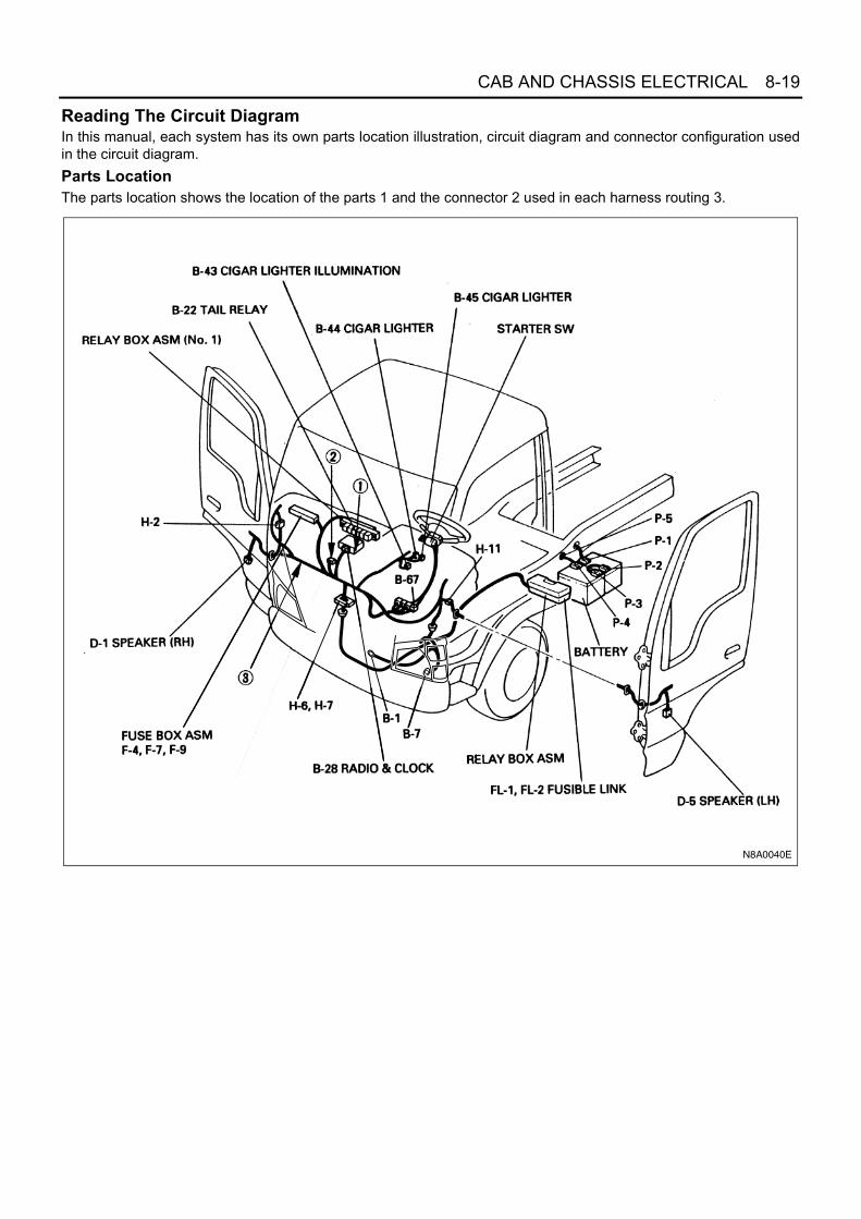
CAB AND CHASSIS ELECTRICAL 8-19
Reading The Circuit DiagramIn this manual, each system has its own parts location illustration, circuit diagram and connector configuration usedin the circuit diagram.Parts LocationThe parts location shows the location of the parts 1 and the connector 2 used in each harness routing 3.
N8A0040E

8-20 CAB AND CHASSIS ELECTRICAL
Circuit DiagramThe circuit diagram shows the power supply 4 the load or loads 5 and the grounding point(s) 6.
N8A5040E

CAB AND CHASSIS ELECTRICAL 8-21
Connector ListThe connector list shows each connectors' configuration 7 and the pin number 8.
Connector Symbol
Connector Symbol Harness name Connector
Symbol Harness name
B Body harness L Dome Light harness
D Door harness N Floor harness (LH & RH)
E Engine harness P Battery harness
H For joint between harnesses R Rear body harness
J Front frame & Rear frame harness
B-341
B-232
B-51
B-52
No. Connector Face
002-009
1
2
002-009
1
2
014-001
1 2 3 4 5 6 7 8 9 1011121314
012-003
1 2 3 4 5 6
7 8 9 10 11 12
E-5
E-16
E-110
E-76
No. Connector Face
000-009
002-014
1 2
009-003
16
27
34
859
1
3
2
4
78
N8A0430E

8-22 CAB AND CHASSIS ELECTRICAL
MAIN DATA AND SPECIFICATIONSBulb Specifications
Light Name Rated Power No. of Bulb Lens Color Remarks
Halogen Headlight60 W / 55 W 2
Clear12 V
75 W / 70 W 2 24 V
Front combi-nation light
Turn signal light 21 W 2 Amber 12 V, 24 V
Cornering light / Clearance light 21 W / 5 W 2 Clear 12 V, 24 V
Fog lightFront
55 W2 Clear
12 V
70 W 24 V
Rear 21 W 1 Red 12 V, 24 V
Rearcombinationlight
Stoplight / Taillight 21 W / 5 W 2 Red 12 V, 24 V
Turn signal light 21 W 2 Amber 12 V, 24 V
Backup light 21 W 2 Clear 12 V, 24 V
License plate light 5 W 1 Clear 12 V, 24 V
Dome light 10 W 1 White 12 V, 24 V
Roof marker light 5 W 2 White 24 V
Side turn signal light 21 W 2 Amber 24 V
Dome light
License plate light
Backup light
Stoplight/Taillight
Turn signallight
Turn signal light
Cornering light / Clearance lightFog light
Headlight
N8A0475E

CAB AND CHASSIS ELECTRICAL 8-23
Light NameRated Power
No. of Bulb RemarksExcept 4HK1-TC 4HK1-TC
Indicator /WarningLight(In the meterassembly)
Glow1.4 W —
112 V
1.4 W 1.8 W 24 V
Engine oil pressure1.4 W —
112 V
1.4 W 1.8 W 24 V
Fuel sedimenter1.4 W —
112 V
1.4 W 1.8 W 24 V
Brake fluid level / Parking brake1.4 W —
112 V
1.4 W 1.8 W 24 V
Charge1.4 W —
112 V
1.4 W 1.8 W 24 V
Exhaust brake 2 W — 1 12 V
High beam1.4 W —
112 V
1.4 W 1.8 W 24 V
Turn signal1.4 W —
112 V
1.4 W 1.8 W 24 V
Fuel level2 W —
112 V
1.8 W 1.8 W 24 V
Seat belt2 W —
112 V
1.8 W 1.8 W 24 V
4WD 1.8 W 1.8 W 1 24 V
Rear fog1.4 W —
112 V
1.4 W 1.8 W 24 V
Brake booster1.4 W —
112 V
1.4 W 1.8 W 24 V
ABS1.4 W —
112 V
1.4 W 1.8 W 24 V
Check engine1.4 W —
112 V
1.4 W 1.8 W 24 V
P.T.O.1.4 W —
112 V
1.4 W 1.8 W 24 V
Smoother — LED 1 24 V
1st start — LED 1 24 V
ECONO — LED 1 24 V
ASR — 1.8 W 1 24 V

8-24 CAB AND CHASSIS ELECTRICAL
Illumination
Illumination light for meterassembly
3.4 W1
12 V
3 W 24 V
Hazard warning Switch2 W
112 V
1.8 W 24 V
Dome light switch2 W
112 V
1.8 W 24 V
Front fog light switch2 W
112 V
1.8 W 24 V
Rear fog lightswitch
For indicator 60 mA 112 V
For illumination 60 mA 1
Cigar lighter1.4 W
112 V
1.8 W 24 V
Heater bezel 1.4 W 1
Ashtray 1.4 W 1
Light NameRated Power
No. of Bulb RemarksExcept 4HK1-TC 4HK1-TC

CAB AND CHASSIS ELECTRICAL 8-25
Fuse and Fusible Link LocationFuse and Circuit Breaker
Fuse Label-for 12 Volt (4JB1)
Relay box(Installed on the left side rear of the cab)
Fuse label
Relay box No. 2
Fuse( )F-1 F-24
Fuse pullerSpare fuse
-
Fuse( )F-25 F-28-
Fuse( )F-29 F-31-
N8A0531E
10 A(1) AIR CON
15 A(2) EXH. BRAKE, FUEL HEATER
15 A(3) REAR HEATER
15 A(4) AUDIO (B), DOOR LOCK
10 A(5) STOP LIGHT
10 A(6) FRT FOG LIGHT, CORNERING LAMP
10 A(7) TAIL LIGHT
10 A(8) EGR
10 A(9) FUEL CUT
15 A(10) FRONT WIPER & WASHER
10 A(11) TURN LIGHT
10 A(12) H/LAMP LEVEL
(13) —
(14) —
15 A(15) AUDIO (IG), CIGAR LIGHTER
10 A(16) METER
(17) —
(18) —
15 A(19) HORN, HAZARD
10 A(20) ABS (IG)
15 A(21) GENERATOR
10 A(22) STARTER
10 A(23) HEAD LIGHT RH

8-26 CAB AND CHASSIS ELECTRICAL
Fuse Label-for 12 Volt (4HG1 / 4HE1)Fuse Label-for 12 Volt (4JH1)
10 A(24) HEAD LIGHT LH
15 A(25) MARKER LAMP
15 A(26) COND. FAN
10 A(27) RR FOG
(28) —
10 A(1) AIR CON
15 A(2) EXH. BRAKE
(3) —
15 A(4) AUDIO (B), DOOR LOCK
10 A(5) STOP LIGHT
(6) —
10 A(7) TAIL LIGHT
10 A(8) FRT FOG LIGHT, CORNERING LAMP
10 A(9) ENG.(IG)
15 A(10) FRONT WIPER & WASHER
10 A(11) TURN LIGHT
(12) —
10 A(13) ENG. STOP
(14) —
15 A(15) AUDIO (IG), CIGAR LIGHTER
10 A(16) METER
(17) —
(18) —
15 A(19) ENG.(B)
15 A(20) HORN, HAZARD
(21) —
10 A(22) STARTER
10 A(23) HEAD LIGHT RH
10 A(24) HEAD LIGHT LH
15 A(25) MARKER LAMP
(26) —
10 A(27) RR FOG
(28) —
10 A(1) AIR CON
15 A(2) FUEL HEATER
15 A(3) REAR HEATER
15 A(4) AUDIO (B), DOOR LOCK
10 A(5) STOP LIGHT
10 A(6) FRT FOG LIGHT, CORNERING LAMP
10 A(7) TAIL LIGHT
15 A(8) ENG.(B1)
15 A(9) ENG.(B2)
15 A(10) FRONT WIPER & WASHER
10 A(11) TURN LIGHT
10 A(12) H/LAMP LEVEL
(13) —
(14) —
15 A(15) AUDIO (IG), CIGAR LIGHTER
10 A(16) METER
(17) —
(18) —
15 A(19) HORN, HAZARD
10 A(20) ABS (IG)

CAB AND CHASSIS ELECTRICAL 8-27
Fuse Label-for 24 Volt (4HF1 / 4HG1 / 4HE1)
Fuse Label-for 24 Volt (4HK1)
(21) —
10 A(22) STARTER
10 A(23) HEAD LIGHT RH
10 A(24) HEAD LIGHT LH
15 A(25) MARKER LAMP
15 A(26) COND. FAN
10 A(27) RR FOG
(28) —
15 A(1) HEATER, AIR CON
10 A(2) EXH. BRAKE, FUEL HEATER
15 A(3) REAR HEATER
15 A(4) AUDIO (B), DOOR LOCK
10 A(5) STOP LIGHT
20 A(6) POWER WINDOW
10 A(7) TAIL LIGHT
10 A(8) FRT FOG LIGHT, CORNERING LAMP
10 A(9)
ENG. (IG)
FUEL CUT
15 A(10) FRONT WIPER & WASHER
10 A(11) TURN LIGHT
10 A(12) H/LAMP LEVEL
10 A(13) ENG. STOP
(14) —
15 A(15) AUDIO (IG), CIGAR LIGHTER
10 A(16) METER
(17) —
15 A(18) GENERATOR
15 A(19) ENG. (B)
15 A(20) HORN, HAZARD
10 A(21) ABS (IG)
10 A(22) STARTER
10 A(23) HEAD LIGHT RH
10 A(24) HEAD LIGHT LH
15 A(25) MARKER LAMP
15 A(26) COND. FAN
10 A(27) RR FOG
(28) —
20 A(29) PTO
10 A(30) PTO
10 A(31) PTO
15 A(1) HEATER, AIR CON
10 A(2) FUEL HEATER
15 A(3) REAR HEATER
15 A(4) AUDIO (B), DOOR LOCK
10 A(5) STOP LIGHT
20 A(6) POWER WINDOW
10 A(7) TAIL LIGHT
10 A(8) FRT FOG LIGHT
10 A(9) ENG. (IG)
15 A(10) FRONT WIPER & WASHER

8-28 CAB AND CHASSIS ELECTRICAL
Notice:The fuse numbers (1) — (31) indicated on the fuse la-bels are expressed as — in the circuit dia-grams of this manual.
10 A(11) TURN LIGHT
10 A(12) H/LAMP LEVEL
10 A(13) NEES (B)
(14) —
15 A(15) AUDIO (IG), CIGAR LIGHTER
10 A(16) METER
10 A(17)
NEES (IG)
HSA
10 A(18) SRS
10 A(19) ENG. (BACK UP) HSA
15 A(20) HORN, HAZARD
10 A(21) ABS (IG)
10 A(22) STARTER
10 A(23) HEAD LIGHT RH
10 A(24) HEAD LIGHT LH
15 A(25) MARKER LAMP
15 A(26) COND. FAN
10 A(27) RR FOG
10 A(28) ECM. ENG.
F-1 F-31

CAB AND CHASSIS ELECTRICAL 8-29
Fusible Link
For 12 Volt (4JB1)
For 12 Volt (4HG1 / 4HE1)
Relay box(Installed on the left side rear of the cab)
1
Fusible link
Fusible link
2 3 4 5
6 7 8 9
26
FU
SE
PU
LLER
25
N8A0047E
100 A(1) MAIN
50 A(2) KEY
60 A(3) GLOW
30 A(4) HEAD LAMP
(5) —
(6) —
(7) —
60 A(8) STARTER
60 A(9) ABS
30 A(25) HEATER
30 A(26) POWER WINDOW
100 A(1) MAIN
50 A(2) KEY
60 A(3) GLOW
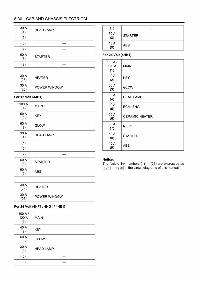
8-30 CAB AND CHASSIS ELECTRICAL
For 12 Volt (4JH1)
For 24 Volt (4HF1 / 4HG1 / 4HE1)
For 24 Volt (4HK1)
Notice:The fusible link numbers (1) — (26) are expressed as
— in the circuit diagrams of this manual.
30 A(4) HEAD LAMP
(5) —
(6) —
(7) —
60 A(8) STARTER
(9) —
30 A(25) HEATER
30 A(26) POWER WINDOW
100 A(1) MAIN
50 A(2) KEY
60 A(3) GLOW
30 A(4) HEAD LAMP
(5) —
(6) —
(7) —
60 A(8) STARTER
60 A(9) ABS
30 A(25) HEATER
30 A(26) POWER WINDOW
100 A / 120 A
(1)MAIN
40 A(2) KEY
60 A(3) GLOW
30 A(4) HEAD LAMP
(5) —
(6) —
(7) —
60 A(8) STARTER
40 A(9) ABS
100 A / 120 A
(1)MAIN
40 A(2) KEY
60 A(3) GLOW
30 A(4) HEAD LAMP
40 A(5) ECM. ENG.
60 A(6) CERAMIC HEATER
60 A(7) NEES
60 A(8) STARTER
40 A(9) ABS
FL-1 FL-26

CAB AND CHASSIS ELECTRICAL 8-31
Fuse Block CircuitFor 12 Volt-4JB1 Engine
HEATER &A/C RELAY
10A
HEAD LIGHT LHF-24
10A
HEAD LIGHT RHF-23
10A
STARTERF-22
15A
GENERATORF-21
10A
ABS (IG)F-20
15A
HORN, HAZARDF-19
F-18
F-17
10A
METERF-16
15A
AUDIO (IG), CIGAR LIGHTERF-15
F-14
F-13
10A
H/LAMP LEVELF-12
10A
TURN LIGHT
15A
F-11
15A
FRONT WIPER & WASHERF-10
10A
FUEL CUTF-9
10A
EGRF-8
10A
TAIL LIGHTF-7
F-2510A
FRT FOG LIGHT, CORNERING LAMPF-6
10A
STOP LIGHTF-5
15A
AUDIO (B), DOOR LOCKF-4
15A
REAR HEATERF-3
15A
EXH. BRAKE, FUEL HEATERF-2
10A
AIR CONF-1
30A
POWER WINDOW
FL-26
30AHEAD LAMP
FL-4
30A
FL-25
HEATER
INDICATION ON LABEL
INDICATION ON LABEL
KEY ONRELAY
EXH.BRAKERELAY
TAILRELAY
HEAD LIGHTRELAY
COMBINATION SWITCH
STARTER
STARTERRELAY
CONDENSER FAN
ABS UNIT
GLOW PLUG
GLOW PLUGRELAY
CONDENSER FANRELAY
KEY SW OFF
ACCON
ST
60AGLOW
FL-3
60AABS
FL-9
60ASTARTER
FL-8
50AKEY
FL-2
REAR FOGRELAY
REAR FOG
COMBINATIONSWITCH
CHARGEWARNING
RELAY
MARKER LIGHT
100AMAIN
FL-1
MARKERLIGHTRELAY
15AF-26
10AF-27
F-28
GENERATOR
GENERATOR B
RR FOG
COND. FAN
MARKER LAMP
N8A0506E

8-32 CAB AND CHASSIS ELECTRICAL
For 12 Volt-4HG1 / 4HE1 Engine
HEATER &A/C RELAY
10A
HEAD LIGHT LHF-24
10A
HEAD LIGHT RHF-23
10A
STARTERF-22
F-21
15A
HORN, HAZARDF-20
15A
ENG. (B)F-19
F-18
F-17
10A
METERF-16
15A
AUDIO (IG), CIGAR LIGHTER
ENG. STOP
F-15
F-14
F-13 10A
F-12
10A
15A
F-11
15A
FRONT WIPER & WASHERF-10
10A
ENG. (IG)F-9
10A
FRT FOG LIGHT, CORNERING LAMPF-8
10A
TAIL LIGHT
TURN LIGHT
F-7
F-25F-6
10A
STOP LIGHTF-5
15A
AUDIO (B), DOOR LOCKF-4
F-3
15A
EXH. BRAKEF-2
10A
AIR CONF-1
30A
POWER WINDOW
FL-26
30AHEAD LAMP
FL-4
30A
FL-25
HEATER
INDICATION ON LABEL
INDICATION ON LABEL
KEY ONRELAY
EXH.BRAKERELAY
TAILRELAY
HEAD LIGHTRELAY
COMBINATION SWITCH
STARTER
STARTERRELAY
GLOW PLUG
GLOW PLUGRELAY
KEY SW OFF
ACCON
ST
60AGLOW
FL-3
FL-9
60ASTARTER
FL-8
50AKEY
FL-2
REAR FOGRELAY
REAR FOG
COMBINATIONSWITCH
CHARGEWARNING
RELAY
MARKER LIGHT
100AMAIN
FL-1
MARKERLIGHTRELAY
F-26
10AF-27
F-28
GENERATOR
GENERATOR B
RR FOG
MARKER LAMP
N8A0507E

CAB AND CHASSIS ELECTRICAL 8-33
For 12 Volt-4JH1 Engine
HEATER &A/C RELAY
10A
HEAD LIGHT LHF-24
10A
HEAD LIGHT RHF-23
10A
STARTERF-22
F-21
10A
ABS (IG)F-20
15A
HORN, HAZARDF-19
F-18
F-17
10A
METERF-16
15A
AUDIO (IG), CIGAR LIGHTERF-15
F-14
F-13
10A
H/LAMP LEVELF-12
10A
TURN LIGHT
15A
F-11
15A
FRONT WIPER & WASHERF-10
15A
ENG. (B2)F-9
15A
ENG. (B1)F-8
10A
TAIL LIGHTF-7
F-2510A
FRT FOG LIGHT, CORNERING LAMPF-6
10A
STOP LIGHTF-5
15A
AUDIO (B), DOOR LOCKF-4
15A
REAR HEATERF-3
15A
FUEL HEATERF-2
10A
AIR CONF-1
30A
POWER WINDOW
FL-26
30AHEAD LAMP
FL-4
30A
FL-25
HEATER
INDICATION ON LABEL
INDICATION ON LABEL
KEY ONRELAY
HEATERRELAY
TAILRELAY
HEAD LIGHTRELAY
COMBINATION SWITCH
STARTER
STARTERRELAY
CONDENSER FAN
ABS UNIT
GLOW PLUG
GLOW PLUGRELAY
CONDENSER FANRELAY
KEY SW OFF
ACCON
ST
60AGLOW
FL-3
60AABS
FL-9
60ASTARTER
FL-8
50AKEY
FL-2
REAR FOGRELAY
REAR FOG
COMBINATIONSWITCH
CHARGEWARNING
RELAY
MARKER LIGHT
100AMAIN
FL-1
MARKERLIGHTRELAY
15AF-26
10AF-27
F-28
GENERATOR
GENERATOR B
RR FOG
COND. FAN
MARKER LAMP
N8A0508E

8-34 CAB AND CHASSIS ELECTRICAL
For 24 Volt-4HF1 / 4HG1 / 4HE1 Engine
HEATER &A/C RELAY
10A
HEAD LIGHT LHF-24
10A
HEAD LIGHT RHF-23
10A
10A
20A
STARTERF-22
F-31
F-30
F-29
10A
ABS (IG)
PTO
PTO
PTO
10A
F-21
15A
HORN, HAZARDF-20
15A
ENG. (B)
GENERATOR15A
F-19
F-18
F-17
10A
METER
ENG. STOP
F-16
15A
AUDIO (IG), CIGAR LIGHTERF-15
F-14
F-13
10A
H/LAMP LEVEL10A
F-12
10A
TURN LIGHT
15A
F-11
15A
FRONT WIPER & WASHERF-10
10A ENG. (IG)FUEL CUT
F-9
10A
FRT FOG LIGHT, CORNERING LAMPF-8
10A
TAIL LIGHTF-7
F-2520A
POWER WINDOWF-6
10A
STOP LIGHTF-5
15A
AUDIO (B), DOOR LOCKF-4
15A
REAR HEATERF-3
10A
EXH. BRAKE, FUEL HEATERF-2
15A
HEATER, AIR CONF-1
FL-26
30AHEAD LAMP
FL-4
FL-25
INDICATION ON LABEL
INDICATION ON LABEL
KEY ONRELAY
EXH.BRAKERELAY
TAILRELAY
HEAD LIGHTRELAY
COMBINATIONSWITCH
STARTER
STARTERRELAY
CONDENSER FAN
ABS UNIT
GLOW PLUG
GLOW PLUGRELAY
CONDENSER FANRELAY
KEY SW OFF
ACCON
ST
60AGLOW
FL-3
40AABS
FL-9
60ASTARTER
FL-8
40AKEY
FL-2
REAR FOGRELAY
COMBINATIONSWITCH
CHARGEWARNING
RELAY
100A or 120AMAIN
FL-1
MARKERLIGHTRELAY
15AF-26
10AF-27
F-28
GENERATOR
GENERATOR B
RR FOG
COND. FAN
MARKER LAMP
REAR FOG
MARKER LIGHT
N8A0509E

CAB AND CHASSIS ELECTRICAL 8-35
For 24 Volt-4HK1 Engine
HEATER &A/C RELAY
10A
HEAD LIGHT LHF-24
10A
HEAD LIGHT RHF-23
10A
STARTERF-22
10AABS (IG)
F-21
15AHORN, HAZARD
F-20
10A
ENG. (BACK UP) HSAF-19
F-18
F-17
10A
METER
NEES (B)
SRS
F-16
15AAUDIO (IG), CIGAR LIGHTER
F-15
F-14
F-13
10AH/LAMP LEVEL
10A
F-12
10ATURN LIGHT
15A
F-11
15AFRONT WIPER & WASHER
F-10
10AF-9
10A
FRT FOG LIGHTF-8
10A
TAIL LIGHT
ENG. (IG)
F-7
F-2520A
POWER WINDOWF-6
10A
STOP LIGHTF-5
15A
AUDIO (B), DOOR LOCKF-4
15A
REAR HEATERF-3
10A
FUEL HEATERF-2
15A
HEATER, AIR CONF-1
FL-26
30AHEAD LAMP
FL-4
FL-25INDICATION ON LABEL
INDICATION ON LABEL
NEES (IG)HSA
KEY ONRELAY
HEATERRELAY
TAILRELAY
HEAD LIGHTRELAY
COMBINATION SWITCH
STARTER
STARTERRELAY
CONDENSER FAN
ABS UNIT
GLOW PLUG
GLOW PLUGRELAY
CONDENSER FANRELAY
KEY SW OFF
ACCON
ST
60AGLOW
FL-3
40AABS
FL-9
60ASTARTER
FL-8
40AKEY
FL-2
REAR FOGRELAY
COMBINATIONSWITCH
CHARGEWARNING
RELAY
100A or 120AMAIN
FL-1
MARKERLIGHTRELAY
15AF-26
10AF-27
F-28
GENERATOR
GENERATOR B
RR FOG
ECM. ENG.
COND. FAN
MARKER LAMP
METER(BOOST IND)
10A
10A
ECM
ECM
ECM MAINRELAY
ECM
40AECM. ENG.
FL-5
STARTER CUTRELAY
ECMECM
NEUTRAL SWITCH
TCM
GEAR SHIFTERRELAY
TCM
60ANEES
FL-7
CERAMIC HEATER60A
CERAMIC HEATER
FL-6
REAR FOG
MARKER LIGHT
N8A0510E

8-36 CAB AND CHASSIS ELECTRICAL
Reference Table of Fuse and Circuit BreakerFuse12 Volt 4JB1 Engine
Fuse No. Capacity Indication on label Main parts (Load)
F-1 10 A AIR CON A/C switch, A/C thermo relay, Pressure switch, Magneticclutch, VSV: FICD, Electronic thermostat
F-2 15 A EXH. BRAKE, FUEL HEATER
Exhaust brake switch, Exhaust brake control relay, Exhaustbrake magnetic valve, Clutch switch, Accel switch, Fuel heater
F-3 15 A REAR HEATER Rear heater, Rear heater switch
F-4 15 A AUDIO (B), DOOR LOCK
Radio & clock, Dome light switch, Dome light, Door switch(RH & LH), Door lock switch, Door lock actuator, Door lockcontroller, Speedometer, Key cylinder switch, Key remindbuzzer
F-5 10 A STOP LIGHT Stoplight switch, Stoplight
F-6 10 A FRT FOG LIGHT, CORNERING LAMP
Fog light switch, Fog light, Lighting switch, Cornering lightrelay, Cornering light, Cornering light switch
F-7 10 A TAIL LIGHT Tail relay, Illumination light(s), Clearance light(s), Tail light(s)
F-8 10 A EGR ECM ignition
F-9 10 A FUEL CUT Fuel cut solenoid
F-10 15 A FRONT WIPER & WASHER
Wiper & Washer switch, Wiper motor, Washer motor, Intermit-tent relay
F-11 10 A TURN LIGHT Flasher unit, Front turn signal light, Rear turn signal light, Turnsignal light switch, Hazard warning switch
F-12 10 A H/LAMP LEVEL Headlight leveling switch, Headlight leveling motor (actuator)
F-13 — — —
F-14 — — —
F-15 15 A AUDIO (IG), CIGAR LIGHTER Radio, Cigar lighter
F-16 10 A METER
Exhaust brake control relay, CSD Relay, Key remind buzzer,Backup light switch, Backup light, Neutral switch, Starter relay,QOS-II controller, QOS-III controller, Glow relay, Glow-1 relay,Glow-2 relay, Glow indicator (Meter), Coolant temperaturegauge, Thermo unit, Vehicle speed sensor (Installed on themeter assembly & Transmission), Meter assembly, Powerwindow relay, Cornering light relay
F-17 — — —
F-18 — — —
F-19 15 A HORN, HAZARD Horn, Horn relay, Horn switch, Flasher unit, Hazard warningswitch
F-20 10 A ABS (IG) ABS
F-21 15 A GENERATOR Generator
F-22 10 A STARTER Starter relay, QOS-II controller, QOS-III controller
F-23 10 A HEAD LIGHT RH Headlight (RH), Dimmer relay, High beam indicator light
F-24 10 A HEAD LIGHT LH Headlight (LH), Dimmer relay
F-25 15 A MARKER LAMP Marker light, Marker light relay
F-26 15 A COND. FAN Condenser fan
F-27 10 A RR FOG Rear fog light switch, Rear fog light relay

CAB AND CHASSIS ELECTRICAL 8-37
12 Volt 4HG1 / 4HE1 Engine
F-28 — — —
Fuse No. Capacity Indication on label Main parts (Load)
F-1 10 A AIR CON A/C switch, A/C thermo relay, Pressure switch, Magneticclutch, VSV: FICD, Electronic thermostat
F-2 15 A EXH. BRAKE Exhaust brake switch, Exhaust brake control relay, Exhaustbrake magnetic valve, Clutch switch, Accel switch
F-3 — — —
F-4 15 A AUDIO (B), DOOR LOCK
Radio & clock, Dome light switch, Dome light, Door switch(RH & LH), Door lock switch, Door lock actuator, Door lockcontroller, Speedometer, Key cylinder switch, Key remindbuzzer
F-5 10 A STOP LIGHT Stoplight switch, Stoplight
F-6 — — —
F-7 10 A TAIL LIGHT Tail relay, Illumination light(s), Clearance light(s), Tail light(s)
F-8 10 A FRT FOG LIGHT, CORNERING LAMP
Fog light switch, Fog light, Lighting switch, Cornering lightrelay, Cornering light, Cornering light switch
F-9 10 A ENG. (IG) ECM ignition
F-10 15 A FRONT WIPER & WASHER
Wiper & Washer switch, Wiper motor, Washer motor, Intermit-tent relay
F-11 10 A TURN LIGHT Flasher unit, Front turn signal light, Rear turn signal light, Turnsignal light switch, Hazard warning switch
F-12 — — —
F-13 10 A ENG. STOP Engine stop motor
F-14 — — —
F-15 15 A AUDIO (IG), CIGAR LIGHTER Radio, Cigar lighter
F-16 10 A METER
Exhaust brake control relay, CSD Relay, Key remind buzzer,Backup light switch, Backup light, Inhibitor switch, Neutralswitch, Starter relay, QOS-II controller, QOS-III controller,Glow relay, Glow-1 relay, Glow-2 relay, Glow indicator (Meter),Coolant temperature gauge, Thermo unit, Vehicle speed sen-sor (Installed on the meter assembly & Transmission), Meterassembly, Power window relay, Cornering light relay
F-17 — — —
F-18 — — —
F-19 15 A ENG. (B) ECM battery
F-20 15 A HORN, HAZARD Horn, Horn relay, Horn switch, Flasher unit, Hazard warningswitch
F-21 — — —
F-22 10 A STARTER Starter relay, Inhibitor switch, QOS-II controller, QOS-III con-troller
F-23 10 A HEAD LIGHT RH Headlight (RH), Dimmer relay, High beam indicator light
F-24 10 A HEAD LIGHT LH Headlight (LH), Dimmer relay
F-25 15 A MARKER LAMP Marker light, Marker light relay
Fuse No. Capacity Indication on label Main parts (Load)

8-38 CAB AND CHASSIS ELECTRICAL
12 Volt 4JH1 Engine
F-26 — — —
F-27 10 A RR FOG Rear fog light switch, Rear fog light relay
F-28 — — —
Fuse No. Capacity Indication on label Main parts (Load)
F-1 10 A AIR CON A/C switch, A/C thermo relay, Pressure switch, Magneticclutch, VSV: FICD, Electronic thermostat
F-2 15 A FUEL HEATER Fuel heater
F-3 15 A REAR HEATER Rear heater, Rear heater switch
F-4 15 A AUDIO (B), DOOR LOCK
Radio & clock, Dome light switch, Dome light, Door switch(RH & LH), Door lock switch, Door lock actuator, Door lockcontroller, Speedometer, Key cylinder switch, Key remindbuzzer
F-5 10 A STOP LIGHT Stoplight switch, Stoplight
F-6 10 A FRT FOG LIGHT, CORNERING LAMP
Fog light switch, Fog light, Lighting switch, Cornering lightrelay, Cornering light, Cornering light switch
F-7 10 A TAIL LIGHT Tail relay, Illumination light(s), Clearance light(s), Tail light(s)
F-8 15 A ENG. (B1) ECM battery
F-9 15 A ENG. (B2) ECM battery
F-10 15 A FRONT WIPER & WASHER
Wiper & Washer switch, Wiper motor, Washer motor, Intermit-tent relay
F-11 10 A TURN LIGHT Flasher unit, Front turn signal light, Rear turn signal light, Turnsignal light switch, Hazard warning switch
F-12 10 A H/LAMP LEVEL Headlight leveling switch, Headlight leveling motor (actuator)
F-13 — — —
F-14 — — —
F-15 15 A AUDIO (IG), CIGAR LIGHTER Radio, Cigar lighter
F-16 10 A METER
Exhaust brake control relay, CSD Relay, Key remind buzzer,Backup light switch, Backup light, Neutral switch, Starter relay,QOS-II controller, QOS-III controller, Glow relay, Glow-1 relay,Glow-2 relay, Glow indicator (Meter), Coolant temperaturegauge, Thermo unit, Vehicle speed sensor (Installed on themeter assembly & Transmission), Meter assembly, Powerwindow relay, Cornering light relay
F-17 — — —
F-18 — — —
F-19 15 A HORN, HAZARD Horn, Horn relay, Horn switch, Flasher unit, Hazard warningswitch
F-20 10 A ABS (IG) ABS
F-21 — — —
F-22 10 A STARTER Starter relay, QOS-II controller, QOS-III controller
F-23 10 A HEAD LIGHT RH Headlight (RH), Dimmer relay, High beam indicator light
F-24 10 A HEAD LIGHT LH Headlight (LH), Dimmer relay
F-25 15 A MARKER LAMP Marker light, Marker light relay
Fuse No. Capacity Indication on label Main parts (Load)

CAB AND CHASSIS ELECTRICAL 8-39
24 Volt 4HF1 / 4HG1 / 4HE1 Engine
F-26 15 A COND. FAN Condenser fan
F-27 10 A RR FOG Rear fog light switch, Rear fog light relay
F-28 — — —
Fuse No. Capacity Indication on label Main parts (Load)
F-1 15 A HEATER, AIR CONBlower motor, Blower resistor, Fan switch, A/C switch, A/Cthermo relay, Pressure switch, A/C cut relay, Thermo switch(A/C cut), VSV: FICD, Electronic thermostat
F-2 10 A EXH. BRAKE, FUEL HEATER
Exhaust brake switch, Exhaust brake control relay, Exhaustbrake magnetic valve, Clutch switch, Accel switch, Fuel heater
F-3 15 A REAR HEATER Rear heater, Rear heater switch
F-4 15 A AUDIO (B), DOOR LOCK
Radio & clock, Dome light switch, Dome light, Door switch(RH & LH), Door lock switch, Door lock actuator, Door lockcontroller, Speedometer, Key cylinder switch, Key remindbuzzer
F-5 10 A STOP LIGHT Stoplight switch, Stoplight
F-6 20 A POWER WINDOW Power window
F-7 10 A TAIL LIGHT Tail relay, Illumination light(s), Clearance light(s), Tail light(s)
F-8 10 A FRT FOG LIGHT, CORNERING LAMP
Fog light switch, Fog light, Lighting switch, Cornering lightrelay, Cornering light, Cornering light switch
F-9 10 AENG. (IG) ECM ignition (EXCEPT 4HF1-2)
FUEL CUT Fuel cut solenoid (4HF1-2)
F-10 15 A FRONT WIPER & WASHER
Wiper & Washer switch, Wiper motor, Washer motor, Intermit-tent relay
F-11 10 A TURN LIGHT Flasher unit, Front turn signal light, Rear turn signal light, Turnsignal light switch, Hazard warning switch
F-12 10 A H/LAMP LEVEL Headlight leveling switch, Headlight leveling motor (actuator)
F-13 10 A ENG. STOP Engine stop motor
F-14 — — —
F-15 15 A AUDIO (IG), CIGAR LIGHTER Radio, Cigar lighter
F-16 10 A METER
Exhaust brake control relay, CSD Relay, Key remind buzzer,Backup light switch, Backup light, Neutral switch, Starter relay,QOS-II controller, QOS-III controller, Glow relay, Glow-1 relay,Glow-2 relay, Glow indicator (Meter), Coolant temperaturegauge, Thermo unit, Vehicle speed sensor (Installed on themeter assembly & Transmission), Meter assembly, Powerwindow relay, Cornering light relay
F-17 — — —
F-18 15 A GENERATOR Generator
F-19 15 A ENG. (B) ECM battery (4HG1-T)
F-20 15 A HORN, HAZARD Horn, Horn relay, Horn switch, Flasher unit, Hazard warningswitch
F-21 10 A ABS (IG) ABS
F-22 10 A STARTER Starter relay, QOS-II controller, QOS-III controller
Fuse No. Capacity Indication on label Main parts (Load)

8-40 CAB AND CHASSIS ELECTRICAL
24 Volt 4HK1 Engine
F-23 10 A HEAD LIGHT RH Headlight (RH), Dimmer relay, High beam indicator light
F-24 10 A HEAD LIGHT LH Headlight (LH), Dimmer relay
F-25 15 A MARKER LAMP Marker light, Marker light relay
F-26 15 A COND. FAN Condenser fan
F-27 10 A RR FOG Rear fog light switch, Rear fog light relay
F-28 — — —
F-29 20 A PTO PTO main relay (Electronic control type PTO)
F-30 10 A PTO PTO cut relay (Electronic control type PTO)
F-31 10 A PTO PTO cut relay (Electronic control type PTO)
Fuse No. Capacity Indication on label Main parts (Load)
F-1 15 A HEATER, AIR CON
Blower motor, Blower resistor, Fan switch, A/C switch, A/Cthermo relay, Pressure switch, VSV: FICD, Electronic thermo-stat, A/C compressor, A/C thermo relay, Condenser fan, ECM(A/C compressor SIG.)
F-2 10 A FUEL HEATERExhaust brake magnetic valve, Clutch switch, Accel switch,Fuel heater, VSV: Intake throttle, ABS (Exhaust brake SIG.),Ceramic heater relay
F-3 15 A REAR HEATER Rear heater, Rear heater switch
F-4 15 A AUDIO (B), DOOR LOCK
Radio & clock, Dome light switch, Dome light, Door switch(RH & LH), Door lock switch, Door lock actuator, Door lockcontroller, Speedometer, Key cylinder switch, Key remindbuzzer, Side turn signal light(s)
F-5 10 A STOP LIGHT Stoplight switch, Stoplight, ABS (Stop on SIG.), ECM (brakeon SIG.)
F-6 20 A POWER WINDOW Power window
F-7 10 A TAIL LIGHT Tail relay, Illumination light(s), Clearance light(s), Tail light(s),Roof marker light, License light(s), Marker light relay
F-8 10 A FRT FOG LIGHT Fog light switch, Fog light, Lighting switch, Cornering lightrelay, Cornering light, Cornering light switch
F-9 10 A ENG. (IG)ECM (IG SIG.), Starter cut relay, ECM (Exhaust brake SIG.),Exhaust brake indicator, ECM (brake off SIG.), ECM (clutchon SIG.), ALDL connector
F-10 15 A FRONT WIPER & WASHER
Wiper & Washer switch, Wiper motor, Washer motor, Intermit-tent relay
F-11 10 A TURN LIGHTFlasher unit, Front turn signal light, Rear turn signal light, Turnsignal light switch, Hazard warning switch, Side turn signallight relay
F-12 10 A H/LAMP LEVEL Headlight leveling switch, Headlight leveling motor (actuator)
F-13 10 A NEES (B) Smoother
F-14 — — —
F-15 15 A AUDIO (IG), CIGAR LIGHTER Radio, Cigar lighter, Digital clock
Fuse No. Capacity Indication on label Main parts (Load)

CAB AND CHASSIS ELECTRICAL 8-41
F-16 10 A METER
CSD Relay, Key remind buzzer, Backup light switch, Backuplight, Neutral switch, Starter relay, QOS-II controller, Glowrelay, Glow indicator (Meter), Coolant temperature gauge,Thermo unit, Vehicle speed sensor (Installed on the meterassembly & Transmission), Meter assembly, Power windowrelay, Cornering light relay, Backup buzzer, ABS indicatorrelay, Charge relay, Heater A/C relay, VSV: 2WD (4WD), VSV:4WD (4WD), 4WD relay
F-17 10 ANEES (IG) Smoother (IGN SIG.)
HSA —
F-18 — SRS —
F-19 10 A ENG. (BACK UP) HSA ECM (Back up)
F-20 15 A HORN, HAZARD Horn, Horn relay, Horn switch, Flasher unit, Hazard warningswitch, Turn light(s), Side turn signal light relay
F-21 10 A ABS (IG) ABS (IGN SIG.)
F-22 10 A STARTER Starter relay, QOS-II controller
F-23 10 A HEAD LIGHT RH Headlight (RH), Dimmer relay, High beam indicator light
F-24 10 A HEAD LIGHT LH Headlight (LH), Dimmer relay
F-25 15 A MARKER LAMP Marker light, Marker light relay
F-26 15 A COND. FAN Condenser fan
F-27 10 A RR FOG Rear fog light switch, Rear fog light relay
F-28 10 A ECM. ENG. ECM
Fuse No. Capacity Indication on label Main parts (Load)

8-42 CAB AND CHASSIS ELECTRICAL
Relay Location
X-16 X-15 X-14 X-13
X-8 X-9 X-10 X-11 X-12X-7X-6X-5
Relay box No.2
Relay box No.1
X-28X-27X-26X-25X-24X-23X-22
X-21
X-20X-19X-18
Relay box(Installed on the left side rear of the cab)
X-4X-3X-1 X-2
N8A0054E

CAB AND CHASSIS ELECTRICAL 8-43
Relay List: Standard, : Option
X-1 X-2 X-3 X-4 X-5 X-6
Charge warning Key ON Horn Lamp Tail ABS
IND.Smoother
main Dimmer
12 V
NHR55 — — —
NKR55 — — —
NKR69 — — —
NPR71 — — —
NKR77 — —
NPR77 — —
NKR77 for Taiwan — — —
24 V
NKR66 — — —
NPR66 — —
NQR66 — —
NPR70 — — —
NQR70 — — —
NKR71 — — —
NQR71with turbocharger — —
NPS71 — — —
NPR71 — — —
NQR71w/o turbocharger — — —
NPR75 — —
NQR75 — —

8-44 CAB AND CHASSIS ELECTRICAL
* : Except EC / Turkey
X-7 X-8 X-9 X-10 X-11 X-12
Power window
Exh. brake Heater Corner-
ing lampThermo
A/CCharge warning Key ON Heater
& A/C
12 V
NHR55 — —
NKR55 — —
NKR69 — —
NPR71 — —
NKR77 — — —
NPR77 — — —
NKR77 for Taiwan — — —
24 V
NKR66 — —
NPR66 — —
NQR66 — —
NPR70 — —
NQR70 — —
NKR71 — —
NQR71with turbocharger — —
NPS71 — —
NPR71 — —
NQR71w/o turbocharger — —
NPR75 — * —
NQR75 — * —

CAB AND CHASSIS ELECTRICAL 8-45
X-13 X-14 X-15 X-16
Heater Buzzer cancel ECM PTO
main TimingSmoother
emer-gency
PTO solenoid,
M/TPTO cut
12 V
NHR55 — — — — — — — —
NKR55 — — — — — — — —
NKR69 — — — — — — — —
NPR71 — — — — — — — —
NKR77 — — — — — —
NPR77 — — — — — —
NKR77 for Taiwan — — — — — —
24 V
NKR66 — — — — — — — —
NPR66 — — — — — — —
NQR66 — — — — — — —
NPR70 — — — — — —
NQR70 — — — — — —
NKR71 — — — — — — — —
NQR71with turbocharger — — — — — — —
NPS71 — — — — —
NPR71 — — — — — — —
NQR71w/o turbocharger — — — — — — —
NPR75 — — — — —
NQR75 — — — — —

8-46 CAB AND CHASSIS ELECTRICAL
*1 : For EC*2 : For Turkey*3 : For EC / Turkey
X-18 X-19 X-20 X-21 X-22 X-23 X-24
ECM main
Gear shifter Glow 2 Glow
plug Starter Marker lamp Rear fog A/C
COMP
12 V
NHR55 — — — — — —
NKR55 — — — — —
NKR69 — — — — —
NPR71 — — — — — —
NKR77 — — — *1 *1
NPR77 — — — *1 *1
NKR77 for Taiwan — — — — —
24 V
NKR66 — — — — — —
NPR66 — — — *2 *2 —
NQR66 — — — — — —
NPR70 — — — — — —
NQR70 — — — — — —
NKR71 — — — — — —
NQR71with turbocharger — — — *2 *2 —
NPS71 — — — — — —
NPR71 — — — — — —
NQR71w/o turbocharger — — — — — —
NPR75 — *3 *3 —
NQR75 — *3 *3 —

CAB AND CHASSIS ELECTRICAL 8-47
X-24 X-25 X-26 X-27 X-28
4WD ind. lamp
Exh. brake control
CSD A/C ON SIGNAL
Starter cut
Con-denser
fan
Exh. brake
cut
12V
NHR55 — — — — —
NKR55 — — — — —
NKR69 — — — — — —
NPR71 — — — — — —
NKR77 — — — — — —
NPR77 — — — — — —
NKR77 for Taiwan — — — — —
24V
NKR66 — — — — — —
NPR66 — — — — —
NQR66 — — — — —
NPR70 — — — — —
NQR70 — — — — —
NKR71 — — — — — —
NQR71with turbocharger — — — — —
NPS71 — — — — —
NPR71 — — — — —
NQR71w/o turbocharger — — — — — —
NPR75 — — — — —
NQR75 — — — — —

8-48 CAB AND CHASSIS ELECTRICAL
Diode Location
Connector No. B-17 B-18 B-25 J-23 L-1 L-3
Usage A/CDoor switch Lighting
QOS-III(Except GCC and Taiwan)
VSV: FICD(Except GCC and Taiwan)
Dome lightDome light(Except Tai-
wan)
N8A0055E

CAB AND CHASSIS ELECTRICAL 8-49
Reference Table of Grounding PointNotice:Abnormal phenomena of electrical components are considered resulted from defective grounding.In repair, be sure to inspect grounding points and to tighten all fastening parts surrounding the grounding points.
Grounding Point Location
Connector No. Cable harness name Location Main parts (Load)
B-1
Body harness
Frame-LH (FRT)Vehicle speed sensor, QOS-III control unit, Turn signalindicator light, Meter, High beam indicator light, PTOlever, TCM
B-7 Headlightbracket-LH
Charge relay, Exhaust brake relay, QOS-II control unit,QOS-III control unit, Dome light switch, Key remind andback up buzzer, Meter, Brake fluid switch, Tail relay,Cornering light switch, Cornering light, Cornering lightrelay, Fog light switch, Fog light, Dimmer relay, Doorlock switch, Door lock relay, Power window switch(RH), Power window relay, Stoplight switch, Mirrorswitch, Wiper motor, Washer motor intermittent relay,Radio, Cigar lighter, Heater & A/C relay, Fan switch,Horn relay, Rear heater switch, Rear heater, Radio &clock, Cigar lighter, Fan switch, Blower resistor, A/Cswitch, Blower motor, Electronic thermostat, Accelswitch, Door lock switch, Door lock controller, Headlightleveling switch, Headlight leveling motor, Power win-dow relay, Power window switch, QOS-III control unit,Ceramic heater relay, Emergency relay, Select switch,Emergency adjust switch, PTO-Smoother switch
J-9 Frame front har-ness Frame-LH (CTR)
Marker light relay, Marker light, Water sedimenterswitch, Fuel tank unit, Starter relay, Neutral switch, Fuelheater, Pressure switch, A/C thermo relay, VSV: FICD,Exhaust brake control relay, Exhaust brake magneticvalve, Accel switch, Clutch switch, VSV: intake throttle,Engine stop motor, ECM, ECM main relay, Starter cutrelay, Shift 1,3,5 solenoid, Shift 2,4,R solenoid, SelectsolenoidLicense plate light, Taillight, Rear fog light, Rear turnsignal light, Stoplight, Stoplight switch, Backup light
N8A5054E
B-7
N8A5055E

8-50 CAB AND CHASSIS ELECTRICAL
Cable Harness Routing
N8A5056E
FLOOR HARNESS (RH)
FLOOR HARNESS (LH)
N8A0060E

CAB AND CHASSIS ELECTRICAL 8-51
BODY HARNESS
DOOR HARNESS (RH)
DOME LIGHT HARNESS
DOOR HARNESS (LH)
N8A0061E

8-52 CAB AND CHASSIS ELECTRICAL
For Taiwan
RE
AR
FR
AM
E H
AR
NE
SS
FRO
NT
FR
AM
E H
AR
NE
SS
RE
AR
BO
DY
HA
RN
ES
S
N8A0062E

CAB AND CHASSIS ELECTRICAL 8-53
For GCC
RE
AR
FR
AM
E H
AR
NE
SS
FRO
NT
FR
AM
E H
AR
NE
SS
RE
AR
BO
DY
HA
RN
ES
S
N8A0063E
8-54 CAB AND CHASSIS ELECTRICAL
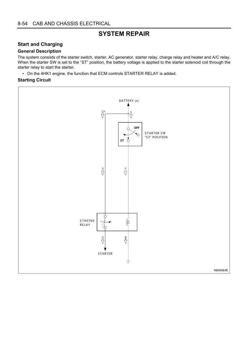
SYSTEM REPAIRStart and ChargingGeneral DescriptionThe system consists of the starter switch, starter, AC generator, starter relay, charge relay and heater and A/C relay.When the starter SW is set to the “ST” position, the battery voltage is applied to the starter solenoid coil through thestarter relay to start the starter.
• On the 4HK1 engine, the function that ECM controls STARTER RELAY is added.Starting Circuit
N8A0064E

CAB AND CHASSIS ELECTRICAL 8-55
Parts LocationFor 12 Volt
B-7
<4JB
1, 4
JG2>
N8A0065E

8-56 CAB AND CHASSIS ELECTRICAL
For 24 Volt
FU
SE
BO
X A
SM
F-1
6, F
-22
X-1
CH
AR
GE
RE
LAY
B-7
B-1
J-1,
J-2
GE
NE
RA
TO
R
FL-
1, F
L-2,
FL-
8 F
US
IBLE
LIN
KX
-21
ST
AR
TE
R R
ELA
YX
-26
ST
AR
TE
R C
UT
RE
LAY
(4H
K1)
N8A0066E

CAB AND CHASSIS ELECTRICAL 8-57
Circuit DiagramFor 4JB1, 4JB1-TC, 4JG2 Engine & 12 Volt
X-2
1X
-21
X-2
1
X-2
1
J-26
J-27
H-7
B
ST
AC
C
ON
B-6
7
B-6
7B
-67
H-1
4
H-1
4
X-1
1
X-1
1
X-1
1
H-5
X-1
4
H-5
X-1
1
E-1
7
E-1
8
E-1
8
E-1
8
B-7
J-9
P-1
P-2
P-5
1
1
12
32 4
5
3 4
8
1 3 4
5
2
11
15 10
1
23
1
30B
8B
3B/W
3W/B
3B/Y
3B/Y
0.3B/W
0.85
W
0.3B
0.3B
0.3B
0.5W
/R
0.5W
/R
0.5W
/R
0.5W
/R
1.25
B3B
0.85W/L
3W
0.85W
8 W
2B
0.5B
0.5B
/W
FRA
ME
ST
AR
TE
R
FL-1
100
AM
AIN
FL-2
50A
KE
Y S
W
FL-8
60A
ST
AR
TE
R
ST
AR
TE
R S
W
F-21
15A
GE
NE
RA
TO
R
RE
LAY
; CH
AR
GE
RE
LAY
; EX
HA
US
T
RE
LAY
; HE
AT
ER
& A
/C(2
)
BR
AK
E(2
)
CH
AR
GE
WA
RN
ING
LIG
HT
B-5
2 (
3)(M
ET
ER
)
QO
S II
I CO
NT
RO
LU
NIT
(6)
GE
NE
RA
TO
R
IGS
LB
HE
AD
LIG
HT
BR
AC
KE
T (
LH)
RE
LAY
; ST
AR
TE
R
F-22STARTER
10AQOS III CONTROL UNIT(11)QOS II CONTROL UNIT (4)
B
C
P-6
E-7
2
0.85W0.5W/L
B-1
5BFR
AM
E-L
H(F
RO
NT
)
FRA
ME
-LH
(CE
NT
ER
)
H-814
0.5B
/W
2L
2L
3W/B
FUS
E B
LOC
K
N8A0067E

8-58 CAB AND CHASSIS ELECTRICAL
For 4HG1-T Engine & 12 Volt
X-2
1X
-21
X-2
1
X-2
1
J-26
J-27
H-7
B
ST
AC
C
ON
B-6
7
B-6
7B
-67
H-1
4
H-1
4
X-1
1
X-1
1
H-5
X-1
1
H-5
X-1
1
E-1
7
E-1
8
E-1
8
E-1
8
J-9
P-1
P-2
P-5
1
1
12
32 4
5
3 4
8
3 4
5
2
11
15 10
1
23
1
30B
8B
3B/W
3W/B
3B/Y
3B/Y
0.3B/W
0.5B
/Y
0.5B
/Y
0.5B
/Y
0.5W
/R
0.5W
/R
0.5W
/R
0.5W
/R
0.85W/L
3W
0.85W
8W
2B
0.5B
0.5B
/W
FRA
ME
ST
AR
TE
R
FL-1
100
AM
AIN
FL-2
50A
KE
Y S
W
FL-8
60A
ST
AR
TE
R
ST
AR
TE
R S
W
F-16
10A
ME
TE
R
RE
LAY
; CH
AR
GE
RE
LAY
; EX
HA
US
T
RE
LAY
; HE
AT
ER
& A
/C(2
)
BR
AK
E(2
)
CH
AR
GE
WA
RN
ING
LIG
HT
B-5
2 (
3)(M
ET
ER
)
QO
S II
I CO
NT
RO
LU
NIT
(6)
GE
NE
RA
TO
R
IGS
LB
RE
LAY
; ST
AR
TE
R
F-22STARTER
10AQOS III CONTROL UNIT(11)QOS II CONTROL UNIT (4)
B
C
P-6
E-7
2
0.85W
FRA
ME
-LH
(CE
NT
ER
)
H-814
0.5B
/W
2L
2L
3W/B
FUS
E B
LOC
K
N8A0068E

CAB AND CHASSIS ELECTRICAL 8-59
For 4JH1 Engine & 12 Volt
X-2
1X
-21
X-2
1
X-2
1
J-26
J-27
H-7
ST
AC
C
ON
B-6
7
B-6
7B
-67
H-1
4
X-1
1
X-1
1
X-1
1
H-5
X-1
1
E-1
8
E-1
8
J-9
P-1
P-2
P-3
P-4
P-5
12
15 10
30B
8B
3B/W
3W/B
3W/B
3B/Y
3B/Y
0.3B/W
0.5B
/Y
0.5B
/Y
0.5W
/R
0.5W
/R
0.85W/L
3W
8W
2B
0.5B
0.5B
/W
FRA
ME
(12V
)
ST
AR
TE
R
FL-1
100
AM
AIN
FL-2
50A
KE
Y S
W
ST
AR
TE
R S
W
F-16
10A
ME
TE
RR
ELA
Y; C
HA
RG
E
ME
TE
R
RE
LAY
; FU
EL
RE
LAY
; HE
AT
ER
& A
/C(2
)
HE
AT
ER
(2)
GE
NE
RA
TO
R
RE
LAY
; ST
AR
TE
R
F-22STARTER
10A
P-6
E-7
2
0.85W/L0.85W/L
0.5W
/R
E-1
7
FRA
ME
-LH
(CE
NT
ER
)
H-814
43
4
2
53
0.5B
/W
2L
2L
FL-8
60A
ST
AR
TE
R
FUS
E B
LOC
K
1
2
2 4
3
5
1
1
N8A0069E

8-60 CAB AND CHASSIS ELECTRICAL
For 4JH1 Engine, NKR77 for Taiwan
X-2
1X
-21
X-2
1
X-2
1
J-26
J-27
H-7
B
ST
AC
C
ON
B-6
7
B-6
7B
-67
H-1
4
X-1
1
X-1
1
X-1
1
H-5
X-1
1
E-1
7E
-18
E-1
8
J-9
P-1
P-2
P-5
1
1
12
32 4
5
3 4
3 4
5
2 15 10
1
2
1
30B
8B
3B/W
8W3W
/B
3B/Y
3B/Y
0.5B
/Y
0.5W
/L
0.5W
/R
0.85W/L
8W/B
8W/B
3W/L
2B
0.5B
0.5B
/W
FRA
ME
ST
AR
TE
R
FL-1
100
AM
AIN
FL-2
50A
KE
Y S
W
FL-8
60A
ST
AR
TE
R
ST
AR
TE
R S
W
F-16
10A
ME
TE
R
RE
LAY
; CH
AR
GE
RE
LAY
; HE
AT
ER
& A
/C(2
)
CH
AR
GE
WA
RN
ING
LIG
HT
B-5
2 (
3)(M
ET
ER
)
GE
NE
RA
TO
R
S
LB
RE
LAY
; ST
AR
TE
R
F-22STARTER
10A
B
C
P-6
E-7
2
0.85W/L
0.5W
/L
FRA
ME
-LH
(CE
NT
ER
)
H-814
0.5B
/W
2L
2L
3W/B
FUS
E B
LOC
K
N8A0379E

CAB AND CHASSIS ELECTRICAL 8-61
Connector List For 12 Volt
No. Connector Face
X-11
B-67
B-67
E-17
E-18
E-18 (4JH1)
H-14
H-14
005-001
1
32 4
5
004-001
1 23 4
004-002
2
4
1
3
001-001
1
004-003
21
43
002-003
1 2
016-001
1 2 3 4
5 6 7 8
9 10 11 12
13 14 15 16
016-002
4 3 2 1
8 7 6 5
12 11 10 9
16 15 14 13
X-21
E-17 (4JH1)
J-26
P-6
J-27
P-1
P-4
P-2
No. Connector Face
005-003
1
2 3
54
000-002
000-002
000-002
001-002
1
000-004
000-004
000-006

8-62 CAB AND CHASSIS ELECTRICAL
H-5
H-6, H-7, H-8
P-3 (4JH1)
P-5
No. Connector Face
000-006
000-007
1 2 37 8 9
13 14 1519 20 2125 26 2731 32 33 34 35 36 37
4 5 610 11 1216 17 1822 23 2428 29 3038 39 40
6 5 412 11 1018 17 1624 23 2230 29 2840 39 38
3 2 19 8 715 14 1321 20 1927 26 2533 32 3134353637
N8A5488E
1 2
1 2
1 2 3 4
5 6 7 8
9 10 11 12 13
14 15 16 17 18
2 1
2 1
4 3 2 1
8 7 6 5
13 12 11 10 9
18 17 16 15 14
H - 6
H - 7
H - 8
N8A5489E

CAB AND CHASSIS ELECTRICAL 8-63
Circuit Diagram 4H Type Engine & 24 Volt (Except 4HK1 Engine)
X-1
X-1
H-5
X-1
X-1
J-1
J-2
B-6
7H
-7B
ST
AC
C
ON
J-26
B-6
7
B-6
7
H-8
X-2
1
X-2
1X
-21
X-2
1
J-9
P-1
P-2
P-3
P-4
P-5
1
23 4
3 4
5
2 15
11
14
2 4
3
1
1
5
J-1
2
30B
8B
3W/B
3B/W
3W/B(NPR70)
3B/Y
3W/B
3B/Y
2B
0.5B
0.5B
/W
5W
0.5W
/R
0.5W
/L
0.5W
/R
0.5B/W
FRA
ME
FL-1
100
A o
r 12
0AM
AIN
FL-2
40A
KE
Y S
W
FL-8
60A
ST
AR
TE
R
ST
AR
TE
R S
W
F-22 10ASTARTER
RE
LAY
; ST
AR
TE
R
ST
AR
TE
R
FRA
ME
-LH
(C
EN
TE
R)
BL
GE
NE
RA
TO
R
RE
LAY
; HE
AT
ER
&
A/C
(2)
RE
LAY
; CH
AR
GE
0.85W/LB
C
3W(NPR66/71)
P-6
QOS IICONTROL UNIT (4)
ME
TE
R
J-27
F-16
10A
RE
LAY
; EX
HA
US
TB
RA
KE
(2)
CH
AR
GE
WA
RN
ING
LI
GH
T B
-52
(3)
3W/B
0.85W/L
0.5B
0.5B
/W
2L
FUS
E B
LOC
K
N8A0070E

8-64 CAB AND CHASSIS ELECTRICAL
4HK1 Engine
X-1
X-1
H-5
X-1
X-1
J-1
J-2
B-6
7H
-7B
ST
AC
C
ON
J-26
B-6
7
B-6
7
H-8
X-2
1
X-2
1X
-21
X-2
1
P-1
P-2
P-3
P-4
P-5
1
23 4
4 3
1
5
15
11
14
3 4
2
1
1
5
J-1
2
30B
2B0.5B8B
3W/L
3B/W
3W/B
3B/Y
0.5B
/Y
3W/L
3B/Y
0.3B
/W
8W/B
1.25
W/L
0.5W
/R
0.5W
/L
0.3B/W
FR
AM
E
FL-
1 1
00A
or
120A
MA
INF
L-2
40A
KE
Y S
W
FL-
8 6
0AS
TA
RT
ER
ST
AR
TE
R S
W
F-22 10ASTARTER
RE
LAY
; ST
AR
TE
R
X-2
6
X-2
6X
-26
X-2
6
4 3
1
5
RE
LAY
;S
TA
RT
ER
CU
T
ST
AR
TE
R
FR
AM
E-L
H(C
EN
TE
R)
BL
GE
NE
RA
TO
R
RE
LAY
; CH
AR
GE
0.85W/L
B
C
P-6
QOS IICONTROL UNIT (4)
ME
TE
R
J-27
F-1
6 1
0A
RE
LAY
;H
EA
TE
R&
A/C
(2)
CH
AR
GE
WA
RN
ING
LI
GH
T B
-52
(3)
3W/L
0.5W/L
0.5R
/W
0.85
LG0.
5LG
0.5R
2L
FU
SE
BLO
CK
J-9
EC
M M
AIN
RE
LAY
EC
M
F-2
8 1
0AE
CM
N8A0521E
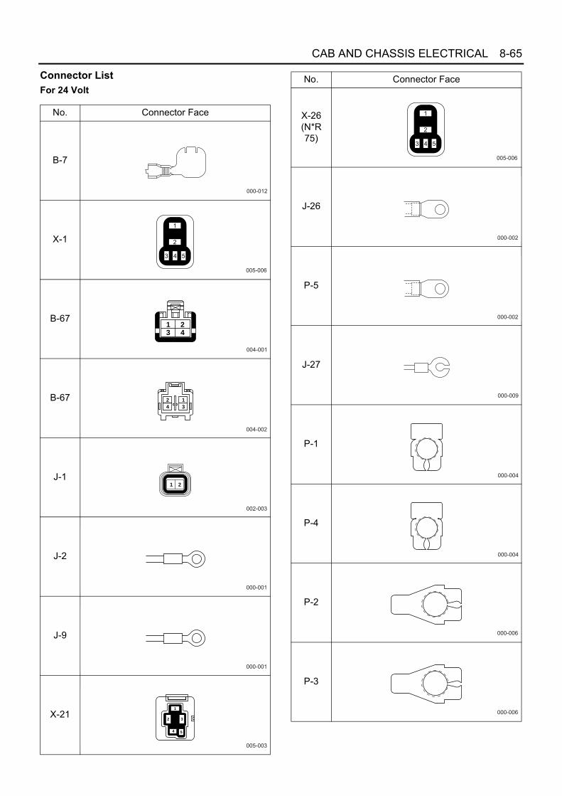
CAB AND CHASSIS ELECTRICAL 8-65
Connector List For 24 Volt
No. Connector Face
B-7
X-1
B-67
B-67
J-1
J-2
J-9
X-21
000-012
005-006
004-001
1 23 4
004-002
2
4
1
3
002-003
1 2
000-001
000-001
005-003
1
2 3
54
X-26 (N*R 75)
J-26
P-5
J-27
P-1
P-4
P-2
P-3
No. Connector Face
005-006
000-002
000-002
000-009
000-004
000-004
000-006
000-006

8-66 CAB AND CHASSIS ELECTRICAL
H-5
H-6, H-7, H-8
Starter SwitchThe starter switch positions are LOCK, ACC, ON andSTART. Turning the starter key to these positions a cir-cuit for starting the engine, the operation of accessories,or stop the engine.
P-6 (N*R 66)
No. Connector Face
000-008
1 2 37 8 9
13 14 1519 20 2125 26 2731 32 33 34 35 36 37
4 5 610 11 1216 17 1822 23 2428 29 3038 39 40
6 5 412 11 1018 17 1624 23 2230 29 2840 39 38
3 2 19 8 715 14 1321 20 1927 26 2533 32 3134353637
N8A5488E
1 2
1 2
1 2 3 4
5 6 7 8
9 10 11 12 13
14 15 16 17 18
2 1
2 1
4 3 2 1
8 7 6 5
13 12 11 10 9
18 17 16 15 14
H - 6
H - 7
H - 8
N8A5489E
N8A0072E

CAB AND CHASSIS ELECTRICAL 8-67
InspectionCheck the continuity between the starter switch connector terminals.Repair or replace the switch when the result of inspection is found abnormal.
RemovalPreparation:Disconnect the battery ground cable.
1. Steering CowlRemove four screws and take off the steering cowl.
2. Starter Switch1) Disconnect the connector.2) Remove the screw.
N8A0073E
N8A0074E

8-68 CAB AND CHASSIS ELECTRICAL
QOS (Quick On Start) II System (4HF1 and 4JB1 Engine Model)General DescriptionThe circuit consists of starter switch, QOSII control unit, glow relay, thermo switch, glow plug, fuel cut solenoid, CSDrelay, CSD solenoid and glow indicator light.The QOS-II controller controls glow plug relay by the ON or OFF signal of QOS thermo switch.Immediately when the starter switch turns “ON”, the glow plug relay indicator light turns on to start preheating.The engine should be started after the indicator light is off. However, the glow plug relay keeps preheating for a fixedperiod even after the indicator light turns off. When the fixed time is over, QOS-II controller performs to switch theglow plug relay off to stop preheating.For details, refer to “PREHEATING SYSTEM”.System Circuit
N8A0075E

CAB AND CHASSIS ELECTRICAL 8-69
Parts Location
F-16
, F-2
2
X-2
0 G
LOW
RE
LAY
X-2
6 C
SD
RE
LAY
(55
)
B-7
N8A0076E

8-70 CAB AND CHASSIS ELECTRICAL
Circuit DiagramNHR55, NKR55
H-5
1
B-5
1
B-5
1
B-1
0
H-5
B-1
0
7
B
ST
AC
C
ON
1
B-6
7B
-67
H-7
B-1
0
H-8
B-1
0B
-10
B-7
P-1
P-2
P-5
B-6
7
23 4
22
3
E-3
5
B-1
0
13
6
8 6
371
4
FR
AM
E
FL-
1 1
00A
MA
IN
FL-
2 5
0AK
EY
SW
FL-
3 6
0AG
LOW
5B/L
3W/L
ST
AR
TE
R S
W
3B/Y
F-1
6 1
0AM
ET
ER
F-2
2 1
0A
ST
AR
TE
R
GLO
W P
LUG
3B
0.3B/R
0.3B
/R
0.5B/Y 0.3O/L
0.5B/Y 0.3B/Y
0.5GR
0.5B/W
THERMO SW(GLOW)
GLOW INDICATOR LIGHT (METER)
QO
S II
CO
NT
RO
L U
NIT
0.5B
0.5G
R
HE
AD
LIG
HT
BR
AC
KE
T (
LH)
B-1
FR
AM
E-L
H (
FR
ON
T)
5B
1
CSD SOLENOID2
3
45
X-2
6X
-26
X-2
6X
-26
H-1
415
0.5B/Y
0.5B/Y
RELAY; STARTER (4)
3W/B
3B/Y
0.5GR
H-1
45
0.5Y
0.5L
1.25L
RELAY; CSD
0.5B/W
E-8
E-2
4
0.5B
/Y0.
3B/Y
RE
LAY
;GLO
W
X-2
0 2
X-2
03
X-2
0 5
X-2
04
5B/Y
0.5B/Y
2L
FU
SE
BLO
CK
N8A0077E

CAB AND CHASSIS ELECTRICAL 8-71
NKR66, NPR66, NQR66
B-5
1
B-5
1
B-1
0
E-8
H-1
4
H-5
B-1
0
7
B
ST
AC
C
ON
1
B-6
7B
-67
H-5
H-7
B-1
0
B-1
0
B-7
P-1
P-2
P-3
P-4
P-5
B-6
7
23 4
B-1
0
13
6
8 6
8 37
1
4
FR
AM
E
FL-
1 1
00A
or
120A
MA
IN
FL-
2 4
0AK
EY
SW
FL-
3 6
0AG
LOW
3B/Y
ST
AR
TE
R S
W
3B/Y
3B/Y
F-1
6 1
0AM
ET
ER
F-2
2 1
0AS
TA
RT
ER
GLO
W P
LUG
HE
AD
LIG
HT
BR
AC
KE
T (
LH)
3B
0.5B/Y
0.3O/L
0.3B/Y
0.5Y
0.5B/W
0.5B/W
RELAY; STARTER (4)
THERMO SW (GLOW)
GLOW INDICATOR LIGHT (METER)
QO
S II
CO
NT
RO
L U
NIT
0.5B
0.5Y
0.5Y
3W/B
B-1
FR
AM
E-L
H (
FR
ON
T)
5B
3W/L
0.5B
/Y22
H-1
4 1
H-8
B-1
0
163
E-3
50.3B/R
0.3B
/R
RELAY;GLOW
X-2
0 2
X-2
03
X-2
0 5
X-2
04
3B/L 3B/Y
2L
FU
SE
BLO
CK
0.5B/Y
0.5B/Y
N8A0380E

8-72 CAB AND CHASSIS ELECTRICAL
Connector List
No. Connector Face
B-1
B-7
B-10
B-51
B-67
B-67
E-3
E-8
000-001
000-012
007-001
64
1
7
3
5
2
014-001
1 2 3 4 5 6 7 8 9 1011121314
004-001
1 23 4
004-002
2
4
1
3
000-009
000-010
E-8
E-15
E-15
E-24
E-24
H-14 (4H/4JH1 type
ENGINE)
H-14 (4H/4JH1 type
ENGINE)
X-20
No. Connector Face
000-011
001-002
1
001-003
1
001-002
1
001-003
1
016-003
1 2 3 4
5 6 7 8 9
11 12 13 14
15 16
10
016-004
4 3 2 1
9 8 7 6 5
13 12 11 10
16 15
14
005-003
1
2 3
54

CAB AND CHASSIS ELECTRICAL 8-73
H-5
H-7, H-8
Starter SwitchRefer to “START AND CHARGING” in this section.
Glow Indicator Light Thermo SwitchRefer to “METER AND WARNING/INDICATOR LIGHT”in this section.
X-26
P-1
P-4
P-2
P-3
P-5
H-14 (4J type
ENGINE)
(Except 4JH1)
H-14 (4J type
ENGINE)
(Except 4JH1)
No. Connector Face
005-006
000-004
000-004
000-006
000-006
000-002
016-001
1 2 3 4
5 6 7 8
9 10 11 12
13 14 15 16
016-002
4 3 2 1
8 7 6 5
12 11 10 9
16 15 14 13
1 2 37 8 9
13 14 1519 20 2125 26 2731 32 33 34 35 36 37
4 5 610 11 1216 17 1822 23 2428 29 3038 39 40
6 5 412 11 1018 17 1624 23 2230 29 2840 39 38
3 2 19 8 7
15 14 1321 20 1927 26 2533 32 3134353637
N8A5488E
1 2
1 2
1 2 3 4
5 6 7 8
9 10 11 12 13
14 15 16 17 18
2 1
2 1
4 3 2 1
8 7 6 5
13 12 11 10 9
18 17 16 15 14
H - 6
H - 7
H - 8
N8A5489E

8-74 CAB AND CHASSIS ELECTRICAL
QOSII Control Unit
Exhaust Brake System
General DescriptionThis circuit consists of starter switch, exhaust brakeswitch (combination switch), accelerator switch, clutchswitch, vacuum switching valve, neutral switch and re-lay.Exhaust brake is a system to increase exhaust pressureby means of squeezing exhaust gas from engine andexert engine brake.Turn the exhaust brake SW on, and the exhaust brakevalve starts to work by the function of the magnetic valveto enable the exhaust bake to operate, when the ex-haust brake indicator light will be on.When either the accelerator pedal or the clutch pedal isdepressed while driving, the switch of the depressedpedal will turn off, subsequently the exhaust braking willstop working.
Terminal No. Connected to
1 Starter switch (ON)
2 —
3 Thermo switch
4 Starter switch (ST)
5 Glow relay
6 Ground
7 Glow indicator (Meter)
N8A0079E

CAB AND CHASSIS ELECTRICAL 8-75
Parts LocationNHR55, NKR55
F-2
, F-1
6, F
-21
X-8
EX
HA
US
T B
RA
KE
RE
LA
Y
B-5
2 E
XH
AU
ST
BR
AK
E IN
DIC
AT
OR
LIG
HT
(M
ET
ER
)
X-1
1
X-2
5
B-7
EX
HA
US
T B
RA
KE
MA
GN
ET
IC V
ALV
E(N
HR
/NK
R55
(T
OR
TC
) O
NLY
)
(NH
R/N
KR
55 (
NIA
) on
ly)
N8A0084E

8-76 CAB AND CHASSIS ELECTRICAL
NKR66, NPR66, NQR66
N8A0085E

CAB AND CHASSIS ELECTRICAL 8-77
Circuit DiagramNHR55, NKR55
B
ST
ACC
ON
1
B-67B-67H-7
B-7
P-1
P-2
P-5
2
3
FRAME
FL-1 100AMAIN2L
FL-2 50AKEY SW
STARTER SW
3B/Y
HEADLIGHT BRACKET (LH)
3W/B
J-9FRAME-LH (CENTER )
3B
3W/L
1
X-8
X-8
X-8
X-8
2
RE
LAY
;E
XH
AU
ST
BR
AK
E
2
H-6
5 4
3W3W
/B5W
OFF
X-11 X-11
X-11
23
X-11
22
H-5
J-50B-69
B-69 J-50
H-8
X-25
5
X-25
X-25
3 2
X-25
4
B-89
H-8
B-89
B-75
B-75
H-5
J-31
J-31
1
2
EX
HA
US
T B
RA
KE
MA
GN
ET
IC V
ALV
E
J-40
J-40
1
2
F-2F-
21
0.5B
0.5B
2B
2B
VS
V; I
NT
AK
E T
HR
OT
TLE
0.5LG
0.5L
G
32
1
2
2
1
0.5L
G/B
0.5L
G/R
CLU
TC
H S
WA
CC
EL.
SW
0.5B
12
0.5L
G/B
RE
LAY
;E
XH
AU
ST
BR
AK
E
CO
NT
RO
L
17
0.5L
G/R
0.5L
G/R
0.5G
/B
2 1
5 2
NE
UT
RA
L S
W
EX
HA
US
T B
RA
KE
SW
(C
OM
BIN
AT
ION
SW
)
0.5LG
F-16
15A
15A
10A
FUEL HEATEREXH. BRAKE
GE
NE
RA
TO
R(N
*R55
)
0.5B
/Y0.
5B/Y
METER
3B/Y
0.85
W
GENERATOR (L)
0.85
W/L
RE
LAY
; C
HA
RG
E
45
3B/R
0.5B
0.5W
/R0.
85W
/R
N8A0086E

8-78 CAB AND CHASSIS ELECTRICAL
NKR66, NPR66, NQR66
B
ST
ACC
ON
1
B-67B-67H-7
B-7
P-1
P-2
P-3
P-4
P-5
2
3
FRAME
FL-1 100AMAIN2L
FL-2 40AKEY SW
STARTER SW
3B/Y
HEADLIGHT BRACKET (LH)
3W/B
J-9FRAME-LH (CENTER )
3B
3W/L
1
X-8
X-8
X-8
X-8
2R
ELA
Y;
EX
HA
US
T B
RA
KE
2
H-6
5 4
3W5W
OFF
X-1 X-1
X-1
23
X-1
22
H-5
B-69
B-69
H-8
X-25
5
X-25
X-25
3 2
X-25
4
B-89
H-8
B-89
B-75
B-75
H-5
J-31
J-31
1
2
EX
HA
US
T B
RA
KE
MA
GN
ET
IC V
ALV
E
J-40
J-40
1
2
F-13
0.5B
0.5B
2B
2B
VS
V; I
NT
AK
E T
HR
OT
TLE
0.5LG
0.5L
G
32
1
2
2
1
0.5L
G/B
0.5L
G/R
CLU
TC
H S
WA
CC
EL.
SW
0.5B
12
0.5L
G/B
RE
LAY
;E
XH
AU
ST
BR
AK
E
CO
NT
RO
L
170.
5LG
/R0.
5LG
/R
0.5G
/B
2
5
EX
HA
US
T B
RA
KE
SW
(C
OM
BIN
AT
ION
SW
)
0.5LG
F-16
10A
10A
FUEL HEATEREXH. BRAKE
0.5B
/Y0.
5B/Y
METER
0.85
W
GENERATOR (L)0.
85W
/L
RE
LAY
; C
HA
RG
E
45
3B/R
0.5B
0.5W
/R0.
85W
/R
E-11
E-11
H-14
H-14
1
2
NE
UT
RA
L S
W
5
10
N8A0381E

CAB AND CHASSIS ELECTRICAL 8-79
Connector List
No. Connector Face
X-1
X-8
X-11
X-25
B-69
B-69
B-75
B-75
005-006
005-006
005-001
1
32 4
5
005-006
008-001
1
5
2
6
3
7
4
8
008-002
1
5
23
67
4
8
002-022
1 2
002-023
2 1
B-89
B-89
E-11
E-11
J-50
J-50
H-14
H-14
No. Connector Face
002-009
1
2
002-010
1
2
002-001
1 2
002-002
12
002-001
1 2
002-002
12
016-003
1 2 3 4
5 6 7 8 9
11 12 13 14
15 16
10
016-004
4 3 2 1
9 8 7 6 5
13 12 11 10
16 15
14
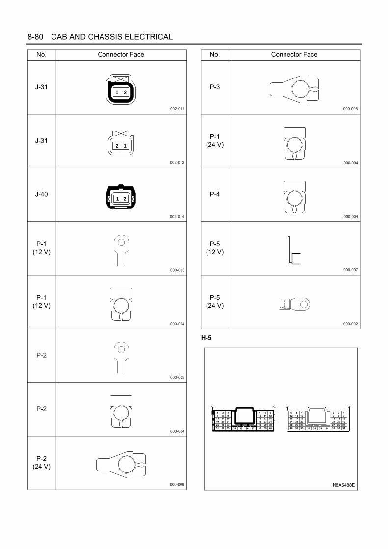
8-80 CAB AND CHASSIS ELECTRICAL
H-5
J-31
J-31
J-40
P-1(12 V)
P-1(12 V)
P-2
P-2
P-2(24 V)
No. Connector Face
002-011
1 2
002-012
12
002-014
1 2
000-003
000-004
000-003
000-004
000-006
P-3
P-1(24 V)
P-4
P-5(12 V)
P-5(24 V)
No. Connector Face
000-006
000-004
000-004
000-007
000-002
1 2 37 8 9
13 14 1519 20 2125 26 2731 32 33 34 35 36 37
4 5 610 11 1216 17 1822 23 2428 29 3038 39 40
6 5 412 11 1018 17 1624 23 2230 29 2840 39 38
3 2 19 8 7
15 14 1321 20 1927 26 2533 32 3134353637
N8A5488E

CAB AND CHASSIS ELECTRICAL 8-81
H-6, H-7, H-8
Neutral SwitchRefer to “START AND CHARGING” in this section.
Starter RelayRefer to “START AND CHARGING” in this section.
Charge RelayRefer to “START AND CHARGING” in this section.
Starter SwitchRefer to “START AND CHARGING” in this section.
Accel SwitchInspection
1. Check the continuity between the switch connectorterminals.
2. Check to see if switch plunger operates smoothly.Repair or replace the accel switch when result ofinspection is found abnormal.
RemovalPreparation:Disconnect the battery ground cable.
1. Accel Switch1) Disconnect the connector.2) Remove the two screws.
InstallationTo install, follow the removal steps in the reverse order,noting the following points.
1. Check to see if the accel pedal has been returnedby the return spring to the specified position.
Clutch SwitchInspection
1. Check the continuity between the switch connectorterminals.
2. Check to see if switch push rod operates smoothly.Repair or replace the switch when result of inspec-tion is found abnormal.
1 2
1 2
1 2 3 4
5 6 7 8
9 10 11 12 13
14 15 16 17 18
2 1
2 1
4 3 2 1
8 7 6 5
13 12 11 10 9
18 17 16 15 14
H - 6
H - 7
H - 8
N8A5489E
N8A0087E
N8A0088E
N8A0089E

8-82 CAB AND CHASSIS ELECTRICAL
RemovalPreparation:Disconnect the battery ground cable.
1. Clutch Switch1) Disconnect the connector.2) Loosen the lock nut of the switch.3) Remove the switch by turning it.
InstallationTo install, follow the removal steps in the reverse order,noting the following points.
1. Check to see if the clutch pedal has been returnedby the return spring to the specified position.
2. Turn the clutch switch clockwise until the tip of thethreaded portion of the switch contacts the pedalarm.
3. Tighten the lock nut to the specified torque.
Tighten:Lock nut to 13 N⋅m (130 kg⋅cm / 115 lb⋅in)
Exhaust Brake SwitchInspectionCheck the continuity between the terminals of the exhaust brake switch.Repair or replace the switch when the result of inspection is found abnormal.
N8A0088E
N8A0091E

CAB AND CHASSIS ELECTRICAL 8-83
Removal and InstallationRefer to “HEADLIGHT, FOG LIGHT AND CORNERINGLIGHT” in this section.
Exhaust Brake Magnetic Valve (4H Series En-gine)InspectionConnect the magnetic valve connector terminal No. 1 tothe battery (+) terminal and terminal No. 2 to the (−) ter-minal and then check the continuity among each port.
Vacuum Switching Valve: Intake Throttle (4HSeries Engine)InspectionConnect the magnetic valve connector terminal No. 1 tothe battery (+) terminal and terminal No. 2 to the (−) ter-minal and then check the continuity among each port.Repair or replace the vacuum switching valve when theresult of inspection is found abnormal.
N8A0094E
N8A0096E

8-84 CAB AND CHASSIS ELECTRICAL
Exhaust Brake System and Engine ControlParts LocationFor 4HE1-TC Engine
N8A0097E

CAB AND CHASSIS ELECTRICAL 8-85
For 4JH1 Engine
P-5 P
-4P-3
BA
TT
ER
Y (
12V
)
P-1
P-2
B-5
1, B
-52
EX
HA
US
T B
RA
KE
IND
ICA
TO
R L
IGH
T(M
ET
ER
)B
-55
SP
EE
DO
ME
TE
R
X-1
4 E
CM
RE
LAY
X-1
0 A
/C T
HE
RM
O R
ELA
Y
RE
LAY
BO
X A
SM
(No.
1)
B-1
8 D
IOD
EX
-12
HE
AT
ER
A/C
RE
LAY
X-1
1 C
HA
RG
E R
ELA
Y
B-3
1 E
NG
INE
WA
RM
ING
SW
EX
HA
US
T B
RA
KE
SW
ST
AR
TE
R S
W
H-1
4
J-17
7 A
BS
; C
/U
J-50
NE
UT
RA
L S
W
J-32
VE
HIC
LE S
PE
ED
SE
NS
OR
J-9
B-6
6 B
RA
KE
SW
B-8
9 C
LUT
CH
SW
B-7
9D
AT
A L
INK
CO
NN
EC
TO
R
B-8
0 T
HR
OT
TLE
PO
SIT
ION
S
EN
SO
R B-3
40 ID
LE L
SW
B-3
41
RE
SIS
TO
R ID
LE L
SW H
-5~
H-8
B-2
33, B
-234
EC
M B-7
B-2
32JO
INT
CO
NN
EC
TO
R-2
B-2
9JO
INT
CO
NN
EC
TO
R-1
B-3
42 N
EU
TR
AL
SW
RE
SIS
TO
R
B-3
39 A
/C O
NS
IGN
AL
RE
SIS
TO
R
B-3
43 J
OIN
T C
ON
NE
CT
OR
RE
LAY
BO
X A
SM
(No.
2)
FU
SE
BO
X A
SM
F-1
, F-5
,F
-8, F
-9,
F-1
6
J-6
PR
ES
SU
RE
SW
B-6
7
B-6
9
H-1
4
RE
LAY
BO
XS
BF
1, S
BF
2, S
BF
3, S
BF
25 F
US
IBLE
LIN
KX
-20
GLO
W R
ELA
YX
-24
A/C
CO
MP
RE
SS
OR
RE
LAY
X-2
6 A
/C S
IGN
AL
RE
LAY
J-10
5 E
VR
V :
EG
RJ-
40
VS
V
: IN
TA
KE
TH
RO
TT
LE
J-31
EX
H B
RA
KE
MA
GN
ET
IC V
ALV
E(B
)
E-5
MA
GN
ET
IC
CLU
TC
H
J-18
2 M
AS
S A
IR F
LOW
SE
NS
OR
J-18
3 T
DC
E-1
6C
OO
LAN
TT
EM
PE
RA
TU
RE
SE
NS
OR
J-12
2 G
LOW
PLU
G
E-1
10 IN
JEC
T P
UM
P
FR
AM
EH
AR
NE
SS
N8A0099E

8-86 CAB AND CHASSIS ELECTRICAL
For 4HK1-TC Engine
RE
LAY
BO
X A
SM
(N
o. 2
)
FU
SE
BO
X A
SM
F-2
, F-7
,F
-9, F
-16,
F-2
2
B-4
31R
ES
IST
OR
2
B-3
87R
ES
IST
OR
1B-7
9D
AT
A L
INK
CO
NN
EC
TO
R
B-5
1, B
-53
ME
TE
R
B-6
7 S
TA
RT
ER
SW
B-1
B-7
H-1
5
P-5
P-1
P-2
BA
TT
ER
Y
P-3
P-4
F-2
8 F
US
ES
BF
1, S
BF
2, S
BF
3, S
BF
5, S
BF
8F
US
IBLE
LIN
KX
-18
EC
M M
AIN
RE
LAY
X-2
1 S
TA
RT
ER
RE
LAY
X-2
6 S
TA
RT
ER
CU
T R
ELA
Y
RE
LAY
BO
X A
SM
H-1
2
H-4
, H-5
, H-6
,H
-7, H
-8
RE
LAY
BO
X A
SM
(N
o. 1
)S
TA
RT
ER
SW
MA
FS
EN
SO
R
MA
PS
EN
SO
R
RE
V S
WJ-
50N
EU
TR
AL
SW
J-31
EX
H B
RA
KE
MA
GN
ET
IC V
ALV
E (
B)
X-1
4 S
MO
OT
HE
RE
ME
RG
EN
CY
RE
LAY
X-1
CH
AR
GE
RE
LAY
X-3
3 D
IOD
E
J-9
B-4
25, B
-426
,B
-427
, B-4
28T
CM
B-3
1E
NG
INE
WA
RM
ING
SW
J-19
1 E
CM
N8A0530E

CAB AND CHASSIS ELECTRICAL 8-87
Circuit Diagram4HE1-TC Engine (1)
N8A0100E

8-88 CAB AND CHASSIS ELECTRICAL
4HE1-TC Engine (2)
SW
:LO
W(N
-SP
EC
ON
LY)
RE
LAY
:GLO
W
J-131
2
J-145 VSV:VSS
J-145
0.5B/Y
0.5B/Y
0.5B/Y
3B/L
0.5B/Y
2
1
B-233
X-20
B-233
B-11VSV:VSS
11
H-14
4
E-76
THERMO SENSOR
HEAD LIGHTBRACKET-LH
RACK SENSOR ENGINE SPEED SENSOR EVRV:EGR
2
X-20
4
7
H-5
26
B-233
H-14
8
E-76
1
8
H-5
27
5
X-20
2
B-233
J-146
B-13VSV:
ANECON
VSV:ANEROIDCOMPENSATOR
13
0.5B
R/B
0.5B
R/Y
0.5
BR
/W
0.5B
R/B
0.5B
R/Y
0.5B
R/W
0.3B
R/B
0.3B
R/Y
0.3B
R/W
0.3Y
0.3B
/Y
0.3L
J-146
2
1
B-233
J-147
B-1VSV:EGR
VSV:EGR
1
H-13
1
B-234
2
H-8
8
H-13
3
H-13
5
H-8
9
H-8
18
H-5
40
X-14
2
J-147
2
1
H-1311
B-234
B-79
DATA LINKCONNECTOR
0.5B
/Y
0.5B
/Y
0.5B
/Y
0.5B
/Y0.
5B/Y
0.3B
/R0.
3B/R
0.5L
G/B
0.3G
R/B
0.3G
R
0.5B
0.5W
0.5R
0.3G
R/B
0.3G
R
0.5B
0.5W
0.5R
0.3V
0.3L
G
0.3G
R/B
0.3G
R
0.5B
0.5W
0.5R
0.3V
0.3L
G
0.85
BR
/R
0.5R
/W
0.5O
0.5B
R/R
0.5R
/W
0.3B
0.5O
0.5B
0.5B
R/R
RE
LAY
:TIM
ING
0.5R
/W
0.3B
R/Y
0.5O
0.3L
G
0.3V
0.3V
0.5L
G/B
3B/Y
5B/Y
A-1CHECKER
1
7
B-234
B-79
A-15GND
15
3
B-234
B-79
A-16DIAG
A-27
ECMB-2
GLOWRELAY
16
B-234
27
H-5
29
B-233
2
6
J-131
1
J-105
2
J-105
1
MA
GN
ET
IC V
ALV
E:T
IMIN
G
E-74
1
H-14
11
H-522
X-20
3
H-8
3
H-14
GLOW PLUG
16
1
E-3
B-234
H-14
1
E-43
1
21
H-5
13
B-234
RACKSIGA-7
H-14
2
E-43
2
7
H-5
7
B-234
H-14
3
E-43
3
6
H-5
1
B-233
H-14
12
E-2
1
9
H-8
16
B-233
ENG SIGB-10
ENG-B-9
RACK+A-6
RACK-A-21
THERMO SIGB-8
THERMO GNDB-7
B-234
H-14
13
E-2
2
10
B-234
1411
B-234
EVRV+A-13
EVRV-A-14
MVTIMING
A-11
13
B-234
GNDA-22
22
5
X-14
4H-8
15X-14
12H-8
H-13
10
6H-8
H-13
4
5H-8
X-14
1
A
B-7
INT
AK
ET
EM
PS
W
N8A0101E

CAB AND CHASSIS ELECTRICAL 8-89
4JH1 Engine (1)S
BF
-1M
AIN
100A
F-8
EN
G.(
B1)
15A
F-5
ST
OP
LIG
HT
10A
F-9
EN
G.(
B2)
15A
2L8B
LK
8 WH
T/
BLK
30 BLK
8 WH
T/
BLK
3 WH
T/
BLK
0.5
WH
T/
RE
D
3 WH
T/
BLK
0.5
WH
T/
BLU
3 BLK
/B
LU
3 BLU
0.5
BLK
0.5
GR
Y/
YE
L
2 WH
T/
BLK
3 BLK
/Y
EL
0.5
BLK
/Y
EL
0.5
BLK
/Y
EL
0.5
BLK
/Y
EL
0.5
BLK
/Y
EL
3 BLK
/Y
EL
3 BLK
/Y
EL
EC
M M
ain
Rel
ay
0.85
BR
N2 B
LU
A/C
The
rmo
Rel
ay
B-7
Hea
dlig
htB
rack
et
Dat
a Li
nkC
onne
ctor
Bra
keS
witc
h
30B
LK
2H
-6
Sta
rter
AC
G
Met
er
42
53
X-1
1
X-1
1 Cha
rge
Rel
ay
42
51
X-1
2
X-1
2 Hea
ter
A/C
Rel
ay
F-1
AIR
CO
N10
A
SB
F-2
5H
EA
TE
R30
A
2 BLK
3 BLK
5 BLK
Sta
rter
Rel
ay
21
ST
ON
AC
CO
FF
Igni
tion
Sw
itch
B-6
7
3B
-67
H-7
SB
F-2
KE
Y50
A
SB
F-3
GLO
W60
A
3 WH
T/
BLU
Glo
w R
elay
P-1
P-3
P-2
P-5
P-4
Bat
tery
EC
MW
/S-M
Fus
e &
Rel
ay B
ox(B
ehin
d th
e C
ab)
Fus
e &
Rel
ay B
ox(G
love
Box
)
Rel
ay B
ox(I
nstr
umen
t P
anel
)
3 WH
T/
BLU
A/C
The
rmo
Rel
ay
Fus
e &
Rel
ay B
ox(G
love
Box
)
N6A3862E

8-90 CAB AND CHASSIS ELECTRICAL
4JH1 Engine (2)
25
X-1
13
X-1
ST
ON
AC
CO
FF
Igni
tion
switc
h
3 BLK
/Y
EL
0.5
BLK
/Y
EL
21
B-6
7
31
H-7
8BLK
SB
F-2
KE
Y50
A
3 WH
T/
BLU
3 WH
T/
BLU
3 WH
T/
BLU
B-6
74
2H
-6
F-2
2S
TAT
ER
10A
F-1
6M
ET
ER
10A
F-2
0A
BS
(IG
)10
A
F-1
5A
UD
IO(I
G),
CIG
AR
LIG
HT
ER
15A
Key
ON
Rel
ay
F-1
2H
/LA
MP
LEV
EL
10A
F-1
1T
UR
NLI
GH
T10
A
F-1
0F
RO
NT
WIP
ER
&W
AS
HE
R15
A
F-2
5M
AR
KE
RLA
MP
15A
F-2
7R
R F
OG
10A
F-2
6C
ON
D.F
AN
15A
SB
F-1
MA
IN10
0A
SB
F-2
6P
OW
ER
WIN
DO
W30
A
SB
F-8
STA
RT
ER
60A
SB
F-9
AB
S60
A
SB
F-3
GLO
W60
A
SB
F-4
HE
AD
LAM
P30
A
Hea
ter
Rel
ay
Glo
w P
lug
Rel
ay
F-4
AU
DIO
(B
),D
OO
R L
OC
K15
A
F-5
ST
OP
LIG
HT
10A
F-8
EN
G.
(B1)
15A
F-9
EN
G.
(B2)
15A
F-1
9H
OR
N,
HA
ZA
RD
15A
2 WH
T/
BLK
3 WH
T/
BLK
3 WH
T/
BLK
3 WH
T/
BLU
3 BLU
0.5
BLK
W/S
-GW
/S-H
W/S
-A
Bat
tery
2BLK
/YE
L
Fus
e &
Rel
ay B
ox(B
ehin
d th
e C
ab) F
use
&R
elay
Box
(Glo
ve B
ox)
Hea
ter
Rel
ay
N6A3863E

CAB AND CHASSIS ELECTRICAL 8-91
4JH1 Engine (3)
Ref
er to
Pow
er D
istr
ibut
ion
Ref
er to
Pow
er D
istr
ibut
ion
SB
F-2
KE
Y50
A
30 BLK
3 BLK
/W
HT
3 WH
T/
BLK
3 WH
T/
BLK
E-7
2P
-6J-
26
3 BLK
/W
HT
SB
F-8
STA
RT
ER
60A
3 WH
T/
BLU
3 WH
T/
BLU
P-1
P-2
P-3
P-2
P-5
P-4
Bat
tery
J-9
Fra
me2 BLK
0.5
BLK
Sta
rter
Rel
ayF
-22
STA
RT
ER
10A
4B
-67
14H
-82B
-67
1H
-7
30B
LK8B
LK
2L
Fus
e &
Rel
ay B
ox(B
ehin
d th
e C
ab)
Fus
e &
Rel
ay B
ox(G
love
Box
)
313
H-3
2P
-81
P-8
P-9
3 WH
T
0.85
WH
T/B
LU
0.85
WH
T/B
LU
0.5
WH
T/B
LU
8 WH
T
H-6
SB
Gen
erat
or
L
ST
ON
AC
CO
FF
Igni
tion
switc
h
Rel
ay B
ox(I
nstr
umen
t P
anel
)
53
4
X-8X-8
2
0.5
BLK
/Y
EL
0.5
BLK
/Y
EL
42
53
X-1
1
X-1
1 Cha
rge
Rel
ay
Fus
e &
Rel
ay B
ox(G
love
Box
)
F-1
6M
ET
ER
10A
Hea
ter
A/C
Rel
ayW/S
-M
Rel
ay B
ox(I
nstr
umen
t P
anel
)
Sta
rter
B C 1J-
27
1
M
N6A3864E

8-92 CAB AND CHASSIS ELECTRICAL
4JH1 Engine (4)
CA
Nhi
ghC
AN
low
ES
Oso
leno
idsi
gnal
outp
ut
12V
Bat
tery
volta
ge
EC
Mm
ain
rela
yco
ntro
l
3 BLU
/R
ED
3 BLU
/R
ED
0.5
BLU
/B
LK
2 BLU
/R
ED
583
B-2
33
EC
M
1H
-615
H-1
4
7E
-110
1056 11
100
9912
CA
Nhi
ghC
AN
low
BA
T (
+)
16
6
2 BLK
2 BLK
0.5
RE
D0.
5Y
EL
0.5
BLU
0.5
YE
L
127
138
105
918
H-8
H-1
4
E-1
105E
SO
sole
noid
sign
al
CK
Pse
nsor
sign
al
J-9
Fra
me
PC
U
CK
Pse
nsor
sign
alou
tput
Exh
aust
Bra
ke S
olen
oid
Val
veIn
take
Thr
ottle
Sol
enoi
d V
alve
Neu
tral
Sw
itch
A/C
Com
pres
sor
Rel
ayA
/C S
igna
l Rel
ayM
AF
& IA
T S
enso
r
Glo
w R
elay
1.25
BLK
/Y
EL
3 BLK
/Y
EL
3 BLK
/Y
EL
EC
MM
ain
Rel
ay
F-8
EN
G.(
B1)
15A
Fus
e &
Rel
ay B
ox(G
love
Box
)
Rel
ay B
ox(I
nstr
umen
t P
anel
)
45
2
X-1
4
X-1
41
2BLU
/RE
D
2 RE
D/
WH
T 0.5
PN
K
0.5
PN
K
0.5
PN
K
0.5
OR
N
0.5
OR
N
0.5
OR
N
0.5
BLU
0.5
YE
L
F-1
6M
ET
ER
10A
0.5
BLK
/Y
EL
Met
er
39B
-234
Igni
tion
volta
ge
W/S
-M
2 BLU
/R
ED
F-9
EN
G.(
B2)
15A
N6A3866E

CAB AND CHASSIS ELECTRICAL 8-93
4JH1 Engine (5)G
roun
dG
roun
d
2 BLK
3 BLK
/Y
EL
2 WH
T/
BLK
2 WH
T/
BLK
0.5
BLK
/Y
EL
2 BLK
5 BLK
0.5
BLU
0.5
YE
L
F-8
EN
G.(
B1)
15A
EC
M
Dat
aLi
nkC
onne
ctor
(DLC
)
451
B+
235
B-2
34
Key
wor
d20
00
Dia
gnos
ticre
ques
tsw
itch
Key
wor
d20
00
616
7B
-79
5 5 9
4B
-79
B-7
Hea
dlig
ht B
rack
et
0.5
BLK
0.5
BLK
0.85
BLK
0.85
BLK
Gro
und
Gro
und
EH
CU
429
J-17
7
212
43
H-1
5
2627
H-5
0.3
WH
T/
BLK
0.3
WH
T/
BLK
0.3
WH
T/
BLK
0.3
WH
T/
GR
N
0.3
WH
T/
GR
N
0.3
WH
T/
GR
N
J185
0(C
lass
2)D
iagn
ostic
requ
est
switc
h
F-9
EN
G.(
B2)
15A
W/S
-C
J/C
-E
Fus
e &
Rel
ay B
ox(G
love
Box
)D
iagn
ostic
requ
est
switc
h
Dia
gnos
ticre
ques
tsw
itch
B-1
Fra
me
EC
MM
ain
Rel
ay
J185
0(C
lass
2)
N6A3867E

8-94 CAB AND CHASSIS ELECTRICAL
4JH1 Engine (6)
12V
VS
Ssi
gnal
Exh
aust
brak
ela
mp
cont
rol
Glo
win
dica
tor
lam
pco
ntro
l
MIL
cont
rol42
43B
-234
6827
EC
M
Inst
rum
ent
Pan
el C
lust
er(I
PC
)M
ILG
low
31
J-32
VS
S
Eng
ine
spee
dsi
gnal
outp
ut
4B
-51
68
0.5
GR
N/
YE
L
0.5
OR
N/
BLU
0.5
BLU
/G
RN
0.85
BLK
0.5
YE
L/G
RN
0.5
BLK
0.85
BLK
2 BLK
0.5
YE
L/G
RN
Tach
omet
er
1B
-55
8 2J-
32
10
Spe
edom
eter
0.5
BLK
/YE
L
F-1
6M
ET
ER
10A
19H
-525
31
B-7
Hea
dlig
htB
rack
et
1B
-51
0.5
LT G
RN
/B
LU
Exh
aust
Bra
ke
Exh
aust
Bra
keS
witc
h
60
0.5
GR
N/
RE
D
2B
-52
3
0.5
BLK
0.85
BLK
9
B-1
Fra
me0.3
BLK
Fus
e &
Rel
ay B
ox(G
love
Box
)
0.3
BLK
/Y
EL
0.3
BLK
/Y
EL
0.5
YE
L/G
RN
N6A3868E

CAB AND CHASSIS ELECTRICAL 8-95
4JH1 Engine (7)
Res
isto
r
Eng
ine
war
m u
psw
itch
sign
al
Low
refe
renc
eS
hiel
dgr
ound
Low
refe
renc
e
Eng
ine
war
m u
psw
itch
indi
cato
rla
mp
cont
rol
AP
Pse
nsor
sign
al
Idle
switc
hsi
gnal
5V r
efer
ence
EC
ME
CM
101
1 2
B-3
40
B-3
40
69
24
98B
-233
49B
-234
18H
-5
2J-
183
1J-
183
J-18
3 3
12H
-5
90B
-233
0.5
RE
D
0.5
RE
D
0.5
WH
T
0.5
WH
T
CK
PS
enso
r
CK
Pse
nsor
sign
al
5V r
efer
ence
3857
B-2
34
Idle
Sw
itch
B-1
Fra
me0.85
BLK
0.5
BLK
/G
RN
0.5
BLK
0.5
GR
N/
BLK
0.5
GR
N/
OR
N
0.5
RE
D/
GR
N
0.5
GR
N/
BLK
32
B-8
0
AP
PS
enso
r
1B
-80
EC
M
0.5
BLK
0.5
BLK
24
4
2
0.5
LT G
RN
/R
ED
Tail
Rel
ay
1B
-31
0.5
BR
N
5B
-31
3 6EC
MM
ain
Rel
ay
4659
0.5
BLU
/R
ED
0.3
BLK
0.5
BR
N/
RE
D
0.5
BR
N/
RE
D
Eng
ine
War
m U
pS
witc
h
W/S
-C
EC
MM
ain
Rel
ay
0.5
BR
N/
RE
D
N6A3869E

8-96 CAB AND CHASSIS ELECTRICAL
4JH1 Engine (8)
N6A3870E
Low
refe
renc
eLo
wre
fere
nce
MA
Fse
nsor
sign
al
IAT
sens
orsi
gnal
5V r
efer
ence
5V r
efer
ence
EC
Tse
nsor
sign
al
5V r
efer
ence
93B
-233
1J-
182
24
5
29H
-5
16H
-14
11H
-14
37H
-5H
-81
2
0.5
BLK
/P
NK
0.5
BLK
/P
NK
0.5
BLK
/P
NK
926H
-8
0.5
BLK
/R
ED
0.5
BLK
/R
ED
84
3J-
182
89B
-233
0.5
BLK
/B
LU
0.5
BLK
/B
LU
16H
-5
0.5
GR
Y
0.5
GR
Y
0.5
GR
Y
EC
M
EC
M
8883
0.5
GR
N/
RE
D
0.5
WH
T/
RE
D
0.5
GR
N/
RE
D
0.5
WH
T/
RE
D
0.5
BLU
/R
ED
MA
F &
IAT
Sen
sor
1E
-16
2E
-16E
CT
Sen
sor
0.5
BLK
/O
RN
0.5
BLK
/O
RN
0.5
BLU
/R
ED
21J-
105
J-10
5EG
RS
olen
oid
Val
ve
7H
-8
97
EG
Rso
leno
idva
lve
cont
rol
(PW
M)
EC
MM
ain
Rel
ay

CAB AND CHASSIS ELECTRICAL 8-97
4JH1 Engine (9)
A/C
Com
pres
sor
A/C
ON
sign
alre
lay
sign
alG
low
rela
yco
ntro
l
A/C
com
pres
sor
rela
yco
ntro
l
Res
isto
r
1B
-339
2B
-339
0.5
GR
N/
YE
L
0.5
GR
N/
YE
L
0.5
GR
N/
YE
L0.
5B
LK/
RE
D
0.5
BLK
25
X-2
6
X-2
6 A/C
Sig
nal
Rel
ay
3 BLK
/R
ED
0.3
BLK
/R
ED
52
X-2
0Glo
wR
elay
Glo
wP
lug
0.85
GR
N/
YE
L
0.85
GR
N/
YE
L
0.5
WH
T/
GR
N
0.5
BLK
0.85
BLK
0.5
WH
T/
GR
N
25
X-2
4
X-2
4 A/C
Com
pres
sor
Rel
ay
16H
-8
3H
-8
H-8
1H
-14
EC
M
J-9
Fra
me B-1
Fra
me
41B
-234
3394
B-2
33
SB
F-3
Glo
w60
A
43
X-2
0
1J-
122
15
41
41
Fus
e &
Rel
ay B
ox(B
ehin
d th
e C
ab)
F-1
AIR
CO
N10
A
SB
F-2
5H
EA
TE
R30
A
0.5
BLU
/R
ED
0.5
GR
N/
OR
N
US
WJO
INT
2
W/S
-C
0.5
PN
K/
GR
N
0.85
GR
N/
WH
T
1.25
LT G
RN
/B
LK
0.85
BR
N
51
42
X-1
0
X-1
0
A/C
The
rmo
Rel
ay
0.5
BLU
/R
ED
3H
-18
J-6
J-6
12
Pre
ssur
eS
witc
h
Dio
de
Ele
ctro
The
rmo
4H
-18
0.5B
LU/R
ED
2 BLU
1.25
BLU
EC
MM
ain
Rel
ay1H
-6F
use
&R
elay
Box
(Glo
ve B
ox)
Rel
ay B
ox(I
nstr
umen
t P
anel
)
EG
R S
olen
oid
Val
veP
CU
Exh
aust
Bra
ke S
olen
oid
Val
veIn
take
Thr
ottle
Sol
enoi
d V
alve
0.5
BLU
/R
ED
N6A3871E

8-98 CAB AND CHASSIS ELECTRICAL
4JH1 Engine (10)
0.5
BLU
/R
ED
US
WJO
INT
2
3 BLU
/R
ED
0.5
YE
L
0.5
WH
T/
BLK
0.5
GR
N
0.5
BLU
/R
ED
0.5
BLU
/R
ED
0.5
GR
N/
YE
L
0.5
GR
N
41
32B
-66 Bra
keS
witc
h
21
87
63
12
B-8
9
B-8
9Clu
tch
Sw
itch
EC
M
EH
CU
(AB
SM
odul
e)
65
Sto
pLi
ght
F-5
ST
OP
LIG
HT
10A
31
EC
MM
ain
Rel
ay
Glo
wR
elay
1H
-6
30
0.5
LT G
RN
0.5
BLK
21J-
31
J-31
40
0.5
LT G
RN
/W
HT
0.5
BLU
/R
ED
21J-
40
J-40
95
Inta
keT
hrot
tleS
olen
oid
Val
ve
Exh
aust
Bra
keS
olen
oid
Val
ve
MA
F S
enso
rE
GR
Sol
enoi
d V
alve
A/C
Com
pres
sor
Rel
ayA
/C S
igna
l Rel
ay
932
H-5
0.5
LT G
RN
0.5
LT G
RN
/W
HT
B-2
34
0.5
LT G
RN
/B
LU
0.5
BLU
/R
ED
21B
-69
B-6
9Exh
aust
Bra
keS
witc
h
64
IPC
12V
Bra
kepe
dal
switc
h1si
gnal
Exh
aust
brak
esw
itch
sign
al
Clu
tch
switc
hsi
gnal
Bra
kepe
dal
switc
h2si
gnal
Inta
keth
rottl
eso
leno
idva
lve
cont
rol
Exh
aust
brak
eso
leno
idva
lve
cont
rol
Fus
e &
Rel
ay B
ox(G
love
Box
)J/
C-E
PC
U
Idle
Sw
itch
Res
isto
r
Eng
ine
War
m U
pS
witc
h
87
1011
H-1
4
0.5
LT G
RN
/W
HT
0.5
LT G
RN
/W
HT
0.5
LT G
RN
/B
LK
0.5
LT G
RN
/B
LK
6232
B-2
34
J-17
7
0.5
LT G
RN
/B
LK
0.5
LT G
RN
/W
HT
3640
H-5
12V
Exh
aust
brak
e cu
tsi
gnal
inpu
t
Exh
aust
brak
e cu
tsi
gnal
feed
back
inpu
t
Exh
aust
brak
ecu
tsi
gnal
feed
back
outp
ut
Exh
aust
brak
e cu
tsi
gnal
outp
ut
0.5
LT G
RN
/B
LU
12V
N6A3872E
Neu
tral
switc
hsi
gnal
Res
isto
r
B-3
42
B-3
420.
3B
LK
0.5
BLK
/W
HT
0.5
BLK
/W
HT
0.5
BLK
/W
HT
21
J-50
J-50 N
eutr
alS
witc
h
9H
-8
87B
-233
W/S
-C
0.5
BLU
/R
ED
1 2

CAB AND CHASSIS ELECTRICAL 8-99
4HK1-TC Engine (1)S
BF
-2K
EY
40A
SB
F-1
MA
IN10
0A o
r 12
0A
2L
30 BLK
/R
ED
8 B
LK
0.3
GR
N/
OR
N
3 WH
T/
BLK
F-1
HE
AT
ER
,A
IR C
ON
15A
Hea
ter
&A
/C R
elay
12
X-1
2
54
X-1
2
F-2
FU
EL
HE
AT
ER
10A
F-7
TA
ILLI
GH
T10
A
Hea
ter
Rel
ay
12
X-8
54
X-8
Tai
lR
elay
12
X-4
54
X-4
Cha
rge
Rel
ay
3 BLK
/R
ED
3 BLU
5 WH
T
5 WH
T/
BLK
8 WH
T/
BLK
3 WH
T/
BLK
3 WH
T/
BLK
0.5
WH
T/
RE
D
0.5
WH
T/R
ED
3 WH
T
F-2
2S
TA
RT
ER
10A
F-9
EN
G.
(IG
)10
A
F-1
6M
ET
ER
10A
3 BLK
/Y
EL
W/S
-H
W/S
-E
US
WJO
INT
3
3 BLK
/Y
EL
3 BLK
0.5
BLK
2 BLK
0.5
BLK
B-6
7 4
H-6
2
H-7
1
SB
F-3
GLO
W60
A
3 BLK
/B
LU
0.5
BLK
3 WH
T/
RE
D 1.25
RE
D
Glo
wP
lug
Rel
ay
34
X-2
0
25
X-2
0
SB
F-8
ST
AR
TE
R60
A
Fus
e &
Rel
ay B
ox(B
ehin
dth
e C
ab)
Fus
e &
Rel
ay B
ox(B
ehin
dth
e C
ab)
Fus
e &
Rel
ay B
ox(G
love
Box
)
Rel
ay B
ox(I
nstr
umen
t P
anel
)
Rel
ay B
ox(I
nstr
umen
t P
anel
)
Fus
e &
Rel
ay B
ox(G
love
Box
)
Fus
e &
Rel
ay B
ox(G
love
Box
)
SB
F-5
EC
M40
A
EC
MM
ain
Rel
ay
Sta
rter
Rel
ay
EC
ME
CM
Com
bina
tion
Sw
itch
Glo
wP
lug
EC
M
0.5
BLU
/B
LK2 R
ED
0.5
BLK
/R
ED
3 BLK
/Y
EL
3 WH
T/
BLK
2 BLK
J-9
Fra
me
2
ST
ON
AC
CO
FF
B-6
7
3B
-67
Igni
tion
Sw
itch
Fus
e &
Rel
ay B
ox(B
ehin
d th
e C
ab)
P-5
B-7
H/L
Bra
cket
6
J/C
-D
1
Bat
tery
P-1
P-2
P-3
P-4
N6A6628E
0.5
YE
L/B
LK
35
X-1
8
24
X-1
8
F-2
8E
CM
10A

8-100 CAB AND CHASSIS ELECTRICAL
4HK1-TC Engine (2)
EC
MT
CM
30 B
LK/R
ED
8 B
LK8
BLK
8 B
LK
3 B
LK/Y
EL
P-1
P-2
P-3
P-4
Bat
tery
P-5
3 BLK
/W
HT
3 WH
T/
BLK
0.5
RE
D/W
HT
0.5
RE
D/W
HT
0.5
RE
D
0.5
WH
T/
BLU
0.3
BLK
/WH
T
3 WH
T/B
LU
3 WH
T/B
LU
2L
SB
F-8
STA
RT
ER
60A
SB
F-2
KE
Y40
A
F-2
2S
TAR
TE
R10
A
14H
-8
0.5
RE
D/
WH
T
0.5
WH
T/
BLU
0.5
WH
T/
BLU
J-9
Fra
me
1H-7
4
B-6
7
US
WJO
INT
32 B
LK
0.5
BLK
14J-
191
B-4
2546
Sta
rt c
utre
lay
cont
rol
Sta
rt s
witc
hsi
gnal
38H
-5
16
Sta
rter
cut
rela
yco
ntro
l
Fus
e &
Rel
ay B
ox(G
love
Box
)
F-2
8E
CM
10A
Fus
e &
Rel
ay B
ox(B
ehin
d th
e C
ab)
2B
-67
2 3J/C
-2
0.85
LT G
RN
0.5
LT G
RN
EC
MM
ain
Rel
ay
52
X-2
1
43
X-2
1 51
X-2
6
34
X-2
6
ST
ON
AC
CO
FF
Igni
tion
Sw
itch
N6A6629E
Sta
rter
B C 1J-
27
1J-
26
Fus
e &
Rel
ay B
ox(B
ehin
d th
e C
ab)
Sta
rter
Rel
ay
Fus
e &
Rel
ay B
ox(B
ehin
d th
e C
ab)
Fus
e &
Rel
ay B
ox(B
ehin
d th
e C
ab)
Sta
rter
Cut
Rel
ay

CAB AND CHASSIS ELECTRICAL 8-101
4HK1-TC Engine (3)
F-1
6M
ET
ER
10A
SB
F-8
STA
RT
ER
60A
SB
F-3
GLO
W60
A
SB
F-1
MA
IN10
0A o
r 12
0A
18 10
B-5
1
B-5
1
0.5
BLK
/Y
EL
0.5
BLK
/Y
EL
0.5
WH
T/
BLU
0.5
WH
T/
BLU
0.5
WH
T/
BLU
8 WH
T/
BLK
0.5
BLK
/Y
EL
0.5
WH
T/
RE
D
0.85
WH
T/
RE
D
Cha
rge
Rel
ay
Glo
w R
elay
8BLK
30B
LK/R
ED
2L
B
Sta
rter
Rel
ay
Cha
rge
BS
21
1
J-1
J-2
J-1
15H
-5
L
AC
G
J-26
Sta
rter
P-1
P-2
P-3
P-4
P-5
0.85
WH
T/
BLU
1.25
WH
T/
BLU
3 WH
T/
BLU
3 BLK
/Y
EL
3 WH
T/
BLU
3 WH
T/
BLU
Hea
ter
& A
/C R
elay
Fus
e &
Rel
ay B
ox
Fus
e &
Rel
ay B
ox(B
ehin
d th
e C
ab)
Fus
e &
Rel
ay B
ox(B
ehin
d th
e C
ab)
Inst
rum
ent
Pan
elC
lust
er(I
PC
)
Fus
e &
Rel
ay B
ox(G
love
Box
)
Fus
e &
Rel
ay B
ox(G
love
Box
)
15
4
X-1X-1
3 21
3
W/S
-M
J/C
-I
0.5
BLK
/Y
EL
N6A6630E
Bat
tery
2
ST
ON
AC
CO
FF
B-6
7
3B
-67
Igni
tion
Sw
itch
1H
-7
SB
F-2
KE
Y40
A

8-102 CAB AND CHASSIS ELECTRICAL
4HK1-TC Engine (4)
2 BLK
0.5B
LK3 W
HT
/R
ED
0.5
BLU
/B
LK
0.5
BLU
/B
LK
0.5
BLU
/B
LK
0.5
YE
L/B
LU
0.5
YE
L/B
LU
2 RE
D
2 RE
D
2 RE
D
EC
M
J-19
1
1.25
RE
D
2418H
-5
J-9
Fra
me
24
3
X-1
8EC
M M
ain
Rel
ay
X-1
85
SB
F-5
EC
M40
A
F-2
8E
CM
10A
212
405
Bat
tery
vol
tage
Fus
e &
Rel
ay B
ox(G
love
Box
)
F-9
EN
G. (
IG)
10A
Fus
e &
Rel
ay B
ox(B
ehin
d th
e C
ab)
Fus
e &
Rel
ay B
ox(B
ehin
d th
e C
ab)
Rel
ay B
ox(I
nstr
umen
tP
anel
)
EC
M m
ain
rela
y co
ntro
l
Igni
tion
volta
ge
US
W J
OIN
T 3
Exh
aust
Bra
ke S
olen
oid
Val
veS
tart
er C
ut R
elay
Inta
ke T
hrot
tle S
olen
oid
Val
ve
N6A6631E
SB
F-2
KE
Y40
A
3 BLK
/Y
EL
1 2
ST
ON
AC
CO
FF
B-6
7
3B
-67
Igni
tion
Sw
itch
B-6
7
3 WH
T/
BLU
3 WH
T/
BLU

CAB AND CHASSIS ELECTRICAL 8-103
4HK1-TC Engine (5)
1311
12
0.5
GR
Y
0.3
BLK
/W
HT
0.3
BLK
/WH
T
0.3
BLK
/WH
T
HS
A C
/U
EH
CU
(AB
S M
odul
e) TC
MH
SA
C/U
TC
MS
RS
C/U
0.3
LT B
LU
0.3
LT B
LU0.
3W
HT
/G
RN
2
0.3
WH
T/
BLK
0.5
LT B
LU
15238
0.5
YE
L
0.5
YE
L
7
0.5
LT B
LU
0.5
BLK
Dat
aLi
nkC
onne
ctor
(DLC
)
EC
MD
iagn
ostic
requ
est
switc
hK
eyw
ord
2000
0.5
BLK
1.25
BLK
1.25
BLK 4 Gro
und
5B
-79
Gro
und
20H
-4
4
1.25
BLK
3
1.25
BLK
1
0.75
BLK
62
0.75
BLK
43
0.5
BLK
81J-
191
9
B-1
Fra
me
2 BLK
J-9
Fra
me
Cas
egr
ound
3 12
US
WJO
INT
3
J/C
-G19
22
18
21
J/C
-B
W/S
-C
Sig
nal
grou
ndS
igna
lgr
ound
Pow
ergr
ound
Pow
ergr
ound
Pow
ergr
ound
Dia
gnos
ticre
ques
t(S
RS
)
Dia
gnos
ticre
ques
t(E
CM
)
Dia
gnos
ticre
ques
t(T
CM
or
HS
A)
Dia
gnos
tic(E
HC
U)
Cla
ss 2
seria
lco
mm
unic
atio
n(E
HC
U)
Key
wor
dse
rial
com
mun
icat
ion
(EC
M, T
CM
or
HS
A &
SR
S)
N6A6632E

8-104 CAB AND CHASSIS ELECTRICAL
4HK1-TC Engine (6)
18B
-51
0.5
BLU
/R
ED
0.5
BLU
/R
ED
0.5
OR
N/
BLU
0.5
BLU
/P
NK
0.5
OR
N/
BLU
0.5
BLU
/P
NK
Par
king
Bra
keS
witc
h
EC
M
Eng
ine
spee
dsi
gnal
outp
ut
VS
Ssi
gnal
MIL
cont
rol
Glo
win
dica
tor
lam
pco
ntro
l
Exh
aust
brak
ela
mp
cont
rol
Par
king
brak
esw
itch
sign
al
12H
-5
135
0.3W
HT
/VIO
0.3
WH
T/
VIO
0.3
WH
T/
RE
D
0.3W
HT
/VIO
5B
-51
B-5
1
3 4 10
3 5H-1
2
H-1
2
156
B-5
1B
-52
B-5
1B
-51
410
B-5
1
0.5B
RN
0.5
BLK
0.5
BLK
/YE
L
0.5
BLK
/Y
EL
0.5
BLK
/Y
EL
0.5
BLK
/Y
EL
0.5
YE
L/G
RN
0.5
YE
L/G
RN
0.5
YE
L/G
RN
0.3
YE
L/G
RN
0.3
LT G
RN
0.3
BLK
/Y
EL
0.5
BLK
0.5
BLK
1.25
BLK
0.3
WH
T/B
LK
0.3
WH
T/B
LK
WIT
HH
BB
W/O
HB
B
Par
king
Bra
keE
xhau
stB
rake
Glo
wM
IL
M/T
M/T
Sm
ooth
erS
moo
ther
0.5
WH
T/
BLK
0.5
WH
T/
BLK
0.5
WH
T/
RE
D
0.3
WH
T/
RE
D
0.5
WH
T/B
LK
0.5
WH
T/B
LU
Inst
rum
ent
Pan
elC
lust
er(I
PC
)
Cha
rge
Cha
rge
Rel
ay
Buz
zer
Rel
ay
Sho
rtC
onne
ctor
8H
-5
M/T
Sm
ooth
er
HB
BLe
vel
Sw
itch
Dio
de B
ox
2J-
32
17
7
19H
-5
4024
31H
-525
H-5
3H
-8
711
68
19
1 48J-
191
H-5
J-19
1
1N
-6
3J-
128
9X
-33
87
X-3
3
4
1J-
128
2
3J-
321
+B
B-1
Fra
meF
-16
ME
TE
R10
A
Fus
e &
Rel
ay B
ox(G
love
Box
)
Tach
omet
erS
peed
omet
er
0.3
LT G
RN
8B
-52
HS
A C
/U
Eng
ine
cool
ant
tem
pera
ture
gau
ge
7H
-14
23H
-5
4B
-55
0.5
LT B
LU
0.5
LT B
LU
0.5
LT B
LU
0.5
GR
N/
YE
L
0.5
BLK
EC
M
2E
-90
1E
-90
3
W/S
-C
W/S
-M12
14
13
J/C
-B
J-9
Fra
me
N6A6633E
EC
M
VS
SE
CT
Sen
sor

CAB AND CHASSIS ELECTRICAL 8-105
4HK1-TC Engine (7)
EC
M
0.5
RE
D
0.5
BLU
0.5
BLU
/W
HT
0.5R
ED
0.5W
HT
0.5
WH
T
0.5
RE
D0.
5W
HT
0.5
BLU
/R
ED
0.5
PN
K/
BLK
0.3
BLK
0.5B
LK
0.5
BLK
0.5
BLK
6164
144
1312
4263
310
111
H-4
H-4
6039
4120
J-19
1
B-2
80
AP
Pse
nsor
1si
gnal
AP
Pse
nsor
2si
gnal
Low
ref
eren
ceLo
w r
efer
ence
Shi
eld
grou
ndS
hiel
d gr
ound
5V r
efer
ence
2E
CM
5B
-280
5V r
efer
ence
1
31
AP
PS
enso
r 2
2
64
AP
PS
enso
r 1
N6A6657E
J-19
1
0.5
RE
D0.
5B
RN
0.5
BLU
0.5
BLU
/Y
EL
0.5
RE
D
0.5
PN
K/
BLK
0.5
BLU
/R
ED
0.5
PN
K/
BLK
7066
31 13
Idle
Up
Sen
sor
22
1 3
PT
OT
hrot
tleS
enso
r
2J-
166
B-2
81
H-4
J-16
6B
-281
H-4
PT
Oth
rottl
ese
nsor
sign
al
Idle
up
sens
orsi
gnal
0.5
PN
K/
BLK
BA
RO
Sen
sor
IAT
Sen
sor
BA
RO
Sen
sor
IAT
Sen
sor
0.5
BLK

8-106 CAB AND CHASSIS ELECTRICAL
4HK1-TC Engine (8)
EC
M
0.5R
ED
0.5
BLU
0.5
BLU
/W
HT
0.5
RE
D0.
5W
HT
0.5
WH
T0.
5R
ED
0.5
WH
T
0.5
BLU
/R
ED
0.5
PN
K/B
LK
0.3
BLK
0.5
BLK
0.5
BLK
0.5
BLK
6164
144
1312
4263
310
111
H-4
H-4
15H
-4
6039
4120
J-19
1
B-2
80
AP
Pse
nsor
1si
gnal
AP
Pse
nsor
2si
gnal
Low
ref
eren
ceLo
w r
efer
ence
Shi
eld
grou
ndS
hiel
d gr
ound
5V r
efer
ence
2E
CM
IAT
Sen
sor
2J-
190
1J-
190
5B
-280
71J-
191
0.5
BR
N/
GR
N
0.5
BR
N/
GR
N0.
5R
ED
0.5
BLK
0.5
BLK
0.5
RE
D/
GR
N
72
IAT
sens
orsi
gnal
5V r
efer
ence
BA
RO
sens
orsi
gnal
1B
-422
5V r
efer
ence
1
2B
-422
3
31
AP
PS
enso
r 2
2
64
AP
PS
enso
r 1
N6A6635E
PT
OT
hrot
tleS
enso
rId
le U
PS
enso
r
0.5R
ED
0.5
PN
K/B
LK
PT
OT
hrot
tleS
enso
rId
le U
PS
enso
r
BA
RO
Sen
sor

CAB AND CHASSIS ELECTRICAL 8-107
4HK1-TC Engine (9)
83E
-111
0.5
LT G
RN
/W
HT
FT
Sen
sor
0.5
GR
N/
YE
L
0.5
LT B
LU
0.5
WH
T0.
5R
ED
0.5
BLK
0.5
BLK
0.5
BLK
0.5
BLK
0.5
BLK
Boo
stP
ress
ure
Sen
sor
EC
T G
auge
FT
sens
orsi
gnal
1E
-93
2E
-93
1J-
216
812
H-1
05
2J-
216
3
4H
-105
3
9195
108
EC
M
EC
M
109
E-1
11
0.5
RE
D0.
5W
HT
2E
-90
1E
-90
EC
TS
enso
r
3
84
EC
Tse
nsor
sign
al
Boo
stpr
essu
rese
nsor
sign
al
5V r
efer
ence
5V r
efer
ence
Low
ref
eren
ceS
hiel
d gr
ound
5V r
efer
ence
4
N6A6637E
CK
PS
enso
r0.
5B
LK

8-108 CAB AND CHASSIS ELECTRICAL
4HK1-TC Engine (10)
N6A6636E
EC
M
EC
M
0.5
WH
T0.
5W
HT
0.5
GR
N/
BLU
0.5
BR
N0.
5B
LK
23
E-1
13
1011
E-1
13
E-1
11
E-1
1190
8287
FR
Pse
nsor
sign
al
5V r
efer
ence
5
Low
ref
eren
ce
100
Shi
eld
grou
nd
0.5
WH
T/
OR
N
0.5
GR
N/
BLU
0.5
BLK
/O
RN
0.5
BR
N
0.5
OR
N
EG
R V
alve
Mot
orE
GR
Pos
ition
Sen
sor
31
4E
-94
26
E-9
4
EG
Rva
lve
mot
or lo
wsi
deco
ntro
l(P
WM
)
8611
1
EG
Rva
lve
mot
or h
igh
side
cont
rol
EG
Rva
lve
posi
tion
sens
orsi
gnal
+B
103
105
E-1
11
0.5
WH
T/
RE
D
FR
Pre
gula
tor
high
sid
eco
ntro
l(P
WM
)
0.5
WH
T/
RE
D
0.5
GR
N/
RE
D
FR
Pre
gula
tor
feed
back
0.5
GR
N/
RE
D
0.5
WH
T/
RE
D
1E
-116
2E
-116
E-1
11
113 97
89
0.5
GR
N/
RE
D
FR
PR
egul
ator
+B
CM
PS
enso
r
FR
PS
enso
r

CAB AND CHASSIS ELECTRICAL 8-109
4HK1-TC Engine (11)
E-1
11
EC
M
EC
M
0.5
BLU
/W
HT
0.5
BLU
/B
LK
0.5
BLK
0.5
BLK
0.5
BLK0.
5BLK
E-1
11
2E
-112
100
1E
-112
3
9899
0.5
OR
N
107 2
E-9
8
106
108
CK
Pse
nsor
low
sign
al
1E
-98
0.5
YE
L
CK
Pse
nsor
high
sign
al
12V
ref
eren
ce
CM
Pse
nsor
sign
al
Shi
eld
grou
ndS
hiel
d gr
ound
N6A6634E
0.5
BLK
0.5
BLK
FR
PS
enso
r
Boo
stP
ress
ure
Sen
sor
CM
PS
enso
rC
KP
Sen
sor

8-110 CAB AND CHASSIS ELECTRICAL
4HK1-TC Engine (12)
121 1 1
12
2 WH
T
EC
M
EC
M
116
2 RE
D
2 WH
T
0.75
WH
T
0.75
GR
N
0.75
GR
N/
WH
T
0.75
WH
T
Cyl
inde
r #1
Fue
lIn
ject
or
Cyl
inde
r #4
Fue
lIn
ject
or
Cyl
inde
r #3
Fue
lIn
ject
or
Cyl
inde
r #2
Fue
lIn
ject
or
4 4
21
2 WH
T
0.75
WH
T
0.75
BLK
0.75
WH
T/
YE
L
3 3
1
33
3
2
2 RE
D
0.75
RE
D
0.75
YE
L
0.75
BLK
/B
LU
0.75
RE
D
2 2
H-1
25
H-1
26
2
3E
-138
E-1
41E
-140
E-1
39
1181
E-1
41E
-138
E-1
40E
-139
2 RE
D
0.75
RE
D
0.75
BLU
0.75
BLK
6 6
H-1
26
H-1
25
1207 7
1178 8
1195 5
Cyl
inde
r #1
fuel
inje
ctor
cont
rol
Cyl
inde
r #4
fuel
inje
ctor
cont
rol
Cyl
inde
r #3
fuel
inje
ctor
cont
rol
Cyl
inde
r #2
fuel
inje
ctor
cont
rol
Cha
rge
volta
ge(C
omm
on 1
)C
harg
e vo
ltage
(Com
mon
2)
N6A6638E

CAB AND CHASSIS ELECTRICAL 8-111
4HK1-TC Engine (13)
0.5
PN
K
0.5
GR
N/
OR
N
EC
M
0.85
GR
N/
OR
N
0.5
BLU
/O
RN
0.5
BLU
/O
RN
0.85
GR
N/O
RN
Ref
riger
ator
Com
pres
sor
J-6
0.85
GR
N/
WH
T
0.85
GR
N/
WH
T
The
rmo
A/C
Rel
ay
2H
-5
9H
-105
8H
-41
1J-
7
J-6
2
E-5
1
1
J-19
134
4433
0.75
WH
T/
RE
D
A/C
Pre
ssur
eS
witc
h
A/C
Com
pres
sor
1H
-120 G
low
Plu
g
3 BLK
/Y
EL
3 BLK
/Y
EL
3 BLK
/B
LU
F-9
EN
G. (
IG)
10A
0.5
BLK
/R
ED
0.5
YE
L/B
LK0.
5 Y
EL/
BLK
0.5
YE
L/B
LU
E-3
Igni
tion
Sw
itch
52
4
X-2
0
X-2
03
H-5
18
10
B-8
4
B-8
412
PT
OS
witc
h
A/C
sign
alR
efrig
erat
orsw
itch
sign
alG
low
plu
gre
lay
cont
rolS
BF
-3G
LOW
60A
Fus
e &
Rel
ay B
ox(G
love
Box
)
Fus
e &
Rel
ay B
ox(B
ehin
d th
e C
ab)
Fus
e &
Rel
ay B
ox(B
ehin
d th
e C
ab)
PT
Osw
itch
sign
al
0.5
BLK
1.25
BLK
B-1
Fra
meW
/S-C
+B
N6A6639E
EC
M
Glo
wR
elay

8-112 CAB AND CHASSIS ELECTRICAL
4HK1-TC Engine (14)
F-2
8E
CM
10A
Fus
e &
Rel
ay B
ox(G
love
Box
)
Fus
e &
Rel
ay B
ox(B
ehin
d th
e C
ab)
6 45
H-5
17H
-4
0.5
LT G
RN
/R
ED
0.5
BR
N/
BLK
0.5
LT G
RN
/R
ED
2
102
H-1
05
0.5
LT G
RN
/W
HT
50
Neu
tral
Sw
itch
0.5
LT G
RN
0.5
LT G
RN
0.5
LT G
RN
0.5
LT G
RN
/W
HT
0.85
LT G
RN
0.5
BLK
/B
LU
15J-
191
E-1
11
0.5
BLK
EC
M
Inta
keth
rottl
eso
leno
idva
lve
cont
rol
Exh
aust
brak
eso
leno
idva
lve
cont
rol
Neu
tral
switc
hsi
gnal
Exh
aust
brak
esw
itch
sign
al
F-9
EN
G. (
IG)
10A
0.5
YE
L/B
LU
0.5
BR
N/
YE
LClu
tch
Sw
itch
0.5
BR
N/
YE
L
Igni
tion
Sw
itch
47
Clu
tch
switc
hsi
gnal
12
54
J/C
-2
21J-
40
J-40
21J-
31
J-31
12J-
50
J-50
25B
-69
B-6
9
21B
-89
B-8
9
Inta
keT
hrot
tleS
olen
oid
Val
ve
Exh
aust
Bra
keS
olen
oid
Val
ve
N6A6640E
TC
M0.
5LT
GR
N/
BLU
0.5
BLK
3 BLK
0.5
BLK
1.25
BLK
0.5
LT G
RN
/BLU
0.5
LT G
RN
/BLU
0.5
BR
N/
BLK
0.85
LT G
RN
/R
ED
0.85
LT G
RN
/R
ED
0.5
LT G
RN
/R
ED
0.5
LT G
RN
/B
LU
B-1
Fra
me
B-7
H/L
Bra
cket
F-2
FU
EL
HE
AT
ER
10A
Hea
ter
Rel
ay
F-7
TAIL
LIG
HT
10A
Tail
Rel
ay
5
Eng
ine
War
m u
pS
witc
h
2
63
41
B-3
1
B-3
1
7 51
H-4
Eng
ine
war
m u
psw
itch
sign
al
W/S
-FW
/S-C
4 9
J/C
-D
11 5
J/C
-B
Exh
aust
Bra
keS
witc
h(C
ombi
natio
nS
witc
h)

CAB AND CHASSIS ELECTRICAL 8-113
4HK1-TC Engine (15)
2 1 B-431
7 8 H-8
B-387
Resistor 1
2 1
1
2TCM
3
2
B-427
10
5
H-15
14
9
15
14
J-177
27
26
5 6 H-8
0.5BLU/WHT
0.5BLU
0.5BLU/WHT
0.5BLU
0.5BLU
0.5BLU/WHT
0.5BLU
0.5BLU/WHT
0.5BLU
0.5BLU/WHT
0.5BLU
0.5BLU/WHT
0.5BLU
0.5BLU/WHT
0.5BLU
0.5BLU/WHT
0.5BLU/WHT
0.5 BLU
0.5BLU/WHT
0.5 BLU
0.5BLU/WHT
0.5 BLU
0.5BLU/WHT
0.5 BLU
0.5BLU/WHT
0.5 BLU
0.5BLU/WHT
0.5 BLU
0.5BLU/WHT
0.5 BLU
EHCU
37
18
J-191 CANhigh
CANlow
CANhigh
CANlow
DRM
ECM
Resistor 2
CANhigh
CANlow
3
J/C-F
4
5
6
J/C-F
Without ABS
2
1
3
J/C-R
5
4
6
J/C-R
CANhigh
CANlow
N6A6641E

8-114 CAB AND CHASSIS ELECTRICAL
Connector ListFor 4HE1-TC Engine
No. Connector Face
B-7
X-1
X-8
X-14
X-25
X-20
B-67
B-67
000-012
005-006
005-006
005-001
1
32 4
5
005-006
005-003
1
2 3
54
004-001
1 23 4
004-002
2
4
1
3
B-69
B-69
B-75
B-75
B-89
B-89
B-233
B-234
No. Connector Face
008-001
1
5
2
6
3
7
4
8
008-002
1
5
23
67
4
8
002-022
1 2
002-023
2 1
002-009
1
2
002-010
1
2
022-002
9 8 7
20 19
6 5 4 3 2 1
18 17 16 15 14 1322 21 12 11
10
030-002
9 8 7 6
30 29 28 27 26 25 24 23 22 21 20 19 18 17 16 15
5 4 3 2 114 13 12 11 10

CAB AND CHASSIS ELECTRICAL 8-115
B-79
B-51
H-14
H-14
H-13
H-13
E-2
E-3
No. Connector Face
016-005
87654321
161514131211109
014-001
1 2 3 4 5 6 7 8 9 1011121314
016-003
1 2 3 4
5 6 7 8 9
11 12 13 14
15 16
10
016-004
4 3 2 1
9 8 7 6 5
13 12 11 10
16 15
14
012-001
1 2 3 4
5 6 7 8
9 10 11 12
012-002
4
8
12
3
7
11
2
6
10
1
5
9
002-013
1 2
000-009
E-11
E-43
E-74
E-76
J-9
J-23
J-31
J-31
No. Connector Face
002-001
1 2
003-003
1 2 3
001-013
1
003-004
1 2
3
000-001
004-009
1 2 3 4
002-011
1 2
002-012
12

8-116 CAB AND CHASSIS ELECTRICAL
H-5
J-131
J-131
J-145
J-146
J-41
J-40
J-105
J-147
No. Connector Face
002-011
1 2
002-012
12
002-014
1 2
002-015
1 2
002-015
1 2
002-015
1 2
002-016
21
002-017
1 2
P-1
P-4
P-2
P-3
P-5
No. Connector Face
000-004
000-004
000-006
000-006
000-002
1 2 37 8 9
13 14 1519 20 2125 26 2731 32 33 34 35 36 37
4 5 610 11 1216 17 1822 23 2428 29 3038 39 40
6 5 412 11 1018 17 1624 23 2230 29 2840 39 38
3 2 19 8 7
15 14 1321 20 1927 26 2533 32 3134353637
N8A5488E

CAB AND CHASSIS ELECTRICAL 8-117
H-6, H-7, H-8
For 4JH1 Engine
No. Connector Face
B-1
B-7
B-18
X-10
X-11
1 2
1 2
1 2 3 4
5 6 7 8
9 10 11 12 13
14 15 16 17 18
2 1
2 1
4 3 2 1
8 7 6 5
13 12 11 10 9
18 17 16 15 14
H - 6
H - 7
H - 8
N8A5489E
000-001
000-012
004-004
1 2 3 4
005-001
1
32 4
5
005-001
1
32 4
5
X-12
X-14
X-20
X-24
X-26
B-31
B-66
B-339
No. Connector Face
005-001
1
32 4
5
005-001
1
32 4
5
005-003
1
2 3
54
005-006
005-006
006-001
1 2 3
4 5 6
004-010
23 41
004-010
23 41
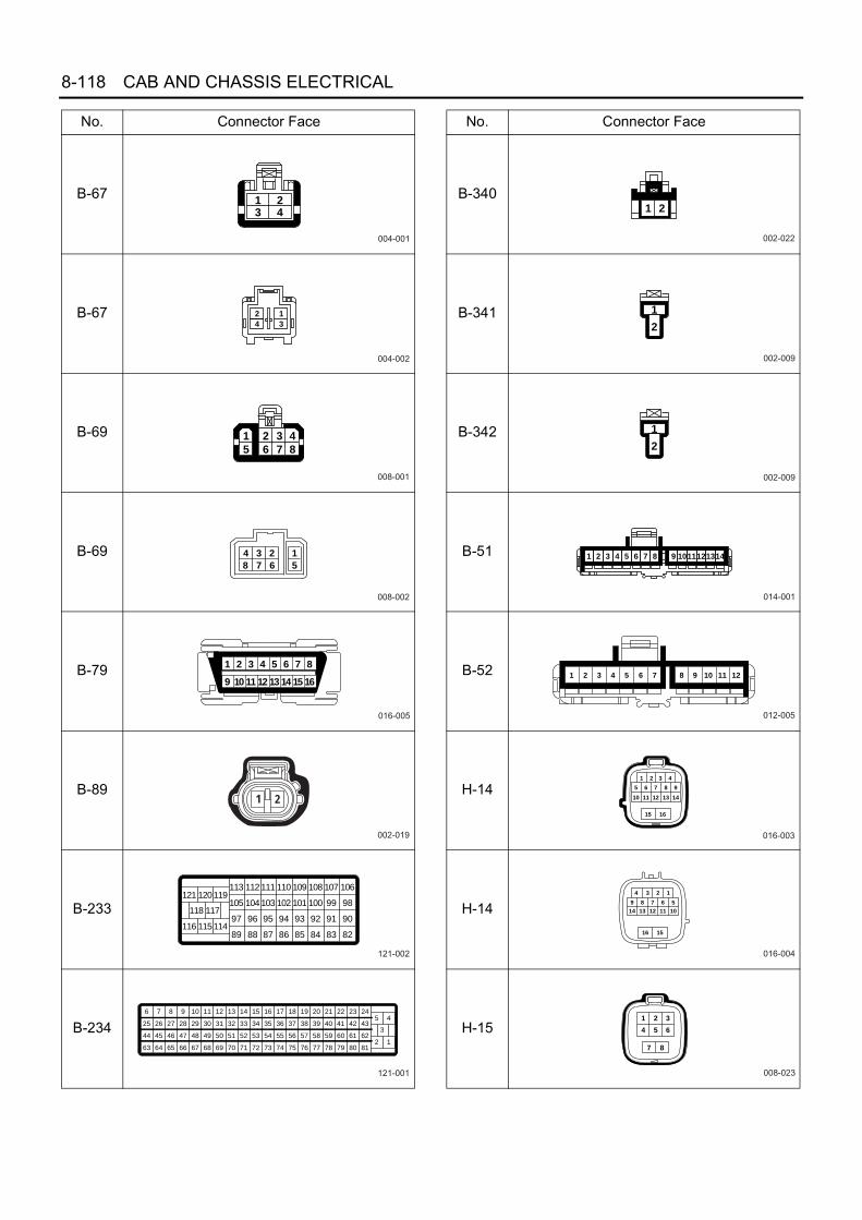
8-118 CAB AND CHASSIS ELECTRICAL
B-67
B-67
B-69
B-69
B-79
B-89
B-233
B-234
No. Connector Face
004-001
1 23 4
004-002
2
4
1
3
008-001
1
5
2
6
3
7
4
8
008-002
1
5
23
67
4
8
016-005
87654321
161514131211109
002-019
1 2
121-002
121 120119113
105
97
89
112
104
96
88
111
103
95
87
110
102
94
86
109
101
93
85
108
100
92
84
107
99
91
83
106
98
90
82116 115114
118 117
121-001
5 417
55
74
18
56
75
19
57
76
20
58
77
21
59
78
22
60
79
23
61
80
24
62
81
9
47
66
10
48
67
11
49
68
6
44
63
7
45
64
8
46
65
12
50
69
13
51
70
14
52
71
15
53
72
16
36 37 38 39 40 41 42 4328 29 3025 26 27 31 32 33 34 35
54
732 1
3
B-340
B-341
B-342
B-51
B-52
H-14
H-14
H-15
No. Connector Face
002-022
1 2
002-009
1
2
002-009
1
2
014-001
1 2 3 4 5 6 7 8 9 1011121314
012-005
1 2 3 4 5 6 7 8 9 10 11 12
016-003
1 2 3 4
5 6 7 8 9
11 12 13 14
15 16
10
016-004
4 3 2 1
9 8 7 6 5
13 12 11 10
16 15
14
008-023
1 2 3
4 5 6
7 8

CAB AND CHASSIS ELECTRICAL 8-119
H-15
B-80
E-5
E-16
E-110
J-6
J-9
J-31
No. Connector Face
008-024
3 2 1
6 5 4
8 7
003-005
1 2 3
000-009
002-014
1 2
009-003
16
27
34
859
004-011
1
3
2
4
000-001
002-011
1 2
J-31
J-32
J-40
J-50
J-122
J-177
J-182
J-183
No. Connector Face
002-012
12
003-018
1 2 3
002-017
1 2
002-035
001-007
1
034-001
005-004
1 2 3 4 5
003-006
1 2 3

8-120 CAB AND CHASSIS ELECTRICAL
H-5
H-6, H-7, H-8
P-1
P-2
P-4
P-3
P-5
No. Connector Face
000-002
000-002
000-014
000-014
000-007
1 2 37 8 9
13 14 1519 20 2125 26 2731 32 33 34 35 36 37
4 5 610 11 1216 17 1822 23 2428 29 3038 39 40
6 5 412 11 1018 17 1624 23 2230 29 2840 39 38
3 2 19 8 715 14 1321 20 1927 26 2533 32 3134353637
N8A5488E
1 2
1 2
1 2 3 4
5 6 7 8
9 10 11 12 13
14 15 16 17 18
2 1
2 1
4 3 2 1
8 7 6 5
13 12 11 10 9
18 17 16 15 14
H - 6
H - 7
H - 8
N8A5489E

CAB AND CHASSIS ELECTRICAL 8-121
For 4HK1-TC Engine
No. Connector Face
B-1
B-7
B-31
B-51
B-52
B-67
B-67
B-69
000-001
000-012
006-001
1 2 3
4 5 6
020-005
020-005
004-001
1 23 4
004-002
2
4
1
3
008-001
1
5
2
6
3
7
4
8
B-69
B-84
B-89
B-89
B-79
B-280
B-281
B-387
No. Connector Face
008-002
1
5
23
67
4
8
006-001
1 2 3
4 5 6
002-009
1
2
002-010
1
2
016-005
87654321
161514131211109
003-005
1 2 3
003-028
002-038

8-122 CAB AND CHASSIS ELECTRICAL
B-387
B-422
B-427
B-431
B-431
H-4
H-4
H-12
No. Connector Face
002-039
002-027
21
017-001
002-038
002-039
020-002
10111213 14 15
1 2 3 4 5
171819 20
6 7 8 9
16
020-003
9 8 7 6
20191817 16
5
1415
4
13
3
12
2
11
1
10
022-001
1 2 3 4
13 14
5 6 7 8 9 10
15 16 17 18 19 2011 12 21 22
H-12
H-15
H-15
H-105
H-105
H-120
H-120
H-125
No. Connector Face
022-002
9 8 7
20 19
6 5 4 3 2 1
18 17 16 15 14 1322 21 12 11
10
016-003
1 2 3 4
5 6 7 8 9
11 12 13 14
15 16
10
016-004
4 3 2 1
9 8 7 6 5
13 12 11 10
16 15
14
006-026
3 2 1
6 5 4
006-027
1 2 3
4 5 6
001-023
1
001-022
1
008-019
1 2 3 4
5 6 7 8

CAB AND CHASSIS ELECTRICAL 8-123
H-125
H-126
H-126
E-3
E-5
E-90
E-93
E-94
No. Connector Face
008-020
4 3 2 1
8 7 6 5
008-022
1 2 3 4
5 6 7 8
008-021
4 3 2 1
8 7 6 5
000-009
001-021
003-004
1 2
3
002-035
005-007
E-98
E-112
E-113
E-116
E-138
E-139
E-140
E-141
No. Connector Face
002-036
003-026
003-029
002-036
003-031
003-031
003-031
003-031

8-124 CAB AND CHASSIS ELECTRICAL
X-1
X-11
X-18
X-20
X-21
X-26
X-33
J-1
No. Connector Face
005-006
005-001
1
32 4
5
005-003
1
2 3
54
005-003
1
2 3
54
005-003
1
2 3
54
005-006
014-002
1 2 3
7 8 9 10 11
4
12
5
13
6
14
002-003
1 2
J-2
J-6
J-26
J-27
J-31
J-31
J-32
J-40
No. Connector Face
000-001
002-032
1 2
000-002
000-009
002-011
1 2
002-012
12
003-018
1 2 3
002-017
1 2

CAB AND CHASSIS ELECTRICAL 8-125
H-5
J-50
J-166
J-177
J-191
N-6
N-6
P-1
P-4
No. Connector Face
002-035
003-001
1 2 3
034-001
002-022
1 2
002-023
2 1
000-004
000-004
P-2
P-3
P-5
No. Connector Face
000-006
000-006
000-002
1 2 37 8 9
13 14 1519 20 2125 26 2731 32 33 34 35 36 37
4 5 610 11 1216 17 1822 23 2428 29 3038 39 40
6 5 412 11 1018 17 1624 23 2230 29 2840 39 38
3 2 19 8 7
15 14 1321 20 1927 26 2533 32 3134353637
N8A5488E

8-126 CAB AND CHASSIS ELECTRICAL
H-6, H-7, H-8
Engine Stop System
General DescriptionThe circuit consists of starter switch and engine stopmotor.The engine stop mechanism aims at shut-off of fuel sup-ply.Available are motor type and solenoid type dependingon the types of the engine mounted.Motor type is forcible pull the injection pump control rackto the direction of fuel supply reduction by means of en-gine stop motor, thus shutting it off.Solenoid type is to have the starter switch turn from“ON” position to “OFF”, so that the solenoid valve fittedto the injection pump closes to shut off the fuel circuit.
Engine stop system Engine model
Motor type 4HF1, 4HG1,4HE1
Solenoid type 4JB1, 4JG2
1 2
1 2
1 2 3 4
5 6 7 8
9 10 11 12 13
14 15 16 17 18
2 1
2 1
4 3 2 1
8 7 6 5
13 12 11 10 9
18 17 16 15 14
H - 6
H - 7
H - 8
N8A5489E

CAB AND CHASSIS ELECTRICAL 8-127
Parts Location4JB1 / 4JG2 / 4HG1 (N-Spec) Engine
N8A0108E
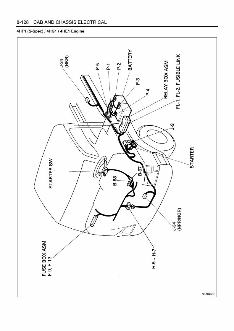
8-128 CAB AND CHASSIS ELECTRICAL
4HF1 (S-Spec) / 4HG1 / 4HE1 Engine
F-9
, F-1
3
J-34
(NK
R)
J-34
(NP
R/N
QR
)
N8A0450E

CAB AND CHASSIS ELECTRICAL 8-129
Circuit Diagram
N8A0109E

8-130 CAB AND CHASSIS ELECTRICAL
Connector List
No. Connector Face
B-67
B-67
B-68
B-68
J-34
J-34
P-1
P-4
004-001
1 23 4
004-002
2
4
1
3
006-002
1
3 4 5 6
2
006-003
2
6 5 4 3
1
006-004
1 2 3
4 5 6
006-005
3 2 1
6 5 4
000-004
000-004
P-2
P-3
P-5(12 V)
P-5(24 V)
E-15
E-15
H-14
H-14
No. Connector Face
000-006
000-006
000-007
000-002
001-002
1
001-003
1
016-001
1 2 3 4
5 6 7 8
9 10 11 12
13 14 15 16
016-002
4 3 2 1
8 7 6 5
12 11 10 9
16 15 14 13
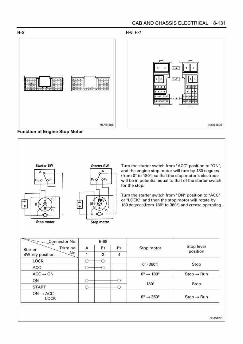
CAB AND CHASSIS ELECTRICAL 8-131
H-5 H-6, H-7
Function of Engine Stop Motor
1 2 37 8 9
13 14 1519 20 2125 26 2731 32 33 34 35 36 37
4 5 610 11 1216 17 1822 23 2428 29 3038 39 40
6 5 412 11 1018 17 1624 23 2230 29 2840 39 38
3 2 19 8 715 14 1321 20 1927 26 2533 32 3134353637
N8A5488E
1 2
1 2
1 2 3 4
5 6 7 8
9 10 11 12 13
14 15 16 17 18
2 1
2 1
4 3 2 1
8 7 6 5
13 12 11 10 9
18 17 16 15 14
H - 6
H - 7
H - 8
N8A5489E
N8A5127E

8-132 CAB AND CHASSIS ELECTRICAL
Solenoid TypeStarter Switch and Solenoid ValveTurn the starter switch from “ON” position to “OFF”, andthen the solenoid valve fitted to the injection pump clos-es to cut off the fuel circuit.
Key position Solenoid valve
LOCKClose
ACC
ONOpen
START
N8A0112E

CAB AND CHASSIS ELECTRICAL 8-133
Headlight, Fog Light, Rear Fog Light and Cornering LightGeneral DescriptionThe circuit consists of headlight, fog light, cornering light, starter switch, combination switch (Lighting switch, dimmer/ passing switch, cornering light switch), fog light switch, rear fog light switch, rear fog light, high beam indicator lightand relay.When the lighting SW is turned on by setting it at headlight position, the lighting relay is actuated to turn on the head-light. The optical axis of the headlight can be turned up or down by operating the dimmer SW while headlight is on.The passing SW is independent of the lighting SW, and the optical axis of the passing light can be turned up onlywhile the switch lever is pulled up and held in this state.Fog light turns on by switching it to “ON” position to activate relay only while lighting SW is on. Rear fog light turns onby switching it to “ON” position to activate relay only while lighting SW is at headlight position.When the headlight is on, turn the turn-signal switch left or right, and then the cornering switch built in the combinationswitch turns on, followed by the cornering light turning on.Lighting Circuit
Notice:Arrow marks indicate the direction of current.
CORNERING LIGHT HEADLIGHT FOG LIGHT REAR FOG LIGHT
Starter sw.(ON)
Corneringlight relay
Dimmer relay
Corneringlight
Corneringlight sw.
Lighting sw.
Dimmer sw.
Fog lightsw.
Fog light
LO HI
L H
OFF RR FOG
Rearfog light
Rearfog lightrelay
Headlight
Headlight relay
Tail relay
Battery (+)
N8A5573E

8-134 CAB AND CHASSIS ELECTRICAL
Parts Location
FL-
1, F
L-2,
FL-
4 F
US
IBLE
LIN
K
F-6
, F-7
, F-8
, F-1
6,F
-23,
F-2
4, F
-27
B-7
X-4
TA
IL R
ELA
YX
-3 H
EA
DLI
GH
T R
ELA
Y
X-6
DIM
ME
R R
ELA
YX
-9 C
OR
NE
RIN
G L
IGH
T R
ELA
Y
X-2
3 R
EA
R F
OG
LIG
HT
RE
LAY
B-4
HE
AD
LIG
HT
(LH
)
B-7
3 H
EA
DLI
GH
T (
RH
)
N8A0114E

CAB AND CHASSIS ELECTRICAL 8-135
Circuit DiagramFor 12 Volt (Except NKR77 for Taiwan)
HI
B-4
X-9
X-1
4
H-6
B-6
7B
-67
B-1
8
B-1
8
X-6
B-5
5
B-5
2
B-7
3
B-7
3
X-3
H-7
OFF
ON
AC
C
ST
B
B-1
B-7
4B
-5
B-7
0B
-70
B-7
4B
-5
B-7
OFF
H T
HIG
HLO
E2
PA
SS
B-7
0
P-5
P-1
P-2
2
H-7
2
X-3
X-3
X-3
21
45
1
23
X-1
4
X-1
4X
-141
2 45
X-9
X-9
X-9
21
45
B-4
B-4
B-7
3
12
3
21
3
10 10
X-6
X-6
X-6
X-6
21
3
45
11
33
119
LH
RH
B-7
0
B-7
0
B-7
0
Hu
24107
B-7
0
B-7
0
81
B-1
813
2
KE
Y S
W
FL-2
50
A
HE
AD
LA
MP
FL-4
30
A
MA
IN
FL-1
10
0A
3W/B
2W/R
2W/R
8W5W
RELAY; HEAD LIGHT
0.3R D
IOD
ELI
GH
TIN
G S
W
0.3L
/R
0.3R
CO
RN
ER
ING
LIG
HT
SW
ITC
H
COMBINATION SW
0.3L
0.5R/W
0.5P
0.85B0.5P/B
3B
FRA
ME
-LH
(FR
ON
T)
HE
AD
LIG
HT
BR
AC
KE
T (
LH)
0.85B
1.25B
0.3R/L
RE
LAY
; DIM
ME
R
1.25B
0.85
B
0.85B
0.5R/G
0.85
R/G
1.25
R/Y
0.5R
/B
RE
LAY
;C
OR
NE
RIN
G L
IGH
T
0.3G
/O0.
5R/L
0.5B/Y
ST
AR
TE
R S
W
F-16
10
A
ME
TE
R
3W/B
8W/B
RE
LAY
; TA
IL
0.3G
/O
F-24
HE
AD
LIG
HT
(LH
)
F-23
HE
AD
LIG
HT
(RH
)
2R
2R
CORNERING LIGHT(FRT. COMBINATION LIGHT)
(RH)
(LH)
HL
0.85R
0.85R/L
HIGH BEAM INDICATORLIGHT (METER)
2
FRA
ME
RH
LO
HI
HEADLIGHTLH
LO
HEADLIGHT1.
25R
/Y
0.85
R/G
3B/Y
3W/L
5B
F-7
10A
10A
10A
TA
IL L
IGH
T
3W/B
3W/B
4JH1: 3W4HG1-T: 3W4JB1, 4JB1-TC: 3L
4JH
1: 3
W4H
G1-
T: 3
W4J
B1,
4JB
1-T
C: 3
L
B-7
2B
-3
B-7
2
B-8
7B
-87
B-8
7B
-87
23
56
B-3
1 2
1 2
0.85R/G
0.85R/G
0.85LG/R
0.85
LG/R
FRT. COMBINATION LIGHT (LH) (4)
FOG LIGHT SW
FOG LIGHT (LH)
FOG LIGHT (RH)
10A
: 4JB
1,4J
B1-
TC
/ 4J
H1
F-6
10A
: 4H
G1-
TF-
8
FRT
FO
G L
IGH
T,
CO
RN
ER
ING
LA
MP
0.5B
0.85V
0.5B
0.5B
2L
P-3
P-4
4JH
1
N8A0115E

8-136 CAB AND CHASSIS ELECTRICAL
For 24 Volt
HI
B-4
X-9
X-4
H-6
B-6
7B
-67
B-1
8
B-1
8
X-6
B-5
5
B-5
2
B-7
2B
-3
B-7
2
B-8
7B
-73
B-7
3
X-3
H-7
OFF
ON
AC
C
ST
B
B-1
B-7
4B
-5
B-7
0B
-70
B-7
4B
-5
B-7
OFF
H T
HIG
HLO
E2
PA
SS
B-7
0
P-5
P-4
P-3P-1
P-2
2
H-7
2
X-3
X-3
X-3
21
45
1
23
X-4
X-4
X-41
2 45
X-9
X-9
X-9
21
45
B-4
B-4
B-7
3
12
3
21
3B
-87
B-8
7B
-87
32
65
B-3
1 2
1 2
10 10
X-6
X-6
X-6
X-6
21
3
45
11
33
119
LH
RH
B-7
0
B-7
0
B-7
0
Hu
24107
B-7
0
B-7
0
81
B-1
813
2
KE
Y S
W
FL-2
40
A
MA
INFL
-1
100A
or
120A
HE
AD
LA
MP
FL-4
30
A
3W/B
5W/B
2W/R
2W/R
5W
RELAY; HEAD LIGHT
0.3R D
IOD
ELI
GH
TIN
G S
W
0.3L
/R
0.3R
CO
RN
ER
ING
LIG
HT
SW
ITC
H
COMBINATION SW
0.3L
0.5R/W
0.5P
0.85B0.5P/B
3B
FRA
ME
-LH
(FR
ON
T)
HE
AD
LIG
HT
BR
AC
KE
T (
LH)
0.85B
1.25B
0.3R/L
RE
LAY
; DIM
ME
R
0.85B
0.85
B
0.85B
0.5B
0.5B
0.5R/G
0.85R/G
0.85R/G
0.5B
0.5R
/G
0.85
R/Y
0.5R
/B
RE
LAY
;C
OR
NE
RIN
G L
IGH
T
0.3G
/O0.
5R/L
0.5B/Y
ST
AR
TE
R S
W
F-16
10
A
ME
TE
R
3W/B
3W/B
3W/B
RE
LAY
; TA
IL 3W
0.85LG/R
0.85LG/R
F-24
10A
F-23
10A
HE
AD
LIG
HT
(LH
)H
EA
D L
IGH
T(R
H)
F-8
10A
FRT
FO
G L
IGH
T,
CO
RN
ER
ING
LA
MP
F-7
TA
IL L
IGH
TFR
T. C
OM
BIN
AT
ION
LIG
HT
(LH
) (4
)
FOG LIGHT SW
2R
2R/W
CORNERING LIGHT(FRT. COMBINATION LIGHT)
(RH)
(LH)
HL
0.85R
0.85R/L
HIGH BEAM INDICATORLIGHT (METER)
FOG LIGHT (LH)
FOG LIGHT (RH)
2
FRA
ME
RH
LO
HI
HEADLIGHT
LH
LO
HEADLIGHT
0.85
R/Y
0.5R
/G
3B/Y
3W/L
2B
5B
2L
10A
N8A0386E

CAB AND CHASSIS ELECTRICAL 8-137
With Rear Fog Light
HI
B-4
X-4
H-6
X-6
B-5
5
B-5
2
B-7
2B
-3
B-7
2
B-8
7B
-73
B-7
3
X-3
B-1
B-7
OFF
RR
FO
G
H T
HIG
HLO
E2
PA
SS
P-5
2
X-3
X-3
X-3
21
45
45
X-4
X-4
X-41
2
B-4
B-4
B-7
3
12
3
21
3B
-87
B-8
7B
-87
32
65
B-3
1 2
1 2
10 10
X-6
X-6
X-6
X-6
21
3
45
B-7
0
B-7
0
B-7
0
Hu
4107
B-7
0
B-7
0
81
MA
IN
FL-1
10
0A
HE
AD
LA
MP
FL-4
30
A
8W
2W
5W8W
/B
RELAY; HEAD LIGHT
0.3R
0.3R
LIG
HT
ING
SW
COMBINATION SW
0.5R/W
5BFR
AM
E-L
H (
FRO
NT
)
HE
AD
LIG
HT
BR
AC
KE
T (
LH)
1.25B
0.5R/L
RE
LAY
; DIM
ME
R
1.25B
0.85
B
0.5B
0.5R/G
0.85R/G
0.85R/G
0.3G
/O
RELAY; TAIL
0.85V
4JB
1, 4
JB1-
TC
: 3L
4JH
1: 3
W
F-24
10A
10A
10A
HE
AD
LIG
HT
(LH
)
F-23
HE
AD
LIG
HT
(RH
)FRT. COMBINATIONLIGHT (LH) (4)
LICENSE LIGHT
HEADLIGHT
2R
2R
HL
0.85R
0.85R/L
HIGH BEAM INDICATORLIGHT (METER)
INDICATORLIGHT (METER)
FOG LIGHT (LH)
FOG LIGHT (RH)
FRA
ME
3B
3B
J-9
FRA
ME
-LH
(C
EN
TE
R)
1.25
B2B
1.25
R/Y 0.
85R
/G
HI
LO
LH
1.25
R/Y
0.85
R/G
HEADLIGHT
LORH
B-7
0 14
F-6
FRT
FO
G L
IGH
T,
CO
RN
ER
ING
LA
MP
F-27
(1
5A)
FOG
LIG
HT
(R
EA
R) 0.5L
G/R
0.85
R/G 2B
H-1
67
1.25
B
F-7
TA
IL L
IGH
T
0.85LG/R
0.85
LG/R
0.85LG/R
0.85LG/W
X-2
3
X-2
3X
-234
1 52
RELAY;RR FOG LIGHT
H-8
X-2
3
5
H-5 5
0.85R/G 0.85R/G
0.5GR/B
H-1
63
H-8
0.5R/G 0.5R
R-1
21
R-1
2 2
RR
FO
GLI
GH
T
0.85
B
0.85
R/G
0.85
LG/R
1.25
B
0.5G
R/B
0.5B
0.5B
P-1
P-2
2W/R
2W/R
2L
P-3
P-4
4JH
1
3W/B
3W/B
B-8
7
B-8
7
FOG LIGHT SWITCH
41
H-7
2
0.5B
4 10
0.5G
/R
10A
N8A0117E
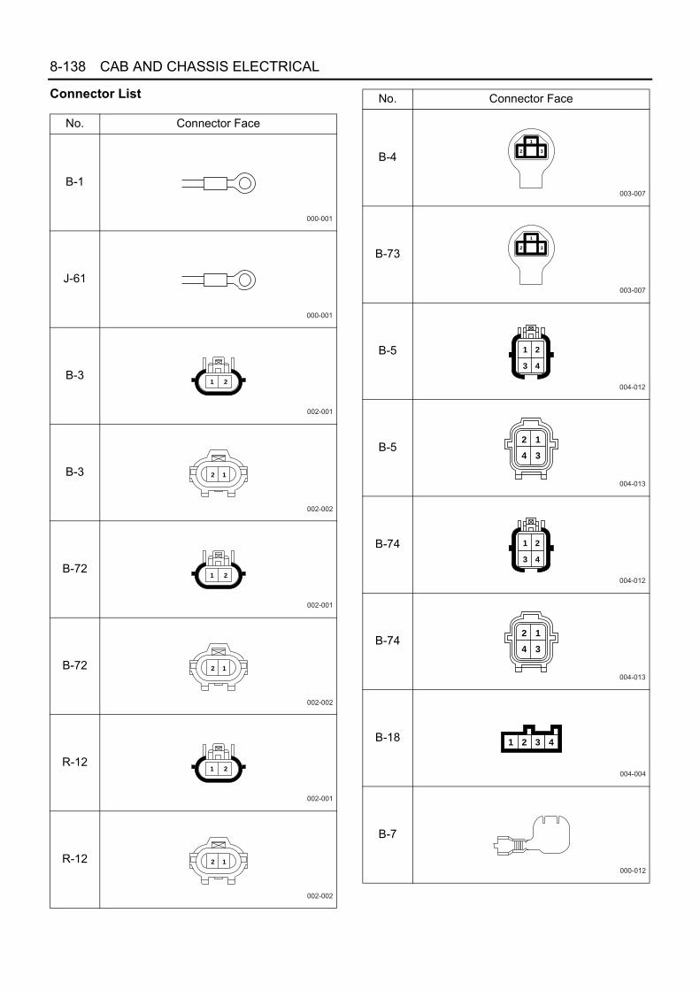
8-138 CAB AND CHASSIS ELECTRICAL
Connector List
No. Connector Face
B-1
J-61
B-3
B-3
B-72
B-72
R-12
R-12
000-001
000-001
002-001
1 2
002-002
12
002-001
1 2
002-002
12
002-001
1 2
002-002
12
B-4
B-73
B-5
B-5
B-74
B-74
B-18
B-7
No. Connector Face
003-007
1
32
003-007
1
32
004-012
1 2
3 4
004-013
12
34
004-012
1 2
3 4
004-013
12
34
004-004
1 2 3 4
000-012

CAB AND CHASSIS ELECTRICAL 8-139
X-3
X-4
X-6
X-9
X-23
B-153
B-154
B-52
No. Connector Face
005-006
005-006
005-006
005-006
005-006
006-007
1 2 34 5 6
000-016
012-005
1 2 3 4 5 6 7 8 9 10 11 12
B-55
B-67
B-67
B-70
B-70
B-87
H-16
H-16
No. Connector Face
012-004
1 2 3 4 5 6 7 8 9 10 11 12
004-001
1 23 4
004-002
2
4
1
3
014-002
1 2 3
7 8 9 10 11
4
12
5
13
6
14
014-003
6 5 4
14131211
3 2 1
9 8 710
006-006
21 3
54 6
008-003
1 2 3 4
5 6 7 8
008-004
4 3 2 1
8 7 6 5

8-140 CAB AND CHASSIS ELECTRICAL
H-6, H-7, H-8
P-1(12 V)
P-2
P-1(24 V)
P-4
P-2(24 V)
P-3
P-5(12 V)
P-5(24 V)
No. Connector Face
000-003
000-004
000-004
000-004
000-006
000-006
000-007
000-002
1 2
1 2
1 2 3 4
5 6 7 8
9 10 11 12 13
14 15 16 17 18
2 1
2 1
4 3 2 1
8 7 6 5
13 12 11 10 9
18 17 16 15 14
H - 6
H - 7
H - 8
N8A5489E

CAB AND CHASSIS ELECTRICAL 8-141
DiagnosisQuick Chart for Check Point1. Headlight
Notice:Figure in parenthesis “( )” indicates the order of inspection.
Check point
FuseFus-ible link Head-
light relay
Light-ing SW
Dim-mer / Pass-
ing SW
Dim-mer relay
Headlight bulb Cable
har-nessF-6
F-8(10 A)
F-23(10 A)
F-24(10 A)
FL-4(30A) LH RH
Trouble mode
1-1. Both Head-lights inopera-tive
(2)
(1)
(4)
(3)
1-2. Headlight on the left (or right) side inop-erative
(1)
((1))
(2)
1-3. Headlight in low-beam inop-erative
(1)
(2)
1-4. Headlight in high-beam inop-erative
(1)
(2)
1-5. Headlight on the left (or right) side in low (or high)-beam inoperative
(1)
((1))
(2)
1-6. Headlight beam does not change
(1)
(2)
(3)
(4)
1-7. Headlights remain on when the lighting switch turned off
(1)
(2)
(3)
1-8. Headlights come on with the lighting SW at the clearance light position
(1)

8-142 CAB AND CHASSIS ELECTRICAL
2. Fog Light
Notice:Figure in parenthesis “( )” indicates the order of inspection.
3. Cornering Light
4. Rear Fog Light
Check point
FuseF-6 (10 A): 4JH1,4JB1, 4JB1-
TCF-8 (10 A): 24V, 4HG1-T (12 V)
Tail-light relay
Fog light SW
Fog light bulb Cable
harnessLH RH
Trouble mode
2-1. Both fog lights inopera-tive (while lighting switch is on)
(1)
(2)
(3)
(4)
2-2. Fog light on the left (or right) side inoperative (while lighting switch is on)
(1)
((1))
(2)
2-3. Fog lights remain on
(1)
(2)
(3)
Check point
FuseCornering light SW
Cornering light bulb
Cornering light relay
Cable harness
F-6 : 4JH1,4JB1,4JB1-TC
F-8 : 24V,4HG1-T(12V)
F-16(10 A)
Trouble mode
3-1. Both corner-ing lights inoper-ative
(2)
(1)
(5)
(3)
(4)
3-2. Cornering light on the left (or right) side inoperative
(2)
(1)
(3)
3-3. Cornering light remains on even when steer-ing wheel is in the straight ahead position
(1)
Check point
FuseF-27 (15 A)
Rear fog light SW
Rear fog light relay
Rear fog light bulb
Cable harness
Trouble mode
4-1. Rear fog light inoperative (while headlight is ON)
(2)
(4)
(3)
(1)
(5)

CAB AND CHASSIS ELECTRICAL 8-143
1. Headlight1-1. Both Headlights Inoperative
1-2. Headlight on The Left (or Right) Side Inoperative
N8A0118E
IS FUSE F-24 OR F-23 (10A) NORMAL?
YES NO
REPLACE THE FUSEREPAIR A POOR CONNECTION AT THE CONNECTORSOR AN OPEN CIRCUIT BETWEEN FUSE F-24 (10A) AND 3 B-4 (OR 3 B-148 ) OR FUSE F-23 (10A) AND 3 B-73(OR 3 B-150 )
•
N8A0119E

8-144 CAB AND CHASSIS ELECTRICAL
1-3. Headlight in Low-beam Inoperative
1-4. Headlight in High-beam Inoperative
N8A0120E
• IS THE DIMMER RELAY NORMAL?
• DISCONNECT THE DIMMER / PASSING SWCONNECTOR
• IS THERE ANY CONTINUITY BETWEEN SW SIDECONNECTORS 4 B-70 AND 10 B-70 WHEN THE SW ISAT HIGH-BEAM POSITION?
YES NO
REPLACE THE RELAY
REPAIR A POOR CONNECTION AT THE CONNECTORSOR AN OPEN CIRCUIT BETWEEN 1 X-6 AND 2 B-74
YES NO
REPAIR OR REPLACE THE SW• DISCONNECT THE HEADLIGHT RELAY• IS THERE ANY CONTINUITY BETWEEN CHASSIS SIDE
CONNECTORS 10 B-70 AND 5 X-3 ?
YES NO
REPAIR A POOR CONNECTION AT THECONNECTORS OR AN OPEN CIRCUITBETWEEN 10 B-70 AND 5 X-3
IS FUSE F-6 OR F-8 CONNECTED?
YES NO
REPLACE THE FUSE
•
N8A0121E

CAB AND CHASSIS ELECTRICAL 8-145
1-5. Headlight on The Left (or Right) Side in Low (or High)-beam Inoperative
1-6. Headlight Beam Does Not Change
• IS THE BULB NORMAL?
REPAIR A POOR CONNECTION AT THE CONNECTORSOR AN OPEN CIRCUIT[LOW BEAM]BETWEEN 1 B-4 (OR 1 B-73 ) AND 3 X-6 [HIGH BEAM]BETWEEN 2 B-4 (OR 2 B-73 ) AND 1 X-6
YES NO
REPLACE THE BULB
N8A0122E
N8A0123E

8-146 CAB AND CHASSIS ELECTRICAL
1-7. Headlight Remains On when the Lighting SW is Turned Off
1-8. Headlight Comes On with The Lighting SW at The Clearance Light Position
• IS THE LIGHTING RELAY NORMAL?
• DISCONNECT THE LIGHTING SW CONNECTOR• IS THE CONTINUITY BETWEEN THE SWITCH
CONNECTOR TERMINALS 1 B-70 AND 4 B-70NORMAL?
YES NO
REPLACE THE LIGHTING RELAY
REPAIR A SHORT CIRCUIT BETWEEN 4 X-3 AND 1 B-70
YES NO
REPAIR OR REPLACE THE LIGHTING SW
N8A0124E
• DISCONNECT THE LIGHTING SW CONNECTOR• WITH THE LIGHTING SW AT THE CLEARANCE LIGHT
POSITION, IS THE CONTINUITY BETWEEN 1 B-70AND 4 B-70 NORMAL?(NO CONTINUITY NORMAL)
NO
REPAIR OR REPLACE THE LIGHTING SW
N8A0125E

CAB AND CHASSIS ELECTRICAL 8-147
2. Fog Light2-1. Both Fog Lights Inoperative (While Lighting Switch is On)
• IS FUSE F-6 (10A) OR F-8 (10A) NORMAL?
• IS THE TAIL RELAY NORMAL?
YES NO
REPLACE THE FUSE
• REMOVE THE FOG LIGHT SW• WHEN THE SWITCH IS "ON", IS THERE CONTINUITY
BETWEEN THE SWITCH CONNECTOR TERMINALS 3 B-87 AND 6 B-87 ?
YES NO
REPLACE THE RELAY
• IS THE BATTERY VOLTAGE APPLIED BETWEEN THEHARNESS SIDE CONNECTOR 3 B-87 AND THEGROUND, WHILE THE LIGHTING SW IS ON?(LIGHTING OPERATION IS NORMAL)
YES NO
REPAIR OR REPLACE THE SW
• REPAIR A POOR CONNECTION AT THE CONNECTORSOR AN OPEN CIRCUIT BETWEEN 6 B-87 AND 1 B-3
YES NO
REPAIR A POOR CONNECTION AT THECONNECTORS OR AN OPEN CIRCUIT BETWEEN 8 B-70 AND 5 X-15
N8A0126E

8-148 CAB AND CHASSIS ELECTRICAL
2-2. Fog Light on The Left (or Right) Side Inoperative (While Lighting Switch is On)
Notice:Figures in parenthesis “( )” indicate place of inspection for the fog light on the right.
2-3. Fog Light Remains On
• IS THE BULB NORMAL?
REPAIR A POOR CONNECTION AT THE CONNECTORSOR AN OPEN CIRCUIT BETWEEN 2 B-3 AND B-7 (2 B-72 AND B-7 )
YES NO
REPLACE THE BULB
N8A0127E
• DO THE TAILLIGHTS GO OFF?
REPAIR OR REPLACE THE FOG LIGHT SWITCH
YES NO
REPLACE THE TAIL RELAY
N8A0128E

CAB AND CHASSIS ELECTRICAL 8-149
3. Cornering Light3-1. Both Cornering Lights Inoperative
N8A0129E

8-150 CAB AND CHASSIS ELECTRICAL
3-2. Cornering Light on The Left (or Right) Side Inoperative
Notice:Figures in parenthesis “( )” indicate place of inspection for the cornering light on the right.
3-3. Cornering Light Remains on Even when Steering Wheel is in Straight Ahead Position
N8A5149E
• DOES THE CORNERING LIGHT SWITCH OPERATESMOOTHLY?
NO
REPAIR OR REPLACE THE CORNERING LIGHTSWITCH (COMBINATION SWITCH)
N8A0131E
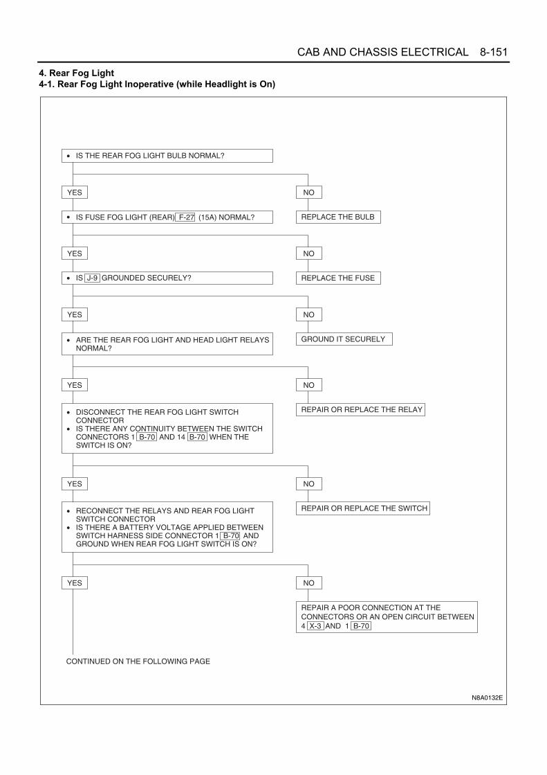
CAB AND CHASSIS ELECTRICAL 8-151
4. Rear Fog Light4-1. Rear Fog Light Inoperative (while Headlight is On)
• IS THE REAR FOG LIGHT BULB NORMAL?
• IS FUSE FOG LIGHT (REAR) F-27 (15A) NORMAL?
YES NO
REPLACE THE BULB
• IS J-9 GROUNDED SECURELY?
YES NO
REPLACE THE FUSE
• ARE THE REAR FOG LIGHT AND HEAD LIGHT RELAYSNORMAL?
YES NO
GROUND IT SECURELY
YES NO
REPAIR OR REPLACE THE RELAY• DISCONNECT THE REAR FOG LIGHT SWITCHCONNECTOR
• IS THERE ANY CONTINUITY BETWEEN THE SWITCHCONNECTORS 1 B-70 AND 14 B-70 WHEN THESWITCH IS ON?
YES NO
CONTINUED ON THE FOLLOWING PAGE
YES NO
REPAIR A POOR CONNECTION AT THECONNECTORS OR AN OPEN CIRCUIT BETWEEN4 X-3 AND 1 B-70
• RECONNECT THE RELAYS AND REAR FOG LIGHTSWITCH CONNECTOR
• IS THERE A BATTERY VOLTAGE APPLIED BETWEENSWITCH HARNESS SIDE CONNECTOR 1 B-70 ANDGROUND WHEN REAR FOG LIGHT SWITCH IS ON?
REPAIR OR REPLACE THE SWITCH
N8A0132E

8-152 CAB AND CHASSIS ELECTRICAL
Starter SwitchRefer to “START AND CHARGING” in this section.
High Beam Indicator LightRefer to “METER AND WARNING/INDICATOR LIGHT”in this section.
Headlight Bulb ReplacementRemoval
1. Remove the battery ground cable at the battery.2. Remove the headlight assembly. (Refer to ‘Head-
light Replacement’ below.)3. Remove the headlight bulb.
• Remove the dust cover (3).• Remove the clip (1).• Remove the headlight bulb (2).
Caution:Do not touch the glass portion of the bulb with your fin-gers.
Installation1. Install the headlight bulb.
• Set the headlight bulb (2).• Fix the headlight bulb with clip (1).• Install the dust cover (3).
2. Install the headlight assembly.(Refer to ‘Headlight Replacement’ below.)
3. Connect the battery ground cable at the battery.4. Check if the light lights.
N8A0133E
1 2 3
N8A5468E

CAB AND CHASSIS ELECTRICAL 8-153
Caution:Do not touch the glass portion of the new bulb with yourfingers.
Headlight ReplacementRemovalPreparation: Disconnect the battery ground cable.
1. Remove the battery ground cable at the battery.2. Remove the seal rubber (3).
• Remove the seal rubber from beneath theheadlight.
3. Remove the front combination light (2).• Open the cab door. Insert a screwdriver (1) into
the space between the cab and the cab door.Use the screwdriver to force out the stud pin atthe center of the grommet (the pin securing thefront combination light).
• Remove the fixing screw.• Remove the two catches.
• Remove the front combination light connector.4. Remove the front grille (4).
• Remove the bolt at the center of the front grille.• Remove the four clips securing the front grille.• The grille is secured by 4 clips (2 clips at the in-
side of each headlight). Pull the grille towardyou to remove it.
5. Remove the front corner panel.6. Remove the headlight (1).
• Remove the four bolts securing the headlight(loosen the fixing bolts at the bottom of the frontside panel to create working space).
• Remove the headlight clips.• Remove the headlight connector.
Installation1. Assemble the headlight assembly (1).
• Connect the connector.• Fix it to body panel with four bolts (5).
2. Assemble the front panel side.(Refer to “DOOR” in section 2.)
3. Install the front grille (4).4. Install the front combination assembly (2).
1) Position it by aligning two pawls with the grooveof H/L.
2) Fit the iron PIN in the upper portion by aligningit with the center of corresponding grommet.
Notice:Push it into securely with a force of approx. 250 N (25kgf) until click is heard.
3) Pull the front combination light assembly lightlytoward the front of vehicle to make sure that thePIN and grommet are engaged securely.
4) Tighten one bolt (6) in the lower portion of frontcombination light assembly.
5) Hook the seal rubber (3) on two projections un-der H/L.
1 2 3
N8A5468E
Door side Cab side
1
N8A5471E
1 2
3
4
N8A5472E

8-154 CAB AND CHASSIS ELECTRICAL
5. Connect the battery ground cable.6. Check the operation and lighting of each lamp.
Aiming of HeadlightPreparation: Place the unloaded vehicle on a level sur-face and check to see if the inflation pressure of the tiresis correct, the lenses are clean, and the battery is suffi-ciently charged. Adjust the aim with the headlight tester.When adjusting, follow the procedure of the tester man-ufacturer’s.
Vertical AdjustmentInsert the tip of a screwdriver into the hole beneath theheadlight (the shaft of the screwdriver must be slantedup) until contact is made with the head of the adjustingscrew. Turn the screw to adjust headlight focus up ordown.Two vertical aim screws should be turned in the samedirection at the same time to adjust aiming.
Horizontal AdjustmentInsert the tip of a screwdriver into the hole beneath theheadlight (the shaft of the screwdriver must be slantedup) until contact is made with the head of the adjustingscrew. Turn the screw to adjust headlight focus to theleft or right.
Cornering Light Bulb ReplacementRemoval
1. Remove the battery ground cable at the battery.2. Remove the front combination light.
• Open the cab door. Insert a screwdriver (1) intothe space between the cab and the cab door.Use the screwdriver to force out the stud pin atthe center of the grommet (the pin securing thefront combination light).
1 2
3
4
6
5
N8A0441E
N8A5473E
N8A5474E
N8A5475E

CAB AND CHASSIS ELECTRICAL 8-155
• Remove the fixing screw.• Remove the two catches.• Remove the front combination light (1) connec-
tor.
3. Remove the cornering light bulb.• Turn the cornering / clearance bulb socket (3)
to the left to remove it.• Press the bulb (2) in and turn it to the left to re-
move it from the socket.Installation
1. Install the cornering / clearance bulb.• While pressing the bulb (2), turn it clockwise to
fit.
Notice:Do not let the glass portion dirty with sebum etc.
• Turn the bulb socket (3) clockwise to fit.
2. Installation procedure of front combination light as-sembly• Connect the connector of the front combination
light assembly.• Position it by aligning two pawls with the groove
of H/L.• Fit the iron PIN (1) in the upper portion of the
side by aligning it with the center of correspond-ing grommet.
Notice:Push it into securely with a force of approx. 250 N (25kgf) until click is heard.
• Pull the front combination light assembly lightlytoward the front of vehicle to make sure that thePIN and grommet are engaged securely.
• Tighten one bolt in the lower portion of frontcombination light assembly.
3. Hook the seal rubber on two projections under H/L.4. Connect the battery ground cable.5. Check lighting of each light.
Door side Cab side
1
N8A5471E
1
3
2
N8A5477E
1
3
2
N8A0442E

8-156 CAB AND CHASSIS ELECTRICAL
Fog Light BulbRemoval
1. Remove the battery ground cable at the battery.2. Remove the four screws (1) to remove the cover
which holds fog light assembly (2).3. Remove the connector (3).4. Remove the fog light assembly (2).
5. Bulb• Push the clip (1) inward as arrow to remove.• Remove the bulb (2).
Installation1. Install the fog light bulb.
• Set the fog light bulb (2).• Hook the clip (1) to secure fog light bulb.
2. Connect the two locations of connector (4).3. Install the fog light assembly.
• Hold the fog light (2) with right and left covers(1) and secure it with four screws (3).
Notice:Make sure that “TOP” mark on the lens comes upside.
4. Connect the battery ground cable.5. Check lighting.
2
1
3
N8A5478E
12
N8A5479E
1
2
N8A0443E
2
1
4
3 N8A0444E

CAB AND CHASSIS ELECTRICAL 8-157
Fog Light SwitchInspectionCheck the continuity between the connector terminalswhile operating the switch.Replace the switch when the result of inspection isfound abnormal.
RemovalPreparation:Disconnect the battery ground cable.
1. Meter ClusterRefer to “METER AND WARNING/INDICATORLIGHT” in this section.
2. Fog Light SwitchRelease the lock pushing the switch from the backside of the meter cluster.
InstallationTo install, follow the removal steps in the reverse order.
N8A0435E
N8A0436E

8-158 CAB AND CHASSIS ELECTRICAL
Combination Switch (Lighting Switch, Dimmer, Passing Switch, Cornering Light Switch and RearFog Light Switch)InspectionCheck the continuity between the connector terminals while operating the switch.Replace the switch when the result of inspection is found abnormal.
RemovalPreparation:Disconnect the battery ground cable.
1. Horn Pad1) Hold the horn pad and pull it upward.
2. Steering Wheel1) Remove the steering shaft nut.2) Remove the steering wheel by using steering
wheel remover.(Refer to Section 3B4 “STEERING COLUMN”for steering wheel removal steps.)
3. Steering CowlRemove the four screws.
4. Combination Switch1) Remove the four screws.2) Disconnect the connector.
1 2 4 5 7 8 9 10 11 12 13 14
REAR FOGSW
OFF
High beam
Passing
Turning left
Neutral
Turningright
Lighting SW
Corneringlight SW
Terminal No.
SW position
N8A0143E

CAB AND CHASSIS ELECTRICAL 8-159
InstallationTo install, follow the removal steps in the reverse order,noting the following point.
1. Tighten the steering shaft nut to the specifiedtorque.
Tighten:Shaft nut to 49 N⋅m (5 kg⋅m / 36 lb⋅ft)
Headlight Leveling
General DescriptionThe circuit consists of starter SW, headlight leveling SWand headlight leveling actuator.When the headlight leveling SW is operated with thestarter SW at ON position, the actuator is operated tochange the angle of the optical axis of the headlight.
Operation of The Circuit
Notice:Arrow marks indicate the direction of current.
1. When headlight leveling SW is turned to “1” posi-tion
2. When headlight leveling SW is turned to “0” posi-tion
N8A0144E
0 1 2 3
HEADLIGHT LEVELINGACTUATOR - LH
HEADLIGHT LEVELINGACTUATOR - RH
STARTER SW "ON"
HEADLIGHTLEVELING SW
N8A0145E
0 1 2 3
HEADLIGHT LEVELINGACTUATOR - LH
HEADLIGHT LEVELINGACTUATOR - RH
STARTER SW "ON"
HEADLIGHTLEVELING SW
N8A0146E

8-160 CAB AND CHASSIS ELECTRICAL
Parts Location
F-12
B-7
X-1
1 (2
4V)
KE
Y O
N R
ELA
Y
X-1
(24
V)
KE
Y O
N R
ELA
YS
TA
RT
ER
SW
DC
-DC
CO
NV
ER
TE
R (
24V
ON
LY)
RE
LAY
BO
X A
SM
(N
o.1
)
HE
AD
LIG
HT
LE
VE
LIN
G R
ES
IST
OR
N8A0147E

CAB AND CHASSIS ELECTRICAL 8-161
Circuit DiagramFor 12 Volt
P-1
P-2
FL-1
100A
(12V
)M
AIN
B
ST
AC
C
ON
ST
AR
TE
R S
W
B-6
71
H-7
P-5
FRA
ME
FL-2
50A
(12V
)K
EY
SW
3W/L
3W/L
3W/B
23
B-6
7
F-12
10A
H/L
AM
P L
EV
EL
0.5R/W
2L
P-3
P-4
4JH
1
RE
LAY
; KE
Y O
N
3L
0.5B
3B/Y
3B/Y
X-1
X-1
X-1
X-1
AC
G B
2L
FUS
E B
LOC
K
2B
-421
3B
-421
4B
-421
5B
-421
6
0.5O
/G
0.5O
/B
0.5O
/W
0.5O
/L
0.5O
B-4
21
1B
-421
14B
-421
4B
-156
10B
-156
6B
-156
7
3
2
4 0
1B
-156
8B
-156
9B
-156
R5
R6
RESISTOR;H/L LEVELING
R4
R3
R2
R1
0.5R
/W
0.5R
/W
0.5B
1
B-1
55
3
B-1
55
2
0.5B
0.5B
B-1
55
AC
TU
AT
OR
; HLL
(LH
)(D
R S
IDE
HE
AD
LA
MP
)
1
B-1
52
3
B-1
52
2
B-1
52
AC
TU
AT
OR
; HLL
(R
H)
(AS
SID
E H
EA
D L
AM
P)
0.5R/W
0.5R/Y
0.5R
/Y
SW
; H/L
LEV
ELIN
G
1 3
2 5
N8A0148E

8-162 CAB AND CHASSIS ELECTRICAL
For 24 Volt
P-1
P-2
FL-1
100A
or
120A
MA
IN
B
ST
AC
C
ON
ST
AR
TE
R S
W
B-6
71
H-7
FL-2
40A
KE
Y S
W3W
/L
3W/L
3W/B
5W/B
3W/B
23
B-6
7
F-12
10A
H/L
AM
P L
EV
EL
2L
RE
LAY
; KE
Y O
N
3L
0.5B
3B/Y
3B/Y
X-1
1
X-1
1
X-1
1
X-1
1
AC
G B
FUS
E B
LOC
K
P-3
P-4
P-5
FRA
ME
2B
-421
3B
-421
4B
-421
5B
-421
6
0.5O
/G
0.5O
/B
0.5O
/W
0.5O
/L
0.5O
B-4
21
1B
-421
14B
-421
1B
-420
6B
-420
3B
-420
2B
-420
4B
-156
10B
-156
6B
-156
7
3
2
4 0
1B
-156
8B
-156
9B
-156
R5
R6
RESISTOR;H/L LEVELING
R4
R3
R2
R1
0.5R
/W
0.5B
/W1
B-1
55
3
B-1
55
2
B-1
55
AC
TU
AT
OR
; HLL
(LH
)(D
R S
IDE
HE
AD
LA
MP
)
1
B-1
52
3
B-1
52
2
B-1
52
AC
TU
AT
OR
; HLL
(R
H)
(AS
SID
E H
EA
D L
AM
P)
0.5R/W
0.5B/W
0.5R/Y
0.5R
/Y
SW
; H/L
LEV
ELIN
G
CO
NV
ER
TE
R;
DC
-DC
(HLL
)
0.5L
/O
0.5R
/W
0.5B
/W
1 3
2 5
N8A0388E

CAB AND CHASSIS ELECTRICAL 8-163
Connector List
H-7
No. Connector Face
B-7
B-67
B-67
B-152
B-155
B-156
P-1
P-2
000-012
004-001
1 23 4
004-002
2
4
1
3
003-016
3
1 2
003-016
3
1 2
010-002
5
21
6 7 8 9
43
10
000-004
000-003
P-5
B-420(24 V)
B-421
X-1(12V)
X-11(24 V)
No. Connector Face
000-007
006-019
4 5 6
1 2 3
014-002
1 2 3
7 8 9 10 11
4
12
5
13
6
14
005-006
005-001
1
32 4
5
1 2
1 2
1 2 3 4
5 6 7 8
9 10 11 12 13
14 15 16 17 18
2 1
2 1
4 3 2 1
8 7 6 5
13 12 11 10 9
18 17 16 15 14
H - 6
H - 7
H - 8
N8A5489E

8-164 CAB AND CHASSIS ELECTRICAL
DiagnosisQuick Chart for Check Points
1. Both Actuators Inoperative
Check point
FuseF-12 (10 A)
Headlight leveling switch
Headlight leveling actuator
Cable harness
Trouble mode
1. Both actuators inoperative
2. Actuator on the left (right) side inop-erative
3. When leveling SW is turned to a certain position, actuator inoperative
• IS FUSE F-12 (10A) NORMAL?
• IS B-7 GROUNDED SECURELY?
YES NO
REPLACE THE FUSE
• TURN THE STARTER SW TO ON POSITION• IS THE BATTERY VOLTAGE APPLIED BETWEEN THE
FUSE TERMINAL AND THE GROUND?
YES NO
GROUND IT SECURELY
• IS THE CONTINUITY IN THE HEADLIGHT LEVELING SW NORMAL?
YES NO
REPAIR AN OPEN CIRCUIT BETWEEN STARTERSW AND FUSE F-12 (10A)
• IS THERE CONTINUITY BETWEEN 6 B-156 AND THEGROUND?
YES NO
REPAIR OR REPLACE THE SWITCH
REPAIR A POOR CONNECTION AT THE CONNECTORS OR AN OPEN CIRCUIT BETWEEN FUSE F-20 AND 1 B-155 (1 B-152 )
YES NO
REPAIR AN OPEN CIRCUIT BETWEEN6 B-156 AND B-7
N8A0149E

CAB AND CHASSIS ELECTRICAL 8-165
2. Actuator on the Left (Right) Side Inoperative
3. When Headlight Leveling SW is Turned to A Certain Position, Actuator Inoperative
• IS THE ACTUATOR ON THE LEFT (RIGHT) SIDENORMAL?
• IS THERE CONTINUITY BETWEEN 6 B-155 (6 B-152 ) AND THE GROUND?
YES NO
REPLACE THE ACTUATOR
REPAIR A POOR CONNECTION AT THE CONNECTORS OR AN OPEN CIRCUIT BETWEEN F-12 (10A) AND 1 B-155 (1 B-152 )
YES NO
REPAIR A POOR CONNECTION AT THECONNECTORS OR AN OPEN CIRCUITBETWEEN 6 B-155 (6 B-152 ) AND B-7
N8A0150E
• IS THE CONTINUITY IN THE HEADLIGHT LEVELING SW NORMAL?
• IS THE ACTUATOR ON THE LEFT (RIGHT) SIDENORMAL?
YES NO
REPAIR OR REPLACE THE SWITCH
REPAIR A POOR CONNECTION AT THE CONNECTORS OR AN OPEN CIRCUIT(REFER TO THE FOLLOWING PAGE)
YES NO
REPLACE THE ACTUATOR
N8A0151E

8-166 CAB AND CHASSIS ELECTRICAL
Inspect and repair the circuit that is corresponding to theheadlight leveling switch position where the actuator be-comes inoperative.Actuator - LH
Actuator - RH
Starter SwitchRefer to “START AND CHARGING” in this manual.
Headlight Leveling SwitchInspectionCheck the continuity between the switch connector ter-minals.Repair or replace the switch when the result of inspec-tion is found abnormal.
RemovalPreparation:Disconnect the battery ground cable.
1. Switch Bezel2. Headlight Leveling Switch
Disconnect the connector.
InstallationTo install, follow the removal steps in the reverse order.
Headlight Leveling ActuatorInspectionApply the battery voltage to the connector terminals andcheck its function.This actuator has a mechanism that the angle of head-light leveling varies according to input voltage of SIG-NAL.
1. Make sure that the voltage specified in table is out-put to vehicle harness connector which will be con-nected to actuator.If the power supply is not 12 V, the SIGNAL outputvaries in proportion to its voltage.
2. Connect the connector of actuator and vehicle har-ness connector.Make sure that the reflector of headlight moves tothe position indicated by HEAD LAMP LEVELINGSW.
Headlight leveling SW position Circuit
1 Between 3 and 3
2 Between 2 and 4
3 Between 1 and 5
0 Between 4 and 2
Headlight leveling SW position Circuit
1 Between 3 and 3
2 Between 2 and 4
3 Between 1 and 5
0 Between 4 and 2
B-156 B-155
B-156 B-155
B-156 B-155
B-156 B-155
B-156 B-152
B-156 B-152
B-156 B-152
B-156 B-152
1 2 3 4 6
0
1
2
3
Terminal No.SWposition
B-156
4 3
10 9 8 7
2 1
6 5Switch side
N8A0152E
N8A5175E
B-152 B-155
Actuator side3
1 2
N8A0154E
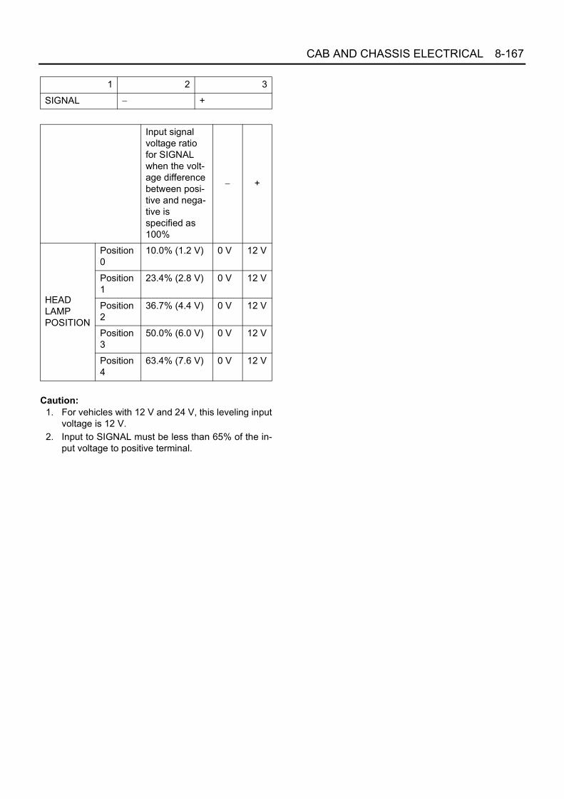
CAB AND CHASSIS ELECTRICAL 8-167
Caution:1. For vehicles with 12 V and 24 V, this leveling input
voltage is 12 V.2. Input to SIGNAL must be less than 65% of the in-
put voltage to positive terminal.
1 2 3
SIGNAL − +
Input signal voltage ratio for SIGNAL when the volt-age difference between posi-tive and nega-tive is specified as 100%
− +
HEADLAMPPOSITION
Position0
10.0% (1.2 V) 0 V 12 V
Position1
23.4% (2.8 V) 0 V 12 V
Position2
36.7% (4.4 V) 0 V 12 V
Position3
50.0% (6.0 V) 0 V 12 V
Position4
63.4% (7.6 V) 0 V 12 V

8-168 CAB AND CHASSIS ELECTRICAL
Clearance Light, Taillight, License Plate Light and Illumination LightGeneral DescriptionThe circuit consists of the lighting switch, clearance light, taillight, license plate light and the illumination light for eachof switch, meter and ashtray.All these lights come on when the lighting switch is turned on with the switch to either clearance or headlight position.Lighting Circuit
N8A0156E

CAB AND CHASSIS ELECTRICAL 8-169
Parts Location
F-7
B-7
X-4
TA
IL R
ELA
Y
X-2
2
B-3
3 H
EA
TE
RB
EZ
EL
SW
RO
OF
MA
RK
ER
LI
GH
T (
RH
)(F
OR
EC
/ T
UR
KE
Y
N2
CA
TE
GO
RY
ON
LY)
RO
OF
MA
RK
ER
LI
GH
T (
LH)
(FO
R E
C /
TU
RK
EY
N
2 C
AT
EG
OR
Y O
NLY
)
B-4
6 A
SH
TR
AY
F-2
5
B-5
2 M
ET
ER
B-3
1E
NG
INE
WA
RM
UP
SW
N8A0157E

8-170 CAB AND CHASSIS ELECTRICAL
Circuit DiagramFor 12 Volt
5B
-52
B-5
2
X-4
B-7
0
B-7
0
H T
LOOF
F
PA
SS
HIG
H
EHu
PA
SS
P-1
P-2
1 8 7 10 4
21
45
211 2
8 7
10 9
1 3
HE
AD
LIG
HT
BR
AC
KE
T-L
HFL-
1
MA
IN
RE
LAY
; HE
AD
LIG
HT
(4)
LIG
HT
ING
SW
COMBINATION SW
0.3L
/R
3W
F-7
TA
ILLI
GH
T
2
RELAY; TAIL
RE
LAY
; DIM
ME
R (
4)0.
3R/L
0.5R
/G0.
5R/G
0.5B
0.5B
ASHTRAY
CIGAR LIGHTER
HAZARD WARNING SW
RADIO
DOME LIGHT SW
3B
0.3G
/O
8W8B
100A
0.3R
1 2
HEATER BEZEL
52
FOG LIGHT SW
5METER
B-7
0
B-7
0
B-7
0
H-6
X-4
X-4
X-4
B-8
7
B-8
7
B-8
6
B-8
6
B-2
8
B-2
8
B-3
0
B-3
0
B-4
3
B-4
3
B-3
3
B-3
3
B-4
6
B-4
6
10A
0.5LG/R 0.5B
0.5LG/R 0.5B
0.5LG/R 0.5B
0.5LG/R 0.5B
0.5LG/R 0.3B
0.5LG/R 0.3B
0.5LG/R 0.3B
0.5LG/R 0.85B
ROOF MARKER LIGHT (LH)
ROOF MARKER LIGHT (RH)
NPR / NQR (EC / TURKEY)
1.25B
B-7
B-1
J-9
FR
AM
E-L
H (
FR
ON
T)
FR
AM
E-L
H (
CE
NT
ER
)
B-7
4B
-74
B-7
4
3
CLEARANCE LIGHT-RH
4
B-5
B-5
B-5
3
CLEARANCE LIGHT-LH
4
0.5L
G/R
10
0.85B 2B
3B
1.25B
2B
3B
11
61
TAILLIGHT-LH
R-1
R-1
61
TAILLIGHT-RH
R-6
R-6
11
LICENSE PLATE LIGHT
R-3
0.5G/R
4
H-1
6
0.5G/R
45
H-5
0.5LG/R 0.5LG/RH-1
6
0.85LG/R 0.5LG/R
X-2
2
41
RELAY; MARKER LIGHT
X-2
2
X-2
2X
-22
1.25
W
F-2
5
MA
RK
ER
LIG
HT
15A
0.85
LG/R
0.5LG/R
7H
-16
1.25
B
2B
0.85LG/B J-25
J-24
0.85B
25 1 1
MARKER LIGHT
0.5LG/R
0.85LG/W
0.5B
1.25B
1.25B
0.5B
3W/B
3W/B8W/B
0.5G
/R
R-2
H-5
P-5
FR
AM
E
5W
3W/B
CORNERING LIGHTSW (13)
CORNERING LIGHTSW (5)
0.85B
2L
P-3
P-4
4JH
1
N8A0158E

CAB AND CHASSIS ELECTRICAL 8-171
For 24 Volt
J-9
FR
AM
E-L
H (
CE
NT
ER
)1.
25B
2B
H T
LOOF
F
PA
SS
HIG
H
EHu
PA
SS
B-1
8
B-4
3B
-52
B-4
6
H-5
H-6
X-4
B-2
8B
-31
B-8
6B
-87
B-3
3
H-1
6
H-1
6
H-5
R-1
R-2
R-3
B-7
0
H-5
J-63
J-65
J-62
B-7B-1
B-3
0
B-3
0B
-32
B-3
2
B-7
4
R-6
B-5
P-1
P-2
P-3
P-4
P-5
B-7
0
B-7
0
B-7
0
B-7
0
1 8 7 10 4
B-1
8
B-1
8
31
2
X-4
X-4
X-4
21
45
4
5
J-65
J-62
1 6
1 6
1 1
5
5
1
4 11
16
6
B-7
4B
-74
B-5
B-5
4
1
43
3
1
R-1
R-6
B-4
6
B-5
2B
-28
B-3
3
1 2
1 2
10 9
5 10
B-4
3
21
B-8
7B
-86
B-3
1
521 3
2 1
3 1
8 7
FR
AM
E
FL-
1
MA
IN
RE
LAY
; HE
AD
LIG
HT
(4)
LIG
HT
ING
SW
COMBINATION SW
0.5R
0.5L
RE
LAY
; CO
RN
ER
ING
LIG
HT
(4)
0.5L
/R
0.5R
F-7
1
0A
TA
ILLI
GH
T
2
RELAY; TAIL
DIODE
RE
LAY
; DIM
ME
R (
4)0.
5R/L
0.85LG/R
0.85
LG/R
0.5G/R
REAR COMBINATION LIGHT RH (TAIL)
REAR COMBINATION LIGHT LH (TAIL)
0.5LG/R 0.5B
1.25B
1.25B
0.5G/R
0.5G/R
LICENSE PLATE LIGHT
CORNERINGLIGHT SW (9)(COMBINATION SW)
CORNERING LIGHTSW (11)
(COMBINATION SW)
CLEARANCE LIGHT (RH)
CLEARANCE LIGHT (LH)
0.5LG/R
2LG/W
0.5LG/R
0.85B
0.85B
0.5B
0.85B1.25LG/B
0.5G/R
0.5G/R
0.5LG/R
0.85B
0.85B
0.5B
TAILLIGHT-RH (REAR COMBINATION LIGHT)
TAILLIGHT-LH(REAR COMBINATION LIGHT)
0.5LG/R
0.5LG/R
0.5LG/R
0.5LG/R
0.5LG/R
ASHTRAY
HEATER BEZEL
RADIO
ILLUMINATION LIGHT (METER)
CIGAR LIGHTER
FOG LIGHT SW
DOME LIGHT SW
ENGINE WARMING UP SW
MIRROR SW
HAZARD WARNING SW
0.85LG/R
0.5LG/R
0.5LG/R
0.5LG/R
0.5R/G
0.3B
0.3B
0.5B
0.85B
0.3B
0.5B
0.5B
0.5B
0.5B
0.5B
3B
0.5G
/O
3W/B
5W
LICENSE PLATE LIGHT
(DU
MP
) J-64
0.5G
/R
0.5L
G/R
100A
or
120A
HE
AD
LIG
HT
BR
AC
KE
T (
LH)
FR
AM
E-L
H (
FR
ON
T)
0.85G/B
H-1
67
(DU
MP
)
2L
0.5L
G/R
0.5L
G/R
0.5B
0.5B
1
12
2
ROOF MARKER LIGHT (LH)
ROOF MARKER LIGHT (RH)
NPR / NQR (EC / TURKEY)
1 2
X-2
2X
-22
X-2
2X
-22
32
51
J-24
J-25
1 1
RELAY; MARKER LIGHT MARKER LIGHT
F-2
5
MA
RK
ER
LIG
HT
15A
0.5B
N8A0538E

8-172 CAB AND CHASSIS ELECTRICAL
Connector List
No. Connector Face
B-5
B-5
B-74
B-74
B-18
X-4
X-22
B-28
004-012
1 2
3 4
004-013
12
34
004-012
1 2
3 4
004-013
12
34
003-024
1 2 3
005-006
005-006
013-001
1 2 3
7 8 9
4 5 6
11 12 1310
B-30
B-31
B-33
B-33
B-46
B-46
B-43
B-43
No. Connector Face
008-005
1 2 3 4
5 6 7 8
006-001
1 2 3
4 5 6
002-022
1 2
002-023
2 1
002-022
1 2
002-023
2 1
002-009
1
2
002-010
1
2

CAB AND CHASSIS ELECTRICAL 8-173
B-52
B-70
B-70
B-86
B-87
H-16
H-16
J-24
No. Connector Face
012-005
1 2 3 4 5 6 7 8 9 10 11 12
014-002
1 2 3
7 8 9 10 11
4
12
5
13
6
14
014-003
6 5 4
14131211
3 2 1
9 8 710
004-001
1 23 4
006-006
21 3
54 6
008-003
1 2 3 4
5 6 7 8
008-004
4 3 2 1
8 7 6 5
000-010
J-24
J-25
J-25
J-62
J-62
J-65
J-65
J-63
No. Connector Face
000-011
000-010
000-011
006-010
1 2 34 5 6
006-015
123
456
006-010
1 2 34 5 6
006-015
123
456
000-010

8-174 CAB AND CHASSIS ELECTRICAL
J-63
J-64
J-64
R-2
R-2
R-3
R-3
P-1(12 V)
No. Connector Face
000-011
000-010
000-011
000-010
000-011
000-010
000-011
000-003
P-2
P-1(24 V)
P-4
P-2(24 V)
P-3
P-5(12 V)
P-5(24 V)
R-1
No. Connector Face
000-004
000-004
000-004
000-006
000-006
000-007
000-002
006-004
1 2 3
4 5 6

CAB AND CHASSIS ELECTRICAL 8-175
H-5
H-6
R-1
R-6
R-6
No. Connector Face
006-005
3 2 1
6 5 4
006-004
1 2 3
4 5 6
006-005
3 2 1
6 5 4
1 2 37 8 9
13 14 1519 20 2125 26 2731 32 33 34 35 36 37
4 5 610 11 1216 17 1822 23 2428 29 3038 39 40
6 5 412 11 1018 17 1624 23 2230 29 2840 39 38
3 2 19 8 715 14 1321 20 1927 26 2533 32 3134353637
N8A5488E
1 2
1 2
1 2 3 4
5 6 7 8
9 10 11 12 13
14 15 16 17 18
2 1
2 1
4 3 2 1
8 7 6 5
13 12 11 10 9
18 17 16 15 14
H - 6
H - 7
H - 8
N8A5489E

8-176 CAB AND CHASSIS ELECTRICAL
DiagnosisQuick Chart for Check Point
Notice:Figure in parenthesis “( )” indicates the order of inspection.
Check point
Fuse Light-ing SW
Tail-light bulb
Clear-ance
light bulb
License plate
light bulb
Marker light relay
Cable har-ness
Marker light bulb
F-7(10 A)
F-25(15 A)
Troublemode
1. Both clearance lights inoperative
(1)
(3)
(2)
(4)
2. Clearance light on the left (or right) side inoperative
(1)
(2)
3. Both taillights inoperative
(1)
(2)
(3)
4. Taillight on the left (or right) side inoperative
(1)
(2)
5. License plate light inoperative
(1)
(2)
6. Marker light inoperative
(2)
(3)
(4)
(1)

CAB AND CHASSIS ELECTRICAL 8-177
1. Both Clearance Lights Inoperative
Notice:Figure in parenthesis “( )” indicates place of inspection for clearance light on the right side.
• ARE BOTH TAILLIGHTS OPERATIVE?
• IS B-7 SECURELY GROUNDED?
YES NO
TURN TAILLIGHTS ON (REFER TO TAILLIGHTDIAGNOSIS IN THIS SECTION)
REPAIR A POOR CONNECTION AT THE CONNECTORSOR AN OPEN CIRCUIT BETWEEN CLEARANCE LIGHTCONNECTOR TERMINALS 1 B-5 (1 B-74 ) AND B-7
YES
• TURN THE LIGHTING SWITCH TO OR POSITION• IS THERE BATTERY VOLTAGE APPLIED TO
CLEARANCE LIGHT CONNECTOR 4 B-5 (4 B-74 ) ANDGROUND?
YES NO
NO
GROUND IT SECURELY
REPAIR A POOR CONNECTION AT THECONNECTORS OR AN OPEN CIRCUIT BETWEENFUSE F-7 (10A) AND 4 B-5 (4 B-74 )
N8A0160E

8-178 CAB AND CHASSIS ELECTRICAL
2. Clearance Light on the Left (or Right) Side Inoperative
Notice:Figure in parenthesis “( )” indicates place of inspection for clearance light on the right side.
• IS THE CLEARANCE LIGHT BULB ON THE LEFT (ORRIGHT) SIDE NORMAL?
• IS THERE ANY CONTINUITY BETWEEN THE
YES NO
REPLACE THE BULB
• REPAIR A POOR CONNECTION AT THECONNECTORS OR AN OPEN CIRCUIT BETWEEN 1 B-5 (1 B-74 ) AND B-7
YES NO
REPAIR A POOR CONNECTION AT THECONNECTORS OR AN OPEN CIRCUIT IN THECIRCUIT
HARNESS SIDE CONNECTOR 5 X-15 (12V), 5 X-4 (24VAND NKR77 FOR TAIWAN) AND 4 B-5 (OR 4 B-74 )?
N8A0161E

CAB AND CHASSIS ELECTRICAL 8-179
3. Both Taillights Inoperative
• IS FUSE F-7 (10A) NORMAL?
• IS J-9 SECURELY GROUNDED?
YES
REPLACE THE FUSE
• IS THE TAIL RELAY NORMAL?
YES
GROUND IT SECURELY
YES
REPLACE THE RELAY• IS THE LIGHTING SWITCH NORMAL?
• IS THE BATTERY VOLTAGE APPLIED BETWEENLIGHTING SWITCH HARNESS SIDE CONNECTOR 8 B-70 AND THE GROUND?
YES NO
REPAIR OR REPLACE THE LIGHTINGSWITCH
YES NO
NO
NO
NO
• TURN THE LIGHTING SWITCH TO OR POSITION• IS THERE BATTERY VOLTAGE APPLIED TO 4 H-16
AND GROUND?
REPAIR A POOR CONNECTION AT THECONNECTORS OR AN OPEN CIRCUIT BETWEENFUSE F-7 (10A) AND 8 B-70
• REPAIR A POOR CONNECTION AT THE CONNECTORSOR AN OPEN CIRCUIT BETWEEN LIGHTING SWITCHHARNESS SIDE CONNECTORS 7 H-16 AND J-9
YES NO
REPAIR A POOR CONNECTION AT THECONNECTORS OR AN OPEN CIRCUIT BETWEENTAILLIGHT RELAY CONNECTORS 5 X-15 (12V), 5 X-4 (24V AND NKR77 FOR TAIWAN) AND4 H-16
N8A0162E

8-180 CAB AND CHASSIS ELECTRICAL
4. Taillight on the Left (or Right) Side Inoperative
Notice:Figure in parenthesis “( )” indicates place of inspection for taillight on the right side.
5. License Plate Light Inoperative
• IS TAILLIGHT BULB ON THE LEFT (OR RIGHT) SIDENORMAL?
• REPAIR A POOR CONNECTION AT THE CONNECTORSOR AN OPEN CIRCUIT BETWEEN CONNECTORTERMINAL 4 H-16 AND TAILLIGHT CONNECTOR 1 R-1 ( 1 R-6 )
YES NO
REPLACE THE BULB
N8A0163E
• ARE BOTH TAILLIGHTS OPERATIVE?
• IS THE LICENSE PLATE LIGHT BULB NORMAL?
YES NO
TURN THE TAILLIGHTS ON (REFER TOTAILLIGHT DIAGNOSIS IN THIS SECTION)
YES NO
REPLACE THE BULB IS THERE BATTERY VOLTAGE APPLIED BETWEEN 5 H-16 AND THE GROUND WHEN TURNING THELIGHTING SWITCH ON?
• REPAIR A POOR CONNECTION AT THE CONNECTORSOR AN OPEN CIRCUIT BETWEEN 1 R-2 OR 1 R-14AND 7 H-16
YES NO
REPAIR A POOR CONNECTION AT THECONNECTORS OR AN OPEN CIRCUIT IN THECIRCUIT
•
N8A0164E

CAB AND CHASSIS ELECTRICAL 8-181
6. Marker Light Inoperative
Lighting SwitchRefer to “HEADLIGHT, FOG LIGHT AND CORNERINGLIGHT” in this section.
Clearance Light/BulbRemoval
1. Remove the battery ground cable at the battery.2. Remove the front combination light.
• Open the cab door. Insert a screwdriver (1) intothe space between the cab and the cab door.Use the screwdriver to force out the stud pin atthe center of the grommet (the pin securing thefront combination light).
• Remove the fixing screw.
• IS FUSE F-25 (15A) NORMAL?
• IS J-9 SECURELY GROUNDED?
YES NO
REPLACE THE FUSE
• IS MARKER LIGHT RELAY NORMAL?
YES NO
GROUND IT SECURELY
• IS THERE BATTERY VOLTAGE APPLIED TO THEMARKER LIGHT CONNECTOR J-24 WHEN TURNINGTHE LIGHTING SWITCH ON?
YES NO
REPLACE THE MARKER LIGHT RELAY
• REPAIR A POOR CONNECTION AT THE CONNECTORSOR AN OPEN CIRCUIT BETWEEN THE MARKER LIGHTCONNECTORS J-25 - J-9
YES NO
REPAIR A POOR CONNECTION AT THECONNECTORS OR AN OPEN CIRCUIT OF 2 X-22OR BETWEEN 5 X-22 AND J-9
N8A0165E
Door side Cab side
1
N8A5471E

8-182 CAB AND CHASSIS ELECTRICAL
• Remove the two catches.• Remove the front combination light (1) connec-
tor.
3. Remove the clearance light bulb.• Turn the bulb socket (3) to the left to remove it.• Press the bulb (2) in and turn it to the left to re-
move it from the socket.InstallationInstallation procedure of cornering/clearance light bulb
1. Install the cornering/clearance light bulb.• While pressing the bulb (2), turn it clockwise to
fit.
Notice:Do not let the glass portion dirty with sebum etc.
• Turn the bulb socket (3) clockwise to fit.
2. Installation procedure of front combination light as-sembly• Connect the connector of the combination light
assembly.
• Position it by aligning two pawls with the grooveof H/L.
• Fit the iron PIN (1) in the upper portion of theside by aligning it with the center of correspond-ing grommet.
Notice:Push it into securely with a force of approx. 250 N (25kgf) until click is heard.
• Pull the front combination light assembly lightlytoward the front of vehicle to make sure that thePIN and grommet are engaged securely.
• Tighten one bolt in the lower portion of frontcombination light assembly.
3. Hook the seal rubber on two projections under H/L.4. Connect the battery ground cable.5. Check lighting of each light.
Taillight BulbRemoval
1. Lens2. Bulb
InstallationTo install, follow the removal steps in the reverse order.
1
3
2
N8A5477E
1
3
2
N8A0445E
N8A0167E

CAB AND CHASSIS ELECTRICAL 8-183
License Plate Light BulbRemoval
1. Cover2. Lens3. Bulb
InstallationTo install, follow the removal steps in the reverse order.
Turn Signal Light, Hazard Warning Light,and Stoplight
General DescriptionThe circuit consists of the starter switch, turn signal light(front and rear), turn signal light switch, hazard warninglight, flasher unit, stoplight and stoplight switch.When turning on the respective switches with the starterswitch on, the turn signal light will operate. When theturn signal light is flashing, the indicator light in the meteralso starts flashing. When the hazard warning switch isturned on, the current flows to the flasher unit throughthe hazard warning switch to cause the hazard warninglight to flash, independent of the position of the starterswitch. At the same time, the indicator lights in the meteralso start flashing.The stoplight switch will turn on and the light comes ononce the brake pedal is depressed, independent of theposition of the starter switch.
N8A0168E
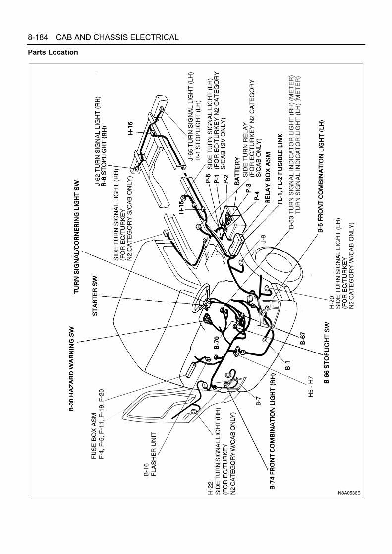
8-184 CAB AND CHASSIS ELECTRICAL
Parts Location
B-7
H5
- H
7
H-2
2S
IDE
TU
RN
SIG
NA
L LI
GH
T (R
H)
(FO
R E
C/T
UR
KE
Y
N2
CA
TE
GO
RY
W/C
AB
ON
LY)
H-2
0S
IDE
TU
RN
SIG
NA
L LI
GH
T (
LH)
(FO
R E
C/T
UR
KE
Y
N2
CA
TE
GO
RY
W/C
AB
ON
LY)
SID
E T
UR
N S
IGN
AL
LIG
HT
(R
H)
(FO
R E
C/T
UR
KE
Y
N2
CA
TE
GO
RY
S/C
AB
ON
LY)
J-62
TU
RN
SIG
NA
L LI
GH
T (
RH
)
J-65
TU
RN
SIG
NA
L LI
GH
T (
LH)
R-1
ST
OP
LIG
HT
(LH
)
SID
E T
UR
N S
IGN
AL
LIG
HT
(LH
)(F
OR
EC
/TU
RK
EY
N2
CA
TE
GO
RY
S/C
AB
12V
ON
LY)
SID
E T
UR
N R
ELA
Y(F
OR
EC
/TU
RK
EY
N2
CA
TE
GO
RY
S/C
AB
ON
LY)
FU
SE
BO
X A
SM
F-4
, F-5
, F-1
1, F
-19,
F-2
0
B-1
6F
LAS
HE
R U
NIT
B-5
3 T
UR
N S
IGN
AL
IND
ICA
TO
R L
IGH
T (
RH
) (M
ET
ER
)T
UR
N S
IGN
AL
IND
ICA
TO
R L
IGH
T (
LH)
(ME
TE
R)
J-9
N8A0536E

CAB AND CHASSIS ELECTRICAL 8-185
Circuit DiagramO
FF
ON
AC
C
ST
B
RH
LH
IGR
HLH
B
TB
FU
B-7
0B
-70
B-7
0
B-1
6
H-6
H-7
B-6
7B
-67
B-5
3
B-5
3
B-7
4
B-7
4
R-6
R-1
R-6
R-1
H-1
6H
-16
H-5
H-5
B-5
B-5
B-5
3
B-5
3
H-2
0
H-2
0
B-3
0
B-3
0
B-3
0
R-1
R-1
H-1
6
R-6
R-6
H-1
6
B-6
6
B-6
6
H-5
J-9
B-7
B-1
P-1
P-2
P-3
P-4
P-5
12
2
3
3
1
2(12
V)
82
6
1
54
37
12
135
17 8
10 12
4 3
211
H-2
2
H-2
24 10
71
1
82 3
2 37
33
66
7
111 2 2 2 6
2 6
(24
V M
OD
EL)
FR
AM
E
MA
IN
ST
AR
TE
R S
WIT
CH
FLA
SH
ER
U
NIT
RELAY; TAIL (5)
3W/L
5W
0.5G
3B/Y 0.5Y/R
0.5B
R
0.5L
G/R
TURN SIGNAL LIGHT SWITCH(COMBINATION SWITCH)
0.5G/B
0.5G/W
0.85
B(2
4V)
0.5G/W
0.5G/B
0.5B
F-19 15A(4JH1, 4JB1, 4JB1-TC)
F-20 15A(24V)
HORN, HAZARD
F-11 10ATURN LIGHT
5W/B
(24V
)8W
/B(1
2V)
F-5 10ASTOPLIGHT
F-4 15AAUDIO
STOPLIGHT SWITCH0.5G0.5G
0.5G 1.25B
2BSTOPLIGHT (RH)
(Exc
ept D
UM
P V
EH
ICLE
)
TURN SIGNALINDICATOR LIGHT (RH) (METER)
0.5G/Y
0.5LG/B
(Except DUMP VEHICLE)
FR
AM
E-L
H(F
RO
NT
)
HE
AD
LIG
HT
B
RA
CK
ET
(LH
)
0.5BR
B-1
6
B-1
6
B-3
0B
-30
B-3
0B
-30
B-3
0H
AZ
AR
D
WA
RN
ING
S
WIT
CH
3W/B
5W
FL-
110
0A o
r 12
0A
KE
Y S
W
FL-
2 40
A(2
4V)
50A
(12V
)
J-65
J-65
J-62
J-62
2 6
2 60.5G 1.25B
2B
5W(2
4V)
8W(1
2V)
TURN SIGNAL LIGHT (FRONT COMBINATION LIGHT-RH)
5(24
V)
0.5B
(NK
R D
UM
P V
EH
ICLE
)
STOPLIGHT (LH)
STOPLIGHT (RH)
STOPLIGHT (LH)
TURN SIGNAL LIGHT(REAR COMBINATION LIGHT-RH)
TURN SIGNAL LIGHT(REAR COMBINATION LIGHT-LH)
TURN SIGNAL LIGHT(FRONT COMBINATION LIGHT-LH)
TURN SIGNAL INDICATOR LIGHT (LH) (METER)
0.5G
/B0.
5G/W
1.25
B(1
2V)
0.5G
0.85B
0.85B
1.25B
1.25B
0.85B
0.85B 3B
FR
AM
E-L
H (
CE
NT
ER
)
2L
P-3
P-4
4JH
1
SIDE TURN SIGNAL LIGHT (RH)(DOOR)
SIDE TURN SIGNAL LIGHT (LH)(DOOR)
(NP
R/N
QR
W/C
AB
EC
ON
LY)
(NP
R/N
QR
W/C
AB
EC
ON
LY)
SIDE TURN SIGNAL LIGHT (LH)(S/CAB)
RELAY; SIDE TURN(S/CAB)
P/SOURCE(SERVICE)
SIDE TURN SIGNAL LIGHT (RH)(S/CAB)
4
25
1
0.5W
3
0.5B
6
0.5L
0.5G/W 0.5B
0.85R
0.85
R0.
5G/W
0.5G
/B
0.5B
0.5B
(S/C
AB
EC
TU
RK
EY
ON
LY)
J-62
J-65
J-62
J-653
3
66
(NK
R D
UM
P V
EH
ICLE
)
TURN SIGNAL LIGHT(REAR COMBINATION LIGHT-RH)
TURN SIGNAL LIGHT(REAR COMBINATION LIGHT-LH)
0.5G/W
0.5G/B
0.5G/B 0.5B
2B
1.25B
N8A0399E

8-186 CAB AND CHASSIS ELECTRICAL
Connector List
No. Connector Face
B-1
J-9
B-5
B-5
B-74
B-74
B-7
B-16(24 V)
000-001
000-001
004-012
1 2
3 4
004-013
12
34
004-012
1 2
3 4
004-013
12
34
000-012
006-010
1 2 34 5 6
B-16(12 V)
B-30
B-53
B-66
B-67
B-67
B-70
B-70
No. Connector Face
003-008
1 3
2
008-005
1 2 3 4
5 6 7 8
012-004
1 2 3 4 5 6 7 8 9 10 11 12
002-024
1 2
004-001
1 23 4
004-002
2
4
1
3
014-002
1 2 3
7 8 9 10 11
4
12
5
13
6
14
014-003
6 5 4
14131211
3 2 1
9 8 710

CAB AND CHASSIS ELECTRICAL 8-187
H-16
H-16
H-20
H-20
H-22
H-22
J-62
J-62
No. Connector Face
008-003
1 2 3 4
5 6 7 8
008-004
4 3 2 1
8 7 6 5
010-003
1098765
4321
010-004
12
5678910
34
010-003
1098765
4321
010-004
12
5678910
34
006-010
1 2 34 5 6
006-015
123
456
J-65
J-65
P-1(12 V)
P-2
P-1(24 V)
P-4
P-2(24 V)
P-3
No. Connector Face
006-010
1 2 34 5 6
006-015
123
456
000-003
000-006
000-006
000-006
000-004
000-004

8-188 CAB AND CHASSIS ELECTRICAL
H-5
H-6, H-7
P-5(12 V)
P-5(24 V)
R-1
R-1
R-6
R-6
No. Connector Face
000-007
000-002
006-004
1 2 3
4 5 6
006-005
3 2 1
6 5 4
006-004
1 2 3
4 5 6
006-005
3 2 1
6 5 4
000-010
000-011
No. Connector Face
000-010
000-011
1 2 37 8 9
13 14 1519 20 2125 26 2731 32 33 34 35 36 37
4 5 610 11 1216 17 1822 23 2428 29 3038 39 40
6 5 412 11 1018 17 1624 23 2230 29 2840 39 38
3 2 19 8 7
15 14 1321 20 1927 26 2533 32 3134353637
N8A5488E
1 2
1 2
1 2 3 4
5 6 7 8
9 10 11 12 13
14 15 16 17 18
2 1
2 1
4 3 2 1
8 7 6 5
13 12 11 10 9
18 17 16 15 14
H - 6
H - 7
H - 8
N8A5489E

CAB AND CHASSIS ELECTRICAL 8-189
DiagnosisQuick Chart for Check Point1. Turn Signal Light, Hazard Warning Light
Notice:Figure in parenthesis “( )” indicates the order of inspection.
2. Stoplight
Notice:Figure in parenthesis “( )” indicates the order of inspection.
Check point
Fuse Turn signal
light SW
Hazard warning light SW
Flasher unit
Turn signal
light bulb
Cable harnessF-19, F-20
(15 A)F-11
(10 A)
Troublemode
1-1. Turn signal lights inoperative
1-2. Turn signal lights flash too quickly
1-3. Hazard warning lights inoperative
Check point
FuseF-5 (10 A) Stoplight SW Stoplight bulb Cable harness
Troublemode
2-1. Both stoplights inoperative
2-2. Stoplight on the left (or right) side inoperative

8-190 CAB AND CHASSIS ELECTRICAL
1. Turn Signal Light, Hazard Warning Light1-1. Turn Signal Lights Inoperative
N8A0169E

CAB AND CHASSIS ELECTRICAL 8-191
1-2. Turn Signal Lights Flash Too Quickly
• IS THERE ANY CONTINUITY BETWEEN THE HARNESSSIDE CONNECTORS 3 B-16 AND B-7 ?
GROUND IT SECURELY
CONTINUED FROM THE PREVIOUS PAGE CONTINUED FROM THE PREVIOUS PAGE
• DISCONNECT THE COMBINATION SWITCHCONNECTOR
• IS THERE ANY CONTINUITY BETWEEN THE SWITCHCONNECTORS 5 B-70 AND 12 B-70 (WHEN TURNING LEFT), 13 B-70 AND 12 B-70 (WHENTURNING RIGHT) RESPECTIVELY?
YES NO
REPAIR A POOR CONNECTION AT THECONNECTORS OR AN OPEN CIRCUIT BETWEENTHE CIRCUIT
• REPAIR A POOR CONNECTION AT THE CONNECTORSOR AN OPEN CIRCUIT BETWEEN THE HARNESS SIDECONNECTORS 2 B-16 (12V), 5 B-16 (24V) AND 12 B-70
YES NO
REPAIR OR REPLACE THE SWITCH
N8A0170E
• DOES ANY TURN SIGNAL LIGHT REMAINUNLIGHTED?
YES
DISCONNECT AND REINSTALL THE BULB, ORREPLACE IT, OR REPAIR AN OPEN CIRCUIT INTHE CIRCUIT OF THE INOPERATIVE BULB, ORCHECK THE GROUND
N8A0171E

8-192 CAB AND CHASSIS ELECTRICAL
1-3. Hazard Warning Lights Inoperative
2. Stoplight2-1. Both Stoplights Inoperative
• IS FUSE F-19 , F-20 (15A) NORMAL?
• DOES THE HAZARD WARNING LIGHT SWITCHFUNCTION NORMALLY?
YES NO
REPLACE THE FUSE
• REPAIR A POOR CONNECTION AT THE CONNECTORSOR AN OPEN CIRCUIT BETWEEN FUSE F-19 , F-20 (15A) AND 1 B-30
YES NO
REPLACE THE HAZARD WARNING LIGHTSWITCH
N8A0172E
• IS FUSE F-5 (10A) NORMAL?
• IS J-9 GROUNDED SECURELY?
YES NO
REPLACE THE FUSE
• IS BATTERY VOLTAGE APPLIED TO THE 1 B-66 OFTHE STOPLIGHT SW?
YES NO
GROUND IT SECURELY
• IS STOPLIGHT SWITCH NORMAL?
YES NO
REPAIR A POOR CONNECTION AT THECONNECTORS OR AN OPEN CIRCUIT BETWEENTHE FUSE F-5 (10A) AND 1 B-66
YES NO
• DOES THE PUSH ROD OF THE STOPLIGHT SWOPERATE SMOOTHLY?
REPLACE THE STOPLIGHT SW
REPAIR A POOR CONNECTION AT THE CONNECTORSOR AN OPEN CIRCUIT BETWEEN 2 B-66 AND J-9
YES NO
REPLACE THE STOPLIGHT SW
N8A0173E

CAB AND CHASSIS ELECTRICAL 8-193
2-2. Stoplight on the Left (or Right) Side Inoperative
Notice:Figure in parenthesis “( )” indicates the place of inspection for the right side stoplight.
Starter SwitchRefer to “START AND CHARGING” in this section.
Front Turn Signal Light/BulbRemoval
1. Remove the battery ground cable at the battery.2. Remove the front combination light.
• Open the cab door. Insert a screwdriver (1) intothe space between the cab and the cab door.Use the screwdriver to force out the stud pin atthe center of the grommet (the pin securing thefront combination light).
• Remove the fixing screw.• Remove the two catches.
• Remove the front combination light (1) connec-tor.
3. Remove the front turn signal light bulb.• Turn the bulb socket (2) to the left to remove it.• Press the bulb (3) in and turn it to the left to re-
move it from the socket.Installation
1. Install the front turn signal light bulb.• While pressing the bulb (2), turn it clockwise to
fit.
Notice:Do not let the glass portion dirty with sebum etc.
• Turn the bulb socket (3) clockwise to fit.
N8A5206E
Door side Cab side
1
N8A5471E
21
3
N8A5484E

8-194 CAB AND CHASSIS ELECTRICAL
2. Installation procedure of front combination light as-sembly• Connect the connector of the front combination
light assembly.• Position it by aligning two pawls with the groove
of H/L.• Fit the iron PIN (1) in the upper portion of the
side by aligning it with the center of correspond-ing grommet.
Notice:Push it into securely with a force of approx. 250 N (25kgf) until click is heard.
• Pull the front combination light assembly lightlytoward the front of vehicle to make sure that thePIN and grommet are engaged securely.
• Tighten one bolt in the lower portion of frontcombination light assembly.
3. Hook the seal rubber on two projections under H/L.
4. Connect the battery ground cable.5. Check lighting of each light.
Rear Turn Signal Light/BulbRemovalPreparation:Disconnect the battery ground cable.
1. Lens2. Bulb
InstallationTo install, follow the removal steps in the reverse order.
Turn Signal Light Switch (Combination Switch)InspectionCheck the continuity between the terminals of the turnsignal light switch.Repair or replace the switch when the result of inspec-tion is found abnormal.
1
3
2
N8A0445E
N8A0176E
2 5 9 11 12 13Terminal No.
SW position
Turningleft
NeutralTurn signallight SW
Turningright
N8A0177E

CAB AND CHASSIS ELECTRICAL 8-195
Removal and InstallationRefer to “HEADLIGHT, FOG LIGHT AND CORNERINGLIGHT” in this section.
Flasher UnitInspectionWhen a 55W bulb is connected to the unit side terminals“L” and “E” while connecting the battery (+) terminal toterminal “B”, and the battery (−) terminal to terminal “E”,does the bulb light on and off?Replace the unit when the result of inspection is foundabnormal.
Stoplight BulbRemoval and InstallationRefer to “CLEARANCE LIGHT, TAILLIGHT, LICENSEPLATE LIGHT AND ILLUMINATION LIGHT” for TAIL-LIGHT BULB removal and installation steps in this sec-tion.
Stoplight SwitchInspection
1. Check to see if the stoplight switch is installed cor-rectly to the specified position. Adjust the positionwhen the result of the inspection is found abnor-mal.
2. Check to see if there is any continuity between theterminals of the stoplight switch.Replace the switch when the result of inspection isfound abnormal.
RemovalPreparation:Disconnect the battery ground cable.
1. Stoplight Switch1) Disconnect the connector.2) Loosen the lock nut of the switch.3) Remove the switch by turning it.
N8A0178E
1 2
Depress brake pedal (Pushrod out)Release brake pedal (Pushrod in)
Terminal No.SW position
Switch side1 2
B-66
N8A0179E
N8A0180E

8-196 CAB AND CHASSIS ELECTRICAL
InstallationTo install, follow the removal steps in the reverse order,noting the following points.
1) Check to see if the brake pedal has been re-turned by the return spring to the specified po-sition.
2) Turn the stoplight switch clockwise until the tipof the threaded portion of the switch contactsthe pedal arm.
3) Turn the switch counterclockwise until thespace between the tip of the threaded portionand the pedal arm is 0.5 to 1.0 mm (0.02 —0.04 in.).
Hazard Warning SwitchInspectionCheck the continuity between the terminals of the haz-ard warning switch.Repair or replace the switch when the result of inspec-tion is found abnormal.
RemovalPreparation:Disconnect the battery ground cable.
1. Meter ClusterRefer to the “METER AND WARNING/INDICA-TOR LIGHT” in this section.
2. Hazard Warning SwitchRelease the lock pushing the switch from the backside of the meter cluster.
InstallationTo install, follow the removal steps in the reverse ordernoting the following point.
1. Push the switch with your fingers until locks se-curely.
N8A0181E
B-30
6 5 1 2 3 4 7 8
ON
OFF
TerminalNo.SW
position
N8A0182E
N8A0436E

CAB AND CHASSIS ELECTRICAL 8-197
Horn, Backup Light and Backup BuzzerGeneral DescriptionThe circuit consists of the starter switch, horn, horn switch, backup light (Rear combination light), backup light switch,back buzzer and the relay.When the horn switch is turned on independent of the position of the starter switch, the relay is activated to sound thehorn. When the backup light switch turns on with the starter switch on, the backup light will operate.Backup Light and Backup Buzzer Circuit
N8A5216E

8-198 CAB AND CHASSIS ELECTRICAL
Parts Location
X-2
J-49
(55
, 69)
F-16
, F-1
9, F
-20
N8A0184E

CAB AND CHASSIS ELECTRICAL 8-199
Circuit DiagramO
N
AC
C
ST
B
J-5
J-4
H-5
X-2
X-2
X-2
X-2
B-6
7B
-67
H-5
J-49
J-49
R-1
R-1
B-7
0
R-6
J-9
H-7
P-1
P-2
P-3
P-4
P-5
1
H-1
67
23
22
1 2
5 6
5 6
3
113
45
12
5W(2
4V)
8W(1
2V)
0.5G
3W/L
3B/Y
0.5G
0.5G
/R
0.5B
/Y
0.5B/Y
0.5R
/L
1.25B
1.25B
0.5G/W1.
25B
2B
MA
IN
ST
AR
TE
R S
W
F-1
915
A :4
JH1,
4JB
1, 4
JB1-
TC
F-2
015
A :2
4V, 4
HG
1-T
(12V
)
HO
RN
, HA
ZA
RD
FR
AM
E
RELAY; HORN HORN (LH)
FR
AM
E-L
H (
CE
NT
ER
)
HORN SW(COMBINATION SW)
F-1
6 1
0AM
ET
ER
ME
TE
R B
-51
(8)
BACKUP LIGHTSW
FL-
110
0A o
r 12
0A(2
4V)
100A
(12V
)
KE
Y S
W
FL-
240
A(2
4V)
50A
(12V
)
(24
V M
OD
EL)
H-6
5W
0.5R/L
HO
RN
CO
NT
AC
T
(EXCEPT DUMP VEHICLE)
2
BACKUP LIGHT(REAR COMBINATION LIGHT-RH)
BACKUP LIGHT(REAR COMBINATION LIGHT-LH)
(EX
CE
PT
DU
MP
VE
HIC
LE)
HORN (RH)
R-6
3W/B
H-1
66
J-65
J-655 6
BACKUP LIGHT(REAR COMBINATION LIGHT-LH)
(DUMP VEHICLE)
0.5B/Y
0.5R
/L
2L
P-3
P-4
4JH
1
N8A0185E

8-200 CAB AND CHASSIS ELECTRICAL
Connector List
No. Connector Face
X-2
B-70
B-70
E-10
E-10
J-49
J-49
H-14
005-006
014-002
1 2 3
7 8 9 10 11
4
12
5
13
6
14
014-003
6 5 4
14131211
3 2 1
9 8 710
002-025
1 2
002-026
2 1
002-025
1 2
002-026
2 1
016-003
1 2 3 4
5 6 7 8 9
11 12 13 14
15 16
10
H-14
H-16
H-16
J-62
J-62
J-65
J-65
J-4
No. Connector Face
016-004
4 3 2 1
9 8 7 6 5
13 12 11 10
16 15
14
008-003
1 2 3 4
5 6 7 8
008-004
4 3 2 1
8 7 6 5
006-010
1 2 34 5 6
006-015
123
456
006-010
1 2 34 5 6
006-015
123
456
001-018
1

CAB AND CHASSIS ELECTRICAL 8-201
H-5
J-5
P-1(12 V)
P-2
P-1(24 V)
P-4
P-2(24 V)
P-3
P-5(12 V)
No. Connector Face
001-018
1
000-003
000-004
000-004
000-004
000-006
000-006
000-007
P-5(24 V)
R-1
R-1
R-6
R-6
No. Connector Face
000-002
006-004
1 2 3
4 5 6
006-005
3 2 1
6 5 4
006-004
1 2 3
4 5 6
006-005
3 2 1
6 5 4
1 2 37 8 9
13 14 1519 20 2125 26 2731 32 33 34 35 36 37
4 5 610 11 1216 17 1822 23 2428 29 3038 39 40
6 5 412 11 1018 17 1624 23 2230 29 2840 39 38
3 2 19 8 7
15 14 1321 20 1927 26 2533 32 3134353637
N8A5488E

8-202 CAB AND CHASSIS ELECTRICAL
H-6
DiagnosisQuick Chart for Check Point1. Horn
Notice:Figure in parenthesis “( )” indicates the order of inspection.
2. Backup Light
Notice:Figure in parenthesis “( )” indicates the order of inspection.
1 2
1 2
1 2 3 4
5 6 7 8
9 10 11 12 13
14 15 16 17 18
2 1
2 1
4 3 2 1
8 7 6 5
13 12 11 10 9
18 17 16 15 14
H - 6
H - 7
H - 8
N8A5489E
Check point
FuseF-19, F-20
(15 A)Horn Horn SW Horn
relayHorn
contactCable
harness
Troublemode
1-1. Horn does not sound
(1)
(4)
(6)
(2)
(5)
(3)
1-2. Horn does not shut off
(2)
(1)
(3)
Check point
FuseF-16 (10 A)
Backup light SW
(Inhibitor SW)
Backup light bulb
Backup buzzer
Cable harness
Troublemode
2-1. Both backup lights inoperative
(1)
(3)
(2)
2-2. Backup light on the left (or right) side inoperative
(1)
(2)
2-3. Backup light remains on
(1)

CAB AND CHASSIS ELECTRICAL 8-203
1. Horn1-1. Horn Does Not Sound
• IS FUSE F-19 , F-20 (15A) NORMAL?
YES NO
REPLACE THE FUSE• IS THE HORN RELAY NORMAL?
• IS THE HORN NORMALLY GROUNDED?
YES NO
REPLACE THE HORN RELAY
• IS THE HORN CONNECTOR 1 J-4 OR 1 J-5SECURELY CONNECTED?
YES NO
CLEAN UP THE FITTING SURFACE AND THEGROUND FIRMLY
• DISCONNECT THE HORN SWITCH CONNECTOR• IS THERE BATTERY VOLTAGE APPLIED BETWEEN
3 B-70 AND THE GROUND?
YES NO
CONNECT THE CONNECTOR SECURELY
• IS THERE ANY CONTINUITY BETWEEN THE HORNRELAY HARNESS SIDE CONNECTORS 5 X-2 AND 1 J-4 (OR 1 J-5 )?
YES NO
REPAIR A POOR CONNECTION AT THECONNECTORS OR AN OPEN CIRCUIT OR REPAIRA POOR CONNECTION AT THE HORNCONNECTOR
YES NO
DOES THE HORN SOUND WHEN CONNECTING THEBATTERY (+) TERMINAL TO THE HORN CONNECTOR 1 J-4 (1 J-5 ), AND (-) TERMINAL TO THE HORNBRACKET?
NO
REPAIR A POOR CONNECTION AT THECONNECTORS OR AN OPEN CIRCUIT IN THECIRCUIT
PEPLACE THE HORN
N8A0187E
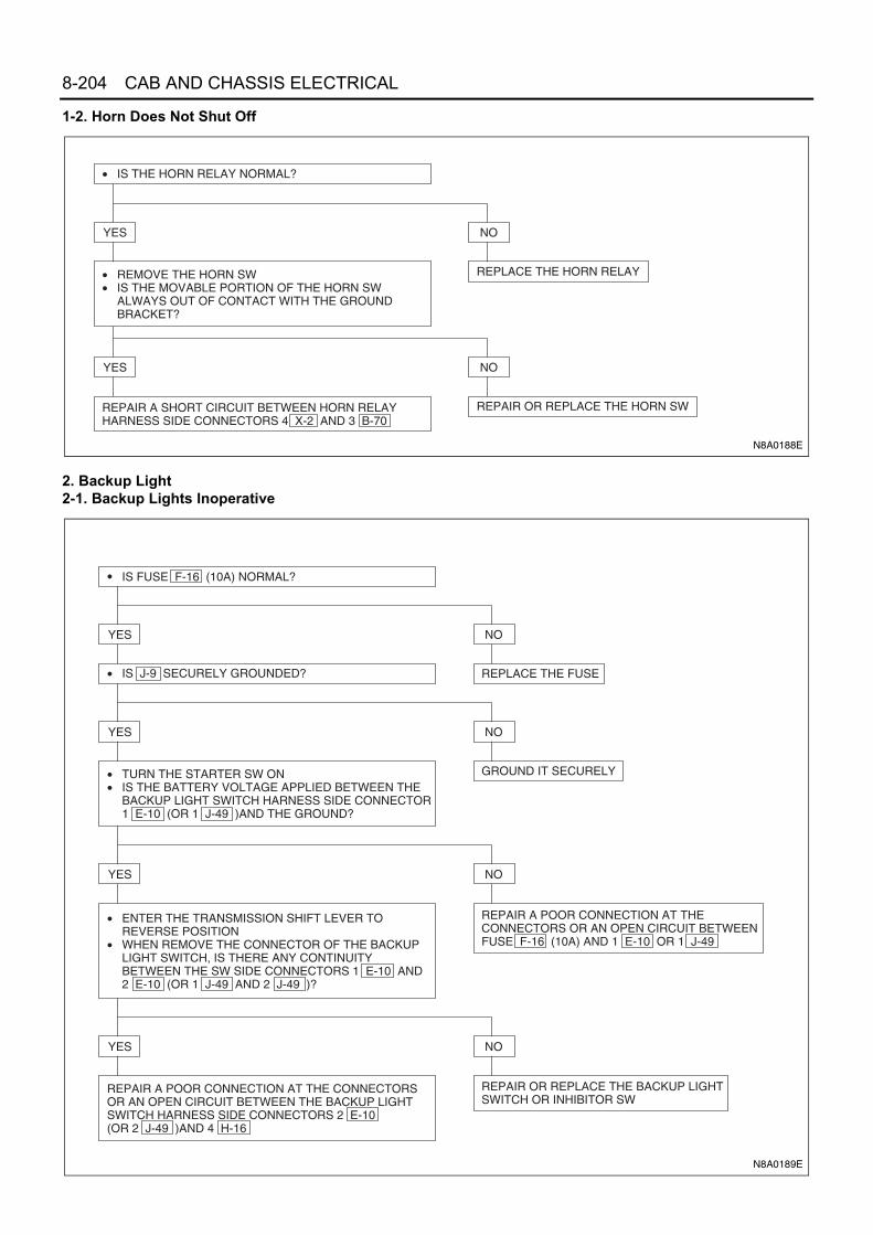
8-204 CAB AND CHASSIS ELECTRICAL
1-2. Horn Does Not Shut Off
2. Backup Light2-1. Backup Lights Inoperative
• IS THE HORN RELAY NORMAL?
• REMOVE THE HORN SW• IS THE MOVABLE PORTION OF THE HORN SW
ALWAYS OUT OF CONTACT WITH THE GROUNDBRACKET?
YES NO
REPLACE THE HORN RELAY
REPAIR A SHORT CIRCUIT BETWEEN HORN RELAYHARNESS SIDE CONNECTORS 4 X-2 AND 3 B-70
YES NO
REPAIR OR REPLACE THE HORN SW
N8A0188E
• IS FUSE F-16 (10A) NORMAL?
• IS J-9 SECURELY GROUNDED?
YES NO
REPLACE THE FUSE
• TURN THE STARTER SW ON• IS THE BATTERY VOLTAGE APPLIED BETWEEN THE
BACKUP LIGHT SWITCH HARNESS SIDE CONNECTOR1 E-10 (OR 1 J-49 )AND THE GROUND?
YES NO
GROUND IT SECURELY
• ENTER THE TRANSMISSION SHIFT LEVER TOREVERSE POSITION
• WHEN REMOVE THE CONNECTOR OF THE BACKUPLIGHT SWITCH, IS THERE ANY CONTINUITY BETWEEN THE SW SIDE CONNECTORS 1 E-10 AND 2 E-10 (OR 1 J-49 AND 2 J-49 )?
YES NO
REPAIR A POOR CONNECTION AT THECONNECTORS OR AN OPEN CIRCUIT BETWEENFUSE F-16 (10A) AND 1 E-10 OR 1 J-49
REPAIR A POOR CONNECTION AT THE CONNECTORS OR AN OPEN CIRCUIT BETWEEN THE BACKUP LIGHTSWITCH HARNESS SIDE CONNECTORS 2 E-10 (OR 2 J-49 )AND 4 H-16
YES NO
REPAIR OR REPLACE THE BACKUP LIGHTSWITCH OR INHIBITOR SW
N8A0189E

CAB AND CHASSIS ELECTRICAL 8-205
2-2. Backup Light on the Left (or Right) Side Inoperative
2-3. Backup Light Remains on
Starter SwitchRefer to “START AND CHARGING” in this section.
HornInspectionCheck to see if horn sound when a battery voltage be-tween horn terminal and the fixing bracket. Repair or re-place the horn when the result of inspection is foundabnormal.
N8A5226E
REPAIR OR REPLACE THE BACKUP LIGHT SW OR INHIBITOR SW
N8A0191E
N8A0192E

8-206 CAB AND CHASSIS ELECTRICAL
RemovalPreparation:Disconnect the battery ground cable.
1. BumperRefer to “BUMPER” in section 2.
2. HornDisconnect the connector (3).
InstallationTo install, follow the removal steps in the reverse order.
Horn SwitchInspectionWith the contact point of the horn switch pressed to theswitch bracket, check the continuity between the con-nector terminal and the bracket of the switch.Check the contact condition between horn contact of thecombination switch and contact plate of steering wheel.Repair or replace the switch when the result of inspec-tion is found abnormal.
RemovalPreparation:Disconnect the battery ground cable.
1. Horn Pad1) Hold the horn pad and pull it upward.
2. Steering Wheel1) Remove the steering shaft nut.2) Remove the steering wheel by using steering
wheel remover.(Refer to Section 3B4 “STEERING COLUMN”for steering wheel removal steps.)
3. Horn Switch
InstallationTo install, follow the removal steps in the reverse order,noting the following point.
1. Tighten the steering shaft nut to the specifiedtorque.
Tighten:Shaft nut to 49 N⋅m (5 kg⋅m / 36 lb⋅ft)
1
23
N8A5485E
N8A0194E
N8A0476E

CAB AND CHASSIS ELECTRICAL 8-207
Backup Light BulbRemovalPreparation:Disconnect the battery ground cable.
1. Lens2. Bulb
InstallationTo install, follow the removal steps in the reverse order.
Backup Light Switch
Inspection1. With the switch installed to the transmission, check
the continuity between the terminals of the switchconnectors.When the continuity is found between the terminalsonly with the switch shifted to the reverse position,the switch is normal.
2. When the result of the above inspection is foundabnormal, remove the switch from the transmis-sion and conduct a test on the switch alone.If the continuity appears between the connectorterminals when the ball of the switch is released,the switch is normal. (When the ball is pushed, thecontinuity disappears.)
3. If there is no continuity with the switch installed tothe transmission, even though the switch is foundto be normal, then adjust the stroke of the switch bychanging the thickness of the switch gasket.
RemovalPreparation:Disconnect the battery ground cable.
1. Backup Light Switch1) Disconnect the connectors.2) Remove the switch by turning it counterclock-
wise.Installation
1. Backup Light SwitchApply liquid gasket to the screw portion of theswitch to prevent oil leak.
Backup BuzzerInspectionApply battery voltage to the backup buzzer connector tocheck the buzzer sound.Repair or replace the buzzer when the result of inspec-tion is found abnormal.
N8A0195E
N8A0196E
N8A0197E

8-208 CAB AND CHASSIS ELECTRICAL
RemovalPreparation:Disconnect the battery ground cable.
1. Rear Combination Light Cover2. Backup Buzzer
1) Remove the rear combination light connectorfixing screw.
2) Remove buzzer fixing screw.3) Disconnect the connector.
InstallationTo install, follow the removal steps in the reverse order.
N8A0198E

CAB AND CHASSIS ELECTRICAL 8-209
Dome Light and Key Remind BuzzerGeneral DescriptionThe circuit consists of the starter switch, dome light, dome light switch, door switch, backup light switch and the keyremind buzzer.The dome light lights up when the left or right side door is opened with the switch set at the door mode. It can be litby operating ON or OFF of the dome light switch.The dome light can be lit by respective switch independent of the position of the starter switch.By operating the dome light switch fitted on the instrument panel, the dome light can be lit independent of the switchposition of dome light.Key remind buzzer sounds to remind the driver of leaving the key in the starter switch when opening the driver’s sidedoor.Lighting Circuit
BATTERY (+)
DOME LIGHT(FOR CREW CAB)
DOME LIGHT
DOMELIGHT SW
DOOR SW(FRT PASSENGERSIDE)
DOOR SW(DRIVER SIDE)
: Lighting circuit by door sw
: Lighting circuit by dome light sw
OFFON
DOOR
NOTE: Arrow marks " " indicate the direction of current
N8A0199E

8-210 CAB AND CHASSIS ELECTRICAL
Parts Location
F-4
, F-1
6
L-3
DIO
DE
(C
RE
W C
AB
)
N8A0200E

CAB AND CHASSIS ELECTRICAL 8-211
Circuit Diagram
B-8
6
L-2
H-1
0
B-8
6
B-6
7B
-67
H-7
OND
OO
RO
FF
B
ST
AC
C
ON
OFF
B-8
6B
-86
B-8
3B
-83
B-8
3
B-6
8
B-6
8
N-2
H-1
2
B-1
7
B-1
7
B-8
3
N-7
L-1
L-1
H-2
0
H-3
L-4
L-3
B-7
L-3
L-4
12
3
3
1
32
1 21
21
21
41
23
3
1
6 5
1 2
1 32
6
4
P-1
P-2 P-3
P-4
P-5
(24
V M
OD
EL)
5W
0.5R
3W/L
3B/Y
0.5R
0.5Y
0.5G
R0.
5Y
0.85
LG/R
RE
LAY
; TA
IL(5
)
DO
ME
LIG
HT
SW
0.5B
DOOR SW (RH)
3BH
EA
DLI
GH
T B
RA
CK
ET
(LH
)
0.5GR/B
DOOR SW (LH)0.5GR/R
0.5G
R/B
KE
Y R
EM
IND
B
UZ
ZE
R
0.5G
R/R
3B
0.5B
0.5P/L
0.5B/Y
KEY CYLINDER SW
F-4
15A
AU
DIO
(B
),D
OO
R L
OC
K
0.5R
F-16
10A
ME
TE
R
ROOM LIGHT (CREW CAB)
ST
AR
TE
R S
W
L-2
H-1
0
H-62 2
H-2
0
L-2
0.5G
R/B
DIODE0.5GR 0.5GRH
-102
0.5GR/R 1.25GR/R
0.5GR/R
1
10.5GR/B
1.25GR/B(CREW CAB)
DIODE
0.5R
0.5B
FRA
ME
DOME LIGHT
(CREW CAB)
2L
P-3
P-4
4JH
15W
/B(2
4V)
8W/B
(12V
)
MA
IN
FL-1
100A
or
120A
(24V
)
KE
Y S
W
FL-2
40A
(24V
)50
A(1
2V)
0.5R
3W/B
N8A0201E

8-212 CAB AND CHASSIS ELECTRICAL
Connector List
No. Connector Face
B-17
B-67
B-67
B-86
B-86
B-68
B-68
B-83
004-004
1 2 3 4
004-001
1 23 4
004-002
2
4
1
3
004-001
1 23 4
004-002
2
4
1
3
006-002
1
3 4 5 6
2
006-003
2
6 5 4 3
1
006-010
1 2 34 5 6
H-3
H-3
H-10
H-10
L-2
L-2
H-12
H-12
No. Connector Face
006-014
1 2 3
4 5 6
006-015
123
456
003-009
1 2 3
003-010
3 2 1
003-009
1 2 3
003-010
3 2 1
014-002
1 2 3
7 8 9 10 11
4
12
5
13
6
14
014-003
6 5 4
14131211
3 2 1
9 8 710

CAB AND CHASSIS ELECTRICAL 8-213
H-20
H-20
L-1
L-3
L-4
L-4
N-2
N-7
No. Connector Face
002-009
1
2
002-010
1
2
002-027
21
002-027
21
002-022
1 2
002-023
2 1
001-009
1
001-009
1
P-1(12 V)
P-2
P-1(24 V)
P-4
P-2(24 V)
P-3
P-5(12 V)
P-5(24 V)
No. Connector Face
000-003
000-004
000-004
000-004
000-006
000-006
000-007
000-002
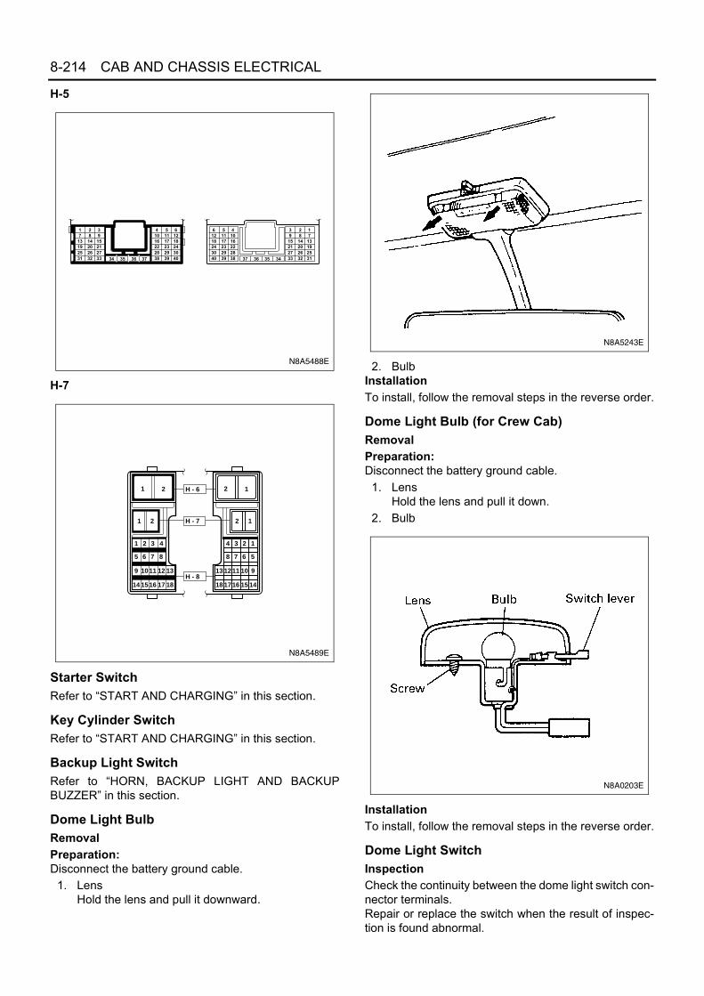
8-214 CAB AND CHASSIS ELECTRICAL
H-5
H-7
Starter SwitchRefer to “START AND CHARGING” in this section.
Key Cylinder SwitchRefer to “START AND CHARGING” in this section.
Backup Light SwitchRefer to “HORN, BACKUP LIGHT AND BACKUPBUZZER” in this section.
Dome Light BulbRemovalPreparation:Disconnect the battery ground cable.
1. LensHold the lens and pull it downward.
2. BulbInstallationTo install, follow the removal steps in the reverse order.
Dome Light Bulb (for Crew Cab)RemovalPreparation:Disconnect the battery ground cable.
1. LensHold the lens and pull it down.
2. Bulb
InstallationTo install, follow the removal steps in the reverse order.
Dome Light SwitchInspectionCheck the continuity between the dome light switch con-nector terminals.Repair or replace the switch when the result of inspec-tion is found abnormal.
1 2 37 8 9
13 14 1519 20 2125 26 2731 32 33 34 35 36 37
4 5 610 11 1216 17 1822 23 2428 29 3038 39 40
6 5 412 11 1018 17 1624 23 2230 29 2840 39 38
3 2 19 8 715 14 1321 20 1927 26 2533 32 3134353637
N8A5488E
1 2
1 2
1 2 3 4
5 6 7 8
9 10 11 12 13
14 15 16 17 18
2 1
2 1
4 3 2 1
8 7 6 5
13 12 11 10 9
18 17 16 15 14
H - 6
H - 7
H - 8
N8A5489E
N8A5243E
N8A0203E

CAB AND CHASSIS ELECTRICAL 8-215
RemovalPreparation:Disconnect the battery ground cable.
1. Meter clusterRefer to the “METER AND WARNING/INDICA-TOR LIGHT” in this section.
2. Dome Light SwitchRelease the lock pushing the switch from the backside of the meter cluster.
InstallationTo install, follow the removal steps in the reverse ordernoting the following point.
1. Push the switch with your fingers until locks se-curely.
Door SwitchInspectionCheck to see if there is any continuity between the ter-minals and the body while operating the door switch.Repair or replace the switch, when the result of inspec-tion is found abnormal.
RemovalPreparation:Disconnect the battery ground cable.
1. Door Switch1) Remove the screw.2) Disconnect the connector of the switch.
B-86
2 4 1 3
ONOFF
TerminalNo.SW
position
N8A0204E
N8A5160E
1 Body
Push
Release
ConnectorNo.
Terminal No.SWoperation
N-2 N-7
N8A0206E

8-216 CAB AND CHASSIS ELECTRICAL
InstallationTo install, follow the removal steps in the reverse order.
Key Remind BuzzerThe key remind buzzer sounds to remind the driver to remove the starter key from the starter switch when front driverside door is opened (Front driver side door switch is on).
N8A0207E
Key cylinder SW(Starter SW) Key remind buzzer
F-16(10A)
Front door SW
N8A0208E

CAB AND CHASSIS ELECTRICAL 8-217
Inspection of The Buzzer CircuitDisconnect the key remind buzzer connector, measure the continuity and voltage between the harness side connec-tor terminals.
Termi- Item Connect-Wirenal Connected to to be ing Checking conditions StandardcolorNo. checked terminal
2 B Ground Continuity 2-Ground - Continuity
Starter key inserted Approx. batteryvoltage1 P/L Ground Voltage 1-Ground
Starter key removed 0VFront driver·s side door"OPEN" Continuity
3 GR/R Ground Continuity 3-GroundFront driver·s side door"CLOSE" No Continuity
6 B/Y Fuse F-12 (10A) Voltage 6-Ground • Starter SW ONApprox. batteryvoltage
Harness side
1 2 34 5 6
B-83
N8A0209E

8-218 CAB AND CHASSIS ELECTRICAL
Key Cylinder Switch (Starter Switch)InspectionCheck to see if there is any continuity between the connector terminals of the key cylinder switch.Repair or replace the switch when the result of inspection is found abnormal.
B-68
Switch side
5 6
Key removedLOCK
OFFACC Key insertedONSTART
Terminal No.Starter keyposition
N8A0210E

CAB AND CHASSIS ELECTRICAL 8-219
Power Door LockGeneral DescriptionThe circuit consists of the door lock switch, actuator for the front passenger door, rear doors and the door lock con-troller.The door lock controller is always provided with battery voltage. The key or the inside lock knob on the driver’s doorcan activate the lock mechanism of all the doors.When the driver’s door lock switch is turned on, current flows for about one second to the door lock actuator of eachdoor connected in parallel with the controller to activate the actuator to lock and unlock the doors.Operation of Door Lock Controller
Notice:Arrow marks indicate the direction of current.
When lockingthe door.
Battery(+)
Relay;Door lock
Door lock sw.(Lock position)
To actuator(Actuatoroperateto lock side)
When lockingthe door.
Battery(+)
Relay;Door lock
Door lock sw.(Unlock position)
To actuator(Actuatoroperates tounlockposition)
N8A0211E

8-220 CAB AND CHASSIS ELECTRICAL
Parts Location
F-4
B-7
N8A0212E

CAB AND CHASSIS ELECTRICAL 8-221
Circuit Diagram
2 3
1 2 3
6
5
4
42H-11 H-11
1
B-12 B-12
B-12
B-12
B-12
B-12
D-4
D-4D-4 212112
2
3
1 2 1
D-8 D-8 D-9D-9
H-18
D-10 D-10
H-11
B-7
FL-1 100A or 120A
MAIN AUDIO, DOOR LOCK
5W
RELAY:DOOR LOCK
0.3R
/G
0.3G
/B
0.3R
/G
0.3G
/B
DOOR LOCK SW-LH
0.3B
2B
3BHEADLIGHT BRACKET (LH)
0.85
B
0.85
BR
/R
0.85
BR
/Y
0.85
BR
/R
0.85
BR
/Y
0.85
BR
/R
0.85
BR
/Y
0.85
BR
/R
0.85
BR
/Y
0.5B
R/R
0.5B
R/Y
0.5B
R/R
0.5B
R/Y
DOOR LOCK ACTUATOR-RH
DOOR LOCKACTUATOR-LH(CREW CAB)
(24V MODEL)
P-5
P-3
P-4
P-1
P-2
F-4 15A
H-63W/B
2
H-18 H-19 H-19
H-12 H-12 H-3 H-3
41135
FRAME
0.85
BR
/R
0.85
BR
/R
0.85
BR
/Y
0.85
BR
/Y
UN
LOC
K
LOC
K
UN
LOC
K
UN
LOC
K
UN
LOC
K
LOC
K
LOC
K
LOC
K
4 3H-2 H-2
DOOR LOCKACTUATOR-RH(CREW CAB)
B-1 5BFRAME-LH (FRONT)
0.85
R
2L
P-3
P-4
4JH1
8W/B(12V)
5W/B(24V)
N8A0213E

8-222 CAB AND CHASSIS ELECTRICAL
Connector List
No. Connector Face
B-12
D-4
D-4
D-8
D-8
D-9
D-9
D-10
006-010
1 2 34 5 6
003-003
1 2 3
003-011
3 2 1
002-001
1 2
002-002
12
002-001
1 2
002-002
12
002-001
1 2
D-10
H-18
H-18
H-19
H-19
H-2
H-2
H-11
No. Connector Face
002-002
12
002-001
1 2
002-002
12
002-001
1 2
002-002
12
008-009
1 2 3
84 5 6 7
008-010
123
8 4567
008-009
1 2 3
84 5 6 7

CAB AND CHASSIS ELECTRICAL 8-223
H-6
H-11
H-3
H-3
H-12
H-12
P-1(12 V)
P-2
P-1(24 V)
No. Connector Face
008-010
123
8 4567
006-014
1 2 3
4 5 6
006-015
123
456
014-002
1 2 3
7 8 9 10 11
4
12
5
13
6
14
014-003
6 5 4
14131211
3 2 1
9 8 710
000-003
000-004
000-004
P-4
P-2(24 V)
P-3
P-5(12 V)
P-5(24 V)
No. Connector Face
000-004
000-006
000-006
000-007
000-002
1 2
1 2
1 2 3 4
5 6 7 8
9 10 11 12 13
14 15 16 17 18
2 1
2 1
4 3 2 1
8 7 6 5
13 12 11 10 9
18 17 16 15 14
H - 6
H - 7
H - 8
N8A5489E

8-224 CAB AND CHASSIS ELECTRICAL
DiagnosisQuick Chart for Check Point
Notice:Figure in parenthesis “( )” indicates the order of inspection.
Check point
FuseF-4
(15 A)
Door lock controller
Door lock SW (Driver side)
Door lock actuator
Front (Passen-ger side)
Rear(RH)
Rear(LH)
Cable harness
Troublemode
1. All the doors do not lock and unlock
2. All the doors do not get locked (or unlocked)
3. Driver side door does not get locked (or unlocked)
4. Front passenger side door does not get locked (or unlocked)
5. Rear door-RH side does not get locked (or unlocked)
6. Rear door-LH side does not get locked (or unlocked)

CAB AND CHASSIS ELECTRICAL 8-225
All the Doors Do Not Lock and Unlock
All the Doors Do Not Get Locked (or Unlocked)
N8A5256E
N8A5257E

8-226 CAB AND CHASSIS ELECTRICAL
Driver Side Door Does Not Get Locked (or Unlocked)
FRT Passenger Side Door Does Not Get Locked (or Unlocked)RR Door-RH Side Does Not Get Locked (or Unlocked)RR Door-LH Side Does Not Get Locked (or Unlocked)
REPLACE THE DOOR LOCK SWITCH
N8A0216E
REPLACE THE DOOR LOCK ACTUATOR
N8A0217E

CAB AND CHASSIS ELECTRICAL 8-227
Inspection of The Door Lock CircuitCheck the voltage and the continuity between the controller harness side connector terminals.
Termi- Item Connect-Wirenal Connected to to be ing Checking conditions StandardcolorNo. checked terminalUnlock Continuity
1 R/G 1-GroundLock No continuity
Unlock No continuity2 G/B 2-Ground
Lock Continuity
3 B Ground 3-Ground - Continuity
Continuity4 BR/Y Actuator 4-5 - (There is some(Unlock) resistance)
Continuity5 BR/R Actuator 5-4 - (There is some(Lock) resistance)
6 R Fuse F-7 (15A) Voltage 6-Ground - Battery voltage
Conti-nuity
(Resis-tance)
Door lock SW(Unlock)
Door lock SW(Lock)
Driver seat sidedoor
Driver seat sidedoor
Harness side
1 2 34 5 6
B-12
N8A0218E

8-228 CAB AND CHASSIS ELECTRICAL
Door Lock RelayThe door lock controller sends out to each door lock ac-tuator the lock/unlock signals received from door lockswitch of driver seat side.
InspectionRemove the connector of the door lock controller, andcheck the continuity and the voltage between the con-troller side connector terminals.(Connect the (+) terminal of the battery to 6 andthe (−) terminal to 3 .)3 — 5 .................Continuity3 — 4 .................Continuity(Then, ground 2 .)5 ..................Voltage for approx. 1 second(Disconnect the ground of 2 , and ground 1 .)4 ..................Voltage for approx. 1 secondReplace the controller when the result of inspection isfound abnormal.
Door Lock Operation TestAfter confirming that there is continuity between the har-ness side connector terminals 4 and 5 of thedoor lock controller, apply battery voltage to each of theterminals to conduct the operation test.When the door lock will not operate, check the door lockactuator for any trouble.
For 24 Volt
For 12V
N8A0219E
B-12
B-12
B-12 B-12
B-12 B-12
B-12
B-12
B-12 B-12
B-12
B-12
Controller side
3 2 16 5 4
N8A0220E
B-12 B-12
Connecting terminal4 (BR/Y) 5 (BR/R)
Operation
UnlockLock
Harnessside
1 2 34 5 6
B-12
N8A0221E

CAB AND CHASSIS ELECTRICAL 8-229
Door Lock Switch (Driver Seat Side)The door lock switch on the driver’s door is connectedwith the door lock cylinder and the inside lock knob witha rod. The switch sends lock/unlock signals to the doorlock controller.
InspectionCheck to see if there is any continuity between the con-nector terminals of the door lock switch.Replace the switch when the result of inspection isfound abnormal.
Removal and InstallationRefer to Section 2 for “DOOR LOCK ASSEMBLY”.
Door Lock ActuatorReceiving forward or reverse current from the door lockcontroller, the door lock actuator locks or unlocks thedoor with the rod connected to the door lock mecha-nism.
Inspection of The Door Lock ActuatorApply the battery voltage to the connector terminals ofthe door lock actuator to check the operation.When the door lock actuator is checked on the vehicleand there is no continuity, and when the door lock actu-ator itself is checked and no trouble is found, check thecircuit between the door lock actuator and the door lockcontroller for any failure.
N8A0223E
1 2 3
Lock
Unlock
TerminalNo.Operation
Switch side1 2 3
D-4
N8A0224E
N8A0225E

8-230 CAB AND CHASSIS ELECTRICAL
Removal and InstallationRefer to Section 2 for “DOOR LOCK ASSEMBLY”.
Door lock ASM
Actuator
D-8 D-9 D-10
Actuator side Actuator side
RR-LH RR-RH
D-8 D-9 D-10
1 2 1 2 1 2
Lock
Unlock
FRTPassenger
Door
ConnectorNo.
TerminalNo.Operation
N8A0226E

CAB AND CHASSIS ELECTRICAL 8-231
Power WindowGeneral DescriptionThe circuit consists of the starter switch, power window switch for each of the windows and power window motor.When the starter switch is turned on, the battery voltage is applied to each of the power window switches through thecircuit breaker and the power window relay on the circuit.By operating the switches of each window to select “UP” or “DOWN”, the revolving direction of the power windowmotor changes to open or close the window.The driver’s power window switch has a built-in one-touch operating circuit which allows to automatically open thewindow by operating the switch to the AUTO position.When the driver’s power lock switch at the driver side is depressed, the power source to the passenger’s power win-dow switches will be shut off and passenger’s side power window motor will not operate if the switch is operated.Operation of Passenger Side Window
NOTE: Arrow marks " " indicate the direction of current
N8A0227E

8-232 CAB AND CHASSIS ELECTRICAL
Parts Location
F-6,
F-1
6X
-7
FL-1
, FL-
2, F
L-26
FUS
IBLE
LIN
K
B-7
N8A0228E

CAB AND CHASSIS ELECTRICAL 8-233
Circuit DiagramFor 12 Volt
X-7
B-6
7
H-1
1
H-2
H-2
D-3
H-1
1
D-3
D-3
H-1
1
X-7
X-7
X-7
H-2
H-1
1
D-3
D-7
D-7
D-7
D-7
D-7
D-6
D-6
D-2
D-2
D-3
D-3
B
OFF
ON
AC
C
ST
B-7
B-6
7
FL-1
100
A
MA
IN
ST
AR
TE
R S
W
P-1
P-2
P-5
8W3W
/B
F-16
10A
ME
TE
R
3B/Y
0.5B
/Y
2B/L
2L/B
1.25
L/B
2L/B
2B
0.3B
PO
WE
R W
IND
OW
SW
(LH
)
WIN
DO
W L
OC
K S
W
WINDOW SW-LH
WINDOWSW (RH)
AU
TO
CIR
CU
IT
1.25L/B
1.25L/Y
1.25BR/Y
1.25L
1.25L/W
PO
WE
R W
IND
OW
MO
TO
R(R
H)
UP
DO
WN
UP
DO
WN
UP
DO
WN
FL
DO
WN
UP
DO
WN
POWER WINDOW SW (RH)
1.25G/Y
1.25R/Y
SW
3BH
EA
DLI
GH
T B
RA
CK
ET
(LH
)
12
12
12
35
24
1
3
85
54
1
6 8
1
5 4
1 2
32
85
METER B-51 (8)
B E
0.5B/Y
RE
LAY
; PO
WE
R W
IND
OW
UP
2B
FL-2
50A
(12V
)
KE
Y S
W
5W8W
/BH
-62
H-7
3W/L
3W/B
1
PO
WE
R W
IND
OW
1.25G/Y
1.25R/Y
1.25G/Y
1.25R/Y
2B
FRA
ME
PO
WE
R W
IND
OW
MO
TO
R(L
H)
B-1
FRA
ME
-LH
(FR
ON
T)
5B
2L
FL-2
630
A
P-3
P-4
4JH
1
N8A0229E

8-234 CAB AND CHASSIS ELECTRICAL
For 24 Volt
X-7
B-6
7
H-1
1
H-2
H-2
D-3
H-1
1
D-3
D-3
H-1
1
X-7
X-7
X-7
H-2
H-1
1
D-3
D-7
D-7
D-7
D-7
D-7
D-6
D-6
D-2
D-2
D-3
D-3
B
OFF
ON
AC
C
ST
B-7
B-6
7
ST
AR
TE
R S
W3W/B
F-6
F-16
10A
ME
TE
R
3B/Y
0.5B
/Y
2B/L
2L/B
1.25
L/B
2L/B
2B
0.3B
PO
WE
R W
IND
OW
SW
(LH
)
WIN
DO
W L
OC
K S
W
WINDOW SW-LH
WINDOWSW (RH)
AU
TO
CIR
CU
IT
1.25L/B
1.25L/Y
1.25BR/Y
1.25L
1.25L/W
PO
WE
R W
IND
OW
MO
TO
R(R
H)
UP
DO
WN
UP
DO
WN
UP
DO
WN
FL
DO
WN
UP
DO
WN
POWER WINDOW SW (RH)
1.25G/Y
1.25R/Y
SW
3BH
EA
DLI
GH
T B
RA
CK
ET
(LH
)
12
12
12
35
24
1
3
85
54
1
6 8
1
5 4
1 2
32
85
METER B-51 (8)
B E
0.5B/Y
RE
LAY
; PO
WE
R W
IND
OW
UP
2B
5W/B
H-6
2P
OW
ER
WIN
DO
W
1.25G/Y
1.25R/Y
1.25G/Y
1.25R/Y
2B
PO
WE
R W
IND
OW
MO
TO
R(L
H)
B-1
FRA
ME
-LH
(FR
ON
T)
5B
20A
FL-1
100
A o
r 12
0A
MA
IN
P-1
P-2
5W
FL-2
40A
KE
Y S
W
5W
H-7
3W/L
3W/B
12L
P-3
P-4
P-5
FRA
ME
N8A0390E

CAB AND CHASSIS ELECTRICAL 8-235
Connector List
No. Connector Face
B-1
B-7
X-7
B-67
B-67
D-2
D-2
D-6
000-001
000-012
005-006
004-001
1 23 4
004-002
2
4
1
3
002-028
1 2
002-029
2 1
002-028
1 2
D-6
D-3
D-7
H-2
H-2
H-11
H-11
P-1(12V)
No. Connector Face
002-029
2 1
008-011
1 2 3
4 5 86 7
005-005
1 2 3 4 5
008-009
1 2 3
84 5 6 7
008-010
123
8 4567
008-009
1 2 3
84 5 6 7
008-010
123
8 4567
000-003

8-236 CAB AND CHASSIS ELECTRICAL
H-6, H-7
P-2
P-1(24V)
P-4
P-2(24V)
P-3
P-5(12V)
P-5(24V)
No. Connector Face
000-004
000-006
000-006
000-004
000-004
000-007
000-002
1 2
1 2
1 2 3 4
5 6 7 8
9 10 11 12 13
14 15 16 17 18
2 1
2 1
4 3 2 1
8 7 6 5
13 12 11 10 9
18 17 16 15 14
H - 6
H - 7
H - 8
N8A5489E

CAB AND CHASSIS ELECTRICAL 8-237
DiagnosisQuick Chart for Check Point
Notice: Figure in parenthesis “( )” indicates the order of inspection.
Check point
FuseF-16
(10A)
F-6,FL-26 (20A,30A)
Power win-dow relay
Power window SW
Power window motor Cable
har-nessDriver
side
Pas-senger
side
Driver side
Pas-senger
side
Troublemode
All windows do notoperate
(1)
(2)
(3)
(5)
(4)
Lock SW does notfunction
(1)
Driver side window
Window does notoperate
(1)
(2)
(3)
One-touch opera-tion does not oper-ate
(1)
Window operates inonly one direction
(1)
Front passenger sidewindow
Window does notoperate
(2)
(1)
(3)
(4)
Window does notoperate when oper-ating the driver sideSW
(1)
(2)
Window does notoperate when oper-ating the passen-ger side SW
(1)
(2)
Window operates inonly one directionwhen operating thedriver side SW
(1)
(2)
Window operates inonly one directionwhen operating thepassenger side SW
(2)
(1)

8-238 CAB AND CHASSIS ELECTRICAL
All Windows Do Not Operate
• IS FUSE F-16 (10A) NORMAL?
YES NO
REPLACE THE FUSE• IS THE FUSE F-6 or FL-26 NORMAL?
• IS THE POWER WINDOW RELAY NORMAL?
YES NO
REPLACE THE CIRCUIT BREAKER
• IS B-7 SECURELY GROUNDED?
YES NO
REPLACE THE RELAY
• DISCONNECT THE POWER WINDOW SW CONNECTORON THE DRIVER SEAT SIDE
• TURN THE STARTER SW ON• IS THE BATTERY VOLTAGE APPLIED BETWEEN THE
HARNESS SIDE CONNECTOR 6 D-3 AND THEGROUND?
YES NO
GROUND IT SECURELY
• IS THE BATTERY VOLTAGE APPLIED BETWEEN B-7AND THE GROUND?
YES NO
REPLACE THE SWITCH
• IS THE POWER WINDOW SW ON THE DRIVER SIDENORMAL?
YES NO
REPAIR A POOR CONNECTION AT THECONNECTORS OR AN OPEN CIRCUIT BETWEEN 6 D-3 AND 5 X-7
NO
REPAIR A POOR CONNECTION AT THECONNECTORS OR AN OPEN CIRCUIT BETWEEN 8 D-3 AND B-7
N8A0230E

CAB AND CHASSIS ELECTRICAL 8-239
Lock Sw Does Not Function
Window on the Driver Side Does Not Operate
REPAIR OR REPLACE THE POWER WINDOW SWON THE DRIVER SEAT SIDE
N8A0231E
• IS THE POWER WINDOW SWITCH ON THE DRIVERSEAT SIDE NORMAL?
• DISCONNECT THE CONNECTOR OF THE POWERWINDOW MOTOR ON THE DRIVER SEAT SIDE
• WHEN CONNECTING THE MOTOR CONNECTOR 1 D-2 TO THE BATTERY (+) TERMINAL AND 2 D-2TO THE (-) TERMINAL, DOES THE MOTOR ROTATE INTHE "UP" DIRECTION OF THE WINDOW (OR WHENCONNECTING 2 D-2 TO THE (+) TERMINAL AND 1 D-2 TO THE (-) TERMINAL, DOES THE MOTORROTATE IN THE "DOWN" DIRECTION OF THEWINDOW)?
YES NO
REPLACE THE POWER WINDOW SWITCHON THE DRIVER SEAT SIDE
REPAIR A POOR CONNECTION AT THE CONNECTORSOR AN OPEN CIRCUIT BETWEEN HARNESS SIDECONNECTOR TERMINALS 1 D-3 AND POWERWINDOW MOTOR 1 D-2 OR 2 D-3 AND 2 D-2
YES NO
REPAIR OR REPLACE THE POWER WINDOWMOTOR
N8A0232E

8-240 CAB AND CHASSIS ELECTRICAL
Window on the Front Passenger Side Does Not Operate
• IS THE FRONT PASSENGER SIDE POWER WINDOWSW NORMAL?
• IS THE DRIVER´S POWER WINDOW SW NORMAL?
YES NO
REPAIR OR REPLACE THE SW
• REMOVE THE CONNECTOR OF THE FRONTPASSENGER SIDE POWER WINDOW MOTOR
• WHEN CONNECTING THE MOTOR CONNECTOR 1 D-6 TO THE BATTERY (+) TERMINAL AND 2 D-6TO THE (-) TERMINAL, DOES THE MOTOR ROTATE INTHE "UP" DIRECTION OF THE WINDOW? (OR WHENCONNECTING 2 D-6 TO THE (+) TERMINAL AND 1 D-6 TO THE (-) TERMINAL, DOES THE MOTORROTATE IN THE "DOWN" DIRECTION OF THEWINDOW?)
YES NO
REPAIR OR REPLACE THE SW
• WITH THE SWITCH AT THE NEUTRAL POSITION, ISTHERE ANY CONTINUITY BETWEEN THE HARNESSSIDE CONNECTORS 1 D-6 AND 2 D-6 ?
YES NO
REPAIR OR REPLACE THE POWER WINDOWMOTOR
REPAIR A POOR CONNECTION AT THE CONNECTORSOR AN OPEN CIRCUIT BETWEEN 5 D-3 AND 2 D-7 (OR 4 D-3 AND 4 D-7 )
YES NO
REPAIR A POOR CONNECTION AT THECONNECTORS OR AN OPEN CIRCUIT BETWEENTHE PASSENGER SIDE POWER WINDOW SWAND THE MOTOR CONNECTOR
N8A0233E

CAB AND CHASSIS ELECTRICAL 8-241
Starter SwitchRefer to “START AND CHARGING” in this section.Power Window Switch-driver SideCircuit InspectionDisconnect the switch connectors to check the voltage and the continuity between the harness side connector termi-nals.
Termi- Item Connect-Wirenal Connected to to be ing Checking conditions StandardcolorNo. checked terminal1 L/W
2 LDriver seat side motor 1-2
4 G/Y 4-5- Continuity
5 R/Y 5-4
6 L/B Power window relay Voltage 6-Ground Starter SW "ON" Battery voltage
8 B GroundContinuity
8-Ground - Continuity(resistance)
Continuity(resistance)Passenger side power
window SW
Harness side
D-3
N8A0234E

8-242 CAB AND CHASSIS ELECTRICAL
InspectionCheck the continuity between the connector terminals of the switch.Repair or replace the switch when the result of inspection is found abnormal.
RemovalPreparation:Disconnect the battery ground cable.
1. Switch1) Insert the screw driver to the cut off portion to
remove the switch.2) Disconnect the connector.
Driver side Passenger side
6 1 2 8 6 5 4 8UP
OFF
DOWN
UP
OFF
DOWN
LOCK
Window
TerminalNo.
SWposition
D-3
Switch side
N8A0235E
N8A0236E

CAB AND CHASSIS ELECTRICAL 8-243
InstallationTo install, follow the removal steps in the reverse order.Power Window Switch-passenger SideCircuit InspectionDisconnect the switch connectors to check the voltage and the continuity between the harness side connector termi-nals.
InspectionCheck the continuity between the connector terminals ofthe switch.Repair or replace the switch when the result of inspec-tion is found abnormal.
N8A5280E

8-244 CAB AND CHASSIS ELECTRICAL
RemovalPreparation:Disconnect the battery ground cable.
1. Switch1) Insert the screw driver to the cut off portion to
remove the switch.2) Disconnect the connector.
InstallationTo install, follow the removal steps in the reverse order.
Driver Seat Side Power Window MotorInspectionBefore checking to see if the motor functions correctly,be sure to check the circuit through the connector of the driver’s power window switch.If the motor does not operate smoothly, either the motoror the circuit between the switch and the motor is defec-tive.
1. Circuit inspection of the driver side window switchDisconnect the switch connector and apply batteryvoltage to the harness side connector terminals tocheck its function.
1 2 4 3 5
UP
OFF
DOWN
TerminalNo.SW position
Switch side
D-7
N8A0238E
N8A0239E
D-3

CAB AND CHASSIS ELECTRICAL 8-245
2. Inspection of the driver seat side motorRemove the motor connector and apply batteryvoltage to the motor side connector terminals tocheck its function.Replace the motor when the result of inspection isfound abnormal.
RemovalPreparation:Disconnect the battery ground cable.
1. Window Regulator AssemblyRefer to Section 2 for Window Regulator andGlass.
2. Power Window MotorRemove three screws.
InstallationTo install, follow the removal steps in the reverse order.
Connecting terminal1 (L/W) 2 (L)
Operation
DOWNUP
Harness side
D-3
N8A0240E
D-2M
1 2
DOWNUP
Terminal No.Direction of operation
N8A0241E
N8A0242E

8-246 CAB AND CHASSIS ELECTRICAL
Front Passenger Seat Side Power Window Mo-torInspectionBefore checking to see if the motor functions correctly,be sure to check the circuit through the front passen-ger’s switch connector and the driver’s power win-dow switch connector .If the motor does not operate smoothly, either the motoror the circuit between the switch and the motor is defec-tive.
1. Circuit inspection of the front passenger seat sidewindowDisconnect the switch connector and apply batteryvoltage to the harness side connector terminals tocheck its function.
2. Circuit inspection of the driver seat side switchDisconnect the switch connector and apply batteryvoltage to the harness side connector terminals tocheck its function.
3. Inspection of the front passenger window motorDisconnect the motor connector and apply batteryvoltage to the motor side connector terminals tocheck its function.Repair or replace the motor when the result of in-spection is found abnormal.
RemovalPreparation:Disconnect the battery ground cable.
1. Window Regulator AssemblyRefer to Section 2 for Window Regulator andGlass.
2. Power Window MotorRemove three screws.
InstallationTo install, follow the removal steps in the reverse order.
D-7
D-3
D-7
Harness side
Connecting terminal Direction of3 (L/Y) 5 (BR/Y) operation
DOWNUP
N8A0243E
Harness side
D-3
Connecting terminal Direction of4 (G/Y) 5 (R/Y) operation
DOWNUP
++
N8A0244E
D-6
M
1 2
DOWNUP
Terminal No.Direction of operation
N8A0245E
N8A0246E

CAB AND CHASSIS ELECTRICAL 8-247
Windshield Wiper and WasherGeneral DescriptionThe circuit consists of the starter switch, windshield wiper & washer switch, wiper motor, washer motor and the inter-mittent relay.When the wiper & washer switch is turned on with starter switch on, the battery voltage is applied to the wiper motorto activate the wiper.The washer motor squirts glass cleaning fluid while the washer switch is being pushed. The intermittent relay is usedto control motion of the wiper.Operation of Windshield Wiper Motor(When wiper “LO” or “INT” position)
Notice:Arrow marks indicate the direction of current.
N8A0250E

8-248 CAB AND CHASSIS ELECTRICAL
Parts Location
B-7
X-1
KE
Y O
N R
ELA
Y(1
2V O
NLY
)
X-1
1 K
EY
ON
RE
LAY
(24
V O
NLY
)
RE
LAY
BO
X A
SM
(N
o.1
)
N8A0251E

CAB AND CHASSIS ELECTRICAL 8-249
Circuit Diagram
B-11 B-11
B-11
B-11
B-11
B-69B-69 B-69B-69B-69
B-69
B-9
B-9
B-9
B-9
B-9
B-9
B-8
B-8
B-7
B
ST
ACC
ONB-67
B-67
P-1
P-2
P-3
P-4
P-5
(24V MODEL)
(12V)
23
8
3
6
7
4
2
BPS
I
PM
WE
B
P
4
5
2 3
LO HI
1
3 8 7 4 6
1
POFF I H WL
1
2
HEADLIGHT BRACKET (LH)3B
0.5B
0.5B
(24V
)1.
25B
(12V
)
0.5L/B
0.5BR/Y(24V)0.85BR/Y(12V)
0.5L
(24V
)1.
25L(
12V
)
0.5L
/B
0.5L/O(24V)0.85L/O(12V)
0.5L/R(24V)0.85L/R(12V)
0.5B
R/W
(24V
)0.
85B
R/W
(12V
)
0.5B
R/R
(24V
)1.
25B
R/R
(12V
)
WIPER, WASHER SW(COMBINATION SW)
0.5L(24V)0.85L(12V)
0.5L(24V)1.25L(12V)
0.5L
(24V
)3L
1.25
L(12
V)
3B/Y3W/L
FL-1 60A or 100A(24V)80A(12V)
MAIN
FL-2 40A(24V)50A(12V)
KEY SW
STARTER SW
F-10 15AWIPER, WASHER
WIPER MOTOR
WA
SH
ER
MO
TO
R
0.5B
H-73W/B
1
RE
LAY
; IN
TE
RM
ITT
EN
T
FRAME
2L
P-3
P-4
4JH1
FUSE BLOCK
X-1
X-1
X-1
X-1
RELAYTAIL ON
(24V)
X-11
X-11
X-11
X-11
RELAYTAIL ON
0.5B
3W/L
5 2
3 1
5 2
3 1
N8A0252E

8-250 CAB AND CHASSIS ELECTRICAL
Connector List
No. Connector Face
B-8
B-9
B-11
B-11
B-67
B-67
B-69
B-69
002-009
1
2
008-012
1 2 3 4
5 6 7 8
006-001
1 2 3
4 5 6
006-016
3
6
2
5
1
4
004-001
1 23 4
004-002
2
4
1
3
008-001
1
5
2
6
3
7
4
8
008-002
1
5
23
67
4
8
P-1(12V)
P-2
P-1(24V)
P-4
P-2(24V)
P-3
P-5(12V)
P-5(24V)
No. Connector Face
000-003
000-004
000-004
000-004
000-006
000-006
000-007
000-002

CAB AND CHASSIS ELECTRICAL 8-251
H-7
DiagnosisQuick Chart for Check Point1. Windshield Wiper and Washer
Notice:Figure in parenthesis “( )” indicates the order of inspection.
X-1
X-11
No. Connector Face
005-006
005-006
1 2
1 2
1 2 3 4
5 6 7 8
9 10 11 12 13
14 15 16 17 18
2 1
2 1
4 3 2 1
8 7 6 5
13 12 11 10 9
18 17 16 15 14
H - 6
H - 7
H - 8
N8A5489E
Check point
FuseF-10(15A)
Wiper& washer
SW
Intermittent relay
Wiper motor
Washer motor
Cable harness
Trouble mode
1. Windshield wiper does not op-erate at any switch position
(1)
(3)
(4)
(2)
2. Windshield wiper does not op-erate at “INT” position
(1)
(3)
(2)
3. Windshield wiper does not op-erate at “LO” position
(1)
(3)
(2)
4. Windshield wiper does not op-erate at “HI” position
(1)
(2)
(3)
5. Auto-stop function of the windshield wiper motor does not operate
(1)
(4)
(2)
(3)
6. Rotation of the windshield wiper motor does not stop
(1)
(2)
7. Windshield washer motor does not operate
(1)
(3)
(2)

8-252 CAB AND CHASSIS ELECTRICAL
1. Windshield Wiper and Washer1-1. Windshield Wiper Does Not Operate at Any Switch Position
• IS FUSE F-10 (15A) NORMAL?
NO
• DISCONNECT THE CONNECTOR OF THE WINDSHIELDWIPER & WASHER SWITCH
• TURN THE STARTER SWITCH ON• IS THE BATTERY VOLTAGE APPLIED BETWEEN THE
SWITCH HARNESS SIDE CONNECTOR 1 B-69 AND THEGROUND?
REPLACE THE FUSE
• DISCONNECT THE CONNECTOR OF THE WINDSHIELDWIPER MOTOR WITH THE MOTOR CONNECTOR 2 B-11CONNECTED TO THE BATTERY (+) TERMINAL, AND THECONNECTOR 1 B-11 TO THE (-) TERMINAL, DOES THEMOTOR ROTATE AT A LOW SPEED?
• AND WITH THE CONNECTOR 3 B-11 CONNECTED TOTHE (+) TERMINAL, DOES THE MOTOR ROTATE AT AHIGH SPEED?
GROUND IT SECURELY
YES NO
• IS CONTINUITY IN THE WINDSHIELD WIPER & WASHERSWITCH NORMAL?
REPAIR A POOR CONNECTION AT THECONNECTORS OR AN OPEN CIRCUIT BETWEENTHE FUSE F-10 (15A) AND 1 B-69
YES NO
• IS B-7 GROUNDED SECURELY? REPAIR OR REPLACE THE SWITCH
YES NO
YES NO
REPAIR A POOR CONNECTION AT THE CONNECTORS ORAN OPEN CIRCUIT BETWEEN 1 B-11 AND B-7
REPAIR OR REPLACE THE WINDSHIELD WIPERMOTOR
YES
N8A0254E

CAB AND CHASSIS ELECTRICAL 8-253
1-2. Windshield Wiper Does Not Operate at “INT” Position
1-3. Windshield Wiper Does Not Operate at “LO” Position
NO
• DISCONNECT THE CONNECTOR OF THEINTERMITTENT RELAY
• IS THERE CONTINUITY BETWEEN THE RELAY ANDTHE WINDSHIELD WIPER & WASHER SWITCHHARNESS SIDE CONNECTOR 6 B-9 AND 8 B-69 ,OR 3 B-9 AND 3 B-69 RESPECTIVELY?
REPAIR OR REPLACE WINDSHIELD WIPER &WASHER SWITCH
YES NO
REPLACE THE INTERMITTENT RELAY REPAIR A POOR CONNECTION OR AN OPENCIRCUIT BETWEEN THE CIRCUITS
YES
• IS CONTINUITY IN THE WINDSHIELD WIPER &WASHER SWITCH NORMAL?
N8A0255E
NO
• DISCONNECT THE WINDSHIELD WIPER MOTORCONNECTOR
• CONNECT THE BATTERY (+) TERMINAL TO THEWINDSHIELD WIPER MOTOR CONNECTOR 2 B-11 ANDTHE (-) TERMINAL TO 1 B-11
• DOES THE MOTOR ROTATE AT A LOW SPEED?
REPAIR OR REPLACE THE WINDSHIELD WIPER &WASHER SWITCH
YES NO
REPAIR A POOR CONNECTION AT THE CONNECTORS ORAN OPEN CIRCUIT BETWEEN THE CONNECTORS 7 B-69AND 2 B-11
REPAIR OR REPLACE THE WINDSHIELD WIPERMOTOR
YES
• IS CONTINUITY IN THE WINDSHIELD WIPER & WASHERSWITCH NORMAL?
N8A0256E

8-254 CAB AND CHASSIS ELECTRICAL
1-4. Windshield Wiper Does Not Operate at “HI” Position
NO
• DISCONNECT THE WINDSHIELD WIPER MOTORCONNECTOR
• CONNECT THE BATTERY (+) TERMINAL TO THEWINDSHIELD WIPER MOTOR CONNECTOR 3 B-11 ANDTHE (-) TERMINAL TO 1 B-11
• DOES THE MOTOR ROTATE AT A HIGH SPEED?
REPAIR OR REPLACE THE WINDSHIELD WIPER &WASHER SWITCH
YES NO
REPAIR OR REPLACE THE WINDSHIELD WIPERMOTOR
YES
• IS CONTINUITY IN THE WINDSHIELD WIPER &WASHER SWITCH NORMAL?
REPAIR A POOR CONNECTION AT THE CONNECTORSOR AN OPEN CIRCUIT BETWEEN 4 B-69 AND 3 B-11
N8A0257E

CAB AND CHASSIS ELECTRICAL 8-255
1-5. Auto-stop Function of the Windshield Wiper Motor Does Not Operate
NO
• DISCONNECT THE CONNECTOR OF THE WINDSHIELDWIPER MOTOR
• CONNECT THE MOTOR CONNECTOR 2 B-11 TO THEBATTERY (+) TERMINAL, AND 1 B-11 TO THE BATTERY(-) TERMINAL, AND THEN CHANGE THE CONNECTIONOF THE BATTERY (+) TERMINAL TO THE CONNECTOR 4 B-11 WHILE ROTATING THE MOTOR AT A LOW SPEED
• WHEN CONNECTING THE CONNECTOR TERMINALS 2 B-11 AND 5 B-11 IN THIS CONDITION, DOES THEMOTOR STOP AT AUTO-STOP POSITION?
REPAIR OR REPLACE THE WINDSHIELD WIPER &WASHER SWITCH
NOYES
YES NO
NOYES
• TURN THE STARTER SWITCH ON• IS THERE BATTERY VOLTAGE APPLIED BETWEEN THE
WINDSHIELD WIPER MOTOR HARNESS SIDECONNECTOR TERMINAL 4 B-11 AND GROUND?
• DISCONNECT THE CONNECTOR OF THE WINDSHIELDINTERMITTENT RELAY
• IS THERE CONTINUITY BETWEEN THE RELAY HARNESSSIDE CONNECTOR 7 B-9 AND THE WINDSHIELD WIPERMOTOR HARNESS SIDE CONNECTOR 5 B-11 ?
REPAIR A POOR CONNECTION AT THECONNECTORS OR AN OPEN CIRCUIT BETWEENTHE FUSE F-10 (15A) AND 4 B-11
REPLACE THE WINDSHIELD INTERMITTENT RELAY REPAIR A POOR CONNECTION AT THECONNECTORS OR AN OPEN CIRCUIT BETWEENTHE CIRCUITS
REPAIR OR REPLACE THE WINDSHIELD WIPERMOTOR
YES
• IS CONTINUITY IN THE WINDSHIELD WIPER &WASHER SWITCH NORMAL?
N8A0258E

8-256 CAB AND CHASSIS ELECTRICAL
1-6. Rotation of the Windshield Wiper Motor Does Not Stop
NO
• THE MOMENT THE WINDSHIELD WIPER COMES TOAUTO-STOP POSITION, TURN THE STARTER SWITCHOFF(ALTERNATIVELY, CONNECT THE BATTERY (+)TERMINAL TO THE WINDSHIELD WIPER MOTORCONNECTOR 2 B-11 AND THE (-) TERMINAL TO 1 B-11 , AND THEN MOVE THE WINDSHIELD WIPERMOTOR TO AUTO-STOP POSITION AND STOP IT)
REPAIR OR REPLACE THE WINDSHIELD WIPER &WASHER SWITCH
YES
CONFIRM CONTINUITY BETWEEN THE WINDSHIELDWIPER MOTOR SIDE CONNECTOR TERMINALS 4 B-11AND 5 B-11 , AND REPAIR OR REPLACE THE MOTOR
YES
• IS CONTINUITY IN THE WINDSHIELD WIPER &WASHER SWITCH NORMAL?
N8A0259E

CAB AND CHASSIS ELECTRICAL 8-257
1-7. Windshield Washer Motor Does Not Operate
NO
NO
NO
NO
NO
• TURN THE STARTER SWITCH ON• IS THE BATTERY VOLTAGE APPLIED BETWEEN THE
WINDSHIELD WIPER & WASHER SWITCH HARNESSSIDE CONNECTOR TERMINAL 1 B-69 AND THEGROUND?
• DISCONNECT THE CONNECTOR OF THE WINDSHIELDWASHER MOTOR
• TURN THE STARTER SWITCH ON• WITH THE WASHER BUTTON OF THE WINDSHIELD
WIPER & WASHER SWITCH DEPRESSED, IS THEBATTERY VOLTAGE APPLIED BETWEEN THE WASHERMOTOR HARNESS SIDE CONNECTOR TERMINAL 1 B-8AND THE GROUND?
• IS B-7 GROUNDED SECURELY?
• CONNECT THE MOTOR SIDE CONNECTOR 1 B-8 OFTHE WINDSHIELD WASHER MOTOR TO THE BATTERY(+) TERMINAL, AND THE CONNECTOR 2 B-8 TO THE (-)TERMINAL
• DOES THE MOTOR ROTATE?
REPAIR A POOR CONNECTION AT THE CONNECTORS ORAN OPEN CIRCUIT BETWEEN 2 B-8 AND B-7
REPAIR OR REPLACE THE WINDSHIELD WIPER &WASHER SWITCH
REPAIR A POOR CONNECTION AT THECONNECTORS OR AN OPEN CIRCUIT BETWEENFUSE F-10 (15A) AND 1 B-69
REPAIR A POOR CONNECTION AT THECONNECTORS OR AN OPEN CIRCUIT BETWEEN 1 B-8 AND 6 B-69
GROUND IT SECURELY
REPAIR OR REPLACE THE WINDSHIELD WASHERMOTOR
YES
YES
YES
YES
YES
• IS CONTINUITY IN THE WINDSHIELD WIPER & WASHERSWITCH NORMAL?
N8A0260E

8-258 CAB AND CHASSIS ELECTRICAL
Starter SwitchRefer to “START AND CHARGING” in this section.
Windshield Wiper & Washer SwitchWith the starter switch on, the windshield wiper andwasher switch controls the start and stop operation aswell as the change of operating speeds.Both the windshield washer motor and the wipermotor jointly operate while the washer button ispushed.
InspectionCheck the continuity between the connector terminals of the switch.Repair or replace the switch when the result of inspection is found abnormal.
Removal and InspectionRefer to “HEADLIGHT, FOG LIGHT AND CORNERINGLIGHT” in this section.
N8A0261E
Terminal No.Washer SW Wiper SW
3 7 1 4 8 6
OFF
OFFINT
LO
HI
ONMIST,OFF
INT,LO,HI
B-69
Switch side1
5
2
6
3
7
4
8
N8A0262E

CAB AND CHASSIS ELECTRICAL 8-259
Windshield Wiper Motor
Inspection1. Operation in low speed
With the motor connector terminal 2 connect-ed to the battery (+) terminal and the connector 1
to the (−) terminal, check to see if the motorrotates in low speed.
2. Operation in high speedWith the motor connector terminal 3 connect-ed to the battery (+) terminal and the connector 1
to the (−) terminal, check to see if the motorrotates in low speed.
3. Stop operationAfter stopping the windshield wiper in the positionon the way by confirming the operation at the lowspeed in item No. 1.When the connectors 2 and 5 are con-nected, while connecting the motor connector ter-minal 4 to the battery (+) terminal, check tosee, if the motor rotates at low speed and stops atthe auto-stop position.Repair or replace the motor when the results of theabove inspections are found abnormal.
RemovalPreparation:Disconnect the battery ground cable.
1. Glove BoxRefer to “INSTRUMENT PANEL” of section 2.
2. Windshield Wiper Motor1) Disconnect the connector.2) Remove four screws.3) Remove the ball joint between crank arm and
wiper link.
InstallationTo install, follow the removal steps in the reverse order,noting the following points.
• Windshield Wiper MotorWhen the crank arm is removed from the wind-shield wiper motor, tighten the motor shaft nut withthe specified torque.
Tighten:Shaft nut to 17 N⋅m (170 kg⋅cm/147 lb⋅in)
• Temporarily fit the motor by using one of the fourwiper motor fixing screws.
• Put the crank arm ball joint in the wiper link holeand fix them together while pulling the wiper link.
N8A0263E
B-11
B-11
B-11
B-11
B-11 B-11
B-11
N8A0264E
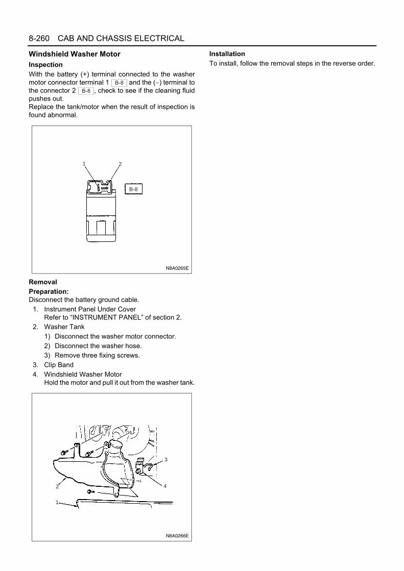
8-260 CAB AND CHASSIS ELECTRICAL
Windshield Washer MotorInspectionWith the battery (+) terminal connected to the washermotor connector terminal 1 and the (−) terminal tothe connector 2 , check to see if the cleaning fluidpushes out.Replace the tank/motor when the result of inspection isfound abnormal.
RemovalPreparation:Disconnect the battery ground cable.
1. Instrument Panel Under CoverRefer to “INSTRUMENT PANEL” of section 2.
2. Washer Tank1) Disconnect the washer motor connector.2) Disconnect the washer hose.3) Remove three fixing screws.
3. Clip Band4. Windshield Washer Motor
Hold the motor and pull it out from the washer tank.
InstallationTo install, follow the removal steps in the reverse order.
B-8
B-8
1 2
B-8
N8A0265E
3
42
1
N8A0266E

CAB AND CHASSIS ELECTRICAL 8-261
Intermittent RelayCircuit Diagram
RemovalPreparation:Disconnect the battery ground cable.
1. Glove BoxOpen the lid and remove the four screws.
2. Intermittent Relay1) Press A position with your finger and pry up B
position with the tip of a screw-driver.2) When the relay moves up by about 2/3 of its
size, tilt and take off the relay to avoid interfer-ence with the instrument panel.
3) Disconnect the connector.
N8A0267E

8-262 CAB AND CHASSIS ELECTRICAL
InstallationTo install, follow the removal steps in the reverse order.
Windshield Wiper Arm & BladeRemoval
1. Cover2. Wiper Arm Nut3. Wiper Arm & Blade
InstallationTo install, follow the removal steps in the reverse order,noting the following points.
1. Before installing the wiper arm & blade to the shaft,confirm that the motor stops at the auto-stop posi-tion.
2. Set the wiper arm & blade so that the tips of bothblades are positioned as shown in the illustration.
3. Tighten the wiper arm nut to the specified torque.
Tighten:Wiper arm nut to 17 N⋅m (170 kg⋅cm/147 lb⋅in)
Instrumental panel
Instrumentpanel rein-forcement
1
2
2
A
S
B
View S
N8A0268E
321
N8A0269E
Approx. 45mm(STD Cab)Approx. 70mm(Wide Cab)
N8A0270E

CAB AND CHASSIS ELECTRICAL 8-263
Windshield Wiper LinkageLocation of Rod and Pivot
RemovalPreparation:Disconnect the battery ground cable.
1. Wiper Arm & BladeRemove the cover, nut and wiper arm & blade.
2. Pivot NutRemove the rubber seal, nut and retaining rubber.
Pivot (Wiper: LH)
Rod Rod
Pivot (Wiper: RH)
Wiper motor
N8A0271E
1NutCover
N8A0272E
Rubber seal
2 Retaining rubber
N8A0273E

8-264 CAB AND CHASSIS ELECTRICAL
3. Instrument Panel AssemblyRefer to “INSTRUMENT PANEL” of section 2.
4. Wiper Motor1) Remove the four screws.2) Disconnect the ball joint between the crank arm
and the wiper link.
5. Instrument Panel ReinforcementRefer to “INSTRUMENT PANEL” of section 2.
6. Wiper Link AssemblyRemove two retaining nuts from left hand side ofpivot.
3
N8A0274E
N8A0275E
N8A0276E
6
Pivot (Wiper: LH)
N8A0277E

CAB AND CHASSIS ELECTRICAL 8-265
Remove two retaining nuts from right hand side ofpivot.
InstallationTo install, follow the removal steps in the reverse order,noting the following points.
• Temporarily fit the wiper motor by using one of thefour wiper motor fixing screws.
• Put the crank arm ball joint in the wiper link holeand fix them together while pulling the wiper link.
• Fit the motor with four screws.• Tighten the pivot nut with the specified torque.
Tighten:Pivot nut to 8 N⋅m (80 kg⋅cm/70 lb⋅in)
• Tighten the wiper arm nut with the specified torque.
Tighten:Wiper arm nut to 17 N⋅m (170 kg⋅cm/147 lb⋅in)
Wiper Blade RubberRemoval
1. Wiper BladePush the wiper blade lock while pulling the wiperblade in the arrow direction.
Notice:When the wiper blade has been removed, wrap the tipof the wiper arm with cloth, to avoid damaging the glass.
2. Wiper Blade Rubber1) Pull the end of rubber and remove the projec-
tion from the click of the blade stay.2) Pull the rubber out in the same direction.
6
Pivot (Wiper: RH)
N8A0278E
N8A0477E
N8A0280E

8-266 CAB AND CHASSIS ELECTRICAL
Installation1. Wiper Blade Rubber
Install the click of the blade stay in the groove of thenew rubber and slide it in. Complete installation bypushing the click.
Finally, check that the click of the stay has caughtin the hole of the rubber.
2. Wiper BladePush the lock of wiper blade (1) into the retentiveportion on the tip of wiper arm (2).
Audio and Cigar Lighter
General DescriptionThe circuit consists of the starter switch, radio, cigarlighter and the relay.The audio circuit is designed for the current to flowthrough the receiver circuit when the radio switch isturned on with the starter switch in “ACC” or “ON”. Cur-rent runs through the memory circuit of the audio regard-less of the position of the starter switch.When the cigar lighter is pushed in with the starterswitch at either “ACC” or “ON” position, a circuit isformed in the cigar lighter case to heat the lighter coil.The cigar lighter is spring back to its original position af-ter the lighter coil is heated.
N8A0281E
N8A0282E
1
2N8A0486E

CAB AND CHASSIS ELECTRICAL 8-267
Parts Location
X-4
TA
IL R
ELA
Y
F-4,
F-7
, F-1
5
N8A0283E

8-268 CAB AND CHASSIS ELECTRICAL
Circuit Diagram
2
D-5
1
D-5
H-71
5
10 11 4
6135129
6767
12
1
B-28
B-28B-28B-28
B-67
B-45
H-11H-2H-2
B-28B-28B-28B-28
4
H-11
B-44
B-43
2
2 1
2
B-7
X-4
X-4
X-4
X-4
H-6
B-67B
ST
ACC
ON
OFF
STARTER SWITCH
FL-1 100A or 120A
KEY SW
FL-2 40A(24V)50A(12V)
AUDIO(B),DOOR LOCK
F-4 15AF-15 15A
1
RELAY; TAIL
LIG
HT
ING
SW
ITC
H(8
)(C
OM
BIN
AIT
ION
SW
ITC
H)
(24V MODEL)
HEADLIGHT BRACKET (LH)
CLE
AR
AN
CE
LIG
HT
(LH
)
3W/B
5W3W
/B
3W/B
0.85
LG/R
3W
0.3G
/O
0.5B
3B 2B
5W/B
(24
V)
8W/B
(12
V)
3R/Y
0.
5R/Y
0.5R
2B
0.3B0.
5G/R
0.5G
/R
0.5G
0.5G
0.5O
0.5O
0.5B
0.5B
0.5LG/R
SPEAKER (LH) SPEAKER (RH)
RADIO & CLOCK
CIG
AR
LIG
HT
ER
P-1
P-2
P-3
P-4
P-5
MAIN
3W/L
5W
AUDIO(IG)CIGAR LIGHTER
1
B-43
2
D-1
1
D-1
0.5LG/R
FRAME
(12V
)8W
0.85LG/R
0.5B
(24
V)
1.25
B (
12V
)
2L
0.5R
/Y
0.5R
/YTAILLIGHT
F-7 10A
0.85
G/B
N8A0284E

CAB AND CHASSIS ELECTRICAL 8-269
Connector List
No. Connector Face
B-1
B-7
X-4
B-28
B-43
B-43
D-5
D-5
000-001
000-012
005-006
013-001
1 2 3
7 8 9
4 5 6
11 12 1310
002-009
1
2
002-010
1
2
002-009
1
2
002-010
1
2
D-1
D-1
B-44
B-45
B-67
B-67
H-2
H-2
No. Connector Face
002-009
1
2
002-010
1
2
001-011
1
001-009
1
004-001
1 23 4
004-002
2
4
1
3
008-009
1 2 3
84 5 6 7
008-010
123
8 4567

8-270 CAB AND CHASSIS ELECTRICAL
H-6, H-7
H-11
H-11
P-1(12V)
P-2
P-1(24V)
P-4
P-2(24V)
P-3
No. Connector Face
008-009
1 2 3
84 5 6 7
008-010
123
8 4567
000-003
000-004
000-004
000-004
000-006
000-006
P-5(12V)
P-5(24V)
No. Connector Face
000-007
000-002
1 2
1 2
1 2 3 4
5 6 7 8
9 10 11 12 13
14 15 16 17 18
2 1
2 1
4 3 2 1
8 7 6 5
13 12 11 10 9
18 17 16 15 14
H - 6
H - 7
H - 8
N8A5489E

CAB AND CHASSIS ELECTRICAL 8-271
Diagnosis1. Cigar Lighter Does Not Heat Sufficiently
• IS FUSE F-15 (15A) NORMAL?
NO
• REMOVE THE CIGAR LIGHTER• SET THE STARTER SWITCH TO EITHER "ACC" OR "ON"
POSITION• IS THE BATTERY VOLTAGE APPLIED BETWEEN THE
BIMETAL AT THE CENTER OF THE CASE AND OUTEROF THE CASE?
REPLACE THE FUSE
YES
• IS B-7 GROUNDED SECURELY?
YES NO
GROUND IT SECURELY
YES
NO
REPAIR A POOR CONNECTION AT THECONNECTORS OR AN OPEN CIRCUIT BETWEENFUSE F-15 (15A) AND 1 B-44
• SET THE STARTER SWITCH TO EITHER "ACC" OR "ON"• IS THE BATTERY VOLTAGE APPLIED BETWEEN B-7
AND GROUND?
REPLACE THE CIGAR LIGHTER ASSEMBLY
YES
REPAIR A POOR CONNECTION AT THECONNECTORS OR AN OPEN CIRCUIT BETWEEN 1 B-45 AND B-7
NO
N8A0285E

8-272 CAB AND CHASSIS ELECTRICAL
2. The Cigar Lighter Does Not Spring Out After Being Heated
Starter SwitchRefer to “START AND CHARGING” in this section.
RadioRemovalPreparation:Disconnect the battery ground cable.
1. Center Cluster1) Pull it to remove. Pry off three clips by the tip of
screwdriver.2) Remove the cigar lighter power source and its
illumination connector.
Notice:To remove the center cluster, do not force to pry offthree clips at upper portion of the center cluster.
2. Radio1) Remove the two radio fixing screws.2) Disconnect the connector and feeder plug.
InstallationTo install, follow the removal steps in the reverse order.
AntennaInspectionThe metal A is connected to the pole D at the top of theantenna through the core of the feeder.The metal B is fitted in the feeder shielding the core, andgrounded at the screw C to avoid the core hampered bynoise.Defective grounding would cause noise.
• IS THE FORM OF CIGAR LIGHTER NORMAL?
NO
REPLACE THE CIGAR LIGHTER ASSEMBLY(INCLUDE OUTER CASE)
REPLACE THE CIGAR LIGHTER
YES
N8A0286E
Legend1. Center Cluster
N8A0392E
Legend1. Radio
1
N8A0393E

CAB AND CHASSIS ELECTRICAL 8-273
In checking, measure the following three points with thecircuit tester in the range of “resistance x 1 (Ω).”Between A and BNo continuity (No reading at the indicator) →NormalContinuity (A bite in the feeder. The core grounded) →Lower receptionBetween B and CContinuity (Indicator reading: 0Ω) → NormalNo continuity (Shielded core disconnected or defectivegrounding at the screw → Hampered by noise)Between A and DContinuity or no continuityThere are some antenna feeders and relay feeders witha condenser built in their connections.Measuring resistance between the two points does notresult in correct judgment. Connect temporarily anothernormal antenna to the radio and check to see if its re-ception is audible. Most antenna now available are slidetype. Rust at the screw C and the cab panel wheregrounded would lead no continuity, followed by lower re-ception.Keep this portion clean to avoid rust.RemovalPreparation:Disconnect the battery ground cable.
1. Antenna1) Disconnect the joint connector.2) Remove the upper and lower side antenna
bracket.3) Pull out the antenna feeder.
Notice:For easier fitting, tie the lead wire to the end of the an-tenna feeder in advance.
InstallationTo install, follow the removal steps in the reverse order.
SpeakerInspection
1. With the circuit tester set to the range of × 1 (Ω),connect the circuit tester probes (red and black) tothe (+) and (−) terminals of the speaker.
2. When the speaker is normal, a low buzzing soundis heard.
3. When the speaker is defective, no sound is heard.However, the distortion or chattering of the soundcannot be identified.When the speaker is installed to the vehicle, dis-connect the connectors before checking.
N8A0289E
Legend1. Antenna2. Antenna Bracket3. Feeder4. Joint Connection5. Feeder6. Clip7. Radio
1
2
3
4
5
67
N8A0394E

8-274 CAB AND CHASSIS ELECTRICAL
When no sound is heard, the following are consid-ered as the cause.
• The speaker wiring is disconnected at the speakerterminals.
• The speaker body is defective.• There is an open circuit somewhere in the speaker
harness on the vehicle side.• The speaker harness on the vehicle side is ground-
ed or caught up.RemovalPreparation:Disconnect the battery ground cable.
1. Door PadRefer to “FRONT DOOR TRIM PAD” of section 2.
2. Speaker PanelDisconnect the speaker connector.
3. Speaker4. Waterproof Sheet
InstallationTo install, follow the removal steps in the reverse order.
Cigar LighterRemovalPreparation:Disconnect the battery ground cable.
1. Center ClusterRefer to “RADIO” in this section.
2. Cigar Lighter AssemblyRemove the nut, then remove cigar lighter assem-bly, bezel and outer case.
InstallationTo install, follow the removal steps in the reverse order.
Meter and Warning/indicator Light
General DescriptionThe circuit consists of the starter switch, meter assem-bly, vacuum tank switch, seat belt switch, oil pressureswitch, fuel sedimenter switch, brake fluid switch, park-ing brake switch, vehicle speed sensor, fuel tank unit,thermo unit and engine speed sensor.The meter assembly contains the speedometer, ta-chometer, fuel meter, thermometer and the warning/in-dicator light.The meter warning/indicator lights and their bulb sock-ets are a unit, they are installed from the back of thespeedometer assembly.
Legend1. Trim Panel2. Speaker Panel3. Speaker4. Waterproof Sheet
N8A5341E
Legend1. Bezel2. Cigar Lighter Assembly3. Center Cluster4. Outer Case5. Nut
2
14
5
3
N8A0395E

CAB AND CHASSIS ELECTRICAL 8-275
Parts LocationFor 12 Volt
AFR
AM
EH
AR
NE
SS
E-1
4O
IL P
RE
SS
UR
ES
WIT
CH
E-7
TH
ER
MO
UN
IT
H-1
4
H-1
4
E-2
TA
CH
OS
EN
SO
R H
-14
E-7
TH
ER
MO
UN
IT
<4J
B1>
<4J
H1>
<4J
H1>
FU
SE
BO
X A
SM
F-4
,F-7
,F-1
6
B-5
5 M
ET
ER
B-3
34, B
-335
TA
CH
OG
RA
PH
(IN
ME
TE
R)
B-3
38T
AC
HO
GR
AP
H(I
N IN
ST
)
H-5
~H
-7
B-1
B-6
7
B-3
37P
LUS
CO
NV
ER
TE
RB
-7
H-1
2
J-9
B-7
1 V
AC
UU
MT
AN
K S
WB
-85
BR
AK
EO
IL L
EV
EL
SW
ST
AR
TE
R
J-8
OIL
PR
ES
SU
RE
SW
(Exc
ept 4
JH1)
J-12
8H
BB
LE
VE
L S
W
FL-
1,F
L-2
FU
SIB
LE L
INK
RE
LAY
BO
XA
SM
P-1P-2
P-5
BA
TT
ER
Y
J-32
VE
HIC
LES
PE
ED
SE
NS
OR
J-28
F
UE
L T
AN
K U
NIT
N-6
P
AR
KIN
G B
RA
KE
SW
J-53
,J-5
4 F
UE
L S
ED
IME
NT
ER
ST
AT
ER
SW
B-5
2 M
ET
ER
B-5
1 M
ET
ER
B-3
36 M
ET
ER
(4JH
1)
A
N-5
P-5
P-1 (1
2V)
P-2
P-4
P-3
<4J
H1>
B-2
36
AIR
PR
ES
SU
RE
SW
ITC
H
X-5
AB
SIN
DIC
AT
OR
RE
LAY
B-1
8 D
IOD
EX
-33
DIO
DE
X-1
3 B
UZ
ZE
RC
AN
CE
L R
ELA
Y
N8A0534E

8-276 CAB AND CHASSIS ELECTRICAL
For 24 Volt
<4H
E1,
4H
F1,
4H
G1,
4H
K1>
J-28
FU
EL
TA
NK
UN
IT
N-6
PA
RK
ING
BR
AK
E S
W
J-32
VE
HIC
LE S
PE
ED
SE
NS
OR
E-2
TA
CH
O S
EN
SO
R
H-1
4
P-5
P-1
P-2
P-3
P-4
RE
LAY
BO
X A
SM
FL-
1, F
L-2
FU
SIB
LE L
INK
J-9
H-1
2
B-6
7
B-7
B-1
H-5
, H -
7, H
-8
ST
AR
TE
R
J-8
OIL
PR
ES
SU
RE
SW
B-7
1 V
AC
UU
M T
AN
K S
WB
-85
BR
AK
E F
LUID
LE
VE
L S
W
BA
TT
ER
Y
H-1
4
ST
AR
TE
R S
W
B-5
2 M
ET
ER
B-5
1 M
ET
ER
B-5
5 M
ET
ER
FU
SE
BO
X A
SM
F-4
, F-7
, F-1
6
E-7
6 T
HE
RM
O
SE
NS
OR
(UN
IT)
J-12
8H
BB
LE
VE
L S
W
X-1
3 B
UZ
ZE
RC
AN
CE
L R
ELA
Y
B-1
8D
IOD
E
B-2
36
AIR
PR
ES
SU
RE
SW
ITC
H
X-3
3 D
IOD
E
X-5
AB
S
IND
ICA
TO
R R
ELA
Y
J-53
, J-5
4F
UE
L S
ED
IME
NT
ER
N-5
SE
AT
BE
LT S
W
N8A0535E

CAB AND CHASSIS ELECTRICAL 8-277
Circuit DiagramExcept 4JH1 / 4HK1 Engine
B-5
1B
-52
0.3BR/Y
0.3BR
B-5
2 3 0.5W/L
RELAY; CHARGE (5)
B-8
5
B-8
5
B-5
1 14 2 10.3W/B
0.5B
0.5B
/Y
0.3W
/B
0.3W
/B
0.3W
/B
0.3W
/B
0.3B
SHORT CONNECTOR (WITH HBB)
RELAY;BUZZER CANCEL
BRAKE FLUID SWITCH
3B
11
3 5
X-1
3
X-1
3
X-1
3
X-1
32 4 1
HBB LEVELSW
J-12
8
J-12
82
J-12
8
J-12
8412
TACHOMETER
SPEEDOMETER
CHARGE
SEAT BELT (SAUDI ARABIA)
GLOW
COOLANT TEMPERATURE GAUGE
TURN - RH
BOOST
TURN - LH
HIGH BEAM
EXHAUST BRAKE
SP
EE
D W
AR
NIN
G(S
AU
DI A
RA
BIA
)
VACUUM
BRAKE FLUID LEVEL
ILLUMINATION (X5)
WATERSEDIMENTER
OIL PRESSURE
BUZZER
REAR FOG
H-1
4H
-14
E-2
E-2H-5
H-5
B-5
2B
-52
3938
109
12
ENGINE SPEEDSENSOR
0.3L/O
0.5B/L
98
H-5
H-1
4
E-7
B-5
5
4 23
6 1
0.3Y/B
FUEL GAUGE
FUEL LEVEL
J-28
J-28 3
B-5
5B
-51
H-5
H-5
105
1421
21
J-280.3BR/R
0.3Y/R
B-5
5
H-5
J-32
J-32
B-5
5
H-5
B-5
2
H-5
B-5
5
J-32
72
31
1931
25
21
3
0.85B
0.3Y/G
0.3B/Y
0.5B
WATER SEDIMENTER SW
SEAT BELT SW
N-5
N-5
H-1
2
3B
B-5
1
H-1
2
2 10 3
43
15
1
0.5B0.3W/G 0.3W/G
J-53
J-54
B-5
1
H-5
12 30 1 1
0.3BR/W 0.5BR/W
B-5
1
6
0.3O/L
0.5W2B0.5B
0.3W/V
0.5B/Y
QOS-III CONTROL UNIT (13)
ABS
B-5
1
7
0.5L/O
0.5B/L
0.5L/O
0.5B/L
0.5Y/B 0.5Y/B
THERMO UNIT
0.5BR/R
0.5Y/R
FUEL TANK UNIT
0.5Y/G
0.5B/Y
0.5B
SIG
+
OIL PRESSURE SW (55, 69, 66)
J-8
B-5
2
H-5
1 20 1
0.3SB 0.5SB
QOS-II CONTROL UNIT (7)
9
TIMER
B-5
212
B-5
5B
-55
B-5
5B
-51EXHAUST BRAKE SW
B-69 (2)
B-5
18
B-5
25
HEAD LIGHT (LH)
TURN SIGNAL LIGHT SW B-70 (5)
TURN SIGNAL LIGHT SW B-70 (13)
RELAY:RR FOG LIGHT(5)
FUSE NO. 9
RELAY; TAIL (5)
H-7
B-6
7B
-67
B
ST
AC
C
ON
OF
F
2
P-1
P-2
P-3
P-4
P-5
21
3
FR
AM
E
FL-
1
3B/Y
ST
AR
TE
R S
W
(24V
MO
DE
L)
F-1
6 1
0A
ME
TE
R
H-6
3W/L
MA
IN
FL-
2
100A
or
120A
40A
(24V
)50
A(1
2V)
KE
Y S
W
8W
0.5B/Y
F-4
15A
AU
DIO
(B),
DO
OR
LO
CK
0.5LG/R
(24V)
0.5LG/L
118
101
0.5R/G
0.5G/B
0.5G/W
0.5R/B
B-5
52
0.3W
0.5R0.85R
5W/B
(24
V)
8W/B
(12
V)
B-7
J-9
HE
AD
LIG
HT
BR
AC
KE
T (
LH)
FR
AM
E-L
H(C
EN
TE
R)
B-1
FR
AM
E-L
H(F
RO
NT
)
0.5B
VEHICLE SPEED SENSOR
DSW
QOS-III CONTROL UNIT (9)
2B
SENSORPOWER SOURCE
CIRCUIT
B-5
2
4
EHCU ; ABS
ABS INDICATOR RELAY
X-5
X-5
X-5
X-5
SHORT CONNECTOR (W/O HBB)
1 5 4 3 10 6 2
0.3W/B
PARKING BRAKESW
0.3W/B3 1
H-1
2
H-5
N-6
0.3W
/L
0.3B
R
9 3
78
X-3
3
X-33
X-33
DIO
DE
0.3
W/R
0.3W
/B
H-5
H-50.5BR
0.5W/B
13
980.5W
/R
23
4
B-18
B-18
VACUUM TANKSW
1
DIO
DE
AIR PRESSURESW
B-23
6
B-23
62 10.3BR0.3BR
0.3BR0.3
BR
/Y
B-7
1
B-18
N8A0527E

8-278 CAB AND CHASSIS ELECTRICAL
For 4JH1 Engine
B-5
1B
-52
0.3BR/Y0.3W/B
0.3BR
B-5
2 3 0.5W/L
RELAY; CHARGE (5)
B-8
5
B-8
5
B-5
1 14 2 10.3W/B
0.5B
0.5B
/Y
0.3W
/B
0.3W
/B
0.3W
/B
0.3W
/BPARKING BRAKESW
SHORT CONNECTOR (WITH HBB)
RELAY;BUZZER CANCEL
BRAKE FLUID SWITCH
3B
11
3 5
X-1
3
X-1
3
X-1
3
X-1
3
0.3W/B3 1
H-1
2
N-6
2 4 1
HBB LEVELSW
B-5
2B
-52
B-5
1B
-55
B-5
5B
-55
H-6
H-5
J-28
B-5
5B
-52
B-5
2
J-28
E-7
H-1
4
B-5
1
H-5
H-5
B-5
5
J-32
J-32
B-5
5
H-5
B-5
2
J-28
H-5
B-5
5
H-5
B-5
5
J-32
B
ST
AC
C
ON
B-6
7B
-67
8
B-5
2
H-5
E-1
4
J-9
B-7
B-1
B-5
1
70dB
J-53
J-54
H-5
B-5
1
BUZZER
P-1
P-2
P-5
H-7
21
3
2
B-5
1
61
12
20 1
30 1 1
310
15
3119
25
12
3
7
21 1
104
98
1423 6 1
2
3
1
B-5
2410
811
FR
AM
E
FL-
1
100A
3W/L
ST
AR
TE
R S
WIT
CH
F-1
6
ME
TE
R10
A
0.5B
/Y
3B/Y
EXHAUST BRAKE SWITCH B-69 (2)
(COMBINATION SWITCH)
HEADLIGHT (LO)
RELAY; RR FOG LIGHT (5)
TURN SIGNAL LIGHT SWITCH (LH) B-70 (5)
(COMBINATION SWITCH)
TURN SIGNAL LIGHT SWITCH (RH) B-70 (13)
(COMBINATION SWITCH)
0.5LG/L
0.5R/G
0.5R/G
0.5G/B
0.5G/W
B-33
6312
5
0.3W/R
0.5LG/R
5W8W
/B
0.5R 0.5R
FR
AM
E-L
H(F
RO
NT
)
HE
AD
LIG
HT
BR
AC
KE
T (
LH)
FR
AM
E-L
H(C
EN
TE
R)
0.85
B
3B2B 0.5B
0.3O/LECM (43)
OIL PRESSURE SWITCH
0.3LB
0.3LG/W 0.5LG/W 0.5B
WATER SEDIMENTER SWITCH
0.3B/Y 0.5B/Y
0.3Y/R 0.5Y/R
0.85B 0.5B
0.85B
0.5B0.3BR/R 0.5BR/R
0.3Y/B 0.5Y/B 0.5Y/B
0.3B
0.5LG
THERMO UNIT
FUEL TANK UNIT
VE
HIC
LE S
PE
ED
SE
NS
OR
0.3Y/G 0.5Y/G
8WM
AIN
2L
FL-
2
50A
KE
Y S
W
TACHOMETER
COOLANTTEMPERATURE GAUGE
FUEL LEVEL
FUEL GAUGE
SPEEDOMETER
ILLUMINATION(X5)
TURN (RH)
TURN (LH)
HIGH BEAM
EXHAUST BRAKE
REAR FOG
CHARGE
BRAKE FLUIDLEVEL
WATER SEDIMENTER
OIL PRESSURE
VACUUM
GLOW
SENSORPOWER SOURCE
CIRCUIT
ECM (27)
CHECK ENGINE
B-5
1 4
0.5G/YECM (43)
B-5
1 2
0.5G/R
EC
M (
60)
0.5LB H-1
4
1.25LB
B-5
1 7ABS
X-54
X-5
3
15
X-5
X-5
ABS INDICATORRELAY
0.5W
0.5B/Y
2B0.5B
0.3W/VEHCU ; ABS
0.3B
B-33
7B-
3374
1 PLU
SC
ON
VE
RT
ER
B-33
7B-
337 6
5
B-33
8B-
3384
3
TA
CH
OG
RA
PH
(IN
INS
T)
B-33
8B-
338 2
6
B-33
85
B-33
81
B-33
5B-
334
B-33
5 13
2
TA
CH
OG
RA
PH
(IN
ME
TE
R)
7B-
335
6B-
335
5B-
335
F-7
1
0A
TA
IL L
IGH
T
0.5R
0.5L
G/R
0.5B0.
3W/B
0.5B
0.5B/Y
0.5B/Y
0.5LG/R
0.5R
BOOSTER
0.85
LG/R
F-4
1
5A
AU
DIO
(B),
DO
OR
LO
CK
TA
IL R
ELA
Y
0.5B
/Y
4
P-3
P-4
FOR EC ONLY
SHORT CONNECTOR (W/O HBB)
1 5 4 3 10 6 2
AIR PRESSURESW
B-23
6
B-23
6
23
4
2 1
B-18
B-18
VACUUM TANKSW
1
DIO
DE
0.3
BR
B-7
1
0.3B
R
0.3
BR
0.5BR
0.5W/B
2 1
412 3
98
0.3W
/L
0.3B
R
9 3
78
X-3
3
X-33
X-33
DIO
DE
0.3
W/R
0.5W
/R0.
5W/B
0.3
BR
/YJ-
128
J-12
8
J-12
8
J-12
8
H-5
H-5
H-5
H-5
B-18
N8A0528E

CAB AND CHASSIS ELECTRICAL 8-279
For 4HK1 Engine
B-5
5
H-5
J-32
H-7
B-6
7
J-32
B-6
7
B-5
5
H-5
B-5
2
H-5
B-5
5
J-32
2
B-5
5B
-55
B-5
5B
-51
B-1
5
J-28
J-28
H-5
H-1
4
3
E-7
6
E-2
E-2
B-5
5B
-51
H-5
H-5
B-5
2B
-52
B-5
5
B-5
2
P-1
P-2
P-3
P-4
P-5
21
B-5
2
118
101
104
12
23 7 3
57
1421
21
103
1
1931
25
21
3
FR
AM
E
FL-
1 1
00A
or
120A
B
ST
AC
C
ON
OF
F
ST
AR
TE
R S
WIT
CH
5WH
-6
EXHAUST BRAKE SWITCH B-69 (2)(COMBINATION SWITCH)
HEADLIGHT (LO)
TURN SIGNAL LIGHT SWITCH (LH) B-70 (5)(COMBINATION SWITCH)
TURN SIGNAL LIGHT SWITCH (RH) B-70 (13)(COMBINATION SWITCH)
0.5R0.5R
F-4
1
5A
AU
DIO
(B),
DO
OR
LO
CK
J-28
ENGINE SPEED SENSOR
THERMO UNIT
0.3B/L
0.3LG
0.3Y/B
0.3BR/R
0.3Y/R
0.5B
FUEL TANK UNIT
0.85B
0.85B
VE
HIC
LE S
PE
ED
SE
NS
OR
0.3Y/G
0.3B/Y
0.5B/Y
0.5Y/G
0.5B
FR
AM
E-L
H(F
RO
NT
)
3W/L
MA
IN
2L
FL-
2 4
0A
KE
Y S
W
TACHOMETER
89
THERMO METER
FUEL LEVEL
FUEL METER
SPEEDOMETER
ILLUMINATION(X5)
TURN(RH)
TURN(LH)
HIGHBEAM
EXHAUSTBRAKE
0.5G/W
12
0.5G/B
0.5R/G
0.5LG/R
SENSORPOWER SOURCE
CIRCUIT
3
F-1
6 1
0A
ME
TE
R
B-5
24
RR FOG RELAY X-23 (5) RR FOG0.5R/G
H-8
H-8
1615
H-8
13
H-1
4H
-14
1213
H-1
413
0.3V
0.3LG0.3LG
0.3V
0.3LG
0.3V
(
)(
)
F-7
1
0A
TA
ILLI
GH
TT
AIL
RE
LAY
5W/B
0.5LG/R
BUZZER
B-5
1
90dB
B-5
1
67
ECM (3)0.3O/L
2B
GLOW
ABS
J-8
B-5
2
H-5
B-5
18
1 20
1
OIL PRESSURE SWITCH
0.3LB
0.5B
/Y 0.5LBOIL PRESSURE
CHARGE
BOOSTER
VACUUM
BRAKE FLUIDLEVEL
ABS INDICATOR RELAY
0.5W
0.5B/Y
0.5B
EHCU ; ABS0.3W/V
4 1
3 5
X-5
X-5
X-5
X-5
J-9
B-7
3BH
EA
DLI
GH
TB
RA
CK
ET
(LH
)
FR
AM
E-L
H(C
EN
TE
R)
0.5B
B-5
1B
-52
0.3BR/Y
0.3BR
B-5
2 3 0.5W/L
RELAY; CHARGE (5)
B-8
5
B-8
5
B-5
1 14 2 10.3W/B
0.5B
0.5BR
0.5W/B
0.5B
/Y
0.3W
/B
0.3
W/B
0.3
W/R 0.
5W/R
0.5W
/B
0.3W
/B
0.3W
/B
0.3W
/B
0.3B
PARKING BRAKESW
AIR PRESSURESW
SHORT CONNECTOR (WITH HBB)
RELAY;BUZZER CANCEL
BRAKE FLUID SWITCH
3B
11
3 5
X-1
3
B-23
6
X-1
3
X-1
3
X-1
3
B-23
60.3W/B3 1
H-1
29
78
X-3
3
N-6
2 4 1
23
4
2 1
SHORT CONNECTOR (W/O HBB)
HBB LEVELSW
B-18
B-18
X-33
X-33
2 1
12 4 3
98
VACUUM TANKSW
1
DIO
DE
DIO
DE
0.3B
R
0.3B
R
0.3B
R
1 5 4 3 10 6 2
0.3
BR
0.3
BR
B-7
1H
-5H
-5
J-12
8
J-12
8
J-12
8
J-12
8
0.3
BR
H-5
H-5
B-18
N8A0529E

8-280 CAB AND CHASSIS ELECTRICAL
Connector ListExcept 4JH1 / 4HK1 Engine
No. Connector Face
B-1
B-7
B-18
B-52
B-51
B-55
N-6
N-6
000-001
000-001
004-004
1 2 3 4
012-005
1 2 3 4 5 6 7 8 9 10 11 12
014-001
1 2 3 4 5 6 7 8 9 1011121314
012-004
1 2 3 4 5 6 7 8 9 10 11 12
001-002
1
001-011
1
B-67
B-67
B-71
B-71
J-8
J-8
B-85
B-85
No. Connector Face
004-001
1 23 4
004-002
2
4
1
3
001-013
1
001-014
1
001-013
1
001-014
1
002-009
1
2
002-010
1
2

CAB AND CHASSIS ELECTRICAL 8-281
B-236
N-5
N-5
E-2(66)
E-2(66)
E-2(55,69)
E-2(55,69)
E-7
No. Connector Face
002-022
1 2
003-020
2 3
1
003-021
1
3 2
002-001
1 2
002-002
12
002-011
1 2
002-012
12
001-018
1
H-12
H-12
H-14
H-14
J-9
J-53
J-53
J-54
No. Connector Face
014-002
1 2 3
7 8 9 10 11
4
12
5
13
6
14
014-003
6 5 4
14131211
3 2 1
9 8 710
016-003
1 2 3 4
5 6 7 8 9
11 12 13 14
15 16
10
016-004
4 3 2 1
9 8 7 6 5
13 12 11 10
16 15
14
000-001
000-010
000-011
000-010

8-282 CAB AND CHASSIS ELECTRICAL
J-54
J-128
J-28
J-28
J-32
P-1(12V)
P-1
P-4
No. Connector Face
000-011
004-018
003-016
3
1 2
003-017
3
2 1
003-018
1 2 3
000-003
000-004
000-004
P-2
P-3
P-5(12V)
P-5
H-14
H-14
J-8(FOR
4J type ENGIN
E)
X-5
No. Connector Face
000-006
000-006
000-007
000-002
016-001
1 2 3 4
5 6 7 8
9 10 11 12
13 14 15 16
016-002
4 3 2 1
8 7 6 5
12 11 10 9
16 15 14 13
001-019
1
005-006

CAB AND CHASSIS ELECTRICAL 8-283
H-5
H-6, H-7
For 4JH1 Engine
X-13
X-33
No. Connector Face
005-006
014-002
1 2 3
7 8 9 10 11
4
12
5
13
6
14
1 2 37 8 9
13 14 1519 20 2125 26 2731 32 33 34 35 36 37
4 5 610 11 1216 17 1822 23 2428 29 3038 39 40
6 5 412 11 1018 17 1624 23 2230 29 2840 39 38
3 2 19 8 715 14 1321 20 1927 26 2533 32 3134353637
N8A5488E
1 2
1 2
1 2 3 4
5 6 7 8
9 10 11 12 13
14 15 16 17 18
2 1
2 1
4 3 2 1
8 7 6 5
13 12 11 10 9
18 17 16 15 14
H - 6
H - 7
H - 8
N8A5489E
No. Connector Face
B-1
B-7
B-18
B-52
B-51
B-55
B-67
B-67
000-001
000-017
004-004
1 2 3 4
012-005
1 2 3 4 5 6 7 8 9 10 11 12
014-001
1 2 3 4 5 6 7 8 9 1011121314
012-004
1 2 3 4 5 6 7 8 9 10 11 12
004-001
1 23 4
004-002
2
4
1
3

8-284 CAB AND CHASSIS ELECTRICAL
B-71
B-71
E-14
E-14
B-85
B-85
N-6
B236
No. Connector Face
001-013
1
001-014
1
001-013
1
001-014
1
002-009
1
2
002-010
1
2
002-023
2 1
002-022
1 2
B-334
B-335
B-336
B-337
B-338
E-7
H-12
H-12
No. Connector Face
004-014
2
1
4
3
008-014
234
1678
5
006-018
1 2 3 4 5 6
008-013
8 7 6 51 2 3 4
006-003
2
6 5 4 3
1
001-009
1
014-002
1 2 3
7 8 9 10 11
4
12
5
13
6
14
014-003
6 5 4
14131211
3 2 1
9 8 710

CAB AND CHASSIS ELECTRICAL 8-285
H-14
H-14
J-9
J-53
J-53
J-54
J-54
J-28
No. Connector Face
016-003
1 2 3 4
5 6 7 8 9
11 12 13 14
15 16
10
016-004
4 3 2 1
9 8 7 6 5
13 12 11 10
16 15
14
000-001
000-010
000-011
000-010
000-011
003-016
3
1 2
J-28
J-32
J-128
P-5
P-1
P-2
P-3
P-4
No. Connector Face
003-017
3
2 1
003-018
1 2 3
004-018
000-007
000-002
000-002
000-014
000-014

8-286 CAB AND CHASSIS ELECTRICAL
H-5
H-6, H-7
For 4HK1 Engine
X-5
X-13
X-33
No. Connector Face
005-001
1
32 4
5
005-006
014-002
1 2 3
7 8 9 10 11
4
12
5
13
6
14
1 2 37 8 9
13 14 1519 20 2125 26 2731 32 33 34 35 36 37
4 5 610 11 1216 17 1822 23 2428 29 3038 39 40
6 5 412 11 1018 17 1624 23 2230 29 2840 39 38
3 2 19 8 715 14 1321 20 1927 26 2533 32 3134353637
N8A5488E
No. Connector Face
B-1
B-7
J-9
B-18
X-5
1 2
1 2
1 2 3 4
5 6 7 8
9 10 11 12 13
14 15 16 17 18
2 1
2 1
4 3 2 1
8 7 6 5
13 12 11 10 9
18 17 16 15 14
H - 6
H - 7
H - 8
N8A5489E
000-001
000-001
000-001
004-004
1 2 3 4
005-006

CAB AND CHASSIS ELECTRICAL 8-287
X-13
X-33
B-52
B-51
B-55
B-67
B-67
B-71
No. Connector Face
005-006
014-002
1 2 3
7 8 9 10 11
4
12
5
13
6
14
012-005
1 2 3 4 5 6 7 8 9 10 11 12
014-001
1 2 3 4 5 6 7 8 9 1011121314
012-004
1 2 3 4 5 6 7 8 9 10 11 12
004-001
1 23 4
004-002
2
4
1
3
001-013
1
B-71
J-8
J-8
B-85
B-85
B-236
N-6
E-2
No. Connector Face
001-014
1
001-013
1
001-014
1
002-009
1
2
002-010
1
2
002-022
1 2
002-023
2 1
002-013
1 2

8-288 CAB AND CHASSIS ELECTRICAL
E-76
H-12
H-12
H-14
H-14
J-28
J-28
J-32
No. Connector Face
003-004
1 2
3
014-002
1 2 3
7 8 9 10 11
4
12
5
13
6
14
014-003
6 5 4
14131211
3 2 1
9 8 710
016-003
1 2 3 4
5 6 7 8 9
11 12 13 14
15 16
10
016-004
4 3 2 1
9 8 7 6 5
13 12 11 10
16 15
14
003-016
3
1 2
003-017
3
2 1
003-018
1 2 3
J-128
P-1
P-4
P-2
P-3
P-5
No. Connector Face
004-018
000-004
000-004
000-006
000-006
000-002

CAB AND CHASSIS ELECTRICAL 8-289
H-5
H-6, H-7, H-8
1 2 37 8 9
13 14 1519 20 2125 26 2731 32 33 34 35 36 37
4 5 610 11 1216 17 1822 23 2428 29 3038 39 40
6 5 412 11 1018 17 1624 23 2230 29 2840 39 38
3 2 19 8 715 14 1321 20 1927 26 2533 32 3134353637
N8A5488E
1 2
1 2
1 2 3 4
5 6 7 8
9 10 11 12 13
14 15 16 17 18
2 1
2 1
4 3 2 1
8 7 6 5
13 12 11 10 9
18 17 16 15 14
H - 6
H - 7
H - 8
N8A5489E

8-290 CAB AND CHASSIS ELECTRICAL
DiagnosisQuick Chart for Check Point1. Speedometer
Notice:Figure in parenthesis “( )” indicates the order of inspection.
2. Tachometer
Notice:Figure in parenthesis “( )” indicates the order of inspection.
3. Coolant Temperature Gauge
Notice:Figure in parenthesis “( )” indicates the order of inspection.
Check point
Speedometer Vehicle speed sensor Cable harness
Troublemode
1-1. Speedometer and odometer do not func-tion
(3)
(1)
(2)
1-2. Speedometer does not function(odometer is normal)
(1)
1-3. Odometer does not function(Speedometer is normal)
(1)
1-4. Speedometer needle fluctuates(May be wide fluctuation)
(3)
(1)
(2)
1-5. Speedometer needle jumps erratically
(3)
(1)
(2)
Check point
Tachometer Engine speed sensor Cable harness
Troublemode
2-1. Tachometer does not function
(3)
(1)
(2)
2-2. Tachometer needle fluctuates(May be wide fluctuation)
(3)
(1)
(2)
2-3. Tachometer needle jumps erratically
(3)
(1)
(2)
Check point
Meter ASM
Thermo meter
Thermo unit
Thermo seat
Cable harness
Troublemode
3-1. Coolant temperature gauge nee-dle does not move
(3)
(4)
(2)
(1)
3-2. Coolant temperature gauge read-ing is too low (or high)
(4)
(5)
(3)
(1)
(2)
3-3. Needle overshoots (or goes up tothe “H” range)
(3)
(4)
(1)
(2)

CAB AND CHASSIS ELECTRICAL 8-291
4. Fuel Gauge
Notice:Figure in parenthesis “( )” indicates the order of inspection.
5. Warning/indicator Light
Check point
Meter ASM Fuel gauge Fuel tank unit
Cable harness
Troublemode
4-1. Fuel gauge needle does not move
(3)
(4)
(2)
(1)
4-2. Even when the tank is filled up with fuel,the needle does not reach “F”
(3)
(4)
(2)
(1)
4-3. When the tank is not full of fuel, the nee-dle overshoots (or goes to “F”)
(3)
(4)
(2)
(1)
Check point
Light bulb
Parking brake SW
Brake fluid SW
Oil pressure
SW
Fuel tank unit
Vacuum SW
4WD SW
Sedimenter SW
Seat belt SW
Cable harness
Troublemode
5-1. When the parkingbrake lever is pulled, theindicator light does notlight up
(2)
(1)
(3)
5-2. Even when the park-ing brake lever isreleased, the indicatorlight does not go off
(1)
(2)
5-3. While the engineoperating, the oil pressurewarning light does not gooff
(2)
(1)
5-4. Even when the tank isfull with fuel, the fuel warn-ing light lights up
(1)
(2)
5-5. Even when the tank isempty, the low fuel warn-ing light does not light up
(1)
(2)
(3)
5-6. Even when the float inthe water sedimenter goesup above the drain warn-ing level, the indicator lightdoes not light up
(2)
(1)
(3)
5-7. Even when the brakefluid is lower than speci-fied level, the level warn-ing light does not light up
(1)
(2)
(3)
5-8. Even when the vac-uum tank is empty vac-uum warning buzzer doesnot sound
(1)
(2)

8-292 CAB AND CHASSIS ELECTRICAL
Notice:Figure in parenthesis “( )” indicates the order of inspection.
1. Speedometer1-1. Speedometer and Odometer Do Not Function
1-2. Speedometer Does Not Function (Odometer Is Normal)
• DOES THE VEHICLE SPEED SENSOR OUTPUT INNORMALLY?
• ARE THE CIRCUITS BETWEEN THE VEHICLE SPEEDSENSOR AND THE METER, AND THE FUSE ( F-16 10A)AND THE GROUND NORMAL?
REPLACE THE VEHICLE SPEED SENSOR
YES NO
YES NO
REPAIR A POOR CONNECTION AT THECONNECTORS OR AN OPEN CIRCUIT INTHE CIRCUIT
REPLACE THE SPEEDOMETER
N8A0299E
REPLACE THE SPEEDOMETER ASSEMBLY
N8A0300E

CAB AND CHASSIS ELECTRICAL 8-293
1-3. Odometer Does Not Function (Speedometer Is Normal)
1-4. Speedometer Needle Fluctuates (May Be Wide Fluctuation)
REPLACE THE SPEEDOMETER ASSEMBLY
N8A0300E
N8A5366E

8-294 CAB AND CHASSIS ELECTRICAL
1-5. Speedometer Needle Jumps Erratically
N8A5366E
Inspection of waveform by oscilloscope1. Connect a resistance of 1.3 to 5k ohm (1.4W or more) between the harness side connectors 8 B-51
and 1 B-55 of the meter.
2. Install a speedometer tester.
3. Turn on the starter SW.
4. Check the waveform at the time when the vehicle speed is at 60 Km (37 mph).
Normal waveform
Approximate battery voltage
23.6 m sec.
0V
2V or less
1 2 3 4 5 6 7 8 9 10 11 12 13 14 1 2 3 4 5 6 7 8 9 10 11 12
B-51 B-55
N8A0304E

CAB AND CHASSIS ELECTRICAL 8-295
2. Tachometer2-1. Tachometer Does Not Function
2-2. Tachometer Needle Fluctuates (May Be Wide Fluctuation)
N8A5368E
N8A5368E

8-296 CAB AND CHASSIS ELECTRICAL
2-3 Tachometer Needle Jumps Erratically
• IS THE PULSE INPUT NORMAL?
YES NO
REPAIR A POOR CONNECTION AT THECONNECTORS IN THE CIRCUIT OR A FAILURE INTHE HARNESS, OR REPLACE ENGINE SPEEDSENSOR
REPLACE THE TACHOMETER
N8A0307E
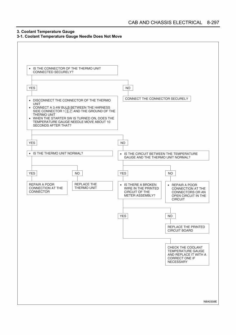
CAB AND CHASSIS ELECTRICAL 8-297
3. Coolant Temperature Gauge3-1. Coolant Temperature Gauge Needle Does Not Move
• IS THE CONNECTOR OF THE THERMO UNITCONNECTED SECURELY?
• DISCONNECT THE CONNECTOR OF THE THERMOUNIT
• CONNECT A 3.4W BULB BETWEEN THE HARNESSSIDE CONNECTOR 1 E-7 AND THE GROUND OF THETHERMO UNIT
• WHEN THE STARTER SW IS TURNED ON, DOES THETEMPERATURE GAUGE NEEDLE MOVE ABOUT 10SECONDS AFTER THAT?
• IS THE THERMO UNIT NORMAL?
YES NO
REPAIR A POORCONNECTION AT THECONNECTOR
REPLACE THETHERMO UNIT
YES
YES NO
YES
• IS THERE A BROKENWIRE IN THE PRINTEDCIRCUIT OF THEMETER ASSEMBLY?
YES NO
REPLACE THE PRINTEDCIRCUIT BOARD
CHECK THE COOLANTTEMPERATURE GAUGEAND REPLACE IT WITH ACORRECT ONE IFNECESSARY
• REPAIR A POORCONNECTION AT THECONNECTORS OR ANOPEN CIRCUIT IN THECIRCUIT
NO
• IS THE CIRCUIT BETWEEN THE TEMPERATUREGAUGE AND THE THERMO UNIT NORMAL?
NO
CONNECT THE CONNECTOR SECURELY
N8A0308E

8-298 CAB AND CHASSIS ELECTRICAL
3-2. Coolant Temperature Gauge Reading Is Too Low (or High)
• DOES THE THERMOSTAT OPERATE NORMALLY?
• TURN THE STARTER SWITCH ON• WHEN INSERTING AND PULLING OUT THE
THERMOSTAT CONNECTOR 1 E-7 SEVERALTIMES, DOES THE INDICATION OF THE COOLANTTEMPERATURE GAUGE VARY?
• IS THE THERMO UNIT NORMAL? REPAIR A POOR CONNECTION AT THE CONNECTOROF THE THERMO UNIT
• IS THERE AN OPEN CIRCUIT IN THE METERASSEMBLY PRINTED CIRCUIT BOARD?
REPLACE THE THERMO UNIT
YES
YES NO
YES NO
YES NO
REPLACE THE PRINTED CIRCUIT BOARD
CHECK THE COOLANT TEMPERATURE GAUGE ANDREPLACE IT IF FOUND DEFECTIVE
NO
REPLACE THE THERMOSTAT
N8A0309E

CAB AND CHASSIS ELECTRICAL 8-299
3-3. Needle Overshoots (or Goes Up to the “H” Range)
• DISCONNECT THE CONNECTOR OF THE THERMOUNIT
• WHEN THE STARTER SW IS TURNED ON, DOESTHE POINTER REACH TO THE "H" RANGE?
• IS THERE A SHORT CIRCUIT BETWEEN THETHERMO UNIT AND THE COOLANTTEMPERATURE GAUGE?
REPLACE THE THERMO UNIT
• IS THE PRINTED CIRCUIT OF THE METERASSEMBLY GROUNDED SECURELY?
REPAIR A SHORT CIRCUIT
YES
YES
NO
YES
NO
NO
REPAIR OR REPLACE THE PRINTED CIRCUIT BOARD
CHECK THE COOLANT TEMPERATURE GAUGE ANDREPLACE IT IF FOUND ABNORMAL
N8A0310E

8-300 CAB AND CHASSIS ELECTRICAL
4. Fuel Gauge4-1. Fuel Gauge Needle Does Not Move
• IS THE CONNECTOR OF THE FUEL TANK UNIT J-28CONNECTED SECURELY?
• DISCONNECT THE CONNECTOR OF THE FUELTANK UNIT
• CONNECT A 3.4W BULB BETWEEN THE HARNESSSIDE CONNECTOR 1 J-28 AND THE GROUND OFTHE FUEL TANK UNIT
• WHEN THE STARTER SW IS TURNED ON, DOES THEFUEL GAUGE NEEDLE FLUCTUATE AFTER ABOUT 90SECONDS?
• IS THERE CONTINUITY BETWEEN THE FUELTANK UNIT CONNECTOR TERMINALS 1 J-28AND 3 J-28 ?
YES NO
REPLACE THE FUELTANK UNIT
REPAIR A POORCONNECTION AT THECONNECTORS OR ANOPEN CIRCUITBETWEEN THE FUELTANK UNIT AND THEMETER
YES
YES NO
YES
• IS THERE A BROKENWIRE IN THE PRINTEDCIRCUIT OF THEMETER ASSEMBLY?
YES NO
CHECK THE FUELMETER, AND REPLACE ITIF NECESSARY
REPLACE THE PRINTEDCIRCUIT BOARD
REPAIR A POORCONNECTION AT THECONNECTORS OR ANOPEN CIRCUIT IN THECIRCUIT
NO
• IS THE CIRCUIT BETWEEN THE FUEL GAUGE ANDTHE FUEL TANK UNIT NORMAL?
NO
CONNECT THE CONNECTOR SECURELY
N8A0311E

CAB AND CHASSIS ELECTRICAL 8-301
4-2. Even when the Tank Is Filled Up with Fuel, the Needle Does Not Reach “F”
• WHEN INSERTING AND PULLING OUT THECONNECTOR J-28 OF THE FUEL TANK UNITSEVERAL TIMES, DOES THE POINTER OF THE FUELGAUGE STAY AT THE SAME POSITION?
• DISCONNECT THE CONNECTOR OF THE FUEL TANKUNIT
• CONNECT THE FUEL TANK UNIT HARNESS SIDECONNECTOR 1 J-28 AND 3 J-28 WITH A LEADWIRE
• WHEN THE STARTER SW IS TURNED ON, DOES THENEEDLE OVERSHOOT TO "F" AFTER ABOUT 5MINUTES?
• IS THERE A BROKEN CIRCUIT IN THE PRINTEDCIRCUIT OF THE METER ASSEMBLY?
YES NO
REPLACE THE PRINTEDCIRCUIT BOARD
CHECK THE FUELGAUGE AND REPLACEIT IF FOUNDABNORMAL
YES
YES NO
YES
• IS THE RESISTANCEVALUE OF THE FUELTANK UNIT NORMAL?
NO
REPLACE THE FUELTANK UNIT
• REMOVE THE FUEL TANK UNIT• DOES THE FLOAT ARM OPERATE SMOOTHLY?
NO
REPAIR A POOR CONNECTION AT THE CONNECTOROF THE FUEL TANK UNIT
N8A0312E

8-302 CAB AND CHASSIS ELECTRICAL
4-3. When the Tank Is Not Full of Fuel, the Needle Overshoots (or Goes Up To “F”)
• DISCONNECT THE CONNECTOR OF THE FUEL TANKUNIT
• WHEN THE STARTER SW IS TURNED ON, DOES THENEEDLE STILL POINT TO "F"?
• IS THE CIRCUIT BETWEEN THE FUEL TANK UNITAND THE FUEL METER NORMAL?
YES NONO
REPAIR A SHORTCIRCUIT IN THECIRCUIT
REPAIR OR REPLACETHE PRINTED CIRCUITBOARD
CHECK THE FUELGAUGE, AND REPLACEIT IF NECESSARY
• IS THE PRINTEDCIRCUIT OF THEMETER ASSEMBLYGROUNDEDSECURELY?
• ARE THE RESISTANCE VALUES OF THEFUEL TANK UNIT AT "E" AND "F" POINTSNORMAL?
YES
YES YESNO
REPLACE THE FUEL TANK UNIT
NO
• REMOVE THE FUEL TANK UNIT• DOES THE FLOAT ARM OPERATE SMOOTHLY?
N8A0313E

CAB AND CHASSIS ELECTRICAL 8-303
5. Warning/indicator Light5-1. When the Parking Brake Lever Is Pulled, the Indicator Light Does Not Light Up
5-2. Even when the Parking Brake Lever Is Released, the Indicator Light Does Not Go Off
N8A5377E
N8A5378E

8-304 CAB AND CHASSIS ELECTRICAL
5-3. While the Engine Is Operating, the Oil Pressure Warning Light Does Not Go Off
5-4. Even when the Fuel Tank Is Full with Fuel, the Fuel Warning Light Lights Up
• IS THE ENGINE OIL PRESSURE NORMAL?
• WITH THE OIL PRESSURE SWITCH CONNECTOR J-8DISCONNECTED, DOES THE WARNING LIGHT GOOFF?
• WHILE THE ENGINE IS OPERATING, IS THERECONTINUITY BETWEEN THE OIL PRESSURE SWITCHCONNECTOR J-8 AND THE BODY GROUND?
YES
YES
NO
NO
NO
REFER TO THE "ENGINE" SECTION
REPAIR A SHORT CIRCUIT BETWEEN 1 J-8 AND 1 B-52 (METER)
REPLACE THE OIL PRESSURE SWITCH
N8A0316E
• WHEN THE FUEL TANK UNIT CONNECTOR J-28 ISDISCONNECTED, DOES THE WARNING LIGHT GOOFF?
• IS THE FUEL TANK UNIT NORMAL?
YES NO
NO
REPAIR A SHORT CIRCUIT BETWEEN THE FUELTANK UNIT HARNESS SIDE CONNECTORS 2 J-28AND 10 B-51 (METER)
REPLACE THE FUEL TANK UNIT
N8A0317E

CAB AND CHASSIS ELECTRICAL 8-305
5-5. Even when the Fuel Tank Is Empty, the Low Fuel Warning Light Does Not Light Up
• DOES THE WARNING LIGHT HAVE A BURNED OUTBULB, OR IS THE SOCKET POORLY CONNECTED?
• IS THE FUEL TANK UNIT NORMAL?
YES
YES
NO
NO
REPLACE THE BULB, OR REPAIR A POORCONNECTION AT THE SOCKET
REPLACE THE FUEL TANK UNIT
REPAIR A POOR CONNECTION AT THE CONNECTOROR AN OPEN CIRCUIT BETWEEN THE HARNESSSIDE CONNECTORS 2 J-28 AND 10 B-51 (METER)OR 3 J-28 AND J-9
N8A0318E

8-306 CAB AND CHASSIS ELECTRICAL
5-6. Even when the Float in the Water Sedimenter Goes Up above the Drain Warning Level, the Indicator LightDoes Not Light Up
NO
REPLACE THE BULB, OR REPAIR A POORCONNECTION AT THE SOCKET
YES
• DOES THE INDICATOR LIGHT HAVE A BURNED-OUTBULB OR IS THE SOCKET POORLY CONNECTED?
YES
• IS THE WATER SEDIMENTER SWITCH NORMAL?
NO
REPLACE THE WATER SEDIMENTER SWITCH
REPAIR A POOR CONNECTION AT THECONNECTORS OR AN OPEN CIRCUIT IN THECIRCUIT BETWEEN THE WATER SEDIMENTERSWITCH HARNESS SIDE CONNECTOR 1 J-53AND 12 B-51 (METER), OR 1 J-54 AND J-9
N8A0319E

CAB AND CHASSIS ELECTRICAL 8-307
5-7. Even when the Brake Fluid Is Lower than Specified Level, the Level Warning Light Does Not Light Up
5-8. Vacuum Warning Buzzer Does Not Sound
Starter SwitchRefer to “START AND CHARGING” in this section.
Turn Signal Light SwitchRefer to “TURN SIGNAL LIGHT, HAZARD WARNINGLIGHT AND STOPLIGHT” in this section.
Exhaust Brake SwitchRefer to “EXHAUST BRAKE” in this section.
N8A5384E
N8A0321E

8-308 CAB AND CHASSIS ELECTRICAL
Meter AssemblyLayout for Gauges, Warning, Indicator and Illumination LightsExcept 4HK1-TC
Notice:The calibration and the red zone of tachometer are various depending on the models fitted.
1
0
2
x1000 r/min
3
4
PUSHSET
MH
km/hTRIPODO
AB
E F
HC
Speedometer
Fuel gauge Coolant temperature gauge
Tachometer &digital clock
Warning lens
N8A0479E

CAB AND CHASSIS ELECTRICAL 8-309
For 4HK1-TC
Without Smoother Smoother
Fuel gauge Coolant temperature gauge
Speedometer TachometerWarning lens Warning lens
1STSTART
N8A0480E

8-310 CAB AND CHASSIS ELECTRICAL
Bulb Location for Warning LensExcept 4HK1-TC
N8A0481E

CAB AND CHASSIS ELECTRICAL 8-311
For 4HK1-TC
*1 : Smoother
*2 : Without Smoother
1STSTART
N8A0482E

8-312 CAB AND CHASSIS ELECTRICAL
Table for Meter Connector Terminal ConnectionsExcept 4HK1-TC
B-336
B-51
B-55
ECT - Engine Coolant Temperature
B-55
B-52
B-51
B-336
N8A0483E
Terminal No. Connected to
1 IGN (+)
2 —
3 Speed pulse input
4 —
5 Ground
6 Illumination (+)
Terminal No. Connected to
1 Exh. Brake
2 Exh. Brake / Seat belt (GCC)
3 —
4 Check engine
5 PTO
6 Glow
7 ABS
8 IGN (+)
9 4WD
10 Fuel low
11 Vacuum / Booster
12 Sedimenter
13 Low coolant
14 Brake
Terminal No. Connected to
1 Speed pulse input
2 —
3 Power output (sensor)
4 ECT unit (GAUGE)
5 Fuel tank unit (GAUGE)
6 —
7 Ground
8 Turn signal (LH)
9 —
10 Beam (+)
11 Turn signal (RH)
12 —

CAB AND CHASSIS ELECTRICAL 8-313
B-52
For 4HK1-TC
Terminal No. Connected to
1 Oil pressure
2 Vacuum SW
3 Charge
4 Parking / Rear fog
5 Illumination (+)
6 —
7 Illumination (−)
8 Signal (tacho)
9 Ground (tacho)
10 Ground
11 —
12 +B
N8A0484E

8-314 CAB AND CHASSIS ELECTRICAL
B-53 (With Smoother)
B-51
*1: With Smoother*2: Without Smoother
B-52
Terminal No. Connected to
1 TCM
2 —
3 —
4 —
5 —
6 1st Start
7 ECONO
8 Smoother
9 —
10 —
11 —
12 —
Terminal No. Connected to
1 Turn LH
2 Beam
3 —
4 Brake (*1) / — (*2)
5 Check Engine (*1) / Brake (*2)
6 Exhaust Brake
7 —
8 —
9 Brake Booster
10 Charge
11 Oil Pressure
12 ABS
13 — (*1) / Check Engine (*2)
14 —
15 Ground
16 Vehicle Speed Signal Output
17 Illumination +
18 Ignition
19 Rear Fog
20 ASR
Terminal No. Connected to
1 4WD
2 —
3 Turn RH
4 —
5 Thermal
6 Fuel
7 TAM Pulse (−)
8 TAM Pulse (+)
9 —
10 Sedimenter
11 Front Fog
12 —
13 —
14 —
15 Glow
16 Battery
17 Vehicle Speed Sensor
18 —
19 —
20 Ground
Terminal No. Connected to
1 Battery
2 —
3 Ground
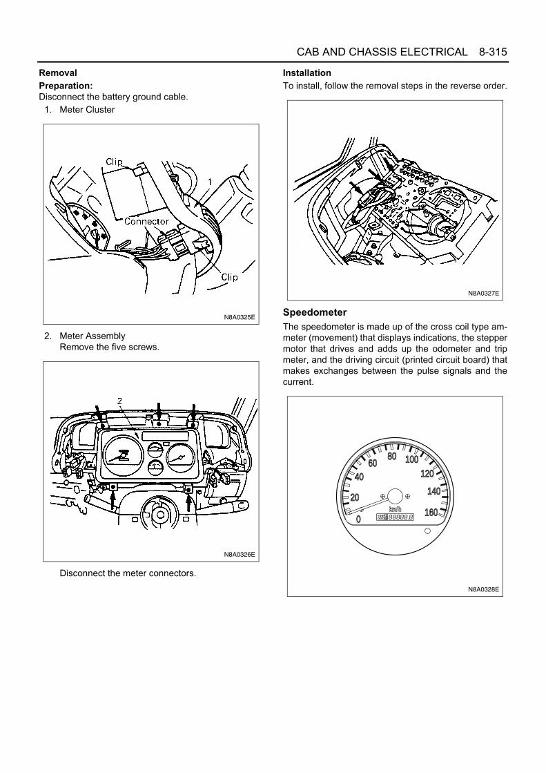
CAB AND CHASSIS ELECTRICAL 8-315
RemovalPreparation:Disconnect the battery ground cable.
1. Meter Cluster
2. Meter AssemblyRemove the five screws.
Disconnect the meter connectors.
InstallationTo install, follow the removal steps in the reverse order.
SpeedometerThe speedometer is made up of the cross coil type am-meter (movement) that displays indications, the steppermotor that drives and adds up the odometer and tripmeter, and the driving circuit (printed circuit board) thatmakes exchanges between the pulse signals and thecurrent.
N8A0325E
N8A0326E
N8A0327E
TRIPODO
AB
km/h
0
20
4060
80 100120
140
160
N8A0328E

8-316 CAB AND CHASSIS ELECTRICAL
On-vehicle ServiceCheck the meter display accuracy and the operation ofthe odometer with the speedometer tester.
Notice:Inappropriate tire inflation may affect the accuracy of theodometer.(To conduct this test, refer to the tester manufacturer'sinstruction manual.)Since the meter display permissible levels above arespecifications solely for the meter, they are to be usedas reference values when conducting on-vehicle ser-vice.
Except 4HK1-TC
For 4HK1-TC (General Export)
For 4HK1-TC (Europe)
Individual InspectionRemove the speedometer from the meter assembly andmeasure the resistance and the current consumptionbetween each terminals.Replace the speedometer when the result of inspectionis found abnormal.
RemovalPreparation:Disconnect the battery ground cable.
Tester display speed Meter display permissible level
20 km/h 17.5 — 22.5 km/h
40 37.5 — 42.5
60 57.5 — 62.5
80 77.5 — 82.5
100 97.6 — 103.4
120 117.6 — 123.4
140 137.6 — 143.4
Tester display speed Meter display permissible level
20 MPH 18.3 — 21.7 MPH
40 38.3 — 41.7
60 58.3 — 61.7
80 77.8 — 82.8
TRIPODO
AB
MPH
0
10
20
3040 50 60
7080
90
100
N8A0330E
Tester display speed Meter display permissible level
40 km/h 37 — 41 km/h
60 58 — 62
80 77.5 — 82.5
100 97.5 — 103
120 117 — 122.5
140 137.5 — 143
Tester display speed Meter display permissible level
20 km/h 20 — 22.5 km/h
40 40 — 42.5
60 60 — 63.2
80 79.7 — 83.4
Terminal symbol Resistance value
IGN — GND 58±20 kΩ
SEN — GND 70±20 kΩ
4P — GND ∞
IGN
GND
SENSOR B4 Pulse output
N8A0332E
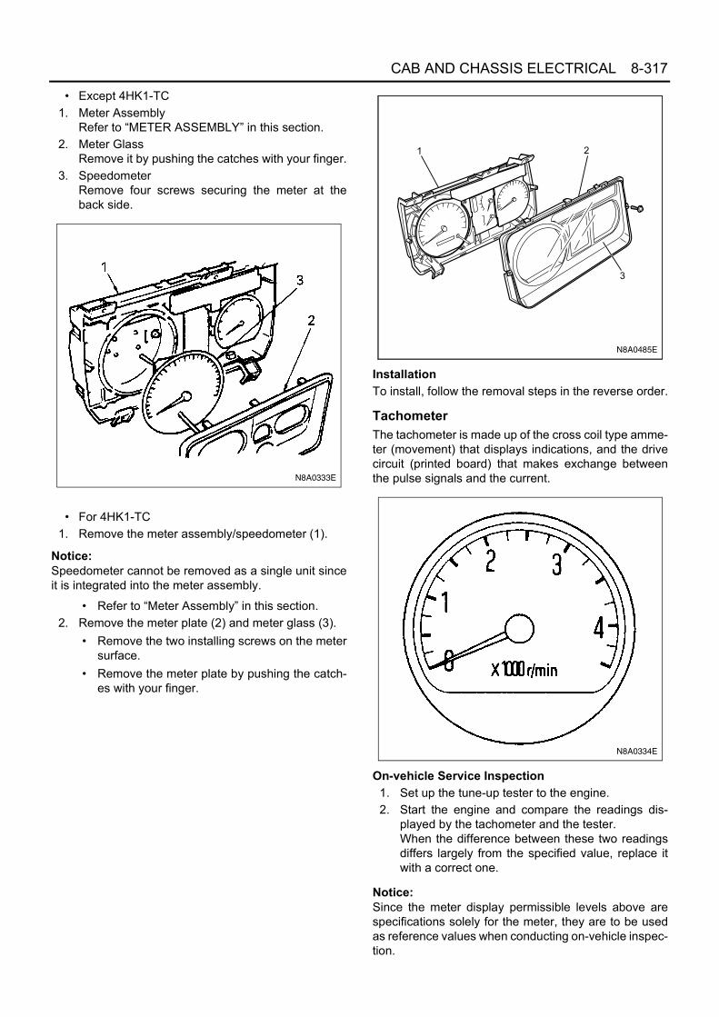
CAB AND CHASSIS ELECTRICAL 8-317
• Except 4HK1-TC1. Meter Assembly
Refer to “METER ASSEMBLY” in this section.2. Meter Glass
Remove it by pushing the catches with your finger.3. Speedometer
Remove four screws securing the meter at theback side.
• For 4HK1-TC1. Remove the meter assembly/speedometer (1).
Notice:Speedometer cannot be removed as a single unit sinceit is integrated into the meter assembly.
• Refer to “Meter Assembly” in this section.2. Remove the meter plate (2) and meter glass (3).
• Remove the two installing screws on the metersurface.
• Remove the meter plate by pushing the catch-es with your finger.
InstallationTo install, follow the removal steps in the reverse order.
TachometerThe tachometer is made up of the cross coil type amme-ter (movement) that displays indications, and the drivecircuit (printed board) that makes exchange betweenthe pulse signals and the current.
On-vehicle Service Inspection1. Set up the tune-up tester to the engine.2. Start the engine and compare the readings dis-
played by the tachometer and the tester.When the difference between these two readingsdiffers largely from the specified value, replace itwith a correct one.
Notice:Since the meter display permissible levels above arespecifications solely for the meter, they are to be usedas reference values when conducting on-vehicle inspec-tion.
N8A0333E
N8A0485E
N8A0334E

8-318 CAB AND CHASSIS ELECTRICAL
Except 4HK1-TC
For 4HK1-TC
Individual InspectionRemove the tachometer from the meter assembly andmeasure the resistance value and the current consump-tion between each terminals.Replace the tachometer when the result of inspection isfound abnormal.
1. Resistance valueUse the analog type circuit tester. (Range: 1K)For 12 Volt tachometer
For 24 Volt tachometer
2. Current valueUse the analog type circuit tester.Since the current consumption fluctuates as the powervoltage varies, check to be sure that the voltage appliedis 12±1 V or 24±1 V.
RemovalPreparation:Disconnect the battery ground cable.
• Except 4HK1-TC1. Meter Assembly
Refer to “METER ASSEMBLY” in this section.2. Meter Glass
Remove it by pushing the catches with your finger.3. Tachometer
Remove three screws securing the meter at theback side.
Tester display speed Meter display permissible level
500 400 — 500
1000 800 — 1050
2000 1800 — 2050
3000 2800 — 3050
4000 3800 — 4050
Tester display speed Meter display permissible level
750 700 — 800
2000 1900 — 2150
3000 2950 — 3200
4000 3950 — 4200
N8A0336E
Terminalsymbol
Tester terminal
Red (+)
Black (−)
Black (−)
Red (+)
IGN — GNDIGN GND IGN GND
∞ 30±5 kΩ
PIN — GNDPIN GND PIN GND
33±5 kΩ 500 — 1000 kΩ
Terminalsymbol
Tester terminal
Red (+)
Black (−)
Black (−)
Red (+)
IGN — GNDIGN GND IGN GND
∞ 30±5 kΩ
PIN — GNDPIN GND PIN GND
33±5 kΩ 500 — 1000 kΩ
Voltage Connecting terminal
Current consumption Remarks
12Volt
IGN — GND
12±1 V(when 12±1 V
applied)
No signal input
24Volt 24±1 V
(when 24±1 V applied)
No signal input

CAB AND CHASSIS ELECTRICAL 8-319
• For 4HK1-TC1. Remove the meter assembly/tachometer (1).
Notice:Tachometer cannot be removed as a single unit since itis integrated into the meter assembly.
• Refer to “Meter Assembly” in this section.
2. Remove the meter plate (2) and meter glass (3).• Remove the two installing screws on the meter
surface.• Remove the meter plate by pushing the catch-
es with your finger.
InstallationTo install, follow the removal steps in the reverse order.
Coolant Temperature GaugeCircuit Diagram
InspectionRemove the coolant temperature gauge from the meterassembly, and measure the resistance value betweeneach terminal.Replace the coolant temperature gauge when the resultof inspection is found abnormal.
N8A0337E
N8A0485E
+
IGN
GND
UNIT
Thermo unit
Engine coolant temperature gauge
-
N8A0338E

8-320 CAB AND CHASSIS ELECTRICAL
RemovalPreparation:Disconnect the battery ground cable.
• Except 4HK1-TC1. Meter Assembly
Refer to “METER ASSEMBLY” in this section.2. Meter Glass
Remove it by pushing the catches with your finger.3. Coolant Temperature Gauge
Remove six screws securing the meter at the backside.
• For 4HK1-TC1. Remove the meter assembly (1).
Notice:Coolant temperature gauge and fuel gauge cannot beremoved as a single unit since they are integrated intothe meter assembly.
• Refer to “Meter Assembly” in this section.2. Remove the meter plate (2) and meter glass (3).
• Remove the two installing screws on the metersurface.
• Remove the meter plate by pushing the catch-es with your finger.
InstallationTo install, follow the removal steps in the reverse order.
Terminal symbol Resistance value
IG — U 169 Ω±10%
U — E 333 Ω±10%
IG — E 242 Ω±10%
N8A0339E
N8A0340E
N8A0485E

CAB AND CHASSIS ELECTRICAL 8-321
Fuel GaugeCircuit Diagram
InspectionRemove the fuel gauge from the meter assembly, andmeasure the resistance value between each terminal.Replace the meter when the result of inspection is foundabnormal.
Removal and InstallationRefer to the “COOLANT TEMPERATURE GAUGE” inthis section.
Warning LensRemovalPreparation:Disconnect the battery ground cable.
1. Meter AssemblyRefer to “METER ASSEMBLY” in this section.
2. Meter GlassRemove it by pushing the catches with your finger.
3. Meter PlateRemove it by pushing the catches with your finger.
4. Warning Lens
N8A0341E
Terminal symbol Resistance value
IG — U 108.1 Ω±10%
U — E 103 Ω±10%
IG — E 211.1 Ω±10%
N8A0342E
3
2
1
4
N8A5404E

8-322 CAB AND CHASSIS ELECTRICAL
InstallationTo install, follow the removal steps in the reverse order.
Warning Light Bulb, Indicator Light Bulb and Il-lumination Light BulbRemovalPreparation:Disconnect the battery ground cable.
1. Meter AssemblyRefer to “METER ASSEMBLY” in this section.
2. Socket and BulbHold the bulb socket by hand and rotate it counter-clockwise to remove them from the meter body.
3. BulbPull out the bulb from the socket.
InstallationTo install, follow the removal steps in the reverse order.
Vehicle Speed SensorThe vehicle speed sensor is installed on the rear portionof the transmission or transfer case.The number of pulses generated is four pulses per onerotation of the pinion shaft.
Inspection1. Connect a resistance of 390 Ω±5%, 2W between
connector terminal 1 and battery (+) terminaland connect the connector terminal 2 to thebattery (−) terminal.
Caution:Be extremely careful not to connect the battery (+) ter-minal to the connector 3 .
This may damage the vehicle speed sensor.
2. Rotate the shaft of the vehicle speed sensor slowlyand measure the voltage between 3 and 2
with a digital tester.The voltage, with one rotation of shaft, fluctuates fourtimes in the following range: 10 to 14V ↔ 24 or less.Replace the sensor when the result of inspection isfound abnormal.
Legend1. Meter Assembly2. Meter Glass3. Meter Plate4. Warning Lens
N8A0344E
N8A0345E
J-32
J-32
J-32
J-32
J-32

CAB AND CHASSIS ELECTRICAL 8-323
RemovalPreparation:Disconnect the battery ground cable.
1. Vehicle Speed SensorDisconnect the connector.
Installation1. Tighten the vehicle speed sensor to the specified
torque.
Tighten:Vehicle speed sensor to 25 N⋅m (2.5 kg⋅m/18 lb⋅ft)
Caution:Tightening must be made at the hexagonal part of thesensor.
To tighten the connector itself would cause damage.
Thermo UnitInspectionThe thermo unit is thermistor type and must be inspect-ed under the conditions as shown below.
1. Put the deviation of the galvanometer to 0 by usingthe variable resistor, switch the thermo unit off andthen measure the resistance of the resistor throughthe bridge.Confirm that the resistance is continuously variablein any other points than those shown below.
2. Dip the thermo unit into 80 — 90°C (176 — 194°F)water and confirm that there is no bubble continu-ously coming out of inside of the unit.Replace the unit when the result of inspection isfound abnormal.
N8A0346E
Parkingbrake drum
Connector
1
N8A0347E
Check conditionTemperature
50°C(112°F)
115°C(239°F)
7 V 55 Ω Gauge Resis-
tance value(Ω)
+33.6−33.6226.0
+1.71−2.2126.4
7 V 25 Ω Gauge —
+2.68−3.6824.3
N8A0348E

8-324 CAB AND CHASSIS ELECTRICAL
Oil Pressure SwitchInspectionCheck the continuity between the switch terminal andthe body ground with the starter switch is OFF position.Replace the switch when the result of inspection isfound abnormal.
Circuit Inspection1. Start the engine.2. When disconnecting the oil pressure switch con-
nector then connecting the harness side connectorto the ground, check to see if the oil pressure warn-ing light lights up. When the light will not light up,check the circuit between the meter and the oilpressure switch, and repair an open circuit if nec-essary.
Fuel Tank UnitThe tank unit varies the internal resistance according tothe float position (fluid level) to operate the fuel meterneedle. Also available is the build-in switch type to warnthe driver of low fuel level (about 5 liters left in the tank)by illuminating the fuel warning light.
Inspection(Level Switch type of warn low fuel level)
1. Check the resistance between the connector termi-nals 1 and 3 while shifting the floatfrom “E” to “F” point.
2. Check if the low fuel warning switch turns on andoff at the specified positions. If found defective, re-place the fuel tank unit.
N8A5410E
N8A5411E
N8A5412E
J-28 J-28

CAB AND CHASSIS ELECTRICAL 8-325
(Float type of warn low fuel level)1. Check the resistance between the connector termi-
nals 1 and 3 while shifting the floatfrom “E” to “F” point.
2. Check if the low fuel warning light turns on whenthe float is at “E” position. If found defective replacethe fuel tank unit.
N8A0352E
Float position Resistance value (Ω)
F 3±2.1
1/2 32.5±4.8
E 110±7.7
N8A0331E
J-28 J-28

8-326 CAB AND CHASSIS ELECTRICAL
RemovalPreparation:Disconnect the battery ground cable.
1. Fuel Tank Unit1) Disconnect the connector.
2) Remove five screws.
InstallationTo install, follow the removal steps in the reverse order.
Engine Speed SensorInspectionMeasure the resistance value between the enginespeed sensor connector terminals.Replace the engine speed sensor when the result ofinspection is found abnormal.4J Series engine = 1.36 — 1.86 KΩ4H Series engine = 0.57 — 0.86 KΩ
N8A0353E
Float position Resistance value (Ω)
F 3±2.1
1/2 32.5±4.8
E 110±7.7
N8A0331E
N8A0354E

CAB AND CHASSIS ELECTRICAL 8-327
RemovalPreparation:Disconnect the battery ground cable.
1. Engine Speed Sensor1) Disconnect the connector.2) Remove the engine speed sensor.
InstallationTo install, follow the removal steps in the reverse order.
Vacuum SwitchInspectionWhen the pressure value is below 250±30 mm Hg(33.3±4.0 kPa), check to see if there is continuity be-tween the terminal and the ground. If no continuity, re-place the switch with a normal one.
RemovalPreparation:Disconnect the battery ground cable.
1. Vacuum Switch1) Disconnect the connector.2) Remove the vacuum switch.
InstallationApply liquid gasket to the screw portion of the switch toprevent vacuum leak.
Vacuum Warning BuzzerInspectionApply battery voltage to the buzzer connector terminalsto check the buzzer sound.Replace the buzzer when the result of inspection isfound abnormal.RemovalPreparation:Disconnect the battery ground cable.
1. Meter AssemblyRefer to “METER ASSEMBLY” in this section.
2. Vacuum Warning Buzzer1) Disconnect the connector.2) Remove the buzzer fixing screw.
N8A0355E
N8A0356E
N8A0357E

8-328 CAB AND CHASSIS ELECTRICAL
InstallationTo install, follow the removal steps in the reverse order.
Water Sedimenter SwitchInspection
1. When the float in the water sedimenter is above thedrain warning level, confirm if there is continuity be-tween the switch connector terminals.
2. Turn the starter switch on, disconnect the watersedimenter connector and connect the harnessside connector terminals. Then confirm that thesedimenter warning light turns on.If found defective, replace the switch or repair apoor connection or an open circuit between theconnector terminals.
Brake Fluid SwitchInspection
1. Confirm there is continuity between the switch con-nector terminals when the brake fluid in the tank isbetween 60 — 75 cc level.
2. Turn the switch on, disconnect the brake fluidswitch connector and connect the harness sideconnector terminals. Then confirm that brakewarning light turns on.If found defective, replace the tank, or repair a poorconnection or an open circuit between the connec-tor terminals.
RemovalPreparation:Disconnect the battery ground cable.
1. Instrument Panel AssemblyRefer to “INSTRUMENT PANEL” of section 2.
2. Brake Fluid Tank (Brake Fluid Switch)1) Disconnect the switch connector.2) Remove four fixing nuts.3) Drain brake fluid in the tank.4) Disconnect the tubes.
Caution:Be very careful not to allow the brake fluid to come incontact with painted surfaces or resin parts surfaces.
Legend1. Meter Assembly2. Vacuum Warning Buzzer
1
2
N8A0358E
N8A0359E
N8A0360E

CAB AND CHASSIS ELECTRICAL 8-329
InstallationTo install, follow the removal steps in the reverse order,noting the following points.
1. Bleed the air from brake and clutch fluid pipe line.2. Check to see if the brake fluid level in the tank with-
in specified level.3. Check to see if brake warning light comes on when
starter switch is turned on and then warning lightgoes off after the engine running.
Parking Brake Indicator LightThe parking brake indicator light is connected in serieswith the parking brake switch installed to the parkingbrake lever bracket.The light comes on when the parking brake lever ispulled, and goes out when the parking brake lever is ful-ly released.
Notice:The parking brake indicator light illuminates to warn thedriver that the parking brake is on. This light does not in-dicate the condition of the operability of the parkingbrake.Circuit Inspection
1. Disconnect the parking brake switch connector.2. Connect the harness side connector terminal to the
ground.3. Check to see if the indicator light comes on with the
starter switch “ON”.Check the bulb or the harness when the result ofinspection is found abnormal.
Parking Brake SwitchInspection
1. Disconnect the parking brake switch connector.2. Check to see if there is any continuity between the
switch terminal and the body ground with the circuittester connected between them.
Repair the parking brake switch or replace it when theresult of inspection is found abnormal.
RemovalPreparation:Disconnect the battery ground cable.
1. Parking Brake Switch1) Disconnect the connector.2) Remove the fixing screw.
N8A0361E
When parking brake applied Continuity
When parking brake released No continuity
N8A0362E
N8A0363E

8-330 CAB AND CHASSIS ELECTRICAL
InstallationTo install, follow the removal steps in the reverse order.
Heater and Air ConditioningGeneral DescriptionThe air conditioning consists of compressor, evaporator,condenser, A/C switch, fan switch, etc. When the engineis rotating, the A/C starts to work with both the A/C andfan switches “ON”, followed by the engagement of themagnetic clutch. It stops to work when either the fanswitch or the A/C switch turns “OFF”. In addition to theswitches, the A/C has the function of temporary stop ofits operation by the sensing system in the A/C cycle,such as:
• sensing abnormal rise of the refrigerant pressureby means of the pressure switch.
• sensing temperature of the blowing-off air bymeans of the thermo switch preventing the evapo-rator from freezing.
• sensing the coolant temperature by the thermoswitch (available for limited models only).
N8A0364E

CAB AND CHASSIS ELECTRICAL 8-331
Parts LocationFor 12 Volt
X-1
0
X-1
2<
4JB
1, 4
JH1,
4JG
2>
FL-
1, F
L-25
FU
SIB
LE L
INK
X-2
4 A
/C C
OM
PR
ES
SO
R R
ELA
YX
-26
A/C
SIG
NA
L R
ELA
Y
<4H
G1>
(55)
H-5
, H-6
,H
-8
B-3
39 A
/C O
NS
IGN
AL
RE
SIS
TO
R
RE
LAY
BO
X A
SM
(N
o.2)
B-2
34 E
CM
N8A0532E

8-332 CAB AND CHASSIS ELECTRICAL
For 24 Volt
X-1
0
X-1
2
<4H
F1
/ 4H
G1
/ 4H
E1
/ 4H
K1>
J-19
1 E
CM
H-1
4, H
-105
(4H
K1)
FU
SE
BO
X A
SM
F-1
F-2
6 F
US
EF
L-1
FU
SIB
LE L
INK
J-23
DIO
DE
X-2
7 C
ON
DE
NS
ER
FA
NR
ELA
Y
N8A0533E
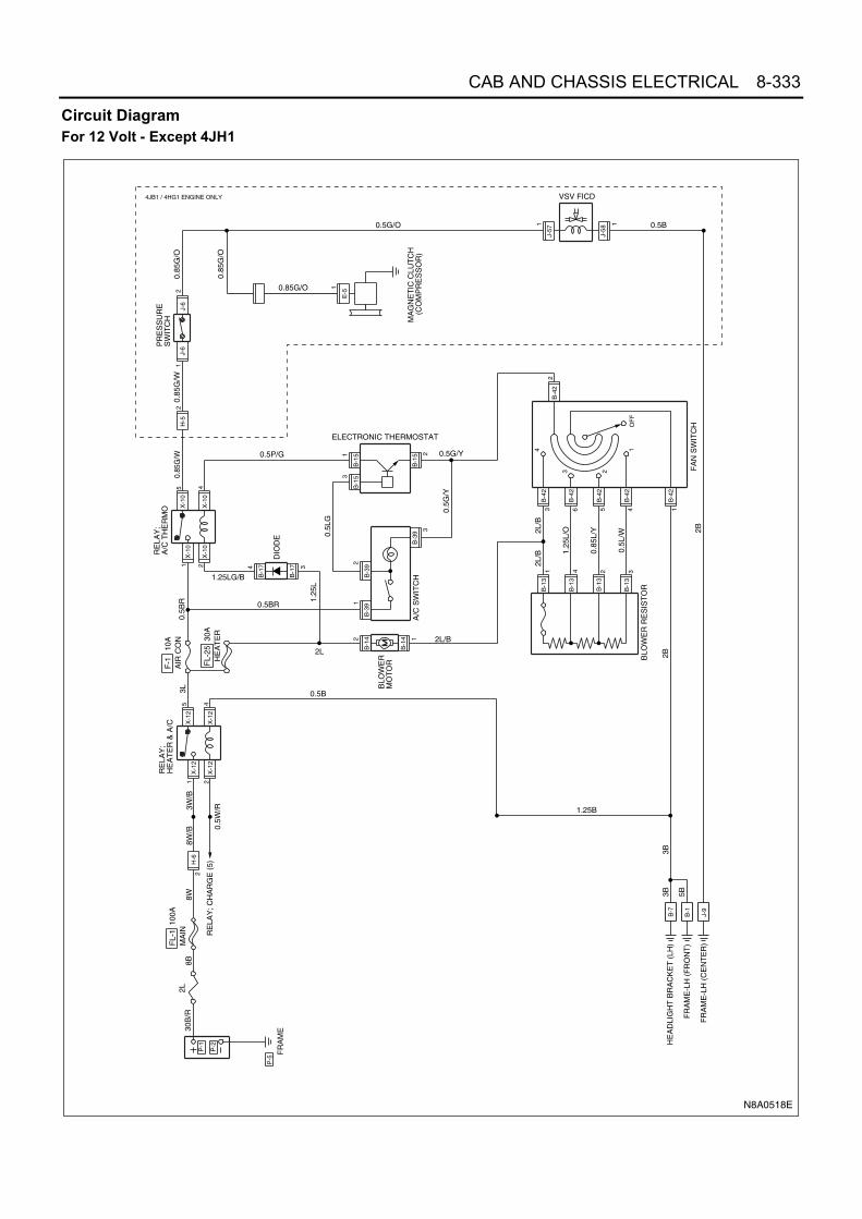
CAB AND CHASSIS ELECTRICAL 8-333
Circuit DiagramFor 12 Volt - Except 4JH1
X-1
2
X-1
2
X-1
2
X-1
2
B-1
4
B-1
4
B-3
9B
-39
B-3
9
B-1
7
B-1
7
B-1
5B
-15
X-1
0
X-1
0
X-1
0
X-1
0
J-6
J-6
H-5
B-4
2
B-1
3
B-1
3
B-1
3
B-4
2
B-4
2
B-4
2
B-4
2
H-6
B-1
5
J-57
J-58
B-1
B-7
J-9
221
5 4
15
24
2
4 3
12
3
31 2
3 6 5 4
2
4
B-1
31 2 3
2 1
1 1
1
30B
/R8B
2L8W
0.5W
/R
3L0.
5BR
0.5B
2L/B
0.5BR
1.25LG/B
0.5L
G
1.25
L
0.85
G/W
0.85
G/W
0.85
G/O
0.85
G/O
0.5G/O
0.5G/Y0.
5G/Y
2L/B
2L/B 1.
25L/
O
0.85
L/Y
0.5L
/W
B-4
21
0.5P/G
2L
0.5B
2B
2B
3B3B
5B
1.25B
8W/B
3W/B
P-1
P-2
P-5
FR
AM
E
FL-
1 1
00A
RE
LAY
;H
EA
TE
R &
A/C
RE
LAY
; CH
AR
GE
(5)
FL-
2530
A
F-1
10
A
BLO
WE
RM
OT
OR
DIO
DE
PR
ES
SU
RE
SW
ITC
H
4 1
3 2
OF
F
FA
N S
WIT
CH
BLO
WE
R R
ES
IST
OR
ELECTRONIC THERMOSTAT
A/C
SW
ITC
HM
AG
NE
TIC
CLU
TC
H(C
OM
PR
ES
SO
R)
RE
LAY
;A
/C T
HE
RM
O
HE
AD
LIG
HT
BR
AC
KE
T (
LH)
FR
AM
E-L
H (
FR
ON
T)M
AIN
AIR
CO
N
HE
AT
ER
FR
AM
E-L
H (
CE
NT
ER
)
E-5
10.85G/O
VSV FICD
2
4JB1 / 4HG1 ENGINE ONLY
N8A0518E

8-334 CAB AND CHASSIS ELECTRICAL
For 12 Volt - 4JH1 Engine
X-1
2
X-1
2
X-1
2
X-1
2
B-1
4
B-1
4
B-3
9B
-39
B-3
9
B-1
7
B-1
7
B-1
5B
-15
X-1
0
X-1
0
X-1
0
X-1
0
B-4
2
B-1
3
B-1
3
B-1
3
B-4
2
B-4
2
B-4
2
B-4
2
H-6
B-1
5
B-1
B-7
J-9
2
215 4
15
24
2 1
12
3
31 2
3 6 5 4
2
4
B-1
31 2 3
2 1
30B
/R8B
2L8W
/B
0.5W
/R
3L0.
85B
R
0.5B
2L/B
0.85BR
1.25LG/B
0.5L
G
1.25
L
0.85
G/W 0.5G/Y
0.5G
/Y
2L/B
2L/B 1.
25L/
O
0.85
L/Y
0.5L
/W
B-4
21
0.5P/G
2L2B
0.85
B0.
5B
2B
5B3B
2B
8W/B
3W/B
P-1
P-2
P-5
FR
AM
E
FL-
1 1
00A
RE
LAY
;H
EA
TE
R &
A/C
RE
LAY
; CH
AR
GE
(5)
FL-
2530
A
F-1
10
A
BLO
WE
RM
OT
OR
DIO
DE
4 1
3 2
OF
F
FA
N S
WIT
CH
BLO
WE
R R
ES
IST
OR
ELECTRONIC THERMOSTAT
A/C
SW
ITC
H
RE
LAY
;A
/C T
HE
RM
O
HE
AD
LIG
HT
BR
AC
KE
T (
LH)
FR
AM
E-L
H (
FR
ON
T)
MA
INA
IR C
ON
HE
AT
ER
FR
AM
E-L
H (
CE
NT
ER
)
J-6
J-6
H-1
4
E-5
H-5
2
1 1
12
0.85
G/W
0.85
G/O
0.85
G/Y
0.5W
/G 0.5G
/Y
PR
ES
SU
RE
SW
ITC
H
A/C
ON
SIG
NA
L R
ES
IST
OR
MA
GN
ET
ICC
LUT
CH
(CO
MP
RE
SS
OR
)EC
M
0.85G/Y
0.5G/O
0.5L/R
0.5W/G
0.5G/Y
0.5G/Y
0.5B
B-3
391
2B
-339
X-2
6
X-2
6
X-2
6
X-2
6
12
53
X-2
4
X-2
4
X-2
4
X-2
4
12
53
B-2
34B
-23433
41
H-8
H-816
15
RE
LAY
;G
LOW
(4)
RE
LAY
;A
/C S
IGN
AL
RE
LAY
;A
/C C
OM
PR
ES
SO
R
P-3
P-4
N8A0514E

CAB AND CHASSIS ELECTRICAL 8-335
For 12 Volt - 4JH1 Engine For Taiwan
X-1
2
X-1
2
X-1
2
X-1
2
B-1
4
B-1
4
B-3
9B
-39
B-3
9
B-1
7
B-1
7
B-1
5B
-15
X-1
0
X-1
0
X-1
0
X-1
0
J-6
J-6
H-1
4
E-5
H-5
B-1
3
B-1
3B
-42
B-1
3
B-1
3
B-1
3
B-4
2
B-4
2
B-4
2
B-4
2
H-6
B-1
5
B-1
B-7
J-9
21 2
5 4
15
24
2
2 1
12
3
31 2
3 6 5 4
2 1
3 6 4 1
22 1
1 1
12
30B
/R
8B
2L
8W/B
0.85
W/R
3L0.
85B
R
0.5B
2L/B
0.85BR
1.25LG/B
0.5L
G
1.25
L
0.85
G/W
0.85
G/W
0.85
G/O
0.85
G/Y
2B
0.5G/Y
0.5G
/Y
2L/R
1.25
L/O
0.85
L/Y
0.5L
/W
0.5P/G
2L
2B 2B
0.85
B0.
5B
5B3B
2B
5W3W
FL-
1 1
00A
RE
LAY
;H
EA
TE
R &
A/C
RE
LAY
; CH
AR
GE
(5)
F-2
5 3
0A
F-1
10
A
BLO
WE
RM
OT
OR
DIO
DE
PR
ES
SU
RE
SW
ITC
H
4 1
3 2
OF
F
FA
N S
WIT
CH
A/C
ON
SIG
NA
L R
ES
IST
OR
BLO
WE
R R
ES
IST
OR
ELECTRONIC THERMOSTAT
A/C
SW
ITC
HM
AG
NE
TIC
CLU
TC
H(C
OM
PR
ES
SO
R)
EC
M
RE
LAY
;A
/C T
HE
RM
O
HE
AD
LIG
HT
BR
AC
KE
T (
LH)
FR
AM
E-L
H (
FR
ON
T)
MA
INA
IR C
ON
HE
AT
ER
FR
AM
E-L
H (
CE
NT
ER
)
0.85G/Y
0.5W/G
0.5G/O
0.5W/G
0.5G/Y0.5G/Y
0.5G/Y
0.5B
B-4
2
B-3
391
2B
-339
X-2
6
X-2
6
X-2
6
X-2
6
12
53
X-2
4
X-2
4
X-2
4
X-2
4
12
53
B-2
34B
-23433
41
H-8
H-816
15
RE
LAY
;G
LOW
(4)
RE
LAY
;A
/C S
IGN
AL
RE
LAY
;A
/C C
OM
PR
ES
SO
R
P-1
P-2
P-5
FR
AM
E
P-3
P-4
N8A0517E

8-336 CAB AND CHASSIS ELECTRICAL
For 24 Volt - Except 4HK1 Engine
J-6
J-6
B-1
3
B-1
3
B-1
3
B-4
2
B-4
2
B-4
2
B-4
2
B-4
2
B-7
B-1
J-9
B-3
9B
-39
B-3
9
B-1
5B
-15
B-1
5
X-1
0
X-1
0
X-1
0
X-1
0
H-5
B-1
7
B-1
7
H-6
B-1
4
B-1
4
B-1
3
OF
F
X-1
2
X-1
2
X-1
2
X-1
2
J-41
J-41
E-5
P-5
P-4
P-3
P-2
P-1
2
1 2
5 4
1 21
2
3
34
1 2
5 4
1 4 2 3
3 6 5 4
2
31 2
21
2
9
H-1
4
J-23
2
3
J-23
J-23
4
1 2
1
30B
/R8B
8W/B
2L
8W/B 3W/B5W/B 0.5W/R
3L
0.85L
0.85
BR
0.85BR
0.85L/B
0.5B 0.85B
2BB
-42
1
0.5G
/Y
0.5G/Y 0.5G/Y
0.5LG
0.5L
G
0.5P/G0.85
G/W
0.85
G/W
0.85
G/O
0.5G
/O
0.85G/O
0.85
BR
3B
5B
FR
AM
E
FL-
1 1
00A
or
120A
F-1
15
A
RE
LAY
; A
/C T
HE
RM
O
VS
VF
ICD
MA
GN
ET
IC
CLU
TC
H
ELE
CT
RO
NIC
TH
ER
MO
ST
AT
4
3 2
1
FA
N S
WIT
CH
BLO
WE
R R
ES
IST
OR
A/C
SW
ITC
H
RE
LAY
;H
EA
TE
R &
A/C
RE
LAY
; CH
AR
GE
(5)
FR
AM
E-L
H (
FR
ON
T)
HE
AD
LIG
HT
BR
AC
KE
T (
LH)
PR
ES
SU
RE
SW
ITC
H
0.5LG/B
MA
INA
IR C
ON
, HE
AT
ER BLOWER MOTOR
DIODE
FR
AM
E-L
H (
CE
NT
ER
)
0.85G/O
0.5B
2B
0.85
L/B
0.5L
/O
0.5L
/Y
0.5L
/W
0.85
B
DIODE
ECM
(WITHOUT 4HE1 ENGINE)
(4HE1 ENGINE ONLY)
N8A0515E

CAB AND CHASSIS ELECTRICAL 8-337
For 24 Volt - 4HK1 Engine
J-6
J-6
J-6
J-6
B-1
3
B-1
3
B-1
3
B-4
2
B-4
2
B-4
2
B-4
2
B-4
2
B-7
B-1
J-9
B-3
9B
-39
B-3
9
B-1
5B
-15
B-1
5
X-1
0
X-1
0
X-1
0
X-1
0
H-5
B-1
7
B-1
7
H-6
B-1
4
B-1
4
B-1
3
OF
F
X-1
2
X-1
2
X-1
2
X-1
2
E-5
P-5
P-4
P-3
P-2
P-1
2
1 2
5 4
1 21
2
3
34
1 2
5 44
3
1 4 2 3
3 6 5 4
2
31 2
21
J-19
134
2
9
H-1
05 1
30B
/R8B
8W/B
2L
5W/B 3W/B5W/B 0.5W/R
3L
0.85L
0.85
BR
0.85BR
0.85L/B
0.5B 0.85B
2BB
-42
1
0.5G
/Y
0.5G/Y 0.5G/Y
0.5LG
0.5L
G
0.5P/G
0.85B
2B
0.85
G/W
0.85
G/W
0.85
L
0.5B
2B/L
0.85
G/O
0.5G
/O
0.75G/O
0.85
BR
3B
5B
FR
AM
E
FL-
1 1
00A
or
120A
F-1
15
A
RE
LAY
; A
/C T
HE
RM
O
MA
GN
ET
IC
CLU
TC
H
ELE
CT
RO
NIC
TH
ER
MO
ST
AT
4
3 2
1
FA
N S
WIT
CH
BLO
WE
R R
ES
IST
OR
A/C
SW
ITC
H
RE
LAY
;H
EA
TE
R &
A/C
RE
LAY
; CH
AR
GE
(5)
FR
AM
E-L
H (
FR
ON
T)
HE
AD
LIG
HT
BR
AC
KE
T (
LH)
PR
ES
SU
RE
SW
ITC
H
RE
LAY
;C
ON
DE
NS
ER
FA
N
RE
LAY
;G
LOW
(3)
CO
ND
EN
SE
RF
AN
EC
M
0.5LG/B
MA
INA
IR C
ON
, HE
AT
ER BLOWER MOTOR
DIODEF
RA
ME
-LH
(C
EN
TE
R)
0.85G/O
0.5G/Y 0.85L/Y
2B
0.85
L/B
0.5L
/O
0.5L
/Y
0.5L
/W
0.85
B
X-2
7
X-2
7
X-2
7
X-2
75
1
23
21
F-2
6 1
5AC
ON
D. F
AN
N8A0519E

8-338 CAB AND CHASSIS ELECTRICAL
Connector ListFor 12 Volt
No. Connector Face
B-1
B-7
B-13
B-13 (For Tai-wan)
B-14
B-17
B-234
B-339
000-001
000-012
004-010
23 41
006-010
1 2 34 5 6
002-009
1
2
004-004
1 2 3 4
121-001
5 417
55
74
18
56
75
19
57
76
20
58
77
21
59
78
22
60
79
23
61
80
24
62
81
9
47
66
10
48
67
11
49
68
6
44
63
7
45
64
8
46
65
12
50
69
13
51
70
14
52
71
15
53
72
16
36 37 38 39 40 41 42 4328 29 3025 26 27 31 32 33 34 35
54
732 1
3
004-010
23 41
B-15
X-12
X-10
X-24
X-26
B-39
B-42
E-5
No. Connector Face
003-009
1 2 3
005-001
1
32 4
5
005-001
1
32 4
5
005-006
005-006
003-019
2 3
1
006-001
1 2 3
4 5 6
001-013
1

CAB AND CHASSIS ELECTRICAL 8-339
H-5
E-5
J-6
J-9
J-57
J-58
P-1
P-2
P-4
No. Connector Face
001-014
1
004-011
1
3
2
4
000-001
001-009
1
001-009
1
000-003
000-004
000-004
P-3
P-5
H-14
H-14
No. Connector Face
000-006
000-007
016-001
1 2 3 4
5 6 7 8
9 10 11 12
13 14 15 16
016-002
4 3 2 1
8 7 6 5
12 11 10 9
16 15 14 13
1 2 37 8 9
13 14 1519 20 2125 26 2731 32 33 34 35 36 37
4 5 610 11 1216 17 1822 23 2428 29 3038 39 40
6 5 412 11 1018 17 1624 23 2230 29 2840 39 38
3 2 19 8 7
15 14 1321 20 1927 26 2533 32 3134353637
N8A5488E

8-340 CAB AND CHASSIS ELECTRICAL
H-6
For 24 Volt
No. Connector Face
B-1
B-7
B-13
B-14
B-17
1 2
1 2
1 2 3 4
5 6 7 8
9 10 11 12 13
14 15 16 17 18
2 1
2 1
4 3 2 1
8 7 6 5
13 12 11 10 9
18 17 16 15 14
H - 6
H - 7
H - 8
N8A5489E
000-001
000-012
004-010
23 41
002-009
1
2
004-004
1 2 3 4
J-23
J-191
B-15
X-12
X-10
X-27
B-39
B-42
No. Connector Face
004-004
1 2 3 4
003-009
1 2 3
005-001
1
32 4
5
005-001
1
32 4
5
005-006
003-019
2 3
1
006-001
1 2 3
4 5 6

CAB AND CHASSIS ELECTRICAL 8-341
E-5
E-5
H-14
H-14
H-105
H-105
J-6
J-9
No. Connector Face
001-013
1
001-014
1
016-003
1 2 3 4
5 6 7 8 9
11 12 13 14
15 16
10
016-004
4 3 2 1
9 8 7 6 5
13 12 11 10
16 15
14
012-001
1 2 3 4
5 6 7 8
9 10 11 12
012-002
4
8
12
3
7
11
2
6
10
1
5
9
004-011
1
3
2
4
000-001
J-41
P-1
P-4
P-2
P-3
P-5
J-23
No. Connector Face
002-015
1 2
000-004
000-004
000-006
000-006
000-002
001-009
1

8-342 CAB AND CHASSIS ELECTRICAL
H-5
H-6
Fuel Heater and Rear Heater
General DescriptionThe circuit consists of fuel heater, rear heater, rear heat-er switch and the exhaust brake relay.The fuel heater circuit is always in “ON” position whenthe generator is charging and its temperature is auto-matically controlled by the circuit breaker built in the fuelheater.
1 2 37 8 9
13 14 1519 20 2125 26 2731 32 33 34 35 36 37
4 5 610 11 1216 17 1822 23 2428 29 3038 39 40
6 5 412 11 1018 17 1624 23 2230 29 2840 39 38
3 2 19 8 715 14 1321 20 1927 26 2533 32 3134353637
N8A5488E
1 2
1 2
1 2 3 4
5 6 7 8
9 10 11 12 13
14 15 16 17 18
2 1
2 1
4 3 2 1
8 7 6 5
13 12 11 10 9
18 17 16 15 14
H - 6
H - 7
H - 8
N8A5489E

CAB AND CHASSIS ELECTRICAL 8-343
Parts Location
F-2,
F-3
X-1
3 H
EA
TE
R R
ELA
Y (
12V
, 4JH
1)R
ELA
Y B
OX
AS
M (
No
.1)
X-8
EX
HA
US
T B
RA
KE
RE
LAY
(4JB
1 / 4
HF1
/ 4H
G1
4HE
1 E
NG
INE
)
N8A0369E

8-344 CAB AND CHASSIS ELECTRICAL
Circuit DiagramExcept 4JH1 Engine
2L
B-7
H-25
H-3
B-59
B-59
N-8
N-8
1J-52
B-1
J-9
H-6 X-8H-5
P-1
P-2
P-5
2
X-8
1
2 X-8
X-8
4
5 6
J-522
N-8
H-25
32
H-3
52
B-59
41
2
FRAME
30B
/R8B
FL-1 100A
MAIN8W 5W 8W/B 3W/B
RE
LAY
; CH
AR
GE
(5)
0.85W/R
RELAY; EXHAUSTBRAKE
3B/R
F-2 15AEXH. BRAKE,FUEL HEATER
F-3 15AREAR HEATER
0.5B/R
0.5B
/R
0.5B
FUEL HEATER
0.5B
/RREAR HEATER
0.5B
0.85
L/R
0.5L
/R
0.5L
/W0.
85L/
W
H ILO
OFF
REAR HEATER SW
3B
5B
0.5B
2B
0.85
L/R
0.85
L/W
0.85
B/R
12
3
0.5W/R
H-25
H-3
0.5B
/R
1
6
2B
3B
HEADLIGHT BRACKET (LH)
FRAME-LH(FRONT)
FRAME-LH (CENTER)
N8A0370E

CAB AND CHASSIS ELECTRICAL 8-345
4JH1 Engine
2L
B-7
H-25
H-3
B-59
B-59
N-8
N-8
1J-52
B-1
J-9
H-6 X-13H-5
P-1
P-2
P-5
2
X-13
1
2 X-13
X-13
4
5 6
J-522
N-8
H-25
32
H-3
52
B-59
41
2
FRAME
30B
/R8B
FL-1 100AMAIN
8W 5W 8W/B 3W/B
RE
LAY
; CH
AR
GE
(5)
0.85W/R
RELAY; HEATER
2B/R
F-2 15AFUEL HEATER
F-3 15AREAR HEATER
0.5B/R
0.5B
/R
0.3B FUEL HEATER
0.5B
/R
REAR HEATER
0.5B
0.85
L/R
0.5L
/R
0.5L
/W0.
85L/
W
H ILO
OFF
REAR HEATER SW
3B
5B
0.5B
2B
0.85
L/R
0.85
L/W
0.85
B/R
12
3
0.5W/R
H-25
H-3
0.5B
/R
1
6
2B
3B
P-3
P-4
HEADLIGHT BRACKET (LH)
FRAME-LH(FRONT)
FRAME-LH (CENTER)
N8A0396E

8-346 CAB AND CHASSIS ELECTRICAL
Connector List
No. Connector Face
X-8
X-13
B-59
H-3
H-3
H-25
H-25
J-52
005-006
005-006
004-015
1 2
3 4
006-014
1 2 3
4 5 6
006-015
123
456
003-020
2 3
1
003-021
1
3 2
002-033
1 2
J-52
N-8
N-8
P-1(12 V)
P-2
P-1(24 V)
P-4
P-2(24 V)
No. Connector Face
002-034
2 1
003-022
1 2 3
003-023
23 1
000-003
000-004
000-004
000-004
000-006

CAB AND CHASSIS ELECTRICAL 8-347
H-5
H-6
Fuel Heater
P-3
P-5(12 V)
P-5(24 V)
No. Connector Face
000-006
000-007
000-002
1 2 37 8 9
13 14 1519 20 2125 26 2731 32 33 34 35 36 37
4 5 610 11 1216 17 1822 23 2428 29 3038 39 40
6 5 412 11 1018 17 1624 23 2230 29 2840 39 38
3 2 19 8 715 14 1321 20 1927 26 2533 32 3134353637
N8A5488E
1 2
1 2
1 2 3 4
5 6 7 8
9 10 11 12 13
14 15 16 17 18
2 1
2 1
4 3 2 1
8 7 6 5
13 12 11 10 9
18 17 16 15 14
H - 6
H - 7
H - 8
N8A5489E
N8A0371E

8-348 CAB AND CHASSIS ELECTRICAL
Characteristic of fuel heater
Rear Heater SwitchInspectionCheck the continuity between the connector terminalswhile operating the switch.Replace the switch when the result of inspection isfound abnormal.
Rear Heater MotorInspectionDisconnect the rear heater connector.Connect the battery positive terminal to the NO.3 termi-nal of the rear heater motor side connector and negativeto the NO.2. Check to see if rear heater motor operateslow-speed correctly.Connect the battery positive terminal to the NO.3 termi-nal of the rear heater motor side connector and negativeto the NO.1. Check to see if rear heater motor operateshigh-speed correctly.Replace the rear heater motor when the result of inspec-tion is found abnormal.
4WD Transfer (Vacuum Control)
General DescriptionThe circuit consists of the starter switch, 4WD switch,4WD detect switch, 4L switch, vacuum switching valve,4WD indicator light, neutral switch and the relay.When the 4WD switch is turned on to drive in the 4WDmode, the vacuum switching valve for the transfer con-trol is activated through the 4WD relay, and the transfershift rod connected to the vacuum actuator is shifted tothe 4WD side to turn on the 4WD detect switch. At thesame time, the indicator light in the meter lights on to tellthat the mode is transferred to 4WD mode.However, when running in the normal mode (2WD), the4WD switch is not operated. Accordingly, no currentflows through the 4WD vacuum switching valve for thetransfer control, with the 4WD detect switch left in the“OFF” condition (2WD mode).
N8A5440E
N8A5438E
N8A5439E

CAB AND CHASSIS ELECTRICAL 8-349
Parts Location
H-5
~H
-8FU
SE
BO
X A
SM
F-1
6
ST
AR
TE
R S
W
J-9
RE
LAY
BO
X A
SM
X-2
4 4W
D R
ELA
YF
L-1,
FL-
2 F
US
IBLE
LIN
K
RE
LAY
BO
X A
SM
(N
o.2)
RE
LAY
BO
X A
SM
(N
o.1) B-7
B-6
7
B-5
1
B-9
3 4W
D S
WJ-42
J-43
, J-4
4 4W
D D
ET
EC
T S
W
ST
AR
TE
R
N8A0398E
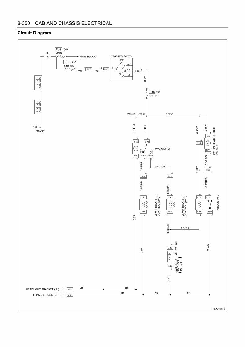
8-350 CAB AND CHASSIS ELECTRICAL
Circuit Diagram
X-24
X-24
J-44
J-43
H-8
J-42
J-42
B-93
B-93
B-93
J-42
J-42
B-93
B-93
X-24
X-24
H-8H-8
OFF
ON
ACC
ST
B
B-67B-67
B-7
J-9
P-1
P-2
P-3
P-4
P-5
23
5 8
6 7 3
9
1
15
2
3 4
1
1
4 5
2
10
2WD
4WD
FRAME
FL-1 100AMAIN2L
FL-2 40A
STARTER SWITCH
3W/B 3W/L
3B/Y
KEY SW
FUSE BLOCK
F-16 10AMETER
RELAY; TAIL (5)
0.5L
G/R
0.5B
/Y
0.5B/Y
0.5B
/Y
0.5B
/Y
4WD SWITCH
0.5G
R/B
0.5GR/R
0.3G
R/G
4WD
IND
ICA
TO
R L
IGH
T(M
ET
ER
)
0.5G
R/G
0.5B
/Y
RE
LAY
; 4W
D
0.5B/R
0.85
B/R
0.5G
R/R
0.85
B
VS
V:1
TR
AN
SF
ER
C
ON
TR
OL
(2W
D)
VS
V:2
TR
AN
SF
ER
CO
NT
RO
L (4
WD
)
4WD
DE
TE
CT
IVE
SW
ITC
H 2
WD
=O
N 4
WD
=O
FF
(
)
0.85
B
2B2B2B
3B3B
0.5B
0.3B
HEADLIGHT BRACKET (LH)
FRAME-LH (CENTER)
H-71
B-51
B-51
8
22
9
0.5G
R/B
H-5
3
N8A0427E

CAB AND CHASSIS ELECTRICAL 8-351
Connector List
No. Connector Face
B-51
B-67
B-67
B-93
X-24
J-42
J-42
J-43
014-001
1 2 3 4 5 6 7 8 9 1011121314
004-001
1 23 4
004-002
2
4
1
3
008-005
1 2 3 4
5 6 7 8
005-006
004-012
1 2
3 4
004-013
12
34
001-002
1
J-43
J-44
J-44
P-1
P-4
P-2
P-3
P-5
No. Connector Face
001-003
1
001-002
1
001-003
1
000-004
000-004
000-006
000-006
000-002

8-352 CAB AND CHASSIS ELECTRICAL
H-5
H-7
Starter SwitchRefer to “START AND CHARGING” in this section.
Neutral SwitchRefer to “START AND CHARGING” in this section.
4WD Indicator LightRefer to “METER AND WARNING/INDICATOR LIGHT”in this section.
4WD SwitchInspectionCheck the continuity between the connector terminalswhile operating the switch.Replace the switch when the result of inspection isfound abnormal.
Vacuum Switching Valve: Transfer Control (for2WD)InspectionConnect the vacuum switching valve connector terminalNo. 1 to the battery (+) terminal and terminal No. 3 to the(−) terminal and then check the continuity among eachport.
1 2 37 8 9
13 14 1519 20 2125 26 2731 32 33 34 35 36 37
4 5 610 11 1216 17 1822 23 2428 29 3038 39 40
6 5 412 11 1018 17 1624 23 2230 29 2840 39 38
3 2 19 8 715 14 1321 20 1927 26 2533 32 3134353637
N8A5488E
1 2
1 2
1 2 3 4
5 6 7 8
9 10 11 12 13
14 15 16 17 18
2 1
2 1
4 3 2 1
8 7 6 5
13 12 11 10 9
18 17 16 15 14
H - 6
H - 7
H - 8
N8A5489E
N8A5444E
N8A5445E

CAB AND CHASSIS ELECTRICAL 8-353
Vacuum Switching Valve: Transfer Control (for4WD)InspectionConnect the vacuum switching valve connector terminalNo. 2 to the battery (+) terminal and terminal No. 4 to the(−) terminal and then check the continuity among eachport.
4WD Detective SwitchInspection of the 4WD Warning Light Circuit
1. Disconnect the 4WD switch connectors.2. Connect the harness side connector terminals.3. Check to see if the indicator light comes on with the
starter switch “ON”.Check the bulb or harness when the result of in-spection is found abnormal.
Inspection1. Shift the transfer lever to the 4H (4L) position.2. Check to see if there is continuity between the
4WD switch connectors.Replace the switch when the result of the inspec-tion is found abnormal.
N8A5446E
N8A5447E
N8A5448E

8-354 CAB AND CHASSIS ELECTRICAL
ABS (Anti-lock Brake System, Without ASR)Parts Location
H-1
6
J-74
F/R
H S
EN
SO
R
B-6
6 S
TOP
LIG
HT
SW
(BR
AK
E S
W)
B-1
EA
RT
H ;
FR
AM
E (
FR
)
B-6
7 IG
NIT
ION
SW
"A
"
B-2
33,B
-234
EC
M
FU
SE
BO
X A
SM
F-2
,F-5
,F-1
6 S
TA
RT
ER
SW
J-14
8 R
/RH
SE
NS
OR
(24
V)
J-17
7A
BS
EH
CU
B-5
2 E
XH
. BR
AK
EIN
D. L
AM
P (
ME
TE
R)
B-5
1A
BS
AR
NIN
G L
IGH
T(M
ET
ER
)
J-75
F/L
H S
EN
SO
R
B-7
9 D
AT
A L
INK
CO
NN
EC
TO
R
J-9
EA
RT
H ;
FR
AM
E
(12V
)
(24V
)
X-5
AB
S IN
DIC
AT
OR
RE
LAY
X-8
EX
HA
US
T B
RA
KE
RE
LAY
(24
V)
RE
LAY
BO
X A
SM
(N
o.1)
X-2
5 E
XH
AU
ST
BR
AK
E C
ON
TR
OL
RE
LAY
X-2
8 E
XH
AU
ST
BR
AK
E C
UT
RE
LAY
J-23
DIO
DE
FL-
1,F
L-2,
FL-
9 F
US
IBLE
LIN
K
J-31
EX
H. B
RA
KE
MA
GN
ET
IC V
ALV
E
B-7
5A
CC
EL
SW
H-1
3
P-5
P-1
~P
-4B
AT
TE
RY
H-1
7
H-1
4
H-1
5
J-14
9 R
/LH
SE
NS
OR
(24
V)
R-6
ST
OP
LIG
HT
(R
H)
R-1
ST
OP
LIG
HT
(LH
)
SE
NS
OR
(12
V)
J-78
R/R
H,R
/LH
B-7
EA
RT
H ;
HE
AD
LIG
HT
B/T
B-6
9E
XH
. BR
AK
E S
W
B-8
9 C
LUT
CH
SW
H-5
~H
-8
N8A0537E

CAB AND CHASSIS ELECTRICAL 8-355
Circuit DiagramFor 12 Volt (4JH1 Engine)
ABS60A
P-5
P-2BATTERY
P-1
B-1
B-7
0.85B
H-62
B-517
B-518
FL-9
MAIN100A
FL-1
KEY SW50A
FL-2
METER10A
F-16
8B 8W/B
3R
8W/B 3W/B
3W/B 0.5G/Y 0.5GSW ; STOP LIGHT
B
OFF
ACC
ON
ST
B-672
B-673
KEY SW
3W/L
0.5B2B3B
0.5B
/Y
0.5B/Y
0.5B/Y
STOP LIGHT10A
F-5
B-664
B-661
0.5B/Y
0.5W
X-5
4
X-5
5
X-5
1
X-5
3
3B/Y
METER
ABS
RELAY ;ABS IND.
3W/L
H-7
1
3B
3B
2B
0.3W
/V
22
H-5
J-9
P-4
P-3
FRAME-LH (CENTER)
FRAME LH (FRONT)
HEADLIGHT BRACKET (LH)
C
D
E
F
A
B
G
H
N8A5590E

8-356 CAB AND CHASSIS ELECTRICAL
J-784
J-783
0.5R
0.5W
0.3W/G
0.3W/B
0.3W/G
0.3W/B
0.3W/B
0.5B
0.5B
SPEEDSENSOR(RR,RH)
J-741
J-742
0.5P
0.5L
SPEEDSENSOR(FRT,RH)
J-751
J-752
0.5V
0.5R/B
0.5P
0.5L
0.5V
0.5R/B
SPEEDSENSOR(FRT,LH)
0.85B
J-17722J-177
16STOP LAMP
EHCU ; ABS
ECMB-234 (62)
RL 12V
34
J-782
J-781
24MOTOR +B
RL SIG
32
2VALVE +B
FL SIG
33
23MOTOR GND
FL GRD
10
1VALVE GND
FR SIG
11
8 EXH.B/CUTOUT
FR GRD
21
7 EXH.B/CUTIN
RR 12V
12
6IND.
RR SIG
29
IG
MODE1
MODE2
MODE3
J1850
4FRASH
VEHICLE TYPE CONNECTOR
NKR77-3 (FLAT LOW)
EXCEPT NKR77-3(EXCEPT FLAT LOW)
2B
3R
3R
3B
3B
0.5B/Y
0.3W/V 0.3W/V 0.3W/V
0.5B/Y
0.5B
/Y
0.5B
/G
0.5B
/R
0.5B
/W
1.25
B
0.5G
0.5G 0.5G0.5G
0.5G
H-511 2
(30)
ECM
H-162
STOPLIGHT(RH)
STOPLIGHT(LH)
0.5G
1.25B
1.25
B
0.5L
0.5Y
SPEEDSENSOR(RR,LH)
16 15 14 13 12 11 10 9
8 7 6 5 4 3 2 1
H-535
H-536
H-540
H-1410
H-1411
H-1412
DATA LINKCONNECTOR
B-79
0.3W
/G
H-527
H-526
3R
0.5G
0.5LG/B
0.5LG/W
0.5LG/B
0.5LG0.5LG/W
0.5LG/B
3B
3B
ECMB-234 (32)
B-234
J-177
J-177
J-177
J-177
J-177
J-177
J-177
J-177
J-177
J-177
J-177
J-177
J-177
J-177
J-177
J-177
H-14
H-1415
H-1416
H-151
H-152
H-155
H-156
H-154
H-153
H-157
H-158
3J-177
17J-177
14J-177
15J-177
H-149
H-1
74
H-1
73
H-1
71
H-1
72
H-1
7
H-1
7
H-1
7
H-1
7
H-1
7
H-1
7
H-1
7
H-1
7
R-1
2
6
R-1
7H-16
7
H-14
R-6
2
6
R-6
C
D
A
B
E
F
G
H
0.5Y
0.5LECM
35
45
B-234
B-234
N8A5591E

CAB AND CHASSIS ELECTRICAL 8-357
For 24 Volt
ABS40A
P-4
P-5
BATTERYP-3
P-2BATTERY
P-1
FRAME-LH (CENTER)
3B
2B2B2B
2B
3B
B-7HEADLIGHT BRACKET (LH) 3B
B-1FRAME-LH (FRONT) 0.85B
RELAY ;EXH.BRAKE
X-81
X-85
X-82
H-62
X-83
B-517
B-518
FL-9
MAIN100A
or120A
FL-1
EXH.BRAKE10A
F-2
KEY SW40A
FL-2
METER10A
F-16
8B 8W/B
3R
5W/B 3W/B
0.5W/R
0.5B
3W/B 0.5G/Y 0.5G
0.5LG
SW ; STOP LIGHT
B
OFF
ACC
ON
ST
B-672
B-673
KEY SW
3W/L
3W/L
3B/R 0.5LG/W
0.5L
G/W
0.5B
0.5B
0.5B
0.5B
/Y
0.5L
G/B
0.5P
0.5B
0.5B
/G
0.5L
G/R
0.5B
0.5B
0.5B 0.5B
2B
0.5L
G/B
0.5LG/B 0.5LG/R
0.5B
/Y
0.5L
G/B
RELAY;CHARGE
X-28
4
X-28
2
X-28
5
X-28
1
H-8
8
H-7
1
X-28
3
STOP LIGHT10A
F-5
B-662
B-661
SW ; NEUTRAL(Neutral=ON)
RELAY ;EXH. BRAKECONTROL
SW ; EXH.BRAKE
0.5LG/B
0.5B/Y
0.5B/Y
0.5W
X-5
4
X-5
5
X-5
1
X-5
3
E-11
2
H-145
E-11
1
X-25
3
X-25
5
H-14
10
H-5
22
3B/Y
METER
ABS
5
H-8
10
B-692
X-25
4
X-25
1
H-8
17
SW ; CLUTCH
B-892
B-891
B-5210
B-511
IND. LAMP ;EXH. BRAKE
0.5LG/R0.5LG/R
H-5
38
0.5G/O
RELAY ;ABS IND.
A/CCOMPRESSOR
0.5B/Y
0.5B/Y
RELAY ;EXH. B/CUT(ABS)
0.5B
0.5B
1.25B
0.85
B
0.3W
/V
0.5L
G/R
B-69
J-9
D
E
F
G
H
IJ
A
B
C
KLM
N8A5592E

8-358 CAB AND CHASSIS ELECTRICAL
1.25
B1.
25B
7H-16
7
H-14
SPEEDSENSOR(RR,RH)
SPEEDSENSOR(FRT,RH)
SPEEDSENSOR(FRT,LH)
SPEEDSENSOR(RR,LH)
STOPLIGHT(LH)
STOPLIGHT(RH)
0.5G
1.25B
R-1
2
6
R-1
R-6
2
6
R-6
2B
J-1481
J-1482
0.5R
0.5W
0.3Y
0.3W/G
0.3W
/G
0.3W/B
0.3W/G
0.3W/B
0.3W/B0.3L
0.5B
0.5B
J-741
J-742
0.5P
0.5L
J-751
J-752
1
2
0.5V
0.5R/B
0.5V
0.5R/B
3B
0.5B
0.5B
0.5B
1.25B
0.5LG/W
J-17722J-177
16STOP LAMP
EHCU ; ABS
RL 12V
34
J-1491
J-1492
24MOTOR +B
RL SIG
32
2VALVE +B
FL SIG
33
23MOTOR GND
FL GRD
10
1VALVE GND
FR SIG
11
8 EXH.B/CUTOUT
FR GRD
21
7 EXH.B/CUTIN
RR 12V
12
6IND.
RR SIG
29
3IG
J1850
4
15MODE1
FRASH
14MODE2
17H-5
30
H-524
3
4
MODE3
0.5L
/G0.
5L/G 0.
5LG
0.5B
0.5LG
J-23
2
H-13
2
VEHICLE TYPE CONNECTORFOR TURKEY / GCC(4-WHEEL DRUM BRAKE MODEL)
FOR OTHER COUNTRIES
SW ; ACCEL
B-751
B-752 B-234
14
B-23321
QWS
ECM
CHECKER
B-23429
B-23314
EXH.BRAKE
DIAGB-23415
H-537
FICD
0.5B/G(NQR)
3R
3R
0.5B/Y
0.3W/V 0.3W/V
0.5LG
0.5LG/B
0.5B/R(NQR)
0.5B/W(NQR)
NQR
0.5LG 0.5LG
0.5L/W
0.5L/W
0.5G
3B
0.5GH-5
11H-16
2
0.5L
0.5Y
16 15 14 13 12 11 10 9
8 7 6 5 4 3 2 1
H-13
12
J-41
2
J-41
4
J-233
J-231
DIODE ; FICD
J-31
2
J-31
1
MAG.VALVE ;EXH.BRAKE
VSV ;FICD
J-40
2
J-40
1
VSV ; INT.THROTTLE
H-13
6
H-5
32
DATA LINKCONNECTOR
B-79
0.5G
0.5LG
3R
0.5LG/B
1.25B
3B
0.5B
J-177
J-177
J-177
J-177
J-177
J-177
J-177
J-177
J-177
J-177
J-177
J-177
J-177
J-177
J-177
J-177
J-177
J-177
J-177
J-177
10H-14
2H-14
12H-14
11H-14
9H-14
15H-14
16H-14
7H-15
8H-15
H-56
H-1
7
2
H-1
7
1
H-1
7
3
H-1
7
4
H-1
7
H-1
7
H-1
7
H-1
7
H-1
7
H-1
7
H-1
7
H-1
7
H-15
H-15
H-15
H-15
5
6
0.5P
0.5L
H-15
H-15
D
E
F
G
H
IJ
A
B
C
KLM
N8A5593E
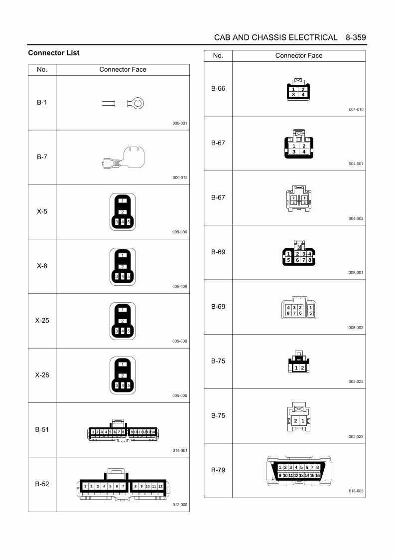
CAB AND CHASSIS ELECTRICAL 8-359
Connector List
No. Connector Face
B-1
B-7
X-5
X-8
X-25
X-28
B-51
B-52
000-001
000-012
005-006
005-006
005-006
005-006
014-001
1 2 3 4 5 6 7 8 9 1011121314
012-005
1 2 3 4 5 6 7 8 9 10 11 12
B-66
B-67
B-67
B-69
B-69
B-75
B-75
B-79
No. Connector Face
004-010
23 41
004-001
1 23 4
004-002
2
4
1
3
008-001
1
5
2
6
3
7
4
8
008-002
1
5
23
67
4
8
002-022
1 2
002-023
2 1
016-005
87654321
161514131211109

8-360 CAB AND CHASSIS ELECTRICAL
B-89
B-89
B-233(24 V)
B-234(24 V)
B-234(12 V)
E-11
E-11
H-13
No. Connector Face
002-009
1
2
002-010
1
2
022-002
9 8 7
20 19
6 5 4 3 2 1
18 17 16 15 14 1322 21 12 11
10
030-002
9 8 7 6
30 29 28 27 26 25 24 23 22 21 20 19 18 17 16 15
5 4 3 2 114 13 12 11 10
121-001
5 417
55
74
18
56
75
19
57
76
20
58
77
21
59
78
22
60
79
23
61
80
24
62
81
9
47
66
10
48
67
11
49
68
6
44
63
7
45
64
8
46
65
12
50
69
13
51
70
14
52
71
15
53
72
16
36 37 38 39 40 41 42 4328 29 3025 26 27 31 32 33 34 35
54
732 1
3
002-001
1 2
002-002
12
012-001
1 2 3 4
5 6 7 8
9 10 11 12
H-13
H-14(12 V)
H-14(12 V)
H-14(24 V)
H-14(24 V)
H-15(12 V)
H-15(12 V)
H-15(24 V)
No. Connector Face
012-002
4
8
12
3
7
11
2
6
10
1
5
9
014-004
1 2 3 4
5 6 7 8
9 10 11 12
13 14
014-005
4 3 2 1
8 7 6 5
12 11 10 9
14 13
016-003
1 2 3 4
5 6 7 8 9
11 12 13 14
15 16
10
016-004
4 3 2 1
9 8 7 6 5
13 12 11 10
16 15
14
008-023
1 2 3
4 5 6
7 8
008-024
3 2 1
6 5 4
8 7
016-003
1 2 3 4
5 6 7 8 9
11 12 13 14
15 16
10

CAB AND CHASSIS ELECTRICAL 8-361
H-15(24 V)
H-16
H-16
H-17
J-9
J-23
J-31
J-31
No. Connector Face
016-004
4 3 2 1
9 8 7 6 5
13 12 11 10
16 15
14
008-003
1 2 3 4
5 6 7 8
008-004
4 3 2 1
8 7 6 5
004-011
1
3
2
4
000-001
004-009
1 2 3 4
002-011
1 2
002-012
12
J-40
J-41
J-74
J-74
J-75
J-75
J-148
J-148
No. Connector Face
002-015
1 2
002-015
1 2
002-011
1 2
002-012
12
002-011
1 2
002-012
12
002-011
1 2
002-012
12

8-362 CAB AND CHASSIS ELECTRICAL
J-149(24 V)
J-149(24 V)
J-78(12 V)
J-78(12 V)
J-177
P-1(12 V)
P-2
P-1(24 V)
No. Connector Face
002-011
1 2
002-012
12
004-011
1
3
2
4
004-018
034-001
000-003
000-004
000-004
P-4
P-2(24 V)
P-3
P-5(12 V)
P-5(24 V)
R-1
R-1
R-6
No. Connector Face
000-004
000-006
000-006
000-007
000-002
006-004
1 2 3
4 5 6
006-005
3 2 1
6 5 4
006-004
1 2 3
4 5 6

CAB AND CHASSIS ELECTRICAL 8-363
H-5
H-6, H-7, H-8
ABS/ASR System
General DescriptionABS (Anti-lock Brake System) and ASR (Anti-Slip Reg-ulator) are the system to prevent the wheels from lock-ing and wheel spin, and to assure stability and steeringability of the vehicle.When a malfunction occurs in the system, fail-safe de-activate the ABS and ASR, and the warning lamp comeson. Also, the self-diagnosis function is equipped to im-prove serviceability.
R-6
No. Connector Face
006-005
3 2 1
6 5 4
1 2 37 8 9
13 14 1519 20 2125 26 2731 32 33 34 35 36 37
4 5 610 11 1216 17 1822 23 2428 29 3038 39 40
6 5 412 11 1018 17 1624 23 2230 29 2840 39 38
3 2 19 8 715 14 1321 20 1927 26 2533 32 3134353637
N8A5488E
1 2
1 2
1 2 3 4
5 6 7 8
9 10 11 12 13
14 15 16 17 18
2 1
2 1
4 3 2 1
8 7 6 5
13 12 11 10 9
18 17 16 15 14
H - 6
H - 7
H - 8
N8A5489E

8-364 CAB AND CHASSIS ELECTRICAL
Parts Location
J-74
F/R
H S
EN
SO
R
H-4
, H-5
H-6
, H-7
, H-8
B-6
6 S
TO
PLI
GH
T S
W(B
RA
KE
SW
)
B-1
EA
RT
H ;
FR
AM
E (
FR
)
B-6
7 IG
NIT
ION
SW
"A
"
B-7
EA
RT
H ;
HE
AD
LIG
HT
B/T
FU
SE
BO
X A
SM
F-5
, F-7
, F-1
6, F
-21
ST
AR
TE
R S
W
B-1
25 A
SR
OF
F S
W
B-4
31 R
ES
IST
OR
1
B-3
87 R
ES
IST
OR
2J-
148
R/R
H
P-5
SE
NS
OR
J-14
9 R
/LH
SE
NS
OR J-
177
AB
S E
HC
U
P1~
P4
BA
TT
ER
Y
H-1
4, H
-15
B-5
1 A
BS
WA
RN
ING
LIG
HT
(M
ET
ER
)
AS
R W
AR
NIN
G L
IGH
T (
ME
TE
R)
J-75
F/L
H S
EN
SO
R
B-7
9 D
AT
A L
INK
CO
NN
EC
TO
R
J-19
1 E
CM
J-9
EA
RT
H ;
FR
AM
E
FL-
1, F
L-2,
FL-
9 F
US
IBLE
LIN
K
N5A2075E
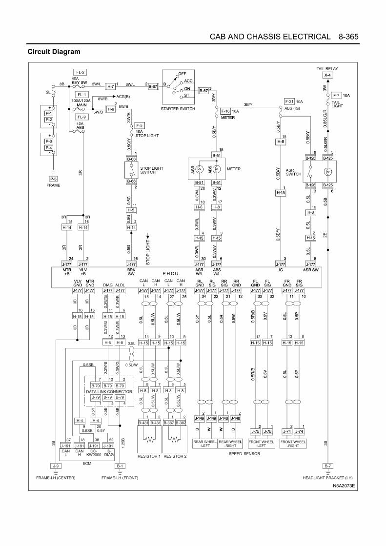
CAB AND CHASSIS ELECTRICAL 8-365
Circuit Diagram
8B
8W/B
5W/B
3R3R
ACG(B)
5W/B
3B/Y
0.5B
/Y
0.3W
/V
0.3W
/L
0.5G
3W/L
100A/120A
34
2ABS (IG)
TAILLIGHT
H-8
12
H-15
15
H-15
16
J-191
37
J-191
18
J-191
38
J-191
52
H-4
20
H-4
9
B-79
B-1
12
B-79
5
0.3W
/G
H-8
13
H-15
11
H-15
6
B-79
2
B-79
1
B-79
4
B-79
7
0.3W
/B
3B 3B
0.3W
/G
0.3W
/B
3B 3B
0.3W
/B
0.3W
/G
0.5B
0.5Y
0.5B
H-8
8
B-431
1
0.5L
H-8
7
B-431
2
0.5L
/W
0.5L
0.5L
/W
RESISTOR 1
H-8
6
B-387
1
0.5L
H-8
5
B-387
2
0.5L
/W
0.5L
0.5L
/W
RESISTOR 2
DATA LINK CONNECTOR
1.25
B
FRAME-LH (FRONT)
B-7
3B
HEADLIGHT BRACKET (LH)
J-9
FRAME-LH (CENTER)
0.5L
0.5L/W0.5SB
0.5SB
3B
0.5Y
CANL
CANH
CC-KW2000
IS-DIAG
ECM
N5A2073E

8-366 CAB AND CHASSIS ELECTRICAL
Connector List
No. Connector Face
B-1
B-7
B-51
B-66
B-67
B-67
B-79
B-125
000-001
000-012
020-004
002-031
1 2
004-002
2
4
1
3
004-001
1 23 4
016-005
87654321
161514131211109
008-001
1
5
2
6
3
7
4
8
B-387
B-387
B-431
B-431
H-4
H-4
H-14
H-14
No. Connector Face
002-038
002-039
002-038
002-039
020-002
10111213 14 15
1 2 3 4 5
171819 20
6 7 8 9
16
020-003
9 8 7 6
20191817 16
5
1415
4
13
3
12
2
11
1
10
016-004
4 3 2 1
9 8 7 6 5
13 12 11 10
16 15
14
016-003
1 2 3 4
5 6 7 8 9
11 12 13 14
15 16
10

CAB AND CHASSIS ELECTRICAL 8-367
H-15
H-15
J-9
J-74
J-74
J-75
J-75
J-148
No. Connector Face
016-003
1 2 3 4
5 6 7 8 9
11 12 13 14
15 16
10
016-004
4 3 2 1
9 8 7 6 5
13 12 11 10
16 15
14
000-001
002-012
12
002-011
1 2
002-012
12
002-011
1 2
002-012
12
J-148
J-149
J-149
J-177
J-177
J-191
P-1
P-2
No. Connector Face
002-011
1 2
002-012
12
002-011
1 2
034-001
034-002
000-004
000-006
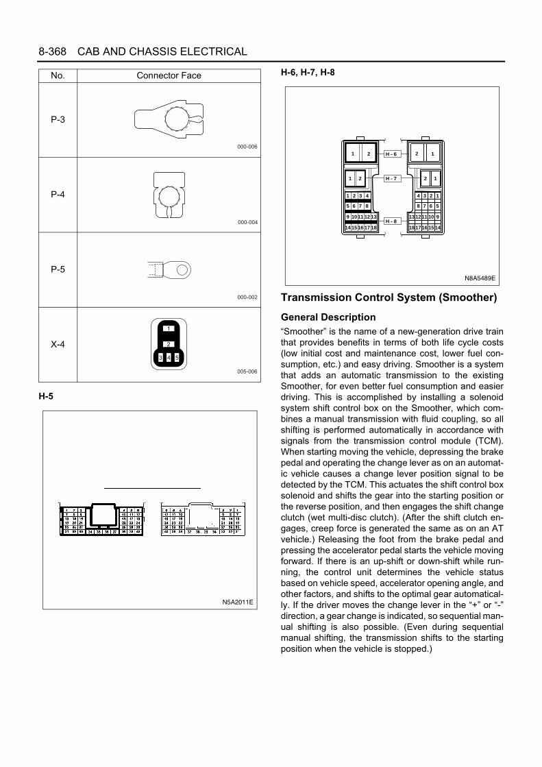
8-368 CAB AND CHASSIS ELECTRICAL
H-5
H-6, H-7, H-8
Transmission Control System (Smoother)
General Description“Smoother” is the name of a new-generation drive trainthat provides benefits in terms of both life cycle costs(low initial cost and maintenance cost, lower fuel con-sumption, etc.) and easy driving. Smoother is a systemthat adds an automatic transmission to the existingSmoother, for even better fuel consumption and easierdriving. This is accomplished by installing a solenoidsystem shift control box on the Smoother, which com-bines a manual transmission with fluid coupling, so allshifting is performed automatically in accordance withsignals from the transmission control module (TCM).When starting moving the vehicle, depressing the brakepedal and operating the change lever as on an automat-ic vehicle causes a change lever position signal to bedetected by the TCM. This actuates the shift control boxsolenoid and shifts the gear into the starting position orthe reverse position, and then engages the shift changeclutch (wet multi-disc clutch). (After the shift clutch en-gages, creep force is generated the same as on an ATvehicle.) Releasing the foot from the brake pedal andpressing the accelerator pedal starts the vehicle movingforward. If there is an up-shift or down-shift while run-ning, the control unit determines the vehicle statusbased on vehicle speed, accelerator opening angle, andother factors, and shifts to the optimal gear automatical-ly. If the driver moves the change lever in the “+” or “-”direction, a gear change is indicated, so sequential man-ual shifting is also possible. (Even during sequentialmanual shifting, the transmission shifts to the startingposition when the vehicle is stopped.)
P-3
P-4
P-5
X-4
No. Connector Face
000-006
000-004
000-002
005-006
N5A2011E
1 2
1 2
1 2 3 4
5 6 7 8
9 10 11 12 13
14 15 16 17 18
2 1
2 1
4 3 2 1
8 7 6 5
13 12 11 10 9
18 17 16 15 14
H - 6
H - 7
H - 8
N8A5489E

CAB AND CHASSIS ELECTRICAL 8-369
Parts Location
RELAY BOX ASM (No. 2)
FUSE BOX ASMF-5,F-13,F-16, F-17,F-22
B-431RESISTOR 2
B-387RESISTOR 1
B-79DATA LINK CONNECTOR
B-66STOPLIGHT SW
B-51, B-53 METER
B-67 STARTER SW
B-1
B-7
H-15
P-5
P-1
P-2
BATTERY
P-3P-4
F-28 FUSESBF1, SBF2, SBF5, SBF7, SBF8 FUSIBLE LINKX-18 ECM MAIN RELAYX-19 GEAR SHIFTER RELAYX-21 STARTER RELAYX-26 STARTER CUT RELAY
RELAY BOX ASM
H-10
H-12H-17
H-4, H-5, H-6,H-7, H-8
RELAY BOX ASM (No. 1)
N-7 DOOR SW (RH)
N-19 SELECT SW
N-17 EMERGENCY SW
N-18 EMERGENCY SHIFT SW
B-417 PTO SWITCH
STARTERSW
L-2 DOME LIGHT
X-14 SMOOTHEREMERGENCY RELAY
H-3
X-5 SMOOTHER MAIN RELAYX-32 DIODE
B-105 RESET SW
J-9
B-106 ADJUST SW
B-86DOME LIGHT SW
B-425, B-426,B-427, B-428TCM
H-118N-2DOOR SW (LH) H-119
H-118
H-119
J-177 EHCU
J-191 ECM
J-237SOLENOID & ATF TEMPERATURE SENSOR
J-50NEUTRAL SW
J-223SELECT STROKE SENSOR
J-234SELECT SOLENOID
J-232TURBINE SPEED SENSOR
J-236SHIFT SOLENOID 2, 4, R
J-235SHIFT SOLENOID 1, 3, 5J-139
INPUT SPEED SENSOR
J-142SHIFT STROKE SENSOR
N7A2053E
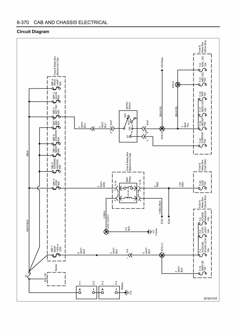
8-370 CAB AND CHASSIS ELECTRICAL
Circuit Diagram8W
HT
/BLK
8BLK
2L J-26
B
SB
F-8
60A
SB
F-4
40A
Bat
teryP-1
P-2
P-3
P-4
P-5
STA
RT
ER
Sta
rter
HE
AD
LAM
P
SB
F-5
EC
M40
A
Fus
e &
Rel
ay B
ox(B
ehin
d th
e C
ab)
SB
F-3
60A
GLO
WS
BF
-2
40A
KE
Y S
WS
BF
-9
40A
AB
SS
BF
-7
60A
NE
ES
SB
F-6
60A
CE
RA
MIC
HE
AT
ER
SB
F-1
MA
IN10
0A o
r12
0A
3 WH
T/
BLU
F-2
1
10A
F-9
3 BLK
/Y
EL
3BLK
/YE
L
F-1
6
10A
F-1
7N
EE
S (
IG)
10A
F-1
8
10A
Fus
e &
Rel
ay B
ox(G
love
Box
)E
NG
. (IG
)10
AA
BS
(IG
)M
ET
ER
SR
SF
-22
10A
STA
RT
ER
3 WH
T/
BLU
5 WH
T/
BLK
5 WH
T/
BLK
8 WH
T/
BLK
1.25
RE
D
0.5B
LU/B
LK
0.5
BLK
3 WH
T/
BLK
J-9
Fra
me
3 WH
T/
GR
N
2 RE
D
Mai
nR
elay
42
53
X-1
8
X-1
8
F-2
8E
CM
10A
Fus
e &
Rel
ay B
ox(C
ab S
ide)
EC
M
EC
M
Fus
e &
Rel
ay B
ox(B
ehin
d th
e C
ab)
Fus
e &
Rel
ay B
ox(G
love
Box
)
F-4
15A
AU
DIO
(B)
DO
OR
LO
CK
F-1
3N
EE
S (
B)
10A
F-5
F-6
10A
PO
WE
RW
IND
OW
10A
ST
OP
LIG
HT
W/S
-I/-
J
W/S
-H
W/S
-H3B
LK/Y
EL
ON
Rel
ay
H-6
1Ig
nitio
nS
witc
h
2
ST
ON
AC
CO
FF
B-6
7
34
B-6
7
US
W J
OIN
T3
0.5B
LK
N7A2131E

CAB AND CHASSIS ELECTRICAL 8-371
EC
MT
CM
30 B
LK/R
ED
8 B
LK8
BLK
8 B
LK
3 B
LK/Y
EL
P-1
P-2
P-3
P-4
Bat
tery
P-5
3 BLK
/W
HT
3 WH
T/
BLK
0.5
RE
D/W
HT
0.5
RE
D/W
HT
0.5
RE
D
0.5
WH
T/
BLU
0.3
BLK
/WH
T
3 WH
T/
BLU
3 WH
T/
BLU
2L
SB
F-8
STA
RT
ER
60A
SB
F-2
KE
Y40
A
F-2
2S
TAR
TE
R10
A
14H
-8
0.5
RE
D/
WH
T
0.5
WH
T/
BLU
0.5
WH
T/
BLU
J-9
Fra
me
4
B-6
7
US
WJO
INT
32 B
LK
0.5
BLK
14J-
191
B-4
2546
Sta
rt c
utre
lay
cont
rol
Sta
rtsw
itch
sign
al
38H
-5
16
Sta
rter
cut
rela
yco
ntro
l
Fus
e &
Rel
ay B
ox(G
love
Box
)
F-2
8E
CM
10A
Fus
e &
Rel
ay B
ox(B
ehin
d th
e C
ab)
Fus
e &
Rel
ay B
ox(B
ehin
d th
e C
ab) Fus
e &
Rel
ay B
ox(B
ehin
d th
e C
ab)
2 3J/C
-2
0.85
LT G
RN
0.5
LT G
RN
EC
MM
ain
Rel
ay
52
X-2
1Sta
rter
Rel
ay
43
X-2
1 51
X-2
6Sta
rter
Cut
Rel
ay
34
X-2
6
ST
ON
AC
CO
FF
Igni
tion
Sw
itch
Sta
rter
B C 1J-
27
1J-
26
F-1
6
10A
ME
TE
R
0.5
BLK
/Y
EL
0.5
BLK
/Y
EL
0.5
BLK
/Y
EL
14H
-12 E
mer
genc
yS
witc
h
51N
-17
N-1
7
W/S
-M
0.3
BLU
/R
ED
0.3
BLU
/R
ED
0.3
BLK
0.3
BLKW
/S-E
0.3
BLK
B-7
Hea
dlig
htB
rack
et
Sm
ooth
erE
mer
genc
yR
elay
1X
-14
3
Rel
ay B
ox(I
nstr
umen
t Pan
el)
0.3B
LU/R
ED
4B
-428
14
4H
-12
Em
erge
ncy
switc
hsi
gnal
1H
-7
2B
-67
25
X-1
4
N7A2144E

8-372 CAB AND CHASSIS ELECTRICAL
N7A2132E
0.5
WH
T/
VIO
0.5
GR
N/
WH
T
1.25
GR
N/
WH
T
1.25
GR
N/
WH
T
TC
M
Fus
e &
Rel
ay B
ox(G
love
Box
)
15B
-425
F-1
3N
EE
S(B
)10
A
1.25
WH
T/
OR
N
3
Sm
ooth
erM
ain
Rel
ay
15
2
X-5X-5
3
Mai
nre
lay
cont
rol
Bat
tery
vol
tage
Rel
ay B
ox(I
nstr
umen
t Pan
el)
0.5
BLK
/O
RN
0.5
BLK
/O
RN
0.5
BLK
/O
RN
2B
-426
1
Igni
tion
volta
ge
F-1
7N
EE
S(I
G)
10A

CAB AND CHASSIS ELECTRICAL 8-373
TC
M
4B
-426
0.5
BLK
2 BLK
12
0.5
BLK
17
1.25
BLK
8
212
113 D
iagn
ostic
requ
est
(SR
S)
Dia
gnos
ticre
ques
t(E
CM
)
Dia
gnos
ticre
ques
t(E
HC
U)
Cla
ss 2
Ser
ial
Com
mun
icat
ion
Gro
und
Gro
und
5B
-79
4
18B
-428
11
Dia
gnos
ticre
ques
tsw
itch
Dia
gnos
ticre
ques
t
1.25
BLK
1.25
BLK
0.3
BLK
/W
HT
0.5
BLK
0.5
BLK
0.3
WH
T/
BLK
0.3
WH
T/
GR
N
0.5
YE
L0.
5G
RY
0.5L
T B
LU
DLC
9B
-426
7
Key
wor
d 20
00
Key
wor
d se
rial
com
mun
icat
ion
0.3
LT B
LU
0.5
LT B
LU
EH
CU
(A
BS
Mod
ule)
EH
CU
(A
BS
Mod
ule)
EC
M
SR
S C
/U
EC
M
B-1
Fra
me
W/S
-D
1821
22
J/C
-B
W/S
-C
Sig
nal g
roun
dS
igna
l gro
und
Pow
er g
roun
dP
ower
gro
und
N7A2133E

8-374 CAB AND CHASSIS ELECTRICAL
0.5
YE
L/B
LK
0.5
1(LH
D)
3(R
HD
)3(
LHD
)5(
RH
D)
RE
D/
YE
L
0.5
YE
L/B
LK
0.5
RE
D/
YE
L
0.5
YE
L/B
LK
0.5
RE
D/
YE
L
0.5
YE
L/R
ED
0.5
BLU
/W
HT
0.5
BLU
/W
HT
0.5
YE
L/R
ED
0.5
BLU
/W
HT
0.5
YE
L/R
ED
3029
6
12B
-427
B-4
25
31
2
4J-
237
J-23
7
TC
M
Oil
Pum
p A
SM
Tran
smis
sion
fluid
tem
pera
ture
sens
or
Lock
up
clut
chso
leno
id v
alve
Gea
rshi
ft cl
utch
sole
noid
val
ve
5
6H
-4
H-1
7
6
14H
-119
H-1
187
3
Low
ref
eren
ceT
CM
H-4
B-4
27
TF
Tse
nsor
sign
al
5V r
efer
ence
Gea
rshi
ft cl
utch
sole
noid
val
veco
ntro
l
+B
Lock
up
clut
chso
leno
id v
alve
cont
rol
+B
N7A2134E

CAB AND CHASSIS ELECTRICAL 8-375
0.5
YE
L/W
HT
TC
M
33H
-5
1110
B-4
2610
4B
-427
2923
H-5
0.5
YE
L/W
HT
11H
-119
0.5
YE
L/W
HT
0.5
YE
L/B
LK
32
0.5
YE
L/B
LK
7
0.5
YE
L/B
LK
Low
ref
eren
ce
0.5
WH
T
10H
-8
1918
0.5
WH
T
3H
-119
0.5
WH
T
0.5
RE
D
0.5
WH
T/
BLU
0.5
OR
N/
BLU
0.5
WH
T/
BLU
0.5
OR
N/
BLU
812
H-1
190.
5W
HT
/B
LU
0.5
OR
N/
BLU
9
0.5
RE
D
2
0.5
RE
D
Turb
ine
Spe
edS
enso
r
Low
ref
eren
ce
5V r
efer
ence
Inpu
t sha
ftsp
eed
sens
orsi
gnal
TC
M
13B
-426
0.5
YE
L/R
ED
15H
-119
0.5
YE
L/R
ED
27H
-5
0.5
YE
L/R
ED
20
H-8
0.5
BLK
6
0.5
BLK
11
0.5
BLK
12
J-23
2
5V r
efer
ence
Turb
ine
spee
d se
nsor
sign
al
5V r
efer
ence
Gea
r se
lect
posi
tion
sens
orsi
gnal
5V r
efer
ence
Gea
r se
lect
posi
tion
sens
orsi
gnal
115
2620
H-5
0.5
YE
L0.
5B
RN
0.5
YE
L0.
5B
RN
0.5
YE
L0.
5B
RN
52
H-1
18
Inpu
tS
haft
Spe
edS
enso
r
12
J-13
9
21
J-22
3
3J-
223
Gea
r S
elec
tP
ositi
onS
enso
r
Gea
r S
hift
Pos
ition
Sen
sor
21
J-14
2
3J-
142
Low
ref
eren
ceLo
w r
efer
ence
N7A2135E

8-376 CAB AND CHASSIS ELECTRICAL
F-5
10A
F-1
7N
EE
S (
IG)
10A
F-1
6
10A
F-1
8
10A
0.5
BLK
/O
RN
0.5
BLK
/O
RN
0.5
BLK
/O
RN
0.3
GR
Y/
BLU
0.3
GR
Y/
RE
D
0.3
GR
Y/
BLK
0.5
GR
N
0.5
GR
N
0.5
GR
N/
YE
L 0.5G
RN
Sto
p Li
ght
11H-5
3B
-428
29
17
Fus
e &
Rel
ay B
ox(G
love
Box
)S
TO
P L
IGH
TM
ET
ER
SR
S
TC
M
J/C
-2
Bra
keP
edal
Sw
itch
21B
-66
B-6
6
Neu
tral
Sw
itch
12J-
50
J-50
F-2
8E
CM
10A
0.5
LT G
RN
0.5
LT G
RN
EC
M
Exh
aust
B
rake
S
olen
oid
Val
ve
0.5
BLK
/B
LU
0.5
BLK
/B
LU
37H
-5
10
0.5B
/L
2
64
1
Neu
tral
switc
hsi
gnal
Res
etsw
itch
sign
al
Slo
wsw
itch
sign
al
Fas
tsw
itch
sign
al
Bra
kepe
dal
switc
h
Res
etS
witc
h
64B
-105
B-1
05
Hal
f-cl
utch
Adj
ustm
ent
Sw
itch
3B
-106
12
B-1
06
J/C
-G
5
46
TC
M
0.3
2 BLK
0.5
BLK
3 BLK
1.25
BLK
B-7
Hea
dlig
htB
rack
et
Tai
lLi
ght
BLU
/W
HT
2 BLK
2 BLK
0.5G
RY
/RE
D
1.25
GR
Y/
BLK
0.5
GR
Y/
RE
D
0.5
GR
Y/
RE
D
12 5
7 1
1
6H
-12
19B
-428
3H
-3
B-1
Fra
me
Roo
m L
amp
TC
M
PT
Osw
itch
sign
al
Doo
rsw
itch
sign
al
Igni
tion
volta
ge
W/S
-B
J/C
-D
J/C
-H
W/S
-D
W/S
-C
2 3
Doo
r S
witc
h(L
eft)
1N
-7
Doo
r S
witc
h(R
ight
)
1N
-2
PT
OS
witc
h
12
3
B-4
17
B-4
174Ig
nitio
nvo
ltage
N7A2136E

CAB AND CHASSIS ELECTRICAL 8-377
20 3 1
0.5
RE
D
0.5
RE
D
R
TC
M
6 13 2
0.5
WH
T
0.5
WH
T
N
14 9 3
B-4
28
H-1
2
N-1
8
5N
-18
0.5
GR
N
0.5
GR
N
1
13 8 2
B-4
27
0.5
RE
D/
BLK 0.5
RE
D/
BLK
R
Em
erge
ncy
Shi
ft S
witc
h
21
202
67
B-4
28B
-427
0.5
WH
T/
BLK 0.5
WH
T/
BLK
N
Sel
ecto
rLe
ver
14
0.5
OR
N
0.5
OR
N
D
12 1015
0.5
BLU
/B
LK 0.5
BLU
/B
LK
+
1 87
0.5
PN
K/
BLK 0.5
PN
K/
BLK
-
11 48
0.5
GR
N/
BLK 0.5
GR
N/
BLK
A
1.25
BLK
B-1
Fra
me
0.5B
LK0.
5BLK
N-1
99
15
IPC
Leve
r Asw
itch
sign
al
Igni
tion
volta
ge
Leve
r -
switc
hsi
gnal
Igni
tion
volta
ge
Eco
nom
ym
ode
switc
hsi
gnal
Igni
tion
volta
ge
1st g
ear
star
tsw
itch
sign
al
Igni
tion
volta
ge
Leve
r +
switc
hsi
gnal
Igni
tion
volta
ge
Leve
r D
switc
hsi
gnal
Igni
tion
volta
ge
Leve
r N
switc
hsi
gnal
Igni
tion
volta
ge
Leve
r R
switc
hsi
gnal
Igni
tion
volta
ge
Em
erge
ncy
shift
1st
switc
hsi
gnal
Igni
tion
volta
ge
Em
erge
ncy
shift
Nsw
itch
sign
al
Igni
tion
volta
ge
Em
erge
ncy
shift
Rsw
itch
sign
al
Igni
tion
volta
ge
1B
-427
0.5
YE
L/R
ED 0.5Y
EL/
RE
D
13
10 5
B-4
28
H-1
2
EC
ON
OM
ode
Sw
itch
1st
Gea
rS
tart
Sw
itch
0.5
BLU
0.5
BLU
21 3N
-19
0.5
YE
L/R
ED
IPC
0.5
BLK
0.5
BLK
N-2
0
N-2
0
64
31
N7A2137E

8-378 CAB AND CHASSIS ELECTRICAL
12
J-23
5
J-23
5 1-3-
5S
hift
Sol
enoi
d
0.5
VIO
/W
HT
3 PN
K3 P
NK
0.5
VIO
/W
HT
2 RE
D3 R
ED
3 RE
D
TC
M
12
B-4
25
1.25
BLK
1.25
BLK
Fus
e &
Rel
ay B
ox(B
ehin
d th
e C
ab)
18
Gea
r sh
iftco
ntro
l box
rela
y co
ntro
l
19H
-17
8H
-118
14H
-17
1H
-118
7H
-17
SB
F-7
NE
ES
60A
1
715
B-4
28B
-425
1.25
BLK
2 BLK
1.25
BLK
1.25
BLK
1.25
BLK
8H
-17
67
1.25
BLK
1.25
BLK6
H-1
7
J-9
Fra
me
45
2131
B-4
25B
-426
1.25
PN
K
1.25
BLK
/R
ED
1.25
PN
K
1.25
BLK
/R
ED
56
89
B-4
25
1.25
PN
K
1.25
BLK
/B
LU
1.25
BLK
/R
ED
2 BLK
2 GR
N
1.25
BLK
/R
ED
4H
-119
12H
-17
1H
-119
2 BLK
2 BLU
1.25
BLU
16H
-119
10H
-17
13H
-119
2 BLK
2 BLK
1.25
BLK
1.25
BLK
/B
LU
1.25
PN
K
1.25
BLK
/B
LU
18
1622
B-4
28
1.25
PN
K
1.25
WH
T/
BLK
1.25
WH
T/
BLK
1.25
PN
K
1.25
WH
T/
BLK
TC
M
Gro
und
Gro
und
Gro
und
2 BLK
1-3-
5 sh
iftso
leno
id v
alve
cont
rol
2-4-
6-R
shi
ftso
leno
id v
alve
cont
rol
Sel
ect
sole
noid
val
veco
ntro
l
12
J-23
6
J-23
6 2-4-
6-R
Shi
ftS
olen
oid
12
J-23
4
J-23
4 Sel
ect
Sol
enoi
d
1.25
BLK
1.25
BLK
1.25
BLK
1.25
BLK
W/S
-Q US
WJO
INT
2
US
WJO
INT
1
Gea
r S
hift
Con
trol
Box
Rel
ay
25
3
X-1
9
X-1
94
N7A2138E

CAB AND CHASSIS ELECTRICAL 8-379
0.5
VIO
/W
HT
3 PN
K3 P
NK
0.5
VIO
/W
HT
2 RE
D3 R
ED
3 RE
D
Fus
e &
Rel
ay B
ox(B
ehin
d th
e C
ab)
18
Gea
r sh
iftco
ntro
l box
rela
y co
ntro
l
19H
-17
8H
-118
14H
-17
SB
F-7
NE
ES
60A
1
B-4
25
45
2131
B-4
25B
-426
1.25
PN
K
1.25
BLK
/R
ED
1.25
PN
K
1.25
BLK
/R
ED
56
89
B-4
25
1.25
PN
K
1.25
BLK
/B
LU
1.25
BLK
/R
ED
2 GR
N
1.25
BLK
/R
ED
4H
-119
12H
-17
2 BLU
1.25
BLU
16H
-119
10H
-17
151
8
2 BLK
1.25
BLK
1.25
BLK
/B
LU
1.25
PN
K
1.25
BLK
/B
LU
18
1622
B-4
28
1.25
PN
K
1.25
WH
T/
BLK
1.25
WH
T/
BLK
1.25
PN
K
1.25
PN
K1.
25P
NK
1.25
PN
K
1.25
WH
T/
BLK
TC
M1-
3-5
shift
sole
noid
val
veco
ntro
l
2-4-
6-R
shi
ftso
leno
id v
alve
cont
rol
Sel
ect
sole
noid
val
veco
ntro
l
US
WJO
INT
4G
ear
Shi
ftC
ontr
ol B
oxR
elay
25
3
X-1
9
X-1
94
12
J-23
5
J-23
5 1-3-
5S
hift
Sol
enoi
d
TC
M
12
B-4
25
1.25
BLK
1.25
BLK
1H
-118
19H
-17
715
B-4
28
1.25
BLK
2 BLK
1.25
BLK
1.25
BLK
1.25
BLK
17H
-17
67
1.25
BLK
1.25
BLK
21H
-17
J-9
Fra
me
2 BLK
1H
-119
2 BLK
13H
-119
2 BLK
Gro
und
Gro
und
Gro
und
2 BLK
12
J-23
6
J-23
6 2-4-
6-R
Shi
ftS
olen
oid
12
J-23
4
J-23
4 Sel
ect
Sol
enoi
d
1.25
BLK
1.25
BLK
1.25
BLK
1.25
BLK
US
WJO
INT
2
US
WJO
INT
1
N7A2139E

8-380 CAB AND CHASSIS ELECTRICAL
1112
B-4
25
TC
M
0.5
BLK
/Y
EL
0.5
BLK
/Y
EL
0.5
YE
L
0.3
YE
L/G
RN
0.5
YE
L/R
ED
Sel
ecto
r Le
ver
0.3
GR
N/
OR
N
818
IPC
B-5
1
Fus
e &
Rel
ay B
ox(G
love
Box
)
F-1
6M
ET
ER
10A Tr
ansm
issi
onw
arni
ngla
mp
7
EC
ON
Ola
mp
61
1st
STA
RT
lam
p
B-5
3
14
Gea
rP
ositi
onIn
dica
tor
Gea
r po
sitio
ndi
spla
y co
ntro
l
0.5B
LKS
moo
ther
Em
erge
ncy
Sw
itch
EC
ON
Ola
mp
cont
rol
Tran
smis
sion
war
ning
lam
pco
ntro
l
W/S
-M
Dio
deB
-1
21X
-32
X-3
2
0.3
PN
K
N7A2141E

CAB AND CHASSIS ELECTRICAL 8-381
2 1 B-431
7 8 H-8
B-387
Resistor 1
2 1
1
2TCM
3
2
B-427
10
5
H-15
14
9
15
14
J-177
27
26
5 6 H-8
0.5BLU/WHT
0.5BLU
0.5BLU/WHT
0.5BLU
0.5BLU
0.5BLU/WHT
0.5BLU
0.5BLU/WHT
0.5BLU
0.5BLU/WHT
0.5BLU
0.5BLU/WHT
0.5BLU
0.5BLU/WHT
0.5BLU
0.5BLU/WHT
0.5BLU/WHT
0.5 BLU
0.5BLU/WHT
0.5 BLU
0.5BLU/WHT
0.5 BLU
0.5BLU/WHT
0.5 BLU
0.5BLU/WHT
0.5 BLU
0.5BLU/WHT
0.5 BLU
0.5BLU/WHT
0.5 BLU
EHCU
37
18
J-191 CANhigh
CANlow
CANhigh
CANlow
DRM
ECM
Resistor 2
CANhigh
CANlow
3
J/C-F
4
5
6
J/C-F
Without ABS
2
1
3
J/C-R
5
4
6
J/C-R
CANhigh
CANlow
N6A6641E

8-382 CAB AND CHASSIS ELECTRICAL
Connector list
No. Connector Face
B-1
l
B-7
B-51
B-53
B-66
B-67
B-67
B-79
000-001
000-018
020-004
012-009
002-031
1 2
004-002
2
4
1
3
004-001
1 23 4
016-005
87654321
161514131211109
B-86
B-86
B-105
B-106
B-387
B-387
B-417
B-425
No. Connector Face
004-001
1 23 4
004-002
2
4
1
3
006-021
003-014
1
2
3
002-038
002-039
004-001
1 23 4
031-001

CAB AND CHASSIS ELECTRICAL 8-383
B-426
B-427
B-428
B-431
B-431
H-3
H-3
H-4
No. Connector Face
024-001
017-001
022-006
002-038
002-039
006-014
1 2 3
4 5 6
006-015
123
456
020-003
9 8 7 6
20191817 16
5
1415
4
13
3
12
2
11
1
10
H-4
H-10
H-10
H-12
H-12
H-15
H-15
H-17
No. Connector Face
020-002
10111213 14 15
1 2 3 4 5
171819 20
6 7 8 9
16
003-009
1 2 3
003-010
3 2 1
022-002
9 8 7
20 19
6 5 4 3 2 1
18 17 16 15 14 1322 21 12 11
10
022-001
1 2 3 4
13 14
5 6 7 8 9 10
15 16 17 18 19 2011 12 21 22
016-003
1 2 3 4
5 6 7 8 9
11 12 13 14
15 16
10
016-004
4 3 2 1
9 8 7 6 5
13 12 11 10
16 15
14
008-007
1 2 3 4
5 6 7 8

8-384 CAB AND CHASSIS ELECTRICAL
H-17
H-118
H-118
H-119
H-119
H-xx
J-9
J-26
No. Connector Face
008-008
1234
5678
008-003
1 2 3 4
5 6 7 8
008-018
016-001
1 2 3 4
5 6 7 8
9 10 11 12
13 14 15 16
016-002
4 3 2 1
8 7 6 5
12 11 10 9
16 15 14 13
001-002
1
000-001
000-002
J-27
J-50
J-139
J-142
J-177
J-191
J-223
J-232
No. Connector Face
000-009
002-035
002-040
003-005
1 2 3
034-001
003-005
1 2 3
002-040
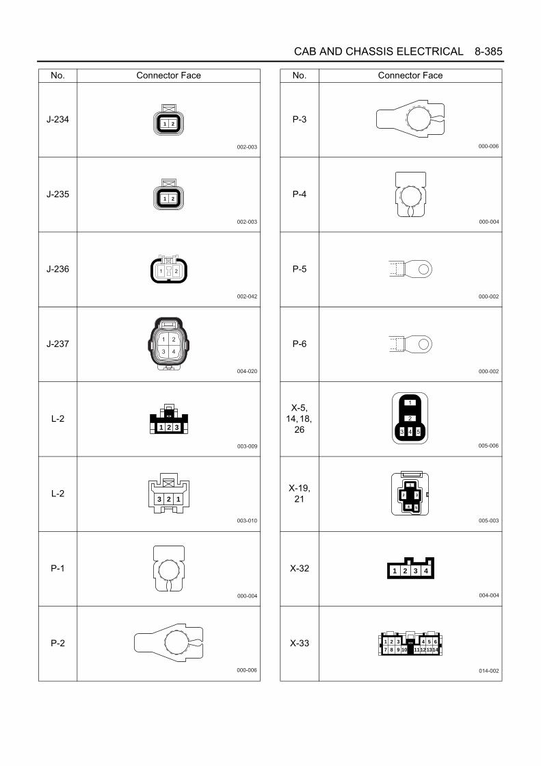
CAB AND CHASSIS ELECTRICAL 8-385
J-234
J-235
J-236
J-237
L-2
L-2
P-1
P-2
No. Connector Face
002-003
1 2
002-003
1 2
002-042
004-020
003-009
1 2 3
003-010
3 2 1
000-004
000-006
P-3
P-4
P-5
P-6
X-5, 14, 18,
26
X-19, 21
X-32
X-33
No. Connector Face
000-006
000-004
000-002
000-002
005-006
005-003
1
2 3
54
004-004
1 2 3 4
014-002
1 2 3
7 8 9 10 11
4
12
5
13
6
14

8-386 CAB AND CHASSIS ELECTRICAL
H-5
H-6, H-7, H-8
Electronic Control Type PTO
General DescriptionThis circuit consists of starter switch, PTO switch (fordump vehicle, it shares with dump control switch), relay,diodes, solenoid and control unit.Electronic control type PTO is installed on the left side oftransmission. PTO's gears are engaged at any time. There is a sleeveinstalled on the output shift, and the sleeve is shifted bythe solenoid through the shift rods(s) and shift arm(s).This causes turning the power on or off.
N-2
N-7
N-17
N-18
N-19
No. Connector Face
001-020
001-020
008-005
1 2 3 4
5 6 7 8
006-007
1 2 34 5 6
010-003
1098765
4321
1 2 37 8 9
13 14 1519 20 2125 26 2731 32 33 34 35 36 37
4 5 610 11 1216 17 1822 23 2428 29 3038 39 40
6 5 412 11 1018 17 1624 23 2230 29 2840 39 38
3 2 19 8 715 14 1321 20 1927 26 2533 32 3134353637
N8A5488E
1 2
1 2
1 2 3 4
5 6 7 8
9 10 11 12 13
14 15 16 17 18
2 1
2 1
4 3 2 1
8 7 6 5
13 12 11 10 9
18 17 16 15 14
H - 6
H - 7
H - 8
N8A5489E

CAB AND CHASSIS ELECTRICAL 8-387
Parts Location
B-6
7 S
TA
RT
ER
SWB
-84
PT
O S
W
P-1
J-12
3, J
-124
PT
O C
ON
TR
OL
UN
IT
J-12
5 P
TO
SO
LEN
OID
J-12
6 P
TO
SO
LEN
OID
SW
P-2
P-3
P-4
J-9
B-5
1P
TO
IND
ICA
TO
R L
AM
P (
ME
TE
R)
RE
LAY
BO
X A
SM
FL-
1, F
L-2
FU
SIB
LE L
INK
BA
TT
ER
Y
P-5
RE
LAY
BO
X A
SM
(N
o.1)
X-1
2 H
EA
TE
R &
A/C
RE
LAY
X-3
2, X
-34
DIO
DE
FU
SE
BO
X A
SM
F-1
6 F
US
E
RE
LAY
BO
X A
SM
(N
o.2)
F-2
9~F
-31
FU
SE
X-1
4 P
TO
MA
IN R
ELA
YX
-15
PT
O S
OLE
NO
ID R
ELA
YX
-16
PT
O C
UT
RE
LAY B-7
B-2
74H
6~H
8 B-8
9 C
LUT
CH
SW
N8A0526E

8-388 CAB AND CHASSIS ELECTRICAL
Circuit Diagram
40AKEY
P-1
P-2
P-3
P-4
P-5FRAME
H-71
B-672
2
FL-2
10A
PTO
F-31
100A/120AMAIN
CHARGERELAY
HEATER& A/CRELAY
FL-1
B
ST
ACC
ON
STARTER SW
DIODE
PTO CUTRELAY
CLUTCHSWITCH
DIODE
PTO SOLM/T RELAY
PTOSWITCH
B-67
B-67
3
4
X-34
1
X-16
3
X-34
2
X-16
5
3.0W/L
3.0L
3.0W/B
3.0B/Y
3.0B/Y
0.5B/Y
0.5W/B 3.0B/Y
0.5B/W
0.5L/R
0.5R/Y
0.3W
0.3W
0.3B
0.5Y
0.5Y0.5Y
0.3B
0.85P
0.85Y
0.85B
0.85W/G
0.85B
0.5B
0.5V/W
0.5R/Y
1.25W/L
0.85G/O
0.5L
10APTO
F-30
10AMETER
F-16
20APTO
F-29
X-16
1
X-16
2
X-16
4
X-12
1
X-12
2
X-12
5
X-12
4
X-15
5
X-15
2
X-15
3
X-15
1
B-89
1
B-89
4
H-8
2
B-51
5
J-126
1
J-126
2
B-51
8
H-6
2X-14
0.85L
3.0B/Y
2X-32
1X-32
X-34
3
3X-14
DIODE
PTO MAINRELAY
PTO SOL.SWITCH
METERPTO
3X-32
4X-32
B-84
4
B-84
B-7
1
J-9 B-274
H-81
J-1232
J-1245
1X-14
5X-14
J-1231
J-1253
J-1252
J-1244
J-1243
J-1251
FRAME FRAME H/L BRACKET
PTO SOL.
CONT UNITPTO
2.0L
0.5B
N8A0516E

CAB AND CHASSIS ELECTRICAL 8-389
Connector List
No. Connector Face
B-7
B-51
B-67
B-67
B-84
B-89
B-274
J-9
000-018
014-001
1 2 3 4 5 6 7 8 9 1011121314
004-002
2
4
1
3
004-001
1 23 4
006-001
1 2 3
4 5 6
004-001
1 23 4
000-001
000-001
J-123
J-123
J-126
J-126
X-12
X-14
X-15
X-16
No. Connector Face
002-012
12
002-011
1 2
002-012
12
002-011
1 2
005-001
1
32 4
5
005-006
005-006
005-006

8-390 CAB AND CHASSIS ELECTRICAL
H-6, H-7, H-8
X-32
X-34
No. Connector Face
004-004
1 2 3 4
004-004
1 2 3 4
1 2
1 2
1 2 3 4
5 6 7 8
9 10 11 12 13
14 15 16 17 18
2 1
2 1
4 3 2 1
8 7 6 5
13 12 11 10 9
18 17 16 15 14
H - 6
H - 7
H - 8
N8A5489E