Operator's Manual A3-2/A3/A4/A6 - cab Produkttechnik GmbH
138
Edition 10/04 Thermal-direct Printer / Transfer Printer / / / Operator’s Manual
-
Upload
khangminh22 -
Category
Documents
-
view
5 -
download
0
Transcript of Operator's Manual A3-2/A3/A4/A6 - cab Produkttechnik GmbH
Edition 10/04
Thermal-direct Printer / Transfer Printer
/ / /Operator's Manual

2 cab Produkttechnik GmbH & Co KG
copyright by cab / 9008298 / O45 / 1Angaben zu Lieferumfang, Aussehen, Leistung, Maßen und Gewicht entsprechen unseren Kenntnissen zum Zeitpunkt derDrucklegung. Änderungen sind vorbehalten.All specifications about delivery, design, performance and weight are given to the best of our current knowledge and are subjectto change without prior notice.
Gesellschaft fürComputer- und Automations-Bausteine mbH & Co KGcab-Produkttechnik GmbH & Co KGPostfach 19 04 D-76007 KarlsruheWilhelm-Schickard-Str. 14 D-76131 KarlsruheTelefon +49 (0) 721 / 66 26-0Telefax +49 (0) 721 / 66 26-249http://www.cabgmbh.come-mail : [email protected]

3cab Produkttechnik GmbH & Co KG
A3-2 / A3 / A4 / A6
Thermal-direct Printer /Transfer Printer
Operator's Manual
Thermal-direct Printer /Transfer Printer
Operator's Manual
All rights reserved, including those of the translations.
No part of this manual nor any translation may be reproduced or transmitted in any formor by any means, for any purpose other than the purchaser's personal use, without theexpress written permission of cab Produkttechnik GmbH & Co KG Karlsruhe.
Edition 10/04Printed in Germany
A3-2 / A3 / A4 / A6

4 cab Produkttechnik GmbH & Co KG
A3-2 / A3 / A4 / A6
Table of Contents
Trademarks .................................................................................................................................... 6A General Guide to the Documentation ........................................................................................ 7
1. Product Description ................................................................................................................ 8General Information .................................................................................................................. 8Printer Types ............................................................................................................................. 9Particular Features A3/200P, A3/300P .................................................................................... 10Characteristics of the Thermal Printhead ................................................................................ 10Compliances ............................................................................................................................ 11Instructions for the Lithium Battery ........................................................................................... 11Technical Specifications .......................................................................................................... 12Options ................................................................................................................................... 16
External Media Unwinder/Rewinder .................................................................................. 16Cutter Unit ........................................................................................................................ 16Memory Card ................................................................................................................... 16External Keyboard ............................................................................................................ 17Interface Extensions ......................................................................................................... 17Applicator ......................................................................................................................... 17RFID Read-Write Unit ...................................................................................................... 17
Print Media .............................................................................................................................. 18Print Media for Direct Thermal Printing ............................................................................. 19Print Media for Thermal Transfer Printing ......................................................................... 19Label / Tag Media Specifications ...................................................................................... 20Transfer Ribbon ................................................................................................................ 21
Software .................................................................................................................................. 22
2. General Safety Instructions .................................................................................................. 23
3. Unpacking .................................................................................................................... .......... 23Delivery Contents .................................................................................................................... 23Removing the Securing Devices ............................................................................................. 24
4. Printer Component Location ................................................................................................ 25
5. Connecting the Printer ......................................................................................................... 31Connection to Power Supply ................................................................................................... 31Connection to a Computer ...................................................................................................... 32Switch on the Printer ............................................................................................................... 33
6. Control Panel ......................................................................................................................... 34Use of the Control Panel ......................................................................................................... 34Structure of the Control Panel ................................................................................................. 35Functions of the Control Panel during Printing ........................................................................ 36Functions of the Control Panel in the Offline Menu .................................................................. 39
7. Media Loading ....................................................................................................................... 42General Information ................................................................................................................ 42Preparation for Tear-Off Mode / Rewind Mode ........................................................................ 43Loading Labels ........................................................................................................................ 44Loading Labels from Roll ....................................................................................................... . 44Adjustment of the Printhead Support ....................................................................................... 49Loading Fanfold Labels ........................................................................................................... 50Loading Transfer Ribbon ......................................................................................................... 52Adjustment of the Transfer Ribbon .......................................................................................... 54
Table of Contents

5cab Produkttechnik GmbH & Co KG
A3-2 / A3 / A4 / A6
8. Printer Configuration ............................................................................................................ 56Overview ................................................................................................................................. 56Local Settings ......................................................................................................................... 58Machine Parameters ............................................................................................................... 60Print Parameters ............................................................................................................... ...... 64Interfaces ................................................................................................................................ 68Security ................................................................................................................................... 70
9. Test Options .......................................................................................................................... 72Overview ................................................................................................................................. 72Short Status ............................................................................................................................ 74Status Print .............................................................................................................................. 76Font List .................................................................................................................................. 78Device List .............................................................................................................................. 80Printhead Profile ..................................................................................................................... 82ASCII Dump (Monitor) Mode ................................................................................................... 84Test Grid ................................................................................................................................. 86Label Profile ............................................................................................................................ 88
10. Memory Cards ....................................................................................................................... 90Installation and Removing the Memory Card ........................................................................... 91Preparing the Memory Card .................................................................................................... 92Writing to the Memory Card .................................................................................................... 92Memory Card Options in the Offline Menu ............................................................................... 93
Overview ....................................................................................................................... ... 93Label from Card ............................................................................................................... 94Print Directory .................................................................................................................. 95Copy Memory Card .......................................................................................................... 96Format Card ..................................................................................................................... 98ASCII Dump (Card) .......................................................................................................... 99
11. External Keyboard ............................................................................................................... 100Connecting the External Keyboard ......................................................................................... 100Key Assignment ..................................................................................................................... 101Special Key Functions ............................................................................................................ 101Special Characters Available with an External Keyboard ........................................................ 102
Appendices
Appendix A - Operation in Peel-off Mode .................................................................................. A-1Components for the Peel-off Mode ......................................................................................... A-1Preliminary Tests .................................................................................................................... A-2Present Sensor, Peel-off Adapter, Tamp Applicator ................................................................ A-2
Appendix B - Pin Assignment of the Interface Connectors ..................................................... B-1Pin Assignment of the RS-232 Interface ................................................................................. B-1Interface Cable for RS-232 .................................................................................................... B-2Pin Assignment of the Parallel Interface Connector ................................................................ B-3Parallel Interface Cable .......................................................................................................... B-3
Table of Contents

6 cab Produkttechnik GmbH & Co KG
A3-2 / A3 / A4 / A6
Trademarks
Centronics ® is a registered trademark owned by Centronics Data ComputerCorporation.
Macintosh-Computer is a product of Apple Computer, Inc.
Microsoft ® is a registered trademark owned by Microsoft Corporation.
Bitstream ® is a registered trademark owned by Bitstream Inc.
TrueType � is a registered trademark owned by Apple Computer Inc.
cablabel ® is a registered trademark owned by cab Produkttechnik GmbH &Co KG.
Table of Contents / Trademarks
Appendix C - Error Messages / Problem Solution .................................................................... C-1Error Messages ...................................................................................................................... C-1
Recoverable Errors ......................................................................................................... C-1Non-Recoverable Errors .................................................................................................. C-2Errors during System Test ............................................................................................... C-2List of Error Messages ..................................................................................................... C-3
Problem Solution .................................................................................................................... C-7
Appendix D - Maintenance / Cleaning ....................................................................................... D-1General Cleaning ................................................................................................................... D-1Cleaning the Print Roller ........................................................................................................ D-1Cleaning the Printhead ........................................................................................................... D-2Cleaning the Label Edge Sensor A3-2/A3/A4 ......................................................................... D-3
Appendix E - Replacing Assembly Units ................................................................................... E-1Replacing the Prinhead A3-2/A3/A4 ....................................................................................... E-1Replacing the Prinhead A6 ..................................................................................................... E-4Replacing the Print Roller and the Rewind Assist Roller ......................................................... E-6
Appendix F - Firmware Updates ................................................................................................ F-1General Information ............................................................................................................... F-1Firmware Update Using the Parallel Interface ........................................................................ F-1Firmware Update from Memory Card ..................................................................................... F-2Error Messages During the Firmware Update ........................................................................ F-3
Index
EU - Conformity Declaration

7cab Produkttechnik GmbH & Co KG
A3-2 / A3 / A4 / A6
A General Guide to the Documentation
This manual contains the description and usage instructions for the A3-2, A3,A4 and A6 printers.For detailed technical information on programming of the A3-2, A3, A4 and A6,a separate Programming Guide is available on request. For specificinformation on maintenance and repair of the printers, separate Service/Maintenance Manuals are available.
The first few chapters cover general information which is necessary forunpacking and setup of the printer, including ribbon and media loading.Chapter 5 covers the connection and usage of optional equipment that may beattached to the printer.
In the appendices, additional information such as cabling specifications, errormessages and problem resolution, and maintenance/cleaning instructions areincluded.
Please take special note of the specifications for suggested print media andthe references to cleaning the printer, to prevent damage, poor quality printingand avoidable failures of your printer.
Every effort has been made in the creation of this manual to provide as muchinformation as possible in a form that is both understandable and useful.
We welcome your comments and suggestions regarding additions orcorrections to improve future editions of this manual.
NOTICE !The figures in this manual normally show the Transfer Printer A4 !If there are important differences between the printer types you will find anotice !
A General Guide to the Documentation

8 cab Produkttechnik GmbH & Co KG
A3-2 / A3 / A4 / A6
1. Product Description
General Information
A3-2, A3, A4 and A6 are innovative printers which may be used in either directthermal or thermal transfer mode. They offer a high resolution with virtually anunlimited variety of printout designs.The center mounting plate is made of die-cast aluminum which makes it veryrobust and resistant to bending.By using 32 bit-processors from Motorola and the internal memory of 8 MB(A3-2, A3) or 16 MB (A4, A6), very long large labels (up to a length of 39 in /1000 mm) can be printed quickly.As standard equipment, the printers have a bi-directional parallel and a serialRS-232-interface. An optional RS-422/485-interface, USB-interface orethernet-interface can be installed. The printers auto-sense which interface isactually used. Furthermore the printers have a keyboard interface to connect astandard keyboard as well as a bar code scanner. By using a memory card itis possible to print and to enter variable data without any connection to acomputer.The ranging power supply (100-240VAC) allows the printers to be used aroundthe world without re-configuration.The operation and usage of the printers is simple and comfortable. All printersettings can be carried out with the Navigator Pad. To ease the operation theactive key is marked in the several operating modes.The graphic LCD display keeps the operator constantly informed about thecurrent status of the printer.The modular design of the printers guarantees efficient service.A special feature of the A3-2 and A3 printers is the possibility to changebetween the 203 dpi-printhead and the 300 dpi-printhead easily, with aminimum amount of time and effort.For the printers a wide range of optional accessories like external un- andrewinders, label/tag cutters, different peel-off modules and a tamp applicator isavailable.
1. Product Description

9cab Produkttechnik GmbH & Co KG
A3-2 / A3 / A4 / A6
Printer Types
A3-2, A3, A4 and A6 printers are available in different equipment variations: fortearing-off, internal rewinding or peeling-off the labels. Moreover A3-2, A3 andA4 printer types with different printhead resolutions are offered.This results in the following product range :
Basic Devices :
Printer types for tearing-off the labels :
Printhead Transfer Printer Thermal -direct PrinterA3-2 : 203 dpi A3-2/200 A3-2/200
300 dpi A3-2/300 A3-2/300
A3 : 203 dpi A3/200 A3/200300 dpi A3/300 A3/300
A4 : 300 dpi A4/300 -600 dpi A4/600 -
A6 : 300 dpi A6/300 A6/300
R-Versions :
Printer types for internal rewinding of the labels with internal rewinder :
Printhead Transfer Printer Thermal -direct PrinterA3-2 : 203 dpi A3-2/200R A3-2/200R
300 dpi A3-2/300R A3-2/300R
A3 : 203 dpi A3/200R A3/200R300 dpi A3/300R A3/300R
A4 : 300 dpi A4/300R -600 dpi A4/600R -
P-Versions :
Printer types for peeling-off the labels with internal rewinder and dispenseplate :
Printhead Transfer Printer Thermal -direct PrinterA3-2 : 203 dpi A3-2/200P A3-2/200P
300 dpi A3-2/300P A3-2/300P
A3 : 203 dpi A3/200P A3/200P300 dpi A3/300P A3/300P
A4 : 300 dpi A4/300P -600 dpi A4/600P -
A6 : 300 dpi A6/300P A6/300P
1. Product Description

10 cab Produkttechnik GmbH & Co KG
A3-2 / A3 / A4 / A6
Particular Features A3/200P, A3/300P
The P-versions of the printers are specificly developed for operation in thepeel-off mode and they are equipped with dispense edge as standard. In thepeel-off mode the labels are removed from the silicon liner immediately afterprinting, and then available in a dispense position ready for further processing.A peel-off module, for example an optional present sensor, which is attached tothe printer by the peripheral connector, indicates the presence of a label, andpauses the printing process until the label is removed. After taking the labelfrom the dispense position the next label will be printed. To guarantee amaximum of reliability in the peel-off mode the printers are additionallyequipped with a pair of rollers to cause the dispense tension.
NOTICE !In the delivery state, A3 is configured in such a way, that the print speedin the peel-off mode is limited to maximum 100mm/s. When usingsmaller labels or supply rolls with a small outside diameter it is possibleto increase the print speed for the peel-off mode.We recommend to carry out preliminary tests with speed limitationswitched off (see printer configuration) !
For the other P-version printers there is no limitation of the print speed in thepeel-off mode.
Characteristics of the Thermal Printhead
CAUTION !The thermal printhead is the most sensitive part of your printer. Pleasepay special attention to the following guidelines:
1) The glass cover on the printhead must not be touched with the hand. Also,do not use sharp objects (knives, screwdrivers, etc) to clean the printhead.
2) Ensure that the printhead is properly adjusted at all times.3) Make sure that there are no high spots or debris on your media to lodge on
or damage the printhead. The label surface must be smooth. Lower gradedirect thermal paper is very rough and will act like sandpaper on the head,reducing the head's lifetime. Do not use low grade stock.
4) Clean the head at each change of ribbon, or with each new roll of directthermal media, with a special cleaning pen, or a cotton swab with isopropylalcohol.
5) Print with the lowest possible head temperature to increase the life of theprinthead.
6) When changing the printhead, first turn the power off and disconnect thepower cord. Then, place a clean paper towel or tissue under the head toprovide a clean surface for it to rest on. When removing the head, hold iton the sides only.
Failure to observe the instructions above can lead to a reduced printhead life.
1. Product Description
11cab Produkttechnik GmbH & Co KG
A3-2 / A3 / A4 / A6
Compliances
The device complies with the following safety regulations :
CE : The printer complies with the following safety requirements- EC Low Voltage Directive (73/23/EEC)- EC Machinery Directive (98/37/EEC)- EC Electromagnetic Compatibility Directive (89/336/EEC)
FCC : The device complies with the requirements of the FCCregulations part 15 for class A computers. Underdisadvantageous circumstances, the operation of thesedevices may cause interference with radio or TV reception,which has to be eliminated by the operator.
Instructions for the Lithium Battery
The PCB of the printer is equipped with a Lithium battery.
Take necessary precautions against a possible short circuit if the battery is notfully discharged. Properly remove the battery should the printer be scrapped.
WARNING !
This is a Class A product. In a domestic environment this product may causeradio interference in which case the user may be required to take adequatemeasures.
1. Product Description

12 cab Produkttechnik GmbH & Co KG
A3-2 / A3 / A4 / A6
Technical Specifications
Printhead
Printhead Type : Direct thermal or thermal transfer
Printhead Model : A3-2, A3, A6 : Thick film transfer printheadA4 : Thin film transfer printhead
Printhead Resolution : A3-2/200 : 203 dpi = 8 Punkte / mmA3-2/300 : 300 dpi = 11,8 Punkte / mm
A3/200 : 203 dpi = 8 Punkte / mmA3/300 : 300 dpi = 11,8 Punkte / mm
A4/300 : 300 dpi = 11,8 Punkte / mmA4/600 : 600 dpi = 23,6 Punkte / mm
A6/300 : 300 dpi = 11,8 Punkte / mm
Number of dots/line : A3-2/200 : 448A3-2/300 : 640
A3/200 : 832A3/300 : 1280
A4/300 : 1248A4/600 : 2496
A6/300 : 1920
Print Speed : A3-2/200 : 2,3,4,5,6,7,8 ips (50,75,100,125,150,175,200 mm/s)A3-2/300 : 2,3,4,5,6 ips (50,75,100,125,150 mm/s)
A3/200 : 2,3,4,5,6,7,8 ips (50,75,100,125,150,175,200 mm/s)A3/300 : 2,3,4,5,6 ips (50,75,100,125,150 mm/s)
A4/300 : 2,3,4,5,6,7,8,9,10 ips (50,75,100,125,150,175,200,225,300 mm/s)A4/600 : 2,3,4 ips (50,75,100 mm/s)
A6/300 : 2,3,4,5,6,7,8 ips (50,75,100,125,150,175,200 mm/s)
for peel-off mode : On A3 the print speed is limited to maximum 4 ips (100mm/s) as standard
Print Width : A3-2/200 : up to 2.2 in (56 mm)A3-2/300 : up to 2.1 in (54.2 mm)
A3/200 : up to 4.1 in (104 mm)A3/300 : up to 4.25 in (108.4 mm)
A4/300 : up to 4.15 in (105.6 mm)A4/600 : up to 4.15 in (105.6 mm)
A6/300 : up to 6.4 in (162.6 mm)
1. Product Description

13cab Produkttechnik GmbH & Co KG
A3-2 / A3 / A4 / A6
Media
Material : Standard Labels and Cardboard / TagsDirect Thermal, Thermal Transfer and various Synthetics including: thermaltransfer plaincoated papers, vinyl, Mylar, metalized paper, non-wovenfabric, fine woven fabric, thermal visible light scannable paper, infraredscannable paper, thermal ticket/tag stock, thermally sensitive plastic stock.
Media Type : die cut labels, continuous paper
Media Winding : face-in or face-out on the roll
Supply roll Diameter : up to 8.2 in (210 mm)
Core Diameter : 1.5 to 3 in (38.1-76 mm)
Material thickness : 0.003-0.01 in (0,07-0,25 mm)
Weight : 60-250 g/sqm
Material Width : A3-2 : 2.5 in (65 mm)A3, A4 : 4.7 in (120 mm)A6 : 7.1 in (180 mm)
Media Width : A3-2 : .5 to 2.3 in (12-60 mm)A3, A4 : .5 to 4.6 in (12-116 mm)A6 : 2 to 6.9 in (50-176 mm)
for peel-off mode : A3-2 : 1 to 2.3 in (25-60 mm)A3, A4 : 1 to 4.6 in (25-116 mm)A6 : 2 to 6.9 in (50-176 mm)
Media Height : A3-2, A3, A4/300 : .2 to 39 in (5-1000 mm)A4/600 : .2 to 9.8 in (5-250 mm)A6 : .24 to 39 in (6-1000 mm)
for peel-off mode : A3-2, A3, A4 : .5 to 7.9 in (12-200 mm)A6 : 1 to 7.9 in (25-200 mm)
Internal Rewinder : to rewind media or the liner in peel-off modeCore Diameter : 1.5 (38.1mm)Rewind Diameter : up to 5.7 in (145 mm)Label side : out
Transfer Ribbon
Inkside : in or out
Outer Diameter : up to 3.1 in (80 mm)
Core Diameter : 1 in (25 mm)
Length : up to 1650 in (500 m)
Width : A3-2 : up to 2.2 in (56mm)A3, A4 : up to 4.5 in (114 mm)A6 : up to 6.5 in (165 mm)
Media Edge Sensor
Distance to paper edge : A3-2 : .16-.32 in (4-8 mm)A3, A4, A6 : .16-2.3 in (4-57,5 mm)
Material recognition : Gap sensor ("see-through"),Bottom-reflective sensor for black marks
1. Product Description
14 cab Produkttechnik GmbH & Co KG
A3-2 / A3 / A4 / A6
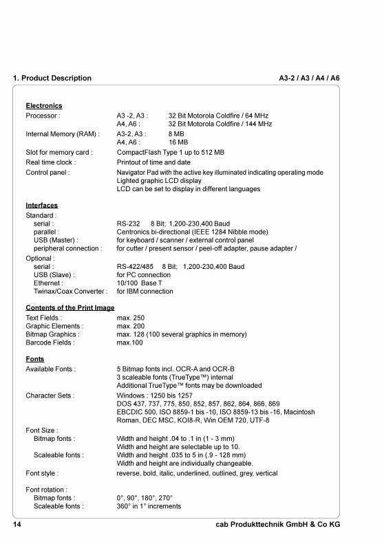
Electronics
Processor : A3 -2, A3 : 32 Bit Motorola Coldfire / 64 MHzA4, A6 : 32 Bit Motorola Coldfire / 144 MHz
Internal Memory (RAM) : A3-2, A3 : 8 MBA4, A6 : 16 MB
Slot for memory card : CompactFlash Type 1 up to 512 MB
Real time clock : Printout of time and date
Control panel : Navigator Pad with the active key illuminated indicating operating modeLighted graphic LCD displayLCD can be set to display in different languages
Interfaces
Standard :serial : RS-232 8 Bit; 1,200-230,400 Baudparallel : Centronics bi-directional (IEEE 1284 Nibble mode)USB (Master) : for keyboard / scanner / external control panelperipheral connection : for cutter / present sensor / peel-off adapter, pause adapter /
Optional :serial : RS-422/485 8 Bit; 1,200-230,400 BaudUSB (Slave) : for PC connectionEthernet : 10/100 Base TTwinax/Coax Converter : for IBM connection
Contents of the Print Image
Text Fields : max. 250Graphic Elements : max. 200Bitmap Graphics : max. 128 (100 several graphics in memory)Barcode Fields : max.100
Fonts
Available Fonts : 5 Bitmap fonts incl. OCR-A and OCR-B3 scaleable fonts (TrueType�) internalAdditional TrueType� fonts may be downloaded
Character Sets : Windows : 1250 bis 1257DOS 437, 737, 775, 850, 852, 857, 862, 864, 866, 869EBCDIC 500, ISO 8859-1 bis -10, ISO 8859-13 bis -16, MacintoshRoman, DEC MSC, KOI8-R, Win OEM 720, UTF-8
Font Size :Bitmap fonts : Width and height .04 to .1 in (1 - 3 mm)
Width and height are selectable up to 10.Scaleable fonts : Width and height .035 to 5 in (.9 - 128 mm)
Width and height are individually changeable.
Font style : reverse, bold, italic, underlined, outlined, grey, vertical
Font rotation :Bitmap fonts : 0°, 90°, 180°, 270°Scaleable fonts : 360° in 1° increments
1. Product Description

15cab Produkttechnik GmbH & Co KG
A3-2 / A3 / A4 / A6
Graphics
Graphic elements : line, box, circle, ellipse, fill-in segment, arrow
Graphic file types : .PCX, .IMG, .BMP, .TIF, .GIF and .MAC Graphic files
Barcodes
Lineare Codes : Code 39, Code 93, Code 128 A,B,C, Codabar, EAN 8, EAN 13, EAN128, EAN/UCC 128, EAN/UPC Anhang 2, EAN/UPC Anhang 5, FIM,HIBC, Interleaved 2/5, Ident-/Leitcode der Deutschen Post AG, Jan 8,Jan 13, MSI, Plessey, Postnet, RSS 14, UPC A, UPC E
2-D Codes : Aztec, Codablock, Data Matrix, PDF417, Micro PDF, UPS Maxicode,QR-Code
Bar code height, module width and ratio are variabe, with/withoutcheck digit, human readable character, start/stop character
Control / Test
Control : Ribbon availablePaper / fanfold availablePrinthead closed
Test options : System test when powering on including a printhead testshort status, status print, font list, device list,printhead profile, label profile, test grid, ASCII dump mode
Status messages : Counter of the printed length, counter of the operating hours
Software
Windows driver : 95, 98, ME, 2000, XP, NT from Version 4.0
cablabel : As Lite free version in the delivery contentsWith Advanced, Professional und Expert versionen für complexlabels
Others
Dimensions : A3-2 : H: 10.8 in (274mm) W: 7.5 in (190mm) D: 17.6 in (446mm)A3, A4 : H: 10.8 in (274mm) W: 9.5 in (242mm) D: 17.6 in (446mm)A6 : H: 10.8 in (274mm) W: 11.9 in (302mm) D: 17.6 in (446mm)
Weight : A3-2 : 19 lb. (8.5 kg)A3, A4 : 20 lb. (9 kg)A6 : 29 lb. (13 kg)
Operating Voltage : 100-240 V A.C. / 50-60 Hz
Maximum Power Input : A3-2, A3 : 250 WA4, A6 : 500 W
Environment :Operation : at 50° to 95° F (10 to 35°C) at a humidity of 30 to 85%Transport : at -13° to 158° F (-25 to +70°C) at a max. humidity of 95%
non-condensingStorage : at 41° to 104° F (5 to 40 °C) at a humidity of 5 to 85%
1. Product Description

16 cab Produkttechnik GmbH & Co KG
A3-2 / A3 / A4 / A6
Options
External Media Unwinder/Rewinder
For operating large print jobs, external unwinders and rewinders are availableto handle big label rolls :
A3-2 A3 A4 A6
Ext. Rewinder ER1 (up to diam. 8.3in/210mm) x x x -
Ext. Rewinder ER2 (up to diam. 8.3in/210mm) - - - x
Ext. Rewinder ER4 (up to diam. 11.8in/300mm) x x x -
Ext. Rewinder ER6 (up to diam. 11.8in/300mm) - - - x
Ext. Unwinder EU4 (up to diam. 11.8in/300mm) x x x -
Ext. Unwinder EU6 (up to diam. 11.8in/300mm) - - - x
Cutter Unit
With the cutter unit installed, labels or continuous media may be cut whendesired. Cutter options include a choice of: after each label, after a specificquantity of labels, or at the end of a print job. For cutter operation, the printerfirmware will extend the label for cutting based on specified displacements,then automatically backfeed the label, so that after making a cut, the label rollwill be repositioned and ready for printing the next label.The cutter is powered directly by the printers peripheral connector.
A3-2 A3 A4 A6
Cutter CU2 x - - -
Cutter CU4 - x x -
Cutter CU6 - - - x
Memory Card
The printer includes an option for using memory cards in order to permanentlystore graphics, fonts or whole label formats. The data can be downloaded viaany of the printers data interfaces. CompactFlash Type 1 cards with amaximum capacity of 512 MB are accepted. Using a memory card, the printercan be operated without being connected to a computer which represents agreat advantage regarding the flexibility.
1. Product Description

17cab Produkttechnik GmbH & Co KG
A3-2 / A3 / A4 / A6 1. Product Description
External Keyboard
The keyboard connector allows you to connect your printer to an USBkeyboard. This will allow you to input variable data to a format stored on amemory card.
Interface Extensions
The printer is equipped with a slot to connect an additional interface.It is possible to install a RS-422/485 interface, an USB interface or anethernet interface allowing the printer to be connected to several differenttypes of interfaces and networks.
Applicator
The applicator A 1000 represents, in combination with the P-versions of A3-2,A3 and A4, the inexpensive solution both for the semi-automatic labeling andfor the integration into automated production lines.
RFID Read-Write Unit
The A3 and A4 could be supplied with a factory installed RFID Read-Write Unit13.56 MHz with Ethernet for the marking of smart labels.

18 cab Produkttechnik GmbH & Co KG
A3-2 / A3 / A4 / A61. Product Description
Print Media
The A3-2, A3, A4 and A6 printers can be run in a direct thermal or thermaltransfer mode.
For direct thermal mode, the label material must be specifically designed forthis use. The printout is created directly on the paper, as the paper reacts withthe heat of the printhead and results in the darkening of the material.
Driving the printer in thermal transfer mode requires standard paper labels andthe addition of thermal transfer ribbons. The printout is created by heating theribbon with the printhead, resulting in a transfer of color from the ribbon ontothe labels.
The printers allow for regulating the required heat setting through the software,which offers a wide range of printing possibilities.
A3-2, A3, A4 and A6 are able to print on labels and continuous media, with amaximum supply roll diameter of 8.2" (210 mm). The minimum core diameteris 1.5" (38.1mm).
Top of form (label edge) detection is accomplished with a moveable photocell,which is driven by the internal processor of the printer. The photocell does anautomatic measurement of the used material. No additional adjustments arerequired.
The following pages contain more detailed information and specifications whichapply depending on the print method to be used.
For information of specific materials you may wish to use, check with your localdistributor. Not every material is suitable for quality direct thermal or thermaltransfer printing. The surface of the material is very often the main factor, butnot the only factor determining suitability. There are many materials availablefor labeling and your local distributor can offer suggestions to meet yourparticular needs.
19cab Produkttechnik GmbH & Co KG
A3-2 / A3 / A4 / A6 1. Product Description
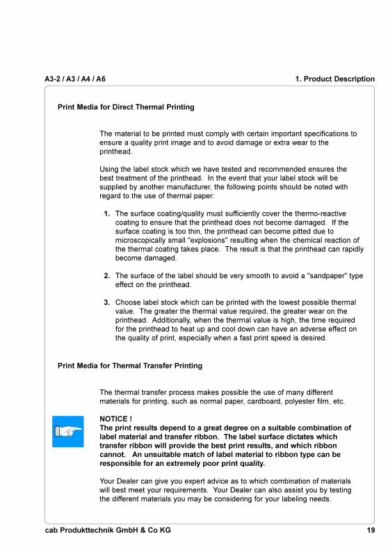
Print Media for Direct Thermal Printing
The material to be printed must comply with certain important specifications toensure a quality print image and to avoid damage or extra wear to theprinthead.
Using the label stock which we have tested and recommended ensures thebest treatment of the printhead. In the event that your label stock will besupplied by another manufacturer, the following points should be noted withregard to the use of thermal paper:
1. The surface coating/quality must sufficiently cover the thermo-reactivecoating to ensure that the printhead does not become damaged. If thesurface coating is too thin, the printhead can become pitted due tomicroscopically small "explosions" resulting when the chemical reaction ofthe thermal coating takes place. The result is that the printhead can rapidlybecome damaged.
2. The surface of the label should be very smooth to avoid a "sandpaper" typeeffect on the printhead.
3. Choose label stock which can be printed with the lowest possible thermalvalue. The greater the thermal value required, the greater wear on theprinthead. Additionally, when the thermal value is high, the time requiredfor the printhead to heat up and cool down can have an adverse effect onthe quality of print, especially when a fast print speed is desired.
Print Media for Thermal Transfer Printing
The thermal transfer process makes possible the use of many differentmaterials for printing, such as normal paper, cardboard, polyester film, etc.
NOTICE !The print results depend to a great degree on a suitable combination oflabel material and transfer ribbon. The label surface dictates whichtransfer ribbon will provide the best print results, and which ribboncannot. An unsuitable match of label material to ribbon type can beresponsible for an extremely poor print quality.
Your Dealer can give you expert advice as to which combination of materialswill best meet your requirements. Your Dealer can also assist you by testingthe different materials you may be considering for your labeling needs.
20 cab Produkttechnik GmbH & Co KG
A3-2 / A3 / A4 / A6
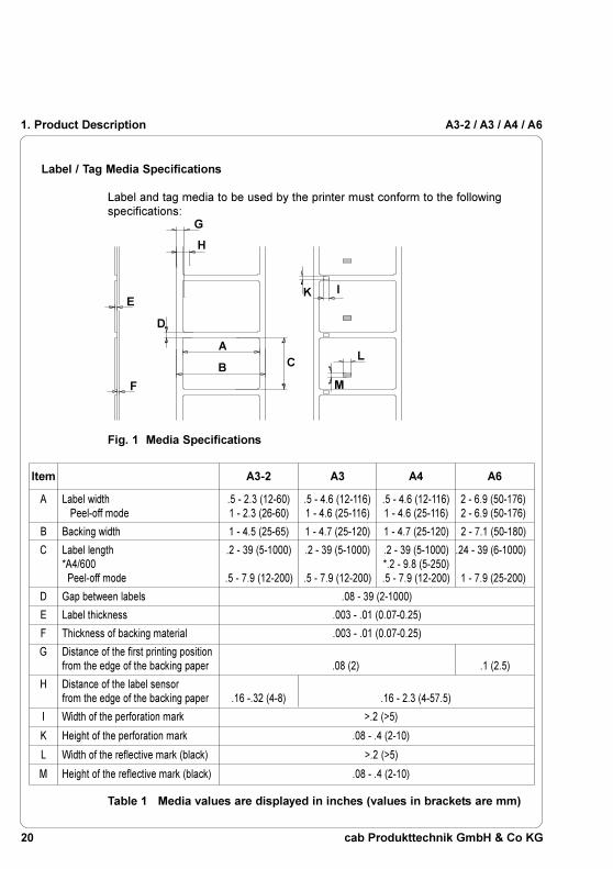
Item A3-2 A3 A4 A6
A Label width .5 - 2.3 (12-60) .5 - 4.6 (12-116) .5 - 4.6 (12-116) 2 - 6.9 (50-176) Peel-off mode 1 - 2.3 (26-60) 1 - 4.6 (25-116) 1 - 4.6 (25-116) 2 - 6.9 (50-176)
B Backing width 1 - 4.5 (25-65) 1 - 4.7 (25-120) 1 - 4.7 (25-120) 2 - 7.1 (50-180)
C Label length .2 - 39 (5-1000) .2 - 39 (5-1000) .2 - 39 (5-1000) .24 - 39 (6-1000)*A4/600 *.2 - 9.8 (5-250) Peel-off mode .5 - 7.9 (12-200) .5 - 7.9 (12-200) .5 - 7.9 (12-200) 1 - 7.9 (25-200)
D Gap between labels .08 - 39 (2-1000)
E Label thickness .003 - .01 (0.07-0.25)
F Thickness of backing material .003 - .01 (0.07-0.25)
G Distance of the first printing positionfrom the edge of the backing paper .08 (2) .1 (2.5)
H Distance of the label sensorfrom the edge of the backing paper .16 -.32 (4-8) .16 - 2.3 (4-57.5)
I Width of the perforation mark >.2 (>5)
K Height of the perforation mark .08 - .4 (2-10)
L Width of the reflective mark (black) >.2 (>5)
M Height of the reflective mark (black) .08 - .4 (2-10)
Label / Tag Media Specifications
Label and tag media to be used by the printer must conform to the followingspecifications:
Fig. 1 Media Specifications
Table 1 Media values are displayed in inches (values in brackets are mm)
E
F
D
A
B
K I
C
G
H
L
M
1. Product Description

21cab Produkttechnik GmbH & Co KG
A3-2 / A3 / A4 / A6 1. Product Description
Transfer Ribbon
The choice of transfer ribbon plays an important role in the quality of printimage that can be produced, and it also directly affects the longevity of theprinthead.
CAUTION !Poor quality transfer ribbon can lead to premature deterioration of theprinthead !
The ribbon material must be as anti-static as possible. This is because theextremely thin surface coating on the printhead can be damaged by a build upof electrostatic charges. The temperature tolerance of the material must beextremely high in order to avoid the transfer ribbon melting directly onto theprinthead. The temperature increase which results from the printing cycle mustbe dissipated over the label and the transfer ribbon. Poor quality transferribbon often has only a limited ability to dissipate the heat. This can contributeto overheating of the printhead, despite electronic protection againstoverheatingPoor quality transfer ribbon also tends to partially shed its ink coating, causingthe printhead and sensors to accumulate dirt. In addition, with some transferribbons, the back coating can flake or smudge, leaving traces on theprinthead. All of these effects contribute to lowering the print quality to belowdesired standards.Numerous tests have been conducted with a very large number of differenttransfer ribbons and we recommend only ribbons supplied by reputablemanufacturers. A variety of different transfer ribbons can sometimes be usedfor a particular type of label stock. The quality of print is determined by thecorrect combination of these materials.
NOTICE !When choosing material, make sure the transfer ribbon is slightly widerthan the width of the label backing.
The presence of transfer ribbon is sensed by the rotational movement controlof the transfer ribbon unwinder, rather than with photocell sensors. As a result,ribbons that have a thinner coating or those with a colored coating can be usedwithout problems.The possiblity of printing labels up to the absolute end of the ribbon is restrictedby the length of the uncoated "trailer", which attaches the end of the ribbon tothe core.
NOTICE !Make certain before purchasing transfer ribbon that the "trailer" (seeabove) is not more than 2.3in (60mm) long.

22 cab Produkttechnik GmbH & Co KG
A3-2 / A3 / A4 / A61. Product Description
Software
There are several methods to create formats and to send them to the printer.Below, a short explanation of the most common methods is given.
Direct Programming
The printer is equipped with an internal command set. The command set isdesigned to program all functions of the printer. To create a label format, useany ASCII editor to combine the necessary commands. Save the commandsto a file, then copy the file to the printer using the connected interface andHyperTerminal or the DOS COPY command.Direct programming requires a minimum knowledge of programming logic.The printer commands are designed logically and structured clearly. Howeverit is necessary to carry out several test prints when creating a label using thecommand set since no image of the label is displayed on the monitor.The complete description of the command set and sample programs isavailable in the "Programming Guide cab Printers".
Windows Printer Driver
Windows Printer drivers are available for the different Windows versions. Youcan get these drivers from your distributor or from the web. Visit the appropriatewebsite listed on page 2 to download the drivers.
The printer can be operated from any Windows Application that supportsWindows Printer drivers using the Windows Printer driver. The graphical userinterface allows for easier creation of label formats. However, the functionalitydepends on the choosen application and how each product supports WindowsPrinter drivers. There could be restrictions depending on the application youare using. A help file is included with the drivers to explain the usage andlimitations when using certain Windows applications.
Label Software
There are several Windows Applications that are designed to create labels.These programs are more suited to the requirements of label printing thanstandard Windows Applications. In some cases these programs use theWindows Printer Driver.
Some applications, for example cablabel, have integrated internal drivers tooperate the printers of the A series. These applications offer the best solutionfor creating and printing labels.

23cab Produkttechnik GmbH & Co KG
A3-2 / A3 / A4 / A6
2. General Safety Instructions
CAUTION !
- The printer is built exclusively to print die-cut labels, continuous media, andsimilar materials as listed in Technical Specifications in Chapter 1.
- Connect the printer to an outlet with the correct voltage!The printer is configured for voltages of 100 to 240 V.Connect only to a power outlet with a grounded contact.
- The printer must only be connected to devices which have extra low voltage.- Power must be OFF before plugging in any accessory, connecting to a
computer and before performing any maintenance on the printer. Also turnthe power off on all appliances before disconnecting from the printer.
- Do not expose the printer to any moisture, or use in damp or wet areas.- The printer will operate with the cover open if necessary. This is not
recommended, as it might allow debris to collect on the printhead surface. Ifthe printer must be operated with the cover open, extra care must be takento avoid allowing hair, jewelry, clothing, etc. near the moving parts.
- During the print process the printhead will become hot. Use extra cautionwhen touching the printhead. Do not touch the printing surface of theprinthead with you hand!
- Any adjustments or repairs which are not described in this manual, shouldonly be carried out by an authorized service technician.WARNING !To avoid possible electric shock, do not open the backside cover!
3. Unpacking
Delivery Contents
Please inspect the printers packaging and contents immediately after receipt forpossible damage during shipment.
NOTICE !Be sure to preserve the original packaging for possible later shipment!
The shipping container will contain the following standard components:
- Thermal Transfer Printer- Cardboard Core for the transfer ribbon rewinder- Tear-off Plate (Basic devices only)- Rewind Guide Plate (R-Versions only)- Dispense Plate (P-Versions only)- Power Cord- Documentation
2. General Safety Instructions / 3. Unpacking

24 cab Produkttechnik GmbH & Co KG
A3-2 / A3 / A4 / A6
1
2
3. Unpacking
Fig. 3 Removing the securing devices
Removing the Securing Devices
1. Place the printer on a solid flat surface.
2. Open the cover.
3. Remove the securing devices (1, 2).

25cab Produkttechnik GmbH & Co KG
A3-2 / A3 / A4 / A6
1
2
3
4 5 6 7
8
9
11
10
4. Printer Component Location
4. Printer Component Location
Fig. 4a General view
1 - Warning label ''End of Ribbon''2 - Control panel3 - Present sensor (Option for P-Version)4 - Print mechanism5 - Internal rewinder (P- and R-Versions only)6 - Ribbon take up hub7 - Ribbon supply hub8 - Media hub9 - Media Retainer
10 - Warning label ''End of Paper''11 - Cover

26 cab Produkttechnik GmbH & Co KG
A3-2 / A3 / A4 / A6
1
2
3
4
5
6
7
8
9
10
11
12
13
4. Printer Component Location
Fig. 4b Print mechanism Basic Devices with printhead open
1 - Printhead locking screw2 - Ribbon shield3 - Label edge sensor4 - Media feed roller5 - Tear-off plate6 - Printhead support7 - Screw to adjust the printhead support8 - Printhead lever9 - Screw to adjust the ribbon shield
10 - Thermal printhead11 - Media guide12 - Swing (A3-2 and A3: Guide axle)13 - Allen Key

27cab Produkttechnik GmbH & Co KG
A3-2 / A3 / A4 / A6
1
2
3
4
5
6
7
8
9
10
11
12
13
Fig. 4c Print mechanism R-Versions with printhead open
1 - Printhead locking screw2 - Ribbon shield3 - Label edge sensor4 - Media feed roller5 - Rewind guide plate6 - Printhead support7 - Screw to adjust the printhead support8 - Printhead lever9 - Screw to adjust the ribbon shield
10 - Thermal printhead11 - Media guide12 - Swing (A3-2 and A3: Guide axle)13 - Allen Key
4. Printer Component Location

28 cab Produkttechnik GmbH & Co KG
A3-2 / A3 / A4 / A6
1
2
3
4
5
7
8
9 10
11
12
13
14
15
16
6
4. Printer Component Location
Fig. 4d Print mechanism P-Versions with printhead open
1 - Printhead locking screw2 - Ribbon shield3 - Label edge sensor4 - Media feed roller5 - Dispense plate6 - Rewind assist roller7 - Locking system8 - Printhead support9 - Screw for adjusting locking system
10 - Screw for adjusting printhead support11 - Allen key12 - Swing (A3-2 and A3: Guide axle)13 - Media guide14 - Thermal printhead15 - Screw to adjust the ribbon shield16 - Printhead lever

29cab Produkttechnik GmbH & Co KG
A3-2 / A3 / A4 / A6
1
2
3
4
5
4. Printer Component Location
Fig. 4e Control panel
1 - Display2 - Navigator pad with keys3 - Memory card LED4 - Memory card slot5 - Memory card ejection lever

30 cab Produkttechnik GmbH & Co KG
A3-2 / A3 / A4 / A6
1
2
3
4
5
6
4. Printer Component Location
Fig. 4f Back view
1 - Slot for the additional interface card(RS-422/485, ethernet or USB-slave)
2 - Bi-directional parallel interface3 - USB master interface for keyboard or scanner4 - RS-232-interface5 - Power switch6 - Power supply connector

31cab Produkttechnik GmbH & Co KG
A3-2 / A3 / A4 / A6
1
2
5. Connecting the Printer
5. Connecting the Printer
CAUTION !Make sure the printer is located where the unit or the operator cannotcome in contact with water. Otherwise it could cause damage to theprinter.
Connection to Power Supply
The printer is equipped with a wide range power unit (100-240V~), so it ispossible to use the printer both with a voltage of 230V~/50 Hz and with avoltage of 115V~/60 Hz without making changes to the printer.
CAUTION !Make sure the power switch (1) is in position "O" (OFF) beforeconnecting the printer to a power supply !
Fig. 5a Power supply
Insert the power cable supplied in the accessories carton into the power supplyconnector (2) and contact the cable to a grounded outlet.

32 cab Produkttechnik GmbH & Co KG
A3-2 / A3 / A4 / A6
1
2
3
4
5. Connecting the Printer
Connection to a Computer
As standard, the printer is equipped with a bi-directional parallel interface (3)and a serial RS-232-interface with a 9 pin connector (4).
For connection to the parallel interface use a suitable parallel interface cable(1).Cables for the serial connection (2) are described in appendix B. You can alsofind descriptions of the pin assignments for the interface connectors
NOTICE !For serial connection, make sure the serial interface RS-232 of the printeris correctly configured to the settings of your computer (see printerconfiguration section).
Connect the computer and the printer with a suitable cable and secure thecable connections with screws provided on the connectors.
CAUTION !Make sure that all connected computers and their connecting cables arecorrectly grounded.
Information for the optional interfaces (RS-422/485, ethernet, USB) can befound in the documentation for the respective interface.
Fig. 5b Computer connection

33cab Produkttechnik GmbH & Co KG
A3-2 / A3 / A4 / A6
1
Switch on the Printer
Fig. 5c Switch on the printer
After making all connections, power on the printer using the power switch (1).
The printer will perform a short system test, then display "ONLINE" on the frontpanel LCD.
If a hardware failure occurs during the system test, the symbol and a
description of the failure will be displayed on the LCD. In this case the printershould be powered off and on again. If the failure re-occurs, call for service.
5. Connecting the Printer

34 cab Produkttechnik GmbH & Co KG
A3-2 / A3 / A4 / A6
6. Control Panel
Use of the Control Panel
The control panel allows the operator the ability to control the operation of theprinter in various ways.
Uses of the control panel :
- to control the current print job, e.g. to pause and continue or to cancel printjobs on demand.
- to set print parameters, for example the heat level, the print speed, the baudrate of the serial interface, the language or the time.
- to execute self test functions of the printer.- to operate the printer using a memory card without having a computer
connected.- to carry out an update of the printer's firmware.
Several functions and settings can also be configured by sending printercommands from software or through direct programming.
The settings configured by the control panel are basic settings.Parameters can be set on/off for all print jobs, for example "Transfer print on/off" or the setting can be set by software for single print jobs.
Parameters such as "Printhead position", which determines the position of theprint image, can be set for all print jobs. Any setting that has both a front panelsetting and software command, the values are totaled together for printing.In the case of On/Off settings, the software commands will override the frontpanel setting.The section "Printer Configuration" will indicate whether it is possible to changethe settings of the front panel via software.
NOTICE !Whenever possible, use the software command during print jobs tocontrol the printer's settings.
6. Control Panel

35cab Produkttechnik GmbH & Co KG
A3-2 / A3 / A4 / A6
Structure of the Control Panel
The control panel consists of a graphic display (1) and the Navigator Pad (2)with four integrated keys.
The control panel display constantly provides the operator with realtimeinformation concerning the current printer mode and label processing.
The function and operation of the keys depends on the current mode.The available functions are marked by illuminating the valid symbols and text inthe keys.
Fig. 6a Control Panel
6. Control Panel
Online1
2

36 cab Produkttechnik GmbH & Co KG
A3-2 / A3 / A4 / A6
Functions of the Control Panel during Printing
System Mode ONLINE
The printer is switched ON and ready to receive data.The display shows the time and the word "Online".
During the transfer of data a rotating symbol appears on the display.
When saving data on the PC card the symbol appears on the display.
Key Description Function
on Switches to OFFLINE mode.
on Performs a label feed.
(on) Repeats the print of the last label, after the previousprint job has been completed.(Only when setup parameter "Pause reprint" is on.)
(on) Clears internal memory of the previous print job."Pause reprint" is no longer available.
Fig. 6b Navigator Pad during Printing
During printing the keys on the Navigator Pad are illuminated to indicate whatfunctions control the print jobs. The exact key functions in the different systemmodes are described below.The text is not illuminated when the keys have no function in the current mode.
6. Control Panel

37cab Produkttechnik GmbH & Co KG
A3-2 / A3 / A4 / A6
System Mode PRINT
The printer is currently processing an active print job.In this mode, the transfer of data is possible. New print jobs will be carried outimmediately following the completion of the previous job. The display showsthe message "Printing label" and the current number of printed labels.
Key Description Function
on Interrupts the current print job
on Short press - cancels the current print jobLong press - cancels the current print job
and deletes all jobs contained in theinternal memory
System Mode PAUSE
The printing process is temporarily interrupted by the operator.
The display shows "Pause" and the symbol appears.
Key Description Function
on Continues the print job
on Short press - cancels the current print jobLong press - cancels the current print job
and deletes all jobs contained in theinternal memory
System Mode POWERSAVE
If the printer does not receive a print job or the front panel has not beenaccessed for a period of time, the printer will switch into a powersave mode.During powersave mode, certain functions such as the background lighting of
the display are powered off. The display shows . The illumination of
the keys is switched off.
To leave this mode press any key or send a print job.
6. Control Panel

38 cab Produkttechnik GmbH & Co KG
A3-2 / A3 / A4 / A6
System Mode FAULT-CORRECTABLE
The printer has encountered a fault during printing which is easily corrected bythe operator (e.g. "Out of paper"). Once the fault has been corrected, theprinting process may be continued.
The symbol appears on the display. Additionally, the type of fault and the
total of the remaining labels is also displayed.
Key Description Function
flashes Continues current print job after fault correction
on Short press - cancels the current print jobLong press - cancels the current print job
and deletes all jobs contained in theinternal memory
System Mode FAULT-IRRECOVERABLE
During printing, a fault has occured which cannot be cleared by the operatorwithout canceling the current print job.
The symbol appears on the display and the type of the fault is displayed.
Key Description Function
flashes Short press - cancels the current print jobLong press - cancels the current print job
and deletes all jobs contained in theinternal memory
6. Control Panel
39cab Produkttechnik GmbH & Co KG
A3-2 / A3 / A4 / A6
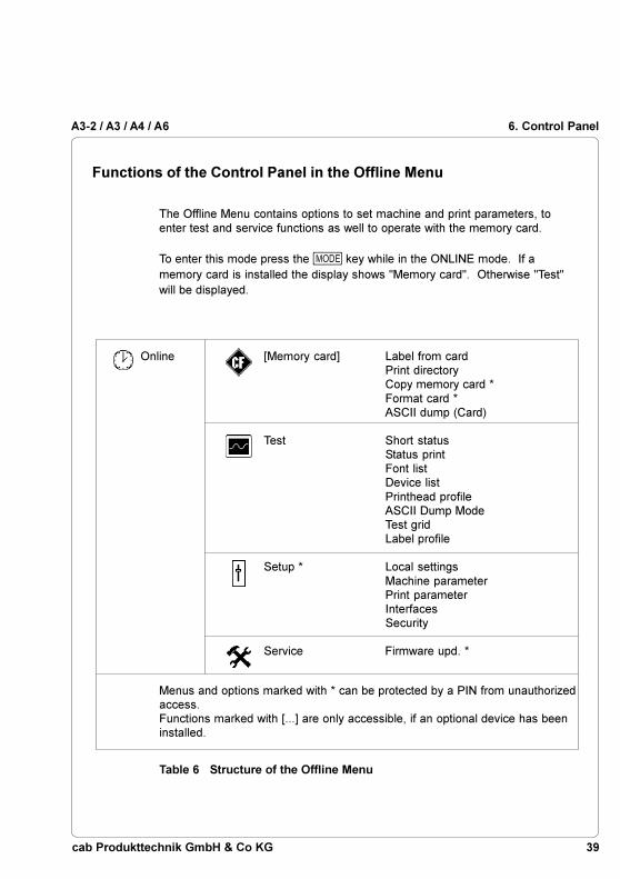
Functions of the Control Panel in the Offline Menu
The Offline Menu contains options to set machine and print parameters, toenter test and service functions as well to operate with the memory card.
To enter this mode press the key while in the ONLINE mode. If amemory card is installed the display shows "Memory card". Otherwise "Test"will be displayed.
Table 6 Structure of the Offline Menu
Online [Memory card] Label from cardPrint directoryCopy memory card *Format card *ASCII dump (Card)
Test Short statusStatus printFont listDevice listPrinthead profileASCII Dump ModeTest gridLabel profile
Setup * Local settingsMachine parameterPrint parameterInterfacesSecurity
Service Firmware upd. *
Menus and options marked with * can be protected by a PIN from unauthorizedaccess.Functions marked with [...] are only accessible, if an optional device has beeninstalled.
6. Control Panel

40 cab Produkttechnik GmbH & Co KG
A3-2 / A3 / A4 / A66. Control Panel
Fig. 6c Navigator Pad in the Offline Menu
After switching from the "Online" mode into the Offline Menu the function of thekeys are changed. Now the keys of the Navigator Pad have the function ofcursor keys.
Key Function
- Move up in the menu- Increase numeric values
- Move down in the menu- Decrease numeric values
- Switch to a secondary menu- Move the cursor to the right during numeric settings- Finish a setting with confirmation of the selected settings- Start of a selected test or service function
- Return from a secondary menu- Move the cursor to the left during numeric settings- Finish a setting with rejecting the selected settings- At the start of the menu, return to the system mode
"Online"

41cab Produkttechnik GmbH & Co KG
A3-2 / A3 / A4 / A6 6. Control Panel
Fig. 6d Display during selection of a function
During selection of the test and service functions the display shows theselected menu. A graphic symbol accompanies the text.
In the "Setup" menu, the display shows the selected parameter and the currentsetting of the parameter.
If the symbol appears in the upper line, the symbol indicates that it is
possible to switch between several parameters by pressing the key and the key.
Fig. 6e Display during selection of a parameter
Fig. 6f Display during change of a parameter
To change the current setting press the key. Then the symbol is shown in
the bottom line of the display indicating that it is possible to change the settingof the parameter by pressing the key and the key.

42 cab Produkttechnik GmbH & Co KG
A3-2 / A3 / A4 / A6
1 2
7. Media Loading
General Information
1. Pay attention to the specifications of the material indicated in chapter 1 .
2. When using the printer for the first time or using label media with a differentwidth, make sure to adjust the printhead support as well as the position ofthe label edge sensor.
3. There are warning labels on the media hub and on the ribbon supply hubwhich will be visible if the material is getting low. When these warninglabels are visible, prepare to replace the material soon.
1 - Warning label "End of Ribbon"2 - Warning label "End of Paper"
4. If you do not use the printer for an extended period of time, lift the printheadto avoid possible flattening of the print roller.
5. If you want to move or ship the printer to another location, remove themedia and the ribbon from the printer.
Fig. 7a Warning labels
7. Media Loading

43cab Produkttechnik GmbH & Co KG
A3-2 / A3 / A4 / A6
Preparation for Tear-Off Mode / Rewind Mode
The R-version printers are delivered with the rewind guide plate (1) mountedfor operation in rewind mode. With the optional tear-off plate the printer alsomay be operated in tear-off mode. For this purpose the rewind guide plate (1)must be replaced by the tear-off plate (3).
The P-version printers are prepared for the dispense mode. After mounting theoptional tear-off or rewind guide plate the printers also may be operated in tear-off or rewind mode.
7. Media Loading
Fig. 7b Exchange Rewind Guide Plate / Tear-Off Plate
The exchange of the different plates can be made in a similar way as theexchange rewind guide plate / tear-off plate :
1. Open the cover.
2. Loosen the two screws (2).
3. Slide the rewind guide plate (1) to the right as far as possible to remove theplate from the printer.
4. Place the slotted holes on the tear-off plate (3) over the screws (2) on thefront of the printer and slide the plate to the left until it stops.
5. Tighten the two screws (2).
2
2
3
1

44 cab Produkttechnik GmbH & Co KG
A3-2 / A3 / A4 / A6
1
2
3
48
9
10
11
12
7. Media Loading
Loading Labels
Fig. 7c Label Loading in Tear-off Mode
1. Open the cover (1).
2. Loosen the knurled screw (10), swing the media retainer (11) upwards andslide it out as far as possible.If you are using material with the same width as the previous material, justswing the media retainer (11) upwards.
3. Place the media roll (8) onto the media hub (9) and unwind a strip ofmedia (4) from the roll. When operating in the rewind or peel-off modemake sure that the strip is long enough to reach the internal rewinder byguiding the strip through the whole print mechanism and underneath of it.Make sure that the labels between the media hub and the printmechanism are facing up. Slide the roll onto the media hub (9) until itsstops.
Loading Labels from Roll
5 6 7

45cab Produkttechnik GmbH & Co KG
A3-2 / A3 / A4 / A6
13
Fig. 7d Feed path in Tear-off Mode
8. Slide the media guide ring (6) inward until it lightly touches the side of themedia strip.
7. Media Loading
4. Swing the media retainer (11) downwards until it touches the media hub(9). Push the media retainer against the supply role until it rests againstthe label media. Tighten the knurled screw (10).
5. Raise the printhead assembly (2) by rotating the lever (7) clockwise until itstops.
6. Slide the media guide ring (6) outward, allowing enough clearance for thelabel stock's width when loaded.
7. Slide the media strip underneath the swing (5 /A3-2 and A3: axle) andthrough the adjustable photocell assembly (3) until it comes out of thefront of the printer. If you are using labels that are wound-in, please makesure that you slide the media strip over the internal rewind hub (13).In figure 7d the feed path for labels wound-out is represented by a solidline, and the feed path for wound-in labels is represented by a broken line.

46 cab Produkttechnik GmbH & Co KG
A3-2 / A3 / A4 / A6
3
14
15
7
9. To accommodate a variety of print jobs, the position of the label edgesensor (3) can be adjusted until it is at the proper sensing position.It is important to ensure that the sensor (14) itself (the position of which isindicated by a notch in the sensor housing) is positioned so that the spacebetween the labels can be recognized by the photocell. In the case oflabels which have an unconventional shape (ie. not square or rectangular),the photo cell should be positioned at the leading edge of the label.Adjustment of the sensor is performed by sliding the handle (15) in andout.
10. Lower the printhead by rotating the lever (7) counter-clockwise until itlocks.
11. When the printer is operated in rewind mode continue with point 12.When the printer is operated in peel-off mode continue with point 13.
Fig. 7e Adjustment of the Label Edge Sensor
7. Media Loading

47cab Produkttechnik GmbH & Co KG
A3-2 / A3 / A4 / A6
16 4 17 13 18
Fig. 7f Loading Labels from Roll in Rewind Mode
7. Media Loading
12. In rewind mode, the rewind guide plate (16) must be mounted.Remove the labels from the first 4 in (100mm) of the label strip.Then, slide the media strip (4) around the rewind guide plate (16) to theinternal rewind hub (13) as shown in figure 7f. Slide the strip under theclamps (17) that are located on the internal rewind hub (13). Hold theinternal rewind hub (13) and rotate the nut (18) counter-clockwise until it istight. The media strip will now be fastened to the internal rewind hub (13).Rotate the internal rewind hub (13) counter-clockwise to tighten the mediastrip.

48 cab Produkttechnik GmbH & Co KG
A3-2 / A3 / A4 / A6
25 17 13 1822 23 24
21
20
19
Fig. 7g Loading Labels from Roll in Peel-off mode
13. For peel-off mode swing the locking system (21) away from the rewindassist roller (23).
14. Remove all labels from the media strip hangig out of the printer. Then,slide the strip (25) around the dispense plate (19) to the internal rewindhub (13) as shown in figure 7g. Slide the strip under the clamps (17) thatare located on the internal rewind hub (13). Hold the internal rewind hub(13) and rotate the nut (18) counter-clockwise until it is tight. The mediastrip will now be fastened to the internal rewind hub (13). Rotate theinternal rewind hub (13) counter-clockwise to tighten the media strip.
15. Loosen the screw (22) using the Allen key (24).Align the locking system (21) including the pinch roller (20) by sliding itsidewards. The alignment is correct if the pinch roller (20) is placed in themiddle of the label strip.
16. Swing the locking system (21) to the rewind assist roller (23) and tightenthe screw (22).
17. For further informationen about operating in the peel-off mode seeappendix A.
7. Media Loading

49cab Produkttechnik GmbH & Co KG
A3-2 / A3 / A4 / A6
1
2
3
4
5
When printing narrow label stock (width less than 60% of the maximum printwidth), it is possible that the printhead will come into direct contact with theprinting roller in the area where there is no media.
CAUTION !The printhead touching the printing roller could lead to premature failureon the printhead or the print roller!
This can also cause the printhead to be at a slight angle to the media, leadingto a variation in the darkness of the print across the label.This fault can be corrected by adjusting the printhead support :
Adjustment of the Printhead Support
7. Media Loading
1. The current position of the printhead support (2) is shown by the positionof the screw (3) in the elongated hole (4).
2. For wide media the screw position shown in figure 7h is recommended. Inthis position the printhead support (2) is not used.
3. For narrow media, it is necessary to adjust the printhead support. In thiscase insert a second strip of a label at the outer side of the print roller andclose the printhead. Loosen the screw (3) using the Allen key (5) and slideit slowly in the arrow direction until the printhead support (2) touches theprinthead mounting (1).
4. Tighten the screw (3).5. Remove the second label strip.
NOTICE !Incorrect adjustments of the printhead support may cause wrinkles in thetransfer ribbon.
Fig. 7h Adjustment of the Printhead Support

50 cab Produkttechnik GmbH & Co KG
A3-2 / A3 / A4 / A6
1
2
3
7
6
5
4
Loading Fanfold Labels
1. Open the cover.
2. Loosen the knurled screw (7) and slide the media guide (6) to itsoutermost position. Rotate the media guide (6) downwards past the mediaretainer (5).
3. Place the stack of media (4) behind the printer. Make sure the labels onthe media strip are facing up.
4. To raise the printhead assembly (2), rotate the lever (1) clockwise until itstops.
5. Slide the media guide ring (3) outward, allowing enough clearance for themedia's width when loaded.
6. Slide the media strip through the printer as shown in figure 7i.
7. Adjust the label edge sensor so, that the sensor can recognize the spacebetween the labels respectively the reflective or the perforation mark.
8. Slide the media guide (6) inward until it lightly touches the side of themedia strip. Rotate the media guide (6) upwards against the mediaretainer (5) and tighten the knurled screw (7).
Fig. 7i Loading Fanfold Labels
7. Media Loading

51cab Produkttechnik GmbH & Co KG
A3-2 / A3 / A4 / A6 7. Media Loading
9. Slide the media guide ring (3) inward until it lightly touches the side of themedia strip.
10. Lower the printhead by rotating the lever (1) counter-clockwise until itstops.
NOTICE !When printing narrow label stock please activate the printhead support asdescribed in the previous chapter !

52 cab Produkttechnik GmbH & Co KG
A3-2 / A3 / A4 / A6
3
4
5
6
1
2
7
7. Media Loading
NOTICE !For direct thermal printing no transfer ribbon is needed !
1. Rotate the printhead lever (7) clockwise until it stops to raise theprinthead.
2. Slide the roll of transfer ribbon (4) as far as possible onto the ribbonsupply hub (5).
NOTICE !Note which side of the transfer ribbon is coated with ink! The inked sideis generally the dull side of the transfer ribbon. When the ribbon isinserted, the inked side must not be placed in contact with the printhead!In figure 7l the solid line represents ribbon with ink on the inner side, andthe broken line represents ribbon with ink on the outer side.
3. Rotate the knurled knob (6) counter-clockwise to clamp the roll of transferribbon (4) onto the ribbon supply hub (5).
Loading Transfer Ribbon
Fig. 7k Loading Transfer Ribbon

53cab Produkttechnik GmbH & Co KG
A3-2 / A3 / A4 / A6
1 27
4. Slide a cardboard core (1) onto the ribbon take up hub (2). Clamp thecore by rotating the knurled knob (3) counter-clockwise.
5. Feed the transfer ribbon along the path as shown in figure 7l and attach itto the cardboard core (1) using a piece of tape or a label.
6. Turn the ribbon take up hub (2) counter-clockwise until the ribbon is tautand without any wrinkles.
7. Rotate the printhead lever (7) counter-clockwise until it stops, therebylocking the printhead into position.
Fig. 7l Path of Transfer Ribbon
7. Media Loading

54 cab Produkttechnik GmbH & Co KG
A3-2 / A3 / A4 / A6
1
24
3
5
Fig. 7m Adjustment of the Transfer Ribbon
In the event that wrinkles appear in the transfer ribbon (1), which cause aninconsistent print image, the transfer ribbon shield (2) can be adjusted toremove the wrinkles. The adjustment should be done during the printingprocess.
1. The current position is visible on the scale (3).
2. To change the position, rotate the screw (4) using the Allen key (5).Rotating it in the direction of "+" will tighten the transfer ribbon the inneredge of the transfer ribbon. Rotating it in the direction of "-" will tighten theouter edge of the tranfer ribbon.
To eliminate the wrinkles, tighten the side where the wrinkles areoriginating.
Adjustment of the Transfer Ribbon
7. Media Loading

55cab Produkttechnik GmbH & Co KG
A3-2 / A3 / A4 / A6
This page is intentionally left blank
7. Media Loading

56 cab Produkttechnik GmbH & Co KG
A3-2 / A3 / A4 / A68. Printer Configuration
8. Printer Configuration
Overview
There are a variety of parameters that can be set to configure the printer tospecific requirements in the "Setup" menu of the Offline Menu.The setup should be performed when operating the printer for the first time andalso when basic changes need to be carried out. In most cases however,simple changes such as heat setting adjustments, using different media will bemade with software settings.The "Setup" menu can be protected from unauthorized access by using a codenumber (PIN).
1. Switch to the Offline Menu by pressing the key.
2. Continue to press the key or the key until you reach the "Setup"menu. Press the key.
3. If the "Setup" menu is protected by a PIN the display will show "PIN: 0000".You will need to enter the correct PIN before you can continue. Thenumbers of the PIN can be changed by using the key and the key.The position to be changed will be flashing on the display. Press the keyto move to the next number. If the correct number is entered, the "Setup"menu is displayed.
4. The parameters are arranged in a tree like structure. Pressing the keyas well as the key will scroll between the secondary menus. By pressingthe key, the selected secondary menu will be chosen.
5. If a parameter is selected, the display shows the actual value underneaththe parameter. On the top line the symbol is shown. This symbolindicates that it is possible to switch between the parameter choices bypressing the key and the key.
6. To change the current setting press the key.Then the symbol is shown in the lower line of the display and it indicatesthat it is possible to change the setting of the parameter by pressing the key and the key.
7. Press the key to confirm the change. To cancel the change press the
key. In both cases the symbol appears on the top line again.

57cab Produkttechnik GmbH & Co KG
A3-2 / A3 / A4 / A6
Online
[Memory card]
Test
Setup Local settings CountryTimezoneDaylight savingSet dateSet time
Machine param. Printhead pos. XPrinthead pos. YTear-off pos.[Demand sensor][Cutter][Applicator]Brightness LCDContrast LCDTime PowersaveDebug mode
Print parameters Heat levelPrint speedTransfer printWarn level ribbonLabel sensorTear-off modeBackfeedPause-ReprintError-ReprintBarcode errorWidth ASCII dump
Interfaces Character setIEEE 1284RS-232[RS-422/485][Ethernet][Keyboard]
Security PIN
Service
The "Setup" menu can be protected from unauthorized access by using a PIN.[...] The parameters in the brackets are only accessible after installing an
optional device
8. Printer Configuration
8. Press the key several times if necessary to return to the "Setup"menu or to "Online" mode.
Table 8a Structure of the "Setup" Menu under the Offline-Menu

58 cab Produkttechnik GmbH & Co KG
A3-2 / A3 / A4 / A6
Parameter Meaning
Country Set the display language and thedate and time format for thecountryDefault Setting: USA
Time zone Set the Time zone using UTC(Universal Time Coordinated)Default : UTC +1
Daylight saving Select the method of daylightsavings adjustmentDefault : USA
Set date Set the printer's dateDefault : current
Set time Set the printer's timeDefault : current
Setup
Local settings
Selection
Belgie, België,Byjc`oh~,Ceska republika,Danmark,Deutschland, Ελλας,Espana, Farsi,France, Italia,Lietuva,L`iedmlh®`,Magyarország,Nederlands, Norge,Polska, Portugal,Pmpph~, Schweiz,South Africa,Suisse, Suomi,Sverige, Türkiye,United Kingdom,USA
UTC +12...UTC -10
EUUSAOff
31.12.2069...01.01.1970
23:59:59...00:00:00
8. Printer Configuration
Local Settings1. Switch from the "Online" mode to the offline-menu by pressing the
key.2. Select the "Setup" menu.3. Select the "Local settings" menu.
Table 8b Overview of the "Local settings" Menu

59cab Produkttechnik GmbH & Co KG
A3-2 / A3 / A4 / A6 8. Printer Configuration
Country
The "Country" parameter allows the setting of the LCD display language, whichalso defines the date and time format used for the printer display as well as forprinting. The formats for time and date can be configured with software, butwill not be saved permanently.
Time zone
UTC (Universal Time Coordinated) describes the international time base usedon the web. To adjust the printer to the local time, set the parameter time zonein relation to the UTC. The selection contains all valid time zones of the world.Information regarding the correct time zone for UTC can be obtained from theweb.
Daylight saving
Using this parameter you can select the valid daylight savings regulation.The time will automatically change on the correct days to adjust for daylightsavings.
Set date
Using this parameter you can change the date in the printer's internal clock.The order of data to be changed (day, month, year) is independent from theformat of the date. The field to be changed will be flashing on the display.When printed, the current date is given in the format selected based on the"Country" parameter. It is possible to change the date with software, but thechange will not be saved permanently.
Set time
Using this parameter you can set the correct time in the internal clockmanually.The order of data to be changed is hour, minute, second. The field to bechanged will be flashing on the display. If the optional ethernet-interface isinstalled, it is possible to synchronize the time with the web automatically.When printed, the current time is given in the format selected based on the"Country" parameter. It is possible to change the time with software, but thechange will not be saved permanently.

60 cab Produkttechnik GmbH & Co KG
A3-2 / A3 / A4 / A6
Parameter Meaning
Printhead pos. Shift the print image on the labelX left to right.
Default : 0.0 mm
Printhead pos. Shift the print image on the labelY top to bottom.
Default : 0.0 mm
Tear-off pos. Shift the tear-off positionDefault : 0.0 mm
Demand sensor (only displayed when the optionalPresent Sensor or Peel-Off Adapter is installed)
Peel position Shift the position of the dispensedlabel relative to the dispense plateDefault : 0.0 mm
Backfeed Delay time between removing thedelay label from the peel position and the
backfeed of the labelDefault : 250 ms
Limit peel-off Limitation of the print speed in thespd. peel-off mode to 100 mm/s
Default : A3 - OnA3-2/A4/A6 - Off
Table 8c Overview of the "Machine parameters" Menu
Setup
Machine parameters
Selection
9,9...0,0
+9,9...-9,9
+9,9...-9,9
+9,9...-9,9
500 ms...0 msin 50 msincrements
OnOff
Machine Parameters
1. Switch from "Online" mode to the Offline Menu by pressing the key.2. Select the "Setup" menu.3. Select the "Machine parameters" menu.
8. Printer Configuration

61cab Produkttechnik GmbH & Co KG
A3-2 / A3 / A4 / A6 8. Printer Configuration
Parameter Meaning
Cutter(Only displayed if the cutter is attached)
Applicator(Only displayed if the optional Tamp Applicatoris attached)
Brightness LCD Sets the brightness of the displayDefault : 8
Contrast LCD Sets the contrast of the displayDefault : 8
Time Powersave Amount of time before switching topowersave modeDefault : 10 min
Debug mode Activates the debug modeDefault : Off
Selection
1..12
6..11
60 min...0 min
OnOff
Table 8c Overview of the "Machine parameters" Menu (continuation)
Printhead position X
Using this setting will shift the entire print image to the left on the label. Thisparameter should only be altered if you are printing the same format on severalprinters, and the printed image is not consistent on each printer.
NOTICE !The value of Printhead position X cannot be greater than the difference ofthe printhead width and the defined label width in software. A valuegreater than the difference will be ignored and the actual difference willbe used in place. For example, if the printhead width is 104mm and thelabel width defined in software is 100mm, the printer will only accept avalue of 4mm or less for printhead position X. If Printhead position X isset for 6mm, the printer will only shift the label 4mm.
The Printhead position X value to be changed will be flashing on the display.
It is possible to adjust the value for individual jobs using software. The frontpanel values and software command values will be totaled together for printing.

62 cab Produkttechnik GmbH & Co KG
A3-2 / A3 / A4 / A6
Printhead position Y
Using this setting will shift the entire print image up or down the label. Thisparameter should only be altered if you are printing the same format on severalprinters, and the printed image is not consistent on each printer.
NOTICE !Changing the Printhead position value Y also effects the peel positionand cut position as well. It will be necessary to readjust the values for thepeel and cut positions using the previous value +/- the printhead positionvalue.
The Printhead position Y value to be changed will be flashing on the display.It is possible to adjust the value for individual jobs using software. The frontpanel values and software command values will be totaled together for printing.
Tear-off position
When the "Tear-off mode" (see chapter "Print parameters") is active, anadditional feed forward will take place after completion of the print job. Thisadditional feed makes it possible to tear off the last label at the tear-off plate.Using the setting "Tear-off position" the length of the additional feed can beadjusted.
Demand sensor - Peel position
This parameter allows for adjustment of the presentation position of theprinted label on the dispense plate.Peel position with the initial offset value of �0� causes the printed label to bepeeled off from the liner leaving approximately a .1� (2mm) wide strip of thelabel still adhering to the liner. The amount of label left adhering to the linercan be altered with this parameter, using an offset in the range from -9.9mm to+9.9mm. Positive offset values cause more of the label surface to protrudepast the dispense plate.The Peel position value to be changed will be flashing on the display.The offset values from �Peel position� and from software are added together forexecution. The software value does not replace the �Peel position� value, buttemporarily adjusts it for the current job.
Demand sensor - Backfeed delay
The "Backfeed delay" adjustment allows you to input an amount of time inmilliseconds between when the label is removed from the peel edge and whenthe backfeed is executed. Using "Backfeed delay" should prevent labels frombecoming jammed between the printhead and print roller when the liner is fedback too quickly.
8. Printer Configuration

63cab Produkttechnik GmbH & Co KG
A3-2 / A3 / A4 / A6
Demand sensor - Limit peel-off spd.
This parameter allows to limit the print speed in peel-off mode to 4 ips(100mm/s). For A3-2, A4 and A6 such a limitation is not necessary. So thesetting "Off" should be chosen.When an A3 printer is delivered, the maximum print speed in peel-off mode islimited to 4 ips (100mm/s). Even if the print speed for the peel-off mode is sethigher in the software, the print job will be carried out with a speed of 4 ips(100mm/s). This limitation guarantees correct operation of the A3 in peel-offmode when using maximum supply rolls (diameter 8 in (203mm), width 4.7 in(120mm)).When using smaller supply rolls it is possible to operate with higher speed. Forthat purpose the speed limitation must be switched off. Then the print speedcan be set on all speeds up to 8 ips (200mm/s) for A3/200P or 6 ips (150mm/s)for A3/300P.
CAUTION !When operating the A3 in peel-off mode with higher speed it is stronglyrecommended to carry out some tests beforehand by using appropriaterolls with maximum diameter !
The speed limitation in the peel-off mode does not affect any other operationmodes like tear-off mode, cut mode or external rewinding.
Cutter
When the optional cutter is attached, the "Cutter" menu appears in the"Machine parameters" menu.The menu contains all of the parameters for the cut function.Detailed information is available in the cutter documentation.
Applicator
When the optional applicator is attached, the "Applicator" menu appears in the"Machine parameters" menu.The menu contains all of the parameters for the applicator function.Detailed information is available in the applicator documentation.
Brightness LCD
This parameter adjusts the level of brightness for the background on thedisplay.
Contrast LCD
This parameter adjusts the level of contrast to improve readability on thedisplay.
8. Printer Configuration

64 cab Produkttechnik GmbH & Co KG
A3-2 / A3 / A4 / A6
Print Parameters
1. Switch from "Online" mode to the Offline Menu by pressing the key.2. Select the "Setup" menu.3. Select the "Print parameters" menu.
Time Powersave
If the printer does not receive a print job or the front panel has not beenaccessed for a period of time, the printer will switch into a powersave mode.During powersave mode, certain functions such as the background lighting ofthe display are powered off until the next operation is carried out.This parameter defines the amount of time the printer will wait before enteringpowersave mode after the last operation.
Debug mode
The "Debug mode" is a tool for the firmware programmer.It will assist in recognizing faults and their possible sources beyond standarderror messages.
Table 8d Overview of the "Print parameters" Menu
8. Printer Configuration
Parameter Meaning
Heat level Basic adjustment of the heatintensityDefault : 0
Print speed Basic adjustment of the printspeedDefault : 100 mm/s
Transfer print Basic selection of thermaltransfer mode / direct thermalmodeDefault : On
Setup
Print Parameters
Selection
-20 ... +10
A3-2/200 : 50-200 mm/sA3-2/300 : 50-150 mm/sA3/200 : 50-200 mm/sA3/300 : 50-150 mm/sA4/300 : 50-250 mm/sA4/600 : 50-100 mm/sA6/300 : 50-200 mm/ssteps of 25mm/s
OnOff

65cab Produkttechnik GmbH & Co KG
A3-2 / A3 / A4 / A6
Parameter Meaning
Warn level Setting the threshold diameter for theribbon warning message "ribbon end"
Default : Off
Label sensor Method of label sensingDefault : Gap sensor
Tear-off mode Activating a small feed to the tearplate at the end of a print jobDefault : Off
Backfeed Method of backfeed when using peel-off mode or the cut modeDefault : smart
Pause reprint Allows you to print additional labelsafter finishing a print job by pressingthe keyDefault : On
Error - Reprint Selection of automatically reprinting alabel after a correctable error hasbeen fixed.Default : On
Barcode error Selection, if the printer should handleinvalid barcode data as errorsDefault : On
Width Setting the print width for ASCII dumpASCII dump mode
Default : Automatic
Table 8d Overview of the "Print parameters" Menu (continuation)
Selection
Off32 ... 74 mm
Gap sensorBottom reflectEndless media
OnOff
smartalways
OnOff
OnOff
OnOff
Automatic,50mm to max.print widthin steps of 5mm
Heat level
The "Heat level" parameter enables the printer to adapt to possible differencesin the thermal properties of the thermal printheads.An adjustment has already been made in the factory. If the printhead must bereplaced, it is very likely the "Heat level" parameter will have to be adjusted.To adjust the print for different print jobs, it is recommended that you make theheat level adjustment with software. (e.g. for different materials and speed)The heat level can be set using the software commands. The front panel valueand software command value will be totaled together when printing.The setting of the "Heat level" parameter also affects the printer test prints (seeTest functions section).
8. Printer Configuration

66 cab Produkttechnik GmbH & Co KG
A3-2 / A3 / A4 / A6
Print speed
This parameter allows the adjustment of the print speed. This adjustment alsoaffects the printer test prints (see Test functions section).The print speed can be set for each print job separately with software.Changing the print speed with software does not change the basic adjustment.
Transfer print
This parameter is used to set the printer's method of printing to thermal transferprinting or direct thermal printing. The setting affects two factors directlyrelated to thermal transfer mode. First, for thermal transfer mode, theprinthead requires a lower temperature than when in direct thermal printingmode. Second, the ribbon sensor is active. The setting for transfer print for asingle print job can be overwritten with software.
Warn level ribbon
That parameter allows to define a threshold diameter of the ribbon supply roll.As soon as the diameter of the roll falls below this threshold a SNMP or E-mailwarning message is sent via Ethernet interface.So the operator is already asked to prepare a new ribbon roll when the printeris still running.If your printer has no Ethernet interface, the diameter of the ribbon supply rollcan be asked by the q r command (see Programming Manual) using the serialinterface. This method is also available if the parameter "Warn level ribbon" isset to "Off".
Label sensor
The printer offers two methods for recognizing the start of label. In mostcases, the label edge sensor photocell can be used in the "shine-through"mode ("Gap sensor" mode), where the differing opacities between the labelarea and spaces between labels is distinguished. In certain special cases, (ie.pre-printed endless material), recognition of the start of the label can be madevia reflective markings on the bottom side of the label material.This parameter can also be changed using software. For different print jobs itis recommended that you make the change in the software.The setting "Endless media" is especially intended to synchronize the feed ofcontinuous material in cut mode after switching on the printer.You can find detailed information in the cutter documentation.
Tear-off mode
When the "Tear-off mode" is active, an additional feed forward will take placeafter completion of the print job. This additional feed makes it possible to cut
8. Printer Configuration

67cab Produkttechnik GmbH & Co KG
A3-2 / A3 / A4 / A6 8. Printer Configuration
or tear off the last label at the tear-off plate. When a new print job is started,the label material will be fed back until the front edge of the first label isrepositioned under the printhead.If the parameter is OFF, the label feed forward stops immediately after the lastlabel has completely passed the printhead.
Backfeed
In cut and peel-off mode, the material will be stopped in a position where theleading edge of the following label has already been forwarded beyond theprinthead. The printer will then backfeed the label material from its cut/dispense position to the printhead. Therefore, the next label can be printedcompletely.A backfeed will always be performed if the parameter is set to "always". If thesetting is set to "smart", the backfeed will only be performed if the front label isin its cut/dispense position and the printer has not yet received all of the datafor printing the following label. Otherwise, the print of the second label will bestarted, but only completed once the first label has been removed.
Pause reprint
When this option is enabled (On), it is possible to print additional labels by
pressing the key after the print job has completed, as long as the
internal memory of the printer has not been cleared by pressing the key.
Error-Reprint
When a recoverable error occurs while printing, this option will determine howthe last label will be handled. If this option is enabled (On), the last label will bereprinted once the error has been cleared. If this option is disabled (Off), theprint job will continue with the next label.
Barcode error
When this option is enabled (On), after the recognition of invalid bar codecontents or invalid bar code sizes the print job will be stopped.If this option is disabled (Off), the printer tries to replace invalid data by validcharacters (e.g. "0"). If the bar code size is invalid, instead of the bar code agrey box will be printed.
Width ASCII dump
The ASCII Dump mode (see chapter 9) provides a method to print the controlsequences sent to the interface. In this mode the data received will be printedin text format depending on the selected character set.

68 cab Produkttechnik GmbH & Co KG
A3-2 / A3 / A4 / A6
Parameter Meaning
Character set Select the character set tableDefault : Windows 1252
IEEE1284 Bidirectional parallel InterfaceDefault : On
RS-232 1. Set the baud rateDefault : 57.600
2. Set the protocolDefault : RTS/CTS
Table 8e Overview of the "Interfaces" Menu
Setup
Interfaces
Selection
Windows 1250,1251, 1252, 1253,1254, 1255, 1256,1257,DOS 437, 737, 775,850, 852, 857, 862,864, 866, 869,EBCDIC 500,ISO 8859-1 up to -10,ISO 8859-13 up to -16,Macintosh Roman,DEC MCS, KOI8-R,Win OEM720, UTF-8
OnOff
1.200 ... 230.400
RTS/CTS---XON/XOFF
RS-422/485 Menu to configure the optional RS-422/RS-485-interface(Menu is only displayed when the PCB is installed.)
Ethernet Menu to configure the optional ethernet-interface(Menu is only displayed when the PCB is installed.)
Keyboard (Menu is only displayed when anexternal keyboard is installed.)
1. LayoutDefault : Automatic = currentsetting "Country"
2. NumLockDefault: On
Automatic andall country settingslisted in "Localsettings, Country"
OnOff
8. Printer Configuration
Interfaces1. Switch from "Online" mode to the Offline Menu by pressing the key.2. Select the "Setup" menu.3. Select the "Interfaces" menu.

69cab Produkttechnik GmbH & Co KG
A3-2 / A3 / A4 / A6 8. Printer Configuration
Character set
The parameter defines how different characters (symbols, letters, specialcharacters) will be translated to the interface.Before operating the printer, the "Character set" of the printer should beadapted to match the character set of the computer.Adjustment is not possible with software. However, it is possible to use theUnicode character table for characters which are not included in the selectedfont.
IEEE1284
The parallel interface basically works in the bidirectional mode.If the bidirectional mode is switched off, the interface works as a standardCentronics interface.
RS-232
The baud rate and protocol of the interface RS-232 can be set with thisparameter.NOTICE !If you have the RS-422/RS-485-interface-PCB installed in your printer, thebaud rate for the RS-232-interface affects the baud rate of the RS-422-interface and the RS-485-interface.For the RS-232-interface to operate correctly, it is absolutely necessary to havethe computer and printer parameters set the same.
RS-422/485
Once the optional RS-422/RS-485-interface-PCB has been installed, the RS-422/485 menu appears in the interface menu. The RS-422/485 menu containsthe parameters necessary to configure the interface. Detailed informationabout the interface settings can be located in the documentation of the PCB.
Ethernet
Once the optional ethernet-interface-PCB has been installed, the ethernetmenu appears in the interface menu. The ethernet menu contains theparameters necessary to configure the interface. Detailed information aboutthe interface settings can be located in the documentation of the PCB.
Keyboard - Layout
If the parameter is set to "Automatic" the printer uses the key assignment ofthe country that is chosen in the parameter "Local settings / Country".With the parameter "Keyboard" a key assignment can be chosen that differsfrom the setting "Country".
Keyboard - NumLock
Turns the Keyboard NumLock option on and off.

70 cab Produkttechnik GmbH & Co KG
A3-2 / A3 / A4 / A6
Parameter Meaning
PIN Set, erase, change a PIN number toprotect certain functionsDefault : Off
Security
Table 8f Overview of the "Security" Menu
Setup
Security
Selection
OffOnChange
1. Switch from "Online" mode to the Offline Menu by pressing the key.2. Select the "Setup" menu.3. Select the "Security" menu.
PIN
With this menu it is possible to set, erase or change a four-digit code number(PIN). If the PIN is activated, access to the "Setup" menu, certain functions ofthe memory card and upgrading of the firmware is only possible after the PINnumber is entered. This allows protection against unauthorized access tocertain settings and functions.Menu's that are protected will display the symbol .To set a code number for the first time, choose the "On" option. The first line ofthe display appears "New PIN" and the second line displays "0000" to enter thenew pin. With the key and the key the numbers of the PIN can bechanged. The field to be changed will be flashing on the display. Press the key to switch to the next number.To change the PIN, select "Change". The directions to change a PIN are thesame as entering a new PIN number.To disable the PIN, select "Off". The previous PIN will be erased permanently.
8. Printer Configuration

71cab Produkttechnik GmbH & Co KG
A3-2 / A3 / A4 / A6
This page is intentionally left blank
8. Printer Configuration

72 cab Produkttechnik GmbH & Co KG
A3-2 / A3 / A4 / A6
9. Test Options
Overview
The printer is equipped with several test options. These options make itpossible for the user to understand something about :
- important configuration parameters- the fonts available in the printer- important hardware components of the printer and connected peripheral
devices- the quality of the print image and the condition of the printhead- the recognition of the front edge of the label in relation to the optical
characteristics of the media- label data sent from a computer or loaded from the memory card.
The test options are summarized in the "Test" menu of the offline menu.
1. Switch from the "Online" mode to the Offline Menu by pressing the
key.
2. Press the key or the key until the "Test" menu is displayed.Press the key to confirm the selection.
3. Select the required test function by pressing the key or the key and
confirm the selection by pressing the key.
4. For more details on each test option, see the appropriate section.
9. Test Options

73cab Produkttechnik GmbH & Co KG
A3-2 / A3 / A4 / A6
Online [Memory Card]
Test Short status
Status print*
Font list*
Device list*
Printhead profile**
ASCII Dump Mode
Test grid
Label profile*
Setup
Service
* not available for A3-2** only available for A3
Table 9a Structure of the "Test" Menu in the Offline Menu
9. Test Options

74 cab Produkttechnik GmbH & Co KG
A3-2 / A3 / A4 / A6
Short Status
The "Short status" option offers a convenient method for retrieving and viewinginformation about the printer configuration on the display.These values give the user detailed information about the printer and installedoptions.
1. Switch from "Online" mode to the Offline Menu by pressing the key.
2. Press the key or the key until the "Test" menu is displayed.Press the key to confirm the selection.
3. Select the "Short status" option by pressing the key or the key andconfirm the selection by pressing the key.
4. There are ten pieces of information available using the "Short status" option.Each piece of information is viewed seperately. Use the key or the key to move between different pieces of information.
9. Test Options
A4/300
Fig. 9a Short status 1
The type of printer is displayed on the first line.
Firmware V2.94
Fig. 9b Short status 2
The second line will display the version of firmware.
(Aug 30 2004)
Fig. 9c Short status 3
The third line displays the date of the firmware.
PCB: Rev. 9
Fig. 9d Short status 4
The fourth line displays the revision number of the CPU.

75cab Produkttechnik GmbH & Co KG
A3-2 / A3 / A4 / A6
5. To leave the "Short status" display and return to the "Test" menu, press the key.
9. Test Options
FPGA: Rev.10
Fig. 9e Short status 5
The fifth line displays the revision number of the FPGA.
TPH: 300 dpi
Fig. 9f Short status 6
The resolution of the installed printhead is displayed on the sixth line.
TT: 64.44m
Fig. 9g Short status 7
The seventh line displays the length of material printed in thermal transfermode in realtime.
TH: 44.65m
Fig. 9h Short status 8
The eighth line displays the length of material printed in direct thermal modein realtime.
Slot: -
Fig. 9i Short status 9
If the printer is equipped with the optional interface (RS-422/485, ethernet,USB), it is displayed on the ninth line.
Card: 8 MByte
Fig. 9k Short status 10
If you are using a memory card, the capacity of the memory card isdisplayed on the tenth line.

76 cab Produkttechnik GmbH & Co KG
A3-2 / A3 / A4 / A69. Test Options
Status Print
When selecting the "Status print" option, an internal test sample will be printedwhich contains a variety of information about the configuration of the printer aswell as status of the printer.To prepare for a status print, load media (labels, continuous paper) and atransfer ribbon (if applicable), which extends over the entire print width of theprinter.
NOTICE !With "Status print", the printer will not sense any label gaps, and will printnon-stop, producing output with an approximate length of 10.3" (260mm). Continuous paper works best for the prints, otherwise, a regularsheet of paper cut to a width of 4.7 in (120 mm) for A3/A4 or 7.1 in(180mm) for A6 can be used in thermal transfer mode.
1. Switch from "Online" mode to the Offline Menu by pressing the key.
2. Press the key or the key until the "Test" menu is displayed.
Press the key to confirm the selection.
3. Select the "Status print" option by pressing the key or the key and
confirm the selection by pressing the key.
4. Start the printout by pressing the key.
5. The "Status print" will be printed with the heat level and the print speed setin the "Setup" menu.
6. To cancel the "Status print", press the key.
7. Once the printout has completed, the printer returns to the selection list ofthe "Test" menu.
The status print contains :
A) the type of printer as well as the version and date of the printer's firmware.
B) the values of selected configuration parameters.
C) cumulative operating time of the printer, amount of printed labels as well ascumulative length of printed material in direct thermal and thermal transfermode.
D) the current values of printhead temperature and heat voltage
E) details about the operation of the sensor used for recognizing the mediafront edge
F) a test pattern to display the quality of the print image.
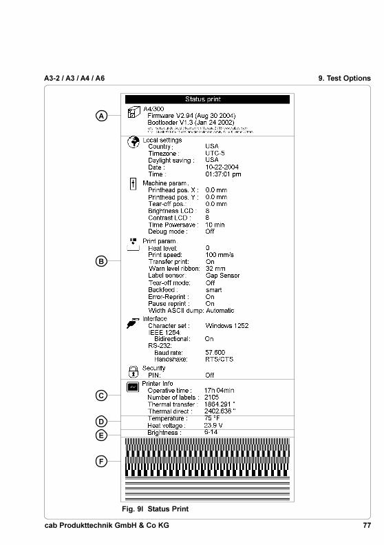
77cab Produkttechnik GmbH & Co KG
A3-2 / A3 / A4 / A6
A
B
D
C
E
F
9. Test Options
Fig. 9l Status Print

78 cab Produkttechnik GmbH & Co KG
A3-2 / A3 / A4 / A69. Test Options
Font List
The important parameters of the fonts available in the printer are printed as atable. The table contains both the fonts saved in the printer internal memoryand the fonts loaded into the printer externally from the memory card.To prepare for a font list, load media (labels, continuous paper) and a transferribbon (if applicable), which extends over the entire print width of the printer.The font list will print continuously without sensing the label gap.
1. Switch from "Online" mode to the Offline Menu by pressing the key.
2. Press the key or the key until the "Test" menu is displayed. Press
the key to confirm the selection.
3. Select the "Font list" option by pressing the key or the key and
confirm the selection by pressing the key.
4. Start the printout by pressing the key.
5. The "Font list" will be printed with the heat level and the print speed set inthe "Setup" menu.
6. To cancel the "Font list" print, press the key.
7. After completing the printout, the printer returns to the selection list of the"Test" menu.
Fig. 9m Font List
79cab Produkttechnik GmbH & Co KG
A3-2 / A3 / A4 / A6 9. Test Options
The definition of the parameters printed on the font list are as follows:
No. : Font number for the font used in programming(T command)
Name : Name of the font as it is saved internally
Type : Type of the font. Determines how the font is sized andwhat options are available when programming. (see the Tcommand in the programming guide)
Description : A detailed description of the font's name, size, etc.

80 cab Produkttechnik GmbH & Co KG
A3-2 / A3 / A4 / A69. Test Options
Device List
The hardware components installed in the printer and the optional devicesconnected to the printer are displayed in this list.To print the device list, load media (labels, continuous paper) and a transferribbon, which extends over the entire print width of the printer.The device list will print continuously without sensing the label gap.
1. Switch from "Online" mode to the Offline Menu by pressing the key.
2. Press the key or the key until the "Test" menu is displayed.
Press the key to confirm the selection.
3. Select the "Device list" option by pressing the key or the key and
confirm the selection by pressing the key.
4. Start the printout by pressing the key.
5. The "Device list" is printed using the heat level and print speed set in the"Setup" menu.
6. To cancel the "Device list" printing, press the key.
7. After completing the printout, the printer will return to the selection list onthe "Test" menu.
Fig. 9n Device List

81cab Produkttechnik GmbH & Co KG
A3-2 / A3 / A4 / A6 9. Test Options
The meaning of the details printed on the device list are as follows:
CPU : Type and serial number of the CPURevision number of the CPU and FPGA
TPH : Resolution and number of dotsof the printhead installed
CARD* : Capacity, manufacturer, serial number andversion number of the FlashCard installed
SLOT* : Type, serial number and revision number of theinterface expansion card installed.
USB [a]* : Type and revision number of the USB devices installed [b/c]Speed a : identifying number of the USB device
b : identifying number of the USB device, which isconnected to device a
c : identifying number of the device b port, which isconnected to device a
Speed : Low- or High-Speed-USB-device
* Will only be printed if the respective devices are installed.

82 cab Produkttechnik GmbH & Co KG
A3-2 / A3 / A4 / A6
Printhead Profile
NOTICE !The test option "Printhead profile" is available for A3 only !
When selecting the option "Printhead profile", a diagram will be printed whichshows the resistance values for the single printhead dots. This printout makesit possible to see the status of the printhead.When a dot is damaged or defective its resistance value increases. When thiserror occurs, it causes white lines in the print image from top to bottom. Insome cases, the white line could cause an invalid scan of certain barcodes.
To print the printhead profile, load media (labels, continuous paper) and atransfer ribbon (if applicable), which extends over the entire print width of theprinter.
NOTICE !With "Printhead profile", the printer will not sense any label gaps, and willprint non-stop, producing output with an approximate length of 9" (230mm) for a 203dpi printhead and 13" (340 mm) for a 300dpi printhead.Continuous paper works best for the prints, otherwise, a regular sheet ofpaper cut to a width of 4.7" (120 mm) can be used in thermal transfermode.
1. Switch from "Online" mode to the Offline Menu by pressing the key.
2. Press the key or the key until the "Test" menu is displayed. Press the key to confirm the selection.
3. Select the option "Printhead profile" by pressing the key or the keyand confirm the selection by pressing the key.
4. Start the printout by pressing the key.
5. The "Printhead profile" will be printed with the heat level and print speed setin the "Setup" menu.
6. To cancel the print, press the key.
7. After completing the printout the printer returns to the selection list of the"Test" menu.
The printout has a scale which marks the actual geometric position of the dots.The scale will be printed underneath the black bar with the text "Printheadprofile". It is possible to compare a single dot to the scale as demonstrated inthe following diagram.Figure 9o indicates a print image failure around 22.5 mm in the black bar.In the scale section of the diagram, a dot with an increased resistance valueappears around 22.5 mm. Using this comparison makes it clear that the imagefault on the top line is caused by a defective printhead and not a case of a dirtyprinthead surface.
9. Test Options
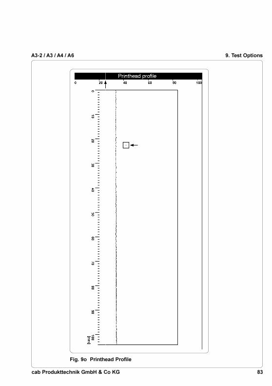
83cab Produkttechnik GmbH & Co KG
A3-2 / A3 / A4 / A6 9. Test Options
Fig. 9o Printhead Profile

84 cab Produkttechnik GmbH & Co KG
A3-2 / A3 / A4 / A69. Test Options
ASCII Dump (Monitor) Mode
The ASCII Dump mode provides a method to print the control sequences sentto the interface. In this mode the data received will be printed in text formatdepending on the selected character set. Error messages will be printeddirectly behind the fault, e.g. for unknown commands.In this mode, the printer will not sense gaps between labels.
NOTICE !The font used for the printout in this mode is large enough to be clearlyreadable after facsimile transmission. For questions or future reference,using this mode, you may print and retain a copy of the label data for eachlabel you print.
To get a printout in monitor mode, load media (labels, continuous paper) and atransfer ribbon (if applicable), which extends over the entire print width of theprinter.
NOTICE !If only small materials available then it is possible to cut the width of theprintout to at least 2 in (50mm). The value can be set using the parameter''Width ASCII dump'' (see chapter Setup / Print Parameters).
1. Switch from "Online" mode to the Offline Menu by pressing the key.
2. Press the key or the key until the "Test" menu is displayed.
Press the key to confirm the selection.
3. Select the option "ASCII Dump Mode" by pressing the key or the key
and confirm the selection by pressing the key.
4. Start the ASCII Dump mode by pressing the key.
5. Send a print job to the printer.
6. The ASCII Dump mode printout will be printed with the heat level and printspeed set in the "Setup" menu.
7. In ASCII Dump mode, the printing of data will occur after four lines of datahas been received. In some cases, the last few lines of text have to be
printed by pressing the key.
8. To cancel the ASCII Dump mode printout, press the key.
9. Press the key to return to "Online" mode.

85cab Produkttechnik GmbH & Co KG
A3-2 / A3 / A4 / A6 9. Test Options
Code Printout Code Printout Code Printout Code PrintoutDEC HEX DEC HEX DEC HEX DEC HEX
00 00 08 08 16 10 24 18
01 01 09 09 17 11 25 19
02 02 10 0A 18 12 26 1A
03 03 11 0B 19 13 27 1B
04 04 12 0C 20 14 28 1C
05 05 13 0D 21 15 29 1D
06 06 14 0E 22 16 30 1E
07 07 15 0F 23 17 31 1F
Example of ASCII Dump Mode
The following shows the "normal" appearance of a printed label, followed by theappearance of the same label when its commands are printed in ASCII Dumpmode.
The control characters (ASCII Code 00 ... 31) as printed on ASCII Dump modeprintouts are as follows:
Fig. 9p Representation of the Control Characters in ASCII Dump Mode
Fig. 9q Output Label
Fig. 9r Label commands printed in ASCII Dump mode

86 cab Produkttechnik GmbH & Co KG
A3-2 / A3 / A4 / A69. Test Options
Test Grid
The "Test grid" option generates a printout that prints a test grid that allows theoperator or service technician to evaluate and check the quality of the printedimage.
To get a printout of the test grid, load media (labels, continuous paper) and atransfer ribbon (if applicable), which extends over the entire print width of theprinter.
1. Switch from "Online" mode to the Offline Menu by pressing the key.
2. Press the key or the key until the "Test" menu is displayed.
Press the key to confirm the selection.
3. Select the option "Test grid" by pressing the key or the key and
confirm the selection by pressing the key.
4. Start the printout by pressing the key.
5. The pattern shown in figure 9s will be printed. The printout will repeat aboutevery 5 seconds making it possible to make adjustments on the printerbetween the individual printouts.
6. The "Test grid" printout will be printed with the heat level and print speed setin the "Setup" menu.
7. The "Test grid" printout can be canceled by pressing the key. Oncethe printout has been canceled, the printer returns to the selection list of the"Test" menu.

87cab Produkttechnik GmbH & Co KG
A3-2 / A3 / A4 / A6 9. Test Options
Fig. 9s Test Grid

88 cab Produkttechnik GmbH & Co KG
A3-2 / A3 / A4 / A69. Test Options
Label Profile
The "Label profile" option checks the recognition of the media edge in relationto the optical characteristics of the media and liner.Values measured by the media edge sensor during the media feed are savedand printed in the "Label profile" printout.
To print the "Label profile" printout, you will need to load media (labels,continuous paper) and a transfer ribbon (if applicable), which extends over theentire print width of the printer. The media the profile will be printed on, isindependent of the media to be tested.
1. Select the type of sensor (gap sensor or bottom-reflective sensor) to betested in the "Setup" menu.
2. Load the media to be tested in the printer.
3. Switch from "Online" mode to the Offline Menu by pressing the key.
4. Press the key or the key until the "Test" menu is displayed.
Press the key to confirm the selection.
5. Select the "Label profile" option by pressing the key or the key and
confirm the selection by pressing the key.
6. The printer will carry out a media feed. The sensor will measure the opticalproperties of the media.
7. After completing the media feed, "Test print OK " will appear on thedisplay.
8. Load media (labels, continuous paper) and a transfer ribbon (if applicable),which extends over the entire print width of the printer.
9. Press key to start printing the "Label profile" printout.
10. The "Label profile" printout is printed with the heat level and print speedset in the "Setup" menu.
11. After completing the printout, the printer will return to the selection list ofthe "Test" menu.

89cab Produkttechnik GmbH & Co KG
A3-2 / A3 / A4 / A6 9. Test Options
Fig. 9t Label Profile
The meaning of the details shown in the label profile are as follows:
A) Profile of the values measured at the sensor. These values are terms for thedifference in opacity between the media and gap or in the case of thebottom reflective sensor, the reflectivity between the media and the printedmark.
B) Coordinates in paper feed direction where media front edges were detected.
C) The method of media recognition (gap sensor or bottom-reflective sensor).
D) The type of peripheral device connected.
E) Settings for use by Maintenance technicians. A more detailed explanationcan be found in the Service Manual.
F) Settings for use by Maintenance technicians. A more detailed explanationcan be found in the Service Manual.
G) Settings for use by Maintenance technicians. A more detailed explanationcan be found in the Service Manual.
B
A
E
C
F GD

90 cab Produkttechnik GmbH & Co KG
A3-2 / A3 / A4 / A6
10. Memory Cards
The A-series printers offer the ability to use memory cards to permanentlysave formats, graphics, fonts and database information on the memory card.Data is sent to the memory card using the printer's interface and stored on thememory card.
Although memory cards have non-volatile memory, it is recommended that youmake backup copies in case the original card malfunctions or is lost.
Type 1 CompactFlash cards with a maximum capacity of 512 MegaByte can beused.
Fig. 10a CompactFlash Memory Card
10. Memory Cards

91cab Produkttechnik GmbH & Co KG
A3-2 / A3 / A4 / A6
1
2
3
4
Installation and Removing the Memory Card
Installation of the Memory Card
With the CompactFlash card contacts facing the slot (2), insert the card (4) intothe slot (2) until the eject button (3) pops out of the cover on the front panel.
NOTICE !There are guides on the sides of the memory card which make itimpossible to insert the card incorrectly.
Removing the Memory Card
Press the eject button (3) and remove the card from the slot (2) by hand.
CAUTION !To avoid loss of data on the memory card, do not eject the memory card ifthe LED (1) next to the slot (2) is illuminated.
Fig. 10b Installation of the Memory Card
10. Memory Cards

92 cab Produkttechnik GmbH & Co KG
A3-2 / A3 / A4 / A610. Memory Cards
Preparing the Memory Card
In order to use the memory card the first time, the card must be formatted forthe printer to read and write data. Often the cards are preformatted for usewith the printer.If the card you are using is not formatted, the printer will display either"Unknown card" or "Structural err" on the front display. If the message isdisplayed, you must format the card using one of the following methods:
1. Format the card using the printer's "Format card" option in the Offlinemenu (see "Memory card options in the Offline Menu" section).
2. Format the card sending the software command "Mf;name CR" (see theProgramming Manual for more information) through the connectedinterface.
3. Format the card using a FlashCard drive on a PC.
Writing to the Memory Card
There are different methods to write formats to a memory card.
The most secure and practical method to write to the memory card is theprinter's interface.
For saving a label to the memory card using direct programming, place the"Ms" command at the beginning and end of your format:
Ms LBL;ABC Command to save a file called ABC"J |H 100,0,T |S l1;0,0,68,71,104 | Contents of the file "ABC"T 10,10,0,3,pt15;Memory card |A 1[NOPRINT] |Ms LBL End of Save File command
After processing the commands, the format "ABC" is stored on the memorycardThe [NOPRINT] parameter after the A command suppresses the printing of alabel while saving the file to the memory card. Whenever the file "ABC" isaccessed from the memory card, one label will be printed. If you want theoperator to specify an amount of labels to be printed, move the A commandstatement after the second "Ms" command in the example above.
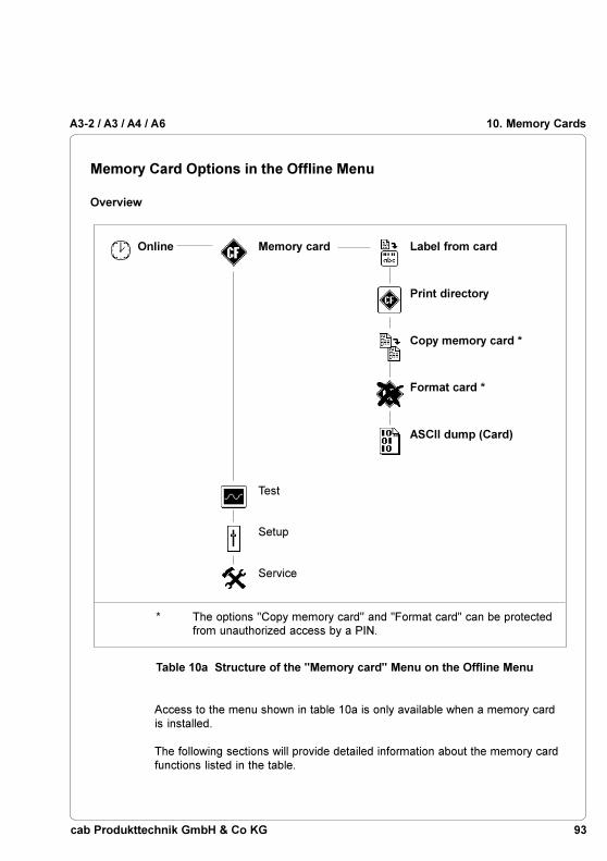
93cab Produkttechnik GmbH & Co KG
A3-2 / A3 / A4 / A6
Online Memory card Label from card
Print directory
Copy memory card *
Format card *
ASCII dump (Card)
Test
Setup
Service
10. Memory Cards
Table 10a Structure of the "Memory card" Menu on the Offline Menu
* The options ''Copy memory card'' and "Format card" can be protectedfrom unauthorized access by a PIN.
Access to the menu shown in table 10a is only available when a memory cardis installed.
The following sections will provide detailed information about the memory cardfunctions listed in the table.
Memory Card Options in the Offline Menu
Overview

94 cab Produkttechnik GmbH & Co KG
A3-2 / A3 / A4 / A610. Memory Cards
Label from Card
The "Label from card" option prints labels which are stored on a memory card.
1. Switch from "Online" mode to the Offline Menu by pressing the key.The "Memory card" selection will be displayed on the LCD.
2. Press the key. The "Label from card" selection is displayed on the LCD.
3. Press the key again. The name of the first label stored on the memorycard is displayed on the LCD.
4. Scroll up and down the directory of the card using the key or the key.
Press the key to confirm the selection of the label to be printed.
5. If you select a label which was saved with a defined number of labels toprint, the printout starts at once.
6. If you select a label with a variable number of labels to print, "Number oflabels" appears on the first line of the LCD. On the second line "00001"appears with the first number flashing (cursor).
7. With the key or the key, the number at the cursor position may bechanged. The cursor can be moved one number to the right by using the
key. After confirming the last number the printout will start.
8. If the label was designed with operator prompted fields, the symbol is
shown on the display. Using a keyboard, an externel device or the keyson the front panel, enter the data on the requested line. The method ofentering operator prompted data is similar to the method of entering thenumber of labels. Letters and numbers can also be entered with the frontpanel keys if necessary.
9. Label selection or the number of labels selected, can be canceled by
pressing the key.
Access to the stored data on the memory card is also possible using theconnected interface and computer.

95cab Produkttechnik GmbH & Co KG
A3-2 / A3 / A4 / A6 10. Memory Cards
Print Directory
When using the "Print directory" option, the directory of the installed memorycard is printed.To print the directory, load media (labels, continuous paper) and a transferribbon (if applicable), which extends over the entire print width of the printer.
1. Switch from "Online" mode to the Offline Menu by pressing the key.
The "Memory card" menu is displayed on the LCD. Press the key.
2. Select the "Print directory" option using the key or the key.
3. Press the key. The directory of the card is printed.
4. In the printout you can find :- the name of the memory card- information about the data saved on the memory card- the amount of space remaining on the memory card
5. After completing the printout, the "Memory card" selection is displayed onthe LCD.
Fig. 10c Printout of the Directory of a Memory Card

96 cab Produkttechnik GmbH & Co KG
A3-2 / A3 / A4 / A610. Memory Cards
Copy Memory Card
This option may be used to copy all of the files from one memory card ontoanother one.The duplication is carried out file by file. This allows the usage of memorycards with different capacities.It is also possible to copy files to a previously used card.
CAUTION !If there are files on both source and destination cards with identicalnames, the files on the destination card will be overwritten withoutwarning!
To protect the card from unauthorized copying, a code number (PIN) can be set(see the "Printer Configuration - Security" section).
CAUTION !While copying, DO NOT remove the source or destination card unless youare prompted to do so by the LCD !
1. Install the source card.
2. Switch from "Online" mode to the Offline Menu by pressing the key.
The "Memory card" menu is displayed on the LCD. Press the key.
3. Select the "Copy memory card" option using the key or the key.
Press the key.
4. The "Copy memory card" option is displayed on the LCD with a defaultselection of "No". Change the selection to "Yes" using the key or the
key. Press the key.
5. If the "Copy memory card" option is protected by a PIN, the printer willprompt for the PIN by displaying "PIN: 0000" on the LCD. The numbersof the PIN may be changed using the key and the key. The positionof the number to be changed will be flashing. You can switch to the next
number by pressing the key. If the all of the numbers are enteredcorrectly, the "Copy memory card" process will begin.
6. The printers LCD will indicate the progress with a progress bar. Oncearound 2 MByte is read from the source card the "Insert dest." requestappears on the LCD.
7. Remove the source card and insert the destination card.

97cab Produkttechnik GmbH & Co KG
A3-2 / A3 / A4 / A6 10. Memory Cards
8. The data that was read from the source card will now be transferred ontothe destination card. As this is happening the progress bar on the LCDwill be emptied.If not all files were read from the source card yet; the request "Insertsource" will appear on the LCD.
9. Remove the destination card and insert the source card again. The nextcycle of copying will start.
10. Repeat steps 6 to 9 until all the files are copied. When the printer finishes
copying the files the LCD will display "OK ".
11. Press the key to return to the "Memory card" menu selection list.
When the destination card cannot store any more information the LCD willdisplay "Card full".

98 cab Produkttechnik GmbH & Co KG
A3-2 / A3 / A4 / A610. Memory Cards
Format Card
This option will format and delete all data from a memory card. This optionmust be used if the message "Unknown card" or "Structural err." is displayedon the LCD. To protect the card from unauthorized formatting, a code number(PIN) can be set (see the "Printer Configuration - Security" section).
1. Switch from "Online" mode to the Offline Menu by pressing the key.
The "Memory card" menu is displayed on the LCD. Press the key.
2. Select the "Format card" option using the key or the key. Press the
key.
3. The "Format card" option is displayed on the LCD with a default selectionof "No".
4. Change the selection to "Yes" using the key or the key. Press the
key. If the "Format card" option is not protected by a PIN, theformatting will begin immediately.
5. If the "Format card" option is protected by a PIN, "PIN: 0000" appears onthe display requesting input. The numbers of the PIN may be changedusing the key and the key. The number to be changed will beflashing on the display. You can switch to the next number by pressing the
key. If the input of all numbers is correct, the formatting will begin.
CAUTION !During formatting, DO NOT remove the memory card from the printer!
6. After completing the memory card formatting, the memory card capacity isdisplayed on the bottom line of the LCD.
7. Press any key to return to the "Memory card" menu selection list.

99cab Produkttechnik GmbH & Co KG
A3-2 / A3 / A4 / A6 10. Memory Cards
ASCII Dump (Card)
The label formats stored on a memory card are files that contain printercommands. The "ASCII dump (Card)" option offers the ability to print thesecommand sequences as text.The "ASCII dump (card)" option works the same as the standard ASCII dumpmode explained in the "Test Options" section.
To print the "ASCII dump (Card)", load media (labels, continuous paper) and atransfer ribbon (if applicable), which extends over the entire print width of theprinter.
1. Switch from "Online" mode to the Offline Menu by pressing the key.
The "Memory card" menu will be displayed on the LCD. Press the key.
2. Select the "ASCII dump (Card)" option using the key or the key.
3. After pressing the key, the name of the first label format saved on thememory card is displayed on the LCD.
4. Select the desired label format using the key or the key.
5. Start the printout by pressing the key.
6. In "ASCII dump (card)" mode, the printout starts after four lines of data
has been received. It is often necessary to press the key to print theremaining lines.
7. The printout may be canceled by pressing the key.
8. Press the key to return to "Online" mode.

100 cab Produkttechnik GmbH & Co KG
A3-2 / A3 / A4 / A6
1 2 3
11. External Keyboard
The printer offers the ability to connect an external keyboard or any othercompatible input device, such as a barcode scanner, directly to the printer.Using an external keyboard, the input of variable data when using a memorycard is easier.Data that is typed on the keyboard will be displayed on the printer's LCD.
All USB keyboards with a Type A USB connector are compatible.
Connecting the External Keyboard
Fig. 11a Connecting the External Keyboard
Plug the cable (2) of the keyboard (1) into the keyboard interface connector (3)located on the rear of the printer.
11. External Keyboard

101cab Produkttechnik GmbH & Co KG
A3-2 / A3 / A4 / A6
Key Assignment
The printer can be configured to the keyboards configuration for the particularcountry by setting the "Country" parameter. For each "Country" setting, theprinter has a different key assignment table, which is normally the same as theMS DOS keyboard tables.
The [ALTGR] key has no function. Therefore all signs which are located on theright hand side of the key opposite of the normal characters (e.g. { } [ ] \ ) canbe generated by pressing the [ALT] key. A few other signs (e.g. ¨ × ÷ ) may alsobe generated the same way (see table 11a).
Other special characters (e.g. ñ ç �) can be created by typing two charactersone after the other, where the second input is a combination with the [ALT] key(see table 11b).
Some of the special characters cannot be displayed on the printer LCD. In thatcase, the printer will use a character which looks similar to the requiredcharacter.
NOTICE !When using a scanner, the character set of the scanner has to be thesame as used by the printer.
Special Key Functions
[F1] Enter the memory card directory to see labels stored on the memory card.
[F2] Repeat the print of the last label.
[F3] Repeat the print of the last label and prompt for variable data.
[F8] Formfeed on the printer
[ENTER] Without a print job present, switch between ONLINE and OFFLINE mode;When processing a print job, confirms the inputed data on variable datafields and prompts.
[ESC] To cancel the data input .(Has the same effect as CANCEL when printing).
[SPACE] Will PAUSE the printer if labels are currently printing.
[Shift]-[Del] Delete the inputed data on variable fields and prompts.
[á],[â] Scroll up and down the directory of the memory card.
11. External Keyboard

102 cab Produkttechnik GmbH & Co KG
A3-2 / A3 / A4 / A6
Special Characters Available with an External Keyboard
Table 11a Special characters with reference to different countrysettings, which are available with the [ALT] key on theexternal keyboard
| / |,| * | ... Keys of the numeric keyboard
GR : Deutschland SU : SuomiFR : France IT : ItaliaUK : United Kingdom SP : EspañaUS : USA DK : DanmarkSG : Schweiz CZ : Ceska republikaSF : SuisseBE : Belgie
[ALT] + key ...Character Character [ALT] + key
11. External Keyboard

103cab Produkttechnik GmbH & Co KG
A3-2 / A3 / A4 / A6
ZZ Z1 Z2 ZZ Z1 Z2 ZZ Z1 Z2 ZZ Z1 Z2
To create the character ZZ: Type the first character [Z1], then type the secondcharacter [ALT-Z2]
For example : For the letter "ñ", type the first character [~], then type thesecond character [ALT-n]
NOTICE !Use the data in table 11a to enter the Z1 character if it is not available onyour keyboard.
Table 11b Special characters available by entering twocharacters one after another using the externalkeyboard.
11. External Keyboard

104 cab Produkttechnik GmbH & Co KG
A3-2 / A3 / A4 / A6
This page is intentionally left blank
11. External Keyboard

A-1cab Produkttechnik GmbH & Co KG
A3-2 / A3 / A4 / A6
Appendix A - Operation in Peel-off Mode
Components for the Peel-off Mode
The P-version printer types are specificly developed for operation in the peel-off mode and they are equipped with dispense plate (8) as standard.Additionally an optional present sensor (3), peel-off adapter or applicator isneeded.
In the peel-off mode the labels are removed from the silicon liner immediatelyafter printing, and then available in a dispense position (4) ready for furtherprocessing. For example the see-through present sensor consisting oftransmitter (1) and receiver (2) indicates the presence of a label, and pausesthe printing process until the label is removed. After taking the label from thedispense position the next label will be printed.
To guarantee a maximum of reliability in the peel-off mode the printer isadditionally equipped with a pair of rollers (5,6) to cause the dispense tension.
Appendix A - Operation in Peel-off Mode
Fig. A-1 Components for Peel-off Mode
1
2
3
4 5 6 7

A-2 cab Produkttechnik GmbH & Co KG
A3-2 / A3 / A4 / A6
Prelimininary Tests
The media width and height given in the Technical Specifications are suggestedvalues for media when using the present sensor :
Label Width : A3-2: 1 to 2.3 in (25-60 mm)A3, A4: 1 to 4.6 in (25-116 mm)A6: 2 to 6.9 in (50-176 mm)
Label Height : A3-2, A3, A4: .5 to 7.9 in (12-200 mm)A6: 1 to 7.9 in (25-200 mm)
CAUTION !When using different media from the specifications, for example
- media which is smaller than the specifications above,- very thin media,- very thick silicon liner,- media with aggressive adhesive,- transparent media
it is recommended to test the media before !
For A3 the print speed in the peel-off mode is limited to maximum 4 ips(100mm/s). This limitation guarantees a correct operation in the dispensemode when using maximum supply rolls (diameter 8 in (203mm), width 4.7 in(120mm)) also with A3. When using supply rolls with a small outside diameter itis possible to increase the print speed during on-demand labelling. For thatpurpose the speed limitation has to switch off. Then the print speed can be seton all possibilities until 8 ips (200mm/s) for A3/200P or until 6 ips (150mm/s) forA3/300P.
CAUTION !When operating the A3 with higher speed it is strongly recommended tocarry out preliminary tests using the appropriate maximum rolls !
For A3-2, A4 and A6 there is no limitation of the print speed in peel-off mode.
Present Sensor, Peel-off Adapter, Tamp Applicator
Detailed information about the different peel-off modules can be found in theconcerning Operator's Manuals.
Appendix A - Operation in Peel-off Mode

B-1cab Produkttechnik GmbH & Co KG
A3-2 / A3 / A4 / A6
Appendix B - Pin Assignment of the Interface Connectors
Pin Assignment of the RS-232 Interface
The printer is equipped with a 9 pin SUB-D connector for the serialRS-232 interface.
Fig. B-1 RS-232 Interface Connector (rear of the printer)
Table B-1 Pin Assignments of the RS-232 Interface Connector
Pin Signal Function
1 CD Carrier Detect
2 TxD Transmit Data
3 RxD Receive Data
4 DTR Data Terminal Ready (not used)
5 GND Ground
6 DSR Data set ready (not used)
7 RTS Request to send
8 CTS Clear to send
9 RI Ring Indication (not used)
Pin 5
Pin 1 Pin 6
Pin 9
Appendix B - Pin Assignment of the Interface Connectors

B-2 cab Produkttechnik GmbH & Co KG
A3-2 / A3 / A4 / A6
Interface Cable for RS-232
To communicate with the printer, a standard RS-232 interface cable is used.
If you have any problems interfacing with the printer, contact the manufacturerof your computer on the pin assignments of the interface. Use the pinassignment of the printer as shown in Table B-1 to obtain a compatible cable.
9 pin connector 9 pin plug
Fig. B-2 Interface Cable with 9 pin Connector
1 12 23 34 45 56 67 78 89 9
PC Printer
Appendix B - Pin Assignment of the Interface Connectors

B-3cab Produkttechnik GmbH & Co KG
A3-2 / A3 / A4 / A6
Pin Assignment of the Parallel Interface Connector
The printer provides a 36 pin connector for the parallel interface.
Table B-2 Signals of the Parallel Interface
Fig. B-3 Parallel Interface Connector (rear of the printer)
Parallel Interface Cable
The cables for parallel interface connections are standard parallel cables.
If problems occur, please contact the manufacturer of your computer on the pinassignment of the computer's parallel interface. Use the pin assignment of theprinter as shown in Table B-2 to obtain a compatible cable.
Pin Signal Pin Signal Pin Signal Pin Signal
1 /STROBE 10 /ACKNLG 19 GND 28 GND2 DATA 0 11 BUSY 20 GND 29 GND3 DATA 1 12 PE 21 GND 30 GND4 DATA 2 13 SLCT 22 GND 31 /INIT5 DATA 3 14 /AUTOFD 23 GND 32 /FAULT6 DATA 4 15 nc 24 GND 33 nc7 DATA 5 16 GND 25 GND 34 nc8 DATA 6 17 Chassis 26 GND 35 nc9 DATA 7 18 +5V 27 GND 36 /SLCTIN
Pin 19
Pin 36Pin 18
Pin 1
Appendix B - Pin Assignment of the Interface Connectors

B-4 cab Produkttechnik GmbH & Co KG
A3-2 / A3 / A4 / A6
This page is intentionally left blank
Appendix B - Pin Assignment of the Interface Connectors

C-1cab Produkttechnik GmbH & Co KG
A3-2 / A3 / A4 / A6
Appendix C - Error Messages / Problem Solution
Error Messages
The printer is equipped with a self diagnostic system that will indicate errors onthe printer's LCD. The operator will be informed by the printer LEDs whetherthere are recoverable errors allowing continuation of the print job (ie. "Out ofpaper"), or an error which requires discontinuation of the print job.
Recoverable Errors
While processing a print job, errors can occur that can be 'recovered' by theoperator, allowing the print job to continue from the point at which it wasstopped.
Display
The symbol appears in the display.
The display shows the type of error and the total amount of labels remaining forthe current print job.
Function Keys
Key Description Function
flashing Continues the current print job after the error hasbeen corrected.
on Short press - Cancels the current print jobLong press - Cancels the current print job
and deletes all jobs from theinternal memory
Table C-1 Function of Keys in the Recoverable Error Mode
Appendix C - Error Messages / Problem Solution

C-2 cab Produkttechnik GmbH & Co KG
A3-2 / A3 / A4 / A6
Non-Recoverable Errors
During printing, an error has occured which cannot be cleared withoutcanceling the print job (e.g. hardware error).
Display
If a non-recoverable error occurs the symbol appears in the display and
the type of error is displayed.
Function Keys
Key Description Function
flashing Short press - Cancels the current print jobLong press - Cancels the current print job
and deletes all jobs in theinternal memory
Table C-2 Function of Keys in Non-Recoverable Error Mode
Errors during System Test
When powered on, the printer automatically performs an internal self test.If the test is completed succesfully, the printer proceeds to ONLINE mode.
If a hardware-error occurs, the symbol appears on the LCD and the type of
error is displayed. If this happens, power the printer off, then on again.If the error is still present, call for Service.
Appendix C - Error Messages / Problem Solution

C-3cab Produkttechnik GmbH & Co KG
A3-2 / A3 / A4 / A6
Possible Cause
Hardware error
The data receive buffer is full but thecomputer is still sending data.
Refers to the optional memory card;No more data can be stored on thecard.
Optional "Cutter" error.The cutter is unable to cut the mediadue to the thickness;The Cutter blades cannot return to thehome position and stay in anundefined position.
Optional "Cutter" error.The cutter is unable to cut the mediadue to the thickness, but the Cutterblades are able to return to the homeposition.
Hardware error on the optional"Cutter".
Hardware error
Error
ADC malfunction
Buffer overflow
Card full
Cutter blocked
Cutter jammed
Cutter stuck
dRAMmalfunction
Table C-3 Error Messages
Solution
Switch printer off, then on again.If error reoccurs, contact Service.
Make sure you are using the RTS/CTS protocol to send data.
Replace the card.
Switch printer off, remove mediafrom the cutter and turn the printeron. If the error message continues,contact Service. Otherwise, checkthe thickness of the media andreplace if necessary.
Switch printer off and check themedia in the cutter area forpossible double layering or folding.Start a test cut by pressing the
key. If the error reoccurs,replace the media.
Switch printer off, then on again.If error reoccurs, contact Service.
Switch printer off, then on again.If error reoccurs, contact Service.
List of Error Messages
The following table contains an overview of possible error messages, possiblecauses and solutions. Errors that can be recovered are marked with " * ".If the solution does not solve the problem, call for Service.
Appendix C - Error Messages / Problem Solution

C-4 cab Produkttechnik GmbH & Co KG
A3-2 / A3 / A4 / A6
Error message
File not found
FPGAmalfunction
Headmalfunction
Head open *
Head too hot *
Invalid data
Invalid outline
Invalid setup
LCD malfunction
Memory overflow
Solution
Check the contents of the card.
Switch printer off, then on again.If error reoccurs, contact Service.
Switch printer off, then on again.If error reoccurs, contact Service.
Lock the printhead.
After allowing the printhead to cooldown, the print job will continueautomatically.If the fault occurs repeatedly reducethe heat level or the print speedsetting in the software.
Cancel the current print job.Re-check the data being sent.
Cancel the current print job.Change to another font.
Reconfigure the printer's setup(see chapter 8).If error reoccurs, contact Service.
Switch printer off, then on again.If error reoccurs, contact Service.
Cancel the current print job.Reduce the amount of information onthe label format.
Possible cause
Requested file is not on the card.
Hardware error
Hardware error
Printhead is not locked.
Printhead has overheated due tolabels containing a lot of graphics,text, bar codes, etc.
Error while downloading graphicdata.
Error with the selected font beingdownloaded.
Setup is invalid.
Hardware error
Current print job contains too muchinformation (selected fonts, largegraphics)
Table C-3 Error Messages (continued)
Appendix C - Error Messages / Problem Solution

C-5cab Produkttechnik GmbH & Co KG
A3-2 / A3 / A4 / A6
Possible cause
There are labels missing on themedia.
The label size defined in the formatsent to the printer does not match theactual media size.
Printer is loaded with continuousmedia, the software is configured fordie-cut media.
The label size is missing in the labelformat
No database record has been foundwhen using optional memory card.
Out of media
Media has not been properly loadedunder the label sensor.
Out of transfer ribbon.
Ribbon melted during printing.
Printer is loaded with thermal labelsfor direct thermal mode, and noribbon is loaded, but the software isconfigured for transfer printing.
The supply roll of transfer ribbon isnot secured to the ribbon supply hub.
Solution
Press the key repeatedly untilprinter recognizes the next label onthe media.
Cancel the current print job .Change the label size to the correctvalue. Restart the print job.
Cancel the current print job.Change either the software settingor the media; Restart the print job.
Check programmimg for theS command.
Check programming and/ordatabase for record in question.
Insert new media.
Check the media feed path.
Load new supply roll of transferribbon.
Cancel the current print job.Change the heat level in thesoftware, clean the printhead,reload the transfer ribbon andrestart the print job.
Cancel the current print job.Set the software to direct thermalmode. Restart the print job.
Tighten the roll of transfer ribbon byturning the knurled knob on theribbon supply hub.
Table C-3 Error messages (continued)
Error message
No label found *
No label size
No record found
Out of paper *
Out of ribbon *
Appendix C - Error Messages / Problem Solution

C-6 cab Produkttechnik GmbH & Co KG
A3-2 / A3 / A4 / A6
Error message
Protocol error (*)
Read error
ROM malfunction
Structural error
Unknown card
Voltage error
Write error
Wrong revision
Solution
Depending on the type of error, thecommand can be skipped bypressing the key or the printjob must be canceled by pressingthe key.
Switch the printer off.Correct the interface settings inprinter setup (see chapter 8).
Check the data on the memory card.Save the data to another card andreformat the original card.
Switch printer off, then on again.If error reoccurs, contact Service.
Format the memory card.
Format the memory card. Use thecorrect type of card as specified inthe Memory Card section.
Switch printer off, then on again.If error reoccurs, contact Service.Please note the voltage errordisplayed to Service personnel!
Repeat the write process or reformatthe memory card.
Load a valid firmware version.
Possible cause
Printer has received an unknown orinvalid command (display showscommand abbreviated).
The interface of the computer andprinter are set differently.
Error when reading from theoptional memory card.
Hardware error
The optional memory card filestructure is not compatible.
The optional memory card is notformatted, or is not the typesupported by printer.
Hardware error
The optional memory card hasencountered a hardware error.
Error during a firmware update.Firmware version is not valid for thepresent hardware version.
Table C-3 Error Messages (continued)
Appendix C - Error Messages / Problem Solution

C-7cab Produkttechnik GmbH & Co KG
A3-2 / A3 / A4 / A6
Cause and Solution
Shield for the transfer ribbon is not correctly adjusted.Make the adjustment according to chapter 7.
Printhead support is not correctly adjusted.Make the adjustment according to chapter 7.
Transfer ribbon is too wide. Use transfer ribbon which isslightly wider than the media.
Printhead is dirty, clean the printhead (appendix D).
Temperature is set too high, decrease heat level in software.
Incompatible combination of ribbon and media. Choose aribbon compatible to the media.
Direct thermal printing is selected in the software. Changethe setting to thermal transfer printing.
Media is not feed through the media edge sensor. Correct thepath of the media (chapter 7).
Media edge sensor is dirty. Clean the sensor.
Printer is in ASCII dump mode. Cancel this mode.
Transfer ribbon is installed incorrectly. Check to see if theinked side is facing the media (chapter 7).
The combination of ribbon and media is incompatible.Choose a ribbon that is compatible.
The label height in the software is set too large. Correct thesetting and print the format again.
Problem
Thermal transfer ribbonwrinkles
Print image has smears orvoids
Printer does not stop after thetransfer ribbon runs out
Printer does not display"Paper out" message.
Printer prints a sequence ofcharacters instead of theactual label format
Media is moving but the ribbonis not moving.
Printer is skipping every otherlabel when printing.
Problem Solution
Table C-4 Problems / Solutions
Appendix C - Error Messages / Problem Solution

C-8 cab Produkttechnik GmbH & Co KG
A3-2 / A3 / A4 / A6
Cause and Solution
Printhead is dirty, clean the printhead (appendix D).
Printhead is defective (failure of heating elements), replacethe printhead.
Printer is being used with backfeed set to "smart" in cut ordispense mode (see chapter 8). Set backfeed to "always" inthe Setup.
Printhead is dirty, clean the printhead (appendix D).
The printhead support is not adjusted for the width of themedia. Readjust the printhead support (see chapter 7).
Transfer ribbon is not secured to the ribbon supply hub.Tighten the knob on the ribbon supply hub (see chapter 7).
Problem
Vertical white lines in the printimage
Horizontal white lines in theprint image
Print image is irregular or oneside is lighter than the otherside.
"Ribbon out" message appearswhen ribbon is loaded
Table C-4 Problems / Solutions (continued)
Appendix C - Error Messages / Problem Solution

D-1cab Produkttechnik GmbH & Co KG
A3-2 / A3 / A4 / A6
Appendix D - Maintenance / Cleaning
The A series printers require very little maintenance.
Most important, clean the printhead on a regular basis. This will ensure a highquality printed image. It also reduces the amount of wear of the printhead.Aside from that, the only other servicing required is to clean the outside of theprinter occasionally.
WARNING !Before starting any maintenance, power OFF the printer and disconnectthe printer from the outlet!
General Cleaning
During the normal operation of the printer, particles of dust and paper canaccumulate inside the printer. Remove these particles with a soft brush or avacuum.
The cover of the printer can be cleaned with a standard cleanser.
CAUTION !Do not use abrasive cleaners or solvents !
Cleaning the Print Roller
Accumulations of dirt on the print roller can lead to impaired media transport.
Clean the roller as follows :
1. Open the printhead.
2. Remove the media from the printer.
3. Remove all deposits with a rubber cleaner or isopropyl alcohol and a softcloth.
Appendix D - Maintenance / Cleaning

D-2 cab Produkttechnik GmbH & Co KG
A3-2 / A3 / A4 / A6
Cleaning the Printhead
During printing, the thermal printhead will accumulate dirt such as paper dust orparticles of color from the ribbon. This accumulation can caused adeterioration of the print quality (contrast difference of the label, appearance ofclear vertical stripes). To correct or avoid these types of problems, theprinthead should be cleaned at regular intervals:
Direct Thermal Printing : every media roll change
Thermal Transfer Printing : each ribbon change
CAUTION !Do not use sharp objects for cleaning the printhead !Do not touch the protective layer of the printhead with your hands!
Clean the printhead as follows :
1. Open the printhead as far as possible.
2. Remove the media and ribbon from the printer.
3. Clean the surface of the printhead with a cleaning pen, or use a cotton swabdipped in isopropyl alcohol.
4. Let the printhead dry approximately 2 to 3 minutes before powering-on andrestarting the printer.
Appendix D - Maintenance / Cleaning

D-3cab Produkttechnik GmbH & Co KG
A3-2 / A3 / A4 / A6
CAUTION !The following instructions do not apply for A6 ! If you try to pull the labeledge sensor out of the A6 as described below, the sensor cable could betorn off from the sensor ! For that reason, on A6 the cleaning of the labeledge sensor must be done by a service technician !
During operation of the printer, paper dust can accumulate on the label edgesensor. In some cases, this may lead to problems when sensing the media.If this is the case, you should clean the label edge sensor.
CAUTION !Do not use solvents to clean the label edge sensor!Do not use sharp objects to clean the optical sensor!
1. Remove the media from the printer.
2. Press the latch (1) in the direction of the arrow in figure D-1.
3. Continue pressing the latch and pull the label edge sensor (2) with thehandle (4) to its outermost position.
CAUTION !The label edge sensor cannot be removed totally ! There is a stop whenthe label edge sensor reaches the outermost position ! If you try to pullfurther the label edge sensor can be damaged !
4. Clean the label edge sensor and its optical sensors (3) with a soft brush ora cloth dipped in isopropyl alcohol.
5. Slide the label edge sensor back into its original position.
1
2
3
4
Fig. D-1 Cleaning the Label Edge Sensor
Cleaning the Label Edge Sensor A3-2/A3/A4
Appendix D - Maintenance / Cleaning

D-4 cab Produkttechnik GmbH & Co KG
A3-2 / A3 / A4 / A6
This page is intentionally left blank.
Appendix D - Maintenance / Cleaning

E-1cab Produkttechnik GmbH & Co KG
A3-2 / A3 / A4 / A6
The printers are designed so the printhead replacement can be completedwithout making any adjustments.
For A3-2 and A3 this applies to both replacing failed printheads and switchingbetween printheads with 203 dpi and 300 dpi print resolution.On A4 cannot be switched between printheads with 300 dpi and 600 dpi printresolution.
CAUTION !The printhead (1) is attached and aligned on a head plate (2). Do notloosen the screws (3), that attach the printhead to the head plate.
Replacing the Printhead A3-2/A3/A4
Fig. E-1 Printhead
For easy distinction between the printheads, a label (4) with information aboutthe printer type is located on the head plate.
Appendix E - Replacing Assembly Units
Appendix E - Replacing Assembly Units
1 2 3 4
A4/300

E-2 cab Produkttechnik GmbH & Co KG
A3-2 / A3 / A4 / A6
5
6
1
7
Fig. E-2 Changing Printhead A3-2/A3/A4 (I)
1. Remove the media from the printer.
2. Swing the lever (6) to the position shown in figure E-2. In this position, theprinthead assembly is unlocked but still lying on the print roller.
3. Loosen the printhead locking screw (5) using the Allen key (7).
4. To lift the printhead assembly, swing the lever (6) clockwise until it stops.
5. Remove the printhead (1) from the pins (11) on the printhead carriage.
WARNING !Unplug the power cord from the power source before starting!
CAUTION !Protect the printhead against damage by electrostatic dischargement !
- Put the printer on to a grounded conductive surface !- Ground yourself during printhead replacement for example using a
grounded wrist-strap !- Do not touch the connector pins of the printhead by naked hands !
Make sure the glass surface on the printhead is not touched by sharpobjects or your hand!
Appendix E - Replacing Assembly Units

E-3cab Produkttechnik GmbH & Co KG
A3-2 / A3 / A4 / A6
18 9 10 8 11 6
6. Carefully unplug the printhead (1) from the connectors of the printheadcables (9 and 10).
7. Connect the new printhead to the cables.
8. Place the printhead into the assembly and insert the holes (8) onto thepins (11).
9. Tighten the locking screw (5) by hand. Check that the printhead iscompletely secured in the printhead carriage.
10. Swing the lever (6) again into the position shown in figure E-2.
11. Tighten the locking screw (5) completely. Do not over-tighten the lockingscrew (5).
Fig. E-3 Changing Printhead A3-2/A3/A4 (II)
Appendix E - Replacing Assembly Units

E-4 cab Produkttechnik GmbH & Co KG
A3-2 / A3 / A4 / A6
Replacing the Printhead A6
2
3
1
Fig. E-4 Changing Printhead A6 (I)
1. Remove the media from the printer.
2. Swing the lever (2) to the position shown in figure E-4. In this position, theprinthead assembly is unlocked but still lying on the print roller.
3. Loosen the printhead locking screws (1) using the Allen key (4).
WARNING !Unplug the power cord from the power source before starting!
CAUTION !Protect the printhead against damage by electrostatic dischargement !
- Put the printer on to a grounded conductive surface !- Ground yourself during printhead replacement for example using a
grounded wrist-strap !- Do not touch the connector pins of the printhead by naked hands !
Make sure the glass surface on the printhead is not touched by sharpobjects or your hand!
4
Appendix E - Replacing Assembly Units
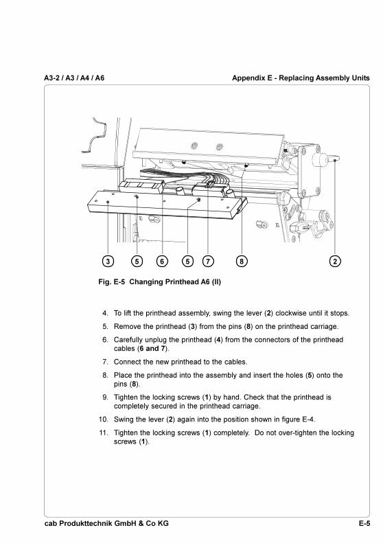
E-5cab Produkttechnik GmbH & Co KG
A3-2 / A3 / A4 / A6
4. To lift the printhead assembly, swing the lever (2) clockwise until it stops.
5. Remove the printhead (3) from the pins (8) on the printhead carriage.
6. Carefully unplug the printhead (4) from the connectors of the printheadcables (6 and 7).
7. Connect the new printhead to the cables.
8. Place the printhead into the assembly and insert the holes (5) onto thepins (8).
9. Tighten the locking screws (1) by hand. Check that the printhead iscompletely secured in the printhead carriage.
10. Swing the lever (2) again into the position shown in figure E-4.
11. Tighten the locking screws (1) completely. Do not over-tighten the lockingscrews (1).
Fig. E-5 Changing Printhead A6 (II)
25 563 7 8
Appendix E - Replacing Assembly Units

E-6 cab Produkttechnik GmbH & Co KG
A3-2 / A3 / A4 / A6
1
2
3
3
4
5
6
7a
7c
8
7b
9
Appendix E - Replacing Assembly Units
Replacing the Print Roller and the Rewind Assist Roller
NOTICE !There is described the replacement of the print roller and the rewindassist roller for the P-version printer types in this chapter.The replacement of the print roller at the other printer types can be madein the same way !
Fig. E-6 Changing Print Roller and Rewind Assist Roller (I)
1. Lift the printhead up and swing the locking system (5) away from therewind assist roller (4). Remove the media from the printer.
2. Take the Allen key (8), loosen the screws (3) and remove the dispenseplate (2).
3. Remove the three screws (7).
4. Remove the plate (9) and the printhead support (6) from the axle of theprint roller (1) and the rewind assist roller (4).
WARNING !Unplug the power cord from the power source before starting!

E-7cab Produkttechnik GmbH & Co KG
A3-2 / A3 / A4 / A6
10 11 1
12
13
4
Appendix E - Replacing Assembly Units
Fig. E-7 Changing Print Roller and Rewind Assist Roller (II)
5. Remove the print roller (1) or the rewind assist roller from the respectiveshafts (11, 12).
CAUTION !Before assembling the new roller check if the keys (10, 13) are placedcorrectly in the shafts (11,12) !
6. Slide the new print roller or rewind assist roller onto the appropriate shaft.Make sure the groove in the axle of the roller (1, 4) is aligned to the key(10, 13) on the shaft (11, 12).
7. Reinstall the plate (9) and printhead support (6).
8. Tighten the screws (7) a screw first, then the b screw and then the cscrew.
9. Reassemble the dispense plate (2).

E-8 cab Produkttechnik GmbH & Co KG
A3-2 / A3 / A4 / A6
This page is intentionally left blank.
Appendix E - Replacing Assembly Units

F-1cab Produkttechnik GmbH & Co KG
A3-2 / A3 / A4 / A6
Appendix F - Firmware Updates
General Information
Over a period of time, the printer's firmware is subject to constant developmentand revisions to allow for new features, easier error correction, etc.The firmware is stored in a flash-EPROM, which represents a new technologyin thermal transfer printers. For firmware updates, a file containing the updatedversion can be copied to the printer using the parallel interface.The firmware file is available on a disk or can be obtained from the Internet.The cab Internet address is included at the front of this manual.
Firmware Update Using the Parallel Interface
1. Switch from "Online" mode to the Offline Menu by pressing the key.
2. Press the key or the key until the "Service" menu is displayed.
Press the key to confirm the selection.
3. The display shows "Firmware upd.". Press the key.
4. If the "Firmware update" option is protected by a PIN, "PIN: 0000" willappear on the display. The numbers of the PIN may be changedindividually using the key and the key. The number to be changedwill be flashing on the display. You can switch to the next number by
pressing the key. If the input of all numbers is correct, the access tothe "Firmware update" option is made possible.
5. Upload the firmware file (e.g. 294_4830.ax) to the printer using MS-DOS.Under MS-DOS, type the following copy command :
COPY 294_4830.ax LPT1: /b
6. During the firmware upload, the printer's LCD will indicate the progresswith a progress bar. After completing the update process, the LCD will
display "OK ". This indicates the completion of the updating.
7. Press the key and the printer returns to "Online" mode.
Appendix F - Firmware Updates

F-2 cab Produkttechnik GmbH & Co KG
A3-2 / A3 / A4 / A6Appendix F - Firmware Updates
Firmware Update from Memory Card
Preparing the Memory Card
1. Format a CompactFlash Card in the printer using the command "FormatCard" in the Offline menu.That way the directories "fonts", "images", "labels" and "misc" are installedon the memory card.
2. Insert the formatted card in to a CompactFlash drive of a PC and copy afirmware file to the directory "misc".
Firmware Update
1. Insert the memory card with the firmware file in to the slot of the printer.
2. Switch from "Online" mode to the Offline Menu by pressing the key.
3. Press the key or the key until the "Service" menu is displayed.
Press the key to confirm the selection.
4. The display shows "Firmware upd.". Press the key.Press the key or the key until "Firmw. fr. card" is displayed. Press
the key.
5. If the "Firmware update" option is protected by a PIN, "PIN: 0000" willappear on the display. The numbers of the PIN may be changedindividually using the key and the key. The number to be changedwill be flashing on the display. You can switch to the next number by
pressing the key. If the input of all numbers is correct, the access tothe "Firmware update" option is made possible.
6. In the second line of the display the name of the firmware file (e.g.294_4830) is shown.If there are several firmware files on the memory card, press the key orthe key to select a file. Confirm the selection by pressing the key.
7. The selected firmware file is copied. During the firmware upload, theprinter's LCD will indicate the progress with a progress bar. After
completing the update process, the LCD will display "OK ". Thisindicates the completion of the updating.
8. Press the key and the printer returns to "Online" mode.

F-3cab Produkttechnik GmbH & Co KG
A3-2 / A3 / A4 / A6
Error Messages During the Firmware Update
In the event an error occurs during the updating process, the error code will bedisplayed on the LCD:
'C' : Check sum error (possibly "/b" missing in COPY command ora corrupt firmware file)
'H' : Header fault (possibly "/b" missing in COPY command or acorrupt firmware file)
'E' : EPROM could not be erased'V' : Programming voltage too low'P' : Programming fault
NOTICE !If any one of the faults described above occurs, the previous firmwaresetting is invalid and the update has to be started again. In some specialcases, it is possible that the printer will not return to normal operationmode after powering on after a failed firmware update. In this case,upload a previous firmware file over the parallel interface after poweringon.
Appendix F - Firmware Updates

F-4 cab Produkttechnik GmbH & Co KG
A3-2 / A3 / A4 / A6
This page is intentionally left blank.
Appendix F - Firmware Updates

cab Produkttechnik GmbH & Co KG
A3-2 / A3 / A4 / A6
IndexAADC malfunction C-3Adjustment of the label edge sensor 46Adjustment of the printhead support 49Applicator 17,61,63, A1f.ASCII Dump mode 73,84f.
BBackfeed 65,67Backfeed delay 60,62Bar codes 15Baud rate 68f.Bottom reflect 65f.,88f.Brightness LCD 61,63Buffer overflow C-3
CCard full C-3CE 11Character set 14,68f.Cleaning D-1f.Cleaning the label edge sensor D-3Cleaning the printhead D-2Cleaning the print roller D-1CompactFlash 90ff.Compliances 11Connecting the printer 31ff.Connection to a computer 32Connection to power supply 31Contrast LCD 61,63Control panel 29,34ff.Copy memory card 93,96f.Country 58f.Cover 25Cutter 16,61,63Cutter blocked C-3Cutter jammed C-3Cutter stuck C-3
DDaylight saving 58f.Debug mode 61,64Demand Sensor 58,60,62f.Device list 73,80f.Direct programming 22Direct thermal print 19
Index
Dispense plate 23,28,48,A-1Display 28,35ff.,61,63f.Documentation 7dRAM malfunction C-3
EError messages C-1ff.Error-reprint 65,67Ethernet 17,68f.
FFanfold labels 50f.FAULT-CORRECTABLE (system mode)
38,C-1FAULT-IRRECOVERABLE (system
mode) 38,C-2File not found C-4FCC 11Firmware 74,76f.,F-1ff.Firmware update F-1ff.Font list 73,78f.Fonts 14Format card 93,98FPGA malfunction C-4
GGap sensor 65f.,88f.Graphic elements 15Graphic file types 15
HHead malfunction C-4Head open C-4Heat level 64f.Head too hot C-4
IInterface extensions 17,30,75Interfaces 14,57,68f.Invalid data C-4Invalid outline C-4Invalid setup C-4
KKeyboard 68f.Keyboard, external 17,100ff.Keyboard interface 30,100

cab Produkttechnik GmbH & Co KG
A3-2 / A3 / A4 / A6Index
LLabel edge sensor 26ff.,65f.,88f.Label edge sensor, adjustment 46Label edge sensor, cleaning D-3Label from card 93f.Label profile 73,88f.Labels from roll 44ff.Label software 22Label / tag media specification 20LCD malfunction C-4Lithium battery 11Loading labels 44ff.Loading ribbon 52f.Local settings 57ff.Locking system 28,48
MMachine parameters 57,60ff.Maintenance D-1f.Media feed roller (print roller) 26ff.Media guide 26ff.Media hub 25Media loading 42ff.Media retainer 25Memory card 14,16,34,39,75,90ff.Memory card, copy 96f.Memory card ejection lever 29,91Memory card functions in the Offline
menu 93ff.Memory card, installation 91Memory card LED 29,91Memory card, preparation 92Memory card, removing 91Memory card slot 29Memory card, writing to 92Memory overflow C-4
NNo label found C-5No label size C-5No record found C-5Navigator pad 29,35ff.
OOffline menu 36,39f.,93ff.Online (System mode) 33,36Options16f.
Out of paper C-5Out of ribbon C-5
PParallel inteface 30,32,B-3Pause Reprint 36,65,67Pause (system mode) 37Peel-off mode 48,A-1f.Peel position 60,62Perforation mark 20,46Powersave mode 37,61,64Power supply connector 30f.Power switch 30,33Preliminary tests peel-off mode A-2Present sensor 25,A-1f.Print directory 93,99Printer configuration 56ff.Printer driver 22Printer types 9Printhead 10Printhead, cleaning D-2Printhead position 60ff.Printhead pos. X 60f.Printhead pos. Y 60,62Printhead profile 73,82f.Printhead, replacement E-1ff.Printhead support 26ff.Printhead support, adjustment 49Print media 18ff.Print parameters 57,64ff.Print roller, cleaning D-1Print roller, replacement E-6f.Print speed 12,64,66PRINT (system mode) 37PIN 70Problem solution C-7f.Programming 7,22,84f.Protocol 68f.Protocol error C-6
RRead error C-6Replacing the printhead E-1ff.Replacing the print roller E-6f.Rewind assist roller 28,48Rewind assist roller, replacement E-6f.

cab Produkttechnik GmbH & Co KG
A3-2 / A3 / A4 / A6 Index
Rewinder, external 16Rewinder, internal 25Rewind guide plate 23,27,43,47Rewind mode 43,47Ribbon shield 26ff.,54Ribbon supply hub 25Ribbon take up hub 25Ribbon wrinkling 49,54Reflective mark 20,46,66ROM malfunction C-6RS-232 30,32,68f.,B-1f.RS-422/485 68f.
SSafety instructions 23Securing device 24Security 57,70Service (menu) 39Set date 58f.Set time 58f.Setup (menu) 39,56ff.Short status 73ff.Software 22Speed limitation 10,60,63, A-2Status print 73,76f.Structural error C-6Swing 26ff.Switch on the printer 33System mode FAULT-CORRECTABLE
38System mode FAULT-
IRRECOVERABLE 33,36System mode PAUSE 37System mode POWERSAVE 37System mode PRINT 37
TTear-off mode 43ff.,65,67Tear-off plate 23,26,43Tear-off position 60,62Technical Specifications 12ff.Test (menu) 39,72ff.Test grid 73,86f.Thermal printhead 10,26ff.Thermal transfer print 19Time powersave 61,64
Time zone 58f.Trademarks 6Transfer print 64,66Transfer ribbon 21
UUnknown card C-6Unwinder, external 16UTC 58f.
VVoltage error C-6
WWarning labels 25,42Warn level ribbon 57,65f.Width ASCII dump 57,65,67Windows printer driver 22Wrinkling 49,54Write error C-6Wrong revision C-6

cab Produkttechnik GmbH & Co KG
A3-2 / A3 / A4 / A6
EU - Conformity DeclarationWe declare herewith that as a result of the manner in which the machine designated belowwas designed, the type of construction and the machines which, as a result have beenbrought on to the general market comply with the relevant fundamental regulations of the EURules for Safety and Health. In the event of any alteration which has not been approved byus being made to any machine as designated below, this statement shall thereby be madeinvalid.
Description: Type:
Transfer/Thermal-direct Printer A3-2 / A3 / A4 / A6
Applied EU Regulations and Norms:
- EC Machinery Regulations 98/37/EU- Machine Safety EN ISO 12100-1:2003
EN ISO 12100-2:2003
- EC Low Voltage Regulations 73/23/EEC- Data and Office Machine Safety EN 60950-1:2001
- EC Electromagnetic Compatibility Regulations 89/336/EEC- Threshold values for the Interference EN 55022:1998+ A1:2000 +
of Data Machines A2:2003 - Class A- Limits for harmonic current emission EN 61000-3-2:2000- Limits of voltage fluctuation and flicker EN 61000-3-3:1995+A1:2001- Immunity characteristics- EN 55024:1998+ A1:2001 +
Limits and methods of measurement A2:2003
Gesellschaft für Computer-und Automations-Bausteine mbH & Co KGWilhelm-Schickard-Str. 14D-76131 Karlsruhe
Signed for, and on behalf of, the Manufacturer :
cab Produkttechnik SömmerdaGesellschaft für Computer-und Automationsbausteine mbH99610 Sömmerda
Sömmerda, 04.10.04
Erwin FascherManaging Director