
Global M4HSD - Service Manual
213
Service Manual Mechanical Sweeper March 2016 COPYRIGHT 2012 GLOBAL ENVIRONMENTAL PRODUCTS, INC. ALL RIGHTS RESERVED REV 1 MAY 2012 GS332073 Revision A GLOBALM4HSD
-
Upload
khangminh22 -
Category
Documents
-
view
3 -
download
0
Transcript of Global M4HSD - Service Manual

Service ManualMechanical Sweeper
March 2016
COPYRIGHT 2012 GLOBALENVIRONMENTALPRODUCTS, INC. ALLRIGHTS RESERVED REV 1 MAY 2012
GS332073Revision A
GLOBALM4HSD


4000Series
MechanicalSw
eeperJuly
2005Manual326270Revision
B
JSC
OperatorM
anual
1st Ed2005
4000Series
MechanicalSw
eeperJuly
2005Manual326270Revision
B
JSC
OperatorM
anual
1st Ed2005
Revision A
Service Manual
1st Ed2016
4000Series
MechanicalSw
eeperJuly
2005Manual326270Revision
B
JSC
OperatorM
anual
1st Ed2005
4000Series
MechanicalSw
eeperJuly
2005Manual326270Revision
B
JSC
OperatorM
anual
1st Ed2005
Mechanical Sw
eeper M
arch 2016
GLOBALM4HSDGLOBALM4HSD


Introduction
General Information 1
Sweeper Operation 2
Sweeper Adjustment 3
Sweeper Lubrication 4
Maintenence Overhaul 5
Global M4 SeriesMechanical Sweeper Broom Service Manualp/n: GS332073, March 2016
Hydraulic 6
Troubleshoot 7

Global M4 Series Operator’s Manual
This page intentionally left blank

I-1Introduction
Introduction
Subject PageIntroduction
Introduction I-3 Service Assistance I-5 Safety Decals I-7 Safety Precautions I-9 Safety Summary I-10

IntroductionI-2
This page intentionally left blank

I-3Introduction
Introduction
- Keep this manual in the cab buddy seat compartment as a permanent and convenient
reference.
- Throughout this manual, you will findWARNINGS , CAUTIONS , and NOTES .
DTheWARNINGs reminds you to be especially careful to avoid possible personalinjury.
D TheCAUTIONs aregiven toprevent you frommakinganerror that coulddamage thesweeper or cause personal injury.
D The NOTEs are suggestions that will help you make full use of the sweeper.
- A thumb tabbedquick referenceguide is locatedon the title pageofmanual to assist you
in locating a desired function.
- Procedure titles andchapters arepositioned inmargins for easy reference while flippingthrough the manual.
How to Use This Manual
The information contained in this manual will help you better understand the op-eration of the sweeper. The Global M4 Series model sweeper represents the highestgrade of craftsmanship and reliability that makes Global Environmental Products aworld leader in sweeper technology. Careful attention to proper operating procedureswill ensure efficient operation, maximum performance and total customer satisfaction.
All information in this manual is based on the latest product information available at the time ofprinting. Due to improvements in design, performance and reliability, there may be minordiscrepanciesbetweenactual vehicleand thecontentsof thismanual.Global EnvironmentalProducts, Inc. reserves the right to make changes at any time without notice and without incur-ring any obligation to make such changes toproductsmanufacturedpreviously.No liability canbeaccepted for any inaccuracies or omissions in this publication, although every endeavor ismade to ensure that information contained in this manual is correct.
No part of this publicationmay be reproduced, stored in retrieval system, or transmitted, in anyform by any means, mechanical, electronic, photocopying, recording, or otherwise, withoutprior written permission of Global Environmental Products Technical Publications.
Important Information
Global Environmental Products Technical Publications

IntroductionI-4
This page intentionally left blank
I-5Introduction
Service Assistance
To better serve you, the following information will be needed during a service call.
1. Name and address.2. Complete model and serial number.3. Description of procedure, function or problem.
NOTE: The identification nameplate is locatedinside the operator’s cab on the right side - wall below the companion seat.
Global Environmental Products Inc.
5405 Industrial Parkway
San Bernardino, CA 92407 USA
Tel.: 1 (909) 713-1600
Fax:1 (909) 713-1613
E-Mail : [email protected]
Web: www.globalsweeper.com

IntroductionI-6
This page intentionally left blank
GS244998, May 2012

I-7Introduction
Safety DecalsSafety must always be the operator’s utmost concern and responsibility. The operator must read and under-stand this manual and all safety decals on the sweeper before operating the vehicle. Failure to follow thesesafety precautions could result in damage to the equipment and/or personal injury or death. Decals are de-
signedand installedon thesweeper for yourprotection. Theyareplacedat appropriateareason thesweeper
to be constant reminders of the ever---present dangers. KNOWandADHERE to the information theyprovide.

IntroductionI-8

I-9Introduction
1. Always fasten seat belts.
2 . Always drive at a safe speed. Slow do wn forcurves and downgrades.
3. Be extremely careful when maneuvering aroundparked cars.
4. Never make sudden starts, stops or turns.
5. Be very careful when backing up sweeper.
6. Do not use sweeper for towing.
7. Never operate sweeper with a known hydraulicleak. Repair leak immediately.
8. Check sweeper daily for hydraulic leaks.
9. Avoid sweeping near bystanders or in congestedareas eliminating possible injury caused fromsweeper brooms throwing debris.
10. If elevator becomes jammed, turn off elevatordrive motor and stop engine before proceedingto clear debris.
11. Do not overload sweeper.
12. Whenever amechanic, operator, inspector or anyother person needs to perform work under a
raised hopper, stop engine and install bothsa fety prop s . Do not stand under raised hopperwith engine running.
13. Never use a hydraulic cylinder or hydraulic me-chanicalmechanism to lift anotherobject orpart.
14. Never leave sweeper unattended with enginerunning and/or ignition key in vehicle.
15. Be certain sweeper is parked in a position allow-ing hopper to clear container before dumpinghopper.
16. Be sure sweeper is parked on level ground andbystanders are clear before dumping hopper.
17. Stay clear of electrical power lines and otheroverhead obstructions to prevent injury or prop-
erty damage when dumping hopper.
18. Always cover battery terminals during mainte-nance to prevent electrical short.
19. When operating at slow speed or wheneversweeper may cause traffic problems, operate
beacon and rear flashers lights.
20. Never step on either gutter broom for any rea-son. Serious injury may result. Use provided
step plates located on right front bumper and
handle to enter cab.
The safety precautions listed in this manual and on the sweeper are not all-inclusive. Anyone using service procedures, methods, or tools, whether or not recommended by Global Environmental Prod-ucts must satisfy himself thoroughly that neither personal safety nor vehicle safety will be jeopardized by the service methods or tools selected. Remember, your ability as a professional operator is critical to ensuring your safety and that of others around you.
Always follow local and state traffic laws. Drive defensively - the other driver may be wrong, but it is bet-ter to avoid collisions of any kind. Carefully study the following safety related operating suggestions.
Safety Precautions

IntroductionI-10
Safety SummaryThe following safetymeasuresareessential andmust beobservedwhenservicing, repairing, ormaintain-ing the Global M4 Series sweeper.
- JACKSTANDS&CHOCKS -- Before jacking the vehicle, or releasing or adjusting the parking brakeon a stationary sweeper, always chock the wheels. Always use safety (jack) stands when usinghydraulic jacks or hoists to raise the vehicle. Do not rely on either the jack or the hoist to hold theload.
- SAFETYGLASSES -- Safety glassesmustbewornwhenusing tools suchashammers, chisels, pull-ers and punches. Always wear safety glasses when working on the hydraulic system.
- WELDING --Wear welding gloves and goggles whenwelding or using an acetylene torch. Make surethat a metal shield separates the acetylene and oxygen bottles, both of which must be chained to acart.Do notweld or heat areas near fuel tanks or fuel lines. Utilize proper shielding around hydrauliclines. CAUTION: Disconnect battery terminals prior to welding.
- WORKAREA -- Organize your work area and keep it clean. To prevent slips and falls, promptly wipeclean any oil spills. Keep all tools and parts off the floor. After servicing the sweeper, reinstall all safetydevices, guards and shields. Before starting the engine or moving the sweeper, check to make surethat all tools and servicing equipment are removed from the engine area.
- CLOTHING& JEWELRY--Wear close fitting clothing appropriate for the job. Use sturdy work shoesand rough--soled.Bare feet, sandals, or sneakers arenotacceptable footwearwhenadjusting and/orservicing the sweeper. Do not wear rings, wrist watches, neck chains, or loose--fitting clothing whenworking on the engine. Any of these items could catch on moving parts, causing serious injury.
- COMPRESSEDAIR -- Toavoid serious injury or death,donot apply compressed air to any part of thebody or clothing. Use only approved air guns that do not exceed 30 psi (207 kPa).Always wear safetyglasses or goggles. Use proper shield to protect everyone in the work area.
- PRESSURIZED FLUIDS -- Be extremely careful when dealing with fluids under pressure. Fluidsunder pressure can have enough pressure to penetrate the skin. These fluids can infect a minor cutor opening in the skin. If injuredbyescapingpressurized fluids, seeadoctor at once.Serious infectionor reaction can result without immediate medical treatment.
When opening the radiator cap, always remove the coolant pressure control cap slowly, andonly when the coolant is at room temperature. A sudden release of pressure from a heated coolingsystem can result in possible personal injury from the expulsion of hot coolant.
Always use extreme caution while inspecting or working on the pressurized hydraulic sys-tems.Donot attempt to look for hydraulic leaks without hand and eye protection. Oil can shoot from apinhole in a fine jet at a velocity that can penetrate the skin and cause severe injury.Never attempt toblock the oil flow with your hands or fingers.

I-11Introduction
Safety Summary- DIESEL FUEL -- Diesel fuel is highly flammable. Take extra precautions to avoid personal injury. Do
not smokewhen fueling the vehicle, or when servicing the engine or the fuel system.Store diesel fueland other flammable fluids away from fire hazards.
- HOT EXHAUST -- Engine produces extremely hot exhaust gases (over 1200 degrees F). To preventthe possibility of serious burns, always allow the engine and exhaust system to cool to ambient tem-perature before working on or servicing the engine or exhaust system. Engine exhaust fumes cancause sickness or death. Do not run engine in an enclosed area without exhaust pipe extension.
- BATTERIES -- Electrical batteries give off highly explosive and flammable hydrogen gaswhen charg-ing, and continue to do so for some time after receiving a steady charge. Do not smoke or allow anopen flame or spark near the batteries -- an explosion may result. Prevent battery explosions. Do notcharge a frozen battery; it may explode. Warm battery to 16 degrees C (60 degrees F). Prevent acidburns. Avoid contact with sulfuric acid in battery electrolyte. Wear proper eye protection and wearrubber gloveswhen handling battery. Use voltmeter or hydrometer to check battery charge.To avoidthe possibility of electrical shock, always remove the battery ground cable beforeworking on the elec-trical system.
- FIRE EXTINGUISHER -- Always keep a charged fire extinguisher within reach while working on orservicing the vehicle. Make sure the extinguisher is the correct type for the situation: a Type A extin-guisher is for wood, paper, textiles and rubbish (as might be found in the sweeper hopper); a Type Bextinguisher is for flammable liquids such as solvents; and a Type C extinguisher is for electricalequipment.
- HOPPER & ELEVATOR SAFETY -- A combination of a hydraulic system and an elevatable, heavyhopper present several safety concerns.The followingcautionsmust be taken toavoidpersonal injuryor damage to equipment:
1. Do not raise the hopper unless the sweeper is parked on firm, level ground.
2. Before raising the hopper, make sure that the vehicle is clear of overhead electrical powerlines or other obstructions such as trees.
3. Make sure that bystanders are well clear of the sweeper before dumping.
4. Before working beneath a raised hopper, always install the safety props on both sides ofscissor base. The safety props rest on the top edge of the cylinder body, positionedaround the cylinder rod to keep the hopper from falling in the event of a hydraulic failure.Never position yourself beneath the hopper while installing or removing the safety props.
5. Always stay clear of the running elevator while making adjustments. Themoving equipmentcan easily grab clothing and cause personal injury.

IntroductionI-12
This page intentionally left blank

1-1Chapter 1 - General Information
Engine 1-3Hydrostatic Traction 1-3Auxiliary Hydraulic Drive 1-4Operator’s Cab 1-4Cab Mounted Controls & Indicators 1-4Water Tanks 1-4Water Pumps 1-4Water Spray System 1-5Hopper 1-5Elevator 1-5Gutter Brooms 1-5Pickup Broom 1-5Dirt Shoes and Dust 1-5Electrical System 1-6PM 10 Option 1-6Autolube System Option 1-6Steering Column Controls 1-23Seat Adjustments 1-24Safety Restraints 1-24Side View Mirrors 1-24
Table of ContentsSubject Page
Sweeper Functions
Tables1.1 Cab Mounted Controls 1-71.2 Front Console Panel 1-81.3 Shifter Control Panel 1-111.4 Kysor AV-1000 Front Panel 1-121.5 Diagnostic Warning Lights Panel 1-141.6 Elevator/Broom Control Panel 1-16
1.7 Light Switch Option Control Panel 1-181.8 Aux. Shutdown & Air Conditioner 1-191.9 Water Level Gauge & Hopper Switch 1-201.10 DPF Diagnostic & Remote Mirrors 1-211.11 PUB Odometer & Air Restriction 1-22
Subject Page
Tables
Figures1.3A Component Locations 1-31.4A Hydraulic Pumps 1-41.4B Cab Controls 1-41.4C Gutter Broom 1-41.6A ECU Box 1-61.6B Batteries 1-61.6C Autolube System 1-61.22A Steering 1-231.22B Column Controls 1-231.23A Seats 1-24
General Information
CHAPTER 1

Chapter 1 - General Information1-2
This page intentionally left blank
1-3Chapter 1 - General Information
SWEEPER FUNCTIONS
The Global M4 model sweeper is a uniquespecially designed and manufactured mechanical typestreet sweeper. The operation of the sweeperencompasses the use of mechanical, hydraulic andelectrical systems employing related components for thespecific purpose of removal of debris from streets,highways, parking areas and other large pavedlocations. The sweeper is ruggedly constructed anddurably designed to withstand the everyday operation aswell as enabling the unit to sweep and pickup theheaviest of debris within its’ published ratings and speci-fications.
Engine A standard Cummins series en-
gine, 6.7 liter (409 cu. in.) turbocharged diesel engine
powers the M4 sweeper. This in -- line six - cylinder en-gine delivers 280 peak horsepower at 2300 RPM with amaximum torque rating of 660 lb ft at 1600 RPM. The Cum-mins engine electronic “Interact System” features built inpronostics and diagnostics. A programmable electroniccontrol module (ECM) allows for multi range setting of keyperformance parameters.
(Refer to Cummins EngineOwners Manual, Troubleshoot-ing and Repair Manual, and Parts Catalog for serviceinformation)
Hydrostatic Tra c tion A hydrostatic traction system isused on the unit to meet the mobility requirements of thesweeper. The engine RPM is separate from the mile---per---hour speed to allow engine speed to be set at a high RPMto run sweeping operations while vehicle travel is kept atslow sweeping speed.
Three major components make up the traction system:hydraulic traction pump, hydraulic motor, and a rearaxle. The traction pump consists of a single variabledisplacement hydrostatic pump accompanied with afixed displacement charge pump. A variable displace-ment hydraulic motor enables the sweeper to shift in highrange or low range which changes torque and mile---per---hour capabilities. A conventional heavy duty truck rearaxle is the last link in the drive system. The rear axle isequipped with a two---speed gear drive of high and lowrange to enable the sweeper to reach speeds specified in the M4 Series specifications for highway travel.
ISB-12 280
(Global M4 Series sweeper major component locations) Fig: 1.3 A

1:4 Chapter 1 -- General Information
Auxiliary Hydraulic Drive ⎯ The auxiliary hydraulic driveprovidespower andcontrol to operate thesweepgearandother related systems. The auxiliary hydraulic systemcon-sists of a triple pumpmounted on the rear of the hydrostat-ic pump that is driven by the engine. Hydraulicmotors areused to drive the gutter brooms, pickup broom and eleva-tor. Various hydraulic cylinders areused for lifting and low-ering functions of the brooms and the hopper.
Operatror’s Cab ⎯ The cab is designed for operatorscomfort inside a dust and weather protected interior. Theoperatorsdrivingpositionat thecenter of the sweeperpro-vides excellent visibility while observing the sweepingpath.
Cab Mounted Controls and Indicators ⎯Operator con-trols and performance indicators are mounted in cabwithin easy reach and view of operator. A front consolepanel allows operator to monitor gauges and switchesdedicated for driving operation. A set of side instrumentpanels allows operator to monitor gauges and switchesdedicated for sweeping operation.
The engine RPM adjustment is controlled electronicallyusing a rocker switch next to the shifter. A sweep/travelmode switch allows the engine RPM to be controlled inde-pendently during sweeping operations. The go---pedal(similar to a gas pedal in a conventional truck) controlssweeper speed and RPM speed simultaneously in travelmode. A built--- in hydrostatic braking system activateswhen go---pedal is fully released. In addition, a mechani-cal brake pedal activates the wheel brakes and brakelights. The parking brake automatically engages whenshifter is placed in park.
Wate r Ta nks ⎯ The storage of water for the spray systemconsists of three inter--- linked water tanks designed to befilled froma fire hydrant through a single filler hole andwa-ter fill strainer. A fire hydrant hose needed to fill water tanksis stored in the right hand center body panel.
Water Pumps⎯ The pressure and flow requirements forthe water system is met by the use of two 12---volt electricmotor driven diaphragmpumpunits. The electricmotor isa permanent magnet, fan cooled with an amperage drawof 10 amps. The electric power source is taken from thechassis battery. The self---priming pumps are designed toproduce a flow rate of 4.0 gpm (per pump) at 0 head pres-sure. The pumps have a maximum pressure of 35 psi.
Triple Pump Shown (Option)
Fig: 1.4 A
Fig: 1.4 B
Gutter Broom
Fig: 1.4 C

1-5Chapter 1 - General Information
CHAPTER 1Wate r Spray System The water spray system isintended to control dust created when sweeping.Water nozzles spray in front of each gutter broom. Aseries of water nozzles mounted under the front bumpersprays water on debris being picked up by the sweeper.The water pump pressurizes the water spray system ofthe sweeper.The water control valves located behindthe companion seat backrest are adjustable ball valvesused to control the amount of water flow to the spraynozzles.
Hoppe r The sweeper utilizes a hopper for storage ofcollected debris that has been swept. It is located basicallyat the center behind the cab. The hopper is designed andconstructed from carbon steel (a stainless steel option isalso avalaible) and is powder coated to reduce corrosion(a Rhino lining option is also avalaible).
Elevator The elevator assembly is used to transfer theswept debris from the pickup broom disposing it into thehopper. This conveyor type component is located in anear vertical position between the front of the hopper andthe rear of the cab. The elevator has squeegee type designconsisting of 7 or 11 flights of squeegees with replaceablecorded rubber tips. The squeegees carry the debris up thebackplate of the elevator and throws the debris into thehopper. The elevator consists of the squeegee bars, largerubber belts, sprocket pulleys and drive shafts. The eleva-tor is powered by a hydraulic motor that works in conjunc-tion with the pickup broom operation. When the switch incab is actuated, both the broom and elevator operation issimultaneously activated. Because of close clearances ofthe squeegees the possibility exists that the elevator couldstall or stop operating. This is usually caused by an ob-struction of a larger than normal piece of debris that iswedged at some point on the elevator. When this condi-tion occurs, an alarm buzzer sounds alerting the operatorof the condition. The obstruction must be cleared beforeproceeding to sweep.
Gutter Brooms The gutter broom is located on each
side of the sweeper just behind the cab. The gutter broommeasures 47 inches in diameter and is equipped with 12brush segments of the Tuf---grip type with 26” wire bristlesattached to the broom drive plate. A four brush segment isalso avalaible. Each gutter broom is independently low-ered and raised hydraulically and controlled from the cab.The direct connected hydraulic motor accomplishes therotation motion of the brooms.The speed is based on theengine RPM. The broom down pressure can be selectedto suit the specific type of sweeping being done. It is se
lected by the control in the cab that consists of a gauge
which indicates a HEAVY---LIGHT or UP range. The ad-justment is made with the broom raised and by setting theneedle on the gauge. Once set, this range remains until re-set even if broom is raised and again lowered.
The 4000 C Series sweeper has the In---Cab Broom Tilt
(Option) capability which allows the operator to easily ad-
just the broom to sweep various different road cambers
without exiting the cab. The tilt option is a complete arm
assembly.
Shock absorbers are installed on the horizontal move-ment of the gutter brooms. These are used as a protectivedevice when the gutter broom is forced inward by hitting acurb or another type of obstacle. The shock absorbersalso return the broom back to its’ preset outward position.
Pickup Broom The pickup broom is located un-
derneath the unit just to the rear of the gutter brooms.
The
broom is a two broom type, polypropylene filled and it is 32inches in diameter by 58 inches in length. The purpose ofthe pickup broom is to sweep up the debris in the centerportion of the path including the debris directed to the cen-ter by the gutter brooms and deposit it on the elevator. Thebroom rotates in the opposite direction of travel. The rota-tion is accomplished by use of a hydraulic motor and iscontrolled by the switch in the cab. The rotational speed isbased on the engine RPM. The broom is raised andlowered hydraulically.
Dirt Shoes and Dust Flaps A fabricated structure re-
ferred to as a dirt shoe is located on both sides of the pickup broom with the purpose of funnelling or containing thedebris in front of the pickup broom and elevator. Withoutthis component the debris would be thrown out from un-der the machine and left behind while sweeping. The dirtshoe is set to slightly drag and ride parallel to the sweep-ing surface. It is safety chained to the pickup broom and islowered and raised as the broom is lowered and raised.
In an effort to control the dust and contain the debris beingswept into the center of the sweep path by the gutterbrooms, a rubberized flap deflector is located under thechassis and just to the rear of the front wheels. A dust flapis also located to the rear of the pickup broom to keep thedebris and dust from escaping to the rear of the sweeper.In addition, a chain curtain is installed to reduce debris“cow plops” behind the sweeper.
The M4

1:6 Chapter 1 -- General Information
Electrical System ⎯A centralized, weatherproof system,equippedwithacomponent identifyingdecalwhichallowsaccessibility to electrical components. Power source con-sists of dual batteries, 955CCA@0degrees Fahrenheit. Asystem voltage of 12 volt is circuit breaker protected. Elec-trical control unit is a sealed system lockerwith sealed subcompartments for high and low amperage components.
Always shield eyes and face from bat-teries.
PM ---10 ⎯ The Global Environmental Products 4000 CNG sweeper has been tested and certified as being in compliance with the South Coast Air Quality Management District’s Rule #1186 regulating collection and containment of PM10 (Particle Matter 10 Microns). T h e PM 1 0 i s a u n i q u e f e a t u r e of dust suppression system using an array of water spray mist. The application of water spray mist in appropriate areas of sweeping is important for the efficiency of the PM10. Dust particle as small as 10 microns can be swept.
In order to ensure compliance with Rule #1186 require-ments, the sweeper must be operated and maintained inaccordance with sweeper’s PM10 specifications.
DoNot attempt to sweepwith thewaterspray system inoperative.
(Refer to the PM10 maintenance and specifications sec-tion in the service and lubrication chapter in this manual.)
Fig: 1.6 A
Fig: 1.6 B

1-7Chapter 1 - General Information
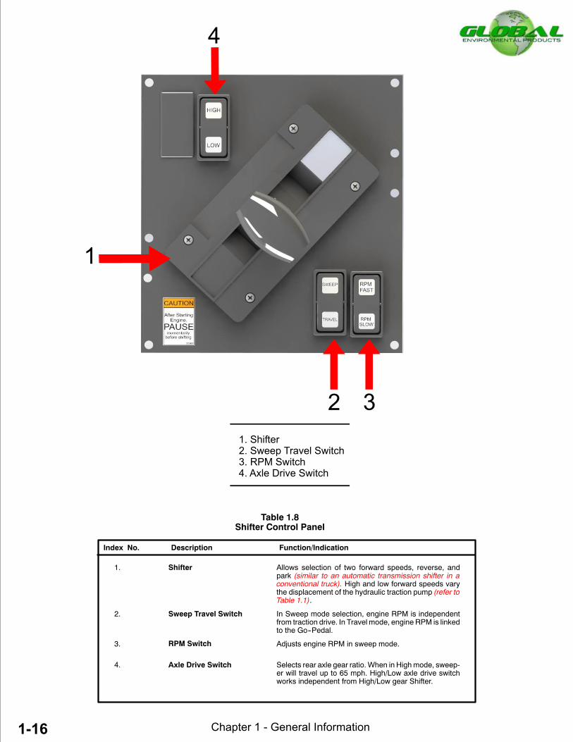
1. Shifter Allows selection of two forward speeds, reverse, andpark (similar to an automatic transmission shifter in aconventional truck).
- HI Position Selects high ratio of hydrostatic system. Sweepertravels forward at speeds up to 55 mph (88 km/h).
- LO Position Selects low ratio of hydrostatic system toprovidegreatertorque to rear wheels. Sweeper travels forward atspeeds up to 18 mph (29km/h).
- P Position Place shifter in park position to start engine. Emer-gency brake is automatically activated when shifteris in park position.
- R Position Allows sweeper to move in reverse direction.
2 Side Instrument Panels Allows operator to adjust and monitor sweeping opera-tions.
3. Steering Wheel/Column Besides performing standard turning applications,steering wheel tilts and telescope for operator comfortand easy access in and out of cab. Refer to Table 1.5 fordetailed explanation of steering wheel/column func-tions.
4. Front Console Panel Allows operator to monitor driving and engine perform-ance. Refer to Table 1.2 for detailed explanation of frontinstrument panel.
5. Foot Brake Pedal Foot brake pedal applies wheel brakes and activatesbrake lights simultaneously.
6. Go--Pedal Controls sweeper speed and engine rpm simultaneous-ly (similar to a gas pedal in a conventional truck) whenvehicle is in travel mode. Hydrostatic braking occurswhen go--pedal is released.
7. Engine RPM Switch Used to adjust engine rpm. RPM switch functions sepa-rate from go--pedal when vehicle is in sweeping mode.Recommended sweeping RPM is 2100.
8. Water Valves Valves control overall water flow to spray nozzles.
9. Hydraulic Temp Gauge Hydraulic temperature gauges allows the operator tomonitor the oil temperatures of both left hand and righthand hydraulic tanks.
10. Mirror Controls (Option) Allows the operator to heat and defrost mirrors, and ad-just left hand and right hand mirrors electronically.
Index No. Description Function/Indication
Table 1.1Cab Mounted Controls and Indicators
DO NOT shift into REVERSE while sweeper is mov-ing. Damage to hydrostatic traction may result.

Chapter 1 - General Information1-8
1- Temperature Gauge2- Engine Oil Gauge3- Motor Overspeed Light4- Tachometer5- Gutter Broom Tilt RH (Option)6- Fuel Gauge7- Power Source (Option)
8- Ignition Key Switch9- Voltmeter Gauge
10- Wiper / Washer Switch11- Headlight Switch12- Gutter Broom Tilt LH (Option)13- Speedometer14- ABS Indicator Light Ass’y
15- Work Lights16- Kysor AV-1000 System17- Diagnostic Light Ass’y18- Hopper Light19- DDR Connectors20- Traction Control Diag.Connector
Table 1.2Front Console Controls and Indicator Panel
15
jthompson
Line
1:9Chapter 1 -- General Information
8. Engine Oil Gauge Indicates engine oil pressure when the engine is running.Normal oil pressure is between 20 and 50 psi (138 and 345kPa).
9. Tachometer Indicates engine speed in hundreds of revolutions permin-ute (rpm x 100).
10. Power Source (Option) Used for 12 volt accessories.
11. Headlight Switch First extended position activates panel lights, runninglights, clearance lights, and tail lights. Full extended posi-tion turns on the headlights. All lights are OFF with switchpushed in. Rotate switch clockwise to brighten or counter-clockwise to dim panel lights.
12. Wiper/Washer Two speed switch controls windshield wiper motor andwindshield washer.
13. Ignition Key Switch Used for activating solenoid to crankenginestarter, normalengine ignition operation and powering accessories.
14. Gutter Broom Tilt LH (Option) Switch used to adjust broom angle of the left hand gutterbroom.
15. Gutter Broom Tilt RH (Option) Switch used to adjust broom angle of the right hand gutterbroom.
16. Gutter Broom Light Switchs Used to turn the GB & front bumber spot lights lights ON.
17. Motor Overspeed Light Indicates drive motor overspeed, warning to reduce thesweeper speed.
When ignition switch is turned ON, ABS indicator lampcomes on momentarily then goes out, indicating SystemOK. Light stays on indicates fault in the system.
Indicates electrical system voltage. Troubleshoot sys-tem if voltmeter constantly indicates an over or undercharge.
Indicates approximate amount of fuel remaining in thetank. Fuel tank capacity is 57 diesel equivalent gallons(216 L)@ 3600 PSI.
4. ABS Indicator Lamp
5. Voltmeter
6. Fuel Gauge
7. Temperature Gauge Indicates engine water temperature. Normal temperaturereads between 180° and 225° Fahrenheit (82° and 99°C).
Table 1.2 (continued)Front Console Controls and Indicator Panel
Index No. Description Function/Indication
If ENGINEWATER TEMPERATURE gauge rises above238° F (114° C), the engine shuts down automatically.
If ENGINEOILPRESSUREgoesbelow8psi (55 kPa) orabove 55 psi (379 kPa), the engine will shut downautomatically.
1:10 Chapter 1 -- General Information
1. Hopper Full Indicator Light2. Engine Oil Pressure Light3. Elevator Stall Alarm Light4. Engine Water Temperature Light5. Low Engine Water Level Light6. Not Used7. Right Hydraulic Tank Level Light
(Controls and indicators on front console panel) Fig: 1.10 A
8. Left Hydraulic Tank Level Light9. Brake Fail Light10. Brake Differential Light11. Parking Brake Light12. Left Turn Signal Light13. Right Turn Signal Light14. High Beam Light
112 11 5 10 8 3
2 9 4 14 7 13
Table 1.3Kysor AV--1000 Front Console Panel
Index No. Description Function/Indication
(continued)
1. Hopper Full Indicator Light Indicates hopper reached full capacity.
2. Engine Oil Pressure Light indicates lowengine oil pressure. Theminimumen-gine oil pressure is 15 psi (103 kPa) @ idle. The maxi-mum oil pressure is 55 psi (379 kPa).
3. Elevator Stall Alarm Light Indicates the elevator stalled and an alarm willsound. (Immediately bring sweeper to a full stop. Repairthe elevator stall problem before proceeding to sweep).
4. Engine Water Temperature The enginewater temperature alarm comes onwhen theengine water temperature has reached 225° Fahren-height, as a warning that the engine is begining to over-heat.
If ENGINE WATER TEMPERATURE rises above 238°Fahrenheit (114° Celsius), the engine will shut downautomatically.
If ENGINEOILPRESSUREgoesbelow8psi (55 kPa) orabove 55 psi (379 kPa), the engine will shut downautomatically.

1:11Chapter 1 -- General Information
Table 1.3 (continued)Kysor AV--1000 Front Console Panel
Index No. Description Function/Indication
5. Low Engine Water Level Light indicates low engine coolant level. Check enginecoolant level at deaeration tank.
6. Not Used N/A
7. Right Hydraulic Tank Level Light indicates low traction hydraulic oil level. Check righthand hydraulic tank.
8. Left Hydraulic Tank Level Light indicates low auxiliary hydraulic oil level. Check lefthand hydraulic tank.
9. Brake Fail Light indicates brake power boost system failure. Areserve electric motor provides the power source for thehydraulic booster. The pumps use is signaled by an inter-nal flow switch.
10. Brake Differential Light indicates brake fluid system failure. The System isbiased, front & rear. When the light is illuminated, the unithas only the front or rear brakes.
11. Parking Brake Light indicates parking brake is ON.
12. Left Turn Signal When flashing, left front and left rear turn signals operate.All turn signals flashwhen hazardwarning flasher switch isON.
13. Right Turn Signal When flashing, right front and right rear turn signals oper-ate. All turn signals flash when hazard warning flasherswitch is ON.
14. High Beam Light Blue light indicates high beam headlights are ON.
If ENGINE COOLANT is low, the engine will shutdown. Add necessary coolant at deaeration tank.
If BRAKE DEFFERENTIAL light illuminates, Stopsweeper. DO NOT drive for an extended period oftime while Brake Fail indicator is ON.Correct the brake system failure immediately.
IfHYDRAULICAUXILIARYorTRACTIONoiloverheats,stop engine and correct overheating problem.

Chapter 1 - General Information1-14
Index No. Description Function / Indication
1. Stop Engine WarningLight
Light indicates that the engine stopped. Light will stay ONmomentarily until the ignition switch is turned to the ONposition to start engine.
2. Grid Heater WarningLight
Light indicates that the grid heater needs to warm the airprior to starting. Light will stay on until Grid Heater hasreached its operating temperature. When the light goes off,the engine is ready to start.
3. Exhaust High Tempera-ture
The EXH HI TEMP light indicates that the exhaust temper-atures are high due to regeneration of the diesel particu-late filter. This light could illuminate during normal engineoperation or during stationary regeneration.
WARNING: When this light is illuminated, the exhaust gas temperature can reach 800"~ /1,500"F), which is hot enough to ignite or melt some materials or make severe burns to people. -Keep the exhaust outlet away from people and anything thatcan bum, melt, or explode. Nothing within 2 ft (0.6 m) of the exhaust outlet.
-In an emergency, turn off the engine to stop the flow of exhaust.NOTE: The EXH HI TEMP light does not signify the need for any kind of vehicle orengine service; it merely alerts the operator to the high exhaust temperatures. It will becommon for the EXH HI TEMP light to illuminate on and off during normal vehicleoperation as the engine completes regeneration.
4. Malfunctioning WarningLight-
1 2 3 4
7 6 5
Engine Diagnostic Warning Lights Panel
The MIL Illuminates when On-Board Diagnostics system detects a malfunction related to the emissions control system. The Illuminated MIL indicates that the engine and aftertreatment system should be diagnosed and serviced at your next availabe oppurtunity.

1-15Chapter 1 - General Information
Index No. Description Function / Indication
5. Low Level DEF WarningLight
The DEF low level warning lamp illuminates when the DEFlevel is low. If the vehicle is operated such that one wouldrun completely out of DEF, the vehicle power will bereduced enough to encourage the operator to refill the DEFtank. Once the tank has been refilled the engine willresume normal power levels.
6. Regeneration NeededWarning Light
This light indicates when illuminated or flashing that thediesel particulate filter requires stationary regeneration.A STEADY REGEN NEED light indicates that the dieselparticulate filter needs to be regenerated at the next possi-ble opportunity.A FLASHING REGEN NEED light indicates that theengine power may be reduced automatically. The dieselparticulate filter needs to be regenerated at the next possi-ble opportunity. This can be accomplished by:
1) Changing to a more challenging duty cycle, such ashighway driving, for at least 20 minutes.
2) Performing a stationary regeneration.
A FLASHING REGEN NEED light combined with an ILLU-MINATED CHECK ENGINE light indicates that the dieselparticulate filter needs to be regenerated immediately.Engine power will be reduced automatically. Whenthese lamps are illuminated a stationary regeneration isrequired.
NOTE: If a stationary regeneration is not performed, theSTOP ENGINE WARNING LIGHT will illuninate and thevehicle will need to be taken to an authorized repair loca-tion.
7. Check Engine WarningLight
Light indicates an engine problem. The engine will requirediagnostics by a qualified technician with the proper soft-ware.If the CHECK ENGINE warning light illuminates, you haveapproximately 30 seconds to pull over to a safe placebefore the engine shuts down. Notify a qualified technicianto troubteshoot any malfunction.
Engine Diagnostic Warning Lights Panel(continued)
Chapter 1 - General Information1-16
jthompson
Line
jthompson
Line
jthompson
Line

Chapter 1 -- General Information 1-17
jthompson
Line
jthompson
Line
1-17Chapter 1 - General Information
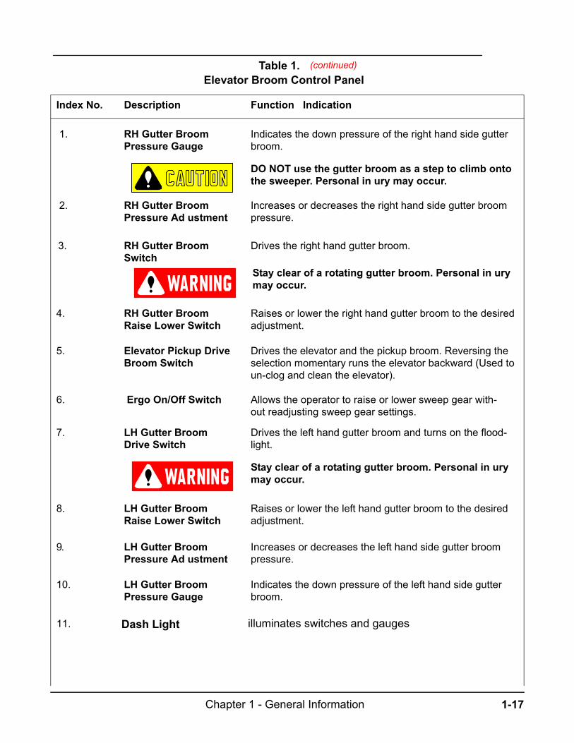
Index No. Description Function / Indication
1. RH Gutter BroomPressure Gauge
Indicates the down pressure of the right hand side gutterbroom.
DO NOT use the gutter broom as a step to climb onto the sweeper. Personal injury may occur.
2. RH Gutter BroomPressure Adjustment
Increases or decreases the right hand side gutter broompressure.
3. RH Gutter BroomSwitch
Drives the right hand gutter broom.
Stay clear of a rotating gutter broom. Personal injury may occur.
4. RH Gutter BroomRaise/Lower Switch
Raises or lower the right hand gutter broom to the desiredadjustment.
5. Elevator/Pickup DriveBroom Switch
Drives the elevator and the pickup broom. Reversing theselection momentary runs the elevator backward (Used toun-clog and clean the elevator).
6. Ergo On/Off Switch Allows the operator to raise or lower sweep gear with-out readjusting sweep gear settings.
7. LH Gutter BroomDrive Switch
Drives the left hand gutter broom and turns on the flood-light.
Stay clear of a rotating gutter broom. Personal injury may occur.
8. LH Gutter BroomRaise/Lower Switch
Raises or lower the left hand gutter broom to the desiredadjustment.
9. LH Gutter BroomPressure Adjustment
Increases or decreases the left hand side gutter broompressure.
10. LH Gutter BroomPressure Gauge
Indicates the down pressure of the left hand side gutterbroom.
Table 1.6Elevator/Broom Control Panel
(continued)
11. Dash Light illuminates switches and gauges
1:18Chapter 1 -- General Information
(Controls and indicators on side instrument panel) Fig: 1.15 A
1
2
3
4
5
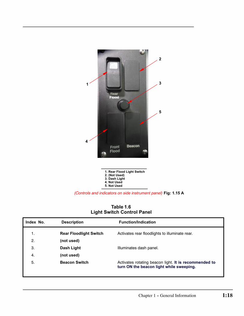
1. Rear Flood Light Switch2. (Not Used)3. Dash Light4. Not Used5.
1. Rear Floodlight Switch Activates rear floodlights to illuminate rear.
2. (not used)
3. Dash Light Illuminates dash panel.
4. (not used)
5. Beacon Switch Activates rotating beacon light. It is recommended toturn ON the beacon light while sweeping.
Index No. Description Function/Indication
Table 1.6Light Switch Control Panel
Not Used

1:19 Chapter 1 -- General Information
1. Battery Master Disconnect Turn knob to ON or OFF to connect or disconnect battery.
2. (not used) N/A.
3. Heat Temperature Control Selects desired hot temperature of cab air by directing hotwater through heater (Turn off when using the A/C).
4. Fan Switch Turns heater/air conditioner fanOnorOff and selects desiredfan speed (Low, Medium, High).
5. Air Circulation Control Selection controls fresh air or recirculating air.
6. AC On/Off Switch Turns On/Off Air Conditioner.
Index No. Description Function/Indication
(Controls and indicators on side instrument panel) Fig: 1.16 A
Table 1.7Master Shutoff Switch & Air Conditioner Control Panel
1
3
4
5
6
1. Battery Master Disconnect2. Circuit Breaker Manual Reset3. Heat Temperature Control4. Fan Switch5. Air Circulation Control6. AC ON/OFF Switch

Chapter 1 - General Information1-21
Index No. Description Function Indication
1. Air RestrictionGuage
2. Hopper Dump/Retractswicth
Tilts the hopper to dump and retacts the hopper back to its original position.
3. Hopper raise/lowerSwitch
Raises the hopper to the dump position. Lowers the hop-per to sweeping and driving positions.
Table 1.9 & Hopper Switch Panel
1
32
Indicates the restriction of the air flow from the air filter tothe engine. This restriction is due to the accumulation ofdirt on the air filter. If the gauge indicator is in red area(Above 30 in or 7.5 kPa) replace the air filter.
jthompson
Line
jthompson
Line
jthompson
Line

1:19Chapter 1 -- General Information
1. Mirror Heater Switch Heats and Defrosts both left and right mirrors.
2. Mirror Adjustment, LH Adjust Left Hand mirror in--and--out.
3. Mirror Adjustment, RH Adjust Right Hand mirror in--and--out.
Index No. Description Function/Indication
Table 1.10Remote Mirror Control Panel (Option)
(Controls and indicators on the wall below side instrument panel) Fig: 1.19 A
1. Mirror Heater Switch2. Mirror Adjustment, LH3. Mirror Adjustment, RH
1
2 3
DONOTadjust the side viewmirrorwhile sweeper is inmotion.
Make sure you can see clearly through the side viewmirror at all times. DO NOT allow anything to blockyour vision.
Chapter 1 - General Information1-23
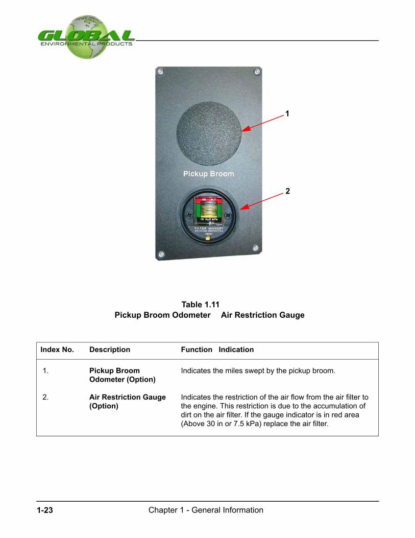
Table 1.11 Pickup Broom Odometer & Air Restriction Gauge
1
2
Index No. Description Function / Indication
1. Pickup BroomOdometer (Option)
Indicates the miles swept by the pickup broom.
2. Air Restriction Gauge(Option)
Indicates the restriction of the air flow from the air filter tothe engine. This restriction is due to the accumulation ofdirt on the air filter. If the gauge indicator is in red area(Above 30 in or 7.5 kPa) replace the air filter.

1-24Chapter 1 - General Information
Fig: 1.22 A
Fig: 1.22 B
STEERING COL UMN CONTROLS
The sweeper has power steering to help you steer the
sweeper easily. Never hold the steering wheel in the ex-
treme left or right position for more than five seconds if the
engine is running.
The following controls are located on the steering column:
D Turn Si g na l Le ve r You can use the turn signal leveron the left side of the steering column to operate turnsignals, turn the headlights to high beam or flash head-lights.
Usually, the turn signals turn off automatically after youturn the sweeper. If the turn signal continues to flash
after you have made the turn, pull lever back to theneutral position.
To indicate a lane change to the right, push the turn sig-nal lever up slightly (without latching) and hold it inposition. To indicate a lane change to the left, push theturn signal lever down slightly (without latching) andhold it in position. The lever will return to the Off positionwhen you release it.
D High Be a ms To turn on the high beams, turn theheadlights on and push the turn signal lever away fromyou until it latches. When the high beams are on, theblue high beam indicator lights on the instrument panelis illuminated.
D Tilt Steeri ng Whe e l Pull lever up to adjust steeringwheel to desired position then release lever to locksteering wheel in place.
Do not adjust steering wheel while thesweeper is in motion.
D Te le s c ope St e e ring Whe e l This is the same leverused for tilt steering wheel. To telescope steering pushlever down and adjust steering height to comfortableposition.
D Horn Pa d To sound the horn, press the center padon the steering wheel firmly. Check the horn regularly tomake sure it operates properly.
D Hazard Flas he r Sw itc h The hazard flasher is usedto alert other drivers to hazardous situations.
The hazard flasher switch operates the same lights asthe turn signal lever. When the hazard flasher is acti-vated, all of these lights will flash on and off. The turnsignal indicators cannot be used when the hazardlights are flashing. Operation of the hazard flashersdoes not affect operation of the brakelights.
To use the hazard flasher, pull the HAZARD switch;you’ll see the turn signal arrows flash.
To stop the hazard flasher, push the HAZARD switch.

Chapter 1 - General Information1-25
Fig: 1.23 A
SEA T ADJUST MENTS
Perform weight, height, fore and aft seat adjustments prio rto driving the sweeper.
D Weig ht/Ride Air Adjus tme nt With no weight onseat, set desired weight adjustment. On the bottomright side of seat, push and turn knob to raise/stiffenbounce and pull to lower/soften bounce.
D He ight Adjus tme nt Height of seat is adjustable tofour levels. To raise, pull lever on left side and lift seatuntil it automatically engages. To lower seat, pull leverand let weight of operator push seat down to next level.
NOTE: Adjust Tether Belt after changing seat height.
D Fo re and Aft Adjus tme nt Pull up on left side fore/aftadjustment bar and slide seat to desired position. Theoperator must be able to comfortably reach all cab con-trols.
D Arm Rests Armrests may be positioned up or down.In up setting, arm rests are flush with seat backing.
SAFET Y RE S TRAINTS
Using safety belt will help to restrain you and your com-
panion in case of rough ride or collision. In most states, the
law requires their use.
D Sea t Bel t Adju stm en t Seat belt is a common lift typerelease with a shoulder harness. Insert the tongue intothe buckle until it snaps and locks into place. Adjustbelt by pulling extra strap material through buckle.
D Te the r Bel t Adju stm en t Tether belt is a safety devicethat allows seat to travel up to a maximum distance. In-sert the tongue into the buckle until it snaps and locksinto place. Adjust belt by pulling extra strap materialthrough buckle.
NOTE:Adjust tether strap tight enough to eliminate chanceof operator from hitting roof of cab during a rough ride.
SIDE VIEW MIRRORS
Close your door and adjust the driver’s seat to the most
comfortable position before you adjust the side view mir-
rors.
If you have a manually adjusting side view mirrors, you can
adjust them in any direction by moving the mirror head.
Make sure you can see clearly throughthe side viewmirror at all times. Do notallow anything to block your vision.
Be careful. The convex side view mir-rorsmakes objects appear smaller andfarther away than they actually are.
Do not adjust the side view mirrorwhile the sweeper is in motion.

2-1Chapter 2 - Sweeper Operation
Start--Up ChecklistStart--up Checklist 2--3.................................
Starting the EngineStarting Engine 2--5....................................Ignition Positions 2--5...................................Before Starting the Engine 2--6....................Starting the Engine 2--6...............................Warm--up Procedures 2--6...........................Stopping the Engine 2--6.............................
Driving the SweeperDriving the Sweeper 2--7.............................Driving in Normal Conditions 2--7.................Driving in Hazardous Conditions 2--8...........
SweepingSweeping 2--8.............................................Filling the Water Tank 2--8...........................Preliminary Sweeping Procedures 2--8........Driving in Sweep Mode 2--9........................
DumpingBefore Unloading the Sweeper 2--9.............Unloading Procedure 2--10...........................Raising the Hopper 2--10...............................Emergency Hopper Lift 2--10..........................
ElevatorElevator Stall 2--11
........................................Clearing Obstruction from the Elevator 2--11
.
Parking2--12.................................................
Table of ContentsSubject Page
Parking the SweeperParking Procedure 2--12...............................
Towing the SweeperTowing 2--13...................................................Emergency Towing 2--13...............................Special Towing Instruction 2--13....................Rear End Towing Procedure 2--14.................Unhitch From Towing Vehicle (Rear Tow) 2--14.Front End Towing......................................2--14Unhitch From Towing Vehicle (Front Tow)....2--15
Jacking the SweeperJacking the Sweeper................................2--15
FiguresFig. 2.3A Sweeper.............................2--3Fig. 2.4A Hydraulic Tank Gauge 2--4. .Fig. 2.4B Engine Oil Fill 2--4.................Fig. 2.4C Engine Coolant 2--4.............Fig. 2.5A Brake Cylinder Reservoir 2--5Fig. 2.5B Shifter Controls 2--5.............Fig. 2.5C Ignition Switch 2--5...............Fig. 2.8A Beacon Light 2--8.................Fig. 2.11A Emergency Hopper Lift 2--11. .Fig. 2.11B Hopper Up 2--11....................Fig. 2.11C Prop Rod 2--11........................Fig. 2.12A Shifter-- Park 2--12.................Fig. 2.12B Sweep Gear Up 2--12.............Fig. 2.12C Gutter Broom No--Step 2--12. .Fig. 2.13A Front Tow Eyelet 2--13...........Fig. 2.13B Rear Tow Eyelet 2--13...........Fig. 2.13C Rear Axle Shaft 2--13.............Fig. 2.15A Rear Jacking Point 2--15........
Subject Page
Sweeper Operation
CHAPTER 2
Start--Up ChecklistStart--up Checklist 2--3.................................
Starting the EngineStarting Engine 2--5....................................Ignition Positions 2--5...................................Before Starting the Engine 2--6....................Starting the Engine 2--6...............................Warm--up Procedures 2--6...........................Stopping the Engine 2--6.............................
Driving the SweeperDriving the Sweeper 2--7.............................Driving in Normal Conditions 2--7.................Driving in Hazardous Conditions 2--8...........
SweepingSweeping 2--8.............................................Filling the Water Tank 2--8...........................Preliminary Sweeping Procedures 2--8........Driving in Sweep Mode 2--9........................
DumpingBefore Unloading the Sweeper 2--9.............Unloading Procedure 2--10...........................Raising the Hopper 2--10...............................Emergency Hopper Lift 2--10..........................
ElevatorElevator Stall 2--11Clearing Obstruction from the Elevator 2--11
Parking the SweeperParking .....................................................2--12
Cummins Driver TipsCummins Driver Tips . . . . . . . . . . . . . . . 2 -2

Chapter 2 - Sweeper Operation2-2
If the MIL Lamp is illuminated with the red stop engine lamp, the vehicle should be stopped as soon as it is safe to do so. it should then be taken to an authorized Cummins location for repair.
Illuminated-An illuminated DEF lamp is an indication that the DEF level is low. This can be corrected by refilling the DEF tank with Diesel Exhaust Fluid.
Flashing DEF-A flashing DEF lamp indicates that the DEF level has fallen below a critical level. This can be corrected by refilling the DEF tank.
Flashing DEF lamp with Check Engine lamp/ Amber Warning lamp-A flashing DEF lamp combined with an illuminated Check Engine lamp/ amber warning lamp indicates that the DEF level is critically low and you will experience a power loss. Normal engine power will be restored after refilling the DEF tank.
Diesel Exhaust Fluid For Selective Catalytic Reduction (SCR) Aftertreatment.
Flashing DEF lamp with Check Engine lamp/ Amber warning lamp and stop engine lamp-When you Def gauge reads zero and the engine has been shut down, has idled for one hour after the DEF tank has been run dry or if the vehicle's diesel fuel tank is refilled without refilling the DEF tank, the Stop Engine lamp will also be illuminated, along with the flashing DEF lamp and the illuminated check engine lamp/amber warning lamp. Engine power will continue to be reduced automatically. The vehicle will also be limited to a speed of 5 miles (8km) per hour. Normal engine power and vehicle speed will be restored after refilling the DEF tank.
Diesel Particular Filter (DPR)
High Exhaust System Temperature (HEST) Lamp-The HEST lamp illuminates to indicate that the high exhaust temperatures may exist due to aftertreatment regeneration. This is normal and does not ignify the need for any kind of vehicle service or engine service. When this lamp is illuminated, ensure that the exhaust pipe outlet is not directed at any combustible surface or material. Reference your Cummins Owners Manual for complete instructions.
Aftertreatment Diesel Particulate Filter (DPF) lamp-When illuminated or flashing, the aftertreatment DPF requires regeneration. This is accomplished by the following.
1. If the vehicle is equipped with a regenerationinhibit Switch, ensure that the switch is not in the inhibit posistion.
2. Perform a DPF regeneration by one of thefollowing methods:
a. change to a more challenging duty cylce.such as highway, for atleast 20 minutes to increse exhaust temperatures.
b. Perform a parked regeneration.
Flashing Regeneration-If a regeneration is not performed in a timely manner after the DPF lamp is illuminated, the DPF lamp will begin to flash. This indicates a higher level of PM in the DPF. In addition, engine power may be reduced automatically.
Flashing with check engine lamp/amber warning lamp-Indicates that the aftertreatment DPF needs regeneration immediately. Engine power will be reduced automatically. A parked regeneration is required.
Stop Engine Lamp-If a parked regeneration is not performed, the red stop engine lamp will illuminate. As soon as it is safe to do so, the vehicle should be stopped. It should then be taken to an authorized Cummins location for repair.
Chapter 2 - Sweeper Operation 2-3
jthompson
Line
jthompson
Line

Regeneration Inhibit Switch
The purpose of this switch is to prevent or disable aftertreatment DPF regeneration. Reference the vehicle Owners Manual for complete operation and use of this switch. Unnecessary or excessive use of the Regeneration Inhibit Switch will result in a loss of fuel economy, or an increased need for parked regeneration.
How To Perform A Parked (Stationary) Regeneration.
If the vehicle has a Manual Regeneration Switch and the DPF Lamp is flashing:
■ Park vehicle in an appropriate location, set parking brake, and place transmission in Park (if provided) or Neutral, and allow up to one hour for the regeneration.
■ Set up a safe exhaust area. Confirm that nothing is on or near the exhaustsystem surfaces.
■ Ensure that your fast-idle and Power Take-Off switches are off before startingregeneration.
■ Push the Manual Regeneration Switch to begin a parked regeneration. Note:Engine speed will increase, and there may be a noticeable change to the sound of the turbocharger during the regeneration process. Once the DPF is regenerated, the engine will automatically return to the normal idle speed.
■ Monitor the vehicle and surrounding area during regeneration. If any unsafe condition occurs, shut off the engine immediately. To stop a parked regeneration, depress the clutch, brake or throttle pedal.
■ Once regeneration is complete, exhaust gas and exhaust surfacetemperatures will remain elevated for 3 to 5 minutes. Reference your Cummins Owners Manual and Vehicle Owners Manual for complete operating instructions.
Fuel, Oil And DEF.
■ Use only Ultra-Low Sulfur Diesel (ULSD) fuel.
■ CJ-4 (low ash) is the recommended oil.
■ Be sure to check the DEF gauge at every refueling. Cummins recommendstopping off the DEF tank when refueling. DEF meeting ISO 22241-1 must be used.
■ Please read your vehicle manufacturer’s OwnersManual to familiarize yourself with the location andcapacity of the DEF tank.
■ Put only DEF in the DEF tank, which has a blue cap.
Chapter 2 - Sweeper Operation2-4
jthompson
Line
jthompson
Line

Cummins Care.
Our authorized service technicians are fully trained to promptly handle any type of service issue. Call Cummins Care at 1-800-DIESELS™ (1-800-343-7357), and you’ll get 24/7/365 assistance from a Cummins Care representative. Ifyou need service, your Cummins Care representative will locate the nearest available and authorized facility.
Items Driver Will Notice.
■ Under certain conditions (cold or very dry), condensation in the form of watervapor can be seen coming from the vehicle tailpipe. This is normal. It will clear within a few minutes of normal vehicle operation.
■ If the engine is left at idle for significant periods of time without reachingthe minimum exhaust operating temperatures, the engine will automatically increase the engine idle speed for several minutes to maintain the condition of the particulate filter. This can be interrupted by pressing either the service brake or the clutch.
■ After prolonged idle, you may notice momentary white vapor and an odor. Thisis normal.
■ When the High Exhaust System Temperature Lamp is illuminated, you maynotice an odor. This is normal. If the odor is excessive and you also notice white vapor, have the exhaust system inspected for leaks.
Tips For Efficient Driving.
1. Lower drive speeds – At interstate speeds, each 1.0 mph (1.6 kph) increaseequals a 0.1 mpg (0.04 km/L) decrease. For example, driving at 65 mph instead of 70 mph can save 0.5 mpg (0.21 km/L) and create roughly a 7 percent improvement in fuel economy.
2. Run in top gear more than 90 percent of the time – Every 10 percent dropin time in top gear equals approximately a 3 percent to 5 percent decrease in fuel economy.
3. Decrease idle rpm and idling time – Using the lowest idle speed possible helps reduce fuel use by up to 0.5 gal/hr (1.89 L/hr). Every hour of idle time that you eliminate can increase your vehicle’s fuel economy by as much as1 percent.
4. Follow proper driving habits – Sudden braking, rapid acceleration, early downshifting and other poor driving habits can negatively impact fuel economy by as much as 30 percent.
Additional information is available in our “10 Tips To Maximize Fuel Economy”brochure, Bulletin 4971341, which can be downloaded at cumminsengines.com. Or ask your local Cummins distributor or dealer for a copy.
Chapter 2 - Sweeper Operation 2-5
jthompson
Line
jthompson
Line

2-6Chapter 2 - Sweeper Operation
START---UP CHECKLIST
The condition of the sweeper prior to start---up is a very
important factor as it directly affects the operator’s safety
as well as those around him. It should be a common prac-
tice to the operator to perform preliminary inspection on a
daily basis. The purpose of the inspection is to keep the
equipment in proper working condition and to detect any
signs of malfunction. These inspections aid in trouble---
free operation reducing wear and mechanical failure.
Daily Check List
1. Lightsn
2. Tires n
3. Water Spray Level n
4. Fuel Level n
5. Air Cleaner Service Indicator n
6. Radiator and Oil Cooler n
7. Belts n
8. Hydraulic Oil n
9. Engine Oil n
10. Engine Coolant n
11. Coolant and Oil Leaks n
12. Brake Fluid n
13. Charge Air Cooler n
14. Service and Lubrication n
1. Lights It is a good idea to check the operation of
the following lights frequently:
- Headlights
- Taillights
- Brakelights
- Hazard Flasher
- Turn Signal
- Flood Lights
- Beacon Lights
2. Tire s Visually check tires for correct inflation daily.Front-tireManufacturer Recommended air pressure(9R22.5F), Rear=tireManufacurer recommended airpressure (315/80R22.5J). If one tire looks lowerthan theothers, check thepressure in all of them.Per-form inflation checks when tires are cool.
- Keep your tires inflated to the recommendedpressures.
- Stay within the recommended load limit.
- Drive sweeper at safe speeds
NOTE: If you don’t take these precautions, your tires mayfail or go flat.
3. Wate r Level Check water spray level. Add wateras required. (ref ---Filling Water Tank procedure in thischapter).
4. Fu e l Lev el Turn ignition key todrivingposition and
observe fuel gauge. Add fuel as required.
5. Air Cle a ne r Service Indicator Check air cleanerservice indicator daily. Cleanor replace air cleaner fil-ter element before yellow indicator spool reaches redline. Reset indicator after servicing air cleaner.
NOTE: Frequent air cleaner cleaning is necessary whensweeping under severe dusty conditions.
5. DEF Fluid Level --- Turn ignition key to drivingposition and observe DEF Fluid Level gauge.Add DEF Fluid as required.
5. Air Cleaner Service Indicator Check air cleaner
service indicator daily. Clean or replace air cleaner fil-
ter element before yellow indicator spool reaches redline. Reset indicator after servicing air cleaner.
NOTE: Frequent air cleaner cleaning is necessary whensweeping under severe dusty conditions.
6.

Chapter 2 - Sweeper Operation2-7
damage, leaking weldments, and clogged fins. Re-
pair all leaks and clean clogged fins. Visually checkmounting screws for proper tightness.
NOTE: Visually check and clean radiator daily.
Belts Check all engine driven belts (commonly re-ferred to as fan belts) for wear and tension. Beltsshould reflect 1/2 inch free play when a force of 12pounds is applied between pulleys. Adjust the AC
belt tension as required. Replace worn belts.
8. Hydraulic Oil Checkoil level in eachof thehydrau-
lic tank sight gauges located outside of hopper tow-ers. Sweepermust be on a level groundwhen check-ing oil level. With engine OFF add hydraulic oil (ISO60 AW---WR) as required.
Do not attempt to check for HYDRAU-LIC OIL LEAKS without hand and eyeprotection. Hydraulic oil under pres-sure can penetrate skin and cause se-vere injury.
9. Engine Oil Stop engine before checking engine oil level. Remove dipstick, wipe clean and re---insert intoengine. Then remove dipstick and check oil level byobserving gradient lines. Oil level should indicate be-tween Add and Full marks. If necessary, add oil(15W---40MustMeetCES20081)by removingoil fillercap. Never over fill engine with oil (Fig 2.4B).
NOTE:When inserting, ensure that dipstick is fully seatedto get a proper oil level reading and prevent contaminationfrom entering engine.
10. Engine Coolant Check engine coolant level atdeaeration tank. If coolant is not visible in betweenmaximum and minimum fill lines, wait for radiator tocool, remove filler cap and add coolant as required.Shell Rotella Prediluted Extended Life Coolant--94042 (RELC) When filling coolant, open coolantvalve on top of engine. When beginning to fill, closevalve and continue filling until air bubbles start tocome out of engine plumbing.
Fig. 2.4 A
Fig: 2.4 B
Coolant Fill
Fig: 2.4 C
Oil Dipstick
Oil Fill
(ISO 46) as required.
Belts Check all engine driven belts (commonly re-ferred to as fan belts) for wear and tension. Beltsshould reflect 1/2 inch free play when a force of 12pounds is applied between pulleys. Adjust the AC
belt tension as required. Replace worn belts.
8. Hydraulic Oil Checkoil level in eachof thehydrau-
lic tank sight gauges located outside of hopper tow-ers. Sweepermust be on a level groundwhen check-ing oil level. With engine OFF add hydraulic oil (ISO60 AW---WR) as required.
Do not attempt to check for HYDRAU-LIC OIL LEAKS without hand and eyeprotection. Hydraulic oil under pres-sure can penetrate skin and cause se-vere injury.
9. Engine Oil Stopenginebeforecheckingengineoillevel. Remove dipstick, wipe clean and re---insert intoengine. Then remove dipstick and check oil level byobserving gradient lines. Oil level should indicate be-tween Add and Full marks. If necessary, add oil(15W---40MustMeetCES20081)by removingoil fillercap. Never over fill engine with oil (Fig 2.4B).
NOTE:When inserting, ensure that dipstick is fully seatedto get a proper oil level reading and prevent contaminationfrom entering engine.
10. Engine Coolant Check engine coolant level atdeaeration tank. If coolant is not visible in betweenmaximum and minimum fill lines, wait for radiator tocool, remove filler cap and add coolant as required.Shell Rotella Prediluted Extended Life Coolant--94042 (RELC) When filling coolant, open coolantvalve on top of engine. When beginning to fill, closevalve and continue filling until air bubbles start tocome out of engine plumbing.
7. Radiator and Oil Cooler - Check radiator and oilcooler for leaks. Inspect radiator and oil cooler for
8.7.7.
9.
10.
11.
(ISO 46) as required.
Global M4 Series Operator Manual

2-8Chapter 2 - Sweeper Operation
Never remove deaeration tank cap orany radiator hose when ENGINECOOLANT is hot.
11. Coolant and Oil Leaks Check for fluid leaks byinspecting the surface beneath the sweeper for oil,coolant and other fluid drips.
12.Brake Fluid Check the brake fluid level in themaster cylinder. Fluid level should indicate betweenAdd and Full marks. If necessary, add fluid (BrakeFluid DOT 3 or equivalent).
13.
Charge Air Cooler Check charge air cooler for
leaks.
14.
ServiceandLubrication Performall daily service
and lubrication functions.
STARTING ENGINE
As previously indicated, it is important from a safe opera-tional standpoint that you theoperator knowyour sweeperbefore starting the engine. This means knowing the func-tion of each control as to what happens when it is acti-vated, how it might interact with other functions and any
limitations that might exist. A good understanding of thecontrols and capabilities will enhance operation and as-
sure maximum operating efficiency and safety.
Ignition Positions
The sweeper’s ignition has four positions:
- OFF position allows you to shut off the engine and allaccessories.
NOTE: The OFF position is the only position that allowsyou to insert and remove the key from the ignition.
- ON position allow you to test the sweeper’s warninglights to make sure they work before you start theengine. The key returns to the ON position once theengine is started and remains in this position whilethe engine runs.
(Master Cylinder Reservoir) Fig: 2.5 A
Fig: 2.5 B
Accessory
Off
On
Start
Fig: 2.5 C
12.
13.
14.
15.
Chapter 2 - Sweeper Operation2-9
Release the key once the engine startsso that you do not damage the starter.
- ST ART position allows you to crank the engine. Re-lease the key once the engine starts so that you don’t
damage the starter.
- ACCES S ORY positionallowsyou tooperate someofthe sweeper’s electrical accessories while the engine
is not running.
Before starting the EngineBefore you start the sweeper, always:
1. Make sure you close and lock the door.
2. Make sure you fasten your safety belt.
3. Make sure you adjust the rearview mirrors.
4. Make sure the sweep gear, headlights and otheraccessories are turned OFF when starting the en-gine.
5. Make sure that the shifter is inPark (P)positionbeforeyou turn ON the ignition key.
Starting the Engine
Normal starting procedure will fire up the engine in most
conditions. To start the engine:
1. Make sure the shifter is in Park (P) position. Theengine will not start with shifter in any other position.
2. Place the Speed Travel Switch to Travel mode (makesure that the GB switch is in the “OFF” position).
3. Insert and turn the IgnitionKeySwitch toONposition.
Check the dash controls and monitor instruments.
4. Proceed to turn the Ignition Switch to the far right toengage starter. As soon as the engine has started,
release ignition key switchallowing it to automatically
return to ON position.
Do not engage the STARTER MOTORfor more than30secondsat a time. Al-low thestartermotor to cool for at least3minutesbetweenstartingattempts toavoid heat damage to the starter mo-tor.
5. DoNOT press on the accelerator until the engine hasstarted and the status indicator lights on the dashmonitor have turned off, as this will enter an unnec-essary fault code in the engines’ computer system.
6. The engine oil pressure gauge should read 20 PSIminimumwithin 30 seconds. If the oil pressure is low,immediately turn the IgnitionKey toOFFposition.No-tify a qualified mechanic to determine and correctcause of low oil pressure.
7. Allow the engine and hydraulic pumps towarmup fora few minutes before driving the sweeper or perform
ing any hydraulic operations.
Vehicle Warm--up Procedure
It is recommended that a short warm---up period between
10 to 15minutes be part of the pre---operating procedures
for the sweeper. This warm---up period will allow the oil in
the hydrostatic drive system to reach the desired tempera
ture and consistency for safe and smooth operation.
Stopping the Engine
1. Allow the engine to idle 3 to 5minutes before shutting
it off after a full --- load operation. This allows adequate
cool down of pistons, cylinders, bearings, and
turbo---charger components.
2. Turn OFF all the sweeping functions and acces-
sories.
3. Turn the ignition keyswitch to the OFF position.
2-10Chapter 2 - Sweeper Operation
DRIVING THE SWEEPER
Always operate the sweeper within reasonable limits.
Abrupt changes in acceleration, deceleration, turning, or
combinations of both of these maneuvers can cause the
sweeper to behave differently than anticipated, especially
when road conditions vary.
Use greater care until you become accustomed to its
features and characteristics.
There are two distinct methods of driving sweeper. One isthe normal street or highway travel mode and the other isthe sweep---drivingmode. Sweep---drivingmode is simplydriving the unit with the sweep gear lowered and operat-ing.
NOTE: In a safe area designed specifically for training, firsttime operators should practice driving, turning, accelerat-ing, stopping and familiarizing themselves with theG lobal-M4 Series sweeper.
Observe all safety precautions whileoperating the sweeper.
Driving in Normal Conditions
1. Position yourself in the driver’s seat andmakeadjustment to your comfort.
2. If necessary make adjustment to the steering wheelheight (telescope) and tilt.
3. If necessary adjust your side view mirrors.
4. With the engine running, check that all sweep gear isin the OFF position. Press the hopper switch to lowertomake sure it is completely down or traction systemwill not shift into gear with hopper out of travel posi-tion.
5. Actuate Travel/Sweep Switch to Travel position.
6. Select High or Low axle speed switch.
- The two speed axle switchHigh --- Shifter Posi-tion Lo (L) maximum speed is 23-25 MPH
(37- 40 km/h).
- Speedaxle switchLo w ---Shifter PositionLo (L)maximum speed is 12 MPH.
NOTE: High and Low speed axle switch can only bechanged while shifter is in Park (P) position.
Do not shift to PARK while sweeper is inmotion.
7. Place shifter to Hi (H) or Lo (L) position.
- Shifter Position Hi (H) --- Speed axle switchHigh maximum speed is 54- 57 MPH
(87- 92 km/h).
- Shifter Position Hi (H) --- Speed axle switch Lowmaximum speed is 45 MPH.
8. Activate accelerator pedal to regulate travel speed.
Hold foot on accelerator pedal to stabilize speed.
9. When reducing sweeper speed, slowly removepressure from the accelerator pedal.
When go--pedal is fully released,hydraulic drive system automaticallyapplies hydrostatic braking. Wheel brakeis applied with the foot brake pedal.
Do not drive sweeper with your footresting on the brake pedal.
10.To drive in reverse, position shifter inReverse (R) andstep on the accelerator pedal. When backing upsweeper, warning alarms sounds and back up light il-luminates cautioning bystanders to stay clear.
NOTE:Make sure the sweeper is completely stoppedbefore shifting into Reverse (R).
Whenever sweeper is traveling at slowspeed, Tuarn ON beacon flasher asa safety precaution.
15 - 17 MPH (24 - 27 km/h).
42 - 46 MPH (67-74 km/h).
2:11 Chapter 2 -- Sweeper Operation
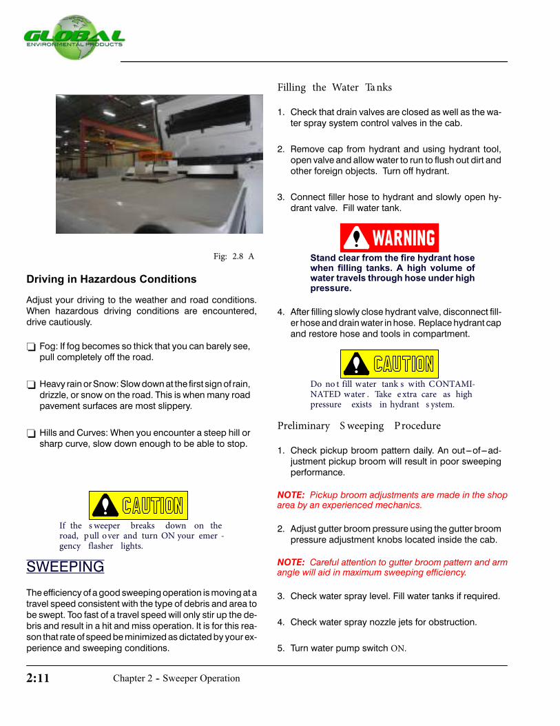
Fig: 2.8 A
Driving in Hazardous Conditions
Adjust your driving to the weather and road conditions.When hazardous driving conditions are encountered,drive cautiously.
- Fog: If fog becomes so thick that you can barely see,pull completely off the road.
- Heavy rain or Snow: Slow down at the first sign of rain,drizzle, or snow on the road. This is when many roadpavement surfaces are most slippery.
- Hills and Curves: When you encounter a steep hill orsharp curve, slow down enough to be able to stop.
If the s weeper breaks down on theroad, pull over and turn ON your emer -gency flasher lights.
SWEEPING
The efficiency of a good sweeping operation is moving at atravel speed consistent with the type of debris and area tobe swept. Too fast of a travel speed will only stir up the de-bris and result in a hit and miss operation. It is for this rea-son that rate of speed be minimized as dictated by your ex-perience and sweeping conditions.
Filling the Water Ta nks
1. Check that drain valves are closed as well as the wa-ter spray system control valves in the cab.
2. Remove cap from hydrant and using hydrant tool,open valve and allow water to run to flush out dirt andother foreign objects. Turn off hydrant.
3. Connect filler hose to hydrant and slowly open hy-drant valve. Fill water tank.
Stand clear from the fire hydrant hosewhen filling tanks. A high volume ofwater travels through hose under highpressure.
4. After filling slowly close hydrant valve, disconnect fill-er hose and drain water in hose. Replace hydrant capand restore hose and tools in compartment.
Do no t fill water tank s with CONTAMI-NATED water . Take e xtra care as highpressure exists in hydrant s ystem.
Preliminary S weeping Procedure
1. Check pickup broom pattern daily. An out---of---ad-justment pickup broom will result in poor sweepingperformance.
NOTE: Pickup broom adjustments are made in the shoparea by an experienced mechanics.
2. Adjust gutter broom pressure using the gutter broompressure adjustment knobs located inside the cab.
NOTE: Careful attention to gutter broom pattern and armangle will aid in maximum sweeping efficiency.
3. Check water spray level. Fill water tanks if required.
4. Check water spray nozzle jets for obstruction.
5. Turn water pump switch ON.
2-12Chapter 2 - Sweeper Operation
Driving in Sw e e p Mode
With water tanks full and having arrived at the sweep area
stop sweeper and set the various hydrostatic drive con-
trols to the appropriate position for SWEEPING MODE.
1. Determine from your experience the best travelspeed to enable an efficient and satisfactory sweepoperation.
- Travel/Sweep Mode Switch --- Place the switch in
SW EEP position.
-
RPM Switch --- Adjust engine RPM speed untilTACHOMETER read out is between 1800 & 2100
RPM (Do not exceed 1975 RPM) .
- Shifter --- Move shifter to LO (L) position.
2. Turn ON Emergency Flashers, Rotating Beacon andother warning lights.
3. Lower gutter brooms to pavement by actuating theGB RIGHT and GB LEFT switches to LOWER. Holddown switch and check DOWN PRESSURE gaugefor setting.
4. Actuate GB DRIVE switches to start rotation op-eration of brooms. One or both broomsmay be used
depending on the sweep application.
5. Lower the PICKUP broom by actuating the switch toLOWER.
6. Start operation of pickup broom and elevator by ac-tuating DRIVE switch to FORWARD position. Bothoperate from same switch.
7. Activate water spray system by placing water pump
switch to ON position.
8. TurnON andadjustwater volume to each spray bar ofthe gutter broom and front nozzle bar by controlslocated behind buddy seat.
9. Step on the go---pedal to start sweeping. Travel
speed can be varied to maximum sweep speed bythe accelerator pedal.
Remove large objects from the sweep-ing path and manually load large ob-jects through the hopper access door.
10.Continuously monitor all instruments and gauges
while sweeping.
11.Using the rear viewmirrors, observe the swept path to
ensure it is clean. If not, stop anddetermine the cause
of the problem.
Observe all local and state traffic lawsand regulations.
Avoid sweeping near bystanders andtake extra precautions in and aroundcongested areas.
DUMPING
During the sweep operation or at the end of shift, it maybe necessary to empty collected debris from the hopper.The hopper is designed to dump from the right hand side of the sweeper. The large hopper discharge door allows un-loading of debris into a trash bin at the sweepsite or at the dump site.
Before Unload ing the Sw e e pe r
Before you unload the sweeper, always:
1. Make sure sweeper is parked firmly on level ground
2. Check overhead area above the sweeper for anyobstructions such as trees, power lines, streetlighting or street signs.
3. Make sure bystanders are clear from the sweeper.
RPM Switch -- Adjust the engine RPM speed untilTACHOMETER read out is around 2300 RPM.(Do not exceed 2600 RPM)
Chapter 2 - Sweeper Operation2-13
Unloading Procedure
1. Place shifter in Park (P) position to engage parkingbrake.
2. Actuate hopper switch to Raise and continue to holdswitch until hopper is fully elevated.
Unloading a full hopper changes thesweeper’s center of gravity and can tipthe sweeper resulting in severe injuryor property damage. DO NOT raisehopper unless sweeper is parked firm-ly on level ground.
Stay clear of electrical power lines andother overhead obstructions. A clear-ance of approximately 12 to 15 feet isrequired.
As the hopper is being unloaded, de-bris in the hopper will be discharged.Be sure bystanders are clear fromsweeper until hopper is emptied.
3. Once the hopper is empty and cleaned out, actuate
the hopper switch to Lower position and hold untilhopper is fully lowered.
NOTE: Sweeper will not shift into gear with hopper still outof travel position.
Raising the Hopper
Sometimes it is necessary to raise hopper in order to clean
inside the hopper, check the engine, or check the elevator.
When raising hopper other than unloading, install safety
props on the both hopper cylinder rods.
Do not raise hopper unless sweeper isparked on firm, level ground.
1. Always use safety props when working on, around, orunder raised hopper.
2. Always install safety props on both sides of scissor base.
3. Never position yourself under hopper while installingor removing safety props.
4. Be sure to clear any obstructions under the hopper andremove safety props before lowering the hopper.
Hopper may drift downwards when liftcylinders are not fully extended.
Serious injury or death may result ifhopper cylinders fail.
Auxilia ry Hopper Lift
If engine is inoperable, the hopper can still be lifted using
the auxiliary dumping ports and a portable hydraulic
pump.
1. Connect suction port from hydraulic tank to anexternal portable hydraulic pump (5 to 10 GPM @2500 PSI).
2. To raise the hopper, connect return line to the lower
port. (Fig: 2.11A).
3. To lower the hopper, connect return line to the upper
port. (Fig: 2.11A).
4. Always install safety props when hopper is in raised
or dump position.

2-14Chapter 2 - Sweeper Operation
Emergency HopperLift (Option)
Return Port toRaise Hopper Suction Port
From Tank
Fig: 2.11 A
Fig: 2.11 B
Prop Rod
Fig: 2.11 C
ELEVATOR STALL
The M4HSD Series sweeper includes optional Elevator Stall Alarm. When the elevator is running a sensor continuously detects the target point on the sprocket and sends an impulse signal to the stall alarm system. Once the signal is interrupted, after a five second delay, an alarm will sound indicating the elevator has stalled. An elevator stall condition is usually caused by an obstruction in the eleva-tor. Clear obstruction from elevator area before proceed-ing to sweep.
Clearing Obstruction from the Elevator
To clear obstruction from the elevator:
1. Bring the sweeper to a complete stop.
2. Place the shifter in Park (P) position.
3. Adjust theengine speed toapproximately 1500RPM.
4. Jog elevator/pickup broom switch to Reverse, Off,then Forward every few seconds until obstruction iscleared.
NOTE: If stall condition continues after several attempts to remove obstruction, drive sweeper to dump site and empty hopper.
With the hopper raised:
1. Stop the engine.
2. Install the hopper safetly props on scissor base .
3. Remove the obstruction from the elevator.
Stayclear of runningelevator. Person-al injury may occur.
NOTE: With hopper raised, install safety prop on scissor base. Safety prop rests on top scissor base. Install safety props on both sides.
Prop Rod
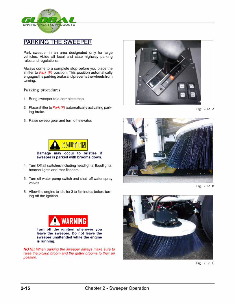
Chapter 2 - Sweeper Operation2-15
PARKING THE SWEEPER
Park sweeper in an area designated only for largevehicles. Abide all local and state highway parkingrules and regulations.
Always come to a complete stop before you place theshifter to Park (P) position. This position automaticallyengages theparkingbrakeandprevents thewheels fromturning.
Pa rking procedures
1. Bring sweeper to a complete stop.
2. Place shifter toPark (P) automatically activatingpark-ing brake.
3. Raise sweep gear and turn off elevator.
Damage may occur to bristles ifsweeper is parked with brooms down.
4. Turn Off all switches including headlights, floodlights,beacon lights and rear flashers.
5. Turn off water pump switch and shut--off water sprayvalves
6. Allow the engine to idle for 3 to 5minutes before turn-ing off the ignition.
Turn off the ignition whenever youleave the sweeper. Do not leave thesweeper unattended while the engineis running.
NOTE: When parking the sweeper always make sure toraise the pickup broom and the gutter brooms to their upposition.
Fig: 2.12 A
Fig: 2.12 B
Fig: 2.12 C

2-16Chapter 2 - Sweeper Operation
TOWING THE SWEEPER
If towing is necessary, GlobalEnvironmental Products,
Inc. recommends having it done by a commercial tow---
truck service. Proper lifting and towing procedures are
necessary to prevent damage to the sweeper. State and
local lawsapplicable tovehicle in towmustbe followed.Donot tow sweeper without strict adherence to instructionsin this manual. Strict procedures must be performed
before towing to alleviate further damage to inoperable
sweeper.
Emergency Towing
DoNot towsweepermore than100 feetusing the emergency towing pro-cedure. Serious damage may occur.
NOTE: The rear wheels will not turn during emergencytowing procedure due to parking brake engagement. Reartires will skid as the sweeper is being dragged.
1. Hitch front endof sweeper to towingvehicle (use rigidtow hitch).
2. Tow vehicle out of emergency situation.
NOTE:An alternative to towing is to transport the sweeperon a flat bed truck or trailer.
Special Towing Instructions
1. Follow all state and local laws that apply to vehicle intow including warning signals, night illumination,speed, etc.
2. Always use safety chains.
3. Sweeper should not be towed at speeds in excess of
20 mph (32km/h).
4. Remove any loose or protruding parts of sweeperprior to moving.
5. A safety chain systemcompletely independent of theprimary lifting and towing attachment must be used.
Fig: 2.13 A
Fig: 2.13 B
Fig: 2.13 C

Chapter 2 - Sweeper Operation2-17
6. Use only equipment designed for this purpose.
7. No towingoperation shouldbeattempted that for anyreason jeopardizes the safety of the operator or anybystanders or other motorists.
Rear End Towing Pr oc e dure
DoNot towsweepermore than100 feetusing the emergency towing pro-cedure. Serious damage may occur.
Only tow sweeper from rear using aproper tow bar spreader.
Do not exceed over 20 mph while tow-ingsweeper.Useextremecaution.Useproper tow--vehicle lighting. Observelocal towing regulations.
1. Usingaproper towbar spreader, hitch the rear endofthe sweeper to the towing vehicle through tow barson the back of sweeper.
2. With the rear of the sweeper hitched to the towingvehicle, raise the rear wheels off ground.
3. Ensure that the front wheels spin freely.
4. Make sure that the front wheels are aligned in thestraight ahead position and the steering wheel issecurely locked.
Secure steering wheel when towingsweeper from the rear otherwise se-rious damage may occur.
Unhitching the Sweeper From the TowingVehicle(Rear End Towing)
1. Lower sweeper to ground and unhitch tow bar fromsweeper.
2. Remove tow bar and chain from towing vehicle.
Front End Towing Procedure
Chock wheels before preparingsweeper for towing.
First remove axle shafts, then re-lease parking brake before towingsweeper.
1. Chock the rear wheels.
2. Remove the axle shafts from left and right wheelhubs. With axle shafts removed, axle ends must becapped to prevent dirt and water from entering axle.Store axle shafts and related parts in rear fender toolbox.
NOTE: An alternative method to preparing sweeper fortowing is to remove the drive shaft and universal joints(instead of axle shafts) from rear axle differential.
3. Hitch the front end of the sweeper to the towing ve-hicle (use rigid tow hitch).
Use proper tow--vehicle lighting.Observe local towing regulations.
4. Disengage the parking brake by mechanically un---
screwing theparkingbrake turnbucklecounterclock-
wise (relative to brake canister), until the spring iscompressed. Screw turnbuckle clockwise to engage
parking brake.
5. With the front end of sweeper hitched to towing ve-hicle, raise the front wheels off ground.
6. Ensure that the rearwheelsspin freelywithaxleshaftsremoved and parking brake disengaged.
7. Remove the wheel chocks.
NOTE:Remove the frontmagnet or front basket optionbefore towing sweeper from the front.

2-18Chapter 2 - Sweeper Operation
Unhitching the Sweeper From the TowingVehic le(Front End Towing )
1. Install thewheel chocks after towing transportation iscomplete.
Chock the wheels before unhitchingsweeper from tow vehicle.
First engage the parking brake, thenreplace sweeper the axle shafts.
2. Remove the parking brake hairpin from linkagescrew. Engage the parking brake by mechanicallyscrewing the parking brake turnbuckle clockwise(relative to brake canister) until spring is de-compressed.
3. Replace the parking brake release hairpin in linkagethe screw.
4. Lower the sweeper to ground and unhitch it from the
towing vehicle.
5. Check the parking brakes for proper operation.
6. Remove the axle end caps and replace the axle
shafts. Torque the axle end cap nuts at 65 to 75 foot
pounds.
7. Remove the wheel chocks.
JACKING THE SWEEPER
There will come a timewhen it may be necessary to safely
jack the sweeper to a position where you can either, ac-
cesscomponentsunder thesweeper, removeoneormore
wheel(s), raise the sweeper to lower vehicle components
when otherwise impossible (ie. rear axle) or just replacingcomponents which will make it easier to service the
sweeper raisedup. Inanycase, it is recommended that the
operatormust always read and understand the sweeper’s
manualbeforeattemptinganyservice items.Youwill be re-
quired to know and identify the factory approved ”jack
points”. These jackingpoints canbe found under Jacking
Procedure in the Service’s Manual.
D Jack---stands anda floor jackmust be strongenoughto lift and support the sweeper’s weight (about16,600 lbs for an empty sweeper).
D Before you consider jacking up a sweeper, find asflat/level a work area as possible. This is essential asyou do not want to have a sweeper leaning while upon jack stands.
If you can not find a nearly level workarea, DO NOT attempt to jack thesweeper up!
D If you are jacking the rear of the sweeper, be sure tochock the front wheels.
D If you are jacking the front of the sweeper, be sure tochock the rear wheels.
NOTE: The basic concept with chocking and locking thewheels (brakes) is to prevent the sweeper from shifting orrolling during the jacking procedure and through out theentire servicing procedure.
Safety is everyone’s responsibility. Do not take any chances to compromise personal safety and/or others around you.
Fig: 2.15 A
Global M4 Series Operator Manual
Rear Jack Point

Chapter 2 - Sweeper Operation2-19
This page intentionally left blank

3-1Chapter 3 - Sweeper Adjustments
Sweeper Adjustments
CHAPTER 3

Chapter 3 - Sweeper Adjustments3-2
This page intentionally left blank

3-3Chapter 3 - Sweeper Adjustments
PICKUP BROOM ADJUSTMENTS
There are several adjustments that must be checked in
order to maintain satisfactory sweeping. Learn the
procedures carefully to obtain the best results.
PressureadjustmentandConingadjustment to thepickupbroom must be checked daily to ensure sweeping ef-ficiencyandachievemaximumbroom life. Pressureadjust-ment needs to beperformeddaily. Coning adjustments onthe other hand, (also referred as leveling) rarely requiresadjustment but it should also be checked regularly.
The broom pattern is the width and length of the polishedarea made on the ground by the pickup broom when thebroom is turning while the sweeper is standing still.
Pickup Broom Pressure Adjustment
Check tire pressure prior to testing pickup broom patternto ensure proper adjustment. Recommended pickupbroom pressure patterns are 3 to 5 inches for light sweep-ing and 5 to 7 inches for heavy sweeping (Fig:3.3 A&B).Too much broom pressure produces a wide pattern caus-ing broom life to be significantly cut down. If pattern is toonarrow, broom will not sweep cleanly. To test broompattern, proceed as follows:
1. On level ground, select a test area to runabroompat-tern test. With all brooms off and raised, drivesweeper onto test site. Stopmachineandplace shifterin Park (P).
2. TurnON the elevator/pickup broomdrive switch. Runfor approximately 10 seconds at maximum1800
RPM.
3. Turn OFF elevator/pickup broom switch. Raisepickup broom and drive sweeper clear from patterntest area.
4. Place shifter in Park, shut down sweeper and exit cabto examine pattern.
Light Sweeping3’’ to 5’’ Pattern
Front
Fig: 3.3 A
Heavy Sweeping5’’ to 7’’ Pattern
Front
Fig: 3.3 B
5. Measure pattern (Fig: 3.3 A&B).
a. If not enough pressure exists, measurement isnarrow and broom does not sweep clean.
b. If too much pressure exists, measurement iswide and excessive broom wear results.
c. If pattern measurement is not equal on bothsides, repeat steps 1---5 with sweeper facingopposite direction and broom under the sametest

Chapter 3 - Sweeper Adjustments3-4
site. If pattern is unequal on the opposite side,pickup broomconing exists (ref ---Coning Adjust-ment). If the pattern is unequal on the same side,test surface is not level.
6. Adjust pickup broom pressure from left side of
sweeper by changing position of float spring linkage
on threaded adjustment bolt (Fig: 3.4B).
7. If narrow pattern exists, increase pickup broompressure.
a. Turn pickup broom spring linkage adjustment
bolt clockwise to increase broom pressure (Fig:3.4B).
8. If wide pattern exists, decrease pickup broom
pressure.
a. Turn pickup broom spring linkage adjustmentbolt counterclockwise to decrease broompres-sure (Fig: 3.4B).
Do not over--adjust bolt counterclock-wise. If pin shears, adjustment rod willpull out from bottom of bracket.
9. Repeat steps 7, 8 and 9 until desired pickup broom
pressure pattern is achieved.
NOTE: Adjust pickup broom pressure by raising or lower-ing spring linkage adjustment bolt on left side of sweeper.Turn clockwise to increase broom pressure and coun-terclockwise to decrease broom pressure.
Pickup Broom Snubber Adjustment
Snubber adjustment (broom free play) controls side toside pickup broommovement. Properly adjusted freeplayhelps eliminate broom bounce while sweeping as well asreducewearonpickupbroombristlesby allowing it to spinconcentric. The adjustable pickup broom shaft collar is onthe right side of sweeper opposite of the hydraulic drivemotor.
1. Follow standard procedures for lowering the pickupbroom. Turn Off engine.
Float Spring
Fig: 3.4 A
Float SpringAdjustment Bolt
Fig: 3.4 B
Pickup BroomLift Cylinder
Fig: 3.4 C

3-5Chapter 3 - Sweeper Adjustments
2. On the four (4) bolt flange bearing an adjustment col-lar (snubber) is located inward from the shaft. Loosentwo set of grub screws on adjustment collar behindshaft nut (Fig: 3.5B).
3. Remove cotter pin from pickup broom shaft nut andadjust assembly free play by turning shaft nut. Tight-en to reduce free play and loosen to increase freeplay. Correct free play adjustment is set at 1/32 of aninch (or slight drag).
4. Check pickup broom snubber for proper clearance.
The broom should slightly drag when spun.
5. Replace broom shaft cotter pin.
6. Tighten two grub screws on collar.
NOTE: Pickup broom shaft has several cotter pin holeslocated at various thread depths to allow proper snubberadjustment.
Pickup Broom Coning Adjustment
A level pickupbroomwill increase broom life aswell as im-prove sweeper performance. The pickup broom requiresconing adjustment if either of the following conditions ex-ist:
- Broom pattern measures wider on one side.
- Broom bristles are wearing quicker on one end.
Measure the length of bristles on each end of broom. Ifbristles vary slightly, an immediate adjustment will correctproblem and extend broom life. However, if bristles oneachendofpickupbroomvarymore thana1/2 inch, itmaybe difficult adjusting the broom to wear evenly again.
Pickup broom arms are connected to a shaft andadjustable clevis assemblies. The clevis assemblies areseparate from the float spring linkage on left sideof the sweeper. Although both left and right clevisassemblies areadjustable, it is common to only adjust theright side when leveling the pickup broom (Fig: 3.6A).
Pickup BroomMotor
Fig: 3.5 A
Grub Screws
Fig: 3.5 B
Shaft Nut
Fig: 3.5 C

Chapter 3 - Sweeper Adjustments3-6
Proceed as follows to make adjustments:
1. Park sweeper on a clean, level surface and raisepickup broom.
NOTE:Pickupbroomarmmeasurement is dependentonaflat level surface.
2. Measure distance from left pickup broomarm to levelsurface. Then measure distance from right pickupbroom arm to level surface.
3. If right and left measurements are not equal, adjust
the right clevis assembly that connects right pickupbroom arm to lift assembly.
a. Loosen lock nut and turn clevis to adjust length ofclevis assembly until left and right “arm toground”measurements are equal.
b. Tighten lock nut against clevis.
NOTE: Adjust pickup broom coning by raising or loweringright side of broom assembly. Turn adjustable clevis clock-wise to raise and counterclockwise to lower right side ofbroom.
Stay clear from running pickupbroom. Personal injury may occur.
Coning Clevis
Fig: 3.6 A
Pickup BroomArm
Fig: 3.6 B
Fig: 3.6 C

3-7Chapter 3 - Sweeper Adjustments
Coned Pickup Broom Strike Pattern(Incorrect)
1/2 inch
Less than 3 inches(Standard Sweep)
3 to 5 inches(Standard Sweep)
58 inches
Coned Pickup Broom(Top View)
32 to 18inches
1 or moreinches lessthan theother side
1/2 inch
3 to 5 inches(Standard Sweep)
Pickup Broom Strike Pattern(Correct)
58 inches
58 inches
Pickup Broom(Top View)
32 to 18inches
Fig: 3.7 A
Fig: 3.7 B

Chapter 3 - Sweeper Adjustments3-8
Pickup Broom Dirt Shoe Lift Adjus tme nt
Dirt shoes funnel debris in front of elevator and pickup
broom. An “out of adjustment“ dirt shoe causes debris tobe thrown out from under machine and left behind while
sweeping.
1. Lower pickup broom and check dirt shoe to groundclearance at front and back of dirt shoe.
2. Start with the first hole at the bottom of the dirt shoepivot mounting holes.
3. Push downback end of the dirt shoe bracket tomakeeven contact with the road surface. Adjust front of dirtshoe to no more than 1/8 of an inch from the ground.
4. Dirt shoe level adjustment is accomplished by liftingor lowering the two adjustment slots.
5. Lift and lower pickup broom several times and re---checkadjustmentwithbroom indownposition.Prop-erly adjusted dirt shoes slightly drag and ride parallelto sweeping surface.
6. Repeat steps 2, 3, & 4 to adjust dirt shoe on opposite
side of sweeper.
NOTE: Dirt shoe safety chain helps eliminate damage todirt shoe assembly caused while driving sweeper inreverse. Safety chain seldom requires adjustment.
Dirt Shoe Chain
Fig: 3.8 A
Shackle
Fig: 3.8 B
Dirt ShoeAdj Slots
Dirt Shoe PivotMounting Holes
Fig: 3.8 C
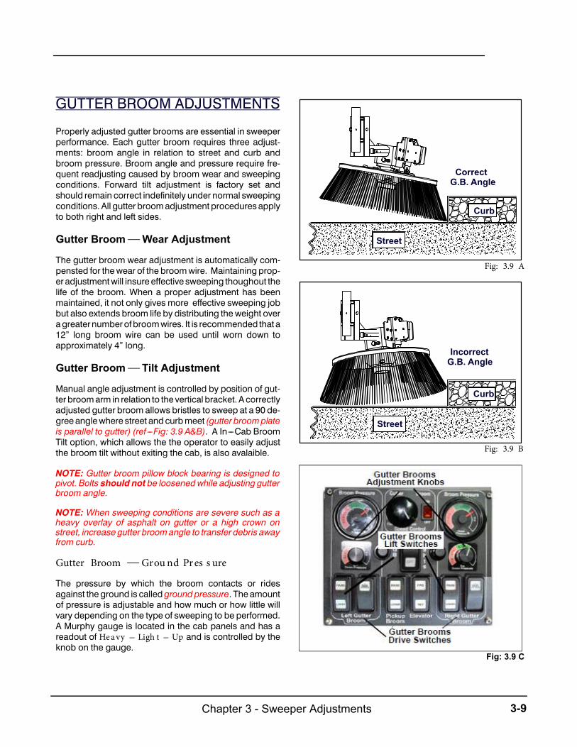
3-9Chapter 3 - Sweeper Adjustments
GUTTER BROOM ADJUSTMENTS
Properly adjusted gutter brooms are essential in sweeperperformance. Each gutter broom requires three adjust-ments: broom angle in relation to street and curb andbroom pressure. Broom angle and pressure require fre-quent readjusting caused by broom wear and sweepingconditions. Forward tilt adjustment is factory set andshould remain correct indefinitely under normal sweepingconditions. All gutter broomadjustment procedures applyto both right and left sides.
Gutter Broom Wear Adjustment
The gutter broom wear adjustment is automatically com-pensted for thewear of the broomwire. Maintaining prop-er adjustmentwill insure effective sweeping thoughout thelife of the broom. When a proper adjustment has beenmaintained, it not only gives more effective sweeping jobbut also extends broom life by distributing the weight overagreaternumberofbroomwires. It is recommended that a12” long broom wire can be used until worn down toapproximately 4” long.
Gutter Broom Tilt Adjustment
Manual angle adjustment is controlled by position of gut-ter broomarm in relation to the vertical bracket. A correctlyadjusted gutter broom allows bristles to sweep at a 90 de-gree anglewhere street andcurbmeet (gutter broomplateis parallel to gutter) (ref ---Fig: 3.9 A&B). A In---Cab BroomTilt option, which allows the the operator to easily adjustthe broom tilt without exiting the cab, is also avalaible.
NOTE: Gutter broom pillow block bearing is designed topivot. Bolts should not be loosened while adjusting gutterbroom angle.
NOTE: When sweeping conditions are severe such as aheavy overlay of asphalt on gutter or a high crown onstreet, increase gutter broomangle to transfer debris awayfrom curb.
Gutter Broom Grou nd Pr es s ure
The pressure by which the broom contacts or ridesagainst the ground is calledgroundpressure. The amountof pressure is adjustable and how much or how little willvary depending on the type of sweeping to be performed.A Murphy gauge is located in the cab panels and has areadout of He a vy --- Ligh t --- Up and is controlled by theknob on the gauge.
Street
Curb
CorrectG.B. Angle
Fig: 3.9 A
Curb
Street
IncorrectG.B. Angle
Fig: 3.9 B
GB Drive Switch
GB Lift Switch
GB PressureAdjustment Knob
Fig: 3.9 C
Fig: 3.9 C

Chapter 3 - Sweeper Adjustments3-10
An accumulator is installed in the system to establish andmaintain the amount of pressure being applied to thebroom. It balances out the pressure in the cylinder rodside. The gauge is equipped with an electrical contactswitch thatwill enable thebroomtobe lowered to thesamepressureaspreviouslypreset. Thiselectric signal opensorcloses the lowering valve unless the gauge is in Up posi-tion.
Gutter Broom Pressure Adjustment
Gutter broompressure is altered using left and right gutterbroom pressure adjustment switches in cab (Fig: 3.9C).Use the following procedures to test gutter broompressure.
1. On level ground, select a test area to run broom
pressure test. With all brooms off and raised,
drive sweeper onto test site. Stop machine and
place shifter in Park.
2. Run engine at 1800 rpm and perform the following
procedures (a thru f):
a. Lower gutter brooms. Pickupbroomshould beoff.
b.Turn On gutter broom drive switches and run forapproximately 30 seconds (DO NOT exceed 1800RPM).
c.Turn Off and raise gutter brooms. Drive sweeperforward a few feet.
d. Lower pickup broom. Gutter brooms should beoff.
e. Turn On elevator/pickup broom drive switch andrun for approximately 30 seconds.
Fig: 3.10 A
Gutter BroomContact Area
( 11 to 3 O’Clock )
Gutter BroomContact Area
( 9 to 1 O’Clock )
Pick--Up Broom
GB/PUB CriticalOverlap Areas

3-11Chapter 3 - Sweeper Adjustments
f. Turn Off and raise elevator/pickup broom. Dri-ve sweeper forward, clear of test site.
3. Place shifter inPark, shut down sweeper and exit cabto examine patterns. Each gutter broom pattern is120 degrees when properly adjusted. The criticalarea is where the gutter broom pattern overlaps thepickup broom pattern (Fig: 3.10A).
NOTE: Insufficient gutter broom/pickup broom overlapresults in streaking and poor sweeping performance.
4. Adjust gutter brooms using the pressure gauge ad-justment knobs in operators cab panel (Fig: 3.9C).
a. If broom pattern is too light: broom is notscrubbing ground hard enough causing broombouncing and streaking.
b. If broom pattern is too heavy: broom isscrubbing ground too hard causing excessivewear.
NOTE: Gutter broom pressure adjustment is designed toreturn to pre--selected setting each time lowered.
5. Repeat test procedures 1, 2, & 3 after re---ad-justments.
Gutter Broom Ergo Switch Option
1. Depressing the RAISE position of the Ergo switch:
- Suspends all of the sweeping functions.
- Stows thegutterbroomsand thepickupbroom.
- Turns the elevator OFF.
- Turns the water spray OFF.
Gutter Broom Tilt
Fig: 3.11 A
Fig: 3.11 B
Fig: 3.11 C

Chapter 3 - Sweeper Adjustments3-12
2. Depressing the LOWER position of the Ergo switch:
- Turns the water spray back ON.
- Turns the elevator back ON.
- Returns the gutter brooms and the pickupbroom to the previously selected positions.
- Resumes all of the previous sweeping func-tions.
When restarting with ergo switch ON,stay clear from rotating gutter broom.Personal injury may occur.
NOTE: Ergo switch will resume previous sweep gear set-ting, ensure bystander are clear from rotating broomswhen you restart engine.
ELEVATOR ADJUSTMENTS
The elevator assembly transfers dirt and debris frompickup broom into the hopper. The channel type chute ispositioned almost vertically between the front of hopperand rear of operators cab.
Squeegee bars, large rubber belts, sprocket pulleys, splitdrive shafts and a hydraulic drive motor are all internallypart of the elevator assembly. Sprocket pulley shields aidin preventing debris from building up between belt teethand sprocket pulley teeth.
Preventing structural damage, the elevator automatically
raises if large obstructions on the street are swept.
Elevator BeltTension
2’’ Free--Playw/60 lbs Pressure
5--1/2’’ to 6’’
Upper Shroud
Lower Back Plate
Fig: 3.12 A
Sprocket ShieldBack Plate
Elevator Bearing
Adj ScrewJam Nut
Fig: 3.12 B

3-13Chapter 3 - Sweeper Adjustments
Elevator Belt Tension Adjustment
Both elevator belts work together; therefore, tension ad-justment on each belt must be equal. If one belt is mis-aligned, the entire elevator assembly will run off centertoward thebelt with the least amount of tension. Asa resultof unequal belt tension, sweeper performance and beltlife will be greatly reduced.
NOTE: Due to the crown in the street, elevator belts runslightly toward curb side of sweeper. However, adjust el-evator belt tension on a level surface. Adjust each eleva-tor belt separately.
1. Check elevator belt tension by applying 60 lbs ofpush/pull pressure tocenterofbelt assembly.Aprop-erly adjusted belt will give about 2 inches in eitherdirection (Fig: 3.11A). Insidemeasurement of the beltis between 5 1/2 and 6 inches. If belt is properly ad-justed, go to step 10.
2. On side of elevator, loosen four nuts securing upper
elevator bearing bracket to side plate.
3. On side of elevator, loosen four nuts securing upperelevator sprocket shield to side plate.
4. Loosen jamnuts onelevator bracket adjustingscrew.To adjust belt tension, raise (or lower) bearing brack-et by changing position of jam nuts on top of bearingbracket.
5. Tighten jamnutsonelevatorbracket adjustingscrew.
6. Tightennuts securingupperelevatorbearingbracketto side plate.
7. Adjust sprocket shield to allow the cleaning finger to
be positioned inside sprocket without rubbing.
8. Tighten nuts securing upper sprocket shield to sideplate.
9. Adjust opposite elevatorbelt by repeating steps1---8.
10.Run Elevator for severalminutes. Check elevator belttension on both sides. Repeat steps 2---9 if read-justment is necessary.
Stay clear from running elevator.Personal injury may occur.
11.Adjust elevator upper arch (ref ---Upper Arch Adj).
Elevator Belt Timing Adjustment
Asageneral rule, belt timingonly requires adjustment if anobject lodges betweena belt tooth and the sprocket caus-ing the belt to jump ahead.
Visually check timing by observing that each squeegeebar remains parallel to elevator lip as it runs over sprocketpulleys. Adjust belt timing as required.
1. On each side of elevator assembly, loosen four boltssecuring upper elevator bearing brackets to sideplates.
2. Loosen jamnutsonelevator bracket adjustingscrew.
Relieve belt tension by either loosening or tightening
of jam nuts, and lowering the bearing bracket.
3. Actual belt timing is accomplished fromwithin eleva-
tor. Place a 1/2 inch thick by 3 inch wide by 12 inch
long (approximately) piece of solid rubber betweenone belt and sprocket pulley.
4. Rotate sprocket pulley slowly and jumpbelt aheadorbehind one tooth.
NOTE: Properly tracking belts ride on sprocket with 1/4inch clearance between side of belt and sprocket flange.
5. Repeat procedure until squeegee bars are parallel tolip of elevator.
6. Adjust elevator belt tension (ref ---Elevator BeltTension Adjustment procedure).

Chapter 3 - Sweeper Adjustments3-14
Lower Back Plate
1/8’’ to 1/4’’
Upper Shroud
1/2’’ to 3/4’’
1/4’’to3/8’’
Fig: 3.14 A
Squeegee Bars
Elevator Belt
Fig: 3.14 B
Sprocket
Fig: 3.14 C
Elevator Upper Arch Adjustment
Elevator upper arch usually needs adjustments after ele-
vator belts and/or squeegee bars have been replaced or
altered. Rubber squeegee bars shouldmaintain 1/2 to 3/4inch clearance around entire inside of upper elevatorshroud.
1. From the back side of elevator, loosen five slotted ad-juster nuts securing elevator upper arch to elevatorback plate.
2. On upper inside of elevator plate, loosen two slottedadjuster nuts.
NOTE: There are a total of 7 upper arch adjuster nuts.
3. Adjust both sides of elevator upper arch to achieve a1/2 to 3/4 inch clearance from squeegee bar toshroud. Position upper arch to be parallel to squeegeebar. Top measuring point is on upper elevatorshroud perpendicular to the elevator shaft axis andwhere the back plate connects to the upper arch.
4. Frombacksideof elevator assembly, tighten fivenutssecuring elevator upper arch to elevator back plate.
5. Tighten two slotted adjuster nuts inside each uppercorner of elevator upper arch.
6. Double check squeegee clearance.

3-15Chapter 3 - Sweeper Adjustments
Sprocket ShieldCleaner Finger
Fig: 3.15 A
Upper Arch Nut
Fig: 3.15 B
Sprocket Shield
Fig: 3.15 C
Upper Arch Nuts
Fig: 3.15 D
Elevator Back Plate Adjustment
This back plate panel reaches from the lower part of theelevator and connects to the upper arch panel. Properlyadjusted squeegee bars have 1/4 inch clearance aroundentire insideof lowerelevatorbackplate.Checksqueegeebar clearance adjustment on a regular basis because ofwear on elevator squeegees, back plate, and upper arch.
1. On each side of elevator assembly, loosen 12 (6 on
each side) slotted back plate nuts (Fig. 3.16 A & B)securing elevator back plate to elevator side plate.
3. Using the 6 (3 on each side) jack screws (Fig. 3.16 B& C), adjust both sides of elevator back plate toachieve a 1/4 inch clearance from squeegee bar toshroud.
4. On each side of elevator assembly, tighten 12 slotedback plate nuts securing elevator back plate to theupper arch.
6. Double check squeegee clearance.
Stay clear from running elevator.Personal injury may occur.
NOTE:Run elevator for severalminutes, turn elevator andengine off. Re--check squeegee bar adjustment.

Chapter 3 - Sweeper Adjustments3-16
Back Plate Nuts
Fig: 3.16A
Jack Screw
Back Plate Nut
Bottom of theElevator
Fig: 3.16 B
Jack Screw
Fig: 3.16 C
L.H.Gutter Broom
Tower
Elevator Rest
ElevatorSide Plate
ElevatorCenteringGuide Stop
Front
Fig: 3.16 D
Elevator Centering & Side Adjustment
Elevator centering and side adjustments control the posi-tion of the elevator between frame rails and the side to sidefree play. Centering adjustment guides are mounted onelevator side plates and rub against an inside bracket at-tached to the gutter broom mounting tower (Fig: 3.16D).
1. Measure thedistance from the right sideof elevator tothesweeper frame.Measure thedistance fromthe leftside of elevator to the sweeper frame.
2. Compare the two measurements and prepare toadjust centering guide bolts accordingly.
3. Loosen lock nuts on left and right guide bolts (Fig:3.16D). Adjust round guides to center elevator be-tween frame rails.
4. Repeat steps 1, 2, & 3 until elevator is centered andguide bolts slightly touch gutter broom towers.
5. Tighten lock nuts on guide bolts
3-19Chapter 3 - Sweeper Adjustments
Anti ---Lock Braking System (AB S)
The Global M4Series sweeper is equipped with an An-ti---Lock Braking System (ABS). ABS helps prevent wheellock---up during braking to increase sweeper stability andoperator control. There is no regularly scheduled main-tenance required for ABS. However, ABS does not changethe current sweeper maintenance requirements. For ex-ample, it is important that the sweeper brake fluid levelbe properly maintained. The ABS must be examined inthe course of every periodic brake inspection by makinga visual check for damaged components.
Principle of Operation
The operational principle of the Anti---Lock Braking Sys-tem (ABS) is that ABS takes over control of the hydraulicpressurewhenever awheel starts to lockup. Sensors con-tinuously monitor wheel speed and send this informationtoanElectronicControlUnit (ECU).Whenawheel starts tolock, the ECU, using the wheel---speed information andprogrammeddata, sendsoutputsignals tocontrol theopera-tion of the ABS valves. The ECU causes the ABS valves toadjust hydraulic pressure supplied to the wheel cylin-ders to control braking and prevent wheel lockup.
The ABS systemusually tests itself everytime the sweeperis started and every time the brakes are applied. The sys-tem evaluates its own signals. If a defect is detected, thesystem turns off, leaving normal braking unaffected.
When troubleshooting or testing theABS system, do not damage theconnector terminals.
NOTE: An ABS indicator lamp on the sweeper dash alertsthe operator to a possible system fault and provides blinkcode information to diagnose the system.
AB S Indic a tor Lamp
If the ABS indicator lamp does not comeON after the igni-tion is turnedON, or it comesONbut does not go out afterthree seconds, check all ABS fuses or circuit breakers andreplace if necessary.Check thewiring to theABSdiagnos-tic switch and indicator lamp and repair or replace wiringas required.
When checking the indicator lamp:
1. Check voltage potential at the lamp socket.
2. Check continuity of the wires to the socket.
3. Replace the bulb.

Chapter 3 - Sweeper Adjustments3-20

3-21Chapter 3 - Sweeper Adjustments
ABS System Diagostics
Use Meritor WABCO’s PC---based diagnostic program,
TOOLBOX Software, or standard blink codes to diagnose
hydraulic ABS faults.
If you have TOOLBOX Software installed on your com-
puter, use it to identify system faults. Then, follow the
on---screen repair information to make necessary repairs
or replacements.
NOTE: For complete instructions using this program,contact Global Environmental Products or Visit the MeritorWab-co website at www.arvinmeritor.com
NOTE: Refer to Meritor Wabco maintenance and servicemanuals onHydraulic Anti--Lock Braking System (ABS) forblink codes and additional maintenance and service in-formation.
To avoid damage to the electrical sys-tem or ABS components, when weld-ing on an ABS--equipped sweeper dis-connect the power connector from theECU.
Brake Bleeding Procedures
The following brake bleeding methods explain how to
bleed the hydraulic ABS modulator assembly during
installation, or in the event of air in the brake system.
NOTE: The modulator assembly must be handled withappropriate care and should not be exposed to excessiveimpact or compressed air at the hydraulic ports prior toassembly.
Failure to bleed the system wheneverany hydraulic system fitting is loos-ened or disconnected will allow air toremain in the system.
This will prevent the hydraulic pres-sure in the brake system from risingenough to apply the brakes properly.This will cause the stopping distanceto increase and can result in seriouspersonal injury.
Pressure Fill and Bleed
Pressure fill andbleed is the preferredmethod for bleeding
the brake system. It requires the use of a special pressure
bleeder kit, consisting of a tank, pressure pump and valve,
gauge, tubing and adapter.
Pressure Fill and Bleed Procedures
1. Block wheels using wheel chocks.Turn Off the igni-tion and disconnect battery terminals.
NOTE: The ignition must remain off for the entire bleedingprocedures.
2. Fill the pressure bleeder with hydraulic brake fluid.
3. Connect the pressure bleeder to the master cylinder.
4. Set Filling pressure to 20 to 30 PSI.
5. TurnOn bleeding equipment until fluid level in thereservoir reaches approximately .875--- inches.
6. Release pressure for 3 to 5 seconds. Apply pressure
for 5 to 10 seconds.
7. Repeat steps 5 and 6 approximately 10 times. Afterreleasing thepressure, air bubbles should rise up intothe reservoir.
Do not let the brake master cylinderfluid get below the minimum level dur-ing the bleeding operation.
Failure to keep the brake reservoir lev-el above the minimum could result inmore air entering the system,making itimpossible to bleed the system.
8. Bleed the brake system:
D Set Filling pressure to 20 to 30 PSI.
D Put wrench on the brake actuator bleederfitting. Start with the farthest to the nearestfrom themodulator, then attach a length ofclear plastic tubing to the bleeder fitting.

Chapter 3 - Sweeper Adjustments3-22
9. Submerge the tubing in a container of cleanhydraulic
brake fluid. Loosen the bleeder fitting until the fluid
begins to flow (about 3/4 turn). Let the hydraulic fluidfow out of the fitting until free of air bubbles.
10. Tighten firmly to secure the fitting.
11. Repeat Steps 5 through 8 to bleed the remaining
three brake actuators.
NOTE: Bleed in sequence of the longest to shortest fromthe modulator assembly.
Manual Bleed Procedures
1. Block wheels using wheel chocks.Turn Off the igni-tion and disconnect battery terminals.
NOTE: The ignition must remain off for the entire bleedingprocedures.
2. Fill the pressure bleeder with hydraulic brake fluid.
3. Depress the brake pedal five times using the stroke
between 1/3 travel andmaximum travel in 5 seconds.
4. Release thepedal for 5 to 10 seconds. Air bubbleswillrise into the reservoir while depressing and releasingpedal.
5. Repeat Steps 3 and 4 approximately three times, or
until sufficient pedal resistance is felt.
Do not let the brake master cylinderfluid get below the minimum level dur-ing the bleeding operation.
Failure to keep the brake reservoir lev-el above the minimum could result inmore air entering the system,making itimpossible to bleed the system.
6. Bleed the brake system. Put a wrench on the brakeactuator bleeder fitting. Start with the farthest from themodulator.
7. Submerge the tubing in a container of cleanhydraulic
brake fluid.
8. Depress the brake pedal 10 to 15 times, using themaximum available stroke.
9. Loosen the bleeder fitting until the fluid begins to flow(about 3/4 turn), while depressing the brake pedalthrough its maximum available stroke.
10.Tighten the fitting firmly prior to releasing the brakepedal.
11.Repeat Steps 6 through 8 several times until the
discharged fluid is free of air bubbles.
12.Repeat Steps 3 through9 to bleed the remaining threebrake actuators.
NOTE: Bleed in sequence of the longest to shortest fromthe modulator assembly.
13.Check the travel of the brake pedal. If a firm resistance
is felt the manual bleeding procedure is complete.
14.Check the fluid level in reservoir and fill if necessary.
Replace reservoir cap anddispose of used brake fluid
properly.
15.Remove wheel chocks.
Failure to bleed the system wheneverany hydraulic system fitting is loos-ened or disconnected will allow air toremain in the system.
This will prevent the hydraulic pres-sure in the brake system from risingenough to apply the brakes properly.This will cause the stopping distanceto increase and can result in seriouspersonal injury.

3-23Chapter 3 - Sweeper Adjustments
Inlet(Pressure Port)
Outlet(Return Port)
IntegralFlow Switch
Motor Pump
Booster
(Master Cylinder Components) Fig: 3.22 A
Pedal Adjusting Nut
Fig: 3.22 B
Go-Pedal
Brake Pedal
Fig: 3.22 C
Master Cylinder & Brake Booster
The hydraulically powered booster in conjuction with the
master cylinder, provides a power assist for applying
hydraulic brakes. The brake system is composed of the
following:
- A hydraulically powered Booster
- A reserve electric motor pump
- A Hydraulic master cylinder
- An integral flow sensing warning switch
The pedal stop must be adjusted such that, when brake
pedal is fully released, there is no load on the rubber grom-
met that retains the pedal rod to the master cylinder and
brake booster. When the brake pedal is fully released, the
spring load must not be greater than that required to sup-
port the pedal weight. The reason for a properly adjusted
pedal stop and for the limitation on the spring load is to
prevent the spring from pulling on the rubber grommet
and damaging the grommet.
Brake Pedal Adjustment
1. Position sweeper on clean, level surface with front
wheels pointing forward. Place shifter in Park andstop engine. Block wheels using wheel chocks.
2. Measure free play in brake pedal where arm goes
through floor inside operators cab. If free play is 1/8inch , go to step 6.
3. From under the sweeper cab, remove brake pedal
box bottom panel (6 bolts) to gain access to brakepedal and go---pedal linkage (Fig: 3.25B).
4. Loosen lock nuts on both ends of adjusting tube be-tween pedal linkage andmaster cylinder (Fig: 3.25B).Take care not to damage any linkage parts while loos-ening lock nuts. Turn adjusting tube by hand toachieve 1/8 inc h free play in brake pedal.
5. Tighten lock nuts and replace side panel.
6. Remove wheel chocks.
Pa rking Br a ke Adjust me nt

3:24 Chapter 3 -- Sweeper Adjustments
Pa rking B rake Adjustment
NOTE: Make sure the brake shoe adjustment is checkedbefore the parking brake adjustment is done.
The parking brake is used to hold the brakes continuouslyin the applied position. The parking brake employs the hy-draulic actuator to engage parking brakes when shifter isplaced in Park (P) position (spring apply).
Chock wheels before releasing park-ing brake.
1. Position sweeper on clean, level surface. Place shiftlever in Park, stop engine and chock wheels.
2. Start engine and place shifter into a forward gear.
Parking brake actuator is under inter-nal compressed spring loaded. DONOT disassemble or service. Seriousinjury or fatality may result.
3. At parking brake canister, measure free play in cableassembly where it connects to hydraulic parkingbrake actuator. If free play is 1/4 inch , go to step 6.
4. Remove parking brake release hair pin from linkagescrew. Screw parking brake turnbuckle achieving 1/8inch free play. Relative to brake canister, counter-clockwise achieves more free play and clockwiseachieves less free play.
5. Replace parking brake release hair pin in linkagescrew.
6. Place gear shifter in Park and turn off engine.
7. Check parking brake engagement and adjustmentfor proper operation.
8. Remove wheel chocks.
Parking BrakeAdjusting Clevis
Fig: 3.24 A
Parking BrakeTurnbuckle
Fig: 3.24 B
Parking BrakeCanister
Fig: 3.24 C

4-1Chapter 4 - Sweeper Service & Lubrification
Sweeper Service Lubrication
CHAPTER 4
Subect PageService Lubrication
Service & Lubrication 4-3Lubrication 4-3Engine Oil & Viscosity 4-3Break-in Engine Oil 4-3Maintenance 4-3
Service Routine
Normal Sweeper Use 4-7
PM - 10 Option
PM - 10 Procedures 4-18
Washdown
Washdown Procedures 4-20
Figures
Fig. 4.5A Recommended Fluids & Lubricants 4-5Fig. 4.7A Hydraulic Oil Injection 4-7Fig. 4.9A Autolube Option Lubrification Points 4-9Fig. 4.18A PM 10 Water Plumbing Schematic 4-18Fig. 4.19A PM 10 Elevator Seal Schematic 4-19
Charts
Chart 4.1 Engine Oil Viscosity 4-6Chart 4.2 Engine Coolant Mixture 4-10Chart 4.3 Multipurpose Grease 4-11Chart 4.4 Diesel Fuel 4-11
Lubrification Chart
Sweeper Lubrification Chart 4-12Maintenance & Service Intervals 4-16

Chapter 4 - Sweeper Service & Lubrification4-2
This page intentionally left blank

4-3Chapter 4 - Sweeper Service & Lubrification
SERVICE & LUBRICATION
How good is any of the equipment you own? It is only asgood as it is maintained. Even the finest equipmentmanufactured requires attention and care. The Johnston
4000ries sweeper is no different. A good well plannedpreventive maintenance program will enhance a properlyoperating sweeper as well as providing safety to thoseoperating the equipment.
It is very important to establish a good maintenance pro-gram. Costly repairs can often be avoided by planningahead, setting a regular schedule, and excercising goodpreventive maintenance techniques.
Lubrication
Strict adherence to a detailed lubrication schedule is asimportant as timely preventive maintenance. The rec-ommended lubrication schedule in the following charts,figures and tables is based on average sweeper useunder normal sweeping and whether conditions.
Abnormal use suchas sweeping in dusty, dirty conditions,or in extremely hot or cold climates, requires lubricants tobecheckedandchangedmore frequently thansuggestedin lubrication schedule. Also, short---haul driving maycause acids to form in engine and hydraulic oil. Theseacids are injurious to moving parts and may cause ab-normal wear similar to that caused by dirty lubricants.
Lack of lubrication on bearings and cables make controloperation difficult in addition to causing premature wear.However, lubricants should be used sparingly with excessoil and grease wiped away to prevent the attraction ofadditional dirt.
Engine Oil and Viscosity
The engine oil viscosity specification depends on the tem-perature of the engine oil at the time of starting the engine.Viscosity recommendations for various starting tempera-ture are shown in the “Engine Oil Viscosity Chart.”
When choosing an oil, consider the range of temperatureyour sweeper will operate in before the next oil change.Then select the recommendedoil viscosity from the chart.(Refer to Chart 4.1).
NOTE:Usingoil other thanAPIService classifiedSEorCD,or not changing the oil and filter often enough could re-duce engine life.
Break--In Engine Oil
Special “break---in” engine lubricating oils are NOT rec-ommended for new or rebuilt Cummins engines. Use thesame type oil during the “break---in” as that which is usedin normal condition. (Refer to Section V of CumminsISB---02 245 Engine Owners Manual)
Damage to engines due to impropermaintenance or use of incorrect oilquality and/or viscosity is not coveredby the warranty.
Maintenance
Listed below are sweeper routine checkswhich should bemadeperiodically by aqualifiedmechanic to ensureprop-
er performance and safety of the sweeper.
For your safety and that of others, anyof the safety--related components thatare damaged should be checked andnecessary repairs performed beforeoperating the sweeper.
At aminimum, these routinechecks shouldbemadeeverysix months or every 500 hours whichever comes first.Whenever repairs are necessary, have them completedbefore operating the sweeper.
-Pa rking Brake --- Park on a fairly steep hill and put
shifter in “P” Park position. This checks holding ability.Parking brake automatically engages when shifter is puton “P” Park. Before checking Parking Brake be sure tohave enough room around the sweeper.
- Pa rking Brake Actuator --- Check free play in cableassembly where it connects to hydraulic actuator. If freeplay is more than 1/8 inch see chapter 3 for adjustment.Check every 250 hours.
ISB10 Engine Owners Manual)
The M4 Series sweeper is no different. A good well planned
Chapter 4 - Sweeper Service & Lubrification4-4
- Br a ke s --- Be alert on changes to braking action, un-usual soundswhenbrakingor increasedbrakepedal trav-el. Any of these conditions could indicate the need forbrake system inspection and/or service.
- Brake Linings and Pa ds --- Check Drum brake lin-ings and disc brake pads for wear and cracks every 250hours. Replace cracked and worn out brake linings andpads. Failure to do so can result in expensive damage tothe brake system or a serious accident.
- Br a ke Drum an d Ro tor --- Check brake drums androtors for wear or damage every 250 hours of service.
- Brake Lines and Hoses --- Check brake lines andhoses for leaks, cracks, chafing etc. every 500 hours.When rubbing or wear is noted on brake lines and hoses,correct the problem at once.
-Steering --- Be alert for any changes in steering ac-
tion. An inspectionor service is requiredwhen the steeringwheel is harder to turn or has too much free play or when
there are strange sounds when turning.
- Wheel Alignment, Balance, and Tire s --- Checktires for abnormal wear or damage. A pull to the left or tothe rightonastraight and level roadmayshow theneed fora wheel alignment. Too much vibration of the steeringwheel may mean wheel balancing is needed. Check tirepressure for correct inflation. Perform inflation checkswhen tires are “Cold”.
- Wheel Nut Torque --- Be sure wheels are not bent orcrackedand thatwheel nuts havebeen tightened to speci-fied torque every 500 hours.
Specified Tightening Torque:
D Torque Front Lug Nuts to 400---420 ft lbs.
D Torque Rear Lug Nuts to 450---500 ft lbs.
- Le af Spr ing U---B olt Torque --- Tighten U---bolt tothe specified torque the first 50 hours and every 500 hoursthereafter.
Specified Tightening Torque:
D Torque Nuts to 350 ft lbs.
- Ca b --- Check interior and exterior of the cab. Keepinterior of the cab clean at all times. Check daily.
- Safety Restraints --- Check seat belts system (in-cluding buckles, latch plates, and anchors) for proper op-eration.
- Seat Adjuster --- Check seat adjustment prior todriving the sweeper. Do not attempt to adjust the seat
when the sweeper is in motion.
- Horn --- Sound horn periodically to be sure it works.
- Mirrors --- Check mirrors to make sure you can seeclearly through thesidemirrorat all times. Look forbroken,scratched, dirty or damaged mirrors that could reducedthe view or visibility. Replace, clean or repair promptly.
- Ligh ts --- Check panel lighting, warning lamps, indi-cator lamps and interior lamps. On the outside check:headlights, taillights, brakelights, turn signal, backup
lights, hazard flasher, flood lights and beacon lights.
- Su n Vis or --- Check that friction joints hold sun visorin place.
- Winds hie ld Wipe rs an d Was he rs --- Check opera-tion and condition of the wiper blades. Replace worn out
wiper blades. Check the flow and aim of the windshieldwasher spray.
- Door Latches --- Check that doors close, latch, andlock tightly.
- Flu id Le ak s ---Check for fuel, water, oil, coolant, andother fluid drips by looking at the surface beneath the
sweeper after it has been parked for a while.
- Air Cleaner System --- Check air cleaner service in-dicatoron theLH instrumentpanel inside thecab.Cleanorreplace air cleaner filter element.
- Wate r Spray System --- Check water level. Add wa-ter as required. Check to make sure all nozzles spray
cleanly.
- En g ine --- (For engine information, refer to Cummins245 wners Manual, Troubleshooting & Repair Manual,and Parts Catalog)
- Be lts ---Check all engine driven belts (commonly re-ferred to as fan belts) for wear and tension. Replace worn
(For engine information, refer to CumminsISB12 Engine Owners Manual, Troubleshooting &Repair Manual, and Parts Catalog)
4-5Chapter 4 - Sweeper Service & Lubrification
belts.
- Fuel Filter --- Replace filter every 250 hours or 12months whichever occurs first, or more frequently if the fil-ter is clogged.
- Batteries --- Keep battery securely mounted, topclean and dry. Keep terminals and connections clean andtight and coated with petroleum jelly. check batteries every100 hours.
- Electrical Control Unit (ECU) ---Checkwirings andconnections.Makesuredoor toECUbox is secured tightlyto prevent dust from accumulating. Check every 100hours.
- Exh a ust S yst em --- Check the complete exhaustsystem every 250 hours of operation. Look for broken,damaged, missing or out---of position parts. Check forholes, loose connections or other conditions which couldcause fumes to leak. Be alert for any changes in the sound
of the exhaust system or any smell of fumes. These aresigns that systemmay be leaking. Have it checked and/orrepaired immediately.
- Radiator --- Every 500 hours Sample &analyze theengine cool-ant by opening the drain cock at the bottomof the radiator core, flush and refill the engine coolingsystem with a new engine coolant. (Clean Radiator Daily)
- Cha rg e Air Cooler --- Inspect charge air cooler forexternal damage, leaks, and clogged fins. Repair all leaksand clean clogged fins. Check every 250 hours.
- Oil Cool er --- Inspect charge oil cooler for damage,leaks, and clogged fins. Repair all leaks and cleanclogged fins. Check Daily.
- De a e ra tion Tank ---Visually checkengine coolant atdeaeration tank. Add coolant as required. Do not allowcoolant to go below the minimum level. Check every 50
hours.
- Air Conditioner --- Check compressor, condenser,evaporator, receiver/drier and control knobs to ensure itssafe and reliable operation. Check every 250 hours.
- Ele va to r --- Check squeegee bars, large rubberbelts, sprocketpulleys, split driveshaftsandhydraulicmo-
tors for any signs of damage. Elevator should be checkeddaily and needed repair should be made prior to sweep-ing. (Refer to Chapter 3 for Elevator Adjustment)
- Elevator Belt Te nsion --- Measure 2” free play with60 lbs. pressure.
- Gutter Broom --- Check gutter brooms daily. Broomwire should be replaced when the length is less than 4inches long.(Refer to Chapter 3 for Gutter Broom Ad-justment)
- Pickup Broom ---Check pickupbroompattern dailyprior to sweeping. (Refer to Chapter 3 for Pickup BroomAdjustment)
-Dirt Shoe --- If sweeper is not equippedwith anauto-
matic lubricating system, lubricate dirt shoe bushings on
the left and right pivots every 50 hours.
Usage Fluids & LubricantsEngine Oil
Hydraulic OilSteering FluidBrake FluidEngine Coolant
Differential OilDEF FluidGreaseWindshieldWasherCab-DoorHingesBatteryTerminalsDiesel FuelAC RefrigerantFront WheelBearing
15W40(Must meet CES 20081)ISO 68ISO 68Dot 3 or equivalentELC 94042-(RELC).
80W90API, ISO 22241-1NLGI 1 & NLGI 2Windshield Washer Solvent
General Purpose Grease
Petroleum Jelly
Grade 1-D or 2-DR134aHigh Temperature Roller BearingGrease.
Recommended Fluids & Lubricants

Chapter 4 - Sweeper Service & Lubrification4-6
Air Temp
Engine Oil Viscosity
Chart 4.1 -- Choose the proper engine oil viscosity based on expected air temperature range during sweeper opera-tion. All oils usedmustmeet APIServiceClassificationSEorCD.SAE5W20and arctic oil viscosity gradesmeetingAPIService Classification CC may be used, but oil and filter must be changed twice as often. A slight increase in oil con-sumption is expectedwhen low viscosity oils are used; therefore, check oil levelmore frequently. An oil engine heater isrequired when ambient air temperature is less than 14 F (--10 C).
50
40
30
20
10
0
--10
--20
--30
--40
--50
--60
C
40WSAE
30WSAE
OilArctic
20W50SAE
15W40
SAE
5W20
SAE
10W30SAE
F
122
104
86
68
50
32
14
--4
--22
--40
--58
--76
Air Temp
20WSAE
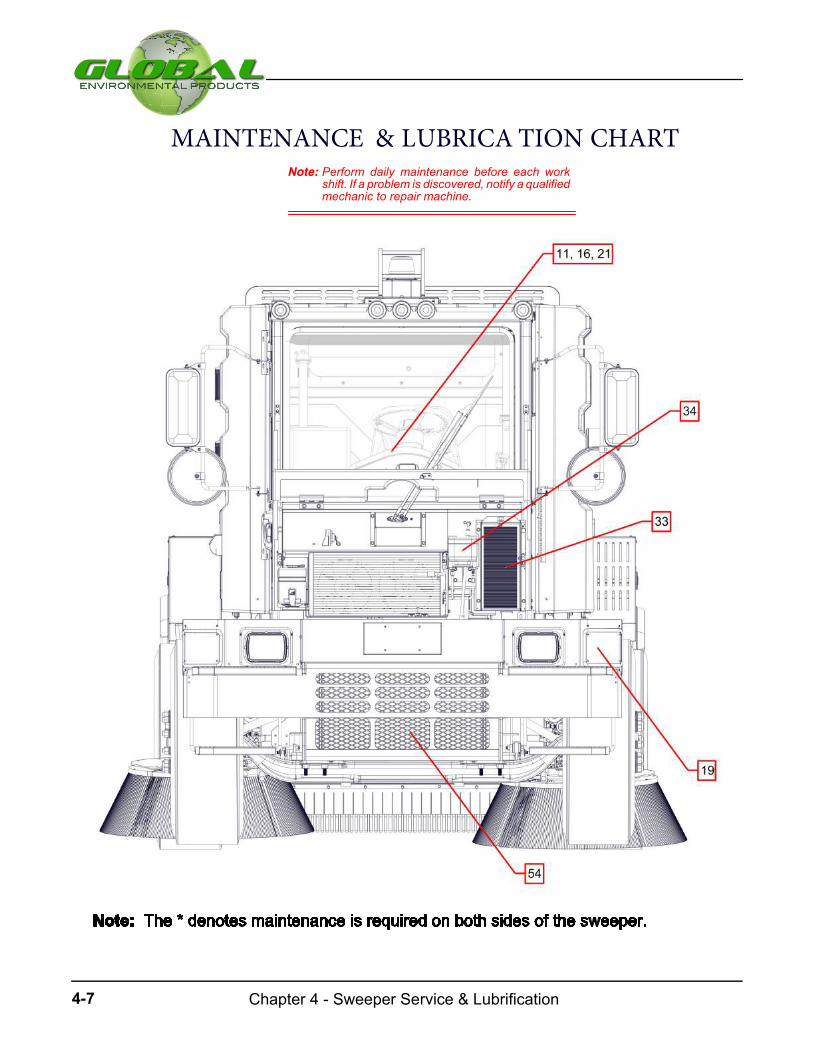
Chapter 4 - Sweeper Service & Lubrification4-7
MAINTENANCE & LUBRICA TION CHARTNote: Perform daily maintenance before each work
shift. If a problem is discovered, notify a qualifiedmechanic to repair machine.
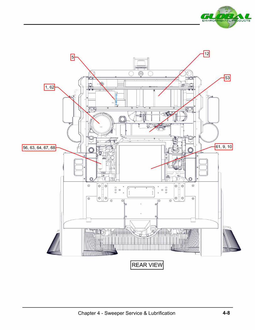
4-8Chapter 4 - Sweeper Service & Lubrification
jthompson
Rectangle
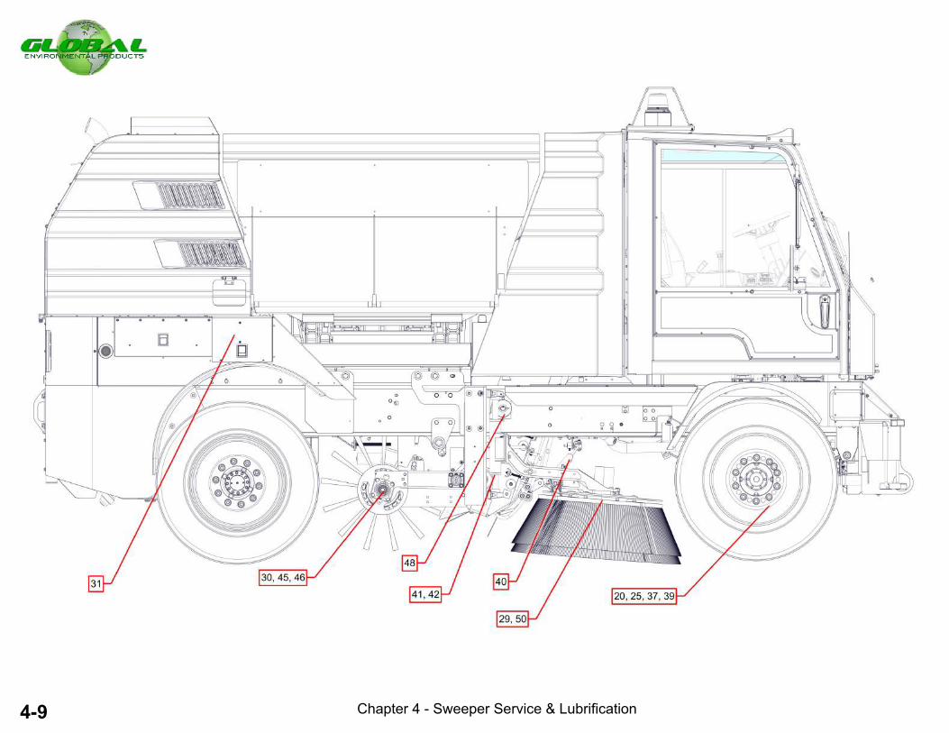
4-9
Chapter 4 - Sweeper Service & Lubrification
Chapter 4 - Sweeper Service & Lubrification
nthompson
Line
nthompson
Line

4-10Chapter 4 - Sweeper Service & Lubrification
nthompson
Line
nthompson
Line

Chapter 4 - Sweeper Service & Lubrification4-16

4-12Chapter 4 - Sweeper Service & Lubrification
69
Hydraulic Oil Cooler- Wash
jthompson
Rectangle
jthompson
Rectangle

4-13Chapter 4 - Sweeper Service & Lubrification
Donot attempt to check for hydraulicoil leaks without hand and eyeprotection. Oil under pressure canpenetrate skin and cause severe in-jury.
Do not attempt to block oil flow withhands or fingers.
Oil can shoot fromapinhole in a fine jetat a velocity sufficient to penetrate skincausing serious injury.
Use extreme caution when inspectinghydraulic system for oil leaks.
Always wear appropriate clothing andeye protection when working on ornear hydraulic system.
Fig: 4.7 A
Keep all dirt, grime, dust and debrisfrom contaminating hydraulic oilwhen working on hydraulic system.
SERVICE ROUTINE
Normal Sweeper Use Routine
The sweeper service maintenance instructions are based
on theassumption that the sweeperwill besubjected toanaverage use. A sweeper that is extensively exposed toabusive conditions requires more frequent attention. AGlobal M4 sweeper that spends months non---operat-
ing also requires periodicmaintenance. Rust, dirt and cor-rosion cause unnecessary damage if the sweeper is ne-glected. The following routine service maintenance sug-gestions will help avoid expensive repairs.
1. Air Cleaner Filter ---Check and clean air clean-er filter daily. Replace the engine air cleaner filter under
normal operations every 250 hours. Operation of sweeperin dusty areaswill necessitatemore frequent filter replace-ment.
2. Air Inta ke Sy s te m --- Check daily if air cleaner,filters, hoses and ducts are in good condition.
3. Air Cle a ne r Service Indicator --- Check aircleaner service indicator daily.
4. Air Clea ner & Sa fe ty Ele me nts --- Clean aircleaner safety element when required or change at least
every third time the primary elements is replaced.
5. Br a ke Flu id Le ve l --- Check the fluid in brakefluid reservoir every 50hours andadd fluid (UseSAEBrakeFluid DOT 3 or equivalent) as required.
6. Engine Coo ling Sys te m ---Check coolant leveldaily. Every 50 hour intervals clean exterior of radiator,tighten hose clamps and inspect condition of all coolingand heater hoses. Replace hoses if cracked, swollen or
deteriorated.
7. Engine Coolant Leakage --- Visually checkcooling system for leaks. Look at the surface beneath thesweeperafter it hasbeenparked for awhile forany signsofleakage.
8. Engine Oil and Filter --- Check engine oil level-daily. Replace oil and filter every 100 hours of service(15W---40).
9. Engine Oil Leakage --- Visually check enginefor oil leaks and repair as required.
.
Global M4 Series Operator’s Manual

Chapter 4 - Sweeper Service & Lubrification4-14
10. Belts --- Check all engine driven belts forcracks, fraying, wear and tension every 50 hours. Replaceworn belts.
11. Fu e l System --- Check Fuel level daily. Inspectthe fuel tank, cap for proper sealing. and fuel lines for dam-
age which could cause fuel leakage. Check every 250hours intervals.
12. Fu e l Filter , Pr e ---filte r --- Replace fuel filter ele-ment every 250 hours of operation.
13. Fu e l Filter , Wate r Separator ---Cleananddrainfuel filter every 100 hours of operation.
14. Fu e l Filter , Wate r Separator --- Replace fuel fil-ter element every 250 hours of operation.
- Water Level --- Check water level indicator inside thecab for water spray system.
15. Wate r Spray System --- Check water spraynozzle jets for obstruction. Clean, repair or replace
clogged nozzles. Check for water leaks. Check the follow-ing daily:
- Water Tanks --- Check for leaks.
- Water Pumps --- Check water pumps for operation.
- Strainers --- Clean two Water Strainers: 1st--next tothe engine (rear right hand side of the engine), 2nd--underelbow on top of water tank.
16. Hydraulic Oil --- Check oil level daily in eachhydraulic tank at sight glass located on outside of hopper
towers. With engine turned off add hydraulic oil as re-quired (ISO 46). Sweeper must be warmed to operatingtemperature when checking oil level. Be sure sweeper ison a level ground when checking oil level.
17. Hydrau lic Oil Leakage --- Check hydraulic oilsystem for leaks daily and repair as required.
18. Hydraulic Oil Filter High Pressure --- Ifsweeper is new or any components (motors or pumps)have been replaced, change filters after 50 hours of opera-tion. Thereafter, replace hydraulic oil filters every 100Hours. If the filter gauge indicator is in RED, replace thefilter, regardless of the filter operational hours.
19. Hydraulic Oil Filter (Low Pressure) --- Ifsweeper is new or any components (motors or pumps)have been replaced, change filter after 50 hours of opera-tion. Thereafter, replace the lowpressure hydraulic oil filterevery100Hours. If thepop--up indicator on the filter showsRED, replace the filter.
21. Hydraulic Oil Co mpos ition --- Run engine for15 minutes while operating several hydraulic componentssuch as brooms, elevator or hopper dump.Turn engine off.Clean a convenient hydraulic fitting and using a kit (P/N381930), provided by Global Environmental Products,draw sample of hydraulic oil and send container to
Global Environmental Products for results. Perform thetest every 500 hours of operation.
21. Front Whe el Be ari ng Gre ase --- Check andreplenish if necessary every 500 hours.
22. Steering Ba ll Jo ints --- Lubricate steeringcross---linkage and steering drive linkage every 50 hours.
23. Steering Spindle Bearing --- Lubricate steeringbox, steering universal ball joints and steering spindle
input shaft every 50 hours.
24. Differential Oil Level --- Change differential oilevery 500 hours of operation. Operate engine and
differential for 15 minutes before draining oil. Do not run
engine while changing oil.
25. Rear Axle Grease --- If sweeper is new or therear axle has been rebuilt change grease after 50 hours.
Thereafter, replace rear axle grease every 500 hours.
26. Tire Pressure --- Check tires daily for excessiveor abnormal wear, or damage. Also, check tire pressure
and adjust to proper inflation.
-
Front Tires --- 105 PSI (Goodyear) 9R22.5F-
Rear Tires --- 22.5J
28. Door Hinge & Latch ---Check that door closes,latches, and locks tightly. Check broken, damaged, ormissing parts that might prevent from tight latching. Lubri-
cate hinges.
Front Tires - (Manufacturer Recommended Tire Pressure) - 9R22.5F
Rear Tires - Manufacturer Recommended Tire Pressure - 315/80R22.5J
20.
27.
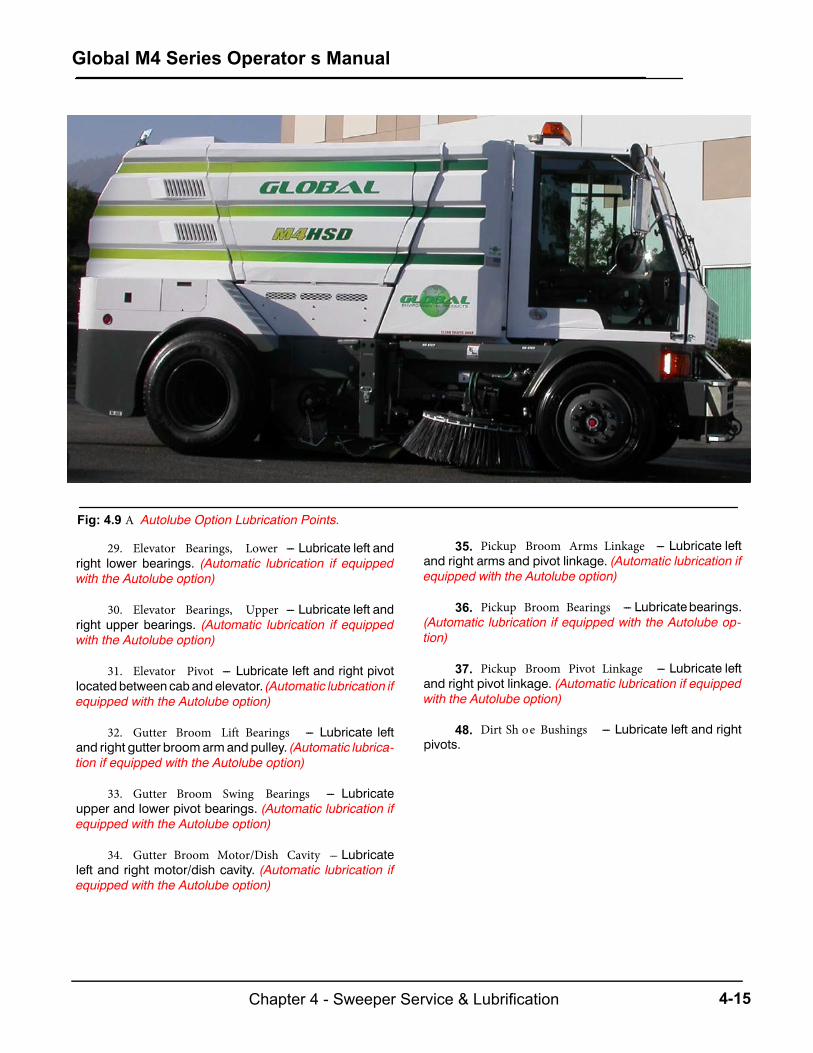
4-15Chapter 4 - Sweeper Service & Lubrification
Fig: 4.9 A Autolube Option Lubrication Points.
29. Elevator Bearings, Lower --- Lubricate left andright lower bearings. (Automatic lubrication if equippedwith the Autolube option)
30. Elevator Bearings, Upper --- Lubricate left andright upper bearings. (Automatic lubrication if equippedwith the Autolube option)
31. Elevator Pivot --- Lubricate left and right pivotlocatedbetween cabandelevator. (Automatic lubrication ifequipped with the Autolube option)
32. Gutter Broom Lift Bearings --- Lubricate leftand right gutter broomarmandpulley. (Automatic lubrica-tion if equipped with the Autolube option)
33. Gutter Broom Swing Bearings --- Lubricateupper and lower pivot bearings. (Automatic lubrication ifequipped with the Autolube option)
34. Gutter Broom Motor/Dish Cavity --- Lubricateleft and right motor/dish cavity. (Automatic lubrication ifequipped with the Autolube option)
35. Pickup Broom Arms Linkage --- Lubricate left
and right arms and pivot linkage. (Automatic lubrication ifequipped with the Autolube option)
36. Pickup Broom Bearings --- Lubricatebearings.
(Automatic lubrication if equipped with the Autolube op-tion)
37. Pickup Broom Pivot Linkage --- Lubricate left
and right pivot linkage. (Automatic lubrication if equippedwith the Autolube option)
48. Dirt Sh oe Bushings --- Lubricate left and rightpivots.
Global M4 Series Operator’s Manual
jthompson
Oval
jthompson
Oval
jthompson
Oval
jthompson
Oval
jthompson
Oval
jthompson
Oval
jthompson
Oval
jthompson
Oval
jthompson
Oval
jthompson
Oval
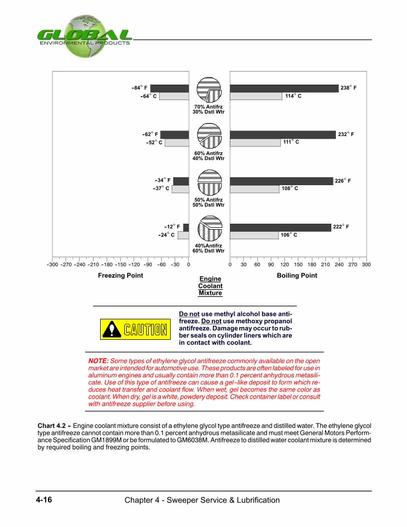
Chapter 4 - Sweeper Service & Lubrification4-16
--300 --270 --240 --210 --180 --150 --120 --90 --60 --30 0 0 30 60 90 120 150 180 210 240 270 300
Chart 4.2 -- Engine coolant mixture consist of a ethylene glycol type antifreeze and distilled water. The ethylene glycoltype antifreeze cannot containmore than 0.1 percent anhydrousmetasilicate andmust meet General Motors Perform-anceSpecificationGM1899Mor be formulated toGM6038M.Antifreeze to distilledwater coolantmixture is determinedby required boiling and freezing points.
70% Antifrz30% Dstl Wtr
60% Antifrz40% Dstl Wtr
50% Antifrz50% Dstl Wtr
40%Antifrz60% Dstl Wtr
238 F--84 F
--62 F 232 F
226 F--34 F
--12 F 222 F
Boiling PointFreezing Point EngineCoolantMixture
--64 C
--52 C
--37 C
--24 C
114 C
111 C
108 C
106 C
NOTE: Some types of ethylene glycol antifreeze commonly available on the openmarket are intended for automotiveuse.Theseproductsareoften labeled for use inaluminum engines and usually contain more than 0.1 percent anhydrous metasili-cate. Use of this type of antifreeze can cause a gel--like deposit to form which re-duces heat transfer and coolant flow. When wet, gel becomes the same color ascoolant.Whendry, gel is awhite, powderydeposit.Checkcontainer label or consultwith antifreeze supplier before using.
Do not use methyl alcohol base anti-freeze. Do not usemethoxy propanolantifreeze.Damagemayoccur to rub-ber seals on cylinder linerswhich arein contact with coolant.

4-17Chapter 4 - Sweeper Service & Lubrification
No. 1
Chart 4.3 -- Choose the proper Multipurpose ExtremePressure (EP) grease based on expected air tempera-ture range during sweeper operation. All grease usedmust meet SAEMultipurpose EP (MPG) service classi-fication or SAE Multipurpose EP with Molybdenum Di-sulfide (MPGM) service classification. The consistencyproperty of grease determines it’s classificationwhich isthe measure of relative hardness expressed in terms ofa National Lubricating Grease Institute (NLGI) consis-tency number.
50
40
30
20
10
0
--10
--20
--30
--40
--50
--55
FC
122
104
86
68
50
32
14
--4
--22
--40
--58
--67
NLGI
MultipurposeAir Temp
No. 2NLGI
No. 0NLGI
GreaseArctic
Grease--EPMultipurposeGrease--EP
No. 2--D
50
40
30
20
10
0
--10
--20
--30
--40
--50
--55
5
FC
122
104
86
68
50
32
14
--4
--22
--40
--58
--67
40
Grade
No. 1--DGrade
Air Temp
Chart 4.4 -- Either Grade No. 1--D or Grade No. 2--Ddiesel fuel, as definedbyASTMdesignationD975, is re-quired for diesel engines. Choose the correct EPA certi-fied diesel fuel corresponding to air temperature at thetimemotor is started.When sweeper is operating at alti-tudes above 5000 ft (1500m), useGradeNo. 1--D for alltemperatures. If sweeper is frequently being shutdownand restarted, use Grade No. 1--D for all temperatures.
Diesel Fuel

Chapter 4 - Sweeper Service & Lubrification4-18
PM---10 OPTION
To maintain optimal PM---10 efficiency, the operator mustinspect the hopper and elevator seals for proper sealing.Water spray systemmust also be in properworking condi-tion. Checked all PM10 components on a daily basis. Pri-or to sweeping, the following functions must be setand checked:
a. Check water level and make sure water gauge in-
dicates adequate water level.
Donot attempt to sweep ifwater gaugeindicates below empty.
b. Water control valves behind the buddy seat must be
turned ON.
c. Pickupbroomandgutter broommust bedownandrotating.
d. Elevator switchmust be in the FORWARD position andwater pump switchmust beON or thewater spray sys-tem will not function.
e. With the unit stationary and the water spray operat-ing, visually inspect all nozzles are spraying cleanly.
Donot attempt to sweepwith thewaterspray system inoperative.
Standard Water SprayPM--10 Water Spray
Hose Color ChartBlueGreen
(PM 10 Water Plumbing Schematic) Fig: 4.18 A

4-19Chapter 4 - Sweeper Service & Lubrification
Fig: 4.19 A The PM 10 Elevator Seals must be inspected daily prior to sweeping.
325947ELEVATOR LIPRUBBER FLAP FOR LEAF GATE OPTION

Chapter 4 - Sweeper Service & Lubrification4-20
WASHDOWN
Because your job and responsibility is to primarily operate
the equipment does not prevent you from focusing some
attention on the cleanliness of the unit. Keeping the ma-
chine in a clean conditionwill help prolong the life of some
components. If the unit is exposed to high dust level,
washdown the machine after use. Do not let dirt accumu-
late. Washdown sweeper after every sweeping shift.
Washdown Procedure
1. Park the sweeper on a level surface.
2. Raise hopper. Install prop rods.
Fallinghopper cancausesevere injuryordeath. Theprop rodmust be inposi-tion before anyone goes underhopper.
3. Attach the fire hydrant hose located at the centerbody panel to a high volume water source such as afire hydrant.
4. Attach the high pressure hose provided in the toolbox to the fitting next to the filler hose.
Stand clear from the fire hydrant hosewhen filling tanks or attaching waterhose. A high volume of water travelsthrough hose under high pressure.
5. TurnON the built--- in elevator washdownwater spray
system.
6. Lower thePUB to sweepingposition. Start rotationofthe elevator.
7. With the elevator running, use a high pressure waterhose (connected toahighvolumesource) to flush theelevator.
8. Flush out the hopper, all undercarriage parts, side
broom(s), and dirt shoes.
9. Use a high pressure hose to dislodge materialbetween the lower sprocket and the edge of thesqueegee bar. Flush the lower sprocket from bothsides of the sweeper.
An engine must never be washed orsteamcleanedwhile it is running. Coldwater on a hot manifold could crackthe manifold.
A high pressure hose should never beused to clean a radiator or oil cooler.The high pressure water can damagecores.
A high pressure hose should never beaimed directly at solenoid valves, par-ticularly when they are hot.
DO NOT spray high pressure water ator around ECM or fuse/relay box.
10. Before washing down the engine compartment, becertain that the engine is cool. Be sure to clean outthe engine radiator, oil cooler and other engine ex-ternal components.
11. After the washdown, visually inspect for damage orunusual signs of wear.

Chapter 5 - Specifications5-5
This page intentionally left blank

5-1Chapter 5 - Maintenance & Overhaul
Subject PageGeneral Information
General Information 5-3Front & Rear Axles
Front Wheel 5-4Rear Wheel 5-4Shock Absorber 5-5Steering Gear Assembly 5-5Master Brake Assembly 5-6Parking Brake Actuator 5-9Parking Brake Cable 5-9
CabLeft Window 5-10Right Window 5-10Inside Paddle Latch, Door 5-11Exterior Lock Latch, Door 5-11Interior Latch, Door 5-12
Heater & Air ConditionerEvacuation by Vacuum Pump 5-12Charging A/C System 5-13Leak Detection 5-14Condenser 5-14Receiver Dryer 5-15Evaporator 5-15Compressor 5-16
Elevator GroupElevator Hydraulic Motor 5-16Seft-Align bearings 5-16Elevator 5-18Sprocket Pulley Replacement 5-20Squeegee Bar Replacement 5-21
Pickup Broom GroupHydraulic Motor 5-21Hydraulic Cylinder 5-21Shock Absorber 5-23Pickup Broom 5-24
Gutter Broom GroupHydraulic Motor 5-24Plate & Brush Assembly 5-25Hydraulic Lift Cylinder 5-26Arm Assembly 5-27Shock Absorber 5-28
Engine GroupFilters 5-30
Maintenance/Overhaul
CHAPTER 5
Air Cleaner 5-32Aftertreatment System 5-33Cooling System 5-35Oil Cooler Assembly 5-37Alternator 5-38
5-395-40
5-41
5-11
Battery GroupReplacement Precautions Removal/Installation
Hopper GroupRemoval/Installation
TablesTable 5.1 Jacking Procedure
Scissor's

Chapter 5 - Maintenance & Overhaul5-2
This page intentionally left blank

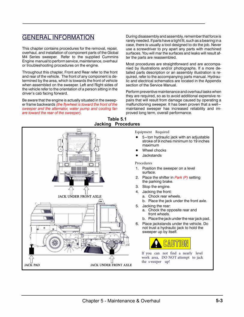
5-3Chapter 5 - Maintenance & Overhaul
GENERAL INFORMATION
This chapter contains procedures for the removal, repair,overhaul, and installation of component parts of the GlobalM4 Series sweeper. Refer to the supplied CumminsEngine manual to perform service, maintenance, overhaulor troubleshooting procedures on the engine.
Throughout this chapter, Front and Rear refer to the frontand rear of the vehicle. The front of any component is de-termined by the area, which is towards the front of vehiclewhen assembled on the sweeper. Left and Right sides ofthe vehicle refer to the orientation of a person sitting in thedriver’s cab facing forward.
Be aware that the engine is actually situated in the sweep-er frame backwards (the flywheel is toward the front of the sweeper and the alternator, water pump and cooling fan are toward the rear of the sweeper).
During disassembly and assembly, remember that force israrely needed. If parts have a tight fit, such as a bearing in acase, there is usually a tool designed to do the job. Neveruse a screwdriver to pry apart any parts with machinedsurfaces. You will mar the surfaces and leaks will result af-ter the parts are reassembled.
Most procedures are straightforward and are accompa-nied by illustrations and/or photographs. If a more de-tailed parts description or an assembly illustration is re-quired, refer to the accompanying parts manual. Hydrau-lic and electrical schematics are located in the Appendixsection of the Service Manual.
Perform preventive maintenance and overhaul tasks whenthey are required, so as to avoid additional expensive re-pairs that will result from damage caused by operating amalfunctioning sweeper. It has been proven that a well---maintained sweeper has increased reliability and im-proved long term, overall performance.
Table 5.1Jacking Procedures
Equipment RequiredD 5---ton hydraulic jack with an adjustable
stroke of 9 inches minimum to 19 inchesmaximum
D Wheel chocks
D Jackstands
Procedures1. Position the sweeper on a level
surface.
2. Place the shifter in Park (P) settingthe parking brake.
3. Stop the engine.
4. Jacking the front:
a. Chock rear wheels.
b. Place the jack under the front axle.
5. Jacking the rear:a. Chock the opposite rear and
front wheels.
b. Place the jack under the rear jack pad.
6. Place jackstands under the vehicle. Donot trust a hydraulic jack to hold thesweeper up by itself.
If you can not find a nearly levelwork area, DO NOT attempt to jackthe s weeper up!
JACK UNDER FRONT AXLE
JACK PAD JACK UNDER FRONT AXLE

Chapter 5 - Maintenance & Overhaul5-4
FRONT & REAR AXLES
Front Wheel--- Removal/Installation
1. Position the sweeper on a hard level surface.
2, Set the parking brake, stop the engine, and jack the vehicle in accordance with the Jacking Procedures inTable 5.1.
To prevent death or accidental injury ,always place jack ---stands to support araised vehicle.
3. With the front tire slightly off the ground, clean the areaaround the wheel and hub.
4. Remove the wheel lug nuts.
5. Remove the wheel assembly from the front hub.
6. Remove the tire from the wheel, and repair the tire asrequired, using standard procedures.
7. With the tire dismounted, inspect the wheel for signs ofdamage such as a rough area that might damage themounted tire. Repair the wheel as required.
8. Using standard procedures, remount the tire to thewheel. Inflate the mounted tire to 105 psi.
9. Place the assembled wheel on the front hub, and installand hand tighten the lug nuts. Tighten the lug nuts inthe numerical order shown in Fig: 5.4 A. Final torquespecification of front wheel lug nuts is 400---420 ft lbs.
10. Adjust the magnetic sensor to .010---.015 in. gap fromthe timing plate.
11. Remove the jack---stands and lower the sweeper tothe ground.
12. Remove the jack and wheel chocks.
Rear Wheel--- Removal/Installation
1. Position the sweeper on a hard level surface.
2. Set the parking brake, stop the engine, and jack thevehicle in accordance with the Jacking Procedures inTable 5.1.
To prevent death or accidental injury ,always place jack ---stands to support araised vehicle.
3. With the rear tire slightly off the ground, clean the areaaround the wheel and hub.
4. Remove the wheel lug nuts.
5. Remove the wheel assembly from the rear hub.
6. Remove the tire from the wheel, and repair the tire asrequired, using standard procedures.
7. With the tire dismounted, inspect the wheel for signs ofdamage such as a rough area that might damage themounted tire. Repair the wheel as required.
8. Using standard procedures, remount the tire to thewheel. Inflate the mounted tire to 120 psi.
9. Place the assembled wheel on the rear hub, and installand hand tighten the lug nuts. Tighten the lug nuts inthe numerical order shown in Fig: 5.4 A. Final torquespecification of rear wheel lug nuts is 450---500 ft lbs.
10. Remove the jack---stands and lower the sweeper tothe ground.
11. Remove the jack and wheel chocks.
Rear Lug Nut TorquePattern (450--500 ft lbs)
10
47
58
69
31
2Front Lug Nut TorquePattern (400--420 ft lbs)
Fig: 5.4 A Lug nut tightening sequence for replacing the front and rear wheels. Torque the first and second lug nutsto properly seat in the wheel recess before tightening down other lug nuts. Tighten in the sequence order shown.
10
47
58
69
31
2

5-5Chapter 5 - Maintenance & Overhaul
Shock Absorber--- Removal/Installation1. Position the sweeper on a level surface and follow theJacking Procedure in Table 5.1. Jack the front of thesweeper to extend the shock absorber.
2. Remove thenut, screw,washers andspacer (Fig: 5.5A:1, 2, 3 & 4) from the bottom mount of the shockabsorber.
3. Detach the lowermount of the shockabsorber from thehanger weldment (6).
4. Remove the nut, screw, washers and spacer (1, 2, 3 &5) from the top mount of the shock absorber.
3. Detach the upper mount of the shock absorber fromthe frame.
4. Remove the shock absorber (7).5. Install the shock absorber by reversing the steps.
NOTE: Check the spacers for proper fit in the rubbergrommet mounts prior to installing the shockabsorber.
Steering Gear Assembly---Removal/Installation1. Position the sweeper on a level surface.
2. Place the shifter in the Park (P) position, setting theparking brake.
3. Stop the engine.
4. Chock the rear wheels.
5. Clean the area around the steering shaft and gearassembly.
6. Identify the hoses connected to the steering gearassembly.
NOTE: Provide a container to catch the excess hy-draulic fluid from the steering gear assembly priorto removing the hoses.
7. Disconnect both hose assemblies from each elbow.
8. Temporarily plug the disconnected hydraulic hoses.
NOTE: If replacing the steering gear assembly,remove both elbows.
Fig: 5.5 A The Front Shock Absorber Removal/Installation procedure is the same for both left and right sides. Thetopmount of the shock fastens to the frame and the bottommount fastens to the hanger weldment, which is bolted tothe front axle spring.
1. Nut--lock, 5/8--112. Washer--flat, 5/83. Tube4. Scr Hx Hd, 5/8--11x3 F/T5. Scr--hx Hd, 5/8--11x5--1/26. Hanger Wldmt--LH Shock7. Shock Absorber
NOTE: Tighten according to torque specifications included in Parts Manual, Chapter 1, drawing 324338. Rev K.

Chapter 5 - Maintenance & Overhaul5-6
Fig: 5.6 A The Steering Gear Assembly is bolted to the steering gear frame bracket, which is welded to the frame.Prior to removal, identify the position of the steering arm as it relates to the spine shaft. Replace the arm in a similarposition and adjust the linkage.
1. Steering Shaft2. Pitman Arm3. Pin-- Cotter, 1/8 X 1--1/24. Nut-- Hx 7/8--14 cstl5. Gear Box-- Power Steering Assy
9. Remove the locknut andcapscrewsecuring theupperswivel joint of the lower steering shaft to the steeringcolumn shaft (Fig: 5.6A: 1). When disconnected, theupper half slides into the lower half of the shaft.
10. Remove thehexnut andcapscrewsecuring the lowerjoint of the lower steering shaft to the steering gearassembly.
11. Remove the lower steering shaft (1).
12. Remove cotter pin and loosen the castle nut. Pull thesteering pitman arm (2) from the output shaft of thesteering gear assembly.
13. Remove the screw and lock washers securing thesteering gear assembly (5) to the steering gear framebracket.
14. Remove the steering gear assembly (5).
15. Install the steering gear assembly by reversing thesteps.
Master Brake Cylinder--- Removal/Installation1. Position the sweeper on a level surface.
2. Place the shifter in the Park (P) position, setting theparking brake.
3. Stop the engine.
4. Chock the rear wheels.
5. Clean the area around the booster/master cylinderassembly and the brake pedal.
6. Identify the hydraulic hoses connected to the booster/master cylinder assembly and the electrical leads con-nected to the flow switch, differential pressure switch,brake relay and pump.
NOTE: Before removing the hoses, provide a con-tainer to catch the excess hydraulic fluid from thebooster/master brake cylinder.
7. Disconnect hydraulic hoses from the master cylinder.
NOTE: Tighten according to torque specifications included in Parts Manual, Chapter 1, drawing 324338. Rev K.

5-7Chapter 5 - Maintenance & Overhaul
Fig: 5.7 A The Booster/Brake Master Cylinder is located under the front hood and extends back under the operator’scab. Themaster cylinder is accessible from the front of the vehicle and the linkage is accessible from the right side of thevehicle between the bottom of the cab and the top of the front fender.
8. Temporarily plug the disconnected hydraulic hoses.
9. Disconnect the electrical leads from themaster cylin-der.
10. Remove the brake box bottom cover (Fig: 5.7 A: 6)and remove the return spring from the brake pedal.
11. Remove the nuts, washers and screws securing thebrake lever weldment and flange bearing.
12. Loosen the jam nut (3) and remove pivot pin (5) con-necting rear end shaft of the master cylinder.
13. Remove the nuts and washers securing the frontmounting plate.
14. Remove nut and disconnect push/pull cable.
15. Remove the master cylinder (4) with the front mount-ing plate intact.
16. Remove the nuts and washers securing the plate tothe master cylinder.
17. Install the front mounting plate and the new or rebuiltbooster/master cylinder by reversing steps 10through 17.
18. Adjust the jam nut (3) to the shaft on the rear end ofthe master cylinder.
NOTE: Do not tighten the jam nut until step 20.
19. Screw the shaft on the rear end of themaster cylinderto the pivot pin and adjust the position of the brake le-ver weldment and secure flange bearing.
20. Tighten the jam nut (3).21. Install the electrical leads and hydraulic hoses by re-versing steps 6 thru 9. Fill the booster/master cylinderwith approved brake fluid.
NOTE:Bleed the brake system anytime the boost-er/master cylinder assembly or hydraulic hosesare replaced or repaired.
22. Adjust thebrakesystem following theadjustmentpro-cedure in Chapter 3.
NOTE: Tighten according to torque specifications included in Parts Manual, Chapter 4, drawing 325452. Rev C.
1. Elbow-- MJ--FJ90--82. Elbow-- MJ--MPX90--63. Jam-- Nut, Pltd, 1/2--204. Master Cylinder5. Pin-- Pivot, 1.38 X 3.006. Plate-- Cover7. Brake Pedal Assembly8. Brake Box Weldment
2
4 3
7
5
8
6
nthompson
Line
nthompson
Line
nthompson
Line
nthompson
Line
nthompson
Line
nthompson
Line
nthompson
Line
nthompson
Line

Chapter 5 - Maintenance & Overhaul5-8
Fig: 5.8 A The Parking Brake Actuator is located in front of the left rear fender. Do not cut into, disassemble or torch thecanister. The spring is under compressed force. The actuator canister is not repairable and must be replaced if a failureoccurs.
1. Actuator-- Parking Brake2. Elbow-- MB--MJX90--83. Nut-- Jam, Plated, 5/8--184. Nut-- Lock, Plated, 5/8--185. Washer-- Lock, Split, Plated, 5/86. Washer-- Flat, SAE, Plated, 5/87. Turn Buckle Weldment8. Hairpin-- 5/8 Dia.9. Clevis Pin-- 3/8 X 1 1/810. Cotter Pin-- Plated, 1/8 X 111. Cleavis Weldment, LH Thread12. Clevis Weldment
NOTE: Tighten according to torque specifications included in Parts Manual, Chapter 1,
2
1
6 5 47 8
11
9
10
3
12
jthompson
Line
jthompson
Line
jthompson
Line
jthompson
Line
jthompson
Line
jthompson
Line
jthompson
Line
jthompson
Line
jthompson
Line
jthompson
Line
jthompson
Line
jthompson
Line

5-9Chapter 5 - Maintenance & Overhaul
Parking Brake Actuator-- Removal/Installation
1. Position sweeper on a level surface.2. Chock the rear wheels.3. Clean the area around the Parking Brake Actuator,
cables and connecting hardware.4. With an assistant in cab, have them turn ignition ON,
place shifter in the Low (L) position, releasing the park-ing brake and engage the brake pedal.
Do not cut into, disassemble, ortorch the canister . The internalsp ring is under co mpressedfo rc e. The ca nis te r is no t re pa ir-able. Obtain a new canister iffailure occurs.
Fig: 5.9 A
5. Remove the parking brake release cotter pin and theclevis (Fig: 5.8A: 9 & 10) from the clevis weldment (11).
6. Loosen the locking nut (3). Using the gutter broomangle adjustment tool, mechanically unscrew the park-ing brake clevis weldment (7) turnbuckle and remove itfrom the actuator (1).
7. Turn off engine.8. Disconnect thehydraulic hose from theelbow (2)on the
front of the actuator. Plug the hose.
NOTE: Before removing the hydraulic hose, pro-vide a container to catch the excess hydraulic fluidfrom the parking brake actuator.
9. Remove the nuts and flat washers securing the actua-tor to the frame. Remove the actuator (1).
10. Install the parking brake actuator by reversing thesteps.
Hydraulic pressure is present withparking brake activated. Do not re-move hydraulic hoses with shaft pro-truding out of cannister.
Parking Brake Cable-- Removal/Installation
1. Position sweeper on a level surface.
2. Chock the rear wheels.
3. Clean the area around the Parking Brake Actuator,cables and connecting hardware.
4. With an assistant in cab, have them turn ignition ON,place shifter in the Low (L) position, releasing the park-ing brake and engage the brake pedal.
5. Remove the parking brake release cotter pin and theclevis (Fig: 5.8A: 9 & 10) from the clevis weldment (11).
6. Loosen the locking nut (3). Using the gutter broomangle adjustment tool, mechanically unscrew the park-ing brake clevis weldment (7) turnbuckle and remove itfrom the actuator (1).
7. Turn off engine.
8. Remove the cotter pins and clevis pins from the parkingbrake cable clevis(13).
9. Loosen the lock nuts on the cable. Unscrew theclevis from the cable.
10. Remove the wheel end of the cable from the rearpark brake assembly.
11. Remove the brake cable clamps.
12. Remove the brake cable (15 & 16).
13. Install the cable by reversing the steps.
14. Use the procedure in Chapter 3 to adjust the brakesystem.
15. Remove the nuts, lock washers, screws and clamps fromthe cable assembly. Remove drivelin4e brake drum


/
/
/
/ / /
/
Chapter 5 - Maintenance & Overhaul5-10
WINDOW & DOOR MECHANISM
Left Window-- Removal/Installation
1. Position the sweeper on a level surface.2. Place the shifter in the Park (P) position, setting the
parking brake.3. Remove silicone sealant and rubber (2) to gain access
to the self tapping screws securing thewindow frame tothe cab.
NOTE: Sealant may make it difficult to take outrubber seal around the window frame.
4. Remove self tapping screws securing window (Fig:5.10A; 1).
4. Slide window to left or right to remove from cab frame.5. Install the left window by reversing the steps.
Fig: 5.10 AAlways takeextraprecautionwhenhandlingleft cab glass window to avoid breaking.
1. Window-- Operator, LH2. Rubber--.25 X .75,Closed Cell3. Cab Frame4. Silicone Black Sealant (Not Shown)
1. Window-- Operator, RH2. Rubber3. Cab Door Weldment4. Silicone Black Sealant (Not Shown)
Fig: 5.10 B Right Cab Door is heavy. Removal mayrequire two mechanics.
Right Window-- Removal/Installation
1. Position the sweeper on a level surface.2. Place the shifter in the Park (P) position, setting the
parking brake.3. Remove the screws securing the panel brackets to the
top and front edges of the window frame inside the cabdoor.
4. Remove upholstery door trims from the operator’s cabdoor.
5. Remove the pan head screws securing the windowassembly to the door (Fig: 5.10B; 3).
7. Remove the window assembly (1).8. Install the right window by reversing the steps.
NOTE: Use a sealing compound on the windowseal when installing left and right windows.
CAB
2
nthompson
Line
nthompson
Line

5-11Chapter 5 - Maintenance & Overhaul
Fig: 5.11 A Remove bottom upholstery and grip handle to gain access to the inside latch mechanism.
DOOR ASSEMBLY LATCH MECHANISM
Inside Latch--- Removal/Installation
1. Position the sweeper on a level surface.
2. Place the shifter in the Park (P) position, setting theparking brake.
3. Remove screws and washers (Fig: 5.11A; 2 &3) secur-ing the door latch cover plate (3) inside the door.
4. Remove bottom upholstery clipped to the door.
5. Remove cotter pins and clevis pins securing insidedoor latch.
6. Remove flat socket head screws.
7. Remove the inside paddle latch mechanism.
8. Install the inside paddle latch assembly by reversingthe steps.
Exterior Lock Latch--- Removal/Installation
1. Position the sweeper on a level surface.
2. Place the shifter in the Park (P) position, setting theparking brake.
3. Remove the four truss head screws securing theoutside paddle lock (8) to the door.
4. Remove screws and washers (Fig: 5.11A; 2 & 3) secur-ing the door latch cover plate (3) inside the door.
5. Remove bottom upholstery clipped to the door.
6. Remove cotter pins and clevis pins securing insidedoor latch.
7. Remove the outside latch with key (8).8. Install the outside latch with key assembly by reversing
the steps.
88
66
55
44
77
1111
99
33
22
1010
11
1 DOOR LOCK KNOB2 OPEN & LOCK PLATE INDICATOR3 HANDLE PANEL COVER4 LATCH MECHANISM 5 HANDLE PANEL6 RUBBER DOOR HANDLE GASKET7 DOOR HANDLE MOUNT, INNER8 OUTER HANDLE 9 PULL CABLE10
0ROTARY LATCH, RH (MODIFIED)11 DOOR RELEASE LATCH ASSY
NOTE: If necessary, adjust the position of the tworod assemblies that attach to the latchmechanismassembly.
Chapter 5 - Maintenance & Overhaul5-12
HEATER/AIR CONDITIONER
NOTE: Only the EPA certified technicians maywork with refrigerants.
The air conditioning system consists of a condenser, acompressor, an evaporator, a receiver/dryer and an ACcontrol panel.
Use manifold gauges, charging hoses and other air condi-tioning service tools when checking the refrigerant sys-tem. Use Refrigerant Recovery System or equivalent be-fore removing or replacing any air conditioning parts.
Improper service methods may causeinjury. Air Conditioning System is tobe serviced by qualified personnelonly. Consult the A/C service manual.
The maximum operating charge is 4.0lbs. of R--134A refrigerant.
Air Conditioner--- Evacuation by Vacuum Pump
DO NOT allow air conditioner refrig-erant to escape into atmosphere.
1. Position the sweeper on a level surface.
2. Place the shifter in the Park (P) position, setting theparking brake.
3. Clean the area around the air conditioner and connect-ing hardware.
Before connecting the manifold, closethe gauge valves. Serious injury mayoccur if escaping refrigerant touchesyour skin.
NOTE: The following procedures requires the useof a Refrigerant Recovery System or a manifoldwith three charging hoses, a compound gaugeand pressure gauge.
4. Remove the compression valve port caps and stemcovers.
5. Connect the compound gauge to the compressor suc-tion port with the hose. Connect the pressure gauge tothe compressor discharge port with the hose.
6. Hook the hose to the vacuum pump.
7. Back out both compressor valve port stems com-pletely and turn the valve stems two turns to a slightlyopen position.
8. Open the gauge valves and turn on the vacuum pump.
9. Operate the vacuum pump for 30 minutes. Close thegauge valves, stop the pump, and disconnect the hosefrom the vacuum pump.
10. The reading on the compound gauge should remainconstant at 28 inches of vacuum. Let the systemremain idle for 15 minutes.
NOTE: If the reading remains constant, the systemis ready for charging. If the vacuum drops off, it isan indication of a leak. The leak must be locatedand sealed before charging.
Should Refrigerant--134A contact youreye(s), do not rub the affected eye(s).Instead, splash with fresh clean coldwater. Consult a doctor immediately.

5-13Chapter 5 - Maintenance & Overhaul
Refrigerant Recovery
Fig: 5.13 A
AC Charge Ports
Fig: 5.13 B
Fig: 5.13 C
Air Conditioner--- Charging or Adding Refrigerant
1. Position the sweeper on a level surface.
2. Place the shifter in the Park (P) position, setting theparking brake.
3. Clean the area around the air conditioner and connect-ing hardware.
NOTE: The following procedures requires the useof a Refrigerant Recovery System or a manifoldwith three charging hoses, a compound gaugeand pressure gauge.
Before connecting the manifold, closethe gauge valves. Serious injury mayoccur if escaping refrigerant touchesyour skin.
4. Remove the compression valve port caps and stemcovers.
5. Connect the compound gauge to the compressor suc-tion port with the hose. Connect the pressure gauge tothe compressor discharge port with the hose.
6. Turn in the compressor discharge valve and suctionvalve port stems.
7. Bleed air from the hoses by slightly opening the shutoffvalves slowly and individually for three seconds each.Then close each valve.
8. Install the valve on a refrigerant per the manufacturer’sinstructions and connect it to the center hose.
9. Open the valve at the refrigerant and bleed air from thecenter hose at the manifold. Retighten the center hosecouplings.
Themaximum operating charge is 4.0lbs. of R--134A refrigerant.
10. Open both gauge valves. When the gauge readingsare equal, close the pressure gauge valve. Check forleaks in the system.
11. When the refrigerant is empty, close the compoundgauge valve. Close the refrigerant valve. Remove anddiscard the empty container. Attach another refriger-ant. Open the refrigerant valve and the compoundgauge valve.
The low pressure side suction gaugeshould not exceed 40 psi.
AC Control Panel

Chapter 5 - Maintenance & Overhaul5-14
AC Condenser
Fig: 5.14 A
Leak Detection DeviceLeak Detection Device
Fig: 5.14 B
Receiver Dryer
Fig: 5.14 C
12. Start the engine and set the throttle at fast idle. Posi-tion the fan switch to On and turn the cool switch tomaximum.
13. Repeat step 8 until the sight glass on the receiver/dryer is clear and free of bubbles.
14. Close the compound gauge valve and the refrigerantvalve. Slowly disconnect the center hose from the re-frigerant.
15. Back out the compressor discharge valve port stemand open the pressure gauge shut off valve. Back outthe compressor suction valve port stem.
16. Disconnect the hose from the refrigerant hose. Dis-connect the hoses from the compressor valve portcaps and stem covers.
17. In the A/C panel located in the operator’s cab, posi-
tion the fan switch to Off and stop the engine.
Air Conditioner---Leak Detection
Avoid breathing the refrigerant fumes.They are toxic and may cause deathor severe injury.
1. Leaks of refrigerant can be detected and located by us-ing an electronic leak detection device with a sniffingtube tip for drawing air samples. If a leak is detected,the device will beep rapidly.
2. Explore the refrigerant system by passing the openend of the sniffing tube tip close to every joint.
3. If a leak is detected at a connection, tighten the fittingcarefully. Recheck for leaks. If any leak is still appar-ent,
discharge system and replace damaged components.
Air Conditioner Condenser--- Removal/Installation
1. Position the sweeper on a level surface.2. Place the shifter in the Park (P) position, setting the
parking brake.
3. Raise the front grille.4. Clean area around the air conditioner condenser and
connecting hardware.5. Discharge the air conditioner system (refer to previousprocedures).
Serious injury may occur if the escap-ing refrigerant touches the skin.
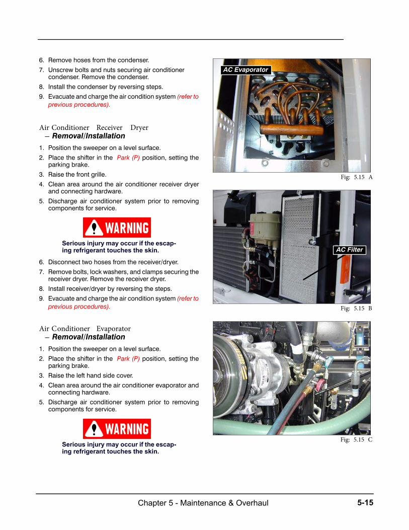
5-15Chapter 5 - Maintenance & Overhaul
6. Remove hoses from the condenser.
7. Unscrew bolts and nuts securing air conditionercondenser. Remove the condenser.
8. Install the condenser by reversing steps.
9. Evacuate and charge the air condition system (refer toprevious procedures).
Air Conditioner Receiver Dryer--- Removal/Installation
1. Position the sweeper on a level surface.
2. Place the shifter in the Park (P) position, setting theparking brake.
3. Raise the front grille.
4. Clean area around the air conditioner receiver dryerand connecting hardware.
5. Discharge air conditioner system prior to removingcomponents for service.
Serious injury may occur if the escap-ing refrigerant touches the skin.
6. Disconnect two hoses from the receiver/dryer.
7. Remove bolts, lock washers, and clamps securing thereceiver dryer. Remove the receiver dryer.
8. Install receiver/dryer by reversing the steps.
9. Evacuate and charge the air condition system (refer toprevious procedures).
Air Conditioner Evaporator--- Removal/Installation
1. Position the sweeper on a level surface.
2. Place the shifter in the Park (P) position, setting theparking brake.
3. Raise the left hand side cover.
4. Clean area around the air conditioner evaporator andconnecting hardware.
5. Discharge air conditioner system prior to removingcomponents for service.
Serious injury may occur if the escap-ing refrigerant touches the skin.
AC Evaporator
Fig: 5.15 A
AC Filter
Fig: 5.15 B
Fig: 5.15 C
Chapter 5 - Maintenance & Overhaul5-16
6. Disconnect electrical leads and remove hoseclamps- from the evaporator.
7. Remove bolts, lock washers, and clamps securing theevaporator. Remove the evaporator.
8. Install evaporator by reversing the steps.
9. Evacuate and charge the air condition system (refer toprevious procedures).
Air Conditioner Compressor---Removal/Installation
1. Position the sweeper on a level surface.
2. Place the shifter in the Park (P) position, setting theparking brake.
3. Working from the rear of the sweeper, swing out andlatch the radiator.
4. Clean the area around the air conditioner compressorand connecting hardware.
5. Have the air conditioning system discharged (refer toprevious procedure).
NOTE: Before removing components for service orbefore recharging refrigerant, always dischargethe air conditioner system.
6. Disconnect the air conditioner hoses from thecompressor.
7. Remove the electrical leads from the compressor.
8. Loosen the lock nut and turn the adjusting bolt to allowthe compressor to slide toward the engine relieving V---belt tension.
10. Remove the V---belt from the compressor pulley.
11. Remove compressor bracket bolts & lock washers.
12. Remove the compressor.
13. Install the compressor by reversing the steps.
14. Use the following procedure to adjust the “V---belt”
tension.
a. Tighten the bolts securing the compressor to theengine bracket.
b. With the lock nut loose, turn the adjusting bolt tomove the compressor away from the engineincreasing the belt tension.
NOTE: The properly ---adjusted tension on the V---belts is a 1/2 inch deflectionwith a 12 pound forceapplied.
c. Tighten the lock nut.
d. Tighten the bolt and nut securing compressor tothe bracket.
e. Have the air conditioning system evacuated and
recharged (refer to the previous procedures).
ELEVATOR GROUP
Elevator Hydraulic Motor- Removal/Installation
1. Position the sweeper on a level surface.2. Place the shifter in the Park (P) position, setting the
parking brake.
3. Clean the area around the hydraulic motor andconnecting hardware.
4. Remove thehydraulic hoses from theelbowson thehy-draulic motor (Fig: 5.17A; 1). Drain the fluid into a cleancontainer.
Plug all hoses and open ports toprevent foreign matter from enteringthe system.
NOTE:Before removing thehoses, providea con-tainer to catch the excess hydraulic fluid from theelevator motor.
5. Remove the elbows from the hydraulic motor.6. Remove the lock nuts and bolts securing the hydraulic
motor to the mount plate.7. Loosen the lock nut on the collar to allow the motor
shaft to slide out.8. Remove the hydraulic motor with the collar in place.9. Install the elevator motor by reversing the steps.
Elevator Self--Align Bearings-- Removal/Installation
1. Position the sweeper on a level surface.2. Place the shifter in the Park (P) position, setting the
parking brake.
3. Raise the hopper and install the safety props.

5-17Chapter 5 - Maintenance & Overhaul
Fig: 5.17 A Elevator Assembly. This assembly is located behind the operator cab and extends to the ground in front ofthe pickup broom. Elevator removal/Installation requires two experienced mechanics and an overhead crane.
1. Elevator Motor2. Hydraulic Motor Angle Mounting3. Flange Ball Bearing4. Bearing Bracket Weldment5. Elevator Belt6. Elevator Side Plate7. Elevator Half--Shaft Assembly8. Sprocket Shield-- Machined9. Hardfaced Split Sprocket10. Deflector Pad

Chapter 5 - Maintenance & Overhaul5-18
INSTALL safety props. DEATH orserious INJURY may result if thehopper cylinders fail.
4. Stop the engine.
5. Clean the area around the self---aligned bearings.
6. Remove the elevator hydraulic motor (refer to theprevious procedure).
7. Release tension on the elevator rubber belt (Fig: 5.17A;5)by loosening the top carriage bolts, jam nut, and hexnut counterclockwise on the bearing bracketweldment (4).
8. Remove the nuts, washers and bolts securing the bear-ing (3) to the elevator side wall.
NOTE: Make a note where the elevator bearinggrease fittings are located since the bearingneeds to be remounted in the same position. Thetop bearings have grease fittings facing down andthe bottom bearings have grease fittings facing tothe back.
9. Remove the self---align bearing (3).10. Install the elevator bearings by reversing the steps.
Elevator--- Removal/Installation
1. Position the sweeper on a level surface under anoverhead crane or hoist capable of lifting the eleva-tor assembly.
2. Place the shifter in the Park (P) position, setting theparking brake.
3. Raise the hopper and install the safety props
INSTALL safety props. DEATH orserious INJURY may result if thehopper cylinders fail.
4. Stop the engine.
5. Clean the area around the elevator.
6. Remove the bolts securing the center body panels tothe elevator.
7. Remove the center body panels from the elevator.
8. Remove the hydraulic hoses from the elbows on thehydraulic motor. Drain the fluid into a container.
9. Disconnect hose mounts from the elevator housing.
INSTALL safety props. DEATH orserious INJURY may result if thehopper cylinders fail.
INSTALL safety props when workingon, around or under raised hopper.
NEVER position yourself under hop-per while installing or removing safetyprops.
NOTE:With hopper raised, install safety prop onhopper cylinder rod. Safety prop rests on top edgeof cylinder body. Install safety props on bothhopper cylinders.
Plug all hoses and open ports toprevent foreign matter from enteringthe system.
10. Remove the nuts and bolts securing the left and rightdirt shoe bracket assembly to the lower sides of theelevator.
11. Remove the center deflector chain.
12. Attach the hoist securely to the elevator and place aslight tension on the hoist chain.
NOTE: The elevator assembly is only attached attwo pivot points and rests on two rubber stops.
13. Remove the bolts, lock washers and pivot block capssecuring the elevator assembly to the elevator pivotweldments (behind the operator’s cab).
Before attempting to do any inspectionsor repairs under a raised hopper, makesure that BOTH Auto Props are restingon the hopper clyinder rods.
Safety Under the Hopper

5-19Chapter 5 - Maintenance & Overhaul
NOTE: Check for removal of the elevator com-ponents that attach the assembly to the frame.
14. Use the hoist to slowly raise the elevator from thesweeper. When the elevator clears the frame, movethe assembly to a clean work area.
15. If required, remove the right and left elevator pivotweldments.
16. Remove the bolts, lock nuts and washers securing thepivot weldments to the cross frame.
17. Remove the bolts and nuts securing the pivotweldments to the main frame.
18. Remove the pivot weldments.
NOTE: Replace all worn or defective parts on theelevator assembly. Refer to replacement proce-dures of squeegee bar, sprockets and belts inChapter 3.
19. Install the elevator by reversing the steps.
NOTE: Coat each end of the upper and lower ele-vator shaftswith anti ---seize compoundsbefore in-stalling the self ---aligned bearings.
20. Adjust the elevator assembly (refer to the adjustmentprocedure in chapter 3).
Fig: 5.19 A Removal and installation of the Elevator Assembly requires an overhead crane and a sling to hoist.
1. Elevator Assembly
2. Elevator Pivot Weldment LH
3. Elevator Pivot Weldment RH
4. Cap Pivot

Chapter 5 - Maintenance & Overhaul5-20
Elevator ---Sprocket Pulley--- Removal/Installation
The elevator sprocket pulleys are split---type with each halfsecured to a mounting hub. Frequently check for sprocketpulley wear. Continued operation with a worn sprocket
pulley shortens the life of the elevator belt.
1. On each side of the elevator assembly, loosen the eightbolts securing the upper elevator bearings and bracketsto the side plates (Fig: 5.16A; 3 & 4).
2. Loosen the jam nuts to bearing bracket weldment (4).Lower the bearing bracket by loosening the ad-justment nuts on the screw in the bearing bracket untilthe belt tension is relieved.
3. Rotate the elevator belt until the sprocket pulley andmounting bolts are accessible. Position the sprocketpulley split line horizontal with the ground. The beltteeth will be linked in only the top half sprocket pulley.
4. Remove the bolts and washers securing the bottomhalf sprocket pulley. Remove the half sprocket pulley.
Fig: 5.19 A Each Elevator Squeegee Bar Assembly is attached to the left and right elevator belts. It is not necessary toremove the elevator belt assembly from the elevator to replace squeegees.
1. Cstg.--- Elev Flight Mtg Brkt
2. Squeegee--- Rubber
3. Backing Strip
4. Angle--- Machined
5. Washer--- Flat, Uss Plated 1/2
6. Nut--- Nyl Insert, Plated, 1/2---13
7. Washer--- Flat, Uss, Plated, 5/16
8. Nut--- Lock Nyl Insert Pl 5/16---18
9. Scr--- Hx Hd, Pltd, 5/16---18x1---3/4
10. Scr--- Hx Hd, Pltd, 1/2---13x2---1/2
11. Tube--- Spacer
12. Squeegee Assembly
Fig: 5.20 A
5-21Chapter 5 - Maintenance & Overhaul
5. Thoroughly clean the tapped screw holes in the hub.Remove any accumulation of dirt and debris. Thethreads may need to be re---tapped.
NOTE: Make sure the new sprocket pulley halfhas the same number of teeth as the one being re-moved. A different size sprocket pulley will notwork. Always use newcap screwswhen replacingthe sprocket pulleys.
6. Assemble the new half sprocket pulley on the hub andsecure with new bolts. Torque the bolts to 105---110foot---pounds (142---149 Nm).
7. Rotate the elevator belt until the opposite half sprocketpulley and mounting bolts are accessible. Position thesprocket pulley split line perpendicular to the elevatorshaft. The belt teeth will be linked in only the new tophalf sprocket pulley.
8. Replace the second half sprocket pulley repeatingsteps 4, 5 and 6.
9. Repeat replacement procedure steps 3 thru 8 for allworn sprocket pulleys.
10. After the worn sprocket pulleys have been replaced,adjust the elevator belt tension (refer to the Elevator ---Belt Tension Adjustment procedure in Chapter 3).
Elevator ---Squeegee Bar--- Removal/Installation
The squeegee bars are rubber strips mounted onto thebrackets. Parallel to the elevator shafts, each bar assem-bly end connects to the elevator belts. When thesqueegeebars require replacement, always replace nuts, screws
and locking tabs.
1. Remove the nuts and washers attaching squeegee barassembly to belts (Fig: 5.20A; 12).
2. Inspect the angles and hardware that attach squeegeebar assembly to elevator belt. Replace all worn ordamaged parts.
3. Remove the bolts, washers, nuts, the backing strip andthe squeegee bar.
4. Replace squeegee bar (2) by installing rubber edgetoward outside (edge that scrapes on elevatorback plate). Inside edge has a cord exposed.
5. Assemble in the reverse order of disassembly. Torquethe bolts and nuts (6) to 90 foot---pounds. Torquebracket bolts and nuts (8 & 9) to 50 foot---pounds.
6. Adjust the elevator to squeegee bar clearance and ele-vator upper arch clearance (refer to the Elevator ---Squeegee Bar Clearance Adjustment and Elevator ---Upper Arch Adjustment ---Chapter 3).
PICKUP BROOM GROUP
Pickup Broom Hydraulic Motor--- Removal/Installation
1. Position the sweeper on a level surface.
2. Place the shifter in the Park (P) position, setting theparking brake.
3. Stop the engine.
4. Clean the area around the hydraulic motor andconnecting hardware.
5. Remove the hydraulic hoses from the elbows on the
hydraulic motor. Drain the fluid in a container.
NOTE:Before removing the hoses, provide acon-tainer to catch the excess hydraulic fluid from thepickup broom motor.
6. Remove the elbows from the hydraulic motor.
7. Unscrew the float adjusting bolt (Fig: 5.22A; 13) fromthe spring about 3 to 3 1/2 inches.
8. Remove the Pickup Broom (refer to Pickup BroomRemoval/Installation procedure on the followingpages).
9. Remove the nut and washer securing the broom huband the end plate of the pickup broom.
10. Remove the four bolts, nuts and lock washers se-curing the hydraulic motor to the left arm and bushingassembly.
11. Remove the hydraulic motor.
12. Install the pickup broom motor by reversing the steps.
NOTE: Be careful to align the holes in the endplateandpickupbroomwheelhubprior to tighten-ing the bolts. The broom core must align with thethree holes in the end plate assembly. Torque themotor shaft hex nut from 300 to 310 foot ---pounds.
Pickup Broom Hydraulic Cylinder--- Removal/Installation1. Position the sweeper on a level surface.
2. Place the shifter in the Park (P) position, setting theparking brake.
3. Stop the engine.
4. Clean the area around the hydraulic cylinder andconnecting hardware.
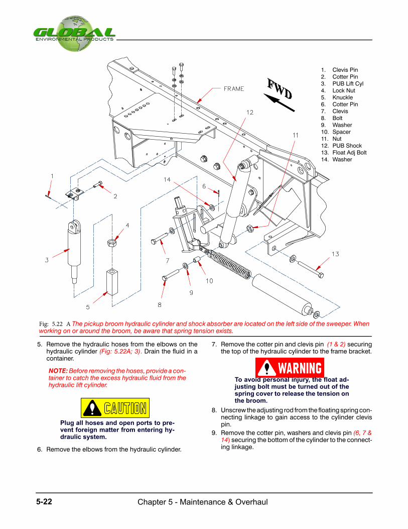
Chapter 5 - Maintenance & Overhaul5-22
Fig: 5.22 A The pickup broom hydraulic cylinder and shock absorber are located on the left side of the sweeper. Whenworking on or around the broom, be aware that spring tension exists.
1. Clevis Pin2. Cotter Pin3. PUB Lift Cyl4. Lock Nut5. Knuckle6. Cotter Pin7. Clevis8. Bolt9. Washer10. Spacer11. Nut12. PUB Shock13. Float Adj Bolt14. Washer
5. Remove the hydraulic hoses from the elbows on thehydraulic cylinder (Fig: 5.22A; 3). Drain the fluid in acontainer.
NOTE:Before removing the hoses, provide acon-tainer to catch the excess hydraulic fluid from thehydraulic lift cylinder.
Plug all hoses and open ports to pre-vent foreign matter from entering hy-draulic system.
6. Remove the elbows from the hydraulic cylinder.
7. Remove the cotter pin and clevis pin (1 & 2) securingthe top of the hydraulic cylinder to the frame bracket.
To avoid personal injury, the float ad-justing bolt must be turned out of thespring cover to release the tension onthe broom.
8. Unscrew the adjusting rod from the floating spring con-necting linkage to gain access to the cylinder clevispin.
9. Remove the cotter pin, washers and clevis pin (6, 7 &14) securing the bottom of the cylinder to the connect-ing linkage.

5-23Chapter 5 - Maintenance & Overhaul
10. Remove the hydraulic cylinder (3)with the knuckleattached.
11. Loosen the lock nut holding the knuckle to thethreaded shaft of the cylinder.
12. Remove the knuckle and lock nut (4 & 5) from thecylinder.
13. Install the pickup broom cylinder by reversing thesteps.
14. Adjust the distance between the mounting holes ofthe hydraulic cylinder and the knuckle on the cylindershaft to 11 inches.
15. Adjust the pickup broom floating position to themidpoint of travel measuring the knuckle in relation to the
slots of the shaft and linkage assembly.
Pickup Broom Shock Absorber--- Removal/Installation
1. Position the sweeper on a level surface.
2. Place the shifter in the Park (P) position, setting theparking brake.
3. Lower the pickup broom to relieve tension on theshockabsorber.
4. Stop the engine.
5. Clean the area around the shock absorber andconnecting hardware.
6. Remove the lock nuts (Fig: 5.22A; 11) on each end ofthe shock absorber. Remove the bolts (8), flat washers
(9), and spacers (10).7. Remove the shock absorber (12).8. Install the pickup broom shock absorber by reversing
the steps.
Fig: 5.23 A Pickup Broom Assembly. The Pickup Broom is removed from the right side of the sweeper.
1. Pickup Broom2. Bearing Mounting Plate RH3. PUB Arm and Bushing Assembly RH4. PUB Drive Core Shaft5. End Plate RH6. PUB Hub RH7. Threaded Stud (Both Ends)8. PUB Arm and Bushing Assembly LH9. PUB Hub LH10. End Plate LH11. Threaded Stud (Both Ends)
Chapter 5 - Maintenance & Overhaul5-24
Pickup Broom--- Replacement
Pickup broom replacement should only be performed byan experienced mechanic. Park the sweeper on a clean,
level surface and proceed as follows.
To avoid personal injury, the float ad-justing bolt must be turned out of thespring cover to release the tension onthe broom.
1. Unscrew the float adjusting bolt (Fig: 5.22A; 13)about 3 to 3---1/2 inches from the spring.
2. Remove the three hex nuts and lock washers secur-ing the right broom hub to the core of the broom (Fig:5.23A; 5,6,9 & 10). Do not disassemble the broomhub and pivot bearing assemblies.
3. Remove the cotter pin securing the clevis pin.Remove the clevis pin from the adjustable connect-ing link and pickup broom arm.
4. Remove the two hex head screws and lock washerssecuring the side plate and one hex head screw andlock washer securing the support bracket on thepickup broom arm.
5. Remove the assembled side plate, pickup broomarm, support bracket and dirt shoe.
6. Remove the three hex nuts and lock washers secur-ing the left end plate and wheel hub to the pickupbroom. DO NOT disassemble the Pickup Broommotor assembly.
7. Pull out the pickup broom (1) from the right side ofsweeper.
8. Slide in the new pickup broom from the right side ofthe sweeper. Position the broom so the core alignswith the assembled end plate and wheel hub. Attachthe left end plate, wheel hub and core using the threehex nuts and lock washers. Tighten the hex nutssecurely.
9. Replace the assembled side plate, pickup broomarm, support bracket and dirt shoe. The bearing,end plate and wheel hub must align with the threeholes in the core of the pickup broom.
10. Attach the side plate with two hex head screws andlock washers. Attach the support bracket using asingle screw and lock washer.
11. Attach the end plate and wheel hub to the core of thebroom using three hex nuts and lock washers.
12. Connect theadjustableconnecting rod to thepickupbroom arm with the clevis pin. Secure the clevis pinwith the cotter pin.
13. Test the broom pattern (refer to Pattern Adjustment,Chapter 3) and coning adjustment (refer to Leveling
Adjustment, Chapter 3).
GUTTER BROOM GROUP
The right and left gutter brooms are similar in construction.Mounting each broom on its respective side of the sweeperrequires minor changes. The following procedure cov
ers only the right gutter broom.
Gutter Broom Hydraulic Motor--- Removal/Installation
1, Position the sweeper on a level surface.
2. Place the shifter in the Park (P) position, setting theparking brake.
3. Stop the engine.
4. Clean the area around the hydraulic motor andconnecting hardware.
5. Remove the hex nut (Fig: 5.25A: 1) securing the gutterbroom plate assembly and dish assembly to thehydraulic motor. Lower the assembly to the floor.
6. Disconnect the hydraulic hoses from the elbows. Re-
move the elbows and connectors from the hydraulic
motor.
NOTE: Before removing the hoses, provide a container tocatch the excess hydraulic fluid from the
gutter broom motor.
Plug all hoses and open ports to pre-vent foreign matter from entering hy-draulic system.
The GB Motor will separate from thecollar once free. Take care so that theGB motor does not fall on you.
7. Place protective plugs in the ports of the hydraulic mo-tor and on the hoses to prevent dirt from entering thesystem.

5-25Chapter 5 - Maintenance & Overhaul
Fig: 5.25 A Gutter Broom Plate/Brush Removal andInstallation are basically the same on both sides.
1. Dish & Motor Assembly2. Gutter Broom Plate Wledment3. Broom Bristle Segment4. Latch Segment5. Rod Tool6. Gutter Broom Arm Assembly
(Tilt Option Arm Shown)
8. Remove the four hex nuts, lock washers, flat washers,and bolts securing the hydraulic motor to the gutterbroom arm.
9. Remove the hydraulic motor and separate the dish as-sembly. Inspect the dish assembly for rust or damage.Replace the parts.
10. Install the gutter broom motor by reversing the steps.
11. Before installing the plate assembly and dish assembly,make sure the woodruff key is positioned in the gutterbroom motor shaft. Install the motor shaft hex
nut and torque from 300 to 310 foot---pounds.
Gutter Broom Plate & Brush Assembly--- Removal/Installation
1. Position the sweeper on a level surface.
2. Place the shifter in the Park (P) position, setting theparking brake.
3. Raise the gutter broom.
4. Stop the engine.
5. Clean the area around the gutter broom and connect-ing hardware.
6. Using the rod tool (Fig: 5.25 A; 5), unlock the bristlesegment (3) from the gutter broom plate.
7. Steam clean the gutter broom segment plate, remov-ing all dirt and debris.
8. Remove the hex nut securing the gutter broom plateassembly, plate and mounting dish to the hydraulicmotor. Lower the assembly to the floor making sure theshaft key stays in place.
9. Remove the six bolts securing the mounting dish to theplate.
10. Remove the mounting dish.
NOTE: Inspect themountingdish threads fordam-age. Replace the mounting dish if damaged. In-spect the threads on the bolts for damage, and replace as necessary.
12. Install the gutter broom plate assembly by reversing
the steps.
NOTE: Be careful to position the woodruf key inthe gutter broom motor shaft before installing theplate assembly and mounting dish. Torque the motor shaft hex nut from 300 to 310 foot ---pounds.
13. Re---adjust the gutter broom pressure.
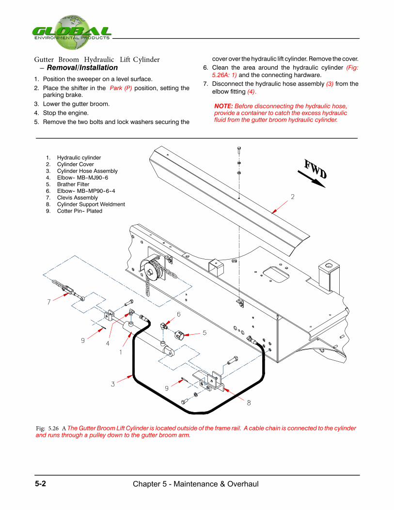
Chapter 5 - Maintenance & Overhaul5-26
Gutter Broom Hydraulic Lift Cylinder--- Removal/Installation
1. Position the sweeper on a level surface.
2. Place the shifter in the Park (P) position, setting theparking brake.
3. Lower the gutter broom.
4. Stop the engine.
5. Remove the two bolts and lock washers securing the
cover over the hydraulic lift cylinder. Remove the cover.
6. Clean the area around the hydraulic cylinder (Fig:5.26A: 1) and the connecting hardware.
7. Disconnect the hydraulic hose assembly (3) from the
elbow fitting (4).
NOTE: Before disconnecting the hydraulic hose,provide a container to catch the excess hydraulicfluid from the gutter broom hydraulic cylinder.
Fig: 5.26 A The Gutter Broom Lift Cylinder is located outside of the frame rail. A cable chain is connected to the cylinderand runs through a pulley down to the gutter broom arm.
1. Hydraulic cylinder2. Cylinder Cover3. Cylinder Hose Assembly4. Elbow-- MB--MJ90--65. Brather Filter6. Elbow-- MB--MP90--6--47. Clevis Assembly8. Cylinder Support Weldment9. Cotter Pin-- Plated
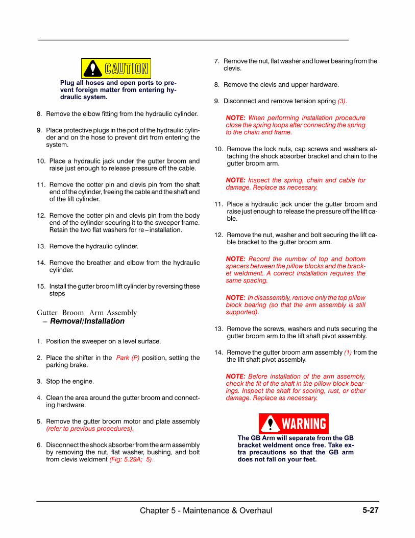
5-27Chapter 5 - Maintenance & Overhaul
Plug all hoses and open ports to pre-vent foreign matter from entering hy-draulic system.
8. Remove the elbow fitting from the hydraulic cylinder.
9. Place protective plugs in the port of the hydraulic cylin-der and on the hose to prevent dirt from entering thesystem.
10. Place a hydraulic jack under the gutter broom andraise just enough to release pressure off the cable.
11. Remove the cotter pin and clevis pin from the shaftend of the cylinder, freeing the cable and the shaft endof the lift cylinder.
12. Remove the cotter pin and clevis pin from the bodyend of the cylinder securing it to the sweeper frame.Retain the two flat washers for re--- installation.
13. Remove the hydraulic cylinder.
14. Remove the breather and elbow from the hydrauliccylinder.
15. Install the gutter broom lift cylinder by reversing thesesteps
Gutter Broom Arm Assembly--- Removal/Installation
1. Position the sweeper on a level surface.
2. Place the shifter in the Park (P) position, setting theparking brake.
3. Stop the engine.
4. Clean the area around the gutter broom and connect-ing hardware.
5. Remove the gutter broom motor and plate assembly(refer to previous procedures).
6. Disconnect the shock absorber from the arm assemblyby removing the nut, flat washer, bushing, and boltfrom clevis weldment (Fig: 5.29A; 5).
7. Remove the nut, flat washer and lower bearing from theclevis.
8. Remove the clevis and upper hardware.
9. Disconnect and remove tension spring (3).
NOTE: When performing installation procedureclose the spring loops after connecting the springto the chain and frame.
10. Remove the lock nuts, cap screws and washers at-taching the shock absorber bracket and chain to thegutter broom arm.
NOTE: Inspect the spring, chain and cable fordamage. Replace as necessary.
11. Place a hydraulic jack under the gutter broom andraise just enough to release the pressure off the lift ca-ble.
12. Remove the nut, washer and bolt securing the lift ca-ble bracket to the gutter broom arm.
NOTE: Record the number of top and bottomspacers between the pillow blocks and the brack-et weldment. A correct installation requires thesame spacing.
NOTE: In disassembly, remove only the top pillowblock bearing (so that the arm assembly is stillsupported).
13. Remove the screws, washers and nuts securing thegutter broom arm to the lift shaft pivot assembly.
14. Remove the gutter broom arm assembly (1) from thethe lift shaft pivot assembly.
NOTE: Before installation of the arm assembly,check the fit of the shaft in the pillow block bear-ings. Inspect the shaft for scoring, rust, or otherdamage. Replace as necessary.
The GB Arm will separate from the GBbracket weldment once free. Take ex-tra precautions so that the GB armdoes not fall on your feet.

Chapter 5 - Maintenance & Overhaul5-28
Fig: 5.28 A Removal of the Gutter Broom Arm requiresthe use of a jack to hold up the assembly while springtension is being released.
1. Pivot Mounting Wldmt2. Pillow Block Bearing3. Gutter Broom Arm Spacer4. Spacer5. Angle Wldmt6. Chain Assembly
NOTE: During each overhaul, always replace thebumpers, housing wipers and wiper rings. Installthe bumpers against the bearing collars.
15. Install gutter broom arm assembly by reversing steps.
16. Grease pillow block bearing fittings after installation.
Plug all hoses and open ports to pre-vent foreign matter from entering hy-draulic system.
Gutter B room Shock Abs orber--- Removal/Installation
1. Position the sweeper on a level surface.
2. Place the shifter in the Park (P) position, setting theparking brake.
3. Lower the gutter broom.
4. Stop the engine.
5. Clean the area around the shock absorber andconnecting hardware.
6. Remove the nut, flat washers, bushing, and bolt fromboth ends of the shock absorber, securing the absorberto the gutter broom arm and frame.
7. Remove the shock absorber .
NOTE: If either clevis requires replacement, go tostep 8. Otherwise go to step 10.
8. Remove the nut, washer and lower bearing from theclevis.
9. Remove the clevis and separate the washer, sleeve,and upper bearing from the clevis shaft.
10. Before replacing the shock absorber, collapse thenew shock and rotate it to the ”R” setting until it clicks.
11. Partially extend the shock and rotate the ends until theeyes align with each clevis.
12. Proceed with shock absorber installation by reversingthe above steps.
NOTE: Tighten the lock nuts securing the shock toeach clevis just enough to allow free rotation.

5-29Chapter 5 - Maintenance & Overhaul
Fig: 5.29 A The gutter broom arm shock absorber mounts to the gutter broom arm and to the frame. A jack may berequired when working on the gutter broom arm assembly to relieve the spring tension.
1. Gutter Broom Arm Assembly2. Shock Absorber3. Spring4. Chain 1/4”5. Clevis Weldment
Fig: 5.29 B The gutter broom arm shock absorber mounts to the gutter broom arm and to the frame. A jack may berequired when working on the gutter broom arm assembly to relieve the spring tension.
1. Gutter Broom Arm Assembly2. Shock Absorber3. Spring4. Chain 1/4”5. Clevis Weldment
STANDARD
WITH TILT OPTION

Chapter 5 - Maintenance & Overhaul5-30
ENGINE GROUP
The engine group section in this chapter provides instruc-tions on the removal and installation of the engine externalcomponents. Refer to the IS---07 280 Cummins EngineTroubleshooting and Reapair Manual to repair andoverhaul the engine.
Fu e l Filters/W ater Separator--- Removal/Installation
The purpose of the fuel filters are to keep fuel clean, to filterany dirt particles that can cause wear on the fuel system,and to separate any water from the fuel. The primary fuelfilter is mounted on the right side of to the engine towardsthe front of the sweeper. The pre---filter is mounted on thewall inside RH hydraulic tower next to the engine.
Condensation can easily build up in the fuel tank. Whenthe condensed water in the fuel filter/water separatorcomes to a warning level on the indicator, drain the fluidfrom the drain plug located at the bottom of the fuel filter/water separator.
The filter element should always be re-placed with new. Never try to clean thefilter element.
1. Position the sweeper on a level surface.
2. Place the shifter in the Park (P) position, setting theparking brake.
3. Raise the hopper.
4. Stop the engine.
5. Clean area at the right front of engine and fuel filter.
NOTE:Before removing the fuel filter strainer,provide a container to catch the excess fuel.
6. On the right front of the engine, unscrew the fuel filterstrainer from the filter head.
7. Remove the fuel filter element and gasket.
NOTE: The engine fuel system may requirepriming the first time the engine is started afterworking on the fuel system.
8. Replace the fuel filter element and gasket by reversingthe steps.
Refer to ISB-12 280 Cummins Engine

5-31Chapter 5 - Maintenance & Overhaul
Fig: 5.31 A The engine is situated in the sweeper frame backwards that is the flywheel is toward the front of thesweeper and the radiator cooling fan is toward the rear of the sweeper.
1. Cummins ISB--122. Coupling3. Hydraulic Block Bracket4. Hydraulic Block5. Grid Heater Relay Panel Assy6. Variable Displacement Pump7. Triple Pump8. Alternator9. Alternator Dust Shield10. Compressor
11. Fuel Filter12. Starter13. Turbo14. Oil Filter15. Air Intake16. Engine Belt17. Fan18. Fan Spacer19. Fan Adapter

Chapter 5 - Maintenance & Overhaul5-32
1 Precleaner2 Reducer Inlet Sleeve 3 U-bolt4 Clamp 5 Pipe6 Hump Hose7 Mounting Band8 Air Cleaner
9 Elbow10 Elbow, Reducing11 Gauge, Air Filter
Fig: 5: 32 A The air cleaner assembly is located above the engine next to the charge air cleaner.
Air Cleaner--- Removal/Installation
Hot exhaust systemspresent burnandfire hazards. Do not work on or nearthe engine or muffler until allcomponents are cool.
1. Position the sweeper on a level surface.
2. Place the shifter in the Park (P) position, setting theparking brake.
3. Raise the hopper and install the safety props.
INSTALL safety props. DEATH orserious INJURY may result if thehopper cylinders fail.
4. Stop the engine.
5. Unlatch and swing open the radiator.
6. Clean the area around the air cleaner.
7. Remove the wing nut securing the front cap of the aircleaner housing.
8. Remove the front cap and the air cleaner element fromthe housing.
NOTE: Replace the filter element if required. Thefollowing steps refer to replacement of the hous-ing.
9. Disconnect the filter indicator hose from the housing.
10. Loosen the hose clamp and disconnect the air intakeelbow from the housing.
NOTE: Support the air cleaner housing beforeremoving it from the mounting plate.
11. From the top of the air cleaner housing, loosen thehose clamp and remove the air inlet hood.
12. Remove the bolts and washers that secure the aircleaner housing clamps to the mounting plate.
13. Remove the air cleaner housing assembly.
14. Install the air cleaner assembly by reversing the steps.
12
3
4
44
4
5
6
7
89
5
10
11
jthompson
Line
jthompson
Line
jthompson
Line
jthompson
Line
jthompson
Line
jthompson
Line
jthompson
Line
jthompson
Line
jthompson
Line
jthompson
Line
jthompson
Line
jthompson
Line
jthompson
Line
jthompson
Line
jthompson
Line
jthompson
Line
jthompson
Line
jthompson
Line
jthompson
Line
jthompson
Line

5-33Chapter 5 - Maintenance & Overhaul
1 Exhaust Cover2 Turbo to DPF Tubing 3 DPF (Diesel Fuel Atomizer)4 DPF Clamps5 Exhaust Pipe6 SCR (Selective Catalytic Reduction)7 Channel8 Gasket
9 Elbow Fitting10 Decomposition Reactor
Fig: 5:33 A The Aftertreatment system is located at the rear above the engine on top of the Charge Air Cooler.
1
3
4
5
6
7
8
9
8
10
jthompson
Line
jthompson
Line
jthompson
Line
jthompson
Line
jthompson
Line
jthompson
Line
jthompson
Line
jthompson
Line
jthompson
Line
jthompson
Line

Chapter 5 - Maintenance & Overhaul5-34
SCR (Selective Catalytic Reduction)
- Removal
1. Position the sweeper on a level surface.
2. Place the shifter in the Park(P)position, settingthe parking brake.
3. Raise the hopper and install the safety props.
4. Stop the engine.
5. Remove the clamp (item 16) joining the exhaustpipe (item 5) to the SCR.
6. Remove the clamp (item 17) joining the SCR tothe elbow (item 14).
7. Loosen the straps (item 7).
8. Remove the SCR.
- Installation
Install the SCR by reversing the steps and replace the gasket (item 15) with a new one.
REACTOR (Decomposition Reactor)
- Removal
1. Position the sweeper on a level surface.
2. Place the shifter in the Park(P)position, settingthe parking brake.
3. Raise the hopper and install the safety props.
4. Stop the engine.
5. Remove the clamp (item 17) joining the SCR(item 6) to the elbow (item 14).
6. Remove the clamp (item 18) joining the elbow(item 14) to the REACTOR (item 12).
7. Remove the clamp (item 19) joining the REAC-TOR (item 12) to the elbow (item 10).
8. Remove the REACTOR.
- Installation
Install the REACTOR by reversing the steps and replace the gaskets (items 11, 13 and 15) with new ones.
DPF (Diesel Particulate Filter)
- Removal
1. Position the sweeper on a level surface.
2. Place the shifter in the Park(P)position, settingthe parking brake.
3. Raise the hopper and install the safety props.
4. Stop the engine.
5. Remove the clamp (item 20) joining the elbow(item 10) to the DPF (item 3).
6. Remove the clamp (item 22) joining the tubing(item 2) to the DPF (item 3).
7. Loosen the straps (item 4).
8. Remove the DPF.
- Installation
Install the DPF by reversing the steps and replace the gasket (item 20) with a new one.
INSTALL the safety props. DEATH or serious INJURY may result if the hoppercylinders fail.
Do not work on the exhaust systemuntil the components completely cooldown.

5-35Chapter 5 - Maintenance & Overhaul
1
2
3
4
5
6
Fig: 5.35 A The Radiator Assembly is located at the Front of the sweeper. Use a hoist to remove radiator.
1. Radiator2. Radiator Fan Assembly3.4.5.6.
Radiator Support WldtBracket WldmtTrim SealFront Bumper Installation
Radiator - Removal/Installation
1. Position the sweeper on a level surface.
2. Place the shifter in the Park (P) position, setting theparking brake.
3. Stop the engine.
To prevent burn injury, allow the en-gine to completely cool down beforeworking on or around the Radiator.
4. Remove the baffle guard and the fans.
5. Remove thehydraulic hoses from the fittings on theup-per side of the cooler.
6. Pull the Radiator out the rear of the shroud.
Before removing any mounting hard-ware, support the oil cooler to preventthe assembly from dropping.
7. Install the Radiator by reversing the steps.8. Fill the hydraulic oil tanks (refer to service/lubrication
procedure).
jthompson
Rectangle
jthompson
Line
jthompson
Line
jthompson
Line
jthompson
Line
jthompson
Line
jthompson
Line
jthompson
Line
jthompson
Line

Chapter 5 - Maintenance & Overhaul5-36
Deaeration Tank- Removal/Installation1. Position the sweeper on a level surface.2. Place the shifter in the Park (P) position, setting
the parking brake.3. Stop the engine.
To prevent burn injury, allow the engine to completely cool down before working on or around the Radiator.
4. Working from the rear of the sweeper, open reargrille and swing out the radiator.
5. Remove electrical wirings connected to deaera-tion tank (item 1).
6. Remove the deaeration tank cap.NOTE: Provide a container to drain the coolantfrom the deaeration tank.
7. Drain the coolant from the deaeration tank.8. Remove the overflow hose from the over-
flow nipple on the deaeration tank (item 6).9. At the bottom of the deaeration tank, loosen the
hose clamp securing the engine water inlethose (item 3).
10.On the side of the deaeration tank, loosen the-hose clamp securing the EGR valve hose(item4) and the radiator outlet hoses (item 5).
11.Remove the outlet hoses (item 4 & 5). Plug theoutlet hoses to stop any excess coolant fromdraining.
12.Remove the bolt and washers securing thedeaeration tank to the bracket (item2).
13.Remove the deaeration tank from the bracket.14.Install the deaeration tank by reversing the
steps.15.Fill engine coolant (refer to service/lubrica-
tion procedure).
Radiator- Removal/Installation1. Position the sweeper on a level surface,
2. Place the shifter in the Park (P) position, settingthe parking brake.
3. Stop the engine.
To prevent burn injury, allow the engine to completely cool down before working on or around the Radiator.
4. Working from the rear of the sweeper, swingoutthe radiator.
5. When the engine is cool, remove the deaerationradiator cap.
6. When the engine is cool, open the radiator valveto drain the coolant.NOTE: Provide a container to drain the coolantfrom the radiator.
7. Unlatch and swing out the radiator to gainaccess to the radiator hoses.
8. On the left side of the radiator, loosen theupper hose clamp securing the small radiatorcoolant hose (item 4) coming from the deaera-tiontank.
9. Loosen the upper hose clamp securing the largeradiator hose (item 15) coming from the engineoutlet.
10.Remove the two upper hoses. Plug the twoupper hoses to stop excess coolant from drain-ing.
11.Loosen the lower hose clamp securing the largeradiator hose (item 16) going to the engine wa-terpump.
12.Remove the lower hose. Plug the lower hose tostop excess coolant from draining.
13.Remove the nuts, bolts and washers securingthe radiator shroud (item 12) to the radiatorsupport frame (item 13). Remove the radiatorshroud.
14.Remove the bolts and washers securing theradiator (item 7) to the radiator supportframe (item 13).
15.Remove the radiator.16.Install the radiator by reversing the steps.17.Fill the engine coolant (refer to the service/
lubrication procedure).

Chapter 5 - Maintenance & Overhaul5-37
Fig: 5.37 A The Alternator is located on the engine. Remove the air conditioner belt before removing alternator belt fromthe fan pulley.
1. Alternator2. Alternator Dust Shield3. Alternator Bolt
Alternator---Removal/Installation
1. Position the sweeper on a level surface.
2. Place the shifter in the Park (P) position, setting theparking brake.
3. Raise the hopper and install the props.
4. Stop the engine.
5. Working from the rear of the sweeper, swing out theradiator to gain access to the alternator.
6. Disconnect the negative battery cable (black) fromeach battery. Move the cables away from the terminals.
7. Disconnect the positive battery cables (red) from eachbattery. Move the cables away from the terminals.
When disconnecting cables from thebatteries, ensure that cables are movedaway from the terminals.
8. Identify and tag the electrical leads connected to the al-ternator.
NOTE:Aplugwith yellowandwhite/redwirescon-nects to the side of the alternator. A single black/white stripedwire connects to the side of the alter-nator. A single redwire is bolted to the positive ter-minal on thebackof thealternator. Awhitewireandthe ground cable is bolted to the negative terminalon the back of the alternator.
Thegroundcablecomes from theengine. All otherwires come from the wire harness.

5-38Chapter 5 - Maintenance & Overhaul
9. Move tension pulley away from belt and relieve thetension on the large groove---belt.
10.Remove the groove---belt from the alternator pulley.
NOTE: If the belt needs replacing, first remove theair conditioner belt from the fan pulley (refer to thefollowing procedure). Next remove the alternatorbelt from the fan pulley.
11. Remove the ground wire at the alternator body.
12. Remove hose clamp to the alternator dust shield.
13. Remove bottom bracket bolt and washer.
14. While supporting thealternator, remove the nut, wash-ers and bolt securing the alternator to the enginebracket.
15. Remove the rear cover and then remove the electricalcable.
16. Remove the alternator
17. Install the alternator by reversing the steps.
18. Use the following procedure to adjust the groove---belt tension.
a. Tighten the alternator bracket nuts.
b. Place the groove belt around all the various pulleysexcept the tension pulley.
c. Move the tension pulley away from the belt relievingtension. Tighten the adjusting bolt.
NOTE: The properly ---adjusted tension on thegroove---belt is controlled by the spring loadedtension pulley.
d. Place the groove---belt over the tension pulley. Re-
lease the tension pulley.
BATTERY GROUP
The battery provides a source of energy for cranking theengine and acts a voltage stabilizer for the electrical sys-tem.
Batteries are factory sealed.Water never needs to be add-ed. A small amount of electrolyte may leak from the top ofthe battery if it is tipped at more than 45 degree angle. Evi-dence of electrolyte leakage on top of the battery does notnecessarily mean that the battery is defective.
Battery-Warning
EXPLOSIVE GASES. Always shieldeyes and face when working on oraround batteries. Cigarettes, flames or
sparks could cause the battery toexplode.Batteries contain poisonous sulfuricacid which can cause severe burns.Avoid contact with skin, eyes andclothing. In the event of accident flushwith water and call a physicianimmediately.Antidote--External:Flush thoroughly with water.Antidote--Internal:Drink large quantities of water or milk.Followwithmilk ofmagnesia, a beatenegg or vegetable oil.Antidote--Eyes:Flush eyes with water for 15minutes.Accidental shortingacross the battery terminals mayresult in lead splatter which cancause bodily injury and/or fire.
Do not tip the battery more than 45 de-gree angle when carrying or installingit.
NOTE: Keeping the batteries in a charged condi-tion should protect it against freezing.
Batteries--Replacement PrecautionsWhen handling a battery, the following precautions shouldbe observed:1. Hydrogen gas is produced by the battery. A flame or
spark near the battery may cause the gas to ignite.2. Inspect the battery for physical damage and replace as
required.3. Battery fluid is highly acidic. Avoid spilling on clothing or
other fabric. Any spilled should be flushed with waterimmediately.
4. To disconnect, remove negative cable from the negativeterminal and positive cable from the positive terminal.
5. To connect or install make sure positive cable is con-nected to the positive terminal and negative cable isconnected to the negative terminal.
Donot charge or use booster cables oradjust post connectionswithout properinstructions and training.
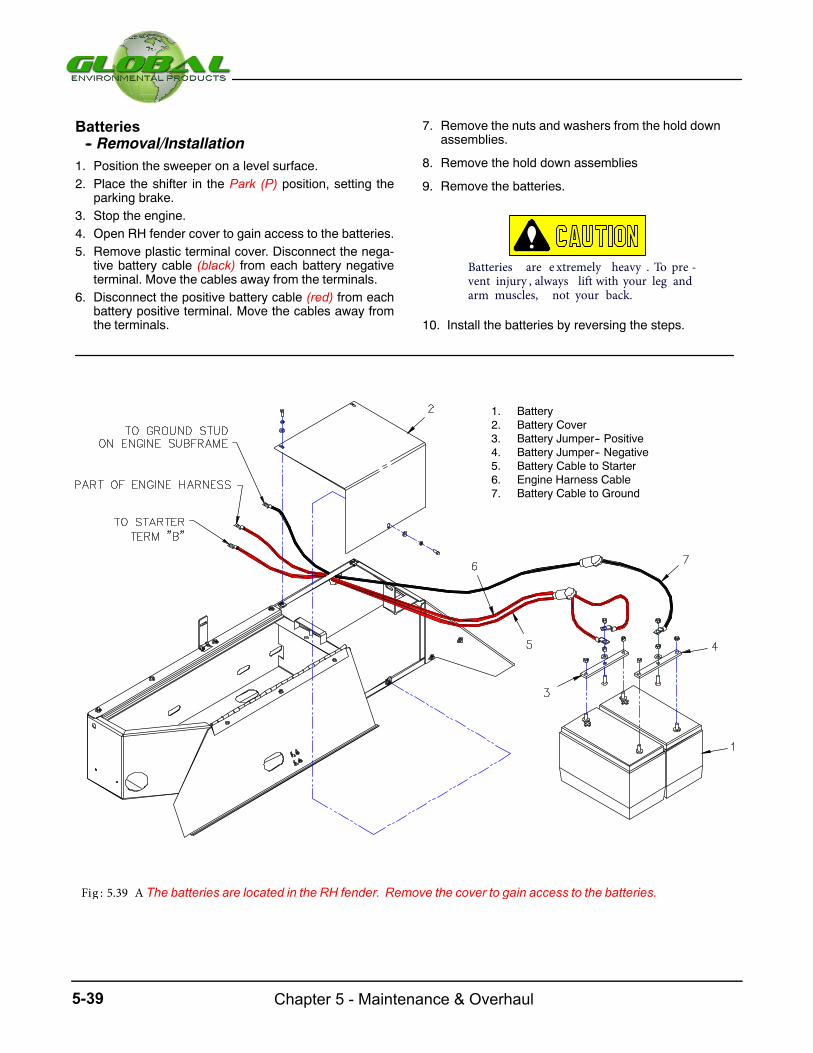
Chapter 5 - Maintenance & Overhaul5-39
Batteries-- Removal/Installation
1. Position the sweeper on a level surface.2. Place the shifter in the Park (P) position, setting the
parking brake.3. Stop the engine.4. Open RH fender cover to gain access to the batteries.5. Remove plastic terminal cover. Disconnect the nega-
tive battery cable (black) from each battery negativeterminal. Move the cables away from the terminals.
6. Disconnect the positive battery cable (red) from eachbattery positive terminal. Move the cables away fromthe terminals.
7. Remove the nuts and washers from the hold downassemblies.
8. Remove the hold down assemblies
9. Remove the batteries.
Batteries are e xtremely heavy . To pre -vent injury , always lift with your leg andarm muscles, not your back.
10. Install the batteries by reversing the steps.
1. Battery2. Battery Cover3. Battery Jumper-- Positive4. Battery Jumper-- Negative5. Battery Cable to Starter6. Engine Harness Cable7. Battery Cable to Ground
Fig : 5.39 A The batteries are located in the RH fender. Remove the cover to gain access to the batteries.

5-40Chapter 5 - Maintenance & Overhaul
HOPPER GROUP
The removal and installation of the hopper requires a lifting
equipment designed to lift the hopper safely as an as-
sembly without causing personal injury or damage to
the equipment.
Hopper-- Removal/Installation
1. Position the sweeper on a level surface.
2. Place the shifter in the Park (P) position, setting the
parking brake.
4. Stop the engine.
5. Provide a chain sling and hoist capable of lifting the
hopper. Attach the sling to the lifting eye at each corner
of the hopper, with a center pull crane (or hoist) con-
figuration.
6. Disconnect
the
hydraulic
lines,
and
the
hopper
full
sensor.
3. Raise hopper to access Mtg. bolts on bottom, installsafety props
Do Not remove the lower lift cylinderpins from the frame.
8. Raise the crane (or hoist) to lift the hopper from the
sweeper.
9. Install the hopper by reversing the steps.
Raising the Hopper Without Engine Power
In order to raise the hopper without engine power, a
remote hydraulic pump is required to actuate pressure
necessary to lift the cylinder.
1. Position the sweeper on a level surface.
2. Place the shifter in the Park (P) position, setting the
parking brake.
3. Remove remote high pressure and low pressure caps
from auxiliary hopper lift ports.
4. Attach remote hydraulic hoses and a remote hydraulic
pump to the ports.
NOTE: Themale port (pressure) comes directlyfrom the auxiliary pump. The female port (return)should dump into a hydraulic oil container or pumpreservoir.
5. Start the remote hydraulic pump and raise the hopper.
NOTE:Pressure necesssary to lift the cylinder willdepend on the amount of debris inside the hopper.
Before attempting to do any inspections or repairs under a raised hopper, make sure that BOTH Safety Props are in place
Safety Under the Hopper
6. Remove the remote pump and related connections.
7. Replace the auxiliary port caps.
8. Check the hydraulic fluid level.
Remove hopper mounting bolts at bottom ofhopper corners
7.


Chapter 6 - Hydraulic Components
Hydraulic Components
CHAPTER6
Subject PageComponents
6-36-56-76-96-116-13
Extended O-Reach Manifold Elev./ Pickup Broom Manifold Hopper, Up/Down Manifold Gutterbroom Drive Manifold Parking Brake ManifoldBroom Lift ManifoldPU.B Drive Manifold Hydraulic Traction Pump & MotorHopper Hydraulic schematics
6-15
6-16

Chapter 6 - Hydraulic Components6-2
This page intentionally left blank

CHECK VALVE PART# (331222)
SOLENOID VALVE & COILPART# (331225)
REDUCING/ RELIEVING CARTRIDGE (800PSI)
PART # (331227)
NOTE: PART#331223 & 331224ARE BUILT INSIDE AND ARENOT SHOWN.
BLUE MANIFOLD- EXT O-REACH OPTPART# (248020)
6-3 Chapter 6- Hydraulic Components
jthompson
Line
jthompson
Line
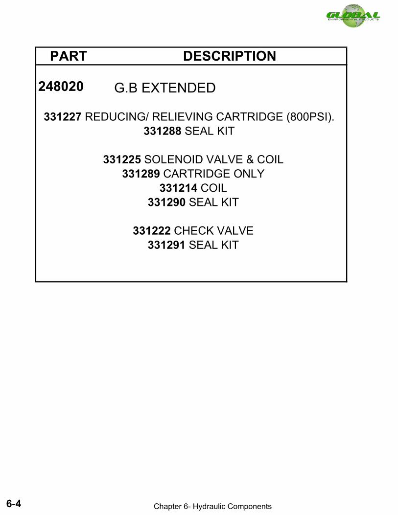
PART # DESCRIPTION
248020 G.B EXTENDED
331222 CHECK VALVE 331291 SEAL KIT
331225 SOLENOID VALVE & COIL 331289 CARTRIDGE ONLY
331214 COIL331290 SEAL KIT
331227 REDUCING/ RELIEVING CARTRIDGE (800PSI). 331288 SEAL KIT
6-4 Chapter 6- Hydraulic Components
jthompson
Line
jthompson
Line

B
B
SOLENOID VALVE & COIL.BY-PASS (2-WAY) VALVE.
(PART# 382707)
RELIEF VALVE CARTRIDGE, (3500 PSI).PART# (381209)
4X CHECK VALVE.PART# (382708)
4X PISTON.PART# (381212)
VIEW B-B
SOLENOID VALVE & COIL.FOWARD/ REVERSE (4-WAY) VALVE.
PART# (307839)
CHECK VALVE CARTRIDGE.PART# (382709)
12X BACKUP RING PART# (331233)
NOTE:BACK UP RINGS AND PISTONSARE BUILT INSIDE MANIFOLD AND ARE NOT SHOWN IN DRAWING.
BLUE MANIFOLD- ELEV./ PICKUP BROOM PART# (319872)
6-5 Chapter 6- Hydraulic Components
jthompson
Line
jthompson
Line

PART # DESCRIPTION
319872 ELEV./ PICK UP BROOM
382708 CHECK VALVE 381258 SEAL KIT
382707 BY-PASS (2-WAY) VALVE 382723 CARTRIDGE
382724 COIL331276 SEAL KIT
307839 FORWARD/ REVERSE (4-WAY) VALVE 331280 CARTRIDGE
382724 COIL331283 SEAL KIT
331284 BACK UP RING FOR PILOT PISTON
331236 RELIEF VALVE (3500PSI). 381258 SEAL KIT
382709 CHECK VALVE 381258 SEAL KIT
6-6 Chapter 6- Hydraulic Components
jthompson
Line
jthompson
Line

COUNTERBALANCE VALVE(800 PSI).PART# (331238)
RELIEF VALVE CARTRIDGE (2500 PSI).PART# (331239)
RELIEF VALVE CARTRIDGE (900 PSI).PART# (331240)
3X FITTING, DIAGNOSTIC, 7/16.PART# (381223)3X DUST CAP.
PART# (381224)
CARTRIDGE & COILBYPASS VALVE.PART# (382707)
CARTRIDGE & COILG.B. RUN VALVE.PART# (382706)
FLOW CONTROL CARTIDGE(7GPM).PART# (381202)
2X CARTRIDGE & COIL HOPPER UP.
PART# (331247)2X CARTRIDGE & COIL
HOPPER DOWN.PART# (331247)
NOTE:PART NUMBER (381223) &(381224) NOT SHOWN.
BLUE MAINFOLD- HOPPER, UP/ DOWN PART# (319870)
6-7 Chapter 6- Hydraulic Components
jthompson
Line
jthompson
Line
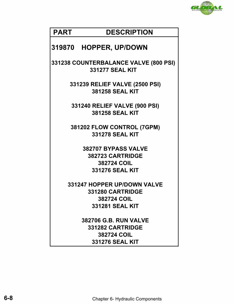
PART # DESCRIPTION
319870 HOPPER, UP/DOWN
382706 G.B. RUN VALVE 331282 CARTRIDGE
382724 COIL331276 SEAL KIT
331247 HOPPER UP/DOWN VALVE 331280 CARTRIDGE
382724 COIL331281 SEAL KIT
382707 BYPASS VALVE 382723 CARTRIDGE
382724 COIL331276 SEAL KIT
381202 FLOW CONTROL (7GPM) 331278 SEAL KIT
331238 COUNTERBALANCE VALVE (800 PSI) 331277 SEAL KIT
331239 RELIEF VALVE (2500 PSI) 381258 SEAL KIT
331240 RELIEF VALVE (900 PSI) 381258 SEAL KIT
6-8 Chapter 6- Hydraulic Components
jthompson
Line
jthompson
Line

A A
RELIEF VALVE CARTRIDGE (2000 PSI).PART# (331256)
SOLENOID VALVE & COIL.LH G/B RUN VALVE.
PART# (382707)
SOLENOID VALVE & COIL.RH G/B VALVE.PART# (382707)
VIEW A-ASCALE 1 : 3
CHECK VALVE.PART# (382709)
BLUE MANIFOLD- GUTTERBROOM DRIVE.PART# (319871)
6-9 Chapter 6- Hydraulic Components
jthompson
Line
jthompson
Line

PART # DESCRIPTION
319871 GUTTER BROOM DRIVE
382707 SOLENOID VALVE & COIL 382723 CARTRIDGE
382724 COIL331276 SEAL KIT
382709 CHECK VALVE 381258 SEAL KIT
331256 RELIEF VALVE (2000 PSI) 381258 SEAL KIT
6-10 Chapter 6- Hydraulic Components
jthompson
Line
jthompson
Line

SOLENOID VALVE & COIL. PART# (331266)
CHECK VALVE CARTRIDGE.PART# (382709)
BLUE MANIFOLD-PARKING BRAKE PART# (319874)
6-11
Chapter 7- Hydraulic Components
Chapter 6- Hydraulic Components
jthompson
Line
jthompson
Line
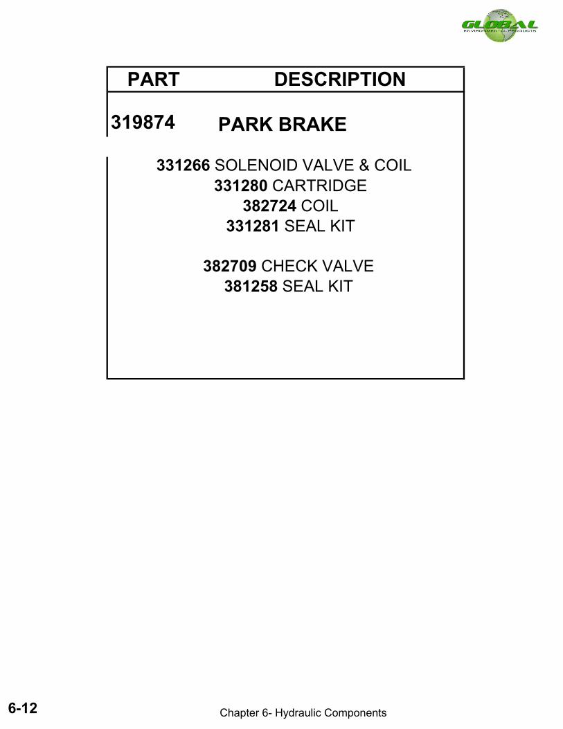
PART # DESCRIPTION
319874 PARK BRAKE
331266 SOLENOID VALVE & COIL
382709 CHECK VALVE 381258 SEAL KIT
331280 CARTRIDGE 382724 COIL
331281 SEAL KIT
6-12 Chapter 6- Hydraulic Components
jthompson
Line
jthompson
Line

COUNTERBALANCE CARTRIDGE (3045PSI). PART# (331268)
4X SOLENOID VALVE & COILLH G.B UP
PART# (331266)
4X SOLENOID VALVE & COILRH G.B. DOWN.PART# (331266)
2X SOLENOID VALVE & COILP.U.B UP.
PART# (331270)
FITTING, DIAGNOSTIC, 7/16.PART# (381223)
DUST CAP.PART# (381224)
PRESSURE REDUCING/RELIEVING(600PSI).PART# (382712)
4X SOLENOID VALVE & COILLH G.B DOWN.PART# (331266)
2X SOLENOID VALVE & COILP.U.B DOWN.
PART# (331270)
4X SOLENOID VALVE & COILP.U.B DOWN.
PART# (331266)
BLUE MANIFOLD-BROOM LIFT PART# (319875)
6-13 Chapter 6- Hydraulic Components
jthompson
Line
jthompson
Line

PART # DESCRIPTION
319875 BROOM LIFT
331268 COUNTERBALANCE VALVE (3045PSI) 331277 SEAL KIT
382712 PRESSURE REDUCER VALVE (600PSI) 331285 SEAL KIT
331266 P.U.B DOWN 331280 CARTRIDGE
382724 COIL 331281 SEAL KIT
331270 P.U.B UP 331282 CARTRIDGE
382724 COIL 331276 SEAL KIT
6-14 Chapter 6- Hydraulic Components
jthompson
Line
jthompson
Line

BB
RELIEF VALVE CARTRIDGE (3500PSI).PART# (381209)
SOLENOID VALVE & COILNORMALLY OPEN VALVE.
PART# (382706)
SOLENOID VALVE & COILNORMALLY CLOSED VALVE.
PART# (382707)
BLUE MANIFOLD- P.U.B DRIVE PART# (319876)
6-15 Chapter 6- Hydraulic Components
jthompson
Line
jthompson
Line

PART # DESCRIPTION
319876 P.U.B DRIVE
381209 RELIEF VALVE (3500PSI) 381258 SEAL KIT
382706 NORMALLY OPEN VALVE 331282 CARTRIDGE
382724 COIL331276 SEAL KIT
382723 CARTRIDGE 382724 COIL 331276
SEAL KIT
382707 NORMALLY CLOSED VALVE
6-16 Chapter 6- Hydraulic Components
jthompson
Line
jthompson
Line
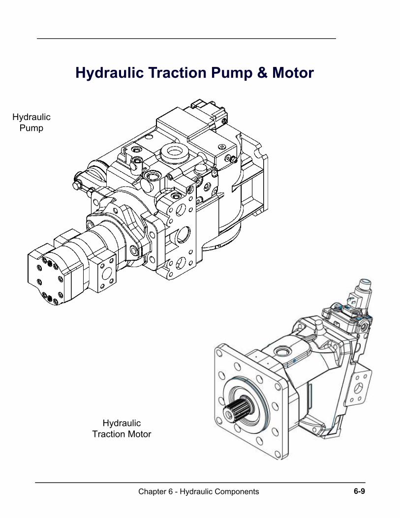
6-9Chapter 6 - Hydraulic Components
Hydraulic Traction Pump & Motor
Hydraulic Traction Motor
Hydraulic Pump
nthompson
Line
nthompson
Line
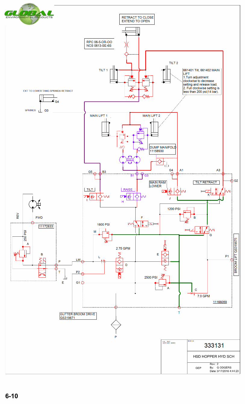
6-10
godgers
Line

Chapter 6 - Hydraulic Components6-10
This page intentionally left blank

Chapter 6 - Hydraulic Components6-32
This page intentionally left blank

7-1Chapter 7 - Schematics
Troubleshoot
CHAPTER 7
Page
7-27-17
Electrical SchematicPark Brake Maintenence


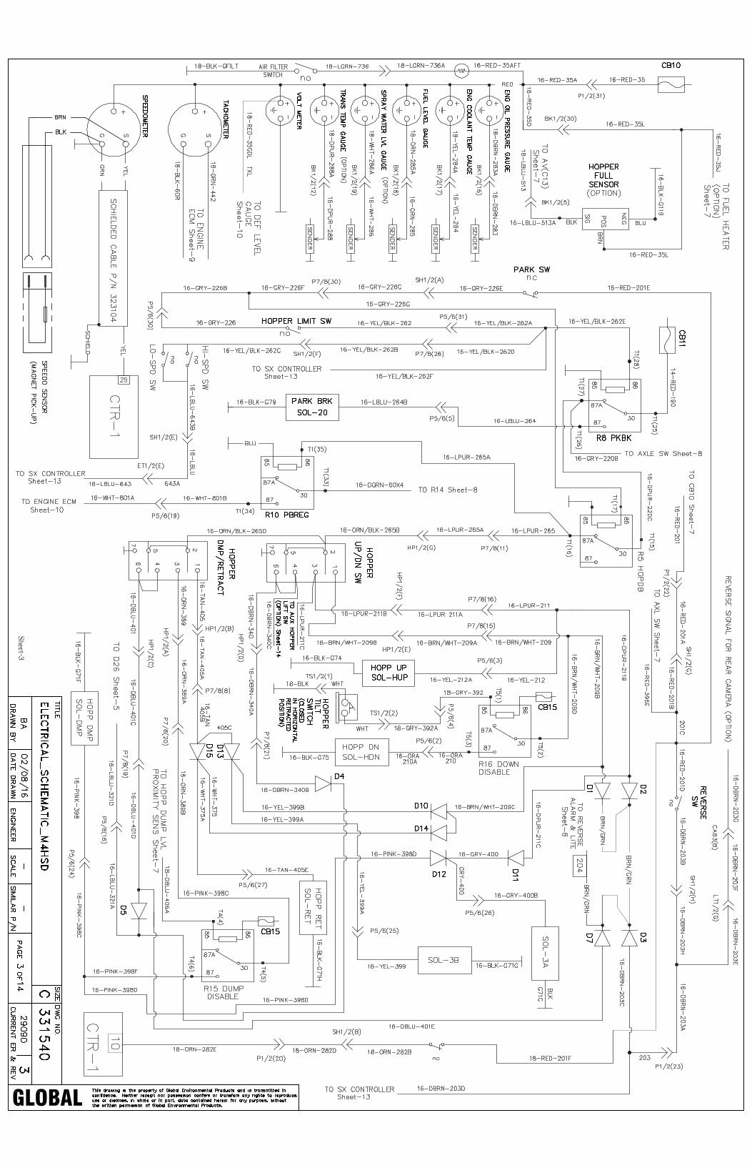
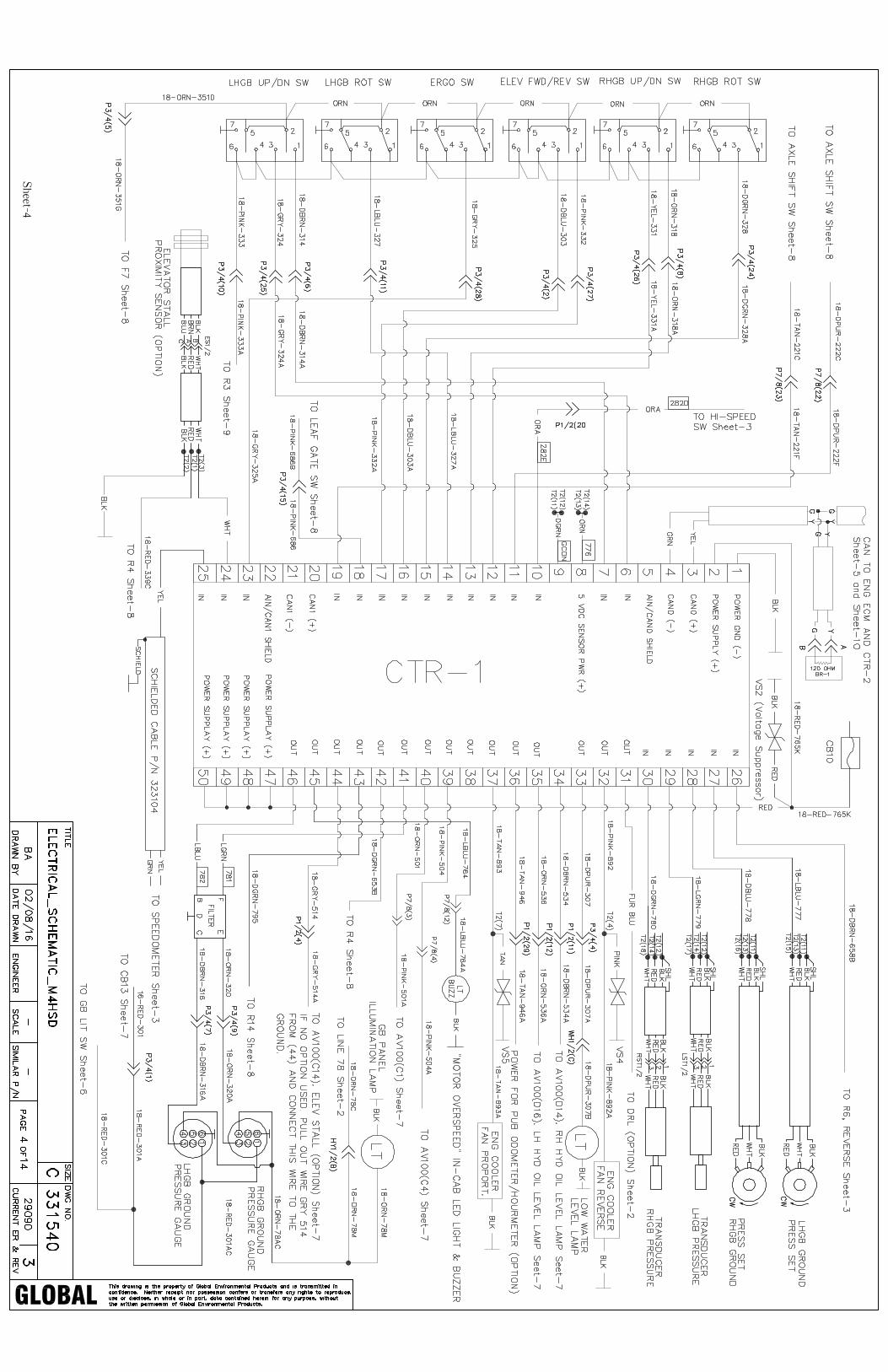


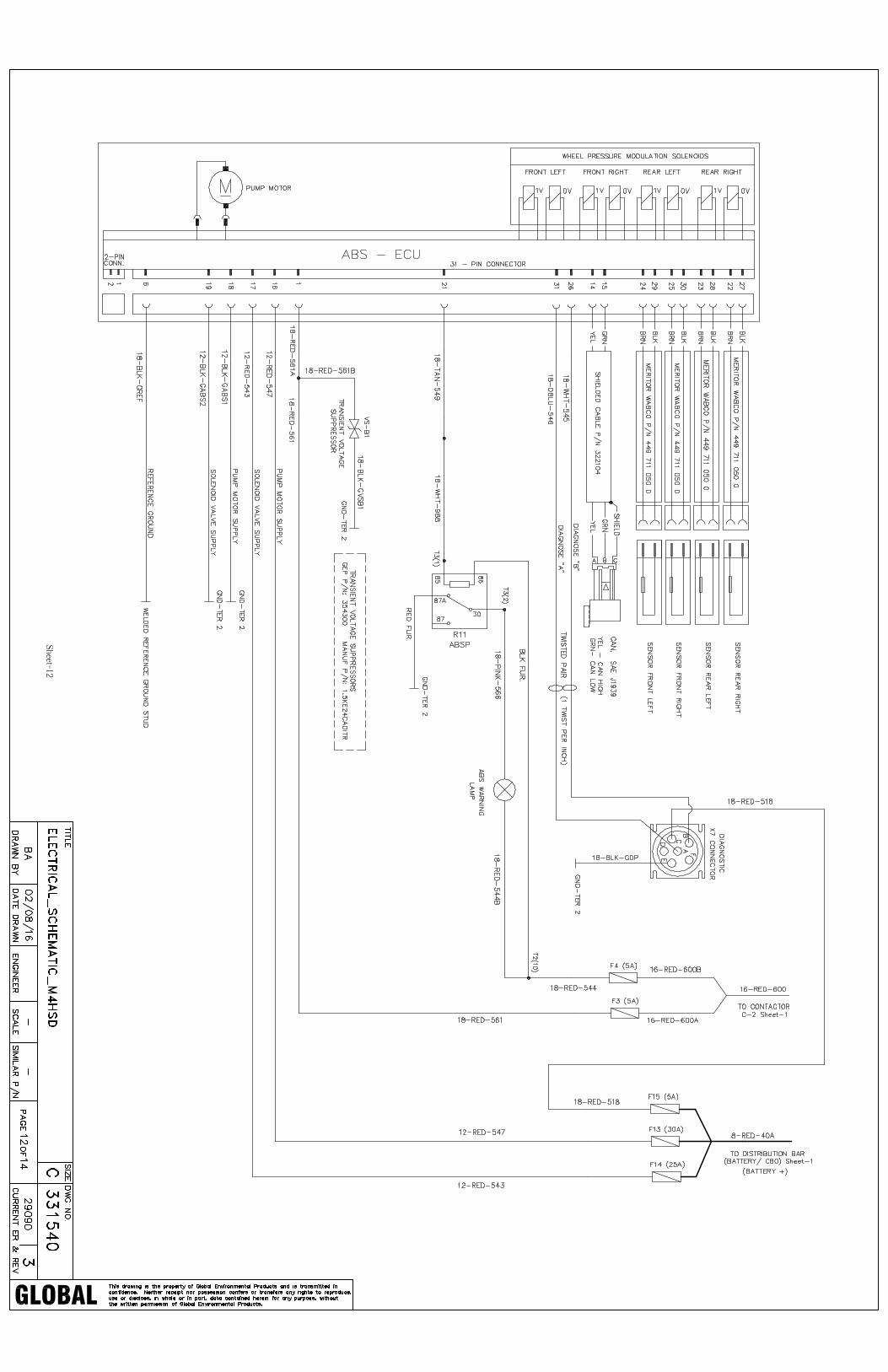


305x76 Park Brake Service Manual�
Brake systems for medium duty trucks
305x76 Park Brake
Service Manual2nd Edition
7-17
jthompson
Rectangle
305x76 Park Brake Service Manual�
�nd EditionFebruary �006
Important Service NotesThe information in this publication was current at the time of printing. The information presented in this publication is subject to change without notice or liability.
The information contained in this publication is intended for use by properly trained and equipped professional technicians and is NOT for the “Do It Yourselfer.”
Failure to follow safety and vehicle repair procedures either contained in this manual, in the chassis and vehicle manufacturer’s repair manuals or in accordance with other accepted methods can result in personal injury, death, or damage to components, vehicles, or personal property.

305x76 Park Brake Service Manual3
Contents
Introduction ......................................................................................................................5
Basic Major Components ..............................................................................................5
Service Component Interchangeability ..................................................................5
Shoes and Related Components.................................................................................9
Shoe Cage Adjusting Components........................................................................ �0
Before Servicing Brakes... ........................................................................................... ��
Inspection ....................................................................................................................... ��
Shoe Replacement ....................................................................................................... �4
Removing the Shoes .................................................................................................................. �4
Installing the Shoes .................................................................................................................... �6
Shoe Cage Adjustment Procedures ....................................................................... �0
Adjustment with Drum Off - Primary Procedure ............................................................. �0
Adjustment with Drum Installed - Alternate Procedure ............................................... ��
Disengaging Adjuster Lever from Adjuster Starwheel to Loosen Brake..................�3
Anchor Screw, Lever, and Cam Replacement ..................................................... �5
Removing Components ............................................................................................................ �5
Installing Components .............................................................................................................. �7
Trouble Shooting .......................................................................................................... 30
Component Specifications ....................................................................................... 3�
Fastener Torque Specifications ................................................................................ 3�
Special Tools ................................................................................................................... 3�
Lubrication ...................................................................................................................... 3�

305x76 Park Brake Service Manual4
305x76 mm Park BrakeEXPLODED VIEW
(Typical)
BACKING PLATE
BRAKE SHOE
HOLD-DOWN SPRING
HOLD-DOWNBRACKET
UPPER RETURN SPRING
HOLD-DOWN PIN
CAM PLATE
ADJUSTER CABLEADJUSTER CABLE SPRING
SPRING ENDFITTING
ADJUSTER NUT (LH THREADS)ADJUSTER SCREW
(LH THREADS)
LEVER GUIDE
LEVER
ADJUSTER CABLEGUIDE
ANTI-RATTLE SPRING
BRAKE SHOE
ANCHOR SCREW
ADJUSTER CABLERETAINER TAB
ALTERNATE ADJUSTER CABLE END FITTING TYPE
LOWER RETURN SPRING
AUTO ADJUSTER LEVER
AUTOADJUSTER SPRING
HOLD-DOWN SPRING
Figure 1.
LEVER RETURN SPRING
ADJUSTER LEVER PIN

305x76 Park Brake Service Manual5
IntroductionThe 305 x 76 mm park brake is a lever actuated, duo-servo, single-anchor drum brake. The brake is designed for driveline mounted applications typically on the rear axle differential carrier housing. Its self-adjusting feature enables the brake to maintain a consistent functional clearance between the brake shoes and the drum as the shoe linings wear.
There are three (3) releases of this brake in service. Release � was the original release and manufactured prior to April �00�. The Release � design has a brake manufacture date after April �00� and up to December �005. The Release 3 design has a manufacture date after December �005. Figure � shows the Release � brake, highlights the differences between the Release � and Release � brakes. Figure 3 shows the Release � brake and highlights the differences between Release � and Release � brakes. Figure 4 shows the Release 3 brake and highlights the differences between Release � and Release 3.
Basic Major ComponentsThe foundation of the brake is a ductile iron backing plate. Major actuating components are a cam and a lever, which are fastened to the backing plate by an anchor screw. An anti-rattle spring under the head of this screw reduces clatter. Brakes with hex socket anchor screw (Release �) will also have two flat washers immediately under the head of the screw. The anchor point for brake actuation and shoe abutment is located at the �� o’clock position when the assembly is properly mounted. See Figures �, �, 3 and 4.
Service Component InterchangeabilityOnly use Release 1 brake components on Release 1 brakes.Only use Release 2 brake components on Release 2 brakes.Release 3 brake components can be used on Release 2 brakes.

305x76 Park Brake Service Manual6
305 x 76 mm Park Brake
Figure 4. 305x76 Park Brake Major Components(Release 3 Shown)
Release 3 - Manufactured beginning December �005.
Features:• No apply lever guide• Revised anti-rattle spring• Adjuster access slot size increased
Includes features from Release �:• Apply lever with bump stop• External hex head style anchor screw with M�� thread• Abex-608�-GG lining codes• Revised adjuster cable anchor end fitting• Adjuster cable retainer tab
ANTI-RATTLE SPRING
ADJUSTER ACCESS SLOT IN BACKING PLATE

305x76 Park Brake Service Manual7
Shoes and Related ComponentsBrake shoes are attached to the backing plate by hold-down springs and pins, shown in Figure 5. Both shoes seat against the backing plate anchor post at the top and are connected by the adjuster nut and screw assembly at the bottom. Shoe hold-down brackets are permanently mounted to the backing plate to assist in guiding the shoes. The shoes are pulled toward each other by two low-tension shoe return springs. Proper orientation of the various springs, including their hook ends, must be maintained for proper function. The starwheel used for adjusting the shoe clearance to the drum is on the adjuster nut.
Figure 5. Brake Shoes and Related Components(Release 3 shown)
ADJUSTER NUT AND SCREW ASSEMBLY (LH THREADS)
BRAKE SHOE
BRAKE SHOE
ADJUSTER NUTADJUSTER SCREW
SHOE HOLD-DOWN BRACKET
SHOE HOLD-DOWN BRACKET
UPPER SHOE RETURN SPRING
LOWER SHOERETURN SPRING
ADJUSTER STARWHEEL
BACKINGPLATE
HOLD-DOWN SPRING
PANEL TAB
LEVER RETURN SPRING
HOLD-DOWN PIN
HOLD-DOWNSPRING
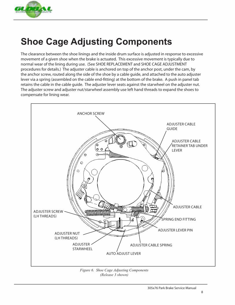
305x76 Park Brake Service Manual8
Shoe Cage Adjusting ComponentsThe clearance between the shoe linings and the inside drum surface is adjusted in response to excessive movement of a given shoe when the brake is actuated. This excessive movement is typically due to normal wear of the lining during use. (See SHOE REPLACEMENT and SHOE CAGE ADJUSTMENT procedures for details.) The adjuster cable is anchored on top of the anchor post, under the cam, by the anchor screw, routed along the side of the shoe by a cable guide, and attached to the auto adjuster lever via a spring (assembled on the cable end-fitting) at the bottom of the brake. A push in panel tab retains the cable in the cable guide. The adjuster lever seats against the starwheel on the adjuster nut. The adjuster screw and adjuster nut/starwheel assembly use left hand threads to expand the shoes to compensate for lining wear.
Figure 6. Shoe Cage Adjusting Components(Release 3 shown)
ADJUSTER CABLE GUIDE
ADJUSTER CABLE
ANCHOR SCREW
ADJUSTER CABLE SPRING
AUTO ADJUST LEVER
ADJUSTER STARWHEEL
ADJUSTER NUT(LH THREADS)
ADJUSTER SCREW(LH THREADS)
ADJUSTER CABLE RETAINER TAB UNDER LEVER
SPRING END FITTING
ADJUSTER LEVER PIN

305x76 Park Brake Service Manual9
Before Servicing Brakes...Information in this manual is not intended to replace the vehicle manufacturer’s service manual. Always refer to the latest vehicle manufacturer’s service information. Information contained in this manual is subject to change without notice.
Always verify proper operation of the park brake prior to returning vehicle to service.
Do not work under or around a vehicle supported by a mechanical or hydraulic jack. Vehicle must be supported by suitable floor stands. Failure to do so can result in personal injury or propery
Always block vehicle to prevent vehicle movement, such as with suitable wheel chocks. Failure to do this could result in personal injury or property damage.
Keep grease and other foreign materials away from the shoe lining and drum surfaces. Contamination of shoe linings or drum surface may result in degradation of brake holding capability, possibly resulting in personal injury or property damage.
Always wear eye protection. Keep fingers, hands and other body parts away from the brake when verifying operation. Do not stand by or under a vehicle at this time.
Use only original equipment parts, available through the vehicle manufacturer’s Service department.
Failure to do so may result in reduced brake performance, possibly resulting in personal injury or property damage.

305x76 Park Brake Service Manual�0
InspectionNote: It is not necessary to raise vehicle for “inspection” in most cases. However, if required, follow steps 1 through 3 in SHOE REPLACEMENT section.
Anytime service is required, it is recommended that a complete visual inspection be performed on all com-ponents in the park brake assembly. This includes:
�. Follow manufacturer’s recommended procedures to ready the vehicle for servicing. Pay attention toall WARNING and CAUTION notes throughout this booklet.
�. Remove the drum. See vehicle manufacturer’s service manual for details.
3. Clean the individual brake components, removing dust and grease.
4. Visually inspect the brake shoes (Figure 5). Shoes should be replaced if there is uneven lining wearor when the remaining lining reaches 0.76 mm (0.030” or approximately �/3�”) thickness or lessabove the shoe. If grease, automotive fluids, or other foreign material that would compromiseoperation is found on, soaked into or embedded in the linings, the shoes should be replaced. Also,if cracks, excessive deformation, or wear on either end is found, the shoes should be replaced. Seesection on SHOE REPLACEMENT for service details.
5. Visually inspect the brake lever and cam (Figure �). If cracks, excessive wear, or abnormal deforma-tion is found in either part, they should be replaced. Light wear, which typically shows up as polish-ing is acceptable. If unsure, replace brake lever, cam plate and anchor screw. See section onANCHOR SCREW, LEVER, AND CAM REPLACEMENT for service details.
6. Inspect various springs and hold down pins (Figure 5) for excessive wear, heat discoloration, heavycorrosion or other damage and replace as necessary. See section on SHOE REPLACEMENT for service
Whenever possible, work on brakes in a separate area away from other operations. Always wear a respirator approved by NIOSH or MSHA during all brake service procedures. NEVER use compressed air or dry brushing to clean brake parts or assemblies. OSHA recommends that you use cylinders that enclose the brake. These cylinders have vacuums with high efficiency HEPA filters and worker’s arm access sleeves. But, if such equipment is not available, carefully clean parts and assemblies in the open air.
Clean brake parts and assemblies in the open air. During disassembly, carefully handle all parts to avoid getting dust in the air. Use an industrial vacuum cleaner with a HEPA filter system to clean dust from the brake drums, backing plates and other brake parts. After using the vacuum, remove any remaining dust with a rag soaked in water and wrung until nearly dry.

305x76 Park Brake Service Manual�1
Inspection (continued)7. Inspect adjuster cable assembly for damage or wear (Figure 5). Replace as necessary. See section on
SHOE REPLACEMENT for service details.
8. Inspect adjuster nut and screw (Figure 5) for any damage or corrosion to the threads or burrs, chips,corrosion or other damage to the teeth on the adjuster nut starwheel. Damaged teeth or threadsmay prevent proper function of the brake self-adjusting function. Replace as necessary. See sectionSHOE REPLACEMENT for service details.
9. Clean-out all dust or grease present on the inside of drum. Use a �� inch caliper or an inside diame-ter micrometer to measure the manufacturer’s recommended inside diameter of the drum. Replacedrum if it exceeds maximum inside diameter (which typically is stamped on the inside of the drumnear the mounting holes), is worn unevenly, has deep grooves, heavy corrosion or excessive runout.See vehicle manufacturer’s service manual for details.
�0. Inspect the parking brake lever-apply cable for excessive wear or damage, and replace as necessary.See vehicle manufacturer’s service manual for details.
��. Inspect the axle pinion oil seal for leakage that can contaminate the park brake system parts andrepair as necessary. See vehicle manufacturer’s service manual for details.
��. After a thorough inspection, if the brake and its components are found to be in good workingcondition, check parking brake for proper shoe cage adjustment. See Shoe Cage AdjustmentProcedures section for details.

305x76 Park Brake Service Manual�2
Shoe ReplacementRemoving the Shoes�. Block the front wheels to keep the vehicle from moving.�. With the engine off and battery disconnected, place the transmission in gear and release the parking
brake.3. If recommended in vehicle manufacturer’s service manual, raise the rear of the vehicle so the wheels
clear the floor and install safety stands to support.4. Remove the drum. See vehicle manufacturer’s service manual for details, if necessary.
Note: If the drum proves difficult to remove, insert a thin flat bladed screwdriver through the brake adjusting hole in the backing plate and disengage the adjuster lever from the adjuster nut teeth. With the adjuster lever disengaged as shown in Figures 14 and 15, insert a brake adjusting tool (or flat bladed screw driver) through the adjusting hole to engage the adjusting nut teeth. Move the teeth upward enough times to retract the brake shoes to clear the drum. If the drum is rusted to the axle input flange yoke pilot, tap the center of the brake drum with a nonmetallic mallet to loosen.
5. Inspect the brake per the INSPECTION PROCEDURE in this service manual.
Figure 7. Adjuster Lever and Adjuster Spring Removal
Do not use a drum puller or a torch to remove a brake drum.Drum distortion may result.
RAISE LEVER OFF STARWHEEL AND PUSH UP
1 DISENGAGE SPRING2
DISENGAGE LEVER SPRING3
REMOVE LEVERAND LEVER SPRING4
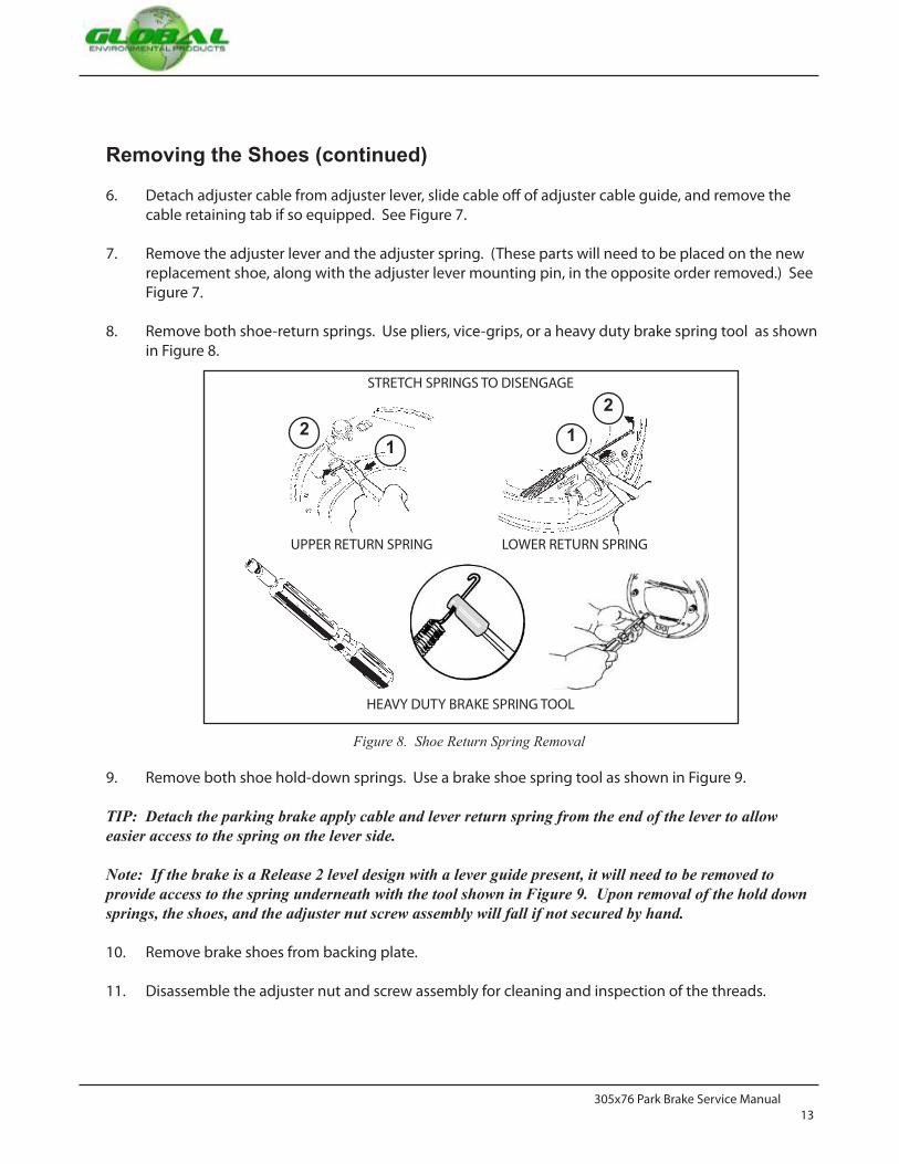
305x76 Park Brake Service Manual�3
Removing the Shoes (continued)
6. Detach adjuster cable from adjuster lever, slide cable off of adjuster cable guide, and remove thecable retaining tab if so equipped. See Figure 7.
7. Remove the adjuster lever and the adjuster spring. (These parts will need to be placed on the newreplacement shoe, along with the adjuster lever mounting pin, in the opposite order removed.) SeeFigure 7.
8. Remove both shoe-return springs. Use pliers, vice-grips, or a heavy duty brake spring tool as shownin Figure 8.
9. Remove both shoe hold-down springs. Use a brake shoe spring tool as shown in Figure 9.
TIP: Detach the parking brake apply cable and lever return spring from the end of the lever to allow easier access to the spring on the lever side.
Note: If the brake is a Release 2 level design with a lever guide present, it will need to be removed to provide access to the spring underneath with the tool shown in Figure 9. Upon removal of the hold down springs, the shoes, and the adjuster nut screw assembly will fall if not secured by hand.
�0. Remove brake shoes from backing plate.
��. Disassemble the adjuster nut and screw assembly for cleaning and inspection of the threads.
Figure 8. Shoe Return Spring Removal
STRETCH SPRINGS TO DISENGAGE
LOWER RETURN SPRING
21
UPPER RETURN SPRING
21
HEAVY DUTY BRAKE SPRING TOOL
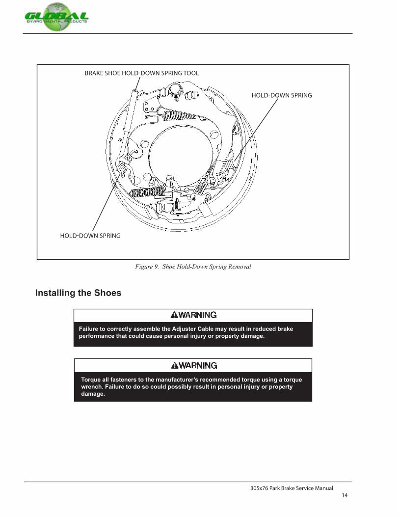
305x76 Park Brake Service Manual�4
Installing the Shoes
Figure 9. Shoe Hold-Down Spring Removal
Failure to correctly assemble the Adjuster Cable may result in reduced brake performance that could cause personal injury or property damage.
Torque all fasteners to the manufacturer’s recommended torque using a torque wrench. Failure to do so could possibly result in personal injury or property damage.
HOLD-DOWN SPRING
HOLD-DOWN SPRING
BRAKE SHOE HOLD-DOWN SPRING TOOL
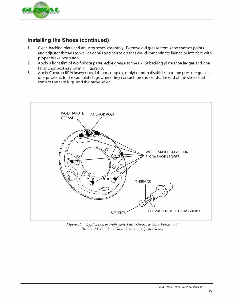
305x76 Park Brake Service Manual�5
Installing the Shoes (continued)�. Clean backing plate and adjuster screw assembly. Remove old grease from shoe contact points
and adjuster threads as well as debris and corrosion that could contaminate linings or interfere withproper brake operation.
�. Apply a light film of Wolfrakote paste ledge grease to the six (6) backing plate shoe ledges and one(�) anchor post as shown in Figure �0.
3. Apply Chevron RPM heavy duty, lithium complex, molybdenum disulfide, extreme pressure grease,or equivalent, to the cam plate lugs where they contact the shoe ends, the end of the shoes thatcontact the cam lugs, and the brake lever.
Figure 10. Application of Wolfrakote Paste Grease to Wear Points andChevron RPM Lithium Shoe Grease to Adjuster Screw
CHEVRON RPM LITHIUM GREASESOCKETS
THREADS
WOLFRAKOTE GREASE ON SIX (6) SHOE LEDGES
ANCHOR POSTWOLFRAKOTE GREASE

305x76 Park Brake Service Manual�6
Installing the Shoes (continued)
4. Apply Chevron RPM heavy duty, lithium complex, molybdenum disulfide, extreme pressure greaseto the threads of the adjuster screw, adjuster nut, and the socket ends of the adjuster nut and installthe screw fully into the adjuster nut. Insure the screw moves in and out freely. If any damage to thethreads prohibits free movement, or if the starwheel is damaged, replace adjuster assembly. SeeFigure �0.
Note: Only use the approved lubricants as specified. Do not substitute.
Note: When installing new shoes, make sure the shoe with the adjuster cable guide and adjuster lever pin is installed on the correct side of the shoe. See Figure 11.
5. Place one shoe into the installed position. Reattach shoe hold-down spring and pin. See Figures 9and ��.
Figure 11. Brake Shoe Installation
For Steps 5 through 10, proper orientation of the various springs, including their hook-ends must be maintained, as shown in Figure 11, for proper brake function.
ADJUSTER CABLE GUIDE
HOLD-DOWN SPRING
HOLD-DOWN SPRING
BRAKE SHOE WITH ADJUSTERCABLE GUIDE
ADJUSTER NUTADJUSTER SCREW
UPPER SHOE RETURN SPRING
LOWER SHOE RETURN SPRING
HOLD-DOWN PIN
ADJUSTER LEVER
ADJUSTER CABLE RETAINER TAB
ADJUSTER LEVER PIN
ADJUSTER SPRING

305x76 Park Brake Service Manual�7
Installing the Shoes (continued)
6. Position the second shoe and the adjuster nut and screw assembly as shown in Figure ��. Theadjuster nut (internally threaded) should be seated against the shoe with the adjuster cable guideand pin. Reattach shoe hold-down spring to shoe hold-down pin using the brake spring tool asshown in Figure 9.
7. Install both shoe-return springs as shown in Figure ��.
8. Install the adjuster spring and the adjuster lever. Ensure that the adjuster lever is properly seatedagainst the starwheel as shown in Figure ��.
9. If the lever has been removed, reinstall lever and associated components per the ANCHOR SCREW,LEVER, AND CAM REPLACEMENT section in the manual.
Figure 12. Adjuster Cable Installation
ADJUSTER CABLE
CORRECT SPRING POSITION(SPRING HOOK FACING OUT)
ADJUSTER SPRING
ADJUSTER CABLE GUIDE
ADJUSTER CABLE RETAINER TAB

305x76 Park Brake Service Manual18
Installing the Shoes (continued)
�0. Route the adjuster cable around the adjuster cable guide, under the shoe hold down spring, andattach to the adjuster lever as shown in Figure ��. Install adjuster cable retaining tab if so equipped.
Note: Correctly assembled, the adjuster cable end-fitting is behind the adjuster lever, with the spring hook facing out as shown in Figure 12.
��. The shoe cage should be adjusted now per the SHOE CAGE ADJUSTMENT PRIMARY procedure orafter the drum has been reinstalled per the SHOE CAGE ADJUSTMENT ALTERNATE procedure in thisservice manual.
��. Make a final inspection of the shoe linings and the inside of the drum to ensure that no grease orother contamination was accidentally applied.
�3. Inspect, service and reinstall drum per the vehicle manufacturer’s service manual.
�4. Lower the vehicle and test the brake for proper function before returning the vehicle for service use.If necessary, make adjustments per the vehicle manufacturer’s service manual.
Shoe Cage Adjustment ProceduresAdjustment with Drum Off - Primary Procedure
�. Use a �� inch caliper, or inside micrometer, to measure the inside diameter of the drum. Subtract0.0�5 inches from the drum inside diameter measurement. Set the measurement caliper to thisvalue, and lock the set screw.
�. Rotate the axle input flange yoke as necessary to provide clearance for the measurement caliper.
3. Place the pre-adjusted caliper over the shoes at the center of the shoes.
Keep grease and other foreign materials away from the shoe lining and drum sur-faces. Contamination of shoe linings or drum surface may result in degradation of brake holding capability, possibly resulting in personal injury or property damage.

305x76 Park Brake Service Manual19
Adjustment with Drum Off - Primary Procedure (continued)
4. To adjust brake, rotate the starwheel until the shoes touch the measurement caliper jaws. It isnecessary to disengage the adjuster lever away from the starwheel. See Figure �3.
Note: During adjustment the calipers should be moved up and down around the shoe center points to ensure adjustment at the highest points across the width of the shoes.
Figure 13. Initial Brake Shoe Adjustment
DECREASE OR INCREASE SHOE SPREAD BY ROTATING THE STARWHEEL
DRUM INSIDE DIAMETER MINUS 0.0�5”
ADJUSTER LEVER

305x76 Park Brake Service Manual20
Adjustment with Drum Installed - Alternate Procedure
�. With the engine off, the battery disconnected, and the tires blocked to prevent vehicle movement,place transmission in neutral and fully release the parking brake. Check to see if the drum can berotated back and forth by hand. If the drum cannot rotate, it will be necessary to raise the rearwheels off the ground, in order to allow rotation of the drum. Support the vehicle with suitable floorstands.
Note: Some vehicles may not have enough clearance behind the park brake to have direct access through the access slot to the adjuster lever. In these cases, an adjuster lever tool can be made from 3/32” diameter welding filler rod. See Figure 16.
�. Insert the adjuster lever tool or a thin flat bladed screw driver through the adjusting slot in thebackplate and push on the adjuster lever to disengage it from the adjuster starwheel. Insert a brakeadjusting tool (or flathead screwdriver) through the adjusting slot and move the starwheel teethdownward to expand the brake shoes outward. See Figures �4 and �5. Continue expanding theshoes until the drum can not be rotated by hand.
3. Now adjust the starwheel teeth upward to retract the shoes until the drum just begins to rotatefreely by hand (without drag from the shoes). See Figures �4 and �5.
Figure 14. Brake Adjustment With Drum In Place (cut away view)
PUSH ADJUSTER LEVER AWAY FROM STARWHEEL, THENROTATE STARWHEEL AS SHOWN TO INCREASE OR DECREASE SHOE SPAN
DECREASE SHOE SPAN
INCREASE SHOE SPAN
ROTATE ADJUSTER STARWHEEL
BRAKE ADJUSTING TOOL
ADJUSTER LEVER TOOL OR THIN FLAT BLADED SCREWDRIVER

305x76 Park Brake Service Manual�1
INSERT THIN SCREW DRIVER OR ADJUSTER LEVER TOOL THROUGH ACCESS SLOT IN BRAKE BACK PLATE AND PUSH ON ADJUSTER LEVER TODISENGAGE ADJUSTER LEVER FROM ADJUSTER STARWHEEL. ADJUSTER STARWHEEL CAN NOW BE ROTATED TO LOOSEN BRAKE.
ADJUSTER LEVER TOOL
TO RETRACT BRAKE SHOES, ROTATE ADJUSTER STARWHEEL IN THIS DIRECTION.
Disengaging Adjuster Lever from Adjuster Starwheel to Allow Retracting the Brake shoes (Loosen Brake)
Note: Some vehicles may not have enough clearance behind the park brake to have direct access through the access slot to the adjuster lever. In these cases, an adjuster lever tool can be made from 3/32” diameter welding filler rod. See Figure 16.
PUSH
ADJUSTER ACCESS SLOT IN BACK PLATE
ADJUST STARWHEEL(STARWHEEL TEETH NOT SHOWN)
ADJUSTER LEVER
Figure 15. Disengaging Adjuster Lever from Adjuster Starwheel to Allow Retracting the Brake Shoes (Loosen Brake)

305x76 Park Brake Service Manual�2
Figure 16. Brake Adjuster Lever Tool

305x76 Park Brake Service Manual�3
Removing Components
Note: The anchor screw, lever, and cam should all be replaced at the same time. Do not replace just one or two of the three parts at any time. Inspection of these parts is recommended at 250,000 miles or 5 years for typical use, or more often under severe operating conditions.
�. Block the front wheels to keep the vehicle from moving.
�. With the engine off and battery disconnected, place the transmission in gear and fully release theparking brake.
3. If recommended in vehicle manufacturer’s service manual, raise the rear of the vehicle so the wheelsclear the floor and install safety stands to support.
4. Remove the drum. See vehicle manufacturer’s service manual for details, if necessary.
Note: If the drum proves difficult to remove, insert a narrow screwdriver through the brake adjusting hole in the backing plate and disengage the adjuster lever from the adjuster nut starwheel teeth. With adjuster lever disengaged as shown in Figures 14 and 15, insert a brake adjusting tool (or screw driver) through the adjusting hole to engage the adjusting nut teeth. Move the teeth upward enough times to retract the brake shoes to clear the drum. If the drum is rusted to the axle input flange yoke pilot, tap the center of the brake drum with a non-metallic mallet to loosen.
5. Inspect the brake per the INSPECTION procedure in this service manual.
6. Detach the parking brake apply cable and lever return spring from end of brake lever. Remove theapply lever guide (on Release � brakes).
7. Detach adjuster cable from the adjuster lever and slide adjuster cable off the adjuster cable guide,remove retaining tab if so equipped. See Figure 7.
8. Remove the anchor screw. See Figure �7.
Anchor Screw, Lever, and Cam Replacement
Do not use a drum puller or a torch to remove a brake drum. Drum distortion may result.

305x76 Park Brake Service Manual�4
Removing Components (continued)
Note: On Release 1 brakes with a hex socket anchor screw, the use of a thread-locking compound may prevent removal of the anchor screw with a hex key and torque in excess of 55 Nm (40 ft.-lbs.) May break or deform a 6mm hex key. If necessary, use a pipe wrench, vice grips, or similar tool on the knurling of the head to loosen the anchor screw. Replace screw if removed, regardless of condition.
9. Remove the flat washers (if installed on your application for Release � level brake), anti-rattle spring,lever, cam, and adjuster cable. See Figures � and �7.
Figure 17. Spring, Lever, Cam, and Adjuster Cable Removal (Release 3 Brake Shown)
ANTI-RATTLE SPRINGANCHOR SCREW
ANCHOR POST
CAM
LEVER
ADJUSTER CABLE
ALTERNATE TYPE END FITTING
305x76 Park Brake Service Manual�5
Installing Components
Note: If for any reason the cam, lever, and anchor screw is removed, a complete new set is recommended for service.
�. Remove the cured thread-locking compound from the anchor post hole threads. Run theappropriate size tap completely into the anchor post and back out to clean the threads. Removeloose debris from anchor post hole.
Note: For brakes with a hex socket head anchor screw, use an M10 x 1.5 tap (brakes manufactured prior to April 2002). For brakes with an external hex head anchor screw, use and M12 x 1.75 tap (brakes manufactured after April 2002).
�. Apply Chevron heavy duty lithium complex extreme pressure grease, or equivalent, to the camplate lugs where they contact the shoes and the apply lever, to the cam plate slotted hole and topand bottom faces. Apply grease to the brake lever pivot hole and the contact surfaces with the camplate lugs. Apply grease to the non-threaded portion of the anchor screw. Do not get grease onanchor screw threads or in anchor post threaded hole.
3. Reinstall the adjuster cable, new cam plate, new lever, anti-rattle spring (small coil end toward screwhead for Release �), flat washers (if previously installed on your application), and new anchor screwas shown in Figure �8. Make sure the adjuster cable end fitting is installed to allow the cam plate tosit flat on the fitting and anchor post.• Stepped type end fitting - the step faces towards the backplate. See Figure �8.• Alternate “eyelet” type fitting - cable crimp portion faces towards the backplate. See Figure �8.
Only thread anchor screw into the anchor post 1 to 2 turns to temporarily hold assembly together. Do not thread in completely until ready to tighten to speci-fication (step 4).
A faulty installation will result if the thread-locking compound is activated and begins to cure prior to tightening the screw.
When installing the hex socket head anchor screw, careful attention should be taken during reassembly to ensure that the adjuster cable-end fitting is not clamped underneath the shoulder of the anchor screw during reassembly.
Clamping the adjuster cable may prevent proper functioning of the brake self-adjust feature.

305x76 Park Brake Service Manual�6
Installing Components (continued)
4. Tighten the anchor screw per the appropriate specification:For the internal hex socket anchor screw tighten to 50 ± 3 Nm (37 ± � ft-lbs.)For the external hex head anchor screw tighten to �00 ± �0 Nm (74 ± 7 ft-lbs.)
Note: Remove excess grease that could contaminate brake drum or linings while the brake is in service.
5. Reinstall the lever return spring and parking brake cable to the end of the brake lever.
6. Route the adjuster cable around the adjuster cable guide, under the shoe hold-down spring, andattach to the adjuster lever as shown in Figure ��. Install adjuster cable retainer tab if equipped.
Note: When correctly assembled, the adjuster cable end-fitting is behind the adjuster lever with the spring hook facing out as shown in Figures 12 and 18. Failure to do so may result in reduced brake operation.
To tighten the anchor screw, only use a recently calibrated, known good, “clicker” type torque wrench set to the correct torque specification. Do not use add on devices such as universal joints, swivels, crows feet or other devices as these can cause inaccurate tightening results. Do not attempt this repair if a recently calibrated, known good “clicker” type torque wrench is not available. Failure to do so could result in personal injury or property damage.

305x76 Park Brake Service Manual�7
7. The shoe cage should now be adjusted per the SHOE CAGE ADJUSTMENT PRIMARY procedure orafter the drum has been reinstalled, per the SHOE CAGE ADJUSTMENT ALTERNATE procedure in thisservice manual.
8. Make a final inspection of the shoe linings and the inside of the drum to ensure that no grease orother contamination is present.
9. Inspect, service, then reinstall drum per the vehicle manufacturer’s service manual.
�0. Lower vehicle and remove the blocks or wheel chocks from the front wheels.
��. Test the brake for proper function before returning the vehicle for service use. If necessary, makeadjustments per the vehicle manufacturer’s service manual.
Keep grease and other foreign materials away from the shoe lining and drum surfaces. Contamination of shoe linings or drum surface may result in degradation of brake holding capability, possibly resulting in personal injury or property damage.
ANCHOR POST
ADJUSTER CABLE
CAM
ANTI-RATTLE SPRING
LEVER
ANCHOR SCREW
ADJUSTER CABLE ROUTING AND SPRINGATTACHED TO ADJUSTER LEVER
ADJUSTER CABLE GUIDE
Figure 18. Install Adjuster Cable, Cam Lever, Anti-rattle Spring and Anchor Screw
NOTE: INSTALL WITH CRIMP FACING THIS DIRECTION
ALTERNATE ADJUSTER CABLE END FITTING TYPE

305x76 Park Brake Service Manual28
Condition Cause RemedyLight force or lack of resistance when applying brake lever (on manual apply systems)
Shoe cage under-adjusted1 Adjust shoes per shoe cage adjustment procedure
Worn or deformed actuation components (lever, cam lugs shoe ends)
Inspect and replace per Anchor Screw, Lever, and Cam Replacement procedure or Shoe Replacement procedure
Apply system not operating properly
Repair per manufacturer’s recommended procedure
Heavy force or excessive resistance when applying brake lever (on manual apply system)
Over adjusted brake Adjust brake cage clearance diameter
Apply system over adjusted Adjust or repair per manufacturer’s recommended procedures
Brake does not release Internal damage to brake Inspect and replace damaged components
Apply cable bound up Check cable for corrosion, binding, kinks, or damage. Repair per vehicle manufacturer’s recommended procedures
Apply system not operating properly
Repair per vehicle manufacturer’s recommended procedure
Brake does not hold vehicle on hill
Grease, oil or other foreign material on or embedded in shoe linings
Replace shoes and clean drum2
Damaged or incorrect shoes Replace with correct shoesWorn out lining (metal shoe rim contacting drum)
Replace shoes and resurface or replace drum as necessary
Excessive drum runout Resurface or replace drum per manufacturer’s recommended procedure
Shoe cage under-adjusted Adjust shoes per primary (or alternate) Shoe Cage Adjustment procedure
Worn or deformed actuation components (lever, cam lugs, shoe)
Inspect and replace per Anchor Screw, Lever, and Cam Replacement procedure
1 Inspect adjuster components to see if any are damaged or jammed.2 Inspect the rear pinion seal for leakage that can contaminate the park brake system parts. Repair as necessary.
Trouble Shooting
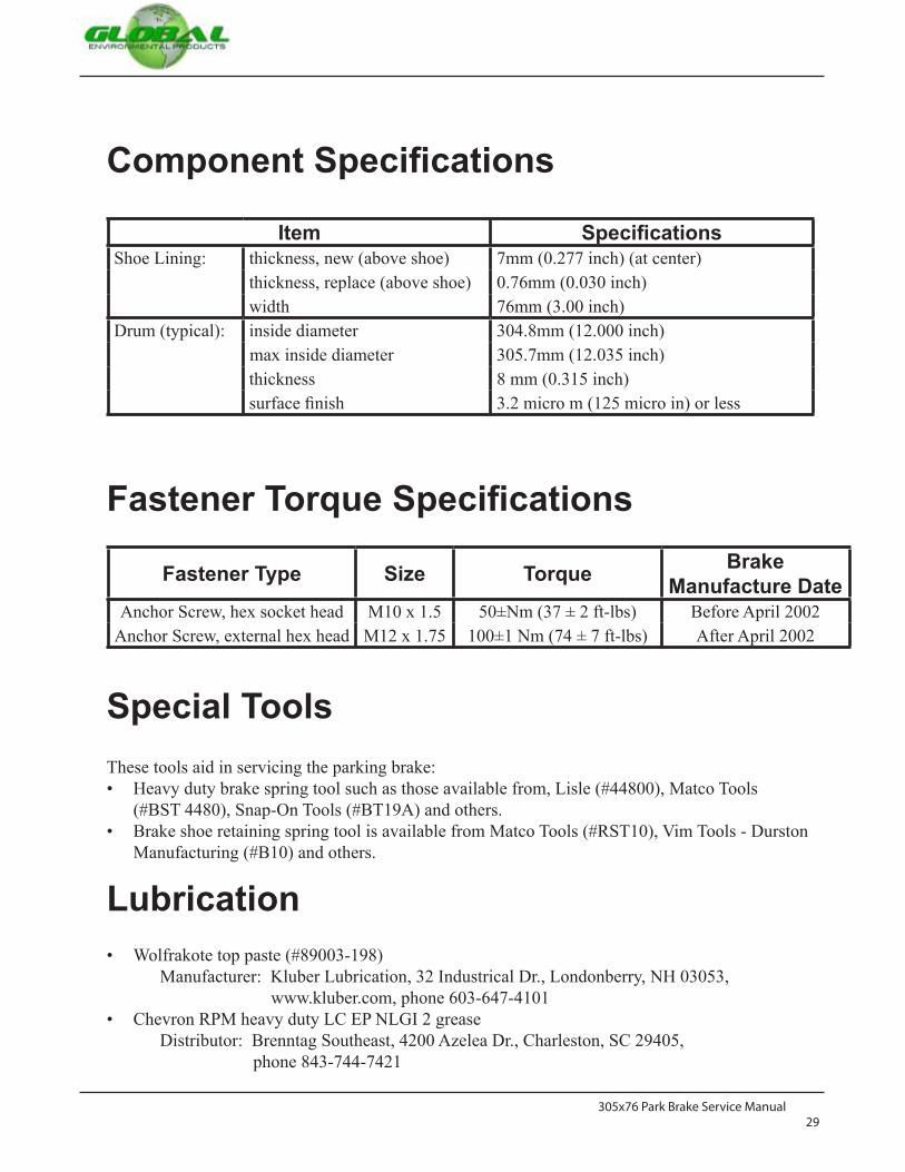
305x76 Park Brake Service Manual29
Component Specifications
Fastener Torque Specifications
Item SpecificationsShoe Lining: thickness, new (above shoe) 7mm (0.277 inch) (at center)
thickness, replace (above shoe) 0.76mm (0.030 inch)76mm (3.00 inch)304.8mm (12.000 inch)
widthDrum (typical): inside diameter
max inside diameter 305.7mm (12.035 inch)thickness 8 mm (0.315 inch)surface finish 3.2 micro m (125 micro in) or less
Fastener Type Size Torque Brake Manufacture Date
Anchor Screw, hex socket head M10 x 1.5 50±Nm (37 ± 2 ft-lbs) Before April 2002Anchor Screw, external hex head M12 x 1.75 100±1 Nm (74 ± 7 ft-lbs) After April 2002
Special ToolsThese tools aid in servicing the parking brake:
Heavy duty brake spring tool such as those available from, Lisle (#44800), Matco Tools (#BST 4480), Snap-On Tools (#BT19A) and others.Brake shoe retaining spring tool is available from Matco Tools (#RST10), Vim Tools - Durston Manufacturing (#B10) and others.
•
•
LubricationWolfrakote top paste (#89003-198)
Manufacturer: Kluber Lubrication, 32 Industrical Dr., Londonberry, NH 03053,www.kluber.com, phone 603-647-4101
Chevron RPM heavy duty LC EP NLGI 2 greaseDistributor: Brenntag Southeast, 4200 Azelea Dr., Charleston, SC 29405,
phone 843-744-7421
•
•


COPYRIGHT 2012 GLOBAL ENVIRONMENTAL PRODUCTS, INC. ALL RIGHTS RESERVED REV A MAY 2012
5405 Industrial ParkwaySan Bernardino, CA 92407 USA
Phone: 909-713-1600 [email protected]
www.GlobalSweeper.com


