HARMONY III™ zoning system (X9953) - Lennox International -
68
HARMONY III™ zoning system (X9953) Installation, Setup and User Guide 507936-01 7/2019 Supersedes 2/2019 2019 © Lennox Industries Inc. Dallas, Texas, USA
-
Upload
khangminh22 -
Category
Documents
-
view
3 -
download
0
Transcript of HARMONY III™ zoning system (X9953) - Lennox International -

HARMONY III™ zoning system (X9953)Installation, Setup and User Guide
507936-01 7/2019 Supersedes 2/2019
2019© Lennox Industries Inc. Dallas, Texas, USA

2
1.10.9.SystemConfiguration/E-HeatStages) ................................................................ 13
1.10.9.1. GasFurnaceandAirConditioning ...................................................... 13
1.10.9.2. HeatPumpwithElectricBackupHeat ................................................ 13
1.10.9.3. HeatPump-DualFuelheating,1-stageor2StageHeatPumpandGasFurnace ....................................................................................... 13
1.11.CommonSystemComponentWiring ...............................................................13
1.11.1.DampersandDamperTransformer .................................................................... 13
1.11.2.DischargeAirSensor(DAS)Probe ..................................................................... 14
1.12.ComponentSpecificWiring ..............................................................................14
1.12.1.ZoneControlTransformerPhasing ..................................................................... 14
1.12.2.Thermostat .......................................................................................................... 15
1.12.3.GasFurnace ....................................................................................................... 15
1.12.4.AirConditionerUnit ............................................................................................. 15
1.13.MinimumCFMinVariableSpeedFurnaceandAirHandlers ...........................16
1.14.SystemFlowDiagrams ....................................................................................17
2. Heat Pump ............................................................................. 18
2.1.InstallingHeatPumpandAccessories ...............................................................18
2.1.1. EquipmentInstallation ......................................................................................... 18
2.1.2. PressureSwitch .................................................................................................. 18
2.1.3. PressureSwitchWiring ...................................................................................... 18
2.1.4. Tee(HighPressureSwitch;HeatPumpsonly) ................................................... 18
2.1.5. BalancePointSensor(OutdoorThermostat) ...................................................... 18
2.1.6. DefrostTemperingKit .......................................................................................... 19
2.2.VariableSpeedMotor(VSM)AirHandlerandHeatPump-Option2(ZoningSystem) .................................................................................................20
2.3.HeatPumpSystemStart-UpandCheckout.......................................................21
2.3.1. PoweringtheSystem(AllSystems) .................................................................... 21
2.3.2. Checkouts ........................................................................................................... 21
2.3.2.1. TypicalHeatPumpHeatingCheckout(SingleZone) .......................... 21
2.3.2.2. TypicalHeatPumpHeatingCheckout(MultipleZone) ....................... 22
2.3.2.3. TypicalHeatPumpHeatingCheckout(CentralMode) ....................... 23
2.4.HeatPumpSystemStart-UpandCheckout.......................................................24
2.4.1. TroubleshootingDiagram .................................................................................... 24
2.4.2. HeatPumpHeatingOperation ............................................................................ 25
2.4.3. DefrostOperations .............................................................................................. 25
3. Gas Furnace .......................................................................... 26
3.1.TypicalWiringforVariable-SpeedGasFurnaceandOutdoorACUnit-Option1 26
Table of Contents1. General ..................................................................................... 4
1.1.ShippingandPackingList ....................................................................................4
1.2.AcronymsUsed ....................................................................................................4
1.3.AdditionalPartsRequired ....................................................................................4
1.4.Introduction ..........................................................................................................4
1.5.ResidentialZoneControlSystem-OverviewofFieldWiring ..............................5
1.6.SystemComponents ............................................................................................5
1.6.1. ZoneControlSystem ............................................................................................ 5
1.6.2. DischargeAirSensor(DAS) .................................................................................. 6
1.6.3. Thermostats .......................................................................................................... 6
1.6.4. Transformers ......................................................................................................... 6
1.6.5. Dampers ................................................................................................................ 6
1.6.6. RemoteVacationSwitch ....................................................................................... 6
1.7.InstallationPlanningandSelectingHeatingandCoolingEquipment ..................7
1.7.1. InstallationConsiderations ................................................................................... 7
1.7.2. VariableSpeedBlowerMotor(VSM) .................................................................... 7
1.7.3. Selecting/InstallingIndoorandOutdoorUnits ...................................................... 7
1.8.OptionalDehumidificationAccessories ................................................................7
1.9.InstallingZoneControlComponents ....................................................................7
1.9.1. DischargeAirSensor(DAS) .................................................................................. 7
1.9.2. ZoneControlPanel ............................................................................................... 8
1.9.3. Thermostats .......................................................................................................... 8
1.9.4. Transformer ........................................................................................................... 8
1.9.5. Dampers ................................................................................................................ 8
1.9.6. ZoneLinking .......................................................................................................... 8
1.10.ZoneControlPanelJumpers..............................................................................9
1.10.1.SetupforControllingEquipmentStagingandVolumeofAirtoZones ................. 9
1.10.2.PIABJumpersAffectBlowerOperation ................................................................ 9
1.10.3.UpgradingfromHarmonyIIzoningsystem? ....................................................... 10
1.10.4.Zone1PIABJumpers–140ºFDAS ................................................................... 10
1.10.5.DeterminingPIABJumperSettings ..................................................................... 10
1.10.6.ContinuousAirReductionJumpers ......................................................................11
1.10.7.HeatingAirReductionJumpers ............................................................................11
1.10.8.Heat/CoolStaging ................................................................................................11
1.10.8.1. HeatingStagingTemperatureJumper .................................................11
1.10.8.2. CoolingStagingTemperatureJumper ................................................ 12

3
3.2.FurnaceVariableSpeedMotorElectricalAdjustments ......................................27
3.3.VariableSpeedMotorFurnaceSystemOperations ...........................................27
3.3.1. Operation ............................................................................................................ 27
3.3.2. IntegratedFurnaceControlW2terminaltoHarmonyIIIzoningsystem Control ................................................................................................................. 28
3.3.3. InstallationSetupWorksheets ............................................................................. 29
3.3.3.1. SLP98V—Cooling/Heating(Non-HeatPumpApplications) .............. 29
3.3.3.2. SL280V,SL280NV,EL296VandSL297NV—Cooling/Heating (Non-HeatPump) ................................................................................ 30
3.3.4. ZoneControlOperationinaGasFurnaceSystem ............................................. 31
3.3.4.1. ZoneThermostats ............................................................................... 31
3.3.4.2. BalancePointSetting .......................................................................... 31
3.3.4.3. ZoneMode .......................................................................................... 31
3.3.4.4. Central(Vacation)Mode ..................................................................... 31
3.3.4.5. CoolingOperation ............................................................................... 31
3.3.5. InstallationSetupWorksheetsforHoneywell2-StageIFCControl—Cooling/Heating(Non-HeatPump) ................................................................................... 32
3.4.FurnaceSystemStart-UpandCheckout ...........................................................33
3.4.1. Start-UptheSystem(AllModels) ........................................................................ 33
3.4.2. Checkouts ........................................................................................................... 33
3.4.2.1. TypicalGasHeatingCheckout(SingleZone) ..................................... 33
3.4.2.2. TypicalGasHeatingCheckout(MultipleZone) ................................... 34
3.4.2.3. TypicalGasHeatingCheckout(CentralMode) ................................... 35
3.5.ZoningSystemwithGasFurnaceTroubleshooting-Option1...........................36
3.5.1. TroubleshootingDiagrams .................................................................................. 36
3.5.2. GasHeatingOperation ....................................................................................... 38
3.5.3. DischargeAirUpperLimitandDifferentialTemperatures ................................... 38
4. Air Handlers ........................................................................... 39
4.1.VariationsonCommonACUnitApplications .....................................................39
4.1.1. Heating/CoolingEquipmentInstallation .............................................................. 39
4.1.2. AirHandlerWiring ............................................................................................... 39
4.1.3. Variations ............................................................................................................ 39
4.2.ElectricalAdjustments ........................................................................................40
4.2.1. CommunicatingIndoorControl ........................................................................... 40
4.2.2. Non-CommunicatingIndoorControl .................................................................... 40
4.2.3. InstallationWorksheets ....................................................................................... 42
4.2.3.1. Cooling/HeatingwithElectricStripHeat(Non-HeatPump) ................ 42
4.2.3.2. HeatPump—ElectricStripHeat ....................................................... 44
4.2.3.3. CoolingOnlyorCoolingwithHotWaterCoil(Non-HeatPump) ......... 46
5. Dual Fuel (Option 3) .............................................................. 48
5.1.ZoneControlSystemWiring-Option3 .............................................................48
5.2.DualFuelSystemStart-UpDefrostTemperatingSensorPlacementandCheckout ............................................................................................................49
5.2.1. Start-UptheSystem(AllModels) ........................................................................ 49
5.2.2. DefrostTemperatingSensorPlacement ............................................................. 49
5.2.3. Checkouts ........................................................................................................... 50
5.2.3.1. TypicalDualFuelGasHeating(SingleZone) ..................................... 50
5.2.3.2. TypicalDualFuelGasHeating(MultipleZone) .................................. 51
5.2.3.3. TypicalDualFuelGasHeating(CentralMode) .................................. 52
5.3.ZoningSystemwithDualFuelTroubleshooting-Option3 ................................53
5.3.1. TroubleshootingDiagram .................................................................................... 53
5.3.2. DualFuelOperation(BelowBalancePoint) ........................................................ 54
5.3.3. DischargeAirUpperLimitandDifferentialTemperatures ................................... 54
5.3.4. DualFuelOperation(AboveBalancePoint) ....................................................... 55
5.3.5. DefrostOperation ................................................................................................ 55
5.3.6. InstallationSetupWorksheets ............................................................................. 56
5.3.6.1. DualFuel-IndoorUnitHoneywell2-StageIFCControland HeatPump .......................................................................................... 56
5.3.6.2. DualFuel-SLP98VariableCapacityandHeatPump ........................ 57
5.3.6.3. DualFuel-VariableSpeedSL280V,EL296V,SL297NVandHeatPump .......................................................................................... 58
6. Troubleshooting .................................................................... 59
6.1.OperationandTroubleshootingIndicators .........................................................59
6.1.1. ZoneControlPanelLEDs ................................................................................... 59
6.1.2. FaultRecallandTimeDelayOverride ................................................................ 60
6.1.3. TimeDelays ........................................................................................................ 60
6.1.4. DischargeAirProbeCheckout(AllSystems) ...................................................... 60
6.1.5. BlowerSpeedCheckout ...................................................................................... 61
6.2.DiagnosticLEDErrorCodes ..............................................................................62
6.3.AirDeliveredByBlower .....................................................................................63
6.3.1. Formulas ............................................................................................................. 63
6.3.2. PIABCalculationWorksheet ............................................................................... 65
7. User Guide ............................................................................. 66
7.1.WhatistheHarmonyIII™zoningsystem? .......................................................66
7.2.WhatdoestheHarmonyIII™zoningsystemconsistof?...................................66
7.3.HowdoIsettheControlCenterSwitches? ......................................................66
4
7.4.HowdoIusetheThermostatControls? .............................................................66
7.5.HowdoIusetheCentral(Vacation)Mode? ......................................................66
7.6.HowdoIusetheZoneMode? ...........................................................................67
7.7.HowareZonesDetermined? .............................................................................67
7.8.HowdoIusetheOptionalHumiditrol®DehumidificationAccessory? ................67
7.9.EnablingandDisablingHumiditrolSettinginThermostat ..................................67
7.10.HumiditrolUserAdjustmentisalsoavailableundertheUserSettings.............67
7.11.OwnerReminder! ............................................................................................67
7.12.Thermostatreplacement ..................................................................................67
7.13.Maintenance .....................................................................................................67
7.14.HomeownersZoneInformationRecord ...........................................................68
1. General
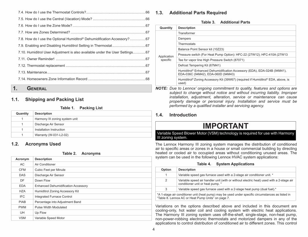
1.1. Shipping and Packing List
Table 1. Packing ListQuantity Description
1 HarmonyIIIzoningsystemunit
1 DischargeAirSensor
1 InstallationInstruction
1 Warranty(W-031-L2-02)
1.2. Acronyms Used
Table 2. AcronymsAcronym Description
AC AirConditioner
CFM CubicFeetperMinute
DAS DischargeAirSensor
DF DownFlow
EDA EnhancedDehumidificationAccessory
HZA HumiditrolZoningAccessoryKit
IFC IntegratedFurnaceControl
PIAB PercentageintoAdjustmentBand
PWM PulseWidthModulated
UH UpFlow
VSM VariableSpeedMotor
1.3. Additional Parts Required
Table 3. Additional PartsQuantity Description
Applicationspecific
Transformer
Dampers
Thermostats
BalancePointSensorkit(10Z23)
Pressureswitch(ForHeatPumpOption):HFC-22(27W12);HFC-410A(27W13
TeeforvaporlineHighPressureSwitch(87071)
DefrostTemperingKit(67M41)
Humiditrol®EnhancedDehumidificationAccessory(EDA),EDA-024B(94M41),EDA-036C(94M42),EDA-060D(94M43)
Humiditrol® ZoningAccessoryKit(39W67)(requiredifHumiditrol®EDA,above,isused)
NOTE: Due to Lennox’ ongoing commitment to quality, features and options are subject to change without notice and without incurring liability. Improper installation, adjustment, alteration, service or maintenance can cause property damage or personal injury. Installation and service must be performed by a qualified installer and servicing agency.
1.4. Introduction
IMPORTANTVariableSpeedBlowerMotor(VSM)technologyisrequiredforusewithHarmonyIIIzoningsystem.
TheLennoxHarmony III zoningsystemmanages thedistributionof conditionedairtospecificareasorzonesinahouseorsmallcommercialbuildingbydirectingheated or cooled air to occupied areaswithout conditioning unused areas.ThesystemcanbeusedinthefollowingLennoxHVACsystemapplications:
Table 4. System ApplicationsOption Description
1 Variablespeedgasfurnaceusedwitha2-stageairconditionerunit.*
2 Variablespeedairhandlerunit(withorwithoutelectricheat)usedwitha2-stageairconditionerunitorheatpump.*
3 Variablespeedgasfurnaceusedwitha2-stageheatpump(dualfuel).*
*A1-stageairconditionerunit(heatpump)maybeusedunderspecificcircumstancesaslistedin“Table8.LennoxACorHeatPumpUnits”onpage7.
Variations on the options described above and included in this document arecooling-only, hot water coil and cooling system with electric heat applications.TheHarmony III zoningsystemusesoff-the-shelf, single-stage,non-heatpump,non-power-robbing electronic thermostats andmotorized dampers in any of theapplicationstocontroldistributionofconditionedairtodifferentzones.Thiscontrol
5
allowsconditioningofdifferentzoneswithinaresidencewhileusingasingleHVACsystem.Thezonecontrolsystemoperatesintwomodes:centralcontrol(vacationmode) or zone control. LEDs on the zone control panel indicate the currentoperatingmode.
Whenthesystemisinthecentralcontrolmode,ademandfromthecentralcontrolthermostatresultsinconditionedairbeingdirectedtoallofthezones.Inthismode,zone1thermostatisdesignatedasthecontrollingthermostat;otherthermostatsarenotused.Whenthesystemisinthezonecontrolmode,azoneisconditionedonlyupondemandfromthatzone’sthermostat.Thezonecontrolsystemisidealforretrofitapplicationsaswellasnewconstruction.Thesystemcontrolstheairvolume,eliminating theneed forbypassdampers inmostapplications.Thehomeownercontrols the system using zone thermostats tomake comfort settings for eachzone.Aprogrammablethermostatshouldbeusedtoprovideaspecializedheatingandcoolingsequence.While thesystem is in thezonemode,aprogrammablethermostatcontrolsthetemperatureforitsparticularzone.
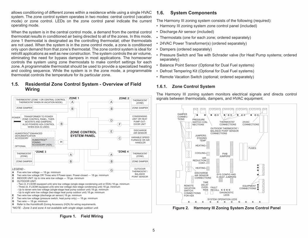
1.5. Residential Zone Control System - Overview of Field Wiring
VARIABLE SPEEDFURNACE OR AIR
HANDLER
ZONE 1 ZONE 2
*ZONE 4
POWER
THERMOSTAT (ZONE 1 OR CENTRAL CONTROLTHERMOSTAT WHEN IN VACATION MODE)
ZONE DAMPER
THERMOSTAT(ZONE)
CONDENSINGUNIT OR HEAT
DOOR UNIT
TRANSFORMER TO POWER
MOSTATS AND DAMPERS;ALSO POWERS HZA CONTROL
WHEN EDA IS USED)
THERMOSTAT(ZONE)
LEGEND -A Five wire low voltage — 18 ga. minimumB Two wire low voltage OR Three wire if Power-open, Power-closed — 18 ga. minimumC INDOOR UNIT: Up to nine wire low voltage — 18 ga. minimumD OUTDOOR UNIT:
- Two (3, if LSOM equipped unit) wire low voltage (single‐stage condensing unit or EDA) 18 ga. minimum- Three (4, if LSOM equipped unit) wire low voltage (two‐stage condensing unit) 18 ga. minimum- Up to seven wire low voltage (single‐stage heat pump outdoor unit) 18 ga. minimum- Up to eight wire low voltage (two‐stage heat pump outdoor unit) 18 ga. minimum
E Two wire low voltage (discharge air sensor) 18 ga. minimumF Two wire low voltage (pressure switch, heat pump only) — 18 ga. minimumG Two wire — 18 ga. minimumH Refer to the Humiditrol® Zoning Accessory (HZA) for wiring requirements.*NOTE - Zone 3 and zone 4 not available with single‐stage outdoor unit.
OUTDOORTHERMOSTAT /
BALANCEPOINT SENSOR
ZONE CONTROLSYSTEM PANEL
A
B
DISCHARGEAIR SENSORE
C
DF
ZONE DAMPER
G
*ZONE 3THERMOSTAT
(ZONE)
ZONE DAMPER
ZONE DAMPER
HUMIDITROL® ENHANCEDDEHUMIDIFICATIONACCESSORY
HUMIDITROL®
ZONINGACCESSORY (HZA)
OPTIONAL
H
A
B
B
A
B
A
B
Figure 1. Field Wiring
1.6. System ComponentsTheHarmonyIIIzoningsystemconsistsofthefollowing(required):• HarmonyIIIzoningsystemzonecontrolpanel(included)• DischargeAirsensor(included)• Thermostats(oneforeachzone;orderedseparately)• 24VACPowerTransformer(s)(orderedseparately)• Dampers(orderedseparately)• PressureSwitchandTeewithSchradervalve(forHeatPumpsystems;orderedseparately)
• BalancePointSensor(OptionalforDualFuelsystems)• DefrostTemperingKit(OptionalforDualFuelsystems)• RemoteVacationSwitch(optional;orderedseparately)
1.6.1. Zone Control System
The Harmony III zoning system monitors electrical signals and directs controlsignalsbetweenthermostats,dampers,andHVACequipment.
JUMPERS:STAGING
TEMP`
HEATING--
COOLING--
AIR REDUCTION
CONT.--
HEATING--
EQUIPMENTCONNECTIONS
THERMOSTATCONNECTIONS
24VACCONNECTIONS
PIABJUMPERS
SYS CONFIG ANDE-HEAT JUMPERS
DIAGNOSTICLEDS
TIMEDELAY
RIDEFAULTRECALL
OUTDOOR THERMOSTAT /BALANCE POINT SENSORCONNECTIONS
PRESSURE
NECTIONS
DISCHARGEAIR SENSORCONNECTIONS
DAMPER
TIONS
FUSES
SYSTEM OPERATION LEDS
REMOTEVACATIONSWITCH;CONNECTIONSFOR HZA
Figure 2. Harmony III Zoning System Zone Control Panel

6
1.6.2. Discharge Air Sensor (DAS)
Adischargeairtemperaturesensor(88K38)monitorsthesupplyair.Thiselectronicsensor’sprobeisinsertedintothedischargeairplenumtogatherairtemperaturedata for thezonecontrolpanel. “Figure4.DischargeAirSensor Installation”onpage8forlocationofthesensor.
TEMPERATURE/RESISTANCE CHARTTEMP ºF RESISTANCE (OHMS)
30 34,56640 26,10650 19,90460 15,31370 11.88480 9,29890 7,332100 5,826
Figure 3. Discharge Air Sensor
1.6.3. Thermostats
IMPORTANTUseonlyElectronicthermostats.Mechanicalorelectro-mechanicalthermostatswillnotworkwiththeHarmonyIIIzoningsystem.
Forallzones,usethermostatsthatareofthistype:• Electronicthermostat• Single-stage• Non-heatpump• Non-powerrobbing• Auto-changeoverornonauto-changeover• Lennoxrecommendsthatzone1thermostat(central[vacation]modecontroller)beprogrammable.
• EachthermostatmusthaveadeadbandbetweenHEATandCOOL.
Recommendedthermostatsinclude:• ComfortSense® 5500(13H13)7-DayProgrammableTouchScreenThermostat-1heat/1cool
• ComfortSense® 7500(13H14)7-DayProgrammableTouchScreenThermostat- 4Heat / 2Cool (configured for non-heat pumpoperation).Whenusing thisthermostat,onlyPrecisionModedehumidificationcanbeusedwherein2°Fofover-cooling isallowed.Also, it cannot reduce theblowerspeedbecause thezonecontrolDSsignalcontrolstheblower.ThermostatDterminalisnotused.
1.6.4. Transformers
The dampers, zone control panel, zone thermostats and Humiditrol® ZoningAccessory (if EDA is used) are powered by a single, field-provided 24VACtransformer. Together, the zone control panel and thermostats require 10VA;dampersrequire10VAeach.ThetransformermusthaveanadequateVAratingtoserveallcomponentsasdescribedinthefollowingtable.
IMPORTANTUpto5dampersperzonemaybeconnectedinparalleltothezonecontrolpanel—nottoexceedatotalofsixdampersforentiresystem.Also,ifmorethan6dampersareused,anothertransformerandisolationrelaywillbenecessary.
Table 5. 24VAC Transformer Selection ChartCatalog Number Size Description VA LOAD =
Panel Plus
10P17 40VA 120/208/240VAC,24VAC 3dampers
10P87 50VA 120/208/240VAC,24VAC 4dampers
12P61 75VA 120/208/240VAC,24VAC 6dampers
83P74 _ ElectricalBox(4-in.Square)
1.6.5. Dampers
Motorized24VACpoweredclosed/spring returnopendampersarestandard fortheHarmonyIIIzoningsystem.However,“power-open/spring-close”and“power-open/power-close”damperscanbeaccommodated
1.6.6. Remote Vacation Switch
TheHarmonyIIIzoningsystemcontrolpanelincludesconnectionsforanoptionalremotevacationswitch(see“Figure2.HarmonyIIIZoningSystemZoneControlPanel” on page 5). The same connections are also used for connecting anoptionalHumiditrol®ZoningAccessorycontroller(seeHumiditrol®ZoningAccessoryInstallationInstructionsfordetails).NOTE: If a remote vacation switch is connected for routing to a convenient location
for end user operation, be sure the switch (field-provided) is properly labeled and instructions provided for proper operation.
IMPORTANTDo not locate the remote vacation switch next to other house switches! TherecommendlocationisnexttoZone1thermostat.

7
1.7. Installation Planning and Selecting Heating and Cooling Equipment
WARNINGImproperinstallation,adjustment,alteration,serviceormaintenancecancausepropertydamage,personalinjuryorlossoflife.Installation and servicemust be performed by a licensed professional HVACinstaller(orequivalent)oraserviceagency.
1.7.1. Installation Considerations
ThetotalHVACsystemmustbeproperlysizedtoprovidethebestcomfort.Also,forbestperformance, zonesshouldbesimilar in sizeso thateachzonewouldrequireabout thesameCFM.Eachzone’sducting lengthsshouldbesimilar inlengthwheneverpossible.Alwaysattempt tokeepCFM requirementsperzonewithin25%oftheaverageCFMasreferencedinthefollowingtable.
Ifa“small”zonecannotbeavoided,giveconsiderationtoincreasingtheCFMofthesmallzoneandlinkingadamperinanearbyzonethatwillopenalongwiththesmallzone’sdamper(s).Theprocedureforzonelinkingisdescribedin“1.9.6.ZoneLinking”onpage8.
Table 6. Adjusting for Average CFM ExampleRequired CFM CFM Adjusted to within Average
Zone CFM Avg %CFM Adj Avg %CFM
1 500 713 0.70 600 738 0.81 DamperlinkedwithZone2
2 825 1.16 825 1.12
3 775 1.09 775 1.05
4 750 1.05 750 1.02
1.7.2. Variable Speed Blower Motor (VSM)
Indoor units with variable speed “blower” motors (VSM) are required to allowthezonecontrolsystemtodistributeadequateair toeachzone.Useonlyunitsrecommendedinthefollowing3optionsreferencedin“1.7.3.Selecting/InstallingIndoor andOutdoorUnits” as only thosewill workwith theHarmony III zoningsystem; other types of units will not allow the Harmony III zoning system toproportiontheamountofairgoingtoeachzone.
1.7.3. Selecting/Installing Indoor and Outdoor Units
Outdoorunitsmaybesingleor two-stage;use the following table todeterminewhichtouse,basedonthenumberofzonesbeingimplemented,andwhethertheairconditionedzonesareofequalorunequalsize.
Table 7. Indoor / Outdoor OptionsOptions Indoor Unit Outdoor Unit
1 AnyLennoxGasFurnacewithVSMonly.
LennoxAirConditionerunitasdescribedin“Table8.LennoxACorHeatPumpUnits”.
2 LennoxAirHandlerUnitwithVSMonly.
LennoxHeatPumpunitasdescribedin“Table8.LennoxACorHeatPumpUnits”.
3 AnyLennoxGasFurnacewithVSMonly.
LennoxHeatPumpunitasdescribedin“Table8.LennoxACorHeatPumpUnits”.
NOTE: Limited variations to AC units described herein are detailed. Go to “4.1. Variations on Common AC Unit Applications” on page 39 for further details.
Table 8. Lennox AC or Heat Pump UnitsNumber of
Zones Comparative Zone Sizes Lennox AC or Heat Pump Unit
2 Equal SingleorTwo-stageandVSMunits
2 *Unequal Two-stageonlyandVSMunits
3or4 EqualorUnequal Two-stageonlyandVSMunits
*EqualzoneswouldhaveverysimilartotalductinglengthswithCFMrequirementswithin10%ofaverageCFMperzone.UnequalwouldhavelesssimilarductinglengthandgreatervariancesfromaverageCFM(see“Table6.AdjustingforAverageCFMExample”onpage7example).
1.8. Optional Dehumidification AccessoriesTheHarmony III zoning systemmay be used in conjunctionwith aHumiditrol® EnhancedDehumidificationAccessory(EDA)andwhichalsorequiresaHumiditrol® ZoningAccessory(39W67).Thisdocumentreflectsthecontrolwhichisoutfittedforconnectionto,andcontrolof,theEDAinazonecontrolsystemusingtheHZA.SeeHumiditrol®ZoningAccessoryInstallationInstructionsformoreinformation.
1.9. Installing Zone Control Components
1.9.1. Discharge Air Sensor (DAS)
CAUTIONThis device is manufactured using unpainted and pre-painted metal. Sharpsheetmetaledgescancauseinjury.Wheninstallingthedevice,avoidaccidentalcontactwithsharpedges.
Install the discharge air sensor in the discharge plenum downstream from thecoolingcoil.Besurethatthedischargeairwillpassoverthesensorbeforetheairisdistributedintotheductsystem.Typicalup-flowsensorapplicationsareshowninfigure4;thesensordimensionsshown(distancefromheatstrips,coil,andpositioninplenum)alsoapplytootherapplications.

8
1. Whenpossible,positionthesensorsomedistanceawayfromthecoilratherthanintheimmediatecoilarea.Thedischargeairsensorshouldbelocatedatleast10inchesabovethecoilifpossible.
2. Fasten the sensor bracket to the plenumwith two self-tapping sheetmetalscrews.
3. ConnectwirestoDASonzonecontrolpanel.Notontheairhandlercontrolor IFC (see “Figure20.Option2 -Typical LennoxHeatPumpandLennoxVariable-SpeedAirHandler(Troubleshooting)”onpage20).
4. Besurethatthetipofthesensorislocatedapproximately10inchesfromtheindoor coil in thedischargeplenum,andhalf thedepthof theplenum,andcenteroverthedischargeairflow,side-to-side.
IMPORTANTFortheDAS,transversingthesupplyductforthebestlocationisrecommended.Optimallocationiscriticaltotheproperoperationofthezoningsystem
plenum
coil
INDOOR UNIT FRONT
VIEW
1/2 the width
of theplenum
sensor centered indischarge airflow(see note 1)
Temperature19
(254)
INDOOR UNITSIDE VIEW
ECBElectric
HeatStrips
NOTE 1 - FOR UNITS WITH HUMIDITROL—Discharge air sensor(DAS) MUST be located on the output side of the EDA (if used; seeHumiditrol Zoning Accessory Installation 505,337M)
SENSOR PROBEsee PROBEMOUNTING
DETAIL below
PLENUM
SENSOR MOUNTING
DETAIL
Figure 4. Discharge Air Sensor Installation
1.9.2. Zone Control Panel
IMPORTANTThe electrical power source for the zone control system, i.e. the transformerprimary,andfurnaceorairhandlerunitmustbethesamesource.Inaddition,thezonecontrolsystempower-upmustoccuratthesametimeorbeforethefurnaceorairhandlerunitispoweredup.
SelectaninstallationsitefortheHarmonyIIIzoningsystemcontrolconsideringthefollowinglocationparameters:
• Is conveniently accessible and centrally located to facilitate wiring fromthermostats,dampers,pressureswitch(ifused),andHVACequipment.
• Isinanon-condensingarea(suchasacloset).• IsNOTinalaundryroom(norotherroominthehousewherethehumiditywouldtypicallybemuchhigherthantherestofthehouse).
• IsNOTinanypartofthebuildingwherethetemperaturemayexceed150°F.
1.9.3. Thermostats
Identifythebestlocationforathermostatineachzone.Iftwoormoreroomsarewithinasinglezone,placethethermostatinalocationthatiscentraltoallrooms.Forexample, ifazonecontains twobedrooms, try toplace the thermostat inahallwaynearbothbedrooms.
Donotinstallthermostatsindraftyareas,behinddoors,incorners,nearradiantheatsources(appliances),nearsunnywindows,nearconcealedpipesandchimneys,norinunconditionedspacessuchasclosetsorexteriorwalls.
1.9.4. Transformer
Obtain an appropriately-rated transformer (see “Table 5. 24VAC TransformerSelectionChart” on page 6). Install the transformer in either the indoor unit orinanelectricaljunctionboxnearthezonecontrolpanel.NOTE: Two transformer systems need to be in phase with each other.
1.9.5. DampersNOTE: The power source for the transformer must be the same power source as
the indoor unit’s transformer.
Motorized dampers in the supply duct system regulate air to the zones. Someapplications will be unique and require more than one damper per zone. Ifadditionaldampersarerequired,refertothewiringdiagramin“1.12.ComponentSpecificWiring” onpage14.Also, ifmore than six dampers areused, anothertransformerandisolationrelaywillbenecessary.
Formoreeffectivezoneisolation,thereturnductsystemmayalsobedamperedbyzone.Dampersforeachzonemustbewiredinparallel.Installdampersinthedesired locations; thenrunthermostatwire fromthedamperto thezonecontrolpanelanddamperrelaysasneeded.
1.9.6. Zone Linking
Zonelinkasmallzonetoalargezonebywiringdampersinamannersimilartofigure4.Effectively,thisdistributessomeofthesmallzone’sairtoanotherzonetoreducethechanceofoverheatingorovercoolingthesmallerzone.Referto“Table8. LennoxACorHeatPumpUnits” on page7which showsan example of anunequalzoneandhowtoadjusttobringitwithin25%oftheaverageCFM.Figure4showshowthedampersmaybelinkedtodistributesomeoftheairfromasmallzoneintoanotherzone.

9
Zone 2 (largest zone)
Zone 1 (smallest zone)
This damper is linked to the zone 1damper; it opens when Zone 1opens to redirect some air awayfrom Zone 1 and closes only whenzone 1 damper closes.
RELAYZONE 2
DAMPER
DAMPER
DAMPER
All Zone 2dampersopen onlyfor calls toZone 2calls for air.
DAMPER
ZONE 1Note: ZoneDampers arePower-Closetype.
Figure 5. Zone Linking
Table 9. Zone Demands to Small and Large Zones
Zone DampersZone with Demand
None Small Sm.& Lg. LargeSmall Zone Closed(24V) Open(0V) Open(0V) Closed(24V)
Large ZoneClosed(24V) Open(0V) Open(0V) Open(0V)
Closed(24V) Closed(24V) Open(0V) Open(0V)
Closed(24V) Closed(24V) Open(0V) Open(0V)
NOTE: Zone Dampers are Power-Close type.
1.10. Zone Control Panel Jumpers
1.10.1. Setup for Controlling Equipment Staging and Volume of Air to Zones
Thissectionprovidesinformationforinstallingjumpersonthezonecontrolpaneljumperbanks(see“Figure6.ZoneControlPanelJumperBanks”).ThesejumpersdefinehowthezonecontrolsystemfunctionstocontrolequipmentstagingandtodelivertheproperamountofCFMtothezones.
HEATING STAGINGJUMPERS
COOLING STAGINGJUMPERS
CONTINUOUS AIRREDUCTION JUMPERS
HEATING AIRREDUCTION JUMPERS
PIABJUMPERS
SYS CONFIG ANDE-HEAT JUMPERS
Figure 6. Zone Control Panel Jumper Banks
CAUTIONStaticelectricaldischargewilldamageelectronics.Discharge static electricity before touching the zone control panel. Touch agroundedmetalobjectbeforetouchingthecircuitboard.
1.10.2. PIAB Jumpers Affect Blower Operation
A variable-speedmotor will operate at itsminimum speed or at any incrementfaster up to itsmaximumspeed.ThePercentage IntoAdjustmentBand (PIAB)jumperscontrol thespeedvarianceof themotor.Whenthezonecontrol’sPIABjumpersaresetto0%,thebloweroperatesattheminimumairvolumeproducedby theairhandlerandwhenset to100%, thebloweroperatesatmaximumairvolumeproducedbytheairhandler(seeyourairhandlerinstallationinstructionsforspecificCFMs).
For example: if an air handler has a minimum air volume of 800 CFM,and a maximum of 1500 CFM, and the jumper is set to 0%, the airdelivered to the zone will be 800 CFM. Similarly, if the jumper is set to100%, the air delivered to the zone is 1500 CFM. By placing a jumperin the 50%er's minimum and maximum CFM capacities.
PIAB JUMPER = 0%MIN. 800 CFM
PIAB JUMPER = 100%MAX. 1500 CFM
(MOTOR RUNS ATMINIMUM SPEED)
(MOTOR RUNS ATMAXIMUM SPEED)
(MOTOR RUNS AT VARIABLE SPEEDS)
PIAB JUMPER = 50%MID. 1150 CFM
Figure 7. VSM Adjustment Band Example
Byinstallingjumpersatdifferent%oneachPIABbank,youcandirectdifferentamountsofairvolumetoeachzone.Youmustjumpera%onzone1andat

10
leastoneotherzone,andyoumustjumperOFFonunusedzonesasshowninthefollowingfigure.
Pin shown withjumper on
ZONE 1 AT 10%.Pin shown with
jumper onZONE 2 AT 0%
(allows min. cfmairflow).
ZONE 1 ZONE 3PIAB PIAB
ZONE 2 ZONE 4PIAB PIABNOTE - Only zones 2,
3, and 4 have an OFFsetting.
ZONES 3AND 4 ARESHOWNNOT USED(JUMPERSSET ON“OFF”).
Figure 8. PIAB Jumper Settings (Typical)NOTE: The blower speed may be affected by the reduction jumpers, if installed.
See “1.10.6. Continuous Air Reduction Jumpers” on page 11 for more details.
1.10.3. Upgrading from Harmony II zoning system?NOTE: If replacing a Harmony II zoning system, use conversion values in “Table
10. Air Jumper Positions Conversion Chart” to maintain equivalent air settings when setting up the Harmony III zoning system.
Table 10. Air Jumper Positions Conversion ChartModel Equivalent Positions (%)
HarmonyIIzoningsystem 25 35 45 55 65 75 85 95
HarmonyIIIzoningsystem 0 10 30 40 50 70 80 90
1.10.4. Zone 1 PIAB Jumpers – 140ºF DAS
Zone1PIABterminalstriphasanadditional jumpersetting(labeled140FDAS)that may be used for added operational flexibility (see “Figure 9. 140ºF DASJumper”).Whenthesuppliedjumperisinplaceacrossbothpins,thedischargeairsensor(DAS)upperlimitwillbe140°Finsteadof160°F(default)toprovideaddedoperationalflexibility.
HEATING STAGINGJUMPERS
COOLING STAGINGJUMPERS
CONTINUOUS AIRREDUCTION JUMPERS
HEATING AIRREDUCTION JUMPERS
PIABJUMPERS
Figure 9. 140ºF DAS JumperNOTE: If the heating staging jumper is set to either 120 or 130 and the 140F DAS
jumper is in place, the furnace will stage up at 115ºF and down to 130ºF (see “1.10.8.1. Heating Staging Temperature Jumper” on page 11) for further details.
1.10.5. Determining PIAB Jumper SettingsNOTE: Use “6.3.2. PIAB Calculation Worksheet” on page 65 (also see example
below) to help calculate the zone control system PIAB settings.
1. Fromacoolingloadanalysis,determinewhatCFMisrequiredforeachzone.Also,fromtheairhandler,determineitsminimumandmaximumCFMratings.
2. UsingthePIABformula,foundinTable5andreflectedintheworksheetbelow,calculatethePercentIntoAdjustmentBand(PIAB)usingthevaluesfromstep1 foreachzone. “DeterminePIABJumperSettings”onpage11alsogivesexampleCFMvaluestoillustrateshowtodeterminethecorrectjumperforthePIABforZone1usingthosevalues.
3. Settheairselectionjumperforthezoneusingthepercentairdeterminedinstep2. If thepercentair fallsbetweenavailable jumper settings, select thenearestunitoften.
4. Foreachzone,repeatsteps1through3.NOTE: See “1.10.4. Zone 1 PIAB Jumpers – 140ºF DAS” or information on 140F
DAS (discharge air sensor) jumper used on Zone 1 PIAB.

11
PIAB = [(Required CFM - Minimum CFM) / (Maximum CFM - Minimum CFM)] * 100Sample CFM Required Minimum Maximum MinimumSample PIAB = ([___920 - 450 ] / [ 2000 - 450 ]) x 100
==
Sample PIAB = ([ 470 ] / [ 1550 ]) x 100=
Sample PIAB = [ 0.303 ] x 100 = 30 %
Figure 10. PIAB Calculation Example
example CFM valuesRequired CFM CFM
Zone 1 Zone 2 Zone 3 Zone 4 Min. Max.
1020 1500 720 OFF 720 2200*
*High cool jumper setting
PIAB formula100(Req’d CFM − min. CFM)
(Max. CFM − min. CFM) x
Using example values above, find PIAB for Zone 1:PIAB (1020 - 720) = 300 =.20. . . . . . . . . . . . . . . . . . . . . . . . . . . . .
(2220 - 720) =1500. . . . . . . . . . . . . . . . . . . . . . .PIAB Jumper setting % .20 x 100 20%. . . . . . . . . . . . . . . . . . . .
Figure 11. Determine PIAB Jumper Settings
1.10.6. Continuous Air Reduction Jumpers
Duringcontinuousfanmodewithouteitheraheatingorcoolingdemand,theblowerrunsat thetotalpercentageof theCFMjumpersettingsof thezonescalling forcontinuousfan(nottoexceed100%ofblowercapacity).Acontinuousairreductionjumperallowstheblowerspeedtobereducedbyapercentageduringcontinuousfanmode.
Theselectionsare75%,50%,25%and0%.Atthefactory,thejumperisseton0%.Setthejumpertothepositionequaltotheamountofcontinuousairreductiondesired.NOTE: If the calculations using a reduction percentage indicated a resulting CFM
lower than the blower’s minimum CFM rating, the blower will deliver its minimum CFM
1.10.7. Heating Air Reduction JumpersNOTE: For heat pump applications, ALWAYS set the jumper on 0%. High head
pressures may result if air is reduced during heating mode.NOTE: For use in warm-climate areas where units have high cooling capacity with
low heat capacity, ALWAYS set the jumper on 0%.
Theheatingairreductionjumperenablestheblowerspeed,duringheatingonly,torunatareducedratecomparedtothecoolingblowerspeed.
Theselectionsare40%,20%and0%.Jumpersareset to0%fromthe factory.Setthejumpertothepositionequaltotheamountofheatingairreductiondesired.
CONTINUOUS HEATING
0%20%40%75%
50%
0%25%
factorysettingsshown
heating jumperMust be set on 0%for heat pumpapplication
Figure 12. Heating Air Reduction Jumpers
1.10.8. Heat/Cool Staging
Heating/Coolingstagingjumperspreventanyrapidstagingoftheequipment.Thissectionshowstherecommendedsettingsforheating/coolingstagingtemperaturesandexplainsthetemperaturedifferentials fordifferentequipmentconfigurations.In the diagrams, sinewaves indicatewhich stageoperates during the rise andfallofdischargeairtemperatureforthedifferentheating/coolingstagingjumpers.Recommendedjumpersettingsareshowninboldtype.
1.10.8.1. Heating Staging Temperature Jumper
HeatingStagingtemperaturejumpersareusedtosetthetemperatureatwhichthesecondstageheatingequipmentcomesON.Itsselectionsrangefrom85-130(°F).Thesettinghasabuilt-indifferentialof20°F(exceptasdescribedwhen140DASjumperisused).Duringoperation,whenthedischargeairtemperaturefallsbelowthe jumper setpoint, 2nd-stageheatingbegins. If thedischargeair temperaturereaches thedifferential temperature, 2nd-stageoperation ceasesand1st-stageheatingresumesuntilthetemperatureagainfallsbelowthejumpersetpoint.NOTE: For SLP98 furnaces only, the furnace ignition control will automatically
adjust firing rate without a second stage heat demand to match the blower airflow (CFM) requested by the Harmony III zoning system.
HeatPump(range:85-110°F,recommended:90).Themaximumdischargeairtemperatureatwhichtheheatpump/electricheatisallowedtorunisfixedat135°F.

12
105F
1ST STAGE2ND STAGETIME
2ND STAGEDis
char
ge A
ir Te
mpe
ratu
re ºF
When thezonecontrolsystem isapplied toaheatpumpwithelectricheat, theelectricheatwillbestagedONtomaintainthedischargeairtemperaturesetbytheheatingstagingjumperposition.
Gasfurnacewith160°Fupper limit (range:100-130;recommended:120).Themaximumdischargeairtemperatureatwhichthefurnacemayrunisfixedat160°F.
Dis
char
ge A
ir Te
mpe
ratu
re ºF
1ST STAGE2ND STAGETIME
2ND STAGE
Gas Furnace with 140F DAS jumper (range: 100 - 130; recommended: 120).Whenthe140FDASjumperisinplace(asshowntothefollowingillustration),themaximumdischargeairtemperatureatwhichthefurnacemayrunisfixedat140°F.NOTE: Note the 140F DAS jumper’s impact on the differential at 120 and 130
settings.
1ST STAGE2ND STAGE 2ND STAGE
Dis
char
ge A
ir Te
mpe
ratu
re ºF
1.10.8.2. Cooling Staging Temperature Jumper
CoolingStagingtemperaturejumpersareusedtosetthedischargeairtemperatureatwhichsecondstagecoolingcomeson.Itisselectablebetween50°,55°and60°F.A7degreetotaldifferentialisassociatedwiththisstagingtemperature,beginningatthejumpersetpoint,andextendingtosevendegreesabovethesetpoint.
Foranyjumpersetting, if thedischargeairshouldfall to45°Fandanyzonestilldemandscooling,thecompressorwillnotrunleavingonlytheblowertooperateuntil thedischargeaironceagain rises to50°Fand thefiveminutecompressorOFFdelayhasbeensatisfied.Forthisreason,andtobettersatisfylatentloads,thejumperrecommendedsettingis50.
2ND STAGE
67F
62F
57F
1ST STAGE

13
1.10.9. System Configuration/E-Heat Stages)
TheSYSTEMconfigurationjumpersmustbeinsertedtoselectthetypeofcoolingandheatingsystemthathasbeeninstalledandtheE-HEATStagesjumperdefinesifthesystemisdualfuelordefinesthenumberofelectricheatingstagesused.
1.10.9.1. Gas Furnace and Air Conditioning
Foragasfurnaceandairconditioningcombinations, put the jumper onGAS (as shown) and select thenumberofequipmentcoolingstagesbyplacing thecooling jumper to theappropriatesite(placeon1COOLfor1stagecoolingor2COOLfor2-stagecooling).
SYSTEMConfigurationHP
2COOL2HP
GAS1COOL1HP
E-HEATStages
DF123
IN A/C AND GAS FURNACECONFIGURATION, “HP”AND “E-HEAT” JUMPERSARE IGNORED
Inthisconfiguration,themaximumdischargetemperature(uppertemperaturelimit)atwhichthefurnaceisallowedtorunis160°F(exceptwhen140FDASjumperisinplace).Attheupperlimit,thezonecontrolsystemremovesanyheatdemandfromthefurnaceforaminimumoffiveminutesanduntilthetemperaturecomesbackwithinnormaloperatingtemperatures.
Whileatorabovetheuppertemperaturelimit,thecontrolunitsignalsforcontinuousbloweroperationtothosezonesfromwhichathermostatheatdemandisreceived.Whensettingupthefurnacecontrolboardoptions,besuretosettheBLOWER-OFFDELAYtonogreaterthan210seconds.
1.10.9.2. Heat Pump with Electric Backup Heat
For heat pumpwith electric backupheat,selectHPpositionasshowninthisdiagram.
SYSTEMConfigurationHP
2COOL2HP
GAS1COOL1HP
E-HEATStages
DF123
Inthisconfiguration,themaximumdischargetemperaturetheelectricheatorheatpump is allowed to run is 135°F.At that temperature, the zone control systemremovesdemandfromtheheatingunitforaminimumoffiveminutesanduntilthetemperaturereturnstothenormaloperatingtemperaturerange.Whileatorabove135°F,thecontrolunitsignalsforcontinuousbloweroperationtothosezonesfromwhichathermostatheatdemandisreceived.
SelectthenumberofequipmentcoolingstagesbyplacingtheCOOLstagesjumpertotheappropriateside(1COOLor2COOL).Similarly,setthenumberofHeatPumpstages(1HPor2HP).Jumpersettingsontheabovediagramillustratethepropersettingsforatwostageheatpumpandtwo-stageairconditioningsystem.
Whenusingaheatpumpwithelectricbackupheat, insertanE-HEATjumpertoselectthetotalnumberofavailableelectricheatstages.Thediagramaboveshowsasingleheat-stripconfiguration.
1.10.9.3. Heat Pump - Dual Fuel heating, 1-stage or 2 Stage Heat Pump and Gas Furnace
This diagram shows a dual-fuelconfiguration (heat pump for heatandcoolwithgasbackupheat).
SYSTEMConfigurationHP
2COOL2HP
GAS1COOL1HP
E-HEATStages
DF123
HPpositionmustbejumperedforDualFuelapplicationsandtheE-HeatStagesjumpermustbesetto“DF”fordualfueloperation.
Select the number of equipment cooling stages by placing the COOL stagesjumpertotheappropriateside(1COOLor2COOL).Similarly,set thenumberofHeatPumpstages(1HPor2HP).Jumpersettingsontheabovediagramillustratethepropersettingsforaonestageheatpumpandonestageofcooling.
1.11. Common System Component WiringUse thermostat wire to connect dampers, damper transformers, and the DASprobewiththezonecontrolsystem.
IMPORTANTAvoid running any control wiring close toAC house wiring. If this cannot beavoided,limitcloseparallelofpowerandcontrolwiringtoafewfeet.
1.11.1. Dampers and Damper Transformer
Connect dampers to the zone control panel. A total of six dampers may beconnectedatthedamperoutputterminalsonthezonecontrolpanel.Ifadditionaldampersareused,additionaltransformersandrelayswillbeneeded.
FuseF1will protect the damper outputs froma short circuit or overload in thedamperwiring.
Ifdampersareappliedtothereturnductsystem,thedampersforeachzonemustbewired inparallel.Connectdampertransformertozonecontrolpanel terminalblock.

14
120VAC
24VAC
EXTENDED DAMPERTRANSFORMER(SEE NOTE)
(NOT TO EXCEED75 VA) CLASS IIWIRING
120 VAC
24 VAC
ZONERELAY K4
ZONERELAY K3
ZONERELAY K2
ZONERELAY K1
ZONE 1DAMPER
ZONE 2DAMPER
ZONE 3DAMPER
ZONE 4DAMPER
EXTENDEDZONE 1DAMPER
EXTENDEDZONE 2DAMPER
EXTENDEDZONE 3DAMPER
EXTENDEDZONE 4DAMPER
EXTENDED DAMPERWIRING
ZONE CONTROL,THERMOSTATS, and DAMPERS TRANSFORMER
Figure 13. Heating Air Reduction JumpersNOTE: The extended damper transformer rating should be sized to adequately
handle zone dampers (1-4) plus relays (K1-K4) not to exceed class II wiring limit of 75 VA. Combined load of zone dampers and zone relays not to exceed 60 VA. Use Lennox Catalog number 56L68 for Zone Relays 1 through 4.
1.11.2. Discharge Air Sensor (DAS) Probe
Wiredischargeairsensorprobetozonecontrolpanel.Thevariable immersion-temperatureprobeisnotpolaritysensitive.
1.12. Component Specific Wiring
CHECK VOLTAGE BEFORE CONNECTING ZONE CONTROL TRANSFORMER (ZONE CTRL XFMR) LEADS TO THE ZONE CONTROL PANEL CONNECTIONS
VERSED; SWAP LEADS (AS SHOWN IN “C”) AND CONFIRM 0 VOLTS
IF 0 VOLTS (AS SHOWN IN “A”)THEN POLARITY IS CORRECT
Figure 14. Confirming Transformer Phasing (Polarity) is Correct
1.12.1. Zone Control Transformer Phasing
Usingtwotransformersonasinglesystem—WhentheHarmonyIIIzoningsystemcontrolpanelisconnectedtoasystemthathasitsowntransformer,thephasing(orpolarity)oftheairhandlertransformertothezonecontrol’sadd-ontransformerisextremely IMPORTANTbecausethezonecontrol transformerpowerstheDS circuitwithinthezonecontrolandthenconnectstotheairhandlerDScircuit.Theonlytwotransformersthatneedcorrectphasingwiththeircommonsconnectedare the zone control and air handler transformers. Check the phasing prior toconnecting the zone control transformer zone control panel’s connections. The

15
zonecontroltransformerprimaryshouldbethesamesourceastheairhandlertokeepituncomplicated.• Usea230VACprimary transformerwithairhandlers(CBX25UHV,CBX32MV,CBA38MVandCBX40UHV)
• Use a 115VAC transformer with furnaces (SLP98, SL280V,EL296V andSL297NV)andwithCBWMV.
1. Connectthezonecontroltransformerprimarytotheairhandlervoltagesource.
2. Donot connect thezonecontrol transformersecondary to thezonecontrolpanelatthistime.
3. Connect air handler secondary common to the assumed zone controltransformercommon.
4. Measure voltage between air handler R and unconnected zone controltransformersecondarylead.
» if0volts(A,“Figure14.ConfirmingTransformerPhasing(Polarity)isCorrect” on page 14) then polarity is correct; connect the leads tozonecontrolCandRasshown.
» if48volts(B,“Figure14.ConfirmingTransformerPhasing(Polarity)isCorrect”onpage14)thenpolarityisreversed;swapleadsasshownandconfirm0volts (C, “Figure14.ConfirmingTransformerPhasing(Polarity) isCorrect”onpage14);connecttheleadstozonecontrolCandRasshown.
5. Withthecorrectpolaritydetermined,connectCwiretozonecontrol24VACC terminalandRwiretoRterminal.
1.12.2. Thermostat
Using standard electronic 1-heat/1-cool non-heat pump, non-power robbingthermostats,andfive-wirethermostatcable,wireunitsasfollows:
1. WireeachthermostattoterminalsY,W,G,R,andC.
2. Runcablefromeachofthethermostatstothezonecontrolpanel.Markeachcableaccordingtothezonethermostatfromwhereitoriginates.
3. Stripthecablesandattacheachofthefivewirestothezonecontrolpanel.
1.12.3. Gas Furnace
IMPORTANTThecommonC terminalof theHarmony IIIzoningsystemzonecontrolpanelMUSTbeconnectedtothecommonterminaloftheintegratedcontrol,orifusinganairhandler,MUSTbeconnectedtothecommonterminaloftheairhandlerterminalstrip.Ifnotconnected,blowermayoperateonlyattheminimumCFMorwillnotramptozoneairvolume.
After the furnace is installed, fieldwire the unit as described in the installationinstructionsprovidedwiththefurnace.Usethermostatwiretoconnectthefurnaceandthezonecontrolpanelandtoconnectthezonecontrolpanel24VACCtotheintegratedcontrolterminalstripC.
1.12.4. Air Conditioner Unit
Aftertheairconditionerunitisinstalled,fieldwiretheunitasshownintheinstallationinstructionsprovidedwiththeunit.UsethermostatwiretoconnecttheACunittothezonecontrolpanel.

16
1.13. Minimum CFM in Variable Speed Furnace and Air Handlers
Harmonylll™zoningsystemminimumCFMvaluesforvariablespeedfurnacesarelistedinthefollowingtable.Theseapplytofurnacesandairhandlerswithserialnumbersindicatingtheywerebuiltin2004orlater.Withfurnacesbuiltbefore2004,usetheHarmonyIIzonesystemcontrolsystemminimumairnoteintheinstallationinstructionsorproductspecification for that furnaceorairhandler’sairhandlingdata.
Table 11. Minimum CFM for Harmony III zoning system with Variable Speed Blower Motors (Gas Furnaces)
Unit Model Numbers CFM (min) Unit Model
Numbers CFM (min)
EL296DF090XV60CEL296DF110XV60C
450 SL280UH135V60D 450
ML180UH030V36AML180UH045V36AML180UH070V36AML180UH070V36B
350SL297UH040NV36BSL297UH060NV36B
250
ML180UH110V60C 550 SL297UH080NV48C 380
ML180UH070V48BML180UH090V48B
400 SL297UH080NV60C 450
SL280DF070V36A 250SLP98DF070XV36B**SLP98DF090XV36C**
250
SL280DF090V48B 380 SLP98DF090XV48C** 360
SL280DF090V60C 450SLP98DF090XV60C**SLP98DF110XV60C**
450
SL280UH060NV36A 250SLP98UH070XV36B**SLP98UH090XV36C**SLP98UH090XV48C**
250
SL280UH080NV48B 380 SLP98UH090XV60C** 450
SL280UH080NV60CSL280UH100NV60C
450
SL280UH070V36ASL280UH090V36B
250
SL280UH090V48B 380
SL280UH090V60CSL280UH110V60C
450
Table 12. Minimum CFM for Harmony III zoning system with Variable Speed Blower Motors (Air Handlers)
Unit Model Number CFM (min) Unit Model
Number CFM (min)
CBA25UHV-018CBA25UHV-024CBA25UHV-030CBA25UHV-036
250CBX32MV-048**CBX32MV-068**
450
CBA25UHV-042CBA25UHV-048CBA25UHV-060
450CBX40UHV-024**CBX40UHV-030**
250
CBA38MV-018/024**CBA38MV-030**CBA38MV-036**
250 CBX40UHV-036** 380
CBA38MV-042**CBA38MV-048**CBA38MV-060**
450CBX40UHV-042**CBX40UHV-048**CBX40UHV-060**
450
CBX25UHV-018CBX25UHV-024CBX25UHV-030CBX25UHV-036
250CBWMV-24B-040CBWMV-36B-070CBWMV-36C-090
250
CBX25UHV-042CBX25UHV-048CBX25UHV-060
450 CBWMV-60C-100 450
CBX32MV-018/024**CBX32MV-024/030**CBX32MV-036**
250 CBWMV-60C-120 380
NOTE: Three percent duty cycle corresponds to the minimum CFM, and a 97% duty cycle corresponds to the maximum CFM.
**Listedvaluesinthetablecorrespondto0%dutycycleoftheHarmonyIIIzoningsystemcontrolsignal.SincetheHarmonyIIIzoningsystemputs3%atminimum,actualvaluemaybe10-30CFMhigher.NOTE: For discontinued air handlers and furnaces, please refer to the individual
product installation instruction. Minimum CFM values for Harmony III will be listed at the end of the listed CFM tables.

17
1.14. System Flow Diagrams
Shutdowncompressorstage 1 or 2
Continuous airdelivered to
calling zones
Dischargeair 7°F or moreabove cooling staging jumper
setting?
4-minuteminimum runtime
in 1st stagecompleted
?
5 minutessince completion
of last coolingdemand
?
sor stages 1 and 2and blower fan
Yes
No
Yes
No
Yes
No
No
Yes
No
Yes
No
Yes
No
Yes
No
Dischargeair lower than
45°F?
Monitordischarge airtemperature
COOLINGDEMAND
RECEIVED
Dischargeair lower than
45°F?
Energize stage 2compressor and
ramp indoorblower to
CFM setting
Energize stage 1compressor and
ramp indoorblower to
CFM setting
Monitordischarge airtemperature
Dischargeair rises above
55°F?
Coolingdemand satisfied
?
Coolingdemand satisfied
?
Dischargeair below cooling staging jumper
setting?
De-energizestage 2
4-minuteminimum runtime
in 2nd stagecompleted
?Yes
No
No
Yes
Yes
Figure 15. Cooling Operations - AC/HP
Shutdown all
pressor /electric heat
Continuous airdelivered to
calling zones
Dischargeair below heating
staging jumpersetting
?
4-minuteminimum
stage runtimecompleted
?
5 minutessince completion
of last heatingdemand
?
Yes
No
Yes
No
No
Yes
No
Yes
No
Yes
No
Yes
No
Dischargeair higher than
135°F?
Monitordischarge airtemperature
HEATINGDEMAND
RECEIVED
Dischargeair higher than
135°F?
Energize heat stripstage (W1/W2) and
ramp indoor blower toCFM setting
Energize (Y1/Y2)compressor heatstage and rampindoor blower to
CFM setting
Monitordischarge airtemperature
Dischargeair falls below
130°F?
Was 2ndstage (Y2)
running?
Heatingdemand satisfied
?
Dischargeair 20°F or more
above heatingstaging jumper
setting?
De-energizefurnace W1 &
W2
2-minute minimumstage runtime
completed?
Yes
No
No
Yes
Yes
Order of Staging:HP stg 1 (Y1)HP stg 2 (Y2)Elec strip stg 1 (W1)Elec strip stg 2 (W2)
Heatingdemand satisfied
?
NoUpstage
Was 2ndstage (W2)
running?
Yes
sor stages 1 and 2and blower fan
YesYes
No
NoUpstage
Figure 16. Heating Operation - HP and Electric Heat Strips

18
2. Heat PumP
2.1. Installing Heat Pump and Accessories
2.1.1. Equipment Installation
Followallequipmentinstallationinstructionsprovidedwitheachunit.
2.1.2. Pressure Switch
The high pressure switch is a normally closed (N.C.) auto-reset high pressureswitch located in thecompressordischarge lineoron thesuctionvalveserviceport.Theswitch is factoryset toopenwhenoperatingpressuresriseandclosewhenthepressuredrops(seefollowingtable).Theintentoftheswitchistoprotectthe outdoor unit fromabnormally high operating pressures duringmildweatherheatingdays.ThegreenpressureLEDcomesonwhentheheatpumppressureswitchisclosedindicatednormalcondensingpressures.
Table 13. High Pressure Switch OperationRefrigerant Open on pressure rise (psig) Close on pressure fall
(psig)HFC-22 375 275
HFC-410A 550 425
NOTE: If a pressure switch is factory installed in the unit, do not remove the switch or switch wires.
Theswitchmayalsobe fasteneddirectly to thevaporvalveserviceportwhichbecomesthedischargelineinheatpumpheatingmode(see“Figure17.TeeandVaporLineHighPressureSwitch”).
1. Connectrefrigerantgaugesettotheoutdoorunitvaporline.
2. Establishacompressorheatingdemandandallowsystemtobeginoperating(see heat pump heating checkout section for details). Note that the greenpressureswitchLEDcomeson.
3. Allowsystemtooperateseveralminutessorefrigerantpressurescanbalance.
4. Momentarilyblockthereturnairopeningandobservethehighpressuregauge.Whenhotgas linepressure reaches the “openon”pressureand thegreenpressureswitchLED turnsoff,anerrorcodewillbeset in thezonecontrolsystem,DIAGs1and4willturnon,andoutdoorunitwillstagedownandturnoffiftheswitchdoesnotclosewithin90seconds.Afterwards,backupheatwillbeusedtosatisfythedemand.
5. Remove the restriction.Whenhotgaspressuredropsbelow the “closeon”pressure, thegreenpressureswitchLEDwill turnonandallDIAGsshouldturnoff.
2.1.3. Pressure Switch Wiring
Pullatwo-wirethermostatcablefromthefield-installedpressureswitchtothezonecontrolpanelandconnectatthepressureswitch,andatthezonecontrolpanelasshownintheconnectionlocationdiagram.
2.1.4. Tee (High Pressure Switch; Heat Pumps only)
Atee(Lennox#87071)isneededtoinstallthepressureswitchalongwithavalvecore(Schrader)forcheckingpressureinthevaporlineduringheatpumpheatingmode.Theswitchmayalsobe fasteneddirectly to thevaporvalveserviceportwhichbecomesthedischargelineinheatpumpmode.
TOREVERSING
VALVE
VAPOR LINE(TO INDOOR
COIL)
HIGH PRESSURESWITCHNEW SERVICE
PORT
VALVE DEPRESSOR TEE (LENNOX 87071)
Figure 17. Tee and Vapor Line High Pressure Switch
IMPORTANTHigh pressure switch must be installed on open side of tee first to preventrefrigerantloss.
2.1.5. Balance Point Sensor (Outdoor Thermostat)
Abalancepointsensorasillustratedinthefollowingfiguremaybeimplementedinadual-fuel(Option3)system.Thisthermostatmonitorstheoutdoortemperature,comparesittothebalancepointsetting,andsignalsthezonecontrolifthereadingisbelowthesetpoint.Thezonecontroltheninstructsthegasfurnacetoprovidealltheheatingandprohibitstheheatpumpfromattemptingtofillademandforheat.See“Figure32.Option3-TypicalLennoxHeatPumpandLennoxVariable-SpeedGas Furnace (Dual Fuel) (Troubleshooting)” on page 48 for connecting sensorswitchtoHarmonyIII.
TERMINAL B
TERMINALR
Figure 18. Balance Point Sensor (10Z23)NOTE: In Harmony III zoning system applications, terminal B and R are wired to
the Harmony III zoning system panel.

19
2.1.6. Defrost Tempering Kit
A defrost tempering kit (67M41)may be implemented in a dual-fuel (Option 3)system.Thiskitconsistsofathermostatprobe/switchwhichisinstalledbetweenthe furnaceand theevaporator coil to turn the furnaceon (at80°F)andoff (at90°F) during a defrost cycle. This tempers the discharge air and protects thecompressorfromhighrefrigerationpressuresduringdefrost.Thefollowingfigureshow the defrost temperating kit components and see “Figure 4.DischargeAirSensorInstallation”onpage8forlocationoftheprobe.
LIMIT CONTROL
MOUNTINGBRACKET
STRAINRELIEF
LABEL
WHEN FULLY ASSEMBLED,TABS ARE BENT DOWN TOHOLD CONTROL AND WIRESIN PLACE.
Figure 19. Defrost Tempering Limit Control

20
2.2. Variable Speed Motor (VSM) Air Handler and Heat Pump - Option 2 (Zoning System)
IMPORTANT!DO NOT MAKECONNECTIONSTO Y1 AND Y2
Vacation OFF for individualzone control.
Vacation ON for all zones to beconditioned at the same time.
Emergency Heat OFF to allowHeat Pump to provide heat.
Emergency Heat ON to force
vide all heating (disallows heatpump from providing any heat).
RCY1Y2OW1
R GW1W2CDSY1Y2
DAMPERS(Spring open, power close)
Thermostat 2 Thermostat 1
240VAC
24VAC
PRESSURE SWITCH21J18 (HFC-22)
27W13 (HFC-410AW C Y G R W C Y G R
IMPORTANT
VARIABLESPEED AIR
HANDLER
HEAT PUMP
System Configuration & E-Heatjumper settings
CONNECT TO THESAME POWER
SUPPLY AS THE AIRHANDLER
ZONE CONTROLTRANSFORMER
Connect thermostat gaugewire to “C” terminal on heat pump terminal strip.
Connection for remote vacation switch or Humiditrol Accessory
Discharge Air Sensor(88K38) is included
NOTE: Select number of HP stages by placing jumper in appropriate position(2-Stage HP illustrated)
NOTE: Do not wire “Y” wires(s) from the Harmony III control panel to the air handler terminals strip. Doing so will cause the motor to search for proper CFM.
Figure 20. Option 2 - Typical Lennox Heat Pump and Lennox Variable-Speed Air Handler (Troubleshooting)

21
2.3. Heat Pump System Start-Up and Checkout
IMPORTANTThezonecontrolsystempower-upmustoccuratthesametimeorbeforethefurnaceorairhandlerunitispoweredup.
2.3.1. Powering the System (All Systems)
1. Adjustallthermostatsettingssothatnodemandwilloccur.
2. Applypowertothezonepaneltransformerandtotheairhandlerandobservethefollowing:allfourdiagnosticLEDswilllight;theneachindividualdiagnosticLEDwilllightinsequence;thenallfourdiagnosticLEDswilllightandextinguish.
3. Finally,thestatuslightwillbegintoflash,indicatingproperoperation.Performheatpumpheatingcheckoutsreferencedinthissection.
2.3.2. Checkouts
2.3.2.1. Typical Heat Pump Heating Checkout (Single Zone)
Prerequisites:Zone1thermostatsettoheat.
OUTPUT STATUS LEDs
DAMPER 2,3,4 ONDAMPER 1 OFF
(W) RED ONPRESSURESWITCH LED ON
HEATING ONFAN ON
ELECTRIC HEATING ON (W/EVENT 3)
EVENT SEQUENCE:1- Y1 ON
2- Y2 (IF EQUIPPED) ONIF NO SIGNIFICANTWARMING AFTER 4 MIN.
3- W1 ON IF NOSIGNIFICANT WARMINGAFTER 4 MIN; THEN W2;THEN W3
1. Setzone1thermostatforaheatdemand;check:• Zone1thermostatWLEDon(heatingdemand).• DamperLED1off(damperopen).• DamperLEDs2,3,and4on(dampersclosed).• OutputHeatY1LEDon(compressoron).• HeatingLEDon.• FanLEDon.• PressureSwitchLEDon.Thecompressorintheoutdoorunitbeginsoperatingintheheatingmode.Atapproximatelythesametime,theindoorblowerstarts,operatingataspeedaccordingtothesettingofthePIABjumperforzone1.Itmaytaketheblower60to90secondstoreachthisspeed.
2. IfSingle-StageHeatPump-Skiptostep3.Thedischargeairsensorcontinuallysamplesairtemperature.If,after4minutes,airtemperatureisnotwarmingsignificantly,thehighspeedcompressorenergizes.OutputHeat Y2LEDon(highspeedcompressor).
3. Thedischargeairsensorcontinuallysamplesairtemperature.If,after(another)4minutes,airisnotwarmingsignificantly,auxiliaryheatsequencebegins:• ElectricHeating(E-Heating)LEDon.• OutputHeatW1on,followedby(ifavailable,andifnecessary)W2,andthenW3.
4. Removeheatdemandfromzone1.• AllLEDsoff,except:• DamperLEDs2,3,4on.Tochecktheamountofairbeingdeliveredtoeachzoneandtoconfirmthateachindividualzonedamperfunctionsproperly,repeatthesestepsforzones2-4.

22
2.3.2.2. Typical Heat Pump Heating Checkout (Multiple Zone)
Prerequisites:Allzonethermostatssettoheat.
ELECTRIC HEATING ON (W/EVENT 3)
OUTPUT STATUS LEDs
DAMPER 2,3,4 OFF
(W) RED ONPRESSURESWITCH LED ON
EVENT SEQUENCE:1- Y1 ON
2- Y2 (IF EQUIPPED) ONIF NO SIGNIFICANTWARMING AFTER 4 MIN.
3- W1 ON IF NOSIGNIFICANT WARMINGAFTER 4 MIN; THEN W2;THEN W3
HEATING ONFAN ON
1. Applyheatingdemandtoallthermostats.• AllzonethermostatWLEDson(heatdemands).• OutputHeatLEDY1on(compressor).• HeatingandFanLEDson.• LEDsdampers1-4off(alldampersopen).• PressureSwitchLEDon.Thecompressorintheoutdoorunitbeginsoperatingintheheatingmode.Atapproximatelythesametime,theindoorblowerstarts,operatingataspeedaccordingtothePIABjumpersettingsforallzones.Itmaytaketheblower60to90secondstoreachthisspeed.
2. If Single-Stage Heat Pump - skip to step 3. The discharge air sensorcontinuallysamplesairtemperature.If,afterfourminutes,airtemperatureisnotwarmingsignificantly,thehighspeedcompressorenergizes.OutputHeatY2LEDon(highspeedcompressor).
3. Thedischargeairsensorcontinuallysamplesairtemperature.If,after(another)fourminutes,airisnotwarmingsignificantly,auxiliaryheatsequencebegins:• ElectricHeating(E-Heating)LEDon.• OutputHeatW1on,followedby(ifavailable,andifnecessary)W2,and
thenW3.
4. Removetheheatdemandfromallzones.• InputLEDsoff.• FanLEDoff(Bloweroff).• HeatingLEDsoff.• DamperLEDs-Lastzonethermostatdemandremoved:LEDisoff(this
zone’sdamperremainsopenduring3-1/2minutepurge);OtherzonesdamperLEDsareonduringthe3-1/2minutepurge(dampersclosed).After3-1/2minutedelay,alldampersLEDsgooff(dampersopen).

23
2.3.2.3. Typical Heat Pump Heating Checkout (Central Mode)
Prerequisites:• Centralmodeswitchon• RedLEDonthecentralmodefanswitchon.
OUTPUT STATUS LEDs
(W) RED ON
DAMPER 2,3,4 OFF
PRESSURESWITCH LED ON
EVENT SEQUENCE:1- Y1 ON
2- Y2 (IF EQUIPPED) ONIF NO SIGNIFICANTWARMING AFTER 4 MIN.
3- W1 ON IF NOSIGNIFICANT WARMINGAFTER 4 MIN; THEN W2;THEN W3
HEATING ONFAN ON
ELECTRIC HEATING ON (W/EVENT 3)
CENTRALMODE ON
1. Setzone1thermostatforaheatdemand;check:• Zone1thermostatWLEDon(heatingdemand).• OutputHeatY1LEDon(compressoron).• HeatingLEDon.• AlldamperLEDsoff(dampersopen).• PressureSwitchLEDon.Theoutdoor-unitcompressorbeginsoperatingintheheatingmode(low-speedif2-stagecompressor).Atapproximately thesametime, the indoorblowerstarts,operatingataspeedaccordingtothePIABjumpersettingsforallzones.Itmaytaketheblower60to90secondstoreachthisspeed.
2. IfSingle-StageHeatPump-skiptostep3.Thedischargeairsensorcontinuallysamples air temperature. If, after fourminutes, air temperature is notwarmingsignificantly,thehighspeedcompressorenergizes.OutputHeatY2LEDon(highspeedcompressor).
3. Thedischargeairsensorcontinuallysamplesairtemperature.If,after(another)fourminutes,airisnotwarmingsignificantly,auxiliaryheatsequencebegins:• ElectricHeating(E-Heating)LEDon.• OutputHeatW1LEDon,followedby(ifavailable,andifnecessary)W2,and
thenW3.
4. Removetheheatdemandfromzone1.Uponremovalofthedemandfromzone1,check:• Zone1thermostatWLEDoff(noheatdemand).• OutputHeatY1,(Y2)LED(s)off.• FanandHeatingLEDsoff.

24
2.4. Heat Pump System Start-Up and Checkout
2.4.1. Troubleshooting Diagram
Do dampers respond to demand? 0volts AC = open. 24 volts AC =closed. Dampers should drive closedwhen 24 volts is jumpered to dampermotor.Is wiring correct & in good condition?
Are thermostats wired correctly?Does zone control system respond appropriately to demand?
tion relays may need to be used.24VAC supplied to each thermostat terminal R from zone control system?Check each thermostat for output signal when calling. Heating output W1? Cooling output Y1?
Error code present?
shooting/diagnosticsection of thismanual .
rectly for auxiliaryheat and cooling?
Is dischargeprobe installed?Is probe locatedin discharge air
rectly?
Does outdoor unit respond to demand?Is it operating properly?Test Defrost. Does outdoor unit initiate andterminate defrost correctly?W1 energized during defrost?
ately during defrost?
sponse to demand?
propriate outputs? During Cooling? DuringHeating? During Defrost? During Emer.Heating?24VAC from furnace transformer to R?
ing? Heating? Defrost? Emer. Heating?
mand changes? If no, does DS output varyfrom 0 to 25VDC?
Line Voltage to transformer?24VAC from transformer to zone control panel?Are all wire connections good? Are all wire connections correct?
Pressure Switch installed in correct position?
porarily blocking airflow in heating mode)?
sure condition is simulated (temporarily disconnecting switchsimulates high pressure).
DAMPERS
240VAC
24VAC
Thermostat 2 Thermostat 1W C Y G R
DISCHARGEAIR SENSOR
THERMOSTATS
Are PIAB jumpers set correctly?Only 1 jumper per Zone? (ZoneControl System Jumper Settings
duction jumpers set correctly?On heat pumps, Heating AirReduction must be 0%.Do jumpers provide appropriatespeed reduction? If no, checkindoor unit before replacingzone control panel.
Have heating and coolingstaging jumpers been set fordesired 2nd stage operation?
PRESSURESWITCH
RCY1Y2OW1
R GW1W2CDSY1Y2
HEAT PUMP
VARIABLESPEED AIR
HANDLER
W C Y G R
HUMIDITROL ZONINGACCESSORY CONTROL
Verify Air Handler
moved Verify NO connectionsmade to Y1 or Y2.
“C” connectedto “C”?
Fuses OK?
ZONE PANEL TRANSFORMER TO AIR
HAN
DLER
POW
ER SU
PPLY
Figure 21. Option 2 - Typical Lennox Heat Pump and Lennox Variable-Speed Air Handler (Troubleshooting)

25
2.4.2. Heat Pump Heating Operation
De-energizeW1 & W2@furnace
Dischargeair below
130ºF?
Discharge air above than
135ºF?
Dischargeair above than
135ºF?
Dischargeair 20ºF aboveheating stagingjumper setting
?
Dischargeair below heatingstaging jumper
setting?
4-minuteminimum runtime
in 1st stagecompleted
?
2-minuteminimum runtime
in 2nd stagecompleted
?
sor stage; ramp indoor
ing jumper setting
Energize next heat stagesMultiple stages stage on
and off to maintain heatingstaging jumper setting
5-minutessince completion
of last heatingdemand
?
HEATINGDEMAND
RECEIVED
Shutdowncompressor
stages 1 and 2and blower fan
Yes
No
No
Yes
No
Yes
Yes
No
Yes
No
No
YesNo
Yes
No
Yes
No
Yes
Shutdown allcompressor stages
and electric heat Yes
No
Monitordischarge airtemperature
Monitordischarge airtemperature
Heatingdemandsatisfied
?
Heatingdemandsatisfied
?
Yes
5 mindelay
complete?
No
Continuous airdelivered to
calling zones
ORDER OF STAGING:HP stg 1 (Y1)HP stg 2 (Y2)Elec strip stg 1 (W1)Elec strip stg 2 (W2)
ture at which the heat pump/electricheat is allowed to run is fixed at 135°F.
plied to a heat pump with electric heat,the electric heat will be staged ON tomaintainthedischargeairtemperature
tion.
5
2.4.3. Defrost Operations
Defrostcontrol detectsneed for defrost
cycle?
Yes
No
Yes
Harmony IIIcontrol energizesall compressor
stages
Heat Pumpenters defrost
Defrostcompleted
? No
Yes
Harmony III controlde-energizes all
compressor stages - usesauxiliary heat to complete
existing heat demand
Defrostperiod exceeds
20 minutes?
No
De-energizeall compressor
stages
Yes
No
NORMALHEAT PUMPOPERATION
Heatingdemandsatisfied
?
Dual Fuel? Yes
No
Harmony IIIsends signal to
W1 at indoor unit
DefrostTempering
? Yes
No
HP cycles W1 OFF at90ºF and ON at 80ºFduring defrost cycle.

26
3. Gas Furnace
3.1. Typical Wiring for Variable-Speed Gas Furnace and Outdoor AC Unit - Option 1
IMPORTANT!DO NOT
NECTIONSTO Y1 AND
Y2
Vacation OFF for individualzone control.
Vacation ON for all zones to beconditioned at the same time.
Emergency Heat OFF to allowHeat Pump to provide heat.
Emergency Heat ON to force
vide all heating (disallows heatpump from providing any heat).
Y1Y2CR
R GW1W2CDSY1Y2
DAMPERS(Spring open,power close)
120VAC
24VAC
IMPORTANT! trical adjustments (jumpers and wiring changes) have been
IMPORTANTConnectthermostat‐gaugewire to integratedcontrol “C” terminal
Thermostat 2 Thermostat 1
W C Y G R W C Y G R
VariableSpeedFurnace
2‐Stage CondensingUnit shown (No Y2wire on 1-Stage Unit)
NOTE - Do not wire “Y” wire(s) from the
furnace terminal strip. Doing so causes themotor to “search” for proper CFM.
ON G71MPP &SLP98 Furnace -W2 Not required,but may beconnected toincrease firing rate.
CONNECT TOTHE SAME
POWERSUPPLY AS
THE GASFURNACE
SEE IMPO
RTA
NT
NO
TE BELO
W!
NOTE:SELECT # OFCOOL STAGESBY PLACINGJUMPER INAPPROPRIATEPOSITION.(2-STG CLGSHOWN)
ZONE CONTROLTRANSFORMER
Discharge Air Sensor (88K38)Included
Connections for remote vacation switch or Humiditrol zoningaccessory
Figure 22. Harmony III zoning system Option 1 - Typical Lennox Variable-Speed Gas Furnace and 1- or 2-Stage Air Conditioner

27
3.2. Furnace Variable Speed Motor Electrical Adjustments
NOTE: Follow all equipment installation instructions provided with each unit.The variable-speedmotor (VSM) in the furnace is controlled by the integratedfurnacecontrol (IFC).Adjustmentof thesedrivecontrols ismadebycutting theclippableon-boardlinksandselectingDIPswitchsettings.Thisisdescribedinthefollowingparagraphs.• ThefurnaceblowermotorspeedmustbeadjustedtoproducethezoningCFMrequirementsmanagedbythezonecontrolsystem.
• TheHarmonyIIIzoningsystemcontrol’spulsewidthmodulated(PWM)outputsignalisconnectedtotheDSterminalonthefurnacecontrol.ThePWMsignal,alongwithanyotherthermostatrequest(G,W1,orW1+W2),controlsfanspeedlinearlybetweentheminimumandmaximumCFMforthefurnaceasdeterminedbythecoolspeedDIPswitches(seeSLP98InstallationInstructionsforsettings).
• Locatetheintegratedcontrolinthefurnacecontrolboxarea.Beforeconnectingthezonecontrolpaneltotheintegratedcontrol,completetheapplicableelectricaladjustmentsshowninthefollowingfigures.
+
W915 2 Stage Compr (Y1 to Y2)—DO NOT CUT
W951 Heat Pump (R to O)—DO NOT CUT
W914 Dehum - Harmony (R to DS)—CUT IN ALL CASES
EAC
HUM
ON-BOARD LINKS:
Electrical Adjustments1. In all cases—cut the clippable on‐board link W914 Dehum - Harmony
(between R and DS, see figure 18); if not cut, the zone control panelDS fuse will blow.
tween Y1 and Y2).Do NOT cut any wires in the variable speed motor harness.
Figure 23. Typical Furnace VSM Electrical AdjustmentsSettheupperlimitofblowerCFMasfollows:
1. DeterminethemaximumsystemCFMrequirements(sumofalltheindividualzones).
2. FromtheBlowerMotorPerformancetables(seefurnaceInstallationInstructions)determine theHIGHspeedcoolDIPswitchsetting that corresponds to thisCFM.
3. SettheHIGHspeedcoolDIPswitchsettingontheintegratedcontroltothisvalue.
NOTE: The lower limit of blower CFM is factory set. It is not field adjustable.Theminimumairflowachievedbytheanyofthegasfurnaceswhenconnectedtoa
HarmonyIIIzoningsystemcontrollistedin“Table11.MinimumCFMforHarmonyIII zoningsystemwithVariableSpeedBlowerMotors (GasFurnaces)”onpage16.A 3%duty cycle corresponds to theminimumCFM, and a 97%duty cyclecorrespondstothemaximumCFM.NOTE: Any on/off delays present for a heating or cooling sequence are still present
with Harmony III zoning system control operation.
3.3. Variable Speed Motor Furnace System OperationsThedehumidificationon-boardclippablelinkW914Dehum-Harmony(RtoDS)ontheintegratedfurnacecontrolmustbecutforoperationwiththeHarmonyIIIzoningsystem control.Once the link is cut, the presence of theHarmony III™zoningsystem,versusastandarddehumidificationcontrol, isautomaticallydetectedbytheintegratedcontrol.
IMPORTANTDONOTalterblowerharness!
3.3.1. Operation
WhentheintegratedcontrolisproperlyconnectedtoaHarmonyIIIzonecontrol,operationisasfollows:• IntegratedcontrolDIPswitches1and2,whichconfigurethecontrolforoperationwithvarioustypesofthermostats,areignored.
• ThezonecontrolsendsaW1Signaltothefurnacewhichgoesthroughitsnormalignitionsequenceasdescribedinthefurnaceinstallationinstructions.
• Theblowerwillstartandoperateattheminimumblowerspeedaftera45seconddelay.
• AfterthetemperatureoftheDASrisesabove100ºFthezonecontrolwillprovideaPWMsignaltothefurnaceonterminalDSbasedupontheZonePIABJumperselections(andtheheatingairreductionjumper).
• Theblowerspeed(CFM)issetaccordingtothepulsewidthmodulated(PWM)signalfromtheHarmonyIIIzoningsystemcontrol.
• TheblowerspeedadjustsimmediatelywithPWMadjustments.• ThefurnacefiringrateisbasedoncurrentoperatingCFMandinternal lookuptableformidpointtemperaturerise.Ifresultingfiringrateisbelowminimumfiringrate, itwill operate atminimumfire rate.Accordingly, if resulting firing rate isabovemaximumfiringrate,itwilloperateatmaximumfiringrate.
• Firing rate adjusts anytime thePWMdeviates bymore than5% (e.g. 60%>65%).
NOTE: Integrated control DIP switches 14 through 19 are not disabled, and can be used in conjunction with Harmony III zoning system to increase or decrease airflow volume during heating operation.
NOTE: DIP switches 14-19 adjust firing rate when Harmony III zoning system is detected. Air volume is controlled by Harmony III zoning system. The

28
furnace looks at air volume and determines proper firing rate based on DIP switch 14-19 settings. See SLP98 Installation Instructions for adjustment options.
3.3.2. Integrated Furnace Control W2 terminal to Harmony III zoning system Control
SincethefurnaceautomaticallyadjustsfiringratetomatchCFMtoachieveatargettemperaturerise,connectionofHarmonyIIIzoningsystemcontroltoW2terminalontheintegratedcontrolisnotrequired.
WithW2connected,lowerfiringratescanbeusedforW1demandusuallyresultingingreatercomfortlevelsperzone.Iftemperaturecannotbemaintained,thenW2 willquicklyincreasefiringratestosatisfydemand.
Ifdischargeairtemperatureistoolow,theintegratedcontrolW2canbeconnectedtoHarmonyIIIzoningsystemcontroltocausethefurnacetoincreasefiringrate.Everytwominutes,theintegratedcontrollooksatW2.IfW2isON,thefiringrateincreasesby5%.This5%increaseisaddedtothedesiredfiringrateasdeterminedbythePWM.Therefore,ifa50%dutycyclecorrespondstoa70%firingrate,after2minutesofW2,thatsame50%dutycyclewillcorrespondtoa75%firingrate.Thiswilllastfortheremainderoftheheatcycle.
WhenW2goesfromONtoOFF,theintegratedcontroldecreasesthefiringrateby5%.

29
3.3.3. Installation Setup Worksheets
3.3.3.1. SLP98V — Cooling/Heating (Non-Heat Pump Applications)
JobName:
IndoorUnitModel:
OutdoorUnitModel:
Indoor Unit Setup:√Cuton-boardlinkW914DEHUMORHARMONY(RtoDS)onfurnaceIFCcontrol(ifnotcut,fusewillblowinHarmonyIIIzoningsystemcontrolboard)√W2connectionfromHarmonyIIIzoningsystemtoSLP98isoptional–seeHarmonyIIIzoningsystem/furnaceinstallationinstructionsfordetails√DIPswitchsettings(ONorOFF):
DIP Switch ON or OFF Condition
1 OFF DIPswitch1–leaveatfactorysetting–ignoredbyHarmonyIIIzoningsystem
2 OFF DIPswitch2–leaveatfactorysetting–ignoredbyHarmonyIIIzoningsystem
3 OFF DIPswitch3–leaveatfactorysetting–ignoredbyHarmonyIIIzoningsystem
4 ON DIPswitches4and5determineheatingblower“off”delay–recommended180seconds5 ON
6 OFF DIPswitches6and7–leaveatfactorysetting–ignoredbyHarmonyIIIzoningsystem7 OFF
8 DIPswitches8and9–coolingblowerspeed–determinesmaximumsystemCFM–seeG71MPPblowertables)9
10 DIPswitches10and11–coolingbloweradjust–determinesmaximumsystemCFM–seeG71MPPblowertables11
12 OFF DIPswitches12and13–leaveatfactorysetting–ignoredbyHarmonyIIIzoningsystem13 OFF
14 OFF DIPswitches14,15,and16–setslowfire,minimumcapacity,firingrate-DEFAULTSETTINGSHOWNandISRECOMMENDEDSTARTINGPOINT–seeHarmonyIIIzoningsystem/furnaceinstallinstruction
15 OFF
16 OFF
17 OFF DIPswitches17,18and19–setshighfire,100%capacity,firingrate-DEFAULTSETTINGSHOWNandISRECOMMENDED STARTINGPOINT–seeHarmonyIIIzoningsystem/furnaceinstallinstruction
18 OFF
19 OFF
Panel Setup:
9 Heatingstagingjumper Circleone:8590100110120 130 Recommended120deg-F
9 Zone1PIAB140FDASjumperinplace Circleone:YesNo
See“1.10.4.Zone1PIABJumpers–140ºFDAS”onpage10.
9 Coolingstagingjumper Circleone:505560 Selectdesireddischargeairtempduringcooling
9 Cont.AirReductionjumper Circleone:0255075 Percentageairflowreductionforcontinuousfanoperation
9 HeatingAirReductionjumper Circleone:02040 Percentageairflowreduction
forheatingmode
9 SystemConfigurationjumpers Circleone:HPGAS SettoGAS
9 Stages Circleone:2COOL1COOL Settomatchcondenser,1or2stage
9 Stages Circleone:2HP1HP Ignoredforgasheat,non-heatpumpapplication
9 E-HEATStages Circleone:DF123 Ignoredforgasheat,non-heatpumpapplication
9 DesiredtotalsystemCFMwithallzonescalling: TotalsystemCFMpertables: MinimumCFM:
9 Zone 1 Name: DesiredCFM: PIABSetting: ActualCFM:
9 Zone 2 Name: DesiredCFM: PIABSetting: ActualCFM:
9 Zone 3 Name: DesiredCFM: PIABSetting: ActualCFM:
9 Zone 4 Name: DesiredCFM: PIABSetting: ActualCFM:
Field Wiring Checklist
√ IndoorUnitWiringCompleted:
DS”onHarmonyIIIto“DS”onindoorunitconnected
”C”onindoorunitconnectedtoHarmonyIIIzoningsystemtransformer“C”,
Noconnectionto“Y1”or“Y2”onindoorunit.
√ OutdoorUnitWiringCompleted
√ Thermostatanddamperwiringcompleted
√ DischargeSensorwiredtoHarmonyIIIzoningsystem

30
3.3.3.2. SL280V, SL280NV, EL296V and SL297NV — Cooling/Heating (Non-Heat Pump)
JobName:
IndoorUnitModel:
OutdoorUnitModel:
Indoor Unit Setup: 9 Cuton-boardlinkW914DEHUMORHARMONY(RtoDS)onfurnaceIFCcontrol(ifnotcut,fusewillblowinHarmonyIIIzoningsystemcontrolboard)
9 DIPswitchsettings(ONorOFF):
DIP Switch ON or OFF Condition
1 OFF DIPswitch1–leaveatfactorysetting–ignoredbyHarmonyIIIzoningsystem
2 OFF DIPswitch2–leaveatfactorysetting–ignoredbyHarmonyIIIzoningsystem
3 ON DIPswitches3and4–BlowerOffDelaySwitchSettings,setDIPswitches3and4toON(180seconds)
4 ON DIPswitches4and5determineheatingblower“off”delay–recommended180seconds
5 OFF DIPswitches5and6-CoolingModeBlowerSpeed,setDIPswitches5and6toOFF(High-Factory)6 OFF
7 OFF DIPSwitches7and8-CoolingBlowerSpeedAdjustment,setDIPswitches7and8toOFF(FactoryDefault)8 OFF
9 OFF DIPSwitches9and10-CoolingModeBlowerSpeedRamping,setDIPswitches9and10toOFF(A-Factory)10 OFF
11 OFFDIPSwitches11,12and13-HeatingModeBlowerSpeed,setDIPswitches11,12and13toOFF(FactoryDefault)12 OFF
13 OFF
14 OFF DIPSwitches14and15-ContinuousBlowerSpeed,setDIPswitches14and15toOFF(38%ofHighCoolSpeed-FactoryDefault)15 OFF
Panel Setup: 9 Heatingstagingjumper Circleone:8590100110
120 130Recommended120deg-F
9 Zone1PIAB140FDASjumperinplace
Circleone:YesNo See“1.10.4.Zone1PIABJumpers–140ºFDAS”onpage10.
9 Coolingstagingjumper Circleone:505560 Selectdesireddischargeairtempduringcooling
9 Cont.AirReductionjumper Circleone:0255075 Percentageairflowreductionforcontinuousfanoperation
9 HeatingAirReductionjumper
Circleone:02040 Percentageairflowreductionforheatingmode
9 SystemConfigurationjumpers
Circleone:HPGAS SettoGAS
9 Stages Circleone:2COOL1COOL Settomatchcondenser,1or2stage
9 Stages Circleone:2HP1HP Ignoredforgasheat,non-heatpumpapplication
9 E-HEATStages Circleone:DF123 Ignoredforgasheat,non-heatpumpapplication
9 DesiredtotalsystemCFMwithallzonescalling:
TotalsystemCFMpertables: MinimumCFM:
9 Zone 1 Name: DesiredCFM: PIABSetting: ActualCFM:
9 Zone 2 Name: DesiredCFM: PIABSetting: ActualCFM:
9 Zone 3 Name: DesiredCFM: PIABSetting: ActualCFM:
9 Zone 4 Name: DesiredCFM: PIABSetting: ActualCFM:
Field Wiring Checklist
√ IndoorUnitWiringCompleted:
DS”onHarmonyIIIto“DS”onindoorunitconnected
”C”onindoorunitconnectedtoHarmonyIIItransformer“C”,
Noconnectionto“Y1”or“Y2”onindoorunit.√ OutdoorUnitWiringCompleted
√ ThermostatandDamperWiringCompleted
√ DischargeSensorwiredtoHarmonyIIIzoningsystem

31
3.3.4. Zone Control Operation in a Gas Furnace SystemThissectiondescribestheoperationofthezonecontrolinasystemthatusesagasfurnace.
3.3.4.1. Zone Thermostats
OnlyelectronicthermostatswithaCterminalmaybeusedwiththezonecontrolsystem.Thezonecontrolsystemdistinguishesbetweenheatpumpandheat/coolapplicationsviatheSYSTEMjumperplacementonthezonecontrolpanel.
1. Cool / Heat / Auto-Changeover Modes—Zonethermostatssendaheatingorcoolingsignaltothezonecontrolpanel.Thermostatservicingzone1isthecentralcontrolthermostat.Zones2,3and4eachhavetheirownthermostat.Thermostatsmaybestandardorauto-changeovertype.Heatandcooldemandspresentatthesametimefromdifferentzones(opposingdemands)aresatisfiedonafirstcomefirstservedbasis.Ifaheatingdemandand a cooling demand reach the zone control panel at the same time, theheatingdemandissatisfiedfirst.Ifopposingdemandspersist,thesystemwillworktosatisfythecurrentdemandforamaximumof20minutes,thenswitchoverand try tosatisfy theopposingdemand foramaximumof20minutes.Wheneitherdemandissatisfied,thesystemworkstosatisfytheotherdemand.
NOTE: Allowing opposing demands to persist may consume excess energy. If this condition continues, check the installation (i.e. zone arrangement, supply registers, return registers, zone loads etc.) and make adjustments as necessary. “Table 14. Time Delays” on page 60 shows the time delays that may be expected when opposing demands are received from the zone thermostats.
Thezonecontrolsystemacknowledgesaneworopposingdemandassoonasit isreceivedbyilluminatingthatzone’sthermostatinputlights.Ifthefirstdemand isnotsatisfiedby the time thedelayselapse, thesystemswitchesoverandbeginssatisfying theopposingdemand.During theswitch-over,adelaymaybeimposedbeforethesystembeginssatisfyingthenewdemand.
2. Fan On / Auto Mode—Zonethermostatscansendacontinuousfansignalto the zone control system.The zone control systemwill signal the blowertosupplyair tozonescalling forcontinuous fanwhilenootherconditioningcallsexist.When thezonecontrolsystemreceivesaconditioningcallwhilesatisfyingademandforcontinuousfan,itsignalsthedampercontrollingthecontinuous-fanzonetoclose.Aftertheconditioningdemandissatisfied,thecontinuous-fanzonedamperissignaledtoreopen.
3.3.4.2. Balance Point Setting
(Dual Fuel Systems) Balance Point Sensor (kit 10Z23) communicates with thezone control panel whether or not to force theGas Furnace to satisfy heatingdemands,basedonacomparisonof theBalancePointsettingwith theoutdoortemperature.Terminals2-3closeontemperaturefalltolockoutheatpump.
3.3.4.3. Zone Mode
Thezonecontrolmode(VacationswitchOFF)utilizesthezonecontrolsystem’sfullpotential.Whileinthismode,thezonecontrolsystemwillrespondtodemandsfromanyzone,controllingdampersandregulatingblowerCFMtomaintaincomfort.Whenthesystemisinzonemode,thezonecontrolsystemrespondstodemandsfromanyzonethermostat.TheonlyOPENsupply-airdampersarethosezonesfromwhichademandwasreceived;allotherdampersareCLOSED.ThebloweroperatesataspeedbasedonthepositionoftheZonePIABselectionjumpers(andtheheatingairreductionjumper,ifacallforheatispresent).NOTE: To ensure that the zone control performs optimally, avoid mixing air
between the zones.
3.3.4.4. Central (Vacation) Mode
Whenincentralmode(VacationswitchON),thesystemrespondsonlytoheatingor coolingdemands from the central control (Zone1) thermostat; all zoneswillreceiveconditionedair.Alldampersremainopenandthebloweroperatesatfullspeed(minustheamountselectedbytheheatingairreductionjumper).InFan-Automode,theblowerwillcycleonandoffwitheachdemand.Duringgasorelectric-stripheating,theblowermaycontinueaftertheendofademanduntiltheheateriscooledsufficiently.
3.3.4.5. Cooling Operation
When theHarmony III™ zoning system receives a thermostat cooling call, thefollowingeventsoccur:• Thezonecontrolcheckstomakesureithasbeenatleastfiveminutessincethelastcoolingcallendedtopreventstartingagainsthighheadpressures.
• Whentimed-offdelay issatisfied, thezonecontrolstarts theoutdoorunitwith1st-stagecompressorandslowlyincreasestheindoorblowerspeedtoachieveproperCFM.Fourminutesmustelapseatthisstatetoallowthesystemtoreachsteady-stateoperationbeforestagingagain.
• The zone control checks the discharge air sensor for proper temperature. Ifmeasuredtemperatureis7ºFormoreabovethecoolingstagingjumpersetting,thenY2energizes(ifavailable). Ifbothstagesofcoolingareenergizedand4minuteshaselapsedsincethelaststagingevent,andthedischargeairsensor(DAS)detectsa temperature less than thecoolingstaging jumper, thenY2 isstagedoff.
• If, at any time, the discharge air sensormeasures a temperature of 45ºF orbelow, the zone control de-energizes theY1 and/orY2 output, stopping thecompressorandpreventingtheindoorcoilfromfreezingup.ThecompressorwillnotbeenergizedagainuntilthetemperatureattheDASrisesby10ºFandthetimed-offdelayexpires.Duringthistime,continuousfanissuppliedtothezonescallingforcooling.

32
3.3.5. Installation Setup Worksheets for Honeywell 2-Stage IFC Control — Cooling/Heating (Non-Heat Pump)
JobName:
IndoorUnitModel:
OutdoorUnitModel:
Indoor Unit Setup: 9 Cuton-boardlinkW914DEHUMORHARMONY(R to DS)onfurnaceIFCcontrol(ifnotcut,fusewillblowinHarmonyIIIzoningsystemcontrolboard).
9 Cutandtapewiresfrompin#2andpin#13onplugJ46ofthevariablespeedmotorwiringharnessroutedfromthemotortothefurnaceIntegratedcontrol(IFC).
9 FurnaceIFCControlDIPswitchsettings(ONorOFF):
DIP Switch ON or OFF Condition
1 OFF DIPswitch1mustbesettoOfffor2-stageheatingoperation
2 OFF DIPswitch2determines2ndstageheattimedelayandisignoredbyHarmonyIIIzoningsystem
3 ON DIPswitches3and4determinesheatingbloweroffdelay,recommendedis180sec4 ON
5 DIPswitches5and6determines2ndstagecoolingblowerspeedormaximumsystemairvol.6
7 DIPswitches7and8determineblower“adjust”settingformaximumsystemairvolume8
9 OFF DIPswitches9and10determinescoolingblowerrampingprofileandisignoredbyHarmonyIIIzoningsystem10 OFF
11 OFF DIPswitches11and12determinesheatingblowerspeedandisignoredbyHarmonyIIIzoningsystem12 ON
Panel Setup:
9 Heatingstagingjumper Circleone:8590100110120 130 Recommended120deg-F
9 Zone1PIAB140FDASjumperinplace Circleone:YesNo
See“1.10.4.Zone1PIABJumpers–140ºFDAS”onpage10.
9 Coolingstagingjumper Circleone:505560 Selectdesireddischargeairtempduringcooling
9 Cont.AirReductionjumper Circleone:0255075 Percentageairflowreductionforcontinuousfanoperation
9 HeatingAirReductionjumper Circleone:02040 Percentageairflowreductionfor
heatingmode
9 SystemConfigurationjumpers Circleone:HPGAS SettoGAS
9 Stages Circleone:2COOL1COOL
Settomatchcondenser,1or2stage
9 Stages Circleone:2HP1HP Ignoredforgasheat,non-heatpumpapplication
9 E-HEATStages Circleone:DF123 Ignoredforgasheat,non-heatpumpapplication
9 DesiredtotalsystemCFMwithallzonescalling:
TotalsystemCFMpertables: MinimumCFM:
9 Zone 1 Name: DesiredCFM: PIABSetting: ActualCFM:
9 Zone 2 Name: DesiredCFM: PIABSetting: ActualCFM:
9 Zone 3 Name: DesiredCFM: PIABSetting: ActualCFM:
9 Zone 4 Name: DesiredCFM: PIABSetting: ActualCFM:
Field Wiring Checklist
√ IndoorUnitWiringCompleted:
DSonHarmonyIIItoDSonindoorunitconnected
ConindoorunitconnectedtoHarmonyIIItransformerCNoconnectiontoY1orY2onindoorunit.
√ OutdoorUnitWiringCompleted
√ ThermostatandDamperWiringCompleted
√ DischargesensorwiredtoHarmonyIIIzoningsystem

33
3.4. Furnace System Start-Up and Checkout
IMPORTANTThezonecontrolsystempower-upmustoccuratthesametimeorbeforethefurnaceorairhandlerunitispoweredup.
3.4.1. Start-Up the System (All Models)
1. Adjustallthermostatsettingssothatnodemandwilloccur.
2. Applypowertothezonepaneltransformerandtotheairhandlerandobservethefollowing:allfourdiagnosticLEDswilllight;theneachindividualdiagnosticLEDwilllightinsequence;thenallfourdiagnosticLEDswilllightandextinguish.
3. Finally,thestatuslightwillbegintoflash,indicatingproperoperation.Performgasheatingchecks.
3.4.2. Checkouts
3.4.2.1. Typical Gas Heating Checkout (Single Zone)
Prerequisites:Zone1thermostatsettoheat.
OUTPUT STATUS LEDs
DAMPER 2,3,4 ONDAMPER 1 OFF
(W) RED ON
HEATING ONFAN ON
W1 ON
1. Setzone1thermostatforaheatdemand;check:• Zone1thermostatWLEDon(heatingdemand).• DamperLED1off(damperopen).• DamperLEDs2,3,and4on(dampersclosed).• OutputHeatW1LEDon(furnaceon).• HeatingLEDon.Thefurnacebeginsignitionsequenceafterzone1hasdemandedheat.Thezonecontrolsystemwillstart the furnacebloweron lowspeed(0PIAB)45secondsafterthecombustioncyclehasbegun..
2. When100ºFwarmairissensedbythedischargeairsensor,thefanLEDwilllightand theblowerwill slowly increase to speed requiredby thezonecalling.ThebloweroperatesatspeedsettingofPIABjumperforzone1andthe jumperforheatingairreduction.Itmayrequire60-90secondstoreachthisspeed.
3. Setzone1thermostatforNOheatdemand;check:• Zone1thermostatWLEDoff(noheatdemand).• OutputHeatW1LEDoff.• FanLEDoff.• HeatingLEDoff.• DamperLEDs2-4remainonuntilafter3-1/2minutepurge;thenoff.Tochecktheamountofairbeingdeliveredtoeachzoneandtoconfirmthateachindividualzonedamperfunctionsproperly,repeatthesestepsforzones2-4.

34
3.4.2.2. Typical Gas Heating Checkout (Multiple Zone)
Prerequisites:Allzonethermostatssettoheat.
OUTPUT STATUS LEDs
DAMPER 2,3,4 OFF
(W) RED ON
HEATING ONFAN ON
W1 ON
1. Applyheatingdemandtoallthermostats.• AllzonethermostatWLEDson(heatdemands)• LEDsdampers1-4off(alldampersopen)• OutputHeatLEDW1on(furnaceon)• HeatingLEDsonThefurnacebeginsignitionsequenceafteraheatdemandisdetected.Thezonecontrolsystemwillstartthefurnacebloweronlowspeed(0PIAB)45secondsafterthecombustioncyclehasbegun.
2. When100ºFwarmair issensedby thedischargeairsensor, the fanLEDcomesonandtheblowerwillslowlyincreasetospeedrequiredbythezonescalling.Thebloweroperatesataspeedequivalent to thesumofall zonePIAB jumpersbut at amaximumnot to exceed the settingof theheatingairreductionjumper.Itmaytaketheblower60to90secondstoreachthisspeed.
3. SetallzonethermostatsforNOheatdemands;check:• OutputHeatW1LEDoff• HeatingLEDoff• FanLEDoff(blowerturnsoffafterdelay)• AllzonethermostatWLEDsoff• DamperLEDs-Lastzonethermostatdemandremoved:LEDisoff(this
zone’sdamper remainsopenduring3-1/2minutepurge);otherzonesdamperLEDsareonduringthe3-1/2minutepurge(dampersclosed).After3-1/2minutedelay,alldampersLEDsgooff(dampersopen).

35
3.4.2.3. Typical Gas Heating Checkout (Central Mode)
Prerequisites:• Centralmodeswitchon• RedLEDonthecentralmodefanswitchon.
OUTPUT STATUS LEDs
(W) RED ON
DAMPER 2,3,4 OFF
HEATING ONFAN ON
CENTRALMODE ON
W1 ON
1. Setzone1thermostatforaheatdemand;check:• Zone1thermostatWLEDon(heatingdemand).• OutputHeatY1LEDon(furnaceon).• HeatingLEDon.• AlldamperLEDsoff(dampersopen).
2. ThefurnacewillbeginitsignitionsequenceafterZone1hasdemandedheat.Thezonecontrolsystemwillstartthefurnacebloweronlowspeed(0PIABair)45secondsafterthecombustioncyclehasbegun.
3. When100ºFwarmairissensedbythedischargeairsensor,thefanLEDwilllightandtheblowerwillslowlyincreasetospeed.Theblowerwilloperateataspeedequivalent to thePIABcalculated forallzonescalling, taking intoaccounttheheatingairreductionjumperposition.Itmaytaketheblower60to90secondstoreachthisspeed.
4. Removetheheatdemandfromzone1(noheatinputoroutputandnoblowerdemand).Uponremovalofthedemandfromzone1,check:• Zone1thermostatWLEDoff(noheatdemand).• OutputHeatW1LEDoff.• FanandHeatingLEDsoff.

36
3.5. Zoning System with Gas Furnace Troubleshooting - Option 1
3.5.1. Troubleshooting Diagrams
Do dampers respond to demand? 0volts AC = open. 24 volts AC =closed. Dampers should drive closedwhen 24 volts is jumpered to dampermotor.Is wiring correct & in good condition?
Are thermostats wired correctly?Does zone control system respond appropriately to demand?Heat/cool thermostat used? (Must not use heat pump thermostat.)Does electronic thermostat have relay switching output? If not, isolation relays may need to be used.24VAC supplied to each thermostat terminal R from zone control system?Check each thermostat for output signal when calling. Heating output? Cooling output?
“C” connectedto “C”?
Fuses OK?
Error code present? Ifso, see troubleshooting/diagnostic section of thismanual
rectly for furnace andcooling?
Is dischargeprobe installed?Is probe locatedin discharge air
rectly?
Does outdoor unit respond todemand?Is it operating properly?
gized in response to demand?
ergize appropriate outputs?
ing?
er to R?
puts?Does blower speed change aszone demand changes? If no,does DS output vary from 0 to25VDC?
Line Voltage to transformer?24VAC from transformer to zone control panel?Are all wire connections good? Are all wire connections correct?
(No pressure Switch should be installed.)
DAMPERS
120VAC
24VAC
Thermostat 2 Thermostat 1W C Y G R
DISCHARGEAIR SENSOR
THERMOSTATS
Y1Y2CR
R GW1W2CDSY1Y2
VARIABLE SPEEDFURNACE
2‐STAGECONDENSING
UNIT
Are PIAB jumpers set correctly?Only 1 jumper per Zone? (Zone ControlSystem Jumper Settings (NOTE: Zone 1 may have a secondjumper on 140F DAS pins)Has 140F DAS jumper been installed (ifrequired)
duction jumpers set correctly?Do jumpers provide appropriatespeed reduction? If no, checkindoor unit before replacingzone control panel.
Have heating and coolingstaging jumpers been set fordesired 2nd stage operation?
140F DASjumper
W C Y G R
HUMIDITROL ZONINGACCESSORY CONTROL
ZONE PANEL TRANSFORMER
moved
Verify NO connectionsmade to Y1 or Y2.
TO FU
RN
ACE
POW
ER SU
PPLY
Figure 24. Integrated Control Cable Modifications for Furnaces (Two Stages)

37
Do dampers respond to demand? 0volts AC = open. 24 volts AC =closed. Dampers should drive closedwhen 24 volts is jumpered to dampermotor.Is wiring correct & in good condition?
Are thermostats wired correctly?Does zone control system respond appropriately to demand?Heat/cool thermostat used? (Must not use heat pump thermostat.)Does electronic thermostat have relay switching output? If not, isolation relays may need to be used.24VAC supplied to each thermostat terminal R from zone control system?Check each thermostat for output signal when calling. Heating output? Cooling output?
“C” connectedto “C”?
Fuses OK?
Error code present? Ifso, see troubleshooting/diagnostic section of thismanual
rectly for furnace andcooling?
Is dischargeprobe installed?Is probe locatedin discharge air
rectly?
Does outdoor unit respond todemand?Is it operating properly?
gized in response to demand?
ergize appropriate outputs?
ing?
er to R?
puts?Does blower speed change aszone demand changes? If no,does DS output vary from 0 to25VDC?
Line Voltage to transformer?24VAC from transformer to zone control panel?Are all wire connections good? Are all wire connections correct?
(No pressure Switch should be installed.)
DAMPERS
120VAC
24VAC
Thermostat 2 Thermostat 1W C Y G R
DISCHARGEAIR SENSOR
THERMOSTATS
Y1Y2CR
R GW1W2CDSY1Y2
Are PIAB jumpers set correctly?Only 1 jumper per Zone? (Zone ControlSystem Jumper Settings (NOTE: Zone 1 may have a secondjumper on 140F DAS pins)Has 140F DAS jumper been installed (ifrequired)
duction jumpers set correctly?Do jumpers provide appropriatespeed reduction? If no, checkindoor unit before replacingzone control panel.
Have heating and coolingstaging jumpers been set fordesired 2nd stage operation?
140F DASjumper
W C Y G R
HUMIDITROL ZONINGACCESSORY CONTROL
ZONE PANEL TRANSFORMER
TO FU
RN
ACE
POW
ER SU
PPLY
H MC C
WRGAS VALVE
BROWN
ORANGE
12B
IFC
IFC9B
YELLOW
CONNECT HARMONY III W2 DIRECTLY TO THE HIGH STAGE TERMINAL ON GAS VALVE
(EXCEPT -030 MODEL)
H MC C
WRGAS VALVE
BROWN ORANGE12B
IFC
IFC9B
YELLOW
FACTORY WIRING MODIFIED WIRING
2-STAGE OUTDOOR CONTROL
VARIABLESPEEDFURNACECONTROL
Verify that Furnace control dehumidlink it cut.
Verify that NO connections are made to Y1 or Y2.
DEH
UM
HEA
TPU
MP
2STA
GE
COM
P
CUT DEHUM LINK
VARIABLE SPEED FURNACE CONTROL
Figure 25. Integrated Control Cable Modifications for Furnaces - ML180UHV Models Only

38
3.5.2. Gas Heating Operation
3-Minutessince completion
of last heatingdemand
?
Energize W1 @furnace; Rampindoor blower tominimum CFM
setting
Dischargeair above
100°F?
Dischargeair below heatingstaging jumper
setting?
Ramp indoorblower to
heating stagingjumper setting
3-Minutesminimum run time
in 1st stagecompleted
?
3-Minutesminimum run time
in 2nd stagecompleted
?
No
Yes
No
Yes
No
No
Yes
Yes Yes
Yes
No
No
No
Yes
Yes
No
De-energizeW2
Energize W2@ furnace
Monitordischarge airtemperature
HEATINGDEMAND
RECEIVED
BLOWERSHUTDOWN
Yes
NoYes
NoYes
No
De-energizeW1 @ furnace
Hold dampersopen for 3½
minutes
Monitordischarge airtemperature
REFER TO DISCHARGE AIRUPPER LIMIT DIAGRAM(Page 38) FOR UPPER LIMITAND DIFFERENTIAL DETAILS.
Shut down allheat stages
Isdischarge
air at upperlimit
?
Doesdischarge airtemp. meet
heating stagingdifferential
?
Isdischarge
air at upperlimit
?
Heatingdemandsatisfied
? Heatingdemandsatisfied
?
Heatingdemandsatisfied
?
Dischargeair falls to
130°F?
No
Yes
Continuous airdelivered to
calling zones
Yes
5 mindelay
complete?
No
3.5.3. Discharge Air Upper Limit and Differential Temperatures
Discharge air upper limit is160ºF unless 140ºF DASjumper installed
To / from the appropriate
gas heating ordual fueldiagram
Furnaceenergized
No
Yes
No
Yes
No
Monitordischarge airtemperature
Isdischarge
air at upperlimit
?
3-minute
pleted?
Yes
Differential is 20ºF aboveheating staging jumpersetting with the followingexception:Differential is 15ºF if the 140ºF DAS jumper is in place on PIAB 1 terminalsander is on 120 or 130.
Doesdischarge airtemp. meet
heating stagingdifferential
?

39
4. air Handlers
4.1. Variations on Common AC Unit Applications
4.1.1. Heating/Cooling Equipment InstallationFollowallequipmentinstallationinstructionsprovidedwitheachunit.
4.1.2. Air Handler WiringAfter theairhandlerunit is installed,fieldwire the linevoltageasshown in theinstallationinstructionsprovidedwiththeunit.Usethermostatwiretoconnecttheairhandlertothezonecontrolpanelandtoconnectwirefromzonecontrolpanel24VCtoairhandlerterminalstripC(24VACcommon)bluewireinCBX25UHVairhandler..NOTE: Be sure to remove the factory installed jumper bar between W1 to W2
and W2 to W3 (CBA38MV, CBX40 or CBX32MV rev 06) or remove the jumper wires between R to W1 and R to W2 (CBX32MV prior to rev 06). CBX25UHV does not have any factory jumpers.
4.1.3. VariationsSeveralvariationsmayberequiredforspecificapplications.Thefollowingfigureshows alternate wiring and describes specific jumper configurations and otherspecialmodificationsrequiredforeachvariation.
For any option or variation, connect thermostat wire between “C” on terminal strip(s) of controlled equipment and zone control
COOLING ONLY
System configuration jumpers:GAS; 1COOL or 2COOL;Others do not matter.
As applicable, cut jumpers and harnesswires
HEATING ONLYNOTE - JUMPER between RC and RHmust be in place on the control!
Y1Y2CR
R GW1W2CDSY1Y2
Y1Y2O
RCW1-Def
RHG
W1W2W3DS
Equipment
Equipment
CondensingUnit
VSM AirHandler
IMPORTANT!DO NOT MAKECONNECTIONSTO Y1 AND Y2
Figure 26. Cooling Only For any option or variation, connect thermostat wire between “C” on terminal strip(s) of controlled equipment and zone control
Y1Y2CR
R GW1W2CDSY1Y2
System configuration jumpers:GAS; 1COOL or 2COOL;Others do not matter.
AHC (prior to revision 06): Cut or remove 24 volt jumper Y1to DS.AHC (revision 06): Cut R to DS clippable link on air handlercontrol.
cation is not required.- Cut or remove 24v jumper Jumper Y1 to DS- Remove Pink wire from TB1-W1 to J46-2 on CBWMV
CBX25UHV does not have factory jumper between R to DS.NOTE - K212 field hookup relay must be field provided on theCBX25UHV, CBX32MV and CBX40UHVNOTE - DAS must be located downstream of the cooling coil andHW coil
Y1Y2O
RCW1-Def
RHG
W1W2W3DS
Equipment
Equipment
CondensingUnit CBX25UHV, CBWMV,
CBX32MV ORCBX40UHV USEDWITH HOT WATERCOIL
TO BOILER OR ZONECONTROL
K212 (CAT#67K66) FIELDHOOKUPRELAY MUSTBE PROVIDEDON CBX25UHV,CBX32MV ORCBX40
VSMAir
Handler
TANT! DONOT MAKE
TIONS TOY1 AND Y2
Figure 27. Hot Water Coil and Current Lennox Air Handlers

40
System configuration jumpers:HP; 1COOL or 2COOL.
E-Heat stage jumper set on #agreeing with # of available heatstages.E-HEAT Selector Switch alwaysON.As applicable, cut jumpers andharness wires.
Y1Y2CR
R GW1W2W3CDSY1Y2
Y1Y2O
RCW1-Def
RHG
W1W2W3DS
Equipment
Equipment
CondensingUnit
VSM AirHandler
tric HeatFor any option or variation, connect thermostat wire between “C” on terminal strip(s) of controlled equipment and zone control
IMPORTANT!DO NOT MAKECONNECTIONSTO Y1 AND Y2
Figure 28. Cooling with Electric Heat
4.2. Electrical Adjustments
4.2.1. Communicating Indoor ControlAsillustratedinthefollowingdiagram,makethefollowingadjustments:
1. Cuton-boardlinkR to DS(DehumorHarmony).
2. RemovejumpbarsfromW1 to W2andW2 to W3.
3. DONOTCUTon-boardlinksY1-Y2 2 STAGE COMPRandR-O HEAT PUMP.
CUT on boardLink R-DS
RemoveW1-W2 and W2-W3
Jumper Bars from theterminal strip
DO NOT CUTon board links
Y1-Y2 2 Stage Comprand R-0 Heat Pump
Figure 29. Electrical Adjustments for Air Handler Control CBX32MV (revision 06) and CBX40UHV
4.2.2. Non-Communicating Indoor ControlTheseairhandlerblowermotorsarecontrolledbytheBDC3drivecontrol;CFMadjustmentIsbyjumpersettingselection.LocatetheBDC3boardintheblowercontrolbox.BeforeconnectingthezonecontrolpaneltotheBDC3board,completealloftheapplicableelectricaladjustmentsasshowninthefollowingfigure.NOTE: Before cutting wires or jumpers, be sure your installation is not affected by
“4.1. Variations on Common AC Unit Applications” on page 39.
14
7
36
9
K20 INDOORBLOWER RELAY
JP1
BDC3
Electrical AdjustmentsAs shown in this diagram, make the following adjustments:In all cases except “Cooling Only” or CBWMV units:Cut wire near the BDC3 board JP1 pin 2Tape exposed end of short JP1 pin 2 wireRe-route wire connected to K20 terminal 4; strip end andconnect to terminal “G” (K20 wiring change not requiredon CBWMV)If CBWMV, remove pink wire TB1-W1 to J46-2
DO NOT CUT jumper R - ODO NOT CUT Jumper Y1 - Y2In all cases, CUT Jumper DS - Y1
q
qw
w
e
e
r Except for cooling onloy units, remove any jumperbetween R-W2 and R-W3
r
Figure 30. Electrical Adjustments for Air Handler Control CBX32MV (pre-rev. 06) and CBWMV

41
RECONNECT THISEND TO G PIGTAIL
CUT HERETAPE OFFTHIS END
Figure 31. Electrical Adjustments for Air Handler Control CBX25UHVAsshowninthefigureabove,makethefollowingadjustments:• Bluewirethatgoesbetweenplug#2of thecircuitboardandonesideof thecontactsontheBRrelaymustberemovedandconnectedtotheGpigtail.Tapeoffendofwiringgoingtothecircuitboardjackplug.Ifthiswireisnotremoved,theDSsignalfromtheHarmonyIIIzoningsystemcontrolwillnotbeabletovarythespeedoftheindoorblowermotor.
• ConnectionfromBRrelaytoGrequiredtoprovidebloweroperationduringelectricheatsequencershutofftimeperiodafterdemandends.Otherwiseelectricheatcanremainonforaperiodwithoutbloweroperationandtriponeshotthermallimitsonelements.

42
4.2.3. Installation Worksheets
4.2.3.1. Cooling/Heating with Electric Strip Heat (Non-Heat Pump)
JobName:
IndoorUnitModel:
OutdoorUnitModel:
CBX32MV, Rev 6 or higher, CBX40UHV and CBA38MV Indoor Unit Setup:
9 Cuton-boardlinkRtoDS“DEHUMorHARMONY” 9 Removeanyfactory-installedjumpersbarsfromW1 to W2orW2 to W3. 9 Airhandlercontroljumpersettings:
Function Settings Condition
COOL Thissetting,alongw/ADJUSTsetting,determinesmaximumsystemCFM(Seeblowertables)
ADJUST Settingaffectsbothheatingandcoolingblowerspeeds(seeblowertablestodeterminesetting)
HEAT HIGH Heatingblowerspeedselection–IgnoredbyHarmonyIIIzoningsystem
DELAY 4 Coolingblowerramping–IgnoredbyHarmonyIIIzoningsystem
BLOWERONLYCFM Continuousfanspeed–IgnoredbyHarmonyIIIzoningsystem
EVENHEAT EVENHEATisnotusedwithHarmonyIIIzoningsystem
Panel Setup: 9 Heatingstagingjumper Circleone:8590100
110 120 130Recommended120deg-F
9 Zone1PIAB140FDASjumperinplace
Circleone:YesNo See“1.10.4.Zone1PIABJumpers–140ºFDAS”onpage10.
9 Coolingstagingjumper Circleone:505560 Selectdesireddischargeairtempduringcooling
9 Cont.AirReductionjumper Circleone:0255075 Percentageairflowreductionforcontinuousfanoperation
9 HeatingAirReductionjumper
Circleone:02040 Percentageairflowreductionforheatingmode
9 SystemConfigurationjumpers
Circleone:HPGAS SettoGAS
9 Stages Circleone:2COOL1COOL
Settomatchcondenser,1or2stage
9 Stages Circleone:2HP1HP Ignoredforgasheat,non-heatpumpapplication
9 E-HEATStages Circleone:DF123 Ignoredforgasheat,non-heatpumpapplication
9 DesiredtotalsystemCFMwithallzonescalling:
TotalsystemCFMpertables:
MinimumCFM:
9 Zone 1 Name: DesiredCFM: PIABSetting: ActualCFM:
9 Zone 2 Name: DesiredCFM: PIABSetting: ActualCFM:
9 Zone 3 Name: DesiredCFM: PIABSetting: ActualCFM:
9 Zone 4 Name: DesiredCFM: PIABSetting: ActualCFM:
Field Wiring Checklist
√ IndoorUnitWiringCompleted:
DSonHarmonyIIItoDSonindoorunitconnectedConindoorunitconnectedtoHarmonyIIItransformerC,NoconnectiontoY1orY2onindoorunit.
√ OutdoorUnitWiringCompleted
√ ThermostatandDamperWiringCompleted
√ DischargeSensorwiredtoHarmonyIIIzoningsystem
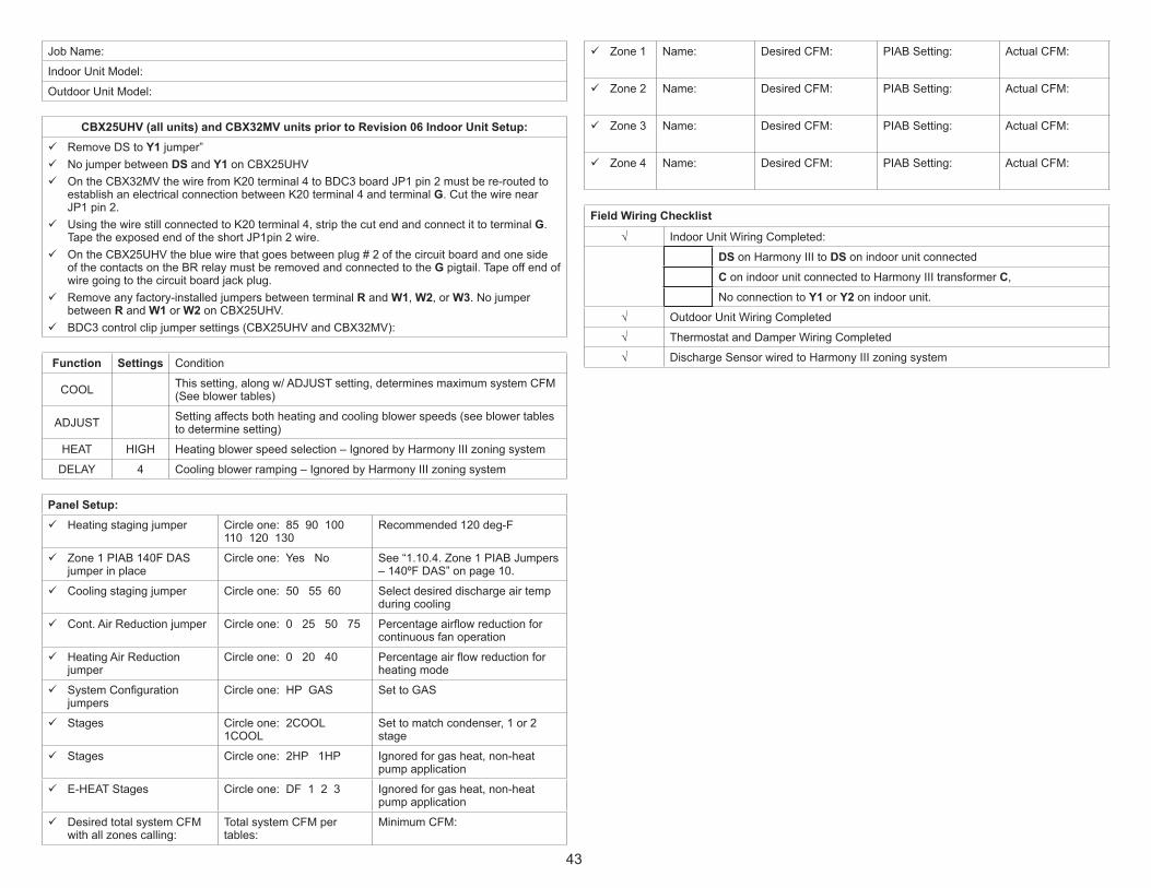
43
JobName:
IndoorUnitModel:
OutdoorUnitModel:
CBX25UHV (all units) and CBX32MV units prior to Revision 06 Indoor Unit Setup: 9 RemoveDStoY1jumper” 9 NojumperbetweenDSandY1onCBX25UHV 9 OntheCBX32MVthewirefromK20terminal4toBDC3boardJP1pin2mustbere-routedtoestablishanelectricalconnectionbetweenK20terminal4andterminalG.CutthewirenearJP1pin2.
9 UsingthewirestillconnectedtoK20terminal4,stripthecutendandconnectittoterminalG. TapetheexposedendoftheshortJP1pin2wire.
9 OntheCBX25UHVthebluewirethatgoesbetweenplug#2ofthecircuitboardandonesideofthecontactsontheBRrelaymustberemovedandconnectedtotheGpigtail.Tapeoffendofwiregoingtothecircuitboardjackplug.
9 Removeanyfactory-installedjumpersbetweenterminalRandW1,W2,orW3.NojumperbetweenRandW1orW2onCBX25UHV.
9 BDC3controlclipjumpersettings(CBX25UHVandCBX32MV):
Function Settings Condition
COOL Thissetting,alongw/ADJUSTsetting,determinesmaximumsystemCFM(Seeblowertables)
ADJUST Settingaffectsbothheatingandcoolingblowerspeeds(seeblowertablestodeterminesetting)
HEAT HIGH Heatingblowerspeedselection–IgnoredbyHarmonyIIIzoningsystem
DELAY 4 Coolingblowerramping–IgnoredbyHarmonyIIIzoningsystem
Panel Setup: 9 Heatingstagingjumper Circleone:8590100
110 120 130Recommended120deg-F
9 Zone1PIAB140FDASjumperinplace
Circleone:YesNo See“1.10.4.Zone1PIABJumpers–140ºFDAS”onpage10.
9 Coolingstagingjumper Circleone:505560 Selectdesireddischargeairtempduringcooling
9 Cont.AirReductionjumper Circleone:0255075 Percentageairflowreductionforcontinuousfanoperation
9 HeatingAirReductionjumper
Circleone:02040 Percentageairflowreductionforheatingmode
9 SystemConfigurationjumpers
Circleone:HPGAS SettoGAS
9 Stages Circleone:2COOL1COOL
Settomatchcondenser,1or2stage
9 Stages Circleone:2HP1HP Ignoredforgasheat,non-heatpumpapplication
9 E-HEATStages Circleone:DF123 Ignoredforgasheat,non-heatpumpapplication
9 DesiredtotalsystemCFMwithallzonescalling:
TotalsystemCFMpertables:
MinimumCFM:
9 Zone 1 Name: DesiredCFM: PIABSetting: ActualCFM:
9 Zone 2 Name: DesiredCFM: PIABSetting: ActualCFM:
9 Zone 3 Name: DesiredCFM: PIABSetting: ActualCFM:
9 Zone 4 Name: DesiredCFM: PIABSetting: ActualCFM:
Field Wiring Checklist
√ IndoorUnitWiringCompleted:
DSonHarmonyIIItoDSonindoorunitconnectedConindoorunitconnectedtoHarmonyIIItransformerC,NoconnectiontoY1orY2onindoorunit.
√ OutdoorUnitWiringCompleted
√ ThermostatandDamperWiringCompleted
√ DischargeSensorwiredtoHarmonyIIIzoningsystem

44
4.2.3.2. Heat Pump — Electric Strip Heat
JobName:
IndoorUnitModel:
OutdoorUnitModel:
CBX32MV, Rev 6 or higher, CBX40UHV and CBA38MV Indoor Unit Setup: 9 Cuton-boardlinkR to DS“DEHUMorHARMONY” 9 Removeanyfactory-installedjumpersbarsfromW1 to W2orW2 to W3. 9 Airhandlercontroljumpersettings:
Function Settings Condition
COOL Thissetting,alongw/ADJUSTsetting,determinesmaximumsystemCFM(Seeblowertables)
ADJUST Settingaffectsbothheatingandcoolingblowerspeeds(seeblowertablestodeterminesetting)
HEAT HIGH Heatingblowerspeedselection–IgnoredbyHarmonyIIIzoningsystem
DELAY 4 Coolingblowerramping–IgnoredbyHarmonyIIIzoningsystem
BLOWERONLYCFM Continuousfanspeed–IgnoredbyHarmonyIIIzoningsystem
EVENHEAT EVENHEATisnotusedwithHarmonyIIIzoningsystem
Panel Setup: 9 Heatingstagingjumper Circleone:8590100110
120 130Recommended120deg-F
9 Zone1PIAB140FDASjumperinplace
Circleone:YesNo See“1.10.4.Zone1PIABJumpers–140ºFDAS”onpage10.
9 Coolingstagingjumper Circleone:505560 Selectdesireddischargeairtempduringcooling
9 Cont.AirReductionjumper Circleone:0255075 Percentageairflowreductionforcontinuousfanoperation
9 HeatingAirReductionjumper
Circleone:02040 Percentageairflowreductionforheatingmode
9 SystemConfigurationjumpers
Circleone:HPGAS SettoGAS
9 Stages Circleone:2COOL1COOL
Settomatchcondenser,1or2stage
9 Stages Circleone:2HP1HP Ignoredforgasheat,non-heatpumpapplication
9 E-HEATStages Circleone:DF123 Ignoredforgasheat,non-heatpumpapplication
9 DesiredtotalsystemCFMwithallzonescalling:
TotalsystemCFMpertables:
MinimumCFM:
9 Zone 1 Name: DesiredCFM: PIABSetting: ActualCFM:
9 Zone 2 Name: DesiredCFM: PIABSetting: ActualCFM:
9 Zone 3 Name: DesiredCFM: PIABSetting: ActualCFM:
9 Zone 4 Name: DesiredCFM: PIABSetting: ActualCFM:
Field Wiring Checklist
√ IndoorUnitWiringCompleted:
DSonHarmonyIIItoDSonindoorunitconnectedConindoorunitconnectedtoHarmonyIIItransformer C.
NoconnectiontoY1orY2onindoorunit.√ OutdoorUnitWiringCompleted
√ ThermostatandDamperWiringCompleted
√ DischargeSensorwiredtoHarmonyIIIzoningsystem

45
JobName:
IndoorUnitModel:
OutdoorUnitModel:
CBX25UHV (all units) and CBX32MV units prior to Revision 06 Indoor Unit Setup: 9 RemoveDS to Y1jumper” 9 NojumperbetweenDSandY1onCBX25UHV 9 OntheCBX32MVthewirefromK20terminal4toBDC3boardJP1pin2mustbere-routedtoestablishanelectricalconnectionbetweenK20terminal4andterminalG.CutthewirenearJP1pin2.
9 UsingthewirestillconnectedtoK20terminal4,stripthecutendandconnectittoterminalG. TapetheexposedendoftheshortJP1pin2wire.
9 OntheCBX25UHVthebluewirethatgoesbetweenplug#2ofthecircuitboardandonesideofthecontactsontheBRrelaymustberemovedandconnectedtotheGpigtail.Tapeoffendofwiregoingtothecircuitboardjackplug.
9 Removeanyfactory-installedjumpersbetweenterminalRandW1,W2,orW3.NojumperbetweenRandW1orW2onCBX25UHV.
9 BDC3controlclipjumpersettings(CBX25UHVandCBX32MV
Function Settings Condition
COOL Thissetting,alongw/ADJUSTsetting,determinesmaximumsystemCFM(seeblowerCFMtables)
ADJUST Settingaffectsbothheatingandcoolingblowerspeeds(seeblowertablestodeterminesetting)
HEAT HIGH Heatingblowerspeedselection–IgnoredbyHarmonyIIIzoningsystem
DELAY 4 Coolingblowerramping–IgnoredbyHarmonyIIIzoningsystem
Panel Setup: 9 Heatingstagingjumper Circleone:8590100110
120 130Recommended120deg-F
9 Zone1PIAB140FDASjumperinplace
Circleone:YesNo See“1.10.4.Zone1PIABJumpers–140ºFDAS”onpage10.
9 Coolingstagingjumper Circleone:505560 Selectdesireddischargeairtempduringcooling
9 Cont.AirReductionjumper
Circleone:0255075 Percentageairflowreductionforcontinuousfanoperation
9 HeatingAirReductionjumper
Circleone:02040 Percentageairflowreductionforheatingmode
9 SystemConfigurationjumpers
Circleone:HPGAS SettoGAS
9 Stages Circleone:2COOL1COOL
Settomatchcondenser,1or2stage
9 Stages Circleone:2HP1HP Ignoredforgasheat,non-heatpumpapplication
9 E-HEATStages Circleone:DF123 Ignoredforgasheat,non-heatpumpapplication
9 DesiredtotalsystemCFMwithallzonescalling:
TotalsystemCFMpertables:
MinimumCFM:
9 Zone 1 Name: DesiredCFM: PIABSetting: ActualCFM:
9 Zone 2 Name: DesiredCFM: PIABSetting: ActualCFM:
9 Zone 3 Name: DesiredCFM: PIABSetting: ActualCFM:
9 Zone 4 Name: DesiredCFM: PIABSetting: ActualCFM:
Field Wiring Checklist
√ IndoorUnitWiringCompleted:
DSonHarmonyIIItoDSonindoorunitconnectedConindoorunitconnectedtoHarmonyIIItransformer C.
NoconnectiontoY1orY2onindoorunit.√ OutdoorUnitWiringCompleted
√ ThermostatandDamperWiringCompleted
√ DischargeSensorwiredtoHarmonyIIIzoningsystem

46
4.2.3.3. Cooling Only or Cooling with Hot Water Coil (Non-Heat Pump)
JobName:
IndoorUnitModel:
OutdoorUnitModel:
CBX32MV, Rev 6 or higher, CBX40UHV and CBA38MV Indoor Unit Setup: 9 Cuton-boardlinkR to DS“DEHUMorHARMONY” 9 ForHotWaterCoilOnly—AddK212RelayandwireperHarmonyIIIwiringdetail.NOTE-Dischargeairsensormustbelocateddownstreamofcoolingcoilandhotwatercoil.
9 Airhandlercontroljumpersettings:
Function Settings Condition
COOL Thissetting,alongw/ADJUSTsetting,determinesmaximumsystemCFM(Seeblowertables)
ADJUST Settingaffectsbothheatingandcoolingblowerspeeds(seeblowertablestodeterminesetting)
HEAT HIGH Heatingblowerspeedselection–IgnoredbyHarmonyIIIzoningsystem
DELAY 4 Coolingblowerramping–IgnoredbyHarmonyIIIzoningsystem
BLOWERONLYCFM Continuousfanspeed–IgnoredbyHarmonyIIIzoningsystem
EVENHEAT EVENHEATisnotusedwithHarmonyIIIzoningsystem
Panel Setup: 9 Heatingstagingjumper Circleone:8590100110
120 130Recommended120deg-F
9 Zone1PIAB140FDASjumperinplace
Circleone:YesNo See“1.10.4.Zone1PIABJumpers–140ºFDAS”onpage10.
9 Coolingstagingjumper Circleone:505560 Selectdesireddischargeairtempduringcooling
9 Cont.AirReductionjumper Circleone:0255075 Percentageairflowreductionforcontinuousfanoperation
9 HeatingAirReductionjumper
Circleone:02040 Percentageairflowreductionforheatingmode
9 SystemConfigurationjumpers
Circleone:HPGAS SettoGAS
9 Stages Circleone:2COOL1COOL
Settomatchcondenser,1or2stage
9 Stages Circleone:2HP1HP Ignoredforgasheat,non-heatpumpapplication
9 E-HEATStages Circleone:DF123 Ignoredforgasheat,non-heatpumpapplication
9 DesiredtotalsystemCFMwithallzonescalling:
TotalsystemCFMpertables:
MinimumCFM:
9 CBunit“minimum”CFM____________(determinedbyunitspeclistedbelowunitblowertable)
√Zone1 Name: DesiredCFM: PIABSetting: ActualCFM:
√Zone2 Name: DesiredCFM: PIABSetting: ActualCFM:
√Zone3 Name: DesiredCFM: PIABSetting: ActualCFM:
√Zone4 Name: DesiredCFM: PIABSetting: ActualCFM:
NOTE: All of the above are recommended starting positions for DIP switches and Harmony III zoning system jumpers. Slight variations may be required during system start up and operation checks.
Field Wiring Checklist
√ IndoorUnitWiringCompleted:
DSonHarmonyIIItoDSonindoorunitconnectedConindoorunitconnectedtoHarmonyIIItransformerC
NoconnectiontoY1orY2onindoorunit.√ OutdoorUnitWiringCompleted
√ ThermostatandDamperWiringCompleted
√ DischargeSensorwiredtoHarmonyIIIzoningsystemandifahotwatercoilisused,thesensormustbelocateddownstreamofthehotwatercoil.

47
JobName:
IndoorUnitModel:
OutdoorUnitModel:
CBX25UHV (all units) and CBX32MV units prior to Revision 06 Indoor Unit Setup: 9 RemoveDStoY1jumper” 9 NojumperbetweenDSandY1onCBX25UHV 9 OntheCBX32MVthewirefromK20terminal4toBDC3boardJP1pin2mustbere-routedtoestablishanelectricalconnectionbetweenK20terminal4andterminalG.CutthewirenearJP1pin2.
9 UsingthewirestillconnectedtoK20terminal4,stripthecutendandconnectittoterminal G. TapetheexposedendoftheshortJP1pin2wire.
9 OntheCBX25UHVthebluewirethatgoesbetweenplug#2ofthecircuitboardandonesideofthecontactsontheBRrelaymustberemovedandconnectedtotheGpigtail.Tapeoffendofwiregoingtothecircuitboardjackplug.
9 Removeanyfactory-installedjumpersbetweenterminalRandW1,W2,orW3.NojumperbetweenRandW1orW2onCBX25UHV.
9 BDC3controlclipjumpersettings(CBX25UHVandCBX32MV
Function Settings Condition
COOLThissetting,alongwithADJUSTsetting,determinesmaximumsystemCFM(seeblowertables)
ADJUSTSettingaffectsbothheatingandcoolingblowerspeeds(seeblowertablestodeterminesetting)
HEAT 4 Heatingblowerspeedselection–IgnoredbyHarmonyIIIzoningsystem
DELAY 4 Coolingblowerramping–IgnoredbyHarmonyIIIzoningsystem
Panel Setup: 9 Heatingstagingjumper Circleone:8590100110
120 130Recommended120deg-F
9 Zone1PIAB140FDASjumperinplace
Circleone:YesNo See“1.10.4.Zone1PIABJumpers–140ºFDAS”onpage10.
9 Coolingstagingjumper Circleone:505560 Selectdesireddischargeairtempduringcooling
9 Cont.AirReductionjumper Circleone:0255075 Percentageairflowreductionforcontinuousfanoperation
9 HeatingAirReductionjumper
Circleone:02040 Percentageairflowreductionforheatingmode
9 SystemConfigurationjumpers
Circleone:HPGAS SettoGAS
9 Stages Circleone:2COOL1COOL
Settomatchcondenser,1or2stage
9 Stages Circleone:2HP1HP Ignoredforgasheat,non-heatpumpapplication
9 E-HEATStages Circleone:DF123 Ignoredforgasheat,non-heatpumpapplication
9 DesiredtotalsystemCFMwithallzonescalling:
TotalsystemCFMpertables:
MinimumCFM:
9 CBunit“minimum”CFM____________(determinedbyunitspeclistedbelowunitblowertable)
√Zone1 Name: DesiredCFM: PIABSetting: ActualCFM:
√Zone2 Name: DesiredCFM: PIABSetting: ActualCFM:
√Zone3 Name: DesiredCFM: PIABSetting: ActualCFM:
√Zone4 Name: DesiredCFM: PIABSetting: ActualCFM:
NOTE: All of the above are recommended starting positions for DIP switches and Harmony III zoning system jumpers. Slight variations may be required during system start up and operation checks.
Field Wiring Checklist
√ IndoorUnitWiringCompleted:
DSonHarmonyIIItoDSonindoorunitconnectedConindoorunitconnectedtoHarmonyIIItransformerC
NoconnectiontoY1orY2onindoorunit.√ OutdoorUnitWiringCompleted
√ ThermostatandDamperWiringCompleted
√ DischargeSensorwiredtoHarmonyIIIzoningsystemandifahotwatercoilisused,thesensormustbelocateddownstreamofthehotwatercoil.

48
5. dual Fuel (OPtiOn 3)Followallequipmentinstallationinstructionsprovidedwitheachunit.
5.1. Zone Control System Wiring - Option 3After theheatpumpunit is installed,fieldwire the linevoltageasshown in theinstallationinstructionsprovidedwiththeunit.Usethermostatwiretoconnecttheheatpumptothezonecontrolpanelasillustratedinthefollowingfigure.
IMPORTANT!DO NOT MAKECONNECTIONSTO Y1 AND Y2
Thermostat 2 Thermostat 1W C Y G R W C Y G R
IMPORTANT! Connectivity is NOT COMPLETE until allelectrical adjustments (jumpers and wiring changes) have
BALANCE POINTSENSOR Kit 10Z23
DAMPERS(Spring open, power close)
PRESSURE SWITCH21J18 (HFC-22)
27W13 (HFC-410A) Y R B 120VAC
24VAC
Vacation OFF for individualzone control.
Vacation ON for all zones to beconditioned at the same time.
Emergency Heat OFF to allowHeat Pump to provide heat.
Emergency Heat ON to force
vide all heating (disallows heatpump from providing any heat).
RCY1Y2OW1
R GW1W2CDSY1Y2
IMPORTANTConnectthermostat‐gaugewire to integratedcontrol “C” terminal
HEAT PUMP
VARIABLESPEEDFURNACE
NOTE - Do not wire “Y” wire(s) from the
furnace terminal strip. Doing so causesthe motor to “search” for proper CFM.
DT2 (S89) Lim
it Control (O
ptional[67M
41], for defrost tempering kit)
ON G71MPP & SLP98Furnace - W2 Notrequired, but may be connected toincrease firing rate.
SEE IMPO
RTANT NOTE BELO
W!
NOTE: SELECT #OF HP STAGESBY PLACINGJUMPER INAPPROPRIATEPOSITION. (2-STGHP SHOWN)
CONNECT TO THESAME POWER
SUPPLY AS THEGAS FURNACE
ZONE CONTROLTRANSFORMER
Discharge Air Sensor (88K38)Included
Connections for remote vacation switch or Humiditrol zoningaccessory
Figure 32. Option 3 - Typical Lennox Heat Pump and Lennox Variable-Speed Gas Furnace (Dual Fuel) (Troubleshooting)

49
5.2. Dual Fuel System Start-Up Defrost Temperating Sensor Placement and Checkout
5.2.1. Start-Up the System (All Models)
1. Adjustallthermostatsettingssothatnodemandwilloccur.
2. Applypowertothezonepaneltransformerandtothefurnaceandobservethefollowing:allfourdiagnosticLEDswilllight;theneachindividualdiagnosticLEDwilllightinsequence;thenallfourdiagnosticLEDswilllightandextinguish.
3. Finally,thestatuslightwillbegintoflash,indicatingproperoperation.Performthegasheatingchecksusingtheinformationinthefollowingsections.
5.2.2. Defrost Temperating Sensor PlacementInstall the defrost temperating sensor (if used) where shown in the followingillustration. For additional information, see the installation instruction that camewiththeDefrostTemperatingKit(67M41).
plenum
coil
furnace
front
Typical UpflowFurnace Shown
Defrost temperating sensor / limit control(if used in Option 3)
Figure 33. Defrost Tempering Sensor Placement

50
5.2.3. Checkouts
5.2.3.1. Typical Dual Fuel Gas Heating (Single Zone)
Prerequisites:• Zone1thermostatsettoHeat.• BalancePointSensorsetathighertemperaturethanoutdoorBPS-sensedtemperature(redbalancepointsensorLEDon)or
• BalancePointSensorinputsjumperedtosimulatecoldoutdoortemperaturebelowbalancepoint(redbalancepointsensorLEDon).
.
OUTPUT STATUS LEDs
(W) RED ON
DAMPER 2,3,4 OFF
HEATING ONFAN ON
CENTRALMODE ON
W1 ON
1. Setzone1thermostatforaheatdemand;check:• Zone1thermostatWLEDon(heatingdemand).• DamperLED1off(damperopen).• DamperLEDs2,3,and4on(dampersclosed).• OutputHeatW1LEDon(furnaceon).• HeatingLEDon.Thefurnacebeginsignitionsequenceafterzone1hasdemandedheat.Thezonecontrolsystemwillstart the furnacebloweron lowspeed(0PIAB)45secondsafterthecombustioncyclehasbegun..
2. When100ºFwarmairissensedbythedischargeairsensor,thefanLEDwilllightand theblowerwill slowly increase to speed requiredby thezonecalling.ThebloweroperatesatspeedsettingofPIABjumperforzone1andthe jumperforheatingairreduction.Itmayrequire60-90secondstoreachthisspeed.
3. Setzone1thermostatforNOheatdemand;check:• Zone1thermostatWLEDoff(noheatdemand).• OutputHeatW1 LEDoff.• FanLEDoff.• HeatingLEDoff.• DamperLEDs2-4remainonuntilafter3-1/2minutepurge;thenoff.Tochecktheamountofairbeingdeliveredtoeachzoneandtoconfirmthateachindividualzonedamperfunctionsproperly,repeatthesestepsforzones2-4.

51
5.2.3.2. Typical Dual Fuel Gas Heating (Multiple Zone)
Prerequisites:Zone1thermostatsettoHeat.• BalancePointSensorsetathighertemperaturethanoutdoorBPS-sensedtemperature(redbalancepointsensorLEDon)or
• BalancePointSensorinputsjumperedtosimulatecoldoutdoortemperaturebelowbalancepoint(redbalancepointsensorLEDon).
.
OUTPUT STATUS LEDs
DAMPER 2,3,4 OFF
(W) RED ON
HEATING ONFAN ON
W1 ON
1. Setallzonethermostatsforaheatdemand;check:• Allzone1thermostatWLEDon(heatingdemand).• DamperLED1-4off(alldamperopen).• DamperLEDs2,3,and4on(dampersclosed).• OutputHeatW1LEDon(furnaceon).• HeatingLEDon.Thefurnacebeginsignitionsequenceafteraheatdemandisdetected.Thezonecontrolsystemwillstart the furnacebloweron lowspeed(0PIAB)45secondsafterthecombustioncyclehasbegun..
2. When100ºFwarmairissensedbythedischargeairsensor,thefanLEDwilllightand theblowerwill slowly increase to speed requiredby thezonecalling.ThebloweroperatesatspeedsettingofPIABjumperforzone1andthe jumperforheatingairreduction.Itmayrequire60-90secondstoreachthisspeed.
3. SetallzonethermostatsforNOheatdemand;check:• OutputHeatW1LEDoff.• HeatingLEDoff.• FanLEDoff(blowerturnsoffafterdelay).• AllzonethermostatWLEDsoff.• DamperLEDs-Lastzonethermostatdemandremoved:LEDisoff(thiszone’s
damperremainsopenduring3-1/2minutepurge);otherzonesdamperLEDsareonduring the3-1/2minutepurge (dampersclosed).After3-1/2minutedelay,alldampersLEDsgooff(dampersopen).

52
5.2.3.3. Typical Dual Fuel Gas Heating (Central Mode)
Prerequisites:• Centralmodeswitchon.• RedLEDonthecentralmodefanswitchon.• Zone1thermostatsettoHeat.
9 Balance Point Sensor set at higher temperature than outdoor BPS-sensedtemperature(redbalancepointsensorLEDon)or
9 Balance Point Sensor inputs jumpered to simulate cold outdoortemperaturebelowbalancepoint(redbalancepointsensorLEDon).
.
OUTPUT STATUS LEDs
DAMPER 2,3,4 OFF
(W) RED ON
HEATING ONFAN ON
W1 ON
1. Setzone1thermostatforaheatdemand;check:• Zone1thermostat WLEDon(heatingdemand).• OutputHeatW1 LEDon(furnaceon).• HeatingLEDon.• AlldamperLEDsoff(damperopen).
2. ThefurnacewillbeginitsignitionsequenceafterZone1hasdemandedheat.Thezonecontrolsystemwillstart the furnacebloweron lowspeed (0PIABair)45secondsafterthecombustioncyclehasbegun.
3. When100ºFwarmairissensedbythedischargeairsensor,thefanLEDwilllightandtheblowerwillslowlyincreasetospeed.Theblowerwilloperateataspeedequivalent to thePIAB calculated for all zones calling, taking into account theheatingairreductionjumperposition.Itmaytaketheblower60to90secondstoreachthisspeed.
4. Removetheheatdemandfromzone1(noheat inputoroutputandnoblowerdemand).Uponremovalofthedemandfromzone1,check:• Zone1thermostatWLEDoff(noheatdemand).• OutputHeatW1LEDoff.• FanLEDoff.• HeatingLEDoff.After3-1/2minutepurgetime,furnaceblowerturnsoff.

53
5.3. Zoning System with Dual Fuel Troubleshooting - Option 3
5.3.1. Troubleshooting Diagram
Do dampers respond to demand? 0volts AC = open. 24 volts AC =closed. Dampers should drive closedwhen 24 volts is jumpered to dampermotor.Is wiring correct & in good condition?
Are thermostats wired correctly?Does zone control system respond appropriately to demand?
tion relays may need to be used.24VAC supplied to each thermostat terminal R from zone control system?Check each thermostat for output signal when calling. Heating output W1? Cooling output Y1?
Error code present?
shooting/diagnosticsection of thismanual.
ing?
Does outdoor unit respond to demand?Is it operating properly?Test Defrost. Does outdoor unit initiate and terminate defrost correctly?Check defrost tempering switch, if installed.Does zone control system respond appropriately during defrost?Are appropriate outputs energized in response to demand?Does zone control system energize appropriate outputs? During Cooling? DuringHeating? During Defrost? During Emer. Heating?24VAC from furnace transformer to R?Does indoor unit respond to outputs? Cooling? Heating? Defrost? Emer. Heating?Does blower speed change as zone demand changes? If no, does DS output varyfrom 0 to 25VDC?
Line Voltage to transformer?24VAC from transformer to zone control panel?Are all wire connections good? Are all wire connections correct?
Pressure Switch installed. in correct position?Does switch open when high pressure condition is simulated (temporarilyblocking airflow in heating mode)?
tion is simulated (temporarily disconnecting switch simulates high pressure).Balance Point Sensor Installed and correctly wired?Contacts close on temperature fall?
DAMPERS
Heating
Cooling
120VAC
24VAC
THERMOSTATS
rectly?Only 1 jumper per Zone?
er Settings NOTE:Zone 1 may have a secondjumper on 140F DAS pins)Has 140F DAS jumper beeninstalled
Are continuous & heating air
ly? On heat pumps, HeatingAir Reduction must be 0%.
ate speed reduction? If no,
placing zone control panel.
Have heating and coolingstaging jumpers been set
eration?
PRESSURESWITCH
Y R B
BALANCEPOINT
SENSOR
RCY1Y2OW1
R GW1W2CDSY1Y2
HEAT PUMP
VARIABLESPEED
FURNACE
DT2 (S89)
tional, fordefrosttemperingkit)
Is dischargeprobe installed?Is probe locatedin discharge air
rectly?
DISCHARGEAIR SENSOR
HUMIDITROL ZONINGACCESSORY CONTROL
“C” connectedto “C”?
Fuses OK?
TO FU
RN
ACE
POW
ER SU
PPLY
Verify Furnace jumpers/links cut or removed(see Pages 29 - 25)Verify NO connectionsmade to Y1 or Y2.
Airreduction
jumpersettings -
page 9.
ZONE PANEL TRANSFORMER
Figure 34. Option 3 - Typical Lennox Heat Pump and Lennox Variable-Speed Gas Furnace (Dual Fuel) (Troubleshooting

54
5.3.2. Dual Fuel Operation (Below Balance Point)
REFER TO DISCHARGE AIRUPPER LIMIT DIAGRAM(Page 51) FOR UPPER LIMITAND DIFFERENTIAL DETAILS.
Energize W1@ furnace; Rampindoor blower tominimum CFM
setting
Dischargeair below heatingstaging jumper
setting?
Ramp indoorblower to
heating stagingjumper setting
3-Minutesminimum run time
in 1st stagecompleted
?
3-Minutesminimum run time
in 2nd stagecompleted
?
No
Yes
No
Yes
Yes
Dischargeair falls to
130°F?
Yes
No
No
No
Yes
No
Yes
HEATINGDEMAND
RECEIVED
3-Minutessince completion
of last heatingdemand
?Yes
Ambienttemp. Below
Balance PointSensor setpoint
?
Yes
No
No
See Above BalancePoint Sensor
setpoint flow diagram
BLOWERSHUTDOWN
Yes
No
Yes
No
Yes
No
De-energizeW2
charge airtemperature
Energize W2@ furnace
charge airtemperature
De-energizeW1 @ furnace
Hold dampersopen for 3½
minutes
Dischargeair (DAS) above
100°F?
No
Yes Yes
No
Isdischarge
air at upperlimit
?
De-energizeW1 & W2@ furnace
Isdischarge
air at upperlimit
?
Doesdischarge airtemp. meet
heating stagingdifferential
?
Heatingdemandsatisfied
?
Heatingdemandsatisfied
?
Heatingdemandsatisfied
?
Yes
5 mindelay
complete?
No
Continuous airdelivered to
calling zones
5.3.3. Discharge Air Upper Limit and Differential Temperatures
Discharge air upper limit is160ºF unless 140ºF DASjumper installed
To / from the appropriate
gas heating ordual fueldiagram
Furnaceenergized
No
Yes
No
Yes
No
Monitordischarge airtemperature
Isdischarge
air at upperlimit
?
3-minute
pleted?
Yes
Differential is 20ºF aboveheating staging jumpersetting with the followingexception:Differential is 15ºF if the 140ºF DAS jumper is in place on PIAB 1 terminalsander is on 120 or 130.
Doesdischarge airtemp. meet
heating stagingdifferential
?
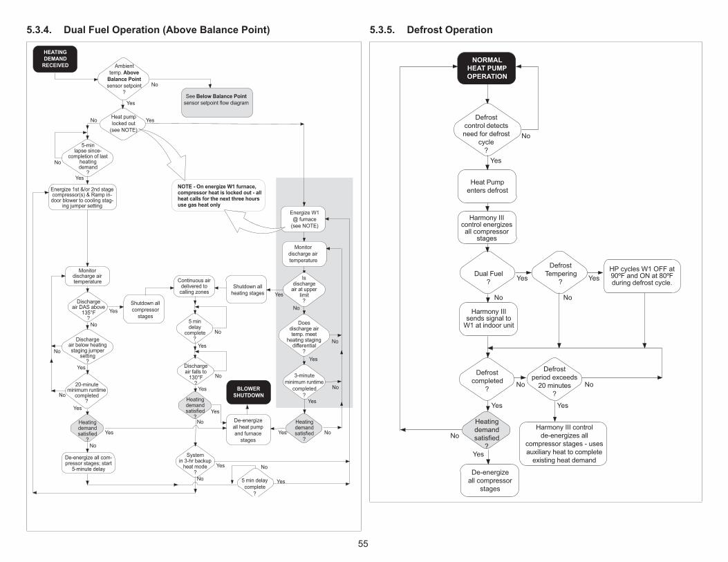
55
5.3.4. Dual Fuel Operation (Above Balance Point)
Energize W1@ furnace
(see NOTE)
No
De-energizeall heat pumpand furnace
stages
Dischargeair falls to
130°F?
Yes
Yes
No
Yes
BLOWERSHUTDOWN
Heatingdemandsatisfied
?
Yes
Yes
No
No
Yes
No
Energize 1st &/or 2nd stage
ing jumper setting
Dischargeair below heatingstaging jumper
setting?
20-minuteminimum runtime
completed?
No
No
No
Yes
pressor stages; start5-minute delay
Shutdown allcompressor
stagesYes
NOTE - On energize W1 furnace,compressor heat is locked out - allheat calls for the next three hoursuse gas heat only
Yes
HEATINGDEMAND
RECEIVED
5-min
completion of lastheatingdemand
?Yes
Ambienttemp. Above
Balance Pointsensor setpoint
?
Yes
No
No
See Below Balance Pointsensor setpoint flow diagram
Monitordischarge airtemperature
Shutdown allheating stages
Continuous airdelivered to
calling zones
Yes
No
No
Heat pumplocked out
(see NOTE)
YesNo
Monitordischarge airtemperature
5 min delaycomplete
?
Yes No
Systemin 3-hr backup
heat mode?
Yes
No
Dischargeair DAS above
135°F?
3-minuteminimum runtime
completed?
Isdischarge
air at upperlimit
?
Doesdischarge airtemp. meet
heating stagingdifferential
?
Heatingdemandsatisfied
?
Yes
5 mindelay
complete?
Heatingdemandsatisfied
?
No
5.3.5. Defrost Operation
Defrostcontrol detectsneed for defrost
cycle?
Yes
No
Yes
Harmony IIIcontrol energizesall compressor
stages
Heat Pumpenters defrost
Defrostcompleted
? No
Yes
Harmony III controlde-energizes all
compressor stages - usesauxiliary heat to complete
existing heat demand
Defrostperiod exceeds
20 minutes?
No
De-energizeall compressor
stages
Yes
No
NORMALHEAT PUMPOPERATION
Heatingdemandsatisfied
?
Dual Fuel? Yes
No
Harmony IIIsends signal to
W1 at indoor unit
DefrostTempering
? Yes
No
HP cycles W1 OFF at90ºF and ON at 80ºFduring defrost cycle.

56
5.3.6. Installation Setup Worksheets
5.3.6.1. Dual Fuel - Indoor Unit Honeywell 2-Stage IFC Control and Heat Pump
JobName:
IndoorUnitModel:
OutdoorUnitModel:
Miscellaneous Items: 9 InstallPressureSwitchintheoutdoorunitperthisinstructions(27W13forR410Aor21J18forR22)
9 InstallBalancePointSensor(10Z23)asperthisinstallationinstruction.SettodesiredoutdoorlockouttemperatureforHP
9 InstallOptionalDefrostTemperingSensor67M41(ifused)perinstallationinstructions.NOTE:MUSTbelocatedincoildeltaplatebetweenfurnaceandcoil
9 InstallDischargeAirSensorperinstallationinstructions.ThelocationofthesensorisCRITICALforpropersystemoperation
Indoor Unit Setup: 9 Cuton-boardlinkW914DEHUMORHARMONY(RtoDS)onfurnaceIFCcontrol(ifnotcut,fusewillblowinzonecontrolboard)
9 Cutandtapewiresfrompin#2andpin#13onplugJ46oftheVSMwiringharnessroutedfromthemotortotheFurnaceIntegratedcontrol.
9 FurnaceIFCControlDIPswitchsettings(ONorOFF):
DIP Switch ON or OFF Condition
1 OFF DIPswitch1mustbesettoOFFfortwostageheatingoperation
2 OFF DIPswitch2determinessecondstageheattimedelayandisignoredbyHarmonyIIIzoningsystem
3 ON DIPswitches3and4determinesheatingbloweroffdelay,recommendedis180sec4 ON
5 DIPswitches5and6determinessecondstagecoolingblowerspeedormaximumsystemairvol.6
7 DIPswitches7and8determineblower“adjust”settingformaximumsystemairvolume8
9 OFF DIPswitches9and10determinescoolingblowerrampingprofileandisignoredbyHarmonyIIIzoningsystem10 OFF
11 OFF DIPswitches11and12determinesheatingblowerspeedandisignoredbyHarmonyIIIzoningsystem12 ON
Panel Setup:√Heatingstagingjumper Circleone:8590100
110 120 130Recommended120deg-F
√Zone1PIAB140FDASjumperinplace
Circleone:YesNo See“1.10.4.Zone1PIABJumpers–140ºFDAS”onpage10.
√Coolingstagingjumper Circleone:505560 Selectdesireddischargeairtempduringcooling
√Cont.AirReductionjumper Circleone:0255075
Percentageairflowreductionforcontinuousfanoperation
√HeatingAirReductionjumper Circleone:02040 Percentageairflowreductionforheatingmode
√SystemConfigurationjumpers
Circleone:HPGAS SettoGAS
√Stages Circleone:2COOL1COOL
Settomatchcondenser,1or2stage
√Stages Circleone:2HP1HP Ignoredforgasheat,non-heatpumpapplication
√E-HEATStages Circleone:DF123 Ignoredforgasheat,non-heatpumpapplication
√DesiredtotalsystemCFMwithallzonescalling:
TotalsystemCFMpertables:
MinimumCFM:
√Zone1 Name: DesiredCFM: PIABSetting: ActualCFM:
√Zone2 Name: DesiredCFM: PIABSetting: ActualCFM:
√Zone3 Name: DesiredCFM: PIABSetting: ActualCFM:
√Zone4 Name: DesiredCFM: PIABSetting: ActualCFM:
NOTE: All of the above are recommended starting positions for furnace DIP switches and Harmony III jumpers. Slight variations may be required during system start up and operation checks.
Field Wiring Checklist
√ IndoorUnitWiringCompleted:
DSonHarmonyIIItoDSonindoorunitconnectedConindoorunitconnectedtoHarmonyIIItransformerCNoconnectiontoY1orY2onindoorunit.
√ OutdoorUnitWiringCompleted
√ ThermostatandDamperWiringCompleted
√ DischargeSensorwiredtoHarmonyIIIzoningsystem
√ HeatPumpPressureSwitchwiredtoHarmonyIIIzoningsystem

57
5.3.6.2. Dual Fuel - SLP98 Variable Capacity and Heat Pump
JobName:
IndoorUnitModel:
OutdoorUnitModel:
Miscellaneous Items: 9 InstallPressureSwitchintheoutdoorunitperthisinstructions(27W13forR410Aor21J18forR22)
9 InstallBalancePointSensor(10Z23)asillustratedinthekitinstallationinstruction.SettodesiredoutdoorlockouttemperatureforHP
9 InstallOptionalDefrostTemperingSensor67M41(ifused)perinstallationinstructions.NOTE:MUSTbelocatedincoildeltaplatebetweenfurnaceandcoil
9 InstallDischargeAirSensorperinstallationinstructions.ThelocationofthesensorisCRITICALforpropersystemoperation
Indoor Unit Setup: 9 Cuton-boardlinkW914DEHUMORHARMONY(R to DS)onfurnaceIFCcontrol(ifnotcut,fusewillblowinHarmonyIIIzoningsystemcontrolboard)
9 W2connectionfromHarmonyIIItoSLP98isoptional. 9 DIPswitchsettings(ONorOFF):
DIP Switch ON or OFF Condition
1 OFF DIPswitch1–leaveatfactorysetting–ignoredbyHarmonyIIIzoningsystem
2 OFF DIPswitch2–leaveatfactorysetting–ignoredbyHarmonyIIIzoningsystem
3 OFF DIPswitch3–leaveatfactorysetting–ignoredbyHarmonyIIIzoningsystem
4 ON DIPswitches4and5determineheatingblower“off”delay–recommended180seconds5 ON
6 OFF DIPswitches6and7–leaveatfactorysetting–ignoredbyHarmonyIIIzoningsystem7 OFF
8 DIPswitches8and9–coolingblowerspeed–determinesmaximumsystemCFM–seefurnaceblowertables9
10 DIPswitches10and11–coolingbloweradjust–determinesmaximumsystemCFM–seefurnaceblowertables11
12 OFF DIPswitches12and13–leaveatfactorysetting–ignoredbyHarmonyIIIzoningsystem13 OFF
14 OFFDIPswitches14,15,and16–setslowfire,minimumcapacity,firingrate-defaultsettingshownandisrecommendedstartingpoint.15 OFF
16 OFF
17 OFFDIPswitches17,18and19–setshighfire,100%capacity,firingrate-defaultsettingshownandisrecommendedstartingpoint18 OFF
19 OFF
Panel Setup: 9 Heatingstagingjumper Circleone:8590100110
120 130Recommended120deg-F
9 Zone1PIAB140FDASjumperinplace
Circleone:YesNo See“1.10.4.Zone1PIABJumpers–140ºFDAS”onpage10.
9 Coolingstagingjumper Circleone:505560 Selectdesireddischargeairtempduringcooling
9 Cont.AirReductionjumper Circleone:0255075 Percentageairflowreductionforcontinuousfanoperation
9 HeatingAirReductionjumper
Circleone:02040 Percentageairflowreductionforheatingmode
9 SystemConfigurationjumpers
Circleone:HPGAS SettoGAS
9 Stages Circleone:2COOL1COOL
Settomatchcondenser,1or2stage
9 Stages Circleone:2HP1HP Ignoredforgasheat,non-heatpumpapplication
9 E-HEATStages Circleone:DF123 Ignoredforgasheat,non-heatpumpapplication
9 DesiredtotalsystemCFMwithallzonescalling:
TotalsystemCFMpertables:
MinimumCFM:
9 Zone 1 Name: DesiredCFM: PIABSetting: ActualCFM:
9 Zone 2 Name: DesiredCFM: PIABSetting: ActualCFM:
9 Zone 3 Name: DesiredCFM: PIABSetting: ActualCFM:
9 Zone 4 Name: DesiredCFM: PIABSetting: ActualCFM:
NOTE: All of the above are recommended “starting” positions for the furnace DIP switches and Harmony III jumpers. Slight variations may be required during system start up and operation checks.
Field Wiring Checklist
√ IndoorUnitWiringCompleted:
DSonHarmonyIIItoDSonindoorunitconnectedConindoorunitconnectedtoHarmonyIIItransformerCNoconnectiontoY1orY2onindoorunit.
√ OutdoorUnitWiringCompleted
√ ThermostatandDamperWiringCompleted
√ DischargeSensorwiredtoHarmonyIIIzoningsystem
√ HeatPumpPressureSwitchwiredtoHarmonyIIIzoningsystem

58
5.3.6.3. Dual Fuel - Variable Speed SL280V, EL296V, SL297NV and Heat Pump
JobName:
IndoorUnitModel:
OutdoorUnitModel:
Miscellaneous Items: 9 InstallPressureSwitchintheoutdoorunitperHarmonyIIIinstallationinstructions(27W13forR410Aor27W12forR22)
9 InstallBalancePointSensor(10Z23)asperinstallationinstructions.SettodesiredoutdoorlockouttemperatureforHP
9 InstallOptionalDefrostTemperingSensor67M41(ifused)perinstallationinstructions.NOTE:MUSTbelocatedincoildeltaplatebetweenfurnaceandcoil
9 InstallDischargeAirSensorperinstallationinstructions.ThelocationofthesensorisCRITICALforpropersystemoperation
Indoor Unit Setup:√Cuton-boardlinkW914DEHUMORHARMONY(R to DS)onfurnaceIFCcontrol(ifnotcut,fusewillblowinHarmonyIIIzonecontrolboard)√DIPswitchsettings(ONorOFF):
DIP Switch
ON or OFF Condition
1 OFF DIPswitch1–leaveatfactorysetting–ignoredbyHarmonyIII
2 OFF DIPswitch2–leaveatfactorysetting–ignoredbyHarmonyIII
3 ON DIPswitches3and4–Bloweroffdelayswitchsettings,setDIPswitches3and4toON(180seconds)
4 ON DIPswitches4and5–Determinesheatingblower“off”delay–recommended180seconds
5 OFF DIPswitches5and6–Coolingbodeblowerspeed,setDIPswitches5and6toOFF(High-Factory)6 OFF
7 OFF DIPSwitches7and8–Coolingblowerspeedadjustment,setDIPswitches7and8toOFF(FactoryDefault)8 OFF
9 OFF DIPSwitches9and10–CoolingmodeblowerSpeedramping,setDIPswitches9and10toOFF(A-Factory)10 OFF
11 OFFDIPSwitches11,12and13–Heatingmodeblowerspeed,setDIPswitches11,12and13toOFF(FactoryDefault)12 OFF
13 OFF
14 OFF DIPSwitches14and15–Continuousblowerspeed,setDIPswitches14and15toOFF(38%ofHighCoolSpeed-FactoryDefault)15 OFF
Panel Setup: 9 Heatingstagingjumper Circleone:8590100110
120 130Recommended120deg-F
9 Zone1PIAB140FDASjumperinplace
Circleone:YesNo SeeHarmonyIIIinstallinstructionsforinfo
9 Coolingstagingjumper Circleone:505560 Selectdesireddischargeairtempduringcooling
9 Cont.AirReductionjumper Circleone:0255075 Percentageairflowreductionforcontinuousfanoperation
9 HeatingAirReductionjumper
Circleone:02040 Percentageairflowreductionforheatingmode
9 SystemConfigurationjumpers
Circleone:HPGAS SettoGAS
9 Stages Circleone:2COOL1COOL Settomatchcondenser,1or2stage
9 Stages Circleone:2HP1HP Ignoredforgasheat,non-heatpumpapplication
9 E-HEATStages Circleone:DF123 Ignoredforgasheat,non-heatpumpapplication
9 DesiredtotalsystemCFMwithallzonescalling:
TotalsystemCFMpertables: MinimumCFM:
9 Zone 1 Name: DesiredCFM: PIABSetting: ActualCFM:
9 Zone 2 Name: DesiredCFM: PIABSetting: ActualCFM:
9 Zone 3 Name: DesiredCFM: PIABSetting: ActualCFM:
9 Zone 4 Name: DesiredCFM: PIABSetting: ActualCFM:
NOTE: All of the above are recommended “starting” positions for the furnace DIP switches and Harmony III jumpers. Slight variations may be required during system start up and operation checks.
Field Wiring Checklist
√ IndoorUnitWiringCompleted:
DSonHarmonyIIItoDSonindoorunitconnectedConindoorunitconnectedtoHarmonyIIItransformerCNoconnectiontoY1orY2onindoorunit.
√ OutdoorUnitWiringCompleted
√ ThermostatandDamperWiringCompleted
√ DischargeSensorwiredtoHarmonyIIIzoningsystem

59
6. trOublesHOOtinG
6.1. Operation and Troubleshooting Indicators
6.1.1. Zone Control Panel LEDsThe zone control systemoperation is indicated by light emitting diodes (LEDs)located on the zone control panel. In addition to operating condition, the LEDsprovidevaluableinformationsystemtroubleshooting.TheLEDs(showninfigure30)arethermostat,diagnostic,andoutputstatus.
1. Thermostat LEDs —Locatedalongtheupperedgeofthezonecontrolpanel.Each zone has three LEDs to indicate a call for heating or cooling: green(indicatesaY /compressordemand),red(indicatesaW /heatingdemand)andamber(indicatesaG/indoorblowerdemand).TheseLEDsarelabeledaccordingtothezoneanddemand.
2. Diagnostic LEDs—Diags1,2,3,4—locatednearthebottomcenterofthethe zone control panel. These LEDs aid the technician in troubleshootingproblems.Whenanerrorisdetected,LEDsilluminateinapattern.SeeFaultRecallandTimeDelayOverrideonpage58.
3. Output LEDs— Located along the bottom of the zone control panel andnear connection terminals. These red LEDs indicate the output status ofdampers,furnace,outdoorunit,etc.Whenanoutputispoweredoractive,thecorrespondingLEDisilluminated.
4. Pressure Switch LED—Locatedatthetopleftcorner.GreenLEDilluminateswhentheheatpumppressureswitchisclosedindicatednormalpressures.TheLEDwillbeoffwhenthepressureswitchopensunderabnormalorexcessivecondensingpressureintheheatpumpheatingmode.Pressureswitchisusedonlyonheatpumpsystems.
5. Balance Point Sensor LED — Located at the top left corner. Red LEDilluminates when the balance point sensor is closed indicating outdoortemperatureisbelowthebalancepointsensorsetting.Onlyusedondualfuelheatpumpsystems.
TheLEDsarelabeledaccordingtooutputandfunction.Forexample,ifDamper1LED is illuminated, it’s damperhasbeensignaled to close;when theLED isextinguished,it’sdamperhasbeensignaledtoopen,allowingairflowtothatzone.
THERMOSTATLEDs
OUTPUT STATUS LEDs
DIAGNOSTICLEDsTIME DELAY
OVERRIDE
FAULTRECALL
EQUIPMENTOUTPUT LEDs
OUTDOOR THERMOSTAT /BALANCE POINT LED
PRESSURESWITCH LED
Figure 35. System Indicators/Troubleshooting Devices
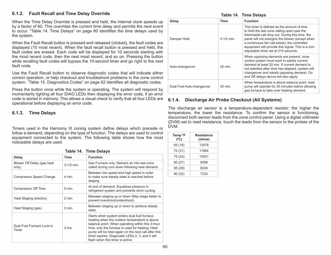
60
6.1.2. Fault Recall and Time Delay Override
WhentheTimeDelayOverrideispressedandheld,theinternalclockspeedsupbyafactorof60.Thisoverridesthecurrenttimedelayandpermitsthenexteventtooccur.“Table14.TimeDelays”onpage60identifiesthetimedelaysusedbythesystem.
WhentheFaultRecallbuttonispressedandreleased(clicked),thefaultcodesaredisplayed(10mostrecent).Whenthefaultrecallbuttonispressedandheld,thefaultcodesareerased.Eachcodewillbedisplayedfor10secondsstartingwiththemostrecentcode,thenthenextmostrecent,andsoon.Pressingthebuttonwhilerecallingfaultcodeswillbypassthe10-secondtimerandgorighttothenextfaultcode.
Use theFaultRecallbutton toobservediagnosticcodes thatwill indicateeithercorrectoperation,orhelpcheckoutandtroubleshootproblemsinthezonecontrolsystem.“Table15.DiagnosticsCodes”onpage62identifiesalldiagnosticcodes.
Pressthebuttononcewhilethesystemisoperating.ThesystemwillrespondbymomentarilylightingallfourDIAGLEDsthendisplayingtheerrorcode,ifanerrorcodeisstoredinmemory.ThisallowsavisualchecktoverifythatallfourLEDsareoperationalbeforedisplayinganerrorcode.
6.1.3. Time Delays
Timers used in theHarmony III zoning systemdefine delayswhich precede orfollowademand,dependingonthetypeoffunction.Thedelaysareusedtocontrolequipment connected to the system. The following table shows how the mostnoticeabledelaysareused.
Table 14. Time DelaysDelay Time FunctionBlowerOffDelay(gasheatonly) 3-1/2min. GasFurnaceonly.Deliversairintolastzone
calledduringcooldownfollowingheatdemand.
CompressorSpeedChange 4min.Betweenlowspeedandhighspeedinordertomakesuresteadystateisreachedbeforestaging.
CompressorOffTime 5min. Atendofdemand.Equalizespressureinrefrigerantsystemandpreventsshortcycling.
HeatStaging(electric) 2min. Betweenstagingupordown(Maystagefastertopreventovershoot/undershoot).
HeatStaging(gas) 3min. Betweenstagingupordowntoachievesteadystate.
DualFuelFurnaceLock-inTimer 3hrs.
Startswhensystementersdualfuelfurnaceheatingwhentheoutdoortemperatureisabovebalancepoint.Whenoperatingwithinthis3-hourtime,onlythefurnaceisusedforheating.Heatpumpwillbetriedagainonthenextcallafterthistimerexpires.DiagnosticLEDs2,3,and4willflashwhenthistimerisactive.
Table 14. Time DelaysDelay Time Function
DamperHold 3-1/2min.
Thistimerisdefinedastheamountoftimetoholdthelastzonecallingopenpastthethermostatcalldropout.Duringthistime,thepanelwillnotenergizetheblower(exceptwhenacontinuousfancallexists);thecontrolledequipmentwillprovidethissignal.Thisisanon-adjustabletimersetat210seconds.
Auto-changeover 20min.
Whenopposingdemandsarepresent,zonecontrolsystemmustworktosatisfycurrentdemandatleast20min.Ifcurrentdemandisnotsatisfiedaftertimehaselapsed,systemwillchangeoverandsatisfyopposingdemand.OnandOffdelaysabovewillalsoapply.
DualFuelAuto-changeover 20min.Whentemperatureisabovebalancepoint,heatpumpwilloperatefor20minutesbeforeallowinggasfurnacetotakeoverheatingdemand.
6.1.4. Discharge Air Probe Checkout (All Systems)
The discharge air sensor is a temperature-dependent resistor; the higher thetemperature, the lower the resistance. To confirm the sensor is functioning,disconnectbothsensorleadsfromthezonecontrolpanel.Usingadigitalvoltmeter(DVM)settoreadresistance,touchtheleadsfromthesensortotheprobesoftheDVM.
Temp ºF (ºC)
Resistance (ohms)
65(18) 13476
70(21) 11884
75(24) 10501
80(27) 9298
85(29) 8249
90(32) 7333

61
Donottouchbothprobeswithyourfingers—doingsowillproduceafaultyreading.At77°F,theresistanceofthesensorwillbe10Kohm;atlowerprobetemperatures,expecthigherresistance;atwarmerprobetemperatures,expectlowerresistance.
Afterreadingtheresistanceatroomtemperature,warmthetipofthesensorbyholding it in the palm of your hand, and take another resistance reading. Theresistanceshouldbenoticeablylowerthanthepreviousreading.
Thezonecontrol systemwillmonitor theoperationof theprobeanddetermineif a failure has occurred.The probe is an integral (but replaceable) part of thezonecontrolsystem.Thezonecontrolsystemwillindicateiftheprobeisoperatingimproperlyandneedstobereplaced.Thedischargeairtemperatureprobeservesseveralpurposes:
1. Incoolingsystems(andheatpumpsystemsincoolingmode)theprobevariesthe speedof the compressor fromhigh to low to off in order tomaintain aconstantdischargeairtemperatureandpreventcoilfreezing.
2. Ingasheatingsystems,itisresponsibleforincreasingthespeedoftheblowerto thesettingof theCFMjumpersafter thedischargeairhaswarmeduptoabout 100ºF.Also stages equipment up and down to control discharge airtemperature.
3. In heat pump systems operating in the heating mode, the probe variescompressorspeedandstagesofauxiliaryheatinordertomaintainaconstantdischargeairtemperature.
6.1.5. Blower Speed Checkout
Theindoorblowerspeedshouldvaryaszonedemandchanges.ThefanspeedLEDvariesinbrightnessastheblowervariesinspeed.ThebrightertheLED,themoreCFMbeing delivered. Blower speed can also be viewed by attaching anelectronicvoltmeterbetweenDSandanyC terminalon thezonecontrolpanel.While not a precise measurement, the voltmeter fluctuation indicates that theblowerspeedischanging.
1. Connect electronic voltmeter betweenDS and anyC terminal on the zonecontrolpanel.Leaveallfieldwiringinplace.
2. SelectDCvoltsscale.
3. Startzoneheatingorcoolingcheckoutprocedure.
4. Observevoltages:• 22voltsDC=highspeed(variesdependingoninputvoltageatprimary
transformer).• 11voltsDC(approx.)=Mediumspeed50%intoadjustmentbandofblower.• 0voltsDC=lowspeedoroff.
NOTE: All speeds in between are a percentage of 22VDC.
5. AlsomeasurevoltageattheindoorunitbetweenDSandC.IfthevoltageislowerthanthevoltagemeasuredattheHarmonyzonepaneland/ortheblower
runsataminimumfanspeed,checkandmakesureContheindoorunit isconnectedtoConthezonepaneltransformerconnection.
NOTE: SLP98 furnace models are equipped with an LED on the integrated control which displays blower airflow in all modes of operation. See SLP98 installation instructions for additional information.
NOTE: CBA38MV, CBX40UHV and CBX32MV Rev 06 or higher have an LED display that will indicate the unit air volume. “A” followed by the number indicates the CFM. For example, “A-2-0-0-5” indicates 2005 CFM.
NOTE: If blower operates only at the minimum CFM or will not ramp to zone air volume, check and make sure terminal C on the indoor unit terminal strip is connected to Harmony 24 VAC terminal C (see figures 17 through 27).
NOTE: If blower “hunts”, check and make sure there is no connections on Y1 or Y2 on the indoor unit terminals strip.
NOTE: Units without a 7-Segment LED will have a “CFM” LED to indicate blower airflow. One blink of the LED is equal to approximately 100 CFM; then it pauses and repeats. For example if the CFM indicator LED blinks 10 times this indicates approximately 1000 CFM.
NOTE: Make sure DS on the Harmony board is connected to DS on the furnace/air handler terminal strip.

62
6.2. Diagnostic LED Error CodesWhen the zone control system finds a problem (error condition), it will turn ononeormoreofthediagnosticLEDsonthezonecontrol.TheseLEDscanbelitinseveraldifferentpatterns,eachpatterncorrespondingtoadifferenterrorcondition.Thefollowingtableshowseachpossibledisplaypattern,adescriptionoftheerror,andwaystocorrecttheerror.
Someoftheerrorsfoundintablewillcauseafail-safeorshutdowncondition.Thesystemwillshutdownafter theerror ispresent foraboutfiveseconds.Duringashutdowncondition,alldamperswillopen,thereisnodemandtotheairconditionerunitorfurnace.Normaloperationwillresumefivesecondsaftertheerrorhasbeencorrected.
Theblowermayrunduringafail-safeconditionafteraheatingdemand.Thisisduetotheoperationoftheintegratedcontrolinsidethefurnace.
Ifashutdownconditionoccurswhilethereisacallforcooling,afive-minutetimerisinitiatedbeforecoolingcanbecalledforagain.Thetimerbeginsatthetimeoftheshutdownconditionanddoesnotaffecttheresponseto,norisaffectedby,aheatingdemand.
Troubleshootingdiagramsinthisinstructionidentifycommonareastocheckwhentroubleshootingspecificequipment.Thediagramsprovidecheckpointsrelatedtoconnectivityandoperationofsystemequipment.Usethesediagrams,alongwithinstallation informationcontained throughout thismanual, to identifyandcorrectproblems.
Table 15. Diagnostics Codes
Code #
(0-off;1-on) Diag
LED1234Fault Indicated Remedy
Fail-safe (System
Shut Down)
0 0000 Normaloperation Noremedialactionrequired.
1 1000 Insufficientcooling
OccurswhenthereisacallforcoolingandtheDischargeAirSensordoesnotsenseadecreaseinsupplyairtemperatureindicatingthecoolingisnotfunctioningproperly. No
2 0100 Defrosttime>20minutes
Thedefrostboardshouldneverallowadefrostforgreaterthan20minutes.Ifthiserroroccurs,checktheoutdoorunittoseeifitisstuckindefrostmode.Thezonecontrolsystemwillusethebackupheatduringthiserrorandnottheheatpump. No
3 1100 Unsteadythermostatinput
Thiserroroccurswhenathermostatchangesstaterepeatedlyandrapidly,indicatingthatthethermostatismakingintermittentcontactandneedsattention.Theoffendingthermostatwillbeignoredforfourminutesafterthezonecontrolsystemdetectstheproblem.Afterfourminutesifthesignalfromthethermostatissteadyagain,itwillberecognizedbythezonecontrolsystem.Disconnectthermostatsuntilerrorgoesaway.Thiswillidentifythesourceofbadinput.Iferrorremainsafterallinputshavebeendisconnected,replacezonecontrolpanel.
No
4 0010 Defrostwhilegasheatselected
SystemdetecteddefrostsignalatW1-Defterminalblockwhilethejumperisselectedforthefurnace.Maybecausedby:
• Wrongselectionforindoorunitjumper.• Outdoorunitterminalblockmisfired.• Zonecontrolsystemfailure.
Checkunitinstallationinstructionsforcorrectwiring.IfnosignalispresentatW1,thenreplacezonecontrolpanel.
Yes
5 1010
DischargeAirSensor
(DAS)detectshighheatingtemperature
Thisconditionmayoccuranytimethedischargeprobesensesairwarmerthan160ºFforfurnaceor135ºFforheatpump.Ifsystemisinzonemodewhenthiscodeisset,thesystemcontinuesinzonemode,shutsoffequipment,andrunscontinuousblowertosatisfydemand.TheheatpumporfurnacewillremainoffforaminimumoffiveminutesanduntiltheDASsenses130ºF.
Addmoreairtozoneorredistributezonestodivideairmoreevenly.
No
6 0110 Zoneairjumpernotselected
Airselectedforfewerthantwozones.Noairisselectedforzone1or,3.Ifazoneairselectionjumperisleftoffofazonethatissuesaheatorcooldemand.InthiscasethesystemwillassumethataPIABof100isrequiredtoservicethezone.Makeazoneairjumperselection.Ifjumpersareinplace,replacethezonecontrolpanel.
No
7 1110 OpenorshortedDAS
Ifsystemisoperating,systemwillbeforcedintocentralmode.Thecompressorwillcyclefromhightooffincooling.Thecompressorwillcyclefromhightooffinheating.Thefurnacewilloperatenormallyingasheat.Replacedischargeprobe.Iferrorpersists,replacezonecontrolpanel. No
8 0001
Simultaneousheatandcoolcallfromsamethermostat
Inaddition,possibleinconsistentthermostatsignals.Verifythermostatsarecorrectlyconnectedtothezonecontrolpanel.Iferrorpersistsafteryoucheckthethermostatsandjumperselectionsortryanotherthermostatmodelorbrand.Demandwillbeignoredfromthezonesendingthebadsignals.See“Table14.TimeDelays”onpage60.
No

63
Table 15. Diagnostics Codes
Code #
(0-off;1-on) Diag
LED1234Fault Indicated Remedy
Fail-safe (System
Shut Down)
9 1001
Openpressureswitch(heatpumpsystems
only)
Displayedwhenthepressureswitchopensanddoesnotnecessarilymeanthereisanythingwrong.However,tryincreasingtheairdeliveredtothesmallestzone.Anopenpressureswitchwillstagetheheatpumpdownto1ststageonly,ifafter90secondstheswitchdoesnotclose,theheatpumpisshutoffandbackupheatisusedtosatisfythecall.GreenPressureswitchLEDonzonepanelwillbeoff.
No
10 0101 Insufficientheating
OccurswhenthereisacallforheatingandtheDischargeAirSensordoesnotsenseaincreaseinsupplyairtemperatureindicatingtheheatingisnotfunctioningproperly. No
11 1101 DASsensedfrozencoil
Indicatesdischargeairtemperaturesensedbydischargeairsensordropsbelow45degreesduringthecoolingmode.Whensensed,theairconditionerunitwillstopandaslongasthecoolingdemandispresenttheIDblowerwillcontinuetorununtilthe5minutetimedofftimerexpiresandthedischargeairsensorsenses55ºF.
No
12 0011 Multiplejumperselection Eachjumperblockonzonecontrolpanelisallowedonlyonejumper,exceptforthesystemsetupblock.Removeextrajumper. No
13 0111 Dual-fuelfurnaceuselock-in
Heatpumpwasnotabletomaintaindesireddischargeairtemperature;furnacewillbeusedtosatisfyheatcallsforthenextthreehours.Afterthreehours,theheatpumpwillbeusedagain. No
6.3. Air Delivered By BlowerTheactualCFMdelivered toeachzonewillbedeterminedby thezonecontrolsystem settings, blowermotor control board settings, zone thermostat demandstatus(calling forheating,cooling,continuousfan,ornodemand[zonedamperclosed]),andtheairdistributionsystem’sductsize.
6.3.1. Formulas
Whenthezonecontrolsystemissetforaparticularzone,heatingreductionjumper,and/orcontinuousairreductionsettingsdeterminethetotalCFMavailablefromtheunitasfollows:
1. Determine Total Unit PIAB—Usingtheformulain“Table16.DeterminetotalPIABandTotalCFMDelivered” calculate theTotalPercent intoAdjustmentBand.Thisillustratesthepercentageintotheadjustmentbandthatthemotorrunswhenmorethanonezoneiscallingforconditioning.
2. Determine Total CFM Delivered—Continuing from thepreviousexampleandassumptions,andusingtheformulainTable11,calculatethetotalCFMdelivered.ThemaximumandminimumCFMvaluesusedintheformulashouldcorrespond to the jumper settings on the blower control board. This valuerepresentsthevolumeofairreceivedifallzoneswerecallingforcooling.
3. Determine heating PIAB and Total Heating air CFM Delivered during a Heating Call —Calculate these totalsusing the formulasandexamples in“Table17.DetermineTotalHeatingCFMdelivered”.
4. Check”CFM”LEDor7-SegmentLEDonindoorunittoobtainapproximatelyCFMtheindoorunitisoperatingat.
5. Determine Total Air Delivered during a Continuous Blower Call—Calculatethese totalsusing the formulasandexamples in “Table18.DetermineTotalContinuousCFMdelivered”.
IMPORTANTIf any blower speed settings (furnace or air handler) are changed, the zonecontrolPIABcalculationsmustbeperformedagaintoensureproperairflow.

64
Table 16. Determine total PIAB and Total CFM DeliveredJumpers CFM
Zn1 Zn2 Zn3 Zn4 Cont. Air Reduction
Heating Air Red. Min. Max.
30% 10% 20% OFF 25% 20% 720 2200
Grayzonesarecalling.
TotalPIABFormula
(#ofzonescalling-1)3(Sumofcallingzones1to4jumperpositions)+
1. Usingexamplevaluesabove,findTotalPIAB:• Jumperpositions.10+.20.30(#ofCallingzonesminus1)dividedby3(2-1)/3+.33Total(motorruns63%intoadjustmentbandofmotor).63
• TotalCFMFormula• TotalPIABx(CFMmax.-CFMmin.)+(min.CFM)
2. ThenfindTotalCFM:• TotalPIABfromstep1.63CFMmax.-CFMmin.(2220-720)x1500
• CFMintoadjustmentband945
• TotalCFM(CFMmin+CFMintoadjustmentband)1665
Table 17. Determine Total Heating CFM deliveredExamplevalues
Jumpers CFM
Zn1 Zn2 Zn3 Zn4 Cont. Air Reduction
Heating Air Red. Min. Max.
30% 50% 40% OFF 25% 20% 720 2200
• Grayzonesarecalling.
• TotalPIABFormula
• (#ofzonescalling-1)3(Sumofcallingzones1to4jumperpositions)+
1. Usingexamplevaluesabove,findTotalPIAB:• Jumperpositions.30+.40.70(Callingzonesminus1)dividedby3(2-1)/3+.33Total(usesum
or1.00,whicheverisless)1.03*1.00*Blowercannotsupport103%;uses100%• HeatingPIABFormula• TotalPIABx(1-Heatingairreductionsetting)
2. ThenfindHeatingPIAB:• TotalPIABfromstep11.00(1-Heatingairreductionsetting)(1.00-.20)x.80TotalHeatingPIAB
.80• TotalHeatingCFMFormula• HeatingPIABx(CFMMax.-Min.)+(Min.CFM)
3. ThenfindTotalHeatingCFM:• HeatingPIABfromstep2.80CFMmax.-CFMmin.(2220-720)x1500• Subtotal1200MinCFM+720TotalHeatingCFM1920
Table 18. Determine Total Continuous CFM deliveredExamplevalues
Jumpers CFM
Zn1 Zn2 Zn3 Zn4 Cont. Air Reduction
Heating Air Red. Min. Max.
30% 50% 40% OFF 25% 20% 720 2200
• Grayzonesarecalling.
• TotalPIABFormula
• (#ofzonescalling-1)3(Sumofcallingzones1to4jumperpositions)+
1. Usingexamplevaluesabove,findTotalPIAB:• Jumperpositions(.30+.50+.40)1.20(Callingzonesminus1)dividedby3(3-1)/3+.66Total
(usesumor1.00,whicheverisless)1.86*1.00*Blowercannotsupport186%;uses100%• ContinuousAirPIABFormula• TotalPIABx(1-continuousairreductionsetting)
2. ThenfindContinuousAirPIAB:TotalPIABfromstep1.1x(1-Continuousairreductionsetting)(1.00-.25)x.75TotalContinuousAirPIAB.75
• TotalContinuousCFMFormula• ContinuousairPIABx(CFMmax.-CFMmin.)+(min.CFM)
3. ThenfindTotalContinuousAirCFM:• ContinuousAirPIABfromstep2..75CFMmax.-CFMmin.(2220-720)x1500• Subtotal1125MinCFM+720TotalContinuousAirCFM1845

65
6.3.2. PIAB Calculation Worksheet
PIAB Calculation WorksheetPIAB = [(Required CFM - Minimum CFM) / (Maximum CFM - Minimum CFM)] * 100Sample CFM Required Minimum Maximum MinimumSample PIAB = ([___920 - 450 ] / [ 2000 - 450 ]) x 100
==
Sample PIAB = ([ 470 ] / [ 1550 ]) x 100=
Sample PIAB = [ 0.303 ] x 100 = 30 %Zone 1 CFM Required Minimum Maximum MinimumZONE 1 PIAB = ([ - ] / [ - ]) x 100
==
001 x )][ / ][(= BAIP 1 ENOZ=
% = 001 x ][= BAIP 1 ENOZ
Zone 2 CFM Required Minimum Maximum MinimumZONE 2 PIAB = ([ - ] / [ - ]) x 100
==
001 x)][ / ][(= BAIP 2 ENOZ=
% = 001 x ][= BAIP 2 ENOZ
Zone 3 CFM Required Minimum Maximum MinimumZONE 3 PIAB = ([ - ] / [ - ]) x 100
==
001 x )][ / ][(= BAIP 3 ENOZ=
% = 001 x ][= BAIP 3 ENOZ
Zone 4 CFM Required Minimum Maximum MinimumZONE 4 PIAB = ([ - ] / [ - ]) x 100
==
001 x )][ / ][(= BAIP 4 ENOZ=
% = 001 x)(= BAIP 4 ENOZ

66
7. user Guide
7.1. What is the Harmony III™ zoning system? LennoxHarmony III zoning systemmanages the distribution of conditioned airtoasmanyas fourspecificareasorzones in thehome.TheHarmony III isanadvancedcontrolsystemthatallowsahometobezonedforheatingandcoolingwithouttheextraexpenseofpurchasingtwoormoreHVAC(Heating,Ventilation,andAirConditioning)systems.Thiscontrolallowstheownertoheatorcooloccupiedareas,withoutconditioningunusedareas.ThesystemadaptstheHVACcomponentstoprovideabalancedandcomfortableenvironment.
7.2. What does the Harmony III™ zoning system consist of?
Theprinciplesystemcomponentisthecontrolcenterwhichactsasthe“brains”oftheHarmonyIIIzoningsystem.Itcoordinatesalloftheoperationsofthermostats,motorizeddampers,andHVACequipment.Harmony III zoning systemuses off-the-shelf 1-heat/1-cool, non-power-robbing,non-heat pump electronic thermostats andmotorized dampers with one of thefollowingLennoxHVACsystemstodistributeconditionedairtozones:• Option 1.GasFurnacewithVariableSpeedBlowerMotor(VSM)andeitherasingle-ortwo-speedairconditionerunit.
• Option 2.BlowercoilunitwithVariableSpeedBlowerMotorandeitherasingle-ortwo-speedheatpump.
• Option 3.GasfurnacewithVariableSpeedBlowerMotorandheatpump.• Option 4.AddingHumiditrol®Interfacetoanyoftheaboveoptions.
7.3. How do I set the Control Center Switches?TheHarmonyIIIcontrolcenterhasonlytwoON/OFFswitches(seeillustration).For themost part, the system relies on thermo- stats to provide control of thedesired comfort level for each zone. The control center also has LEDs (lightemittingdiodes)whichlighttoindicatethecurrentoperatingmodeandwhichzonedampersareclosed.LatermodelsoftheHarmonyIII™controlcenterboardincludesconnectingpointsforaremotevacationswitchwhichmaybeinstalledneartheZone1thermostatforthehomeownersconvenience.
1. Vacation Switch. TheHarmony III control center operates in either of twomodes: centralmode (Vacation switchON) or zonemode (Vacation switchOFF).• Central Mode (VacationON)−all zones receive conditionedair at the
same time (like traditional, non−zoned HVAC systems). The masterthermostat(locatedinZone1)controlsanyheatingorcoolingneedforallzonesinthebuilding.
• Zone Mode(VacationOFF)−specificzonesareconditionedonlywhenthedemandcomesfromthatzone.Eachzone(notnecessarilyeachroom)hasitsownthermostat.Theindividualzonethermostatsonlyworkwhenthecontrolcenterisinzonemode.
IMPORTANTTheheatingandairconditioningequipmentincludessafetydevicesthatprotectyou and your property. If one ormore of these devices is activated, heatingoperationwill stop. If your home is left unattended for an extendedperiod oftime,equipmentoperationmustbecheckedperiodically.Ifthisisnotpossible,thewatersupplytothehouseshouldbeshutoffandthepipesshouldbedrained.ThiswillpreventproblemsassociatedwithaNOHEATcondition(frozenpipes,etc.)
7.4. How do I use the Thermostat Controls?Whether in centralmode (whereonly zone1 thermostat is functional) or in thezonemode (where all thermostats are functional), thermostats function as in atraditional,non−zoned,system.Thatis:• HEATsettingtells thecontrolcenter that itshouldprovideheat tothezone(s)whenitisneeded.
• COOLsettingtellsthecontrolcentertoprovidecoolairtothezone(s)whenthereisaneed.
• AUTOsettingallowseitherheatingorcoolingtooccur,dependingontheneed.Thisselectionisbestinspringorautumn,whenthetemperatureiscoolinthemorningbutstillwarmsintheafternoon.Byplacingthethermostats inAUTO,heatingwouldcomeoninthemorningandcoolingintheafternoon,ifneeded.
• FANAUTOorFANONtellsthecontrolcenterhowtheblowershouldoperate.Selectoneortheother.FANAUTOallowstheblowertoturnonandturnoffwiththeheatingorcoolingneeds.FANONtellstheblowertoruncontinuously.Zone-controlleddampersinthesystemmakeitpossibletohavesomezonescallforcontinuousfan(FANON)whileotherzonesaresettoFANAUTO.
7.5. How do I use the Central (Vacation) Mode?Whenyouchoosecentral(VacationON)mode,heatingandcoolingwillaffectallzones.
1. MovethevacationswitchonthezonecontroltoVACATIONON(or,ifused,movetheremotevacationswitchto“vacationon”).
2. ChooseeitherHEATorCOOLorAUTOonthemaster(zone1)thermostat.

67
3. ChooseeitherFANAUTOorFANONonthemasterthermostat.
4. Setmasterthermostattodesiredroomtemperature.
7.6. How do I use the Zone Mode?Whenyouchoosezone(VacationOFF)mode,heatingandcoolingiscontrolledbyspecificzonethermostats.
1. MovetheVacationswitchonthecontrolcentertoOFF.
2. ChooseeitherHEATorCOOLorAUTOoneachthermostat(thermostatsneednotbesetalike).
3. ChooseeitherFANAUTOorFANONoneachthermostat(thesemaybesetdifferentlyineachzone).
4. Setthermostatstodesiredroomtemperature.
7.7. How are Zones Determined?YourLennoxdealerhassectionedtheroomsofyourhomeorbuildingintozonesusingthefollowingconsiderations:• Structural and Architectural Considerations - Inmulti-levelhousesusing
regularHVACsystems,heatedair rises to theupper floor(s) causing thoseroomsbecometoohot.Zoningwillremedythissituationbysplittingthecon-ditionedspaceintotwospecificzones(1stand2ndfloors).The2ndfloortem-peratureisnowcontrolledbyitsownthermostat,notthatofthe1stfloor.
• Climate Considerations-Exposurefromthesunandweathercanproducecoldandhotspotsinhomesthatareconditionedwiththeuseofonethermo-stat.Zoninglessensthisbygroupingroomswiththesameexposureintoonezone.Therefore,roomswithanorthernexposureandroomswithasouthernexposureshouldnotbezonedtogether.Inthewinter,northernroomsmaybetoocoolwhilesouthernroomsmaybetoohot.Inordertokeepabalanceofconditionedair, thezonemust contain roomswith thesameweatherexpo-sure.
• Occupancy Considerations-Asinglestructurecontainsdifferenttypesofliv-ingspaces.Withoutzoning,itisdifficulttoconditionallareassothateveryonewillbecomfortable.Zoningahomeorofficeallowstheownertocontrol thezoneswhichneedtobeconditioned.Roomsthatareusedoroccupiedatthesametimearezonedtogether.Bedroomswhicharegenerallyusedatnight,shouldnotzonedwithalivingroomthatisusedonlyduringthedayorevening.
7.8. How do I use the Optional Humiditrol® Dehumidification Accessory?
If your zoned system is equipped with an optional Humiditrol dehumidificationaccessory,seeinstructionsprovidedwiththeHumiditrolZoningAccessorymanualforsettingupzonecontrolandthermostatforoperation.
7.9. Enabling and Disabling Humiditrol Setting in Thermostat
YouinstallershouldhavealreadyenabledHumiditroloptionduringtheinstallationoftheequipment.Pleasecontactourinstallertoverifyinstallationiscompletedandconfiguredcorrectly.
7.10. Humiditrol User Adjustment is also available under the User Settings
PleaserefertoyourthermostatuserguideoninstructionsonhowtoadjustyourspecificthermostatforHumiditrolfunction.
7.11. Owner Reminder! Be sure the system installer has recorded the zoning information in “Table 19.HomeownersZoneInformationRecord”andhasidentifiedacontactpersonandphonenumberincaseofproblems.IfyouhavetheoptionalHumiditrol®EnhancedDehumidificationAccessory (EDA) alongwith theHumiditrol® ZoningAccessoryinstalled,askforacopyofthosekit’sinstallationandoperationinstructions.
7.12. Thermostat replacementIntheeventathermostatshouldfailandrequirereplacement,beawarethatnotall thermostatswillworkforallsystems.Certaintypesofthermostats,knownaspower-robbingthermostats,haveno“C”(common)wireconnectionterminal;thesecancauseunintendedsystemoperationandthereforemustnotbeused.CallyourLennoxdealertohelpyouidentifyandinstallanappropriatethermostatwitha“C”terminal.
7.13. MaintenanceOnceyourLennoxHarmonyIIIzoningsystemisproperlyinstalled,nomaintenanceisrequiredforthecontrolpanel’scomponents.Onlystandardheatingandcoolingequipment(HVAC)maintenanceisrequired.If you experience problems turning the system on to either heat or cool, theproblemmaysimplybeaprogrammed timedelay,which, inmostcases,wouldexpirewithin5to20minutes.Suchdelaysarenormalandarebuilt-intoassureproperequipmentoperation.
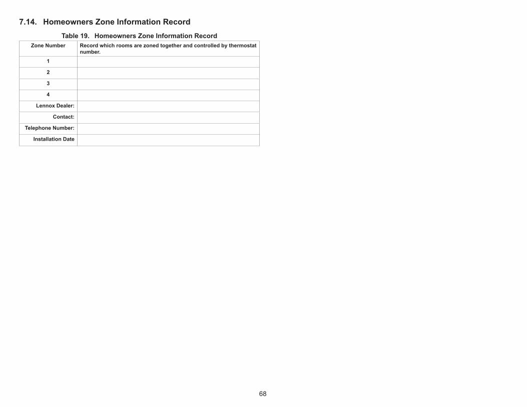
68
7.14. Homeowners Zone Information RecordTable 19. Homeowners Zone Information Record
Zone Number Record which rooms are zoned together and controlled by thermostat number.
1
2
3
4
Lennox Dealer:
Contact:
Telephone Number:
Installation Date