FAQ – AC Motor Drives Industrial Automation - Delta EMEA
81
FAQ – AC Motor Drives Delta Electronics (Netherlands) B.V. De Witbogt 20, 5652AG, Eindhoven, the Netherlands Technical Support contact: [email protected] www.delta-emea.com Industrial Automation
-
Upload
khangminh22 -
Category
Documents
-
view
1 -
download
0
Transcript of FAQ – AC Motor Drives Industrial Automation - Delta EMEA

FAQ – AC Motor Drives
Delta Electronics (Netherlands) B.V.
De Witbogt 20, 5652AG, Eindhoven, the Netherlands
Technical Support contact: [email protected]
www.delta-emea.com
Industrial Automation

2 of 81
Table of Contents
VFD series AC Motor Drives ··························································································3 Motors ·················································································································· 10 VFD-E ·················································································································· 15 VFD-L ·················································································································· 42 VFD-EL ················································································································ 45 C2000/CP2000/CFP2000 ························································································· 48 C200 ···················································································································· 69 MS300 ················································································································· 71 ME300 ················································································································· 77 VFD-ED ················································································································ 78 EMC-PG01O ········································································································· 78 Brake Units ··········································································································· 78 CMM-EIP01··········································································································· 79
AFE Series Active Front End ························································································ 80 AFE2000 ·············································································································· 80

3 of 81
VFD series AC Motor Drives
Q What does the line start lockout function do?
A If Line Start Lockout is disabled, the AC motor drive will run when mains power is switched on if a RUN command was present at power off. If Line Start Lockout is enabled, the AC motor drive does not run when mains power is switched on. It needs a new RUN command after power on. If between power off and power on the source of operation command is changed, the AC motor drive can be set to follow this new status or ignore this and keep the old status.
Q How to dimension brake resistors for VFD?
A Please look for the application note “Dimensioning brake resistors 2008-01.pdf” and AMD Braking.ppsx on ftp-site (Industrial Automation Products\AMD-Options\AMD Brake units & resistors\Application notes for braking).
Q Can two drives in parallel control one motor?
A No, with Delta VFD this is not possible. For this application, drives need to be able to cooperate in master-slave configuration where one drive acts as master with frequency command input and controls the slave gate drive.
Q Reset to defaults via Modbus RS-485 communication doesn’t work. Why?
A When a reset to defaults (e.g in VFD-E Pr00-02=9 (Modbus RTU command 01 06 0002 0009) is performed, all parameters, including the communication parameters, are reset to default. If the settings you use are different from default (Station address, protocol and/or Baudrate), they will be reset to the default values and the communication will fail. Also the source of frequency command and operation command (e.g. Pr02-00 and 02-01 in VFD-E) will be reset to their default values, making it afterwards impossible to control the drive via Modbus RS-485. This is an extra attention point that has to be taken into account when setting up serial communication.

4 of 81
Q Where can I find CAD drawings of the VFD series?
A You can find them on Delta’s download center.
Q How to read/write parameters via serial communication? Which address to use?
A To read/write parameters in the drives via serial communication, the parameter number is also the address. However, the address is in Hex format. Please see examples below: Pr05-14 = 050Dh Pr10-03 = 0A03h
Q When and how are the DC-link capacitors to be recharged?
A The drive’s DC link capacitors need to be recharged if the drive has been non-operational for more than one year. Without recharging, the capacitors may be damaged when the drive is powered up. The recharging methods are introduced in the application note Guide For Capacitor Recharging in Delta AC Motor Drives.pdf which you can download from our ftp-site (Industrial Automation Products\AMD\General VFD\VFD-General Applications).
Q How to select the potentiometer for the AVI analogue input?
A See the circuit diagram and curves below:
GND
AVI
AVI Input Resistance R Ω
Potentio- meter aR Ω
+10V
0%
100%
Assume the AVI input resistance is R Ω and the potentiometer value is aR Ω, where “a” is a ratio. In the curves diagram the black line represents a fully linear response when the potentiometer is moved from 0 to 100%. The green and red curves show the response depending on “a”, the larger “a” is, the
Potentiometer on AVI
0
10
20
30
40
50
60
70
80
90
100
0 10 20 30 40 50 60 70 80 90 100
Potentiometer 0-100%
AVI s
igna
l 0-1
00% a=0.1
a=0.2a=0.5a=1a=2linear

5 of 81
more non-linear the response becomes, see the red curves. As an engineering rule of thumb “a” should be ≤0.1 to have an acceptably linear response, although ≤0.2 is also often accepted. The next consideration is the current that can be supplied by the 10V terminal. This gives the minimum allowed potentiometer value. The lower the value is, the more power is dissipated in the potentiometer, therefore you want to keep the potentiometer resistance as high as possible. Example for VFD-E: - The AVI input resistance is 47kΩ. - Select potentiometer ≤0.1*47k=4.7k. - The 10V terminal can supply 3mA so the minimum potentiometer value is 10V/3mA=3.3kΩ. - So in practice a potentiometer value between 3.3kΩ and 4.7kΩ gives a linear response and will not overload the 10V terminal (if a≤0.2 is accepted, then a potentiometer between 3.3kΩ and 10kΩ (=47kΩ/5) can be used).
Q Which parameters must be set when using the built-in brake chopper or a brake unit?
A The OV stall prevention must be disabled because it would interfere with the brake chopper action and the DC-bus voltage level at which the brake chopper is activated must be set.
VFD-EL VFD-E MS300 ME300 MH300 C2000 C2000
CFP2000 VFD-ED
Disable OV
stall
prevention
Pr06-00=0 Pr06-01=0 n.a.
Set level n.a. Pr08-19 Pr07-00
Q How to connect a 4-20mA sensor to an analogue input?
A 4-20mA sensors have 2 terminals and “source” the current into the input. They need normally a minimum voltage drop of ca. 8VDC. On Delta drives the input impedance of 4-20mA inputs is 250Ω (please refer to the user manual which input can be used for 4-20mA and how to set it).

6 of 81
At 20mA the input voltage is 5VDC. So the total supply voltage must be ≥13VDC (5VDC + 8VDC). The supply voltage must be able to supply at least 20mA. Internal power supply In general the 24VDC power supply terminal can be used, except on VFD-L, VFD-M, VFD-S (A and D version) and VFD-VL. On VFD-B, VFD-E, VFD-F, VFD-S (E version) and VFD-VE the 24VDC terminal can supply 20mA, therefore it depends also on the use of the digital inputs whether 20mA is available.Connection is as follows (also connect DCM to ACM):
+24VDC
ACI 4-20mA
Sensor 4-20mA
DRIVE 20mA max
Voltage drop >ca. 8VDC
+
-
ACM
DCM
External power supply For VFD-L, VFD-M, VFD-S and VFD-VL an external power supply must be used of at least ≥13VDC and ≥20mA. (Delta’s 24VDC power supplies are perfect). For other drives an external power supply can be used. The external power supply must be connected as follows:
ACM/GND
ACI 4-20mA
Sensor 4-20mA
DRIVE 20mA max
Voltage drop >ca. 8VDC
+
- External power
supply ≥ca. 13VDC -
+

7 of 81
Q What are the available control modes in the different drives?
A
Series C2000 CP2000 C200 * B E EL L
V/F OK OK OK OK OK OK OK
V/F+PG OK OK OK OK
Sensorless
OK OK OK OK OK OK
Vector+PG OK OK
FOC+PG for IM OK OK
FOC+PG for PM OK
TQC+PG for IM OK OK
TQC+PG for PM OK
FOC Sensorless
OK OK
PM Sensorless
OK OK
TQC Sensorless
OK OK
Q What is the slip compensation parameter?
A The slip to be compensated in all our drives is calculated as follows:
where Slip = slip to be compensated IL = actual load current INL = no load current IFL = full load current. Rated_slip = the motor rated slip in Hz Slip_compensation = slip compensation factor
In some drives the slip compensation is The setting range is in that case 0.0~10.0 and the rated slip cannot be entered separately
In some drives the slip compensation is The setting range is in that case 0.0~3.0 and the rated slip can be entered separately

8 of 81
Q What is the maximum output frequency with the 599Hz limitation?
A - In VF Mode the maximum output frequency is 599Hz. - In SVC or Vector Mode the maximum output frequency, including slip compensation, is 599Hz. Therefore the max frequency command is 599Hz-Slip ! - In FOC mode (C2000) , the max frequency command is limited to (Fset + Pr10-29)≤599Hz, to make sure the actual output frequency is limited to 599.00Hz.
Q When using a Profibus card how do I change the Baud rate? Do I need to make any changes in the Menu 9 parameters?
A No, the transmission speed is only set in the master configuration (as shown below) and the Profibus slave card will auto-detect the speed.
Q What power cable section to use?
A We often get questions about the power cable cross section that is needed in an application and the relevant info in the user manuals. In our user manuals, we state the cable cross section that the power terminals can accommodate. It doesn’t mean you always have to use the indicated cable.
Example: ME300 Frame B

9 of 81
The maximum cable section that these terminals can accommodate is 12AWG or 4mm2. The minimum cable section that these terminals can accommodate is 18AWG or 0.75mm2. Because the terminals of a frame size are always the same, it means that the power terminals of any ME300 in Frame B can accommodate a wire section between 0.75~4mm2. The actual wire section, that should be used, depends on the application: Current and Cable length. • Very long cables or cables for higher current should be thicker (but in this case not >4mm2). • Short cables or cable for lower current can be thinner (but in this case not <0.75mm2). If you have to or want to use another cable section, please use lugs or ferrules. The same applies to other frame sizes and Delta drives.
10 of 81
Motors
Q Can a 230V 3-phase motor be driven by a 400V drive?
A Yes, no problem. Just set the Max. Output Voltage Pr01-02=230V. The output rms voltage is in this case 230V but the peaks are still 560V (from the DC-bus). But 230V motors in general can handle this.If you use 400V drives, you should select them based on the motor’s rated current.
Q How to preset speeds and master frequency via Modbus?
A When Frequency command by RS-485 and preset speeds are active, all drives will accept a change of the master frequency via RS-485 without 04 error, except VFD-E.
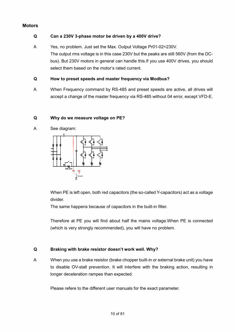
Q Why do we measure voltage on PE?
A See diagram:
When PE is left open, both red capacitors (the so-called Y-capacitors) act as a voltage divider. The same happens because of capacitors in the built-in filter. Therefore at PE you will find about half the mains voltage.When PE is connected (which is very strongly recommended), you will have no problem.
Q Braking with brake resistor doesn’t work well. Why?
A When you use a brake resistor (brake chopper built-in or external brake unit) you have to disable OV-stall prevention. It will interfere with the braking action, resulting in longer deceleration rampes than expected. Please refere to the different user manuals for the exact parameter.

11 of 81
Q Do I need to connect the shielding on one end or on both ends?
A - Motor power cables need to be connected on both ends. - Encoder and control cables need to be connected only at one end. In both cases, the cable shield needs to have a 360° connection.
Below are some examples of proper shielding connection.
Connecting the shield via a pigtail directly to the VFD ground terminal is not acceptable.
Q When using the internal PLC of a VFD, is it possible to use the FPID function block to control other processes? Or can it only be used for the output frequency?
A The FPID can only be used to control the output frequency. However, the onboard PLC does offer two independent PID functions (not in all drives) which can be assigned to any process. These work by using the Special D registers D1200 to D1235 as shown below.

12 of 81
In order to enable these PID functions it is necessary to use the Special M contacts below.
A working example of such a PID function.can be found on our ftp site (Industrial Automation Products\_Delta Application Guide\General information\Built-in PID function).
Q How to read/write from/to the onboard PLC through Modbus TCP and Ethernet IP?
A For the CMC-MOD01 and CMC-EIP01 cards this is supported starting with firmware V1.08 (date code: W1852). The drive firmware needs to be at least: - CP2000 - V2.06 or higher. - CFP2000 - V1.06 or higher. - For C2000 this has not yet been released. For the CMM-MOD01 and CMM-EIP01 cards this is supported starting with firmware V1.04 (date code: W1850) The drive firmware needs to be at least: - MS300 - V1.08 or higher. You can control the onboard PLC registers and contacts directly through station address acc. to Pr09-35.

13 of 81
Q In C/CP2000 and MS300: What is the difference between M1042 Quick Stop and M1044 Pause in the PLC?
A Quick Stop M1042 = 1: Drive will stop with the shortest possible deceleration ramp. M1042 = 0: Drive start enabled. The drive will not restart by itself. Pause M1044 = 1: The drive will stop with the normal deceleration ramp. M1044 = 0: The drive will resume the previous operation with the normal acceleration ramp. The user does not need to restart.
Q How can I read drive series and model by serial communication?
A Read address 2110hex.
Series Code 2110h High byte 2110h Low byte Type
C2000 20 14h
FFh
Read ID in
Pr00-00
(Address 000h)
CP2000 21 15h
CH2000 22 16h
C200 25 19h
CT2000 30 1Eh
CFP2000 42 2Ah
MH300 31 1Fh
MS300 32 20h
ME300 33 21h
MH300-L 48 30h
C2000HS 49 31h
MH300HS 51 33h
MS300HS 52 34h

14 of 81
Series Code 2110h High byte 2110h Low byte Type
VFD-M 0 00h
ID (as in Pr00-00) N/A
VFD-S 1 01h
VFD-B 2 02h
VFD-L 3 03h
VFD-V/VE 4 04h
VFD-F 5 05h
VFD-E 6 06h
VFD-E-C 7 07h
VFD-EL 8 08h
VFD-VL 9 09h
VFD-DD 13 0Dh
VFD-ED 17 11h

15 of 81
VFD-E
Q How to use the PTC function?
A Please ask for the application note “VFD-E PTC.pdf”. It shows how to set up the VFD-E for use with PTC acc. to DIN44081/44082 for motor protection.
Q Can an option card be used together with a fieldbus option on the VFD-E?
A Yes, there is room for one option card and one fieldbus option, which can be mounted together on the VFD-E.
Q What is the function of the dipswitches 1, 2, 3?
A Dipswitch 123
The dipswitches 1,2,3 are meant to be used in case there is no keypad. If you use keypad, its recommended to set all dipswitches to OFF to avoid conflict between parameter settings and dipswitches. The dipswitches have priority. The ex-factory setting of the dipswitches is OFF.
Dipswitch 1 (50Hz defaults) To set to 50Hz defaults. The following parameters are set: Pr01.00=50Hz and Pr01.01=50Hz.
Dipswitch 1 = OFF
The defaults are for 60Hz.When keypad is connected it is possible to set Pr00-02=10 (60Hz defaults and all other defaults) or Pr00-02=9 (50Hz defaults and all other defaults).
Dipswitch 1 = ON
Only Pr01.00=50Hz and Pr01.01=50Hz are set. All other parameters are not influenced. When keypad is connected and Pr00-02=10 then display shows "Err" and no defaults are reset. When keypad is connected and Pr00-02=9 then 50Hz defaults are set but also all other defaults.

16 of 81
Dipswitch 2 (Free run to stop) This sets the stop mode. Its identical to setting Pr02 -02=1. It means the stop mode is free run or coast.
Dipswitch 2 = OFF
When keypad connected Pr02-02 can be set as needed.
Dipswitch 2 = ON
Pr02-02 is set to 1 automatically and when keypad connected other setting results in "Err" on display.
Dipswitch 3 (ACI) This sets the frequency command source to ACI.
Dipswitch 3 = OFF
Pr02-00 sets the Frequency command source, see manual.
Dipswitch 3 = ON
The Frequency command source is ACI 4~20mA, independently of the ACI/AVI dipswitch.
Normally when you set Pr02-00=2 to select ACI/AVI2 and Pr04-19=0 (ACI) or 1 (AVI2), you can select with the dipswitch ACI/AVI the input to be ACI with 4-20mA or AVI2 with 0-10V. If input ACI 4-20mA is selected, either via dipswitch 3 or via Pr02.00=2, Pr04-19=0 (default) with dipswitch ACI/AVI=ACI it gives "Aerr" on display and the FAULT LED lights up because the current is >0mA and <4mA. In case of keypad, the fault "AErr" can be reset by RESET command (via digital input of keypad depending on Pr02.01) provided cause of the fault is removed. The FAULT LED can only be reset by power off/power on, also if the cause of the fault is removed. In case you want to use AVI2, you need to set Pr04-19=1, then Pr02-00=2, then set switch ACI/AVI=AVI to avoid "AErr" error.
Therefore, it is recommended to set all dipswitches 1, 2, 3 to OFF in case you use the keypad.

17 of 81
Q What is the function of the dipswitches ACI/AVI?
A Dipswitch ACI/AVI Normally when you set Pr02-00=2 to select ACI/AVI2 and Pr04-19=0 (ACI) or 1 (AVI2), you can select with the dipswitch ACI/AVI the input to be ACI with 4-20mA or AVI2 with 0-10V. In case you want to use AVI2, you need to set Pr04-19=1, then Pr02-00=2, then set switch ACI/AVI=AVI to avoid "AErr" error. The delivery condition is ACI.
Q What is the function of the dipswitch NPN/PNP?
A It can be used to select the Digital Inputs as NPN (sink) or PNP (source). Dipswitch NPN/PNP=PNP The Digital Inputs are PNP (source), see user manual (Sensorless Vecotr Control Compact Drive VFD-E Series user manual). Dipswitch NPN/PNP=NPN The Digital Inputs are NPN (sink), see user manual (Sensorless Vecotr Control Compact Drive VFD-E Series user manual). The delivery condition is NPN.
Q Does the option card EME-D33A have PNP inputs?
A Yes, it can be used for PNP inputs. On the card there’s a switch J1 to select PNP or NPN.
Q Why is Parameter group 11 not visible?
A Parameter group 11 is meant for setting parameters for options. It will become visible and accessible when an option card is installed and recognized. Please remember to switch off the power when installing option cards.
Q When I read AVI in a PLC program, why does it not work for frequency command?
A When any digital input/output or any analogue input/output is used in the PLC program, it loses its normal function. For example, if Pr02.00=1 (frequency command via AVI) and AVI is read in the PLC

18 of 81
program by reading D1028, then it doesn’t work for frequency command anymore. In that case, the PLC program needs to include functionality to let the AVI input also function for frequency command.
Q How to save variables in the PLC at power off?
A The VFD-E PLC cannot save variables when it is power off. However, by writing the variable to an unused parameter, e.g. the Preset Speeds, it can be done. Writing Constant K1 to Pr05.14:
Reading Pr05.14 and move to register D20:
Q How to set a 0.01Hz frequency step for the UP/DOWN mode?
A You can set Pr02-07=3, then each time the up/down input is activated, the change is acc. to Pr02-08, so each step is from 0.01Hz to 10Hz. Since the output frequency display has only resolution of 0.1Hz, you need 10 steps to notice a change on the display. You can set Pr02-07=2. Then the rate of change of the output frequency is acc. to Pr02-08, so from 0.01Hz/ms to 10.00Hz/ms. Of course, you need to set Pr02-00=0 for UP/DOWN operation.
Q How to read the PID feedback value via serial communication?
A Set Pr00.04=5 (PID feedback value 0-100%) At address 2116H you can read this value. In general: At address 2116H you can read the value as selected by Pr00.04.
Q Why does Pr00.04=6 show strange behaviour?
A Pr00.04=6 shows the power factor angle in ° (degrees) and not cosphi !

19 of 81
Q How to set a negative slope in AVI-input?
A This is not possible. The parameters Pr04.00 ~ Pr04.03 can only be used to set Bias and Gain of the front potentiometer on the keypad. In the examples, however, it is inadvertently suggested that it also is possible for the AVI-input. And with Pr04.11 ~ Pr04-14 it is also not possible, because Pr04.12 must be lower than Pr04.14. (the same applies to the settings of ACI and AVI2).
Q How to set PID?
A To set-up PID do the following: Pr10-00 to select the PID set point (not via Pr02-00 as e.g. in VFD-B) Pr10-01 to select the feedback input and positive or negative feedback [ negative means error=setpoint – feedback ] [ positive means error=feedback – setpoint ]
Q What is the difference between “AErr” and “FbE” error messages?
A Both messages are generated when the signal on the ACI input is lost. Normally, when using 4-20mA, if the signal is <4mA. In normal operation (no PID) with the frequency command via ACI (Pr02-00=2) the blinking warning “AErr” (Analogue Error) can be displayed when the signal is lost. In Pr02-06 the required action can be set. The detection cannot be set and is immediate.
Pr02-06=0. When feedback on ACI is lost, the drive ramps to stop. After reconnecting ACI the drive goes back to the set frequency.
Pr02-06=1. When feedback on ACI is lost, display shows blinking "AErr" and coasts to stop. After reconnecting ACI it becomes steady. Press reset, give new RUN command, and it runs again to the set frequency.
Pr02-06=2. When feedback on ACI is lost, the drive goes to last frequency command value without any warning on display. After reconnecting ACI the drive goes back to the set frequency.
When using PID with the feedback signal on ACI, the VFD-E can show the warning “FbE” (Feedback Error) when the feedback signal is lost. The detection time is set in Pr10.08. The default value is 60s, so in that case it will take 60s before the warning is

20 of 81
displayed.The required action in case the signal is lost can be set in Pr10-09.
Pr10.09=0. When feedback on ACI is lost, display shows blinking "FbE" and ramps to stop after 60s, after reconnecting ACI it remains blinking. Press reset, give new RUN command, and it runs again.
Pr10.09=1. When feedback on ACI is lost, display shows blinking "FbE" and coasts to stop after 60s, after reconnecting ACI it remains blinking. Press reset, give new RUN command, and it runs again.
Pr10.09=2. When feedback on ACI is lost, display shows blinking "FbE" after 60s. Because no feedback, the output goes to max frequency, after reconnecting ACI it goes immediately back to normal PID control.
Q How does the mechanical brake output function in case of faults?
A Normally the brake will be engaged after a STOP command and if the frequency is lower than the value set in Pr03.12. After one of the faults OV, OC, LV an internal STOP command is given and because the motor coasts to 0Hz, the output frequency is immediately 0Hz and lower than value of P03.12, therefore the brake engages also immediately. Upon external fault EF, also an internal STOP command is given but because the drive ramps to 0Hz, the brake will be engaged when the frequency drops below the value of Pr03.12. Please set one of the outputs MO1 (Pr03.01) or RA-RC (Pr03.00) to 21 for mechanical brake control. The frequency values for brake engage and brake release can be set in Pr03.11 and Pr03.12 respectively.
Q How to clear the status of MI3 when 3-wire operation is selected (Pr04.04=2)?
A When MI3 is on (active) and when Pr04.02=2 to select 3-wire operation, MI3 keeps its status. To clear this, please power off and power it on again.

21 of 81
Q How to connect the new PLC editor WPLSoft to VFD-E?
A If you haven’t done so, please download the latest version of WPLSoft from our website and install it. Step 1: Start the program.
Step 2: Open Options/Communication Setting
Step 3: Select RS-232. If you use VFD-USB01, please connect your computer to the VFD-E. Step 4: Select the right COM port, this depends on your computer. Step 5: Select the right Station Address. It must be equal to VFD-E Pr09.00. Step 6: Press Autodetect. The communication settings are now automatically detected and the message as shown on the right appears.

22 of 81
Step 7: Open a project with File/Open.
Step 8: Select Options/Change PLC Type and select VFD-E and press OK. Note: VFRD-Eplus now has 500 steps (was 350)
Step 9: On VFD-E press the MODE key several times until the display shows [PLC0]. With the or keys change to [PLC2] and press ENTER. VFD-E is now ready to receive a PLC-program.

23 of 81
Step 10: Select Communication/Transfer Setup.
Step 11: Select PC => PLC and press OK
Step 12: The transfer progress is shown as follows:
Step 13: After completion of the transfer please set VFD-E with the or keys to [PLC1] and press ENTER for standalone operation or leave at [PLC2] for online operation and monitoring. Please refer to the user manual (Sensorless Vecotr Control Compact Drive VFD-E Series user manual) for further details.

24 of 81
Q Can individual inputs be inverted, so they can be operated from NC contacts?
A Yes, refer to the user manual, Pr04-09. Normally they are set for NO (Normally Closed) contacts (input is activated when contact is closed). Please see the example below: Inputs MI2 and MI5 too be set for NC (Normally Closed) contacts, e.g. when used for EF. Pr04-09=18 (= 010010 binary).
Q Does Pr07-03 Slip Compensation have to be set in Vector Mode?
A No, when the control mode (Pr00-10) is changed from V/f to Vector, Pr07-03 is automatically set to 1. When the control mode is changed from Vector to V/f, Pr07-03 is set to 0.0. If slip compensation is to be used in V/f mode, Pr07-03 must be set normally to 1.0. In order to have good slip compensation, please set Pr07-00, Pr07-01 and Pr07-06 to the right values and execute an Autotune (Pr05-00) for optimal vector mode performance.
Q OL in PLC2 mode: How to reset?
A When VFD-E works in PLC2 mode and OL is displayed, it will be reset after power off/on.
Q What is the best way to set up Master-Slave operation?
A One VFD-E, the master, needs to control three VFD-E (we call them slaves). The best way is to connect the AFM output the master to all AVI inputs of the slaves, which are thus all connected in parallel.
The VFD-E AFM output can do 10V/2mA, so the maximum load resistance is 10V/2mA=5kΩ. The AVI input impedance is 47kΩ. If you put 3 inputs in parallel, the total resistance

25 of 81
is 47k/3=15.67kΩ. (Or, each input takes 10V/47k=0.2mA. Three inputs in parallel take 3x 0.2mA = 0.6mA, well below 2mA). It is best to tune the AFM output to have exactly 10V at 50Hz (or max freq) by Pr03.04. Then, to tune each AVI input to give 50Hz at 10V by using Pr04-13 and Pr04-14. This way gives much better performance and linearity. We DO NOT recommend to connect the AFM output of the master to the AVI input of the first slave, its AFM output to next slave’s AVI input, etc. Because of the AVI input resolution of 10 bits and the AFM output resolution of 8 bits, this will lead to unacceptable errors in the command frequency of the slaves
Note: This applies to other drive series as well (not all VFD have 0-10VDC AFM outputs but
some have PWM which is unsuitable for master-slave operation).
Q What is the maximum voltage on analogue input AVI?
A The maximum voltage in AVI is 15 VDC.
Q How to read AVI and ACI via serial communication?
A In register A7C0h you can read AVI and in A7C2h you can read ACI, both from 0-3FFh=0-1023d. (There is no such solution for AVI3, AVI4, ACI2 and ACI3 on option card EME-A22A.)
Q What is the maximum frequency of the digital inputs MIx when set to 12 for counting?
A Due to the internal debouncing delay of 6ms, the maximum frequency is
( ) HzmsOFFmsON 33.83661 =+ .

26 of 81
Q How can I read the EME-A22A analogue inputs in the PLC?
A AI1 can be read in D1031 and AI2 can be read in D1032.
Q What does fault code 42“AcL” mean?
A “AcL” means communication error between power board and control board in STOP mode and “CP10” means communication error between power board and control board in RUN mode.
Q Why does the display show PLSn error?
A If there’s no PLC program loaded and the drive is accidentally set to PLC1 or PLC2, the PLSn error is displayed (all PLC error messages are mentioned in the Sensorless Vector Control Compact Drive VFD-E Series User Manual - Appendix D. To solve this, please set the PLC mode back to PLC0.
Q Does the option card EME-D33A have PNP outputs?
A No, the outputs are always NPN. The inputs, however, can be set to NPN or PNP.
Q Where can I get the eds file for CME-COP01?
A Download the file VFD-E Drives.eds from our ftp-site in the folder (AMD-Options/AMD Fieldbus options/CANopen/CME-COP01/EDS for CME-COP01).
Q Pr00-03 setting is different in the summary and description, which one is correct?
A There is a difference in the settings for Pr00-03 in the Summary of Parameter Settings and in the Description of Parameter Settings. The latter one is correct. It will be corrected in the next version of the user manual (Sensorless Vecotr Control Compact Drive VFD-E Series user manual).
Q How to set the range 30-50Hz for the front potentiometer?
A This is not possible. If Pr04-00=100% and Pr04-02=50%, only 25-50Hz can be achieved because the bias can only be 100%. (With AVI it is possible by setting Pr04-11 to 04-14).

27 of 81
Q EME-A22A: How to set 4-20mA for the analogue inputs?
A Please refer to Pr12.20 and Pr12.23 in the manual (Sensorless Vecotr Control Compact Drive VFD-E Series user manual) to select 0-20mA or 4-20mA.
Q When Pr10-01=1, the PID set-point is via front potentiometer, but the manual says via UP/DOWN keys, why?
A This is an error in the manual (Sensorless Vecotr Control Compact Drive VFD-E Series user manual). When Pr10-01=1, PID set-point is acc. to Pr02-00, but in that case only 1 (UP/DOWN keys) or 4 (front potentiometer) can be selected.
Q Register D1029 in the PLC shows wrong info
A This is an error in the manual (Sensorless Vecotr Control Compact Drive VFD-E Series user manual). When ACI 4-20mA is selected, the range of 4-20mA corresponds to 205-1023. 0-20mA corresponds to 0-1023.
Q How to read a PLC register via Modbus?
A It is not possible to read a PLC register directly via Modbus, but it can be done with the following workaround. Assume your data are in Register D5. With instruction WPR write the value of D5 to an unused parameter, e.g. Preset Speed 15 in Pr05-14. Then read address 050D (the address of Pr05-14) by Modbus.
Q How to use and scale the analogue output AFM in the PLC program?
A The analogue output AFM can be used by putting the value in register D1040. The range is 0-10V=0-65535. The PLC cannot handle unsigned numbers >32767, therefore, first division by 2 and then by 32767 is used. The loss of resolution is acceptable because the real AFM resolution is 8 bits. An example to output the output frequency on AFM, scaled to 0-10V=0-Fmax:

28 of 81
If needed the AFM output voltage can be adjusted by Pr03-04.
Q How to use preset speed as PID setpoint?
A The preset speeds can be used as follows as PID setpoint. Pr05-00=15 Preset speed 1=15Hz Pr05-01=25 Preset Speed 2=25Hz Pr05-02=35 Preset Speed 3=35Hz (to have 3 set points) Pr04-05=1 MI3=Select Preset Speed 1 Pr04-06=2 MI4=Select Preset Speed 2 (to select different setpoints) Pr10-03=3 (to use AVI2 as setpoint if no preset speeds are selected) Pr10-01=1 (to use AVI as negative feedback) If you Run the drive, it will use either AVI2 as setpoint (MI3=Off, MI4=Off) or a preset speed (MI3=On and/or MI4=On).
Note: Bear in mind that in this case the preset speeds are not speeds or frequencies but PID
setpoints. For example, 15Hz means 15/50=30%, 35Hz means 35/50=70%.
Q Is it possible to use EME D33A with NPN mode and use VFD-E terminal with PNP mode?
A Yes, it is possible. Bear in mind that the 24V on the control board is the same as the 24V on the option card. Also, both DCM terminals are the same.

29 of 81
Q On EME-D33A, is it possible to switch between NPN and PNP?
A The inputs can be switched from NPN to PNP by the switch. The outputs are NPN only with MCM as common.
Q How to read the analogue inputs and outputs of EME-A22A?
A Both inputs and outputs can be read via the following PLC registers (it is not possible to read them directly via Modbus): D1031 AI1 D1032 AI2 D1041 AO1 D1042 AO2
Q When writing to 2002hex, BaseBlock is set. Why?
A BaseBlock is set when Bit2 of 2002hex is set to 1. The definition of 2002hex is: Bit0 EF on Bit1 Reset Bit2 BaseBlock on. Bit3~Bit15 Unused. When writing, best set to 0.
Q How does line-start lock-out work?
A When Pr02-01=1 or 2 (line-start lock-out only works when operation command is via terminals), Pr02-05=0 or 2 and Pr08-04=1 or 2 it works as follows:
As long as the display is normal and the power comes back, the drive continues.
As the display shows LV and the power comes back within the time Pr08-05, the drive runs (with speed search acc. to Pr08-04). In firmware 2.14 the Pr08-05 max setting range is 20s, previously it was 5s.
As the display shows LV and the power comes back after time Pr08-05, nothing happens. The drive needs to finish its internal LV process (save parameters etc). It needs a new RUN command.
When the drive is powered off and "dead", then, with Pr02-05=0 or 2, the drives

30 of 81
starts running when the power comes back, provided there’s an active RUN command.
Q How to display the motor speed in rpm?
A To be able to display the speed in rpm, an encoder must be used (and the option card EME-PG01). Pr00-04=14 (Press MODE until display shows [G xxx]. (When Pr00-03=3, it shows the value as selected by Pr00-04 as start-up display). Please set Pr13-00, Pr13-01, Pr13-02 acc. to the used encoder.
Q Which parameters can be used to save data (RS-485 or PLC)?
A In principle any unused parameter can be used to save data. In Newsletter 2007-01 it was suggested to use the Preset Speeds (Pr05-00 to 05-14) for this but these parameters are saved in EEPROM (written) whenever they are changed. It could lead to exceeding the number of EEPROM write operations and fault cF1.0 or cF2.0. Therefore, it is better to use (one of) the following parameters hereafter, they are not used in their original function. Pr01-11; Pr01-12; Pr01-13; Pr01-14; Pr02-11; Pr02-12; Pr10-02; Pr10-03; Pr10-04. They are only saved at power off.
Q Is it possible to use option card EME D33A with NPN inputs and use VFD-E with PNP inputs?
A Yes, this is possible. Bear in mind that the 24V on the control board is the same as the 24V on the option card, also DCM on both are the same.
Q Where can a warning be read by serial communication?
A In address 2100hex both warnings and alarms are saved. The MSB (Most Significant Byte) contains the warning code. The LSB (Least Significant Byte) contains the alarm code. Please see examples below: 2100hex = 0D00hex (PTC2 warn code 13) 2100hex = 0022hex (PTC1 fault code 34)

31 of 81
Q How to set a digital input for NC operation?
A Normally the digital input is activated when the input is closed (to DCM for NPN inputs or to 24V for PNP inputs). Sometimes it is useful to activate an input when its contact is opened (NC operation), For instance, when an input is used for EF and the connected switch (or clixon) opens in case of a fault. In that case, please set Pr04-09. Example: MI5 and MI3 need to be NC; MI1, MI2, MI4, MI6 need to be NO. Please refer to the user manual for Pr04-09:
010100bin = 20dec, therefore set Pr04-09=20.
Q What does fault code AcL mean?
A AcL is the same as CP10. Both indicate that the communication between control board and power board is abnormal. This can be caused by a bad connection, EMC or even defect IGBTs. AcL is detected during power up and initializing and CP10 is detected during normal operation.
Q What is the max. frequency for a digital input and for the PLC counter?
A The normal counter, such as Pr03-05 and 03-06, has a maximum input frequency of 250Hz (2ms high, 2ms low) acc. to the VFD-E manual but in reality ca. 80Hz. The hi-speed counter in the PLC uses the signal from the encoder card, it cannot use normal inputs. In Chapter D.4.6 of the VFD-E manual a single pulse signal the frequency can be 500 kHz. An encoder with A and B channels. it can be 30kHz (so n*60*ppr<30kHz where n=shaft rpm).
0

32 of 81
Q Which brake resistors to use for VFD-E ?
A The brake resistors are given in the VFD-E manual (Chapter B1) but not all types are specified or stated. You can either buy it locally or "build" them from several individual brake resistors. Please also refer to the Datasheet Brake Res Version8 Mar2019.pdf on the ftp-site (Industrial Automation Products\AMD-Options\AMD Brake units & resistors\Brake resistors for available types). Remember the total resistance must never be lower than the indicated minimum and the power maybe higher.
Q How to make AVI=0-10V=Fmax-0 (reversed)?
A In 1.15/2.15 and higher it is possible in a normal way. Pr04-11=0, Pr04-12=100%, Pr04-13=10, Pr04-14=0.
Q Which parameters are only saved in EEPROM at power-off and not when changed?
A The following parameters are only saved in EEPROM at power off and can be used in a PLC program to avoid frequent writing by serial communication or WPR instruction: Pr01-09 1st Acc time Pr01-10 1st Dec time Pr01-11 2nd Acc time Pr01-12 2nd Dec time Pr01-13 JOG Acc time Pr01-14 JOG Dec time Pr01-17 S-Curve Acc time Pr01-18 S-Curve Dec time Pr10-02 P value of PID function Pr10-03 I value of PID function Pr10-04 D value of PID function Pr10-12 PID set point
Besides, VFD-E offers two parameters, P09-05 and P09-06, for temporary buffer. Users can use WPR to write to these parameters. However, these parameters will not be written to EEPROM when power off.

33 of 81
Q Is it possible to use CME-USB01 to connect to WPL and at the same time use RS-485 port for control of the drive (by an external PLC or even VFDSoft)?
A Yes, they can be used at the same time.
Q After OV fault the drive doesn’t restart. Why?
A E.g. Pr08-15=3 and Pr08-16=30. The auto-reset function ONLY works in RUN status. For example, if the DC-bus voltage rises during deceleration and the drive trips on OV, the drive automatically restarts when the DC-bus voltage goes back to its normal level. But if the drive is stopped, the auto-restart function doesn’t not work because the drive is then in STOP status.
Q How to unlock the keypad when Pr00-02=8?
A Pr00-02=8 locks the keypad. To unlock it, press and hold the ENTER key for 5 seconds to temporarily unlock the keypad. Then set Pr00-02=0 to unlock the keypad. You can also set Pr00-02=0 via VFDSoft.
Q What is the difference between Pr00-04=0 and Pr00-04=16?
A Pr00-04=0: Display shows [Output Frequency * Pr00-05] Pr00-04=16: Display shows [Frequency Command * Pr00-05]
Q How to restart at power on?
A From one of our customers who wanted a reliable solution to RUN the drive after a short or long mains power interruption. DCM to MCM and connect MO1 to MI1. Then set parameter Pr03.01=22 (Drive Ready). Leave Pr02-05, 08-04 and 08-05 at their default values. This ensures a new RUN command every time after power on. Note: As long as other Delta drive series also have a “Drive Ready” signal, this method can be
used, even with a Relay output.

34 of 81
Q When is FbE fault generated?
A FbE (feedback error) is generated when the signal on ACI (4-20mA) is lost (input < Pr04-15 during > Pr10-08 seconds). In Pr10-09 you can set the response. When Pr10-09=2, the drive keeps running and FbE is automatically cleared when feedback is normal again. When Pr10-09=0 or 1, the drive stops and you have to reset.
Q How does PID offset detection (Pr10-12/10-13) work?
A The PID Offset is the absolute value of the difference between setpoint and feedback in %. So, PID Offset is |setpoint – feedback|. The PID Offset can be set in Pr10-12. The detection time is in Pr10-13. Please see the example below: Pr10-12=10%, Setpoint is 50%. When feedback is <40% or >60% a signal is generated after the time in Pr10-13. The signal can be output via relay or MO by setting Pr03-00/Pr03-01=16.
Q What is the function of Pr08-28?
A VFD-E Pr08-28 is the same as VFD-F Pr01-22. When Pr08-28>100%, it will increase output voltage limitation. Please see the function block diagram below for reference.
Limitation 1: IF V>Pr08-28*(Minimum of VAC and Pr01-02) then V= Pr08-28*(Minimum of VAC
and Pr01-02)
Limitation 2: IF V>Pr08-28*( Pr01-02) then V= Pr08-28*( Pr01-02),where VAC is based on
average DC-bus voltage.
*Vm: voltage command for modulation

35 of 81
Q What is the effect of the S-curve settings?
A Pr01-17 must be smaller than Pr01-09/01-11 and Pr01-18 must be smaller than Pr01-10/01-12. Higher values of Pr01-17/01-18 will have no effect.
Q Why does DC-braking not work at start-up?
A When started with frequency command < Fmin, DC braking doesn’t work. The frequency command must be >Fmin. Acc. to the picture in the manual (Sensorless Vecotr Control Compact Drive VFD-E Series user manual)
DC-braking should be always on when Fcommand<Fmin. But that could mean that DC-braking is
on for a very long time. We took precaution to prevent this.
Q When is OH1 activated/deactivated?
A OH1 activates at 85°C. It will be deactivated at 85° - 5° = 80°C.
Q How to restart after LV?
A In the latest firmware 1.22/2.22 and higher the setting of Pr02-05 has been extended. When Pr02-05=4, the drive restarts also when powered again during “LV” and also during “LV” the RUN command on MI1/MI2 is interrupted. Valid when Pr02-01=1 or 2.
Q In PLC Mode, the drive always starts with [PLC1] or [PLC2] display, despite Pr00-03 setting. Why?
A When PLC1 or PLC2 mode is activated, the setting of Pr00-03 is changed to 5, so the start-up display is always PLC1 or 2.

36 of 81
Q How to reset VFD-E with a Modbus Multi-write instruction?
A 01 10 2000 0003 06 0011 1388 0002 Doesn’t allow to reset the drive, gives error message. 01 10 2000 0003 06 0000 1388 0002 Allows to reset the drive.
Q How to set the PLC registers D1041 and 1042?
A The PLC registers D1041 (AO1) and D1042 (AO2) can be set as follows: Set switch to 0~10V: D1041 = 0000hex AO1 will output 0V FFFFhex AO1 will output 10V Set switch to 0~20mA: D1041 = 0000hex AO1 will output 0mA FFFFhex AO1 will output 20mA Here is an example program showing how to set values >32767:
Q How to set Pr10-00 for PID set-point?
A In VFD-E Pr10-00=1 means it follows Pr02-00 setting. Pr10-01=1 and: Pr02-00=0: Setpoint via keypad UP/DOWN Pr02-00=1: Setpoint AVI (same as Pr10-00=2) Pr02-00=2: Setpoint ACI (same as Pr10-00=3) Pr02-00=3: Setpoint via comm Pr02-00=4: Setpoint via front potmeter

37 of 81
Q What is the function of register 210Ch~210Fh ?
A 210Chex: AVI 0~3FFhex or 0~1023dec 210Dhex: ACI or AVI2 0~3FFhex or 0~1023dec 210Ehex: ACI2 or AVI3 0~FFFhex or 0~4092dec 210Fhex: ACI3 or AVI4 0~FFFhex or 0~4092dec
Q EME-PG01: What is the number of output pulses on A0 and B0?
A The ratio of input/output pulses is 1:1.
Q How to switch between two different setpoints for PID?
A Pr00-02=9 (50Hz default) Pr02-00=1 Pr04-19=1 and switch AVI to use ACI=AVI2 0-10V for feedback Pr05-00=25Hz (=50% setpoint) Pr08-00=1 (setpoint acc. to Pr02-00) Prt08-00=3 (neg feedback on AVI2) Pr04-05=1 (MI3) So the setpoint can be switched between AVI and Preset1 (value in Pr05-00 and active via MI3).
Q How to preset speed and master frequency via Modbus
A When Pr02-00=3 (Frequency command by RS-485) and preset speed are active (Pr04-05 to -08, Pr05-00 to –14, MI3~6 active), the drive doesn’t accept a change of the master frequency via RS-485 and gives 04 error. It keeps the last frequency command value before preset speeds were activated.
Only when MI3~MI6 are off (no preset speed selected), you can change the master frequency by RS-485.
Q Does MKE-EP fit on all VFD-E?
A MKE-EP only fits on Frame A, B and C. It does not fit on Frame D

38 of 81
Q What is the 2101h bit assignment?
A Bit 7 shows “reserved” in the manual but its assignment is Operation via External Terminals. When Bit7=1, operation is via external terminals. The other bits “reserved” are not assigned.
Q VFD-E brake units: BUE or VFDB?
A In the VFD-E user manual (Sensorless Vector Control Compact Drive VFD-E Series User Manual), the brake units are stated as VFDB. This is an error. It should be BUE.
Q What is the meaning of [PLor] on the display?
A PLor happens when the PLC memory is really empty. In PLC0 Mode the message should disappear. In PLC1 or 2 mode, you can solve the issue by uploading a simple program which only includes the END instruction.
Q What is DEV fault?
A DEV means the PID feedback deviates too much from the setpoint. This is not in the manual but it works. The function is the same as in VFD-EL. The level and time can be set in Pr10-12/10-13 and when it is exceeded the display showing the warning [Dev]. Pr03-00=16 activates the relay.
Pr06-08

39 of 81
Q How to activate an output/relay in case of a warning?
A Set Pr03-00/03-01=20.
Q Why does Pr07-01 display the wrong value?
A This is a bug in firmware 1.23/2.23. After setting Pr07-01, it shows the wrong value after power off/on. The internal value of Pr07-01 is still correct, only the display value is wrong. It will be corrected in the next firmware.
Q How does OPL work and which parameters to set?
A See user manual (Sensorless Vecotr Control Compact Drive VFD-E Series user manual) but some parameter descriptions and explanations are not correct.
Ramping will be done by DC-braking.
Same as Pr06-46 in C20000/MS300. It should be “Detection Time of Output Phase Loss”

40 of 81
This is “Detection Current Level”. 100% is drive rated current. Setting range 0~100.0% with default 2.0%. When the setting is 0.0%, there’s no OPL detection.
When Pr06-13=1, the drive will decelerate (ramp down) by DC-braking (This is the only way because only 2 phases are available). The DC-brake current level is set in Pr08-00. During DC-braking (also when set acc. to Pr08-01 ~ Pr08-03), there is no OPL detection.
Summary
When the phase current is <Pr06-15 for Pr06-14 time, you get OPL with action acc. to Pr06-13.
Ramping down (decelerating) is done by DC-braking with current level acc. to Pr08-00.
During DC-braking action or when Pr06-15=0, there’s no OPL detection.
Q Can I see in the PLC which keypad button is pressed?
A Yes, see D1015.
As long as the button is pressed, the relevant bit in D1015 is set. The buttons keep their original function. Please see the example below:
Press RUN (Bit 2)

41 of 81
Press STOP (Bit 1)
Press UP (Bit 5)
Press DOWN (Bit 6)
Press MODE (Bit 0)
Press ENTER (Bit 7)
42 of 81
VFD-L
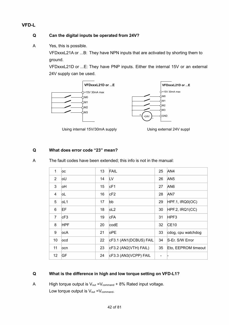
Q Can the digital inputs be operated from 24V?
A Yes, this is possible. VFDxxxL21A or ...B: They have NPN inputs that are activated by shorting them to ground. VFDxxxL21D or ...E: They have PNP inputs. Either the internal 15V or an external 24V supply can be used.
+15V 30mA max
M0
M1
M2
VFDxxxL21D or ...E
M3
GND
M0
M1
M2
VFDxxxL21D or ...E
M3 +24V
+15V 30mA max
+ −
Using internal 15V/30mA supply Using external 24V suppl
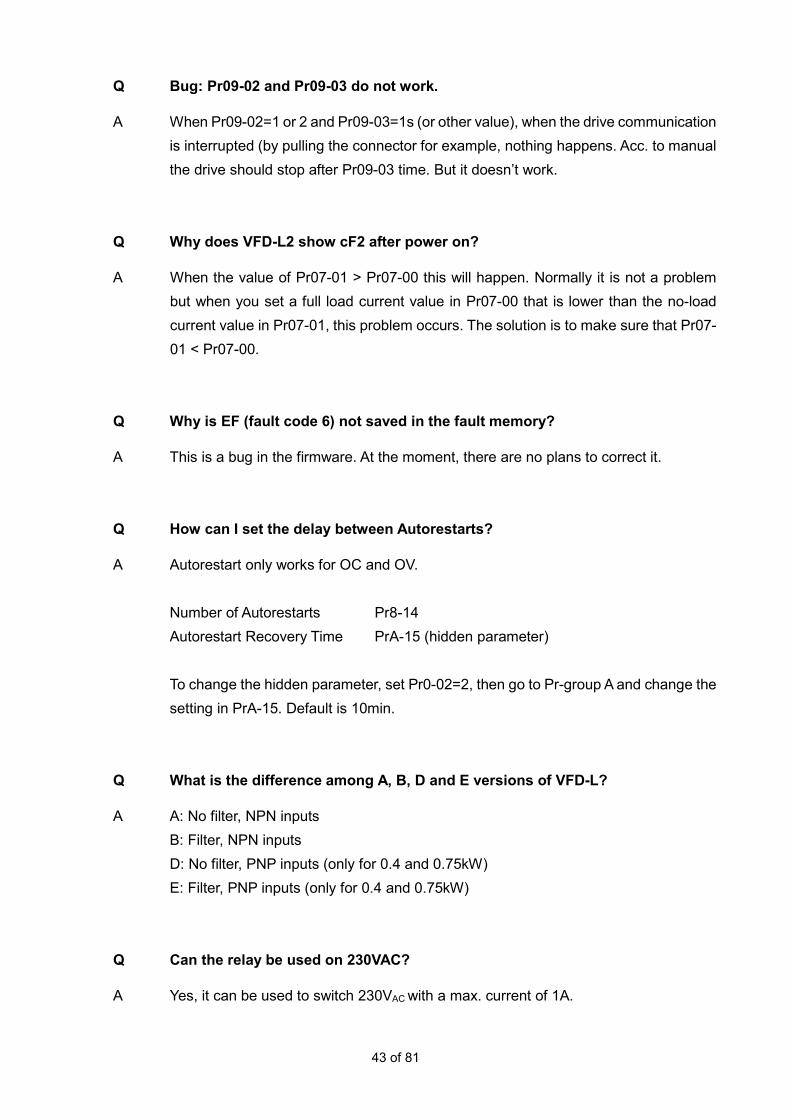
Q What does error code “23” mean?
A The fault codes have been extended; this info is not in the manual:
1 oc 13 FAIL 25 AN4
2 oU 14 LV 26 AN5
3 oH 15 cF1 27 AN6
4 oL 16 cF2 28 AN7
5 oL1 17 bb 29 HPF.1, IRQ0(OC)
6 EF 18 oL2 30 HPF.2, IRQ1(CC)
7 cF3 19 cFA 31 HPF3
8 HPF 20 codE 32 CE10
9 ocA 21 oPE 33 cdog, cpu watchdog
10 ocd 22 cF3.1 (AN1(DCBUS) FAIL 34 S-Er. S/W Error
11 ocn 23 cF3.2 (AN2(VTH) FAIL) 35 Eto, EEPROM timeout
12 GF 24 cF3.3 (AN3(VCPP) FAIL - -
Q What is the difference in high and low torque setting on VFD-L1?
A High torque output is Vout =Vcommand + 8% Rated input voltage. Low torque output is Vout =Vcommand.
43 of 81
Q Bug: Pr09-02 and Pr09-03 do not work.
A When Pr09-02=1 or 2 and Pr09-03=1s (or other value), when the drive communication is interrupted (by pulling the connector for example, nothing happens. Acc. to manual the drive should stop after Pr09-03 time. But it doesn’t work.
Q Why does VFD-L2 show cF2 after power on?
A When the value of Pr07-01 > Pr07-00 this will happen. Normally it is not a problem but when you set a full load current value in Pr07-00 that is lower than the no-load current value in Pr07-01, this problem occurs. The solution is to make sure that Pr07-01 < Pr07-00.
Q Why is EF (fault code 6) not saved in the fault memory?
A This is a bug in the firmware. At the moment, there are no plans to correct it.
Q How can I set the delay between Autorestarts?
A Autorestart only works for OC and OV. Number of Autorestarts Pr8-14 Autorestart Recovery Time PrA-15 (hidden parameter) To change the hidden parameter, set Pr0-02=2, then go to Pr-group A and change the setting in PrA-15. Default is 10min.
Q What is the difference among A, B, D and E versions of VFD-L?
A A: No filter, NPN inputs B: Filter, NPN inputs D: No filter, PNP inputs (only for 0.4 and 0.75kW) E: Filter, PNP inputs (only for 0.4 and 0.75kW)
Q Can the relay be used on 230VAC?
A Yes, it can be used to switch 230VAC with a max. current of 1A.

44 of 81
Q What is the class and max. motor length for VFD-L2?
A For VFDxxxL21B/E the class is EN61800-3:2011 C2 with 10m shielded motor cable both for conducted and radiated emission.
Q How do Pr06-02, 06-03 and 06-04 work together?
A OL2 happens always when output current >Pr06-03 for time Pr06-04 and the conditions below are met. Pr06-02=1 or 3: When OL2 occurs, the drive keeps running and no warning message on the display. You can set Pr03-03=4 for the relay to activate in that case. Pr06-02=2 or 4: When OL2 occurs, the drive stops and ”OL2” is displayed. You can set Pr03-03=4 for the relay to activate in that case. Pr06-02=1 or 2: OL2 happens when output frequency ≥ command frequency (H≥F) Pr06-02=3 or 4: OL2 happens when output frequency < command frequency (H<F). So during acceleration.
Q Which Modbus commands are available?
A 03 = read N words 06 = write 1 word 08 (loop detection) and 10 (write multiple registers) are not available.
Q Does VFD-L have brake chopper built-in?
A No. The VFD-L manual is wrong. This parameter has no function.

45 of 81
VFD-EL
Q Pr00-03 setting is different in the summary and description, which one is right?
A There is a difference in the settings for Pr00-03 in the Summary of Parameter Settings and in the Description of Parameter Settings. The latter is correct. It will be corrected in the next version of the user manual.
Q Is it possible to get AErr message when the PID feedback signal on ACI is lost?
A No, when the ACI input for PID feedback is used, you cannot get “AErr” message. Instead, you can have FbE (FeedbackError) message, see Sensorless Vector Control Micro Drive VFD-EL Series User manual - Chapter 6. You have to set Pr10-01 and then set Pr10-08 and 10-09 accordingly. You can set an output to 20 to have a signal in case of FbE.
Q How to read the PWM AFM output by a digital voltmeter?
A On VFD-EL the AFM output is a 1kHz PWM signal, which is suitable for read-out by an analogue voltmeter but not always by a digital voltmeter. The signal can be smoothed by a 100kΩ/100nF combination. This is only suitable for high-impedance digital voltmeters or equipment.
Q Is it possible in VFD-EL to read AVI and ACI directly via Modbus?
A Yes, it is possible. 210Chex AVI 210Dhex ACI
Q How to set a range of 3~50Hz on AVI 0~10V?
A Pr04-11=0.00V Pr04-12=6.0% (3Hz is 6% of FMAX=50Hz in Pr01-00) Pr04-13=10.00V Pr04-14=100.0% (50Hz is 100% of FMAX=50Hz in Pr01-00)

46 of 81
Q When are parameters saved in EEPROM?
A We save the parameters in EEPROM at power off, except some special frequently written parameters, such as Fcmd & Fpid. They are written in RAM.
Q How to set Pr10-00 for PID set-point?
A In VFD-EL Pr10-00=1 means it follows Pr02-00 setting. Pr10-01=1 and: Pr02-00=0: Setpoint via keypad UP/DOWN Pr02-00=1: Setpoint AVI (same as Pr10-00=2) Pr02-00=2: Setpoint ACI/AVI2 (same as Pr10-00=3) Pr02-00=3: Setpoint via comm Pr02-00=4: Setpoint via front potmeter
Q Why can the carrier frequency not be set >8kHz?
A When Pr00-10=0, then Pr02-03=12 it’s OK. When Pr00-10=1 (vector mode) Pr02-03=12, but it goes back to 8kHz. When Pr00-10=0, then Pr02-03=12 it’s OK, but when Pr00-10=1, Pr02-03 shows 8kHz. So in vector mode max carrier frequency is 8kHz.
Q What is the temperature for OH1?
A OH1 happens when IGBT temperature >105°C. It can be reset when <72°C
Q What cable to use for the multi-pump function?
A See user manual page Pr-group 10. The RS-485 wiring in VFD-EL as below:
EV is supply voltage to external keypad
GND is for communication cable shielding

47 of 81
SG+ & SG- are for RS-485 communication wiring
For multi-pump communication application, we could only connect SG+ ,SG- ,GND(option) with customized RJ45 or RJ11 cable, or use CAT5 cable cutting off pin2(EV). CAT5 A or B cross-over cables cannot work.
Q What is DEV fault?
A DEV means the PID feedback deviates too much from the setpoint. The level and time can be set in Pr10-12/10-13 and when it is exceeded the display shows the warning [Dev]. Pr03-00=16 activates in this case the relay.
Pr06-08
Q How to activate the relay in case of a warning?
A Set Pr03-00=20. Please refer to the Sensorless Vector Control Micro Drive VFD-EL Series User manual for further information.

48 of 81
C2000/CP2000/CFP2000
Q WPL cannot make connection to C2000. Why?
A Please check the setting of Pr09-35. The default station address for PLC is 2. You need to select station address 2 when setting up the connection to WPL *VFDSoft uses station address 1 (as set in Pr09-00).
Q Which elements are supported by KPC-CC01?
A In the latest firmware KPC1021-20110720 and higher, the following elements are available.
1 Static text Totally supported
2 Numeric display
When the referred value is from VFD then the integer/decimal
number is decided by the control board.
When the referred value is from PLC then value type can be
Unsigned, Signed and Hex, and the decimal number is available
(to be decided by user).
Frame/Font/Alignment settings are available but always with
leading zero
3 Bit lamp Not available
4 Word lamp Not available
5 Static bitmap Totally supported
6 Scale Totally supported
7 Bar graph The value type only support Unsigned and Signed , the value
length only support 16 bits

49 of 81
8 Buttons Support constant setting and jump page only , The Call function
and User level are not available
9 Clock display The setting of refer device is useless , cause the keypad have
build-in RTC
10 Multi-status bitmap Support bit type of device only
11 Unit Totally supported
12 Numeric input
When the referred value is from PLC then the integer/decimal
number will be available (to be decided by user)
When the referred value is from VFD then the integer/decimal
number is decided by control board.
The value length only supports 16 bits.
Call function and User level are not available.
Q How to connect a PT100 temperature sensor?
A Analogue output AFM2 can be set to give 9mA. The voltage drop over the PT100 is measured via AVI. 2 Levels can be set, at the first level the frequency command can be changed to avoid further temperature increase and that the second level Alarm OH3 is generated. The required action can be set. Please find more in the application note VFD-C PT100.pdf on the ftp-site (Industrial Automation Products\AMD\VFD-C2000\C2000 Application notes).
Q Write to EEPROM: Yes or no?
A In the C2000, it is possible to disable writing to EEPROM, e.g. when using serial communication for changing parameters. Set MIx=38 (Pr02-01, etc) and activate the input. The setting of MIx=38 itself is saved in EEPROM at power off, independent of the input status.
Q Can C2000 work without keypad?
A Yes, C2000 works normal without keypad, you can remove it. But you have to make sure the drive’s frequency command and start/stop command do not come from the keypad, otherwise it is not possible to run the drive (or, more dangerously, stop it when it is running). So please make sure, before you remove the keypad, that Pr00-20≠0 and Pr00-21≠0.

50 of 81
Q How to set a range of 42~50Hz on the AVI analogue input?
A Due to the limited bias range of -100% to +100% Pr03-03, it is not possible to set this range of 42~50Hz.Therefore an alternative way of scaling the analogue inputs by setting 3 points is introduced in C2000 and CP2000. Pr03-50=0 Use Bias and Gain acc. to Pr03-03, Pr03-07, Pr03-10, Pr03-11. Pr03-50=1 Use Pr03-51 to Pr03-56 to set AVI by 3 points Pr03-50=2~7 to select ACI, AUI and combinations of AVI, ACI and AUI. *Please refer to the user manual for the parameters for the analogue inputs ACI and AUI.
Q Which parameters in C2000 are only saved in EEPROM at power-off?
A The following parameters are only saved in EEPROM at power off (and can be used in a PLC program to avoid frequent writing by serial communication or WPR instruction: Pr00-10 Control Mode Pr00-11 Control of Speed Mode Pr00-12 P2P control Pr00-13 Torque mode Pr01-12~Pr01-19 1st ~ 4th Acc/Dec Time Pr02-12 Digital Input Operation Setting Pr02-18 Multi-function Output Direction Pr08-04 Upper Limit of Integral Control Pr08-05 PID Output Frequency Limit Pr10-17 Electrical Gear A Pr10-18 Electrical Gear B Pr11-34 Torque Command
Q C2000 Autotuning
A Pr05-00=1: For IM motor dynamic auto-tuning. You can get the motor parameters Rs, Rr, Lm, Lx and no-load current. This is for FOC+PG mode. The motor runs and must be unloaded. Pr05-00=2: For IM motor static auto-tuning. You can get the same motor parameters as Pr05-00=1 except the no-load current. So you must input the no-load current to parameter by hand. This mode is to be used when the motor cannot be unloaded. So the auto-tuning result is not good as after Pr05-00=1. This is for FOC+PG or SVC mode.

51 of 81
Pr05-00=6: For IM motor dynamic auto-tuning. You can get the motor parameters Rs, Rr, Lm, Lx and no-load current and the field weakening flux table. This is for FOC Sensorless mode. The motor runs and must be unloaded. Pr05-00=12: For IM motor inertia auto-tuning in FOC Sensorless. After finishing Pr05-00=6 auto-tuning, if you want to use Pr11-03, Pr11-04, and Pr11-05 as ASR, you must set Pr05-00=12 for inertia auto-tuning.
Q How to read parameters from C2000/CP2000 keypad by VFDSoft?
A Connect the keypad via IFD6530. Press MENU, go to 13. PC-Link, ENTER, select VFDSoft, ENTER. Select the file you want. Press ENTER. The display shows Waiting 0%
Now open VFDSoft.
Open Parameter
Select Table: Read from KPC-CC01

52 of 81
Select the right COM port and press OK. If a table is already loaded, then a message will pop up and ask if you want to save it. Then, the transfer begins and the table is read into VFDSoft until Completed 100%. After connecting the keypad again to the drive, via MENU, 2. Copy Pr, select the right file, ENTER, you can select 1:Keypad->VFD upon which the transfer begins.
Q How low can the motor rated power be compared to C2000 rated power and still have good FOC+PG performance?
A FOC+PG is OK as long as the motor rated current is ≥10% of drive rated current. If the motor rated current is <10%, the current measurement resolution is not very precise anymore.
Q How can the keypad backlight set to be always on?
A 1. Press MENU key 2. Select item 8 Display Setup 3. Select sub item "2" Back-light 4. Press the "Down key" to make the time as "0"

53 of 81
Q How do Sleep and Wake-up work in CP2000?
A The relevant parameters are:
There are 3 different Sleep/Wake-up modes: 1. Frequency command (PID off, Pr08-00=0) When the Frequency Command < Sleep Frequency, the output frequency will remain at the sleep frequency. Once the setting of Pr08-12 Sleep Time is reached, the drive will go to sleep at 0Hz.
2. Internal PID calculated frequency command (PID on, Pr08-00≠0) Once the sleep frequency is reached, the system starts to calculate the sleep time and the output frequency starts to decrease. When it passes the preset sleep time, the motor drive will go to sleep at 0Hz. If the preset sleep time is not reached (if there is a preset), the motor drive will remain at the lower frequency or will stay at Pr01-07 Minimum Output Frequency. Then the drive waits to for the sleep time to elapse, then goes to sleep at 0Hz.

54 of 81
3: Percentage of PID’s Target Value (Set PID, Pr08-00 ≠ 0) Once reaching the percentage of PID’s target value and the percentage of the feedback value, the motor drive starts to calculate the sleep time. The output frequency decreases immediately. If the motor drive passes the preset sleep time, it will go to sleep at 0Hz. However, if it doesn’t reach the preset sleep time, it will remain at lower frequency (if there is a preset) or Pr01-07 Minimum Output Frequency. Then the motor drive waits to reach the sleep time and go to sleep at 0Hz.
Q What is the max. motor cable length for CP2000?
A At full load condition without reactor: Non-shielded cables: ≤ 5.5kW(7.5hp): Max 100m
≥ 7.5kW(10hp): Max. 200m Shielded cables: ≤ 5.5kW(7.5hp): Max 50m ≥ 7.5kW(10hp): Max. 100m
For longer cables, an output reactor is required. Please refer to the manual for recommended values. Delta does not have output reactors so you need to purchase them locally.

55 of 81
Q What is the effect of motor cable length on motor insulation?
A When the motor is driven by an AC motor drive with PWM modulated output voltage, the motor terminals will experience surge voltages due to cable capacitance. When the motor cable is very long (especially for the 460V series), surge voltages can reduce the insulation quality. To prevent this, please follow the rules below: a. Use a motor with enhanced insulation b. Connect an output reactor (optional) to the output terminals of the AC motor drive c. The length of the cable between AC motor drive and motor should be as short as possible (10 to 20m or less). Please refer to the Delta Vector Control Drive C2000 Series User Manual and Delta Fan/Pump Vector Control Drive CP2000 Series User Manual - Chapter 7.
Q Is in C2000 the charge resistor after the DC+/DC- connection?
A Yes, it is. When the drive is supplied by the DC-bus, the inrush current is still limited.
Q How to add analogue input signals?
A See Pr03-18. Pr03-18=0 Adding disabled. When AVI, ACI, AVI2 (or AUI) have the same setting in Pr03-00 to 03-02, the priority is AVI>ACI>AVI2orAUI. Pr03-18=1 Adding enabled. Only the analogue input signals with the same setting in Pr03-00 to 03-02 are added.Subtraction is possible by inverting an input. Please see examples below: Pr03-00=1, Pr03-01=1: AVI+ACI for frequency command Pr03-00=5, Pr03-01=5, Pr03-02=5 AVI+ACI+AVI2orAUI for PID feedback.

56 of 81
Q How to connect Open Collector signals to PG card Channel 2?
A Please refer to the following diagram for wiring information. VP depends on type of encoder card.
Pull-up resistor: 1~2kΩ 0.5W
Q Can EMC-BPS01 also be used in CP2000?
A Yes, but the info is not in the user manual. Please consult the info in the Delta Vector Control Drive C2000 Series User Manual. The CP2000 user manual will soon be updated.
Q How to set up PID in CP2000?
A An example based on a customer requirement. Requirement: Setpoint via keypad. 0~6bar Feedback on AVI1. Sensor 0~10V = 0~10bar Sensor 0~10V = 0~20bar Do reset to 50Hz defaults, Pr00-02=9 to have a well-defined starting point. Setting the unit to bar: Pr00-25=162hex to have bar with 2 decimals (set 163hex for 3 decimals) Pr00-26=6.00 (so the max range is 6.00bar). (Will be 6.000bar if you use 3 decimals) Setting up PID Pr08-00=1 Negative feedback on analogue input acc. to Pr03-00 to 03-02 Pr03-00=5 AVI1 for PID feedback. Pr00-04=10 to show feedback (in bar) on the display. So now you have 0~6.00-bar setpoint range and also feedback is 0~10V = 0~6.00bar Scaling the feedback
Sensor 0~10V = 0~10bar:

57 of 81
You can use two methods:
1. Pr03-50=0 (default setting). In that case you use bias and gain for AVI1. Pr03-11=166.7% (=10/6) The feedback range is now 0~6.00bar for the 0~10bar sensor. (or 0~6.000bar)
2. Pr03-50=1. To set AVI1 via 3 points. Pr03-51=0V Pr03-52=0% Pr03-53=3V Pr03-54=50% Pr03-55=6V Pr03-56=100% The feedback range is now 0~6.00bar for the 0~10bar sensor.
Sensor 0~10V = 0~20bar: You can use two methods: 1. Pr03-50=0 (default setting). In that case you use bias and gain for AVI1.
Pr03-11=333.3% (20/6) The feedback range is now 0~6.00bar for the 0~20bar sensor. (or 6.000bar)
2. Pr03-50=1. To set AVI1 via 3 points. Pr03-51=0V Pr03-52=0% Pr03-53=1.5V Pr03-54=50% Pr03-55=3V Pr03-56=100% The feedback range is now 0~6.00bar for the 0~20bar sensor. And if you use PID, it’s best in general to set acc and dec time as low as possible without overcurrent or overvoltage. Acc and Dec time add an unnecessary delay to the PID loop.
Q How do I order fans?
A In C/CP2000 the fans are defined as an option, not as a spare part. You can find info about the fan kits, for easy change, in the Delta Vector Control Drive C2000 Series User Manual and Delta Fan/Pump Vector Control Drive CP2000 Series User Manual - Chapter 7 and you can order them as regular parts. They are in your

58 of 81
price list.
Q Are C/CP2000 suitable for flange mounting on a panel for heat dissipation?
A See Delta Vector Control Drive C2000 Series User Manual and Delta Fan/Pump Vector Control Drive CP2000 Series User Manual - Chapter 7 for the flange mounting kits for Frame A~C: MKC-AFM(1), -BFM, -CFM. For Frame D~F the lower flange brackets can be moved up to halfway of the drive.
Q What is the difference between 210Bhex and 2208hex?
A There is no difference. Both display the output torque in %. The address range 22xxh is designed for TP, because TP cannot read 21xxh.
Q Is it possible to connect external 24VDC power supply to C2000?
A It is possible by using option card EMC-BPS01.Then, keep the control board alive via an external 24VDC power supply.
Q What does “V”and “V(RS)” mean in the table for error detection in normal mode, fire mode and bypass mode? (See Pr06-85)
A “V” means detectable and “V(RS)”means detectable and can be auto-reset.
Q How to clear the alarm via the STO connector on CP2000/C2000?
A An error can occur as a result of incorrect connection of the STO connector of the CP2000/C2000 series when testing or after moving. Screw the connector again with torque screwdriver in 1.5~2.2 kgf.cm. Then shake the wiring board to ensure the connector is correctly tightened and the alarm is cleared.
Correct Incorrect

59 of 81
Q What is the relationship between duty and the max. output frequency on C2000?
A Contrary to what is stated in the manual, it is:
Valid for firmware 1.20.
Q How to control AFM1&2 via Modbus?
A There are no Modbus registers to directly control AFM1&2. But it can be done in this way: Please follow the steps below: Set Pr 03-20/03-23 = 23 for constant voltage. Then, write to Pr03-32/03-33 to control the level. Pr03-32 has Modbus address 320h and setting is 0~10000 = 0.00~100.00% Pr03-33 has Modbus address 321h and setting is 0~10000 = 0.00~100.00% This also works in CP2000.
Q What is the setting range of Pr08-01 in CP2000?
A In the CP2000 manual the setting range is 0.0~100.0%. This is not correct. The setting range is 0.0~100.0.
Q How can we read that the drive is in a fault condition in the PLC or a C/CP2000?
A In address 2100hex, a warning or fault code is saved.
So if 2100hex=0, then no fault or warning is saved. Only the latest warning and fault is saved in 2100hex.
Q What is the bandwidth for the master speed attained function?
A For the master speed attained function: CP2000: Pr02-13, 02-14, 02-15=2 C2000: Pr02-13, 02-14, 02-16, 02-17=2) The bandwidth is ±2Hz. It is fixed and cannot be changed.

60 of 81
Q How to read the kWh value in Pr05-28~05-30?
A Pr05-28 shows the Wh value in xxx.x Wh. When it exceeds 1000.0Wh, Pr05-28=0 and Pr05-29 is incremented. Pr05-29 is kWh low word from 0~65535 (the decimal point has no meaning). When it exceeds 65535, it becomes 0 and Pr05-30 is incremented. Pr05-30 is kWh high word, also from 0~65535. Basically Pr05-29 and 05-30 are just 2 binary words that show the total kWh xxxxxxxxxxxxxxxx xxxxxxxxxxxxxxxx high word low word Pr05-29 Pr05-30 So the reading Pr05-29= 4.060,8 means 40608kWh Pr05-30= 1,1 means 11*65535=720885kWh Total 720885+40608=761493kWh
Q What is the minimum response time of the digital inputs?
A The minimum response time of the digital inputs MIx is 1ms. Exception: When in C2000 MI8 is used for single-phase encoder feedback (Pr10-00=5), the max. frequency is 30kHz. and Pr02-11 is not valid for MI8.
Q How to disable PID control in HAND mode in CP2000?
A In HAND mode, PID control can be disabled by Bit2 of Pr00-28 (Firmware 1.21 and up)

61 of 81
Q Fan control: Can changing ID cause damage?
A C/CP2000 Frame A and B have on/off fan control. Frame C and up have PWM fan control. When the ID is (re)set on a Frame A and B drive to e.g. prepare the control board for a drive of Frame C and up, the fan control changes but it won’t cause any damage. It can be that the fan on the Frame A or B drive doesn’t work properly at that moment.
Q How to read HAND/AUTO and Local/Remote status via serial comm or in PLC?
A Bits 13 to 15 from register 2119H can be used to identify if HAND/AUTO or Local/Remote are active. Please see the table below for the definition
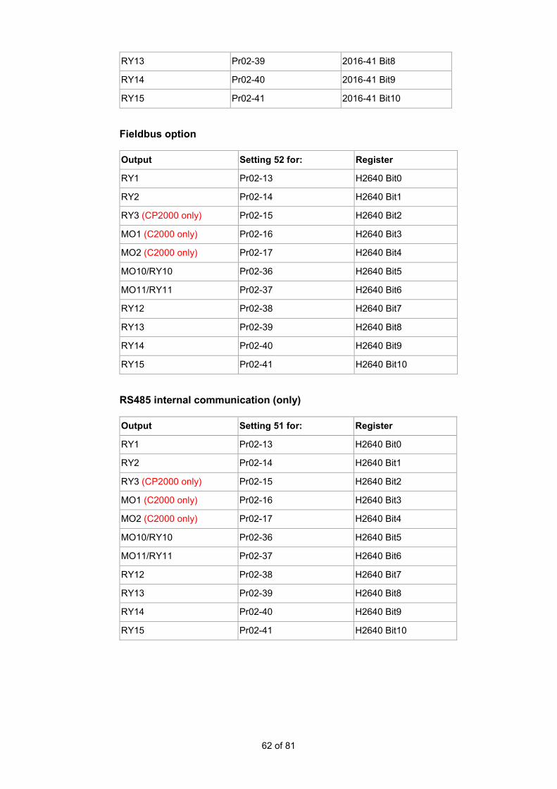
Q What is the function of the settings 50, 51, 52 for the digital outputs and relays?
A In the slave, these settings assign the outputs to bits in a special register, depending on the communication. By sending the bits to the register, the assigned outputs can be controlled. - The actual MO or RY depends on the drive series and option card - The bits (1 or 0) in this register set the outputs active/inactive. - Some bits are not available depending on drive series and option cards. CANopen
Output Setting 50 for: Register
RY1 Pr02-13 2016-41 Bit0
RY2 Pr02-14 2016-41 Bit1
RY3 (CP2000 only) Pr02-15 2016-41 Bit2
MO1 (C2000 only) Pr02-16 2016-41 Bit3
MO2 (C2000 only) Pr02-17 2016-41 Bit4
MO10/RY10 Pr02-36 2016-41 Bit5
MO11/RY11 Pr02-37 2016-41 Bit6
RY12 Pr02-38 2016-41 Bit7
62 of 81
RY13 Pr02-39 2016-41 Bit8
RY14 Pr02-40 2016-41 Bit9
RY15 Pr02-41 2016-41 Bit10
Fieldbus option
Output Setting 52 for: Register
RY1 Pr02-13 H2640 Bit0
RY2 Pr02-14 H2640 Bit1
RY3 (CP2000 only) Pr02-15 H2640 Bit2
MO1 (C2000 only) Pr02-16 H2640 Bit3
MO2 (C2000 only) Pr02-17 H2640 Bit4
MO10/RY10 Pr02-36 H2640 Bit5
MO11/RY11 Pr02-37 H2640 Bit6
RY12 Pr02-38 H2640 Bit7
RY13 Pr02-39 H2640 Bit8
RY14 Pr02-40 H2640 Bit9
RY15 Pr02-41 H2640 Bit10
RS485 internal communication (only)
Output Setting 51 for: Register
RY1 Pr02-13 H2640 Bit0
RY2 Pr02-14 H2640 Bit1
RY3 (CP2000 only) Pr02-15 H2640 Bit2
MO1 (C2000 only) Pr02-16 H2640 Bit3
MO2 (C2000 only) Pr02-17 H2640 Bit4
MO10/RY10 Pr02-36 H2640 Bit5
MO11/RY11 Pr02-37 H2640 Bit6
RY12 Pr02-38 H2640 Bit7
RY13 Pr02-39 H2640 Bit8
RY14 Pr02-40 H2640 Bit9
RY15 Pr02-41 H2640 Bit10

63 of 81
The correct way to address this is by using the function block below to write in the Inter-Com master PLC program:
This FB is written in the master PLC and it is used to write a value inside one of the slave drives as follows: S1 = Select Slave 1 S2 = Device (0: converter, 1: internal PLC) S3 = Register H2640 S4 = Value to write (1 corresponds to RY1) - Set the master drive 9-31=-10 (which stops communication with the laptop) - Connect the master to the slave - Set the slave pr09-31=-1 (Slave 1) and pr02-13=51 (to allow the Relay to be controlled through RS485) - Set the PLC program on the master drive in RUN state See also the Application Note Inner Com Control for C2000.pdf on the ftp-site in the folder (Industrial Automation Products\AMD\VFD-C2000\VFD-C Application notes\C2000 Application Notes\C2000 PLC Built-in\Internal Communication in Modbus).
Q What is the fan behaviour when Pr07-19=3?
A When Pr07-19=3: When IGBT temperature >60°C or CAP temperature >60°C, the fan is ON. When IGBT temperature <40°C and CAP temperature <40°C, the fan is OFF. It will be corrected in the next user manual.

64 of 81
Q What does fault CE3 mean?
A
Q What is the function of Pr08-15?
A Contrary to what’s in the C2000 and CP2000manual, Pr08-15 is reserved and has no function.
Q What is the function of Pr03-14 in C2000?
A Pr03-14 sets the gain for the negative input on AUI. If you put a negative value to the negative input, you will get a positive gain. If you put a positive value to the negative input, you will get a negative gain.
Q C2000 doesn’t run when Enable and FWD are activated simultaneously. Why?
A MI5=49 is Drive Enable. Level triggered. Only when MI5 is active, Drive Enable, RUN, FWD, REV can be activated (edge triggered). The driver scans Multi-IO status at 500μs timer interrupts with scan sequence FWD, REV, MI1, MI2 …MI8. Due to this scan sequence, the drive can’t run when Enable and FWD are activated simultaneously. Therefore a delay of minimum 500 μs between activating Enable and RUN (or FWD, REV) is required.

65 of 81
Q How to copy the PLC program into the keypad?
A For C family, we need to disable PLC first. Please see the steps below: 1. Disable PLC On the keypad, go to Menu #4 PLC. Then, select 1=Disable PLC 2. Upload PLC program
On the keypad, go to Menu #5 Copy PLC and select the file (001, 002, etc). Then, press ENTER and select 2:VFD->Keypad (for uploading to keypad). Enter a password if desired, otherwise skip. Finally, press ENTER and uploading starts
Q C2000 Pr08-23 setting?
A Pr08-23 is bit setting. But because it only affects bit0, you can consider it to be: Pr08-23=0 (bit0=0) and Pr08-23=1 (bit0=1).
Bit0=0 When the PID calculates its output to be positive or negative for forward or reverse, it is enabled if Pr08-21=1. If Pr08-21=0, it only runs in the direction of the RUN command (FWD or REV). Bit0=1 Then the PID calculates its output, but it follows the rule as set in Pr00-23 (0=FWD/REV enable, 1=REV disable, 2=FWD disable).
Q We get a warning TPNO unsupported (TP editor object unsupported) on keypad KPC-CC01. How can we reset it?
A Press “Menu” Select “12: Main Page” Select “1:Default”
Q Are both heatsink fan and capacitor fan in C/CP/CH2000 controlled by Pr07-19 setting?
A See the following table, which is valid for C2000, CP2000 and CH2000:

66 of 81
The heatsink fans are always controlled by Pr07-19, the capacitor fan acc. to the table.
Q Is it possible to run the C2000 in torque mode and use a pulse train as speed limit?
A Yes, this is possible by setting the following parameters: Pr00-20 = 4 or 5 Pr11-36 = 2 Pr10-16 = 1 ~ 5 (depending on the type of pulses you are using) Note: For Pr10-16 = 1 ~ 4 you will need to use a PG card and connect the pulse train to the
PG2 terminals.
Q Is it possible to set the password only by software?
A Yes, it is possible. Please follow the steps below. Fristly, enter the password in VFDSoft, e.g. Pr00-08=1234 and write to Pr00-08. Password is then set. After that all parameters show 0 because the drive is password protected and Pr00-08 shows reserved. Then, you can write 1234 to Pr00-07 (the only parameter you can write to in that case) to unlock the drive.
Q How to wire for Y-Δ switch-over?
A The picture as shown for Pr05-25 in the user manual is for indication only and is not complete. Please see below of how it should be connected.
Note: This also applies to C/CP/CFP2000.

67 of 81
Q What is the compatibility of CP2000 firmware and CMC-EIP01/-MOD01 option cards?
A There is a compatibility issue between the newer CMC-EIP01/CMC-MOD01 cards and the older CP2000 firmware. When a card with firmware version 1.08 or newer is placed on a CP2000 firmware version 2.03 or older, the card will not be recognized (Pr09-60=0) Solution: Update the CP2000 firmware to the latest version V2.06. The firmware and update instructions are available on the ftp-site.
Q Why can’t I find Pr11-17~Pr11-20 and Pr06-12 in the C2000 of firmware V2.06?
A These are removed in 2.06. OC-stall prevention can now only be set in Pr06-03 and Pr06-04.
Q How to use the Bypass functionality in CP/CFP2000?
A The Bypass function only works in combination with Fire Mode functionality in the CP/CFP2000. In Fire mode the drive can ignore most drive fault codes and can continue running (the complete list of faults ignored is in the manual). If bypass is enabled, the drive can use one of its relays to automatically switch the motor directly to the mains supply when a particular fault occurs. Below is the complete list of faults which can trigger the bypass function:

68 of 81
The minimum settings required to enable this function are: - Pr06-82=1 and Pr06-83≠0
- One relay output must be set to function 54. This will be the function that controls the contactors that switch the motor to mains supply
- Parameter 06-83 is the delay time from when a fault occurs to when the drive enables Bypass:
- In addition, the drive can attempt to auto-reset the fault that occurred during fire mode and prevent it from going into Bypass mode. This can be programmed using parameters Pr06-84 and Pr06-85:
When Pr06-84=0 this function is disabled meaning that if a fault from the above list occurs the drive will inevitably go into Bypass mode (after the time set in pr06-83). If, for example, Pr06-84=3 then the drive will reset a fault up to 3 times. If a fault occurs 4 times within the time set in pr06-85, then the drive will no longer attempt to reset the fault and will switch to Bypass mode.

69 of 81
C200
Q Is Pr02-11 Digital input response time also valid for MI7, 8?
A Yes it is. However, when encoder feedback is used (Pr10-02≠0), Pr02-11 is disabled for MI7&8.
Q How to select RS-485 Modbus or CANopen?
A When Pr09-36=0, CANopen is disabled and RS-485 Modbus is enabled. When Pr09-36≠0, CANopen is enabled by assigning a CANopen slave address and RS-485 Modbus is disabled.
Q How to change to high speed for spindles?
A Set Pr00-14=1, then set Pr00-14=2 to enable high-speed mode with max. output frequency of 2000Hz. Set Pr00-14=1, then set Pr00-14=0 to disable high-speed mode and go back to the normal max. output frequency of 600Hz. Note: Whenever Pr 00-14 has been changed, the drive will reset to factory defaults, so please
set this parameter first before any setting in case of data loss.
Q Does C200 support pulse signals for frequency commands? How does it work?
A The external pulse signal (AB phase) can be converted into frequency commands by the following steps: The C200 series only supports open-collector type signals and the maximum speed is 33kHz. When the AB phase pulse signal is connected to MI7 and MI8 for frequency command, then, if the difference between phase A and phase B exceeds 90 degrees, it is counted as 1 pulse. The pulse counting is stored at D1056. - D1054 Present MI8 count value (L word) Read Only - D1055 Present MI8 count value (H word) Read Only - D1056 MI8 corresponding frequency Read Only - D1057 MI8 speed ratio Read/Write - D1058 MI8 mapping frequency update speed (ms) Read/Write - D1059 MI8 mapping frequency decimal place Read/Write - Then set MI1038 to 1

70 of 81
- D1058 Starts MI8 counting Read/Write - D1059 Reset MI8 count value Read/Write - For the last step, the internal PLC instruction FREQ will send a frequency command to the drive. Note: C200 doesn’t support PG cards. Once MI7 and MI8 are used for pulse train frequency
commands, the drive cannot support closed-loop operation.
Q MI7/8 for encoder?
A When Pr10-02=1,2,3,4, then MI7/8 are automatically assigned for encoder input.
Q How to activate encoder?
A When 10-01~02 is set, MI7 & MI8 are automatically activated for encoder input. The original setting of MI7 & MI8 will be ignored. The encoder type must be 24V Open Collector. See also page 6-5 of the Delta Economy Vector Control Drive C200 Series User Manual (PG-Function Explanation).
Q Which PLC registers in C200 are latched?
A The register D0~D99. The C200 manual says D0~399, this will be corrected.

71 of 81
MS300
Q What does Pr07-20=5 (System deceleration) mean?
A For MS300, there is the function Forced to stop (Pr02-01 ~ 02-06 = 18 or 10). Then, Pr07-20 needs to be set.
Pr07-20=5 means the drive stops with the actual deceleration time.
Q What is the crane function (MO=42)?
A The crane function is as follows.

72 of 81
Q How to set pulse train frequency command?
A Set the following parameters to use a pulse train as frequency command:. - Pr02-07=0 (MI7 no function, therefore can be used for pulse train input.) - Connect a 24VDC pulse train signal to MI7 (PNP or NPN depending on wiring). The max. frequency on MI7 is 33kHz. - Pr00-20=4 (pulse input without direction) Note: direction via terminals or keypad - Pr10-00=5 (pulse input MI7) - Pr10-16=5 (single phase input MI7) - Pr10-01 for frequency relationship: E.g. Pulse train f=0~10kHz. Pr10-01=100. Then Fout (H)= f/100 Note: Fmax must be ≥f/100
Q What is the IP of the keypad?
A If the keypad is mounted through a plate, like below, it is IP40.
Q Why is MS300 unstable at 0Hz frequency command?
A When the frequency command is 0Hz, the drive goes in standby mode. Any noise on the analogue input can keep the drive switching between RUN and standby. Pr00-21=1 Operation command via terminals

73 of 81
In firmware 1.05 3 additional settings were introduced for Pr02-00.
Select 4-5-6 instead of 1-2-3 to avoid this problem. The response with these settings is faster and with higher initial output voltage. Pr00-21≠1 Operation command not via terminals - Select Pr03-50≠0. - Using AVI or ACI:0~10V: Set Voltage Lowest Point to 1V (Pr03-57 or 03-63). Set Proportional Lowest Point to 10% (Pr03-58 or 03-64).
- Using ACI:0~20mA: Set ACI Lowest Point to 2mA (Pr03-57). Set ACI Proportional Lowest Point to 10% (Pr03-58). With these settings some margins around 0V and 0Hz are set. Please change the values if needed. In firmware 1.06 this problem is solved and selecting Pr02-00 settings 4~5~6 is not needed anymore for solving this problem.
Q How to calculate and set the OPL level?
A In Pr06-47 the trigger level for Output Phase Loss is set as a percentage of drive rated current =100%. If one the output phase cuirrents >Pr06-47*Rated current for Pr06-46 time, OPL fault is generated. Please see the example below. VFD rated current: 10A Pr06-47=10% One of three phase current < 1A for >Pr06-46 time, OPL is generated.

74 of 81
Q How to wire for Y-Δ switch-over?
A The picture as shown for Pr05-25 in the user manual is for indication only and is not complete. Here’s how it should be connected.
This applies also to C/CP/CFP2000.
Q What is the difference between the Traditional OV stall prevention (Pr06-02=0) and the Smart OV stall prevention (Pr06-02=1)?
A Over Voltage stall prevention is a function commonly used in applications where the goal is to decelerate the motor as quickly as possible without using a braking resistor. To enable this function parameter Pr06-01 needs to be ≠0. In traditional OV stall, during deceleration the drive will maintain the output frequency at a constant level when VDC > Pr06-01. When VDC<Pr06-01 the drive will always follow the same slope to decelerate (Hz/s = constant)

75 of 81
In smart OV stall, during Acceleration/Deceleration/Normal state, the drive will maintain and/or increase the output frequency when the VDC > Pr06-01. When VDC<Pr06-01 the drive will change the slope by which it decelerates (Hz/s not constant). In this mode the drive will calculate a new deceleration slope with the aim of maintaining a stable DC bus voltage. It will therefore ignore the deceleration ramp (Pr01-13) and the 4th S ramp (Pr01-27).
When smart OV stall is used it is recommended to also set Pr01-49=1.
Q How does Pr00-02=8 work?
A Pr00-02=8 works differently on MS300 than on VFD-E. When Pr00-02=8 is set, the keys RUN, STOP, and </ do not work. When parameters are entered via ENTER the keys and </can be used to change parameter and settings.
Q How to install a fieldbus option card on MS300?
A There have been some changes, please refer to MS300_Comm card_installation.pdf, which is available on our ftp-site (Industrial Automation Products\AMD-Options\AMD Fieldbus options). Mounting position 1 (Frame A~F)

76 of 81
Mounting position 2 (Frame A~D)
Cable
Q Why do I get LV-error even if the voltage is >LV-level (supplying 230VAC to a 400V drive)?
A In Pr06-00 you can set the LV-level. For a 400V drive, the minimum setting value is 300VDC. When the drive is supplied with 230VAC, the DC-bus voltage is around 230*√2=325VDC which is higher than 300VDC so LV is not expected. But in order to “cancel” LV, the DC-bus voltage must become >(Pr06-00 +60VDC *) which in this case never happens. Therefore LV stays and cannot be reset.
Note: For 230V drives, this value is +30VDC.

77 of 81
Q How to use the TORQ command in the PLC?
A The TORQ command works in the same way as in C2000.
ME300
Q What class and motor cable length for the ME300 built-in filter?
A 230V 1phase: Class C2 20m shielded motor cable. 400V: Class C3 30m shielded motor cable. Carrier frequency can be over the whole setting range.
Q Is the STO certificate valid when I install the option card EMM-SAF01?
A No. The STO certificate is only valid for ME300 models with pre-installed STO option: VFDxxxMExxAxSAA. However, the STO functionality is exactly the same when you install EMM-SAF01 later yourself.

78 of 81
VFD-ED
Q How to connect the encoder in case of non-differential signals?
A If the encoder only has non-differential output signals A1, B1, and Z1, please do the following: Connect the encoder signals to the inputs A1, B1, and Z1. Connect the unused inputs /A1, /B1, and /Z1 to DCM to avoid interference problems.
EMC-PG01O
Q How to connect an encoder with OC outputs to EMC-PG01O?
A The encoder outputs A, /A, B, /B, Z, /Z should be connected to the following pins of EMC-PG01O: A1, /A1, B1, /B1, Z1, /Z1 respectively. Because these inputs do not have an internal pull-up resistor, it is necessary to connect them externally from each input to VP. VP=12V R= 680Ω~1.2kΩ ½W VP=5V R= 330Ω~470Ω ½W
Brake Units
Q What happens on BUExxxxx when the MASTER-SLAVE switch is set to SLAVE and only one brake unit is connected?
A If you use one braking unit and set the switch to SLAVE, it means there is no signal to control the braking unit. Therefore, there will be no braking action. When the DC-bus voltage (P-N) is too high, the drive and/or the brake unit may be damaged.
Q What is the braking voltage when all dipswitches are OFF on a BUExxxxx ?
A When you set all dip-switch OFF, the voltage is equal to 190VAC (380VAC). It is shorted by inside circuit. It means dip-switch 190VAC (380VAC) is always ON for safety concerns.
Q What is the purpose of the Master-Slave switch?
A On BUE20015 (and other BUE and VFDB brake units) the master-slave switch is used whenever you need 2 units on one drive.

79 of 81
The dipswitch Master-Slave tells the unit if it is used as master or slave. When it is used as the master, it responds to the DC-bus voltage. When it is used as the slave, it responds to slave input (S1-S2) which has to be connected to the masters M1-M2 output. In case only one brake unit is used, leave it at Master position, which is the factory setting.
CMM-EIP01
Q What is the meaning of the LEDs on CMM-EIP01?
A The explanation in the MS300 manual is not complete.
The 2 yellow LEDS are for engineering purposes and can be disregarded by the user.

80 of 81
AFE Series Active Front End
AFE2000
Q To reduce harmonics we want to use AFE2000. We do not need regeneration; do we still need the input reactor?
A Yes, AFE2000 does not only reduce harmonics, correct the power factor and regenerate braking energy back into the mains power supply, but also stabilises its DC output voltage. For all these functions the reactor is necessary (think of it as a switched-mode power supply).
Q How to connect the AFE LC filter?
A Refer to the AFE user manual (which user manual?)
Q Why do we get ocn fault?
A When the recommended LC-filter is used, please connect r1,s1,t1 to the LC-filter Us1,Vs1,Ws1 and not to the RC reactor so the AFE can lock to the mains..

81 of 81
Q Does AFE start running if MI1 is active at power on?
A Yes.
Q Which fuses are recommended?
A Each drive must be fused at the DC-bus terminals. Please select the fuse value acc. to (AC rated input current/0.78)*1.5. We recommend to use fast DC fuses.