AX-8 Series User Guide - Delta
50
www.deltaww.com AX-8 Series User Guide Industrial Automation Headquarters Delta Electronics, Inc. Taoyuan Technology Center No.18, Xinglong Rd., Taoyuan District, Taoyuan City 33068, Taiwan TEL: 886-3-362-6301 / FAX: 886-3-371-6301 Asia Delta Electronics (Shanghai) Co., Ltd. No.182 Minyu Rd., Pudong Shanghai, P.R.C. Post code : 201209 TEL: 86-21-6872-3988 / FAX: 86-21-6872-3996 Customer Service: 400-820-9595 Delta Electronics (Japan), Inc. Tokyo Office Industrial Automation Sales Department 2-1-14 Shibadaimon, Minato-ku Tokyo, Japan 105-0012 TEL: 81-3-5733-1155 / FAX: 81-3-5733-1255 Delta Electronics (Korea), Inc. Seoul Office 1511, 219, Gasan Digital 1-Ro., Geumcheon-gu, Seoul, 08501 South Korea TEL: 82-2-515-5305 / FAX: 82-2-515-5302 Delta Energy Systems (Singapore) Pte Ltd. 4 Kaki Bukit Avenue 1, #05-04, Singapore 417939 TEL: 65-6747-5155 / FAX: 65-6744-9228 Delta Electronics (India) Pvt. Ltd. Plot No.43, Sector 35, HSIIDC Gurgaon, PIN 122001, Haryana, India TEL: 91-124-4874900 / FAX : 91-124-4874945 Delta Electronics (Thailand) PCL. 909 Soi 9, Moo 4, Bangpoo Industrial Estate (E.P.Z), Pattana 1 Rd., T.Phraksa, A.Muang, Samutprakarn 10280, Thailand TEL: 66-2709-2800 / FAX : 662-709-2827 Delta Electronics (Australia) Pty Ltd. Unit 20-21/45 Normanby Rd., Notting Hill Vic 3168, Australia TEL: 61-3-9543-3720 Americas Delta Electronics (Americas) Ltd. Raleigh Office P.O. Box 12173, 5101 Davis Drive, Research Triangle Park, NC 27709, U.S.A. TEL: 1-919-767-3813 / FAX: 1-919-767-3969 Delta Greentech (Brasil) S/A São Paulo Office Rua Itapeva, 26 – 3˚ Andar - Bela Vista CEP: 01332-000 – São Paulo – SP - Brasil TEL: 55-11-3530-8643 / 55-11-3530-8640 Delta Electronics International Mexico S.A. de C.V. Mexico Office Gustavo Baz No. 309 Edificio E PB 103 Colonia La Loma, CP 54060 Tlalnepantla, Estado de México TEL: 52-55-3603-9200 *We reserve the right to change the information in this catalogue without prior notice. EMEA Headquarters: Delta Electronics (Netherlands) B.V. Sales: [email protected] Marketing: [email protected] Technical Support: [email protected] Customer Support: [email protected] Service: [email protected] TEL: +31(0)40 800 3900 BENELUX: Delta Electronics (Netherlands) B.V. De Witbogt 20, 5652 AG Eindhoven, The Netherlands Mail: [email protected] TEL: +31(0)40 800 3900 DACH: Delta Electronics (Netherlands) B.V. Coesterweg 45, D-59494 Soest, Germany Mail: [email protected] TEL: +49(0)2921 987 0 France: Delta Electronics (France) S.A. ZI du bois Challand 2, 15 rue des Pyrénées, Lisses, 91090 Evry Cedex, France Mail: [email protected] TEL: +33(0)1 69 77 82 60 Iberia: Delta Electronics Solutions (Spain) S.L.U Ctra. De Villaverde a Vallecas, 265 1º Dcha Ed. Hormigueras – P.I. de Vallecas 28031 Madrid TEL: +34(0)91 223 74 20 Carrer Llacuna 166, 08018 Barcelona, Spain Mail: [email protected] Italy: Delta Electronics (Italy) S.r.l. Via Meda 2–22060 Novedrate(CO) Piazza Grazioli 18 00186 Roma Italy Mail: [email protected] TEL: +39 039 8900365 Russia: Delta Energy System LLC Vereyskaya Plaza II, office 112 Vereyskaya str. 17 121357 Moscow Russia Mail: [email protected] TEL: +7 495 644 3240 Turkey: Delta Greentech Elektronik San. Ltd. Sti. (Turkey) Şerifali Mah. Hendem Cad. Kule Sok. No:16-A 34775 Ümraniye – İstanbul Mail: [email protected] TEL: + 90 216 499 9910 GCC: Delta Energy Systems AG (Dubai BR) P.O. Box 185668, Gate 7, 3rd Floor, Hamarain Centre Dubai, United Arab Emirates Mail: [email protected] TEL: +971(0)4 2690148 Egypt + North Africa: Delta Electronics Unit 318, 3rd Floor, Trivium Business Complex, North 90 street, New Cairo, Cairo, Egypt Mail: [email protected]
-
Upload
khangminh22 -
Category
Documents
-
view
1 -
download
0
Transcript of AX-8 Series User Guide - Delta

www.deltaww.com
AX-8 Series User Guide
Industrial Automation HeadquartersDelta Electronics, Inc. Taoyuan Technology CenterNo.18, Xinglong Rd., Taoyuan District, Taoyuan City 33068, TaiwanTEL: 886-3-362-6301 / FAX: 886-3-371-6301
AsiaDelta Electronics (Shanghai) Co., Ltd.No.182 Minyu Rd., Pudong Shanghai, P.R.C.Post code : 201209 TEL: 86-21-6872-3988 / FAX: 86-21-6872-3996Customer Service: 400-820-9595
Delta Electronics (Japan), Inc.Tokyo Office Industrial Automation Sales Department 2-1-14 Shibadaimon, Minato-kuTokyo, Japan 105-0012TEL: 81-3-5733-1155 / FAX: 81-3-5733-1255
Delta Electronics (Korea), Inc.Seoul Office1511, 219, Gasan Digital 1-Ro., Geumcheon-gu, Seoul, 08501 South KoreaTEL: 82-2-515-5305 / FAX: 82-2-515-5302
Delta Energy Systems (Singapore) Pte Ltd.4 Kaki Bukit Avenue 1, #05-04, Singapore 417939TEL: 65-6747-5155 / FAX: 65-6744-9228
Delta Electronics (India) Pvt. Ltd.Plot No.43, Sector 35, HSIIDC Gurgaon, PIN 122001, Haryana, IndiaTEL: 91-124-4874900 / FAX : 91-124-4874945
Delta Electronics (Thailand) PCL. 909 Soi 9, Moo 4, Bangpoo Industrial Estate (E.P.Z), Pattana 1 Rd., T.Phraksa, A.Muang, Samutprakarn 10280, ThailandTEL: 66-2709-2800 / FAX : 662-709-2827
Delta Electronics (Australia) Pty Ltd.Unit 20-21/45 Normanby Rd., Notting Hill Vic 3168, AustraliaTEL: 61-3-9543-3720
AmericasDelta Electronics (Americas) Ltd.Raleigh OfficeP.O. Box 12173, 5101 Davis Drive, Research Triangle Park, NC 27709, U.S.A.TEL: 1-919-767-3813 / FAX: 1-919-767-3969
Delta Greentech (Brasil) S/ASão Paulo OfficeRua Itapeva, 26 – 3˚ Andar - Bela VistaCEP: 01332-000 – São Paulo – SP - BrasilTEL: 55-11-3530-8643 / 55-11-3530-8640
Delta Electronics International Mexico S.A. de C.V.Mexico OfficeGustavo Baz No. 309 Edificio E PB 103Colonia La Loma, CP 54060Tlalnepantla, Estado de MéxicoTEL: 52-55-3603-9200
*We reserve the right to change the information in this catalogue without prior notice.
EMEAHeadquarters: Delta Electronics (Netherlands) B.V. Sales: [email protected] Marketing: [email protected] Technical Support: [email protected] Customer Support: [email protected] Service: [email protected]: +31(0)40 800 3900
BENELUX: Delta Electronics (Netherlands) B.V.De Witbogt 20, 5652 AG Eindhoven, The Netherlands Mail: [email protected]: +31(0)40 800 3900
DACH: Delta Electronics (Netherlands) B.V.Coesterweg 45, D-59494 Soest, GermanyMail: [email protected]: +49(0)2921 987 0
France: Delta Electronics (France) S.A.ZI du bois Challand 2, 15 rue des Pyrénées, Lisses, 91090 Evry Cedex, France Mail: [email protected]: +33(0)1 69 77 82 60
Iberia: Delta Electronics Solutions (Spain) S.L.UCtra. De Villaverde a Vallecas, 265 1º Dcha Ed. Hormigueras – P.I. de Vallecas 28031 Madrid TEL: +34(0)91 223 74 20
Carrer Llacuna 166, 08018 Barcelona, SpainMail: [email protected]
Italy: Delta Electronics (Italy) S.r.l.Via Meda 2–22060 Novedrate(CO) Piazza Grazioli 18 00186 Roma ItalyMail: [email protected]: +39 039 8900365
Russia: Delta Energy System LLC Vereyskaya Plaza II, office 112 Vereyskaya str. 17 121357 Moscow Russia Mail: [email protected]: +7 495 644 3240
Turkey: Delta Greentech Elektronik San. Ltd. Sti. (Turkey) Şerifali Mah. Hendem Cad. Kule Sok. No:16-A 34775 Ümraniye – İstanbulMail: [email protected]: + 90 216 499 9910
GCC: Delta Energy Systems AG (Dubai BR)P.O. Box 185668, Gate 7, 3rd Floor, Hamarain Centre Dubai, United Arab Emirates Mail: [email protected]: +971(0)4 2690148
Egypt + North Africa: Delta ElectronicsUnit 318, 3rd Floor, Trivium Business Complex, North 90 street, New Cairo, Cairo, Egypt Mail: [email protected]

i
Preface
Thank you for purchasing this product. This user manual provides information about the AX-8 series motion
control PAC.
This manual includes:
Product inspection and Model Explanation
Specifications and Product Interface
Product Installation
BIOS setting instructions
System Operation and Settings
Product features
The AX-8 series motion control PAC supports EtherCAT (Ethernet Control Automation
Technology) control interface, which can be operated with libraries.
It supports a minimum synchronization period of 250 microseconds, and 64 axes and 32 stations
in 1 millisecond.
AX-8 series provides 35 kinds of homing methods, point-to point position control, speed control,
torque control, multi-axis interpolation, Robot and CNC etc.
The complete motion control functions of the AX-8 series products are able to meet the needs of
the diverse industry. This product optimally integrates the operations of multi-axis synchronous
motion control, enabling easier assembly, better stability, and more flexible expansion capabilities.
This is the one and only choice for industrial upgrading.
How to use this manual
You can use this manual as a reference when using the AX-8 series motion control PAC, which
contains information about installation, setting, and instructions on how to use and maintain the
product.
Delta technical services
Contact the local distributors or Delta Customer Service Center if you have any inquiry during
operation.

Table of Contents
Product Inspection and Model Explanation 1.1 Product Inspection ····························································································1-2
1.2 Model Explanation ····························································································1-3
1.3 Electrical Safety precautions ···············································································1-4
Specifications and Product Interface
2.1 Electrical Specifications ···················································································· 2-2
2.2 External Dimensions ························································································ 2-4
2.3 Part Names and Port Descriptions ······································································· 2-5
2.3.1 HDMI Display Port ····················································································· 2-6
2.3.2 Ethernet Port···························································································· 2-7
2.3.3 USB Port ································································································· 2-8
2.3.4 Status Indicator ························································································ 2-9
2.3.5 RS-485/422 Encoder and GPIO Port ··························································· 2-10
2.3.6 Power Port ···························································································· 2-11
2.3.7 Protocol Port Bus Communication interface ·················································· 2-12
2.3.8 WatchDog On/Off Switch ·········································································· 2-13
2.4 Wiring Example ····························································································· 2-14
2.4.1 AX-8 Series Wiring for Input Point Connection With External Devices ················· 2-14
2.4.2 AX-8 Series Wiring for Output Point Connection With External Devices ·············· 2-15
2.4.3 AX-8SeriesEncoder Wiring ········································································ 2-17
Product Installation
3.1 Hung Installation ······························································································ 3-2
3.2 SD Card Installation ························································································· 3-3
1
2
3

BIOS
4.1 BIOS Operation and Setting ················································································4-1
4.1.1 Main ········································································································4-3
4.1.2 Advanced ·································································································4-4
4.1.3 WatchDot ·································································································4-5
4.1.4 Chipset ····································································································4-6
4.1.5 Security ································································································· 4-11
4.1.6 Boot ······································································································ 4-12
4.1.7 Save & Exit ····························································································· 4-13
System Operation and Settings
5.1 Setting and Releasing of the Write Protection UWF Function······································ 5-2
5.1.1 Using the PAC_Tool to Perform Write Protection UWF Operations ························5-3
5.1.2 Read Current Write Protection Status ·····························································5-3
5.1.3 Enabling Write Protection ·············································································5-4
5.1.4 Disabling Write Protection ············································································5-5
5.1.5 Write Protection Fix ····················································································5-6
5.2 Operating System Language Change Setting··························································5-7
5.3 Write Protection Function Exception······································································5-9
4
5

1-1
Product Inspection and Model Explanation
This chapter mainly introduces the product inspection and product model description,
as well as the electrical safety precautions of the AX-8 series product. Read this
chapter before using the product to understand related contents.
000
1.1 Product Inspection ··············································································· 1-2
1.2 Model Description ················································································ 1-3
1.3 Electrical Safety Precautions ·································································· 1-4

Product Inspection and Model Description AX-8 Series User Manual
1-2
1
1.1 Product Inspection
Users please verify the integrity of this product package, and confirm whether all the following
items and accessories are complete:
1. Host
2. Product Installation Manual
3. Accessories (As shown in Figure 1.1.1)
(1)(2)
(3)
(4)
(5)
Figure 1.1.1 Accessory Diagrams
No. Item Quantity
(1) I/O Cable Connector 1
(2) Power Cable Connector 1
(3) Wall Mount Fixture 1
(4) M3 Pan Head Screws 4
(5) M4 Truss Head Screws 2

AX-8 Series User Manual Product Inspection and Model Description
1-3
15
1.2 Model Description
AX – 8 64 E P0 CB1 T (1) (2) (3) (4) (5)(6) (7) (8) (9) (10)
No. Item Description
(1) Product type AX = AX Series Standalone Controller
(2) Processor 7, 8, 9 = PC-based 1, 2, 3, 4, 5, 6 = PLC-based (1, 2 = Compact; 3, 4, 5 = Middle; 6 = High)
(3) Number of Axes
Supported 08 = 8 axes; 16 = 16 axes; 32 = 32 axes; 64 = 64 axes; 1H = 128 axes; 2H = 256 axes; 5H = 512 axes
(4) Network Type
Movement Type E = EtherCAT; C = CANopen; D = DMCNet; P = ProfiNet; F = Safety; I = CIP; M = Pulse
(5), (6) Hardware Version
(5): CPU Version
A = Intel Atom Series
P = Intel Celeron Series
C = Intel Core Series
(6): Controller Version
0 = Version One 1 = Version Two
(7), (8), (9) Software Version
(7): License Certification
P = CODESYSodesys PLC
M = CODESYSCodesys SoftMotion
C = CODESYSCodesys SoftMotion + CNC +Robot
(8): System Type
A = A type (Win10 IoT 64-bit + 32G M.2 SSD)
B = B type (Win10 IoT 64-bit + QT HMI + 32G M.2 SSD)
C = C type (Win10 IoT 64-bit + Codesys HMI + 32G M.2 SSD)
(9): Firmware Version
1 = Version One
(10) IO Type T: Transistor NPN; P: Transistor PNP; R: Relay S: TRIAC; A: Analog I/O; M: Differential

Product Inspection and Model Description AX-8 Series User Manual
1-4
1
1.3 Electrical Safety Precautions
In order to prevent possible severe damage caused by electric shocks, please first unplug
the host power cable from the power outlet before moving the host.
Confirm that all power cables have been unplugged before connecting or disconnecting
any signal cables from the host.
Confirm that the voltage setting of the power supply is adjusted to the standard voltage
value used in this country/this region. If you are unsure of the supplied voltage value of
your region, please consult your local power company staff.
If the power supply is damaged, do not attempt to fix it by yourself. Please contact Delta’s
professional technical service staff or the dealer.
Restart Instructions: Pressing and holding down the reset button for 2 seconds will force
restart.
It is recommended to install this product inside a cabinet or inside an external case in
order to block external collisions.
This product is applicable to industrial automation equipment and applications. Please
read this User Manual carefully and perform installation according to the instructions in
order to prevent danger from occurring.
If this product is not operated in accordance with the instructions described in the Manual,
it will cause damage to the equipment or abnormal functions.

2-1
Specifications and Product Interface
This chapter mainly introduces the specifications and part compositions of the AX-8
series product. Please assemble the parts in accordance with the descriptions in this
chapter; do not remove the non-removable parts by yourself.
000
2.1 ELECTRICAL SPECIFICATIONS ······························································································· 2
2.2 EXTERNAL DIMENSIONS ········································································································ 4
2.3 PART NAMES AND PORT DESCRIPTIONS ·············································································· 5
2.3.1 HDMI Display Port ······································································································ 6
2.3.2 Ethernet Port ··············································································································· 7
2.3.3 USB Port ······················································································································ 8
2.3.4 Status Indicator ··········································································································· 9
2.3.5 RS-485/422 Encoder and GPIO Port ···································································· 10
2.3.6 Power Port ················································································································· 11
2.3.7 Protocol Port Bus Communication Interface ························································ 12
2.3.8 WatchDog On/Off Switch ····················································································· 13
2.4 WIRING EXAMPLES ·············································································································· 14
2.4.1 AX-8 Series Wiring for Input Point Connection With External Devices ············ 14
2.4.3 AX-8SeriesEncoder Wiring ····················································································· 17

Product Specifications and Part Descriptions AX-8 Series User Manual
2-2
2
2.1 Electrical Specifications
Item AX-8 TEP0
AX-8 PEP0
Processor System
Processor Intel Celeron J1900 Quad Core 2.00GHz,
up to 2.42GHz
BIOS AMI BIOS
Memory On Board DDR3L-1333 4GB
Power Loss Retentive Memory
128 KB MRAM
Communication
interface
Network Interface 2 x IEEE 802.3 / 802.3u / 802.3ab 1 Gbps
Bus Communication Interface
1 x EtherCAT
USB 4 x USB 2.0
Serial Communication Port 1 x isolated RS-485 / 422
Digital input
Output Signal Form NPN (SINK) / PNP (SOURCE)
Number of End Points 8
Power Used DC 24V (tolerance + 20%,-15%)
Max. input current 5 mA / CH
Response time
(OFFON) Ton ≤ 200 ns
Motion Level
(OFFON) ≥15 VDC
Response time
(ONOFF) Toff ≤ 150 ns
Motion Level
(ONOFF) ≤ 5 VDC
Digital Output
Signal Form NPN (SINK) PNP (SOURCE)
Number of End Points 8 8
Power Used DC 24V (tolerance + 20%,-15%)
Max. output current 100 mA / CH 50 mA / CH
Response time
Ton = 0.2 us / Toff = 4.6 us
(24 V / 5.1 mA)
Ton = 0.2 us / Toff = 2.5 us
(24 V / 10 mA)
Ton = 0.2 us / Toff = 0.6 us
(24 V / 51 mA)
Ton = 0.2 us / Toff = 0.35 us
(24 V / 100 mA)
Ton = 1.3 us / Toff = 8.2 us
(24 V / 5.1 mA)
Ton = 1.3 us / Toff = 5 us
(24 V / 10 mA)
Ton = 1.3 us/ Toff = 2.6 us (24 V / 51 mA)
Encoder Input
Signal Form Differential
Number of End Points 1-CH EA± / EB± / EZ±
Response time Ton ≤ 150 ns

AX-8 Series User Manual Product Specifications and Part Descriptions
2-3
2
Item AX-8 TEP0
AX-8 PEP0
Toff ≤ 150 ns
Display Interface Display Interface
Specifications 1 x HDMI 1.4a
Expansion Interface Expansion Interface
Specifications 1 x SD Card Slot (SD card 3.0 Interface)
Storage Device Solid State Drive 1 x M.2 2242 type B&M-key SATA SSD
(SATA 2.0 Interface)
Power Requirement Input Voltage Type DC 24V (tolerance + 20%, -15%)
Power Consumption*1 24 V / 1.2 A / 28.8 W
Mechanism Installation Wall Mount Type, Orbital Type
External Dimensions 54.2 mm*141 mm*137.4 mm (W x H x D)
Applicable
Environment
Operating Temperature 0 °C ~ 50 °C
Storage temperature -20°C ~ 70°C
Relative Humidity 0% ~ 90% RH (Uncondensed)
Seismic Test
2 Grms, IEC 60068-2-64, random continuous
vibration,
5 ~ 500 Hz, 1 hr / axis
Impact Test 75 G, IEC 60068-2-27, half sine wave, continually for
11ms
Safety Certification CE
Software Supported Microsoft Windows Window 10 IOT 64-bit
Notes:
1. CPU and peripheral at full load status; power consumption includes USB, SSD, and other interfaces.

Product Specifications and Part Descriptions AX-8 Series User Manual
2-4
2
2.2 External Dimensions
AX-8 Series Model External Dimensions: 54.2 x 141 x 137.4 mm (W x H x D)
Unit:mm14
1

AX-8 Series User Manual Product Specifications and Part Descriptions
2-5
2
2.3 Part Names and Port Descriptions
AX-8 series model host port illustration diagram and descriptions.
(1)
(2)
(3)
(4)
(5)
(6)
(7)
(8)
(9)
Introduction to Part Names and Port Functions:
No. Description No. Description
(1) SD Card Slot (6) Status Indicator
(2) Reset Switch (7) RS-485/422;Encoder; GPIO Port
(3) HDMI Display Port (8) Power Connection Port
(4) Gigabit LAN Network Port (9) EtherCAT Port
(5) USB 2.0 Port - -

Product Specifications and Part Descriptions AX-8 Series User Manual
2-6
2
2.3.1 HDMI Display Port
HDMI display port pin illustration diagram and pin descriptions are as follows.
1
19
(1) (2)2
18
(1) HDMI Display Port (2) HDMI Cable Port
HDMI Pin Definitions:
Pin Description Pin Description
1 TX+_2 11 HDMI_GND
2 HDMI_GND 12 CLK-
3 TX-_2 13 NC
4 TX+_1 14 NC
5 HDMI_GND 15 SCL
6 TX- 1 16 SDA
7 TX+_0 17 HDMI_GND
8 HDMI_GND 18 +5V
9 TX- 0 19 Hot Plug Detect
10 CLK+ - -

AX-8 Series User Manual Product Specifications and Part Descriptions
2-7
2
2.3.2 Ethernet Port
Gigabit LAN network port pin illustration diagram and its pin descriptions are as follows.
(1) (2)
8
1
8
1
(a)
(b)
(a)
(b)
(1) Gigabit LAN Network Port (2) Network Cable Connector
Gigabit LAN Network Port Pin Definitions:
Pin Description Pin Description
1 TP+_1 5 TP-_3
2 TP-_1 6 TP-_2
3 TP+_2 7 TP+_4
4 TP+_3 8 TP-_4
Ethernet Port Indicator Descriptions:
LED Indicator Display Status Description
LED (a)
OFF 10 Mbps
Green 100 Mbps
Orange 1000 Mbps
LED (b)
Constantly ON (orange)
Mesh Connected
Flashing (orange) Data Transmitting

Product Specifications and Part Descriptions AX-8 Series User Manual
2-8
2
2.3.3 USB Port
USB 2.0 port pin illustration diagram and its pin descriptions are as follows.
(1) (2)
4
1
(1) USB2.0 (2) USB Signal Cable Connector
USB 2.0 Port Pin Definitions:
Pin Description Pin Description
1 Power (+5V) 3 D+
2 D- 4 GND
Note: The maximum voltage of each port is 5V (±5%), and the maximum current is 500 mA.

AX-8 Series User Manual Product Specifications and Part Descriptions
2-9
2
2.3.4 Status Indicator
The following is the status indicator location map and description.
PWR
RUN
ERR
FB1
FB2
Status Indicator Definitions:
Mark Description Mark Description
PWR Power Indicator FB1 Bus 1 Indicator
RUN Operation Indicator FB2 Bus 2 Indicator
ERR Error Indicator - -

Product Specifications and Part Descriptions AX-8 Series User Manual
2-10
2
2.3.5 RS-485/422 Encoder and GPIO Port
RS-485/RS-422 encoder GPIO port pin illustration diagram and its pin descriptions are as
follows.
(1) (2)
12
2930
(1) RS-485/RS-422 Encoder and GPIO Port (2) Port Cable Connector
RS-485/RS-422 Encoder and GPIO Pin Definitions:
Pin Mark Description Pin Mark Description
1 TX+ RS422 TX+ Signal
/RS485+ Signal 2 TX-
RS422 TX- Signal /RS485- Signal
3 SG RS-422/485 GND 4 SG RS-422/485 GND
5 RX+ RS-422 RX+ Signal 6 RX- RS-422 RX- Signal
7 A+ EA+ Signal 8 A- EA+ Signal
9 B+ EB+ Signal 10 B- EB- Signal
11 Z+ EZ+ Signal 12 Z- EZ- Signal
13 X0 GPIO Input Signal 14 Y0 GPIO Output Signal
15 X1 GPIO Input Signal 16 Y1 GPIO Output Signal
17 X2 GPIO Input Signal 18 Y2 GPIO Output Signal
19 X3 GPIO Input Signal 20 Y3 GPIO Output Signal
21 X4 GPIO Input Signal 22 Y4 GPIO Output Signal
23 X5 GPIO Input Signal 24 Y5 GPIO Output Signal
25 X6 GPIO Input Signal 26 Y6 GPIO Output Signal
27 X7 GPIO Input Signal 28 Y7 GPIO Output Signal
29 VCC External 24V Power 30 GND External 24V Power GND

AX-8 Series User Manual Product Specifications and Part Descriptions
2-11
2
2.3.6 Power Port
Power port pin illustration diagram and its pin descriptions are as follows.
(1) (2)
1234
(1) Power Port (2) Power Port Cable Connector
Power Port Pin Definitions:
Note: When using an external power supply, make sure that it complies with the safety regulations of each
location:
1. Safety: EN60950-1
2. CE Certification
3. EMC Certification : Emission (CE & RE) ; CISPR 32, EN 55032, EN 55011, FCC Title 47: Class B, EN
61204-3
Immunity EN 55024, EN 61000-6-2
Pin Description Pin Description
1 Frame Ground (FG) 3 Frame Ground (FG)
2 Master Power (+24V) 4 Ground (GND)

Product Specifications and Part Descriptions AX-8 Series User Manual
2-12
2
2.3.7 Protocol Port Bus Communication Interface
EtherCAT port pin illustration diagram and its pin descriptions are as follows.
(1) (2)
8
1(a)
(b)
(1) EtherCAT Port (2) Network Cable Connector
EtherCAT Port Pin Descriptions:
Pin Description Pin Description
1 TP+_1 5 TP-_3
2 TP-_1 6 TP-_2
3 TP+_2 7 TP+_4
4 TP+_3 8 TP-_4
EtherCAT Port Indicator Descriptions:
LED Indicator Display Status Description
LED (a) OFF 10 Mbps
Green 100 Mbps
LED (b)
Constantly ON (orange)
Mesh Connected
Flashing (orange) Data Transmitting

AX-8 Series User Manual Product Specifications and Part Descriptions
2-13
2
2.3.8 WatchDog On/Off Switch
The watchdog function switch is as follows
(1) Function Enable;(2) Function Disable
User can switch on/off watchdog function on the bottom of AX-8.
When Watchdog function is enable and there is a system crash, the watchdog timer will send out the reset signal to let system return normal operation. Please refer to Chapter 4.1.3 Watchdog parameter detail settings.

Product Specifications and Part Descriptions AX-8 Series User Manual
2-14
2
2.4 Wiring Examples
2.4.1 AX-8 Series Wiring for Input Point Connection With External Devices
SINK Type Wiring: (AX-8󠇜󠇜EP0󠇜󠇜󠇜T)
24VDC
24V
0V
Power supply
J3 SINK
1 2 324V COM
SINKInternal circuit
3.3V
GND
X00
24V COM
X07
Co
ntro
ller
IOGND
Relay
N.O N.C
SOURCE Type Wiring: (AX-8󠇜󠇜EP0󠇜󠇜󠇜P)
24VDC
24V
0V
Power supply
J3 SOURCE
1 2 3GNDCOM
N.CN.O
Relay
24V
SourceInternal circuit
3.3V
GND
X00
24V COM
X07
Co
ntro
ller

AX-8 Series User Manual Product Specifications and Part Descriptions
2-15
2
2.4.2 AX-8 Series Wiring for Output Point Connection With External Devices
SINK Type Wiring: (AX-8󠇜󠇜EP0󠇜󠇜󠇜T)
(1) Application 1: Relay Type
Co
ntro
ller
IOGND
Internal Circuit
IOGND
IO24V
N.O N.C
Relay
N.O N.C
Relay
24VDC
IO Power Supply
FBD
FBD
FBD : Flyback Diode
24V
GND
Y00
Y07
24V
0V
24VDC
SINK
(2) Application 2: External equivalent load resistance type.
Co
ntro
ller
IOGND
Internal Circuit
IOGND
IO24V24VDC
IO Power Supply
24V
GND
Y00
Y07
24V
0V
24VDC
SINK
RLO
AD
RLO
AD
Note: When the external power is 24V, the external load equivalent resistance must not be less than
240ohm (maximum output current: 100mA/CH).

Product Specifications and Part Descriptions AX-8 Series User Manual
2-16
2
SOURCE Type Wiring: (AX-8󠇜󠇜EP0󠇜󠇜󠇜P)
(1) Application 1: Relay Type
Co
ntro
ller
Internal Circuit
IOGND
IO24V
N.O N.C
24VDC
IO Power Supply
FBD
FBD : Flyback Diode
24V
GND
Y00
Y07
24V
0V
24VDC
SOURCE
IO24V
Relay
N.O N.C
RelayIOGND
FBD
(2) Application 2: External equivalent load resistance type.
Co
ntro
ller
IOGNDInternal Circuit
IOGND
IO24V24VDC
24V
GND
Y00
Y07
24V
0V
24VDC
SOURCE
RLO
AD
RLO
AD
IO24V
Note: When the external power is 24V, the external load equivalent resistance must not be less than
480ohm (maximum output current: 50mA/CH).

AX-8 Series User Manual Product Specifications and Part Descriptions
2-17
2
2.4.3 AX-8SeriesEncoder Wiring
Encoder Signal Wiring Diagram
Internal Circuit
EA+
EB+
EZ+
EA-
EB-
EZ-
GND GND
QA-
QB-
QZ-
QA+
QB+
QZ+

3-1
Product Installation
This chapter explains the installation method of the AX-8 series host and the
installation method of storage devices.
000
3.1 Hung Installation ·················································································· 3-2
3.2 SD Card Installation ············································································· 3-3

Product Installation AX-8 Series User Manual
3-2
3
3.1 Hung Installation
As shown in the diagram, rotate the host to its back and use the M3 pan head screws to lock the
fixture component onto the host body, and use the wall mount to fix the two upper and lower holes
of the fixture in place. To lock the AX-8 host on a rack or cabinet, the M4 screws included in the
accessory kit can be used to lock it in place at the (A) position.
M3*4
(A)
(A)

AX-8 Series User Manual Product Installation
3-3
3
3.2 SD Card Installation
Insert the SD card into the slot according to the direction illustrated in the diagram.

4-1
BIOS
This chapter provides BIOS related settings and descriptions for the AX-8 series.
000
4.1 BIOS Operations and Settings ································································ 4-2
4.1.1 Main ··························································································· 4-3
4.1.2 Advanced ····················································································· 4-4
4.1.3 WatchDog ···················································································· 4-5
4.1.4 Chipset ························································································ 4-6
4.1.5 Security ······················································································4-11
4.1.6 Boot ·························································································· 4-12
4.1.7 Save & Exit ················································································ 4-13

BIOS AX-8 Series User Manual
4-2
4
4.1 BIOS Operations and Settings
When “Press Del or F2 to Enter Setup” is displayed during boot up, press the Del button or F2
button to enter the BIOS setting screen as shown in Figure 4.1.1.
1. BIOS Button Operation Method:
Button Function Button Function
↑↓← → Move Between Items F1 Button Operation Help
Enter Enter or Select the Current Item F2 Restores All Previous
Settings
+ , - Value Adjustment F3 Restores All Default Settings
Esc Exit Program F4 Save All Current Settings
2. Introduction to the Main Menu:
Figure 4.1.1
Menu Function Menu Function
Main Basic System Settings Boot Boot Setting
Advanced Advanced Function Setting Security Security Setting
Chipset Chipset Setting Save & Exit Setting Value Operation and
Exit Program
(← and → can be used to browse the various menus.)

AX-8 Series User Manual BIOS
4-3
4
4.1.1 Main
The Main option of the BIOS includes Total Memory and System Language, etc. as shown in the
figure below:
Figure 4.1.1.1
Item Default Value Description
System Language English N/A
System Date N/A Sets System Date
System Time N/A Sets System Time

BIOS AX-8 Series User Manual
4-4
4
4.1.2 Advanced
The Advanced option of the BIOS includes HW Monitor, etc. as shown in the figure below.
Figure 4.1.2.1
Item Default Value
Description
H/W Monitor N/A Hardware Monitor
IDE Configuration N/A IDE Device Configuration
Miscellaneous Configuration N/A MISC Configuration
LPSS & SSC Configuration N/A LPSS & SSC Configuration
SDIO Configuration N/A SDIO Configuration
USB Configuration N/A USB Configuration
Platform Trust Configuration N/A Platform Trust (TPM) Configuration
Security Configuration N/A Security (TXE) Configuration
WatchDog N/A WatchDog Configuration

AX-8 Series User Manual BIOS
4-5
4
4.1.3 WatchDog
The WatchDog timer function is used to determine whether the system is operating normally; it
is activated at fixed intervals to check the system. If the result displayed is abnormal, it will
restart the system.
Figure 4.1.3.1
Item Default Value
Description
WatchDog Timer Support Enable Whether to enable the WatchDog
timer.
Run Time 60 Checking interval after entering the
OS.
Power On Timer 300 Checking interval before entering the
OS.
BIOS AX-8 Series User Manual
4-6
4
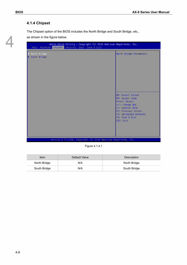
4.1.4 Chipset
The Chipset option of the BIOS includes the North Bridge and South Bridge, etc.,
as shown in the figure below.
Figure 4.1.4.1
Item Default Value Description
North Bridge N/A North Bridge
South Bridge N/A South Bridge

AX-8 Series User Manual BIOS
4-7
4
North Bridge
The North Bridge option of the BIOS includes Intel IGD Configuration and Max TOLUD, etc., as
shown in the figure below:
Figure 4.1.4.2
Item Default Value Description
Intel IGD Configuration N/A Intel Built-in Display Chipset Configuration
Max TOLUD 3 GB TOLUD Setting

BIOS AX-8 Series User Manual
4-8
4
South Bridge
The South Bridge option of the BIOS includes USB Configuration, etc., as shown in the figure
below:
Figure 4.1.4.3
Item Default Value Description
Azalia HD Audio N/A Azalia Audio Configuration
USB Configuration N/A USB Configuration
High Precision Timer Enabled N/A
Restore AC Power Loss Power On N/A
Serial IRQ Mode Quiet N/A
Global SMI Lock Enabled N/A
BIOS Read/Write Protection Enabled N/A

AX-8 Series User Manual BIOS
4-9
4
Automatic Booting When Power is Connected
Steps to enable or disable the automatic booting when power is connected are as described
below:
1. Under the Chipset screen, select the South Bridge option as shown in Figure 4.1.4.4.
2. Select Restore AC Power Loss and set either Power On or Power Off as shown in Figure
4.1.4.5.
When set as Power On, once power is supplied, it will boot directly without the need to press
the boot button.
When set as Power Off, once power is supplied, the boot button also needs to be pressed for it
to boot.
Figure 4.1.4.4

BIOS AX-8 Series User Manual
4-10
4
Figure 4.1.4.5

AX-8 Series User Manual BIOS
4-11
4
4.1.5 Security
The Security option of the BIOS includes the Administrator Password and User Password, etc.,
as shown in Figure 4.1. 5.1:
Figure 4.1.5.1
Item Default Value
Description
Administrator Password N/A Set/Change System Administrator
Password
User Password N/A Set/Change User Password
Secure Boot menu N/A Secure Boot menu

BIOS AX-8 Series User Manual
4-12
4
4.1.6 Boot
The Boot option of the BIOS includes Setup Prompt Timeout and Bootup NumLock State, etc.,
as shown in Figure 4.1.6.1:
Figure 4.1.6.1
Item Default Value Description
Setup Prompt Timeout 1 N/A
Bootup NumLock State On N/A
Quiet Boot Disabled N/A
Boot Option Priorities N/A All Boot Device Priorities
Hard Drive BBS Priorities N/A Hard Drive Device Priorities

AX-8 Series User Manual BIOS
4-13
4
4.1.7 Save & Exit
The Save & Exit option of the BIOS includes Save Changes and Exit and Discard Changes and
Exit, etc., as shown in Figure 4.1.7.1:
Figure 4.1.7.1
Item Default Value
Description
Save Changes and Exit N/A Saves All Current Settings and Exits
Discard Changes and Exit N/A Restores All Previous Settings and Exits
Save Changes and Reset N/A Saves All Current Settings and Restarts
Discard Changes and Reset N/A Restores All Previous Settings and Restarts
Save Changes N/A Save All Current Settings
Discard Changes N/A Restores All Previous Settings
Restore Defaults N/A Restores All Default Settings
Save as User Defaults N/A Saves All Current User Default Settings
Restore User Defaults N/A Restores All User Default Settings
Boot Override N/A Force Boot

5-1
System Operation and Settings
This chapter will explain the system environment operations and settings; users can learn
how to set the system write protection (UWF) function and language change function.
000
5.1 Setting and Releasing of the Write Protection UWF Function ····························· 5-2
5.1.1 Using the PAC_Tool to Perform Write Protection UWF Operations ················· 5-2
5.1.2 Read Current Write Protection Status ······················································ 5-3
5.1.3 Enabling Write Protection······································································ 5-4
5.1.4 Disabling Write Protection ····································································· 5-5
5.1.5 Write Protection Fix ············································································· 5-6
5.2 Operating System Language Change Setting ················································· 5-7
5.3 Write Protection Function Exception ····························································· 5-9

System Operations and Settings AX-8 Series User Manual
5-2
5
5.1 Setting and Releasing of the Write Protection UWF Function
5.1.1 Using the PAC_Tool to Perform Write Protection UWF Operations
The main function of the PAC_Tool is to protect the C drive using write protection mechanisms;
when write protection is enabled, data written to the C drive will be saved in the memory. When
power is disconnected and the system is restarted, the written data will not be saved. To
execute this function, please click PAC_Tool.exe on the desktop.
Figure 5.1.1.1

AX-8 Series User Manual System Operations and Settings
5-3
5
5.1.2 Read Current Write Protection Status
After opening PAC_Tool, Current Status will display the current status.
Disabled: This means that write protection is currently in the Disabled status and changes
will be saved after power disconnection, as shown in the figure below.
Figure 5.1.2.1
Enabled: This means that write protection is currently in the Enabled status and changes
will not be saved after power disconnection, as shown in the figure below.
Figure 5.1.2.2

System Operations and Settings AX-8 Series User Manual
5-4
5
5.1.3 Enabling Write Protection
Using the following steps to enable the write protection function.
(1) Click Enable.
(2) Press Reboot to restart and setting is complete.
Figure 5.1.3.1
(1)
(2)

AX-8 Series User Manual System Operations and Settings
5-5
5
5.1.4 Disabling Write Protection
Using the following steps to disable the write protection function.
(1) Click Disable.
(2) Press Reboot to restart and setting is complete.
Figure 5.1.4.1
(1)
(2)

System Operations and Settings AX-8 Series User Manual
5-6
5
5.1.5 Write Protection Fix
Using the following steps to enable the write protection fix function.
(1) Click Fix.
(2) Press Reboot to restart and setting is complete.
Figure 5.1.5.1
(1) (2)

AX-8 Series User Manual System Operations and Settings
5-7
5
5.2 Operating System Language Change Setting If there is the need to change the language of the operating system, use the following steps to
complete the setting.
If the Current Status is displayed as Disabled,
(1) Click the system language to change.
(2) Press Reboot to restart and setting is complete.
Figure 5.2.1
(1)
(2)

System Operations and Settings AX-8 Series User Manual
5-8
5
If Current Status is Enabled, the write protection function must be disabled first.
(1) Click Disable.
(2) Press Reboot to restart.
(3) Click the system language to change.
(4) Press Reboot to restart.
Figure 5.2.2
(3)
(2), (4)
(1)

AX-8 Series User Manual System Operations and Settings
5-9
5
5.3 Write Protection Function Exception To exclude some folders or files from write protection while the write protection function is
enabled, use the following steps to complete the setting.
If the Current Status is Enabled,
(1) Select the folders or files to add to the exception.
(2) Press Reboot to restart and setting is complete.
Figure 5.3.1
Note: The Touch Panel tab is only for use with Panel type machines. Therefore, this function is not
enabled.
(1) (2) *