S-4000 - Full Compass Systems
108
S-4000 Owner’s Manual http://www.roland.com/ Copyright © 2005 ROLAND CORPORATION Pg. 7). These sections provide important information concerning the proper operation INSTRUCTIONS” (S-4000 Owner’s Manual Pg. 2), “USING THE UNIT SAFELY” Before using this unit, carefully read the sections entitled: “IMPORTANT SAFETY (S-4000 Owner’s Manual Pg. 3), and “IMPORTANT NOTES” (S-4000 Owner’s Manual of the unit. Additionally, in order to feel assured that you have gained a good grasp of every feature provided by your new unit, S-4000 Owner’s Manual should be read in its entirety. The manual should be saved and kept on hand as a convenient reference. All rights reserved. No part of this publication may be reproduced in any form without the written permission of ROLAND CORPORATION.
-
Upload
khangminh22 -
Category
Documents
-
view
1 -
download
0
Transcript of S-4000 - Full Compass Systems
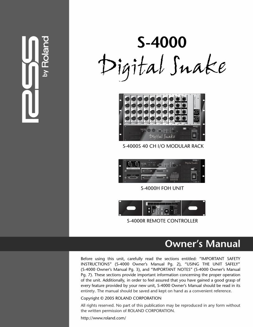
S-4000
Owner’s Manual
•
•
•
http://www.roland.com/
Copyright © 2005 ROLAND CORPORATION
Pg. 7). These sections provide important information concerning the proper operation
INSTRUCTIONS” (S-4000 Owner’s Manual Pg. 2), “USING THE UNIT SAFELY”Before using this unit, carefully read the sections entitled: “IMPORTANT SAFETY
(S-4000 Owner’s Manual Pg. 3), and “IMPORTANT NOTES” (S-4000 Owner’s Manual
of the unit. Additionally, in order to feel assured that you have gained a good grasp ofevery feature provided by your new unit, S-4000 Owner’s Manual should be read in itsentirety. The manual should be saved and kept on hand as a convenient reference.
All rights reserved. No part of this publication may be reproduced in any form without
• Neutrik and EtherCon are registered trademarks of Neutrik, Inc
the written permission of ROLAND CORPORATION.
* 0 4 1 2 8 2 3 4 - 0 8 *
• MMP (Moore Microprocessor Portfolio) refers to a patent portfolio concerned with microprocessor architecture, which was developed by Technology Properties Limited (TPL). Roland has licensed this technology from the TPL Group.
Microsoft and Windows are registered trademarks of Microsoft Corporation.•
Apple and Macintosh are registered trademarks of Apple Computer, Inc.
Mac OS is a trademark of Apple Computer, Inc.
All product names mentioned in this document are trademarks or registered trademarks of their respective owners.
InformationWhen you need repair service, call your nearest Roland Service Center or authorized Roland distributor in your country as shown below.
As of Jan. 1, 2009 (RSS)
ASIA
INDONESIAPT. Citra IntiRamaJL. Cideng Timur No. 15J-15O Jakarta PusatINDONESIATEL: (021) 632-4170
CHINARoland Shanghai Electronics Co.,Ltd.5F. No.1500 Pingliang Road Shanghai 200090, CHINATEL: (021) 5580-0800
Roland Shanghai Electronics Co.,Ltd.(BEIJING OFFICE)10F. No.18 3 Section Anhuaxili Chaoyang District Beijing 100011 CHINATEL: (010) 6426-5050
KOREAKOREA AVICS CO., LTD.Unit B-2208, Woolimblue9, #240-21, Yeomchang-dong, Gangseo-gu, Seoul, KoreaTel: 02-322-3264
TAIWANROLAND TAIWAN ENTERPRISE CO., LTD.Room 5, 9fl. No. 112 Chung Shan N.Road Sec.2, Taipei, TAIWAN, R.O.C.TEL: (02) 2561 3339
SINGAPORE/MALAYSIARoland Asia Pacific Sdn. Bhd.45-1, Block C2, Jalan PJU 1/39, Dataran Prima, 47301 Petaling Jaya, Selangor, MALAYSIATEL: 3-7805-3263
CENTRAL/LATINAMERICA
DENMARKRoland Scandinavia A/SNordhavnsvej 7, Postbox 880,DK-2100 CopenhagenDENMARK
TEL: 3916 6200
FINLANDRoland Scandinavia As, Filial FinlandElannontie 5FIN-01510 Vantaa, FINLANDTEL: (0)9 68 24 020
HUNGARYRoland East Europe Ltd.Warehouse Area ‘DEPO’ Pf.83H-2046 Torokbalint, HUNGARYTEL: (23) 511011
NORWAYRoland Scandinavia Avd. Kontor NorgeLilleakerveien 2 Postboks 95 Lilleaker N-0216 Oslo NORWAYTEL: 2273 0074
POLANDROLAND POLSKA SP. Z O.O.ul. Kty Grodziskie 16B03-289 Warszawa, POLANDTEL: (022) 678 9512
ROMANIAFBS LINESPiata Libertatii 1,535500 Gheorgheni, ROMANIATEL: (266) 364 609
BRAZILRoland Brasil Ltda.Rua San Jose, 211Parque Industrial San JoseCotia - Sao Paulo - SP, BRAZILTEL: (011) 4615 5666
Other CENTRAL/ LATIN AMERICARoland Systems Group U.S.425 Sequoia Drive Suite 114, Bellingham, Washington, 98226 USATEL: 360-594-4282
AUSTRIA/BELGIUM/FRANCE/GERMANY/HOLLAND/LUXEMBOURG/PORTUGAL/SPAIN/SWITZERLANDRoland Iberia, S.L. Paseo García Faria, 33-3508005 Barcelona SPAINTEL: 93 493 91 00
CROATIAART-CENTARDegenova 3.HR - 10000 ZagrebTEL: (1) 466 8493
CZECH REP.CZECH REPUBLIC DISTRIBUTOR s.r.oVoctárova 247/16CZ - 180 00 PRAHA 8,CZECH REP.TEL: (2) 830 20270
EUROPE
OCEANIA
AUSTRALIA/NEW ZEALAND Roland CorporationAustralia Pty.,Ltd. 38 Campbell AvenueDee Why West, NSW 2099AUSTRALIA
For AustraliaTEL: (02) 9982 8266For New ZealandTEL: (09) 3098 715
CANADARoland Canada Ltd.(Head Office)5480 Parkwood Way, Richmond B. C., V6V 2M4 CANADA TEL: (604) 270 6626
Roland Canada Ltd.(Toronto Office)170 Admiral BoulevardMississauga ON L5T 2N6 CANADA TEL: (905) 362 9707
U. S. A.Roland Systems Group U.S.425 Sequoia Drive Suite 114, Bellingham, Washington, 98226 USATEL: 360-594-4282
RUSSIAMuTekDorozhnaya ul.3,korp.6117 545 Moscow, RUSSIA TEL: (095) 981-4967
SLOVAKIADAN Acoustic s.r.o. Povazská 18.SK - 940 01 Nové ZámkyTEL: (035) 6424 330
SWEDENRoland Scandinavia A/S SWEDISH SALES OFFICEDanvik Center 28, 2 tr. S-131 30 Nacka SWEDEN TEL: (0)8 702 00 20
UKRAINEEURHYTHMICS Ltd.P.O.Box: 37-a.Nedecey Str. 30UA - 89600 Mukachevo, UKRAINETEL: (03131) 414-40
UNITED KINGDOM/IRELANDRoland (U.K.) Ltd.Atlantic Close, Swansea Enterprise Park, SwanseaSA7 9FJ, UNITED KINGDOMTEL: (01792) 702701
NORTH AMERICA

This product complies with the requirements of EMCD 2004/108/EC and LVD 2006/95/EC.
For EU Countries
For Canada
This Class B digital apparatus meets all requirements of the Canadian Interference-Causing Equipment Regulations.
Cet appareil numérique de la classe B respecte toutes les exigences du Règlement sur le matériel brouilleur du Canada.
NOTICE
AVIS
For the USA
FEDERAL COMMUNICATIONS COMMISSIONRADIO FREQUENCY INTERFERENCE STATEMENT
This equipment has been tested and found to comply with the limits for a Class B digital device, pursuant to Part 15 of the FCC Rules. These limits are designed to provide reasonable protection against harmful interference in a residential installation. This equipment generates, uses, and can radiate radio frequency energy and, if not installed and used in accordance with the instructions, may cause harmful interference to radio communications. However, there is no guarantee that interference will not occur in a particular installation. If this equipment does cause harmful interference to radio or television reception, which can be determined by turning the equipment off and on, the user is encouraged to try to correct the interference by one or more of the following measures:
– Reorient or relocate the receiving antenna.– Increase the separation between the equipment and receiver.– Connect the equipment into an outlet on a circuit different from that to which the receiver is connected.– Consult the dealer or an experienced radio/TV technician for help.
This device complies with Part 15 of the FCC Rules. Operation is subject to the following two conditions: (1) this device may not cause harmful interference, and (2) this device must accept any interference received, including interference that may cause undesired operation.
Unauthorized changes or modification to this system can void the users authority to operate this equipment.This equipment requires shielded interface cables in order to meet FCC class B Limit.
WARNINGThis product contains chemicals known to cause cancer, birth defects and other reproductive harm, including lead.
For C.A. US (Proposition 65)
For EU Countries

S-4000 Digital Snake Owner’s Manual 3
• Before using this unit, make sure to read the instructions below, and the Owner's Manual.
• Connect mains plug of this model to a mains socket outlet with a protective earthing connection.
• Do not open or perform any internal modifica-tions on the unit.
• Do not attempt to repair the unit, or replace parts within it (except when this manual provides specific instructions directing you to do so). Refer all servicing to your retailer, the nearest Roland Service Center, or an authorized Roland distributor, as listed on the "Information" page.
• Never use or store the unit in places that are:• Subject to temperature extremes (e.g., direct
sunlight in an enclosed vehicle, near a heating duct, on top of heat-generating equipment); or are
• Damp (e.g., baths, washrooms, on wet floors); or are
• Humid; or are• Exposed to rain; or are• Dusty; or are• Subject to high levels of vibration.
• Make sure you always have the unit placed so it is level and sure to remain stable. Never place it on stands that could wobble, or on inclined surfaces.
• The unit should be connected to a power supply only of the type described in the operating instructions, or as marked on the rear side of unit.
• Use only the attached power-supply cord. Also, the supplied power cord must not be used with any other device.
• Do not excessively twist or bend the power cord, nor place heavy objects on it. Doing so can damage the cord, producing severed elements and short circuits. Damaged cords are fire and shock hazards!
• This unit, either alone or in combination with an amplifier and headphones or speakers, may be capable of producing sound levels that could cause permanent hearing loss. Do not operate for a long period of time at a high volume level, or at a level that is uncomfortable. If you experience any hearing loss or ringing in the ears, you should immediately stop using the unit, and consult an audiologist.
• Do not allow any objects (e.g., flammable material, coins, pins); or liquids of any kind (water, soft drinks, etc.) to penetrate the unit.
Used for instructions intended to alert the user to the risk of injury or material damage should the unit be used improperly.
* Material damage refers to damage or other adverse effects caused with respect to the home and all its furnishings, as well to domestic animals or pets.
Used for instructions intended to alert the user to the risk of death or severe injury should the unit be used improperly.
The symbol alerts the user to things that must be carried out. The specific thing that must be done is indicated by the design contained within the circle. In the case of the symbol at left, it means that the power-cord plug must be unplugged from the outlet.
The symbol alerts the user to important instructions or warnings. The specific meaning of the symbol is determined by the design contained within the triangle. In the case of the symbol at left, it is used for general cautions, warnings, or alerts to danger.
The symbol alerts the user to items that must never be carried out (are forbidden). The specific thing that must not be done is indicated by the design contained within the circle. In the case of the symbol at left, it means that the unit must never be disassembled.

Using the Unit Safely
4 S-4000 Digital Snake Owner’s Manual
• Immediately turn the power off, remove the power cord from the outlet, and request servicing by your retailer, the nearest Roland Service Center, or an authorized Roland distributor, as listed on the "Information" page when:• The power-supply cord, or the plug has been
damaged; or• If smoke or unusual odor occurs• Objects have fallen into, or liquid has been
spilled onto the unit; or• The unit has been exposed to rain (or
otherwise has become wet); or• The unit does not appear to operate normally
or exhibits a marked change in performance.
• In households with small children, an adult should provide supervision until the child is capable of following all the rules essential for the safe operation of the unit.
• Protect the unit from strong impact.(Do not drop it!)
• Do not force the unit's power-supply cord to share an outlet with an unreasonable number of other devices. Be especially careful when using extension cords---the total power used by all devices you have connected to the extension cord's outlet must never exceed the power rating (watts/amperes) for the extension cord. Excessive loads can cause the insulation on the cord to heat up and eventually melt through.
• Before using the unit in a foreign country, consult with your retailer, the nearest Roland Service Center, or an authorized Roland distributor, as listed on the "Information" page.
• Do not put anything that contains water (e.g., flower vases) on this unit. Also, avoid the use of insecticides, perfumes, alcohol, nail polish, spray cans, etc., near the unit. Swiftly wipe away any liquid that spills on the unit using a dry, soft cloth.
• The unit should be located so that its location or position does not interfere with its proper venti-lation.
• Always grasp only the plug on the power-supply cord when plugging into, or unplugging from, an outlet or this unit.
• At regular intervals, you should unplug the power plug and clean it by using a dry cloth to wipe all dust and other accumulations away from its prongs. Also, disconnect the power plug from the power outlet whenever the unit is to remain unused for an extended period of time. Any accumulation of dust between the power plug and the power outlet can result in poor insulation and lead to fire.
• Try to prevent cords and cables from becoming entangled. Also, all cords and cables should be placed so they are out of the reach of children.
• Never climb on top of, nor place heavy objects on the unit.
• Never handle the power cord or its plugs with wet hands when plugging into, or unplugging from, an outlet or this unit.
• Before moving the unit, disconnect the power plug from the outlet, and pull out all cords from external devices.
• Before cleaning the unit, turn off the power and unplug the power cord from the outlet.
• Whenever you suspect the possibility of lightning in your area, pull the plug on the power cord out of the outlet.
• Keep the included ferrite cores and REAC connector covers in a safe place out of children's reach, so there is no chance of them being swallowed accidentally.
• Keep any screws for the connector guard you may remove and the included screws for the connector guard in a safe place out of children's reach, so there is no chance of them being swallowed accidentally.

S-4000 Digital Snake Owner’s Manual 5
Using the Unit Safely
• Always turn the phantom power off when connecting any device that does not require +48 V phantom power. You risk causing damage if you mistakenly supply phantom power to dynamic microphones, audio playback devices, or other devices that donʼt require such power. Be sure to check the specifications of any microphone or other device you intend to use by referring to the documentation that came with it.
(The S-4000S phantom power specification: +48 V DC, 14 mA Max.)

Using the Unit Safely
6 S-4000 Digital Snake Owner’s Manual

S-4000 Digital Snake Owner’s Manual 7
In addition to the items listed under IMPORTANT SAFETY INSTRUCTIONS (Page 2) and USING THE UNIT SAFELY (Page 3), please read and observe thefollowing:
Power Supply• Do not connect this unit to same electrical outlet
that is being used by an electrical appliance thatis controlled by an inverter (such as a refrigerator, washing machine, microwave oven, or air conditioner), or that contains a motor. Dependingon the way in which the electrical appliance isused, power supply noise may cause this unit tomalfunction or may produce audible noise. If itis not practical to use a separate electrical outlet,connect a power supply noise filter between thisunit and the electrical outlet.
• Before connecting this unit to other devices, turnoff the power to all units. This will help preventmalfunctions and/or damage to speakers or other devices.
• Although the LEDs are switched off when thePOWER switch is switched off, this does not meanthat the unit has been completely disconnectedfrom the source of power. If you need to turn off thepower completely, first turn off the POWER switch,then unplug the power cord from the power outlet.For this reason, the outlet into which you choose toconnect the power cord’s plug should be one thatis within easy reach and readily accessible.
Placement• Using the unit near power amplifiers (or other
equipment containing large power transformers)may induce hum. To alleviate the problem, changethe orientation of this unit; or move it farther awayfrom the source of interference.
• This device may interfere with radio and televisionreception. Do not use this device in the vicinity of such receivers.
• Noise may be produced if wireless communicationsdevices, such as cell phones, are operated in thevicinity of this unit. Such noise could occur whenreceiving or initiating a call, or while conversing.Should you experience such problems, you shouldrelocate such wireless devices so they are at agreater distance from this unit, or switch them off.
• When moved from one location to another wherethe temperature and/or humidity is very different,water droplets (condensation) may form insidethe unit. Damage or malfunction may result if youattempt to use the unit in this condition. Therefore,before using the unit, you must allow it to stand for several hours, until the condensation has completelyevaporated.
Maintenance• For everyday cleaning wipe the unit with a soft,
dry cloth or one that has been slightly dampenedwith water. To remove stubborn dirt, use a clothimpregnated with a mild, non-abrasive detergent.Afterwards, be sure to wipe the unit thoroughlywith a soft, dry cloth.
• Never use benzine, thinners, alcohol or solvents of any kind, to avoid the possibility of discolorationand/or deformation.
Additional Precautions• Use a reasonable amount of care when using the
unit’s buttons, sliders, or other controls; and whenusing its jacks and connectors. Rough handling canlead to malfunctions.
• When connecting / disconnecting all cables, graspthe connector itself—never pull on the cable. Thisway, you will avoid causing shorts, or damage tothe cable’s internal elements.
• A small amount of heat will radiate from the unitduring normal operation.
• To avoid disturbing your neighbors, try to keep theunit’s volume at reasonable levels (especially whenit is late at night).
Important Notes

Important Notes
8 S-4000 Digital Snake Owner’s Manual
• When you need to transport the unit, package itin the box (including padding) that it came in, if possible. Otherwise, you will need to use equivalentpackaging materials.

S-4000 Digital Snake Owner’s Manual 9
Table of Contents
Important Safety Instructions . . . . . . . . . . . . . . . . . . . . . . . . . . . . . . . . . . 2
Using the Unit Safely . . . . . . . . . . . . . . . . . . . . . . . . . . . . . . . . . . . . . . . . . 3
Important Notes . . . . . . . . . . . . . . . . . . . . . . . . . . . . . . . . . . . . . . . . . . . . 7
1—Introduction . . . . . . . . . . . . . . . . . . . . . . . . . . . . . . . . . . . . . . . . . . . . 13Welcome . . . . . . . . . . . . . . . . . . . . . . . . . . . . . . . . . . . . . . . . . . . . . . . . . . . . . . . . . . . . . . . . . . . . . 13
About This Manual . . . . . . . . . . . . . . . . . . . . . . . . . . . . . . . . . . . . . . . . . . . . . . . . . . . . . . . . . . . . . 13
How the Manual is Organized . . . . . . . . . . . . . . . . . . . . . . . . . . . . . . . . . . . . . . . . . . . . . . . . . . 13
Conventions Used in the Manual . . . . . . . . . . . . . . . . . . . . . . . . . . . . . . . . . . . . . . . . . . . . . . . . 14
Note, Tip, and Warning Icons . . . . . . . . . . . . . . . . . . . . . . . . . . . . . . . . . . . . . . . . . . . . . . . . . . . 15
Other S-4000 Digital Snake Documents . . . . . . . . . . . . . . . . . . . . . . . . . . . . . . . . . . . . . . . . . . . 15
2—Main Features . . . . . . . . . . . . . . . . . . . . . . . . . . . . . . . . . . . . . . . . . . . 17S-4000 System . . . . . . . . . . . . . . . . . . . . . . . . . . . . . . . . . . . . . . . . . . . . . . . . . . . . . . . . . . . . . . . . 17
System Components . . . . . . . . . . . . . . . . . . . . . . . . . . . . . . . . . . . . . . . . . . . . . . . . . . . . . . . . . . . . 17
3—Components and Accessories . . . . . . . . . . . . . . . . . . . . . . . . . . . . . . . 19What’s Included. . . . . . . . . . . . . . . . . . . . . . . . . . . . . . . . . . . . . . . . . . . . . . . . . . . . . . . . . . . . . . . . 19
System Options . . . . . . . . . . . . . . . . . . . . . . . . . . . . . . . . . . . . . . . . . . . . . . . . . . . . . . . . . . . . . . . . 20
4—Panel Descriptions . . . . . . . . . . . . . . . . . . . . . . . . . . . . . . . . . . . . . . . 21S-4000S 40 CH I/O Modular Rack . . . . . . . . . . . . . . . . . . . . . . . . . . . . . . . . . . . . . . . . . . . . . . . . . . 21
S-4000S Front Panel . . . . . . . . . . . . . . . . . . . . . . . . . . . . . . . . . . . . . . . . . . . . . . . . . . . . . . . . . . 21
S-4000S Rear Panel . . . . . . . . . . . . . . . . . . . . . . . . . . . . . . . . . . . . . . . . . . . . . . . . . . . . . . . . . . . 24
S-4000H 32x8 FOH Unit . . . . . . . . . . . . . . . . . . . . . . . . . . . . . . . . . . . . . . . . . . . . . . . . . . . . . . . . . 25
S-4000H Front Panel . . . . . . . . . . . . . . . . . . . . . . . . . . . . . . . . . . . . . . . . . . . . . . . . . . . . . . . . . 25
S-4000H Rear Panel . . . . . . . . . . . . . . . . . . . . . . . . . . . . . . . . . . . . . . . . . . . . . . . . . . . . . . . . . . 28
S-4000R Remote Controller . . . . . . . . . . . . . . . . . . . . . . . . . . . . . . . . . . . . . . . . . . . . . . . . . . . . . . .r 29
S-4000R Front Panel . . . . . . . . . . . . . . . . . . . . . . . . . . . . . . . . . . . . . . . . . . . . . . . . . . . . . . . . . . 29
S-4000R Rear Panel . . . . . . . . . . . . . . . . . . . . . . . . . . . . . . . . . . . . . . . . . . . . . . . . . . . . . . . . . . 31
5—S-4000 System Overview . . . . . . . . . . . . . . . . . . . . . . . . . . . . . . . . . . 33Concept . . . . . . . . . . . . . . . . . . . . . . . . . . . . . . . . . . . . . . . . . . . . . . . . . . . . . . . . . . . . . . . . . . . . . 33
Things to Know . . . . . . . . . . . . . . . . . . . . . . . . . . . . . . . . . . . . . . . . . . . . . . . . . . . . . . . . . . . . . . . . 34
About REAC . . . . . . . . . . . . . . . . . . . . . . . . . . . . . . . . . . . . . . . . . . . . . . . . . . . . . . . . . . . . . . . . 34
Understanding Cables and Connections . . . . . . . . . . . . . . . . . . . . . . . . . . . . . . . . . . . . . . . . 34
Cat5e Ethernet Cable Types . . . . . . . . . . . . . . . . . . . . . . . . . . . . . . . . . . . . . . . . . . . . . . . . . . 34
Table of Contents
10 S-4000 Digital Snake Owner’s Manual
Ethernet Connectors . . . . . . . . . . . . . . . . . . . . . . . . . . . . . . . . . . . . . . . . . . . . . . . . . . . . . . . 35
About Ethernet Switching Hubs. . . . . . . . . . . . . . . . . . . . . . . . . . . . . . . . . . . . . . . . . . . . . . . 36
Built-in Redundant Connections . . . . . . . . . . . . . . . . . . . . . . . . . . . . . . . . . . . . . . . . . . . . . . 37
A/D-D/A Conversion and Signal Optimization . . . . . . . . . . . . . . . . . . . . . . . . . . . . . . . . . . . . . . 37
RS-232C Serial Interface . . . . . . . . . . . . . . . . . . . . . . . . . . . . . . . . . . . . . . . . . . . . . . . . . . . . . . . 37
Optional Redundant Power Supply . . . . . . . . . . . . . . . . . . . . . . . . . . . . . . . . . . . . . . . . . . . . . . . 38
The System Components: A Closer Look . . . . . . . . . . . . . . . . . . . . . . . . . . . . . . . . . . . . . . . . . . . . . 38
S-4000S 40 Channel I/O Modular Rack . . . . . . . . . . . . . . . . . . . . . . . . . . . . . . . . . . . . . . . . . . . 38
About the Remote Controlled Preamps . . . . . . . . . . . . . . . . . . . . . . . . . . . . . . . . . . . . . . . . . 38
S-4000H 32x8 FOH Unit. . . . . . . . . . . . . . . . . . . . . . . . . . . . . . . . . . . . . . . . . . . . . . . . . . . . . . . 39
About the S-4000H’s Audio I/O . . . . . . . . . . . . . . . . . . . . . . . . . . . . . . . . . . . . . . . . . . . . . . . 39
S-4000R Remote Controller . . . . . . . . . . . . . . . . . . . . . . . . . . . . . . . . . . . . . . . . . . . . . . . . . . . . 40
Computer Control . . . . . . . . . . . . . . . . . . . . . . . . . . . . . . . . . . . . . . . . . . . . . . . . . . . . . . . . . . . 40
6—Using the S-4000 System . . . . . . . . . . . . . . . . . . . . . . . . . . . . . . . . . . 41Installation Notes . . . . . . . . . . . . . . . . . . . . . . . . . . . . . . . . . . . . . . . . . . . . . . . . . . . . . . . . . . . . . . . 41
S-4000S and S-4000H . . . . . . . . . . . . . . . . . . . . . . . . . . . . . . . . . . . . . . . . . . . . . . . . . . . . . . . . 41
Using the AC Cord Clamp . . . . . . . . . . . . . . . . . . . . . . . . . . . . . . . . . . . . . . . . . . . . . . . . . . . 41
Recessed Rack-Mounting . . . . . . . . . . . . . . . . . . . . . . . . . . . . . . . . . . . . . . . . . . . . . . . . . . . . 41
DB-25 Connector Guard (S-4000H Only) . . . . . . . . . . . . . . . . . . . . . . . . . . . . . . . . . . . . . . . 44
Rack-Mounting the S-4000R. . . . . . . . . . . . . . . . . . . . . . . . . . . . . . . . . . . . . . . . . . . . . . . . . . . . 45
Using the REAC Connector Covers (S-4000S and S-4000H) . . . . . . . . . . . . . . . . . . . . . . . . . . . . 46
Installing the Included Ferrite Cores on Ethernet Cables . . . . . . . . . . . . . . . . . . . . . . . . . . . . . . . 47
Connection Overview . . . . . . . . . . . . . . . . . . . . . . . . . . . . . . . . . . . . . . . . . . . . . . . . . . . . . . . . . . . 48
Setting the REAC Mode . . . . . . . . . . . . . . . . . . . . . . . . . . . . . . . . . . . . . . . . . . . . . . . . . . . . . . . . . . 49
Setting the REAC MODE Switches . . . . . . . . . . . . . . . . . . . . . . . . . . . . . . . . . . . . . . . . . . . . . 50
Component Connections . . . . . . . . . . . . . . . . . . . . . . . . . . . . . . . . . . . . . . . . . . . . . . . . . . . . . . . . 50
AC Power Connections . . . . . . . . . . . . . . . . . . . . . . . . . . . . . . . . . . . . . . . . . . . . . . . . . . . . . . . . 50
REAC Connections . . . . . . . . . . . . . . . . . . . . . . . . . . . . . . . . . . . . . . . . . . . . . . . . . . . . . . . . . . . 51
Cable Requirements . . . . . . . . . . . . . . . . . . . . . . . . . . . . . . . . . . . . . . . . . . . . . . . . . . . . . . . 51
Connecting Cables to the REAC Ports . . . . . . . . . . . . . . . . . . . . . . . . . . . . . . . . . . . . . . . . . . 52
REAC Cable Length Extension . . . . . . . . . . . . . . . . . . . . . . . . . . . . . . . . . . . . . . . . . . . . . . . . 53
Using an Ethernet Switching Hub with Redundant REAC Connections . . . . . . . . . . . . . . . . . 53
REAC Connection Notes . . . . . . . . . . . . . . . . . . . . . . . . . . . . . . . . . . . . . . . . . . . . . . . . . . . . 54
Notes About Handling Cat5e Cables . . . . . . . . . . . . . . . . . . . . . . . . . . . . . . . . . . . . . . . . . . . 54
Connecting the S-4000R Remote Controller. . . . . . . . . . . . . . . . . . . . . . . . . . . . . . . . . . . . . . . .r 55
Audio Connections . . . . . . . . . . . . . . . . . . . . . . . . . . . . . . . . . . . . . . . . . . . . . . . . . . . . . . . . . . . . . 56
S-4000S Audio Connections . . . . . . . . . . . . . . . . . . . . . . . . . . . . . . . . . . . . . . . . . . . . . . . . . . . . 56
S-4000S Audio Inputs . . . . . . . . . . . . . . . . . . . . . . . . . . . . . . . . . . . . . . . . . . . . . . . . . . . . . . 57
Input Status Indicators . . . . . . . . . . . . . . . . . . . . . . . . . . . . . . . . . . . . . . . . . . . . . . . . . . . 58
S-4000S Audio Outputs . . . . . . . . . . . . . . . . . . . . . . . . . . . . . . . . . . . . . . . . . . . . . . . . . . . . . 58

S-4000 Digital Snake Owner’s Manual 11
Table of Contents
S-4000H Audio Connections . . . . . . . . . . . . . . . . . . . . . . . . . . . . . . . . . . . . . . . . . . . . . . . . . . . 59
S-4000H Audio Outputs . . . . . . . . . . . . . . . . . . . . . . . . . . . . . . . . . . . . . . . . . . . . . . . . . . . . 59
S-4000H Audio Inputs . . . . . . . . . . . . . . . . . . . . . . . . . . . . . . . . . . . . . . . . . . . . . . . . . . . . . . 60
Powering Up/System Status Indicators . . . . . . . . . . . . . . . . . . . . . . . . . . . . . . . . . . . . . . . . . . . . . . 60
Powering Up . . . . . . . . . . . . . . . . . . . . . . . . . . . . . . . . . . . . . . . . . . . . . . . . . . . . . . . . . . . . . . . 60
Checking the System Status Indicators . . . . . . . . . . . . . . . . . . . . . . . . . . . . . . . . . . . . . . . . . . . . 61
Power Indicators . . . . . . . . . . . . . . . . . . . . . . . . . . . . . . . . . . . . . . . . . . . . . . . . . . . . . . . . . . 61
REAC Communication . . . . . . . . . . . . . . . . . . . . . . . . . . . . . . . . . . . . . . . . . . . . . . . . . . . . . . 61
Remote Communication . . . . . . . . . . . . . . . . . . . . . . . . . . . . . . . . . . . . . . . . . . . . . . . . . . . . 62
Powering Off . . . . . . . . . . . . . . . . . . . . . . . . . . . . . . . . . . . . . . . . . . . . . . . . . . . . . . . . . . . . . . . . . .f 62
Muting the System Outputs . . . . . . . . . . . . . . . . . . . . . . . . . . . . . . . . . . . . . . . . . . . . . . . . . . . . . . 63
Using the S-4000R Remote Controller . . . . . . . . . . . . . . . . . . . . . . . . . . . . . . . . . . . . . . . . . . . . . . .r 64
Lock Mode . . . . . . . . . . . . . . . . . . . . . . . . . . . . . . . . . . . . . . . . . . . . . . . . . . . . . . . . . . . . . . . . . 64
Monitoring Input Signals . . . . . . . . . . . . . . . . . . . . . . . . . . . . . . . . . . . . . . . . . . . . . . . . . . . . . . 65
Signal Status Indicators . . . . . . . . . . . . . . . . . . . . . . . . . . . . . . . . . . . . . . . . . . . . . . . . . . . . . 65
Clearing the CLIP Indicators . . . . . . . . . . . . . . . . . . . . . . . . . . . . . . . . . . . . . . . . . . . . . . . . . 65
LED Input Meter . . . . . . . . . . . . . . . . . . . . . . . . . . . . . . . . . . . . . . . . . . . . . . . . . . . . . . . . . . 66
S-4000S Input Channel Settings . . . . . . . . . . . . . . . . . . . . . . . . . . . . . . . . . . . . . . . . . . . . . . . . . 66
Selecting a Channel for Editing . . . . . . . . . . . . . . . . . . . . . . . . . . . . . . . . . . . . . . . . . . . . . . . 66
Setting the Preamp Gain . . . . . . . . . . . . . . . . . . . . . . . . . . . . . . . . . . . . . . . . . . . . . . . . . . . . 67
Input Pad . . . . . . . . . . . . . . . . . . . . . . . . . . . . . . . . . . . . . . . . . . . . . . . . . . . . . . . . . . . . . . . 67
Phantom Power . . . . . . . . . . . . . . . . . . . . . . . . . . . . . . . . . . . . . . . . . . . . . . . . . . . . . . . . . . .r 68
Stereo Link . . . . . . . . . . . . . . . . . . . . . . . . . . . . . . . . . . . . . . . . . . . . . . . . . . . . . . . . . . . . . . 69
Memory Function. . . . . . . . . . . . . . . . . . . . . . . . . . . . . . . . . . . . . . . . . . . . . . . . . . . . . . . . . . . . 70
Storing a Memory Preset (Memory Store Mode) . . . . . . . . . . . . . . . . . . . . . . . . . . . . . . . . . . 70
Recalling a Memory Preset (Memory Recall Mode) . . . . . . . . . . . . . . . . . . . . . . . . . . . . . . . . 70
7—Advanced Use . . . . . . . . . . . . . . . . . . . . . . . . . . . . . . . . . . . . . . . . . . . 71Using Two S-4000R Units in a Single S-4000 System . . . . . . . . . . . . . . . . . . . . . . . . . . . . . . . . . . . . 71
Computer Control (S-4000 RCS) . . . . . . . . . . . . . . . . . . . . . . . . . . . . . . . . . . . . . . . . . . . . . . . . . . . 72
Where to Get the S-4000 RCS . . . . . . . . . . . . . . . . . . . . . . . . . . . . . . . . . . . . . . . . . . . . . . . . 72
System Requirements . . . . . . . . . . . . . . . . . . . . . . . . . . . . . . . . . . . . . . . . . . . . . . . . . . . . . . 72
System Expansion . . . . . . . . . . . . . . . . . . . . . . . . . . . . . . . . . . . . . . . . . . . . . . . . . . . . . . . . . . . . . . 73
Adding More I/O . . . . . . . . . . . . . . . . . . . . . . . . . . . . . . . . . . . . . . . . . . . . . . . . . . . . . . . . . . . . 73
Remote Control and Monitoring of Multiple Systems . . . . . . . . . . . . . . . . . . . . . . . . . . . . . . 73
Splitting Stage Audio to Multiple Destinations . . . . . . . . . . . . . . . . . . . . . . . . . . . . . . . . . . . . . . 74
What You’ll Need . . . . . . . . . . . . . . . . . . . . . . . . . . . . . . . . . . . . . . . . . . . . . . . . . . . . . . . . . 74
Ethernet Switching Hub Requirements . . . . . . . . . . . . . . . . . . . . . . . . . . . . . . . . . . . . . . . . . 74
Split Connection Overview . . . . . . . . . . . . . . . . . . . . . . . . . . . . . . . . . . . . . . . . . . . . . . . . . . 75
Setting the REAC MODE Switches . . . . . . . . . . . . . . . . . . . . . . . . . . . . . . . . . . . . . . . . . . . . . 76
REAC Connections. . . . . . . . . . . . . . . . . . . . . . . . . . . . . . . . . . . . . . . . . . . . . . . . . . . . . . . . . 76
Table of Contents
12 S-4000 Digital Snake Owner’s Manual
Audio Connections and Power Up . . . . . . . . . . . . . . . . . . . . . . . . . . . . . . . . . . . . . . . . . . . . . 77
Notes on Split Setups . . . . . . . . . . . . . . . . . . . . . . . . . . . . . . . . . . . . . . . . . . . . . . . . . . . . . . 77
MIDI Communication Via REAC. . . . . . . . . . . . . . . . . . . . . . . . . . . . . . . . . . . . . . . . . . . . . . . . . . . . 78
8—Applications . . . . . . . . . . . . . . . . . . . . . . . . . . . . . . . . . . . . . . . . . . . . 7932x8 System . . . . . . . . . . . . . . . . . . . . . . . . . . . . . . . . . . . . . . . . . . . . . . . . . . . . . . . . . . . . . . . . . . 79
32x8 System with 32 Channel Split . . . . . . . . . . . . . . . . . . . . . . . . . . . . . . . . . . . . . . . . . . . . . . . . . 80
64x16 System . . . . . . . . . . . . . . . . . . . . . . . . . . . . . . . . . . . . . . . . . . . . . . . . . . . . . . . . . . . . . . . . . 81
64x16 System with 64 Channel Split. . . . . . . . . . . . . . . . . . . . . . . . . . . . . . . . . . . . . . . . . . . . . . . . 82
Appendices . . . . . . . . . . . . . . . . . . . . . . . . . . . . . . . . . . . . . . . . . . . . . . . . 83Appendix A: Troubleshooting . . . . . . . . . . . . . . . . . . . . . . . . . . . . . . . . . . . . . . . . . . . . . . . . . . . . . 83
System Status and Error Indicators . . . . . . . . . . . . . . . . . . . . . . . . . . . . . . . . . . . . . . . . . . . . . . . 83
Appendix B: Connector Information . . . . . . . . . . . . . . . . . . . . . . . . . . . . . . . . . . . . . . . . . . . . . . . . 89
Cat5e Ethernet Cable Wiring (RJ45-type Connectors) . . . . . . . . . . . . . . . . . . . . . . . . . . . . . . . . . 89
Cat5e Crossover Wiring . . . . . . . . . . . . . . . . . . . . . . . . . . . . . . . . . . . . . . . . . . . . . . . . . . . . . 89
Cat5e Straight-Through Wiring . . . . . . . . . . . . . . . . . . . . . . . . . . . . . . . . . . . . . . . . . . . . . . . 89
RS-232C (REMOTE) Connector (D-Sub, DB-9-type) . . . . . . . . . . . . . . . . . . . . . . . . . . . . . . . . . . 90
S-4000S Audio Connectors (XLR-type) . . . . . . . . . . . . . . . . . . . . . . . . . . . . . . . . . . . . . . . . . . . . 90
S-4000S Channel Numbers . . . . . . . . . . . . . . . . . . . . . . . . . . . . . . . . . . . . . . . . . . . . . . . . . . 90
S-4000S XLR Audio Pin Outs (INPUT and OUTPUT) . . . . . . . . . . . . . . . . . . . . . . . . . . . . . . . 91
S-4000H Audio Connectors (D-Sub, DB-25-type) . . . . . . . . . . . . . . . . . . . . . . . . . . . . . . . . . . . . 91
Lock-Down Screw Thread Size . . . . . . . . . . . . . . . . . . . . . . . . . . . . . . . . . . . . . . . . . . . . . . . . 91
S-4000H DB-25 Audio Pin Outs . . . . . . . . . . . . . . . . . . . . . . . . . . . . . . . . . . . . . . . . . . . . . . . 92
Appendix C: Ethernet Switching Hub Requirements . . . . . . . . . . . . . . . . . . . . . . . . . . . . . . . . . . . . 93
Appendix D: Specifications . . . . . . . . . . . . . . . . . . . . . . . . . . . . . . . . . . . . . . . . . . . . . . . . . . . . . . . 94
Appendix E: Dimensions . . . . . . . . . . . . . . . . . . . . . . . . . . . . . . . . . . . . . . . . . . . . . . . . . . . . . . . . . 98
Dimensions: S-4000S . . . . . . . . . . . . . . . . . . . . . . . . . . . . . . . . . . . . . . . . . . . . . . . . . . . . . . . . . 98
Dimensions: S-4000H . . . . . . . . . . . . . . . . . . . . . . . . . . . . . . . . . . . . . . . . . . . . . . . . . . . . . . . . . 99
Dimensions: S-4000R . . . . . . . . . . . . . . . . . . . . . . . . . . . . . . . . . . . . . . . . . . . . . . . . . . . . . . . . 100
Index. . . . . . . . . . . . . . . . . . . . . . . . . . . . . . . . . . . . . . . . . . . . . . . . . . . . 101

S-4000 Digital Snake Owner’s Manual 13
Welcome
Congratulations on your purchase of the RSS S-4000 Digital Snake System. Featuring the new REAC(Roland Ethernet Audio Communication) interface, the S-4000 System brings the audio snake into the digital age.
The S-4000 System is designed to be extremely easy to configure and set up, and is at home in anyapplication where multichannel audio transfer is required.
About This Manual
How the Manual is OrganizedThe S-4000 Digital Snake Owner’s Manual explains the S-4000 System’s primary components and lfunctions. It also details the connection and operation of the system, and provides many tips and diagrams to help you configure the Digital Snake for your particular application.
To get the most out of your S-4000 Digital Snake, we recommend reading the entire manual. Thematerial is presented in the following chapters:
• Main Features—briefly describes the features and benefits of the system and its components.ss
• Components and Accessories—lists what’s included with the S-4000 System and some of the ssavailable system options.
• Panel Descriptions—show you where everything is and what it’s for.ss
• S-4000 System Overview—discusses the concept of the Digital Snake, and explains some of thewwtechnologies that make up the system.
• Using the S-4000 System—shows you how to hook everything together and use the system’s components.
• Advanced Use—discusses advanced topics such as controlling the system with a computer and eesplitting the audio to multiple destinations.
• Applications—provides diagrams for various S-4000 System setups.ss
• Appendices—details system status and error indicators, troubleshooting, cable pin outs, andsstechnical specifications.
Introduction 1

1—Introduction
14 S-4000 Digital Snake Owner’s Manual
Conventions Used in the Manual
Names
The S-4000 Digital Snake System is comprised of three primary components:
• S-4000S 40 CH I/O Modular Rack
• S-4000H 32x8 FOH Unit
• S-4000R Remote Controller
Throughout the text, the individual components’ names are often shortened, and referred to simply as“S-4000S,” “S-4000H,” and “S-4000R.” When a procedure or description refers to the entire system,the name “S-4000 System” is used.
Additionally, the names of buttons, knobs, and connectors are shown exactly as they appear on thesystem components. As a result, these names are shown completely in capital letters. For example, thebutton labeled “LOCK” will appear in the manual as the LOCK button, or simply LOCK, as in “PressLOCK.”
One button on the S-4000R serves a dual purpose. The button’s name indicates both of its functions:CLIP CLEAR•ENTER.
Usage Conventions
The purpose of the S-4000 System is to function as an audio “snake”—a device used to transfer multiple audio signals from one place to another, usually over a long distance. Since the S-4000System transfers signals as digital data—the system’s primary benefit—it’s called a “digital snake.”
In most cases, audio snakes are used in sound reinforcement applications that involve a musical performance, a theatre presentation, or an orator (or orators). In such applications, the primary source of the audio is at a “stage” area, and that audio is sent via the snake to a “mixing” position (also referred to as the “front of house” or FOH position).
Of course, there are many other usage applications for an audio snake, such as transferring audioto a recording setup, a broadcast feed, or any other application where multiple audio signals are transferred and managed.
Occasionally, the manual refers to a physical location for the system’s components as the “stage,”“mixing,” or “front of house” location. These terms are used only for the sake of brevity or to illustratethe signal flow of the system in terms understood by a typical audio engineer. However, they are notmeant to imply that the system is unsuited for a particular alternate application. The S-4000 Systemwill function just as well in any installation where an audio snake is required.

S-4000 Digital Snake Owner’s Manual 15
1—Introduction
Note, Tip, and Warning IconsThroughout the S-4000 Digital Snake Owner’s Manual, you’ll occasionally come across areas highlighted lin gray that provide extra information related to the feature or operation described in the main text.The symbols in the left-hand margin define the nature of this extra information.
A note is something that adds information about the topic at hand.
A tip offers suggestions for using the feature being discussed.
A warning contains important information that will help you avoid damage to the S-4000 System, other equipment, or yourself.
Other S-4000 Digital Snake DocumentsIn addition to the S-4000 Digital Snake Owner’s Manual, carefully read the following manuals included lwith the S-4000 System:
• S-4000H Installation Manual
• S-4000R Installation Manual
These manuals provide important information concerning the proper operation of each unit, and detail precautions for using the units safely.

1—Introduction
16 S-4000 Digital Snake Owner’s Manual
S-4000 Digital Snake Owner’s Manual 17
S-4000 System
• REAC transmission protocol provides 40 channels of 24-bit, 96 kHz audio transfer over a singleCat5e Ethernet cable
• Transmission distance of 100 meters (330 feet) with REAC (cable length can be extended using Ethernet switching hubs)
• Extremely low device-to-device transmission latency (under 375 microseconds)
• Rack-mountable modular system for easy installation and pain-free expansion
• Free software for system control from a PC or Mac
• Two REAC connection paths (one primary, one redundant)
• Redundant backup power supply available (S-240P)
System Components
S-4000S 40 CH I/O Modular Rack• Modular “stage box” with 32 inputs and 8 outputs on XLR connectors
• All new, precision-designed XR-1 preamps with massive headroom and clean, warm sound (gain range from -65 to +10 dBu typical, +28 dBu maximum input level)
• Audio signal and system status indicators
• Two REAC ports (one primary, one redundant)
• RS-232C interface for S-4000R Remote Controller or computer control
• MUTE ALL OUTPUTS button for noise-free connection of audio sources
• Connection port for optional redundant power supply
S-4000H 32x8 FOH Unit• “Front of house” unit with 8 inputs and 32 outputs on DB-25 connectors (+4 dBu typical, +22
dBu maximum, balanced)
• Two REAC ports (one primary, one redundant)
• RS-232C interface for S-4000R Remote Controller or computer control
• MUTE ALL OUTPUTS button for noise-free connection of audio sources
• Connection port for optional redundant power supply
S-4000R Remote Controller• Simple, easy-to-use remote control unit
• Provides control of preamp gain, phantom power, and pad for each S-4000S input channel
Main Features 2

2—Main Features
18 S-4000 Digital Snake Owner’s Manual
• Smooth and clean input gain adjustment (1 dB steps)
• Ten memory presets for storing frequently used input setups
• Eight-segment LED meter for precise input signal level monitoring
• Signal status indicators for all 40 channels
• System status indicators
• System lock for protection of channel settings

S 91 launaM s’renwO ekanS latigiD 0004-
What’s Included
The following components and accessories are included with the S-4000 Digital Snake.
Main Components
1—S-4000S 40 CH I/O Modular Rack
1—S-4000H 32x8 FOH Unit
1—S-4000R Remote Controller
Accessories
2—AC power supply cords (2.5 meters each)
1—RS-232C cable (3 meters)
1—Rack-mounting hardware kit (for S-4000R unit)
1—DB-25 connector guard (for S-4000H unit)
4—REAC connector covers
4—Ferrite cores
2—Adhesive-backed number label sheets (for labeling S-4000S input and output channels)
1—S-4000 Digital Snake Owner’s Manual
1—S-4000H Installation Manual
1—S-4000R Installation Manual
Audio is transferred between the S-4000S and S-4000H via REAC. A single cable REAC -to-REAC device connection requires a Cat5e Ethernet cable wired in a crossover configuration. You'll need to provide Cat5e cabling with the appropriate length for your particular installation circumstances. See Chapter 5 for a discussion about REAC and REAC cable requirements.
Components and Accessories 3

3—Components and Accessories
20 S-4000 Digital Snake Owner’s Manual
System Options
These items are available system options:
• S-4000 Remote Control Software (S-4000 RCS)—Computer control software for PC/Mac (freedownload from www.roland.com)
• SC-A0805DM—4.5 meter male breakout cable to connect S-4000H outputs to audio destinationsMM(DB-25 connector to 8 male XLR connectors)
• SC-A0805DF—4.5 meter female breakout cable to connect audio sources to S-4000H inputs (8 FFfemale XLR connectors to DB-25 connector)
• SC-W100X—Heavy duty 100 meter Cat5e Ethernet crossover cable with Neutrik® EtherCon®XXconnectors
• S-240P—External Power Supply UnitPP

S-4000 Digital Snake Owner’s Manual 21
S-4000S 40 CH I/O Modular Rack
S-4000S Front Panel
1—SI-AD4 Input Module
Each SI-AD4 Input Module provides four balanced input jacks with female XLR connectors. Each inputhas a variable gain XR-1 preamp that accepts signals from -65 to +10 dBu (+28 dBu maximum). Additionally, there are three status indicators for each input:
• +48V—lights orange when +48V phantom power is supplied from the channel.VV
• CLIP—lights red when the input signal exceeds 0 dB (after A/D conversion).PP
• SIG—lights green when the input signal is greater than -40 dB (after A/D conversion).
The S-4000S includes eight SI-AD4 Input Modules, providing a total of 32 input channels.
Preamp gain adjustment and phantom power status can be controlled from the S-4000R Remote Controller or from a computer using the S-4000 RCS.
If desired, use the included adhesive-backed number label sheets to affix channel number labels to the S-4000S’s input and output modules. See Appendix B: Connector Information for channel number details.
Panel Descriptions 4

4—Panel Descriptions
22 S-4000 Digital Snake Owner’s Manual
2—SO-DA4 Output Module
Each SO-DA4 Output Module provides four balanced output jacks with male XLR connectors. Signaloutput is +4 dBu typical, +22 dBu maximum.
The S-4000S includes two SO-DA4 Output Modules, providing a total of eight output channels.
3—REAC Module (S-REAC2)
The S-REAC2 Module has two REAC ports for connecting the S-4000S to another REAC device or an Ethernet switching hub. These ports use Neutrik® EtherCon® RJ45 connectors for a robust connection.Standard RJ45 plugs can be connected here as well.
• MAIN REAC port—This functions as the primary REAC connection interface. Its status indicator ttflashes when communicating with another REAC device.
• BACKUP REAC port—This functions as a redundant backup to the MAIN REAC port. REACttcommunication will automatically switch to this port if the MAIN REAC connection fails. Its statusindicator flashes when communicating with another REAC device.
See Chapter 5 for information about the types of Ethernet cables that should be used for making REAC connections. See the Appendices for Ethernet cable wiring diagrams and Ethernet switching hub requirements.
4—REAC MODE Switch
This switch sets the S-4000S’s REAC device behavior.
• M—configures the S-4000S as a Master REAC device.——
• S—configures the S-4000S as a Slave REAC device.——
• SP—configures the S-4000S as a Split REAC device.——
The REAC MODE switches must be set properly for the system to work. See Chapters 6 and 7 for information on configuring the system and setting the REAC MODE switches.
5—MIDI Jacks
MIDI jacks are provided for the connection of MIDI devices.
• MIDI IN—Connect the MIDI output of an external MIDI device to this jack.—
• MIDI OUT—Connect this jack to the MIDI input of an external MIDI device.—
See Chapter 7 for information about transmitting MIDI data through REAC.

S-4000 Digital Snake Owner’s Manual 23
4—Panel Descriptions
6—REMO TE Connector
This D-Sub 9-pin female connector is provided for remote control and signal monitoring of the S-4000System from an external device supporting the RS-232C serial interface protocol. Normally, you’dconnect the S-4000R Remote Controller to this connector using the supplied DB-9 cable. If you’re using the S-4000 RCS on a computer, connect the computer’s RS-232C port to this connector.
See Chapters 6 and 7 for information about remote control of the S-4000 System. See Appendix B: Connector Information for a diagram of the REMOTE (RS-232C) connector.
7—System Status Indicators
• REAC—This indicator lights when REAC communication is established within the S-4000 System.CCIf REAC communication fails, this indicator will flash.
• CTRL—The CTRL indicator lights in orange when an S-4000 Series device is communicating with another device via the RS-232C connection. If no RS-232C device is connected, or if a problemoccurs in transmitting via the RS-232C connection, the indicator flashes or goes off. See Page 62for more information.
8—MUTE ALL OUTPUTS Button
The MUTE ALL OUTPUTS button is a momentary switch used to temporarily mute the S-4000 System’s audio outputs. This allows for noise-free connection of audio input sources.
Press and hold the MUTE ALL OUTPUTS button. After approximately 1.5 seconds, its indicator lights. While the indicator is lit, the audio outputs of all connected REAC devices are muted.
The system outputs will become un-muted a few seconds after MUTE ALL OUTPUTS is released. If audio is passing through the system when MUTE ALL OUTPUTS is released, the sound may be distorted until the system outputs are completely un-muted.
9—Power Status and ALARM Indicators
• INT—This indicator lights when the S-4000S is receiving power from its internal power supply.TT
• EXT—This indicator lights when the S-4000S is receiving power from an optional S-240P ExternalTTPower Supply Unit connected to its rear panel EXT. POWER DC INPUT jack.
• ALARM—This indicator lights when a problem is detected in the S-4000S. SeeMM Appendix A: Troubleshooting for more information.g
10—POWER Switch
Use the POWER switch to turn the internal power supply of S-4000S on and off.
When receiving power from an S-240P External Power Supply Unit, the S-4000S will work even if the POWER switch is in the OFF position.

4—Panel Descriptions
24 S-4000 Digital Snake Owner’s Manual
11—Air Intake Vents
The S-4000S contains cooling fans that prevent the unit from overheating. The air intake vents providefresh air for the cooling fans.
Be sure never to block the air intake vents. Doing so may cause the S-4000S to overheat and be damaged.
S-4000S Rear Panel
Connect one end of the supplied AC power cord to a grounded AC outlet, and the other end to theINT. POWER AC INPUT jack to provide power for the S-4000S’s internal power supply. Use the cordrestraint to prevent the power cord from being accidentally pulled out.
Use only the supplied power cord to prevent damage to the S-4000S.
2—Grounding Terminal
If necessary, use this terminal to connect the S-4000S chassis to an external grounding source.
Never attempt to use the following sources for an external ground connection:
• Water pipes (may result in shock or electrocution).
• Gas pipes (may result in fire or explosion).
• Telephone line ground or lightning rod (may be dangerous in the event of lightning).

S-4000 Digital Snake Owner’s Manual 25
4—Panel Descriptions
3—EXT. POWER DC INPUT Jack
Connect the DC output of an optional S-240P External Power Supply Unit to this jack to supply redundant backup power to the S-4000S.
To avoid damage or injury, never connect anything to the EXT. POWER DC INPUT jack except the DC output of the S-240P External Power Supply Unit.
4—Cooling Fan Exhaust Vents
The S-4000S contains cooling fans that prevent the unit from overheating. The fans expel hot air through these vents.
Be sure never to block the cooling fan exhaust vents. Doing so may cause the S-4000S to overheat and be damaged.
S-4000H 32x8 FOH Unit
S-4000H Front Panel
1—REAC Ports
The S-4000H provides two REAC ports for connecting the S-4000H to another REAC device or anEthernet switching hub. These ports use Neutrik EtherCon® RJ45 connectors for a robust connection.However, standard RJ45 plugs can be connected here as well.
• MAIN REAC port—This functions as the primary REAC connection interface. Its status indicator ttflashes when communicating with another REAC device.
• BACKUP REAC port—This functions as a redundant backup to the MAIN REAC port. REACttcommunication will automatically switch to this port if the MAIN REAC connection fails. Its statusindicator flashes when communicating with another REAC device.
See Chapter 5 for information about the types of Ethernet cables that should be used for making REAC connections. See the Appendices for Ethernet cable wiring diagrams and Ethernet switching hub requirements.

4—Panel Descriptions
26 S-4000 Digital Snake Owner’s Manual
2—REAC MODE Switch
This switch sets the S-4000H’s REAC device behavior.
• M—This configures the S-4000H as a Master REAC device.—
• S—This configures the S-4000H as a Slave REAC device.—
• SP—This configures the S-4000H as a Split REAC device.—
The REAC MODE switches must be set properly for the system to work. See Chapters 6 and 7 for information on configuring the system and setting the REAC MODE switches.
3—MIDI Jacks
MIDI jacks are provided for the connection of MIDI devices.
• MIDI IN—Connect the MIDI output of an external MIDI device to this jack.—
• MIDI OUT—Connect this jack to the MIDI input of an external MIDI device.—
See Chapter 7 for information about transmitting MIDI data through REAC.
4—REMOTE Connector
This D-Sub 9-pin female connector is provided for remote control and signal monitoring of the S-4000System from an external device supporting the RS-232C serial interface protocol. Normally, you’dconnect the S-4000R Remote Controller to this connector using the supplied DB-9 cable. If you’re using the S-4000 RCS on a computer, connect the computer’s RS-232C port to this connector.
See Chapters 6 and 7 for information about remote control of the S-4000 System.
See Appendix B: Connector Information for a diagram of the REMOTE (RS-232C) connector.
5—System Status Indicators
• REAC—This indicator lights when REAC communication is established within the S-4000 System.CCIf REAC communication fails, this indicator will flash.
• CTRL—This indicator shows the communication status of RS-232C devices (such as the S-4000R)connected to the S-4000 System. See Page 62 for more information.
6—MUTE ALL OUTPUTS Button
The MUTE ALL OUTPUTS button is a momentary switch used to temporarily mute the S-4000 System’s audio outputs. This allows for noise-free connection of audio input sources.

S-4000 Digital Snake Owner’s Manual 27
4—Panel Descriptions
Press and hold the MUTE ALL OUTPUTS button. After approximately 1.5 seconds, its indicator lights. While the indicator is lit, the audio outputs of all connected REAC devices are muted.
The system outputs will become un-muted a few seconds after MUTE ALL OUTPUTS is released. If audio is passing through the system when MUTE ALL OUTPUTS is released, the sound may be distorted until the system outputs are completely un-muted.
7—INPUT 1-8 Connector
Eight balanced audio input channels are provided on a single female DB-25 connector. Each input channel accepts +4 dBu line level signals (+22 dBu maximum). Connect an optional SC-A0805DFbreakout cable to this connector.
8—OUTPUT Connectors (1-8, 9-16, 17-24, 25-32)
Each OUTPUT connector provides eight balanced audio output channels on a single female DB-25 connector. Signal output is +4 dBu typical (+22 dBu maximum). Connect an optional SC-A0805DM breakout cable to this connector.
If you wish to purchase third-party breakout cables—or fabricate your own—for use with the S-4000H, see Appendix B: Connector Information for DB-25 connector requirements and pin out diagrams of the INPUT and OUTPUT connectors.
9—Power Status and ALARM Indicators
• INT—This indicator lights when the S-4000H is receiving power from its internal power supply.TT
• EXT—This indicator lights when the S-4000H is receiving power from an optional S-240P ExternalTTPower Supply Unit connected to its rear panel EXT. POWER DC INPUT jack.
• ALARM—This indicator lights when a problem is detected in the S-4000H. SeeMM Appendix A:Troubleshooting for more information.g
10—POWER Switch
Use the POWER switch to turn the internal power supply of S-4000H on and off.
When receiving power from an S-240P External Power Supply Unit, the S-4000H will work even if the POWER switch is in the OFF position.
11—Air Intake Vents
The S-4000H contains cooling fans that prevent the unit from overheating. The air intake vents providefresh air for the cooling fans.
Be sure never to block the air intake vents. Doing so may cause the S-4000H to overheat and be damaged.

4—Panel Descriptions
28 S-4000 Digital Snake Owner’s Manual
S-4000H Rear Panel
1—INT. POWER AC INPUT Jack
Connect one end of the supplied AC power cord to a grounded AC outlet, and the other end to theINT. POWER AC INPUT jack to provide power for the S-4000H’s internal power supply. Use the cordrestraint to prevent the power cord from being accidentally pulled out.
Use only the supplied power cord to prevent damage to the S-4000H.
2—EXT. POWER DC INPUT Jack
Connect the DC output of an optional S-240P External Power Supply Unit to this jack to supply redundant backup power to the S-4000H.
To avoid damage or injury, never connect anything to the EXT. POWER DC INPUT jack except the DC output of the S-240P External Power Supply Unit.
3—Grounding Terminal
If necessary, use this terminal to connect the S-4000H chassis to an external ground source.
Never attempt to use the following sources for an external ground connection:
• Water pipes (may result in shock or electrocution).
• Gas pipes (may result in fire or explosion).
• Telephone line ground or lightning rod (may be dangerous in the event of lightning).
4—Cooling Fan Exhaust Vents
The S-4000H contains cooling fans that prevent the unit from overheating. The fans expel hot air through these vents.
Be sure never to block the cooling fan exhaust vents. Doing so may cause the S-4000H to overheat and be damaged.

S-4000 Digital Snake Owner’s Manual 29
4—Panel Descriptions
S-4000R Remote Controller
S-4000R Front Panel
1—Memory Buttons
The S-4000R provides ten memory presets for storing S-4000S input channel settings. Use the RECALLand STORE buttons to recall and store settings.
See Page 70 to learn how to recall and store memory presets.
2—CHANNEL Knob and CHANNEL Display
Use the CHANNEL knob to select an input channel for editing or signal level monitoring. The currentlyselected channel is shown in the CHANNEL display.
The CHANNEL knob and CHANNEL display are also used to select memory presets and link odd/evenchannel pairs (Stereo Link function).
See Page 66 to learn how to edit channel settings.
3—LOCK Button
The LOCK button allows you to lock the S-4000R so that input channel settings cannot be altered.
The S-4000R is locked when the LOCK button is lit. To unlock the S-4000R, hold the LOCK button until its light goes out.
To retain the current S-4000S input channel settings, lock the S-4000R before powering down the S-4000 System. When the system is powered up, the settings will return to the state they were in when the S-4000R was last locked.

4—Panel Descriptions
30 S-4000 Digital Snake Owner’s Manual
4—CLIP CLEAR•ENTER Button
The CLIP CLEAR•ENTER button is a dual-function button. It’s used to:
• clear the clip indicators—When an input signal connected to one of the system’s audio inputs ssexceeds 0 dB (in the digital domain), the corresponding clip indicators on the S-4000R light, andthe CLIP CLEAR•ENTER button flashes. To turn off all clip lights, press CLIP CLEAR•ENTER so that it stops flashing.
• finalize a selection—When a selection is made (such as a memory preset), press CLIP CLEAR•ENTERto finalize the selection.
5—PAD Button
Press the PAD button so its indicator lights to engage a 20 dB pad on the currently selected inputchannel.
To disengage the pad, select the desired channel and press the PAD button so its indicator goes out.
6—PHANTOM +48 V Button
Each S-4000S input channel can provide +48 V phantom power to connected devices that require it (such as condenser microphones and active direct boxes).
Press the PHANTOM +48 V button so its indicator lights to turn on phantom power on the currently selected input channel.
To turn off phantom power, select the desired channel and press PHANTOM +48 V so its indicator goes out.
Always turn the phantom power off when connecting any device other than condenser microphones that require phantom power. You risk causing damage if you mistakenly supply phantom power to dynamic microphones, audio playback devices, or other devices that don’t require such power. Be sure to check the specifications of any microphone you intend to use by referring to the manual that came with it. (This instrument’s phantom power: 48 V DC, 14 mA Max.)
7—GAIN Knob
Use this knob to set the preamp gain for the currently selected S-4000S input channel. Indicator lightssurrounding the GAIN knob show the current gain setting.
Each S-4000S input channel’s gain range is -45 to +10 dBu with the pad on, and -65 to -10 dBu withthe pad off.
8—Input Signal Level Meter
This eight-segment LED meter indicates signal level for the currently selected input channel.

S-4000 Digital Snake Owner’s Manual 31
4—Panel Descriptions
9—Signal Status Indicators
These indicator lights show signal status for each of the S-4000 System’s 40 input channels.
• SIG—lights green when the input signal level is greater than -40 dB (after A/D conversion).
• CLIP—lights red when the input signal exceeds 0 dB (after A/D conversion). Once a CLIP indicator lights, it stays lit until cleared with the CLIP CLEAR•ENTER button.
10—POWER Indicator
This indicator lights when power is supplied to the S-4000R. (Power is supplied via the RS-232C cablewhen the S-4000R is connected to a powered-on S-4000S or S-4000H.)
11—System Status Indicators
• REAC—This indicator lights when REAC communication is established within the S-4000 System.CCIf REAC communication fails, this indicator will flash.
• CTRL—This indicator lights when the S-4000R is connected to a powered on S-4000S or S-4000H and communication is established.
S-4000R Rear Panel
Use the supplied RS-232C cable to connect the S-4000R’s REMOTE connector to the REMOTE connector on either the S-4000S or S-4000H.
See Appendix B: Connector Information for a diagram of the REMOTE (RS-232C) connector.

4—Panel Descriptions
32 S-4000 Digital Snake Owner’s Manual

S-4000 Digital Snake Owner’s Manual 33
Concept
The S-4000 System brings the digital revolution to the world of audio snakes. Using computer networking technology, the system allows you to transfer 40 channels of high-quality audio over an extremely long distance on a single lightweight cable. The digital advantage also brings with it easy installation, low cost, portability, and pain-free expansion.
The Old School...Traditional audio snakes transfer signals as analog audio. They consist of a large diameter cablecontaining multiple wires—one for each channel—that carry the audio signals from one location to the other. Though they get the job done, analog snakes are bulky, heavy, and often very expensive. On top of that, analog signals traveling through hundreds of feet of cable always have some degree of high-frequency loss and overall degradation due to cable capacitance, inductance, and resistance.
...Meets the New GenerationThe fundamental benefit of the digital snake is that it eliminates long analog audio signal transfers andthe signal degradation and noise interference that always comes along with them. This is accomplishedby converting audio signals to digital data near the source, allowing them to be transferred hundredsof feet with absolutely no loss in sound quality. Additionally, since the multiple signals are transferredover a single lightweight cable, the enormous bulk of the analog snake’s multichannel cable is also eliminated.
S-4000 System Overview 5

5—S-4000 System Overview
34 S-4000 Digital Snake Owner’s Manual
Things to Know
AboutAt the heart of the S-4000 System is the REAC (Roland Ethernet Audio Communication) interface. This proprietary protocol is based on the Ethernet technology that’s used in computer networks, and allowsfor the transfer of up to 40 channels of digital audio over a single Cat5e Ethernet cable.
REAC features and benefits:
• 40 channels of digital audio transfer at a 24-bit/96 kHz sampling rate
• Cable length up to 100 meters (330 feet)
• Cable length extension using Ethernet switching hubs
• Easy device splits using Ethernet switching hubs
• Extremely low device-to-device transmission latency (375 microseconds)
• Hot-swappable connection
• MIDI pass-through communication between REAC devices
Understanding Cables and Connections
Hooking REAC devices together is extremely easy, as connections are made using Cat5e (short for “Enhanced Category 5”) Ethernet cable. This cable is a standard in the computer connection world—infact, you may be using an Ethernet cable in your home or office right now to connect your computer to a high-speed modem, a printer, or a network. This lightweight cable uses RJ45 plugs, which are very similar to standard telephone connectors.
Cat5e Ethernet Cable TypesThere are two different types of Cat5e Ethernet cables that you can use with the S-4000 System. Though the cables look the same on the outside, the RJ45 plugs are wired in differentways. With a:
• crossover cable—some of the wires inside the cable are “crossed over” at each RJ45 plug. As aeeresult, the two RJ45 plugs on each end of a single cable are wired differently.
• straight-through cable—the wires inside the cable are connected to each RJ45 plug in the sameeearrangement (each plug is wired the same).
It’s important to understand and recognize the difference between these cable types, because theycan’t always be used interchangeably when making REAC connections. In Chapters 6 and 7, we’lldiscuss making REAC connections and let you know what cable type to use in particular situations. For now, here are some basic rules to know when connecting REAC devices together:
• A crossover cable must be used whenever one device’s REAC port is connected directly to another tdevice’s REAC port with a single Ethernet cable. (The connection of REAC devices directly to eachother is referred to throughout this manual as a “REAC-to-REAC” connection.)
• Two straight-through cables coupled with an Ethernet crossover adaptor can be used for a REAC-to-REAC connection.

S-4000 Digital Snake Owner’s Manual 35
5—S-4000 System Overview
• Straight-through cables should be used when an Ethernet switching hub is integrated into the system for cable length extension or split applications. (We’ll discuss switching hubs a little later.)
Ethernet connection standards recommend using straight-through cables to connect devices to the ports on a switching hub, and crossover cables when connecting hub-to-hub. However, some switching hubs provide ports that allow the use of either crossover or straight-through cables—the port will detect the type of cable that’s connected and adjust the signal transfer accordingly. Consult the switching hub’s documentation to determine which type of cables you should use with it.
See Appendix B: Connector Information for Cat5e crossover and straight-through cable wiring diagrams.
Ethernet ConnectorsAs mentioned previously, Cat5e Ethernet cables use RJ45 plugs. Each REAC device provides an RJ45receptacle for each of its REAC ports (MAIN and BACKUP).
Though the standard RJ45 connection is very reliable, in high-traffic installations you may want toprotect the connection between the RJ45 plug and its receptacle. To this end, REAC RJ45 receptaclesutilize rugged Neutrik® EtherCon® connectors. When used with RJ45 plugs housed in EtherConconnectors, this provides a robust latching connection similar to that provided by an XLR connector.
Neutrik offers EtherCon connectors for the fabrication of new cables (models NE8MC-1 and NE8MC-1-B), and EtherCon connectors that can be added to a pre-made Ethernet cable (models NE8MC andNE8MC-B).
A REAC port’s RJ45 receptacle can accept either a regular RJ45 plug or one housed in an EtherCon connector.

5—S-4000 System Overview
36 S-4000 Digital Snake Owner’s Manual
About Ethernet Switching HubsAn Ethernet switching hub—sometimes referred to simply as a “switch”—is an interface that allowsmultiple devices (called “nodes” in Ethernet lingo) to communicate with each other in an Ethernetnetwork. The switching hub has multiple ports with RJ45 receptacles, and each network device is connected to one of these ports. When one of the network devices transmits information, theswitching hub’s internal electronics makes sure this information is passed on to the intended receiving device.
Since REAC is based on Ethernet technology, switching hubs can be used to extend the functionality of the REAC system. Use a switching hub when:
• you need to extend the REAC cable length—The maximum length for a single REAC cable is 100meters. However, if you need to extend the cable length, you can use two straight-throughcables with a switching hub in-line to “refresh” the REAC signal and extend it another 100 meters. (Up to four switching hubs can be used for a maximum cable length extension of 500meters.) See Chapter 6 for more information.
• you want to split input audio—from a “Master” REAC device to one or more “Split” REAC devices.ooSee Chapter 7 for information on splitting audio to multiple destinations.
REAC device modes—including “Master” and “Split”—are discussed starting on Page 49.
To be used in a REAC system, an Ethernet switching hub must meet the following requirements:
• 1000BASE-T transmission speed (IEEE802.3ab, Gigabit Ethernet)
• Support for 100BASE-TX devices (IEEE802.3u, Fast Ethernet)
• Bidirectional (full-duplex) communication
Connect REAC devices only to switching hub ports that support 100BASE-TX.

S-4000 Digital Snake Owner’s Manual 37
5—S-4000 System Overview
The transmission protocol for REAC is based on 100BASE-TX (Fast Ethernet). To transfer 40 channels of digital audio, REAC uses the full bandwidth of this protocol. However, some 100BASE-TX switching hubs cannot handle this amount of data traffic. Gigabit Ethernet switching hubs can handle a larger amount of data traffic, so we recommend them for use with REAC devices (just be sure that the Gigabit switching hub you use supports 100BASE-TX devices).
Consult the switching hub’s documentation for information on its proper use.
Built-in Redundant ConnectionsIn case of an Ethernet cable failure, each REAC device provides two REAC ports—MAIN and BACKUP. The MAIN port is used for the primary REAC connection, while the BACKUP port provides a redundantbackup. Should the primary connection fail, the backup connection will automatically take over. (Note:Separate Ethernet cables are used for the MAIN and BACKUP connections.)
A/D-D/A Conversion and Signal OptimizationBefore an analog audio signal can be transmitted through REAC, it must first be converted to digital data. Once in digital form, the audio is sent down the Ethernet cable to the receiving REAC device.When it arrives there, the signal is converted back to analog for connection to an audio device suchas an analog mixing console. This process of turning analog audio into digital data and back again iscalled analog-to-digital (A/D) andl digital-to-analog (D/A) conversion.g
The S-4000S and S-4000H units employ extremely high-quality 24-bit/96 kHz A/D and D/A converterson all audio inputs and outputs for the very best possible sound quality.
Additionally, the S-4000S provides variable gain preamps on each of its 32 audio inputs. This allowsfor signal optimization at the source, resulting in the highest A/D conversion quality.
RS-232C Serial InterfaceThe S-4000S and S-4000H feature REMOTE jacks that support the RS-232C serial interface protocol.RS-232C is a standard communications interface found in computers.
The S-4000 System can be controlled from a remote device utilizing RS-232C, such as the includedS-4000R Remote Controller or a personal computer running the S-4000 Remote Control Software.
If RS-232C devices are connected to the REMOTE jacks on both the S-4000S and S-4000H, the system can be controlled from either device (though only one remote device can control the system at any given time).

5—S-4000 System Overview
38 S-4000 Digital Snake Owner’s Manual
Optional Redundant Power SupplyThe S-4000S and S-4000H units each provide rear panel EXT. POWER DC INPUT jacks for connecting anoptional S-240P External Power Supply Unit. The S-240P provides backup power—and uninterruptedaudio—should a unit’s internal power supply fail. As with the redundant REAC connection, thisprovides an important “safety net” in critical sound reinforcement situations.
To provide redundant power for the entire system, use a separate S-240P for each S-4000S/S-4000H unit.
The System Components: A Closer Look
S-4000S 40 Channel I/O Modular RackThe S-4000S is the stage connection interface for the S-4000 System. Its modular design supports 40channels of audio input and output (I/O). As standard, it comes in a 32x8 configuration—32 audio inputs and 8 audio outputs.
The “modular” aspect of the S-4000S is in its connectivity. The unit’s chassis provides 12 slots for various RSS modules. The standard 32x8 configuration includes:
• eight SI-AD4 Input Modules—Each SI-AD4 contains four balanced audio inputs with variable gainsspreamps, phantom power, and pad. Additionally, each input is equipped with a 24-bit/96 kHzA/D converter.
• two SO-DA4 Output Modules—Each SO-DA4 contains four balanced line level audio outputs. ssAdditionally, each output is equipped with a 24-bit/96 kHz D/A converter.
• one S-REAC2 Module—This module provides two REAC connection ports—one for the main REACeeconnection, the other for a redundant backup.
• one S-BP Blank Panel—This panel covers the final unused module slot. An optional RSS module llcan be installed here.
RSS modules are not user-installable. They must be installed at the factory or by an RSS Authorized Service Center.
About the Remote Controlled Preamps
Each input on the SI-AD4 modules employ a newly-developed XR-1 variable gain preamp. Designed for warm and accurate sound reproduction, the XR-1 accepts input signal levels from -65 to +10 dBu.Additionally, it provides an enormous amount of headroom before distortion—an incredible +28 dBu maximum input level. Each preamp’s gain is controlled remotely from the S-4000R or S-4000 RCS,allowing you to optimize signal levels right at the connection interface.
If you’re connecting the S-4000 System to an analog mixing console, you may be wondering why youneed adjustable gain at the S-4000S’s inputs. After all, you have gain adjustment at the console inputs,right? Well, there are a few very good reasons to adjust the signal level at the S-4000S inputs:

S-4000 Digital Snake Owner’s Manual 39
5—S-4000 System Overview
• Better analog signal quality—By adjusting the input gain so close to the source, the analog signal yytravels through less analog cabling before the signal level is optimized. Shorter analog cabling means less possibility of noise and signal deterioration.
• Better digital signal quality—A/D converters take “snapshots” of the analog audio during theyydigital conversion process. By optimizing the signal level before the A/D converter, a muchhigher resolution snapshot can be taken—and higher resolution means better signal quality.
• Memory presets add digital mixer features to the analog mixer—One of the big advantages of a rrdigital mixer is the ability to store and recall frequently used setups. By taking advantage of the10 memory presets in the S-4000R—or 100 presets using the S-4000 RCS—you can bring some digital functionality to your analog mixer. (More on the S-4000R in a little bit.)
S-4000H 32x8 FOH UnitThe S-4000H is the front-of-house (FOH) connection interface for the S-4000 System. As such, its I/O configuration is the opposite of the S-4000S—8 audio inputs and 32 audio outputs.
As it name suggests, the S-4000H FOH Unit’s main application is near the FOH mixing console. However, the S-4000H can be used anywhere you need to receive stage audio from the S-4000S—at a monitor console, a multi-channel recording device, a broadcast feed, etc. Additionally, multiple S-4000H units can be used for split destinations when connected to the system via an Ethernet switching hub. See Chapter 7 for details.
About the S-4000H’s Audio I/O
The S-4000H’s audio I/O is provided on standard DB-25 connectors. Each connector supports eight channels of audio.
• One input connector—provides eight channels of balanced line level audio. Each input channel isrrequipped with a 24-bit/96 kHz A/D converter.
• Four output connectors—provide eight channels of balanced line level audio per connector. Eachssoutput channel is equipped with a 24-bit/96 kHz D/A converter.
By providing audio on DB-25 connectors, breakout cables can be easily connected for a quick andclean setup. RSS offers the following optional breakout cables:
• SC-A0805DM—4.5 meter male breakout cable to connect S-4000H outputs to audio destinationsMM(DB-25 connector to eight male XLR connectors).
• SC-A0805DF—4.5 meter female breakout cable to connect audio sources to S-4000H inputs FF(eight female XLR connectors to DB-25 connector).
If desired, you can purchase third-party breakout cables or fabricate your own to suit your requirements.See Appendix B: Connector Information for information about the S-4000H’s DB-25 connectors.

5—S-4000 System Overview
40 S-4000 Digital Snake Owner’s Manual
Why Doesn’t the S-4000H Have Remote Controlled Preamps?Since the S-4000H is designed to be used near the mixing location, its audio inputs will most oftenreceive line level audio from the mixing console (e.g., to feed amplifiers at the stage position). In thisapplication, variable gain preamps are unnecessary, since the audio level can be easily adjusted at thesource. As such, the S-4000H’s inputs are fixed at line level (+4 dBu).
The signal level at the S-4000H inputs can be monitored from the S-4000R or the S-4000 RCS.
S-4000R Remote ControllerThe S-4000R functions as a remote controller for the S-4000 System. It can be connected to either theS-4000S or S-4000H unit, whichever is most convenient for you.
• S-4000S input channel control—The S-4000R provides control over the S-4000S’s input channels.llThis includes preamp gain adjustment, phantom power and pad on/off status, and channellinking.
• Input level monitoring—An eight-segment LED meter allows for precise preamp gain adjustmentggof the S-4000S’s input channels. Additionally, the meter can be used to view signal levels fromthe S-4000H’s audio inputs.
• Signal status—The S-4000R provides signal status indicators for all of the S-4000 System’s 40 ssinput channels.
• Clip indicators—The S-4000R provides channel clip indicators for all of the S-4000 System’s 40 ssinput channels.
• Memory presets—10 memory presets allow you to store and recall frequently used S-4000S inputsschannel setups.
Computer ControlAll functions that can be controlled from the S-4000R can also be controlled from a personal computer equipped with an RS-232C port(s), and running the S-4000 Remote Control Software (S-4000 RCS).Up to four S-4000 Systems can be controlled at once.
The S-4000 RCS is a free download from www.roland.com.

S-4000 Digital Snake Owner’s Manual 41
Installation Notes
S-4000S and S-4000HThe S-4000S and S-4000H can be used in a free standing configuration, or rack-mounted using the installed rack-mount brackets.
Whatever method you choose, be sure to provide adequate air flow around the units, and be surenot to block the intake and exhaust vents. Failure to do so will result in the units overheating, causing automatic shutdown and possible damage.
For the location of the intake and exhaust vents, see Chapter 4, Panel Descriptions.
Using the AC Cord Clamp
The S-4000 and S-4000H units have AC cord clamps to prevent the cord from being pulled out accidentally.
Recessed Rack-Mounting
If desired, the rack-mount brackets on the S-4000S and S-4000H units can be reinstalled so that theunits’ face plates are recessed when mounted in a rack. This can be useful for protecting the front panel connections in high-traffic installations, as the connectors plugged into the various inputs and outputswill not protrude from the face of the rack.
Reinstall the rack-mount brackets only in the configurations shown. Attempting to reinstall the rack-mount brackets in a different configuration will not provide enough support for rack-mounting, and may result in damage to the units.
Using the S-4000 System 6

6—Using the S-4000 System
42 S-4000 Digital Snake Owner’s Manual
Recessed Rack-Mounting: S-4000SUse the following procedure to remove and reinstall the S-4000S’s rack-mount brackets for recessedrack-mounting.
1. Turn off the power on all equipment and disconnect all cables from the S-4000S unit.
2. Remove only the screws shown in the following diagram (12 screws total), and detach the rack-mount bracket from one side of the unit as shown.
3. Using the 12 screws you removed in Step 2, reinstall the rack-mount bracket as shown. (Notethat 8 screws are used to secure the rack-mount bracket, and 4 screws are reinstalled along therear edge of the side panel.)
4. Repeat Steps 2 and 3 to remove and reinstall the rack-mount bracket on the other side of the unit.

S-4000 Digital Snake Owner’s Manual 43
6—Using the S-4000 System
Recessed Rack-Mounting: S-4000HUse the following procedure to remove and reinstall the S-4000H’s rack-mount brackets for recessedrack-mounting.
1. Turn off the power on all equipment and disconnect all cables from the S-4000H unit.
2. Remove only the screws shown in the following diagram (6 screws on each side, 12 screws total),and detach the rack-mount brackets from the sides of the unit as shown.
3. Using the screws you removed in Step 2, reinstall the rack-mount brackets as shown.

6—Using the S-4000 System
44 S-4000 Digital Snake Owner’s Manual
DB-25 Connector Guard (S-4000H Only)
Install the slide-on connector guard on the S-4000H front panel to provide protection for the DB-25 input and output connectors. When installed, the connector guard will support DB-25 connectorsthat are plugged in the front panel, and prevent them from being bent due to accidental stress or theweight of the connector’s cable.
1. Turn off the power on all equipment and disconnect all cables from the S-4000H unit.
2. Slide the DB-25 connector guard over the S-4000H front-panel lugs as shown.
3. To hold the connector guard in place, use the supplied screws as shown.
Make sure that the connector guard is installed as shown in the above illustrations. If its orientation is reversed, it won’t remain attached.

S-4000 Digital Snake Owner’s Manual 45
6—Using the S-4000 System
Rack-Mounting the S-4000RThe S-4000R Remote Controller is designed for handheld or desktop use. If desired, it can be rack-mounted by installing the included rack-mount brackets.
Use the following procedure to install the rack-mount brackets on the S-4000R.
1. Disconnect the RS-232C cable from the S-4000R unit.
2. Install the S-4000R rack-mount brackets with the supplied screws as shown in the following diagram.

6—Using the S-4000 System
46 S-4000 Digital Snake Owner’s Manual
Using the REAC Connector Covers (S-4000S and S-4000H)The REAC ports on the S-4000S and S-4000H units feature rugged Neutrik® EtherCon® connectors. Asdiscussed in Chapter 5, they can accept either standard RJ45 plugs or RJ45 plugs housed in EtherCon-type connectors.
When using an Ethernet cable with standard RJ45 plugs, fit the included REAC connector covers on the REAC
ports as shown.
S-4000S
S-4000H
Remove the REAC connector covers when using Ethernet cables with EtherCon-type connectors.

S-4000 Digital Snake Owner’s Manual 47
6—Using the S-4000 System
Installing the Included Ferrite Cores on Ethernet CablesFour ferrite cores are included with the S-4000 System for installation on Ethernet cables. Install a ferrite core on the Ethernet cable near the RJ45 plug that will be connected to a REAC port.
Use the following procedure to install a ferrite core on an Ethernet cable.
1. Lift up the ferrite core’s tabs and open the ferrite core.
2. Place the Ethernet cable in the ferrite core so that the core abuts the base of the cable’sconnector.
3. Push the tabs until they close securely with a snapping sound.

6—Using the S-4000 System
48 S-4000 Digital Snake Owner’s Manual
Connection Overview
S-4000H 8x32 (Slave REAC device)
S-4000RRemote Controller
RS-232C cable
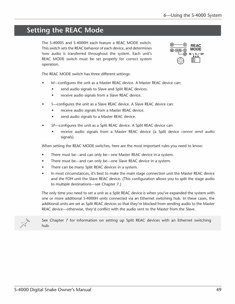
S-4000 Digital Snake Owner’s Manual 49
6—Using the S-4000 System
Setting the REAC Mode
The S-4000S and S-4000H each feature a REAC MODE switch. This switch sets the REAC behavior of each device, and determineshow audio is transferred throughout the system. Each unit’s REAC MODE switch must be set properly for correct system operation.
The REAC MODE switch has three different settings:
• M—configures the unit as a Master REAC device. A Master REAC device can:——
• send audio signals to Slave and Split REAC devices.
• receive audio signals from a Slave REAC device.
• S—configures the unit as a Slave REAC device. A Slave REAC device can:——
• receive audio signals from a Master REAC device.
• send audio signals to a Master REAC device.
• SP—configures the unit as a Split REAC device. A Split REAC device can:——
• receive audio signals from a Master REAC device (a Split device cannot send audio tsignals).
When setting the REAC MODE switches, here are the most important rules you need to know:
• There must be—and can only be—one Master REAC device in a system.
• There must be—and can only be—one Slave REAC device in a system.
• There can be many Split REAC devices in a system.
• In most circumstances, it’s best to make the main stage connection unit the Master REAC deviceand the FOH unit the Slave REAC device. (This configuration allows you to split the stage audio to multiple destinations—see Chapter 7.)
The only time you need to set a unit as a Split REAC device is when you’ve expanded the system with one or more additional S-4000H units connected via an Ethernet switching hub. In these cases, theadditional units are set as Split REAC devices so that they’re blocked from sending audio to the Master REAC device—otherwise, they’d conflict with the audio sent to the Master from the Slave.
See Chapter 7 for information on setting up Split REAC devices with an Ethernet switching hub.

6—Using the S-4000 System
50 S-4000 Digital Snake Owner’s Manual
Setting the REAC MODE Switches
The REAC MODE switch on the S-4000S/S-4000H is recessed from the front panel so that its setting can’t be changed inadvertently. To change the switch setting, use a blunt-tipped instrument such as a ball-point pen, mechanical pencil, etc.
With their power off, set the units as follows:
1. On the S-4000S, set the REAC MODE switch to M.
2. On the S-4000H, set the REAC MODE switch to S.
If the REAC MODE switch setting is changed when the unit is powered on, the new setting won’t take effect until the unit is powered off and then back on again.
Component Connections
AC Power ConnectionsOn the S-4000S:
• Connect one end of the supplied AC power cord to a grounded AC outlet,and the other end to the INT. POWER AC INPUT jack to provide power for the S-4000S’s internal power supply.
On the S-4000H:
• Connect one end of the supplied AC power cord to a grounded AC outlet,and the other end to the INT. POWER AC INPUT jack to provide power for the S-4000H’s internal power supply.
Use only the supplied power cords to prevent damage to the units.
An optional S-240P External Power Supply Unit can be used to supply redundant backup power to an S-4000S or S-4000H unit. Visit www.roland.com or contact an RSS dealer for more information.

S-4000 Digital Snake Owner’s Manual 51
6—Using the S-4000 System
REAC Connections
Cable Requirements
A single cable REAC-to-REAC connection requires a standard Cat5e Ethernet cable with RJ45 plugs wired in a crossover configuration. The maximum length for a single cable is 100 meters (330 feet).
As a reminder, a “REAC-to-REAC” connection means connecting directly from REAC device to REAC device, with no switching hub in between.
If a crossover cable is not available, two Cat5e straight-through cables coupled with a Cat5e crossover adaptor can be used for a REAC-to-REAC connection. In such cases, the total cable length—includingthe crossover adaptor—must not exceed 100 meters.

6—Using the S-4000 System
52 S-4000 Digital Snake Owner’s Manual
Connecting Cables to the REAC Ports
The S-4000S and S-4000H each feature two REAC ports—one labeled MAIN and the other BACKUP.
The MAIN REAC port provides the primary REAC connection.
For the primary REAC-to-REAC connection:
• Connect one end of a Cat5e crossover cable to the MAIN REAC port on the S-4000S, and the other end to the MAIN REAC port on the S-4000H.
The BACKUP REAC port provides a redundant REAC connection in case the MAIN REAC connectionfails. This redundancy requires a second Cat5e cable.
For the redundant REAC-to-REAC connection:
• Connect one end of a second Cat5e crossover cable to the BACKUP REAC port on the S-4000S, and the other end to the BACKUP REAC port on the S-4000H.
If redundant operation is not required, use only the MAIN REAC ports.
For proper system operation, the REAC port on one device must be connected to the like-named REAC port on the other device—that is, always connect MAIN to MAIN, and BACKUP to BACKUP.

S-4000 Digital Snake Owner’s Manual 53
6—Using the S-4000 System
REAC Cable Length Extension
If necessary, the REAC cable length can be extended by placing an Ethernet switching hub in-line torefresh the REAC signal. Multiple switching hubs can be used (up to four total), with a maximum cablelength of 100 meters between hubs. (Total cable length with four switching hubs: 500 meters.)
See Chapter 5 for a discussion about Ethernet cables. See the Appendices for a crossover cable wiring diagram and Ethernet switching hub requirements.
Use Cat5e straight-through cables to connect REAC devices to the ports on the switching hub. If multiple hubs are used, use Cat5e crossover or straight-through cables to connect hub-to-hub.
Some switching hubs have ports that allow the use of either crossover or straight-through cables—they will detect the type of cable that’s connected and adjust the signal transfer accordingly. Consult the documentation for the switching hub to determine what type of cables can be used.
Using an Ethernet Switching Hub with Redundant REAC ConnectionsIf an Ethernet switching hub with at least four ports is used in-line for cable length extension, theS-4000S and S-4000H MAIN and BACKUP REAC ports can be connected to the ports on a single hub.The proper signal negotiation will be handled within the switching hub. (See the diagram on thefollowing page.)
If you connect both the MAIN and BACKUP REAC ports to a single switching hub, you are weakening the redundancy of the system somewhat—if the switching hub fails, both the MAIN and BACKUP connections fail along with it. Therefore, in critical installations you may want to consider using separate switching hubs for the MAIN and BACKUP REAC device connections.

6—Using the S-4000 System
54 S-4000 Digital Snake Owner’s Manual
Note: The connection shown above will work when extending the REAC cable length (MAIN and BACKUP) a total of 200 meters. If you need to extend the distance another 100 meters, use separateswitching hubs in-line (four total) for the MAIN and BACKUP connections.
REAC Connection Notes
• The REAC connection can be “hot-swapped”—that is, connections can be made when theS-4000S and S-4000H units are powered on.
• The system is designed so that operation will inaudibly switch to the BACKUP REAC port should the MAIN REAC connection fail. However, in some circumstances, this switch-over may result inbrief noise at the system’s audio outputs.
• If the REAC cable is disconnected while MUTE ALL OUTPUTS is held, it’s possible that one of the S-4000 units will remain in a muted state when MUTE ALL OUTPUTS is released. If this occurs,use the following procedure:
1. Reconnect the REAC cable.
2. Press and release MUTE ALL OUTPUTS.
Notes About Handling Cat5e Cables
• Do not subject the Cat5e cable to stress or physical shock.
• Do not bend the Cat5e cable within a range of 25 mm.
• Do not fasten Cat5e cables in a tight bundle.
• Avoid laying multiple Cat5e cables in a parallel orientation over long distances.
• Avoid laying Cat5e cables near noise sources (AC power cables, motors, fluorescent lighting, etc.).

S-4000 Digital Snake Owner’s Manual 55
6—Using the S-4000 System
Connecting the S-4000R Remote ControllerUsing the supplied RS-232C cable, connect the S-4000R’s REMOTE jack to the REMOTE jack on either the S-4000S or S-4000H.
Power is supplied to the S-4000R through the REMOTE connection. The S-4000R’s POWER indicator will light when receiving power.
If you require a longer cable than the one provided, you can use an off-the-shelf RS-232C cable or fabricate your own. See Appendix B: Connector Information for an RS-232C pin out diagram.
The S-4000R can be connected to either the S-4000S or S-4000H. Connect it to whichever device location is most convenient for you.
The REMOTE connections can be hot-swapped—that is, connections can be made when the S-4000S and S-4000H units are powered on. This allows you to move the S-4000R from stage to FOH without shutting down the system’s power first.
Multiple S-4000R units can be simultaneously connected to all S-4000S and S-4000H units in the S-4000 System. See Chapter 7 for more information.

6—Using the S-4000 System
56 S-4000 Digital Snake Owner’s Manual
Audio Connections
When making audio input connections with the S-4000S and/or S-4000H units powered on, always press and hold the MUTE ALL OUTPUTS button on the respective unit’s front panel so its indicator lights. This will mute the sound coming from the S-4000 System’s audio outputs and prevent possible damage to connected speakers and other devices. See Page 63 for more information about MUTE ALL OUTPUTS.
Note that MUTE ALL OUTPUTS only mutes the outputs of the S-4000 System, and not the outputs of other devices. Before connecting the audio outputs on the S-4000S and S-4000H units to the audio inputs of other devices, always turn down the volume or turn off the power on the receiving devices to prevent possible damage.
S-4000S Audio Connections
The S-4000S’s balanced audio I/O is provided on XLR-type jacks. The wiring diagram for these jacks is shown in the following illustration. Make connections after first checking the wiring diagrams of other equipment you intend to connect.
To prevent hazard or damage, ensure that only microphone cables and microphones conforming to IEC-268-15A are connected.
Afin d’éviter tout risque ou dommage, ne brancher que des câbles de microphone et des microphones conformes à la norme IEC-268-15A.

S-4000 Digital Snake Owner’s Manual 57
6—Using the S-4000 System
To facilitate custom labeling for a particular installation or multiple S-4000 Systems, the S-4000S is shipped from the factory without channel number labels on its input and output modules. See Appendix B: Connector Information for an illustration showing the S-4000S’s input and output channels as they correlate to the S-4000H’s audio I/O channel numbers and input channel selection on the S-4000R.
If desired, use the included adhesive-backed number label sheets to affix channel numbers to the S-4000S’s input and output modules.
S-4000S Audio Inputs
The S-4000S’s audio inputs are used to send source audio signals to the S-4000H’s audio outputs.
Connect the output of balanced audio devices (microphones, instrument outputs, etc.) to the 32balanced audio inputs on the S-4000S front panel.
To connect unbalanced sources:
• use a direct box—such as the BOSS DI-1—or balancing adaptor in-line
—or—
• a cable adaptor with the following wiring:
When connecting unbalanced sources that require long cable runs (over 6 meters), a direct box or balancing adaptor placed in-line near the source is recommended for the best audio quality and noise rejection.
To connect high-impedance sources—such as the output of an electric guitar or bass with passivepickups—use a direct box or impedance-matching transformer in-line.
Howling (feedback) could be produced depending on the location of microphones relative to speakers. This can be remedied by:
• changing the orientation of the microphone(s).
• relocating the microphone(s) to a greater distance from the speakers.
• lowering volume levels.

6—Using the S-4000 System
58 S-4000 Digital Snake Owner’s Manual
Input Status IndicatorsEach S-4000S input has three status indicators:
• +48V—lights orange when +48 V phantom power is supplied fromVVthe channel.
• CLIP—lights red when the input signal exceeds 0 dB.PP
• SIG—lights green when the input signal is greater than -40 dB.
The CLIP and SIG signal status indicators represent the signal level in the digital domain (post-A/D conversion). Signals exceeding 0 dB will clip, resulting in distortion.
Preamp gain and phantom power on/off status are controlled from the S-4000R. See Pages 67 and 68 for more information.
S-4000S Audio Outputs
The S-4000S’s audio outputs are used to receive audio signals connected to the S-4000H’s audio inputs.
Connect the S-4000S’s eight balanced audio outputs to the balanced audio inputs of the desired devices.
If you need to connect the S-4000S’s audio outputs to unbalanced devices, use a direct box or balancing adaptor in-line, or a cable adaptor with the wiring described in the previous section (S-4000S Audio Inputs).
When audio outputs from an S-4000S or an S-4000H are connected to inputs of external devices such as mixing consoles, please be sure to turn off the phantom power supply from these external devices.Noise may come out while [MUTE ALL OUTPUTS] is pressed and all outputs are muted ifphantom power is supplied from the external device.

S-4000 Digital Snake Owner’s Manual 59
6—Using the S-4000 System
S-4000H Audio ConnectionsThe S-4000H’s balanced audio I/O is provided in groups of eight on DB-25 connectors. See Appendix B: Connector Information for DB-25 connector requirements and diagrams of the S-4000H’s INPUT andOUTPUT connectors.
S-4000H Audio Outputs
The S-4000H’s audio outputs are used to receive audio signals connected to the S-4000S’s audio inputs.
Connect the S-4000H’s balanced audio outputs to the destination device’s balanced line level (+4 dBu)inputs.
In most cases, you’ll use a breakout cable—such as the RSS SC-A0805DM—for connecting theS-4000H’s audio outputs to the balanced inputs on the receiving device. This cable has a DB-25connector on one end and eight male XLR connectors on the other.
If the receiving audio device’s inputs are provided on DB-25 connectors, DB-25-to-DB-25 cableswith the appropriate wiring can be used. Refer to the documentation for the receiving device for information on its DB-25 input wiring.
When audio outputs from an S-4000S or an S-4000H are connected to inputs of external devices such as mixing consoles, please be sure to turn off the phantom power supply from these external devices.Noise may come out while [MUTE ALL OUTPUTS] is pressed and all outputs are muted ifphantom power is supplied from the external device.

6—Using the S-4000 System
60 S-4000 Digital Snake Owner’s Manual
S-4000H Audio Inputs
The S-4000H’s audio inputs are used to send source audio signals to the S-4000S’s audio outputs.
Connect the sending device’s balanced line level (+4 dBu) outputs to the S-4000H’s balanced audio inputs.
In most cases, you’ll use a breakout cable—such as the RSS SC-A0805DF—for connecting the sendingdevice’s balanced audio outputs to the S-4000H’s DB-25 audio input. This cable has a DB-25 connector on one end and eight female XLR connectors on the other.
If the receiving audio device’s outputs are provided on a DB-25 connector, a DB-25-to-DB-25 cablewith the appropriate wiring can be used. Refer to the documentation for the sending device for information on its DB-25 output wiring.
The signal level received at the S-4000H’s inputs can be monitored from the S-4000R. See Page 66 for more information.
Powering Up/System Status Indicators
Powering UpConnect and power up devices in the following order:
Turn on power to your various devices in the order specified. By turning on devices in the wrong order, you risk causing malfunction and/or damage to speakers and other devices.
Additionally, in each of the following steps, allow each piece of equipment to finish its power-up sequence before proceeding to the next step.
1. Connect the system components as described previously.
2. Connect audio devices to the S-4000S and S-4000H inputs and outputs as described previously.
3. Turn on any devices connected to the S-4000S and S-4000H units’ audio inputs.
4. Turn on the front panel power switches on the S-4000S and S-4000H units so that their INTindicators light.
The S-4000S and S-4000H units are equipped with protection circuits. A brief interval (a few seconds) after power up is required before the units will operate normally.
5. Turn on the power to the audio devices (mixing consoles, power amplifiers, monitor speakers,etc.) connected to the S-4000S and S-4000H units’ audio outputs. (Note: It’s always best to power on any speakers or amplification systems last.)

S-4000 Digital Snake Owner’s Manual 61
6—Using the S-4000 System
Checking the System Status IndicatorsThe S-4000S, S-4000H, and S-4000R have system status indicators that allow you to monitor the integrity of the component connections when the system is powered up.
Power Indicators
S-4000S/S-4000H
• INT—This indicator lights when the unit is receiving power from itsTTinternal power supply.
• EXT—This indicator lights when the unit is receiving power from anTToptional S-240P External Power Supply Unit connected to its rear panel EXT. POWER DC INPUT jack.
Visit www.roland.com or contact an RSS dealer for information about the S-240P External Power Supply Unit.
S-4000R
The POWER indicator on the S-4000R will light when it’s receiving power from an S-4000S or S-4000H.
REAC Communication
REAC Ports (S-4000S/S-4000H)The indicator on the REAC port (MAIN and/or BACKUP) flashes when communication is established with another REAC device. If communication fails, the indicator will go out.
REAC System Indicators
The S-4000S, S-4000H, and S-4000R have REAC indicators that lightwhen REAC communication is established. If communication fails, these indicators flash.

6—Using the S-4000 System
62 S-4000 Digital Snake Owner’s Manual
Remote Communication
CTRL IndicatorsThe S-4000S, S-4000H, and S-4000R have CTRL indicators that show when RS-232C communication is established within the system.
• On the S-4000S and S-4000H units—ss
• CTRL lights when an RS-232C device (such as the S-4000R)is connected to the S-4000 System and communication is established.
• If no RS-232C device is connected to the S-4000 System—or if a device is connected and communication is not established—CTRL will not light.
• If the RS-232C device is disconnected after communication has been established, CTRL will flash for 10 seconds.
• On the S-4000R—CTRL lights when communication is established with the S-4000 System. If communication fails, CTRL will flash.
For more information about the system status indicators, see Appendix A: Troubleshooting.
Powering Off
Perform the following steps to power off the S-4000 System.
1. Turn down the volume and power off any devices connected to the S-4000S and S-4000H units’inputs and outputs. (Note: It’s always best to turn down the volume and power off any speakersor amplification systems first.)
2. If an S-4000R is connected to the system, press and hold the S-4000R’s LOCK button until its indicator lights. (Locking the S-4000R retains the current S-4000S input settings when the power is turned off.)
3. Power off the S-4000S and S-4000H units. To prevent the units from being powered up againinadvertently, unplug the power cords from the AC outlets after the front panel power switcheshave been turned off.
If an S-240P External Power Supply Unit is providing power to an S-4000S or S-4000H, the S-4000S or S-4000H unit will keep operating even if the front panel power switch is in the OFF position.

S-4000 Digital Snake Owner’s Manual 63
6—Using the S-4000 System
Muting the System Outputs
Ordinarily, when plugging and unplugging devices to and from theaudio inputs on the S-4000S and S-4000H units, the volume of alldevices connected to the S-4000 System’s audio outputs should belowered.
However, this may be impractical in some circumstances. In suchcases, you can temporarily mute the sound coming from the S-4000System’s audio outputs.
1. On the S-4000S or S-4000H front panel, press and hold the MUTE ALL OUTPUTS button. After approximately 1.5 seconds, its indicator will light. No sound is output while the indicator is lit.
2. When you have finished making input connections to the unit, release MUTE ALL OUTPUTS.
The system outputs will become un-muted a few seconds after releasing MUTE ALL OUTPUTS. If audio is passing through the system when MUTE ALL OUTPUTS is released, the sound may be distorted until the system outputs are completely un-muted.
Note that MUTE ALL OUTPUTS only mutes the outputs of the S-4000 System, and not the outputs of other devices. Before connecting the audio outputs on the S-4000S and S-4000H units to the audio inputs of other devices, always turn down the volume or turn off the power on the receiving devices.
When an S-4000R is connected to the system, its CHANNEL display flashes when the audio outputs are muted using MUTE ALL OUTPUTS.
If the REAC cable is disconnected while MUTE ALL OUTPUTS is held, it’s possible that one of the S-4000 units will remain in a muted state when MUTE ALL OUTPUTS is released. If this occurs, use the following procedure:
1. Reconnect the REAC cable.
2. Press and release MUTE ALL OUTPUTS.

6—Using the S-4000 System
64 S-4000 Digital Snake Owner’s Manual
Using the S-4000R Remote Controller
When the S-4000R is connected to the S-4000 System, you can:
• control S-4000S input channel functions—including preamp gain, pad, and phantom power.ss
• monitor signal level status of the system’s input channels—including the presence of signal andssoverload (clip).
• monitor the level of the system’s input channels—using the eight-segment LED input meter.ss
• monitor system status—using the various indicators on the S-4000R panel.ss
• store and recall—10 different sets of S-4000S channel settingsll
To facilitate custom labeling for a particular installation or multiple S-4000 Systems, the S-4000S is shipped from the factory without channel number labels on its input modules. See Appendix B: Connector Information for an illustration that identifies the S-4000S’s input channels for channel selection on the S-4000R.
When the S-4000R is connected to a unit set as a Split REAC device, only system and signal level monitoring is possible. See Chapter 7 for more about split setups.
In the following sections, we’ll show you how to use the S-4000R’s functions. Before proceeding, makesure that the S-4000R is connected to the S-4000S or S-4000H as described on Page 55.
Lock ModeThe S-4000R has a Lock mode that blocks the editing of S-4000S inputchannels. This protects the current channel settings from accidental changesduring a live performance.
• To lock the S-4000R—press LOCK so its indicator lights. When locked,S-4000S channel settings cannot be adjusted.
• To unlock the S-4000R—press and hold LOCK until its indicator goes out(approximately 1.5 seconds). When unlocked, S-4000S channel settingscan be adjusted.
When the S-4000R is powered up, it will remember its last Lock mode state (locked or unlocked).
When the S-4000R is in a locked state, you can still use the CHANNEL knob to select channels whose signal level you want to monitor with the LED input meter.

S-4000 Digital Snake Owner’s Manual 65
6—Using the S-4000 System
Monitoring Input Signals
Signal Status Indicators
The S-4000R has two rows of signal status indicators that allow you to monitor the signal activity onthe S-4000 System’s 40 audio inputs (1-32 for the S-4000S and 33-40 for the S-4000H).
• SIG—lights green when the input signal level is higher than -40 dB on a particular channel.
• CLIP—lights red when the input signal exceeds 0 dB. Once a CLIP indicator lights, it stays lit untilcleared with the CLIP CLEAR•ENTER button.
The signal status indicators represent the signal level in the digital domain (post-A/D conversion). Signals exceeding 0 dB will clip, resulting in distortion.
Clearing the CLIP IndicatorsWhen an input signal on a particular channel exceeds 0 dB, the corresponding signal status CLIPindicator will light, and the CLIP CLEAR•ENTER button will flash.
To clear all lit CLIP indicators, press CLIP CLEAR•ENTER so its indicator goes out.
To keep a channel’s CLIP indicator from lighting again, lower the preamp gain on that particular channel (see Page 67 for more information).
The signal status indicators also warn you when there’s a problem with the system. See Appendix A: Troubleshooting for more information.

6—Using the S-4000 System
66 S-4000 Digital Snake Owner’s Manual
LED Input Meter
The S-4000R features an eight-segment LED input meter for precise input signal measurement.
To view an input channel’s signal level with the LED input meter, turn the CHANNEL knob to selectthe desired channel (1-32 for the S-4000S and 33-40 for the S-4000H).
The LED input meter represents the signal level in the digital domain (post-A/D conversion).
CLIP will light when the signal exceeds 0 dB.
S-4000S Input Channel SettingsWith the S-4000R unlocked, use the following procedures to adjust settings on the S-4000S input channels.
To retain your changes to the S-4000S input channel settings, lock the S-4000R before powering down the S-4000 System. When the system is powered up, the settings will return to the state they were in when the S-4000R was last locked. It’s also a good idea to store your custom settings to a memory preset as well (see the next section for information).
The S-4000H’s eight input channels do not have any adjustable features. However, they can still be selected with the CHANNEL knob for the purpose of viewing their input levels on the LED input meter. They are represented on the S-4000R as Channels 33-40.
Selecting a Channel for Editing
Use the CHANNEL knob to select the desired S-4000S channel for editing (1-32). The currentlyselected channel is shown in the CHANNEL display.

S-4000 Digital Snake Owner’s Manual 67
6—Using the S-4000 System
Setting the Preamp Gain
Use the following procedure to set the preamp gain on an S-4000S input channel:
1. Select the desired channel (1-32) with the CHANNEL knob.
2. Send an input signal to the selected channel.
3. While viewing the input level on the LED input meter, use the GAIN knob to adjust the preampgain to the desired level.
indicators will light and distortion will occur. For the best audio quality, set the preamp gain sothe meter reads between -18 and -3 dB on the input signal’s loudest peaks.
4. Repeat Steps 1-3 to adjust other channels’ preamp gain.
The indicator lights surrounding the GAIN knob show the currently selected channel’s gain setting.
To adjust the input level on an S-4000H input, adjust the level at the sending device.
Input Pad
Each S-4000S input channel features a switchable input pad. Whenthe pad is engaged, the channel’s input sensitivity is reduced by 20dBu.
Use the pad when connecting a “hot” audio source to an S-4000Sinput—one whose signal exceeds 0 dB (and causes the clip indicator to light) even when the channel’s GAIN knob is at its lowest setting.

6—Using the S-4000 System
68 S-4000 Digital Snake Owner’s Manual
Use the following procedure to engage the input pad on a particular channel:
1. Select the desired channel (1-32) with the CHANNEL knob.
2. Press PAD so its indicator lights.
3. Repeat Steps 1-2 to engage the input pad on other channels.
To turn off a pad, select the channel with the CHANNEL knob, and then press PAD so its indicator goes out.
While a channel’s input pad setting (on/off) is changed, its output is temporarily muted to avoid noise.
Phantom Power
Each of the S-4000S’s inputs can supply +48 V phantom power to devices that require it, such ascondenser microphones or active direct boxes.
Always turn the phantom power off when connecting any device other than condenser microphones that require phantom power. You risk causing damage if you mistakenly supply phantom power to dynamic microphones, audio playback devices, or other devices that don’t require such power. Be sure to check the specifications of any microphone you intend to use by referring to the manual that came with it. (This instrument’s phantom power: 48 V DC, 14 mA Max.)
Use the following procedure to turn on phantom power on a particular channel:
1. Select the desired channel (1-32) with the CHANNEL knob.
2. Press PHANTOM +48 V so its indicator lights.
3. Repeat Steps 1-2 to turn on other channels’ phantom power.
PHANTOM +48 V so its indicator goes out.
While a channel’s phantom power setting (on/off) is changed, its output is temporarily muted to avoid noise.

S-4000 Digital Snake Owner’s Manual 69
6—Using the S-4000 System
Stereo Link
The Stereo Link function allows you to link odd/even adjacent S-4000S input channel pairs (1/2, 3/4,etc.). When channels are linked, gain and pad settings made on one channel of the linked pair will beduplicated on the other. This can be convenient when audio devices with stereo outputs are connectedto the S-4000S.
With the S-4000R unlocked, use the following procedure to link a pair of channels:
1. Using the CHANNEL knob, select one channel of the pair that you wish to link together. For example, if you wish to link Channels 7 and 8, choose either “07” or “08”.
2. While holding CLIP CLEAR•ENTER, turn the CHANNEL knob clockwise.
3. Release CLIP CLEAR•ENTER.
When channels are linked, their channel numbers are displayed with two periods (.), as shown in the following examples:
1. Using the CHANNEL knob, select one channel of the linked pair that you wish to unlink.
2. While holding CLIP CLEAR•ENTER, turn the CHANNEL knob counterclockwise.
3. Release CLIP CLEAR•ENTER.
Stereo Link Notes• Only odd/even adjacent pairs can be linked (1/2, 3/4, etc.).
• When a channel pair is linked, the current gain and pad settings of the odd-numbered channelwill be copied to the even-numbered channel.
• When a channel pair is unlinked, each channel’s gain and pad settings will remain in the samestate as when they were linked.
• While channels are linked, their phantom power status can still be set independently.
• S-4000H inputs (33-40) cannot be linked.

6—Using the S-4000 System
70 S-4000 Digital Snake Owner’s Manual
Memory FunctionThe S-4000R features 10 user-storable memory presets. A memory preset contains channel settings (preamp gain, pad, phantom power, and stereo link) for all of the S-4000S’s 32 input channels. Usingmemory presets, you can quickly reconfigure the S-4000S for frequently used audio input setups.
If the S-4000R is in a locked state, it’s not necessary to unlock the unit before selecting or storing presets. The unit is automatically unlocked when entering a Memory mode.
Storing a Memory Preset (Memory Store Mode)
To store the current settings to a memory preset:
1. Press and hold STORE until its indicator lights solid.
2. Turn the CHANNEL knob until the desired memory preset (0-9) is shown in the CHANNELdisplay.
The currently loaded preset displays a period (.) next to the preset number. If the currentlyloaded preset is in a state different than the stored version, two periods are displayed.
3. Press CLIP CLEAR•ENTER to finalize your selection. (To exit Memory Store mode without storingthe current settings, press STORE so that its indicator goes out instead.)
4. If you wish to store the current settings to another memory preset, repeat Steps 2-3. To exit Memory Store mode, press STORE so that its indicator goes out.
Recalling a Memory Preset (Memory Recall Mode)
To recall a memory preset:
1. Press and hold RECALL until its indicator lights solid.
2. Turn the CHANNEL knob until the desired memory preset (0-9) is shown in the CHANNELdisplay.
The currently loaded preset displays a period (.) next to the preset number. If the currentlyloaded preset is in a state different than the stored version, two periods are displayed (see the illustration above). If you wish to retain the current settings, exit as indicated in Step 3.
3. Press CLIP CLEAR•ENTER to finalize your selection. (To exit Memory Recall mode without making a selection, press RECALL so that its indicator goes out instead.)
4. If you wish to select another memory preset, repeat Steps 2-3. To exit Memory Recall mode, press RECALL so that its indicator goes out.
While a memory preset is recalled, all system outputs are temporarily muted.

S-4000 Digital Snake Owner’s Manual 71
Using Two S-4000R Units in a Single S-4000 System
As discussed in Chapter 6, the S-4000R can be connected to either the S-4000S or S-4000H. However, if you have a second S-4000R (available separately), you can connect one to each unit. This allows for control and signal monitoring of the S-4000 System at the location of either S-4000 unit.
The following behaviors occur when two S-4000Rs are used in a single system:
• Only one S-4000R unit can be used to edit S-4000S channels and recall/store memory presets at any one time.
• When one S-4000R unit is in use, the other S-4000R unit automatically enters a locked state and its LOCK button flashes.
See “Using the S-4000R Remote Controller” in Chapter 6 for information on operating the S-4000R.
Advanced Use 7

7—Advanced Use
72 S-4000 Digital Snake Owner’s Manual
Computer Control (S-4000 RCS)
The S-4000 Remote Control Software (S-4000 RCS) allows for the remote control and monitoring of the S-4000 System from a personal computer equipped with an RS-232C port.
Functionally, using the S-4000 RCS is similar to using the S-4000R Remote Controller, but with theconveniences provided by a personal computer.
S-4000 RCS features:
• S-4000S input channel control screen—View and adjust settings for all S-4000S channels from onescreen.
• Comprehensive input level meter screen—View input activity of all input channels from onescreen.
• 100 memory presets—Store and recall up to 100 different S-4000S input setups.ss
• Integrated monitoring and control of multiple systems—You can connect up to four S-4000 Systemsssto multiple RS-232C ports on a personal computer. This allows for control and signal monitoring of multiple systems from a single interface.
Where to Get the S-4000 RCS
The S-4000 RCS is available as a free download from www.roland.com. Refer to the documentationincluded with software for instructions on using it with the S-4000 System.
System Requirements
The S-4000 RCS is available for both Windows and Macintosh operating systems. Please visit www.roland.com for the latest S-4000 RCS version and current computer and operating systemrequirements.

S-4000 Digital Snake Owner’s Manual 73
7—Advanced Use
System Expansion
Adding More I/OThe standard S-4000 System provides 40 channels of audio in a 32x8 configuration. By adding additional systems, you can easily expand your audio I/O as needed.
Each additional system increases your audio I/O capability, as shown in the following table:
Number of S-4000 Systems Total I/O Capability
1 32x8
2 64x16
3 96x24
4 128x32
Remote Control and Monitoring of Multiple Systems
There are two ways to accomplish remote control and signal level monitoring of multiple systems:
• Multiple S-4000R Units—Connect one or two S-4000R units to each S-4000 System and controlsseach 32x8 setup independently.
• A personal computer with multiple RS-232C serial ports and the S-4000 RCS—Connect a REMOTE SSjack from each S-4000 System to an RS-232C port on the personal computer running the S-4000RCS. See the previous section for information on the S-4000 RCS.
To identify S-4000S channels, use the included adhesive-backed number label sheets to affix channel numbers to the S-4000S units’ front panel inputs and outputs.

7—Advanced Use
74 S-4000 Digital Snake Owner’s Manual
Splitting Stage Audio to Multiple DestinationsAs we’ve discussed previously, REAC uses Ethernet networking technology to transfer audio signals.Besides providing great sound quality and inexpensive and convenient installation, this allows for onemore huge benefit: pain-free audio splits using standard Ethernet hardware.
By integrating an Ethernet switching hub into the REAC system, S-4000S source signals can be splitto multiple additional S-4000H units. This allows you to send stage audio to multiple destinations in addition to the FOH position, such as:
• a monitor console.
• a multitrack recorder.
• a remote truck.
• a broadcast feed.
• a secondary FOH console.
• anywhere else you need to send stage audio.
Traditionally, when using an analog snake system, audio splits are taken directly at the source. Thisrequires the use of expensive and bulky transformer-based audio splitters, as well as an additional analog snake for each split destination. Besides this, analog signal splitting can reduce the source signals’ quality and greatly increase the potential for introducing noise into the entire soundreinforcement system via ground loops and RF interference.
Using REAC, splitting the stage audio in an S-4000 System is extremely easy. Simply add a switching hub and an S-4000H unit for each split destination, hook them together with Cat5e cables, and you’reready to go! Besides this setup convenience, REAC splits provide pristine audio quality—once the inputsignals are converted to digital data in the S-4000S, they can be split as many times as you wish withabsolutely no loss in quality.
What You’ll Need
To split the S-4000S’s 32 channels of input audio, you’ll need:
• an Ethernet switching hub with enough ports to connect each REAC device.
• an additional S-4000H unit for each split destination.
• straight-through Cat5e Ethernet cables.
Ethernet Switching Hub RequirementsTo work with REAC, an Ethernet switching hub must meet the following requirements:
• 1000BASE-T transmission speed (IEEE802.3ab, Gigabit Ethernet)
• Support for 100BASE-TX devices (IEEE802.3u, Fast Ethernet)
• Bi-directional (full-duplex) communication
Connect REAC devices only to switching hub ports that support 100BASE-TX.

S-4000 Digital Snake Owner’s Manual 75
7—Advanced Use
Split Connection Overview
(Master REAC device)
S-4000H 8x32 (Slave REAC device)
S-4000RRemote Controller
RS-232C cable
S-4000H 8x32 (Split REAC device)
32 mic/line sourcesfrom the stageMonitor
Console

7—Advanced Use
76 S-4000 Digital Snake Owner’s Manual
Setting the REAC MODE Switches
See Page 49 for a discussion about the REAC MODE switches and how they affect REAC signal flow.
With their power off, set the units as follows:
1. On the S-4000S, set the REAC MODE switch to M.
2. On the primary S-4000H (usually at the FOH position), set the REAC MODE switch to S.
3. On each S-4000H used to receive audio splits from the stage, set the REAC MODE switch to SP.
If the REAC MODE switch setting is changed when the unit is powered on, the new setting won’t take effect until the unit is powered off and then back on again.
REAC Connections
For the primary REAC connections:
• Using Cat5e straight-through cables, connect the MAIN REAC ports on the S-4000S/H units to ports on the switching hub.
For the redundant REAC connections:
• Using Cat5e straight-through cables, connect the BACKUP REAC ports on the S-4000S/H units toports on the same switching hub (or a second switching hub).
The cable length from each REAC device to the switching hub must not exceed 100 meters. If you need to extend the cable length of a particular REAC device connection beyond 100 meters, a separate switching hub must be used in-line. See “REAC Cable Length Extension” in Chapter 6 for more information.

S-4000 Digital Snake Owner’s Manual 77
7—Advanced Use
As mentioned earlier in the manual, some switching hubs have ports that allow the use of either crossover or straight-through cables—they will detect the type of cable that’s connected and adjust the signal transfer accordingly. Consult the documentation for the switching hub to determine what type of cables can be used.
If you connect both the MAIN and BACKUP REAC ports to a single switching hub, you are weakening the redundancy of the system somewhat—if the switching hub fails, both the MAIN and BACKUP connections fail along with it. Therefore, in critical installations you may want to consider using separate switching hubs for the MAIN and BACKUP REAC device connections.
Audio Connections and Power Up
Connect and power up devices in the following order:
In each of the following steps, allow each piece of equipment to finish its power-up sequence before proceeding to the next step.
1. Connect the system components as described here and in Chapter 6.
2. Connect audio devices to the Master and Slave REAC devices’ inputs and outputs.
3. Connect audio devices to the Split REAC devices’ outputs.
S-4000S and S-4000H audio connections are explained in Chapter 6.
4. Turn on any devices connected to the Master and Slave REAC devices’ audio inputs.
5. Turn on the power on the switching hub(s).
6. Turn on the front panel power switches on the Master, Slave, and Split devices so that their INTindicators light.
7. Turn on the power to the audio devices (mixing consoles, power amplifiers, monitor speakers,etc.) connected to the Master, Slave, and Split devices’ audio outputs.
Notes on Split Setups
• A Split REAC device can only receive audio from the Master REAC device—it can’t receive audiofrom a Slave REAC device (or another Split device).
• When a unit is set as a Split REAC device, its audio inputs are disabled.
• An S-4000R can be connected to the REMOTE connector on a Split REAC device. However, itcan only be used for system and signal level monitoring—adjustment of S-4000S inputs is not possible. (If you need to adjust the signal level coming from a Split device’s outputs, use the inputtrim controls on the receiving device.)

78 S-4000 Digital Snake Owner’s Manual
MIDI Communication Via REAC
In addition to audio communication, the REAC connection allows for MIDI communication as well. Both the S-4000S and S-4000H units feature MIDI IN and OUT jacks. When you connect MIDI devicesto these jacks, they can send and receive MIDI information to and from each other via REAC. For thisapplication, you can think of the REAC connection as a “MIDI cable extender.”
REAC’s ability to pass along MIDI information can prove useful for synchronizing devices via MIDI Time Code (MTC), triggering MIDI sound modules and samplers, and integrating MIDI remote controldevices.
Notes on REAC MIDI Communication
• MIDI data received at the MIDI IN connector of the Master REAC device is transmitted unchanged to the MIDI OUT connectors of the Slave REAC device and any SPLIT REAC devices.
• MIDI data received at the MIDI IN connector of the Slave REAC device is transmitted unchanged to the MIDI OUT connector of the Master REAC device.
• When an S-4000S or S-4000H is set as a Split REAC device, its MIDI IN connector is disabled.
• A Split REAC device can only receive MIDI data from a Master REAC device (MIDI data reception from a Slave REAC device is not possible).
7—Advanced Use7—Advanced Use

S-4000 Digital Snake Owner’s Manual 79
8—Applications
32x8 System
S-4000S 32x8 (Master)
S-4000H 8x32 (Slave)
Applications 8

8—Applications
80 S-4000 Digital Snake Owner’s Manual
32x8 System with 32 Channel Split

S-4000 Digital Snake Owner’s Manual 81
8—Applications
64x16 System

8—Applications
82 S-4000 Digital Snake Owner’s Manual
64x16 System with 64 Channel Split

S-4000 Digital Snake Owner’s Manual 83
Appendix A: Troubleshooting
System Status and Error IndicatorsThe components in the S-4000 System provide many different indicators that show the current systemstatus. Additionally, the units provide error indicators that let you know whenever a potentially serious problem is detected in the system.
The following tables show the meaning of the various status and error indicators, and suggest actions for troubleshooting and safe system operation.
S-4000S and S-4000H Units: System Status Indicators
Indicator Status Definition Troubleshooting Action
MAIN REAC Port/BACKUPREAC Port
Lit Standby • None (normal operation)
Flashing REACcommunication isestablished
• None (normal operation)
Dark No communication • Make sure all REAC devices are turned on• Check Cat5e cable connections • Check the Cat5e cable(s) for damage• Is the proper cable type being used? (See Page
51)• If a switching hub is used, is it working?• If a switching hub is used, is it properly
connected? (See Page 53, 76)• If a switching hub is used, does it have the proper
specification? (See Appendix C)
Appendices

Appendices
84 S-4000 Digital Snake Owner’s Manual
S-4000S and S-4000H Units: System Status Indicators
Indicator Status Definition Troubleshooting Action
REAC Lit Communication isestablished
• None (normal operation)
Dark System power-up • None (normal operation)
Flashing No REACcommunication
• Make sure all REAC devices are turned on• Check Cat5e cable connections • Check the Cat5e cable(s) for damage• Is the proper cable type being used? (See Page
51)• If a switching hub is used, is it working?• If a switching hub is used, is it properly
connected? (See Page 53, 76)• If a switching hub is used, does it have the proper
specification? (See Appendix C)
CTRL Lit RS-232C communicationestablished
• None (normal operation)
Dark No device is connected toREMOTE jack
• None (normal operation)
Flashing No RS-232C communication
• Check the RS-232C cable for damage• Are you using an RS-232C cable with the proper
wiring? (See Appendix B)• If connected to a computer, is the computer on?• Is the computer’s RS-232C port functioning
properly?
S-4000S and S-4000H Units: ALARM Indicator
Indicator Status Definition Troubleshooting Action
ALARM Lit Abnormal (high)temperature detected
• Make sure the intake and/or exhaust vents on the unit are not blocked.
• Shut down the unit to prevent overheating and damage
An exhaust fan (or fans) has stopped working
• Shut down the unit to prevent overheating and damage
NOTE: If ALARM lights, see the S-4000R error indicators for more specific information

S-4000 Digital Snake Owner’s Manual 85
Appendices
S-4000R Unit: System Status Indicators
Indicator Status Definition Troubleshooting Action
POWER Lit Power is received • None (normal operation)
Dark No power is received • Make sure all REAC devices are turned on• Check the RS-232C cable for damage• Are you using an RS-232C cable with the proper
wiring? (See Appendix B)
REAC Lit Communication isestablished
• None (normal operation)
Flashing System power-up • None (normal operation)
No REACcommunication
• Make sure all REAC devices are turned on• Check Cat5e cable connections • Check the Cat5e cable(s) for damage• Is the proper cable type being used? (See Page
51)• If a switching hub is used, is it working?• If a switching hub is used, is it properly
connected? (See Page 53, 76)• If a switching hub is used, does it have the proper
specification? (See Appendix C)
CTRL Lit RS-232C communicationestablished
• None (normal operation)
Flashing System power-up • None (normal operation)
No RS-232C communication
• Check the RS-232C cable for damage• Are you using an RS-232C cable with the proper
wiring? (See Appendix B)

Appendices
86 S-4000 Digital Snake Owner’s Manual
S-4000R Unit: Error Indicators
Indicator Status Definition Troubleshooting Action
CLIP 1/SIG 1
Lit The MAIN REACconnection hasfailed and thesystem has switched to the BACKUP REACconnection
• Check MAIN REAC cabling• Check MAIN REAC connections• Check in-line switching hub (if used) on MAIN
REAC connection
Flashing Recovery from the above error
• None
CLIP 2 Lit An exhaust fan (or fans) on the Master REAC unit has stopped working
• Shut down the unit to prevent overheating and damage
Flashing Recovery from the above error
• None
CLIP 3 Lit Abnormal (high)temperature detected on the Master REAC unit
• Make sure the intake and/or exhaust vents on the Master REAC unit are not blocked
• Shut down the unit to prevent overheating and damage
Flashing Recovery from the above error
• None
CLIP 4/SIG 4
Lit REAC packets error detected on the unit connected to the S-4000R
• Check MAIN and BACKUP REAC cabling• Check MAIN and BACKUP REAC connections• Check in-line switching hub (if used) on MAIN
and BACKUP REAC connections

S-4000 Digital Snake Owner’s Manual 87
Appendices
S-4000R Unit: Error Indicators
Indicator Status Definition Troubleshooting Action
CLIP 5/SIG 5
Lit There is a problem with one or more modules installed inthe S-4000S Master REAC device
View CLIP and SIG indicators 9–19 to determine the location of the problem module(s). Refer to thefollowing for more information.
When CLIP 5 and SIG 5 are lit, this indicates that there’s a problem with one or more modules installed in an S-4000S set as the Master REAC device.When this occurs, CLIP and SIG indicators 9–19 show the status of anyinstalled modules. Use these indicators to determine the location of the problem module(s).CLIP 9–19 represent A/D modules (SI-AD4, etc.) installed in Slots 1–11.The S-4000S recognizes an A/D module installed in a particular slot when the following indicators are lit:
• CLIP 9—Slot 1 (leftmost slot)
• CLIP 10—Slot 2
‚
• CLIP 19—Slot 11
SIG 9-19 represent D/A modules (SO-DA4, etc.) installed in Slots 1-11.The S-4000S recognizes a D/A module installed in a particular slot whenthe following indicators are lit:
• SIG 9—Slot 1 (leftmost slot)
• SIG 10—Slot 2
‚
• SIG 19—Slot 11
If an A/D or D/A module is installed in one of the slots and the appropriate indicator (CLIP or SIG 9-19) does not light, this indicates that the S-4000Sdoes not recognize the module. In this case, contact an RSS Authorized Service Center for assistance.Note: If no module is installed a particular slot location, the CLIP and SIGindicators that represent that slot will not light.

Appendices
88 S-4000 Digital Snake Owner’s Manual
S-4000R Unit: Error Indicators
Indicator Status Definition Troubleshooting Action
SIG 2 Lit An exhaust fan (or fans) on a Slave/Split REAC unit hasstopped working
• Shut down the unit(s) to prevent overheating and damage
Flashing Recovery from the above error
• None
SIG 3 Lit Abnormal (high)temperature detected on a Slave/Split REAC unit
• Make sure the intake and/or exhaust vents on the Slave/Split units are not blocked
• Shut down the unit(s) to prevent overheating and damage
Flashing Recovery from the above error
• None
CHANNEL Display
Flashes “Er”
This happenswhenever one of the previously describedS-4000R error indicators lights or flashes
• Look for the source of the error• Press CLIP CLEAR•ENTER to return to normal
S-4000R operation

S-4000 Digital Snake Owner’s Manual 89
Appendices
Appendix B: Connector Information
Cat5e Ethernet Cable Wiring (RJ45-type Connectors)
Cat5e Crossover Wiring
Note: Pins 4, 5, 7, and 8 are not used in this application, but may be wired in the cable as shown.
Cat5e Straight-Through Wiring
Note: Pins 4, 5, 7, and 8 are not used in this application, but may be wired in the cable as shown.
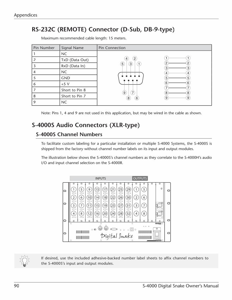
Appendices
90 S-4000 Digital Snake Owner’s Manual
RS-232C (REMOTE) Connector (D-Sub, DB-9-type)Maximum recommended cable length: 15 meters.
Pin Number Signal Name Pin Connection
1 NC
8 6
9 7
5
4
9
8
7
6
3
5
31
12
4
2
9
8
7
65
3
1
4
22 TxD (Data Out)
3 RxD (Data In)
4 NC
5 GND
6 +5 V
7 Short to Pin 8
8 Short to Pin 7
9 NC
Note: Pins 1, 4 and 9 are not used in this application, but may be wired in the cable as shown.
S-4000S Audio Connectors (XLR-type)
S-4000S Channel Numbers
To facilitate custom labeling for a particular installation or multiple S-4000 Systems, the S-4000S isshipped from the factory without channel number labels on its input and output modules.
The illustration below shows the S-4000S’s channel numbers as they correlate to the S-4000H’s audioI/O and input channel selection on the S-4000R.
If desired, use the included adhesive-backed number label sheets to affix channel numbers to the S-4000S’s input and output modules.

S-4000 Digital Snake Owner’s Manual 91
Appendices
S-4000S XLR Audio Pin Outs (INPUT and OUTPUT)
Balanced connections (recommended):
Lock-Down Screw Thread Size
The S-4000H’s INPUT and OUTPUT connectors have threaded nuts for locking a DB-25 connector inplace. Use DB-25 connectors that have lock-down screws with #4-40 UNC thread size.

Appendices
92 S-4000 Digital Snake Owner’s Manual
S-4000H DB-25 Audio Pin Outs
Balanced connections are recommended.
• G = Ground
• C = Cold
• H = Hot
For unbalanced connections, connect cold to ground.
INPUT 1-8, OUTPUT 1-8 OUTPUT 9-16
OUTPUT 17-24 OUTPUT 25-32
S-4000 Digital Snake Owner’s Manual 93
Appendices
Appendix C: Ethernet Switching Hub Requirements
To be used in a REAC system, an Ethernet switching hub must meet the following requirements:
• 1000BASE-T transmission speed (IEEE802.3ab, Gigabit Ethernet)
• 1000BASE-T switching hub you use support for 100BASE-TX devices (IEEE802.3u, Fast Ethernet)
• Bi-directional (full-duplex) communication
Connect REAC devices only to switching hub ports that support 100BASE-TX.
The transmission protocol for REAC is based on 100BASE-TX (Fast Ethernet). To transfer 40 channels of digital audio, REAC uses the full bandwidth of this protocol. However, some100BASE-TX switching hubs cannot handle this amount of data traffic. Gigabit Ethernet switching hubs can handle a larger amount of data traffic, so we recommend them for usewith REAC devices (just be sure that the Gigabit switching hub you use supports 100BASE-TXdevices).
When using switching hubs in-line for REAC cable length extension, a maximum of four hubscan be used. (Total cable length with four switching hubs: 500 meters. See Chapter 6 formore information.)
Consult the switching hub’s documentation for information on its proper use.

Appendices
94 S-4000 Digital Snake Owner’s Manual
Appendix D: Specifications
Specifications: S-4000S 40 CH I/O MODULAR RACK
Nominal Output Level:
+4 dBu, Max. +22 dBu
Output Impedance:
150 ohms
Recommended Load Impedance:
10 k ohm or greater
Residual Noise Level (IHF-A, typ.):
-90 dBu
Equivalent Input Noise (E.I.N.):
-128 dB
Network Latency:
375 microseconds when using REAC cable only*(AD ‡ REAC ‡ DA latency: about 1.2 milliseconds)
Connectors:
Input: 32 (XLR, balanced, phantom power, 4 ch input module x 8)
Output: 8 (XLR, balanced, 4 ch output module x 2)
REAC: MAIN, BACKUP (RJ-45 EtherCon-type)
Remote Connector: 1 (RS-232C, DB-9-type)
MIDI Connectors: IN, OUT(5-pin DIN-type)
Number of Channels:
32 in, 8 out
AD Conversion:
Sample Rate: 96.0 kHz
Signal Processing: 24 bits
DA Conversion:
Sample Rate: 96.0 kHz
Signal Processing: 24 bits
Frequency Response:
-2 dB / 0 dB (20 Hz to 20 kHz at +4 dBu)
Total Harmonic Distortion + Noise(Pad: On, Input gain: +4 dBu, 22 ~ 20000 Hz):
0.05 % or less
Dynamic Range:
110 dB
Cross Talk:
-80 dB
Nominal Input Level
-65 to -10 dBu (PAD: Off)
-45 to +10 dBu (PAD: On)
Max. input +28 dBu
Remote Controlled Preamp Gain
Controllable in 1 dB steps
PAD:
20 dB On/Off
Input Impedance:
20 k ohms
* When a switching hub is used in-line with REAC cables, the network latency will increase by the amount of processing delay introduced by the hub itself. The actual delay is dependant upon the specifications of thehub, though the maximum delay amount for a single hub should be about 200 microseconds.

S-4000 Digital Snake Owner’s Manual 95
Appendices
Indicators:
EXT Indicator (External Power Supply)
INT Indicator
REAC Indicator
CTRL Indicator
ALARM Indicator
MUTE ALL OUTPUTS Indicator
Power Supply:
AC 115 V, AC 117 V, AC 220 V, AC 230 V, AC 240 V (50/60 Hz)
Power Supply (for optional power supply; Model S-240P):
+24 V DC
Power Consumption:
130 W
Current Draw (for optional power supply;Model S-240P):
6 A
Phantom Power:
+48 V / 14 mA (each input on SI-AD4, remote controlled
Dimensions:
482.0 (W) x 336.0 (D) x 266.4 (H) mm
19 (W) x 13-1/4 (D) x 10-1/2 (H) inches
Weight:
17 kg
37 lbs. 8 oz.
Operation Temperature:
0 to +40 degrees Celsius
+32 to +104 degrees Fahrenheit
Accessories:
Power cord
REAC connector covers (2)
Ferrite cores (2)
Rack-mount brackets
Adhesive-backed number label sheets
Owner’s Manual
Options
External Power Supply Unit: S-240P
* 0 dBu = 0.775 V rms

Appendices
96 S-4000 Digital Snake Owner’s Manual
Specifications: S-4000H 32x8 FOH UNIT
Number of Channels:
8 in, 32 out
AD Conversion:
Sample Rate: 96.0 kHz
Signal Processing: 24 bit
DA Conversion:
Sample Rate: 96.0 kHz
Signal Processing: 24 bit
Frequency Response:
-2 dB / +0 dB(20 Hz to 20 kHz at +4 dBu)
Total Harmonic Distortion + Noise(Input gain: +4 dBu, 22 ~ 20000 Hz):
0.05 % or less
Dynamic Range:
110 dB
Cross Talk:
-80 dB
Nominal Input Level:
+4 dBu, Max. +22 dBu
Input Impedance:
30 k ohms
Nominal Output Level:
+4 dBu, Max. +22 dBu
Output Impedance:
600 ohms
Recommended Load Impedance:
10 k ohm or greater
Residual Noise Level (IHF-A, typ.):
-90 dBu
Network Latency:
375 microseconds when using REAC cable only*(AD ‡ REAC ‡ DA latency: about 1.2 milliseconds)
Connectors
Input: 1 (D-sub 25-pin connector, balanced, 8 channels)
Output: 4 (D-sub 25-pin connectors, balanced, 8channels each)
REAC: MAIN, BACKUP(RJ-45 EtherCon-type)
Remote Connector: 1 (RS-232C, DB-9-type)
MIDI Connectors: IN, OUT(5-pin DIN-type)
Indicators:
EXT Indicator (External power supply)
INT Indicator
REAC Indicator
CTRL Indicator
ALARM Indicator
MUTE ALL OUTPUTS Indicator
Power Supply:
AC 115 V, AC 117 V, AC 220 V, AC 230 V, AC 240 V (50/60 Hz)
Power Supply (for optional power supply; ModelS-240P):
+24 V DC
Power Consumption:
70 W
Current Draw (for optional power supply; Model S-240P):
6 A
* When a switching hub is used in-line with REAC cables, the network latency will increase by the amount of processing delay introduced by the hub itself. The actual delay is dependant upon the specifications of thehub, though the maximum delay amount for a single hub should be about 200 microseconds.

S-4000 Digital Snake Owner’s Manual 97
Appendices
Dimensions:
482.0 (W) x 386.7 (D) x 133 (H) mm
19 (W) x 15-1/4 (D) x 5-1/4 (H) inches
Weight:
9.4 kg
20 lbs. 12 oz.
Operation Temperature:
0 to +40 degrees Celsius
+32 to +104 degrees Fahrenheit
Accessories:
Power cord
REAC connector covers (2)
Connector guard
Ferrite cores (2)
Rack-mount brackets
Owner’s Manual
Options:
External Power Supply Unit: S-240P
Cable: SC-A0805DM D-sub to XLR Male
Cable: SC-A0805DF D-sub to XLR Female
* 0 dBu = 0.775 V rms
Specifications: S-4000R REMOTE CONTROLLER
In the interest of product improvement, the specifications and/or appearance of the S-4000System components and accessories are subject to change without prior notice.
Connector:
Remote Connector: 1 (RS-232C, DB-9-type)
Power Supply:
Supplied from connected device (S-4000S or S-4000H, through the remote cable)
Indicators:
CLIP Indicators (1-40)
SIG Indicators (1-40)
POWER Indicator
REAC Indicator
CTRL Indicator
Level Meter
CHANNEL Display (8 segments 2 digits.)
GAIN Indicators (15 steps)
Memory:
10 memory presets
Dimensions:
215 (W) x 87 (D) x 54.6 (H) mm
8-1/2 (W) x 3-7/16 (D) x 2-3/16 (H) inches
Weight:
0.8 kg
1 lb. 13 oz.
Operating Temperature:
0 to +40 degrees Celsius
+32 to +104 degrees Fahrenheit
Accessories
Remote Cable (3 meter)
Rack-mount brackets
Owner’s Manual

Appendices
98 S-4000 Digital Snake Owner’s Manual
Appendix E: Dimensions
Dimensions: S-4000SNote: Dimensions are shown in millimeters.

S-4000 Digital Snake Owner’s Manual 99
Appendices
Dimensions: S-4000HNote: Dimensions are shown in millimeters.

Appendices
100 S-4000 Digital Snake Owner’s Manual
Dimensions: S-4000RNote: Dimensions are shown in millimeters.

S-4000 Digital Snake Owner’s Manual 101
Index
AA/D-D/A conversion, 37
AC cord clamp, 41
ALARM indicator, 23, 27, 84
Ccables
breakout cables (for S-4000H), 20, 59, 60
Cat5e Ethernet cables
connecting to REAC ports, 52
crossover, 34–35, 51–54, 77
handling Cat5e cables, 54
length extension, 53
straight-through, 34–35, 51–52, 54, 75, 76
wiring diagrams, 89
Ethernet cable extension, 35, 53
microphone, 56
CHANNEL knob (S-4000R), 29, 66
channel numbers (S-4000S), 90
CLIP clear, 29, 65, 66
CLIP indicators
S-4000R, 31, 65, 86
S-4000S, 21, 58
computer control. S-4000 RCS
connection overview
S-4000 System, 48
crossover adaptor, 34, 51
crossover cable (Cat5e). cables
CTRL indicator, 23, 26, 31, 62, 84, 85
DDB-25 connector guard, 44
DB-25 connectors (S-4000H), 59
wiring, 91–92
Dimensions
S-4000H, 99
S-4000R, 100
S-4000S, 98
Eerror indicators, 86
Ethernet cables. cables
Ethernet connectors (RJ45), 35
wiring, 89
Ethernet switching hub
about, 36
requirements for REAC use, 36, 93
using for cable length extension, 35, 53
using for split applications, 35
using with redundant connection, 53–54, 76
Ffan, exhaust, 25, 28
Ferrite cores, 47
FOH (front-of-house), 14
GGAIN knob (S-4000R), 30, 67
II/O expansion, 73
INPUT connector (S-4000H), 39, 60
wiring, 92
Input meter (S-4000R), 66
Llinking S-4000S input channels, 69
locking the S-4000R, 64

Index
102 S-4000 Digital Snake Owner’s Manual
Mmemory presets. S-4000R: memory presets
modules
S-REAC2, 22, 38
SI-AD4, 21, 38
SO-DA4, 22, 38
multiple S-4000R units, using, 71
MUTE ALL OUTPUTS, 56, 63
OOUTPUT connectors (S-4000H), 27, 39, 59
wiring, 92
PPAD button, 30, 67
phantom power
setting, 30, 68
status indicator (S-4000S), 21, 58
pin out diagrams, 89–92
power connections
S-4000R, 55
S-4000S, S-4000H, 50
powering off, 62
powering up
S-4000 System, 60
S-4000 System with splits, 77
power supply, redundant, 38
Rrack-mounting
recessed rack-mounting (S-4000S/H), 41–43
S-4000R, 45
REAC
about, 34
cables, 34–35, 51–54
checking indicators, 61, 83, 85
connecting cables, 51–54
connecting cables (for splits), 76
connection covers, 46
connectors (RJ45), 35
REAC MODE
about, 49
switch setting, 49, 50, 76
switch setting (for splits), 76
redundant connections, 52–54
using Ethernet switching hubs, 36, 53–54,74–76
REAC MODE. REAC
redundant connections. REAC
REMOTE connector
S-4000H, 26, 55
S-4000R, 31, 55
S-4000S, 23, 55
remote control. S-4000R ; S-4000 RCS
remote controlled preamps, about, 38–39
retaining S-4000S input settings, 66
RJ45 connectors, 35, 89
RS-232C, 37
wiring, 90
SS-4000R
clearing CLIP indicators, 65
connecting, 55
features, 40
hot-swapping, 55
LED input meter, 66
Lock function, 64
memory presets
recalling, 70
storing, 70
pad setting, 67
phantom power setting, 68
preamp gain setting, 67
selecting channels, 66
signal status indicators, 65
Stereo Link, 69
using, 64–70
using multiple S-4000R units, 71
S-4000 RCS, 40, 72
S-REAC2. modules

S-4000 Digital Snake Owner’s Manual 103
Index
SI-AD4. modules
SO-DA4. modules
Specifications
S-4000H, 96–97
S-4000R, 97
S-4000S, 94–95
Splits, audio, 74–77
straight-through cable (Cat5e). cables
switching hub. Ethernet switching hub
Ttroubleshooting, 83–88
Uunlocking the S-4000R, 64
Vvents, 23, 25, 27, 28
XXLR jacks (S-4000S), 21, 22, 56
unbalanced connections, 57
wiring, 91
XR-1 Preamp, 38–39

Index
104 S-4000 Digital Snake Owner’s Manual

S-4000 Digital Snake Owner’s Manual 105
...MEMO...

106 S-4000 Digital Snake Owner’s Manual
...MEMO...

This product complies with the requirements of EMCD 2004/108/EC and LVD 2006/95/EC.
For EU Countries
For Canada
This Class B digital apparatus meets all requirements of the Canadian Interference-Causing Equipment Regulations.
Cet appareil numérique de la classe B respecte toutes les exigences du Règlement sur le matériel brouilleur du Canada.
NOTICE
AVIS
For the USA
FEDERAL COMMUNICATIONS COMMISSIONRADIO FREQUENCY INTERFERENCE STATEMENT
This equipment has been tested and found to comply with the limits for a Class B digital device, pursuant to Part 15 of the FCC Rules. These limits are designed to provide reasonable protection against harmful interference in a residential installation. This equipment generates, uses, and can radiate radio frequency energy and, if not installed and used in accordance with the instructions, may cause harmful interference to radio communications. However, there is no guarantee that interference will not occur in a particular installation. If this equipment does cause harmful interference to radio or television reception, which can be determined by turning the equipment off and on, the user is encouraged to try to correct the interference by one or more of the following measures:
– Reorient or relocate the receiving antenna.– Increase the separation between the equipment and receiver.– Connect the equipment into an outlet on a circuit different from that to which the receiver is connected.– Consult the dealer or an experienced radio/TV technician for help.
This device complies with Part 15 of the FCC Rules. Operation is subject to the following two conditions: (1) this device may not cause harmful interference, and (2) this device must accept any interference received, including interference that may cause undesired operation.
Unauthorized changes or modification to this system can void the users authority to operate this equipment.This equipment requires shielded interface cables in order to meet FCC class B Limit.
WARNINGThis product contains chemicals known to cause cancer, birth defects and other reproductive harm, including lead.
For C.A. US (Proposition 65)
For EU Countries

S-4000
Owner’s Manual
•
•
•
http://www.roland.com/
Copyright © 2005 ROLAND CORPORATION
Pg. 7). These sections provide important information concerning the proper operation
INSTRUCTIONS” (S-4000 Owner’s Manual Pg. 2), “USING THE UNIT SAFELY”Before using this unit, carefully read the sections entitled: “IMPORTANT SAFETY
(S-4000 Owner’s Manual Pg. 3), and “IMPORTANT NOTES” (S-4000 Owner’s Manual
of the unit. Additionally, in order to feel assured that you have gained a good grasp ofevery feature provided by your new unit, S-4000 Owner’s Manual should be read in itsentirety. The manual should be saved and kept on hand as a convenient reference.
All rights reserved. No part of this publication may be reproduced in any form without
• Neutrik and EtherCon are registered trademarks of Neutrik, Inc
the written permission of ROLAND CORPORATION.
* 0 4 1 2 8 2 3 4 - 0 8 *
• MMP (Moore Microprocessor Portfolio) refers to a patent portfolio concerned with microprocessor architecture, which was developed by Technology Properties Limited (TPL). Roland has licensed this technology from the TPL Group.
Microsoft and Windows are registered trademarks of Microsoft Corporation.•
Apple and Macintosh are registered trademarks of Apple Computer, Inc.
Mac OS is a trademark of Apple Computer, Inc.
All product names mentioned in this document are trademarks or registered trademarks of their respective owners.
InformationWhen you need repair service, call your nearest Roland Service Center or authorized Roland distributor in your country as shown below.
As of Jan. 1, 2009 (RSS)
ASIA
INDONESIAPT. Citra IntiRamaJL. Cideng Timur No. 15J-15O Jakarta PusatINDONESIATEL: (021) 632-4170
CHINARoland Shanghai Electronics Co.,Ltd.5F. No.1500 Pingliang Road Shanghai 200090, CHINATEL: (021) 5580-0800
Roland Shanghai Electronics Co.,Ltd.(BEIJING OFFICE)10F. No.18 3 Section Anhuaxili Chaoyang District Beijing 100011 CHINATEL: (010) 6426-5050
KOREAKOREA AVICS CO., LTD.Unit B-2208, Woolimblue9, #240-21, Yeomchang-dong, Gangseo-gu, Seoul, KoreaTel: 02-322-3264
TAIWANROLAND TAIWAN ENTERPRISE CO., LTD.Room 5, 9fl. No. 112 Chung Shan N.Road Sec.2, Taipei, TAIWAN, R.O.C.TEL: (02) 2561 3339
SINGAPORE/MALAYSIARoland Asia Pacific Sdn. Bhd.45-1, Block C2, Jalan PJU 1/39, Dataran Prima, 47301 Petaling Jaya, Selangor, MALAYSIATEL: 3-7805-3263
CENTRAL/LATINAMERICA
DENMARKRoland Scandinavia A/SNordhavnsvej 7, Postbox 880,DK-2100 CopenhagenDENMARK
TEL: 3916 6200
FINLANDRoland Scandinavia As, Filial FinlandElannontie 5FIN-01510 Vantaa, FINLANDTEL: (0)9 68 24 020
HUNGARYRoland East Europe Ltd.Warehouse Area ‘DEPO’ Pf.83H-2046 Torokbalint, HUNGARYTEL: (23) 511011
NORWAYRoland Scandinavia Avd. Kontor NorgeLilleakerveien 2 Postboks 95 Lilleaker N-0216 Oslo NORWAYTEL: 2273 0074
POLANDROLAND POLSKA SP. Z O.O.ul. Kty Grodziskie 16B03-289 Warszawa, POLANDTEL: (022) 678 9512
ROMANIAFBS LINESPiata Libertatii 1,535500 Gheorgheni, ROMANIATEL: (266) 364 609
BRAZILRoland Brasil Ltda.Rua San Jose, 211Parque Industrial San JoseCotia - Sao Paulo - SP, BRAZILTEL: (011) 4615 5666
Other CENTRAL/ LATIN AMERICARoland Systems Group U.S.425 Sequoia Drive Suite 114, Bellingham, Washington, 98226 USATEL: 360-594-4282
AUSTRIA/BELGIUM/FRANCE/GERMANY/HOLLAND/LUXEMBOURG/PORTUGAL/SPAIN/SWITZERLANDRoland Iberia, S.L. Paseo García Faria, 33-3508005 Barcelona SPAINTEL: 93 493 91 00
CROATIAART-CENTARDegenova 3.HR - 10000 ZagrebTEL: (1) 466 8493
CZECH REP.CZECH REPUBLIC DISTRIBUTOR s.r.oVoctárova 247/16CZ - 180 00 PRAHA 8,CZECH REP.TEL: (2) 830 20270
EUROPE
OCEANIA
AUSTRALIA/NEW ZEALAND Roland CorporationAustralia Pty.,Ltd. 38 Campbell AvenueDee Why West, NSW 2099AUSTRALIA
For AustraliaTEL: (02) 9982 8266For New ZealandTEL: (09) 3098 715
CANADARoland Canada Ltd.(Head Office)5480 Parkwood Way, Richmond B. C., V6V 2M4 CANADA TEL: (604) 270 6626
Roland Canada Ltd.(Toronto Office)170 Admiral BoulevardMississauga ON L5T 2N6 CANADA TEL: (905) 362 9707
U. S. A.Roland Systems Group U.S.425 Sequoia Drive Suite 114, Bellingham, Washington, 98226 USATEL: 360-594-4282
RUSSIAMuTekDorozhnaya ul.3,korp.6117 545 Moscow, RUSSIA TEL: (095) 981-4967
SLOVAKIADAN Acoustic s.r.o. Povazská 18.SK - 940 01 Nové ZámkyTEL: (035) 6424 330
SWEDENRoland Scandinavia A/S SWEDISH SALES OFFICEDanvik Center 28, 2 tr. S-131 30 Nacka SWEDEN TEL: (0)8 702 00 20
UKRAINEEURHYTHMICS Ltd.P.O.Box: 37-a.Nedecey Str. 30UA - 89600 Mukachevo, UKRAINETEL: (03131) 414-40
UNITED KINGDOM/IRELANDRoland (U.K.) Ltd.Atlantic Close, Swansea Enterprise Park, SwanseaSA7 9FJ, UNITED KINGDOMTEL: (01792) 702701
NORTH AMERICA