ECO-COMPASS - - Nottingham ePrints
156
ECO-COMPASS Ecological and Multifunctional Composites for Application in Aircraſt Interior and Secondary Structures Xiaosu Yi and Konstantinos Tserpes www.mdpi.com/journal/aerospace Edited by Printed Edition of the Special Issue Published in Aerospace aerospace
-
Upload
khangminh22 -
Category
Documents
-
view
3 -
download
0
Transcript of ECO-COMPASS - - Nottingham ePrints

ECO-COMPASSEcological and Multifunctional Composites for Application in Aircraft Interior and Secondary Structures
Xiaosu Yi and Konstantinos Tserpes
www.mdpi.com/journal/aerospace
Edited by
Printed Edition of the Special Issue Published in Aerospace
aerospace

ECO-COMPASS


andECO-COMPASS: Ecological Multifunctional Composites forApplication in Aircraft Interior andSecondary Structures
Special Issue Editors
Xiaosu Yi
Konstantinos Tserpes
MDPI • Basel • Beijing • Wuhan • Barcelona • Belgrade
Special Issue EditorsXiaosu Yi
University of Nottingham Ningbo China (UNNC) China
Konstantinos Tserpes University of Patras Greece
Editorial Office
MDPI
St. Alban-Anlage 66
4052 Basel, Switzerland
This is a reprint of articles from the Special Issue published online in the open access journal Aerospace
(ISSN 2226-4310) from 2018 to 2019 (available at: https://www.mdpi.com/journal/aerospace/
special issues/ECO-COMPASS)
For citation purposes, cite each article independently as indicated on the article page online and as
indicated below:
LastName, A.A.; LastName, B.B.; LastName, C.C. Article Title. Journal Name Year, Article Number,
Page Range.
ISBN 978-3-03897-690-5 (Pbk)
ISBN 978-3-03897-691-2 (PDF)
c© 2019 by the authors. Articles in this book are Open Access and distributed under the Creative
Commons Attribution (CC BY) license, which allows users to download, copy and build upon
published articles, as long as the author and publisher are properly credited, which ensures maximum
dissemination and a wider impact of our publications.
The book as a whole is distributed by MDPI under the terms and conditions of the Creative Commons
license CC BY-NC-ND.

Contents
About the Special Issue Editors . . . . . . . . . . . . . . . . . . . . . . . . . . . . . . . . . . . . . vii
Xiaosu Yi and Konstantinos Tserpes
Special Issue “ECO-COMPASS: Ecological and Multifunctional Composites for Application inAircraft Interior and Secondary Structures”Reprinted from: Aerospace 2019, 6, 17, doi:10.3390/aerospace6020017 . . . . . . . . . . . . . . . . 1
Barbara Tse, Xueli Yu, Hugh Gong and Constantinos Soutis
Flexural Properties of Wet-Laid Hybrid Nonwoven Recycled Carbon and Flax Fibre Compositesin Poly-Lactic Acid MatrixReprinted from: Aerospace 2018, 5, 120, doi:10.3390/aerospace5040120 . . . . . . . . . . . . . . . . 4
Jens Bachmann, Martin Wiedemann and Peter Wierach
Flexural Mechanical Properties of Hybrid Epoxy Composites Reinforced with Nonwoven Madeof Flax Fibres and Recycled Carbon FibresReprinted from: Aerospace 2018, 5, 107, doi:10.3390/aerospace5040107 . . . . . . . . . . . . . . . . 20
Konstantinos Tserpes and Christos Kora
A Multi-Scale Modeling Approach for Simulating Crack Sensing in Polymer FibrousComposites Using Electrically Conductive Carbon Nanotube Networks. Part II: Meso- andMacro-Scale AnalysesReprinted from: Aerospace 2018, 5, 106, doi:10.3390/aerospace5040106 . . . . . . . . . . . . . . . . 36
Chunhong Wang, Zilong Ren, Shan Li and Xiaosu Yi
Effect of Ramie Fabric Chemical Treatments on the Physical Properties of Thermoset PolylacticAcid (PLA) CompositesReprinted from: Aerospace 2018, 5, 93, doi:10.3390/aerospace5030093 . . . . . . . . . . . . . . . . 49
Shaoce Dong, Guijun Xian and Xiao-Su Yi
Life Cycle Assessment of Ramie Fiber Used for FRPsReprinted from: Aerospace 2018, 5, 81, doi:10.3390/aerospace5030081 . . . . . . . . . . . . . . . . 61
Miaocai Guo and Xiaosu Yi
Effect of Paper or Silver Nanowires-Loaded Paper Interleaves on the Electrical Conductivityand Interlaminar Fracture Toughness of CompositesReprinted from: Aerospace 2018, 5, 77, doi:10.3390/aerospace5030077 . . . . . . . . . . . . . . . . 72
Jichun Zhang, Yiou Shen, Bing Jiang and Yan Li
Sound Absorption Characterization of Natural Materials and Sandwich Structure CompositesReprinted from: Aerospace 2018, 5, 75, doi:10.3390/aerospace5030075 . . . . . . . . . . . . . . . . 87
Xiao-Su Yi, Xvfeng Zhang, Fangbo Ding and Jianfeng Tong
Development of Bio-Sourced Epoxies for Bio-CompositesReprinted from: Aerospace 2018, 5, 65, doi:10.3390/aerospace5020065 . . . . . . . . . . . . . . . . 100
Eric Ramon, Carmen Sguazzo and Pedro M. G. P. Moreira
A Review of Recent Research on Bio-Based Epoxy Systems for Engineering Applications andPotentialities in the Aviation SectorReprinted from: Aerospace 2018, 5, 110, doi:10.3390/aerospace5040110 . . . . . . . . . . . . . . . . 109
v


About the Special Issue Editors
Xiaosu Yi Earned his Dipl.-Ing. (M.S.) in 1982 and his Dr.-Ing. (Ph.D.) degree in 1986 in Material
Engineering at the University of Paderborn, Germany. A full professor in Polymer Materials and
Technology since 1987 at Zhejiang University, Hangzhou, China, he joined the Beijing Institute of
Aeronautical Materials (BIAM) in 1998, before moving on to the AVIC Composite Center (ACC)
in 2010. Since 2017, he has been a Chair professor at the University of Nottingham, Ningbo, China.
He is the director of the National Engineering Laboratory of Carbon-Fiber Structural Composites
and the Beijing Engineering Laboratory of Green Composites. Fellow of SAMPE (F. SAMPE), Fellow
of Aviation Industry of China (AVIC), Academician of APAM (Asia-Pacific Academy of Materials),
Chairman of SAMPE China, and an executive council member of the International Conference of
Composite Materials (ICCM) and Asia-Pacific Conference of Composite Materials (ACCM). He has,
to date, received the SAMPE Fellow Award, the ZhouGuangZhao Award, a KC Wong Fellowship,
the Aerospace Laureate Award, the Feng Ru Aerospace Science and Technology Award, and the
China Patent Excellence Award. He has published approximately 400 papers, 8 monographs, and
approximately 60 invention patents.
Konstantinos Tserpes is a Mechanical and Aeronautical Engineer with a Ph.D. in strength prediction
of composite materials. Currently, he is Assistant Professor at the Department of Mechanical
Engineering and Aeronautics, University of Patras, Greece. His research interests are in the areas of
strength of composite materials, strength of bonded and bolted joints, mechanical behavior of carbon
nanotubes, graphene, nanocomposites and nanocrystalline materials, multiscale analysis of materials
and structural parts, development of methodologies for relating data from nondestructive testing
with numerical strength prediction models, as well as strength prediction of corroded aluminum
parts. He has co-edited four international books and published 6 chapters in books, as well as more
than 65 papers in journals and more than 75 papers in conference proceedings. He has 20 years of
research experience in the areas of aeronautical materials and structures gained through participation
in more than 20 national and international research projects.
vii

aerospace
Editorial
Special Issue “ECO-COMPASS: Ecological andMultifunctional Composites for Application inAircraft Interior and Secondary Structures”
Xiaosu Yi 1,2,* and Konstantinos Tserpes 3,*
1 Beijing Institute of Aeronautical Materials, Beijing 100095, China2 Aviation Composite (Beijing) Science and Technology Co., Ltd., Beijing 101300, China3 Laboratory of Technology & Strength of Materials, Department of Mechanical Engineering & Aeronautics,
University of Patras, Patras 26500, Greece* Correspondence: [email protected] (X.Y.); [email protected] (K.T.)
Received: 12 February 2019; Accepted: 13 February 2019; Published: 13 February 2019
Today, composite aircraft structural parts are mainly made of man-made materials, such as carbonand glass fibres and epoxy resin. Renewable materials, such as natural fibres or bio-sourced resinsystems, have not yet found their way into aircraft production. The project ECO-COMPASS [1] aims toevaluate the potential applications of ecologically improved composite materials in the aeronautics sectorthrough an international collaboration between Chinese and European partners. Natural fibres, such asflax and ramie, are used for different types of reinforcements and sandwich cores. The substitution ofbisphenol-A based epoxy resins in secondary structures by bio-based epoxy resins is currently underinvestigation. Adapted material protection technologies aiming to reduce environmental influence and toimprove fire resistance are needed to fulfil the demanding safety requirements in aviation. The modellingand simulation of the chosen eco-composites aims to optimize the use of materials while a Life CycleAssessment aims to prove the ecological advantages compared to the synthetic state-of-the-art materials.
This Special Issue provides selected papers from the project consortium partners. The SpecialIssue is partially based on the special session entitled “ECO-COMPASS: Ecological and MultifunctionalComposites for Application in Aircraft Interior and Secondary Structures” that was organized at theICCS20 Conference (Paris, France, 4–7 September 2017, https://events.unibo.it/iccs20).
This Special Issue of Aerospace contains nine interesting articles, which cover a wide range oftopics from production, experimental characterization and numerical simulation. The paper by BarbaraTse et al. [2] characterizes the flexural behavior and the morphological properties of wet-laid hybridnonwoven recycled carbon and flax fibre composites in a polylactic acid matrix. Experimental datashowed that the flexural properties increased with higher recycled carbon fibres (rCF) content. The intimatemixing of the fibres contributed to a lesser reduction of flexural properties when increasing the flax fibrecontent. Jens Bachmann et al. [3] measured flexural properties of hybrid epoxy composites reinforcedwith nonwoven flax and recycled carbon fibres. Experimental results show a potential increase in flexuralproperties after combining rCF and flax fibre in a nonwoven hybrid. Tserpes and Kora [4] proposeda multiscale modeling approach to simulate crack sensing in polymer fibrous composites by exploiting theinterruption of electrically conductive carbon nanotube (CNT) networks. In the special issue, the secondpaper of a two paper series [4,5] was published. The numerical results highlight the prospect of conductiveCNT networks to be used as a localized structural health monitoring technique in carbon fibre reinforcedpolymers (CFRP) and bio-composites. Wang et al. [6] studied the effect of ramie fabric chemical treatmentson the physical properties of thermoset polylactic acid (PLA) composites. It was found that chemicaltreatments lead to an increase in tensile and flexural strength of PLA composites while they lead toa decrease in water absorption. The authors concluded that the ramie fabric-reinforced PLA composites canmeet the standard requirements of aircraft interior structures and have favorable foreground application.
Aerospace 2019, 6, 17; doi:10.3390/aerospace6020017 www.mdpi.com/journal/aerospace1

Aerospace 2019, 6, 17
Dong et al. [7] performed cradle-to-gate life cycle assessment (LCA) study to demonstrate the possibleadvantages of ramie fibre on environmental impacts and to provide fundamental data for the furtherassessment of ramie fibre reinforced polymers (RFRP) and its structures. Guo et al. [8] studied theeffect of plant-fibre paper or silver nanowires-loaded paper interleaves on the electrical conductivityand interlaminar fracture toughness of composites. Experimental data show an increase in electricalconductivity and a decrease in interlaminar fracture toughness. Zhang et al. [9] evaluated the soundabsorption performance of flax fibre and its reinforced composite, as well as balsa wood, using thetwo-microphone transfer function technique with an impedance tube system. The sandwich structure withintegrated natural materials was found to provide a superior sound absorption performance comparedto the synthetic-materials-based sandwich structure composite. Yi et al. [10] reported on current R&Defforts to develop bio-sourced materials by an international joint project. Novel bio-sourced epoxiesand biocomposites were developed, characterized, modified and evaluated in terms of the mechanicalproperty levels. Quasi-structural composite parts were finally trial-manufactured and demonstrated.Finally, the paper of Ramon et al. [11] reviewed recent advances on new bio-based epoxy resins, whichwere derived from natural oils, natural polyphenols, saccharides, natural rubber and rosin.
The editors of this Special Issue would like to thank the authors for their high-quality contributionsand for making this Special Issue a success. Additionally, the editors would like to thank the Aerospaceeditorial office, in particular Ms. Linghua Ding.
Funding: This project has received funding from the European Union’s Horizon 2020 research and innovationprogramme under grant agreement No 690638.
Conflicts of Interest: The authors declare no conflict of interest.
References
1. Bachmann, J.; Yi, X.; Gong, H.; Martinez, X.; Tserpes, K.; Ramon, E.; Paris, C.; Moreira, P.; Fang, Z.;Li, Y.; et al. Outlook on ecologically improved composites for aviation interior and secondary structures.CEAS Aeronaut. J. 2018, 9, 533–543. [CrossRef]
2. Tse, B.; Yu, X.; Gong, H.; Soutis, C. Flexural Properties of Wet-Laid Hybrid Nonwoven Recycled Carbon andFlax Fibre Composites in Poly-Lactic Acid Matrix. Aerospace 2018, 5, 120. [CrossRef]
3. Bachmann, J.; Wiedemann, M.; Wierach, P. Flexural Mechanical Properties of Hybrid Epoxy CompositesReinforced with Nonwoven Made of Flax Fibres and Recycled Carbon Fibres. Aerospace 2018, 5, 107.[CrossRef]
4. Tserpes, K.; Kora, C. A Multi-Scale Modeling Approach for Simulating Crack Sensing in Polymer FibrousComposites Using Electrically Conductive Carbon Nanotube Networks. Part II: Meso- and Macro-ScaleAnalyses. Aerospace 2018, 5, 106. [CrossRef]
5. Tserpes, K.; Kora, C. A multi-scale modeling approach for simulating crack sensing in polymer fibrouscomposites using electrically conductive carbon nanotube networks. Part I: Micro-scale analysis.Comput. Mater. Sci. 2018, 154, 530. [CrossRef]
6. Wang, C.; Ren, Z.; Li, S.; Yi, X. Effect of Ramie Fabric Chemical Treatments on the Physical Properties ofThermoset Polylactic Acid (PLA) Composites. Aerospace 2018, 5, 93. [CrossRef]
7. Dong, S.; Xian, G.; Yi, X.-S. Life Cycle Assessment of Ramie Fiber Used for FRPs. Aerospace 2018, 5, 81.[CrossRef]
8. Guo, M.; Yi, X. Effect of Paper or Silver Nanowires-Loaded Paper Interleaves on the Electrical Conductivityand Interlaminar Fracture Toughness of Composites. Aerospace 2018, 5, 77. [CrossRef]
2

Aerospace 2019, 6, 17
9. Zhang, J.; Shen, Y.; Jiang, B.; Li, Y. Sound Absorption Characterization of Natural Materials and SandwichStructure Composites. Aerospace 2018, 5, 75. [CrossRef]
10. Yi, X.-S.; Zhang, X.; Ding, F.; Tong, J. Development of Bio-Sourced Epoxies for Bio-Composites. Aerospace2018, 5, 65. [CrossRef]
11. Ramon, E.; Sguazzo, C.; Moreira, P.M.G.P. A Review of Recent Research on Bio-Based Epoxy Systems forEngineering Applications and Potentialities in the Aviation Sector. Aerospace 2018, 5, 110. [CrossRef]
© 2019 by the authors. Licensee MDPI, Basel, Switzerland. This article is an open accessarticle distributed under the terms and conditions of the Creative Commons Attribution(CC BY) license (http://creativecommons.org/licenses/by/4.0/).
3

aerospace
Article
Flexural Properties of Wet-Laid Hybrid NonwovenRecycled Carbon and Flax Fibre Composites inPoly-Lactic Acid Matrix
Barbara Tse 1,*, Xueli Yu 1, Hugh Gong 1 and Constantinos Soutis 1,2
1 School of Materials, The University of Manchester, Manchester M13 9PL, UK;[email protected] (X.Y.); [email protected] (H.G.);[email protected] (C.S.)
2 Aerospace Research Institute, The University of Manchester, Manchester M13 9PL, UK* Correspondence: [email protected]; Tel.: +44-161-306-2868
Received: 3 September 2018; Accepted: 5 November 2018; Published: 15 November 2018
Abstract: Recycling carbon fibre is crucial in the reduction of waste from the increasing use ofcarbon fibre reinforced composites in industry. The reclaimed fibres, however, are usually shortand discontinuous as opposed to the continuous virgin carbon fibre. In this work, short recycledcarbon fibres (rCF) were mixed with flax and poly-lactic acid (PLA) fibres acting as the matrix to formnonwoven mats through wet-laying. The mats were compression moulded to produce compositeswith different ratios of rCF and flax fibre in the PLA matrix. Their flexural behaviour was examinedthrough three-point-bending tests, and their morphological properties were characterised withscanning electron and optical microscopes. Experimental data showed that the flexural propertiesincreased with higher rCF content, with the maximum being a flexural modulus of approximately14 GPa and flexural strength of 203 MPa with a fibre volume fraction of 75% rCF and 25% flaxfibre. The intimate mixing of the fibres contributed to a lesser reduction of flexural properties whenincreasing the flax fibre content.
Keywords: hybrid composite; eco-composite; nonwoven; recycled carbon fibre; flax fibre; poly-lacticacid; wet-laying
1. Introduction
Carbon fibres (CF) are the preferred reinforcement material for polymer composites because theycombine high strength and low weight compared to metallic or ceramic fibres [1]. The global demandfor CF rose from 33,000 t in 2010 to 72,000 t in 2017 and is expected to grow at a rate of 9–12% for thenext five years [2]. This increase of CF products comes with the increasing levels of waste resultingfrom expired prepregs, production cut-offs, testing materials, and end-of-life components from theaeronautics, automotive, and wind industries [3].
Due to the energy-intensive manufacturing of virgin CF [4], it also becomes more economicalto recover and reuse CF. In the ideal case, recycled carbon fibres (rCF) would replace virgin fibres tosave more energy and reduce production cost. However, fibre damage and resin residues from therecycling process decreases the fibre tensile strength to around 80% of the virgin fibres, dependingon the recycling method, through thermal, mechanical, and chemical recycling treatments [5–7].For mechanical recycling, the composites are crushed and sieved, which results in a powdered formthat can be further used for injection moulding. In chemical recycling, the matrix is removed throughdifferent solvents, while thermal methods such as pyrolysis or the fluidised-bed process utilise heatenergy. Pyrolysis is the most widespread method, but the fibres reclaimed by this process are commonlycontaminated with char residues from the matrix which can degrade the fibre properties [7].
Aerospace 2018, 5, 120; doi:10.3390/aerospace5040120 www.mdpi.com/journal/aerospace4

Aerospace 2018, 5, 120
After the recycling procedure, the majority of the rCF comes in a short and discontinuous formwith the length of the fibres ranging from 0.1 mm to 60 mm [5,7].
One way to further process these short rCF could be the conversion into nonwovens. Nonwovensare a type of fabric in which the fibres are bonded by thermal, mechanical, or chemical treatments [8].Since they do not require yarn, short fibres can be used. For rCF, wet-laying would be suitable formanufacturing the nonwoven mat. This method is derived from the paper-making process in whichthe fibres are dispersed in an aqueous solution. The fibre slurry is deposited on a wire screen to drainthe liquid, leaving the fibres to form a web. This process is suitable for almost all fibres [9] and ismore gentle towards the fibres in comparison to carding, especially for more brittle fibres such ascarbon, which tend to break into shorter lengths during the carding operation [10]. In addition, the wetmedium also provides a safer environment in the manufacturing process since rCF reclaimed bypyrolysis can contain very fine carbon particles that could contaminate the air and equipment [11,12].
The disadvantages for the wet-laying process are the relatively low thickness of the resulting rCFmats and the higher consolidation pressure needed to adjust the composite thickness and increase thefibre volume fraction [13,14].
In the effort to compensate for the brittle nature of the rCF, hybridisation with natural fibressuch as flax can be considered. The term “hybridisation” refers to the combination of two or morefibres inside a matrix. Oftentimes, natural fibre and synthetic fibre are chosen in order to achieve asynergetic effect on the composite’s properties [15]. Flax is one of the strongest natural fibres andis already used in a variety of composites [16,17]. With a tensile strength of 1.3 GPa and a Young’smodulus of 54 GPa, its properties are comparable to glass fibres [18,19]. CF are superior in strength,with a tensile strength of 3–5 GPa, but they exhibit brittle behaviour because of their high modulusof 250–700 GPa [20]. In a hybrid, the CF would provide strength while flax balances the inherentbrittleness of CF. CF/flax hybrids are already used for sporting goods because of their combinedstrength and damping properties since the damping coefficient of composites reinforced by woven flaxcan be up to four times higher than the ones reinforced by carbon only [16,21].
Much of the work reported in the literature about hybrid CF/flax composites [21–25] has beenfocused on the plies of woven fabric from continuous virgin CF and long flax fibres rather thannonwoven recycled short fibres as proposed in this work. Few studies have examined the wet-laying ofshort fibre composites with either flax fibres [26–30] or rCF [11–13,31,32]. Recently, Longana et al. [33]have investigated a rCF/flax hybrid manufactured through a water-assisted fibre alignment methodthat was successfully used with short rCF and rCF/glass fibre hybrids [34,35]. The blending of bothfibre types could potentially decrease the tendency for catastrophic delamination as the mixing is moreintimate, which can enhance the hybrid’s properties [36].
In this research, short fibre rCF/flax composites were produced using wet-laying. To maximizethe intermixing of the rCF/flax fibres for improved hybrid properties, the rCF, flax, and the poly-lacticacid (PLA) matrix fibres were dispersed together during the wet-laying process. The different fibreratios were characterised through three-point-bending, scanning electron microscopy, and opticalmicroscopy to optimise the processing parameters for future manufacturing.
2. Materials and Methods
2.1. Materials
Recycled CF and flax fibres were used as the reinforcement material, while the PLA in fibre formwas the matrix constituent. CF reclaimed by pyrolysis, unsized, and chopped to the length of 12 mmwith the diameter of 6–8 μm were purchased from ELG Carbon Fibre Ltd. (Coseley, UK). Scutched flaxfibres in 10 mm lengths were supplied by FRD (Rosières-près-Troyes, France). For the matrix material,PLA slivers from Sirdar Spinning Ltd. (Wakefield, UK) were cut into 10 mm long segments.
5

Aerospace 2018, 5, 120
2.2. Nonwoven Formation
Fibres of 2 g in weight were dispersed in 2 litres of water through a paper pulp disintegrator for10,000 revolutions at a speed of 3000 revolutions per minute.
The dispersion was poured with additional water into a Handsheet Former manufactured byMavis Engineering Ltd. (London, UK). This apparatus consisted of a base with a porous mesh that wasconnected to a drain pipe. A metallic cylinder closed the top which was filled with the fibre dispersion.Through draining the water, the fibres collected on the net at the bottom and formed a circular matwith a diameter of 16 cm. These were blotted with filter papers and pressed with a couch roll to extractexcess water and smooth out the surface. Afterwards, the mats were left to dry by air convection for24 h at room temperature.
Five different samples were made with the volume ratios of rCF and flax fibre as presentedin Table 1.
Table 1. Fibre volume ratio of recycled carbon fibres (rCF) and flax for each sample.
Sample No. 1 2 3 4 5
rCF [%] 100 75 50 25 0Flax [%] 0 25 50 75 100
For the dispersion of the fibres, all components of the mat had to be added in the desiredproportions. To keep the grammage of the fabric constant at 100 g/m2, 2 g of fibres were used per matin the form of a disc with a 16 cm diameter. The target fibre volume fraction Vf for the final compositewas chosen to be 30% since previous work [13,27,28,30] reported lowered mechanical properties athigher fibre fractions due to fibre breakage. Assuming Vf + Vm = 1 (Vm = matrix volume fraction),Equation (1) can be used to determine the corresponding weight composition of the fibres. One layerof sample 2 with 75% rCF and 25% flax is shown in Figure 1.
Vf =ρmWf
ρmWf + ρ f Wm(1)
where
ρ f = Density of fibre [g/cm3]
ρm = Density of matrix [g/cm3]Wf = Weight of fibres [g]
Wm = Weight of matrix [g]
Figure 1. One layer of Sample 2 with 75% rCF and 25% flax.
6
Aerospace 2018, 5, 120
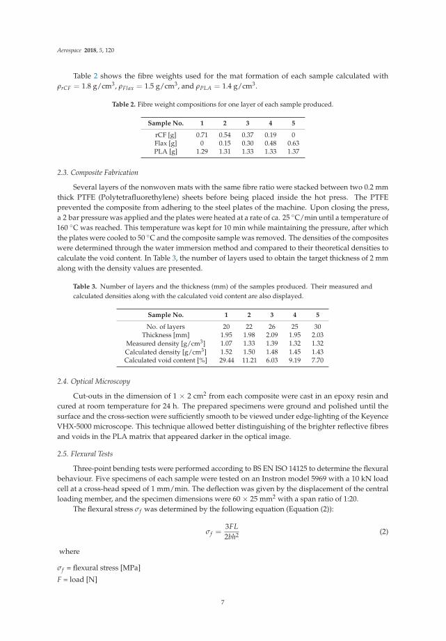
Table 2 shows the fibre weights used for the mat formation of each sample calculated withρrCF = 1.8 g/cm3, ρFlax = 1.5 g/cm3, and ρPLA = 1.4 g/cm3.
Table 2. Fibre weight compositions for one layer of each sample produced.
Sample No. 1 2 3 4 5
rCF [g] 0.71 0.54 0.37 0.19 0Flax [g] 0 0.15 0.30 0.48 0.63PLA [g] 1.29 1.31 1.33 1.33 1.37
2.3. Composite Fabrication
Several layers of the nonwoven mats with the same fibre ratio were stacked between two 0.2 mmthick PTFE (Polytetrafluorethylene) sheets before being placed inside the hot press. The PTFEprevented the composite from adhering to the steel plates of the machine. Upon closing the press,a 2 bar pressure was applied and the plates were heated at a rate of ca. 25 ◦C/min until a temperature of160 ◦C was reached. This temperature was kept for 10 min while maintaining the pressure, after whichthe plates were cooled to 50 ◦C and the composite sample was removed. The densities of the compositeswere determined through the water immersion method and compared to their theoretical densities tocalculate the void content. In Table 3, the number of layers used to obtain the target thickness of 2 mmalong with the density values are presented.
Table 3. Number of layers and the thickness (mm) of the samples produced. Their measured andcalculated densities along with the calculated void content are also displayed.
Sample No. 1 2 3 4 5
No. of layers 20 22 26 25 30Thickness [mm] 1.95 1.98 2.09 1.95 2.03
Measured density [g/cm3] 1.07 1.33 1.39 1.32 1.32Calculated density [g/cm3] 1.52 1.50 1.48 1.45 1.43Calculated void content [%] 29.44 11.21 6.03 9.19 7.70
2.4. Optical Microscopy
Cut-outs in the dimension of 1 × 2 cm2 from each composite were cast in an epoxy resin andcured at room temperature for 24 h. The prepared specimens were ground and polished until thesurface and the cross-section were sufficiently smooth to be viewed under edge-lighting of the KeyenceVHX-5000 microscope. This technique allowed better distinguishing of the brighter reflective fibresand voids in the PLA matrix that appeared darker in the optical image.
2.5. Flexural Tests
Three-point bending tests were performed according to BS EN ISO 14125 to determine the flexuralbehaviour. Five specimens of each sample were tested on an Instron model 5969 with a 10 kN loadcell at a cross-head speed of 1 mm/min. The deflection was given by the displacement of the centralloading member, and the specimen dimensions were 60 × 25 mm2 with a span ratio of 1:20.
The flexural stress σf was determined by the following equation (Equation (2)):
σf =3FL2bh2 (2)
where
σf = flexural stress [MPa]
F = load [N]
7
Aerospace 2018, 5, 120
L = length of span [mm]b = width of the specimen [mm]h = thickness of the specimen [mm]
Flexural modulus Ef was obtained by:
Ef =L3F
4bh3d(3)
where
Ef = flexural modulus of elasticity [MPa]
d = central deflection [mm]
Flexural strain was calculated as:ε =
6dhL2 (4)
2.6. Scanning Electron Microscopy
After the flexural tests were performed, the specimens were viewed under the scanning electronmicroscope (SEM) in order to assess surface damage. The specimens were sputter coated with goldand examined with the Zeiss EVO60 at 8 kV.
3. Results and Discussion
3.1. Morphological Observations
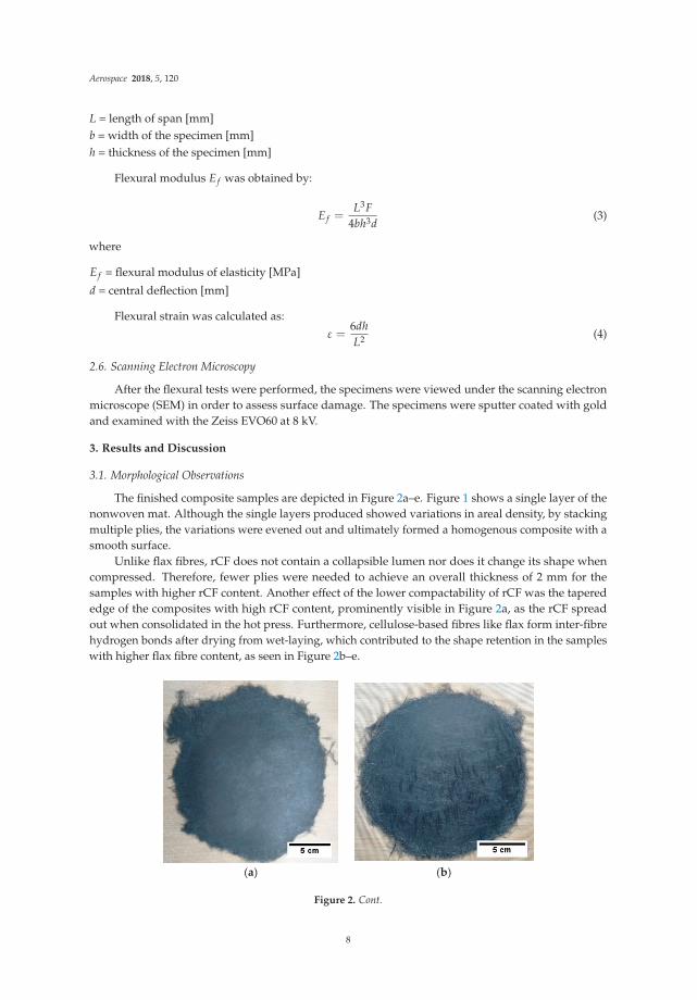
The finished composite samples are depicted in Figure 2a–e. Figure 1 shows a single layer of thenonwoven mat. Although the single layers produced showed variations in areal density, by stackingmultiple plies, the variations were evened out and ultimately formed a homogenous composite with asmooth surface.
Unlike flax fibres, rCF does not contain a collapsible lumen nor does it change its shape whencompressed. Therefore, fewer plies were needed to achieve an overall thickness of 2 mm for thesamples with higher rCF content. Another effect of the lower compactability of rCF was the taperededge of the composites with high rCF content, prominently visible in Figure 2a, as the rCF spreadout when consolidated in the hot press. Furthermore, cellulose-based fibres like flax form inter-fibrehydrogen bonds after drying from wet-laying, which contributed to the shape retention in the sampleswith higher flax fibre content, as seen in Figure 2b–e.
(a) (b)
Figure 2. Cont.
8

Aerospace 2018, 5, 120
(c) (d)
(e)
Figure 2. Finished composites of (a) sample 1, 100% rCF; (b) sample 2, 75% rCF and 25% flax;(c) sample 3, 50% rCF and 50% flax; (d) sample 4, 25% rCF and 75% flax; and (e) sample 5, 100% flax.
3.2. Analysis of the Cross-Section and Void Content
In Figure 3, the optical micrographs of the composites’ cross-sections are presented. For sample 1(Figure 3a), the view under the microscope revealed several voids inside the composite which explainedthe low density measured compared to the theoretical value. These almost round voids were in thesize range of 10–100 μm and randomly distributed throughout the cross-section. The bright edges ofthe voids and the other bright spots were caused by the polished congregations of PLA which alsoreflected the light. This indicated that the 2 bar applied pressure was not enough to obtain sufficientlydensely packed fibres for the target composite fibre volume fraction of 30% with a 100% rCF content.
Samples 2, 3, and 4 (Figure 3b–d) showed no visible voids and a fairly homogeneous distributionof rCF and flax fibres. The density measurements showed slightly elevated void contents for samples 2and 4 at 9.1% and 11.2%, respectively, in comparison to samples 3 and 5 with 6.0% and 7.7%. They couldbe caused by increased gas formation from the PLA during the heating process on the hot press [37].The higher void content from samples 2 and 4 were not detected through the microscope since thecross-section examined only represented a small part of the overall composite specimen and the voidsmight be present in other areas.
However, increasing the flax fibre content seemed to reduce the void content when compared tosample 1 by achieving the right amount of compactability for the PLA to fill in the space between thefibres and form a continuous solid phase. Replacing 25 vol % rCF with flax, e.g., sample 2 in Figure 3b,was enough to obtain the target fibre content without further increasing the pressure.
In sample 5, with 100% flax fibres (Figure 2e), thin voids were seen mostly surrounding tightlypacked fibre bundles. This suggests that the fibre bundles were packed too closely for the PLA towet the fibres. The elongated shape of the voids could potentially contribute to premature failure byinitiating matrix cracking from the ends of the voids [19].
9

Aerospace 2018, 5, 120
Generally, nonwoven composites will have higher void content compared to woven orunidirectional composites because the random orientation of the fibres can impede matrix flow orentrap air [38]. Furthermore, the hollow lumen inside natural fibres such as flax also act as a void andincrease the void content of the composite [37].
(a) (b)
(c) (d)
(e)
Figure 3. Optical micrographs with edge-lighting of the cross-section of (a) sample 1, 100% rCF;(b) sample 2, 75% rCF and 25% flax; (c) sample 3, 50% rCF and 50% flax; (d) sample 4, 25% rCF and75% flax; and (e) sample 5, 100% flax.
10
Aerospace 2018, 5, 120
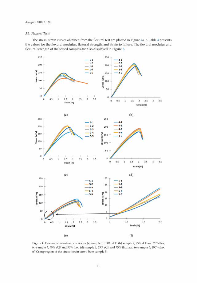
3.3. Flexural Tests
The stress–strain curves obtained from the flexural test are plotted in Figure 4a–e. Table 4 presentsthe values for the flexural modulus, flexural strength, and strain to failure. The flexural modulus andflexural strength of the tested samples are also displayed in Figure 5.
(a) (b)
(c) (d)
(e) (f)
Figure 4. Flexural stress–strain curves for (a) sample 1, 100% rCF; (b) sample 2, 75% rCF and 25% flax;(c) sample 3, 50% rCF and 50% flax; (d) sample 4, 25% rCF and 75% flax; and (e) sample 5, 100% flax.(f) Crimp region of the stress–strain curve from sample 5.
11

Aerospace 2018, 5, 120
Table 4. Flexural strength, flexural modulus, and strain at failure with standard deviations of alltested samples.
Sample No. 1 2 3 4 5
Flexural Modulus [GPa] 12.20 13.98 13.12 10.47 6.17S.D. 0.90 0.97 1.03 0.73 1.17
Flexural Strength [MPa] 133.77 202.61 198.66 179.00 111.61S.D. 13.70 5.9 23.21 9.84 8.40
Flexural Failure Strain [%] 2.26 2.08 2.04 2.26 2.47S.D. 0.43 0.09 0.36 0.04 0.09
Figure 5. Flexural modulus and strength for all tested samples. Sample 1 showed lower properties dueto voids in the matrix.
Below 0.3% strain, the stress–strain response showed a small crimp region for all curves.A magnification of the area up 0.3% strain for the stress–strain curve of sample 5 can be seen inFigure 4f. The crimp could be attributed to the elastic deformation of the PLA matrix. Its polymerstrands were stretched and absorbed some of the stress as the cross-head touched the outermost layersat low strains. Afterwards, the curve became more linear with the increasing rCF content. The additionof flax fibres contributed to the non-linear deformation in the composite past the point of ultimatestrength at which the matrix fails, and further softening of the curves could be seen for samples 1, 2,and 3 (Figure 4a–c) which corresponded to breakages of rCF. Overall, by increasing the flax content,the composite’s ability to withstand higher strain was also increased due to the ductile behaviour offlax. Sample 1 seemed to break at a higher strain at failure on average because the high void contentwhich introduced irregularities to the composite’s composition, resulting in variable flexural behaviour.Although sample 3 contained more flax than sample 2, they behaved similarly and failed at around 2%strain. Sample 4 failed at 2.3% strain and sample 5 had the highest strain to failure at 2.5%, since thiswas made entirely of flax fibres.
In general, the composites with higher rCF content had higher flexural modulus and strength.For this reason, sample 1 with 100% rCF as reinforcement was expected to exhibit the highest flexuralproperties. However, its flexural modulus of 12.20 GPa was below those of samples 2 and 3 with13.98 GPa and 13.12 GPa, respectively. Moreover, the flexural strength of sample 1 at 133.77 MPawas the second lowest after sample 5 with 111.61 MPa which only used flax fibres as reinforcement.This could be explained by the numerous voids observed in the optical micrographs of sample 1.Because of the high void fraction, the load could not be completely transferred to the rCF so that the
12

Aerospace 2018, 5, 120
matrix and the rCF broke separately from each other. This caused the softening after the point ofultimate strength in the stress–strain curve in Figure 4a.
It was found that sample 2 had the highest average flexural strength of 202.61 MPa followedclosely by sample 3 with 198.66 MPa. Between samples 2 and 3, the increase of flax fibre contentonly decreased the flexural strength by 2.1% and the flexural modulus by 6.2%, which was withinthe scatter of the measured data. Further reducing the rCF content to 25% in sample 4 resulted in adecrease of almost 10% in flexural strength and 20% in flexural modulus when compared to sample 3.From the perspective of sample 5, replacing 25 vol % of flax with rCF increased the flexural strengthby 60% and the flexural modulus by 70%. Compared to the relevant literature, Le Guen et al. [21]showed a decrease of 34.2% in flexural strength of their woven CF/flax epoxy composite as the CFvolume fraction was lowered from 58% to 26%. However, this is a different system with long fibres andseparate plies. This suggests that with the better intermixing of rCF/flax, the higher flexural propertiescould be maintained over a wider range of rCF/flax ratios; the void content and overall quality of thefabricated specimen are vital.
3.4. Surface Morphology and Failure Assessment
SEM results revealed that in addition to the voids inside sample 1, it also had a porous surface.The surface images of each sample are shown in Figure 6. Although the optical micrographs suggestan even mixture of the fibres, from the images it appeared as if the rCF in the composites tended toaccumulate on the outermost layers and leave a rougher surface, as seen in Figure 6a–c. In contrast,samples with higher flax fibre content gave the surface a smoother appearance (Figure 6e).
(a) (b)
(c) (d)
Figure 6. Cont.
13

Aerospace 2018, 5, 120
(e)
Figure 6. Scanning electron microscope (SEM) images at 60× magnification of the surface of(a) sample 1, 100% rCF; (b) sample 2, 75% rCF and 25% flax; (c) sample 3, 50% rCF and 50% flax;(d) sample 4, 25% rCF and 75% flax; and (e) sample 5, 100% flax.
The main cause of failure was the excessive tensile stress at the bottom surface of the specimenwhich resulted in the breakage of the matrix. This failure mode contributed towards the low flexuralproperties of sample 1 as well, since the propagation of the crack was facilitated by the presence ofvoids and surface porosity that magnified local stresses. Fibre pull-out and breakage were also visible,especially for the rCF, which could be seen in Figure 7. Most of the rCF fibres beneath the crack werenot coated by matrix material, also visible in Figure 7, suggesting that they were de-bonded from thePLA matrix due to poor adhesion. This led to poor interfacial strength and hence a less effective loadtransfer from the resin to the fibres, resulting in premature failure and hence lower flexural strength.The matrix crack in sample 2 (Figure 8) was similar in size and shape to the one observed in sample 1.Fibre pull-out and breakages of rCF could be detected, but without the surface porosity, higher loadwas needed to propagate the crack through the matrix, which was why the average flexural strengthof sample 2 was higher when compared to sample 1.
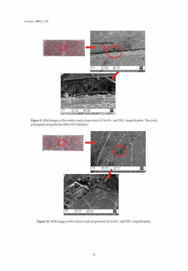
With higher flax content, more flax fibres were visible on the composite fracture surface. The flaxfibres perpendicular to the direction of load could act as a crack initiator through de-bonding from thematrix, as seen in specimen 3-3 in Figure 9. Below the crack surface, flax fibres with matrix residuewere visible which suggested better matrix adhesion. Specimen 4-3 in Figure 10 also had fibres onthe surface; however, the fibres were not aligned in the direction of the crack and seemed to deflect it.It seemed as if the increase in flax fibre content decreased the rCF de-bonding from the matrix since thepropagation of the crack appeared to be more winded and less prominent, e.g., in Figures 10 and 11.
From the higher magnification images of the composites with rCF, it can be concluded that thematrix adhesion between rCF and PLA tended to be poorer in comparison to flax as pull-outs andbreakages of the rCF were clean. The higher affinity between flax and PLA is explained through theirhydrophilic nature and the ability to form hydrogen bonds with their abundance of polar groups intheir structures. Meanwhile, rCF containing mostly nonpolar C–C bonds was not able to form lastinghydrogen bonds with PLA and parted from the matrix with less force. The better matrix combabilityalso resulted in a smaller matrix crack, as seen when comparing samples 1 and 2 with high rCF contentand a gap of 100 μm in the matrix in (Figures 7 and 8) with sample 5 with 20 μm (Figure 11).
14

Aerospace 2018, 5, 120
Figure 7. SEM images of the matrix crack of specimen 1-3 in 60× and 500× magnification. Fibre pull-outand breakages are visible.
Figure 8. SEM images of the matrix crack of specimen 2-3 in 60× and 500× magnification.
15
Aerospace 2018, 5, 120
Figure 9. SEM images of the matrix crack of specimen 3-3 in 60× and 500× magnification. The crackpropagated along the flax-fibre-PLA interface.
Figure 10. SEM images of the matrix crack of specimen 4-3 in 60× and 500× magnification.
16

Aerospace 2018, 5, 120
Figure 11. SEM images of the matrix crack of specimen 5-3 in 60× and 500× magnification.
4. Conclusions
Short fibre hybrid composites were manufactured through wet-laying with different ratios of rCFand flax fibres, and their flexural behaviour and morphological structure were analysed. The compositewith 75% rCF and 25% flax fibre showed the highest average flexural strength and modulus of202.61 MPa and 13.98 GPa, respectively, followed closely by the sample with 50% rCF and 50% flax.The intimate mixing between rCF and flax fibre during the dispersing stage allowed for a lesserdecrease of flexural properties as the flax fibre content increased. Surface porosity and void content inthe 100% rCF composite induced during the fabrication process contributed to early matrix crackinginitiation that led to fibre/matrix de-bonding and premature fibre failure in the form of breakage andfibre pull-out. Replacing 25% of the rCF content with flax helped to increase the compactability ofthe nonwoven, resulting in the lowering of the void content without increasing the pressure of thehot press. Furthermore, rCF showed poor matrix adhesion with PLA, and fibre treatments could beconsidered to increase the interfacial bond between matrix and fibres.
Author Contributions: Conceptualization and methodology, B.T. and H.G.; validation, C.S. and H.G.;investigation, B.T. and X.Y.; writing–original draft preparation, B.T. and X.Y.; writing–review and editing, B.T., C.S.and H.G.; supervision, C.S. and H.G.
Funding: This project received funding from The European Union’s Horizon 2020 research and innovationprogramme under grant agreement No. 690638.
Conflicts of Interest: The authors declare no conflict of interest.
References
1. Bunsell, A.R. Fibres for composite reinforcement: Properties and microstructures. In Composite Reinforcementsfor Optimum Performance; Woodhead Publishing: Sawston, UK, 2011; pp. 3–31, ISBN 9781845699659.
2. Kuehnel, M.; Kraus, T. The Global CFRP Market 2016. In Proceedings of the International CompositesCongress (ICC), Düsseldorf, Germany, 28 November 2016.
17

Aerospace 2018, 5, 120
3. Pimenta, S.; Pinho, S.T. Recycling carbon fibre reinforced polymers for structural applications: Technologyreview and market outlook. Waste Manag. 2011, 31, 378–392. [CrossRef] [PubMed]
4. Witik, R.A.; Teuscher, R.; Michaud, V.; Ludwig, C.; Månson, J.-A.E. Carbon fibre reinforced composite waste:An environmental assessment of recycling, energy recovery and landfilling. Compos. Part A Appl. Sci. Manuf.2013, 49, 89–99. [CrossRef]
5. Pimenta, S.; Pinho, S.T. Recycling of Carbon Fibers. In Handbook of Recycling: State-of-the-Art for Practitioners,Analysts, and Scientists; Worrell, E., Reuter, M.A., Eds.; Elsevier Inc.: Amsterdam, The Netherlands, 2014;pp. 269–283. ISBN 9780123965066.
6. Pickering, S.J. Recycling technologies for thermoset composite materials—Current status. Compos. Part AAppl. Sci. Manuf. 2006, 37, 1206–1215. [CrossRef]
7. Oliveux, G.; Dandy, L.O.; Leeke, G.A. Current status of recycling of fibre reinforced polymers: Review oftechnologies, reuse and resulting properties. Prog. Mater. Sci. 2015, 72, 61–99. [CrossRef]
8. Russell, S.J. Handbook of Nonwovens; CRC Press: Boca Raton, FL, USA, 2006; ISBN 9781845691998.9. Pill, H.; Afflerbach, K. Wet Lay Method. In Nonwoven Fabrics; Wiley-VCH Verlag GmbH & Co. KGaA:
Weinheim, Germany, 2004; pp. 237–267.10. Akonda, M.H.; Lawrence, C.A.; Weager, B.M. Recycled carbon fibre-reinforced polypropylene thermoplastic
composites. Compos. Part A Appl. Sci. Manuf. 2012, 43, 79–86. [CrossRef]11. Giannadakis, K.; Szpieg, M.; Varna, J. Mechanical Performance of a Recycled Carbon Fibre/PP Composite.
Exp. Mech. 2011, 51, 767–777. [CrossRef]12. Szpieg, M.; Wysocki, M.; Asp, L.E. Reuse of polymer materials and carbon fibres in novel engineering
composite materials. Plast. Rubber Compos. 2009, 38, 419–425. [CrossRef]13. Shah, D.U.; Schubel, P.J. On recycled carbon fibre composites manufactured through a liquid composite
moulding process. J. Reinf. Plast. Compos. 2016, 35, 533–540. [CrossRef]14. Turner, T.A.; Warrior, N.A.; Pickering, S.J. Development of high value moulding compounds from recycled
carbon fibres. Plast. Rubber Compos. 2010, 39, 151–156. [CrossRef]15. Nunna, S.; Chandra, P.R.; Shrivastava, S.; Jalan, A. A review on mechanical behavior of natural fiber based
hybrid composites. J. Reinf. Plast. Compos. 2012, 31, 759–769. [CrossRef]16. Pil, L.; Bensadoun, F.; Pariset, J.; Verpoest, I. Why are designers fascinated by flax and hemp fibre composites?
Compos. Part A Appl. Sci. Manuf. 2016, 83, 193–205. [CrossRef]17. Yan, L.; Chouw, N.; Jayaraman, K. Flax fibre and its composites—A review. Compos. Part B Eng. 2014, 56,
296–317. [CrossRef]18. Baley, C. Analysis of the flax fibres tensile behaviour and analysis of the tensile stiffness increase. Compos. Part
A Appl. Sci. Manuf. 2002, 33, 939–948. [CrossRef]19. Hull, D.; Clyne, T.W. An Introduction to Composite Materials; Cambridge University Press: Cambridge, UK,
1996; ISBN 9781139170130.20. Chung, D.D.L. Carbon Fiber Composites; Butterworth-Heinemann: Oxford, UK, 1994; ISBN 9780080500737.21. Le Guen, M.J.; Newman, R.H.; Fernyhough, A.; Emms, G.W.; Staiger, M.P. The damping–modulus
relationship in flax–carbon fibre hybrid composites. Compos. Part B Eng. 2016, 89, 27–33. [CrossRef]22. Sarasini, F.; Tirillò, J.; D’Altilia, S.; Valente, T.; Santulli, C.; Touchard, F.; Chocinski-Arnault, L.; Mellier, D.;
Lampani, L.; Gaudenzi, P. Damage tolerance of carbon/flax hybrid composites subjected to low velocityimpact. Compos. Part B Eng. 2016, 91, 144–153. [CrossRef]
23. Dhakal, H.N.; Zhang, Z.Y.; Guthrie, R.; MacMullen, J.; Bennett, N. Development of flax/carbon fibre hybridcomposites for enhanced properties. Carbohydr. Polym. 2013, 96, 1–8. [CrossRef] [PubMed]
24. Assarar, M.; Zouari, W.; Sabhi, H.; Ayad, R.; Berthelot, J.M. Evaluation of the damping of hybrid carbon-flaxreinforced composites. Compos. Struct. 2015, 132, 148–154. [CrossRef]
25. Fiore, V.; Valenza, A.; Di Bella, G. Mechanical behavior of carbon/flax hybrid composites for structuralapplications. J. Compos. Mater. 2012, 46, 2089–2096. [CrossRef]
26. Bos, H.L.; Müssig, J.; van den Oever, M.J.A. Mechanical properties of short-flax-fibre reinforced compounds.Compos. Part A Appl. Sci. Manuf. 2006, 37, 1591–1604. [CrossRef]
27. Bodros, E.; Pillin, I.; Montrelay, N.; Baley, C. Could biopolymers reinforced by randomly scattered flax fibrebe used in structural applications? Compos. Sci. Technol. 2007, 67, 462–470. [CrossRef]
28. Roussière, F.; Baley, C.; Godard, G.; Burr, D. Compressive and Tensile Behaviours of PLLA Matrix CompositesReinforced with Randomly Dispersed Flax Fibres. Appl. Compos. Mater. 2012, 19, 171–188. [CrossRef]
18
Aerospace 2018, 5, 120
29. Fages, E.; Cano, M.; Gironés, S.; Boronat, T.; Fenollar, O.; Balart, R. The use of wet-laid techniques to obtainflax nonwovens with different thermoplastic binding fibers for technical insulation applications. Text. Res. J.2013, 83, 426–437. [CrossRef]
30. Fages, E.; Gironés, S.; Sánchez-Nacher, L.; García-Sanoguera, D.; Balart, R. Use of wet-laid techniques to formflax-polypropylene nonwovens as base substrates for eco-friendly composites by using hot-press molding.Polym. Compos. 2012, 33, 253–261. [CrossRef]
31. Wong, K.H.; Syed Mohammed, D.; Pickering, S.J.; Brooks, R. Effect of coupling agents on reinforcing potentialof recycled carbon fibre for polypropylene composite. Compos. Sci. Technol. 2012, 72, 835–844. [CrossRef]
32. Pickering, S.; Liu, Z.; Turner, T.; Wong, K. Applications for carbon fibre recovered from composites. IOP Conf.Ser. Mater. Sci. Eng. 2016, 139. [CrossRef]
33. Longana, M.L.; Yu, H.; Aryal, P.; Potter, K.D. The High Performance Discontinuous Fibre (HiPerDiF) Methodfor Carbon-Flax Hybrid Composites Manufacturing. In Proceedings of the 21st International Conference onComposite Materials, Xi’an, China, 20–25 August 2017.
34. Longana, M.L.; Yu, H.; Potter, K.D. The High Performance Discontinuous Fibre (HiPerDif) Method forthe Remanufacturing of Mixed Length Reclaimed Carbon Fibres. In Proceedings of the 21st InternationalConference on Composite Materials, Xi’an, China, 20–25 August 2017.
35. Yu, H.; Potter, K.D.; Wisnom, M.R. A novel manufacturing method for aligned discontinuous fibre composites(High Performance-Discontinuous Fibre method). Compos. Part A Appl. Sci. Manuf. 2014, 65, 175–185.[CrossRef]
36. Flynn, J.; Amiri, A.; Ulven, C. Hybridized carbon and flax fiber composites for tailored performance.Mater. Des. 2016, 102, 21–29. [CrossRef]
37. Alimuzzaman, S.; Gong, R.H.; Akonda, M. Impact Property of PLA/Flax Nonwoven Biocomposite. Conf. Pap.Mater. Sci. 2013, 2013, 136861. [CrossRef]
38. Yahaya, R.; Sapuan, S.M.; Jawaid, M.; Leman, Z.; Zainudin, E.S. Effect of fibre orientations on the mechanicalproperties of kenaf–aramid hybrid composites for spall-liner application. Def. Technol. 2016, 12, 52–58.[CrossRef]
© 2018 by the authors. Licensee MDPI, Basel, Switzerland. This article is an open accessarticle distributed under the terms and conditions of the Creative Commons Attribution(CC BY) license (http://creativecommons.org/licenses/by/4.0/).
19
aerospace
Article
Flexural Mechanical Properties of Hybrid EpoxyComposites Reinforced with Nonwoven Made of FlaxFibres and Recycled Carbon Fibres
Jens Bachmann *, Martin Wiedemann and Peter Wierach
DLR—Deutsches Zentrum für Luft-und Raumfahrt e.V. (German Aerospace Centre),Institute of Composite Structures and Adaptive Systems, Braunschweig 38108, Germany;[email protected] (M.W.); [email protected] (P.W.)* Correspondence: [email protected]; Tel.: +49-531-295-3218
Received: 3 September 2018; Accepted: 3 October 2018; Published: 10 October 2018
Abstract: Can a hybrid composite made of recycled carbon fibres and natural fibres improve theflexural mechanical properties of epoxy composites compared to pure natural fibre reinforcedpolymers (NFRP)? Growing environmental concerns have led to an increased interest in theapplication of bio-based materials such as natural fibres in composites. Despite their good specificproperties based on their low fibre density, the application of NFRP in load bearing applicationssuch as aviation secondary structures is still limited. Low strength NFRP, compared to compositessuch as carbon fibre reinforced polymers (CFRP), have significant drawbacks. At the same time, theconstantly growing demand for CFRP in aviation and other transport sectors inevitably leads to anincreasing amount of waste from manufacturing processes and end-of-life products. Recoveringvaluable carbon fibres by means of recycling and their corresponding re-application is an importanttask. However, such recycled carbon fibres (rCF) are usually available in a deteriorated (downcycled)form compared to virgin carbon fibres (vCF), which is limiting their use for high performanceapplications. Therefore, in this study the combination of natural fibres and rCF in a hybrid compositewas assessed for the effect on flexural mechanical properties. Monolithic laminates made of hybridnonwoven containing flax fibres and recycled carbon fibres were manufactured with a fibre volumefraction of 30% and compared to references with pure flax and rCF reinforcement. Three-pointbending tests show a potential increase in flexural mechanical properties by combining rCF and flaxfibre in a hybrid nonwoven.
Keywords: composite; natural fibre; flax; recycled carbon fibre; nonwoven; hybrid
1. Introduction
Fibre reinforced polymers (FRP) have gained importance in aviation and other transportationsectors due to their excellent mechanical properties combined with relatively low weight. Highperformance composites like carbon fibre reinforced polymers (CFRP) and also glass fibre reinforcedpolymers (GFRP) are used in primary and secondary structures of modern aircrafts. They enablethe construction of lighter and more efficient aircraft resulting in the reduction of fuel consumptionand increased payloads Carbon fibres consume high amounts of energy during the production phase.Therefore, it is of high interest to reduce the consumption of synthetic materials in favour of bio-basedmaterials in certain applications. Bio-based (renewable) materials like natural fibres have been underinvestigation for a long time for their use in composites but they have not yet been introduced intomodern aircraft in a noticeable way. Lack of experience and confidence in the long-term performanceand mechanical properties of composites containing natural fibres are still an obstacle for their usagein safety relevant applications like primary structures (e.g., fuselage). However, secondary structures
Aerospace 2018, 5, 107; doi:10.3390/aerospace5040107 www.mdpi.com/journal/aerospace20

Aerospace 2018, 5, 107
and interior composites, which are not stressed on such high levels offer possible areas of applicationin aviation [1].
In contrast to synthetic fibres, natural fibres are characterised by a complex multiscale structure,leading to a large variability in mechanical properties for different natural fibres [2]. Compared toglass fibres, natural fibres usually offer good specific stiffness due to their low density. However,their tensile strength cannot compete even when taking into account the fibre density. Furthermore,the length of natural fibres is limited to the maximum of the plant length. Single flax fibres reach amaximum length in the two-digit millimetre range. This is a major difference compared to syntheticfibres which are available as filaments in theoretically unrestricted length. A comprehensive review ofnatural fibres and their properties can be found in the literature [3–7].
The mechanical properties of natural fibre reinforced polymers (NFRP) are typically lower whencompared to GFRP and especially CFRP. In order to broaden the application of NFRP, it is important toincrease their mechanical properties. Several ways to improve the mechanical properties of NFRP havebeen investigated [8]. Most of them use chemical treatments to improve the fibre-matrix adhesion. Forexample, the effect of silane coupling agents on NFRP has been reviewed by Xie et al. [9]. As anotherexample, the positive effects of the grafting of flax fibres with nanoparticles and incorporation ofcarbon nanotubes on natural fibres was recently reviewed by Li et al. [10].
Another way to increase the mechanical properties of NFRP is the hybridization with syntheticfibres such as glass or carbon fibres. There is a differentiation between interlayer (interply) andintralayer (intraply) hybrid composites [11,12]. A common configuration of hybrid composites is theinterlayer (Figure 1a) because it is simple to produce by stacking commercially available reinforcementlayers with different types of fibres, such as carbon fibre and glass fibre woven fabrics. A mix ofdifferent fibre types in one layer characterises intralayer hybrid composites, resulting in a higherdispersion of fibres but also a more complex production process (Figure 1b). Swolfs et al. [11]reported the limited availability of investigations in the comparison of interlayer and intralayerhybrid composites. Smaller delamination areas have been found by Park et al. [13] after impact testsin intralayer compared to interlayer hybrids aramid/polypropylene fibre composites. An increasedresistance to crack propagation has been found by Pegoretti et al. [14] for E-glass and polyvinyl alcoholwoven fabrics.
(a) (b)
Figure 1. Hybrid configurations: interlayer (a) and intralayer (b). Dark and light grey fields indicatedifferent types of fibres in the hybrid laminate. Based on [11].
In the literature, a multitude of hybrid combinations of all kind of natural fibres with glass, aramidand carbon fibres can be found. Manders and Bader [15] evaluated the tensile mechanical properties ofglass/carbon fibre hybrid composites with epoxy resin. They found that the dispersion and localisationof the fibres had a strong effect on the results. An increase in toughness and failure strain was observedwith a finer dispersion (“hybrid effect”). Reddy et al. [16] found a gradual increase in tensile andflexural modulus by stacking layers of jute, pineapple leaf and glass fibres. Lützkendorf et al. [17]assessed the combination of recycled carbon fibres (rCF) and natural fibres in a hybrid nonwoven andthermoplastic polypropylene matrix. With bonding agent, the flexural stiffness could be increased bymore than 100% with an rCF-content of 20%. Using rCF/PP only in the top-layers with pure NF/PPin between (interlayer hybrid) led to a minor increase in flexural stiffness. Flynn et al. [18] tested theeffects of hybridization with flax and carbon fibre fabrics in different stacking configurations. A gainin tensile strength of 252% compared to a purely flax fibre reinforced composite was found for thehybrid variant. Adekunle et al. [19] tested different hybrid combinations of woven and nonwoven flax
21
Aerospace 2018, 5, 107
fibres with glass fibres using a soybean oil derived bio-resin. They found a considerable increase intensile strength by integration of a glass fibre mat. Cicala et al. [20] combined flax and carbon fibres indifferent stacking sequences and found up to three times higher tensile strength compared to the pureflax composite. Murdani et al. [21] found that the damping ratio decreased while flexural propertieswere improved by adding glass and carbon fibres to a jute fibre reinforced composite.
Summarizing the available literature on hybrid natural fibre/synthetic fibre composites, animprovement in mechanical properties was usually observed. A majority of studies are based onreinforcements using usual (commercial) delivery forms of reinforcement, such as woven fabric.However, the increasing use of CFRP in aviation and other high performance applications leads to afurther rise in carbon fibre production. Double-digit growth for the demand of carbon fibre is expectedin the next decade [22]. From an ecological perspective, composites like CFRP consume high amountsof energy during the production phase. The high value of carbon fibres makes them very interestingfor recycling. Recycled carbon fibres can be obtained from production waste (dry fibres from cuttingand trimming as well as uncured prepreg) and cured end-of-life CFRP products. Close-loop recycling,as with metals is currently not available for end-of-life CFRP because of their intrinsic heterogenicstructure. Especially in combination with cross-linked thermoset polymer systems, this impedesefficient recycling at the end of life [23].
Potential cost savings and reduced energy consumption through carbon fibre recycling werepredicted by Carberry [24]. However, recycling processes can be even more expensive comparedto the production of vCF [25]. A comprehensive overview of composite recycling processes can befound in the review papers of Oliveux et al. [26] and Naqvi et al. [27]. Currently, the CFRP recyclingprocess with the highest technology readiness level is pyrolysis [28]. CFRP waste is fed into thepyrolysis chamber at temperatures up to 600 ◦C. Pyrolysis has already found its way into commercialapplications in the UK and Germany [29]. Typically, the quality of the recycled carbon fibres (rCF) islower compared to virgin carbon fibres (vCF). A main reason is the discontinuous length due to thepreceding shredding process to reduce the size of end-of-life parts. The removal of fibre sizing andthus a possible reduction of fibre-matrix adhesion is another drawback. Information on the influenceof the fibre-matrix interface and interphase on the composite properties can be found in the workof Jesson et al. [30]. The mechanical properties of rCF can still be considered as very good. Tensilefibre tests have shown comparable results for rCF and vCF [31]. Because of the reduced length, theapplication of rCF is currently restricted to alternative use-cases with lower quality requirements [28].The usual delivery forms are chopped, milled and pelletized rCF [29]. Another way to obtain recycledfibres is the recycling of waste of carbon fibre fabrics generated during the production of composites.Waste from fabric cutting is the main source for this material. The short and variable length of rCF isa challenge for converting them into continuous yarns used in woven reinforcements. Nonwovensmade of chopped rCF are already available on the market [32,33].
Chopped rCF (Figure 2b) shows some apparent similarities to natural fibres (Figure 2a), forexample, randomness, restricted length and curvature. Therefore, a possible way of using rCF is incombination with natural fibres in a hybrid nonwoven as reinforcement for FRP, combining the verygood mechanical properties of the rCF with the low density and good damping properties of naturalfibres. Nonwoven processes are capable of combining different types of fibres of variable length in asingle web structure. Nonwovens are also less expensive and potentially more eco efficient comparedto classic woven fabrics from bio-fibres due to their simple production process [34]. The questionis, do the added steps in the production of a hybrid nonwoven add benefits compared to a morecommon reinforcement, which uses just one fibre type in woven or nonwoven fabrics? The aim ofthis study is to make a preliminary assessment of the impact of flexural mechanical properties. Anoverview of typical manufacturing processes for nonwoven fabric in relation to fibre length and degreeof isotropic behaviour is given in Figure 3. A distinction can be made between four processes, and thetwo dry-laying processes are capable of processing fibre lengths of more than 30 mm. Aerodynamicairlay processes usually utilize an airstream to feed the fibres on a moving belt. Carding is a process
22

Aerospace 2018, 5, 107
of separating individual fibres, using a series of dividing and re-dividing steps. This results in aparallelisation of the fibres. Carding is possible by using hand cards or drum cards in which fibres arefed through one or more pinned drums. The nonwoven web can be parallel or random laid. Parallellaid carded nonwoven usually results in good tensile strength and low elongation in the machinedirection (MD) compared to the cross direction (CD) [34].
(a) (b)
Figure 2. The delivery form of the fibres used for the assessment of hybrid nonwoven in this study.Flax fibres (a) and recycled carbon fibres (b).
Figure 3. Manufacturing processes for nonwoven in relation to fibre length and degree of isotropicmaterial properties. Figure based on [35].
The manufacturing processes of nonwoven fabrics are very efficient and it is possible to usedifferent fibre length fractions. For woven fabrics, the fibres are normally processed into yarns,which leads to strong twists and thus to areas of potentially poor wettability by liquid resin systems.A possible advantage of the use of nonwoven for FRP lies in the better availability of the fibres to beembedded in the resin system. Nonwoven is an obvious choice because of the fibre characteristics ofthe flax and rCF. However, fibres can be damaged because of the mechanical stress during the cardingprocess [35].
The hybrid combination of recycled carbon fibres with natural fibres and their differentdistribution in thermoset composites has not been assessed in detail so far. This study aimed toprovide a preliminary assessment of the potential of hybrid rCF/flax nonwoven as reinforcement incombination with a thermoset resin. Two references, pure flax and pure rCF nonwoven reinforcedcomposite, were produced as a base line. Two hybrid variants contained fibres in the same totalvolumetric mixing ratio of flax to rCF (3:1). The difference was the distribution of the rCF overthe laminate thickness. The effect on flexural mechanical properties was studied by three-point
23

Aerospace 2018, 5, 107
bending (3PB). This test was chosen because of the simple specimen preparation and the small size ofthe samples.
2. Materials and Methods
2.1. Materials
The four variants of laminates tested in this paper were based on recycled carbon fibres fromproduction waste (e.g., dry fibre cut-off) and staple flax fibres. Flax fibres were obtained from thecompany Intercot in Barcelona, Spain. The flax fibres had no length restriction due to chopping.To avoid the potentially weak fibre-matrix adhesion of pyrolysed rCF because of their removed sizing,recycled fibres from dry cut-off waste were chosen for this preliminary study. Those rCF usually havean intact sizing. However, the exact type of sizing was unknown. These rCF, chopped to maximumlength of 25 mm, were obtained from CarboNXT GmbH (Wischhafen, Germany). The delivery form ofthe fibres is shown in Figure 2. A thermoset matrix system, the two-component liquid epoxy infusionresin Epikote™ RIMR135 with curing agent RIMH1366 (Hexion B.V., Rotterdam, The Netherlands)was used to produce the laminates.
2.2. Manufacturing of the Nonwoven
Sensitivity of electrical equipment to short circuits caused by conductive rCF led to the decisionto perform the whole nonwoven manufacturing process in a closed exhaust hood. Therefore, a simpletwo-stage laboratory process was used to manufacture the nonwoven from flax and recycled carbonfibres. The first step in the process was opening of the fibres. The resulting increased volume of thefibre batches led to better control of the fibre feed into the card. The fibre opening process used inthis study was based on the principle of a gas jet mixer. A container with a volume of approximatelyseven litres was modified for fibre opening and mixing, as shown in Figure 4a. Compressed air(2–3 bars) was introduced to the fibre filled container through a funnel attached the bottom. A manuallycontrolled pistol was used to control the release of the compressed air in a pulsating manner. Circulardistributed air outlets with cotton wool filter elements were installed in the upper part to the capsule.The outflowing compressed air took up the fibres and whirled them around in the capsule, resulting ina fibre opening (separation). This is schematically shown in Figure 4a. Opening and mixing processesalso removed shives (wooden residues of the bast fibre stem) and dust which was gathered in thecotton wool filters. A transparent screw cap was used to visually observe the opening process. Thefibre mixing was carried out in the same modified container that was used for the fibre opening. Afteropening, fibre batches were mixed according to the mixing ratio given in Table 1.
(a) (b)
Figure 4. Reinforcement manufacturing process with fibre opening and mixing in a capsule withturbulent air (a) and nonwoven web formation on a small-scale electric card with two rotatingdrums (b).
24

Aerospace 2018, 5, 107
Table 1. Nomenclature, composition and schematic drawings of the volumetric distribution of flax(light grey) and rCF (dark grey). Total fibre volume content for each composite was approximately 30%.The volumetric rCF to flax ratio in the outer layers of the Gr-22.5Flax-7.5rCF laminate was rCF/flax = 3:1(intralayer). The four inner layers contained 100% flax fibres, resulting in a combination of intralayerand interlayer hybrid. The same total amount of flax and rCF was used for the 22.5Flax-7.5rCF laminate(pure intralayer).
Laminate Stacking Sequence and Volumetric Distribution of Fibres Composition
30Flax
30 vol.-% Flax70 vol.-% Epoxy
30rCF
30 vol.-% rCF70 vol.-% Epoxy
22.5Flax-7.5rCF22.5 vol.-% Flax7.5 vol.-% rCF
70 vol.-% Epoxy
Gr-22.5Flax-7.5rCF
22.5 vol.-% Flax7.5 vol.-% rCF
70 vol.-% Epoxy
Legend:
For the nonwoven web formation, an electric drum card with a simple two drum design waspurchased from the company Holzwurmwolle in Alfdorf, Germany) (Figure 4b). Both drums hada width of 190 mm. The diameter of the small drum was 45 mm. The big drum had a diameterof 160 mm, resulting in a circumferential length of approximately 500 mm. Both drums could beindividually activated and adjusted for rotating direction and rotating speed. Carding cloths withbuckled needles of 17 mm length were attached to the drums. Needle density was 52 ppsi for the smallintake drum and 72 ppsi for the big drum. Nonwoven webs with an area of approximately 500 mmlength to 190 mm width were produced.
The opened fibres were fed manually to the electric drum carding device. A possible result ofthe manual feeding process was the increased risk of uneven fibre distribution (areal weight) in thenonwoven. This effect was reduced by quality control and the stacking process of several nonwovenlayers to even out the distribution of fibres in the laminate. The fibres fed manually to the cardingdevice were taken up by the small entrance roll and fed to the counter rotating big drum. This processstep was carried out until all fibres were taken up from the big drum. Compression of the fibres onthe big drum was carried out with a fixed brush. A flat card with a needle felt of 52 ppsi pressedmanually on the big drum during the fibre take-up process led to a further increased fibre densityof the nonwoven web. The last step was cutting and manual removal of the nonwoven from the bigroll followed by quality control. No further compaction was applied to the nonwoven webs beforelaminate manufacturing. The quality control included the measurement of areal weight and checkingthe distribution of fibres with the help of a transmission light desk.
2.3. Composition and Nomenclature of the Composites
The stacking sequence and number of nonwovens used for the composite manufacturing is shownin Table 1. Four variations of laminates with a total of six nonwoven layers were produced. All layerswere stacked symmetrically to the neutral axis and oriented in the same direction. The machinedirection (MD) of the nonwoven was always oriented in 0◦ laminate direction. As the carding process
25
Aerospace 2018, 5, 107
led to a clear orientation of fibres in MD compared to the cross direction (CD), the laminates had noin-plane isotropic characteristics.
The nomenclature used for the laminates in this paper is a combination of fibre volume fractionin percent and the used fibre, e.g., 30Flax = 30% fibre volume fraction of flax fibres. Two non-hybridreference laminates contain nonwoven with pure flax (30Flax) and pure rCF (30rC) reinforcements.Furthermore, two hybrid variants with an rCF to flax ratio of 1:3 but differing fibre distribution weremanufactured. Of these, the intralayer hybrid variant contained 22.5 vol.-% flax fibres and 7.5 vol.-%rCF (=22.5Flax-7.5rCF) which were mixed with the aim of achieving a homogeneous distribution. Thegradient or sandwich like variant was a combination of interlayer and intralayer hybrid nonwoven(Gr-22.5Flax-7.5rCF). Here, the rCF were distributed only in each outer layer mixed with a smalleramount of flax fibres added (intralayer). In these outer layers, the nonwoven had a flax rCF to flaxratio of 3:1. The four layers in between were purely made of flax fibres. The gradient variant waschosen in order to assess the effect of the concentration of rCF on the flexural mechanical properties.Placing stiffer plies (i.e., layers with higher rCF content) away from the neutral axis should result inincreased flexural mechanical properties [12]. For both hybrid variants the same total mixing ratio ofrCF and flax fibres was applied.
2.4. Manufacturing of the Composites
The two-component epoxy resin RIMR135 and hardener RIMH1366 were mixed in a weightratio of 100:35, followed by a degassing step in a desiccator to remove air bubbles. The nonwovenlayers have been stacked in order to achieve the desired fibre volume fraction and fibre distributionat an intended thickness of 3 mm. The stacking sequence, number of layers and nomenclature of thelaminates is shown in Table 1. The monolithic laminates were produced with the single line infusion(SLI) method in a Lauffer hydraulic press (500 mm × 500 mm pressing area). The SLI process ischaracterised by using the same line for vacuum generation followed by the liquid resin infusion.Curing time in the heated hydraulic press was 120 min at 85 ◦C followed by deforming and post-curingat 100 ◦C for 60 min in a Memmert UFP500 convection oven (Memmert GmbH + Co. KG, Schwabach,Germany). After cutting, ultrasonic testing in water were carried out to assess the laminate qualityregarding pore distribution and delamination. The cured and trimmed laminates were stored at 23 ◦Cand 50% relative humidity. The physical properties of the laminates are summarized in Table 2.
Table 2. Measured and calculated physical properties of the cured monolithic composites.
LaminateFibre VolumeContent 1 [%]
AverageThickness 2 [mm]
Density 3
[g/cm3]Void Content 4
[%]Glass Transition
Temp.5 [◦C]Water Content 6
[%]
30Flax 29.1 3.11 1.16 7.7 82.3 1.9430rCF 29.0 3.16 1.29 4.3 87.5 0.46
22.5Flax-7.5rCF 29.5 3.12 1.24 2.9 85.2 1.65Gr-22.5Flax-7.5rCF 29.9 3.07 1.23 3.8 85.8 1.45
1 Calculated from average measured laminate thickness given in this table and nonwoven areal weight used for themanufacturing of the composites, with a fibre density of 1.5 g/cm3 for flax, 1.78 g/cm3 for the rCF and 1.15 g/cm3
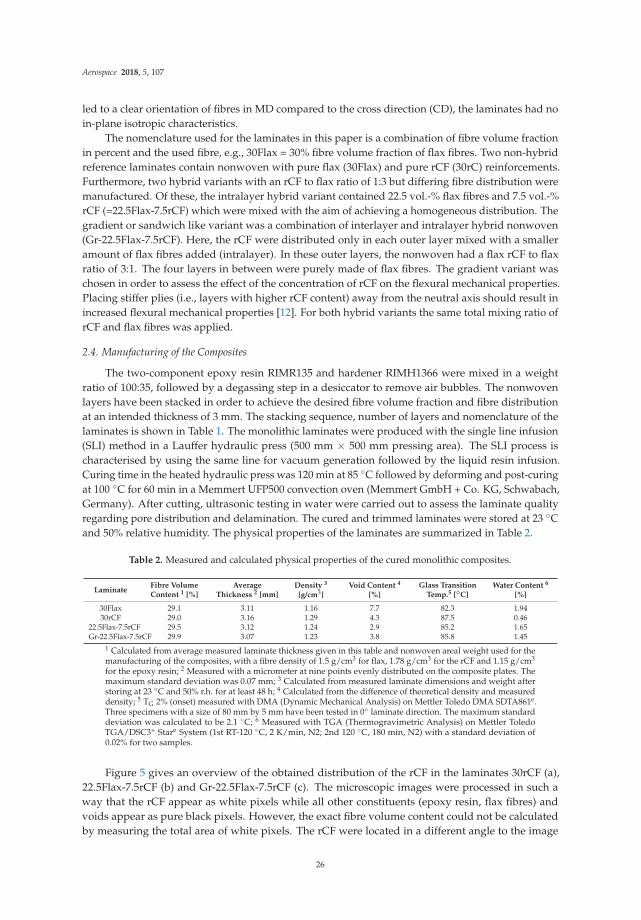
for the epoxy resin; 2 Measured with a micrometer at nine points evenly distributed on the composite plates. Themaximum standard deviation was 0.07 mm; 3 Calculated from measured laminate dimensions and weight afterstoring at 23 ◦C and 50% r.h. for at least 48 h; 4 Calculated from the difference of theoretical density and measureddensity; 5 TG 2% (onset) measured with DMA (Dynamic Mechanical Analysis) on Mettler Toledo DMA SDTA861e.Three specimens with a size of 80 mm by 5 mm have been tested in 0◦ laminate direction. The maximum standarddeviation was calculated to be 2.1 ◦C; 6 Measured with TGA (Thermogravimetric Analysis) on Mettler ToledoTGA/DSC3+ Stare System (1st RT-120 ◦C, 2 K/min, N2; 2nd 120 ◦C, 180 min, N2) with a standard deviation of0.02% for two samples.
Figure 5 gives an overview of the obtained distribution of the rCF in the laminates 30rCF (a),22.5Flax-7.5rCF (b) and Gr-22.5Flax-7.5rCF (c). The microscopic images were processed in such away that the rCF appear as white pixels while all other constituents (epoxy resin, flax fibres) andvoids appear as pure black pixels. However, the exact fibre volume content could not be calculatedby measuring the total area of white pixels. The rCF were located in a different angle to the image
26

Aerospace 2018, 5, 107
plain, resulting in ellipses instead of circles. This indicates the randomness of the fibre orientationtypically seen in nonwoven fabric. In Figure 5a, the higher amount 30 vol.-% rCF compared to7.5 vol.-% rCF in Figure 5b,c is obvious. For all laminates, the distribution of rCF and flax fibreswas not homogeneous. This can be seen in the areal concentration of white pixels. Furthermore,Figure 5c shows the concentration of rCF in both outer layers of the laminate. Undulations and varyingthicknesses of the rCF rich layers can be observed and are typical for all produced samples.
(a)
(b)
(c)
Figure 5. Visualisation of the typical rCF distribution shown as white areas. For the laminates 30rCF(a) and 22.5Flax-7.5rCF (b), the rCF should have been evenly distributed all over the composite.As not all fibres where fully opened, fibre rich areas as well as resin rich areas occurred. The laminateGr-22.5Flax-7.5rCF (c) contains the same volumetric amount of rCF compared to (b), but is concentratedin both outer nonwoven layers. Micrographs were taken with Keyence VFX1000 and VH-Z100URlens (×200) and stitched to a horizontal panorama. The image plane is the 90◦ laminate direction.All images were converted to black (flax, epoxy resin, voids) and white pixels (rCF) with the colourthreshold tool in ImageJ software.
More detailed microscopic images of all four tested variants are shown in Figure 6. Here,the flax fibres and rCF are clearly visible. Flax fibres occur both as single fibres as well as inaccumulations of single flax fibres (technical fibres). Voids can be observed especially around theseflax fibre accumulations (Figure 6a). Flax fibres oriented perpendicular or in an angle between 0◦ and90◦ appear as elongated dark voids (Figure 6c), most likely resulting from the removal of flax fibresegments during the polishing process. Filaments of rCF are visible as bright areas in Figure 6b, 6cand 6d. Similarly to the flax fibres, the rCF are arranged as single fibres as well as accumulations fromthe original tows. The fibre orientation can roughly be calculated using the minimum and maximumdiameter of the ellipse. For example, in Figure 6d the group of carbon fibre marked as rCF1 hasan angle of approximately 0◦ and is therefore oriented in the machine direction (MD = 0◦ laminatedirection). The rCF2 in Figure 6d has a major axis length of about 40 μm and a minor axis lengthof about 7 μm (i.e., the diameter of the carbon fibre). Using the cosine function this results in an
27

Aerospace 2018, 5, 107
approximately 75◦ fibre angle. However, the curvature (Figure 2) of the fibres makes clear statementson fibre orientation difficult.
30Flax 30rCF
(a) (b)
22.5Flax-7.5rCF Gr-22.5Flax-7.5rCF
(c) (d)
Figure 6. The micrographs show exemplary images of the fibres and their distribution in a 0◦ laminatedirection, corresponding to the nonwoven machine direction. Reference composites of flax and rCF areshown in (a) respectively (b). All images show areas near the upper or lower surface of the compositesin order to give a better distinction of the amount of rCF relative to flax fibres in the homogeneoushybrid composite (c) compared to the concentration of rCF in the outer layers (d). Voids betweenfibre and matrix are visible as dark areas. The elongated dark areas, as indicated by the arrow in (c)are probably flax fibres oriented near 90◦ laminate direction that were removed during the polishingprocess of the microscopy specimens.
The micrographs in Figure 6 indicate the relatively low fibre volume content of approximately30% for all tested laminates, visible by major areas of epoxy resin. The calculated void content washighest for the pure flax fibre reinforced sample 30Flax (7.7%, see Table 2), while the two hybridlaminates had an even lower void content compared to the pure rCF reinforced laminate 30rCF. Forthe laminates containing flax fibre, the void content can partly be explained by water in the natural
28

Aerospace 2018, 5, 107
fibres. Generally, also the processing parameters during the laminate manufacturing have an impacton the void content [36].
2.5. Characterisation Methods
Micrographs were prepared with VFX1000 digital microscope (Keyence, Osaka, Japan) andVH-Z100UR lens (Keyence, Osaka, Japan). For this, samples in the 0◦ and 90◦ direction measuring15 mm width were cut and embedded in a room temperature curing acrylic resin ClaroCit (StruersGmbH, Willich, Germany) followed by a three-stage polishing process. ImageJ software (version 1.50e)was used to analyse the micrograph images.
Three-point flexural tests were carried out according to the standard DIN EN ISO 14125 (class II,l/h ∼= 20) on a Zwick Roell universal testing machine Z005. A strain rate of 2 mm/min was used witha load cell of 5 kN (type KAF-Z, Zwick Roell GmbH & Co KG, Ulm, Germany). Strain was measuredby cross-head displacement. Test samples were sawed to 60 mm length and 15 mm width in the 0◦
and 90◦ laminate direction on a KKS 1300 C (MAIKO Engineering GmbH). A span-to-depth ratioof 20:1 at a laminate thickness of 3 mm was chosen in this study because of the limited availablenumber of specimens. The relatively low span-to-depth ratio can cause shear stresses resulting inadditional displacements, and therefore, a potentially lower modulus [12]. Six samples were tested inthe 0◦ direction. Because of limited composite space, a minimum of just two samples were tested inthe 90◦ direction. The flexural modulus was calculated with the secant method between 0.05% and0.25% strain.
3. Results and Discussion
The mean results and standard deviations on flexural strength, modulus and strain at failureobtained from the flexural test are summarized in Table 3. Figure 7 provides a graphical overview ofthe test results for flexural strength and modulus. It can be observed that the fibre type and distributionin hybrid laminates has a strong impact on the flexural mechanical properties.
Table 3. Data for flexural strength (σ), flexural modulus (E) and strain at break (ε) testing in 0◦ and90◦ laminate directions with standard deviations. All layers of the laminates are pointing in the samedirection. 0◦ corresponds to the machine direction (MD) in nonwoven. 90◦ corresponds to the crossdirection (CD) in nonwoven.
LaminateFlexural Strength [MPa] Flexural Modulus [MPa] Strain at Failure [%]
0◦ 90◦ 0◦ 90◦ 0◦ 90◦
30Flax 131.2 ± 7.0 85.6 ± 3.2 7902 ± 385 4363 ± 141 2.92 ± 0.08 2.93 ± 0.0630rCF 491.5 ± 44.6 279.9 ± 39.9 22795 ± 2367 11736 ± 1413 2.00 ± 0.17 2.35 ± 0.16
22.5Flax-7.5rCF 225.3 ± 15.0 114.2 ± 9.4 12540 ± 643 5562 ± 652 2.25 ± 0.18 2.54 ± 0.09Gr-22.5Flax-7.5rCF 286.7 ± 18.8 165.5 ± 14.2 16818 ± 1987 7763 ± 903 1.82 ± 0.16 2.37 ± 0.07
As a reference, the pure flax fibre reinforced laminate 30Flax achieved the lowest flexuralmechanical properties of all tested laminates. Mean flexural strength was 131.2 MPa in the 0◦ laminatedirection, while the mean flexural stiffness was 7.9 GPa. A decrease of 35% for flexural strength and45% for flexural modulus was found in the transverse (90◦) direction compared to the 0◦ laminatedirection. The lower flexural properties in 90◦ can be explained by the stronger alignment of the fibresin the machine direction (MD) compared to the cross direction (CD) for the nonwoven produced withthe electrical carding machine (see Section 2.2).
The laminate with the highest flexural modulus and strength was reinforced purely with rCFnonwoven (30rCF). In the 0◦ laminate direction, 30rCF reached a mean flexural strength of 491.5 MPaand a modulus of 22.8 GPa. Flexural strength and modulus dropped by 43% and 49%, respectively,in the 90◦ laminate direction. Compared to the pure flax fibre reinforced variant (30Flax), a strongincrease of 274% for flexural strength and 188% for flexural modulus was observed for 30rCF.
29

Aerospace 2018, 5, 107
The intralayer hybrid laminate 22.5F-7.5rC, with an rCF to flax ratio of 3:1 distributed evenly inthe laminate, reached a flexural strength of 225.3 MPa and a flexural modulus of 12.5 GPa in the 0◦
direction. Similar to the other laminates, flexural strength and modulus decreased by 49% and 56%,respectively, in the 90◦ laminate test direction. Compared to the pure flax reinforced laminate 30F, thesubstitution of 7.5 vol.-% flax fibres by rCF led to an increase of 72% strength and 59% stiffness in the0◦ direction. The increase in flexural modulus and flexural strength was considerably lower in the 90◦
laminate test direction compared to the 0◦ direction. This corresponds to the stronger alignment offibres in the machine direction (MD) during manufacturing of the nonwoven and led to a strongerinfluence of the matrix in the 90◦ direction.
(a) (b)
Figure 7. Flexural modulus (a) and flexural strength (b) in the 0◦ and 90◦ composite direction inaccordance with DIN EN ISO 14125. The error bars show the minimum and maximum values measuredfor each set of specimens.
In contrast to 22.5Flax-7.5rCF, the second hybrid laminate Gr-22.5Flax-7.5rCF contained the sametotal volumetric flax to rCF ratio of 3:1. However, here all rCF fibres were concentrated in the outerlayers with flax to rCF ratio of 1:3. All remaining flax fibres were located as non-hybrid layers inthe four middle layers (see Table 1). This resulted in a combined intralayer and interlayer hybridconfiguration. Concentrating the rCF in the outer layers resulted in a flexural strength of 286.7 MPaand a flexural modulus of 16.8 GPa in the 0◦ laminate direction. Compared to the evenly distributedrCF/flax mix in the laminate 22.5Flax-7.5rCF, the flexural strength and modulus were further increasedby 27% and 34%, respectively. Compared to the pure flax fibre reinforced variant (30Flax), an increase of118% flexural strength and 113% modulus was found. The flexural properties of the pure rCF laminate(30rCF) were still out of reach with a reduction of flexural strength of −71% for Gr-22.5Flax-7.5rCF.However, the flexural modulus of the Gr-22.5Flax-7.5rCF laminate approaches the stiffness of the30rCF laminate with a loss of −36%. A reduction in flexural strength (−42%) and modulus (−54%) inthe 90◦ laminate direction compared to 0◦ was found for Gr-22.5Flax-7.5rCF.
Typical stress-strain curves for each set of specimens in the 0◦ laminate direction (=machinedirection of nonwoven) can be seen in Figure 8, while Figure 9 gives an overview of the fracture patternafter completion of the three-point bending tests. All measurement curves show an almost linear,slightly degressive behavior. Major differences in the stress-strain curves can be observed in stiffness,stress and strain at failure. While the 30rCF laminate obtained the highest flexural stress at failure, italso had the steepest rise, resulting in the highest stiffness. The fracture pattern of 30rCF is shown inFigure 9b. Fracture occurred abruptly on the tension side (lower side in the specimen), with clearly
30

Aerospace 2018, 5, 107
visible delamination effects and branched crack patterns. The reference laminate 30Flax, made purelyof flax fibres, had the lowest mechanical properties of approximately 125 MPa flexural strength and 8GPa flexural modulus. A more degressive behaviour compared to 30rCF is visible for the test curve inFigure 8. The strain at failure of about 3% is considerably higher compared to the laminates containingrCF with a strain at failure of up to 2.5%. Just as in laminate 30rCF, the fracture of 30Flax occurred onthe tension side of the laminate, without observation of compression damage (Figure 9a).
Figure 8. Stress-strain curves of three-point bending test samples in the 0◦ laminate test direction(similar to the machine direction of the nonwoven). For the sake of clarity, only one typical curve, withresults comparable to the average values per set of specimens, is shown here. For Gr-22.5Flax-7.5rCF, asecond dashed curve is indicating the considerable deviations between the test specimens because ofthe manual nonwoven production.
The hybridisation of flax and rCF introduced further variables, which resulted in a more complexbehaviour of the stress-strain curves in the form of several drops of load (primary and final failure).The hybrid laminate 22.5Flax-7.5rCF (with evenly distributed rCF) shows several minor drops, startingat a strain of approximately 1.9%. Each drop is followed by a further increasing stress level as can beseen in the exemplary measurement curve in Figure 8. Similar to the purely flax and rCF reinforcedlaminates, the fracture pattern was predominantly visible on the tension side (Figure 9c).
A stronger distinction between primary and final flexural failure was observed for the gradientlaminate Gr-22.5Flax-7.5rCF. Kretzis et al. [12] described the flexural behaviour of hybrid fibrereinforced composites. They found that for some hybrid configurations, the stress at primary failurewas about half of the stress at final failure. In the case of the laminate Gr-22.5Flax-7.5rCF, the first failureoccurred on the compression side. The location of the compression failure (buckling) is indicated withan arrow in Figure 9d and can also be attributed to a slight drop visible in the exemplary stress-straincurve at a strain of approximately 1.4% (Figure 8). This first compressive failure had no significanteffect on the further development of the stress-strain curve. Final failure started on the tensionside, comparable to the other tested laminates. However, the final failure did not occur as a singlecatastrophic failure. Instead, after the first visible tensile failure, the stress level dropped slightly at astrain of approximately 1.7%, until the specimen failed completely at a strain of approximately 2.3%.
31

Aerospace 2018, 5, 107
30Flax 30rCF
(a) (b)
22.5Flax-7.5rCF Gr-22.5Flax-7.5rCF
(c) (d)
Figure 9. Fracture patterns after completion of the three-point bending tests in the 0◦ laminate testdirection. The arrow in (d) marks the first area of compressive failure in the laminate with rCFconcentration in the outer layers while the final failure occurred on the tensile side. The rCF rich areasin the laminate Gr-22.5Flax-7.5rCF (d) are marked. All other samples (a–c) failed on the tensile sidewithout any visible compression damage. All images were extracted from video footage taken duringtesting with Panasonic GH-5 and Sigma 105 mm/2.8 DG Macro HSM lens mounted on a tripod. Theloading pin of the flexural test is the blurred object in the upper part of the images.
In the 90◦ laminate test direction the flexural mechanical properties were considerably lower thanthe 0◦ test direction because of the main fibre alignment in the machine direction of the composite.The failure in the 90◦ laminate test direction always occurred on the tension side without visiblecompression failure. Typically, the crack pattern was less branched compared to the 0◦ laminate testdirection, with the exception of the 30rCF laminate, which showed a similar crack pattern in the 0◦
and 90◦ test direction.Deviations in flexural mechanical properties measured for the hybrid nonwoven specimens
were observed. The highest standard deviation in the 0◦ laminate test direction was found in theGr-22.5Flax-7.5rCF variant. In principle, the standard deviation varies between 4.5% and 11.8% inthe 0◦ laminate test direction. Two curves measured during the flexural test for the Gr-22.5Flax-rCFsamples are shown in Figure 8 as an example. The dashed line shows a low performing sample ofGr-22.5Flax-7.5rCF for comparison. Different reasons for the standard deviation can be considered andwill be discussed in the following paragraph.
The distribution of fibres (rCF and flax) in the nonwoven was not fully homogeneous and led tovariance in the fibre volume content in the laminate. For example, relative accumulations of rCF leadto higher mechanical properties in these specific areas compared to areas with low fibre content. Anexample can be observed in Figure 5c, which shows a deviation in the thickness of the rCF rich outerlayers. The random distribution of fibres in the nonwoven also has an effect on the fibre orientationin different areas of the laminate. This can lead to fibres oriented anywhere between the 0◦ and 90◦
laminate direction. The laboratory nonwoven produced in this study also showed a strong curvatureof fibres which resulted in reduced mechanical performance compared to perfectly aligned fibres.Another aspect, generally applicable for natural fibre reinforced polymers, is the embedding of shives
32
Aerospace 2018, 5, 107
into the composite and a considerable void content. Shives are wooden particles that can be left overfrom the manufacturing process of the flax fibres. With a possible shive diameter in the millimetrerange, compared to approximately 20 μm for flax fibres, these shives can act as a weak point in thecomposite. Voids and unwanted constituents like shives can increase stresses locally, leading to earlierfailure [37].
4. Conclusions and Outlook
Growing environmental concerns have led to an increased interest in the application of bio-basedmaterials such as flax fibres in composites. In parallel, increasing amounts of CFRP waste raisequestions on the utilisation of valuable recycled carbon fibres (rCF). Recycling only makes sense whenthe regained materials are used again in new applications. As NFRP usually have low mechanicalproperties compared to GFRP and CFRP, a possible solution for the improvement could be the additionof rCF in a hybrid composite. This study gives a preliminary insight into the potential of mixing flaxfibres with rCF in a hybrid nonwoven and the effect on the flexural properties of epoxy composites.
The nonwoven, containing flax and rCF was manufactured manually with a two-drum card. Whileobtaining the typical overall randomness of fibre distribution, the nonwoven had a fibre orientationin the machine direction. Epoxy laminates with 30% fibre volume content were manufactured. Theresults presented in this study show that mixing natural bast fibres such as flax with a small amount ofrecycled carbon fibres (7.5 volume percent of the laminate) can lead to a significant increase in flexuralmechanical properties compared to a composite only reinforced with flax fibres. The concentrationof rCF in the outer layers of the laminate, away from the neutral axis, further increased the flexuralmechanical properties, compared to the same mixing ratio of rCF to flax distributed evenly in thelaminate. However, the flexural mechanical properties of composites purely reinforced with rCF werenot obtained with the hybrid variants.
The hybrid combination of flax and rCF makes it possible to modify the material characteristics.The mixing ratio and distribution of the different fibres can be fully adapted to the requirements ofthe desired application. While such hybrid composites lose their fully bio-based nature, they maygain enough multifunctional characteristics to compete with fully synthetic materials. Usually, a highdegree of freedom for the choice of fibre orientation, ranging from a strong fibre orientation up to amore isotropic material behaviour, can be obtained by standard nonwoven manufacturing processes.Therefore, a hybrid combination of natural fibres and recycled carbon fibres can be considered asa possible alternative to state-of-the-art materials such as GFRP for application in semi-structuralapplications. However, a more detailed characterisation of the hybrid nonwoven from rCF and flaxis required. Tensile, compressive, damping and fatigue behaviour need to be characterised for abetter understanding of the potential of natural fibres combined with recycled carbon fibres. Anassessment of the damping properties is important to highlight the multifunctional advantages of themultiscale structure of natural fibres. Furthermore, recycled carbon fibres from a pyrolysis processshould also be considered. Such rCF are decreased in size by the pyrolysis step, usually leading toreduced fibre-matrix adhesion. Chemical and physical treatments of the rCF could help to improvethis interface.
Finally, it must be stressed that the environmental impacts need to be assessed. For example,a reduction in environmental impacts is not generally possible by just substituting synthetic fibreswith natural fibres. The use-phase in transportation applications usually has a strong impact onthe environmental properties. Another important aspect is the end-of-life treatment. NFRP can beincinerated but the addition of rCF would make another process necessary. Further recycling of therCF in the hybrid laminates is theoretically possible. Such “re-recycled” rCF could be recovered in aneven more deteriorated quality and used to produce milled rCF in the form that is already availabletoday [38]. It is important to calculate the environmental impacts of all life phases of composites witha life cycle assessment (LCA); from raw material extraction, production, and the use-phase to theend-of-life treatments, and to compare them with competing materials.
33

Aerospace 2018, 5, 107
Author Contributions: J.B. conceived and designed the experiments; J.B. performed the experiments; J.B., P.W.and M.W. analysed the data; J.B. wrote the paper.
Funding: This project has received funding from the European Union’s Horizon 2020 research and innovationprogramme under grant agreement No 690638 and the Special Research Plan on Civil Aircraft of Ministry forIndustry and Information of the People’s Republic of China (MIIT) under Grant No MJ-2015-H-G-103.
Conflicts of Interest: The authors declare no conflict of interest.
References
1. Bachmann, J.; Yi, X.; Gong, H.; Martinez, X.; Tserpes, K.; Ramon, E.; Paris, C.; Moreira, P.; Fang, Z.;Li, Y.; et al. Outlook on ecologically improved composites for aviation interior and secondary structures.CEAS Aeronaut. J. 2018, 9, 533–543. [CrossRef]
2. Li, Y.; Hi, Y.; Hu, C.; Yu, Y. Microstructures and mechanical properties of natural fibers. Adv. Mater. Res. 2008,33–37, 553–558. [CrossRef]
3. Pickering, K.L.; Aruan Efendy, M.G.; Le, T.M. A review of recent developments in natural fibre compositesand their mechanical performance. Compos. A 2016, 83, 98–112. [CrossRef]
4. Yan, L.; Chouw, N.; Jayaraman, K. Flax fibres and its composites—A review. Compos. B 2014, 56, 296–317.[CrossRef]
5. Summerscales, J.; Dissanayake, N.; Virk, A.; Hall, W. A review of bast fibres and their composites. Part2—Composites. Compos. B 2010, 41, 1336–1344. [CrossRef]
6. Wambua, P.; Ivens, J.; Verpoest, I. Natural fibres: Can they replace glass in fibre reinforced plastics?Compos. Sci. Tech. 2003, 63, 1259–1264. [CrossRef]
7. Satyanarayana, K.G.; Arizaga, G.G.C.; Wypch, F. Biodegradable composites based on lignocellulosic fibers—An overview. J. Prog. Polym. Sci. 2009, 34, 982–1021. [CrossRef]
8. Sood, M.; Dwivedi, G. Effect of fiber treatment on flexural properties of natural fiber reinforced composites:A. review. Egypt. J. Pet. 2017. [CrossRef]
9. Xie, Y.; Hill, C.A.S.; Xiao, Z.; Militz, H.; Mai, C. Silane coupling agents used for natural fiber/polymercomposites: A review. Compos. A 2010, 806–819. [CrossRef]
10. Li, Y.; Yi, X.; Xian, G. An overview of structural-functional-integrated composites based on the hierarchicalmicrostructures of plant fibers. Adv. Compos. Hybrid. Mater. 2018, 1, 232–246. [CrossRef]
11. Swolfs, Y.; Crauwels, L.; Van Breda, E. Tensile behaviour of intralayer hybrid composites of carbon fibre andself-reinforced polypropylene. Compos. A 2014, 59, 78–84. [CrossRef]
12. Kretzis, G. A review of the tensile, compressive, flexural and shear properties of hybrid fibre-reinforcedplastics. Comoposites 1987, 18, 13–23. [CrossRef]
13. Park, R.; Jang, J. Effect of laminate geometry on impact performance of aramid fiber/polyethylene fiberhybrid composites. J. Appl. Polym. Sci. 2000, 75, 952–959. [CrossRef]
14. Pegoretti, A.; Fabbri, E.; Migliaresi, P.F. Intraply and interplay hybrid composites based on E-glass andpoly(vinyl alcohol) woven fabrics: Tensile and impact properties. Polym. Int. 2004, 53, 1920–1927. [CrossRef]
15. Manders, P.W.; Bader, M.G. The strength of hybrid glass/carbon fibre composites. J. Mater. Sci. 1981, 16,2233–2245. [CrossRef]
16. Indra Reddy, M.; Anil Kumar, M.; Rama Bhadri Raju, C. Tensile and Flexural properties of Jute, Pineapple leafand Glass Fiber Reinforced Polymer Matrix Hybrid Composites. Mater. Today 2018, 5, 458–462. [CrossRef]
17. Lützkendorf, R.; Reussmann, T.; Danzer, M. Hybride Verbundwerkstoffe mit recycelten Carbonfasern.Lightweightdesign 2017, 2, 22–26. [CrossRef]
18. Flynn, J.; Amiri, A.; Ulven, C. Hybridized carbon and flax fiber composites for tailored performance. J. Mat.Des. 2016, 102, 21–29. [CrossRef]
19. Adekunle, K.; Cho, S.W.; Ketzscher, R.; Skrifvars, M. Mechanical Properties of Natural Fiber HybridComposites Based on Renewable Thermoset Resins Derived from Soybean Oil, for use in technicalapplications. J. Appl. Polym. Sci. 2012, 124, 4530–4541. [CrossRef]
20. Cicala, G.; Pergolizzi, E.; Piscopo, F.; Carbone, D.; Recca, G. Hybrid composites manufactured by resininfusion with a fully recyclable bioepoxy resin. Compos. B 2018, 132, 69–79. [CrossRef]
34

Aerospace 2018, 5, 107
21. Murdani, A.; Hadi, A.; Amrullah, U.S. Flexural Properties and Vibration Behavior of JuteGlassCarbon FiberReinforced Unsaturated Polyester Hybrid Composites for Wind Turbine Blade. Key Eng. Mater. 2017, 748,62–68. [CrossRef]
22. Witten, E.; Kraus, T.; Kühnel, M. Composites-Marktbericht 2015: Marktentwicklungen, Trends, Ausblickeund Herausforderungen. CCeV and AVK, 21 September 2015. Available online: http://www.avk-tv.de/files/20151214_20150923_composites_marktbericht_gesamt.pdf (accessed on 25 June 2018).
23. Yang, Y.; Boom, R.; Irion, B.; van Heerden, D.J.; Kuiper, P. Recycling of composite materials. Chem. Eng.Process. 2012, 51, 53–68. [CrossRef]
24. Carberry, W. Airplane Recycling Efforts Benefit Boeing Operators. Available online: http://www.boeingvideo.com/commercial/aeromagazine/articles/qtr_4_08/pdfs/AERO_Q408_article02.pdf (accessedon 30 June 2018).
25. Verma, S.; Balasubramamaniam, B.; Gupta, R.K. Recycling, reclamation and re-manufacturing of carbonfibres. Curr. Option Green Sus. Chem. 2018, 13, 86–90. [CrossRef]
26. Oliveux, G.; Dandy, L.O.; Leeke, G.A. Current status of recycling of fibre reinforced polymers: Review oftechnologies, reuse and resulting properties. Prog. Mater. Sci. 2015, 72, 61–99. [CrossRef]
27. Naqvi, S.R.; Mysore Prabhakara, H.; Bramer, E.A.; Dierkes, W. A critical review on recycling of end-of-lifecarbon fibre/glass fibre reinforced composites waste using pyrolysis towards a circular economy. Resour.Conserv. Recycl. 2018, 136, 118–129. [CrossRef]
28. Rybicka, J.; Tiwari, A.; Leeke, G.A. Technology readiness level assessment of composites recyclingtechnologies. J. Clean. Prod. 2016, 112, 1001–1012. [CrossRef]
29. Gardiner, G. Recycled Carbon Fiber Update: Closing the CFRP Lifecycle Loop. Compos. Tech. 2014.Available online: https://www.compositesworld.com/articles/recycled-carbon-fiber-update-closing-the-cfrp-lifecycle-loop (accessed on 25 June 2018).
30. Jesson, D.A.; Watts, J.F. The Interface and Interphase in Polymer Matrix Composites: Effect on MechanicalProperties and Methods for Identfication. Polym. Rev. 2012, 52, 321–354. [CrossRef]
31. Fischer, H.; Schmid, H.G. Quality Control for Recycled Carbon Fibres. Kunststoffe Intern. 2013, 11, 68–71.32. Illing-Günther, H.; Hofmann, M.; Gulich, B. Nonwovens made of recycled carbon fibres as basic material for
composites. In Proceedings of the 7th International CFK-Valley Stade Convention “Latest Innovations insCFPR Technology”, Stade, Germany, 11–12 June 2013.
33. Recycling Today. ELG Carbon Fibre Ltd. to Highlight Role of Recycled Carbon Fibre. 2016. Availableonline: http://www.recyclingtoday.com/article/elg-carbon-fibre-jec-world-2016-exhibit (accessed on31 August 2018).
34. Albrecht, W.; Fuchs, H.; Kittelmann, W. Nonwoven Fabrics: Raw Materials, Manufacture, Applications,Characteristics, Testing Processes; Wiley-VCH Verlag GmbH & Co. KGkA: Germany, 2015; Available online:https://onlinelibrary.wiley.com/doi/book/10.1002/3527603344 (accessed on 30 June 2018).
35. Lütke, C.; Rübsam, U.; Schlüter, T.; Schröter, A.; Gloy, Y.S. Sustainability in Luxury Textile Applications:A Contradiction or a New Business Opportunity. In Handbook of Sustainable Luxury Textiles and Fashion;Gardetti, M.A., Muthu, S.S., Eds.; Springer: Singapore, 2015; pp. 121–143. ISBN 978-981-287-632-4.
36. Li, Y.; Ma, H.; Shen, Y.; Li, Q.; Zheng, Z. Effects of resin inside fiber lumen on the mechanical properties ofsisal fiber reinforced composites. Compos. Sci. Technol. 2015, 108, 32–40. [CrossRef]
37. Pupure, L.; Varna, J.; Joffe, R.; Berthold, F.; Miettinen, A. Mechanical properties of natural fiber compositesproduced using dynamic sheet former. Wood Mater Sci. Eng. 2018. [CrossRef]
38. Composites World 2016. Recycled Carbon Fiber: Its Time Has Come. Available online: https://www.compositesworld.com/columns/recycled-carbon-fiber-its-time-has-come (accessed on 8 September 2018).
© 2018 by the authors. Licensee MDPI, Basel, Switzerland. This article is an open accessarticle distributed under the terms and conditions of the Creative Commons Attribution(CC BY) license (http://creativecommons.org/licenses/by/4.0/).
35

aerospace
Article
A Multi-Scale Modeling Approach for SimulatingCrack Sensing in Polymer Fibrous Composites UsingElectrically Conductive Carbon Nanotube Networks.Part II: Meso- and Macro-Scale Analyses
Konstantinos Tserpes * and Christos Kora
Laboratory of Technology & Strength of Materials, Department of Mechanical Engineering & Aeronautics,University of Patras, Patras 26500, Greece; [email protected]* Correspondence: [email protected]
Received: 26 August 2018; Accepted: 4 October 2018; Published: 9 October 2018
Abstract: This is the second of a two-paper series describing a multi-scale modeling approachdeveloped to simulate crack sensing in polymer fibrous composites by exploiting interruption ofelectrically conductive carbon nanotube (CNT) networks. The approach is based on the finite element(FE) method. Numerical models at three different scales, namely the micro-scale, the meso-scale andthe macro-scale, have been developed using the ANSYS APDL environment. In the present paper,the meso- and macro-scale analyses are described. In the meso-scale, a two-dimensional model of theCNT/polymer matrix reinforced by carbon fibers is used to develop a crack sensing methodologyfrom a parametric study which relates the crack position and length with the reduction of currentflow. In the meso-model, the effective electrical conductivity of the CNT/polymer computedfrom the micro-scale is used as input. In the macro-scale, the final implementation of the cracksensing methodology is performed on a CNT/polymer/carbon fiber composite volume using asinput the electrical response of the cracked CNT/polymer derived at the micro-scale and the cracksensing methodology. Analyses have been performed for cracks of two different lengths. In bothcases, the numerical model predicts with good accuracy both the length and position of the crack.These results highlight the prospect of conductive CNT networks to be used as a localized structuralhealth monitoring technique.
Keywords: carbon nanotubes; polymer nanocomposites; electrical conductivity; crack sensing;multi-scale modeling
1. Introduction
Structural Health Monitoring (SHM) aims to provide at every moment during the life of astructure, a diagnosis of the “integrity” of the materials, of the different structural parts, and of theentire structure. Based on Reference [1], an effective SHM system aims to minimize the time required forground inspections, to increase the operation time of the aircraft and to reduce the maintenance cost bymore than 30%. These advantages represent a major contribution towards a greener aviation. SHM hastwo modules, i.e., the diagnosis and prognosis. The diagnosis module is based on a monitoring system,which usually consists of a network of sensors distributed over a relatively large area of the structure.However, with such a monitoring system only major damage events can be detected. The currenttrend is the development of dense wireless networks of very small sensors. Moreover, multifunctionalmaterials for SHM have gained attention due to their ability to sense, actuate and harvest energy fromambient vibrations.
Carbon nanotubes (CNTs) are used as nanofillers to produce multifunctional polymers(nanocomposites) and fiber composites due to their extraordinary mechanical [2–7], thermal [8]
Aerospace 2018, 5, 106; doi:10.3390/aerospace5040106 www.mdpi.com/journal/aerospace36

Aerospace 2018, 5, 106
and electrical properties [2,7,9] combined to their 1D structure. Amongst the targeted functionalitiesof the CNT-based materials is strain and damage sensing. Damage sensing in fiber composites byconductive CNT networks has been initially studied by Fiedler et al. [10]. Since then, numerous works,mainly experimental (e.g., References [11–15]), have been performed. On the contrary, there havebeen reported only a few models of damage sensing by CNT networks. The most representative ofthem are those of References [13] and References [14]. In [13], the authors modeled damage sensing in[0/90]s cross-ply glass fiber composites using embedded CNT networks. The contact resistances of theCNTs were modeled using the electrical tunneling effect and the effective electrical resistance of thepercolating CNT network was calculated by considering nanotube matrix resistors and employingthe FE method for electrical circuits. The loading process of the composite, from initial loading tofinal failure, was simulated also by the FE method. The deformation and damage induced resistancechange was identified at each loading step. The numerical results show that the model captures theessential parameters influencing the electrical resistance of the CNT networks. The authors did notcarry out any parametric study. In [14], the authors presented an analytical model of the strain sensingbehavior of CNT-based nanocomposites. The model incorporated the electrical tunneling effect due tothe matrix material between the CNTs to describe the electrical resistance variation due to mechanicaldeformation. The model simulates the inter-nanotube matrix deformation at the micro/nanoscale dueto the macroscale deformation of the nanocomposites. A comparison of the analytical predictions withthe experimental data showed that the proposed model simulates the sensing behavior efficiently.
Based on the above overview, we can summarize that the understanding of the key factorsgoverning strain and damage identification mechanisms of nanocomposites through localizedvariations of the electrical conductivity in the absence of mechanical loads has been mainly attemptedexperimentally. However, in the design of such SHM systems, simulation-driven design tools couldbe very useful as they could to the reduction of development cost and time. Within this framework,in the present paper, proposed is a multi-scale FE-based modeling approach for simulating the basicmechanisms of crack sensing by conductive CNT networks in nanocomposites and fibrous composites.The description of the modeling approach is done in two papers. The first paper [15] describes themicro-scale model while the present paper (second paper) describes the development of a crack sensingmethodology by means of a meso-scale model, a parametric study and the final implementation of thecrack sensing methodology.
2. Meso-Scale Model
2.1. Geometry and FE Model
In the meso-scale, a 2D model of a CNT/polymer reinforced by carbon fibers has been developed.The modeled area is a transverse section of size of 0.2 mm × 0.2 mm containing 400 carbon fibers(circular cross-sections). The fibers are placed in a square configuration, but they are not equally spacedand do not have the same diameter. The model was structured in line with electron microscopy imagesof unidirectional carbon fiber reinforced plastic (UD CFRP) cross sections which show a randompositioning and diameter of carbon fibers. In the process of developing a realistic approach, thisobservation is incorporated as a geometrical variation. The model describes a quadratic distributionand is divided in square fiber-polymer sections of size of 10 μm × 10 μm. In each sector, the fibers’diameter varies according to D = rand(6, 8) (μm), thus a unique value inside this interval is assignediteratively. Simultaneously, there is shift of the fiber center from the center of the section in the x and yaxes given by x = rand(1.3 ∗ (D/2), s − 1/3(D/2)) and y = rand(1.3 ∗ (D/2), s − 1/3(D/2)) wheres is the section’s size and D is the diameter value at the given iteration. The variation quantities arearbitrary with respect to the physical mechanisms though they were chosen based on the requirementof the minimum mesh distortion.
The aim of this analysis is to develop a crack sensing methodology through the parametriccorrelation of current drop with the characteristics of the crack (length and position). The analysis is
37

Aerospace 2018, 5, 106
based on the simplicity of the implementation of the direct current (DC) for measuring the variationof resistance in conductive composites (e.g., the four-probe method e.g., Reference [11]) and thethrough-the-thickness measurement of resistance in thin-walled structures with a known transverseconductivity. Both the fibers and the matrix are modeled using the 2D 8-node ANSYS PLANE223triangular elements [16]. The 3-node option of the elements has been used as it was found that itreduces significantly the computational effort without compromising considerably the accuracy of theresults. PLANE223 has many capabilities including structural-thermal and thermal-electric capabilities.The element input data includes eight nodes and structural, thermal, and electrical material properties.The FE mesh of the meso-scale model is shown in Figure 1.
For the transition to the meso-scale, we consider electrically homogeneous matrix and afull bonding between the fibers and the matrix. The transition from micro-scale to meso-scale isachieved through the definition of discrete electrical conductivity regions using the values computedin the validation process of the micro-scale model as demonstrated in the first part [15] for the5 volume fractions above the percolation threshold. The regions were distributed randomly utilizingAPDL algorithm to alter element properties and this was done to reproduce the inhomogeneity ofnetwork density.
x
y
Figure 1. FE mesh of the meso-scale model. The different colors in the elements of the matrix indicateareas with different effective electrical conductivity due to the various density of the CNT network thatcomes from the micro-scale.
2.2. Imposed Electric Field
Charging has been applied to the model using a series of circuit ANSYS CIRCU124 elements [16]placed at the top nodes. These are 2-node circuit elements with a constant resistance which are notaffected by geometrical factors. The contact with the upper end of the model is utilized using commonnodes. A circuit element was placed at each node of the plane elements. A voltage V0 is applied to thefree node of the circuit element while the lower nodes of the model are grounded. A benefit from theuse of circuit elements is the direct computation of reaction currents without the need for gathering andprocessing data from the interior of the model. It is noted that parasitic capacitance could occur giventhe miniscule distances between the resistors of the meso-scale model. However, the aim of modellingthis arrangement in this scale is to bridge the microstructural electrical behavior with the macro-scaleresponse from a resistor response standpoint. In a hypothetical implementation, the density of a resistorarrangement on a surface determines the resolution of measurement. The normalized quantities ofdrop and span can be used to roughly characterize discontinuities of larger scales through proportionalconsiderations. Moreover, the use of resistor elements constitutes a modelling approach of a simplisticarrangement from which we can derive information externally from the holistic response of the model.Moreover, the data acquisition is rendered easier.
38

Aerospace 2018, 5, 106
The sketch in Figure 2 describes the simple electric circuit of the meso-scale model. The reactioncurrent iR is simply derived from Ohm’s law as
iR =V0
R0 + Rp, (1)
where V0 is the voltage and R0 and Rp are the resistances. In the present application, R0 is the resistanceof the circuit element while Rp is the resistance of the model (material). Furthermore, the parallelnetwork of the circuit elements provides information about the location of the current drop.
(a)
(b)
Figure 2. (a) Part of the FE mesh of the meso-scale model showing the connection of the circuit elementswith the nodes of the nanocomposite and (b) sketch of the electric circuit of the meso-scale model.
2.3. Crack Sensing Methodology
The proposed crack sensing methodology is based on the parameterization of the measurementsderived for different crack lengths and crack distance from the measurement points (crack depth). It isassumed that the crack is single, continuous and parallel to the x axis. Inclined cracks might be alsoconsidered by using the effective length, which is projection of the inclined crack to the x direction.The crack is introduced in the mesh by releasing nodes as it was done in the micro-scale model.
For each crack case, we derive through repetitive analyses the reaction currents ii,l,dR at the circuit
elements (i is the number of circuit element, l is the crack length and d is the crack depth. For a constantdepth, we derive the reaction current for different crack lengths and we compare the values with thereference value of the uncracked material ii,0
R ). This way, we evaluate the effect of crack length on thecurrent drop for each circuit through the current drop parameter δii,l,d
R given by
δIi,l,dR =
Ii,0R − Ii,l,d
R
Ii,0R
× 100%, (2)
Figure 3 shows a typical computed distribution of current drop around the crack zone. It isobserved that outside the crack zone the reaction current increases (negative δii,l,d
R ) due to theredistribution of current flow in the area around the crack. As shown, the maximum current dropoccurs at the centroid of the crack. Using the electrical response of the reference material we define inthe diagram the maximum current drop value (drop) and the difference between the maximum andminimum current drops (span). The latter was used to quantify the inhomogeneity of the electrical
39

Aerospace 2018, 5, 106
response, i.e., whether a sudden or a smooth increase takes place. For the difference between themaximum and minimum current drops to be generalized, span is normalized over the maximumcurrent drop value. Based on the above, we have
drop = max(δIi,l,dR ), (3)
span =max(δIi,l,d
R )− min(δIi,l,dR )
max(δIi,l,dR )
, (4)
Figure 3. An example of the electrical response curve in the area around the crack.
A parametric study has been performed to correlate the different crack scenarios with themeasured values of the drop and span values and develop corresponding functions. By cross-checkingthe drop and span values for every circuit element, the maximum values are located. Then, 2D plotsof the maximum values with regards to the normalized crack length and normalized crack depth arecreated and every surface is fitted with a two-variable function. The outcome of this process, whencompared to the outcome of the reference material can give an estimation about the size and locationof the crack. Graphically, this can be implemented by using the cross-section of the curves derivedfrom the cross-section of the drop and span surface plots as will be shown in Section 4.1.
3. Macro-Scale Model
3.1. Geometry and FE Modeling
In the macro-scale, a CNT/polymer/carbon fibers composite volume of dimensions of10 mm × 10 mm × 2.5 mm has been modeled. The volume has been meshed with 20-node SOLID131elements [16]. The mesh density is selected such as each element to have the dimensions of themicro-model. The FE mesh of the macro-model is shown in Figure 4. As in the mesoscale, the 5 volumefraction values used in the validation graph [15] are used as input in the full fiber-CNT-polymermicroscale model and the 5 effective electrical conductivities are computed. These values are assignedrandomly as the transverse electrical conductivity property of each macro-scale element using APDLcode. Similarly, thee electrical conductivity of the solid elements in the fiber direction has beencomputed using the rule of mixtures
σz = σf ib × 0.55 + σm × 0.45 (5)
40

Aerospace 2018, 5, 106
in which the electrical conductivity of the matrix σm is either one of the 5 values in the validationgraph chosen randomly by the code. In Equation (5), σf ib is the conductivity of the fibers and σm is theconductivity of the matrix. The parameter of 0.55 corresponds to the fiber volume fraction (55%) andthe 0.45 to the matrix volume fraction (%). Again, this approach aims in the numerical reproduction ofthe network density inhomogeneity.
Figure 4. FE mesh of the macro-scale model.
3.2. Introduction of a Virtual Crack, Charging and Computations
As for the meso-scale model, charging has been applied to the macro-scale model using circuitelements CIRCUIT124 [16] which are placed on the nodes of the top XY surface while the nodes ofthe bottom surface are grounded. Crack growth in the composite volume has been simulated byapplying the corresponding drop of effective conductivity σe f f at the elements of crack path using themicro-scale analysis results on the variation of σe f f with regards to crack length. Computations havebeen performed by gathering the values of the current from the circuit elements and comparing themwith the corresponding values of the reference model. Then, the differences are qualified on the plane,thus producing a graphical representation for the location and magnitude of the current drop at theXY plane. In order to validate the meso-scale model, results from the macro-scale for a known crackhave been used.
4. Numerical Results
4.1. Meso-Scale: Effect of Crack Presence
In the meso-scale, the electrical response of models with 39 different crack lengths and 9 differentdepths (from −0.1 to −0.9) has been simulated. The crack length and depth are normalized withregards to the dimension of the Representative Volume Element (RVE) [15], l0 = 0.2 mm. The inputparameters and material properties of the meso-scale model are listed in Table 1. Note that theresistance of the circuit elements does not affect the results.
41

Aerospace 2018, 5, 106
Table 1. Input parameters and materials properties in the meso-scale model.
Parameter/Property Value
Fiber’s diameter 6–8 μmFiber volume fraction 55%
Fiber’s electrical conductivity at direction, σyc f 104 S/m
Fiber’s electrical conductivity at X direction, σxc f 104 S/m
Electrical conductivity of polymeric matrixvariation, σm
[3.77 × 10⁻⁵, 1.12 × 10⁻³, 3.28 × 10⁻³, 5.06 × 10−3,8.77 × 10−3] S/m
Electrical resistance of circuit elements 103 Ohm
The predicted drop and span values for the different lc/l0 and d/l0 ratios have been listed in tables.Table 2 lists the results for the case of d/l0 = −0.1. The other tables are omitted for the sake of briefness.To visualize the data, 3D plots have been created from tabular data in the MATLAB software usingfitting functions. Figure 5 shows the 3D plot of drop vs. lc/l0 and d/l0 for the case of maximum dropwhile Figure 6 shows the 3D plot of span vs. lc/l0 and d/l0 for the case of maximum span. We observea decrease in the sensitivity of the response with increasing the depth ratio d/l0, which means that thedeeper the crack is the less sensitive the method becomes.
Figure 5. Fitted 3D plot of the drop function with regards to length ratio lc/l0 and depth ratio d/l0.
Figure 6. Fitted 3D plot of the span function with regards to length ratio lc/l0 and depth ratio d/l0.
42

Aerospace 2018, 5, 106
Table 2. Drop and span values vs. length ratio, lc/l0 and depth ratio d/l0 = −0.1.
Length Ratio, lc/l0 Drop (%) Span
0.009 0.376 1.2560.015 0.426 1.2620.019 0.629 1.2380.023 0.763 1.2140.029 1.328 1.2030.031 1.724 1.1770.036 2.178 1.1700.040 3.343 1.1640.043 3.832 1.1570.047 4.508 1.1510.050 5.250 1.1520.052 6.457 1.1520.057 7.012 1.1530.060 7.850 1.1530.066 8.794 1.1530.067 9.345 1.1520.070 9.897 1.1450.072 10.15 1.1490.077 10.64 1.1480.100 8.644 1.2320.112 12.920 1.2080.129 17.400 1.1930.174 21.664 1.1810.208 27.084 1.1700.218 29.910 1.1660.237 32.345 1.1620.367 35.678 1.1590.379 38.693 1.1570.390 44.412 1.1550.400 51.903 1.1510.410 56.378 1.1490.426 59.376 1.1470.622 65.263 1.1440.633 67.230 1.1420.645 71.411 1.1410.660 74.113 1.1410.667 77.364 1.1420.681 79.746 1.1430.692 83.053 1.146
The opposite procedure, i.e., the characterization of a cracked model, lies in the determination ofcrack length and position using the tabular data or the graphs. To demonstrate the process, we selectrandom values of drop and span, for instance, drop = 6.2% and span = 1.18%, and from the graphsof Figures 7 and 8 using intersection lines we gather all sets of the lc/l0 and d/l0 ratios which havegiven the selected values. The outcome of this first step are projection-curves (see Figures 7 and 8).Then, we plot the two lines in a lc/l0 vs. d/l0 system (Figure 9) and we find their intersections.The intersection points give sets of lc/l0 and d/l0 ratios which lead to the selected drop and span values.Since the intersections are more than one, this means we have more than one sets of drop and spanvalues that lead to the same electrical result. The selection of a unique solution requires more data.Nevertheless if we use the solution with the maximum lc/l0 ratio, i.e., lc/l0 = 0.28 and d/l0 = −0.21,we get a crack length of lc = 0.056 mm and a depth of d = 0.042 mm.
43

Aerospace 2018, 5, 106
Figure 7. Intersection curve for drop = 6.2%.
Figure 8. Intersection curve for span = 1.18%.
Figure 9. Intersection curves for drop = 6.2% and span = 1.18%.
44

Aerospace 2018, 5, 106
4.2. Macro-Scale: Crack Detection
The input parameters and material properties of the macro-scale model are listed in Table 3.In the macro-scale, we examine the model’s capability of detecting a crack in the ZY plane introducedthrough the reduction of the element’s electrical conductivity derived from the micro-scale analysis [14].Two cracks (crack1 and crack2) of different length have been modeled at the same location; theircharacteristics are listed in Table 4.
Table 3. Input parameters and materials properties in the macro-scale model.
Parameter/Property Value
Theoritical fiber volume fraction 55%
Transverse electrical conductivity variation [1.13 × 10⁻⁴, 3.47 × 10⁻³, 4.02 × 10⁻³, 5.77 × 10−3,9.32 × 10−3] S/m
Fiber’s electrical conductivity at Z direction, σzc f 105 S/m
Electrical resistance of circuit elements 103 Ohm
Table 4. The characteristics of the cracks modeled.
Position (X, Z) (mm) Depth from Topurface (mm) Length (μm) Reduction in (%)
1 (6, 2) −0.2 50 592 (6, 2) −0.2 100 100
By comparing the current values taken from the circuit elements for the reference and the crackedmodel, we plot the results at the XZ plane in Figure 10. The obtained inhomogeneity of the currentdistribution is due to the inhomogeneous electrical properties of the model’s elements.
The computed contours of drop at the Y direction due to the presence of crack1 and crack2are plotted on the XZ plane in Figures 10 and 11, respectively. The results have been normalizedby the current of the reference model. As shown, in both cases the location of the current dropat the Y direction matches the location of the crack. For crack1, given the crack spans throughthe width of the modified element, the ratio of the crack surface to the XZ surface of the modelis 50 μm × 10 μm
104 μm × (2.5 × 103)μm= 0.00002 = 0.002%. Hence, the response is quite large compared to the
modeled crack length. The reason for choosing the width of 0.2 mm (20% of the model’s width) isbecause the meso-scale analyses have shown that smaller crack widths give very weak responses.In the case of crack2, the magnitude of electrical response increases by 643.3% for a 100% increase incrack length from 50 μm to 100 μm. This finding is an indication of the high sensitivity of the model tothe crack length.
45

Aerospace 2018, 5, 106
Figure 10. 2D plot of the drop at the XZ plane for crack1 (50 μm).
To further exploit the above findings, we note that the same technique does not have thesame sensitivity in metallic materials since in that case the electric current from the cracked areais redistributed to the remaining material volume and the drop is not detectable. On the contrary, dueto the very small volume of the CNT network compared to the volume of the composite material, anyinterruption of the network, which leads to the redistribution of electric current, is detectable.
Aiming to characterize crack1, we use the technique described in the previous section. Based onthe computed values of drop and span, we delimit the area around the crack until the nodes where theelectrical response is fully recovered (zero value). The dimension of the perturbation area is definedas the dimension in the direction of the denser mesh (Z direction). For crack1, we define an area ofdimension of 250 μm and for this area we read drop = 3% and span = 1.1 (see Figure 3). The intersectionof the drop and span intersection-curves shown in Figure 12 gives lc/l0 = 2.1, a crack length of 52.5 μmand dc/l0 = −1.88. The characterized values of crack length and crack depth are close to the actualvalues, something which validates the proposed crack sensing methodology.
Figure 11. 2D plot of the drop at the XZ plane for crack1 (100 μm).
46

Aerospace 2018, 5, 106
Figure 12. Intersection curves for drop = 3% and span = 1.1.
5. Conclusions
This is the second of a two-paper series describing a multi-scale modeling approach developedto simulate crack sensing in polymer fibrous composites by exploiting interruption of electricallyconductive carbon nanotube (CNT) networks. In the present paper, the meso- and macro-scale analyseshas been described. In the meso-scale, a crack sensing methodology has been developed by means of aparametric study which correlates the crack characteristics with the current drop characteristics. In themacro-scale, the final implementation of the crack sensing methodology has been made for cracks ofdifferent lengths. The numerical results show a large sensitivity of the current flow to the crack length.Moreover, the model has been proved capable of predicting both the length and the position of thecracks considered.
Based on the findings of the two papers, we can conclude that the proposed multi-scaleelectrical modeling approach is capable of simulating the electrical response of CNT/polymers andCNT/composites. The model in combination with the crack sensing methodology is also capableof characterizing cracks in these materials. The proposed modeling approach after being improvedcould be used for the virtual design and optimization of structural health monitoring systems basedon conductive CNT networks in polymers, epoxy adhesives, and polymer fibrous composites.
Author Contributions: Conceptualization, K.T. and C.K.; methodology, K.T. and C.K.; software, C.K.; validation,K.T.; investigation, K.T. and C.K.; writing—original draft preparation, K.T. and C.K.; writing—review and editing,K.T.; supervision, K.T.; project administration, K.T.; funding acquisition, K.T.
Funding: Part of the work reported in this paper has received funding from the European Union’s Horizon 2020research and innovation programme ECO-COMPASS (Grant no. 690638).
Conflicts of Interest: The authors declare no conflict of interest.
References
1. Boller, C. Why SHM? A Motivation. In NATO Lecture Series STO-MP-AVT-220 Structural Health Monitoring ofMilitary Vehicles: STO Educational Notes; NATO STO: Brussels, Belgium, 2014.
2. Duong, H.M.; Gong, F.; Liu, P.; Tran, T.Q. Advanced Fabrication and Properties of Aligned CarbonNanotube Composites: Experiments and Modeling. Available online: https://www.intechopen.com/books/carbon-nanotubes-current-progress-of-their-polymer-composites/advanced-fabrication-and-properties-of-aligned-carbon-nanotube-composites-experiments-and-modeling (accessed on 5 October 2017).
3. Tran, T.Q.; Headrick, R.J.; Bengio, E.A.; Myo Myint, S.; Khoshnevis, H.; Jamali, V.; Duong, H.M.;Pasquali, M. Purification and Dissolution of Carbon Nanotube Fibers Spun from the Floating CatalystMethod. Appl. Mater. Interfaces 2017, 9, 37112–37119. [CrossRef] [PubMed]
47
Aerospace 2018, 5, 106
4. Tserpes, K.I.; Papanikos, P. Finite element modeling of single-walled carbon nanotubes. Compos. Part B 2005,36, 468–477. [CrossRef]
5. Papanikos, P.; Nikolopoulos, D.D.; Tserpes, K.I. Equivalent beams for carbon nanotubes. Comput. Mater. Sci.2008, 43, 345–352. [CrossRef]
6. Tserpes, K.I.; Papanikos, P.; Tsirkas, S.A. A progressive fracture model for carbon nanotubes. Compos. Part. B2006, 37, 662–669. [CrossRef]
7. Tserpes, K.I.; Papanikos, P. The effect of Stone-Wales defect on the tensile behavior and fracture ofsingle-walled carbon nanotubes. Compos. Struct. 2007, 79, 581–589. [CrossRef]
8. Kim, P.; Shi, L.; Majumdar, A.; Mc Euen, P.L. Thermal transport measurements of individual multiwallednanotube. Phys. Rev. Lett. 2001, 87, 215502. [CrossRef] [PubMed]
9. Ebbesen, T.W.; Lezec, H.J.; Hiura, H.; Bennett, J.W.; Ghaemi, H.F.; Thio, T. Electrical conductivity of individualcarbon nanotubes. Nature 1996, 382, 54–56. [CrossRef]
10. Fiedler, B.; Gojny, F.H.; Wichmann, M.H.G.; Bauhofer, W.; Karl, S. Can carbon nanotubes be used to sensedamage in composites? Eur. J. Control. 2004, 29, 81–94. [CrossRef]
11. Gallo, G.J.; Thostenson, E.T. Electrical characterization and modeling of carbon nanotube and carbonfiber self-sensing composites for enhanced sensing of microcracks. Mater. Today Commun. 2015, 3, 17–26.[CrossRef]
12. Aly, K.; Li, A.; Bradford, P.D. Strain sensing in composites using aligned carbon nanotube sheets embeddedin the interlaminar region. Compos. Part. A 2016, 90, 536–548. [CrossRef]
13. Li, C.; Chou, T.W. Modeling of damage sensing in fiber composites using carbon nanotube networks.Compos. Sci. Technol. 2008, 68, 3373–3379. [CrossRef]
14. Kuronuma, Y.; Takeda, T.; Shindo, Y.; Narita, F.; Wei, Z. Electrical resistance-based strain sensing in carbonnanotube/polymer composites under tension: Analytical modeling and experiments. Compos. Sci. Technol.2012, 72, 1678–1682. [CrossRef]
15. Tserpes, K.; Kora, Ch. A multi-scale modeling approach for simulating crack sensing in polymerfibrous composites using electrically conductive carbon nanotube networks. Part II: Micro-scale analysis.Comput. Mater. Sci. 2018, 154, 530–537. [CrossRef]
16. ANSYS User’s Manual, version 11; Swanson Analysis Systems: Pittsburgh, PA, USA, 2008.
© 2018 by the authors. Licensee MDPI, Basel, Switzerland. This article is an open accessarticle distributed under the terms and conditions of the Creative Commons Attribution(CC BY) license (http://creativecommons.org/licenses/by/4.0/).
48

aerospace
Article
Effect of Ramie Fabric Chemical Treatments on thePhysical Properties of Thermoset Polylactic Acid(PLA) Composites
Chunhong Wang 1,2,3,*, Zilong Ren 1,2,3, Shan Li 4 and Xiaosu Yi 5,6
1 School of Textile, Tianjin Polytechnic University, Tianjin 300387, China; [email protected] Key Laboratory of Advanced Textile Composite Materials, Tianjin Polytechnic University,
Tianjin 300387, China3 Key Laboratory of Hollow Fiber Membrane Material and Membrane Process of Ministry of Education,
Tianjin Polytechnic University, Tianjin 300387, China4 Chinatesta Textile Testing & Certification Services, Beijing 100025, China; [email protected] Beijing Institute of Aeronautical Materials, Beijing 100095, China; [email protected] Aviation Composite (Beijing) Science and Technology Co., Ltd., Beijing 101300, China* Correspondence: [email protected]; Tel.: +86-022-8395-5608
Received: 13 July 2018; Accepted: 30 August 2018; Published: 2 September 2018
Abstract: Ramie fabric-reinforced thermoset polylactic acid (PLA) composites were prepared byusing heat pressing technology. Fabrics were treated with alkali, silane, and alkali–silane respectively,expecting an improvement of the interface between the fabric and the matrix. Scanning electronmicroscopy (SEM) results indicated that after alkali treatment, impurities on the fiber surface wereremoved and its diameter became finer. After the silane, and alkali–silane treatments, the contactangles of the ramie fibers increased by 14.26%, and 33.12%, respectively. The contact angle of thealkali–silane treated fiber reached 76.41◦; this is beneficial for the adhesion between ramie fiber andthe PLA. The research revealed that the tensile strength of the fiber increased after the alkali and silanetreatments. A slight decrease was noticed on the tensile strength of fibers treated with alkali–silane.After all, three chemical treatments were done, the flexure strength of the ramie fabric-reinforcedPLA composites, improved in all cases. Among the three treatments, the alkali–silane treatmentdemonstrated the best result, as far as the flexure strength and modulus of the fabricated compositeswere concerned. On the other hand, water absorption of the related composites decreased by 23.70%,which might contribute to the closer contact between the ramie fiber and the matrix. The ramiefabric-reinforced PLA composites, prepared in this study, can meet the standard requirements ofaircraft interior structures and have favorable application foreground.
Keywords: fabric; interface; physical properties; thermosetting resin
1. Introduction
In recent years, with the global environment and energy problems becoming increasinglyprominent, the consciousness about ecological environmental protection is continuously beingstrengthened. Therefore, natural fibers become more popular to replace synthetic ones in thecomposites field [1–4]. However, most of the resins used to fabricate the composites are originated fromoil, which is considered to not be environment-friendly. Moreover, oil is a non-renewable resource,and all countries face the problem of an oil shortage. Thus, biological resins have aroused wideinterest as a substitute for oil-based resins because of renewable raw materials, such as soybean oiland rapeseed oil. Unlike petroleum oil, vegetable oils can be circularly obtained every year with nopollution of the environment [5].
Aerospace 2018, 5, 93; doi:10.3390/aerospace5030093 www.mdpi.com/journal/aerospace49
Aerospace 2018, 5, 93
Biological resins may include starch, polyhydroxybutyrate (PHB), thermoplastic polylactic acid,polybutylene succinate (PBS), and various other biological resins [6]. During the composite fabricationprocess, when using biological resins, injection, extrusion and compression molding processes maybe employed [7]. Biological resin includes thermoset and thermoplastic resins. The toughness ofthermoplastic resin is higher, but it cannot be dissolved easily in ethanol, acetone, and other generalsolvents. On the other hand, its performance is not considered to be stable [8]. Thermoset resin is acrosslinked polymer with a mesh structure, after heating with the curing agent included, it becomesinsoluble and infusible. It is believed that thermoset matrix composites offer excellent thermal, mechanicaland flexure performance and the composite fabrication process is simple and easy to control [9].
The raw materials of thermoset PLA are vegetable oils, such as soybean oil, linseed oil,and rapeseed oil. However, due to different synthetic processes, most of the thermoset PLA isnondegradable, such as acrylic epoxy soya oil resin (AESO)—researched by the University of Delaware(USA)—and bio-based resins derived from soybean oil in North Dakota State University.
Zhang et al. [10,11] prepared bio-matrix composites using phthalic anhydride modified AESOas a matrix and glass fibers as reinforcements for circuit boards. Adekunle [12] found thatsisal/AESO/styrene composite has higher tensile strength, flexural strength, and flexural modulus.The effects of acidification, silane and peroxide modifications on the interfacial properties of ramiefiber/AESO composites were investigated by Lee [13]. The results showed that the interfacial shearstrength of the composites was significantly improved after modifications.
In the study by Amiri [14], the mechanical properties of bio-based resin composites showedimprovement when using alkaline-treated flax fibers as reinforcements, and their performances couldmeet the requirements of aircraft’s interior structures. Amiri [15,16] studied the long-term creepbehavior of flax/VE bio-based composites. It was found that the flax/VE composites could beconsidered to be thermorheologically complex materials. Amiri [17] investigated the effect of alkalinetreatment of flax fiber as well as an addition of 1% acrylic resin to vinyl ester on mechanical propertiesand long-term creep behavior of flax/vinyl ester composites. Findings revealed that alkaline treatmentwas successful in increasing interlaminar shear, tensile and flexural strength of the composite butdecreased the tensile and flexural modulus by 10%. Addition of acrylic resin to the vinyl ester resinimproved all mechanical properties except the flexural modulus which was decreased by 5%. In a studyby Taylor [18], a newly developed bio-based resin, epoxidized sucrose soyate (ESS), was combinedwith surface-treated flax fiber to produce novel bio-composites. The bio-composites properties couldmeet and exceed those of conventional pultruded members.
Distinguished from traditional studies, this paper used the bio-based thermoset polylactic acid(PLA), developed by Professor Jukka Seppala of Helsinki University of Technology (Finland). This PLAis completely degradable and is considered to be more environmental–friendlier, with a great potentialfor use [19–22]. It is based on a polylactic acid and its molecular formula is shown in Figure 1, where ‘k’,‘n’, ‘m’, and ‘p’ refer to the polymerization degrees of different functional groups.
Ramie is a perennial herbaceous plant; its fiber is long, has great strength, as well as excellentthermal conductivity [23]. On the other hand, due to the strong polarity of the fiber, it offers a morehydrophilic, greater expansion, in a humid environment, and lower thermal stability [19,24].
Research studies have revealed that shortcomings exist for composites fabricated with naturalfiber and the thermosetting resin. These fibers are more moisture sensitive, and the interface betweenthe hydrophilic fiber and hydrophobic matrix is not closely combined [25–28]. It is well known that theinterface plays a critical role in the mechanical performance of composites [29]. Therefore, improvementof the interface behavior is of extreme importance. The aim of this study is to investigate the effect ofthe chemical treatment on the properties of the ramie fiber as well as the produced composites.
50

Aerospace 2018, 5, 93
Figure 1. Polylactic acid (PLA) molecular formula.
In this investigation, composites with PLA were used as the resin and the ramie fabrics, with andwithout chemical treatment, were used as the reinforcement. They were prepared using the heatpress technology. The morphology of the fibers and the composites was studied using scanningelectron microscopy (SEM) and the mechanical properties were determined by Instron Model 3369.The purpose of this study was to explore whether ramie/PLA composites could be used in aerospaceapplications, to replace composites that use glass fiber and petroleum oil-based resins, so as to saveenergy and protect the environment.
2. Experimental Details
2.1. Materials
Ramie fabrics with the area density of 135.1 g/m2 and thickness of 0.291 mm, were providedby Hunan Dongting Maye Company, China. The tensile strength of the warp and weft yarns was44.81 MPa and 55.45 MPa, respectively. The thermosetting polylactic acid, with a flexure strength of110.72 MPa, was provided by the Helsinki University of Technology, Finland. The curing agent,benzoyl peroxide dibutyl paste, was supplied by Tianjin Synthetic Materials Company, China.The release agent was produced by Beijing Carat Chemical Technology Company, China. Couplingagent KH550 (silane) was made by Nanjing Safer Silane Coupling Agent Factory, China. NaOHgranules were given by Tianjin Wind Ship Chemical Technology Co. Ltd., Tianjin, China.
2.2. Surface Treatment
2.2.1. Alkali Treatment
The alkali solution concentration was 1 wt% (weight percentage compared to distilled water),the ramie fabric and alkali bath ratio was 1:20. After immersing the fabrics in the alkali liquid for60 min, at a temperature of 60 ◦C, the fabrics were removed and washed to neutral, in warm water,and then cured in an electro-thermal blowing oven (Model DHG-9070A, Shanghai Scientific InstrumentCo. Ltd., Shanghai, China) for 12 h. The temperature in the oven was kept at 80 ◦C during the dryingprocess. All the process parameters of alkali treatment were derived from previous studies [30].
2.2.2. Silane Treatment
The silane (KH550) solution concentration was 3 wt% and the ramie fabric and silane bath ratiowas 1:20. The fabric was soaked in the silane liquid for 2 h, at the room temperature, then was removedand cured for 12 h, in conditions identical to the alkali treatment. All the process parameters of silanetreatment were derived from previous studies [30].
2.2.3. Combined Alkali–Silane Treatment
The fabric was first treated by the alkali treatment process, then the silane treatment process.
51

Aerospace 2018, 5, 93
2.3. Fabrication of the Composites
Ramie fabric-reinforced PLA composites were prepared by using a hydraulic press (ModelY/TD71-45, Tianjin Hydraulic Machine Factory, Tianjin, China). Ramie fabric/PLA (v/v) was 60/40,crosslink agent/PLA (w/w) was 33/67, curing agent/PLA (w/w) was 1/99. The ramie fabric/PLAprepreg was first pressed for 10 min, at room temperature, with pressures up to 10 MPa. Then washeat pressed for another 60 min, at a temperature of 90 ◦C, with pressures up to 20 MPa, this made thepercolation of PLA more uniform. Then it was pressed at pressures up to 20 MPa, at a temperatureof 115 ◦C, for 2 min. The process continued with pressures up to 20 MPa, at a temperature of 130 ◦C,for 30 min, after which it was cooled down to the room temperature. At last the composites wereremoved from the press and post-cured at a temperature of 140 ◦C, for 120 min. In this study, time wasrecorded after the hydraulic press reached the set temperature, and the time required for the heatingprocess was not included in the calculation.
2.4. Scanning Electron Microscope (SEM) Examination
The surface of ramie fibers and the composites were examined using a Model TM-1000 scanningelectron microscope (HITICH, Japan), to reveal the morphological changes after the chemical treatmentsof the fabrics were carried out.
2.5. Contact Angle Test
Contact angle investigation was performed using the Model K100 contact angle instrument(Rruss Company, Emsdetten, Germany). During the measurement, the specific fiber length was 4 to6 mm, fiber pull-out speed was 0.01 mm/s. The experiments were performed at a temperature of 20 ◦Cand a relative humidity of 65%. The diameter of the ramie fiber was first measured by a microscopediameter analyzer (Model VHX-1000, Keyence International Trade Co. Ltd, Shanghai, China).
2.6. Tensile Strength Test
In order to explore the effect of chemical treatments on the fibers, tensile properties of ramie fiberswere tested by a Model YG001A electronic power meter (Taicang Textile Instrument Factory, Suzhou,China). The test was carried out according to ASTM D3822-07 procedures. The clamping distancewas 20 mm, and the stretching speed was 5 mm/min. Twenty samples in each case were included inthe test.
2.7. Flexure Property
Composites were subjected to three-point bend test, in an Instron instrument (Model 3369,Instron Corporation, Boston, MA, USA), in accordance with the ASTM 790-03 Standard. The samplesize was 60 mm × 12.5 mm × 3 mm. The span was 48 mm, loading gauge was 48 mm, and loadingspeed was 2 mm/min.
2.8. Water Absorption
The dimensions of the specimen were 60 mm × 12.5 mm. The specimens were dried at 60 ◦C for24 h, then cooled down to room temperature, in a desiccator. After weight measurements were done,specimens were immersed in distilled water for 24 h, at the room temperature. Then water on thesurface was wiped dry and weighed again. Five specimens in each case were included in the test.
3. Results and Discussion
3.1. Surface Morphology
Morphology of ramie fibers, both chemicals treated and untreated, are compared in Figure 2.It is understandable that some impurities which are rich in their content of hydroxyls, such as
52

Aerospace 2018, 5, 93
hemicelluloses, pectin, and lignin, existed on the surface of the untreated fibers. After thealkali treatment, the fiber surface became cleaner and some impurities were removed duringthe treatment [29]. However, the fiber surface also became rough [31] with an increase of thelength/diameter ratio. This may contribute to the combination of the sodium hydroxide, in thehydroxyl, with the hydrogen bonding in the cellulose, resulting in a decrease of the active groups onthe fiber surface. On the other hand, the hemicellulose, lignin, pectin, ester waxy, and biological oil onthe fiber surface were reduced, causing an improvement of the surface purity and the reduction ofthe fiber diameter [5,25,32–35]. As for the silane treated fibers, impurities were noticed on the fibersurface. It was considered to be the membrane coupling agent [36,37]. Compared to the untreatedfiber, no obvious difference was seen on the surface of the ramie fibers treated by alkali alone and thosetreated by the alkali–silane treatment. Similar results have been noticed by other researchers [21].
(a) untreated (b) alkali treated.
(c) silane treated (d) alkali–silane treated
Figure 2. SEM photographs of ramie fibers with different modifications.
3.2. Contact Angle
Figure 3 shows the water contact angle of the treated and untreated ramie fibers. From thefigure, one can see that after the alkali treatment, the water contact angle of ramie fiber increasedfrom 57.39◦ to 58.76◦, i.e., slightly increased by 2.38%. Alkali treatment could remove the lignin andother non-cellulosic substances so that the inner cellulose was exposed on the surface of ramie fiber.However, as lignin and cellulose are polar, alkali treatments had little effect on the polarity of the ramiefiber surface, and the contact angle more-or-less held the line.
53

Aerospace 2018, 5, 93
Figure 3. Water contact angle of ramie fibers with different modifications.
Contact angle on the ramie fiber increased by 14.26% after the silane treatment. The generalformula of the organic sliane coupling agent is RnSiX4−n, the X group hydrolyzed into silicon alcohol(Figure 4), then the silicon hydroxyl reacted with the hydroxyl on the surface of the ramie fiber to formhydrogen bonds, the hydrogen then chemically bonded the coupling agent KH550, in combinationwith the ramie fiber (Figure 5). On the other hand, the silicon hydroxyls in the silicon alcoholreacted with each other to form hydrogen bonds, then the coupling agent KH550 on the ramie fibersurface changed into a film, through condensation. As Figure 2 shows, the impurities on the fibersurface were considered to be the membrane coupling agent. Due to the reaction between the Xgroup and the ramie fiber, some organic groups (R) with a reactive functional were left on the fibersurface, which was beneficial for the increase of the contact angle. After the alkali–silane treatment,the contact angle increased by 33.12% and reached an angle, as large as 76.41◦, this was the result ofthe double treatments.
Figure 4. Hydrolysis of coupling agent KH550.
Figure 5. Reaction of coupling agent KH550 and the ramie fiber.
3.3. Single Fiber Tensile Properties
The tensile strength and modulus of the ramie fibers with different treatments are shown inTable 1. As seen in the table, the tensile strength of the fiber treated by the alkali solution receivedthe highest value of 529.39 MPa, which increased by 32.53%, compared to that of the untreated fibers.This result is in line with previous research works [38]. The tensile strength of silane treated fiberswas increased by 15.00%. Both of these increments may be a result of the reduction of impurities,causing an increase of the cellulose ratio on the fiber surface. The research of Cao et al. [39] supportsthis view. They found that after the alkali treatment, the content of the lignin and the pectin of flaxfibers decreased by 37.04% and 53.85%, respectively, and the content of cellulose had increased. As hasbeen well recognized, the crystal in the ramie fiber is composed of cellulose, the higher the degreeof crystallinity, the higher the fiber tensile strength. Therefore, an increase in cellulose ratio wouldenhance the tensile strength of the ramie fiber. It was beneficial to enhance the mechanical performance
54
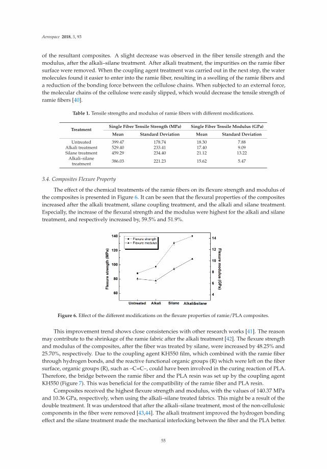
Aerospace 2018, 5, 93
of the resultant composites. A slight decrease was observed in the fiber tensile strength and themodulus, after the alkali–silane treatment. After alkali treatment, the impurities on the ramie fibersurface were removed. When the coupling agent treatment was carried out in the next step, the watermolecules found it easier to enter into the ramie fiber, resulting in a swelling of the ramie fibers anda reduction of the bonding force between the cellulose chains. When subjected to an external force,the molecular chains of the cellulose were easily slipped, which would decrease the tensile strength oframie fibers [40].
Table 1. Tensile strengths and modulus of ramie fibers with different modifications.
TreatmentSingle Fiber Tensile Strength (MPa) Single Fiber Tensile Modulus (GPa)
Mean Standard Deviation Mean Standard Deviation
Untreated 399.47 178.74 18.30 7.88Alkali treatment 529.40 233.41 17.40 9.09Silane treatment 459.29 234.40 21.12 13.22
Alkali–silanetreatment 386.03 221.23 15.62 5.47
3.4. Composites Flexure Property
The effect of the chemical treatments of the ramie fibers on its flexure strength and modulus ofthe composites is presented in Figure 6. It can be seen that the flexural properties of the compositesincreased after the alkali treatment, silane coupling treatment, and the alkali and silane treatment.Especially, the increase of the flexural strength and the modulus were highest for the alkali and silanetreatment, and respectively increased by, 59.5% and 51.9%.
Figure 6. Effect of the different modifications on the flexure properties of ramie/PLA composites.
This improvement trend shows close consistencies with other research works [41]. The reasonmay contribute to the shrinkage of the ramie fabric after the alkali treatment [42]. The flexure strengthand modulus of the composites, after the fiber was treated by silane, were increased by 48.25% and25.70%, respectively. Due to the coupling agent KH550 film, which combined with the ramie fiberthrough hydrogen bonds, and the reactive functional organic groups (R) which were left on the fibersurface, organic groups (R), such as –C=C–, could have been involved in the curing reaction of PLA.Therefore, the bridge between the ramie fiber and the PLA resin was set up by the coupling agentKH550 (Figure 7). This was beneficial for the compatibility of the ramie fiber and PLA resin.
Composites received the highest flexure strength and modulus, with the values of 140.37 MPaand 10.36 GPa, respectively, when using the alkali–silane treated fabrics. This might be a result of thedouble treatment. It was understood that after the alkali–silane treatment, most of the non-cellulosiccomponents in the fiber were removed [43,44]. The alkali treatment improved the hydrogen bondingeffect and the silane treatment made the mechanical interlocking between the fiber and the PLA better.
55

Aerospace 2018, 5, 93
Figure 8 illustrates the cross-section of the composites, when using the original and the alkali–silanetreated fibers, respectively. An ideal fiber/matrix adhesion could be observed in Figure 8b; even more,the fibers in the matrix were well dispersed. It is understandable that a good dispersion and invasionof fibers into the matrix would result in ideal mechanical properties [45].
Figure 7. Reaction of the coupling agent KH550, the ramie fiber and the PLA.
(a) (b)
Figure 8. SEM fracture interface of ramie/PLA composites. (a) using original fabric and (b) usingalkali–silane treated fabric.
3.5. Water Absorption Properties
Water absorption behavior of materials is critical to the dimensional stability of the final products.The water absorption behavior of the composites, prepared in the research, is given in Figure 9.
Compared to the synthetic fiber-reinforced composites, the water absorption rate for the ramiefiber-reinforced materials was much higher, this was true for all the specimens provided in thisresearch. A possible explanation is the strong water imbibition of natural fibers [42]. Nevertheless,one could conclude that the fabric treating method played a major role, as far as the water absorptionof the composites was concerned. As can be seen from Figure 9, the water absorption of ramie/PLAcomposites decreased to 14.97% after the alkali and the coupling agent treatment, and reduced by23.70% compared to the untreated. The number of hydrophilic groups on the surface of ramie fiber,and the interfacial bonding between the fiber and the resin, were two important factors affectingthe water absorption properties of composites. After the alkali and the coupling agent treatment,the hydroxyl groups (–OH) on the surface of ramie fiber reacted with silicon hydroxyl groups (Si–OH),produced by the hydrolysis of the coupling agent, and the number of hydrophilic groups, on the surfaceof ramie fiber, decrease. At the same time, the interfacial properties of the ramie/PLA composites were
56

Aerospace 2018, 5, 93
improved, and the internal structure was more compact, which might prohibit the penetration of thewater molecules into the composites, so the water absorption of the composites was reduced.
Figure 9. Effect of the different modifications on water absorption properties of the ramie/PLA composites.
3.6. Application Performance Analysis
The application performance of ramie fabric-reinforced PLA composites is showed in Table 2.It can be seen that the ramie fabric-reinforced PLA composites, prepared in this study, were providedwith excellent mechanical properties, and could be applied to an aircraft’s interior structures, such asseats, console, floor and wall panels, luggage rack, etc.
Table 2. Application performance analysis of the ramie fabric/PLA composites.
Material Flexural Strength/MPa
ramie fabric/PLA composites 140.37Standard requirements for aircraft interior structures [46] 70
4. Conclusions
Ramie fabrics were treated by alkali, silane, and alkali–silane solutions, respectively. Then thefabrics were fabricated with thermoset polylactic acid (PLA) to prepare the composites. The researchrevealed that after the chemical treatments, the contact angle of the ramie fiber increased considerably.This is considered to be beneficial for the combination between the fiber and the matrix, during thecomposite processing.
Surface morphology observations indicated that the surface of the ramie fiber became muchcleaner, after the alkali treatment, indicating that more impurities were removed during the chemicaltreatment. Meanwhile, after the alkali–silane treatment, the contact angle with water, increased, on theramie fiber, and the tensile strength of the fiber improved significantly.
After molding, the flexure strength of the composites, when using fabrics treated by chemicals,was improved in each case. Among them, materials using the alkali–silane treated fabric received thehighest flexure strength and modulus, of 140.37 MPa and 10.36 GPa, respectively.
Water absorption property of the composites was tested. The water absorption rate of the material,when using the alkali treated fabric, increased by 25.18%. No obvious change was noticed in the caseof silane treatment. In the case of the alkali–silane treatment, the water adsorption of the materialdecreased by 23.70%. This may contribute to the closer fiber/matrix adhesion at the interface, in thiscase, as water molecules found it difficult to penetrate into the materials.
The ramie fabric-reinforced PLA composites, prepared in this study, can meet the standardrequirements of an aircraft’s interior structures and have a favorable application foreground.
57

Aerospace 2018, 5, 93
Author Contributions: C.W. performed the design and guidance of experiments, data analysis; Z.R. and S.L.operated the experiments, and wrote the original draft preparation. X.Y. was responsible for the evaluation ofapplication performance, and checked the accuracy of the data.
Funding: This research was funded by the National Natural Science Foundation of China, grant number 11802205,and the state key laboratory of automotive safety and energy of Tsinghua University, grant number KF1811.
Conflicts of Interest: The authors declare no conflicts of interest.
References
1. Scarponi, C.; P.izzinelli, C.S.; Sanchez-Saez, S. Impact load behaviour of resin transfer moulding (RTM) hempfibre composite laminates. J. Biobased Mater. Bioenergy 2009, 3, 298–310. [CrossRef]
2. Khan, J.A.; Khan, M.A.; Islam, M.R. A study on mechnical, thermal and environmental degradationcharacteristics of N,N-Dimethylaniline treated jute fabric-reinforced polypropylene composites. Fibers Polym.2014, 15, 823–830. [CrossRef]
3. Sarkar, B.K.; Ray, D. Effect of the defect concentration on the impact fatigue endurance of untreated andalkali treated jute-vinylester composites under normal and liquid nitrogen atmosphere. Compos. Sci. Technol.2004, 64, 2213–2219. [CrossRef]
4. Ray, D.; Sarkar, B.K.; Rana, A.K. The mechanical properties of vinylester resin matrix composites reinforcewith alkali-treated jute fibres. Compos. Part A Appl. Sci. Manuf. 2001, 32, 119–127. [CrossRef]
5. Wang, L.L.; He, L.P.; Tian, Y. Effects of surface modification on mechanical properties of sisal fiber reinforcedpolypropylene composites. J. Mech. Eng. Mater. 2008, 32, 58–61.
6. Chan, C.M.; Vandi, L.J.; Pratt, S. Composites of wood and biodegradable thermoplastics: A review. Polym. Rev.2017, 58, 444–494. [CrossRef]
7. Faruk, O.; Bledzki, A.K.; Fink, H.P.; Sain, M. Biocomposites reinforced with natural fibers: 2000–2010.Prog. Polym. Sci. 2012, 37, 1552–1596. [CrossRef]
8. Zhang, N.; Zhang, J.J. Recent Progress in Study of Biomacromolecular Material Polylactide. J. Hebei PolytecnicUniv. Nat. Sci. Ed. 2010, 32, 116–120.
9. Helminen, A.O.; Korhonen, H.; Seppala, J.V. Structure modification and crosslinking of methacrylatedpolylactide oligomers. J. Appl. Polym. Sci. 2002, 86, 3616–3624. [CrossRef]
10. Zhan, M.; Wool, R.P. Biobased composite resins design for electronic materials. J. Appl. Polym. Sci. 2010, 118,3274–3283. [CrossRef]
11. Lincoln, J.D.; Shapiro, A.A.; Earthman, J.C.; Saphores, J.D.M.; Ogunseitan, O.A. Design and evaluation ofbio-based composites for printed circuit board application. Compos. Part A Appl. Sci. Manuf. 2013, 47, 22–30.
12. Adekunle, K.; Ghoreishi, R.; Ehsani, M.; Cho, S.; Skrifvars, M. Jute Fiber Reinforced MethacrylatedSoybean Oil Based Thermoset Composites Prepared by Vacuum Injection Molding Technique. J. BiobasedMater. Bioenergy 2015, 6, 172–177. [CrossRef]
13. Lee, T.S.; Choi, H.Y.; Choi, H.N.; Kim, S.; Lee, S.G.; Yong, D.K. Effect of surface treatment of ramie fiber onthe interfacial adhesion of ramie/acetylated epoxidized soybean oil (AESO) green composite. J. Adhes. Sci.Technol. 2013, 27, 1335–1347. [CrossRef]
14. Amiri, A.; Burkart, V.; Yu, A.; Webster, D.; Ulven, C. The potential of natural composite materials in structuraldesign. Sustain. Compos. Aerosp. Appl. 2018, 269–291. [CrossRef]
15. Amiri, A.; Ulven, C. Bio-based Composites as Thermorheologically Complex Materials. Chall. Mech. TimeDepend. Mater. 2017, 2, 55–63.
16. Amiri, A.; Yu, A.; Webster, D.; Ulven, C. Bio-Based Resin Reinforced with Flax Fiber as ThermorheologicallyComplex Materials. Polymers 2016, 8, 153. [CrossRef]
17. Amiri, A.; Ulven, C.; Huo, S. Effect of Chemical Treatment of Flax Fiber and Resin Manipulation on ServiceLife of Their Composites Using Time-Temperature Superposition. Polymers 2015, 7, 1965–1978. [CrossRef]
18. Taylor, C.; Amiri, A.; Paramarta, A.; Ulven, C.; Webster, D. Development and weatherability of bio-basedcomposites of structural quality using flax fiber and epoxidized sucrose soyate. Mater. Des. 2017, 113, 17–26.[CrossRef]
19. Oksman, K.; Skrifvars, M.; Selin, J.-F. Natural fibers as reinforcement in polylactic acid (PLA) composites.Compos. Sci. Technol. 2003, 63, 1317–1324. [CrossRef]
58

Aerospace 2018, 5, 93
20. Sawpan, M.A.; Pickering, K.L.; Fernyhough, A. Improvement of mechanical performance of industrial hempfibre reinforced polylactide biocomposites. Compos. Part A Appl. Sci. Manuf. 2011, 42, 310–319. [CrossRef]
21. Zhou, N.T.; Yu, B.; Sun, J. Influence of chemical treatments on the interfacial properties of ramie fiberreinforced poly(lactic acid)(PLA) composites. J. Biobased Mater. Bioenergy 2012, 6, 564–568. [CrossRef]
22. Aesson, D.; Skrifvars, M.; Lv, S. Preparation of nanocomposites from biobased thermoset resins by UV-curing.Prog. Org. Coatings 2010, 67, 281–286. [CrossRef]
23. Wang, H.G.; Xina, G.J.; Li, H. Durability study of a ramie-fiber reinforced henolic composite subjected towater immersion. Fibers Polym. 2014, 15, 1029–1034. [CrossRef]
24. Daniel, S.; Mustapha, A.; Christophe, P. Influence of hygrothermal ageing on the damage mechanisms offlax-fibre reinforced epoxy composites. Compos. Part B Eng. 2013, 48, 51–58.
25. Scarponi, C.; Schiavoni, E.; Sanchez-Saez, S. Polypropylene/hemp fabric reinforced composites:Manufacturing and mechanical behaviour. J. Biobased Mater. Bioenergy 2012, 6, 361–369. [CrossRef]
26. Asumani, O.M.L.; Reid, R.G.; Paskaramoorthy, R. The effects of alkali-silane treatment on the tensile andflexural properties of short fibre non-woven kenaf reinforced polypropylene composites. Compos. Part AAppl. Sci. Manuf. 2012, 43, 1431–1440. [CrossRef]
27. Goriarthi, B.K.; Suman, K.N.S.; Rao, N.M. Effect of fiber surface treatments on mechnical and abrasivewear performance of polylactide/jute composites. Compos. Part A Appl. Sci. Manuf. 2012, 43, 1800–1808.[CrossRef]
28. Kabir, M.M.; Wang, H.; Lau, K.T. Chemical treatments on plant-based natural fibre reinforced polymercomposites: An overview. Compos. Part B Eng. 2012, 43, 2883–2892. [CrossRef]
29. Sawpan, M.A.; Pickering, K.L.; Fernyhough, A. Effect of fibre treatments on interfacial shear strength ofhemp fibre reinforced polylactide and unsaturated polyester composites. Compos. Part A Appl. Sci. Manuf.2011, 49, 1189–1196. [CrossRef]
30. Li, S.; Wang, C.H.; Yi, S.G.; Wang, R. Study on the preparation and flexural properties of ramie reinforcedpoly-lactic acid composites. Fiber Reinf. Plast./Compos. 2012, S1, 59–62.
31. Nam, T.H.; Ogihara, S.; Tung, N.H. Effect of alkali treatment on interfacial and mechanical properties of coirfiber reinforced poly(butylen succinate) biodegradable composites. Compos. Part B Eng. 2011, 42, 1648–1656.[CrossRef]
32. John, M.J.; Anandjiwala, R.D. Recent developments in chemical modification and characterization of naturalfibre-reinforced composites. Polym. Compos. 2008, 29, 187–207. [CrossRef]
33. Li, X.; Tabil, L.G.; Panigrahi, S. Chemical treatment of natural fibre for use in natural fibre-reinforcedcomposites: A review. Polym. Environ. 2007, 15, 25–33. [CrossRef]
34. Mwaikambo, L.Y.; Tucker, N.; Clark, A.J. Mechanical properties of hemp fibre reinforced euphorbiacomposites. Macromol. Mater. Eng. 2007, 292, 993–1000. [CrossRef]
35. Ray, D.; Sarkar, B.K.; Rana, A.K. Effect of alkali treated jute fibres on composite properties. Bull. Mater. Sci.2001, 24, 129–135. [CrossRef]
36. Wang, W.H.; Lu, G.J. The silane coupling agent treatment of basalt fibers reinforced wood-plastic composite.Acta Mater. Compos. Sin. 2013, 30, 315–320.
37. Guo, Z.F.; Zhong, Z.L. The effect of silane coupling agent treatment on tensile property of basalt fiber fabric.Shanghai Text. Sci. Technol. 2012, 42, 25–27.
38. Prasad, S.V.; Pavithran, C.; Rohatgi, P.K. Alkali treatment of coir fibers for coir–polyester composites.J. Mater. Sci. 1983, 18, 1443–1454. [CrossRef]
39. Cao, Y.; Wu, L.L.; Yu, J.Y. Influence of alkali treatment time on index of flax spinnability. Text. Aux. 2009, 26,43–46.
40. Arbelaiz, A.; Cantero, G.; Fernandez, B.; Mondragon, I.; Gañán, P.; Kenny, J.M. Flax fiber surfacemodifications:effects on fiber physico mechanical and flax polypropylene interface properties. Polym. Compos.2005, 26, 324–332. [CrossRef]
41. Moyeenuddin, A.S.; Kim, L.P.; Fernyhough, A. Flexural properties of hemp fibre reinforced polylactide andunsaturated polyester composites. Compos. Part. A Appl. Sci. Manuf. 2012, 43, 519–526.
42. Sahoo, S.; Nakai, A.; Kotaki, M. Mechanical properties and durability of jute reinforced thermosettingcomposites. J. Biobased Mater. Bioenergy 2007, 1, 427–436. [CrossRef]
59

Aerospace 2018, 5, 93
43. Islam, M.S.; Pickering, K.L.; Foreman, N.J. Influence of alkali treatment on the interfacial andphysico-mechanical properties of industrial hemp fibre reinforced polylactic acid composites. Compos. Part AAppl. Sci. Manuf. 2010, 41, 596–603. [CrossRef]
44. Kayode, A.; Riam, G.; Mehdi, E. Jute fiber reinforced methacrylated soybean oil based thermoset compositesprepared by vacuum injection molding technique. J. Biobased Mater. Bioenergy 2012, 6, 172–177.
45. Lu, T.J.; Jiang, M.; Hui, D.; Wang, Z.; Zhou, Z. Effect of surface modification of bamboo cellulose fibers onmechanical properties of cellulose/epoxy composites. Compos. Part. B Eng. 2013, 51, 28–34. [CrossRef]
46. Editorial Board. China Aerospace Materials Handbook; Standards Press of China: Beijing, China, 2002.
© 2018 by the authors. Licensee MDPI, Basel, Switzerland. This article is an open accessarticle distributed under the terms and conditions of the Creative Commons Attribution(CC BY) license (http://creativecommons.org/licenses/by/4.0/).
60
aerospace
Article
Life Cycle Assessment of Ramie Fiber Used for FRPs
Shaoce Dong 1, Guijun Xian 1,* and Xiao-Su Yi 2,3
1 School of Civil Engineering, Harbin Institute of Technology (HIT), 73 Hanghe Road, Nangang District,Harbin 150090, China; [email protected]
2 Faculty of Science & Engineering, University of Nottingham Ningbo China (UNNC), Ningbo 315000, China;[email protected]
3 National Key Laboratory of Advanced Composites, AVIC Composite Technology Center, AVIC CompositeCorporation Ltd. (ACC), Beijing 101300, China
* Correspondence: [email protected]; Tel.: +86-0451-8628-3120
Received: 15 June 2018; Accepted: 31 July 2018; Published: 3 August 2018
Abstract: With the depletion of natural resources and the deterioration of environment, naturalfiber based biomaterials are attracting more and more attentions. Natural fibers are considered tobe renewable, biodegradable, and ecofriendly, and have been applied to be used as alternativereinforcements to traditional glass fibers for polymer based composites (GFRP). Natural fiberreinforced polymer (NFRP) composites have been found to be manufactured as secondary structuresor interior parts of aircrafts or automobiles. In this paper, a cradle-to-gate life cycle assessment (LCA)study was performed to demonstrate the possible advantages of ramie fiber on environmental impactsand to provide fundamental data for the further assessment of ramie fiber reinforced polymers (RFRP)and its structures. By collecting the material inventories of the production process of ramie fiber,the environmental impacts of ramie fiber (characterized by eight main impact categories, whichare climate change, terrestrial acidification, freshwater eutrophication, human toxicity potential,ozone depletion, photochemical oxidant creation, freshwater ecotoxicity, and fossil depletion) werecalculated and compared with that of glass fiber. Found if spinning process is ignored within theproduction of the ramie fiber, ramie fiber exhibits better ozone depletion and they have almostthe same values of climate change and terrestrial acidification in terms of glass fiber. However,if the spinning process is included, ramie fiber only performs better in terms of ozone depletion.And degumming and carding and spinning processes are the processes that cause more pollution.
Keywords: ramie fiber; life cycle assessment; glass fibre; environmental impacts
1. Introduction
Fiber reinforced polymers (FRPs) have been widely used in modern industries because of theirnumerous advantages, like high specific strength and modulus, excellent fatigue performances,resistance to corrosion, and so on. The areas in which FRPs have been applied include aircraft,automotive, marine, sporting goods, infrastructure, and so on [1].
The fiber reinforcements used for FRPs are generally carbon- or glass-fibers. The productionof such traditional fibers will bring in high emissions of greenhouse gases and the depletion of rawmaterial natural resources (e.g., fossil fuel). Natural fibers are introduced and used in secondary ordecorative structures considering their mechanical properties, because they are considered to be rawmaterials available, biodegradable, eco-friendly. Recently, natural fibers (e.g., ramie fiber, flax fiber,etc.) have been developed and utilized as a substitute for traditional glass fiber, to serve as fiberreinforcements of FRPs [2–4].
The life cycle assessment (LCA) of FRPs has received extensive attention for a better understandingof the environmental problems of FRPs and its structures. For example, regarding the traditional
Aerospace 2018, 5, 81; doi:10.3390/aerospace5030081 www.mdpi.com/journal/aerospace61

Aerospace 2018, 5, 81
carbon FRPs (CFRPs) and glass FRPs (GFRPs), Foraboschi [5,6] studied the environmental problems ofusing FRP to strengthen masonry and reinforced concrete (RC) structures. For natural fiber reinforcedpolymers (NFRPS), there are many LCA studies on various natural fibers. Le Duigou et al. [7], andSummerscales and Dissanayake [8] have studied the environmental problems of flax fiber used in FRPs.Also, a comparative life cycle assessment (LCA) study was done between two bus body componentsmade of hemp fiber reinforced polymers (HFRP) and GFRP [3]. It was found that the hemp-basedcomposites show a lower environmental impact. Furthermore, LCA studies of jute fiber and sisal fiberhave also been found [9,10].
In this article, the LCA of another widely used natural fiber, ramie fiber, was studied, becauseit is one of the best fibers that has better mechanical properties [11] in natural fibers and it can beused in ramie fiber reinforced polymers (RFRP). To the best of our knowledge, research about theenvironmental problems of ramie fiber is still limited.
Ramie, known as Chinese grass, is a perennial herbaceous plant of the Urticaceae family and itis mainly cultivated in Asia [12]. China contributes more than 90% of the cultivation of ramie in theworld [13]. In Chinese major production areas, ramie can be harvested three times in one year [12].As ramie fibers are abundant and can meet the requirements of FRP manufacturing, in the EuropeanUnion’s Horizon 2020 research and innovation programme between China and European (Grant No.,690638), ramie fiber was selected to manufacture some of the secondary structures of airports.
In the present study, a cradle-to-gate LCA was performed for the ramie fiber in order todemonstrate the possible advantages of ramie fiber on the environmental impacts and to providefundamental data for further the assessment of RFRP and its structures. The inventories of theprocesses, including ramie cultivation, harvesting, peeling, transportation, degumming, and cardingand spinning, were collected and calculated. Then, eight environmental categories, namely, climatechange, terrestrial acidification, freshwater eutrophication, human toxicity potential, ozone depletion,photochemical oxidant creation, freshwater ecotoxicity, and fossil depletion, were used to characterizethe environmental impacts of the ramie fiber. Finally, the environmental impacts of the ramie fiberwere compared with that of glass fiber, based on the same mass. A professional LCA software, GaBi,was used to perform the LCA study [14]. The results show that if the spinning process is ignoredwithin the production of the ramie fiber, the ramie fiber exhibits better ozone depletion and they havealmost the same values on categories like climate change and terrestrial acidification, in terms of glassfibre. However, if the spinning process is included, the ramie fiber performs only better in term of theozone depletion. The degumming, and carding and spinning processes are the processes that causemore pollution.
2. Methodology
Quantitative LCA was the research methodology that was used in the present study to quantifythe environmental performance of the ramie fiber. LCA is an internationally accepted method to assessthe environmental impacts of a product or product system. With the collected and/or calculatedinputs and outputs of the whole life cycle of a product or product system, LCA can be performedaccording to some standards (ISO 14040 and ISO 14044 [15,16]), in order to evaluate the relatedenvironmental impacts quantitatively. A complete LCA study includes four stages, goal and scopedefinition, life cycle inventory analysis (LCI), life cycle impact assessment (LCIA), and life cycleinterpretation [15]. The following explicitly explains the calculation and/or estimation methods used.
2.1. Goal and Scope Definition
The goal of an LCA study is related to its intended application and audience, while the scope ofan LCA is related to the studied system. The goal of the present study is to get the fundamental dataregarding the environmental impacts of ramie fibers. The scope of this study includes ramie cultivationand harvesting, peeling, transportation, degumming, carding and spinning (shown in Figure 1).
62
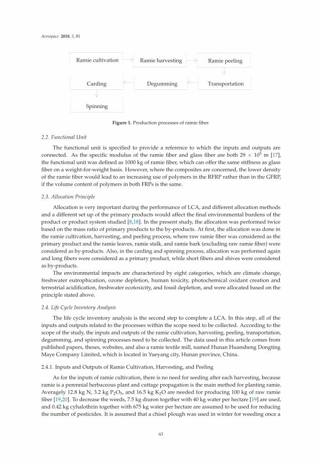
Aerospace 2018, 5, 81
Ramie cultivation Ramie harvesting Ramie peeling
Carding Degumming Transportation
Spinning
Figure 1. Production processes of ramie fiber.
2.2. Functional Unit
The functional unit is specified to provide a reference to which the inputs and outputs areconnected. As the specific modulus of the ramie fiber and glass fiber are both 29 × 105 m [17],the functional unit was defined as 1000 kg of ramie fiber, which can offer the same stiffness as glassfiber on a weight-for-weight basis. However, where the composites are concerned, the lower densityof the ramie fiber would lead to an increasing use of polymers in the RFRP rather than in the GFRP,if the volume content of polymers in both FRPs is the same.
2.3. Allocation Principle
Allocation is very important during the performance of LCA, and different allocation methodsand a different set up of the primary products would affect the final environmental burdens of theproduct or product system studied [8,18]. In the present study, the allocation was performed twicebased on the mass ratio of primary products to the by-products. At first, the allocation was done inthe ramie cultivation, harvesting, and peeling process, where raw ramie fiber was considered as theprimary product and the ramie leaves, ramie stalk, and ramie bark (excluding raw ramie fiber) wereconsidered as by-products. Also, in the carding and spinning process, allocation was performed againand long fibers were considered as a primary product, while short fibers and shives were consideredas by-products.
The environmental impacts are characterized by eight categories, which are climate change,freshwater eutrophication, ozone depletion, human toxicity, photochemical oxidant creation andterrestrial acidification, freshwater ecotoxicity, and fossil depletion, and were allocated based on theprinciple stated above.
2.4. Life Cycle Inventory Analysis
The life cycle inventory analysis is the second step to complete a LCA. In this step, all of theinputs and outputs related to the processes within the scope need to be collected. According to thescope of the study, the inputs and outputs of the ramie cultivation, harvesting, peeling, transportation,degumming, and spinning processes need to be collected. The data used in this article comes frompublished papers, theses, websites, and also a ramie textile mill, named Hunan Huansheng DongtingMaye Company Limited, which is located in Yueyang city, Hunan province, China.
2.4.1. Inputs and Outputs of Ramie Cultivation, Harvesting, and Peeling
As for the inputs of ramie cultivation, there is no need for seeding after each harvesting, becauseramie is a perennial herbaceous plant and cuttage propagation is the main method for planting ramie.Averagely 12.8 kg N, 3.2 kg P2O5, and 16.5 kg K2O are needed for producing 100 kg of raw ramiefiber [19,20]. To decrease the weeds, 7.5 kg diuron together with 40 kg water per hectare [19] are used,and 0.42 kg cyhalothrin together with 675 kg water per hectare are assumed to be used for reducingthe number of pesticides. It is assumed that a chisel plough was used in winter for weeding once a
63
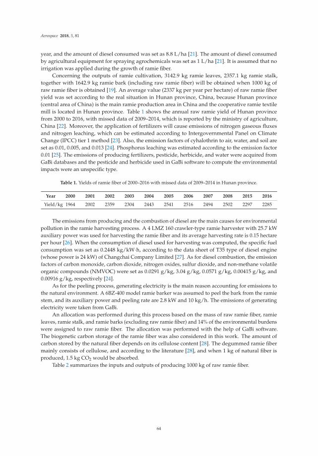
Aerospace 2018, 5, 81
year, and the amount of diesel consumed was set as 8.8 L/ha [21]. The amount of diesel consumedby agricultural equipment for spraying agrochemicals was set as 1 L/ha [21]. It is assumed that noirrigation was applied during the growth of ramie fiber.
Concerning the outputs of ramie cultivation, 3142.9 kg ramie leaves, 2357.1 kg ramie stalk,together with 1642.9 kg ramie bark (including raw ramie fiber) will be obtained when 1000 kg ofraw ramie fiber is obtained [19]. An average value (2337 kg per year per hectare) of raw ramie fiberyield was set according to the real situation in Hunan province, China, because Hunan province(central area of China) is the main ramie production area in China and the cooperative ramie textilemill is located in Hunan province. Table 1 shows the annual raw ramie yield of Hunan provincefrom 2000 to 2016, with missed data of 2009–2014, which is reported by the ministry of agriculture,China [22]. Moreover, the application of fertilizers will cause emissions of nitrogen gaseous fluxesand nitrogen leaching, which can be estimated according to Intergovernmental Panel on ClimateChange (IPCC) tier 1 method [23]. Also, the emission factors of cyhalothrin to air, water, and soil areset as 0.01, 0.005, and 0.013 [24]. Phosphorus leaching was estimated according to the emission factor0.01 [25]. The emissions of producing fertilizers, pesticide, herbicide, and water were acquired fromGaBi databases and the pesticide and herbicide used in GaBi software to compute the environmentalimpacts were an unspecific type.
Table 1. Yields of ramie fiber of 2000–2016 with missed data of 2009–2014 in Hunan province.
Year 2000 2001 2002 2003 2004 2005 2006 2007 2008 2015 2016
Yield/kg 1964 2002 2359 2304 2443 2541 2516 2494 2502 2297 2285
The emissions from producing and the combustion of diesel are the main causes for environmentalpollution in the ramie harvesting process. A 4 LMZ 160 crawler-type ramie harvester with 25.7 kWauxiliary power was used for harvesting the ramie fiber and its average harvesting rate is 0.15 hectareper hour [26]. When the consumption of diesel used for harvesting was computed, the specific fuelconsumption was set as 0.2448 kg/kW·h, according to the data sheet of T35 type of diesel engine(whose power is 24 kW) of Changchai Company Limited [27]. As for diesel combustion, the emissionfactors of carbon monoxide, carbon dioxide, nitrogen oxides, sulfur dioxide, and non-methane volatileorganic compounds (NMVOC) were set as 0.0291 g/kg, 3.04 g/kg, 0.0571 g/kg, 0.00415 g/kg, and0.00916 g/kg, respectively [24].
As for the peeling process, generating electricity is the main reason accounting for emissions tothe natural environment. A 6BZ-400 model ramie barker was assumed to peel the bark from the ramiestem, and its auxiliary power and peeling rate are 2.8 kW and 10 kg/h. The emissions of generatingelectricity were taken from GaBi.
An allocation was performed during this process based on the mass of raw ramie fiber, ramieleaves, ramie stalk, and ramie barks (excluding raw ramie fiber) and 14% of the environmental burdenswere assigned to raw ramie fiber. The allocation was performed with the help of GaBi software.The biogenetic carbon storage of the ramie fiber was also considered in this work. The amount ofcarbon stored by the natural fiber depends on its cellulose content [28]. The degummed ramie fibermainly consists of cellulose, and according to the literature [28], and when 1 kg of natural fiber isproduced, 1.5 kg CO2 would be absorbed.
Table 2 summarizes the inputs and outputs of producing 1000 kg of raw ramie fiber.
64

Aerospace 2018, 5, 81
Table 2. Inputs and output of producing 1000 kg of raw ramie fiber.
Input Quantity Output Quantity
Ammonium nitrate(33.5% N) 382.1 kg Raw ramie fiber 1000 kg
Triple superphosphate(46% P2O5) 69.6 kg Ramie bark
(excluding raw ramie fiber) 642.9 kg
Potassium chloride(60% K2O) 275 kg Ramie leaf 3142.9 kg
Diuron 9.6 kg Ramie stalk 2357.1 kgCyhalothrin 0.5 kg Carbon monoxide 1.7 g
Water 917.8 kg Carbon dioxide 176.5 gElectricity 280 kW·h Nitrous oxide 5.4 kg
Diesel 58 kg Nitrogen oxides 3.3 gSequestered atmospheric CO2 1500 kg Sulfur dioxide 0.2 g
Emission of cyhalothrin to air 5 gEmission of cyhalothrin to water 2.5 gEmission of cyhalothrin to soil 6.5 g
Phosphate to water 0.14 kgNMVOC 0.5 g
This table does not include the inputs of the ramie rootstock and soil components consumed, which are about fourtons. NMVOC—non-methane volatile organic compounds.
2.4.2. Inputs and Outputs of Transportation
The GaBi software contains almost all of the transport modes. In the present paper, the transportationprocess was modeled with GaBi. The transportation distance between the ramie field and themanufacturing factory is assumed as 50 km. A Euro 5 diesel truck with a 3.3 ton payload capacity wasset to be the transportation method, considering the yield of the ramie fiber. Although the distancefrom field to factory is difficult to determine precisely, the environmental impacts of this processcontribute very little to the overall environmental impacts, which can be seen from later parts.
2.4.3. Inputs and Outputs of Degumming Process
Because there are gummy matters (20–40% of the mass of raw ramie fiber), mainly composed ofhemicellulose and pectin in raw ramie fibers [29], the raw ramie fiber cannot be used directly in FRPsuntil they are degummed. Degumming methods mainly include chemical, enzymatic, and microbialmethods [30], and in the present study, enzymes together with chemicals (shown in Figure 2) wereused to get the degummed fiber in this study.
The inputs of the degumming process were the chemicals (shown in Table 3) used to dissolve andremove the gummy matters, which were collected from the cooperative company mentioned above.It is known that, when 100 kg of raw ramie fibers were degummed, 60 kg degummed ramie fiberwould be obtained, and 11 kg sulphuric acid, 20.25 kg sodium hydroxide, 2.4 kg hypochlorous, and1.4 kg degumming agent would be consumed. The emissions for producing the chemicals used inthis process were taken from the GaBi databases, except for degumming agent because of commercialconfidentiality. As the dosage of the degumming agent is usually very small, the environmentalimpacts of producing and using the degumming agent have not been taken into consideration in thisstudy. The environmental impacts of producing enzymes were not included in this paper, because of alack of reliable data. A lack of data regarding the environmental impacts of hypochlorous acid, whenthe GaBi model was built, led to the use of calcium hypochlorite in order to produce hypochlorousacid, according to a chemical reaction among calcium hypochlorite, carbon dioxide, and water.
The outputs of the degumming process were mainly wastewater and it mainly comes from thepickling, boiling, washing, and bleaching processes. The wastewater from ramie degumming processusually has high pH value, high contents of chemical oxygen demand (COD), and biochemical oxygendemand (BOD). The wastewater cannot be discharged directly until it has been well treated. In thisstudy, the wastewater treatment method was set based on the literature [31], in which a acidifyinghydrolysis/biological oxidation/photochemical process method was utilized in a sewage treatment
65

Aerospace 2018, 5, 81
plant to make the wastewater meet the requirements of the national sewage discharge standard inChina. To run the whole treatment process, electricity and chlorine need to be supplied constantly andthe environmental impacts of producing electricity and chlorine were also within the system boundaryin the present study. After treatment, the contents of COD, BOD, and sulfide were set as 300 mg/L,100 mg/L according to the national wastewater discharge standard in China.
Raw ramie fiber Pretreatment Degumming by enzymes
Washing with water Boiling in alkaline Washing with water
Beating and bleaching of ramie Washing with acid
Washing with water Soaking in oil and drying
Figure 2. Typical enzymatic degumming processes of ramie fiber.
Table 3 shows the inputs and outputs for producing 1000 kg of degummed ramie fiber and theemissions of producing water, electricity, chlorine, sulphuric acid, and sodium hydroxide were takenfrom GaBi software.
Table 3. Inputs and outputs of producing 1000 kg of degummed ramie fiber. COD—chemical oxygendemand; BOD—biochemical oxygen demand.
Input Quantity Output Quantity
Water 733 tons Degummed ramie fiber 1000 kgElectricity 1475.52 kW·h Pectin, lignin, and hemicellulose 666.7 kgChlorine 8.8 kg Wastewater (treated) 733 tons
Sulphuric acid 183.3 kg COD 300 mg/LSodium hydroxide 337.5 kg BOD 100 mg/LHypochlorous acid 40.0 kg
Ramie degumming agent 23.3 kgSteam from biomass 16.7 tons
Raw ramie fiber 1666.7 kg
2.4.4. Inputs and Outputs of Carding and Spinning Process
Degummed ramie fibers could be spun to get yarns, which were used to for the comparison toglass filaments. Before spinning, carding is necessary to get long degummed ramie fibers suitable forspinning, and short fibers and shives that could be used in other ways like building particle boards oranimal beddings. Therefore, the allocation was performed again in this stage, based on the mass oflong fibers and others. Based on the data from the cooperative factory, only 30% of the degummedfibers will be formed into yarns. The electricity consumption for the carding and spinning are based onthe data for the flax fiber carding and spinning [21], because of no reliable data are available for ramiecarding and spinning. Table 4 shows the inputs and outputs of the ramie carding and spinning process.
66

Aerospace 2018, 5, 81
Table 4. Inputs and outputs of producing 1000 kg ramie yarns.
Input Quantity Output Quantity
Electricity 7260 kW·h Ramie yarns 1000 kgDegummed ramie fiber 3333.3 kg Short fibers and shives 2333.3 kg
2.5. Life Cycle Impact Assessment (LCIA)
In the LCIA stage, the emissions and resource extraction will be translated into severalenvironmental impact scores by multiplying the corresponding characterization factors. There aremainly two types of characterization factors, which are at a midpoint level and endpointlevel, respectively.
In this paper, the ReCiPe method was chosen to model the environmental impacts of differentfibers with the help of GaBi software. The environmental impact categories used to characterizethe overall environmental performance of every fiber are climate change, terrestrial acidification,freshwater eutrophication, ozone depletion, human toxicity, photochemical oxidants creation,freshwater eco-toxicity, and fossil depletion.
The inputs and outputs of the processes involved in the scope of this study were used to buildmodels in GaBi software.
2.6. Interpretation
Interpretation was the final step of an LCA study, and by interpretating the results from LCIAstage, the processes that have a high potential for pollution would be identified, and some usefulconclusions and recommendations can be made.
3. Results and Discussions
Using the inputs and outputs from the LCI stage, the ReCiPe method and the eight mainenvironmental categories to characterize the environmental performance of the ramie fiber, the LCIAresults are shown in Table 5 and Figure 3.
Table 5. Life cycle impact assessment (LCIA) results of one ton ramie yarns, ramie fiber (after carding),and glass fibers.
Environmental Impact Category Unit Glass FibersRamie Fiber
(after Carding)Ramie Yarns
Climate change kg CO2-Equiv. 1740 1770 3790Terrestrial acidification kg SO2 eq. 10.3 10.9 13.4
Freshwater eutrophication kg P eq. 5.25 × 10⁻³ 86.9 × 10⁻³ 87.1 × 10⁻³
Ozone depletion kg CFC-11 eq. 483 × 10−10 7.88 × 10⁻¹⁰ 8.26 × 10⁻¹⁰
Human toxicity potential kg 1,4-DB eq. 20.8 147 175Photochemical oxidant formation kg NMVOC 5.26 11.9 14.4
Freshwater ecotoxicity kg 1,4-DB eq. 0.461 4.12 4.15Fossil depletion kg oil eq. 578 832 1.34 × 10³
As can be seen from Table 5 and Figure 3, when the environmental burdens of the ramie yarnswere compared to that of the glass fibers, the ramie yarns only performed better in terms of ozonedepletion, with a reduction rate of 98.29%. However, as for the other categories, the glass fibers aremore eco-friendly compared with the ramie yarns. When the environmental performance of the ramiefibers (after carding and without spinning) are compared to that of the glass fibers, the ramie fibers(after carding and without spinning) perform better on ozone depletion, with a reduction rate of98.37%, and it has almost the same values for climate change and terrestrial acidification compared toglass fiber.
67

Aerospace 2018, 5, 81
Concerning identifying the processes that contribute the most to the overall environment pollution,as can be seen Table 6 and Figure 4, the degumming process and carding and spinning process are themain causes for massive environmental pollution. The percentages of the degumming process andspinning and carding process that contributes to climate change, terrestrial acidification, freshwatereutrophication, ozone depletion, human toxicity, photochemical oxidant formation, freshwaterecotoxicity, and fossil depletion is 65.2% and 58.3%, 76.9% and 20.4%, 74.2% and 0.28%, 94.3% and5.05%, 81.4% and 17.5%, 79.2% and 18.8%, 68.7% and 0.95%, and 53.7% and 41.1%, respectively.The cultivation, harvesting, and peeling processes mainly contribute to freshwater eutrophication,ozone depletion, and freshwater ecotoxicity, and the negative value caused by these processes are dueto the absorption of carbon dioxide. The transportation process contributes little to all eight of thesecategories, compared to other processes.
Table 6. Values of the eight categories contributed by different production processes of ramie yarns.
EnvironmentalImpact Category
Unit TransportationCultivation,
Harvesting andPeeling
Carding andSpinning
Degumming
Climate change kg CO2-Equiv. 31 −921 2210 2400
Terrestrial acidification kg SO2 eq. 0.024 0.346 2.74 4.94
Freshwatereutrophication kg P eq. 5.9 × 10⁻⁵ 0.0125 24.1 × 10⁻⁵ 0.027
Ozone depletion kg CFC-11 eq. 0 5.30 × 10⁻¹² 41.7 × 10⁻¹² 738 × 10−12
Human toxicitypotential kg 1,4-DB eq. 0 1.8 30.6 63
Photochemical oxidantformation kg NMVOC 0.0431 0.353 2.7 4.39
Freshwater ecotoxicity kg 1,4-DB eq. 1.25 × 10⁻¹¹ 1.26 0.0395 2.51
Fossil depletion kg oil eq. 1.4 67.6 550 701
From the results above, it seems that the environmental performance of ramie fiber is not socompetitive compared with glass fiber, especially when the spinning process was included into thewhole manufacturing system of the ramie fiber. However, this idea may not be true. Because, at first,compared with the manufacturing technology of glass fiber, the production techniques of the ramiefiber are still not perfect and there is still a lot of room for improvement in the production techniquesof ramie fiber. Then, there are no production techniques just for RFRP. For example, during thedegumming process of the ramie fiber, when ramie fibers are used in FRPs, there may be no needfor bleaching, which will reduce the consumption of sodium hypochlorite, washing water, and thereleasing of treated wastewater. Then, the residual gum rate of the degummed ramie fiber should beless than 2% in the textile industry, while in the FRPs, the residual gum rate may be not so strict, whichmeans that less chemicals may be used in the degumming process. Next, the spinning requirementsfor the textiles and FRPs may be different too. Finally, ramie fibers can degrade automatically, whichcan reduce the energy required for handling the disposals made of RFRP.
Based on the discussion above, more research should be performed to establish the manufacturingtechnologies of the ramie fiber just for RFRP. Degumming and spinning processes are the mainprocesses that can be targeted to decrease the environmental burdens of ramie fibers used for FRPs.
Although some results have been obtained, there are also some limitations in this article. Firstly,the data used in the calculation is relatively limited, which means there will be more uncertaintyregarding the final results. Then, data from the cooperative ramie textile mill was collected by thelocal workers in the mill, because of commercial confidentiality, which means there may be somevariation because they know nothing about LCA principles. However, this study did provide someuseful information and conclusions in general.
68

Aerospace 2018, 5, 81
Figure 3. Comparison between three different kinds of fibers in terms of the eight mainenvironmental categories.
Figure 4. Percentages of different processes that contribute to the eight different environmental impactcategories of ramie yarns.
4. Conclusions
According to LCA, the input and output data of the production processes of ramie fibers weresummarized and analyzed. The comparison of LCA between the ramie fibers and glass fibers wereperformed. The following conclusions can be drawn based on the above study.
69
Aerospace 2018, 5, 81
According to the results of LCA, if the spinning process was included within the manufacturing ofthe ramie fiber, the ramie fiber performs better than glass fiber only in ozone depletion. If the spinningprocess was not included, the ramie fiber performs better in the ozone depletion and has almost thesame values of climate change and terrestrial acidification.
The degumming, and carding and spinning processes are the main causes of pollutionduring the production of ramie fibers. The cultivation, harvesting, and peeling processes mainlycontribute to the categories of freshwater eutrophication, ozone depletion, and freshwater ecotoxicity.The transportation process contributes little to the overall pollution.
More research should be done toward developing production techniques for the ramie fibers forthe RFRP.
Author Contributions: G.X. and X.-S.Y. conceived and guided the study; S.D. collected the data and wrotethe paper.
Funding: This work was financially supported by the Chinese MIIT Special Research Plan on Civil Aircraft,grant No. MJ-2015-H-G-103 and European Union’s Horizon 2020 research and innovation programme, under grantagreement No. 690638.
Conflicts of Interest: The authors declare no conflict of interest.
References
1. Mallick, P.K. Fiber-Reinforced Composites: Materials, Manufacturing, and Design, 3rd ed.; CRC Press: Boca Raton,FL, USA; London, UK; New York, NY, USA, 2007; ISBN 9780849342059-CAT# 4205.
2. Wötzell, K.; Wirth, R.; Flake, M. Life cycle studies on hemp fibre reinforced components and ABS forautomotive part. Die Angew. Makromol. Chem. 1999, 272, 121–127. [CrossRef]
3. Schmehl, M.; Müssig, J.; Schönfeld, U.; Von Buttlar, H.B. Life Cycle Assessment on a Bus Body ComponentBased on Hemp Fiber and PTP. J. Polym. Environ. 2008, 16, 51–60. [CrossRef]
4. Scarponi, C.; Messano, M. Comparative evaluation between E-Glass and hemp fiber composites applicationin rotorcraft interiors. Compos. Part B Eng. 2015, 69, 542–549. [CrossRef]
5. Foraboschi, P. Analytical model to predict the lifetime of concrete members externally reinforced with FRP.Theor. Appl. Fract. Mech. 2015, 75, 137–145. [CrossRef]
6. Foraboschi, P. Effectiveness of novel methods to increase the FRP-masonry bond capacity. Compos. PartB Eng. 2016, 107, 214–232. [CrossRef]
7. Le Duigou, A.; Davies, P.; Baley, C. Environmental impact analysis of the production of flax fibres to be usedas composite material reinforcement. J. Biobased Mater. Bioenergy 2011, 5, 153–165. [CrossRef]
8. Summerscales, J.; Dissanayake, N.P.J. Allocation in the life cycle assessment (LCA) of flax fibres for thereinforcement of composites. In Proceedings of the 21st International Conference on Composite Materials,Xi’an, China, 20–25 August 2017.
9. Islam, M.S.; Ahmed, S.K. The impacts of jute on environment: An analytical review of Bangladesh. J. Environ.Earth Sci. 2012, 2, 24–32.
10. Broeren, M.L.M.; Dellaert, S.N.C.; Cok, B.; Patel, M.K.; Worrell, E.; Shen, L. Life cycle assessment of sisalfibre—Exploring how local practices can influence environmental performance. J. Clean. Prod. 2017, 149,818–827. [CrossRef]
11. Saheb, D.N.; Jog, J.P. Natural fiber polymer composites: A review. Adv. Polym. Technol. 1999, 18, 351–363.[CrossRef]
12. Liu, F.; Liu, Q.; Liang, X.; Huang, H.; Zhang, S. Morphological, anatomical, and physiological assessment oframie [Boehmeria nivea (L.) Gaud.] tolerance to soil drought. Genet. Resour. Crop. Evol. 2005, 52, 497–506.[CrossRef]
13. Bo, W.; Dingxia, P.; Lijun, L.; Zhenxia, S.; Na, Z.; Shimei, G. An effcient adventitious shoot regenerationsystem for ramie (Bohehmeria nivea Gaud) using thidiazuron. Bot. Study 2007, 48, 173–180.
14. Thinkstep GaBi. Available online: www.gabi-software.com (accessed on 24 April 2018).15. ISO 14040:2006 Environmental Management—Life Cycle Assessment—Principles and Framework. Available
online: www.iso.org (accessed on 24 April 2018).
70

Aerospace 2018, 5, 81
16. ISO 14044:2006 Environmental management—Life cycle Assessment—Requirements and Guidelines.Available online: www.iso.org (accessed on 24 April 2018).
17. Paul, W.; Ivens, J.; Ignaas, V. Natural fibres: Can they replace glass in fibre reinforced plastics?Compos. Sci. Technol. 2003, 63, 1259–1264.
18. Ekvall, T.; Finnveden, G. Allocation in ISO 14041—A critical review. J. Clean. Prod. 2001, 9, 197–208.[CrossRef]
19. Ramie Institute of Hunan Agricultural University. Available online: http://chinagrass.hunau.edu.cn/(accessed on 24 April 2018).
20. Wang, C.T.; Li, Z.D.; Yu, T.W.; Liu, M.S.; Xiao, Z.P.; Cui, G.X.; Xue, N.D.; Li, G.S.; Deng, M.Q. Fertilizationprogramma in ducing fine quality and high yield of ramie and its application technique. J. Hunan Agric. Coll.1994, 20, 318–324.
21. Dissanayake, N.P.J. Life Cycle Assessment of Flax Fibres for the Reinforcement of Polymer Matrix Composites.Ph.D. Thesis, University of Plymouth, Plymouth, UK, May 2011.
22. Ministry of Agriculture of the People’s Republic of China. Available online: www.moa.gov.cn (accessed on24 April 2018).
23. 2006 IPCC Guidelines for National Greenhouse Gas Inventories—Volume 4—Agriculture, Forestry andOther Land Use. Available online: www.ipcc-nggip.iges.or.jp/public/2006gl/index.html (accessed on24 April 2018).
24. EU Concerted Action Report Harmonization of Environmental Life Cycle Assessment for AgricultureFinal Report. Concerted Action AIR3-CT94-2028. Available online: www.researchgate.net (accessed on24 April 2018).
25. Bioenergy for Europe: Which One Fits Best? A Comparative Analysis for the Community. Availableonline: https://www.researchgate.net/publication/320258744_Bioenergy_for_Europe_Which_Ones_Fit_Best_-_A_Comparative_Analysis_for_the_Community (accessed on 24 April 2018).
26. Huang, J.C.; Li, X.W.; Zhang, B.; Tian, K.P.; Shen, C.; Wang, J.G. Research on the 4LMZ160 crawler ramiecombine harvester. J. Agric. Mech. Res. 2015, 9, 155–158. [CrossRef]
27. Changchai Company Limited’s Product Sheet. Available online: http://www.changchai.com.cn/show.asp?id=18 (accessed on 24 April 2018).
28. Benoît, C.; Xavier, P.; André, G.; Fritz, S.; Gérard, C. Contributions of hemicellulose, cellulose and ligninto the mass and the porous properties of chars and steam activated carbons from various lignocellulosicprecursors. Bioresour. Technol. 2009, 100, 292–298.
29. Shengwen, D.; Zhengchu, L.; Xiangyuan, F.; Ke, Z.; Lifeng, C.; Xia, Z. Diversity and characterization oframie-degumming strains. Sci. Agricola 2011, 69, 119–125.
30. Deb, P.R.; Pratik, S.; Sabyasachi, M.; Pradipta, B.; Rakesh, K.G. Degumming of ramie: Challenge to the queenof fibres. Int. J. Bioresour. Sci. 2014, 1, 37–41.
31. Bao, H.F.; Bao, J.G.; Li, H.W. Treatment of ramie retting wastewater using acidifying hydrolysis/biologicaloxidation/photochemical process. China Water Wastewater 2006, 22, 52–55.
© 2018 by the authors. Licensee MDPI, Basel, Switzerland. This article is an open accessarticle distributed under the terms and conditions of the Creative Commons Attribution(CC BY) license (http://creativecommons.org/licenses/by/4.0/).
71

aerospace
Article
Effect of Paper or Silver Nanowires-Loaded PaperInterleaves on the Electrical Conductivity andInterlaminar Fracture Toughness of Composites
Miaocai Guo 1 and Xiaosu Yi 1,2,*
1 National Key Laboratory of Advanced Composites, AVIC Composite Technology Center, Beijing 101300,China; [email protected]
2 Faculty of Science & Engineering, University of Nottingham Ningbo China (UNNC), Ningbo 315100, China* Correspondence: [email protected] or [email protected]; Tel.: +86-574-8818-8746
Received: 19 June 2018; Accepted: 17 July 2018; Published: 19 July 2018
Abstract: The effect of plant-fiber paper or silver nanowires-loaded paper interleaves on the electricalconductivity and interlaminar fracture toughness of composites was studied. Highly conductivepaper was prepared by surface-loaded silver nanowires. The percolation threshold appeared at about0.4 g/m2. The surface resistivity reached 2.3 Ω/sq when the areal density of silver nanowires was0.95 g/m2. After interleaving the conductive papers in the composite interlayers, in-plane electricalconductivity perpendicular to the fiber direction was increased by 171 times and conductivitythrough thickness direction was increased by 2.81 times. However, Mode I and Mode II interlaminarfracture toughness decreased by 67.3% and 66.9%, respectively. Microscopic analysis showed that theimprovement of conductivity was attributable to the formation of an electrical conducting network ofsilver nanowires which played a role in electrical connection of carbon fiber plies and the interleavinglayers. However, the density of the highly packed flat plant fibers impeded the infiltration of resin.The parallel distribution of flat fibers to the carbon plies, and poor resin-fiber interface made theinterlaminar fracture occur mainly at the interface of plant fibers and resin inside the interleaves,resulting in a decline of the interlaminar fracture toughness. The surface-loading of silver nanowiresfurther impeded the infiltration of resin in the densely packed plant fibers, resulting in further declineof the fracture toughness.
Keywords: functional composites; electrical properties; fracture toughness; function integratedinterleave; plant fiber; paper
1. Introduction
Continuous carbon fiber-reinforced resin matrix composites are usually made of continuouscarbon fibers as the reinforcement and thermosetting resin as the matrix. Specifically because of theirhigh strength and modulus, these materials are widely used in aerospace and attract an increasingamount of attention in many fields [1]. On the other hand, going green and going functionalare the two major themes in material development in the world. To develop greener composites,an increasing number of researchers are focused on the 'greening' of raw materials such as developingbio-based epoxy resin matrix and applying natural fibers as the reinforcement [2–4]. To developfunctional composites while maintaining their performance, many studies focus on the application ofnanomaterials, for instance by improving the conductivity of composites for lightning-strike protectionand electromagnetic shielding [5–7].
One of the most effective ways to improve the impact resistance of composites is throughinterleaving technology. Currently, interleaving materials generally use thermoplastic resin particles,thin films and non-woven fabrics [8–11]. Among these materials, tough and high-strength fibers such as
Aerospace 2018, 5, 77; doi:10.3390/aerospace5030077 www.mdpi.com/journal/aerospace72

Aerospace 2018, 5, 77
nylon fiber, aramid fiber, carbon nanofiber and their non-wovens are attracting more attention [9,12–14].By introducing micro- and nano-structures into the interlays, new crack propagation mechanismswere introduced to improve the areal density of energy dissipation, thus the interlaminar fracturetoughness of the composites was remarkably improved. However, the structures of the interleavesstrongly affect the interlaminar toughness of the composite. Palazzetti et al. studied the effects ofthickness, orientation and diameter of electrospun nylon6,6 veils on the Mode I (GIC) and Mode II (GIIC)interlaminar fracture toughness of composites [15]. Ramirez et al. studied the interlaminar fracturetoughness of composites interleaved with PPS and PEEK veils of different areal densities, lineardensities and fiber diameters. They found that GIC and GIIC were increased with the mean coverage,but the polymer types showed nearly no effect [16]. Heijden et al. studied the toughening propertiesof polycaprolactone interleaves with different non-porous and porous structures. They found thepolycaprolactone thin layer of nanofibers had the best performance [17]. KuWata et al. studied thetoughening properties of five interleaf veils formed by carbon fibers, polyester fibers, and polyamidefibers and their mixtures [18,19]. Beckermann et al. found that the most important factors of theinterleaf layers were the polymer types and areal densities [20]. Daelemans et al. found the orientationof veil fibers strongly affected toughening performance of veils. The laminate interleaved with veilswith random fiber orientation had the highest interlaminar fracture toughness [21]. All these studiesrevealed that the material property, fiber diameter, areal densities, fiber orientation and other structuralfactors of the interleaved layer showed large or small effect on the toughening performance relatedto the composite material systems. However, although many studies have been done, the interlayertoughening mechanism is still not thoroughly understood [22].
Combined with the interleaving technology, a functionalized interlayer technology was developedin our previous researches which can simultaneously and effectively improve the interlaminar fracturetoughness and the electrical conductivity of composites [23,24]. The principle was constructingan electrical conducting–toughening double functions network in the interlays of composites byinterleaving thin sheet formed of micron-sized nylon network and nano-sized silver nanowires network.The loaded highly conductive silver nanowires showed no negative influences on the tougheningmechanism, thus the toughness performance of the interleave was well kept. Aside from in ourwork, the nano-hybrid of interleaf has attracted much attention elsewhere in recent years. Eskizeybeket al. used electrospinning carbon nanotube-polyacrylonitrile (CNT-PAN) hybrid nanofibrous matas the interleaf to toughening composite. The GIC of the composite was much higher than thatinterleaved with neat PAN nanofibrous mat [25]. Zhou et al. used hierarchical CNT-short carbon fiberinterleaves to improve the GIC of composite [26]. Zheng et al. used carbon nanotubes/polysulfonenanofiber prepared by vacuum filtration as the toughening interleaf [27]. Lee et al. used CNT-enhancednonwoven carbon tissue as the interleaf and found a significant improvement of GIIC [28]. Although thefunctions of the materials in these references were not studied, the multi-scale toughening mechanismof different material systems was interesting and still needed to be further explored.
The above also indicates most current research is focused on tough and high-strength artificialfibers. However, although many plant fibers have good mechanical properties and have been used asreinforced fibers [29], the use of plant fibers or papers as interleaving materials to modify compositesis rarely reported. Moreover, different from the circular shaped artificial fibers reported before, plantfibers have extremely complex structures, with most of them containing two walls and lumens [30].Study of the effect of different structures and materials of plant-fiber interleaves can give us a deeperunderstanding of the interlaminar failure mechanism of composites. The nano-scale effect on thetoughening mechanism and the function integration of the composite using nano hybridized plant-fiberinterleaf are also interesting.
In this paper, a conductive plant fiber paper was prepared through solution immersion method.Using the papers and conductive papers as the interleaving materials, the interlaminar fracturetoughness and conductivity of the modified composites was studied, and the influence mechanism ofthe multi-scale structures on the interlaminar properties is discussed.
73

Aerospace 2018, 5, 77
2. Materials and Methods
2.1. Materials
In this study, papers used as interleaves were a kind of thin layer formed by plant fibers, with themain component being cellulose. The thickness of the paper was 16~18 μm. The surface density was11.26 g/m2. Silver nanowires (AgNWs) were purchased from Beijing NaHui Technology and Trade Co.,Ltd. (Beijing, China). The diameter of the silver nanowire was about 40 nm. The length was between30 μm and 50 μm. The silver nanowires were dispersed in isopropyl alcohol in a concentration of5 mg/mL. The unidirectional carbon fiber fabric used in this study was U3160 (CCF 300, 3K, arealdensity: 160 g/m2). The thickness of a single ply was 0.166 mm. The average diameter of the carbonfiber was 7.2 ± 0.3 μm. An aero-grade RTM (resin transfer molding) epoxy resin under the brand 3226,which is a product of AVIC Composites Technology Co., Ltd. (Beijing, China) was chosen as the matrixresin. All other auxiliary materials were purchased from commercial sources.
2.2. Preparation of the Conductive Papers and the Composite Laminates
Figure 1 illustrates the preparation process of the conductive papers, composite laminates, and testsamples. First, the conductive paper was prepared by immersion method. Then the unidirectionalcarbon plies were stacked into preforms with one sheet of plain or conductive paper inserted as theinterleaf in each interlayer. Finally, the required composites were injected with epoxy resin 3226 andcured at the given RTM molding condition of U3160/3226 composite. The test specimens wereprepared according to the corresponding test standards.
To prepare the conductive papers, the plain papers were immersed into the slurry of AgNWsdispersed by isopropanol. After immersion for 5 s at room temperature, the papers were removedfrom the slurry and dried at room temperature. The conductive papers of different AgNWs arealdensities can be obtained by controlling the immersion times. The conductive paper used in thisstudy had an AgNWs areal density of 0.95 g/m2 obtained by performing the immersing and dryingprocess twice.
The composite laminates prepared for the conductivity test and interlaminar fracture toughnesstest were unidirectional with the preform stacked sequence of [0]24 according to specimens for testing(Figure 2). Here [0]24 means total 24 carbon fiber plies were stacked with all the fibers oriented at 0◦
direction. Each interlayer of the preform was interleaved with one plain paper or conductive paper.To prepare the samples for GIC and GIC tests, a 25 μm thick polytetrafluoroethylene (PTFE) film wasinserted into the middle plane of the preform to prefabricate the cracks with controlled length. Afterbeing prepared, the preforms were injected with 3226 epoxy resin and cured according to the standardRTM method of U3160/3226 composite. After cooling, the composite laminates were released from themold, and then the samples were machined according to the test standards.
74

Aerospace 2018, 5, 77
Figure 1. Schematic diagram of preparation of conductive papers, composite laminates andtest specimens.
Figure 2. Schematic map of the specimen geometries for fracture toughness and conductivity testing.(a) GIC and GIIC specimens; (b) conductivity specimen.
2.3. Measurement of Mode I and II Fracture Toughness
The characterization method of fracture toughness and conductivity was the same as our previouspaper [23]. The specimen geometry is given in Figure 2a. Mode I fracture toughness tests were carriedout according to the Chinese Aviation Industry Standard HB 7402-96 using double cantilever beam(DCB) specimens. The specimens had a width of 25 mm and a length of 180 mm. A pre-crack witha length of 50 mm was made by inserting a PTFE film in the midplane. To make a fresh pre-crack,an initial loading was applied to the specimen before testing. The growing length of the fresh pre-crackwas controlled to around 20 mm. The specimen was then reloaded, and the loading was stoppedafter an increment of a delamination crack growth of 10 mm. The process was carried out five times.Three specimens were tested for each sample. GIC was calculated from Equation (1).
GIC =mPδ
2Wa× 103 (1)
where:
GIC = Mode I interlaminar fracture toughness, J/m2
m = coefficientP = load, Nδ = load point displacement, mm
75

Aerospace 2018, 5, 77
W = specimen width, mma = delamination length, mm.
Mode II fracture toughness tests were performed according to the Chinese Aviation IndustryStandard HB 7403-96. The specimens had a width of 25 mm and a length of 180 mm. The lengthof pre-crack made by a PTFE film was 40 mm. To make a fresh pre-crack, an initial loading wasapplied to the specimen before testing first. The growth of delamination crack was about 5 mm.The specimen was then also reloaded. Five specimens were tested. GIIC was calculated from Equation(2). A difference is that the crack growth of the GIC test was stable, while the growth of the GIIC testwas unstable and faster propagated.
GIIC =9Pδa2
2W(2L3 + 3a3)× 103 (2)
where:
GIIC = Mode II interlaminar fracture toughness, J/m2
P = load, Nδ = load point displacement, mma = delamination length, mmW = specimen width, mm2L = support span, mm.
2.4. Measurement of Conductivity
The AgNWs-loaded papers used for the surface resistivity test were 100 mm wide and 100 mmlong. The two opposite edges of the paper were silver-painted and then dried. When testing, copperplates were tightly pressed on the silver-painted edges as electrodes. The surface resistivity (Rs) wascalculated from the test resistance (R) by Equation (3). The volume resistivity (Rv) was calculated byEquation (4).
Rs = R × width/length (3)
Rv = R × width × thickness/length (4)
Three main directions of the composite for the conductivity test were defined in Figure 2b since mostfiber materials had their orientation [31]. The in-plain volume conductivity along the fiber direction(x direction) and perpendicular to the fiber direction (y direction) of the carbon composite laminatewas tested on the samples 10 mm wide and 100 mm long. The volume conductivity through-thicknessdirection (z direction) was measured on the samples 5 mm square. For each orientation five sampleswere tested. The two opposite surfaces of the composite specimens were silver-painted and dried beforetest. When testing, two copper plates were tightly pressed on the silver-painted surface as electrodes.The volume resistivity and conductivity (σ) was calculated by Equations (4) and (5) respectively.
σ = 1/Rv (5)
2.5. Characterization of Morphology
Scanning electron microscopy (SEM) images were obtained using a Hitachi S-4800 SEM (Hitachi,Ltd., Tokyo, Japan). All samples for SEM test were coated with a gold layer before the test.The photographs were taken using a smart phone. The optical micrographs were obtained byan Olympus SZ61 optical microscope (Olympus Corporation, Tokyo, Japan).
76

Aerospace 2018, 5, 77
3. Results
3.1. Preparation of the Conductive Paper
Figure 3 gives the SEM images of the paper. The paper had a thickness of 16~18 μm and arealdensity of 11.26 g/m2. The paper was formed from a large number of plant fibers overlapping eachother. The plant fibers were flat-like and their widths were between 20 μm and 40 μm. A large numberof throughout-thickness holes uncovered with fibers existed in the paper because areal density of thepaper was small. Figure 3c,d give the cross section of the plant fibers. The plant fiber was hollow witha single wall. The wall thickness was about 1.5 μm. Due to the paper production process involvedthe extrusion process, all the plant fibers were flattened. Two typical shapes of the flattened fibers aregiven in Figure 3c,d. The fiber thickness was about 3~5 μm. Figure 3e gives the cross section of theplant fibers embedded in the epoxy resin. It also shows that the thickness of the fiber wall was about1.5 μm. Some of the plant fibers which were not completely flattened had a larger apparent thicknessand epoxy resin was filled into the hollow cores. For those plant fibers completely flattened, the twowalls were tightly contacting each other. As seen from Figure 3e, the flattened fibers overlapped eachother and the resin had difficulty penetrating their gaps. In addition, the interface bonding betweenfiber and resin was obviously separated, indicating that interface adhesion was poor.
Figure 3. SEM images of (a,b) paper; (c,d) cross section of a plant fiber; (e) cross section of paperembedded in epoxy resin.
The conductive paper was obtained by surface-loading AgNWs on the paper using an immersionmethod which is widely used to prepare functional thin sheets or porous materials such as conductivefilms, non-woven fabrics, and foams etc. [24,32,33]. Generally, the thin sheet was dipped into the slurryof nanomaterials to absorb a certain amount of dispersive liquid. After being dried, the surface of thethin sheet was covered with a layer of nanomaterials and thus it was functionalized. After being loadedwith AgNWs, the color of the paper changed from white to silver gray. However, the AgNWs wereonly adsorbed on the fiber surface and could be easily removed by ultrasonic treatments. Figure 4agives the areal density of AgNWs changing with the dipped time. It indicates the areal density waslinearly increased with the increase of immersion time. Figure 4b gives the surface resistivity of thepaper changed with the areal density of AgNWs. Before being loaded with AgNWs, the paper wasobviously electrical insulation material. However, after being loaded with AgNWs, the paper becameconductive and its conductivity was gradually increased with the increase of AgNWs areal density.The percolation threshold was found to be near 0.3 g/m2 areal density of AgNWs. To the paperloaded with 0.95 g/cm2 AgNWs, the surface resistivity was typically 2.3 Ω/sq., that is, the volume
77

Aerospace 2018, 5, 77
resistivity was calculated to be 256 S/cm, indicating that the paper had good conductivity witha small AgNWs loading. The conductive paper was still very flexible, and met the requirements ofcomposite processing.
Figure 4. (a) Areal density of AgNWs versus immersion times in AgNWs slurry of paper; (b) Surfaceresistivity of paper versus areal density of AgNWs.
Figure 5 shows the SEM images of the paper after being loaded with AgNWs of different arealdensities. Figure 5a gives a large scaled view of the AgNWs-loaded paper with the areal density of0.95 g/m2. It can be seen that AgNWs were uniformly adsorbed on the surface of the plant fibers,and almost covered all the fiber surface forming a continuous conducting network, thus the paperloaded with AgNWs has a low percolation threshold and good conductivity. Figure 5b–d give the SEMimages of the conductive papers with different AgNWs areal densities. For all densities, AgNWs wereuniformly distributed on the surface of the paper. With an increase of AgNWs density, the AgNWsnetwork on the paper gradually went from sparse to dense. The plant fibers were barely observed atthe AgNWs density of 1.73 g/m2 (Figure 5d). However, no local enrichment of AgNWs was found.It also indicated AgNWs were uniformly distributed even at such a high loading. In addition, in thecase of large holes that not covered with plant fibers on the paper (generally larger than 10 μm inlength, seen in Figure 5a,c,d), AgNWs bridged across the holes under the capillary of the dispersion.The existence of AgNWs bridging made the AgNWs network distributed on the two opposite surfacesof the paper interconnect and formed a holistic continuous conducting structure. The above resultsshow that we obtained the conductive paper with a continuous and uniform AgNWs conductingnetwork on surface the paper.
Figure 5. SEM images of the conductive papers with different AgNWs areal densities. (a) 0.95 g/m2,a large scaled view; (b) 0.3 g/m2; (c) 0.95 g/m2, a small scaled view; (d) 1.73 g/m2.
78

Aerospace 2018, 5, 77
3.2. Electrical Conductivity of the Laminates
Three groups of samples containing control, plain papers interleaved, conductive papersinterleaved for conductivity test were prepared using RTM method. The stacking sequence of all thesamples was [0]24. The final thickness was controlled to 4.0 mm by steel spacers. Table 1 containsa summary of the volume electrical conductivity in the two in-plane directions (σx and σy) and thethrough-thickness direction (σz) of all these samples.
Table 1. Electrical conductivity of composite laminates samples studied.
SamplesIn-Plain Out of Plain Fiber Volume
Fraction Vf (%)σx (S/m) σy (S/m) σz (S/m)
Control, no interleaf ~6 × 10³ 9.7 4.7 54.7Interleaved with plain papers ~6 × 10³ 9.2 <1.3 × 10⁻⁶ 54.7
Interleaved with AgNWs-loadedpapers ~6 × 10³ 1.67 × 10³ 17.9 54.7
The in-plane electrical conductivity along the fiber direction (σx) for all the composite samples wasabout 6 × 10³ S/m. This indicated that the change of σx was very small and σx was mainly dependedon the intrinsic conductivity of the carbon fibers because it was much higher than the conductivity ofthe interleaves.
The in-plane electrical conductivity perpendicular to the fiber direction (σy) of the conductivepapers interleaved samples was significantly increased by 171 times and 180 times compared withthe control and plain paper interleaved samples respectively. This means σy of the control and plainpaper interleaved samples were very close, while σy of conductive papers interleaved sample wassignificantly higher.
The through-thickness conductivity of the conductive paper interleaved samples reached 17.9 S/mand also significantly increased 2.81 times compared with the control samples, while for the plainpaper interleaved samples, the through-thickness direction was nearly insulated. The interleavesplayed barrier roles in the electrical conduction between carbon fiber layers, leading to the decrease ofconductivity. When interleaved with the conductive papers, the laminated carbon fiber layers and theconductive papers formed a series structure. The through-thickness conductivity was mainly limited bythe conductivity of the carbon fiber layers because the AgNWs-loaded conductive papers had relativelyhigher conductivity. The good conductivity of the conductive papers played an effective conductingconnection, making the through-thickness conductivity of composite samples greatly improved.
Compared with our previous work [23], the in-plane and out of plain conductivities of compositeswere smaller. That is because the conductivity was influenced by many factors such as the structuralcharacteristics of the conductive interleaves, the bulk conductivity of carbon fibers, the volume fractionof composites and so on.
Figure 6a,b give the cross section SEM images of the composites interleaved with plain papersand conductive papers. The interleaves were distributed between two carbon layers with thicknessbetween 5 μm and 25 μm. The different contrast shown in Figure 6b can be assigned to the differentphases/structures based on their electrical properties, e.g., non-conductive epoxy resin region wasdark while the AgNWs region was much brighter [34,35]. Comparing Figure 6a,b, relatively brightzones on the surface of the plant fibers of the conductive paper were found due to the high conductivityof AgNWs in the epoxy resin (see the enlarged images of the regions 1 and 2). The loading of AgNWson the surface of the paper showed nearly no effect on the thickness of the interlayer. The conductingpaths on the opposite faces of the paper formed by AgNWs-doped epoxy resin were connected inthe hole not covered with plant fibers shown in the enlarged image of Region 2. Thus, a continuousconducting structure on the whole surface of the interleave was formed. As seen from the enlargedimage of Region 1, the conducting path had good electrical contact with carbon fibers, so it playeda role in connecting the two carbon layers. AgNWs were well and uniformly distributed on the surface
79
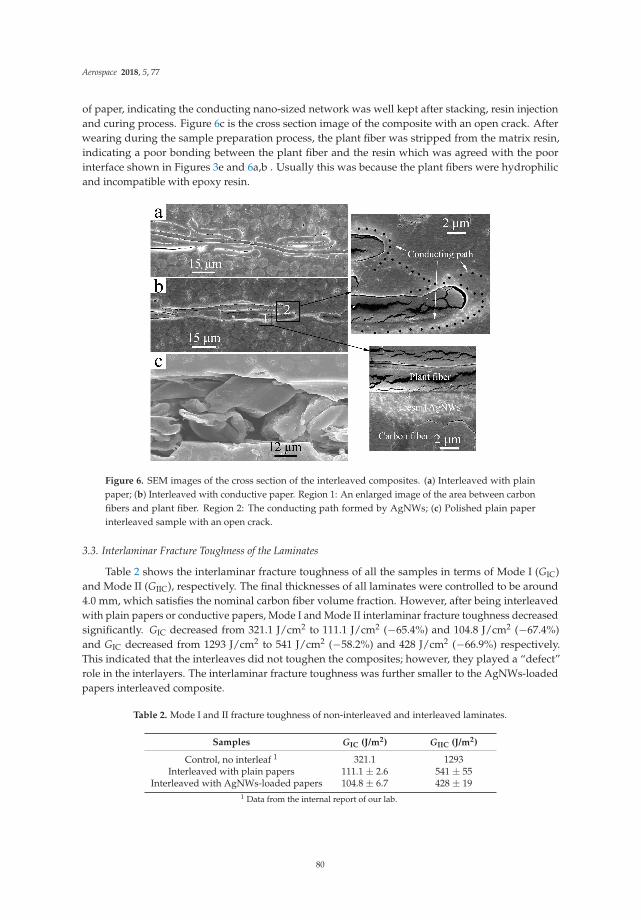
Aerospace 2018, 5, 77
of paper, indicating the conducting nano-sized network was well kept after stacking, resin injectionand curing process. Figure 6c is the cross section image of the composite with an open crack. Afterwearing during the sample preparation process, the plant fiber was stripped from the matrix resin,indicating a poor bonding between the plant fiber and the resin which was agreed with the poorinterface shown in Figures 3e and 6a,b . Usually this was because the plant fibers were hydrophilicand incompatible with epoxy resin.
Figure 6. SEM images of the cross section of the interleaved composites. (a) Interleaved with plainpaper; (b) Interleaved with conductive paper. Region 1: An enlarged image of the area between carbonfibers and plant fiber. Region 2: The conducting path formed by AgNWs; (c) Polished plain paperinterleaved sample with an open crack.
3.3. Interlaminar Fracture Toughness of the Laminates
Table 2 shows the interlaminar fracture toughness of all the samples in terms of Mode I (GIC)and Mode II (GIIC), respectively. The final thicknesses of all laminates were controlled to be around4.0 mm, which satisfies the nominal carbon fiber volume fraction. However, after being interleavedwith plain papers or conductive papers, Mode I and Mode II interlaminar fracture toughness decreasedsignificantly. GIC decreased from 321.1 J/cm2 to 111.1 J/cm2 (−65.4%) and 104.8 J/cm2 (−67.4%)and GIC decreased from 1293 J/cm2 to 541 J/cm2 (−58.2%) and 428 J/cm2 (−66.9%) respectively.This indicated that the interleaves did not toughen the composites; however, they played a “defect”role in the interlayers. The interlaminar fracture toughness was further smaller to the AgNWs-loadedpapers interleaved composite.
Table 2. Mode I and II fracture toughness of non-interleaved and interleaved laminates.
Samples GIC (J/m2) GIIC (J/m2)
Control, no interleaf 1 321.1 1293Interleaved with plain papers 111.1 ± 2.6 541 ± 55
Interleaved with AgNWs-loaded papers 104.8 ± 6.7 428 ± 191 Data from the internal report of our lab.
80

Aerospace 2018, 5, 77
Figure 7 gives the optical images and micrographs of the Mode I and Mode II fracture surfacesof the papers and conductive papers interleaved composites. As can be clearly seen from the figure,all the fracture surfaces occurred inside the interleaves, which means a similar fracture mechanismfor the different interleaves. In addition, the fracture surface of the conductive paper interleavedcomposites was relatively whitish, probably because of the existing of AgNWs or the insufficientinfiltration of epoxy inside the conductive paper.
Figure 7. Optical photos and optical microscope photographs of failure surfaces after Mode I andMode II fracture toughness test. (a) conductive papers interleaved, Mode I fracture surface; (b) plainpapers interleaved, Mode I fracture surface; (c) conductive papers interleaved, Mode II fracture surface;(d) plain papers interleaved, Mode II fracture surface.
Figure 8 gives the SEM images of the Mode I fracture surfaces. It was found that all the ModeI fracture surfaces were covered with plant fibers, that is, the failure mainly occurred inside theinterleave layers. Compared with the structure of nylon veil [23], the flattened plant fibers of thepaper stacked more densely. More fibers were distributed per unit volume, and more parallel to thecarbon plies. From Figure 8a,c, most of the interlaminar failures occurred in the plant fiber–epoxy resininterfaces or the overlapped areas of plant fibers. Compared with Figures 3e and 6a,b , because of theflat shape and highly packed density of the plant fibers, we can see the epoxy resin had not completelypenetrated into the overlapped areas of the plant fibers. In addition, poor interface between plantfiber and resin was found, thus it was much easier for the fracture to occur inside the interleaves.Besides, the surface of plant fibers or resin on the failure surface was very smooth, and no destroyedresin particles were found, also indicating that the interfacial bonding between paper fiber and resinwas weak. Only a few plant fibers were destroyed, as can be seen in Figure 8b,d. In the case of theAgNWs-loaded paper interleaved sample, AgNWs can easily be seen at the resin area of fracture
81

Aerospace 2018, 5, 77
surface shown in Figure 8d. However, this area has became more rough indicating that the resin hadrelatively poor infiltration in the AgNWs-enriched area.
Compared with Figure 8a,c, resin may be easily seen in the gap of the overlapped plant fibersin Figure 8a, while the resin was small in quantity except for the area not covered with plant fiber,and more bare plant fibers are found in Figure 8c. This indicates that the presence of AgNWsconcentrated on the surface of the interleaved paper greatly reduced the permeability of the resin intothe densely packed plant fibers, making the interlayer much liable to be destroyed when not filledwith resin, and thus the Mode I fracture toughness of the conductive papers interleaved compositewas lower than the plain papers interleaved composite.
Figure 8. SEM images of Mode I fracture surfaces of (a,b) plain paper interleaved composite and(c,d) conductive paper interleaved composite.
Figure 9 gives the SEM images of the Mode II fracture surfaces. It can also be seen from the imagesthat most of the Mode II fractures occurred inside the interleave layers of the composites. Only in thearea not covered with plant fibers, shear failure of resin was observed at the interface between thecarbon ply and the interlayer. As seen from Figure 9a,c, fracture failure at plant fiber–resin interfaces,paper fiber–paper fiber interfaces obviously exist everywhere. As seen from Figure 9b,d, the fracturefailure of plain paper interleaved composite mostly occurred at the fiber-resin interfaces while thatof conductive paper interleaved composite mostly occurred at the non-resin infiltrated fiber–fiberoverlapped areas. More surfaces of plant fibers were found and little resin existed in the gap of plantfibers as seen in Figure 9c,d, which are very different from the fracture surfaces shown in Figure 9a,b.This indicates that the presence of AgNWs impeded the impregnation of resin in densely packed paperfibers, leading to the further decline of Mode II interlaminar fracture toughness.
82
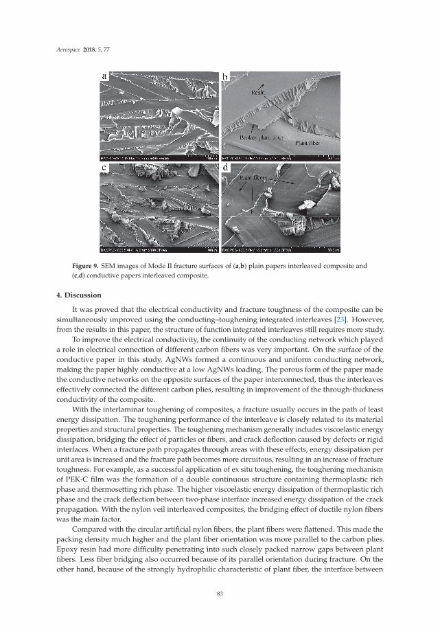
Aerospace 2018, 5, 77
Figure 9. SEM images of Mode II fracture surfaces of (a,b) plain papers interleaved composite and(c,d) conductive papers interleaved composite.
4. Discussion
It was proved that the electrical conductivity and fracture toughness of the composite can besimultaneously improved using the conducting–toughening integrated interleaves [23]. However,from the results in this paper, the structure of function integrated interleaves still requires more study.
To improve the electrical conductivity, the continuity of the conducting network which playeda role in electrical connection of different carbon fibers was very important. On the surface of theconductive paper in this study, AgNWs formed a continuous and uniform conducting network,making the paper highly conductive at a low AgNWs loading. The porous form of the paper madethe conductive networks on the opposite surfaces of the paper interconnected, thus the interleaveseffectively connected the different carbon plies, resulting in improvement of the through-thicknessconductivity of the composite.
With the interlaminar toughening of composites, a fracture usually occurs in the path of leastenergy dissipation. The toughening performance of the interleave is closely related to its materialproperties and structural properties. The toughening mechanism generally includes viscoelastic energydissipation, bridging the effect of particles or fibers, and crack deflection caused by defects or rigidinterfaces. When a fracture path propagates through areas with these effects, energy dissipation perunit area is increased and the fracture path becomes more circuitous, resulting in an increase of fracturetoughness. For example, as a successful application of ex situ toughening, the toughening mechanismof PEK-C film was the formation of a double continuous structure containing thermoplastic richphase and thermosetting rich phase. The higher viscoelastic energy dissipation of thermoplastic richphase and the crack deflection between two-phase interface increased energy dissipation of the crackpropagation. With the nylon veil interleaved composites, the bridging effect of ductile nylon fiberswas the main factor.
Compared with the circular artificial nylon fibers, the plant fibers were flattened. This made thepacking density much higher and the plant fiber orientation was more parallel to the carbon plies.Epoxy resin had more difficulty penetrating into such closely packed narrow gaps between plantfibers. Less fiber bridging also occurred because of its parallel orientation during fracture. On theother hand, because of the strongly hydrophilic characteristic of plant fiber, the interface between
83
Aerospace 2018, 5, 77
plant fiber and epoxy resin was poor. Combined the above factors, the interlaminar failure mostlyoccurred in fiber-resin interface and non-resin infiltrated fiber–fiber overlapped area where the energydissipation per unit area was much lower, thus the interlaminar fracture toughness was significantlydecreased. With the AgNWs-loaded papers interleaved composites, a large number of AgNWs formeda nanoscaled network on the surface of densely packed plant fibers, which was very different from theAgNWs-loaded nylon veil interleaved composite, with which the AgNWs network mostly coveredsingle nylon fibers and bridged between fibers, further reducing the penetration of resin in the interiorof paper, so interlaminar failure occurred in non-resin infiltrated fiber–fiber overlapping areas and ledto the further decline of interlaminar fracture toughness.
In addition, although interlaminar toughness was decreased after interleaving with papers madeof plant fibers, the result can provide us with some useful inspirations. For example, we could use flaxfiber, which is much stronger and nearly circular to improve the fiber fracture energy and infiltrationof resin. Additionally, the surface treatment is required to improve the bonding of fiber and resin.The sound absorption and damping properties of composites interleaved with plant fibers may also bevery interesting.
5. Conclusions
In conclusion, through preparing conductive papers and using as interleaves, the electricalconductivity of composites was effectively improved, but the interlaminar fracture toughness wasobviously decreased. The increase of conductivity was achieved from the good conductivity of AgNWsnetwork and good electrical connection between AgNWs network and carbon plies. The decreaseof the interlaminar fracture toughness can be attributed to highly parallel, densely packed interleafstructure formed by the flattened plant fibers and the poor interface between plant fibers and epoxyresin. The highly parallel distribution of plant fiber and its poor bonding with resin caused the fracturepath to mainly propagate on the peeling surfaces of epoxy resin–plant fiber and plant fiber–plant fiber.Few plant fibers were destroyed during facture to dissipate energy. The densely packed plant fibersimpeded the penetration of resin inside the paper and the penetration became worse for the paper withAgNWs surface loaded. All these reasons resulted the decrease of interlaminar fracture toughness.
Author Contributions: X.Y. conceived and guided the project and study; M.G. performed the experiments andwrote the paper.
Funding: Financial supports from National 973 Project 2010CB631100 and the Aeronautical Science Foundationof China under Projects 2016ZFV8010 are gratefully acknowledged.
Conflicts of Interest: The authors declare no conflicts of interest.
References
1. Lubineau, G.; Rahaman, A. A review of strategies for improving the degradation properties of laminatedcontinuous-fiber/epoxy composites with carbon-based nanoreinforcements. Carbon 2012, 50, 2377–2395.[CrossRef]
2. Cicala, G.; Pergolizzi, E.; Piscopo, F.; Carbone, D.; Recca, G. Hybrid composites manufactured by resininfusion with a fully recyclable bioepoxy resin. Composites Part B 2018, 132, 69–76. [CrossRef]
3. Ma, S.; Li, T.; Liu, X.; Zhu, J. Research progress on bio-based thermosetting resins. Polym. Int. 2016,65, 164–173. [CrossRef]
4. Chegdani, F.; Mansori, M.E.; Mezghani, S.; Montagne, A. Scale effect on tribo-mechanical behavior of vegetalfibers in reinforced bio-composite materials. Composites Science and Technology. Compos. Sci. Technol. 2017,150, 87–94. [CrossRef]
5. Zhang, D.; Ye, L.; Deng, S.; Zhang, J.; Tang, Y.; Chen, Y. CF/EP composite laminates with carbonblack and copper chloride for improved electrical conductivity and interlaminar fracture toughness.Compos. Sci. Technol. 2012, 72, 412–420. [CrossRef]
6. Kim, H.S.; Hahn, H.T. Graphite fiber composites interlayered with single-walled carbon nanotubes.J. Compos. Mater. 2011, 45, 1109–1120. [CrossRef]
84

Aerospace 2018, 5, 77
7. Garcia, E.J.; Wardle, B.L.; Hart, A.J.; Yamamoto, N. Fabrication and multifunctional properties of a hybridlaminate with aligned carbon nanotubes grown In Situ. Compos. Sci. Technol. 2008, 68, 2034–2041. [CrossRef]
8. Sun, S.; Guo, M.; Yi, X. Phase separation morphology and mode II interlaminar fracture toughness ofbismaleimide laminates toughened by thermoplastics with triphenylphosphine oxide group. Sci. ChinaTechnol. Sci. 2017, 60, 444–451. [CrossRef]
9. Sun, L.; Warren, G.L.; Davis, D.; Sue, H.-J. Nylon toughened epoxy/SWCNT composites. J. Mater. Sci. 2011,46, 207–214. [CrossRef]
10. Groleau, M.R.; Shi, Y.-B.; Yee, A.F.; Bertram, J.L.; Sue, H.J.; Yang, P.C. Mode II fracture of compositesinterlayered with nylon particles. Compos. Sci. Technol. 1996, 56, 1223–1240. [CrossRef]
11. Yi, X.; Cheng, Q.; Liu, Z. Preform-based toughening technology for RTMable high-temperature aerospacecomposites. Sci. China Technol. Sci. 2012, 55, 2255–2263. [CrossRef]
12. Anand, A.; Kumar, N.; Harshe, R.; Joshi, M. Glass/epoxy structural composites with interleaved nylon6/6 nanofibers. J. Compos. Mater. 2017, 51, 3291–3298. [CrossRef]
13. Yadav, S.N.; Kumar, V.; Verma, S.K. Fracture toughness behavior of carbon fibre epoxy composite withKevlar reinforced interleave. Mater. Sci. Eng. B 2006, 132, 108–112. [CrossRef]
14. Khan, S.U.; Kim, J.-K. Improved interlaminar shear properties of multiscale carbon fiber composites withbucky paper interleaves made from carbon nanofibers. Carbon 2012, 50, 5265–5277. [CrossRef]
15. Palazzetti, R.; Yan, X.; Zucchelli, A. Influence of geometrical features of electrospun nylon6, 6 interleave onthe CFRP laminates mechanical properties. Polym. Compos. 2014, 35, 137–150. [CrossRef]
16. Ramirez, V.A.; Hogg, P.J.; Sampson, W.W. The influence of the nonwoven veil architectures on interlaminarfracture toughness of the interleaved composites. Compos. Sci. Technol. 2015, 110, 103–110. [CrossRef]
17. Heijden, S.; Daelemans, L.; Meireman, T.; Baere, I.D.; Rahier, H.; Paepegem, W.V.; Clerck, K.D. Interlaminartoughening of resin transfer molded laminates by electrospun polycaprolactone structures: Effect of theinterleave morphology. Compos. Sci. Technol. 2016, 136, 10–17. [CrossRef]
18. KuWata, M.; Hogg, P.J. Interlaminar toughness of interleaved CFRP using non-woven veils: Part 1. Mode-Itesting. Composites Part A 2011, 42, 1551–1559. [CrossRef]
19. KuWata, M.; Hogg, P.J. Interlaminar toughness of interleaved CFRP using non-woven veils: Part 2. Mode-IItesting. Composites Part A 2011, 42, 1560–1570. [CrossRef]
20. Beckermann, G.W.; Pickering, K.L. Mode I and Mode II interlaminar fracture toughness of compositelaminates interleaved with electrospun nanofibre veils. Composites Part A 2015, 72, 11–21. [CrossRef]
21. Daelemans, L.; Heijden, S.; Baere, I.D.; Rahier, H.; Paepegem, W.V.; Clerck, K.D. Using aligned nanofibres foridentifying the toughening micromechanisms in nanofibre interleaved laminates. Compos. Sci. Technol. 2016,124, 17–26. [CrossRef]
22. Daelemans, L.; Heijden, S.; Baere, I.D.; Rahier, H.; Paepegem, W.V.; Clerck, K.D. Nanofibre bridging asa toughening mechanism in carbon/epoxy composite laminates interleaved with electrospun polyamidenanofibrous veils. Compos. Sci. Technol. 2015, 117, 244–256. [CrossRef]
23. Guo, M.; Yi, X.; Liu, G.; Liu, L. Simultaneously increasing the electrical conductivity and fracture toughnessof carbon-fiber composites by using silver nanowires-loaded interleaves. Compos. Sci. Technol. 2014, 97, 27–33.[CrossRef]
24. Guo, M.; Yi, X. The production of tough, electrically carbon fiber composite laminates for use in airframe.Carbon 2013, 58, 241–244. [CrossRef]
25. Eskizeybek, V.; Yar, A.; Avcı, A. CNT-PAN hybrid nanofibrous mat interleaved carbon/epoxy laminates withimproved Mode I interlaminar fracture toughness. Compos. Sci. Technol. 2018, 157, 30–39. [CrossRef]
26. Zhou, H.; Du, X.; Liu, H.-Y.; Zhou, H.; Zhang, Y.; Mai, Y.-W. Delamination toughening of carbon fiber/epoxylaminates by hierarchical carbon nanotube-short carbon fiber interleaves. Compos. Sci. Technol. 2017,140, 46–53. [CrossRef]
27. Zheng, N.; Huang, Y.; Liu, H.-Y.; Gao, J.; Mai, Y.-W. Improvement of interlaminar fracture toughness incarbon fiber/epoxy composites with carbon nanotubes/polysulfone interleaves. Compos. Sci. Technol. 2017,140, 8–15. [CrossRef]
28. Lee, S.-H.; Kim, H.; Hang, S.; Cheong, S.-K. Interlaminar fracture toughness of composite laminates withCNT-enhanced nonwoven carbon tissue interleave. Compos. Sci. Technol. 2012, 73, 1–8. [CrossRef]
29. Chen, C.Z.; Li, Y.; Yu, T. Interlaminar toughening in flax fiber-reinforced composites interleaved with carbonnanotube buckypaper. J. Reinf. Plast. Compos. 2014, 33, 1859–1868. [CrossRef]
85

Aerospace 2018, 5, 77
30. Ramamoorthy, S.K.; Skrifvars, M.; Persson, A. A review of natural fibers used in biocomposites: Plant,animal and regenerated cellulose fibers. Polym. Rev. 2015, 55, 107–162. [CrossRef]
31. Cesano, F.; Zaccone, M.; Armentano, I.; Cravanzola, S.; Muscuso, L.; Torre, L.; Kenny, J.M.; Monti, M.;Scarano, D. Relationship between morphology and electrical properties in PP/MWCNT composites:Processing-induced anisotropic percolation threshold. Mater. Chem. Phys. 2016, 180, 284–290. [CrossRef]
32. Ge, J.; Yao, H.-B.; Wang, X.; Ye, Y.-D.; Wang, J.-L.; Wu, Z.-Y.; Liu, J.-W.; Fan, F.-J.; Gao, H.-L.; Zhang, C.-L.;et al. Stretchable conductors based on silver nanowires: Improved performance through a binary networkdesign. Angew. Chem. Int. Ed. 2013, 52, 1654–1659. [CrossRef] [PubMed]
33. Wu, C.; Fang, L.; Huang, X.; Jiang, P. Three-dimensional highly conductive graphene-silver nanowire hybridfoams for flexible and stretchable conductors. ACS Appl. Mater. Interfaces 2014, 6, 21026–21034. [CrossRef][PubMed]
34. Haznedar, G.; Cravanzola, S.; Zanetti, M.; Scarano, D.; Zecchina, A.; Cesano, F. Graphite nanoplateletsand carbon nanotubes based polyethylene composites: Electrical conductivity and morphology.Mater. Chem. Phys. 2013, 143, 47–52. [CrossRef]
35. Cesano, F.; Rattalino, I.; Demarchi, D.; Bardelli, F.; Sanginario, A.; Gianturco, A.; Veca, A.;Viazzi, C.; Castelli, P.; Scarano, D.; et al. Structure and properties of metal-free conductive tracks onpolyethylene/multiwalled carbon nanotube composites as obtained by laser stimulated percolation. Carbon2013, 61, 63–71. [CrossRef]
© 2018 by the authors. Licensee MDPI, Basel, Switzerland. This article is an open accessarticle distributed under the terms and conditions of the Creative Commons Attribution(CC BY) license (http://creativecommons.org/licenses/by/4.0/).
86

aerospace
Article
Sound Absorption Characterization of NaturalMaterials and Sandwich Structure Composites
Jichun Zhang 1, Yiou Shen 1,*, Bing Jiang 1 and Yan Li 1,2
1 School of Aerospace Engineering and Applied Mechanics, Tongji University, Shanghai 200092, China;[email protected] (J.Z.); [email protected] (B.J.); [email protected] (Y.L.)
2 Key Laboratory of Advanced Civil Engineering Materials, Ministry of Education, Tongji University,Shanghai 200092, China
* Correspondence: [email protected]; Tel.: +86-21-6598-5919
Received: 19 June 2018; Accepted: 5 July 2018; Published: 11 July 2018
Abstract: Natural fiber and wood are environmentally friendly materials with multiscalemicrostructures. The sound absorption performance of flax fiber and its reinforced composite,as well as balsa wood, were evaluated using the two-microphone transfer function techniquewith an impedance tube system. The microstructures of natural materials were studied throughscanning electrical microscope in order to reveal their complex acoustical dissipation mechanisms.The sound absorption coefficients of flax fiber fabric were predicted using a double-porosity model,which showed relatively accurate results. The integrated natural materials sandwich structure wasfound to provide a superior sound absorption performance compared to the synthetic-materials-basedsandwich structure composite due to the contribution of their multiscale structures to sound waveattenuation and energy dissipation. It was concluded that the natural-materials-based sandwichstructure has the potential of being used as a sound absorption structure, especially at high frequency.
Keywords: plant fiber; balsa; sound absorption; microstructures; sandwich structures
1. Introduction
Over the last couple of decades, there has been an increasing demand for improving the interiornoise and indoor noise of aircraft, railway, automobile, and building compartments. Interior noiseimpairs people’s health and causes a decrease in passenger comfort and active safety performance [1].The use of sound-absorbing materials is one of the present effective noise control technologies.The conventional industrial sound absorption and insulation materials are mineral fibers, foam,and their composites. However, the usage of such materials is expensive, energy-consumptive,and adds more weight to the structures, which impacts their structural integrity.
Sandwich structure composites have been extensively employed in aerospace, transportation,construction, and new energy fields as load-bearing components due to their high strength-to-weightratio. Sandwich structure composites can be designable and multifunctional, and more functions canbe provided besides bearing with proper design, such as impact tolerance, thermal isolation, radiationresistance, acoustic absorption, etc. Nowadays, growing attention has focused on environmentallyfriendly materials that can be recycled or need less energy for production and contribute minimumgreenhouse gas emissions. Utilizing natural materials as face sheets or core materials for sandwichstructures would provide superior load-bearing and fatigue properties. Moreover, this kind ofstructure provides good sound absorption properties compared to the conventional metallic andlaminated composite structural members [2]. These natural materials and sandwich structures havethe potential of replacing synthetic materials in applications with demands of weight constraints orenvironmental friendliness, such as interior panels or floors in the aerospace industry, high-speedtrains, and automobiles.
Aerospace 2018, 5, 75; doi:10.3390/aerospace5030075 www.mdpi.com/journal/aerospace87

Aerospace 2018, 5, 75
Zheng and Li [3] found using plant-fiber-reinforced composite (PFRC) as skins of sandwichstructures processes better sound absorption properties than using glass-fiber-reinforced composite(GFRC) as skins. The damping properties of flax-fiber-reinforced composite (FFRC) face sheets andGFRC face-sheet-based sandwich structures were compared by Petrone et al. [4,5]. Their researchresults indicated that FFRC face sheet sandwich panels have outperformed energy dissipation abilitycompared to the synthetic fiber face sheet ones. Sarginis et al. [6] investigated the sound and vibrationdamping characteristics of balsa-core-based sandwich beams. They found that the coincidencefrequency of sandwich beams with natural fiber facing sheet and balsa core was tripled comparedto a synthetic-core-based sandwich beam. Plant fiber is a kind of natural material, and it has beenwidely used as reinforcement in composite structures for the last decades due to their rich source,low price, specific strength, high specific modulus, and so on. Plant fiber has a complex, multiscale,hollow structure compared with synthetic fiber [7,8]. For example, flax fiber is extracted from thestalk of the plant, and the characteristics of its natural growth result in its multiscale structure,which can be simplified at two scales. At the mesoscopic scale, a bundle contains 10 to 40 elementaryfibers (12–16 μm in diameter, 2–5 cm in length) which are linked together mainly by pectin. At themicroscopic scale, different from the solid structure of synthetic fiber, each elementary fiber is made upof concentric cell walls called the primary cell wall (0.2 μm) and the secondary cell wall. The secondarycell wall is composed of three layers, namely the S1 layer (0.08–0.2 μm), the S2 layer (1–10 μm),and the S3 layer (0.1 μm). Most of the cellulose microfibrils are located in the S2 layer, which is atype of polymer and possesses viscoelastic properties. The S2 layer of flax fiber consists of numerouscellulose microfibril sublayers (L1, L2 . . . Ln) which run parallel to each other and form a microfibrilangle with the fiber direction. At the center of the elementary fiber, there is a 2–5-μm diameter smallopen channel called lumen, as revealed in Figure 1a. It can be seen from Figure 1b that hundreds ofelementary fibers twist together to form a continuous yarn, and a gap of dozens of microns is betweeneach elementary fiber. The unique microstructure brings many distinctive advantages for plant fiber,such as superior energy absorption [9], acoustic [10] and damping [11] performances, etc. Naturalfiber was found to be a good acoustically absorbent material due to the hollow structures whichefficiently convert acoustic energy into mechanical and heat energy [12]. The investigations on theacoustic absorption properties of natural-fibrous-material-reinforced composites are limited; however,several scholars have experimentally studied the sound absorption coefficients of plant-fiber-reinforcedcomposites (PFRC) and found their sound absorption coefficients (SAC) were much higher than thoseof the synthetic-fiber-reinforced composites at 100–2000 Hz frequency level [12,13]. Yang and Li [14]also found that the Garai–Pompoli model and Delany–Bazley model have good agreement with theexperimental results. However, the acoustical dissipation mechanisms of plant fiber materials werenot plenarily analyzed in these studies and the multiscale hollow structure of plant fibers was notreflected by these two models. Therefore, the multiscale structure of plant fiber should be consideredduring sound absorption mechanisms analysis as well as the acoustic properties prediction. Olny andBoutin [15] theoretically studied the acoustic wave propagation in media with two interconnectednetworks of pores of very different characteristic sizes. In this study, flax fiber yarn was consideredas a double-porosity media, and this double-porosity model was employed to predict the acousticproperties of flax fiber.
The relatively high mechanical properties and low density of balsa make it attractive for cores insandwich panels, and more importantly, sustainable. To date, there are no engineered materials suitablefor sandwich panel cores with a similar combination of mechanical properties and low density [16].Balsa wood can be considered as a kind of cellular material; it is composed of different size cell fibers,rays, and vessels, and there are also many micropores connecting each grain. It can be seen fromFigure 2a,b that the fibers are long prismatic cells, resembling a hexagon in cross-section, rangingfrom 20 to 40 μm in diameter. The rays are brick-like parenchyma cells ranging from 20 to 40 μmin cross-section. The vessels are long, tubular structures that run axially along the trunk of the tree,and the diameter of the vessels is 200–350 μm. Tiny micropores with a diameter of a few microns
88
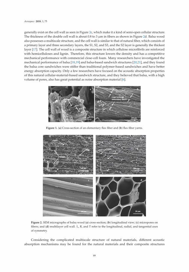
Aerospace 2018, 5, 75
generally exist on the cell wall as seen in Figure 2c, which make it a kind of semi-open cellular structure.The thickness of the double cell wall is about 0.8 to 3 μm in fibers as shown in Figure 2d. Balsa woodalso possesses a multiscale structure, and the cell wall is similar to that of natural fiber, which consists ofa primary layer and three secondary layers, the S1, S2, and S3, and the S2 layer is generally the thickestlayer [17]. The cell wall of wood is a composite structure in which cellulose microfibrils are reinforcedwith hemicelluloses and lignin. Therefore, this structure lowers the density and has a competitivemechanical performance with commercial close-cell foam. Many researchers have investigated themechanical performance of balsa [18,19] and balsa-based sandwich structures [20,21], and they foundthe balsa core sandwiches were stiffer than traditional polymer-based sandwiches and have betterenergy absorption capacity. Only a few researchers have focused on the acoustic absorption propertiesof this natural cellular-material-based sandwich structure, and they believed that balsa, with a highvolume of pores, also has great potential as noise absorption material [6].
Figure 1. (a) Cross-section of an elementary flax fiber and (b) flax fiber yarns.
Figure 2. SEM micrographs of balsa wood (a) cross-section; (b) longitudinal view; (c) micropores onfibers; and (d) multilayer cell wall. L, R, and T refer to the longitudinal, radial, and tangential axesof symmetry.
Considering the complicated multiscale structure of natural materials, different acousticabsorption mechanisms may be found for the natural materials and their composite structures
89

Aerospace 2018, 5, 75
compared to the synthetic fiber and reinforced composites. However, the above studies have notfocused on this point, thus the sound absorption mechanism of natural materials and its compositestructures is still unclear. In this paper, the sound absorption performance of flax fiber, reinforcedcomposite, balsa wood, and the integrated sandwich structure composites were evaluated usingthe impedance tube method. The acoustical dissipation mechanisms were analyzed on the point ofview of their unique multiscale microstructures. With a purpose of comparison, commonly usedsandwich composites with glass fiber face sheets and polyethylene terephthalate (PET) foam core werealso investigated.
2. Materials and Experiments
2.1. Materials
Flax-fiber-fabric-reinforced epoxy composite was used as skins and balsa wood was used asthe core material for Flax-Balsa sandwich structures. Likewise, Flax-PET and Glass-PET sandwichstructures were prepared for comparison. The unidirectional flax fabric was provided by Lineo Co.Ltd., Saint Martin Du Tilleul, France, and the unidirectional glass fabric was provided by ZhejiangMengtai Reinforced Composite Material Co. Ltd., Jiaxing, China. These two fabrics had similar arealdensity, however, the thickness of the glass fiber fabric was only half of the flax fiber fabric due to thedensity reason. The NPEL-128 epoxy was supplied by Shanghai Zhongsi Industry Co. Ltd., Shanghai,China. The balsa wood and the AIREX® T92.100 close-cell PET foam were supplied by Zhuhai DechiTechnology Co. Ltd., Zhuhai, China and 3A Composites (China) Ltd., Shanghai, China, respectively.The detail parameters of the flax and glass fiber fabric used for fabricating the sandwich structureskins are listed in Table 1.
Balsa wood and PET foam panel with a thickness of 10 mm were prepared as core materials tofabricate the sandwich structure. The basic parameters of these two types of core material are shownin Table 2. Balsa wood and PET foam with similar density and porosity were selected in this studyfor comparison.
Table 1. The details of fiber fabrics used in manufacturing sandwich structures skins.
MaterialsFiber Density
(g/cm3)Mean Fiber
Diameter (μm)Mean Yarn
Diameter (μm)Areal
Density (g/m2)Mean
Thickness (mm)
SpecificStrength
(MPa/g/cm3)
SpecificModulus
(GPa/g/cm3)
Flax fabric 1.5 15 200 213.3 0.2 1034 55Glass fabric 2.55 11 100 207.5 0.1 980 30
Table 2. The parameters of core materials used in manufacturing sandwich structures.
MaterialsDensity(kg/m3)
PorosityCellular
Diameter (μm)Axial Compression
Modulus (MPa)Transverse Compression
Modulus (MPa)
Balsa wood 125 0.920 35–200 280–320 30–80PET foam 112 0.933 500–700 90 90
2.2. Fabrication
The epoxy resin, curing agent, and accelerating agent were mixed at the weight ratio of 100:80:1.Initially, 12 layers of flax fiber fabrics and 24 layers of glass fiber fabrics were impregnated with theresin system and laid inside of a steel mold in stacking sequence of [0/90/0]2s and [02/902/02]2s,respectively. In addition, 6 layers of impregnated flax fiber fabrics were laid on the top and bottomof the core material with stacking sequence of [0/90/0]s in order to fabricate flax-fiber-reinforcedcomposite (FFRC) skin-based sandwich panels. A similar process was used for GFRP skin-basedsandwich panels (12 layers on each side, [02/902/02]s). The resulting laminates and sandwich prepregsystems were then respectively placed in a hot press machine under pressure of 1 MPa and temperatureof 120 ◦C for 2 h for complete curing. Two types of composite laminate, being flax-fiber-reinforced
90

Aerospace 2018, 5, 75
composite (FFRC) and glass-fiber-reinforced composite (GFRC), with mean thickness of 4 mm andfiber volume fraction of 50% were manufactured. Three types of sandwich structures, Flax-Balsa,Flax-PET, and Glass-PET, with 2 mm thickness and 50% fiber volume fraction of composite skin oneach side were manufactured, in which Flax-Balsa and Flax-PET denote sandwich structures basedon FFRC skins and balsa or PET foam cores, respectively. The thickness of the balsa panel was on thetangential direction of the balsa wood. The Glass-PET denotes a sandwich structure with GFRC skinsand PET foam core, as illustrated in Figure 3.
Figure 3. Schematic diagram of sandwich structures.
2.3. Acoustic Property Measurement
Sound absorption measurement was performed using the impedance tube method. The soundabsorption coefficient (SAC) of sandwich composites was measured through a transfer functiontechnique with the impedance tube facilities manufactured by BSWA Technology Co. Ltd., Beijing,China. The SAC is defined as the ratio of the absorbed sound energy and the incident sound energy.The measurements were conducted according to ISO10534-2 standard at medium to high frequenciesfrom 250 to 10,000 Hz at 25 ◦C and 60% relative humidity, and at least three specimens were testedfor each group. The measurements were composed of SW422, SW477, and SW499 impedancetubes with diameters of 100, 30, and 16 mm for measuring frequencies from 250–2000, 800–6300,and 2500–10,000 Hz, respectively. Samples were backed up by a rigid wall which reflected all theincoming sound energy. Two microphones were mounted at the wall of the tube to measure the soundpressure. Therefore, if the incident sound energy was known and the transmission sound energy couldbe measured with the aid of the transfer function, the sound energy absorbed by the materials couldbe obtained, as illustrated in Figure 4.
The SACs of 12 layers of flax fiber fabric and 24 layers of glass fiber fabric with same thicknesswere initially measured at frequency ranging from 250 to 4000 Hz. The composite laminates andsandwich structures were carefully cut to the required size and wrapped with Teflon tape providedby 3M Company, Maplewood, MN, USA to prevent air leaks between the sample and tube. All thesamples were put in the oven at 120 ◦C for 4 h to remove moisture.
Figure 4. Instrumentation for the transfer function method of measuring sound absorption coefficients.
3. Results and Discussions
3.1. Sound Absorption Performance of Flax Fiber and Its Reinforced Composite
The tested sound absorption coefficients of unidirectional flax fiber fabric and glass fiber fabricare presented in Figure 5 as a function of frequency. The results show that in the test frequency rangeof 250–4000 Hz, flax fiber fabric has superior acoustic absorption ability compared to glass fiber fabric.It can be seen from Figure 5 that the SACs of flax fiber fabric were higher than 0.5 when the sound
91
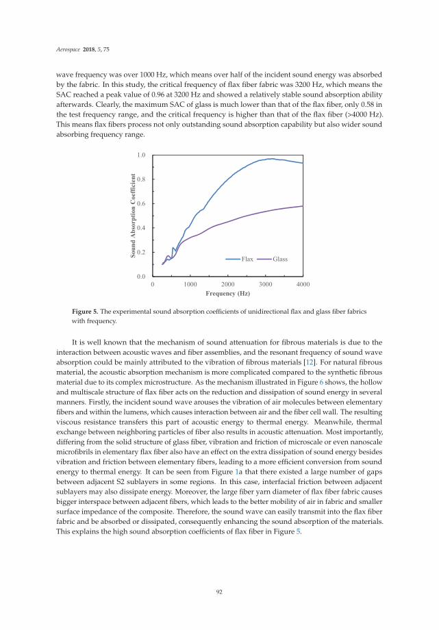
Aerospace 2018, 5, 75
wave frequency was over 1000 Hz, which means over half of the incident sound energy was absorbedby the fabric. In this study, the critical frequency of flax fiber fabric was 3200 Hz, which means theSAC reached a peak value of 0.96 at 3200 Hz and showed a relatively stable sound absorption abilityafterwards. Clearly, the maximum SAC of glass is much lower than that of the flax fiber, only 0.58 inthe test frequency range, and the critical frequency is higher than that of the flax fiber (>4000 Hz).This means flax fibers process not only outstanding sound absorption capability but also wider soundabsorbing frequency range.
0.0
0.2
0.4
0.6
0.8
1.0
0 1000 2000 3000 4000
Soun
d A
bsor
ptio
n C
oeffi
cien
t
Frequency (Hz)
Flax Glass
Figure 5. The experimental sound absorption coefficients of unidirectional flax and glass fiber fabricswith frequency.
It is well known that the mechanism of sound attenuation for fibrous materials is due to theinteraction between acoustic waves and fiber assemblies, and the resonant frequency of sound waveabsorption could be mainly attributed to the vibration of fibrous materials [12]. For natural fibrousmaterial, the acoustic absorption mechanism is more complicated compared to the synthetic fibrousmaterial due to its complex microstructure. As the mechanism illustrated in Figure 6 shows, the hollowand multiscale structure of flax fiber acts on the reduction and dissipation of sound energy in severalmanners. Firstly, the incident sound wave arouses the vibration of air molecules between elementaryfibers and within the lumens, which causes interaction between air and the fiber cell wall. The resultingviscous resistance transfers this part of acoustic energy to thermal energy. Meanwhile, thermalexchange between neighboring particles of fiber also results in acoustic attenuation. Most importantly,differing from the solid structure of glass fiber, vibration and friction of microscale or even nanoscalemicrofibrils in elementary flax fiber also have an effect on the extra dissipation of sound energy besidesvibration and friction between elementary fibers, leading to a more efficient conversion from soundenergy to thermal energy. It can be seen from Figure 1a that there existed a large number of gapsbetween adjacent S2 sublayers in some regions. In this case, interfacial friction between adjacentsublayers may also dissipate energy. Moreover, the large fiber yarn diameter of flax fiber fabric causesbigger interspace between adjacent fibers, which leads to the better mobility of air in fabric and smallersurface impedance of the composite. Therefore, the sound wave can easily transmit into the flax fiberfabric and be absorbed or dissipated, consequently enhancing the sound absorption of the materials.This explains the high sound absorption coefficients of flax fiber in Figure 5.
92

Aerospace 2018, 5, 75
Figure 6. Acoustic energy dissipation mechanisms of flax fiber yarns.
The superior sound absorbing ability of plant fiber is essentially attributed to its multiscalemicromorphology. However, the multiscale hollow structure of plant fibers was not reflected by theGarai–Pompoli model or Champoux–Allard model in predicting the SACs of plant fibers. In this study,the lumen of flax fiber was considered in predicting its acoustic properties. Firstly, an idealized flaxelementary fiber was assumed as a 15-μm diameter tubular cell with a 5-μm diameter lumen inside.The effective density ρeq and the effective modulus Keq of unidirectional flax fiber fabric were predictedaccording to the double-porosity model developed by Olny and Boutin [15] as shown in Equations (1)and (2):
ρeq(ω) =
(1
ρp(ω)+
1 −∅p
ρm(ω)
)−1(1)
Keq(ω) =
(1
Kp(ω)+
(1 −∅p
)Fd(ω, ωd)
Km(ω)
)−1
, ωd ≈ P0
∅mσml2p
(2)
where subscripts ‘p’ and ‘m’ present the mesoscopic scale (between fibers) and microscopic scale (withinthe fiber). lp and lm present the characteristic length in these two scales. ρp(ω), ρm(ω), and Kp(ω) wereobtained by plugging the basic mesoscopic and microscopic scales acoustic parameters into theChampoux–Allard model, Equations (3) and (4). Fd is a pressure diffusion function. In this study,the test frequency ω < ωd, Fd ≈ 1 and voids at both scales participated in the attenuation of acousticenergy; the sound pressure between fibers and lumens are the same.
ρeq(ω) =ρ0α∞
∅
⎢⎢⎢⎣1 − iσ∅
ωρ0α∞
√1 + iωρ0η
(2α∞
σ∅Λ
)2⎥⎥⎥⎦ (3)
1Keq
(ω) =∅
γP0
⎧⎪⎨⎪⎩γ − (γ − 1)
⎡⎣1 − i
8η
ωρ0PrΛ′2
√1 +
iωρ0Pr
η
(Λ′4
)2⎤⎦−1⎫⎪⎬⎪⎭ (4)
where ω is the angular frequency, ω = 2πf, f is the incident sound wave frequency, ø is the porosity,and α∞ is the tortuosity, which characterizes the buckling of channels in the material. For ideal fibermaterials, α∞ = 1.34. Λ and Λ’ are viscous characteristic length and thermal characteristic dimension,which characterize the average diameter of unit length for viscous loss and thermal loss, respectively.Λ and Λ’ are defined as Λ = 1/2πrL, Λ’ = 2Λ, in which L = 4ρf/πa2ρb, r = a/2, a is fiber diameter and
93

Aerospace 2018, 5, 75
ρb is the fabric density. ρ0 and γ are air density and specific heat ratio, respectively, and P0 is theatmospheric pressure. Pr is the Prandtl number, defined as Pr = Cp/k, where Cp is isobaric heat capacity,μ is viscosity, and k is thermal conductivity. The Prandtl number characterizes the effect of the physicalcharacteristic of air on the heat transfer process. The porosity can be obtained by Equation (5)
∅ = 1 − ρbρ f
(5)
where ρf is the fiber density.The resulting ρeq and Keq were then substituted into Equation (6) to get the acoustic characteristic
impedance, Zeq, and wave number, keq, of flax fiber fabric. The sound absorption coefficients can thenbe obtained using Equation (9)
Zeq =√
ρeqKeq, keq = ω
√ρeq
Keq(6)
α = 1 −∣∣∣∣Zn − 1Zn + 1
∣∣∣∣2, Zn = −i
Zeq
ρ0c0cot h
(keqt)
(7)
where c0 is the sound velocity in air, t is the thickness of material. It can be observed fromEquations (3)–(7) that the acoustic parameters of material are related to its physical parameters,including fiber diameter, fiber density, fabric density, and fabric thickness. It indicates that thesephysical parameters of material play a critical role on the sound absorption properties.
It can be found from Figure 7 that the double-porosity model showed more accuracy predictingresults compared to the Champoux–Allard model [22], and the critical frequency of flax fiber fabric wasaccurately estimated. This indicates that the main factors affecting the sound absorption properties ofplant fiber materials are not only fiber diameter, density, and fabric density, but the lumen diameter isalso an important parameter. The double-porosity model can be used to predict the sound absorptioncoefficients of plant fibers effectively.
0.0
0.2
0.4
0.6
0.8
1.0
0 1000 2000 3000 4000
Soun
d A
bsor
ptio
n C
oeffi
cien
t
Frequency (Hz)
Flax-experiment
Flax-Allard's model
Flax-Double porositymodel
Figure 7. Comparison of experimental and theoretical sound absorption coefficients of unidirectionalflax fiber fabrics with frequency.
Figure 8 compares the experimental results on SACs of flax fiber and glass-fiber-reinforcedcomposites. FFRC laminate provides superior sound absorption capacity to GFRC especially at higherfrequency, as expected. However, the SACs of the composites are obviously much lower than the fiberfabric and the effective sound absorption frequency range (SACs value over 0.2) was reduced. This isdue to the reason that when an incident sound wave reaches the surface of material, partial sound
94

Aerospace 2018, 5, 75
energy is reflected. The reflected energy depends on the surface acoustic impedance, Z, which can bedescribed using Equation (8).
Z =√
E·ρ (8)
where E is the modulus of the materials (sound wave incident direction) and ρ is the density of thematerials. The sound wave can be easily reflected when Z is high and more sound energy is reflected.In contrast, a substantial part of sound energy enters into the materials when Z is low. Apparently,more sound energy was reflected by the composite and this limited its sound absorption ability.Furthermore, the microstructure of the material structure had a major effect on energy dissipation athigh frequency due to the very short wavelength of sound wave, which made it easily eliminatedwhen transmitted through the media. The SACs of pure epoxy are very low, generally below 0.2.Thus, the sound absorption performance of composite laminate is mainly dependent on the soundabsorption characteristics of fiber. Previous work [23] has found that the multilayer structure of flaxfiber provided more internal interfaces (primary cell wall, S1, S2, and S3 layers of the secondary cellwall, and S2 layer consist of numerous cellulose microfibril sublayers) and paths inside of flax fiber todissipate energy compare to the solid synthetic fiber. Therefore, the damping property of flax fiberswas much better and resulted in a higher damping ratio for its reinforced composite. This indicatesthat the FFPC possesses higher energy dissipation and acoustic–thermal conversion capacity, and italso evidences its better acoustic absorption performance than that of GFRP. Prabhakaran et al. [13]also found FFRC process better SACs and damping factors compared to GFRC.
0.0
0.2
0.4
0.6
0.8
1.0
0 2000 4000 6000 8000 10000
Soun
d ab
sorp
tion
coef
ficie
nt
Frequency (Hz)
FFRPGFRP
Figure 8. The experimental sound absorption coefficients of FFRC and GFRC with frequency.
3.2. Sound Absorption Performance of Balsa Wood
Figure 9 illustrates the SACs of balsa and PET foam, which indicate that these two types of corematerials possess similar sound absorption ability along the test frequencies. The peak value of SACsbelow 10,000 Hz for these two materials are 0.4 and 0.42, respectively. The maximum SAC of these twoporous materials at 10,000 Hz are also very close, being 0.85 and 0.87. The similar density and porosityof these two materials lead to their essentially identical trend on the sound absorption behavior.The cell wall of balsa is composed of polymer materials, and the visco-inertial and thermal dampingdominates the sound absorption behavior for polymeric foams. In low frequency stage, thermalexchange is dominated in energy dissipation, whereas in high frequency, viscous resistance is the mainenergy consuming method. The loss of sound energy is mainly due to the contribution of the poroussound absorption mechanism and resonance absorption mechanism. The air molecules periodicallyvibrate under the influence of sound waves; meanwhile, the friction between the air molecules and cellwall cause frictional heat. On the other hand, the compression and expanding deformation of air insideof the cell occurs; this transfers partial sound energy into thermal energy. In terms of balsa, vibration
95

Aerospace 2018, 5, 75
and friction of cellulose microfibrils in the cell wall and interfacial friction between adjacent sublayerscaused sound energy dissipation, which is similar to the flax fiber. In addition, the micropores in thecell wall of balsa consumed sound energy due to this complex inner geometry providing a tortuoussound path through the foam. It can be found that natural material has a complicated acoustical energydissipation mechanism due to its natural growth multiscale structure which reveals a satisfactorysound absorption performance.
0.0
0.2
0.4
0.6
0.8
1.0
0 2000 4000 6000 8000 10000
Soun
d ab
sorp
tion
coef
ficie
nt
Frequency (Hz)
BalsaPET
Figure 9. The experimental sound absorption coefficients of balsa and PET foam with frequency.
3.3. Sound Absorption Performance of Sandwich Structures
An effective way to improve the acoustic absorption performance of composite laminate isinducing a porous material as the core material to cooperate a sandwich structure. Meanwhile,the sound wave can be reflected repeatedly by the stiff composite skins back to the interior of thecellular core material for energy exchange and dissipation. Figure 10 shows the variation of SACswith frequency of Flax-Balsa, Flax-PET, and Glass-PET sandwich structures and their correspondingcore materials. It can be seen from Figure 10 that the SACs increase with frequency for all thesamples, reaching at least 0.8 at 10,000 Hz. For flax-fiber-reinforced composite skin-based sandwichstructures, the SACs of the sandwich panel are higher than those of the core materials in all frequencylevels. The SACs are clearly improved for the balsa if cooperated with FFRC skins from 1600 Hz.The sound absorption peak of the Flax-Balsa sandwich panel is 0.65, which is approximately 63%and 86% enhancement compared to that of the balsa and FFRC, respectively. On the other hand,the SACs of PET foam have been distinctly enhanced over 40% at high frequency from 4000 Hzwhen cooperated with FFRC skins. It can be concluded that flax fiber skin-based sandwich structuresprovide better sound absorption performance than their corresponding core materials at a largerange of frequency band, and the composite skins definitely play a significant role. The dashed linerepresents the effective sound absorption peak width (SACs value over 0.2) which has been enlargedfrom 4000–8000 Hz (balsa) to 3150–8000 Hz (Flax-Balsa). Nevertheless, the SACs of the sandwichstructure with flax-fiber-reinforced skins are overall higher compared to the sandwich structures withglass fiber skins, especially at higher frequency due to the high surface acoustic impedance and lowsound absorption ability of GFRC skins. Thus, choosing the appropriate fiber type for composite skinswill improve the acoustic performance of sandwich structures effectively.
It is worth noting that when cooperated with flax fiber reinforced skins, the SACs of Flax-Balsasandwiches are clearly higher than those of Flax-PET despite their core materials possessing similaracoustic behavior with the same skins. This is due to the fact that PET foam has larger cell size rangingfrom 500 to 700 μm, whereas the cell size of balsa ranges from 35 to 200 μm. The epoxy resin filled thelayer of cells that contacted the skin during fabrication. After curing, the solid layer of epoxy resin inFlax-PET sandwich structures was much thicker than that of Flax-Balsa; this limited the sound wave
96

Aerospace 2018, 5, 75
entering into the core materials and resulted in its relatively lower SACs. It is clear from Figure 10 thatthe Flax-Balsa sandwich structure has the best sound absorption behavior over most of the frequencyband compared to the other two sandwich structures and their core materials. The superior acousticperformance of this environmentally friendly sandwich structure plays a great role in their uniquemultiscale microstructure advantages.
0.0
0.2
0.4
0.6
0.8
1.0
0 2000 4000 6000 8000 10000
Soun
d ab
sorp
tion
coef
ficie
nt
Frequency (Hz)
Flax-BalsaFlax-PETGlass-PETBalsaPET
Figure 10. The experimental sound absorption coefficients of sandwich structures and theircorresponding core materials.
Figure 11 illustrates the sound absorption mechanism of natural-material-based sandwichstructure composites. When sound energy (Ei) vertically incidents from one side of the structure,partial sound energy is reflected (Er) by the surface of the composite skin. The incident sound energy isinitially absorbed (Ea1) by the FFRC skin through viscous resistance, thermal exchange, and dampingof fibers or microfibrils and multilayer cell walls. Partial energy transmits through top skin (Et1)and some energy reflects by the interface of skin and core (Er1). Balsa core absorbs sound energy(Ea2) mainly through visco-inertial and thermal damping, multilayer cell wall damping, and air flowthrough micropores also causing sound energy dissipation. The residual sound energy was reflected(Er2), absorbed (Ea3), and transmitted by the bottom skin (Et1).
Figure 11. Schematic diagram of sound energy absorption mechanism for sandwich structure.
4. Conclusions
Sound absorption properties of natural materials and their integrated sandwich structure werecharacterized and compared with synthetic materials. It was found that the multiscale structure ofnatural materials was the reason for their outstanding sound energy absorption performance andcomplicated energy dissipation mechanism. The double-porosity model was applied for predicting thesound absorption coefficients of plant fiber yarns and it showed more accurate results compared to the
97

Aerospace 2018, 5, 75
Champoux–Allard model. This suggested that the unique multiscaled hollow structure has an effecton the acoustic behavior of plant fiber. The multilayer sandwich structure is conducive to effective andgradual dissipation of sound energy compared to the individual core material or composite laminates,especially at high frequency. With proper design, the natural-materials-based sandwich structurehas the potential for being utilized as a load-bearing and sound-absorbing multifunctional structure,especially at high frequency, which would be very beneficial for aeronautical applications due toweight restriction and the high sound frequency service environment in order to increase the comfortof the passengers.
Author Contributions: Y.S. and Y.L. conceived and guided the project and study; J.Z. was responsible for themanufacturing of the sandwich structures and preparing samples; J.Z. and B.J. processed the experimental dataand performed the calculation; J.Z. prepared the writing-original draft and Y.S. made the writing-review & editing.
Funding: This paper was supported by National Natural Science Foundation (11302151) and the FundamentalResearch Funds for the Central Universities.
Acknowledgments: The authors are thankful to Lineo Co. Ltd. (Saint Martin Du Tilleul, France) and BSWATechnology Co. Ltd. (Beijing, China) for supplying the natural flax fibers and the impedance tube facilities formeasuring SACs respectively.
Conflicts of Interest: The authors declare no conflict of interest.
References
1. Wilby, J.F. Aircraft interior noise. J. Sound Vib. 1996, 190, 545–564. [CrossRef]2. Liu, J.L.; Bao, W.; Shi, L.; Zuo, B.Q.; Gao, W.D. General regression neural network for prediction of sound
absorption coefficients of sandwich structure nonwoven absorbers. Appl. Acoust. 2014, 76, 128–137.[CrossRef]
3. Zheng, Z.Y.; Li, Y.; Yang, W.D. Absorption properties of natural fiber-reinforced sandwich structures basedon the fabric structures. J. Reinf. Plast. Compos. 2013, 32, 1561–1568. [CrossRef]
4. Petrone, G.; D’Alessandro, V.; Franco, F.; De Rosa, S. Damping evaluation on eco-friendly sandwich panelsthrough reverberation time (RT 60) measurements. J. Vib. Control 2015, 21, 3328–3338. [CrossRef]
5. Petrone, G.; D’Alessandro, V.; Franco, F.; Mace, B.; De Rosa, S. Modal characterisation of recyclable foamsandwich panels. Compos. Struct. 2014, 113, 362–368. [CrossRef]
6. Sargianis, J.J.; Kim, H.I.; Andres, E.; Suhr, J. Sound and vibration damping characteristics in natural materialbased sandwich composites. Compos. Struct. 2013, 96, 538–544. [CrossRef]
7. Fratzl, P.; Weinkamer, R. Nature’s hierarchical materials. Prog. Mater. Sci. 2007, 52, 1263–1334. [CrossRef]8. Charlet, K.; Jernot, J.; Eve, S. Multi-scale morphological characterisation of flax: From the stem to the fibrils.
Carbohydr. Polym. 2010, 82, 54–61. [CrossRef]9. Meredith, J.; Ebsworth, R.; Coles, S.R.; Wood, B.M.; Kirwan, K. Natural fibre composite energy absorption
structures. Compos. Sci. Technol. 2012, 72, 211–217. [CrossRef]10. Berardi, U.; Iannace, G. Acoustic characterization of natural fibers for sound absorption application.
Build. Environ. 2015, 94, 840–852. [CrossRef]11. Duc, F.; Bourban, P.E.; Plummer, C.J.G.; Månson, J.A.E. Damping of thermoset and thermoplastic flax fibre
composites. Compos. Part A-Appl. Sci. 2014, 64, 115–123. [CrossRef]12. Tang, X.; Yan, X. Acoustic energy absorption properties of fibrous materials: A review. Compos. Part A-Appl. Sci.
2017, 101, 360–380. [CrossRef]13. Prabhakaran, S.; Krishnaraj, V.; Senthil kumar, M.; Zitoune, R. Sound and vibration damping properties of
flax fiber reinforced composites. Procedia Eng. 2014, 97, 573–581. [CrossRef]14. Yang, W.; Li, Y. Sound absorption performance of natural fibers and their composites. Sci. China Technol. Sci.
2012, 55, 2278–2283. [CrossRef]15. Olny, X.; Boutin, C. Acoustic wave propagation in double porosity media. J. Acoust. Soc. Am. 2003, 114,
73–89. [CrossRef] [PubMed]16. Damian, B. An introduction to core materials. Reinf. Plast. 2014, 58, 32–37.17. Borrega, M.; Ahvenainen, P.; Serimaa, R.; Gibson, L. Composition and structure of balsa (Ochroma pyramidale)
wood. Wood Sci. Technol. 2015, 49, 403–420. [CrossRef]
98

Aerospace 2018, 5, 75
18. Borrega, M.; Gibson, L.J. Mechanics of balsa (Ochroma pyramidale) wood. Mech. Mater. 2015, 84, 75–90.[CrossRef]
19. Silva, A.D.; Kyriakides, S. Compressive response and failure of balsa wood. Int. J. Solids Struct. 2007, 44,8685–8717. [CrossRef]
20. Atas, C.; Sevim, C. On the impact response of sandwich composites with cores of balsa wood and PVC foam.Compos. Struct. 2010, 93, 40–48. [CrossRef]
21. Osei-Antwi, M.; Castro, M.; Vassilopoulos, A.P.; Keller, T. Fracture in complex balsa cores of fiber-reinforcedpolymer sandwich structures. Constr. Build. Mater. 2014, 71, 194–201. [CrossRef]
22. Champoux, Y.; Allard, J. Dynamic tortuosity and bulk modulus in air-saturated porous media. J. Appl. Phys.1991, 70, 1975–1979. [CrossRef]
23. Li, Y.; Cai, S.; Huang, X. Multi-scaled enhancement of damping property for carbon fiber reinforcedcomposites. Compos. Sci. Technol. 2017, 143, 89–97. [CrossRef]
© 2018 by the authors. Licensee MDPI, Basel, Switzerland. This article is an open accessarticle distributed under the terms and conditions of the Creative Commons Attribution(CC BY) license (http://creativecommons.org/licenses/by/4.0/).
99
aerospace
Article
Development of Bio-Sourced Epoxiesfor Bio-Composites
Xiao-Su Yi 1,2,*, Xvfeng Zhang 2,†, Fangbo Ding 3,† and Jianfeng Tong 2,†
1 Advanced Materials and Composites Department, Faculty of Science & Engineering,University of Nottingham (UNNC), Ningbo 315100, China
2 AVIC Composite Corporation Ltd. (ACC), Beijing 101300, China; [email protected] (X.Z.);[email protected] (J.T.)
3 AVIC XAC, Commercial Aircraft Co., Ltd., Xi’an 710000, China; [email protected]* Correspondence: [email protected]; Tel.: +86-574-8818-0000 (ext. 8746)† These authors contributed equally to this work.
Received: 22 April 2018; Accepted: 11 June 2018; Published: 15 June 2018
Abstract: In the air and ground transportation sectors, new environmental regulations and societalconcerns have triggered a search for new products and processes that complement resources andthe environment. To address these issues, this article reports on current R&D efforts to developbio-sourced materials by an international joint project. Novel bio-sourced epoxies and biocompositeswere developed, characterized, modified and evaluated in terms of the mechanical property levels.Quasi-structural composite parts were finally trial-manufactured and demonstrated.
Keywords: rosin acid; itaconic acid; bio-sourced epoxy; bio-composites
1. Introduction
With the present state of composite technological development, biocomposites are understoodas composites that consist of biopolymer matrices, i.e., bio-sourced resins and/or natural fiberreinforcements, e.g., plant fibers (PF) [1,2]. Besides existing applications in automobiles [3], this newmember of the material family may provide an economical and environmentally-friendly alternativeto glass-fiber-reinforced composites for quasi-structural applications in aircraft. The present paperprovides an overview on the current development of biocomposite materials by an international jointproject, ECO-COMPASS (Ecological and Multifunctional Composites for Application in AircraftInterior and Secondary Structures, 2016–2019) [4], which is co-funded by the Chinese Ministryof Industry and Information Technology (MIIT) and the European Union, but with a specialemphasis on bio-sourced epoxies and biocomposites. Quasi-structural composite parts were finallytrial-manufactured and demonstrated using the epoxies as matrix resins.
2. Rosin-Sourced Epoxy as a Matrix Resin
Rosin is an abundantly available natural product, it is nontoxic and odorless, and contains variousisomerized acids (>90%) and some neutral substances [5]. Reactive double bonds and carboxyl groupsof rosin acids render them suitable for the Diels–Alder reaction, esterification and condensation reactionusage. Therefore, rosin acid has received increasing attention as a bio-sourced form of renewablefeedstock in polymer science.
Anhydride is one of the curing agents for epoxies (EPs). Owing to their characteristic bulkyhydrogenated phenanthrene ring structure, rosin acids are analogous to many aromatic compounds inrigidity. However, their curing temperature is generally high, about 200–250 ◦C, and the curing time islong, which limits the use of the anhydride in some products and apparatus. The complex reactionsof epoxy/anhydride curing include the carboxyl group reaction with an epoxy ring in the catalyzed
Aerospace 2018, 5, 65; doi:10.3390/aerospace5020065 www.mdpi.com/journal/aerospace100

Aerospace 2018, 5, 65
action of accelerator, alternate ring-opening copolymerization of epoxy, and anhydride catalyzed byamine and polyetherification at high temperatures, initiated by amine and catalyzed by hydroxylgroups [6]. These processes occur when an amine is added as the catalyst. An excellent reference [6]on this issue can be found in the literature.
In this study [7,8], an anhydride-type epoxy curing agent, maleopimaric (Scheme 1),was synthesized as a hardener from rosin acid (Scheme 1). This was supplied by the Ningbo Instituteof Materials and Technology Engineering. A resin mixed with an E51-type epoxy and a solid phenolicepoxy was then prepared as the main component, together with an accelerator mixed of two aminoimidazole salts as the thermally latent curing agent and also as the catalyst for the anhydride.The experimental details can also be find in reference [7]. Figure 1 exhibits the glass transition behaviorof the formulated resin system. As shown, the curing degree increased with the curing temperaturefor a constant curing time of 3 h, as well as the glass transition temperature. The formulated matrixresin was finally designated as AGMP3600, with a bio-content of about 30%.
Scheme 1. Structure formula of abietic acid and maleopimaric acid anhydride.
50 75 100 125 150 175 200 225 250-0.5
0.0
0.5
1.0
1.5
2.0
Figure 1. Differential Scanning Calorimetry (DSC) curves of the rosin-sourced epoxy resin systemdesignated as AGMP3600 at different temperature conditions.
Figure 2 shows the typical viscosity behavior of the trial product AGMP3600. It behaved well inthe film manufacturing and subsequent prepreg production. The process condition for the prepregusing AGMP3600 as the matrix in the autoclave is shown in Figure 3.
The mechanical properties of AGMP 3600 laminates reinforced with different kinds of fibers andweaves were determined and are listed in Tables 1–4 in some cases compared with the state-of-the-artcounterparts as reference.
101

Aerospace 2018, 5, 65
50 60 70 80 90 100 110 120 130
0
20
40
60
80
100
120
700mPa.s
operating range
12000mPa.s
Figure 2. Viscosity vs. temperature of AGMP3600, a rosin-sourced epoxy resin system.
0 25 50 75 100 125 150 175 200 225 250 275 300
20
40
60
80
100
120
140
/
-0.2
-0.1
0.0
0.1
0.2
0.3
0.4
0.5
0.6
0.7
0.8
Time/ min
0.5~0.6MPa
1~3
90
Figure 3. Process parameters for the curing of AGMP3600 prepreg in an autoclave.
Table 1. Mechanical properties of AGMP3600/EW250F (glass fabric, 8 satin, 47 vol %), a rosin-sourcedepoxy laminates, and of 3233B/EW250F, a standard intermediate-temperature epoxy laminate forreference and comparison.
Properties UNIT 3233B/EW250F AGMP3600/EW250F
Ply thickness mm 0.241 0.237Bending strength MPa 696 674Bending modulus GPa 19.9 21.1
Short beam shear strength MPa 45 60.9Tensile strength MPa 470 540Tensile modulus GPa 22.5 25.3
Compression strength MPa 474 483Compression modulus GPa 23.9 27
In parallel, a 180 ◦C/2 h cured-rosin epoxy was also developed, designated as AGMP5600,with a higher bio-content of about 40%. It is particularly interesting to note that the glass transitiontemperature of AGMP5600 matrix composite reinforced with EW250F glass weave was about220 ◦C. Table 4 lists the mechanical properties of the laminated composite. The temperature-dependent mechanical properties were also studied, as well as those after the hot/wet exposure(1000 h/70 ◦C/85% r.H.)
102

Aerospace 2018, 5, 65
Table 2. Mechanical properties of AGMP3600/CW3011 (carbon fiber plain weave, 200 g/m2, 57 vol %),a rosin-epoxy laminate, and a corresponding reference laminate for comparison.
Property and Test Condition Unit Reference 1 Test Result Standard
Tensile strength warp RT/dry MPa ≥500 707
ASTM D3039Tensile modulus warp RT/dry GPa 65 ± 8 62.3Tensile strength weft RT/dry MPa ≥500 557Tensile modulus weft RT/dry GPa 65 ± 8 60.9
Compression strength warp RT/dry MPa ≥300 509
ASTM D6641Compression modulus Warp RT/dry GPa 58 ± 8 61.2Compression strength Weft RT/dry MPa ≥280 362Compression modulus weft RT/dry GPa 57 ± 8 57.7
Bending strength warp RT/dry MPa ≥650 883ASTM D790Bending modulus warp RT/dry GPa 58 ± 8 56.8
Short bean shear strength RT/dry MPa ≥50 55.7 ASTM D2344
In plane shear strength RT/dry MPa ≥45 72.6ASTM D3518In plane shear modulus RT/dry GPa 3.5 ± 1 3.84
1 A commercial product.
Table 3. Mechanical properties of AGMP3600/A38 (carbon fiber, twill fabric, 200 g/m2, 42 vol %),a rosin-epoxy laminate, under a hydrothermal condition of 1000 h/70 ◦C/85% r.H.
Properties Unit Humidity Temperature/◦CReference 1 AGMP3600/A38 Standard
ply thickness mm — 0.26 0.265
Flexuralstrength warp MPa
dry−55 — 949
ASTMD 790–03
RT — 94770 — 903
70 ◦C/wet 85% 70 — 826
Flexuralmodulus warp GPa
dry−55 — 50.9RT — 51.470 — 58.7
70 ◦C/wet 85% 70 — 51.8
Interlaminarshear strength
warpMPa
dry−55 65 62.4
ASTMD2344/D2344M-00(2006)
RT 60 74.870 40 65.3
70 ◦C/wet 85% 70 19 46.4
Tensile strengthwarp MPa
dry−55 500 618
ASTMD3039/D3039M-e1
RT 625 66770 590 714
70 ◦C/wet 85% 70 560 674
Tensile moduluswarp GPa
dry−55 52 ± 6 55.25RT 52 ± 6 54.670 52 ± 6 53
70 ◦C/wet 85% 70 52 ± 6 49
Poisson ratio - dry RT 0.05 ± 0.005 0.052
Compressionstrength warp MPa
dry−55 600 758
ASTMD6641/D6641M-14
RT 535 65170 430 630
70 ◦C/wet 85% 70 310 605
Compressionmodulus warp GPa
dry−55 46 ± 6 52.5RT 46 ± 6 5370 46 ± 6 52.5
70 ◦C/wet 85% 70 46 ± 6 55
In plane shearstrength MPa
dry−55 100 136
ASTMD3518/D3518M-94
RT 95 11470 80 96.8
70 ◦C/wet 85% 70 60 89
In plane shearmodulus
GPadry
−55 4.5 ± 0.35 4.74RT 3.65 ± 0.35 4.2170 3.5 ± 0.35 2.63
70 ◦C/wet 85% 70 1.25 ± 0.35 2.75
103

Aerospace 2018, 5, 65
Table 3. Cont.
Properties Unit Humidity Temperature/◦CReference 1 AGMP3600/A38 Standard
CAI (lay up(+/0/−/90)2 s,
energy 25 JMPa dry RT 180 185 ASTMD 7136/7137
Filled holetension strength MPa dry RT 180 317 ASTMD3518
Filled holecompression
strengthMPa dry RT 250
no destroy,displacement
4 mmASTMD6742
1 A commercial product.
Table 4. Mechanical properties of AGMP5600/EW250F (glass fabric, 8 satin, 47 vol %), a 180 ◦C curerosin-sourced epoxy laminate, under different hydrothermal conditions.
Mechanical Properties Unit Test Condition Reference 1 AGMP5600/EW250F
ply thickness mm — 0.26 0.265
Flexural strength warp MPa
−55 — 864RT — 68770 — 650
70 ◦C/wet 85% — 431
Flexural modulus warp GPa
−55 — 21.4RT — 23.470 — 22
70 ◦C/wet 85% — 22.2
Interlaminar shear strength warp MPa
−55 88 74.6RT 68 59.170 59 49
70 ◦C/wet 85% 39.6 48.3
Tensile strength warp MPa
−55 500 573RT 410 51070 330 460
70 ◦C/wet 85% 315 —
Tensile modulus warp GPa
−55 27 ± 6 23.9RT 24 ± 6 24.470 24 ± 6 22.3
70 ◦C/wet 85% 24 ± 6 —
Compression strength warp MPa
−55 800 589RT 660 45670 550 397
70 ◦C/wet 85% 470 384
Compression modulus warp GPa
−55 26 ± 3 26.7RT 25 ± 3 25.870 25 ± 3 24
70 ◦C/wet 85% 25 ± 3 24.7
In plane shear strength MPa
−55 110 113RT 85 9070 88 71
70 ◦C/wet 85% 77 56.4
In plane shear modulus GPa
−55 5.7 ± 1 4.8RT 4.8 ± 1 3.2670 3.9 ± 1 3.1
70 ◦C/wet 85% 3.5 ± 1 3.131 A commercial product.
3. Epoxy Resins Based on Itaconic Acid
Itaconic acid, which is also referred to as methylenesuccinic acid, is typically produced throughthe fermentation of carbohydrates such as glucose or starch using Aspergillus terreus. Given its strongcapacity to replace petrochemicals in the chemical industry, it has been selected as one of the top12 potential bio-based platform chemicals by the U.S. Department of Energy [9]. To the best of our
104

Aerospace 2018, 5, 65
knowledge, it has been widely used in the production of styrene–butadiene–acrylonitrile and acrylatelatex in the paper and coating sectors.
Epoxy (EP) resin derived from itaconic acid, designated in the paper as EIA, can be synthesizedfollowing the synthetic route shown in Scheme 2. To evaluate its properties, EIA and commercialDGEBA (diglycidyl ether of bisphenol A, epoxide equivalent weight of 182–192 g/eq.) were cured withmethyl hexahydrophthalic anhydride (MHHPA), respectively. The results show that EIA presentedhigher epoxide (0.625) and higher reactivity values than DGEBA. Relative to DGEBA, the cured EIAshowed comparable or higher tensile strength (87.5 MPa), elongation at break (7.1%), flexural strength(152.4 MPa) and modulus (3430.8 MPa), and glass transition temperature (Tg = 130 ◦C). In addition,after co-monomers such as divinyl benzene (DVB) and acrylated epoxidized soybean oil (AESO) wereintroduced into the EIA/MHHPA system, dual-curing systems were formed, and the rigidity andtoughness could be manipulated further via the various contents of rigid DVB or soft AESO, as shownin Figure 4, compared with data from reference published [10].
Scheme 2. Synthetic route and chemical structures of itaconic-acid-based epoxy resin (EIA).
Figure 4. Mechanical properties of the cured EP resins. EIA0 and DGEBA refer to the cured sampleswithout comonomers; D and A denote the DVB (divinyl benzene) and AESO (acrylated epoxidizedsoybean oil) co-monomers, respectively.
As shown in Scheme 3, direct reactions between itaconic acid and epichlorohydrin generate resinEIA, which is a mixture of different oligomers of varying molecular weights. To make the best use of the
105

Aerospace 2018, 5, 65
carboxyl groups and itaconic acid double bond, a trifunctional EP monomer (TEIA) was designed andsynthesized (Figure 4), and it generated an extremely high epoxide value of 1.16 and a low viscosity of0.92 Pa s at 25 ◦C. It is well known that low resin viscosities are beneficial for manufacturing. The lowerviscosities in TEIA render it easier to process than DGEBA. In Table 5, the flexural properties of TEIAcured by different curing agents are listed. When flexible poly(propylene glycol) bis(2-aminopropylether) (D230) is used as the curing agent, the TEIA/D230 system shows higher flexural modulus, higherstrain at break and comparable flexural strength to DGEBA/D230. When rigid MHHPA was employedas the curing agent, the flexural strength, modulus and elongation at break of the TEIA/MHHPAsystem exceeded those of the DGEBA/MHHPA system. These results denote that TEIA may be usedas a high-performance epoxy resin [11].
Scheme 3. Synthesis of the trifunctional epoxy resin of itaconic acid (TEIA).
Table 5. Flexural properties of cured EP resins with D230 curing agents.
Samples Flexural Strength (MPa) Flexural Modulus (MPa) Elongation at Break (%)
DGEBA/D230 121 ± 1 2952 ± 18 13 ± 2TEIA/D230 117 ± 2 3603 ± 77 21 ± 1
Given the presence of double bonds in itaconic acid and the low flame retardancy of EP resins,a flame-resistant DOPO (6H-dibenz(C,E)(1,2)oxaphosphorin-6-oxide) was chemically incorporatedinto the itaconic-acid-based EP resin, and a phosphorus-containing EP resin (EADI) was obtained(Scheme 4). The property study showed that the cured EADI network presents a comparable glasstransition temperature and mechanical properties to those of the DGEBA system. In addition, excellentflame retardancy capacities with the UL94 V-0 grade used during vertical burning tests were observedfor the EADI system. EADI may be used as a bio-based candidate for EP flame retardancy [12].
Scheme 4. Synthetic route of phosphorus-containing itaconic-acid-based epoxy resin.
106

Aerospace 2018, 5, 65
4. Trial Manufacturing and Demonstration
With the promising properties, as one of the project targets, biocomposites weretrial-manufactured to produce interior and quasi-structural parts for potential application in airplaneand ground transportation vehicles. Figure 5 is an illustration of an interior side panel made ofAGMP3600, the rosin-sourced EP, with a honeycomb sandwich core for a MA600 airplane. The sidepanel was manufactured using AGMP3600 prepregs in an autoclave. The composite panels are strong,lightweight, fire resistant, decorative, and impervious to mold and insects. Structure–decorationintegration methods can clearly support to the production of identical or even more complexcomposite parts while simultaneously presenting mechanical and structural damping advantages invarious applications.
Figure 5. MA600 airplane and the composite side panel made of AGMP3600/honeycomb sandwichcomposites (Photos courtesy of Fangbo Ding, AVIC XAC, Commercial Aircraft Co., Ltd.).
Figure 6 shows an electric race car in cooperation with Tsinghua University, China. In this case,the rosin-sourced epoxy composite was used to produce the carbon composite body with a honeycombcore. The process also used AGMP3600 prepreg. The strong conforming capacities of the materialsalong the curved contour were well-demonstrated. A manufacturing benefit of the biocomposites curedin an autoclave pertains to their full compatibility with the standard industrial production processes.
Figure 6. Electric race car, its body was manufactured using AGMP3600/honeycomb sandwich composites.
5. Conclusions
1. Rosin-sourced anhydride was developed and used as a hardener for epoxy to formulatea matrix resin with an imidazole-type latent catalyst for biocomposites. The mechanicalproperties of the biocomposites with the rosin-epoxy as matrix resins were tested, also underhydrothermal conditions. It was shown that the mechanical properties were generally comparableto the state-of-the-art, petroleum-sourced counterpart materials, but yielded a higher glasstransition temperature.
107

Aerospace 2018, 5, 65
2. Epoxy resin derived from itaconic acid was also synthesized. It showed comparable or highermechanical properties and glass transition temperatures compared to a common counterpart.A phosphorus-containing epoxy was also developed by incorporating DOPO into the itaconicacid EP to formulate a flame-retardant resin system.
3. Using the rosin epoxy system, which is technologically more mature than the itaconic system,quasi-structural plant fiber reinforced components were manufactured and demonstrated foraircraft and ground transportation vehicles. The process condition was found to be fullycompatible with standard industrial processes.
Author Contributions: X.Y. conceived and guided the project and study; X.Z. performed the formulation of theresins; F.D. and J.T. were responsible for the manufacturing of the structural parts.
Funding: The study was partially supported by the Chinese MIIT Special Research Program under Grant No.MJ-2015-H-G-103 and the European Union’s Horizon 2020 Research and Innovation Program under GrantAgreement No. 690638. They are greatly acknowledged.
Acknowledgments: The authors are thankful to Xiaoqing Liu, Songqi Ma and Jin Zhu, NIMTE-CAS (NingboInstitute of Materials and Technology Engineering, Chinese Academy of Sciences), for supplying the rosin-sourcedpolymers and related information.
Conflicts of Interest: The authors declare no conflict of interest.
References
1. Yi, X.; Li, Y. Bio-Sourced Resins, Plant Fibers and Biocomposites; China Construction Industry Press:Beijing, China, 2017. (In Chinese)
2. Powers, W.F. Automotive Materials in the 21st Century. Adv. Mater. Process. 2000, 157, 38–41.3. Drzal, L.T.; Mohanty, A.K.; Misra, M. Bio-composite materials as alternatives to Petroleum-based composites
for automotive applications. In Composite Materials and Structures Center; Michigan State University:East Lansing, MI, USA, 2000.
4. ECO-COMPASS. Available online: http://www.eco-compass.eu (accessed on 30 June 2016).5. Coppen, J.J.W.; Hone, G.A. Gum naval stores: Turpentine and rosin from pine resin. In NON-WOOD FOREST
PRODUCTS 2; Natural Resources Institute, Ed.; Food and Agriculture Organization of the United Nations:Rome, Italy, 1995; p. 4. ISBN 92-5-103684-5.
6. Liu, X.; Yi, X.; Zhu, J. Bio-based epoxies and composites as environmentally friendly alternative materials.In Thermosets: Structure, Properties and Applications, 2nd ed.; Guo, Q., Ed.; Elsevier: Amsterdam,The Netherlands, 2017; pp. 621–636. ISBN 978-0-08-101021-1.
7. Zhang, X.; Wu, Y.; Wei, J.; Tong, J.; Yi, X. Curing kinetics and mechanical properties of bio-based compositeusing rosin-sourced anhydrides as curing agent for hot-melt prepreg. Sci. China Technol. Sci. 2017, 60,1318–1331. [CrossRef]
8. Lu, Y.; Zhao, Z.; Bi, L.; Chen, Y.; Wang, J.; Xu, S. Synthesis of a multifunctional hard monomer from rosin: Therelationship of allyl structure in maleopimarate and UV-curing property. Sci. Rep. 2018, 8, 2399. [CrossRef][PubMed]
9. Werpy, T.; Petersen, G. Top Value Added Chemicals from Biomass. In Volume I—Results of Screening forPotential Candidates from Sugars and Synthesis Gas; The National Renewable Energy Laboratory (NREL) ReportDOE/GO-102004-1992; U.S. Department of Energy: Washington, DC, USA, 2004.
10. Ma, S.; Liu, X.; Jiang, Y.; Tang, Z.; Zhang, C.; Zhu, J. Bio-based epoxy resin from itaconic acid and itsthermosets cured with anhydride and comonomers. Green Chem. 2013, 15, 245–254. [CrossRef]
11. Ma, S.; Liu, X.; Fan, L.; Jiang, Y.; Cao, L.; Tang, Z.; Zhu, J. Synthesis and Properties of a Bio-Based EpoxyResin with High Epoxy Value and Low Viscosity. ChemSusChem 2014, 7, 555–562. [CrossRef] [PubMed]
12. Ma, S.; Liu, X.; Jiang, Y.; Fan, L.; Feng, J.; Zhu, J. Synthesis and properties of phosphorus-containing bio-basedepoxy resin from itaconic acid. Sci. China-Chem. 2014, 57, 379–388. [CrossRef]
© 2018 by the authors. Licensee MDPI, Basel, Switzerland. This article is an open accessarticle distributed under the terms and conditions of the Creative Commons Attribution(CC BY) license (http://creativecommons.org/licenses/by/4.0/).
108

aerospace
Review
A Review of Recent Research on Bio-Based EpoxySystems for Engineering Applications andPotentialities in the Aviation Sector
Eric Ramon 1,*, Carmen Sguazzo 2,* and Pedro M. G. P. Moreira 2
1 LEITAT Technological Center, 08225 Terrassa, Barcelona, Spain2 Laboratory of optics and experimental mechanics (LOME), INEGI Institute of Science and Innovation in
Mechanical and Industrial Engineering, 4200-465 Porto, Portugal; [email protected]* Correspondence: [email protected] (E.R.); [email protected] (C.S.); Tel.: +34-937882300
(E.R.); +351-225082151 (C.S.)
Received: 1 September 2018; Accepted: 14 October 2018; Published: 16 October 2018
Abstract: Epoxy resins are one of the most widely used thermosets in different engineering fields,due to their chemical resistance and thermo-mechanical properties. Recently, bio-based thermosetresin systems have attracted significant attention given their environmental benefits related tothe wide variety of available natural resources, as well as the resulting reduction in the use ofpetroleum feedstocks. During the last two decades, considerable improvement on the propertiesof bio-sourced resins has been achieved to obtain performances comparable to petroleum-basedsystems. This paper reviews recent advances on new bio-based epoxy resins, derived from natural oils,natural polyphenols, saccharides, natural rubber and rosin. Particular focus has been given to novelchemical formulations and resulting mechanical properties of natural derived- epoxies, curing agentsor entire systems, constituting an interesting alternative for a large variety of engineering applications,including the aviation sector. The present work is within the scope of the ECO-COMPASS project,where new bio-sourced epoxy matrixes for green composites are under investigation.
Keywords: bio-based epoxy; green composite; engineering applications; aviation sector
1. Introduction
Thermosetting polymers are widely used within the engineering fields because of their versatilityin tailoring their ultimate properties and performances in terms of strength, durability, thermal andchemical resistances as provided by the high cross-linked structure [1]. Such features make their usefeasible to a broad range of applications as, for example, in bonding and adhesives for the automotiveand aircraft industry [2,3], in repairing products for civil infrastructures, electronic componentssuch as circuit boards [4], maintenance coatings for marine and multiple industries [5] or binderin laminates and composites [6]. Epoxy resins are one of the most used thermosetting systemscommonly synthesized by reacting polyols, polyphenols or other active hydrogen compounds withepichlorohydrin in basic conditions [7].
According to a recent market projection [8], thermosets constitute the 14% of the overallproduction of polymers, mainly characterized by a wider production (82%) of thermoplastics andelastomers. Consequently, compared to thermosets, more attention has been given to thermoplastics,including bio-based ones.
Nowadays, composites based on fiber reinforced thermosetting polymer matrixes have gainedimportance in this field, due to their excellent mechanical properties for aircraft lightweightstructures [9]. These materials are used with the aim, not to replace classic materials such as titanium
Aerospace 2018, 5, 110; doi:10.3390/aerospace5040110 www.mdpi.com/journal/aerospace109
Aerospace 2018, 5, 110
and aluminum, but rather maintaining or even improving their performance. Moreover, their versatilitymakes them able to be used in a wide span of applications [9].
During the last fifty years, the presence of composite materials based on thermosetting polymericmatrixes for aircraft application has increased exponentially [10]. Currently, the Airbus A350 and theBoeing 787 Dreamliner are the manned passenger airplanes with more composite proportion on itsstructures reaching values of 50% and 53% by weight [11]. Composites used in aircrafts are usuallyreinforced with glass or carbon fibers, with phenolic and epoxy resins the most used thermosettingpolymeric matrices for interior and secondary structures, respectively [12].
Thermosetting epoxy resins can currently encompass a wide range of properties dependingon the curing agents and proportions, curing cycles and additives that can be added during theirformulation [13]. This fact makes them suitable for many applications including the aerospacefield. Epoxy thermosets typically used in aircrafts are based on diglycidyl ether of BispehenolA (DGEBA). However, there are other epoxy compositions such as cycloaliphatic epoxy resins,trifunctional and tetrafunctional epoxy resins and novolac epoxy resins, although they are lessused [7]. For thermosetting epoxies, the tensile strength ranges from 90 to 120 MPa with a tensilemodulus ranging from 3100 to 3800 MPa [10]. Moreover, these systems usually have glass transitiontemperatures (Tg) that range from 150 to 220 ◦C, making it possible to use them as first and secondaerospace resin systems [10].
Aside from the aforementioned properties, epoxy resins have two main drawbacks which aretheir brittleness and moisture sensitivity [10]. Besides, epoxy thermosets are difficult to be recycledand the aeronautic industry is looking for feasible alternatives to reduce the carbon footprint generatedduring their production [11].
Concurrently, due to an increasing demand of green industries, new natural feedstock has startedbeing used to develop new materials. In addition, the thermosetting polymers field is currentlyfollowing the same line because of the low cost, sustainability and light weight that these materialscan offer.
Even though the use of bio-based epoxy systems is not yet significant in the aviation field, the aimof the present review is to highlight the possibilities of such systems, by comparing them with thecorresponding petroleum-based ones and pointing out the importance to find a balance between thethermal and mechanical properties by means of chemical structure design. To that aim, in this worksuitable characteristics for their application as matrix in composites for aircraft interior and secondarystructures are identified within recent literature. Natural oil-based (Section 2), isosorbide-based(Section 3), furan-based epoxy systems (Section 4), phenolic and polyphenolic epoxies (Section 5),epoxidized natural rubber (Section 6), epoxy lignin derivatives (Section 7) and rosin-based resins(Section 8) are reviewed, comprising the chemical structure and the resulting mechanical properties.Glass transition temperature and viscosity are also addressed. Finally, such physical properties aresummarized in Section 9, thus providing useful data that can help the future design of bio-basedresins for composites in secondary and interior aviation structures. A comparison between the mainmechanical properties of bio-based resins and of the petroleum-based resin systems, already used inthe aeronautical field, is provided. Emphasis on potential opportunities, but also gaps and drawbacksconcerning the reviewed bio-resins, are given.
2. Natural Oil-Based Epoxies
Soybean oil currently has a stable market as cooking oil, especially for the preparation ofshortenings and margarine. However, soybean oil market has recently opened a new field ofapplications because of the capability of this oil to be epoxidized [14,15]. During the epoxidation,the double bonds of the unsaturated soybean oil are oxidated generating oxirane groups [16].The obtained final product currently has a large market as a plasticizer and stabilizer of poly(vinylchloride) (PVC) polymers. On the other hand, the epoxidation of vegetable oils such as epoxidizedsoybean oil (ESO) opens a new opportunity for the bio-based thermosetting epoxy resins. However,
110

Aerospace 2018, 5, 110
due to the aliphatic structure of the vegetable oils, the mechanical properties of these epoxies do notsatisfy the needs for most of the aforementioned applications of thermosetting epoxy resins, and thislimits their use. Nevertheless, in this section some relative recent studies of ESO thermosetting resinsare described.
In a study by Zhu et al. [17], the potentialities of alternative ESO based resin systems ascomposite matrix were investigated, starting from the synthesis of epoxidized methyl soyate (EMS)and epoxidized allyl soyate (EAS). The two epoxidized soybean systems were added to an Epon resin,developed for pultrude composites and compared both with the neat Epon resin and a commerciallyavailable ESO resin. One-step and two-step curing processes were also analyzed. The mechanicalproperties of the different systems were investigated in terms of tensile and flexural behavior and aresummarized in Table 1.
Table 1. Thermo-mechanical properties of the Epon/-epoxidized soybean oil (ESO); -epoxidized methylsoyate (EMS) and -epoxidized allyl soyate (EAS) systems from two-step curing adapted from [17].
Sample Tg (◦C)Young’s Modulus
(MPa)Peak Strength
(MPa)Flexural Modulus
(MPa)Flexural Strength
(MPa)
Epon epoxy 74.8 3145 59 3021 11010 wt % ESO 72.3 2807 51 3234 11920 wt % ESO 67.0 2434 36 3090 11130 wt % ESO 61.9 3193 60 2910 9910 wt % EAS 75.1 2972 53 3503 12720 wt % EAS 69.2 2979 41 3359 12330 wt % EAS 65.0 2952 54 2979 10310 wt % EMS 68.0 2890 45 3214 11520 wt % EMS 63.3 2621 31 3083 11030 wt % EMS 55.3 3145 59 2841 98
Due to the capability of the epoxidized soy ester additives of forming flexible crosslinkedstructures, the two synthesized soy-based resins showed better crosslinking and the resultingmaterials had mechanical characteristics higher than the corresponding system obtained withthe commercial ESO resin. Particularly, the Epon/EAS systems provided higher values ofthermo-mechanical properties.
In 2011, Altuna et al. [18] presented a study of the structure–properties relationship of blendsof ESO and DGEBA cured epoxy resins. The blends were cured using a stoichiometric amount ofmethyltetrahydrophthalic anhydride (MTHPA) as a crosslinking agent and 1-methyl imidazole (1-MI)as a catalyst. Once cured, the thermal and mechanical properties of these samples were characterized.The obtained results indicated that increasing amounts of ESO in the blends generated a decrease inthe Tg values from 108 ◦C (0% ESO) to 57 ◦C (100% ESO). The E’ in the glassy state also decreased withthe content of ESO, whereas it was maintained in the rubbery phase.
The effects of ESO content were also investigated in terms of mechanical properties, in relationto impact and compression behaviors. It was observed that the compression strength and modulusremained almost constant up to 20% of ESO content and showed a decrease with higher ESO content.The impact strength of DGEBA and ESO increased about 38% in comparison with the neat DGEBA fora content of 40% ESO, whereas decreased for higher amounts of ESO. Such a behavior was ascribed tophase separation of DGEBA–40% ESO–MTHPA shown by SEM analyses.
Jin and Park [19] also investigated the effects of ESO content on the mechanical properties ofDGEBA/ESO blends. Flexural properties, such as strength and elastic modulus, were derived bymeans of three-point bending tests, where the flexural strength had comparable values to the DGEBAneat system until a content of 40 wt % of ESO and decreased when the ESO content reached 60 wt %,and the flexural modulus showed a similar tendency. The impact strength increased with an increaseof ESO wt %, while the adhesive strength increased until 40 wt % ESO content and decreased in thecase of higher ESO contents.
111

Aerospace 2018, 5, 110
Gupta et al. [20] investigated the influence of the DGEBA content on a epoxidized soybean oil(ESO) based systems, crosslinked by phthalic anhydride. The mechanical investigation in terms ofimpact, tensile and flexural testing, showed results in accordance with [18,19].
Parallel with this study, Tan et al. [21] synthesized an ESO thermally curable using2-ethyl-4-methylimidazole (EMI) as a catalyst. They demonstrated the increment of the storagemodulus as function of the EMI concentration due to the crosslinking density increment and reductionof the molecular weight. On the other hand, the Tg values (below 60.8 ◦C) also increased with higherEMI concentrations, but were still too low for structural and high-performance applications.
Other interesting applications of ESO as thermosetting system have been studied recently.This is the case of Cavusoglu et al. [22], that polymerized maleate half esters of oil-soluble resolesp-tertiary butyl phenol (TBP) and p-nonyl phenol (NP) with ESO. Under tensile loading conditions,the synthetized polymers showed the highest elongation for the ESO–p-NPMA–150 resin, which is ingeneral higher than the nonpliable phenolic resins. The ESO–p-NPMA–190 resin showed the higheststress at break, and the ESO–p-TBPMA–190 showed the highest value of storage modulus at 30 ◦C.The mechanical properties obtained from the characterization of these samples are reported in Table 2.
Table 2. Mechanical properties of maleate half esters of oil-soluble resoles polymerized with ESOadapted from [22].
Sample Elongation (%) Stress at break (MPa) Storage Modulus at 30 ◦C (MPa)
ESO–p-TBPMA–150 a 34 4 40ESO–p-NPMA–150 128 1.5 10ESO–p-TBPMA–190 20 12 1088ESO–p-NPMA–190 48 13 180
a ESO polymerized with the maleate esters (MA) of p-TBP and p-NP.
Another application was studied by Tsujimoto et al. [23] that used ESO and polycaprolactone togenerate new biodegradable shape memory polymers.
Usually, the viscosity of these systems is not optimal for application in composites, for example,during prepreg process development. However, some other applications have also been investigatedfor ESO, such as high temperature lubricants as indicated by Erhan et al. [15]. In that study,they determined the kinematic viscosity of ESO samples at different temperatures, which showedvalues of 170.87 mm2·s–1 at 40 ◦C and 20.41 mm2·s–1 at 100 ◦C.
On the other hand, other market established oils have also been used to generate thermosettingepoxy systems. This is the case of Linseed oil, which can be epoxidized through their multiple chaininsaturations to generate epoxidized linseed oil (ELO), which is already commercial. One of themain applications of ELO is as plasticizer due to its flexible structure [24–26] also promoting thermalstabilization due to the scavenging ability of acid groups through catalytic degradation [27–29].
Researchers are now focusing on the development of thermosetting systems based on ELO,but some modifications of its chemical structure or the final composition of the materials is needed toachieve the desired properties. The study of Supanchaiyamat et al. [30] shows how ELO can be usedto develop a new thermosetting resin cured with a bio-based long chain diacid (Pripol 1009) througha two steps curing process. This resin was catalyzed using different amine catalysts: Triethylamine(TEA), 1,8-diazabicycloundec-7-ene (DBU), 1-methylimidazole (1-MeIm), 2-methylimidazole (2-MeIm)and 4-dimethylaminopyridine (DMAP). Depending on the used catalyst, the viscosity of the samplesranged from 400 centipoises (cP) to 2000 cP. The obtained films showed thermal stability and excellentwater resistance when 50:50 (wt %) of ELO, and Pripol 1009 and DMAP as curing agents were used.With that sample, a tensile strength of 1.65 MPa was observed.
Another study of Ding et al. [31] demonstrates how the length of the bio-derived dicarboxylicacid chains can modify the mechanical properties and the Tg of the ELO based cured epoxy resins.Using shorter dicarboxylic acids, the mechanical properties improve in terms of tensile strength,strains and modulus, toughness and Tg. However, the thermal stability decreases.
112
Aerospace 2018, 5, 110
On the other hand, anhydrides have also been selected as alternative curing agents.This is the case of Pin et al. [32] that used methylhexahydrophthalic anhydride (MHHPA) andbenzophenone-3,3′,4,4′-tetracarboxylic dianhydride (BTDA) as curing agents. The final resins show abio-sourced ration over 60% and 70% for the ELO/MHHPA and ELO/BTDA respectively. These aregreat values compared to other green thermosetting systems currently developed. Thermal analysesreveal high thermal stability of these cured resins, with a degradation temperature that startsat 333–337 ◦C, which is better than some DGEBA/amine cured systems, having a degradationtemperature of 300–370 ◦C in air. Moreover, they analyzed the viscosity changes during the curingprocess. The used ELO had an initial viscosity of 1200 MPa·s–1 which can decrease to 1 Pa·s–1 during thefirst curing stage from 25 ◦C to 120 ◦C. Such properties make these thermosets potentially appropriatein electronic applications.
Towards the development of fiber reinforced composites based on ELO, Samper et al. [29] usedslate fibers as reinforcement to develop new laminate composites through resin transfer molding (RTM)process. These composite systems with ELO-based resins showed tensile strengths between 328.2 and359.1 MPa, which are still lower values comparable with those of high-performance composites suchas carbon fiber or aramid reinforced epoxies.
ESO and ELO are the most common vegetable oils able to be epoxidized due to their stability inthe market and the huge amount of instaurations able to be epoxidized in their structures.
In 2012, Samper et al. [33] also investigated the production of polymers, starting from ESO,ELO and mixtures of the two oils, where phthalic anhydride (17 mol%) and maleic anhydride (83 mol%) were used as crosslinking agents and benzyl dimethyl amine (BDMA) and ethylene glycol wereused respectively as the catalyst and initiator. The influence of the percentage of the two oils on themechanical properties of the final epoxy showed that with an increase of the ESO percentage intothe ESO-ELO system, the flexural strength and modulus decreased because of the smaller number ofepoxy groups in ESO respect to ELO. For the same reason, the ELO-ESO resin systems also showed adecrease of the hardness when the ESO content increased. On the other hand, an increase of the impactenergy was observed when the ELO percentage decreased, because of the less cross-linking whichmade the final epoxy system more ductile.
However, other vegetable oils have been investigated for their potential application as bio-derivedthermosets. This is the case of canola oil, castor oil, karanja oil or grapeseed oil.
Espinoza Pérez et al. [34] implemented a process for the epoxidation of canola oil, obtainingsufficient conversion and scaled it up to 300 g. The process consisted of a solvent free reaction inthe presence of a heterogeneous catalyst which allows for generating high content of epoxy groupson the resin. This characteristic makes the obtained resin able to be applied as matrix for compositeapplications. The conversion obtained was 98.5% which represented an improvement compared withother canola oil epoxidation methods [35,36].
On the other hand, Omonov et al. [37] developed a new bio-derived thermoset using epoxidizedcanola oil (ECO) and phthalic anhydride (PA) as curing agent. The epoxidation reaction was performedusing performic acid and hydrogen peroxide. In order to prepare the curing mixture, it was necessaryto form a homogeneous mixture of the ECO with the PA at higher temperatures, particularly abovethe melting point of PA because of its solid state at room temperature. The authors demonstrate thatthermomechanical properties can be modified depending on the curing temperature and ECO/PAratio, which makes these systems versatile for composite applications (lignocellulosic fiberboardsand particleboards). They performed rheology tests to 1.0:1.0, 1.0:1.5 and 1.0:2.0 ECO/PA (mol/mol)samples at different curing temperatures, 155 ◦C, 170 ◦C, 185 ◦C and 200 ◦C. Before curing, the samplesshow a liquidlike behavior with optimal low viscosity that makes them optimal for their applicability.An increase in the curing temperature and PA amount decreased the gelation time of the mixtures.Conversely, the Tg also increases with an increasing amount of PA curing agent but it does not varysignificantly with the curing temperature. For example, the Tg (measured with DSC) obtained for1.0:1.0 and 1.0:2.0 ECO/PA (mol/mol) samples cured at 155 ◦C increased from −24.1 ± 0.3 ◦C to
113
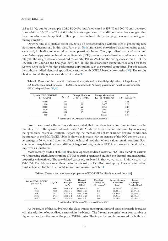
Aerospace 2018, 5, 110
16.1 ± 1.0 ◦C, but for the sample 1.0:1.0 ECO/PA (mol/mol) cured at 155 ◦C and 200 ◦C only increasedfrom −24.1 ± 0.3 ◦C to −23.9 ± 0.1 which is not significant. In addition, the authors suggest thatthese procedures can be applied to other epoxidized natural oils by changing the reagents, curing andmixing variables.
Other natural oils, such as castor oil, have also been epoxidized with the idea of generating newbio-sourced thermosets. In this case, Park et al. [38] synthesized epoxidized castor oil using glacialacetic acid, Amberlite, toluene and hydrogen peroxide solution. Then, epoxidized castor oil was curedusing N-benzylpyrazinium hexafluoroantimonate (BPH) previously tested in other studies as a cationiccatalyst. The weight ratio of epoxidized castor oil/BPH was 99:1 and the curing cycles were 110 ◦C for1 h, then 130 ◦C for 2 h and finally at 150 ◦C for 1 h. The glass transition temperature obtained for thesesystems were too low for high performance applications such as structural composites. For this reason,the authors studied blends of epoxidized castor oil with DGEBA based epoxy resins [39]. The resultsobtained for all the systems are shown in Table 3.
Table 3. Results of the dynamic mechanical analysis and of the diglycidyl ether of Bispehenol A(DGEBA)/epoxidized canola oil (ECO) blends cured with N-benzylpyrazinium hexafluoroantimonate(BPH) adapted from [39,40].
System (ECO 1:DGEBA)(wt %:wt %)
Tg (◦C)Storage Modulusat 30 ◦C (109 Pa)
Storage Modulus atTα + 30 ◦C (109 Pa)
ρ
(10−3 mol·cm−3)
0:100 197 1.27 0.102 4.6110:90 169 1.19 0.077 3.6820:80 158 1.22 0.065 3.1830:70 150 1.15 0.051 2.5440:60 131 1.15 0.041 2.13100:0 38 - 0.0079 0.57
1 In this table ECO means “Epoxidized Castor Oil”.
From these results the authors demonstrated that the glass transition temperature can bemodulated with the epoxidized castor oil/DGEBA ratio with an observed decrease by increasingthe epoxidized castor oil content. Regarding the mechanical behavior under flexural conditions,the strength of the ECO/DGEBA blends shows an increase with an increase of the ECO content up to apercentage of 30 wt % and does not affect the flexural modulus, whose values remain constant. Sucha behavior is explained by the addition of larger soft segments of ECO into the epoxy blend, whichimproves its toughness.
More recently, Sudha et al. [41] also developed epoxidized castor oil/DGEBA blends at variouswt % but using triethylenetetramine (TETA) as curing agent and studied the thermal and mechanicalproperties exhaustively. The epoxidized castor oil, analyzed in this work, had an initial viscosity of950–1050 cP which was lower than the initial viscosity of DGEBA based epoxy. The characterizationresults obtained for the different blends are summarized in Table 4.
Table 4. Thermal and mechanical properties of ECO:DGEBA blends adapted from [41].
Sample (ECO 1:DGEBA)(wt %:wt %)
Tg (◦C)Tensile
Strength(MPa)
FlexuralStrength
(MPa)
CrosslinkDensity, νe
(×103 mol/m3)
Impact StrengthUn-Notched
(J/m)
ImpactStrength
Notched (J/m)
0:100 96.64 70.18 ± 8 95.644 ± 3 2.81 58.23 ± 6 14.05 ± 210:90 91.37 50.79 ± 6 83.263 ± 28 2.43 87.20 ± 4 20.27 ± 220:80 71.37 54.22 ± 3 100.07 ± 18 2.33 120.53 ± 11 25.33 ± 230:70 47.44 42.41 ± 4 81.847 ± 26 1.15 59.31 ± 1 21.80 ± 150:50 39.21 18.26 ± 2 40.04 ± 7 0.66 31.25 ± 3 17.25 ± 1
1 In this table ECO means “Epoxidized Castor Oil”.
As the results of this study show, the glass transition temperature and tensile strength decreaseswith the addition of epoxidized castor oil in the blends. The flexural strength shows comparable orhigher values than the one of the pure DGEBA resin. The impact strength, measured for both Izod
114

Aerospace 2018, 5, 110
un-notched and notched specimens, increased with an increase of the ECO content into the blend.This is explained by the micrographs of the blends, showing the distribution of different sized particlesinto the cavities.
The research community has also started investigating with other less common oils such askaranja oil (KO), a natural oil extracted from karanja seeds (Pongamia Glabra) that mainly grows inIndia. However, not all the oil generated for human consumption is used and huge amounts of this oilfinish as a waste product. With the purpose of looking for solutions for this currently unprofitableproduct, Kadam et al. [42] epoxidized KO using hydrogen peroxide and acetic acid. Once the naturaloil was epoxidized they cured the samples using two curing agents: citric acid (CA) and tartaric acid(TA) at acid/epoxy equivalent weight ratio of 1:1. The authors tested the mechanical and thermalproperties, which are summarized in Table 5.
Table 5. Thermal and mechanical properties of epoxidized karanja oil (KO) cured with citric acid (CA)and tartaric acid (TA) adapted from [42].
Sample Tg (◦C) Tensile Strength (MPa) Young’s Modulus (E) (MPa) Shore Hardness (A)
Bioepoxy CA 1 112.70 10.60 2.65 56Bioepoxy TA 2 108.64 4.50 2.58 45
1 Cured with citric acid. 2 Cured with tannic acid.
The differences can be seen in the glass transition temperatures being 112.70 ◦C for the samplecured with citric acid and 108.64 ◦C for the sample cured with tannic acid. Moreover, the mechanicalproperties depend very closely on its composition and polymerization. In the case of tensile strength,the value for the bio-epoxy cured with citric acid is higher than for the cured with tannic acid.
Other strategies to generate bio-based epoxy resins based on natural oils have been developed inrecent years. This is the case of grapeseed and rapeseed oils which can be used as hardeners for epoxies.Stemmelen et al. [43], developed a novel vegetable oil-based polyamine from grapeseed oil (AGSO)through thiol-ene coupling reaction. The aminated curing agent was used to cure epoxidized linseedoil which was compared with ELO cured with tetrahydrophthalic anhydride (THPA) curing agentfrom the literature. The AGSO-ELO system exhibited a Tg of −38 ◦C, whereas the THPA-ELO systemexhibited a Tg about 80 ◦C. The authors interpreted that this extreme change on the glass transitiontemperature of these two systems can be explained due to the higher molecular flexibility of AGSOcompared with THPA. Manthey et al. [44], explored the thermo-mechanical properties of epoxidizedhemp oil based samples (EHO), as possible matrix material for jute fibre-reinforced bio-composites.A maximum concentration of 30% of EHO in a synthetic bisphenol A diglycidyl ether-based epoxycontrol, R246TX cured with a blend of triethylenetetramine and isophorone diamine, was investigated.Such an epoxy system was also studied in comparison with an ESO-based system with the samebio content. The EHO-based epoxy blends displayed slightly higher mechanical properties than thecorresponding ESO-based system. Furthermore, the EHO-based resin blend, when used as matrix forthe jute fibre-reinforced biocomposites, was found to be competitive with the commercially producedESO-based system.
In the work of Akesson et al. [45], two ESO based resins were synthesized and cured by meansof ultraviolet (UV) irradiation: particularly one resin was a synthesized methacrylic anhydridemodified soybean oil (MMSO) type and another resin was an acrylated epoxidized soybean oil(AESO). The MMSO resin had a storage modulus of 1800 MPa and a glass transition temperatureabove 150 ◦C and showed a tensile strength at break, over five specimens, of 24.4 ± 3.6 MPa.
3. Isosorbide Based Epoxy Resins
Isosorbide is a bio-derived diol with a structure based on two fused furan rings. It is obtainedfrom starch originated from depolymerization of biomass, which is firstly hydrolyzed to generateD-glucose [46]. Then, the D-glucose is hydrogenated to generate sorbitol which is dehydrated to
115

Aerospace 2018, 5, 110
obtain the isosorbide in a multi-step process [46]. Due to the versatility of its hydroxyl groups,isosorbide can be easily derivatized for use in some applications for pharma, detergency, cosmetics,or as a stabilizer or plasticizer [47]. Moreover, isosorbide has recently become a solution for thegeneration of new bio-based thermoplastics and thermosets, such as epoxy resins. As reported byHong et al. [48], isosorbide rigidity and thermal stability provided by its structure allows its use asan alternative monomer to bisphenol-A (BPA) in epoxy resins: diglycidyl ether of isosorbide (DGEI).This monomer can be obtained through different ways: epoxidation of isosorbide diallyl ether, reactionof isosorbide with epichlorohydrin in presence of Lewis acid or alkali hydroxides, or through reactionof isosorbide disodium alcoholate with epichlorohydrin. In that study, isosorbide resins and controlDGEBA resin were cured with diethylene triamine (DETA) and isosorbide diamine (ISODA). Anextensive experimental campaign was also conducted to determine the thermo-mechanical propertiesof the isosorbide-based resin from corn and some of the results are reported in Table 6.
Table 6. Thermal and mechanical properties of isosorbide-based resin adapted from [48].
Sample Tg (◦C) *Tensile Strength
(MPa) **
YoungModulus(MPa) **
FlexuralModulus(MPa) **
ImpactStrength(J/m) **
DGEBA/DETA 129 (134) 26 (8.2%) 1389 (4.7%) 3061 (1.6%) 60 (1.2%)DGEBA/ISODA 74 (79) 67 (4%) 1825 (4.5%) 3364 94 (65%)
DGEI(mono)/DETA 75 (76) 62 (9%) 1798 (1.2%) 4027 72 (16.8%)DGEI(mono)/ISODA 32 (43) 41 (21%) 1532 (2.6%) 1168 65 (23%)
DGEI(polymeric)/ISODA 36 (43) 52 (8.1% 2461 (9.5%) 3520 57 (14.7%)DGEI(polymeric)/DETA 48 (63) 52 (18%) 1774 (8%) 2747 113 (33%)
* Values in brackets are obtained after post-curing at 150 ◦C for 2 h. ** Values in brackets-coefficient of variation.Those without coefficient of variation are based on one specimen.
The isosorbide-based resins showed glass transition temperatures of about 60 ◦C lower than thosefrom DGEBA/DETA, and comparable or better tensile and impact strength than commercial epoxyresins. Moreover, rheological tests were performed to the curing mixtures. The initial viscosity valuesfor the DGEI/ISODA and DGEI/DETA were found to be below the 10,000 cP, which are values similarto the commercial DGEBA (from 10,000 to 25,000 cP using the same curing agents), as compared withnatural oils.
Feng et al. [49], prepared bisisorbide diglycidyl ether through isosorbide reaction withepichlorohydrin under alkali conditions. The resulting resin was then cured using an aliphaticamine Jeffarnine T403 and compared with EPON 826, a diglycidyl ether of bisphenol A cured usingthe same curing agent. The tensile strength of the cured isosorbide-based epoxy and the DGEBA wereon average 68.8 MPa and 66.2 MPa, respectively. This means that the tensile strength of the bisphenolA is 96% of the isosorbide-based epoxy. The impact strength of the isosorbide-based epoxy was 40%higher compared with the DGEBA based epoxy with average values of 3.87 J/cm and 6.42 J/cmrespectively. However, the Tg of isosorbide-based epoxy systems was usually lower than the Tg of theDGEBA based epoxy thermosets (48 ◦C compared with 90 ◦C respectively). This is because of the highhydrophilicity of the isosorbide and the diamine, but it can be optimized with other curing agents suchas methyl-5-norbornene-2,3-dicarboxylic anhydride with catalyst benzyl dimethyl amine (BDMA) orwith 4,4′-(hexafluoro-isopropylidene) diphthalic anhydride that allows an increase of its Tg to 113 ◦Cand 200 ◦C respectively.
Łukaszczyk et al. [50], compared the properties of isosorbide epoxy resins (IS-EPO) curedwith phthalic anhydride (PHA), tetrahydrophthalic anhydride (TPHA), triethylenetetramine (TETA),isophoronediamine (IPHA) with the properties of Epidian 5 DGEBA based epoxy resin. This studyalso confirmed that, in most of the cases, the mechanical properties of isosorbide based epoxy resins,such as flexural and compression strength and modulus, Brinell hardness, Izod impact strength, werefound to be comparable to, or better than, the properties of DGEBA based epoxy resins, as reportedin Table 7.
116

Aerospace 2018, 5, 110
Table 7. Mechanical and Tg properties of Epidian 5 and isosorbide based epoxy resin systems curedwith phthalic anhydride (PHA), tetrahydrophthalic anhydride (TPHA), triethylenetetramine (TETA)and isophoronediamine (IPHA) adapted from [50].
SampleComposition
Tg (◦C)Flexural
Strength (MPa)Compression
Strength (MPa)Brinell Hardness
(MPa)Izod Impact
Strength (kJ/m2)
Epidian 5/PHA 171 158.4 290.8 198.0 7.2IS-EPO/PHA 108 225.5 254.1 202.4 30.9
Epidian 5/THPHA 172 27.9 122.2 209.4 4.1IS-EPO/THPHA 95 100.5 88.8 214.3 2.9Epidian 5/TETA 116 170.8 234.2 212.1 9.5
IS-EPO/TETA 49 228.3 311.6 193.8 20.8Epidian 5/IPHA 141 175.4 193.9 231.2 13.5
IS-EPO/IPHA 73 158.5 318.1 205.7 33.8
However, the Tg of isosorbide-based epoxy resins is, in all cases, lower than the DGEBA basedones. The kinematic viscosity obtained for the IS-EPO samples before the curing was 60,120 cP, whichis higher than the values of the Epidian based samples (25,000 cP).
In 2013, Sadler et al. [51] synthetized isosorbide-methacrylate (IM) by the direct esterification ofisosorbide using methacryloyl chloride or methacrylic anhydride and a base catalyst. The IM was alsoblend in a vinyl-ester (VE) resin. The IM-based VE resin possessed a Tg higher than that of any knowncommercial vinyl ester resins. Very interesting mechanical properties were found out, such as quitehigh flexural strength and modulus of the neat IM. Those properties make it classifiable in the range ofhigh-performance materials.
In 2017, Liu et al. [52] synthetized isosorbide-methacrylate (IM), from isosorbide with methacrylateanhydride (MAA) via a solvent-free, ultrasonic-assisted method. It was then to copolymerize anacrylated epoxidized soybean oil (AESO), finally obtaining a biobased thermosetting resin (IM-AESO).A second system was obtained by further modifying the AESO with MAA to replace the hydroxylgroups with methacrylate groups, thus generating a resin (IM-MAESO). The soybean oil-based resinsblended with IM as an RD shows superior processability due to the low viscosity. The mechanicalproperties, such as flexural strengths, flexural moduli, storage moduli were investigated, showinghigh values. These aspects together with the superior processability make these two resins systemssuitable for potential application in fiber-reinforced composites.
4. Furan Based Epoxy Resins
Furan resins have recently appeared as a new bio-based alternative to phenolic resins due totheir aromaticity and mechanical properties. The origin of furanyl building blocks usually starts fromfurfural, which is transformed to furfuryl alcohol through their hydrogenation [53,54]. Furfural isobtained by chemical dehydration of five carbon carbohydrates, such as xylose and arabinose byfractionation of hemicellulose from bagasse, left over from sugar cane processing and also from corncobs or other biomass waste [55,56]. The structure of furfural is shown in Figure 1.
Figure 1. Furfural structure.
117

Aerospace 2018, 5, 110
Apart from furfural and furfuryl alcohol derived from five carbon carbohydrates, there arealso other building blocks able to be polymerized to obtain different furan resins with somepromising properties that could be useful for aircraft applications. However, these are still underdevelopment and they are not yet implemented in the industrial field. One important example is5-Hydroxymethylfurfural HMF, which is obtained by hexoses dehydration [53].
Main monomers used for furan building blocks can be obtained from bio-sources which allowreduction of carbon footprint of final polymeric material. A list of the most important ones and itsmarket availability is shown in Table 8.
Table 8. Bio-sourced building blocks for furan resins.
Furanyl Monomer Source Status
Furfural (F) Sugar cane bagasse or corn cobs (derived from pentoses) CommercialFurfuryl alcohol (FA) from furfural. Commercial
5-Hydroxymethylfurfural (HMF) Plant based sugars (derived from hexoses) Commercial2-Furfurylmethacrylate (FM) From HMF or furfural Non-commercial
Bis-2,5-hydroxymethylfuran (BHMF) From HMF or furfural Non-commercial2,5-Furandicarboxylic acid (FDCA) From HMF or furfural Commercial
Currently, epoxidized furanyl building blocks are not up-scaled and commercially available.However, some researchers have studied the functionalization of raw furan monomers F and HMF inorder to synthesize new epoxy building blocks. This is the case of Cho et al. [57], who reported thepreparation of furan monoepoxide, 2,5-bis[(2-oxiranyl-methoxy) methyl]-furan (BOF) and bis-furandiepoxide. These monomers were photo-cured using IRGACURE 250 and triphenylsulfoniumhexafluoroantimonate salt (TSAS, 50% in propylene carbonate) as cationic crosslinking agents andtheir properties for adhesive industry were investigated.
The furanic compounds functionalized by epoxide group(s) were used for bonding polycarbonate(PC) by cationic photo-curing and with petrochemical-based phenyl glycidyl ether (PGE) havinga phenyl ring. Specimens of the bonded joint for the measurement of tensile-shear strength wereprepared and tested. PC joints bonded by both compounds biomass-based furan monoepoxide (FmE)and PGE petroleum-based epoxy were prepared. The strength of bonded PC joints (FmE) showedbetter performance as an adhesive than PGE. The authors attributed the lower tensile-shear strengthsof PC joints bonded by Furan diepoxide (FdE) and bis-furan di-epoxide (bFdE) to their rigid structureand hydrophobic property.
Hu et al. [58] synthesized 2,5-Bis[(2-oxiranylmethoxy)methyl]-furan (BOF) and 1,4-Bis[(2-oxiranylmethoxy)methyl]-benzene (BOB) monomers and cured them using PACM and EPIKUREW as curing agents. Both monomers were low viscosity liquids with really good processability.The authors also blended the two furanyl monomers with DGEBA and performed a thermo-mechanicalcharacterization. The results of the Tg values (obtained from DMA analysis) are shown in Table 9.
From these results, the authors determined that for the samples cured with EPIKURE W theTg values are always higher compared with the samples cured with PACM. This fact is due to thearomatic structure of EPIKURE W. Another observation was that for BOF systems cured with eithercuring agents the Tg values and the storage modulus are higher than for the BOB systems. A possibleexplanation for this success could be the higher possibility of creating hydrogen bonds between theoxygen atoms of the furan rings and the hydroxyl groups created during the epoxy group openingduring the reaction with the curing agents for BOF. Another explanation could be the differences inrotation of the furan rings due to their structures.
In another study, Hu et al. [59] also developed a new bio-based curing agent based on furanchemistry in order to create full furan based thermosetting resins. To achieve this aim, the authorsprepared 5,5′-Methylenedifurfurylamine (DFDA) and 5,5′-Ethylidenedifurfurylamine (CH3-DFDA)as curing agents and compared the Tg values obtained from DMA thermograms. BOF/DFDA andBOF/CH3-DFDA samples exhibited Tg values of 69 and 62 ◦C, respectively, which allows for explainingthe positive effect of the methyl group on the Tg value for CH3 DFDA cured BOF. On the other hand,
118

Aerospace 2018, 5, 110
PACM cured BOF showed a Tg of 72 ◦C, a higher value compared with DFDA and CH3- DFDA curedsamples due to the connection to the furan rings through the methylene groups and amine groups.The samples of DGEBA cured with the same curing agents showed higher Tg values as it was expected(121 ◦C, 128 ◦C and 168 ◦C for DGEBA/DFDA, DGEBA/CH3-DGBA and DGBA/PACM respectively).
Table 9. Tg values of 2,5-bis[(2-oxiranyl-methoxy) methyl]-furan (BOF), 1,4-Bis[(2-oxiranylmethoxy)methyl]-benzene (BOB) and DGEBA mixtures cured with PACM and EPIKURE W adapted from [58].
Weight Ratio Monomers(BOF:BOB:DGEBA)
Tg (◦C)
PACM EPIKURE W
100:0:0 71 (80) 1 88 (94)70:0:30 96 (106) 114 (120)50:0:50 111 (121) 133 (139)30:0:70 131 (140) 153 (160)0:100:0 55 (63) 80 (90)0:70:30 84 (94) 104 (103)0:50:50 103 (114) 126 (136)0:30:70 124 (134) 148 (159)0:0:100 167 (176) 185 (198)
1 Tg in parentheses is the value obtained from maximum of tan δ curve from DMA.
The authors investigated the tensile and fracture properties of BOF/PACM, BOB/PACM andDGEBA/PACM samples. In terms of tensile maximum stress, the BOF/PACM, BOB/PACM showsslightly lower values when compared to the DGEBA/PACM system; while in terms of the critical stressintensity factor (K1C) and critical strain energy release rate (G1C) values, BOF/PACM sample showssuperior fracture toughness properties compared with BOB/PACM and DGEBA/PACM samples.Further studies about the mechanical characterization are also reported in Hu et al. [60].
On the other hand, Deng et al. [61] prepared diglycidyl ester of 2,5-furandicarboxylic acid (DGF)and compared its properties to the petroleum-based counterpart diglycidyl ester of terephthalicacid (DGT). The curing agents used were methylhexahydrophthalic anhydride (MHHPA) andpoly(propylene glycol)bis(2-aminopropyl ether) (D230) as the rigid and soft curing agents respectively.The synthesis of DGF was performed using 2,5-Furandicarboxylic acid (FDCA) as raw material whichwas first used to generate bis(prop-2-enyl)furan-2,5-dicarboxylate (FDCE). The equivalent ratio ofMHHPA and DGF or DGT was 1:1 respectively and the mixtures were cured at 100 ◦C during 2 h,130 ◦C during 2 h and 150 ◦C during 2 h. The thermal and mechanical properties of the differentsamples developed in this study are listed in Table 10.
Table 10. Thermal and mechanical properties of diglycidyl ester of 2,5-furandicarboxylic acid (DGF),diglycidyl ester of terephthalic acid (DGT) and DGEPA resins cured with methylhexahydrophthalicanhydride (MHHPA) and D230 adapted from [61].
Sample Tg (◦C)Tensile Strength
(MPa)Tensile Modulus
(MPa)Flexural Strength
(MPa)Flexural Modulus
(MPa)
DGF/MHHPA 152 84 ± 4 3000 ± 50 96 ± 3 3100 ± 110DGT/MHPPA 128.8 78 ± 2 3080 ± 80 90 ± 5 2950 ± 40
DGF/D230 101.2 68 ± 3 2700 ± 110 75 ± 2 2500 ± 90DGT/D230 91.8 64 ± 2 2800 ± 60 73 ± 3 2400 ± 100
DGEBA/MHHPA 125 68 2900 135 3400DGEBA/D230 97 NA NA 121 2950
The results obtained from the thermal and mechanical analysis show that DGF systems havehigher Tg, and mechanical properties compared with DGT systems. Moreover, these two systemsshow comparable properties to the DGEBA based ones. This fact allows for confirming that bio-basedepoxy resins obtained from FDCE have a high potential as petrol-sourced epoxy alternatives.
119

Aerospace 2018, 5, 110
5. Phenolic and Polyphenolic Epoxies
Polyphenols can be classified in different classes depending on the strength of the phenolicring: phenolic acids, flavonoids, stiblins, phenolic alcohols and lignans [62]. Natural polyphenolicand phenolic structures are interesting due to their mechanical properties and thermal stability thatthey confer to the epoxy resins. For this reason, some researchers have focused their activity on thefunctionalization and preparation of epoxy resins based on natural phenolic or polyphenlic structures.
Tannins are natural polyphenolic structures generally obtained from black mimosa bark,quebracho wood, oak bark, chestnut wood, mangrove wood, Acacia catechu, Uncaria gambir, sumach,myrabolans, divi-divi, algarobilla chilena, tara, and bark of several pine species [63]. Tannins can bemainly classified depending on their structures as hydrolysable tannins and polyflavonoid tannins [63].
Catechin is one of the main components of tannins and one of the most studied naturalpolyphenol for the generation of new epoxy resins. Epoxidation of catechin was firstly examinedby Nouailhas et al. [64] as a laboratory model with the aim of studying the reactivity of tannins aspotential substitutes for BPA. The authors also used resorcinol and 4-methylcatechol in order to mimicthe A- and B-rings of catechin. The glycidylation of rescorcinol, 4-methylcatechol and catechin wasperformed using epichlorohydrin. The final products were then identified, and their structures wereconfirmed by Nuclear Magentic Resonance (NMR) and Furier-transform Infrared Spectroscopy (FTIR).Finally, some formulations were prepared blending glycidyl ether of catechin (GEC) with DGEBAresin in order to reduce the initial viscosity of initially solid GEC. Then the samples were analysed byDynamic Mechanical Analysis once cured at 60 ◦C for 24 h with Epamine PC 19. This curing agentprovides low viscosity and fast curing capabilities. The results obtained are shown in Table 11.
Table 11. Tg values and mechanical properties of DGEBA/glycidyl ether of catechin (GEC) blendscured with Epamine PC 19 adapted from [64].
Sample Tg (◦C)Storage Modulus (GPa)
at 30 ◦CStorage Modulus (GPa)
at Tg + 30 ◦C
DGEBA 209 2.81 0.01975DGEBA/25GEC 221 2.46 0.01650DGEBA/50GEC 202 2.40 0.014
Some of the authors of the previous work also participated in a study published in 2014 [65] withthe aim of continuing the study on model phenolic monomers but now using tannins directly extractedfrom green tea. In this work, Benyahya et al. [65] also used epichlorohydrin for the epoxidation of thetannins extracted from green tea with BnEt3NCl as phase transfer catalyst. After curing blends of GEC,glycidyl ether of green tea extract (GEGTE) and a DGEBA epoxy resin (DER 352) with isophoronediamine (IPDA) in a 1:1 molar ratio of epoxy groups, dynamic mechanical analysis was also performed.Some of the main results are shown in Table 12.
Table 12. Tg values and mechanical properties of GEC, glycidyl ether of green tea extract (GEGTE) andDGEBA based epoxy resins cured with isophorone diamine (IPDA) adapted from [65].
Sample Tg (◦C)Storage Modulus (GPa)
at 30 ◦CStorage Modulus (GPa)
at Tg + 30 ◦C
GEGTE-IPDA 142 2.34 0.0593GEC-IPDA 179 1.50 0.0364
DER352-IPDA 140 1.29 0.0136
120

Aerospace 2018, 5, 110
The authors observed similar values for GEGTE-IPD and DER352-IPD systems, but a higher valuewas observed for the GEC-IPD. This could be explained by the higher presence of glycidyl groupsthat allows higher crosslinking density. Another explanation that the authors give is that, althoughGEGTE-IPD could have high functionality, a reduction of the crosslinking density could be causedby the presence of dimmers of gallate. However, gallic acid groups could reinforce the GEGTE-IPDsystem that shows higher storage modulus than GEC-IPD and DER352-IPD.
Basnet et al. [66] used a lignin derivative as curing agent. The glycidylation process of catechinwas performed using epichlorohydrin under alkaline conditions and with the presence of TMAC asphase transfer catalyst. The authors also synthesized glycidyl ether of heat dried green tea extract(GEHDGTE), glycidyl ether of freeze-dried green tea extract (GEFDGTE), glycidyl ether of standardcatechin (GEC), as well as EP828 (a commercial DGEBA based epoxy resin) and compared theirproperties. Glass transition temperature and flexural strength results are shown in Table 13.
Table 13. Tg values and flexural strength of GEC, glycidyl ether of heat dried green tea extract(GEHDGTE), glycidyl ether of freeze-dried green tea extract (GEFHDGTE) and BPA based epoxiescured with a lignin derivative adapted from [66].
Sample Tg (◦C) Flexural Strength (MPa)
GEC-Lignin 178 63GEHDGTE-Lignin 155 56
GEFHDGTE-Lignin 173 40BPA-Lignin 150 29
In this study, the authors demonstrated the potential applicability of these materials for electronicapplications also due to the temperature resistance of the formulations that were similar or higherthan for DGEBA based epoxy resins. The mechanical flexural properties were found to be muchhigher than the corresponding DGEBA-Lg. The authors attributed the higher rigidity of the newlignin-based compounds to the combination of aromatic raw material of low molecular weight and thehard segment of the lignin, as curing agent, which has average molecular weight.
Other phenolic biomolecules, such as gallic acid, have also been considered as a potential sourcefor bio-based epoxy thermosetting resins. Gallic acid or its derivatives are present in grapes, tea,gallnuts, oak bark, some fruits, vegetables, honey and can also be found in plant tissues [67–71].The phenolic structure of gallic acid is shown in Figure 2.
Figure 2. Gallic Acid.
Tomita et al. [72], presented a patent where they epoxidized gallic acid or tannic acidwith epichlorohydrin in presence of a phase transfer catalyst. They cured the resulting epoxiesusing 3,6-endomethylene-l,2,3,6-tetrahydromethylphthalic anhydride (Methylhimic Anhydride) andbenzyldimethylamine at different proportions. The curing conditions were 100 ◦C for 3 h andthen 150 ◦C for 15 h. Finally, they compared the heat deflection temperature of these systemswith Epikote 828, a DGEBA derivative epoxy resin and the results showed higher values for thebio-based systems.
121

Aerospace 2018, 5, 110
On the other hand, Aouf et al. [73] synthesized epoxy resin prepolymers based on natural phenoliccompounds such as gallic and vanillic acids. The strategy used by those authors was to synthesize theallylated phenolic before the epoxidation of the double bonds using caprylic acid as oxygen carrier andNovozym 435, an immobilized lipase B from Candida Antarctica, as a biocatalyst. This method wasthen compared with the epoxidation using the peracid mCPBA, which showed lower yields comparedwith the curing process using mCPBA.
Recently, Tarzia et al. [74], slightly modified the epoxidation method previously used byAouf et al. [73]. In this study, tri- and tetra-glycidyl ethers of gallic acid (GEGAs) were obtainedand cured with three different curing agents: a cycloaliphatic primary amine, isophorone diamine(IPDA), and Jeffamine D-230 (DPG). Moreover, they used N,N-dimethylbenzylamine (BDMA) as anionic initiator. The Tg values and mechanical properties of each system are collected in Table 14.
Table 14. Tg values and mechanical properties of GEGA and DGEBA cured with IPDA, DPG andN-dimethylbenzylamine (BDMA) adapted from [74].
Sample Tg (◦C)Tensile Modulus
(GPa)Tensile Strength
(MPa)Elongation at
Break (%)
GEGA/IPDA 158 3.6 ± 0.3 43.1 ± 13.1 1.4 ± 0.3GEGA/DPG 98 3.5 ± 0.2 70.6 ± 2.9 6.1 ± 0.6GEGA/BDMA 136 3.2 ± 0.2 31.2 ± 2.3 1.1 ± 0.1DGEBA/IPDA - 3.1 ± 0.8 34.1 ± 2.0 1.7 ± 0.2DGEBA/DPG - 3.0 ± 0.2 116.4 ± 7.0 8.6 ± 0.3
The GEGA/DPG system is the one with lower Tg values which can be explained due to theflexibility and linearity of the DPG backbone. On the other hand, IPDA showed the higher Tg value.This can be explained due to a higher crosslinking density and more rigidity due to the IPDA ring.Comparing the mechanical properties, DPG cured system showed improved strength compared withthe IPDA and BDMA systems. However, DGEBA/DPG system showed higher tensile strength andelongation at break compared with the GEGA/DPG system. This result can be attributed to the GEGAstructure, which is stiffer due to the single aromatic ring compared with DGEBA and with higherfunctionality. Regarding the elastic modulus, the GEGA systems showed an elastic modulus slightlyhigher than the one corresponding to the DGEBA systems. The viscosity value obtained for the GEGAprecursor was found to be 2000 cP before curing. This value is lower than the one of typical commercialDGEBA systems, that ranges from 11,000 to 15,000 cP [75] and can reach higher values depending onthe formulation.
In 2013, Cao [76] derived a bio-based epoxy monomer GA-II from renewable gallic acid.An extensive experimental campaign was performed by investigating the mechanical propertiesin terms of tensile strength and modulus, where values of 66 MPa and 1970 MPa were respectivelyreached, and flexural strength and modulus, where values of 128 MPa and 3050 MPa were reached.
Tannic acid has also been considered as an interesting candidate to be used as acuring agent forepoxy resins. Tannic acid is a polyphenol currently commercial as a mixture of gallotannins. Somestudies have been carried out with the aim of generating epoxy thermosets from tannic acid. This is thecase of Shibata et al. [77], that used commercial tannic acid as curing agent to prepare composites withglycerol polyglycidyl ether (GPE) and sorbitol polyglycidyl ether (SPE). The mechanical propertiesand Tg values of each system are shown in Table 15.
Table 15. Tg values and tensile strength of glycerol polyglycidyl ether (GPE) and sorbitol polyglycidylether (SPE) cured with TA adapted from [77].
Sample Epoxy/–OH Tg (◦C) [TMA] Tensile Strength (MPa)
GPE-TA 1.0 87.3 36.7SPE-TA 1.0 106.6 60.6
122

Aerospace 2018, 5, 110
SPE cured with TA samples showed higher Tg values compared with GPE samples. This resultcan be explained by the higher functionality of SPE compared with GPE. For the same reason,the mechanical properties of SPE have a higher result than the GPE ones.
Cardanol is another phenolic molecule obtained from cashew nut shell liquid extracts [78,79].The structure of cardanol is shown in Figure 3.
Figure 3. Cardanol.
One of the multiple and recent proposes for cardanol is to use it as a green raw material for theproduction of various polymers types, such as polyurethanes or Novolac resins. Green epoxy resinshave been produced in some studies through the epoxidation of cardanol or using it as a curing agent.In 2004, Maffezzoli et al. [80] demonstrated the effectiveness of cardanol as a green building blockfor thermosetting epoxy matrix. The samples were cured using an amine curing agent and an acidcatalyst and mixed with DGEBA resins. The sample with the resol and DGEBA in a stoichiometricratio and with acid catalyst showed a tensile strength of 12 ± 2.2 MPa and a modulus of 864 ± 79 MPa;its values of deformation under tensile load also resulted to be higher than the resol DGEBA systemnot containing acid catalyst.
In 2008, Unnikrishnan et al. [75], epoxidized cardanol using epichlorohydrin in presence of causticsoda catalyst and compared the results with DGEBA based resins. Some of the mechanical propertiesobtained from these samples have been collected in Table 16.
Table 16. Mechanical properties of cured BPA/cardanol epoxy blends adapted from [75].
SampleTensile
Strength (MPa)Compressive
Strength (MPa)Elongation
at Break (%)Flexural
Strength (MPa)Impact Strength
(Izod, J/m)Young’s
Modulus (MPa)
CommercialDGEBA 48.0 108 3.1 91.45 28.5 2420
BPA/cardanolepoxy (80:20) a 31.7 92.55 5.68 80.8 22.25 2045
BPA/cardanolepoxy (50:50) 23.5 78 8.42 71.45 20.4 1926
a Molar compositions.
The authors of this study demonstrated that the introduction of epoxidized cardanol in DGEBAresins produces a decrease of the tensile, compressive and Izod impact strengths and it does not havemuch influence on the elongation-at-break. However, the introduction of cardanol can reduce thebrittleness of the epoxy systems making them more flexible, as shown by the higher values of flexuralmodulus and strength of these values, comparable with the commercial liquid epoxy resins whichhave a viscosity of 11,000–15,000 cP [75].
Jaillet et al. [81], used a commercial epoxidized cardanol to generate new green epoxies in 2014.The commercial name of the epoxidized cardanol is NC-514 from Cardolite which was then curedusing IPDA and Jeffamine D400. The maximum Tg values obtained for each system were 50 ◦C whencured with IPDA and 15 ◦C when cured with Jeffamine D400. These values are too low for mostepoxy applications that require higher thermal and mechanical properties. To solve this problem,Darroman et al. [82] proposed to use epoxy blends with epoxidized cardanol to improve the finalthermomechanical properties. The authors used isophorone diamine (IPDA) and Jeffamine T403 as
123
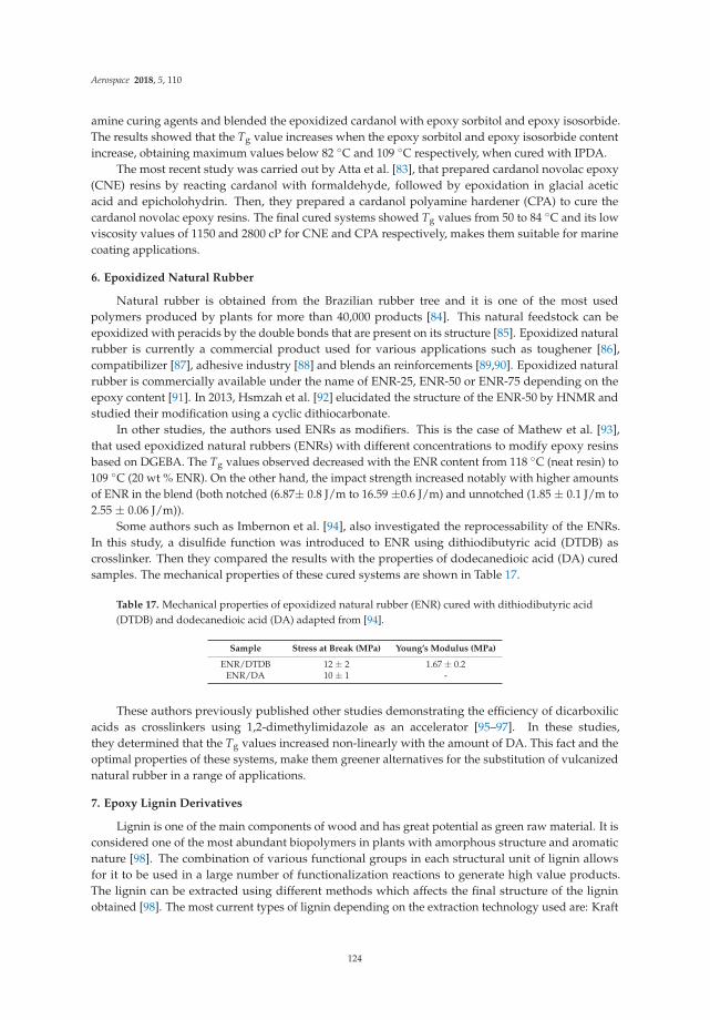
Aerospace 2018, 5, 110
amine curing agents and blended the epoxidized cardanol with epoxy sorbitol and epoxy isosorbide.The results showed that the Tg value increases when the epoxy sorbitol and epoxy isosorbide contentincrease, obtaining maximum values below 82 ◦C and 109 ◦C respectively, when cured with IPDA.
The most recent study was carried out by Atta et al. [83], that prepared cardanol novolac epoxy(CNE) resins by reacting cardanol with formaldehyde, followed by epoxidation in glacial aceticacid and epicholohydrin. Then, they prepared a cardanol polyamine hardener (CPA) to cure thecardanol novolac epoxy resins. The final cured systems showed Tg values from 50 to 84 ◦C and its lowviscosity values of 1150 and 2800 cP for CNE and CPA respectively, makes them suitable for marinecoating applications.
6. Epoxidized Natural Rubber
Natural rubber is obtained from the Brazilian rubber tree and it is one of the most usedpolymers produced by plants for more than 40,000 products [84]. This natural feedstock can beepoxidized with peracids by the double bonds that are present on its structure [85]. Epoxidized naturalrubber is currently a commercial product used for various applications such as toughener [86],compatibilizer [87], adhesive industry [88] and blends an reinforcements [89,90]. Epoxidized naturalrubber is commercially available under the name of ENR-25, ENR-50 or ENR-75 depending on theepoxy content [91]. In 2013, Hsmzah et al. [92] elucidated the structure of the ENR-50 by HNMR andstudied their modification using a cyclic dithiocarbonate.
In other studies, the authors used ENRs as modifiers. This is the case of Mathew et al. [93],that used epoxidized natural rubbers (ENRs) with different concentrations to modify epoxy resinsbased on DGEBA. The Tg values observed decreased with the ENR content from 118 ◦C (neat resin) to109 ◦C (20 wt % ENR). On the other hand, the impact strength increased notably with higher amountsof ENR in the blend (both notched (6.87± 0.8 J/m to 16.59 ±0.6 J/m) and unnotched (1.85 ± 0.1 J/m to2.55 ± 0.06 J/m)).
Some authors such as Imbernon et al. [94], also investigated the reprocessability of the ENRs.In this study, a disulfide function was introduced to ENR using dithiodibutyric acid (DTDB) ascrosslinker. Then they compared the results with the properties of dodecanedioic acid (DA) curedsamples. The mechanical properties of these cured systems are shown in Table 17.
Table 17. Mechanical properties of epoxidized natural rubber (ENR) cured with dithiodibutyric acid(DTDB) and dodecanedioic acid (DA) adapted from [94].
Sample Stress at Break (MPa) Young’s Modulus (MPa)
ENR/DTDB 12 ± 2 1.67 ± 0.2ENR/DA 10 ± 1 -
These authors previously published other studies demonstrating the efficiency of dicarboxilicacids as crosslinkers using 1,2-dimethylimidazole as an accelerator [95–97]. In these studies,they determined that the Tg values increased non-linearly with the amount of DA. This fact and theoptimal properties of these systems, make them greener alternatives for the substitution of vulcanizednatural rubber in a range of applications.
7. Epoxy Lignin Derivatives
Lignin is one of the main components of wood and has great potential as green raw material. It isconsidered one of the most abundant biopolymers in plants with amorphous structure and aromaticnature [98]. The combination of various functional groups in each structural unit of lignin allowsfor it to be used in a large number of functionalization reactions to generate high value products.The lignin can be extracted using different methods which affects the final structure of the ligninobtained [98]. The most current types of lignin depending on the extraction technology used are: Kraft
124
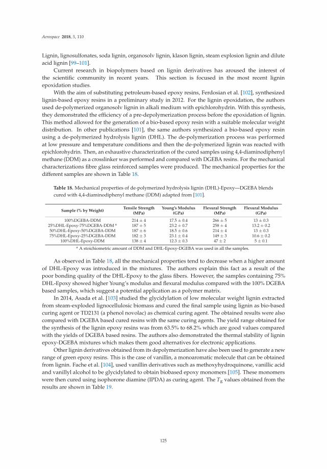
Aerospace 2018, 5, 110
Lignin, lignosulfonates, soda lignin, organosolv lignin, klason lignin, steam explosion lignin and diluteacid lignin [99–101].
Current research in biopolymers based on lignin derivatives has aroused the interest ofthe scientific community in recent years. This section is focused in the most recent ligninepoxidation studies.
With the aim of substituting petroleum-based epoxy resins, Ferdosian et al. [102], synthesizedlignin-based epoxy resins in a preliminary study in 2012. For the lignin epoxidation, the authorsused de-polymerized organosolv lignin in alkali medium with epichlorohydrin. With this synthesis,they demonstrated the efficiency of a pre-depolymerization process before the epoxidation of lignin.This method allowed for the generation of a bio-based epoxy resin with a suitable molecular weightdistribution. In other publications [101], the same authors synthesized a bio-based epoxy resinusing a de-polymerized hydrolysis lignin (DHL). The de-polymerization process was performedat low pressure and temperature conditions and then the de-polymerized lignin was reacted withepichlorohydrin. Then, an exhaustive characterization of the cured samples using 4,4-diaminodiphenylmethane (DDM) as a crosslinker was performed and compared with DGEBA resins. For the mechanicalcharacterizations fibre glass reinforced samples were produced. The mechanical properties for thedifferent samples are shown in Table 18.
Table 18. Mechanical properties of de-polymerized hydrolysis lignin (DHL)-Epoxy—DGEBA blendscured with 4,4-diaminodiphenyl methane (DDM) adapted from [101].
Sample (% by Weight)Tensile Strength
(MPa)Young’s Modulus
(GPa)Flexural Strength
(MPa)Flexural Modulus
(GPa)
100%DGEBA-DDM 214 ± 4 17.5 ± 0.4 266 ± 5 13 ± 0.325%DHL-Epoxy-75%DGEBA-DDM a 187 ± 5 23.2 ± 0.7 258 ± 4 13.2 ± 0.250%DHL-Epoxy-50%DGEBA-DDM 187 ± 6 18.5 ± 0.6 214 ± 4 13 ± 0.375%DHL-Epoxy-25%DGEBA-DDM 182 ± 3 23.1 ± 0.4 149 ± 3 10.6 ± 0.2
100%DHL-Epoxy-DDM 138 ± 4 12.3 ± 0.3 47 ± 2 5 ± 0.1a A stoichiometric amount of DDM and DHL-Epoxy-DGEBA was used in all the samples.
As observed in Table 18, all the mechanical properties tend to decrease when a higher amountof DHL-Epoxy was introduced in the mixtures. The authors explain this fact as a result of thepoor bonding quality of the DHL-Epoxy to the glass fibers. However, the samples containing 75%DHL-Epoxy showed higher Young’s modulus and flexural modulus compared with the 100% DGEBAbased samples, which suggest a potential application as a polymer matrix.
In 2014, Asada et al. [103] studied the glycidylation of low molecular weight lignin extractedfrom steam-exploded lignocellulosic biomass and cured the final sample using lignin as bio-basedcuring agent or TD2131 (a phenol novolac) as chemical curing agent. The obtained results were alsocompared with DGEBA based cured resins with the same curing agents. The yield range obtained forthe synthesis of the lignin epoxy resins was from 63.5% to 68.2% which are good values comparedwith the yields of DGEBA based resins. The authors also demonstrated the thermal stability of ligninepoxy-DGEBA mixtures which makes them good alternatives for electronic applications.
Other lignin derivatives obtained from its depolymerization have also been used to generate a newrange of green epoxy resins. This is the case of vanillin, a monoaromatic molecule that can be obtainedfrom lignin. Fache et al. [104], used vanillin derivatives such as methoxyhydroquinone, vanillic acidand vanillyl alcohol to be glycidylated to obtain biobased epoxy monomers [105]. These monomerswere then cured using isophorone diamine (IPDA) as curing agent. The Tg values obtained from theresults are shown in Table 19.
125
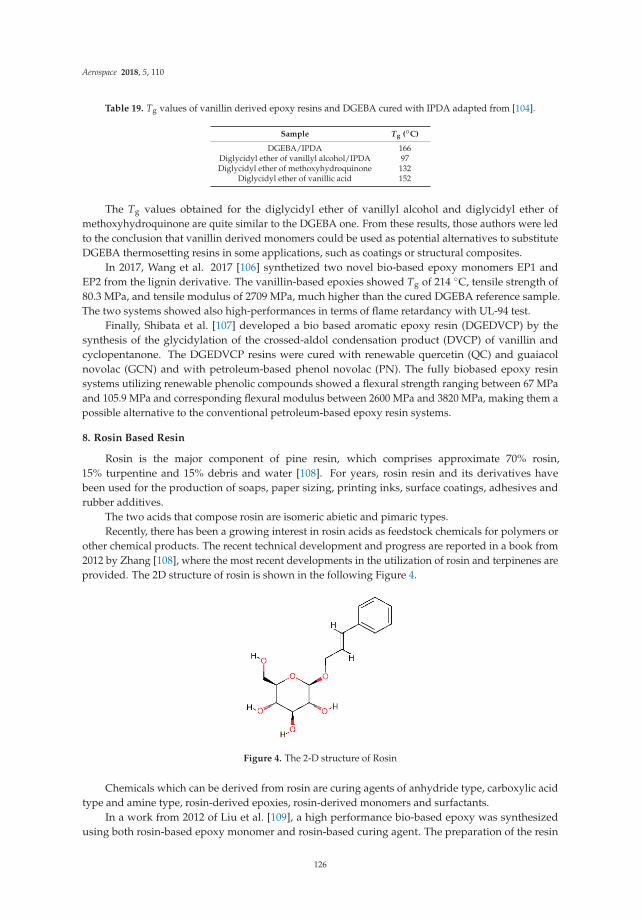
Aerospace 2018, 5, 110
Table 19. Tg values of vanillin derived epoxy resins and DGEBA cured with IPDA adapted from [104].
Sample Tg (◦C)
DGEBA/IPDA 166Diglycidyl ether of vanillyl alcohol/IPDA 97Diglycidyl ether of methoxyhydroquinone 132
Diglycidyl ether of vanillic acid 152
The Tg values obtained for the diglycidyl ether of vanillyl alcohol and diglycidyl ether ofmethoxyhydroquinone are quite similar to the DGEBA one. From these results, those authors were ledto the conclusion that vanillin derived monomers could be used as potential alternatives to substituteDGEBA thermosetting resins in some applications, such as coatings or structural composites.
In 2017, Wang et al. 2017 [106] synthetized two novel bio-based epoxy monomers EP1 andEP2 from the lignin derivative. The vanillin-based epoxies showed Tg of 214 ◦C, tensile strength of80.3 MPa, and tensile modulus of 2709 MPa, much higher than the cured DGEBA reference sample.The two systems showed also high-performances in terms of flame retardancy with UL-94 test.
Finally, Shibata et al. [107] developed a bio based aromatic epoxy resin (DGEDVCP) by thesynthesis of the glycidylation of the crossed-aldol condensation product (DVCP) of vanillin andcyclopentanone. The DGEDVCP resins were cured with renewable quercetin (QC) and guaiacolnovolac (GCN) and with petroleum-based phenol novolac (PN). The fully biobased epoxy resinsystems utilizing renewable phenolic compounds showed a flexural strength ranging between 67 MPaand 105.9 MPa and corresponding flexural modulus between 2600 MPa and 3820 MPa, making them apossible alternative to the conventional petroleum-based epoxy resin systems.
8. Rosin Based Resin
Rosin is the major component of pine resin, which comprises approximate 70% rosin,15% turpentine and 15% debris and water [108]. For years, rosin resin and its derivatives havebeen used for the production of soaps, paper sizing, printing inks, surface coatings, adhesives andrubber additives.
The two acids that compose rosin are isomeric abietic and pimaric types.Recently, there has been a growing interest in rosin acids as feedstock chemicals for polymers or
other chemical products. The recent technical development and progress are reported in a book from2012 by Zhang [108], where the most recent developments in the utilization of rosin and terpinenes areprovided. The 2D structure of rosin is shown in the following Figure 4.
Figure 4. The 2-D structure of Rosin
Chemicals which can be derived from rosin are curing agents of anhydride type, carboxylic acidtype and amine type, rosin-derived epoxies, rosin-derived monomers and surfactants.
In a work from 2012 of Liu et al. [109], a high performance bio-based epoxy was synthesizedusing both rosin-based epoxy monomer and rosin-based curing agent. The preparation of the resin
126

Aerospace 2018, 5, 110
started from a 1:1 stoichiometeric ratio of maleopimaric acid and triglycidyl ester of maleopimaric acidtogether with catalyst 2-ethyl-4-methylimidazole. The synthesis of maleopimaric acid was reportedin detail in a previous work of the authors [110]. A glass transition temperature (Tg) of 164 ◦C andflexural strength and modulus, respectively, as high as 70 and 2200 MPa, were exhibited by the curedrosin-based epoxy. The impact strength and the elongation at break were, on the other end, lower thanthe values showed by a petroleum-based reference resin, as reported in Table 20.
Table 20. Mechanical properties of cured tirglycidyl ester of maleopimaric acid and petroleum-basedDEGBA adapted from [109].
SampleFlexural Modulus
(MPa)Flexural Strength
(MPa)Impact Strength
(kJ/m2)Strain at Break
(%)
rosin-based 2200 ± 30 70 ± 1 2.1 ± 0.2 1.9 ± 0.3DGEBA 3000 ± 200 80 ± 3 [24] 3.2 [25] 2.6 [24]
The properties of bio-based epoxy resins derived from rosin with different flexible chains wereinvestigated by Deng et al. [111], who obtained triglycidyl ester FPAE and glycidyl ethers FPEG1,FPEG2, and FPEG3 from rosin and studied the effects of flexible chains on tensile strength properties.Rosin based systems characterized by different ratios of FPA, Ethylene glycol diglycidyl ether (EGDE)and curing agent were synthesized. The authors also performed viscosity measurements at roomtemperature, showing a viscosity higher than 100 Pa s for the FPAE and FPEG1 and decreased valuesfor FPEG2 and FPEG3, respectively of 43.5 Pa s and 7.8 Pa s.
In Table 21, the glass transition temperature Tg and the mechanical properties of products curedwith different flexible chains are reported.
Table 21. Tg and mechanical properties of rosin-based resin systems cured with different flexible chainsadapted from [111].
Sample Tg (◦C)Tensile Strength
(MPa)Tensile Modulus
(GPa)Breaking
Elongation (%)
E-44 140 56.25 0.29 12.35FPAE1C 167 48.54 0.471 13.37FPEG1C 81 68.75 0.495 17.35FPEG2C 79 58.18 0.300 20.54FPEG3C 75 42.41 0.270 13.67
In 2013, Li et al. [112] developed a bio-based epoxy derived from dehydroabietylamine (DHAA),which is a derivative of rosin acid and after compared with a benzylamine based epoxy. Those authorssynthesized two glycidyl amine type epoxies diglycidyl dehydroabietylamine (DGDHAA) derivedfrom DHAA, as well as a diglycidyl benzylamine (DGBA) derived from benzylamine was also obtainedfor further comparison. The authors investigated thermal, mechanical properties and crosslink density.The epoxy derived from dehydroabietylamine showed a higher glass transition temperature than thebenzylamine-based one but lower, even if still comparable, tensile and flexural mechanical properties,explained by the authors with a weaker molecular motion ability and a lower cross-link density.
9. Summary and Discussion
A review of recent bio-based epoxy resins of different natural origins was presented, with theperspective of looking for alternative thermosets for the aviation sector, especially as matrix systemsof composites for aircraft interior and secondary structures. The chemical formulation and resultingmechanical properties, glass transition temperature and viscosity have been reviewed.
Such bio-based epoxy systems were developed with the objective of obtaining renewablealternatives to petroleum based polymeric materials and performances comparable to them, althoughnot specifically oriented to the aviation sector.
127
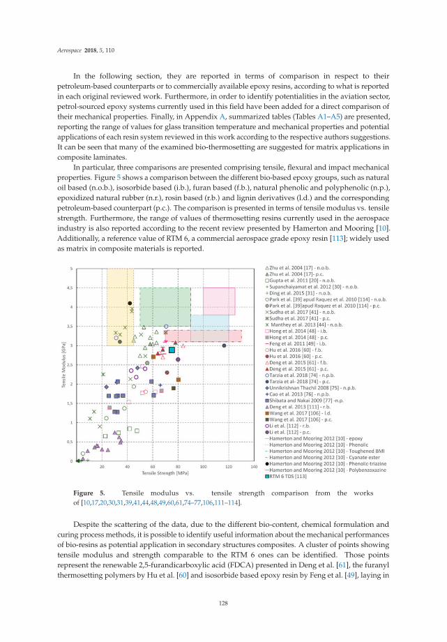
Aerospace 2018, 5, 110
In the following section, they are reported in terms of comparison in respect to theirpetroleum-based counterparts or to commercially available epoxy resins, according to what is reportedin each original reviewed work. Furthermore, in order to identify potentialities in the aviation sector,petrol-sourced epoxy systems currently used in this field have been added for a direct comparison oftheir mechanical properties. Finally, in Appendix A, summarized tables (Tables A1–A5) are presented,reporting the range of values for glass transition temperature and mechanical properties and potentialapplications of each resin system reviewed in this work according to the respective authors suggestions.It can be seen that many of the examined bio-thermosetting are suggested for matrix applications incomposite laminates.
In particular, three comparisons are presented comprising tensile, flexural and impact mechanicalproperties. Figure 5 shows a comparison between the different bio-based epoxy groups, such as naturaloil based (n.o.b.), isosorbide based (i.b.), furan based (f.b.), natural phenolic and polyphenolic (n.p.),epoxidized natural rubber (n.r.), rosin based (r.b.) and lignin derivatives (l.d.) and the correspondingpetroleum-based counterpart (p.c.). The comparison is presented in terms of tensile modulus vs. tensilestrength. Furthermore, the range of values of thermosetting resins currently used in the aerospaceindustry is also reported according to the recent review presented by Hamerton and Mooring [10].Additionally, a reference value of RTM 6, a commercial aerospace grade epoxy resin [113]; widely usedas matrix in composite materials is reported.
Figure 5. Tensile modulus vs. tensile strength comparison from the worksof [10,17,20,30,31,39,41,44,48,49,60,61,74–77,106,111–114].
Despite the scattering of the data, due to the different bio-content, chemical formulation andcuring process methods, it is possible to identify useful information about the mechanical performancesof bio-resins as potential application in secondary structures composites. A cluster of points showingtensile modulus and strength comparable to the RTM 6 ones can be identified. Those pointsrepresent the renewable 2,5-furandicarboxylic acid (FDCA) presented in Deng et al. [61], the furanylthermosetting polymers by Hu et al. [60] and isosorbide based epoxy resin by Feng et al. [49], laying in
128
Aerospace 2018, 5, 110
the same range of RTM 6 resin. Furthermore, interesting results characterize the epoxidized soy-basedresins synthetized by Zhu et al. [17], the epoxidized hemp oil-based bioresins by Manthey et al. [44]and the epoxy resin derived from gallic acid in Tarzia et al. [74], where higher tensile modulus andrelatively lower tensile strength than RTM 6 are shown. Such mechanical characteristics suggest themas suitable candidates for matrices of composite materials with enhanced modulus. Additionally,the tensile characteristics of the hemp oil-based bioresins by Manthey et al. [44] and the epoxy resinfrom gallic acid by Tarzia et al. [74], are located in the range values of the phenolic resin, that aregenerally employed in aircraft interiors, such as interior panels of glass honeycomb composites of civilairliners, flooring and partitions [10].
In the modern aerospace industry, different types of petroleum-based thermosets are employed,depending on the different performance demands, budget, aerospace sector (civil or military,smaller executive and light aircrafts) [10]. This is the case of toughened maleimide (BMI),with applications in high performance structural elements, cyanate ester, employed in space andsatellite applications, polybenzoxazine, for coating and electrical applications, and epoxy for hightemperature adhesives, [10] characterized by very high tensile strength and modulus. They arereported in Figure 5, according to the ranges of values presented in [10], although these applicationsare out of the scope of the present review on bio-based resins systems for applications in secondaryand interior structures.
A comparison in terms of flexural modulus vs. flexural strength of the bio-based systems isreported in Figure 6, where bio-based epoxy synthesized from renewable gallic acid from the workof Cao et al. [76] and the soy-based epoxy resin system by Zhu et al. [17] show flexural mechanicalcharacteristics comparable to the RTM 6 reference value [113]. Other resin systems, such as therosin-based epoxy synthetized by Li et al. [112], the epoxy blends from castor oil by Sudha et al. [41]and the isosorbide-methacrylate based epoxy by Sadler et al. [51] present comparable or higher valuesin terms of flexural modulus and a lower flexural strength than the aerospace high performanceresin; thus resulting more brittle than it. Finally, very interesting flexural properties characterize theisosorbide-based resin by Łukaszczyk et al. [50], with enhanced values of flexural modulus, rangingbetween 5.5 GPa (TETA) and 17.4 GPa (PHA), reported in detail in Appendix A, and values of flexuralstrength from 100.5 (THPHA) to 228.3 (TETA), making them a promising alternative to petrol-derivedbisphenol A resin, as suggested by the same authors.
129

Aerospace 2018, 5, 110
Figure 6. Flexural modulus vs. flexural strength comparison from the worksof [14,17,19,20,29,39,41,44,51,52,61,76,86,107,112–114].
Further considerations can be drawn for the group of natural oil-based epoxy by examining theirperformances under impact loading conditions, (Figures 7 and 8). For the reported bibliography, it canbe seen that the addition of a certain percentage of epoxidized natural oil content to petroleum-basedsystems, enhance the Charpy impact and the Izod impact strengths. In Figures 7 and 8, the gray filledsymbols represent petroleum-based control samples and the unfilled symbols represent the blend ofresins with a certain percentage of eco content. Such an increase of toughness with the increase of biocontent in the epoxy blend is related to the change of crosslinking density of the polymer networks,which results in an increase of absorption of the energy of impact [41].
130

Aerospace 2018, 5, 110
Figure 7. Izod impact strength of epoxidizes natural oil resins from the works of [19,20,24,25,41,115].
Figure 8. Charpy impact strength of epoxidized natural oil resins from the works of [29,39,44,114,116,117].
131
Aerospace 2018, 5, 110
Furthermore, the bio-based resins show comparable or higher values than high-performances resinsused in the aviation sector, like neat resin cyanate by Ganesan et al. [115], bismaleimidodiphenylmethane(BMI) —diallylbisphenol A (BA) by Wang et al. [116] and cyanate resin system by Wang et al. [117].
Together with the mechanical properties, for applications in composites of all the studied bio-basedepoxy systems, a key aspect lays on the adhesion with the fibers for composite materials. In fact,besides the mechanical properties of the single components (epoxy resin matrix and fibers), when theyare employed to produce composite materials, a good adhesion contributes to an improvement of themechanical characteristics of the composite.
Such an aspect is also related to other factors, such as the viscosity of the resin systems to properlypermeate the fibers. In Table A6 of Appendix B, the values determined by rheological analysescharacterizing the bio-based systems are summarized in terms of kinematic and dynamic viscosity. Inorder to provide a first comparison with the resins generally used in the aerospace for the productionof composite, the values characterizing the RTM 6 resin are also reported [113]. Here, it comes clearthat bio-based systems such as the isosorbide-based systems presented in [51,52] and natural phenolicbased resin systems of glycerol polyglycidyl ether (GPE) and sorbitol polyglycidyl ether (SPE) curedwith tannic acid (TA) presented in [77], show interesting properties in terms of viscosity, making thempromising for fibers permeation.
The studies reported in this work already provide several examples where the mechanicalproperties and viscosity of the systems are suitable for applications in fiber composites and make thempromising candidates for interior components of an airplane, even if more research is still required.Despite significant advances on the use of bio-based epoxy systems, there is still a need to furtheroptimize their performances to make them competitive for applications in the aviation sector.
Even though it is outside the scope of the present review, it is worth mentioning that initial studieson the costs of bio-based resins and natural fibers for composites and life cycle assessment analysis hasbeen carried in [118,119]. Further studies must still be conducted as most of the abovementioned resinsystems are not yet at a commercial production level.
Funding: This research was funded by the European Union’s Horizon 2020 research and innovation programunder grant number 690638.
Conflicts of Interest: The authors declare no conflict of interest.
132
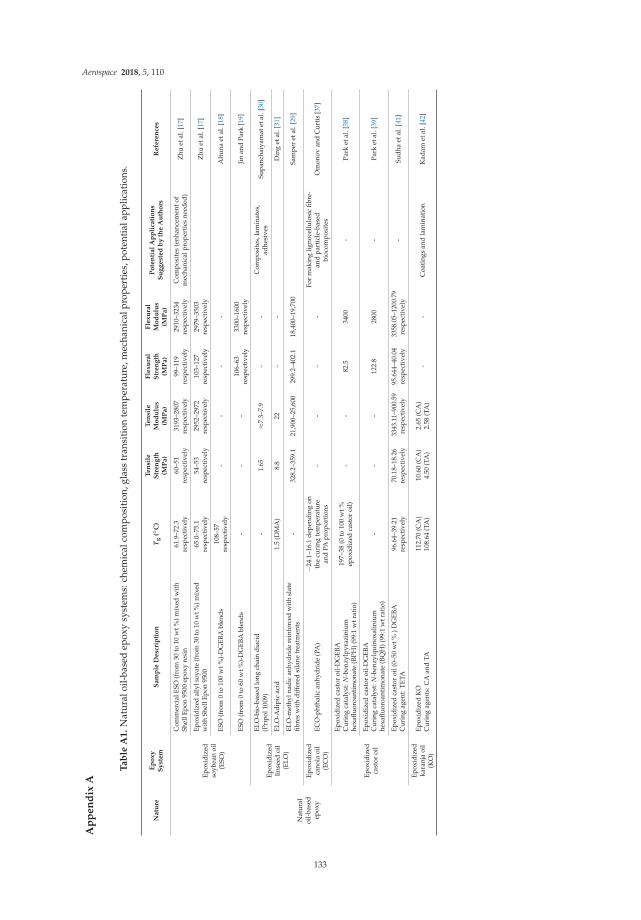
Aerospace 2018, 5, 110
Ap
pe
nd
ixA
Ta
ble
A1
.N
atur
aloi
l-ba
sed
epox
ysy
stem
s:ch
emic
alco
mpo
siti
on,g
lass
tran
siti
onte
mpe
ratu
re,m
echa
nica
lpro
pert
ies,
pote
ntia
lapp
licat
ions
.
Na
ture
Ep
ox
yS
yst
em
Sa
mp
leD
esc
rip
tio
nT
g(◦
C)
Te
nsi
leS
tre
ng
th(M
Pa
)
Te
nsi
leM
od
ulu
s(M
Pa
)
Fle
xu
ral
Str
en
gth
(MP
a)
Fle
xu
ral
Mo
du
lus
(MP
a)
Po
ten
tia
lA
pp
lica
tio
ns
Su
gg
est
ed
by
the
Au
tho
rsR
efe
ren
ces
Nat
ural
oil-
base
dep
oxy
Epox
idiz
edso
ybea
noi
l(E
SO)
Com
mer
cial
ESO
(fro
m30
to10
wt%
)mix
edw
ith
Shel
lEpo
n95
00ep
oxy
resi
n61
.9–7
2.3
resp
ecti
vely
60–5
1re
spec
tive
ly31
93–2
807
resp
ecti
vely
99–1
19re
spec
tive
ly29
10–3
234
resp
ecti
vely
Com
posi
tes
(enh
ance
men
tof
mec
hani
calp
rope
rtie
sne
eded
)Z
huet
al.[
17]
Epox
idiz
edal
lyls
oyat
e(f
rom
30to
10w
t%)m
ixed
wit
hSh
ellE
pon
9500
65.0
–75.
1re
spec
tive
ly54
–53
resp
ecti
vely
2952
–297
2re
spec
tive
ly10
3–12
7re
spec
tive
ly29
79–3
503
resp
ecti
vely
Zhu
etal
.[17
]
ESO
(fro
m0
to10
0w
t%)-
DG
EBA
blen
ds10
8–57
resp
ecti
vely
--
--
Alt
una
etal
.[18
]
ESO
(fro
m0
to60
wt%
)-D
GEB
Abl
ends
--
-10
6–63
resp
ecti
vely
3300
–160
0re
spec
tive
lyJi
nan
dPa
rk[1
9]
Epox
idiz
edlin
seed
oil
(ELO
)
ELO
-bio
-bas
edlo
ngch
ain
diac
id(P
ripo
l100
9)-
1.65
≈7.3
–7.9
--
Com
posi
tes,
lam
inat
es,
adhe
sive
sSu
panc
haiy
amat
etal
.[30
]
ELO
-Adi
pic
acid
1.5
(DM
A)
8.8
22-
-D
ing
etal
.[31
]
ELO
-met
hyln
adic
anhy
drid
ere
info
rced
with
slat
efib
res
wit
hdi
ffer
edsi
lane
trea
tmen
ts-
328.
2–35
9.1
21,9
00–2
5,60
029
9.2–
402.
118
,400
–19,
700
Sam
per
etal
.[29
]
Epox
idiz
edca
nola
oil
(EC
O)
ECO
-pht
halic
anhy
drid
e(P
A)
−24.
1–16
.1de
pend
ing
onth
ecu
ring
tem
pera
ture
and
PApr
opor
tion
s-
--
-Fo
rm
akin
glig
noce
llulo
sic
fibre
-an
dpa
rtic
le-b
ased
bioc
ompo
site
sO
mon
ovan
dC
urti
s[3
7]
Epox
idiz
edca
stor
oil
Epox
idiz
edca
stor
oil-
DG
EBA
Cur
ing
cata
lyst
:N-b
enzy
lpyr
azin
ium
hexa
fluor
oant
imon
ate
(BPH
)(99
:1w
trat
io)
197–
38(0
to10
0w
t%ep
oxid
ized
cast
oroi
l)-
-82
.534
00-
Park
etal
.[38
]
Epox
idiz
edca
stor
oil-
DG
EBA
Cur
ing
cata
lyst
:N-b
enzy
lqui
noxa
liniu
mhe
xaflu
oroa
ntim
onat
e(B
QH
)(99
:1w
trat
io)
--
-12
2.8
2800
-Pa
rket
al.[
39]
Epox
idiz
edca
stor
oil(
0–50
wt%
)DG
EBA
Cur
ing
agen
t:TE
TA96
.64–
39.2
1re
spec
tive
ly70
.18–
18.2
6re
spec
tive
ly33
43.1
1–90
0.59
resp
ecti
vely
95.6
44–4
0.04
resp
ecti
vely
3358
.05–
1200
.79
resp
ecti
vely
-Su
dha
etal
.[41
]
Epox
idiz
edka
ranj
aoi
l(K
O)
Epox
idiz
edK
OC
urin
gag
ents
:CA
and
TA11
2.70
(CA
)10
8.64
(TA
)10
.60
(CA
)4.
50(T
A)
2.65
(CA
)2.
58(T
A)
--
Coa
ting
san
dla
min
atio
nK
adam
etal
.[42
]
133

Aerospace 2018, 5, 110
Ta
ble
A2
.Is
osor
bide
-and
fura
n-ba
sed
epox
ysy
stem
s:ch
emic
alco
mpo
siti
on,g
lass
tran
siti
onte
mpe
ratu
re,m
echa
nica
lpro
pert
ies,
pote
ntia
lapp
licat
ions
.
Na
ture
Ep
ox
yS
yst
em
Sa
mp
leD
esc
rip
tio
nT
g(◦
C)
Te
nsi
leS
tre
ng
th(M
Pa
)
Te
nsi
leM
od
ulu
s(M
Pa
)
Fle
xu
ral
Str
en
gth
(MP
a)
Fle
xu
ral
Mo
du
lus
(MP
a)
Po
ten
tia
lA
pp
lica
tio
ns
Su
gg
est
ed
by
the
Au
tho
rsR
efe
ren
ces
Isos
orbi
deba
sed
epox
y
Dig
licid
ylet
erof
isos
orbi
de(D
GEI
)
DG
EIC
urin
gag
ents
:DET
Aan
dIS
OD
A76
(DET
A)
43(I
SOD
A)
62(D
ETA
)41
(ISO
DA
)17
98(D
ETA
)15
32(I
SOD
A)
-40
27(D
ETA
)11
68(I
SOD
A)
Rep
lace
men
tofB
PA(f
orfo
odco
ntac
tapp
licat
ions
),In
dust
ryad
diti
ves,
can
coat
ings
,bi
omed
ical
appl
icat
ions
like
bone
cem
ents
and
drug
deliv
ery
syst
ems,
pack
agin
g,au
tom
otiv
ein
dust
ry.
Hon
get
al.
DG
EIC
urin
gag
ents
:PH
A,T
HPH
A,T
ETA
and
IPH
A
108
(PH
A)
95(T
HPH
A)
49(T
ETA
)73
(IPH
A)
--
225.
5(P
HA
)10
0.5
(TH
PHA
)22
8.3
(TET
A)
158.
8(I
PHA
)
17,4
00(P
HA
)15
,100
(TH
PHA
)55
00(T
ETA
)14
,600
(IPH
A)
Łuka
szcz
yket
al.[
50]
Bisi
soso
rbid
edi
glic
idyl
eter
Bisi
soso
rbid
edi
glyd
icyl
eter
Cur
ing
agen
t:Je
ffam
ine
T403
48bu
tcan
bein
crea
sed
to20
0◦ C
chan
ging
the
curi
ngag
ent
68.8
2944
--
Feng
etal
.[49
]
Fura
nba
sed
epox
y
BOF
and
BOB
BOF/
BOB—
DG
EBA
Cur
ing
agen
ts:P
AC
Man
dEP
IKU
RE
W
80to
150
depe
ndin
gon
the
prop
orti
ons
and
curi
ngag
ent.
--
--
Adh
esiv
es,s
truc
tura
land
engi
neer
ing
mat
eria
lsan
dco
mpo
site
s
Hu
etal
.[58
]
BOF
Cur
ing
agen
ts:D
FDA
,CH
3-D
GBA
,PA
CM
69(D
FDA
)62
(CH
3-D
GBA
)72
(PA
CM
)-
--
-H
uet
al.[
59]
DG
FD
GF
Cur
ing
agen
ts:
MH
HPA
,D23
0
152
(MH
HPA
)10
1.2
(D23
0)84
(MH
HPA
)68
(D23
0)
3000
(MH
HPA
)27
00(D
230)
96(M
HH
PA)
75(D
230)
3100
(MH
HPA
)25
00(D
230)
Den
get
al.[
61]
134

Aerospace 2018, 5, 110
Ta
ble
A3
.Ph
enol
ican
dpo
lyph
enol
icep
oxy:
chem
ical
com
posi
tion
,gla
sstr
ansi
tion
tem
pera
ture
,mec
hani
calp
rope
rtie
s,po
tent
iala
pplic
atio
ns.
Na
ture
Ep
ox
yS
yst
em
Sa
mp
leD
esc
rip
tio
nT
g(◦
C)
Te
nsi
leS
tre
ng
th(M
Pa
)
Te
nsi
leM
od
ulu
s(M
Pa
)
Fle
xu
ral
Str
en
gth
(MP
a)
Fle
xu
ral
Mo
du
lus
(MP
a)
Po
ten
tia
lA
pp
lica
tio
ns
Su
gg
est
ed
by
the
Au
tho
rsR
efe
ren
ces
Phen
olic
and
poly
phen
olic
epox
y
GEH
DG
TE,
GEF
DG
TE,
GEC
GEG
TE,G
ECC
urin
gag
ent:
IPD
A14
2(G
EGTE
)179
(GEC
)-
--
-
Elec
tron
icap
plic
atio
ns,
com
posi
tes
Beny
ahya
etal
.[65
]
GEH
DG
TE,G
EFD
GTE
,GEC
Cur
ing
agen
t:Li
gnin
deri
vati
ve
178
(GEC
)15
5(G
EFD
GTE
)17
3(G
EFH
DG
TlE)
--
63(G
EC)
56(G
EFD
GTE
)40
(GEF
HD
GTE
)
-Ba
snet
etal
.[66
]
GEG
AG
EGA
Cur
ing
agen
ts:I
PDA
,DPG
,BD
MA
158
(IPD
A)
98(D
PG)
136
(BD
MA
)
43.1
(IPD
A)
70.6
(DPG
)31
.2(B
DM
A)
3600
(IPD
A)
3500
(DPG
)32
00(B
DM
A)
--
Tarz
iaet
al.[
74]
TAG
PE,S
PEC
urin
gag
ent:
TA87
.3(G
PE)
106.
6(S
PE)
36.7
(GPE
)60
.6(S
PE)
2400
(GPE
)17
10(S
PE)
--
Shib
ata
etal
.[77
]
Car
dano
lep
oxy
Car
dano
lbas
edre
sol-
DG
EBA
Cur
ing
agen
t:A
min
eca
taly
stor
anac
idca
taly
st-
1286
4-
-
Com
posi
tes,
bind
ers
and
coat
ings
Maf
fezz
olie
tal.
[80]
BPA
-Car
dano
lepo
xy(8
0:20
and
50:5
0)-
31.7
(80:
20)
23.5
(50:
50)
2045
(80:
20)
1926
(50:
50)
80.8
(80:
20)
71.4
5(5
0:50
)-
Unn
ikri
shna
net
al.[
75]
NC
-514
Cur
ing
agen
ts:I
PDA
,Jef
fam
ine
D40
050
(IPD
A)
15(J
effa
min
eD
400)
--
--
Jaill
etet
al.[
81]
NC
-514
-Sor
bito
l/Is
osor
bide
epox
ies
Cur
ing
agen
ts:I
PDA
,Jef
fam
ine
T403
83(2
5:75
Epox
idiz
edca
rdan
ol:E
poxi
dize
dis
osor
bide
cure
dw
ith
IPD
A)
60(5
0w
t%Ep
oxid
ized
card
anol
/Epo
xidi
zed
sorb
itol
cure
dw
ith
IPD
A)
37(5
0w
t%Ep
oxid
ized
card
anol
/Epo
xidi
zed
sorb
itol
cure
dw
ith
Jeff
amin
eT4
03)
--
--
Dar
rom
anet
al.[
82]
CN
EC
urin
gag
ent:
CPA
50–8
4-
--
Att
aet
al.[
83]
135

Aerospace 2018, 5, 110
Ta
ble
A4
.E
pox
idiz
edN
atu
ral
rubb
er(E
NR
)an
dep
oxy
ligni
nd
eriv
ativ
es:
chem
ical
com
pos
itio
n,gl
ass
tran
siti
onte
mp
erat
ure
,m
echa
nica
lp
rop
erti
es,
pote
ntia
lapp
licat
ions
.
Na
ture
Ep
ox
yS
yst
em
Sa
mp
leD
esc
rip
tio
nT
g(◦
C)
Te
nsi
leS
tre
ng
th(M
Pa
)
Te
nsi
leM
od
ulu
s(M
Pa
)
Fle
xu
ral
Str
en
gth
(MP
a)
Fle
xu
ral
Mo
du
lus
(MP
a)
Po
ten
tia
lA
pp
lica
tio
ns
Su
gg
est
ed
by
the
Au
tho
rsR
efe
ren
ces
Epox
idiz
edN
atur
alru
bber
(EN
R)
ENR
ENR
-DG
EBA
Cur
ing
agen
t:N
adic
met
hyla
nhyd
ride
(K68
)11
2(5
wt%
ENR
)–10
9(2
0w
t%EN
R)
--
--
-M
athe
wet
al.[
93]
ENR
Cur
ing
agen
t:D
TDB
-12
1.67
--
-Im
bern
onet
al.[
94]
Epox
ylig
nin
deri
vati
ves
Dep
olym
eriz
edlig
nin
epox
yD
HL
epox
y-D
GEB
AC
urin
gag
ent:
DD
M-
138
(100
%D
HL)
—18
7(2
5%D
HL)
12,3
00(1
00%
DH
L)23
,200
(25%
DH
L)
47(1
00%
DH
L)—
258
(25%
DH
L)
5000
(100
%D
HL)
—13
,200
(25%
DH
L)
Elec
tron
ics,
subs
titu
tefo
rfo
ssil
reso
urce
-der
ived
bisp
heno
lA,
poly
mer
mat
rix
for
man
ufac
ture
ofbi
o-ba
sed
fibre
-rei
nfor
ced
plas
tics
orco
mpo
site
s
Ferd
osia
net
al.[
101]
Van
illin
deri
vati
ves
Dig
lyci
dyle
ther
sof
vani
llyla
lcoh
ol,v
anill
icac
idan
dm
etho
xyhy
droq
uino
neC
urin
gag
ent:
IPD
A
97(d
igly
cidy
leth
erof
vani
llyla
lcoh
ol)
132
(Dig
lyci
dyle
ther
ofm
etho
xyhy
droq
uino
ne)
152
(Dig
lyci
dyle
ther
ofva
nilli
cac
id)
--
--
Fach
eet
al.[
104]
Ta
ble
A5
.R
osin
base
dep
oxy:
chem
ical
com
posi
tion
,gla
sstr
ansi
tion
tem
pera
ture
,mec
hani
calp
rope
rtie
s,po
tent
iala
pplic
atio
ns.
Na
ture
Ep
ox
yS
yst
em
Sa
mp
leD
esc
rip
tio
nT
g(◦
C)
Te
nsi
leS
tre
ng
th(M
Pa
)
Te
nsi
leM
od
ulu
s(M
Pa
)
Fle
xu
ral
Str
en
gth
(MP
a)
Fle
xu
ral
Mo
du
lus
(MP
a)
Po
ten
tia
lA
pp
lica
tio
ns
Su
gg
est
ed
by
the
Au
tho
rsR
efe
ren
ces
Ros
inba
sed
Trig
lyci
dyl
este
rFP
AE
and
glyc
idyl
ethe
rsFP
EG1,
FPEG
2,an
dFP
EG3
obta
ined
from
Ros
in
E-44
FPA
E1C
FPEG
1CFP
EG2C
FPEG
3C
140
167
81 79 75
56.2
548
.54
68.7
558
.18
42.4
1
290
471
495
300
270
--
-D
eng
etal
.[11
1]
Ros
inba
sed-
epox
ym
onom
eran
dcu
ring
agen
t
Mal
eopi
mar
icac
id(M
PA)a
ndtr
igly
cidy
lest
erof
mal
eopi
mar
icac
id16
4-
-70
2200
-Li
uet
al.[
109]
Ros
in-b
ased
Epox
yM
onom
er
Two
glyc
idyl
amin
ety
peep
oxie
s:di
glyc
idyl
dehy
droa
biet
ylam
ine
(DG
DH
AA
)der
ived
from
DH
AA
(ros
in)a
nddi
glyc
idyl
benz
ylam
ine
(DG
BA)d
eriv
edfr
ombe
nzyl
amin
ehe
xahy
drop
htha
lican
hydr
ide
HH
PA
47 43 54
2180
2350
2400
68 69 98
3250
3417
3540
Liet
al.[
112]
136
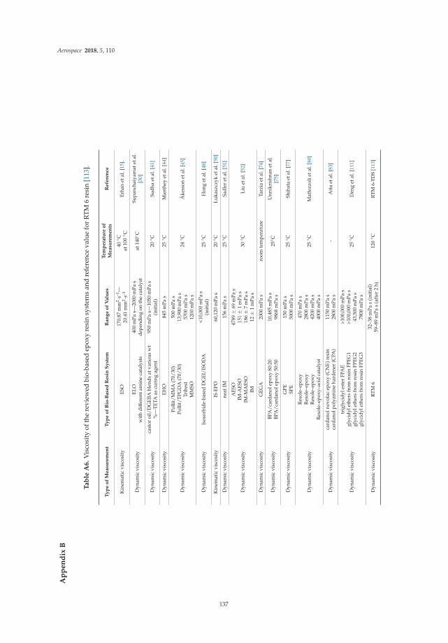
Aerospace 2018, 5, 110
Ap
pe
nd
ixB
Ta
ble
A6
.V
isco
sity
ofth
ere
view
edbi
o-ba
sed
epox
yre
sin
syst
ems
and
refe
renc
eva
lue
for
RT
M6
resi
n[1
13].
Ty
pe
of
Measu
rem
en
tT
yp
eo
fB
io-B
ase
dR
esi
nS
yst
em
Ran
ge
of
Valu
es
Tem
pera
ture
of
Measu
rem
en
tsR
efe
ren
ce
Kin
emat
icvi
scos
ity
ESO
170.
87m
m2 ·s
–1—
20.4
1m
m2 ·s
–140
◦ Cat
100◦ C
Erha
net
al.[
15].
Dyn
amic
visc
osit
yEL
Ow
ith
diff
eren
tam
ine
cata
lyst
s40
0m
Pas—
2000
mPa
sde
pend
ing
onth
eca
taly
stat
140◦
CSu
panc
haiy
amat
etal
.[3
0]
Dyn
amic
visc
osit
yca
stor
oil/
DG
EBA
blen
dsat
vari
ous
wt
%—
TETA
ascu
ring
agen
t95
0m
Pas—
1050
mPa
s(i
niti
al)
20◦ C
Sudh
aet
al.[
41]
Dyn
amic
visc
osit
yEH
O84
5m
Pas
25◦ C
Man
they
etal
.[44
]
Dyn
amic
visc
osit
y
Polli
t/M
MA
(70/
30)
Polli
t/TP
GD
A(7
0/30
)Tr
ibes
tM
MSO
500
mPa
s13
,900
mPa
s57
00m
Pas
1200
mPa
s
24◦ C
Åke
sson
etal
.[45
]
Dyn
amic
visc
osit
yIs
osor
bide
-bas
edD
GEI
/ISO
DA
<10,
000
mPa
s(i
niti
al)
25◦ C
Hon
get
al.[
48]
Kin
emat
icvi
scos
ity
IS-E
PO60
,120
mPa
s20
◦ CŁu
kasz
czyk
etal
.[50
]
Dyn
amic
visc
osit
yne
atIM
156
mPa
s25
◦ CSa
dler
etal
.[51
]
Dyn
amic
visc
osit
y
AES
OIM
-AES
OIM
-MA
ESO
IM
4789
±69
mPa
s15
1±
1m
Pas
186±
7m
Pas
12±
1m
Pas
30◦ C
Liu
etal
.[52
]
Dyn
amic
visc
osit
yG
EGA
2000
mPa
sro
omte
mpe
ratu
reTa
rzia
etal
.[74
]
Dyn
amic
visc
osit
yBP
A/c
arda
nole
poxy
80:2
0BP
A/c
arda
nole
poxy
50:5
010
,485
mPa
s98
68m
Pas
25◦ C
Unn
ikri
shna
net
al.
[75]
Dyn
amic
visc
osit
yG
PESP
E15
0m
Pas
5000
mPa
s25
◦ CSh
ibat
aet
al.[
77]
Dyn
amic
visc
osit
y
Res
ole–
epox
yR
esol
e–ep
oxy
Res
ole–
epox
yR
esol
e–ep
oxy–
acid
cata
lyst
470
mPa
s28
00m
Pas
4200
mPa
s40
00m
Pas
25◦ C
Maf
fezz
olie
tal.
[80]
Dyn
amic
visc
osit
yca
rdan
olno
vola
cep
oxy
(CN
E)re
sin
card
anol
poly
amin
eha
rden
er(C
PA)
1150
mPa
s28
00m
Pas
-A
tta
etal
.[83
]
Dyn
amic
visc
osit
y
trig
lyci
dyle
ster
FPA
Egl
ycid
ylet
hers
from
rosi
nFP
EG1
glyc
idyl
ethe
rsfr
omro
sin
FPEG
2gl
ycid
ylet
hers
from
rosi
nFP
EG3
>100
,000
mPa
s>1
00,0
00m
Pas
43,5
00m
Pas
7800
mPa
s
25◦ C
Den
get
al.[
111]
Dyn
amic
visc
osit
yR
TM6
32–3
8m
Pas
(ini
tial
)59
–89
mPa
s(a
fter
2h)
120◦ C
RTM
6-TD
S[1
13]
137

Aerospace 2018, 5, 110
References
1. Pascault, J.; Sautereau, H.; Verdu, J.; Williams, R.J.J. Thermosetting Polymers; Marcel Dekker: New York, NY,USA, 2002; ISBN 0824706706.
2. Holbery, J.; Houston, D. Natural-fibre-reinforced polymer composites in automotive applications. J. Miner.Met. Mater. Soc. 2006, 58, 80–86. [CrossRef]
3. Prolongo, S.G.; Gude, M.R.; Sanchez, J.; Ureña, A. Nanoreinforced epoxy adhesives for aerospace industry.J. Adhes. 2009, 85, 180–199. [CrossRef]
4. Guo, C.; Zhou, L.; Lv, J. Effects of expandable graphite and modified ammonium polyphosphate on theflame-retardant and mechanical properties of wood flour-polypropylene composites. Polym. Polym. Compos.2013, 21, 449–456. [CrossRef]
5. Sharmin, E.; Alam, M.S.; Philip, R.K.; Ahmad, S. Linseed amide diol/DGEBA epoxy blends for coatingapplications: Preparation, characterization, ageing studies and coating properties. Prog. Org. Coat. 2010,67, 170–179. [CrossRef]
6. Gibson, R.F. A review of recent research on mechanics of multifunctional composite materials and structures.Compos. Struct. 2010, 92, 2793–2810. [CrossRef]
7. Jin, F.L.; Li, X.; Park, S.J. Synthesis and application of epoxy resins: A review. J. Ind. Eng. Chem. 2015, 29, 1–11.[CrossRef]
8. Shen, L.; Haufe, J.; Patel, M. Product Overview and Market Projection of Emerging Biobased Plastics (PROBIP2009); Utrecht University: Utrecht, The Netherlands, 2009.
9. Soutis, C. Fibre reinforced composites in aircraft construction. Prog. Aerosp. Sci. 2005, 41, 143–151. [CrossRef]10. Hamerton, I.; Mooring, L. The use of thermosets in aerospace applications. Thermosets Struct. Prop. Appl.
2012, 189–227. [CrossRef]11. Yang, Y.; Boom, R.; Irion, B.; van Heerden, D.J.; Kuiper, P.; de Wit, H. Recycling of composite materials.
Chem. Eng. Process. Process Intensif. 2012, 51, 53–68. [CrossRef]12. Soutis, C. Carbon fiber reinforced plastics in aircraft construction. Mater. Sci. Eng. A 2005, 412, 171–176.
[CrossRef]13. Kausar, A. Role of Thermosetting Polymer in Structural Composite. Am. J. Polym. Sci. Eng. 2017, 5, 1–12.14. Park, S.J.; Jin, F.L.; Lee, J.R. Thermal and mechanical properties of tetrafunctional epoxy resin toughened
with epoxidized soybean oil. Mater. Sci. Eng. A 2004, 374, 109–114. [CrossRef]15. Adhvaryu, A.; Erhan, S.Z. Epoxidized soybean oil as a potential source of high-temperature lubricants.
Ind. Crops Prod. 2002, 15, 247–254. [CrossRef]16. Petrovic, Z.S.; Zlatanic, A.; Lava, C.C.; Sinadinovic-Fišer, S. Epoxidation of soybean oil in toluene with
peroxoacetic and peroxoformic acids—Kinetics and side reactions. Eur. J. Lipid Sci. Technol. 2002, 104,293–299. [CrossRef]
17. Zhu, J.; Chandrashekhara, K.; Flanigan, V.; Kapila, S. Curing and mechanical characterization of a soy-basedepoxy resin system. J. Appl. Polym. Sci. 2004, 91, 3513–3518. [CrossRef]
18. Altuna, F.I.; Espósito, L.H.; Ruseckaite, R.A.; Stefani, P.M. Thermal and mechanical properties ofanhydride-cured epoxy resins with different contents of biobased epoxidized soybean oil. J. Appl. Polym. Sci.2011, 120, 789–798. [CrossRef]
19. Jin, F.-L.; Park, S.-J. Impact-strength improvement of epoxy resins reinforced with a biodegradable polymer.Mater. Sci. Eng. A 2008, 478, 402–405. [CrossRef]
20. Gupta, A.P.; Ahmad, S.; Dev, A. Modification of novel bio-based resin-epoxidized soybean oil by conventionalepoxy resin. Polym. Eng. Sci. 2011, 51, 1087–1091. [CrossRef]
21. Tan, S.G.; Chow, W.S. Curing characteristics and thermal properties of Epoxidized soybean oil basedthermosetting resin. Am. Oil Chem. Soc. 2011, 88, 915–923. [CrossRef]
22. Cavusoglu, J.; Çayli, G. Polymerization reactions of epoxidized soybean oil and maleate esters of oil-solubleresoles. J. Appl. Polym. Sci. 2015, 132, 1–6. [CrossRef]
23. Tsujimoto, T.; Takayama, T.; Uyama, H. Biodegradable Shape Memory Polymeric Material from EpoxidizedSoybean Oil and Polycaprolactone. Polymers 2015, 7, 2165–2174. [CrossRef]
24. Miyagawa, H.; Mohanty, A.K.; Misra, M.; Drzal, L.T. Thermo-physical and impact properties of epoxycontaining epoxidized linseed oil, 1: Anhydride-cured epoxy. Macromol. Mater. Eng. 2004, 289, 629–635.[CrossRef]
138
Aerospace 2018, 5, 110
25. Miyagawa, H.; Mohanty, A.K.; Misra, M.; Drzal, L.T. Thermo-Physical and Impact Properties of EpoxyContaining Epoxidized Linseed Oil, 2. Macromol. Mater. Eng. 2004, 289, 636–641. [CrossRef]
26. Kanno, S.; Kawamura, Y.; Mutsuga, M.; Tanamoto, K. Determination of Epoxidized Soybean Oil and LinseedOil in Wrapping Film and Cap Sealing. J. Food Hyg. Soc. Jpn. (Shokuhin Eiseigaku Zasshi) 2006, 47, 89–94.[CrossRef]
27. Sánchez, N.; Chirinos, J. Estabilizantes térmicos alternativos para el PVC. Rev. Iberoam. Polímeros 2014,15, 178–197.
28. Espín, J.C.; Soler-Rivas, C.; Wichers, H.J. Characterization of the total free radical scavenger capacity ofvegetable oils and oil fractions using 2,2-diphenyl-1-picrylhydrazyl radical. J. Agric. Food Chem. 2000,48, 648–656. [CrossRef] [PubMed]
29. Samper, M.D.; Petrucci, R.; Sánchez-Nacher, L.; Balart, R.; Kenny, J.M. New environmentally friendlycomposite laminates with epoxidized linseed oil (ELO) and slate fiber fabrics. Compos. Part B Eng. 2015,71, 203–209. [CrossRef]
30. Supanchaiyamat, N.; Shuttleworth, P.S.; Hunt, A.J.; Clark, J.H.; Matharu, A.S. Thermosetting resin based onepoxidised linseed oil and bio-derived crosslinker. Green Chem. 2012, 14, 1759–1765. [CrossRef]
31. Ding, C.; Shuttleworth, P.S.; Makin, S.; Clark, J.H.; Matharu, A.S. New insights into the curing of epoxidizedlinseed oil with dicarboxylic acids. Green Chem. 2015, 17, 4000–4008. [CrossRef]
32. Pin, J.M.; Sbirrazzuoli, N.; Mija, A. From epoxidized linseed oil to bioresin: An overall approach ofepoxy/anhydride cross-linking. ChemSusChem 2015, 8, 1232–1243. [CrossRef] [PubMed]
33. Samper, M.D.; Fombuena, V.; Boronat, T.; García-Sanoguera, D.; Balart, R. Thermal and MechanicalCharacterization of Epoxy Resins (ELO and ESO) Cured with Anhydrides. J. Am. Oil Chem. Soc. 2012,89, 1521–1528. [CrossRef]
34. Pérez, J.D.E.; Haagenson, D.M.; Pryor, S.W.; Ulven, C.A.; Wiesenborn, D.P. Production and Characterizationof Epoxidized Canola Oil. Trans. ASABE 2009, 52, 1289–1297. [CrossRef]
35. Campanella, A.; Fahimian, M.; Wool, R.P.; Raghavan, J. Synthesis and Rheology of Chemically ModifiedCanola Oil. J. Biobased Mater. Bioenergy 2009, 3, 91–99. [CrossRef]
36. Mungroo, R.; Pradhan, N.C.; Goud, V.V.; Dalai, A.K. Epoxidation of Canola Oil with Hydrogen PeroxideCatalyzed by Acidic Ion Exchange Resin. J. Am. Oil Chem. Soc. 2008, 85, 887–896. [CrossRef]
37. Omonov, T.S.; Curtis, J.M. Biobased epoxy resin from canola oil. J. Appl. Polym. Sci. 2014, 131. [CrossRef]38. Park, S.-J.; Seo, M.-K.; Lee, J.-R.; Lee, D.-R. Studies on epoxy resins cured by cationic latent thermal catalysts:
The effect of the catalysts on the thermal, rheological, and mechanical properties. J. Polym. Sci. Part APolym. Chem. 2001, 39, 187–195. [CrossRef]
39. Park, S.-J.; Jin, F.-L.; Lee, J.-R. Effect of Biodegradable Epoxidized Castor Oil on Physicochemical andMechanical Properties of Epoxy Resins. Macromol. Chem. Phys. 2004, 205, 2048–2054. [CrossRef]
40. Park, S.-J.; Jin, F.-L.; Lee, J.-R. Synthesis and Thermal Properties of Epoxidized Vegetable Oil. Macromol.Rapid Commun. 2004, 25, 724–727. [CrossRef]
41. Sudha, G.S.; Kalita, H.; Mohanty, S.; Nayak, S.K. Biobased epoxy blends from epoxidized castor oil: Effect onmechanical, thermal, and morphological properties. Macromol. Res. 2017, 25, 420–430. [CrossRef]
42. Kadam, A.; Pawar, M.; Yemul, O.; Thamke, V.; Kodam, K. Biodegradable biobased epoxy resin from karanjaoil. Polymer 2015, 72, 82–92. [CrossRef]
43. Stemmelen, M.; Pessel, F.; Lapinte, V.; Caillol, S.; Habas, J.-P.; Robin, J.-J. A fully biobased epoxy resin fromvegetable oils: From the synthesis of the precursors by thiol-ene reaction to the study of the final material.J. Polym. Sci. Part A Polym. Chem. 2011, 49, 2434–2444. [CrossRef]
44. Manthey, N.W.; Cardona, F.; Francucci, G.; Aravinthan, T. Thermo-mechanical properties of epoxidizedhemp oil-based bioresins and biocomposites. J. Reinf. Plast. Compos. 2013, 32, 1444–1456. [CrossRef]
45. Åkesson, D.; Skrifvars, M.; Lv, S.; Shi, W.; Adekunle, K.; Seppälä, J.; Turunen, M. Preparation ofnanocomposites from biobased thermoset resins by UV-curing. Prog. Org. Coat. 2010, 67, 281–286. [CrossRef]
46. Flèche, G.; Huchette, M. Isosorbide. Preparation, Properties and Chemistry. Starch 1986, 38, 26–30. [CrossRef]47. Rose, M.; Palkovits, R. Isosorbide as a Renewable Platform chemical for Versatile Applications—Quo Vadis?
ChemSusChem 2012, 5, 167–176. [CrossRef] [PubMed]48. Hong, J.; Radojcic, D.; Ionescu, M.; Petrovic, Z.S.; Eastwood, E. Advanced materials from corn:
Isosorbide-based epoxy resins. Polym. Chem. 2014, 5, 5360–5368. [CrossRef]
139

Aerospace 2018, 5, 110
49. Feng, X.; East, A.J.; Hammond, W.B.; Zhang, Y.; Jaffe, M. Overview of advances in sugar-based polymers.Polym. Adv. Technol. 2011, 22, 139–150. [CrossRef]
50. Łukaszczyk, J.; Janicki, B.; Kaczmarek, M. Synthesis and properties of isosorbide based epoxy resin.Eur. Polym. J. 2011, 47, 1601–1606. [CrossRef]
51. Sadler, J.M.; Nguyen, A.-P.T.; Toulan, F.R.; Szabo, J.P.; Palmese, G.R.; Scheck, C.; Lutgen, S.; La Scala, J.J.Isosorbide-methacrylate as a bio-based low viscosity resin for high performance thermosetting applications.J. Mater. Chem. A 2013, 1, 12579. [CrossRef]
52. Liu, W.; Xie, T.; Qiu, R. Biobased Thermosets Prepared from Rigid Isosorbide and Flexible Soybean OilDerivatives. ACS Sustain. Chem. Eng. 2017. [CrossRef]
53. Gandini, A. Furans as offspring of sugars and polysaccharides and progenitors of a family of remarkablepolymers: a review of recent progress. Polym. Chem. 2010, 1, 245–251. [CrossRef]
54. Spillman, P.J.; Pollnitz, A.P.; Liacopoulos, D.; Pardon, K.H.; Sefton, M.A. Formation and Degradation ofFurfuryl Alcohol, 5-Methylfurfuryl Alcohol, Vanillyl Alcohol, and Their Ethyl Ethers in Barrel-Aged Wines.J. Agric. Food Chem. 1998, 46, 657–663. [CrossRef] [PubMed]
55. Lamminpää, K.; Ahola, J.; Tanskanen, J. Kinetics of Xylose Dehydration into Furfural in Formic Acid. Ind. Eng.Chem. Res. 2012, 51, 6297–6303. [CrossRef]
56. Lamminpää, K. Formic Acid Catalysed Xylose Dehydration into Furfural. Ph.D. Thesis, University of Oulu,Oulu, Finland, 2015.
57. Cho, J.K.; Lee, J.-S.; Jeong, J.; Kim, B.; Kim, B.; Kim, S.; Shin, S.; Kim, H.-J.; Lee, S.-H. Synthesis of carbohydratebiomass-based furanic compounds bearing epoxide end group(s) and evaluation of their feasibility asadhesives. J. Adhes. Sci. Technol. 2013, 27, 2127–2138. [CrossRef]
58. Hu, F.; La Scala, J.J.; Sadler, J.M.; Palmese, G.R. Synthesis and Characterization of Thermosetting Furan-BasedEpoxy Systems. Macromolecules 2014, 47, 3332–3342. [CrossRef]
59. Hu, F.; Yadav, S.K.; La Scala, J.J.; Sadler, J.M.; Palmese, G.R. Preparation and Characterization of FullyFuran-Based Renewable Thermosetting Epoxy-Amine Systems. Macromol. Chem. Phys. 2015, 216, 1441–1446.[CrossRef]
60. Hu, F.; Yadav, S.K.; Sharifi, M.; La Scala, J.; Sadler, J.; McAninch, I.; Palmesea, G. Characterization ofFuranyl Thermosetting Polymers with Superior Mechanical Properties and High-Temperature Char Yield.In Proceedings of the International SAMPE Technical Conference, Long Beach, CA, USA, 23–26 May 2016.
61. Deng, J.; Liu, X.; Li, C.; Jiang, Y.; Zhu, J. Synthesis and properties of a bio-based epoxy resin from2,5-furandicarboxylic acid (FDCA). RSC Adv. 2015, 5, 15930–15939. [CrossRef]
62. Abbas, M.; Saeed, F.; Anjum, F.M.; Afzaal, M.; Tufail, T.; Bashir, M.S.; Ishtiaq, A.; Hussain, S.; Suleria, H.A.R.Natural polyphenols: An overview. Int. J. Food Prop. 2017, 20, 1689–1699. [CrossRef]
63. Pizzi, A. Monomers, Polymers and Composites from Renewable Resources. Monomers Polym. Compos. Renew.Resour. 2008, 179–199. [CrossRef]
64. Nouailhas, H.; Aouf, C.; Le Guerneve, C.; Caillol, S.; Boutevin, B.; Fulcrand, H. Synthesis and propertiesof biobased epoxy resins. Part 1. Glycidylation of flavonoids by epichlorohydrin. J. Polym. Sci. Part APolym. Chem. 2011, 49, 2261–2270. [CrossRef]
65. Benyahya, S.; Aouf, C.; Caillol, S.; Boutevin, B.; Pascault, J.P.; Fulcrand, H. Functionalized green tea tanninsas phenolic prepolymers for bio-based epoxy resins. Ind. Crops Prod. 2014, 53, 296–307. [CrossRef]
66. Basnet, S.; Otsuka, M.; Sasaki, C.; Asada, C.; Nakamura, Y. Functionalization of the active ingredients ofJapanese green tea (Camellia sinensis) for the synthesis of bio-based epoxy resin. Ind. Crops Prod. 2015,73, 63–72. [CrossRef]
67. Haslam, E.; Cai, Y. Plant polyphenols (Vegetable tannins): Gallic acid metabolism. Nat. Prod. Rep. 1994,11, 41–66. [CrossRef] [PubMed]
68. Badhani, B.; Sharma, N.; Kakkar, R. Gallic acid: A versatile antioxidant with promising therapeutic andindustrial applications. RSC Adv. 2015, 5, 27540–27557. [CrossRef]
69. Al, M.L.; Daniel, D.; Moise, A.; Bobis, O.; Laslo, L.; Bogdanov, S. Physico-chemical and bioactive propertiesof different floral origin honeys from Romania. Food Chem. 2009, 112, 863–867. [CrossRef]
70. Samanidou, V.; Tsagiannidis, A.; Sarakatsianos, I. Simultaneous determination of polyphenols andmajor purine alkaloids in Greek Sideritis species, herbal extracts, green tea, black tea, and coffee byhigh-performance liquid chromatography-diode array detection. J. Sep. Sci. 2012, 35, 608–615. [CrossRef][PubMed]
140

Aerospace 2018, 5, 110
71. Schmitzer, V.; Slatnar, A.; Veberic, R.; Stampar, F.; Solar, A. Roasting Affects Phenolic Composition andAntioxidative Activity of Hazelnuts (Corylus avellana L.). J. Food Sci. 2011, 76. [CrossRef] [PubMed]
72. Tomita, H.; Yonezawa, K. Epoxy Resin and Process for Preparing the Same. U.S. Patent No. 4,540,802,10 September 1985.
73. Aouf, C.; Lecomte, J.; Villeneuve, P.; Dubreucq, E.; Fulcrand, H. Chemo-enzymatic functionalization ofgallic and vanillic acids: Synthesis of bio-based epoxy resins prepolymers. Green Chem. 2012, 14, 2328–2336.[CrossRef]
74. Tarzia, A.; Montanaro, J.; Casiello, M.; Annese, C.; Nacci, A.; Maffezzoli, A. Synthesis, Curing, and Propertiesof an Epoxy Resin Derived from Gallic Acid. BioResources 2017, 13, 632–645. [CrossRef]
75. Unnikrishnan, K.P.; Thachil, E.T. Synthesis and characterization of cardanol-based epoxy systems.Des. Monomers Polym. 2008, 11, 593–607. [CrossRef]
76. Cao, L.; Liu, X.; Na, H.; Wu, Y.; Zheng, W.; Zhu, J. How a bio-based epoxy monomer enhanced the propertiesof diglycidyl ether of bisphenol A (DGEBA)/graphene composites. J. Mater. Chem. A 2013, 1, 5081–5088.[CrossRef]
77. Shibata, M.; Nakai, K. Preparation and properties of biocomposites composed of bio-based epoxy resin,tannic acid, and microfibrillated cellulose. J. Polym. Sci. Part B Polym. Phys. 2010, 48, 425–433. [CrossRef]
78. Kumar, P.P.; Paramashivappa, R.; Vithayathil, P.J.; Rao, P.V.S.; Rao, A.S. Process for isolation of cardanolfrom technical cashew (Anacardium occidentale L.) Nut shell liquid. J. Agric. Food Chem. 2002, 50, 4705–4708.[CrossRef]
79. Voirin, C.; Caillol, S.; Sadavarte, N.V.; Tawade, B.V.; Boutevin, B.; Wadgaonkar, P.P. Functionalization ofcardanol: towards biobased polymers and additives. Polym. Chem. 2014, 5, 3142–3162. [CrossRef]
80. Maffezzoli, A.; Calò, E.; Zurlo, S.; Mele, G.; Tarzia, A.; Stifani, C. Cardanol based matrix biocompositesreinforced with natural fibres. Compos. Sci. Technol. 2004, 64, 839–845. [CrossRef]
81. Jaillet, F.; Darroman, E.; Ratsimihety, A.; Auvergne, R.; Boutevin, B.; Caillol, S. New biobased epoxy materialsfrom cardanol. Eur. J. Lipid Sci. Technol. 2014, 116, 63–73. [CrossRef]
82. Darroman, E.; Durand, N.; Boutevin, B.; Caillol, S. New cardanol/sucrose epoxy blends for biobased coatings.Prog. Org. Coat. 2015, 83, 47–54. [CrossRef]
83. Atta, A.M.; Al-Hodan, H.A.; Hameed, R.S.A.; Ezzat, A.O. Preparation of green cardanol-based epoxy andhardener as primer coatings for petroleum and gas steel in marine environment. Prog. Org. Coat. 2017,111, 283–293. [CrossRef]
84. Mooibroek, H.; Cornish, K. Alternative sources of natural rubber. Appl. Microbiol. Biotechnol. 2000, 53, 355–365.[CrossRef] [PubMed]
85. Baker, C.S.L.; Gelling, I.R.; Newell, R. Epoxidized Natural Rubber. Rubber Chem. Technol. 1985, 58, 67–85.[CrossRef]
86. Balakrishnan, H.; Nematzadeh, N.; Wahit, M.U.; Hassan, A.; Imran, M. Epoxidized natural rubber toughenedpolyamide 6/organically modified montmorillonite nanocomposites. J. Thermoplast. Compos. Mater. 2014,27, 395–412. [CrossRef]
87. Hashim, A.S.; Ong, S.K. Study on polypropylene/natural rubber blend with polystyrene-modified naturalrubber as compatibilizer. Polym. Int. 2002, 51, 611–616. [CrossRef]
88. Yoksan, R. Epoxidized Natural Rubber for Adhesive Applications. Kasetsart J. (Nat. Sci.) 2008, 42, 325–332.89. Grande, A.M.; Rahaman, A.; Landro, L.D.; Penco, M.; Spagnoli, G. Self Healing of Blends Based on Sodium
Salt of Poly(Ethylene-co-Methacrylic Acid)/Poly(Ethylene-co-Vinyl Alcohol) and Epoxidized Natural RubberFollowing High Energy Impact. In Proceedings of the 3rd International Conference on Self-Healing Materials,Bath, UK, 27–29 June 2011.
90. Arroyo, M.; López-Manchado, M.A.; Valentín, J.L.; Carretero, J. Morphology/behaviour relationship ofnanocomposites based on natural rubber/epoxidized natural rubber blends. Compos. Sci. Technol. 2007,67, 1330–1339. [CrossRef]
91. Greve, H.-H. Rubber, 2. Natural. ULLMANN’S Encycl. Ind. Chem. 2012, 31, 583–594.92. Hamzah, R.; Bakar, M.A.; Khairuddean, M.; Mohammed, I.A.; Adnan, R. A structural study of epoxidized
natural rubber (ENR-50) and its cyclic dithiocarbonate derivative using NMR spectroscopy techniques.Molecules 2012, 17, 10974–10993. [CrossRef] [PubMed]
93. Mathew, V.S.; George, S.C.; Parameswaranpillai, J.; Thomas, S. Epoxidized natural rubber/epoxy blends:Phase morphology and thermomechanical properties. J. Appl. Polym. Sci. 2014, 131, 1–9. [CrossRef]
141

Aerospace 2018, 5, 110
94. Imbernon, L.; Oikonomou, E.K.; Norvez, S.; Leibler, L. Chemically crosslinked yet reprocessable epoxidizednatural rubber via thermo-activated disulfide rearrangements. Polym. Chem. 2015, 6, 4271–4278. [CrossRef]
95. Pire, M.; Norvez, S.; Iliopoulos, I.; Rossignol, B. Le Leibler, L. Epoxidized natural rubber/dicarboxylic acidself-vulcanized blends. Polymer 2010, 51, 5903–5909. [CrossRef]
96. Pire, M.; Norvez, S.; Iliopoulos, I.; Le Rossignol, B.; Leibler, L. Dicarboxylic acids may compete with standardvulcanisation processes for crosslinking epoxidised natural rubber. Compos. Interfaces 2014, 21, 45–50.[CrossRef]
97. Imbernon, L.; Pire, M.; Oikonomou, E.K.; Norvez, S. Macromol. Chem. Phys. 7/2013. Macromol. Chem. Phys.2013, 214, 745. [CrossRef]
98. McCarthy, J.L.; Islam, A. Lignin Chemistry, Technology, and Utilization: A Brief History. In Lignin: Historical,Biological, and Materials Perspectives; American Chemical Society: Washington, DC, USA, 2000.
99. Chung, H.; Washburn, N.R. Extraction and Types of Lignin; Elsevier Inc.: Amsterdam, The Netherlands, 2015;ISBN 9780323355667.
100. Lora, J.H.; Glasser, W.G. Recent industrial applications of lignin: A sustainable alternative to nonrenewablematerials. J. Polym. Environ. 2002, 10, 39–48. [CrossRef]
101. Ferdosian, F.; Yuan, Z.; Anderson, M.; Xu, C. Synthesis and characterization of hydrolysis lignin-based epoxyresins. Ind. Crops Prod. 2016, 91, 295–301. [CrossRef]
102. Ferdosian, F.; Yuan, Z.; Anderson, M.; Xu, C.C. Chemically modified lignin through epoxidation and itsthermal properties. J-FOR 2012, 2, 11–15.
103. Asada, C.; Basnet, S.; Otsuka, M.; Sasaki, C.; Nakamura, Y. Epoxy resin synthesis using low molecular weightlignin separated from various lignocellulosic materials. Int. J. Biol. Macromol. 2015, 74, 413–419. [CrossRef][PubMed]
104. Fache, M.; Auvergne, R.; Boutevin, B.; Caillol, S. New vanillin-derived diepoxy monomers for the synthesisof biobased thermosets. Eur. Polym. J. 2015, 67, 527–538. [CrossRef]
105. Fache, M.; Darroman, E.; Besse, V.; Auvergne, R.; Caillol, S.; Boutevin, B. Vanillin, a promising biobasedbuilding-block for monomer synthesis. Green Chem. 2014, 16, 1987–1998. [CrossRef]
106. Wang, S.; Ma, S.; Xu, C.; Liu, Y.; Dai, J.; Wang, Z.; Liu, X.; Chen, J.; Shen, X.; Wei, J.; Zhu, J. Vanillin-DerivedHigh-Performance Flame Retardant Epoxy Resins: Facile Synthesis and Properties. Macromolecules 2017,50, 1892–1901. [CrossRef]
107. Shibata, M.; Ohkita, T. Fully biobased epoxy resin systems composed of a vanillin-derived epoxy resin andrenewable phenolic hardeners. Eur. Polym. J. 2017, 92, 165–173. [CrossRef]
108. Zhang, J. Rosin-Based Chemicals and Polymers, 1st ed.; Smithers Rapra Technology Ltd.: Shrewsbury, UK, 2012;ISBN 978-1-84735-506-5.
109. Liu, X.Q.; Huang, W.; Jiang, Y.H.; Zhu, J.; Zhang, C.Z. Preparation of a bio-based epoxy with comparableproperties to those of petroleum-based counterparts. eXPRESS Polym. Lett. 2012, 6, 293–298. [CrossRef]
110. Liu, X.; Xin, W.; Zhang, J. Rosin-based acid anhydrides as alternatives to petrochemical curing agents.Green Chem. 2009, 11, 1018–1025. [CrossRef]
111. Deng, L.; Ha, C.; Sun, C.; Zhou, B.; Yu, J.; Shen, M.; Mo, J. Properties of Bio-based Epoxy Resins from Rosinwith Different Flexible Chains. Ind. Eng. Chem. Res. 2013, 52, 13233–13240. [CrossRef]
112. Li, C.; Liu, X.; Zhu, J.; Zhang, C.; Guo, J. Synthesis, Characterization of a Rosin-based Epoxy Monomer andits Comparison with a Petroleum-based Counterpart. J. Macromol. Sci. Part A 2013, 50, 321–329. [CrossRef]
113. HEXCEL HexFlow®RTM 6 Product Data Sheet. Available online: https://www.hexcel.com/user_area/content_media/raw/HexFlow_RTM6_DataSheet.pdf (accessed on 1 October 2018).
114. Raquez, J.-M.; Deléglise, M.; Lacrampe, M.-F.; Krawczak, P. Thermosetting (bio)materials derived fromrenewable resources: A critical review. Prog. Polym. Sci. 2010, 35, 487–509. [CrossRef]
115. Ganesan, A.; Muthusamy, S. Mechanical properties of high temperature cyanate ester/BMI blend composites.Polym. Compos. 2009, 30, 782–790. [CrossRef]
116. Wang, J.; Liang, G.; Zhu, B. Modification of Cyanate Resin by Nanometer Silica. J. Reinf. Plast. Compos. 2007,26, 419–429. [CrossRef]
117. Yuan, L.; Gu, A.; Liang, G.; Zhang, Z. Microcapsule-modified bismaleimide (BMI) resins. Compos. Sci. Technol.2008, 68, 2107–2113. [CrossRef]
142

Aerospace 2018, 5, 110
118. Nikafshar, S.; Zabihi, O.; Hamidi, S.; Moradi, Y.; Barzegar, S.; Ahmadi, M.; Naebe, M. A renewable bio-basedepoxy resin with improved mechanical performance that can compete with DGEBA. RSC Adv. 2017,7, 8694–8701. [CrossRef]
119. Dicker, M.P.M.; Duckworth, P.F.; Baker, A.B.; Francois, G.; Hazzard, M.K.; Weaver, P.M. Green composites:A review of material attributes and complementary applications. Compos. Part A Appl. Sci. Manuf. 2014,56, 280–289. [CrossRef]
© 2018 by the authors. Licensee MDPI, Basel, Switzerland. This article is an open accessarticle distributed under the terms and conditions of the Creative Commons Attribution(CC BY) license (http://creativecommons.org/licenses/by/4.0/).
143


MDPISt. Alban-Anlage 66
4052 BaselSwitzerland
Tel. +41 61 683 77 34Fax +41 61 302 89 18
www.mdpi.com
Aerospace Editorial OfficeE-mail: [email protected]
www.mdpi.com/journal/aerospace


MDPI St. Alban-Anlage 66 4052 Basel Switzerland
Tel: +41 61 683 77 34 Fax: +41 61 302 89 18
www.mdpi.com ISBN 978-3-03897-691-2