Aurora-4000-User-Manual.pdf - Polar Nephelometer - Ecotech
102
www.ecotech.com Aurora 4000 Polar Nephelometer User Manual Version: 1.0
-
Upload
khangminh22 -
Category
Documents
-
view
0 -
download
0
Transcript of Aurora-4000-User-Manual.pdf - Polar Nephelometer - Ecotech

www.ecotech.com
Aurora 4000
Polar Nephelometer
User Manual
Version: 1.0

Aurora 4000 User manual 1.0 Front Matter
i
Manufacturers statement
Thank you for selecting the Aurora 4000 polar nephelometer.
The Aurora 4000 is the next generation of nephelometers incorporating integrated
nephelometry (3 wavelengths 450nm, 525nm, 635nm) with a backscatter shutter that
includes angle control. These features allow for a greater range of light scattering
measurements beyond what simple backscatter can give. The Aurora 4000 is a
product of exceptional quality capable of producing years of maintenance free
operation.
This User Manual provides a complete product description including operating
instructions, calibration, and maintenance requirements for particulate sampling
techniques.
Reference should also be made to the relevant standards, which should be used in
conjunction with this manual. Some relevant standards are listed in the References
section of this manual.
If, after reading this manual you have any questions or you are still unsure or unclear
on any part of the Aurora 4000 then please do not hesitate to contact Ecotech.
Ecotech also welcomes any improvements that you feel would make this a more
useable and helpful product then please send your suggestions to us here at Ecotech.
Please help the environment and recycle the
pages of this manual when finished using it.
Notice
The information contained in this manual is subject to change without notice. Ecotech
reserves the right to make changes to equipment construction, design, specifications
and /or procedures without notice.
The Aurora lightsource is covered by the following patent:
U.S. Patent Office 7, 671, 988
Copyright © 2011. All rights reserved. Reproduction of this manual, in any form, is
prohibited without the written consent of Ecotech Pty Ltd.
Front Matter Aurora 4000 User manual 1.0
ii
Safety requirements
To reduce the risk of personal injury caused by electrical shock, follow all
safety notices and warnings in this documentation.
If the equipment is used for purposes not specified by Ecotech, the protection
provided by this equipment may be impaired.
Replacement of any part should only be carried out by qualified personnel,
only using parts specified by Ecotech. Always disconnect power source before
removing or replacing any components.
Factory service/warranty
This product has been manufactured with care and attention.
The product is subject to a 12-month warranty on parts and labour. The warranty
period commences when the product is shipped from the factory. Consumable items
are not covered by this warranty.
To ensure that we process your factory repairs and returned goods efficiently and
expeditiously, we need your help. Before you ship any equipment to our factory,
please call your local Ecotech service response centre (or distributor) to obtain a
return authorisation number.
When you call please be prepared to provide the following information:
1. Your name, telephone number and facsimile number
2. Your company name
3. The model number or a description of each item
4. The serial number of each item, if applicable
5. A description of the problem or the reason you are returning the equipment
(eg, sales return, warranty return, etc)
If you are required to return the equipment, include the following information:
1. Your name, number and facsimile number
2. Your company name with return shipment
3. The model number or a description of each item
4. The serial number of each item, if applicable
A description of the problem/reason you are returning the equipment
Aurora 4000 User manual 1.0 Front Matter
iii
Claims for Damaged Shipments and
Shipping Discrepancies
Damaged shipments
1. Inspect all instruments thoroughly on receipt. Check materials in the
container(s) against the enclosed packing list. If the contents are damaged
and/or the instrument fails to operate properly, notify the carrier and Ecotech
immediately.
2. The following documents are necessary to support claims:
a. Original freight bill and bill lading
b. Original invoice or photocopy of original invoice
c. Copy of packing list
d. Photographs of damaged equipment and container
You may want to keep a copy of these documents for your records also.
Refer to the instrument name, model number, serial number, sales order
number, and your purchase order number on all claims. Upon receipt of a
claim, we will advise you of the disposition of your equipment for repair or
replacement.
Shipping Discrepancies
Check all containers against the packing list immediately on receipt. If a shortage or
other discrepancy is found, notify the carrier and Ecotech immediately. We will not be
responsible for shortages against the packing list unless they are reported promptly.

Front Matter Aurora 4000 User manual 1.0
iv
Internationally recognised symbols used
on Ecotech Equipment
Electrical fuse IEC 60417, No. 5016
Earth (ground) terminal IEC 417, No. 5017
Equipotentiality IEC 417, No. 5021
Alternating current IEC 417, No. 5032
Caution, hot surface IEC 417, No. 5041
Caution, refer to
accompanying documents
ISO 3864, No. B.3.1
Caution, risk of electric shock ISO 3864, No. B.3.6
Aurora 4000 User manual 1.0 Front Matter
v
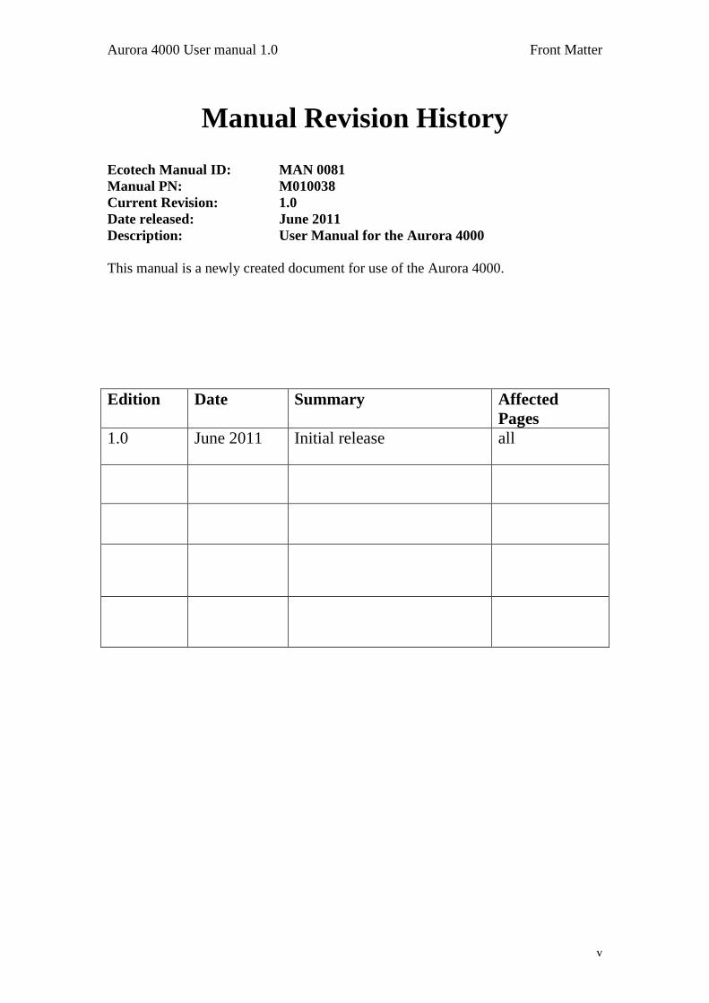
Manual Revision History
Ecotech Manual ID: MAN 0081
Manual PN: M010038
Current Revision: 1.0
Date released: June 2011
Description: User Manual for the Aurora 4000
This manual is a newly created document for use of the Aurora 4000.
Edition Date Summary Affected
Pages
1.0 June 2011 Initial release all

Front Matter Aurora 4000 User manual 1.0
vi
Table of Contents
1 INTRODUCTION ............................................................................................................ 1
1.1 DESCRIPTION ................................................................................................................... 1 1.2 SPECIFICATIONS .............................................................................................................. 1 1.2.1 MEASUREMENT ............................................................................................................. 1 1.2.2 CALIBRATION ................................................................................................................ 2 1.2.3 POWER ........................................................................................................................... 2 1.2.4 OPERATING CONDITIONS ............................................................................................... 2 1.2.5 PHYSICAL DIMENSIONS .................................................................................................. 2 1.2.6 COMMUNICATION AND DATA ........................................................................................ 2 1.3 NOMENCLATURE ............................................................................................................. 4 1.4 BACKGROUND/ THEORY ................................................................................................. 5 1.4.1 BACKGROUND ............................................................................................................... 6 1.4.2 MEASUREMENT THEORY ............................................................................................... 9 1.4.3 CALIBRATION THEORY ................................................................................................ 11 1.5 INSTRUMENT DESCRIPTION .......................................................................................... 14 1.5.1 CELL ............................................................................................................................ 15 1.5.2 PMT ............................................................................................................................. 15 1.5.3 REFERENCE SHUTTER .................................................................................................. 15 1.5.4 LIGHT SOURCE ............................................................................................................. 16 1.5.5 SAMPLE PUMP .............................................................................................................. 16 1.5.6 ZERO PUMP .................................................................................................................. 17 1.5.7 ZERO FINE FILTER ....................................................................................................... 17 1.5.8 SPAN & ZERO VALVE .................................................................................................. 17 1.5.9 TEMPERATURE / RH SENSOR ....................................................................................... 18 1.5.10 PRESSURE SENSOR ..................................................................................................... 18 1.5.11 SAMPLE HEATER ....................................................................................................... 18 1.5.12 MICROPROCESSOR ..................................................................................................... 19 1.5.13 KEYPAD & DISPLAY .................................................................................................. 19 1.5.14 BACKUP BATTERY ..................................................................................................... 20 1.5.15 ELECTRICAL CONNECTIONS ...................................................................................... 20 1.5.16 PNEUMATIC INLETS ................................................................................................... 21
2 INSTALLATION ........................................................................................................... 22
2.1 INITIAL CHECK .............................................................................................................. 22 2.2 ASSEMBLY ..................................................................................................................... 23 2.2.1 CONNECTING THE CALIBRATION GAS ......................................................................... 23 2.2.2 CONNECTING THE POWER ........................................................................................... 23 2.2.3 EXTERNAL CABLE CONNECTIONS ............................................................................... 24 2.3 MOUNTING/SITING ........................................................................................................ 25 2.4 INSTRUMENT SETUP ...................................................................................................... 26
3 OPERATION.................................................................................................................. 27
3.1 STARTUP ........................................................................................................................ 27 3.2 GENERAL OPERATIONAL INFORMATION ..................................................................... 28 3.2.1 DISPLAY PANEL AND KEYPAD ..................................................................................... 28
Aurora 4000 User manual 1.0 Front Matter
vii
3.2.2 SETTING POLAR ANGLE MEASUREMENTS .................................................................... 29 3.2.3 DISPLAY BACKLIGHT................................................................................................... 29 3.2.4 DISPLAY ADJUSTMENT ................................................................................................ 29 3.2.5 NAVIGATING THE MENU SYSTEM: ............................................................................... 29 3.2.6 EDITING PARAMETERS: ................................................................................................ 29 3.2.7 OBTAINING READINGS ................................................................................................. 30 3.3 MAIN SCREEN ................................................................................................................ 31 3.4 SAMPLING ...................................................................................................................... 31 3.5 MENUS AND SCREENS .................................................................................................... 32 3.5.1 READINGS .................................................................................................................... 32 3.5.2 SYSTEM COUNTS ......................................................................................................... 32 3.5.3 SYSTEM STATUS .......................................................................................................... 33 3.5.4 CALIBRATION .............................................................................................................. 34 3.5.5 ANGLE SELECT MENU .................................................................................................. 36 3.5.6 CONTROL ..................................................................................................................... 37 3.5.7 REPORT PREFERENCES ................................................................................................ 37 3.5.8 SERIAL IO .................................................................................................................... 39 3.5.9 ADJUST CLOCK ............................................................................................................ 39 3.5.10 DATA LOGGING ......................................................................................................... 40 3.5.11 LEAK TEST ................................................................................................................. 40
4 CALIBRATION ............................................................................................................. 41
4.1 PRECISION CHECK ........................................................................................................ 41 4.1.1 SPAN CHECK ................................................................................................................ 42 4.1.2 ZERO CHECK ................................................................................................................ 42 4.2 FULL CALIBRATION ...................................................................................................... 43 4.2.1 SETUP ........................................................................................................................... 43 4.2.2 PROCEDURE ................................................................................................................. 43 4.2.3 ZERO ADJUST............................................................................................................... 44 4.3 AUTO CALIBRATION ..................................................................................................... 45 4.4 SENSOR CALIBRATION .................................................................................................. 45 4.4.1 PRESSURE CALIBRATION ............................................................................................. 45 4.4.2 SAMPLE TEMPERATURE AND HUMIDITY CALIBRATION .............................................. 45 4.5 CALIBRATION CHECK VIA EXTERNAL IO/RS232 ....................................................... 46 4.5.1 INITIATING A CALIBRATION VIA THE EXTERNAL IO ................................................... 46 4.5.2 INITIATING A CALIBRATION VIA THE RS232 INTERFACE ............................................ 47 4.6 CALIBRATION GASES/STANDARDS............................................................................... 48 4.6.1 ZERO AIR ..................................................................................................................... 48 4.6.2 SPAN GAS .................................................................................................................... 48
5 DOWNLOADING DATA ............................................................................................. 50
5.1 RS232 INTERFACE ......................................................................................................... 50 5.1.1 MULTIDROP PORT ........................................................................................................ 50 5.1.2 SERVICE PORT ............................................................................................................. 51 5.1.3 ESTABLISHING COMMUNICATIONS .............................................................................. 51 5.2 INTERNAL DATA LOGGING ........................................................................................... 51 5.2.1 CONFIGURATION .......................................................................................................... 51 5.2.2 DATA DOWNLOADING ................................................................................................. 52 5.2.3 DATA DOWNLOADER SOFTWARE ................................................................................ 52 5.2.4 IMPORTING DATA INTO MS. EXCEL ............................................................................ 54 5.3 EXTERNAL DATA LOGGING .......................................................................................... 57
Front Matter Aurora 4000 User manual 1.0
viii
5.4 UPGRADING THE AURORA 4000 FIRMWARE ............................................................... 57
6 MAINTENANCE ........................................................................................................... 60
6.1 MAINTENANCE TOOLS .................................................................................................. 60 6.2 MAINTENANCE SCHEDULE............................................................................................ 61 6.3 MAINTENANCE PROCEDURES ....................................................................................... 61 6.3.1 PRECISION CHECK ........................................................................................................ 61 6.3.2 MEASUREMENT CELL CLEANING ................................................................................. 62 6.3.3 SAMPLE INLET AND BUG TRAP CLEAN ......................................................................... 63 6.3.4 COARSE FILTER ............................................................................................................ 63 6.3.5 ZERO/SPAN FINE FILTER .............................................................................................. 63 6.3.6 LEAK CHECK ................................................................................................................ 64 6.3.7 BATTERY REPLACEMENT ............................................................................................. 64 6.3.8 PNEUMATICS CLEANING .............................................................................................. 65 6.3.9 PMT REPLACEMENT .................................................................................................... 66 6.3.10 OPTICAL CHAMBER CLEANING ................................................................................. 68 6.3.11 ZERO NOISE TEST ...................................................................................................... 71 6.3.12 LIGHT SOURCE CHECK .............................................................................................. 72
7 TROUBLESHOOTING ................................................................................................ 74
7.1 LIGHTSOURCE FAIL ...................................................................................................... 74 7.2 REFERENCE SHUTTER FAIL ......................................................................................... 75 7.3 RH SENSOR & TEMPERATURE SENSOR FAIL ............................................................... 76 7.4 PMT FAIL ...................................................................................................................... 77 7.5 ENCLOSURE TEMPERATURE SENSOR FAIL .................................................................. 77
APPENDIX A AURORA COMMAND SET ....................................................................... 79
Aurora 4000 User manual 1.0 Front Matter
ix
List of Figures Figure 1 Graphical demonstration of backscatter measurements at 40, 70 and 90 ............. 5
Figure 2 Light path layout, without backscatter (top) and with 90 backscatter (bottom).......... 9 Figure 3 Block Diagram ........................................................................................................... 11 Figure 4 Aurora calibration curve ............................................................................................ 12 Figure 5 Ecotech Aurora 4000 (with cover removed) .............................................................. 14 Figure 6 Cell ............................................................................................................................ 15 Figure 7 PMT ........................................................................................................................... 15 Figure 8 Shutter ....................................................................................................................... 15 Figure 9 Light source ............................................................................................................... 16 Figure 10 Sample pump .......................................................................................................... 16 Figure 11 Zero pump ............................................................................................................... 17 Figure 12 Zero Filter ................................................................................................................ 17 Figure 13 Span and Zero valve ............................................................................................... 17 Figure 14 Temperature/RH sensor .......................................................................................... 18 Figure 15 Pressure sensor ...................................................................................................... 18 Figure 16 Cell Heater .............................................................................................................. 19 Figure 17 Microprocessor board .............................................................................................. 19 Figure 18 Keypad and Display ................................................................................................ 20 Figure 19 Electrical connections to the Aurora 4000............................................................... 20 Figure 20 Pneumatic connections to the Aurora 4000 ............................................................ 21 Figure 21 Span gas plumbing installation ............................................................................... 23 Figure 22 Aurora Service & Multi-drop Serial Port Cable ........................................................ 24 Figure 24 Display panel and keypad ....................................................................................... 28 Figure 25 main screen ............................................................................................................. 31 Figure 26 Temperature/Humidity sensor ................................................................................. 45 Figure 27 External Span & Zero Control ................................................................................. 46 Figure 29 Clear the data store window .................................................................................... 53 Figure 31 Step 1. ..................................................................................................................... 54 Figure 32 Step 2. ..................................................................................................................... 55 Figure 33 Step 3. ..................................................................................................................... 55 Figure 34 Imported Data. ......................................................................................................... 56 Figure 35 Regional Settings. ................................................................................................... 56 Figure 37 File Window. ............................................................................................................ 58 Figure 38 Operations Window. ................................................................................................ 58 Figure 39 Data Transfer Window. ............................................................................................ 59 Figure 40 Aurora 4000 O-Ring Locations ................................................................................ 60 Figure 41 Aurora internal components .................................................................................... 62 Figure 42 Insect trap removal .................................................................................................. 63 Figure 43 Aurora with Filters highlighted and leak test setup shown ...................................... 64 Figure 44 Internal pneumatic tubing ........................................................................................ 65 Figure 45 Removing the PMT .................................................................................................. 66 Figure 46 New PMT inserted ................................................................................................... 67 Figure 47 Removal of cell fittings ............................................................................................ 68 Figure 48 Optical chamber right cylinder components ............................................................ 69 Figure 49 Removing Light Trap ............................................................................................... 69
Front Matter Aurora 4000 User manual 1.0
x
List of Tables Table 1 Calibration Data .......................................................................................................... 11 Table 2 Properties of Calibration Gases at different wavelengths. ......................................... 13 Table 3 Serial Port Pins and their function .............................................................................. 24 Table 4 Aurora 4000 External I/O connector ........................................................................... 24 Table 6 Maintenance schedule................................................................................................ 61
List of Equations
Equation 1 Beer-Lambert law .............................................................................................................. 6 Equation 2 Koschmieder’s Formula .................................................................................................... 6 Equation 3 Light attenuation equation ................................................................................................ 6 Equation 4 Scattering Coefficient ........................................................................................................ 6 Equation 5 Absorption Coefficient ....................................................................................................... 6 Equation 6 Relationship of Extinction ................................................................................................. 7
Aurora 4000 User manual 1.0 Introduction
1
111 IIInnntttrrroooddduuuccctttiiiooonnn
1.1 Description
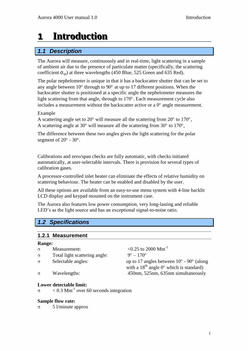
The Aurora will measure, continuously and in real-time, light scattering in a sample
of ambient air due to the presence of particulate matter (specifically, the scattering
coefficient σsp) at three wavelengths (450 Blue, 525 Green and 635 Red).
The polar nephelometer is unique in that it has a backscatter shutter that can be set to
any angle between 10 through to 90 at up to 17 different positions. When the
backscatter shutter is positioned at a specific angle the nephelometer measures the
light scattering from that angle, through to 170. Each measurement cycle also
includes a measurement without the backscatter active or a 0 angle measurement.
Example
A scattering angle set to 20 will measure all the scattering from 20 to 170,
A scattering angle at 30 will measure all the scattering from 30 to 170,
The difference between these two angles gives the light scattering for the polar
segment of 20 - 30.
Calibrations and zero/span checks are fully automatic, with checks initiated
automatically, at user-selectable intervals. There is provision for several types of
calibration gases.
A processor-controlled inlet heater can eliminate the effects of relative humidity on
scattering behaviour. The heater can be enabled and disabled by the user.
All these options are available from an easy-to-use menu system with 4-line backlit
LCD display and keypad mounted on the instrument case.
The Aurora also features low power consumption, very long-lasting and reliable
LED‟s as the light source and has an exceptional signal-to-noise ratio.
1.2 Specifications
1.2.1 Measurement
Range:
Measurement: <0.25 to 2000 Mm-1
Total light scattering angle: 9 – 170
Selectable angles: up to 17 angles between 10 - 90 (along
with a 18th
angle 0 which is standard)
Wavelengths: 450nm, 525nm, 635nm simultaneously
Lower detectable limit:
< 0.3 Mm-1
over 60 seconds integration
Sample flow rate:
5 l/minute approx
Introduction Aurora 4000 User manual 1.0
2
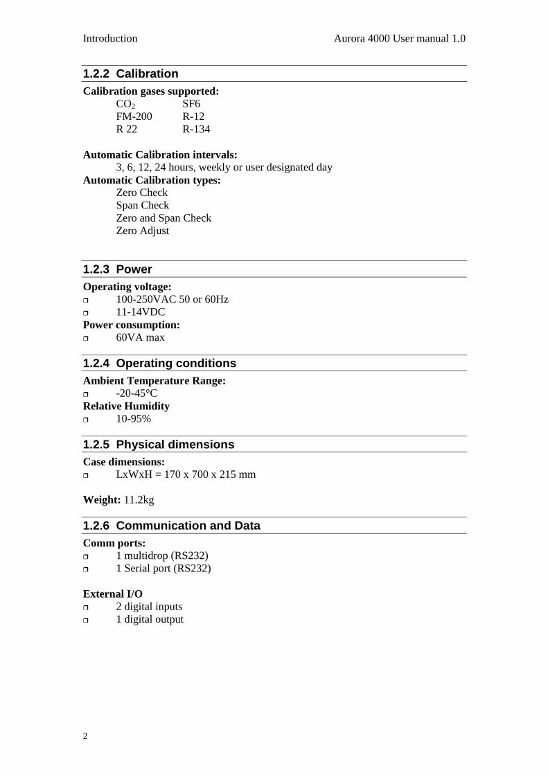
1.2.2 Calibration
Calibration gases supported: CO2 SF6
FM-200 R-12
R 22 R-134
Automatic Calibration intervals:
3, 6, 12, 24 hours, weekly or user designated day
Automatic Calibration types:
Zero Check
Span Check
Zero and Span Check
Zero Adjust
1.2.3 Power
Operating voltage: 100-250VAC 50 or 60Hz
11-14VDC
Power consumption:
60VA max
1.2.4 Operating conditions
Ambient Temperature Range: -20-45°C
Relative Humidity
10-95%
1.2.5 Physical dimensions
Case dimensions: LxWxH = 170 x 700 x 215 mm
Weight: 11.2kg
1.2.6 Communication and Data
Comm ports:
1 multidrop (RS232)
1 Serial port (RS232)
External I/O
2 digital inputs
1 digital output
Aurora 4000 User manual 1.0 Introduction
3
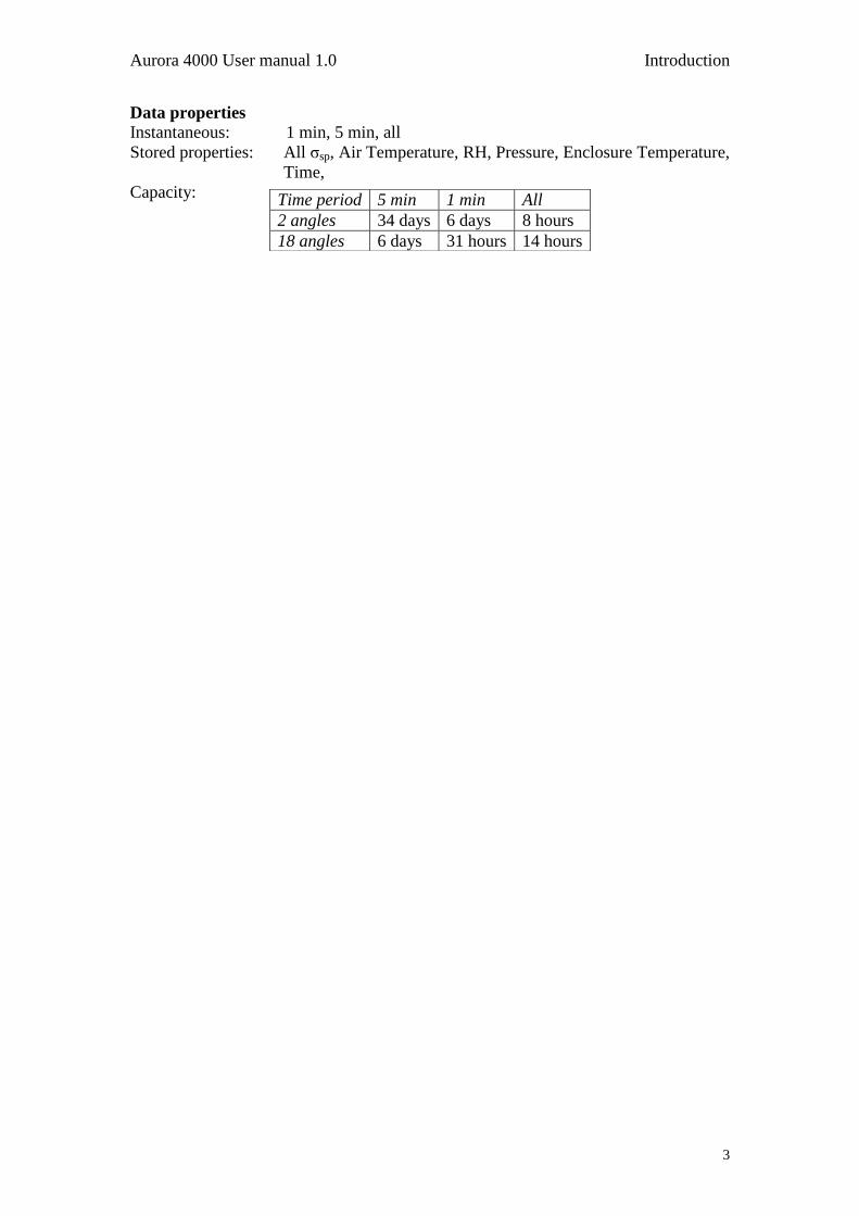
Data properties
Instantaneous: 1 min, 5 min, all
Stored properties: All σsp, Air Temperature, RH, Pressure, Enclosure Temperature,
Time,
Capacity: Time period 5 min 1 min All
2 angles 34 days 6 days 8 hours
18 angles 6 days 31 hours 14 hours
Introduction Aurora 4000 User manual 1.0
4
1.3 Nomenclature
Span: When gas of known Rayleigh factor is passed through
instrument and measured as a reference. This measurement is used to
correct measure coefficients.
Zero: When air with no particulate matter is passed through
instrument and measured as a reference. This measurement is used to
ascertain the effect of air (CO2, CO etc) on scattering coefficient.
Shutter count: The shutter count is the measurement of light shone
directly through a dark glass with known transmittance. This
measurement is used as a reference for light intensity and PMT
measurement.
Dark count: Measures background light scattering when light source
is off (< 5000 are considered typical). Used to subtract from measure
count to eliminate noise from background interference.
Measure count: Raw measurement of the light scattering of
particulates in the sample air within the cell.
Aurora 4000 User manual 1.0 Introduction
5
1.4 Background/ Theory
Aerosol and cloud scattering/absorption of light are one of the main influences on
solar radiation penetration into the lower parts of the Earth‟s atmosphere.
Nephelometers have predominantly been used to measure light scattering and
determine solar radiation entering the Earth‟s atmosphere
A traditional multi wavelength backscatter nepehelometer would allow a researcher to
accurately estimate both the total scatter of light by aerosols and how much of this
scatter is backscatter (scattered back towards the source).
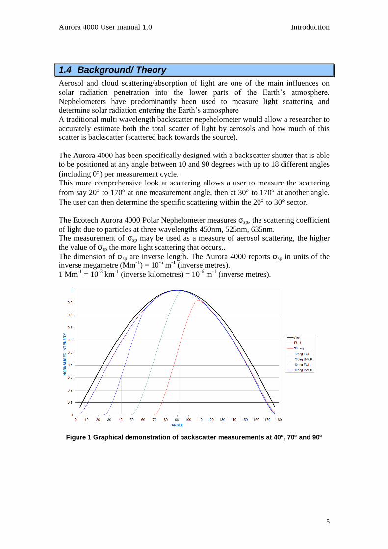
The Aurora 4000 has been specifically designed with a backscatter shutter that is able
to be positioned at any angle between 10 and 90 degrees with up to 18 different angles
(including 0) per measurement cycle.
This more comprehensive look at scattering allows a user to measure the scattering
from say 20 to 170 at one measurement angle, then at 30 to 170 at another angle.
The user can then determine the specific scattering within the 20 to 30 sector.
The Ecotech Aurora 4000 Polar Nephelometer measures σsp, the scattering coefficient
of light due to particles at three wavelengths 450nm, 525nm, 635nm.
The measurement of σsp may be used as a measure of aerosol scattering, the higher
the value of σsp the more light scattering that occurs..
The dimension of σsp are inverse length. The Aurora 4000 reports σsp in units of the
inverse megametre (Mm-1
) = 10-6
m-1
(inverse metres).
1 Mm-1
= 10-3
km-1
(inverse kilometres) = 10-6
m-1
(inverse metres).
Figure 1 Graphical demonstration of backscatter measurements at 40, 70 and 90
Introduction Aurora 4000 User manual 1.0
6
1.4.1 Background
Extinction Coefficients σext
Attenuation of light (that is, reduction in its intensity) is usually expressed using the
Beer-Lambert law:
xexteII
0
Equation 1 Beer-Lambert law
where:
I0 = initial light intensity,
I = intensity after distance x,
x = distance,
σext = the attenuation, or extinction coefficient.
(sometimes the symbol b is used instead of ext)
The relationship between extinction coefficient and visual range is expressed in
Koschmieder’s Formula.
Lv = 3.912 / σext
Equation 2 Koschmieder’s Formula
where:
Lv = visual range,
σext = extinction coefficient.
The larger ext , the more rapidly the light is attenuated (ie reducing visibility).
Assumptions
Light may be attenuated either by scattering off objects or by absorption by
objects. Thus the extinction coefficient ext may be broken down into a
scattering coefficient scat and an absorption coefficient abs:
σext = σscat + σabs. Equation 3 Light attenuation equation
For light attenuation in the atmosphere, the objects responsible can be either
gas molecules or airborne particles. The scattering and absorption coefficients
may therefore be further broken down into
σscat = σsg + σsp
Equation 4 Scattering Coefficient
and abs = σag + σap, Equation 5 Absorption Coefficient
where the subscripts denote:
s: scattering
a: absorption
g: due to gas molecules
p: due to particulate matter.
sp, for example, is the extinction coefficient due to scattering from particulate
matter. Scattering due to gas molecules (coefficient sg) is also called
„Rayleigh scattering‟.

Aurora 4000 User manual 1.0 Introduction
7
NO2 is the most significant gaseous absorber and soot the most significant
particulate absorber. However, except in extremely high concentrations, the
effects of absorption are negligible compared to the effects of scattering.
Therefore, to a very good approximation,
ext scat = sg + sp.
Equation 6 Relationship of Extinction coefficient with scattering Coefficient
It is scat that the Ecotech Aurora 4000 measures directly. When the instrument
performs a zero adjust in particle-free air (that is, where only Rayleigh
scattering is present), the sg component of scat is subtracted leaving sp as
the reported parameter.
Higher particulate concentrations mean more scattering, so sp is a good
measure of particulate pollution.
In urban situations sp will be much greater than Rayleigh scattering (sg). sp
is therefore also a good measure of atmospheric visibility.

Introduction Aurora 4000 User manual 1.0
8
Effects of Wavelength
Absorption and scattering are dependent on the wavelength of the incident
light. The Aurora 4000 uses a light source emitting light at three different
wavelengths (infrared to ultra-violet). The three wavelengths (Red 635nm,
Green 525nm, Blue 450nm) all produce differential scattering and are affected
differently by particles of different size, shape and composition.
450nm (blue) interacts strongly with fine and ultrafine particulates
(wood fires, automobiles)
525nm (green) interacts strongly throughout the human range of
visibility (smog, fog, haze)
635nm (red) interacts strongly with large particulate matter (pollen, sea
salt)
This allows partial characterisation and in-depth analysis of the type of
particulates and their effects within the environment. These different
wavelengths overlap in measurements and do not directly measure differences
in particulate composition.
Effects of Humidity
Above about 60% relative humidity, particles collect water droplets and grow
because of the water vapour condensing on them, hence scattering more light.
If enabled (section 1.1.1), the instrument will heat the sample as its humidity
approaches that set by the user. This decreases the relative humidity and
evaporates the water droplets.
Switching on the heater (dry measurement) would give a more reliable
measure of airborne pollutant concentrations, as this evaporates (much of) the
water droplets. Switching off the heater (wet measurement) would give a more
reliable measure of true scattering of aerosols.
Aurora 4000 User manual 1.0 Introduction
9
1.4.2 Measurement Theory
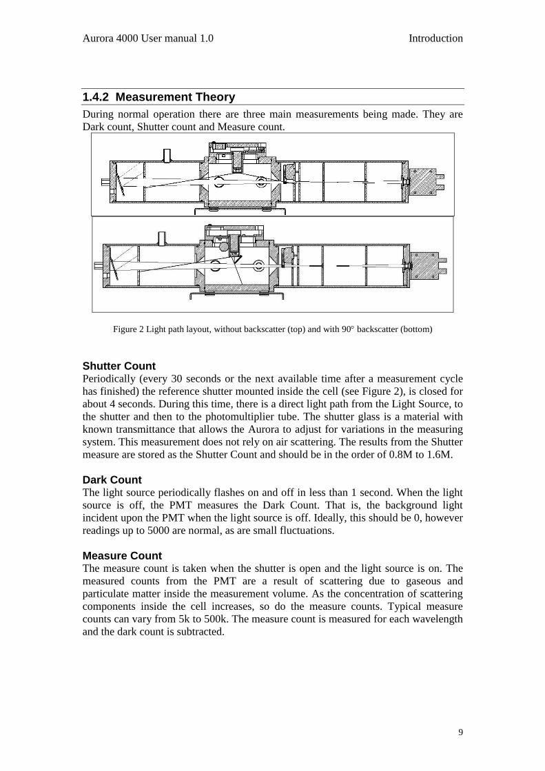
During normal operation there are three main measurements being made. They are
Dark count, Shutter count and Measure count.
Figure 2 Light path layout, without backscatter (top) and with 90 backscatter (bottom)
Shutter Count Periodically (every 30 seconds or the next available time after a measurement cycle
has finished) the reference shutter mounted inside the cell (see Figure 2), is closed for
about 4 seconds. During this time, there is a direct light path from the Light Source, to
the shutter and then to the photomultiplier tube. The shutter glass is a material with
known transmittance that allows the Aurora to adjust for variations in the measuring
system. This measurement does not rely on air scattering. The results from the Shutter
measure are stored as the Shutter Count and should be in the order of 0.8M to 1.6M.
Dark Count The light source periodically flashes on and off in less than 1 second. When the light
source is off, the PMT measures the Dark Count. That is, the background light
incident upon the PMT when the light source is off. Ideally, this should be 0, however
readings up to 5000 are normal, as are small fluctuations.
Measure Count The measure count is taken when the shutter is open and the light source is on. The
measured counts from the PMT are a result of scattering due to gaseous and
particulate matter inside the measurement volume. As the concentration of scattering
components inside the cell increases, so do the measure counts. Typical measure
counts can vary from 5k to 500k. The measure count is measured for each wavelength
and the dark count is subtracted.
Introduction Aurora 4000 User manual 1.0
10
Measure Ratio The measure ratio (MR) is the ratio between the Measure count (Cm) and the shutter
count (Csh).
MR = Cm / Csh
Eg. If Cm = 15,000 & Csh = 1,200,000, then MR = 12.5 x 10⁻³
.
Because the Csh is a stable known source, the MR is directly proportional to σscat.
If there are changes in the measurement system (ie. Light source intensity or
temperature), then both Cm & Csh will change proportionally. Therefore the MR will
remain constant. However if the σscat of the sample changes, then only the Cm will
vary.
Measurement sequence During measurement the light source sequentially emits a short pulse of light (red,
green, blue) one at a time. This sequence is repeated for every angle taking
approximately 1.5 seconds to complete. This process measures the dark count,
measure count and measure ratio are all calculated every second. The shutter count is
calculated every 30 sec (or the first available opportunity after a measurement cycle
has taken place). These measurements along with stored parameters allow the Aurora
to calculate sp for every angle at every wavelength.
Kalman Filter The Aurora 4000 has the option of using a fixed 30 second Moving Average Filter or
the advanced digital Kalman filter (selectable from the Report Prefs menu).
The Kalman filter provides the best possible compromise between response time and
noise reduction for the type of signal and noise present in the ambient air.
Ecotech‟s implementation of the Kalman filter enhances the Aurora's measurement
method by making the time constant variable, depending on the change rate of the
measured value. If the signal rate is changing rapidly, the instrument is allowed to
respond quickly. When the signal is steady, a longer integration time is used to reduce
noise. The system continuously analyses the signal and uses the appropriate filtering
time.

Aurora 4000 User manual 1.0 Introduction
11
1.4.3 Calibration Theory
During calibration, calibration gas and particle free air are passed through the cell at
different times. Both these components have known values of σsp and σsg (for each
wavelength). The Measure ratio for these components is plotted against the known
σsp, and a linear relationship is formed between σsp and Measure ratio (for each
wavelength).
Note: that the effects of dark count and other variations measured
through the shutter count, are compensated for in this relationship.
Figure 3 Block Diagram
Zero calibrations are performed with zero air to subtract the Rayleigh scattering
component) of σscat. Span calibrations are performed using certified gas, typically
CO2 or FM-200 gas (HFC-227ea Heptafluropropane).
Note: Calibrations for all three wavelengths are performed simultaneously
Calibration Example The following is an example of a typical calibration using CO2 calibration gas with
525nm (green light source).
During a full calibration two points are measured.
The span point is measured with CO2 calibration Gas.
The Zero point is measured with particle free air.
During the calibration, the Aurora measures the Cm & Csh as well as sample
temperature (ST) and barometric pressure (BP). The following results are obtained. Table 1 Calibration Data
Point Span Zero
Cm (Hz) 13692 11582
Csh (Hz) 1,200,000 1,200,000
MR (Cm/Csh) 11.41 x 10⁻³
9.65 x 10⁻³
ST (oK) 300.2 300.2
BP (mBar) 1004 1004
σscat (10-6
m)* 24.79 0

Introduction Aurora 4000 User manual 1.0
12
At STP (273.15 oK, 1013.25mBar) and wavelength 525nm:
σscat for particle free air (Air Rayleigh) = 14.82 x 10⁻⁶
m.
σscat for CO2 = 2.61 x 14.82 = 40.19 x 10⁻⁶
m. (2.61 is the known multiplier
of CO2).
*Use STP normalisation to calculate the σscat at 300.2oK & 1004mBar as measured in Table 1.
Figure 4 Aurora calibration curve
The values for σscat and MR are plotted on the above calibration curve. From this
curve we can obtain a formula for converting the MR to σscat.
σscat = (MR - 8.56) / 0.0817 (10-3
)
If for example our MR = 10 then,
σscat = 17.63 x 10⁻⁶
m.
In the Aurora 4000 all results are reported with Air Rayleigh subtracted.
σsp = σscat- σsg where σsg = 17.63 - 13.36 = 4.26 10-6
m.
Calibration Stability When a full calibration is completed, the Aurora 4000 reports a value for Cal
Stability. This is an indication of the variation of readings about the mean.
Given 150 samples, let x be the mean and s be the standard error.
Cal Stability = 100 * ( 1 - 2s/x ) .
If Cal stability = 95%, then the standard error = 2.5%.
Typically during a calibration of either span or zero, a Cal stability of > 97% should
be achieved.
11.41
9.65
y = 0.0817x + 8.5601
0
5
10
15
0 10 20 30 40
Extinction Coefficient x 10-6
Measu
re R
ati
o x
10
-3
Zero
Span
M = 81.7 x 10⁻⁶
C = 8.56 x 10⁻³
m
Aurora 4000 User manual 1.0 Introduction
13
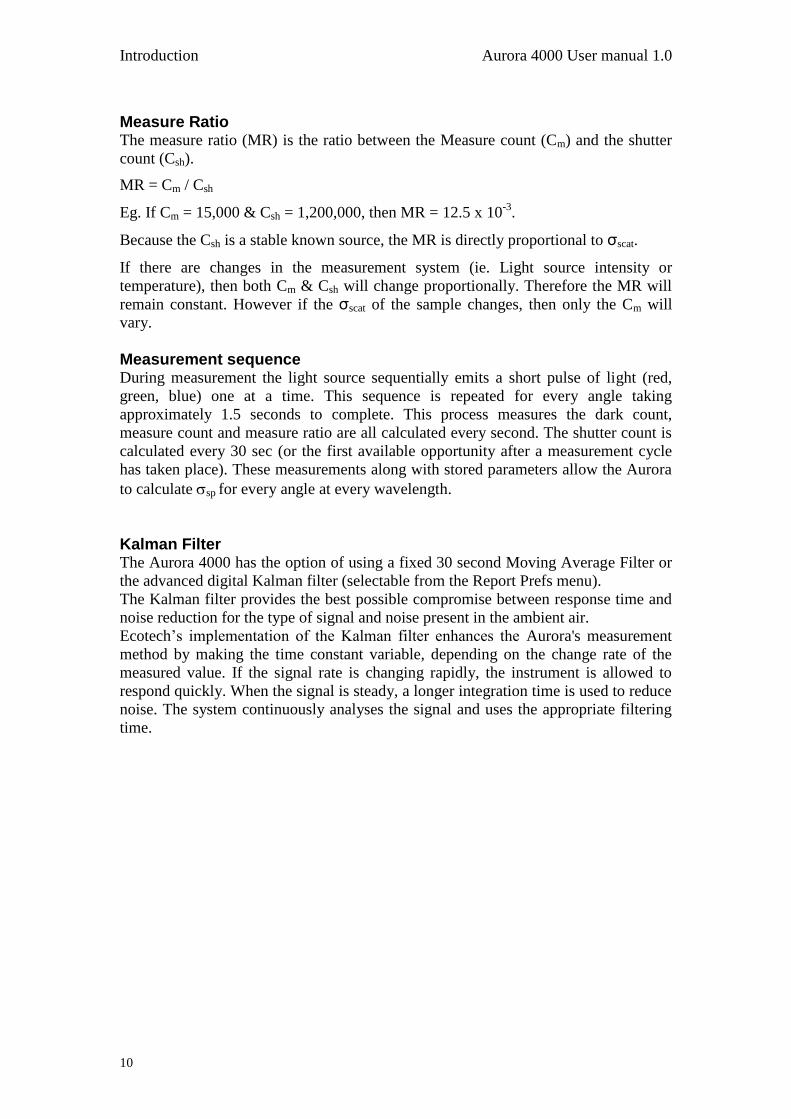
Wall Signal The Wall signal is the amount of scattering contributed as a result of internal
reflections within the cell and foreign matter. The wall signal is calculated after a full
calibration. Looking at the graph of Figure 4 the wall signal can be calculated as
follows:
Wall = 100x (C / MR(ZERO) ) = 100 x (8.56 / 9.65) = 88.7%.
Calibration Gas Constants Table 2 lists the σsp for the supported calibration gases at different wavelengths and at
STP.
The general formula to calculate the coefficient at a different wavelength:
4
1
221 )()(
spsp
So for example:
4
450
520)520()450(
spsp
Note: the following table shows the Calibration Gas Constants used by the Aurora during a full calibration. The Aurora readings are with Air Rayleigh subtracted so that for clean particle free air (zero), the Aurora Nephelometer reads 0. All values are at STP.
Table 2 Properties of Calibration Gases at different wavelengths.
Gas Constants
wavelength Rayleigh air CO B2B fm200 SF6 r12 r22 r134
2.61 15.3 6.74 15.31 7.53 7.35
450 27.46 71.67 420.14 185.08 420.41 206.77 201.83
525 14.82 38.68 226.75 99.89 226.89 111.59 108.93
635 6.92 18.07 105.95 46.64 105.95 52.14 50.90
Aurora Readings Full Scattering
wavelength CO B2B fm200 SF6 r12 r22 r134
450 44.21 392.68 157.62 392.95 179.31 174.37
525 23.86 211.93 85.07 211.93 96.77 94.11
635 11.15 99.02 39.72 99.02 45.22 43.97
The Aurora 4000 polar nephelometer performs internal calculations when calibrating
each angle or measurement. The Aurora 4000 must be calibrated each time the angles
being measured are changed, see section 4 for more details.
Wavelength (nm): 525 450 635
Air Rayleigh (10P
-6Pm): 14.82 27.46 6.92
Temp (P
oPK): 273.15 273.15 273.15
Pressure (mBar): 1013.25 1013.25 1013.25
Introduction Aurora 4000 User manual 1.0
14
1.5 Instrument description
The Aurora 4000 measures σsp in the following way:
Sample air is drawn through the sample inlet into the measurement volume
and exits through the sample outlet via the pump.
The light source illuminates the sample air in the measurement cell
The light source pulses through the three wavelengths
This illumination of 3 wavelengths is performed for each angle set within the
instrument
The baffles inside the cell are positioned so that only light scattered inside a
narrow cone, at scattering angles between 10° and 170°, reaches the
photomultiplier tube and so that multiple scattered light is unlikely to reach the
photomultiplier tube.
The photomultiplier tube produces electrical signals proportional to the
intensity of the incident light. Hence the signal produced by the
photomultiplier tube is proportional to the scattering coefficient of the sample
air, scat.
The light trap and other baffles eliminate unwanted reflections from the light
source and scattered light off the non-detecting end of the cell. The cell
interior and baffles are coated with a special mat finish black paint to reduce
any internal reflections.
This same procedure is conducted for each wavelength both for full and
backscatter. Backscatter involves a backscatter shutter blocking the scatter on
the opposite side from the light source, removing forward scatter.
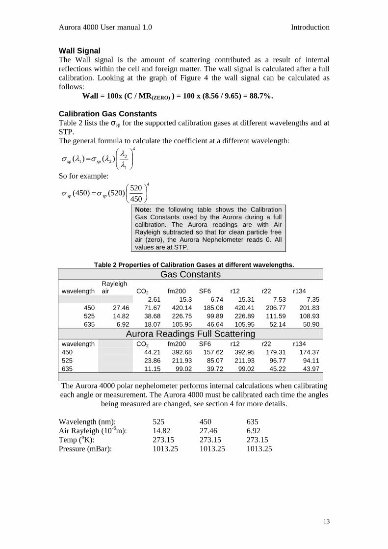
After removing the front cover, you will see the Aurora‟s components. The following
is a brief description of each of these components.
Figure 5 Ecotech Aurora 4000 (with cover removed)
Aurora 4000 User manual 1.0 Introduction
15
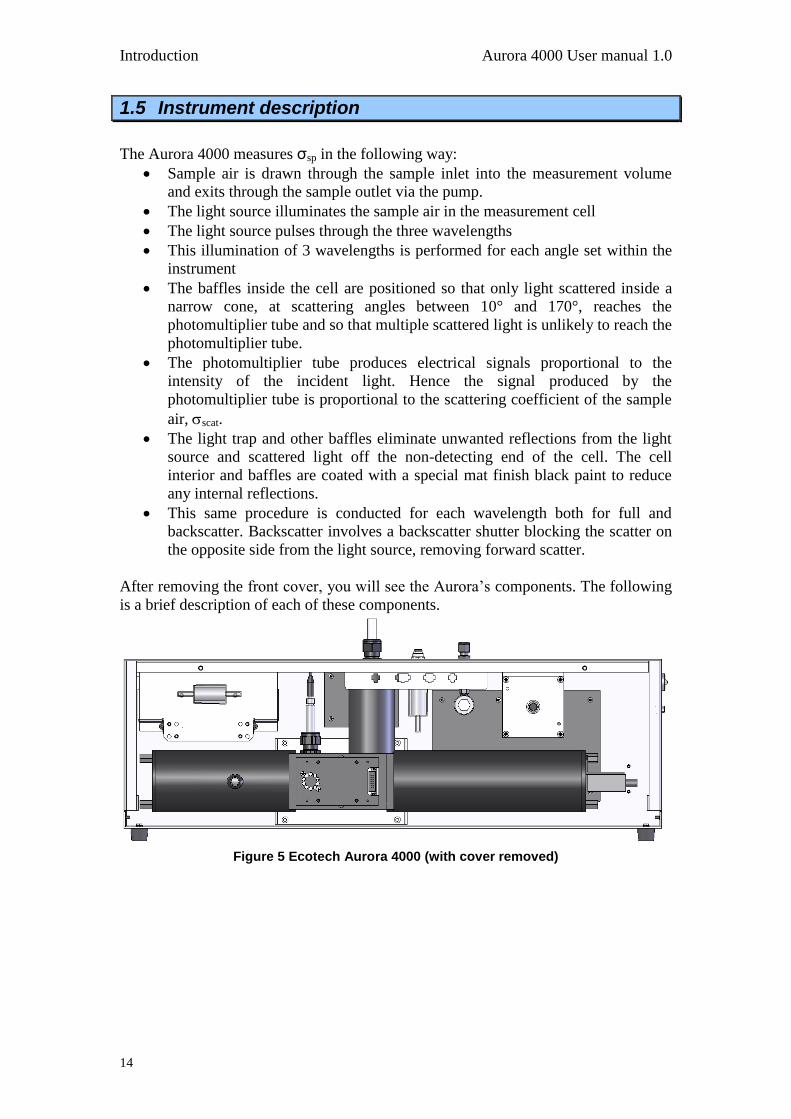
1.5.1 Cell
The cell is the critical part of the Aurora. It is within cell that the optics, the
electronics and the pneumatics all come together. The cell pneumatically and optically
sealed to prevent stray light and air from entering. It is made of black anodised
aluminium with a coating of matt black paint on the inside to reduce internal wall
scatter.
Figure 6 Cell
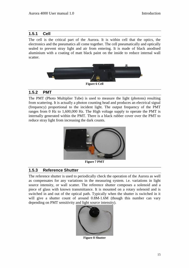
1.5.2 PMT
The PMT (Photo Multiplier Tube) is used to measure the light (photons) resulting
from scattering. It is actually a photon counting head and produces an electrical signal
(frequency) proportional to the incident light. The output frequency of the PMT
ranges from 0 Hz to 1,600,000 Hz. The High voltage supply to operate the PMT is
internally generated within the PMT. There is a black rubber cover over the PMT to
reduce stray light from increasing the dark counts.
Figure 7 PMT
1.5.3 Reference Shutter
The reference shutter is used to periodically check the operation of the Aurora as well
as compensates for any variations in the measuring system. i.e. variations in light
source intensity, or wall scatter. The reference shutter composes a solenoid and a
piece of glass with known transmittance. It is mounted on a rotary solenoid and is
switched in and out of the optical path. Typically when the shutter is switched in it
will give a shutter count of around 0.8M-1.6M (though this number can vary
depending on PMT sensitivity and light source intensity).
Figure 8 Shutter
Introduction Aurora 4000 User manual 1.0
16
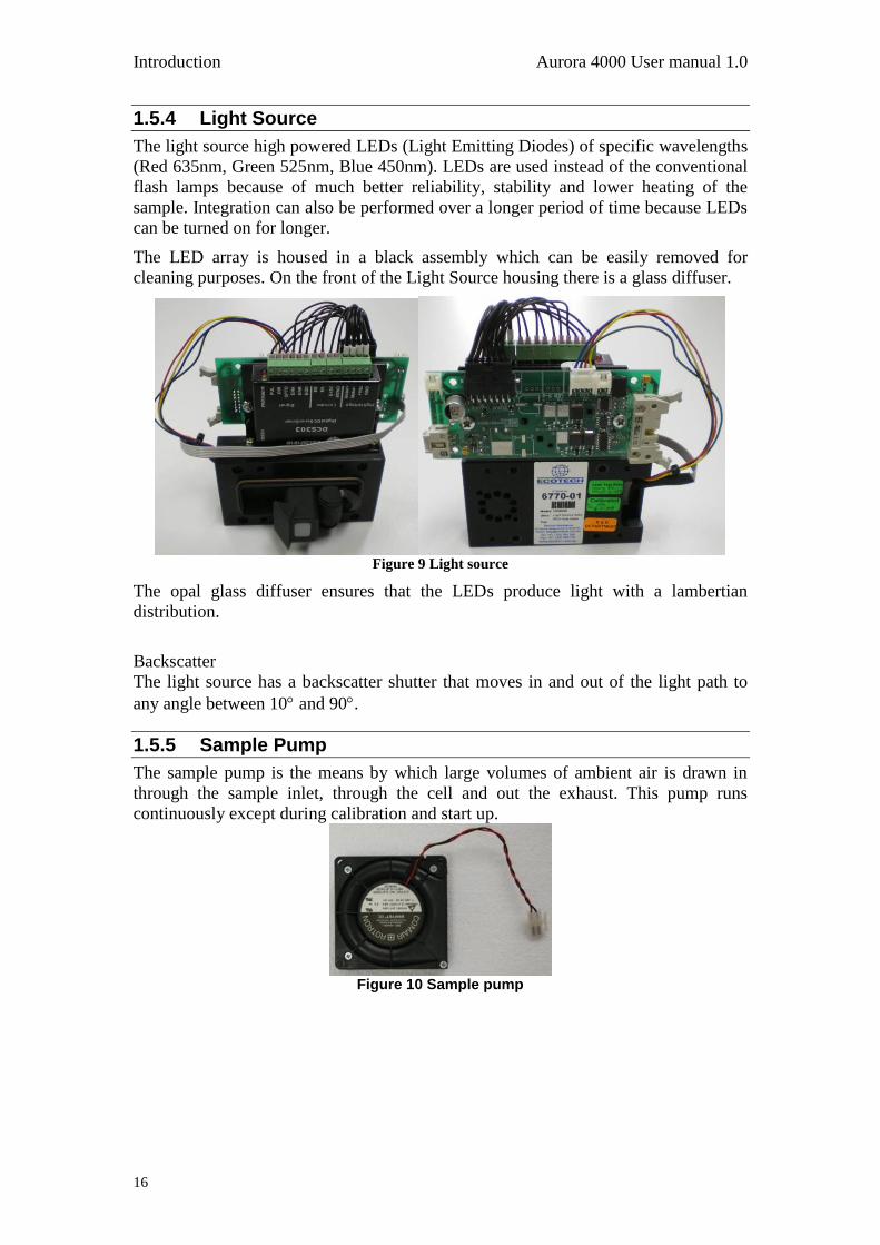
1.5.4 Light Source
The light source high powered LEDs (Light Emitting Diodes) of specific wavelengths
(Red 635nm, Green 525nm, Blue 450nm). LEDs are used instead of the conventional
flash lamps because of much better reliability, stability and lower heating of the
sample. Integration can also be performed over a longer period of time because LEDs
can be turned on for longer.
The LED array is housed in a black assembly which can be easily removed for
cleaning purposes. On the front of the Light Source housing there is a glass diffuser.
Figure 9 Light source
The opal glass diffuser ensures that the LEDs produce light with a lambertian
distribution.
Backscatter
The light source has a backscatter shutter that moves in and out of the light path to
any angle between 10 and 90.
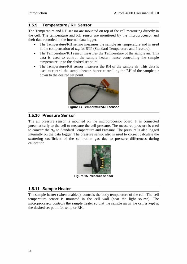
1.5.5 Sample Pump
The sample pump is the means by which large volumes of ambient air is drawn in
through the sample inlet, through the cell and out the exhaust. This pump runs
continuously except during calibration and start up.
Figure 10 Sample pump

Aurora 4000 User manual 1.0 Introduction
17
1.5.6 Zero Pump
The Zero air pump is a +12V DC diaphragm pump which draws air through the fine
filter providing particle free air (zero calibration or zero check). It is not on during
normal measuring mode. The zero pump has a DFU filter on its inlet to protect the
pump from dust build up.
Figure 11 Zero pump
1.5.7 Zero Fine Filter
The zero filter works in conjunction with the zero pump to provide the particle free air
during zero calibration and zero check. Its filtration efficiency is greater than 99.5%
removing particles greater than 0.1 micron in size.
Figure 12 Zero Filter
1.5.8 Span & Zero Valve
The span valve and Zero valve are +12V solenoid valve which are opened during a
span calibration/span check or zero calibration respectively. When opened, it allows
the calibration gas/zero air to pass into the cell for calibration.
Figure 13 Span and Zero valve
Introduction Aurora 4000 User manual 1.0
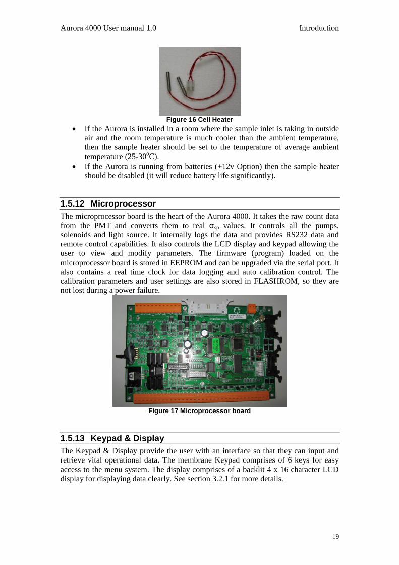
18
1.5.9 Temperature / RH Sensor
The Temperature and RH sensor are mounted on top of the cell measuring directly in
the cell. The temperature and RH sensor are monitored by the microprocessor and
their data recorded in the internal data logger.
The Temperature/RH sensor measures the sample air temperature and is used
in the compensation of σsp for STP (Standard Temperature and Pressure).
The Temperature/RH sensor measures the Temperature of the sample air. This
data is used to control the sample heater, hence controlling the sample
temperature up to the desired set point.
The Temperature/RH sensor measures the RH of the sample air. This data is
used to control the sample heater, hence controlling the RH of the sample air
down to the desired set point.
Figure 14 Temperature/RH sensor
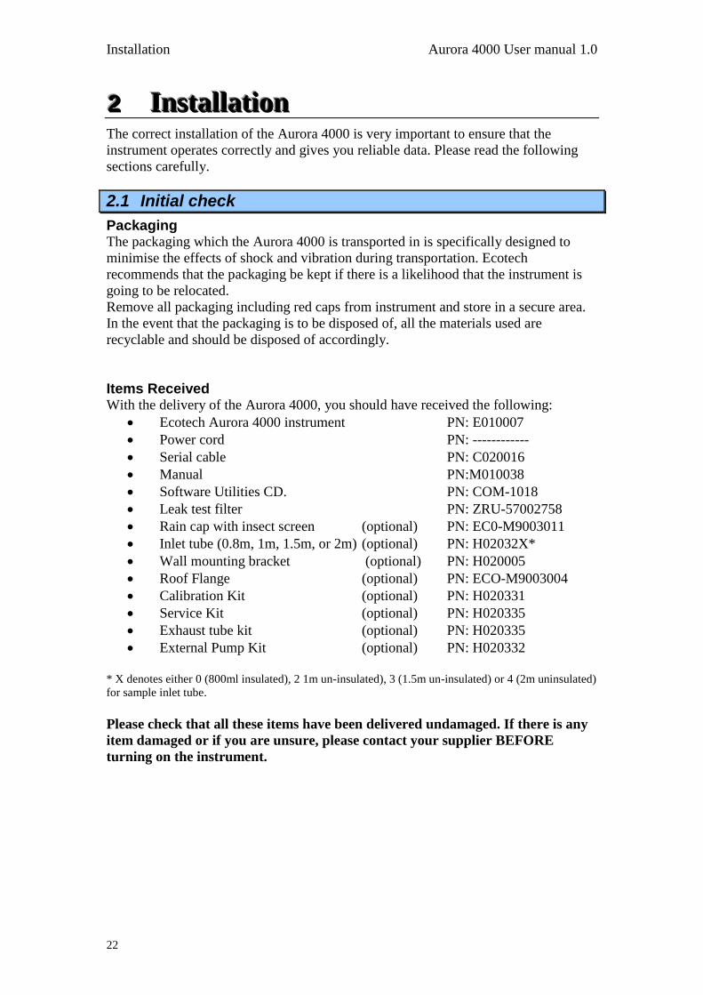
1.5.10 Pressure Sensor
The air pressure sensor is mounted on the microprocessor board. It is connected
pneumatically to the cell to measure the cell pressure. The measured pressure is used
to convert the σsp to Standard Temperature and Pressure. The pressure is also logged
internally on the data logger. The pressure sensor also is used to correct calculate the
scattering coefficient of the calibration gas due to pressure differences during
calibration.
Figure 15 Pressure sensor
1.5.11 Sample Heater
The sample heater (when enabled), controls the body temperature of the cell. The cell
temperature sensor is mounted in the cell wall (near the light source). The
microprocessor controls the sample heater so that the sample air in the cell is kept at
the desired set point for temp or RH.
Aurora 4000 User manual 1.0 Introduction
19
Figure 16 Cell Heater
If the Aurora is installed in a room where the sample inlet is taking in outside
air and the room temperature is much cooler than the ambient temperature,
then the sample heater should be set to the temperature of average ambient
temperature (25-30oC).
If the Aurora is running from batteries (+12v Option) then the sample heater
should be disabled (it will reduce battery life significantly).
1.5.12 Microprocessor
The microprocessor board is the heart of the Aurora 4000. It takes the raw count data
from the PMT and converts them to real σsp values. It controls all the pumps,
solenoids and light source. It internally logs the data and provides RS232 data and
remote control capabilities. It also controls the LCD display and keypad allowing the
user to view and modify parameters. The firmware (program) loaded on the
microprocessor board is stored in EEPROM and can be upgraded via the serial port. It
also contains a real time clock for data logging and auto calibration control. The
calibration parameters and user settings are also stored in FLASHROM, so they are
not lost during a power failure.
Figure 17 Microprocessor board
1.5.13 Keypad & Display
The Keypad & Display provide the user with an interface so that they can input and
retrieve vital operational data. The membrane Keypad comprises of 6 keys for easy
access to the menu system. The display comprises of a backlit 4 x 16 character LCD
display for displaying data clearly. See section 3.2.1 for more details.

Introduction Aurora 4000 User manual 1.0
20
Figure 18 Keypad and Display
1.5.14 Backup Battery
The backup batteries are located next to the microprocessor board. They provide
power to the real time clock and logged data when the Aurora 4000 is turned off.
Note if you disconnect the battery while the power is off, the clock settings and all logged data will be lost. However calibration and setup parameters will not be lost. The batteries are two AA 1.5V alkaline cells.
1.5.15 Electrical Connections
The following connections are found on the right side of the instrument (when
looking at the screen). The placement of these electrical and communication
connections is designed to minimise any interference from liquid spills or dust build
up.
Figure 19 Electrical connections to the Aurora 4000
RS232 There are two RS232 serial ports available on the Aurora 4000, The multi-drop and
Service ports. The Multi-drop serial port is used for communication and data
download, they can be connected to data logger or in a daisy chain configuration. The
service port is used for diagnostic purposes. Refer to section 4.5.1 for further details
on setting up the RS232 ports.

Aurora 4000 User manual 1.0 Introduction
21
12V in The12V inlet is where the 12V power pack is connected. This supplies the power for
the instrument which will not operate if not plugged in. The Power switch is located
on the left side of the connector and must also be turned on (switched down) for the
instrument to work.
1.5.16 Pneumatic inlets
The pneumatic inlet connections for the Aurora are located on the top of the
instrument case (when looking at screen) so that inlet tubing can be positioned
directly above the case and to the external environment (if necessary).
Figure 20 Pneumatic connections to the Aurora 4000
Sample The ½” port labelled “sample”, is where the sample inlet is connected. During
transport or storage, this port should be closed to avoid debris from falling into the
cell.
Zero The Aurora 4000 has its own internal filters for generating particle free air. There is
no need for any further connections on the “zero gas” port.
Span The calibration gas used for calibrating the Aurora is connected here as discussed in
section 2.2.1.
Warning: DO NOT leave FM200 gas connected to the Aurora for long periods of time as this may cause condensation and damage to the calibration control kit.
Exhaust The Exhaust is located at the top of the instrument to the right side of the other
pneumatic connections. The exhaust is pumped up through this outlet which has the
ability to be vented out with a screw in exhaust hose (optional)
Note: During normal operation make
sure that the exhaust is not covered.
Installation Aurora 4000 User manual 1.0
22
222 IIInnnssstttaaallllllaaatttiiiooonnn The correct installation of the Aurora 4000 is very important to ensure that the
instrument operates correctly and gives you reliable data. Please read the following
sections carefully.
2.1 Initial check
Packaging The packaging which the Aurora 4000 is transported in is specifically designed to
minimise the effects of shock and vibration during transportation. Ecotech
recommends that the packaging be kept if there is a likelihood that the instrument is
going to be relocated.
Remove all packaging including red caps from instrument and store in a secure area.
In the event that the packaging is to be disposed of, all the materials used are
recyclable and should be disposed of accordingly.
Items Received With the delivery of the Aurora 4000, you should have received the following:
Ecotech Aurora 4000 instrument PN: E010007
Power cord PN: ------------
Serial cable PN: C020016
Manual PN:M010038
Software Utilities CD. PN: COM-1018
Leak test filter PN: ZRU-57002758
Rain cap with insect screen (optional) PN: EC0-M9003011
Inlet tube (0.8m, 1m, 1.5m, or 2m) (optional) PN: H02032X*
Wall mounting bracket (optional) PN: H020005
Roof Flange (optional) PN: ECO-M9003004
Calibration Kit (optional) PN: H020331
Service Kit (optional) PN: H020335
Exhaust tube kit (optional) PN: H020335
External Pump Kit (optional) PN: H020332
* X denotes either 0 (800ml insulated), 2 1m un-insulated), 3 (1.5m un-insulated) or 4 (2m uninsulated)
for sample inlet tube.
Please check that all these items have been delivered undamaged. If there is any
item damaged or if you are unsure, please contact your supplier BEFORE
turning on the instrument.
Aurora 4000 User manual 1.0 Installation
23
2.2 Assembly
2.2.1 Connecting the Calibration Gas
Consult your local regulations for the positioning of the gas cylinder.
In most cases the gas cylinders should be located outside the building and
secured to a solid wall.
The Calibration gas should be high purity 99.99% gas for accurate calibration.
The calibration gas cylinder should be fitted with a regulator and flow meter.
It should also include at least 1 metre coiled metal line to bring gas
temperature to room temperature, especially if a refrigerant gas is used.
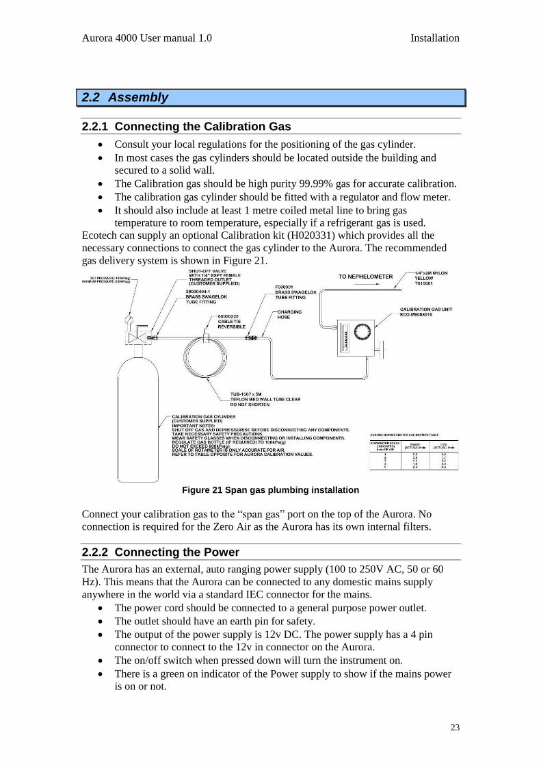
Ecotech can supply an optional Calibration kit (H020331) which provides all the
necessary connections to connect the gas cylinder to the Aurora. The recommended
gas delivery system is shown in Figure 21.
Figure 21 Span gas plumbing installation
Connect your calibration gas to the “span gas” port on the top of the Aurora. No
connection is required for the Zero Air as the Aurora has its own internal filters.
2.2.2 Connecting the Power
The Aurora has an external, auto ranging power supply (100 to 250V AC, 50 or 60
Hz). This means that the Aurora can be connected to any domestic mains supply
anywhere in the world via a standard IEC connector for the mains.
The power cord should be connected to a general purpose power outlet.
The outlet should have an earth pin for safety.
The output of the power supply is 12v DC. The power supply has a 4 pin
connector to connect to the 12v in connector on the Aurora.
The on/off switch when pressed down will turn the instrument on.
There is a green on indicator of the Power supply to show if the mains power
is on or not.

Installation Aurora 4000 User manual 1.0
24
2.2.3 External Cable Connections
Although the Aurora has its own internal data logging feature, some situations may
require it to be connected to an external data logger. There are two ways to connect to
a data logger.
RS232 Ecotech supply an RS232 cable with each Aurora 4000. This cable is suitable for
connecting directly from the Aurora 4000 (Multi-drop port) to a standard 9 pin RS232
port found on most personal or laptop computers.
If you require a longer cable for your application, the following diagram shows how it
can be made.
Note: When using cable lengths in excess of about 5 meters, you may need to reduce the Baud rate in order to reduce communication errors.
Section 5 contains more information on setting up the RS232 communications for
data logger.
Figure 22 Aurora Service & Multi-drop Serial Port Cable
Table 3 Serial Port Pins and their function Pin No Function 1 CD (not used)
6 DSR (not used)
2 RD
7 RTS (not used)
3 TD
8 CTS (not used)
4 DTR (not used)
9
5 GND
Shell Chassis GND
1
2
3
4
5
6
7
8
9
1
2
3
4
5
6
7
8
9
Aurora Multi-drop or
Service Port. DB9 M
M9003 MULTIiDROP or
SERVICE PORT
Data Logger or
PC Serial Port.
DB9F.
Aurora 4000 User manual 1.0 Installation
25
2.3 Mounting/Siting
Siting Considerations For additional information regarding siting, please consult your local Standards for
siting guidelines.
The Australian Standard AS2922 requires that the sampling inlet be positioned:
Between 2 and 5 metres above ground;
At least one horizontal metre and one vertical metre from supporting
structures or walls;
With 120° of clear sky above the sampling inlet;
With an unrestricted airflow of 270° around the inlet, or 180° if the inlet is
on the side of a building;
20 metres from trees;
With no boiler or incinerator flues nearby.
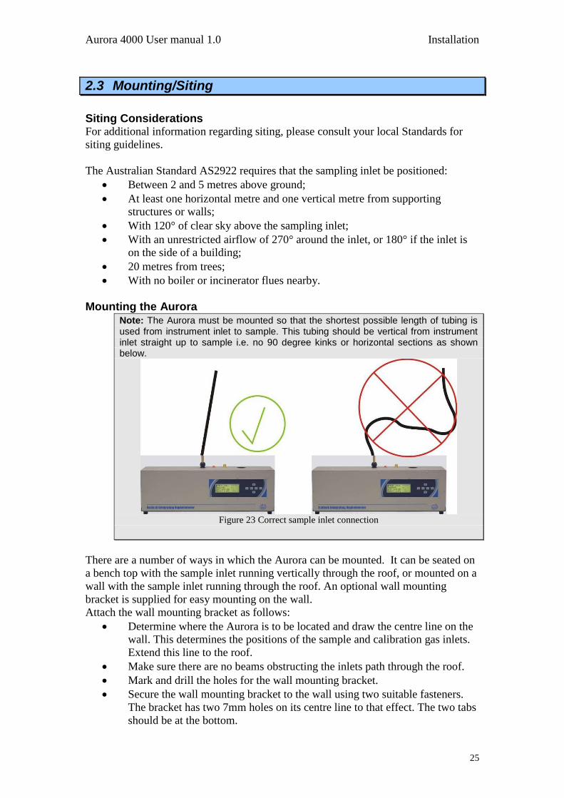
Mounting the Aurora Note: The Aurora must be mounted so that the shortest possible length of tubing is used from instrument inlet to sample. This tubing should be vertical from instrument inlet straight up to sample i.e. no 90 degree kinks or horizontal sections as shown below.
Figure 23 Correct sample inlet connection
There are a number of ways in which the Aurora can be mounted. It can be seated on
a bench top with the sample inlet running vertically through the roof, or mounted on a
wall with the sample inlet running through the roof. An optional wall mounting
bracket is supplied for easy mounting on the wall.
Attach the wall mounting bracket as follows:
Determine where the Aurora is to be located and draw the centre line on the
wall. This determines the positions of the sample and calibration gas inlets.
Extend this line to the roof.
Make sure there are no beams obstructing the inlets path through the roof.
Mark and drill the holes for the wall mounting bracket.
Secure the wall mounting bracket to the wall using two suitable fasteners.
The bracket has two 7mm holes on its centre line to that effect. The two tabs
should be at the bottom.
Installation Aurora 4000 User manual 1.0
26
Mark the position of the hole for the sample inlet tube and drill.
The roof flange option can be used on the top of the roof to seal the sample
inlet.
Note: When drilling holes, be sure to cover all open ports on the
Aurora and supplied tubing. This will reduce cell contamination.
2.4 Instrument setup
When setting up the Aurora the following points should completed:
Set correct time (section 3.5.9)
Clear data logger ( section 3.5.10)
Set standard temperature (section 3.5.7 “Normalise to”)
Set automatic calibration interval (section 3.5.4.2 “Autocal intv”)
Set Calibration gas type (section 3.5.4.2 “span gas” and/or “custom span gas”)
Perform calibration (section 4.2)
Aurora 4000 User manual 1.0 Operation
27
333 OOOpppeeerrraaatttiiiooonnn With the Aurora 4000 installed correctly as outlined in the previous sections, it is now
ready to be used. This section will discuss what to expect and how to configure the
Aurora once it is powered up.
3.1 Startup
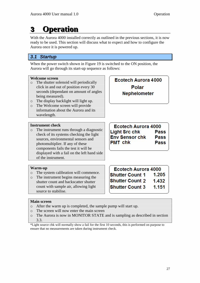
When the power switch shown in Figure 19 is switched to the ON position, the
Aurora will go through its start-up sequence as follows:
Welcome screen o The shutter solenoid will periodically
click in and out of position every 30
seconds (dependant on amount of angles
being measured).
o The display backlight will light up.
o The Welcome screen will provide
information about the Aurora and its
wavelength.
Instrument check
o The instrument runs through a diagnostic
check of its systems checking the light
sources, environmental sensors and
photomultiplier. If any of these
components fails the test it will be
displayed with a fail on the left hand side
of the instrument.
Warm-up
o The system calibration will commence.
o The instrument begins measuring the
shutter count and backscatter shutter
count with sample air, allowing light
source to stabilise.
Main screen
o After the warm up is completed, the sample pump will start up.
o The screen will now enter the main screen
o The Aurora is now in MONITOR STATE and is sampling as described in section
3.3. *Light source chk will normally show a fail for the first 10 seconds, this is performed on purpose to
ensure that no measurements are taken during instrument check.
Operation Aurora 4000 User manual 1.0
28
3.2 General operational information
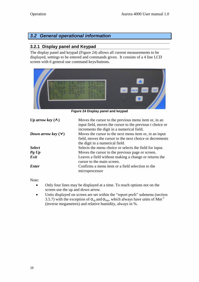
3.2.1 Display panel and Keypad
The display panel and keypad (Figure 24) allows all current measurements to be
displayed, settings to be entered and commands given. It consists of a 4 line LCD
screen with 6 general use command keys/buttons.
Figure 24 Display panel and keypad
Up arrow key () Moves the cursor to the previous menu item or, in an
input field, moves the cursor to the previous t choice or
increments the digit in a numerical field.
Down arrow key () Moves the cursor to the next menu item or, in an input
field, moves the cursor to the next choice or decrements
the digit in a numerical field.
Select Selects the menu choice or selects the field for input.
Pg Up Moves the cursor to the previous page or screen.
Exit Leaves a field without making a change or returns the
cursor to the main screen.
Enter Confirms a menu item or a field selection to the
microprocessor
Note:
Only four lines may be displayed at a time. To reach options not on the
screen use the up and down arrow.
Units displayed on screen are set within the “report prefs” submenu (section
3.5.7) with the exception of σsp and σbsp, which always have units of Mm-1
(inverse megametres) and relative humidity, always in %.
Aurora 4000 User manual 1.0 Operation
29
3.2.2 Setting polar angle measurements
The polar nephelometer is flexible in the angles that can be measured. The user has
the ability to select and the number and the degree position of polar angles being
measured. To select these angles enter the Angle select menu
1. Within this menu first choose the number of angles that will be measured,
between 2 and 18 (remember 0 is always measured and must be the first
angle).
Note: Changing the amount of angles will delete all previous data, ensure all data has been downloaded before performing this action
2. If the number of angles measured is increased, the new angles will be set at
90 automatically.
3. Individually set the degrees for each angle ensuring that they are in order and
increasing in value (i.e. 1st = 0, 2
nd = 10, 3
rd = 20, 4
th = 30 etc). Note that
the smallest non-zero angle that can be measured is 10, (the truncation angle).
3.2.3 Display Backlight
When the Aurora is initially turned on, the Backlight on the LCD display will also
turn on. However if the keypad is not used for approximately 3 minutes, then the
Backlight will turn off automatically. The Display Backlight can be re-activated by
pressing any one of the keys on the keypad.
3.2.4 Display Adjustment
On power up the display contrast will maintain the setting from its previous operation.
The contrast can be adjusted by pressing either the up or down arrows on the keypad
when on the main screen.
3.2.5 Navigating the menu system:
Press the up arrow and down arrow to move the cursor amongst menu
options.
Press Select or Enter to activate a submenu or to perform an operation (these
menu entries usually have after them to indicate their type), or to edit an
editable parameter. If the parameter is not editable then pressing Select or
Enter will have no effect.
Press Page up to return to the next highest level menu.
Press Exit to return to the Information Screen.
3.2.6 Editing parameters:
Press the up arrow and down arrow to cycle among the options for that
parameter.
Operation Aurora 4000 User manual 1.0
30
Numerical parameters are usually entered digit by digit. Press the up arrow
and down arrow to cycle among the options for that digit (including the
decimal point). Press Select to move to the next digit to the right or Page up
to move to the next digit to the left.
Press Enter to save changes to the parameter.
Press Exit to cancel changes to the parameter.
3.2.7 Obtaining readings
The Instrument readings may be obtained through any of the following
methods:
Display panel (see section 3.2.1).
Internal Data Logging (see section 5.1).
Serial RS232 Communication Ports (see section 5.3).

Aurora 4000 User manual 1.0 Operation
31
3.3 Main screen
The main screen is displayed after the Aurora has passed through its warm-up or after
pressing Exit while navigating the menu system. This screen is divided into two
sections.
The first section has three lines, the first line displays the angle that the
current measurement is being performed at either 0 or an angle from 10-90.
the second line lists which wavelength is being reported in that column and
the third line displays the current measure of σsp.
The second section includes the last line which display the current sample
temperature (ST°C), Relative Humidity (RH%) and Barometric Pressure (BP).
The value of each of these parameters is displayed immediately below on the
fourth line.
The forth line alternates after 16 seconds from the parameter names to the date and
time. The date and time are only shown for 6 seconds.
Angle: 90 degrees
635σsp 525σsp 450σsp
1.256 2.346 1.498
Temp Humidity Pressure
Figure 25 main screen
3.4 Sampling
The Aurora 4000 performs continuous real-time sampling. The Aurora will provide
updated measurements over the sampling time period chosen by the user (section
3.5.10 “Log period”).The units logged are:
σsp 1: Scattering coefficient for 635nm (0 to 2000Mm-1
or user
defined full scale).
σsp 2: Scattering coefficient for 525nm (0 to 2000Mm-1
or user
defined full scale).
σsp 3: Scattering coefficient for 450nm (0 to 2000Mm-1
or user
defined full scale).
ST: Sample air temperature in the cell (-40°C to 60°C).
ET: Temperature within the Enclosure (-40°C to 60°C).
RH: Sample air relative humidity (0% to 100%).
BP: Barometric pressure in the cell (150 to 1150 mbar).
Operation Aurora 4000 User manual 1.0
32
3.5 Menus and screens
To enter the Main Menu from the Information Screen press Enter or Select. The main
menu gives access to the following submenus.
3.5.1 Readings
The Readings Submenu displays the current environmental sensor readings. The σsp
reading is updated more frequently than the other parameters.
σsp 1
Displays the current particulate scattering coefficient in Mm-1
for the red light
source (635nm)
σsp 2
Displays the current particulate scattering coefficient in Mm-1
for the green
light source (525nm)
σsp 3
Displays the current particulate scattering coefficient in Mm-1
for the blue light
source (450nm)
BP
Displays the current air pressure inside the cell (mBar or atm).
Sample T
Displays the current sample air temperature inside the cell (oC or
oK)
Enclosure T
Displays the current enclosure temperature (oC or
oK).
RH
Displays the current sample air relative humidity (% ).
3.5.2 System Counts
Dark Count
The measurement count taken when the light is off, used to offset incident
light from reading. Should be 0 though 0-200 is typical (see section 1.4.2).
Shtr Count 1, 2 & 3
The shutter count take while the reference shutter is closed. This figure should
be between 0.8M and 1.6M (see section 1.4.2).
Angle
Selects the current angle being displayed. You can edit this number to show
information for angles 1-18.
Degrees
Displays the angle in degrees. This number cannot be edited here (go to Angle
Select to change the degrees). It is displayed to remind you which angle you
are viewing calibration information for.
Meas Count 1, 2 & 3
The measurement taken with light source on and reference shutter open. This
figure will vary from 5k to 500k depending on particulate concentration (see
section 1.4.2 for more details).
Aurora 4000 User manual 1.0 Operation
33
Meas Ratio 1, 2 & 3
The measure ratio is the ratio between the measure count and shutter count.
(see section 1.4.2 for more details).
3.5.3 System Status
Major States
Monitr: Normal monitoring mode
SysCal: System calibration mode (During start-up or reset)
SpnCal: Span calibration mode (During Full Calibration)
ZroCal: Zero calibration mode (During Full Calibration)
ZroChk: Zero check mode
SpnChk: Span check mode
LeaChk: Performing a leak check
ZroAdj: Zero offset adjust (manual or automatic offset adjustment)
Minor states
Normal: Normal Monitoring
ShtrDn: Light path shutter moving into position and stabilizing
ShtrMs: Reference shutter in place, taking shutter measurement
ShtrUp: Reference shutter moving out of the way and stabilising
System Status
The System Status is the overall instruments status. If one status below fails
then the system status will fail indicating that the entire system is not working.
Light Source
This status indicates whether the light source is working (pass/fail).
Enviro Status
The Enviro Status is the overall status of all the environmental sensors (RH
Sensor, ST sensor, ET Sensor and BP Sensor). If one environmental sensor
status fails then the Enviro Status will.
Shutter
This status indicates whether the reference shutter is working (pass/fail).
PMT
This status indicates whether the PMT is working (pass/fail).
Backscatter
This status indicates whether the Backscatter shutter is working (pass/fail).
Calibration
This status indicates whether the calibration is valid for the current set of
angles. Whenever the number or value of angles is changed, a new calibration
needs to be performed.
RH Sensor
This status indicates whether the Relative Humidity sensor is working
(pass/fail).
ST Sensor
This status indicates whether the Sample Temperature sensor is working
(pass/fail).

Operation Aurora 4000 User manual 1.0
34
ET Sensor
This status indicates whether the Enclosure Temperature sensor is working
(pass/fail).
BP Sensor
This status indicates whether the Pressure sensor is working (pass/fail).
ID Number
Lists the ID number of this unit
S/W Version
This menu item displays the version of software that the instrument is
currently running. This is useful during some diagnostic and fault finding
checks as well as for finding if an update to the software is required.
3.5.4 Calibration
The Calibration submenu has 5 submenus which cover all the aspects of calibration.
These submenus allow the user to set the correct parameters to perform a calibration,
initiate a calibration sequence and view the results from the previous calibration. For
more information on performing calibrations, refer to section 4.
3.5.4.1 Activate Cal
Do full cal.
Performs a two point calibration using calibration gas and zero air. This
sequence will adjust the calibration curve. The results are recorded as Last
span ck & Last zero ck.
Do zero adj
Performs a zero adjustment on the instrument using zero air.
The results are recorded as Last zero adj.
Do zero chk.
Performs a check but no adjustment of the instrument‟s zero using zero air.
The results are recorded as Last zero ck.
Do span chk
Performs a check but no adjustment of instrument‟s span using calibration gas.
The results are recorded as Last span ck.
3.5.4.2 Cal Settings
AutoCal Intv
Sets the automatic calibration type (see next) repeat period: Hourly, 3hrs, 6hrs,
12hrs, 24hrs, Weekly on a designated day or Off .
AutoCal Type
Sets the type of Auto Cal sequence: ZroChk, SpnChk, Z&SChk & ZroAdj.
Span gas
Sets the span gas to the type to be used during a full calibration: CO2, SF6,
FM-200, R-12, R 22, R-134 or Custom.
Custom SpanG
If the span gas type Custom is selected above, then the Rayleigh multiplier is
entered here for the type of gas you are using.
Aurora 4000 User manual 1.0 Operation
35
Cal min time
Sets the minimum time (in minutes) that any span or zero adjustment or check
may take.
Cal max time
Sets the maximum time (in minutes) that any span or zero adjustment or check
may take.
% Stability
Sets the target stability for any span or zero adjustment or check.
3.5.4.3 Last Tmp & Prs
Cal Span T
Displays the temperature during the last span calibration.
Cal Span P
Displays the pressure during the last span calibration.
Cal Zero T
Displays the temperature during the last zero calibration.
Cal Zero P
Displays the pressure during the last zero calibration.
Adj Zero T
Displays the temperature during the last zero adjustment.
Adj Zero P
Displays the pressure during the last zero adjustment.
3.5.4.4 Wavelength
The following parameters are displayed within each of the Wavelengths
(Red635, Green525, and Blue450).
Angle
Selects the current angle being displayed. You can edit this number to show
information for angles 1-18.
Degrees
Displays the angle in degrees. This number cannot be edited here (go to Angle
Select to change the degrees). It is displayed to remind you which angle you
are viewing calibration information for.
Last span
Displays the σsp value (in Mm-1
) obtained during the last span check or
calibration. If a full calibration is performed, it will display the σsp value
before the calibration curve adjustment was made.
Span stab
Displays the % stability achieved during a span check or full calibration.
Last zero
Displays the σsp value (in Mm-1
) obtained after a zero check. If a zero adjust is
performed, it will display the σsp value before the calibration cure adjustment
was made.
Operation Aurora 4000 User manual 1.0
36
Zero stab
Displays the % stability achieved during a zero check or zero adjust.
Cal M
Displays the gradient of the calibration line.
Cal C
Displays the intercept of the calibration line.
Wall Sig
Displays the calculated % of scattering as a result of wall scattering. This
value is updated after a full calibration or zero adjust is completed. Refer to
wall signal on page 9 for more details.
Cal span Y
Displays the measurement ratio at span calibration point
Cal zero Y
Displays the measurement ratio at zero calibration point
Adj Zero Y
Displays the measurement ratio at zero adjustment point
3.5.4.5 Env Sensors
The Environmental sensors menu will display a screen:
* Warning * Changes will re-calibrate environmental sensors immediately.
By scrolling down you can find the four environmental sensors readings. To
calibrate these sensors all that must be done is to enter in the correct value, the
correct value must be obtained from a calibrated temperature, humidity or
pressure sensor (see sections 4.4.1 and 4.4.2).
Sample T Cal
Displays the current temperature within the sample cell, field is editable.
BP Cal
Displays the current barometric pressure, field is editable.
RH Cal
Displays the current relative humidity, field is editable.
ET Cal
Displays the current temperature within the enclosure, field is editable
Note: Do not change any of the above fields unless you are confident that the figure being entered is correct, inaccurate figures entered will result in faulty readings.
3.5.5 Angle select menu
Within this menu the number of angles being measured and the degree at which they
occur can be set.
Important Note: Changing the number of angles or degree of any angle will result in the erasing of all currently stored data. Ensure all data is downloaded before changing settings Important Note: Changing the number of angles or degree of any angle will also require the instrument to be recalibrated. The accuracy of any data measured without recalibration cannot be guaranteed.
Aurora 4000 User manual 1.0 Operation
37
Angle Count
Select the number of angles that will be measured, minimum 2 (0 , X)
maximum 18 (0, X, X etc)
Angle 1
This angle is always set to 0
Angle 2-18
Angles 2 up to 18 can be set at any angle starting from 10 up to 90. Angle
degrees must always increase starting from 0 in angle 1 and the largest angle
being the last angle in the sequence
3.5.6 Control
The control submenu is where the user can set the sample heater properties. The
configuration of this menu depends on which options are supplied and the application
of the instrument.
Sample Heater
Sets the sample heater to either enabled (RH or XX°C) or disabled (No).
If enabled (RH) the heater will maintain the sample air RH at a level
less than that set in the Desired RH field (below).
The heater can also be enabled by choosing a temperature at which the
heater will maintain the sample at 0-50°C.
If the sample heater is disabled then the sample air will not be heated.
Desired RH.
Sets the desired relative humidity range of the sample air: <40% (less than
40%), <50%,<60%,<70%,<80%,or <90%.
RH time on
Time in seconds that the sample heater is turned on for RH control.
3.5.7 Report Preferences
The Report preferences submenu allows the user to set the reporting preferences such
as units and date format so that it is compatible with the local formats. These settings
will alter the way the data is recorded in the internal data logger or via the RS232
interface.
Filtering
Sets the type of filtering used on the output data: Kalman (Adaptive digital
filter, see section 2.3.1.5), MovAvg (fixed 30 second moving average filter) or
None.
Date Format
Sets the date reporting format: D/M/Y, M/D/Y or Y-M-D (where D=Day,
M=Month, Y=Year)
Temp.Unit
Sets the temperature unit:
°C, °F or K (degree Celsius, Fahrenheit or Kelvin)
Press.Unit
Sets the barometric pressure unit:
mb or atm (millibar or atmosphere)
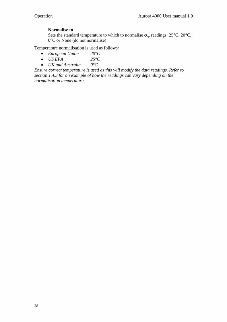
Operation Aurora 4000 User manual 1.0
38
Normalise to
Sets the standard temperature to which to normalise σsp readings: 25°C, 20°C,
0°C or None (do not normalise)
Temperature normalisation is used as follows:
European Union 20°C
US EPA 25°C
UK and Australia 0°C
Ensure correct temperature is used as this will modify the data readings. Refer to
section 1.4.3 for an example of how the readings can vary depending on the
normalisation temperature.

Aurora 4000 User manual 1.0 Operation
39
3.5.8 Serial IO
The Serial IO submenu is where the user sets the parameters for the two RS232 serial
ports (Multidrop and Service ports, Figure 19).
SvcPort Mode
This field allows the user to choose how the Serial port will be used. The
options are:
None: Serial port will not be used
Reading : Data will be sent through the Serial port in the time periods
specified within the “Reading Output” field below
Menu: When enabled, the user can access the menu system using an
ASCII terminal program. The user can navigate the menu
remotely using the Up, Down, Left, Right arrow keys on the
terminal.
Module Addr
Address for multidrop RS232 port: 0-7
MltDr Baud Rt
Communication Baud rate for multidrop RS232 port 1200 - 38400
MltDr Parity
Parity setting for multidrop RS232 port: None, Even, Odd
SvcPt BaudRt
Communication Baud rate for service port: 1200 - 38400
SvcPt Parity
Parity setting for service port: None, Even, Odd
Reading Output
Sends unpolled data through the service port when None, 1 sec, 5 sec,
enabled in SvcPort Mode (See section 0.): 10 sec or 60 sec.
3.5.9 Adjust Clock
Note: When adjusting the clock ensure all data is downloaded before any changes are made.
To enter the current date and time: set the current date, the current time and remember
to press enter on the Save time menu to have the date & time recorded.
A message “Setting clock…” will appear on the display and then return to the
information screen.
Date 06/10/2007 Sets the current date
Time 11:02:09 Sets the current time
Save time Records the date and time entered above
Note: Clear the data logger after changing
time see section 3.5.10.
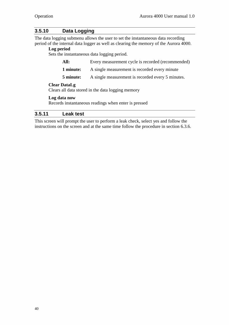
Operation Aurora 4000 User manual 1.0
40
3.5.10 Data Logging
The data logging submenu allows the user to set the instantaneous data recording
period of the internal data logger as well as clearing the memory of the Aurora 4000.
Log period Sets the instantaneous data logging period.
All: Every measurement cycle is recorded (recommended)
1 minute: A single measurement is recorded every minute
5 minute: A single measurement is recorded every 5 minutes.
Clear DataLg
Clears all data stored in the data logging memory
Log data now
Records instantaneous readings when enter is pressed
3.5.11 Leak test
This screen will prompt the user to perform a leak check, select yes and follow the
instructions on the screen and at the same time follow the procedure in section 6.3.6.
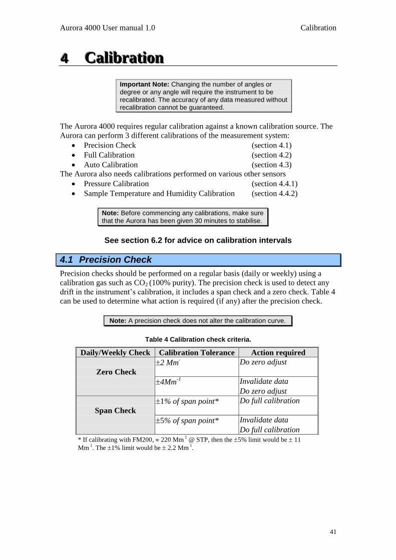
Aurora 4000 User manual 1.0 Calibration
41
444 CCCaaallliiibbbrrraaatttiiiooonnn
Important Note: Changing the number of angles or degree or any angle will require the instrument to be recalibrated. The accuracy of any data measured without recalibration cannot be guaranteed.
The Aurora 4000 requires regular calibration against a known calibration source. The
Aurora can perform 3 different calibrations of the measurement system:
Precision Check (section 4.1)
Full Calibration (section 4.2)
Auto Calibration (section 4.3)
The Aurora also needs calibrations performed on various other sensors
Pressure Calibration (section 4.4.1)
Sample Temperature and Humidity Calibration (section 4.4.2)
Note: Before commencing any calibrations, make sure that the Aurora has been given 30 minutes to stabilise.
See section 6.2 for advice on calibration intervals
4.1 Precision Check
Precision checks should be performed on a regular basis (daily or weekly) using a
calibration gas such as CO2 (100% purity). The precision check is used to detect any
drift in the instrument‟s calibration, it includes a span check and a zero check. Table 4
can be used to determine what action is required (if any) after the precision check.
Note: A precision check does not alter the calibration curve.
Table 4 Calibration check criteria.
* If calibrating with FM200, 220 Mm 1 @ STP, then the 5% limit would be 11
Mm 1. The 1% limit would be 2.2 Mm
1.
Daily/Weekly Check Calibration Tolerance Action required
2 Mm- Do zero adjust
Zero Check
4Mm-1
Invalidate data
Do zero adjust
1% of span point* Do full calibration
Span Check
5% of span point* Invalidate data
Do full calibration
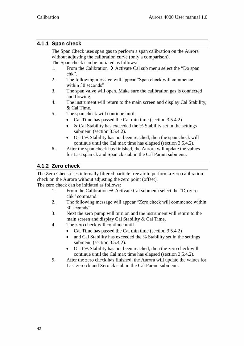
Calibration Aurora 4000 User manual 1.0
42
4.1.1 Span check
The Span Check uses span gas to perform a span calibration on the Aurora
without adjusting the calibration curve (only a comparison).
The Span check can be initiated as follows:
1. From the Calibration Activate Cal sub menu select the “Do span
chk”.
2. The following message will appear “Span check will commence
within 30 seconds”
3. The span valve will open. Make sure the calibration gas is connected
and flowing.
4. The instrument will return to the main screen and display Cal Stability,
& Cal Time.
5. The span check will continue until
Cal Time has passed the Cal min time (section 3.5.4.2)
& Cal Stability has exceeded the % Stability set in the settings
submenu (section 3.5.4.2).
Or if % Stability has not been reached, then the span check will
continue until the Cal max time has elapsed (section 3.5.4.2).
6. After the span check has finished, the Aurora will update the values
for Last span ck and Span ck stab in the Cal Param submenu.
4.1.2 Zero check
The Zero Check uses internally filtered particle free air to perform a zero calibration
check on the Aurora without adjusting the zero point (offset).
The zero check can be initiated as follows:
1. From the Calibration Activate Cal submenu select the “Do zero
chk” command.
2. The following message will appear “Zero check will commence within
30 seconds”
3. Next the zero pump will turn on and the instrument will return to the
main screen and display Cal Stability & Cal Time.
4. The zero check will continue until
Cal Time has passed the Cal min time (section 3.5.4.2)
and Cal Stability has exceeded the % Stability set in the settings
submenu (section 3.5.4.2).
Or if % Stability has not been reached, then the zero check will
continue until the Cal max time has elapsed (section 3.5.4.2).
5. After the zero check has finished, the Aurora will update the values for
Last zero ck and Zero ck stab in the Cal Param submenu.
Aurora 4000 User manual 1.0 Calibration
43
4.2 Full Calibration
The full calibration performs a two-point calibration on the Aurora. The span point
uses calibration gas, the zero point use internally filtered particle free air. A full
calibration is one in which both the span and zero points on the calibration curve will
be modified. Due to the high stability of the Aurora this type of calibration only needs
to be performed approximately every 3 months using calibration gas. Typically
FM200 is used for the full calibration. A full calibration can be performed as follows
once the setup is completed:
4.2.1 Setup
Make sure that the following options in the Calibration submenu are set (see section
3.5.4) before commencing a calibration.
1. Span Gas type: Set to the type of calibration gas you are using. Generally CO2
or FM200.
2. Cal min time. Set the minimum time (in minutes) required to complete each
calibration step (span or zero). Typically set to 15 minutes for a good
calibration.
3. Cal max time. Set to the maximum time (in minutes) required to complete
each calibration step (span or zero). Typically set to 20 minutes for a good
calibration.
4. % Stability. Set the target stability for the calibration. A value of about 95-
97% is recommended. If after Cal min time the calibration has not reached the
target stability then the calibration will continue until it reaches the target
stability or Cal max time, whichever comes first. Refer to sections 1.4.3for
further details.
5. Make sure you Calibration Gas is connected correctly and the valves and
regulators have been opened. Refer to section 2.2.1 for details on connecting
the calibration gas to the Aurora.
Note: Set the calibration gas flow rate to typically 3-4 lpm to calibrate the Aurora.
4.2.2 Procedure
1. From the Calibration Activate Cal submenu select the Do full cal
command. Immediately the following message will appear on the display.
“Full calibration will commence within 30 seconds” after this the span gas
solenoid valve inside the Aurora will open and the Main screen will display
the following parameters (alternating):
Current σsp: 23.56
The current σsp during the calibration.
(based on the old calibration curve)
Cal Stability: 97.50
% Stability during the calibration.
Meas Ratio: 0.0138
The Measure Ratio during the calibration.
Cal Time: 00:07:45
The time the calibration has been running. (hh:mm:ss)
Calibration Aurora 4000 User manual 1.0
44
2. The span calibration portion of the full calibration sequence will end after:
Cal Time has passed the Cal min time (section 3.5.4.2)
and Cal Stability has exceeded the % Stability set in the settings
submenu (section 3.5.4.2).
Or if % Stability has not been reached, then the zero check will
3. After the span calibration has finished, the Aurora will update the values for
Last span and Span stab in the Calibration submenu as well as other vital
calibration data. It will then automatically close the span gas solenoid valve
and turn on the zero air pump ready for the zero calibration portion of the full
calibration sequence.
4. The zero calibration will proceed the same as the span calibration. The
information screen will display “ZroCal” as the major state. The bottom line
will also display σsp, Cal Stability, Meas Ratio & Cal Time.
5. After the zero calibration has finished, the Aurora will update the values for
Last zero and Zero stab in the Calibration submenu as well as other vital zero
data. It will then turn off the zero air pump and turn on the sample pump ready
for sample measuring.
6. After the sample measuring has commenced, the new calibration curve will be
applied to the σsp readings.
7. Be sure to close the calibration gas cylinder after use to prevent any leaking.
4.2.3 Zero Adjust
The Zero Adjust performs a single point zero calibration on the Aurora. Using
internally filtered particle free air, the zero adjust will adjust the zero calibration point
(or offset) of the nephelometer. Although a zero calibration is calibrating against air
rayleigh (14.82 x 10⁻⁶
m @ STP), the Aurora sets this point to zero (0) after the
calibration. The zero adjust can be initiated as follows:
1. From the Calibration Activate submenu select the Do zero adj command.
Immediately the following message will appear on the display. “Zero
adjustment will commence within 30 seconds” after this the zero pump will
turn on and the information screen will be displayed.
2. In the same manner as the span calibration, the information screen will display
σsp, Cal Stability, Meas Ratio & Cal Time.
3. The zero adjust will end after the Cal Time has passed the Cal min time and
Cal Stability has exceeded the % Stability set in the calibration submenu. If
the % Stability has not yet been reached, then the zero adjust will continue
until the Cal max time has elapsed.
4. After the zero adjust has finished, the Aurora will update the values for last
zero and zero stab in the Calibration Parameters submenu as well as
changing the zero offset on the calibration curve. It will then turn off the zero
pump and turn on the sample pump ready for sample measuring.
5. After the sample measuring has commenced, the new calibration curve will be
applied to the σsp readings.
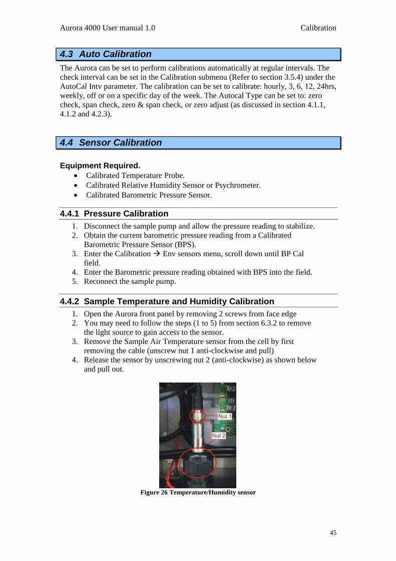
Aurora 4000 User manual 1.0 Calibration
45
4.3 Auto Calibration
The Aurora can be set to perform calibrations automatically at regular intervals. The
check interval can be set in the Calibration submenu (Refer to section 3.5.4) under the
AutoCal Intv parameter. The calibration can be set to calibrate: hourly, 3, 6, 12, 24hrs,
weekly, off or on a specific day of the week. The Autocal Type can be set to: zero
check, span check, zero & span check, or zero adjust (as discussed in section 4.1.1,
4.1.2 and 4.2.3).
4.4 Sensor Calibration
Equipment Required.
Calibrated Temperature Probe.
Calibrated Relative Humidity Sensor or Psychrometer.
Calibrated Barometric Pressure Sensor.
4.4.1 Pressure Calibration
1. Disconnect the sample pump and allow the pressure reading to stabilize.
2. Obtain the current barometric pressure reading from a Calibrated
Barometric Pressure Sensor (BPS).
3. Enter the Calibration Env sensors menu, scroll down until BP Cal
field.
4. Enter the Barometric pressure reading obtained with BPS into the field.
5. Reconnect the sample pump.
4.4.2 Sample Temperature and Humidity Calibration
1. Open the Aurora front panel by removing 2 screws from face edge
2. You may need to follow the steps (1 to 5) from section 6.3.2 to remove
the light source to gain access to the sensor.
3. Remove the Sample Air Temperature sensor from the cell by first
removing the cable (unscrew nut 1 anti-clockwise and pull)
4. Release the sensor by unscrewing nut 2 (anti-clockwise) as shown below
and pull out.
Figure 26 Temperature/Humidity sensor
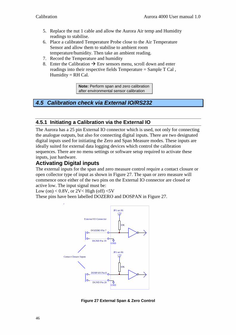
Calibration Aurora 4000 User manual 1.0
46
5. Replace the nut 1 cable and allow the Aurora Air temp and Humidity
readings to stabilise.
6. Place a calibrated Temperature Probe close to the Air Temperature
Sensor and allow them to stabilise to ambient room
temperature/humidity. Then take an ambient reading.
7. Record the Temperature and humidity
8. Enter the Calibration Env sensors menu, scroll down and enter
readings into their respective fields Temperature = Sample T Cal ,
Humidity = RH Cal.
Note: Perform span and zero calibration after environmental sensor calibration
4.5 Calibration check via External IO/RS232
4.5.1 Initiating a Calibration via the External IO
The Aurora has a 25 pin External IO connector which is used, not only for connecting
the analogue outputs, but also for connecting digital inputs. There are two designated
digital inputs used for initiating the Zero and Span Measure modes. These inputs are
ideally suited for external data logging devices which control the calibration
sequences. There are no menu settings or software setup required to activate these
inputs, just hardware.
Activating Digital inputs The external inputs for the span and zero measure control require a contact closure or
open collector type of input as shown in Figure 27. The span or zero measure will
commence once either of the two pins on the External IO connector are closed or
active low. The input signal must be:
Low (on) < 0.8V, or 2V< High (off) <5V
These pins have been labelled DOZERO and DOSPAN in Figure 27.
Figure 27 External Span & Zero Control
+5V
+5V
10K
10K
GND
GND
JP1 set Hi
JP1 set Hi
DOZERO Pin 7
DOSPAN Pin 8
DGND Pin 19
DGND Pin 20
External IO Connector
Contact Closure Inputs
Aurora 4000 User manual 1.0 Calibration
47
Zero Measure The Zero Measure mode is activated using the DOZERO digital input.
1. As soon as the DOZERO input is activated the instrument will go into
zero measure mode. The sample pump will turn off and the zero pump
will turn on, pumping particle free zero air into the measurement cell.
2. During the Zero Measure, the main screen will display “Zero Measure”
on the top line.
3. The Zero Measure will continue for as long as the DOZERO input is
activated. As soon as this input is de-activated, the Zero Measure will
stop by turning off the zero pump and turning on the sample pump. This
procedure is only a check, no adjustment is made to the calibration curve
Span Measure The Span Measure mode is activated using the DOSPAN digital input.
1. As soon as the DOSPAN input is activated the instrument will go into
Span measure mode. The sample pump will turn off and span gas
solenoid valve will open, allowing calibration gas to pass into the
measurement cell.
2. During the Span Measure, the main screen will display “Span Measure”
on the top line.
3. The Span Measure will continue for as long as the DOSPAN input is
activated. As soon as this input is de-activated, the Span Measure will
stop by closing the span gas solenoid valve and turning on the sample
pump. This procedure is only a check, no adjustment is made to the
calibration curve
4.5.2 Initiating a Calibration via the RS232 Interface
The following commands can be used to initiate a calibration via the multidrop serial
port: (The multidrop address is 0 in this example).
DO0001<CR> Sets the Aurora 4000 into span measure.
DO0000<CR> Sets the Aurora 4000 back to sample measure.
DO0011<CR> Sets the Aurora 4000 into zero measure.
DO0010<CR> Sets the Aurora 4000 back to sample measure.
Refer to section Appendix A for more details on these commands and others.
Calibration Aurora 4000 User manual 1.0
48
4.6 Calibration Gases/Standards
4.6.1 Zero Air
The Aurora requires particle free air as its source of zero air. This is generated
internally using the zero pump and a series of filters to remove all particulate
matter. There is no need for any external connections to the zero air port. The
zero point on the Aurora is also called Air Rayleigh which is equal to 14.82 x
10-6
m @ STP, however the measured σsp will read zero (0) at this point. All
other measurements are made relative to Air Rayleigh.
4.6.2 Span Gas
The unique advantage of calibration (span) gases used in nephelometers is that
they are stored in their liquefied form. Hence there is no need for expensive
gas dilution systems. The calibration gas can be connected directly to the
Aurora as specified in section 2.2.1. The other advantage is that each gas type
has a unique σsp relative to Air Rayleigh. Hence the user when calibrating only
has to select the correct span gas type and does not have to calculate dilution
ratios and concentrations. The Aurora 4000 does everything for you.
The Aurora supports CO2, SF6, FM-200, R-12, R 22 and R-134 as the span
gas types. See section 1.4.3 for further details on calibration gas constants for
these gases. There is also the option of entering the Rayleigh multiplier of an
unlisted calibration gas (or Custom Gas) in the calibration menu.
Ecotech use CO2 and FM-200 when calibrating the Aurora 4000s in the
factory. FM200 is a trade name and may also be known as
Heptafluoropropane, CF3CHFCF3, HFC-227ea.
It is best to check with your local regulations and standards to see which
calibration gas is to best used in your location.

Downloading Data Aurora 4000 User manual 1.0
50
555 DDDooowwwnnnllloooaaadddiiinnnggg dddaaatttaaa There are two main ways of recording data from the Aurora 4000 which are
mentioned in this manual. These are:
Internal Data Logging Facility
External Data Logging using RS232 interfaces
Note: A laptop computer is a practical way of downloading the data from a Nephelometer that is in service in the field. If your laptop does not contain a serial port then a U.S.B. – serial adaptor should be used. It is highly recommended that the easysync U.S.B. – serial adaptor be used for this function as it has been widely tested with all Ecotech products, works effectively and can be purchased from Ecotech.
5.1 RS232 Interface
There are two RS232 interface connections available on the Aurora. They can be used
for such things as downloading historical data, retrieving instantaneous readings or
controlling certain features of the instrument. The following section will discuss the
various functions of the Multidrop Port and the Service Port.
5.1.1 Multidrop Port
The multidrop serial port is the main port used for external data logging and control.
This port responds to the majority of RS232 commands. The term multidrop is a term
used to denote a parallel connection of multiple RS232 devices. All receivers share
the same receive line that comes from a single master computer. Likewise, these
multiple devices share the same transmit line which goes back to a single master
computer. This method is ideal for attaching multiple instruments to a single master
computer where the number of available serial ports are limited. All the instruments
can be connected to a single multidrop cable. This type of configuration is often
referred to as a daisy chain.
The integrity of this method relies on a number of important rules being followed:
Each instrument in the multidrop must have a unique Module Address that is
programmed into the unit before attaching to multidrop cable. Aurora 4000
instruments consume 4 module addresses; the one you assign and the next
three. Therefore you can only have at most two Aurora 4000 instruments in
the same daisy chain, one at address 0 and one at address 4.
After a command is sent by the master, the master must then wait for a
response. Only after a reasonable time-out period should the master send
another command.
The multidrop master must include a time-out mechanism in the event that the
Module Address sent with the command is garbled.
The master must correlate the unit response with the Module Address sent in
the command to know which unit in the multidrop is responding.
Any command that would cause two units on the multidrop to respond at the
same time must be avoided. If more than one unit attempts to respond on the
common transmit line, a "data collision" will occur destroying both messages.
Aurora 4000 User manual 1.0 Downloading Data
51
5.1.2 Service Port
The service serial port is not a multidrop port and will not respond to any multidrop
commands. It is primarily used factory testing.
5.1.3 Establishing Communications
The first step in establishing communications with the Aurora is to connect a
computer or terminal to the Multidrop RS232 port. The default serial configuration
for serial port is 9600, 8, N, 1 (9600 baud, 8 bits, no parity, and one stop bit). If you
need to change the serial configuration from the default, use the Serial IO Submenu.
Also make sure that the Module address is set to a unique value (the default is “0”).
Once the instrument has been connected, use a communication package such as Hyper
Terminal to establish communications with the instrument. Use one of the commands
mentioned in section Appendix A to test the communications.
5.2 Internal Data Logging
5.2.1 Configuration
The internal Data Logging capabilities of the Aurora are very simple to operate. As
long as the instrument is operating, the data logger is recording the data. The user has
only to select the instantaneous data reporting period from the Data Logging menu
(section 3.5.10). These are:
5 minutes
1 minute
All, which captures every single measurement taken
The time period covered depends on the number of angles measured. When capturing
every 1 or 5 minutes, the amount of time covered will decrease as the number of
angles increases. When capturing all data, the amount of time covered will actually
increase as the number of angles increase, because the overhead (temperature,
humidity) stored with each cycle will occupy less memory.
The data logger memory is cyclic, so that once it is full it will rewrite over the earliest
data records. The memory is also battery backed so that data will not be lost when the
power is off.
The data logger memory should be reset at the start of a sampling episode and when
the date is changed. When data is downloaded, it will only be taken from that time
onwards.
Note: When the list of angles being measured is changed, the data logger memory will be erased for you.
The Log Data Now function allows the user to manually test the data logger by
recording data instantaneously when the enter key is pressed.
The parameters recorded in the data logger are as follows and cannot be changed:
Time (in seconds), Status, Type, [σsp 1, σsp 2, σsp 3 (m10-6
),]* ST (°C), ET (°C), RH
(%), BP (mbar)
* This section (between the []) is repeated for each angle being measured.
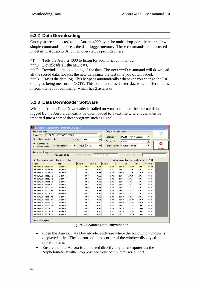
Downloading Data Aurora 4000 User manual 1.0
52
5.2.2 Data Downloading
Once you are connected to the Aurora 4000 over the multi-drop port, there are a few
simple commands to access the data logger memory. These commands are discussed
in detail in Appendix A, but an overview is provided here:
^T Tells the Aurora 4000 to listen for additional commands.
***D Downloads all the new data.
***R Rewinds to the beginning of the data. The next ***D command will download
all the stored data, not just the new data since the last time you downloaded.
***B Erases the data log. This happens automatically whenever you change the list
of angles being measured. NOTE: This command has 3 asterisks, which differentiates
it from the reboot command (which has 2 asterisks).
5.2.3 Data Downloader Software
With the Aurora Data Downloader installed on your computer, the internal data
logged by the Aurora can easily be downloaded to a text file where it can then be
imported into a spreadsheet program such as Excel.
Figure 28 Aurora Data Downloader
Open the Aurora Data Downloader software where the following window is
displayed as in . The bottom left hand corner of the window displays the
current status.
Ensure that the Aurora is connected directly to your computer via the
Nephelometer Multi-Drop port and your computer‟s serial port.
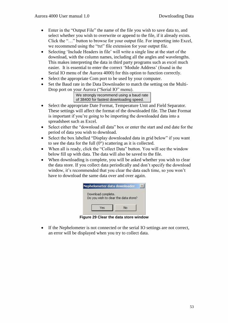
Aurora 4000 User manual 1.0 Downloading Data
53
Enter in the “Output File” the name of the file you wish to save data to, and
select whether you wish to overwrite or append to the file, if it already exists.
Click the “…” button to browse for your output file. For importing into Excel,
we recommend using the “txt” file extension for your output file.
Selecting „Include Headers in file‟ will write a single line at the start of the
download, with the column names, including all the angles and wavelengths.
This makes interpreting the data in third party programs such as excel much
easier. It is essential to enter the correct „Module Address‟ (found in the
Serial IO menu of the Aurora 4000) for this option to function correctly.
Select the appropriate Com port to be used by your computer.
Set the Baud rate in the Data Downloader to match the setting on the Multi-
Drop port on your Aurora (“Serial IO” menu).
We strongly recommend using a baud rate of 38400 for fastest downloading speed.
Select the appropriate Date Format, Temperature Unit and Field Separator.
These settings will affect the format of the downloaded file. The Date Format
is important if you‟re going to be importing the downloaded data into a
spreadsheet such as Excel.
Select either the “download all data” box or enter the start and end date for the
period of data you wish to download.
Select the box labelled “Display downloaded data in grid below” if you want
to see the data for the full (0°) scattering as it is collected.
When all is ready, click the “Collect Data” button. You will see the window
below fill up with data. The data will also be saved to the file.
When downloading is complete, you will be asked whether you wish to clear
the data store. If you collect data periodically and don‟t specify the download
window, it‟s recommended that you clear the data each time, so you won‟t
have to download the same data over and over again.
Figure 29 Clear the data store window
If the Nephelometer is not connected or the serial IO settings are not correct,
an error will be displayed when you try to collect data.
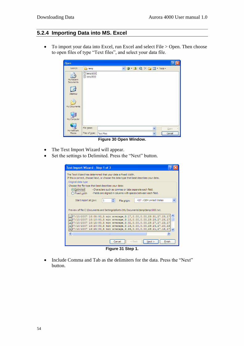
Downloading Data Aurora 4000 User manual 1.0
54
5.2.4 Importing Data into MS. Excel
To import your data into Excel, run Excel and select File > Open. Then choose
to open files of type “Text files”, and select your data file.
Figure 30 Open Window.
The Text Import Wizard will appear.
Set the settings to Delimited. Press the “Next” button.
Figure 31 Step 1.
Include Comma and Tab as the delimiters for the data. Press the “Next”
button.
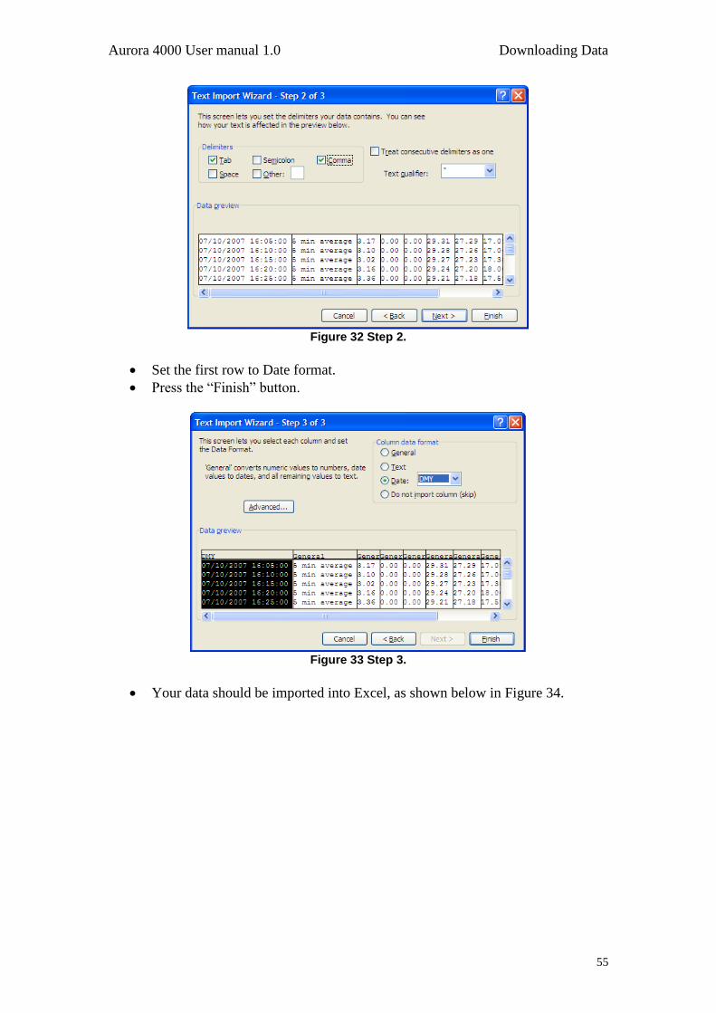
Aurora 4000 User manual 1.0 Downloading Data
55
Figure 32 Step 2.
Set the first row to Date format.
Press the “Finish” button.
Figure 33 Step 3.
Your data should be imported into Excel, as shown below in Figure 34.
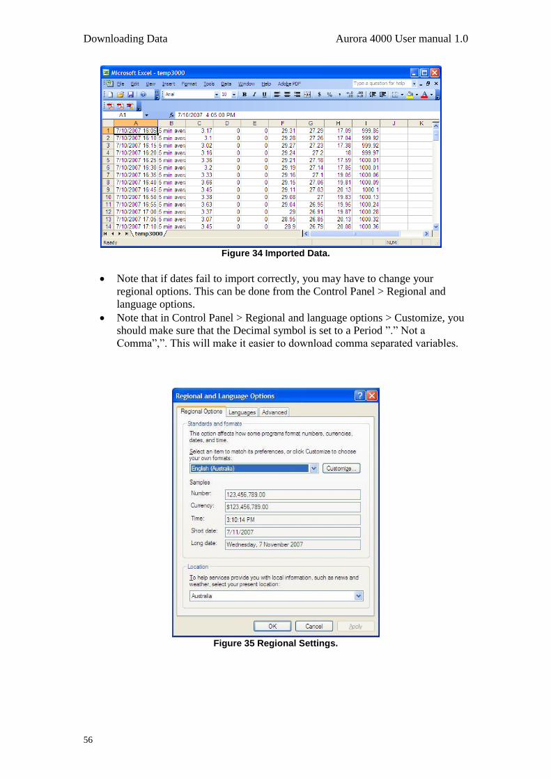
Downloading Data Aurora 4000 User manual 1.0
56
Figure 34 Imported Data.
Note that if dates fail to import correctly, you may have to change your
regional options. This can be done from the Control Panel > Regional and
language options.
Note that in Control Panel > Regional and language options > Customize, you
should make sure that the Decimal symbol is set to a Period ”.” Not a
Comma”,”. This will make it easier to download comma separated variables.
Figure 35 Regional Settings.
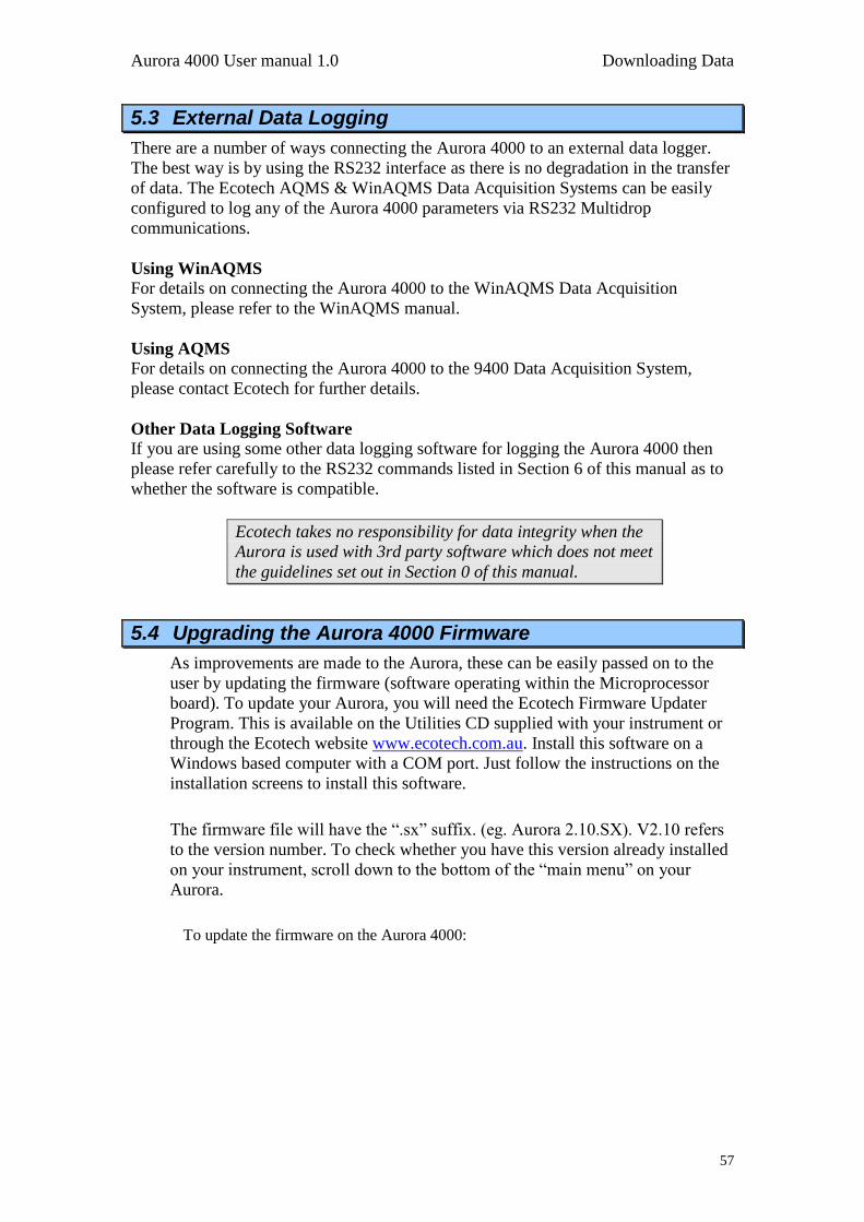
Aurora 4000 User manual 1.0 Downloading Data
57
5.3 External Data Logging
There are a number of ways connecting the Aurora 4000 to an external data logger.
The best way is by using the RS232 interface as there is no degradation in the transfer
of data. The Ecotech AQMS & WinAQMS Data Acquisition Systems can be easily
configured to log any of the Aurora 4000 parameters via RS232 Multidrop
communications.
Using WinAQMS
For details on connecting the Aurora 4000 to the WinAQMS Data Acquisition
System, please refer to the WinAQMS manual.
Using AQMS
For details on connecting the Aurora 4000 to the 9400 Data Acquisition System,
please contact Ecotech for further details.
Other Data Logging Software
If you are using some other data logging software for logging the Aurora 4000 then
please refer carefully to the RS232 commands listed in Section 6 of this manual as to
whether the software is compatible.
Ecotech takes no responsibility for data integrity when the
Aurora is used with 3rd party software which does not meet
the guidelines set out in Section 0 of this manual.
5.4 Upgrading the Aurora 4000 Firmware
As improvements are made to the Aurora, these can be easily passed on to the
user by updating the firmware (software operating within the Microprocessor
board). To update your Aurora, you will need the Ecotech Firmware Updater
Program. This is available on the Utilities CD supplied with your instrument or
through the Ecotech website www.ecotech.com.au. Install this software on a
Windows based computer with a COM port. Just follow the instructions on the
installation screens to install this software.
The firmware file will have the “.sx” suffix. (eg. Aurora 2.10.SX). V2.10 refers
to the version number. To check whether you have this version already installed
on your instrument, scroll down to the bottom of the “main menu” on your
Aurora.
To update the firmware on the Aurora 4000:
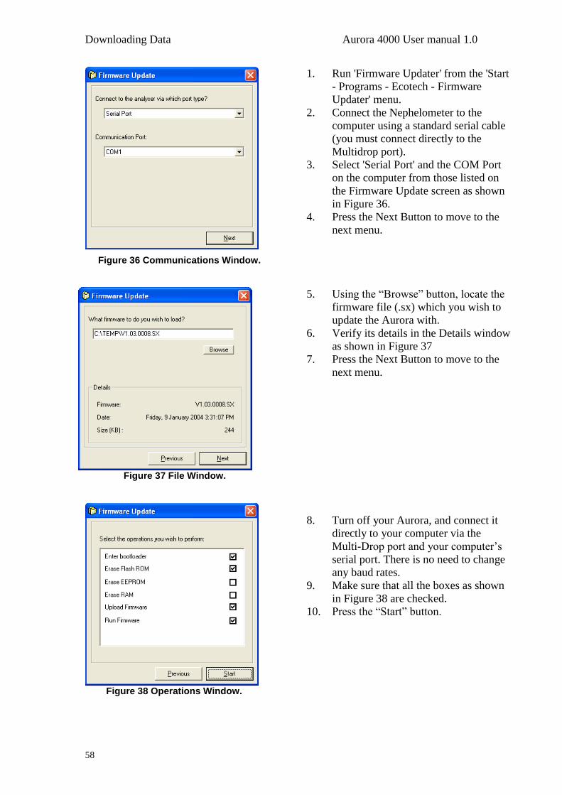
Downloading Data Aurora 4000 User manual 1.0
58
1. Run 'Firmware Updater' from the 'Start
- Programs - Ecotech - Firmware
Updater' menu.
2. Connect the Nephelometer to the
computer using a standard serial cable
(you must connect directly to the
Multidrop port).
3. Select 'Serial Port' and the COM Port
on the computer from those listed on
the Firmware Update screen as shown
in Figure 36.
4. Press the Next Button to move to the
next menu.
Figure 36 Communications Window.
Figure 37 File Window.
5. Using the “Browse” button, locate the
firmware file (.sx) which you wish to
update the Aurora with.
6. Verify its details in the Details window
as shown in Figure 37
7. Press the Next Button to move to the
next menu.
Figure 38 Operations Window.
8. Turn off your Aurora, and connect it
directly to your computer via the
Multi-Drop port and your computer‟s
serial port. There is no need to change
any baud rates.
9. Make sure that all the boxes as shown
in Figure 38 are checked.
10. Press the “Start” button.
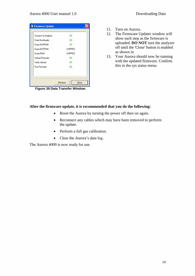
Aurora 4000 User manual 1.0 Downloading Data
59
Figure 39 Data Transfer Window.
11. Turn on Aurora.
12. The Firmware Updater window will
show each step as the firmware is
uploaded. DO NOT turn the analyzer
off until the 'Close' button is enabled
as shown in
13. Your Aurora should now be running
with the updated firmware. Confirm
this in the sys status menu.
After the firmware update, it is recommended that you do the following:
Reset the Aurora by turning the power off then on again.
Reconnect any cables which may have been removed to perform
the update.
Perform a full gas calibration.
Clear the Aurora‟s data log.
The Aurora 4000 is now ready for use.
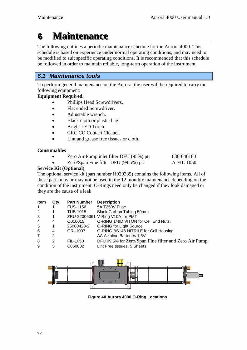
Maintenance Aurora 4000 User manual 1.0
60
666 MMMaaaiiinnnttteeennnaaannnccceee The following outlines a periodic maintenance schedule for the Aurora 4000. This
schedule is based on experience under normal operating conditions, and may need to
be modified to suit specific operating conditions. It is recommended that this schedule
be followed in order to maintain reliable, long-term operation of the instrument.
6.1 Maintenance tools
To perform general maintenance on the Aurora, the user will be required to carry the
following equipment:
Equipment Required.
Phillips Head Screwdrivers.
Flat ended Screwdriver.
Adjustable wrench.
Black cloth or plastic bag.
Bright LED Torch.
CRC CO Contact Cleaner.
Lint and grease free tissues or cloth.
Consumables
Zero Air Pump inlet filter DFU (95%) pt: 036-040180
Zero/Span Fine filter DFU (99.5%) pt: A-FIL-1050
Service Kit (Optional)
The optional service kit (part number H020335) contains the following items. All of
these parts may or may not be used in the 12 monthly maintenance depending on the
condition of the instrument. O-Rings need only be changed if they look damaged or
they are the cause of a leak
Item Qty Part Number Description 1 1 FUS-1156 5A T250V Fuse 2 1 TUB-1015 Black Carbon Tubing 50mm 3 1 ZRU-22006361 V-Ring V10A for PMT 4 4 O010015 O-RING 1/4ID VITON for Cell End Nuts. 5 1 25000420-2 O-RING for Light Source 6 4 ORI-1007 O-RING BS148 NITRILE for Cell Housing 7 2 AA Alkaline Batteries 1.5V
8 2 FIL-1050 DFU 99.5% for Zero/Span Fine filter and Zero Air Pump. 9 5 C060002 Lint Free tissues, 5 Sheets.
Figure 40 Aurora 4000 O-Ring Locations
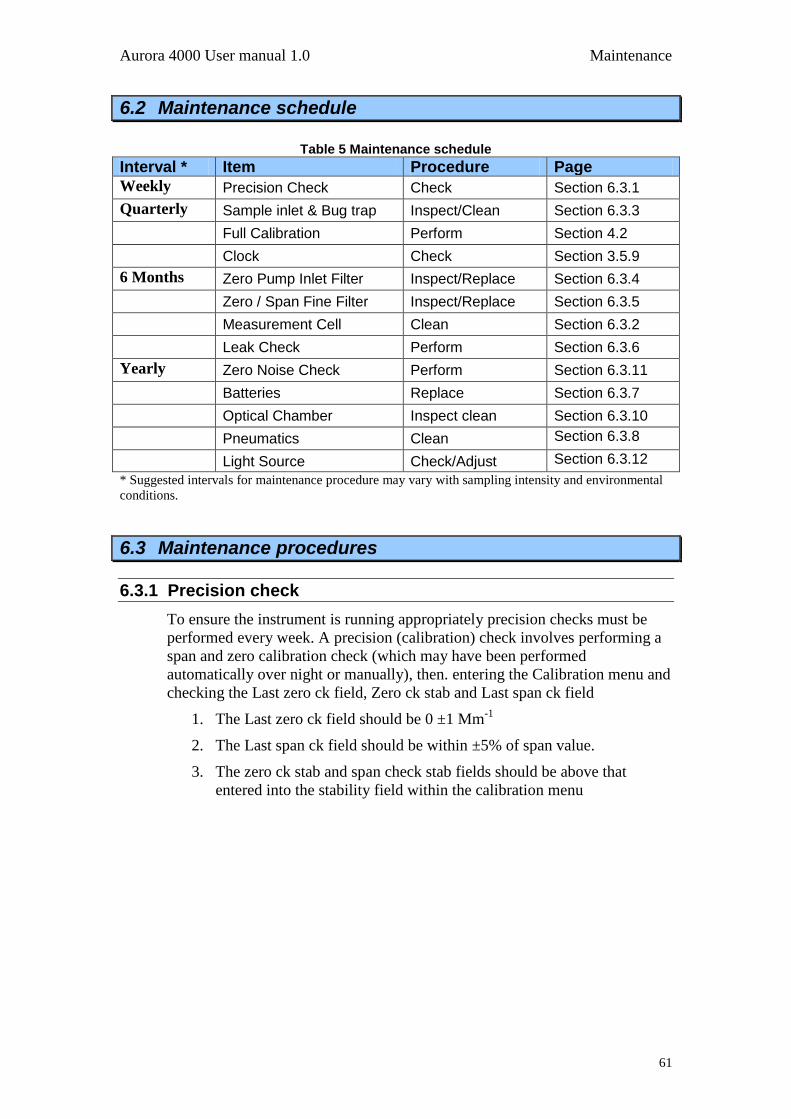
Aurora 4000 User manual 1.0 Maintenance
61
6.2 Maintenance schedule
Table 5 Maintenance schedule
Interval * Item Procedure Page
Weekly Precision Check Check Section 6.3.1
Quarterly Sample inlet & Bug trap Inspect/Clean Section 6.3.3
Full Calibration Perform Section 4.2
Clock Check Section 3.5.9
6 Months Zero Pump Inlet Filter Inspect/Replace Section 6.3.4
Zero / Span Fine Filter Inspect/Replace Section 6.3.5
Measurement Cell Clean Section 6.3.2
Leak Check Perform Section 6.3.6
Yearly Zero Noise Check Perform Section 6.3.11
Batteries Replace Section 6.3.7
Optical Chamber Inspect clean Section 6.3.10
Pneumatics Clean Section 6.3.8
Light Source Check/Adjust Section 6.3.12
* Suggested intervals for maintenance procedure may vary with sampling intensity and environmental
conditions.
6.3 Maintenance procedures
6.3.1 Precision check
To ensure the instrument is running appropriately precision checks must be
performed every week. A precision (calibration) check involves performing a
span and zero calibration check (which may have been performed
automatically over night or manually), then. entering the Calibration menu and
checking the Last zero ck field, Zero ck stab and Last span ck field
1. The Last zero ck field should be 0 ±1 Mm-1
2. The Last span ck field should be within ±5% of span value.
3. The zero ck stab and span check stab fields should be above that
entered into the stability field within the calibration menu
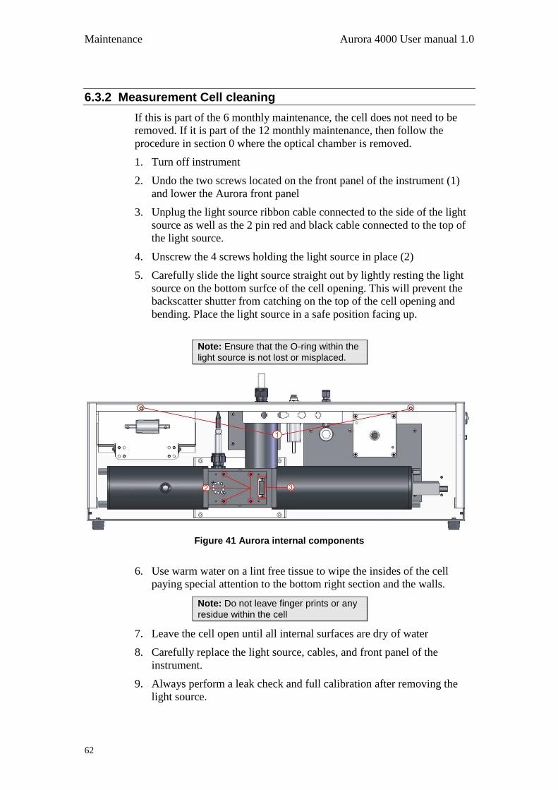
Maintenance Aurora 4000 User manual 1.0
62
6.3.2 Measurement Cell cleaning
If this is part of the 6 monthly maintenance, the cell does not need to be
removed. If it is part of the 12 monthly maintenance, then follow the
procedure in section 0 where the optical chamber is removed.
1. Turn off instrument
2. Undo the two screws located on the front panel of the instrument (1)
and lower the Aurora front panel
3. Unplug the light source ribbon cable connected to the side of the light
source as well as the 2 pin red and black cable connected to the top of
the light source.
4. Unscrew the 4 screws holding the light source in place (2)
5. Carefully slide the light source straight out by lightly resting the light
source on the bottom surfce of the cell opening. This will prevent the
backscatter shutter from catching on the top of the cell opening and
bending. Place the light source in a safe position facing up.
Note: Ensure that the O-ring within the
light source is not lost or misplaced.
Figure 41 Aurora internal components
6. Use warm water on a lint free tissue to wipe the insides of the cell
paying special attention to the bottom right section and the walls.
Note: Do not leave finger prints or any
residue within the cell
7. Leave the cell open until all internal surfaces are dry of water
8. Carefully replace the light source, cables, and front panel of the
instrument.
9. Always perform a leak check and full calibration after removing the
light source.

Aurora 4000 User manual 1.0 Maintenance
63
6.3.3 Sample inlet and bug trap clean
1. Remove the insect trap from the inlet.
2. Turn the two white handles so that they are not holding the central
filter in place (see Figure 42).
Figure 42 Insect trap removal
3. Remove the central filter and clean both the inner and outer filters with
warm water. Allow them to dry.
4. Place the inner filter back into the insect trap, return the handles to
their original position and return the insect trap to the inlet.
6.3.4 Coarse filter
1. Open front panel.
2. Remove DFU from the quick fit fitting and the clear tubing ()
3. Replace with a new DFU 95% (pt: 036-040180) or you can use the fine
filter (FIL-1050).
4. Close case.
Note: The 6 month interval is given as an indication only. More frequent filter replacements may be required depending on the instrument location.
6.3.5 Zero/Span fine filter
1. Open front panel.
2. Remove DFU from the clear tubing ()
3. Replace with a new DFU 99.5% only (pt: A-FIL-1050)
4. Perform a leak check
5. Close case.
Note: The 6 month interval is given as an indication only. More frequent filter replacements may be required depending on the instrument location.
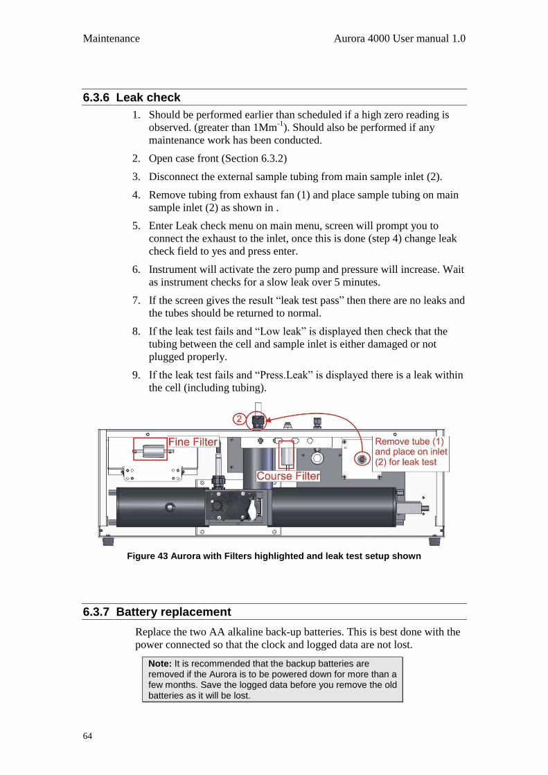
Maintenance Aurora 4000 User manual 1.0
64
6.3.6 Leak check
1. Should be performed earlier than scheduled if a high zero reading is
observed. (greater than 1Mm-1
). Should also be performed if any
maintenance work has been conducted.
2. Open case front (Section 6.3.2)
3. Disconnect the external sample tubing from main sample inlet (2).
4. Remove tubing from exhaust fan (1) and place sample tubing on main
sample inlet (2) as shown in .
5. Enter Leak check menu on main menu, screen will prompt you to
connect the exhaust to the inlet, once this is done (step 4) change leak
check field to yes and press enter.
6. Instrument will activate the zero pump and pressure will increase. Wait
as instrument checks for a slow leak over 5 minutes.
7. If the screen gives the result “leak test pass” then there are no leaks and
the tubes should be returned to normal.
8. If the leak test fails and “Low leak” is displayed then check that the
tubing between the cell and sample inlet is either damaged or not
plugged properly.
9. If the leak test fails and “Press.Leak” is displayed there is a leak within
the cell (including tubing).
Figure 43 Aurora with Filters highlighted and leak test setup shown
6.3.7 Battery replacement
Replace the two AA alkaline back-up batteries. This is best done with the
power connected so that the clock and logged data are not lost.
Note: It is recommended that the backup batteries are removed if the Aurora is to be powered down for more than a few months. Save the logged data before you remove the old batteries as it will be lost.
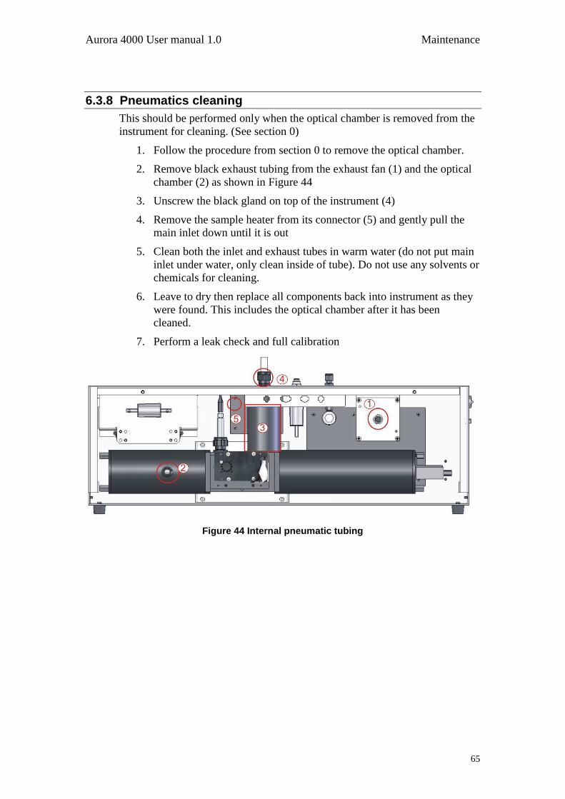
Aurora 4000 User manual 1.0 Maintenance
65
6.3.8 Pneumatics cleaning
This should be performed only when the optical chamber is removed from the
instrument for cleaning. (See section 0)
1. Follow the procedure from section 0 to remove the optical chamber.
2. Remove black exhaust tubing from the exhaust fan (1) and the optical
chamber (2) as shown in Figure 44
3. Unscrew the black gland on top of the instrument (4)
4. Remove the sample heater from its connector (5) and gently pull the
main inlet down until it is out
5. Clean both the inlet and exhaust tubes in warm water (do not put main
inlet under water, only clean inside of tube). Do not use any solvents or
chemicals for cleaning.
6. Leave to dry then replace all components back into instrument as they
were found. This includes the optical chamber after it has been
cleaned.
7. Perform a leak check and full calibration
Figure 44 Internal pneumatic tubing
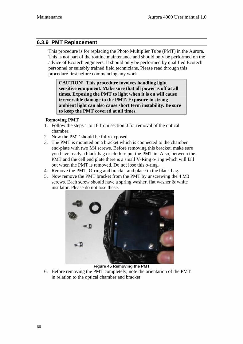
Maintenance Aurora 4000 User manual 1.0
66
6.3.9 PMT Replacement
This procedure is for replacing the Photo Multiplier Tube (PMT) in the Aurora.
This is not part of the routine maintenance and should only be performed on the
advice of Ecotech engineers. It should only be performed by qualified Ecotech
personnel or suitably trained field technicians. Please read through this
procedure first before commencing any work.
CAUTION! This procedure involves handling light
sensitive equipment. Make sure that all power is off at all
times. Exposing the PMT to light when it is on will cause
irreversible damage to the PMT. Exposure to strong
ambient light can also cause short term instability. Be sure
to keep the PMT covered at all times.
Removing PMT
1. Follow the steps 1 to 16 from section 0 for removal of the optical
chamber.
2. Now the PMT should be fully exposed.
3. The PMT is mounted on a bracket which is connected to the chamber
end-plate with two M4 screws. Before removing this bracket, make sure
you have ready a black bag or cloth to put the PMT in. Also, between the
PMT and the cell end plate there is a small V-Ring o-ring which will fall
out when the PMT is removed. Do not lose this o-ring.
4. Remove the PMT, O-ring and bracket and place in the black bag.
5. Now remove the PMT bracket from the PMT by unscrewing the 4 M3
screws. Each screw should have a spring washer, flat washer & white
insulator. Please do not lose these.
Figure 45 Removing the PMT
6. Before removing the PMT completely, note the orientation of the PMT
in relation to the optical chamber and bracket.

Aurora 4000 User manual 1.0 Maintenance
67
Installing new PMT
7. Now take the new PMT from its box. Remove its protective black cover
from its window and place it on the OLD PMT.
Figure 46 New PMT inserted
8. Then screw the new PMT onto the PMT bracket with the 4 M3 screws.
9. Attach the PMT bracket to the cell end plate and make sure the V-ring is
re-inserted flat and its sides are not twisted.
10. Re connect the 2 cables and push the black tubing in firmly.
11. Replace the black rubber cap making sure there are no gaps around the
optical chamber.
12. Return the assembled optical chamber to the instrument in the reverse
order to which it was removed.
13. Double check all connections before turning the instrument on.
Restarting the instrument:
14. After turning on the power, observe the dark count. It should be stable
and typically less than 1000. check for further light leaks by turning off
the room lighting and looking for a decrease in dark count.
15. In the system counts menu, check that the shutter counts and measure
counts are all within their limits. (shutter count 0.8M to 1.6M, measure
count greater than 10K)
16. When you are confident that everything is good, perform a leak check,
then close the front panel.
17. Allow the Aurora to warm up for at least 10 minutes, and then perform a
Full Calibration.
18. After the calibration, verify that the ambient readings are realistic and
stable.
19. Return the faulty PMT to Ecotech.
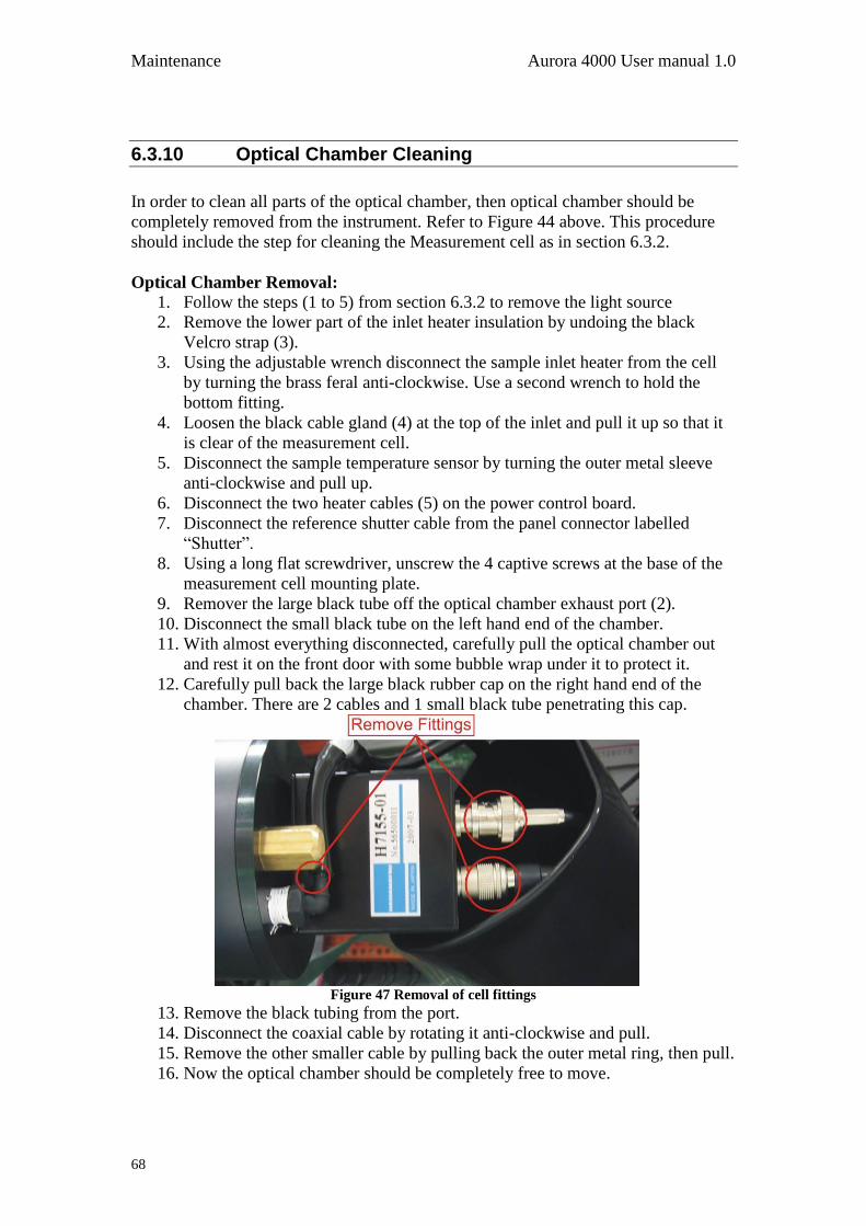
Maintenance Aurora 4000 User manual 1.0
68
6.3.10 Optical Chamber Cleaning
In order to clean all parts of the optical chamber, then optical chamber should be
completely removed from the instrument. Refer to Figure 44 above. This procedure
should include the step for cleaning the Measurement cell as in section 6.3.2.
Optical Chamber Removal:
1. Follow the steps (1 to 5) from section 6.3.2 to remove the light source
2. Remove the lower part of the inlet heater insulation by undoing the black
Velcro strap (3).
3. Using the adjustable wrench disconnect the sample inlet heater from the cell
by turning the brass feral anti-clockwise. Use a second wrench to hold the
bottom fitting.
4. Loosen the black cable gland (4) at the top of the inlet and pull it up so that it
is clear of the measurement cell.
5. Disconnect the sample temperature sensor by turning the outer metal sleeve
anti-clockwise and pull up.
6. Disconnect the two heater cables (5) on the power control board.
7. Disconnect the reference shutter cable from the panel connector labelled
“Shutter”.
8. Using a long flat screwdriver, unscrew the 4 captive screws at the base of the
measurement cell mounting plate.
9. Remover the large black tube off the optical chamber exhaust port (2).
10. Disconnect the small black tube on the left hand end of the chamber.
11. With almost everything disconnected, carefully pull the optical chamber out
and rest it on the front door with some bubble wrap under it to protect it.
12. Carefully pull back the large black rubber cap on the right hand end of the
chamber. There are 2 cables and 1 small black tube penetrating this cap.
Figure 47 Removal of cell fittings
13. Remove the black tubing from the port.
14. Disconnect the coaxial cable by rotating it anti-clockwise and pull.
15. Remove the other smaller cable by pulling back the outer metal ring, then pull.
16. Now the optical chamber should be completely free to move.
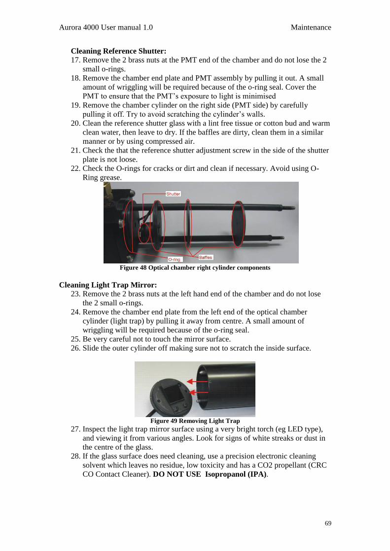
Aurora 4000 User manual 1.0 Maintenance
69
Cleaning Reference Shutter:
17. Remove the 2 brass nuts at the PMT end of the chamber and do not lose the 2
small o-rings.
18. Remove the chamber end plate and PMT assembly by pulling it out. A small
amount of wriggling will be required because of the o-ring seal. Cover the
PMT to ensure that the PMT‟s exposure to light is minimised
19. Remove the chamber cylinder on the right side (PMT side) by carefully
pulling it off. Try to avoid scratching the cylinder‟s walls.
20. Clean the reference shutter glass with a lint free tissue or cotton bud and warm
clean water, then leave to dry. If the baffles are dirty, clean them in a similar
manner or by using compressed air.
21. Check the that the reference shutter adjustment screw in the side of the shutter
plate is not loose.
22. Check the O-rings for cracks or dirt and clean if necessary. Avoid using O-
Ring grease.
Figure 48 Optical chamber right cylinder components
Cleaning Light Trap Mirror: 23. Remove the 2 brass nuts at the left hand end of the chamber and do not lose
the 2 small o-rings.
24. Remove the chamber end plate from the left end of the optical chamber
cylinder (light trap) by pulling it away from centre. A small amount of
wriggling will be required because of the o-ring seal.
25. Be very careful not to touch the mirror surface.
26. Slide the outer cylinder off making sure not to scratch the inside surface.
Figure 49 Removing Light Trap
27. Inspect the light trap mirror surface using a very bright torch (eg LED type),
and viewing it from various angles. Look for signs of white streaks or dust in
the centre of the glass.
28. If the glass surface does need cleaning, use a precision electronic cleaning
solvent which leaves no residue, low toxicity and has a CO2 propellant (CRC
CO Contact Cleaner). DO NOT USE Isopropanol (IPA).
Maintenance Aurora 4000 User manual 1.0
70
29. Spray the electronic cleaning solvent on the surface of the glass, then quickly
using a lint free tissue, remove the solvent in one continuous sweep covering
the full width of the glass. Then re-inspect with a torch for no residue.
30. Surface dust can be cleaned by lightly blowing or using a horse hair camera
lens cleaner.
31. If the baffles are dirty, clean them with a lint free tissue or cotton bud and
warm clean water or by using compressed air, then leave to dry.
32. Check the O-rings for cracks or dirt and clean if necessary. Avoid using O-
Ring grease.
Optical Chamber replacement:
33. With all parts of the chamber cleaned and dry, it is now time to replace the
chamber back to its original position.
34. Slide the two cylinders back on the push the light trap end plate and PMT end
plates on.
35. Tighten the 4 brass nuts and o-rings on each end to seal the optical chamber.
36. Now replace the optical chamber into instrument and replace all connectors
and pneumatic connections in reverse order to steps 1 to 16.
37. With everything connected, perform a leak check, then a full calibration
before normal operations can begin.
Aurora 4000 User manual 1.0 Maintenance
71
6.3.11 Zero Noise Test
Calculating the zero noise is the best way to confirm the operational performance of
the Aurora 4000 Nephelometer. The following procedure explains how to do this:
1. Operate the Aurora 4000 at room temperature for at least 30 minutes
before starting the test.
2. Set the Aurora 4000 into zero calibration mode for a period of 2 hours.
This can be done by using either of the following three methods:
In the calibration menu, set the minimum calibration time to 120
minutes, and the maximum calibration time to 121 minutes, then set it
to do a zero check. Or
On the 25pin external IO connector, connect pin 7 (DO ZERO) to pin
20 (Digital GND) to put it in zero mode. or
Connect an external Disposable Filter Unit (DFU) to the sample inlet
during normal sampling mode, or
In hidden menu 2, from the counts menu, set Span/Zero Ovr to 032
(016 will put it into span measure and 000 is normal sample measure)
3. In the Data Logging menu, set the Log Period to 1. minute.
4. Clear the Data Log memory. (be sure you have downloaded any previously
logged data that you may need).
5. Allow the Aurora 4000 to continue running on zero air for a period of 120
minutes (2 hours), uninterrupted.
6. When the 2 hours are complete, connect the Aurora 4000 to a PC using the
RS232 cable and use the installed Aurora Data Downloader software to
download the 2 hours of zero data to the PC.
7. Using MS Excel, import the data into a new spread sheet.
8. For the scattering data use the STDEV() command in Excel to calculated
the Standard Deviation of the zero data over the 2 hour period for each of
the 6 scattering parameters.
9. This calculated standard deviation is the zero noise value for that particular
instrument.
10. If the zero noise is less than 0.15Mm-1
, then the instrument is considered
to be in good working order.
If the instrument zero noise is above 0.15Mm-1
, then this could be due to a number of
factors:
Pneumatic leak in the cell or plumbing,
Light leak near the PMT,
Dirty measurement cell or optical chamber,
Low intensity light source,
Dirty light trap mirror,
Noisy PMT
Maintenance Aurora 4000 User manual 1.0
72
6.3.12 Light Source Check
The performance of the light source and backscatter shutter can be verified without
having to remove the light source from the measurement cell. The following
procedures are simple checks which can be done. Ultimately the, calculating the zero
noise is the best way to confirm the overall operational performance of the Aurora
4000 Nephelometer. See section 0.
Performance Verification:
1. Visually inspect the operation of the light source by looking down the
sample inlet tube. You will see a sequence of Red, Green and Blue
flashes inside the cell.
2. Enter the first hidden menu by pressing the hidden key which is
located directly below the “exit” key on the keypad. Select the “Light
Source menu”.
3. Verify that the parameters in the Light Source menu are as follows: Manual Mode NO
Wavelength 1 635nm
Output 1 NO
ST CorConst1 0.6000*
LED 1 100-250*
Wavelength 2 525nm
Output 2 NO
ST CorConst2 0.5000*
LED 2 100-250*
Wavelength 3 450nm
Output 3 NO
ST CorConst3 0.0000*
LED 3 100-250*
Set LED Pots
Backscatter YES
Cal BackScat 160 to 180*
ManualBackOn NO
These parameters should match those given on the instrument test sheet
supplied with the Aurora 4000.
Note: that these settings may be different for each instrument.
4. After the Aurora 4000 has been running for 2-3 minutes, enter into the
Sys Status menu from the Main Menu, and verify that all parameters
PASS.
5. Enter into the Sys Counts menu from the Main Menu and verify that
the Dark Count is less than 1000 and relatively stable. (Note the dark
count can go above 1000 if the cell temperature is higher than 30oC.
6. Enter the Wavelength 1 menu. The readings will vary, but may be
similar to the following: Shtr Count 1 1.085M*
Meas Count 1 14.55k*
Meas Ratio 1 14.21m
BS Meas Cnt1 12.30k*
BS Meas Rt 1 11.79m
Aurora 4000 User manual 1.0 Maintenance
73
7. Verify that the Shutter count is between 0.800M and 1.6M.
8. Verify that the Measure count is greater than 10K.
9. Verify that the BS Measure count (Backscatter) is less than the
Measure count.
10. Repeat steps 7 to 9 for Wavelength 2 and Wavelength 3 menus.
Note: It is recommended that these values be recorded in a system log for book for future reference and should be quoted if contacting Ecotech for assistance.
11. Open the front panel and verify that the Fan on the back of the Light
Source control board is running.
12. Verify that the Green LED on the Servo Controller (black box) is ON.
The Red LED may flash at startup, but wait until the Instrument warm
up period has completed, then check that the Green LED is on.
Light Source Adjustments:
If the Shutter counts or the Measure counts are too low or too high, they can be
adjusted in the Light Source Menu mentioned above.
1. To increase the shutter count or Measure count of Wavelength 1,
increase LED1 up to a higher value, but no higher than a maximum of
250.
2. Return to the Sys Counts menu and check that the Shutter and
Measure counts for wavelength 1 are at an acceptable level.
a. Note that the shutter count is only updated every 30 seconds.
b. The shutter count and measure count will increase or decrease
proportionally when adjusting the LED1 setting.
c. The backscatter measure count should be at least 1K or 2K less
than the measure count.
3. Now repeat the same procedure for wavelength 2 by adjusting LED 2
and verifying its Shutter and Measure counts.
4. Now repeat the same procedure for wavelength 3 by adjusting LED 3
and verifying its Shutter and Measure counts.
For each wavelength, the optimum settings are for: Measure count > 10K,
Shutter count ~1.2M (0.8M minimum and 1.6M maximum.
LED 1,2 & 3 should be between 100 and 250.
If you cannot adjust the shutter count above 0.8M, then please contact
Ecotech for further instructions on how it can be adjusted.
5. If the light source parameters have been adjusted, then a full
calibration will be required.

Troubleshooting Aurora 4000 User manual 1.0
74
777 TTTrrrooouuubbbllleeessshhhooooootttiiinnnggg
7.1 Lightsource Fail

Aurora 4000 User manual 1.0 Troubleshooting
75
7.2 Reference Shutter Fail
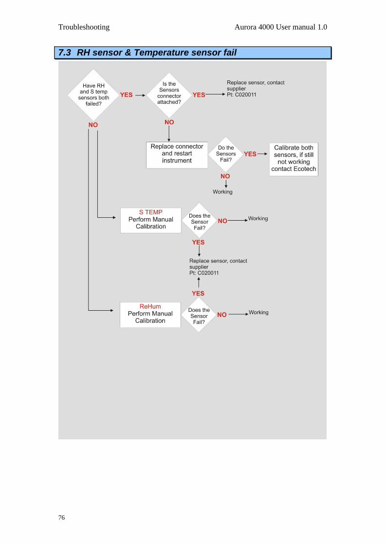
Troubleshooting Aurora 4000 User manual 1.0
76
7.3 RH sensor & Temperature sensor fail
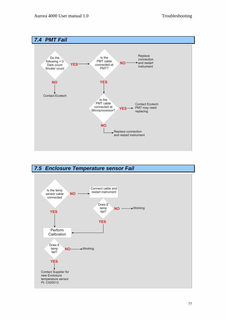
Aurora 4000 User manual 1.0 Troubleshooting
77
7.4 PMT Fail
7.5 Enclosure Temperature sensor Fail

Troubleshooting Aurora 4000 User manual 1.0
78
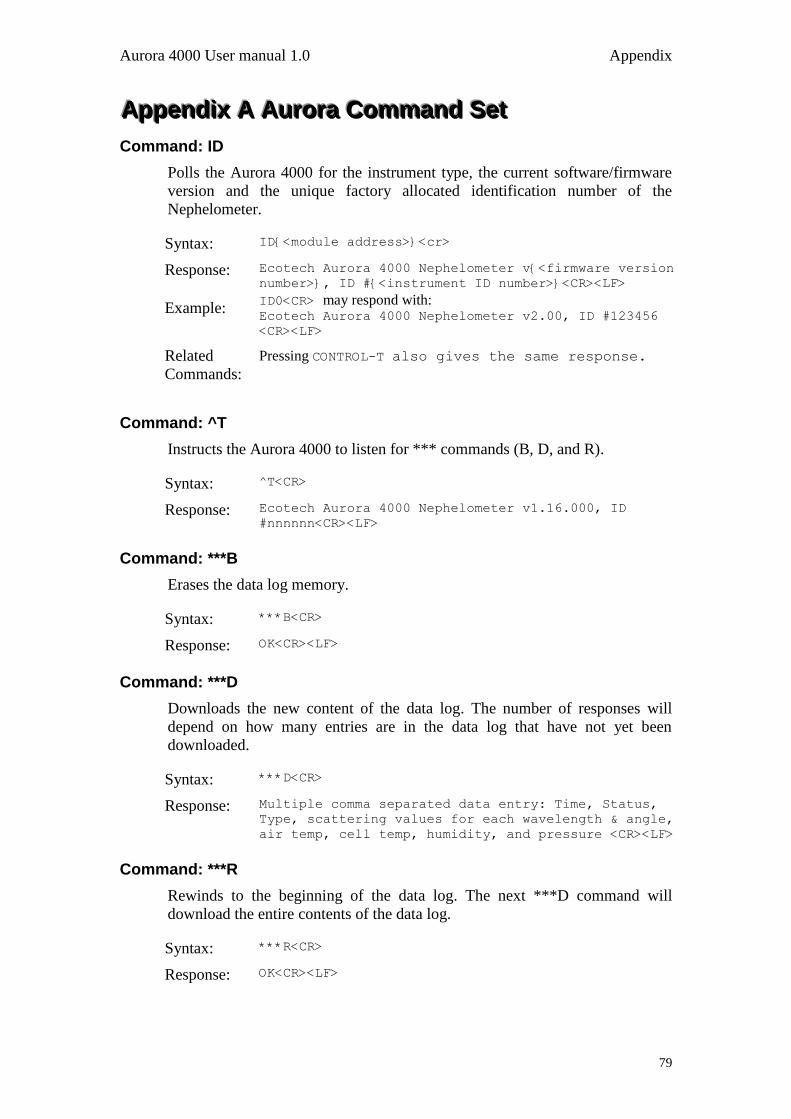
Aurora 4000 User manual 1.0 Appendix
79
AAAppppppeeennndddiiixxx AAA AAAuuurrrooorrraaa CCCooommmmmmaaannnddd SSSeeettt
Command: ID
Polls the Aurora 4000 for the instrument type, the current software/firmware
version and the unique factory allocated identification number of the
Nephelometer.
Syntax: ID{<module address>}<cr>
Response: Ecotech Aurora 4000 Nephelometer v{<firmware version
number>}, ID #{<instrument ID number>}<CR><LF>
Example: ID0<CR> may respond with: Ecotech Aurora 4000 Nephelometer v2.00, ID #123456
<CR><LF>
Related
Commands:
Pressing CONTROL-T also gives the same response.
Command: ^T
Instructs the Aurora 4000 to listen for *** commands (B, D, and R).
Syntax: ^T<CR>
Response: Ecotech Aurora 4000 Nephelometer v1.16.000, ID
#nnnnnn<CR><LF>
Command: ***B
Erases the data log memory.
Syntax: ***B<CR>
Response: OK<CR><LF>
Command: ***D
Downloads the new content of the data log. The number of responses will
depend on how many entries are in the data log that have not yet been
downloaded.
Syntax: ***D<CR>
Response: Multiple comma separated data entry: Time, Status,
Type, scattering values for each wavelength & angle,
air temp, cell temp, humidity, and pressure <CR><LF>
Command: ***R
Rewinds to the beginning of the data log. The next ***D command will
download the entire contents of the data log.
Syntax: ***R<CR>
Response: OK<CR><LF>

Appendix Aurora 4000 User manual 1.0
80
Command: **PS
Programs the unique factory allocated identification number of the
Nephelometer into memory. This number can be found in the bottom line of
the main menu.
Syntax: **{<module address>}PS{space}{<instrument ID
number>}<CR>
Response: OK<CR><LF>
Arguments: <instrument ID> is a six digit number allocated by Ecotech to each
individual instrument.
Example: **0PS_123456<CR> responds with: OK<CR><LF> and sets the instrument ID number to 123456.
Command: **B
Re-Boot test. When initiated the Watchdog timer will be activated and cause
the Aurora 4000 microprocessor to re-boot. The same as pressing the reset
button on the microprocessor board.
Syntax: **{<module address>}B<CR>
Response: null
Example: **0B<CR> will re-boot the Aurora.
Command: **M
Enables / Disables the remote menu feature of the Aurora 4000. When
enabled, the user can perform all menu operations remotely using a RS232
terminal connected to the Service port.
Syntax: **{<module address>}M{<remote menu status>}<CR>
Response: OK<CR><LF>
Arguments: <remote menu status> = 1 turns the remote menu ON.
<remote menu status> = 0 turns the remote menu OFF
Example: **0M1<CR> responds with: OK<CR><LF> and terns the remote menu on.

Aurora 4000 User manual 1.0 Appendix
81
Command: **S
Sets the real-time clock on the Aurora 4000 microprocessor board. A single
command can set the time and date.
Syntax: **{<module address>}S{<hhmmssddMMyy>}<CR>
Response: OK<CR><LF>
Arguments: <hhmmssddMMyy> is the current time and date. (hh) hour, (mm) minutes,
(ss) seconds, (dd) day, (MM) Month, (yy) year.
Example: **0S142536061003<CR> responds with: OK<CR><LF> and sets the clock to: 14:25:36 on 6/10/2003.
Command: **PC
Programs the calibration parameters for the analog inputs and analog outputs.
This is used mostly during factory calibration.
Syntax: **{<module address>}PC{<calibration
parameter>}{<calibration value>}<CR>
Response: OK<CR><LF>
Arguments: <calibration parameter> = one of the following:
0 Calibration Pressure X point - pressure in kpa at calibration point.
1 Calibration Pressure Y point - A2D reading at calibration point.
2 Calibration thermistor factor - A2D reading of thermistor at 25
degrees.
3 Calibration Vaisala temperature offset - Vaisala temperature offset
at minimum reading.
4 Calibration RH gradient - Vaisala RH gradient correction factor.
5 Calibration RH offset - Vaisala RH offset adjustment.
6 Analogue Output Current 1 Zero A/D point.
7 Analogue Output Current 1 Full A/D point.
8 Analogue Output Current 2 Zero A/D point.
9 Analogue Output Current 2 Full A/D point.
<calibration value> = an appropriate value to set each calibration
point.
Example: **0PC01013.25<CR> responds with: OK<CR><LF> and programs the
calibration pressure X point to 1013.25.
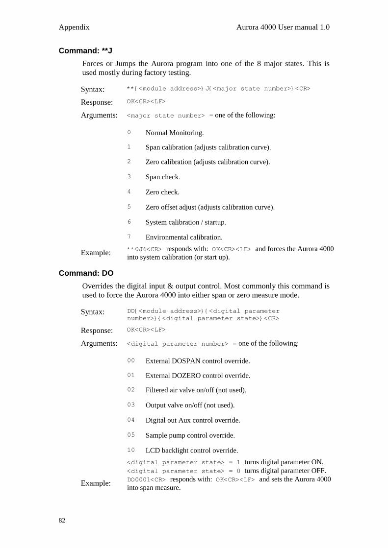
Appendix Aurora 4000 User manual 1.0
82
Command: **J
Forces or Jumps the Aurora program into one of the 8 major states. This is
used mostly during factory testing.
Syntax: **{<module address>}J{<major state number>}<CR>
Response: OK<CR><LF>
Arguments: <major state number> = one of the following:
0 Normal Monitoring.
1 Span calibration (adjusts calibration curve).
2 Zero calibration (adjusts calibration curve).
3 Span check.
4 Zero check.
5 Zero offset adjust (adjusts calibration curve).
6 System calibration / startup.
7 Environmental calibration.
Example: **0J6<CR> responds with: OK<CR><LF> and forces the Aurora 4000
into system calibration (or start up).
Command: DO
Overrides the digital input & output control. Most commonly this command is
used to force the Aurora 4000 into either span or zero measure mode.
Syntax: DO{<module address>}{<digital parameter
number>}{<digital parameter state>}<CR>
Response: OK<CR><LF>
Arguments: <digital parameter number> = one of the following:
00 External DOSPAN control override.
01 External DOZERO control override.
02 Filtered air valve on/off (not used).
03 Output valve on/off (not used).
04 Digital out Aux control override.
05 Sample pump control override.
10 LCD backlight control override.
<digital parameter state> = 1 turns digital parameter ON.
<digital parameter state> = 0 turns digital parameter OFF.
Example: DO0001<CR> responds with: OK<CR><LF> and sets the Aurora 4000
into span measure.
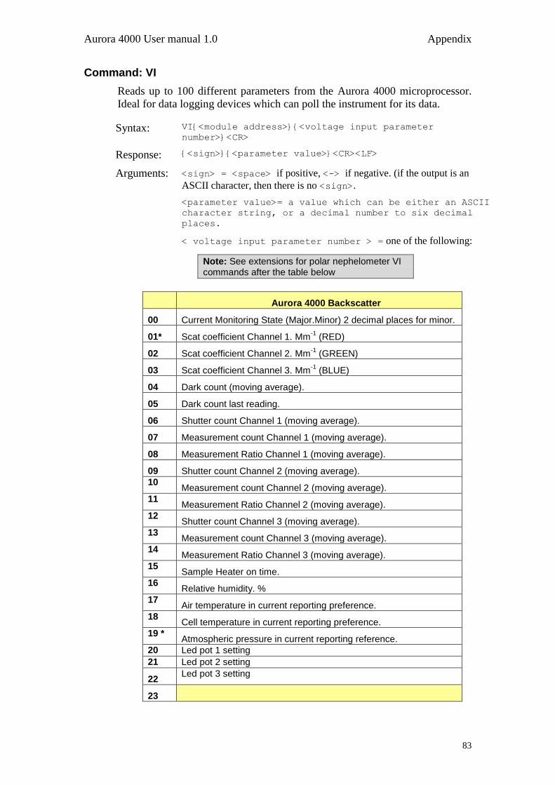
Aurora 4000 User manual 1.0 Appendix
83
Command: VI
Reads up to 100 different parameters from the Aurora 4000 microprocessor.
Ideal for data logging devices which can poll the instrument for its data.
Syntax: VI{<module address>}{<voltage input parameter
number>}<CR>
Response: {<sign>}{<parameter value>}<CR><LF>
Arguments: <sign> = <space> if positive, <-> if negative. (if the output is an
ASCII character, then there is no <sign>.
<parameter value>= a value which can be either an ASCII
character string, or a decimal number to six decimal
places.
< voltage input parameter number > = one of the following:
Note: See extensions for polar nephelometer VI commands after the table below
Aurora 4000 Backscatter
00 Current Monitoring State (Major.Minor) 2 decimal places for minor.
01* Scat coefficient Channel 1. Mm-1
(RED)
02 Scat coefficient Channel 2. Mm-1
(GREEN)
03 Scat coefficient Channel 3. Mm-1
(BLUE)
04 Dark count (moving average).
05 Dark count last reading.
06 Shutter count Channel 1 (moving average).
07 Measurement count Channel 1 (moving average).
08 Measurement Ratio Channel 1 (moving average).
09 Shutter count Channel 2 (moving average).
10 Measurement count Channel 2 (moving average).
11 Measurement Ratio Channel 2 (moving average).
12 Shutter count Channel 3 (moving average).
13 Measurement count Channel 3 (moving average).
14 Measurement Ratio Channel 3 (moving average).
15 Sample Heater on time.
16 Relative humidity. %
17 Air temperature in current reporting preference.
18 Cell temperature in current reporting preference.
19 * Atmospheric pressure in current reporting reference.
20 Led pot 1 setting
21 Led pot 2 setting
22 Led pot 3 setting
23

Appendix Aurora 4000 User manual 1.0
84
Aurora 4000 Backscatter
24
25
26 Wavelength channel 1
27 Wavelength channel 2
28 Wavelength channel 3
29
30 Backscatter Channel 1. Mm-1
(RED)
30 Backscatter Channel 2. Mm-1
(GREEN)
32 Backscatter Channel 3. Mm-1
(BLUE)
33 Backscatter Measurement count Channel 1 (moving average).
34 Backscatter Measurement Ratio Channel 1 (moving average).
35 Backscatter Measurement count Channel 2 (moving average).
36 Backscatter Measurement Ratio Channel 2 (moving average).
37 Backscatter Measurement count Channel 3 (moving average).
38 Backscatter Measurement Ratio Channel 3 (moving average).
39
40
41
42
43
44
45
46
47
48
49
50
51
52
53
54
55
56
57
58
59
60
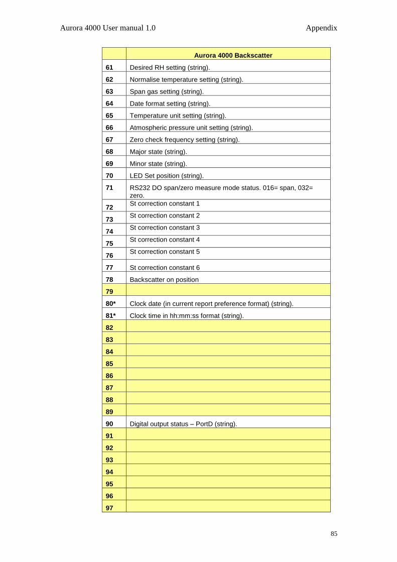
Aurora 4000 User manual 1.0 Appendix
85
Aurora 4000 Backscatter
61 Desired RH setting (string).
62 Normalise temperature setting (string).
63 Span gas setting (string).
64 Date format setting (string).
65 Temperature unit setting (string).
66 Atmospheric pressure unit setting (string).
67 Zero check frequency setting (string).
68 Major state (string).
69 Minor state (string).
70 LED Set position (string).
71 RS232 DO span/zero measure mode status. 016= span, 032= zero.
72 St correction constant 1
73 St correction constant 2
74 St correction constant 3
75 St correction constant 4
76 St correction constant 5
77 St correction constant 6
78 Backscatter on position
79
80* Clock date (in current report preference format) (string).
81* Clock time in hh:mm:ss format (string).
82
83
84
85
86
87
88
89
90 Digital output status – PortD (string).
91
92
93
94
95
96
97
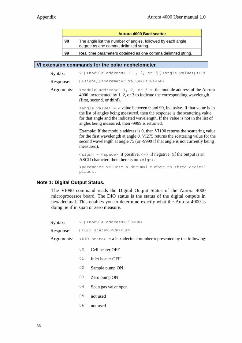
Appendix Aurora 4000 User manual 1.0
86
Aurora 4000 Backscatter
98 The angle list the number of angles, followed by each angle degree as one comma delimited string.
99 Real time parameters obtained as one comma delimited string.
VI extension commands for the polar nephelometer
Syntax: VI{<module address> + 1, 2, or 3}{<angle value>}<CR>
Response: {<sign>}{<parameter value>}<CR><LF>
Arguments: <module address> +1, 2, or 3 = the module address of the Aurora
4000 incremented by 1, 2, or 3 to indicate the corresponding wavelength
(first, second, or third).
<angle value> = a value between 0 and 90, inclusive. If that value is in
the list of angles being measured, then the response is the scattering value
for that angle and the indicated wavelength. If the value is not in the list of
angles being measured, then -9999 is returned.
Example: If the module address is 0, then VI100 returns the scattering value
for the first wavelength at angle 0. VI275 returns the scattering value for the
second wavelength at angle 75 (or -9999 if that angle is not currently being
measured).
<sign> = <space> if positive, <-> if negative. (if the output is an
ASCII character, then there is no <sign>.
<parameter value>= a decimal number to three decimal
places.
Note 1: Digital Output Status.
The VI090 command reads the Digital Output Status of the Aurora 4000
microprocessor board. The DIO status is the status of the digital outputs in
hexadecimal. This enables you to determine exactly what the Aurora 4000 is
doing. ie if in span or zero measure.
Syntax: VI{<module address>}90<CR>
Response: {<DIO state>}<CR><LF>
Arguments: <DIO state> = a hexadecimal number represented by the following:
00 Cell heater OFF
01 Inlet heater OFF
02 Sample pump ON
03 Zero pump ON
04 Span gas valve open
05 not used
06 not used
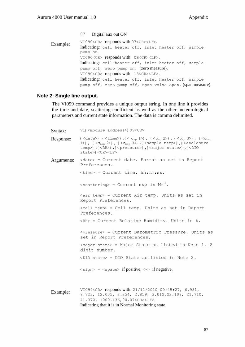
Aurora 4000 User manual 1.0 Appendix
87
07 Digital aux out ON
Example: VI090<CR> responds with 07<CR><LF>.
Indicating: cell heater off, inlet heater off, sample pump on.
VI090<CR> responds with 0B<CR><LF>.
Indicating: cell heater off, inlet heater off, sample
pump off, zero pump on. (zero measure).
VI090<CR> responds with 13<CR><LF>.
Indicating: cell heater off, inlet heater off, sample
pump off, zero pump off, span valve open. (span measure).
Note 2: Single line output.
The VI099 command provides a unique output string. In one line it provides
the time and date, scattering coefficient as well as the other meteorological
parameters and current state information. The data is comma delimited.
Syntax: VI{<module address>}99<CR>
Response: {<date>},{<time>},{< σsp 1>}, {<σsp 2>}, {<σsp 3>}, {<σbsp 1>}, {<σbsp 2>}, {<σbsp 3>},{<sample temp>},{<enclosure
temp>},{<RH>},{<pressure>},{<major state>},{<DIO
state>}<CR><LF>
Arguments: <date> = Current date. Format as set in Report
Preferences.
<time> = Current time. hh:mm:ss.
<scattering> = Current s p in Mm-1.
<air temp> = Current Air temp. Units as set in
Report Preferences.
<cell temp> = Cell temp. Units as set in Report
Preferences.
<RH> = Current Relative Humidity. Units in %.
<pressure> = Current Barometric Pressure. Units as
set in Report Preferences.
<major state> = Major State as listed in Note 1. 2
digit number.
<DIO state> = DIO State as listed in Note 2.
<sign> = <space> if positive, <-> if negative.
Example: VI099<CR> responds with: 21/11/2010 09:45:27, 6.981, 8.723, 12.035, 2.254, 2.859, 3.012,22.108, 21.710,
41.370, 1000.436,00,07<CR><LF>.
Indicating that it is in Normal Monitoring state.

Appendix Aurora 4000 User manual 1.0
88
VI099<CR> responds with: 21/11/2010 09:56:10, 6.981, 8.723, 12.035, 2.254, 2.859, 3.012, 22.894, 20.952,
40.671, 1000.642,04,0B<CR><LF>.
Indicating that it is in Zero Check state.