TS240 Service Manual.pdf
78
OM0083 TellerScan ™ 240 Countertop Check Scanner Service Manual DIGITAL CHECK CORPORATION 466 Central Avenue Northfield, IL 60093
-
Upload
khangminh22 -
Category
Documents
-
view
2 -
download
0
Transcript of TS240 Service Manual.pdf

OM0083
TellerScan
™ 240
Countertop Check Scanner
Service Manual
DIGITAL CHECK CORPORATION 466 Central Avenue Northfield, IL 60093

Rev Level 1
1
Foreword
This service manual has been prepared to provide information necessary for the proper support of the TellerScan™ 240 Countertop Check Scanner. It is intended for use by qualified service technicians who have been trained in the installation, operation, maintenance, troubleshooting, and repair of this scanner product. The manual is divided into sections providing all the data required to install, demonstrate, understand, adjust, maintain, repair, and replace parts on the scanner. The manual also includes many parts and sub-assembly annotated pictorials that illustrate part details. These pictorials are very helpful for identification purposes, and other useful information that aid in the assembly/disassembly procedures. The Illustrated Parts Breakdown PowerPoint is a separate file (TS240 Final Assembly.pdf) included as part of this manual) which provides complete assembly information and individual parts identification data. We are confident that this manual will be a useful tool in servicing the TellerScan™ 240 Scanner.
Service Manual Notation Convention: NOTES: Useful information and tips to help make the manual more useful. CAUTION: Critical information that if not observed, can cause damage to your unit. WARNING: Vital information that if not observed, can cause personal harm or injury.
Copyright © 2009 Digital Check Corporation
All Rights Reserved
Reproduction, copying, or dissemination of this material in any form without the express written consent of Digital Check Corporation is strictly prohibited.

Rev Level 1
2
TellerScan™ 240 Countertop Check Scanner
Service Manual
Table of Contents Page
1.0 General…………... …………………………………………….….…………. 5
1.1 About the TellerScan240 Check Scanner…………………….. 5
1.2 Computer System Requirements…………………………………… 5
1.3 Radio Frequency Interference……………………………………… 6
1.4 UL/cUL Listing………………………………………………………… 6
1.5 CE Compliance………………………………………………………. 6
2.0 Installation……………………………………………………………………… 7
2.1 Physically Install the Scanner………………………………………. 7
2.2 Optional Driver Installation Directions………………………………… 7
2.3 Install the Demo Software Program………………………………… 7
3.0 Theory of Operation…………………………………………………………… 9
3.1 Startup Sequence…………………………………………………….. 9
3.2 Firmware on Board……………………………………………………. 9
3.3 Check(s) Present Sensor……………………………………………. 10
3.4 Synchronization/Double Feed Sensor……………………………… 11
3.5 Discriminator Roller Assembly………………………………………. 12
3.6 LED Status Indicator……..……………………………………………. 13
3.7 Double Feed Sensor…………………………………………………. 13
3.8 Double Feed Delay……………………………………………………. 14
3.9 Contact Image Sensor Modules………………………………………. 15

Rev Level 1
3
3.10 Acquisition of the Check Image……………………………………….. 15
3.11 MICR Reading…………………………………………………..………. 16
3.12 Inkjet Printer (Endorser)……………………………………………….. 17
4.0 Adjustments………………………………………………………………………. 20
4.1 Mechanical Adjustments……………………………………………….. 20
4.1.1 Belt Tension Adjustment………………………………………… 20
4.1.2 Tension Roller Adjustment……………………………………… 21
4.2 Software Adjustments………………………………………………….. 22
4.2.1 Calibrating the Front & Rear CIS Modules…………………… 23
4.2.2 Calibrating the Double Feed Sensor…………………………. 23
5.0 Cleaning & Maintenance Schedules………………………………………….. 25
5.1 Thoroughly Cleaning the Scanner Unit………………………………. 25
5.2 Using the TellerScan Cleaning Card………………………………….. 25
5.3 Cleaning the Input Drive Rollers……………………………………….. 26
5.4 Cleaning the Front and Rear CIS & Magnetic Head….………………26
5.5 Cleaning the Internal Drive Rollers…………………………………… 27
5.6 Replacing the Inkjet Cartridge (Optional Equipment)……………… 27
5.7 Replacing the Franking Stamp (Optional Equipment)……………… 29
6.0 Part Removal…………………………………………………………………….. 30
6.1 Center Cover…………………………………………………………….. 30
6.2 Outer Main Cover………………………………………………………. 30
6.3 Base Plate Assembly……………………………………………………. 31
6.4 CIS Modules…….……………………………………………………….. 31
6.5 Discriminator Roller Assembly…………………………………………. 33
6.6 Dense Foam Roller……………………………………………………… 33

Rev Level 1
4
6.7 MICR Curve Assembly…………………..……………………………… 34
6.8 Solenoid…………………………………………………………………... 37
6.9 Inkjet Assembly (Optional Equipment)………………………………… 38
6.10 Input Drive Roller…………….………………………………………….. 39
6.11 Internal Drive Roller Assemblies………………………………..…….. 39
6.12 Stepper Motor……………………………….…………………………… 41
6.13 DC Gear Head Motor…………………………………………………… 41
6.14 Drive Belt………………………………………………………………… 41
6.15 Main Printed Circuit Board Assembly……………………………….. 42
7.0 Assembly Drawings & Parts Identification……….……………………..……. 43
8.0 Electrical Assembly……………………………………………..….…………… 44
9.0 Recommended Spare Parts List………………………………………………. 45
10.0 TellerScan™ 240 Scanner Specifications………………………………….… 46
11.0 TS240 Sample Configuration File………….…….…………………………… 49
12.0 Sample Initialization File………………………………………………………… 57
13.0 API Error Codes……………..…………………………………………………… 67

Rev Level 1
5
1.0 General
1.1 About the TellerScan 240 Check Scanner
The TellerScan 240 Countertop Check Scanner is an easy-to-use compact check scanner that connects to a Personal Computer (PC). This product is intended for use in the teller window environment, and meets or exceeds all the requirements of The Check Clearing for the 21st Century Act (Check 21 Act). The TS240 Scanner automatically scans the front and/or back of checks while simultaneously magnetically capturing the Magnetic Ink Character Recognition (MICR) code line. The images and data are then transmitted through a high speed Universal Serial Bus 2.0 interface (USB2) to the PC. Scanner Equipment Options:
• Ink-jet Endorser – to print characters, logos and/or graphics on the back side of checks. The Endorser is located up stream of the actual check image acquisition, so printed information is captured as part of the archival image.
• Franking Stamp – Front, roll-on, red ink stamp that prints the word SCANNED on the face of the check after electronically processing the document. This is a fixed position stamp in the lower right corner of the check. There are four selectable modes of operation: Frank None, Frank All, Intelligent Frank, External Frank.
Peripheral Equipment:
• Replacement Ink Jet Cartridge
• Replacement Franking Stamp Roller
• Scanner Cleaning Cards/Cleaning Kit
• Replacement Ink Jet Absorbent Pads
1.2 Computer System Requirements
To insure proper operation and maximum performance from your TellerScan 240 Scanner, the following PC requirements should be observed:
Recommended Minimum
• 2.4 GHz Pentium Core 2 Duo Processor • 1 GHZ Pentium IV Processor
• 2 GB RAM • 1 GB RAM
• 5 GB free disk space • 1.5 GB free disk space
• XP Professional, Vista Premium or Windows 7 (32 or 64 bit)
• XP, Vista Home Premium or Windows 7 (32 or 64 bit)
• USB 2.0 Port • USB 2.0 Port

Rev Level 1
6
1.3 Radio Frequency Interference The Scanner generates, uses, and can radiate radio frequency energy. If the unit is not installed and used properly, that is in strict accordance with the instructions contained in this
manual, it may cause harmful interference to radio communications. The TellerScan 240 Scanners have been tested and found to comply with the limits for a Class B computing device pursuant to Subpart J of Part 15 of the FCC Rules, which are designed to provide reasonable protection against such interferences when operated in a commercial or residential environment.
The use of certified shielded cables is required when connecting this device to any/all peripheral or host devices. Failure to do so may violate FCC rules.
1.4 UL/cUL Listing
The TellerScan 240 product has been tested for safety to the UL950 Information Technology Equipment standard and is listed with Underwriters Laboratories, Inc. under File Number E201270. The product has also been tested and conforms to the Canadian UL (cUL) requirements.
1.5 CE Compliance
The TellerScan 240 is CE compliant and has been tested for safety in accordance with the requirements of ICE Directive 89/336.

Rev Level 1
7
2.0 Installation
2.1 Physically Install the Scanner The TS240 comes fully assembled. Simply pull out the exit tray to accommodate various check lengths and facilitate proper stacking. Locate the USB cable and the TS240 power supply in the packaging. Open them for use, but do not connect them until advised to do so.
CAUTION: Confirm that the TellerScan USB Device drivers have been installed before connecting the USB cable to the PC. If you have not received or installed the device drivers, contact your check scanning solution provider.
NOTE: The USB cable from the scanner to the PC and the power connection must both be connected and into a live port on the PC for the LED to show a RED or powered on indication.
2.2 Optional Driver Installation Directions:
a. Download the TellerScan USB Driver file from the web site:
http://www.digitalcheck.com/integration_support/drivers_and_demo_programs
b. Unzip the file and run the driver utility program to automatically install the driver and
create a folder for the driver files (C:\Program Files\TellerScan\Drivers).
c. Connect the power supply and the USB Cable to the scanner, PC, and an appropriate
power source. The LED status indicator on the scanner should now be showing Red.
d. Windows will automatically detect a new hardware device.
e. The LED status indicator will turn Green when the application launches and acquires
the scanner.
NOTE: While the scanner will run on a USB 1.1 port, it is recommended that a USB 2.0 port
be used to provide better performance. An INI file parameters may need to be increased to
allow running on a USB 1.1 port due to the slower data throughput. Check with your
application provider if operation is sporadic.
2.3 Install the Demo Software Program
a. Download the ScanLite demo program from the web site for testing the scanner (and if needed during the cleaning process):

Rev Level 1
8
http://www.digitalcheck.com/integration_support/drivers_and_demo_programs b. Create a sub directory on the PC and name it ScanLite. c. Copy the ScanLite files into the directory. d. Launch ScanLite.exe to open the demo application.
NOTE: The ScanLite demo software is a basic scan program that allows you to test for proper operation of the scanner hardware. It allows for changing of different scanner settings, view images, read MICR, and store them on your PC’s hard disk. This demo program is not the software used to run the full system. Additional application software is required. ScanLite may also be used to facilitate cleaning of the scanner.

Rev Level 1
9
3.0 Theory of Operation
This section will briefly describe the electrical, mechanical, and any optical theory of
operation as it pertains to maintenance, support, and repair of the TellerScan240 scanner. A thorough understanding of the TS240 scanner theory of operation is essential to accurate troubleshooting and quick, efficient repairs.
3.1 Startup Sequence The TS240 is a USB device that has current (as of the date of manufacture) resident firmware on board the scanner. Firmware that controls the scanner may also be located in a file on the PC workstation connected to the scanner. Scanner specific data is stored onboard the scanner in a configuration file that resides in non-volatile Electrically Erasable Programmable Read Only Memory (EEPROM). Non scanner specific control parameters (generic to all TS240scanners) can be found in an initialization file located on the PC workstation. When power is initially applied, the TS240 scanner initializes, and then identifies itself to the PC operating system with the hard coded Product Identification (PID) code of the particular TellerScan device. The appropriate drivers are then installed as part of the startup sequence. This startup sequence from resident Flash memory is very quick and can be monitored by observing the LED indicator on the top cover of the scanner. When power is switched on, the LED Status Indicator illuminates immediately as Red indicating power is on (no firmware yet downloaded). When the application program is launched and acquires the scanner the LED Status Indicator turns Green (scanner ready). This process takes approximately 3 seconds. The scanner is now operational, and the LED Status Indicator will next change to Amber once Check(s) are present in the input hopper.
3.2 Firmware on Board For the default mode of operation, the dynamic link library (dll) compares the version of firmware on board the scanner with the firmware version located on the PC. If the scanner resident firmware version is newer, the dll simply loads that firmware to the scanner operating memory. If the version located on the workstation is newer, the dll copies the firmware file from the PC to the non-volatile EEPROM on board the scanner (over-writing the older firmware), then loads that firmware to the scanner operating memory. When the application program loads, the dynamic link library (dll) completes the remaining processes automatically. At this point, the scanner is now fully operational. Based on INI file values or program settings, the firmware onboard the scanner may or may not be updated. The INI file parameter or program can be set to:
a. Never Download from PC [always uses firmware located in flash memory].

Rev Level 1
10
b. Always Download from PC [always uses firmware located on the PC and no writing to the scanner Flash memory].
c. Download newer version of firmware from Flash or PC [default mode for TS240]. d. Download from PC if versions are different [used for reverting to a pervious firmware
version]. A new firmware file naming convention now includes the version level so multiple levels of the TS240Firmware_v1.2.3.4.bin file may reside in the same PC folder.
3.3 Check(s) Present Sensor The presence of checks at the feeder entrance is detected by an infrared (IR) sensor placed just slightly above the surface of the Base Plate. This placement is intended to insure that checks are positioned all the way down flat against the base plate prior to pulling them into the scanner track (see illustration below).
Entry Pocket
TS240 Component Locations
Exit Pocket
Main Drive Rollers
MICR Read Head
Double Feed Adjustment Wheel
Double Feed Separation Roller (Replaceable)
Sync /Double Feed Sensor
Ink Jet Platform
DC Motor Drive
Main Drive Motor (Under Solenoid) Entry solenoid
Check(s) Present Sensor

Rev Level 1
11
On the TS240 the Check Present sensor is comprised of an IR LED (D2) which is located on the outboard side PCBA (P/N 913022). This device is multiplexed with a secondary VBUS monitoring function so its drive is a rectangular waveform designed to minimize the aging effect of driving the device continually. The associated IR Photo-Detector (Q2) is located on the inboard side PCBA (P/N 153120-01). When this sensor is interrupted, a signal is sent to the Main PCBA and the LED Status Indicator is illuminated Amber. Once a scan multiple command is initiated, the scanner will begin feeding check(s), and the LED Status Indicator will flash green (indicating normal a normal scanning function). This process will continue until this sensor is no longer interrupted (hopper empty) as indicated by scanner stopping and the LED status indicator returning to solid green.
3.4 Synchronization/Double Feed Sensor
When the scanner receives an “Enable to Scan” command from the host, the following operations are performed:
- Check that there are no pending errors - Energize the Feed Solenoid - Drive the DC Motor and the Stepper Motor for 2.5 seconds
The check is then feed, by the Input Drive Roller, from the hopper past the Double Feed Separation Roller and on to the first set of pinch rollers. Once the check is captured by the first set of pinch rollers, the leading edge soon arrives at the infrared Synchronization/Double Feed Sensor. If the check doesn’t arrive at the Sync sensor in the prescribed amount of time, blockage or slippage is assumed, and a fault is indicated by the LED Status Indicator blinking red. This Sync/Double Feed sensor is comprised of an IR LED (D1) which is located on the outboard side PCBA (P/N 146132-02). The associated IR Photo-Detector (Q1) is located on the inboard side PCBA (P/N 913019). (Refer to illustration above for location). There are multiple functions for this sensor which will be briefly described here: Synchronization – The primary purpose of this sensor is to define the exact position of the leading edge of the check. From this reference position, all scanner capture functions are synchronized by means of counting stepper motor steps. Various pre-defined parameters contained in an initialization file define the window for reading MICR for instance. Another parameter defines the window for scanning the front side of the check, and another, for the back side. A final parameter defines the overall length of time that the motor must drive to cause the check to completely exit the scanner. Check Length Measurement – This sensor also allows the scanner to accurately measure the length of check by counting the number of motor steps until the sensor no longer sees the document. This variable parameter then defines the exact end point of each of the image capture windows.

Rev Level 1
12
Double Feed Detection – This sensor is multiplexed to perform the additional separate function of detecting double feed checks. This function is fully described later in this section.
3.5 Discriminator Roller Assembly Scanners with automatic document feeders (ADF) that have the ability to strip checks from a stack must have a means to prevent multiple checks from entering the scanner simultaneously. This is the function of the discriminator roller assembly. The assembly consists of a Dense Foam roller that is stationary during the feed cycle, but indexes backwards 1/8 turn at the end of each cycle (and during scanner initialization) in order to distribute the wear evenly around the periphery of the roller. A Solid Rubber Drive Roller that turns forward is housed in a spring-loaded Sheet Metal Bracket that pivots about a pin. The Sheet Metal Bracket position is adjusted at the plant and should not need adjustment in the field for the next 100,000 items. It’s adjusted by means of a small Thumbwheel located at the top of the bracket (see illustration below).
Dense Foam Roller Factory Adjust Thumbwheel Pivot Pin Solid Rubber Drive Roller Sheet Metal Bracket

Rev Level 1
13
The stationary dense foam roller holds back all but the first check in the stack, while the forward turning of the solid Drive Roller strips the first check from the stack and passes it on to the first set of pinch rollers. It can easily be seen that if the intersection of the two rollers is too tight, no checks will be allowed to pass through the discriminator roller assembly. Likewise, if the intersection of the two rollers is too loose, more than one check will pass through. Normally, an intersection equivalent to slightly less than the thickness of one (typical thickness) document is ideal for reliable check separation. The adjustment mechanism increases or decreases the interference of these two rollers. Refer to the Mechanical Adjustments Section of this manual for complete details of how to perform this adjustment.
3.6 LED Status Indicator The LED Status Indicator consists of a single, multi-color (Red, Green, Amber) Light Emitting Diode (LED). During various modes of operation, the LED may be flashing or solid. The light is transmitted to the center cover indicator by means of a translucent plastic light pipe that is attached to the underside of the center cover. Indication modes are as follows:
a. Solid Amber indicates that a document is in the feeder hopper. b. Flashing Green indicates that a scan function is in progress. c. Solid Green indicates that the scanner is ready for documents. d. Flashing Red indicates either initialization or an error condition. The Red LED will
flash (and the transport will stop) whenever any of the following scanner feed errors has occurred: -216 Error Feeding Current Document -217 Double Feed Detected -220 Document Jam NOTE: The flashing red LED error condition will be reset when an Eject cycle is commanded from the application program, the condition is cleared, or the power rest button is pressed.
e. Slow pulsing Green indicates the Energy Star low power standby mode. The scanner comes out of standby mode when a command is sent that causes a motor to turn on (eject, scan enable etc) or when placing a check in the feed hopper.
3.7 Double Feed Sensor The Double Feed and Sync senor are the same physical device (see illustration above) used in a multiplexed fashion. The principle of this function is based upon the ability to pass infrared energy from an LED through a check to the photo-receptor on the opposite side. By means of software calibration of the circuitry associated with the phototransistor, the opacity of the check can be precisely measured. Two checks (as in a double feed condition) are

Rev Level 1
14
obviously much more opaque than a single check, and will therefore be detected by the circuitry and indicated as a double feed. NOTE: Since this function depends upon precise measurement of IR energy, any repositioning or movement of either sensor circuit board will require a recalibration. Refer to the Software Adjustments section of this manual for detailed information on how to calibrate the Double Feed Sensor. The scanner hardware produces a Double Feed error when the double feed sensor is triggered continuously for a specified minimum sampling time interval. The Double Feed Delay Parameter, as further defined in the next section of this manual, defines the specified time interval associated with this sampling.
NOTE: The Double Feed detection feature of this scanner is only intended as a fail-safe to stop the scanning cycle if a double feed is detected. Continual double feeding is not normal and usually indicates that the dense foam roller tension is not adjusted properly. Refer to the Mechanical Adjustments section of this manual for detailed information on how to adjust the Tension Roller. NOTE: A new Double Feed No Stop logic was introduced in API v8.22 (and newer) which, when the sensor indicates a thick document, has the API interrogate MICR data and document size parameters. If either one is out of range, then the API notifies the application of a -217 double feed error condition. If within range, normal operation continues after a short interval. In practice, this feature eliminates 85% of false double feeds. Refer to the current API documentation for more information.
3.8 Double Feed Delay Occasionally, a heavy ink stamp on the backside of a check, or a dark logo printed on the front side of the check will cause a double feed condition when in fact it is just a single check with a darker (opaque) area that just happens to be located in such a position (about ½ inch up from the bottom of the document) that it is seen by the double feed sensor.
This false indication can often be avoided with software by use of the Double Feed Delay parameter, which has a user selectable value in the initialization file. The theory behind the function of this feature is that the double feed condition (as indicated by the Double Feed Sensor) must be continually present for a sustained period of time before the software actually indicates a double feed condition. This time period translates to a fixed distance because the check is moving through this part of the scanner at a constant speed. The units of this parameter are therefore distance, with 15 mm (about ½ inch) being the default value. With a setting of 15, a false double feed condition (opaque area) can be present for 15 mm of distance along the length of the check without a double feed being indicated. It can be seen, therefore, that the software can be made to skip over any opaque area on a check simply by selecting a value for the Double Feed Delay parameter that exceeds the length of the opaque area causing a problem. Remember that the values do not represent exact distances.

Rev Level 1
15
NOTE: In practice, it is not advisable to set the value of the Double Feed Delay too high. If the value selected exceeds the length of your minimum size documents, a legitimate double feed (2 checks) will go undetected. Use caution when setting this parameter for the scanner. NOTE: Should the documents being scanned appear opaque all the time as might be the case with a heavier card stock material, the Double Feed Detector parameter also located in the initialization file of the software application, should be disabled. If this heavier card stock material is always used in a particular scanner, it may be possible to re-calibrate the thickness sensors of that particular scanner to accommodate the abnormal condition. Refer to the Software Adjustments section of this manual for information on calibration of the Double Feed Sensors.
3.9 Contact Image Sensor Modules
The TellerScan 240 Scanner utilizes the latest Contact Image Sensor (CIS) technology to acquire the raw check images. CIS modules are complete self contained assemblies comprising the LED light source, optical Selfoc (rod) lens, photo-diode receptors, and signal amplifier all mounted to a ceramic substrate. These components are housed in a molded plastic module and operate from a single voltage power supply (see illustration below). The module has a polished glass faceplate on the viewing side. In practice, the document to be scanned is passed by the glass faceplate while the CIS module illuminates and captures the data at optimum focus producing the highest quality image definition and contrast.
3.10 Acquisition of the Check Image
All positioning of the check in relation to the various capture functions is controlled by the stepper motor. The check leading edge is marked at the starting reference position by
Rear CIS Module
Exit Sensor PCBA
(Inner)
CIS Electrical Connector

Rev Level 1
16
means of the Synchronization Sensor. From that reference point, all positioning is controlled by a fixed count of stepper motor steps. The Front CIS Module is located a fixed number of steps from the Synchronization Sensor as defined by a parameter of the initialization file. Once the check is fed this number of steps, its leading edge is at the beginning of the scan window. The front and rear LED arrays illuminate and the check is fed forward at a rate of 50 cm/sec (bitonal mode). The same process with a different count offset is next repeated for the Rear CIS Module.
Raw image data is captured in a vertical orientation, and in a format defined by the acquisition mode (gray scale/color), and resolution (300x300 dpi bitonal, 300x150 dpi color). NOTE: Image data is always captured at the maximum resolution and density capability of the TS240 scanner (namely 300x300 dpi, 256 levels of gray or 300x150 dpi 24 bit color). Lower resolution images, and/or lower density images (if desired) are produced from the high resolution/high definition images by means of the Application Program Interface (API) software. Therefore, the speed of scanning, and conversely the scanner throughput, are not a function of the resolution or density selected. The raw image data is processed and normalized (pixel by pixel) by the internal electronics of the scanner, and sent to the host PC via the Universal Serial Bus (USB) Interface. Under API software control, the PC then converts the raw data to the bitmap format (B/W, 256 levels of gray) and compression (TIFF Group IV, or JPEG) previously selected by the application. This software also rotates the image to a horizontal format and crops all four edges.
As the trailing edge of the check passes the Synchronization Sensor, the end reference point is established thereby defining the overall check length. Scanning continues until the trailing end of the check has progressed the pre-defined number of steps to the end of the front, then rear CIS scan heads. At this point the scan heads are disabled and the LED arrays are switched off to preserve life of the LED’s and conserve power.
3.11 MICR Reading The MICR Head is located along the track a fixed number of motor steps from the starting reference mark as defined by another value in the initialization file. Once the check leading edge arrives at the MICR head, the analog electronics are enabled and the raw analog signal from the head is acquired and processed. The analog head registers the variations of magnetic flux caused by the passage of the magnetic characters against the physical head. The check is held against the head in the area of the MICR code line by means of a spring loaded small plastic roller assembly. The check passes the head at a constant linear speed of 50 cm/sec. The magnetic ink on the check is first polarized by the permanent magnet located immediately before the MICR Head. See location of the MICR head in the pictorial below.

Rev Level 1
17
The MICR Head, and associated electronics and software, allow for recognition of the numerals printed on the front of the check in magnetic ink. It is possible to read and interpret both CMC7 and E13B type characters.
The recognition is made by the numeric processing of the analog signals produced by the magnetic head. This processing is according to sophisticated proprietary algorithms contained within the DLL software running on the PC. Characters are read from left to right along the bottom of the check as it passes the MICR Head. A single character at the beginning of the string defines the type to be either CMC7 or E13B. Rejected characters are identified by the software with an @ sign. The MICR reading electronics is disabled when the check is not present in front of the head to reduce the possibility of picking up stray readings.
3.12 Inkjet Printer (Endorser) The print endorsement on the back of the check is made using Hewlett Packard ink jet technology. The HP c6602a inkjet printer cartridge was selected because of its small size, relatively low cost, fast drying ink, and large reservoir capacity. The cartridge is available in black, red, green or blue colors, and prints up to 7,000,000 characters from a single cartridge. This cartridge has 12 nozzles and produces a good quality print with only a single pass while the check is being transported for scanning. The cartridge has an easy snap-in feature to facilitate replacement by the scanner operator (see illustration below).
MICR Head

Rev Level 1
18
The inkjet holder carriage assembly is set at a fixed height and is not adjustable. The operating principle is the same as for all the Ink Jet printers. The printer derives its 22VDC power from a on-board regulator, and is driven by electronics located on the main control board of the scanner. The most significant parameters controlling the printer operation are:
a. Print Position, expressed in pixels beginning from the left side of the check b. Print Intensity c. Print Thickness
These parameters are selectable and programmable within the API initialization file, and can be configured from the PC. Various parameters in the scanner specific configuration file (located onboard the scanner) control the cleaning intervals, duration, and intensity. The print head is fully under program control. The DCC API offers several options and modes for printing both fixed block fonts and BMP graphical fonts.
Performance of the scanner can be affected by use of a complex versus simple endorsements. A complex endorsement is one that is sent down prior to scanning each document. A simple endorsement is one that is sent down once and can either print the
Replaceable Ink Jet Cartridge
Ink Jet Holder Carriage

Rev Level 1
19
same print string or is capable of incrementing or decrementing a number sequence in the print string. Use of the complex endorsements can limit the scanner to less than its full rated speed.

Rev Level 1
20
4.0 Adjustments The TS240 scanner has only two mechanical adjustments that can be performed in the field. There are no field electrical adjustments. With use of the software Maintenance Program, there are two software calibration procedures that can be performed in the field.
4.1 Mechanical Adjustments 4.1.1 Belt Tension Adjustment WARNING: Unplug the scanner power connector to prevent personal harm.
The scanner uses a cleat style timing belt and therefore the belt tension is not required to be too tight. If the belt is too loose, the cleats will skip over the teeth on the drive gears during motor acceleration. If the belt is too tight, there will be too much load on the motor and the drive bearings will wear prematurely. NOTE: Having the belt tension too tight or too loose can also affect MICR reading accuracy and MICR transposition of numerals. CAUTION: Belts that are worn, frayed, or show any sign of the cords being exposed or pulling loose need to be replaced immediately.
Belt Tension Adjust Screw
Exit Drive Roller
Belt Flex Area

Rev Level 1
21
Proper belt tension is defined as that tension that allows the belt to just have a little flex when pressed in the area indicated, but when manually turning the Exit Drive Roller both clockwise and counter clockwise fairly rapidly, the belt will not jump or skip teeth positions. The adjustment is made with the Belt Tension Adjustment screw (see illustration above). The adjustment sequence is described as follows:
a. Using a medium Philips blade screwdriver, loosen the locking screw holding the belt tension pulley.
b. Grasping the final Drive Roller (exit position), rotate the transport mechanism in both directions allowing the spring loaded tension adjust mechanism to find itself.
c. Lock the mechanism in place by tightening the locking screw.
NOTE: Do not over-tighten the belt. 4.1.2 Tension Roller Adjustment This adjustment is used to set the interference between the Dense Foam Roller and the Solid Rubber Drive Roller. (Refer to section 3.5 of this manual for additional information on the function of this component of the assembly). The adjustment is set at the factory and normally does not need further adjustment in the field until after 100,000 items have been run through the unit. A good starting point for the adjustment is when the friction between the two rollers allows for a single document to be slide between them and pulled up vertically feeling a modest amount of resistance.
Slide a document between the pinch of the two rollers then slowly lift vertically until the document clears the rollers to get a better feel. A modest amount of drag should be felt.

Rev Level 1
22
If you are experiencing chronic double feeding of documents, turn the Adjustment Thumbwheel 1/4 turn counter clockwise (CCW) and retest (see illustration below). Adjustments should be made only in 1/4 turn increments and always retest. Remember CCW tightens the pinch between the 2 rollers, and CW loosens the pinch. NOTE: Adjusting the rollers too tight can affect MICR quality in certain locations on the document when the trailing edge pulls free of the rollers causing a possible speed change in the document as it moves across the MICR read head.
4.2 Software Adjustments Software calibration of the CIS Modules and Double Feed sensor can only be accomplished by means of a dedicated software tool. The TS240 Maintenance Program is required to perform these functions.
NOTE: Before starting this program, it is necessary to install the appropriate drivers as previously described in the Installation Section of this manual.
The latest version of the Maintenance Program can be found at Digital Check’s Web Site at https://www.digitalcheck.com/clientarea. You will need to request a login from tech support in order to gain access for the area. Once you have the approval and are logged onto the Client Area, navigate to the TS240 Maintenance Program. Contact Digital Check technical support to get the program if the web site is unavailable. (847) 446-2285. Under TS240 Service Section, click on Maintenance Program, then select Open to unzip the files. From the WinZip program, Extract all the files to a new Folder c:\DCC\Maintenance Pgrm.
Tension Roller Adjustment Thumbwheel

Rev Level 1
23
From the c:\DCC\Maintenance Pgrm sub-directory, double click on the TS240_Maintenance.exe file to launch the program. CAUTION: The Maintenance Program is only made available to qualified service technicians. DO NOT accidentally leave this program installed on an end-user’s computer as misuse can render the scanner totally inoperative. 4.2.1 Calibrating the Front & Rear CIS Modules
NOTE: This procedure requires a clean, wrinkle-free, calibration target that is 4 ½ inches tall (114 mm) and approximately 7 ½ inches (190 mm) long, 28lb, 98% bright white paper. A calibration target is available from the factory.
NOTE: This calibration should be performed with the scanner covers in place, and away from any direct light as this could adversely affect the outcome. If possible, calibrate with the scanner in the same exact position, and the same environment as is normally found during everyday use.
NOTE: Calibration data is automatically saved to the scanner’s non-volatile EEPROM. Calibration is performed according to the following procedure:
a. Launch the TS240 Maintenance Program as described above under Software Adjustments. After a few seconds, the program will connect to the scanner as shown in the status window (Connected) under Scanner Info.
b. Click the Front + Rear Button under Image Calibration.
c. Insert the calibration target into the scanner hopper.
d. Click the Start Calibration Button on the Image Calibration screen. The scanner
will feed and process the document.
e. The document will exit automatically when the process is complete. f. Exit the Calibration routine then Exit the Maintenance program.
CAUTION: Do not terminate the program in the middle of the calibration process. It takes a few minutes to complete the calibration so please be patient. The program will indicate when the calibration is complete. 4.2.2 Calibrating the Double Feed Sensor The Double Feed sensor will need to be calibrated whenever either of the two sensor circuit boards are replaced, repositioned, or moved in any manner.

Rev Level 1
24
Calibration is performed according to the following procedure:
a. Launch the TS240 Maintenance Program as described above under Software Adjustments. After a few seconds, the program will connect to the scanner as shown in the status window (Connected) under Scanner Info.
b. Click the Start button under Double Feed Calibration.
NOTE: There are two automatic calibration programs to choose from, Factory Calibration and Field Calibration. Factory Calibration is best, but requires a special DF Calibration Target (available from the factory). Field Calibration uses typical checks (single and 2 taped together) so results are very dependent upon how representative the checks are. The following procedure assumes use of the DF Calibration Target.
c. Enter the LJ Scale Factor (printed on the special DF Calibration Target) in the box
adjacent to the Factory Calibration button on the screen, then click the Factory Calibration button.
d. Insert the special DF Calibration Target in the scanner input hopper, then click OK. NOTE: Should the document pass through the scanner without stopping, an error
message will display in the value window. Click the Factory Calibration button and try again.
e. Once the calibration cycle is complete, the new calibration value will be displayed
in the ‘Current Double Feed Setting’ window.
f. Exit the Double Feed Calibration window, the Exit the Maintenance program.

Rev Level 1
25
5.0 Cleaning & Maintenance Schedules
5.1 Thoroughly Cleaning the Scanner Unit NOTE: This procedure is recommended every month or two under normal use conditions. Severe duty conditions, where dirt and ink build up more quickly, may require cleaning the scanner once every week or two. Debris, paper dust, and lint can get into the track area between the front and rear scan heads. If you notice image quality problems then clean this area as follows:
a. Remove the plastic top Center Cover, and top Surrounding Cover by lifting up and off.
b. Visually inspect the entire track area from beginning to end.
c. Remove any staples, paper clips, and rubber bands that may have accumulated during use. Specifically look for any metal debris that may be attached to the MICR magnet.
d. Using a container of canned air and nozzle, spray the area around the photo-
interrupters and check entrance. See pictorial in Section 3 of this manual for location of the various sensors.
e. Remove the nylon thumbscrew holding the outboard CIS module in place, then swing
the CIS assembly out to gain access to the surface of the modules.
f. Spray the area around both CIS modules and associated plastic rollers starting at the top and working downward to remove any debris and dust that may be caught in the track.
g. Continue to spray around the remainder of the track all the way to the exit.
h. Using a soft, lint free cloth dampened in isopropyl alcohol, gently wipe the glass
faceplate of each CIS module to remove any residue of ink or whiteout that may have accumulated.
i. Swing the CIS assembly closed and replace the nylon thumbscrew.
5.2 Using the TellerScan Cleaning Card NOTE: Use of the TellerScan cleaning card (P/N IS0028) for the TS240 scanner is recommended weekly, or more often as heavy usage may otherwise dictate. The specially constructed pre-saturated, disposable TellerScan™ Cleaning Card is designed to safely and effectively remove dirt, ink, debris, residue and other contaminants from the

Rev Level 1
26
scanner’s magnetic head, camera (CIS) glass faceplates, paper guides, and rubber roller surfaces. Regular use of this Cleaning Card will improve MICR read rates and image quality, while optimizing overall transport performance. NOTE: Use immediately after opening so as not to allow the card to dry out.
5.3 Cleaning the Input Drive Rollers NOTE: This procedure is recommended every week as needed.
a. Carefully tear open the end of the foil pouch so as not to damage the card, then remove the card from the pouch.
b. To clean the Input Drive Rollers (as illustrated below), insert the TellerScan Cleaning
Card into the hopper entrance so the leading edge is fully inserted into the entry pocket. While firmly holding on to the end of the card, command a scan cycle and allow the first two sets of rollers to turn against the card to clean themselves. Gently pulling back on the card while the roller is turning will facilitate the cleaning process.
c. Repeat the process two or three times using a different part of the card.
5.4 Cleaning the Front and Rear CIS & Magnetic Head
a. To clean the CIS Module glass faceplate and magnetic head, insert the card into the scanner hopper then command a scan cycle. Repeat using the other side of the card.
b. Repeat three to four more times while reversing the card end for end each time.
Input Drive Rollers

Rev Level 1
27
5.5 Cleaning the Internal Drive Rollers NOTE: This procedure is recommended every fourth cleaning card cycle or sooner as heavy usage may otherwise dictate.
a. To clean the four (4) internal drive rollers (illustrated below), use the Cleaning Swabs (P/N IS0030) that come in the cleaning kit and carefully hold against the side of one of the internal drive rollers. Using the ScanLite Program, command an Eject cycle and allow the rollers to slowly turn against the swab.
b. Repeat the process with each of the remaining internal drive rollers.
5.6 Replacing the Inkjet Cartridge (Optional Equipment)
When the endorsement on the rear of the check begins to fade out and it is difficult to read because it is too light, it is likely time to replace the ink jet cartridge as follows: a. Remove the Center Cover and locate the Inkjet Cartridge.
Four Internal Drive Rollers

Rev Level 1
28
b. Remove the Inkjet Cartridge by grasping the small tab at the rear end and gently pulling upward. Discard the used cartridge.
c. Obtain a new Inkjet Cartridge (Hewlett Packard Part Number c6602A). Be certain to
read the instructions included with the HP cartridge packet.
d. Remove the protective tape covering the ink nozzles. Be careful not to touch the ink with your fingers or let it come in contact with any clothing.
CAUTION: Don’t touch the electrical contacts (copper-colored areas) with your fingers.
e. Insert the nose (ink-jet end) of the cartridge into the cradle in the scanner (as illustrated below) then slide forward while keeping the reservoir end of the cartridge tilted slightly upward.
f. Push the cartridge downward firmly until it snaps into position.
g. Replace the Center Cover.
NOTE: If the scanner has to be transported by common carrier from one place to another, it’s advisable to remove the Inkjet Cartridge and ship it in its original box. During transport, ink could accidentally flow out of the cartridge. Also in case of long periods of inactivity, it’s advisable to remove the Inkjet Cartridge. NOTE: If the scanner has not been used for an extended period of time, clean the inkjet nozzles with an absorbent paper towel dampened with water, then blot dry. Do not use a solvent as this style of cartridge uses water soluble ink.
Angle Nose of Cartridge Down into Cradle
Cradle

Rev Level 1
29
5.7 Replacing the Franking Stamp (Optional Equipment)
Installing the Franker Roller (Optional on the TS240-50 Only)
Step 1:Remove theCenter and Outer scanner
covers.Locate and remove theWhiteNylon
Thumbscrew.
Step 2: Swing out theouter CameraDoor.
Locate theFranker Roller Mounting Post.
Hold theFranker Roller with the tab facing out
and lined up with theMetal Spring.Snap the
Franker Roller onto theMounting Post.
Step 3:Rotate theFranker Roller until it touchestheMetal Spring (asshown).
Step 4:Close theCameraDoor and screw the
WhiteNylon Thumbscrew back in place.
Replace theCenter and Outer scanner covers.

Rev Level 1
30
6.0 Part Removal
The TellerScan 240 Scanner is assembled with metric hardware. An assortment of standard size metric Allen wrenches and nut drivers, together with close nose and needle nose pliers will greatly facilitate the disassembly process. In addition, both Phillips and blade screw drivers will be required.
This section will not attempt to describe disassembly of every item in the scanner since it is highly unlikely that all the items will ever need be removed. Major assemblies are generally covered and, in most instances, the disassembly technique is obvious. Notes and cautions throughout this section are key to learning the nice-to-know tips that will insure proper operation once the unit is repaired. In most instances, the reassembly is not described in detail since it is simply the opposite of the disassembly procedure. Most detailed disassembly instructions assume all the plastic covers have already been removed from the unit. These procedures assume a general aptitude and knowledge of hand tools and their use. Always remember that a little common sense in this area goes a long way.
6.1 Center Cover The top Center Cover can be removed by simply grasping at either end and lifting it upward. The cover is held by friction from two (2) tight-fitting locating pins, and an alignment guide at the narrow end. When the Center Cover is re-installed, its position is defined by these two pins that must be aligned to the corresponding holes in the underside of the cover. To install, align the pins to the holes then push down evenly on each side of the cover. NOTE: Installing the Center Cover after all the other top covers have already been installed will facilitate aligning the holes to the locating pins.
6.2 Outer Main Cover The Outer Main Cover can be removed by simply grasping on both sides and lifting it upward. The cover is held by friction from three (3) tight-fitting locating pins. When the Outer Main Front Cover is re-installed, its position is defined by these three pins that must be aligned to the corresponding holes in the underside of the cover. To install, align the pins to the holes then push down evenly on each side of the cover. NOTE: Just a reminder that these covers are made of plastic and require a reasonable amount of care to prevent damage. Don’t force these parts or twist or torque then unnecessarily as cracking will likely occur.

Rev Level 1
31
6.3 Base Plate Assembly First remove the top housing pieces as previously described in this section. Be certain the USB cable and power cord are unplugged from the unit. Place the unit on its side and remove the 4 screws securing the plastic Base Housing to the underside of the base plate. Grasp the base plate assembly near to the edges at adjacent corners with both hands, then lift and pry the plastic Base Housing from the plate by pushing downward with your fingers. CAUTION: Do not set the chassis down such that the main circuit board is contacting any conductive surface. The main circuit board is equipped with Surface Mount Devices on both sides and damage and/or ESD (Electro Static Discharge) may result. Strictly adhere to all standard ESD precautions.
6.4 CIS Modules Each of the CIS Modules is mounted to a plastic holder. It is NOT recommended that the CIS module itself be removed from the plastic holder as this may physically damage the holder and/or the module itself. CAUTION: The CIS modules are held in place with two (2) plastic pins at the bottom, and two (2) plastic spring clips at the top. These mounting features are actually part of the overall holder. These spring clips are extremely easy to damage which will then require replacement of the entire holder assembly. It is NOT recommended to remove the CIS from the holder assembly. CAUTION: The FFC ribbon cables and associated electrical connectors on the CIS modules are tiny and very fragile. Use extreme care not to damage these parts if the connector must be unplugged. The plastic release must be pushed downward evenly on each side to release the ribbon cable. Note the cable orientation (pins outward) for re-installation. To remove the inboard module assembly from the scanner, first unplug the cable to the Exit Sensor PCBA, then unplug the FFC ribbon cable at the main circuit board connector J2 (see connector location illustration in Section 8 of this manual). Next, remove the three (3) screws securing the plastic holder to the base plate and lift off. To remove the outboard module assembly from the scanner, first unplug the cable to the Exit Sensor PCBA, then unplug the FFC ribbon cable at the main circuit board connector J1 (see connector location illustration in Section 8 of this manual). Remove the e-ring and associated nylon washer and wave washer securing the holder to the top of the vertical pivot post at the rear side of the assembly (as illustrated below). Remove the thumbscrew, then lift the assembly off the post. During reassembly, the nylon washer must go against the e-ring with the wave washer underneath the nylon washer.

Rev Level 1
32
NOTE: When replacing the CIS modules be certain to plug the correct CIS into the correct
connector on the main circuit board, otherwise the front and rear images will be reversed. For reference purposes, the inboard CIS plugs to the outside connector near to the edge of the board (as illustrated below).
E-Ring, Nylon & Wave Washers
Pivot Post
Inboard CIS Outboard CIS Connector Connector
Exit Sensor PCBA

Rev Level 1
33
6.5 Discriminator Roller Assembly Remove the separator roller assembly by first separating the spring from the hole in the end of the sheet metal bracket (as illustrated below). Then remove the e-ring and associated nylon washer from the top of the pivot post. The assembly can now be lifted off the pivot post.
CAUTION: When re-installing the spring, insure that the pin tip on the far side of the brass thumbwheel engages into the mating hole in the plastic side wall as shown above.
6.6 Dense Foam Roller Remove the top Retaining Clip that secures the Dense Foam Roller to the drive shaft by pinching the tabs and lifting the clip off of the shaft. Then lift the roller and hub off vertically (it may be tight). NOTE: Do not try to remove the Dense Foam roller from the plastic hub. This is a precision ground assembly and they are not designed to come apart. CAUTION: When replacing the Dense Foam Roller, the height on the Drive Shaft is important. Align the top edge of the foam roller with the top edge of the outer rubber roller by making sure the hub is fully seated. This is a ‘D’ shaped shaft. (see illustration below).
Spring Attachment point
E-Ring, Nylon Washer
Caution: Wheel Tip Must be Seated in the Wall Recess to work properly.

Rev Level 1
34
The expected life of the Dense Foam Roller is approximately 500,000 documents. Three or four periodic adjustments may need to be made throughout the life of the roller. Typically, just a one half turn counter clockwise to compensate for normal wear. Abnormal or premature wear may occur if improper loading of checks causes tears or chunks out of the foam roller. Replace the roller and hub as a single assembly.
NOTE: On newer versions of the TS240 scanner, the Retaining Clip has been eliminated. On these units, the plastic Top Center Cover has been modified to include a feature which extends downward and prevents the Dense Foam Roller from coming off during operation.
6.7 MICR Curve Assembly The MICR curve assembly consists of the MICR head, together with two sets of twin pinch roller assemblies, one at each 90 degree corner. (See illustration below). The pinch rollers are spring loaded against the mating Internal Drive Rollers when the entire assembly is fastened into its normal mounting position on the baseplate.
Dense Foam Roller Assy & Retaining Clip
Caution: Wheel Tip Must be Seated in Wall Recess to work properly.

Rev Level 1
35
To remove the MICR Curve Assembly, first unplug the MICR Head from the main circuit board, then route the connector and cable up through the hole in the base plate. Remove the four (4) mounting screws securing the MICR Curve Assembly to the Base Plate, then gently lift the entire assembly up and back to remove from the scanner. The permanent Magnet is attached to the back of the Sync sensor. The normal mounting position for the magnet is aligned vertically and parallel to the edges of the sensor board. The MICR Head is glued to the plastic MICR curve to avoid any possibility of resonance and vibration. It is not intended to be replaced as an individual component. The twin Roller Assemblies consist of plastic Rollers that rotate freely on their Shafts and a plastic H Bracket. The roller Shafts are pressed only at one side of the H Bracket. Normal assembly is to pass the shaft through the large hole end, then through the roller, then press into the small hole end of the H Bracket.
Twin Pinch Rollers
Twin Pinch Rollers
MICR Permanent Magnet
MICR Head Ground Lead
Rev Level 1
36
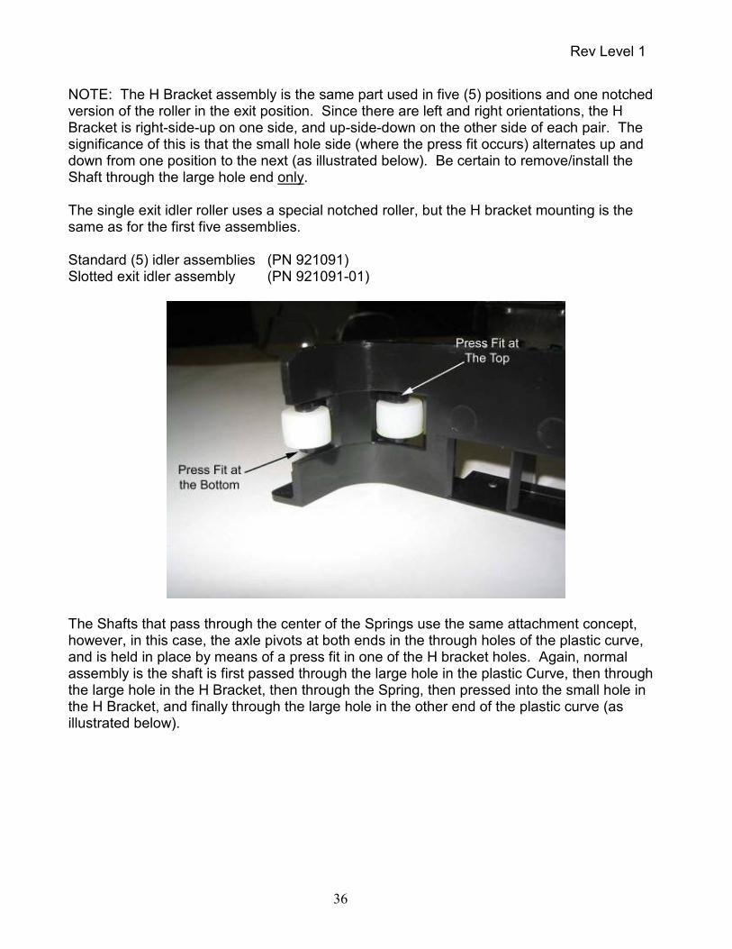
NOTE: The H Bracket assembly is the same part used in five (5) positions and one notched version of the roller in the exit position. Since there are left and right orientations, the H Bracket is right-side-up on one side, and up-side-down on the other side of each pair. The significance of this is that the small hole side (where the press fit occurs) alternates up and down from one position to the next (as illustrated below). Be certain to remove/install the Shaft through the large hole end only. The single exit idler roller uses a special notched roller, but the H bracket mounting is the same as for the first five assemblies. Standard (5) idler assemblies (PN 921091) Slotted exit idler assembly (PN 921091-01)
The Shafts that pass through the center of the Springs use the same attachment concept, however, in this case, the axle pivots at both ends in the through holes of the plastic curve, and is held in place by means of a press fit in one of the H bracket holes. Again, normal assembly is the shaft is first passed through the large hole in the plastic Curve, then through the large hole in the H Bracket, then through the Spring, then pressed into the small hole in the H Bracket, and finally through the large hole in the other end of the plastic curve (as illustrated below).

Rev Level 1
37
6.8 Solenoid To remove the Solenoid Assembly, first unplug the solenoid connector from the main board at position JP6 (see connector location illustration in Section 8 of this manual). NOTE: It will be necessary to remove some cable tie wraps to remove this assembly. Note wire routing and harness attachment points for reinstallation of the replacement assembly. It is extremely important to keep wires routed away from any moving parts and rotating gears. Remove the Pivot Pin (see illustration below) connecting the Solenoid Plunger Assembly to the Hopper Arm by pulling straight up while gently twisting, then remove the Solenoid Plunger Assembly (as illustrated below). Gently detach the rear end of the Spring from the Frame as illustrated below being careful not to damage the Spring. Remove the three (3) screws securing the Frame to the base plate, then lift the entire assembly out. Remove the two (2) Mounting Screws securing the Solenoid to the Frame.

Rev Level 1
38
NOTE: When replacing the assembly, the position of the solenoid frame must be such that the plunger (once the linkage is installed) easily moves in and out of the solenoid cavity. The holes in the solenoid bracket, where it attaches to the base plate, are large enough to provide adequate movement to allow proper alignment of the of the solenoid bracket to the movement of the plunger. Be certain the plunger moves freely throughout the entire stroke and does not rub against the sides of the solenoid cavity. When properly aligned, the plunger will go straight down the center of the cavity. The linkage mechanism should be totally free to move when actuated manually.
6.9 Inkjet Assembly (Optional Equipment) To remove the Inkjet Assembly, first remove the Inkjet Cartridge from the Carriage Assembly (should one be present). Refer to the Maintenance Section of this manual for instructions how to remove the cartridge. Remove the four (4) screws securing the scanner plastic base to the metal baseplate, then remove the scanner assembly from the plastic base. Unplug the 6 connectors along the front side of the Main Printed Circuit Board Assembly to allow the board to tilt down once the screws are removed. Remove the four (4) screws securing the circuit board assembly to the standoffs, then allow the board to hang down while supported by the remaining cables. Unplug the inkjet ribbon cable from the main board at position JP10 (see connector location illustration in Section 8 of this manual). CAUTION: Detailed instructions for removal of the Ribbon Cable from its connector are
Mounting Screws
Solenoid Plunger Assembly
Pivot Pin
Hopper Arm
Frame Solenoid
Spring

Rev Level 1
39
contained in (6.15) the Main Printed Circuit Board section of the manual. Remove the two (2) small screws holding the plastic inkjet carriage (cradle) to the mounting platform. NOTE: When re-installing the carriage (cradle) to the mounting platform, be sure to slide the carriage as far into the track as possible before tightening the two small screws.
6.10 Input Drive Roller The Input Drive Roller is a bushing style assembly with a gear pressed on (slip fit) to the bottom of the roller shaft (see illustration below).
To remove the roller, remove the Tru-Arc ring from the end of the Drive Shaft. Next, insert the blade of a flat screw driver between the top of the plastic gear and the metal boss protruding down from the underside of the base plate. Rotate the screw driver gently to pry the gear down the shaft. Grasp the gear firmly, then pull off the end of the shaft. The roller can now be removed from the top side of the base unit.
6.11 Internal Drive Roller Assemblies There are four (4) Internal Drive Roller Assemblies, three (3) of the jack shaft style, and one (1) with a Bushing that allows the shaft to protrude below the base plate where a drive gear is
Metal Boss
Drive Gear
Tru-Arc Ring
Input Drive Roller

Rev Level 1
40
mounted (see illustration below).
In order to remove the last two (proceeding around the track in a clockwise fashion) Internal Drive Roller Assemblies, it will be necessary to first remove the inboard CIS Module as previously described in this section of the manual. To remove the jack shaft style assemblies, simply remove the e-ring and associated nylon washer from the top of the shaft, then rotate the roller while lifting the roller off the shaft end. NOTE: These rollers are driven with an integral cog style plastic pulley at the base of the assembly. When reinstalling the roller, it will be necessary to ensure that the toothed belt is wrapped around the pulley, and properly engaged with the cogs. To remove the busing style assembly it will first be necessary to remove the Main Printed Circuit Board Assembly as described elsewhere in this section of this manual. With the circuit board removed, remove the Tru-Arc ring from the end of the Drive Shaft. Next, insert the blade of a flat screw driver between the top of the plastic gear and the metal boss protruding down from the underside of the base plate. Rotate the screw driver gently to pry the gear down the shaft. Grasp gear firmly, then pull off the end of the shaft. The roller can now be removed from the top side of the base unit.
Jack Shaft Style with E-Ring and Nylon Washer
Bushing Style

Rev Level 1
41
6.12 Stepper Motor To remove the Stepper Motor, first remove the Solenoid Assembly as previously described in this section of the manual. Unplug the cable from the connector at the Stepper Motor. There are four (4) screws that secure the Stepper Motor to the Base Plate. Once the Solenoid Assembly is removed, there is access to these screws from the top side of the Base Plate. Remove the screws and the motor is free. NOTE: The Stepper Motor has a cog style pulley attached to the shaft. When reinstalling the motor, it will be necessary to ensure that the toothed belt is wrapped around the pulley, and properly engaged with the cogs.
6.13 DC Gear Head Motor To remove the DC Gear Head Motor it is first necessary to remove the Input Drive Roller as previously described in this section of the manual. Unplug the DC motor connector from the main board at position JP5 (see connector location illustration in Section 8 of this manual). NOTE: It will be necessary to remove some cable tie wraps to remove this assembly. Note wire routing and harness attachment points for re-installation of the replacement assembly. Remove the Tru-Arc ring from the end of the motor output shaft and removed the plastic washer. Remove the gear off the end of the DC Gear Head Motor shaft. Remove the three (3) screws securing the motor from the top side of the base plate. The motor is now free.
6.14 Drive Belt To remove the drive belt it is first necessary to remove some other assemblies as previously described in this manual. Refer to applicable sections for complete instructions and pictorials. Remove the Inkjet Assembly, and Internal Drive Roller Assemblies. NOTE: It is not necessary to remove the fourth (last) Internal Roller Assembly. Remove the Pivot Pin connecting the Solenoid Plunger Assembly to the Hopper Arm by pulling straight up while gently twisting, then remove the Solenoid Plunger Assembly. Remove the three (3) screws securing the Frame of the Solenoid Assembly to the base plate, then lift the entire assembly up enough to gain access to the belt. The Drive Belt is now free to remove out the top side of the unit.

Rev Level 1
42
6.15 Main Printed Circuit Board Assembly Unplug the six (6) connectors along the front side of the circuit board, then the six (6) connectors along the back side while the board is still mechanically secured. Remove the four (4) screws securing the board to the standoffs. Gently slide the board straight down, then carefully unplug the inkjet ribbon cable from the main board at position JP10. CAUTION: The Printer ribbon cable and associated connector are very fragile. Exercise patience and a gentle touch when working with this connector so as not to cause any damage which could render your main board useless. To unplug the ribbon cable from the connector, very gently pull back the connector plastic lock evenly on both sides with your finger nails. Once open, the cable will easily pull out. When re-installing, slide the cable squarely into the socket (noting the orientation of the electrical contacts), then push the connector plastic lock evenly on both sides to hold the cable in place. Gently pull on the ribbon cable to insure it is locked into the connector securely. See illustration below for proper (electrical contacts of pins facing down) cable orientation.
CAUTION: Whenever re-installing the PCBA mounting hardware, insure that the proper washers are installed in the proper positions so as to insure grounding through the metal support studs. Note that the pad on the PCB around the mounting screw hole closest to the CIS does not have solder mask on the back side. This technique provides electrical grounding of the PCB to the chassis and is critical for proper operation of the scanner. This position needs to use the screw with the external star washer to insure proper electrical connection.

Rev Level 1
43
7.0 Assembly Drawings & Parts Identification The Illustrated Parts Breakdown PowerPoint file (TS240 Final Assembly.pdf), which is included as part of this manual, provides complete assembly information and individual parts identification data. The PowerPoint is divided into sections as follows:
TS240 Final Assembly.pdf Section A (Slides 1-11) Shafts
Rollers Gears Motors
Section B (Slides 12-22) Belt Solenoid Mount Sync Sensor Detector Guide Wall Feed Sensor Emitter Tension Mechanism
Section C (Slides 23-36)
Outer/Inner Walls Sync Sensor Emitter Mounting Belt Tension Adjust Inkjet Support MICR Curve Installation Discriminator Assembly Installation Cable Arrangement CIS
Section D (Slides 37-55) Franker
Sync Emitter Cable Routing Solenoid Plunger Assembly Mounting Cable Arrangement and Wire Routing Main Board Mounting Section E (Slides 56-68)
Plastic Base Assembly Unit Installed Exit Tray Installed Light Pipe Installed Ink Absorbent Pad Installed Top Covers

Rev Level 1
44
8.0 Electrical Assembly The connector identification locations on the Main CPU Board are as illustrated below. These connectors are referenced throughout the Part Removal Section of this Service Manual.
TS240 Main CPU Board

Rev Level 1
45
9.0 Recommended Spare Parts List Following are the individual parts and sub-assemblies recommended for purchase as spare parts for the TS240 Scanner. The part numbers shown represent the Lowest Replaceable Unit (LRU) for each assembly. It is not recommended that individual parts or assemblies below the LRU level be purchased due to difficulty in assembly and/or replacement in the field. DCT Part No. Description Qty/Unit
148021-01 POWER SUPPLY W/CORD, ROHS, 90-260VAC/30VDC 1.5A 1
143104 MYLAR EXIT POCKET GUIDE 1
143156 ASSY, STEPPER MOTOR WITH CABLE AND PULLEY 1
146130 ASSY, DC MOTOR W/CABLE (4MM OUTPUT SHAFT) 1
364012-01 ASSY, SOLENOID WITH CABLE (3 pin) 1
144101-01 ASSY, FEED ROLLER POSITION 1 1
146104 ASSY, FEED ROLLER POSITION 2 (W/SHAFT AND GEAR) 1
151161 ASSY, CLOSED CELL RUBBER ROLLER W/HUB 1
921085-01 ASSY, PINCH ROLLER POSITION 3 1
921084-01 ASSY, TRANSPORT ROLLER POSITION 4,5,6 3
146230 IDLER ROLLER, FLANGED 12mm OD 1
153050-01 PCBA, CPU TS240 USB2 1
913022 PCBA, FEEDER SENSOR-EMITTER TS240/230/220 (OUTSIDE) 1
153120-01 PCBA, FEEDER SENSOR-DETECTOR/INDICATOR TS240 w/CABLE (INSIDE) 1
146132-02 PCBA, SYNC SENSOR-EMITTER W/MAGNET (OUTSIDE) 1
913019 PCBA, SYNC SENSOR-DETECTOR (INSIDE) 1
148052-02 PCBA, EXIT SENSORS-EMITTER TS240/230/215 (OUTSIDE) 1
148052-01 PCBA, EXIT SENSORS-DETECTOR TS240/230/215 (INSIDE) 1
146107 ASSY, OUTER PLASTIC CURVE W/MICR HEAD, ROLLERS&SPRINGS 1
146131 ASSY, INNER PLASTIC CURVE W/MICR ROLLER&SPRING 1
146106 ASSY, INKJET HOLDER & C6602 CARTRIDGE W/CABLE & MOUNTING SCRW 1
148112-01 ASSY, LEFT FRONT WALL W/O SENSOR BOARD 1
153104 ASSY, CENTER COVER W/LIGHT PIPE TS240 1
153105 ASSY, OUTER COVER W/ABSORPTION PAD TS240 1
153103 ASSY, PLASTIC BASE W/BUMPONS TS240 1
153312 CHECK EXIT TRAY SLIDE TS240 1
153160 ASSY, CIS & SUPPORT, FIXED TS240 W/EXIT SENSOR 1
153161 ASSY, CIS & SUPPORT, HINGED TS240 W/EXIT SENSOR 1
153156 ASSY, FRANKER TS240 W/"SCANNED" STAMP 1
153237 DOMED LABEL DIGITAL CHECK TS240 1
928747-01 THUMBSCREW, FOR HINGED CIS DOOR 1
BE0030 TIMING BELT TS240/230/220E/215 1
CA0036 CABLE, USB 2.0 CERTIFIED (A/B MALE BLACK) 2M 1

Rev Level 1
46
10.0 TellerScan™ 240 Scanner Specifications
Scanning Device 108mm Contact Information Sensor (CIS)
Light Source Tricolor Light Emitting Diode (LED)
Scanning Method Concurrent, Duplex (front & rear) Document Size Up to UNI A6 Document Height 2.12 – 4.13 inches (54 – 105 mm) Document Length 3.19 – 8.98 inches (81 – 228 mm) Document Weight 16 – 28 lbs. (60 – 105 grams/square meter) Auto Feeder Capacity 1-100 Documents (depends on document thickness and
condition)
Output Sort Pockets One Pocket, 100 Documents (depends on document thickness and condition)
Scanning Capture Speed 19.7 in/sec (50 cm/sec) grayscale / color 13.0 in/sec (33 cm/sec) color Scan System Throughput 50, 75 or 100 6-inch checks per minute (depending on computer power)
Scanner Image Format Uncompressed Grayscale and Color
Grayscale Image Depth 8 bits/pixel (256 shades of Gray) 1 bit/pilxel Bitonal (B&W), and 4 bits/pixel (16 shades of gray) software selectable from the API
Color Image Depth 24 bits/pixel (16,777,216 shades)
Image Resolution 300x300 dots per inch (dpi) 240 x 240, 200 x 200, 120 x 120 100x100 (software selectable from the API) Image Formats Bitmap (BMP) 4-side cropping, and image rotation performed by the API Image Compression Tag Image File Format (TIFF) Group 4, Joint Photographic Experts Group (JPEG)
Image Transmission Through the USB port

Rev Level 1
47
TellerScan™ 240 Scanner Specifications (continued)
Double Feed Device Infra Red (IR) Transmissive Type
Double Feed Detection Programmable delay (performs skip-over function) Perforation Skipping Included (selectable perforation size)
Interface USB2 (backwards compatible to USB1.1, though not
recommended) RS-232 (MICR Reader Emulation and Service Functions)
MICR Recognition Recognition algorithm for E13B, CMC7, or CMC0 standards performed by the API
MICR Data Transmission Analog waveform through the USB port
Environmental Specifications Temperature (operating) 60–90 degrees F (15–32 degrees C) Humidity (operating) 35–85% non-condensing Scanner Physical Dimensions Height 7.50 inches (19.05 cm) Length 11.0 inches (28.19 cm) Depth 5.1 inches (12.95 cm) Weight 5.2 lbs. (2.40 kg) Footprint 5.1 inches (12.9 cm) x 8.25 inches (20.8 cm) Electrical Specifications Power Consumption 45 Watts (maximum) Input Voltage 100VAC to 240VAC (+/- 10 %), 50/60 Hz (+/- 10 %), auto sensing Separate modular power supply Agency Approvals UL, CUL, CE, FCC class B (RoHS) Product Life Designed for a useful life of 5,000,000 checks Duty Cycle 3,000 to 6,000 checks per day
MTTR (Mean time to repair) 20 minutes

Rev Level 1
48
TellerScan™ 240 Scanner Specifications (continued)
Optional Inkjet Endorser Endorse back side of checks prior to capturing the scanned Image 12 Nozzle Printing resolution (96 dpi) Hewlett Packard (HP) Cartridge C6602A
- Yield is 5,000,000 to 7,000,000characters Optional Front Franking Stamp Two Franking stamps available The standard says ‘SCANNED’ printed multiple times at an angle.

Rev Level 1
49
11.0 TS240 Sample Configuration File
This sample configuration file is representative of Scanner Specific Data stored on-board the TS240 Scanner. [SCAN] Path Length=700 Pos. Pipeline=50 EdgeDebounceLen=75 Pwm DoubleFeed 0=68 Pwm DoubleFeed 1=50 T.Rewind End Batch=50 Feed Time Out=2 Motor Start Delay=250 Motor Off Delay=2000 Pos Jam Detector 0=550 Pos Jam Detector 1=0 Solenoid Pwm Drive=240 Solenoid Pwm Hold=60 Solenoid Off Delay=2000 Pos. Sorter=860 T.Drive Feed Solenoid=120 Slip Length=28 Operating Mode=0 PreSync Position=48 MechFrankPosition=579 FrankOnLag=16 FrankOffLag=40 FeedSolnReEnergizeDelayMS=230 FeedSolnOffBeforeReEnergizeMS=15 FrankDefaultLength=120 FrankDefaultMargin=8 [FRONT IMG] PosFront=461 [FRONT IMG SENSOR] Type=2 PelsDirTopDown=0 [FRONT IMG MODULE] Resolution=300 StartPixel=0 NGoodPixel=1296 XIntensDrop=0 TotNpixel=1536 [FRONT IMG ACQ] Gain_R=3000

Rev Level 1
50
Gain_G=3000 Gain_B=3000 Gain_GRAY=2065 Offset_R=1000 Offset_G=1000 Offset_B=1000 Offset_GRAY=1000 Pwm_R=222 Pwm_G=222 Pwm_B=157 [REAR IMG] PosRear=507 [REAR IMG SENSOR] Type=2 PelsDirTopDown=0 [REAR IMG MODULE] Resolution=300 StartPixel=0 NGoodPixel=1296 XIntensDrop=0 TotNpixel=1536 [REAR IMG ACQ] Gain_R=3000 Gain_G=3000 Gain_B=3000 Gain_GRAY=2027 Offset_R=500 Offset_G=500 Offset_B=500 Offset_GRAY=750 Pwm_R=186 Pwm_G=226 Pwm_B=125 [MICR HEAD] Position=250 Sample Frequency=34254 Gain Calib Factor=60 Offset=717 [PRINTER] Position=230 CleanPulse=45 Delay Clean0=3600 Num Clean0=50 Delay Clean1=36000 Num Clean1=100 Delay Clean2=65000

Rev Level 1
51
Num Clean2=200 [MOTOR] Steps Per Meter=2800 Eject Speed=15 Feed Speed=35 Out Speed=61 CCW Direction=0 [MOT 0] Accel.#00 Num=4 Accel.#00 Speed=-700 Accel.#01 Num=0 Accel.#01 Speed=0 Accel.#02 Num=10 Accel.#02 Speed=700 Accel.#03 Num=20 Accel.#03 Speed=970 Accel.#04 Num=10 Accel.#04 Speed=1000 Accel.#05 Num=10 Accel.#05 Speed=1050 Accel.#06 Num=10 Accel.#06 Speed=1100 Accel.#07 Num=10 Accel.#07 Speed=1150 Accel.#08 Num=105 Accel.#08 Speed=1200 Accel.#09 Num=10 Accel.#09 Speed=1250 Accel.#10 Num=10 Accel.#10 Speed=1300 Accel.#11 Num=10 Accel.#11 Speed=1350 Accel.#12 Num=10 Accel.#12 Speed=1385 Accel.#13 Num=10 Accel.#13 Speed=1450 Accel.#14 Num=10 Accel.#14 Speed=1500 Accel.#15 Num=10 Accel.#15 Speed=1580 Accel.#16 Num=10 Accel.#16 Speed=1650 Accel.#17 Num=0 Accel.#17 Speed=1700 Accel.#18 Num=0 Accel.#18 Speed=1700

Rev Level 1
52
Accel.#19 Num=0 Accel.#19 Speed=1700 Accel.#20 Num=0 Accel.#20 Speed=1700 Accel.#21 Num=0 Accel.#21 Speed=1700 Accel.#22 Num=0 Accel.#22 Speed=1700 Accel.#23 Num=0 Accel.#23 Speed=1700 Accel.#24 Num=0 Accel.#24 Speed=1700 Accel.#25 Num=0 Accel.#25 Speed=1700 Accel.#26 Num=0 Accel.#26 Speed=1700 Accel.#27 Num=0 Accel.#27 Speed=1700 Accel.#28 Num=0 Accel.#28 Speed=1700 Accel.#29 Num=0 Accel.#29 Speed=1700 Accel.#30 Num=0 Accel.#30 Speed=1700 Accel.#31 Num=0 Accel.#31 Speed=1700 Decel.#00 Num=4 Decel.#00 Speed=-700 Decel.#01 Num=0 Decel.#01 Speed=0 Decel.#02 Num=10 Decel.#02 Speed=700 Decel.#03 Num=10 Decel.#03 Speed=1000 Decel.#04 Num=10 Decel.#04 Speed=1200 Decel.#05 Num=10 Decel.#05 Speed=1350 Decel.#06 Num=10 Decel.#06 Speed=1450 Decel.#07 Num=10 Decel.#07 Speed=1530 Decel.#08 Num=10 Decel.#08 Speed=1600 Decel.#09 Num=10 Decel.#09 Speed=1650

Rev Level 1
53
Decel.#10 Num=10 Decel.#10 Speed=1680 Decel.#11 Num=0 Decel.#11 Speed=1700 Decel.#12 Num=0 Decel.#12 Speed=1700 Decel.#13 Num=0 Decel.#13 Speed=1700 Decel.#14 Num=0 Decel.#14 Speed=1700 Decel.#15 Num=0 Decel.#15 Speed=1700 Decel.#16 Num=0 Decel.#16 Speed=1700 Decel.#17 Num=0 Decel.#17 Speed=1700 Decel.#18 Num=0 Decel.#18 Speed=1700 Decel.#19 Num=0 Decel.#19 Speed=1700 Decel.#20 Num=0 Decel.#20 Speed=1700 Decel.#21 Num=0 Decel.#21 Speed=1700 Decel.#22 Num=0 Decel.#22 Speed=1700 Decel.#23 Num=0 Decel.#23 Speed=1700 Decel.#24 Num=0 Decel.#24 Speed=1700 Decel.#25 Num=0 Decel.#25 Speed=1700 Decel.#26 Num=0 Decel.#26 Speed=1700 Decel.#27 Num=0 Decel.#27 Speed=1700 Decel.#28 Num=0 Decel.#28 Speed=1700 Decel.#29 Num=0 Decel.#29 Speed=1700 Decel.#30 Num=0 Decel.#30 Speed=1700 Decel.#31 Num=0 Decel.#31 Speed=1700 [MOT 1] Accel.#00 Num=4

Rev Level 1
54
Accel.#00 Speed=-700 Accel.#01 Num=0 Accel.#01 Speed=0 Accel.#02 Num=10 Accel.#02 Speed=700 Accel.#03 Num=20 Accel.#03 Speed=970 Accel.#04 Num=10 Accel.#04 Speed=1000 Accel.#05 Num=10 Accel.#05 Speed=1050 Accel.#06 Num=10 Accel.#06 Speed=1100 Accel.#07 Num=10 Accel.#07 Speed=1150 Accel.#08 Num=105 Accel.#08 Speed=1200 Accel.#09 Num=10 Accel.#09 Speed=1250 Accel.#10 Num=10 Accel.#10 Speed=1300 Accel.#11 Num=10 Accel.#11 Speed=1350 Accel.#12 Num=10 Accel.#12 Speed=1385 Accel.#13 Num=10 Accel.#13 Speed=1450 Accel.#14 Num=10 Accel.#14 Speed=1500 Accel.#15 Num=10 Accel.#15 Speed=1580 Accel.#16 Num=10 Accel.#16 Speed=1650 Accel.#17 Num=0 Accel.#17 Speed=1700 Accel.#18 Num=0 Accel.#18 Speed=1700 Accel.#19 Num=0 Accel.#19 Speed=1700 Accel.#20 Num=0 Accel.#20 Speed=1700 Accel.#21 Num=0 Accel.#21 Speed=1700 Accel.#22 Num=0 Accel.#22 Speed=1700 Accel.#23 Num=0

Rev Level 1
55
Accel.#23 Speed=1700 Accel.#24 Num=0 Accel.#24 Speed=1700 Accel.#25 Num=0 Accel.#25 Speed=1700 Accel.#26 Num=0 Accel.#26 Speed=1700 Accel.#27 Num=0 Accel.#27 Speed=1700 Accel.#28 Num=0 Accel.#28 Speed=1700 Accel.#29 Num=0 Accel.#29 Speed=1700 Accel.#30 Num=0 Accel.#30 Speed=1700 Accel.#31 Num=0 Accel.#31 Speed=1700 Decel.#00 Num=4 Decel.#00 Speed=-700 Decel.#01 Num=0 Decel.#01 Speed=0 Decel.#02 Num=10 Decel.#02 Speed=700 Decel.#03 Num=10 Decel.#03 Speed=1000 Decel.#04 Num=10 Decel.#04 Speed=1200 Decel.#05 Num=10 Decel.#05 Speed=1350 Decel.#06 Num=10 Decel.#06 Speed=1450 Decel.#07 Num=10 Decel.#07 Speed=1530 Decel.#08 Num=10 Decel.#08 Speed=1600 Decel.#09 Num=10 Decel.#09 Speed=1650 Decel.#10 Num=10 Decel.#10 Speed=1680 Decel.#11 Num=0 Decel.#11 Speed=1700 Decel.#12 Num=0 Decel.#12 Speed=1700 Decel.#13 Num=0 Decel.#13 Speed=1700 Decel.#14 Num=0

Rev Level 1
56
Decel.#14 Speed=1700 Decel.#15 Num=0 Decel.#15 Speed=1700 Decel.#16 Num=0 Decel.#16 Speed=1700 Decel.#17 Num=0 Decel.#17 Speed=1700 Decel.#18 Num=0 Decel.#18 Speed=1700 Decel.#19 Num=0 Decel.#19 Speed=1700 Decel.#20 Num=0 Decel.#20 Speed=1700 Decel.#21 Num=0 Decel.#21 Speed=1700 Decel.#22 Num=0 Decel.#22 Speed=1700 Decel.#23 Num=0 Decel.#23 Speed=1700 Decel.#24 Num=0 Decel.#24 Speed=1700 Decel.#25 Num=0 Decel.#25 Speed=1700 Decel.#26 Num=0 Decel.#26 Speed=1700 Decel.#27 Num=0 Decel.#27 Speed=1700 Decel.#28 Num=0 Decel.#28 Speed=1700 Decel.#29 Num=0 Decel.#29 Speed=1700 Decel.#30 Num=0 Decel.#30 Speed=1700 Decel.#31 Num=0 Decel.#31 Speed=1700

Rev Level 1
57
12.0 Sample Initialization File
This sample initialization file is representative of general Generic Scanner Data stored in a file on the PC.
# API Version 10.00 # # Digital Check Sample Configuration File for Teller Scan Check Scanners # Models TS200, TS220, TS230, TS240, TS300, TS350, TS350EBS, TS400, TS400ES # TS4080, TS4120, CX30, SB500, SB600 # # DCCAPI Version 10.00 Release History # Includes all previous API changes and Updates # Rolled SB500 and SB600 Device Support Into Common API # #******************** API Version 9.17 Improvements ************************* # Added FIRMWARE_LOAD_MODE for TS240 support # Fixed a problem in DCCLoadImage # Updated TS2DLL.DLL to 4.7.6.23 # Updated CX30Firmware.bin and CX30KfFirmware.bin to 1.1.2.8 # Added Automatic test for USB1 support # Added DCCAltBWImage #******************** API Version 9.16 Improvements ************************* #******* No Longer Saves or Utilizes temp files stored on Hard Drive ******* # Display compressed images from memory buffers. # Removed Ts4cfg.tmp communication file. # Increase USB1 Timeout for CX30 and Ts240 # Updated TS240 Firmware to 1.1.1.20 # Added FIRMWARE_LOAD_MODE and FILE_WRITE_ALLOWED # Double Feed No Stop no longer generates a DFNS.tif file in the temp directory, all # testing is now done in memory buffers. # Made EEPROM.DAT file optional in temp directory. #******************** API Version 9.15 Improvements ************************ # Changed location for the CFG file to the environmental temp folder. #******************** API Version 9.14 Improvements ************************ # Fixed Error in endorsement increment procedure # Now allow one error in MICR read for identifying New Postal Money order (Bad MICR Printing). # Changed Threshold settings for Postal Money Order to handle new dark colors. # Added automatic Double Feed Disable in Special Doc Handling for New Money Orders (thicker paper). # Added Automatic Double Feed Disable for all identified documents in Special Document Handling. # 4120/TS240

Rev Level 1
58
# Added DOUBLE WIDE FONT for improved endorse readability by putting 0x1234 in # place of the Italics variable in the DCCBatchPrintBMP function. # CX-30 # New Firmware to handle incidence of document being placed in Scan Ready position prior to # initialization or application startup. #******************** API Version 9.12 Improvements ************************ # 4120 # Performance increase, speed and sorting # New Thresholding Option to increase the readability for light endorsements # CX-30 # Fixed Initial Installation issue concerning the updating of onboard # Scanner Firmware. # Added Suport for higher sensors to address sensitve Skew issue that if # undetected may cause cropped images. #******************** API Version 9.10 Improvements ************************ # Special Documents # Hard to handle Money Orders # Better handling of documents that cause or should cause double Feeds # Special Processing like despeckling or edge removal for problem documents # Image Quality Analysis overrides for typically problem images # Upside Down Image Handling # Improved Logic for determining Upside down images. # Built-In Scanner Diagnostics # User selected automatic (non application dependent) scanner diagnostic reporting added. # Requires no programming or any new distribution files be added to your application. # Scanner Speed # Improved Image processing and timing issues. 4120 runs noticeably faster and # smoother while improving image quality. # Best Read # Improved to support CMC7 OCR on 300 dpi Digital Check Scanners # Security # CRC16 embedded in Tiff Header to verify image was scanned by a Digital Check Scanner # TS240 Support # Beta Code for TS240 included in this release. API 10.0 will be official TS240 release # CX30 updates - Sensors, better Magnetic MICR, latch # Auto E13B/CMC7 Magnetic MICR with automatically MICR OCR/Verification for either font # Franker Support # Custom programming support added as well as always on, always off and Frank

Rev Level 1
59
# on good MICR added to API on CX30 and TS240 # Barcode Recognition # New zone configurable Barcode recognition engine added to API # OCR Reading # New Zone configurable OCR 'A' and OCR 'B' reading added to API # New Active X API # ActiveX Control added to make development of Browser based programs as well as other # development environments quicker and easier. # Image DPI Output choices added # Bi-tonal images can be scanned at 200 or 300 dpi on CX30 and Ts240. # Grayscales can be saved at 300, 240, 200, 120, or 100 dpi. # Improved "C" demonstrations which are more useful for current applications # Updated C# Demo application and Source Code. #******************** Version 9.08 **************************************** # Fixed a COM Object issue with dirty checks. # Fixed IE Browser Memory issue #******************** Version 9.07 **************************************** # Added Force DF flag in Special Documents #******************** Version 9.06 **************************************** # Added BUICEjectPocket # Added Kiosk Mode for short check endorsing on CX30 # Fixed a bug in E13B Magnetic MICR #******************** Version 9.05 **************************************** # Added DCCResolveTwoPassMICR ## Added DCCScan Option 2048 – CX30 Two Pass MICR # Added CX30 PreJam Testing in all Scan Modes # Fixed an Update/TS2ClearErrors conflict while endorsing after a jam. #******************** Version 9.04 **************************************** # Added a pretest for BUICClearDocument #******************** Version 9.03 **************************************** # Added existing MICR space formatting for application backward compatibility for CX30. #******************** Version 9.02 **************************************** # Added a Late Jam Test Option for CX30 in Scan/Return # Added a test on next scan for CX30 in Scan/Return Mode to test if the previous # document JAMMED during Return. # Added a test to Change 'GENERIC ERROR' to 'JAM' if it is a CX30 in Scan/Return Mode. #******************** Version 9.01 **************************************** # Fixed a problem with TS200_CB_EVENT_BACK. Greatly improves 4120 sorting performance. #******************** Version 9.00 **************************************** # Released tested CX30 Support. # Updated TS2DLL.DLL to fix a bi-direction endorsement issue.

Rev Level 1
60
# Add MICR Formation to new MICR Verification Routines, so E13B MICR could be returned # without spaces and with the optional ‘E’ character. # Released new firmware for the CX30 Scanner (CX30Firmware.bin). # Added CheckEndorsementInvert() (Reverse Contrast Text Printing). # Added support for manual Gain and AGC (Automatic Gain Control). This required an updated # TS2DLL.DLL and CX30Firmware.bin. # Added a second pass of special document handling after OCR MICR since the magnetic MICR # lines on some special documents were below #standard. # Fixed a Photosync flag in CleanMode and BUICClearDocument. # Fixed a MICR issue with isolated Training MICR Character. # Added DCCScanSetSpecialDocument (Applications can set special endorsements outside of # ini file) # Added funcImage300To240 (Support 240 dpi on CX30) # Added support for CX30 (More Modes, etc) # Improved Magnetic MICR and Fixed Lockup on bad data # Added Min Length Image Check to DCCScan (Issue Warning on Possible Short Images if using # DCCScan) # Fixed a color image problem in FindE13B (Just improved rates some) # 300 dpi support for CX30 # Added 240 dpi support for CX30 # Added Upside Down Document Test to DCCScan – Option 0x400 or 1024. # Four new Parameters (two are actually a patch to make images on the TS4120 the same as TS300 images) # 1. define CFG_IMAGE_PADBOTTOM 189 Extra Scanlines at bottom # 2. define CFG_IMAGE_PADTOP 190 Extra Scanlines at top # 3. define CFG_SCAN_MODE 191 FOR CX30 ONLY: # define CFG_SCAN_MODE_FORWARD 0 - Scan Through # place check in OUTPUT tray # define CFG_SCAN_MODE_REVERSE 1 - Scan & Return, # place check in INPUT tray # define CFG_SCAN_MODE_HOLD 2 - Scan forward direction, HOLD check after reading. NEXT SCAN # will place check in tray. # 4. define CFG_DCCSCAN_MINLENGTH 192 Check Min Len in 10th inches. Default is 40 for 4 inches. # Problem Document/Money Order Image Enhancement #-------------------------------------------------------------------------------------------------------------------------------# # All Setting in this file can be overridden by making BUICSetParam calls in # application. Any line that starts with a "#" is a comment. #

Rev Level 1
61
#DCC Scan Parameters [DCCSCAN] #See IQAStatus function instructions (Test Values are added together): #IQACROP-1,IQACLEAN1-2, IQACLEAN2-4, IQACLEAN3-8, IQACLEAN4-16, #IQASTANDARDSIZE-32,IQASKEW-64, #IQACORNERS-128, IQALINES-256, #IQAMICRQUALITY-512,IQADENSITY-2048, IQACOMPRESSEDSIZE-4096, #IQACARPRESENT-8192, IQALARPRESENT-16384, IQATOPRESENT-32768,IQADATEPRESENT-65536, #IQASIGNPRESENT-131072,IQAMEMOPRESENT-262144,IQABLOB-524288,IQACARBON-1048576, #IQASTREAKS-2097152,IQAFOCUS-4194304,IQACOUNTINSIDE-8388608,IQACLEANSIDES-16777216, #IQADOUBLETOPEDGE-33554432,IQACLEANSIDES2-67108864 #Performing all recommend tests=10492612 IQATests=10492612 #Edge Detection Contrast should start at 450, 600, and end at 750 StartContrast=450 EndContrast=750 IncrementContrast=150 #All DCCScan function Scanning is done at 200 dpi and JPEGS can be stored at # 100, 120, 200 or 300 DPI. If set to 0, no JPEGs are saved. JPEGEndResolution=200 #Maximum allowable Speckles before image must be rethresholded MaxSpeckles=1000 #Min allowable MICR Quality based on 1 (Wrong) to 10 (Perfect MICR and MICR Image) MinMICRQuality=5 #Number of allowable Corner Pixels (60 is 3 tenths of an inch at 200 dpi) MaxBentCorner=60 #Percent of black pixels to total pixels. MaxRawDensity=20 #Number of K bytes of allowable compressed Tiff Image Data MaxTiffImageSize=24 #Options=1 -- Try using multiple Contrast Settings (Depends on StartContrast, # EndContrast, and IncrementContrast) #Options=2 -- Try a simple thresholding (depends on "Acq: Front B/W threshold") #Options=4 -- Save the image after despeckling and edge Removal #Options=8 -- Save the grayscale/color image as BMP #Options=16 - Group 4 Filter - Smaller Tiffs #Options=32 - FSThreshold - Return optional Tiff as JPEG #Options=64 - Force EdgeDetected Images to 3.1% if possible #options=128- Return uncompressed grayscale/color images as JPEGs (BUICMemHdr) #Options=256- Return Rear Grayscale Density in iDocStatus[31] #Options-512- Reduce 300 dpi to 240 dpi #Options-1024-Check for Upside Down Images #Options-2048-CX30 Only - Read MICR Forward and Backwards

Rev Level 1
62
#Options-4096-TS240/CX30 - Reduce a 300 dpi scan to 200 dpi - Important feature # since CMC7 OCR only works at 300 dpi #Options-8192-Use Faster Simple Threshold instead of Edge Threshold on Back Image Options=67 #Options=8259 #Min Length is the minimun acceptable image length in 10th of inches (default 30) Min Length=58 #Scout Path=C:\Program Files\Silver Bullet Technology\ScoutClient\ScoutScannerDLL.dll #Scout Enable=1 #Override Rear Threshold and Increase (Mostly for TS4120) Rear Threshold=400 [DCCSCAN EXCEPTION] #Number of Exception Documents Count=4 # Postal Money Order 1Routing=:000008002: 1Accout= 1Threshold=1 1Min=50 1Options=63 // 1-Smaller Tiffs, 2-Ignore Speckles, 4-Remove Speckles, // 8- Ignore Corners, 16 - Ignore Streaks, 32 - Ignore DF 1Contrast=600 # Western Union Money Order 2Routing=:102100400: 2Accout= 2Threshold=1 2Min=65 2Options=71 // 1-Smaller Tiffs, 2-Ignore Speckles, 4-Remove Speckles // 64-Ignore compressed image size 2Contrast=350 # MoneyGram 3Routing=:091900533: 3Accout= 3Threshold=1 3Min=64 3Options=23 // 1-Smaller Tiffs, 2-Ignore Speckles, 4-Remove Speckles // 16 - Ignore Streaks 3Contrast=450

Rev Level 1
63
# Bank of America Money Order 4Routing=:114000019: 4Accout=001641 4Threshold=3 4Min=30 4Options=7 // 1-Smaller Tiffs, 2-Ignore Speckles, 4-Remove Speckles 4Contrast=450 [ACQ. SETUP] #0= Never load, 1 = Always load, 2= Load if newer (default) FIRMW_LOAD_MODE=1 #Pipelining or Batch Scanning Enabled =1 (Default), Item Scanning = 0, Only TS230 #and TS4120 support Batch Scanning all other models ignore this setting SCANBATCH Enable=1 #TS230 and TS4120 Step Down Parameter. This is normally set to 100 (Default) but can be set to #65 or 35 to make a scanner simulate a slower scanner for testing. TS230_65=100 #USB Type Setting #USB2.0 Only = 0 (Default), USB1.1 or USB2.0 = 1 (Slightly Slower) USB1=0 #Simple Thresholding Red Filter Off = 0 (Default), Right Bottom Corner = 1, #Full Image = 2 Threshold Red Filter=0 #Double Feed Enabled = 1, Double Feed Disabled = 0, # For 220, 230, 4120 Double Feed Enabled but No Stop in Track = 2 (Default) # (Double Feed is triggered by the double feed sensor and poor MICR or multiple #documents in the image.) #NOTE: Developers support two calls for backwards compatibility. #Devices: Double feed detect and Acq: Doc.thickness #But Devices: Double feed detect is more readable and understandable Devices: Double feed detect=2 #If Double Feed No Stop is set, then test for and set American MICR rules: One #Routing, One Amount = 1 (Default) American MICR Rules=1 #Magnetic MICR Disabled = 0, Magnetic MICR Enabled = 1 (Default) MICR: Enable=1 #Set Expected MICR Font: CMC7 = 0, E13B = 1 (Default)

Rev Level 1
64
MICR: font=1 #MICR String Format Settings #Leaving E and no spaces - 0, no spaces = 1, spaces = 2, #spaces even in amount field if MICR is verified = 3 (Default) MICR: Format=3 Printer: Initial pos.=0 Printer: Selection=0 Printer: Double density=0 Printer: Intensity=80 Printer: Intensity12=185 Printer: Xpixeld=8 Printer: 2 rows=0 Printer: Clean 44=1500 Printer: Clean 18=480 Printer: Clean 6=60 Printer: Clean 2=5 #Image Resolution Settings (DPI) #100x100 = 0, 200x200 = 1 (Default), 200x100 = 2, 300x300 = 4 Acq: Resolution=1 #Use Scanner Internal Sort Algorithms for Sorting = 0, Use Programmatic Sorting = 1 #(Default) Sorter: Input=1 #Thresholds for Simple Thresholding 2 to 13 (US Default: Front = 10, Back = 8) Acq: Front B/W threshold=10 Acq: Rear B/W threshold=8 #4 bit grayscale = 0, 8 bit grayscale = 1, Should be 1 for all USB Scanners Acq: Gray 256 lev.=1 #Top Image Crop Disabled= 0, Top Image Crop Enabled = 1 (Default) Image: Crop=1 #Grayscale Cropping threshold (Usually 48 to 112, Default = 64) Crop Threshold=64 #No Image rotation (Not available on all models) = 0, Rotate 90 degrees = 1 (Default) Image: Rotate=1 Acq: Img Right=0 Acq: Img Left=1500 Acq: Img Bottom=0 Acq: Img Top=864

Rev Level 1
65
# No Additional TIFF Micr Tag = 0 (Default), Add a TIFF Micr Tag = 1 TIFF Micr Tag=0 #Reload the Endorsement BMP between scans = 0 #Reload the Endorsement BMP only on command = 1 (Default) Printer BMP Load Once=1 #Double Feed Offset - Depending on Scanner Adjust both Double feed: length=40 Double feed: delay=30 #Scan only on command = 0, Prefeed checks = 1 #If endorsement is changing on every check then prefeed must be turned off Enable Scan=0 #Millisecond delay for next check in feeder, usually 500 for scanners with #autofeeder and 2000 to 10000 for drop feed scanners. Image Wait=500 #JPEG Quality Factor (valid 25 to 75) where 25 is lowest quality and 75 is highest #Default = 75, lower settings relate to faster scanning and lower quality JPEG Quality=75 #No debug and no delay = 0, 1 - delay for slow USB and enale debug messages # which can be viewed using dbgview.exe = 1, more debug detail = 2 Delay TS200=0 #if Log Messages is enabled, debug messages are stored in c:\buicapi.log Log Messages=0 # 0-Off, 1-Check any micr for multiple routing or amount fields. Return -227 if found. MICR Parse Error Test=0 # In milliseconds of additional red light blinking time. (0 to 2000 is valid). Additional Blink Time=0 # 0-Off, 1 - When first check of batch is loaded - beep Input Feeder Beep=0 #0-Off, 1 - Force an Eject on Jam to clear scanner error light Force Eject=0 #0-off, 1 - test for late jam on a TS4120 Late Jam Test=0 #0-Off, 1 - Log Remote Monitoring Info, 2 - MICR Also Remote Monitor Log=0

Rev Level 1
66
#If using a Remote Monitor, Limit size to xxxx bytes at startup Remote Monitor Log Size=0 #Image Padding to force an image to be taller Pad Bottom=0 Pad Top=0 [DOUBLE LIGHT SOURCE] Front: 2 light=0 Front: RIDO en.=0 Front: intensity share=50 Front: clip threshold=60 Front: out format=1 Front: B/W threshold=10 Rear: 2 light=0 Rear: RIDO en.=0 Rear: intensity share=50 Rear: clip threshold=60 Rear: out format=1 Rear: B/W threshold=8 [SCSI] Adapters=6 Target ID=2 Adapter ID=1 [SCANNER] #200 for USB Scanners, 400 for SCSI Scanners, 500 for SB 500, 600 for SB600 for quicker initialization Type=200 #Front Red Drop Out on TS210 and TS220, TS230, TS240, and TS4120 Uncomment the following #[TS200 CONFIG] #FRONT_IMG RED Intensity=100 #FRONT_IMG GREEN Intensity=0 #FRONT_IMG BLU Intensity=0 [KODAK] Endorse Offset=1000 Endorse String=***Kodak Test String***Kodak Test String***Kodak Test String #[SCANDEMO] #PrintString=Digital Check Test String #PrintOffset=1000

Rev Level 1
67
13.0 API Error Codes BUIC_ERROR -1
Error while initializing ASPI, unable to find a scanner (DCC Supported Scanner) when scanning SCSI bus. 1. Is ASPI installed correctly? If not, install ASPI. Check SCSI interrogator under
WIN95 or check to see if scanner found on SCSI bus when booting. 2. Is the scanner on now and was it on when booting? Try steps listed in 1. 3. Is the scanner properly cabled? Check cables.
BUIC_ERROR_NODEVICE -2 No scanner was found while querying the SCSI bus. 1. Try steps under BUIC_ERROR.
BUIC_ERROR_OLDMANAGER -3 Old version of ASPI installed. Install latest version of ASPI before continuing or ASPI was installed properly in the operating system configuration.
BUIC_ERROR_ILLEGALMODE -4 Illegal mode for ASPI. 1. Verify ASPI is installed correctly. 2. Verify ASPI has not been corrupted. 3. Verify a recent version of ASPI has been installed.
BUIC_ERROR_NOMANAGER -5 No ASPI manager found. 1. Verify ASPI is installed correctly. 2. Verify ASPI has not been corrupted. 3. Verify a recent version of ASPI has been installed. 4. Verify ASPI has been properly configured for operating system.
BUIC_ERROR_NOINIT -100 ASPI SCSI inquiry command was issued before ASPI SCSI was initialized.
1. Call BUICInit before calling other functions. 2. ASPI SCSI inquiry command failed while inquiring scanner.
BUIC_ERROR_BADJOB -101 Job type not in range 0 to 7 for a BUICScan call. 1. Verify job type in a BUICScan, BUICScanMemory, BUICScanGray, or BUICScanGrayMemory.
BUIC_ERROR_BADPARAM -102 Parameter passed in a function call is bad.
1. For BUICSetParam and BUICGetParam verify it is a valid parameter. 2. For BUICSetParam and BUICGetParam verify it is a valid value for the parameter. 3. For Scans, verify memory pointers or file names are valid. 4. For the function called, verify the parameters passed are valid. 5. Verify *.INI values are correct for the situation. Passed parameter and an *.INI file
value may conflict. BUIC_ERROR_BADFILENAME -103 Filename passed is invalid.
1. Verify file exists if reading a file. 2. Verify file attributes are acceptable for action desired.

Rev Level 1
68
3. Verify path exists. 4. Verify path and file are properly terminated with a ‘\0’.
BUIC_ERROR_IMAGE_TYPE -104 Mismatch between scanning and compression. Separate routines for bitonal and gray scale. 1. Verify parameters passed. 2. Verify parameters passed do not conflict with values in *.INI file.
BUIC_ERROR_FILE_OPEN -105 Unable to open file for compression. 1. Verify file exists if reading a file. 2. Verify file attributes are acceptable for action desired. 3. Verify path exists. 4. Verify path and file are properly terminated with a ‘\0’.
BUIC_ERROR_MEMORY_ALLOC -106 Unable to allocate memory. 1. Shut down other windows and programs running to free memory. 2. Reboot system to see if some memory has been lost. 3. Get more memory for system. 4. Use a dedicated system for the scanner.
BUIC_ERROR_FILE_IO -107 Error while reading/writing file 1. Verify file attributes are acceptable for action desired. 2. Verify disk is not full. 3. Verify device is available and on line.
BUIC_INV_WINDOW -108 Invalid window specification (1 or 2 ONLY). 1. BUIC API supports only two windows. 2. Was the window opened prior to this call? 3. Does the window exist? Has it been closed or error while opening?
BUIC_OPEN_WINDOW -109 Error opening window.
BUIC_CREATE_WINDOW -110 Error creating window.
BUIC_CLOSE_WINDOW -111 Error closing window. 1. Was window previously opened? 2. Was window previously closed? 3. Was the correct window selected for closing?
BUIC_DISPLAY_IMAGE -112 Error displaying image. 1. Does the image exist? 2. Is the image corrupted? 3. Are the scan document sizes correct to allow an image to be scanned? 4. Is the file read protected?
BUIC_ERROR_MEMORY_DEALLOC -113 Unable to de-allocate memory.

Rev Level 1
69
1. Was the memory allocated? 2. Was the memory previously de-allocated?
E_OPEN_BMP_FILE -120 Error while trying to open a BMP file. 1. Verify file exists if reading a file. 2. Verify file attributes are acceptable for action desired. 3. Verify path exists. 4. Verify path and file are properly terminated with a ‘\0’.
E_STRING_TOO_LONG -122 No longer used.
E_TS400_NO_INIT -123 TS400 was not initialized before calling a scan. 1. Call BUICInit before attempting to scan.
BUIC_NOT_INIT -124 Scanner not initialized. 1. Call BUICInit before checking status. 2. Cover was lifted and scanner lost initialization. Re-initialize and/or verify correct
settings for scanner. E_NO_SCANNER -125
While scanning the SCSI bus with an inquiry command, no DCC Supported Scanner was found. 1. Verify scanner was on when system was booted. 2. Verify scanner is now on. 3. Verify scanner is cabled properly. 4. Check lights on scanner for error condition.
E_NO_DCC_SCANNER -126 Serial number or identification does not match DCC scanners. B1000_START_ACQ -202
Error during SCSI communication. This problem seems to be more prevalent when running 16-bit applications. It appears to be a communication problem between ASPI and the operating system on fast machines with low power. 1. Try 32-bit API and application. 2. Try running on a slower system. 3. Try running with a different SCSI card. 4. Try running on a non portable system.
B1000_CLR_ERR -203 Error while calling scanner to clear errors. Clear errors is called after a scanner error and to clear the scanner before issuing certain commands to the scanner.
B1000_BADGE -204 Badge reader support has not been added at the current time.
B1000_GET_DOC -205 Error when calling get document. This function starts the scan by requesting the scanner to input a document. An error here is a SCSI communication error and not a scanner malfunction.
B1000_SCSI_ACQ -206 Error while retrieving the scanned data.

Rev Level 1
70
1. System is too slow to retrieve data from scanner. 2. Check jammed (unlikely). 3. System too busy to respond to scanner. Close down other applications. 4. Priority of application is too high and does not let ASPI have any time slices.
B1000_TIME_OUT -207 Time out during a SCSI command.
1. Verify cable is good and has a good connection. 2. Verify SCSI time out parameter in *.INI is set high enough for SCSI read to
complete and SCSI inquiries to complete. 3. Verify time out in ASPI is sufficient.
B1000_DMA_TRANSFER -208 Time out or error during DMA transfer
1. Verify no other application is attempting to use DMA, conflict. 2. Verify no other applications are running and stealing CPU time. 3. Verify application has a high enough priority.
B1000_MAGN_READER -209 Error from Magnetic reader while reading magnetic code (MICR).
1. Verify MICR exists. 2. Verify MICR is not damaged.
B1000_END_OF_JOB -210 No longer used. B1000_SEND_CONFIG -211 Error while sending configuration or *.INI parameters to scanner.
1. Verify *.INI file has been read or defaults initialized. 2. Verify configuration parameters are valid and do not conflict.
B1000_NO_CHEQUES -212 No checks in the feeder. Check that checks are past the feed sensor in the input feeder.
B1000_GEN_ERR -213 Error code no longer used.
B1000_NO_CFG -214 Error code no longer used.
B1000_NO_LOOP -215 Loop not terminated. Document did not completely clear end sensor. Remove document from scan path.
B1000_NO_FEED -216 No feeding. Unable to load document. 1. Verify document is not damaged, bent, or for some other reason unable to feed. 2. Remove document and reinsert into input tray. 3. Remove any folds or crinkles in document.
B1000_DOUBLE_FEED -217 Two or more documents in the check path. Double feed problem. 1. Remove checks from document path. 2. Remove any folds or crinkles in the checks. 3. Fan the checks to separate them. 4. Replace them in the input feeder.

Rev Level 1
71
5. If double feed thresh holding is set too low, the scanner may be detecting the document as two checks and a double-feed.
B1000_TMPFILE_ERR -218 Error creating temp file. B1000_DANGEROUS -219 The cover is up on the scanner.
1. Close the scanner cover. 2. See if the scanner cover is properly closed. 3. Check cover switch.
B1000_PAPER_JAM -220 Document is jammed in track. 1. Remove check from document path. 2. Remove any folds or crinkles in the check. 3. Fan checks to separate them. 4. Replace check in the input feeder.
B1000_DISK_READ -222 Disk read/write error. 1. Check attributes on file. 2. Verify removable media is present. 3. Verify operation of media.
B1000_MEM_ALLOC -223 Unable to allocate memory. 1. Shut down other windows and programs running to free memory. 2. Reboot system to see if some memory has been lost. 3. Get more memory for system. 4. Use a dedicated system for the scanner.
B1000_MEM_NOT_AVAILABLE -224 Unable to allocate memory or memory was not allocated previously as expected. 1. Shut down other windows and programs running to free memory. 2. Reboot system to see if some memory has been lost. 3. Get more memory for system. 4. Use a dedicated system for the scanner. 5. Call initialization routine that initializes memory.
MICR_PARSE_ERROR -227 If the user enabled the CFG_REPORT_MICR_PARSE_ERROR, then Magnetic MICR lines are tested for multiple routing and amount fields.
B1000_GRAYFILE -230 Scan to file with gray not supported
B1000_ROTATE -231 Problem with rotation of file
B1000_USI_COMPRESS -232 Problem with UniSoft Imaging compression
B1000_DISK_WRITE -233 Error while writing to file. 1. Check attributes on file. 2. Verify removable media is present.

Rev Level 1
72
3. Verify operation of media. B1000_USI_ROTATE -234
Problem with UniSoft Imaging rotation BUIC_ERROR_GET_MICR -315
TIFF magnetic code TAG not found. BUIC_ERROR_IMAGETYPE -316
Not a TIFF file. 1. Verify path and file name.
BUIC_ERROR_SETTING_MICR_TAG –317 Error setting magnetic code TAG. 1. Verify path and file name. 2. Verify file is a TIFF image (bitonal) and not a gray scale image (BMP or JPEG).
BUIC_ERROR_SAME_FILENAME -318 Cannot copy file to itself. 1. Check file names. Input and output file are the same.
BUIC_ERROR_SET_MICR -319 Error setting TIFF magnetic code TAG. 1. Verify path and file name. 2. Verify file is a TIFF image (bitonal) and not a gray scale image (BMP or JPEG).
SCAN_GET_DOC -510 Problem with low level SCSI command Get Document to scanner. FAIL_PMEC -516
Failure of SCSI command to set mechanical configuration parameters. Scanner was busy or parameters were invalid.
SCSICMD_ERR -517 Failure of SCSI command.
ERR_LIGHTCAL -518 Error with light calibration. 1. Check parameters dealing with light calibration in *.INI file.
ERR_BLACKLEVCAL -519 Error with black level calibration. 1. Check parameters dealing with black level calibration in *.INI file.
ERR_WHITELEVCAL -520 Error with white level calibration. 1. Check parameters dealing with white level calibration in *.INI file.
EXTRD_ERR or MICRRD_ERR -521 Problem reading magnetic code on a TS400 or BUIC1500.
1. Check parameters dealing with reading magnetic code in *.INI file. BADINSERT_ERR -522
Multiple documents fed at same time. 1. Fan documents before inserting in input pocket. NO_PRTHEAD -523 Error no longer used. SCAN_ERRFLASH -524 Scanner cover is open or not correctly latched. BAD_MICR -525

Rev Level 1
73
Magnetic code had an unreadable character or was not found. CLEARPRT_ERR -526 Error while clearing printer of previous BMP file. LOADPRT_ERR -527 Error while loading printer with BMP file or print string. EEREAD_ERR -528 Error reading EEPROM’s. EEUPDATE_ERR -529 Error updating EEPROM’s on scanner. GETDOC_ERR -530 Error getting a document. Error with Get document SCSI command. ENDDOC_ERR -540 Error with end document SCSI command. SETDOCPOS_ERR -541 Error with set document position. EJECT_ERR -542 Error while ejecting a document.
1. Verify document is not stuck in document path. 2. Verify document is not bent or crinkled. 3. Verify output feeder is not full.
FAIL_TMPCFG -543 Failure of temporary configuration command. TMPCFG_REJECTED -544 Temporary configuration rejected. FAIL_ACQPAR -545 Configuration failed.
1. Verify configuration parameters. 2. Verify configuration parameters match scanner being configured.
ACQPAR_REJECT -546 Configuration rejected.
1. Verify configuration parameters. 2. Verify configuration parameters match scanner being configured.
PMEC_REJECTED -547 Mechanical configuration rejected. 1. Verify parameters. GETSTATUS_ERR -548 Error getting status. CLRERR_ERR -549 Error clearing errors. ACQTIME_OUT -550 Acquisition time out error.
Make acquisition time out longer. MICRTIME_OUT -551 MICR has timed out. BAD_PARAM_ERR -552 Invalid parameter or parameter setting.

Rev Level 1
74
E_NO_PRINT_HEAD -553 No printer cartridge detected. Verify printer cartridge is present and properly seated OR turn off printer option (in configuration or *.INI file).
E_NO_DPI100_BW -554 100 DPI Black/white images not currently supported.
E_BITS_PER_PIXEL -555 Requested bits per pixel are invalid.
E_EXCEEDS_MAX -556 Maximum of 3600 lines is exceeded. 1. Probable cause is check jam in front of optical heads.
E_INIFILEPATH -557 Invalid Configuration File E_CFGFILEPATH -558 Usually unable to create configuration file used to communicate to low level DLL’s E_OPEN_FONT_FILE -600
Error opening the font file for print string. 1. Verify font file path and filename. 2. Verify font file is a valid font file. 3. Verify font file meets format specified for a font file.
FONTFILE_ERR -601 Error reading the font file for print string. 1. Verify font file is a valid font file. 2. Verify font file meets format specified for a font file.
ERR_DESTSELECT -602 Maxtime waiting for host sorting was exceeded. During a Hold and View session, TS400SetPocket was not called within 10 seconds of the completion of a scan. 1. Hold and View is selected when Sorter is ON and Sorter Input is selected as
external. 2. After scan, is the application calling set pocket within 10 seconds.
E_ERR_FLASH -603 Error downloading to flash memory. Application should not be downloading to flash memory. Please notify technical support if this error is seen.
E_HOSTSORT_TIMEOUT -604 Application did not notify scanner of pocket selection before timeout. Application should send pocket information more quickly.
NOT_SUPPORTED -605 Function or option no longer supported by this DLL. See if more recent function is available or if option no longer supported by scanner.
ERR_CFGCREATION -606 Error creating configuration. Is disk write protected or does the BUICScan.ini file have invalid parameters.
IMAGE_TOO_LONG -607
Image was too long. 1. Document too long. 2. Two documents fed at once and looked like a very long document.

Rev Level 1
75
TS2_CALLBACK_FULL -608 User has been setting too many call back functions and overloaded call back storage area.
1. User fewer calls to funcSetUpCallBack or use same events each time called. FORMAT_ERR -609
Format error. TIFF images are bitonal (black/white) while JPEG and BMP are gray scale images. 1. Black/White images must be saved as TIFF. 2. Gray scale images must be saved as JPEG or BMP.
NO_DATA_AVAIL -610 Scanner did not save any data when document was scanned. Is at least one of these options set: front, back, or MICR. 1. Set front to ON with BUICSetParam or BUICScan.ini. 2. Set Back to ON with BUICSetParam or BUICScan.ini. 3. Set MICR to ON with BUICSetParam or BUICScan.ini.
UNKNOWN_CAL -611 Not used.
ABORTED_CAL -612 Not used.
ERR_FEEDSTAMP -613 Not used.
E_POST -614 Unable to post a message. Windows error.
TS2_ERR_GENERIC -615 Generic error on TS200.
TS2_ERR_DEVID_NOTVALID -616 Was TS200 connected and initialized. 1. Are more than two scanners on system? 2. Was TS200 properly connected?
TS2_ERR_NOPORTAVAILABLE -617 No USB port available.
TS2_ERR_OPENDEVICE -618 Open port Error.
TS2_ERR_NOCONNECTION -619 Device not connected.
TS2_ERR_INVALID_FUNCTION -620 Incorrect function. Windows error.
TS2_ERR_FILE_NOT_FOUND -621 The system cannot find the file specified. Windows error.
TS2_ERR_ACCESS_DENIED -622 The access is denied. Windows error. Or Command Order Error.
TS2_ERR_INVALID_HANDLE -623 The handle is invalid. Windows error.
TS2_NOT_ENOUGH_MEMORY -624 Not enough storage is available to process this command. Windows error.
TS2_ERR_INVALID_ACCESS -625

Rev Level 1
76
The access code is invalid. Windows error. TS2_ERR_INVALID_DATA -626
The data is invalid. Windows error. TS2_ERR_BAD_UNIT -627
The system cannot find the device specified. Windows error. TS2_ERR_NOT_READY -628
The device is not ready. Windows error. Check USB cable and allow a few seconds to reset. TS2_ERR_BAD_COMMAND -629
The device does not recognize the command. Windows error. TS2_ERR_BAD_LENGTH - 630 The program issued a command but the command length is incorrect. TS2_ERR_WRITE_FAULT -631
The system cannot write to the specified device. Windows error. TS2_ERR_READ_FAULT -632
The system cannot read from the specified device. Windows error. TS2_ERR_GEN_FAILURE -633
A device attached to the system is not functioning. Windows error. TS2_ERR_INVALID_PARAMETER -634
The parameter is incorrect. TS2_ERR_IO_DEVICE -636
The request could not be performed because of an I/O device error. Windows error. TS2_ERR_INVALID_DLL -637
One of the library files needed to run this application is damaged. TS2_ERR_DLL_NOT_FOUND -638
One of the library files needed to run this application cannot be found. Windows error. TS2_ERR_DEVICE_REINITIALIZATION_NEEDED -639 The indicated device requires re-initialization due to hardware errors. TS2_ERR_DEVICE_NOT_CONNECTED -640
The device is not connected. Windows error. TS2_ERR_DEVICE_REINITIALIZATION_NEEDED -641 An attempt was made to perform initialization when initialization was already completed. TS2_ERR_NO_MORE_DEVICES -642
No more local devices. Windows error. TS4_UNABLE_TO_LOAD_TS4DLL -643
Unable to load TS4 DLL. TS2_ERR_FRANKER -644 CHECKENDORSEMENT_PARAM_ERROR -701
Bad parameter passed to check endorsement functions. CHECKENDORSEMENT_MEMORY_ERROR -702
Unable to allocate enough memory for check endorsement functions. CHECKENDORSEMENT_ROTATE_ERROR -703
Error rotating in check endorsement functions. CHECKENDORSEMENT_BMP_FILE_ERROR -704
BMP File writing error in check endorsement functions.

Rev Level 1
77
CHECKENDORSEMENT_MIRROR_ERROR -705 Error while mirroring BMP in check endorsement functions.
CHECKENDORSEMENT_TEXT_CONVERT_ERROR -706 Error while converting text to a BitMap image in check endorsement functions.
E_OPEN_STAT_FILE -707 Could not open a statistics file for the given scanner in system directory. E_READ_STAT_FILE -708 Could not read statistics from statistics file for given scanner in system directory. E_WRITE_STAT_FILE -709 Could not write statistics from statistics file for given scanner in system directory.