


2001-Polaris-Sportsman-500-Service Manual.pdf
381
CHAPTER INDEX CHAPTER 1 GENERAL CHAPTER 2 MAINTENANCE CHAPTER 3 ENGINE CHAPTER 4 FUEL SYSTEM/CARBURETION CHAPTER 5 BODY / SUSPENSION CHAPTER 6 PVT SYSTEM CHAPTER 7 FINAL DRIVE CHAPTER 8 TRANSMISSION CHAPTER 9 BRAKES CHAPTER 10 ELECTRICAL - [email protected] -
-
Upload
khangminh22 -
Category
Documents
-
view
0 -
download
0
Transcript of 2001-Polaris-Sportsman-500-Service Manual.pdf

CHAPTER INDEX
CHAPTER 1 GENERAL
CHAPTER 2 MAINTENANCE
CHAPTER 3 ENGINE
CHAPTER 4 FUEL SYSTEM/CARBURETION
CHAPTER 5 BODY / SUSPENSION
CHAPTER 6 PVT SYSTEM
CHAPTER 7 FINAL DRIVE
CHAPTER 8 TRANSMISSION
CHAPTER 9 BRAKES
CHAPTER 10 ELECTRICAL

1CHAPTER 1GENERAL INFORMATION
Model Identification 1.1. . . . . . . . . . . . . . . . . . . . . . . . . . .
Serial Number Location 1.1. . . . . . . . . . . . . . . . . . . . . . .
Replacement Keys 1.2. . . . . . . . . . . . . . . . . . . . . . . . . . . .
Model Color Identification 1.3-1.7. . . . . . . . . . . . . . . . . . . . . .
Machine Dimensions 1.8-1.10. . . . . . . . . . . . . . . . . . . . . . . . . .
Specifications - Sportsman 400 1.11-1.12. . . . . . . . . . . . . . . . .
Specifications - Sportsman 500 DUSE 1.13-1.14. . . . . . . . . .
Specifications - Sportsman 500 H.O. 1.15-1.16. . . . . . . . . . . .
Publication Numbers 1.17. . . . . . . . . . . . . . . . . . . . . . . . . .
Paint Codes 1.17. . . . . . . . . . . . . . . . . . . . . . . . . . . . . . . . .
Standard Torque Specifications 1.18. . . . . . . . . . . . . . . .
Torque Conversion Table 1.19-1.20. . . . . . . . . . . . . . . . . . . . . .
Decimal Equivalent Chart 1.21. . . . . . . . . . . . . . . . . . . . . .
Conversion Table 1.22. . . . . . . . . . . . . . . . . . . . . . . . . . . . .
Tap Drill Charts 1.23. . . . . . . . . . . . . . . . . . . . . . . . . . . . . . .
Glossary of Terms 1.24-1.25. . . . . . . . . . . . . . . . . . . . . . . . . . . .
GENERAL INFORMATION
1.1
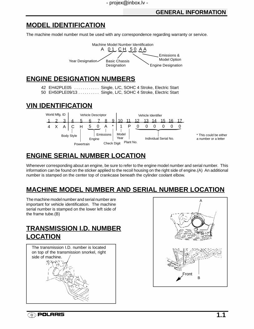
MODEL IDENTIFICATIONThe machine model number must be used with any correspondence regarding warranty or service.
Machine Model Number Identification
Year Designation Basic ChassisDesignation Engine Designation
A 0 1 C H 5 0 A AEmissions &Model Option
ENGINE DESIGNATION NUMBERS42 EH42PLE05 Single, L/C, SOHC 4 Stroke, Electric Start. . . . . . . . . . . .50 EH50PLE09/13 Single, L/C, SOHC 4 Stroke, Electric Start. . . . . . . . . .
VIN IDENTIFICATION
1 2 3 4 5 6 7 8 9 10 11 12 13 14 15 16 174 X A C H 5 0 A * 1 P 0 0 0 0 0 0
Vehicle Descriptor Vehicle Identifier
Powertrain
EngineEmissions Model
YearPlant No.
Individual Serial No.Body Style
Check Digit
World Mfg. ID
* This could be eithera number or a letter
ENGINE SERIAL NUMBER LOCATIONWhenever corresponding about an engine, be sure to refer to the engine model number and serial number. Thisinformation can be found on the sticker applied to the recoil housing on the right side of engine.(A) An additionalnumber is stamped on the center top of crankcase beneath the cylinder coolant elbow.
MACHINE MODEL NUMBER AND SERIAL NUMBER LOCATIONThe machine model number and serial number areimportant for vehicle identification. The machineserial number is stamped on the lower left side ofthe frame tube.(B)
TRANSMISSION I.D. NUMBERLOCATION
The transmission I.D. number is locatedon top of the transmission snorkel, rightside of machine.
A
BFront

GENERAL INFORMATION
1.2
REPLACEMENT KEYSReplacement keys can be made from the originalkey. To identify which series the key is, take thefirst two digits on the original key and refer to thechart to the right for the proper part number.
Series # Part Number31 4110141
32 4110148
67 4010278
68 4010278
27 4010321
28 4010321
31XX
Key SeriesNumber

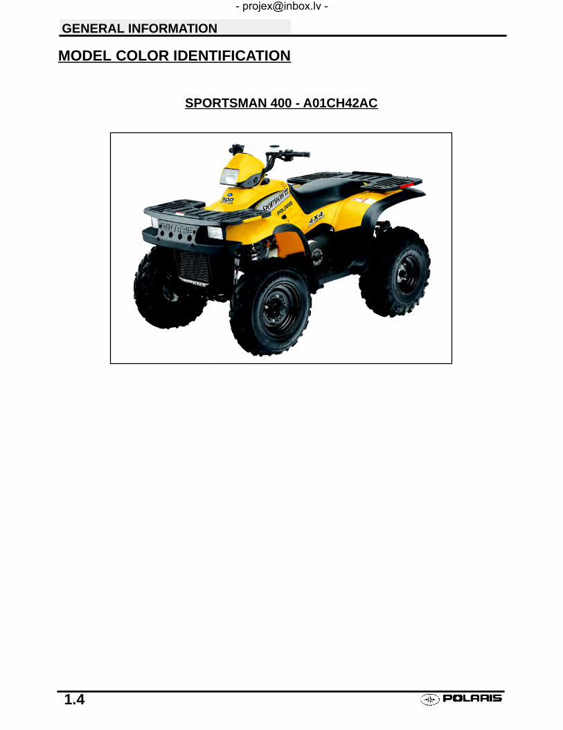
SPORTSMAN 400 - A01CH42AB
SPORTSMAN 400 - A01CH42AA
GENERAL INFORMATION
1.3
MODEL COLOR IDENTIFICATION

SPORTSMAN 500 H.O. - A01CH50AB
SPORTSMAN 500 H.O. - A01CH50AA
GENERAL INFORMATION
1.5
MODEL COLOR IDENTIFICATION

SPORTSMAN 500 DUSE - A01CH50AD
SPORTSMAN 500 H.O. - A01CH50AE
GENERAL INFORMATION
1.6
MODEL COLOR IDENTIFICATION

SPORTSMAN 500 H.O. DUSE - A01CH50AF
SPORTSMAN 500 H.O. RSE - A01CH50AJ
GENERAL INFORMATION
1.7
MODEL COLOR IDENTIFICATION

SPORTSMAN 500
SPORTSMAN 400
30 in76.2 cm
45 in114.3 cm
41 in104.1 cm
22 in55.8 cm
22 in55.8 cm
42 in106.6 cm
46 in116.8 cm
32 in81.2 cm
GENERAL INFORMATION
1.8
MACHINE DIMENSIONS
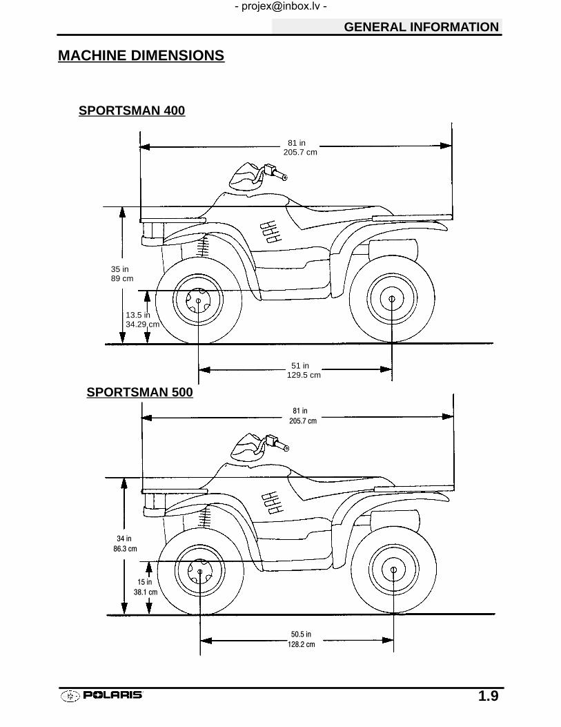
SPORTSMAN 400
SPORTSMAN 500
51 in129.5 cm
35 in89 cm
13.5 in34.29 cm
81 in205.7 cm
81 in205.7 cm
50.5 in128.2 cm
34 in86.3 cm
15 in38.1 cm
GENERAL INFORMATION
1.9
MACHINE DIMENSIONS

SPORTSMAN 400
SPORTSMAN 500
46 in
116.8 cm
9.25 in
23.5 cm
38 in
96.5 cm47 in
119.4 cm
45 in114.3 cm
45 in114.3 cm
48 in121.9 cm
37 in93.9 cm
10 in25.4 cm
47 in119.3 cm
GENERAL INFORMATION
1.10
MACHINE DIMENSIONS

GENERAL INFORMATION
1.11
MODEL: SPORTSMAN 400. . . . . . . . . .MODEL NUMBER: A01CH42AA/AB/AC.ENGINE MODEL: EH42PLE05. .
JETTING CHARTAMBIENT TEMPERATURE
Altitude Below 40°F +40_F and aboveAltitude Below 40 FBelow +5°C
+40 F and above+5_C and above
Meters 0-1800175 167 5
Meters(Feet)
0-1800(0-6000) 175 167.5(Feet)
Above 1800165 160
Above 1800Above (6000) 165 160
CLUTCH CHART
Shift Clutch DrivenAltitude ShiftWeight
ClutchSpring
DrivenHelixAltitude Weight Spring Helix
Meters 0-1800 10BH Blue/Green 2+2Meters(Feet)
0-1800(0-6000) 10BH Blue/Green 2+2(Feet)
1800-3700 10WH Blue/Green 2+21800-3700(6000-12000) 10WH Blue/Green 2+2
ENGINEType 4 Cycle, Single Cyl.. . . . . . . . . . . . . . . . . . . . . . .Displacement 425 cc. . . . . . . . . . . . . . .Bore 3.461I (87.9mm). . . . . . . . . . . . . . . . . . . . . . .Stroke 2.756I (70mm). . . . . . . . . . . . . . . . . . . . .Valve Clearance In/Ex 0.006/0.006I@ TDC on compression. . . . . . .Compression Ratio 9.2/1 Full Stroke. . . . . . . . . .Cooling Liquid. . . . . . . . . . . . . . . . . . . .Lubrication Type Dry Sump. . . . . . . . . . . .Operating RPM±200 6300 RPM. . . . . . . . .Idle RPM±200 (lights off) 1200 RPM. . . . .Compression Pressure (Std) ±15%. . . . . . .
CARBURETIONType BST 34 Mikuni. . . . . . . . . . . . . . . .Main Jet 167.5. . . . . . . . . . . .Pilot Jet 40. . . . . . . . . . . . .Jet Needle JF-3. . . . . . . . . . .Needle Jet Q-0 (829). . . . . . . . . . .Throttle Valve #100. . . . . . . .Pilot Screw 2 3/4 Turns Out. . . . . . . . . .Pilot Air Jet 160. . . . . . . . . .Valve Seat 1.5. . . . . . . . . . .Float Height 13.0mm (.51I)±1mm. . . . . . . . .Fuel Octane (R+M/2) 87 Non-Oxygenated or.
89 Oxygenated
CLUTCHType PVT. . . . . . . . . . . . . . . . . . . .Belt 3211069. . . . . . . . . . . . . . . . . . . . .Belt Width (Projected) 1.188I (30.18mm). . . . .Side Angle (Overall) 26°. . . . . .Outside Circumference 40.86 ±.12I. . . .Center Distance 10±.12I (254.5mm). . . . . . . . . .Clutch Offset 0.5I (12.7mm). . . . . . . . . . . .Secondary Spring Black. . . . . . . .Driven Helix 44-36°. . . . . . . . . . . . .Spring Position (Helix) 2. . . .Spring Position (Sheave) 2. .

Lubricant Key
GENERAL INFORMATION
1.12
MODEL: SPORTSMAN 400. . . . . . . . . . . .MODEL NUMBER: A01CH42AA/AB/AC. . .ENGINE MODEL: EH42PLE05. . . .
ELECTRICAL FLUID Capacity TypeFlywheel I.D. FF95 Fuel Tank 5.25 gals. (19.9L). . . . . . . . . . . . . . . .CDI Marking CU2565 Injector Oil N / A. . . . . . . . . . . . . . . . . . . . . . . . . .Alternator Output 200 Watts Coolant 2.25 qts. (2.1L) PP6*. . . . . . . . . . . . . . .Ignition Timing 30° BTDC@5000RPM±2° Transmission 32 oz. PPS*. . . . . . . . . . . . . . . . . . .Spark Plug / Gap NGK BKR5E / 0.036I (0.9mm) Gearcase Oil (Front) 4 oz. (120ml) 80-90 GL5. . . . .Lights: Head Halogen 60/60 watts Gearcase Oil (Center) N / A. . . . . .
Tail 8.26 watts Gearcase Oil (Rear) N / A. . . . . . . . .Brake 26.9 watts Engine Counter Bal. N / A. . . . . . . . . . . . . . . .
Voltage Regulator LR39 Engine Oil 2 qts. (1.9L) PP4*. . . . . . . . . . . . . .Electric Start Standard Brake (Hand) Dot 3. . . . . . . . . . . . . .
Brake (Foot) Dot 3. . . . . . . .Front Hubs (AWD) 2.5 oz. (75ml) PDD*. . .Shift Selector Box 1 oz. (30ml) PP4*. . . . .
*PP6 Polaris Premium 60/40 Antifreeze/Coolant*PPS Polaris Premium Synthetic Gear Case Oil*PP4 Polaris 0W/40 Synthetic Engine Lubricant*PDD Premium Demand Drive Hub Fluid
SUSPENSION / CHASSIS DRIVE TRAINBody Style Gen IV Chain Type Shaft Drive. . . . . . . . . . . . . . . . .Front Suspension MacPherson Strut Gear Reduction-Low 6.69/1. . .Tow Capacity 850 lbs. (385.6kg) Gear Reduction-Rev 5.17/1. . . . . . .Turning Radius 65I (165.1cm) Gear Reduction-High 3.34/1. . . . .Toe Out 1/8I-1/4I (3-6.35mm) Front Drive Ratio 2/1. . . . . . . . . . . . . . .Ground Clearance 11I (27.94cm) Center Drive Ratio N / A. . . . .Front Vertical Travel 6.7I (17.02cm) Final Drive Ratio 3.16/1. . . .Rear Suspension Progressive Rate Independent Brake (Hand) Single Lever, Hyd. Disc. . . . . . . . . .Rear Travel 9.5I (24.13cm) Brake ( Auxiliary Foot) Hydraulic. . . . . . . .Rear Shock 2I Twin Tube. . . . . . . .Shock Adjustment Cam. .TIRESTire Size - Front 25 x 8 - 12. . . .Tire Size - Rear 25 x 11 - 10. . . .Tire Size - Center N / A. .Tire Pressure - F/R 5/5 lbs.Total Width 46I (116.84cm). . . . . . . .Total Length 81I (205.74cm). . . . . . .Total Height 47I (119.38cm). . . . . . . .Wheel Base 50.50I (128.27cm). . . . . . .Weight - Dry 697 lbs. (316.4kg). . . . . . .
OPTIONAL SUSPENSION SPRINGSSOFT STANDARD FIRM
Rear Compression Spring N / A 7041453-067Standard 100 lb/in.
7041519-067Option 140 lb/in.
Front Strut Spring 7041238-067Option 61 lb/in.
7041375-067Standard 64/113 lb/in.
7041450-067Option 101 lb/in.
LOAD CAPACITYFront Rack (Std) 90 lbs.. . . . .Rear Rack (Std) 180 lbs.. . . . . .
Tongue Weight 30 lbs.. . . .
Tow Hitch Std. . . . . . . . . . .
GENERAL INFORMATION
1.13
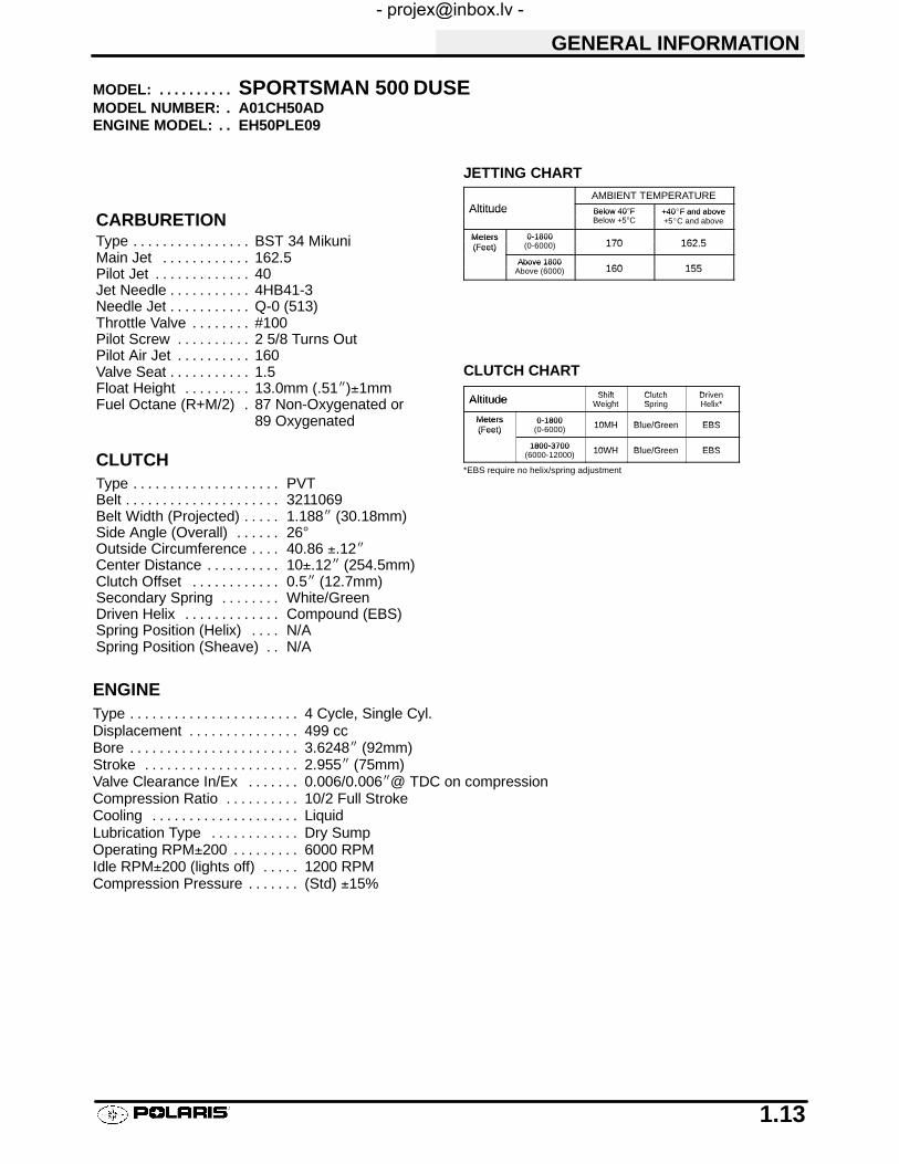
MODEL: SPORTSMAN 500 DUSE. . . . . . . . . .MODEL NUMBER: A01CH50AD.ENGINE MODEL: EH50PLE09. .
JETTING CHARTAMBIENT TEMPERATURE
Altitude Below 40°F +40_F and aboveAltitude Below 40 FBelow +5°C
+40 F and above+5_C and above
Meters 0-1800170 162 5
Meters(Feet)
0-1800(0-6000) 170 162.5(Feet)
Above 1800160 155
Above 1800Above (6000) 160 155
CLUTCH CHART
Shift Clutch DrivenAltitude ShiftWeight
ClutchSpring
DrivenHelix*Altitude Weight Spring Helix*
Meters 0-1800 10MH Blue/Green EBSMeters(Feet)
0-1800(0-6000) 10MH Blue/Green EBS(Feet)
1800-3700 10WH Blue/Green EBS1800-3700(6000-12000) 10WH Blue/Green EBS
*EBS require no helix/spring adjustment
ENGINEType 4 Cycle, Single Cyl.. . . . . . . . . . . . . . . . . . . . . . .Displacement 499 cc. . . . . . . . . . . . . . .Bore 3.6248I (92mm). . . . . . . . . . . . . . . . . . . . . . .Stroke 2.955I (75mm). . . . . . . . . . . . . . . . . . . . .Valve Clearance In/Ex 0.006/0.006I@ TDC on compression. . . . . . .Compression Ratio 10/2 Full Stroke. . . . . . . . . .Cooling Liquid. . . . . . . . . . . . . . . . . . . .Lubrication Type Dry Sump. . . . . . . . . . . .Operating RPM±200 6000 RPM. . . . . . . . .Idle RPM±200 (lights off) 1200 RPM. . . . .Compression Pressure (Std) ±15%. . . . . . .
CARBURETIONType BST 34 Mikuni. . . . . . . . . . . . . . . .Main Jet 162.5. . . . . . . . . . . .Pilot Jet 40. . . . . . . . . . . . .Jet Needle 4HB41-3. . . . . . . . . . .Needle Jet Q-0 (513). . . . . . . . . . .Throttle Valve #100. . . . . . . .Pilot Screw 2 5/8 Turns Out. . . . . . . . . .Pilot Air Jet 160. . . . . . . . . .Valve Seat 1.5. . . . . . . . . . .Float Height 13.0mm (.51I)±1mm. . . . . . . . .Fuel Octane (R+M/2) 87 Non-Oxygenated or.
89 Oxygenated
CLUTCHType PVT. . . . . . . . . . . . . . . . . . . .Belt 3211069. . . . . . . . . . . . . . . . . . . . .Belt Width (Projected) 1.188I (30.18mm). . . . .Side Angle (Overall) 26°. . . . . .Outside Circumference 40.86 ±.12I. . . .Center Distance 10±.12I (254.5mm). . . . . . . . . .Clutch Offset 0.5I (12.7mm). . . . . . . . . . . .Secondary Spring White/Green. . . . . . . .Driven Helix Compound (EBS). . . . . . . . . . . . .Spring Position (Helix) N/A. . . .Spring Position (Sheave) N/A. .

Lubricant Key
GENERAL INFORMATION
1.14
MODEL: SPORTSMAN 500 DUSE. . . . . . . . . . . .MODEL NUMBER: A01CH50AD. . .ENGINE MODEL: EH50PLE09. . . .
ELECTRICAL FLUID Capacity TypeFlywheel I.D. FF97 Fuel Tank 5.25 gals. (19.9L). . . . . . . . . . . . . . . .CDI Marking CU2570 Injector Oil N / A. . . . . . . . . . . . . . . . . . . . . . . . . .Alternator Output 250 Watts Coolant 2.25 qts. (2.1L) PP6*. . . . . . . . . . . . . . .Ignition Timing 30° BTDC@5000RPM±2° Transmission 32 oz. PPS*. . . . . . . . . . . . . . . . . . .Spark Plug / Gap NGK BKR5E / 0.036I (0.9mm) Gearcase Oil (Front) 4 oz. (120ml) 80-90 GL5. . . . .Lights: Head Halogen 60/60 watts Gearcase Oil (Center) N / A. . . . . .
Tail 8.26 watts Gearcase Oil (Rear) N / A. . . . . . . . .Brake 26.9 watts Engine Counter Bal. N / A. . . . . . . . . . . . . . . .
Voltage Regulator LR39 Engine Oil 2 qts. (1.9L) PP4*. . . . . . . . . . . . . .Electric Start Standard Brake (Hand) Dot 3. . . . . . . . . . . . . .
Brake (Foot) Dot 3. . . . . . . .Front Hubs (AWD) 2.5 oz. (75ml) PDD*. . .Shift Selector Box 1 oz. (30ml) PP4*. . . . .
*PP6 Polaris Premium 60/40 Antifreeze/Coolant*PPS Polaris Premium Synthetic Gear Case Oil*PP4 Polaris 0W/40 Synthetic Engine Lubricant*PDD Premium Demand Drive Hub Fluid
SUSPENSION / CHASSIS DRIVE TRAINBody Style Gen IV Chain Type Shaft Drive. . . . . . . . . . . . . . . . .Front Suspension MacPherson Strut Gear Reduction-Low 6.69/1. . .Tow Capacity 1225 lbs. (555.6kg) Gear Reduction-Rev 5.17/1. . . . . . .Turning Radius 65I (165.1cm) Gear Reduction-High 3.34/1. . . . .Toe Out 1/8I-1/4I (3-6.35mm) Front Drive Ratio 2/1. . . . . . . . . . . . . . .Ground Clearance 11I (27.94cm) Center Drive Ratio N / A. . . . .Front Vertical Travel 6.7I (17.02cm) Final Drive Ratio 3.16/1. . . .Rear Suspension Progressive Rate Independent Brake (Hand) Single Lever, Hyd. Disc. . . . . . . . . .Rear Travel 9.5I (24.13cm) Brake ( Auxiliary Foot) Hydraulic. . . . . . . .Rear Shock 2I Twin Tube. . . . . . . .Shock Adjustment Cam. .TIRESTire Size - Front 25 x 8 - 12. . . .Tire Size - Rear 25 x 11 - 10. . . .Tire Size - Center N / A. .Tire Pressure - F/R 5/5 lbs.Total Width 46I (116.84cm). . . . . . . .Total Length 81I (205.74cm). . . . . . .Total Height 47I (119.38cm). . . . . . . .Wheel Base 50.50I (128.27cm). . . . . . .Weight - Dry 697 lbs. (316.4kg). . . . . . .
OPTIONAL SUSPENSION SPRINGSSOFT STANDARD FIRM
Rear Compression Spring N / A 7041453-067Standard 100 lb/in.
7041519-067Option 140 lb/in.
Front Strut Spring 7041238-067Option 61 lb/in.
7041375-067Standard 64/113 lb/in.
7041450-067Option 101 lb/in.
LOAD CAPACITYFront Rack (Std) 90 lbs.. . . . .Rear Rack (Std) 180 lbs.. . . . . .
Tongue Weight 35 lbs.. . . .
Tow Hitch Std. . . . . . . . . . .

GENERAL INFORMATION
1.15
MODEL: SPORTSMAN 500 H.O.. . . . . . . . . .MODEL NUMBER: A01CH50AA/AB/AE/AF/AJ.ENGINE MODEL: EH50PLE13. .
JETTING CHARTAMBIENT TEMPERATURE
Altitude Below 40°F +40_F and aboveAltitude Below 40 FBelow +5°C
+40 F and above+5_C and above
Meters 0-1800157 5 152 5
Meters(Feet)
0-1800(0-6000) 157.5 152.5(Feet)
Above 1800150 145
Above 1800Above (6000) 150 145
CLUTCH CHART
Shift Clutch DrivenAltitude ShiftWeight
ClutchSpring
DrivenHelix*Altitude Weight Spring Helix*
Meters 0-1800 10WH Blue/Green EBSMeters(Feet)
0-1800(0-6000) 10WH Blue/Green EBS(Feet)
1800-3700 10RH Blue/Green EBS1800-3700(6000-12000) 10RH Blue/Green EBS
*EBS require no helix/spring adjustment
ENGINEType 4 Cycle, Single Cyl.. . . . . . . . . . . . . . . . . . . . . . .Displacement 499 cc. . . . . . . . . . . . . . .Bore 3.6248I (92mm). . . . . . . . . . . . . . . . . . . . . . .Stroke 2.955I (75mm). . . . . . . . . . . . . . . . . . . . .Valve Clearance In/Ex 0.006/0.006I@ TDC on compression. . . . . . .Compression Ratio 10/2 Full Stroke. . . . . . . . . .Cooling Liquid. . . . . . . . . . . . . . . . . . . .Lubrication Type Dry Sump. . . . . . . . . . . .Operating RPM±200 6500 RPM. . . . . . . . .Idle RPM±200 (lights off) 1200 RPM. . . . .Compression Pressure (Std) ±15%. . . . . . .
CARBURETIONType BST 40 Mikuni. . . . . . . . . . . . . . . .Main Jet 152.5. . . . . . . . . . . .Pilot Jet 40. . . . . . . . . . . . .Jet Needle KE-3 (683). . . . . . . . . . .Needle Jet X-6. . . . . . . . . . .Throttle Valve #120. . . . . . . .Pilot Screw 2 1/2 Turns Out. . . . . . . . . .Pilot Air Jet 1.3. . . . . . . . . .Valve Seat 1.5. . . . . . . . . . .Float Height 14.7mm (.58I)±1mm. . . . . . . . .Fuel Octane (R+M/2) 87 Non-Oxygenated or.
89 Oxygenated
CLUTCHType PVT. . . . . . . . . . . . . . . . . . . .Belt 3211069. . . . . . . . . . . . . . . . . . . . .Belt Width (Projected) 1.188I (30.18mm). . . . .Side Angle (Overall) 26°. . . . . .Outside Circumference 40.86 ±.12I. . . .Center Distance 10±.12I (254.5mm). . . . . . . . . .Clutch Offset 0.5I (12.7mm). . . . . . . . . . . .Secondary Spring White/Yellow. . . . . . . .Driven Helix Compound (EBS). . . . . . . . . . . . .Spring Position (Helix) N/A. . . .Spring Position (Sheave) N/A. .

Lubricant Key
GENERAL INFORMATION
1.16
MODEL: SPORTSMAN 500 H.O.. . . . . . . . . . . .MODEL NUMBER: A01CH50AA/AB/AE/AF/AJ. . .ENGINE MODEL: EH50PLE13. . . .
ELECTRICAL FLUID Capacity TypeFlywheel I.D. FF97 Fuel Tank 5.25 gals. (19.9L). . . . . . . . . . . . . . . .CDI Marking CU2570 Injector Oil N / A. . . . . . . . . . . . . . . . . . . . . . . . . .Alternator Output 250 Watts Coolant 2.25 qts. (2.1L) PP6*. . . . . . . . . . . . . . .Ignition Timing 30° BTDC@5000RPM±2° Transmission 32 oz. PPS*. . . . . . . . . . . . . . . . . . .Spark Plug / Gap NGK BKR5E / 0.036I (0.9mm) Gearcase Oil (Front) 4 oz. (120ml) 80-90 GL5. . . . .Lights: Head Halogen 60/60 watts Gearcase Oil (Center) N / A. . . . . .
Tail 8.26 watts Gearcase Oil (Rear) N / A. . . . . . . . .Brake 26.9 watts Engine Counter Bal. N / A. . . . . . . . . . . . . . . .
Voltage Regulator LR39 Engine Oil 2 qts. (1.9L) PP4*. . . . . . . . . . . . . .Electric Start Standard Brake (Hand) Dot 3. . . . . . . . . . . . . .
Brake (Foot) Dot 3. . . . . . . .Front Hubs (AWD) 2.5 oz. (75ml) PDD*. . .Shift Selector Box 1 oz. (30ml) PP4*. . . . .
*PP6 Polaris Premium 60/40 Antifreeze/Coolant*PPS Polaris Premium Synthetic Gear Case Oil*PP4 Polaris 0W/40 Synthetic Engine Lubricant*PDD Premium Demand Drive Hub Fluid
SUSPENSION / CHASSIS DRIVE TRAINBody Style Gen IV Chain Type Shaft Drive. . . . . . . . . . . . . . . . .Front Suspension MacPherson Strut Gear Reduction-Low 6.69/1. . .Tow Capacity 1225 lbs. (555.6kg) Gear Reduction-Rev 5.17/1. . . . . . .Turning Radius 65I (165.1cm) Gear Reduction-High 3.34/1. . . . .Toe Out 1/8I-1/4I (3-6.35mm) Front Drive Ratio 2/1. . . . . . . . . . . . . . .Ground Clearance 11I (27.94cm) Center Drive Ratio N / A. . . . .Front Vertical Travel 6.7I (17.02cm) Final Drive Ratio 3.16/1. . . .Rear Suspension Progressive Rate Independent Brake (Hand) Single Lever, Hyd. Disc. . . . . . . . . .Rear Travel 9.5I (24.13cm) Brake ( Auxiliary Foot) Hydraulic. . . . . . . .Rear Shock 2I Twin Tube. . . . . . . .Shock Adjustment Cam. .TIRESTire Size - Front 25 x 8 - 12. . . .Tire Size - Rear 25 x 11 - 10. . . .Tire Size - Center N / A. .Tire Pressure - F/R 5/5 lbs.Total Width 46I (116.84cm). . . . . . . .Total Length 81I (205.74cm) (AA/AB/AE). . . . . . .
85I (215.9cm) (AF/AJ). . . . . . . . . . . . . . . . . . .Total Height 47I (119.38cm). . . . . . . .Wheel Base 50.50I (128.27cm). . . . . . .Weight - Dry 697 lbs. (316.4kg) (AA/AB/AE). . . . . . .
750 lbs. (340kg) (AF/AJ). . . . . . . . . . . . . . . . . . .
OPTIONAL SUSPENSION SPRINGSSOFT STANDARD FIRM
Rear Compression Spring N / A 7041453-067Standard 100 lb/in.
7041519-067Option 140 lb/in.
Front Strut Spring 7041238-067Option 61 lb/in.
7041375-067Standard 64/113 lb/in.
7041450-067Option 101 lb/in.
LOAD CAPACITYFront Rack (Std) 90 lbs.. . . . .Rear Rack (Std) 180 lbs.. . . . . .
Tongue Weight 35 lbs.. . . .
Tow Hitch Std. . . . . . . . . . .

GENERAL INFORMATION
1.17
PUBLICATION NUMBERS
Year Model Model No. Owner’s ManualPN
PartsManual PN
PartsMicro Fiche PN
2001 Sportsman 400 A01CH42AA/AB/AC 9915754 9916443 9916444
2001 Sportsman 500 DUSE A01CH50AD 9915754 9916002 9916003
2001 Sportsman 500 H.O. A01CH50AA/AB/AE/AF/AJ
9915754 9916446 9916447
When ordering service parts be sure to use the correct parts manual.
PAINT CODES
PAINTED PART COLORDESCRIPTION
DITZLERNUMBER
POLARISNUMBER
(400) Springs/Rims Black 9440 P-067
(500) Springs/Rims Black 9440 P-067
(500) Opt. B Springs Black 9440 P-067
(500) Opt. B Rims Brushed Aluminum N/A P-117
FRAME COLOR - (All) P067 Medium Gloss Black 9440 / 8520147.Order direct from Midwest Industrial Coatings (952-942-1840). Mix as directed.

GENERAL INFORMATION
1.18
STANDARD TORQUE SPECIFICATIONS
The following torque specifications are to be used as a general guideline. There are exceptions in the steering,suspension, and engine areas. Always consult the exploded views in each manual section for torque values offasteners before using standard torque.
Bolt Size Threads/In Grade 2 Grade 5 Grade 8
Torque in. lbs. (Nm)#10 - 24 27 (3.1) 43 (5.0) 60 (6.9). . . . . . . . . . . . . . . . . . . . . . . . . . . . . . . . . . . . . . . . . . . .#10 - 32 31 (3.6) 49 (5.6) 68 (7.8). . . . . . . . . . . . . . . . . . . . . . . . . . . . . . . . . . . . . . . . . . . .
Torque ft. lbs. (Nm)*1/4 - 20 5 (7) 8 (11) 12 (16). . . . . . . . . . . . . . . . . . . . . . . . . . . . . . . . . . . . . . . . . . . . . . . .1/4 - 28 6 (8) 10 (14) 14 (19). . . . . . . . . . . . . . . . . . . . . . . . . . . . . . . . . . . . . . . . . . . . . .5/16 - 18 11 (15) 17 (23) 25 (35). . . . . . . . . . . . . . . . . . . . . . . . . . . . . . . . . . . . . . . . . . . .5/16 - 24 12 (16) 19 (26) 29 (40). . . . . . . . . . . . . . . . . . . . . . . . . . . . . . . . . . . . . . . . . . . .3/8 - 16 20 (27) 30 (40) 45 (62). . . . . . . . . . . . . . . . . . . . . . . . . . . . . . . . . . . . . . . . . . . .3/8 - 24 23 (32) 35 (48) 50 (69). . . . . . . . . . . . . . . . . . . . . . . . . . . . . . . . . . . . . . . . . . . .7/16 - 14 30 (40) 50 (69) 70 (97). . . . . . . . . . . . . . . . . . . . . . . . . . . . . . . . . . . . . . . . . . . .7/16 - 20 35 (48) 55 (76) 80 (110). . . . . . . . . . . . . . . . . . . . . . . . . . . . . . . . . . . . . . . . . . . .1/2 - 13 50 (69) 75 (104) 110 (152). . . . . . . . . . . . . . . . . . . . . . . . . . . . . . . . . . . . . . . . . . .1/2 - 20 55 (76) 90 (124) 120 (166). . . . . . . . . . . . . . . . . . . . . . . . . . . . . . . . . . . . . . . . . . .
Metric6 x 1.0 72-78 In. lbs.8 x 1.25 14-18 ft. lbs.10 x 1.25 26-30 ft. lbs.
*To convert ft. lbs. to Nm multiply foot pounds by .1.382*To convert Nm to ft. lbs. multiply Nm by .7376.
SPECIFIC TORQUE VALUES OF FASTENERSRefer to exploded views in the appropriate section.

Newton Meter to Pound Foot and Pound Inch
GENERAL INFORMATION
1.19
TORQUE CONVERSIONS

Newton Meter to Pound Foot and Pound Inch
GENERAL INFORMATION
1.20
TORQUE CONVERSIONS

GENERAL INFORMATION
1.21
DECIMAL EQUIVALENTS1/64 .0156. . . . . . . . . . . . . . . . . . . . . . . . .
1/32 .0312 1 mm = .0394″. . . . . . . . . . . . . . . . . . . . . . . . . . . . . . . . . . .3/64 .0469. . . . . . . . . . . . . . . . . . . . . . . . .
1/16 .0625. . . . . . . . . . . . . .5/64 .0781 2 mm = .0787″. . . . . . . . . . . . . . . . . . . . . . . . . . . . . . . . . . . . . . . . .
3/32 .0938. . . . . . . . . . . . . . . . . . .7/64 .1094 3 mm = .1181″. . . . . . . . . . . . . . . . . . . . . . . . . . . . . . . . . . . . . . .
1/8 . 1250. . . . . . . .9/64 .1406. . . . . . . . . . . . . . . . . . . . . . . . .
5/32 .1563 4 mm = .1575″. . . . . . . . . . . . . . . . . . . . . . . . . . . . . . . . . . .11/64 .1719. . . . . . . . . . . . . . . . . . . . . . . .
3/16 .1875 5 mm = .1969″. . . . . . . . . . . . . . . . . . . . . . . . . . . . . .13/64 .2031. . . . . . . . . . . . . . . . . . . . . . . .
7/32 .2188. . . . . . . . . . . . . . . . . . .15/64 .2344 6 mm = .2362″. . . . . . . . . . . . . . . . . . . . . . . . . . . . . . . . . . . . . . . .
1/4 .25. . . . . . . . . .17/64 .2656 7 mm = .2756″. . . . . . . . . . . . . . . . . . . . . . . . . . . . . . . . . . . . . . . .
9/32 .2813. . . . . . . . . . . . . . . . . . .19/64 .2969. . . . . . . . . . . . . . . . . . . . . . . .
5/16 .3125 8 mm = .3150″. . . . . . . . . . . . . . . . . . . . . . . . . . . . . .21/64 .3281. . . . . . . . . . . . . . . . . . . . . . . .
11/32 .3438 9 mm = .3543″. . . . . . . . . . . . . . . . . . . . . . . . . . . . . . . . . .23/64 .3594. . . . . . . . . . . . . . . . . . . . . . . .
3/8 .375. . . . . . . . . .25/64 .3906 10 mm = .3937″. . . . . . . . . . . . . . . . . . . . . . . . . . . . . . . . . . . . . . . .
13/32 .4063. . . . . . . . . . . . . . . . . .27/64 .4219 11 mm = .4331″. . . . . . . . . . . . . . . . . . . . . . . . . . . . . . . . . . . . . . . .
7/16 .4375. . . . . . . . . . . . . .29/64 .4531. . . . . . . . . . . . . . . . . . . . . . . .
15/32 .4688 12 mm = .4724″. . . . . . . . . . . . . . . . . . . . . . . . . . . . . . . . . .31/64 .4844. . . . . . . . . . . . . . . . . . . . . . . .
1/2 .5 13 mm = .5118. . . . . . . . . . . . . . . . . . . . . . . . . . . . .33/64 .5156. . . . . . . . . . . . . . . . . . . . . . . .
17/32 .5313. . . . . . . . . . . . . . . . . .35/64 .5469 14 mm = .5512″. . . . . . . . . . . . . . . . . . . . . . . . . . . . . . . . . . . . . . . .
9/16 .5625. . . . . . . . . . . . . .37/64 .5781 15 mm = .5906″. . . . . . . . . . . . . . . . . . . . . . . . . . . . . . . . . . . . . . . .
19/32 .5938. . . . . . . . . . . . . . . . . .39/64 .6094. . . . . . . . . . . . . . . . . . . . . . . .
5/8 .625 16 mm = .6299″. . . . . . . . . . . . . . . . . . . . . . . . . . .41/64 .6406. . . . . . . . . . . . . . . . . . . . . . . .
21/32 .6563 17 mm = .6693″. . . . . . . . . . . . . . . . . . . . . . . . . . . . . . . . . .43/64 .6719. . . . . . . . . . . . . . . . . . . . . . .
11/16 .6875. . . . . . . . . . . . .45/64 .7031 18 mm = .7087″. . . . . . . . . . . . . . . . . . . . . . . . . . . . . . . . . . . . . . . .
23/32 .7188. . . . . . . . . . . . . . . . . .47/64 .7344 19 mm = .7480″. . . . . . . . . . . . . . . . . . . . . . . . . . . . . . . . . . . . . . . .
3/4 .75. . . . . . . . . .49/64 .7656. . . . . . . . . . . . . . . . . . . . . . . .
25/32 .7813 20 mm = .7874″. . . . . . . . . . . . . . . . . . . . . . . . . . . . . . . . . .51/64 .7969. . . . . . . . . . . . . . . . . . . . . . . .
13/16 .8125 21 mm = .8268″. . . . . . . . . . . . . . . . . . . . . . . . . . . . .53/64 .8281. . . . . . . . . . . . . . . . . . . . . . . .
27/32 .8438. . . . . . . . . . . . . . . . . .55/64 .8594 22 mm = .8661″. . . . . . . . . . . . . . . . . . . . . . . . . . . . . . . . . . . . . . . .
7/8 .875. . . . . . . . . .57/64 .8906 23 mm = .9055″. . . . . . . . . . . . . . . . . . . . . . . . . . . . . . . . . . . . . . . .
29/32 .9063. . . . . . . . . . . . . . . . . .59/64 .9219. . . . . . . . . . . . . . . . . . . . . . .
15/16 .9375 24 mm = .9449″. . . . . . . . . . . . . . . . . . . . . . . . . . . . .61/64 .9531. . . . . . . . . . . . . . . . . . . . . . . .
31/32 .9688 25 mm = .9843. . . . . . . . . . . . . . . . . . . . . . . . . . . . . . . . . .63/64 .9844. . . . . . . . . . . . . . . . . . . . . . . .
1 1.0. . . . . . . . . . . .

GENERAL INFORMATION
1.22
CONVERSION TABLE
Unit of Measure Multiplied by Converts to
ft. lbs. x 12 = in. lbs.
in. lbs. x .0833 = ft. lbs.
ft. lbs. x 1.356 = Nm
in. lbs. x .0115 = kg-m
Nm x .7376 = ft.lbs.
kg-m x 7.233 = ft. lbs.
kg-m x 86.796 = in. lbs.
kg-m x 10 = Nm
in. x 25.4 =mm
mm x .03937 = in.
in. x 2.54 = cm
mile (mi.) x 1.6 = km
km x .6214 = mile (mi.)
Ounces (oz) x 28.35 = Grams (g)
Fluid Ounces (fl. oz.) x 29.57 = Cubic Centimeters (cc)
Cubic Centimeters (cc) x .03381 = Fluid Ounces (fl. oz.)
Grams (g) x 0.035 = Ounces (oz)
lb. x .454 = kg
kg x 2.2046 = lb.
Cubic inches (cu in) x 16.387 = Cubic centimeters (cc)
Cubic centimeters (cc) x 0.061 = Cubic inches (cu in)
Imperial pints (Imp pt) x 0.568 = Liters (l)
Liters (l) x 1.76 = Imperial pints (Imp pt)
Imperial quarts (Imp qt) x 1.137 = Liters (l)
Liters (l) x 0.88 = Imperial quarts (Imp qt)
Imperial quarts (Imp qt) x 1.201 = US quarts (US qt)
US quarts (US qt) x 0.833 = Imperial quarts (Imp qt)
US quarts (US qt) x 0.946 = Liters (l)
Liters (l) x 1.057 = US quarts (US qt)
US gallons (US gal) x 3.785 =Liters (l)
Liters (l) x 0.264 = US gallons (US gal)
Pounds - force per square inch (psi) x 6.895 = Kilopascals (kPa)
Kilopascals (kPa) x 0.145 = Pounds - force per square inch (psi)
Kilopascals (kPa) x 0.01 = Kilograms - force per square cm
Kilograms - force per square cm x 98.1 = Kilopascals (kPa)
π (3.14) x R2 x H (height) = Cylinder Volume
°C to °F: 9 (°C + 40) ÷ 5 - 40 = °F°F to °C: 5 (°F + 40) ÷ 9 - 40 = °C

GENERAL INFORMATION
1.23
SAE TAP DRILL SIZES
Thread Size Drill Size Thread Size Drill Size
#0-80 3/64#1-64 53#1-72 53#2-56 51#2-64 50#3-48 5/64#3-56 45#4-40 43#4-48 42#5-40 38#5-44 37#6-32 36#6-40 33#8-32 29#8-36 29#10-24 24#10-32 21#12-24 17#12-28 4.6mm1/4-20 71/4-28 35/16-18 F5/16-24 I3/8-16 O3/8-24 Q7/16-14 U7/16-20 25/64
1/2-13 27/641/2-20 29/649/16-12 31/649/16-18 33/645/8-11 17/325/8-18 37/643/4-10 21/323/4-16 11/167/8-9 49/647/8-14 13/161-8 7/81-12 59/641 1/8-7 63/641 1/8-12 1 3/641 1/4-7 1 7/641 1/4-12 1 11/641 1/2-6 1 11/321 1/2-12 1 27/641 3/4-5 1 9/161 3/4-12 1 43/642-4 1/2 1 25/322-12 1 59/642 1/4-4 1/2 2 1/322 1/2-4 2 1/42 3/4-4 2 1/23-4 2 3/4
METRIC TAP DRILL SIZES
Tap Size Drill Size Decimal Equivalent Nearest Fraction
3 x .503 x .604 x .704 x .755 x .805 x .906 x 1.007 x 1.008 x 1.008 x 1.259 x 1.009 x 1.2510 x 1.2510 x 1.5011 x 1.5012 x 1.5012 x 1.75
#393/32#301/8#19#20#916/64J17/645/165/1611/32R3/813/3213/32
0.09950.09370.12850.1250.1660.1610.1960.2340.2770.2650.31250.31250.34370.3390.3750.4060.406
3/323/321/81/811/645/3213/6415/649/3217/645/165/1611/3211/323/813/3213/32

GENERAL INFORMATION
1.24
GLOSSARY OF TERMS
ABDC: After bottom dead center.ACV: Alternating current voltage.Alternator: Electrical generator producing voltage alternating current.ATDC: After top dead center.BBDC: Before bottom dead center.BDC: Bottom dead center.BTDC: Before top dead center.CC: Cubic centimeters.Center Distance: Distance between center of crankshaft and center of driven clutch shaft.Chain Pitch: Distance between chain link pins (No. 35 = 3/8″ or 1 cm). Polaris measures chain length in number ofpitches.CI: Cubic inches.Clutch Buttons: Plastic bushings which transmit rotation of the clutch to the movable sheave in the drive and drivenclutch.Clutch Offset: Drive and driven clutches are offset so that drive belt will stay nearly straight as it moves along the clutchface.Clutch Weights: Three levers in the drive clutch which relative to their weight, profile and engine RPM cause the driveclutch to close.Condenser/Capacitor: A storage reservoir for DC voltage.Crankshaft Run-Out: Run-out or “bend” of crankshaft measured with a dial indicator while crankshaft is supportedbetween centers on V blocks or resting in crankcase. Measure at various points especially at PTO.DCV: Direct current voltage.Dial Bore Gauge: A cylinder measuring instrument which uses a dial indicator. Good for showing taper andout-of-round in the cylinder bore.Electrical Open: Open circuit. An electrical circuit which isn’t complete.Electrical Short: Short circuit. An electrical circuit which is completed before the current reaches the intended load.(i.e. a bare wire touching the chassis).End Seals: Rubber seals at each end of the crankshaft.Engagement RPM: Engine RPM at which the drive clutch engages to make contact with the drive belt.ft.: Foot/feet.Foot Pound: Ft. lb. A force of one pound at the end of a lever one foot in length, applied in a rotational direction.g: Gram. Unit of weight in the metric system.gal.: Gallon.HP: Horsepower.ID: Inside diameter.in.: Inch/inches.Inch Pound: In. lb. 12 in. lbs. = 1 ft. lb.
kg/cm2
: Kilograms per square centimeter.kg-m: Kilogram meters.Kilogram/meter: A force of one kilogram at the end of a lever one meter in length, applied in a rotational direction.l or ltr: Liter.
lbs/in2
: Pounds per square inch.Left Side: Always referred to based on normal operating position of the driver.
GENERAL INFORMATION
1.25
GLOSSARY OF TERMS
m: Meter/meters.Mag: Magneto.Magnetic Induction: As a conductor (coil) is moved through a magnetic field, a voltage will be generated in thewindings. Mechanical energy is converted to electrical energy in the stator.mi.: Mile/miles.mm: Millimeter. Unit of length in the metric system. 1mm = approximately .040″.Nm: Newton meters.OD: Outside diameter.Ohm: The unit of electrical resistance opposing current flow.oz.: Ounce/ounces.Piston Clearance: Total distance between piston and cylinder wall.psi.: Pounds per square inch.PTO: Power take off.PVT: Polaris Variable Transmission (Drive Clutch System)qt.: Quart/quarts.RPM: Revolutions per minute.Regulator: Voltage regulator. Regulates battery charging system output at approx. 14.5 DCV as engine RPMincreases.Reservoir Tank: The fill tank in the liquid cooling system.Resistance: In the mechanical sense, friction or load. In the electrical sense, ohms. Both result in energy conversion toheat.Right Side: Always referred to based on normal operating position of the driver.RPM: Revolutions per minute.Secondary Clutch: Driven clutch on chaincase or jackshaft.Seized Piston: Galling of the sides of a piston. Usually there is a transfer of aluminum from the piston onto the cylinderwall. Possible causes: 1) improper lubrication; 2) excessive temperatures; 3) insufficient piston clearance; 4) stuckpiston rings.Stator Plate: The plate mounted under the flywheel supporting the battery charging coils.TDC: Top dead center. Piston’s most outward travel from crankshaft.Volt: The unit of measure for electrical pressure of electromotive force. Measured by a voltmeter in parallel with thecircuit.Watt: Unit of electrical power. Watts = amperes x volts.WOT: Wide open throttle.
2
CHAPTER 2MAINTENANCE
Periodic Maintenance Chart 2.1-2.2. . . . . . . . . . . . . . . . . . . .
Pre-Ride Inspection 2.2. . . . . . . . . . . . . . . . . . . . . . . . . . .
Recommended Lubricants and Capacities 2.3. . . . . . .
Lubricant and Maintenance Product Numbers 2.4. . . .
Lubrication Charts 2.5-2.8. . . . . . . . . . . . . . . . . . . . . . . . . . . .
Front Gearcase Lubrication 2.9. . . . . . . . . . . . . . . . . . .
Transmission Lubrication 2.10. . . . . . . . . . . . . . . . . . . . . .
Transmission LInkage Adjustment 2.11-2.12. . . . . . . . . . . . . .
Carburetor Adjustments 2.13-2.15. . . . . . . . . . . . . . . . . . . . . . .
Fuel System 2.16-2.17. . . . . . . . . . . . . . . . . . . . . . . . . . . . . . . . .
Compression Test 2.18. . . . . . . . . . . . . . . . . . . . . . . . . . . .
Battery Maintenance 2.19. . . . . . . . . . . . . . . . . . . . . . . . . .
Electrical 2.20. . . . . . . . . . . . . . . . . . . . . . . . . . . . . . . . . . . .
Coolant System Maintenance 2.21-2.22. . . . . . . . . . . . . . . . . .
Air Filter Service 2.23. . . . . . . . . . . . . . . . . . . . . . . . . . . . . .
Air Box Sediment Tube Service 2.24. . . . . . . . . . . . . . . . .
Breather Filter 2.24. . . . . . . . . . . . . . . . . . . . . . . . . . . . . . . .
Recoil Housing 2.25. . . . . . . . . . . . . . . . . . . . . . . . . . . . . . .
Oil Change/Filter 2.26-2.27. . . . . . . . . . . . . . . . . . . . . . . . . . . . .
Valve Clearance 2.28-2.29. . . . . . . . . . . . . . . . . . . . . . . . . . . . . .
Steering and Toe Alignment 2.30-2.32. . . . . . . . . . . . . . . . . . . .
Front Hub Maintenance 2.33. . . . . . . . . . . . . . . . . . . . . . .
Exhaust System Maintenance 2.34. . . . . . . . . . . . . . . . . .
Brake System Service 2.35-2.36. . . . . . . . . . . . . . . . . . . . . . . . .
Suspension Service 2.37. . . . . . . . . . . . . . . . . . . . . . . . . . .
Controls 2.38. . . . . . . . . . . . . . . . . . . . . . . . . . . . . . . . . . . . .
Wheel Removal/Installation 2.39. . . . . . . . . . . . . . . . . . . .
Tire Inspection 2.40. . . . . . . . . . . . . . . . . . . . . . . . . . . . . . .

MAINTENANCE
2.1
PERIODIC MAINTENANCE CHARTInspection, adjustment and lubrication intervals of important components is listed in the following chart.Maintenance intervals are based upon average riding conditions and a vehicle speed of approximately 10 mph.Inspect, clean, lubricate, adjust or replace parts as necessary. NOTE: Inspection may reveal the need for re-placement parts. Always use genuine Polaris parts.HCAUTION: Due to the nature of these adjustments, it is recommended that service be performed by anauthorized Polaris dealer."Vehicles subjected to severe use (operation in wet or dusty areas, low speed heavy load operation, prolongedidle) should be inspected and serviced more frequently. For engine oil, short trip cold weather riding also consti-tutes severe use. Pay special attention to oil level. A rise in oil level in cold weather can indicate moisture collect-ing in the oil tank. Change oil immediately if oil level begins to rise.E Emission Control System Service (California).
PERIODIC MAINTENANCE - ENGINEFrequency
(Whichever comes first)
Item Hours Calendar Miles(Km)
Remarks
E" Engine Oil - Level/Change 100 hrs 6 months 1000 (1600) Check Level Daily; Break In service at 1 month
E Oil Filter 100 hrs 6 months 1000 (1600) Replace with oil change
E" Air Filter - Foam Pre-Cleaner Daily Daily Inspect-Clean & oil more often in dirty conditions.
E" Air Filter - Main Element Weekly Weekly Inspect - Replace if necessary
" Air Box Sediment Tube - Daily Drain deposits whenever visible
" Engine Breather Filter 20 hrs Monthly 200 (320) Inspect and replace if necessary
" Oil Tank Vent Hose 100 hrs 12 months 1000 (1600) Inspect hose routing /hose condition
EH Valve Clearance 100 hrs 12 months 1000 (1600) Inspect/Adjust
E Idle Speed As required As required Adjust
H Throttle Cable / ETC Switch 50 hrs 6 months 500 (800) Inspect -Adjust, Lubricate, Replace if necessary
Choke (Enricher) Cable 50 hrs 6 months 500 (800) Inspect -Adjust, Lubricate, Replace if necessary
Carburetor Float Bowl 50 hrs 6 months 500 (800) Drain bowl periodically and prior to storage
Carburetor Air Intake Ducts/Flange 50 hrs 6 months 500 (800) Inspect all ducts for proper sealing/air leaks
EH Fuel System 100 hrs 12 months 1000 (1600) Check for leaks at tank cap, lines, fuel valve, filter,pump & carburetor. Replace lines every 2 years.
EH Fuel Filter 100 hrs 12 months 1000 (1600) Replace filter annually
Coolant/Level Inspection Daily Daily Replace engine coolant every 2 years
Coolant Strength / Pressure TestSystem
100 hrs 6 months 1000 (1600) Inspect strength seasonally; Pressure test sys-tem annually
Radiator 100 hrs 12 months 1000 (1600) Inspect / Clean external surface
Cooling System Hoses 100 hrs 12 months 1000 (1600) Inspect
Engine Mounts 100 hrs 12 months 1000 (1600) Inspect
Drain Recoil Housing Weekly Weekly More often if operating in wet environment
Exhaust Muffler / Pipe 100 hrs 12 months 1000 (1600)
ELECTRICALE Spark Plug 100 hrs 12 months 1000 (1600) Inspect - Replace if necessary
Wiring 100 hrs 12 months 1000 (1600) Inspect for abrasion, routing, security
Ignition Timing 100 hrs 12 months 1000 (1600) Inspect
Battery 20 hrs Monthly 200 (320) Check terminals; Clean; Check fluid level
Headlight Aim As required As required Adjust if Necessary
Headlamp Inspection Daily Daily Check operation daily; Apply Nyogelt Greaseto connector when lamp is replaced
Tail Lamp Inspection Daily Daily Check Operation Daily; Apply Nyogelt Greaseto socket when lamp is replaced

MAINTENANCE
2.2
PERIODIC MAINTENANCE CHART, CONT.
CHASSISFrequency
(Whichever comes first)
Item Hours Calendar Miles(Km)
Remarks
" General Lubrication 50 hrs 3 months 500 (800) Lubricate All Fittings, Pivots, Cables, Etc.
" Front Hubs/Fluid Check 50 hrs 6 months 500 (800) Check monthly
" Front Hubs/Fluid Change 100 hrs 12 months 1000 (1600) Check monthly
" Front Gearcase Lubricant 100 hrs 12 months 1000 (1600) Inspect Monthly; Change Annually
Drive Belt 50 hrs 6 months 500 (800) Inspect - Adjust, Replace if Necessary
Clutches (Drive And Driven) 100 hrs 12 months 1000 (1600) Inspect, Clean
" Transmission Oil Level 25 hrs Monthly 250 (400) Inspect Monthly; Change Annually
Shift Linkage 50 hrs 6 months 500 (800) Inspect,Lubricate, Adjust
Shift Selector Box 200 hrs 24 months 2000 (3200) Change Lubricant Every Two Years
H Steering 50 hrs 6 months 500 (800) Inspect Daily, Lubricate
H Toe Adjustment As required As required Periodic Inspection, Adjust When Parts are Re-placed
" Front Suspension 50 hrs 6 months 500 (800) Inspect - Lubricate
" Rear Suspension 50 hrs 6 months 500 (800) Inspect - Lubricate
Tires Pre-ride Pre-ride Inspect Daily, Pre-Ride Inspection Item
H Brake Fluid 200 hrs 24 months 2000 (3200) Change Every Two Years
" Brake Fluid Level Pre-ride Pre-ride Inspect Daily, Pre-Ride Inspection Item
" Brake Lever Travel Pre-ride Pre-ride Inspect Daily, Pre-Ride Inspection Item
H Brake Pad Wear 10 hrs Monthly 100 (160) Inspect Periodically
Auxiliary Brake Adjustment As required As required Inspect Deflection Daily; Adjust
Brake System Pre-ride Pre-ride Pre-Ride Inspection Item
Wheels Pre-ride Pre-ride Pre-Ride Inspection Item
Frame Nuts, Bolts, Fasteners Pre-ride Pre-ride Pre-Ride Inspection Item
PRE-RIDE / DAILY INSPECTION
Perform the following pre-ride inspection daily, and when servicing the vehicle at each scheduled maintenance.
S Tires - check condition and pressuresS Fuel and oil tanks - fill both tanks to their proper level; Do not overfill oil tankS All brakes - check operation and adjustment (includes auxiliary brake)S Throttle - check for free operation and closingS Headlight/Taillight/Brakelight - check operation of all indicator lights and switchesS Engine stop switch - check for proper functionS Wheels - check for tightness of wheel nuts and axle nuts; check to be sure axle nuts are se-
cured by cotter pinsS Air cleaner element - check for dirt; clean or replaceS Steering - check for free operation noting any unusual looseness in any areaS Loose parts - visually inspect vehicle for any damaged or loose nuts, bolts or fastenersS Engine coolant - check for proper level at the recovery bottle

MAINTENANCE
2.3
RECOMMENDED LUBRICANTS - QUICK REFERENCE
LUBRICANTS AND MAINTENANCE PRODUCT PART NUMBERS ARE LISTED ON PAGE 2.4. REFER
TO SPECIFICATIONS CHAPTER 1 FOR CAPACITY INFORMATION.
Item Type Notes SeePages
Engine Oil Polaris Premium 4Synthetic, 0W/40
Add to proper level on dipstick. 2.26-2.27
Transmission Polaris Synthetic GearCase Lubricant
Refer to procedures outlined later in thischapter.
2.10
Front Gear Case Premium Front GearcaseFluid or GL5 80-90 GearLube
Refer to procedures outlined later in thischapter.
2.9
Gear Shift SelectorBox
Polaris 0W/40 SyntheticEngine Lubricant or10W Motor Oil
Oil in selector box should be at the centerline of the shift selector plungers. Do notoverfill or the selector may hydro-lock.
8.4
Coolant Level Polaris Premium 60/40Pre-mixed Antifreeze/Coolant or a 50/50 mixturehigh quality antifreeze/coolant and distilled water
Fill reservoir tank to full line. Add if neces-sary. If reservoir was empty or extremelylow, allow engine and cooling system tocool completely and check level in radia-tor. Fill to top of filler neck.
2.22
Front Hubs Premium Demand DriveHub Fluid
Fill hub at 4:00 or 8:00 position until fluidtrickles out. Do not force fluid into hub.
2.33
Brake Fluid Polaris DOT 3 Brake Fluid Fill to indicated level inside reservoir. 2.35
COLD WEATHER KITS FOR 4 CYCLE ATVS
Oil Tank Cover -- PN 287187
Engine Heater -- PN 2871507
Oil Tank Heater -- PN 2871873

MAINTENANCE
2.4
POLARIS PREMIUM LUBRICANT AND MAINTENANCE PROD-UCT PART NUMBERS
Part No. Description
Engine Lubricant
2870791 Fogging Oil
2871281 Engine Oil (Quart) Premium 4 Synthetic 0-W40 (4-Cycle)
2871567 Engine Oil (16 Gallon) Premium 4 Synthetic 0-W40 (4-Cycle)
Gearcase / Transmission Lubricants
2871477 Premium Synthetic Gearcase Lubricant (1 Gal.)
2871478 Premium Synthetic Gearcase Lubricant (12 oz.. bottle)
2870465 Oil Pump for Gearcase Oil
2871653 Premium Front Gearcase Fluid (12 oz..)
Grease / Specialized Lubricants
2871322 Premium All Season Grease (3 oz.. cartridge)
2871423 Premium All Season Grease (14 oz.. cartridge)
2871460 Starter Drive Grease
2871515 Premium U-Joint Lube (3 oz..)
2871551 Premium U-Joint Lube (14 oz..)
2871312 Grease Gun Kit
1350046 CV Joint Grease Pack (30g)
1350047 CV Joint Grease Pack 50g
2871329 Dielectric Grease (Nyogelt)
2871654 Premium Demand Drive Hub Fluid (12 oz..)
Coolant
2871323 60/40 Coolant Gallon
2871534 60/40 Coolant Quart
Additives / Sealants / Thread Locking Agents / Misc.
2870585 Loctitet Primer N, Aerosol, 25g
2871949 Loctitet Threadlock 242 (50ml.)
2871950 Loctitet Threadlock 242 (6ml.)
2871951 Loctitet Threadlock 262 (50ml.)
2871952 Loctitet Threadlock 262 (6ml.)
2871953 Loctitet Threadlock 271 (6ml.)
2871954 Loctitet Threadlock 271 (36ml.)
2870584 Loctitet RC 680-Retaining Compound (10ml. )
2870587 Loctitet 518 Gasket Eliminator / Flange Sealant (50ml.)
2871326 Premium Carbon Clean 12 oz..
2870652 Fuel Stabilizer 16 oz..
2871957 Black RTV Silicone Sealer (3 oz.. tube)
2871958 Black RTV Silicone Sealer (11 oz.. cartridge)
8560054 Marine Grade Silicone Sealer (14 oz.. cartridge)
2870990 DOT3 Brake Fluid
2872113 Disc Brake Quiet, Aerosol, (9 oz..)
2871557 Crankcase Sealant, 3-Bond 1215

MAINTENANCE
2.5
LUBRICATION
Ill.#
Item Lube Rec. Method Frequency*
1 Engine Oil Polaris 0W/40Synthetic
Add oil to proper level. Change after 1st month, 6 months or 100hours thereafter; Change more often (25-50hours) in extremely dirty conditions, or shorttrip cold weather operation.
2 Transmission Polaris Synthet-ic Gear CaseLubricant
Add lube to FULL level on dip-stick.
Change annually ©
3 Brake Fluid Polaris DOT 3Brake Fluid
Fill master cylinder reservoir to in-dicated level inside reservoir. Seepage 2.36.
As required. Change fluid every 2 years.
* More often under severe use, such as operated in water or under severe loads.
Operating Range2. Transmission
Dipstick
Filter
1. Engine Oil and Filter
Master CylinderReservoir
3. Brake Fluid (Left hand Master Cylinder)
Transmission Dipstick
Full

MAINTENANCE
2.6
LUBRICATION, CONT.
9. Steering PostBushings 8. Tie Rod End
6. Ball Joint
7. Front A-ArmPivot Shaft
Lower
Upper4. Demand 4 Hubs
4 or 8 O’clock position-(end view)
5. Front DriveAxleU-Joint
Ill.#
Item Lube Rec. Method Frequency*
4 Demand 4 Hubs -All Wheel DriveATVs
Polaris DemandDrive Hub Fluid orATF Type F
Remove filler hole screw in hubs. Rotate wheels to4 or 8 O’clock position. If lubricant is not visible adduntil it flows from filler hole. Reinstall screw.
Semi-annually¡
5 Front Drive Axle “U”Joints
Polaris U-JointGrease¢
Locate grease fitting and grease with grease gun. Semi-annually¡
6 Ball Joint Polaris All SeasonGrease¢
Locate grease fitting on back side of struts andgrease with grease gun.
Semi-annually¡
7 Front A-Arm PivotShaft
Polaris All SeasonGrease¢
Locate grease fitting on pivot shaft and grease withgrease gun.
Semi-annually¡
8 Tie Rod Ends Polaris All SeasonGrease¢
Lift boot. Clean away dirt and grease. Apply freshgrease by hand and reassemble.
Semi-annually¡
9 Steering Post Bush-ings
All SeasonGrease¢
Locate fittings on upper and lower steering post andgrease with grease gun.
Semi-annually¡
* More often under severe use, such as operated in water or under severe loads.
¡ Semi-annually or 50 hours of operation (refer to Maintenance Schedule for additional information)More often under severe conditions (operating in water or hauling heavy loads)
© Annually or 100 hours of operation (refer to Maintenance Schedule for additional information)More often under severe conditions (operating in water or hauling heavy loads)
¢Grease conforming to NLGI No. 2, such as Polaris Premium All Season Grease, Conoco Superlube M orMobilegrease Special
MAINTENANCE
2.7
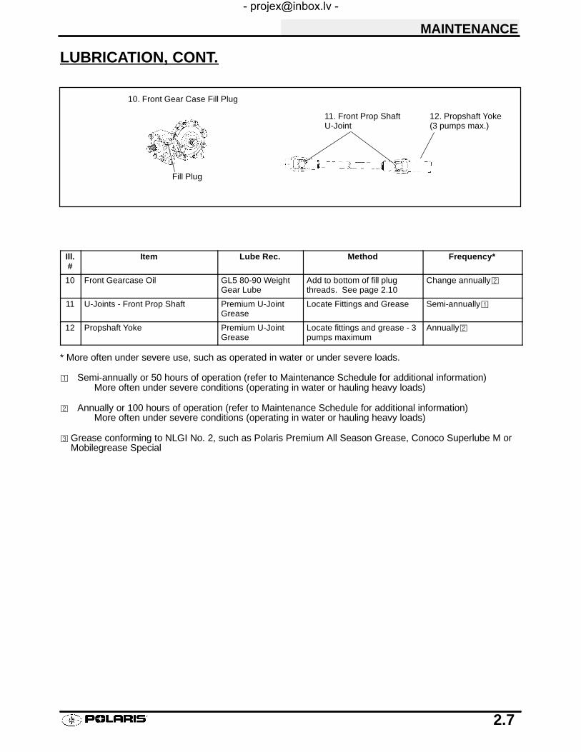
LUBRICATION, CONT.
11. Front Prop ShaftU-Joint
12. Propshaft Yoke(3 pumps max.)
10. Front Gear Case Fill Plug
Fill Plug
Ill.#
Item Lube Rec. Method Frequency*
10 Front Gearcase Oil GL5 80-90 WeightGear Lube
Add to bottom of fill plugthreads. See page 2.10
Change annually©
11 U-Joints - Front Prop Shaft Premium U-JointGrease
Locate Fittings and Grease Semi-annually¡
12 Propshaft Yoke Premium U-JointGrease
Locate fittings and grease - 3pumps maximum
Annually©
* More often under severe use, such as operated in water or under severe loads.
¡ Semi-annually or 50 hours of operation (refer to Maintenance Schedule for additional information)More often under severe conditions (operating in water or hauling heavy loads)
© Annually or 100 hours of operation (refer to Maintenance Schedule for additional information)More often under severe conditions (operating in water or hauling heavy loads)
¢Grease conforming to NLGI No. 2, such as Polaris Premium All Season Grease, Conoco Superlube M orMobilegrease Special

MAINTENANCE
2.8
LUBRICATION, CONT.
14. Lower ControlArm
13. Upper ControlArm
15. Rear Wheel Hub Bear-ing Carrier
16. Rear Anti-Roll Bar
14. Lower ControlArm
Ill.#
Item Lube Rec. Method Frequency*
13 Upper Control Arms Polaris All SeasonGrease¢
Locate fittings and grease Semi-annually ¡
14 Lower Control Arms Polaris All SeasonGrease¢
Locate fittings and grease Semi-annually ¡
15 Rear Wheel Hub Bearing Carrier Polaris All SeasonGrease¢
Locate fittings and grease Semi-annually ¡
16 Rear Anti-Roll Bar Polaris All SeasonGrease¢
Locate fittings and grease Semi-annually ¡
* More often under severe use, such as operated in water or under severe loads.
¡ Semi-annually or 50 hours of operation (refer to Maintenance Schedule for additional information)More often under severe conditions (operating in water or hauling heavy loads)
© Annually or 100 hours of operation (refer to Maintenance Schedule for additional information)More often under severe conditions (operating in water or hauling heavy loads)
¢Grease conforming to NLGI No. 2, such as Polaris Premium All Season Grease, Conoco Superlube M orMobilegrease Special

MAINTENANCE
2.9
FRONT GEARCASE LUBRICATIONThe gearcase lubricant level should be checked and changed in accordance with the maintenance schedule.S Be sure vehicle is level before proceeding.S Check vent hose to be sure it is routed properly and unobstructed.
S The correct gearcase lubricant to use is Polaris Premium GL5 80-90 Gear Lube, or an equivalent lubricantwith a GL5 rating.
To check the level:
1. The front gearcase lubricant level cannot bechecked with a dipstick or by visual reference.The gearcase must be drained and re-filled withthe proper amount of lubricant. Refer to procedurebelow.
To change lubricant:
1. Remove gearcase drain plug located on the bottomand drain oil. Catch and discard used oil properly.
2. Clean and reinstall drain plug using a new sealingwasher.
3. Remove fill plug.
4. Add proper amount of lubricant.
5. Install fill plug.
6. Check for leaks.
Specified Lubricant:Polaris Front Gearcase Lube PN 2871653
...Or API GL5 80-90 Gearlube
Capacity: 4.0 Oz. (120ml.). . . . . . . . . . .
Drain Plug / Fill Plug Torque:
14 ft. lbs. (19.4 Nm)
FRONT GEARCASE SPECIFICATIONS
Fill plug
Make sure vent is unobstructed
Drain plug

MAINTENANCE
2.10
TRANSMISSION LUBRICATIONThe transmission lubricant level should be checked and changed in accordance with the maintenance schedule.S Be sure vehicle is level before proceeding.S Check vent hose to be sure it is routed properly and unobstructed.
To check the level:
1. Remove dipstick and wipe clean.
2. Reinstall dipstick completely, remove and check thelevel. Add the proper lubricant as required to bringlevel into operating range as shown.
To change lubricant:
1. Remove skid plate (if necessary).
2. Place a drain pan beneath the transmission oil drainplug area.
3. Remove the drain plug and wipe the magnetic endclean to remove accumulated metallic filings.
4. After the oil has drained completely, install a newsealing washer and install the drain plug. Torque to14 ft. lbs. (19 Nm).
5. Add the proper lubricant through the dipstick hole un-til the oil level is between the upper and lower limits.Do not overfill.
6. Check for leaks.
7. Reinstall skid plate if removed in step 1.
DipstickSpecified Lubricant:Polaris Premium Synthetic Gearcase LubricantPN 2871477 (Gallon) PN 2871478 (12 oz..)
Capacity: At change: Approx. 20 oz.. . . .
Drain Plug:
14 ft. lbs. (19.4 Nm)
TRANSMISSION SPECIFICATIONS
Full OperatingRange

MAINTENANCE
2.11
TRANSMISSION GEARSHIFT LINKAGE ADJUSTMENT, PRE-LIMINARY INSPECTION
S If shifting problems are encountered, the transmis-sion linkage can be adjusted.
S Tighten shift linkage rod end jam nuts properly afteradjustment. You should be able to rotate the linkagerod between 1/8 and 1/4 turn after both jam nuts aretight.
S The transmission shift linkage should be periodicallyinspected for wear and parts replaced as required toremove excess play from shift linkage.
S Refer to Transmission chapter for more information.
SHIFT LINKAGE ADJUSTMENTLinkage rod adjustment is necessary when symptoms include:
S No All Wheel Drive light
S Noise on deceleration
S Inability to engage a gear
S Excessive gear clash (noise)
S Shift selectors moving out of desired range
NOTE: When adjusting linkage, always adjust both linkage rods. The adjustment of one rod can prevent properadjustment of the other rod. Remove necessary components to gain access to shift linkage rod ends (i.e. exhaustheat shield, exhaust pipe, etc.).
1. Inspect shift linkage tie rod ends, clevis pins, andpivot bushings and replace if worn or damaged.Lubricate the tie rod ends with a light aerosollubricant or grease.
2. Loosen all rod end adjuster jam nuts see Ill. 1.
3. Note orientation of tie rod end studs with stud up ordown. Remove both rod end studs fromtransmission bell cranks.
4. Be sure idle speed is adjusted properly.
NOTE: It is important to disconnect both rod ends fromthe transmission bell cranks. If one linkage rod is incor-rectly adjusted, it can affect the adjustment of the otherrod.
Correctly TightenedJam Nut
Incorrectly TightenedJam Nut
Parallel
Linkage rod will rotate1/8 -1/4 turn if rod endsare tightened properly.
Low RangeGear SelectorSlides
Jam NutJamNut
NOTE: Rod end orientation, rod ends areboth down.
Ill. 1

MAINTENANCE
2.12
SHIFT LINKAGE ADJUSTMENT, CONT.
5. Place gear selector in neutral. Make sure thetransmission bell cranks are engaged in the neutralposition detents.
6. Be sure the shift linkage rod ends are firmly attachedto the gear selector slides. Adjust the low range(inside) rod so the rod end is centered on thetransmission bell crank. Install the lock nut to the rodend and torque to 35 in. lbs.
7. Rotate the linkage rod clockwise until resistance isfelt. Mark the rod so revolutions can be easilycounted. See Ill. 3 at right.
8. Rotate the linkage rod counterclockwise until thesame resistance is felt, counting the revolutions asthe rod is turned.
9. Turn the rod clockwise again one half of therevolutions counted in Step 9.
10. Tighten the rod end jam nuts securely while holdingthe rod end. The jam nuts must be tightened withboth front and rear rod ends parallel to each other. Ifjam nuts are properly tightened, the rod should rotatefreely 1/4 turn without binding.
11. Repeat steps 7-10 for the High/Reverse rod.
Adjust to align linkage rod end studswith holes in bellcrank(s).
Ill. 2
35 in. lbs.
35 in. lbs.
Placemarkon rod
Ill. 3
S Rotate rod both directions tofind points where resistanceis felt.
S Center the rod between thepoints.
S Hold rod end parallel tomounting surface andtighten jam nut.
Parallel

MAINTENANCE
2.13
THROTTLE OPERATIONCheck for smooth throttle opening and closing in all han-dlebar positions. Throttle lever operation should besmooth and lever must return freely without binding.
1. Place the gear selector in neutral.
2. Set parking brake.
3. Start the engine and let it idle.
4. Turn handlebars from full right to full left. If idle speedincreases at any point in the turning range, inspectthrottle cable routing and condition.
5. Replace the throttle cable if worn, kinked, or damaged.
To remove the ETC cover:1. Use a medium flat blade screwdriver and insert blade
into the pocket of the cover starting on the #1position.
2. Twist screwdriver slightly while lifting on the cover torelease snap.
3. Repeat procedure at the other five locations asshown. NOTE: Do not attempt to remove cover untilall latch points are released.
CHOKE (ENRICHER) ADJUSTMENTWith the choke control pushed in, the choke plunger mustbe seated on the fuel passage way in the carburetor. If theplunger is not seated on the fuel passage way inside thecarburetor (not enough cable freeplay), the engine will floodor run too rich, causing plug fouling and poor performance.
If cable slack is excessive, the choke fuel passage will notopen far enough, which may cause cold starting difficulty.Also, the half-choke position used for intermittent applica-tions will not function properly.
1. Locate the boot behind the choke knob and pull it back.Loosen the friction nut 1 turn or until choke slides freely.Re-install boot.
2. Push the choke knob in to the full off position.
3. Slide boots off in-line cable adjuster and loosenadjustment locknut.
4. Turn adjuster until the choke knob pulls out over 1/4″.
5. Push on the choke knob lightly while turning theadjuster the opposite way.
6. Turn the adjuster until the knob contacts the boot.
7. Tighten adjuster nut.
8. Slide boots back over cable adjuster sleeve until theytouch at the middle point of the adjuster.
9. Pull back the choke knob boot and tighten the frictionnut until the choke will maintain a set position.Re-install boot.
1
23
456
56
Boot AdjusterSleeve
Lock-nut
Boot

MAINTENANCE
2.14
PILOT SCREW ADJUSTMENT
Pilot Screw (Idle Mixture) Adjustment NotesDo not tighten the pilot screw forcefully against the seat or the screw and/or seat will be permanently damaged.Start engine and warm it up to operating temperature (about 10 minutes). This is a very important step.
1. Turn pilot screw in (clockwise) until lightly seated.Turn screw out the specified number of turns.
2. Connect an accurate tachometer that will read inincrements of + or -- 50 RPM such as the PET2100DX (P/N 8712100DX) or the PET 2500 (P/N8712500).
3. Set idle speed to 1200 RPM. Always check throttlecable freeplay after adjusting idle speed and adjust ifnecessary.
4. Slowly turn mixture screw clockwise using the pilotscrew wrench until RPM begins to decrease by 50RPM or greater.
5. Slowly turn mixture screw counterclockwise until idlespeed increases to maximum RPM. Continue turningcounterclockwise until idle RPM begins to drop.
6. Center the pilot screw between the points in step 5and 6.
7. Re adjust idle speed if not within specification.
IDLE SPEED ADJUSTMENT
1. Start engine and warm it up thoroughly.
2. Adjust idle speed by turning the idle adjustment screwin (clockwise) to increase or out (counterclockwise) todecrease RPM. (Refer to Ill. at right).
NOTE: Adjusting the idle speed affects throttle cablefreeplay and electronic throttle control (ETC) adjustment.Always check throttle cable freeplay after adjusting idlespeed and adjust if necessary.
Pilot Screw Adjustment:
2.0 Turns
Idle Speed:
1200 +/-- 200 RPM
Pilot Screw
FRONT(Engine)
Idle Screw
CV Carburetor
MAINTENANCE
2.15
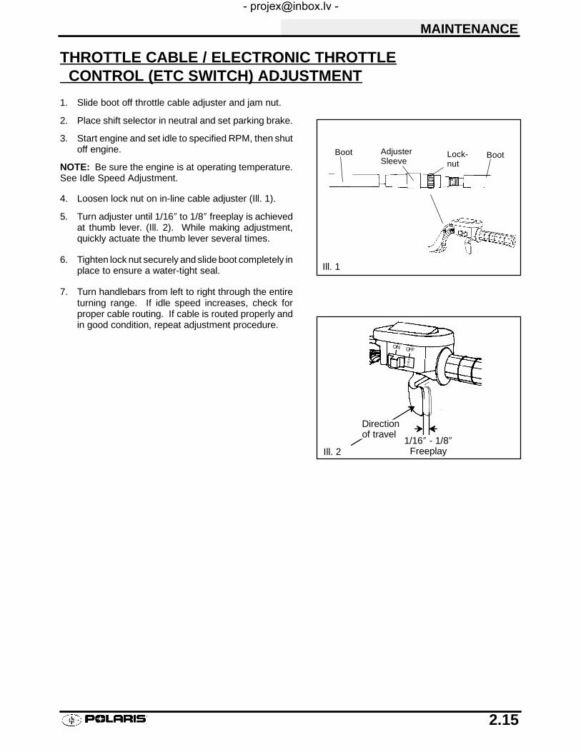
THROTTLE CABLE / ELECTRONIC THROTTLECONTROL (ETC SWITCH) ADJUSTMENT
1. Slide boot off throttle cable adjuster and jam nut.
2. Place shift selector in neutral and set parking brake.
3. Start engine and set idle to specified RPM, then shutoff engine.
NOTE: Be sure the engine is at operating temperature.See Idle Speed Adjustment.
4. Loosen lock nut on in-line cable adjuster (Ill. 1).
5. Turn adjuster until 1/16″ to 1/8″ freeplay is achievedat thumb lever. (Ill. 2). While making adjustment,quickly actuate the thumb lever several times.
6. Tighten lock nut securely and slide boot completely inplace to ensure a water-tight seal.
7. Turn handlebars from left to right through the entireturning range. If idle speed increases, check forproper cable routing. If cable is routed properly andin good condition, repeat adjustment procedure.
Boot AdjusterSleeve
Lock-nut
Boot
Ill. 1
1/16″ - 1/8″Freeplay
Directionof travel
Ill. 2
MAINTENANCE
2.16
FUEL SYSTEM
WARNING
Gasoline is extremely flammable and explosive under certain conditions.
Always stop the engine and refuel outdoors or in a well ventilated area.
Do not smoke or allow open flames or sparks in or near the area where refueling is performed or wheregasoline is stored.
Do not overfill the tank. Do not fill the tank neck.
If you get gasoline in your eyes or if you swallow gasoline, see your doctor immediately.
If you spill gasoline on your skin or clothing, immediately wash it off with soapand water and changeclothing.
Never start the engine or let it run in an enclosed area. Gasoline powered engine exhaust fumes are poison-ous and can cause loss of consciousness and death in a short time.
Never drain the float bowl when the engine is hot. Severe burns may result.
FUEL LINES
1. Check fuel lines for signs of wear, deterioration,damage or leakage. Replace if necessary.
2. Be sure fuel lines are routed properly and secured withcable ties. CAUTION: Make sure lines are not kinkedor pinched.
3. Replace all fuel lines every two years.
VENT LINES
1. Check fuel tank, oil tank, carburetor, battery andtransmission vent lines for signs of wear, deterioration,damage or leakage. Replace every two years.
2. Be sure vent lines are routed properly and securedwith cable ties. CAUTION: Make sure lines are notkinked or pinched.
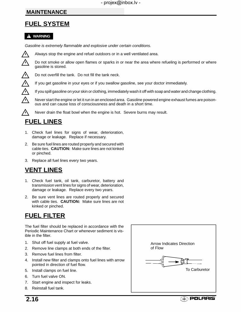
FUEL FILTER
The fuel filter should be replaced in accordance with thePeriodic Maintenance Chart or whenever sediment is vis-ible in the filter.
1. Shut off fuel supply at fuel valve.
2. Remove line clamps at both ends of the filter.
3. Remove fuel lines from filter.
4. Install new filter and clamps onto fuel lines with arrowpointed in direction of fuel flow.
5. Install clamps on fuel line.
6. Turn fuel valve ON.
7. Start engine and inspect for leaks.
8. Reinstall fuel tank.
Arrow Indicates Directionof Flow
To Carburetor
MAINTENANCE
2.17
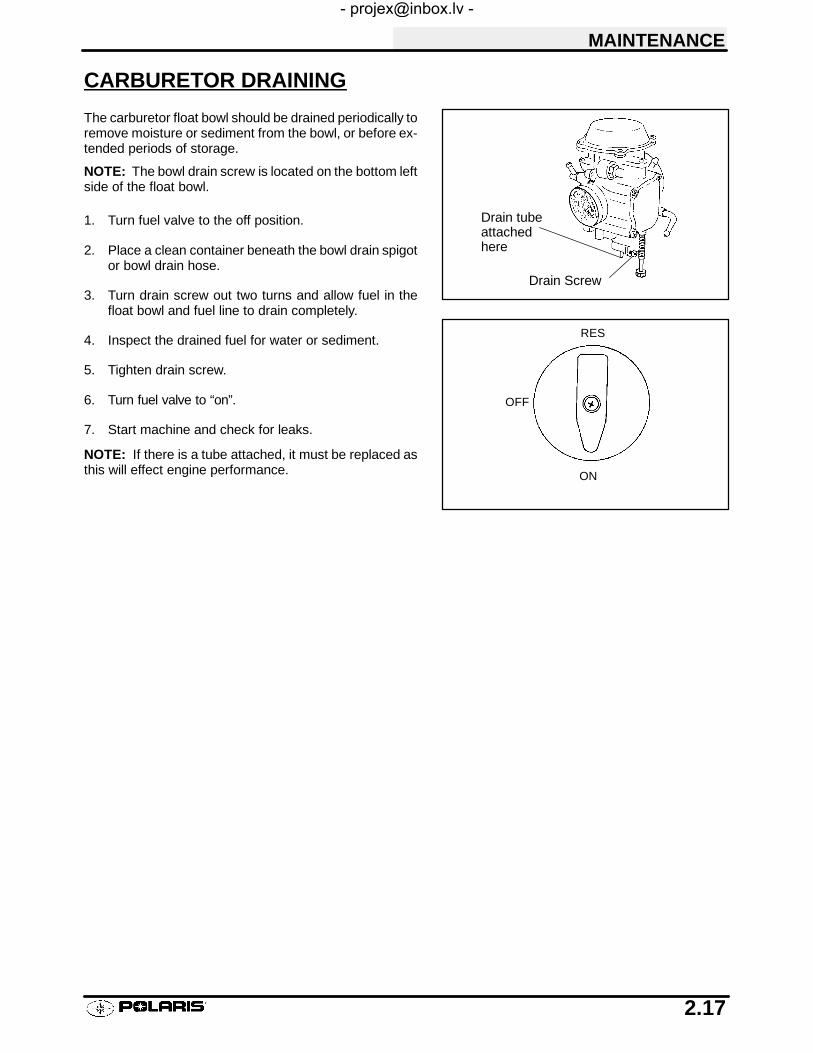
CARBURETOR DRAINING
The carburetor float bowl should be drained periodically toremove moisture or sediment from the bowl, or before ex-tended periods of storage.
NOTE: The bowl drain screw is located on the bottom leftside of the float bowl.
1. Turn fuel valve to the off position.
2. Place a clean container beneath the bowl drain spigotor bowl drain hose.
3. Turn drain screw out two turns and allow fuel in thefloat bowl and fuel line to drain completely.
4. Inspect the drained fuel for water or sediment.
5. Tighten drain screw.
6. Turn fuel valve to “on”.
7. Start machine and check for leaks.
NOTE: If there is a tube attached, it must be replaced asthis will effect engine performance.
Drain tubeattachedhere
Drain Screw
ON
OFF
RES
MAINTENANCE
2.18
COMPRESSION TEST
NOTE: 4-Stroke engines are equipped with an automatic decompressor. Compression readings will vary in pro-portion to cranking speed during the test. Average compression (measured) is about 50-90 psi during a compres-sion test.
Smooth idle generally indicates good compression. Low engine compression is rarely a factor in runningconditionproblems above idle speed. Abnormally high compression can be caused by a decompressor malfunction, orworn or damaged exhaust cam lobes. Inspect camshaft and automatic decompression mechanism if compres-sion is abnormally high.
A cylinder leakage test is the best indication of engine condition on models with automatic decompression. Followmanufacturer’s instructions to perform a cylinder leakage test. (Never use high pressure leakage tester as crank-shaft seals may dislodge and leak).
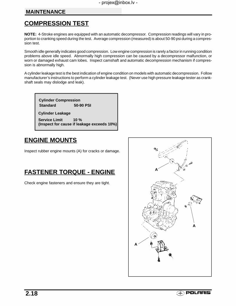
ENGINE MOUNTS
Inspect rubber engine mounts (A) for cracks or damage.
FASTENER TORQUE - ENGINE
Check engine fasteners and ensure they are tight.
Cylinder CompressionStandard 50-90 PSI
Cylinder Leakage
Service Limit 10 %(Inspect for cause if leakage exceeds 10%)
A
A
A

MAINTENANCE
2.19
BATTERY MAINTENANCE
WARNINGBattery electrolyte is poisonous. It contains sulfuric acid. Seriousburns can result from contact with skin, eyes or clothing. Antidote:
External: Flush with water.
Internal: Drink large quantities of water or milk. Follow with milkof magnesia, beaten egg, or vegetable oil. Call physician immedi-ately.
Eyes: Flush with water for 15 minutes and get prompt medicalattention.
Batteries produce explosive gases. Keep sparks, flame, ciga-rettes, etc. away. Ventilate when charging or using in an enclosedspace. Always shield eyes when working near batteries. KEEPOUT OF REACH OF CHILDREN.
The battery is located under the left rear fender.
Inspect the battery fluid level. When the battery fluid nearsthe lower level, the battery should be removed and distilledwater should be added to the upper level line. To removethe battery:
1. Disconnect holder strap and remove cover.
2. Disconnect battery negative (-) (black) cable first,followed by the positive (+) (red) cable.
CAUTION
Whenever removing or reinstalling the battery, disconnectthe negative (black) cable first and reinstall the negativecable last!3. Disconnect the vent hose.
4. Remove the battery.5. Remove the filler caps and add distilled water only as needed to bring each cell to the proper level. Do not
overfill the battery. Fully recharge after refilling.
To refill use only distilled water. Tap water contains minerals which are harmful to a battery.
Do not allow cleaning solution or tap water to enter the battery. It will shorten the life of the battery.
6. Reinstall the battery caps.
7. Clean battery cables and terminals with a stiff wire brush. Corrosion can be removed using a solution of onecup water and one tablespoon baking soda. Rinse well with clean water and dry thoroughly.
8. Reinstall battery, attaching positive (+) (red) cable first and then the negative (-) (black) cable.
9. Reattach vent hose making sure it is properly routed and not kinked or pinched.10. Coat terminals and bolt threads with Nyogelt grease.
11. Reinstall battery cover and holder strap.
NOTE: New Battery: Battery must be fully charged before use or battery life will be significantly reduced 10-30%of batterys’ full potential.
Maintainbetween upperand lower levelmarks
MAINTENANCE
2.20
SPARK PLUG
1. Remove spark plug high tension lead. Clean plug areaso no dirt and debris can fall into engine when plug isremoved.
2. Remove spark plug.
3. Inspect electrodes for wear and carbon buildup. Lookfor a sharp outer edge with no rounding or erosion ofthe electrodes.
4. Clean with electrical contact cleaner or a glass beadspark plug cleaner only. CAUTION: A wire brush orcoated abrasive should not be used.
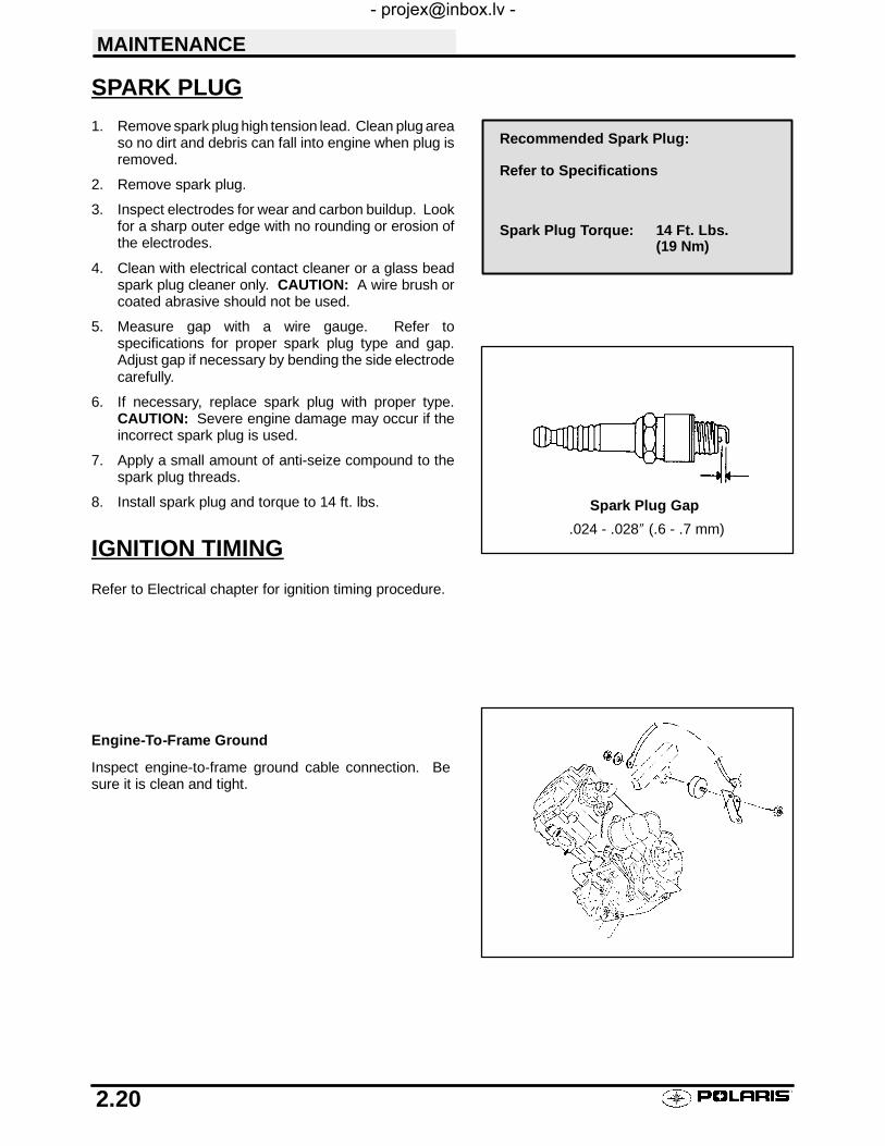
5. Measure gap with a wire gauge. Refer tospecifications for proper spark plug type and gap.Adjust gap if necessary by bending the side electrodecarefully.
6. If necessary, replace spark plug with proper type.CAUTION: Severe engine damage may occur if theincorrect spark plug is used.
7. Apply a small amount of anti-seize compound to thespark plug threads.
8. Install spark plug and torque to 14 ft. lbs.
IGNITION TIMING
Refer to Electrical chapter for ignition timing procedure.
Engine-To-Frame Ground
Inspect engine-to-frame ground cable connection. Besure it is clean and tight.
Recommended Spark Plug:
Refer to Specifications
Spark Plug Torque: 14 Ft. Lbs.(19 Nm)
.024 - .028″ (.6 - .7 mm)
Spark Plug Gap

MAINTENANCE
2.21
LIQUID COOLING SYSTEM OVERVIEWTheenginecoolant level iscontrolledor maintainedby therecovery system. Therecovery systemcomponentsare the recovery bottle, radiator filler neck, radiator pressure cap and connecting hose.
Ascoolantoperatingtemperature increases, theexpanding(heated)excesscoolant isforcedoutof theradiatorpast the pressure cap and into the recovery bottle. As engine coolant temperature decreases the contracting(cooled) coolant is drawn back up from the tank past the pressure cap and into the radiator.
S Somecoolant leveldroponnewmachines is normalas thesystem ispurging itselfof trappedair. Observecoolant levels often during the break-in period.S Overheating of engine could occur if air is not fully purged from system.S Polaris Premium 60/40 is already premixed and ready to use. Do not dilute with water.
COOLANT STRENGTH / TYPE
Test the strength of the coolant using an antifreezehydrometer.
S A 50/50 or 60/40 mixture of antifreeze and distilled wa-ter will provide the optimum cooling, corrosion protec-tion, and antifreeze protection.
S Do not use tap water, straight antifreeze, or straight wa-ter in the system. Tap water contains minerals and im-purities which build up in the system.
S Straight water or antifreeze may cause the system tofreeze, corrode, or overheat.
COOLING SYSTEM HOSES1. Inspect all hoses for cracks, deterioration, abrasion or
leaks. Replace if necessary.2. Check tightness of all hose clamps.
CAUTION:Do not over-tighten hose clamps at radiator, orradiator fitting may distort, causing a restriction to coolantflow. Radiator hose clamp torque is 36 inch lbs.
RADIATOR1. Check radiator air passages for restrictions or
damage.
2. Carefully straighten any bent radiator fins.
3. Remove any obstructions with compressed air or lowpressure water.
COOLING SYSTEM PRESSURE TESTRefer to page 3.6 for pressure test procedure.
Antifreeze Hydrometer
Polaris 60/40 Anti-Freeze / Coolant
PN 2871323
MAINTENANCE
2.22
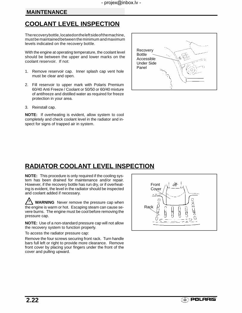
COOLANT LEVEL INSPECTION
Therecoverybottle, locatedontheleftsideof themachine,must bemaintainedbetween theminimum andmaximumlevels indicated on the recovery bottle.
With the engine at operating temperature, the coolant levelshould be between the upper and lower marks on thecoolant reservoir. If not:
1. Remove reservoir cap. Inner splash cap vent holemust be clear and open.
2. Fill reservoir to upper mark with Polaris Premium60/40 Anti Freeze / Coolant or 50/50 or 60/40 mixtureof antifreeze and distilled water as required for freezeprotection in your area.
3. Reinstall cap.
NOTE: If overheating is evident, allow system to coolcompletely and check coolant level in the radiator and in-spect for signs of trapped air in system.
RADIATOR COOLANT LEVEL INSPECTIONNOTE: This procedure is only required if the cooling sys-tem has been drained for maintenance and/or repair.However, if the recovery bottle has run dry, or if overheat-ing is evident, the level in the radiator should be inspectedand coolant added if necessary.
WARNING Never remove the pressure cap whenthe engine is warm or hot. Escaping steam can cause se-vere burns. The engine must be cool before removing thepressure cap.
NOTE: Use of a non-standard pressure cap will not allowthe recovery system to function properly.To access the radiator pressure cap:Remove the four screws securing front rack. Turn handlebars full left or right to provide more clearance. Removefront cover by placing your fingers under the front of thecover and pulling upward.
RecoveryBottleAccessibleUnder SidePanel
Rack
FrontCover

MAINTENANCE
2.23
AIR FILTER PRE-FILTER SERVICE
It is recommended that the air filter and pre filter be replacedannually. When riding in extremely dusty conditions re-placement will be required more often.
The pre filter should be cleaned before each ride, using thefollowing procedure.
1. Lift up on the rear of the seat.2. Pull the seat back and free of the tabs. NOTE: When
reinstalling seat, make sure the slots in the seat engagethe tabs in the fuel tank.
3. Remove clips (6) from air box cover and remove cover.Inspect the gasket. It should adhere tightly to the coverand seal all the way around.
4. Loosen clamp and remove air filter assembly.
Cleaning5. Slip the pre-filter element off of main element. Clean
the pre filter with high flash point solvent, followed byhot soapy water.
6. Rinse and dry thoroughly.7. Inspect element for tears or damage.8. Apply foam filter oil or clean engine oil and squeeze
until excess oil is removed.9. Inspect main element and replace if necessary. If the
filter has been soaked with fuel or oil it must bereplaced.
Installation10. Reinstall pre-filter element over main filter. Be sure the
element covers entire surface of main filter withoutfolds, creases, or gaps.
11. Install air box cover and secure with clips.
NOTE: Apply a small amount of general purpose greaseto the sealing edges of the filter before reinstalling.
8. Reinstall pre-filter in main filter. Replace main filteras required.
Gasket
Cover
Pre-filter
Main Element

MAINTENANCE
2.24
AIR BOX SEDIMENT TUBEPeriodically check the air box drain tube located toward therear of the machine. Drain whenever deposits are visiblein the clear tube.
NOTE: The sediment tube will require more frequent ser-vice if the vehicle is operated in wet conditions or at highthrottle openings for extended periods.
1. Remove drain plug from end of sediment tube.
2. Drain tube.
3. Reinstall drain plug.
BREATHER FILTER INSPECTION
Four cycle ATV engines are equipped with a breather filter.The in-line filter is similar in appearance to a fuel filter, andis visible on the left side (Location A).
1. In-line breather filters should be installed with thearrow pointing toward the engine (away from the airbox).
NOTE: In-line breather filter service life is extended whenthe foam air box pre-filter is in place and maintained prop-erly. Never operate the engine without the pre-filter.
BREATHER HOSE1. Be sure breather line is routed properly and secured in
place. CAUTION: Make sure lines are not kinked orpinched.
Sediment Tube
In-Line Breather FilterLocation A
Typical Breather Filter Location

MAINTENANCE
2.25
RECOIL HOUSINGS Drain the housing periodically to remove moisture.S Drain the recoil housing after operating the ATV in
very wet conditions. This should also be done beforestoring the ATV. The drain screw is located at the bot-tom of the recoil housing. Remove the screw with a10mm wrench. Reinstall screw once housing hasbeen drained.
S CAUTION: Make sure the manual start handle is ful-ly seated on the recoil housing, especially when trav-elling in wet areas. If it is not sealed properly, watermay enter the recoil housing and damage compo-nents.
S Water will enter the recoil housing if the starter handleis disengaged from the rope guide when under water.
S After travelling in wet areas the recoil housing andstarter should always be drained completely by re-moving the recoil.
S Do not open the crankcase drain unless the enginehas ingested water. Some engine oil will be lost ifcrankcase drain is opened.
S If recoil handle seal has been damaged, the handleshopuld be replaced.
Recoil Drain (above frontpropshaft)
Crankcase Drain

MAINTENANCE
2.26
ENGINE OIL LEVEL
The oil tank is located on the left side of the vehicle. Tocheck the oil level:1. Set machine on a level surface.
2. Start and run engine for 20-30 seconds. This will returnoil to its true level in the oil tank. About a cup of oil willremain in the crankcase.
3. Stop engine, remove dipstick and wipe dry with a cleancloth.
4. Reinstall dipstick, screwing into place.
NOTE: The dipstick must be screwed completely in to en-sure accurate measurement.
5. Remove dipstick and check to see that the oil level is inthe normal range. Add oil as indicated by the level onthe dipstick. Do not overfill.
NOTE: Rising oil level between checks in cool weatherdriving, can indicate moisture collecting in the oil reservoir.If the oil level is over the full mark, change the oil.
OIL AND FILTER CHANGE1. Place vehicle on a level surface.
2. Run engine two to three minutes until warm. Stopengine.
3. Clean area around drain plug (B) at bottom of oil tank.
4. Place a drain pan beneath oil tank and remove drainplug. CAUTION: Oil may be hot. Do not allow hot oil tocome into contact with skin as serious burns may result.
5. Allow oil to drain completely.
6. Replace sealing washer (A) on drain plug. NOTE: Thesealing surfaces on drain plug and oil tank should beclean and free of burrs, nicks or scratches.
7. Reinstall drain plug and torque to 14 ft. lbs. (1.9 kgm).
8. Loosen clamp (E) or bolt (D).
9. Remove oil hose from screen fitting (C) on bottom ofoil tank.
10. Remove screen fitting (C).
11. Clean screen thoroughly.
12. Apply Loctitet PST 505 or an equivalent pipethread sealant or PTFE sealant tape to clean, oilfree threads of fitting.
13. Install fitting and torque to 14-17 ft./lbs..
14. Install oil hose on fitting and tighten clamp to 25inch/lbs.
Dipstick
ADD 8 OZ. NORMAL FULL
Maintain Oil Level In Normal Range
Screw in completely to check
Recommended Engine Oil:
Polaris Premium 4 All SeasonSynthetic, 0W/40, PN 2871281
Ambient Temperature Range:-40° F to 120° F
OR
A
B
C
C
D
E

MAINTENANCE
2.27
OIL AND FILTER CHANGE, CONT.15. Place shop towels beneath oil filter. Using an oil
filter wrench, turn filter counterclockwise to remove.16. Using a clean dry cloth, clean filter sealing surface
on crankcase.17. Lubricate O-ring on new filter with a film of engine
oil. Check to make sure the O-ring is in goodcondition.
18. Install new filter and turn by hand until filter gasketcontacts the sealing surface, then turn andadditional 1/2 turn.
19. Approximately 1 cup of engine oil will remain in thecrankcase. To drain, remove drain plug found onlower right side of crankcase.
NOTE: The sealing surfaces on the drain plug andcrankcase should be clean and free of burrs, nicks orscratches.
20. Reinstall drain plug.21. Remove dipstick and fill tank with 2 quarts (1.9 l) of
Polaris Premium 4 synthetic oil.
22. Place gear selector in neutral and set parking brake.23. Prime oil pump using procedure below. Stop
the engine and inspect for leaks.24. Re-check the oil level on the dipstick and add oil as
necessary to bring the level to the upper mark on thedipstick.
25. Dispose of used filter and oil properly.
OIL PUMP PRIMING PROCEDURENOTE: This priming procedure must be per-formed whenever the oil hose connection be-tween the oil tank and pump inlet has been dis-connected.
1. Clamp or pinch off vent line approximately 2I fromoil tank to avoid the end of oil tank vent fitting, andthe vent line’s pressure relief slit
2. Run engine for 45-60 seconds.3. Remove the vent line clamp. The oil pump will now
be properly primed and ready for field operation.
SlitOil Tank
Vent Hose
To Air Box
Pinch Off
2IApprox.
Filter
Engine Sump Drain Plug - Bottom View
Crankcase Drain
RecoilStarter
Oil Tank Drain Plug Torque:14 ft. lbs. (19 Nm)
Crankcase Drain Plug Torque:14 ft. lbs. (19 Nm)
Oil Filter Torque:Turn by hand until filter gasketcontacts sealing surface, thenturn an additional 1/2 turn
Oil Filter Wrench:Snap Ont PN YA997 or 2 1/2 inch
Oil Tank Screen Fitting Torque:14-17 ft. lbs. (19 Nm)
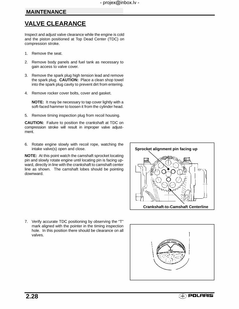
MAINTENANCE
2.28
VALVE CLEARANCE
Inspect and adjust valve clearance while the engine is coldand the piston positioned at Top Dead Center (TDC) oncompression stroke.
1. Remove the seat.
2. Remove body panels and fuel tank as necessary togain access to valve cover.
3. Remove the spark plug high tension lead and removethe spark plug. CAUTION: Place a clean shop towelinto the spark plug cavity to prevent dirt from entering.
4. Remove rocker cover bolts, cover and gasket.
NOTE: It may be necessary to tap cover lightly with asoft-faced hammer to loosen it from the cylinder head.
5. Remove timing inspection plug from recoil housing.
CAUTION: Failure to position the crankshaft at TDC oncompression stroke will result in improper valve adjust-ment.
6. Rotate engine slowly with recoil rope, watching theintake valve(s) open and close.
NOTE: At this point watch the camshaft sprocket locatingpin and slowly rotate engine until locating pin is facing up-ward, directly in line with the crankshaft to camshaft centerline as shown. The camshaft lobes should be pointingdownward.
7. Verify accurate TDC positioning by observing the “T”mark aligned with the pointer in the timing inspectionhole. In this position there should be clearance on allvalves.
Sprocket alignment pin facing up
Crankshaft-to-Camshaft Centerline

MAINTENANCE
2.29
INTAKE VALVE CLEARANCE ADJUSTMENT1. Insert a .006″ (.15mm) feeler gauge between end of
intake valve stem and clearance adjuster screw.2. Using a 10 mm wrench and a screwdriver, loosen
adjuster lock nut and turn adjusting screw until there isa slight drag on the feeler gauge.
3. Hold adjuster screw and tighten adjuster lock nutsecurely.
4. Re-check the valve clearance.5. Repeat adjustment procedure if necessary until
clearance is correct with locknut secured.6. Repeat this step for the other intake valve.
EXHAUST VALVE CLEARANCE ADJUSTMENT
NOTE: The exhaust valves share a common rocker arm,and must be adjusted using two feeler gauges.
1. Insert .006 feeler gauge(s) between end of exhaustvalve stem and adjuster screw(s).
2. Loosen locknut(s) and turn adjuster screw(s) untilthere is a slight drag on feeler gauge(s). NOTE: Bothfeeler gauges should remain inserted duringadjustment of each valve.
3. When clearance is correct, hold adjuster screw andtighten locknut securely
4. Re-check the valve clearance.
5. Repeat adjustment procedure if necessary untilclearance is correct with locknut secured.
.006″ (.15 mm)
INTAKE VALVE CLEARANCE
.006″ (.15 mm)
EXHAUST VALVE CLEARANCE
2 Feeler Gauges

MAINTENANCE
2.30
STEERING
The steering components should be checked periodically for loose fasteners, worn tie rod ends, and damage.Also check to make sure all cotter pins are in place. If cotter pins are removed, they must not be re-used. Alwaysuse new cotter pins.
Replace any worn or damaged steering components. Steering should move freely through entire range of travelwithout binding. Check routing of all cables, hoses, and wiring to be sure the steering mechanism is not restrictedor limited. NOTE: Whenever steering components are replaced, check front end alignment. Use only genuinePolaris parts.
WARNING
Due to the critical nature of the procedures outlined in this chapter, Polaris recommends steering component re-pair and adjustment be performed by an authorized Polaris Dealer. Only a qualified technician should replaceworn or damaged steering parts. Use only genuine Polaris replacement parts.
One of two methods can be used to measure toe alignment. The string method and the chalk method. If adjust-ment is required, refer to following pages for procedure.
TIE ROD END / STEERING INSPECTIONS To check for play in the tie rod end, grasp the steering
tie rod, pull in all directions feeling for movement.
S Repeat inspection for inner tie rod end (on steeringpost).
S Replace any worn steering components. Steeringshould move freely through entire range of travel with-out binding.
S Elevate front end of machine so front wheels are off theground. Check for any looseness in front hub / wheelassembly by grasping the tire firmly at top and bottomfirst, and then at front and rear. Try to move the wheeland hub by pushing inward and pulling outward.
S If abnormal movement is detected, inspect the hubandwheel assembly to determine the cause (loose wheelnuts or loose front hub nut).
S Refer to the Body/Steering or Final Drive chapter formore information.
CAMBER AND CASTER
The camber and caster are non-adjustable.
Check for Loose Wheel or Hub

MAINTENANCE
2.31
METHOD 1: STRAIGHTEDGE OR STRINGBe sure to keep handlebars centered. See note below.
Measure from stringto rim at front andrear of rim.
NOTE: Stringshould just touchside surface of reartire on each side ofmachine.
NOTE: The steering post arm (frog) can be used as an indicator of whether the handle-bars are straight. The frog should always point straight back from the steering post.
Rear rim measure-ment should be1/16″ to 1/8″ (.2 to.3 cm) more thanfront rim measure-ment.

MAINTENANCE
2.32
METHOD 2 CHALK
1. Place machine on a smooth level surface.
2. Set handlebars in a straight ahead position andsecure handlebars in this position. NOTE: Thesteering frog can be used as an indicator of whetherthe handlebars are straight. The frog should alwayspoint straight back from the steering post.
3. Place a chalk mark on the face of the front tiresapproximately 10″ (25.4 cm) from the floor as close tothe hub/axle center line as possible. NOTE: It isimportant that both marks be equally positioned fromthe ground in order to get an accurate measurement.
4. Measure the distance between the marks and recordthe measurement. Call this measurement “A”.
5. Rotate the tires 180° by moving vehicle forward or backward. Position chalk marks facing rearward, even withthe hub/axle centerline.
6. Again measure the distance between the marks and record. Call this measurement “B”. Subtractmeasurement “B” from measurement “A”. The difference between measurements “A” and “B” is the vehicletoe alignment. The recommended vehicle toe tolerance is 1/8″ to 1/4″ (.3 to .6 cm) toe out. This means themeasurement at the front of the tire (A) is 1/8″ to 1/4″ (.3 to .6 cm) wider than the measurement at the rear (B).
TOE ALIGNMENT ADJUSTMENT7. If toe alignment is incorrect, measure the distance between vehicle center and each wheel. This will tell you
which tie rod needs adjusting. NOTE: Be sure handlebars are straight ahead before determining which tierod(s) need adjustment.
CAUTION: During tie rod adjustment it is very important that the following precautions be taken when tighteningtie rod end jam nuts. If the rod end is positioned incorrectly it will not pivot, and may break.
To adjust toe alignment:
S Hold tie rod end to keep it from rotating.
S Loosen jam nuts at both end of the tie rod.
S Shorten or lengthen the tie rod until alignment is as re-quiredtoachievethepropertoesettingasspecifiedinMethod1(1/16″ to1/8″)orMethod2(1/8″ to1/4″).
S IMPORTANT: When the tie rod end jam nuts aretightened, be sure to hold tie rod ends so they are par-allel with the steering arm or the steering frog, respec-tively, to prevent rod end damage.
8. After alignment is complete, torque jam nuts to 12-14 ft.lbs. (1.66-1.93 kg-m).
Chalk LineMeasurement“A” Measurement “B”
IncorrectlyTightenedJam Nut
CorrectlyTightenedJam Nut
HoldRod End

MAINTENANCE
2.33
FRONT HUB FLUID LEVEL INSPECTION
To check front hub fluid:
1. Place vehicle on a level surface.2. Turn wheel until front hub fill/check plug is in either the
4:00 or 8:00 position.3. Remove fill/check plug.4. Add Polaris Demand Drive Hub Fluid if necessary until
fluid trickles out. NOTE: Do not force the fluid into thehub under pressure or seal damage may occur.
5. Reinstall plug.6. Repeat procedure for other hub.
FRONT HUB FLUID CHANGE1. Place a drain pan beneath the hub.2. Remove (3) screws and hub cap. Pry equally in
notches provided until cap is removed.
3. Allow fluid to drain completely.4. Inspect hub cap O-rings for nicks, cuts or abrasions.
Replace if necessary.5. Remove check/fill plug.6. Reinstall the hub cap. NOTE: The check/fill plug
must be removed before reinstalling the hub cap.7. Turn wheel until front hub fill/check plug is in either the
4:00 or 8:00 position.8. Add Polaris Demand Drive Hub Fluid until fluid trickles
out. NOTE: Do not force the fluid into the hub underpressure or seal damage may occur.
Polaris Demand Drive Hub Fluid:PN 2871654 - 8 oz..PN 2872277 - 2.5 gallon

MAINTENANCE
2.34
EXHAUST PIPE
The exhaust pipe must be periodically purged of accumu-lated carbon as follows:1. Remove the clean out plugs located on the bottom of the
muffler as shown at right.
2. Place the transmission in neutral and start the engine.Purge accumulated carbon from the system by momen-tarily revving the engine several times.
3. If some carbon is expelled, cover the exhaust outlet andrap on the pipe around the clean out plugs while revvingthe engine several more times.
4. If particles are still suspected to be in the muffler, backthe machine onto an incline so the rear of the machineis one foot higher than the front. Set the parking brakeand block the wheels. Make sure the machine is in neu-tral and repeat steps 2 and 3. WARNING: SEEBELOW.
5. If particles are still suspected to be in the muffler, drivethe machine onto the incline so the front of the machineis one foot higher than the rear. Set the parking brakeand block the wheels. Make sure the machine is in neu-tral and repeat steps 2 and 3. WARNING: SEEBELOW.
6. Repeat steps 2 through 5 until no more particles are ex-pelled when the engine is revved.
7. Stop the engine and allow the arrestor to cool.
8. Reinstall the clean out plugs.
WARNINGS Do not perform this operation immediately after the engine has
been run because the exhaust system becomes very hot.
S Because of the increased fire hazard, make sure that there areno combustible materials in the area when purging the sparkarrestor.
S Wear eye protection.
S Do not stand behind or in front of the vehicle while purging thecarbon from the spark arrestor.
S Never run the engine in an enclosed area. The exhaust con-tains poisonous carbon monoxide gas.
S Do not go under the machine while it is inclined.
Failure to heed these warnings could result in serious personal injuryor death.
Clean Out Plug

MAINTENANCE
2.35
BRAKE SYSTEM INSPECTION
The following checks are recommended to keep the brake system in good operating condition. Service life ofbrake system components depends on operating conditions. Inspect brakes in accordance with the maintenanceschedule and before each ride.
S Keep fluid level in the master cylinder reservoir to the in-dicated level inside reservoir.
S Use Polaris DOT 3 brake fluid (PN 2870990).
S Check brake system for fluid leaks.
S Check brake for excessive travel or spongy feel.
S Check friction pads for wear, damage and looseness.
S Check surface condition of the disc.
S Inspect thickness of brake pad friction material.
BRAKE PAD INSPECTIONS Pads should be changed when friction material is worn
to 3/64″ (.1 cm), or about the thickness of a dime.
HOSE/FITTING INSPECTIONCheck brake system hoses and fittings for cracks, deterio-ration, abrasion, and leaks. Tighten any loose fittings andreplace any worn or damaged parts.
Parking BrakeLock
SightGlass
MinMax
3/64″(.1cm)
MinimumThickness
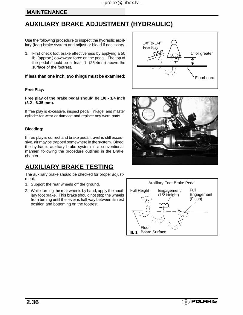
MAINTENANCE
2.36
AUXILIARY BRAKE ADJUSTMENT (HYDRAULIC)
Use the following procedure to inspect the hydraulic auxil-iary (foot) brake system and adjust or bleed if necessary.
1. First check foot brake effectiveness by applying a 50lb. (approx.) downward force on the pedal. The top ofthe pedal should be at least 1, (25.4mm) above thesurface of the footrest.
If less than one inch, two things must be examined:
Free Play:
Free play of the brake pedal should be 1/8 - 1/4 inch(3.2 - 6.35 mm).
If free play is excessive, inspect pedal, linkage, and mastercylinder for wear or damage and replace any worn parts.
Bleeding:
If free play is correct and brake pedal travel is still exces-sive, air may be trapped somewhere in the system. Bleedthe hydraulic auxiliary brake system in a conventionalmanner, following the procedure outlined in the Brakechapter.
AUXILIARY BRAKE TESTINGThe auxiliary brake should be checked for proper adjust-ment.1. Support the rear wheels off the ground.
2. While turning the rear wheels by hand, apply the auxil-iary foot brake. This brake should not stop the wheelsfrom turning until the lever is half way between its restposition and bottoming on the footrest.
50 lbs 1″ or greater
1/8″ to 1/4″Free Play
Floorboard
Auxiliary Foot Brake Pedal
FloorBoard Surface
Full Height Engagement(1/2 Height)
FullEngagement(Flush)
Ill. 1
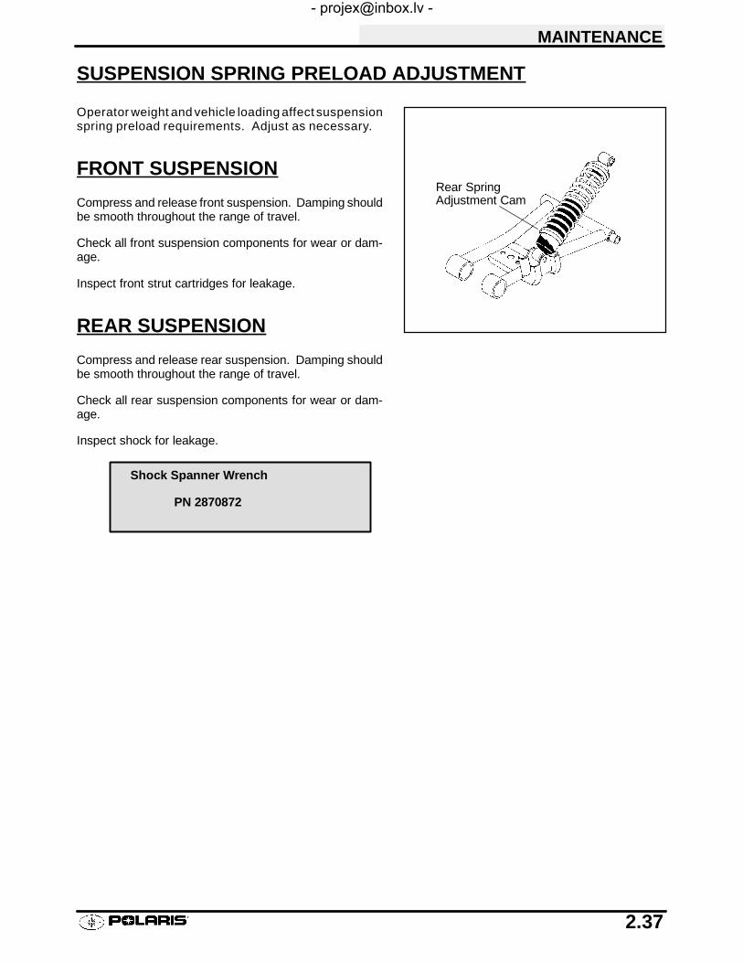
MAINTENANCE
2.37
SUSPENSION SPRING PRELOAD ADJUSTMENT
Operator weight and vehicle loading affect suspensionspring preload requirements. Adjust as necessary.
FRONT SUSPENSION
Compress and release front suspension. Damping shouldbe smooth throughout the range of travel.
Check all front suspension components for wear or dam-age.
Inspect front strut cartridges for leakage.
REAR SUSPENSION
Compress and release rear suspension. Damping shouldbe smooth throughout the range of travel.
Check all rear suspension components for wear or dam-age.
Inspect shock for leakage.
Rear SpringAdjustment Cam
Shock Spanner Wrench
PN 2870872

MAINTENANCE
2.38
CONTROLS
Check controls for proper operation, positioning andadjustment.
Brake control and switch must be positioned to allow brakelever to travel throughout entire range without contactingswitch body.
Align throttle control assembly clamp with knurl on handle-bar
Spacer Tab
Throttleassemblyclamp
Align clampedge withknurl

MAINTENANCE
2.39
WHEELS
Inspect all wheels for runout or damage. Check wheel nutsand ensure they are tight. Do not over tighten the wheelnuts.
WHEEL, HUB, AND SPINDLE TORQUE TABLE
Item Specification
Front Wheel Nuts 20 Ft. Lbs.
Rear Wheel Nuts 20 Ft. Lbs.
Front Spindle Nut Refer to procedure listed in Chapter 7
Rear Hub Retaining Nut 100 Ft. Lbs.
WHEEL REMOVAL FRONT OR REAR1. Stop the engine, place the transmission in gear
and lock the parking brake.2. Loosen the wheel nuts slightly.3. Elevate the side of the vehicle by placing a
suitable stand under the footrest frame.4. Remove the wheel nuts and remove the wheel.
WHEEL INSTALLATION1. With the transmission in gear and the parking brake
locked, place the wheel in the correct position on thewheel hub. Be sure the valve stem is toward theoutside and rotation arrows on the tire point towardforward rotation.
2. Attach the wheel nuts and finger tighten them.3. Lower the vehicle to the ground.4. Securely tighten the wheel nuts to the proper torque
listed in the table above.
CAUTION:
If wheels are improperly installed it could affect vehiclehandling and tire wear. On vehicles with tapered rearwheel nuts, make sure tapered end of nut goes into taperon wheel.
Flange Nuts:Flat side against wheel

MAINTENANCE
2.40
TIRE PRESSURE
Tire Pressure Inspection (PSI - Cold)
Front Rear
5 5
TIRE INSPECTION
CAUTION:
S Maintain proper tire pressure. Refer to the warning tirepressure decal applied to the vehicle.
S Improper tire inflation may affect ATV maneuverability.
S When replacing a tire always use original equipmentsize and type.
S The use of non-standard size or type tires may affectATV handling.
Tire Tread Depth
Alwaysreplacetireswhentreaddepth is wornto1/8″ (3mm) or less.
WARNINGOperating an ATV with worn tires will increase the possibility ofthe vehicle skidding easily with possible loss of control.
Worn tires can cause an accident.
Always replace tires when the tread depth measures 1/8″ (.3 cm)or less.
FRAME, NUTS, BOLTS, FASTENERS
Periodically inspect the tightness of all fasteners in accor-dance with the maintenance schedule. Check that all cot-ter pins are in place. Refer to specific fastener torqueslisted in each chapter.
TreadDepth 1/8I (3 mm)

3
CHAPTER 3ENGINE
Torque Specifications 3.1. . . . . . . . . . . . . . . . . . . . . . . . . . . .Torque Patterns 3.2. . . . . . . . . . . . . . . . . . . . . . . . . . . . . . . . .Piston Identification 3.3. . . . . . . . . . . . . . . . . . . . . . . . . . . . . .Engine Service Data 3.4-3.5. . . . . . . . . . . . . . . . . . . . . . . . . . . . .Cooling System Pressure Test 3.6. . . . . . . . . . . . . . . . . . . .Cooling System Specifications 3.7. . . . . . . . . . . . . . . . . . . .Engine Removal 3.8-3.9. . . . . . . . . . . . . . . . . . . . . . . . . . . . . . . . .Engine Installation Notes 3.10. . . . . . . . . . . . . . . . . . . . . . . . .Cylinder Honing 3.11. . . . . . . . . . . . . . . . . . . . . . . . . . . . . . . . .Crankshaft Runout Inspection 3.12. . . . . . . . . . . . . . . . . . . . .EH42PL / EH50PL Engine Lubrication 3.13. . . . . . . . . . . . .EH42PL / EH50PL Oil Pump Priming Procedure 3.13. . . . .EH42PL / EH50PL Lubrication/Oil Flow 3.14-3.15. . . . . . . . . . . .EH42PL / EH50PL Engine Exploded View 3.16. . . . . . . . . .EH42Pl / EH50PL Engine Top End Disassembly 3.17-3.30. . . . .EH42PL / EH50PL Valve Seat Service 3.31-3.35. . . . . . . . . . . . .EH42PL / EH50PL Cylinder Head Assembly 3.35-3.36. . . . . . . .EH42PL / EH50PL Engine Bottom End Disassembly 3.37-3.54.EH42PL / EH50PL Crankcase & Bearing Assembly 3.55. .EH42PL / EH50PL Crankshaft End Play Inspection 3.56-3.57. .EH42PL / EH50PL Counter Balancer End Play Insp.. 3.58EH42PL / EH50PL Oil Pump Shaft End Play Insp. 3.59. . .EH42PL / EH50PL Engine Assembly/Inspection 3.60-3.73. . . . .Sealed Recoil Disassembly/Inspection 3.74-3.75. . . . . . . . . . . . .Sealed Recoil Assembly 3.76. . . . . . . . . . . . . . . . . . . . . . . . . .Spark Plug Fouling Checklist 3.77. . . . . . . . . . . . . . . . . . . . . .Troubleshooting 3.78-3.80. . . . . . . . . . . . . . . . . . . . . . . . . . . . . . . . .
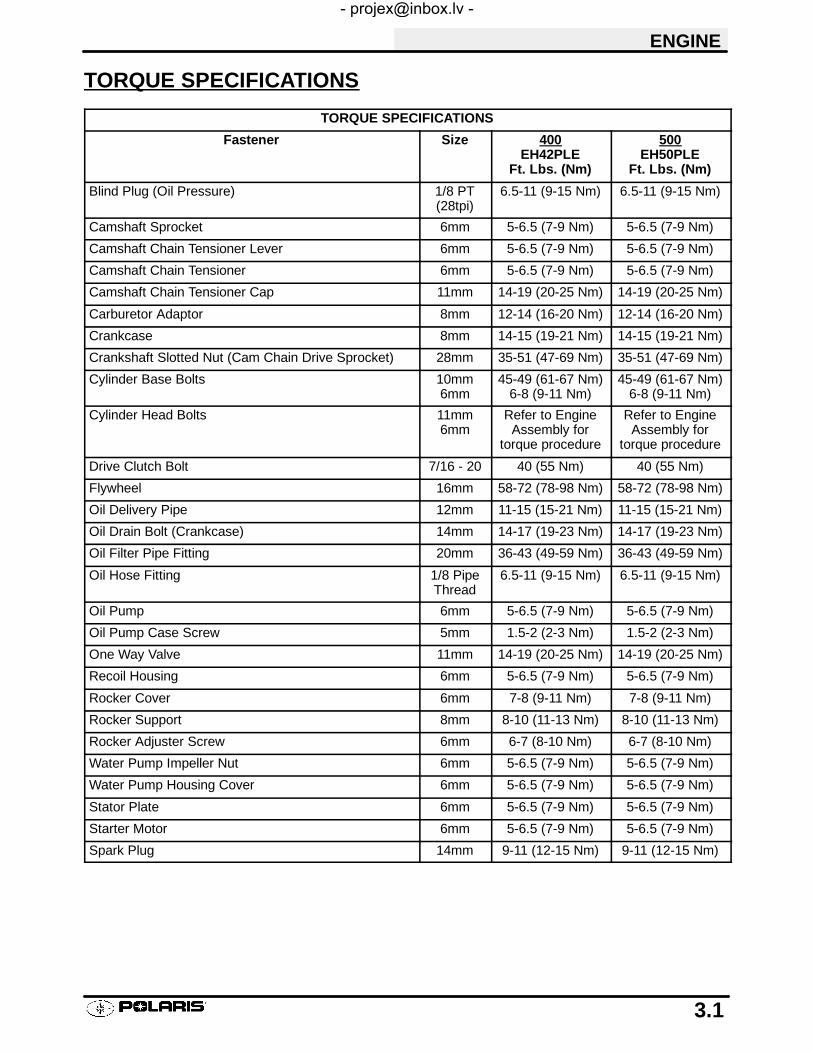
ENGINE
3.1
TORQUE SPECIFICATIONS
TORQUE SPECIFICATIONS
Fastener Size 400EH42PLE
Ft. Lbs. (Nm)
500EH50PLE
Ft. Lbs. (Nm)
Blind Plug (Oil Pressure) 1/8 PT(28tpi)
6.5-11 (9-15 Nm) 6.5-11 (9-15 Nm)
Camshaft Sprocket 6mm 5-6.5 (7-9 Nm) 5-6.5 (7-9 Nm)
Camshaft Chain Tensioner Lever 6mm 5-6.5 (7-9 Nm) 5-6.5 (7-9 Nm)
Camshaft Chain Tensioner 6mm 5-6.5 (7-9 Nm) 5-6.5 (7-9 Nm)
Camshaft Chain Tensioner Cap 11mm 14-19 (20-25 Nm) 14-19 (20-25 Nm)
Carburetor Adaptor 8mm 12-14 (16-20 Nm) 12-14 (16-20 Nm)
Crankcase 8mm 14-15 (19-21 Nm) 14-15 (19-21 Nm)
Crankshaft Slotted Nut (Cam Chain Drive Sprocket) 28mm 35-51 (47-69 Nm) 35-51 (47-69 Nm)
Cylinder Base Bolts 10mm6mm
45-49 (61-67 Nm)6-8 (9-11 Nm)
45-49 (61-67 Nm)6-8 (9-11 Nm)
Cylinder Head Bolts 11mm6mm
Refer to EngineAssembly for
torque procedure
Refer to EngineAssembly for
torque procedure
Drive Clutch Bolt 7/16 - 20 40 (55 Nm) 40 (55 Nm)
Flywheel 16mm 58-72 (78-98 Nm) 58-72 (78-98 Nm)
Oil Delivery Pipe 12mm 11-15 (15-21 Nm) 11-15 (15-21 Nm)
Oil Drain Bolt (Crankcase) 14mm 14-17 (19-23 Nm) 14-17 (19-23 Nm)
Oil Filter Pipe Fitting 20mm 36-43 (49-59 Nm) 36-43 (49-59 Nm)
Oil Hose Fitting 1/8 PipeThread
6.5-11 (9-15 Nm) 6.5-11 (9-15 Nm)
Oil Pump 6mm 5-6.5 (7-9 Nm) 5-6.5 (7-9 Nm)
Oil Pump Case Screw 5mm 1.5-2 (2-3 Nm) 1.5-2 (2-3 Nm)
One Way Valve 11mm 14-19 (20-25 Nm) 14-19 (20-25 Nm)
Recoil Housing 6mm 5-6.5 (7-9 Nm) 5-6.5 (7-9 Nm)
Rocker Cover 6mm 7-8 (9-11 Nm) 7-8 (9-11 Nm)
Rocker Support 8mm 8-10 (11-13 Nm) 8-10 (11-13 Nm)
Rocker Adjuster Screw 6mm 6-7 (8-10 Nm) 6-7 (8-10 Nm)
Water Pump Impeller Nut 6mm 5-6.5 (7-9 Nm) 5-6.5 (7-9 Nm)
Water Pump Housing Cover 6mm 5-6.5 (7-9 Nm) 5-6.5 (7-9 Nm)
Stator Plate 6mm 5-6.5 (7-9 Nm) 5-6.5 (7-9 Nm)
Starter Motor 6mm 5-6.5 (7-9 Nm) 5-6.5 (7-9 Nm)
Spark Plug 14mm 9-11 (12-15 Nm) 9-11 (12-15 Nm)
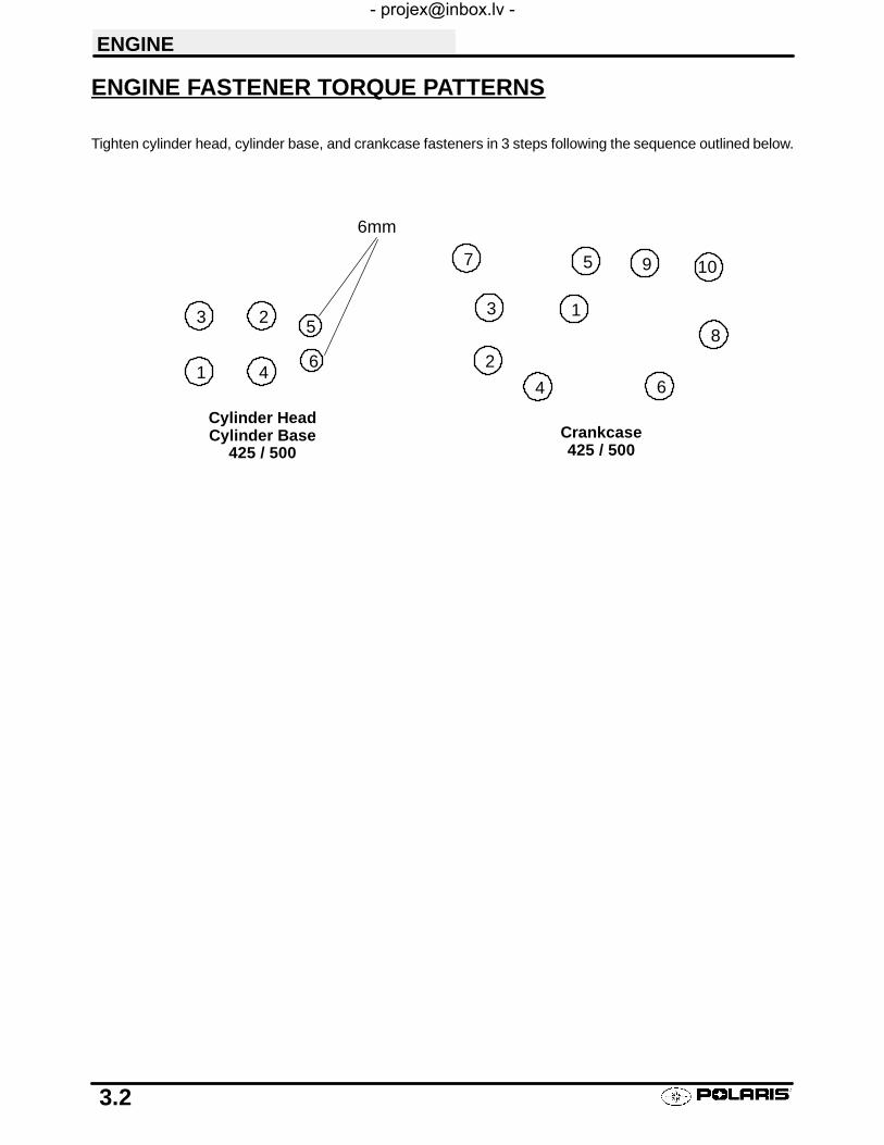
ENGINE
3.2
ENGINE FASTENER TORQUE PATTERNS
Tighten cylinder head, cylinder base, and crankcase fasteners in 3 steps following the sequence outlined below.
6mm
1
23
46
5
Cylinder HeadCylinder Base
425 / 500Crankcase425 / 500
1
2
3
4
97
6
8
5 10

ENGINE
3.3
PISTON IDENTIFICATION
Note the directional and identification marks when viewing the pistons from the top. The letter “F”, “! ”, “"” or :must always be toward the flywheel side of the engine. The other numbers are used for identification as todiameter, length and design. Four stroke engine rings are rectangular profile. See text for oil control ring upper railinstallation. Use the information below to identify pistons and rings.
Engine Model No. Oversize Available*(mm)
Piston Length Standard PistonIdentification
EH42PLE05 .25.50
66mm B
EH50PLE09/13 .25.50
72mm C
*Pistons and rings marked 25 equal .25mm (.010I) oversizedPistons and rings marked 50 equal .50mm (.020I) oversized

ENGINE
3.4
ENGINE SERVICE DATA
Cylinder Head / Valve EH42PLE05 EH50PLE09/13Rocker Arm Rocker arm ID .8669-.8678″ (22.020-22.041 mm) .8669-.8678″ (22.020-22.041 mm)
Rocker shaft OD .8656-.8661″ (21.987-22.0 mm) .8656-.8661″ (21.987-22.0 mm)
Rocker shaft Oil Clearance Std .0008-.0021″ (.020-.054 mm) .0008-.0021″ (.020-.054 mm)
Limit .0039″ (.10 mm) .0039″ (.10 mm)
Camshaft Cam lobe height In Std 1.2884-1.2924″ (32.726-32.826 mm) 1.2884-1.2924″ (32.726-32.826 mm)g
Limit 1.2766″ (32.426 mm) 1.2766″ (32.426 mm)
Ex Std 1.2884-1.2924″ (32.726-32.826 mm) 1.2884-1.2924″ (32.726-32.826 mm)
Limit 1.2766″ (32.426 mm) 1.2766″ (32.426 mm)
Camshaft journal OD Mag 1.4935-1.4941″ (37.935-37.950 mm) 1.4935-1.4941″ (37.935-37.950 mm)j
PTO 1.4935-1.4941″ (37.935-37.950 mm) 1.4935-1.4941″ (37.935-37.950 mm)
Camshaft journal bore ID Mag 1.4963-1.4970″ (38.005-38.025 mm) 1.4963-1.4970″ (38.005-38.025 mm)j
PTO 1.4963-1.4970″ (38.005-38.025 mm) 1.4963-1.4970″ (38.005-38.025 mm)
Camshaft Oil clearance Std .0022-.0035″ (.055-.090 mm) .0022-.0035″ (.055-.090 mm)
Limit .0039″ (.10 mm) .0039″ (.10 mm)
Cylinder Head Surface warpage limit .0020″ (.05 mm) .0020″ (.05 mm)y
Standard height 3.870″ (98.3 mm) 3.870″ (98.3 mm)
Valve Seat Contacting width In Std .028″ (.7 mm) .028″ (.7 mm)g
Limit .055″ (1.4 mm) .055″ (1.4 mm)
Ex Std .039″ (1.0 mm) .039″ (1.0 mm)
Limit .071″ (1.8 mm) .071″ (1.8 mm)
Valve Guide Inner diameter .2362-.2367″ (6.0-6.012 mm) .2362-.2367″ (6.0-6.012 mm)
Protrusion above head .689-.709″ (17.5-18.0 mm) .689-.709″ (17.5-18.0 mm)
Valve Margin thickness In Std .039″ (1.0 mm) .039″ (1.0 mm)g
Limit .031″ (.8 mm) .031″ (.8 mm)
Ex Std .047″ (1.2 mm) .047″ (1.2 mm)
Limit .031″ (.8 mm) .031″ (.8 mm)
Valve Stem diameter In .2343-.2348″ (5.950-5.965 mm) .2343-.2348″ (5.950-5.965 mm)
Ex .2341-.2346″ (5.945-5.960 mm) .2341-.2346″ (5.945-5.960 mm)
Stem oil clearance Std In .0014-.0024″ (.035-.062 mm) .0014-.0024″ (.035-.062 mm)
Ex .0016-.0026″ (.040-.067 mm) .0016-.0026″ (.040-.067 mm)
Limit .0059″ (.15 mm) .0059″ (.15 mm)
Overall length In 3.976″ (101.0 mm) 3.976″ (101.0 mm)g
Ex 3.984″ (101.2 mm) 3.984″ (101.2 mm)
Valve Spring Overall length Std 1.654″ (42.0 mm) 1.654″ (42.0 mm)p g g
Limit 1.575″ (40.0 mm) 1.575″ (40.0 mm)
Squareness .075″ (1.9 mm) .075″ (1.9 mm)

ENGINE
3.5
ENGINE SERVICE DATA
Cylinder / Piston / Connecting Rod EH42PLE05 EH50PLE09/13Cylinder Surface warpage limit (mating with cylinder head) .0020″ (.05 mm) .0020″ (.05 mm)y
Cylinder bore Std 3.4606-3.614″ (87.900-87.920 mm) 3.6216-3.6224″ (91.99-92.01 mm)
Taper limit .0020″ (.050 mm) .0020″ (.050 mm)
Out of round limit .0020″ (.050 mm) .0020″ (.050 mm)
Piston clearance Std .0006-.0018″ (.015-.045 mm) .0006-.0018″ (.015-.045 mm)
Limit .0024″ (.060 mm) .0024″ (.060 mm)
Boring limit .020″ (.5 mm) .020″ (.5 mm)
Piston Outer diameter Std 3.4596-3.4600″ (87.875-87.885 mm) 3.6206-3.6210″ (91.96-91.97 mm)
.0098″ (.25 mm) OS 3.4695-3.4699″ (88.125-88.135 mm) 3.6304-3.6310″ (92.21-92.23 mm)
.0197″ (.50 mm) OS 3.4793-3.4797″ (88.375-88.385 mm) 3.6403-3.6407″ (92.46-92.47 mm)
Standard inner diameter of piston pin bore .9055-.9057″ (23.0-23.006 mm) .9055-.9057″ (23.0-23.006 mm)
Piston Pin Outer diameter .9053-.9055″ (22.994-23.0 mm) .9053-.9055″ (22.994-23.0 mm)
Standard clearance-piston pin to pin bore .0002-.0003″ (.004-.008 mm) .0002-.0003″ (.004-.008 mm)
Degree of fit Piston pin must be a push (by hand) fit at 68° F (20° C)
Piston Ring Piston ring installed gap Top ring Std .0079-.0138″ (.20-.36 mm) .0079-.0138″ (.20-.36 mm)g g g p p g
Limit .039″ (1.0 mm) .039″ (1.0 mm)
Secondi
Std .0079-.0138″ (.20-.36 mm) .0079-.0138″ (.20-.36 mm)ring Limit .039″ (1.0 mm) .039″ (1.0 mm)
Oil ring Std .0079-.0276″ (.20-.70 mm) .0079-.0276″ (.20-.70 mm)g
Limit .059″ (1.5 mm) .059″ (1.5 mm)
Piston Ring Standard clearance -i i i
Top ring Std .0016-.0031″ (.040-.080 mm) .0016-.0031″ (.040-.080 mm)gpiston ring to ring groove
p g
Limit .0059″ (.15 mm) .0059″ (.15 mm)
Secondi
Std .0012-.0028″ (.030-.070 mm) .0012-.0028″ (.030-.070 mm)ring Limit .0059″ (.15 mm) .0059″ (.15 mm)
ConnectingR d
Connecting rod small end ID .9058-.9063″ (23.007-23.020 mm) .9058-.9063″ (23.007-23.020 mm)gRod Connecting rod small end radial clear- Std .0003-.0010″ (.007-.026 mm) .0003-.0010″ (.007-.026 mm)g
ance Limit .0020″ (.05 mm) .0020″ (.05 mm)
Connecting rod big end side clearance Std .0039-.0256″ (.1-.65 mm) .0039-.0256″ (.1-.65 mm)g g
Limit .0315″ (.80 mm) .0315″ (.80 mm)
Connecting rod big end radial clear- Std .0004-.0015″ (.011-.038 mm) .0004-.0015″ (.011-.038 mm)g gance Limit .0020″ (.05 mm) .0020″ (.05 mm)
Crankshaft Crankshaft runout limit .0024″ (.06 mm) .0024″ (.06 mm)
KEY - Std: Standard; OS: Oversize; ID: Inner Diameter; OD: Outer Diameter; Mag: Magneto Side; PTO: PowerTake Off Side

ENGINE
3.6
COOLING SYSTEMWARNING: Never remove radiator cap when engine is warm or hot. The cooling system is under pressure andserious burns may result. Allow the engine and cooling system to cool before servicing.
Radiator
Thermostat
CylinderHead
WaterPump
Cylinder
FLOW System Pressure Test
1. Remove front cover.2. Remove recovery bottle hose from coolant
filler.3. Connect a Mity Vac™ (PN 2870975) to
radiator and pressurize system to 10 PSI. Thesystem must retain 10 lbs of pressure for fiveminutes or longer. If pressure loss is evidentwithin five minutes, check radiator, all coolingsystem hoses and clamps, or water pumpseal.
Radiator Cap Pressure Test
1. Remove radiator cap and test using a captester (commercially available).
2. The radiator cap relief pressure is 13 lbs.
RadiatorLeft SideView
RadiatorFrontView
Top
Bottom

ENGINE
3.7
COOLING SYSTEM, CONT.
RECOMMENDED COOLANT
Use only high quality antifreeze/coolant mixed with dis-tilled water in a 50/50 or 60/40 ratio, depending onfreeze protection required in your area. CAUTION:Using tap water in the cooling system will lead to abuildup of deposits which may restrict coolant flow andreduce heat dissipation, resulting in possible enginedamage. Polaris Premium 60/40 Antifreeze/Coolant isrecommended for use in all cooling systems, andcomes pre-mixed and ready to use.
COOLING SYSTEM SPECIFICATIONS
Fan Switch (Off)Fan Switch (On)
149° F (65° C) ± 8°180° F (82° C) ± 3°
Hot Light On 221° F (105° C)
System Capacity 2.25 Quarts
Radiator Cap Relief Pressure 13 PSI
Thermostat Starts opening 176° F (80° C)Open 8mm @ 205° F (96° C)

ENGINE
3.8
ACCESSIBLE COMPONENTSThe following components can be serviced or removed with the engine installed in the frame:
S Flywheel
S Alternator/Stator
S Starter Motor/Starter Drive
S Cylinder Head
S Cylinder
S Piston/RIngs
S Camshaft
S Rocker Arms
S Cam Chain and Sprockets
S Water Pump / Water Pump Mechanical Seal*
The following components require engine removal for service:
S Oil pump / Oil Pump Drive Gear
S Counterbalance Shaft or Bearing(s)
S Connecting Rod
S Crankshaft
S Crankshaft Main Bearings
S Crankcase
*It may be necessary to loosen engine mounts and move engine slightly to access water pump. Special tool PN2872105 is required to replace mechanical seal with engine in frame.

ENGINE
3.9
ENGINE REMOVAL (TYPICAL)
1. Clean work area.
2. Thoroughly clean the ATV engine and chassis.
3. Disconnect battery negative (-) cable.
4. Remove the following parts as required.S SeatS Left and Right Side Covers (Refer to Chapter 5)
S Fuel Tank Cover / Front Cab (Refer to Chapter 5)S Fuel Tank (Refer to Chapter 4)
5. Disconnect spark plug high tension lead.
6. Remove springs from exhaust pipe and remove pipe.
7. Drain coolant and engine oil.
8. Remove air pre-cleaner and duct.
9. Remove airbox.
10. Remove carburetor. Insert a shop towel into thecarburetor flange to prevent dirt from entering theintake port.
11. Refer to PVT System to remove outer clutch cover,drive belt, drive clutch, driven clutch, and inner cover.
12. Starter motor. Note ground cable location. Markpositive (+) cable mounting angle and remove cable.
13. Remove transmission linkage rods from gear selectorand secure out of the way.
14. Disconnect coolant temperature sensor wire.
15. Remove engine to chassis ground cable.
16. Remove all engine mount nuts and / or engine mountplates.
17. Remove engine through right side of frame.

ENGINE
3.10
ENGINE INSTALLATION NOTES
After the engine is installed in the frame, review this checklist and perform all steps that apply.
General Items1. Install previously removed components using new gaskets, seals, and fasteners where applicable.2. Perform regular checks on fluid levels, controls, and all important areas on the vehicle as outlined in the daily
pre-ride inspection checklist (refer to Chapter 2 or the Owner’s Safety and Maintenance Manual).
PVT System1. Adjust center distance of drive and driven clutch. (Chapter 6)2. Adjust clutch offset, alignment, and belt deflection. (Chapter 6)3. Clean clutch sheaves thoroughly and inspect inlet and outlet ducts for proper routing and sealing. (Chapter 6)
Transmission1. Inspect transmission operation and adjust linkage if necessary. Refer to Chapter 2 and Chapter 8.
Exhaust1. Replace exhaust gaskets. Seal connections with high temp silicone sealant.2. Check to be sure all springs are in good condition.
Bleed Cooling System1. Remove radiator cap and slowly add coolant to top of filler neck.2. Fill coolant reservoir tank to full mark.3. Install radiator cap and squeeze coolant lines to force air out of system.
4. Again remove radiator cap and slowly add coolant to top of fill neck.5. Start engine and observe coolant level in the radiator. Allow air to purge and top off as necessary. Reinstall
radiator cap and bring engine to operating temp. Check level in reservoir tank after engine is cool and addcoolant if necessary.
Engine Break In Period
4 Cycle Engine Break-In Period is defined as the first 10 hours of engine operation, or 2 full tanks of fuel.1. Use only Polaris Premium 4 All Season synthetic oil, or API certified “SH” oil. Never substitute or mix oil
brands. Serious engine damage can result.2. Use fuel with a minimum octane of 87 (R+M)/2 method.3. Change break-in oil and filter at 20 hours or 500 miles, whichever comes first.

ENGINE
3.11
CYLINDER HONE SELECTION/HONING PROCEDURESelecting a hone which will straighten as well as remove material from the cylinder is very important. Using acommon spring loaded finger type glaze breaker for honing is never advised. Polaris recommends using a rigidhone or arbor honing machine which also has the capability of oversizing.
Cylinders may be wet or dry honed depending upon the hone manufacturer’s recommendations. Wet honing re-moves more material faster and leaves a more distinct pattern in the bore.
CAUTION:
HONING TO OVERSIZEIf cylinder wear or damage is excessive, it will be nec-essary to oversize the cylinder using a new oversizepiston and rings. This may be accomplished by eitherboring the cylinder and then finish honing to the finalbore size, or by rough honing followed by finish honing.
For oversize honing always wet hone using honing oiland a coarse roughing stone. Measure the piston (seepiston measurement) and rough hone to the size of thepiston. Always leave .002 - .003″ (.05 - .07 mm) for fin-ish honing. Refer to piston-to-cylinder clearancespec-ifications on page 3.5 before honing. Complete the siz-ing with fine grit stones to provide the propercross-hatch finish and required piston clearance.
A finished cylinder should have a cross-hatch pattern to ensure piston ring seating and to aid in the retention ofthe fuel/oil mixture during initial break in. Hone cylinder according to hone manufacturer’s instructions, or theseguidelines:
S Use a motor speed of approximately 300-500 RPM, run the hone in and out of the cylinder rapidly until cuttingtension decreases. Remember to keep the hone drive shaft centered (or cylinder centered on arbor) and tobring the stone approximately 1/2″ (1.3 cm) beyond the bore at the end of each stroke.
S Release the hone at regular intervals and inspect the bore to determine if it has been cleared, and to checkpiston fit. NOTE: Do not allow cylinder to heat up during honing. The thinner areas of the liner around theports will expand causing uneven bore.
S After honing has been completed inspect all port opening areas for rough or sharp edges. Apply a slight cham-fer to all ports to remove sharp edges or burrs, paying particular attention to the corners of the intake andexhaust ports.
IMPORTANT:
CLEANING THE CYLINDER AFTER HONINGIt is very important that the cylinder be thoroughly cleaned after honing to remove all grit material. Wash the cylinderin a solvent, then in hot, soapy water. Pay close attention to areas where the cylinder sleeve meets the aluminumcasting (transfer port area). Use electrical contact cleaner if necessary to clean these areas. Rinse thoroughly,dry with compressed air, and oil the bore immediately with Polaris 2 Cycle Lubricant.
EXAMPLE OF CROSS HATCH PATTERN
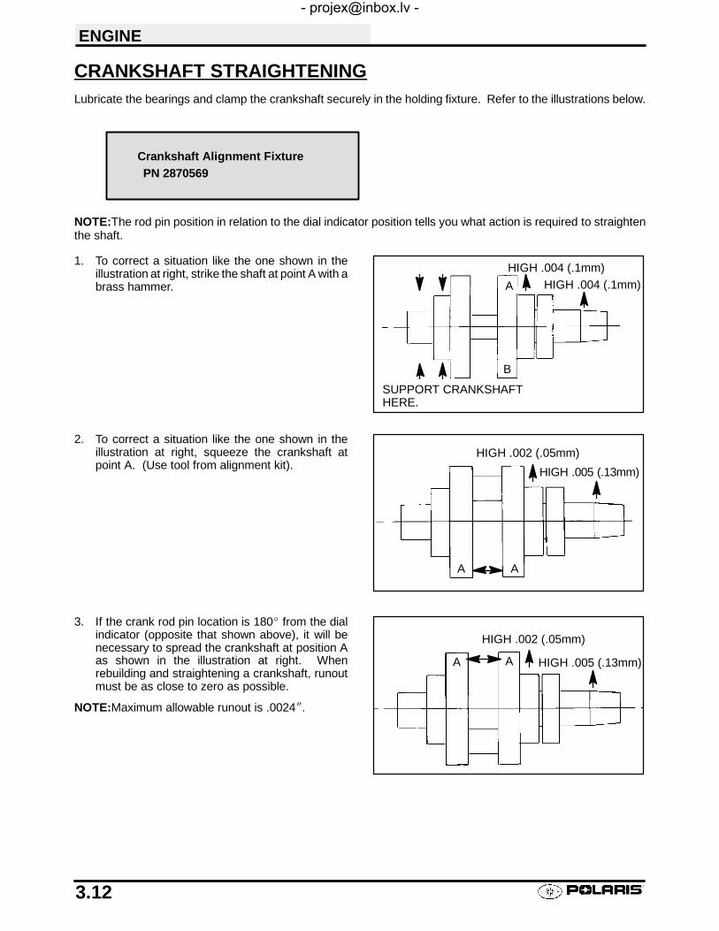
ENGINE
3.12
CRANKSHAFT STRAIGHTENINGLubricate the bearings and clamp the crankshaft securely in the holding fixture. Refer to the illustrations below.
NOTE:The rod pin position in relation to the dial indicator position tells you what action is required to straightenthe shaft.
1. To correct a situation like the one shown in theillustration at right, strike the shaft at point A with abrass hammer.
2. To correct a situation like the one shown in theillustration at right, squeeze the crankshaft atpoint A. (Use tool from alignment kit).
3. If the crank rod pin location is 180_ from the dialindicator (opposite that shown above), it will benecessary to spread the crankshaft at position Aas shown in the illustration at right. Whenrebuilding and straightening a crankshaft, runoutmust be as close to zero as possible.
NOTE:Maximum allowable runout is .0024I.
Crankshaft Alignment FixturePN 2870569
A
B
HIGH .004 (.1mm)HIGH .004 (.1mm)
SUPPORT CRANKSHAFTHERE.
A A
HIGH .002 (.05mm)
HIGH .005 (.13mm)
A
HIGH .002 (.05mm)
HIGH .005 (.13mm)A
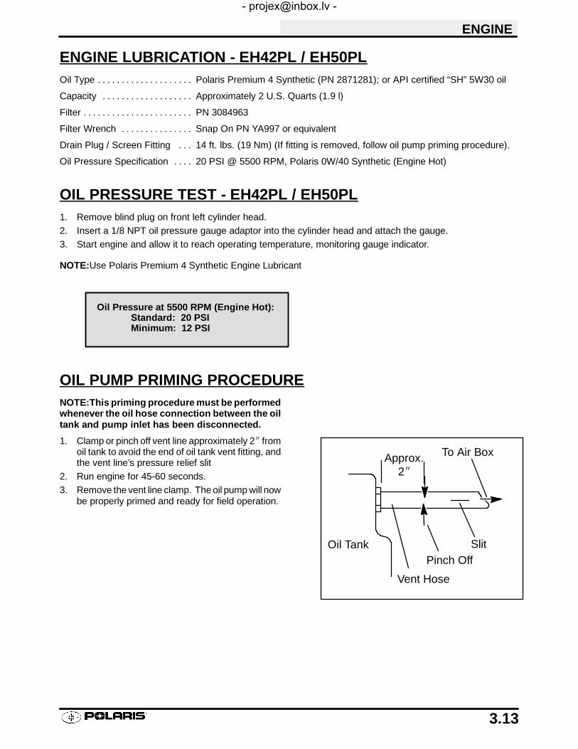
ENGINE
3.13
ENGINE LUBRICATION - EH42PL / EH50PLOil Type Polaris Premium 4 Synthetic (PN 2871281); or API certified “SH” 5W30 oil. . . . . . . . . . . . . . . . . . . .
Capacity Approximately 2 U.S. Quarts (1.9 l). . . . . . . . . . . . . . . . . . .
Filter PN 3084963. . . . . . . . . . . . . . . . . . . . . . .
Filter Wrench Snap On PN YA997 or equivalent. . . . . . . . . . . . . . .
Drain Plug / Screen Fitting 14 ft. lbs. (19 Nm) (If fitting is removed, follow oil pump priming procedure).. . .
Oil Pressure Specification 20 PSI @ 5500 RPM, Polaris 0W/40 Synthetic (Engine Hot). . . .
OIL PRESSURE TEST - EH42PL / EH50PL1. Remove blind plug on front left cylinder head.2. Insert a 1/8 NPT oil pressure gauge adaptor into the cylinder head and attach the gauge.3. Start engine and allow it to reach operating temperature, monitoring gauge indicator.
NOTE:Use Polaris Premium 4 Synthetic Engine Lubricant
OIL PUMP PRIMING PROCEDURENOTE:This priming procedure must be performedwhenever the oil hose connection between the oiltank and pump inlet has been disconnected.
1. Clamp or pinch off vent line approximately 2I fromoil tank to avoid the end of oil tank vent fitting, andthe vent line’s pressure relief slit
2. Run engine for 45-60 seconds.3. Remove the vent line clamp. The oil pump will now
be properly primed and ready for field operation.
Oil Pressure at 5500 RPM (Engine Hot):Standard: 20 PSIMinimum: 12 PSI
SlitOil Tank
Vent Hose
To Air Box
Pinch Off
2IApprox.

ENGINE
3.14
OIL FLOW -- EH42PL / EH50PLThe chart on page 3.15 describes the flow of oil through the EH50PL engine. Beginning at the oil tank, the oilflows through a screen fitting in the bottom of the tank and into the oil supply hose. The feed side of the oil pumpdraws oil through the hose and into the crankcase oil gallery, and then pumps the oil through another passageto the one way valve. (When the engine is off, the one way valve closes to prevent oil in the tank from draininginto the crankcase.) The oil is pumped through a delivery pipe to the oil filter. If the oil filter is obstructed, a bypassvalve contained in the filter allows oil to bypass the filter element.
At this point, the oil is diverted in two directions. Oil is supplied to the camshaft through the left front cylinder stud,and an oil passage in the head. Oil enters the camshaft through the PTO (L) journal. The camshaft journals, camlobes, and rocker arms are lubricated through holes in the camshaft. The oil lubricates the cam chain andsprocketand drains to the sump.
The other oil path from the filter leads through a delivery pipe to the crankcase main oil gallery, which leads tothe stator plate oil passage. Here it passes through the slotted friction bearing (located in the stator plate) intothe crankshaft. An oil seal on the stator plate prevents oil from entering the stator/flywheel area. Oil travelsthrough the crankshaft to the crank pin, lubricating the connecting rod large end bearing directly. Oil also passesthrough an oil jet (drilled orifice) in the end of the crank pin to the PTO end main bearings and counterbalancergears.
Residual oil from the lubrication of the crankshaft and connecting rod indirectly lubricates the cylinder wall, piston,rings, connecting rod small end bearing, piston pin, oil/water pump drive gears, cam chain and drive sprocket,and Magneto end crankshaft main bearing.
The one-way valve is located on the front left (PTO) side of the crankcase. The valve prevents oil in the tank fromdraining into the engine sump when the engine is off. The valve mechanism consists of a plunger, return spring,guide plug, and sealing washer. When the engine is running, oil pressure lifts the plunger off the seat, allowingoil flow. When the engine is off, spring pressure forces the plunger against the oil passage seat, preventing oilflow from the tank to the sump. The one-way valve requires very little maintenance. If engine oil drains into thesump when the engine is off, inspect the valve sealing surface for debris or damage. Inspect the return springfor distortion or damage.

ENGINE
3.15
EH42PL / EH50PL OIL FLOW DIAGRAM
Oil TankOil Hose Crankcase
Oil GalleryOil Pump(Scavenging)
Oil Strainer
Oil Hose
CrankcaseOil Gallery
Oil Pump(Feed)
One Way Valve
Delivery Pipe
Bypass Oil Filter
Chain Room
Cam ShaftJournal
SprocketChain
Rocker ArmRocker Shaft
Cam Lobe
Cam ShaftJournal
Delivery Pipe
Delivery Pipe
Metal
CrankcaseOil Gallery
Crankcase
Small EndBearing
Cylinder Sleeve
Main Bearing(PTO)
Large EndBearing
Crank Pin
Crankshaft
Screen Fitting(Bottom of Tank)
EH42PL / EH50PL Oil Flow ChartTop of Oil Tank Union Fitting (Lower)
Oil Jet
Union Fitting(Upper)
Through CylinderStud Front Left
IndirectLubrication
Prevents oilfrom draininginto crankcasewith engine off
Bottom fitting is oilexhaust or returnto tank
Top fitting is oilfeed or intakefrom bottom oftank
One way valve
From filterto crankshaft
Oil feed tofilter
Oil filter
Internal passage tocamshaft (front lefthead bolt)
EH42PL / EH50PL Engine

ENGINE
3.16
EH42PL / EH50PL ENGINE EXPLODED VIEW
Crankcase Cylinder/CylinderHead
Crankshaftand Piston
Valve Train
A

ENGINE
3.17
ENGINE REMOVALREFER TO PAGE 3.8 - 3.10 FOR ENGINE REMOVAL / INSTALLATION NOTES.
CAM CHAIN TENSIONER/ROCKER ARM/CAMSHAFT REMOVAL1. Remove ignition timing inspection plug from recoil housing.
To position crankshaft at Top Dead Center(TDC) on compression stroke:
2. Rotate engine slowly in the direction of rotationwatching intake valves open and start to close.
3. Continue to rotate engine slowly, watchingcamshaft sprocket marks and the mark in the timinginspection hole.
4. Align single (TDC) mark on flywheel with projectionin inspection hole, and the cam sprocket pin (facingupward) aligned with the camshaft to crankshaftcenter line. NOTE: The cam lobe should bepointing down and valves should have clearance atthis point.
5. Remove cam chain tensioner plug, sealing washer,and spring. CAUTION: The plug is under springtension. Maintain inward pressure while removing.
6. Remove the two 6x25 mm cam chain tensionerflange bolts.
7. Tap lightly on tensioner body with a soft facehammer and remove tensioner.
Advance Marks
Rotation
TDC “T” Mark

ENGINE
3.18
CAM CHAIN TENSIONER INSPECTION1. Pull cam chain tensioner plunger outward to the end
of its travel. Inspect teeth on ratchet pawl (A) andplunger teeth (B) for wear or damage.
2. Push ratchet pawl and hold it. The plunger shouldmove smoothly in and out of the tensioner body.
3. Release ratchet pawl and push inward on plunger. Itshould remain locked in position and not moveinward.
4. Measure free length of tensioner spring. Replacespring if excessively worn. Compare tospecifications.
5. Replace entire tensioner assembly if any part isworn or damaged.
BA
Tensioner Spring Free Length:
2.320I (5.9 cm)

ENGINE
3.19
ROCKER ARM/SHAFT INSPECTION1. Mark or tag rocker arms to keep them in order for
assembly.
2. Inspect each rocker arm cam follower surface. Ifthere is any damage or uneven wear, replace therocker arm. NOTE: Always inspect camshaft lobe ifrocker arms are worn or damaged.
3. Measure O.D. of rocker shaft. Inspect it for wear ordamage. Compare to specifications.
Rocker Shaft O.D.:
.8656-.8661I (21.987-22.0 mm)

ENGINE
3.20
ROCKER ARM/SHAFT INSPECTION, CONT.
4. Measure I.D. of each rocker arm and compare tospecifications.
5. Measure I.D. of both rocker arm shaft supports andvisually inspect surface. Compare to specifications.
6. Subtract rocker shaft O.D. from rocker arm & shaftsupport I.D. This is the oil clearance. Compare tospecifications.
7. Inspect rocker adjuster screws for wear, pitting, ordamage to threads of the adjuster or locknut.Replace all worn or damaged parts. NOTE: Theend of the adjuster screw is hardened and cannot beground or re-faced.
Rocker Arm & Support I.D.:
.8669-.8678I (22.020-22.041 mm)
Rocker Shaft Oil Clearance:
Std: .0008-.0021I (.020-.054 mm)Limit: .0039I (.10 mm)

ENGINE
3.21
CAMSHAFT REMOVAL1. Remove thermostat housing.2. Remove camshaft sprocket inspection cover.3. Loosen three camshaft sprocket bolts.
4. Remove camshaft end cap and O-Ring.
5. Inspect camshaft end cap (thrust face) for wear.Replace if worn or damaged.

ENGINE
3.22
CAMSHAFT REMOVAL, CONT.6. Place a clean shop towel in the area below cam
chain sprocket and remove sprocket retaining bolts.
7. Slide camshaft inward to allow removal of camsprocket and remove sprocket from camshaft andchain.
8. Secure cam chain with a wire to prevent it fromfalling into the crankcase.
9. Inspect cam sprocket teeth for wear or damage.Replace if necessary.
10. Slide camshaft out the PTO side of the cylinderhead.
Inspect for Areas ofTooth Wear or Damage
Decompressor Ball
Retainer Sleeve
Decompressor Shaft

ENGINE
3.23
AUTOMATIC COMPRESSION RELEASE REMOVAL/INSPECTIONNOTE: The automatic compression release mecha-nism can be inspected and serviced without removingthe camshaft from the cylinder head. The actuator ballin the camshaft is not replaceable. Replace the cam-shaft as an assembly if the actuator ball is worn or dam-aged.
1. Check release lever shaft for smooth operationthroughout the entire range of rotation. The springshould hold the shaft weight against the stop pin.In this position, the actuator ball will be heldoutward in the compression release mode.
2. Remove release lever shaft and return spring.
3. Inspect shaft for wear or galling.4. Inspect lobe on end of release lever shaft and
actuator ball for wear and replace if necessary.
AUTOMATIC COMPRESSION RELEASE INSTALLATION1. Slide spring onto shaft.2. Apply engine oil to release lever shaft.
The actuator ball must be held outward to allow instal-lation of the release lever shaft.
If Camshaft Is Removed From Engine:
3. Turn the camshaft until the actuator ball is in thelowest position and install the release lever shaft.
If Camshaft Is Installed In The Engine:
4. Use a small magnet to draw the actuator balloutward, or rotate the engine until the cam lobesface upward and install release lever shaft.
5. Position camshaft as shown at bottom ofillustration at right.
6. Place arm of spring under stop pin as shown andpush release lever inward until fully seated. Do notpre-wind the spring one full turn or thecompression release will not disengage when theengine starts. Check operation of mechanism asoutlined in step 1 of Removal (above).NOTE: When shaft is properly installed, actuatorball will be held in the “out” position. It is importantto note that spring pressure is very light.
Spring in relaxed position
Stop pin

ENGINE
3.24
CAMSHAFT INSPECTION1. Visually inspect each cam lobe for wear, chafing or
damage.2. Thoroughly clean the cam shaft, making sure the oil
feed holes are not obstructed.3. Measure height of each cam lobe using a micrometer.
Compare to specifications.
4. Measure camshaft journal outside diameter (O.D.)
5. Measure ID of camshaft journal bore.
6. Calculate oil clearance by subtracting journal OD fromjournal bore ID. Compare to specifications.
Replace camshaft if damaged or if any part is worn past theservice limit.
Replace cylinder head if camshaft journal bore is damagedor worn excessively.
Lubrication holes
Lobe height
Cam Lobe Height (Intake & Exhaust):
Std: 1.2884-1.2924I (32.726-32.826 mm)Limit: 1.2766I (32.426 mm)
Journal O.D.
Journal
Camshaft Journal O.D.:
Mag & PTO End: 1.4935-1.4941I(37.935-37.950 mm)
Camshaft Journal I.D.:
Mag & PTO End: 1.4963-1.4970I(38.005-38.025 mm)
Camshaft Oil Clearance:
Std: .0022-.0035I (.055-.090 mm)Limit: .0039I (.10 mm)

ENGINE
3.25
CYLINDER HEAD EXPLODED VIEW1. Remove the two 6mm flange bolts (A) from
cylinder head.
A

ENGINE
3.26
CYLINDER HEAD REMOVAL, CONT.2. Loosen each of the four cylinder head bolts
evenly 1/8 turn each time in a criss-crosspattern until loose.
3. Remove bolts (A) and tap cylinder head lightlywith a plastic hammer until loose. CAUTION:Tap only in reinforced areas or on thick parts ofcylinder head casting to avoid damaging thethread.
4. Remove cylinder head and head gasket.
CYLINDER HEAD INSPECTION1. Thoroughly clean cylinder head surface to remove
all traces of gasket material and carbon. CAUTION:Use care not to damage sealing surface.
CYLINDER HEAD WARPAGE1. Lay a straight edge across the surface of the cylinder
head at several different points and measurewarpage by inserting a feeler gauge between thestraight edge and the cylinder head surface. Ifwarpage exceeds the service limit, replace thecylinder head.
A
Cylinder Head Warpage Limit:
.002″ (.05 mm)

ENGINE
3.27
CYLINDER HEAD DISASSEMBLY
WARNING: Wear eye protection or a face shield duringcylinder head disassembly and reassembly.
NOTE: Keep all parts in order with respect to their locationin the cylinder head.
1. Using a valve spring compressor, compress the valvespring and remove the split keeper. NOTE: Toprevent loss of tension, do not compress the valvespring more than necessary.
2. Remove spring retainer and spring.NOTE:The valve springs should be positioned with thetightly wound coils against the cylinder head on progres-sively wound springs (A).
3. Push valve out, keeping it in order for reassembly inthe same guide.
A

ENGINE
3.28
CYLINDER HEAD DISASSEMBLY, CONT.4. Measure free length of spring with a Vernier caliper.
Check spring for squareness. Compare tospecifications. Replace spring if either measurementis out of specification.
5. Remove valve seals. CAUTION: Replace sealswhenever the cylinder head is disassembled.Hardened, cracked or worn valve seals will causeexcessive oil consumption and carbon buildup.
Valve SpringFree Length
Coil Fatigue/Squareness
Valve Spring Length:
Std: 1.654I (42.0 mm)Limit: 1.575I (40.0 mm)
Squareness:.075I (1.9 mm)

ENGINE
3.29
VALVE INSPECTION1. Remove all carbon from valve with a soft wire wheel.2. Check valve face for runout, pitting, and burnt spots.
To check for bent valve stems, mount valve in a drill oruse “V” blocks and a dial indicator.
3. Check end of valve stem for flaring, pitting, wear ordamage (A).
4. Inspect split keeper groove for wear or flaring of thekeeper seat area (B). NOTE: The valves cannot bere-faced or end ground. They must be replaced ifworn, bent, or damaged.
5. Measure diameter of valve stem with a micrometer inthree places and in two different directions (sixmeasurements total). Compare to specifications.
A
B
Measure valve stem inseveral places.
Valve Stem Diameter:
Intake: .2343-.2348I (5.950-5.965 mm)Exhaust: .2341-.2346I (5.945-5.960 mm)
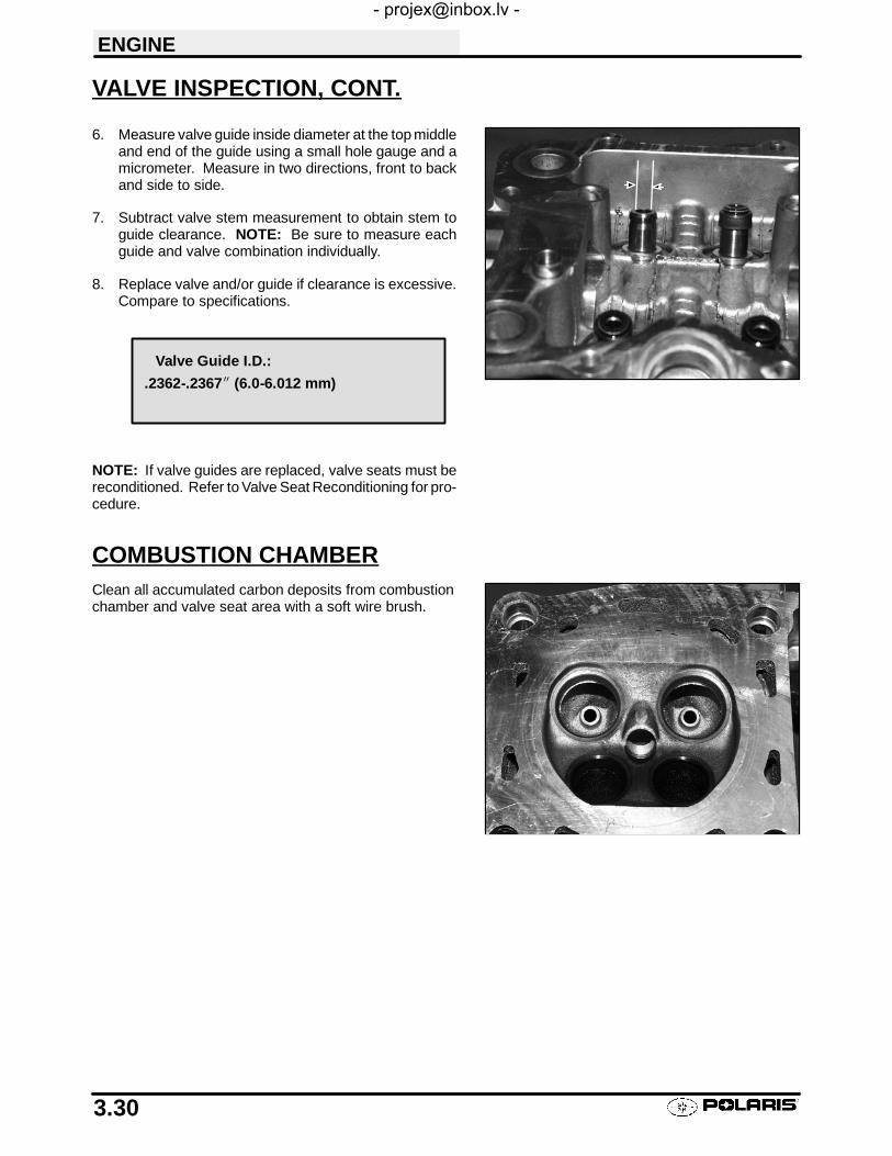
ENGINE
3.30
VALVE INSPECTION, CONT.
6. Measure valve guide inside diameter at the top middleand end of the guide using a small hole gauge and amicrometer. Measure in two directions, front to backand side to side.
7. Subtract valve stem measurement to obtain stem toguide clearance. NOTE: Be sure to measure eachguide and valve combination individually.
8. Replace valve and/or guide if clearance is excessive.Compare to specifications.
NOTE: If valve guides are replaced, valve seats must bereconditioned. Refer to Valve Seat Reconditioning for pro-cedure.
COMBUSTION CHAMBERClean all accumulated carbon deposits from combustionchamber and valve seat area with a soft wire brush.
Valve Guide I.D.:
.2362-.2367I (6.0-6.012 mm)
ENGINE
3.31
VALVE SEAT RECONDITIONING
Valve Seat Inspection
Inspect valve seat in cylinder head for pitting, burnt spots, roughness, and uneven surface. If any of the aboveconditions exist, the valve seat must be reconditioned. See Valve Seat Reconditioning, page 3.32. If the valveseat is cracked the cylinder head must be replaced.
Cylinder Head Reconditioning
NOTE: Servicing the valve guides and valve seats requires special tools and a thorough knowledge of recondi-tioning techniques. Follow the instructions provided in the cylinder head service tool kit.
CAUTION: Wear eye protection when performing cylinder head service. Valve guide replacement will requireheating of the cylinder head. Wear gloves to prevent burns.
Valve Guide Removal/Installation
1. Remove all carbon deposits from the combustion chamber, valve seat and valve guide area before attemptingto remove valve guides. CAUTION: Carbon deposits are extremely abrasive and may damage the valveguide bore when guides are removed.
2. Place new valve guides in a freezer for at least 15 minutes while heating cylinder head.
3. Heat cylinder head in an oven or use a hot plate to bring cylinder head temperature to 212° F (100° C).CAUTION: Do not use a torch to heat cylinder head or warpage may result from uneven heating. Headtemperature can be checked with a pyrometer or a welding temperature stick.

ENGINE
3.32
VALVE SEAT RECONDITIONING, CONT.Follow the manufacturers instructions provided withthe valve seat cutters in the Cylinder Head Recondi-tioning Kit (PN 2200634). Abrasive stone seat re-conditioning equipment can also be used. Keep allvalves in order with their respective seat.
NOTE: Valve seat width and point of contact on thevalve face is very important for proper sealing. Thevalve must contact the valve seat over the entire cir-cumference of the seat, and the seat must be the prop-er width all the way around. If the seat is uneven, com-pression leakage will result. If the seat is too wide, seatpressure is reduced, causing carbon accumulationand possible compression loss. If the seat is too nar-row, heat transfer from valve to seat is reduced and thevalve may overheat and warp, resulting in burntvalves.
1. When thoroughly heated, place cylinder head on blocks of wood which will allow the old guides to be removed.
2. Using valve guide driver, drive guides out of the cylinder head from the combustion chamber side. Be carefulnot to damage guide bore or valve seat when removing guides.
3. Place cylinder head on cylinder head table.NOTE: Be sure cylinder head is still at 212° F(100° C) before installing new guides.
4. Place a new guide in the valve guide installationtool and press guide in to proper depth. Checkheight of each guide above the cylinder head (A).NOTE: The guide can also be driven in to theproper depth. Inspect the guide closely for cracksor damage if a driver is used.
Reaming The Valve Guide
5. Allow cylinder head to cool to room temperature.Apply cutting oil to the reamer. Guides should bereamed from the valve spring side of the cylinderhead. Ream each guide to size by turning thereamer clockwise continually. Continue to rotatereamer clockwise during removal of the tool.
6. Clean guides thoroughly with hot soapy water anda nylon brush. Rinse and dry with compressedair.Apply clean engine oil to guides.
TooWide
Uneven Good TooNarrow
A
Valve Guide Installed Height
Valve Guide Height:
.689-.709I (17.5-18.0 mm)

ENGINE
3.33
VALVE SEAT RECONDITIONING, CONT.1. Install pilot into valve guide.2. Apply cutting oil to valve seat and cutter.
3. Place 46° cutter on the pilot and make a light cut.4. Inspect the cut area of the seat.
S If the contact area is less than 75% of the cir-cumference of the seat, rotate the pilot 180°and make another light cut.
S If the cutter now contacts the uncut portion ofthe seat, check the pilot. Look for burrs,nicks, or runout. If the pilot is bent it must bereplaced.
S If the contact area of the cutter is in the sameplace, the valve guide is distorted from im-proper installation and must be replaced. Besure the cylinder head is at the proper temper-ature and replace the guide.
S If the contact area of the initial cut is greaterthan 75%, continue to cut the seat until all pitsare removed and a new seat surface is evi-dent. NOTE: Remove only the amount ofmaterial necessary to repair the seat surface.
5. To check the contact area of the seat on the valveface, apply a thin coating of Prussian Blue™ paste tothe valve seat. If using an interference angle (46°)apply black permanent marker to the entire valveface (A).
6. Insert valve into guide and tap valve lightly into placea few times.
(A)

ENGINE
3.34
VALVE SEAT RECONDITIONING, CONT.7. Remove valve and check where the Prussian Blue™
indicates seat contact on the valve face. The valveseat should contact the middle of the valve face orslightly above, and must be the proper width.S If the indicated seat contact is at the top edge of
the valve face and contacts the margin area(B) itis too high on the valve face. Use the 30° cutterto lower the valve seat.
S If too low use the 60° or 75° cutter to raise theseat. When contact area is centered on the valveface, measure seat width.
S If the seat is too wide or uneven, use both top andbottom cutters to narrow the seat.
S If the seat is too narrow, widen using the 45° cutterand re-check contact point on the valve face andseat width after each cut.
NOTE:When using an interference angle, theseat contact point on the valve will be very narrow,and is a normal condition. Look for an even andcontinuous contact point on the black marker, allthe way around the valve face.
8. Clean all filings from the area with hot soapy water,rinse, and dry with compressed air.
9. Lubricate the valve guides with clean engine oil, andapply oil or water based lapping compound to the faceof the valve. Lapping is not required with aninterference angle.
(A)
(B)
Proper Seat Contact On Valve Face
Bottom - 60° or 75° Seat - 45° or 46°
Top - 30°
SeatWidth
Valve Seat Width:
Intake Std: .028I (.7 mm)Limit: .055I (1.4 mm)
Exhaust Std: .039I (1.0 mm)Limit: .071I (1.8 mm)

ENGINE
3.35
VALVE SEAT RECONDITIONING, CONT.10. Insert the valve into its respective guide and lap using
a lapping tool or a section of fuel line connected to thevalve stem.
11. Rotate the valve rapidly back and forth until the cutsounds smooth. Lift the valve slightly off of the seat,rotate 1/4 turn, and repeat the lapping process. Dothis four to five times until the valve is fully seated, andrepeat process for the other valve(s).
12. Clean cylinder head, valves, and camshaft oil supplypassage (A) thoroughly.
13. If oil passage blind plug was removed, apply 3 Bond1215 or equivalent sealer to the threads and install,torquing to 8 ft. lbs. (1.1 kg-m). CAUTION: Do notallow sealant to enter oil passage.
14. Spray electrical contact cleaner into oil passage anddry using compressed air.
CYLINDER HEAD ASSEMBLYCAUTION: Wear eye protection during assembly.
NOTE: Assemble the valves one at a time to maintainproper order.
1. Install new valve seals on valve guides.
2. Apply engine oil to valve guides and seats.3. Coat valve stem with molybdenum disulfide grease.4. Install valve carefully with a rotating motion to avoid
damaging valve seal.
A

ENGINE
3.36
CYLINDER HEAD ASSEMBLY, CONT.
5. Dip valve spring and retainer in clean engine oil andinstall spring with closely spaced coils toward thecylinder head.
6. Place retainer on spring and install valve springcompressor. Compress spring only enough to allowsplit keeper installation to prevent loss of springtension. Install split keepers with the gap even on bothsides.
7. Repeat procedure for remaining valve.8. When all valves are installed, tap lightly with soft faced
hammer on the end of the valves to seat the splitkeepers.
VALVE SEALING TEST1. Clean and dry the combustion chamber area.2. Pour a small amount of clean, high flash point solvent
into the intake port and check for leakage around eachintake valve. The valve seats should hold fluid with noseepage.
3. Repeat for exhaust valves by pouring fluid into exhaustport.
Closely spacedcoils towardcylinder head

ENGINE
3.37
CYLINDER/PISTON REMOVAL AND INSPECTIONFollow engine disassembly procedures to remove valvecover, camshaft and rocker arms, and cylinder head.
1. Remove cam chain guide at front of cylinder.
2. Loosen all four oil pipe banjo bolts and then remove thebolts and eight sealing washers. Remove the pipes.
3. Loosen hose clamps and remove coolant inlet hose.

ENGINE
3.38
CYLINDER/PISTON REMOVAL AND INSPECTION, CONT.4. Remove the two 6 mm cylinder base bolts.
5. Loosen each of the four large cylinder base bolts 1/4turn at a time in a criss-cross pattern until loose andremove bolts.
The bolts are inside the water jacket.
6. Tap cylinder lightly with a plastic hammer in thereinforced areas only until loose.
7. Rock cylinder forward and backward and lift it from thecrankcase, supporting piston and connecting rod.Support piston with piston support block PN 2870390.
8. Remove dowel pins from crankcase.

ENGINE
3.39
PISTON REMOVAL1. Remove circlip. Note piston directional arrow pointing
toward the right (Mag) side of engine.
2. Remove piston circlip and push piston pin out of piston.If necessary, heat the crown of the piston slightly with apropane torch. CAUTION: Do not apply heat to thepiston rings. The ring may lose radial tension.
3. Remove top compression ring.
*Using a piston ring pliers: Carefully expand ring and liftit off the piston. CAUTION: Do not expand the ring morethan the amount necessary to remove it from the piston, orthe ring may break.*By hand: Placing both thumbs as shown, spread the ringopen and push up on the opposite side. Do not scratch thering lands.
4. Repeat procedure for second ring.The oil control ring is a three piece design consisting of atop and bottom steel rail and a center expander section.The top rail has a locating tab on the end which fits into anotch (A) in the upper oil ring land of the piston.
5. Remove the top rail first followed by the bottom rail.6. Remove the expander.
A

ENGINE
3.40
CYLINDER INSPECTION1. Remove all gasket material from the cylinder sealing
surfaces.2. Inspect the top of the cylinder for warpage using a
straight edge and feeler gauge.
3. Inspect cylinder for wear, scratches, or damage.
4. Inspect cylinder for taper and out of round with atelescoping gauge or a dial bore gauge. Measure intwo different directions, front to back and side to side,on three different levels (1/2″ down from top, in themiddle, and 1/2″ up from bottom).
Cylinder Warpage:
.002″ (.05 mm)
1/2″ Down From Top of Cylinder
1/2″ Up From Bottom
X
X
Y
Y
X
Y
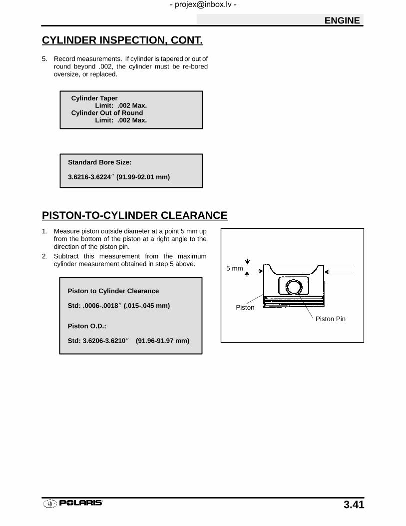
ENGINE
3.41
CYLINDER INSPECTION, CONT.
5. Record measurements. If cylinder is tapered or out ofround beyond .002, the cylinder must be re-boredoversize, or replaced.
PISTON-TO-CYLINDER CLEARANCE1. Measure piston outside diameter at a point 5 mm up
from the bottom of the piston at a right angle to thedirection of the piston pin.
2. Subtract this measurement from the maximumcylinder measurement obtained in step 5 above.
Cylinder TaperLimit: .002 Max.
Cylinder Out of RoundLimit: .002 Max.
Standard Bore Size:
3.6216-3.6224I (91.99-92.01 mm)
5 mm
Piston
Piston Pin
Piston to Cylinder Clearance
Std: .0006-.0018I (.015-.045 mm)
Piston O.D.:
Std: 3.6206-3.6210I (91.96-91.97 mm)
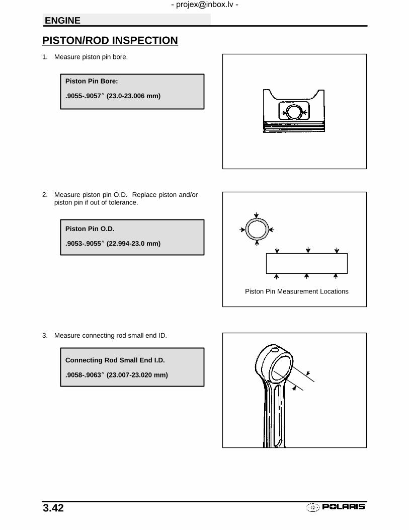
ENGINE
3.42
PISTON/ROD INSPECTION1. Measure piston pin bore.
2. Measure piston pin O.D. Replace piston and/orpiston pin if out of tolerance.
3. Measure connecting rod small end ID.
Piston Pin Bore:
.9055-.9057I (23.0-23.006 mm)
Piston Pin Measurement Locations
Piston Pin O.D.
.9053-.9055I (22.994-23.0 mm)
Connecting Rod Small End I.D.
.9058-.9063I (23.007-23.020 mm)

ENGINE
3.43
PISTON/ROD INSPECTION, CONT.
4. Measure piston ring to groove clearance byplacing the ring in the ring land and measuring witha thickness gauge. Replace piston and rings ifring-to-groove clearance exceeds service limits.
PISTON RING INSTALLED GAP1. Place each piston ring inside cylinder using piston
to push ring squarely into place as shown at right.
2. Measure installed gap with a feeler gauge at boththe top and bottom of the cylinder. NOTE: Adifference in end gap indicates cylinder taper. Thecylinder should be measured for excessive taperand out of round.
3. If the bottom installed gap measurement exceedsthe service limit, replace the rings. If ring gap isbelow specified limit, file ring ends until gap iswithin specified range.
NOTE: Always check piston ring installedgap after re-boring a cylinder or when installing new rings. A re-bored cylinder should always be scrubbed thoroughlywith hot soapy water, rinsed, and dried completely.Wipe cylinder bore with an oil rag immediately to re-move residue and prevent rust.
Piston
Ring
Feeler GaugePiston Ring-to-Groove Clearance
Top Ring Std: .0016-.0031I (.040-.080 mm)Limit: .0059I (15 mm)
Second Ring Std: .0012-.0028I (.030-.070 mm)Limit: .0059I (15 mm)
25-50mmCylinder
Piston Ring
Feeler Gauge
Piston Ring Installed Gap
Top RingStd: .0079-.0138I (.20-.36 mm)Limit: .039I (1.0 mm)
Second RingStd: .0079-.0138I (.20-.36 mm)Limit: .039I (1.0 mm)
Oil RingStd: .0079-.0276I (.20-.70 mm)Limit: .059I (1.5 mm)

ENGINE
3.44
CRANKCASE DISASSEMBLYNOTE: The recoil starter, starter motor, starter drive,flywheel, stator, cam chain and sprockets can be serv-iced with the engine in the frame.
STARTER DRIVE REMOVAL/INSPECTION1. Remove recoil housing bolts and remove housing.2. Remove starter drive assembly. Note the thrust
washer located at the rear of the drive mechanism.3. Inspect the thrust washer for wear or damage and
replace if necessary.
4. Measure the OD of the starter drive shaft on both endsand record.
5. Measure the ID of the bushing in the recoil housing (A)and in the crankcase and record. Measure in twodirections 90° apart to determine if bushing is out ofround. Calculate bushing clearance. Replacebushing if clearance exceeds the service limit.
6. Inspect gear teeth on starter drive. Replacestarter drive if gear teeth are cracked, worn, orbroken.
A
Std. Bushing ID:.4735″-.4740″ (11.11-12.04 mm)
Std. Shaft OD:.470″-.472″ (11.93-11.99 mm)
Starter Drive Bushing Clearance:Std: .0015″-.004″ (.038-.102 mm)
Service Limit:.008″ (.203 mm)
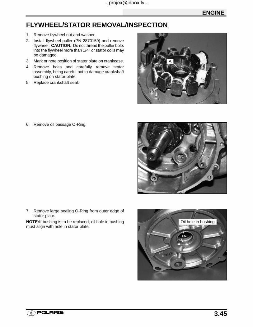
ENGINE
3.45
FLYWHEEL/STATOR REMOVAL/INSPECTION1. Remove flywheel nut and washer.2. Install flywheel puller (PN 2870159) and remove
flywheel. CAUTION: Do not thread the puller boltsinto the flywheel more than 1/4″ or stator coils maybe damaged.
3. Mark or note position of stator plate on crankcase.4. Remove bolts and carefully remove stator
assembly, being careful not to damage crankshaftbushing on stator plate.
5. Replace crankshaft seal.
6. Remove oil passage O-Ring.
7. Remove large sealing O-Ring from outer edge ofstator plate.
NOTE:If bushing is to be replaced, oil hole in bushingmust align with hole in stator plate.
A
Oil hole in bushing

ENGINE
3.46
CAM CHAIN/TENSIONER BLADE1. Remove bolt securing tensioner blade to crankcase
(A).2. Remove blade and inspect for cracks, wear, or
damage.
3. Remove cam chain. Inspect chain for worn or missingrollers or damage. Stretch chain tight on a flat surfaceand apply a 10 lb. (4.53 kg) load. Measure length of a20 pitch section of chain. Replace if worn past servicelimit.
A
Chain Service Limit:5.407″ (13.7 cm)

ENGINE
3.47
CAM CHAIN/TENSIONER BLADE, CONT.
4. Using the special socket, remove the crankshaftslotted nut (A). NOTE: The slotted nut is a left handthread.
5. Remove cam chain drive sprocket (B) and Woodruffkey from crankshaft.
6. Inspect sprocket teeth for wear or damage.
7. Inspect Woodruff key for wear.
8. Replace any worn or damaged parts.
ONE WAY VALVEThe one way valve prevents oil from draining out of the oiltank and into the crankcase when the engine is off. It mustbe clean and have adequate spring pressure in order toseal properly.
1. Remove cap bolt, sealing washer, spring, and oneway valve from PTO side crankcase.
2. Inspect free length of spring and check coils fordistortion.
3. Inspect valve for wear.
4. Check seat area for nicks or foreign material that mayprevent proper sealing of valve.
A
B
One Way Valve Spring Free Length:
Std: 1.450″ (3.68 cm)

ENGINE
3.48
CRANKCASE SEPARATION
1. Remove flange bolts (10) from magneto sidecrankcase evenly in a cross pattern.
2. Separate crankcase by tapping with a soft facedhammer in reinforced areas.
3. Tap lightly on balancer gear with a brass drift throughthe hole in the crankcase if necessary, to ensure thebalancer shaft stays in the PTO side crankcase.Watch the gap along the crankcase mating surfaceand separate the crankcase evenly. It may also benecessary to tap the oil pump shaft lightly to separatethe crankcase.
CAUTION: Do not strike the oil pump shaft at an angle orthe shaft may bend, causing irreparable damage. Tap onlylightly on the pump shaft if necessary.
4. Remove the Mag (RH) crankcase from the PTO case.

ENGINE
3.49
OIL PUMP REMOVAL/INSPECTION1. Remove pump shaft bearing (A) and thrust washer (B)
from pump shaft.2. Remove (2) bolts holding pump drive gear (C).NOTE: On 500 H.O. models this gear is retained by (3)bolts.
3. Inspect drive gear teeth for cracks, damage orexcessive wear.
4. Remove three oil pump retaining bolts and pump.
5. Inspect mating surface of crankcase and oil pump.Check for nicks, burrs, or surface irregularities.
ABC

ENGINE
3.50
OIL PUMP REMOVAL/INSPECTION, CONT.
6. Remove the three screws and strainer screen frompump.
7. Clean screen thoroughly.
8. Remove pump body screw and feed chamber cover.
9. Measure pump end clearance using a feeler gauge andstraight edge.
Pump End Clearance:
Std: .001-.003 (.0254-.0762 mm)
Wear Limit: .004 (.1016 mm)

ENGINE
3.51
OIL PUMP REMOVAL/INSPECTION, CONT.
10. Measure clearance between outer feed rotor andpump body with a feeler gauge.
11. Measure rotor tip clearance with a feeler gauge.
12. Remove inner and outer feed rotor and pump chamberbody.
13. Repeat measurements for scavenge rotor.14. Remove inner and outer scavenge rotor and inspect
pump shaft for wear.
OIL PUMP ASSEMBLY1. Clean and dry all parts thoroughly. Apply clean engine oil to all parts. Do not use gasket sealer on the pump
body mating surfaces or oil passages will become plugged.
2. Install pump shaft and scavenge rotor drive pin.3. Install outer scavenge rotor, inner scavenge rotor, and scavenge casing.4. Install outer feed rotor and inner feed rotor drive pin.5. Install inner feed rotor and feed chamber cover with screw.6. Tighten screw securely.7. Install screen on pump body.8. Install oil pump on crankcase and torque bolts to 6 ft. lbs. (.828 kg-m).
Outer Feed Rotor to PumpBody Clearance:
Std: .001-.003 (.0254-.0762 mm)
Wear Limit: .004 (.1016 mm)
Rotor Tip Clearance:
Std: .005 (.127 mm)
Wear Limit: .008 (.2032 mm)
Oil Pump Attaching Bolt Torque:6 ft. lbs. (.828 kg-m)

ENGINE
3.52
COUNTER BALANCER SHAFT REMOVAL/INSPECTION1. Remove the shim washer from the counter balancer
shaft.
2. Note the alignment dots on the balancer andcrankshaft gears, the marks must be aligned duringreassembly.
3. Turn the shaft until balancer counter weights clear thecrankshaft and remove the balancer shaft from thecrankcase.
4. Inspect the balancer drive gear and pump shaft drivegear.
5. Replace the shaft if gear teeth are abnormally worn ordamaged.
6. Inspect the balancer shaft bearings.
NOTE: Due to extremely close tolerances and minimalwear, the balancer shaft ball bearings must be inspectedvisually and by feel. Look for signs of discoloration, scor-ing or galling. Turn the inner race of each bearing. Thebearings should turn smoothly and quietly. The outer raceof each bearing should fit tightly in the crankcase. The in-ner race should be firm with minimal side to side move-ment and no detectable up and down movement.

ENGINE
3.53
CRANKSHAFT REMOVAL/INSPECTION1. Remove the shim washer from the crankshaft.
2. Support the PTO side crankcase and crankshaft;press the crankshaft out. Be careful not to damagethe crankcase mating surface or connecting rod.
3. Use a feeler gauge to measure the connecting rod bigend side clearance.
4. Place the crankshaft in a truing stand or V-blocks andmeasure the runout on both ends with a dial indicator.
5. Measure the connecting rod big end radial clearance.
6. Inspect the crankshaft main bearing journals forscoring and abnormal wear.
Connecting Rod Big End Side Clearance:
Std: .0039-.0256I (.1-.65 mm)Limit: .0315I (.80 mm)
Max Runout: .0024″ (.06 mm)
Big End Radial Clearance:
Std: .0004-.0015I (.011-.038 mm)Limit: .0020I (.05 mm)

ENGINE
3.54
CRANKCASE BEARING INSPECTION
1. Remove the seal from the PTO side crankcase.
2. Inspect the crankshaft main bearings, balancershaft bearings, and pump shaft bearing.
NOTE: Due to extremely close tolerances and minimalwear, the bearings must be inspected visually, and byfeel. Look for signs of discoloration, scoring or galling.Turn the inner race of each bearing. The bearingsshould turn smoothly and quietly. The outer race ofeach bearing should fit tightly in the crankcase. The in-ner race should be firm with minimal side to side move-ment and no detectable up and down movement.
3. Support the crankcase and drive or press the mainbearings out of each crankcase.
4. To remove balancer shaft bearings and pump shaftbearing use a blind hole bearing puller.
NOTE: Bearings are stressed during the removal pro-cess and should not be re-used!
PUMP SHAFT OIL SEAL/ WATER PUMP MECHANICAL SEALREMOVAL (ENGINE DISASSEMBLED)NOTE:The water pump mechanical seal can be re-moved without removing the engine. Refer to WaterPump Mechanical Seal Installation.
Replace the pump shaft seal andwater pumpmechani-cal seal whenever the crankcase is disassembled.
1. Remove the pump shaft bearing from the Magneto(right hand) side crankcase.
2. Pry out the oil seal, noting the direction ofinstallation with the spring side facing IN (towardinside of case).
3. Drive the water pump mechanical seal out of thecrankcase from inside to outside. Note: The newmechanical seal must be installed after thecrankcases are assembled, using a special tool.See Mechanical Seal Installation.

ENGINE
3.55
CRANKCASE INSPECTION1. Remove all traces of gasket sealer from the
crankcase mating surfaces. Inspect the surfacesclosely for nicks, burrs or damage.
2. Check the oil pump and oil passage matingsurfaces to be sure they are clean and notdamaged.
BEARING INSTALLATIONNOTE: To ease bearing installation, warm the crank-case until hot to the touch. Place the bearings in a freez-er.
1. Install the bearings so the numbers are visible.2. Drive or press new bearings into the crankcases,
using the proper driver. CAUTION: Press only onouter race of bearing to prevent bearing damage.
S 70mm (2.755″) driver- For crankshaftmain bearings.
S 46mm (1.810″) For counter balancerbearings.
S 28mm (1.100″) For pump shaft bearing.

ENGINE
3.56
END PLAY INSPECTION/ADJUSTMENTBefore reassembling the crankcase,the following steps should be performed to determine the amount of crank-shaft, counter balancer shaft, and pump shaft end play. Excessive end play may cause engine noise at idle andslow speeds. Too little play will side load the bearings which may lead to premature bearing failure.
CRANKSHAFT END PLAY ADJUSTMENT1. Make sure all bearings are firmly seated in the
both Mag and PTO crankcase.
2. Measure the distance from the PTO crankcasemating surface to the main bearing using a dialcaliper and a straight edge.
3. Subtract the thickness of the straightedge fromthe measurement obtained in Step 2 and record.
PTO Case Depth
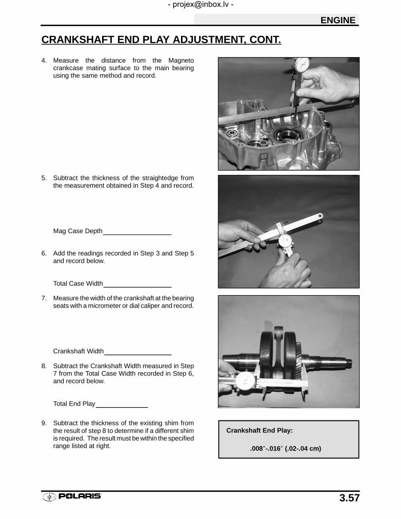
ENGINE
3.57
CRANKSHAFT END PLAY ADJUSTMENT, CONT.
4. Measure the distance from the Magnetocrankcase mating surface to the main bearingusing the same method and record.
5. Subtract the thickness of the straightedge fromthe measurement obtained in Step 4 and record.
Mag Case Depth
6. Add the readings recorded in Step 3 and Step 5and record below.
Total Case Width
7. Measure the width of the crankshaft at the bearingseats with a micrometer or dial caliper and record.
Crankshaft Width
8. Subtract the Crankshaft Width measured in Step7 from the Total Case Width recorded in Step 6,and record below.
Total End Play
9. Subtract the thickness of the existing shim fromthe result of step 8 to determine if a different shimis required. The result must bewithin thespecifiedrange listed at right.
Crankshaft End Play:
.008″-.016″ (.02-.04 cm)
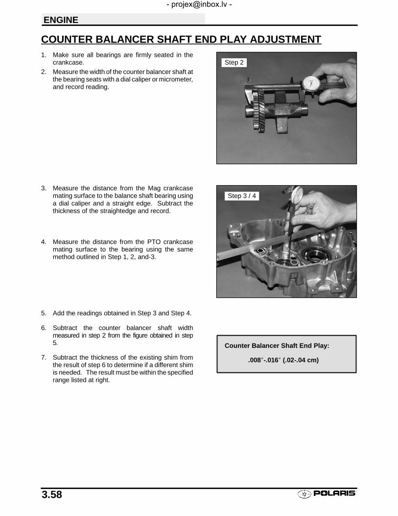
ENGINE
3.58
COUNTER BALANCER SHAFT END PLAY ADJUSTMENT1. Make sure all bearings are firmly seated in the
crankcase.2. Measure the width of the counter balancer shaft at
the bearing seats with a dial caliper or micrometer,and record reading.
3. Measure the distance from the Mag crankcasemating surface to the balance shaft bearing usinga dial caliper and a straight edge. Subtract thethickness of the straightedge and record.
4. Measure the distance from the PTO crankcasemating surface to the bearing using the samemethod outlined in Step 1, 2, and-3.
5. Add the readings obtained in Step 3 and Step 4.
6. Subtract the counter balancer shaft widthmeasured in step 2 from the figure obtained in step5.
7. Subtract the thickness of the existing shim fromthe result of step 6 to determine if a different shimis needed. The result must be within the specifiedrange listed at right.
Step 2
Step 3 / 4
Counter Balancer Shaft End Play:
.008″-.016″ (.02-.04 cm)

ENGINE
3.59
PUMP SHAFT END PLAY ADJUSTMENT1. Make sure the pump shaft bearing is firmly seated
in the Magneto side crankcase.2. Measure the distance from the magneto crankcase
mating surface to the bearing using a dial caliperand a straight edge. Subtract the thickness of thestraightedge and record.
3. Install the gear on the oil pump and measure thewidth of the pump and gear. Subtract thismeasurement from the measurement recorded inStep 2.
4. Subtract the thickness of the existing shim from theresult of Step 3 to determine if a different shim isneeded.
PUMP SHAFT OIL SEAL INSTALLATION1. Install the seal from the outside of the crankcase
(water pump side) with the spring facing inward,toward the pump shaft bearing.
2. Drive or press the seal into place using a 25mm(.985″) seal driver, until flush with the outer edge ofthe seal bore.
3. Lubricate the seal lip with grease.
Pump Shaft End Play:
.008″-.016″ (.02-.04 cm)

ENGINE
3.60
CRANKSHAFT/COUNTER BALANCE/OIL PUMP INSTALLATIONLubricate all bearings with clean engine oil before assembly.
Use the crankshaft installation tool kit PN 2871283 to prevent damage to the crankshaft and main bearings duringinstallation.
1. Install the crankshaft into the PTO side crankcase. Screw the threaded rod into the crankshaft until thethreads are engaged a minimum of one inch (25.4mm).
2. Install the collar, washer, and nut onto the threaded rod. Hold the crankshaft and tighten the nut to draw thecrankshaft into the main bearings until fully seated. Loosen the nut and remove the threaded rod from thecrankshaft. If removal is difficult, install two nuts on the end of the threaded rod and tighten against each other.
3. Install the proper shim on the magneto end of the crankshaft.
4. Place the balancer shaft in the PTO crankcase aligning the timing marks on the crankshaft and balancergears. Install the proper shim washer on the shaft.
5. Inspect the oil pump sealing surface on the crankcase. Apply a light film of engine oil to the surface and installthe oil pump.
NOTE: Do not use gasket sealer on the pump mating surfaces.
NOTE: After engine is assembled and machine is readied for field operation, oil pump MUST be primed. Followoil pump priming procedure on page 3.13.
6. Align the drive gear with the drive pin on the pump shaft and install the gear. Be sure the gear is fully seatedand properly engaged.
7. Install the proper shim washer on the pump shaft.
CRANKCASE ASSEMBLY
1. Apply 3 Bond 1215 (P/N 2871557) to the crankcase mating surfaces. Be sure the alignment pins are in place.
2. Set the crankcase in position carefully to avoid damaging the pump shaft seal, and install the magneto endcrankshaft installation tool (follow instructions provided with tool kit PN 2871283). Draw the crankcase halvestogether by tightening the nut on the tool and tapping lightly in the pump shaft area with a soft faced hammer tomaintain alignment. Continually check alignment of the cases during installation, closing the gap equally untilthe surfaces are tightly seated.
3. Remove the tool.
4. Install the crankcase flange bolts and tighten in 3 steps following the pattern on page 3.2 to specified torque.
Crankcase Sealant:
PN 2871557
Oil Pump Bolt Torque:
6. ft. lbs. (.828 kg-m)
Crankcase Bolt Torque:
14 ft. lbs. (19-20 Nm)

Ill. 2
T-Handle
Main Puller Body
ENGINE
3.61
WATER PUMP MECHANICAL SEAL INSTALLATION
1. Clean the seal cavity to remove all traces of old sealer.
2. Place a new mechanical seal in the seal drive collar, and install on the pump shaft.
3. Screw the guide onto the end of the pump shaft.
4. Install the washer and nut and tighten to draw seal into place until fully seated.
5. Remove the guide adaptor using the additional nut as a jam nut if necessary.
WATER PUMP MECHANICAL SEAL REMOVAL - ENGINEINSTALLED
WATER PUMP MECHANICAL SEAL REMOVAL TOOL:2872105
REPLACEMENT T-HANDLE FOR 2872105: 2872106
This tool allows a technician to replace the mechanical water pump seal on EH50PL engines without removingthe engine and splitting the cases.
CAUTION:Improper or careless use of this tool or procedure can result in a bent water pump shaft. Pump
shaft replacement requires engine removal and crankcase separation. Use caution while performing this proce-dure. Make sure that the puller is parallel to the shaft at all times. Do not place side loads on the water pumpshaft or strike the puller or shaft in any way.
1. After the coolant has been drained, remove the waterpump cover, impeller and the sealing washer. (Ill. 1)
2. Slide the main puller body over the outer portion of themechanical seal as shown in Ill. 2 and turn T-Handleclockwise until it contacts water pump shaft. Continuerotating until outer portion of mechanical seal is sepa-rated from the metal seal body.
Ill. 1
Impeller
Sealing Washer
Coolant DrainBolt
Mechanical Seal
OilSeal
Sealing Washer(Copper or Aluminum)

Ill. 3
Puller Legs
Ill. 4
Position the split90° to openingon main pullerbody
Main pullerbody
Hex Socket Screws
Ill. 5
Lip must grasp insideof mechanical seal.
Puller Legs
Ill. 6
ENGINE
3.62
WATER PUMP MECHANICAL SEAL REMOVAL - ENGINEINSTALLED, CONT.3. Insert the puller legs between the water pump drive
shaft and the remaining portion of the mechanical seal.Attach the puller legs to the main puller body. Ill. 3
4. Ensure that the split between the puller legs is fully sup-ported by the main body of the tool (Ill 4).
5. Tighten the hex socket screws on the puller legs suffi-ciently so the lip of the puller legs will grasp the me-chanical seal. Ill. 5
6. Turn the puller T-Handle clockwise until it contacts thewater pump shaft. Continue rotating until the remainingportion of mechanical seal has been removed from thecases. Ill. 6 Pump shaft oil seal can also be replacedat this time if necessary.
7. Special tool (PN 5131135) is required to install the newmechanical seal. This tool is available separately andit is also included in the Crankshaft/Water Pump SealInstallation Kit (PN 2871283).

ENGINE
3.63
ONE WAY VALVE INSTALLATIONInstall the one way valve plunger, spring, and plug us-ing a new sealing washer.
CAM CHAIN DRIVE SPROCKET INSTALLATION1. Install the Woodruff key, drive sprocket, and
slotted nut. Tighten the nut to the specified torque.
TENSIONER BLADE INSTALLATION1. Install the tensioner blade and tighten the
mounting bolt to specified torque.
One Way Valve Plug Torque:
16 ft. lbs. (2.2 kg-m)
A
B
Tighten
Slotted Nut Torque:
35-51 ft. lbs. (4.71-6.86 kg-m)
Tensioner Blade Mounting Bolt Torque:
6 ft. lbs. (.828 kg-m)

ENGINE
3.64
PISTON RING INSTALLATIONNOTE: Apply clean engine oil to all ring surfaces and ring lands. Always check piston ring installed gap beforerings are installed on piston. See page 3.43. If the piston has been in service clean any accumulated carbonfrom the ring grooves and oil control ring holes.
1. Place the oil control ring expander in oil ring groove with the end gap facing forward. The expander has no upor down marking and can be installed either way. The ends should butt squarely together and must notoverlap.
2. Install the oil ring top rail.NOTE: The top rail has a locating tab to prevent rota-tion. The tab must be positioned in the notch on theside of the piston as shown (A).
3. Install the bottom rail with the gap at least 30° fromthe end of the expander on the side opposite thetop rail gap.(See Ill.).
4. Install the second ring with the “R” mark facing up.Position the end gap toward the rear (intake) sideof the piston.
5. Install the top ring (chrome faced) with the “R”mark facing up and the end gap facing forward(toward the exhaust). (See Ill.).
6. Check to make sure the rings rotate freely in thegroove when compressed.
A
Ring Profile
Top
Mark up
Mark upSecond

ENGINE
3.65
PISTON INSTALLATION1. Clean the gasket surfaces on the cylinder and
crankcase. Remove all traces of old gasket material.2. Make sure the cylinder mounting bolt holes are clean
and free of debris.3. Install a new circlip on one side of the piston with the
end gap facing up or down, and tang outward.CAUTION: Circlips become deformed during the removalprocess. Do not re-use old circlips. Do not compress thenew clip more than necessary upon installation to preventloss of radial tension. Severe engine damage may resultif circlips are re-used or deformed during installation.
4. Apply clean engine oil to the piston rings, ring lands,piston pin bore, piston pin, and piston skirt. Lubricatethe connecting rod (both ends), balancer drive gear,and crankshaft main bearing area.
5. Install the piston on the connecting rod with the arrowor : mark facing the magneto (RH) end of thecrankshaft. The piston pin should be a push fit in thepiston.
6. Install the other circlip with the gap facing up or downand tang outward. (See Caution with step 3 above).Push the piston pin in both directions to make sure theclips are properly seated in the groove.
Tang Outward
Magor :

ENGINE
3.66
CYLINDER INSTALLATION1. Place the dowel pins in the crankcase and install a
new cylinder base gasket.2. Position the piston support block PN 2870390 (A)
beneath the piston skirt to support the piston duringcylinder installation.
3. Apply clean engine oil to the ring compressor (SnapOn™ PN RCL30) and install the compressor followingmanufacturers instructions. CAUTION: Make surethe oil control ring upper rail tab is positioned properlyin the notch of the piston. Verify all ring end gaps arecorrectly located.
4. Apply clean engine oil liberally to the cylinder bore andtapered area of the sleeve. Install the cylinder with aslight rocking motion until the rings are captive in thesleeve.
5. Remove the ring compressor and support block.
6. Push the cylinder downward until fully seated on thebase gasket.
A

Guide inrecess
ENGINE
3.67
CYLINDER INSTALLATION, CONT.7. Apply a light film of oil to the threads and flange
surface of the cylinder mounting bolts.
8. Install all four bolts finger tight. Rotate the engine andposition the piston at BDC.
NOTE: If cam chain is installed, hold it up while rotatingthe engine to avoid damage to the chain, drive sprocketteeth, or tensioner blade.
9. Tighten the cylinder bolts in three steps ina criss crosspattern and torque to specifications.
10. Install the two 6mm bolts.
CYLINDER HEAD INSTALLATIONClean the gasket surfaces on the cylinder head and cylin-der. Remove all traces of old gasket material.Refer to disassembly photos.
1. Install the cam chain tensioner guide. Be sure bottomend of guide is located properly in crankcase.
2. Install the two dowel pins and a new cylinder headgasket.
3. Place the cylinder head on the cylinder. Apply a film ofengine oil to the cylinder head bolt threads andwashers, and hand tighten the bolts.
The following procedure must be used to torque thecylinder head properly:
Cylinder Bolt Torque:
10mm - 46 ft. lbs. (6.348 kg-m)6mm - 6 ft. lbs. (.828 kg-m)
Torque all bolts evenly in a criss crosspattern
*Torque bolts to 22 ft. lbs. (3.04 kg-m)
*Torque bolts to 51 ft. lbs. (7.04 kg-m)
*Loosen bolts evenly 180° (1/2 turn)
*Loosen bolts again another 180° (1/2turn)
*Torque bolts to 11 ft. lbs. (1.52 kg-m)
*From this point, tighten bolts evenly90° (1/4 turn)
*Finally, tighten another 90° (1/4 turn)
*Install two 6mm bolts and torque to 6ft. lbs. (.828 kg-m)

ENGINE
3.68
CAM CHAIN/CAMSHAFT INSTALLATIONInstall the cam chain over the crankshaft.
CAUTION: Serious engine damage may re-sult if the camshaft is not properly timed tothe crankshaft.
IMPORTANT CAMSHAFT TIMING NOTE: In order totime the camshaft to the crankshaft, the piston must beprecisely located at Top Dead Center (TDC).
CAMSHAFT TIMING1. Apply Polaris Premium Starter Drive grease to the
camshaft main journals and cam lobes. Lubricateautomatic compression release mechanism withclean engine oil. (To install the compressionrelease mechanism, refer to page 3.23).
2. Install the camshaft with the lobes facingdownward and the sprocket alignment pin facingupward.
3. Disconnect the wire from the cam chain and rotatethe engine to align the single (TDC ) timing mark(Top Dead Center) on the flywheel with the notchin the timing inspection window. Be sure to usethe single TDC mark when installing the cam. Donot use the advance marks. See Ill. on next page.
Single (TDC)Mark Aligned

ENGINE
3.69
CAMSHAFT TIMING, CONT.
4. Loop the cam chain on the cam sprocket with thedots on the sprocket facing outward and thealignment pin notch facing directly upward.
5. Before positioning the sprocket on the camshaft,check the position of the cam sprocket alignmentpin. When the cam is positioned properly, the camsprocket alignment pin (A) is directly in line withthe crankshaft/camshaft centerline (B).
6. Install the sprocket on the camshaft. Apply Loctite242 to the cam sprocket bolts and torque tospecifications.
7. Verify TDC mark in timing inspection hole andalignment pin is directly in line with crankshaft tocamshaft centerline. Refer to Ill. on followingpage.
8. Apply 3 Bond 1215 (P/N 2871557) to thecamshaft end cap and install using a newO-Ring.
9. Check all cam timing marks to verify proper camtiming, and install the cam chain tensioner bodywith a new gasket.
10. After tensioner installation, rotate engine at leasttwo revolutions and re-check marks/timing.
A
AB
Cam Sprocket Bolt Torque:
6 ft. lbs. (.828 kg-m)
Single (TDC)Mark Aligned

ENGINE
3.70
CAMSHAFT TIMING
Single TDC Mark Aligned
Crankshaft to Camshaft Centerline
Sprocket Alignment Pin
Do Not UseAdvance Marks
Rotation
TDC Mark
Dots

ENGINE
3.71
CAM CHAIN TENSIONER INSTALLATION1. Release the ratchet pawl (A) and push the
tensioner plunger (B) all the way into thetensioner body.
2. Install the tensioner body with a new gasket andtighten the bolts.
3. Install the spring, new sealing washer, andtensioner plug.
4. Slowly rotate engine two to three revolutions andre-check cam timing.
STATOR, FLYWHEEL AND STARTER DRIVE INSTALLATIONNOTE: The stator, flywheel, starter drive, and recoilcan be assembled with the engine in the frame.
Stator
1. Apply a light film of grease to the crankshaft seal.Apply molybdenum disulfide grease or assemblylubricant to the crankshaft bushing.
2. Install a new O-Ring in the oil passage recess inthe crankcase.
3. Apply 3 Bond 1215 (P/N 2871557) or anequivalent sealer to the stator plate outer surfaceand install a new O-Ring.
4. Install the stator plate being careful not to damagethe seal. Align timing reference marks on theplateand crankcase. Be sure the plate is fully seated.NOTE: This is a static timing mark. Strobe timingshould be performed after start up.
BA
Tensioner Bolt Torque:
6 ft. lbs. (.828 kg-m)
Tensioner Plug Torque:
17 ft. lbs. (2.346 kg-m)
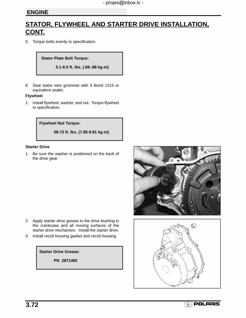
ENGINE
3.72
STATOR, FLYWHEEL AND STARTER DRIVE INSTALLATION,CONT.5. Torque bolts evenly to specification.
6. Seal stator wire grommet with 3 Bond 1215 orequivalent sealer.
Flywheel
1. Install flywheel, washer, and nut. Torque flywheelto specification.
Starter Drive
1. Be sure the washer is positioned on the back ofthe drive gear.
2. Apply starter drive grease to the drive bushing inthe crankcase and all moving surfaces of thestarter drive mechanism. Install the starter drive.
3. Install recoil housing gasket and recoil housing.
Stator Plate Bolt Torque:
5.1-6.5 ft. lbs. (.68-.88 kg-m)
Flywheel Nut Torque:
58-72 ft. lbs. (7.85-9.81 kg-m)
Starter Drive Grease:
PN 2871460

ENGINE
3.73
ROCKER SHAFT/ROCKER ARM ASSEMBLY INSTALLATION1. Assemble rocker arms, rocker shaft, and shaft supports.2. Install and tighten rocker arm shaft locating bolt.3. Apply starter drive grease to the cam lobes and cam follower surfaces.4. Rotate the engine until the cam lobes are pointing downward.5. Be sure the dowel pins are in place and install the rocker shaft assembly.6. Apply a light film of engine oil to the threads of the bolts and tighten evenly.
7. Adjust valves according to the valve adjustment procedure found in Chapter 2, Maintenance.
8. Apply clean engine oil liberally to the valve springs, cam chain, rocker arms, and camshaft.
9. Place a new rocker cover gasket on the cylinder head and install the cover and bolts.
THERMOSTAT INSTALLATIONInstall the thermostat with one of the air bleed holespositioned next to the upper thermostat cover bolt holeas shown.
OIL PIPESInstall the oil pipes with new sealing washers. Tightenall bolts evenly to specified torque.
Rocker Shaft Support Tower Bolt Torque:
9 ft. lbs. (1.242 kg-m)
Rocker Shaft Locating Bolt Torque:
6 ft. lbs. (.828 kg-m)
Rocker Cover Bolt Torque:
6 ft. lbs. (.828 kg-m)
Oil Pipe Bolt Torque:
20 ft. lbs. (2.76 kg-m)

ENGINE
3.74
RECOIL DISASSEMBLY/INSPECTIONCAUTION: The recoil is under spring tension. A faceshield and eye protection is required during this proce-dure.
Replace any parts found to be worn or damaged.
1. Remove bolts and recoil housing.
2. Pull recoil rope so it is extended approximately12-18″.Check handle c-ring for proper tension, andthe handle for cracks or damage which may allowwater or dirt to enter the recoil housing through therope. NOTE: The handle must seal tightly on therecoil housing to prevent water from entering.
3. Remove center bolt from recoil friction plate (A).
4. Inspect plate for wear or damage. Inspect platefriction spring for wear, damage, and proper tension.The spring should fit tightly on friction plate.
5. Remove ratchet pawl with spring and inspect.Replace spring or ratchet pawl if worn, broken, ordamaged.
NOTE:Long arm of spring engages reel. Short endagainst pawl.
A

ENGINE
3.75
RECOIL DISASSEMBLY/INSPECTION, CONT.6. Hold reel firmly in housing. Pull rope handle until
12-18″ of rope is exposed, and hold reel in place.7. Place rope in notch on outer edge of reel. Release
tension on hub and allow reel to unwindapproximately 6-7 turns until spring tension isreleased.
8. Slowly and carefully remove reel from recoil housingmaking sure the spring remains in the housing.Inspect the reel hub and bushing (A) for wear.
9. Unwind rope and inspect for cuts or abrasions.
10. Inspect drive tab on hub return spring for damage. Toremove hub return spring, hold outer coils in placewith one hand and slowly remove spring one coil at atime from the inside out.
11. Pull knot out of of recoil reel. Untie knot. Remove ropefrom reel.
A

ENGINE
3.76
RECOIL ASSEMBLYCAUTION: Be sure to wear a face shield and eye protec-tion when performing this procedure.
To install a new spring:
1. Place spring in housing with the end positioned so thespring spirals inward in a counterclockwise direction.See photo at right.
2. Hold spring in place and cut retaining wire.
To reinstall an old spring:
1. Hook outer tab in place in recoil housing and windspring in a counterclockwise direction one coil at atime while holding the installed coils in place.
2. Lubricate the spring with light lubricant such asPremium All Season Grease.
To complete recoil assembly:
1. Route rope through guide bushing in recoil housingand into reel. Tie a secure knot in end of the rope.
2. Wind rope counterclockwise onto the reel, as viewedfrom ratchet side of reel.
3. Lock rope into notch on outer edge of reel.4. Apply a small amount of grease or equivalent to the
center post of the housing and the bushing.
5. Install reel into housing making sure the spring drivetab on the reel engages the spring and the reel is fullyseated in the housing.
6. Apply downward pressure on the reel and rotatecounterclockwise approximately 6-7 turns to pre-windthe spring. Continue rotating counterclockwise untilrope on outer edge aligns with rope guide bushing.
7. Release rope from notch and allow reel to rewindcompletely. If more pre-wind is required, place rope innotch and add additional turns of pre-wind.
8. Install ratchet pawl and return spring, with long leg ofspring engaged in reel.
9. Reinstall friction plate. NOTE: The friction plate mustbe positioned with both end tabs of the friction springopposite the ratchet pawl.
10. Torque friction plate retaining bolt to 5-6 ft. lbs. (7-9Nm).
11. Reinstall recoil housing using a new gasket. Sealstator wire harness grommet with RTV silicone.
Open end here

ENGINE
3.77
SPARK PLUG FOULINGS Spark plug cap loose or faultyS Choke cable adjustment or plunger/cable stickingS Foreign material on choke plunger seat or plungerS Incorrect spark plug heat range or gapS Carburetor inlet needle and seat wornS Jet needle and/or needle jet worn or improperly adjusted
S Excessive carburetor vibration (loose or missing needle jet locating pins)S Loose jets in carburetor or calibration incorrect for altitude/temperatureS Incorrect float level settingS PVT system calibrated incorrectly or components worn or mis-adjustedS Fuel quality poor (old) or octane too high
S Low compressionS Restricted exhaustS Weak ignition (loose coil ground, faulty coil, stator, or ETC switch)S ETC switch mis-adjustedS Restricted air filter (main or pre-cleaner) or breather systemS Improperly assembled air intake system
S Restricted engine breather systemS Oil contaminated with fuelS Restricted oil tank vent

ENGINE
3.78
TROUBLESHOOTINGEngine Turns Over But Fails to Start
S No fuel
S Dirt in fuel line or filter
S Fuel will not pass through fuel valve
S Fuel pump inoperative/restricted
S Tank vent plugged
S Carb starter circuit
S Engine flooded
S Low compression (high cylinder leakage)
S No spark (Spark plug fouled)
Engine Does Not Turn Over
S Dead battery
S Starter motor does not turn
S Engine seized, rusted, or mechanical failure
Engine Runs But Will Not Idle
S Restricted carburetor pilot system
S Carburetor misadjusted
S Choke not adjusted properly
S Low compression
S Crankcase breather restricted
Engine Idles But Will Not Rev Up
S Spark plug fouled/weak spark
S Broken throttle cable
S Obstruction in air intake
S Air box removed (reinstall all intake components)
S Incorrect or restricted carburetor jetting
S ETC switch limiting speed
S Reverse speed limiter limiting speed
S Carburetor vacuum slide sticking/diaphragm damaged
S Incorrect ignition timing
S Restricted exhaust system
Engine Has Low Power
S Spark plug fouled
S Cylinder, piston, ring, or valve wear or damage (check compression)
S PVT not operating properly
S Restricted exhaust muffler
S Carburetor vacuum slide sticking/diaphragm damaged
S Dirty carburetor
Piston Failure - Scoring
S Lack of lubrication
S Dirt entering engine through cracks in air filter or ducts
S Engine oil dirty or contaminated

ENGINE
3.79
TROUBLESHOOTING, CONTExcessive Smoke and Carbon Buildup
S Excessive piston-to-cylinder clearance
S Wet sumping
S Worn rings, piston, or cylinder
S Worn valve guides or seals
S Restricted breather
S Air filter dirty or contaminated
Low Compression
S Decompressor stuck
S Cylinder head gasket leak
S No valve clearance or incorrectly adjusted
S Cylinder or piston worn
S Piston rings worn, leaking, broken, or sticking
S Bent valve or stuck valve
S Valve spring broken or weak
S Valve not seating properly (bent or carbon accumulated on sealing surface)
S Rocker arm sticking
Backfiring
S ETC or speed limiter system malfunction
S Fouled spark plug or incorrect plug or plug gap
S Carburetion faulty - lean condition
S Exhaust system air leaks
S Ignition system faulty:Spark plug cap cracked/brokenIgnition coil faultyIgnition or kill switch circuit faultyIgnition timing incorrectSheared flywheel key
S Poor connections in ignition system
S System wiring wet
S Valve sticking
S Air leaks in intake
S Lean condition

ENGINE
3.80
COOLING SYSTEM TROUBLESHOOTING
Overheating
S Low coolant level
S Air in cooling system
S Wrong type of coolant
S Faulty pressure cap or system leaks
S Restricted system (mud or debris in radiator fins or restriction to air flow, passages blocked inradiator, lines, pump, or water jacket)
S Lean mixture (restricted jets, vents, fuel pump or fuel valve)
S Fuel pump output weak
S Restricted radiator (internally or cooling fins)
S Water pump failure
S Cooling system restriction
S Cooling fan inoperative or turning too slowly (perform current draw test)
S Ignition timing misadjusted
S Low oil level
S Spark plug incorrect heat range
S Faulty hot light circuit
S Thermostat stuck closed or not opening completely
Temperature Too Low
S Thermostat stuck open
Leak at Water Pump Weep Hole
S Faulty water pump mechanical seal (coolant leak)
S Faulty pump shaft oil seal (oil leak)

4
CHAPTER 4FUEL SYSTEM/CARBURETION
Jetting Guidelines 4.1. . . . . . . . . . . . . . . . . . . . . . . . . . . .
Main Jet Selection 4.1. . . . . . . . . . . . . . . . . . . . . . . . . . . .
Fuel Tank Asm. Exploded View 4.2. . . . . . . . . . . . . . . . .
Fuel Flow Diagram 4.3. . . . . . . . . . . . . . . . . . . . . . . . . . . .
Main Jet / Pilot Jet Part Numbers 4.4. . . . . . . . . . . . . . .
CV Carburetor System Function (4 Cycle) 4.5. . . . . . .
CV Carburetor Vent System (4 Cycle) 4.5. . . . . . . . . . .
CV Carburetor Operation 4.6-4.8. . . . . . . . . . . . . . . . . . . . . .
Exploded View, Mikuni BST 34 Carburetor 4.9. . . . . . .
Exploded View, Mikuni BST 40 Carburetor 4.10. . . . . . .
Disassembly Notes, CV Carburetor 4.11-4.12. . . . . . . . . . . . .
Cleaning, CV Carburetor 4.12. . . . . . . . . . . . . . . . . . . . . .
Inspection, CV Carburetor 4.13. . . . . . . . . . . . . . . . . . . . .
Assembly, CV Carburetor 4.14. . . . . . . . . . . . . . . . . . . . . .
Adjustment, CV Carburetor 4.15-4.16. . . . . . . . . . . . . . . . . . . .
Fuel Pump Disassembly / Inspection / Assembly 4.17.
Fuel Pump Exploded View 4.18. . . . . . . . . . . . . . . . . . . . .
Troubleshooting 4.19-4.20. . . . . . . . . . . . . . . . . . . . . . . . . . . . . .
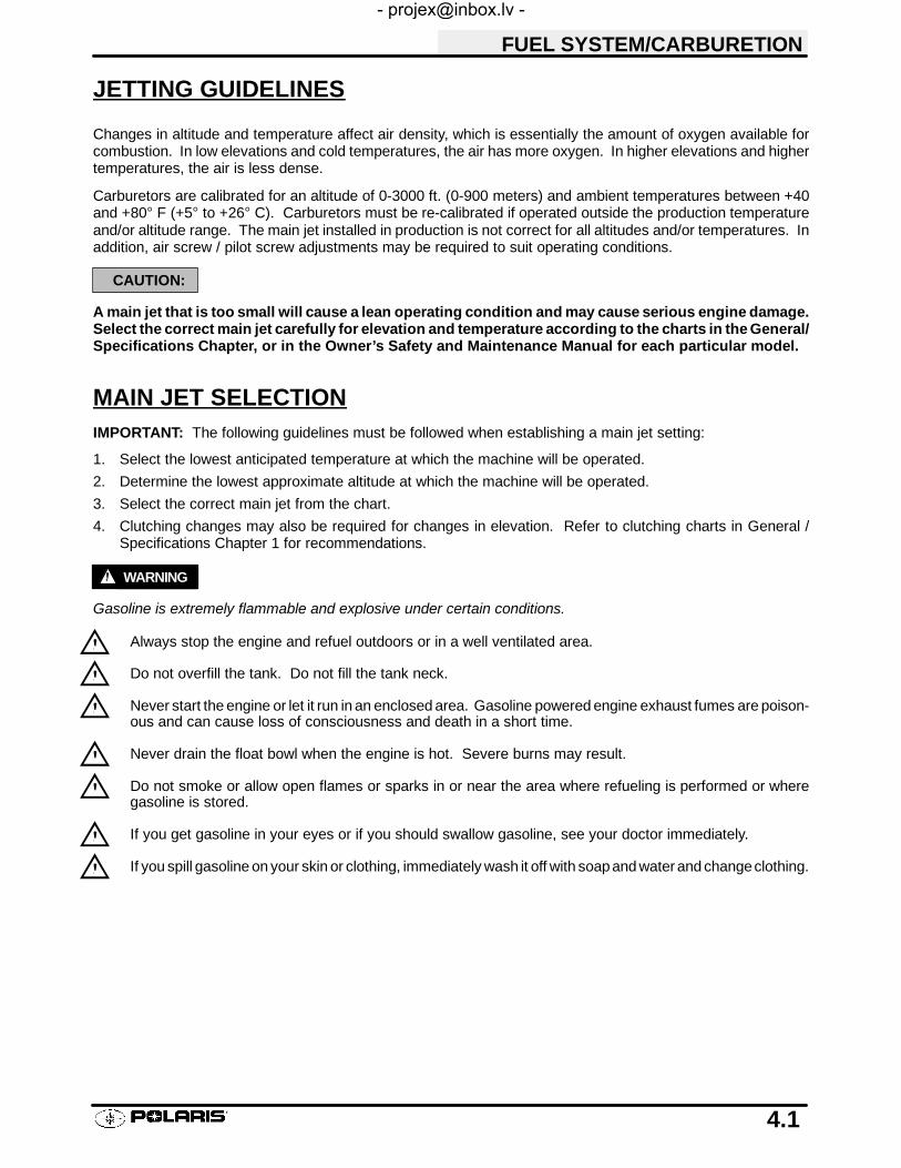
FUEL SYSTEM/CARBURETION
4.1
JETTING GUIDELINES
Changes in altitude and temperature affect air density, which is essentially the amount of oxygen available forcombustion. In low elevations and cold temperatures, the air has more oxygen. In higher elevations and highertemperatures, the air is less dense.
Carburetors are calibrated for an altitude of 0-3000 ft. (0-900 meters) and ambient temperatures between +40and +80° F (+5° to +26° C). Carburetors must be re-calibrated if operated outside the production temperatureand/or altitude range. The main jet installed in production is not correct for all altitudes and/or temperatures. Inaddition, air screw / pilot screw adjustments may be required to suit operating conditions.
CAUTION:
A main jet that is too small will cause a lean operating condition and may cause serious engine damage.Select the correct main jet carefully for elevation and temperature according to the charts in the General/Specifications Chapter, or in the Owner’s Safety and Maintenance Manual for each particular model.
MAIN JET SELECTIONIMPORTANT: The following guidelines must be followed when establishing a main jet setting:
1. Select the lowest anticipated temperature at which the machine will be operated.
2. Determine the lowest approximate altitude at which the machine will be operated.
3. Select the correct main jet from the chart.
4. Clutching changes may also be required for changes in elevation. Refer to clutching charts in General /Specifications Chapter 1 for recommendations.
WARNING
Gasoline is extremely flammable and explosive under certain conditions.
Always stop the engine and refuel outdoors or in a well ventilated area.
Do not overfill the tank. Do not fill the tank neck.
Never start the engine or let it run in an enclosed area. Gasoline powered engine exhaust fumes are poison-ous and can cause loss of consciousness and death in a short time.
Never drain the float bowl when the engine is hot. Severe burns may result.
Do not smoke or allow open flames or sparks in or near the area where refueling is performed or wheregasoline is stored.
If you get gasoline in your eyes or if you should swallow gasoline, see your doctor immediately.
If you spill gasoline on your skin or clothing, immediately wash it off with soapand water and changeclothing.

FUEL SYSTEM/CARBURETION
4.3
FUEL FLOW DIAGRAM
Fuel Tank
Fuel Valve
Engine
FilterFuel Pump
Carburetor
Fuel Tank Vent
Carburetor Vent
Fitting Screens
L
L Located Above Oil Tank

FUEL SYSTEM/CARBURETION
4.4
MIKUNI JET PART NUMBERS
Main Jet Part NumbersMikuni BST Carburetor
Jet Number Part Number
112.5 3130554115 3130555117.5 3130556120 3130557122.5 3130558125 3130559127.5 3130560130 3130561132.5 3130562135 3130563137.5 3130564140 3130527142.5 3130566145 3130567147.5 3130568150 3130569152.5 3130570155 3130571157.5 3130572160 3131141162.5 3131142165 3131143167.5 3131144170 3131145
Mikuni BST Carburetor
Jet Number Part Number
40.0 3130624
42.5 3130526
Pilot Jet Part Numbers

FUEL SYSTEM/CARBURETION
4.5
CV CARBURETOR SYSTEM FUNCTION
Carburetor Component Function
System Main Components Main Function Main Affect
Float System(Fuel Level Control)
Inlet Pipe, Needle and Seat,Float, Float Pin
Maintains specified fuel levelin float chamber (carburetorfloat bowl)
All systemsAll throttle ranges
Venting Vent Passages in Carburetor,Vent lines (2) into (1) to frame
Supplies atmospheric pres-sure to fuel in float chamber
All systemsAll throttle ranges
Starter(Choke/Enrichment)
Choke Lever, Cable, ChokePlunger, Return Spring, CarbPassages (Starter Jet, StarterBleed Pipe)
Supplies additional fuel airmixture necessary for coldstarting
All throttle rangesGreatest effect at low throttlesettings and idle
Pilot (Idle System) Pilot Jet/Passageways, Pilot-Mixture Screw with SpringWasher and Sealing O-Ring,Bypass Ports (BehindThrottle Plate), Pilot Air Jet,Pilot Outlet, Throttle Plate
Primarily supplies fuel at idleand low throttle settings
Mainly idle to 1/4 throttleMinimal effect after 1/2throttle
Main System Main Jet, Main Air Jet, MainAir Passage, Needle Jet, JetNeedle, Vacuum Slide,Throttle Plate
Supplies fuel at mid-rangeand high throttle settings.
1/4 to full throttle
VENT SYSTEMS - CV CARBURETORThe carburetor float bowl vent lines supply atmosphericpressure to the fuel in the float bowl. The lines must befree of kinks and restrictions and be properly routed to al-low fuel to flow in the proper amount and to prevent con-taminants from entering the carburetor.
To frame Vent lines

FUEL SYSTEM/CARBURETION
4.6
MIKUNI CV CARB OPERATION
The constant velocity carburetor incorporates a mechanically operated throttle plate and a vacuum controlledslide valve (vacuum slide). The venturi cross-sectional area in the carburetor bore is increased or decreasedautomatically by the vacuum slide, which moves according to the amount of negative pressure (less than atmo-spheric) present in the venturi.
A diaphragm attached to the top of the vacuum slide is sealed to the slide and to the carburetor body forming twochambers. The chamber above the diaphragm is connected to the venturi area by a drilled orifice in the centerof the vacuum slide. The chamber below the diaphragm is vented to atmospheric pressure by a passage on theair box side of the carburetor. A spring, installed in the center of the vacuum slide, dampens the slide movementand assists the return of the slide.
When the throttle plate is opened and engine speed begins to increase, the pressure in the venturi (and thereforein the chamber above the diaphragm) becomes significantly lower than atmospheric. Atmospheric pressure inthe chamber below the diaphragm forces the diaphragm upward, raising the slide against spring pressure. Whenthe pressure above and below the diaphragm are nearly equal, the slide moves downward under spring pressure.Raising or lowering the slide increases or decreases the cross sectional area in the venturi, and therefore the airvelocity in the venturi is kept relatively constant. This provides improved fuel atomization and optimum fuel/airratio.
Note: Diagrams are for explanation of theory only, and are not true representations of Mikuni BST carburetor.
Air Flow
Low Pressure
Air Flow
Low Pressure
Air BoxPressure
FromAir Box
Venturi
Low PressureFrom Venturi
FromAir Box
ThrottlePlate
ThrottlePlate
Diaphragm Diaphragm
VacuumSlide
VacuumSlide
Low PressureFrom Venturi

FUEL SYSTEM/CARBURETION
4.7
PILOT (IDLE AND SLOW) SYSTEM
This system supplies fuel during engineoperation with throttle valve closed (1) orslightly opened. The fuel from float cham-ber (2) is metered by pilot jet (3) where itmixes with air coming in through pilot airjet (4). The mixture then goes up throughpilot passage to pilot screw (5). A part ofthe mixture is discharged into the mainbore out of bypass ports (6). The remain-der is then metered by pilot screw and dis-charged into the main bore through pilotoutlet (7).
STARTER SYSTEM (CHOKE OR ENRICHMENT)
When the choke cable (1) is activated, thestarter plunger (5) is lifted off the seat.Fuel is drawn into the starter circuit fromthe float chamber (2) through the starterjet (3). Starter jet meters this fuel, whichthen flows into starter pipe (4) and mixeswith the air (7) coming from the floatchamber. The mixture, rich in fuel con-tent, reaches starter plunger and mixesagain with the air coming through a pas-sage (8) extending from underneath thediaphragm. The rich fuel/air mixture forstarting is discharged through starter out-let (6) in the the main bore.
4
1
6
7
5
2
3
158
6
4
2
3
7

FUEL SYSTEM/CARBURETION
4.8
FLOAT SYSTEM
Fuel enters the float chamber (3) bymeans of the inlet pipe and passage,through a screen on the back of the inletneedle seat (4), and around the inletneedle (2). As the fuel fills the float cham-ber, the float (1) rises and forces the inletneedle against the seat, shutting off theorifice in the seat. When fuel level is up infloat chamber, floats are up and needlevalve remains pushed up against valveseat. Under this condition, no fuel entersthe float chamber. As the fuel level falls,floats go down and needle valve unseatsitself to admit fuel into the chamber. In thismanner, the needle valve admits andshuts off fuel alternately to maintain apractically constant fuel level inside thefloat chamber.
MAIN SYSTEM
As throttle valve (1) is opened, enginespeed rises, and this increases negativepressure in the venturi. Consequently thevacuum slide (2) moves upward. The fuelin float chamber (3) is metered by main jet(4), and the metered fuel enters needle jet(5), in which it mixes with the air admittedthrough main air jet (6) to form an emul-sion. The emulsified fuel then passesthrough the clearance between needle jet(5) and jet needle (7), and is dischargedinto the venturi (A). Mixture proportioningis accomplished in needle jet (5); the clear-ance through which the emulsified fuelmust flow is determined ultimately bythrottle position and vacuum slide height.
InletPipe
1
42
3
1
A
5
4
3
6
7
2

FUEL SYSTEM/CARBURETION
4.9
BST 34 CARBURETOR EXPLODED VIEW 1. Carburetor Assembly
2. Screw
3. Throttle Valve
4. Cover, Diaphragm
5. Jet Block Assembly
6. Spring
7. Diaphragm Assembly
8. Ring
9. “E” Ring
10.Ring
11. Needle Jet
12.Cover
13.O-Ring
14.Throttle Shaft Assembly
15.Ring
16.Seal
17.Spring
18.Packing
19.“E” Ring
20.Cap
21.Screw
22.Drain Screw
23.O-Ring
24.Washer
25.Adjuster
26.Spring
27.Pilot Jet
28.Main Jet
29.Washer
30.Jet Needle
31.Float Assembly
32.Float Body Assembly
33.Float Pin
34.Needle Valve
35.O-Ring
36.O-Ring
37.Filter
38.Screw
39.Screw
40.Screw
41.Guide Holder
42.Spring
43.Plunger Assembly
44.Spring Washer
45.Screw
46.Air Jet
47.Cable Guide
48.Spring
49.Ring
50.Adjust Screw
51.Screw and Washer Assy.
Refer to Page 4.4 for Jet Part Numbers
12
34
5
Jet Needle“E” Clip Position
22

FUEL SYSTEM/CARBURETION
4.10
BST 40 CARBURETOR EXPLODED VIEW
Refer to Page 4.4 for Jet Part Numbers
1
2
345
6
7
8
9
10
1112
13
14
15
16
17
18
19
20
2122
23
2425
2627
28
2930
1. Cover, Diaphragm
2. Spring
3. Spring Seat
4. “E” Clip
5. Spacer
6. Jet Needle
7. Diaphragm Assembly
8. Throttle Valve
9. Cable Guide
10.Spring
11. Adjuster Cable
12.Drain Plug
13.O-Ring
14.Jet, Main
15.Spacer Ring
16.Drain Screw
17.O-Ring
18.Float Assembly
19.Plug
20.Pilot Screw
21.Spring
22.Washer
23.O-Ring
24.Pilot Jet
25.Valve, Inlet Needle
26.Shaft Seal
27.O-Ring
28.Air Jet
29.Choke Plunger Guide
30.Spring
31.Choke Plunger
32.Cap
33.O-Ring
34.Jet Block Assembly
35.Needle Jet
36.Case
3132
33
34
35
36

FUEL SYSTEM/CARBURETION
4.11
CARBURETOR DISASSEMBLY - MIKUNI CVUse the following disassembly, assembly, and inspection techniques to service a CV carburetor.
1. Remove carburetor diaphragm chamber cover witha ratchet style screwdriver. DO NOT use an impactdriver to remove the screws or carburetor may bepermanently damaged.
2. Use a small spring loaded center punch to removepressed float pin.
NOTE:Set the center punch to the softest setting (if adjust-able) to avoid damage to float pin tower.
3. Remove inlet needle seat retaining screw along withplate, and carefully remove needle seat. NOTE: Donot use a pliers to remove the seat or permanentdamage may occur.

FUEL SYSTEM/CARBURETION
4.12
CARBURETOR DISASSEMBLY - MIKUNI CV, CONT.
4. Do not misplace the pilot mixture screw, spring, flatwasher, or O-Ring. If anti-tamper plug is installed inpilot screw cavity, refer to Maintenance chapter 2 forremoval procedure.
5. NOTE: The starter jet is not removeable.
CARBURETOR CLEANING
1. Thoroughly clean the carburetor body, jets, and all passages with carburetor cleaner or electrical contactcleaner.
WARNING
Protect eyes from contact with cleaner. If you get cleaner in your eyes or if you swallow cleaner, see your doctorimmediately. Some carburetor cleaners are extremely caustic and extended periods of soaking can loosen theadhesive sealer on the passage drill-way plugs. Do not soak rubber or plastic components (such as the vacuumslide diaphragm, needle seat screen, or O-Rings in caustic cleaning solutions. Irreparable damage may occur.Do not use agitator type carburetor cleaning equipment. Rubber parts must be cleaned with mild detergent andhot water only.
2. If the carburetor is extremely dirty or contaminated with fuel residue and varnish, soak for short periods only incarburetor cleaner, and rinse in hot water.
3. Replace the jets if they are extremely dirty or have a buildup of fuel residue or bacterial growth. Even a smallamount of residue will reduce the flow characteristics of the jet.
4. Verify all passages and jets are unobstructed by spraying electrical contact cleaner through the passages.CAUTION: Do not use wire or welding tip cleaners on the jets as the orifice size may be altered.
5. Use low pressure air to dry carburetor body and all components.
O-Ring
Washer
Spring
Pilot Screw
Starter Jet

FUEL SYSTEM/CARBURETION
4.13
CARBURETOR INSPECTION
1. Inspect jet needle and needle jet for wear. Look fordiscoloration, shiny spots, or and area that looksdifferent than the rest of the needle. The middle toupper portion of the needle where it contacts theneedle jet is the most likely wear point. If jet needleshows signs of wear replace both needle and needlejet to prevent a rich condition.
2. Inspect the inlet needle tapered surface for any sign ofwear or damage. Be sure the spring loaded pin is freemoving and returns freely when pushed. The inletneedle and seat should be pressure tested afterassembly.
Inspect thisarea
Good Condition Worn, Deposits
Wear areas
Seat
Needle

FUEL SYSTEM/CARBURETION
4.14
CARBURETOR ASSEMBLY
1. Inspect the diaphragm (A) for holes,deterioration, or damage. Make sure thediaphragm is pliable but not swollen. Thediaphragm should fit properly in the carburetorbody. Replace diaphragm assembly ifdiaphragm is damaged.
2. Replace parts in proper order. The spring seatwasher (B) is stepped and must be placed onTOP of “E” Clip (C). Spacer washer (D) mustbe installed below the E-Clip. Refer to partsmanual for more information.
3. Be sure the tab (E) on outer edge ofdiaphragm is positioned properly in thecarburetor body.
4. Install the pilot mixture screw, spring, washer, andO-ring as an assembly. Lubricate the O-Ring with oil orlight grease before installation. CAUTION: Do notdamage the O-ring during installation. Turn the screwin until it lightly contacts the seat. Back out thespecified number of turns. NOTE: The final pilot (idle)mixture must be adjusted with the engine running.Refer to Page 2.14.
E
D
C
A
B
Pilot Screw
Pilot Mixture Screw Base Setting(Turns Out)
Refer to General / SpecificationsChapter 1

FUEL SYSTEM/CARBURETION
4.15
FLOAT HEIGHT ADJUSTMENT1. Place the carburetor on a level surface as shown at
right to remove weight from float arm. In this position,the float tongue will rest lightly on the inlet needle valvepin without compressing the spring.
2. Measure the height from the float bowl mating surfaceto the top of step in float as shown. Both sides of floatshould be parallel to each other. The measurementshould be made at the mid-point on the top of the floatusing float adjustment tool (PN 2872314) or a verniercaliper. When measuring the height be sure the inletneedle valve spring is not compressed.
3. If adjustment is necessary, bend the tongue slightly.Be sure float arms are even on left and right side.
Float Height:
Std: BST 34 13.0mm (.51″) ± 1 mmBST 40 14.7mm (.58″) ± 1 mm
Bend to adjustfloat
Float arms even

FUEL SYSTEM/CARBURETION
4.16
NEEDLE AND SEAT LEAKAGE TEST
1. Install the float bowl. Invert the carburetor and install aMity-Vac™ (PN 2870975) to the fuel inlet fitting. Apply5 PSI pressure to inlet fitting. The needle and seatshould hold pressure indefinitely. If not, inspect needleand seat and seat O-ring.
FUEL LEVELA fuel level test can be performed on some models if thedrain hose fitting is accessible. Be sure to re-attach thebowl drain hose after performing the test. A fuel level testallows you to observe the height of the fuel in the float bowlwithout removing the carburetor. The fuel level can be ob-served with the engine either running or shut off, however,engine must run briefly to allow fuel level to stabilize..
1. Attach a clear line to drain fitting. Be sure line fits tightlyon fitting. Position hose along side of carburetor asshown.
2. Open bowl drain screw by turning counterclockwiseapproximately two turns. Start and run engine for 3 to 5seconds to allow fuel level to stabilize in the line. If levelis out of specification, remove carburetor and inspectinlet needle and seat, float height, passages, etc.
3. If a line was removed to perform this procedure, it mustbe replaced.
Mity Vac™ PN 2870975
1.5 mm.060″
Bowl MatingSurface

FUEL SYSTEM/CARBURETION
4.17
FUEL PUMP
The Polaris Sportsman is equipped with a pressure regulated fuel pump (about 1-3 PSI). The pump is locatedunder the headlight cover at the front of the machine. Refer to illustration on following page for fuel pump compo-nent identification.
To test the fuel pump:1. Turn fuel off.2. Disconnect impulse line from pump.3. Connect Mity-Vac™ (PN 2870975) to the impulse line fitting on the pump.
4. Apply 5 inches (Hg) vacuum to the pump fitting. The diaphragm should hold vacuum indefinitely.
If fuel is present in the impulse line or vacuum chamber of the pump, the diaphragm is ruptured and the pumpdiaphragms must be replaced.
FUEL PUMP DISASSEMBLY1. Refer to illustration on following.2. Remove the screws from the pump diaphragm cover. Note the location of the two longer screws.3. Remove the diaphragm cover gasket, diaphragm, and valve body gasket.4. Remove the outlet check valve cover, diaphragm, and gasket.
FUEL PUMP INSPECTION/ASSEMBLY1. Inspect inlet and outlet check valves for cracks,
warpage or damage. Inspect the diaphragms forcracks, holes or swelling.
2. To clean the valves or pump body, remove the setscrew and washer. Remove the valve and washwith soap and water. Carburetor cleaner may beused to clean the pump body when the check valvesare removed. CAUTION: Some carburetorcleaners are very caustic and should not be used toclean the non-metal parts of the fuel pump.
3. Check the sealing surfaces of the pump body andcovers. Carefully remove all traces of old gasketand check the surfaces for damage. Replacediaphragms and gaskets as a set.
4. Reassemble the pump in the reverse order ofdisassembly. Tighten all screws evenly.

FUEL SYSTEM/CARBURETION
4.18
FUEL PUMP EXPLODED VIEW
32
1
5
54
1. Fuel Pump Assembly2. Diaphragm, Gasket Set3. Screw and Washer Assembly4. Screw and Washer Assembly5. Screw and Washer Assembly6. Pressure Regulator7. Fuel Inlet8. Fuel Outlet
6
8
7

FUEL SYSTEM/CARBURETION
4.19
TROUBLESHOOTINGFuel Starvation/Lean Mixture
Symptoms: Hard start or no start, bog, backfire, popping through intake / exhaust, hesitation, detonation, lowpower, spark plug erosion, engine runs hot, surging, high idle, idle speed erratic.
S No fuel in tank
S Restricted tank vent, or routed improperly
S Fuel lines or fuel valve restricted
S Fuel filter plugged
S Carburetor vent line(s) restricted
S Plugged or restricted inlet needle and seat screen or inlet passage
S Clogged jets or passages
S Float stuck, holding inlet needle closed or inlet needle stuck
S Float level too low
S Fuel pump inoperative
S Air leak at impulse line
S Restricted impulse line (kinked, pinched)
S Intake air leak (throttle shaft, intake ducts, airbox or air cleaner cover)
S Ruptured vacuum slide diaphragm, Vacuum slide stuck closed or sticky
S Improper spring
S Jet needle position incorrect
S Incorrect pilot screw adjustment
Rich Mixture
Symptoms: Fouls spark plugs, black, sooty exhaust smoke, rough idle, poor fuel economy, engine runs rough/misses, poor performance, bog, engine loads up, backfire.
S Air intake restricted (inspect intake duct)
S Air filter dirty/plugged
S Choke plunger sticking, incorrectly adjusted choke
S Choke cable binding or improperly routed
S Incorrect pilot air/fuel screw adjustment
S Faulty inlet needle and seat
S Faulty inlet needle seat O-Ring
S Float level too high
S Poor fuel quality (old fuel)
S Loose jets
S Worn jet needle/needle jet or other carburetor parts
S Dirty carburetor (air bleed passages or jets)
S Weak or damaged vacuum piston return spring
S Fouled spark plug
Poor Idle
Symptoms: Idle too high.
S Idle adjusted improperly/idle mixture screw damaged
S Sticky vacuum slide
S Throttle cable sticking, improperly adjusted, routed incorrectly
S Choke cable sticking, improperly adjusted, routed incorrectly

FUEL SYSTEM/CARBURETION
4.20
TROUBLESHOOTING, CONT.Idle Too Low
S Choke cable bending or incorrectly adjustedS Idle speed set incorrectlyS Idle mixture screw misadjusted or damagedS Belt draggingS Ignition timing incorrect
S Worn jet needle/needle jetErratic Idle
S Choke cable bending or incorrectly adjustedS Throttle cable incorrectly adjustedS Air leaks, dirty carburetor passages (pilot circuit)
S Pilot mixture screw damaged or adjusted incorrectlyS Tight valvesS Ignition timing incorrectS Belt draggingS Dirty air cleanerS Engine worn
S Spark plug fouledS Idle speed set incorrectly (speed limiter)S Worn jet needle/needle jet

5
CHAPTER 5BODY AND STEERING
Torque Specifications and Special Tools 5.1. . . . . . . . . . . .
Body Assembly, Exploded View 5.2. . . . . . . . . . . . . . . . . . .
Cover/Panel Removal 5.3. . . . . . . . . . . . . . . . . . . . . . . . . . . .
Headlight Pod Exploded View 5.4. . . . . . . . . . . . . . . . . . . . .
Side Panel Removal 5.5. . . . . . . . . . . . . . . . . . . . . . . . . . . . .
Steering Assembly, Exploded View 5.6. . . . . . . . . . . . . . . .
A-Arm Replacement 5.7. . . . . . . . . . . . . . . . . . . . . . . . . . . . .
Rear Suspension Assembly 5.8. . . . . . . . . . . . . . . . . . . . . . .
Strut Assembly Exploded View 5.9. . . . . . . . . . . . . . . . . . . .
Front Strut Weldment Replacement 5.10. . . . . . . . . . . . . . . .
Front Strut Ball Joint Replacement 5.11. . . . . . . . . . . . . . . . .
Steering Post Assembly 5.12. . . . . . . . . . . . . . . . . . . . . . . . . .
Decal Replacement 5.12. . . . . . . . . . . . . . . . . . . . . . . . . . . . . .

BODY / STEERING / SUSPENSION
5.1
TORQUE SPECIFICATIONSFront A-Arm Attaching Bolt 30 ft. lbs. (41 Nm). . . . . . . . . . . . . . . . .
Front A-Arm Ball Joint Stud Nut 25 ft. lbs. (35 Nm). . . . . . . . . . . . .
Handlebar Adjuster Block 10-12 ft. lbs. (14-17 Nm). . . . . . . . . . . . . . . . . . .
Master Cylinder 45-55 in. lbs. (5.2-6.3 Nm). . . . . . . . . . . . . . . . . . . . . . . . . . .
Rear Shock Bolt (upper) 30 ft. lbs. (41 Nm). . . . . . . . . . . . . . . . . . . .
Rear Shock Bolt (lower) 30 ft. lbs. (41 Nm). . . . . . . . . . . . . . . . . . . .
Rear Wheel Hub Nut 100 ft. lbs. (136 Nm). . . . . . . . . . . . . . . . . . . . . .
Rear Wheel Nuts 20 ft. lbs. (27 Nm). . . . . . . . . . . . . . . . . . . . . . . . . .
Upper Stabilizer Support Nut 17 ft. lbs. (24 Nm). . . . . . . . . . . . . . . .
Upper Control Arm Mounting Bolt 35 ft. lbs. (48 Nm). . . . . . . . . . . .
Lower Control Arm Mounting Bolt 30 ft. lbs. (41 Nm). . . . . . . . . . . .
Upper Wheel Bearing Carrier Bolt 35 ft. lbs. (48 Nm). . . . . . . . . . .
Lower Wheel Bearing Carrier Bolt 30 ft. lbs. (41 Nm). . . . . . . . . . .
Strut Rod Retaining Nut (Top) 15 ft. lbs. (21 Nm). . . . . . . . . . . . . . .
Strut Casting Pinch Bolt 15 ft. lbs. (21 Nm). . . . . . . . . . . . . . . . . . . .
Tie Rod End Jam Nut 12-14 ft. lbs. (17-19 Nm). . . . . . . . . . . . . . . . . . . . . .
Tie Rod End Castle Nut 40-45 ft. lbs. (54-61 Nm). . . . . . . . . . . . . . . . . . . .
Tie Rod End Attaching Bolt 25-30 ft. lbs. (35-41 Nm). . . . . . . . . . . . . . . . .
NOTE: Refer to exploded views throughout this chapter for identification and location of components.
SPECIAL TOOLSDescription Part No.
Strut and Ball Joint Tool Set 2870871. . . . . . . . . .
Shock Spanner Wrench 2870872. . . . . . . . . . . . .
Shock Spring Compressor Tool 2870623. . . . . . .
Strut Rod Holding Wrench 2871572. . . . . . . . . . .
Strut Spring Compressor Tool (LH) 2871573. . .
Strut Spring Compressor Tool (RH) 2871574. . .
Optional Fox™ Shock Tools
Body Holding Tool 2871017. . . . . . . . . . . . . . . . . .
Safety Needle 7052069. . . . . . . . . . . . . . . . . . . . . .
Shock Spring Compressor Tool 2870623. . . . . . .
Gas Shock Recharging Kit 2200421. . . . . . . . . . .
Damper Rod Holding Tool 2871352. . . . . . . . . . .
Fox™ Shock IFP Tool 2871351. . . . . . . . . . . . . . .

BODY / STEERING / SUSPENSION
5.2
BODY ASSEMBLY EXPLODED VIEW
Rear Cab Assembly
Front Cab Assembly
Seat LatchRelease
Storage
Rear Mud Guard
Rear Cab
Side Cover
Front Cover
Front CabFootrest
Front MudGuard
Pull UP on rear of seat and backto disengage tabs at front of seat
All warning information labels must be in place when body parts are assembled.

BODY / STEERING / SUSPENSION
5.3
COVER/PANEL REMOVALTo Remove: Perform These Steps:
Seat Pull release lever at the rear of the seat. . . . . . . . . . . . . . . . . . . . . . .Lift and pull seat rearward, disengaging seat from tabs at the rear of the fuel tank
Side panels (See page 5.5) Remove: Seat. . .Disengage tabs at front and rear
Headlight pod (See page 5.4)
Front cover Remove: Front rack. . . . . . . . . . . . . . . . .Disengage tabs at front and rearLift panel out
Rear rack Remove: Seat. . . . . . . . . . . . . . . . . .2 bolts at rear of rack2 bolts at front of rack
Rear cab assembly Remove: Seat. . . . . . . . . .Rear rack1 screw, nut and washer at rear of inner left footrest4 screws at bottom of left rear mudflap1 screw, nut and washer at rear of inner right footrest4 screws at bottom of right rear mudflap4 bolts and flat washers from top of cab assembly, under seat2 screws at rear bottom of cab assembly near tail light
Disconnect taillight harness
Front rack Remove: 4 screws, lock washers, and flat washers. . . . . . . . . . . . . . . . . .
Front cab assembly Remove: Seat. . . . . . . . . .Side panels2 screws at rear of cab at fuel tank mount bracketFront rackFront bumperFront cover panel3 screws from bottom left mudflap3 screws from bottom right mudflap1 inner screw from front cab to foot rest on each side2 screws under front panel

BODY / STEERING / SUSPENSION
5.4
HEADLIGHT POD EXPLODED VIEW
11-13 ft. lbs.(15-18 Nm)
Clean knurling whenrepositioning handlebars
Adjuster
Torque bolts evenly so gapis equal at front and rear ofhandlebar block
Disassembly
S Remove two front Phillips screws (A).S Remove three rear Phillips screws (B).S Lift top half of pod.
S Disconnect speedometer cable or wire connec-tors.
S Disconnect indicator light wire coupler andheadlight.
S Disconnect 12V power plug (where applicable).S Remove ignition switch (C) and choke cable (D).
S Remove headlight with adjuster.S Remove two screws securing bottom
half of pod (E).
Assembly
S Install bottom of pod onto handlebar and secure to brackets.S Install key switch, choke cable, and headlight.S Connect indicator light wire coupler to indicator lights in top half of pod.
S Connect 12V power outlet (where applicable)S Connect headlight.S Connect speedometer cable or connectors to speedometer.S Install top of pod onto bottom half, making sure interlocking tabs mate properly.S Install two front Phillips screws. NOTE: When assembling a new pod, use the screw to pre-thread
the two front holes in the top pod before mating halves.
S Install three rear Phillips screws, aligning with Tinnerman™ clips.S To adjust headlight, refer to procedure outlined in Maintenance chapter.S To apply decals, refer to 5.12.
Handlebar clamp torque:
11-13 ft. lbs. (15-18 Nm)
To harnessconnector
A
B
C
D
E

BODY / STEERING / SUSPENSION
5.5
SIDE PANEL REMOVAL
Side panel removal may be difficult until the lockingtabs and receivers have been snapped and un-snapped a few times.
1. Remove seat. Grasp rear of side panel near rearcab. With a quick and firm motion, pull the panelforward and outward to disengage the two reartabs.
2. Place hand on top of side panel behind the fueltank. With a quick and firm motion, push downon the side panel to disengage the top rear twotabs. Then pull up on side panel to disengagefront upper and lower tab.
3. To reinstall side panel, align panel tabs with slots onfront cab. Push panel upward and forward until tabslock. Bend rear of side panel and insert the two tabsinto the rear cab.
Pull forward and out to disengagetwo rear tabs.
Step 1.
Push down to disengage top reartwo tabs.
Step 2.
To reinstall, align panel tabs withslots. Push upward and forwarduntil tabs lock.
Step 3.

BODY / STEERING / SUSPENSION
5.6
STEERING ASSEMBLY, EXPLODED VIEW
25-30 ft. lbs.(35-41 Nm)
Loctite™ 2428 ft. lbs.(11 Nm)
25 ft. lbs.(35 Nm)
30 ft. lbs.41 Nm)
Always use new boltsupon reassembly
Always use new cotter pins uponreassembly. Install w/ open end to-ward rear of machine.
B
1
2
1
30 ft. lbs.41 Nm)
A
2
12-14 ft. lbs.(17-17 Nm)
40-45 ft. lbs.54-61 Nm)
Steering Post
Steering PostArm (Frog)
1 2
NOTE:To avoid damage to tie rods and other steeringcomponents, be sure to install tie rod end bolts in theproper direction. The steering post arm bolt (B) points up;the rod end bolts (A) point down. Be sure inner rod endsare placed between the steering post arms.
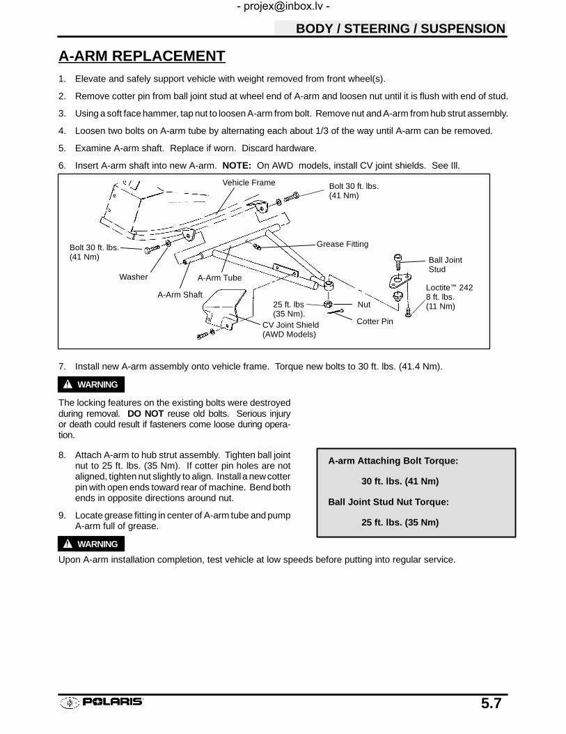
BODY / STEERING / SUSPENSION
5.7
A-ARM REPLACEMENT1. Elevate and safely support vehicle with weight removed from front wheel(s).
2. Remove cotter pin from ball joint stud at wheel end of A-arm and loosen nut until it is flush with end of stud.
3. Using a soft face hammer, tap nut to loosen A-arm from bolt. Remove nut and A-arm from hub strut assembly.
4. Loosen two bolts on A-arm tube by alternating each about 1/3 of the way until A-arm can be removed.
5. Examine A-arm shaft. Replace if worn. Discard hardware.
6. Insert A-arm shaft into new A-arm. NOTE: On AWD models, install CV joint shields. See Ill.
7. Install new A-arm assembly onto vehicle frame. Torque new bolts to 30 ft. lbs. (41.4 Nm).
WARNING
The locking features on the existing bolts were destroyedduring removal. DO NOT reuse old bolts. Serious injuryor death could result if fasteners come loose during opera-tion.
8. Attach A-arm to hub strut assembly. Tighten ball jointnut to 25 ft. lbs. (35 Nm). If cotter pin holes are notaligned, tighten nut slightly to align. Install a newcotterpin with open ends toward rear of machine. Bend bothends in opposite directions around nut.
9. Locate grease fitting in center of A-arm tube and pumpA-arm full of grease.
WARNING
Upon A-arm installation completion, test vehicle at low speeds before putting into regular service.
Vehicle Frame
Grease Fitting
Nut
Cotter Pin
Ball JointStud
CV Joint Shield(AWD Models)
A-Arm Tube
A-Arm Shaft
Bolt 30 ft. lbs.(41 Nm)
Washer
25 ft. lbs(35 Nm).
Loctite™ 2428 ft. lbs.(11 Nm)
Bolt 30 ft. lbs.(41 Nm)
A-arm Attaching Bolt Torque:
30 ft. lbs. (41 Nm)
Ball Joint Stud Nut Torque:
25 ft. lbs. (35 Nm)

BODY / STEERING / SUSPENSION
5.8
REAR SUSPENSION ASSEMBLY
Forward
17 ft. lbs.(24 Nm)
35 ft. lbs.(48 Nm)
UpperControlArm
OrientateBushingsCorrectly
30 ft. lbs.(41 Nm)
30 ft. lbs.(41 Nm)
LowerControlArm
35 ft. lbs.(48 Nm)
100 ft. lbs.(136 Nm)
20 ft. lbs.(27 Nm)
17 ft. lbs.(24 Nm)
35 ft. lbs.(48 Nm)
30 ft. lbs.(41 Nm)
Rear Front
Bushing Orientation

BODY / STEERING / SUSPENSION
5.9
STRUT ASSEMBLY
NOTE: Be sure steel insert notch (1) and strut casting notch are lined up and provide a channel for themagnetic coil wires to lie in. If insert and strut do not match, strut replacement will be necessary.
Grease fitting (2) location. Check lubrication guide for recommended service intervals.
Specified pole gap is 0-.001″ (0-.0254mm)
1
2
15 ft. lbs.(21 Nm)
Nut15 ft. lbs.(21 Nm)
18 ft. lbs.(25 Nm)
Seal SleeveInstall Using tool PN 2871199
Washer
Upper Pivot Ball
Lower Pivot Ball
Washer
Spacer Rubber
Spring Retainer
Spring
Bolt
Spacer
Washer
Clamp
Wire retainer
Hub Coil
Spring Retainer
Strut Bumper

BODY / STEERING / SUSPENSION
5.10
FRONT STRUT CARTRIDGE REPLACEMENTREFER TO ILLUSTRATION ON PAGE 5.9.
1. Hold strut rod and remove top nut.
2. Compress spring using strut spring compressortools.
3. Remove upper strut pivot assembly.
4. Remove coil spring and collapse strut cartridge.
5. Remove two pinch bolts from strut casting.
6. Remove strut cartridge.
7. Install cartridge until bottomed in strut casting.
8. Install pinch bolts with wire clamp(s). Torque pinchbolts to 15 ft. lbs. (21 Nm).
9. Reassemble spring and top pivot assembly. Besure all parts are installed properly and seated fully.
10. Torque strut rod nut to specification. Do not overtorque nut.
Strut Spring Compressor ToolsPN 2871573 and PN 2871574
Strut Rod Nut Torque
15 ft. lbs. (21 Nm)

BODY / STEERING / SUSPENSION
5.11
BALL JOINT REPLACEMENTREFER TO ILLUSTRATION ON PAGE 5.9.
1. Loosen front wheel nuts slightly.
2. Elevate and safely support machine underfootrest/frame area.
CAUTION: Serious injury may result if machine tipsor falls. Be sure machine is secure before beginningthis service procedure.
3. Remove wheel nuts and wheels.
4. Remove cotter pin (A) from ball joint castlenut.
5. Remove castle nut (B) and separate A-arm (C)from ball joint stud.
6. Remove screws (D) and ball joint retaining plateplate (E).
7. Using ball joint removal / installation tool kit (PN2870871), remove ball joint (F) from strut housing.Refer to photos at right.S Install puller guide (A) with extension cap (B).S Apply grease to extension cap and threads of
puller bolt to ease removal.S Thread bolt (D) with nut (C) ontoball joint stud
as shown.S Apply heat to ease removal.S Hold bolt (D) and turn nut (C) clockwise until
ball joint is removed from strut housing.
8. To install new ball joint:S Remove extension cap and attach puller
guide using short bolts provided in the kit.S Insert new ball joint (E) into driver (F).S Slide ball joint/driver assembly into guide.S Apply heat to ease installation.S Drive new joint into strut housing until fully
seated.
9. Apply Loctitet 242 (blue) to threads of retainingplate screws or install new screws with pre-appliedlocking agent. Torque screws to 8 ft. lbs. (11 Nm).
10. Install A-arm on ball joint and torque castle nut to25 ft. lbs. (35 Nm).
11. Reinstall cotter pin with open ends toward rear ofmachine.
AB
C
D
E
F
AB
C
D
AB
C
ED
F
E

BODY / STEERING / SUSPENSION
5.12
STEERING POST ASSEMBLY
Grease Fitting
12 ft. lbs. (16 Nm)
1. Hand tighten.2. Align cotter pin hole.3. Install cotter pin. Bendboth ends of cotter pin aroundnut in opposite directions.4. Check steering, must movefreely and easily from full leftto full right without binding.
12 ft. lbs. (16 Nm)
DECAL REPLACEMENTPlastic polyethylene material must be “flame treated” prior to installing a decal to ensure good adhesion. Theflame treating procedure can often be used to reduce or eliminate the whitish stress marks that are sometimesleft after a fender or cab is bent, flexed, or damaged.
WARNING
The following procedure involves the use of an open flame. Perform this procedure in a well ventilated area,away from gasoline or other flammable materials. Be sure the area to be flame treated is clean and free of gasolineor flammable residue.
To flame treat the decal area:
1. Pass the flame of a propane torch back and forth quickly over the area where the decal is to be applied until thesurface appears slightly glossy. This should occur after just a few seconds of flame treating. Do not hold thetorch too close to the surface. Keep the torch moving to prevent damage.
2. Apply the decal.

6
CHAPTER 6PVT SYSTEM
Service Tools, Supplies & Torques 6.1. . . . . . . . . . . . . .
PVT System Operation 6.2. . . . . . . . . . . . . . . . . . . . . . . .
PVT Maintenance/Inspection 6.3-6.4. . . . . . . . . . . . . . . . . . .
PVT Disassembly 6.5-6.6. . . . . . . . . . . . . . . . . . . . . . . . . . . . .
PVT Assembly 6.7. . . . . . . . . . . . . . . . . . . . . . . . . . . . . . .
PVT Sealing and Ducting Components 6.8. . . . . . . . . .
Clutch System Operation Overview 6.9. . . . . . . . . . . . .
Drive Clutch Spring Specifications 6.10. . . . . . . . . . . . . .
Shift Weights 6.11. . . . . . . . . . . . . . . . . . . . . . . . . . . . . . . . .
Drive Clutch Inspection 6.12. . . . . . . . . . . . . . . . . . . . . . . .
Drive Clutch Exploded View 6.13. . . . . . . . . . . . . . . . . . . .
Drive Clutch Disassembly 6.14-6.16. . . . . . . . . . . . . . . . . . . . . .
Drive Clutch Assembly 6.17-6.18. . . . . . . . . . . . . . . . . . . . . . . .
Drive Belt Tension 6.18. . . . . . . . . . . . . . . . . . . . . . . . . . . .
Drive Belt Removal/Inspection 6.19-6.20. . . . . . . . . . . . . . . . .
Drive Belt Installation 6.20. . . . . . . . . . . . . . . . . . . . . . . . . .
Clutch Alignment /Offset 6.21. . . . . . . . . . . . . . . . . . . . . . .
Drive Clutch Bushing Service 6.22-6.25. . . . . . . . . . . . . . . . . .
Driven Clutch Disassembly/Inspection 6.26-6.28. . . . . . . . . . .
Driven Clutch Assembly 6.29. . . . . . . . . . . . . . . . . . . . . . .
Driven Clutch Bushing Service 6.30-6.33. . . . . . . . . . . . . . . . .
EBS Theory of Operation 6.34. . . . . . . . . . . . . . . . . . . . . .
EBS Operation Guidelines 6.35. . . . . . . . . . . . . . . . . . . . .
EBS Exploded View 6.36. . . . . . . . . . . . . . . . . . . . . . . . . . .
EBS Drive Clutch Disassembly/Inspection 6.37-6.38. . . . . . .
EBS Driven Clutch Disassembly/Inspection 6.39-6.41. . . . . .
EBS Drive Clutch Bushing Service 6.42-6.43. . . . . . . . . . . . . .
EBS Driven Clutch Bushing Service 6.44-6.45. . . . . . . . . . . . .
Troubleshooting 6.46-6.47. . . . . . . . . . . . . . . . . . . . . . . . . . . . . .

CLUTCH
6.1
SPECIAL SERVICE TOOLS AND SUPPLIESDescription Part NumberDrive Clutch Puller 2870506. . . . . . . . . . . . . . . . . . . . . . . . .Clutch Holding Fixture 2871358. . . . . . . . . . . . . . . . . . . . .Spider Removal Tool 2870341. . . . . . . . . . . . . . . . . . . . . . .Offset / Alignment Tool (Std) 2870654. . . . . . . . . . . . . . . .Driven Clutch Puller 2870913. . . . . . . . . . . . . . . . . . . . . . .Spider Pin Tool 2870910. . . . . . . . . . . . . . . . . . . . . . . . . . . .Clutch Bushing Removal & Installation 2871226. . . . . . .Piston Pin Puller (Used with 2871226) 2870386. . . . . . . .
EBS Offset / Alignment Tool 2872292. . . . . . . . . . . . . . . .EBS Clutch Bushing Tool Kit 2201379. . . . . . . . . . . . . . . .
Loctitet 680 2870584. . . . . . . . . . . . . . . . . . . . . . . . . . . . .RTV Silicone Sealer 2870661. . . . . . . . . . . . . . . . . . . . . . .Loctite Gasket Remover 2870601. . . . . . . . . . . . . . . . . . . .
PVT SYSTEM FASTENER TORQUESDrive Clutch Retaining Bolt 40 ft. lbs.. . . . . . . . . . . . . . . . .Driven Clutch Retaining Bolt 17 ft. lbs.. . . . . . . . . . . . . . . .PVT Inner Cover Bolts 12 ft. lbs.. . . . . . . . . . . . . . . . . . . . .Drive Clutch Spider (Standard Clutch) 200 ft. lbs.. . . . . . . .
(EBS Clutch) 185 ft. lbs.. . . . . . . . . . .Drive Clutch Spider Limiter Nut (EBS) 5 ft. lbs.. . . . . . . .Drive Clutch Cover Plate 90 in. lbs.. . . . . . . . . . . . . . . . . . .

CLUTCH
6.2
PVT OPERATION
The Polaris variable transmission (PVT) consists of three major assemblies: 1) drive clutch; 2) drive belt; and3) driven clutch. The internal components of the drive clutch and driven clutch control clutch engagement (forinitial vehicle movement), clutch upshifting and backshifting. During the development of an ATV, the PVT systemis matched first of all to the engine power curve; then to average riding conditions and to vehicle design usage.Modifications to the PVT or variations of components at random are never recommended. Proper PVT systemsetup and careful inspection of existing components must be the primary objective when troubleshooting and tun-ing.
WARNING
All PVT system maintenance repairs must be performed only by an authorized Polaris service technicianwho has attended a Polaris sponsored service training seminar and understands the proper procedures as out-lined in this manual. Because of the critical nature and precision balance incorporated into the PVT sys-tem, it is absolutely essential that no attempt at disassembly or repair be made without factory autho-rized special tools and service procedures.
DRIVE CLUTCH OPERATIONThe drive clutch primarily senses engine RPM. The two major components which control its shifting function arethe shift weights and the coil spring. When the engine RPM is increased, the centrifugal force of the shift weightsworking against the coil spring increases. When this force reaches a force higher than the preload in the spring,the moveable sheave of the drive clutch will move inward, contacting the drive belt. The force will pinch the beltbetween the spinning sheaves and cause the drive belt to move. This movement in turn rotates the driven clutch.
At light throttle settings the drive belt will stay low in the drive clutch and high in the driven clutch. As engine RPMincreases, so does the centrifugal force on the shift weights, causing the drive belt to be forced upward in the driveclutch and downward into the driven clutch. The forces in the driven clutch will now affect the upshift.
DRIVEN CLUTCH OPERATIONThe driven clutch primarily senses torque. It opens and closes according to the forces applied to it from the drivebelt and the transmission input shaft. If the torque resistance on the input shaft is greater than the load from thedrive belt, it will keep the drive belt outward at the top of the driven clutch sheaves. As the throttle setting andengine horsepower increase, there will be a greater load on the drive belt, pulling the belt down into the drivenclutch and up on the drive clutch. This action, which increases the driven clutch speed, is called upshifting.
If the throttle setting remains the same and the vehicle is subjected to a heavier load, the driven clutch sensesthis load, moving the belt back up on the sheaves of the driven clutch and down into thesheaves of the driveclutch.This action, which decreases the driven clutch speed, is called downshifting.
In situations where loads vary (such as uphill and downhill) and throttle settings are constant, the drive and drivenclutches are continually shifting to maintain optimum engine RPM. At full throttle a perfectly matched PVT systemwill hold the engine RPMs at the peak of the power curve. This RPM should be maintained during clutch upshiftand backshift. In this respect the PVT system is similar to a power governor. Rather than change throttle position,as a governor does, the PVT system changes engine load requirements by either upshifting or downshifting.
CLUTCH
6.3
PVT MAINTENANCE/INSPECTION
Under normal operation the PVT system will provide years of trouble free operation. Periodic inspection andmain-tenance is required to keep the system operating at peak performance. The following list of items should be in-spected and maintained to ensure maximum performance and service life of PVT components. Refer to the trou-bleshooting checklist at the end of this chapter for more information.
1. Belt Tension, Drive to Driven Clutch Offset, Belt Width. See pages 6.18-6.21.
2. Drive and Driven Clutch Buttons and Bushings, Drive Clutch Shift Weights and Pins, Drive ClutchSpider Rollers and Roller Pins, Drive and Driven Clutch Springs. See pages 6.10-6.12.
3. Sheave Faces. Clean and inspect for wear.
4. PVT System Sealing. Refer to appropriate illustration below and on the following pages. The PVT system isair cooled by fins on the drive clutch stationary sheave. The fins create a low pressure area in the crankcasecasting, drawing air into the system through an intake duct. The opening for this intake duct is locatedat ahighpoint on the vehicle (location varies by model). The intake duct draws fresh air through a vented cover. Allconnecting air ducts (as well as the inner and outer covers) must be properly sealed to ensure clean air isbeing used for cooling the PVT system and also to prevent water and other contaminants from entering thePVT area. This is especially critical on units subjected to frequent water forging.
PVT DRYINGIf water is ingested, shift transmission to neutral and rev engine slightly to expel the moisture and air-dry thebelt and clutches. Allow engine RPM to settle to idle speed, shift transmission to lowest available range andtest for belt slippage. Operate ATV in lowest available range for a short period of time until PVT system isdry.

CLUTCH
6.4
PVT OVERHEATING
During routine maintenance or whenever PVT system overheating is evident, it’s important to check the inletand outlet ducting for obstructions. Obstructions to air flow through the ducts will significantly increase PVTsystem operating temperatures. The ATV should be operated in LOW RANGE when pulling or plowing heavyloads, or if extended low speed operation is anticipated.
Clutch Drive Belt & Cover Related Issues: DiagnosisPossible Causes Solutions/What to do
Loading the ATV into a pickup or tall trailerwhen in high range.
Shift transmission to low range during loading of the ATV to pre-vent belt burning.
Starting out going up a steep incline. When starting out on an incline, use low range, or dismount theATV after first applying the park brake and perform the “K” turn.
Driving at low RPM or low ground speed (atapproximately 3--7 MPH).
Drive at higher speed or use Low Range. The use of Low Range ishighly recommended for cooler PVT operating temperatures andlonger component life.
Insufficient warm--up of ATVs exposed to lowambient temperatures.
Warm engine at least 5 min., then with transmission in neutral, ad-vance throttle to approx. 1/8 throttle in short bursts, 5 to 7 times.The belt will become more flexible and prevent belt burning.
Slow and easy clutch engagement. Fast, effective use of the throttle for efficient engagement.Towing/Pushing at low RPM/low groundspeed.
Use Low Range only.
Plowing snow, dirt, etc./utility use. Use Low Range only.Stuck in mud or snow. Shift the transmission to Low Range, carefully use fast, aggressive
throttle application to engage clutch. WARNING: Excessivethrottle may cause loss of control and vehicle overturn.
Climbing over large objects from a stoppedposition.
Shift the transmission to Low Range, carefully use fast, aggressive,brief throttle application to engage clutch. WARNING: Excessivethrottle may cause loss of control and vehicle overturn.
Belt slippage from water or snow ingestioninto the PVT system.
Shift the transmission to neutral. Using the throttle, vary the enginerpm from idle to full throttle. Repeat several times as required.During this procedure, the throttle should not be held at the fullposition for more than 10 seconds. Clutch seals should be inspectedfor damage if repeated leaking occurs.
Clutch malfunction. For inspection of clutch components, please contact your Polarisdealer.
Poor engine performance. Fouled plugs, foreign material in gas tank, fuel lines, or carburetor.Contact you dealer for further service information.
GENERAL RANGE OPERATIONGUIDELINES:
Low Range: Heavy pulling, basic operational speeds less than 7MPH, riding through rough terrain (swamps, mountains, etc.), lowground speeds.High Range: High ground speeds, speeds above 7 MPH.

CLUTCH
6.5
PVT DISASSEMBLY
NOTE: Some fasteners and procedures will vary. Refer to the appropriate parts manual for proper fasteners andfastener placement. (See page 6.8).
1. Remove seat.
2. Remove or loosen rear cab fasteners as necessary togain access to PVT outer cover.
3. Remove PVT air outlet duct hose.
4. Remove outer cover screws and clip. Refer to page6.8.
5. Mark the drive belt direction of rotation and removedrive belt. See page 6.19 for drive belt removal.
6. Remove drive clutch retaining bolt and remove driveclutch using puller.
Drive Clutch Puller PN 2870506
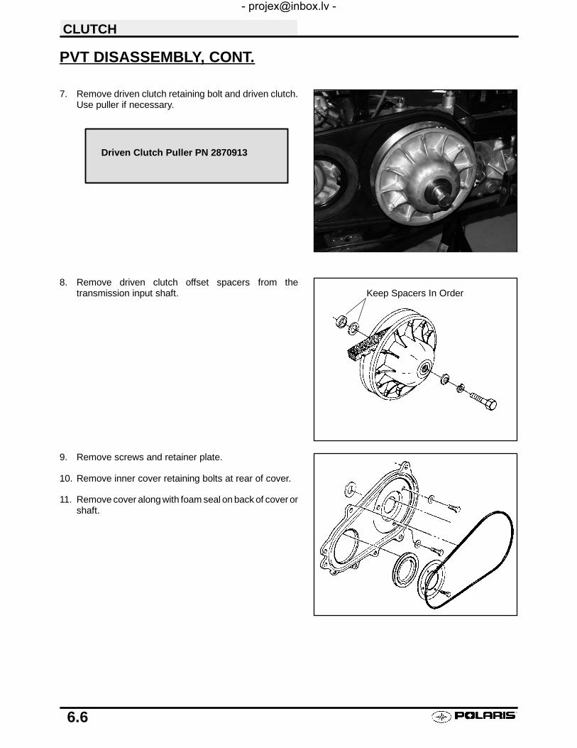
CLUTCH
6.6
PVT DISASSEMBLY, CONT.
7. Remove driven clutch retaining bolt and driven clutch.Use puller if necessary.
8. Remove driven clutch offset spacers from thetransmission input shaft.
9. Remove screws and retainer plate.
10. Remove inner cover retaining bolts at rear of cover.
11. Remove cover along with foam seal on back of cover orshaft.
Driven Clutch Puller PN 2870913
Keep Spacers In Order

CLUTCH
6.7
PVT ASSEMBLY
1. Inspect PVT inner cover-to engine seal. Replace ifcracked or damaged.
2. Place a new foam seal on transmission input shaft.
3. Apply RTV silicone sealant to outside edge of innercover-to-engine seal, to ensure a water tight fitbetween the seal and the cover on engine side.Surfaces must be clean to ensure adhesion ofsilicone sealant.
4. Reinstall cover and tighten rear cover bolts justenough to hold it in place.
5. Fit lip of inner cover seal (A)to engine. Install sealretainer plate and tighten screws securely.
6. Torque rear inner cover bolts (B) to specification.
7. Install clutch offset spacers on transmission inputshaft.
8. Clean splines inside driven clutch and on thetransmission input shaft.
9. Apply a light film of grease to the splines on theshaft.
10. Install the driven clutch, washer, lock washer, andretaining bolt. Torque to specification.
11. Clean end of taper on crankshaft and the taper boreinside drive clutch.
12. Install drive clutch and torque retaining bolt tospecification.
13. Reinstall drive belt noting direction of rotation. If anew belt is installed, install so numbers can beeasily read.
14. Replace PVT outer cover rubber gasket with the flatside out (C).
15. Reinstall PVT outer cover and secure with screws.
16. Reinstall rear cab assembly and seat.
Seal this edge to cover on engine side
Seal outer edge to coverwith RTV silicone sealant
A
B CInner Cover Bolt Torque (Rear):12 ft. lbs. (16.6 Nm)
Driven Clutch Retaining Bolt Torque:17 ft. lbs. (23.5 Nm)
Drive Clutch Retaining Bolt Torque:40 ft. lbs. (55 Nm)
OffsetSpacers
Cover Gasket
Flat edge out(Toward outer cover)

CLUTCH
6.8
PVT SEALING AND DUCTING COMPONENTS
Outer Cover
Exhaust Duct
Inner Cover Seal
Inlet duct
Retainer
ClipInner Cover Outer Cover Seal

CLUTCH
6.9
RELATIONSHIP OF DRIVE CLUTCH WEIGHTS AND SPRING INMAINTAINING OPERATING RPM
The drive clutch is an RPM sensing unit designed to transfer the maximum amount of horsepower from the engineto the ground. This is accomplished through weights and a spring inside the unit which react to the centrifugalforce applied to the clutch from the engine RPM.
The spring and weights work in combination. In a properly set up clutch, the maximum desired operating RPMwill be reached immediately after clutch engagement, under full throttle conditions. To gain optimum power thisRPM should be maintained. As centrifugal force pushes the weights against the rollers, the moveable sheavewill force the belt to climb up the drive clutch sheave and increase vehicle speed.
If the weights and spring are matchedproperly, the engine RPM will go to thedesired range and remain there on boththe upshift and backshift.
If the weights are too light, or the springrate too high, the maximum RPM will betoo great and the drive belt will not moveinto high gear at the top of the clutch.
If the weights are too heavy, or the springrate too low, the engine RPM will be lowand the drive clutch will upshift too fast,keeping the engine out of its powerband.
Example : Engine Operating RPM 6000 ¦200
2000
3000
4000
5000
6000
7000
8000
CLUTCHENGAGEMENT
RP
M
2000
3000
4000
5000
6000
7000
8000
CLUTCHENGAGEMENT
RP
M
2000
3000
4000
5000
6000
7000
8000
CLUTCHENGAGEMENT
RP
M
1000
1000
1000

CLUTCH
6.10
DRIVE CLUTCH SPRING SPECIFICATIONSThe drive clutch spring has two prima-ry functions:
1. To control clutch engagementRPM. The springs which have ahigher rate when the clutch is inneutral will increase clutchengagement RPM.
2. To control the rate at which thedrive belt moves upward in thedrive clutch sheaves. This isreferred to as drive clutch upshift.
There are other components whichcontrol upshift, but the spring is one ofthe primary components in insuringoptimum performance. It is very im-portant that the spring is of the correctdesign and is in good condition.
CAUTION: Never shim a drive clutchspring to increase its compressionrate. This may result in completestacking of the coils and subsequentclutch cover failure.The drive clutch spring is one of themost critical components of the PVTsystem. It is also one of the easiest toservice. Due to the severe stress thespring is subject to during operation, itshould always be inspected for toler-ance limits during any clutch operationdiagnosis or repair.
With the spring resting on a flat surface, measure its freelength from the outer coil surfaces as shown. Refer tothe spring specification chart for specific free lengthmeasurements and tolerances. Also check to see thatspring coils are parallel to one another. Distortion of thespring indicates stress fatigue, requiring replacement.
PART NUMBER COLORCODE
WIREDIAMETER
FREE LENGTH¦.125I
7041021 Plain .157I 4.38I
7041022 Black .140I 4.25I
7041063 Purple .168I 4.37I
7041061 Brown .200I 3.06I
7041132 White .177I 2.92I
7041168 Green .177I 3.05I
7041148 Gold .207I 3.25I
7041150 Red/White .192I 3.59I
7041157 Blue/Green .177I 2.53I
7041653 White/Yellow .187I 4.18I
2.5 2.25 2.00 1.75 1.50 1.25 1.190
20
40
60
80
100
120
140
160
180
200
220
240
260
280
300ATV TRAVEL
COMPRESSED SPRING LENGTH (INCHES)
Blue/Blue-Gold7041080
Gold7041148
Silver7041062
Red7041083
Red/White7041150
Brown7041061
Orange7041060
Pink7041065
Yellow7041102
Green7041168
Purple7041063White7041132
Plain7041021
Black7041022
NEUTRAL FULL UPSHIFT
Blue/Green7041157
FO
RC
E(P
OU
ND
S)
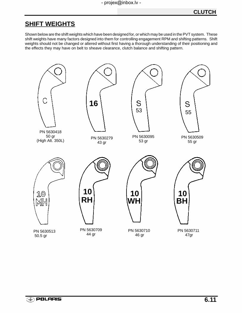
CLUTCH
6.11
SHIFT WEIGHTS
Shown below are the shift weights which have been designed for, or which may be used in the PVT system. Theseshift weights have many factors designed into them for controlling engagement RPM and shifting patterns. Shiftweights should not be changed or altered without first having a thorough understanding of their positioning andthe effects they may have on belt to sheave clearance, clutch balance and shifting pattern.
PN 563051350.5 gr
PN 563050955 gr
55
16
PN 563027943 gr
PN 563041850 gr
(High Alt. 350L)PN 5630095
53 gr
53
PN 563070944 gr
PN 563071046 gr
PN 563071147gr
RH BHWH10 10 10

CLUTCH
6.12
SHIFT WEIGHT INSPECTION
1. Remove shift weight bolts and weights. Inspect asshown. The contact surface of theweight shouldbesmooth and free of dents or gall marks. Inspect theweight pivot bore and pivot bolts for wear or galling.If weights or bolts are worn or broken, replace insets of three with new bolts. NOTE: A damagedshift weight is usually caused by a damaged orstuck roller in the spider assembly. See rollerinspection, page 6.16.
BUTTON TO TOWER CLEARANCE INSPECTION
1. Inspect for any clearance between spider button totower. If clearance exists, replace all buttons andinspect surface of towers. See spider removalpage 6.15.
2. Inspect sheave surfaces. Replace the entireservice clutch if worn, damaged or cracked.
WARNING
The clutch assembly is a precisely balancedunit. Neverreplace parts with used parts from another clutch as-sembly!
All PVT system maintenance repairs must be per-formed only by an authorized Polaris service technicianwho has attended a Polaris sponsored service trainingseminar and understands the proper procedures asoutlined in this manual. Because of the critical natureand precision balance incorporated into the PVTsystem, it is absolutely essential that no attempt atdisassembly or repair be made without factory au-thorized special tools and service procedures.
Broken Worn Good
Button to Tower Clearance:.000 - .001I

CLUTCH
6.13
DRIVE CLUTCH EXPLODED VIEW
Drive Clutch
Mark with permanentmarker before disassembly
Teflon coatedbrass bushing
Teflon coatedbrass bushing
EBS Drive Clutch
Spacer Sleeve
PTFE Washers
One WayClutch
Spider Lock Nut
Mark with permanentmarker before disassembly

CLUTCH
6.14
DRIVE CLUTCH DISASSEMBLY
1. Using a permanent marker, mark the cover, spider,and moveable and stationary sheaves forreference. The X’s may not have been in alignmentbefore disassembly.
2. Remove cover bolts evenly in a cross pattern, andremove cover plate.
3. Inspect cover bushing (A). Theouter cover bushingis manufactured with a Teflon™ coating. Bushingwear is determined by the amount of Teflon™remaining on the bushing.
4. Inspect area on shaft where bushing rides for wear,galling, nicks, or scratches. Replace clutchassembly if worn or damaged.
5. Remove and inspect spring. (See page 6.10)
Mark
“X”Mark
A
Cover Bushing Inspection:
Replace the cover bushing if morebrass than Teflon™ is visible on thebushing. Refer to bushing replacementin this chapter.
Inspect shaft
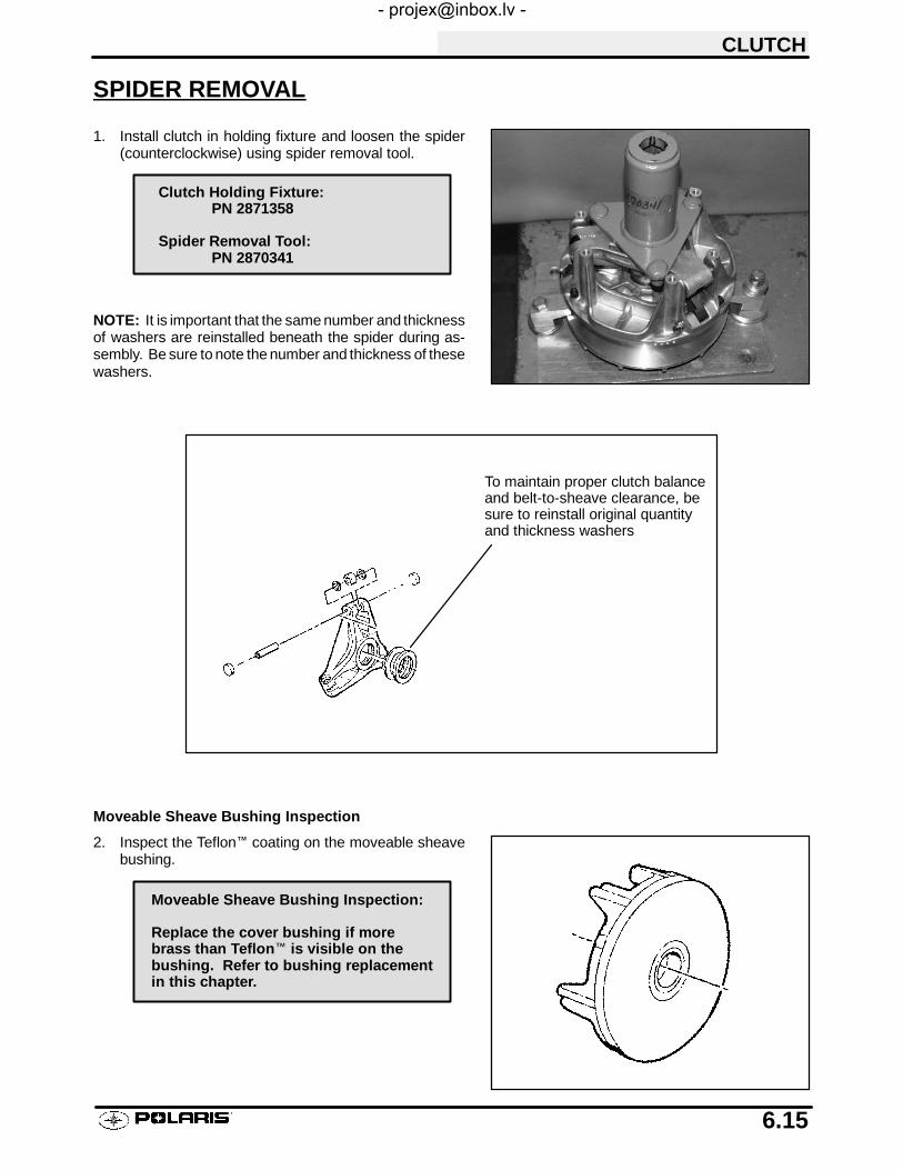
CLUTCH
6.15
SPIDER REMOVAL
1. Install clutch in holding fixture and loosen the spider(counterclockwise) using spider removal tool.
NOTE: It is important that the same number and thicknessof washers are reinstalled beneath the spider during as-sembly. Be sure to note the number and thickness of thesewashers.
To maintain proper clutch balanceand belt-to-sheave clearance, besure to reinstall original quantityand thickness washers
Moveable Sheave Bushing Inspection
2. Inspect the Teflon™ coating on the moveable sheavebushing.
Clutch Holding Fixture:PN 2871358
Spider Removal Tool:PN 2870341
Moveable Sheave Bushing Inspection:
Replace the cover bushing if morebrass than Teflon™ is visible on thebushing. Refer to bushing replacementin this chapter.
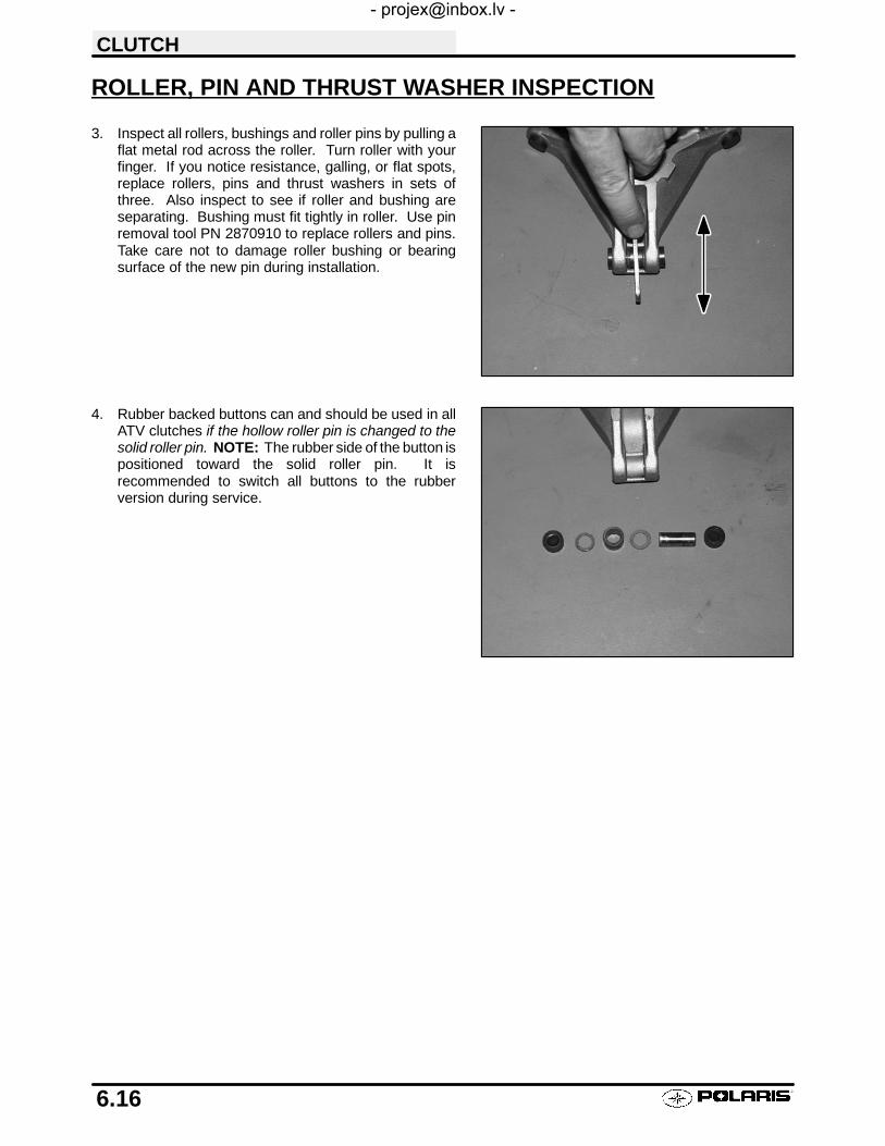
CLUTCH
6.16
ROLLER, PIN AND THRUST WASHER INSPECTION
3. Inspect all rollers, bushings and roller pins by pulling aflat metal rod across the roller. Turn roller with yourfinger. If you notice resistance, galling, or flat spots,replace rollers, pins and thrust washers in sets ofthree. Also inspect to see if roller and bushing areseparating. Bushing must fit tightly in roller. Use pinremoval tool PN 2870910 to replace rollers and pins.Take care not to damage roller bushing or bearingsurface of the new pin during installation.
4. Rubber backed buttons can and should be used in allATV clutches if the hollow roller pin is changed to thesolid roller pin. NOTE: The rubber side of the button ispositioned toward the solid roller pin. It isrecommended to switch all buttons to the rubberversion during service.

CLUTCH
6.17
DRIVE CLUTCH ASSEMBLY
NOTE: It is important that the same number and thick-ness of washers are reinstalled beneath the spider dur-ing assembly. The Teflon bushings are self-lubricating.Do not apply oil or grease to the bushings.
1. Reassemble drive clutch in the following sequence.Be sure the “X”, or the marks that were madeearlier, are aligned during each phase of assembly.
a) “X”, or the marks that were made earlier, oncover
b) spider, making sure spacer washers areinstalled underneath spider and positionedproperly in recess
c) “X”, or the marks that were made earlier,under weight
2. Install moveable sheave onto fixed sheave.3. Install spider spacers. Use same quantity and
thickness as were removed.4. Compress spider buttons for each tower and install
spider, making sure that “X”, or the marks that weremade earlier, on spider aligns with “X”, or the marksthat were made earlier, in moveable sheave.
5. Torque spider to specification using the holdingfixture and spider tool. Torque with smooth motionto avoid damage to the stationary sheave. Refer topage 6.1 for torque specification.
CAUTION:
Be sure the spider spacer washers are fully seated inthe recessed area in the spider. Any misalignment willalter clutch balance. Inverting the clutch while initiallytightening the spider will help position the washers.
6. Install shift weights using new lock nuts on thebolts.
7. Reinstall clutch spring.
Spacer washers
Rotation
Nut on trailing side

CLUTCH
6.18
DRIVE CLUTCH ASSEMBLY, CONT.
8. Reinstall cover, aligning “X” mark with other marks.Torque cover bolts evenly to specification.
DRIVE BELT TENSION
NOTE: Pinch the sheaves lightly together with clamp to prevent the belt from beingpushed into the drivensheave.
1. Place a straight edge on top of the belt between drive anddriven clutch.
2. Push down on drive belt until it is lightly tensioned.
3. Measure belt deflection as shown in photo.
If belt deflection is out of specification, adjust by removing oradding shims between the driven clutch sheaves.
S Remove shims to decrease belt deflection
S Add shims to increase belt deflection
See Driven Clutch Disassembly/Inspection, pages 6.26 -6.28.
NOTE: At least one shim must remain between the inner andouter sheave of the driven clutch. If proper belt deflectioncannot be obtained, measure drive belt width, length, andcenter distance of drive and driven clutch, outlined in this sec-tion; all have an effect on belt deflection.
Spider Torque:200 ft. lbs. (276 Nm)
Cover Screw Torque:90 in. lbs. (10.4 Nm)
1 1/8″ (28.5 mm)
Straight Edge
Belt Deflection (Tension):
1 1/8″ (2.9 cm) - 1 1/4″ (3.2 cm)

CLUTCH
6.19
DRIVE BELT REMOVAL/INSPECTION
1. Remove outer PVT cover as described in PVTDisassembly.
2. Mark drive belt direction of rotation so that it can beinstalled in the same direction. NOTE: Normallypositioned so part numbers are easily read.
3. To remove drive belt, apply brake, pull upward andrearward on belt to open driven clutch sheaves, pullout and down on belt to slip over the driven clutchouter sheave.
4. Measure belt width and replace if worn severely.Generally, belt should be replaced if clutches can nolonger be adjusted to provide proper belt deflection.S The top edges have been trimmed on some
drive belts. It will be necessary to project theside profiles and measure from corner to corner.
S Place a straight edge on each side of the drivebelt.
S Place another straight edge on top of belt.S Measure the distance where the side straight
edges intersect the top, as shown in the illustra-tion at right.
5. Inspect belt for loose cords, missing cogs, cracks,abrasions, thin spots, or excessive wear. Replace ifnecessary.
6. Inspect belt for hour glassing (extreme circular wearin at least one spot and on both sides of the belt).Hour glassing occurs when the drive train does notmove and the drive clutch engages the belt.
Projected BeltWidth
Belt Width:
New 1.174 - 1.188″(2.98-3.02 cm)
Wear Limit 1.125″ (2.86 cm)

CLUTCH
6.20
DRIVE BELT REMOVAL/INSPECTION, CONT.
7. Measure belt length with a tape measure around theouter circumference of the belt. Belts whichmeasure longer than nominal length may requiredriven shimming or engine adjustment for a longercenter distance to obtain proper belt deflection.Belts which measure shorter than nominal lengthmay require driven shimming or a shorter centerdistance. Remember, proper belt deflection is thedesired goal -- not a specific center distance.
8. Replace belt if worn past the service limit. Belts withthin spots, burn marks, etc., should be replaced toeliminate noise, vibration, or erratic PVT operation.See Troubleshooting Chart at the end of this chapterfor possible causes. NOTE: If a new belt is installed,check belt deflection.
DRIVE BELT INSTALLATION1. Loop belt over drive and over top of driven sheave.2. While pushing down on top of belt, turn the back or
moveable driven sheave clockwise.3. The belt then should be able to be pushed down into
and between the sheaves.
NOTE: Be sure to postion belt so part number is easilyread.
CenterDistance
Clutch Center Distance -10″ +.1 / -.05 (254 +2.5 / -1.3mm)Belt Nominal Length - 40.875″± 3/16
(103.8 cm ± .48 cm)

CLUTCH
6.21
CLUTCH ALIGNMENT
1. Remove belt and install offset/alignment tool as shown.
2. With tool touching rear of driven clutch inner sheave, thedistance at point “A” should be 1/8″.
If the distance is greater than 1/8″ or less than 1/16″, clutchalignment must be adjusted as follows:
3. Remove drive and driven clutch. See PVT Disassembly,pages 6.5 - 6.6.
4. Remove PVT inner cover.
5. Loosen all engine mounts. Move front of engine to theright or left slightly until alignment is correct.
6. Tighten engine mounts and verify alignment is correct.
7. Measure belt deflection and measure offset both aboveand below sheave centerlines. Adjust if necessary.
NOTE: On some models, minor adjustments can be made byadding shims between the frame and front lower left enginemount to increase the distance at point “A”. If a shim is pres-ent, it can be removed to decrease the distance at point “A”.
CLUTCH OFFSET
Important: Inspect clutch alignment and center distance be-fore adjusting offset.
1. Install offset alignment tool as shown.
Offset is correct when rear of tool contacts rear of innersheave with driven clutch pushed completely inward on shaftand bolt torqued. Adjust offset by adding or removing spacerwashers between back of driven clutch and spacer as shown.
1/8I +0 / -- 1/163.2mm +0 / -- 1.6 mm)
Offset Alignment ToolPN 2870654 - STDPN 2872292 - EBS
B
A
Center line
Measure offset above and belowcenterline
Shim Kit PN 2200126
Offset Alignment Toolshould contact rear edgeof driven clutch sheave
Driven Clutch OffsetTo adjust, add or removewashers from behind thedriven clutchSpacer Washer PN 7556401

CLUTCH
6.22
DRIVE CLUTCH BUSHING SERVICEPolaris Kit PN 2871226
Item Qty. Part Description Part No.2 1 P-90 Drive Clutch and Driven Clutch 5020628
Bushing Installation Tool
3 1 Drive Clutch Cover Bushing Removal and 5020629Installation Tool (for all drive clutches)
5 1 P-90 Driven Clutch Bushing Removal Tool 5020631
8 1 Main Puller Adapter 50206329 1 Adapter Reducer 5010279
10 1 Number Two Puller Adapter 5020633
DRIVE CLUTCH MOVEABLE SHEAVE - BUSHING REMOVAL1. Install handle end of piston pin puller securely into
bench vise and lightly grease puller threads.
2. Remove nut from puller rod and set aside.
3. Install main adapter (Item 8) onto puller.
4. Insert adaptor #2 into bushing from belt side asshown. With towers pointing toward vise, slidesheave and bushing onto puller rod.
5. Install nut removed in step 2 onto end of puller rod andhand tighten. Turn puller barrel to increase tension onsheave if needed. Nut is left hand thread.
Piston Pin Puller PN 2870386
Main Adaptor
Piston Pin PullerPN 2870386

CLUTCH
6.23
DRIVE CLUTCH MOVEABLE SHEAVE - BUSHING REMOVAL,CONT.
6. Turn sheave and puller barrel togethercounterclockwise on puller rod until bushing isremoved.
7. Remove nut from puller rod and set aside.
8. Pull bushing removal tool and adapter from puller rod.Remove bushing from tool and discard.
DRIVE CLUTCH MOVEABLE SHEAVE - BUSHING INSTALLATION1. Place main adapter (Item 8) on puller.2. Apply Loctite 680 retaining compound to the back side
of new bushing. Push bushing into center of sheaveon tower side by hand.
3. Insert installation tool (Item 2) into center of sheave andwith towers pointing away from vise, slide sheave ontopuller rod.
4. Install nut on puller rod and hand tighten. Turn barrelto apply additional tension if needed.
5. Turn sheave and barrel together counterclockwiseuntil bushing is seated.
6. Remove nut from puller rod and set aside.
7. Remove sheave from puller.
8. Remove installation tool.
Bushing PN 3576504
Loctitet 680 PN 2870584

CLUTCH
6.24
DRIVE CLUTCH COVER - BUSHING REMOVAL1. Install main adapter (Item 8) on puller.
2. From outside of clutch cover, insert removal tool(Item 3) into cover bushing.
3. With inside of cover toward vise, slide cover ontopuller.
4. Install nut onto puller rod and hand tighten. Turnpuller barrel to increase tension as needed.
5. Turn clutch cover counterclockwise on puller roduntil bushing is removed.
6. Remove nut from puller rod and set aside.
7. Remove bushing and bushing removal tool frompuller. Discard bushing.
Main Adaptor
Piston Pin PullerPN 2870386

CLUTCH
6.25
DRIVE CLUTCH COVER - BUSHING INSTALLATION1. Apply Loctite 680 retaining compound to the back
side of new bushing. Working from inside of cover,insert bushing and bushing installation tool intocenter of clutch cover.
2. With main adapter on puller, insert cover onto pullerrod, placing outside of cover toward vise.
3. Install nut on rod and hand tighten. Turn pullerbarrel to apply more tension if needed.
4. Turn clutch cover and barrel togethercounterclockwise on puller rod until bushing isseated.
5. Remove nut from puller rod and take installationtool and clutch cover off rod.
Bushing PN 3576510
Loctitet 680 PN 2870584

CLUTCH
6.26
DRIVEN CLUTCH DISASSEMBLY/INSPECTION (NON EBS)
Used to adjustbelt tension. One mustalways be installed.
CAUTION:
Wear eye protection when removing snap ring to prevent serious personal injury.
1. Apply and hold downward pressure on the helix, orplace driven clutch in compressor tool PN 8700220.
2. Remove snap ring retainer.
3. Note location of spring and remove helix.
4. Note location of spring in themoveable sheave, andremove the spring.
Note hole location of springin helix and sheave
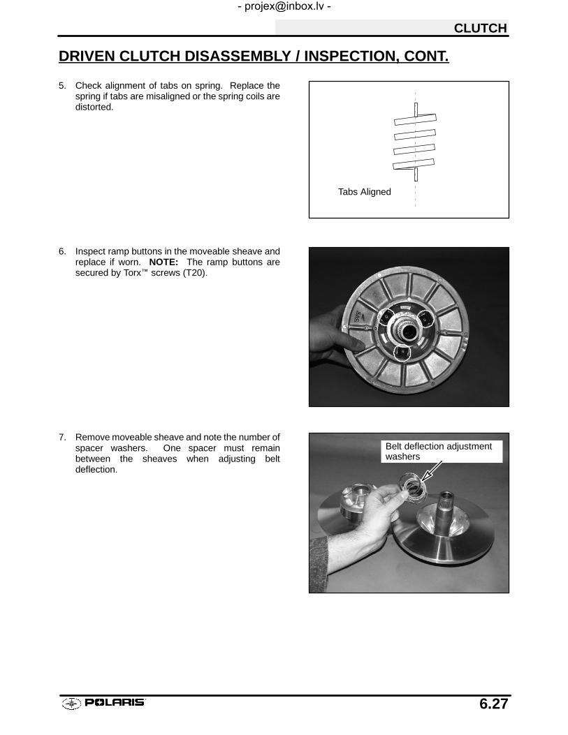
CLUTCH
6.27
DRIVEN CLUTCH DISASSEMBLY / INSPECTION, CONT.
5. Check alignment of tabs on spring. Replace thespring if tabs are misaligned or the spring coils aredistorted.
6. Inspect ramp buttons in the moveable sheave andreplace if worn. NOTE: The ramp buttons aresecured by Torx™ screws (T20).
7. Remove moveable sheave and note the number ofspacer washers. One spacer must remainbetween the sheaves when adjusting beltdeflection.
Tabs Aligned
Belt deflection adjustmentwashers
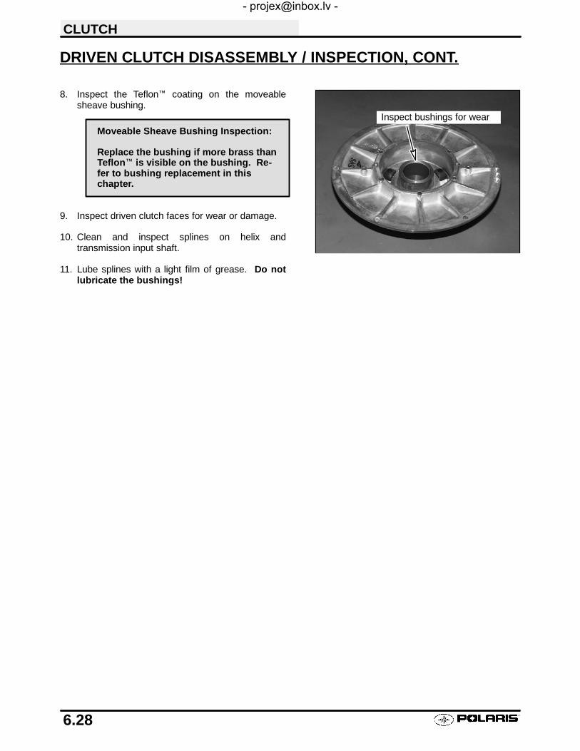
CLUTCH
6.28
DRIVEN CLUTCH DISASSEMBLY / INSPECTION, CONT.
8. Inspect the Teflon™ coating on the moveablesheave bushing.
9. Inspect driven clutch faces for wear or damage.
10. Clean and inspect splines on helix andtransmission input shaft.
11. Lube splines with a light film of grease. Do notlubricate the bushings!
Inspect bushings for wear
Moveable Sheave Bushing Inspection:
Replace the bushing if more brass thanTeflon™ is visible on the bushing. Re-fer to bushing replacement in thischapter.

CLUTCH
6.29
DRIVEN CLUTCH ASSEMBLY
1. Install moveable sheave with spacer washers.Important: At least one spacer washer must beinstalled. Teflon bushings are self-lubricating. Donot apply oil or grease to the bushings.
2. Install spring, inserting spring tab into proper hole inmoveable sheave.
3. Insert spring tab into proper hole in helix. Seespecifications at the beginning of this section.
The driven clutch, helix/moveable assembly has severaldifferent spring locations which affect clutch shifting andRPMs. The greatest amount of spring tension will raiseengine RPMs during clutch upshift and allow quickerbackshift or downshift when pulling or negotiating a hill,for example. The least amount of tension will create aslower downshift and a harder upshift.
4. Line up boss spline and push helix down until itengages the splines 1/2″ to 3/4″.
5. While holding downward pressure on helix, windmoveable sheave counterclockwise approximately1/3 turn (120°).
6. Push helix into place and install snap ring.
Moveable SpringExample: Helix Sheave Tension
2 -- 1 HeavySpring/ 2 -- 2Position 1 -- 1
2 -- 31 -- 21 -- 3 Soft
Refer to General Information Chapter 1 for driv-en clutch spring color and production setting.
Align boss splineto install helix
1/3turn

CLUTCH
6.30
DRIVEN CLUTCH MOVEABLE SHEAVE - BUSHING REMOVAL
NOTE: Bushings are installed at the factory using Loc-tite. In order to remove the bushing it will be necessaryto apply heat. A press can be used to remove and installsome of the bushings. Be sure to support the sheaveor cover as close as possible to the bushing bore whenusing a press.
1. Install main adapter (Item 8) onto puller.
2. Insert adapter reducer (Item 9) onto puller, sliding itinside the main adapter..
3. Remove ramp buttons from moveable sheave.
4. Using a hand held propane torch, apply heatdirectly on bushing until tiny smoke tailings appear.
CAUTION:
Clutch components will be hot! In order to avoid seriousburns, wear some type of insulated gloves for the rest ofthe removal process.
Main Adapter
AdapterReducer
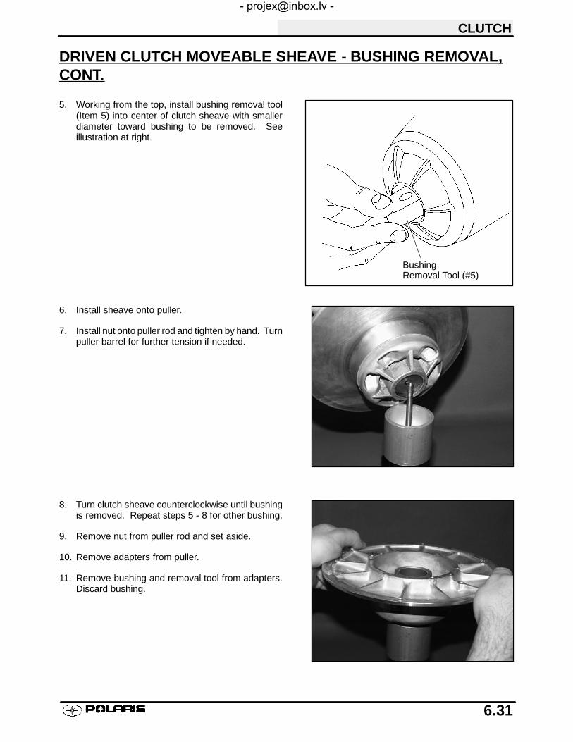
CLUTCH
6.31
DRIVEN CLUTCH MOVEABLE SHEAVE - BUSHING REMOVAL,CONT.
5. Working from the top, install bushing removal tool(Item 5) into center of clutch sheave with smallerdiameter toward bushing to be removed. Seeillustration at right.
6. Install sheave onto puller.
7. Install nut onto puller rod and tighten by hand. Turnpuller barrel for further tension if needed.
8. Turn clutch sheave counterclockwise until bushingis removed. Repeat steps 5 - 8 for other bushing.
9. Remove nut from puller rod and set aside.
10. Remove adapters from puller.
11. Remove bushing and removal tool from adapters.Discard bushing.
BushingRemoval Tool (#5)

CLUTCH
6.32
DRIVEN CLUTCH MOVEABLE SHEAVE - BUSHING INSTALLATION
1. Working from the top, insert adapter number tenonto puller. See illustration at right.
2. Start new bushing evenly in moveable sheave.Apply Loctite 680 retaining compound to the backside of new bushing.
3. Install sheave onto puller with new bushing upwardas shown. Install adaptor number two.
AdapterNumber Ten

CLUTCH
6.33
DRIVEN CLUTCH MOVEABLE SHEAVE - BUSHING INSTALLA-TION, CONT.
4. Install nut onto puller rod and hand tighten againstinstallation tool.
5. Turn clutch sheave counterclockwise until bushingis seated.
6. Remove nut from puller rod and set aside.
7. Remove installation tool and clutch sheave frompuller.
8. Repeat installation procedure for other moveablebushing.
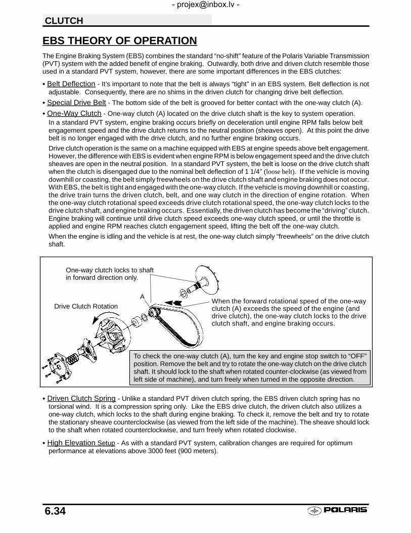
CLUTCH
6.34
EBS THEORY OF OPERATIONThe Engine Braking System (EBS) combines the standard “no-shift” feature of the Polaris Variable Transmission(PVT) system with the added benefit of engine braking. Outwardly, both drive and driven clutch resemble thoseused in a standard PVT system, however, there are some important differences in the EBS clutches:
S Belt Deflection - It’s important to note that the belt is always “tight” in an EBS system. Belt deflection is notadjustable. Consequently, there are no shims in the driven clutch for changing drive belt deflection.
S Special Drive Belt - The bottom side of the belt is grooved for better contact with the one-way clutch (A).
S One-Way Clutch - One-way clutch (A) located on the drive clutch shaft is the key to system operation.In a standard PVT system, engine braking occurs briefly on deceleration until engine RPM falls below beltengagement speed and the drive clutch returns to the neutral position (sheaves open). At this point the drivebelt is no longer engaged with the drive clutch, and no further engine braking occurs.
Drive clutch operation is the same on a machine equipped with EBS at engine speeds above belt engagement.However, the difference with EBS is evident when engine RPM is below engagement speed and the drive clutchsheaves are open in the neutral position. In a standard PVT system, the belt is loose on the drive clutch shaftwhen the clutch is disengaged due to the nominal belt deflection of 1 1/4″ (loose belt). If the vehicle is movingdownhill or coasting, the belt simply freewheels on the drive clutch shaft and engine braking does not occur.With EBS, the belt is tight and engaged with the one-way clutch. If the vehicle is moving downhill or coasting,the drive train turns the driven clutch, belt, and one way clutch in the direction of engine rotation. Whenthe one-way clutch rotational speed exceeds drive clutch rotational speed, the one-way clutch locks to thedrive clutch shaft, and engine braking occurs. Essentially, the driven clutch has becomethe “driving” clutch.Engine braking will continue until drive clutch speed exceeds one-way clutch speed, or until the throttle isapplied and engine RPM reaches clutch engagement speed, lifting the belt off the one-way clutch.
When the engine is idling and the vehicle is at rest, the one-way clutch simply “freewheels” on the drive clutchshaft.
When the forward rotational speed of the one-wayclutch (A) exceeds the speed of the engine (anddrive clutch), the one-way clutch locks to the driveclutch shaft, and engine braking occurs.
Drive Clutch Rotation
One-way clutch locks to shaftin forward direction only.
A
To check the one-way clutch (A), turn the key and engine stop switch to “OFF”position. Remove the belt and try to rotate the one-way clutch on the drive clutchshaft. It should lock to the shaft when rotated counter-clockwise (as viewed fromleft side of machine), and turn freely when turned in the opposite direction.
S Driven Clutch Spring - Unlike a standard PVT driven clutch spring, the EBS driven clutch spring has notorsional wind. It is a compression spring only. Like the EBS drive clutch, the driven clutch also utilizes aone-way clutch, which locks to the shaft during engine braking. To check it, remove the belt and try to rotatethe stationary sheave counterclockwise (as viewed from the left side of the machine). The sheave should lockto the shaft when rotated counterclockwise, and turn freely when rotated clockwise.
S High Elevation Setup - As with a standard PVT system, calibration changes are required for optimumperformance at elevations above 3000 feet (900 meters).

CLUTCH
6.35
OPERATION GUIDELINES FOR EBS CLUTCHES
S EBS clutches have a slightly higher starting gear ratio between the drive anddriven clutch due to the location of the one-way clutch on the clutch shaft. Forbest performance and belt life, always use low-range in hilly terrain and whentowing or hauling a load. In fact, High Range should only be usedwhen traveling on level ground with light or no load.
S EBS kits are recommended for models equipped with High / Low / Reversetransmissions only. Engine braking is enhanced when operating in low range.
S When an operator makes the transition to and from engine braking engagement,the driven clutch helix changes from the acceleration side to the decelerationside. An audible engagement noise may be heard during this transition and is anormal condition.
S Changes to drive clutch calibration are recommended if the vehicle will be oper-ated at elevations above 3000 ft (900 meters). Refer to the model specific clutch-ing chart for type of drive clutch weight and/or drive clutch spring to install forhigh elevation.¡
WARNING
All PVT system maintenance repairs must be performed only by an authorizedPolaris service technician who has attended a Polaris sponsored service trainingseminar and understands PVT system maintenance and repair procedures.Because of the critical nature and precise balance of components within thePVT system, it is absolutely essential that no attempt at disassembly or repairbe made without factory authorized special tools and service procedures.
¡Disregard references to the driven clutch helix position. Helix adjustments do notapply to the EBS driven clutch.
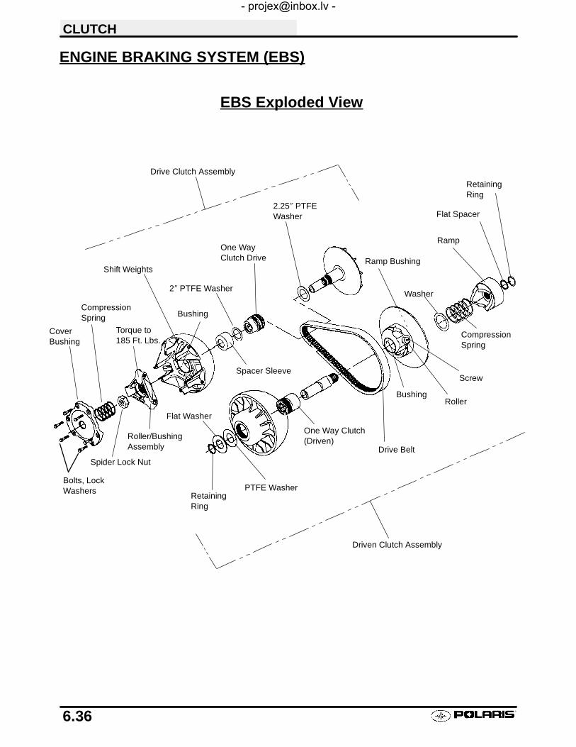
CLUTCH
6.36
ENGINE BRAKING SYSTEM (EBS)
Bolts, LockWashers
CompressionSpring
Shift Weights
Spacer Sleeve
2″ PTFE Washer
One WayClutch Drive
2.25″ PTFEWasher
Washer
Ramp
Flat Spacer
CompressionSpring
Screw
Drive Belt
PTFE WasherRetainingRing
Flat Washer
Drive Clutch Assembly
Driven Clutch Assembly
CoverBushing
Roller/BushingAssembly
RetainingRing
Bushing
Bushing
Ramp Bushing
Torque to185 Ft. Lbs.
Roller
EBS Exploded View
One Way Clutch(Driven)
Spider Lock Nut

CLUTCH
6.37
EBS Drive Clutch
Mark with permanentmarker before disassembly
One way clutch
ONE-WAY CLUTCH INSPECTION (DRIVE CLUTCH)1. Rotate one-way clutch clockwise (as viewed from
the cover plate side). The clutch should rotate onthe shaft with only slight amount of drag. Thereshould not be any binding or rough spots. Whenrotated counterclockwise, the clutch should lock tothe shaft without slipping. If problems are noted ineither direction, continue with disassembly.
DRIVE CLUTCH INSPECTIONNOTE: Remove cover, spring, and spider following in-structions for standard (non EBS) drive clutch, then pro-ceed as follows.
1. Remove moveable sheave spacer sleeve and the2″ PTFE washer. Visually inspect the washer fordamage. Measure the thickness and compare tospecification. Replace if worn or damaged.
PTFE Washer ThicknessStandard: .030″ (.76mm)Service Limit: .025″ (.64mm)

CLUTCH
6.38
DRIVE CLUTCH INSPECTION, CONT.
2. Remove moveable sheave.
3. Lift one-way clutch off shaft. Replace as anassembly if worn, damaged, or if problems werenoted on page 6.37.
4. Inspect surface of shaft for pitting, grooves, ordamage. Measure the outside diameter andcompare to specifications. Replace the drive clutchassembly if shaft is worn or damaged.
5. Remove 2 1/2″ PTFE washer from shaft. Visuallyinspect the washer for damage. Measure thethickness and compare to specification. Replace ifworn or damaged.
MOVEABLE SHEAVE BUSHING INSPECTION1. Inspect the Teflon™ coating on the moveable sheave
bushing.
Shaft DiameterStandard: 1.3745″ - 1.375″Service Limit: 1.3730″
PTFE Washer ThicknessStandard: .030″ (.76mm)Service Limit: .025″ (.64mm)
Moveable Sheave Bushing Inspection:
Replace the cover bushing if morebrass than Teflon™ is visible on thebushing. Refer to bushing replacementin this chapter.

CLUTCH
6.39
DRIVEN CLUTCH DISASSEMBLY/INSPECTION - EBSCAUTION: The driven clutch must be disassembled from the helix end to lessen the chance of damage to sealsin the one-way clutch. Review all information below before proceeding.
ONE-WAY CLUTCH PRELIMINARY INSPECTION (DRIVEN)1. With drive belt removed and transmission in
neutral, hold the outer sheave and rotate the innersheave of the driven clutch (moveable) in acounterclockwise direction as shown at right. Thesheave should rotate on the shaft with only a slightamount of drag. There should not be any binding orrough spots.
2. When rotated clockwise, the inner (moveable)sheave should lock to the shaft and outer sheavewithout slipping.
3. Remove driven clutch from the transmission inputshaft. Do not disassemble the driven clutch fromthe outside snap ring. The driven clutch must bedisassembled from the helix side or the one-wayclutch seals may be damaged.
Move Freely
Lock to Shaft and Outer Sheave
Do not disassemble from this side
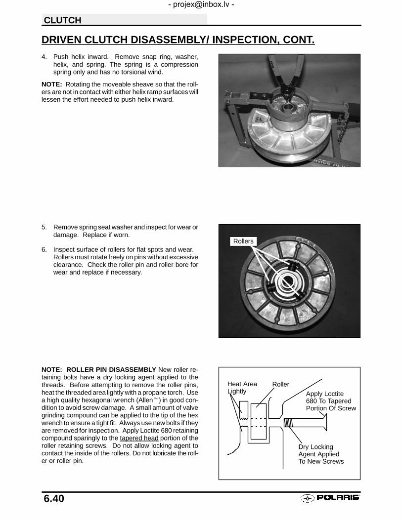
CLUTCH
6.40
DRIVEN CLUTCH DISASSEMBLY/ INSPECTION, CONT.
4. Push helix inward. Remove snap ring, washer,helix, and spring. The spring is a compressionspring only and has no torsional wind.
NOTE: Rotating the moveable sheave so that the roll-ers are not in contact with either helix ramp surfaces willlessen the effort needed to push helix inward.
5. Remove spring seat washer and inspect for wear ordamage. Replace if worn.
6. Inspect surface of rollers for flat spots and wear.Rollers must rotate freely on pins without excessiveclearance. Check the roller pin and roller bore forwear and replace if necessary.
NOTE: ROLLER PIN DISASSEMBLY New roller re-taining bolts have a dry locking agent applied to thethreads. Before attempting to remove the roller pins,heat the threaded area lightly with a propane torch. Usea high quality hexagonal wrench (Allent) in good con-dition to avoid screw damage. A small amount of valvegrinding compound can be applied to the tip of the hexwrench to ensure a tight fit. Always use new bolts if theyare removed for inspection. Apply Loctite 680 retainingcompound sparingly to the tapered head portion of theroller retaining screws. Do not allow locking agent tocontact the inside of the rollers. Do not lubricate the roll-er or roller pin.
Rollers
Roller
Dry LockingAgent AppliedTo New Screws
Apply Loctite680 To TaperedPortion Of Screw
Heat AreaLightly

CLUTCH
6.41
DRIVEN CLUTCH DISASSEMBLY/ INSPECTION, CONT.
7. Inspect moveable sheave bushing for wear.
8. Check for movement of the driven clutch shaft inthe one-way clutch. If the shaft can be movedlaterally, or if the one-way clutch does not functionproperly as described in Step 1 and 2 on page 6.39,replace driven clutch assembly.
Moveable Sheave Bushing Inspection:
Replace the bushing if more brass thanTeflon™ is visible on the surface of thebushing.

CLUTCH
6.42
BUSHING REPLACEMENT, EBS DRIVE
EBS CLUTCH BUSHING REMOVAL AND INSTALLATIONUse Tool Kit PN 2201379The contents of this kit include:
Item Qty. Part Description Part No.
A/B 1 EBS Drive Clutch and Driven Clutch 5132027Puller Tool
C 1 EBS Drive Clutch and Driven Clutch 5132501
Puller NutD 1 EBS Main Adapter 5132029
E 1 EBS Bushing Removal Tool 5132028
1 Instruction 9915111Also required:Clutch Bushing Removal/Installation Tool Kit PN 2871226 (ATV Clutch Kit) or 2871025 (For all clutches)Piston pin puller (PN 2870386)
REMOVAL AND INSTALLATION INSTRUCTIONSNOTE: Bushings are installed at the factory using Loctitet 609. In order to remove bushings it will be necessaryto apply heat evenly to the area around each bushing. Clean all residual Loctite from bushing bore prior to instal-ling new bushing.
EBS Drive Clutch Moveable Sheave - Bushing Removal
1. Remove clutch as outlined previously in this chapter.
2. Install handle end of piston pin puller (PN 2870386)securely into bench vise and lightly grease pullerthreads.
3. Remove nut from puller rod and set aside.
4. Install puller adapter (Item 10 from kit 2871226).
5. Install main adapter (Item D) onto puller.
6. With towers pointing toward the vise, slide sheaveonto puller rod.
7. Install removal tool (Item A/B) into center of sheavewith “A side” toward sheave.
8. Install nut (C) onto end of puller rod and hand tighten.Turn puller barrel to increase tension on sheave ifneeded. Using a hand held propane torch, apply heataround outside of bushing until tiny smoke tailingsappear.
9. Turn sheave counterclockwise on puller rod until it comes free. Lift sheave off puller.
10. Remove nut from puller rod and set aside.
11. Pull bushing removal tool and adapter from puller rod. Remove bushing from tool and discard.
Puller Adapter (10)Main Adapter(D)
Puller Tool (A/B)Side “A” towardsheave
Piston PinPuller
Nut (C)

CLUTCH
6.43
BUSHING REPLACEMENT, EBS DRIVE, CONT.
EBS Drive Moveable - Bushing Installation
1. Place main adapter (Item 8) on puller.
2. Apply Loctitet 609 evenly to bushing bore insidemoveable sheave.
3. Set bushing in place on sheave.
4. Insert installation puller tool (Item A/B) with “A” sidedown, into center of bushing.
5. With towers pointing upward, slide sheave, bushingand tool onto puller rod.
6. Install nut on puller rod and hand tighten. Turn barrelto apply additional tension if needed.
7. Turn sheave counterclockwise, making sure bushingis drawn straight into bore. Continue until bushing isseated.
8. Remove nut from puller rod and set aside.
9. Remove sheave from puller.
10. Remove installation tool.
EBS Clutch Cover - Bushing Removal
1. Install main adapter (Item 8) on puller.
2. Install adapter reducer (Item 9).
3. From outside of clutch cover, insert removal tool(Item 3) into cover bushing.
4. With inside of cover toward vise, slide cover ontopuller.
5. Install nut onto puller rod and hand tighten. Turnpuller barrel to increase tension as needed.
6. Turn clutch cover counterclockwise on puller rod untilbushing is removed and cover comes free.
7. Remove nut from puller rod and set aside.
8. Remove bushing and bushing removal tool frompuller. Discard bushing.
EBS Clutch Cover - Bushing Installation
1. Apply Loctitet 609 evenly to bushing bore in cover.
2. Working from inside of cover, insert new bushing and bushing installation tool into center of clutch cover.
3. With main adapter on puller, insert cover onto puller rod, placing outside of cover toward vise.
4. Install nut on rod and hand tighten. Turn puller barrel to apply more tension if needed.
5. Turn clutch cover counterclockwise on puller rod until bushing is seated.
6. Remove nut from puller rod and take installation tool and clutch cover off rod.
Main Adapter(8)
Piston PinPuller
Nut (C)
Bushing
EBS Drive Clutch Moveable SheaveBushing Installation
Puller Tool (A/B)Side “A” towardsheave
Main Adapter(8)
Removal Tool (3)
Piston PinPuller
Nut (C)
AdapterReducer (9)
EBS Drive Clutch Cover Bushing Removal

CLUTCH
6.44
BUSHING REPLACEMENT, EBS DRIVEN
EBS Driven - Bushing Removal
1. Install puller adapter (Item 10) onto puller.
2. Insert EBS main adapter (Item D) onto puller. See Ill. 1.
3. Install bushing removal tool (Item E) into center ofclutch sheave. See Ill. 2.
4. Install sheave onto puller.
5. Install left hand nut onto puller rod and tighten byhand. Turn puller barrel for further tension if needed.
6. Using a hand held propane torch, apply heat aroundoutside of bushing until tiny smoke tailings appear.
CAUTION: Clutch components will be hot! In order toavoid serious burns, wear some type of insulated glovesfor the rest of the removal process.
7. Turn clutch sheave counterclockwise until bushing isremoved and sheave comes free.
8. Remove nut (C) (left hand thread) from puller rod andset aside.
9. Remove adapters from puller.
10. Remove bushing and removal tool from adapters.Discard bushing.
EBS Driven - Bushing Installation
1. Slide adapter (Item 10) onto puller.
2. Apply Loctitet 609 evenly to bushing bore insidemoveable sheave.
3. Install sheave onto puller (belt surface up).
4. Place new bushing on side B of installation tool (ItemA/B) and slide both over puller rod.
5. Install nut (C) onto puller rod and hand tightenagainst installation tool.
6. Turn clutch sheave counterclockwise until bushing isseated.
7. Remove nut (C) (left hand thread) from puller rod andset aside.
8. Remove installation tool and clutch sheave frompuller.
Ill. 1
D
Ill. 2
BushingRemoval Tool (E)
Nut (C)
Bushing
EBS Driven Clutch Bushing Installation
Puller Adapter (10)
Puller Tool (A/B)Side “B” towardsheave

CLUTCH
6.45
BUSHING REPLACEMENT, EBS DRIVEN, CONT.
EBS Driven - Backside (Outer) Bushing Removal
1. Install main puller adapter (Item 8) onto puller.
2. Install adapter reducer (Item 9).
3. Using a hand held propane torch, apply heat aroundoutside of bushing until tiny smoke tailings appear.
CAUTION: Clutch components will be hot! In order toavoid serious burns, wear some type of insulated glovesfor the rest of the removal process.
4. Flip sheave over onto puller.
5. Install bushing tool (Item 2).
6. Install left hand nut (C) and spacer ontopuller rodandtighten by hand. Turn puller barrel for further tensionif needed.
7. Turn clutch sheave counterclockwise until bushing isremoved and sheave comes free.
8. Remove nut (C) (left hand thread) from puller rod andset aside.
9. Remove adapters from puller.
10. Remove bushing and removal tool from adapters.Discard bushing.
EBS Driven - Backside (Outer) Bushing Installation
1. Install puller adapter (Item 10) onto puller.
2. Install adapter (Item 9) onto puller.
3. Apply Loctitet 609 evenly to bushing bore insidemoveable sheave.
4. Install sheave face down on puller.
5. Install new bushing on installation tool (Item 2) andinstall assembly into sheave.
6. Install left hand thread nut (C) onto puller rod andhand tighten against installation tool.
7. Turn clutch sheave counterclockwise, making surebushing is drawn straight into bore. Continue untilbushing is seated.
8. Remove nut (C) (left hand thread) from puller rod andset aside.
9. Remove installation tool and clutch sheave frompuller.
Heat Bushing Surface Prior To Installation/Removal OF Bushings
Main Adapter(8)
Nut (C)
AdapterReducer (9)
BushingTool (2)
BushingTool (2)
EBS Driven Clutch Outer Bushing Removal
Nut (C)
BushingTool (2)
Bushing
EBS Driven Clutch OuterBushing Installation
Adapter(9)
Puller Adapter(10)

CLUTCH
6.46
TROUBLESHOOTING
Situation Probable Cause Remedy
Engine RPMbelow specifiedoperatingrange, althoughengine is prop-erly tuned.
-Wrong or broken drive clutch spring.
-Drive clutch shift weight too heavy.
-Driven clutch spring broken or installed inwrong helix location.
-Replace with recommended spring.
-Install correct shift weight kit to match engine application.
-Replace spring; refer to proper installation location.
Erratic engineoperating RPMduring accelera-tion or load vari-ations.
-Drive clutch binding.
-Belt worn unevenly - thin/burnt spots
-Driven clutch malfunction.
-Sheave face grooved.
a. Disassemble drive clutch; inspect shift weights for wearand free operation.b. Clean and polish stationary shaft hub; reassemble clutchwithout spring to determine problem area.
Replace belt
a. Replace ramp buttons.b. Inspect movable sheave for excessive bushing clearance/replace.
-Replace the clutch.
Engine RPMabove specifiedoperatingrange.
-Incorrect drive clutch spring (too highspring rate).
-Drive clutch shift weights incorrect for ap-plication (too light).
-Drive clutch binding.
-Driven clutch binding.
-Converter sheaves greasy; belt slippage.
-Install correct recommended spring.
-Install correct recommended shift weights.
-Disassemble and clean clutch, inspecting shift weights androllers. Reassemble without the spring and move sheavesthrough entire range to further determine probable cause.
-Disassemble, clean, and inspect driven clutch, noting wornsheave bushing and ramp buttons and helix spring location.
-Clean sheaves with denatured alcohol or brake clearner,install new belt.
Harsh driveclutch engage-ment.
-Drive belt worn too narrow.
-Excessive belt/sheave clearance with newbelt.
-Replace belt.
-Perform belt/sheave clearance adjustment with shim wash-ers beneath spider.
Drive belt turnsover
-Wrong belt for application.
-Clutch alignment out of spec.
-Engine mount broken or loose.
-Replace with correct belt.
-Adjust alignment offset.
-Inspect/adjust or replace.
PVT coveroverheating(melting)
-Plugged air intake or outlet
-Belt slippage due to water, oil, grease,etc., rubbing on cover
-Clutches or weight being applied to coverwhile in operation
-High vs. low range
-Clear obstruction.
-Inspect system. Clean , repair or replace as necessary.Seal PVT system ducts.
-Remove weight. Inform operator.
-Instruct operator on guidelines for operation in proper drivingrange for different terrain as outlined in Owner’s Safety andMaintenance Manual.
Water ingestion -Cover seals or ducts leaking
-Operator error
-Find leak and repair as necessary.
-Instruct operator on guidelines for operation in wet terrain asoutlined in Owner’s Safety and Maintenance Manual.
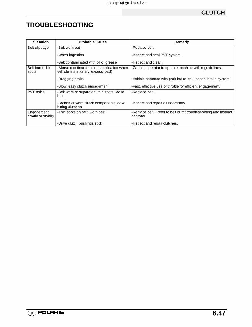
CLUTCH
6.47
TROUBLESHOOTING
Situation Probable Cause Remedy
Belt slippage -Belt worn out
-Water ingestion
-Belt contaminated with oil or grease
-Replace belt.
-Inspect and seal PVT system.
-Inspect and clean.
Belt burnt, thinspots
-Abuse (continued throttle application whenvehicle is stationary, excess load)
-Dragging brake
-Slow, easy clutch engagement
-Caution operator to operate machine within guidelines.
-Vehicle operated with park brake on. Inspect brake system.
-Fast, effective use of throttle for efficient engagement.
PVT noise -Belt worn or separated, thin spots, loosebelt
-Broken or worn clutch components, coverhitting clutches
-Replace belt.
-Inspect and repair as necessary.
Engagementerratic or stabby
-Thin spots on belt, worn belt
-Drive clutch bushings stick
-Replace belt. Refer to belt burnt troubleshooting and instructoperator.
-Inspect and repair clutches.

7
CHAPTER 7FINAL DRIVE
Final Drive Torque Specifications 7.1. . . . . . . . . . . . . . .AWD Operation Overview 7.2. . . . . . . . . . . . . . . . . . . . . .Front Hub Disassembly 7.3. . . . . . . . . . . . . . . . . . . . . . . .Front Hub/Bearing Installation 7.4. . . . . . . . . . . . . . . . . .Front Hub Bearing Adjustment 7.5. . . . . . . . . . . . . . . . .Front Hub Exploded View 7.6. . . . . . . . . . . . . . . . . . . . . .Front Hub Seal Replacement 7.7. . . . . . . . . . . . . . . . . .AWD Magnetic Coil Service 7.8. . . . . . . . . . . . . . . . . . . .AWD Hilliard Clutch Disassembly/Inspection 7.9. . . . .AWD Armature Plate Inspection 7.10. . . . . . . . . . . . . . . .Front Drive Axle Removal 7.11-7.12. . . . . . . . . . . . . . . . . . . . . .Front Drive Axle Installation 7.12. . . . . . . . . . . . . . . . . . . .Front CV Joint Boot Replacement 7.13-7.14. . . . . . . . . . . . . .Front Drive Axle Exploded View 7.15. . . . . . . . . . . . . . . .Front Strut Casting Seal Replacement 7.16. . . . . . . . . .Front Strut Seal Sleeve Replacement 7.17. . . . . . . . . . .Front Prop Shaft Removal 7.18. . . . . . . . . . . . . . . . . . . . .U-Joint Disassembly 7.19-7.20. . . . . . . . . . . . . . . . . . . . . . . . . .U-Joint Assembly 7.20-7.21. . . . . . . . . . . . . . . . . . . . . . . . . . . . .Front Gearcase Removal 7.22. . . . . . . . . . . . . . . . . . . . . .Front Gearcase Disassembly 7.22-7.23. . . . . . . . . . . . . . . . . . .Front Gearcase Assembly 7.24-7.25. . . . . . . . . . . . . . . . . . . . .Front Gearcase Installation 7.25. . . . . . . . . . . . . . . . . . . .Front Gearcase Exploded View 7.26. . . . . . . . . . . . . . . . .Rear Hub Removal 7.27-7.28. . . . . . . . . . . . . . . . . . . . . . . . . . .Rear Hub Installation 7.29. . . . . . . . . . . . . . . . . . . . . . . . . .Rear Hub Disassembly 7.30. . . . . . . . . . . . . . . . . . . . . . . .Rear Hub Assembly 7.31. . . . . . . . . . . . . . . . . . . . . . . . . . .Rear Drive Shaft Removal 7.32. . . . . . . . . . . . . . . . . . . . .Rear Drive Shaft Installation 7.33. . . . . . . . . . . . . . . . . . .Rear Drive Shaft Service 7.34-7.36. . . . . . . . . . . . . . . . . . . . . .

FINAL DRIVE
7.1
WHEEL AND HUB TORQUE TABLE¡
Item Specification
Front Wheel Nuts 20 Ft. Lbs.
Rear Wheel Nuts 20 Ft. Lbs.
Front Hub Nut Refer to text for procedure (Pg 7.5)
Rear Hub Retaining Nut 100 Ft. Lbs.
¡ Refer to exploded views and text for torque values of other fasteners
CAUTION: Locking nuts, and bolts with preapplied locking agent should be replaced if removed. The self-lockingproperties of the nut or bolt are reduced or destroyed during removal.

FINAL DRIVE
7.2
AWD OPERATION OVERVIEW
With the Polaris All Wheel Drive System activated(AWD selected), the machine operates as a 2 wheeldrive vehicle until the rear wheels lose traction. If therear wheels lose traction the front wheel rotationalspeed will decrease, causing the front drive axlespeed to exceed front wheel speed. Restricting therotation of the drive clutch roller cage (2) (see Elec-tric Hub Operation) will cause the rollers (3) to climbthe ramps of the cam (5), and become squeezed be-tween the ramps and the ring in the hub. See Ill. 1.
When the hub clutch assembly, wheel hub, anddriveaxle are engaged, the front wheels will drive andstay engaged until rear wheel traction is regained.When traction is regained, the front wheels will over-drive the hub clutch, pushing the clutch rollers (3) to-ward the lower part of the cam (5), disengaging theclutch. The rollers are held in place by the spring (4).See Ill. 2. The tension of this spring is critical to AWDhub operation. Always use the correct spring (referto appropriate parts manual) and use installationtool PN 2870888.
WARNINGIt is important that the front and rear axle drive ratioand tire size are not changed. Changing this ratiowill cause erratic engagement, which could result ina loss of vehicle control and serious injury or death.
ELECTRIC HUB ENGAGEMENT (AWD)When AWD is selected in a forward gear,current flows through a coil of wire locatedin the strut housing, creating a magneticfield. An armature plate (1) coupled to theroller cage (2) is attracted to the magneticfield, and resists rotation, creating drag onthe drive roller cage assembly. Thiscauses the roller to climb the ramps of thecam, engaging the hub. NOTE: In reversegear the override button must be pushed todeliver power to the wheel coil. Electrichub engagement offers an advantage overmechanical systems. When the AWD but-ton is switched off, the machine will havethe steering ease of a 2 wheel drive unit;and with the switch turned on, All wheeldrive will be engaged whenever the rearwheels lose traction.
RampsHub
Cage (2)
Roller (3)
Axle
Cam (5)
Ill. 1
1 2
3 5
4
A
Tabs must engage the slots
1. Armature Plate2. Roller Cage3. Roller4. Garter Spring5. Cam
Spacer
Ill. 2

FINAL DRIVE
7.3
FRONT HUB REMOVAL (AWD)If an AWD problem is encountered, thoroughly inspectthe electrical portion of the system as well as the fronthub mechanism. Refer to the electrical chapter.
1. Carefully lift and support the front end of themachine as shown with the jack stands under thefront end of the foot rests. CAUTION: Make surethe machine is solidly supported before proceeding.Serious injury could occur if the machine tips or falls.
2. Remove the front wheels and thoroughly clean thearea around the hub, strut casting, brake caliper andbrake disc.
3. Remove the two brake caliper attaching bolts.CAUTION: Do not hang the caliper by the brakehose. Use wire to hang the caliper to preventpossible damage to the brake line or speed sensor.
4. Place a catch pan beneath the front hub and removethe hub cap.
5. Remove cotter pin and nut.6. Remove front hub and bearings.

FINAL DRIVE
7.4
HUB/WHEEL BEARING INSTALLATION
1. Thoroughly inspect the hub internally. If the hubbearing sleeve is damaged or shows signs ofmovement, the hub assembly must be replaced.When the sleeve is pressed into the hub it shouldbe flush with the outside surface of the hub.
2. Grease hub seal to allow it to slideover roller clutchcomponents.
3. Install wheel hub inner bearing.NOTE: All bearings must slide freely onto thespindle. If bearings do not slide freely, wheelbearing torque will be affected.
4. Install wheel hub, outer bearing, washer, andattaching nut. NOTE: It is very important that thehub is not moved outward once installed, or theseal on the hub will disengage the armature plate.

FINAL DRIVE
7.5
AWD FRONT HUB BEARING ADJUSTMENT
WARNING
The following bearing adjustments are very important. Incorrect adjustment will increase bearing wear, reducebraking action, and may affect front drive hub engagement, which could result in serious personal injury or death.
1. Torque spindle nut to 160-170 inch lbs. whilerotating hub continuously.
2. Back off nut 1/2 turn.3. Rotate axle several revolutions by raising rear of
machine and rotating rear wheels with themachine in gear.
4. Re-torque hub nut to 108-144 inch lbs.
5. Install cotter pin. Bend each leg of cotter pinaround castle nut in different directions. Seebelow.
NOTE: If cotter pin hole does not align, tighten slightlyto align and install pin. Do not exceed 144 in. lbs.
6. Reinstall hub cap.7. Remove fill check plug and rotate hole to either
4:00 or 8:00 position.8. Fill with Polaris Premium Demand Drive Hub Fluid
or Type F Automatic Transmission Fluid until fluidtrickles out. NOTE: Do not force the oil into thehub under pressure. This can cause seal damageand leaks.
9. Reinstall plug.10. Reinstall brake caliper assembly. Torque retaining
bolts to 18 ft. lbs. (25 Nm).11. Reinstall front wheels. Torque retaining nuts to 15
ft. lbs. (21 Nm).12. Carefully lower vehicle.13. Field test vehicle for proper operation of brake
system and AWD operation.
Front Spindle Nut Torque:108-144 in. lbs.
Brake Caliper Retaining Bolt Torque:18 ft. lbs. (25 Nm)
Premium Demand Drive Hub Fluid
PN 2871654 (8 oz.)PN 2872277 (2.5 gal.)

DETAIL AA
Castle Nut¡
Bearing Race
Front Hub Clutch
Seal Armature Plate
Brake Disc
Bearing Race
Bearing (1.000″ I.D.)
Garter Spring
Spacer
Cotter Pin
Washer
Wheel Nut
¡Refer to text on page 7.5 for more information.
Detail
Front Hub Clutch
Bearing (1.000″ I.D.)
(Use newcotter pin)
O-Ring
FINAL DRIVE
7.6
AWD FRONT HUB EXPLODED VIEW

FINAL DRIVE
7.7
AWD HUB SEAL REPLACEMENT
1. Remove and disassemble front hub. Refer topage 7.3.
2. Remove brake disc attaching bolts and brakedisc.NOTE: If the attaching bolts are difficult toremove, it may be helpful to heat the outersurfaces of the hub in the area of the discmounting bolts, to soften the locking agent.
3. Apply heat to the hub seal area. When the hubbecomes too hot to touch, pry out the old seal asshown. Do not damage the surface of the sealcavity. Clean the hub in the seal mating area.
4. With spring side of new seal facing toward hubcasting, press it in until flush with brake discmating surface. CAUTION: Do not use a hammeras damage to the seal will result.
5. Thoroughly clean the brake disc with brakecleaner. It is very important that the brake disc befree of any oil or solvents.
6. Reinstall the brake disc using genuine PolarisOEM bolts that have a pre-applied locking agent.Do not substitute bolts or use old ones.
7. Installattachingboltsandtorqueto18ft. lbs.(25Nm).

FINAL DRIVE
7.8
MAGNETIC COIL REMOVAL1. Remove the front drive axle as described later
in this chapter.
2. Remove the seal sleeve from the strut castingusing a drift punch and hammer, tappingevenly on each side until the sleeve slides off.
3. Remove the existing coil and clean the coilwire channel, coil mount area, and the sealsleeve mounting area of all silicone andforeign matter.
4. Disconnect the coil wires at the connector orterminal board.
MAGNETIC COIL INSTALLATION1. Apply 1/4I (.6 cm) bead of silicone in the coil
wire channel.
2. Install the coil to the coil mount surface andpress the coil wires into the silicone in the coilwire channel.
3. Apply 1/4I (.6 cm) bead of Loctite™ Ultra Bluesilicone around the seal sleeve mounting area.NOTE: This includes applying silicone overthe coil lead wires again. Always allow 12hours’ cure time for silicone.
4. Press on the seal sleeve until even with theinner pole. See page 7.17 for additionalinformation. Once the seal sleeve is properlypositioned, a 1/16I (.16 cm) bead of siliconeshould remain around the inner edge. Cleanoff all excess silicone. The seal sleeve areamust be free of silicone or the hub seal mayleak.
NOTE:
- Always install a new seal sleeve whenreplacing the coil. Use tool PN 2871199.
- It may be necessary to apply more silicone(or an equivalent fast drying glue) to thewire channel area to properly secure andprotect the coil wires.
5. Apply 401 Loctitet to the inside of the strutribs and press the foam block to contain thecoil wires. Make sure the foam block isbonded well to protect the coil wires.
NOTE: Coil wires must be contained in the brakeline clip on the back side of the upper strut castingand the wires must be snug against the casting.
6. Route the wires smoothly and away from anymoving parts and secure in place with tiestraps.
7. Assemble front axle and connect hub wires.
Brake LineClip Location
Strut Ribs
Coil WireChannel
Seal SleeveMountingArea
Coil MountingSurface(Inner Magnet Pole)(Fixed)
Electromagnet Coil
Seal Sleeve (Outer Magnet Pole)(Adjustable) Must use tool PN 2871199

FINAL DRIVE
7.9
HILLIARD CLUTCH DISASSEMBLY/INSPECTION1. Remove front hub. See page 7.3.
2. Remove Hilliard clutch assembly.
3. Disassemble the roller clutch and thoroughly clean all parts. CAUTION: Do not remove the garter spring. Ifthe spring is removed, it will become over stressed and will require replacement.
4. Inspect roll cage sliding surface (A). This surface must be clean and free of nicks, burrs or scratches. Inspectroller cage (2) carefully for cracks.
5. Inspect rollers (3). The rollers must slide up and down freely within the roller cage sliding surfaces A.
6. Without removing the garter spring,inspect the coils for consistency. Ifcoils are distorted or uneven, cut theold spring with a side cutter to removeit, and replace it.
7. If garter spring replacement is necessary, it is veryimportant that the correct installation procedureand special tool be used. Hold rollers in place onroller cage with a light film of grease. Gently andevenly roll the spring down the tapered tool (PN2870888) and into the groove of the rollers andcage. WARNING: If this procedure is not followedthe spring will be over stressed and lose its tension.Springs with incorrect tension may allow rollers tomove outward at high vehicle speeds. If the rollersmove outward, the front hub(s) will engage andcause vehicle instability, which could result inserious injury or death.
WARNING: Be sure to use correct garter spring.These springs are very similar in appearance to thoseused on earlier models. If the old, lighter springs wereinstalled on a machine requiring the heavier spring, thefront wheels may engage at high speed, possibly re-sulting in serious injury or death. Check springs be-fore installation. Always verify the correct replace-ment spring part number by referring to theappropriate parts manual.
Current electro-mechanical spring, PN 3250032; wirediameter .018″ (.46 mm); spring free length end to endinside hooks 6.968″ (177 mm).
1 2
3 5
4
A
Engage tabs in the slots
1. Armature Plate NOTE: Armature plate is positioned withtabs in round holes of cage.
2. Roller Cage3. Roller4. Garter Spring5. Cam
SpacerInspect for cracks
Must use tool to install garter springPN 2870888
Measure wire diameter
Measure free length to inside ofloops as shown

FINAL DRIVE
7.10
AWD ARMATURE PLATE INSPECTION1. As the armature plate is engaged, it should contact
the outer magnet pole (seal sleeve) and the innermagnet pole. Also, the armature plate must be flatwhen placed on a flat surface. Bent armature platesshould be replaced.NOTE: It is not unusual to see a double wear ring onthe armature plate; however, the wear rings shouldbe even.
2. Install the roller clutch (Hilliard Clutch) assemblyand be sure the armature plate (A) is positionedproperly. Also, when installing the hub assembly,be sure the armature plate tabs remain engagedwith the roller clutch cage.
CAUTION: After the hub is installed, the slightestmovement outward with the hub may cause thearmature plate tabs to disengage from the roller clutchcage. If the unit is driven with the armature plate out ofposition, it will cause roller clutch damage.
Armature Plate Tabs
Seal Sleeve

FINAL DRIVE
7.11
AWD FRONT DRIVE AXLE REMOVAL1. Loosen front wheel nuts slightly.2. Elevate and support machine under footrest/frame
area with front wheels elevated.CAUTION: Serious injury may result if machine tips orfalls. Be sure machine is secure before beginning thisservice procedure. Wear eye protection when remov-ing and installing drive axles or component parts.
3. Remove wheel nuts and wheels.
4. Remove hub cap.
5. Remove the two brake caliper attaching bolts.CAUTION: Do not hang the caliper by the brakehose. Use wire to hang the caliper to preventpossible damage to the brake line.
6. Place a catch pan beneath the front hub and removethe hub cap.
7. Remove cotter pin and nut.
8. Remove hub, bearings, hilliard assembly, andarmature plate.
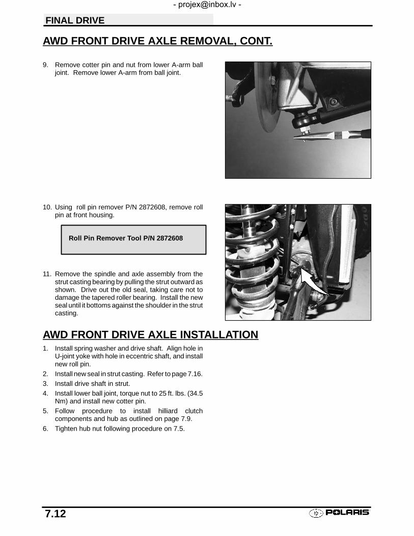
FINAL DRIVE
7.12
AWD FRONT DRIVE AXLE REMOVAL, CONT.
9. Remove cotter pin and nut from lower A-arm balljoint. Remove lower A-arm from ball joint.
10. Using roll pin remover P/N 2872608, remove rollpin at front housing.
11. Remove the spindle and axle assembly from thestrut casting bearing by pulling the strut outward asshown. Drive out the old seal, taking care not todamage the tapered roller bearing. Install the newseal until it bottoms against the shoulder in the strutcasting.
AWD FRONT DRIVE AXLE INSTALLATION1. Install spring washer and drive shaft. Align hole in
U-joint yoke with hole in eccentric shaft, and installnew roll pin.
2. Install new seal in strut casting. Refer to page7.16.3. Install drive shaft in strut.4. Install lower ball joint, torque nut to 25 ft. lbs. (34.5
Nm) and install new cotter pin.5. Follow procedure to install hilliard clutch
components and hub as outlined on page 7.9.
6. Tighten hub nut following procedure on 7.5.
Roll Pin Remover Tool P/N 2872608

FINAL DRIVE
7.13
DRIVESHAFT AND CV JOINT HANDLING TIPSCare should be exercised during driveshaft removal or when servicing CV joints. Driveshaft components are precisionparts.Cleanliness and following these instructions is very important to ensure proper shaft function and a normal servicelife.
S The complete driveshaft and joint should be handled by getting hold of the interconnecting shaft toavoid disassembly or potential damage to the driveshaft joints.
S Over-angling of joints beyond their capacity could result in boot or joint damage.
S Make sure surface-ground areas and splines of shaft are protected during handling to avoid damage.
S Do not allow boots to come into contact with sharp edges or hot engine and exhaust components.
S The driveshaft is not to be used as a lever arm to position other suspension components.
S Never use a hammer or sharp tools to remove or to install boot clamps.
S Be sure joints are thoroughly clean and that the proper amount and type of grease is used to refillwhen joint boots are replaced and when joints are cleaned. Refer to text for grease capacity of CVjoints and CV joint boots.
FRONT DRIVE SHAFT CV JOINT BOOT REPLACEMENT1. Remove wheel, brake caliper and wheel hub. Refer
to front hub disassembly page 7.3 for procedure.
2. Remove cotter pin and castle nut from A-arm balljoint.
3. Disconnect A-arm from ball joint using a tie rod fork.4. Slide strut off end of drive shaft and tie it up out of
the way of the shaft.
NOTE: Be careful not to damage the wheel coil wireswhen positioning the strut. Front Drive Shaft CV JointBoot Replacement Cont.

FRONT SHAFTJoint Capacity30 Grams
Boot Capacity30 Grams
Front outboard joint capacity: 30g if boot is replaced only.Another 30g (60g total) if joint is cleaned.
FINAL DRIVE
7.14
FRONT DRIVE SHAFT CV JOINT BOOT REPLACEMENT, CONT.
5. Remove clamps from rubber boot using the properboot clamp pliers.
6. Remove the large end of the boot from the CV joint,slide the boot back and separate the wheel spindleand CV joint assembly from the axle shaft by pullingthe shaft sharply outward, away from the CV joint. Itmay be necessary to tap the CV joint assemblyoutward with a soft faced hammer.
7. Remove small clamp and boot from driveshaft.
If the ATV has been operated with a damaged boot, the CV joint grease may be contaminated. Inspect the greasecarefully for contamination, and clean the joint thoroughly if necessary. Front drive axle CV boot replacementrequires 30g of grease. If CV joint is cleaned, an additional 30g of grease is required. Refer to information below.
8. Before installing the new boot, remove all greasefrom the boot area and shaft.
NOTE: It is very important to use the correct type andquantity of grease by using the grease contained in theboot kit. DO NOT use a substitute grease and DO NOToverfill or underfill the CV joint.
9. Slide the new clamp and boot (small end first) overthe splined shaft, then slide (tap) the CV joint intothe splines of the axle. Install small boot clamp.
10. Add grease through large end of boot.11. Position large end of boot on CV joint, purge excess
air by partially compressing axle into CV bell, lift oneedge of boot to let out excess air Secure withclamp.
Retaining ring
Pull shaft to remove fromCV joint
CV Joint Grease - 30g PN 1350046
CV Boot Clamp Pliers:Earless Type 8700226
Boot Replacement requires 30g
Boot replacement with complete CVjoint cleaning requires an additional30g. (Total 60g)

CV Joint Assy
Boot
Clamps Circlip
Drive Axle
U--Joint AssyYoke
Front Drive Axle Components
Front Prop Shaft Components
O-Ring
Yoke, Propshaft to Transmission
Prop ShaftCross and Bearing Kit
Spring Pin
Yoke, Front Gearcase
Propshaft Assembly
FINAL DRIVE
7.15
AWD FRONT DRIVE AXLE EXPLODED VIEW

FINAL DRIVE
7.16
AWD STRUT CASTING FRONT DRIVE AXLE SEAL REPLACEMENT1. Disassemble front hub. Refer to page 7.3.
2. Remove the cotter pin and castle nut from the A-arm ball joint. Separate A-arm from ball joint.
3. Remove the spindle and axle assembly from thestrut casting bearing by pulling the strut outwardas shown. Drive out the old seal, taking care notto damage the tapered roller bearing. Install thenew seal until it bottoms against the shoulder inthe strut casting.
4. Apply grease to the seal inner lip, reinstall thespindle and axle assembly.
5. Reinstall the A-arm to the ball joint. Torque to 25ft. lbs. (35 Nm).
NOTE: If the cotter pin hole does not align at theabove torque, tighten slightly until the cotter pin holealigns and install the pin with open ends toward rear ofmachine.
BEARING REPLACEMENT NOTE FOR FRONT DRIVE AXLEAND FRONT HUBNOTE: The front axle bearings have a larger I.D.(1.0625″) than the hub bearings (1.000″). Be sure toinstall the bearings with the larger I.D. in the struthousing, and the bearings with the smaller I.D. in thehub.
Pullstrut offdriveshaft

FINAL DRIVE
7.17
SEAL SLEEVE REPLACEMENTFront Drive Axle Seal Sleeve
1. If front axle sleeves become damaged and leak fluidthey are replaceable. Using a hammer and driftpunch, remove the seal sleeve by driving it offevenly being careful not to nick or damage thesleeve mounting area (A).
2. Coat the sleeve mounting area (A) with silicone andusing extreme care, press the new seal sleeve ontoarea (A) until it bottoms. Allow 12 hours for siliconeto cure.
NOTE: New front drive axle CV joint assemblies anddrive axle assemblies have the seal sleeve installedfrom the factory.
Hub Seal Sleeve Replacement
3. The hub seal sleeve must be driven onto the strutcasting until flush with the inner magnet pole. Usethe flat side (no step) of tool PN 2871199.
4. To check the gap between the inner and outer polesplace a straight edge on the outer pole so that it justintersects with the inner pole. The gap between thestraight edge and inner pole should be 0 to .001I(0-.025mm). This measurement should bechecked in three different positions around the poleassemblies. The three measurements must bewithin .0005I (.013 mm) of each other. If the gap isexcessive, the hub may not engage.
A Seal Sleeve
Inner Magnet Pole(Fixed)
Coil
Seal Sleeve(Outer MagnetPole) (Adjustable)
Not Unusual To SeeTwo Wear Rings
Max. .001″(.025mm)
Measure at 3places 120_apart
Inner Pole Shoe
SealSleeve(OuterMagnetPole)
Seal Sleeve Tool
Step
Use flat side to install seal sleeve
Pole Gap:.000″-.001″ (.00-.025mm)
Seal Sleeve Installation Tool SetPN 2871199

FINAL DRIVE
7.18
AWD FRONT PROP SHAFT REMOVAL1. Using roll pin remover P/N 2872608, remove the
roll pin from prop shaft at rear of housing. Slideprop shaft back and away from front housing. Pullsharply forward to remove from transmissionshaft.
NOTE: If removing front housing, use roll pin removerto remove the roll pins from both front drive axles.
Roll Pin Remover Tool P/N 2872608

FINAL DRIVE
7.19
U-JOINT DISASSEMBLYCAUTION: Always wear eye protection.
1. Remove internal or external snap ring from allbearing caps.
NOTE:If yoke or bearing is removed, cross bearingmust be replaced. Note orientation of grease fitting andmark inner and outer yoke for correct re-positioning dur-ing installation.
2. Support inner yoke as shown and drive outer yokedown (bearing cap out) with a soft face hammer.
3. Support U-joint in vise as shown and drive inneryoke down to remove remaining bearing caps.

FINAL DRIVE
7.20
U-JOINT DISASSEMBLY CONT.
4. Force U-joint cross to one side and lift out of inneryoke.
U-JOINT ASSEMBLY1. Install new bearing caps in yoke by hand. Carefully
install U-joint cross with grease fitting properlypositioned inward toward center of shaft. Take carenot to dislodge needle bearings upon installation ofcross joint. Tighten vise to force bearing caps in.
2. Using a suitable arbor, fully seat bearing cap in oneside. Continually check for free movement ofbearing cross as bearing caps are assembled.
3. Install snap ring to contain bearing cap just installed.Repeat procedure for other side.
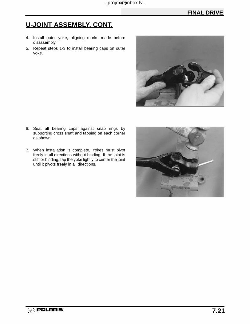
FINAL DRIVE
7.21
U-JOINT ASSEMBLY, CONT.
4. Install outer yoke, aligning marks made beforedisassembly.
5. Repeat steps 1-3 to install bearing caps on outeryoke.
6. Seat all bearing caps against snap rings bysupporting cross shaft and tapping on each corneras shown.
7. When installation is complete, Yokes must pivotfreely in all directions without binding. If the joint isstiff or binding, tap the yoke lightly to center the jointuntil it pivots freely in all directions.

FINAL DRIVE
7.22
AWD FRONT HOUSING REMOVAL1. Stop engine, place machine in gear and set
parking brake.2. Loosen right front wheel nuts slightly.3. Elevate and support machine under
footrest/frame area.CAUTION: Serious injury may result if machine tipsor falls. Be sure machine is secure before beginningthis service procedure. Wear eye protection when re-moving and installing bearings and seals.
4. Remove right wheel nuts and wheel.5. Remove cotter pin, lower ball joint nut and A-arm
from ball joint.6. Punch spring pins out from both axle splines and
front prop shaft.7. Remove bolts securing bottom of housing to
frame. Remove vent line. Remove housing fromright side of frame.
FRONT HOUSING DISASSEMBLY1. Drain and properly dispose of used oil.2. Remove bolts and output shaft cover.
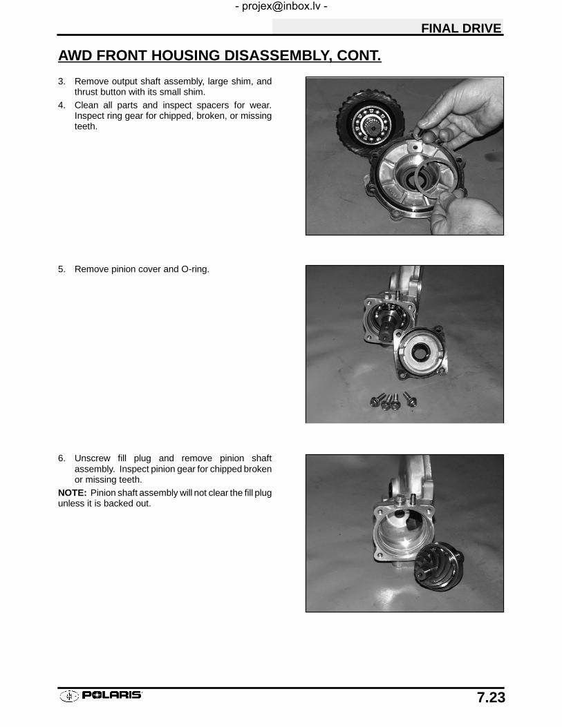
FINAL DRIVE
7.23
AWD FRONT HOUSING DISASSEMBLY, CONT.
3. Remove output shaft assembly, large shim, andthrust button with its small shim.
4. Clean all parts and inspect spacers for wear.Inspect ring gear for chipped, broken, or missingteeth.
5. Remove pinion cover and O-ring.
6. Unscrew fill plug and remove pinion shaftassembly. Inspect pinion gear for chipped brokenor missing teeth.
NOTE: Pinion shaft assembly will not clear the fill plugunless it is backed out.

FINAL DRIVE
7.24
AWD FRONT HOUSING ASSEMBLY1. Replace all O-rings, seals, and worn components.2. Press pinion shaft seal into pinion cover until flush
with sealing surface.3. Inspect pinion and output shaft bushings.
4. Inspect bearings on output and pinion shafts. Toreplace, press new bearing on to shaft.
NOTE: Due to extremely close tolerances and mini-mal wear, the bearings must be inspected visually, andby feel. While rotating bearings by hand, inspect forrough spots, discoloration, or corrosion. The bearingsshould turn smoothly and quietly, with no detectableup and down movement and minimal movement sideto side.
5. Clean pinion shaft and lock nut with PrimerNtand apply red LocTitet to threads. Tighten locknut to specification.
6. Install pinion shaft and pinion cover plate with newo-ring and torque bolts to 14 ft. lbs.
Bushings
Pinion Shaft Lock NutTorque
65 ft. lbs. (89.7 Nm)
Cover Bolts Torque
14 ft. lbs.

FINAL DRIVE
7.25
AWD FRONT HOUSING ASSEMBLY, CONT.
7. Install output shaft assembly.NOTE: The same shim thickness placed behindring gear bearing must also be put behind thecover button.
8. Install output shaft cover with new o-ring andtorque bolts to 14 ft. lbs.
FRONT HOUSING INSTALLATION1. To install housing, reverse removal procedure.
Use new roll pins in drive shafts.2. Add Polaris Premium Front Housing Lubricant or
GL5 80-90 gear lube to front housing. Check drainplug for proper torque.
Equal Shims
Cover Bolts Torque
14 ft. lbs.
Fill Plug
Premium Front Housing FluidPN 2871653 (12 oz.)
Front Housing Capacity4.0 fl. oz. (118 ml)

FINAL DRIVE
7.26
AWD FRONT HOUSING EXPLODED VIEW
Pinion Cover
Seal
O-Ring
Bearing
Pinion Shaft Output Shaft
Bearing
Shim O-RingOutput Cover
Thrust Button
ShimSeal
Vent
BushingSeal
Retaining Ring

FINAL DRIVE
7.27
REAR HUB/BEARING CARRIER REMOVAL
1. Lock the parking brake. Remove rear hub cap.
2. Remove cotter pin.
3. Loosen the hub retaining nut.
4. Loosen the wheel nuts.
5. Safely support the rear of the ATV.
CAUTION:
Serious injury could occur if machine tips or falls.
6. Remove hub nut, domed washer and flat washer.
7. Remove wheel nuts and wheel.

FINAL DRIVE
7.28
REAR HUB/BEARING CARRIER REMOVAL, CONT.
8. Remove hub.
9. Remove upper control arm bolt as shown.
10. Remove both lower control arm bolts.
11. Remove bearing carrier.

FINAL DRIVE
7.29
REAR HUB INSTALLATION
1. Start bearing carrier on drive shaft.
2. Align bottom of carrier housing and lower controlarm. Grease and slide lower control arm bushingsinto place, securing corner housing.
3. Install and torque both lower control arm bolts.
4. Lift bearing carrier until top aligns with upper controlarm. Install and torque upper control arm bolt andtorque to specification.
5. Pull drive shaft outward and install hub ontodriveshaft splines.
6. Install cone washers with domed side facingoutward.
7. Install retainer nut, wheel and wheel nuts.
8. Remove jackstand and torque axle nut and wheelnuts.
9. Install a new cotter pin. Tighten nut slightly to alignholes if required.
10. Install hub cap.
Lower Control Arm Bolt Torque:30 ft. lbs. (41 Nm)
Upper Control Arm Bolt Torque:35 ft. lbs. (48 Nm)
Rear Hub Nut Torque:100 ft. lbs. (138 Nm)
Rear Wheel Nut Torque20 ft. lbs. (27 Nm)

FINAL DRIVE
7.30
REAR HUB DISASSEMBLY
1. Remove outer snap ring.
2. From the back side, tap on the outer bearing racewith a drift punch in the reliefs as shown.
NOTE: Drive bearing out evenly by tapping on outerrace only. Once bearing is at bottom of casting, supportcasting on outer edges so bearing can be removed.
3. Inspect bearing.
NOTE: Due to extremely close tolerances and mini-mal wear, the bearings must be inspected visually, andby feel. While rotating bearings by hand, inspect forrough spots, discoloration, or corrosion. The bearingsshould turn smoothly and quietly, with no detectableup and down movement and minimal movement side-ways between inner and outer race.
4. Inspect bearing housing for scratches, wear ordamage. Replace housing if damaged.
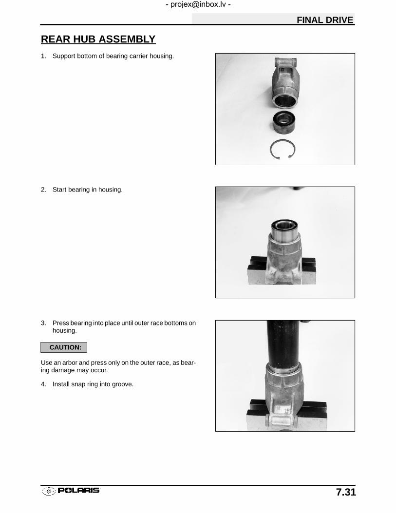
FINAL DRIVE
7.31
REAR HUB ASSEMBLY
1. Support bottom of bearing carrier housing.
2. Start bearing in housing.
3. Press bearing into place until outer race bottoms onhousing.
CAUTION:
Use an arbor and press only on the outer race, as bear-ing damage may occur.
4. Install snap ring into groove.

FINAL DRIVE
7.32
REAR DRIVE SHAFT REMOVAL
1. Remove rear hub and bearing carrier. (See pages7.27 - 7.28, steps 1- 9).
2. Tip hub outward and remove shaft from hub.
3. Pull sharply outward to remove shaft fromtransmission. Install a new lock ring uponassembly.
DRIVESHAFT AND CV JOINT HANDLING TIPSCare should be exercised during driveshaft removal or when servicing CV joints. Driveshaft components are precisionparts.Cleanliness and following these instructions is very important to ensure proper shaft function and a normal servicelife.
S The complete driveshaft and joint should be handled by getting hold of the interconnecting shaft toavoid disassembly or potential damage to the driveshaft joints.
S Over-angling of joints beyond their capacity could result in boot or joint damage.
S Make sure surface-ground areas and splines of shaft are protected during handling to avoid damage.
S Do not allow boots to come into contact with sharp edges or hot engine and exhaust components.
S The driveshaft is not to be used as a lever arm to position other suspension components.
S Never use a hammer or sharp tools to remove or to install boot clamps.
S Be sure joints are thoroughly clean and that the proper amount and type of grease is used to refillwhen joint boots are replaced and when joints are cleaned. Refer to text for grease capacity of CVjoints and CV joint boots.
Pull outward sharply to re-move from transmission

FINAL DRIVE
7.33
REAR DRIVE SHAFT INSTALLATION
1. Slide shaft assembly into bearing carrier hub.
2. Apply anti-seize compound to splines of shaft.
3. Install a new lock ring and install the shaft.
4. Lift bearing carrier into place and install bolt touppercontrol arm. Torque bolt to 35 ft. lbs. (48 Nm).
5. Install hub, flat washer, domed washer (domed sideout) and nut. Torque center nut to 100 ft. lbs. Installnew cotter pin and hub cap.
6. Install rear wheel and torque wheel nuts tospecification.
7. Grease all fittings thoroughly with Premium U-JointLubricant.
Rear Hub Nut Torque:
100 ft. lbs. (138 Nm)
Out
ConeWasher
Conewasherdome tooutside
100 ft. lbs.(138 Nm) Flat Washer
Rear Wheel Nut Torque:
20 ft. lbs. (27 Nm)

FINAL DRIVE
7.34
REAR DRIVE SHAFT SERVICE
1. Remove clamps from rubber boot(s) using theproper boot clamp pliers.
2. NOTE: Photo at right is shown without shaft forclarity. Wipe grease away from recess in CV jointinner hub to locate snap ring.
3. Open the snap ring using a snap ring pliers or smallneedle nose pliers. Tap CV housing off shaft with asoft faced hammer while holding snap ring open.
CV Boot Clamp Pliers:Earless Type 8700226
Snap ring located inrecessed area
Snap ring
Tap CV HousingOff Shaft
Spread ends of snap ringto remove joint from shaft
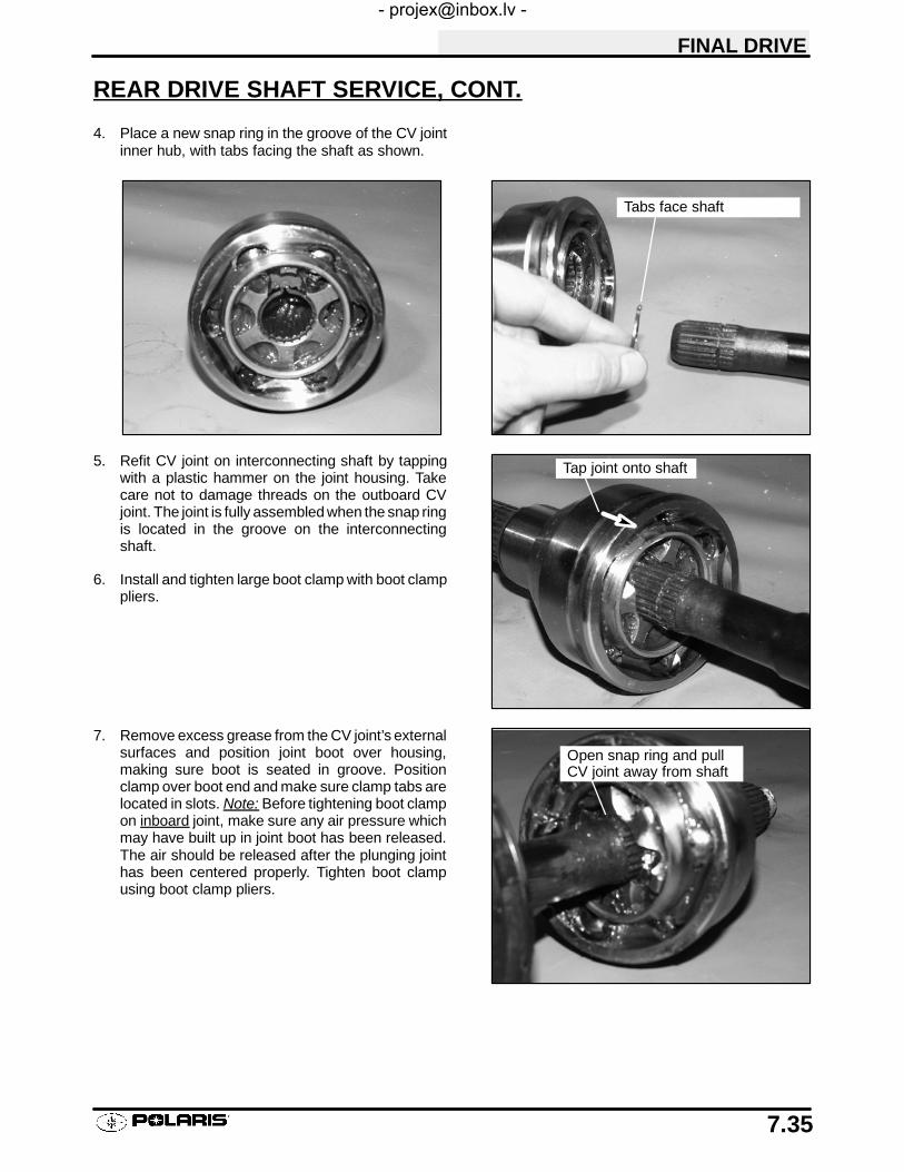
FINAL DRIVE
7.35
REAR DRIVE SHAFT SERVICE, CONT.
4. Place a new snap ring in the groove of the CV jointinner hub, with tabs facing the shaft as shown.
5. Refit CV joint on interconnecting shaft by tappingwith a plastic hammer on the joint housing. Takecare not to damage threads on the outboard CVjoint. The joint is fully assembled when the snap ringis located in the groove on the interconnectingshaft.
6. Install and tighten large boot clamp with boot clamppliers.
7. Remove excess grease from the CV joint’s externalsurfaces and position joint boot over housing,making sure boot is seated in groove. Positionclamp over boot end and make sure clamp tabs arelocated in slots. Note: Before tightening boot clampon inboard joint, make sure any air pressure whichmay have built up in joint boot has been released.The air should be released after the plunging jointhas been centered properly. Tighten boot clampusing boot clamp pliers.
Tabs face shaft
Tap joint onto shaft
Open snap ring and pullCV joint away from shaft

FINAL DRIVE
7.36
REAR DRIVE SHAFT SERVICE, CONT.(Boot Replacement)
1. Remove CV joint from end of shaft. (See page 7.34)
2. Remove boot from shaft.
NOTE:When replacing a damaged boot, check the grease for contamination by rubbing it between two fingers.A gritty feeling indicates contamination. If the grease is not contaminated, the boot can be replaced withoutcleaning the CV joint. Use the recommended amount of grease for boot replacement only (see below). Proceedto Boot Installation.
(CV Joint Cleaning / Replacement)
3. Thoroughly clean and dry the CV joint and inspectball tracks and cages for wear, cracks or otherdamage.
NOTE:Shiny areas in ball tracks and on the cage spheresare normal. Do not replace CV joints because partshave polished surfaces. Replace CV joint only if compo-nents are cracked, broken, worn or otherwise unser-viceable.
4. Add the recommended amount of grease for CVjoint cleaning to the joint as shown below. Be suregrease penetrates all parts of the joint.
(Boot Installation)
5. Fit joint boot and clamps on interconnecting shaft.Make sure small end of boot is fully seated ingroove.
6. Position small clamp over small end of boot. Besure it is seated all the way around in the clamprecess on the boot.
7. Tighten boot clamp using boot clamp pliers.
8. Fill boot with grease supplied with boot service kitand spread remaining grease evenly inside CVjoint. Be sure to use only the Constant Velocity Jointgrease supplied with boot service kit. IF CV JOINTWAS CLEANED, add the recommended amount ofgrease to the joint in addition to the grease packsupplied with boot kit.
NOTE:CV Joint Grease Capacity:
Outboard joint - 30g if boot is replaced only. Another50g (80 total) if joint is cleaned.
Inboard joint - 50g if boot is replaced only. Another 50g(100total) if joint is cleaned.
CV Joint Grease - 30g PN 135004650g PN 1350047
Joint Capacity50 Grams
Boot Capacity30 Grams
Joint Capacity50 Grams
Boot Capacity50 Grams
INBOARD100g Total
OUTBOARD80g Total

8
CHAPTER 8TRANSMISSION SERVICE
Torque Specifications 8.1. . . . . . . . . . . . . . . . . . . . . . . . .
Gear Shift Selector Removal 8.2. . . . . . . . . . . . . . . . . . .
Gear Shift Selector Disassembly 8.2-8.3. . . . . . . . . . . . . . .
Gear Shift Selector Assembly 8.4. . . . . . . . . . . . . . . . . .
Gear Shift Selector Installation 8.5. . . . . . . . . . . . . . . . .
Boot Replacement 8.5. . . . . . . . . . . . . . . . . . . . . . . . . . . .
Transmission Removal 8.6-8.8. . . . . . . . . . . . . . . . . . . . . . . .
Transmission Installation 8.9-8.10. . . . . . . . . . . . . . . . . . . . . .
Transmission Disassembly 8.11-8.19. . . . . . . . . . . . . . . . . . . . .
Transmission Assembly 8.20-8.31. . . . . . . . . . . . . . . . . . . . . . .
Transmission Exploded View 8.32. . . . . . . . . . . . . . . . . . .
Troubleshooting 8.33. . . . . . . . . . . . . . . . . . . . . . . . . . . . . .
TRANSMISSION
8.1
TORQUE SPECIFICATIONSTransmission Case Bolts 12 ft. lbs. (16.6 Nm). . . . . . . . . . . . . . . . . . . . . . . . . . . . . . . . . . . . . . . . .Bell Crank Nut 12 ft. lbs. (16.6 Nm). . . . . . . . . . . . . . . . . . . . . . . . . . . . . . . . . . . . . . . . . . . . . . . . . .Transmission Drain Plug 14 ft. lbs. (19.3 Nm). . . . . . . . . . . . . . . . . . . . . . . . . . . . . . . . . . . . . . . . .Transmission Mounting Bolts 25 ft. lbs. (34.5 Nm). . . . . . . . . . . . . . . . . . . . . . . . . . . . . . . . . . . . . .
LUBRICATIONRefer to maintenance section for transmission lubricant type and capacity.

TRANSMISSION
8.2
GEAR SHIFT SELECTOR REMOVAL
NOTE: To change fluid, remove selector box assembly, disassemble, clean, and assemble.
1. Remove parts that interfere with access to shiftselector (seat, right side panel, and exhaust heatshield, etc.).
2. Disconnect the two linkage rods from gear shiftselector slides.
3. Remove five bolts attaching gear shift selector tothe mounting bracket.
4. Lift gear selector out of mountingbracket andawayfrom frame.
GEAR SHIFT SELECTOR DISASSEMBLY
CAUTION:
Wear eye protection during this procedure. Read eachstep completely before proceeding. Essential partsmay be lost or damaged if you do not heed this caution!
1. Clamp gear selector body lightly in a soft jawedvice. Using a cross pattern, loosen eachof the fourscrews holding the gear shift selector cover to thegear shift selector body. Loosen each screw only afew turns, then proceed to another screw.
NOTE: These parts are under pressure from the inter-nal springs.

TRANSMISSION
8.3
GEAR SHIFT SELECTOR DISASSEMBLY, CONT.
2. Carefully pull the gear shift selector cover and rodfrom the gear shift selector body.
3. Set the cover/rod assembly aside.4. Remove the three springs from gear shift selector.
5. Slowly tilt gear shift selector body sideways todrain oil.
NOTE: Do not tip gear shift selector body upside downor detent bullets and stop pin may fall out. Check forsigns of moisture in the selector body. Inspect shiftboot closely if moisture is present in selector box.
6. Tap gear shift selector body, top down, against ahard, smooth, flat surface to jar the dowel pin andtwo detent bullets loose. Pull the detent bulletsand the dowel pin out of the gear shift selectorbody.
7. Remove the two slides, one at a time.
NOTE: The LH (low) slide has two short notches andthe RH (high/rev) slide has one short and one longnotch. The slides must be replaced in the proper chan-nels.
8. Inspect O-rings for damage. Replace if anydamage is found.
9. Flush housing with parts washer fluid orpenetrating oil to remove all moisture.
10. Dry all gear shift selector parts and remove anycorrosion with a wire brush.
Knob
Screw
Cap
Clamp
Boot
Cover (ApplyLoctite™ 515)
DowelPin
Handle
Selector Slides
Low2 ShortNotches
High/Reverse(1 Short,1 Long Notch)
Detent Spring
DetentBullet
Centering Spring
PlasticSphere
DetentSpring
DetentBullet
GroovePin

TRANSMISSION
8.4
GEAR SHIFT SELECTOR ASSEMBLY
1. Insert slides into gear shift selector body, taking carenot to cut or tear O-rings in the process.
NOTE: The LH slide has two short notches and the RHside has one short and one long notch. The slides mustbe replaced in the proper channels for the shifter to func-tion properly.
2. Replace detent bullets, dowel pin, and springs byreversing steps 5 - 7 of Gear Shift SelectorDisassembly.
3. Clamp gear shift selector body lightly in a soft jawedvise.
4. Fill selector body with Polaris 0W-40 All SeasonSynthetic motor oil. The oil level should be at onehalf the height of the slides (approx. 1 oz.).
CAUTION: Too much oil could cause the selector to hy-drolock. Be sure the selector box is level when addingoil.
5. Wipe gear selector dry, clean surfaces of cover andselector box with Loctite™Primer T and place a beadof Loctite™ 518 Gasket Eliminator or 3 Bond 1215completely around the edge of the gear shift selectorbody.
6. Carefully reattach cover/rod assembly to gear shiftselector body. Make sure slides are in neutral, orbutterfly may be damaged.
7. Torque cover screws to 12 ft. lbs. (1.7 kg-m).
Polaris 0W-40 All Season Synthetic OilPN 2871281 - QuartPN 2871844 - Gallon
Gear Shift Selector Capacity: 1 oz.

TRANSMISSION
8.5
GEAR SHIFT SELECTOR INSTALLATION
1. Place gear shift selector back into the mountingbracket and replace five bolts.
2. Reconnect linkage rods to gear shift selectorslides. Adjust as required. See linkageadjustment procedures.
3. Replace remaining parts.
BOOT REPLACEMENT
NOTE: If moisture is found in the gear shift selectorthe boot should be replaced.
1. Using a slotted screwdriver, remove cap fromgear shift knob.
2. Remove torx screw securing knob to selectorrod.
3. Pull selector knob off selector rod.
4. Remove band clamp on rubber boot.
5. Slide boot off selector rod and replace with anew one.
6. Apply RTV silicone to selector rod to seal top ofboot.
7. Place band clamp in position and tighten usingCV boot clamp pliers.
8. Replace shift knob, securing it to selector rodwith screw removed in step 2.
9. Push shift knob cover back into place. Allowapproximately 12 hours for RTV silicone to cure.
Knob
Screw
Cap
Clamp
Boot
Seal withRTV silicone

TRANSMISSION
8.6
TRANSMISSION REMOVALAll operations regarding transmission front output housing assembly can be performed with transmission installedin frame.
1. Remove the inner PVT cover. Refer to ClutchChapter.
2. Remove complete airbox assembly andtransmission vent line.
3. Loosen rear wheel nuts slightly.4. Elevate and support machine under
footrest/frame area.CAUTION: Serious injury may result if machine tipsor falls. Be sure machine is secure before beginningthis service procedure. Wear eye protection when re-moving and installing bearings and seals.
5. Remove wheel nuts and wheels.
6. Apply hand and auxiliary brake and remove brakedisc retaining nut and washer. NOTE: Domedside of washer faces nut.
7. Remove rear (auxiliary) brake caliper and disc.Support caliper on right hand foot rest.
8. Disconnect transmission shift linkage rods.Remove right hand shock absorber.
9. Disconnect harness from gear position switches.10. Remove right rear drive shaft (see page 7.32).
Domed sidetoward nut
Pull outward to removefrom transmission

TRANSMISSION
8.7
TRANSMISSION REMOVAL, CONT.11. Disconnect the sway bar from bothsides. Remove
right side upper control arm.12. Remove left side shock absorber.13. Remove left rear drive shaft (see page 7.32).14. Remove left side upper control arm.
15. Remove both lower transmission mounting boltsfrom each side.
16. Remove all 8 bolts attaching the stabilizer supportbracket, and remove support.
Lower Mounting Bolts
Stabilizer Mounting Bolts

TRANSMISSION
8.8
TRANSMISSION REMOVAL, CONT.
17. Remove front support bracket.
18. Remove bottom transmission bolts as shown inillustration.
19. Lift and remove transmission out right side offrame.
Front TransmissionSupport Bracket
Forward
Removebolts

TRANSMISSION
8.9
TRANSMISSION INSTALLATION1. Apply Premium All Season grease to splines of
front output shaft ,install new O-ring in prop shaft,insert output shaft into prop shaft.
2. Rotate transmission into place from right side offrame.
3. Loosely install bottom transmission bolts.
4. Install lower right and left transmission mountingbolts, front transmission bracket, and rearstabilizer support bracket. Tighten transmissionbolts securely in the following sequence.S Front support bracket upper and lower.S Stabilizer bracket upper and lower.S Bottom transmission bolts.
S Lower left and right transmission mounting bolts.
5. Apply anti--seize to splines of rear drive shafts,insert drive shafts into transmission. Install leftand right rear upper control arms. Install stabilizerbar arm on stabilizer bar.
Installbolts
Apply anti--seizeto splines

TRANSMISSION
8.10
TRANSMISSION INSTALLATION, CONT.
6. Install brake disc and washer with domed side out,against nut.
7. Install caliper, auxiliary brake master cylinder, andtransmission shift linkage rods. Install left andright hand shock absorbers.
8. Apply brake and torque disc nut to 45 ft./lbs.9. Install PVT system. Refer to PVT section for
procedure.10. Install airbox assembly and transmission vent line.
Be sure vent line is not kinked or pinched.
11. Add Polaris Premium Synthetic GearcaseLubricant to the proper level on dipstick.(Approximately 1 quart). Do not overfill.
12. Install rear wheel nuts and torque to specification.
13. Refer to Maintenance Section to adjusttransmission linkage.
Premium Synthetic Gear Case LubricantPN 2871478 (12 oz.)PN 2871477 (Gallon)
Rear Wheel Retaining Bolt Torque
20 ft. lbs. (27 Nm)

TRANSMISSION
8.11
TRANSMISSION DISASSEMBLY1. Remove gear indicator switches BEFORE
disassembly.
2. Drain and properly dispose of transmission oil.
3. Remove all cover bolts. Tap cover with soft facehammer to remove. Note 2 bolts in center of cover.
CAUTION:
Do not pry on case half sealing surfaces.
Remove switches
Drain
Remove all bolts
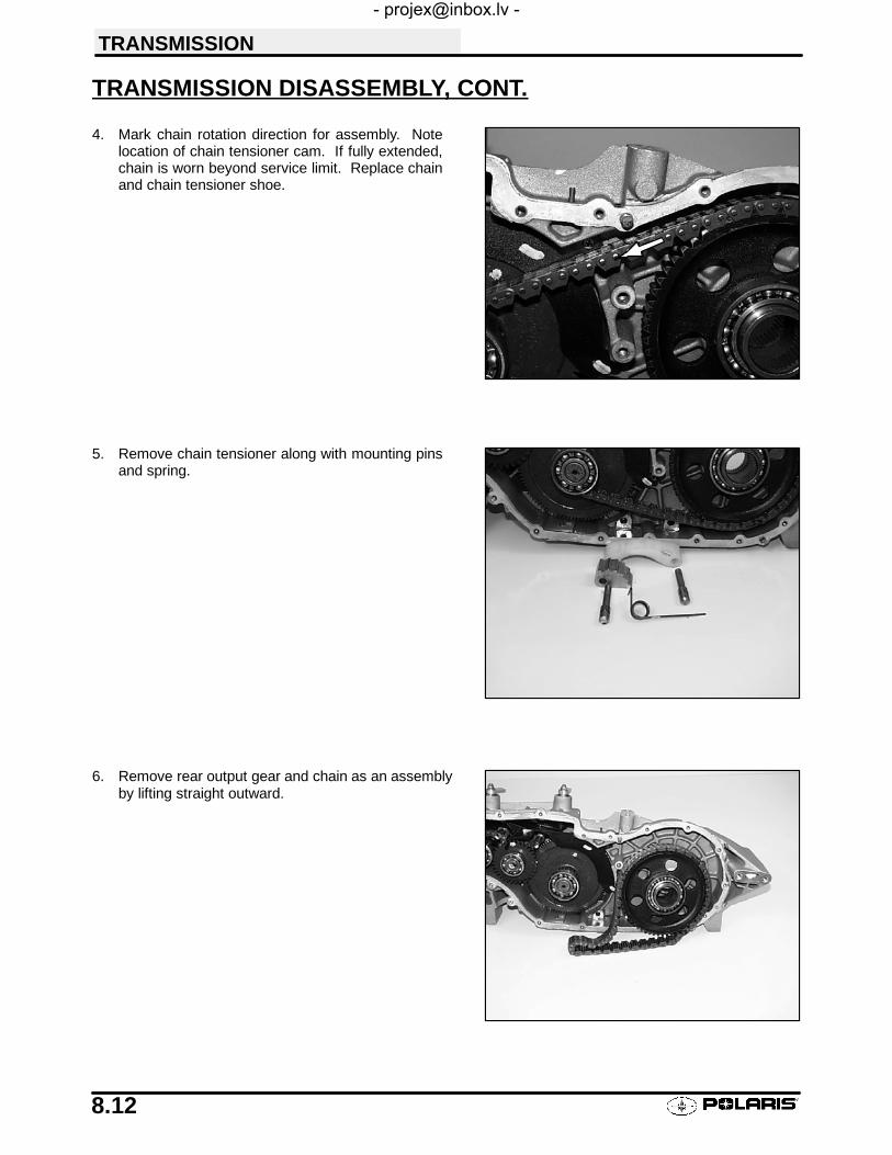
TRANSMISSION
8.12
TRANSMISSION DISASSEMBLY, CONT.
4. Mark chain rotation direction for assembly. Notelocation of chain tensioner cam. If fully extended,chain is worn beyond service limit. Replace chainand chain tensioner shoe.
5. Remove chain tensioner along with mounting pinsand spring.
6. Remove rear output gear and chain as an assemblyby lifting straight outward.

TRANSMISSION
8.13
TRANSMISSION DISASSEMBLY, CONT.
7. Remove oil deflector.
8. Make sure hole in oil deflector is clear andunobstructed.
9. Using a puller remove Hi/Lo/Reverse (HLR) shaftbearing, and bearing thrust washer.
RemoveScrews
Be sure hole is clear

TRANSMISSION
8.14
TRANSMISSION DISASSEMBLY, CONT.
10. Turn transmission so shafts are pointing down. Slidethe Low gear in and out until needle bearing slides outof gear and can be removed. Remove needle bearing,low gear, and inner thrust washer.
11. Inspect shift dogs for excessive rounding on theleading edges. Replace if worn.
12. Remove low range shift fork and dog. Replace alongwith mating gear if wear is evident.

TRANSMISSION
8.15
TRANSMISSION DISASSEMBLY, CONT.
13. Inspect face of shift fork for excessive wear,discoloration, or bending.
14. Remove center shaft assembly by tapping onopposite side with a soft face hammer.
15. Remove the remaining gears and shafts as anassembly. Rotate the shift bellcrank with a 1/2″wrench to aid in removal.

TRANSMISSION
8.16
TRANSMISSION DISASSEMBLY, CONT.
16. Remove pinion gear retaining plate and pinion gearassembly.
17. Inspect pinion gear for broken, chipped, or wornteeth. Check bearing condition, and snap ringlocation.
18. Loosen front output housing pinch bolts.CAUTION: Do not lose pinch plate. Must be used forreassembly or transmission will be damaged.
Loosen PinchBolts
Pinch Plate

TRANSMISSION
8.17
TRANSMISSION DISASSEMBLY, CONT.
19. Mark housing and casting for reference uponreassembly.
20. Using 2 1/8″ wrench (PN 2871701) unscrew thefront drive housing from the transmission castinguntil O-ring is exposed 1/2″ (13mm).
NOTE: Do not attempt to unscrew the front drivehousing completely at this time.
21. Remove bottom access plate.22. Bend the lock plate tab away from ring gear
retaining bolt.
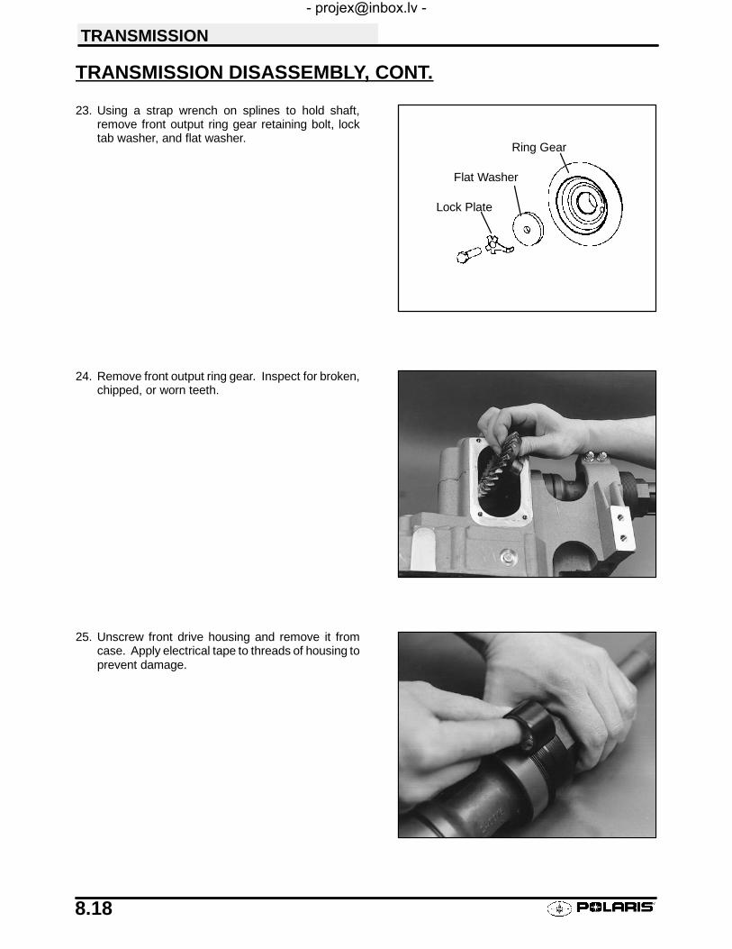
TRANSMISSION
8.18
TRANSMISSION DISASSEMBLY, CONT.
23. Using a strap wrench on splines to hold shaft,remove front output ring gear retaining bolt, locktab washer, and flat washer.
24. Remove front output ring gear. Inspect for broken,chipped, or worn teeth.
25. Unscrew front drive housing and remove it fromcase. Apply electrical tape to threads of housing toprevent damage.
Lock Plate
Flat Washer
Ring Gear

TRANSMISSION
8.19
TRANSMISSION DISASSEMBLY, CONT.
26. Using a brass hammer or a press, drive the shaft,bearing, retaining ring, and seal out of the housingfrom rear to front.
27. Slide seal off shaft and remove snap ring andshims. Record # of shims and thickness of each forreference.
28. Inspect center shaft bushing for wear. If necessary,remove with the large end of bushing drive tool.
29. Remove all remaining seals from transmission casesand clean all parts thoroughly.
Bushing Drive ToolPN 2871697
BearingShim(s)
SealRetaining Ring
ShaftHousing

TRANSMISSION
8.20
BUSHING INSTALLATION, TRANSMISSION CENTER SHAFT1. Install center shaft (brake disc shaft) bushing using
small end of bushing installation tool.
2. Apply Loctite t 243 (blue) to threads of screws andinstall center shaft cover. Tighten screws securely.
FRONT OUTPUT HOUSING (SNORKEL) ASSEMBLY
1. Bearing is a light press fit on ring gear end of frontoutput shaft. Heat inner bearing on a hot plate or witha heat gun to ease installation. Install bearing onshaft until inner race bottoms on flange of shaft.
CAUTION: Do not use a torch - bearing damage may re-sult.
Bushing Drive ToolPN 2871697
Shaft Bushing

TRANSMISSION
8.21
FRONT OUTPUT HOUSING ASSEMBLY, CONT.
2. Install shaft with bearing in front output housing.
3. Turn housing, shaft, and bearing assembly over andinstall front bearing until fully seated.
4. Front output shaft end play must be measured andadjusted if shaft or housing was replaced.To measure end play:Install snap ring on shaft without shims in place.Clamp housing lightly in soft jawed vise.
5. Set up a dial indicator to measure shaft end play.
Bearing
Shaft
TransmissionEnd of Housing

TRANSMISSION
8.22
FRONT OUTPUT HOUSING (SNORKEL) INSTALLATION
6. Measured end play will be between .030″ -.070″.Shims must be added between bearing and circlip toreduce end play. To calculate proper end play,subtract total shim thickness from end play measuredin step 8. Add or subtract shims as required to obtainspecified end play (.000-.003″). Remove snap ring,install shims, reinstall snap ring. It may be necessaryto tap snap ring into place.
NOTE: Shaft should rotate freely when finished. Confirmend play measurement with dial indicator. Do not installfront housing seal until backlash is adjusted.
7. Remove electrical tape and liberally apply anti-seizecompound to the threads of the front output housing.
8. Screw in housing until O-ring is approximately 1/4″(8mm) from transmission housing.
Final Installed Shaft End Play
.000″ - .003″ (0mm - .075mm)

TRANSMISSION
8.23
FRONT OUTPUT HOUSING (SNORKEL) INSTALLATION
9. Install front output ring gear, washer, and retainingbolt with a new lock plate. Hold shaft with strapwrench and tighten retaining bolt. Clean threads ofbolt and shaft with Loctite™Primer N. Apply Loctite™242 or 243 (blue) to retaining bolt threads. Torquebolt to specification and bend lock plate againsthexagonal portion of bolt.
10. Install pinion gear assembly and retaining plate. UseLoctite™ Primer N on threads and housing. ApplyLoctite™ 242 to bolts and torque to specification.
FRONT OUTPUT HOUSING (SNORKEL) BACKLASH ADJUSTMENT
11. Lubricate front housing O-ring thoroughly withPolaris All Season grease. Continue to screw fronthousing in, making sure O-ring enters housingwithout damage. Be sure ring and pinion gear teethmesh properly.
12. Rotate front shaft while slowly turning housinginward. As gear backlash is reduced to zero, theshaft will begin to bind. At this point back off 1/4 turn.
Ring Gear Retaining Bolt17 - 20 ft. lbs. (24-27 Nm)Apply Loctite™ 242 or 243 (Blue)
Pinion Gear Retainer Screws:17 - 20 ft. lbs. (24-27 Nm)Apply Loctite™ 242 or 243 (Blue)

TRANSMISSION
8.24
TRANSMISSION OUTPUT GEAR BACKLASH INSPECTION/ADJUSTMENT
13. The following steps must be performed to obtainproper front output gear backlash adjustment:S The pinion gear must be held securely.S Do not lubricate the gear teeth until backlash ad-
justment is complete. Both Gears should be freeof grease and oil.
S Perform adjustment with front output housingseal removed and end play properly adjusted.
S Measure backlash using tool (PN 2871695).The measurement point is 3.875″ (98.43mm)from shaft centerline.
S Set backlash at .008″ - .014″ (.20 -.36mm).
S Check backlash in several locations of ring gear.
14. Install special tool (PN 2871695) on shaft as shown.With pinion gear held stationary, rotate output shaftback and forth, reading the total movement of dialindicator. The dial indicator must be positioned asshown at the proper distance (aligned withoutermost mark on tool, and 90° to the tool surface),or indicated backlash will be inaccurate.S To reduce backlash, rotate housing clockwise as
viewed from front of housing.S To increase backlash, rotate housing counter-
clockwise.
15. Torque pinch bolts to specification. Be sure pinchplate (A) is installed. Verify backlash measurement.
Front GearcaseUse This Mark
TransmissionFront OutputShaft UseThis Mark
3.875″1.875″
A

TRANSMISSION
8.25
TRANSMISSION ASSEMBLY, CONT.16. Make sure surface of access plate and transmission
are clean and free of oil and grease.Apply 3Bondt 1215 to mating surface oftransmission case. Install access plate with notch tofront as shown, torque screws to specification.
17. Using the Magnum crankshaft installation tool,lubricate and carefully install the front seal until flushwith housing.
18. Assemble Hi/Low/Reverse shaft as shown. Machined (flat) side of retainer should face direction of thrust. Slidinghigh/reverse engagement dog is symmetrical and can be installed either way. The low gear dog must face lowgear.
Access Plate Screws:
8 - 10 ft. lbs. (11-14 Nm)
Low GearReverse Gear
HighGear
H/L/R Shaft
Bearing
Washer
EngagementDog, Low
Bearing
EngagementDog, High/Rev
NeedleBearing
Washer
NeedleBearing
RetainingRing
RetainingRing
RetainingRing
NeedleBearing
RetainingRing
RetainingRing

TRANSMISSION
8.26
TRANSMISSION ASSEMBLY, CONT.
19. Stretch silent cluster chain tight on a flat surface andmeasure the length of 8 pitches in a minimum ofthree places on chain. Replace chain ifmeasurement is longer than 3.0904I.
20. Assemble the input shaft and Hi/Low/Reverse gearcluster as shown.
21. The two shift forks can be easily identified by theindentations. Low/Neutral shaft has 2 detents, andHi/Neutral/Reverse has 3 detents.
22. Install Hi/Reverse cluster in transmission as anassembly. If necessary use a soft face hammer toinstall shafts until fully seated.
Chain Stretch Limit
8 pitch length = 3.0904I Maximum

TRANSMISSION
8.27
TRANSMISSION ASSEMBLY, CONT.
23. Install center shaft assembly.
24. Install Low shift fork with sliding dog in place. Dogsmust be positioned outward (toward you). Slide theshift dog over the spline and the low range shift shaft.
25. Lubricate and install inner thrust washer, low gear,and needle bearing.

TRANSMISSION
8.28
TRANSMISSION ASSEMBLY, CONT.
26. Install outer thrust washer and bearing.
27. Install plastic oil deflector. Apply Loctite™ 242 or 243(blue) to screw threads. Be sure deflector pin seatsinto case.
NOTE: Do not over-tighten deflector screws, or deflectormay crack.
28. Install drive gear with chain.29. Install chain tensioner. Refer to Illustration on
following page.
Oil Deflector Screws
Loctite™ 242 or 243 (Blue)

TRANSMISSION
8.29
TENSIONER INSTALLATION
View From Left Side of Transmission
Tensioner Assembly - Top View
Lock Cam
TensionerSpring Leg
Hook Spring Leg Under Cam
Forward
Forward
Lift Spring Over RearMounting Pin
With chain and sprockets installed:
1. Place tensioner cam on front spacer andtensioner shoe on rear spacer.
2. Insert pins through cam, and through shoe.
3. Place spring over front pin and hook spring leg under cam.
4. Lift leg of spring up and over the rear pin. Tensioner camwill lift shoe and tension chain.

TRANSMISSION
8.30
TRANSMISSION ASSEMBLY, CONT.
30. Pre-lubricate all bearings with Polaris PremiumSynthetic GearCase Lubricant before installingcover.
31. Place the bellcranks in neutral so shift fork shafts willengage into the spring loaded detents of case cover.
32. Be sure sealing surfaces of cover andtransmission case are clean. Apply 3Bondt 1215to surface of case and install cover bolts. Torque tospecification in three steps, following a crosspattern. Start with the center (2) bolts.
33. Install seal installation tool in drive gear as shown.Lubricate new seal with grease and slide onto tool.Drive seal into place using large end of slidehammer. Repeat procedure for other side.
Torque 5/16 bolts (2)17 - 20 ft. lbs. (23.5 - 27.7 Nm)
Torque 1/4 bolts8 - 10 ft. lbs. (11 - 11.4 Nm)
Seal Installation Tool
(Slide Hammer) PN 2871698(Seal Guide) PN 2871699
Start with twocenter bolts

TRANSMISSION
8.31
TRANSMISSION ASSEMBLY, CONT.
34. Apply grease to the lip of a new input shaft seal. Installthe seal, being careful to work the lip of the seal overthe step in the shaft before using installation tool.Install the seal flush with transmission housing.
35. Install gear indicator switches. Apply Loctitet242 (blue) to threads of switch screws and torqueto 13-16 in. lbs. (1.5-1.9 Nm).
Seal Installation Tool
PN 2871282

TRANSMISSION
8.32
TRANSMISSION EXPLODED VIEW
Silent Chain
Low Gear
Input ShaftHR ShiftShaft
Low ShiftShaft
Low Shift Fork
HR Shift Fork
Interlock Pins
Reverse Gear
High Gear
Oil Deflector
Pinion Gear
RetainerPlate
OutputSprocket
Bearings
Drive Chain
Center DriveShaft
Dipstick
Vent TubeSeals
Bottom Access Plate
Bushing
Seal
Front Output RingGear
Bearing
Front OutputShaft
Front OutputHousing
Shims
RetainingRing
Shoe
Pins
Cam
Spring
Forward
PositionSwitches
Bearing
Seal

TRANSMISSION
8.33
TROUBLESHOOTING CHECKLIST
Check the following items when shifting difficulty is encountered.S Idle speed adjustmentS Transmission oil type/qualityS Transmission torque stop adjustment
S Engine torque stop adjustmentS Drive belt deflectionS Loose fasteners on rod endsS Loose fasteners on selector boxS Worn rod ends, clevis pins, or pivot arm bushingsS Linkage rod adjustment and rod end positioning
S Shift selector rail travelS *Worn, broken or damaged internal transmission components
*NOTE: To determine if shifting difficulty or problem is caused by an internal transmission problem, isolate thetransmission by disconnecting linkage rods from transmission bellcranks. Manually select each gear range atthe transmission bellcrank, and test ride vehicle. If it functions properly, the problem is outside the transmission.
If transmission problem remains, disassemble transmission and inspect all gear dogs for wear (rounding), dam-age. Inspect all bearings for wear.

9
CHAPTER 9BRAKES
Specifications/Torques 9.1. . . . . . . . . . . . . . . . . . . . . . . . . . .
Brake System Service Notes 9.2. . . . . . . . . . . . . . . . . . . . . .
Brake Pad Kits 9.2. . . . . . . . . . . . . . . . . . . . . . . . . . . . . . . . . .
Brake Noise Troubleshooting 9.3. . . . . . . . . . . . . . . . . . . . . .
Hydraulic Brake System Operation 9.4. . . . . . . . . . . . . . . . .
Dual Hydraulic Caliper Bleeding 9.5. . . . . . . . . . . . . . . . . . .
Dual Hydraulic Brake Adjustment 9.6. . . . . . . . . . . . . . . . . .
Fluid Replacement/Bleeding Procedure 9.7-9.8. . . . . . . . . . . .
Master Cylinder Removal 9.9. . . . . . . . . . . . . . . . . . . . . . . . .
Master Cylinder Disassembly 9.10. . . . . . . . . . . . . . . . . . . . .
Master Cylinder Inspection 9.11. . . . . . . . . . . . . . . . . . . . . . . .
Master Cylinder Assembly 9.11-9.12. . . . . . . . . . . . . . . . . . . . . . . .
Master Cylinder Installation 9.13. . . . . . . . . . . . . . . . . . . . . . .
Front Pad Removal 9.14. . . . . . . . . . . . . . . . . . . . . . . . . . . . . .
Front Pad Assembly 9.15-9.16. . . . . . . . . . . . . . . . . . . . . . . . . . . . .
Front Disc Inspection 9.16. . . . . . . . . . . . . . . . . . . . . . . . . . . . .
Front Disc Removal/Replacement 9.17. . . . . . . . . . . . . . . . .
Front Caliper Removal 9.18. . . . . . . . . . . . . . . . . . . . . . . . . . .
Front Caliper Disassembly 9.18-9.19. . . . . . . . . . . . . . . . . . . . . . . .
Front Caliper Inspection 9.19. . . . . . . . . . . . . . . . . . . . . . . . . .
Front Caliper Assembly 9.20. . . . . . . . . . . . . . . . . . . . . . . . . . .
Front Caliper Installation 9.21. . . . . . . . . . . . . . . . . . . . . . . . . .
Front Caliper Exploded View 9.22. . . . . . . . . . . . . . . . . . . . . .
DH Pad Removal 9.23. . . . . . . . . . . . . . . . . . . . . . . . . . . . . . . .
DH Pad Installation 9.24. . . . . . . . . . . . . . . . . . . . . . . . . . . . . .
DH Caliper Removal/Inspection 9.25-9.26. . . . . . . . . . . . . . . . . . .
DH Caliper Assembly 9.26-9.27. . . . . . . . . . . . . . . . . . . . . . . . . . . .
DH Disc Inspection 9.28. . . . . . . . . . . . . . . . . . . . . . . . . . . . . .
DH Caliper/Master Cylinder Exploded View 9.29. . . . . . . . .
Troubleshooting 9.30. . . . . . . . . . . . . . . . . . . . . . . . . . . . . . . . .
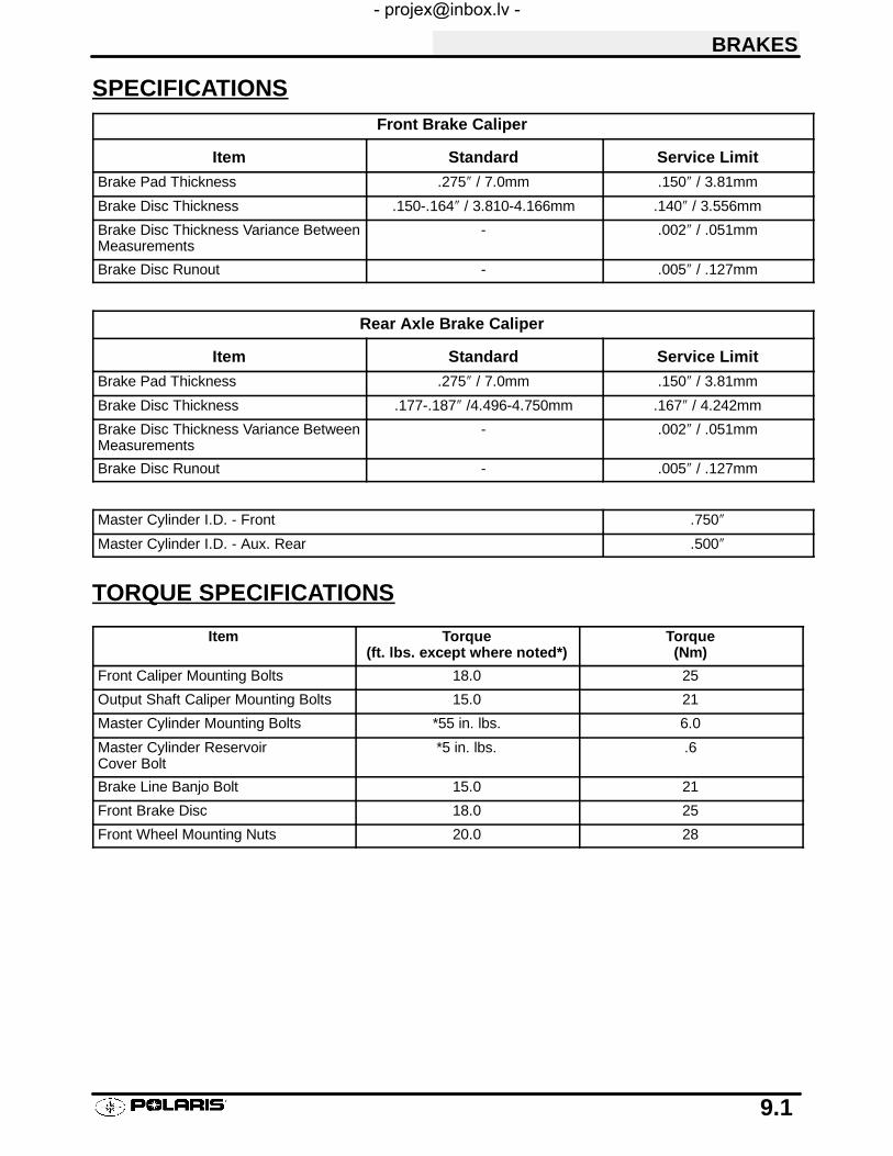
BRAKES
9.1
SPECIFICATIONSFront Brake Caliper
Item Standard Service Limit
Brake Pad Thickness .275″ / 7.0mm .150″ / 3.81mm
Brake Disc Thickness .150-.164″ / 3.810-4.166mm .140″ / 3.556mm
Brake Disc Thickness Variance BetweenMeasurements
- .002″ / .051mm
Brake Disc Runout - .005″ / .127mm
Rear Axle Brake Caliper
Item Standard Service Limit
Brake Pad Thickness .275″ / 7.0mm .150″ / 3.81mm
Brake Disc Thickness .177-.187″ /4.496-4.750mm .167″ / 4.242mm
Brake Disc Thickness Variance BetweenMeasurements
- .002″ / .051mm
Brake Disc Runout - .005″ / .127mm
Master Cylinder I.D. - Front .750″
Master Cylinder I.D. - Aux. Rear .500″
TORQUE SPECIFICATIONS
Item Torque(ft. lbs. except where noted*)
Torque(Nm)
Front Caliper Mounting Bolts 18.0 25
Output Shaft Caliper Mounting Bolts 15.0 21
Master Cylinder Mounting Bolts *55 in. lbs. 6.0
Master Cylinder ReservoirCover Bolt
*5 in. lbs. .6
Brake Line Banjo Bolt 15.0 21
Front Brake Disc 18.0 25
Front Wheel Mounting Nuts 20.0 28

Disc brake systems are light weight, low maintenance, and perform well in the conditions ATVs routinely en-counter. There are a few things to remember when replacing disc brake pads or performing brake system ser-vice to ensure proper system function and maximum pad service life.
S Optional pads are available to suit conditions in your area. Select a pad to fit riding style and environment.
S Do not over-fill the master cylinder fluid reservoir.
S Make sure the brake lever and pedal returns freely and completely.
S Adjust stop pin on front caliper after pad service.
S Check and adjust master cylinder reservoir fluid level after pad service.
S Make sure atmospheric vent on reservoir is unobstructed.
S Test for brake drag after any brake system service and investigate cause if brake drag is evident.
S Make sure caliper moves freely on guide pins (where applicable).
S Inspect caliper piston seals for foreign material that could prevent caliper pistons from returning freely.
S Perform a brake burnishing procedure after installing new pads to maximize service life.
BRAKES
9.2
BRAKE SYSTEM SERVICE NOTES
BRAKE PAD KITSNOTE: Brake pad part numbers are stamped on the back of the pad for identification purposes. This part numbercannot be ordered -- it is included in the chart for reference only. Part numbers on the following chart maychange or supercede to a new number. Always refer to the current parts manual for part numbers.
Part No. Type Description
2201398 - Kit Std Front brake pad kit. (Contains 4 pads PN1910333)
2201399 - Kit Std Rear brake pad kit.

BRAKES
9.3
BRAKE NOISE TROUBLESHOOTINGDirt or dust buildup on the brake pads and disc is the most common cause of brake noise (squeal caused byvibration). If cleaning does not reduce the occurrence of brake noise, Permatext Disc Brake Quiet (availablefrom most auto parts stores) can be applied to the back of the pads. Follow directions on the package. This willkeep pads in contact with caliper piston(s) to reduce the chance of squeaks caused by dirt or dust.
Brake Noise TroubleshootingPossible Cause Remedy
Dirt, dust, or imbedded material on pads or disc Spray disc and pads with CRC Brakeleent or anequivalent non-flammable aerosol brake cleaner. Re-move pads and/or disc hub to clean imbedded materialfrom disc or pads.
Pad(s) dragging on disc (noise or premature pad wear)Improper adjustmentInsufficient lever or pedal clearanceMaster cylinder reservoir overfilledMaster cylinder compensating port restrictedMaster cylinder piston not returning completelyCaliper piston(s) not returningOperator error (riding the brake / park brakeapplied)
Adjust pad stop (front calipers)Check position of controls & switches.Set to proper levelClean compensating portInspect. Repair as necessaryClean piston(s) sealEducate operator
Loose wheel hub or bearings Check wheel and hub for abnormal movement.Brake disc warped or excessively worn Replace discBrake disc misaligned or loose Inspect and repair as necessaryNoise is from other source (chain, axle, hub, disc orwheel)
If noise does not change when brake is applied checkother sources. Inspect and repair as necessary

BRAKES
9.4
HYDRAULIC BRAKE SYSTEM OPERATION
A B
C
D
E
F
Must be clear to allowproper diaphragmmovement
Compensating port compensatesfor temperature changes by allowingfluid back to master cylinder
MoveableBrake Pad G
Typical Hydraulic Brake System
The Polaris brake system consists of the following components or assemblies: brake lever; master cylinder; hy-draulic hose; brake calipers (slave cylinder); brake pads; and brake discs, which are secured to the drive line.
When the hand activated brake lever (A) is applied it contacts a piston (B) within the master cylinder. As the mas-ter cylinder piston moves inward it closes a small opening (compensating port) (C) within the cylinder and startsto build pressure within the brake system. As the pressure within the system is increased, the piston (D) locatedin the brake caliper moves outward and applies pressure to the moveable brake pad. This pad contacts the brakedisc and moves the caliper in its floating bracket, pulling the stationary side pad into the brake disc. The resultingfriction reduces brake disc and vehicle speed. As the lever pressure is increased, the braking affect is also in-creased.
The friction applied to the brake pads will cause the pads to wear. As these pads wear, the piston within the calipermoves further outward and becomes self adjusting. Fluid from the reservoir fills the additional area created whenthe caliper piston moves outward.
Brake fluid level is critical to proper system operation. Too little fluid will allow air to enter the system and causethe brakes to feel spongy. Too much fluid could cause brakes to drag due to fluid expansion.
Located within the master cylinder is the compensating port (C) which is opened and closed by the master cylinderpiston assembly. The port is open when the lever is released and the master cylinder piston is outward. As thetemperature within the hydraulic system changes, this port compensates for fluid expansion (heated fluid) or con-traction (cooled fluid). During system service, be sure this port is open. Due to the high temperatures createdwithin the system during heavy braking, it is very important that the master cylinder reservoir have adequatespaceto allow for fluid expansion. Never overfill the reservoir! Fill to 1/4″ - 5/16″ (.64 - .80 cm) from top of the cylinder.
This system also incorporates a diaphragm (E) as part of the cover gasket; and a vent port (F) located betweenthe gasket and the cover. The combination diaphragm and vent allow for the air above the fluid to equalize pres-sure as the fluid expands or contracts. Make sure the vent is open and allowed to function. If the reservoir isover filled or the diaphragm vent is plugged the expanding fluid may build pressure in the brake system leadingto brake failure.
When servicing Polaris ATV brake systems use only Polaris DOT 3 high temperature brake fluid (PN 2870990).Polaris brake fluid is sold in 5.5 oz. bottles. WARNING: Once a bottle is opened, use what is necessary anddiscard the rest in accordance with local laws. Do not store or use a partial bottle of brake fluid. Brake fluid ishygroscopic, meaning it rapidly absorbs moisture. This causes the boiling temperature of the brake fluid to drop,which can lead to early brake fade and the possibility of serious injury.

BRAKES
9.5
DUAL HYDRAULIC CALIPER BLEEDING
This caliper is a dual opposed piston design, with two independent hydraulic systems contained in the same cali-per body (see Ill.1). The caliper pistons are T-shaped, which allows both hand and foot brake to use the samecaliper piston, but remain separated by seals. The hand brake system applies hydraulic pressure to both frontcalipers and only the outer diameter of the rear caliper pistons. The auxiliary (foot) brake applies pressure to theinner portion of the rear caliper pistons. Because the hand and foot brake hydraulic systems are separate, thereare also two bleed screws -- one for the outer fluid chamber (hand brake), and one for the inner fluid chamber(foot brake). The basic procedure for bleeding the brake system is the same as outlined on page 9.7 - 9.8; howev-er, each system must be bled separately.
Hydraulic Auxiliary Brake inspection and adjustment is outlined on page 9.6.
Uppermost (inner) bleed screw and brake line is for hand brakesystem.
Lower (outer) bleed screw and brake line is for auxiliary (foot)brake system.
Ill. 1
NOTE: Caliper style and location of brake lines and bleeder screws may differ
HandBrake Line
FootBrake Line
Hand Brake BleedFitting
Foot BrakeBleed Screw
DH CALIPER TOP VIEW
PistonSeals
Sealing “O” Rings
Ill. 2
Brake Pedal (Foot)
Brake Lever (Handlebar)
Line infrom footbrakemaster cy-linder
Line in fromhand brakemaster cy-linderBleeder (Foot Brake)
is outermost (lower)on caliper
Bleeder (Hand Brake) positionedinnermost (higher) on caliper
Cutaway View Of DH Caliper
PadSpacer
Upper BleedScrewHand Brake
Lower BleedScrewAuxiliary Brake

BRAKES
9.6
AUXILIARY BRAKE INSPECTION (HYDRAULIC)
Use the following procedure to inspect the auxiliary(foot) brake system and bleed if necessary.
1. First check foot brake effectiveness by applying a50 lb. (approx.) downward force on the pedal. Thetop of the pedal should be at least 1″ (25.4mm)above the surface of the footrest (see Ill. 1).
Free play of the brake pedal should be 1/8 - 1/4 inch (3.2 - 6.35 mm).
If freeplay is excessive, be sure master cylinder piston is returning to the fully extended position. If freeplay isless than 1/8″ (3.2mm) be sure dust seal is fully seated in groove on master cylinder body. See photo on page9.10.
Auxiliary Brake TestingThe auxiliary brake should be checked for proper adjust-ment.1. Support the rear wheels off the ground.
2. While turning the rear wheels by hand, apply the auxil-iary foot brake. This brake should not stop the wheelsfrom turning until the lever is half way between its restposition and bottoming on the footrest.
Bleeding:
If the free play is correct, but pedal travel is excessive or spongy, then air is trapped somewhere in the system.Bleeding the auxiliary brake system is accomplished in a conventional manner, except that there are two brakelines and bleeder screws on the Dual Hydraulic caliper. Refer to page 9.5 for theory of operation and bleedingprocedure. The auxiliary brake line applies pressure to the small (inner) diameter of the caliper piston. Use theoutermost (lower) bleed screw to purge air. See photo on page 9.5.
50 lbs 1″ or greater
1/8″ to 1/4″Free Play
Ill. 1
Floorboard
Auxiliary Foot Brake Pedal
FloorBoard Surface
Full Height Engagement(1/2 Height)
FullEngagement(Flush)
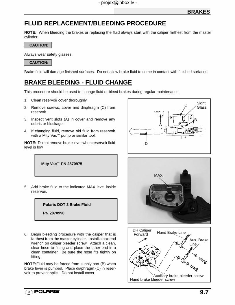
BRAKES
9.7
FLUID REPLACEMENT/BLEEDING PROCEDURENOTE: When bleeding the brakes or replacing the fluid always start with the caliper farthest from the mastercylinder.
CAUTION:
Always wear safety glasses.
CAUTION:
Brake fluid will damage finished surfaces. Do not allow brake fluid to come in contact with finished surfaces.
BRAKE BLEEDING - FLUID CHANGEThis procedure should be used to change fluid or bleed brakes during regular maintenance.
1. Clean reservoir cover thoroughly.
2. Remove screws, cover and diaphragm (C) fromreservoir.
3. Inspect vent slots (A) in cover and remove anydebris or blockage.
4. If changing fluid, remove old fluid from reservoirwith a Mity Vac™ pump or similar tool.
NOTE: Do not remove brake lever when reservoir fluidlevel is low.
5. Add brake fluid to the indicated MAX level insidereservoir.
6. Begin bleeding procedure with the caliper that isfarthest from the master cylinder. Install a box endwrench on caliper bleeder screw. Attach a clean,clear hose to fitting and place the other end in aclean container. Be sure the hose fits tightly onfitting.
NOTE:Fluid may be forced from supply port (B) whenbrake lever is pumped. Place diaphragm (C) in reser-voir to prevent spills. Do not install cover.
BA
D
C SightGlass
Mity Vac™ PN 2870975
MAX
Polaris DOT 3 Brake Fluid
PN 2870990
Hand brake bleeder screwAuxiliary brake bleeder screw
Hand Brake Line
Aux. BrakeLine
ForwardDH Caliper

BRAKES
9.8
BRAKE BLEEDING - FLUID CHANGE CONT.
7. Slowly pump brake lever (D) until pressure builds andholds.
8. While maintaining lever pressure, open bleederscrew. Close bleeder screw and release brake lever.NOTE: Do not release lever before bleeder screw istight or air may be drawn into caliper.
9. Repeat procedure until clean fluid appears in bleederhose and all air has been purged. Add fluid asnecessary to maintain level in reservoir.
CAUTION:
Maintain at least 1/2″ (1.27 cm) of brake fluid in the reser-voir to prevent air from entering the master cylinder.
10. Tighten bleeder screw securely and remove bleederhose.
11. Repeat procedure steps 5-9 for the remainingcaliper(s).
12. Add brake fluid to MAX level inside reservoir.
13. Install diaphragm, cover and screws. Tighten screwsto specification.
14. Field test machine at low speed before putting intoservice. Check for proper braking action and leverreserve. With lever firmly applied, lever reserveshould be no less than 1/2″ (1.3 cm) from handlebar.
15. Check brake system for fluid leaks and inspect allhoses and lines for wear or abrasion. Replace hoseif wear or abrasion is found.
Master Cylinder Fluid Level:
MAX level inside reservoir
Sight glass must look dark, if sightglass is clear, fluid level is too low
Reservoir Cover Torque -
45 in. lbs. (5 Nm)

BRAKES
9.9
MASTER CYLINDER DISASSEMBLY
1. Clean master cylinder and reservoir assembly. Makesure you have a clean work area to disassemble brakecomponents.
2. Place a shop towel under brake line connection atmaster cylinder. Loosen banjo bolt; remove bolt andsealing washers.
CAUTION:
Brake fluid will damage finished surfaces. Do not allowbrake fluid to come in contact with finished surfaces.
3. Remove master cylinder from handlebars.
Banjo Bolt
Master CylinderPiston Assy
Cover
Diaphragm
Sight Glass

BRAKES
9.10
MASTER CYLINDER DISASSEMBLY
1. Remove cover and diaphragm from master cylinderand dispose of the fluid properly.
2. Be sure vents in cover are clean and unobstructed.
3. Remove brake lever.
4. Clean surfaces of the reservoir and master cylinderbody. Be sure supply port is clean before reassembly.
5. Remove outer dust seal. Be ready to catch pistonassembly. NOTE: The return spring may force pistonout when dust seal has been removed.
6. Remove piston assembly and return spring frommaster cylinder. Replace piston assembly and spring.
Vent Slots
Cover
Supply Port
Outer Dust Seal

BRAKES
9.11
MASTER CYLINDER INSPECTION
1. Clean the master cylinder assembly with clean Dot 3brake fluid, brake parts cleaner, or denatured alcohol.Dry thoroughly. Inspect the bore for nicks, scratchesor wear. Replace if damage is evident or if worn.
2. Inspect parking brake for wear. If teeth or locking camare worn, replace lever.
MASTER CYLINDER ASSEMBLY
1. Install new primary and secondary seals on the piston.
2. Select the appropriate master cylinder pistoninstallation tool and insert into master cylinder bore.
Primary Seal
Secondary Seal Return Spring
Components of Kit 2200879
2201190
2201191
Components of Kit 2201177
PlungerHandle
InstallationTool
Insert inMaster Cyl-inder Bore
Type IV Master Cylinder (Hand Brake)
.750 (19mm)
Installation Tool #2200879
Master Cylinder (Aux. Brake)
.500 (13 mm)
Installation Tool #2201177

BRAKES
9.12
MASTER CYLINDER ASSEMBLY, CONT.
3. Dip piston in clean DOT 3 brake fluid, attach spring topiston, and install assembly into installation tool.
CAUTION:
Do not attempt to install the piston without the requiredinstallation tool. Do not allow the lip of the seals to turn in-side out or fold.
4. Push the piston assembly through the installation toolusing the plunger handle. Continue pushing untilplunger is solid against installation tool.
5. Hold piston assembly inward while removing bothtools. Install dust seal plate, spring and plunger.Install a new dust seal. Be sure dust seal is completelyseated in the groove.
NOTE: The piston assembly should move freely in thebore, and spring back against the seal when released.
6. Apply a light film of grease to the lever pin. Install leverand c-clip.

BRAKES
9.13
MASTER CYLINDER INSTALLATION
1. Install master cylinder on handlebars. Torquemounting bolts to 55 in. lbs. (6 Nm).
NOTE: To speed up the brake bleeding procedure the master cylinder can be purged of air before brake line isattached. Fill with DOT3 brake fluid and pump lever slowly two to three times with finger over the outlet end topurge master cylinder of air.
2. Place new sealing washers on each side of banjo lineand torque banjo bolt to specification.
3. Fill reservoir with DOT 3 fluid.
4. Follow bleeding procedure on pages 9.7-9.8. Checkall connections for leaks and repair if necessary.
Brake Line
Banjo Bolt
Sealing Washers
Torque to 15 ft./lbs.(21 Nm)
Master Cylinder Mounting BoltTorque 55 in. lbs. (6 Nm)
Brake Line Banjo Bolt Torque15 ft. lbs. (21 Nm)
Polaris DOT 3 Brake Fluid
PN 2870990

BRAKES
9.14
FRONT PAD REMOVAL1. Elevate and support front of machine.
CAUTION:
Use care when supporting vehicle so that it does not tip orfall. Severe injury may occur if machine tips or falls.
2. Remove the front wheel. Loosen pad adjusterscrew 2-3 turns.
3. Remove caliper from mounting bracket.
4. Push caliper piston into caliper bore slowly usingaC-clamp or locking pliers with pads installed.
NOTE:Brake fluid will be forced through compensatingport into master cylinder fluid reservoir when piston ispushed back into caliper. Remove excess fluid fromreservoir as required.
5. Push mounting bracket inward and slip outerbrake pad past edge. Remove inner pad.
6. Measure the thickness of the pad material.Replace pads if worn beyond the service limit.
MeasureThickness
Front Brake Pad ThicknessNew .275″/7.0 mmService Limit .150″ / 3.81 mm

BRAKES
9.15
FRONT PAD ASSEMBLY1. Lubricate mounting bracket pins with a light film of
Polaris Premium All Season Grease, and install rubberdust boots.
2. Compress mounting bracket and make sure dust bootsare fully seated. Install pads with friction material facingeach other. Be sure pads and disc are free of dirt orgrease.
3. Install caliper on hub strut, and torque mounting bolts.
4. Slowly pump the brake lever until pressure has beenbuilt up. Maintain at least 1/2″ (12.7 mm) of brake fluidin the reservoir to prevent air from entering the brakesystem.
PAD ADJUSTMENT5. Install the adjuster screw and turn clockwise until
stationary pad contacts disc, then back off 1/2 turn(counterclockwise).
6. Be sure fluid level in reservoir is up to MAX line insidereservoir and install reservoir cap.
Polaris Premium All Season Grease
PN 2871423
Front Caliper Mounting Bolts
Torque 18 ft. lbs. (25 Nm)
Master Cylinder FluidUp to MAX line inside reservoir
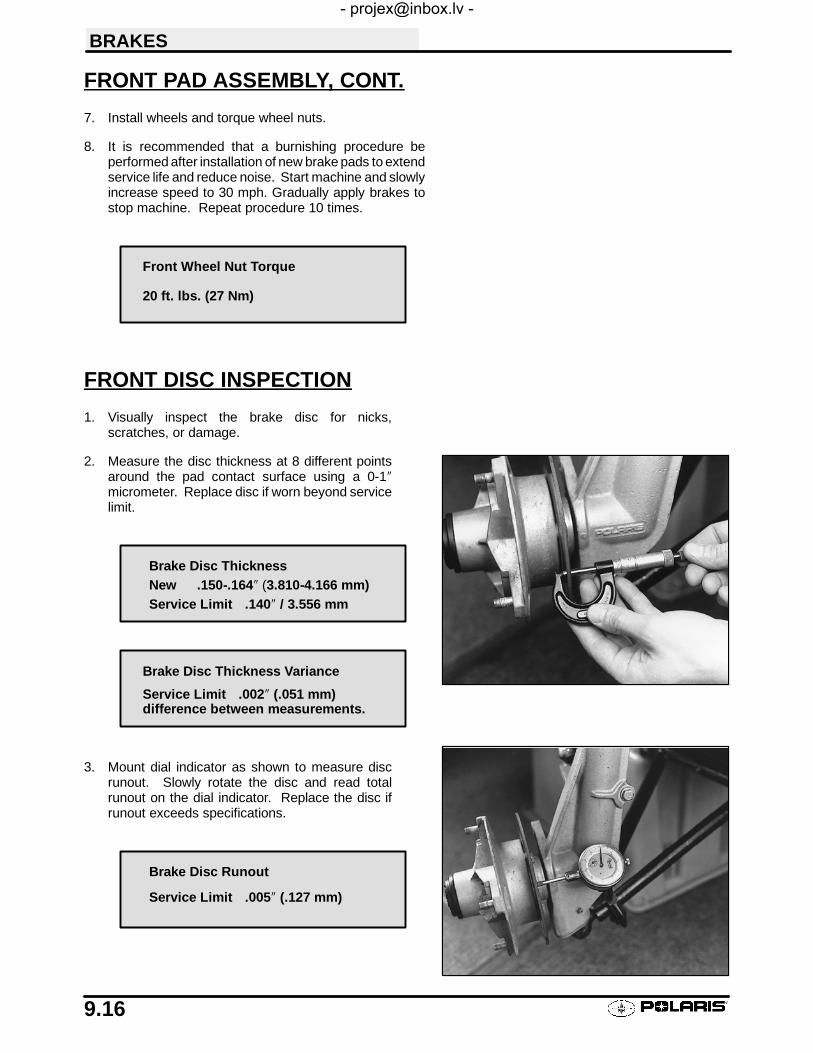
BRAKES
9.16
FRONT PAD ASSEMBLY, CONT.
7. Install wheels and torque wheel nuts.
8. It is recommended that a burnishing procedure beperformed after installation of new brake pads to extendservice life and reduce noise. Start machine and slowlyincrease speed to 30 mph. Gradually apply brakes tostop machine. Repeat procedure 10 times.
FRONT DISC INSPECTION
1. Visually inspect the brake disc for nicks,scratches, or damage.
2. Measure the disc thickness at 8 different pointsaround the pad contact surface using a 0-1″micrometer. Replace disc if worn beyond servicelimit.
3. Mount dial indicator as shown to measure discrunout. Slowly rotate the disc and read totalrunout on the dial indicator. Replace the disc ifrunout exceeds specifications.
Front Wheel Nut Torque
20 ft. lbs. (27 Nm)
Brake Disc Thickness
Service Limit .140″ / 3.556 mmNew .150-.164″ (3.810-4.166 mm)
Brake Disc Thickness Variance
Service Limit .002″ (.051 mm)difference between measurements.
Brake Disc Runout
Service Limit .005″ (.127 mm)

BRAKES
9.17
FRONT BRAKE DISC REMOVAL / REPLACEMENT
1. Apply heat to the hub in the area of the brake discmounting bolts to soften the bolt locking agent.
2. Remove bolts and disc.
3. Clean mating surface of disc and hub.
4. Install disc on hub.
5. Install new bolts and tighten to specified torque.CAUTION: Always use new brake disc mounting bolts.The bolts have a pre-applied locking agent which isdestroyed upon removal.
18 ft. lbs. (25 Nm)Use new bolts with pre-appliedlocking agent.
Front Brake Disc Mounting Bolt Torque
18 ft. lbs. (25 Nm)

BRAKES
9.18
FRONT CALIPER REMOVAL
CAUTION:
Use care when supporting vehicle so that it does not tip orfall. Severe injury may occur if machine tips or falls.
1. Remove brake pads. See page 9.14.
2. Using a line wrench, loosen and remove brake line tocaliper. Place a container under caliper to catch fluiddraining from brake line.
3. Remove brake caliper and drain fluid into container.
FRONT CALIPER DISASSEMBLY
1. Remove brake pad adjuster screw.
2. Push upper pad retainer pin inward and slip brakepads past edge.
3. Remove mounting bracket, pin assembly and dustboot.
RemoveMountingBracket

BRAKES
9.19
FRONT CALIPER DISASSEMBLY, CONT.
4. Remove piston, dust seal and piston seal.
5. Clean the caliper body, piston, and retaining bracketwith brake cleaner or alcohol.
NOTE: Be sure to clean seal grooves in caliper body.
FRONT CALIPER INSPECTION
1. Inspect caliper body for nicks, scratches or wear.Measure bore size and compare to specifications.Replace if damage is evident or if worn beyond servicelimit.
2. Inspect piston for nicks, scratches, wear or damage.Measure diameter and replace if damaged or wornbeyond service limit.
3. Inspect the brake disc and pads as outlined for brakepad replacement this section. See page 9.16.
Front Caliper Piston Bore I.D.
Std. 1.191-1.192″ (30.25-30.28 mm)Service Limit 1.193″ (30.30 mm)
Front Caliper Piston O.D.
Std. 1.186-1.1875″ (30.13-30.16 mm)Service Limit 1.1855″ (30.11 mm)

BRAKES
9.20
FRONT CALIPER ASSEMBLY
1. Install new O-rings in the caliper body. Be sure grooveis clean and free of residue or brakes may drag.
2. Coat piston with clean DOT 3 brake fluid. Install pistonwith a twisting motion while pushing inward. Pistonshould slide in and out of bore smoothly, with lightresistance.
3. Lubricate the mounting bracket pins with PolarisPremium All Season Grease, and install the rubberdust seal boots.
4. Compress the mounting bracket and make sure thedust seals are fully seated. Install the pads as shownon page 9.15. Clean the disc and pads with brakeparts cleaner or denatured alcohol to remove any dirt,oil or grease.
Polaris Premium All Season Grease
PN 2871423

BRAKES
9.21
FRONT CALIPER INSTALLATION
1. Install caliper on hub strut, and torque mounting bolts.
2. Install brake line and tighten securely with a linewrench.
3. Install the adjuster screw and turn until stationary padcontacts disc, then back off 1/2 turn.
4. Follow brake bleeding procedure outlined on pages9.7-9.8.
5. Install wheels and torque wheel nuts to specification.
NOTE: If new brake pads are installed, it is recommendedthat a burnishing procedure be performed toextend padser-vice life and reduce noise. Start machine and slowly in-crease speed to 30 mph. Gradually apply brakes to stopma-chine. Repeat procedure 10 times.
Front Caliper Mounting Bolt Torque18 ft. lbs. (25 Nm)
Front Wheel Nut Torque20 ft. lbs. (27 Nm).

BRAKES
9.22
FRONT BRAKE CALIPER EXPLODED VIEW
Pads
Caliper Mount
Piston
Pin Boot
SquareO--Rings
Adjuster Screw

BRAKES
9.23
REAR BRAKE PAD REMOVAL
1. Remove caliper mounting bolts and lift caliper off ofdisc.
NOTE: When removing caliper, be careful not to dam-age brake line. Support caliper so as not tokink or bendbrake line.
2. Push caliper piston into caliper bore slowly withpads installed.
NOTE: Brake fluid will be forced through compensatingport into master cylinder fluid reservoir when piston ispushed back into caliper. Remove excess fluid fromreservoir as required.
3. Remove brake pad retaining pin, and pad spacer.
NOTE: This is a spring pin, do not spread apart farther thannecessary to remove it.
4. Clean pad retainer pins with a wire brush.
5. Clean the caliper w/ brake cleaner or alcohol.
6. Measure the thickness of the pad material.Replace pads if worn beyond the service limit.
MeasureThickness
Rear Brake Pad ThicknessNew .275″ (7.0 mm)Service Limit .150″ (3.81 mm)

BRAKES
9.24
REAR BRAKE PAD INSTALLATION
1. Install new pads in caliper body. Be sure to putaluminum spacer between pads.
2. Install caliper and torque mounting bolts.
3. Slowly pump the brake lever until pressure has beenbuilt up. Maintain at least 1/2″ (12.7 mm) of brake fluidin the reservoir to prevent air from entering the mastercylinder.
4. It is recommended that a burnishing procedure beperformed after installation of new brake pads to extendservice life and reduce noise. Start machine and slowlyincrease speed to 30 mph. Gradually apply brakes tostopmachine. Repeat procedure 10 times.
Spacer
DH Brake Caliper
Torque 18 ft. lbs. (24.9 Nm)
Auxiliary Brake Master CylinderFluid Level
Between MIN and MAX lines

BRAKES
9.25
REAR CALIPER REMOVAL/INSPECTION
1. Clean caliper area before removal.
2. Using a flare nut wrench, remove hand brake (inner) andauxiliary brake (outer) lines. Place a container to catchbrake fluid draining from brake lines.
3. Remove caliper.
4. Remove brake pad retaining pin pads, and pad spacer.
NOTE: This is a spring pin. Do not spread apart farther thannecessary to remove it.
5. Remove Allen head screw and separate caliper halvesand remove pistons with piston pliers.
6. Remove O-rings and clean O-ring grooves.
7. Clean disc, caliper body, and pistons with brake cleaneror alcohol.

BRAKES
9.26
REAR CALIPER REMOVAL/INSPECTION CONT.
8. Inspect caliper piston bore for scratches, severecorrosion, or galling and replace if necessary.
9. Inspect surface of caliper piston for nicks, scratches, ordamage and replace if necessary.
REAR CALIPER ASSEMBLY
1. Install new O-rings in caliper body (2 piston seals percaliper half). Be sure O-ring grooves are thoroughlycleaned of all residue, or piston may bind in bore. Applybrake fluid to pistons and install carefully with a twistingmotion to ease assembly until fully seated.
2. Install new O-rings between caliper halves.
3. Carefully assemble caliper body, making sure O-ringsare properly positioned in groove. Torque body screwevenly to 18 ft. lbs.
O-Rings
Piston Seals
Caliper Body Torque
18 ft. lbs. (25 Nm)
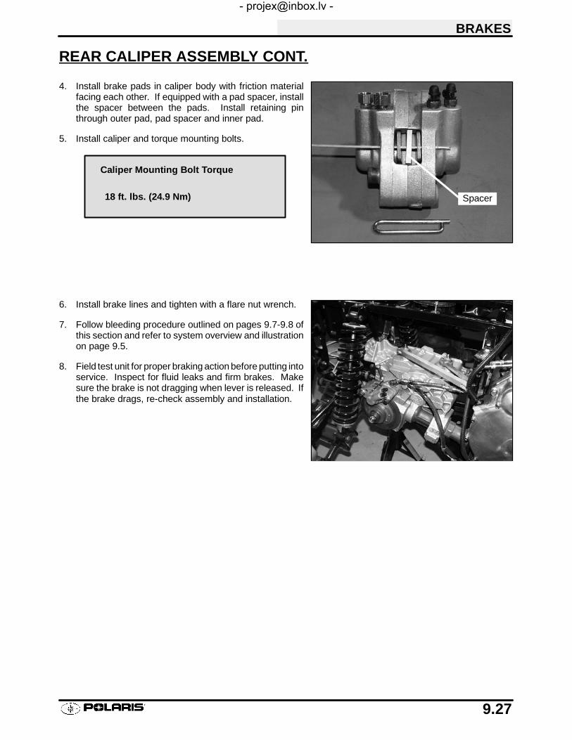
BRAKES
9.27
REAR CALIPER ASSEMBLY CONT.
4. Install brake pads in caliper body with friction materialfacing each other. If equipped with a pad spacer, installthe spacer between the pads. Install retaining pinthrough outer pad, pad spacer and inner pad.
5. Install caliper and torque mounting bolts.
6. Install brake lines and tighten with a flare nut wrench.
7. Follow bleeding procedure outlined on pages 9.7-9.8 ofthis section and refer to system overview and illustrationon page 9.5.
8. Field test unit for proper braking action before putting intoservice. Inspect for fluid leaks and firm brakes. Makesure the brake is not dragging when lever is released. Ifthe brake drags, re-check assembly and installation.
Spacer
Caliper Mounting Bolt Torque
18 ft. lbs. (24.9 Nm)

BRAKES
9.28
REAR BRAKE DISC INSPECTION
1. Visually inspect disc for scoring, scratches, orgouges. Replace the disc if any deep scratches areevident.
2. Use a 0-1″micrometer and measure disc thicknessat 8 different points around perimeter of disc.Replace disc if worn beyond service limit.
3. Mount dial indicator and measure disc runout.Replace the disc if runout exceeds specifications.
MeasureThickness
Rear BrakeDisc
Brake Disc Thickness
Service Limit .167″ (4.242 mm)New .177-.187″ (4.496-4.750 mm)
Brake Disc Thickness Variance
Service Limit .002″ (.051 mm)difference between measurements
Brake Disc Runout
Service Limit .005″ (.127 mm)
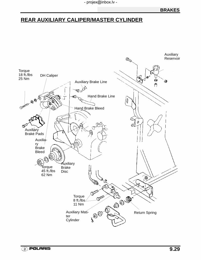
BRAKES
9.29
REAR AUXILIARY CALIPER/MASTER CYLINDER
Return Spring
AuxiliaryBrakeDisc
Auxiliary Mas-terCylinder
Hand Brake Line
Auxiliary Brake Line
AuxiliaryBrake Pads
DH Caliper
AuxiliaryReservoir
Hand Brake Bleed
Auxilia-ryBrakeBleed
Torque8 ft./lbs11 Nm
Torque18 ft./lbs25 Nm
Torque45 ft./lbs62 Nm

BRAKES
9.30
TROUBLESHOOTING
Brakes SquealS Dirty/contaminated friction padsS Improper alignmentS Worn discS Worn disc splines
Poor Brake PerformanceS Air in system
S Water in system (brake fluid contaminated)S Caliper/disc misalignedS Caliper dirty or damagedS Brake line damaged or lining rupturedS Worn disc and/or friction padsS Incorrectly adjusted lever
S Incorrectly adjusted stationary padS Worn or damaged master cylinder or componentsS Improper clearance between lever and switch
Lever VibrationS Disc damagedS Disc worn (runout or thickness variance exceeds service limit)
Caliper Overheats (Brakes Drag)S Compensating port pluggedS Pad clearance set incorrectlyS Auxiliary brake pedal incorrectly adjustedS Brake lever or pedal binding or unable to return fullyS Parking brake left onS Residue build up under caliper seals
S Operator riding brakes
Brakes LockS Alignment of caliper to disc.
10
CHAPTER 10ELECTRICAL
Special Tools 10.1. . . . . . . . . . . . . . . . . . . . . . . . . . . . . . . . . . .
Headlamp Service 10.2-10.3. . . . . . . . . . . . . . . . . . . . . . . . . . . . . .
Indicator Lamp Service 10.3. . . . . . . . . . . . . . . . . . . . . . . . . .
Timing Check Procedure 10.4. . . . . . . . . . . . . . . . . . . . . . . .
Typical Ignition Timing Curve 10.5. . . . . . . . . . . . . . . . . . . . .
Flywheel Identification 10.6. . . . . . . . . . . . . . . . . . . . . . . . . . .
200/250 Watt Alternator, Exploded View 10.7. . . . . . . . . . .
Ignition System Testing 10.8-10.9. . . . . . . . . . . . . . . . . . . . . . . . . .
Ignition System Troubleshooting 10.10. . . . . . . . . . . . . . . . . .
Battery Service 10.11-10.14. . . . . . . . . . . . . . . . . . . . . . . . . . . . . . . . .
Charging System Testing 10.15-10.17. . . . . . . . . . . . . . . . . . . . . . . .
Starter System Troubleshooting 10.18. . . . . . . . . . . . . . . . . .
Starter System Testing 10.19. . . . . . . . . . . . . . . . . . . . . . . . . .
Starter Motor Service 10.20-10.24. . . . . . . . . . . . . . . . . . . . . . . . . . .
Starter Drive 10.25. . . . . . . . . . . . . . . . . . . . . . . . . . . . . . . . . . .
Electronic Speedometer Troubleshooting 10.26-10.32. . . . . . . . . .
Coolant Sensor Tests 10.33. . . . . . . . . . . . . . . . . . . . . . . . . . .
Fan Control Circuit Operation 10.34. . . . . . . . . . . . . . . . . . . .
Fan Motor Current Draw Test 10.35. . . . . . . . . . . . . . . . . . . . .
Transmission Gear Position Switch Testing 10.36. . . . . . . .
Electronic Throttle Control System Operation 10.37. . . . . .
Electrical Notes 10.38. . . . . . . . . . . . . . . . . . . . . . . . . . . . . . . .
Wiring Diagrams 10.39-10.41. . . . . . . . . . . . . . . . . . . . . . . . . . . . . . . .

ELECTRICAL
10.1
SPECIAL TOOLSFluke 73 Multitester or Tektronix DMM 155 PN 2870659. . .
Strobe Timing Light PN 2870630. . . . . . . . . . . . . . . . . . . . . . .
Hydrometer PN 2870836. . . . . . . . . . . . . . . . . . . . . . . . . . . . . .
Tachometer PN 8712100 or. . . . . . . . . . . . . . . . . . . . . . . . . . . . . .PN 8712500
Test Harness, Wheel Speed Sensor PN 2460761. . . . . . . .
LED Test Light Tool PN 2871745. . . . . . . . . . . . . . . . . . . . . . .
ELECTRICAL SERVICE NOTES
Keep the following notes in mind when diagnosing an electrical problem.
SRefer to wiring diagram for stator and electrical component resistance specifications.
SWhen measuring resistance of a component that has a low resistance value (under10 Ohms), remem-ber to subtract meter lead resistance from the reading. Connect the leads together and record theresistance. The resistance of the component is equal to tested value minus the lead resistance.
SBecome familiar with the operation of your meter. Be sure leads are in the proper jack for the test beingperformed (i.e. 10A jack for current readings). Refer to the Owner’s manual included with your meterfor more information.
SVoltage, amperage, and resistance values included in this manual are obtained with a Fluke™ 73Digital Multimeter or a Tektronix DMM155. Both of these meters are acceptable for use whendiagnosing electrical problems. Readings obtained with other meters may differ.
SPay attention to the prefix on the multimeter reading (K, M, etc.) and the position of the decimal point.
SFor resistance readings, isolate the component to be tested. Disconnect it from the wiring harness orpower supply.

ELECTRICAL
10.2
HIGH BEAM HEADLIGHT ADJUSTMENTThe headlight beam can be adjusted to any position desired by turning the adjusting knob located on the bottomright side of the headlight pod.1. Place the vehicle on a level surface with the headlight
approximately 25’ (7.6 m) from a wall.
2. Measure the distance from the floor to the center of theheadlight and make a mark on the wall at the same height.
3. Start the engine and turn the headlight switch to highbeam.
4. Observe headlight aim. The most intense part of theheadlight beam should be aimed 2″ (5.1 cm) below themark placed on the wall in step 2 NOTE: Rider weightmust be included on the seat. On machines with separatelow beam lights, the drop should be 8″ (20.3 cm) in 25’from the center of the low beam lamp.
5. Adjust beam to desired position .
HIGH BEAM HEADLIGHT LAMP REPLACEMENTCAUTION: Do not servicewhile headlight is hot. Seriousburns may result.
1. Remove three Phillips screwsat back of headlight pod.
2. Remove Phillips screws frombottom of headlight pod ateach front corner. NOTE: Toaid in accessing thesescrews, it may be helpful toturn handlebars to left or rightand use a short, stubbyscrewdriver. Removal of thefront rack and cover will alsoallow easier access.
3. Lift pod cover up.
4. Unplug headlamp from wiringharness.
5. Remove rubber shield fromheadlamp housing.
6. Push in and turn plastic re-tainer counter clockwise andremove.
7. Carefully remove headlampbulb from housing.
8. Reverse procedure to installnew headlamp bulb.
25’ (7.6 m)
Lamp Center Height
2″ (5.1 cm)
Snap pinsinto tabs
Positionknob inslot andsecurein lock-ing tabs
Slip O-Ringover pin
AdjustmentKnob Stop
Routeplug overhandlebar

ELECTRICAL
10.3
HEADLIGHT HOUSING REPLACEMENT1. Remove three Phillips screws at back of headlight pod.
2. Remove Phillips screws from bottom of headlight pod at each frontcorner. NOTE: To aid in accessing these screws, it may be helpfulto turn handlebars to left or right and use a short, stubby screwdriver.Removal of the front rack and cover will also allow easier access.
3. Lift pod cover up. Unplug speedometer from harness. Unplug indica-tor lights from harness and remove pod cover.
4. Unplug headlamp from wiring harness.
5. Remove O-Ring from headlight pivot pins.
6. Pull headlight housing up to release from locking tabs.
7. Lift adjusting knob up to remove from locking tabs.
8. Carefully pull assembly up and out of pod.
9. Reverse steps to install new housing and reassemble pod.
10.Adjust headlight aim by turning adjusting knob.
TAILLIGHT/BRAKELIGHT LAMPREPLACEMENT
If the taillight/brakelight does not work the lamp may needto be replaced.
1. From the rear of the taillight remove two screws hold-ing lens cover in place and remove lens cover.
2. Remove lamp and replace it with recommended lamp.Apply Nyogelt grease PN 2871329.
3. Reinstall the lens cover removed in step 1.
4. Test the taillight/brakelight to see that it’s working.
INDICATOR LAMP REPLACEMENT
1. Follow steps 1 - 2 of Headlight Housing Replacement.
2. Disconnect indicator light panel from harness.
3. To remove defective light: Use a small screwdriver andturn light holder a quarter turn, pull light holder out witha needle nose pliers or equivalent. Replace with newholder and bulb assembly and reassemble pod.
O-Ring
5 1/8″(13 cm)
Distance from headlamp partingline to end of adjustment knob stopis 5 1/8″ (13 cm).
Lens Cover
Bulb
Rear view of indicator lamp panel
1/4 Turn

ELECTRICAL
10.4
TIMING CHECK PROCEDURE
1. The ignition timing check hole is in the starter recoil/magneto housing. Remove the check plug.
NOTE: The ignition timing marks are stamped on the outside of the flywheel. Ignition timing must be inspectedwith the engine at room temperature (68°F / 20° C).
2. With the transmission in neutral, start the engine and set engine speed to 3500 ± 200 RPM.
3. Direct the timing light at the ignition timing check hole and check the ignition timing. NOTE: Do not allow theengine to warm up. The timing will retard approximately 2° when the engine is warm.
If the ignition timing is not within the specified range, adjust the stator plate position as described below.
FlywheelRotation 32
TimingPointer
30
28
EH42PLEH50PL
TimingInspec-tionHole
Stator Adjustment
1. Remove the magneto housing.
2. Remove the flywheel.
3. Loosen the stator plate screws and adjust the stator plate position. NOTE: Moving the stator plate clockwiseretards (delays) the ignition timing. Moving the plate counterclockwise advances it.
Retard Advance
Rotation

ELECTRICAL
10.5
TYPICAL IGNITION TIMING CURVE* Actual advance point may vary by several hundred RPM either above or below 3500. Use the point of maximumadvance when checking ignition timing.
8
10
12
14
16
18
20
22
24
26
28
30
IGN
ITIO
NT
IMIN
G(D
EG
RE
ES
)B
.T.D
.C.
MAXIMUM ADVANCE POINT (*)
0 1000 2500 3000 3500 4000 4500 5000 5500 6000

ELECTRICAL
10.6
FLYWHEEL IDENTIFICATION
A
B
Flywheel Identification Stamp Location
The flywheel can be identified by the stamp mark in location A or B. Refer to “I.D.” location in chart below.Do not use the cast mark to determine flywheel application.
Engine Application Cast Stamp Comment FlywheelI.D. Stamp
EH42PLE05 FF95 02 200W A
EH50PLE09/13 FF97 06 250W A

ELECTRICAL
10.7
COMPONENTS OF EH42PL/EH50PL 200/250 WATT ALTERNATOR
CDI Box
Ignition ExciterCoils
ResistorCap
StatorPlate
MagneticSwitch
IgnitionCoil
Meter
Meter
Ignition CoilPrimary Winding
Ignition CoilSecondary Winding
Meter
5k Ω
NOTE: CDI boxes may look the same but havedifferent internal circuitry. Be sure to always usethe correct CDI box part number.
Battery ChargingCoils
Ignition KillWire(Black)
Coil Lead
.3 Ω
6300 ΩPulse Coil (Trigger)Air Gap: .016-.040″
(.4 - 1.0 mm)
Flywheel andRing Gear Casting.Refer to page 10.6 foridentification.
Refer to wiring diagrams forspecified stator coil resistance
200 W(3 wires)
250 W(2 Wires)
Check coil mount for goodground to engine (0-.2 )Ω
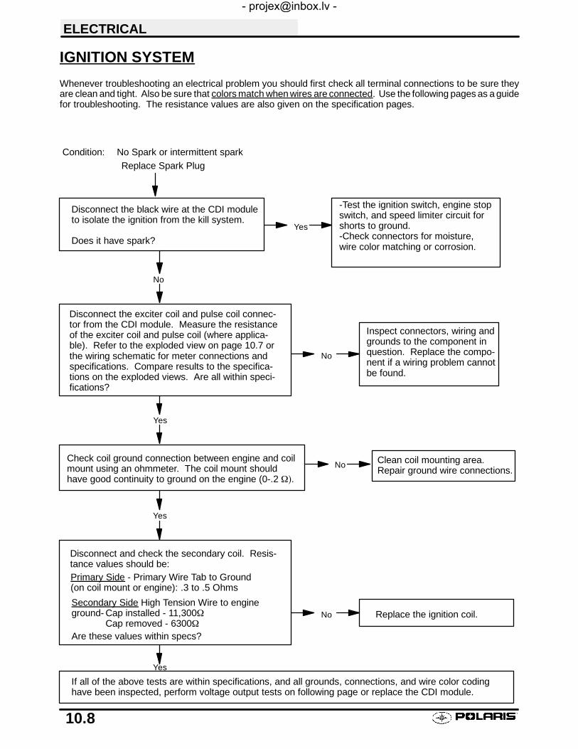
ELECTRICAL
10.8
IGNITION SYSTEM
Whenever troubleshooting an electrical problem you should first check all terminal connections to be sure theyare clean and tight. Also be sure that colors match when wires are connected. Use the following pages as a guidefor troubleshooting. The resistance values are also given on the specification pages.
Condition: No Spark or intermittent spark
Disconnect the black wire at the CDI moduleto isolate the ignition from the kill system.
Does it have spark?
-Test the ignition switch, engine stopswitch, and speed limiter circuit forshorts to ground.-Check connectors for moisture,wire color matching or corrosion.
Disconnect the exciter coil and pulse coil connec-tor from the CDI module. Measure the resistanceof the exciter coil and pulse coil (where applica-ble). Refer to the exploded view on page 10.7 orthe wiring schematic for meter connections andspecifications. Compare results to the specifica-tions on the exploded views. Are all within speci-fications?
Inspect connectors, wiring andgrounds to the component inquestion. Replace the compo-nent if a wiring problem cannotbe found.
Yes
No
Yes
Yes
No
Check coil ground connection between engine and coilmount using an ohmmeter. The coil mount shouldhave good continuity to ground on the engine (0-.2 Ω).
Replace Spark Plug
Disconnect and check the secondary coil. Resis-tance values should be:Primary Side - Primary Wire Tab to Ground(on coil mount or engine): .3 to .5 Ohms
Secondary Side High Tension Wire to engineground- Cap installed - 11,300Ω
Cap removed - 6300ΩAre these values within specs?
Replace the ignition coil.No
Yes
If all of the above tests are within specifications, and all grounds, connections, and wire color codinghave been inspected, perform voltage output tests on following page or replace the CDI module.
Clean coil mounting area.Repair ground wire connections.
No

ELECTRICAL
10.9
CRANKING OUTPUT TEST WITH PEAK READING VOLTMETERThe following peak voltage tests will measure the amount of output directly from each component. A peak readingvoltmeter must be used to perform the tests. A variety of peak reading adaptors are commercially available foruse with the Fluke ™ 73 Digital Multitester, Tektronix DMM155, and other digital VOMs which will allow peak volt-age tests to be performed accurately. Follow the directions provided with the adaptor. All measurements areindicated in DC Volts. Readings obtained without a peak reading adaptor will be significantly different.
Disconnect the stator connectors from the CDI module. Test output from exciter coil, pulse (trigger) coil, andcompare to the chart. The following measurements are obtained when cranking the engine with the electric start-er, spark plug installed. The starter system must be in good condition and the battery fully charged.
200 Watt 4 Stroke (Sportsman 400)
Coil Connect MeterWires To:
Reading(With Peak Reading Volt meter)
Exciter 1 Black/Red and Red 140 DCV
Exciter 2 Black/Red and Green 140 DCV
Exciter 3 Green and Red 5 DCV
Pulse (Trigger) White/Red and White 2.5 DCV
250 Watt 4 Stroke (Sportsman 500)
Coil Connect MeterWires To:
Reading(With Peak Reading Volt meter)
Exciter 1 Black/Red and Red 34 DCV
Pulse (Trigger) White/Red and White 3.3 DCV
CDI OUTPUT TEST USING PEAK READING ADAPTORRe-connect all CDI wires to stator wires. Disconnect CDI module wire from ignition coil primary terminal. Connectone meter lead to engine ground and the other to the ignition coil primary wire leading from the CDI module. Crankengine and check output of CDI wire to coil (130 DCV). Reconnect coil wire to CDI.
Output w/ Peak output tester130 DCV
Average Output w/ Digital Voltmeter20 DCV

ELECTRICAL
10.10
IGNITION SYSTEM TROUBLESHOOTINGNo Spark, Weak or Intermittent Spark
SSpark plug gap incorrectSFouled spark plugSFaulty spark plug cap or poor connection to high tension leadSRelated wiring loose, disconnected, shorted, or corrodedSEngine Stop switch or ignition switch faultySETC switch misadjusted or faulty
STerminal board or connections wet, corrodedSPoor ignition coil ground (e.g. coil mount loose or corroded)SFaulty stator (measure resistance of all ignition related windings)SIncorrect wiring (inspect color coding in connectors etc)SFaulty ignition coil winding (measure resistance of primary and secondary)
SWorn magneto (RH) end Crankshaft bearingsSSheared flywheel keySFlywheel loose or damagedSTrigger coil air gap too wide (where applicable) - should be .016-.040″ (.4-1.0 mm)SExcessive crankshaft runout on magneto (RH) end - should not exceed .0024″SFaulty CDI module

ELECTRICAL
10.11
INITIAL BATTERY SERVICE
WARNINGBattery electrolyte is poisonous. It contains sulfuric acid. Seriousburns can result from contact with skin, eyes or clothing. Antidote:
External: Flush with water.
Internal: Drink large quantities of water or milk. Follow with milkof magnesia, beaten egg, or vegetable oil. Call physician immedi-ately.
Eyes: Flush with water for 15 minutes and get prompt medicalattention.
Batteries produce explosive gases. Keep sparks, flame, ciga-rettes, etc. away. Ventilate when charging or using in an enclosedspace. Always shield eyes when working near batteries. KEEPOUT OF REACH OF CHILDREN.
WARNING: The gases given off by a battery are explosive. Any spark or open flame near a battery can causean explosion which will spray battery acid on anyone close to it. If battery acid gets on anyone, wash the affectedarea with large quantities of cool water and seek immediate medical attention.
To ensure maximum service life and performance from a new battery, perform the following steps. NOTE: Do notservice the battery unless it will be put into regular service within 30 days. After initial service, add only distilledwater to the battery. Never add electrolyte after a battery has been in service.
NOTE: New Battery: Battery must be fully charged before use or battery life will be significantly reduced 10-30%of batterys’ full potential.
1. Remove vent plug from vent fitting.
2. Fill battery with electrolyte to upper level marks on case.
3. Set battery aside and allow it to cool and stabilize for 30 minutes.
4. Add electrolyte to bring level back to upper level mark on case. NOTE: This is the last time that electrolyteshould be added. If the level becomes low after this point, add only distilled water.
5. Charge battery at 1/10 of its amp/hour rating. Examples: 1/10 of 9 amp battery = .9 amp; 1/10 of 14 ampbattery = 1.4 amp; 1/10 of 18 amp battery = 1.8 amp (recommended charging rates).
6. Check specific gravity of each cell with a hydrometer to assure each has a reading of 1.270 or higher.
BATTERY TERMINALS/TERMINAL BOLTSUse Polaris corrosion resistant Nyogelt grease (PN 2871329) on battery bolts. See Battery Installation on page10.12.

ELECTRICAL
10.12
BATTERY INSPECTION/REMOVAL
The battery is located under the left rear fender.
Inspect the battery fluid level. When the battery fluid nearsthe lower level, the battery should be removed and distilledwater should be added to the upper level line. To removethe battery:
1. Disconnect holder strap and remove cover.2. Disconnect battery negative (-) (black) cable first,
followed by the positive (+) (red) cable.
CAUTION
Whenever removing or reinstalling the battery, disconnectthe negative (black) cable first and reinstall the negativecable last!3. Disconnect the vent hose.4. Remove the battery.5. Remove the filler caps and add distilled water only as needed to bring each cell to the proper level. Do not
overfill the battery.
To refill use only distilled water. Tap water contains minerals which are harmful to a battery.
Do not allow cleaning solution or tap water to enter the battery. It will shorten the life of the battery.
6. Reinstall the battery caps.
BATTERY INSTALLATION1. Clean battery cables and terminals with a stiff wire brush. Corrosion can be removed using a solution of one
cup water and one tablespoon baking soda. Rinse will with clean water and dry thoroughly.2. Reinstall battery, attaching positive (+) (red) cable first and then the negative (-) (black) cable. Coat terminals
and bolt threads with Nyogelt grease PN 2871329.3. Install clear battery vent tube from vehicle to battery vent. WARNING: Vent tube must be free from
obstructions and kinks and securely installed. If not, battery gases could accumulate and cause an explosion.Vent should be routed away from frame and body to prevent contact with electrolyte. Avoid skin contact withbattery electrolyte, severe burns could result. If electrolyte contacts the vehicle frame, corrosion will occur.
4. Route cables so they are tucked away in front and behind battery.5. Reinstall battery cover and holder strap.
Do not start the engine with the battery disconnected. Vehicle lamps will burn out if battery is disconnectedduring vehicle operation. Also, the reverse speed limiter can be damaged.
BATTERY TESTINGWhenever a service complaint is related to either the starting or charging systems, the battery should be checkedfirst.
Following are three tests which can easily be made on a battery to determine its condition: OCV Test, SpecificGravity Test and Load Test.
OCV - OPEN CIRCUIT VOLTAGE TESTBattery voltage should be checked with a digital multitester. Readings of 12.6 or less require further battery testingand charging. See charts and Load Test on page 10.13.
NOTE: Lead-acid batteries should be kept at or near a full charge as possible. Electrolyte level should be keptbetween the low and full marks. If the battery is stored or used in a partially charged condition, or with lowelectrolyte levels, hard crystal sulfation will form on the plates, reducing the efficiency and service life of thebattery.
Maintainbetween upperand lower levelmarks

ELECTRICAL
10.13
SPECIFIC GRAVITY TEST
A tool such as a Battery Hydrometer (PN 2870836) can be used to measure electrolyte strength or specific gravity.As the battery goes through the charge/discharge cycle, the electrolyte goes from a heavy (more acidic) state atfull charge to a light (more water) state when discharged. The hydrometer can measure state of charge anddifferences between cells in a multi-cell battery. Readings of 1.270 or greater should be observed in a fullycharged battery. Differences of more than .025 between the lowest and highest cell readings indicate a need toreplace the battery.
OPEN CIRCUIT VOLTAGE
State ofcharge
ConventionalLead-acid
YuMicron™Type
100% Charged75% Charged50% Charged25% Charged0% Charged
12.60V12.40V12.10V11.90Vless than 11.80V
12.70V12.50V12.20V12.0Vless than 11.9V
SPECIFIC GRAVITY
State ofcharge*
Conventionallead-acid
YuMicron™Type
100% Charged75% Charged50% Charged25% Charged0% Charged
1.2651.2101.1601.120less than 1.100
1.2751.2251.1751.135less than 1.115
* At 80_FNOTE: Subtract .01 from the specific gravity reading at 40_ F.
LOAD TESTCAUTION: Remove spark plug high tension leads and connect securely to engine ground before proceeding.
NOTE: This test can only be performed on machines with electric starters. This test cannot be performed withan engine or starting system that is not working properly.A battery may indicate a full charge condition in the OCV test and the specific gravity test, but still may not have thestorage capacity necessary to properly function in the electrical system. For this reason, a battery capacity or loadtest should be conducted whenever poor battery performance is encountered. To perform this test, hook a multitesterto the battery in the same manner as was done in the OCV test. The reading should be 12.6 volts or greater. Engagethe electric starter and view the registered battery voltage while cranking the engine. Continue the test for 15 seconds.During this cranking period, the observed voltage should not drop below 9.5 volts. If the beginning voltage is 12.6or higher and the cranking voltage drops below 9.5 volts during the test, replace the battery.
Detail A
1.10
1.15
1.20
1.25
1.30
Polaris PN 2870876

ELECTRICAL
10.14
OFF SEASON STORAGETo prevent battery damage during extended periods of non-use, the following basic battery maintenance itemsmust be performed:
SRemove the battery from the machine and wash the case and battery tray with a mild solution of bakingsoda and water. Rinse with lots of fresh water after cleaning. NOTE: Do not get any of the bakingsoda into the battery or the acid will be neutralized.SUsing a wire brush or knife, remove any corrosion from the cables and terminals.
SMake sure that the electrolyte is at the proper level. Add distilled water if necessary.SCharge at a rate no greater than 1/10 of the battery’s amp/hr capacity until the electrolyte’s specific
gravity reaches 1.270 or greater.SStore the battery either in the machine with the cables disconnected, or put it on a piece of wood and
store in a cool place. NOTE: Stored batteries lose their charge at the rate of 1% per day. Theyshould be recharged to a full charge every 30 to 60 days during a non-use period. If the battery isstored during the winter months the electrolyte will freeze at a higher temperature as the battery dis-charges. The chart at below indicates freezing points by specific gravity.
CHARGING PROCEDURE
Charge the battery with a charger no larger than 1/10 of the battery’s amp/hr rating for as many hours as neededto raise the specific gravity to 1.270 or greater.
Electrolyte Freezing Points
Specific Gravityof Electrolyte
FreezingPoint
1.265 -75° F
1.225 -35° F
1.200 -17° F
1.150 +5° F
1.100 +18° F
1.050 +27° F
1. Install battery in vehicle with positive terminal toward the front. Coat threads of battery bolt with a corrosionresistant Nyogelt grease.
WARNING
To avoid the possibility of explosion, connect positive (red) cable first and negative (black) cable last.
2. Connect battery cables.3. After connecting the battery cables, install the cover on the battery and attach the hold down strap.4. Install clear battery vent tube from vehicle to battery vent. WARNING: Vent tube must be free from
obstructions and kinks and securely installed. If not, battery gases could accumulate and cause an explosion.Vent should be routed away from frame and body to prevent contact with electrolyte. Avoid skin contact withbattery electrolyte, severe burns could result. If electrolyte contacts the vehicle frame, corrosion will occur.
5. Route cables so they are tucked away in front and behind battery.
Dielectric Grease
PN 2871329 (Nyogel)

ELECTRICAL
10.15
CHARGING SYSTEM TESTING
Whenever charging system problems are suspected, proceed with the following system check.
Check for owner modification, anddiscuss operating habits. The batterywill continually discharge if operatedbelow the “Break Even” RPM. Con-tinued problems would call for batteryinspection.
Disconnect the Yellow/Red, Yellow, and Yel-low/Brn (if applicable) wires from the regula-tor/rectifier. Using a multitester, perform anAlternator Output (AC amp) test. Seetest procedure on page 10.17 for proce-dure.Is output above 5 amps?
Inspect the wiring harness be-tween the panel and the stator fordamage. If no damage is found,remove the recoil and flywheel.Inspect the flywheel magnets, sta-tor coils and stator wire harnessfor damage. Repair or replaceany damaged components.
Reconnect the alternator wires. Note: Redwire must be connected to harness. Batteryvoltage must be present on red wire terminalon harness side of voltage regulator connector.
Is it?
Check regulator/rectifier connectionsand ground, battery connections, cir-cuit breaker and connecting wires.Repair or replace faulty wiring orcomponents.
If all of the previous tests indicate agood condition, but the charging voltagedoes not rise above battery voltage at theconnector or terminal board, replace thevoltage regulator.
No
Yes
No
Yes
Perform system “Break Even Amperage”test outlined on page 10.16.
Does charging occur as specified?
Using a multitester set on D.C. volts, mea-sure the battery open circuit voltage (Seepage 10.12). It should be 12.4 volts ormore. Is it?
Remove the battery and properly ser-vice. Reinstall the fully charged batteryor a fully charged shop battery.
With the transmission in neutral, start theengine and increase RPM to between 3000and 4000. Read battery voltage with themultitester. Readings should increase to be-tween 13.0 and 14.6 V D.C. Are they?
No
Yes
No
Yes Check Key off Current Draw
No
Meter Setting: AC Amps
Meter Setting: DC Amps
Meter Setting: DC Volts
Meter Setting: DC Volts
Yes
Ohm stator wire (Y/YR) If bad replace, if good,continue with alternator output test.

ELECTRICAL
10.16
CURRENT DRAW - KEY OFFCAUTION: Do not connect or disconnect the battery cable or ammeter with the engine running. Damage willoccur to light bulbs and speed limiter.Connect an ammeter in series with the negative battery cable. Check for current draw with the key off. If the drawis excessive, loads should be disconnected from the system one by one until the draw is eliminated. Check com-ponent wiring as well as the component for partial shorts to ground to eliminate the draw.
CHARGING SYSTEM “BREAK EVEN” TEST
CAUTION: Do not connect or disconnect the battery cable or ammeter with the engine running.
CAUTION: Never use the electric starter with the ammeter connected, or damage to the meter or meter fusemay result. Do not run test for extended period of time. Do not run test with high amperage accessories.
The “break even” point of the charging system is the point at which the alternator overcomes all system loads(lights, etc.) and begins to charge the battery. Depending on battery condition and system load, the break evenpoint may vary slightly. The battery should be fully charged before performing this test.
SConnect an ammeter (set to DC amps) in series be-tween the negative battery cable and terminal.
SConnect a tachometer according to manufacturer’s in-structions.
SWith engine off and the key and kill switch in the ONposition, the ammeter should read negative amps(battery discharge). Reverse meter leads if a positivereading is indicated.
SShift transmission into neutral. Start engine with recoilonly.
SIncrease engine RPM while observing ammeter andtachometer.
SNote RPM at which the battery starts to charge (am-meter indication is positive).
SWith lights and other electrical load off, this should oc-cur at approximately 1500 RPM or lower.
STurn the lights on and lock parking brake to keep brakelight on.
SRepeat test, observing ammeter and tachometer.With lights on, charging should occur at or below 2000RPM.
Current Draw - Key Off:Maximum of .01 DCA (10 mA)
Do not use electric start.
--+
Current Draw Inspection
Key Off
Less Than 10 mA
YB14A

ELECTRICAL
10.17
ALTERNATOR OUTPUT TEST (AC AMP)This test measures AC amperage from the alternator.
SMaximum alternator output will be indicated on themeter. It is not necessary to increase engine RPMabove idle.
SPlace the red lead on the tester in the 10A jack.
STurn the selector dial to the AC amps (Aµ) position.
SConnect the meter leads to the Yellow and Yellow/Redwires leading from the alternator.
SStart the engine and let it idle. Reading should be aminimum of 7A at idle.
CAUTION: This test simulates a “full load” on the alter-nator. Do not perform this test longer than required toobtain a reading or the alternator stator windings mayoverheat. 3--5 seconds is acceptable.
Alternator Current Output:Minimum of 7 AC Amps
To Calculate Available Alternator Output
250W12V
= 20.8 Amps
I =PE
I = Current in AmpsP = Power in WattsE = Electromotive Force (Volts)
200W12V
= 16.7 Amps

ELECTRICAL
10.18
STARTER SYSTEM TROUBLESHOOTINGStarter Motor Does Not Turn
SBattery discharged - low specific gravitySLoose or faulty battery cables or corroded connections (see Voltage Drop Tests)SRelated wiring loose, disconnected, or corrodedSPoor ground connections at battery cable, starter motor or starter solenoid (see Voltage Drop
Tests)SFaulty starter button
SFaulty ignition switch (Do other systems function?)SFaulty starter solenoid or starter motor.SEngine problem - seized or binding (Can engine be rotated easily with recoil starter?)
Starter Motor Turns Over Slowly
SBattery discharged - low specific gravitySExcessive circuit resistance - poor connections (see Voltage Drop Test below)
SEngine problem - seized or binding (Can engine be rotated easily with recoil starter?)SFaulty or worn brushes in starter motorSAutomatic compression release inoperative
Starter Motor Turns - Engine Does Not Rotate
SFaulty starter driveSFaulty starter drive gears or starter motor gearSFaulty flywheel gear or loose flywheel
VOLTAGE DROP TESTThe Voltage Drop Test is used to test for bad connections. When performing the test, you are testing the amountof voltage drop through the connection. A poor or corroded connection will appear as a high voltage reading.Voltage shown on the meter when testing connections should not exceed .1 VDC per connection or component.
To perform the test, place the meter on DC volts and place the meter leads across the connection to betested. Refer to the chart on next page to perform voltage drop tests on the starter system.
Voltage should not exceed:.1 DC volts per connection

ELECTRICAL
10.19
STARTER SYSTEM
Condition: Starter fails to turn motor. NOTE: Make sure engine crankshaft is free to turn before proceeding withdynamic testing of starter system. A digital multitester must be used for this test.
With the tester on the VDC position, place the tes-ter’s black lead on the battery negative and the redlead on the battery positive.
Reading should be 12.4 or greater.
Remove battery and properly service.Install fully charged shop battery to continuetest.
Disconnect White/Red engagement coil wire fromthe starter solenoid. Connect tester black wire tobattery ground. Connect red tester lead to White/Red harness wire at solenoid. Turn on ignitionswitch and depress the starter button. Testershould read battery voltage.
Check voltage on both sides of circuitbreaker, ignition switch/engine stop switchand starter button. The voltage on bothsides should be the same. NOTE: The igni-tion switch and engine stop switch must beon and the starter button depressed. Re-place the defective component.
Reconnect the solenoid. Connect the tester blacklead to the battery positive and the red lead to thesolenoid end of the battery-to-solenoid wire. De-press starter button. Reading should be less than.1 V D.C.
Clean the battery-to-solenoid cable ends orreplace the cable.
Connect the black tester lead to solenoid end ofbattery-to-solenoid cable. Connect red tester leadto solenoid end of solenoid-to-starter cable. De-press starter button. Reading should be less than.1 V D.C.
Replace the starter solenoid.
Connect the black tester lead to the solenoid end ofthe solenoid-to-starter cable. Connect the red testerlead to the starter end of the same cable. Depressthe starter button. The reading should be less than.1 V D.C.
Clean the solenoid-to-starter cable ends orreplace the cable.
No
Yes
No
No
Yes
No
Yes
If all of these indicate a good condition, yet the starter still fails to turn, thestarter must be removed for static testing and inspection.
No
Yes
Test starter solenoid coil by connecting an ohmmeter between the solenoidred wire and the solenoid mounting plate. Resistance should be 3.4Ω.Check solenoid ground path by measuring resistance between mountingplate and battery negative terminal (-).Voltage Drop Testing
See Page 10.18 for instructions.
Yes

ELECTRICAL
10.20
STARTER MOTOR DISASSEMBLYNOTE: Use electrical contact cleaner to clean starter motorparts. Some solvents may leave a residue or damage inter-nal parts and insulation.
1. Note the alignment marks on both ends of the startermotor casing. These marks must align duringreassembly.
2. Remove the two bolts, washers, and sealing O-Rings.Inspect O-Rings and replace if damaged.
3. Remove brush terminal end of housing while holdingother two sections together.

ELECTRICAL
10.21
STARTER MOTOR DISASSEMBLY, CONT.
4. Remove shims from armature shaft. NOTE: All shimsmust be replaced during reassembly.
BRUSH INSPECTION/REPLACEMENT1. Using a digital multitester, measure the resistance
between the cable terminal and the insulated brush. Thereading should be .3 ohms or less. Measure theresistance between the cable terminal and brushhousing. Make sure the brush is not touching the case.The reading should be infinite.
2. Remove nut, flat washer, large phenolic washer, twosmall phenolic washers, and O-Ring from brushterminal. Inspect the O-Ring and replace if damaged.
3. Remove brush plate and brushes. Measure length ofbrushes and replace if worn past the service limit.Replace springs if they are discolored or haveinadequate tension.
4. Inspect surface of commutator for wear or discoloration.See steps 3-6 of armature testing on page 10.23.
5. Install a new carbon brush assembly in the brushhousing. NOTE: Be sure that the terminal bolt insulatingwasher is properly seated in the housing, and the tab onthe brush plate engages the notch in the brush platehousing.
Brush Length Service Limit:5/16″ (.8 cm)
Brush Length
5/16″ (.8 cm)

ELECTRICAL
10.22
BRUSH INSPECTION/REPLACEMENT, CONT.
6. Place a wrap of electrical tape on the threads of theterminal bolt to prevent O-Ring damage duringreinstallation.
7. Install the O-Ring over the bolt. Make sure the O-ring isfully seated.
8. Remove the electrical tape and reinstall the two smallphenolic washers, the large phenolic washer, flatwasher, and nut.

ELECTRICAL
10.23
ARMATURE TESTING
1. Remove armature from starter casing. Note orderof shims on drive end for reassembly.
2. Inspect surface of commutator. Replace ifexcessively worn or damaged.
3. Using a digital multitester, measure the resistancebetween each of the commutator segments. Thereading should be .3 ohms or less.
4. Measure the resistance between eachcommutator segment and the armature shaft. Thereading should be infinite (no continuity).
5. Check commutator bars for discoloration. Barsdiscolored in pairs indicate shorted coils, requiringreplacement of the starter motor.
6. Place armature in a growler. Turn growler on andposition a hacksaw blade or feeler gaugelengthwise 1/8″ (.3 cm) above armature coillaminates. Rotate armature 360°. If hacksawblade is drawn to armature on any pole, thearmature is shorted and must be replaced.

ELECTRICAL
10.24
STARTER ASSEMBLY1. Place armature in field magnet casing.2. Place shims on drive end of armature shaft with
phenolic washer outermost on shaft. Engage tabsof stationary washer in drive endhousing, holding itin place with a light film of grease.
3. Install case sealing O-Ring. Make sure O-Ring isin good condition and not twisted on the case.Lubricate needle bearing and oil seal with a lightfilm of grease, and install housing, aligning marks.
4. Install O-Ring on other end of field magnet casing.Make sure it is in good condition and not twisted onthe case.
5. Align casing marks and install housing, pushingback brushes while installing shaft in bushing.
6. Reinstall starter motor housing bolts.Make sure O-Rings are in good condition and seated in groove.
7. Inspect permanent magnets in starter housing. Make sure they are not cracked or separated from housing.
CAUTION:
Use care when handling starter housing. Do not drop or strike the housing as magnet damage is possible. Ifmagnets are damaged, starter must be replaced.

ELECTRICAL
10.25
STARTER DRIVE
Pinion Gear - Anti Kick-out Shoe, Garter SpringReplacementIf the garter spring is damaged, the overrun clutchmay fail to return properly. The replacement spring isPN 7042039. Use either of the following methods toremove and install a new garter spring.
1. Screw the overrun clutch out to the engagedposition on the pinion shaft assembly. Use asmall piece of wire with the end bent in a hook andpick the old spring out of its channel. Slide it offthe end of the shaft. Slide the new spring over theoverrun clutch and into the spring groove. Makesure that the spring is positioned between theshoe alignment pins and the back flange of theanti kick-out shoes.
2. Remove the lock ring, end washer, springretainers and clutch return spring. Screw theoverrun clutch off the end of the pinion shaft.Remove the old spring and install a new one.Lightly grease the pinion shaft and reinstall theclutch, spring, retainers, end washer and lock ringin the reverse order. Make sure the end washer ispositioned properly so that it will hold the lock ringin its groove.
Starter Solenoid Bench TestIt is difficult to test the high amp side of the solenoidaccurately on the bench. The only test which can bedone on the bench is the pull-in coil resistance. Thereading should be 3.4 ohms.
Polaris Premium Starter Drive Grease
PN 2871460
Starter Motor Exploded View
O-ring
Rear Brkt Assy
Armature
Set Bolt Assy
Washer
Washer Set
Rubber Rings
Weight Spring
Return Spring
CarbonBrushSet

A
Overview of OperationThe Polaris Electronic ATV speedometer is poweredby battery voltage (12 VDC) and requires engineRPM, transmission gear, and wheel speed sensorinput signals for proper operation. Wiring to thespeedometer head consists of a three-pin connectorfrom the wheel speed sensor and a six-pin connectorfrom the main ATV wiring harness.A non-serviceable internal memory battery main-tains odometer and hour meter data when the ma-chine is not running.The illumination lamp inside the gauge is non-ser-viceable and is designed to last for the life of the unit.In addition to the ground speed in Miles Per Hour(MPH) or Kilometers Per Hour (KPH), odometer, andtrip odometer, the electronic speedometer providesthe following functions:S Records Engine Run Time in HoursS Reverse Speed LimitS Prevents AWD engagement: When engine RPM
is too highVehicle Speed and OdometerAn electronic wheel speed sensor located on theright front brake caliper bracket senses vehiclespeed. The sensor “reads” notches in the rotatingbrake rotor (disc) and sends a signal through thethree-pin harness pin B. The wheel speed sensor re-ceives approximately 10 VDC power from thespeedometer head and does not differentiate be-tween forward and reverse wheel rotation. LED TestLight PN 2871745, with 2460761 probe kit, can beused to quickly test the sensor.
Engine Run Time Hour MeterIf the engine is running, the hour meter is recordingthe run time. The hour meter logs hours when thespeedometer is powered up. The engine does nothave to be running.Reverse Speed LimitThe transmission gear signal is sent to the speedom-eter on pin F. The operating speed of the ATV is limit-ed when the transmission is shifted into reversegear. The ignition spark to the engine is turned off ifthe ground speed exceeds 7 to 9 MPH in reversegear. Ignition spark returns when the vehicle speeddrops below 7 MPH in reverse without override but-ton pushed.NOTE: If the speedometer does not detect a wheelspeed sensor (motion of the front wheel) it will limitRPM to approximately 3600 in reverse.High RPM AWD Hub Engagement DisableThe electronic speedometer prevents AWD engage-ment at high RPM. If engine RPM is above 3000, theground connection for the AWD wheel coils andAWD indicator lamp (Pin E) is not supplied by thespeedometer.The engine RPM signal is sent to the speedometeron Pin D (typically the yellow/red wire). It is importantto note that a failed voltage regulator can prevent AWDengagement.Override ButtonThe override button (on the left handlebar switchblock) interrupts the transmission gear signal allow-ing AWD engagement in reverse as long as theoverride button is depressed.Refer to the flowcharts and schematic diagrams totroubleshoot the electronic speedometer.
INPUTS
Back of Speedometer
E
A
B
C
DF
B
C
Reverse(top trans sw.)D.C. (trans sw.)
A: Battery Voltage - Red/WB: Ground - BrownC: Engine Stop - BlackD: Alternator - Y/R, A.C., RPME: AWD Hub Coil - Brn/W, Coil groundF: Reverse Override - Gry/Or, Limits
A: D.C. PowerB: SignalC: Ground
Engine Off Switch
ELECTRICAL
10.26
ELECTRONIC SPEEDOMETER TROUBLESHOOTING

PIN NUMBER WIRE COLOR FUNCTIONS AND VALUES
A RED/WHITE Battery voltage (around 12 V DC).
B BROWN Ground. Should show continuity to ignition coil core and engine.
C BLACK Engine stop. Test with engine idling.
200 or 250 Watt alternator: 6 - 12 V DC.150 Watt alternator: more than 10 V AC.Some 150 W alternators have high voltage on this wire
Shorting C to B should stop engine.
D YELLOW/RED Alternator signal. Test with engine idling. More than 3 V AC.0 V DC.
E BROWN/WHITE AWD hub coil ground. With AWD switch on, and transmission ineither (A) Reverse with override button pushed or (B) Forward:around 12 V DC. Measured current from E to B should be around1 Amp DC, and the AWD lamp should light.
F GRAY/ORANGE Reverse signal. With transmission in reverse: around 12 V DC.Should go to 0 V DC when the override button is pushed.
WARNING
All tests done with key and engine stop switch “ON”. All voltages are with reference to pin B (ground). Polarisprobe kit #2201209 will help in measurements but is not necessary if care is used when probing the connectors.
ELECTRONIC SPEEDOMETER HARNESS WIRE LOCATION AND FUNCTION(6 Pin Connector)
Back of Speedometer
REVERSE SIGNAL
ENGINE STOP SIGNAL
BL
K
BR
N/W
GR
Y/O
R
6 Pin Connector
3 Pin Connector
Y/R
BR
NR
/W
BATTERY VOLTAGEGROUND
AWD COIL (GROUND SIDE)ALTERNATOR
HOW TO USE THE TROUBLESHOOTING FLOWCHARTSSH = HARNESS (Test is performed on harness connector)
SS = SPEEDOMETER (Test is performed on the pins on the back of the speedometerwith harness unplugged)
ELECTRICAL
10.27
ELECTRONIC SPEEDOMETER TROUBLESHOOTING, CONT.

CHECKSPEEDOMETER
NOT A SPEEDOMETERFAULT. TEST AWD ANDSHIFT SWITCHES
D SWITCHES ON (RUN)
D AWD ON
D SHIFT TO FORWARD
CONNECT PIN ETO PIN B WITHJUMPER.AWD FUNCTION?
REPLACESPEEDOMETER
REPLACESPEEDO
6PIN MEASUREA-B 12VDC?
REPAIRWIRING
ODOMETERDISPLAY
KEY & STOPSWITCHES ON
TEST DRIVEVEHICLE
ODOMETERCHANGE?
POINTERMOVE?
SPEEDOOK?
REPLACESPEEDO
POINTERMOVE?
REPLACESPEEDO
CHECK WHEELSPEED SENSOR(TEST 6)
CHECKSENSORPOWERSUPPLY
AT BACK OF SPEEDO:CHECK FOR 9-10 VDCON PIN A TO PIN C. ISVOLTAGE PRESENT?
REPLACESPEEDO
REPLACESPEEDO
CHECK FORMINIMUM 6VDCON PIN B TO PIN C
TEST 2 NO SPEEDOMETER AND/OR ODOMETER DISPLAY
N
N
N
Y
Y
Y
Y
N
N
Y
YYY
NN
N
Y
N N
TEST 1 NO ALL WHEEL DRIVENote: If AWD light comes on, speedometer is O.K. Proceed to AWDsystem tests (in Service Manual). Check hub coils, related wiring,and mechanical system for fault and repair as necessary.
REMOVE 6 PIN PLUGFROM BACK OFSPEEDOMETER HEAD
PROCEED WITHHARNESS TEST
(PERFORM TEST 2)
MEASURE PIN ETO PIN B. IS BATTERYVOLTAGE PRESENT?
(12 VDC)
NOT A SPEEDOMETERFAULT.TEST AWD SYSTEM
Y
N
MEASURE PIN DTO PIN B. IS BATTERYVOLTAGE PRESENT?
(12VDC)
NOT A SPEEDOMETERFAULT.TEST CHARGINGSYSTEM (REGULATOR)
NOTE: If there is 12VDCon Pin D with engine off(not running) the regulatoris faulty
Y
SPEEDOMETERFUNCTION OK?
Start Here
S
S
H H
H
H
Start Here
ELECTRICAL
10.28
ELECTRONIC SPEEDOMETER TROUBLESHOOTING, CONT.

TEST TRANSMISSION(SHIFT) SWITCH
REPLACESPEEDO
MEASURE PIN F TOPIN B. IS BATTERYVOLTAGE PRESENT?
(12VDC)
CONNECT PIN BTO PIN C. DOESENGINE STOP?
INSPECT WIRINGAND CDI
TEST 3 NO REVERSE SPEED LIMIT (Vehicle will exceed 7-9mph in reverse)
Y
N
Y
CHECKSPEEDOMETER(PERFORM TEST 2)
REMOVE 6 PIN PLUGFROM BACK OFSPEEDOMETER HEAD
ENGINE IDLING.MEASURE AC VOLT-AGE BETWEEN PIN DAND PIN B. OVER 3VAC?
CHECK CHARGING SYSTEM (STA-TOR, REGULATOR, AND WIRING)
N
Y
Y
N
PROCEED WITHHARNESS TEST
NOTE: Vehicle speed (wheel) sensor is located on right front wheel.
TEST 4 NO HIGH SPEED ENGAGEMENT LIMIT
1. RAISE VEHICLE WHEELS OFF GROUND AND SUPPORT IN A SAFE MANNER.
2. REASSEMBLE SPEEDO. MONITOR VOLTAGE BETWEEN BROWN/WHITE WIRE OFHUB COIL AND VEHICLE GROUND, OR WATCH AWD LAMP.
3. TURN AWD OFF, START ENGINE, REV ABOVE 3000 RPM, AND TURN AWD ON.HUBS SHOULD NOT ENGAGE.VOLTAGE SHOULD REMAIN AT 12 VDC (AWD LAMP OFF).
4. LOWER RPM. AT APPROXIMATELY 2600 RPM, VOLTAGE SHOULD GO TO 1 VDCAND HUBS SHOULD ENGAGE (AWD LAMP SHOULD GO ON).
REMOVE 6 PIN PLUGFROM BACK OFSPEEDOMETER HEAD
SPEEDOMETERFUNCTION OK?
SPEEDOMETERFUNCTION OK?
CHECKSPEEDOMETER(PERFORM TEST 2)
SHIFT INTO REVERSE:IS REVERSE LAMP ON?
LAMP OK?N
N
REPLACE LAMP
Y
Y
TEST OVERRIDESWITCH
Y
N
H
H H
N
ELECTRICAL
10.29
ELECTRONIC SPEEDOMETER TROUBLESHOOTING, CONT.

CHECKSPEEDOMETERSPEEDOMETER
FUNCTION OK?
CHECK FUELSYSTEM
REPLACESPEEDOMETER
N
N
Y
TEST 5 REVERSE SPEED LIMITER ACTIVATED IN FORWARD GEAR(S)
REMOVE 6 PIN PLUGFROM BACK OFSPEEDOMETER HEAD
(PERFORM TEST 2)
Y
N
PROBLEMREMAINS?
Y
SHIFT TO FORWARDGEAR. IS REVERSE IN-DICATOR LAMP LIT?
(Engine loses spark when vehicle speed is above 7-9 mph.)
TEST OVERRIDE SWITCHTEST TRANSMISSION SWITCHCHECK RELATED WIRING
(IN FORWARD)MEASURE PIN F TO PIN BIN HARNESS. IS BATTERYVOLTAGE PRESENT?
(12VDC)
N
Y
CHECK IGNITIONSYSTEM, WIRING.
TEST 6 WHEEL SPEED SENSOR
Tools Required:SL.E.D. Test Light tool P/N 2871745SAdaptor Harness P/N 2460761 or equivalent jumper wires.
To test wheel speed sensor:
1. Disconnect 3 Pin connector from speedometer.
2. Connect wires from test light to sensor 3 Pinconnector as shown at right, using adaptorharness P/N 2460761 or jumper leads.
3. Elevate front right side of vehicle until tire is offthe ground.
4. Slowly turn right front wheel while observing thetest light.
5. If light flashes, sensor is O.K. Be sure connectionsare good and 9 volt battery is in good condition.
9V
-- +
Tool P/N 2871745
LED
Brn To Sensor Red
To SensorWhite
To SensorBlack
680ΩWht
Blk
Start Here
ELECTRICAL
10.30
ELECTRONIC SPEEDOMETER TROUBLESHOOTING, CONT.

TEST 7 RESET SPEEDOMETER
If the key switch or engine stop switch is turned off with the vehicle in motion, the speedometer indicator needlemay stick, indicating the speed at which the vehicle was traveling when the speedometer lost power. For example:If the ATV was traveling 30 mph when the engine stop switch is turned off, speedo may indicate 30 mph until reset.
1. Operate vehicle at a speed greater than indicated on speedometer (past point where needle is stuck). Needle willreturn to normal operation.
2. In the above example, the ATV speed would have to exceed 30 mph to reset.
ELECTRICAL
10.31
ELECTRONIC SPEEDOMETER TROUBLESHOOTING, CONT.

ELECTRICAL
10.33
COOLANT TEMPERATURE SENSOR TEST (HOT LIGHT)With the ignition switch (and engine stop switch) “ON”, power is delivered to the hot light via the Red/White wire.The Blue/White wire (ground) out of the light socket is connected to the coolant temperature sensor on thecylinderhead. In normal operating conditions, the temperature sensor is non-conductive (open). If engine coolant reach-es the specified temperature, the sensor becomes conductive completing the ground path for the light.
With engine cold, disconnect lead and measure resistance of sensor between connector terminal and ground.There should be no continuity or very high resistance (megohms). To test the “ON” temperature, heat the switchin a water bath to the temperature shown in table below. The switch should become conductive (low resistance)at indicated temperature. Do not immerse switch past the threads or allow switch to contact container when heat-ing.
Hot Light On 221° F (105° C)
HOT LIGHT CIRCUIT TESTDisconnect temperature sensor wire lead and short it to ground on the cylinder head. Turn key and auxiliary switchto “ON” position. The hot lamp should come on. Check the bulb and related wiring if the lamp does not illuminate.

ELECTRICAL
10.34
FAN CONTROL CIRCUIT OPERATION / TESTINGThe fan switch is located on the radiator. Power is supplied to the fan switch via the Red/White wire when theignition key and auxiliary shut off switch are ON. When the fan switch reaches the specified temperature, it be-comes conductive and sends power to the fan motor. The ground path for the fan motor is through the Brownharness wire.
CAUTION: Keep hands away from fan blades during this procedure. Serious personal injury could result.
NOTE: The fan switch may not function or operation may be delayed if coolant level is low or if air is trapped in thecooling system. Be sure cooling system is full and purged of air. Refer to Maintenance chapter 2.
FAN CONTROL SWITCH BYPASS TEST1. Disconnect harness from fan switch on radiator.2. Place a jumper wire between the wires in the connector.3. Turn ignition key (and engine stop switch) “ON”. The fan should start running.4. If the fan runs with the jumper wire installed, check the fan control switch and connector terminals. If the fan
does not run or runs slowly with the jumper wire installed, check the fan motor wiring, ground, and motorcondition (refer to Fan Motor Testing this section). Repair or replace as necessary.
FAN CONTROL SWITCH OPERATION TEST1. Place switch in a water bath and submerse it to the base of the threads. Do not allow threads to contact
container or inaccurate reading will result.2. Heat the coolant slowly and monitor the temperature with a thermometer or Fluket meter pyrometer. The
switch should be closed (conductive) at the “ON” temperature indicated in the chart, and stay conductive untilthe “OFF” temperature is reached.
REFER TO PARTS MANUAL FOR FAN SWITCH APPLICATION
Fan Switch Part Number Continuity (On) No Continuity (Off)
4010161 180° F (82° C) ± 3°F 149° F (65° C) ± 8°F

ELECTRICAL
10.35
FAN MOTOR CURRENT DRAWA current draw test will provide a good indication of fanmotor condition. A worn or damaged fan motor will drawmore current, which causes a reduction in blade speedand reduced cooling.1. Disconnect the Red/White wire from the fan motor.2. Connect a DC ammeter in series between the
battery and fan motor as shown at right. Use theRed/White wire in the wiring harness as the powersupply.
3. Be sure fan blade is free to rotate.4. Turn ignition key and engine stop switch to “ON”
position. Read the current draw on ammeter withfan running.
5. If the fan motor draws more than 6.5 Amps, replacethe motor.
BRAKE LIGHT SWITCH1. Remove fuel tank.2. Disconnect wire harness from switch.3. Connect an ohmmeter across switch contacts. Reading should be infinite (∞).
4. Apply brake at handlebar lever and check for continuity between switch contacts. Replace switch if there is nocontinuity or greater than .5 ohms resistance when the brake is applied with slight pressure.
HEADLAMP SWITCHRemove the headlight pod cover. Probe the headlamp plug wires (Brown and Yellow) at back of connector. Turnheadlight on. Test for battery voltage across the connections.
NEUTRAL LIGHT CIRCUIT OPERATIONPower is supplied to the transmission switch from the Red/White wire when the key is on. When neutral is se-lected, power flows through the switch to the Green/White wire, through the lamp and to ground via the Brownwire.
If the light is not on when neutral is selected, check the bulb. If the bulb is good, check the wiring, transmissionswitch, and lamp socket ground path.
Fan Motor
Brn
R/W
Connect ammeter toR/W wire (battery powerside) of wiring harness.
Fan Switch
Fan Motor Current Draw:
Less Than 6.5 Amps
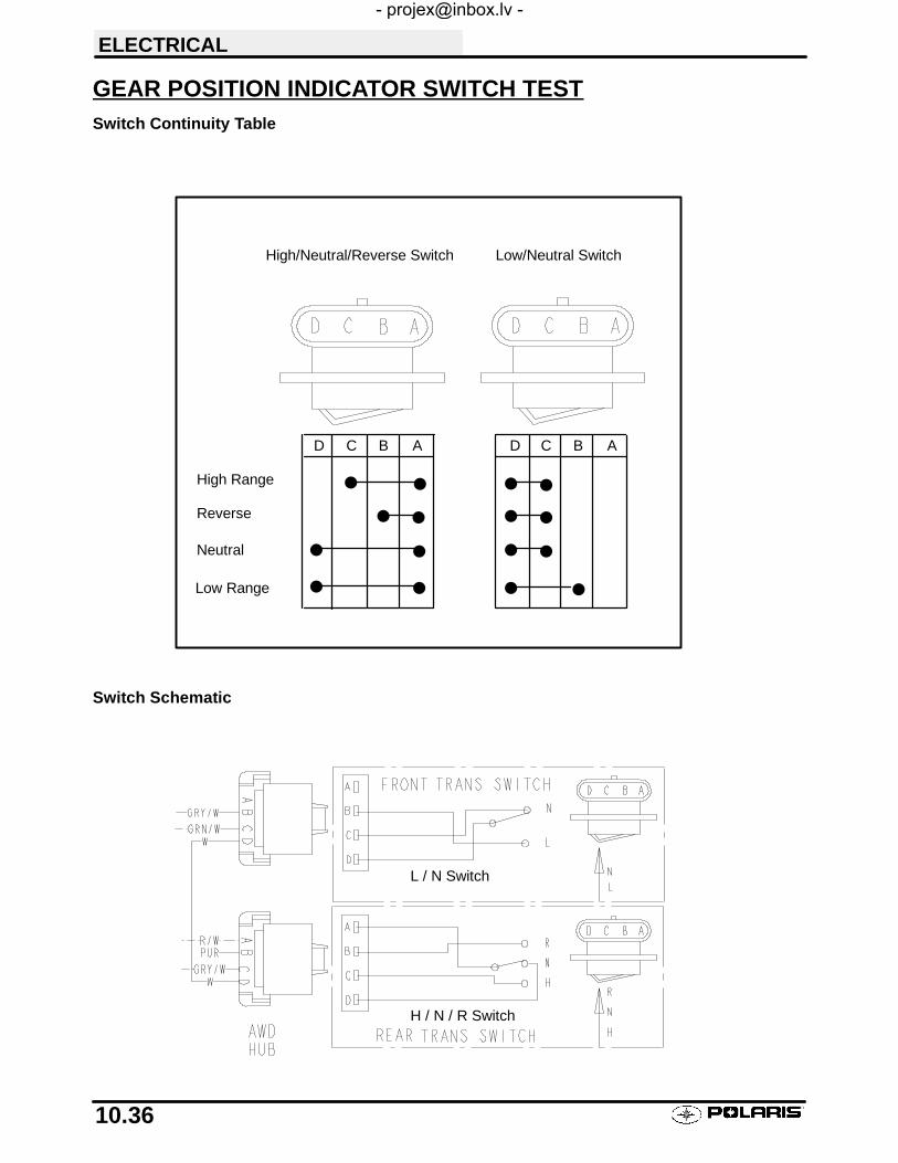
High Range
Neutral
Reverse
F F
F F
Low Range
D C B A C B AD
F F
F F
F F
F F
F F
F F
High/Neutral/Reverse Switch Low/Neutral Switch
H / N / R Switch
L / N Switch
ELECTRICAL
10.36
GEAR POSITION INDICATOR SWITCH TESTSwitch Continuity Table
Switch Schematic
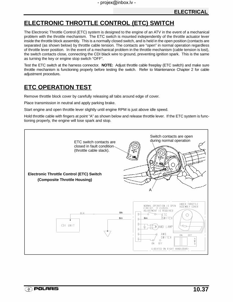
Switch contacts are openduring normal operation
A
ETC switch contacts areclosed in fault condition(throttle cable slack).
Electronic Throttle Control (ETC) Switch(Composite Throttle Housing)
Brn
Blk
Brn
ELECTRICAL
10.37
ELECTRONIC THROTTLE CONTROL (ETC) SWITCHThe Electronic Throttle Control (ETC) system is designed to the engine of an ATV in the event of a mechanicalproblem with the throttle mechanism. The ETC switch is mounted independently of the throttle actuator leverinside the throttle block assembly. This is a normally closed switch, and is held in the open position (contacts areseparated (as shown below) by throttle cable tension. The contacts are “open” in normal operation regardlessof throttle lever position. In the event of a mechanical problem in the throttle mechanism (cable tension is lost),the switch contacts close, connecting the CDI black wire to ground, preventing ignition spark. This is the sameas turning the key or engine stop switch “OFF”.
Test the ETC switch at the harness connector. NOTE: Adjust throttle cable freeplay (ETC switch) and make surethrottle mechanism is functioning properly before testing the switch. Refer to Maintenance Chapter 2 for cableadjustment procedure.
ETC OPERATION TESTRemove throttle block cover by carefully releasing all tabs around edge of cover.
Place transmission in neutral and apply parking brake.
Start engine and open throttle lever slightly until engine RPM is just above idle speed.
Hold throttle cable with fingers at point “A” as shown below and release throttle lever. If the ETC system is func-tioning properly, the engine will lose spark and stop.

INDEX
AA-Arm Replacement, 5.7
Air Filter Service, 2.23
Alternator Output Test, 10.17
Auxiliary Brake Testing, Mechanical, 9.6
AWD Armature Plate Inspection, 7.10
AWD Front Hub Exploded View, 7.6
AWD Magnetic Coil Installation, 7.8
AWD Magnetic Coil Removal, 7.8
AWD Operation, 7.2
BBattery Charging, 10.14
Battery Installation, 10.12
Battery Maintenance, 2.19
Battery Service, 10.11---10.14
Battery Terminal Bolts, 10.11
Battery Testing, 10.12
Battery, Off Season Storage, 10.14
Body Assembly Exploded View, 5.2
Brake Bleeding, 9.7---9.8
Brake Caliper Assembly, Front, 9.20
Brake Caliper Assembly, Rear, 9.26---9.27
Brake Caliper Disassembly, Front, 9.18---9.19
Brake Caliper Exploded View, Front, 9.22
Brake Caliper Exploded View, Rear, 9.29
Brake Caliper Inspection, Front, 9.19
Brake Caliper Installation, Front, 9.21
Brake Caliper Removal, Front, 9.18
Brake Caliper Removal, Rear, 9.25---9.26
Brake Disc Inspection, 9.16
Brake Disc Inspection, Rear, 9.28
Brake Disc Removal / Replacement, Front, 9.17
Brake Disc Removal, Front, 9.17
Brake Fluid Change, 9.7---9.8
Brake Fluid Level, 2.35
Brake Hose/Fitting Inspection, 2.35
Brake Inspection, Auxiliary, 9.6
Brake Light Switch Testing, 10.35
Brake Noise, 9.3
Brake Pad Adjustment, Front, 9.15
Brake Pad Application, 9.2
Brake Pad Assembly, Front, 9.15---9.16
Brake Pad Inspection, 2.35
Brake Pad Installation, Rear, 9.24
Brake Pad Kits, 9.2
Brake Pad Removal, Front, 9.14
Brake Pad Removal, Rear, 9.23
Brake System Inspection, 2.35
Brake System Operation, 9.4
Brake System Service Notes, 9.2
Brake, Auxiliary, Hydraulic, 2.36
Brake, Auxiliary, Testing, 2.36
Brakelight Lamp Replacement, 10.3
Breather Filter Maintenance, 2.24
Breather Hose Inspection, 2.24
CCam Chain Drive Sprocket Installation, 3.63
Cam Chain Tensioner Inspection, 3.18
Cam Chain Tensioner Installation, 3.71
Cam Chain Tensioner Removal, 3.17
Cam Chain/Camshaft Installation, 3.68
Cam Chain/Tensioner Blade, 3.46---3.47
Camber & Caster, 2.30
Camshaft Inspection, 3.24
Camshaft Removal, 3.21---3.22
Camshaft Timing, 3.68---3.70
Carburetor Assembly, 4.14
Carburetor Disassembly, 4.11---4.12
Carburetor Exploded View, BST40, 4.10
Carburetor Exploded View, BST34, 4.9
Carburetor Float Bowl Draining, 2.17
Carburetor Float Height Adjustment, 4.15
Carburetor Float System, 4.8
Carburetor Fuel Level Testing, 4.16
Carburetor Inspection, 4.12---4.13

INDEX
Carburetor Jet Part Numbers, 4.4
Carburetor Main System, 4.8
Carburetor Needle and Seat Testing, 4.16
Carburetor Operation, 4.6
Carburetor Pilot System, 4.7
Carburetor Starter System, 4.7
Carburetor System Function, 4.5
Carburetor Venting Systems, 4.5
CDI Output Test, 10.9
Charging System Break Even Test, 10.16
Charging System Testing, 10.15
Choke Adjustment, 2.13
Clutch Alignment, 6.21
Clutch Offset, 6.21
Cold Weather Kits, 2.3
Combustion Chamber, 3.30
Compression Release Removal/Inspection, 3.23
Compression Test, 2.18
Controls Inspection, 2.38
Coolant Level Inspection , 2.22
Coolant Strength, 2.21
Coolant Temperature Sensor, 10.33
Cooling System Hoses, 2.21
Cooling System Overview , 2.21
Cooling System Pressure Test, 3.6
Cooling System Test, 2.21
Counter Balancer Installation, 3.60
Counter Balancer Shaft End Play, 3.58
Counter Balancer Shaft Removal/Inspection, 3.52
Cover/Panel Removal, 5.3
Crankcase Assembly, 3.60
Crankcase Bearing Inspection, 3.54
Crankcase Bearing Installation, 3.55
Crankcase Disassembly, 3.44
Crankcase Inspection, 3.55
Crankcase Installation, 3.60
Crankcase Separation, 3.48
Cranking Output Test, 10.9
Crankshaft End Play Adjustment, 3.56---3.57
Crankshaft Removal/Inspection, 3.53
Crankshaft Straightening, 3.12
Current Draw, 10.16
CV Joint Handling Tips, 7.13, 7.32
Cylinder Cleaning, 3.11
Cylinder Head Assembly, 3.35---3.36
Cylinder Head Disassembly, 3.27---3.28
Cylinder Head Inspection, 3.26
Cylinder Head Installation, 3.67
Cylinder Head Reconditioning, 3.31
Cylinder Head Removal, 3.25---3.26
Cylinder Head Warpage, 3.26
Cylinder Honing, 3.11
Cylinder Inspection, 3.40---3.41
Cylinder Installation, 3.66---3.67
Cylinder Removal/Inspection, 3.37---3.38
DDecal Replacement, 5.12
Decimal Equivalent Chart, 1.21
Draining Recoil Housing, 2.25
Drive Belt Installation, 6.20
Drive Belt Removal/Inspection, 6.19---6.20
Drive Belt Tension, 6.18
Drive Clutch Assembly, 6.17---6.18
Drive Clutch Bushing Service, 6.22---6.25
Drive Clutch Disassembly, 6.14---6.16
Drive Clutch Exploded View, 6.13
Drive Clutch Inspection, 6.12
Drive Clutch Operation, 6.2
Drive Shaft Boot Replacement, 7.13---7.14
Driven Clutch Assembly, 6.29
Driven Clutch Bushing Service, 6.30---6.33
Driven Clutch Disassembly, 6.26---6.28
Driven Clutch Operation, 6.2
Dual Hydraulic Caliper Bleeding, 9.5

INDEX
EEBS Drive Clutch Bushing Service, 6.42---6.43
EBS Drive Clutch Inspection, 6.37---6.38
EBS Driven Clutch Bushing Service, 6.44---6.45
EBS Driven Clutch Disassembly, 6.39---6.41
EBS Exploded View, 6.36
EBS Moveable Sheave Bushing Inspection, 6.38
EBS One Way Drive Clutch Inspection, 6.37
EBS One Way Driven Clutch Inspection, 6.39
EBS Operation Guidelines, 6.35
EBS Ststem, Theory Of Operation, 6.34
Electrical Service Notes, 10.1
Electrical Special tools, 10.1
Electronic Speedometer Testing, 10.26---10.32
Engine Accessible Components, 3.8
Engine Assembly, 3.55---3.73
Engine Bottom End Disassembly, 3.37---3.54
Engine Break in Period, 3.10
Engine Designation Numbers, 1.1
Engine Exploded View, 3.16
Engine Fastener Torque Patterns, 3.2
Engine Installation Notes, 3.10
Engine Lubrication, 3.13
Engine Mounts, 2.18
Engine Removal, 3.9
Engine Serial Number Location, 1.1
Engine Service Data, 3.4---3.5
Engine to Frame Ground, 2.20
Engine Top End Disassembly, 3.17---3.30
ETC Operation Test, 10.37
ETC Switch Adjustment, 2.15
ETC Switch Testing, 10.37
Exhaust System, Maintenance, 2.34
Exhaust Valve Adjustment, 2.29
FFan Control Circuit Testing, 10.34
Fan Control Switch Bypass Test, 10.34
Fan Control Switch Testing, 10.34
Fan Motor Current Draw Test, 10.35
Fastener Torque, 2.18
Flywheel Identification, 10.6
Flywheel Installation, 3.72
Flywheel Removal/Inspection, 3.45
Frame, Nuts, Bolts, Fasteners, 2.40
Front Axle Exploded View, 7.15
Front Axle Installation, 7.12
Front Axle Removal, 7.11---7.12
Front Axle Seal Sleeve Replacement, 7.17
Front Hub Bearing Adjustment, 7.5
Front Hub Disassembly, 7.3
Front Hub Exploded View, 7.6
Front Hub Fluid Change, 2.33
Front Hub Fluid Level Inspection, 2.33
Front Hub Seal Replacement, 7.7
Front Hub/Wheel Bearing Installation, 7.4
Front Prop Shaft Removal, 7.18
Front Strut Assembly, 5.9
Front Strut Ball Joint Replacement, 5.11
Front Strut Weldment Replacement, 5.10
Fuel Filter Maintenance, 2.16
Fuel Flow Diagrams, 4.3
Fuel Line Maintenance, 2.16
Fuel Pump Exploded View, 4.18
Fuel Pump Service, 4.17
Fuel Tank Assembly, Exploded View, 4.2
GGear Position Switch Test, 10.36
Gear Shift Boot Replacement, 8.5
Gear Shift Selector Assembly, 8.4
Gear Shift Selector Disassembly, 8.2---8.3
Gear Shift Selector Installation, 8.5
Gear Shift Selector Removal, 8.2
Gearcase Assembly, Front, 7.24---7.25
Gearcase Disassembly, Front, 7.22---7.23
Gearcase Exploded View, Front, 7.26

INDEX
Gearcase Installation, Front, 7.25
Gearcase Lubrication, Front, 2.9
Gearcase Removal, Front, 7.22
Glossary of Terms, 1.24---1.25
HHeadlamp Service, 10.2---10.3
Headlamp Switch Testing, 10.35
Headlight Adjustment, 10.2
Headlight Pod Assembly Exploded View, 5.4
Hilliard Clutch Disassembly/Inspection, 7.9
Honing to Oversize, 3.11
Hot Light Testing, 10.33
IIdle Speed Adjustment, 2.14
Ignition System Components, 10.7
Ignition System Testing, 10.8
Ignition Timing, 2.20
Ignition Timing Curve, 10.5
Indicator Lamp Replacement, 10.3
Intake Valve Adjustment, 2.29
JJet Part Numbers, 4.4
Jetting Guidelines, 4.1
KKeys, Replacement, 1.2
LLoad Test, 10.13
Lubricants, 2.4
Lubricants, Recommended, 2.3
Lubrication Charts, 2.5---2.8
Lubrication, Transmission, 2.10, 8.1
MMachine Dimensions, 1.8---1.10
Main Jet Selection, 4.1
Maintenance Chart, Periodic, 2.1---2.2
Master Cylinder Assembly, 9.11---9.12
Master Cylinder Disassembly, 9.9---9.10
Master Cylinder Inspection, 9.11
Master Cylinder Installation, 9.13
Model & Serial Number Location, 1.1
Model Color Identification, 1.3---1.7
Model Identification, 1.1
NNeutral Light Testing, 10.35
OOil Check , Engine, 2.26
Oil Filter Change, 2.26---2.27
Oil Flow, 3.14---3.15
Oil Pipes, 3.73
Oil Pressure Test, 3.13
Oil Pump Assembly, 3.51
Oil Pump Installation, 3.60
Oil Pump Priming, 2.27, 3.13
Oil Pump Removal/Inspection, 3.49---3.51
Oil Pump Shaft End Play, 3.59
One Way Valve Inspection, 3.47
One Way Valve Installation, 3.63
Output Housing (Snorkel) Assembly, 8.20---8.23
Output Housing (Snorkel) Backlash Adjustment,8.23---8.24
PPaint Codes, 1.17
Pilot Screw Adjustment, 2.14
Piston Identification, 3.3
Piston Installation, 3.65
Piston Removal, 3.39

INDEX
Piston Ring Installation, 3.64
Piston Ring Installed Gap, 3.43
Piston to Cylinder Clearance, 3.41
Piston/Rod Inspection, 3.42---3.43
Pre-Ride Inspection, 2.2
Publication Numbers, 1.17
Pump Shaft Oil Seal Installation, 3.59
PVT Assembly, 6.7
PVT Disassembly, 6.5---6.6
PVT Drying, 6.3
PVT Maintenance, 6.3
PVT Operation, 6.2
PVT Overheating, 6.4
PVT Overview, 6.9
PVT System Sealing/Ducting Components, 6.8
PVT Troubleshooting, 6.46---6.47
RRadiator Cap Pressure Test, 3.6
Radiator Coolant Level Inspection, 2.22
Radiator, Maintenance, 2.21
Rear Drive Shaft Installation, 7.33
Rear Drive Shaft Removal, 7.32
Rear Drive Shaft Service, 7.34---7.36
Rear Hub Assembly, 7.31
Rear Hub Disassembly, 7.30
Rear Hub Installation, 7.29
Rear Hub/Bearing Carrier Removal, 7.27---7.28
Rear Suspension Exploded View, 5.8
Recoil Assembly, 3.75---3.76
Recoil Disassembly/Inspection, 3.74
Recoil Draining, 2.25
Rocker Arm/Shaft Inspection, 3.19---3.20
Rocker Shaft/Arm Assembly Installation, 3.73
SSediment Tube, Maintenance, 2.24
Shift Linkage Adjustment, 2.11---2.12
Shift Weights, 6.11
Side Panel Removal, 5.5
Spark Plug Maintenance, 2.20
Special Tools, PVT, 6.1
Special Tools, Suspension, 5.1
Specific Gravity Test, 10.13
Specifications, Brake, 9.1
Specifications, Cooling System, 3.7
Specifications, Drive Clutch Spring, 6.10
Specifications, Model, 1.11---1.16
Specifications, Torque, Brakes, 9.1
Specifications, Torque, Engine, 3.1
Specifications, Torque, Final Drive, 7.1
Specifications, Torque, PVT, 6.1
Specifications, Torque, Standard, 1.18
Specifications, Torque, Steering, 5.1
Specifications, Torque, Suspension, 5.1
Specifications, Torque, Transmission, 8.1
Spider Removal, 6.15
Starter Assembly, 10.24
Starter Disassembly, 10.20, 10.21
Starter Drive, 10.25
Starter Drive Installation, 3.72
Starter Drive Removal/Inspection, 3.44
Starter Motor Armature Testing, 10.23
Starter Motor Brush Inspn/Replmt, 10.21---10.22
Starter Solenoid Bench Test, 10.25
Starter System Test, 10.19
Stator Installation, 3.71---3.72
Stator Removal/Inspection, 3.45
Steering Assembly, Exploded View, 5.6
Steering Maintenance, 2.30
Steering Post Assembly, 5.12
Strut Casting Seal Replacement, 7.16
Suspension Preload Adjustment, 2.37
Suspension, Front, Inspection, 2.37
Suspension, Rear, Inspection, 2.37

INDEX
TTaillight Lamp Replacement, 10.3
Tap Drill Chart, 1.23
Tensioner Blade Installation, 3.63
Thermostat Installation, 3.73
Throttle Cable Adjustment, 2.15
Throttle Operation, 2.13
Tie Rod Inspection, 2.30
Timing Check Procedure, 10.4
Tire Inspection, 2.40
Tire Pressure, 2.40
Tire Tread Depth, 2.40
Toe Alignment, 2.31---2.32
Torque Conversion Table, 1.19---1.20
Torque Patterns, Engine, 3.2
Transmission Assembly, 8.20---8.31
Transmission Center Shaft Bushing Installation,8.20
Transmission Disassembly, 8.11---8.19
Transmission I.D. Location, 1.1
Transmission Installation, 8.9---8.10
Transmission Linkage Adjustment, 2.11
Transmission Removal, 8.6---8.8
Transmission Tensioner Installation, 8.29
Transmission, Exploded View, 8.32
Troubleshooting, Brakes, 9.30
Troubleshooting, Cooling System, 3.80
Troubleshooting, Engine, 3.78---3.79
Troubleshooting, Fuel System/Carb, 4.19---4.20
Troubleshooting, Ignition System, 10.10
Troubleshooting, Spark Plug, 3.77
Troubleshooting, Starter System, 10.18
Troubleshooting, Transmission, 8.33
UU---Joint Assembly, 7.20---7.21
U---Joint Disassembly, 7.19---7.20
Unit of Measure Conversion Table, 1.22
VValve Clearance, 2.28
Valve Guide Removal/Installation, 3.31
Valve Inspection, 3.29---3.30
Valve Seal Testing, 3.36
Valve Seat Inspection, 3.31
Valve Seat Reconditioning, 3.31---3.35
Vent Line Maintenance, 2.16
VIN Identification, 1.1
Voltage Drop Test, 10.18
Voltage Test Open Circuit, 10.12
WWater Pump Mechanical Seal Installation, 3.61
Water Pump Mechanical Seal Removal, 3.54
Water Pump Mechanical Seal Removal, EngineInstalled, 3.61---3.62
Water Pump Shaft Oil Seal, 3.54
Wheel Inspection, 2.39
Wheel Installation, 2.39
Wheel Removal Front or Rear, 2.39
Wiring Diagram, 2001, Sportsman 400, 10.39
Wiring Diagram, 2001, Sportsman 500 Early, 10.40
Wiring Diagram, 2001, Sportsman 500 Late, 10.41