Polaris SeaMap10 ECDIS Manual.pdf
233
-
Upload
khangminh22 -
Category
Documents
-
view
2 -
download
0
Transcript of Polaris SeaMap10 ECDIS Manual.pdf


CN--0276 / 0067 on Bravo / KM
SeaMap 10
ECDISInstruction manual

Document revisions
Rev Date Written by Checked by Approved by
A 29.Feb.2000 PAa TL
B 23.Jun.2000 PAa TL
C 27.Sep.2000 PAa TL
D 16.Mar.2001 MZ TL
E 09.Apr.2001 JOS TL
F 23.Aug.2001 MZ TL
G 9.Jan.2002 Mz TL
H 14.Feb.2002 Mz TL
I 27.May.2002 Mz TL
J 19.Jun.2002 KGr TL
K 20.Nov.2002 Mz TL
L 27.Nov.2002 KGr MZ TL
M 4.Mar.2003 KGr MZ TL
N 6.Jun.2003 KGr MZ TL
The original signatures are recorded in the company’s logistic database.

High voltage safety warning
Precautionary measuresThe voltages used to power this equipmentare potentially lethal. Even 110 volts can kill.Whenever possible, the followingprecautionary measures must be taken beforeany work is carried out inside the equipment:
S Switch off all high-voltage power supplies.
S Check the operation of any door interlocksand any other safety devices.
S Completely discharge all high-voltagecapacitors.
It should be noted that interlocks and safetydevices are normally located only at regularaccess points, and high voltages may beexposed during dismantling.
Never work alone on high-voltageequipment!
First aid in the event ofelectric shockNormally, even a high voltage electric shockwill not kill instantly. The victim can still berevived even when his breathing andheart-beat have ceased.
Could YOU save someone’s life?
In the event of electric shock, the correctactions, performed quickly may well save thevictim’s life. Make sure you know what todo!
Immediate action
While shouting for help, remove the source ofpower from the victim. Switch off the supplyif possible, or using a dry, non-conductivematerial (rubber gloves, broom handle etc.) toinsulate yourself, separate the victim from thesource. If the voltage exceeds 1000 volts,switch off the supply and be ready to catchthe victim. Take care- do not become a victimyourself.
Commence first aid on the spot. Continue toshout for assistance till someone arrives.
1 Lay the victim flat on his back and loosenany tight clothing (collar, tie, belt etc.).
2 Open his mouth and check for and removeany false teeth, chewing gum etc.
3 Check if the victim is breathing. If not,check if his heart is beating. The pulse isnormally easily found in the main arteriesof the neck, either side of the throat, upunder the chin.
If his heart is beating but he is not breathing,commence artificial respiration. If thevictim’s heart is not beating, commenceexternal cardiac massage (ECM). Continue toshout for assistance till someone arrives.
External cardiac massage1 Kneel beside the victim. Place the heel of
one hand in the centre of his chest, at aposition half way between the notchbetween the collar-bones at the top of hischest, and the dip in the breast-bone at thebase of his rib cage. Place the other handon top of the first.
2 Keeping the arms straight and using yourentire weight, press down rapidly so thatthe breast bone is depressed four- five cm,then release the pressure. Repeatrhythmically at a rate of one cycle persecond. This will be hard work, but keepgoing. His life depends on YOU. Do notworry about breaking his ribs - these willheal if he survives.

Artificial respiration1 Kneel besides the victim’s head. Place one
hand under his neck and lift, allowing hishead to fall back. This will lift his tongueand open the air passage in his throat.
2 Place the palm of the hand on his foreheadto maintain the ”chin-up” position.
3 Using the index finger and thumb of thesame hand, pinch the victim’s nostrilsclosed. Open his mouth.
4 Take a deep breath and cover his mouthwith yours. Blow steadily into his lungs toexpand his chest. Remove your mouthfrom his to allow the air to escape from hischest. You should be able to see his chestdeflate.
5 Repeat the ”inflation-deflation” cycle at arate of about 12 cycles per minute till thevictim begins to breath normally again.
Combining ECM and artificialrespirationIf you are alone, perform one cycle ofartificial respiration for every five cycles ofECM. This will be hard work, but keep going.His life depends on you!If there are other people available to help, oneshould perform the ECM while one performsthe artificial respiration for every five cyclesof ECM. It will be much more efficient withtwo people.Once the victim’s heart is beating and he isbreathing, roll him onto his side and supporthim in that position. As consciousness returnshe may vomit, and this will allow any liquidto drain out of his mouth.
Remove the victim to a hospital as soon aspossible, but do not interrupt the artificialrespiration and ECM cycles till his heart beatand breathing returns.
If started quickly and performed correctly, theresuscitation methods described will keep asufficient volume of oxygenated bloodflowing trough the victims body to allow fullrecovery.
Proficiency in the resuscitation methods canonly be achieved trough training. Allpersonnel concerned should attend courses ona regular basis. Remember, someone’s lifecould depend on you.
Do you know what to do?

Warnings and Cautions
WARNING Lethal voltages
This system is not fitted with safety interlocks and lethal voltagesmay be exposed when access covers are removed. Only personsqualified and authorised must remove covers and these personsshould always take extreme care once the covers are removed.
WARNING Fire
If a fire condition arises, emission of toxic fumes can be anticipatedfrom burning insulation, printed circuit boards, ETC.
WARNING Health hazard
When cleaning the inside of this system, do not inhale the dust. Thedust is a temporary health hazard, depending on individualallergies.
Kongsberg Maritime AS disclaims any responsibility for damageor injury caused by improper installation, use or maintenance ofthe equipment.
Caution Electrostatic sensitive device
Certain semiconductive devices used in this equipment are liableto damage due to static voltage. Observe all precautions forhandling of semiconductive sensitive devices.
Note This document
The information contained in this document is subject to changewithout notice. Kongsberg Maritime AS shall not be liable forerrors contained herein or for incidental or consequential damagesin connection with the furnishing, performance, or use of thisdocument. 2003 Kongsberg Maritime AS. All rights reserved.No part of this work covered by the copyright hereon may bereproduced or otherwise copied without prior permission fromKongsberg Maritime AS.
Manufacturer Kongsberg Maritime ASBekkajordet 8 AP.O. Box 1009N--3194 Horten, NORWAYTelephone switchboard: +47 33 03 20 00Fax: +47 85 02 80 82www.kongsberg.com

Purpose
The reader
This instruction manual describes how to use the SeaMap 10 ECDIS controls andfacilities. It is intended for system operators. He/she should be experienced in the operationof ECDISs and have basic knowledge of personal computers or should have attended aKongsberg Maritime training course.
Note
Due to the flexible nature of SeaMap 10 not all systems described in this manual arerelevant for all deliveries. The SeaMap 10 ECDIS is a registered trademark of KongsbergMaritime. Windows NT and Windows are either registered trademarks or trademarks ofMicrosoft Corporation in the United States and/or other countries.
Figure 1 SeaMap 10 with 29” display.

Instruction manual
ICN--0276 / rev.N, 06.06.2003
Chapters
1 Functional descriptionThis chapter presents a functional description of the SeaMap 10 ECDIS. Itgives an overview of the configuration and components of the system.
Refer to page 1.
2 Getting startedThis chapter teaches you how to use the basic – most common functions of theSeaMap 10. It is intended for personnel just starting to use the system andincludes step by step procedures for basic operation.
Refer to page 12.
3 Operating informationThis chapter contains a descriptions of operator functions. It is intended forusers already understanding basic operation of the system.
Refer to page 31.
4 Reference guideThis chapter explains the menus in detail. This chapter explains alarmcategories, acknowledgement and related information.
Refer to page 94
5 MaintenanceThis chapter explains how to keep the system in good working order and whatto do if the system fails.
Refer to page 191.
6 Replaceable partsThis chapter contains a list of replaceable parts including part numbers.
Refer to page 196.
7 AppendixThis chapter contains abbreviations and references.
Refer to page 199.
8 IndexThis chapter contains an index.
Refer to page 203.

SeaMap 10 / Instruction manual
II CN--0276 / rev.N, 06.06.2003
Document historyThe information on this page is for internal use.
Rev.A First edition.
Rev.B Manual updated to cover software version 1.22
Rev.C Manual updated to cover software version 1.27B
Rev.D Manual updated to cover software version 2.0
Rev.E Updated 6.2 Autopilot Remote Control. Added Appendix Alarm List.
Rev.F Manual updated to cover software version 2.2
Rev.G The manual covers software version 2.6Ch. 5.2.2 Revised for PRIMAR charts.Ch. 5.5.8 Added for Depth Recording.Ch. 5.8.5 Added for Printing.Ch. 5.8.11 Revised for TargetIn and Depth sensors.Ch. 6.7.2 Added for PRIMAR chart procedures.
Rev.H The manual covers software version 2.7. Anemometer (wind) sensorinput has been added.
Rev.I The manual covers software version 2.8. Preliminary AIS support hasbeen added. Changes to S57 chart installation.
Rev.J A complete rewriting of the document.
Rev.K Updated to corresponds to software version 2.9. Changes to chart mirror-ing. Added Seafarer (general HCRF) support.
Rev.L Various minor changes. Fail is changed to Alarm in the system softwareand the alarm philosophy is altered somewhat. The document is updatedaccordingly.
Rev.M Included support for presenting positional information in non-WGS da-tums, and for conversion between WGS-84 and other datums. Supportsconfiguration of C-Map ENC data bases and provides mirroring of S57charts. Monitor selection support and new ECDIS-calibrated palettes forTFT displays has been added.
Rev.N Included operating procedures for Automatic Identification System - AISand Navigational Telex - NavTex. Both functions are available as optionsto the system. Upgraded procedure for alarm systems set-up. Updatedto corresponds to software version 2.10.

Instruction manual
IIICN-0276 / rev.N, 06.06.2003
Table of contents
1 FUNCTIONAL DESCRIPTION 1. . . . . . . . . . . . . . . . . . . . . . . . . . . .1.1 Introduction 1. . . . . . . . . . . . . . . . . . . . . . . . . . . . . . . . . . . . . . . . . . . . . .1.1.1 Software version 1. . . . . . . . . . . . . . . . . . . . . . . . . . . . . . . . . . . . . . . . . .1.2 Overview 2. . . . . . . . . . . . . . . . . . . . . . . . . . . . . . . . . . . . . . . . . . . . . . . .1.3 Technical specifications 3. . . . . . . . . . . . . . . . . . . . . . . . . . . . . . . . . . . .1.3.1 Main functions 3. . . . . . . . . . . . . . . . . . . . . . . . . . . . . . . . . . . . . . . . . . .1.3.2 Chart handling 3. . . . . . . . . . . . . . . . . . . . . . . . . . . . . . . . . . . . . . . . . . . .1.3.3 Charts formats 4. . . . . . . . . . . . . . . . . . . . . . . . . . . . . . . . . . . . . . . . . . . .1.3.4 Route planning 4. . . . . . . . . . . . . . . . . . . . . . . . . . . . . . . . . . . . . . . . . . .1.3.5 Route monitoring 5. . . . . . . . . . . . . . . . . . . . . . . . . . . . . . . . . . . . . . . . .1.3.6 Mariners notes 6. . . . . . . . . . . . . . . . . . . . . . . . . . . . . . . . . . . . . . . . . . . .1.3.7 Tools 6. . . . . . . . . . . . . . . . . . . . . . . . . . . . . . . . . . . . . . . . . . . . . . . . . . .1.3.8 Operational alarms and indicators 6. . . . . . . . . . . . . . . . . . . . . . . . . . . .1.3.9 Own ship data calculation 7. . . . . . . . . . . . . . . . . . . . . . . . . . . . . . . . . . .1.3.10 ARPA 7. . . . . . . . . . . . . . . . . . . . . . . . . . . . . . . . . . . . . . . . . . . . . . . . . .1.3.11 Recording and playback 7. . . . . . . . . . . . . . . . . . . . . . . . . . . . . . . . . . . .1.3.12 Printed reports 8. . . . . . . . . . . . . . . . . . . . . . . . . . . . . . . . . . . . . . . . . . . .1.3.13 System maintenance 8. . . . . . . . . . . . . . . . . . . . . . . . . . . . . . . . . . . . . . .1.3.14 Optional applications 8. . . . . . . . . . . . . . . . . . . . . . . . . . . . . . . . . . . . . .1.3.15 User interface 8. . . . . . . . . . . . . . . . . . . . . . . . . . . . . . . . . . . . . . . . . . . .1.3.16 Chart display 9. . . . . . . . . . . . . . . . . . . . . . . . . . . . . . . . . . . . . . . . . . . . .1.3.17 Menus 9. . . . . . . . . . . . . . . . . . . . . . . . . . . . . . . . . . . . . . . . . . . . . . . . . .1.3.18 Serial lines 9. . . . . . . . . . . . . . . . . . . . . . . . . . . . . . . . . . . . . . . . . . . . . . .1.3.19 Local area network 10. . . . . . . . . . . . . . . . . . . . . . . . . . . . . . . . . . . . . . . .1.3.20 Slave display (option) 10. . . . . . . . . . . . . . . . . . . . . . . . . . . . . . . . . . . . . .1.3.21 Printer (option) 10. . . . . . . . . . . . . . . . . . . . . . . . . . . . . . . . . . . . . . . . . . .1.3.22 Display resolution 10. . . . . . . . . . . . . . . . . . . . . . . . . . . . . . . . . . . . . . . . .1.3.23 Power supply 10. . . . . . . . . . . . . . . . . . . . . . . . . . . . . . . . . . . . . . . . . . . . .1.3.24 Environmental 10. . . . . . . . . . . . . . . . . . . . . . . . . . . . . . . . . . . . . . . . . . . .1.3.25 Dimensions and weight 11. . . . . . . . . . . . . . . . . . . . . . . . . . . . . . . . . . . . .
2 GETTING STARTED 12.. . . . . . . . . . . . . . . . . . . . . . . . . . . . . . . . . . . . .2.1 Introduction 12. . . . . . . . . . . . . . . . . . . . . . . . . . . . . . . . . . . . . . . . . . . . . .2.2 Display layout 13. . . . . . . . . . . . . . . . . . . . . . . . . . . . . . . . . . . . . . . . . . . .2.2.1 Overview 13. . . . . . . . . . . . . . . . . . . . . . . . . . . . . . . . . . . . . . . . . . . . . . . .2.2.2 Display areas 13. . . . . . . . . . . . . . . . . . . . . . . . . . . . . . . . . . . . . . . . . . . . .

SeaMap 10 / Instruction manual
IV CN-0276 / rev.N, 06.06.2003
2.2.3 Trackball marker 13. . . . . . . . . . . . . . . . . . . . . . . . . . . . . . . . . . . . . . . . . .
2.2.4 Top bar 13. . . . . . . . . . . . . . . . . . . . . . . . . . . . . . . . . . . . . . . . . . . . . . . . .2.2.5 Boarding area 18. . . . . . . . . . . . . . . . . . . . . . . . . . . . . . . . . . . . . . . . . . . .2.2.6 Main menu 18. . . . . . . . . . . . . . . . . . . . . . . . . . . . . . . . . . . . . . . . . . . . . .2.2.7 About menus 18. . . . . . . . . . . . . . . . . . . . . . . . . . . . . . . . . . . . . . . . . . . . .2.2.8 Alarms and message area 18. . . . . . . . . . . . . . . . . . . . . . . . . . . . . . . . . . .2.2.9 Chart area 20. . . . . . . . . . . . . . . . . . . . . . . . . . . . . . . . . . . . . . . . . . . . . . .
2.3 How to make numeric entries 21. . . . . . . . . . . . . . . . . . . . . . . . . . . . . . . .2.4 Control panel and computer keyboard 22. . . . . . . . . . . . . . . . . . . . . . . . .2.4.1 Display keys 23. . . . . . . . . . . . . . . . . . . . . . . . . . . . . . . . . . . . . . . . . . . . .
2.4.2 Screen keys 24. . . . . . . . . . . . . . . . . . . . . . . . . . . . . . . . . . . . . . . . . . . . . .2.4.3 ECDIS keys 24. . . . . . . . . . . . . . . . . . . . . . . . . . . . . . . . . . . . . . . . . . . . . .2.4.4 Trackball keys 25. . . . . . . . . . . . . . . . . . . . . . . . . . . . . . . . . . . . . . . . . . . .2.4.5 Marker keys 25. . . . . . . . . . . . . . . . . . . . . . . . . . . . . . . . . . . . . . . . . . . . . .
2.4.6 Autopilot keys 25. . . . . . . . . . . . . . . . . . . . . . . . . . . . . . . . . . . . . . . . . . . .2.4.7 Turn keys 26. . . . . . . . . . . . . . . . . . . . . . . . . . . . . . . . . . . . . . . . . . . . . . . .2.4.8 Miscellaneous keys 27. . . . . . . . . . . . . . . . . . . . . . . . . . . . . . . . . . . . . . . .2.5 How to start up SeaMap 10 27. . . . . . . . . . . . . . . . . . . . . . . . . . . . . . . . . .
2.5.1 Switching power on 27. . . . . . . . . . . . . . . . . . . . . . . . . . . . . . . . . . . . . . .2.5.2 Selecting chart database 27. . . . . . . . . . . . . . . . . . . . . . . . . . . . . . . . . . . .2.5.3 Selecting safety contour 28. . . . . . . . . . . . . . . . . . . . . . . . . . . . . . . . . . . .2.5.4 Available charts 28. . . . . . . . . . . . . . . . . . . . . . . . . . . . . . . . . . . . . . . . . . .2.5.5 Changing chart scale 28. . . . . . . . . . . . . . . . . . . . . . . . . . . . . . . . . . . . . . .
2.5.6 Selecting radar video and target vectors 29. . . . . . . . . . . . . . . . . . . . . . . .2.5.7 Changing chart themes 29. . . . . . . . . . . . . . . . . . . . . . . . . . . . . . . . . . . . .2.5.8 Changing presentation mode 29. . . . . . . . . . . . . . . . . . . . . . . . . . . . . . . . .2.6 How to switch off SeaMap 10 29. . . . . . . . . . . . . . . . . . . . . . . . . . . . . . .
2.6.1 Emergency shut--down 30. . . . . . . . . . . . . . . . . . . . . . . . . . . . . . . . . . . . .2.7 How to control objects on the screen 30. . . . . . . . . . . . . . . . . . . . . . . . . .
3 OPERATING INFORMATION 31.. . . . . . . . . . . . . . . . . . . . . . . . . . . .3.1 Introduction 31. . . . . . . . . . . . . . . . . . . . . . . . . . . . . . . . . . . . . . . . . . . . . .3.2 About integrated systems 32. . . . . . . . . . . . . . . . . . . . . . . . . . . . . . . . . . .
3.3 About charts in general 33. . . . . . . . . . . . . . . . . . . . . . . . . . . . . . . . . . . . .3.4 How to use C--Map CM--93 edition 2 charts 33. . . . . . . . . . . . . . . . . . . .3.4.1 Installing charts 34. . . . . . . . . . . . . . . . . . . . . . . . . . . . . . . . . . . . . . . . . . .3.4.2 Updating charts 37. . . . . . . . . . . . . . . . . . . . . . . . . . . . . . . . . . . . . . . . . . .3.4.3 Deleting charts 37. . . . . . . . . . . . . . . . . . . . . . . . . . . . . . . . . . . . . . . . . . .

Instruction manual
VCN-0276 / rev.N, 06.06.2003
3.5 How to use C--Map CM--93 edition 3 charts 38. . . . . . . . . . . . . . . . . . . .
3.5.1 Installing charts 38. . . . . . . . . . . . . . . . . . . . . . . . . . . . . . . . . . . . . . . . . . .3.6 How to use S57 edition 3 charts 40. . . . . . . . . . . . . . . . . . . . . . . . . . . . . .3.6.1 Installing charts 40. . . . . . . . . . . . . . . . . . . . . . . . . . . . . . . . . . . . . . . . . . .3.6.2 Updating charts 41. . . . . . . . . . . . . . . . . . . . . . . . . . . . . . . . . . . . . . . . . . .
3.7 How to use S57 charts from PRIMAR Official ENC service 41. . . . . . . .3.7.1 Installing charts 41. . . . . . . . . . . . . . . . . . . . . . . . . . . . . . . . . . . . . . . . . . .3.7.2 Updating charts 44. . . . . . . . . . . . . . . . . . . . . . . . . . . . . . . . . . . . . . . . . . .
3.8 How to use HCRF charts 45. . . . . . . . . . . . . . . . . . . . . . . . . . . . . . . . . . .3.8.1 Installing charts 45. . . . . . . . . . . . . . . . . . . . . . . . . . . . . . . . . . . . . . . . . . .
3.8.2 Updating charts 47. . . . . . . . . . . . . . . . . . . . . . . . . . . . . . . . . . . . . . . . . . .3.8.3 Deleting and adding charts 48. . . . . . . . . . . . . . . . . . . . . . . . . . . . . . . . . .3.8.4 ARCS demonstration charts 48. . . . . . . . . . . . . . . . . . . . . . . . . . . . . . . . .
3.9 How to enter a position offset 50. . . . . . . . . . . . . . . . . . . . . . . . . . . . . . . .3.10 How to use the log and replay functions 50. . . . . . . . . . . . . . . . . . . . . . . .3.10.1 Past track log 50. . . . . . . . . . . . . . . . . . . . . . . . . . . . . . . . . . . . . . . . . . . . .
3.10.2 Voyage log 51. . . . . . . . . . . . . . . . . . . . . . . . . . . . . . . . . . . . . . . . . . . . . . .3.10.3 Replay track or voyage logs 52. . . . . . . . . . . . . . . . . . . . . . . . . . . . . . . . .
3.10.4 Log printout 53. . . . . . . . . . . . . . . . . . . . . . . . . . . . . . . . . . . . . . . . . . . . .3.11 How to define the regeneration area 55. . . . . . . . . . . . . . . . . . . . . . . . . . .3.12 How to use EBL and VRM 56. . . . . . . . . . . . . . . . . . . . . . . . . . . . . . . . . .3.13 How to use parallel index lines 57. . . . . . . . . . . . . . . . . . . . . . . . . . . . . . .
3.14 How to use the curved EBL 58. . . . . . . . . . . . . . . . . . . . . . . . . . . . . . . . .3.14.1 Planning mode 58. . . . . . . . . . . . . . . . . . . . . . . . . . . . . . . . . . . . . . . . . . .3.14.2 Autopilot mode 59. . . . . . . . . . . . . . . . . . . . . . . . . . . . . . . . . . . . . . . . . . .
3.15 How to use sailing routes 59. . . . . . . . . . . . . . . . . . . . . . . . . . . . . . . . . . .3.15.1 Definitions 59. . . . . . . . . . . . . . . . . . . . . . . . . . . . . . . . . . . . . . . . . . . . . . .3.15.2 Creating a route on the chart 60. . . . . . . . . . . . . . . . . . . . . . . . . . . . . . . . .
3.15.3 Creating a route using the waypoint list 61. . . . . . . . . . . . . . . . . . . . . . . .
3.15.4 Modifying routes 63. . . . . . . . . . . . . . . . . . . . . . . . . . . . . . . . . . . . . . . . . .
3.15.5 Insert waypoints 63. . . . . . . . . . . . . . . . . . . . . . . . . . . . . . . . . . . . . . . . . .3.15.6 Adding waypoints at the end of the route 64. . . . . . . . . . . . . . . . . . . . . . .3.15.7 Modifying routes in the chart 64. . . . . . . . . . . . . . . . . . . . . . . . . . . . . . . .
3.15.8 Copying waypoints 65. . . . . . . . . . . . . . . . . . . . . . . . . . . . . . . . . . . . . . . .3.15.9 Validating routes 66. . . . . . . . . . . . . . . . . . . . . . . . . . . . . . . . . . . . . . . . . .3.16 How to insert critical points 68. . . . . . . . . . . . . . . . . . . . . . . . . . . . . . . . .3.16.1 Creating a critical point in the chart 68. . . . . . . . . . . . . . . . . . . . . . . . . . .

SeaMap 10 / Instruction manual
VI CN-0276 / rev.N, 06.06.2003
3.16.2 Creating a critical point using the menu 69. . . . . . . . . . . . . . . . . . . . . . . .3.17 How to monitor routes 70. . . . . . . . . . . . . . . . . . . . . . . . . . . . . . . . . . . . .3.18 How to export routes to DataBridge 2000 71. . . . . . . . . . . . . . . . . . . . . .3.19 How to use the automatic track keeping 72. . . . . . . . . . . . . . . . . . . . . . . .3.19.1 Introduction 72. . . . . . . . . . . . . . . . . . . . . . . . . . . . . . . . . . . . . . . . . . . . . .3.19.2 Heading mode 73. . . . . . . . . . . . . . . . . . . . . . . . . . . . . . . . . . . . . . . . . . . .3.19.3 Course mode 73. . . . . . . . . . . . . . . . . . . . . . . . . . . . . . . . . . . . . . . . . . . . .3.19.4 Waypoint mode 74. . . . . . . . . . . . . . . . . . . . . . . . . . . . . . . . . . . . . . . . . . .3.19.5 Track mode 74. . . . . . . . . . . . . . . . . . . . . . . . . . . . . . . . . . . . . . . . . . . . . .3.19.6 To stop track steering 75. . . . . . . . . . . . . . . . . . . . . . . . . . . . . . . . . . . . . .3.19.7 Waypoint alarms 75. . . . . . . . . . . . . . . . . . . . . . . . . . . . . . . . . . . . . . . . . .3.19.8 Warnings given 76. . . . . . . . . . . . . . . . . . . . . . . . . . . . . . . . . . . . . . . . . . .3.19.9 Limitations 76. . . . . . . . . . . . . . . . . . . . . . . . . . . . . . . . . . . . . . . . . . . . . .3.19.10 Conditions resulting in an automatic switch--over to a different steering mode
773.19.11 Practical hints 78. . . . . . . . . . . . . . . . . . . . . . . . . . . . . . . . . . . . . . . . . . . .3.20 How to use mariner’s notes 79. . . . . . . . . . . . . . . . . . . . . . . . . . . . . . . . . .3.20.1 Introduction 79. . . . . . . . . . . . . . . . . . . . . . . . . . . . . . . . . . . . . . . . . . . . . .3.20.2 Managing notes 79. . . . . . . . . . . . . . . . . . . . . . . . . . . . . . . . . . . . . . . . . . .3.20.3 Creating point notes 79. . . . . . . . . . . . . . . . . . . . . . . . . . . . . . . . . . . . . . .3.20.4 Creating line or area notes 80. . . . . . . . . . . . . . . . . . . . . . . . . . . . . . . . . .3.20.5 Modifying notes 81. . . . . . . . . . . . . . . . . . . . . . . . . . . . . . . . . . . . . . . . . .3.21 How to use AIS functions 81. . . . . . . . . . . . . . . . . . . . . . . . . . . . . . . . . . .3.21.1 View target information 81. . . . . . . . . . . . . . . . . . . . . . . . . . . . . . . . . . . .3.21.2 Acknowledge lost targets 82. . . . . . . . . . . . . . . . . . . . . . . . . . . . . . . . . . .3.21.3 View own ships data 82. . . . . . . . . . . . . . . . . . . . . . . . . . . . . . . . . . . . . . .3.21.4 Specifying own ships information 82. . . . . . . . . . . . . . . . . . . . . . . . . . . .3.21.5 Sending and receiving text telegrams and safety messages 83. . . . . . . . .3.22 How to use NavTex functions 85. . . . . . . . . . . . . . . . . . . . . . . . . . . . . . . .3.22.1 Introduction 85. . . . . . . . . . . . . . . . . . . . . . . . . . . . . . . . . . . . . . . . . . . . . .3.22.2 View Navtex messages 87. . . . . . . . . . . . . . . . . . . . . . . . . . . . . . . . . . . . .3.22.3 Configure navigation area 87. . . . . . . . . . . . . . . . . . . . . . . . . . . . . . . . . . .3.22.4 Filter Navtex stations 87. . . . . . . . . . . . . . . . . . . . . . . . . . . . . . . . . . . . . .3.22.5 Filter message categories 88. . . . . . . . . . . . . . . . . . . . . . . . . . . . . . . . . . .3.22.6 Creating Mariners notes from Navtex messages 88. . . . . . . . . . . . . . . . . .3.23 How to handle alarms 89. . . . . . . . . . . . . . . . . . . . . . . . . . . . . . . . . . . . . .3.23.1 Alarm categories 89. . . . . . . . . . . . . . . . . . . . . . . . . . . . . . . . . . . . . . . . . .3.23.2 Alarm system set--up 90. . . . . . . . . . . . . . . . . . . . . . . . . . . . . . . . . . . . . . .

Instruction manual
VIICN-0276 / rev.N, 06.06.2003
3.23.3 Alarm acknowledgement using the trackball 91. . . . . . . . . . . . . . . . . . . .
3.23.4 Alarm acknowledgement using the operator panel 91. . . . . . . . . . . . . . . .3.23.5 Listing active alarms 91. . . . . . . . . . . . . . . . . . . . . . . . . . . . . . . . . . . . . . .3.23.6 Alarms from remote display units 92. . . . . . . . . . . . . . . . . . . . . . . . . . . .3.23.7 Alarm filtering 92. . . . . . . . . . . . . . . . . . . . . . . . . . . . . . . . . . . . . . . . . . .3.23.8 Output to external alarm system 92. . . . . . . . . . . . . . . . . . . . . . . . . . . . . .3.24 How to access system parameters 92. . . . . . . . . . . . . . . . . . . . . . . . . . . . .
3.24.1 Operation 93. . . . . . . . . . . . . . . . . . . . . . . . . . . . . . . . . . . . . . . . . . . . . . . .3.25 How to use depth recordings for other applications 93. . . . . . . . . . . . . . .
4 REFERENCE GUIDE 94.. . . . . . . . . . . . . . . . . . . . . . . . . . . . . . . . . . . . .4.1 Introduction 94. . . . . . . . . . . . . . . . . . . . . . . . . . . . . . . . . . . . . . . . . . . . . .
4.2 Menu descriptions 95. . . . . . . . . . . . . . . . . . . . . . . . . . . . . . . . . . . . . . . . .4.2.1 Overview 95. . . . . . . . . . . . . . . . . . . . . . . . . . . . . . . . . . . . . . . . . . . . . . . .4.2.2 How to reach menus 95. . . . . . . . . . . . . . . . . . . . . . . . . . . . . . . . . . . . . . .4.2.3 Menu hierarchy 95. . . . . . . . . . . . . . . . . . . . . . . . . . . . . . . . . . . . . . . . . . .
4.3 Chart 96. . . . . . . . . . . . . . . . . . . . . . . . . . . . . . . . . . . . . . . . . . . . . . . . . . .4.3.1 Display mode 96. . . . . . . . . . . . . . . . . . . . . . . . . . . . . . . . . . . . . . . . . . . .4.3.2 Zoom 97. . . . . . . . . . . . . . . . . . . . . . . . . . . . . . . . . . . . . . . . . . . . . . . . . . .4.3.3 Themes 97. . . . . . . . . . . . . . . . . . . . . . . . . . . . . . . . . . . . . . . . . . . . . . . . .4.3.4 Object info 99. . . . . . . . . . . . . . . . . . . . . . . . . . . . . . . . . . . . . . . . . . . . . .
4.3.5 Chart legend 100. . . . . . . . . . . . . . . . . . . . . . . . . . . . . . . . . . . . . . . . . . . . .4.3.6 Browse position 100. . . . . . . . . . . . . . . . . . . . . . . . . . . . . . . . . . . . . . . . . . .4.3.7 Safety depth setting 101. . . . . . . . . . . . . . . . . . . . . . . . . . . . . . . . . . . . . . . .4.3.8 Chart types 103. . . . . . . . . . . . . . . . . . . . . . . . . . . . . . . . . . . . . . . . . . . . . .
4.3.9 ARCS or Seafarer Chart Management 103. . . . . . . . . . . . . . . . . . . . . . . . .4.3.10 CM--93 Edition 2 Chart Management 107. . . . . . . . . . . . . . . . . . . . . . . . . .4.3.11 CM--93 Edition 3 Chart Management 112. . . . . . . . . . . . . . . . . . . . . . . . . .4.3.12 S57 Edition 3 Chart Management 117. . . . . . . . . . . . . . . . . . . . . . . . . . . . .
4.4 Routes 124. . . . . . . . . . . . . . . . . . . . . . . . . . . . . . . . . . . . . . . . . . . . . . . . . .4.4.1 Manage routes 124. . . . . . . . . . . . . . . . . . . . . . . . . . . . . . . . . . . . . . . . . . . .4.4.2 List waypoints 125. . . . . . . . . . . . . . . . . . . . . . . . . . . . . . . . . . . . . . . . . . . .4.4.3 Validate route 126. . . . . . . . . . . . . . . . . . . . . . . . . . . . . . . . . . . . . . . . . . . .
4.4.4 Routes backup/restore 127. . . . . . . . . . . . . . . . . . . . . . . . . . . . . . . . . . . . . .4.4.5 Set route parameters 128. . . . . . . . . . . . . . . . . . . . . . . . . . . . . . . . . . . . . . .4.4.6 Monitor route 128. . . . . . . . . . . . . . . . . . . . . . . . . . . . . . . . . . . . . . . . . . . .4.4.7 Autopilot 130. . . . . . . . . . . . . . . . . . . . . . . . . . . . . . . . . . . . . . . . . . . . . . . .4.4.8 Speedpilot 130. . . . . . . . . . . . . . . . . . . . . . . . . . . . . . . . . . . . . . . . . . . . . . .

SeaMap 10 / Instruction manual
VIII CN-0276 / rev.N, 06.06.2003
4.5 Radar 132. . . . . . . . . . . . . . . . . . . . . . . . . . . . . . . . . . . . . . . . . . . . . . . . . . .
4.6 AIS/Radar 133. . . . . . . . . . . . . . . . . . . . . . . . . . . . . . . . . . . . . . . . . . . . . . .4.6.1 Radar/Targets 133. . . . . . . . . . . . . . . . . . . . . . . . . . . . . . . . . . . . . . . . . . . .4.6.2 Set Static Ship Data 134. . . . . . . . . . . . . . . . . . . . . . . . . . . . . . . . . . . . . . .4.6.3 Set Static Voyage Data 134. . . . . . . . . . . . . . . . . . . . . . . . . . . . . . . . . . . . .
4.6.4 Display Own Ship Data 135. . . . . . . . . . . . . . . . . . . . . . . . . . . . . . . . . . . .4.6.5 Acknowledge Lost AIS Targets 135. . . . . . . . . . . . . . . . . . . . . . . . . . . . . .4.6.6 Text Message List 135. . . . . . . . . . . . . . . . . . . . . . . . . . . . . . . . . . . . . . . . .
4.6.7 Text Message 135. . . . . . . . . . . . . . . . . . . . . . . . . . . . . . . . . . . . . . . . . . . . .4.6.8 Configure 136. . . . . . . . . . . . . . . . . . . . . . . . . . . . . . . . . . . . . . . . . . . . . . .
4.7 Own ship 137. . . . . . . . . . . . . . . . . . . . . . . . . . . . . . . . . . . . . . . . . . . . . . . .4.7.1 Own ship 137. . . . . . . . . . . . . . . . . . . . . . . . . . . . . . . . . . . . . . . . . . . . . . . .4.7.2 Position 138. . . . . . . . . . . . . . . . . . . . . . . . . . . . . . . . . . . . . . . . . . . . . . . . .
4.7.3 Position sensor 139. . . . . . . . . . . . . . . . . . . . . . . . . . . . . . . . . . . . . . . . . . .4.7.4 Heading 140. . . . . . . . . . . . . . . . . . . . . . . . . . . . . . . . . . . . . . . . . . . . . . . . .4.7.5 Speed 141. . . . . . . . . . . . . . . . . . . . . . . . . . . . . . . . . . . . . . . . . . . . . . . . . . .
4.7.6 Position offset 142. . . . . . . . . . . . . . . . . . . . . . . . . . . . . . . . . . . . . . . . . . . .4.7.7 Position log control 142. . . . . . . . . . . . . . . . . . . . . . . . . . . . . . . . . . . . . . . .
4.7.8 Voyage data recording control 144. . . . . . . . . . . . . . . . . . . . . . . . . . . . . . .4.7.9 Voyage recording list 144. . . . . . . . . . . . . . . . . . . . . . . . . . . . . . . . . . . . . .4.8 Depth data 146. . . . . . . . . . . . . . . . . . . . . . . . . . . . . . . . . . . . . . . . . . . . . . .4.8.1 Depth sensor data 147. . . . . . . . . . . . . . . . . . . . . . . . . . . . . . . . . . . . . . . . .
4.8.2 Depth history 147. . . . . . . . . . . . . . . . . . . . . . . . . . . . . . . . . . . . . . . . . . . . .4.8.3 Depth recording control 147. . . . . . . . . . . . . . . . . . . . . . . . . . . . . . . . . . . .4.8.4 Depth recording list 148. . . . . . . . . . . . . . . . . . . . . . . . . . . . . . . . . . . . . . . .
4.8.5 Depth sensor setup 149. . . . . . . . . . . . . . . . . . . . . . . . . . . . . . . . . . . . . . . .4.9 Wind display 150. . . . . . . . . . . . . . . . . . . . . . . . . . . . . . . . . . . . . . . . . . . . .4.9.1 Wind sensor data 150. . . . . . . . . . . . . . . . . . . . . . . . . . . . . . . . . . . . . . . . . .
4.9.2 Wind sensor configuration 151. . . . . . . . . . . . . . . . . . . . . . . . . . . . . . . . . .
4.10 Notes 152. . . . . . . . . . . . . . . . . . . . . . . . . . . . . . . . . . . . . . . . . . . . . . . . . . .
4.10.1 Manage notes 152. . . . . . . . . . . . . . . . . . . . . . . . . . . . . . . . . . . . . . . . . . . .4.10.2 Edit note 154. . . . . . . . . . . . . . . . . . . . . . . . . . . . . . . . . . . . . . . . . . . . . . . .4.10.3 Save all notes 154. . . . . . . . . . . . . . . . . . . . . . . . . . . . . . . . . . . . . . . . . . . .
4.10.4 Manage note folders 155. . . . . . . . . . . . . . . . . . . . . . . . . . . . . . . . . . . . . . .4.10.5 Load notes from floppy 155. . . . . . . . . . . . . . . . . . . . . . . . . . . . . . . . . . . . .4.10.6 Save notes on floppy 156. . . . . . . . . . . . . . . . . . . . . . . . . . . . . . . . . . . . . . .4.10.7 HCRF notes and diagrams 156. . . . . . . . . . . . . . . . . . . . . . . . . . . . . . . . . .
Instruction manual
IXCN-0276 / rev.N, 06.06.2003
4.10.8 HCRF temporary notices to mariners 156. . . . . . . . . . . . . . . . . . . . . . . . . .
4.11 Tools 156. . . . . . . . . . . . . . . . . . . . . . . . . . . . . . . . . . . . . . . . . . . . . . . . . . .4.11.1 Marker position 157. . . . . . . . . . . . . . . . . . . . . . . . . . . . . . . . . . . . . . . . . . .4.11.2 Marker bearing and range 157. . . . . . . . . . . . . . . . . . . . . . . . . . . . . . . . . . .4.11.3 EBL/VRM 157. . . . . . . . . . . . . . . . . . . . . . . . . . . . . . . . . . . . . . . . . . . . . . .4.11.4 EBL/VRM advanced 158. . . . . . . . . . . . . . . . . . . . . . . . . . . . . . . . . . . . . . .4.11.5 Curved EBL 158. . . . . . . . . . . . . . . . . . . . . . . . . . . . . . . . . . . . . . . . . . . . .
4.11.6 Parallel index lines 159. . . . . . . . . . . . . . . . . . . . . . . . . . . . . . . . . . . . . . . .4.11.7 Position line 159. . . . . . . . . . . . . . . . . . . . . . . . . . . . . . . . . . . . . . . . . . . . .4.11.8 Position fix 160. . . . . . . . . . . . . . . . . . . . . . . . . . . . . . . . . . . . . . . . . . . . . .
4.11.9 Datum conversion 160. . . . . . . . . . . . . . . . . . . . . . . . . . . . . . . . . . . . . . . . .4.11.10 Marker position in other datum 161. . . . . . . . . . . . . . . . . . . . . . . . . . . . . .4.12 System 161. . . . . . . . . . . . . . . . . . . . . . . . . . . . . . . . . . . . . . . . . . . . . . . . . .4.12.1 Palette 162. . . . . . . . . . . . . . . . . . . . . . . . . . . . . . . . . . . . . . . . . . . . . . . . . .
4.12.2 Parameter setup -- display tab 162. . . . . . . . . . . . . . . . . . . . . . . . . . . . . . . .4.12.3 Parameter setup -- ship tab 164. . . . . . . . . . . . . . . . . . . . . . . . . . . . . . . . . .4.12.4 Grounding alarm setup 164. . . . . . . . . . . . . . . . . . . . . . . . . . . . . . . . . . . . .4.12.5 Date and time 165. . . . . . . . . . . . . . . . . . . . . . . . . . . . . . . . . . . . . . . . . . . .
4.12.6 Print screen 165. . . . . . . . . . . . . . . . . . . . . . . . . . . . . . . . . . . . . . . . . . . . . .4.12.7 Export to/import from DB2000 166. . . . . . . . . . . . . . . . . . . . . . . . . . . . . .4.12.8 Navtex message list 168. . . . . . . . . . . . . . . . . . . . . . . . . . . . . . . . . . . . . . . .4.12.9 Navtex configure 168. . . . . . . . . . . . . . . . . . . . . . . . . . . . . . . . . . . . . . . . . .4.12.10 Password 170. . . . . . . . . . . . . . . . . . . . . . . . . . . . . . . . . . . . . . . . . . . . . . . .
4.12.11 Maintenance 171. . . . . . . . . . . . . . . . . . . . . . . . . . . . . . . . . . . . . . . . . . . . .4.12.12 Alarm set--up 173. . . . . . . . . . . . . . . . . . . . . . . . . . . . . . . . . . . . . . . . . . . . .4.12.13 Serial communication 174. . . . . . . . . . . . . . . . . . . . . . . . . . . . . . . . . . . . . .4.12.14 Sensor configuration 176. . . . . . . . . . . . . . . . . . . . . . . . . . . . . . . . . . . . . . .
4.12.15 Sensor type, position 176. . . . . . . . . . . . . . . . . . . . . . . . . . . . . . . . . . . . . . .4.12.16 Sensor type, heading 177. . . . . . . . . . . . . . . . . . . . . . . . . . . . . . . . . . . . . . .4.12.17 Sensor type, speed 178. . . . . . . . . . . . . . . . . . . . . . . . . . . . . . . . . . . . . . . . .4.12.18 ARPA target input 179. . . . . . . . . . . . . . . . . . . . . . . . . . . . . . . . . . . . . . . . .
4.12.19 Depth 179. . . . . . . . . . . . . . . . . . . . . . . . . . . . . . . . . . . . . . . . . . . . . . . . . . .4.12.20 Wind 180. . . . . . . . . . . . . . . . . . . . . . . . . . . . . . . . . . . . . . . . . . . . . . . . . . .4.12.21 ANTS configuration 181. . . . . . . . . . . . . . . . . . . . . . . . . . . . . . . . . . . . . . .4.13 Operator alarms 182. . . . . . . . . . . . . . . . . . . . . . . . . . . . . . . . . . . . . . . . . . .
4.14 Help text messages 187. . . . . . . . . . . . . . . . . . . . . . . . . . . . . . . . . . . . . . . .
5 MAINTENANCE 191. . . . . . . . . . . . . . . . . . . . . . . . . . . . . . . . . . . . . . . . . . .

SeaMap 10 / Instruction manual
X CN-0276 / rev.N, 06.06.2003
5.1 Introduction 191. . . . . . . . . . . . . . . . . . . . . . . . . . . . . . . . . . . . . . . . . . . . . .
5.2 Overview 192. . . . . . . . . . . . . . . . . . . . . . . . . . . . . . . . . . . . . . . . . . . . . . . .
5.2.1 Recommended tools 192. . . . . . . . . . . . . . . . . . . . . . . . . . . . . . . . . . . . . . .5.3 Preventive maintenance 193. . . . . . . . . . . . . . . . . . . . . . . . . . . . . . . . . . . .
5.3.1 General 193. . . . . . . . . . . . . . . . . . . . . . . . . . . . . . . . . . . . . . . . . . . . . . . . .5.3.2 Weekly maintenance 193. . . . . . . . . . . . . . . . . . . . . . . . . . . . . . . . . . . . . . .
5.3.3 Monthly maintenance 194. . . . . . . . . . . . . . . . . . . . . . . . . . . . . . . . . . . . . .
5.3.4 Yearly maintenance 195. . . . . . . . . . . . . . . . . . . . . . . . . . . . . . . . . . . . . . . .
6 REPLACEABLE PARTS 196.. . . . . . . . . . . . . . . . . . . . . . . . . . . . . . . . . .6.1 Introduction 196. . . . . . . . . . . . . . . . . . . . . . . . . . . . . . . . . . . . . . . . . . . . . .
6.2 How to get in touch with us 196. . . . . . . . . . . . . . . . . . . . . . . . . . . . . . . . .6.3 Parts list 197. . . . . . . . . . . . . . . . . . . . . . . . . . . . . . . . . . . . . . . . . . . . . . . . .
7 APPENDIX 199.. . . . . . . . . . . . . . . . . . . . . . . . . . . . . . . . . . . . . . . . . . . . . .7.1 Introduction 199. . . . . . . . . . . . . . . . . . . . . . . . . . . . . . . . . . . . . . . . . . . . . .
7.2 Abbreviations 200. . . . . . . . . . . . . . . . . . . . . . . . . . . . . . . . . . . . . . . . . . . .7.3 References 202. . . . . . . . . . . . . . . . . . . . . . . . . . . . . . . . . . . . . . . . . . . . . . .
8 INDEX 203.. . . . . . . . . . . . . . . . . . . . . . . . . . . . . . . . . . . . . . . . . . . . . . . . . . .
9 KEYBOARD TEMPLATE
Functional description
1CN-0276 / rev.N, 06.06.2003
1 FUNCTIONAL DESCRIPTION
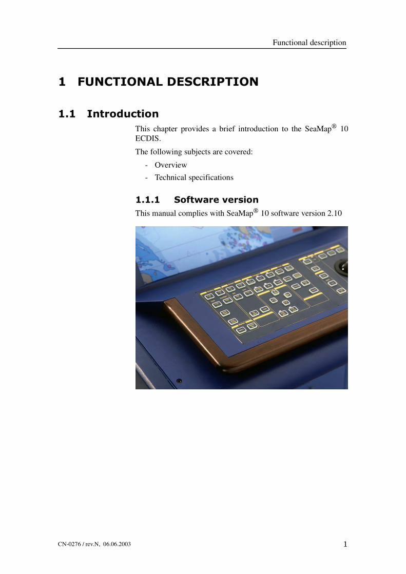
1.1 IntroductionThis chapter provides a brief introduction to the SeaMap 10ECDIS.
The following subjects are covered:
- Overview
- Technical specifications
1.1.1 Software versionThis manual complies with SeaMap 10 software version 2.10
SeaMap 10 / Instruction manual
2 CN-0276 / rev.N, 06.06.2003
1.2 Overview

Functional description
3CN-0276 / rev.N, 06.06.2003
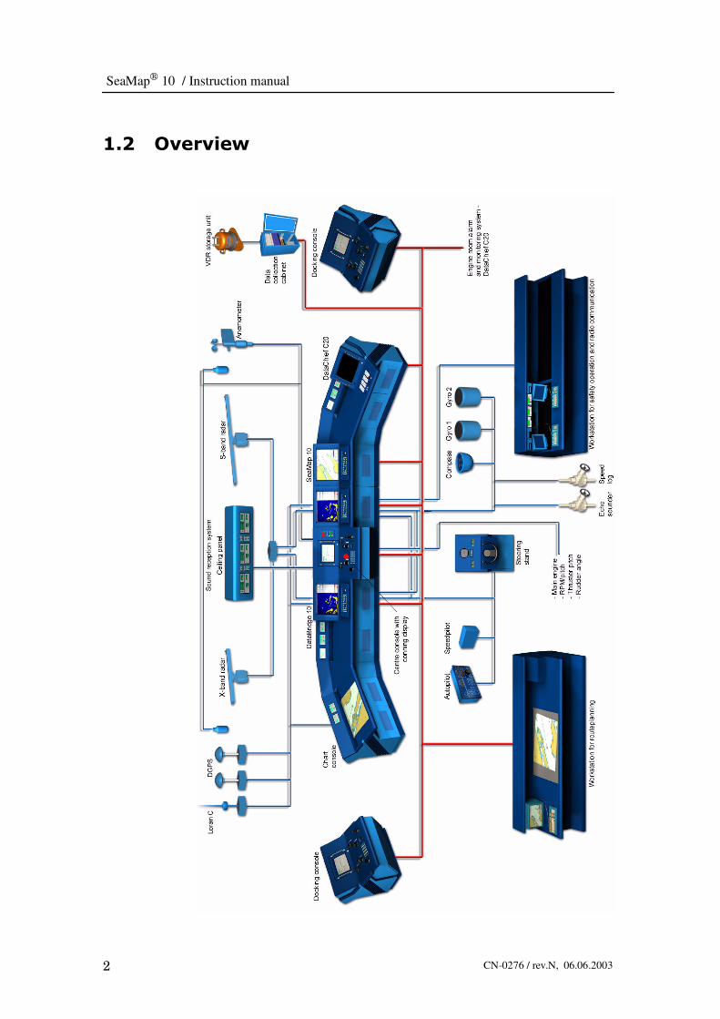
SeaMap 10 is an Electronic Chart Display and InformationSystem (ECDIS).It takes the own ships position from navigationsensor and overlays it on an electronic chart. The system isdesigned to assist the mariner in route planning and monitoring,and displays additional navigation-related information.
SeaMap 10 is easy to use. All main functions are availablethrough the operator panel and all information is available on ahigh resolution colour display.
The system uses official vector charts (S57 Ed.3), accepts CM93vector charts from C-Map and is compatible with ARCS from TheUnited Kingdom Hydrographic Office. This means a world-widecoverage of electronic charts.
In addition to IMO defined functions, SeaMap 10 has manysophisticated optional features.
SeaMap 10 is available with both 21” (SM1021), 23” (SM1023)and 29” (SM1029) display.
1.3 Technical specifications
1.3.1 Main functions• Chart management
• Integrate navigation sensors
• Plan routes on chart display
• Quality checking of routes
• Continuous monitoring of the own ship in relation to the routeplan
• Grounding alarm
• Display of ARPA tracks
• Voyage recording and replay
• Integrated weather routing
• Echo sounder monitoring of chart depth information
• Digitising routes and charts
1.3.2 Chart handling• Manage authorised charts (S57 Ed. 3)
• Manage C-Map charts
• Manage ARCS charts

SeaMap 10 / Instruction manual
4 CN-0276 / rev.N, 06.06.2003
• Select chart type
• Select chart themes
• Zoom
• Select safety depth
• Select chart palette
• Select display mode
• Display chart object info
The display modes are:
• North Up (Browsing)
• North Up, True Motion
• North Up, Relative Motion
• Course Up, True Motion
• Course Up, Relative Motion
• Head Up, Relative Motion
In Browsing mode, charts can be displayed independently of ownship’s position.
1.3.3 Charts formatsThe following chart formats are supported:
• S57 Ed.3 official vector charts.
• S57 Version 2 vector charts.
• CM93 Edition 2 vector charts from C-Map Norway.
• CM93 Edition 3 vector charts from C-Map Norway.
• ARCS raster charts from United Kingdom HydrographicOffice.
• NSKV vector charts from Norwegian Hydrographic office.
• PL2 vector charts, proprietary Kongsberg Maritime format.
1.3.4 Route planningRoute plans may include the following parameters/information:
• Route name
• Date of route creation/last modification
• Waypoint number
• Waypoint name
• Waypoint position (lat/lon)

Functional description
5CN-0276 / rev.N, 06.06.2003
• Course over ground
• Distance of leg between two waypoints
• Leg mode (rhumbline/great circle)
• Distance from start of route to current waypoint
• Distance from current waypoint to end of route
• Speed
• Estimated time of arrival at specific waypoint
• Estimated time of arrival at the end of route
• Delay time at waypoint
• Turn radius
• Turnpoint (start and end of turn)
• Critical point
• Off track limit
• Maximum speed
• Message associated with waypoint
The following functions are available for handling route plans:
• Create new route
• Modify existing route
• Delete existing route
• List existing routes, sorted on:
- Route name
- Distance from own ship’s position
- Date of creation/modification
• Validate route plan, involving:
- Checking the geometry of the route plan
- Checking that the route plan doesnot cross the safety contour
- Checking that the route plan does not cross dangerousobjects
- Checking that the route plan does not cross prohibited areas
1.3.5 Route monitoringThe following information is continually available for the ship inrelation to selected route:
• Course from ship to turn start position (WOP)
• Course to WOP along route

SeaMap 10 / Instruction manual
6 CN-0276 / rev.N, 06.06.2003
• Distance from ship to WOP
• WOP ETA
• Time to WOP
• ETA at last waypoint (destination)
• Cross track error
1.3.6 Mariners notesTypes of notes:
• Event
• Caution note
• Information note
• Chart correction note
• Solid line
• Dashed line
• Safety contour
• Area
• Filled area
1.3.7 Tools• Marker
• Two EBL/VRM
• Curved EBL
• Four parallel index lines
1.3.8 Operational alarms and indicators• Crossing safety contour (grounding)
• Approaching area with special conditions
• Cross track error
• Approaching critical point
• Geodetic datum mismatch
• Malfunction of ECDIS
• Information overscale
• Larger scale ENC available
• Route planning across safety contour

Functional description
7CN-0276 / rev.N, 06.06.2003
• Route planning across special area
• Positioning system failure
• System test failure
1.3.9 Own ship data calculation• Parallel navigation sensor integration filters with sensor
deviation monitoring.
• Calculated position and sensor input values distributed via LANin integrated systems for improved reliability.
• Manual input of offset to calculated position.
• Automatic or manual selection of navigation sensor input tonavigation filter.
• Own ship past track calculation.
• Alternative manual course, speed, set and drift input.
1.3.10 ARPA• ARPA targets from up to 3 sources can be displayed
simultaneously.
• Up to 100 targets from each source can be displayed.
For each target the following information is stored:
• Source and ID.
• Time of observation.
• Range and bearing (absolute) from own ship.
• Position
• Speed
• Course (true)
• Target status (Tracked/acquired/lost/TCPA warning etc).
• Textual target ID
• TCPA (only for inquiry)
• CPA (only for inquiry)
1.3.11 Recording and playback• Recording of last 12 hours, one minute recording frequency
• Up to 10 “12 hour” files can be saved
• Recording of whole voyage, minimum 4 hour recordingfrequency

SeaMap 10 / Instruction manual
8 CN-0276 / rev.N, 06.06.2003
• Up to 30 voyage files can be saved
• Recording frequency adjustable up to one second
• Last 24 hour log file can be copied to floppy disk (adjustedfrequency)
• Playback of 12 hour file, Voyage file or file on floppy disk
• Playback with “cassette player” type control panel
• Adjustable replay speed, x1, x0.1 and x10
1.3.12 Printed reportsFixed format standard reports:
• Planned route
• Position log
1.3.13 System maintenance• Off-line tests of disks and main computer memory.
• On-line monitoring of connected sensors and serial lines.
• System configuration without programming.
• Configuration of integrated system may be set from oneterminal.
1.3.14 Optional applicationsThe optional applications are dependent of connected equipment
• Radar video displayed on chart (requires LAN connection toDataBridgeE 10)
• Remote control of AP2000 track pilot, providing track-keepingfunctions
• Docking display
• Passenger Information display
• Integrated weather routing
• Echo sounder monitoring of chart depth information
• Digitising routes and charts
• Interface to AIS (Automatic Identification System)
• Transfer of charts and routes to DataBridgeE 2000
• Passenger Information Display (SeaGuide)
1.3.15 User interface• Graphical user interface

Functional description
9CN-0276 / rev.N, 06.06.2003
• Dedicated buttons and track ball/menus on the screen
• “Full screen” chart display with the following informationpermanently available in the top
1.3.16 Chart displayChart display with the following information permanentlyavailable in the top bar:
• Position sensor
• Ship’s position (lat/lon)
• Position offset indication
• Course made good
• Speed made good
• Chart scale
• Overscale/underscale indication
• Chart availability indication in current position
• Chart orientation and display mode
• Unit of depth in displayed chart
• Alarm field available when needed displaying
• Alarm text
• Alarm categories
• Help text
1.3.17 MenusOn the operator’s request, a top level menu appears in the chartdisplay with seven entries:
• Chart
• Route
• Radar
• Own Ship
• Note
• Tools
• System
1.3.18 Serial linesSeaMap 10 provides eight serial input/output lines with NMEA0183 format. These can be used for

SeaMap 10 / Instruction manual
10 CN-0276 / rev.N, 06.06.2003
• Position fixing system
• Heading sensor
• Speed log
• Autopilot
• External alarm system
• Echo sounder
• Anemometer
• ARPA track
• Digitising tablet
• Automatic Identification System - AIS
1.3.19 Local area networkSeaMap 10 can be configured to communicate with:
• DataBridge 10.
• DataChief C20.
• Conning display
1.3.20 Slave display (option)The option includes connectors for two slave displays.
• Passenger Information Display (SeaGuide)
1.3.21 Printer (option)Parallel port.
1.3.22 Display resolutionSeaMap 1021 and 1029: 1280x1024 pixels.
SeaMap 1023: 1600x1200 pixels.
1.3.23 Power supplyVoltage: 220 VAC +/- 10%
Consumption: Maximum 600 w
Frequency: 50/60 Hz +/- 5%
1.3.24 EnvironmentalIn compliance with IEC 60945

Functional description
11CN-0276 / rev.N, 06.06.2003
1.3.25 Dimensions and weightDimension are in millimetres and weights in kilos:SeaMap 10 Height Width Depth Weight
29” 1164 750 1090 165
23” 1164 750 1020 115
21” 1164 620 1090 115

SeaMap 10 / Instruction manual
12 CN-0276 / rev.N, 06.06.2003
2 GETTING STARTED
2.1 IntroductionThis chapter teaches you how to use the most common functionsof the SeaMap 10. It is intended for personnel just starting to usethe system. It includes step by step procedures for basic operation.
The following subjects are covered:
- Display layout.
- Control panel and computer keyboard.
- How to start up SeaMap 10.
- How to switch off SeaMap 10.
- How to make numeric entries.
- How to control objects on the screen.

Getting started
13CN--0276 / rev.N, 06.06.2003
2.2 Display layout
2.2.1 OverviewThe SeaMap 10 is fitted with a colour display. This displaypresents chart images, symbols, and various on--screen data suchas heading, speed etc.
2.2.2 Display areasThe display is divided into the following areas:
Alarms andmessage area
Boarding area
Chart area
Top barTop menu
Figure 2 SeaMap 10 display areas.
2.2.3 Trackball markerThe trackball is the system’s pointing device and is referred to asthe marker control. Together with the three associated keys it isused to control the chart and its display. Two different markers areused:
Marker inside chart area.
Marker in all other areas.
2.2.4 Top barThe top bar includes main information and buttons for operationof the SeaMap 10. These are further described below:

SeaMap 10 / Instruction manual
14 CN--0276 / rev.N, 06.06.2003
Figure 3 Top bar information area with buttons.
Pushing buttons in the top bar will bring up menus in the menuarea.
Note Information is displayed with different background colours toprovide additional information to the user. The meaning of thesecolours are:
-- Grey: All is normal.
-- Yellow: Things are not quite normal, such as when trying todisplay charts when no charts are available.
-- Red: Alarm situation. The background is flashing until thealarm is acknowledged. When acknowledged thebackground will be red until the alarm situation is cleared.
Position fixing system used: States the position fixing systemcurrently in use. Pushing the button brings up the Positionmenu.This menu allows you to select position input source or manualposition input. The background colour of the button indicates theaccuracy of the source as follows:
-- Grey: Highest accuracy source, such as dGPS.
-- Yellow: Lowest accuracy source, such as DR (deadreckoning).
Current Own ship’s position: States current own ships position.This is the conning position as computed by the navigation filterin WGS 84.
-- N -- north
-- S -- south
-- E -- east
-- W -- west
Offset indication: Push the button to enter a position offset. Theoffset can be entered as either range and bearing or latitude andlongitude.
-- When the button background is grey and the text reads NOOFS, no position offset has been entered.

Getting started
15CN--0276 / rev.N, 06.06.2003
-- When the button background is yellow and the text readsPOS OFS, current own ship’s position has an offset.
CMG: Course Made Good. This is the course over ground ascomputed by the navigation filter.
SMG: Speed made good. This is the speed over ground ascomputed by the navigation filter
Chart display processing indicator: The hour--glass is displayedwhen charts are being loaded. Push the button to stop the loading.
Chart Scale: Shows the actual scale of the displayed charts. Pushthe button to display the Zoommenu.
→ The Zoom menu is further described on page 97.
Chart type indicator: This button indicates the type of chartdisplayed. Push the button to display the Chart Type menu. Thefollowing chart types are available:
ENC (Electronic Navigational Chart -- official charts) chart isdisplayed.
ENC and vector (non--ENC) chart is displayed.
Vector (non--ENC) chart is displayed.
Raster chart is displayed.
→ The Chart type menu is further described on page 103.
SeaMap 10 / Instruction manual
16 CN--0276 / rev.N, 06.06.2003
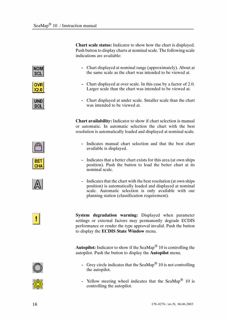
Chart scale status: Indicator to show how the chart is displayed.Push button to display charts at nominal scale. The following scaleindications are available:
-- Chart displayed at nominal range (approximately). About atthe same scale as the chart was intended to be viewed at.
-- Chart displayed at over scale. In this case by a factor of 2.0.Larger scale than the chart was intended to be viewed at.
-- Chart displayed at under scale. Smaller scale than the chartwas intended to be viewed at.
Chart availability: Indicator to show if chart selection is manualor automatic. In automatic selection the chart with the bestresolution is automatically loaded and displayed at nominal scale.
-- Indicates manual chart selection and that the best chartavailable is displayed.
-- Indicates that a better chart exists for this area (at own shipsposition). Push the button to load the better chart at itsnominal scale.
-- Indicates that the chart with the best resolution (at own shipsposition) is automatically loaded and displayed at nominalscale. Automatic selection is only available with ourplanning station (classification requirement).
System degradation warning: Displayed when parametersettings or external factors may permanently degrade ECDISperformance or render the type approval invalid. Push the buttonto display the ECDIS State Window menu.
Autopilot: Indicator to show if the SeaMap 10 is controlling theautopilot. Push the button to display the Autopilot menu.
-- Grey circle indicates that the SeaMap 10 is not controllingthe autopilot.
-- Yellow steering wheel indicates that the SeaMap 10 iscontrolling the autopilot.

Getting started
17CN--0276 / rev.N, 06.06.2003
Chart display mode: Push the button to bring up the DisplayModemenu.Thismenu allows you to select between the followingmonitoring modes:
-- NUP/TM -- north up true motion
-- NUP/RM -- north up relative motion
-- CUP/TM -- course up true motion
-- CUP/RM -- course up relative motion
-- HUP/RM -- head up relative motion
These modes are used for monitoring the ship’s in relation to thechart. The system will automatically update the display to followthe ship’s movement.
-- Browse (NUP) -- Used tomove freely in thechart, away fromown ships position.
Position the trackball marker where you want the centre of thechart to be, and push theOffset button on the operator panel. In thismode the system will not automatically update the display tofollow the ship’s movement.
Targets: Select to display tracked targets. Push the button todisplay the radar menu. When no ARPA or AIS target source isselected, the selection is gray.
Video: Select to display radar video. Push the button to display theradar menu. When no radar video source is selected, the selectionis gray.
When the video is distorted by more than 5 pixels relative to thedisplayed chart, or the video is rotated relative to chart and is notdisplayed, the VID button is shown on a yellow background toindicate an error condition.
→ The Radar menu is further described on page 132.
Depth: Displays depth unit used in the displayed chart. Push todisplay the Chart Legend menu.
Menu: Push to turn display of main menu on or off.
Board: Push this button to display the boarding area. For moreinformation see boarding area below.

SeaMap 10 / Instruction manual
18 CN--0276 / rev.N, 06.06.2003
2.2.5 Boarding areaThe boarding area is used to display severalmenus simultaneously.Each menu is fitted with a boarding button. Push this button tostack menus in the boarding area. Menus are stacked from thebottomup.Newmenusmay beplaced on top of any boardedmenuswhen the area is full.
A menu can also be boarded by dragging it into the boarding area.A menu is removed from the boarding area by dragging it into thechart area, or by closing the menu.
2.2.6 Main menu
Menus are displayed using the dedicated buttons on the operatorpanel, through the buttons in the top bar or using the buttons in themain menu. The main menu have been grouped into sub menus asfollows:
-- Chart-- Route
-- Radar-- Own ship-- Note-- Tools-- System
2.2.7 About menusThe following illustration show a typical menu with the variouselements called out.
-- Boarding button: Push this button to stack menus in theboarding area (board themenu). Menus are stacked from thebottom up.
-- Close button: Push the close button to remove the menu.All control functions in the menus are operated using the trackballand SELECT button. Menus are described in detail in the“Reference” chapter later in this book.
2.2.8 Alarms and message areaThe alarms and message area is used to present alarms andmessages to the operator. Controls for acknowledging alarms andwarnings are found here and on the operator control panel.

Getting started
19CN--0276 / rev.N, 06.06.2003
Boarding button
Top bar
Close buttonMenu name
Alarm text
Help text
Alarm categories
Alarm text: The last unacknowledged alarm is displayed here ona red background. When there are no unacknowledged alarms thearea is grey.→ All alarm texts are listed on page 182.
Alarm categories: Unacknowledged alarms are displayed on aflashing red background. Acknowledged alarms where the alarmsituation still exists are displayed on a steady red background.
-- Steady red background: PushWARN or FAIL to display alist of acknowledged alarms.
-- Flashing red background: PushWARN or FAIL to displaya list of unacknowledged alarms.
The following alarms message types are used:-- Critp: Alarm for critical points, defined by the operatorduring route editing.
-- Area:These are part of the chart, such as for restricted areas.-- XTE:When the cross track error is larger than the set limit.-- GND: Grounding alarm based on chart information (notecho sounder). Requires that vector charts are being used.Given when an obstacle is closer than a set limit.
-- Warn: System warnings. Push theWARN button to displaya list of warning messages, if any.
-- Alarm: System alarms are reported when an equipmentmalfunction is detected. Push theAlarm button to display alist of alarm messages, if any.
Help text: Below the alarm buttons there is a help text area. Thereare three types of help texts:
-- Information: Black text on grey background.-- Advice: Black text on yellow background.-- Correction: Flashing black text on yellow background.

SeaMap 10 / Instruction manual
20 CN--0276 / rev.N, 06.06.2003
Advice and correction messages may be accompanied by a beep.
→ All help text messages are listed on page 187.
2.2.9 Chart area
The chart area is used to display charts, and various chart relatedinformation such as routes, notes etc.
Headingline
Northindicator
Newcourse
Cursor
Alarm category
Alarm text
Offtrack limit
Wheelover line
Turnpoint
Own ship
Activewaypoint
Course
Scale bar
Turnpoint
Figure 4 Explanation to chart area information.
Radar target symbol
For integrated systems, where the SeaMap 10 is connected to aDataBridgeE 10 (optional), radar video and vectors for trackedtargets can be displayedoverlaid the chart information. To indicatetracked targets the radar target symbol on the left is used.
AIS symbols
The SeaMap 10 can be connected to an Automatic IdentificationSystem -- AIS (optional). The AIS targets are treated similar toARPA targets and show in the chart display. The followingdifferent target symbols are used to indicate target status andwarning state.
Figure 5Targetsymbol.

Getting started
21CN--0276 / rev.N, 06.06.2003
Figure 6 SeaMap 10 ECDIS display showing AIS targets.
Sleeping targets: Initial position reports received from other shipsresult in “sleeping” targets on the display. Sleeping targets displaya minimum of information, revealing position and course.
Active targets: Activate targets, reveal the ship’s position, speed,heading and course. Vector length for other ships corresponds toown ships vector setting.
Selected targets: A selected target is indicated by a rectanglesurrounding the target symbol.
Lost targets: Targets lost from the air that are nearer than a setdistance, or that are categorised as dangerous will not be removedfrom the display. These are indicated in their last position as a losttarget.
Dangerous targets: Targets having a TCPA and a CPA less thanset values, are considered to represent a collision danger and willbe indicated using a red, blinking symbol.
2.3 How to make numeric entriesThere are several ways of making numeric entries:

SeaMap 10 / Instruction manual
22 CN--0276 / rev.N, 06.06.2003
1 Point theMarker to the entry field and type in the value usingthe alpha--numeric keyboard found in the drawer below thethe operator panel. If an illegal value is entered the closestlegal value will be entered.
2 Numeric entry--fields can also be edited using a slider, orspin buttons.
-- It is not possible to adjust a variable outside limits set by thesystem. Inmany cases only a predetermined set of values areavailable such as for range scales.
-- In some cases such as for time zone offset, the spin buttonswill select whole hours, while text input field can be used sethalf hours etc.
2.4 Control panel and computer keyboardThe SeaMap 10 is operated through an operator panel and atrackball. A computer style keyboard is located in a drawer belowthe operator panel. Use the holes underneath the panel to pull thedrawer out.
Figure 7 The SeaMap 10 keyboard is used for text input.
The operator panel has dedicated buttons to gain quick access tofrequently used functions. These functions can in most cases alsobe accessed using the trackball and soft keys.

Getting started
23CN--0276 / rev.N, 06.06.2003
Figure 8 SeaMap 10 operator panel.
The function of each button is described in the following.
2.4.1 Display keys
Zoom+ : Increases the chart range by a factor of two for each pushof the button. Decreases the chart scale by a factor of two.
Zoom -- :Decreases the chart range by a factor of two for eachpushof the button. Increases the chart scale by a factor of two.
Zoom reset: Resets the chart to the largest available scale.
Reset Centre: In true motion the sweep centre is moved tomaximum offset. In relative motion the sweep centre is moved tothe display centre.
Day + : Increases the light level in the display and operator panelfrom night to day viewing. Five different levels of intensity areavailable.
Night -- :Decreases the light level in the display and operator panelfrom day to night viewing. Five different levels of intensity areavailable.

SeaMap 10 / Instruction manual
24 CN--0276 / rev.N, 06.06.2003
2.4.2 Screen keys
Brill + : Increases display brilliance.
Brill -- : Decreases display brilliance.
Degauss: Degausses the display.
Contr + : Increases display contrast.
Contr -- : Decreases display contrast
Calib: Resets Contrast and Brilliance to a calibrated/predefinedsetting. (Function dependent on monitor provided).
WARNINGUsing the brilliance and contrastcontrol may degrade the visibility ofcertain information when thedisplay is set for night viewing.
2.4.3 ECDIS keys
Monitor, Browse and Docking are mutually exclusive modes.
Monitor:The normalmode for operating theECDIS system. PushMonitor to display the chart centred on the own ship’s position.The best chart for that position will be loaded.
Browse: Used to view chart areas away from the own ship. Pushthe button and use the trackball and Offset button to centre thechart in a new location. Use the Zoom + and Zoom -- to set theappropriate scale.
Docking: Used for docking and manoeuvres in narrow waters.When selected aDocking Instrumentsmenu is displayed to showthe forces acting on the own ship. Docking is an optional feature.
Std. Display: Push this button to display only standard chartinformation. To select other chart information push theTHEMESDIALOGUE button and select the information you need.
Themes Dialogue: Push to display the Themesmenu. This menuis used to select the displayed chart information.
RadarOff:Push this button to turn radar video and tracked targetson/off.
Board: Push this button to display the boarding area.

Getting started
25CN--0276 / rev.N, 06.06.2003
→ For more information about the boarding area refer to page 18.
2.4.4 Trackball keys
Select: Used to select an object or entry field. Use the trackball topoint to the object and push SELECT. The same function as theSELECT button found among the marker keys.
Offset:Moves chart centre to the position of the trackballMarker.If theMarker is outsidemaximumoffset, the buttonwill invoke thereset centre function.
Object Menu:Used to select an object menu. Use the trackball topoint to the object and pushOBJECTMENU.Most objects drawnin the chart area have menus:
• EBL/VRM
• Parallel Index Lines
• Mariners Notes
• Barrier Lines
• Routes
• Targets
• Charts
• Own ship
• Etc.
Where objects overlap, the topmost object is displayed.
2.4.5 Marker keys
Select: Used to select an object or entry field. Use the trackball topoint to the object and push SELECT. Duplicates the function ofthe SELECT button found next to the trackball.
Object Info: Used to display information about objects in thechart. Point to the object and push the button.
2.4.6 Autopilot keys
These buttons are used to control the autopilot from the SeaMap
10. This function is available as an option.
In Cmnd: When this indicator is lit, the autopilot is controlledfrom the SeaMap 10.
Note All autopilot operation from SeaMap10 requires thatthe IN CMND indicator is lit.
Figure 9Typical
object menu.

SeaMap 10 / Instruction manual
26 CN--0276 / rev.N, 06.06.2003
Activate Turn: Accepts the planned manoeuvre as input to theautopilot. The indicator is on until the manoeuvre is completed, ortheHDG or theCRS buttons are pressed. The indicator will be ontogether with Track.
Crs: Sets the autopilot to operate in coursemode. Turn commandsfrom Curved EBL are accepted.
WP: Sets the autopilot to operate in Way Point Mode.
Hdg: Sets the autopilot to operate in Heading Mode. Turncommands from Curved EBL are accepted.
Track: Sets the autopilot to operate in Track Mode.
→ Refer to page 72 for information on how to use the autopilot.
2.4.7 Turn keys
These buttons are used to operate the Curved EBL and TrialManoeuvre.
Left/ Right/ Up/ Down arrows: Adjusts the Curved EBL. Left/right adjusts heading (course). Up/down adjusts the distance toturn. Works only in CRS or HDG modes and only when theSeaMap 10 is in command of the autopilot.
Autopilot:
-- When the autopilot is in command: The Curved EBL is setwith zero time to turn. The left/right buttons will set the newcourse (heading) set--point on the Autopilot.
-- When the autopilot is not in command: TheAutopilot buttonworks as the Planning button.
Planning:Activates a curved EBL in planningmode. The CurvedEBL is used to plan and indicate where the ship will sail if amanoeuvre with the given turning radius is done.
→ Refer to page 58 for information on how to use the curved EBL.

Getting started
27CN--0276 / rev.N, 06.06.2003
2.4.8 Miscellaneous keys
Power: Switches the power on or off. Must be pushed down untilthe lamp starts blinking.Lamp Test: Push to test that all indicator lights illuminate.MOB: Inserts an event symbol in the ship’s current position on thedisplay. Used for Man Over Board or other events.
Ack: Push to acknowledge alarm and warning messages. A list ofunacknowledged alarms will appear and will be consideredacknowledged when the button is released. Using the Ack buttonwhen there are only active, acknowledged messages will displaythese messages (does not apply to COLL, PROX, NEW andLOST).
SoundOff: Silences audible alarms. When more than one displayunit is connected together, pressing the button on any display unitwill silence the audible alarm on every unit.
FAIL: The lamp indicates that the display computer is stopped oris running out of resources.
2.5 How to start up SeaMap 10To switch on the SeaMap 10, observe the following procedure:
2.5.1 Switching power on1 Push the POWER button on the operator panel. The buzzer
beeps once and the indicator above the button starts flashing(the light more on than off). After about 2 minutes theindicator is steady lit, the buzzer beeps twice and theSeaMap 10 is ready to operate.
-- If a problem occurs during start--up, the FAIL indicator is litand the buzzer is activated.
-- During start--up, the display will remain dark to avoidaccidentally harming the operators night vision. When thesystem is ready, a dark display palette is chosen if the systemis a stand alone unit or if no other DataBridge 10/SeaMap10 in the network is operational. When other units arerunning their palette is chosen.
2.5.2 Selecting chart databaseIf you have more than one chart databases in your system, selectthe one(s) to use.

SeaMap 10 / Instruction manual
28 CN--0276 / rev.N, 06.06.2003
2 On the monitor selectMenu > Chart > Chart type.
3 Select the chart databases you want to use.
2.5.3 Selecting safety contourWhen the system is started the safety contour is always set to 30metres.
-- The safety contour menu is automatically displayed.
4 Select a safety contour suitable for your ship’s draught thatmatches depth contours in the vector charts available.
2.5.4 Available charts
Normally a number of charts with different scales are available forany given position. Zooming in and out will choose between thesecharts.
-- Each chart has a nominal scale (the optimum viewing scale).
5 Push the scale button in the top bar.
-- TheZoommenu is displayed stating the available charts andtheir nominal scale.
6 Select the chart you want to use.
7 The chart is displayed at nominal scale.
→ Refer to page 97 for more information about the Zoom menu.
Note To give the best view of the area you are sailing in, always selectthe largest scale allowed by your operational requirements.
2.5.5 Changing chart scale8 Select chart scale using the Zoom+ and Zoom --.
-- Zoom+ : Increases thechart rangeby a factor of two for eachpush of the button.
-- Zoom -- : Decreases the chart range by a factor of two foreach push of the button.
-- Check the chart scale status indicator to see if the chart isdisplayed at over or under scale.

Getting started
29CN--0276 / rev.N, 06.06.2003
2.5.6 Selecting radar video and targetvectors
If the system is connected to a DataBridgeE 10 both target vectorsand radar video can be displayed as overlays to the chart.
9 In the top bar select TGT and or VID.
10 To quickly remove the selection push Radar Off on theoperator panel.
2.5.7 Changing chart themesVector charts are constructed such that different types of chartinformation can be switched on or off. Use the theme control toavoid cluttering the screen with information unimportant to youroperational requirements.
11 On the operator panel push Themes Dialogue.
-- The Themes menu is displayed.
12 Select the themes required, or choose STANDARD orEVERYTHING.
2.5.8 Changing presentation mode
13 Push the HUP/RM button in the top bar.
-- The display mode menu is shown.
14 Select between the following monitoring display modes:
-- NUP/TM -- north up true motion
-- NUP/RM -- north up relative motion
-- CUP/TM -- course up true motion
-- CUP/RM -- course up relative motion
-- HUP/RM -- head up relative motion
-- Browse -- for north up planning
2.6 How to switch off SeaMap 10To switch off the SeaMap 10, observe the following procedure:
1 Push and hold thePOWER button on the operators panel forabout 3 seconds, until the indicator above the button startsflashing (the lightmore off than on). Thebuzzer beeps twice.When the indicator lamp stops flashing after about 1.5minutes the SeaMap 10 is switched off.

SeaMap 10 / Instruction manual
30 CN--0276 / rev.N, 06.06.2003
2 If a problem occurs during switching off, theFAIL indicatoris lit and the buzzer is activated.
2.6.1 Emergency shut-down1 Push and hold the POWER button and the SOUND OFF
button on the operators panel for about 3 seconds until theindicator above the button starts flashing. The systemwill beturned off immediately.
Note Emergency shut--down is not recommended unless absolutelynecessary as the operating system will not shut down the systemproperly. Restarting the system will take longer, since the systemis scanned for errors.
2.7 How to control objects on the screenThese principles apply to the following objects:
• Electronic Bearing Line (EBL)
• Variable Range Marker (VRM)
• Parallel index lines
• Routes
• Mariners Notes
• Etc.
To control an object, it must be selected. When selected the objectis displayed with a set of handles.Most control operations are donedragging a handle.
Note To speed up control of EBL/VRM, these objects are pre--selected,and can be edited without selecting them.
Each object has an object menu. This menu includes frequentlyused functions for that object. The menu depends on the context(state) of the object. Use the trackball and the OBJECTMENUbutton to display the menu.

Operating information
31CN-0276 / rev.N, 06.06.2003
3 OPERATING INFORMATION
3.1 IntroductionThis chapter contains detailed descriptions of operator functions.It is intended for users already understanding basic operation of thesystem. For basic operation refer to the chapter “Getting Started”.
The following subjects are covered:
- About integrated systems
- About charts in general
- How to use C-Map CM-93 edition 2 charts
- How to use C-Map CM-93 edition 3 charts
- How to use S57 edition 3 charts
- How to use S57 charts from PRIMARt Official ENCservice
- How to use ARCS charts
- How to enter a position offset
- How to use log and relay functions
- How to define the regeneration area
- How to use EBL and VRM
- How to use parallel index lines
- How to use the curved EBL
- How to use sailing routes
- How to insert critical points
- How to use the automatic track keeping
- How to use mariner’s notes
- How to use AIS functions
- How to handle alarms
- How to access system parameters

SeaMap 10 / Instruction manual
32 CN--0276 / rev.N, 06.06.2003
3.2 About integrated systemsThe SeaMap 10 is often connected to other SeaMap 10 units,DataBridge 10 radar/ARPA systems and conning display viaLocal Area Network (LAN). Such integrated systems share thefollowing information:
• Routes
• Charts
• Barrier Lines
• Mariner’s notes
The information is distributed so that if a display unit is switchedoff or fails, the remaining units can continue without degradedperformance. When, for instance, a route is edited in one display,it is automatically updated in the other units.
The principle of shared information also applies to the following:
• Sensors read by any display unit can be monitored at everydisplay unit.
• A route selected for track steeringwill be common to all displayunits.
• Own ships data is common to all display units.
• Tracks from any DataBridge 10 radar/ARPA can bemonitored at every ECDIS display unit.
• Radar video from any DataBridge 10 radar/ARPA can bemonitored at every ECDIS display unit.
It is possible to switch a display unit off line. Thiswill stop the unitfrom sharing the system wide information.

Operating information
33CN--0276 / rev.N, 06.06.2003
3.3 About charts in general
The SeaMap 10 currently supports the following chart formats:
• S57 Ed.3 official vector charts.
• S57 Version 2 vector charts.
• CM93 Edition 2 vector charts from C--Map Norway.
• CM93 Edition 3 vector charts from C--Map Norway.
• HCRF raster charts, either ARCS charts from the UnitedKingdom Hydrographic Office or Seafarer charts from theAustralian Hydrographic Office
• NSKV vector charts from Norwegian Hydrographic office.
• PL2 vector charts, proprietary Kongsberg Maritime format.
While Kongsberg Maritime provides the ECDIS system, chartsmust be purchased/subscribed to from the individual suppliers. Ascharts are updated frequently, subscribing to updates will in mostcases be beneficial.
Charts provided with the SeaMap 10 are a chart covering theworld in a scale of 1 : 20.000.000 and a chart covering the area forthe sea trial.
The chart formats have different handling characteristics. Pleasefollow the individual procedures as described in the following.
3.4 How to use C-Map CM-93 edition 2 chartsCM--93 Edition 2 charts are compatible with the IHO S57 edition2 format and is manufactured by C--Map. All C--Map CM--93edition 2 charts are available on three compact discs. To use thecharts you need a authorization code from C--Map. The world isdivided into nine zones (see below), and each zone is again dividedinto a number of areas. The licence code defines which zones orareas you are able to use.

SeaMap 10 / Instruction manual
34 CN--0276 / rev.N, 06.06.2003
Figure 10 C--Map zone definition.
Charts are grouped in levels according to their scale:Level Scale
Z 1 : 20.000.000
A 1 : 3.500.000 – 1 : 1.500.000
B 1 : 1.500.000 – 1 : 500.000
C 1 : 500.000 – 1 : 150.000
D 1 : 150.000 – 1 : 50.000
E 1 : 50.000 – 1:15.000
F 1 : 15.000 – 1 : 5.000
G Larger than 1 : 7.500
Z level charts are pre--installed on all SeaMap 10 units.
3.4.1 Installing chartsTo install C--Map CM--93 Edition 2 charts you will needCD--ROM(s) containing the charts and an authorization code fromC--Map. To obtain the the authorization code you need first todefine which chart zones or areas you need. Do the following:
1 Contact C--Map to enter into an agreement with them and toobtain CD--ROM(s) for the zones relevant to you.
* C--MAP NORWAY A/SHovlandsveien 52P.O.Box 212N--4379 Egersund NORWAYTel.: +47 51 46 47 00Fax: +47 51 46 47 01E--mail: [email protected]

Operating information
35CN--0276 / rev.N, 06.06.2003
2 Insert theC--MapCM--93Edition 2CD--ROMinto the drive.If you receivedmore than one you can use any of them at thispoint.
3 On the monitor selectMenu > Chart > CM--93 Edition 2Chart Management.
4 Select the zones or areas you need.
5 Push the Authorize button.
-- The systemgenerates aUser code defining the zones or areasyou have selected.
6 Write down the code.
7 Send the code by e--mail to ”[email protected]”, call themat +47 51 46 47 00, or fax them at +47 51 46 47 01.
-- C--Map will respond by returning an Authorisation code. Toenter the code into the system do the following:
8 Enter the the Authorization code and push Authorize.
-- The charts can now be loaded into the system.9 Write down the are/zone information and the authorization
code for later use.
About navigation and overview working sets
When C--Map CM--93Edition 2 charts are installed in theSeaMap 10 they are converted to a proprietary format.Dependent on the number of charts thismay take considerable time-- even hours. To reduce the time, charts that are not required neednot be converted. For any given area several charts at differentscales will normally be available. To speed up the conversionprocess we have defined charts in two categories:
-- Navigational working set: For this category select thecharts that are required for your voyage. Select the scalelevels required (C, D, E, F and/or G).
-- Overview working set: For this category select charts toprovide larger overview. Here youwant chart that go outsidethe charts selected for the navigational working set. For thisarea only charts at scale level A and/or B can be loaded.
Installing all charts in a zone
1 On the monitor selectMenu > Chart > CM--93 Edition 2Chart Management.
2 Select the Install tab.
3 Push Set to Licensed.
-- This selects all charts available according to yourAuthorization Code.

SeaMap 10 / Instruction manual
36 CN--0276 / rev.N, 06.06.2003
4 Push Set to Nav. Working Set.
5 Push Install charts.
-- The installation process may take some time, depending onthe number of charts specified. An indicator is available tomonitor the progress.
Installing a selection of charts
If you do not need all the charts in a zone to navigate the vessel onthe upcoming voyage, specify the Working Set in the followingway:
1 On the monitor selectMenu > Chart > CM--93 Edition 2Chart Management.
2 Select the Install tab.
3 Under Navigation Working Set; select Edit.
4 Select a large chart scale, for instance 1:20.000.000
-- A grey grid is overlaid the chart.
Figure 11 Specification of a working set.
5 Each rectangle in the grid can be selected by pointing to itand pushing the Select button on the operator panel. Therectangle becomes grey when selected.
6 Select the required chart levels under Navigation WorkingSet.
7 Under Overview Working Set; select Edit.
-- A green grid is overlaid the chart.

Operating information
37CN--0276 / rev.N, 06.06.2003
8 Each rectangle in the grid can be selected by pointing to itand pushing the Select button on the operator panel. Therectangle becomes green when selected.
9 Select the required chart levels under Navigation WorkingSet.
10 Push Install charts.
-- The installation process may take some time, depending onthe number of charts specified. An indicator is available tomonitor the progress.
3.4.2 Updating charts
If you subscribe to chart updates, C--Map will from time to timesend out new CD--ROMs. To install the chart updates do thefollowing:
1 Insert the new CD--ROM into the drive.
2 On the monitor selectMenu > Chart > CM--93 Edition 2Chart Management.
3 Select the Install tab (if not already selected).
-- Before installing the new charts, the Working set may bemodified as described above under installing a selection ofcharts.
-- Under Install Options the following functions are available:
* Remove Charts Outside Working Set (default on).
* Remove Old Charts (default on).
* Force Regeneration -- SeaMap 10 will reinstall thecharts that are already in the database (default off).
4 Push Install charts.
-- The Working set is automatically updated with the newcharts available on the CD--ROM.
3.4.3 Deleting charts
The chart delete function provides means to delete all charts, oldcharts or charts located outside the navigation working set. Do thefollowing:
1 On the monitor selectMenu > Chart > CM--93 Edition 2Chart Management.
2 Select the Delete tab.
3 Push the button for the selected option.

SeaMap 10 / Instruction manual
38 CN--0276 / rev.N, 06.06.2003
3.5 How to use C-Map CM-93 edition 3 chartsCM--93 Edition 3 is the latest chart format that is compatible withthe IHO S57 edition 3 format and is manufactured by C--Map. TheC--Map CM--93 Edition 3 chart database contains the same chartsthat are available in CM--93 Edition 2, but the format is differentand the handling inside SeaMap 10 is more efficient. All CM--93Edition 3 charts are available on a single CD--ROM. Both officialHO ENC charts and unofficial non--ENC charts may be included.
The most common C--Map Edition 3 database is called ”World”and contains charts for the whole world. SeaMap 10 allows youto install the whole database, and license only the charts that youwant.
3.5.1 Installing chartsTo install C--Map CM--93 Edition 3 charts you will need aCD--ROM containing the charts and a licence code from C--Map.Do the following:
1 On the monitor selectMenu > Chart > Chart Types.
2 Under databases see ifWorld is included.
3 If it is included, this indicates that the system has beeninitialised, go to point 18, otherwise continue at point 4.
Consoleserial number
Figure 12 Where to find the console serial number.
4 On the monitor selectMenu > System > Passwords
5 Enter the user password.

Operating information
39CN--0276 / rev.N, 06.06.2003
→ Refer to page 170 for information about system password.
6 On the monitor select Menu > System > Maintenance >Reconfigure Chart Database.
7 Push C--Map CM--93 Edition 3 Database.
-- If this is the first time aCM--93Edition 3 database is defined,enter the serial number for your console.* The SeaMap 10 has a six digit serial number: 21xxxxor 29xxxx, do not include the prefix ”SM”.
* The Planning Stations has a four digit serial number:xxxx, do not include the prefix ”PL”.
8 Open the front cover of the console and note down the serialnumber found on the left side, see the illustration below.
9 Type in the serial number.
10 Select Reinitialise (if not already selected).
11 Push Install.
-- The system will install the C--Map Edition 3 software.12 Push the Apply changes button twice.
-- The system creates the World database.13 Restart the system by turning it off and then on again.
14 On the monitor selectMenu > Chart > CM--93 Edition 3Chart Management > General > License.
15 Insert an empty floppy disk into the drive.
16 Push Output C--Map User ID file to Floppy.
17 Send the file by e--mail to ”[email protected]”. Or contactthem at:
* C--MAP NORWAY A/SHovlandsveien 52P.O.Box 212N--4379 Egersund NORWAYTel.: +47 51 46 47 00Fax: +47 51 46 47 01
-- C--Map will send you a CD--ROM containing the Worlddatabase and a licence code.
18 Insert the CD--ROM into the drive.
19 On the monitor selectMenu > Chart > CM--93 Edition 3Chart Management.
20 Select the Install tab.
21 In theChart CD Statuswindow, select the CD--ROMdriveand the CM93_3 directory.
-- This should make the system recognise the database andoutput its version number.

SeaMap 10 / Instruction manual
40 CN--0276 / rev.N, 06.06.2003
22 Push Install Chart Database.
-- The World database takes about 10 minutes to install.
23 Go to Chart > CM--93 Edition 3 Chart Management >General > License.
24 Select the zone or area code corresponding to your license,and enter the code(s) you have received from C--Map.
25 Push Add.
-- The charts should now be ready for use.26 If you do not see the new charts, restart the system.
-- Without any licence codes only the Z--level and A--levelcharts will be available for viewing.
3.6 How to use S57 edition 3 chartsSeaMap 10 is designed to load and update un--encrypted S--57charts from CD--ROM or floppy disk. Before you load S57 chartsfor the first time, you will need to set up a database. If you receivecharts from different Hydrographic Offices, each set of charts willbe stored in its own database.
Note The handling of encrypted S57 data is different for each supplier.Contact Kongsberg Maritime to find out if a specific encryptionscheme is supported.
3.6.1 Installing chartsDo the following:
1 On the monitor selectMenu > System > Passwords
2 Enter the user password.
→ Refer to page 170 for information about system password.
3 On the monitor select Menu > System > Maintenance >Reconfigure Chart Database.
4 Push S57 Edition 3 Database.
5 If this is the first time an S57 database is created on thesystem, the system software will have to be installedotherwise continue at point 9.
-- If this is the first time aCM--93Edition 3 database is defined,enter the serial number for your console.* The SeaMap 10 has a six digit serial number: 21xxxxor 29xxxx, do not include the prefix ”SM”.
* The Planning Stations has a four digit serial number:xxxx, do not include the prefix ”PL”.

Operating information
41CN--0276 / rev.N, 06.06.2003
6 Open the front cover of the console and note down the serialnumber found on the left side, see the illustration below.
7 Type in the serial number.
8 Select Reinitialise (if not already selected).
9 Push Install.
10 Restart the system by turning it off and then on again.
11 On the monitor select Menu > Chart > S57 ChartManagement > Install.
12 Click on the CD--ROM drive and the chart directory(”ENC_ROOT”).
13 Push Import S57 Charts.
-- Thesystemwill indicate the number of charts that are presentand the estimated installation time.
14 Push Install.
3.6.2 Updating chartsTo install chart updates do the following:
1 Insert the CD--ROM or floppy disk.
2 Go to Chart > S57 Chart Management > Update >Update by Disk.
3 Select CD--ROM or floppy and chart directory”ENC_ROOT”.
4 Push Import S57 Charts.
-- Thesystemwill indicate the number of charts that are presentand the estimated installation time.
5 Push Install.
3.7 How to use S57 charts from PRIMAR OfficialENC service
PRIMARt works on behalf of the European HydrographicOffices, and is a co--operation between the National HydrographicOffices of Belgium, Denmark, Finland, France, Germany,Netherlands, Norway, Poland, Portugal, Russia, Spain, Swedenand the United Kingdom. They have all agreed to supply their S57Ed. 3.0/3.1 ENC data through the European ENC CoordinatingCentre known as PRIMARt.
3.7.1 Installing chartsTo install PRIMARt S57 charts you will need a CD--ROMcontaining the charts and an licence code. Do the following:

SeaMap 10 / Instruction manual
42 CN--0276 / rev.N, 06.06.2003
1 On the monitor selectMenu > Chart > Chart Types.
2 Under databases see if there is a Primar database.
3 If it is included, this indicates that the system has beeninitialised, go to point 23, otherwise continue at point 4.
4 On the monitor selectMenu > System > Passwords
5 Enter the user password.
→ Refer to page 170 for information about system password.
6 On the monitor select Menu > System > Maintenance >Reconfigure Chart Database.
7 Push PRIMAR S57e3 Database.
-- If this is the first time an S57e3database is defined, enter theserial number for your console.
* The SeaMap 10 has a six digit serial number: 21xxxxor 29xxxx, do not include the prefix ”SM”.
* The Planning Stations has a four digit serial number:xxxx, do not include the prefix ”PL”.
8 Open the front cover of the console and note down the serialnumber found on the left side, see the illustration below.
Consoleserial number
Figure 13 Where to find the console serial number.
9 Type in the serial number.
10 Push Apply Changes twice.
-- The system creates the database.

Operating information
43CN--0276 / rev.N, 06.06.2003
11 Restart the system by turning it off and then on again.
12 On the monitor selectMenu > Chart > Chart Types.
13 Push theMng button for the PRIMAR database.
14 Select the Licence tab.
15 Push Licence.
-- The system generates theUser Permitwhich is displayed asa 28 character string.
16 Write down the character string.
-- If you have several units, that will use PRIMAR charts,obtain User Permits for all units.
17 Send them to:
* PRIMARtLervigsveien 32P.O.Box 604001 Stavanger, NorwayPhone:+4751939500Fax:+4751939501E--mail: [email protected]
-- PRIMARt will send a floppy disk containing the ChartPermits contained in the following files: ”PERMIT.TXT”and ”ENC.PMT”, found on the root directory. If you receivepermits by e--mail, save the files on a floppy disk.
18 Insert the floppy disk into the drive.
19 On the monitor select Menu > Chart > S57e3 ChartManagement.
20 Push License.
21 Push Read Chart Permits from Floppy Disk.
-- If you have licences for several units, make sure you knowwhich license file belongs to which unit.
22 Insert the PRIMARt base CD--ROM into the drive.
23 On the monitor select Menu > Chart > S57 ChartManagement.
24 Select the Install tab.
25 Push Check CD.
-- This will make the system recognize the PRIMARtCD--ROM.
26 Push Import S57 Chart.
-- This will go through all licensed charts, check which toinstall and give a time estimate.

SeaMap 10 / Instruction manual
44 CN--0276 / rev.N, 06.06.2003
27 Push Install.
3.7.2 Updating chartsWhen you receive new updates of PRIMARt charts, this mayconsist of one or more of the following items:
* Permit file(s).
* Base CD--ROM.* Update CD--ROM.
When you receive a new Permit File do thefollowing:
1 On the monitor select Menu > Chart > S57e3 ChartManagement.
2 Push License.
3 Push Read Chart Permits from Floppy Disk.
-- If you have licences for several units, make sure you knowwhich license file belongs to which unit.
When you receive a new Base CD-ROM do thefollowing:
1 Insert the PRIMARt base CD--ROM into the drive.
2 On the monitor select Menu > Chart > S57 ChartManagement.
3 Select the Install tab.
4 Push Check CD.
-- This will make the system recognize the PRIMARtCD--ROM.
5 Push Import S57 Chart.
-- This will go through all licensed charts, check which toinstall and give a time estimate.
6 Push Install.
When you receive a new Permit File do thefollowing:
1 Insert the PRIMARt update CD--ROM into the drive.
2 On the monitor select Menu > Chart > S57 ChartManagement.
3 Select the Install tab.
4 Push Check CD.
-- This will make the system recognize the PRIMARtCD--ROM.

Operating information
45CN--0276 / rev.N, 06.06.2003
5 Push Import S57 Chart.
-- This will go through all licensed charts, check which toinstall and give a time estimate.
6 Push Install.
3.8 How to use HCRF chartsRaster charts used in the SeaMap 10 are either ARCS chartsprovided by The United Kingdom Hydrographic Office orSeafarer charts provided by the Australian Hydrographic Office.These are distributed in a common format, but have slightlydifferent licensing conditions. The term HCRF -- HydrographicChart Raster Format is used as a common term for ARCS andSeafarer charts. ARCS Navigator provides an annual supply ofdigital chart information, supported by the weekly issue of UpdateDiscs for mariners whose vessels are mandated under Safety ofLife at Sea (SOLAS) regulations, or those who require access tofrequent updating.
Figure 14 ARCS charts broken down into individual Area DiscCD--ROMs.
If youwant to useHCRF charts and your SeaMap 10 has not beenconfigured for HCRF chart you need to contact us. Use theaddressing information found at the beginning of this book,Kongsberg Maritime has to be contacted before the system canoperate with HCRF charts.
3.8.1 Installing chartsTo install ARCS charts you will need a CD--ROM containing thecharts and a Chart Permit. Do the following:

SeaMap 10 / Instruction manual
46 CN--0276 / rev.N, 06.06.2003
1 On the monitor selectMenu > Chart > Chart Types.
2 Under databases see if there is an ARCS database.
3 If it is included, this indicates that the system has beeninitialised, go to point 18, otherwise continue at point 4.
4 On the monitor selectMenu > System > Passwords
5 Enter the user password.
→ Refer to page 170 for information about system password.
6 On the monitor select Menu > System > Maintenance >Reconfigure Chart Database.
7 Push ARCS Database.
8 Push Apply Changes twice.
9 On the monitor select Menu > Chart > ARCS ChartManagement.
10 Select the Licence tab.
11 Push Show User Permit.
12 Write it down.
13 Contact anARCSChart agent providing theUser permit andthe PIN code “1234”.
-- You will receive the Chart Permit on a floppy disk.
14 Insert the disk in the floppy drive.
15 On the monitor select Menu > Chart > ARCS ChartManagement.
16 Select the License tab.
17 Push Add Chart Permits from Floppy Disk.
-- Chart permits can also be inserted manually if obtained bytelephone or fax.
-- When the Chart Permit have been loaded, you can displaythe License information by pushing Show License.
-- You can also take back--up and remove chart permits fromhere.
-- The first time charts are loaded into the system, use themostrecent chart catalogue.
18 On the monitor select Menu > Chart > ARCS ChartManagement.
19 Select the Update tab.
20 Push Load Updates.
21 You will be asked to insert the Update CD.

Operating information
47CN--0276 / rev.N, 06.06.2003
22 Push Load Updates from CD.
23 Select the Load tab.
-- There are three ways of selecting the charts to be loaded:* By pushing Select all.* By selecting all charts within a geographic area. The areacan be specified either by latitude and longitude values,or by pushingGet Cursor and drawing a rectangle in theoverview chart on the screen.
* By selecting individual charts listed under Licensed.24 When the required charts are selected, start the loading by
pushing Load Selected Charts.
-- The user is requested to insert chart CD’s as required by theloading process.
3.8.2 Updating chartsTheUnitedKingdomHydrographicOffice issues chart updates ona weekly basis. From time to time they will also issue new chartCD’s.
When you receive an update CD do the following:
1 On the monitor select Menu > Chart > ARCS ChartManagement.
2 Select the Update tab.
3 Push Load Updates.
4 You will be asked to insert the Update CD.
5 Push Load Updates from CD.
When you receive a new chart CD do thefollowing:
1 On the monitor select Menu > Chart > ARCS ChartManagement.
2 Select the Update tab.
3 Push Load Updates.
4 You will be asked to insert the Update CD.
5 Push Load Updates from CD.
1 Insert the Chart CD.
2 On the monitor select Menu > Chart > ARCS ChartManagement.
3 Select the Load tab.
-- In the Licensed window some charts will be listed asIncompat.

SeaMap 10 / Instruction manual
48 CN--0276 / rev.N, 06.06.2003
4 Select these.
5 Push Load Selected Charts.
3.8.3 Deleting and adding chartsThe charts installed in the system may from time to time need tobe changed, either because the sailing route is changed or for otherreasons. Such changes may include both deleting and addingcharts. If new chart permits are needed contact your ARCS chartagent, who will issue new chart permits.
To enter new chart permits
1 On the monitor select Menu > Chart > ARCS ChartManagement.
2 Select the License tab.
3 Push Add Chart Permits from Floppy Disk.
-- Chart permits can also be inserted manually if obtained bytelephone or fax.
To remove charts
1 On the monitor select Menu > Chart > ARCS ChartManagement.
2 Select the Load tab.
3 Select the charts you want to remove.
4 Push Unload Selected Charts.
-- The charts are removed.
To add new charts
1 On the monitor select Menu > Chart > ARCS ChartManagement.
2 Select the Load tab.
3 Select the charts you want to add.
4 Push Load Selected Charts.
5 Install the CD as requested
6 Push Load CD--ROM.
-- The charts are loaded.
3.8.4 ARCS demonstration chartsThree ARCS charts are normally available on the hard disk fordemonstration purposes. A voyage through these charts have beenrecorded and can be replayed. To set up the demonstration, do thefollowing:

Operating information
49CN--0276 / rev.N, 06.06.2003
1 On the monitor selectMenu > System >Maintenance.
2 Push Reconfigure Chart Databases.
3 Select ARCS Demonstration Dataset.
-- The charts are installed in the SeaMap 10 chart database.
4 When the installation is finished, click Apply Changes
5 Restart the system by turning it off and then on again.
6 On the monitor selectMenu > Chart > Chart Types.
7 SelectAD;ARCS--DEMO, and deselect all other databases.
Figure 15 Demonstration of ARCS raster charts.
8 Set the chart scale to 1:50.000, and choose N UP/TM.
-- The ARCS charts are now ready for display.
9 SelectMenu > OwnShip > Voyage Recordings List.
10 Select ARCSRiverHumber, and then push Replay.
11 In the Voyage Recording Replay menu, select Interpolate,push Start followed by pushing the”>“button.
12 Drag the Voyage Recording Replay menu into the chartarea.
-- The own ship is now sailing through the displayed ARCScharts.
13 To stop the demonstration, push the Close Button “X“ in theVoyage Recording Replay top bar.

SeaMap 10 / Instruction manual
50 CN--0276 / rev.N, 06.06.2003
3.9 How to enter a position offset
Used to specify an offset from WGS--84.
1 Push the NO OFS button in the top bar.
-- The Pos. Offset menu is displayed.
-- The offset can be entered either as a position offset (inlatitude and longitude) or as a bearing and range offset.
2 Use the button to select the appropriate mode.
3 Enter the offset.
4 Push Apply.
3.10 How to use the log and replay functions
3.10.1 Past track logThe system is continually keeping a record of the ship’s past trackfor the last 12 hours. The following parameters are recorded:
Past track Chart
Time ENC source
Position Edition
Heading Date
Speed Cell
Update history
To change the settings or to save the past track log do the following:
1 To display the past track, select Menu > Chart > Themesand select Past Track (track displayed as a thick line) orSecondary Past Track (track displayed as a thin line) andPast Track Labels (to display the time at a position).
2 On the monitor select Menu > OwnShip > Position LogControl.

Operating information
51CN--0276 / rev.N, 06.06.2003
3 Select the Track tab.
4 Use the Log Interval spin buttons to change the timebetween each logging (or select the box and type in theinterval). Inmost cases the initial setting of logging every 10seconds is sufficient (adjustable between 5 and 60 seconds).
5 Use the Past Track Displayed spin buttons to select howmany minutes of track history you want displayed.
6 Use the Past Track Label Interval spin buttons to specifythe interval between time labels on the past track line.
7 Push Save to Folder to save the track log to the system harddisk. The file name will be as follows:
LYYMMDDB
L for LOG
Year, month, day
Index A, B, C...
8 To freely select a filename or to reduce the interval for thelog file push the Save As. Specify the file name and theinterval. Push Save to Voyage Folder.
9 Push Save to Floppy. Specify the file name and the interval.Push Save to Floppy.
3.10.2 Voyage logThe system can record the own ships track for the entire voyage.The navigator chooses recording interval and defines the voyageby giving a start and an end command. When a voyage includesseveral ports, the voyage recording can be ended when reaching aport and resumed when leaving the port again.
Do the following:
1 On the monitor select Menu > OwnShip > VoyageRecording Control.
2 Select the the Voyage tab.
3 Use the Voyage Display Label Interval spin buttons tochange the time between each logging (or select the box andtype in the interval). In most cases the initial setting oflogging every 10 seconds is sufficient (adjustable between 5and 60 seconds).
4 Use the Past Track Displayed spin buttons to select howmany minutes of track history you want displayed.

SeaMap 10 / Instruction manual
52 CN--0276 / rev.N, 06.06.2003
5 Use the Past Track Label Interval spin buttons to specifythe interval between time labels on the past track line.
6 Push Start New Voyage to start saving voyage data to thesystem hard disk. The file name will be as follows:
VYYMMDDB
L for LOG
Year, month, day
Index A, B, C...
7 Push End Voyage when you have reached port or want toend voyage recording.
8 Push Resume Voyage to continue a voyage after calling ata port.
9 Push Voyage List to display a list of recorded Voyages andPast Track logs.
3.10.3 Replay track or voyage logs
Saved Track Logs and Voyage Logs can be replayed whenrequired. Do the following:
1 On the monitor select Menu > OwnShip > VoyageRecording List.
2 Select the Track Log or Voyage Log you want to replay.
3 To display the past track push Display.
4 Push Replay.
Caution When you push Play the displayed information comes from thelog file. The yellow REPLAY is ON button is a warning that ownship’s current position is not displayed. Push this button or pushCancel to display own ship’s current position.
Note SeaMap 10 keeps track of the best chart available for everyposition, but does not keep track of the scale used or the chart thatwas actually displayed at each position during the voyage.

Operating information
53CN--0276 / rev.N, 06.06.2003
Play
Step one recordedinterval forward foreach push of the button
Play fast forward
Stop.Step one recordedinterval backwards foreach push of thebutton.
Play fast backwards
Push to return displayto current ship'sposition
Progress indicator
Figure 16 Voyage recording replay controls.
-- The progress indicator gives an impression of where in thelog file the replay is currently located.
5 Drag the slider to move quickly to a different location in thefile.
6 To replay faster or slower than the original recording use theSpeed spin buttons.
7 Select Interpolate to view a smooth replay betweenrecorded intervals.
3.10.4 Log printout
The Past track or Voyage log can be displayed or printed on aseparate PC. However the recorded data are protected againstmanipulation and requires a special program to be displayed. Dothe following:
1 Insert an empty floppy disk into the drive.
2 On the monitor selectMenu > System > Maintenance.
3 Push Copy Log Program to Floppy.
-- The program is saved to the floppy disk.4 On the monitor select Menu > Own Ship > Voyage
Recordings List.
5 Select the log file you want to view by clicking it.

SeaMap 10 / Instruction manual
54 CN--0276 / rev.N, 06.06.2003
6 Push Back--up.
7 Note down the file name for instance L020208.log.
8 Push Save to Floppy.
9 Insert the floppy disk into the PCwhere youwant to view thefile.
10 Open a command prompt window (InWindows 2000: Start> Programs > Accessories > Command Prompt).
11 Type a: and push Enter.
12 To display the log file type: listlog.exeL020208C.LOG andpushEnter. (In stead of L020208.LOGuse the name of yourlog file).
13 To convert to file that can be read by for instance MicrosoftWord type: LISTLOG.EXE L020208C.LOG >L020208C.TXT and push Enter.
-- The file L020208C.TXT is created on the floppy disk.
14 The file can now be opened, viewed and printed from yourtext editor.
Log file for ship ”SWAN”.
Recordings from:20000210 12:16:27 to 20000210 12:19:57.
Recording interval:10 (hh:mm:ss).
File is authentic and has not been changed.
All times are UTC.
Time: Type: Sensor: Latitude: Longitude: CMG: SMG: Heading: Man.Offset(m, deg):
20000210 12:16:27 SHIP DR 59°31.910’N 010°32.456’E 097.0 50.0 097.0
20000210 12:16:37 SHIP DR 59°31.894’N 010°32.720’E 097.0 50.0 097.0
20000210 12:16:47 SHIP DR 59°31.876’N 010°33.000’E 097.0 50.0 097.0
.
.
20000210 12:19:37 SHIP DR 59°30.024’N 010°33.854’E 186.0 50.0 186.0
20000210 12:19:47 SHIP DR 59°29.889’N 010°33.826’E 186.0 50.0 186.0
20000210 12:19:57 SHIP DR 59°29.755’N 010°33.798’E 186.0 50.0 186.0
Listing completed.
Figure 17 Typical printout of a position log.

Operating information
55CN--0276 / rev.N, 06.06.2003
3.11 How to define the regeneration areaWhen the system is operated in true motion the own ship movesacross the chart. As the own ship reached the edge of the displaythe chart needs to be regenerated. To provide better overview theoperator can configure when the chart shall be regenerated. Thisis done by defining a regeneration rectangle. To change the settingsfor chart regeneration do the following:
1 On the monitor select Menu > System > ParameterSettings.
2 Select the Display tab.
3 Select Display and Edit Regeneration Area.
4 The regeneration rectangle can be defined in threeways. Usethe marker to drag the sides of the rectangle or enter exactvalues using the keyboard:
* Fixed Border Offset: The chart is regenerated when theown ship gets closer than the set percentage from theedge. (In percent of of the screen diameter).
* Movable rectangle:Allowsyou to define each side of therectangle individually.
* Minimum chart area ahead: The chart is regeneratedwhen the distance ahead of the own ship is less that the setpercentage.
Right
Left
Top
Bottom
%%
%
Figure 18 Fixedborder offset.
Figure 19 Movablerectangle.
Figure 20 Fixedborder offset with 50%minimum chart area
ahead.
The regeneration rectangle has its own object menu. To display itpoint to the rectangle and push Object Menu on the operatorpanel.
-- Reset to Left Area Default sets:Sets a regeneration areathat is not in conflict with the menu area on the right handside of the display.
-- Reset to Full Area Default: Sets a regeneration area that is20% off the border of the chart area.

SeaMap 10 / Instruction manual
56 CN--0276 / rev.N, 06.06.2003
3.12 How to use EBL and VRM
Three Electronic Bearing Lines(EBL) and three Variable RangeMarkers (VRM) are available and can be displayedsimultaneously. EBL and VRM always appear in pairs. A numberat the base of the EBL identifies the pair.
1 Display the EBL/VRM menu as follows: Menu > Tools >EBL/VRM.
2 Push NEW.
-- The EBL/VRM will appear centred on the own ship.
3 AdjustEBL direction by dragging the line using the trackballand SELECT key.
4 Adjust VRM by dragging the circle using the trackball andSELECT key.
5 Adjust EBL and VRM simultaneously by dragging theintersection between the two using the trackball andSELECT key.
6 Move EBL/VRM pair by dragging the centre using thetrackball and SELECT key.
-- An EBL/VRM pairs centred on the own ship will move withown ship, while an offset pair will be geographically fixed.
Drag to adjust EBL
Drag to adjust VRM
Drag to move EBLand VRM
Drag to adjust EBLand VRMsimultaneously
Figure 21 Editing EBL/VRM.
7 To obtain an exact bearing or range enter the values in theEBL/VRM entry/information fields in the menu.
8 To remove an EBL/VRM pair, select it and push DELETE.

Operating information
57CN--0276 / rev.N, 06.06.2003
3.13 How to use parallel index linesFour parallel index lines are available. A number at the middle ofthe line identifies it when it is selected. Parallel index lines areeither parallel to own ship heading (relative mode) or have a fixedorientation independent of own ship heading (true mode). Inrelativemode the parallel index lines follow the heading linewhenthe own ship changes course. In true mode the bearing of theparallel index lines are geographically fixed. In both modes, thedistance to own ship is constant.
1 Display the Parallel Index Line menu as follows:Menu >Tools > Parallel Index Line.
2 Push NEW to insert new parallel index lines.
-- The parallel index lines will appear to either side of the ownship as they appear.
3 To change the distance to own ship drag the rectangularnumbered handle using the trackball and SELECT key, orenter the distance in Parallel Index Lines menu.
Drag to adjust bearing
Drag to adjust distance
Own ship heading line
Figure 22 Parallel index lines.
4 To change the bearing drag the line (not the rectangularhandle) using the trackball and SELECT key, or enter thebearing in Parallel Index Lines menu.
5 To delete a parallel index line select it and push DELETE.

SeaMap 10 / Instruction manual
58 CN--0276 / rev.N, 06.06.2003
3.14 How to use the curved EBLThe curved EBL is a tool to plan and execute a turn using a fixedturn radius. The Curved EBL can be operated in two modes,”Autopilot” and ”Planning”. In Autopilot mode, the turn will beexecuted immediately, while you can specify a time and distanceto manoeuvre in planning mode.
3.14.1 Planning mode1 Display the Curved EBL menu as follows: Menu > Tools
> Curved EBL.2 In the menu select ENABLE.
Course Line
New Course
Turnpoint 2
Turnpoint 1
Course after the manoeuvre3 To set the course at the end of the manoeuvre drag thecurved
EBL using the trackball and SELECT button, or in theCurved EBLmenu push the spin buttons forNewHeading.
Distance to the manoeuvre4 To set the distance to the start of the manoeuvre drag the
closest “V”handle to the own ship on the curved EBL, or inthe Curved EBL menu push the Distance to Turn spinbuttons.
Manoeuvre turn radius5 To set the turn radius for themanoeuvre drag the “V” handle
for Turnpoint 2 (see above) on the curved EBL, or in theCurved EBL menu push the Turn radius spin buttons.
-- The waypoint is not changed when the turn radius ischanged. This means that the time and distance to the startof the turn will change.

Operating information
59CN--0276 / rev.N, 06.06.2003
Start over again
6 Use the Reset button to set the parameters to their initialvalues if you want to start over.
Activate the route
-- For systems fitted with an AP 2000 the curved EBL can beused as input to control the autopilot.
-- The autopilot must be in command and operating in eitherheading or course mode.
7 PushActivate to convert the curved EBL to an active route.
3.14.2 Autopilot mode
To use the Curved EBL as input to the autopilot, the autopilot mustbe in command and operating in either heading or coursemode. Dothe following:
1 On the operator panel push In Cmnd and Hdg or Crs.
-- Hdg:The selected heading and turn radiuswill be sent to theautopilot.
-- Crs: The calculated drift is added to the heading order.
2 On the monitor pushMenu > Tools > Curved EBL.
3 In the menu select ENABLE.
4 To set the course at the end of the manoeuvre drag thecurvedEBL using the trackball and SELECT button, or in theCurved EBLmenu push the spin buttons forNewHeading.
5 To set the turn radius for themanoeuvre drag the “V” handleon the curved EBL, or in the Curved EBL menu push theTurn radius spin buttons.
-- The selected turn is executed immediately after the selectionis made.
3.15 How to use sailing routes
3.15.1 Definitions
A route is a sequence of waypoints defining a passage. Each routeis assigned a unique name. Each waypoint in a route represents achange of course that takes place in a fixed radius turn. Thebeginning and end points of the turn are called turnpoints. Thestraight line between two turnpoints is called a leg.
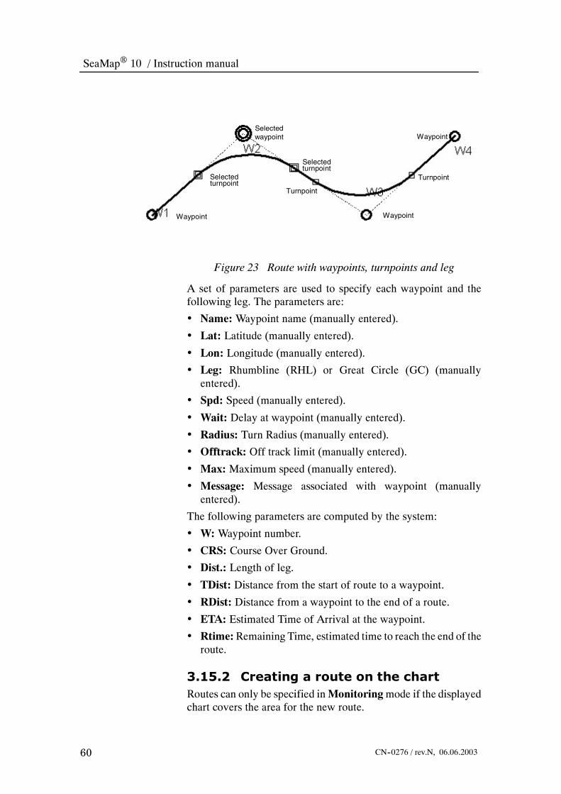
SeaMap 10 / Instruction manual
60 CN--0276 / rev.N, 06.06.2003
Selectedwaypoint
WaypointWaypoint
Waypoint
Selectedturnpoint
Turnpoint
TurnpointSelectedturnpoint
Figure 23 Route with waypoints, turnpoints and leg
A set of parameters are used to specify each waypoint and thefollowing leg. The parameters are:
• Name:Waypoint name (manually entered).
• Lat: Latitude (manually entered).
• Lon: Longitude (manually entered).
• Leg: Rhumbline (RHL) or Great Circle (GC) (manuallyentered).
• Spd: Speed (manually entered).
• Wait: Delay at waypoint (manually entered).
• Radius: Turn Radius (manually entered).
• Offtrack: Off track limit (manually entered).
• Max: Maximum speed (manually entered).
• Message: Message associated with waypoint (manuallyentered).
The following parameters are computed by the system:
• W:Waypoint number.
• CRS: Course Over Ground.
• Dist.: Length of leg.
• TDist: Distance from the start of route to a waypoint.
• RDist: Distance from a waypoint to the end of a route.
• ETA: Estimated Time of Arrival at the waypoint.
• Rtime:Remaining Time, estimated time to reach the end of theroute.
3.15.2 Creating a route on the chartRoutes can only be specified inMonitoringmode if the displayedchart covers the area for the new route.

Operating information
61CN--0276 / rev.N, 06.06.2003
When the new route is located in an area not covered by thedisplayed chart, selectBrowsemode on the operator panel. Set thechart to the area for the route using the trackball andOffset button.
1 PushMenu > Route >Manage Routes.
2 Push the New button.
→ Refer to page 125 for details on each parameter in the menu.
-- The Waypoint List menu is displayed. Move it to aconvenient location.
3 Push Insert.
4 Type in a name for the route.
5 Move the cursor into the chart area.
-- The cursor changes shape to a cross.6 Push Select when the cursor is in the position for the first
waypoint.
-- The position of the waypoint is specified.7 Push Select when the cursor is in the position for the next
waypoint.
-- Create all waypoints in the route in this manner.8 Push End Insert.
9 Push Save.→ Refer to page 66 for how to validate the route.
10 To return to the own ships position push theMonitor buttonon the operator panel.
Note Speed, turning radius and offtrack limit for the waypoints havedefault values. If you need to change these use the procedure below,under “Modifying routes”.
3.15.3 Creating a route using thewaypoint list
Routes can only be specified inMonitoringmode if the displayedchart covers the area for the new route.

SeaMap 10 / Instruction manual
62 CN--0276 / rev.N, 06.06.2003
When the new route is located in an area not covered by thedisplayed chart, selectBrowsemode on the operator panel. Set thechart to the area for the route using the trackball andOffset button.To return to the own ships position push theMonitor button on thepanel.
1 On the monitor pushMenu > Route >Manage Routes.
2 Push the New button.
→ Refer to page 125 for details on each parameter.
-- The Waypoint List menu is displayed. Move it to aconvenient location.
-- If the chart covers the area for the new route, the new routewill be displayed as it is built.
3 If the route is specified using a local datum, select LOCALand specify the offset fromWGS--84 (normally found in thechart).
4 In the menu select Entry.
-- The first waypoint is now appearing with default values. Thedefault values for speed, turning radius and offtrack limit arespecified in the Parameter Setup, Route tabmenu (Menu> System > Parameter Settings). These parameters are setduring commissioning of the system and will not normallyneed to be changed. The user password is required to changethe parameters.
→ Refer to page 170 for information setting the user password.
5 Type in a name for the route.
6 Enter the values for the waypoint by double clicking eachfield using the trackball and Select button.
-- Type in a new value using the keyboard or modify theexisting value.
-- Latitude and longitude formats are as follows:
* Lat: 12 34.123 or --12 34.123

Operating information
63CN--0276 / rev.N, 06.06.2003
* Lon: 123 45.123 or --123 45.123-- If the latitude is in the southern hemisphere or the longitudeis westerly, use a “–” in front of the latitude or longitude.
-- Use the Tab or Shift & Tab on the keyboard to move backand forth between the entry fields in the menu.
7 When the waypoint is completely specified, push Enter onthe keyboard.
-- The next waypoint will appear in the menu as a copy of thelast waypoint.
8 Make the necessary modifications as described above.
9 When all waypoints have been specified, push End Insert.
10 Push Save.→ Refer to page 66 for how to validate the route.
3.15.4 Modifying routes1 PushMenu > Route >Manage Routes.
2 Select the route you want to modify using the trackball andSelect button.
3 Push Edit Wp.
4 Select the waypoint field you want to modify bydouble--clicking the field using the trackball and Selectbutton.
5 Insert your changes.
6 When themodification is carried out, select a new field untilall modifications have been carried out.
7 Push Save.
3.15.5 Insert waypointsUsed for existing routes.
1 PushMenu > Route >Manage Routes.
2 Select the route you want to modify using the trackball andSelect button.
3 In the Waypoint List, select the waypoint after the one youwant to insert.
4 Push the Insert button, and modify the parameters for thenew waypoint as appropriate.
5 The new waypoint appears in the table.
6 If more waypoints are to be inserted push Enter on thekeyboard. Continue this procedure until all new waypointshave been specified.

SeaMap 10 / Instruction manual
64 CN--0276 / rev.N, 06.06.2003
7 Push End Insert .
3.15.6 Adding waypoints at the end ofthe route
1 PushMenu > Route >Manage Routes.
2 To add waypoints at the end of the route, in the menu selectthe line after the last waypoint.
3 Push the Insert button and define the new waypoint(s) asdescribed under inserting waypoints.
4 Push End Insert.
3.15.7 Modifying routes in the chart1 PushMenu > Route >Manage Routes.
2 Select the route you want to modify using the trackball andSelect button.
-- The location of waypoints and turnpoints can be modifieddirectly in the chart area.
3 To modify the position of a waypoint or turnpoint select itusing the trackball and Select button.
4 Drag it to the new location.
-- The effect of moving a turnpoint is shown in the illustrationbelow.
Figure 24 Figure 6.1 The effects of moving waypoints
5 To insert a new waypoint select the waypoint after the oneyou want to insert. Push the Insert button in the menu, andpoint the cursor to where you want the new waypoint.
6 Push End Insert.
7 To add waypoints after the last one, in the menu select theline after the last waypoint.
8 Push the Insert button, and add one or more waypoints bypointing and clicking in the radar area.
9 Push End Insert.

Operating information
65CN--0276 / rev.N, 06.06.2003
3.15.8 Copying waypointsWaypoints existing in one route can be copied to a new route, seethe illustrations below. The new route uses waypoints (markedwith squares) defined in an existing route. This is done by copyingthe waypoints into the new route.
1 Push the following sequence of softkeys in the menu area:Menu > Route >Manage Routes.
2 Select the route you want to modify using the trackball andSelect button.
3 Push the List WP button.
4 In theWaypoint Listmenu select thewaypoints to becopiedby selecting the first waypoint and drag the cursor downacross the waypoints to be selected them.
5 Push Copy.
-- TheMARK button is used to select several waypoints whenthe list needs to be scrolled to see the first and last waypointin the selection.
6 In theManage Routemenu, select the new route, and pushEdit WP.
-- The Route Edit menu for the new route is displayed.
7 In the waypoint list select where the copies of the waypointsshould be inserted, and then push the Paste button.
-- The waypoints are entered into the route.

SeaMap 10 / Instruction manual
66 CN--0276 / rev.N, 06.06.2003
3.15.9 Validating routes
To validate a route is to check if the route crosses own ship’s safetycontour or the route crosses the boundary of a prohibited or ageographic area where special conditions exist.
* Validation is always done on the best charts available.* Routes to be validated are not allowed to haveinconsistent geometry, that means that there must bespace for a straight leg segment between waypoint turns.Correct this prior to validation.
* Validation results are added to the route as validationstatus information.
* Grounding and warning information can be studied indetail in the list box.
To validate a route do the following:
1 Push the following sequence of softkeys in the menu area:Menu > Route >Manage Routes.

Operating information
67CN--0276 / rev.N, 06.06.2003
2 Select the route you want to validate using the trackball andSelect button.
3 Push Validate.
-- The Route Validation Menu is displayed.
4 Validation can take place in four modes:
* Validate (unattended):Validates the complete route andlists the results.
* Validate and View: Validates each leg and turn in theroute separately. If a leg or turn covers twoormore charts,the leg/turn is divided into parts so that only one chart isinvolved in the validation process at a time. The positionof grounding situations are indicated by blinking redstars. In the menu the leg/turn is shown with informationabout the chart used and the number of grounding andwarning situations that have been found. The chart ismoved to show each leg or turn.
* Validate Manually: Used when the available charts(raster charts) do not support automatic validation.Allows you to validate a route manually. For each leg/turn check the route against the chart and specify that itis either OK or has a possible grounding or warningcondition by pushing the appropriate button.
* View:Steps through each leg and turnwithout validation.Possible groundings are displayed in the chart.
5 Select a mode.
6 Push Start.
7 If the route is being edited, push Cancel and save the routestatus from theWaypoint List menu otherwise push Save.
The codes used in validation status are shown in the table below.
ValidationCode
Description
Bad Bad geometry -- not possible to validate
Not Not validated
E ENC charts used for validation
N Non ENC charts used for validation
M Manual validation
O Outside Charts -- No chart coverage
G Grounding
W Warning -- Caution areas etc.

SeaMap 10 / Instruction manual
68 CN--0276 / rev.N, 06.06.2003
-- If only some of the legs/turns in a route needs to be validated,select the waypoints in the Route Edit menu, and pushValidate. The Route Validation menu appears with theselected waypoints specified. Validate as described above.
-- Tovalidate twoormore routes, in theRouteListmenu selectthe routes using the trackball and Select button and pushValidate. The selected routeswill be automatically validatedin the background.
3.16 How to insert critical pointsCritical points are operator defined messages placed along theroute. When reaching, or at a set time before reaching a criticalpoint the system gives an alarm. Critical points can be defined intwo ways; directly on the chart or through the menu system.
Turnpoint
Turnpoint
Alarm
Alarm
0.24 nm
10 min
15min
0.66nm
Waypoint
Waypoint
Figure 25 An illustration of criticalpoints and the critical points menu.
Note Reaching a critical point means passing abeam of it.
3.16.1 Creating a critical point in thechart
1 The route must be displayed in the chart area.
2 On the monitor select Menu > Own Ship > ShipParameters.
3 Select the Route tab.
4 Make sure thatCritical Points is selected both in theEditedand Active column.

Operating information
69CN--0276 / rev.N, 06.06.2003
5 On the chart; point the marker to the route and pushObjectMenu button.
-- An object menu (as shown on the left side) is displayed nextto the marker.
6 Select Insert Critical Point.
-- The critical point is created.
7 Use the marker and the Select button to drag the symbol tothe exact position if not accurately positioned..
-- A message text can be tied to each critical point.
-- If required the alarm can also be given at a set time beforereaching the critical point.
8 On the chart; point the marker to the critical point and pushObject Menu button.
-- An object menu (as shown on the left side) is displayed nextto the marker.
9 Select Critical Point List.
-- The Critical Point menu is displayed.10 Insert message text and time setting by double clicking the
area.
11 Push Save Route.
3.16.2 Creating a critical point using themenu
1 Push the following sequence of softkeys in the menu area:Menu > Route >Manage Routes.
2 Select the route youwant to insert critical points for using thetrackball and Select button.
3 Push the List WP button.
4 In theWaypoint Listmenu push theCritical Points button.
5 Push Add.
6 Type in the waypoint number, distance (to the waypoint),time (the alarm can also begiven at a set time before reachingthe critical point) and a message.
7 Push Apply.
8 Add critical pointmessages to all waypoint that require themin this way.
9 When completed push Save Route.

SeaMap 10 / Instruction manual
70 CN--0276 / rev.N, 06.06.2003
3.17 How to monitor routesThe system includes functionality to continually monitor theposition of the ship against the planned route. Do the following:
1 On the monitor selectMenu > Route > Manage Routes.
2 Select the route to be monitored.
3 PushMonitor.
4 On the monitor selectMenu > Route > Monitor Route.
-- Themenu provides information about the upcoming portionof the route.
Push to go to theautopilot menu
Cross track limit
Cross track error P - port S - starboard
Background colourrelates to validation:Red - groundingYellow - warningGrey - OK
Validation & chartstatus. Yellowbackground - the routehas not been validated.
Route name
Push to step up ordown to show ETA ofother waypoints
5 PushAutopilotwhen youwant to go to theAuto Pilotmenu.
-- The menu presents:
* The name of the route
* The waypoint you are currently sailing against
* Bearing and range to wheel over point (WOP)
* Time to WOP at the current speed
* The course of the next leg
* The rate of turn (for the next turn at the current speed)
* The radius of the turn ( for the next turn)
* The distance to the start of the turn.
* Current cross track error and the set cross track error limit

Operating information
71CN--0276 / rev.N, 06.06.2003
Cross trackerror
Brg/Rng toWOP
WOP Currentwaypoint
Nextleg
Radius
Pivot point
3.18 How to export routes to DataBridge 2000SeaMap 10 is designed to work together with the DataBridge
10, but can also work with the older DataBridge 2000.
Exporting
To export routes to DataBridge 2000 do the following:
1 On the monitor selectMenu > Routes > Manage Routes.
2 Select the routes to be exported, and push Export.
3 On themonitor selectMenu> System> Export to / Importfrom DB 2000.
4 Select the Exp. Route tab.
5 In the Remote Station list select the DataBridge 2000 toexport to.
6 DataBridge 2000 route names are limited to 8 characters.When necessary names are truncated. Rename the route ifrequired.
7 Push Export.
Importing
To import routes from DataBridge 2000 do the following:
1 At the DataBridge 2000; select Menu > Sail > ActiveRoute.
2 Select the route.
3 Push Export.

SeaMap 10 / Instruction manual
72 CN--0276 / rev.N, 06.06.2003
4 Select the SeaMap 10 to export to.
5 Push Send to One.
6 At the SeaMap 10; selectMenu > System > Export to /Import from DB 2000.
7 Select the Imp.Route tab.
8 In the Remote Station list select the DataBridge 2000 toexport to.
9 Select the route to import.
10 Push Import.
3.19 How to use the automatic track keeping
3.19.1 IntroductionWhen the system is interfaced to an AP 2000 Track Pilot,programmed routes can be used to steer the ship. SeaMap 10sends course, upcoming turn radius and new course, off--trackdistance etc. to the autopilot. The autopilot adjusts the steeringaccordingly. The autopilot can be controlled in four modes:
• Heading mode: The heading set--point for the ship is used asthe course to steer. No route required.
• Course mode: The course set--point and the calculated drift isused to calculate the heading to steer. No route required.
• Waypoint mode: The route and the calculated drift is used tocalculate the heading to steer. The systemcompensates for crosstrack error in order to reach the waypoint. Waypoint mode isselected for one waypoint at a time. When the ship is close tothe waypoint, the mode is changed to Course mode to avoidlarge course changes close to the Waypoint. Turns must bestarted manually.
Figure 26 Waypoint mode compensates for drift.
• Track mode: The system steers the ship according to theprogrammed route with a minimum of cross track error (XTE),a minimum of course alterations and optimum rudder usage. Inthis mode turns are executed automatically.

Operating information
73CN--0276 / rev.N, 06.06.2003
The following abbreviations are used:
-- TP -- Turn Point-- T.Rad -- Turn Radius-- WP --Waypoint-- WOP --Wheel Over Point. Where the turn is started to reachthe next waypoint.
-- XTE -- Cross Track Error. The shortest distance betweenship and the intended route.
-- Auto -- Autopilot-- Man -- Manual-- Stb Auto -- Standby Autopilot
3.19.2 Heading modeDo the following to steer the ship in heading mode:
1 On the Autopilot; set the steering system to Autopilot.
-- All further actions are done on the SeaMap 10.2 On the monitor selectMenu > Routes > Autopilot.
-- The autopilot menu indicates AP--Mode = LOCAL.3 Push the In Cmnd button on the operator panel or select In
Cmd in the Autopilot menu.4 SetHeadingOrdered using trackball and the Select button.
5 Push the Hdg button on the operator panel or selectHdg inthe Auto Pilot menu.
-- After a few seconds the Auto Pilot menu indicatesAP--MODE = HDG.
-- Heading steering is in operation using own ships heading asthe course to steer.
3.19.3 Course modeDo the following to steer the ship in course mode:

SeaMap 10 / Instruction manual
74 CN--0276 / rev.N, 06.06.2003
1 On the autopilot: Set the steering system to Autopilot.
-- All further actions are done on the SeaMap 10.
2 On the monitor selectMenu > Routes > Autopilot.
-- The autopilot menu indicates AP--Mode = LOCAL.
3 Push the InCmnd button on operator panel or select InCmdin the Autopilot menu.
4 Set Course Ordered using trackball and the Select button.
5 Push theCrs button on the operator panel or selectCrs in theAuto Pilot menu.
-- After a few seconds the Auto Pilot menu indicatesAP--Mode = CRS.
-- Course steering is in operation using own ships course as thecourse to steer.
3.19.4 Waypoint mode
Do the following to steer the ship in waypoint mode:
1 On the autopilot; set the steering system to Autopilot.
-- All further actions are done on the SeaMap 10.
2 On the monitor selectMenu > Routes > Autopilot.
-- The Auto Pilot menu indicates AP--Mode = LOCAL.
3 Push the InCmnd button on operator panel or select InCmdin the Auto Pilot menu.
4 Push theWp button on the operator panel or selectWp in theAuto Pilot menu.
-- After a few seconds theAutopilot menu indicatesAP--Mode=Wp.
-- Waypoint steering is in operation using own ships headingas the course to steer.
3.19.5 Track mode
Do the following to steer the ship in track mode:
1 Push the following sequence of buttons in the menu area:Menu > Routes >Manage Routes.
2 Select an existing route using the trackball and the Selectbutton.
→ Refer to page 59 for information on how to create routes.

Operating information
75CN--0276 / rev.N, 06.06.2003
3 Push theMonitor button.
-- The route is displayed in the radar area, and appear in theroute list as active.
-- Active routes can not be modified as long as they are active.
-- The own ship should be in a position between twowaypointsin the route, close to the track with a heading close to thecourse between the two turnpoints.
4 Verify that Waypoint 2 is the active waypoint. The activewaypoint is indicated by a pulsating ring in the display.
5 On the autopilot: Set the steering system to Autopilot.
-- The SeaMap 10 autopilot menu indicates AP--Mode =LOCAL.
6 All further actions are done on the SeaMap 10: PushMenu> Routes > Autopilot.
7 Push the In Cmnd button on operator panel.
-- The Autopilot menu indicates AP--Mode = LOCAL.
8 Push theTrack button on the operator panel or select Trackin the Auto Pilot menu.
-- After a few seconds the Auto Pilot menu indicatesAP--Mode = TRACK, and course/heading and cross--trackerror are monitored.
-- Track--steering is in operation.
3.19.6 To stop track steeringThere are several ways to stop track--steering:
-- By selectingWp, Crs or Hdgmode in the Autopilot menu.
-- By pushing the AUTO ON button on the AP 2000.
-- By switching the steering system to manual.
-- By pushing the In Cmnd button on the operator panel.-- When reaching the lastwaypoint in the route, the systemwillautomatically go to Autopilot steering continuing on the lastheading.
3.19.7 Waypoint alarms
Three minutes before reaching the wheel--over line for the nextwaypoint, a pre--warning is given.
1 Acknowledge it.
-- 30 seconds before reaching the wheel--over line for the nextwaypoint, a warning is given.

SeaMap 10 / Instruction manual
76 CN--0276 / rev.N, 06.06.2003
2 Acknowledge it, if you want to make the turn.
3.19.8 Warnings givenThe following warnings related to the automatic track keeping aregiven:
-- XTE--limit is exceeded.-- Time to Wheel Over Position (WOP) = 3min
-- Time to Wheel Over Position (WOP) = 30 sec-- Control of steering is taken at the AP2000 or by manualoverride.
-- Communication failure between the AP2000 and theSeaMap 10.
-- The last waypoint in route is reached.-- Loss of position data from Navigation Receiver.
-- Loss of Gyro input.-- Loss of Speed Log input.
3.19.9 LimitationsThe following is required for track steering:
-- Position, gyro & log input working.-- A sailing route must be displayed and monitored. Both APin command and Route Monitor must be enabled on theANTS configuration menu.
-- Only one console can be in command of the autopilot.-- The ship must be on a straight leg.
-- The distance from the ship to the leg must be less than 1 nm(5 nm in WP mode).
-- The difference between heading of the ship and direction ofthe leg must be less than 30º.
-- The ship must be inside a leg and the remaining part of theleg before the wheel over point must be more than 500meters.
-- The preplanned track has been checked for plausibility andcorrectness of geometric and ship dependent limits. Systemparameter set--up under Ship tab and Route tab must be setto plausible values.
-- The difference between the heading of the ship and thebearing to the turn point must be less than 15º.
-- Gyro & log input working with the autopilot.
-- Communication between autopilot and the SeaMap 10must be established and working.

Operating information
77CN--0276 / rev.N, 06.06.2003
3.19.10Conditions resulting in anautomatic switch-over to adifferent steering mode
Track steering to local autopilot control
The system will automatically change from track steering to localautopilot control in the following cases:
-- When the SeaMap 10 do not receive valid signals from theposition--, heading-- or speed sensor.
-- When reaching the end of the route.-- When a jump in the calculated cross track error of more thanthe preset limit occurs.
-- When a jump in the calculated cross track errorcorresponding to a cross track velocity of more than thepreset limit occurs.
-- When the SeaMap 10 can not detect the presence of aDataBridge 10 radar/ARPA, due to a communication orDataBridge 10 failure.
-- When the SeaMap 10 can not detect the presence of aconning display due to a communication or conning displayfailure.
-- When the SeaMap 10 ceases to receive messages from theautopilot, due to a communication failure.
-- When the autopilot can not detect the presence of theSeaMap 10, due to a communication or SeaMap 10failure.
Waypoint mode to local autopilot mode
-- The system will automatically change from waypoint modeto local autopilot control when the SeaMap 10 is notreceiving valid signals from the position--, heading-- or speedsensor.
Waypoint mode to course mode
-- The system will automatically change from waypoint modeto course mode if the remaining distance to the wheel overpoint is less than 0.5 Nautical miles.
Course mode to local autopilot steering
-- The system will automatically change from course mode tolocal autopilot controlwhen theSeaMap 10 is not receivingvalid signals from the position--, heading-- or speed sensor.
Heading mode to local autopilot control
-- The systemwill automatically change fromheadingmode tolocal autopilot controlwhen theSeaMap 10 is not receivingvalid signals from the position--, heading-- or speed sensor.

SeaMap 10 / Instruction manual
78 CN--0276 / rev.N, 06.06.2003
Note There are no automatic changes to track mode, waypoint mode orheading mode. The only automatic change to course mode is fromwaypoint mode when the remaining distance to wheel over pointis small.
3.19.11Practical hintsWhen you initiate track mode and the ship is away from theroute, the approach will be done as showed in the followingillustration:
The path to get on the route consists of two turns, and possibly astraight leg between the turns. The turn radius of these turns andthe angle of the straight leg are adjustable on the AP2000control unit.
Note that the operator can change between WP mode and Trackmode. In the above illustration it is also possible to select WP04as “approaching” waypoint and use WP mode until WP04 isreached, and then change to Track mode.

Operating information
79CN--0276 / rev.N, 06.06.2003
3.20 How to use mariner’s notes
3.20.1 Introduction
Mariner’s notes are geographically fixed symbols, lines and areascreated by the user to supplement the charts. Notes are displayedindependent of the chart type being used. Notes consists of lines,symbols and and text. The different types of notes are shown in theillustration on the left.
Event notes are automatically located at the own ship’s position atthe time it was created. For all other note types, the navigatorspecifies the position. As a default all notes are stored in the“Navnote” folder. The user can define other folders to organise thenotes.
3.20.2 Managing notes
1 PushMenu > Notes >Manage Notes.
-- The Nav Note List menu is displayed.
2 SelectType,Distance orDate to sort the list by type of note,distance from own ships position, or date of creation/modification.
3 Push the List button to display the full text and otherinformation.
4 Push the Edit button to make changes to notes.
5 Push Cut to remove a note.
3.20.3 Creating point notes
A point note is a symbol placed at a specified position. There arethree types of point notes:
* Event
* Caution
* Information
The Event note is automatically placed at the own ship’s position.Pushing theMOB (Man Over Board) button on the operator panelcreates an event note.
1 Push the following sequence of button in the menu area:Menu > Notes >Manage Notes.
2 Push the Info Note button.
Event
Safety contour
Solid line
Dashed line
Chart correction
Information
Caution
Filled area
Area

SeaMap 10 / Instruction manual
80 CN--0276 / rev.N, 06.06.2003
3 If the note position is specified using a local datum, selectLocal and specify the offset from WGS--84.
4 Type in the note text in the Comment field.
5 Specify the position by double clicking the latitude andlongitude fields. Type in a new value or modify the existingvalue.
-- Latitude and longitude formats are as follows:
* Lat: 12 34.123 or --12 34.123
* Lon: 123 45.123 or --123 45.123
-- If the latitude is in the southern hemisphere or the longitudeis westerly, use a “–” in front of the latitude or longitude.
6 As an alternative to typing in the latitude and longitudevalues use the trackball and Select button in the chart area topoint to the position.
7 When the note is completely specified push Apply.
3.20.4 Creating line or area notes
Line or area notes consists of lines connecting fixed positions.There are five types of lines:
* Solid lines
* Dashed lines
* Safety Contour:When the charts are lacking useful safetycontours, the operator can draw his own safety contoursto increase safety of navigation.
* Areas
* Filled areas
1 Push the following sequence of button in the menu area:Menu > Notes >Manage Notes.
2 Push the Solid Line, Dashed Line or Safety Contourbutton.
3 If the note position is specified using a local datum, selectLocal and specify the offset from WGS--84.
4 Type in the note text in the Comment field.
5 Specify the position by double clicking the latitude andlongitude fields. Type in a new value or modify the existingvalue.
-- Latitude and longitude formats are as follows:
* Lat: 12 34.123 or --12 34.123

Operating information
81CN--0276 / rev.N, 06.06.2003
* Lon: 123 45.123 or --123 45.123-- If the latitude is in the southern hemisphere or the longitudeis westerly, use a “–” in front of the latitude or longitude.
-- Lines may be specified as either rhumb lines (RHL) or greatcircle (GC).
6 Push Enter on the keyboard to provide a new line for thenext point. Continue entering points until the line is defined.
7 Push Apply.8 As an alternative to typing in the latitude and longitude
values use the trackball and Select button in the radar areato specify the position of the lines.
3.20.5 Modifying notes1 Push the following sequence of button in the menu area:
Menu > Notes >Manage Notes.2 Select the the note to be modified either in the list or in the
radar area.3 Push Edit.4 The Nav Note menu will appear ready for editing.5 To edit the latitude or longitude values, double click on the
field using the trackball and Select button and modify thevalue.
-- Use the Tab or Shift & Tab on the keyboard to move backand forth between the entry fields in the menu.
6 As an alternative drag the symbol or any line end in the radararea using the trackball and Select button.
7 Modify the note text in the Comment field.8 Push Apply.
3.21 How to use AIS functionsAll AIS functions require that anAutomatic Identification System(optional) is installed and connected to the SeaMap 10.
3.21.1 View target information
1 Position the cursor over the target and do one of thefollowing:* Push the Object Info button or* Push theObjectmenu and chooseSelectTarget from thelist.
-- All current parameters for the ship are displayed. Bothdynamic navigation information (position, speed, course,CPA, TCPA etc.) and static ship and voyage information(name, cargo, destination etc.) are shown.
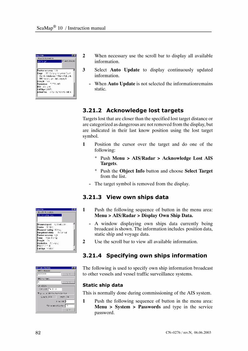
SeaMap 10 / Instruction manual
82 CN--0276 / rev.N, 06.06.2003
2 When necessary use the scroll bar to display all availableinformation.
3 Select Auto Update to display continuously updatedinformation.
-- When Auto Update is not selected the informationremainsstatic.
3.21.2 Acknowledge lost targetsTargets lost that are closer than the specified lost target distance orare categorized as dangerous are not removed from the display, butare indicated in their last know position using the lost targetsymbol.
1 Position the cursor over the target and do one of thefollowing:
* Push Menu > AIS/Radar > Acknowledge Lost AISTargets.
* Push the Object Info button and choose Select Targetfrom the list.
-- The target symbol is removed from the display.
3.21.3 View own ships data
1 Push the following sequence of button in the menu area:Menu > AIS/Radar > Display Own Ship Data.
-- A window displaying own ships data currently beingbroadcast is shown. The information includes position data,static ship and voyage data.
2 Use the scroll bar to view all available information.
3.21.4 Specifying own ships information
The following is used to specify own ship information broadcastto other vessels and vessel traffic surveillance systems.
Static ship data
This is normally done during commissioning of the AIS system.
1 Push the following sequence of button in the menu area:Menu > System > Passwords and type in the servicepassword.

Operating information
83CN--0276 / rev.N, 06.06.2003
2 Push the following sequence of button in the menu area:Menu > AIS/Radar > Set Static Ship Data.
3 Select the field and type in the ships MMSI number andpush Apply.
4 Select the field and type in the IMO number and pushApply.
5 Select the field and type in the ships Call Sign.-- Ship name, length and width are taken from the shipparameter dialog (Menu > System > Parameter settings onthe Ship tab).
6 Select the field and type in the AIS antennas distance FromAft of the ship.
7 Select the field and type in the AIS antennas distance fromthe ships centre line. Use negative values for distance to port.
Static voyage data
1 Push the following sequence of button in the menu area:Menu > AIS/Radar > Set Static Voyage Data.
2 Select Type/Cargo from the drop down list.3 Select Nav.Status from the drop down list.
-- MaxDraught is taken from the ship parameter dialog (Menu> System > Parameter settings on the Ship tab).
4 SelectNumber of PersonsOnboard using the spin buttons.5 Select the field and type in the Destination.6 Select Arrival (UTC) time using the spin buttons.7 Push Apply.
3.21.5 Sending and receiving texttelegrams and safety messages
The AIS functionality allows you to transmit text messages toother ships and to vessel traffic surveillance systems. Texttelegrams and safety messages can either be broadcast or sent to aspecific ship. Only upper case characters can be used and themessage is limited to approx. 160 characters, depending on type ofmessage and transmission mode.AIS messages can either be broadcast or addressed to a singlerecipient. Recipients and message senders are basically identifiedby their MMSI numbers. If the ship name corresponding to theMMSI number is available, the ship name is also displayed.When messages are received from other ships or vessel trafficsurveillance systems, the userwill receive a notification.Messagesare automatically stored in an UnRead folder, waiting for themariner’s attention.

SeaMap 10 / Instruction manual
84 CN--0276 / rev.N, 06.06.2003
Telegram/message archiveAll sent or received telegrams and messages are stored in thesystem until deleted by the operator.1 Push the following sequence of button in the menu area:
Menu > AIS/Radar > Text Message List.-- The displayed dialog is used to manage the four messagearchives.* Unread: Stores all received messages not yet read.* Read: Stores incoming messages after they have beenread.
* Predefined: Stores predefined messages for frequentuse.
* Sent: Stores sent messages.2 Use the correspondingoption button to select the archiveyou
want to view.
Read and answer telegrams/messages1 Push the following sequence of button in the menu area:
Menu > AIS/Radar > Text Message List.2 Select the the Unread option button.3 Select the telegram/message you want to read using the
trackball and Select button.-- The telegram/message is displayed.
4 To compose an answer do the following:* Push the Reply button.* Type in your answer.* Push the Send button.
-- In some cases the sender may have requested that youacknowledge receiving the telegram/message.
5 To acknowledge it push the Acknowledge button.
Create new telegrams/messages1 Push the following sequence of button in the menu area:
Menu > AIS/Radar > Text Message.2 Select the Text Telegram or SafetyMessage option button.3 Select Broadcast or type in the recipientsMMSI number.4 Select Acknowledge Req. if you want the recipient to
acknowledge receiving the telegram/message.-- Acknowledgedmessageswill appear in theUnreadmessagearchive, when acknowledged. Broadcasts can not beacknowledged.

Operating information
85CN--0276 / rev.N, 06.06.2003
5 Type in your telegram/message.
6 Push the Send button.
Create predefined messages
The system allows you to store a number predefined messagesthat are frequently used.
1 Push the following sequence of button in the menu area:Menu > AIS/Radar > Text Message.
2 Select the Text Telegram or SafetyMessage option button.
3 Select Broadcast or type in the recipientsMMSI number.
4 Select Acknowledge Req. if you want the recipient toacknowledge receiving the telegram/message.
-- Acknowledgedmessageswill appear in theUnreadmessagearchive, when acknowledged. Broadcasts can not beacknowledged.
5 Type in your telegram/message.
6 Push the Save Predef. button.
Send predefined messages
1 Select the target you want to send a predefined message tousing the trackball and Object Menu button.
2 Select Send Predef Message from the displayed list.
-- Your list of predefined messages is displayed.
3 Double--click on the message you want to send using thetrackball and Select button.
4 Push Send.
3.22 How to use NavTex functions
3.22.1 IntroductionAll Navtex functions require that a Navtex receiver (optional) isinstalled and connected to the SeaMap 10. NavTex is a systemused by maritime services to advice ships of navigational hazards,weather hazards, weather forecasts, vessels in distress and otherimportant information. There are a number of coast stationsaroundthe world that transmit these messages on 518 kHz. Each stationtransmits messages every 4 hours. The service range is 200--400nautical miles for each station, depending on terrain andtransmitter power.

SeaMap 10 / Instruction manual
86 CN--0276 / rev.N, 06.06.2003
The SeaMap 10 Navtex interface stores telegrams in an archive onand allow telegram reading and management from the ECDISscreen.
Figure 27 Navigational warning received on NavTex andannotated in the chart.
The following functions are available:
• Store telegrams as files in a directory.
• Read and delete new and old telegrams.
• Extract latitude/longitude positions in telegrams and see thatarea in the chart or generate Mariners notes at the specifiedposition.
• Generate an ECDIS alarm when critical Navtex telegramsarrive.
• Filter out certain telegram types and Navtex stations.
Note TheNavTex interface provides a receiving only type interface to theNavTex receiver.User interface settings at the ECDIS display, likecoast station filters do not affect the Navtex receiver.

Operating information
87CN--0276 / rev.N, 06.06.2003
3.22.2 View Navtex messages1 Push the following sequence of buttons in the menu area:
Menu > System >Navtex Messages.
2 Select either the Unread or Read list using the optionbuttons.
-- The corresponding Navtex message list is displayed.
3 Select the message you want to view using the trackball andSelect button.
4 Push Display.
3.22.3 Configure navigation area1 Push the following sequence of buttons in the menu area:
Menu > System >Navtex Messages.
2 Push Configure.
3 Select the Stations tab.
4 Select the area you are in from the drop down list.
5 Select an overlapping area, if any, from the drop down list.
3.22.4 Filter Navtex stations1 Push the following sequence of buttons in the menu area:
Menu > System >Navtex Messages.
2 Push Configure.
3 Select the Stations tab.
4 If not already selected, select the area you are in from thedrop down list, and an overlapping are if any.
5 Select the Navtex stations to ignore.

SeaMap 10 / Instruction manual
88 CN--0276 / rev.N, 06.06.2003
3.22.5 Filter message categoriesMenu to aviod getting unwanted messages.
1 Push the following sequence of buttons in the menu area:Menu > System >Navtex Messages.
2 Push Configure.
3 Select the Categories tab.
4 Select message types to be ignored.
Note Messages of categories A, B, D and L can not beignored.
3.22.6 Creating Mariners notes fromNavtex messages
1 If the message you want to create a Mariners note from isalready displayed go to point 6, otherwise do the following:
2 Push the following sequence of buttons in the menu area:Menu > System >Navtex Messages.
3 Select either theUnreador Read list using the optionbuttons.
-- The corresponding Navtex message list is displayed.4 Select the message you want to view using the trackball and
Select button.
5 Push Display.
-- The message is displayed. The text message is scanned forposititional information. When found, it is displayed asLatitude and Longitude at the bottom of the dialog.
6 Push Go To.
-- The chart jumps to show the position specified in the Navtexmessage.
7 PushMark in Chart.
-- A Mariners note is created in the specified position. Thetelegram text is automatically inserted into the note. If thetext is too long it is truncated.
8 When multiple latitude/longitude pairs are displayed in theNavtex message, each position can be used for theGo To orMark in Chart functions, by selecting the line with theposition information in the telegram text.

Operating information
89CN--0276 / rev.N, 06.06.2003
Figure 28 Swedish navigational warning created as a cautionnote in the chart.
3.23 How to handle alarms
3.23.1 Alarm categoriesThe alarm system has three types of messages:
• Operational alarms:Thesemessages tell something about thesailing of the ship in relation to route plan or chart. Operationalalarms are divided into four categories:
-- Area (entering prohibited area etc. -- may be seen as an alarmor an indication).
-- Critical point
-- Grounding
-- Cross track error
• System warnings: These messages tell something about theperformance of the system and its sensors.
• System faults: These messages are issued when there is anequipment fault.
The operational alarms have individual on--screen indications,while system warnings and system faults are reported as groupalarms where the alarm text will give further information.

SeaMap 10 / Instruction manual
90 CN--0276 / rev.N, 06.06.2003
Alarm text
Help text
Alarm categories
3.23.2 Alarm system set-up
The alarm system set--up is locked behind password protection andshould only be changed by certified operators in special approvedcases. The alternative alarm indications are:
-- By giving a visual indication.
-- By giving a visual indication and a short sound signal (beep).
-- By giving a visual indication and a continues alarm sound.
WARNING Removing the alarm sound may render the ECDIS approvalinvalid.
Do the following:
1 On the monitor selectMenu > System > Passwords.
2 Type in the password and push Open.
3 On the monitor selectMenu > System > Alarm Setup.
* CritP: Alarm for critical points defined by the operatorduring route editing.
* Cross Track: Cross track error alarm. Limit specified inthe Menu > Route > Set Route Parameters underDefault Offtrack Limit.
* Grounding: Grounding alarm. Limit set in theMenu >Chart > Safety Depth Setting.
* Area: Area alarm part of the chart, such as for restrictedareas etc. The look ahead time for grounding is set inSystem > Grounding > Alarm Setup.
* System Warning: System warnings are issued when asystem degradation is detected or predicted. Theconditions for activating the message such as for a sensortimeout are pre--set. The look ahead time for groundingis set in System > Grounding > Alarm Setup.
* System Alarm: System alarms are reported when anequipment malfunction is detected.
Note For integrated systems; operational alarm limits and modes areindividual to each display unit.

Operating information
91CN--0276 / rev.N, 06.06.2003
3.23.3 Alarm acknowledgement using thetrackball
The alarm text line will always present the most recentunacknowledged alarm. Use the following procedures toacknowledge alarms:
-- The alarm category button corresponding to the alarm isflashing (CRITP, AREA, XTE, GND, WARN orALARM).
1 Push the button using trackball and SELECT button:
-- If the alarm message belongs to the CRITP, AREA, XTE,orGND pushing the button will acknowledge the alarm, andthe button will stop flashing.
-- For WARN and ALARM a list of unacknowledgedmessages are displayed in the menu area.
2 Acknowledge individual alarms in the list using the trackballand Select button.
-- The alarmcategory fieldwill stop flashingwhen there are nounacknowledged alarms in that category. When the alarmcondition no longer exists, the field is cleared.
3.23.4 Alarm acknowledgement using theoperator panel
1 Push the Sound Off button to silence the alarm.
2 Push the ACK button to cause the following response:
-- If the alarm message belongs to the CRITP, AREA, XTE,orGND pushing the button will acknowledge the alarm, andthe button will stop flashing.
-- For WARN and ALARM a list of unacknowledgedmessages are displayed in the menu area.
3 Push theACK button once for each unacknowledged alarm.
-- The alarmcategory fieldwill stop flashingwhen there are nounacknowledged alarms in that category. When the alarmcondition no longer exists, the field is cleared.
3.23.5 Listing active alarmsActive alarms can be listed by category.
1 Click the alarm category button indicating active,unacknowledged alarms.
-- The list will display the newest alarm at the top. Applies toWARN and ALARM only.

SeaMap 10 / Instruction manual
92 CN--0276 / rev.N, 06.06.2003
3.23.6 Alarms from remote display unitsIf several SeaMap 10 and DataBridge 10 units are connectedtogether on a Local Area Network (LAN), an alarm in one of themcan be silenced from any of the units using the Sound Off buttonon the operator panel.
Alarm lists will only include alarms that can be acknowledged.This means that the list will include alarms originating from theunit, and alarms reported from other units. The origin of eachalarm is shown in the display unit column in the Alarm List. Youcan always seewhich alarmmessage you acknowledge, andwhichdisplay unit gave the alarm.
3.23.7 Alarm filteringWhen a sensor is connected to more than one display unit, alldisplay units will probably detect a malfunctions related to thesensor. When identical messages exist on multiple display units, itis sufficient to acknowledge it on one unit.
3.23.8 Output to external alarm systemThe SeaMap 10 can be connected to an external alarm system.Alarmmessages will then be transmitted to this alarm system. Thefollowing alarms will trigger a signal to the external alarm system;CRITP, AREA, XTE, GND, WARN and FAIL.
→ Refer to documentation for the external alarm system for moreinformation.
3.24 How to access system parametersThe SeaMap 10 has three access levels. The two higher levels areused to prevent unauthorised access to key system functions andparameters.
• Normal Access: All functions that an officer on the watch willneed are available here.
• UserConfiguration Access: Functions that alters user settingsof the unit or functions that should only be carried out duringmaintenance of the unit.
• Service Access: Functions to change more permanent settings,such as what units are connected, their characteristics, voltagelevels etc.
WARNING Do not change Service Access settings unless you are trained todo so. Changing these settings may render the system uselessor seriously degrade the performance of the system!

Operating information
93CN--0276 / rev.N, 06.06.2003
3.24.1 Operation1 Push the following sequence of buttons in the menu area:
Menu > System > Passwords.2 Type in the password.
-- The user password is user.-- The service password is change.
3 Push the Open button.-- You can now make the changes you need to make.
4 Go back to the password menu and push Lock.-- The system is now inhibited from making further changes.Always lock the systemafter changingparameters to preventunapproved access.
→ Refer to page 170 for information about each of the parameters inthe Password menu.
3.25 How to use depth recordings for otherapplications
Depth recording is an option and is not available with all systems.Depth files are stored in binary format. If youwant to use the depthrecording for other purposes do the following:
1 Save the depth file to floppy disk.2 Use the Voyage/Log printout program to read the file.
3 The data is converted to an alphanumeric format that can beinterpreted by other programs.
A:\>listlogUsage: listlog [--h] logfile [ fromtime totime ]
A:\>listlog e011220a.echSensor recording file for ship ”d/s Southern Comfort”.Recordings from:20011220 12:14:36 to 20011220 12:26:21.
File is authentic and has not been changed.All times are UTC.Time: Type: Sensor: Latitude: Longitude:Value:20011220 12:15:00 SENSOR Depth2 59¦29.948’N 179¦58.931’E 17.9020011220 12:15:06 SENSOR Depth2 59¦29.953’N 179¦58.986’E 17.2020011220 12:15:09 SENSOR Depth2 59¦29.959’N 179¦59.053’E 17.2020011220 12:15:16 SENSOR Depth2 59¦29.969’N 179¦59.170’E 22.0020011220 12:15:24 SENSOR Depth2 59¦29.979’N 179¦59.284’E 21.0020011220 12:15:31 SENSOR Depth2 59¦29.989’N 179¦59.398’E 19.80
Figure 29 Text output from depth file.

SeaMap 10 / Instruction manual
94 CN-0276 / rev.N, 06.06.2003
4 REFERENCE GUIDE
4.1 IntroductionThis document gives an overview of all menus found in theSeaMap 10 and the meaning of each parameter.
The following subjects are covered:
- Overview
- Menu structure
- Each individual menu
- Operator warnings
- Operator messages

Reference guide
95CN--0276 / rev.N, 06.06.2003
4.2 Menu descriptions
4.2.1 OverviewMenusare used tomonitor, control and configureand thevariablesin the SeaMap 10. The following gives an explanation to themenus available to the operator.
4.2.2 How to reach menusAll menus can be reached through the menu hierarchy. The toplevel is displayed in themainmenu.Menuscan be reached in threeways:
• Through the softkeys in the top bar.
• Through the operator control panel.
• Through object (context) menus.
4.2.3 Menu hierarchyMenus are grouped in a logical structure consisting of menus andsub--menus. For each button in the main menu there aresub--menus, and for most of the sub--menus there are alsosub--menus.Menus unavailable due to the operator access level orthe system configuration will appear “grey”. The main menu hasthe following entries:
• Chart
• Route
• Radar
• Own Ship
• Note
• Tools
• System
Frequently used menus are available directly as object menus orthrough the operator control panel or softkeys in the top bar,whileless used menus must be accessed through the menu hierarchy.

SeaMap 10 / Instruction manual
96 CN--0276 / rev.N, 06.06.2003
4.3 Chart
Menu to set up and work with charts.
Display mode: Push this button to select display mode.
Zoom: Push this button to select chart scale.
Themes: Push this button to select chart items to be displayed.
Object info:Push this button to display information about objectsin the chart.
Legend: Push this button to display information about the chartbeing used.
Browse Position: Push this button to move the chart area to aspecific geographic position.
Safety Depth Setting: Push this button to set own ship’s safetydepth setting.
Chart Types: Push this button to select the chart type to be used.
ARCS / Seafarer Chart Management: Push this button tomanage ARCS / Seafarer charts.
CM--93 Edition 2 Chart Management: Push this button tomanage C--Map edition 2 charts.
CM--93 Edition 3 Chart Management: Push this button tomanage C--Map edition 3 charts.
S57 ChartManagement: Push this button to manage S57 charts.
4.3.1 Display mode
Menu to set chart display modes:
• Browse: The chart is displayed independent of own shipsposition. Browse is used for route planning. The chartorientation is north up.
The following modes are monitoring modes. In these modes thechart display is automatically updated to follow own shipsposition:
• N UP/TM: North up/true motion
• N UP/RM: North up/relative motion
• C UP/TM: Course up/true motion
• C UP/RM: Course up/relative motion
• H UP/RM: Head up/relative motion

Reference guide
97CN--0276 / rev.N, 06.06.2003
4.3.2 Zoom
Menu to set chart scale. The system is initially set in automaticchart mode. This means automatic selection of the best chartavailable for the own ships position is selected. To terminateautomatic chart mode:
* Selecting a chart from the FG (foreground) chart list.
* Operate the Zoom In or Zoom Out buttons.
The selected chart will sometimes not cover the whole displayarea. Rather than leave this area blank the system can fill in thisarea with an other chart, normally of lower resolution. The bestchart we call foreground (FG) chart and the other we callbackground (BG) chart.
Reset:Resets chart selection toautomatic chartmode (selectionofthe best chart available for the own ships position).
Zoom In: Increases the chart scale by a factor of two.
Zoom Out: Decreases the chart scale by a factor of two.
FG: (Foreground)Lists available chart typesand chart scales at theship’s position inmonitoringmode, or in themiddle of the displayin browsemode. The navigator can directly choosewhich chart touse for display.
BG: (Background):If the selected foreground chart does not coverall of the display, the rest of the display can be filled with another”fill--in”chart, normallywith smaller scale.Whenyouselect anewentry in the ”BG”--list, the systems choice for background chart isoverridden.
Fill In: Select to use background chart to fill in missing areas.
?: Push to display the chart legend for each chart.
4.3.3 ThemesMenu to select the type of chart information displayed in the chartarea. Turning off all themes corresponds to BASE DISPLAY inECDIS terminology.
Note Only vector charts have themes. The themes informationavailablevaries between chart suppliers.
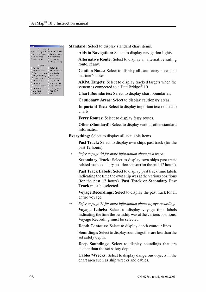
SeaMap 10 / Instruction manual
98 CN--0276 / rev.N, 06.06.2003
Standard: Select to display standard chart items.
Aids to Navigation: Select to display navigation lights.
Alternative Route: Select to display an alternative sailingroute, if any.
Caution Notes: Select to display all cautionary notes andmariner’s notes.
ARPA Targets: Select to display tracked targets when thesystem is connected to a DataBridge 10.
Chart Boundaries: Select to display chart boundaries.
Cautionary Areas: Select to display cautionary areas.
Important Text: Select to display important text related tocharts.
Ferry Routes: Select to display ferry routes.
Other (Standard): Select to display various other standardinformation.
Everything: Select to display all available items.
Past Track: Select to display own ships past track (for thepast 12 hours).
→ Refer to page 50 for more information about past track.
Secondary Track: Select to display own ships past trackrelated to a secondaryposition sensor (for thepast 12hours).
Past Track Labels: Select to display past track time labelsindicating the time the own shipwas at the various positions(for the past 12 hours). Past Track or Secondary PastTrack must be selected.
Voyage Recordings: Select to display the past track for anentire voyage.
→ Refer to page 51 for more information about voyage recording.
Voyage Labels: Select to display voyage time labelsindicating the time theown shipwasat the variouspositions.Voyage Recording must be selected.
Depth Contours: Select to display depth contour lines.
Soundings:Select to display soundings that are less than theset safety depth.
Deep Soundings: Select to display soundings that aredeeper than the set safety depth.
Cables/Wrecks: Select to display dangerous objects in thechart area such as ship wrecks and cables.

Reference guide
99CN--0276 / rev.N, 06.06.2003
LightRanges:Select todisplay lines indicating thenominalrange of navigation lights. When Active Lights is selectedthe nominal range is only indicated for the sector the ownship is in.
Active Lights: Select to display the sector colour for eachnavigation light as seen from the own ships position.
Radar Video: Select to display radar video as an overlaywhen the system is connected to a DataBridge 10.
Add. Information: Select to display various additionalinformation.
Land Details: Select to display relevant details on land.
Place Names: Select to display relevant place names.
Object Names: Select to display object names such as forbuoys.
Seabed Text: Indicates seabed (sand, clay, stone, etc.).
LightChar.Text:Select todisplay text related tonavigationlights characteristics.
Scalebar Labels: Select to display distance labels for thescalebaron the left sideof themonitor.Lat/LongScalemustnot be selected.
Lat/Long Scale:Select to display a latitude/longitude scaleand the outer edge of the monitor in stead of the scale bar.
Data Quality: Indicates the accuracy of the chart data.
Other: Select to display various other information.
4.3.4 Object info
Menu to view information about objects in the chart. Point to anobject andclick theObjectInfobuttonordouble--click it using theSelect button. Object information for all objects under the cursoris captured in this menu.
Object Information:Select to the interestingobject in the top list.All available information forobjects is listed in thewindowbelow.Use the scroll bar when required to view all the information.Information include:
• Lights
• Depth contour
• Caution area
• Depth area

SeaMap 10 / Instruction manual
100 CN--0276 / rev.N, 06.06.2003
• Map source
• Chart identification
• Buoy
4.3.5 Chart legend
Menu to view information about the chart being used. Theinformation is different for different chart types. This menuincludes three tabs; Displayed, Monitored and Other.
Displayed: This tab shows information about the chart currentlydisplayed.
Monitored: This tab shows information about the chart used tomonitor the sailing of the own ship (for grounding checking etc).This is always the best chart available, and may be different fromthe chart currently displayed.
Other: This tab shows information about a chart when inquiringusing the ?--button in the Zoom menu.
-- Each of these menus identifies the chart being used. In thiscase chart number: GB3159 from ARCS that covers“Oslofjorden -- southern part”. Chart edition20010419 withlast update: WK06--02.
4.3.6 Browse position
Menu to set the position used for browsing the chart. The chart isdisplayed independently of own ships position. Browse is used forroute planning.
Latitude/Longitude: Enter a latitude and longitude position forthe area you want to view. The information is automaticallyupdated during browsing. When leaving browse mode the lastposition is kept for later use.
GoTo: Push this button to enter Browse mode and move thedisplay to the specified position and scale.
GetCursor:Push thisbutton; thenuse the trackball andSelectkeyto specify a rectangular area. This updates the Lat/Long and Scalefields. Push the GoTo button to zoom into the area.
Apply Scale: Enter a scale and push the button to set the chart toany scale. Can be used in both Monitoring and Browse modes.
-- Hint:When disrupting a route planning activity in Browsemode by pushing the Monitor button, the last position isremembered by this menu. Push the GoTo button will bringyou back to your planning context.

Reference guide
101CN--0276 / rev.N, 06.06.2003
4.3.7 Safety depth setting
Menu to setownshipssafetydepthandselect safetycontour for thechart used.
SafetyDepth:The safety depth is used to check the planned routeto verify that it has sufficient depth. Enter a depth here that isslightly more that the draught of the ship. The default value is 30meters. The safety depthwill highlight spot soundings in the chartless than the safety depth. Soundings deeper than this depth areDeepSoundings and can be individually turned off in theThemesmenu.
Safety Contour: The safety contour is used to display the depthcontour line for the set depth. The system will choose a contourfrom the chart that is equal to or greater than the set value. Thesafety contour is displayed in the chart area and used in thegrounding avoidance function.
Depth Shades:Depth shades are used to highlight waters relatedto the safety contour. Two or four shades can be used, dependingon the contours available in the chart database. In the figure below,the safety contour is illustrated using two different shades.
Shallow Contour: A depth value that divides the waters withdepth less than the safety contour into two areas. The default valueis 2 meters.
DeepContour:A depth value that divides the waters deeper thanthe safety contour into two areas. The default value is 30 meters.
Shallow pattern: A pattern that emphasises shallow waters, i.e.waters with depth less than the safety contour. This is particularlyuseful for night palettes.
Chart Contours: Lists the contour lines available in the chartcurrently displayed. Selecting a contour line here automaticallysets Safety Contour, Safety Depth and Shallow and DeepContourvalues.
Monitored: The safety contour value currently used formonitoring (grounding checks).

SeaMap 10 / Instruction manual
102 CN--0276 / rev.N, 06.06.2003
280 13 5120
Safety Contour
Figure 30 Safety contour.
280 135120
Safety Contour Deep ContourShallow Contour
Figure 31 Safety, shallow and deep contours.

Reference guide
103CN--0276 / rev.N, 06.06.2003
4.3.8 Chart types
Menu to select the chart type to use.
Databases: This list shows which databases (chart types) that areavailable. Individual databases must be selected to be displayed.
Mng...:Push the button to enter chartmanagement for the specificchart database.
Overscale: By default this is 100%, meaning that a chart isdisplayed at its nominal scale. By selecting 200%, a 200%overscale of all chartswill takeplace.Theoverscale radio--buttonsallow the operator to persistently overscale the displayed charts
4.3.9 ARCS or Seafarer ChartManagement
Raster charts used in the SeaMap 10 are either ARCS chartsprovided by The United Kingdom Hydrographic Office orSeafarer charts provided by the Australian Hydrographic Office.These are distributed in a common format, but have slightlydifferent licensing conditions. The term HCRF -- HydrographicChart Raster Format is used as a common term for ARCS andSeafarer charts.
→ Refer to page45 forproceduresonhow toworkwithHCRFcharts.
Licence tab
Menu to work with chart permits.
-- Due to the registration of licences for ARCS and Seafareryou need to obtain a special enabling code for usingSeaMap 10 with ARCS or Seafarer charts. The first timeyou bring up the ARCS or Seafarer Management menu, thesystem will ask you for this code.
-- HCRF Enabling Code: Enter the four--character code intothe text box and push Enter.
License Type: Seafarer or ARCS charts. ARCS licences areavailable in two versions. ARCS Skipper designed for the leisuremarket, andARCSNavigatordesigned formarinerswhosevesselsaremandatedunder Safety ofLife at Sea (SOLAS).Currently onlyARCS Navigator licences can be used with SeaMap 10.

SeaMap 10 / Instruction manual
104 CN--0276 / rev.N, 06.06.2003
Type--in Permit:When you receive permits by fax or phone typethem in here, one permit at a time and push Add Chart Permit.
Add Chart Permit: Push to enter the permit typed in above.
Add Chart Permits from Floppy Disk: When permits arereceived on floppy disk, insert the disk and push Add ChartPermits from Floppy Disk to enter the permits into the system.
Back--upChart Permits to Floppy Disk: Insert an empty floppydisk into the drive, and push the button to copy all permits to thedisk.
Remove all Chart permits: Push this button to delete all chartpermits from the system.
Show User Permit: Push this button to display User Permit.
Show License: Push this button to display the licensing terms.
Show license sub menu
Menu to display licensee information.
Licensee: Displays the name and contact information for thelicensee.
License Terms…: Push to view the licence terms. For theSeafarer databases the complete licensing terms for the Seafarercharts are displayed.
OK: Push to go back to the license menu.
Show licence terms
Menu to display and accept licence terms.
Licence Terms: The complete terms for licensing Seafarercharts are listed.
Read On >: Push to display the next section of licence terms.
I Accept: You must scroll the text to the end using the Read On> button or the scroll bar before you can accept the licenceterms. When you accept the licence terms you are allowed to useSeafarer charts.
I Decline: If you push I Decline you will not be allowed to useSeafarer charts.

Reference guide
105CN--0276 / rev.N, 06.06.2003
Update tabMenu to view and load chart updates.Most Recent Update: The system reports when the HCRF chartswere last updated.Highlight Updates: Push to show updated charts.
Load Updates: Insert update CD--ROM into the drive and pushthis button. The latest chart updates are loaded.
Verify Updates: Insert update CD--ROM into the drive and pushthis button to display the charts that needs to be updated.
Load tabMenu to select and load charts.Licensed: Contains a list of all licensed charts. Each chart can beindividually be selected for loading into the system.Area Select: To specify a selection of the licensed charts type inthe latitude and longitude for the upper left and lower right cornerof the area.
GetCursor:Push this button to specify a selection of the licensedcharts by drawing a rectangle in the chart area using the trackballand Select button.Select Inside: Selects the charts that are inside or intersecting therectangle specified above.Deselect Inside:Deselects the charts that are insideor intersectingthe rectangle specified above.Select All: Selects all charts listed in the licensed column.Deselect All: Deselects all selected charts.Select Loaded: Selects all charts installed in the system.Deselect Loaded: Deselects charts installed in the system.Go To: Sets browse position to the centre of the selected chart.→ For information about the browse function see page 17.
Load Selected charts: Installs the selected charts. A new menuwill request the user to insert specified HCRFCD’s into the drive.
UnloadSelectedCharts:Deletes selected charts from thesystem.Status: Displays information about the chart specified in theGoTo area.
Note When you receive a newChart CDas part of an update, the systemmay present a list of “Incompat.” charts during updating. Thesecharts should be substituted by charts on the new CD. Insert theChartCDinto thedriveandpush theLoadSelectedChartsbutton.

SeaMap 10 / Instruction manual
106 CN--0276 / rev.N, 06.06.2003
Settings tab
Menu to select disk drive and check validity of charts.
Chart (CDROM) Directory: Specify the address of CD--ROMdrive. Normally: D:.
Licence (Floppy) Directory: Specify the address of the floppydisk drive. Normally: A:.
Verify Permits and Charts: Push this button to check that allpermits in the system are valid.
Remove All Installed Charts: All charts installed in the systemwill be deleted.
Coverage: Push this button to view the HCRF chart coverage.
Coverage submenu
Menu to display chart coverage.
Don’t Show Coverage: HCRF chart coverage is not displayed.
Show Installed Chart Coverage: Displays all HCRF chart youhave loaded into the system.
Show Licensed Chart Coverage: Displays all HCRF chart youhave licensed.Usedwhennot all licensedcharts are loaded into thesystem.
Show Catalog Chart Coverage: Displays the full HCRF chartcoverage available from The United Kingdom HydrographicOffice.
Levels: Select the chart levels to be displayed in coveragepresentation. A colour code is used in the coverage presentation,that is also displayed in the menu.

Reference guide
107CN--0276 / rev.N, 06.06.2003
4.3.10 CM-93 Edition 2 ChartManagement
CM--93 edition 2 charts are provided by C--Map. All C--MapCM--93 edition 2 charts are available on three compact discs. Touse the charts you need a authorization code from C--Map.
→ Refer to page 33 for procedures on howworkwith CM--93 edition2 charts.
Licence tab
Menu toobtain status informationabout availablezones andareas.
ChartLicense:Provides status information for licensed zones. Inthis example zone 1 is licensed.
New License: Push this button to license new zones or areas.
Chart CD Status: Provides status information regarding CD andcontent.
Check CD: Push the button to make the system read the CD andlook for the chart database.
New zone or area license submenu
Menu to select chart zones or areas and to handle user andauthorization codes.
Zone License: Select when you want to license a whole zone.
Area License: Select when you want to license an area.
To License: Your selection of zones or areas to be licensed.
Candidates: List of all available zones or areas.
<Add<: Selected zones or areas in theCandidates list are copiedto the To License list.
>Remove>: Selected zones or areas in the To License list areremoved.
User Code: The user code defines the zones or areas you haveselected.Whenyouhave selected the zonesor areasyouneedpushtheAuthorize button and send the user code to C--Map in order toobtain the Authorization code.
Authorization Code: Type in the authorization code receivedfrom C--Map here. The authorization code is based on the UserCode.
Authorize: Push this button to generate the UserCode and accepta new Authorization Code.
Cancel: Cancels the licensing process.

SeaMap 10 / Instruction manual
108 CN--0276 / rev.N, 06.06.2003
Install tab
Menu to specify chart scale levels and to load charts. Beforeworking with charts in this menu, select a large chart scale, forinstance 1:20.000.000.
→ Refer to page 35 for information about navigation and overviewworking sets.
NavigationWorking Set:Used to specify the area for navigationchart generation.
Edit: Select to edit the licensed chart working set. A grey grid isoverlaid the chart. Each rectangle in the grid can beselected/deselected by pointing to it and pushing theSelectbuttonon the operator panel. Rectangles are grey when selected.
Display: Select to display the licensed chart working set. A greygrid is overlaid the chart. Each grey rectangle indicates an areawhere charts should be generated.
Clear: Push this button only when you want to make a newnavigation working set.
Set toLicensed:Defines thenavigationworking set to all licensedareas.
Levels: Select the chart scale levels you want to load for thenavigationworking charts. The scale levels are defined as follows:
* C: 1:500.000 – 1:150.000* D: 1:150.000 – 1:50.000* E: 1:50.000 – 1:15.000* F: 1:15.000 – 1:5.000* G: > 1:7.500
Overview Working Set: Used to specify the area for overviewchart generation.
Edit: Select to edit the licensed area. A green grid is overlaid thechart. Each rectangle in the grid can be selected/deselected bypointing to it and pushing the Select button on the operator panel.Rectangles are green when selected.
Display: Select to display the the licensed area. A green grid isoverlaid the chart. Each grey rectangle indicates an area whereoverview charts should be generated.
Clear: Push this button only when you want to make a newoverview working set.
Set to Nav. Working set: Defines the overview working set tocover the full licensed working set.

Reference guide
109CN--0276 / rev.N, 06.06.2003
Levels: Select the chart scale levels you want to load for theoverviewworking charts. The scale levels are defined as follows:
* A: 1:3.500.000 – 1:1.500.000
* B: 1:1.500.000 -- 1:500.000
Install options: Used to further control charts to be installed andremoved.
Remove Charts Outside Working Set: Remove any chartcurrently installed that are outside the current Working Set.
Remove old Charts: Remove charts that are older than thosefound on the latest CD.
Force Regeneration: Charts will be regenerated even if theyalready exist in the system.
Install Charts: Push this button to install the selected charts.
Detailed: Push this button for an alternative way to specify thecharts to be installed.
Detailed install submenu
Chart Area: To specify a selection of the licensed charts type inthe latitude and longitude for the upper left and lower right cornerof the area.
Latitude: Specify range in latitude.
Longitude: Specify range in longitude.
GetCursor:Push this button to specify a selection of the licensedcharts by drawing a rectangle in the chart area using the trackballand Select button.
ChartLevels: Select the chart scale levels youwant to load for thenavigation working charts. The chart scale levels are defined asfollows:
* A: 1:3.500.000 – 1:1.500.000
* B: 1:1.500.000 -- 1:500.000
* C: 1:500.000 – 1:150.000
* D: 1:150.000 – 1:50.000
* E: 1:50.000 – 1:15.000
* F: 1:15.000 – 1:5.000
* G: > 1:7.500
Force Regeneration: Charts will be regenerated even if theyalready exist in the system.
Install Charts: Push this button to install the selected charts.

SeaMap 10 / Instruction manual
110 CN--0276 / rev.N, 06.06.2003
WorkingSet:Push this button for analternativeway to specify thecharts to be installed. See above under “Install tab”.
Install Z--level: Push this button to install all overview (Z--level)charts. These are at a scale of 1:20.000.000, and are useful asbackground for chart selection.
Chart install prompt submenu
Menu to confirm chart installation. When starting a chartinstallation thesystemwill compute thecharts that areaffectedandestimate the time required to convert and install them. Then thesystem will ask if you want to carry out the installation.
Information: Number of charts selected, estimated installationtime and disk space required.
Force Regeneration: Charts will be regenerated even if theyalready exist in the system.
Generate Charts: Push this button to start the chart generation.
Cancel: Cancels the installation.
Process tab
Menu to view the progress of the chart installation.
Information: Presents information about the ongoing chartgeneration including a time bar.
Cancel Generation: Stops the generation of charts after thecurrent chart is completed.
Delete tab
Menu to to delete charts from the system.
DeleteAllCharts:Deletes all CM--93 edition 2 charts, except theZ--level charts.
Delete Old Charts: Removes all charts that have not come fromthe CD currently in the drive.
DeleteChartsOutsideWorkingSet:Delete all charts outside thecurrent Working Set.

Reference guide
111CN--0276 / rev.N, 06.06.2003
Chart delete prompt submenu
Menu to confirm charts to be deleted.
Information: Statistics and help information.
Delete: Deletes the selected charts.
Cancel: Cancels the delete operation.
Set tab
Menu to set S52 status.
Do not use S52 for C--Map Charts:When selected, dangerousobjects are displayedwith normal cartographic symbols insteadofS52 symbols, to reduce clutter in low quality charts. Only use inspecial cases!
Coverage:Push this button to display CM--93 edition 2 coverage.
Coverage submenu
Menu to display chart coverage. Coloured rectangleswith the sizeof the nominal chart cells are displayed. Note that for large--scalecharts, the nominal rectangle will not correspond very well withthe chart.Multiple harbour chartswill be representedwith a singlecoverage rectangle. Due to the semi--transparent technique thatmakes it possible to see the chart image through the colour, thecolour will deviate from the pure colours shown in the menu.
Don’t Show Coverage: CM--93 edition 2 chart coverage displayis turned off.
Show Installed Chart Coverage: Displays all CM--93 edition 2charts loaded into the system.
Show CD Chart Coverage: Displays all CM--93 edition 2 chartyou have licensed. Used when not all licensed charts are loadedinto the system.
Show New Charts (from ENCdate): All charts from the mostrecent ENCdate are displayed as coloured rectangles.
ShowOldCharts (not fromENCdate):All charts not frommostrecent ENCdate are displayed as coloured rectangles.

SeaMap 10 / Instruction manual
112 CN--0276 / rev.N, 06.06.2003
Levels: Select the chart levels to be displayed in coveragepresentation.The colour code is used in the coveragepresentation.
4.3.11 CM-93 Edition 3 ChartManagement
CM--93 edition 3 charts are provided by C--Map. All C--MapCM--93 edition3 charts are available on a single compact discs.Touse the charts you need a authorization code from C--Map.
→ Refer to page 38 for procedures on howworkwith CM--93 edition3 charts.
General tab
Menu containing information about the installed chart database.
Database Status:Will display status such as database name andversion number.
License: Brings up the license menu.
Log: Brings up the database log menu.
Coverage: Brings up the chart coverage menu.
License submenu
Menu containing status information about available zones, areasand licence codes. Most CM--93 edition 3 charts require licencecodes.Without a licence code only overview charts are displayed.
Registered Licenses: A list of all licences entered for CM--93edition 3 charts. The list contains zone/area, expiry date andlicence code.
Output C--Map User ID to Floppy: Push this button to save thefile containing the licence codes to floppy disk.
New License: To enter a new zone or area licence, select thezone/area and enter licence code as received from C--Map.
Add: Push this button to enter the license code into the system.
Status: The status field indicates if the license code was acceptedor not.

Reference guide
113CN--0276 / rev.N, 06.06.2003
Log submenu
Menu to view the database log file.
DataBase Log: Displays the contents of the log file includingcharts installed and applied updates.
See Details: Push this button to display detailed installationinformation for any selected chart. There is normally one detailsfile for each installation batch.
Prev.: Scroll Log text to previous chart entry.
Next: Scroll Log text to next chart entry.
Print Log: Allows you to print the log file if the system is fittedwith a printer.
Log submenu - details
Menu to view the database log file details.
Installation Details: Displays detailed contents of the log fileincluding charts installed and applied updates.
Return to Log: Push to return to the less detailed log display.
Prev.: Scroll Log text to previous chart entry.
Next: Scroll Log text to next chart entry.
Print Log: Allows you to print the log file if the system is fittedwith a printer.
Coverage submenu
Menu to display chart coverage. Coloured rectangleswith the sizeof the nominal chart cells are displayed. Note that for large--scalecharts, the nominal rectangle will not correspond very well withthe chart.Multiple harbour chartswill be representedwith a singlecoverage rectangle. Due to the semi--transparent technique thatmakes it possible to see the chart image through the colour, thecolour will deviate from the pure colours shown in the menu.
Don’t Show Coverage: CM--93 edition 3 chart coverage displayis turned off.
ShowCoverageofLicensedCharts:Displays all CM--93 edition3 chart you have licensed.
ShowCoverage of InstalledCharts:Displays all CM--93 edition3 charts available in the database (licensed or not).
Levels: Select the chart levels to be displayed in coveragepresentation.The colour code is used in the coveragepresentation.

SeaMap 10 / Instruction manual
114 CN--0276 / rev.N, 06.06.2003
Install tab
Menu to install or update the chart database.
Chart CDStatus:Directory tree used to locate the chart databaseon the CD--ROM or elsewhere. When a directory is selected, it isautomatically checked to see if it contains a chart database, whichis displayed in the text field below.
Directory: The directory the chart database is loaded from.
Check CD: Push this button to check for a CM93 edition 3database on the CD.
Install Chart Database: Push this button to install the CM--93edition 3 chart database from the CD--ROM. This can take 5 to 15minutes.
UpdateChartDatabase:Will replacean installedCM--93edition3 chart databasewith anewer version.This can take 5--15minutes.
Update tab
Menu to select how to update charts. Chart updates are receivedover some internet connections, by e--mail or by floppy disks.Whenchartdatabasesarereissuedwithanewversionnumber, loadit using the install menu as described above.
Update by Network: Push this button to display the networkupdate menu.
Update byDisk:Push this button to display thedisk updatemenu.
UpdateManually: Push this button to display the manual updatemenu.
Review Updates: Push this button to review chart updates.
Network update submenu
Menu to download chart updates from the C--Map web site.Requires an internet connection.
Get All: Push to download all updates issued for the C--Mapdatabase.
Get List: Push to download a list of all updates issued for heC--Map database.
Get Size: Push to display the size of the updates, to give anindication of the downloading time.
Cancel: Push to break the internet connection.
List Available Updates: Lists available updates when you havepushed the Get List button.

Reference guide
115CN--0276 / rev.N, 06.06.2003
Status Field: Displays communication status when connected tothe internet.
Disk update submenu
Menu to write chart orders to disk or load chart updates fromdisk.
Directory: Select disk drive and directory to write chart order fileor for reading chart updates.
WriteOrderFile:Write theorder for chart updates to the selecteddirectory.
Load Updates: Load updates received from C--Map from theselected directory.
Manual update submenu
Menu to manually insert chart updates.
Chart name: Name of the chart to be updated.
Ed.: Chart edition.
Upd.: Chart update.
Sc.: Chart scale.
Selected Chart Object: To move or delete an object point to theobject and pushObject Info on the operator panel. In theObjectInfo menu select Change.
MoveObject: Push this button to display the object modificationmenu. Thismenu allows you tomove objects through dragging orby entering a new position.
Delete Object: To delete an object point to the object and pushDelete Object.
Select Object Type to Add: Push this button to select an objecttype.
Add Object: Push this button to add the object.

SeaMap 10 / Instruction manual
116 CN--0276 / rev.N, 06.06.2003
Review updates submenu
Menu to view installed chart updates.
Refresh: Refresh the list of updates.
Go To Object: Select an object in the list and push the button tohighlight it.
Reject Manual Update: Deletes selected manual update. If adataset object is selected, all manual updates for this dataset aredeleted. The update is retained for reference, but not displayed.
Reject HO Update: Will reject selected hydrographic officeupdates. If the chart object is selected, all updates in the chart arerejected.
List tab
Menu to display charts available in the CM--93 edition 3database.
List of Charts: Displays a list of all charts in the database.
GoTo:Push this button togo to the centreof the selected chart.Thechart is displayed at nominal scale.
Legend: Push to display the legend for the selected chart.
Settings tab
Menu to display software versions and select symbol types.
Presentation Library Version: Displays the implementedversion of the presentation library (chart symbols).
C--Map SDK Version: Displays the version of the C--Mapsoftware installed in the system. (SDK -- Software DevelopmentKit).
Traditional symbols: Select to display traditional chart symbolsfor chart objects. When not selected simplified symbols are used.
Plain Boundaries: Select to displayed charts with plainboundaries. When not selected chart areas are displayed withannotated boundaries.
Do Not Use S52 for C--Map Charts:When selected, dangerousobjects are presentedwith normal cartographic symbols insteadofS52symbols to reduceclutter in lowqualitycharts.Useit inspecialcases only.

Reference guide
117CN--0276 / rev.N, 06.06.2003
Display Chart1: Push to display a resizable window showingchart symbols used. Use the pull down menu to select differentviews.
Coverage: Push to display the chart coverage menu.
4.3.12 S57 Edition 3 Chart ManagementHandling of encrypted S57 data is different for each supplier.SeaMap 10 currently supports the following S57 charts:
• Unencrypted charts and updates from Hydrographic Office.
• PRIMAR Official ENC Service.
→ Refer to page 40 for procedures on how work with S57 charts.
→ Refer to page 41 for procedures on how work with PRIMARcharts.
General tab
Menu to display database status and provider information.
Data Base Status: Displays the name and status of the chartdatabase.
Provider: Chart database provider (PRIMAR or HydrographicOffice).
License: For encrypted databases push this button to insert yourlicense code or chart permit.
Log: Push to display the database log menu.
Coverage: Push to display the chart coverage menu.
License tab
Menu to work with chart permits. For unencrypted S57 chartdatabases licences are not necessary. The description below isvalid for PRIMAR charts.
User Permit: This 28 character code identifies your system.Provide it to PRIMAR to obtain your chart permits.
Registered Chart Permits:A list of all chart permits entered forthis database. The list contains information about the licensedcharts, their edition and the expiry date.
Remove Permits:Push to remove selected chart permits from thedatabase.When permits are removed the systemwill issue an errormessage when the chart is displayed.
Type--in Chart Permit: Type in chart permits here. Each chartpermit is a 64 character string.

SeaMap 10 / Instruction manual
118 CN--0276 / rev.N, 06.06.2003
Add: Push this button to enter the chart permit into the system. Inmost cases chart permits are loaded from floppy disk.
ReadChart Permits fromFloppy Disk: Push this button to loadchart permits from floppy disk. The system will look for filesnamed ”PERMIT.TXT” or ”ENC.PMT” stored on the rootdirectory of the floppy disk.
Status field: Indicates if entered chart permits are accepted.
Log submenu
Menu to view the database log file.
DataBase Log: Displays the contents of the log file includingcharts installs and applied updates.
See Details: Push this button to display detailed installationinformation for any selected chart. There is normally a details filefor each installation batch.
Prev.: Scroll log text to previous chart entry.
Next: Scroll log text to next chart entry.
Print Log: Allows you to print the log file if the system is fittedwith a printer.
Log submenu - details
Menu to view the database log file details.
Installation Details: Displays detailed contents of the log fileincluding charts installs and applied updates.
Return to Log: Push to return to the less detailed log display.
Prev.: Scroll log text to previous chart entry.
Next: Scroll log text to next chart entry.
Print Log: Allows you to print the log file if the system is fittedwith a printer.

Reference guide
119CN--0276 / rev.N, 06.06.2003
Chart coverage submenu
Menu to display chart coverage. Coloured rectangleswith the sizeof the nominal chart cells are displayed. Note that for large--scalecharts, the nominal rectangle will not correspond very well withthe chart.Multiple harbour chartswill be representedwith a singlecoverage rectangle. Due to the semi--transparent technique thatmakes it possible to see the chart image through the colour, thecolour will deviate from the pure colours shown in the menu.
Don’t Show Coverage: Chart coverage display is turned off.
Show Coverage of Licensed Charts: Displays all the chart youhave licensed.Usedwhennot all licensedcharts are loaded into thesystem.
Show Coverage of Installed Charts: Displays all the chartsloaded into the system.
Show Coverage of Needed Updates: Installed charts arecomparedwith the latest PRIMAR chart list.All charts availablein newer editions or with updates are listed.
ShowCoverage of Product List:Displays all charts listed in thePRIMAR product list.
Levels: Select the chart levels to be displayed in coverage thepresentation. The colour code is used in the presentation.
Install tab
Menu to install or update the chart database.
Chart CDStatus:Directory tree used to locate the chart databaseon the CD--ROM or elsewhere. When a directory is selected, it isautomatically checked to see if it contains a chart database. Thedatabase is displayed in the text field below.
Directory: The directory the chart database is loaded from.
Check CD: Push this button to let the system recognize theinserted CD--ROM as base or update CD.
Import S57 Chart(s): Push this button to install the selectedcharts.

SeaMap 10 / Instruction manual
120 CN--0276 / rev.N, 06.06.2003
Install submenu
Menu to start installation of charts.
S57 Import Status: Displays the number of charts and updatesfound in the directory specified below. Installation time is roughlyestimated.
Ignore Errors: Select to allow installation of chart cells with lessserious errors.
Install: Push to start chart installation.
ShowDetails:Push todisplayadetailed list oferrors andwarningsfrom the verification and installation process. These are availableon the log file.
Cancel: Push to cancel chart installation.
Installation progress submenu
Menu to show the progress when installing charts.
S57 Import Status: The progress bar will show installationprogress and estimate remaining time. When the installation iscompleted the status for the loaded charts is displayed.
OK: Push this button to remove the menu when chart loading iscomplete.
ShowDetails:Push todisplayadetailed list oferrors andwarningsfrom the verification and installation process. These are availableon the log file.
Cancel: Push to cancel the installation.
Updates tab
Menu to select how to update charts. Chart updates are receivedover some internet connections, by e--mail or by floppy disks.When you receive updated chart databases on CD, install themusing the menu as described above.
Update byDisk:Push this button to display thedisk updatemenu.
UpdateManually: Push this button to display the manual updatemenu.
Review Updates: Push this button to review chart updates.

Reference guide
121CN--0276 / rev.N, 06.06.2003
Manual update submenu
Menu to manually insert chart updates to S57 charts.
Chart name: Name of the chart to be updated.
Ed.: Chart edition.
Upd.: Chart update.
Sc.: Chart scale.
Selected Chart Object: To move or delete an object point to theobject and pushObject Menu on the operator panel. In the menuselect Change.
MoveObject: Push this button to display the object modificationmenu. Thismenu allows you tomove objects through dragging orby entering a new position.
Delete Object: To delete an object point to the object and pushDelete Object.
Select Object Type to Add: Push this button to select an objecttype.
Add Object: Push this button to add the object.
Manual updates - selecting object to be modified
Menu to select chart objects to be modified.
Object List: Select the object which should be modified.
Highlight:Will highlight geometry of the selected object
Change:Will allow the selected object to be manually updated.This will update the Selected Chart Object field of the ManualUpdate menu.
Object Information: Attributes for selected object.
Manual updates - object modification menu
Menu to modify chart objects.
Type: Type of object being added or modified.
Time: The date the update was saved.
Comment: The note comment. If necessary use the scroll bar
Latitude / Longitude:A single coordinate for point object, a listof coordinates for line or area objects. These can bewritten into bydouble clicking the Select button on a field.
Apply: Push to apply the update and return to the manual updatemenu.

SeaMap 10 / Instruction manual
122 CN--0276 / rev.N, 06.06.2003
Cancel:Push to cancel themanual update and return to themanualupdate menu.
Edit: Push to edit the object.
Copy Pt: Used to copy selected points to an other object. Selectand push copy.
Paste Pt: Pastes copied points into a list of points.
Insert Pt: Push this button to insert a new point before or betweenexisting points.
Delete Pt: Push to delete selected points.
Datum:SelectWGS--84 or local datum. If local datum is selected,offset from WGS--84 must be specified (normally found in thechart).
Review updates submenu
Menu to view installed chart updates.
Update Tree: Displays hydrographic office updates or manualupdatessortedbyhydrographicoffice,dataset,andupdatenumber.Object changes are shown as:
* x -- Deleted
* + -- Added
* > -- Moved
* c -- Changed attributes
Refresh: Push to show updated database.
Go To Object: Select an object in the list and push the button tohighlight it.
Reject Manual Update: Deletes selected manual update. If adataset object is selected, all manual updates for this dataset aredeleted. The update is retained for reference, but not displayed.
Reject HO Update: Will reject selected hydrographic officeupdates. If the chart object is selected, all updates in the chart arerejected.

Reference guide
123CN--0276 / rev.N, 06.06.2003
List tab
Menu to display charts available in the database.
List of Charts: Displays a list of all charts in the database.
GoTo:Push this button togo to the centreof the selected chart.Thechart is displayed at nominal scale.
Legend: Push to display the legend for the selected chart.
Delete: Push to delete the selected chart from the database.
Settings tab
Menu to display versions and select symbol types.
Presentation Library Version: Displays the implementedversion of the presentation library -- chart symbols.
C--Map SDK Version: Displays the version of the C--Mapsoftware installed in the system. (SDK -- Software DevelopmentKit).
Traditional symbols: Select to display traditional chart symbolsfor chart objects. When not selected simplified symbols are used.
Plain Boundaries: Select to displayed charts with plainboundaries. When not selected chart areas are displayed withannotated boundaries.
Display Chart1: Push to display a resizable window showingchart symbols used. Use the pull down menu to select differentviews.
Coverage: Push to display the chart coverage menu.

SeaMap 10 / Instruction manual
124 CN--0276 / rev.N, 06.06.2003
4.4 Routes
Menu to set up and work with routes.
Manage routes: Push this button to manage all routes.
List waypoints: Push this button to display route details or editroutes.
ValidateRoute:Push this button to check if the route crosses ownship’s safety contour or the route crosses the boundary of aprohibited or a geographic area where special conditions exist.
Back--up/restore Routes: Push this button to back--up or restoreroutes from floppy disk.
Set Route Parameters: Push this button to define route defaultsand display parameters for the route.
Monitor Route: Push this button to display the route monitoringmenu.
Autopilot: Push this button to select autopilot mode.
Speed pilot: Push this button to select speed pilot mode.
4.4.1 Manage routesMenu to manage routes.
Sort on: Routes can be sorted by route name, distance from ownship to start of route, or by date.
Name: The name of the route.
State: The following states are used:
-- Active: An active route is a route currently being used formonitoring the sailing of the ship.
-- Alternate: Means that the route is displayed in the chart,being an alternative for monitoring the sailing of the ship.
-- Listed: Alternative route displayed in the Waypoint Listmenu.
-- Edit: Means that the route plan is currently being modified.
Date:When the route was created or last modified.
New: Pushing the New button brings up the Route Edit menu toallow you to specify a new route.
Edit WP: Allows you to edit the selected route.
List WP: Lists the waypoints for the selected route.
Display: Selected route is displayed in the chart area.

Reference guide
125CN--0276 / rev.N, 06.06.2003
Undisplay: The selected route is removed from the chart area.
Rename: Allows you to change the name of the selected route.
Delete: Deletes the selected route.
Monitor: The selected route is used to monitor that the ship is ontrack and give off--track alarms.
Unmonitor: The monitoring is turned off.
Print:Allows you to print the selected route if the system is fittedwith a printer.
Export:Pushthisbutton toexport theselected route toaconnectedDataBridgeR 2000.
4.4.2 List waypointsMenu to edit the waypoints in a route.
Route Name: The name of the route being displayed. For newroutes type in the name here.
Close: Ends the edit session.
Save: Save the route to the hard disk.
Message field: Provides messages regarding the route status, anderror situations. The SeaMapE 10 system can validate a route bychecking that it does not cross the safety contour, does not violatedangers or restricted areas and does not exceed the own ship’s turnrate. This information is provided here.
List: List the route waypoints. Use the scroll bar to view allinformation.
Select All: Push to select all waypoints in the list.
Mark: Push to mark the start of a selection of waypoints.
Insert: Push to insert a new waypoint.
Delete: Push to delete selected waypoint(s).
Copy: Push to copy selected waypoint(s).
Paste: Push to paste copied waypoints into the waypoint list.

SeaMap 10 / Instruction manual
126 CN--0276 / rev.N, 06.06.2003
Reverse: Push to reverse the selected waypoints, to sail the routein the opposite direction.
Undo: Push to undo last edit operation.
GoTo: Push to centre the chart on the selected waypoint.
Validate: Push to open the validation menu.
Critical Points: Push to open the critical points menu.
WGS--84: Selects WGS--84 chart datum.
EUR--7: Selects a different datum. Push the EUR--7 button toselect from the list of available datums and use this for positionpresentation.
Offset from WGS--84: Selects a local chart datum. Specify theoffset from WGS--84 in latitude and longitude (usually specifiedin the paper chart).
The following buttons control the layout of the route list:
Entry: Select to include only information that can be changed bythe operator in the waypoint list.
Validation: Select to include validation information in thewaypoint list.
Full:Select to include additional information in thewaypoint list.
4.4.3 Validate route
Menu to check if the route crosses own ship’s safety contour or theroute crosses the boundary of a prohibited or a geographic areawhere special conditions exist.
Validate (unattended):Validates the complete route and lists theresults.
Validate and View: Validates each leg and turn in the routeseparately. If a leg or turn covers two or more charts, the leg/turnis divided into parts so that only one chart is involved in thevalidation process at a time. The position of grounding situationsare indicated by blinking red “stars”. In the menu the leg/turn isshown with information about the chart used and the number ofgrounding and warning situations that have been found.
ValidateManually:Usedwhen the availablecharts (rastercharts)donot support automaticvalidation.Allowsyou tovalidate a routemanually. For each leg /turn check the route against the chart andspecify that it is either OK or has a possible grounding or warningcondition by pushing the appropriate button.
View:Steps througheach legand turnwithout validation.Possiblegroundings are displayed in the chart.

Reference guide
127CN--0276 / rev.N, 06.06.2003
Full Route: Select to validate the whole route.
Edit: Push to go to the route edit menu.
Groundings: Lists the number of groundings detected on theleg/turn.
Warnings:Lists the number ofwarnings detected on the leg/turn.
Start: Push to start the validation.
Start On: Push to start validation on the selected waypoint.
Previous: Push to redo validation for the previous waypoint.
Next: Push to validate the next waypoint.
Cancel: Cancel the validation.
Save: Push to save the validation status with the route.
OK: Push to indicate that the leg or turn is OK during manualvalidation.
Grounding: Push to indicate that the leg or turn has a danger ofgrounding during manual validation.
Warning: Push to indicate that the leg or turn has a warningsituation during manual validation.
4.4.4 Routes backup/restore
Menu to back--up/restore routes from floppy disk.
On System: List of route plans in this SeaMap 10. Select routesfrom the list when making a back--up.
Select All: Selects all routes in the list.
Select Updated: Selects only routes that are newer than thosealready on the floppy disk.
Back--up toFloppy >>:Selected routes are copied to floppy disk.
On Floppy: List of routes on the floppy disk. Select from the listwhen restoring routes.
Select All: Selects all routes on the floppy disk.
Select Updated: Selects only routes that are newer than those inthe system.
<< Restore from Floppy: Selected routes are copied from thefloppy disk to the system.
Refresh:Push thisbutton to refresh the lists such aswhenyouhaveinserted a new floppy disk.
Message area:Messages related to the back--up/restore process.

SeaMap 10 / Instruction manual
128 CN--0276 / rev.N, 06.06.2003
4.4.5 Set route parameters
Menu to set default parameters for planning and displaying routes.Cruise Speed: Enter the speed to be used as the default speed.Max Speed: Enter the ship’s maximum speed.Default Radius: Enter the default turning radius.Default Offtrack Limit: Enter the default offtrack limit.The following options control the display of edited and active(monitored) routes in the chart:Route Distance Tag: Enter the distance between distance tags.For Remaining Distance: Select to display the remainingdistance rather than the sailed distance.WPname: Select to display turnpoint number for each turnpoint.PlannedSpeed:Select to displayplanned speed for each legof theroute.NextCourse:Select to display the course for each legof the route.Turn Point: Select to display turnpoints.Offtrack Limit: Select to display off--track limits.Distance Tags: Select to display distance tags.Set Default: Set display options to default settings.Apply: Push to apply changes to the settings.Cancel: Push to cancel the changes.
4.4.6 Monitor route
Menu to continually monitor the position of the ship against theselected route.ActiveRoute:Whena route is selected thename isdisplayedhere.Validation status: Display validation for the monitored route:Route: Indicates the validation status for the route.The button canhave four different texts:
-- Manual Validation -- grey background colour-- Non_ENC Validation -- grey background colour-- Outside Chart -- grey background colour-- Not Validated -- yellow background colour
Current Leg: Background colour indicates the status for thecurrent leg as selected using the forward and backward buttonsbelow.
-- Red -- grounding-- Yellow -- warning-- Grey -- OK

Reference guide
129CN--0276 / rev.N, 06.06.2003
Push to go to autopilotmenu
Cross track limit
Cross track error P - port S - starboard
Background colourrelates to validation:Red - groundingYellow - warningGrey - OK
Validation & chartstatus. Yellowbackground - the routehas not been validated.
Route name
Forward and backwardbuttons to selectcurrent waypoint
Next Turn: Background colour indicates the status for the nextturn as selected using the forward and backward buttons below.
-- Red -- grounding-- Yellow -- warning-- Grey -- OK
Next Leg:Background colour indicates the status for the next legas selected using the forward and backward buttons below.
-- Red -- grounding-- Yellow -- warning-- Grey -- OK
CurrWP: Indicates the current waypoint in the list. Forward andbackward buttons can be used to change the current waypoint.
Brg/Rng WOP: Bearing and range to the next wheel over point.
Time To WOP: Sailing time to the next wheel over point.
Crs: Course on the next leg.
Rate: Turn rate to turn to the next leg.
Radius: Turn radius to turn to the next leg.
Dist: Distance of the next leg.
XTE Actual: Actual cross track error.
XTL: Cross track error limit.
Autopilot: Push this button to display the autopilot menu.
ETA: Estimated time of arrival at the selected waypoint. Thewaypoint number canbemodified by using the buttonon the right.

SeaMap 10 / Instruction manual
130 CN--0276 / rev.N, 06.06.2003
4.4.7 Autopilot
Menu to select autopilot mode. This option requires that anAP2000 trackpilot is installed.
SelectMode:The followingmodes are availablewith theAP2000trackpilot:
Crs : The autopilot will control the ships course.
Hdg: The autopilot will control the ships heading.
WP : The autopilot will control the ships heading so that courseover ground will intersect with the next waypoint in the route.
Track: The autopilot will steer the ship to keep it on the plannedtrack.
In Cmd: Select to set the SeaMap 10 in command of theautopilot.
AP--Mode: Sailing mode as reported from Autopilot.
Course/Heading: In headingmode ordered and actual heading isdisplayed. In course mode ordered and actual course is displayed.
XTE: Displays cross track error.
Turn Radius: Displays the set turn radius.
Route Monitor: Push to go to the Route Monitor menu.
Message field:
-- ECON -- Autopilot in economy mode.-- PREC -- Autopilot in precision mode.
4.4.8 Speedpilot
Menu to select speed pilot mode. This option is not availablewithall systems.
Activate: Push this button to request “REMOTE” mode.
Speed Pilot Mode: Indicates status of the speed pilot.
-- NA – No communication with speed pilot.-- LOCAL – Speed pilot not active.-- REMOTE – Speedpilot controlled by SeaMap 10.
Operating Mode:
-- Passive – Speed pilot not used.-- Speed Mode – Manual adjustment of speed set--point usingthe set speed buttons to the right.
-- Route Mode – Automatic speed set--point from active,monitored route.

Reference guide
131CN--0276 / rev.N, 06.06.2003
Set Speed:
-- In Speed Mode -- Show/ Adjust Speed set--point.
-- In Route Mode -- Show Speed set--point.
Current Setpoint:
-- Ordered Speed -- Speed set--point sent to the speedpilot.
-- Diff. Speed -- Difference between current speed and orderedSpeed.
Message field:
-- No Speed Pilot -- Communication failure with the speedpilot.
-- No Active Route -- Route mode has been selected withouthaving an active route.
Print route submenu
Menu to print out selected routes.
Select Printer: If more than one printer is available select theprinter you want to use from the drop down menu.
Select format: Select between the following printout formats:
* Low:Minimumwaypoint information, inportrait format.
* Medium:Alistwhere additionalwaypoint information isadded, in landscape format.
* Full: A full list of waypoint information, in landscapeformat.
Route list: Shows routes selected for printing.
Remove: Push to remove the selected route from the printingqueue.
Preview: Push to display a preview of the printout.
Print to file:Will print to a file on the floppy disk for external use.
Copies: Select the number of copies you want printed.
Print: Push to start the printing.
Cancel: Push to cancel the printing.
Print preview
A preview of the selected printout.
Prev:Push togobetweenpageswhen theprintout consists ofmorethan one page.
Next:Push togobetweenpageswhen theprintout consists ofmorethan one page.

SeaMap 10 / Instruction manual
132 CN--0276 / rev.N, 06.06.2003
Print: Push to start the printing.
Cancel: Push to cancel the printing.
Zoom In: Push to view the preview in more detail.
Zoom Out: Push to view the preview in less detail.
Figure 32 Example of print preview.
4.5 RadarMenu to control the input sources forARPA tracks and radarvideoif any. Used for systems without an optional AIS system.
ARPA Target Sources: Select up to three sources for ARPAtracks. Lamps blink when receiving target data from the source.
Radar Video Sources: Select one of the radar sources to displayradar video. The corresponding lamp blinks when receiving radarvideo from the source.
Message field: For showing radar video, display mode (northup/head up) for the radar source and the SeaMap 10 unit must bethe same, otherwise an alarm message is given.
Align to Video: Push to align the electronic chart with the radarvideo. The presentation mode will be changed to the samepresentation mode as the selected in the radar video source.

Reference guide
133CN--0276 / rev.N, 06.06.2003
4.6 AIS/Radar
Only available for systems with an optional AIS system installed.Contains menus to control the input sources for ARPA tracks andradar video, functions to read and create AIS messages and toconfigure the AIS system.
Radar/Targets: Menu to control the input sources for ARPAtracks and radar video if any.
Set Static Ship Data:Menu to view and set the static ship datatransmitted by the AIS system.
Set Static Voyage Data:Menu to view and set own ships staticvoyage data transmitted by the AIS system.
Display Own Ship Data:Menu to view own ship data currentlybeing broadcast.
AcknowledgeLostAISTargets:Button to acknowledge lostAIStargets.
TextMessageList:Menu to viewunread, read, predefined or sentmessage archives.
Text Message:Menu to create new telegrams and messages.
Configure:Menu to configure the behaviour of the AIS system.
4.6.1 Radar/TargetsMenu to control the input sources forARPA tracks and radarvideoif any.
ARPA Target Sources: Select up to three sources for ARPAtracks. Lamps blink when receiving target data from the source.
Radar Video Sources: Select one of the radar sources to displayradar video. The corresponding lamp blinks when receiving radarvideo from the source.
Message field: For showing radar video, display mode (northup/head up) for the radar source and the SeaMap 10 unit must bethe same, otherwise an alarm message is given.
Align to Video: Push to align the electronic chart with the radarvideo.Thepresentationmodewillchangeto thepresentationmodeof the selected radar video source.

SeaMap 10 / Instruction manual
134 CN--0276 / rev.N, 06.06.2003
4.6.2 Set Static Ship Data
Menu to view and set static ship data transmitted by the AISsystem. This is normally done during commissioning of thesystem.
MMSI Number: Field to type in own ships MMSI number.
Apply: Push to enter the MMSI number in to the system.
IMO Number: Field to type in own ships IMO number.
Apply: Push to enter the IMO number in to the system.
Call Sign: Field to type in own ships radio call sign.
ShipName:Ownshipsname taken fromtheship parameterdialog(Menu > System > Parameter settings on the Ship tab).
Length: Own ships length taken from the ship parameter dialog.
Width: Own ships width taken from the ship parameter dialog.
From Aft: Type in the AIS antennas distance from the ships aft.
Starboard ofCenter:Type in theAIS antennas distance from theships centre line. Use negative values for distance to port.
Apply: Push to enter the changes to the ship data in to the system.
4.6.3 Set Static Voyage Data
Menu to view and set own ships static voyage data transmitted bythe AIS system.
Type/Cargo:Use the drop down list to select cargo type carried inthe upcoming voyage.
Nav.Status:Use thedropdown list to select the currentnavigationstatus of the own ship.
Max Draught: Use spin buttons to set own ships draught for theupcoming voyage.
Number ofPersonsOnboard:Use spin buttons to set thenumberof persons onboard on the upcoming voyage.
Destination: Type in destination here.
Arrival (UTC): Use spin buttons to set estimated arrival time atthe destination.
Apply: Push to insert the changes you havemade into the system.

Reference guide
135CN--0276 / rev.N, 06.06.2003
4.6.4 Display Own Ship Data
Menu to view own ship data currently being broadcast. Use thescroll bar to view all available information.
4.6.5 Acknowledge Lost AIS TargetsButton to acknowledge lostAIS targets.Targets lost that are closerthan the specified lost target distance or are categorized asdangerous are not removed from the display, but are indicated intheir last know position using the lost target symbol.
4.6.6 Text Message List
Menu to view unread, read, predefined or sent message archives.
Unread:Select to display archive of all receivedmessages not yetread.
Read: Select to display archive of all incoming messages afterthey have been read.
Predefined: Select to display archive of all predefined messagesavailable for frequent use.
Sent: Select to display archive of sent messages.
Message list area: A list of all messages for each archive isdisplayed here.
Delete: Push to delete selected message.
New: Push to create a new telegram or message.
Display: Push to display selected message.
4.6.7 Text Message
Menu to create new telegrams and messages.
TextTelegram:Select this option button to create a text telegram.
Safety Message: Select this option button to create a safetymessage.
To:Select either broadcast or type in theMMSInumberof the shipyou want send a telegram/message to.
AcknowledgeReq.:Select thischeckboxifyouwant therecipientto acknowledge receiving the telegram/message.
Message: Type in the message into this are. Maximum messagelength is about 160 characters dependent on the telegram/messagetype.

SeaMap 10 / Instruction manual
136 CN--0276 / rev.N, 06.06.2003
Cancel: Push to cancel the message you are working on.
Reply: Push to reply to a received message.
Save Predef.: Push to save the message you have created as apredefined message.
Send: Push to send the message you have created.
4.6.8 Configure
Menu to configure the behaviour of the AIS system.
Max. Lost Target Distance: Use spin buttons to select themaximum range for the lost AIS target alarm. Targets lost outsidethis rangewill not result in a lost target alarm, but will be removedfrom from the display. If you do not wish to receive lost targetalarms set the distance to zero.
CPA Alarm Distance: Range limit to give CPA alarm for AIStargets. A collision alarm is given when the target violates bothCPA and TCPA limits.
TCPA Alarm Time: Time limit to give CPA (Closest Point ofApproach) alarm for AIS targets. A collision alarm is given whenthe target violates both CPA and TCPA limits.
Auto Save Sent Messages: Select to save all sent messagesautomatically. If not selected sent messages will be deleted.
Auto Save Read Messages: Select to save all read messagesautomatically. If not selected read messages will be deleted.
Own Ship Position from AIS: Select to use the positiontransmitted from the AIS in the SeaMap 10. This function isnormally only used for demonstration purposes.
Handle AIS Alarms: Select to receive alarms generated by theAIS system in the SeaMap 10.

Reference guide
137CN--0276 / rev.N, 06.06.2003
4.7 Own ship
Menu to set up and work with own ship data.
Own Ship: Push this button to display own ships data.
Position:Push this button to display and select own ships positionsensor information.
Heading:Push this button to display and select own shipsheadingsensor information.
Speed: Push this button to display and select own ships speedsensor information.
Position Offset: Push this button to display and insert own shipsposition offset.
Position Log Control: Push this button to control positionlogging.
Voyage Recording Control: Push this button to display thevoyage log menu.
Voyage Recording List: Push this button to display the voyagerecording list menu.
Ship Parameters: Push this button to display a list of the ownship’s main parameters.
Depth Data: Push this button to set up depth sensor input.
4.7.1 Own ship
Menu to view main data about own ship’s movement.
Source: Displays unit currently calculating and providing ownship’s data. Only relevant for networked systems.
Own ships position: Geographic position of the own shipsconning position (or steering position). Conning position isnormally set up during commissioning. Available in theMenu >Own Ship > Ship Parameters menu.
Quality tag:The tag gives an indication of the position accuracy.
-- Red: The position is based on dead reckoning (using gyroand log input).
-- Yellow: The position is calculated without differentialcorrection (normally from GPS or Loran C).
-- Green: The position includes differential correction (fromdGPS).
HDG: Own ship’s heading (filtered).

SeaMap 10 / Instruction manual
138 CN--0276 / rev.N, 06.06.2003
Pos.Dev.: Deviation between filtered own ship’s position andsensor reading.
STW: Speed through water.
-- L: Longitudinal speed through water (filtered).-- T: Transversal speed through water (filtered).
SOG: Speed over ground (filtered).
COG: Course over ground (filtered).
CalculatedDrift:Speed anddirectionof thecalculateddrift.Driftis only indicated when sensor information is available and in use.
Sensors used
Pos: Push to reach the Position Sensor menu.
Hdg: Push to reach the Heading Sensor menu.
Reset Pos.: The reset button resets the navigation filter providingown ships data. Observe that the drift values are set to zero.
Spd: Push to reach the Speed Sensor menu.
4.7.2 Position
Menu to view and select position sensors.
Priority: The selected button indicates the sensor currentlyproviding position data. To change priority, push the prioritybutton to the left of the sensor you wish to use. The index startsflashing. Confirm the change by pushing the Change Prioritybutton. To cancel the change push the Undo Priority button.
Source:Pushing one of the Source buttons will activate themenufor that sensor.
Deviation: Deviation between the position given by this sensorand the currently used own ship’s position.
State: Shows the operational state of the position sensor. Thefollowing states are available:
-- Diff: Sensor operating in differential mode. The positionsource is dGPS.
-- Abs:Sensor operating without external correction. Positionsource is GPS or Loran C.
-- D/R: Dead reckoning. When dead reckoning sensors areproviding position input to the system.
-- N/A:The sensor is not available. To disable a sensor, use theNav. Filters menu.
ChangePriority:Push this button to accept the change in priorityand reorganise the table.

Reference guide
139CN--0276 / rev.N, 06.06.2003
Undo Priority: Discard ordered changes in priority andre--establish the previous priority.
Manual: Allows you to enter own ship’s position as input to theposition calculation. Only accepted when the current own shipsposition is based on dead reckoning.
Get OS Position: Enters current own ship’s position into themanual position fields.
Apply: Transfers the entered own ship’s position to the deadreckoning calculation.
Pos Filters: Push to display the Nav. Filters menu.
4.7.3 Position sensor
Menu to show information received fromselected position sensor,before the navigation filters has been applied.
Type:Thenameof theposition sensor, as enteredwhen the systemwas configured.
Latest update:Time since the lastmessagewas received from theposition sensor.
Readings: The contents of the last message from the positionsensor:
-- Position
-- SOG: Speed over ground.
-- COG: Course over ground.
Mode: As received from the position sensor:
-- Differential
-- GPS SPS Mode
-- GPS PPS Mode
HDOP: Horizontal Dilution Of Precision. Refer to the GPSmanual for more information on this parameter.
Diff.Age: Time since the latest differential correction wasreceived. Applies only to dGPS receivers in differential mode.
UTC: Coordinated Universal Time, formerly known as GMT(Greenwich Mean Time).

SeaMap 10 / Instruction manual
140 CN--0276 / rev.N, 06.06.2003
4.7.4 Heading
Menu to select the heading source. When available; gyro is thepreferred source.
Source: The option button. Select heading source by ticking offthe appropriate option button. This input is then used by thenavigation filters. The selected heading is displayed in the top bar.
-- Gyro: Heading taken from own ship’s gyro compass.-- Posref: Uses the heading (course) calculated fromconsecutivepositionmeasurements suppliedby thepositionsensor.
-- TMC: True Magnetic Course. Uses heading input from afluxgate type magnetic compass.
-- Manual: Uses manually input heading.Source: The button. Activates the sensor menu for that sensor.
Dev: The deviation between current valid heading and measuredheading for this source.
Meas: The current heading from this source.
Manual Heading:Allows you to enter the manual heading whenmanual heading is selected. The buttons above the entry field areused to increase/decrease the heading value. Will not be effectiveuntil the Apply button is pushed.
Apply: Apply manual heading entry.
Heading sensor submenu
Menu to view heading sensor data.
Type: Sensor type, as entered at system configuration.
Latest Update: Time since the last sensor message was received.
Readings: Shows actual heading read from the sensor and thefiltered heading. If the sensor provides a rate of turn (ROT)measurement, thiswill be displayed.Otherwise, a calculatedROTwill be displayed.
Roll: Available only from sensors providing roll output.
Read: Current roll value.
Max. last: Maximum roll over the specified period of time.Change period as required.
Pitch: Available only from sensors providing pitch output.
Read: Current pitch value.
Max.last: Maximum pitch over the specified period of time.Change period as required.

Reference guide
141CN--0276 / rev.N, 06.06.2003
4.7.5 Speed
Menu to select the speed source. When available log is thepreferred source.
Source: The option button. Select speed source by ticking off theappropriateoptionbutton.This input is thenusedby thenavigationfilters. The selected speed is displayed in the top bar.
-- Log: Speed taken from own ships log.
-- Posref: Uses the speed calculated from consecutive positionmeasurements supplied by the position sensor.
-- Manual: Uses manually input speed.
Source: The button. Activates the sensor menu for that sensor.
MeasuredL/T:The current speed from this source. Longitudinal(L) and Transversal (T)measurement as available from the sensor.
Manual Water Speed: Allows you to enter the manual speedwhen manual speed is selected. The spin buttons are used toincrease/decrease the heading value.Will not be effective until theApply button is pushed.
Apply: Apply manual speed entry.
Manual Set & Drift: Enter set and drift values. Note that thevalues will only be used by the position filters when in deadreckoning mode. Type in the number or operate the controls.
Apply: Apply manual set and drift entry.
Speedlog sensor submenu
Menu to view speedlog sensor data.
Type: Sensor type as entered at system configuration.
Latest Update: Time since the last sensor message was received.
Mode:WaterTrackorBottomTrack.Dependent on typeofsensor.
Readings:
-- Speed Over Ground (SOG): Displayed if available fromsensor. Shows Longitudinal (L) and Transversal (T) speed,as received from the sensor and as output from the speedfilter.
-- Speed Through Water (STW): Displayed if available fromsensor. Shows Longitudinal (L) and Transversal (T) speed,as received from the sensor and as output from the speedsensor filter.
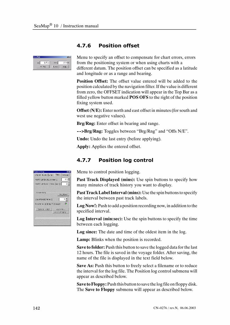
SeaMap 10 / Instruction manual
142 CN--0276 / rev.N, 06.06.2003
4.7.6 Position offset
Menu to specify an offset to compensate for chart errors, errorsfrom the positioning system or when using charts with adifferent datum. The position offset can be specified as a latitudeand longitude or as a range and bearing.
Position Offset: The offset value entered will be added to theposition calculated by the navigation filter. If the value is differentfrom zero, the OFFSET indication will appear in the Top Bar as afilled yellow button marked POSOFS to the right of the positionfixing system used.
Offset (N/E):Enter north and east offset in minutes (for south andwest use negative values).
Brg/Rng: Enter offset in bearing and range.
---->Brg/Rng: Toggles between “Brg/Rng” and “Offs N/E”.
Undo: Undo the last entry (before applying).
Apply: Applies the entered offset.
4.7.7 Position log control
Menu to control position logging.
Past Track Displayed (mins): Use spin buttons to specify howmany minutes of track history you want to display.
PastTrackLabel Interval (mins):Use the spin buttons to specifythe interval between past track labels.
LogNow!:Push to add aposition recordingnow, in addition to thespecified interval.
Log Interval (min:sec): Use the spin buttons to specify the timebetween each logging.
Log since: The date and time of the oldest item in the log.
Lamp: Blinks when the position is recorded.
Save to folder:Push this button to save the logged data for the last12 hours. The file is saved in the voyage folder. After saving, thename of the file is displayed in the text field below.
Save As: Push this button to freely select a filename or to reducethe interval for the log file. The Position log control submenu willappear as described below.
Save toFloppy:Push thisbutton to save the log fileon floppydisk.The Save to Floppy submenu will appear as described below.

Reference guide
143CN--0276 / rev.N, 06.06.2003
Position log control submenu
Menu to save logged data.
File Name: Enter a file name here or use the default file name.
Start time:Use the spin buttons to specify the start time for the logfile.
End time:Use the spin buttons to specify the end time for the logfile.
Log Interval: Time interval between each logging.
Save to Voyage Folder: Push this button to save the log file.
Cancel: Push to cancel the save operation.
Save to Floppy submenu
Menu to save logged data to floppy disk. The log file is sized to fiton a floppy disk. Depending on the log interval, the log file willstore from 12 hours to several days of position data.
File Name: The log file name is constructed as follows:
LYYMMDDB
L for LOG
Year, month, day
Index A, B, C...
For example L020218F was created 18th Feb. 2002. The defaultfile name may be modified.
Start time:Use the spin buttons to specify the start time for the logfile.
End time:Use the spin buttons to specify the end time for the logfile.
Log Interval: Time interval between each logging.
Save toFloppy:Push this button to save the log file to floppydisk.
Cancel: Push to cancel the save operation.

SeaMap 10 / Instruction manual
144 CN--0276 / rev.N, 06.06.2003
4.7.8 Voyage data recording control
Menu to record the own ships track for an entire voyage.
Voyage Display Label Interval: Use the spin buttons to specifythe interval between past positions displayed with text label.
Voyage Recording Interval: Use the spin buttons to specify theinterval between recorded positions.
Text field: Displays voyage recording status.
Lamp: The lamp blinks when the position is recorded.
Name: The name of the voyage recording file.
Started: The voyage recording file contains recordings fromdate/time shown.
Ended: The date/time of the end of a voyage recording. Onlydisplayed when the voyage is ended.
Start New Voyage: Push to start a new voyage recording.
Resume Voyage: Push to continue the last voyage recording.
End Voyage: Push to stop an ongoing voyage recording.
Voyage List: Push to display the Voyage Recording Listmenu.
4.7.9 Voyage recording list
Menu to control log or voyage recordings stored on the system.
Sort On: Select to sort the list by name, type or time.
Name/Type/State/Date: Each file is described by name, type offile (LOG or VOY), state, date and file size.
Display: Push to display the selected log or voyage recording filein the chart. Pushing this button will automatically turn on theVoyage Recording theme in the Chart Theme menu
Undisplay: Turns off display of the selected log or voyagerecording.
Delete: Push to delete the selected file.
Go To: Push to display the chart covering the starting point of thedisplayed log/voyage recording.
Backup: Push to save the selected file on a floppy disk. TheBackup Voyage Recording submenu will appear as describedbelow.
Rename: Push to give the selected file a new name.
Replay: Push to replay the log/voyage file displayed in the chart.The Replay submenu will appear as described below.

Reference guide
145CN--0276 / rev.N, 06.06.2003
Reload: Push to load a log/voyage file from floppy disk. TheRestore Voyage Recording submenu will appear as describedbelow.
Control: Push to display the Voyage Recording Control menu.
Backup Voyage Recording - submenu
Menu to save voyage recording data to floppy disk.
File Name: File name used on floppy disk. Can be modified.
Start time: Use the spin buttons to specify the start time for thevoyage file.
End time: Use the spin buttons to specify the end time for thevoyage file.
Log Interval: Time interval between each logging.
Save to Floppy: Push this button to save the voyage file to floppydisk.
Cancel: Push to cancel the save operation.
Restore Voyage Recording - submenu
Menu to load voyage recording file from floppy disk.
Voyage Files on Floppy: Select a voyage file from the list.
Load:Loads the selected file fromfloppydisk to the SeaMap10.
Cancel: Cancel reloading.
Refresh:Reads and updates the list of voyage files on floppydisk.
Replay - submenu
Menu to control replay of log or voyage recordings.
Ship Name: The name of the ship where the recording was done.Obtained from Ship parameters.
Voyage Name: The name of the replay file.
Started: The start date/time for the voyage recording.
Ended: The end date/time for the voyage recording.
Recording Interval: The interval between each positionrecording.
REPLAY is ON: Push to toggle replay off/on
Speed: Use the spin button to control the replay speed.

SeaMap 10 / Instruction manual
146 CN--0276 / rev.N, 06.06.2003
Play
Step one recordedinterval forward foreach push of the button
Play fast forward
Stop.Step one recordedinterval backwards foreach push of thebutton.
Play fast backwards
Push to return displayto current ship'sposition
Progress indicator
Interpolate: To get a smoother replay select interpolate.
Cancel: Cancels the replay.
Voyages: Push to go to Voyage Recording List menu.
Note All recordings are done inUTC. All times are displayed in currentlocal time zone.
4.8 Depth data
Menu to work with depth data. The depth data input is an optionand requires depth input on a serial line or received across theIntegrated BridgeLine network.
Depth Sensor Data: Push to view raw depth sensor data.
Depth History: Push to display depth history for the past 50minutes.
DepthRecordingControl:Push to start andstopdepth recording.
Depth Recording List: Push to display depth files.
Depth Sensor Setup: Push to set up depth sensors.
→ To display depths in the chart refer to page 97.

Reference guide
147CN--0276 / rev.N, 06.06.2003
4.8.1 Depth sensor data
Menu to view raw depth sensor data.
No: Depth sensor number.
Type: Depth sensor name or type.
Latest Update: Time since the last depth data was received.
BelowTransducer:Depth reading from the sensor.Dependent onthe sensor, additional data can be displayed.
4.8.2 Depth history
Menu to display depth history for the past 50 minutes.
DepthRange:Select the depth range in diagram: 10m, 20m, 50m,100m, or 300m.
Diagram: Colour explanation:
-- Light gray: No data.
-- Dark gray: Depth of ships hull.
-- Brown: Sea bottom as read from sensor1.
-- Blue: Sea bottom as read from sensor2.
Interval: Push to select time scale axis: 5min, 15min or 50min.
4.8.3 Depth recording control
Menu to start and stop depth recording.
State: Indicates if the system is recording or not.
Lamp: Blinks when the depth is recorded. Yellow light indicatesNO DATA.
Record Now!: Push to add a depth recording now.
Name: The depth file name is constructed as follows:
EYYMMDDC
E for ECHOSOUNDER
Year, month, day
Index A, B, C...
For example E020309Fwas created 09thMarch 2002. Default filename may be modified.
Started: The time for the first recording.

SeaMap 10 / Instruction manual
148 CN--0276 / rev.N, 06.06.2003
Ended: The time for the last recording, when the recordings wasstopped.
Start Recordings: Push to start recording a new depth file.Automatic or manual recording depends on the settings in theDepth Recording Setup menu.
ResumeRecordings:Push tocontinue recordings in the lastdepthfile.
End Recordings: Push to stop recording of depth data.
Settings: Push to go to the Depth Recording Setup menu.
List: Push to go to the Depth Recording List menu.
4.8.4 Depth recording list
Menu to display depth files.
Sort On: Select to sort the list by name, type or time.
Name/Type/State/Date: Each file is described by name, state,date and file size.
Display: Push to display the selected depth file.
Undisplay: Turns off display of the selected depth file.
Delete: Push to delete the selected file.
Go To: Push to display the chart covering the starting point of thedisplayed depth file.
Backup: Push to save the selected file on a floppy disk. TheBackup Depth Recording submenu will appear as describedbelow.
Rename: Push to give the selected file a new name.
Reload: Push to load a depth file from floppy disk. The RestoreDepth Recording submenu will appear as described below.
Control: Push to go to the Depth Recording Control menu.
Backup depth recording - submenu
Menu to save depth data to floppy disk.
File Name: File name used on floppy disk. Can be modified.
Start time: Use the spin buttons to specify the start time for thedepth file.
Endtime:Use thespinbuttons to specify theend timefor thedepthfile.
Save to Floppy: Push this button to save the depth file to floppydisk.
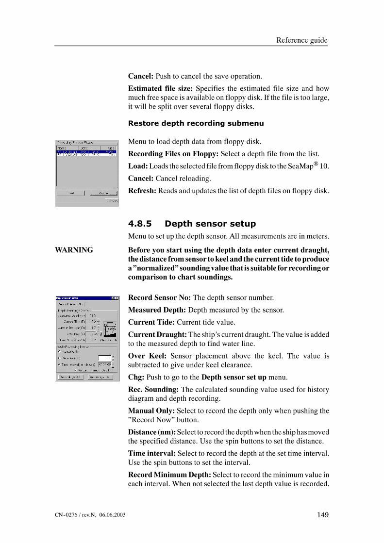
Reference guide
149CN--0276 / rev.N, 06.06.2003
Cancel: Push to cancel the save operation.
Estimated file size: Specifies the estimated file size and howmuch free space is available on floppy disk. If the file is too large,it will be split over several floppy disks.
Restore depth recording submenu
Menu to load depth data from floppy disk.
Recording Files on Floppy: Select a depth file from the list.
Load:Loads the selected file fromfloppydisk to the SeaMap10.
Cancel: Cancel reloading.
Refresh: Reads and updates the list of depth files on floppy disk.
4.8.5 Depth sensor setupMenu to set up the depth sensor. All measurements are in meters.
WARNING Before you start using the depth data enter current draught,thedistance fromsensor tokeel and the current tide toproducea”normalized”soundingvalue that is suitable for recordingorcomparison to chart soundings.
Record Sensor No: The depth sensor number.
Measured Depth: Depth measured by the sensor.
Current Tide: Current tide value.
CurrentDraught:The ship’s current draught. The value is addedto the measured depth to find water line.
Over Keel: Sensor placement above the keel. The value issubtracted to give under keel clearance.
Chg: Push to go to the Depth sensor set up menu.
Rec. Sounding: The calculated sounding value used for historydiagram and depth recording.
Manual Only: Select to record the depth only when pushing the”Record Now” button.
Distance (nm):Select to record thedepthwhen theshiphasmovedthe specified distance. Use the spin buttons to set the distance.
Time interval: Select to record the depth at the set time interval.Use the spin buttons to set the interval.
RecordMinimumDepth: Select to record theminimum value ineach interval. When not selected the last depth value is recorded.

SeaMap 10 / Instruction manual
150 CN--0276 / rev.N, 06.06.2003
Recording Ctrl: Push to go to the Depth Recording Controlmenu.
Recording List: Push to go to the Depth Recording Listmenu.
Depth sensor setup - submenu
Menu to set up communication with the depth sensor.
Type: Select echo sounder type from the menu.
Protocol: Select communication protocol from the menu.
Messages: Select message format from the menu.
Transducer Location ref. Aft Peak: Specify position of thesensor over keel (necessary for computation of soundings) andalong/across (necessary for exact positioning of sensor readings).starboard is positive, port is negative.
4.9 Wind displayMenu to work with wind data. Anemometer (wind sensor) inputcan be integrated on the ECDIS and displayed in connection withthe ship as a wind arrow. In order for it to work, wind sensor(s)must have been enabled in the sensor setup menu. Wind data canbe input on a serial line or received across the IntegratedBridgeLine network.
4.9.1 Wind sensor data
This menu gives the direction and strength of the wind datareceived from the selected wind sensor.
No: Depth sensor number.
Type: Depth sensor name and type.
Latest Update: Time since the last wind data was received.
Rel. Wind:Wind direction and speed relative to ship headingand speed.
True Wind:Wind direction and speed relative to north andground.
Display Arrow: Select to display wind arrow in the chart. Thewind arrow in the chart displays true wind.
Configure...: Push to display the wind sensor configurationmenu.

Reference guide
151CN--0276 / rev.N, 06.06.2003
Figure 33 Wind arrow display.
4.9.2 Wind sensor configuration
Menu to configure the depth sensor. It gives the status of theselected depth sensor.
No:Wind sensor number. If there are multiple wind sensorsselect one.
Type:Wind sensor name.
Latest Update: Time since the last wind data was received.
Wind Speed: Raw wind speed received from the sensor.
Wind Direction: Raw wind direction received from the sensor.
Mode: The data as received from the wind sensor is either:
* Relative to ship heading and speed.
* Relative to ship heading and water speed.
* Relative to ground and north.
m/s or Knots: Select the unit for presentation in wind sensordata.
Wind Arrow Symbol Offset: Specifies the wind arrow’s offsetin millimetres, from the own ship symbol in the chart display.

SeaMap 10 / Instruction manual
152 CN--0276 / rev.N, 06.06.2003
4.10 Notes
Menu to set and work with notes. Mariner’s notes aregeographically fixed symbols, lines and areas that are used tocomplement charts or supplement radar information when chartsare not used.
Manage notes: Push this button to display available notes.
Edit Note: Push this button to edit notes.
SaveAll Notes:Push this button to save newor edited notes to thehard disk.
Manage Note Folders: Push this button to manage notes folders.
Load Notes from Floppy: Push this button to load notes fromfloppy disk.
Save Notes to Floppy: Push this button to save notes to floppydisk.
ARCS Notes and Diagrams: Push this button to view HCRFnotes and diagrams.
ARCS Temp. Notices to Mariners: Push this button to viewHCRF temporary notices to mariners.
4.10.1 Manage notes
Menu to display available notes in a folder.
List:The drop downmenu presents a list of available note folders,when more than one folder is available.
Sort on: Notes can be sorted by type, distance from own ship ordate of creation/modification.
The list: A sorted list of notes from the selected folder. Select anote if you want to edit it. The following information is listed.
-- No. -- The note number.
-- Time -- The time the note was created or last modified.
-- Type -- Type of note. The following note types are available:
* Event
* Caution note
* Information note
* Chart correction note
* Solid line
* Dashed line

Reference guide
153CN--0276 / rev.N, 06.06.2003
* Safety contour
* Hollow area
* Filled area
* Text note
* Chart calibration point
* Danger highlight
* Predicted tidal stream
* A large set of chart point symbols
-- Latitude
-- Longitude
-- First part of note text
List: Push this button to view details about the selected note.
Edit: Push this to edit the selected note.
Cut: Push this button to cut the selected note from the list.
Paste: Push this button to paste a previously cut note to the list.
Event: Push this button to create an event note.
Caution note: Push this button to create a caution note.
Info note: Push this button to create an info note.
Chart Corr: Push this button to create a chart correction.
Other Note: Push this button to display a menu with additionalnote types.
Solid Line: Push this button to create solid lines.
Dashed Line: Push this button to create dashed lines
Safety Contour: Push this button to create a safety contour.
Area: Push this button to create a polygon describing an area.
FilledArea:Push this button to create a filled polygon describingan area.
Other notes - submenu
Menu to work with less frequently used note types.
TextNote: Push to create a textnote that is displayedon thescreen.
Chart Calibration Pt.: Push to create a point note that is usefulfor chart calibration etc.
Danger Highlight: Push to draw highly visible lines arounddangerous objects.
Event
Safety contour
Solid line
Dashed line
Chart correction
Information
Caution
Filled area
Area

SeaMap 10 / Instruction manual
154 CN--0276 / rev.N, 06.06.2003
Pred. Tidal Stream: Push to create Predicted Tidal Streamsymbols.
Actual Tidal Stream: Push to create Actual Tidal Streamsymbols.
Create Symbol: Push and select symbol from the pull down list.
4.10.2 Edit note
Menu to edit notes.
Number: The notes number in the list. Use arrow buttons tochange number.
Time: The date and time when the note was last saved.
Type: Select note type from the drop down menu.
Comment: The note text. If necessary use the scroll bar
Edit: Push to edit the note.
Cancel: Cancels any text changes made using the keyboard.
GoTo: Push to show the chart with the note displayed. Onlyavailable in browse mode.
InsertPt: Push this button to insert a newpoint before the selectedpoint.
Delete Pt: Push to delete selected points.
Copy Pt: Used to copy selected points to an other note. Selectpoints and push copy.
Paste Pt: Pastes copied points into a list of points.
Datum: Select WGS--84, EUR--7 or Offset from WGS--84. IfOffset from WGS--84 is selected, the offset must be specified(normally found in the chart).
EUR--7:Pressing theEUR--7 button will allow you to select fromthe list of available datums and use this for position presentation.
4.10.3 Save all notesPush button to save all notes on the hard disk.

Reference guide
155CN--0276 / rev.N, 06.06.2003
4.10.4 Manage note folders
Menu to manage notes.
NoteFolders inArchive:Listofnote folders in the archive.Selecta folder.
Display: Push to display the notes from selected folder.
Undisplay: Push to remove notes from selected folder from thechart area.
Edit: Push to edit selected folder.
New: Push to create a new notes folder.
Revert: Push to Revert to the previously saved version.
Save: Push to save selected note folder to the hard disk.
Rename: Push to rename selected folder.
Delete: Push to delete selected folder.
Insert File: Push to insert file from floppy disk.
Back--up: Push to save selected folder to floppy disk.
List: Push to list notes in the selected folder.
Refresh:Updates note list. Use if you have inserted a new floppydisk.
4.10.5 Load notes from floppy
Menu to load previously made notes from floppy disk. Insert thedisk into the floppy drive.
Notefiles on Floppy: Lists the note folders on the floppy disk.
Load As: Copies selected folder from the floppy disk to the notefolder specified below.
Note Folder: Select the folder you want to load to, from the dropdown list.
Refresh: Updates the list of files on the floppy disk. Use it whenyou have inserted a new floppy disk.

SeaMap 10 / Instruction manual
156 CN--0276 / rev.N, 06.06.2003
4.10.6 Save notes on floppy
Menu to save notes on floppy disk. Insert an empty disk into thefloppy drive.
Notefiles on Floppy: Lists the files on the floppy disk.
Save As: Copies selected note folder to the floppy disk.
Note Folder: Select the folder you want to save from the dropdown list.
Refresh: Updates the list of files on the floppy disk. Use it whenyou have inserted a new floppy disk.
4.10.7 HCRF notes and diagrams
Menu to view HCRF notes and diagrams.
Chart: Chart number.
Notes andDiagrams:Listofnotesanddiagramsavailable for thischart. By selecting an entry in the table, the note/diagram will bedisplayed in a separate window.
TidalData:List of tidal data stations in the chart. Select one of thestations to display the data in a separate window.
4.10.8 HCRF temporary notices tomariners
Menu to view HCRF temporary notices to mariners.
General: Select to see general notices.
Chart: Select to see notices for chart currently being displayed.
Arrow buttons: Select specific notice by using buttons.
NtM no: Notice to Mariners number.
4.11 Tools
Menu to select and work with system tools.
Marker Position: Push this button to display the geographicposition of the marker.
Marker Bearing and Range: Push this button to display markerbearing and range from own ship.
EBL/VRM:Push this button to set up and displayEBLandVRM.

Reference guide
157CN--0276 / rev.N, 06.06.2003
EBL/VRM (Advanced): Push this button to display EBL andVRM. Includes additional features to the menu above.
Curved EBL: Push this button to display the curved EBL menu.
Parallel IndexLine:Push this button to display the Parallel IndexLines menu.
Position Line: Push this button to calculate own ship’s positionusing the bearing to two or three objects with known positions orobjects shown in the charts.
Position Fix: Push this button to display position fixes fromdifferent sources.
Datumconversion:Push thisbutton toconvert betweenWGS--84and a chosen datum
MarkerPosition inOtherDatum:Push this button to display themarker and own ships position in a chosen datum.
4.11.1 Marker position
Menu to display marker position in latitude and longitude.
4.11.2 Marker bearing and range
Menu to display marker bearing and range from own ship
m: Select to display range in meters. When not selected range isdisplayed in nautical miles.
4.11.3 EBL/VRM
Menu to set up and display EBL and VRM. There are threeEBL/VRM pairs available. Each pair is identified by a number atthe base of the EBL.
No: Displays EBL/VRM number.
From: Position at the base of the EBL/VRM.
To: Position at the intersection between the EBL and the VRM.
New: Push to create a new EBL/VRM.
Delete: Push to delete the current EBL/VRM.
Apply: The displayed bearing and range can be editednumerically. Push Apply to enter new bearing and range values.
→ Refer to page 56 formore information on how touse theEBL/VRMfunction.

SeaMap 10 / Instruction manual
158 CN--0276 / rev.N, 06.06.2003
4.11.4 EBL/VRM advanced
Menu to set up and display EBL and VRM
No: DisplaysEBL/VRMnumberselected in thechart, or specifiedby using the up/down arrows.
From: Position at the base of the EBL/VRM. Edit position asrequired and push Apply to activate.
To: Position at the intersection between the EBL and the VRM.
New: Push to create a new EBL/VRM.
Delete: Push to delete the current EBL/VRM.
Bearing and range of EBL/VRM: Edit bearing and range asrequired and push Apply to activate.
Great Circle: Select to specify EBL/VRM with Great circlegeometry.
Rhumbline: Select to specify EBL/VRM with Rhumblinegeometry.
Meter: Select to display range inmeters.When not selected rangeis displayed in nautical miles.
Datum: Select WGS--84, EUR--7 or Offset from WGS--84. IfOffset from WGS--84 is selected, the offset must be specified(normally found in the chart).
EUR--7:Pressing theEUR--7 button will allow you to select fromthe list of available datums and use this for position presentation.
4.11.5 Curved EBL
Menu to set up and work with a curved EBL.
AutoPilot mode: The curved EBL is to be used as input toAutopilot.
Plan Mode: Curved EBL used to create a route plan.
New Heading: Heading after the turn. Adjust using the pushbuttons.
Time to Turn: Calculated based on distance to turn and currentspeed.
Dist. To turn: Distance from the current position to the turn.Adjusted using the up--down controls.
TurnRadius:The turn radius for themanoeuvre.Adjust using theup--down controls.
Enable: Select to display the curved EBL in the chart area.

Reference guide
159CN--0276 / rev.N, 06.06.2003
Reset: Reset to default values. These are:
-- New course: Same as current heading-- Distance to turn: 1nm-- Turn radius: 1nm
Activate: Creates a route plan from the Curved EBL data.
→ Refer to page 58 for more information on how to use the curvedEBL.
4.11.6 Parallel index lines
Menu to set up Parallel Index Lines. Four parallel index lines areavailable.
ID: Parallel index line number.
Distance: The distance from own ship’s conning position to theparallel index line.
Bearing: The bearing of the parallel index line.
Mode: True or relative bearing. The parallel index line will turnwith the ship when relative mode is selected.
New: Creates a new parallel index line.
Delete: Deletes the selected parallel index line.
Apply: Enters the distance and bearing set in the fields above.
→ Refer to page 57 formore information onhow touse parallel indexlines.
4.11.7 Position line
Menu to find the own ship’s position using the bearing to two orthree objectswith known positions or objects shown in the charts.
Two Points: Selects position fix using two points.
Three Points: Selects position fix using three points.
Table: Table of parameters for two or three position lines. EditBearing/Latitude/Longitude as required.
New Measurement: Push to add a position line record. Definesthe time of the measurement.
Redo: Push to redo the last measurement.
GetCursor: Push this button and point to an object in the chart toidentify the position of the object. This is an alternative to fillingin the latitude and longitude fields.
Intersection: The calculated position ofwhere the lines intersect.

SeaMap 10 / Instruction manual
160 CN--0276 / rev.N, 06.06.2003
Clear All: Push to clear all measurements in the table.
Define Position Fix: Push to define a position fix from thecalculated intersection.
4.11.8 Position fix
Menu to display position fixes from different sources.
Fix Type: The source of the position fix. The following areavailable:
* Dead reckoning
* Visual
* Astronomical
* Radar
* GPS
* Glonass
* Loran/Tchaika
* MFDF
* Transit/Tchaika
Diff.: Select if the position was received from a differentialposition sensor.
Table: Table showing the different position fixes including time,latitude, longitude, fix type, offset and bearing from ship position.Scroll table to show all fields.
Get Cursor: Push to fill in the latitude and longitude fields fromthe cursor position.
Offset Ship: The ship is given amanual offset to correspond withcurrent position fix.
Delete: Push to delete the position fix record.
4.11.9 Datum conversion
SeaMap 10 works with WGS--84 internally. However, otherdatums can be selected to relate geographic positions to old papercharts etc. Non--WGS datums can be used to present positions inroute plans and mariner’s objects and for EBL/VRM tools. Morethan 200 datums are available and can be selected for presentationof positional information.

Reference guide
161CN--0276 / rev.N, 06.06.2003
Datums are either 7 parameter datumsor three--parameter datums.Three--parameter datums are only valid in smaller areas. The validarea is displayed in the dialog. If you try to apply a datum to aposition outside its valid area, an error message is displayed.
Type in aposition inWGS--84 andhave it converted to the selecteddatum, or type in a position in the selected datum and have itconverted to WGS--84.
Datum Parameters: Select datum from the drop down list.
Details: Push to display the conversion parameters between theselected datum and WGS--84.
Datum-->WGS84:Select toconvert fromthedatumchosenaboveto WGS--84.
WGS--84-->Datum:Select to convert fromWGS--84 to thedatumchosen above.
Convert: Push to initiate the datum conversion.
4.11.10Marker position in other datum
Menu to show the Marker position and the current own ship’sposition in the selected datum.
EUR--7: Push to go to the Datum Converter dialog.
4.12 System
Menu to set up system parameters. Commonly used buttons arealways enabled. The other buttons are disabled until the operatorenters a User or Service password.
Palette: Push to set panel and display intensity.
Parameter Settings: Push to setup system specific parameters.
Grounding Alarm Setup: Push to set up the grounding alarm.
Date and Time: Push to set local time.
Print Screen: Push to print the current chart display.
Printer: Push to select printer.
Export to/Import from DB2000: Export routes or charts toDataBridgeE 2000.
Navtex messages: Push to read Navtex messages and configurecategories and stations.

SeaMap 10 / Instruction manual
162 CN--0276 / rev.N, 06.06.2003
Passwords: Push to enter password to obtain access to restrictedmenus.
Maintenance: Push to view various maintenance relatedinformation.
Alarm Setup: Push to set up alarms for the ECDIS display.
Serial Communication: Push to view and configure serial ports.
Sensor Configuration: Push to view and configure sensors.
ANTS Configuration: Push to set configuration parameters forthe autopilot system.
Shutdown: Push to shut down the program. Only available fordesktop systems.
4.12.1 Palette
Menu to control the display and control panel light level.
Palette:Adjust to the ambient light level.
* Lightest -- Day Bright
* Darkest -- Night Filtered
The choice of palette will also influence the operator panelbackground light level.
Set Calibrated: Push to reset brilliance and contrast to thecalibrated settings.
Degauss: Push to degauss cathode ray tube type displays.Degaussing removesanyundesirablemagnetic field thatmayhavebuilt up within the display, causing distortion of the image orcolour.
Brilliance:Use the trackball andobjectmenubutton to operate theslide control and change the brilliance setting.
Contrast:Use the trackball and object menu button to operate theslide control and change the contrast setting.
4.12.2 Parameter setup - display tab
Menu to set up how own ship will be displayed and when/howchart regeneration will be done.
ShipVector: Specify length of own ship’s course/speed vector inseconds.
Ship Bearing Line: Specify length of own ship’s bearing line innautical miles.

Reference guide
163CN--0276 / rev.N, 06.06.2003
Ship Always as Symbol: Select to display own ship as a symbol.When not selected own shipwill be displayed in true sizewhen thechart scale permits it.
ShowHeading Line: Select to display own ship’s heading line inthe chart.
Marks on course vector:Marks indicating where the own shipwill be every oneor every sixminutes. SelectNoMarks,Oneminor Six min as required.
Chart regeneration area: When the system is operated in truemotion the own ship moves across the chart. As the own shipreached the edge of the display the chart needs to be regenerated.To provide better overview the operator can configure when thechart shall be regenerated. This is done by defining a regenerationrectangle. When the own ship crosses any of the sides the chart isregenerated.
→ Refer to page 55 for more information on how to define theregeneration area.
Min. Chart Ahead: The chart is regenerated when the distanceahead of the own ship is less that the set percentage.
FixedBorderOffset: The chart is regeneratedwhen the own shipgets closer than the set percentage from the edge. (In percent of thescreen diameter).
Moveable rectangle:Allows you to define each side of therectangle individually. The distance for left, right, top and bottomas specified below.
Left/Right/Top/Bottom: Type distances for moveable rectangle
Display and Edit Regeneration Area: Select to display theregeneration area in the chart. The area can be resized by draggingthe sides.
Distances in Meters: Select to use meters instead of nauticalmiles for short distances.
Apply: Push to save the parameter set--up.
Cancel: Push to cancel all changes.

SeaMap 10 / Instruction manual
164 CN--0276 / rev.N, 06.06.2003
4.12.3 Parameter setup - ship tab
Menu to set own ship’s specific parameters. These are normallyset at commissioning time and should not need to be changed.
Ship Name: The name of the ship.
Ship Length: Total ship length.
Ship Width:Maximum ship width.
Max Ship Draught:Maximum ship draught when loaded.
Conning from Stern: Distance from stern to conning position.
Conning stb. of Centerline:Distance from centerline to conningposition. For port use negative values.
Pivot Point from Stern: Distance from stern to pivot point.
Pivot Point of Center: Distance from centerline to pivot point.For port use negative values.
Min. Ship Turn Radius: Own ship’s minimum turning radius.The value is used to validate routes.
Max. Ship Turn Rate: Own ship’s maximum rate of turn. If anupcoming turn exceeds this rate of turn, an alarm is given.
Turn Acceleration Length: Distance from Wheel Over Point tostart of turn*2.0. (This is the samevalue that is calledAccelerationLength in AP2000 Operator’s Manual -- See this for details.)
Offtrack Alarm Margin: The distance between the route’soff--track corridor and the own ship’s pivot point when an alarm isgiven.
ANTS on Validated Routes Only(W1): When selected, onlyvalidated routes will be allowed used for autopilot control (WatchOne).
Apply: Push to save the parameter set up.
Cancel: Push to cancel all changes.
4.12.4 Grounding alarm setup
Menutosetup thegroundingalarmchecking.Groundingcheckingis done against the chart.
Vector length: Use buttons to specify how far ahead, in secondsgrounding checking is to be done. When set to 0, groundingchecking is disabled.
Width: Use buttons to specify the width of grounding checkingarea in degrees. Range 0 -- 30 degrees.

Reference guide
165CN--0276 / rev.N, 06.06.2003
Warnings: Lists of warning messages. Select one to have thedetails displayed below.
Groundings: Lists of groundingmessages. Select one to have thedetails displayed below.
Display: Select to display the vector in the chart.
4.12.5 Date and time
Menu to set local time.
UpdateRemote: Sets currentUTC time toother SeaMap10andDataBridge 10 units connected on the local area network.
Current Time (UTC): Current UTC time (UTC -- CoordinatedUniversal Time, formerly known as GMT).
Current Time (Local): Time in the local time zone.
AdjustOffset:Use up and downbuttons or the keyboard to set thedifference between UTC and local time.
Apply: Applies any offset entered using the keyboard.
Synch: Select to synchronise time with the incoming NMEAmessages from the GPS.
Show (Hide) NMEA: Push to display the NMEA time messagebelow. Only used for debugging purposes.
4.12.6 Print screen
Menu to print the current chart display. Route printing is initiatedfrom the Manage Routes menu.
Select Printer: If more than one printer is available select theprinter you want to use from the drop down menu.
Select orientation:Select between portrait and landscape format.
Remove: Push to remove the selected screen dump from theprinting queue.
Preview: Push to display a preview of the printout.
Print to file: Select to print the screen dump to a file on the floppydisk, for external use.

SeaMap 10 / Instruction manual
166 CN--0276 / rev.N, 06.06.2003
Copies: Select the number of copies you want printed.
Print: Push to start the printing.
Cancel: Push to cancel the printing.
Print preview - submenu
A preview of the selected printout.
Prev:Push togobetweenpageswhen theprintout consists ofmorethan one page.
Next:Push togobetweenpageswhen theprintout consists ofmorethan one page.
Print: Push to start to print.
Cancel: Push to cancel printing.
Zoom In: Push to view the preview in more detail.
Zoom Out: Push to view the preview in less detail.
Figure 34 Example of print preview.
4.12.7 Export to/import from DB2000Menu to transfer data between SeaMap 10 and DataBridge
2000.

Reference guide
167CN--0276 / rev.N, 06.06.2003
Export route - tab
Menu to export route data to the selected DataBridge 2000.
Remote Station: Lists available DataBridge 2000 systems.
Refresh: Push to update the list of Remote Stations.
Route Name: Route name used in the SeaMap 10.
DB2000 Name: Route name used in the DataBridge 2000.
Rename: Push to type in a new DataBridge 2000 name for theselected route.
Delete: Push to remove the selected route from the list.
Export: Push to export the selected routes.
Export chart - tab
Menu to export charts to the selected DataBridge 2000.DataBridge 2000 charts are generated in a specificDataBridge
2000 format and stored in a special directory in SeaMap 10before exporting to DataBridge 2000.
Remote Station: Lists available DataBridge 2000 systems.
Refresh: Push to update the list of Remote Stations.
Chart Name/Size : Shows the name and size of the charts thathave been generated for export to DataBridge 2000.
Delete: Push to remove the selected charts from the DataBridge
2000 chart directory.
Export: Push to export the selected charts.
Monitor export - tab
Menu to display export progress for routes and charts.
Remote Station: Lists available DataBridge 2000 systems.
Refresh: Push to update the list of Remote Stations.
Name/Station : Shows the name and destination of the files thatareexported toDataBridge2000.The first file is the file currentlybeing exported
Overall Progress: Progress bar indicating progress of the wholeexport job.
Current Transfer Progress: Progress bar indicating progress ofthe export of the current file.

SeaMap 10 / Instruction manual
168 CN--0276 / rev.N, 06.06.2003
Import route - tab
Menu to import routes from the selected DataBridge 2000.
Remote Station: Lists available DataBridge 2000 systems.
Refresh: Push to update the list of Remote Stations.
Name : Lists routes that has been prepared for export to SeaMap
10.
Overall Progress: Progress bar indicating progress of the totalimport job.
Current Transfer Progress: Progress bar indicating progress ofthe import of the current file.
4.12.8 Navtex message listMenu to view unread and previously read messages.
Unread: Select to display a list of unread messages.
Read: Select to display a list of previously read messages.
The list: The list displays either unread or read messagesdependent on the selection above.
Delete: Push to delete one or several selected messages.
Display: Push to display selected message.
Configure: Push to configure the Navtex interface.
4.12.9 Navtex configure
Push theConfigure... button on the Navtex message list dialog tobrings you to the Navtex configuration dialog.
Settings tab
Menu to configure the type of Navtex receiver connected. Theseparameters are normally only changed during commissioning. Asystem password is required to change them.
EquipmentType:Select the type ofNavtex receiver connected tothe SeaMap 10 from the drop down list.
Port No: Select the serial port number the Navtex receiver isconnected to. Settings for the serial port are done underMenu >System>Serial Communication. By default, the serial line is setto 4800, 8 bit data, 1 stop bit, no parity.
Invoke Alarm: Select to display Navtex alarms of categories A,B, D and L on the ECDIS display as warnings.

Reference guide
169CN--0276 / rev.N, 06.06.2003
Automatically Save After Read: Select to automatically saveincoming messages after they are read. Incoming messages arestored in an Unread directory, while messages are automaticallytransferred to the Read directory after the user has read them.Messages are retained in the Read directory until they areexplicitly deleted. If not selected, messages are automaticallydeleted after they have been read, unless they are explicitly saved.
Note The Navtex interface is purely a passive ”listen” interface. Nosignals are sent from the ECDIS to the Navtex receiver.
Categories tab
Menu to select Navtex message types to be ignored.
MessageTypes:Selectmessage types to be ignoredby theECDISsystem. Messages categories A, B, D and L cannot be disabled.
Reset: Push to enable all Navtex messages.
Note Inaddition to thesettingshere theNavtex receivermayhave it’s own message filtering enabled.The ECDISdisplaywill only receivemessages that are enabled bythe Navtex receiver. The Navtex receiver settings arehow ever not affected by the ECDIS settings.
Stations tab
Menu to specify Navtex stations to be ignored
Area: Select the area you are in. Transmitting stations areidentified by a letter fromA to Z.When you select the area you arein, the systemwill display the name of the transmitting stations inthat area.
Overlap:Sometimesyouwill receive signals fromanoverlappingarea. Select this area here.
Ignore: Select transmitting stations to be ignored by the ECDISsystem.
Reset: Push to enable all stations in the area.

SeaMap 10 / Instruction manual
170 CN--0276 / rev.N, 06.06.2003
4.12.10Password
Menu to insert passwords to obtain access to system parametersand restricted menus.
UserPassword: Inserting the user password allowsyou to changethe following:
-- Alarm setup
-- Chart databases
-- Upgrade system software
Service Password: Inserting the service password allows you tochange the following:
-- Serial communication
-- Sensor configuration
-- ANTS configuration
Thesesettingareconfiguredatcommissioning timeandshouldnotnormally need to be changed. Do not change Service Accesssettings unless you are trained to do so. Changing these settingsmay render the system useless or seriously degrade theperformance of the system!
Open: Push to allow changes.
Lock: Push to inhibit further changes.

Reference guide
171CN--0276 / rev.N, 06.06.2003
4.12.11Maintenance
Menu to view various maintenance related information and loadnew system software. This menu is not used for normal systemoperation. User password is required for some of the functions.
System Software Version: States the version of the installedsoftware.
System ID: Identifies the SeaMap 10 hardware.
ComputerName: Identifies the computer fornetworkedsystems.
Serial number: The SeaMap 10 has a six digit serial number:21xxxx or 29xxxx. Planning Stations has a four digit serialnumber: xxxx.
Global Palette: Select to use a global palette when severalSeaMap 10 and DataBridge 10 units are connected together.
Upgrade System Software: Push to Upgrade System Software.Requires an upgrade CD--ROM.
Change Optional Components: Push to enable or disableoptional components.
Reconfigure chart database: Push to set priority, clean--up, addand remove chart databases.
CopyLogDecoding Program to Floppy:Push to go to themenufor saving the decoding program to floppy disk. This program isnecessary to read position log/voyage recordings from floppydiskon another off--line PC.
Colour Differentiation and Calibration: Displays colourdifferentiation diagram or colour calibration diagram.
Install C--Map SDK: Push to install the C--Map SDK -- SoftwareDevelopment Kit. This is normally only done duringcommissioning.
ConfigureMonitor:Menu to select the type of monitor installedin the system.
Upgrade system software - submenu
Menu to install new versions of the ECDIS software.
Upgrade: Insert the CD--ROM into the drive and push the buttonto start the upgrade.

SeaMap 10 / Instruction manual
172 CN--0276 / rev.N, 06.06.2003
Change optional components - submenu
Menu to enable or disable optional software components.
ECDIS Optional Components: List of available optionalcomponents. Select the option you want to enable or disable.
Enable: Push to enable the selected option.
Disable: Push to disable the selected option.
Pin code: Type in the Pin code provided by Kongsberg Maritimeto enable the option.
Reconfigure chart databases - submenu
Menu to set priority, clean--up, add and remove chart databases.SeaMap 10 can have a number of chart databases active at anytime. Each database is identified by a two letter mnemonic:
* CM C--Map
* PR Primar
* AR ARCS
* CW World
* HO S57 HO data
In the Zoommenu this mnemonic precedes the chart scale. If twodatabases have a chart of the same scale, the database with thehighest priority will have its chart first in the chart table.
Databases:A list of all chart databases in the system. The highestpriority is at the top of the list. The two letter mnemonic can beedited by double--clicking it and typing in a new mnemonic.
RemoveDatabase: Push to remove theselecteddatabase fromthesystem. This is not normally done unless there is little hard diskspace left. The action will also remove all licences related to thedatabase.
Cleanup Database: Push to remove all charts in the selecteddatabase, without removing the database from system.
Increase Priority: Push to increase the priority of the selecteddatabase. The database moves upward in the table.
Decrease Priority: Push to decrease the priority of the selecteddatabase. The database moves downward in the table.
AddNew...: Push the button go to the NewChart Databasemenu.There are restrictions to howmany databases there can be of eachtype.
* C--Map: maximum 7

Reference guide
173CN--0276 / rev.N, 06.06.2003
* ARCS: maximum 1Change Mirror...: Is used to to mirror CM--93 Edition 2 or 3databases from an other ECDIS system on the bridge network.Push the button go to the Chart Database Mirror menu.
Cancel Changes: Push to cancel the changes. Cleaned up orremoved databases cannot be brought back!
Apply Changes: Push to write the changes to the hard disk. Inorder for these changes to take place you will need to restart thesystem.
→ Refer to the operation selection for more information on how toinstall and work with databases.
Select monitor - submenu
Menu to select themonitor type.Will set the correct colour palettefor this monitor. Normally only done during commissioning.
Monitor type: Select monitor type from the drop down list.
Port No: Select the serial communication port used to providebrightness and contrast control, and proper night dimming.
Apply: Saves any changes made.
Note Changingthisparameter toaninappropriatevaluemayaffect typeapproval for your ECDIS system.
4.12.12Alarm set-up
Menu to select how the system will indicate alarms in differentsituations.
Visual: The system will only create a visual alarm indication.
Visual + Beep: The system will create a visual alarm indicationand a short beep.
Visual+Audible:The systemwill create a visual alarmindicationand an audible alarm. The audible alarm remains on untilacknowledged.
CritP: Alarm for critical points defined by the operator duringroute editing.
Area:Area alarm part of the chart, such as for restricted areas etc.
Cross Track: Alarm indication when own ship has a cross trackerror more than the set limit. Only visual and audible indication isavailable for this alarm.
Grounding: Alarm indication when the depth is less than the setlimit.

SeaMap 10 / Instruction manual
174 CN--0276 / rev.N, 06.06.2003
SystemWarning:Alarm indication related to the performance ofthe system and its sensors.
System Alarm: Alarm indication issued when there is anequipment fault.
More Alarm Setup: Push to reach additional alarm settings.
Note To avoid invalidating the ECDIS type approval all but Area alarmmust be set to Audible.
Note All alarms must be acknowledged by the operator.
Alarm setup more - submenu
Menu to set the UPS (Uninterruptible Power Supply) alarm.
Enable Power Supply Input Alarm: Select to enable an alarmwhen the SeaMap 10 draws power from the UPS. Must beselected for SeaMap 10 ECDIS type--approval to be valid.
Alarm Delay: Use buttons to set the time from the power isinterrupted before the alarm is activated.
* Range: 0 to 30 seconds.
Invalid alarm setup warning
Menu to inform the user that the newalarm settingswill render thetype approval invalid.
OK: Push to disregard warning and use the new settings.
Revert toApproved: Push to revert to the type approved settings.
4.12.13Serial communication
Menu to configure the serial ports. This is normally done atcommissioning time and should only be done by qualifiedpersonnel. Changing the settings may render the system useless.
Serial Port: Use buttons to select serial port number.
Monitor: Push to go to the Serial Monitor menu, where themessages on the serial port can be monitored.
Reg User: Displays the units connected to this port.
Select User: Push to go to the Serial Manager menu, where theport number for all connected users can be seen.

Reference guide
175CN--0276 / rev.N, 06.06.2003
Baud Rate: The configured baud rate for the port.
Data Bits: The configured number of data bits in each word.
Parity: The configured parity: Odd, even or no.
Stop Bits: The configured number of stop bits after each word.
Config: Push to go to the Serial Configurationmenu, where theconfiguration parameters can be changed.
Serial port monitor
Menu to monitor the messages on the selected serial port.
Serial Port: Use buttons to select serial port number.
Config: Push to go to the serial configuration menu, where theconfiguration parameters can be changed.
Input: Field where messages coming into the SeaMap 10 aredisplayed.
Output: Field where messages going out of the SeaMap 10 aredisplayed.
HEX: Push to display the messages as hexadecimal numbers.
ASCII: Push to display the messages as ASCII characters.
Start:Push to start monitoring themessages on the selected serialport.Monitoringwill continueuntil youpush“Stop”,or the logfilehas reached 1 Mbyte.
Stop: Push to stop monitoring of the selected port.
Serial management
Menu to display what the different serial ports are used for.
Serial port configuration
Menu to configure the communication protocol on the selectedserial port.
Serial Port: Use the buttons to select serial port number.
Monitor: Push to go to the Serial Monitor menu, where themessages on the serial port can be monitored.
Baud Rate: Push to select the baud rate.
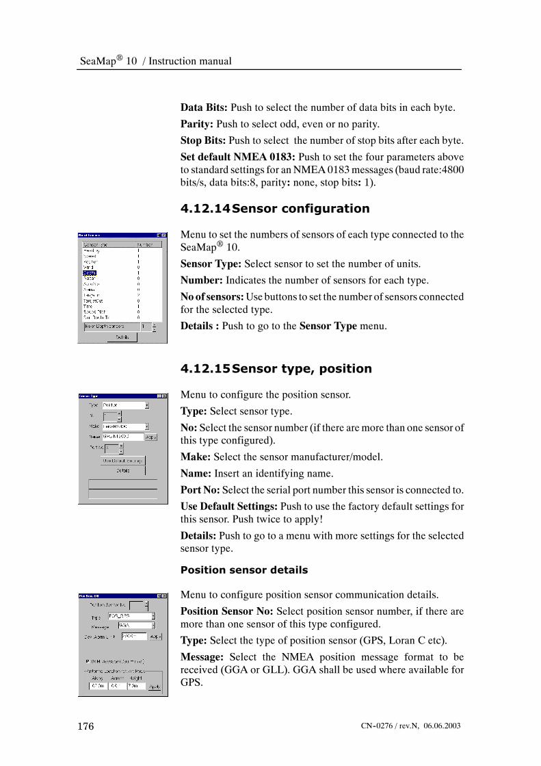
SeaMap 10 / Instruction manual
176 CN--0276 / rev.N, 06.06.2003
Data Bits: Push to select the number of data bits in each byte.
Parity: Push to select odd, even or no parity.
Stop Bits: Push to select the number of stop bits after each byte.
Set default NMEA 0183: Push to set the four parameters aboveto standard settings for anNMEA0183messages (baud rate:4800bits/s, data bits:8, parity: none, stop bits: 1).
4.12.14Sensor configuration
Menu to set the numbers of sensors of each type connected to theSeaMap 10.
Sensor Type: Select sensor to set the number of units.
Number: Indicates the number of sensors for each type.
Noof sensors:Use buttons to set the number of sensors connectedfor the selected type.
Details : Push to go to the Sensor Type menu.
4.12.15Sensor type, position
Menu to configure the position sensor.
Type: Select sensor type.
No: Select the sensor number (if there aremore than one sensor ofthis type configured).
Make: Select the sensor manufacturer/model.
Name: Insert an identifying name.
Port No: Select the serial port number this sensor is connected to.
Use Default Settings: Push to use the factory default settings forthis sensor. Push twice to apply!
Details: Push to go to a menu with more settings for the selectedsensor type.
Position sensor details
Menu to configure position sensor communication details.
Position Sensor No: Select position sensor number, if there aremore than one sensor of this type configured.
Type: Select the type of position sensor (GPS, Loran C etc).
Message: Select the NMEA position message format to bereceived (GGA or GLL). GGA shall be used where available forGPS.

Reference guide
177CN--0276 / rev.N, 06.06.2003
Dev. AlarmLimit:Type in the position deviation alarm limit andpush apply.
DTM Message (Datum Info): Select this option if the positionsensor is able to send DTMmessages. According to ECDIS rulesthis is used to make sure the position sensor is set up to outputposition in WGS--84 datum. If the position sensor is older andcannot output DTMmessages do not select this option to avoid acontinuous “DTMmissing” alarm. Make sure the position sensoris set to output WGS--84.
AntennaLocation:Specify the antenna location. along ship fromstern and across ship from centre line. Height is above water. Anantenna located on the port side will give a negative value across.
4.12.16Sensor type, heading
Menu to configure the heading sensor.
Type: Select heading sensor from the pull down menu.
No: Select the sensor number, if there are more than one sensor ofthis type configured.
Make: Select the sensor manufacturer/model.
Name: Insert an identifying name.
Port No: Select the serial port number this sensor is connected to.
Use Default Settings: Push to use the factory default settings forthis sensor. Push twice to apply!
Details: Push to go to a menu with more settings for the selectedsensor type.
Heading sensor details
Menu to configure heading sensor communication details.
Heading Sensor No: Select the heading sensor number, if thereare more than one sensor of this type configured.
Protocol: Selects the protocol used for heading outputs from thissensor.
Heading Measurement Accuracy: Type in the accuracy of thisheading sensor and push apply.
Heading Filter Time: Type in the filter time used for headingmeasurement and push apply.
Used: Select to use rate of turn measurements. Not available withall heading sensors.

SeaMap 10 / Instruction manual
178 CN--0276 / rev.N, 06.06.2003
Rate of Turn Measurement Accuracy: Type in the accuracy ofthe rate of turn measurements and push apply.
Rate of TurnMeasurement Filter Time: Type in the filter timeused for rate of turn measurements and push apply.
4.12.17Sensor type, speed
Menu to set up the speed sensor.
Type : Select speed sensor from the pull down menu.
No: Select the sensor number, if there are more than one sensor ofthis type configured.
Make: Select the sensor manufacturer/model.
Name: Insert an identifying name.
Port No: Select the port number this sensor is connected to.
Use Default Settings: Push to use the factory default settings forthis sensor. Push twice to apply!
Details:Push to go to the detailsmenu that has additional settingsfor the selected sensor type.Usewhendefault settingsare notused.
Speed sensor details
Menu to configure speed sensor communication details.
Speed Sensor No: Select the speed sensor number, if there aremore than one sensor of this type configured.
Type: Select speed sensor type from the pull down menu; One ortwo axis, sea or ground etc.
Protocol: Selects the communication protocol used for speedoutput from this sensor.
* NMEA 0183
* Pulsed log
Pulses / nm: For pulsed log, select 200 or 400 pulses per nauticalmile.
Accuracy: Set the expected accuracy for this speed sensor.
FilterTimesAlong:Lowpass filter constant for speed alongship.
FilterTimesAcross:Lowpass filter constant for speed acrosship.
TransducerLocation:Specify the transducerlocation. alongshipfrom stern and across ship from centre line. A transducer locatedon the port side will give a negative value across.

Reference guide
179CN--0276 / rev.N, 06.06.2003
4.12.18ARPA target input
Menu to control input of ARPA targets from external, nonDataBridgeR 10 sources.
Type: Type of sensor.
No: Select the sensor number, if there are more than one sensor ofthis type configured.
Make: The manufacturer is selected from the drop down menu.The following manufacturers are currently supported:
* Generic radar (NMEA TTM--messages).
* JRC (binary protocol)
* Transponder (prefixed NMEA GGA--messages)
Name: Insert an identifying name.
Port No: Select the port number this sensor is connected to.
UseDefault Settings: Push to use default settings for the selectedsensor type.
Details:Push to go to the detailsmenu that has additional settingsfor the selected sensor type.
Target input details
Menu to configure ARPA targets communication details.
ARPA Input Sensor No: Select the sensor number, if there aremore than one sensor of this type configured.
Reference Location: Specify the antenna location. along shipfrom stern and across ship from centre line. An antenna located onthe port side will give a negative value across.
4.12.19Depth
Menu to control the input from echo sounders.
Type: Select depth sensor type from the pull down menu.
No: Select the sensor number, if there are more than one sensor ofthis type configured.
Make: The manufacturer is selected from the drop down menu.The following manufacturers are currently supported:
* Generic: Standard NMEA DPT messages.
* Non--IMO: NMEA DBT messages.

SeaMap 10 / Instruction manual
180 CN--0276 / rev.N, 06.06.2003
Name: Insert an identifying name.
Port No: Select the port number this sensor is connected to.
UseDefault Settings: Push to use default settings for the selectedsensor type.
Details: Push to go to the detailsmenu that has additional settingsfor the selected sensor type.
Depth sensor details
Menu to configure depth sensor communication details.
DepthSensorNo: Select the sensornumber, if there aremore thanone sensor of this type configured.
Messages: Selects type of messages which are understood by thesensor driver; DPT or DBT or both.
Transducer Location ref. Aft Peak: Specify position of thetransduceroverkeel (necessary for computationof soundings)andalong/across (necessary for exact positioning of sensor readings).A transducer located on the port side will give a negative valueacross.
4.12.20Wind
Menu to control the input fromwind direction and speed sensors.
Type: Select wind sensor type from the pull down menu.
No: Select the sensor number, if there are more than one sensor ofthis type configured.
Make: The manufacturer is selected from the drop down menu.The following manufacturers are currently supported:
* Generic: Standard NMEA DPT messages.
* Non--IMO: NMEA DBT messages.
Name: Insert an identifying name.
Port No: Select the port number this sensor is connected to.
UseDefault Settings: Push to use default settings for the selectedsensor type.
Details: Push to go to the detailsmenu that has additional settingsfor the selected sensor type.

Reference guide
181CN--0276 / rev.N, 06.06.2003
Wind sensor details
Menu to configure wind sensor communication details
Wind Sensor No: Select the sensor number, if there are morethan one sensor of this type configured.
Type: Select wind sensor type from the pull down menu.
Protocol: The communication protocol used.
Messages: Selects type of messages which are understood by thesensor driver; MWV or MWD or both.
Sensor Location ref. Aft Peak: Specify position of the sensorover keel (currently not used) and along/across. A transducerlocated on the port side will give a negative value across.
4.12.21ANTS configuration
Menu to configure how the autopilot and SeaMap 10 will worktogether.
AP in Command enabled: Must be selected to allow autopilotcontrol from this console.
Route Monitoring enabled: Must be selected to allow routemonitoring from this console.
APTurn Prewarn.:For setting the prewarning alarm time beforereaching thewheel over point. Indicates how long time it will takebefore you reach the wheel over point at current speed. Can be setto 2, 3, 4 or 5 minutes.
AP Turn Warn.: For setting the warning alarm time beforereaching thewheel over point. Indicates how long time it will takebefore you reach the wheel over point at current speed. Can be setto 30, 45 or 60 seconds.
Low Speed Alarm Limit: The speed limit below which tracksteering is not allowed.
Apply: Push to apply the new values.

SeaMap 10 / Instruction manual
182 CN-0276 / rev.N, 06.06.2003
4.13 Operator alarmsThe SeaMap 10 can give a number of different warnings to theuser. The following table gives an overview.
• Alarm Text: The text that appears in the alarms and messagearea when an alarm is given.
• Alarm List Text: The text that appears in the alarm list, whenthe WARN button in the alarm area is pushed, or when ACKbutton on the operator panel is pushed twice.
• Log File Text: The text that is written in the alarm log file. Notavailable to the operator.
• Description: Additional information about the warning.
Alarm Text Alarm List Text Log FileText
Description
Grounding <dis-tance><object type>
Same Same Example: ”Grounding 0.63nmDepth Contour”. Grounding alarmindicates that the ship will reach atoo shallow Depth Contour at thespecified distance. The groundingalarm will detect :Safety Contours, i.e. Depth Con-tours shallower than specified”Safety Contour”.Depth Areas shallower than speci-fied ”Safety Contour”, and LandArea.Isolated Dangers; obstructions andwrecks shallower than specified”Safety Contour”.Objects which represents collisiondanger; buoys, moorings.

Reference guide
183CN-0276 / rev.N, 06.06.2003
DescriptionLog FileText
Alarm List TextAlarm Text
Area <distance><area type>
Same Same Example: ”Area 0.20nm CautionArea”. Ship will reach an area in thespecified distance for which specialconditions exist. The following areatypes are detected:
Traffic separation zoneTraffic routeing scheme crossing
or roundaboutTraffic routeing scheme precau-
tionary areaTwo way traffic routeDeepwater routeRecommended traffic laneInshore traffic zoneFairwayRestricted areaCaution areaOffshore production areaAreas to be avoidedMilitary practise areaSeaplane landing areaSubmarine transit laneIce areaChannelFishing groundFishing prohibitedPipeline areaCable areaAnchorage areaAnchorage prohibitedDumping groundSpoil groundDredged areaCargo transhipment areaIncineration areaSpecially protected areas
Critical point User specifiedcritical point mess-age
Critical pointArrival
When ship approaches the criticalpoint at a distance or time speci-fied, this alarm is issued.

SeaMap 10 / Instruction manual
184 CN-0276 / rev.N, 06.06.2003
DescriptionLog FileText
Alarm List TextAlarm Text
Wrong Datum fromPos. Sensor
Wrong Datum fromPos. Sensor
WrongDatum fromPos. Sensor
In order to be used from DB--10and SM--10, position sensors mustbe set up to WGS--84 datum. Thisalarm is issued when ECDIS de-tects that another datum is beingused. (DTM, GGA, or GNS sensormessages.)
Position ReceiverDeviation Limit Ex-ceeded
Position Deviationis nnn m
Pos Re-ceiver Devi-ation Alarm
The deviation between Own Ship’sfiltered position and the position asreceived from the position receiverhas exceeded the alarm limit.This alarm will not be issued if “NoInput From Position Sensor” is acti-vated.
No Input FromPosition Sensor
Pos. Sensor nnn:No Input
No InputFrom Posi-tion Sensor
The selected Position Sensor hasnot sent Position Information duringthe last 5 seconds. Operator shouldselect another position sensor, oruse dead reckoning
No Input FromHeading Sensor
Heading Sensornnn: No Input
No InputFrom Head-ing Sensor
The selected Heading Sensor hasnot sent Heading Information duringthe last 5 seconds. Operator shouldselect another heading sensor, oruse manual heading
No Rate Of TurnFrom Gyro
No Rate Of TurnFrom Gyro
No ROTFrom Head-ing Sensor
The selected Heading Sensor hasnot sent Rate of Turn Informationduring the last 5 seconds. Operatorshould select another heading sen-sor, or configure the ROT to becalculated instead of read fromGyro.
No Input FromSpeed Sensor
Speed Sensornnn: No Input
No InputFrom SpeedSensor
The selected Speed Sensor has notsent Speed Information during thelast 5 seconds. Operator should se-lect another speed sensor, or usemanual speed
Anchor WatchLimit Exceeded
Anchor WatchLimit Exceeded
Own ship has activated AnchorWatch, and the distance from thegiven anchorage point has ex-ceeded the anchor watch limit.
XTE Limit Ex-ceeded
XTE is nnn m XTE Alarm A route is monitored. The distancefrom own ship pivot position to theroute is exceeding the Cross Tracklimit, XTL.
AP Turn Prewarn-ing
Ship Will Turn Innnn Min
AP TURNPreWarning
A route is monitored. SM10 is InCommand of the autopilot. Thesteering mode is track or WP (Way-Point). There is nnn (3) minutes lefttill the WheelOverPoint is reached.

Reference guide
185CN-0276 / rev.N, 06.06.2003
DescriptionLog FileText
Alarm List TextAlarm Text
AP Turn WarningShip Will Turn Innnn Sec
AP TURNWarning
A route is monitored. SM10 is InCommand of the autopilot. Thesteering mode is track or WP (Way-Point). There is nnn (30) secondsleft till the WheelOverPoint is re-ached.
Autopilot Comm.Fail
Autopilot Comm.Fail
No InputFromAutopilot
An autopilot is configured, a route isbeing monitored and the Autopilothas not sent communication mess-ages on the serial line during thelast 5 seconds. Remote control ofthe autopilot is abandoned. Oper-ator should check if the autopilotfunctions, and if needed revert tomanual steering.
ANTS Mode Ter-minated
ANTS Mode Ter-minated HdgSens. Fail
Nav sen-sor(s) ??:Control toAP
SM10 has been In Command of theautopilot, and the input from Head-ing Sensor has failed. The SM10has aborted control of the autopilot,which is in local control
ANTS Mode Ter-minated
ANTS Mode Ter-minated SpdSens. Fail
Nav sen-sor(s) ??:Control toAP
SM10 has been In Command of theautopilot, a Route is being moni-tored. Steering mode is Track orWayPoint. Input from Speed Sensorhas failed. The SM10 has abortedcontrol of the autopilot, which is inlocal control
ANTS Mode Ter-minated
ANTS Mode Ter-minated PosSens. Fail
Nav sen-sor(s) ??:Control toAP
SM10 has been In Command of theautopilot, a Route is being moni-tored. Steering mode is Track orWayPoint. Input from Position Sen-sor has failed. The SM10 hasaborted control of the autopilot,which is in local control
ANTS Mode Ter-minated (XTEjmp)
ANTS Mode Ter-minated
XTEjump:ANTSmode term
SM10 has been In Command of theautopilot, and there has been asteep rise in the XTE (More than 25knots). The SM10 has aborted con-trol of the autopilot, which is in localcontrol.
ANTS Mode Ter-minated (RouteEnd)
ANTS Mode Ter-minated
Route End:Control toAP
SM10 has been In Command of theautopilot, and the last waypoint inthe monitored route has beenpassed. The SM10 has abortedcontrol of the autopilot, which is inlocal control.
No Ecdis to Moni-tor Route
No Ecdis to Moni-tor Route
No Ecdis:Control toAP
SM10 is In Command of the autopi-lot. Route being monitored. Steer-ing mode is Track or WayPoint. NoSM10 (s) is found on the network.

SeaMap 10 / Instruction manual
186 CN-0276 / rev.N, 06.06.2003
DescriptionLog FileText
Alarm List TextAlarm Text
No Conning Dis-play
No Conning Dis-play Active
No Conning:Control toAP
SM10 is In Command of the autopi-lot. Route is being monitored.Steering mode is Track or Way-Point. No Conning Display is foundon the network.
Speed PilotComm. Fail
Speed PilotComm. Failure
No InputFrom SpeedPilot
A speed pilot is configured, andconnected. There has been nomessages received from the speedpilot in the last 20 seconds (time isconfigurable). The operator shouldcheck the speed pilot, and ifneeded take directly control of theengine settings, and restart thespeed pilot.
ME Remote CTRLCan’t Hold SetSpeed
Can’t Hold WantedSpeed
Speed PilotSpeed Devi-ation
A speed pilot is configured, andconnected. The difference betweenactual speed and set speed hasbeen more than 1 knot during aperiod of 5 minutes, without anysignificant acceleration being pres-ent.
No Diff. Correc-tions Pos.
No Diff. Correc-tions Pos.
Pos. recmodechanged
The GPS receiver has been in dif-ferential mode, and has nowchanged to absolute mode, withoutdifferential corrections. Operatorshould check ship’s position in thechart. If Steering mode is Track orWayPoint, especial attention shouldbe given, as the system may makeadjustments to compensate for theposition jump.
Diff. CorrectionsPos. Resumed
Diff. Corr. Pos. Re-sumed.
Pos. recmodechanged
The GPS receiver has been in dif-ferential mode, and has nowchanged to absolute mode. Oper-ator should check ship’s position inthe chart. If Steering mode is Trackor WayPoint, especial attentionshould be given, as the system maymake adjustments to compensatefor the position jump.
GYRO HeadingJump
GYRO headingjump
GYROheadingjump
The difference in heading on tworeadings from the Heading Sensor(GyroCompass) is more than 3 de-grees. Operator should check thegyro readings. Especial attentionshould be given to see if the autopi-lot makes manoeuvres due to afaulty heading signal.

Reference guide
187CN-0276 / rev.N, 06.06.2003
DescriptionLog FileText
Alarm List TextAlarm Text
WP Mode changedto CRS Mode
Close to Turn, WPMode Terminated
Sailing in WP Mode has been ter-minated because there is less than0.5 nm (configurable) distance leftto the WheelOverPoint. Operatorshould start the turn manually whenhe finds it safe.
Speed below ma-noeuvre speed
Speed below ma-noeuvre speed
Low waterspeed in-track steer-ing
The speed through water in thefore/aft direction is lower than thelow speed alarm limit (definedunder ANTS configuration) necess-ary to steer the ship under trackcontrol.
Display communi-cation failure
Display communi-cation failure
Displaycommunica-tion failure
The monitor (display unit) has notgiven the proper reply to a com-mand within a specified time. Oper-ator should check the operations ofthe monitor, and if needed restart.
Power Supply OnBattery
On Battery fornmin msec
Power Sup-ply InputFailure
The Power Input (220V AC) to theUPS (Uninterruptable Power Sup-ply) has disappeared.
End of Track Pre-warning
End of Track in 3minutes.
End ofTrack Pre-warning
An alarm is given between 1 and 5minutes (defined under ANTS con-figuration), before the last waypointof the track is passed.
End of Track End of Route End of Rou-te
An alarm is given when the lastwaypoint is passed.
4.14 Help text messagesHelp text messages are displayed on a yellow background at thebottom of the alarm and messages area. They may be accompaniedby a beep, and require no acknowledgement. The main purpose isto give messages to the operator when the system is operatedincorrectly or outside limits.
Text Description
Too low speed -- No Groundchecking...
When speed (SMG) goes below 1 knot, grounding alarm isdisabled, as the speed vector will be very unstable duringdocking.
Voyage file has CRC error!! System has detected some error in the recorded voyagedata. Data may have been changed.
Too much overscale -- ad-justing
Charts can only be overscaled by a limited factor. If you try tozoom more than this, chart scale will be adjusted and thiserror message is issued.
WayPoint Steering Termin-ated !!
The sailed route has been unmonitored. Steering mode hastherefore been changed from WayPoint Mode to HDG Mode.The ship will continue straight ahead. The operator shouldactivate all manoeuvres.

SeaMap 10 / Instruction manual
188 CN-0276 / rev.N, 06.06.2003
Track Steering Terminated !! The sailed route has been unmonitored. Steering mode hastherefore been changed from Track Mode to HDG Mode.The ship will continue straight ahead. The operator shouldactivate all manoeuvres.
Manual Drift must be <= 15knots
The manual drift can not be set higher than 15 knots.
Manual Drift must be >= 0knots
The manual drift can not be set to negative values.
Manual Speed must be <=70 knots
The manual speed can not be set higher than 70 knots.
Manual Speed must be >= 0knots
The manual speed can not be set to negative values.
Route: Bad Geometry! The route has inconsistent geometry; too large turn radiusleaving no straight legs between turns. The route must haveconsistent geometry to be validated.
Route: Not Validated! Route has not been validated.
Route: BAD Geom! The route has inconsistent geometry; too large turn radiusleaving no straight legs between turns. The route must haveconsistent geometry to be validated.
Route: Gnd! Validation detected groundings on the designated route seg-ment.
Route: Outside Chart! Validation detected that there was no valid chart coverage forthis part of the route.
Route: OK! This route part has been validated OK.
Speed Control Terminated The SpeedPilot did not respond to activation within 5 sec-onds, and the attempt is stopped.
Remote AP--Mode Terminated!!
Deselection of IN CMD to the autopilot has terminated remotecontrol of the Autopilot.
HDG--Mode Terminated!! Deselection of IN CMD to the autopilot has terminated HDG--Mode.
CRS--Mode Terminated!! Deselection of IN CMD to the autopilot has terminated CRS--Mode.
WP--Mode Terminated!! Deselection of IN CMD to the autopilot has terminated WP--Mode.
TRACK--Mode Terminated!! Deselection of IN CMD to the autopilot has terminatedTRACK--Mode.
Cmd Request Denied Attempt to select IN CMD of the Autopilot has been rejectedbecause either “Route Monitoring” or “AP In Command” isdisabled. This is done in the menu “ANTS Configuration”.
Not In Command! Attempt was made to select one of the remote steeringmodes of the autopilot without being In Command.
No Monitored Route !! Attempt was made to select Steering Mode TRACK or WPwithout any Route being monitored.
TRACK Steering refused. NoECDIS
Attempt was made to select Steering Mode TRACK withoutany SM10 ECDIS connected.
TRACK Steering refused. NoConning Display
Attempt was made to select Steering Mode TRACK withoutany Conning Display connected.

Reference guide
189CN-0276 / rev.N, 06.06.2003
TRACK Refused: Route NotValidated
Attempt was made to select Steering Mode TRACK withouthaving validated the monitored sailing route.
No Route !! Attempt was made to select Steering Mode TRACK withoutany route selected.
Missing OwnShip Data!! Attempt was made to select Steering Mode TRACK, but thenavigation calculations are not OK.
Missing Sail Data!! Attempt was made to select Steering Mode TRACK, but thesailing calculations are not OK.
Route Turn !! Attempt was made to select Steering Mode TRACK, but theship is in a turn on the route.
Not passed 1. WP !! Attempt was made to select Steering Mode TRACK, but theship has not yet reached the start of the route
Heading deviation > 30 deg!! Attempt was made to select Steering Mode TRACK, but thedifference between ship’s heading and bearing of the leg ismore than 30 degrees.
WP too close for TRACKSailing
Attempt was made to select Steering Mode TRACK, but thedistance to the next WheelOverPoint is less than 500 m.
Illegal Act. WP!! Attempt was made to select Steering Mode TRACK, but thecalculated WayPoint does not exist.
Ship outside leg Attempt was made to select Steering Mode TRACK, but theship is not on a straight leg.
XTE too big Attempt was made to select Steering Mode TRACK, but theCrossTrack Error is larger than 1 nm.
Too close to turn Attempt was made to select Steering Mode TRACK, but thedifference between the bearing to the turn point and theheading of the ship is more than 15 degrees.
Sensor type must be se-lected
In Dialog “No of Sensors” a sensor type must be selectedbefore the number can be changed, or details can be se-lected.
Can not be more than nnnsensors
In Dialog “No of Sensors” an attempt has been made to inputa number that is larger than permitted.
Must be at least nnn sensors In Dialog “No of Sensors” an attempt has been made to inputa number that is smaller than permitted
No Detail Menu is available In Dialog “No of Sensors” or “Sensor Type” an attempt hasbeen made to select “Details” for a sensor type where no de-tails are available.
Type must be ”RHL” or ”GC”. Message is issued during editing of routes or Mariner’s notes,when line/leg type field is set to something different from”RHL” -- RhumbLine or ”GC” -- Great Circle.
Illegal coordinate Issued when coordinates are typed in an unrecognized for-mat. The allowed format is ”59°26.230’N” and ”010°26.844’E”(or S or W), but can also be simplified to ”59 26.3” and”10 26.8E”.
Folder name already in use! Note folders must have a unique name when created.
Illegal geometry: too shortleg or large radius
When editing route geometry, when turn radius is too big,there may not be any space for straight legs between way-points.

SeaMap 10 / Instruction manual
190 CN-0276 / rev.N, 06.06.2003
Cannot edit field! In route edit, waypoint list will present some data which canbe edited by the user (like coordinates or planned speed)while other data (like Course and Distance) are derived frominput data and cannot be edited.
Route validation is busy Route validation is handled as one background job, and if youhave started validation of a set of routes, you cannot startanother validation job until the first is completed.
Cannot edit monitored route You cannot edit the route plan while it is being used for moni-toring.
Another route being edited Only one route can be edited at a time. You get this messageif you have edited a route and not saved when another routeedit is started.
Bad Geometry -- cannot vali-date
Before a route can be validated, route geometry must be cor-rect.
Cannot set less than ShipDraught
This error message is issued if you try to set safety contourless than the value for ship draught which is specified in shipparameters.
Local Autopilot Command AP2000 has been controlled (in HDG, CRS, WP or TRACKmode), and the command has been taken from the Autopilotor steering control system.

Maintenance
191CN-0276 / rev.N, 06.06.2003
5 MAINTENANCE
5.1 IntroductionThis document gives an overview of
The following subjects are covered:
- Overview
- Preventive maintenance
- Troubleshooting

SeaMap 10 / Instruction manual
192 CN-0276 / rev.N, 06.06.2003
5.2 OverviewThis maintenance chapter is intended for trained maintenancetechnicians or engineers having experience with electronic anddigital circuits, computers and electro mechanical design. Thelevel of information is based on Kongsberg Maritime maintenancephilosophy: The onboard technical personnel shall, with the helpof the documentation and the system’s built-in test functions, beable to identify malfunctions, locate the fault, and replace majorparts, modules and components on a “Line Replaceable Unit”(LRU) level. He/she will however not attempt to repair the LRUs.
WARNING Turn power off before replacing any parts!
Note Cleaning with abrasive material or strong chemical cleaningsolutions is not recommended as these may damage the system.
5.2.1 Recommended tools• Drawings of the installation.
• Digital multimeter.
• Sensor simulator.
• Screwdriver for wire terminals: Flat 3 x 0.7 mm.
• Screwdriver for screen termination board: Flat 7 x 1.0 mm.
• Screwdriver Pozidriv: POZI #1.
• Cable ties.

Maintenance
193CN-0276 / rev.N, 06.06.2003
5.3 Preventive maintenance
5.3.1 GeneralKongsberg Maritime recommends the following preventivemaintenance routine for the SeaMap 10:
• Weekly: Clean all operator panels, and run the on-line lamptest. Clean all air filters.
• Monthly: Check the monitors ability to differentiate coloursand verify the monitors brightness and contrast.
• Yearly: Check cables and cable entrances, electricalscrew-terminals, fuse connections and plug connections.
Kongsberg Maritime recommends that the operation of each unitand its functions is checked after any major maintenance. Bymajor maintenance is understood the removing, testing,calibrating and re-installing or replacement of components in thesystem.
5.3.2 Weekly maintenanceThis maintenance routine applies to units equipped with lampand/or function test buttons. Pushing function test buttons will notinterrupt system operation. Each week do the following for eachSeaMap 10:
1 Clean the front of the panel and graphics display unit usinga clean cloth and a solution of warm, mild soapy water - nottoo wet.
2 Push LAMP TEST.
- All lamps and the SYSTEM FAILURE indicators shouldbe lit and the buzzer turned on for about five seconds.
- If the test fails, refer to the trouble shooting section.
3 The SeaMap 10 is fitted with air filters. These needs to becleaned.

SeaMap 10 / Instruction manual
194 CN-0276 / rev.N, 06.06.2003
Figure 35 Air filters in the front of the computer unit.
Figure 36 Air filters behind the computer unit.
5.3.3 Monthly maintenance
Monitor colour differentiation
Do the following on a monthly basis to verify the monitors abilityto differentiate colours:
1 On the monitor select Menu > System > Maintenance >Colour Differentiation and Calibration.
2 Push the Windows button to maximise the picture size.
3 A colour diagram consisting of 20 squares, each colouredwith one of the four main background fills are displayed.Inside the squares the six important foreground colours aredisplayed.
4 Use the Day + and the Night - buttons to switch between thedifferent colour palettes. Verify that you can observe anadequate colour differentiation.
Monitor brilliance and contrast
Do the following on a monthly basis to verify the monitorsbrightness and contrast:
1 Do the following on a darkened bridge.

Maintenance
195CN-0276 / rev.N, 06.06.2003
2 On the monitor select Menu > System > Maintenance >Colour Differentiation and Calibration.
3 On the operator panel use the Night - to set the display fornight viewing, and turn Brilliance and Contrast tominimum.
4 Turn the Brilliance up until the black squares can be seen.
5 Turn Brilliance down a little until the black squares justdisappear.
6 Adjust the contrast control to the level required for clearviewing.
7 Re-adjust the contrast as necessary for the other colourpalettes.
5.3.4 Yearly maintenanceWhere applicable; check the following parts of the system eachyear:
1 Check cables and cable entrances for damage to the cable.
2 Tighten all electrical screw-terminals.
3 Tighten all plug connections.
SeaMap 10 / Instruction manual
196 CN-0276 / rev.N, 06.06.2003
6 REPLACEABLE PARTS
6.1 IntroductionThis chapter contains a list of spare parts available for theSeaMap 10 including part numbers. Not all parts are listed here,only those defined as Line Replaceable Units (LRU) to be changedby on-board maintenance personnel.
6.2 How to get in touch with usShould you need to get in touch with us for any reason use thefollowing addressing information:
Kongsberg MaritimeBekkajordet 8 AP.O. Box 1009N-3194 Horten, NORWAY
www.kongsberg.com
Telephone switchboard: +47 33 03 20 00Telephone 24 hours service: +47 91 52 80 82Fax: +47 85 02 80 82E-mail for service: [email protected] for spare parts: [email protected]

Replaceable parts
197CN-0276 / rev.N, 06.06.2003
6.3 Parts listMonitor, Barco 29” Orion 16 C1 4602364
EHT board 4403053
Deflection board 4403054
Power supply board 4403055
Computer COS 200 - KNC 1 4602372
Harddisk, IBM, 40 GByte 4403169
Cooling Fan – computer chassis80x80x25 3600321
Graphic PCB, Matrox G200 4403043
CD-ROM 48X 4403038
Power supply 280W ATX 3800335
8 ch. Serial interface, Equinox, PCI SST-8P 4403050
Main Board – Soyo (M51x) SY-6IBA 4403040
CPU - Pentium 500 PIII 5701129
Sound board, SoundBlaster 128 PCI 4403049
LAN , 3Com, PCI (Soyo only) 3C905TX 4403051
Computer Interface Unit COS 200 CIU 200 8100321
Computer Interface – CIU CIU 200 8200321
Computer Interface Board Ver. 1 6200365
Computer Interface Board Ver. 2 6200388
Conversion kit, Ver. 1 to Ver. 2 3900232
Operator Panel – ECDIS OPE 10 8100164
NA1063 5x11+3 But w/Ind Panel 6200361
Trackball P200 4403036
Panel Controller NA 1051.2 6200367
HUB, HP 12 port 10 base-T J 3300A 4402331
Keyboard – QWERTY 4602636
Power Interface PI 10 8100169
Power Supply MWS-150 3800288
Fuse Switch 5Ax2 3700655
Filter 3A 110/250VAC, Schaffner FN2080-3-07 3600228
Air Filter 2603794
Console fans 3600297

SeaMap 10 / Instruction manual
198 CN-0276 / rev.N, 06.06.2003
Paint (touch-up bottle) - Dark Blue S7020 R80B 1100075
Paint (touch-up bottle) - Light Blue S2050 R80B 1100074

Appendix
199CN-0276 / rev.N, 06.06.2003
7 APPENDIX
7.1 IntroductionThis appendix contains definitions, abbreviations and referencesused in this document.
The following subjects are covered:
- Abbreviations
- References

SeaMap 10 / Instruction manual
200 CN-0276 / rev.N, 06.06.2003
7.2 AbbreviationsAC Alternating CurrentAIS Automatic Identification SystemANTS Automatic Navigation and Track-keeping SystemAR Common mnemonic for ARCS chart databaseARCS Admiralty Raster Chart ServiceARPA Automatic Radar Plotting AidBCR Bow Crossing RangeBCT Bow Crossing TimeBIST Built In System TestCE Communite EuropeenCD Compact DiscCM C-Map chart databaseCM-93 C-MAP vector chart formatCPA Closest Point of ApproachCRS CourseCW C-Map Edition 3 World chart databaseDB-10 DataBridgeE 10DB-2000 DataBridgeE 2000DC DataChiefE
DCU Display and Control UnitdGPS differential GPSDNV Det Norske VeritasDX90 Chart format for S57 chartsEBL Electronic Bearing LineECDIS Electronic Chart Display and Information SystemECS Electronic Chart SystemEMC Electro Magnetic CompatibilityEMD European union Maritime DirectorateENC Electronic Navigation ChartsETA Estimated Time of ArrivalGMDSS Global Maritime Distress and Safety SystemGNSS Global Navigation Satellite SystemGPS Global Positioning SystemGRC Great CircleGUI Graphic User InterfaceHCRF Hydrographic Chart Raster FormatHO S57 Hydrographics Office chart databaseIACS International Assocciation of Class SocietiesIBS Integrated Bridge SystemIEC International Electrotechnical CommissionIHO International Hydrographic Office

Appendix
201CN-0276 / rev.N, 06.06.2003
IMO International Maritime OrganisationI/O Input/OutputIP Ingress ProtectionKMSS Kongsberg Maritime Ship SystemsLAN Local Area NetworkLat LatitudeLCD Liquid Crystal DisplayLED Light Emitting DiodeLon LongitudeLRU Line Replaceable UnitMMSI Maritime Mobile Service IdentityMOB Man Over BoardNAVINT Kalmanfilter based NAVigation INTegratorNMEA National Marine Electronics AssociationPC Personal ComputerPCB Printed Circuit BoardPL-10 Planning StationPROX ProximityRHL RhumbLineRM Relative MotionROT Rate Of TurnS-52 IHO specification for ECDIS chart content & displayS-57 IHO transfer standard for digital hydrographic dataSM-10 SeaMap 10SMG Speed Made GoodSOG Speed Over GroundSTW Speed Trough WaterTCPA Time to Closest Point of ApproachTIC Transceiver Interface and ControlTM True MotionTM Transverse MercatorUPS Uniterrupable Power SupplyUTC Coordinated Universal TimeUTM Universal Transverse MercatorVRM Variable Range MarkerW1 Watch OneWGS84 World Geodetic System 1984WOP Wheel Over PointWP WayPointXTE Cross track error.

SeaMap 10 / Instruction manual
202 CN-0276 / rev.N, 06.06.2003
7.3 ReferencesDataBridge 10Radar/ARPA displayInstruction manual(Document number: CN-0275)
DataBridge 10 and Radar Interswitch 10Technical handbook(Document number: CN-0271)
SeaMap10ECDISInstruction manual(Document number: CN-0276)
SeaMap 10ECDISTechnical handbook(Document number: CN-0278)
Autopilot AP2000Track PilotInstruction manual(Document number: CN-0193)

Index
203CN-0276 / rev.N, 06.06.2003
8 INDEX
AAbbreviations, 200
About charts, 33
AISAcknowledge lost targets, 82, 135Configure, 136Create text message, 135menus, 133View own ships data, 82Static ship data, 82, 134Static voyage data, 83, 134Symbols, 20Specifying own ship information, 82Target information, 81Telegrams and messages, 83Text message list, 135View own ship data, 135
Alarm categories, 89
Alarm system set---up, 90
Automatic track keeping, 72
CC---Map CM---93 edition 2 charts, 33
C---Map CM---93 edition 3 charts, 38
Chart, 96ARCS or Seafarer Chart Management, 103Licence tab, 103Show licence terms, 104Show license sub menu, 104Load tab, 105Settings tab, 106Coverage submenu, 106Update tab, 105Browse position, 100Chart legend, 100Chart types, 103CM---93 Edition 2 Chart Management, 107Delete tab, 110Chart delete prompt submenu, 111Install tab, 108Chart install prompt submenu, 110Detailed install submenu, 109
Licence tab, 107New zone or area license submenu, 107Process tab, 110Set tab, 111Coverage submenu, 111
CM---93 Edition 3 Chart Management, 112General tab, 112Coverage submenu, 113License submenu, 112Log submenu, 113Log submenu --- details, 113
Install tab, 114List tab, 116Settings tab, 116Update tab, 114Disk update submenu, 115Manual update submenu, 115Network update submenu, 114Review updates submenu, 116
Display mode, 97Object info, 99S57 Edition 3 Chart Management, 117General tab, 117Chart coverage submenu, 119License tab, 117Log submenu, 118Log submenu --- details, 118
Install tab, 119Install submenu, 120Installation progress submenu, 120List tab, 123Review updates tab, 122Settings tab, 123Updates tab, 120Manual update submenu, 121Manual updates --- object modificationmenu, 121Manual updates --- selecting object tobe modified, 121
Safety depth setting, 101Zoom, 96, 97
Control panel and computer keyboard, 22Autopilot keys, 25Display keys, 23ECDIS keys, 24Marker keys, 25Miscellaneous keys, 27Screen keys, 24Trackball keys, 25Turn keys, 26
Critical points, 68
Curved EBL, 58

SeaMap 10 / Instruction manual
204 CN-0276 / rev.N, 06.06.2003
DDepth data, 146Depth history, 147Depth recording control, 147Depth recording list, 148Backup depth recording --- submenu, 148Restore depth recording submenu, 149Depth sensor data, 147Depth sensor setup, 149Depth sensor setup --- submenu, 150
Display layout, 13About menus, 18Alarms and message area, 18Boarding area, 18Chart area, 20Display areas, 13Main menu, 18Top bar, 13Trackball marker, 13
EEBL and VRM, 56
HHCRF charts, 45
Help text messages, 187
LLog and replay functions, 50
MMaintenanceOverview, 192Recommended tools, 192Preventive maintenance, 193Monthly maintenance, 194Weekly maintenance, 193Yearly maintenance, 195
Menu structure, 95
NNavtexConfigure, 168Configure navigation area, 87Creating Mariners notes, 88Filter message categories, 88Filter Navtex stations, 87Introduction, 85Message list, 168View messages, 87
Notes, 79, 152Edit note, 154HCRF notes and diagrams, 156HCRF temporary notices to mariners, 156Load notes from floppy, 155Manage note folders, 155Manage notes, 152Other notes --- submenu, 153Save all notes, 154Save notes on floppy, 156
OOperator alarms, 182
Own ship, 137Heading, 140Heading sensor submenu, 140Position, 138Position log control, 142Position log control --- submenu, 143Save to Floppy --- submenu, 143Position offset, 142Position sensor, 139Speed, 141Speedlog sensor submenu, 141Voyage data recording control, 144Voyage Recording ListBackup Voyage Recording --- submenu,145Replay --- submenu, 145Restore Voyage Recording --- submenu,145
Voyage recording list, 144
PParallel index lines, 57
Parts list, 197
Position offset, 50

Index
205CN-0276 / rev.N, 06.06.2003
RRadar, 132
Radar target symbol, 20
References, 202
Regeneration area, 55
Routes, 124, 125Autopilot, 130Manage routes, 124Print route submenu, 131Monitor route, 128Routes backup/restore, 127Set route parameters, 128Speedpilot, 130Validate route, 126
SS57 charts from PRIMAR Official ENCservice, 41
S57 edition 3 charts, 40
Sailing routes, 59
Switch off SeaMap 10, 29
Switching power on, 27
System, 161Alarm set---up, 173Alarm setup more --- submenu, 174Invalid alarm setup warning, 174ANTS configuration, 181ARPA target input, 179Target input details, 179Date and time, 165Depth, 179Depth sensor details, 180Export to/import from DB2000, 166Export chart --- tab, 167Export route --- tab, 167Import route --- tab, 168Monitor export --- tab, 167Grounding alarm setup, 164Maintenance, 171Change optional components ---submenu, 172Reconfigure chart databases --- submenu,172Upgrade system software --- submenu,171
Palette, 162Parameter setup --- display tab, 162Parameter setup --- ship tab, 164
Password, 170Print screen, 165Print preview --- submenu, 166Sensor configuration, 176Sensor type, heading, 177Heading sensor details, 177Sensor type, position, 176Position sensor details, 176Sensor type, speed, 178Speed sensor details, 178Serial communication, 174Serial management, 175Serial port configuration, 175Serial port monitor, 175Wind, 180Wind sensor details, 181
System parameter access, 92
T
Technical specifications, 3
Tools, 156Curved EBL, 158EBL/VRM, 157EBL/VRM advanced, 158Marker bearing and range, 157Marker position, 157Parallel index lines, 159Position fix, 160Position line, 159
W
Wind display, 150Wind sensor configuration, 151Wind sensor data, 150

Blank page
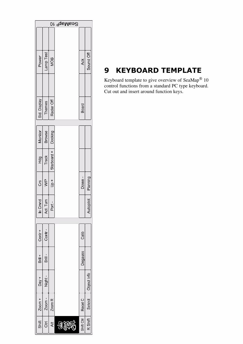
9 KEYBOARD TEMPLATEKeyboard template to give overview of SeaMap 10control functions from a standard PC type keyboard.Cut out and insert around function keys.

Blank page

____
____
____
____
____
____
____
____
____
____
____
____
____
_
SeaMap
10
ECDIS
Instructionmanual
____
____
____
____
____
____
____
____
____
____
____
____
____
_
SeaMap
10
ECDIS
Instructionmanual
____
____
____
____
____
____
____
____
____
____
____
____
____
_
SeaMap
10
ECDIS
Instructionmanual
____
____
____
____
____
____
____
____
____
____
____
____
____
_

Blankpage

Documentprintinginstructions
Thispageandallpageshereafterarenotpartofthemanualandshouldnotbe
printed!
1ThewholedocumentincludingthefrontpageisasinglePDF-filewiththedocument
numberCN-0276.
2Printthefrontpageincolour.
3Therestofthedocumentshouldbeprintedinblack&white,2-sidedprinting.
4Referencesisthelastsectionthatispartofthedocument,afterthatthereisvarious
usefulinformationnotnormallyprinted.
5Thesheetbeforethisonecontainslabelsforthespineofbinders.
6Thefollowingpage(s)containing“TAGS”isusedforinternaldocumentupdating
purposesonly.

Kilde:LibraryI7-
Ansvar:
Dokumenthistorie:
dato
aksjon
Brukt:
reg.no
bok
Version:Ingen
Andreattributteribruk:Ingen
Tags-DONOTPRINT!
Dennesideninneholderalletagssomerbruktimanualen.
1Functionaldescription
2Gettingstarted
3Operatinginformation
4Referenceguide
5Maintenance
6Replaceableparts
7Appendix
Filnavn
Nivå
Tag
Kom
mentar
Functionaldescription
Intro
1db10_funcdes_01
Introduction

Getting
started
Intro
1db10_getstrt_01
Introduction
3sm
10_getstrt_02
Boarding
area
3
Operating
inform
ation
Intro
1db10_operate_01
Introduction
3sm
10_operate_01
Pasttrack
3sm
10_operate_02
Voyage
log
3sm
10_operate_03
Them
es
3sm
10_operate_04
EBL/
VRM
3sm
10_operate_05
CurvedEB
L
3sm
10_operate_06
Parallelindex
lines
3sm
10_operate_07
Regenerationarea
3sm
10_operate_08
Autom
atictrackkeeping
3sm
10_operate_09
Validateroutes
3 3 3 3
3 3I
3 3 3 3 3 3
ReferenceGuide
Intro
1db10_refguid_01
Introduction
3sm
10_refguid_02
brow
seposition
3sm
10_refguid_03
CM-93edition
2
3sm
10_refguid_04
ARCScharts
3sm
10_refguid_05
working
sets
3sm
10_refguid_06
CM-93edition
3
3sm
10_refguid_07
S57charts
3sm
10_refguid_08
Primar
3sm
10_refguid_09
Zoommenu
3sm
10_refguid_10
Charttypesmenu

3sm
10_refguid_11
Radarmenu
3sm
10_refguid_12
Operatoralarms
3sm
10_refguid_13
Helptextmessages
3sm
10_refguid_14
Passw
ord
3sm
10_refguid_15
Listwaypoints
Maintenance
Intro
1db10_m
aint_01
Introduction
Replaceableparts
Intro
1db10_parts_01
Introduction
Append
ix
Intro
1db10_app
end_01
Introduction
Index
Intro
1sm
10_index_01
start