Butter, Spread and Margarine Technology - Polaris Automazioni
Upload
khangminh22Category
view
2download
0
USER MANUAL – May 10th 2021WWW.GARAGE1217.COM
(R1.2 PCB ONLY)
WARNING:Although Project Polaris runs at a generally safe 48VDC, Injury from improper assembly is quite possible. The main danger
comes from installing the polarized capacitors backwards as they can only be installed in one direction much like a battery
(more detail on capacitor installation comes later in this manual) If a capacitor is installed backwards, it may burst resulti ng
in burns or eye injury. If you are not experienced in electronics or electronic kit assembly, it would be wise to have an
experienced electronics person review your work before powering the unit on. Upon first power up, wear eye
protection and be wary of any burning smells or electrical noises such as loud pops or buzzes
If using low impedance headphones with power ratings of 300mW or lower, there is a chance you could blow out the drivers
if left playing at high levels – unattended. At high power levels an SPL of over 120dB may be reached in efficient
headphones which is harmful to your hearing. Project Polaris is a very high powered headphone amplifier – use caution and
common sense. High output headphone amplifiers like Polaris are designed to power very demanding headphones or
provide all the headroom you could want with more efficient designs, not to see if you can get your jawbone to rattle.
GARAGE1217.COM IS NOT RESPONSIBLE OR LIABLE FOR INJURY, PROPERTY LOSS OR DAMAGE AS THE RESULT OF ASSEMBLY OR USE OF THIS “DO IT YOURSELF” KIT. POLARIS IS
CONSIDERED A HOBBY LEVEL PRODUCT. IT CONTAINS NO ELECTRICAL CERTIFICATIONS AND IS NOT ADVERTISED AS SUCH. USE AT YOUR OWN RISK.
ProjectPolaris

Specifications
Solid state output stage with JFET input stage
Power consumption: (0.03A cont, 0.25A peak)
Power supply: 48VDC
Input Resistance: 11k or 21k depending on gain setting
Gain: 12.5X / 7.5X / 4.5X without Attenuation Module. With Module, reduce by ½.
Max Output voltage: 16Vrms at 300 Ohm
Max RCA Output voltage: 2.9V
Output Resistance: Selectable 0.1, 35 or 120Ohm
Frequency range (High BW - 30 Ohm load) -3dB: 2Hz-290kHz
Frequency range (High BW - 30 Ohm load) -.5dB: 6Hz-100kHz
Dynamic Range 108dB
Noise level -109dB
Crosstalk: -98dB
THD: > 0.045%
Phase shift: 180 (inverting amplifier) on wide BW and 30 Ohm load 15Hz - 28kHz (+/- 10)
Slewrate: +16V/us, -20V/us
Suitable for: 16-600ohm Headphones
Polaris Operational Guide
ProjectPolarisProjectPolaris
Normal Operation and Notes:
- Plug in the amplifier and then the power supply (in that order). Make sure the headphone jack and
input RCA’s are secure. Once the amplifier is turned to the ON position, the front red LED will
illuminate red for approximately 3 seconds. This indicates the protection circuit is active while the
amplifier is warming up.
- When the protection circuit activates and de-activates, a slight click may occur
- If load testing Project Polaris, it is not recommended to attach a dummy load with a value below 15 Ω
when testing at full output power for a long periods. Heatsinks and the output devices at the bottom
will become quite hot during testing. The amplifier will go into thermal protection when chip
temperatures of 150oC are reached. Under normal conditions (playing music) even when driving low
impedance loads, the output devices will get slightly warm at best.
- Some channel imbalance below 9 o’clock on the volume potentiometer is normal. We recommend you
adjust your source output levels, Attenuation module and gain module to keep the volpot above this
point
- Cell phones or radio frequency devices in close proximity to Project Polaris may create noise that is
audible when listening to music (generally clicks or digital noises)
- Clean your Project Polaris with a microfiber cloth and plastic cleaner (dusting with a microfiber cloth is
generally all that is required). Compressed air is also great option for dust.
OUTPUT
POWER
INTO:
16Ω32Ω64Ω
120Ω300Ω600Ω
OUTPUT RESISTANCE
.1R 35R 120R
600mW1.4W2.4W1.8W
765mW390mW
590mW1.2W1.5W1.1W
600mW360mW
180mW290mW450mW480mW390mW270mW

Required Assembly Tools:- Soldering iron, 25W minimum – Variable temp soldering station preferred with 1.5 – 2mm wide chisel tip
- .032 diameter 60/40 or 63/37 Tin/Lead solder is recommended. Lead free is difficult to work with and not recommended
- We specifically recommend Kester 331 water soluble flux solder, available on our website for purchase under (Parts – Buy)
- Magnifying glass (recommended but not required)
- Rubber Gloves (recommended but not required)
- 3M Green or Red Scotch Brite (recommended but not required)
- 3/32th Allen Key
- Flush cuts
- 90% Isopropyl alcohol (recommended but not required)
- Paper Towels (recommended but not required)
- Digital Multi Meter (DMM or DVOM)
- Heatgun or Hairdryer (for securing heatsinks)
Thank you for purchasing the Project Polaris Headphone Amplifier Kit. This kit requires minimal electronics and
soldering knowledge. The layout is easy to follow and setup is a snap! Please make sure to follow the instructions
outlined in this guide and you will be enjoying your amp in no time. First, lets go over the tools and items required
for your build which are as follows:
Before You Start Soldering: Prep work needs to be done. Wash your hands thoroughly and dry. Put on the recommended rubber gloves and scrub down
the PCB (circuit board) on both the front and back side with 90% isopropyl alcohol to clean any residuals off of the board
from manufacturing. Once the board has been cleaned, set it on a dry paper towel out of the way. Try to use the rubber
gloves during the entire assembly process to keep oils off of the board and solder joints.
Proper soldering is key to a quality final product. If you are new to soldering, here are some basic guidelines to
follow. It would be wise to buy a copper project board and a few cheap resistors or other components to practice
with before starting this project.
Soldering and Solder Joints:- For best results and maximum conductivity of any component, Wipe each wire lead down using Scotch Bright. Only one
or two passes are required, making sure all of the surface has been cleaned. This removes oxidation or any other build up
on the metal that has accumulated over time. Once cleaned, it is a good idea the further clean the wire leads with 90%+
isopropyl alcohol. Make sure all alcohol has evaporated prior to soldering as alcohol is VERY FLAMMABLE.
- Do not use to much or to little solder on each joint. See images below to get an idea of what you should be looking for
- The idea is to heat the pad and the component wire lead quickly and efficiently so that solder flows to each equally.
Wetting the tip of your iron with a very small amount of solder will aid in quickly heating up the pad and wire lead.
- Having to heat a component for long periods of time, especially capacitors or LED ’s is NOT a good thing. When soldering
capacitors or LED’s, heat them only long enough to ensure a quality joint and let the unit cool down before soldering the
second lead.
- The solder joint should look bright and metallic. A dull or dark gray looking joint is referred to as a
“cold solder joint” Cold solder joints may not pose a problem initially, but can show up later in the amps life.
- After every solder joint, make sure to clean the flux off your soldering iron tip with a wet sponge that should be
provided with your soldering iron kit.
SOLDER PAD
PCB CUTAWAY
WIRE LEAD
PROPER SOLDER JOINT:- Solder is bright and shiny. It is curved smoothly starting at the edge of the solder pad until it reaches the lead from the component- Solder should fill the via and flow through the board slightly. It is ok to add solder to the top side of the board, however it is not
required
CUTAWAY OF A VIA AND SOLDER PAD PRIOR TO SOLDERING:
IMPROPER SOLDER JOINT:- A large blob of solder, often dull in color is not desired. The solder may not flow into the via hole and cause a poor connection
or failure later in the amplifiers life.
VIA / HOLE TOP OF PCB TOP OF PCBTOP OF PCB
ProjectPolarisProjectPolaris

Bottom Chassis Prep / Final Chassis Assembly:
ASSEMBLE EACH OF THE 4 RUBBER FEET AS SHOWN, ATTACHING EACH FOOT TO THE GRAY SMOKED ACRYLIC BOTTOM CHASSIS
ALLEN BOLT + WASHER
HEX STANDOFF
PCB
GRAY ACRYLIC BOTTOM
CLEAR ACRYLIC TOP
- ONCE THE PCB HAS BEEN ASSEMBLED, SET IT ONTO THE FOUR THREADS STICKING OUT OF THE BOTTOM GRAY ACRYLIC CHASSIS THAT YOU PREVIOUSLY ASSEMBLED.
- THREAD ON EACH OF THE FOUR HEX STANDOFFS ONTO THE THREADS THAT ARE NOW PROTRUDING THROUGH THE PCB, SECURING THE PCB TO THE GRAY ACRYLIC CHASSIS BOTTOM. PROCEED TO POWER ON THE UNIT (AS DESCRIBED ON PAGE 2, WEARING EYE PROTECTION AND AT A SAFE DISTANCE IN CASE OF A MISTAKE IN ASSEMBLY)
- ONCE THE AMPLIFIERS FUNCTIONALITY HAS BEEN TESTED AND THE UNIT HAS HAD A CHANCE TO FULLY WARM UP FOR 30 MINUTES, SET THE BIAS AS DESCRIBED LATER IN THIS MANUAL BEFORE PLACING THE TOP CLEAR ACRYLIC COVER IN PLACE
THREADED SPACER
RUBBER FOOT
NYLON WASHER
4-40 BUTTON CAP SCREW
GRAY ACRYLIC BOTTOM
THREADED SPACER
ProjectPolarisProjectPolaris

Assembly Guide
ADJUSTABLE INPUT ATTENUATION JUMPERS
LED ON/OFF
GAIN SELECTION
OUTPUT RESISTANCE JUMPERS
POWER LED(SOCKETED 3MM LED FOR
EASY COLOR CHANGE)
LED BRIGHTNESS TRIMMER
PROTECTION CIRCUIT LED
WHEN THE AMPLIFIER IS TURNED ON, THIS LED WILL LIGHT FOR APPROXIMATLEY 15 SECONDS INDICATING THE PROTECTION
CIRCUIT IS ACTIVE
VOLUMEPOTENTIOMETER
POWER SWITCH
RCA LINE-OUT POWERJACK
¼” - 6.3MM HEADPHONE JACK
RCA LINE-IN
ProjectPolaris
BANDWIDTH ADJUSTMENT
1.2

STEP 1: POPULATE ALL SMALL COMPONENTS ON THE BOARD SUCH AS RESISTORS, RIGHT ANGLE JUMPERS,
DIODES AND SMALL CAPACITORS. THROUGHOUT YOUR BUILD, ALWAYS INSTALL THE SMALLER PARTS FIRST,
WORKING YOUR WAY UP TO THE LARGER COMPONENTS
PAY CLOSE ATTENTION TO THE BLACK BAND ON ALL
DIODES OR ZENERS AS THEY ARE DIRECTIONAL
- RESISTORS ARE NONPOLAR AND CAN BE FITTED IN EITHER DIRECTION. WHEN INSTALLING COMPONENTS, MAKE SURE THE COMPONENT VALUES ALWAYS FACE UP SO THEY ARE VISIBLE (CAN AID IN TROUBLESHOOTING IF A COMPONENT IS PLACED IMPROPERLY)
- DIODES, TRANSISTORS, IC’S AND ELECTROLYTIC CAPACITORS ARE POLAR AND PROPER ORIENTATION IS REQUIRED
ProjectPolarisProjectPolaris
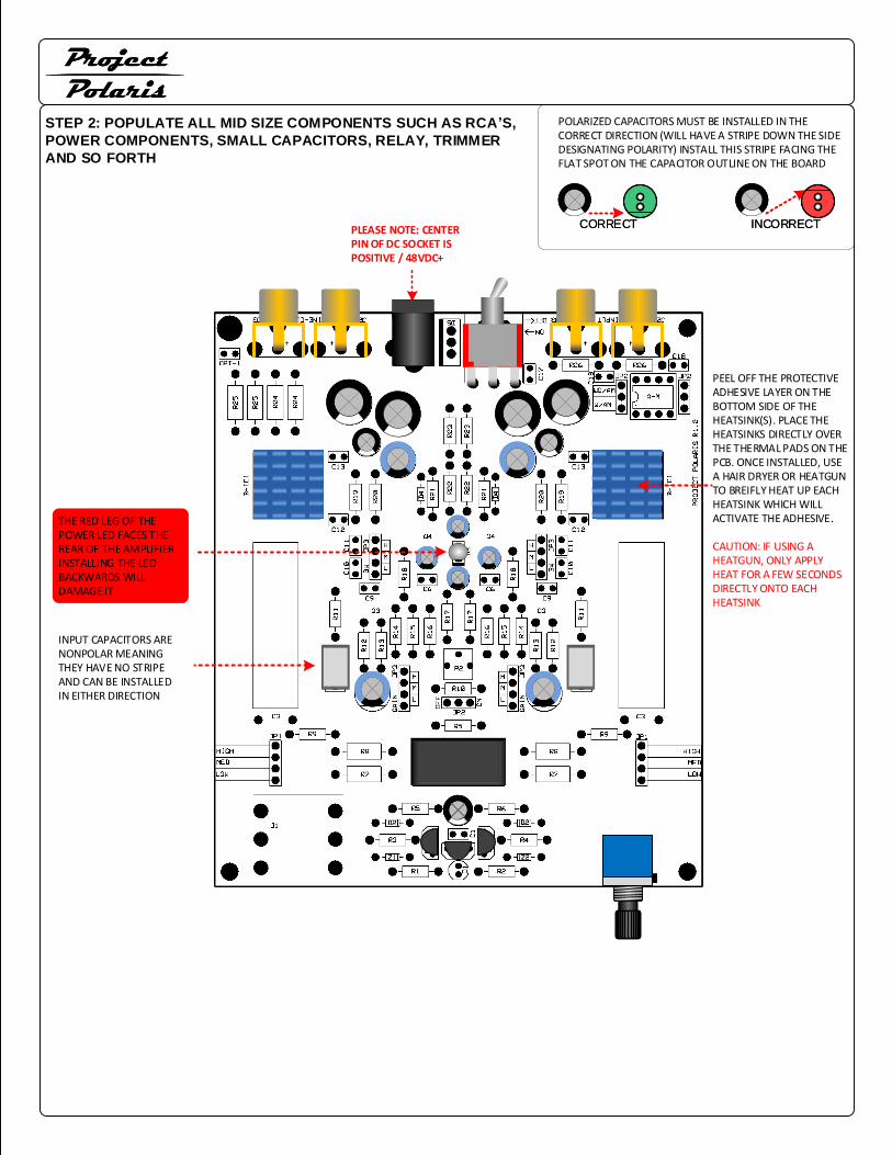
STEP 2: POPULATE ALL MID SIZE COMPONENTS SUCH AS RCA’S,
POWER COMPONENTS, SMALL CAPACITORS, RELAY, TRIMMER
AND SO FORTH
POLARIZED CAPACITORS MUST BE INSTALLED IN THE CORRECT DIRECTION (WILL HAVE A STRIPE DOWN THE SIDE DESIGNATING POLARITY) INSTALL THIS STRIPE FACING THE FLAT SPOT ON THE CAPACITOR OUTLINE ON THE BOARD
CORRECTCORRECT INCORRECTINCORRECTPLEASE NOTE: CENTER PIN OF DC SOCKET IS POSITIVE / 48VDC+
INPUT CAPACITORS ARE NONPOLAR MEANING THEY HAVE NO STRIPE AND CAN BE INSTALLED IN EITHER DIRECTION
PEEL OFF THE PROTECTIVE ADHESIVE LAYER ON THE BOTTOM SIDE OF THE HEATSINK(S). PLACE THE HEATSINKS DIRECTLY OVER THE THERMAL PADS ON THE PCB. ONCE INSTALLED, USE A HAIR DRYER OR HEATGUN TO BREIFLY HEAT UP EACH HEATSINK WHICH WILL ACTIVATE THE ADHESIVE.
CAUTION: IF USING A HEATGUN, ONLY APPLY HEAT FOR A FEW SECONDS DIRECTLY ONTO EACH HEATSINK
ProjectPolarisProjectPolaris
THE RED LEG OF THE POWER LED FACES THE REAR OF THE AMPLIFIER. INSTALLING THE LED BACKWARDS WILL DAMAGE IT

VOLPOT GROUNDING
GROUNDING THE VOLUME POTENTIOMETER IS REQUIRED AS WITHOUT IT, THE AMPLIFIER MAY BE SUBJECTED TO NOISE / INTERFERENCE.
THE IMAGES ARE OF THE PREVIOUS GENERATION SUNRISE, HOWEVER THE GROUNDING PRINCIPAL IS EXACTLY THE SAME.
FIRST, INSERT A WIRE LEAD INTO THE RIGHT SIDE VIA NEXT TO THE VOLPOT AND SOLDER IN PLACE.
WRAP THE WIRE LEAD AROUND THE THREADED PORTION OF THE VOLPOT AS SHOWN.
PUT ON WASHER AND NUT INCLUDED IN THE KIT. ONCE TIGHT, THE VOLUME KNOB MAY BE INSTALLED.
ProjectPolarisProjectPolaris
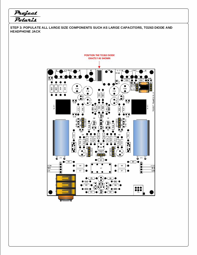
STEP 3: POPULATE ALL LARGE SIZE COMPONENTS SUCH AS LARGE CAPACITORS, TO263 DIODE AND
HEADPHONE JACK
POSITION THE TO263 DIODE EXACTLY AS SHOWN
ProjectPolarisProjectPolaris

COMPLETED POLARIS LAYOUT AND PHOTO:
ProjectPolarisProjectPolaris

Project Polaris has several jumpers settings to customize the amp the way you would like it. Below gives you the
details on what these jumper settings do!
ProjectPolarisProjectPolaris
BANDWIDTH CAN BE ADJUSTED IN 3 LEVELS. DECREASING BANDWIDTH MAY HELP TAME BRIGHT HEADPHONES. DEFAULT SETTING IS ON HIGH.
OUTPUT RESISTANCE IS CONFIGURABLE BETWEEN 0.1Ω (LOW)35Ω (MID) AND 120Ω (HIGH). HIGHER OUTPUT
RESISTANCE CAN HAVE AN EFFECT ON BASS AND/OR TREBLEFREQUENCIES. THIS EFFECT IS DEPENDANT ON THE HEADPHONE IMPEDANCE. (EXAMPLE OF 35Ω SETTING IN RED) EXPERIMENT BY CHANGING THE SETTINGS TO FIND WHAT YOUR PREFERENCE IS
INPUT ATTENUATION CAN BE CHANGED VIA THE JUMPER TABS AT THE BACK, RIGHT HAND CORNER OF THE AMPLIFIER. DEFAULT SETTING IS WITH ATTENUATION MODULE.
CUSTOM ATTENUATION MODULES CAN BE EASILY CREATED LOWER LEVELS OVERALL. THIS CAN BE VERY USEFUL FOR SUPER SENSITIVE HEADPHONES SUCH AS IEM’S.
ACTUAL GAIN CAN BE ADJUSTED IN 3 LEVELS.
WITHOUT MODULE 4.5 / 7.5 / 12.5XWITH 10K MODULE 2.2 / 3.7 / 6.2X
POWER LED CAN BE DIMMED BY THE 250K TRIMMER. LED CAN ALSO BE TURNED OFF. LED IS SOCKETED FOR EASY COLOR CHANGE. LED POLARITY MUST BE OBSERVED OR LED WILL BE DAMAGED
POWER LED ON/OFF JUMPER

Project Polaris 1.2Resistors
R1 = SM 100K X 1
R2 = SM 470K X 1
R3 = SM 10K X 1
R4 = SM 56K X1
R5 = SM 33R X 2
R6 = SM 4.7K X 1
R7 = LG 120R X 2
R8 = LG 47R X 2
R9 = SM 2.2K X 2
R10 = SM 10K X 1
R11 = SM 1K X 2
R12 = SM 470K X 2
R13 = SM 47K X 2
R14 = SM 2.4K X 2
R15 = SM 1K X 2
R16 = SM 3.3K X 2
R17 = SM 6.8K X 2
R18 = SM 10K X 2
R19 = SM 3.3K X 2
R20 = SM 3.3K X 2
R21 = SM 1K X 2
R22 = SM 220K X 2
R23 = SM 47K X 2
R24 = LG 220R X 2
R25 = LG 1K X 2
R26 = SM 1K X 2
Diodes
Z1 = BZX79-C43 X 1
Z2 = BZX79-C39 X 1
D1 = RED LED X 1
D2 = 1N4148 X 2
D3 = 3MM POWER LED X 1
D4 = 1N4148 X 2
D5 = TO-260 DIODE
Regulators / IC
IC1 = OPA551 X 2 (bottom)
Jacks
J1 = HEADPHONE JACK X 1
J2 = BLACK RCA JACK X 2
J3 = RED RCA JACK X 2
J4 = POWER INPUT JACK X 1
Capacitors
C1 = 100nF 100V X 1
C2 = 22uF 63V X 1
C3 = 2200uF 50V X 2
C4 = 1uF X 2
C5 = 220uF 35V X 2
C6 = 10nF X 2
C7 = 10uF 50V X 2
C8 = 10uF 50V X 2
C9 = 10pF X 2
C10 = 470pF or 820pF X 2
C11 = 270pF or 390pF X 2
C12 = 100pF X 2
C13 = 100nF X 2
C14 = 10uF 63V X 2
C15 = 100uF 50V X 2
C16 = 33uF 100V X 4
C17 = 100nF X 1
C18 = 100pF X 2
Transistors
Q1 = BC546 X 2
Q2 = BC556 X 1
Q3 = PMBFJ111 (bottom)
Q4 = MMBF170 (bottom)
Jumpers
JP1 = 4 PIN RA X 2
JP2 = 3 PIN STRAIGHT X 3
JP3 = 4 PIN STRAIGHT X 4
Switches
SW1 = POWER SWITCH X 1
Potentiometers / Trimmers
P1 = 10K VOLUME POTENTIOMETER X 1
P2 = 250K TRIMMER
Relay
U1 = 48V RELAY X 1
Other
JUMPER TABS X 9
ATTENUATION MODULE X1
Copyright © 2022 FDOKUMEN