DESIGNE LAB MANUAL.pdf
49
DESIGN LAB MANUAL MECHANICAL BGSIT - 1 - BG Nagara
-
Upload
khangminh22 -
Category
Documents
-
view
0 -
download
0
Transcript of DESIGNE LAB MANUAL.pdf

DESIGN LAB MANUAL MECHANICAL
BGSIT - 1 - BG Nagara

DESIGN LAB MANUAL MECHANICAL
BGSIT - 2 - BG Nagara

DESIGN LAB MANUAL MECHANICAL
BGSIT - 3 - BG Nagara
EXPERIMENT NO:1
CRITICAL OR WHIRLING OR WHIPPING SPEED
OF SHAFT
AIM: To determine the critical speed of a shaft or whirling speed of a shaft.
APPARATUS: Stop clock, Tachometer and Weights (optional)
THEORY:
The speed at which the rotating shaft varies violently in transverse direction is
called the “critical or whirling speed “
Or
When the speed of shaft is equal to natural frequency of vibration such a
frequency is called as critical or whirling or whipping speed.
If the body or a disc mounted upon the shaft rotates about it, then C.G. of the disc
must be at the shaft axis, if perfect running balance is to be obtained. But practically
because of difficulty of perfect machining of disc (rotor) C.G does not coincide with shaft
axis. Hence, when such shaft rotates, it deflects towards heavier side of the disc due to
unbalanced centrifugal force. As the speed increases the shaft vibrates violently upto
resonance speed, and after resonance speed the shaft again runs smoothly.
CRITICAL SPEED DEPENDS UPON THE FOLLOWING
FACTOR:
1.Length of the shaft
2.Diameter of the shaft
3.Bearing supports conditions i.e. fixed or free.
4.The magnitude of the load.
5.The location of the load carried by the shaft
PROCEDURE:
1) Fix the required shaft at the driving end.
2) Fix the Bearing block at tail end (either for fixed end condition or free end condition) And
tighten the shaft

DESIGN LAB MANUAL MECHANICAL
BGSIT - 4 - BG Nagara
3) Start the motor and slowly increase the speed at certain speed discs will be
vibrating Violently and note down the speed of shaft.
4) Increase the speed now shaft is operating above critical speed without vibration.
5) Repeat the procedure by changing shaft.
SPECIFICATION:
1. Shaft diameter = ……………m
2. Bearing block
a. Driving end: - Fixed end shaft supported with two Bearing
b. Tail end: - Fixed end support with self-aligning ball Bearing
c. Young’s modulus of the shaft =………….N/m2
d. Length of the shaft =…………m
3. Moment of inertia of the shaft =……….. m4
4. Uniformly Distributed Load
i. = 0.064 kg/m for 3.17 mm diameter shaft.
ii. = O.138 kg/m for 4.75 mm diameter shaft
iii. = O.248 kg/m for 6.35 diameter shaft
5. Density of the shaft material () ………..Kg/m3
FORMULAE:
a. For bending mode:
Angular speed , = 22a / L2
Where, a = EI/A, = Mass/ Volume, (Kg/m3),Critical speed, N = X 60 / 2
b. For twisting mode:
Angular speed, = 61.7 a / L2
Critical speed, N = X 60 / 2

DESIGN LAB MANUAL MECHANICAL
BGSIT - 5 - BG Nagara
TABULAR COLUMN:
Critical speed,N rpm
Sl.No Diameter of
shaft ‘mm’
Length of
shaft ‘m’
Bending mode
Twisting mode
Theoretical Experimental Theoretical Experimental
1 3.17 830 1394.00 1450.00 3910.00 3400.00
2 4.75 830 2100.00 2000.00 5392.00 4100.00
3
4
CALCULATION:
For shaft
Diameter = 3.17 mm, Length= 830mm and Mass, M = 0.064 kg/m
Young’s Modulus the shaft = 207 Gpa
Area, A= d2/ 4 = (0.00317) 2 / 4 = 7.892 x 10⁻⁶ m2
Moment of inertia, I = d4 / 6 4 = (0.00317) 4 / 6 4 = 4.9568 x 10⁻¹² m4
Density, = Mass/ Volume, (Kg/m3), Volume=A X L,
a = EI/A, = 4.004
a. For bending mode:
Angular speed , = 22a / L2 = 127.86 rad/Sec
Critical speed, N = X 60 / 2 = 1394.00 rpm
b. For twisting mode:
Angular speed, = 61.7 a / L2 = 358.61 rad/sec
Critical speed, N = X 60 / 2=3910.00 rpm

DESIGN LAB MANUAL MECHANICAL
BGSIT - 6 - BG Nagara
EXPERIMENT: 2
PORTER GOVERNOR
AIM: To determine the theoretical lift, friction and controlling of the governor.
APPARATUS: universal governor experimental set-up, tachometer set of masses.
PROCEDURE:
1. Place the porter governor assembly over the spindle of the universal governor
apparatus
2. Place the required load on the spindle
3. Tighten the bolts and nuts
4. Start the motor adjust the speed to the required value
5. Note down the sleeve rise (lift) and also the speed
6. Repeat the experimental procedure for different loads and different speeds
SPECIFICATION: -
Length of each Link = L = mm
Distance of top link from bottom link 2k = 0.216m = 2k0
Height of balls where central lines intersect with the axis of rotation h = 0.195
m =h0
Initial radius of rotation r0 = 0.1125 m = r
Mass of sleeve assembly M = 2.14 kgs.
Weight of sleeve assembly W = N
Mass of one side balls mb = 0.4kgs.
Weight of one side balls wb = N

DESIGN LAB MANUAL MECHANICAL
BGSIT - 7 - BG Nagara
EXPERIMENTAL SET UP:

DESIGN LAB MANUAL MECHANICAL
BGSIT - 8 - BG Nagara
TABULAR COLUMN:
Sleeve lift ‘h’ ‘cm’
Sl.No Mass
of
Sleeve
‘kg”
Masses
added
to
Sleeve
‘kg’
Total
mass’M’
‘kg’
Governor
speed
‘N’ rpm’
Experimental
Theoretical
Controlling
force ‘fc’
‘N’
Frictional
force ‘F’
‘N’
1 2.14 0 2.14 186 1.5 1.6 17.14 4x10⁻³
2
2.14 0.4 2.54 195 1.5 2.2 13.17 2.52
3
2.14 0.8 2.94 206 1.5 2.0 23.82 2.530
4
2.14 1.2 3.34 215 1.5 2.0 25.95 2.53
FORMULAE :
Lift = h1 = [(mbg+ Mg)/mb] 1/N2 * (60/2)2
L2 = {[h12/ (0.05 + s1)
2] +1} s12
k1 = L2 - s12 , x1 = 2(k0– k1)
Controlling force: Fc=m b 12r1, where r1 = 0.05 + s1
Frictional force = h1 = {wb + (w F) /mb} 1/ N2 * (60/2)2

DESIGN LAB MANUAL MECHANICAL
BGSIT - 9 - BG Nagara
CALCULATION:
Lift = h1 =[(mb g+ Mg/mb)] 1/N2 * (60/2)2
h1 = {(0.4 * 9.81 + 2.14 * 9.81)}/(186)2 * (60/2)2
h1 = 0.164 m
L2 = {[h12/ (0.05 + s1)] +1} s1
2
0.0156 = {(0.164)2 / (0.05 + s1)2 * 1} s1
2
By trial & error, s1 = 0.075m
k1 = L2 - s12
k1 = 0.1m
x1 = 2(k0– k1)
x1 = 2(0.108-0.1) = 0.016m
Fc=m b 12r1
Fc=0.4(18.84)20.125 = 17.74 N
Frictional force = h1 = {wb + (w F) /mb} 1/ N2 * (60/2)2
0.164 = {0.4+(2.14±F)/0.4}*9.81*1/1862*(60/2)2
F= ± 4x10⁻³ N
GRAPHS:
I) Controlling force v/s radius of rotation
II) Controlling force v/s speed

DESIGN LAB MANUAL MECHANICAL
BGSIT - 10 - BG Nagara
EXPERIMENT: 3
HARTNELL GOVERNOR
AIM: To determine the theoretical lift, friction and controlling of the governor.
APPARATUS: universal governor experimental set-up, tachometer set of masses
springs of different stiffness.
PROCEDURE:
1. Mount the given Hartnell governor assembly over the spindle.
2. Tighten the necessary nuts and Bolts.
3. Start the motor and adjust the speed.
4. The flyweight’s fly outwards due to centrifugal force, the sleeve will raise.
5. Measure the sleeve and sleeve raise.
6. Repeat the experiments at different speeds spring forces over the sleeve by
changing the initial compressions and springs of different stiffness of the
governor.
7. Calculate the lift, friction and controlling force of the governor.
SPECIFICATIONS: -
Motor speed = 1500 rpm.
Stiffness of spring = 490 N/m and 980 N/m
Length of the ball arm = ‘a’ = 0.07m
Length of the sleeve arm = ‘b’ = 0.116m
Mass of one side balls = ‘mb’ = 0.196 kg
Initial radius of rotation of balls = ‘r0’ = 0.153m
DESIGN LAB MANUAL MECHANICAL
BGSIT - 11 - BG Nagara
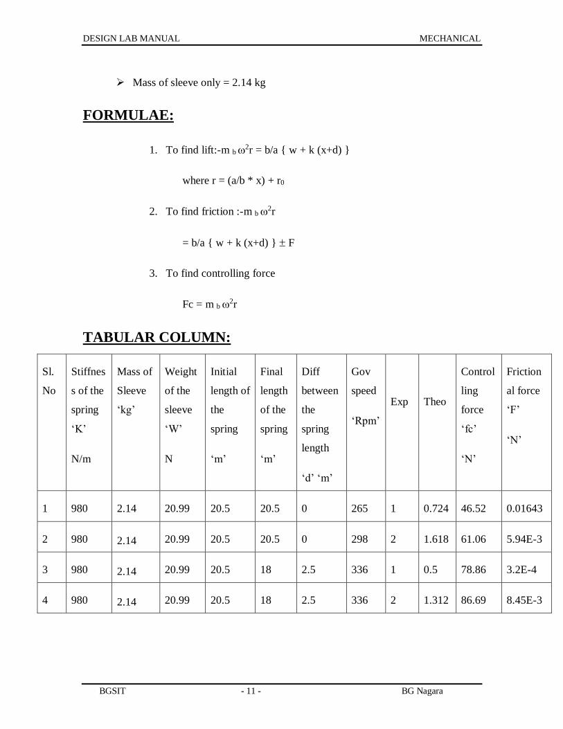
Mass of sleeve only = 2.14 kg
FORMULAE:
1. To find lift:-m b 2r = b/a { w + k (x+d) }
where r = (a/b * x) + r0
2. To find friction :-m b 2r
= b/a { w + k (x+d) } F
3. To find controlling force
Fc = m b 2r
TABULAR COLUMN:
Sl.
No
Stiffnes
s of the
spring
‘K’
N/m
Mass of
Sleeve
‘kg’
Weight
of the
sleeve
‘W’
N
Initial
length of
the
spring
‘m’
Final
length
of the
spring
‘m’
Diff
between
the
spring
length
‘d’ ‘m’
Gov
speed
‘Rpm’
Exp
Theo
Control
ling
force
‘fc’
‘N’
Friction
al force
‘F’
‘N’
1 980 2.14 20.99 20.5 20.5 0 265 1 0.724 46.52 0.01643
2 980
2.14 20.99 20.5 20.5 0 298 2 1.618 61.06 5.94E-3
3 980
2.14 20.99 20.5 18 2.5 336 1 0.5 78.86 3.2E-4
4 980
2.14 20.99 20.5 18 2.5 336 2 1.312 86.69 8.45E-3

DESIGN LAB MANUAL MECHANICAL
BGSIT - 12 - BG Nagara
CALCULATION:
1. To find lift:-
m b 2r = b/a { w + k (x+d) } where r = (a/b * x) + r0
[(2* 0.190) (2* * 265 / 60 )2 *0.1590 ]= [{20.99 +(X1 +0 ) *980}
(0.116/0.07)]
X1 = 0.724 cm
2. To find friction :-
(m b 2r )= = [b/a { w + k (x+d) } F ]
[(2* 0.190) (2* * 265 / 60 )2 *0.1590] = [{20.99 +(X1 +0 ) *980}
(0.116/0.07) F]
F = 0.01643 N
3. To find controlling force
Fc = m b 2r
Fc = (2* 0.190) (2* * 265 / 60 )2 0.1590
= 46.52 N

DESIGN LAB MANUAL MECHANICAL
BGSIT - 13 - BG Nagara
EXPERIMENTAL SET UP :
GRAPHS:
1. Controlling force v/s speed
2. Controlling force v/s radius of rotation.

DESIGN LAB MANUAL MECHANICAL
BGSIT - 14 - BG Nagara
EXPERIMENT 4
TORSION VIBRATION (DAMPED)
Aim: -To study the damped torsion vibration of a single rotor system and to
determine the damping factor logarithmic decrement.
Apparatus: -Rotor, Descended (penholder)
Procedure: -
1) Fix the shaft at the bracket at the top
2) Attach the rotor, and desender to the shaft
3) Put the damping liquid ( oil or water ) into the damping reservoir and set
the pen holder at suitable position
4) Oscillate the rotor carefully, so that lateral oscillation does not appear.
5) Lift the desender and gently press the pen over the paper and graph of
oscillation should be recorded over the paper.
6) Measure height of amplitude from the graph
7) Repeat above procedure by changing depth of immersion in liquid
medium.
8) Plot the graph of logarithmic decrement v/s depth of immersion.
FORMULAE:
1) Logarithmic decrement ():
= 1/n ln (x0/xn)
Where X0 = Initial amplitude
Xn = amplitude of the nth cycle.
n = number of cycles.

DESIGN LAB MANUAL MECHANICAL
BGSIT - 15 - BG Nagara
2) Damping factor ():
= (2 * 3.14 * ) / ( 1-2)
Tabular column :
Sl no. Depth of Immersion in ‘mm’ Logarithmic Decrement Damping factor
1 4 0.152 0.024
2 6 0.086 0.0136
3 8 0.078 0.0124
4
5
Specimen calculation:
Depth of immersion: d = 8 cm.
From graph: x1 = 2.4 cm ; xn = 1.1 cm ; n = 10 ;
1. = 1/n ln( x1 /xn) = 1/10 ln (2.4/1.1) = 0.07
2. = ( /4 2 * 2) = (0.078/4 2 * 0.0782) = 0.0124

DESIGN LAB MANUAL MECHANICAL
BGSIT - 16 - BG Nagara

DESIGN LAB MANUAL MECHANICAL
BGSIT - 17 - BG Nagara
EXPERIMENT 5
TORSIONAL VIBRATION (UNDAMPED)
Aim: - To determine frequency of undamped torsional vibration of a single
rotor system.
Apparatus: - Stop watch, Single rotor systems.
Procedure: -
1. Fix the rotor at the threaded spindle, fitted in the bearings.
2. Fix the gripping chuck over the spindle
3. Fix the stationary speed bracket at suitable length
4. Thread the shaft through the spindle and tighten the chuck.
5. Oscillate the rotor by hand and measure the time taken for 10
oscillations.
6. Repeat the experiment for different length of the shaft.
Formulae:
1) Experimental frequency Fn = 1/tp
Where tp = Time period.
2) Theoretical frequency Ft = (1/ 2 * 3.14) * ( GJ/ IL)
Where G = rigidity modulus of given material
J = polar moment of inertia
I = mass moment of inertia = mk2
m = mass of rotor
k = radius of shaft.

DESIGN LAB MANUAL MECHANICAL
BGSIT - 18 - BG Nagara
Tabular column:
SL.no Length of shaft ‘mm” Time taken for
10 oscillation 1 oscillation
Sec Sec
Frequency
Expi Theo
1 0.78 8 0.8 1.25 1.18
2 0.59 7 0.7 1.428 1.357
3 0.29 5 0.5 2.0 1.936
4
5
Specimen calculation:
1. Fn(exp) = 1/tp = 1/0.8 = 1.25 Hz.
2. I = mk2/2 =0.01482 kg-m2
3. G = 0.8*10E11 N/m2
4. J = d4 / 32 = (3*10e-3) 4 /32 = 7.952*10e-12 m4
5. Fn(the)=1/2(GJ/IL)
=1/2(0.8*10e11) (7.952*10e12) / (0.014820.78)=
=1.HZ

DESIGN LAB MANUAL MECHANICAL
BGSIT - 19 - BG Nagara
EXPERIMENT: 6
STATIC AND DYNAMIC BALANCING OF
ROTATING MASSES
Aim: To find static and dynamic balancing rotating masses.
Apparatus: It consists of a frame, which is hang by chains from the main frame. A
shaft rotates within bearings in the frame. Four eccentric weights are supplied which can
be easily fitted over the shaft. For static balancing one weight is attached and balanced
with another weight. For dynamic balancing three or four weights are mounted over the
shaft at calculated angle and the shaft is rotated. If the system is unbalanced, vibrations
indicate it.
Theory
Balancing of masses is important part of a machine design, when the mass is
stationary it can be easily balanced by putting suitable counter weight on the opposite
side of mass. When the mass is revolving and if it is left unbalanced, then a centrifugal
force is developed which changes its direction during rotation. This causes pre- mature
failure of bearings and shafts are unbalanced, hence balancing is essential in machine
design.
Procedure:
1) Static balancing:
1) Remove the leather rope over the pulley.
2) Fix the points at 00 position.
3) Attach the weight pans on both sides.
4) Remove locking screw and go on putting steel balls in the pan till, the
points is turned through 900.now the weights is balanced by steel balls
count number

DESIGN LAB MANUAL MECHANICAL
BGSIT - 20 - BG Nagara
of balls. This is relative balancing weight for the eccentric weight. Find out
relative weight for all eccentric weight and note down.
2)Dynamic balancing: -
From the relative weight (number of balls) assume position of two of the
weights over shaft, draw the force polygon and find out position of other weights.
1) Mount the weights at proper position over the shaft.
2) Put the leather belt over the pulley and start the motor.
3) If the system is balanced, the shaft will rotate free from vibrations.
CALCULATIONS:
1) Static balancing: -
Let the given weights be m1r1 and m2r2 with an angle between them be m3r3 and
m4r4 are the balancing weights whose angular position are to be determined. Draw
positions of m1r1 and m2r2 in the position diagram. to draw force polygon draw AB
parallel to m1r1 to some scale, from A, draw an arc whose radius is proportional to
m4r4 and from C draw an arc with radius proportional to m3r3 the intersection of arc
gives point D. Join AD and CD draw parallel lines to CD and AD in position
diagram, this will give angular position of m3r3 and m4r4 respectively.
2) Dynamic balancing: -
Follow the procedure for static balancing of the system and find out angular
position of balance weights. To find the linear position couple polygon is required,
assume linear position of m1r1 taking moments about rotating plane of m3r3 couples
are 1) m1r1x 2) m2r2a2 3) m4r4a4
Draw ‘ab’ parallel to m1r1 to the scale of m1r1 couple. From ‘b’ draw parallel to
m2r2 from ‘a’ draw parallel line to m4r4. The intersection gives point ‘c’. “bc” is
proportional to m2r2a2 and “ac ” is proportional to m4r4a4. As m2r2 and m4r4 are
known values of a4 a2 can be determined.

DESIGN LAB MANUAL MECHANICAL
BGSIT - 21 - BG Nagara
Calculation:
m1 = 153.9 gr
m2 = 151.3 gr
m3 = 148.5 gr
m4 = 147.2 gr
r1 = 3.6cm
r2 = 3.6cm
r3 = 3.6cm
r4 = 3.6cm
To find 3 and 4: -

DESIGN LAB MANUAL MECHANICAL
BGSIT - 22 - BG Nagara
TO FIND LINEAR POSITIONS :-
From graph
m2r2a2 = ‘x’ mm
a2 = x / m2r2
m4r4a1 = ‘y’ mm
a1 = ‘y’ / m4r4
L1
a1
a2
m1r1
m4r4
m2r2
m3r3
Reference line
m1r1L1
m2r2a2
m4r4a1
a
b
c

DESIGN LAB MANUAL MECHANICAL
BGSIT - 23 - BG Nagara
EXPERIMENT: 7
FREE UNDAMPED LONGITUDINAL
VIBRATION OF SPRING MASS SYSTEM
AIM: To study the undamped free vibration of the spring mass system
APPARATUS: Stopwatch, weights, and vernier scale.
PROCEDURE:
1. Fix the spring in the strut; attach the weight holder to the spring.
2. Fix the scale for measurement of elongation of spring at the suitable
position. Note initial reading, attach different weights to the spring and
note down the corresponding deflections.
3. Find out the stiffness of the spring ‘K’
4. Repeat the experiments with different springs
5. Now, with weights attached to the spring set the spring vibrating and note
down the time period.
6. Repeat the experiment with different springs and different weights.
EXPERIMENTAL SET UP:

DESIGN LAB MANUAL MECHANICAL
BGSIT - 24 - BG Nagara
FORMULAE:
= Deflection = final length – initial length.
K = stiffness of the spring = mg /
Fn (experi) = 1/tp
Fn (theo.) = (1/2 ) * (K/m) = (1/2 ) * (g/)
Where g = acceleration due to gravity in m/s2
m = attached mass in kg
TABULAR COLUMN:
Sl.no Attached
mass in ‘kgs'
Deflection
in ‘m’
Stiffness K
in ‘N/m’
Time for
In sec
10 osc 1 osc
Frequncy
In ‘Hz’
Expi . theo.
1 0.73 0.018 88.89 4.5 0.45 2.22 1.756
2 0.93 0.036 88.89 6 0.6 1.66 1.55
3 1.13 0.059 88.89 7 0.7 1.428 1.411
4
5

DESIGN LAB MANUAL MECHANICAL
BGSIT - 25 - BG Nagara
SPECIMEN CALCULATION:
Experimental frequency:
Fn=1/tp=1/.45=2.22Hz
Theoritical frequency:
Fn=(1/2)*(K/m)=(1/2)*(88.89/0.73)=1.75Hz
FROM GRAPH:
K=Force/unit deflection=1/0.0112=88.89N/M

DESIGN LAB MANUAL MECHANICAL
BGSIT - 26 - BG Nagara
EXPERIMENT NO.8
STRESS –CONCENTRATION FACTOR USING
PHOTO- ELASTICITY
AIM: To determines stress concentration factor for a circular disc with a circular hole
under diametrical compression.
APPARATUS: Circular Polariscope, photo elastic model in the form of circular
disc with a circular hole, vernier caliper.
THEORY:
In the development of the basic stress equations for tension, compression, bending
and torsion, it was assumed that no irregularities occurred in the member under
consideration. But it is quite difficult to design a machine without permitting some
changes in the cross-sections of the members.
Ex: rotating shafts must have shoulders designed on them so that the bearing can be
properly sealed and so that they will take thrust loads. Other parts require holes, oil
grooves and notches of various kinds.
Any discontinuity in a machine part alters the stress distribution in the neighborhood of
the discontinuity so that the elementary stress equations no longer describe the state of
stress in the part, such discontinuities are called stress raisers and the regions in which
they occur are called areas of stress concentration.
Theoretical or geometric, stress-concentration factor kt
It is the ratio of actual maximum stress at the discontinuity to the normal stress.
kt = max/ o kts = max / o
Where kt used for normal stresses.
kts used for shear stresses.
The subscript t in kt means that this stress- concentration factor depends for its
value only on the geometry of the part. That is, the particular material used has no effect
on the value of kt .this is why it is called theoretical stress- concentration factor.

DESIGN LAB MANUAL MECHANICAL
BGSIT - 27 - BG Nagara
PROCEDURE:
1. The circular specimen is mounted between the lever arm which is
extended from the fulcrum to the load acting on other side.the light
emitted from sodium vapor lamp of circular polariscope is analyzed using
both polarizes and analyzer.
2. The load is applied in the weight hanger and the fringe pattern is observed
.the total number of integral formed plus the fractional fringes are counted
and the fringe order is noted.
3. The load acting on the specimen is calculated. Repeat the procedure for
various loads. At each load calculate the nominal and maximum stress
acting on the specimen.
4. A graph is plotted b/w max v/s 0 and the slope of this is obtained in order
to calculate average value of stress concentration factor
SPECIMEN SPECIFICATIONS: -
Outer diameter of specimen D = 70 mm
Inner diameter of the specimen d = 28 mm
Thickness of the specimen h = 5.23 mm
Distance x = 410 mm
Distance y = 1170 mm

DESIGN LAB MANUAL MECHANICAL
BGSIT - 28 - BG Nagara
Tabular column:
Sl.no Load on hanger Load on
disc ‘P’
N
Fringe
order
N
act max K
Kg N
1 9 88.29 251.94 1.23 1.146 3.207 2.798
2 10 98.1 279.94 1.65 1.274 4.303 3.377
3 11 107.91 307.93 1.79 1.401 4.668 3.331
4
5
6
7
FORMULAE:
Load on the disc
P * x = w * y
P = wy/x in N
nom = p / (D-d) h in N/mm2
act = N F / h in N/mm2
Where N= fringe order
F = Material fringe constant
K = act / nom

DESIGN LAB MANUAL MECHANICAL
BGSIT - 29 - BG Nagara
CALCULATION:
1.Load on the disc
i. P * x = w * y
ii. P = w y/x = 88.29(1170)/410 = 251.94 N
2. nom = p / (D-d) h = 251.94/(70.28)5.23
=1.146 N/mm2
3. act = N F / h = 1.23(13.64)/5.23
= 3.207 N/mm2
4. K = act / nom
=3.207/1.146 = 2.798

DESIGN LAB MANUAL MECHANICAL
BGSIT - 30 - BG Nagara
EXPERIMENT NO.9
FOUR POINT BENDING
AIM: - To calculate the bending stress of a beam using photo- elastic specimen.
APPARATUS: - circular polariscope, test specimen, weights and vernier caliper.
PROCEDURE: -
Place the specimen in the loading frame of the polariscope .the test specimen is
supported as a beam, subjected to pure bending as a four pointing bending set-up, where
load is applied in the weight hanger and the fringe pattern is observed. The total number
of integral fringes formed plus the fractional fringes are counted. Repeat the procedure
for various loads, at each load calculate the actual stress acting on the specimen and
compare the actual stress with theoretical one.
SPECIFICATION:
For rectangular specimen:
Height “H” = 23 mm
Breath “B” = 6 mm
Length “L” = mm
Where “a” is the distance from the loading point to the reaction point = 20
mm
Length “L1” = 1430 mm
“L2” = 680 mm
“L3” = 630 mm
Diameter “d” = mm.

DESIGN LAB MANUAL MECHANICAL
BGSIT - 31 - BG Nagara
FORMULAE:
Actual stress = act = N F / h = N/mm2
Where N is fringe order
F is Material fringe constant.
Theoretical stress theo = 6* P * a / b H2
TABULAR COLUMN:
Sl
no
Load in hanger Load on specimen
‘P’ N
Fringe order act
N/mm2
theo
N/mm2
Kg N
1 5 49.07 107.08 4.048 1.727 0.76
2 7 68.67 149.92 5.688 2.657 1.17
3
4
CALCULATION:
a) Load on specimen
2WL1 = PL2 + PL3
P = 2(49.07) 1430/(680+630)
= 107.08 N
b) theo = 6* P * a / b h2
theo = 6(107.08)20/6(23)2
= 4.408 N/mm2
c) act = N F / h
= 0.76(13.64)/6
= 1.727 N/mm2

DESIGN LAB MANUAL MECHANICAL
BGSIT - 32 - BG Nagara
EXPERIMENT NO.10
CALIBRATION OF PHOTO- ELASTIC MATERIAL
USING A CIRCULAR DISC UNDER COMPRESSION
(DIAMETRICAL –COMPRESSION)
AIM: To determines the material and model fringe constant, using photo elastic
material under diametrical compression
APPARATUS: photo-elastic apparatus with polarizes analyzer and photo elastic
specimen.
PROCEDURE:
The circular disc is mounted between the lever arms, which is extended from the
fulcrum to the load acting on the other side. The light emitted from the sodium vapor
lamp of the circular polariscope is analyzed using both polarizes and analyses. This setup
is set dark field and then the load is applied in the weight hanger. This exerts a pressure
on the disc at the vertical edge and the fringe pattern appears which can be seen through
the analyzer.
The analyzer is rotated till the emerging fringe at the edge coincides with the
clearly formed fringe at the center of the specimen. The angle of rotation and the fringe
order is determined. Repeat the experiment for different loads on the pan and determine
various parameters. The fractional fringes are compensated by Tardy’s compensation
method. The analyzer is turned in clockwise or counterclockwise to move the fringe from
lower to higher order or vice versa, until the fringe coincides and separate and the angle
turned is noted.
Case1: - Fringes move from higher order to lower order.
The total number of fringes = number of Integral fringes – angle turned /1800
Case 2: - when the fringes move from lower to higher order
The total number of fringes = number of Integral fringes + angle turned /1800

DESIGN LAB MANUAL MECHANICAL
BGSIT - 33 - BG Nagara
A graph is plotted between P v/s N and the slope of is obtained in order to calculate
material and fringe constant.
SPECIFICATION:
Diameter ‘D’ = 70 mm
Thickness ‘h’ = 6 mm
Length ‘L1’ = 780 mm
‘L2’ = 329 mm
TABULAR COLUMN:
Sl.no Weight applied Load acting on
specimen ‘p’ in N
Fringe order
Kg N
1 5 49.05 165.29 (1–0.52)=0.48
2 7 68.67 231.41 (1-0.37)=0.63
3
4
5
FORMULAE:
a) Load acting on specimen
W1 * (L2 + L1) = P * L2
b) Material fringe constant:
F = (P / N) * (8/ 3.14 * D) N / mm –Fringe
Where P=Load acting on specimen
N=Fringe order
D=Diameter of specimen
c) Model Fringe constant: -
f = F / h in mm

DESIGN LAB MANUAL MECHANICAL
BGSIT - 34 - BG Nagara
CALCULATION:
a) Load acting on specimen:
W1 * (L2 + L1) = P * L2
P = 49.05(329+780)/329
= 165.29 N
b) Material fringe constant:
F = (P / N) * (8/ 3.14 * D)
=(66.12/0.17)*(8/3.14*70)
= 14.15 N / mm –Fringe
c) Model Fringe constant:
f = F / h = 14.15/6
=2.358 N/mm2 /fringe

DESIGN LAB MANUAL MECHANICAL
BGSIT - 35 - BG Nagara
EXPERIMENT NO.11
FORCED DAMPED VIBRATION OF SPRING MASS
SYSTEM USING CANTILEVER
AIM: - To study forced damped vibrations of spring mass system using cantilever
beam.
APPARATUS: -Spring, beam, Damper, Exciter
PROCEDURE: -
1. Attach the vibration recorder at suitable position so that pen attached to
the pen holder is lightly pressing over the paper
2. Attach the damper over the beam and spring to the stud. Set the damper at
minimum damping positions.
3. Start the vibration recorder.
4. Increase the speed and again read the vibration.
5. At resonance speed the amplitude of vibration may cross the width of
paper. Hold the system and take few reading at speed higher then the
resonance speed.
6. Noting down the frequency of recorder of the vibration. Repeat the
experiment for different level of damping.

DESIGN LAB MANUAL MECHANICAL
BGSIT - 36 - BG Nagara
FORMULAE:
a) Angular velocity,
ω = (ω1 + ω2)/2
b) Damping ratio,
ξ= (ω2 - ω1)/2 ω
TABULAR COLUMN: -
Sl.no Damping position Speed in
‘rpm’
N
Amplitude in
‘mm’
Frequency
‘Hz’
Theo. (N/60) Graph
1 Full close 550 1.25 9.166
2 Three- fourth (3/ 4)
3 Half (1/ 2)
4 One –fourth (1 /4)

DESIGN LAB MANUAL MECHANICAL
BGSIT - 37 - BG Nagara
GRAPH: -
Frequency
Experiment #7
Torsion
al
vibration (
undamped
one)
A
mp
litude
Low damping
Medium damping
High damping

DESIGN LAB MANUAL MECHANICAL
BGSIT - 38 - BG Nagara
EXPERIMENT NO.12
GYROSCOPE
AIM: To find the angular velocity of precision.
APPARATUS: Stop clock, gyroscope tachometer, Weights.
PROCEDURE:
1. Check the rotor for vertical position
2. Adjust the balance weights slightly if necessary
3. Keep the dimmer stat at required position
4. Start the motor by applying the voltage
5. Adjust the speed as required
6. Note down the rotor speed with help of tachometer
7. Speed is noted at steady state
8. Put the weights on the stud & at the same time start the stop clock & note
down the time for 450/900
9. Repeat the experiment for different weights & speed
SPECIFICATION:
Mass of Rotor M = 3.81 Kg
Diameter of rotor d = 0.25 m
Distance between weights stud & center of disc = 0.25m
Mass moment of inertia of disc I = mr2/2 = 0.0297 kg.m2
FORMULAE:
1) Angular velocity of disc = 2N/60
2) Angular velocity of precision (p) exp = angle turned / time taken
3) Angular velocity of precision (p) theo = Mt/I

DESIGN LAB MANUAL MECHANICAL
BGSIT - 39 - BG Nagara
TABULAR COLUMN:
Time taken for angle
turned
Velocity of precision
Sl
no
Rotor Speed
‘N’ rpm
Mass added
in ‘Kg’ Angle ‘’ Time ‘sec’ (p) exp
rad/s
(p) theo
rad/s
1 3000
0.2 450 26 0.0302 0.0524
2 3000
0.5 900 17 0.0923 0.1337
CALCULATIONS:
1) Angular velocity of disc = 2N/60
= 2x x 3000 /60
= 314.159 rad/ s
2) Angular velocity of precision (p) exp = angle turned / time taken
= 45/26 = 0.0302 rad/s
3) Angular velocity of precision (p) theo = Mt/I
= 0.2 x 9.81 x 0.25 / 0.0297 x 314.159
= 0.0524 rad/ s

DESIGN LAB MANUAL MECHANICAL
BGSIT - 40 - BG Nagara
EXPERIMENT NO.13
SLIDER BEARING
AIM: To find the pressure distribution over the bearing.
APPARATUS: slider bearings, apparatus, Manometer.FillerGauge, Tachometer &
thermometer.
PROCEDURE:
1. Motor is connected to the supply
2. The oil of required viscosity is filled in the tank to a particular level such
that lower part of the belt is completely immersed in oil.
3. The tilting pad is adjusted with the help of chuck nut & filler gauge to get
the required value of ‘n’ by adjusting h0 & h1
4. The motor is started & speed is gradually raised till we get required speed
of shaft, which is connected to the motor by a V-belt drive
5. The readings for pressure head in all the tubes is measured only after the
equilibrium condition has reached, at this time oil temperature should be
noted down to get exact value of viscosity
6. Keeping h0 & h1 same pressure heads for different speeds are noted.
SPECIFICATION & OBSERVATION:
Length of the driven pulley L = 137 mm
Width of the belt B = 120 mm
Diameter of roller D = 112 mm
Grade of oil used = SAE 40
Oil film thickness at entry side h1 = 3mm
Oil film thickness at exit h0= 2mm
Speed N = 280 rpm
Density of oil = 853kg/m3
Viscosity of oil at 320c = 0.283 N-S/m2

DESIGN LAB MANUAL MECHANICAL
BGSIT - 41 - BG Nagara
FORMULAE:
1) Pressure p = 6VL/ h02 { ( nX/L) (1-X/L) / (2+ n)(1+nX/L)2 } N/m2]
Where n = ( h0 / h1) –1
X = tapping distance in mm
= Viscosity of the given oil
V = DN /60 N = speed of the driven pulley
2) Theoretical oil film thickness htheo = p/g
Where = density of the oil
g = acceleration due to gravity
3) Load carrying Capacity W = 6VBC1/k2
Where C1 = ln(a-k/a) + (2k/2a-k)
k=( h0 - h1 ) /B
a = h0 /B
4) Frictional force = VLC2
Where C2 = (-4/k) ln(a-k/a) – (6/2a-k)
5) Co efficient of friction = F/ w

DESIGN LAB MANUAL MECHANICAL
BGSIT - 42 - BG Nagara
TABULAR COLUMN:
Longitudinal tapings
Taping no hpratical in ‘m’ htheo in ‘m’ Pressure in
‘N/m2
Taping
distance X in
‘m’
1 0.07 0.173 1448.4 0.0125
2 0.27 0.296 2477.31 0.0265
3 0.49 0.36 3018.57 0.0405
4 0.67 0.38 3183.03 0.0545
5 0.79 0.365 3055.77 0.0685
6 0.63 0.322 2702.66 0.0825
7 0.57 0.259 2175.04 0.0965
8 0.5 0.18 1513.13 0.1105
9 0.43 0.094 748.65 0.1245
Transverse tapings
Taping no hpratical in ‘m’ htheo in ‘m’ Pressure in ‘N/m2
A 0.28 0.26 2175
B 0.41 0.26 2175
C 0.46 0.26 2175
D 0.49 0.26 2175
E 0.515 0.26 2175
F 0.525 0.26 2175
G 0.52 0.26 2175
H 0.51 0.26 2175

DESIGN LAB MANUAL MECHANICAL
BGSIT - 43 - BG Nagara
EXPERIMENT NO.14
JOURNAL BEARING
AIM: To determine the pressure distribution in the oil film of the bearing for various
speeds & plot the Cartesian & polar pressure curve for various speeds
To determine the constants ‘n’ & ‘k’& plot the sommerfield pressure curve for each
speed.
APPARATUS: Journal bearing apparatus, dimmer stat, Tachometer, Dc motor,
manometer counter balance& weights.
PROCEDURE:
1. fill the oil tank using required SAE grade oil under test & position the tank
at the desired level
2. drain out the air from all the tubes of the manometers & check level
balance with the supply level.
3. check for any leakage of the oil.
4. Some leakage of the oil is necessary for cooling purpose
5. Check the d9irection of rotation & increase the speed of motor slowly.
6. Set the speed & let the journal run for about 30 minutes. until the oil in the
bearing is warmed up
7. Check the steady oil level at various tappings.
8. Add required load & keep the balancing load in horizontal position &
observer the steady level.
9. When the manometer level settler down to steady level take the pressure
readings of 16 manometer tubes
10. Repeat the experimental for various speeds & constant loads or constant
speed & varying load.

DESIGN LAB MANUAL MECHANICAL
BGSIT - 44 - BG Nagara
SPECIFICATION & OBSERVATION:
Diameter of journal d = …….mm
Length of journal L = …….mm
Diameter of bearing D =…….mm
Speed of the motor = …….. rpm
Hanger Weight = ……N
Total weight = ………N
Initial Pressure P0 …….N /m2
TABULAR COLUMN :
Manometer Pressure P N /m2 Pressure Diff P- P0
N /m2
1
2
3
4
5
6
7
8
9
10
A
B
12
C
D

DESIGN LAB MANUAL MECHANICAL
BGSIT - 45 - BG Nagara
FORMULAE :
Pressure distribution in Journal
(P- P0 )max = -K sin(2+ cos ) / (1+ cos )2
i. Find K = ……….
Where max = ……. Get the value from the Graph
ii. Cosmax = -3 / (2+2)
iii. Get …. From the above Equation
Load Carried by oil in the projected area
iv. W = hdL
Where Avg Film Thickness h = sum of (P- P0) / number of positive Value
Theoretical Load w = {(12 r3)/ }X ( / 2+2)X {1/√(1-2)}
Where = Radial clearance = D-d/2
Frictional Couple M = {(4 r3)/ }X (1+22 / 2+2)X {1/√(1-2)}
Frictional Force F = (2 NLd2)/
b. coefficient of friction = F/w

DESIGN LAB MANUAL MECHANICAL
BGSIT - 46 - BG Nagara
EXPERIMENT NO.15
STRESS CONCENTRATION USING STRAIN
GAUGE
AIM: To determine the stress concentration factor at a point near a semicircular notch
in a brass plate subjected to tension.
APPARATUS: Brass plate model, strain indicator, spring balance, hooks loading
frame strain gages (foil type)
PROCEDURE:
1. Connect the strain indicator to the strain gage o/p cable & to the
A.C.mains
2. Fix the brass model to the loading frame using spring balance & hooks to
the loading frame
3. Switch on the supply with no load
4. Calibrate the digital indicator for all strain gages using appropriate knobs
to read zero
5. Load the model using loading screw & note the gage o/p in volts
6. Repeat this for different loading.
SPECIFICATION: Young’s modulus of brass plate E = ……….N/m2
Width of the model w = ……..m
Thickness of the model t = ……….m
Notch radius a = ……..m
FORMULAE:
Strain = bridge out put /gage factor
max = E
nom = load /(W-a)t

DESIGN LAB MANUAL MECHANICAL
BGSIT - 47 - BG Nagara
TABULAR COLUMN:
E Volts max kt
Load
in Kg
1 2 3 4 1 2 3 4 1 2 3 4 1 2 3 4

DESIGN LAB MANUAL MECHANICAL
BGSIT - 48 - BG Nagara
VIVA QUESTIONS
1. Classify bearings?
2. What is the difference between hydrodynamic and hydrostatic bearing?
3. Sketch the variation of pressure in the converging film in journal bearing?
4. What are the properties of bearing material?
5. What are the properties of lubricant?
6. Differentiate dynamic and kinematic viscosity?
7. What is bearing characteristics number?
8. Plot the variation of coefficient of friction with bearing characteristics and
identify the important regions?
9. What is the summerfield number?
10. At very high speed which one is preferred –journal or ball bearing?
11. Discuss pressure distribution in journal bearing?
12. Express state of strain at any point on the free surface of a body using Cartesian
co-ordinate?
13. How strain gauges are are classified?
14. What are the main advantages of electric resistance strain gauges?
15. What are the applications of strain gauges?
16. Define strain sensitivity of a strain gauges?
17. How strain gauges rosettes are specified? Give example
18. Write basic torque equation and give an expression for shear stress?
19. Write basic bending equation and give an expression for bending stress?
20. Give expressions for principal stresses in terms of Cartesian stresses?
21. Give expressions for principal strain in terms of Cartesian strain?
22. What is the nature of light?
23. Define wave front, disturbance?
24. What are the requirements of a photo elastic material?
25. Name few of the photo elastic material.

DESIGN LAB MANUAL MECHANICAL
BGSIT - 49 - BG Nagara
26. What is polari scope? How many types are there?
27. What is polarizer?
28. what is the difference between polarizer and analyzer.
29. What is a fringe order? What do you understand birefrigerent materials. Can you
name few such materials?
30. What is a fringe constant?
31. What is a wave plate how are they classified?
32. What are the advantages of photo elasticity over other experimental techniques?
33. What is meant by polarized light?
34. What are the elements of circular polariscope?
35. What is meant by polarizer, analyzer, quarter wave plate, half wave plate?
36. How can we produce dark field and bright field arrangement using circular
polariscope.
37. Difference between isochromatics and isoclinics.
38. What are the methods used for determining the fractional fringe order.
39. What is scattered light photo elasticity?
40. Explain oblique incidence method.
41. Explain why stress concentration occurs at inner fiber of curved beams.
42. What is fringe Multiplication factor?