Nifty HR17n service manual.pdf
79
[email protected] .com Heightrider Service Manual MODEL HR15N/17N SERIES MkIII www.niftylift.com e-mail: [email protected] Tel: +44 (0)1908 223456 Fax: +44 (0)1908 312733 M50602/02 Manufactured by: Niftylift Limited Chalkdell Drive Shenley Wood Milton Keynes MK5 6GF England
-
Upload
khangminh22 -
Category
Documents
-
view
0 -
download
0
Transcript of Nifty HR17n service manual.pdf

info
@n
ifty
lift
.co
m.c
om
HeightriderService Manual
MODEL HR15N/17N SERIESMkIII
www.niftylift.come-mail: [email protected]: +44 (0)1908 223456Fax: +44 (0)1908 312733M50602/02
Manufactured by:Niftylift Limited
Chalkdell DriveShenley WoodMilton Keynes
MK5 6GFEngland


Service ManualHR15/17N HYBRID DC
1 INTRODUCTION AND GENERAL INFORMATION .............................................................................11.1 Foreword ..............................................................................................................................................1
1.1.1 Defined Maintenance Terms..........................................................................................................11.2 Warranty...............................................................................................................................................21.3 Scope...................................................................................................................................................21.4 General Maintenance Information ..........................................................................................................3
1.4.1 Pre-Maintenance Checks ..............................................................................................................31.4.2 Maintenance Information...............................................................................................................31.4.3 Frequent Inspection.......................................................................................................................4
1.5 Maintenance Safety Information ............................................................................................................51.5.1 Personal Injury Prevention.............................................................................................................51.5.2 Machine Damage Prevention.........................................................................................................51.5.3 Diesel System Safety ....................................................................................................................51.5.4 Electrical Safety ............................................................................................................................61.5.5 Hydraulic Safety ...........................................................................................................................71.5.6 Environmental Awareness .............................................................................................................7
2 SPECIFICATIONS ...........................................................................................................................82.1 Engine Specifications Hybrid .................................................................................................................82.2 Gearbox Specifications..........................................................................................................................82.3 Function Times .....................................................................................................................................92.4 Fluid Properties ...................................................................................................................................10
2.4.1 Fluid Volumes.............................................................................................................................102.4.2 Engine Oil Specifications.............................................................................................................102.4.3 Gearbox Oil Specifications...........................................................................................................102.4.4 Hydraulic Oil Specifications.........................................................................................................102.4.5 Engine Coolant Specifications .....................................................................................................112.4.6 Hydraulic Pressure Settings ........................................................................................................11
2.5 Tyre specifications..............................................................................................................................112.6 Torque Settings...................................................................................................................................122.7 Hydraulic Hose And Fitting Torque Specifications ................................................................................13
3 PREVENTATIVE MAINTENANCE ...................................................................................................153.1 Maintenance Schedules ......................................................................................................................15
3.1.1 Maintenance Procedures and Intervals ........................................................................................153.1.2 Engine Oil Level Check................................................................................................................173.1.3 Engine Oil Replace ......................................................................................................................183.1.4 Engine Oil Filter Replace..............................................................................................................183.1.5 Engine Coolant Level Check ........................................................................................................193.1.6 Coolant Replace..........................................................................................................................203.1.7 Coolant Hoses and Clamp Bands Check......................................................................................203.1.8 Air Filter Element Maintenance ....................................................................................................213.1.9 Fuel Pipes Check ........................................................................................................................213.1.10 In-line Fuel Filter Replace ..........................................................................................................223.1.11 Fuel Filter and Water Separator Clean/Replace ...........................................................................223.1.12 Bleeding Air From The Fuel System ...........................................................................................233.1.13 Exhaust System Inspect ............................................................................................................243.1.14 Fan Belt Check (Every 100 hours) .............................................................................................24
3.2 Drive Hub Gearbox ..............................................................................................................................253.2.1 Oil Replace .................................................................................................................................253.2.2 Bleeding Air From The Braking Circuit..........................................................................................25
-4English 07/16

Service ManualHR15/17N HYBRID DC
3.3 Batteries............................................................................................................................................. 263.3.1 Condition Check (Daily) .............................................................................................................. 263.3.2 Condition Check (Weekly) - Excludes AGM Batteries ................................................................... 26
3.4 Hydraulic Oil ....................................................................................................................................... 273.4.1 Level Check (Weekly) ................................................................................................................. 273.4.2 Return Filter Check (Monthly) ..................................................................................................... 273.4.3 Pressure Filter Check (Weekly) ................................................................................................... 273.4.4 Hydraulic Oil And Filters Replace ................................................................................................ 27
3.5 Telescopic Boom................................................................................................................................ 293.5.1 Wear Pad Check (Monthly) ......................................................................................................... 293.5.2 Hose Trunking and Energy Chain Check (Weekly) ....................................................................... 293.5.3 Lubricate Boom Pivot Bushes (Yearly) ........................................................................................ 303.5.4 Boom Pivot Pin Check (Daily) ..................................................................................................... 30
3.6 Boom Rotation Gear ........................................................................................................................... 303.6.1 Slew Gear Engagement Check (Monthly) .................................................................................... 303.6.2 Slew Ring Lubrication (Monthly) ................................................................................................. 313.6.3 Slew Ring Bolts Check (Yearly)................................................................................................... 32
3.7 Front Axle ........................................................................................................................................... 323.7.1 Steer Pin Lubrication (Daily) ....................................................................................................... 32
4 REPAIR PROCEDURES.................................................................................................................334.1 General .............................................................................................................................................. 33
4.1.1 Fuses......................................................................................................................................... 334.2 Platform/Cage .................................................................................................................................... 35
4.2.1 Footswitch - Contact Switch replace ........................................................................................... 354.3 Booms ............................................................................................................................................... 36
4.3.1 Energy Chain Link....................................................................................................................... 364.4 Power Tray......................................................................................................................................... 37
4.4.1 Exhaust ...................................................................................................................................... 374.4.2 Fan Belt...................................................................................................................................... 38
4.5 Base Assembly................................................................................................................................... 394.5.1 Steer Cylinder............................................................................................................................. 39
5 SYSTEM OVERVIEW ....................................................................................................................415.1 Introduction ........................................................................................................................................ 41
5.1.1 Hybrid System............................................................................................................................ 415.1.2 DC Electric System..................................................................................................................... 42
5.2 Hybrid Operation................................................................................................................................. 435.3 Boom System..................................................................................................................................... 445.4 Drive System...................................................................................................................................... 44
5.4.1 Hybrid ........................................................................................................................................ 445.4.2 DC Electric ................................................................................................................................. 45
5.5 Charging System And Batteries........................................................................................................... 455.5.1 Charging System - Hybrid........................................................................................................... 455.5.2 Charging System - DC Electric.................................................................................................... 46
5.6 Hydraulic System Overview ................................................................................................................ 475.7 Load Sensing Pump ........................................................................................................................... 475.8 Valve Block Assembly ........................................................................................................................ 485.9 Diff Lock ............................................................................................................................................ 485.10 Brake Release .................................................................................................................................. 48
English 07/16-3

Service ManualHR15/17N HYBRID DC
5.11 Steering ............................................................................................................................................485.12 Boom Control Valve ..........................................................................................................................495.13 Electrical Control System Overview ...................................................................................................505.14 Control Logic ....................................................................................................................................505.15 Motor Generator................................................................................................................................505.16 Controller..........................................................................................................................................515.17 Niftylift Diagnostic Unit ......................................................................................................................52
6 TROUBLESHOOTING GUIDE.........................................................................................................546.1 Trouble Shooting Information ..............................................................................................................546.2 Platform Function Fault Finding............................................................................................................546.3 Engine Fault Finding ............................................................................................................................556.4 Gearbox Fault Finding..........................................................................................................................576.5 Fault Code Display ..............................................................................................................................586.6 Motor Controller Fault Codes ...............................................................................................................63
-2English 07/16

Service ManualHR15/17N HYBRID DC
Notes
English 07/16-1

Service ManualHR15/17N HYBRID DC
1 Introduction and General Information1.1 Foreword
The purpose of this manual is to provide the owner, service engineer or technician with information to service and maintain the Niftylift.
Prior to carrying out any maintenance or operating the Niftylift the operator's manual should be read and fully understood.
The manufacturer has no direct control over the Niftylift application and use, therefore conformance with good safety practices is the responsibility of the user and his operating personnel.
All information in this manual is based on the use of the Niftylift under proper operating conditions. Alteration and/or modification of the Niftylift are strictly forbidden.
One of the most important facts to remember is that any equipment is only as safe as those who operate it.
DANGER, WARNING, CAUTION, IMPORTANT, INSTRUCTIONS AND NOTICE
Any place these topics may appear, either in this manual or on the Niftylift, are defined as follows:
DANGER: If not correctly followed there is a high probability of serious injury or death to personnel.
WARNING OR CAUTION: If not correctly followed there is some possibility of serious injury or death to personnel.
THE 'SAFETY ALERT' SYMBOL IS USED TO CALL ATTENTION TO POTENTIAL HAZARDS THAT, IF IGNORED, MAY LEAD TO SERIOUS INJURY OR DEATH.
IMPORTANT AND INSTRUCTIONS: Denotes procedures essential to safe operation and prevention of damage to or destruction of the Niftylift.
NOTICE: Indicates general safety rules and/or procedures relating to the Niftylift.
It is the owner's/user's responsibility to know and comply with all applicable rules, regulations, laws, codes and any other requirements applicable to the safe use of this equipment.
1.1.1 Defined Maintenance Terms
Defined maintenance terms used within this manual can be found in the Table 1, “Defined Maintenance Terms,” on page 2.
1English 07/16

Service ManualHR15/17N HYBRID DC
1.2 Warranty
Consult Niftylift prior to carrying out any corrective maintenance on your Niftylift. If work is carried out without Niftylift consent your warranty will be invalidated.
Clean assembly practices must be observed when carrying out repairs, as seals and other hydraulic components are sensitive to contamination.
The Niftylift must not have been neglected, misused or modified and must have been regularly maintained.
Failure to comply with these conditions invalidates the warranty.
1.3 Scope
Please note at the time of going to press all information, illustrations, details and descriptions contained herein are valid. Niftylift reserves the right to change, alter, modify or improve its products without any obligations to install them on previously manufactured Niftylifts.
If information is found to be either incorrect or missing Niftylift encourage you to send in suggestions which will aid our continuous product improvement.
If after reading this manual you require further information please do not hesitate to contact us at your nearest office.
Niftylift Ltd, Chalkdell Drive, Shenley Wood, Milton Keynes MK5 6GF, England
Tel: +44 (0) 1908 223456 Fax: +44 (0) 1908 312733
Table 1: Defined Maintenance Terms
Term Action
Remove Disconnect and take off component
Install Place component in position ready for use
Replace Remove and discard the original component and put a new component in its place
Secure Install or attach locking device
Reinstall Install the previously removed component
Tighten Apply specified torque
Clean Remove all dirt and deposits
Inspect Determine general condition conforms to required standards
Check Determine a particular condition e.g. completeness, security, position
Adjust Change or move in order to achieve a desired result
Connect Install, engage component
Lubricate Apply lubricant
Disconnect Remove, disengage component
English 07/162

Service ManualHR15/17N HYBRID DC
Nifty Pty Ltd, 11 Kennington Dr, Tomago NSW 2322, Australia
Tel: +61 (0) 2 4964 9765 Fax: +61 (0) 2 4964 9714
1.4 General Maintenance Information
Any repair or maintenance work on a Niftylift must be undertaken by a competent person with sufficient training and experience to perform the activity. Basic mechanical, hydraulic, and electrical skills are required to perform routine maintenance and minor repairs to a Niftylift. However, several procedures require specialised skills, tools, lifting equipment and a suitable workshop. In these instances, it is recommended that maintenance and repair be performed by Niftylift or at a Niftylift approved service centre.
Manufacturer's safety rules and instructions must be obeyed at all times.
Refer to “Frequent Inspection” on page 4 where the Niftylift has been out of service for a period longer than 3 months.
FAILURE TO PERFORM PREVENTATIVE MAINTENANCE AT THE REQUIRED INTERVALS MAY RESULT IN A NIFTYLIFT THAT IS NOT SAFE TO USE WHICH COULD CAUSE INJURY OR POSSIBLE DEATH.
Regular inspections and appropriate maintenance will ensure the Niftylift performs efficiently and economically with minimal service or repair down time.
1.4.1 Pre-Maintenance Checks
Perform the following before maintaining the Niftylift:
• Park the Niftylift on firm and level ground,
• Turn off ignition, remove the key, and relieve hydraulic system pressure,
• Ensure the Niftylift is in transport mode, i.e. all booms lowered and slewed parallel to the base, andcage floor horizontal,
• Ensure wheels are chocked, and, if installed, engage the parking brake,
• Allow the Niftylift to cool down,
• Disconnect power to the Niftylift,
• Disconnect batteries before replacing electrical components.
1.4.2 Maintenance Information
Ensure maintenance is carried out in suitable workshop facilities with appropriate tools and suitable lifting equipment.
Components must be replaced with identical or equivalent parts. If unsure contact your nearest Niftylift approved dealer for advice.
Inspect all parts prior to reassembly and replace if necessary. Do not install faulty, used, or worn parts to a Niftylift.
3English 07/16

Service ManualHR15/17N HYBRID DC
Replace all o-rings, seals and gaskets at reassembly.
Replace any parts with damaged threads; replace all roll pins, self locking fittings and circlips.
If any part resists removal check all fasteners, hydraulic lines, electrical wires and interferences before continuing.
Keep all new parts in their packaging until they are to be installed, carry out inspection before installation.
Mark or tag all hydraulic lines before removal to avoid confusion and error. Never leave hydraulic lines open or open them in a contaminated area. Always use plugs or caps.
Use only recommended lubricants. See section 2.4.2.
In general, installation of components can be completed by reversing the removal process and instructions.
Please refer to the following documents for further details.
For easy access to any of the above documents go to www.niftylift.com, register in the 'My Nifty Registration' section, then navigate to the 'My Nifty' section and enter the Niftylift Serial Number.
1.4.3 Frequent Inspection
The owner of the Niftylift shall make sure that a frequent inspection is carried out in accordance with the manufacturer’s instructions, on a Niftylift:
(1) That was purchased used. This inspection shall be accomplished unless it is determined that the frequent and annual inspections are current.
(2) That has been in service for three months or 150 hours, whichever comes first.(3) That has been out of service for a period longer than 3 months.
The inspection must be made by a person qualified as a technician on the specific type of Niftylift or one having similar design characteristics. The inspection must be in accordance with items specified by the manufacturer for a frequent Inspection and shall include, but not limited to the following:
(1) All functions and their controls for speed(s), smoothness, and limits of motion.(2) Lower controls including the provisions for overriding of upper controls.(3) All chain and cable mechanisms for adjustment and worn or damaged parts.(4) All emergency and safety devices.(5) Lubrication of all moving parts, inspection of filter element(s), hydraulic oil, engine oil, and coolant
as specified by the manufacturer.
Document Number
HYBRID DC ELECTRIC
Hydraulic Schematic D81900 D81500
Electric Schematic D81619 D81619
Operating and Safety Instructions M50481 M50461
Parts Manual M50480 M50460
Engine Operator’s Manual M50291 -
English 07/164

Service ManualHR15/17N HYBRID DC
(6) Visual inspection of structural components and other critical components such as fasteners, pins, shafts, and locking devices.
(7) Placards, warnings and control markings.(8) Items specified by the manufacturer.(9) Emergency lowering means.
1.5 Maintenance Safety Information
1.5.1 Personal Injury Prevention
CORRECT PPE (PERSONAL PROTECTION EQUIPMENT) MUST BE WORN FOR ALL MAINTENANCE OPERATIONS CARRIED OUT ON YOUR NIFTYLIFT ACCESS PLATFORM.
Do not wear jewellery whilst carrying out maintenance. Restrain long hair and do not wear loose clothing.
Ensure the work area is well ventilated and well lit.
Never work under an elevated boom. Booms must be restrained from movement by blocking, using overhead slings or fitting a safety prop.
Ensure all stepping surfaces, hand holds and anti-slip surfaces are free from oil, dirt, fuel and ice. Do not step on parts of the Niftylift which are not intended for this.
Use caution when checking hot pressurised systems such as hydraulic and engine coolant.
Use correct tools and equipment, broken or damaged tools and equipment should be replaced/repaired.
Where hydraulic or electrical circuits need to be energized e.g. during maintenance or diagnostic procedures, personnel must be aware of moving parts and position themselves accordingly to avoid being crushed or injured.
1.5.2 Machine Damage Prevention
Never reset a pressure relief valve to a value higher than that stated by the manufacturer.
Ensure no tools, equipment or other objects have been left on the Niftylift.
Please contact your nearest Niftylift approved dealer prior to carrying out any welding.
Never start the engine without the power tray retaining bolt installed.
1.5.3 Diesel System Safety
Escaping fuel under pressure can penetrate the skin causing serious injury. Do not attempt work on the fuel system without proper training and safety equipment.
Seek immediate medical attention in the event of fuel penetrating the skin.
5English 07/16

Service ManualHR15/17N HYBRID DC
1.5.4 Electrical Safety
During maintenance of the electrical system, disconnect the start battery negative (-) terminal. To isolate the 48V battery system depress the isolation switch on Hybrid machines (See upper diagram).
Pull the battery-disconnect handle (Anderson) for DC Electric machines. (See lower diagram). Note; for clarity the diagram shows battery tray removed.
Ensure sparks, flames or lighted tobacco are kept away from batteries as they emit explosive gases.
Keep metallic objects (tools, etc.) well clear from battery posts.
Ensure battery posts are always protected and caps are installed and in good condition.
Never connect a discharged battery in series with a fully charged battery as this creates a risk of explosion. Always use batteries that are charged/discharged to the same level.
English 07/166

Service ManualHR15/17N HYBRID DC
1.5.5 Hydraulic Safety
Hydraulic oil escaping under pressure can penetrate the skin and cause serious injury. Do not allow hydraulic oil to squirt or spray.
Seek immediate medical attention in the event of hydraulic oil penetrating the skin.
Wear chemical-resistant protective gloves and suitable eye protection when handling hydraulic oil.
Relieve system pressure before removing any hydraulic connections, undo fittings slowly to make sure there is no residual pressure. If pressure is detected, allow it to be released slowly before completely removing hose.
Fluid leaks may not be visible to the naked eye. Use a piece of cardboard to check for leaks, not your hand.
Never install hydraulic lines or components that are damaged.
Ensure all connections are correctly tightened (See section 2.7).
1.5.6 Environmental Awareness
When draining fluids, ensure they are collected in a suitable container and spillages avoided.
Used batteries must be disposed of in the correct manner as waste is harmful to the environment.
Consumables such as oils, rags and gloves should also be disposed of correctly in accordance to local regulations as waste is harmful to the environment.
7English 07/16

Service ManualHR15/17N HYBRID DC
2 SpecificationsInformation correct at time of print, refer to serial number of the Niftylift.
2.1 Engine Specifications Hybrid
2.2 Gearbox Specifications
Feature Kubota D722
Type Water cooled 4-cycle, 3 cylinder diesel engine
Fuel Diesel fuel No. 2-D
Engine oil See section 2.4.2
Mass (Dry weight) 63.1kg (139 lbs)
Displacement 719cm3
Net power 14kW/18.8hp @ 3600rpm
Net torque N/A
Oil capacity 3.8 L (0.84 gal)
Fuel capacity 41.5 L (9.13 gal)
Coolant capacity 3.1 L (0.68 gal)
Idle speed 800 - 900rpm
Valve clearance 0.145 - 0.185mm (0.0057 - 0.0073in.)
Type RRWD 600DB GEARBOX
Mass (Dry weight) 42.2kg (93 lbs)
Oil capacity 0.6 L (0.13 gal)
Oil type See section 2.4.3
English 07/168

Service ManualHR15/17N HYBRID DC
2.3 Function Times
Function Up/Right/Out Down/Left/In
Hybrid Time, (Seconds)
HR15 HR17 HR15 HR17
Slew (180°) Tele in 40±5 40±5
Slew (180°) Tele out 47±5 47±5
Links 18±2 26±5 20±4 26±5
Luffing (Boom rest to full height) Tele in
24±5 24±5
Luffing (Boom rest to full height) Tele out
30±5 26±5
Fly boom 13±5 13±5
Telescope (Luffed up) 18±5 18±5
Cage Rotate (180°) 18±5 18±5
Niftylift drive speed FWD/REV 0-3.6 km/h (0-2.2 mph)
DC Electric Time, (Seconds)
HR15 HR17 HR15 HR17
Slew (180°) Tele in 50±5 40±5
Slew (180°) Tele out 50±5 47±5
Links 18±2 26±5 20±4 26±5
Luffing (Boom rest to full height) Tele in
24±5 24±5
Luffing (Boom rest to full height) Tele out
35±5 26±5
Fly boom 13±5 13±5
Telescope (Luffed up) 18±5 18±5
Cage Rotate (180°) 10±5 10±5
Niftylift drive speed FWD/REV 0-3.3 km/h (0-2.1 mph)
FWD/REV drive speed must be measured over a 10 metre (33 feet) distance on flat level ground.
All measurements carried out with 225kg (485 lbs) in cage (including operator) and operated from cage.Niftylift must be at full working temperature. Hydraulic oil must be between 30-40°C (86-104°F).Function speeds may vary depending on ambient air temperature (e.g. extreme cold).
9English 07/16

Service ManualHR15/17N HYBRID DC
2.4 Fluid Properties
2.4.1 Fluid Volumes
2.4.2 Engine Oil Specifications
2.4.3 Gearbox Oil Specifications
2.4.4 Hydraulic Oil Specifications
ISO VG 22 oil is fitted as standard, for other climates or harsh operating conditions please contact your nearest Niftylift approved dealer.
Fluid Volumes
Hydraulic oil tank 35 L (7.7 gal)
Fuel tank 20 L (4.4 gal)
Engine oil 3.8 L (0.84 gal)
Coolant 3.1 L (0.68 gal)
Ambient temperature Oil type
ABOVE 0°C (32°F) SAE30 OR
SAE 10W/30SAE 10W/40
0°C / +25°C (32°F / +25°F) SAE20 OR
SAE 10W/30 Standard fitmentSAE 10W/40
BELOW 0°C (32°F) SAE10W OR
SAE 10W/30SAE 10W/40
Ambient temperature Oil type
-20°C (-4°F) / +30°C (86°F) SAE 80W/90 (Standard fitment)
+10°C (50°F) / +45°C (113°F) SAE 85W/140
English 07/1610

Service ManualHR15/17N HYBRID DC
2.4.5 Engine Coolant Specifications
Use permanent type (PT) for the Kubota D722 engine.
When anti-freeze is mixed with water, the ratio must be less than 50%, see table below.
2.4.6 Hydraulic Pressure Settings
Refer to hydraulic schematic as supplied with the machine noting the serial number of the Niftylift.
2.5 Tyre specifications
Standard tyre fitment: Solideal Safety Master 33x12-20.
DO NOT REPLACE TYRES WITH ANYTHING OTHER THAN THE ABOVE SPECIFICATION. CONSULT NIFTYLIFT PRIOR TO REPLACEMENT.
Volume % Anti-freezeFreezing Point Boiling Point
°C °F °C °F
40 -24 -12 106 222
50 -37 -34 108 226
11English 07/16

Service ManualHR15/17N HYBRID DC
2.6 Torque Settings
Bolt quality/size Tightening torque in Nm (ft-lbs)
Plated Unplated
Grade 8.8 10.9 12.9 8.8 10.9 12.9
M6 7 (5) 10 (8) 12 (9) 8 (6) 11 (8) 13 (10)
M8 17 (13) 25 (18) 29 (22) 19 (14) 27 (20) 32 (23)
M10 34 (25) 49 (36) 58 (43) 37 (27) 54 (40) 63 (46)
M12 58 (43) 85 (63) 99 (73) 63 (47) 93 (69) 108 (80)
M14 93 (68) 135 (100) 158 (117) 101 (74) 148 (109) 172 (127)
M16 143 (106) 209 (154) 245 (180) 156 (115) 228 (168) 267 (197)
M20 288 (212) 408 (301) 477 (352) 304 (224) 445 (328) 521 (384)
M24 491 (362) 698 (515) 806 (602) 519 (383) 760 (561) 889 (656)
WHEEL NUTS Front 150 Nm (110ft lbs) Rear 225 Nm (166ft lbs)
WHEEL GEARBOX NUTS 215 Nm (158ft lbs)
SLEW RING BOLTS 279 Nm (205ft lbs)
This torque chart is based on the following assumptions:Bolts to ISO 898-1 “Mechanical properties of fasteners made of carbon steel and alloy steel”For “unplated” bolts, all grades:Hex head boltsBlack oxide steel bolt with a rolled & oiled thread, no finish on steel nutPrevailing torque includes Nylock (minimum prevailing torque figure assumed)Medium Clearance holes to ISO 273Bolt tightening condition = Yield factor of 75%For “plated” bolts, all grades:Hex head boltsZinc plated oiled (rolled or cut) steel external thread with no finish on steel internal threadPrevailing torque includes Nylock (minimum prevailing torque figure assumed)Medium Clearance holes to ISO 273Bolt tightening condition = Yield factor of 75%Figures quoted in Nm have been calculated in Nm and then rounded to the nearest whole number. Figures quoted in ft-lbs have been calculated in Nm, converted using a factor of 0.737561 and then rounded.
English 07/1612

Service ManualHR15/17N HYBRID DC
2.7 Hydraulic Hose And Fitting Torque Specifications
BSP (Solid Black Nut)
O-Ring Seal Female (ISO 8434) Soft Seal Positional/Banjo/Block Fittings (ISO 6149 & 1179)
Size Thread Torque Nm (ft-lbs) Size Thread Torque Nm (ft-lbs)
4 1/4” - 19 25 (18) 4 1/4” - 19 40 (30)
6 3/8” - 19 35 (26) 6 3/8” - 19 75 (55)
8 1/2” - 14 55 (41) 8 1/2” - 14 100 (74)
10 5/8 - 14 65 (48) 10 5/8 - 14 130 (96)
12 3/4” - 14 100 (70) 12 3/4” - 14 190 (140)
16 1” - 11 125 (92) 16 1” - 11 300 (221)
20 1”1/4 - 11 190 (140) 20 1”1/4 - 11 330 (243)
24 1”1/2- 11 250 (184) 24 1”1/2- 11 460 (339)
32 2” - 11 400 (295) 32 2” - 11 N/A
Elastomeric Seal Male (ISO 1179)
Size Thread Torque Nm (ft-lbs)
Steel Aluminium
4 1/4” - 19 60 (44) 30 (22)
6 3/8” - 19 90 (66) 45 (33)
8 1/2” - 14 130 (96) 65 (48)
10 5/8 - 14 N/A N/A
12 3/4” - 14 200 (148) 100 (74)
16 1” - 11 300 (221) 150 (111)
20 1”1/4 - 11 500 (369) 250 (184)
24 1”1/2- 11 600 (443) 300 (221)
32 2” - 11 N/A N/A
Elastomeric(Integrated Seal)
Soft SealPositional
O-Ring female
13English 07/16

Service ManualHR15/17N HYBRID DC
Metric (S-Series)
UNF Male with O ring
Soft Seal Positional/Banjo/Block Fittings (ISO 6149 & 1179) Elastomeric Seal Male (9974/3869)
Torque Nm (ft-lbs)
Thread Torque Nm (ft-lbs) Thread Steel Aluminium
M12 X 1.5 35 (26) M12 X 1.5 40 (30) 20 (15)
M14 X 1.5 45 (33) M14 X 1.5 60 (44) 30 (22)
M16 X 1.5 55 (41) M16 X 1.5 80 (59) 40 (30)
M18 X 1.5 70 (52) M18 X 1.5 95 (70) 45 (33)
M20 X 1.5 80 (59) M20 X 1.5 140 (103) 70 (52)
M22 X 1.5 100 (74) M22 X 1.5 150 (111) 75 (55)
M27 X 2.0 180 (133) M27 X 2.0 200 (148) 100 (74)
M30 X 2.0 N/A M30 X 2.0 380 (280) 190 (140)
M42 X 2.0 330 (243) M42 X 2.0 480 (354) 240 (177)
Connector Male SAE UNF with O.R ISO 11926 Ports
Thread Torque Nm (ft-lbs)
7/16” 21 (16)
1/2” 27 (20)
9/16” 40 (30)
3/4” 78 (58)
7/8” 110 (81)
1”1/16 180 (133)
1”3/16 230 (170)
1”5/16 285 (210)
1”5/8 320 (236)
UNF with O-RingElastomeric(Integrated Seal)
Soft SealPositional
English 07/1614

Service ManualHR15/17N HYBRID DC
3 Preventative Maintenance3.1 Maintenance Schedules
3.1.1 Maintenance Procedures and Intervals
Operation
Ever
y 50
Hou
rs
Ever
y 10
0 H
ours
Ever
y 20
0 H
ours
Ever
y M
onth
Ever
y 50
0 H
ours
Ever
y Ye
ar
Ever
y 2
Year
s
Engine Oil 1 •
Engine Oil Filter •
Air Filter @ ▲◊ ▲ •
Engine Coolant @ •
Coolant Hoses and Clamp Bands ▲ •
Fuel Filter •
In-Line Fuel Filter •
Water Separator ■
Fuel Tank ■
Fuel Hoses and Clamp Bands @ ▲ •
Battery ▲ ▲ •
Fan Belt ▲ •
Air Intake Line @ •
Electrical Wiring / Connections ▲
▲ Check/Inspect
■ Clean
• Replace
1 First Time Procedure
◊ Arduous Conditions (high levels of dust)
@ Emission Critical Component
15English 07/16
Service ManualHR15/17N HYBRID DC
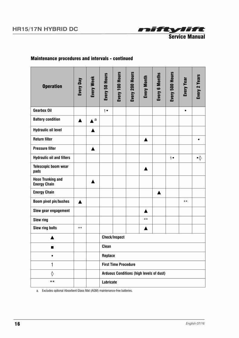
Maintenance procedures and intervals - continued
Operation
Ever
y Da
y
Ever
y W
eek
Ever
y 50
Hou
rs
Ever
y 10
0 H
ours
Ever
y 20
0 H
ours
Ever
y M
onth
Ever
y 6
Mon
ths
Ever
y 50
0 H
ours
Ever
y Ye
ar
Ever
y 2
Year
s
Gearbox Oil 1• •
Battery condition ▲ ▲a
a. Excludes optional Absorbent Glass Mat (AGM) maintenance-free batteries.
Hydraulic oil level ▲
Return filter ▲ •
Pressure filter ▲
Hydraulic oil and filters 1• •◊
Telescopic boom wear pads ▲
Hose Trunking and Energy Chain ▲
Energy Chain ▲
Boom pivot pin/bushes ▲ **
Slew gear engagement ▲
Slew ring **
Slew ring bolts ** ▲
▲ Check/Inspect
■ Clean
• Replace
1 First Time Procedure
◊ Arduous Conditions (high levels of dust)
** Lubricate
English 07/1616

Service ManualHR15/17N HYBRID DC
3.1.2 Engine Oil Level Check
1) Check with the Niftylift on level surfacebefore starting or more than 5 minutes afterstopping the engine.
2) Remove oil level dipstick (2) and wipe clean.
3) Insert dipstick and remove to check oil level.
4) If low, add correct specification oil to the oilfilling port (1) until the upper limit of thedipstick is reached.
5) After adding oil, wait for 5 minutes and re-check oil level. Do not overfill.
6) Reinstall the oil filler cap and tighten by hand.
1
2
MAX
MIN
17English 07/16

Service ManualHR15/17N HYBRID DC
3.1.3 Engine Oil Replace
ENSURE ENGINE IS OFF BEFORE DRAINING THE ENGINE OIL.
WHEN DRAINING ENGINE OIL, PLACE A CONTAINER UNDERNEATH THE ENGINE AND DISPOSE ACCORDING TO LOCAL REGULATIONS.
DO NOT DRAIN OIL AFTER RUNNING THE ENGINE, ALLOW ENGINE TO COOL DOWN SUFFICIENTLY.
1) Remove the drain plug located on the underside of the engine and drain the oil into a suitablecontainer. Note; This will be easier if the oil is warm.
2) Replace seal ring and reinstall drain plug.
3) Tighten drain plug. See section 2.6 for torque settings.
4) Top up engine oil to the upper limit of the dipstick. Oil type can be found in the oil specification table.See section 2.4.2.
5) Re-check oil level at least 5 minutes after filling engine.
3.1.4 Engine Oil Filter Replace
ENSURE ENGINE IS OFF BEFORE REPLACING THE ENGINE OIL FILTER.
PLACE A CONTAINER UNDERNEATH THE ENGINE OIL FILTER AND DISPOSE ANY WASTE ACCORDING TO LOCAL REGULATIONS.
ALLOW ENGINE TO COOL DOWN SUFFICIENTLY PRIOR TO REPLACING THE ENGINE OIL FILTER.
1) Using a filter wrench or strap, remove theengine oil filter (1).
2) Replace oil filter, apply a film of oil to the sealof the oil filter. Ensure oil filter is marked withthe Niftylift’s hours and date of filter change.
3) Screw engine oil filter onto engine by hand.When seal contacts the seal surface, tightenby hand. Do not tighten with filter wrench.
4) Run engine for a short period and check forleaks.
5) Wait 5 minutes and check the engine oil level.
1
English 07/1618

Service ManualHR15/17N HYBRID DC
3.1.5 Engine Coolant Level Check
DO NOT STOP ENGINE SUDDENLY, IDLE ENGINE FOR 5 MINUTES BEFORE STOPPING.
WORK SHOULD BE CARRIED OUT AFTER LETTING THE ENGINE AND RADIATOR COOL OFF COMPLETELY (A MINIMUM OF 30 MINUTES AFTER STOPPING ENGINE).
DO NOT REMOVE RADIATOR CAP WHILST ENGINE COOLANT IS HOT AND PRESSURISED. WHEN COOL TO TOUCH, ROTATE CAP TO THE FIRST STOP TO ALLOW EXCESS PRESSURE TO ESCAPE, THEN REMOVE CAP COMPLETELY.
IF OVERHEATING SHOULD OCCUR, STEAM MAY GUSH FROM THE RADIATOR OR RESERVE TANK RESULTING IN SEVERE BURNS.
1) Remove the radiator cap after the engine hascompletely cooled. Ensure the coolant levelreaches the supply port.
2) Ensure coolant level is sufficient on thereserve tank. The level should be betweenthe full and low marks.
3) Ensure both drain plugs are installed; one tothe lower part of the radiator (2) and theother is on the side of the crank case (1).
4) If coolant levels are low, top-up using thecorrect specification fluid. See section 2.4.5.
Important;
• If the radiator cap has to be removed follow the caution label and securely tighten the cap.
• If coolant should leak, consult your local Kubota dealership.
• Make sure contaminated or sea water does not enter the coolant system.
• Use clean, fresh water with the correct amount of anti-freeze. See section 2.4.5.
• Do not refill reserve tank with coolant higher than the "FULL" level mark.
• Be sure to close the radiator cap securely. If the cap is loose or improperly closed, coolant may leakout and quickly decrease the coolant level.
1
2
19English 07/16

Service ManualHR15/17N HYBRID DC
3.1.6 Coolant Replace
DO NOT STOP ENGINE SUDDENLY, IDLE ENGINE FOR 5 MINUTES BEFORE STOPPING.
WORK SHOULD BE CARRIED OUT AFTER LETTING THE ENGINE AND RADIATOR COOL OFF COMPLETELY (A MINIMUM OF 30 MINUTES AFTER STOPPING ENGINE).
DO NOT REMOVE RADIATOR CAP WHILST ENGINE COOLANT IS HOT AND PRESSURISED. WHEN COOL TO TOUCH, ROTATE CAP TO THE FIRST STOP TO ALLOW EXCESS PRESSURE TO ESCAPE, THEN REMOVE CAP COMPLETELY.
IF OVERHEATING SHOULD OCCUR, STEAM MAY GUSH FROM THE RADIATOR OR RESERVE TANK RESULTING IN SEVERE BURNS.
1) Open both drain plugs and simultaneouslyopen the radiator cap. This must beremoved to allow a full coolant drain.
2) Remove the overflow pipe from the radiatorpressure cap to drain the reserve tank.
3) Ensure both drain plugs are fitted; one to thelower part of the radiator (2) and the other ison the side of the crank case (1).
4) See section 2.4.5 for coolant quantities andfluid specifications.
3.1.7 Coolant Hoses and Clamp Bands Check
BE SURE TO CHECK RADIATOR HOSES AND CLAMPS PERIODICALLY. IF RADIATOR HOSE IS DAMAGED OR COOLANT LEAKS, OVERHEATING OR SEVERE BURNS MAY OCCUR.
1) Check radiator hoses are securely fixed every 200 hours of operation or 6 months, whichever comesfirst.
2) If hose clamps are loose or water leaks, tighten hose clamps securely.
3) If hoses are swollen, hardened or cracked they must be replaced along with clamps. Clamps mustbe tightened securely.
1
2
English 07/1620

Service ManualHR15/17N HYBRID DC
3.1.8 Air Filter Element Maintenance
DO NOT APPLY OIL TO THE AIR FILTER; YOUR NIFTYLIFT IS FITTED WITH A DRY TYPE AIR FILTER. AVOID TOUCHING THE ELEMENT EXCEPT WHEN CLEANING.
1) Open the evacuator valve once a week underordinary conditions, daily when used in a dust richenvironment. This allows dirt and dust to beremoved from the air filter.
2) Release spring clips and remove cover.
3) Slide out of the air filter body.
4) Wipe inside the air cleaner with cloth if found to bedirty or wet.
5) When dry dust adheres to the element, blowcompressed air from the inside out whilst rotatingthe filter. Air pressure must be no more than686kPa (7kgf/cm2 99psi).
6) When carbon or oil adheres to the filter, soak thefilter in detergent for 15 minutes.
7) Wash it several times in water, rinse with clean water and allow to dry naturally.
8) After filter is fully dried, inspect the inside with a flashlight for damage. Refer to instruction labelattached to the filter.
9) Reinstall filter into the air filter body, reinstall cover and engage spring clips.
10) Replace filter element every year or after 6 cleanings. This is in standard operating conditions; dustenriched operating environments will require shorter intervals.
3.1.9 Fuel Pipes Check
1) Fuel pipes and clamps should be checked every 50 hours of engine operation.
2) If clamp bands are found to be loose, apply oil to screw of the band and tighten securely.
3) If rubber fuel pipes are found to be worn, replace immediately.
4) When fuel pipes are not installed, ensure they are capped to prevent dirt entering. This could lead tofuel injection pump malfunction.
Evacuator valve
Spring Clip
Filter Element
21English 07/16

Service ManualHR15/17N HYBRID DC
3.1.10 In-line Fuel Filter Replace
FUEL ESCAPE - PLACE A SUITABLE CONTAINER UNDERNEATH THE WORK AREA AND DISPOSE FUEL ACCORDING TO LOCAL REGULATIONS.
1) Locate fuel filter and clamp the feed pipe fromtank.
2) Loosen jubilee clips and remove fuel pipes.
3) Replace fuel filter ensuring the arrow on the filterpoints in the direction of fuel flow (tank to engine).
4) Tighten Jubilee clips.
5) Remove clamp from feed hose ensuring filterrefills with fuel.
6) Inspect for leaks.
7) See section 3.1.12 for bleeding air from the fuel system before attempting to start the engine.
3.1.11 Fuel Filter and Water Separator Clean/Replace
FUEL ESCAPE - PLACE A SUITABLE CONTAINER UNDERNEATH THE WORK AREA AND DISPOSE FUEL ACCORDING TO LOCAL REGULATIONS.
1) Close the fuel filter tap (1).
2) Undo the top ring and remove container and fuelfilter (3).
3) Rinse out container with clean diesel fuel.
4) Wash fuel filter with clean diesel or replace ifnecessary.
5) Observe clean assembly practices to avoidcontamination by dust or dirt.
6) Reinstall the container and tighten the top ring byhand.
7) See section 3.1.12 for bleeding of air from thefuel system before attempting to start the engine.
To Fuel Pump
From Fuel Tank
Flow Indicator
Place Clamp Here
OFF/CLOSED
3
1
2
English 07/1622

Service ManualHR15/17N HYBRID DC
3.1.12 Bleeding Air From The Fuel System
DO NOT BLEED A HOT ENGINE. FUEL COULD SPILL ON TO THE EXHAUST MANIFOLD CREATING A FIRE RISK.
MAKE SURE SUITABLE EYE PROTECTION AND CLOTHING ARE WORN WHEN BLEEDING THE FUEL SYSTEM.
This procedure is required when;
• the fuel filter and hoses have been detached and refitted
• the fuel tank has become empty
• the Niftylift has been in prolonged storage.
Fuel filter
1) Fill the fuel tank.
2) Open the fuel filter tap (1) as shown above.
3) Loosen air vent plug (2) by a few turns.
4) Tighten plug (2) once air bubbles are no longerpresent in container (3).
5) Carry out procedure to bleed the fuel injectionpump before attempting to start the engine.
Fuel injection pump
1) Fill the fuel tank and bleed fuel filter.
2) Ensure air has been bled from the fuel filter.
3) Loosen air vent plug (1) on the fuel injectionpump.
4) Tighten plug once fuel flows and air bubblesare no longer present.
5) Start the engine and inspect for leaks. If enginefails to start repeat bleed procedure.
OFF/CLOSED
3
1
2
1
23English 07/16

Service ManualHR15/17N HYBRID DC
3.1.13 Exhaust System Inspect
DO NOT CARRY OUT THIS PROCEDURE WHILST THE ENGINE IS RUNNING. BEWARE OF HOT ENGINE COMPONENTS.
1) Open the Engine canopy.
2) Inspect the exhaust components for signs of cracks and leaks; e.g. carbon build up around joints andseams.
3.1.14 Fan Belt Check (Every 100 hours)
1) Ensure engine is switched OFF.
2) Apply moderate pressure to belt using yourthumb in area shown on diagram. If dimensionA does not fall in the range 7 to 9mm(0.28 to 0.35in), loosen the alternator mountingbolts (1) and adjust accordingly until the beltdeflection falls within these limits.
3) Tighten alternator mounting bolts. See section2.6 for torque settings.
4) If belt is damaged, replace immediately.
A
1
English 07/1624

Service ManualHR15/17N HYBRID DC
3.2 Drive Hub Gearbox
3.2.1 Oil Replace
1) Manufacturer’s specifications require thisprocedure to be carried out after the first 50 to100 hours, then every 2500 hours or once ayear. Depending on the operating cycle thisfrequency may vary.
2) Select the drive hub to be serviced. Manoeuvrethe Niftylift until the drive hub is in position A(see diagram).
3) Remove plugs (1) and (2) and drain the oil into asuitable container. Dispose of waste oil inaccordance with local environmental policies.
4) Manoeuvre the Niftylift until the drive hub is inposition B (see diagram). Fill gearbox throughplug hole (1) until oil level reaches bottom of plughole (2). See section 2.4.3 and 2.2 for oilspecifications and capacities.
5) Reinstall plugs and tighten to 33Nm (24 ft-lbs).
6) Repeat for remaining gearboxes.
3.2.2 Bleeding Air From The Braking Circuit
MAKE SURE SUITABLE EYE PROTECTION AND CLOTHING ARE WORN WHEN OPENING THE HYDRAULIC CIRCUIT.
PLACE A SUITABLE CONTAINER UNDERNEATH THE WORK AREA AND DISPOSE OIL ACCORDING TO LOCAL REGULATIONS.
1) Connect the hydraulic couplings to the brake ports on the gearbox.
2) Pressurise the hydraulic circuit, then carefully loosen the hose union on the inlet port.
3) Tighten the hose union once oil flows and air bubbles are no longer present. See section 2.7 forhydraulic hose torque settings.
4) Clean any excess oil and inspect for leaks.
1
1
2
2
A
B
25English 07/16

Service ManualHR15/17N HYBRID DC
3.3 Batteries
MAKE SURE SUITABLE EYE PROTECTION AND CLOTHING ARE WORN WHEN MAINTAINING THE BATTERIES.
MAKE SURE THERE IS ADEQUATE VENTILATION WHEN CARRYING OUT MAINTENANCE ON THE BATTERIES.
CONTACT WITH CONCENTRATED SULFURIC ACID RESULTS IN RAPID DESTRUCTION OF BODY TISSUE VIA BURNS. IF INHALED, SEEK FRESH AIR AND IMMEDIATE MEDICAL ATTENTION. IN THE EVENT OF SKIN OR EYE CONTACT, FLUSH WITH LARGE VOLUMES OF WATER AND SEEK IMMEDIATE MEDICAL ATTENTION. IN THE EVENT OF INGESTION, DO NOT INDUCE VOMITING AND SEEK IMMEDIATE MEDICAL ATTENTION.
ABSORBENT GLASS MAT (AGM) BATTERIES ARE MAINTENANCE FREE AND DO NOT REQUIRE TOPPING UP. IF IGNORED, IRREPARABLE DAMAGE TO THE BATTERIES WILL OCCUR.
3.3.1 Condition Check (Daily)
1) Check that the batteries are fully charged. Batteries should be recharged at the end of each workingday or shift. See manufacturer's Operating Manual for correct battery charging procedure.
2) Check batteries for evidence of leaks or spilt battery acid. If material is released or spilled, lime orsoda ash may be used to neutralise, or flush with large volumes of water. Dispose of waste inaccordance with local regulations for acid and lead scrap. Use approved respiratory protection,rubber gloves, and splash-proof safety goggles. Use rubber boots and acid-proof clothing for majorspills. Replace any defective batteries.
3) Check the condition of battery cables and link wires. Ensure that the insulation is intact along thelength of each cable. Replace any defective battery cables or link wires. Use insulated spanners onbattery terminals. Do not lay tools or other metal objects on the batteries.
4) Check that all battery cables and link wires are securely fastened to the battery terminals andlubricated. Remove any corrosion from battery terminals and clamps. Ensure all surfaces are cleanand free of lubrication. Secure battery terminals using an insulated spanner. Once tightened andsecure, lubricate battery clamps with petroleum jelly to prevent corrosion.
3.3.2 Condition Check (Weekly) - Excludes AGM Batteries
1) Carry out all procedures listed above in Daily checks.
2) Remove all battery cell caps and check the fluid level in each cell in each battery. The level shouldbe sufficient to cover the plates. Top-up each battery cell as necessary using distilled (deionised) water, do not overfill. Replace and tighten battery cell caps and putbatteries on charge. Leave batteries to stabilise for one hour before proceeding with further checks.
English 07/1626

Service ManualHR15/17N HYBRID DC
3) Using a hydrometer, check the specific gravity of the battery fluid in each cell in each battery (Target1.26-1.27 for DYNO Batteries when fully charged). If the specific gravity is not within the serviceablerange, battery de-sulphate fluid may be used to restore batteries.
4) Replace all battery cell caps and clean any liquid from the top surface of the batteries.
3.4 Hydraulic Oil
3.4.1 Level Check (Weekly)
Ensure the Niftylift is on level ground with the platform stowed. Check that the oil level is between the minimum and maximum marks on the gauge. Top-up the tank with oil if the level is below the minimum mark. Use the same oil grade as indicated on the label attached to the hydraulic tank. If the oil level is above the MAX mark, drain as required. See section 3.4.4.
3.4.2 Return Filter Check (Monthly)
With the Niftylift running and the oil temperature at 40°C (104°F), operate the telescope out function and observe the return filter condition indicator (located under right hand canopy). If the needle is in the red zone, the return filter cartridge should be replaced once the oil has cooled sufficiently.
3.4.3 Pressure Filter Check (Weekly)
With the Niftylift running and the oil temperature at 40°C (104°F), observe the pressure filter condition indicator (located on the valve tray). If the visual indicator is red, the pressure filter cartridge should be replaced once the oil has cooled sufficiently.
3.4.4 Hydraulic Oil And Filters Replace
Replace the Hydraulic oil and filters after the first 500 hours of operation, then every 2000 hours or two years (whichever comes first) thereafter.
Replacement or testing of the hydraulic oil is essential for optimum machine performance. Contaminated oil and filters may cause poor performance and continued use may cause component damage. Depending upon the operating environment, more regular oil changes may be required.
Observe clean working practices when servicing the hydraulic system.
1) Ensure that the Niftylift is on level ground with the platform stowed and the oil temperature is notabove 40°C (104°F).
2) Loosen the filler cap to relieve pressure. Caution must be taken when removing the tank cap as thehydraulic tank is pressurised.
3) Place a suitable container under the hydraulic tank.
4) Undo the drain plug located underneath of the hydraulic tank.
5) Dispose of waste oil in accordance with local environmental policies.
3
2
120
40
80
60
87
6
5
4
bar
27English 07/16

Service ManualHR15/17N HYBRID DC
Suction Strainer
6) Disconnect the suction strainer pipe from the tank.Remove strainer and clean with mild solvent orreplace if necessary.
7) Connect suction pipe and tighten. See section 2.7for torque value.
Return Filter
8) Locate the return filter underneath the base controlcanopy.
9) Remove 3 bolts (1) and remove housing cover.
10) Remove seal ring (2).
11) Remove filter element (3) from bowl (4).
12) Remove seal ring (5).
13) Replace filter element and seal ring and lowerbowl into housing.
14) Lubricate seal rings with clean hydraulic oil.
15) Replace seal ring and reinstall housing cover.
16) Tighten 3 bolts to 10.0Nm (7.4ft-lbs).
Pressure filter
17) Locate the pressure filter on the power tray.
18) Place a suitable container underneath filterhousing.
19) Remove the filter bowl (1) and seal ring (2).
20) Remove filter element (3) and seal ring (4).
21) Replace seal rings on filter bowl, lubricate withclean hydraulic oil.
22) Replace filter element.
23) Reinstall filter bowl and tighten. DO NOT APPLYEXCESSIVE TIGHTENING TORQUE.
24) Reinstall drain plug in tank and tighten. DO NOTAPPLY EXCESSIVE TIGHTENING TORQUE.
25) Refill tank with oil until level is between MIN andMAX on gauge. See section 2.4.1 for capacity and 2.4.3 for oil specification.
26) Operate the hydraulic system until oil temperature reaches 40°C (104°F). Check operation andinspect for leaks.
SUCTION
STRAINER
SUCTION
PIPE
1
2
3
4
5
4
2
31
English 07/1628

Service ManualHR15/17N HYBRID DC
3.5 Telescopic Boom
3.5.1 Wear Pad Check (Monthly)
1) With the links and luffing boom down and thetelescope boom fully retracted, check that thereare no loose, missing, or defective components inthe superstructure end of the telescope boom.This includes wear pads, shims, spacers andfasteners.
2) Fully extend the telescope boom.
3) It may be necessary to raise luffing boom slightlyto avoid the platform hitting the floor.
4) Check that there are no loose, missing, ordefective components in the platform end of thetelescope boom. This includes wear pads, shims,spacers, fasteners, wear screws and lockingnuts.
5) Check the clearance between each wear screw and the inner telescope boom section.
6) If adjustment is required, release the locking nut (1) and tighten each wear screw (2) until it makescontact at the tightest point with the inner telescope boom section.
7) Back-off each wear screw until it no longer touches the inner telescope boom, then tighten thelocking nuts.
8) Check that the underside of the inner telescope boom section is adequately lubricated and free fromscoring or rubbing marks.
9) Lubricate if necessary use Hycote White Grease or equivalent.
3.5.2 Hose Trunking and Energy Chain Check (Weekly)
1) Examine the hose trunking and check that there are no loose, missing, or defective components.
2) Check that the hose trunking does not make contact with or “snag” on the boom structure at anypoint over its range of travel.
3) With the telescope section fully extended, check that the trunking system adequately supports theweight of the hose bundle. The upper section of aluminium trunking should be approximately parallelwith the top surface of the boom.
4) Check the condition of the energy chain, paying particular attention to the condition of the links atboth ends, as this is where the highest loads and wear rates occur. See section 4.3.1 if any linksrequire replacement.
5) Check that the energy chain is free from debris or any abrasive material that could cause damage tothe hydraulic hoses. Remove & dispose of any debris in accordance with local environmentalpolicies.
1
2
1
2
1
1
29English 07/16

Service ManualHR15/17N HYBRID DC
3.5.3 Lubricate Boom Pivot Bushes (Yearly)
At yearly intervals lubricate all DU pivot bushes on the Flyboom, Links and Telescope assemblies.
Use a dry PTFE aerosol lubricant spray such as WD40 W/D44394 or equivalent. Apply lubricant spray and allow to penetrate at each of the pivot bush joints identified in the diagram above. Note; there are no grease or lubrication nipples on the pivot bushes.
3.5.4 Boom Pivot Pin Check (Daily)
Check the respective locking device on each boom pivot pin is installed and secure.
3.6 Boom Rotation Gear
3.6.1 Slew Gear Engagement Check (Monthly)
1) Check the play between the slew ring and pinion.
2) With the telescope boom fully extended, manually push the booms from side-to-side. A small amountof play is permissible.
3) Inspect the slew gear for signs of uneven wear, damage or missing teeth.
4) Rotate the machine through a full revolution and check that there are no tight spots where thesuperstructure struggles to rotate.
TELESCOPE BOOMLUBRICATION
POINTS
LINKSLUBRICATION
POINTS
FLYBOOMLUBRICATION
POINTS
English 07/1630

Service ManualHR15/17N HYBRID DC
3.6.2 Slew Ring Lubrication (Monthly)
DO NOT CARRY OUT THIS PROCEDURE WHILST THE ENGINE IS RUNNING.
1) Open the control (left hand) canopy.
2) Two grease nipples (1) are located on the side of the superstructure.
3) Pump the grease gun two to three times as required. Use lithium based (Ep) grease corresponding toDIN 51825 K2K - 20 and ISO L-X-BCHA2. It is also permissible to use equivalent grease with aworking temperature between -20°C (68°F) and +120°C (248°F).
1
31English 07/16

Service ManualHR15/17N HYBRID DC
3.6.3 Slew Ring Bolts Check (Yearly)
Access the slew ring bolts via the aperture in the superstructure. See section 2.6 for torque settings.
3.7 Front Axle
3.7.1 Steer Pin Lubrication (Daily)
1) Two grease nipples (1) are located on eitherside of the front axle.
2) Pump the grease gun two to three times asrequired. Use lithium based (Ep) greasecorresponding to DIN 51825 K2K - 20 and ISOL-X-BCHA2. It is also permissible to useequivalent grease with a working temperaturebetween -20°C (68°F) and +120°C (248°F).
1
English 07/1632

Service ManualHR15/17N HYBRID DC
4 Repair Procedures4.1 General
4.1.1 Fuses
There are 2 main replaceable fuses on the Niftylift:
• 325A - Battery Power Circuit (Hybrid and DC Electric),
• 125A - Diesel Engine Starter Motor and Alternator (Hybrid).
In addition to the 2 main fuses, blade fuses can be found in the following locations:
• 15A (x2), 2A - Base control box,
• 15A, 2A - Control panel assembly.
Prior to the replacement of any fuse, determine the cause of the fault. Do not replace the fuse until the cause of the fault has been remedied.
Isolate Niftylift from power supply during maintenance of the electrical system. (See section 1.5.4).
The replacement fuse must always be the same rating as the defective one.
See location diagrams.
Hybrid - main fuse location
325A
125A
33English 07/16

Service ManualHR15/17N HYBRID DC
DC Electric - main fuse location
Note; for clarity diagram shows battery tray removed.
325A
English 07/1634

Service ManualHR15/17N HYBRID DC
4.2 Platform/Cage
4.2.1 Footswitch - Contact Switch replace
The footswitch is used to provide power to the Niftylift controls.
Remove
1) Isolate the power supply (See section 1.5.4).
2) Remove bolts (1) and (2) and remove thefootswitch cover and rubber gasket.
Note; the longer length of bolt (1).
3) Record wiring locations.
4) Disconnect wiring from switch terminals (3).
5) Remove 2 screws (4) from contact switch andremove.
Install
6) Replace contact switch and tighten 2 screws.
7) Connect wiring to contact switch terminals asobserved in step 3.
8) Reinstall footswitch cover and rubber gasketmaking sure bolts are in the same position asstep 2.
9) Tighten bolt (1) to 3.0Nm (2.2 ft lbs) and bolt(2) to 2.5Nm (1.8 ft lbs).
10) Connect the power supply (See section 1.5.4).
1
2
3
4
35English 07/16

Service ManualHR15/17N HYBRID DC
4.3 Booms
Booms are safety critical components, contact a Niftylift approved dealer for further information.
4.3.1 Energy Chain Link
Remove
1) Operate telescopic boom to access the wornor damaged link.
2) Insert a small flat screwdriver into chainbridge (1).
3) Raise the chain bridge until vertical.
4) Carefully prise apart link (2) at the four pointsarrowed.
5) Remove link and 4 red spacers from chain.
Install
6) Replace 4 red spacers on the link section.
7) Reinstall link to chain and click into position.
8) Lower the chain bridge and click intoposition.
1
2
English 07/1636

Service ManualHR15/17N HYBRID DC
4.4 Power Tray
4.4.1 Exhaust
DO NOT CARRY OUT THIS PROCEDURE WHILST THE ENGINE IS RUNNING. BEWARE OF HOT ENGINE COMPONENTS.
Exhaust silencer
Remove
1) Open the engine canopy.
2) Remove the exhaust clamp (1) from the exhaustsilencer.
3) Remove 2 retaining bolts (2) securing the exhaustassembly to the power tray.
4) Remove exhaust assembly from the exhaust pipe.
5) Remove 4 bolts and remove the heat shield.
Install
6) Reinstall heat shield to exhaust assembly andtighten 4 bolts. See section 2.6 for torque settings.
7) Reinstall exhaust assembly and tighten 2 bolts.See section 2.6 for torque settings.
8) Reinstall the exhaust clamp and tighten bolt. See section 2.6 for torque settings.
Exhaust pipe
Remove
9) Remove the exhaust clamp (1) from the exhaust silencer.
10) Remove 4 retaining nuts (3) securing the exhaust pipe to the manifold.
11) Remove the exhaust pipe and gasket.
Install
12) Replace gasket on manifold.
13) Replace exhaust pipe and tighten 4 nuts. See section 2.6 for torque settings.
14) Start engine, check for leaks around joints and seals.
15) Close the engine canopy.
12
3
37English 07/16

Service ManualHR15/17N HYBRID DC
4.4.2 Fan Belt
DO NOT CARRY OUT THIS PROCEDURE WHILST THE ENGINE IS RUNNING. BEWARE OF HOT ENGINE COMPONENTS.
Remove
1) Open the engine canopy.
2) Remove 4 bolts (1) and remove fan guard.
3) Loosen the alternator mounting bolts andremove the fan belt.
Install
4) Replace fan belt.
5) Reinstall fan guard and tighten 4 bolts. Seesection 2.6 for torque settings.
6) See section 3.1.14 for fan belt adjustment.
7) Close the engine canopy.
1
English 07/1638

Service ManualHR15/17N HYBRID DC
4.5 Base Assembly
4.5.1 Steer Cylinder
MAKE SURE SUITABLE EYE PROTECTION AND CLOTHING ARE WORN WHEN OPENING THE HYDRAULIC CIRCUIT.
PLACE A SUITABLE CONTAINER UNDERNEATH THE WORK AREA AND DISPOSE OIL ACCORDING TO LOCAL REGULATIONS.
Remove
1) Ensure the Niftylift is in its stowedposition.
2) Centre the steering so wheels pointstraight ahead.
3) Undo 4 bolts and remove the coverattached to the front axle allowingaccess to the steer cylinder.
4) Observe clean assembly practices toavoid contamination by dust or dirt.
5) Carefully remove 2 hydraulic hosesfrom the steer cylinder. Slowly loosenfittings to allow pressure to dissipate.
6) Insert plugs and cap to prevent oil loss.
7) Remove and discard 2 roll pins from the steer rod arms.
8) Remove 4 bolts, 4 washers and 4 spring washers.
9) Remove steer cylinder from front axle.
10) Remove and retain 2 bushes fitted to each eyelet on the steer cylinder.
Install
11) Reinstall 2 bushes retained in step 10 to the steer cylinder eyelets.
12) Install steer cylinder.
13) Apply Loctite 243 or equivalent thread locker to bolt threads.
14) Reinstall 4 washers, 4 spring washers and tighten 4 bolts.
15) Tighten bolts to 145Nm (107 ft lbs).
16) Replace roll pins to the steer rod arms.
17) Connect hydraulic hoses and tighten connectors. See section 2.7 for torque settings.
18) Operate the hydraulic system until oil temperature reaches 40°C (104°F). Check operation and inspectfor leaks.
Roll pin 1
Steer arm RH
Steer arm LHBush
Bush
Roll pin 2
39English 07/16

Service ManualHR15/17N HYBRID DC
19) Check hydraulic oil level and top up with appropriate grade of oil if necessary (See section 2.4.4).
20) Reinstall cover to front axle and tighten 4 bolts. See section 2.6 for torque settings.
English 07/1640
Service ManualHR15/17N HYBRID DC
5 System Overview5.1 Introduction
5.1.1 Hybrid System
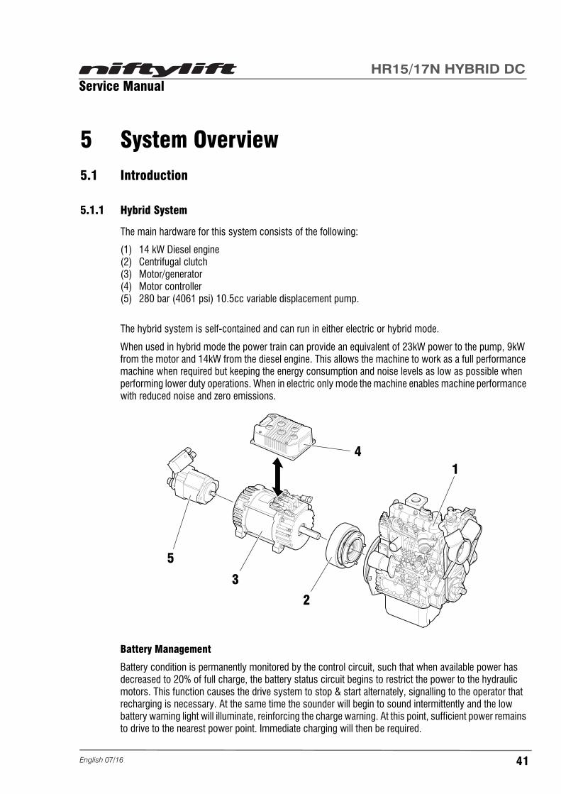
The main hardware for this system consists of the following:
(1) 14 kW Diesel engine(2) Centrifugal clutch (3) Motor/generator(4) Motor controller(5) 280 bar (4061 psi) 10.5cc variable displacement pump.
The hybrid system is self-contained and can run in either electric or hybrid mode.
When used in hybrid mode the power train can provide an equivalent of 23kW power to the pump, 9kW from the motor and 14kW from the diesel engine. This allows the machine to work as a full performance machine when required but keeping the energy consumption and noise levels as low as possible when performing lower duty operations. When in electric only mode the machine enables machine performance with reduced noise and zero emissions.
Battery Management
Battery condition is permanently monitored by the control circuit, such that when available power has decreased to 20% of full charge, the battery status circuit begins to restrict the power to the hydraulic motors. This function causes the drive system to stop & start alternately, signalling to the operator that recharging is necessary. At the same time the sounder will begin to sound intermittently and the low battery warning light will illuminate, reinforcing the charge warning. At this point, sufficient power remains to drive to the nearest power point. Immediate charging will then be required.
14
2
3
5
41English 07/16

Service ManualHR15/17N HYBRID DC
5.1.2 DC Electric System
The main hardware for this system consists of the following:
(1) 28VAC 3 phase electric 8kW motor(2) Motor controller(3) 250 bar (3626 psi) 8cc variable displacement pump.
Battery Management
Battery condition is permanently monitored by the control circuit, such that when available power has decreased to 20% of full charge, the battery status circuit begins to restrict the power to the hydraulic motors. This function causes the drive system to stop & start alternately, signalling to the operator that re-charging is necessary. At the same time the sounder will begin to sound intermittently and the low battery warning light will illuminate, reinforcing the charge warning. At this point, sufficient power remains to drive to the nearest power point. Immediate charging will then be required.
Battery Isolation
The battery-disconnect handle (Anderson) is located inside the chassis, underneath the central access cover. To isolate the machine control and power circuits from the batteries, pull the release handle. See section 1.5.4.
Operation
The electric motor is set to run at 2200RPM during booms operation. Booms have full functionality in electric only mode with no limitations with regard to speed or load.
Batteries
350 AH DYNO Batteries are fitted as standard. The Niftylift charger is tuned to provide the best performance with DYNO batteries. If alternative batteries are used the charger must be reconfigured to suit the replacement batteries. Contact Niftylift for further information.
2
1
3
English 07/1642
Service ManualHR15/17N HYBRID DC
5.2 Hybrid Operation
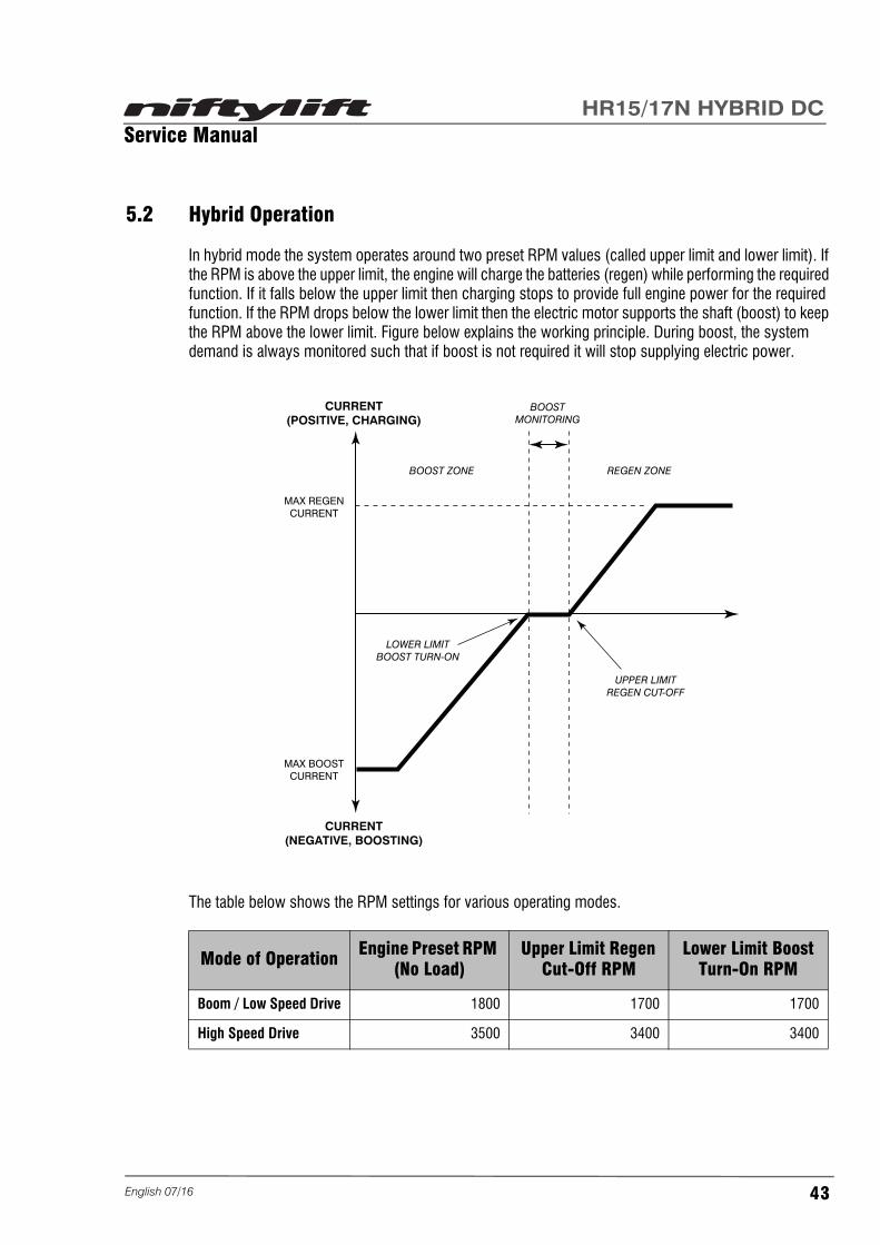
In hybrid mode the system operates around two preset RPM values (called upper limit and lower limit). If the RPM is above the upper limit, the engine will charge the batteries (regen) while performing the required function. If it falls below the upper limit then charging stops to provide full engine power for the required function. If the RPM drops below the lower limit then the electric motor supports the shaft (boost) to keep the RPM above the lower limit. Figure below explains the working principle. During boost, the system demand is always monitored such that if boost is not required it will stop supplying electric power.
The table below shows the RPM settings for various operating modes.
Mode of Operation Engine Preset RPM (No Load)
Upper Limit Regen Cut-Off RPM
Lower Limit Boost Turn-On RPM
Boom / Low Speed Drive 1800 1700 1700
High Speed Drive 3500 3400 3400
CURRENT(POSITIVE, CHARGING)
CURRENT(NEGATIVE, BOOSTING)
MAX BOOSTCURRENT
MAX REGENCURRENT
BOOST ZONE
LOWER LIMITBOOST TURN-ON
UPPER LIMITREGEN CUT-OFF
REGEN ZONE
BOOSTMONITORING
43English 07/16

Service ManualHR15/17N HYBRID DC
5.3 Boom System
The boom system uses a maximum of 25L/min from the pump. Functions can be operated proportionally and simultaneously until the demand reaches 25L/min. If the demand exceeds 25L/min then the flow is shared between the functions with priority given to the function with the lowest operating pressure.
DC Only Mode
The electric motor is set to run at 2200RPM during booms operation. Booms have full functionality in electric only mode with no limitations with regard to speed or load.
Hybrid Mode
In Hybrid mode the engine is set to run at 1800 RPM in a no load condition. The engine can be loaded either by battery charging or by operating the booms. If the revs drops below 1700 RPM, battery charging stops temporarily and the engine then supplies full power to lift the booms, if it drops further then the electric motor will support the shaft to keep the revs above 1700 RPM. Once load is taken off the engine, revs will recover above 1700 RPM and charging will start automatically. Charging current constantly varies depending on the excess power available.
If the electric system fails to function (controller failure, motor failure, etc) the booms can be operated in diesel only mode. However, this mode is only for low duty functions and for assisting to recover the booms back to the transport position. Full boom function performance is only available in electric only or hybrid modes.
5.4 Drive System
5.4.1 Hybrid
The drive system uses 60L/min maximum flow from the pump. The table below describes the available driving modes.
Electric Only Mode
All the listed driving modes are available in electric only operation. Available power is reduced to 8kW and hence performance is reduced. It is advisable to switch to hybrid mode when high power demand is required e.g. off road driving.
Hybrid Mode
In hybrid mode a full 23kW of combined power is available for machine functions. In this mode the machine consumes battery power to support the engine when required and regenerates battery power when the function duty is low. Under continued high duty function for long periods the battery levels will be significantly reduced to support the high power requirement. Under such conditions it will be normal to have to recharge the battery levels prior to electric only use.
Driving Mode Speed HR15N Speed HR17N Gradeablity %
Hare 3.3 km/h (2.1 mph) 3.6 km/h (2.2 mph) 20
Tortoise 1.0 km/h (0.6 mph) 1.2 km/h (0.7 mph) 20
Off road 1.2 km/h (0.7 mph) 1.3 km/h (0.8 mph) 45
English 07/1644

Service ManualHR15/17N HYBRID DC
5.4.2 DC Electric
The drive system uses 60L/min maximum flow from the pump. The table below describes the available driving modes.
5.5 Charging System And Batteries
5.5.1 Charging System - Hybrid
As standard all Niftylifts are fitted with a 18A variable input intelligent charger. The Niftylift can be left on charge over an infinite period or can be used whilst on charge.
Engine charge or "regen" will charge the batteries at differing rates depending on the mode of operation as shown in the table below.
Two charge modes can be combined to give 63A maximum current. The Niftylift is designed to allow this function and will recharge fully discharged batteries quickly to a charged state. If used frequently battery water levels should be monitored and topped up as required. With regular use of this function as a means of charging it is essential that regular and thorough maintenance of the batteries is performed.
The engine alternator charges the start battery when the engine is running which keeps the battery at 14.4V. A step-down unit is fitted to all Niftylifts to convert 48V to 14.4V, which provides control system voltage and keeps the start battery in a charged state. This system also helps keep 48V batteries and the 12V battery in good condition regardless of the operating mode.
Batteries
350 Ah DYNO Batteries are fitted as standard. The Niftylift charger and battery management system are tuned to provide the best performance with DYNO batteries. If alternative batteries are used the charger and battery management system must be reconfigured to suit the replacement batteries. Contact Niftylift for further information.
Driving Mode Speed HR15/HR17 Gradeablity %
Hare 3.3 km/h (2.1 mph) 20
Tortoise 1.0 km/h (0.6 mph) 20
Off road 1.2 km/h (0.7 mph) 45
Operating Mode Maximum Charge Current
Engine idling 45A
Boom operation, Low speed drive, Elevated drive 45A
High speed drive N/A
45English 07/16

Service ManualHR15/17N HYBRID DC
Absorbent Glass Mat (AGM) Batteries
As an alternative to the standard 350 Ah DYNO batteries, the Niftylift may be fitted with 350 Ah Absorbent Glass Mat (AGM) batteries. These batteries are maintenance free, therefore DO NOT REFILL with distilled (deionised) water. Irreparable damage will occur.
5.5.2 Charging System - DC Electric
As standard all Niftylifts are fitted with a 18A variable input intelligent charger. The Niftylift can be left on charge over an infinite period or can be used whilst on charge.
The Niftylift has two charging units; Master and Slave. The Slave unit will switch off when the level of charge reaches approximately 80% and the Master unit will complete the charge.
For further information relating to the charging system, refer to the Operating & Safety Instructions M50461 as supplied with the machine.
English 07/1646

Service ManualHR15/17N HYBRID DC
5.6 Hydraulic System Overview
A simplified version of the hydraulic system is shown below in block diagram format. Brief descriptions of the operation of individual blocks are given below. Component details, valve arrangement and connections are shown in the hydraulic schematics D81900 (Hybrid) and D81500 (DC Electric). Please refer to D81900/D81500 in conjunction with the electric schematic D81619 for in-depth understanding of the complete system.
5.7 Load Sensing Pump
The Niftylift is fitted with an 10.5CC (Hybrid) 8CC (DC Electric) variable displacement pump (open loop load sensing). Standby pressure and maximum pressure are set to 17 bar (247 psi) and 280 bar (4061 psi). The load sense signal is obtained either from the boom control valve or from the drive control valve. The tank is pressurised up to 1.3 bar (18.85 psi) absolute to allow positive head at the suction port. Note that if any maintenance is carried out on the hydraulic system, undo the filler cap on top of the tank to remove the pressure from the tank, this will reduce leakage from the tank ports. The pump runs at fixed preset speeds and swash angle/pressure varies according to the flow demand and load pressure.
DRIVECONTROL
VALVE
STEER CYLINDER
WHEEL MOTORSREAR
BRAKE RELEASEREAR
BOOMCONTROL
VALVE
DIFFLOCKVALVE
HANDPUMP
PILOTJOYSTICK
VARIABLEDISPLACEMENT
PUMP
47English 07/16

Service ManualHR15/17N HYBRID DC
5.8 Valve Block Assembly
The valve block assembly is made up of two components, the Drive Control Valve (DCV) and the Flow Control valve blocks. Together these form the distribution hub of the hydraulic system. The table below describes the main functions. Refer to Hydraulic schematics D81900 (Hybrid) and D81500 (DC Electric).
5.9 Diff Lock
The diff-lock divides/combines the flow to both rear wheels equally when in operation. Bypass restrictors are fitted to help with cornering manoeuvres. Pressure is supplied from the Drive Control Valve to the wheel motors.
When Tortoise or Off-road speed is selected, the diff-lock is engaged and both rear wheels are driven. As with all diff-lock systems, power consumption is increased with the diff-lock engaged, steering whilst diff-lock is engaged further increases power consumption.
Diff-lock is not engaged when Hare speed is selected. In this mode ports A/B of the rear wheels are no longer supplied via the divider/combiner valve and flow is free to go to either of the two rear wheels.
5.10 Brake Release
The rear brakes are released using the Brake Release Valve (BRV) in the DCV which is energised when driving. The rear brakes are released only when driving.
5.11 Steering
Steer Valve
When steer is activated, steer flow is supplied from the DCV via the steer enable valve. This controls the flow to the steer valve and connects the load sense signal to the pump to allow simultaneous operation of drive and steer. Steer valve controls the direction of steer. Pressure Reduction Valves fitted to the main DCV limit the maximum pressure on the steer line to 160 Bar (2321 psi). This will disable steer when the cylinder reaches the end of stroke.
Function Description
Drive Controls drive forward and backward. Provides proportional speed control for both directions.
Brake Release Supplies 30 bar (435 psi) of pressure to the rear brake release valves.
Steer Enables 2 L/min flow to the steer valve and enables pressure compensation.
Elevated Drive Maximum flow is limited for elevated drive. Full flow is enabled for high speed drive.
Boom enable Enables 25 L/min maximum flow to booms valve.
English 07/1648

Service ManualHR15/17N HYBRID DC
5.12 Boom Control Valve
Boom Control Valve
This is a proportional load sensing valve designed to operate all boom functions simultaneously. Flow to each function is compensated and metered by the spool. Where necessary, anti-shock valves are fitted to the work ports. For all main boom functions both manual operation and hydraulic pilot operation is possible. For steer and cage level functions only manual operation is possible.
This valve also provides hydraulic supply to the cage control valve (pilot Joystick). Pilot supply pressure is limited to 50 Bar (725 psi) and controlled by a solenoid fitted to the boom control valve.
49English 07/16

Service ManualHR15/17N HYBRID DC
5.13 Electrical Control System Overview
5.14 Control Logic
Component level details and connections are provided in the Electric Schematic D81619.
5.15 Motor Generator
As previously highlighted, a 48V AC 3 phase motor/generator is fitted to the power train. The motor is equipped with a temperature and speed sensor which feed information to the controller. Current supplied to the motor is controlled by the motor controller. The motor can operate at full power 8 kW output
BASECONTROL
CAGE CONTROL
OUTPUTSTO
VALVES
CAGE USERINPUTS
MOTORCONTROLLER
48VSUPPLY
SiOPS
SAFETYINPUTS
CAGEWEIGH
MOTOR
ENGINE
BASE USERINPUTS
12VSUPPLY
English 07/1650

Service ManualHR15/17N HYBRID DC
(DC Electric), 9 kW output (Hybrid) for 20 minutes continuously. If the motor overheats the controller will reduce the current supply and operate in a low power mode. Using the full available 275A line current, the motor can provide 60Nm torque and 8/9 kW shaft power.
Curtis Diagnostic Unit
This unit can be used to monitor the operation of the controller and for troubleshooting. Under the fault menu existing faults (if applicable) and previous faults are shown.
5.16 Controller
Motor/Generator Control
The Motor Controller has a current rating of 275A. It can supply a maximum power of 9 kW to the motor (power input to the motor). High voltage safety functions are controlled within the motor controller. If a fault is detected in the power supply, motor controller or motor; a main contactor will shut-off the power to the controller. Under this condition a fault code will be displayed on the motor controller status display. Under normal working conditions the yellow LED of the controller status indicator flashes continuously. In a fault condition the yellow and red LED will flash in a particular pattern as shown below.
“X” denotes a flash. A fault code of “34” is represented in the table below.
See section 6.6 for the list of numerical codes and relevant fault descriptions.
If overheating occurs the controller will reduce power accordingly and protect the internal electronics.
LED Status Indicator
RED YELLOW RED YELLOW
X XXX XX XXXX
First Digit (3) Second Digit (4)
Red LED Yellow LED
51English 07/16

Service ManualHR15/17N HYBRID DC
5.17 Niftylift Diagnostic Unit
This unit can be used to monitor the operation of the control system and for troubleshooting. The monitor menu provides useful information for troubleshooting. The diagram on page 53 shows the layout of the menus.
The main menu allows access to the diagnostic units multiple functions. Scroll through the menus using the navigation pad and select options with the OK button. The main menu can be accessed at any point by pressing the right hand menu button on any page.
English 07/1652

Service ManualHR15/17N HYBRID DC
Diagnostic Menu
Back
BASE
MEN
U
CO
NTR
OLS
I/O
Men
uBa
ck
CAG
E M
ENU
JOYS
TIC
KBO
OM
FU
NC
TIO
NS
I/O -
1I/O
- 2
I/O -
3
Men
u
INFO
BASE
CAG
EBO
OM
SD
RIV
EPO
WER
TR
AYC
ALIB
RAT
ION
PAR
AMET
ERS
ERR
OR
S CAN
Back
BOO
MS
MEN
U
SWIT
CH
ESBO
OM
FU
NC
TIO
NS
Men
uBa
ck
DR
IVE
MEN
U
SOLE
NO
IDS
JOYS
TIC
K
Men
uBa
ck
POW
ER T
RAY
MEN
U
MO
TOR
ENG
INE
Men
uBa
ck
CAL
IBR
ATIO
N M
ENU
ANG
LEW
EIG
HT
Men
uBa
ck
ERR
OR
S
Men
u
Back
Base
Con
trols
Gre
en B
utto
n SW
Gre
en B
utto
n LE
DKe
ysw
itch
Base
Keys
witc
h C
age
Die
sel G
low
SW
Die
sel S
tart/
Stop
SW
Gre
en L
EDR
ed L
ED
Men
uBa
ck
Driv
e So
leno
ids
Driv
e En
able
rela
y
Elev
ated
Driv
e so
l.Br
ake
Rel
ease
sol
.D
iffer
entia
l Loc
k so
l.Lo
w D
ispl
acem
ent s
ol.
Men
uBa
ck
Mot
or Spee
dH
igh
Spee
d En
able
Batte
ry L
evel
Batte
ry V
olta
ge (4
8)M
otor
Cur
rent
Con
trolle
r Tem
pera
ture
Mot
or T
empe
ratu
reC
lack
Ala
rm
0% R
PM
0% 48 V
0 A
10 °
C10
°C Men
u
Back
Cag
e I/O
- 1
Gre
en B
utto
n SW
Gre
en B
utto
n LE
DAu
xilia
ry D
esce
nt S
WAu
xilia
ry D
esce
nt L
EDR
ed L
EDH
orn
SWD
iese
l Glo
w S
WD
iese
l Sta
rt/St
op S
W
Men
u
Back
Cag
e I/O
- 2
Spee
d 1
SWSp
eed
3 SW
Cag
e R
otat
e Le
ft SW
Cag
e R
otat
e R
ight
SW
Gen
erat
or S
WLe
vel S
WLe
vel L
ED
Men
u
Back
Cag
e I/O
- 3
Foot
SW
SiO
PS L
eft
SiO
PS R
ight
Soun
der
Beac
onC
age
Enab
le F
eed
Men
u
Back
Base
I/O
Mac
hine
Ena
ble
1 - C
oil
Mac
hine
Ena
ble
1 - S
WM
achi
ne E
nabl
e 2
- Coi
lM
achi
ne E
nabl
e 2
- SW
Mac
hine
Act
ive
Auxi
liary
Des
cent
SW
Soun
der
Hor
n
Men
uBa
ck
Engi
neSp
eed
(from
mot
or)
Hig
h Sp
eed
Enab
leG
low
Star
t/Sto
pSt
op/IG
sol
.D
iese
l Run
ning
Alte
rnat
or L
Oil
Pres
sure
Low
Wat
er T
empe
ratu
re H
igh
0% R
PM Men
u
Back
SER
IAL
NU
MBE
R
Base
Cag
e
1234
5
1234
5
Men
uH
old
+ok
Back
F
2
Angl
e
Hol
d F2
and
pre
ss O
K to
cal
ibra
te
Cal
ibra
ting.
..
Cha
nnel
1C
hann
el 2
Com
poun
d
X
Y
0
0
0
0
0
Men
u
Back
F
2
Wei
ght
Sele
ct Z
ero
or M
axH
old
F2 a
nd p
ress
OK
Men
u
Cha
nnel
1C
hann
el 2
CAL
ZER
O
0 Kg
0 Kg
CAL
MAX
Back
Hol
d+o
k
Mac
hine
Typ
e
Hyb
ridD
iese
lEl
ectri
cH
R15
HR
17H
R21 4x
4N
arro
w
Men
u
Base
Cag
e
Back
Hol
d+o
k
Opt
ions
Cag
e W
eigh
NO
T fit
ted
Auxi
liary
Pow
er fi
tted
Gen
erat
or fi
tted
Soun
der b
ypas
sP2
5553
fitte
dTe
le S
W 2
NO
T fit
ted
Men
u
Base
Cag
e
Back
PAR
AMET
ERS
MEN
U
SER
IAL
NU
MBE
RM
ACH
INE
TYPE
OPT
ION
S
Men
u
Back
Joys
tick
Trig
ger
Stee
r Lef
tSt
eer R
ight
Dire
ctio
n
Spee
d
0%
0%
0%
Men
u
Inpu
tO
utpu
t
Back
Boom
Fun
ctio
ns
Link
sLu
ffing
Slew
Tele
scop
eFl
yC
age
Rot
ate
0% 0% 0% 0% 0% 0%
0% 0% 0% 0% 0%
Spee
dC
age
Rot
ate/
Fly
sol.
0%
Men
u
Inpu
tO
utpu
t
Back
Boom
Fun
ctio
ns
Link
sLu
ffing
Slew
Tele
scop
eFl
yC
age
Rot
ate
0% 0% 0% 0% 0% 0%
0% 0% 0% 0% 0%
Spee
dC
age
Rot
ate/
Fly
sol.
0%
Men
u
Inpu
tO
utpu
t
Back
Joys
tick
Trig
ger
Stee
r Lef
tSt
eer R
ight
Dire
ctio
n
Spee
d
0%
0%
0%
Men
u
Inpu
tO
utpu
t
Back
Boom
Sw
itche
s/So
leno
ids
Boom
s SW
Tele
scop
e SW
1Te
lesc
ope
SW2
Boom
s En
able
Sol
Men
u
Stow
edU
nsto
wed
53English 07/16

Service ManualHR15/17N HYBRID DC
6 Troubleshooting guide6.1 Trouble Shooting Information
This guide is designed to help identify and rectify faults more easily. Known faults are listed below. Your specific Niftylift fault may not be listed here, if not please contact your local Niftylift dealer in order for the guide to be continually improved and updated.
6.2 Platform Function Fault Finding
Problem Cause / Test Solution
Niftylift will not drive
Check that power is reaching the solenoids on the drive block
Replace Drive Enable Relay
Check main PCB for signal in from joystick and out to drive block
Loose connector
Check joystick Replace joystick if faulty
No functions, but engine operates correctly
Coupling failureConnect coupling. Replace any damaged parts
Footswitch faultContact switch may need replacement (See section 4.2.1)
Niftylift inactive, engine will not start
Hybrid - Battery isolator depressedRelease battery isolator (See section 1.5.4)
Check main fuseIf fuse blown, replace with direct replacement (See section 4.1.1)
Batteries discharged Recharge batteries
E-stops activatedEnsure e-stops are pulled out, at base controls and cage controls
Cage weigh activated Remove weight from cage
English 07/1654

Service ManualHR15/17N HYBRID DC
6.3 Engine Fault Finding
Problem Cause / Test Solution
Engine difficult to start
Fuel is thick and doesn't flow
Check the fuel tank and fuel filter. Remove water, dirt and other impurities
As all fuel will be filtered by the filter, if there should be water or other foreign matters on the filter, clean the filter with diesel
Air or water mixed in fuel system
If air is in the fuel filter or injection lines, the fuel pump will not work properly. To attain proper fuel injection pressure, check carefully for loosened fuel line couplings, loose cap nuts etc.
Loosen joint bolt at top of fuel filter and air vent screws of fuel injection pump to eliminate all the air in the fuel system
Thick carbon deposits on orifice of injection nozzle
This is caused when water or dirt is mixed in the fuel. Clean the nozzle injection piece, being careful not to damage the orifice
Check to see if nozzle is working properly. If not, replace nozzle
Valve clearance is incorrectAdjust valve clearance to 0.145 to 0.185mm (0.0057 to 0.0072in.) when the engine is cold
leaking valves Grind valves
Fuel injection timing is wrongAdjust injection timing
The injection timing 0.3 rad (18°) before top dead centre (TDC)
Engine oil becomes thick in cold weather and engine cranks slow
Change grade of oil appropriate to the ambient temperature
Low compressionBad valve or excessive wear of rings, pistons and liners cause insufficient compression. Replace with new parts
Battery is discharged and the engine will not crank
Charge battery
In winter, always remove battery from the Niftylift, charge fully and keep indoors. Reinstall on the Niftylift when required
55English 07/16

Service ManualHR15/17N HYBRID DC
Engine outputinsufficient
Carbon stuck around orifice of injection nozzle piece
Clean orifice and needle valve, being careful not to damage the nozzle orifice
Check nozzle for condition. Replace if necessary
Inadequate compression.Leaking valves
Bad valve or excessive wear of rings, pistons and liners cause insufficient compression. Replace with new parts
Grind valves
Fuel supply is deficient Check fuel system
Moving parts overheating
Check lubricating oil system
Check lubricating oil filter is functioning correctly
Filter element deposited with impurities will cause poor lubrication. Replace element
Check clearance of bearings are within factory specifications
Check ignition timing
Valve clearance is wrongAdjust valve clearance to 0.145 to 0.185mm (0.0057 to 0.0072in.) when the engine is cold
Air cleaner is dirty Clean the air filter every 100 hours of operation
Fuel injection pressure is incorrect
Adjust to correct pressure. 13.7 Mpa (140kgf/cm2, 1991psi)
Injection pump wear
Do not use poor quality fuel as it will cause excessive pump wear. Only use No 2-D fuel
Check the fuel injection pump element and delivery valve assembly and replace if necessary
Engine cutting out due to low fuel level
Fuel level too lowRe-fill fuel tank if problem persists see above for 'Air or water mixed in fuel system'
Fuel line crushed Release fuel line and replace if damaged
Lift pump not functioning correctly
Replace lift pump
Problem Cause / Test Solution
English 07/1656

Service ManualHR15/17N HYBRID DC
6.4 Gearbox Fault Finding
Problem Cause / Test Solution
Oil leakage from seals
Hardening of the seals due to prolonged storage
Clean area and check for leakage after a few days
Seals damaged or worn Contact a Niftylift approved service centre
Too much lubricant Check oil level (See section 3.2.1)
Vibrations and/or excessive noise
Wheel gear is not correctly installed
Check the fixing
Internal anomaly Contact a Niftylift approved service centre
Bearings badly lubricated or faulty
Contact a Niftylift approved service centre
Dented or chipped teeth Contact a Niftylift approved service centre
Low oil level Check oil level, top-up if necessary (See section 3.2.1)
The brakes fails to disengage
Low pressure in the braking circuit
Check the brake connection
Brake stuck due to prolonged storage
Apply pressure to the brake and turn the wheel by turning the motor on
Brakes do not engage
Residual pressure in the circuit
Check hydraulic circuit
Over-heating
Either too much or too little oil
Check the oil level
Unsuitable lubricant Check the lubricant type and condition
Bearings badly lubricated or faulty
Contact a Niftylift approved service centre
Multiple-disc brake not opening completely
Check brake opening pressure
High thermal power Contact a Niftylift approved service centre
57English 07/16

Service ManualHR15/17N HYBRID DC
6.5 Fault Code Display
Code Fault Description Action
00 Sounder ErrorOpen circuit or short circuit of the base sounder
Check wiring to the base sounder
01 Base Green Button, Bulb ErrorOpen circuit or short circuit of the base green button bulb
Check bulb is fitted.Check wiring to the base green button bulb
02 Drive Enable Relay ErrorOpen circuit or short circuit of the drive enable relay coil
Check wiring to the drive enable relay coil on the PCB
03 Elevated Drive Solenoid ErrorOpen circuit or short circuit of the elevated drive solenoid
Check wiring to the elevated drive solenoid
04 Auxiliary Descent ErrorOpen circuit or short circuit of the auxiliary descent contactor
Check wiring to the auxiliary descent contactor
05 Machine Enable Relay 1 ErrorOpen circuit or short circuit of the machine enable relay1 coil
Check wiring to the machine enable relay1 coil on the PCB
06 Machine Enable Relay 2 ErrorOpen circuit or short circuit of the machine enable relay2 coil
Check wiring to the machine enable relay2 coil on the PCB
07 Horn ErrorOpen circuit or short circuit of the horn
Check wiring to the horn
08 Base Angle X Channel 1 ErrorError of the corresponding analogue input during PLC start up check
Check all connections to the tilt sensor.- Reset power
09 Base Angle X Channel 2 ErrorError of the corresponding analogue input during PLC start up check
Check all connections to the tilt sensor.- Reset power
10 Base Angle Y Channel 1 ErrorError of the corresponding analogue input during PLC start up check
Check all connections to the tilt sensor.- Reset power
11 Base Angle Y Channel 2 ErrorError of the corresponding analogue input during PLC start up check
Check all connections to the tilt sensor.- Reset power
12 Fuel Sender ErrorError of the corresponding analogue input during PLC start up check
Check all connections to the fuel sender.- Reset power
13 Base Green Button ErrorError of the corresponding analogue input during PLC start up check
Check wiring from the base green button.- Reset power
English 07/1658

Service ManualHR15/17N HYBRID DC
14 Booms Down Switch ErrorError of the corresponding analogue input during PLC start up check
Check wiring from the booms down switch (Normally Closed).- Reset power
15 Machine Enable OK1 ErrorError of the corresponding analogue input during PLC start up check
Check wiring from the machine enable relay1 (normally closed contact).- Reset power
16 Debug ErrorError of the corresponding digital input during PLC start up check
Check wiring from the debug core of the programming port.- Reset power
17Key switch Base SwitchError
Error of the corresponding digital input during PLC start up check
Check wiring from the 'base' side of the key switch.- Reset power
18 Base ERROR_IOError on one of the inputs or outputs of the base PLC
Check screen for further fault codes.- Diagnose further using the service tool
19 Base ERROR_ANALOGError on one of the analogue inputs to the base PLC
Check screen for further fault codes.- Diagnose further using the service tool
20BaseERROR_OUTPUTBLANKING
Error on one of the safety outputs of the base PLC
Check all connections to the relays on the base PCB and to the elevated drive solenoid
21Axiomatic Valve Controlleroff the CANBus
The base PLC is not receiving the valve controller's 'present' signal
Check the power supply to the Axiomatic controller.Check the CANBus connections from the base box to the Axiomatic controller
22 Screen off the CANBusThe base PLC is not receiving the screen's 'present' signal
Check the power supply to the screen.Check the CANBus connections from the cage panel to the screen
23 Joystick off the CANBusThe base PLC is not receiving the joystick's 'present' signal
Check the power supply to the joystick.Check the CANBus connections from the cage panel to the joystick
Code Fault Description Action
59English 07/16

Service ManualHR15/17N HYBRID DC
24Chassis Node off the CANBus(Hybrid only)
The base PLC is not receiving the chassis node's 'present' signal
Check the power supply to the chassis nodeCheck the CANBus connections from the base box to the chassis nodeCheck address dials are set correctly
25Motor / Engine Controller offthe CANBus
The base PLC is not receiving the motor controller's 'present' signal
Check the power supply to the motor controller (Hybrid) or the engine node (Diesel)
The base PLC is not receiving the engine node 'present' signal (Diesel)
Check the CANBus connections from the base box to the motor controller (Hybrid) or the engine node (Diesel)
26Motor Controller Error(Hybrid only)
The motor controller has diagnosed an internal fault
Diagnose further using the service tool.Use the LEDs on the motor controller to ascertain the fault code(s).(Red and Orange LEDs flash alternately)1 red is followed by the first digit of the code2 reds is followed by the second digit of the code
27 ERROR_CAN_SAFETY
The control system has detected an error in the communication between the base and cage
Check that there is around 60Ohms between CANH and CANL anywhere on the networkCheck there are no short circuits between CANH and CANL anywhere on the networkCheck address dials are set correctly
28 Cage ERROR_ANALOGError on one of the analogueinputs to the cage PLC
Check screen for further fault codesDiagnose further using the service tool
29Cage Weigh Channel 1Disconnected
The channel 1 cage weighmodule is disconnected orfaulty
Check the module is connectedCheck the wiring from the cage panel to the module
Code Fault Description Action
English 07/1660

Service ManualHR15/17N HYBRID DC
30Cage Weigh Channel 2Disconnected
The channel 2 cage weighmodule is disconnected orfaulty
Check the module is connectedCheck the wiring from the cage panel to the module
31 Tilt Sensor DisconnectedThe tilt sensor is disconnected or faulty
Check the sensor is connectedCheck the wiring from the base box to the sensor
32 Telescope Switch ErrorSwitch inputs to the PLC do not oppose or switch in sync
Check wiring between switch and PLCCheck switch operation
33 Telescope2 Switch ErrorSwitch inputs to the PLC do not oppose or switch in sync
Check wiring between switch and PLCCheck switch operation
34 Cage ERROR_IOError on one of the inputs or outputs of the cage PLC
Check screen for further fault codesDiagnose further using the service tool
35 Cage Node off the CANBusThe base PLC is not receiving the cage node's 'present' signal
Check the power supply to the cage nodeCheck the CANBus connections from the cage panel to the cage node
36 Parameter ErrorParameters do not match or incompatible selections have been made
Check on service tool that parameters are the same for base and cageCheck that only one type of machine is selected (e.g. Hybrid, Diesel or Electric)
37 Serial Number ErrorSerial numbers in base and cage PLCs do not match
Fit correct PLCsChange serial number in PLCs
38 Cage Weigh ErrorCage Weigh inputs to the PLC do not oppose or switch in sync
Check wiring between cage weigh PCB and PLCCheck cage weigh PCB operation
39 Links Paddle ErrorPaddle analogue outputs are not within spec of each other
Check paddle analogue voltagesUse another paddle to check inputs to control system
40 Luffing Paddle ErrorPaddle analogue outputs are not within spec of each other
Check paddle analogue voltagesUse another paddle to check inputs to control system
Code Fault Description Action
61English 07/16

Service ManualHR15/17N HYBRID DC
41 Slew Paddle ErrorPaddle analogue outputs are not within spec of each other
Check paddle analogue voltagesUse another paddle to check inputs to control system
42 Telescope Paddle ErrorPaddle analogue outputs are not within spec of each other
Check paddle analogue voltagesUse another paddle to check inputs to control system
43 Fly Paddle ErrorPaddle analogue outputs are not within spec of each other
Check paddle analogue voltagesUse another paddle to check inputs to control system
44 Base Set to DownloadThe base run/download switch is set to download
Check switch is in RUN positionCheck that when the switch is in RUN, pin 24 of the PLC is 0v
45 Cage Set to DownloadThe base run/download switch is set to download
Check switch is in RUN positionCheck that when the switch is in RUN, pin 24 of the PLC is 0v
46 Base ERROR_POWERThe voltage supply to the basePLC has dropped below or isbelow 10V
Check power supply to PLCIf Hybrid/Electric, check step down unit is operational and providing 14.3v to the control system
47 Cage ERROR_POWERThe voltage supply to the cagePLC has dropped below or isbelow 10V
Check power supply to PLCIf Hybrid/Electric, check step down unit is operational and providing 14.3v to the control system
48 Base ERROR_VBBRThe base PLC is not seeing any voltage on pin 34
Check VBBr fuse in main box is OKCheck wiring to and from the fuse
49 Cage ERROR_VBBRThe cage PLC is not seeing any voltage on pin 34
Check VBBr fuse on cage PCB is OKCheck wiring to and from the fuse
Code Fault Description Action
English 07/1662

Service ManualHR15/17N HYBRID DC
6.6 Motor Controller Fault Codes
Code Programmer LCD Display Effect of fault Possible Cause Set/Clear Conditions
12
Controller OvercurrentShutdownMotor; ShutdownMainContactor;ShutdownEMBrake;ShutdownThrottle;FullBrake;ShutdownPump.
1. External short of phase U,V, or W motor connections.2. Motor parameters are mis-tuned.3. Controller defective.4. Speed encoder noise problems.
Set: Phase current exceeded the current measurement limit.
Clear: Cycle KSI.
13
Current Sensor FaultShutdownMotor; ShutdownMainContactor;ShutdownEMBrake;ShutdownThrottle;FullBrake;ShutdownPump.
1. Leakage to vehicle frame from phase U, V, or W (short in motor stator).2. Controller defective.
Set: Controller current sensors have invalid offset reading.
Clear: Cycle KSI.
14
Precharge FailedShutdownMotor; ShutdownMainContactor;ShutdownEMBrake;ShutdownThrottle;FullBrake;ShutdownPump.
1. See Monitor menu» Battery: Capacitor Voltage.2. External load on capacitor bank (B+ connection terminal) that prevents the capacitor bank from charging.
Set: Precharge failed to charge the capacitor bank to the KSI voltage.
Clear: Cycle Interlock input or use VCL function Enable_ Precharge().
15
Controller Severe UndertempShutdownMotor; ShutdownMainContactor;ShutdownEMBrake;ShutdownThrottle;FullBrake;ShutdownPump.
1. See Monitor menu» Controller: Temperature.2. Controller is operating in an extreme environment.
Set: Heatsink temperature below -40°C.
Clear: Bring heatsink temperatureabove -40°C, and cycle interlock or KSI.
16
Controller Severe OvertempShutdownMotor; ShutdownMainContactor;ShutdownEMBrake;ShutdownThrottle;FullBrake;ShutdownPump.
1. See Monitor menu» Controller: Temperature.2. Controller is operating in an extreme environment.3. Excessive load on vehicle.4. Improper mounting of controller.
Set: Heatsink temperature above +95°C (194°F).
Clear: Bring heatsink temperaturebelow +95°C (194°F), and cycle interlock or KSI.
63English 07/16

Service ManualHR15/17N HYBRID DC
17Severe UndervoltageReduced drive torque.
1. Battery Menu parameters are misadjusted.2. Non-controller system drain on battery.3. Battery resistance too high.4. Battery disconnected while driving.5. See Monitor menu» Battery: Capacitor Voltage.6. Blown B+ fuse or main contactor did not close.
Set: Capacitor bank voltage dropped below the Severe Undervoltage limit with FET bridge enabled.
Clear: Bring capacitor voltage above Severe Undervoltage limit.
18
Severe OvervoltageShutdownMotor;ShutdownMainContactor;ShutdownEMBrake;ShutdownThrottle;FullBrake;ShutdownPump.
1. See Monitor menu» Battery: Capacitor Voltage.2. Battery Menu parameters are misadjusted.3. Battery resistance too high for given regen current.4. Battery disconnected while regen braking.
Set: Capacitor bank voltage exceeded the Severe Overvoltage limit with FET bridge enabled.Clear: Bring capacitor voltage below Severe Overvoltage limit, and then cycle KSI.
22Controller Overtemp Cutback Reduced drive and brake torque.
1. See Monitor menu» Controller: Temperature2. Controller is performance limited at this temperature.3. Controller is operating in an extreme environment.4. Excessive load on vehicle.5. Improper mounting of controller.
Set: Heatsink temperature e xceeded 85°C (185°F).
Clear: Bring heatsink temperaturebelow 85°C (185°F).
23Undervoltage CutbackReduced drive torque.
1. Normal operation. Fault shows that the batteries need recharging. Controller is performance limited at this voltage.2. Battery parameters are misadjusted.3. Non-controller system drain on battery.4. Battery resistance too high.5. Battery disconnected while driving.6. See Monitor menu» Battery: Capacitor Voltage.7. Blown B+ fuse or main contactor did not close.
Set: Capacitor bank voltage dropped below the Undervoltage limit with FET bridge enabled.Clear: Bring capacitor voltage above Undervoltage limit.
Code Programmer LCD Display Effect of fault
Possible Cause Set/Clear Conditions
English 07/1664

Service ManualHR15/17N HYBRID DC
24Overvoltage CutbackReduced brake torque.
1. Normal operation. Fault shows that regen braking currents elevated the battery voltage during regen braking. Controller is performance limited at this voltage.2. Battery parameters are misadjusted.3. Battery resistance too high for given regen current.4. Battery disconnected while regen braking.5. See Monitor menu» Battery: Capacitor Voltage
Set: Capacitor bank voltage exceeded the Overvoltage limit with FET bridge enabled.Clear: Bring capacitor voltage below the Overvoltage limit.
25+5V Supply Failure None, unless a fault action is programmed in VCL.
1. External load impedance on the +5V supply (pin 26) is too low.2. See Monitor menu» Outputs: 5 Volts and Ext Supply Current.
Set:+5V supply (pin 26) outside the +5V ±10% range.
Clear: Bring voltage within range.
26Digital Out 6 OvercurrentDigital Output 6 driver will not turn on.
1. External load impedance on Digital Output 6 driver (pin 19) is too low.
Set: Digital output 6 (pin 19) current exceeded 15 mA.
Clear: Remedy the overcurrent cause and use the VCL function Set_DigOut() to turn the driver on again.
27Digital Out 7 OvercurrentDigital Output 7 driver will not turn on.
1. External load impedance on Digital Output 7 driver (pin 20) is too low.
Set: Digital output 7 (pin 20) current exceeded 15 mA.
Clear: Remedy the overcurrent cause and use the VCL function Set_DigOut() to turn the driver on again.
Code Programmer LCD Display Effect of fault
Possible Cause Set/Clear Conditions
65English 07/16

Service ManualHR15/17N HYBRID DC
28Motor Temp Hot CutbackReduced drive torque.
1. Motor temperature is at or above the programmed Temperature Hot setting, and the requested current is being cut back.2. Motor Temperature Control Menu parameters are mis-tuned.3. See Monitor menu» Motor: Temperature and » Inputs: Analog2.4. If the application doesn't use a motor thermistor, Temp Compensation and Temp Cutback should be programmed Off.
Set: Motor temperature is at or above the Temperature Hot parameter setting.
Clear: Bring the motor temperature within range.
29
Motor Temp Sensor FaultMaxSpeed reduced (LOS, Limited Operating Strategy) and motor temperature cutback is disabled.
1. Motor thermistor is not connected properly.2. If the application doesn't use a motor thermistor, Temp Compensation and Temp Cutback should be programmed Off.3. See Monitor menu» Motor: Temperature and » Inputs: Analog2.
Set: Motor thermistor input (pin 8) is at the voltage rail (0 or 10V).
Clear: Bring the motor thermistor input voltage within range.
31Coil1 Driver Open/ShortShutdownDriver1.
1. Open or short on driver load.2. Dirty connector pins.3. Bad crimps or faulty wiring.
Set: Driver 1 (pin 6) is either open or shorted. This fault can be set only when Main Enable = Off.Clear: Correct open or short, and cycle driver.
31
Main Open/ShortShutdownMotor;ShutdownMainContactor;ShutdownEMBrake;ShutdownThrottle;FullBrake;ShutdownPump.
1. Open or short on driver load.2. Dirty connector pins.3. Bad crimps or faulty wiring.
Set: Main contact driver (pin 6) is either open or shorted. This fault can be set only when Main Enable = On.Clear: Correct open or short, and cycle driver.
32Coil2 Driver Open/ShortShutdownDriver2.
1. Open or short on driver load.2. Dirty connector pins.3. Bad crimps or faulty wiring.
Set: Driver 2 (pin 5) is either open or shorted. This fault can be set only when EM Brake Type = 0.Clear: Correct open or short, and cycle driver.
Code Programmer LCD Display Effect of fault
Possible Cause Set/Clear Conditions
English 07/1666

Service ManualHR15/17N HYBRID DC
32
EM Brake Open/ShortShutdownEMBrake;ShutdownThrottle;FullBrake.
1. Open or short on driver load.2. Dirty connector pins.3. Bad crimps or faulty wiring.
Set: Electromagnetic brake driver (pin 5) is either open or shorted. This fault can be set only when EM Brake Type > 0.Clear: Correct open or short, and cycle driver.
33Coil3 Driver Open/ShortShutdownDriver3.
1. Open or short on driver load.2. Dirty connector pins.3. Bad crimps or faulty wiring.
Set: Driver 3 (pin 4) is either open or shorted.Clear: Correct open or short, and cycle driver.
34Coil4 Driver Open/ShortShutdownDriver4.
1. Open or short on driver load.2. Dirty connector pins.3. Bad crimps or faulty wiring.
Set: Driver 4 (pin 3) is either open or shorted.Clear: Correct open or short, and cycle driver.
35PD Open/ShortShutdownPD.
1. Open or short on driver load.2. Dirty connector pins.3. Bad crimps or faulty wiring.
Set: Proportional driver (pin 2) is either open or shorted.Clear: Correct open or short, and cycle driver.
36Encoder FaultShutdownEMBrake;ShutdownThrottle.
1. Motor encoder failure.2. Bad crimps or faulty wiring.3. See Monitor menu» Motor: Motor RPM.
Set: Motor encoder phase failure detected.Clear: Cycle KSI.
37
Motor OpenShutdownMotor;ShutdownMainContactor;ShutdownEMBrake;ShutdownThrottle;FullBrake;ShutdownPump.
1. Motor phase is open.2. Bad crimps or faulty wiring.
Set: Motor phase U, V or W detected open.Clear: Cycle KSI.
38
Main Contactor WeldedShutdownMotor;ShutdownMainContactor;ShutdownEMBrake;ShutdownThrottle;FullBrake;ShutdownPump.
1. Main contactor tips are welded closed.2. Motor phase U is disconnected or open.3. An alternate voltage path (such as an external precharge resistor) is providing a current to the capacitor bank (B+ connection terminal).
Set: Just prior to the main contactor closing, the capacitor bank voltage (B+ connection terminal) was loaded for a short time and the voltage did not discharge.Clear: Cycle KSI.
Code Programmer LCD Display Effect of fault
Possible Cause Set/Clear Conditions
67English 07/16

Service ManualHR15/17N HYBRID DC
39
Main Contactor did not CloseShutdownMotor;ShutdownMainContactor;ShutdownEMBrake;ShutdownThrottle;FullBrake;ShutdownPump.
1. Main contactor did not close.2. Main contactor tips are oxidized, burned or not making good contact.3. External load on capacitor bank (B+ connection terminal) that prevents capacitor bank from charging.4. Blown B+ fuse.
Set: With the main contactor commanded closed, the capacitor bank voltage (B+ connection terminal) did not charge to B+.Clear: Cycle KSI.
41Throttle Wiper HighShutdown Throttle.
1. See Monitor menu» Inputs: Throttle Pot.2. Throttle pot wiper voltage too high.
Set: Throttle pot wiper (pin 16) voltage is higher than the high fault threshold (can be changed with the VCL function Setup_Pot_Faults()).Clear: Bring throttle pot wiper voltage below the fault threshold.
42Throttle Wiper LowShutdown Throttle.
1. See Monitor menu» Inputs: Throttle Pot.2. Throttle pot wiper voltage too low.
Set: Throttle pot wiper (pin16) voltage is lower than the low fault threshold (can be changed with the VCL function Setup_Pot_Faults()).Clear: Bring throttle pot wiper voltage above the fault threshold.
43Pot2 Wiper HighFullBrake.
1. See Monitor menu» Inputs: Pot2 Raw.2. Pot2 wiper voltage too high.
Set: Pot2 wiper (pin 17) voltage is higher than the high fault threshold (can be changed with the VCL function Setup_Pot_Faults()).Clear: Bring Pot2 wiper voltage below the fault threshold.
44Pot2 Wiper LowFullBrake.
1. See Monitor menu» Inputs: Pot2 Raw.2. Pot2 wiper voltage too low.
Set: Brake pot wiper (pin 17) voltage is lower than the low fault threshold (can be changed with the VCL function Setup_Pot_Faults()).Clear: Bring brake pot wiper voltage above the fault threshold.
45Pot Low OvercurrentShutdownThrottle;FullBrake.
1. See Monitor menu» Outputs: Pot Low.2. Combined pot resistance connected to pot low is too low.
Set: Pot low (pin 18) current exceeds 10mA.Clear: Clear pot low overcurrent condition and cycle KSI.
Code Programmer LCD Display Effect of fault
Possible Cause Set/Clear Conditions
English 07/1668

Service ManualHR15/17N HYBRID DC
46
EEPROM FailureShutdownMotor;ShutdownMainContactor;ShutdownEMBrake;ShutdownThrottle;ShutdownInterlock;ShutdownDriver1;ShutdownDriver2;ShutdownDriver3;ShutdownDriver4;ShutdownPD;FullBrake:Shutdown Pump.
1. Failure to write to EEPROM memory. This can be caused by EEPROM memory writes initiated by VCL, by the CAN bus, by adjusting parameters with the Niftylift Diagnostic Unit, or by loading new software into the controller.
Set: Controller operating system tried to write to EEPROM memory and failed.Clear: Download the correct software (OS) and matching parameter default settings into the controller and cycle KSI.
47HPD/Sequencing FaultShutdownThrottle;
1. KSI, interlock, direction and throttle inputs applied in incorrect sequence.2. Faulty wiring, crimps or switches at KSI, interlock, direction or throttle inputs.3. See Monitor menu» Inputs.
Set: HPD (High Pedal Disable) or sequencing fault caused by incorrect sequence of KSI, interlock, direction and throttle inputs.Clear: Reapply inputs in correct sequence.
47Emer Rev HPDShutdownThrottle;ShutdownEMBrake;
1. Emergency Reverse operation has concluded, but the throttle, forward and reverse inputs and interlock have not been returned to neutral.
Set: At the conclusion of Emergency Reverse, the fault was set because various inputs were not returned to neutral.Clear: If EMR_Interlcok = On, clear the interlock, throttle and direction inputs. If EMR_Interlock = Off, clear the throttle and direction inputs.
49
Parameter Change FaultShutdownMotor;ShutdownMainContactor;ShutdownEMBrake;ShutdownThrottle;FullBrake:Shutdown Pump.
1. This is a safety fault caused by a change in certain parameter settings so that the machine will not operate until KSI is cycled.For example, if a user changes the Throttle type this fault will appear and require cycling KSI before the machine can operate.
Set: Adjustment of a parameter setting that requires cycling of KSI.Clear: Cycle KSI.
51-67OEM Faults(See OEM Documentation)
1. These faults can be defined by the OEM and are implemented in the application specific VCL code. See OEM documentation.
Set: See OEM documentation.Clear: See OEM documentation.
Code Programmer LCD Display Effect of fault
Possible Cause Set/Clear Conditions
69English 07/16

Service ManualHR15/17N HYBRID DC
68
VCL Runtime ErrorShutdownMainContactor;ShutdownMotor;ShutdownEMBrake;ShutdownThrottle;ShutdownInterlock;ShutdownDriver1;ShutdownDriver2;ShutdownDriver3;ShutdownDriver4;ShutdownPD;FullBrake;Shutdown Pump.
1. VCL code encountered a runtime VCL error.2. See Monitor menu» Controller: VCL Error Module and VCL Error. This error can then be compared to the runtime VCL module ID and error code definitions found in the specific OS system information file.
Set: Runtime VCL code error condition.Clear: Edit VCL application software to fix this error condition; flash the new compiled software and matching parameter defaults; cycle KSI.
69External Supply out of RangeNone, unless a fault action is programmed in VCL.
1. External load on the 5V and 12V supplies draws either too much or too little current.2. Fault Checking Menu parameters Ext Supply Max and Ext Supply Min are mis-tuned.3. See Monitor menu» Outputs: Ext Supply Current.
Set: The external supply current (combined current used by the 5V supply (pin 26) and 12V supply (pin 25) is either greater than the upper current threshold or lower than the lower current threshold. The two thresholds are defined by the Ext Supply Max and Ext Supply Min parameter settings.Clear: Bring the external supply current within range.
71
OS GeneralShutdownMainContactor;ShutdownMotor;ShutdownEMBrake;ShutdownThrottle;ShutdownInterlock;ShutdownDriver1;ShutdownDriver2;ShutdownDriver3;ShutdownDriver4;FullBrake;Shutdown Pump.
1. Internal controller fault.Set: Internal controller fault detected.Clear: Cycle KSI.
72
PDO TimeoutShutdownThrottle;CAN NMT State set to Pre-operational
1. Time between CAN PDO messages received exceeded the PDO Timeout Period.
Set: Time between CAN PDO messages received exceeded the PDO Timeout Period.Clear: Cycle KSI or receive CAN NMT message.
Code Programmer LCD Display Effect of fault
Possible Cause Set/Clear Conditions
English 07/1670

Service ManualHR15/17N HYBRID DC
73
Stall DetectShutdownEMBrake;ShutdownThrottle;Control Mode changed to LOS, (Limited Operating Strategy).
1. Stalled motor.2. Motor encoder failure.3. Bad crimps or faulty wiring.4. Problems with power supply for the motor encoder.5. See Monitor menu» Motor: Motor RPM.
Set: No motor encoder movement detected.Clear: Either cycle KSI, or detect valid motor encoder signals while operating in LOS mode and return Throttle Command = 0 and Motor RPM = 0.
74Fault On Other Traction Controller
Dual Drive fault: see Dual Drive manual.
-
75 Dual Severe FaultDual Drive fault: see Dual Drive manual.
-
87
Motor Characterization FaultShutdownMainContactor;ShutdownMotor;ShutdownEMBrake;ShutdownThrottle;ShutdownPump.
1. 1. Motor characterization failed during characterization process. See Monitor menu » Controller: Motor Characterization Error for cause:0=none1=encoder signal seen, but step size not determined; set Encoder Step Size manually2=motor temp sensor fault3=motor temp hot cutback fault4=controller overtemp cutback fault5=controller undertemp cutback fault6=undervoltage cutback fault7=severe overvoltage fault8=encoder signal not seen, or one or both channels missing9=motor parameters out of characterization range.
Set: Motor characterization failed during the motor characterization process.Clear: Correct fault; Cycle KSI.
89
Motor Type FaultShutdownMainContactor;ShutdownMotor;ShutdownEMBrake;ShutdownThrottle;ShutdownPump.
1. The Motor_Type parameter value is out of range.
Set: Motor_Type parameter is set to an illegal value.Clear: Set Motor_Type to correct value and cycle KSI.
Code Programmer LCD Display Effect of fault
Possible Cause Set/Clear Conditions
71English 07/16

Service ManualHR15/17N HYBRID DC
91
VCL/OS MismatchShutdownMainContactor;ShutdownMotor;ShutdownEMBrake;ShutdownThrottle;ShutdownInterlock;ShutdownDriver1;ShutdownDriver2;ShutdownDriver3;ShutdownDriver4;FullBrake;Shutdown Pump.
1. The VCL software in the controller does not match the OS software in the controller.
Set: VCL and OS software do not match; when KSI cycles, a check is made to verify that they match and a fault is issued when they do not.Clear: Download the correct VCL and OS software into the controller.
92
EM Brake Failed to SetShutdownEMBrake;ShutdownThrottle.Position Hold is engaged when Interlock = On.
1. Vehicle movement sensed after the EM Brake has been commanded to set.2. EM Brake will not hold the motor from rotating.
Set: After the EM Brake was commanded to set and time has elapsed to allow the brake to fully engage, vehicle movement has been sensed.Clear: Activate the throttle.
93Encoder LOS (Limited Operating Strategy)Enter LOS Control mode.
1. Limited Operating Strategy (LOS) control mode has been activated, as a result of either an Encoder Fault (Code 36) or a Stall Detect Fault (Code 73).2. Motor encoder failure.3. Bad crimps or faulty wiring.4. Vehicle is stalled.
Set: Encoder Fault (Code 36) or a Stall Detect Fault (Code 73) was activated, and Brake or Interlock has been applied to activate LOS control mode, allowing limited motor control.Clear: Cycle KSI or if the LOS mode was activated by the Stall Fault, clear by ensuring encoder senses proper operation, Motor RPM = 0 and Throttle Command = 0
94Emer Rev TimeoutShutdownEMBrake;ShutdownThrottle.
1. Emergency Reverse was activated and concluded because the EMR Timeout timer has expired.2. The emergency reverse input is stuck On.
Set: Emergency Reverse was activated and ran until the EMR Timeout timer expired.Clear: Turn the emergency reverse input Off.
98
Illegal Model NumberShutdownMotor;ShutdownMainContactor;ShutdownEMBrake;ShutdownThrottle;FullBrake:Shutdown Pump.
1. Model_Number variable contains illegal value.2. Software and hardware do not match.3. Controller defective.
Set: Illegal Model_Number variable, or model number and hardware do not match.Clear: Download appropriate software for your controller model.
99Dualmotor Parameter Mismatch
Dual Drive fault: see Dual Drive manual.
-
Code Programmer LCD Display Effect of fault
Possible Cause Set/Clear Conditions
English 07/1672